Poly(styrene)/oligo(fluorene)-intercalated fluoromica hybrids: synthesis, characterization and...
9
2450 Poly(styrene)/oligo(fluorene)-intercalated fluoromica hybrids: synthesis, characterization and self-assembly Giuseppe Leone *1 , Francesco Galeotti *1 , William Porzio 1 , Guido Scavia 1 , Luisa Barba 2 , Gianmichele Arrighetti 2 , Giovanni Ricci 1 , Chiara Botta 1 and Umberto Giovanella *1 Full Research Paper Open Access Address: 1 CNR, Istituto per lo Studio delle Macromolecole (ISMAC), via E. Bassini 15, 20133 Milano, Italy and 2 CNR, Institute of Crystallography, UOS Trieste, Strada Statale 14, 34149 Basovizza, Trieste, Italy Email: Giuseppe Leone * - [email protected]; Francesco Galeotti * - [email protected]; Umberto Giovanella * - [email protected] * Corresponding author Keywords: breath figures; fluoromica; layered silicates; oligo(fluorene); photostability; self-assembly Beilstein J. Nanotechnol. 2014, 5, 2450–2458. doi:10.3762/bjnano.5.254 Received: 04 July 2014 Accepted: 18 November 2014 Published: 19 December 2014 This article is part of the Thematic Series "Molecular materials – towards quantum properties". Guest Editor: M. Ruben © 2014 Leone et al; licensee Beilstein-Institut. License and terms: see end of document. Abstract We report on the intercalation of a cationic fluorescent oligo(fluorene) in between the 2D interlayer region of a fluoromica type sili- cate. The formation of intercalated structures with different fluorophore contents is observed in powders by synchrotron radiation XRD. Successively, the hybrids are dispersed in poly(styrene) through in situ polymerization. Such a procedure allows us to synthesize the materials from solution, to achieve solid films, and to characterize them by optical and morphologic techniques. The polymeric films with homogeneous distribution of the hybrids exhibit ultraviolet–blue photoluminescence with a significantly enhanced photostability compared to the bare oligo(fluorene)s. Finally, under specific conditions, the polymer hybrid with higher oligo(fluorene) content spontaneously assembles into highly ordered microporous films. 2450 Introduction The functionalization of inorganic structures is an effective ap- proach for enriching the potential applications of existing nano- materials [1-7]. Among the inorganic nano-scaled materials, layered silicates have been widely used as hosts for functional π-conjugated molecules (dyes) [8-10], and polymers [11-15], owing to their adsorption properties, ion-exchange ability, high specific surface area, and a two-dimensional (2D) expandable interlayer space. The combination of these features permits the easy tuning of the interaction between the emitting centers by surface chemistry (i.e., ion-exchange and grafting reactions), and a sandwich-type intercalation. In particular, the intercala- tion of functional molecular species within the silicate inter-
-
Upload
independent -
Category
Documents
-
view
2 -
download
0
Transcript of Poly(styrene)/oligo(fluorene)-intercalated fluoromica hybrids: synthesis, characterization and...

2450
Poly(styrene)/oligo(fluorene)-intercalated fluoromica hybrids:synthesis, characterization and self-assemblyGiuseppe Leone*1, Francesco Galeotti*1, William Porzio1, Guido Scavia1, Luisa Barba2,Gianmichele Arrighetti2, Giovanni Ricci1, Chiara Botta1 and Umberto Giovanella*1
Full Research Paper Open Access
Address:1CNR, Istituto per lo Studio delle Macromolecole (ISMAC), via E.Bassini 15, 20133 Milano, Italy and 2CNR, Institute ofCrystallography, UOS Trieste, Strada Statale 14, 34149 Basovizza,Trieste, Italy
Email:Giuseppe Leone* - [email protected];Francesco Galeotti* - [email protected];Umberto Giovanella* - [email protected]
* Corresponding author
Keywords:breath figures; fluoromica; layered silicates; oligo(fluorene);photostability; self-assembly
Beilstein J. Nanotechnol. 2014, 5, 2450–2458.doi:10.3762/bjnano.5.254
Received: 04 July 2014Accepted: 18 November 2014Published: 19 December 2014
This article is part of the Thematic Series "Molecular materials – towardsquantum properties".
Guest Editor: M. Ruben
© 2014 Leone et al; licensee Beilstein-Institut.License and terms: see end of document.
AbstractWe report on the intercalation of a cationic fluorescent oligo(fluorene) in between the 2D interlayer region of a fluoromica type sili-
cate. The formation of intercalated structures with different fluorophore contents is observed in powders by synchrotron
radiation XRD. Successively, the hybrids are dispersed in poly(styrene) through in situ polymerization. Such a procedure allows us
to synthesize the materials from solution, to achieve solid films, and to characterize them by optical and morphologic techniques.
The polymeric films with homogeneous distribution of the hybrids exhibit ultraviolet–blue photoluminescence with a significantly
enhanced photostability compared to the bare oligo(fluorene)s. Finally, under specific conditions, the polymer hybrid with higher
oligo(fluorene) content spontaneously assembles into highly ordered microporous films.
2450
IntroductionThe functionalization of inorganic structures is an effective ap-
proach for enriching the potential applications of existing nano-
materials [1-7]. Among the inorganic nano-scaled materials,
layered silicates have been widely used as hosts for functional
π-conjugated molecules (dyes) [8-10], and polymers [11-15],
owing to their adsorption properties, ion-exchange ability, high
specific surface area, and a two-dimensional (2D) expandable
interlayer space. The combination of these features permits the
easy tuning of the interaction between the emitting centers by
surface chemistry (i.e., ion-exchange and grafting reactions),
and a sandwich-type intercalation. In particular, the intercala-
tion of functional molecular species within the silicate inter-

Beilstein J. Nanotechnol. 2014, 5, 2450–2458.
2451
Table 1: Cation-exchange reaction conditions, and XRD results.
samplecation exchange XRD data
(% vs CEC) 2θ (°) d spacingb (nm) d-freec (nm) Ld (nm)
SMEe 7.26/9.36 1.22/0.95 50/45DHSe 9.40/9.20 0.94
T5 5 5.88/7.1 1.51 0.55 10T15 15 2.65/5.85e 3.3/1.51 2.34/0.55 13/30T30 30 2.87/5.75/8.5f 3.15 2.18 13
aThe XRD data for SME and DHS, reported in [9], are added to help the comparison with the TF-intercalated samples. Peaks other than those indi-cated observed in the patterns are possibly attributable to a mixed reflection of fluoromica [20].bThe basal spacing, d(001), is determined by Bragg’s equation 2d(hkl) sin θ = λ.cThe lamellae clearance (d-free) is determined by subtracting the thickness of the SME layer (0.94 nm) from the basal spacing determined from the(001) diffraction peak.dL is the crystallite size determined by using the package described in [21];eTwo spacings related to different arrangements are observed.fThree orders of [00l] are detected.
layer region is expected (i) to improve the photo-, thermo-, and
chemical stability of the dye, which is generally insufficient for
a use in applied optoelectronic devices, and (ii) to control the
accommodation of the guest for organizing efficient dye assem-
blies, thus allowing the tuning of the photo-functions of the
hybrid [16,17].
Herein we report the intercalation of a cationic oligo(fluorene)
(Figure 1) in between the interlayer region of a fluoromica type
silicate. A series of three samples has been synthesized with
different amounts of the dye with respect to the fluoromica
maximum cation exchange capacity (CEC), and the formation
of intercalated structures has been observed in powders by
synchrotron radiation X-ray diffraction (XRD). Successively, in
order to enhance the solution processability of the material, the
resulting intercalated hybrids were dispersed in a poly(styrene)
(PS) matrix by in situ thermal polymerization. Such a proce-
dure allowed us to process the materials as solid films and to
characterize them by optical, structural, and morphologic
analyses. In addition, we explored the possibility of organizing
these materials in ordered honeycomb structures through a self-
assembly approach.
Results and DiscussionSynthesis and characterization ofTF-intercalated SME HybridsSodium-exchanged Somasif ME100 (SME) has been chosen to
intercalate a fluorescent oligo(fluorene) cation (hereafter named
TF) thanks to its very low iron impurities and low charge
density [18-20]. The organo-modified SME hybrids were
synthesized by a cation-exchange reaction following the proce-
dure reported elsewhere [8]. In Table 1 the amount of charged
TF with respect to the CEC of pristine SME is shown.
Figure 1: Chemical structure of the cationic oligo(fluorene) (TF).
Structural investigation through XRD studiesEvidence of the intercalation of the oligo(fluorene) (TF) cation
was first provided by XRD analysis (Figure 2 and Table 1). The
sample profiles have been treated according to Enzo et al. [21]
to derive relevant parameters reported in Table 1. As reported
on our previous works [8,9], SME shows two diffraction peaks
at 7.30 and 9.40°, corresponding to the interlayer spacing of
1.22 and 0.95 nm of hydrated and dehydrated layers, respective-
ly, while for DHS (dehydrated SME) only the peak at about
9.40° [d(001) = 0.95 nm] is observed.
The XRD pattern of TF-intercalated SME samples (T5, T15,
and T30) are reported in Figure 2. T5 exhibits a broader peak
centered at ca. 5.88°, and a second one at about 7.1°. The
former (marked with an asterisk and equivalent to pristine SME
[9]) stems from the layer which retains water molecules
(meaning that the cation-exchange is incomplete), while the
latter reflection, shifted to lower a Bragg angles compared to
SME (7.30°), is associated with a layer repetition of 1.46 nm
(d-free value of 0.51 nm) thus suggesting that the TF cation is
Beilstein J. Nanotechnol. 2014, 5, 2450–2458.
2452
Figure 2: XRD spectra of SME, dehydrated SME (DHS), TF-interca-lated hybrids (T5, T15, and T30), and the PS/TF–intercalated SMEmaterials (PT5, PT15 and PT30).
intercalated in between the SME galleries. To propose a reason-
able interlayer arrangement of TF molecules, the steric limita-
tions between TF and the SME charged sites should be exam-
ined. Indeed, steric limitations are determined by the SME
equivalent area for the charge deficit layer (Ae) and the
minimum area demand (Ad) of intercalated molecules. In the
case of sample T5, according to the XRD data (d-free =
0.51 nm), and TF size [22], a monolayer arrangement with the
alkyl chains extending nearly parallel to the SME lamellae is in
agreement with XRD data. In such a configuration the evalu-
ated Ad value of the oligo(fluorene) can range from 0.4 to
0.5 nm2 according to the available space to extend the lateral
chains, which is smaller than the SME equivalent area for the
charge deficit layer (assuming an average layer charge density
of 0.77 nm2 as reported by Choy et al. [23]).
When the TF loading is increased up to 15% and 30% CEC the
XRD spectra change. T15 shows two uncorrelated peaks at 2.65
and 5.85°, indicating that different intercalating arrangements
are obtained (in a forthcoming paper a detailed analysis will be
reported). T30 exhibits a diffraction peak having a maximum at
2.9°, strongly shifted to lower angle with respect to the neat
SME, which indicates a successful oligo(fluorene) intercalation.
An approximate doubling of the interlayer height up to 3.1 nm
was observed, and it can be explained if a tilted interlayer distri-
bution of the TF cation is considered. Indeed, such an inter-
layer spacing (d-free = 2.14 nm) is attributable to the intercala-
tion of TF molecules with a position far from flat inside the
SME interlayers, and it becomes coherently positioned with
second and third order appearance [d(002) = 5.7° 2θ, d(003) =
8.5° 2θ, see also Table 1]. This fact possibly suggests that a
sequence of ordered TF molecules standing-up between layers
is formed. For such an inclination, the evaluated Ad can exceed
1 nm2 for each TF molecule; therefore, considering an average
layer charge density of 0.77 nm2, the area available of SME
surface is oversaturated by the oligo(fluorene) cation with a
loading of 30% CEC.
Synthesis and characterization of PS/TF-intercalated SME hybridsAiming to improve the processability of the TF-intercalated
SME material in solution, we believed that an intriguing
strategy would be to use a polymer as dispersing agent. Our
previous results [8-10] caused us to regard the in situ polymer-
ization as a potent tool to improve the intimate mixing between
the polymer and the inorganic component. Thus, we synthe-
sized the polymer directly by mixing the TF-intercalated SME
hybrid with styrene monomer that polymerizes when the
temperature is increased to about 120 °C.
The PS/TF-intercalated SME materials (hereafter named PT5,
PT15, and PT30) were first characterized by XRD analysis. All
the materials still show the presence of a diffraction peak in the
low-angle region, clearly related to the precursor features. Simi-
larly to what observed earlier, no XRD peaks of pristine crys-
talline SME were observed after the polymerization due to the
distribution of intercalated SME tactoids within the continuous
polymer phase [24,25]. As an example, the XRD pattern of the
PT30 material, included in Figure 2, still reveals the presence of
a peak in the low-angle region that corresponds to a layer peri-
odicity of 3.14 nm. This peak is only marginally shifted to a
lower diffraction angle than that of T30 (d001 = 3.10 nm), which
is consistent with the partial intercalation of PS in between the
enlarged SME layers.
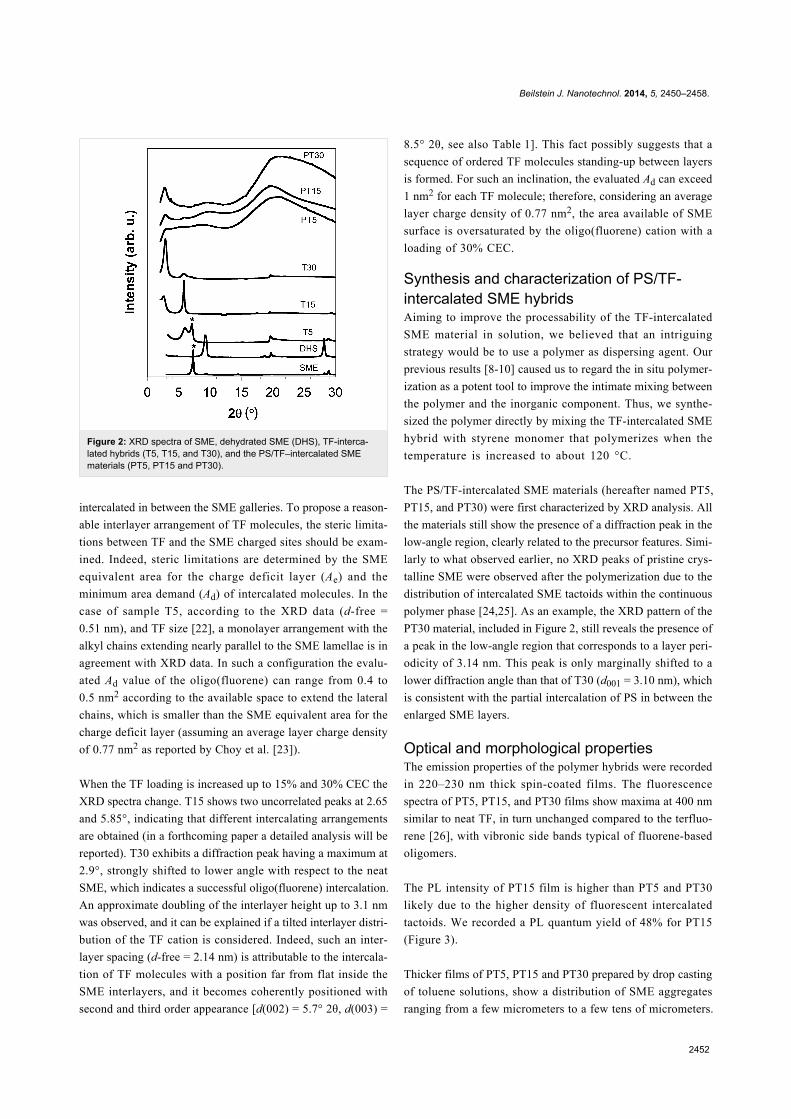
Optical and morphological propertiesThe emission properties of the polymer hybrids were recorded
in 220–230 nm thick spin-coated films. The fluorescence
spectra of PT5, PT15, and PT30 films show maxima at 400 nm
similar to neat TF, in turn unchanged compared to the terfluo-
rene [26], with vibronic side bands typical of fluorene-based
oligomers.
The PL intensity of PT15 film is higher than PT5 and PT30
likely due to the higher density of fluorescent intercalated
tactoids. We recorded a PL quantum yield of 48% for PT15
(Figure 3).
Thicker films of PT5, PT15 and PT30 prepared by drop casting
of toluene solutions, show a distribution of SME aggregates
ranging from a few micrometers to a few tens of micrometers.
Beilstein J. Nanotechnol. 2014, 5, 2450–2458.
2453
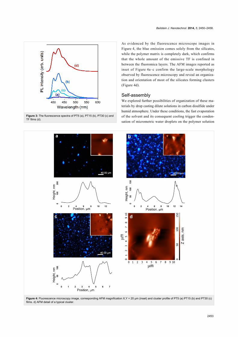
Figure 4: Fluorescence microscopy image, corresponding AFM magnification X,Y = 20 µm (inset) and cluster profile of PT5 (a) PT15 (b) and PT30 (c)films. d) AFM detail of a typical cluster.
Figure 3: The fluorescence spectra of PT5 (a), PT15 (b), PT30 (c) andTF films (d).
As evidenced by the fluorescence microscope images in
Figure 4, the blue emission comes solely from the silicates,
while the polymer matrix is completely dark, which confirms
that the whole amount of the emissive TF is confined in
between the fluoromica layers. The AFM images reported as
inset of Figure 4a–c confirm the large-scale morphology
observed by fluorescence microscopy and reveal an organiza-
tion and orientation of most of the silicates forming clusters
(Figure 4d).
Self-assemblyWe explored further possibilities of organization of these ma-
terials by drop casting dilute solutions in carbon disulfide under
humid atmosphere. Under these conditions, the fast evaporation
of the solvent and its consequent cooling trigger the conden-
sation of micrometric water droplets on the polymer solution

Beilstein J. Nanotechnol. 2014, 5, 2450–2458.
2454
Figure 5: (a–c) Microscopy images of films of PT5, PT15 and PT30 cast under breath figure conditions. (d–f) Fluorescence microscopy images ofPT5, PT15 and PT30 films prepared under the same conditions, after the addition of free TF (0.4% w/w). (g) Highly ordered microporous film of PT30after optimization of parameters. (h) AFM view of a 10 × 10 µm2 area of the same film. All scale bars are 20 µm long.
surface, which leads to the spontaneous formation of breath
figure (BF) patterns [27]. This self-assembly technique allows
one to create patterned surfaces with highly regular geometry,
in an custom-built microfabrication system. Such patterns hold
great promise for several up-to-date applications, including
nanostructures for optoelectronic devices [28-30], microfiltra-
tion membranes [31,32], and plasmonic sensors [33].
In a recently published study [11], we applied the BF pattering
technique to a hybrid copolymer formed by a PS backbone and
oligo(fluorene) branches, partially intercalated within the SME
layers. The balanced combination of flexible coil, rigid rods,
and silicates realized in that single material allowed us to
prepare highly ordered BF patterns. By contrast, when we tried
to organize PT5, PT15, and PT30 by using the same approach,
we could not observe any ordered patterns. As shown in
Figure 5a–c, all the films show unpacked and non-ordered cavi-
ties, with a wide diameter distribution, resembling what is
normally obtained by casting linear PS without polar groups
under the same conditions [34]. This is a clear indication that
the polymer is not able to stabilize the water droplets forming at
the solution/air interface, so that the microdroplets are free to
float around and to coalesce in a disordered way. In order to
increase the hydrophilicity of the system and hence the ability
of the material to stabilize the water droplets, we added some
free TF to the polymer solution.
As soon as a minimal amount of free TF is added to the system
(0.02 mg·mL−1, corresponding to 0.4% w/w with respect to the
polymer hybrid), we could observe the formation of the densely
packed cavities typical of BFs on the surface of the three films.
The micrographs in Figure 5d–f show films of the three ma-

Beilstein J. Nanotechnol. 2014, 5, 2450–2458.
2455
Figure 6: Chromatic stability of steady-state PL spectra upon UV exposure for 0 (dark blue line) to 20 min (red line) of neat flat TF film (a) and PT15film (b). PL intensity of 400 nm peak of TF and PT15 film versus exposure time to UV light (c). PL images of the patterned PT15 film acquired duringexposure to UV light are reported in (d–f).
terials, which now emit blue light because of the presence of
free TF blended with PS, homogeneously covered by cavities of
5–20 µm diameter. Even though the diameter distribution is not
uniform in these films, the presence of free TF clearly aided the
formation of BF. Underneath, the emitting SME clusters
containing intercalated TF are still visible.
The process of BF formation is regulated by different parame-
ters (polymer concentration, cast volume, solvent evaporation
rate) that can be tuned to control both the degree of order in the
arrangement of the micropores and their size [27]. Figure 5g
shows a honeycomb film of PT30 prepared after the optimiz-
ation of BF parameters; in particular, the concentration of TF
blended with PT30 was raised up to 0.2 mg·mL−1, and the flow
rate of humid nitrogen was set to 400 L·h−1. As evidenced by
the AFM detail in Figure 5h, in this film cavities have an
external diameter of 0.65 µm and a pitch of 1.0 µm and are
arranged in a highly ordered hexagonal fashion, while bright
SME aggregates are visible under the honeycomb structure,
which indicates that a hierarchical organization of this material
by the BF approach is feasible.
PhotostabilityThe intercalation of the oligo(fluorene) molecules within the
lamellae interlayers of the inorganic scaffold has dramatically
improved their photophysical stability, a critical issue for fluo-
rene-based materials [35]. PT15, selected as a representative
sample, shows good chromatic stability when irradiated by a
100 mW/cm2 UV lamp at 365 nm (Figure 6b), compared to the
flat film of neat TF (Figure 6a). The photodegradation of fluo-
rene-based compounds leads to a reduction of PL intensity
together with the appearance of the keto-defects green emission
band, peaked at around 530 nm, at the expense of the initial
blue emission. In the flat PT15 film the contribution of keto-
defects emission is almost suppressed and the decrease of PL
intensity is slower (Figure 6c) with respect to neat TF film. In
the nanoporous film (Figure 6d–f), the oxidation affects free TF
oligomers dispersed in the polymer hybrid, while sharp blue
emission from the intercalated TF is still observed, confirming
the protecting role played by the silicate.
ConclusionIn summary, novel inorganic–organic hybrid composites have
been prepared by intercalation of a cationic fluorescent
oligo(fluorene) in between fluoromica-type silicate layers. The
confined arrangement of the emitter is easily tuned by modu-
lating the dye loading as demonstrated by XRD studies. Succes-
sively, the hybrids have been in situ dispersed in a PS matrix
as a mean of making a composite that is processable from solu-
tion.

Beilstein J. Nanotechnol. 2014, 5, 2450–2458.
2456
The hybrid material films exhibit ultraviolet-blue photolumines-
cence with a significantly enhanced photostability with respect
to the bare oligo(fluorene), thanks to the intercalation of the dye
in between the inorganic layers which inhibits the photochem-
ical oxidation by blocking the oxygen penetration.
The possibility to organize the polymer nanocomposite by BF
technique opens to intriguing applications such as optoelec-
tronic devices, microfiltration membranes, and plasmonic
sensors.
ExperimentalReagentsSodium-exchanged Somasif ME100 (SME, CO-OP Chemicals,
CEC = 1.2 mmol·g−1) was dried at 130 °C under reduced pres-
sure (10−3 bar) for 2 weeks and then it was stored under
nitrogen. Ethyl alcohol (Carlo Erba, 96% pure) was degassed
under vacuum then by bubbling nitrogen, kept over molecular
sieves and used without any further purification. Styrene
(Aldrich, 99% pure) was refluxed for 4 h over CaH2, then
distilled trap-to-trap and stored under nitrogen. Distilled deion-
ized water was used for all ion-exchange experiments. 2,7-
dibromofluorene, 1,6-dibromohexane and trimethylamine were
purchased from Sigma–Aldrich. 9,9-di-n-octylfluorene-2-
boronic acid pinacol ester was purchased from Alfa Aesar. 2,7-
dibromo-9,9-bis(6’-bromohexyl)fluorene was synthesized
following the procedure reported elsewhere [36].
Materials preparationSynthesis of 2,7-bis(9,9-dioctylfluorene-2-yl)-9,9-bis[6-(trimethylammonium)hexyl]fluorene dibromide(TF)TF was synthesized by standard Suzuki coupling reaction of
2,7-dibromo-9,9-bis(6’-bromohexyl)fluorene and 9,9-di-n-
octylfluorene-2-boronic acid pinacol ester and subsequent quat-
ernization of the neutral precursor with trimethylamine,
according to the following procedure. A mixture of 2,7-
d ibromo-9 ,9-b is (6’ -bromohexyl ) f luorene (173 mg,
0.266 mmol), 9,9-di-n-octylfluorene-2-boronic acid pinacol
ester (302 mg, 0.585 mmol), Pd(PPh3)4 (6 mg, 0.005 mmol),
aqueous potassium carbonate (2 M, 1.0 mL), and toluene
(2.5 mL) was deoxygenated and then heated to 90 °C under
nitrogen. The mixture was stirred for 48 h and then cooled to
room temperature. The organic fraction was dried over Na2SO4
and purified by silica gel column chromatography, to afford
300 mg of product as pale powder (yield 87%). Condensed
trimethylamine (2.5 mL) was added dropwise to a solution of
the neutral precursor polymer (100 mg) in 7.5 mL of THF at
−30 °C. The mixture was then allowed to warm up to room
temperature for 30 min, and then cooled down again to −30 °C.
More trimethylamine (5 mL) was added and the mixture was
stirred at room temperature overnight. The obtained transparent
gel was dried under a flux of N2 to obtain TF as a white solid
(93 mg; yield 96%).
1H NMR (600 MHz, CD3OD) δ 7.85–7.69 (m, 14H, fluorene
ring), 7.38–7.33 (m, 6H, fluorene ring), 3.14 (t, 4H, -CH2N-),
2.98 (s, 18H,-NCH3), 2.22–2.08 (m, 12H, C(CH2-)2), 1.55 (m,
4H, -CH2-CH2N-), 1.18–0.63 (m, 72H, -CH2C7H15 and
-CH2C3H6C2H4N-); Anal. calcd for C89H130Br2N2: C, 77.02;
H, 9.44; Br, 11.52; N, 2.02%; found: C, 77.95; H, 9.91; Br,
11.08; N, 1.93%.
Preparation of the intercalated SME hybridsThe synthesis of T30 is reported as standard procedure. To a
100 mL three-neck round bottom flask were added SME
(50 mg) and H2O (20 mL) and stirred for 5 days at room
temperature. Meanwhile, an EtOH solution of TF (17 mg,
1.2 × 10⁻⁵ mol, 30% vs CEC) is prepared and then added to the
SME suspension. The cation-exchange reaction proceeds for 3 h
at 60 °C and then for additional 48 h at room temperature. The
suspension was filtrated and washed with a H2O/EtOH mixture
(1:1) to collect the hybrid materials. Once the solvent was
removed under reduced pressure, the product was extracted
with EtOH by Soxhlet extraction for 8 h. The residual fraction
was dried in vacuum and then ground in an agate mortar. T5
was prepared with the loading of 5% of CEC for TF (2.8 mg,
2.0 × 10⁻⁶ mol) and T15 was prepared with the loading of 15%
of CEC for TF (8.1 mg, 5.9 × 10⁻⁶ mol) for 50 mg of SME.
The preparation of PT30 filled with T30 is reported as a stan-
dard procedure. The polymerization experiments were carried
out in a 25 mL round-bottomed Schlenk flask, which had been
dried on the high vacuum line by heating at 110 °C. The reactor
was charged with T30 (10 mg) and styrene (2.20 mL, 1.98 g).
The polymerization was carried out at 125 °C for 100 min.
When the system was cooled to room temperature, polymeriza-
tion was stopped by addition of methanol (20-fold excess). The
precipitated polymer was collected by filtration, repeatedly
washed with fresh MeOH and dried in vacuum to constant
weight (yield = 0.615 g; styrene conversion = 31%; Mw =
30.3 × 10⁴ g/mol; Mw/Mn = 2.0)
Preparation of filmsFilms for optical characterization were obtained by casting or
spin-coating a 20 mg·mL−1 toluene solution of the compound
on a glass substrate. Honeycomb structured films were obtained
by following the procedure reported elsewhere [11], with few
optimizations. In particular, to set the optimal conditions for BF
formation, concentration of PT5, PT15 and PT30 was varied
from 5 to 20 mg·mL−1, while free TF was varied from 0.02 to
0.2 mg·mL−1.

Beilstein J. Nanotechnol. 2014, 5, 2450–2458.
2457
Characterization techniquesSize exclusion chromatography (SEC) measurements were
carried out on a Waters SECV2000 system equipped with two
PLGel Mixed C columns, a 2414 RI detector and a 490 UV
diode-array detector. THF was used as solvent and
poly(styrene) with molecular weights (Mw) ranging from 162 to
3.28 × 10⁶ g·mol−1, as standards. GIWAXS measurements were
performed at the X-ray diffraction beamline 5.2 at the synchro-
tron radiation facility Elettra in Trieste (Italy). The X-ray beam
emitted by the wiggler source on the Elettra 2 GeV electron
storage ring was monochromatized by a Si(111) double crystal
monochromator, focused on the sample and collimated by a
double set of slits giving a spot size of 0.2 × 0.2 mm. Both spin-
coated films (50–80 nm thick) and powders inserted into a
sealed capillary were examined at 25 °C. The beam was mono-
chromatized at energies of 8 keV for films or 10.33 keV for
powders. The samples were oriented by means of a four-circle
diffractometer with a motorized goniometric head. The X-ray
beam direction was fixed, while the sample holder could be
rotated about the different diffractometer axes, in order to reach
the sample surface alignment in the horizontal plane containing
the X-ray beam by means of laser light reflection. Subse-
quently it was possible to rotate it around an axis perpendicular
to this plane or, alternatively, to vary the angle between beam
and surface (angle of incidence). Bidimensional diffraction
patterns were recorded with a 2M Pilatus silicon pixel X-ray
detector (DECTRIS Ltd., Baden, Switzerland) positioned
perpendicular to the incident beam, at 200 mm distance from
the sample, to record the diffraction patterns in reflection
mode. Sample and detector were kept fixed during the measure-
ments. The sample inclination to the beam was changed from
ω = −0.05° to ω = 0.25°, in steps of 0.05° yielding seven
diffraction images. The q-resolution of the 2D images collected
was estimated by means of lanthanum hexaboride powder (stan-
dard reference material 660a of NIST) and it has been evalu-
ated ranging from 0.2 to 0.3 nm−1 both for qz and qxy, in agree-
ment with other synchrotron measurements [37-39]. The same
calibration standard allowed for the integration of 2D patterns
by using the software Fit2D [40] yielding several series of
powder-like patterns, corrected for geometry, Lorentz, and
beam polarization effects. Peaks positions were extracted by
means of the program Winplotr [41]. When sufficient amounts
were available, the powders were examined by using an Anton
Parr camera under nitrogen flux and a Siemens D-500
diffractometer (Cu Kα radiation, λ = 0.154 nm). The operating
voltage and current were 40 kV and 40 mA, respectively. Data
were collected from 3 to 33° at 0.05° intervals. PL spectra were
recorded by using a Spex 270M monochromator combined
with a CCD. UV irradiation of the film was performed
by Hamamatsu LightningcureTM LC8. Atomic force
microscopy investigations were performed by using a NT-MDT
NTEGRA instrument in semicontact mode in ambient condi-
tions.
AcknowledgementsThis work was carried out with the financial support of
Fondazione Cariplo project “EDONHIST” (ref. 2012-0844) and
Regione Lombardia through Project “Tecnologie e materiali per
l’utilizzo efficiente dell’energia solare” (decreto 3667/2013).
Authors wish to thank Daniele Piovani for SEC analysis.
References1. Ma, W.; Yah, W. O.; Otsuka, H.; Takahara, A. Beilstein J. Nanotechnol.
2012, 3, 82–100. doi:10.3762/bjnano.3.102. Sanchez, C.; Arribart, H.; Giraud-Guille, M. M. Nat. Mater. 2005, 4,
277–288. doi:10.1038/nmat13393. Descalzo, B.; Martínez-Máñez, R.; Sancenón, F.; Hoffmann, K.;
Rurack, K. Angew. Chem., Int. Ed. 2006, 45, 5924–5948.doi:10.1002/anie.200600734
4. Yan, D.; Lu, J.; Mei, W.; Evans, D. G.; Duan, X. J. Mater. Chem. 2011,21, 13128–13139. doi:10.1039/c1jm11594d
5. Sanchez, C.; Lebeau, B.; Chaput, F.; Boilot, J.-P. Adv. Mater. 2003, 15,1969–1994. doi:10.1002/adma.200300389
6. Sanchez, C.; Julián, B.; Belleville, P.; Popall, M. J. Mater. Chem. 2005,15, 3559–3592. doi:10.1039/b509097k
7. Fernandes, F. M.; Baradari, H.; Sanchez, C. Appl. Clay Sci. 2014, 100,2–21. doi:10.1016/j.clay.2014.05.013
8. Leone, G.; Giovanella, U.; Bertini, F.; Porzio, W.; Meinardi, F.;Botta, C.; Ricci, G. J. Mater. Chem. C 2013, 1, 1450–1460.doi:10.1039/c2tc00533f
9. Leone, G.; Giovanella, U.; Porzio, W.; Botta, C.; Ricci, G.J. Mater. Chem. 2011, 21, 12901–12909. doi:10.1039/c1jm11281c
10. Giovanella, U.; Leone, G.; Ricci, G.; Virgili, T.; Suarez Lopez, I.;Rajendran, S. K.; Botta, C. Phys. Chem. Chem. Phys. 2012, 14,13646–13650. doi:10.1039/c2cp42361h
11. Leone, G.; Giovanella, U.; Bertini, F.; Hoseinkhani, S.; Porzio, W.;Ricci, G.; Botta, C.; Galeotti, F. J. Mater. Chem. C 2013, 1, 6585–6593.doi:10.1039/c3tc31122h
12. Lee, T.-W.; Park, O. O.; Yoon, J.; Kim, J.-J. Adv. Mater. 2001, 13,211–213.doi:10.1002/1521-4095(200102)13:3<211::AID-ADMA211>3.0.CO;2-H
13. Park, J. H.; Lim, Y. T.; Park, O. O.; Kim, J. K.; Yu, J.-W.; Kim, Y. C.Adv. Funct. Mater. 2004, 14, 377–382. doi:10.1002/adfm.200305045
14. Chakraborty, C.; Dana, K.; Malik, S. J. Colloid Interface Sci. 2012, 368,172–180. doi:10.1016/j.jcis.2011.10.037
15. Chakraborty, C.; Sukul, P. K.; Dana, K.; Malik, S. Ind. Eng. Chem. Res.2013, 52, 6722–6730. doi:10.1021/ie4000213
16. Ogawa, M.; Kuroda, K. Chem. Rev. 1995, 95, 399–438.doi:10.1021/cr00034a005
17. López Arbeloa, F.; Martínez Martínez, V.; Arbeloa, T.; López Arbeloa, I.J. Photochem. Photobiol., C 2007, 8, 85–108.doi:10.1016/j.jphotochemrev.2007.03.003
18. Auerbach, S. M.; Carrado, K. A.; Dutta, S. M. Handbook of LayeredMaterials; Marcel Dekker Inc.: New York, NY, U.S.A., 2004.
19. Utracki, L. A.; Broughton, B.; González-Rojano, N.;Hecker de Carvalho, L.; Achete, C. A. Polym. Eng. Sci. 2011, 51,559–572. doi:10.1002/pen.21807

Beilstein J. Nanotechnol. 2014, 5, 2450–2458.
2458
20. Cattaneo, A. S.; Bracco, S.; Comotti, A.; Galimberti, M.; Sozzani, P.;Eckert, H. J. Phys. Chem. C 2011, 115, 12517–12529.doi:10.1021/jp2020676
21. Enzo, S.; Fagherazzi, G.; Benedetti, A.; Polizzi, S. J. Appl. Crystallogr.1988, 21, 536–542. doi:10.1107/S0021889888006612
22. Indeed the number of different conformations attainable by the alkylchains of TF molecule provokes a large variability of values from theminimum Ad calculation.
23. Yang, J.-H.; Han, Y.-S.; Choy, J.-H.; Tateyama, H. J. Mater. Chem.2001, 11, 1305–1312. doi:10.1039/b006059n
24. Leone, G.; Boglia, A.; Bertini, F.; Canetti, M.; Ricci, G.J. Polym. Sci., Part A: Polym. Chem. 2010, 48, 4473–4483.doi:10.1002/pola.24238
25. Alexandre, M.; Dubois, P. Mater. Sci. Eng., R 2000, 28, 1–63.doi:10.1016/S0927-796X(00)00012-7
26. Jaramillo-Isazaab, F.; Turner, M. L. J. Mater. Chem. 2006, 16, 83–89.doi:10.1039/b511349k
27. Wan, L.-S.; Zhu, L.-W.; Ou, Y.; Xu, Z.-K. Chem. Commun. 2014, 50,4024–4039. doi:10.1039/c3cc49826c
28. Galeotti, F.; Mróz, W.; Scavia, G.; Botta, C. Org. Electron. 2013, 14,212–218. doi:10.1016/j.orgel.2012.10.034
29. Galeotti, F.; Trespidi, F.; Timò, G.; Pasini, M.ACS Appl. Mater. Interfaces 2014, 6, 5827–5834.doi:10.1021/am500687f
30. Galeotti, F.; Mróz, W.; Bolognesi, A. Soft Matter 2011, 7, 3832–3836.doi:10.1039/c1sm05148b
31. Ma, H.; Gao, P.; Zhang, Y.; Fan, D.; Li, G.; Du, B.; Wei, Q. RSC Adv.2013, 3, 25291–25295. doi:10.1039/c3ra44812f
32. Wan, L.-S.; Li, J.-W.; Ke, B.-B.; Xu, Z.-K. J. Am. Chem. Soc. 2011, 134,95–98. doi:10.1021/ja2092745
33. Pisco, M.; Quero, G.; Iadicicco, A.; Giordano, M.; Galeotti, F.;Cusano, A. Proc. SPIE 2013, 8774, 87740R. doi:10.1117/12.2017538
34. Galeotti, F.; Calabrese, V.; Cavazzini, M.; Quici, S.; Poleunis, C.;Yunus, S.; Bolognesi, A. Chem. Mater. 2010, 22, 2764–2769.doi:10.1021/cm903652x
35. Polyfluorenes. Scherf, U.; Neher, D., Eds.; Advances in PolymerScience, Vol. 212; Springer: Berlin Heidelberg, Germany, 2008.doi:10.1007/978-3-540-68734-4
36. Liu, B.; Gaylord, B. S.; Wang, S.; Bazan, G. C. J. Am. Chem. Soc.2003, 125, 6705–6714. doi:10.1021/ja028961w
37. Rivnay, J.; Noriega, R.; Northrup, J. E.; Kline, R. J.; Toney, M. F.;Salleo, A. Phys. Rev. B 2011, 83, 121306.doi:10.1103/PhysRevB.83.121306
38. Rivnay, J.; Noriega, R.; Kline, R. J.; Salleo, A.; Toney, M. F.Phys. Rev. B 2011, 84, 045203. doi:10.1103/PhysRevB.84.045203
39. Gozzo, F.; De Caro, L.; Giannini, C.; Guagliardi, A.; Schmitt, B.;Prodi, A. J. Appl. Crystallogr. 2006, 39, 347–357.doi:10.1107/S0021889806009319
40. Hammersley, A. P.; Svensson, S. O.; Hanfland, M.; Fitch, A. N.;Hausermannm, D. High Pressure Res. 1996, 14, 235–248.doi:10.1080/08957959608201408
41. Roisnel, T.; Rodriguez-Carvajal, J. Mater. Sci. Forum 2001, 378–381,118–123. doi:10.4028/www.scientific.net/MSF.378-381.118
License and TermsThis is an Open Access article under the terms of the
Creative Commons Attribution License
(http://creativecommons.org/licenses/by/2.0), which
permits unrestricted use, distribution, and reproduction in
any medium, provided the original work is properly cited.
The license is subject to the Beilstein Journal of
Nanotechnology terms and conditions:
(http://www.beilstein-journals.org/bjnano)
The definitive version of this article is the electronic one
which can be found at:
doi:10.3762/bjnano.5.254