Spirally configured cis-stilbene/fluorene hybrids as ambipolar, fluorescent materials for organic...
10
Cite this: RSC Advances, 2013, 3, 9381 Spirally configured cis-stilbene/fluorene hybrids as ambipolar, fluorescent materials for organic light emitting diode applications3 Received 5th April 2013, Accepted 25th April 2013 DOI: 10.1039/c3ra41642a www.rsc.org/advances Chien-Tien Chen,* a Wei-Shan Chao, b Hao-Wei Liu, a Yi Wei, a Jwo-Huei Jou* c and Sudhir Kumar c A new class of cis-stilbene/fluorene spiro hybrid systems with paired diphenylamino donor and cyano, N-phenylbenzimidazole, dimesitylboranyl, or b,b-diphenylethenyl acceptor units was synthesized as ambipolar materials for organic light-emitting diode applications. When coupled with hole transporting 4,49-bis(1-naphthylphenylamino)-1,19-biphenyl (a-NPB) and electron transporting 2,29,299-(1,3,5-benzene- triyl)-tris(1-phenyl-1-H-benzimidazole) layers, they served as one of the best bluish green and pure green emitting layers with excellent external quantum efficiencies of 3.9–5.2%, electroluminescent brightness of 2202–3069 cd m 22 , luminance efficiencies of 11.0–15.8 cd A 21 , and power efficiencies of 5.7–6.6 lm W 21 at 20 mA cm 22 , which were about 2–3 times better than those based on standard a-NPB/tris(8- hydroxyquinoline)aluminum bilayer devices. 1. Introduction Organic light-emitting diodes (OLEDs) have attracted con- siderable attention for potential applications in next genera- tion flat panel displays and solid-state lighting sources. 1 Molecular designs of linearly donor–(p-spacer)–acceptor con- jugated templates were often adopted in nonlinear optics, 2 OLED, 3 dye-sensitized solar cell, 4 and organic photovoltaic cell 5 advancement. In the aspect of materials designs for OLEDs, integrating electron-transporting (ET) and hole-trans- porting (HT) components into molecular scaffolds may effectively improve OLED device performance in view of enhanced balance in charge transports of both carriers. 3 In terms of p-spacer selection, oligo-fluorene, -aryl 6 and -styryl templates were often preferred. When combined with diaryla- mine donors (D), the acceptor (A) segments benzimidazole, 1,3,4-oxadiazole, 1,2,4-triazole, and quinoxaline were often adopted. So far the D–(p-spacer)–A conjugated templates based on these scenarios 7–10 have been explored with significant success including several attempts towards single-layered devices. 11 As part of our on-going researches on the uses of dibenzosuber- ene (DBE) and iminostilbene (IMS) templates as chirochromic optical switches 12 and OLED applications, we have pioneered on the development of spirally configured, N-anthryl-dipheny- lamines and 9,9-diphenyl-fluorenes bearing doubly ortho- linked quinoxaline units derived from these two templates (Scheme 1). They served as highly efficient ambipolar materials with tunable, panchromatic emission colors. 13 We have subsequently developed spirally configured, cis- stilbene/fluorene hybrids (STIF) with diarylamino capping groups at both C3 and C7 positions (D = A = NAr 2 in Scheme 2). They served as highly efficient hole-transporting type, sky blue emitting OLED materials. 14 We therefore sought to extend the utility of STIF template towards ambipolar optoelectronic materials by appending diphenylamino donor and various different acceptor groups at C3 and C7 positions, respectively. a Department of Chemistry, National Tsing Hua University, #101, Sec 2, Kuang-Fu Rd., Hsinchu, Taiwan b Department of Chemistry, National Taiwan Normal University, #88, See.4, Ding-jou Road, Taipei 11677, Taiwan c Department of Materials Science and Engineering, National Tsing Hua University, #101, Sec 2, Kuang-Fu Rd., Hsinchu, Taiwan E-mail: [email protected]; [email protected] 3 Electronic supplementary information (ESI) available: Experimental procedures, characterization and NMR spectra for all compounds. CCDC 876488–876491, 880009–880010. For ESI and crystallographic data in CIF or other electronic format see DOI: 10.1039/c3ra41642a Scheme 1 Quinoxaline-fused IMS and DBE ambipolar materials. RSC Advances PAPER This journal is ß The Royal Society of Chemistry 2013 RSC Adv., 2013, 3, 9381–9390 | 9381
Transcript of Spirally configured cis-stilbene/fluorene hybrids as ambipolar, fluorescent materials for organic...

Cite this: RSC Advances, 2013, 3,9381
Spirally configured cis-stilbene/fluorene hybrids asambipolar, fluorescent materials for organic lightemitting diode applications3
Received 5th April 2013,Accepted 25th April 2013
DOI: 10.1039/c3ra41642a
www.rsc.org/advances
Chien-Tien Chen,*a Wei-Shan Chao,b Hao-Wei Liu,a Yi Wei,a Jwo-Huei Jou*c
and Sudhir Kumarc
A new class of cis-stilbene/fluorene spiro hybrid systems with paired diphenylamino donor and cyano,
N-phenylbenzimidazole, dimesitylboranyl, or b,b-diphenylethenyl acceptor units was synthesized as
ambipolar materials for organic light-emitting diode applications. When coupled with hole transporting
4,49-bis(1-naphthylphenylamino)-1,19-biphenyl (a-NPB) and electron transporting 2,29,299-(1,3,5-benzene-
triyl)-tris(1-phenyl-1-H-benzimidazole) layers, they served as one of the best bluish green and pure green
emitting layers with excellent external quantum efficiencies of 3.9–5.2%, electroluminescent brightness of
2202–3069 cd m22, luminance efficiencies of 11.0–15.8 cd A21, and power efficiencies of 5.7–6.6 lm W21
at 20 mA cm22, which were about 2–3 times better than those based on standard a-NPB/tris(8-
hydroxyquinoline)aluminum bilayer devices.
1. Introduction
Organic light-emitting diodes (OLEDs) have attracted con-siderable attention for potential applications in next genera-tion flat panel displays and solid-state lighting sources.1
Molecular designs of linearly donor–(p-spacer)–acceptor con-jugated templates were often adopted in nonlinear optics,2
OLED,3 dye-sensitized solar cell,4 and organic photovoltaiccell5 advancement. In the aspect of materials designs forOLEDs, integrating electron-transporting (ET) and hole-trans-porting (HT) components into molecular scaffolds mayeffectively improve OLED device performance in view ofenhanced balance in charge transports of both carriers.3 Interms of p-spacer selection, oligo-fluorene, -aryl6 and -styryltemplates were often preferred. When combined with diaryla-mine donors (D), the acceptor (A) segments benzimidazole,1,3,4-oxadiazole, 1,2,4-triazole, and quinoxaline were oftenadopted.
So far the D–(p-spacer)–A conjugated templates based onthese scenarios7–10 have been explored with significant success
including several attempts towards single-layered devices.11 Aspart of our on-going researches on the uses of dibenzosuber-ene (DBE) and iminostilbene (IMS) templates as chirochromicoptical switches12 and OLED applications, we have pioneeredon the development of spirally configured, N-anthryl-dipheny-lamines and 9,9-diphenyl-fluorenes bearing doubly ortho-linked quinoxaline units derived from these two templates(Scheme 1). They served as highly efficient ambipolarmaterials with tunable, panchromatic emission colors.13
We have subsequently developed spirally configured, cis-stilbene/fluorene hybrids (STIF) with diarylamino cappinggroups at both C3 and C7 positions (D = A = NAr2 in Scheme 2).They served as highly efficient hole-transporting type, sky blueemitting OLED materials.14 We therefore sought to extend theutility of STIF template towards ambipolar optoelectronicmaterials by appending diphenylamino donor and variousdifferent acceptor groups at C3 and C7 positions, respectively.
aDepartment of Chemistry, National Tsing Hua University, #101, Sec 2, Kuang-Fu
Rd., Hsinchu, TaiwanbDepartment of Chemistry, National Taiwan Normal University, #88, See.4, Ding-jou
Road, Taipei 11677, TaiwancDepartment of Materials Science and Engineering, National Tsing Hua University,
#101, Sec 2, Kuang-Fu Rd., Hsinchu, Taiwan E-mail: [email protected];
3 Electronic supplementary information (ESI) available: Experimentalprocedures, characterization and NMR spectra for all compounds. CCDC876488–876491, 880009–880010. For ESI and crystallographic data in CIF orother electronic format see DOI: 10.1039/c3ra41642a
Scheme 1 Quinoxaline-fused IMS and DBE ambipolar materials.
RSC Advances
PAPER
This journal is � The Royal Society of Chemistry 2013 RSC Adv., 2013, 3, 9381–9390 | 9381
Sudhir Dubey
Highlight

Cyano (CN) and N-phenylbenzimidazole (BIM) units with orwithout a conjugated phenyl spacer were selected as theacceptor end groups in this study (Scheme 2). In addition,dimesitylboranyl and b,b- diphenylethenyl groups were chosenfor comparisons. Herein, we describe the systematic results oftheir applications in OLEDs.
2. Results and discussions
2.1. Structural studies
The materials preparations are described in the ESI3. Thestructural identities of 3a–g were unambigiously confirmed byX-ray crystallographic analyses (see ESI3). In all cases except 3a,the absolute dihedral angles between the central CLC in STIF
template and ring 1 (Q1) or ring 2 (Q2) fall in a range of 19.8–25.5u and 20.8–28.7u respectively (Table 1), which lie slightlylarger than those for the corresponding trans-stilbenes.Notably, the absolute dihedral angles (9.1–10.3u) in 3a areeven much smaller than those of the corresponding trans-stilbene analog (ca 20.3u),15a,b indicating the advantage of theconfined cyclic, spiral configuration. In all cases, the N centeris sp2 hybridized with all its three attached carbon atomscoplanar with the central N, indicating its lone pair electronsare largely delocalized into the central DBE. Given the samecyano acceptor, introduction of the phenyl spacer reduces theextent of conjugation within the central DBE core as evidencedby the increased dihedral angles (Q1 and Q2) from 9.1 and 10.3in 3a to 21.9 and 23.3 in 3b, respectively. In comparison with3c, the extent of conjugation within the central DBE core in 3dremains similar by introduction of the phenyl spacerpresumably due to similar aromatic nature between phenyland BIM groups. The averaged dihedral angles [(Q1 + Q2)/2] are22.3–27.1u in these two cases. An averaged dihedral angle of21.0u is observed in 3g bearing an ethenyl terminal. Theintroduction of sterically hindered dimesitylboranyl group in3f led to a larger Q2 of 26.3u.
Comparison between the BIM-derived compounds 3c and 3dillustrates the potential effect of the phenyl spacer in thedesign of these materials. The lack of the spacer in 3c allows astabilizing intramolecular p–p interaction between theN-phenyl group of the BIM with the spiro-fluorene unit. Incontrast, the addition of the phenyl spacer in 3d now movesthe BIM unit further away from the fluorene, thus prohibitingthis intramolecular interaction. As a result, p–p stacking in 3doccurs been the N-phenyl group of the BIM and the fluorene ofa neighboring compound, thus enhancing intermolecularinteractions. Notably, the steric interaction between one ofthe mesityl groups in BMes2 and the spiro-fluorene unit leadsto a deviation of coplanarity by 22.7u for the three carbonsbounded to the boryl center in 3f.15c Conversely, one of thephenyl groups in the diphenylethenyl terminal in 3g also has asimilar steric interaction, thus resulting in a big deviation ofcoplanarity between ring 2 and DPE (Q3, 40u).16d
2.2. Photophysical and simulation studies
The UV-Vis absorption and emission stacked spectra of 3a–eand 3f,g in CH2Cl2 solution are displayed in Fig. 1 and theirphotophysical property data are compiled in Table 2. Theabsorption maxima (lmax) of the lowest energy bands arecentered around 402–432 nm. They are attributed to intramo-lecular charge transfer transitions from the HOMO locatedprimarily on diphenylamino unit and ring-1 to the LUMOlocalized across ring-2, and the corresponding electron-accepting moiety as supported by molecular simulations oftheir HOMO and LUMO levels (Fig. S1, ESI3 and Fig. 2 in thecases of 3b and 3d). Given the same cyano acceptor, theintroduction of the phenyl spacer leads to a blue shift ofabsorption lmax from 420 to 410 nm and reduction inextinction coefficient (emax) by 40%. Notably, the linear cyanoacceptors in 3a and 3b result in stronger ICT transitions thanthose of the BIM acceptors in 3c and 3d as evidenced by thebathochromic shifts of the absorption and emission lmax
values by 5–12 and 14–25 nm, respectively. However, the
Scheme 2 The molecular design of D-STIF-A materials.
Table 1 Selected dihedral angles based on the X-ray crystal structures of 3a–dand 3f,g
Compound Q1a Q2
a Q3b
3a (A = CN) 9.1 10.3 —3b (A = C6H4CN) 21.9 23.3 21.73c (A = BIM) 25.5 28.7 39.13d (A = C6H4BIM) 22.3 22.3 26.93f (A = BMes2) 19.8 26.3 —3g (A = DPE) 21.2 20.8 40.0
a Q1 and Q2: dihedral angles between CLC and ring 1 or ring 2,respectively, in 3a–g. b Q3: dihedral angle between ring 2 and phenylspacer in 3b and 3d, BIM in 3c, or C = CPh2 (DPE) in 3g.
9382 | RSC Adv., 2013, 3, 9381–9390 This journal is � The Royal Society of Chemistry 2013
Paper RSC Advances
introduction of boryl acceptor group in 3f leads to a blue shiftof its lmax, (395 nm; emax, 21.4 6 103) along with the additionof a shoulder at 432 nm (emax, 14.9 6 103). Conversely, theintroduction of DPE acceptor in 3g (lmax = 410 nm, emax = 30.76 103) shows a similar effect to those (lmax = 405–408 nm, emax
= 25.2 2 27.6 6 103) of BIM-containing 3c and 3d.The photoluminescence emission maxima (PL lmax) for 3a
and 3b (519–523 nm) fall in the saturated green emissionrange. The full-widths at half-maximum (fwhm) for theemission bands of 3a,b are narrower by 11–16 nm than those
of 3c,d. The fluorescent quantum yields (Wf) for 3a–3d are in arange of 62–87%. In comparison with 3d, the introduction oftwo tert-butyl groups to the C-2 and C-7 positions of the spirofluorene moiety in 3e led to a red shift of PL lmax by 12 nm andan increase in Wf by 16% presumably due to reduced inter- andintra-chromophoric contact and increased emission.
In all cases, negligible change was observed in their UV-Visspectra with increasing solvent polarity (Fig. S2, ESI3). Incontrast, there exist progressive bathochromic shifts of PL lmax
with increasing solvent polarity (i.e., CH3CN > CH2Cl2 > THF >toluene) as represented in the cases of 3a and 3c (Fig. 3),suggesting stabilization of the charge transfer excited state inmore polar solvents.
Similar to the emission profiles (lmax, 505–510 nm) in BIM-containing 3c and 3e, the PL emission in DPE-containing 3g iscentered at 512 nm. The introduction of sterically hindered,electron deficient dimesitylboryl moiety as in 3f showed dualemissions with the first emission band at 461 nm and a redshifted second emission lmax at 517 nm. Notably, thecorresponding trans-stilbene analog shows only one emissionband centered at 522 nm.15c The absorption and emissionbands of vibronic features for 3f indicate that the borylacceptor leads to slower conformational interconversion (orflipping) in the seven-membered, DBE template both in theground and excited states.
2.3. Stability, morphology, and electro-chemical studies
Their thermal and morphological properties were examined bythermal gravimetric analysis (TGA) and differential scanningcalorimetry (DSC) measurements (Table 2). The introductionof phenyl spacer led to an increase in Tg by 21–25 uC (cf 3a and3b; 3c and 3d) and in Td by 34 uC for the BIM containingmaterials (cf 3c and 3d). The two tert-butyl appendages in 3efurther increase its thermal stability by 23 uC (cf 3d and 3e). Inaddition, both 3b and 3f show similar Tg (130 and 124 uC,respectively) and Td (385 and 390 uC, respectively) values.Notably, the spirally configured structural motifs of thesematerials result in their high glass transition temperatures (Tg,105–161 uC) and high thermal stabilities (Td, 385–469 uC).These constitute important factors to secure their stability andlifetime performance in OLED devices during repetitive andlong-term operations.
Fig. 1 The stacked plots of UV-Vis absorption and PL emission spectra of 3a–3e(top) and 3f,g (bottom) measured in CH2Cl2.
Table 2 Photophysical, thermal and electrochemical properties of 3a–3g
lmax (emax 6 103),a nm PL lmax nm (fwhm/Wf)a Tg/Td, uC E1/2
ox/E1/2red, Vb DE (Eg, eV)c
3a 420 (25.8) 519 (68/87%) 105/389 +0.48/22.27 2.75 (2.59)3b 410 (15.8) 523 (66/62%) 130/385 +0.45/22.33,22.67 2.78, 3.12 (2.62)3c 408 (25.2) 505 (84/62%) 140/435 +0.45/22.36 2.81 (2.65)3d 405 (27.6) 498 (77/78%) 161/469 +0.41/22.68,22.84 3.09, 3.25 (2.68)3e 402 (29.7) 510 (78/94%) 169/492 +0.41/22.44,22.67 2.85, 3.08 (2.68)3f 395 (21.4),432 (14.9) 461, 517 (106/70%) 124/390 +0.45/22.32 2.77 (2.72, 2.55d)3g 410 (30.7) 512 (78/64%) 117/413 0.46/22.00,22.19,22.39e 2.46, 2.65 (2.66)
a Measured in CH2Cl2. b Electrochemical data of materials measured in CH2Cl2 or THF (1 mM) containing 0.1 M Bu4N+ClO42using a glassy
carbon as a working electrode and a Pt wire counter electrode with a scan rate of 100 mv s21, potentials are quoted with reference to theinternal ferrocene (Fc) standard (E1/2
ox = 482 mV vs. Ag/AgCl). c Calculated from |E1/2red 2 E1/2
ox| and the data in parentheses are derived fromband edge wavelengths of the longest wavelength absorption peaks. d Based on the absorption edges of both lmax. e Estimated Epc values bydifferential pulse voltammetry.
This journal is � The Royal Society of Chemistry 2013 RSC Adv., 2013, 3, 9381–9390 | 9383
RSC Advances Paper

The redox behaviors of 3a–3g were evaluated by cyclicvoltammetry (CV) experiments in CH2Cl2 (E1/2
ox) or THF (E1/
2red). The corresponding HOMO–LUMO energy gaps (Eg) were
calculated from their absolute differences or derived from theobserved optical edges (Table 2). Their oxidation potentials fallin a close range of + 0.41–0.48 V. They all exhibit quasi-reversible one-electron oxidation redox couples (Fig. S3, ESI3)which are attributed to the oxidation of the electron-donatingN,N-diphenylamino group.
Conversely in all cases except 3f and 3g, quasi-reversibleone-electron or two sequential one-electron reductions are
observed (Fig. 4). The reduction potentials for 3a–e range from22.00 to 22.68 V. The reduction potentials for the BIM-containing materials (3c and 3d) are 0.09–0.35 V higher thanthe corresponding CN-containing ones (i.e., 3a and 3b). Thereduction potential is the lowest in DPE-containing 3g (22.00V) presumably due to more conjugative stabilization of theresulting radical anion by the DPE acceptor. Conversely, thereduction potential is the highest in BIM- and boryl-containing3c and 3f (22.32 to 22.36 V). These trends are consistent withthe relative electron-accepting ability of the acceptor (i.e., CN >B(Mes)2 > BIM).
Fig. 2 HOMO (bottom, colored in blue and green) and LUMO (top, colored in red and yellow) plots of 3b (left) and 3d (right) generated by using Scigress molecularsimulation package with ZINDO Configuration Interaction using INDO/S parameters after optimizing geometry either with ZINDO INDO/1 or by using DGauss withthe B88-PW91 GGA functional with the DZVP basis sets.
Fig. 3 Solvent dependent photoluminescent profiles of 3a and 3c in four different solvents.
9384 | RSC Adv., 2013, 3, 9381–9390 This journal is � The Royal Society of Chemistry 2013
Paper RSC Advances

There exist second reduction potentials for the phenyl-containing 3b and 3d/3e which fall in a range of 22.67 to22.84 V. The introduction of DPE as in 3g led to threeirreversible, one-electron reductions (approximate Epc valuesdetermined by differential pulse voltammetry are 22.00,22.19 and 22.39 V; Fig. S3b, ESI3). Notably, the secondreduction potentials observed for the phenyl- and 1,1-diphenylethenyl-containing systems (i.e. 3b, 3d/3e, and 3g)do not exist for the corresponding spiro-bifluorene (SPF)based, PhBIM- and DPE-containing systems (i.e., the structuresabove Table 3).3a,16a,c,d The observed extra reduction potentialsin our phenyl- and DPE-containing materials (i.e., 3b, 3d/3e,
and 3g) indicate the extra conjugation through STIF core canfacilitate further electron accepting. Their quasi-reversibleoxidation and reduction redox couples in 3a–e indicate thatthese materials are ambipolar in nature and the incipientradical cations, anions, and even dianions can be stabilized tosome extent.
The HOMO–LUMO energy gaps (Eg) of the CN- and BIM-containing materials are around 2.59 and 2.68 eV, respectively.Notably, their estimated HOMO levels [EHOMO = (Eonset
ox +5.1)17] are 5.25 ¡ 0.03 eV (Fig. 5) and are slightly lower thanthat of a common hole-transporter, 4,49-bis(1-naphthylphenyl-amino)-1,19-biphenyl (a-NPB18). Therefore one can expect theuse of a-NPB as the hole-transporting layer can facilitate holeinjection between the hole-transporter/emitter interface in oursystem. Notably, the HOMO energy level difference between3a–g and a common electron transporter, 2,29,299-(1,3,5-benzenetriyl)-tris(1-phenyl-1-H-benzimidazole) (TPBI19) isabout 0.9 eV. Therefore, the use of TPBI as the electron-transporter allows us to efficiently confine the holes in theemitting layer.
On the other hand, the calculated LUMO levels (ELUMO =EHOMO 2 Eg) for cyano- and PhBIM-containing 3a–e are 2.52–2.68 eV (Fig. 5) and are higher by 0.04–0.20 eV than that ofTPBI (2.72 eV). As pointed out above, both 3b and 3e exhibitsecond quasi-reversible reductions. Therefore, a LUMO + 1level of slightly higher energy can be expected for each case.The estimated LUMO + 1 levels for 3b and 3e are 2.27 and 2.30eV, which are higher than that of TPBI by 0.45 and 0.42 eV,respectively. The boryl-containing 3f has a LUMO level of 2.52eV, which is higher than that of TPBI by 0.20 eV. On the otherhand, the DPE-containing 3g has a LUMO level of 2.59. ItsLUMO + 1 and LUMO + 2 levels are 2.40 and 2.20 eV,
Fig. 4 Cyclic voltammogram reduction potential stacked plots of 3a–3e.
Table 3 The optoelectronic performance data for 3a–3g and their comparisons with three literature systems
Configurationa Em, lmax (fwhmb) Von,c V gext,c % gc/gp,c Lmax, (L20), cd m22
3a/B 522 (85) 2.7 (6.0) 3.8 12.7/6.6 38901 (2551)Alq3/A 516 (104) 3.9 (5.6) 1.1 3.3/1.8 28911 (638)3b/B 524 (90) 3.0 (8.0) 4.0 13.8/5.4 65182 (2756)3c/B 506 (89) 2.5 (7.6) 5.1 15.8/6.4 51030 (3069)3d/B 490(175),580(199) 6.5 (10.0) 1.7 3.9/1.2 9308 (782)3e/B 500 (83) 2.7 (6.3) 3.9 11.0/5.7 51659 (2202)3f/B 508 (68) 3.3 (6.9) 1.4 4.5/2.1 25580 (1003)3g/B 508 (88) 3.0 (7.4) 3.4 10.3/4.2 35711 (2275)D-SPF(t-Bu)-PhBIM/A 454 (62) 2.7 (—) 1.4 0.9/1.4 10418 (—)d
D-SPF-BMes2/C 484 (90) 11.2 (22) — 5.0/0.9 1813 (—)e
D-SPF-DPE/B 478 (—) —(4.7) 2.9 5.4/5.7 33020 (910)f
a A: ITO/NPB (40 nm)/emitter (40 nm)/LiF (1 nm)/Al; B: ITO/NPB (40 nm)/emitter (40 nm)/TPBI (40 nm)/LiF (1 nm)/Al; C: ITO/NPB (60 nm)/emitter (60 nm)/BCP (10 nm)/Alq3 (10 nm)/LiF (1 nm)/Al. b The data in parentheses correspond to full-width at half-maximum (fwhm). c Von,gext (%), gc (cd A21), gp (lm W21), and L20 measured at 20 mA cm22. d Data as reported in ref. 3a and 16a by Prof. Lin. e Data as reported inref. 16b by Prof. Chang. f Data in ref. 16c by Prof. Chen.
This journal is � The Royal Society of Chemistry 2013 RSC Adv., 2013, 3, 9381–9390 | 9385
RSC Advances Paper

respectively, which are 0.32 and 0.52 eV higher that the LUMOlevel of TPBI. Since all the LUMO + 1 levels for 3b, 3e, and 3gare still lower than the LUMO level of a-NPB, partial electroninjections from the LUMO of TPBI into these LUMO + 1 levelsmay not be completely ignored.
2.4. OLED device fabrication and performance studies
Their optoelectronic performances were evaluated as respec-tive, pure emitting layers by fabricating them into trilayerOLED devices-B (Fig. 5). The OLED devices were fabricatedonto indium tin oxide (ITO) as the anode. a-NPB and TPBIwere used as the HT and ET layers, respectively. LiF and Alwere used as the electron-injection layer and the cathode,respectively. Compounds 3a and 3b were first examined(Table 3). The resultant OLED devices exhibited maximumEL brightness (Lmax) of 38901 and 65182 cd m22, respectively,at 522–524 nm (Fig. 6–7 and S4, ESI3). Their operationalbrightness (L20) at 20 mA cm22 could reach 2551 and 2756 cdm22 (Fig. S4, ESI3), respectively, with individual externalquantum efficiencies (gext) of 3.8–4.0% (Fig. 7). Theirluminance and power efficiencies (gc/gp) were 12.7/6.6 and13.8/5.4 cd A21/lm W21 (Fig. 6 and S4, ESI3), respectively.Notably, the overall device efficiencies and operational bright-ness for 3a and 3b were about 3–4 times better than that forAlq3 in a standard bilayer device configuration-A.
Compounds 3c and 3e were also independently examined asbluish-green emitting layers in trilayer device configurations B(Table 3). The resultant OLED devices exhibited maximum ELbrightness (Lmax) of 51 030 and 51 659 cd m22, respectively, at500–506 nm (Fig. 8–9 and Fig. S5, ESI3). Their operationalbrightness (L20) at 20 mA cm22 could reach 3069 and 2202 cd
m22 (Fig. S5, ESI3), respectively, with individual externalquantum efficiency (gext) of 5.1 and 3.9% (Fig. 9). Theluminance and power efficiencies (gc/gp) were 15.8/6.4 and11.0/5.7 cd A21/lm W21 (Fig. 8 and Fig. S5, ESI3), respectively.Notably, the overall device efficiencies and operational bright-ness for 3c and 3e were at least 3–5 times better than that for
Fig. 5 Schematic HOMO–LUMO energy level diagram for various OLED deviceconfigurations for 3a–3c and 3e–3g (levels in solid lines are based on theirEonset
ox and Eg values; LUMO + 1 or +2 levels are in dashed lines and are basedon the energy difference of their first and second or first and third E1/2
red).
Fig. 6 I–V–L characteristics (top); current density vs. luminance efficiency(bottom) stacked plots for 3a and 3b based trilayer devices B.
Fig. 7 Current density vs. external quantum efficiency stacked plots for 3a and3b based trilayer devices B.
9386 | RSC Adv., 2013, 3, 9381–9390 This journal is � The Royal Society of Chemistry 2013
Paper RSC Advances

Alq3 or for a blue-emitting D-SPF(t-Bu)-PhBIM in a bilayerdevice configuration-A (Table 3).
The t-butyl groups at spiro-fluorene moiety in 3e areessential to prevent adverse intermolecular p–p interactionsin the devices fabricated from the PhBIM-containing materials(cf 3d and 3e). In device configuration B by using 3d as the ETtype emitter, dual band and broad electroluminescent emis-
sions at 490 and 580 nm (fwhm, 175 and 199 nm) arising fromboth 3d and its excimer were observed (Fig. S5, ESI3) withdramatically reduced efficiencies and operational brightness,which only amount to about 33–37% of those based on 3e.
The LUMO energy differences between 3a–c, 3e and TPBIhave the following trend: 3e (+0.18 V) > 3c (+0.11 V) > 3b (+0.09V) > 3a (+0.04 V). Among these devices made of 3a–c and 3e,the turn-on voltages show the following trends: 3a (2.7 V) , 3b(3.0 V) and 3c (2.5 V) , 3e (2.7 V). Notably, materials 3a and 3cwithout a phenyl spacer had slightly lower turn-on voltages by0.2–0.3 V than 3b and 3e presumably due to their slightlyhigher LUMO energy levels (by 0.05–0.07 V) in the phenyl-containing materials 3b and 3e.
In order to evaluate the charge mobility of both carriers interms of current density of the devices, single carrier deviceswere fabricated for 3a and 3b, respectively. Current density-voltage characteristics in the hole-only [ITO/a-NPB (10 nm)/3aor 3b (50 nm)/a-NPB (10 nm)/Al (100 nm)] and electron-only[ITO/BCP (10 nm)/3a or 3b (50 nm)/LiF (1 nm)/Al (100 nm)]devices in a range of 0–12 V are shown in Fig. 10. The currentdensity–voltage characteristics for the hole-only devices arevery similar in both cases, indicating 3a and 3b have similarhole mobilities. However, a large difference in device currentdensity was observed particularly at the driving voltage of 11 Vfor the electron-only devices made of 3a and 3b, respectively.
Fig. 8 I–V–L characteristics (top); current density vs. luminance efficiency(bottom) stacked plots for 3c and 3e based trilayer devices B.
Fig. 9 Current density vs. external quantum efficiency stacked plots for 3c and3e based trilayer devices B.
Fig. 10 Current–voltage characteristics of hole-only and electron-only devicesfor 3a (top) and 3b (bottom).
This journal is � The Royal Society of Chemistry 2013 RSC Adv., 2013, 3, 9381–9390 | 9387
RSC Advances Paper
Since the LUMO energy difference for 3a and 3b is only 0.05 V,the large discrepancy in terms of current density suggests thatthe phenyl-containing 3b has higher electron mobility than 3a.In addition, much more balanced carrier transports wereobserved in the case of 3b, which may explain why the devicemade of 3b shows slightly better operational efficiencies(4.1%, 13.8 cd A21) and brightness (2756 cd m22) than thosemade of 3a (3.8%, 12.7 cd A21, 2551 cd m22) despite thefluorescent quantum yield of 3b (62%) was lower by 25% thanthat of 3a (87%) measured in CH2Cl2 solution.
On the other hand, despite 3c has a lower fluorescentquantum yield (62%), the device made of 3c still showed betteroperational efficiencies (5.1%, 15.5 cd A21) and brightness(3069 cd m22) than those of 3e (3.9%, 11.0 cd A21, 2202 cdm22). The increased inter-chromophoric distance exerted bythe bulky tert-butyl groups in 3e may be responsible forreducing the efficiency of electron injection from TPBI as wellas exciton recombination.
Among the devices made of 3a–c and 3e, their externalquantum efficiency and current efficiency roll-offs (in percen-tage) with current density of up to 400 mA cm22 show thefollowing trend (Fig. S7–S8, ESI3): 3e (18%) , 3b (23%) , 3a(38%) y 3c (37%). In addition, their efficiency roll-offs (inpercentage) with luminance ranging from 2000 to 20 000 cdm22 also show similar trend: 3e (12%) , 3b (19%) , 3a (31%)y 3c (27%). In comparison with 3b and 3e, more severe roll-offs for 3a and 3c in device efficiencies at current density andluminance of up to 400 mA cm22 and 20 000 cd m22,respectively, were observed. Presumably, both phenyl-contain-ing 3b and 3e can accommodate more excitons under highcurrent density in view of their two quasi-reversible, sequentialone-electron accepting ability as evidenced by their CVmeasurements and also much more balanced carrier trans-ports as supported by the hole- and electron-only devices of 3b.
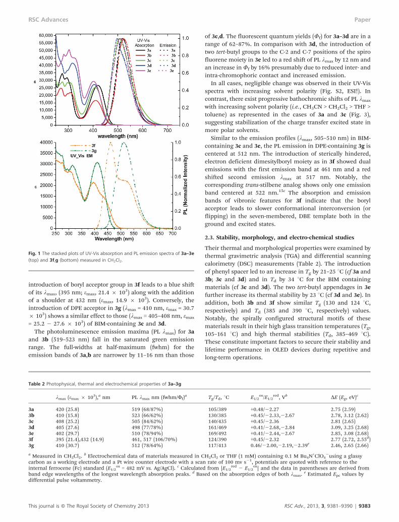
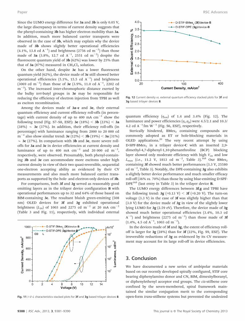
For comparisons, both 3f and 3g served as reasonably goodemitting layers as in the trilayer device configuration B withoperational performances up to 32 and 64% of those based onBIM-containing 3c. The resultant bluish green-emitting (508nm) OLED devices for 3f and 3g exhibited operationalbrightness (L20) of 1003 and 2275 cd m22 at 20 mA cm22
(Table 3 and Fig. 11), respectively, with individual external
quantum efficiency (gext) of 1.4 and 3.4% (Fig. 12). Theluminance and power efficiencies (gc/gp) were 4.5/2.1 and 10.3/4.2 cd A21/lm W21 (Fig. S6, ESI3), respectively.
Sterically hindered, BMes2 containing compounds arecommonly adopted as ET or hole-blocking materials inOLED applications.20 The very recent attempt by usingD-SPF-BMes2 in a trilayer device-C with an inserted 2,9-dimethyl-4,7-diphenyl-1,10-phenanthroline (BCP) blockinglayer showed only moderate efficiency with high Von and lowLmax (i.e., 11.2 V, 1813 cd m22, Table 3).16b Our BMes2
containing 3f showed much better performances (3.3 V, 25580cd m22, Table 3). Notably, the DPE-containing 3g also exhibitsa slightly better device performance and much smaller efficacyroll-off (36% vs. 70%) than those by using blue-emitting D-SPF-DPE16b (last entry in Table 3) in the trilayer device B.
The LUMO energy differences between 3f,g and TPBI havethe following trend: 3g (+0.13 V) , 3f (+0.20 V). The turn-onvoltage (3.3 V) in the case of 3f was slightly higher than that(3.0 V) for the device made of 3g in view of the slightly lowerlying LUMO for 3g (2.59 eV). Therefore, the device made of 3gshowed much better operational efficiencies (3.4%, 10.3 cdA21) and brightness (2275 cd m22) than those made of 3f(1.4%, 4.5 cd A21, 1003 cd m22).
In the devices made of 3f and 3g, the extent of efficiency roll-off is larger for 3g (28%) than for 3f (22%, Fig. S9, ESI3). Theirreversible reductions of 3g as evidenced by its CV measure-ment may account for its large roll-off in device efficiencies.
3. Conclusion
We have documented a new series of ambipolar materialsbased on our recently developed spirally configured, STIF corebearing diphenylamino donor and CN, BIM, dimesitylboranyl,or diphenylethenyl acceptor end groups. The cis-stilbene coreconfined by the seven-membered, spiral framework main-tained the similar conjugation merit to the correspondingopen-form trans-stilbene systems but prevented the undesiredFig. 11 I–V–L characteristics stacked plots for 3f and 3g based trilayer devices B.
Fig. 12 Current density vs. external quantum efficiency stacked plots for 3f and3g based trilayer devices B.
9388 | RSC Adv., 2013, 3, 9381–9390 This journal is � The Royal Society of Chemistry 2013
Paper RSC Advances
radiationless decay through photoisomerization and/or exci-mer emission due to closer inter-chromophoric contact intrans-stilbene systems. Their photoluminescences were redshifted with increasing solvent polarity, indicating that theirexcited states were highly polarized. They have shownpromising thermal stability (Td ¢ 385 uC) and quasi-reversible,redox profiles particularly in the CN- and BIM-containingmaterials. In the combination with a-NPB as the HT layer andTPBI as the ET layer, the BIM-, and BMes2- and DPE-containing materials could function as optimal green- orbluish green-emitting layers as compared to those based onthe corresponding SPF systems. Much more balanced carriertransports in phenyl-containing 3b and 3d may be responsiblefor the significantly reduced roll-offs at high current densityand luminance device conditions.
Acknowledgements
We thank the National Science Council of Taiwan and FrontierResearch Center on Fundamental and Applied Sciences ofMatters for financial support of this research.
References
1 B. W. D’Andrade and S. R. Forrest, Adv. Mater., 2004, 18,1585.
2 F. Rizzo, M. Cavazzini, S. Righetto, F. De Angelis,S. Fantacci and S. Quici, Eur. J. Org. Chem., 2010, 4004.
3 (a) M.-Y. Lai, C.-H. Chen, W.-S. Huang, J.-T. Lin, T.-H. Ke,L.-Y. Chen, M.-H. Tsai and C.-C. Wu, Angew. Chem., Int. Ed.,2008, 47, 581; (b) M. Zhu, T. Ye, C. G. Li, X. Cao, C. Zhong,D. Ma, J. Qin and C. Yang, J. Phys. Chem. C, 2011, 115,17965; (c) W. Jiang, L. Duan, J. Qiao, G. Dong, L. Wang andY. Oiu, Org. Lett., 2011, 13, 3146; (d) Z. H. Li, M. S. Wong,H. Fukutani and Y. Tao, Org. Lett., 2006, 8, 4271; (e)H. Tsuji, C. Mitsui, Y. Sato and E. Nakamura, Adv. Mater.,2009, 21, 3776; (f) K. Mullen and U. Scherf, Organic Light-Emitting Devices Synthesis, Properties and Applications,Wiley, Weinheim, Germany, 2006.
4 For a recent review, see: L. Giribabu, R. K. Kanaparthi andV. Velkannan, Chem. Rec., 2012, 12, 306.
5 (a) B. C. Thompson and J. M. Frechet, Angew. Chem., Int.Ed., 2008, 47, 58; (b) A. Cravino, P. Leriche, O. Aleveque,S. Roquet and J. Roncali, Adv. Mater., 2006, 18, 3033; (c)J. Hou, H. Y. Chen, S. Zhang and Y. Yang, J. Phys. Chem. C,2009, 113, 21202; (d) E. Wang, Z. Ma, Z. Zhang,K. Vandewal, P. Henriksson, O. Inganas, F. Zhang and M.R. Andersson, J. Am. Chem. Soc., 2011, 133, 14244; (e) G.C. Welch and G. Bazan, J. Am. Chem. Soc., 2011, 133, 4632.
6 (a) Y. Zhang, S.-L. Lai, Q.-X. Tong, M.-F. Lo, T.-W. Ng, M.-Y. Chan, Z.-C. Wen, J. He, K.-S. Jeff, X.-L. Tang, W.-M. Liu,C.-C. Ko, P.-F. Wang and C.-S. Lee, Chem. Mater., 2012, 24,61; (b) J. Huang, J.-H. Su, X. Li, M.-K. Lam, K.-M. Fung, H.-H. Fan, K.-W. Cheah, C. H. Chen and H. Tian, J. Mater.Chem., 2011, 21, 2957; (c) M. Debeaux, M. W. Thesen,D. Schneidenbach, H. Hopf, S. Janietz, H. Kruger, A. Wedel,W. Kowalsky and H.-H. Johannes, Adv. Funct. Mater., 2010,20, 399.
7 (a) S. Tao, C. S. Lee, S.-T. Lee and X. Zhang, Appl. Phys. Lett.,2007, 91, 13507; (b) H. Mochizuki, T. Hasui, M. Kawamoto,T. Shiono, T. Ikeda, C. Adachi, Y. Taniguchi and Y. Shirota,Chem. Commun., 2000, 1923; (c) N. Tamoto, C. Adachi andK. Nagai, Chem. Mater., 1997, 9, 1077; (d) Z. Peng, Z. Baoand M. E. Galvin, Chem. Mater., 1998, 10, 2086.
8 (a) T.-H. Huang, J.-T. Lin, L.-Y. Chen, Y.-T. Lin and C.-C. Wu, Adv. Mater., 2006, 18, 602; (b) Y. Liu, H. Ma and A.K.-Y. Jen, Chem. Commun., 1998, 2747; (c) Y. Z. Wang and A.J. Epstein, Acc. Chem. Res., 1999, 32, 217; (d) S. A. Jenekhe,L. D. Lu and M. M. Alam, Macromolecules, 2001, 34, 7315.
9 (a) Z. Ge, T. Hayakawa, S. Ando, M. Ueda, T. Akiike,H. Miyamoto, T. Kajita and M. Kakimoto, Chem. Mater.,2008, 20, 2532; (b) K. R. Justin Thomas, J.-T. Lin, Y.-T. Taoand C.-H. Chuen, Chem. Mater., 2002, 14, 3852; (c) S.Y. Song, M. S. Jang, H. K. Shim, D. H. Hwang and T. Zyung,Macromolecules, 1999, 32, 1482; (d) T. Yamamoto, Z.H. Zhou, T. Kanbara, M. Shimura, K. Kizu, T. Maruyama,Y. Nakamura, T. Fukuda, B. L. Lee, N. Ooba, S. Tomaru,T. Kurihara, T. Kaino, K. Kubota and S. Sasaki, J. Am. Chem.Soc., 1996, 118, 10389.
10 (a) Z. Ge, T. Hayakawa, S. Ando, M. Ueda, T. Akiike,H. Miyamoto, T. Kajita and M. Kakimoto, Org. Lett., 2008,10, 421; (b) Y. Geng, D. Katsis, S. W. Culligan, J. J. Ou, S.H. Chen and L. J. Rothberg, Chem. Mater., 2002, 14, 463; (c)K.-T. Wong, Y.-Y. Chien, R.-T. Chen, C.-F. Wang, Y.-T. Lin,H.-H. Chiang, P.-Y. Hsieh, C.-C. Wu, C.-H. Chou, Y.-O. Su,G.-H. Lee and S.-M. Peng, J. Am. Chem. Soc., 2002, 124,11576; (d) K.-T. Wong, Hwu, T.-Y. A. Balaiah, T.-C. Chao, F.-C. Fang, C.-T. Lee and Y.-C. Peng, Org. Lett., 2006, 8, 1415;(e) F. Fungo, K.-T. Wong, S.-Y. Ku, Y.-Y. Hung and A.-J. Bard, J. Phys. Chem. B, 2005, 109, 3984.
11 For recent reviews: (a) L. Duan, J. Qiao, Y. Sun and Y. Qiu,Adv. Mater., 2011, 23, 1137; (b) H. Jiang, Macromol. RapidCommun., 2010, 31, 2007.
12 (a) C.-T. Chen and I.-C. Chou, J. Am. Chem. Soc., 2000, 122,7662; (b) C.-T. Chen, W.-C. Chen and Y.-W. Lee, Org. Lett.,2010, 12, 1472; (c) C.-T. Chen, W.-C. Chen, P.-C. Lin and C.-H. Chen, Chem.–Eur. J., 2010, 16, 12822.
13 (a) C.-T. Chen, J.-S. Lin, V. R. K. Moturu, Y.-W. Lin, Y. Wei,Y.-T. Tao and C.-H. Chien, Chem. Commun., 2005, 3980; (b)C.-T. Chen, Y. Wei, J.-S. Lin, V. R. K. Moturu, W.-S. Chao,Y.-T. Tao and C.-H. Chien, J. Am. Chem. Soc., 2006, 128,10092; (c) J.-H. Jou, Y.-S. Wang, C.-H. Lin, S.-M. Shen, P.-C. Chen, M.-C. Tang, Y. Wei, F.-Y. Tsai and C.-T. Chen, J.Mater. Chem., 2011, 21, 12613.
14 (a) Y. Wei and C.-T. Chen, J. Am. Chem. Soc., 2007, 129,7478; (b) Y. Wei, S. Samori, S. Tojo, M. Fujitsuka, J.-S. Lin,C.-T. Chen and T. Majima, J. Am. Chem. Soc., 2009, 131,6698; (c) J.-H. Jou, Y.-L. Chen, J.-R. Tseng, R.-Z. Wu, J.-J. Shyue, K. R. Justin Thomas, N. Kapoor, C.-T. Chen, Y.-P. Lin, P.-H. Wang, H.-W. Hung, J.-Y. Li and S.-P. Chen, J.Mater. Chem., 2012, 22, 15500.
15 (a) G.-J. Huang and J.-S. Yang, Chem.–Asian J., 2010, 5, 2075;(b) J.-S. Yang, K.-L. Liau, C.-Y. Hwang and C.-M. Wang, J.Phys. Chem. A, 2006, 110, 8003; (c) Z.-Q. Liu, Q. Fang,D. Wang, D.-X. Cao, G. Xue, W.-T. Yu and H. Lei, Chem.–Eur. J., 2003, 9, 5074.
16 For recent representative examples: (a) C.-H. Chen, W.-S. Huang, M.-Y. Lai, W.-C. Tsao, J.-T. Lin, Y.-H. Wu, T.-H. Ke, L.-Y. Chen and C.-C. Wu, Adv. Funct. Mater., 2009,
This journal is � The Royal Society of Chemistry 2013 RSC Adv., 2013, 3, 9381–9390 | 9389
RSC Advances Paper
19, 266; (b) C.-L. Chiang, S.-M. Tseng, C.-T. Chen, C.-P. Hsuand C.-F. Shu, Adv. Funct. Mater., 2008, 18, 248; (c) C.-L. Chiang, S.-M. Tseng, C.-T. Chen, C.-P. Hsu and C.-F. Shu,Adv. Funct. Mater., 2008, 18, 248; (d) C.-C. Chi, C.-L. Chiang,S.-W. Liu, H. Yueh, C.-T. Chen and C.-T. Chen, J. Mater.Chem., 2009, 19, 5561; (e) D. Thirion, J. Rault-Berthelot,L. Vignau and C. Poriel, Org. Lett., 2011, 13, 4418; (f) A.L. Fischer, K. E. Linton, K. T. Kamtekar, C. Pearson, M.R. Bryce and M. C. Petty, Chem. Mater., 2011, 23, 1640.
17 C. M. Cardona, W. Li, A. E. Kaifer, D. Stockdale and G.C. Bazan, Adv. Mater., 2011, 23, 2367.
18 B. E. Koene, D. E. Loy and M. E. Thompson, Chem. Mater.,1998, 10, 2235.
19 (a) L. B. Lin, R. H. Young, M. G. Mason, S. A. Jenekhe andP. M. Borsenberger, Appl. Phys. Lett., 1998, 72, 864; (b) R.G. Kepler, P. M. Beeson, S. J. Jacobs, R. A. Anderson, M.B. Sinclair, V. S. Valencia and P. A. Cahill, Appl. Phys. Lett.,1995, 66, 3618.
20 (a) H. Doi, M. Kinoshita, K. Okumoto and Y. Shirota, Chem.Mater., 2003, 15, 1080; (b) For the use of trans-stilbeneanalog as a blue fluorescent dopant emitter, see: S. O. Kim,K. H. Lee, S. Kang, J. Y. Lee, J. H. Seo, Y. K. Kim and S.S. Yoon, Bull. Korean Chem. Soc., 2010, 31, 389.
9390 | RSC Adv., 2013, 3, 9381–9390 This journal is � The Royal Society of Chemistry 2013
Paper RSC Advances


![Measurement of the Proportion of D2 Receptors Configured in State of High Affinity for Agonists in Vivo: A Positron Emission Tomography Study Using [11C]N-Propyl-norapomorphine and](https://static.fdokumen.com/doc/165x107/631cb98293f371de19019567/measurement-of-the-proportion-of-d2-receptors-configured-in-state-of-high-affinity-1675155684.jpg)