
Suppression of the Longitudinal Coupled-Bunch Instabilities by the RF Phase Modulation in the Pohang...
14
Nuclear Instruments and Methods in Physics Research A 498 (2003) 112–125 Suppression of longitudinal coupled bunch instabilities by LFS in PLS storage ring H.S. Kang*, W.H. Hwang, D.T. Kim, Y.J. Kim, M.K. Park, J.Y. Huang Pohang Accelerator Laboratory, Pohang 790-784, Kyungbuk, South Korea Received 8 July 2002; received in revised form 20 October 2002; accepted 11 November 2002 Abstract The Pohang Light Source (PLS) storage ring uses a longitudinal feedback system (LFS) that is a bunch-by-bunch feedback system employing the digital electronics and the DSP filter algorithm to cure the longitudinal coupled bunch instabilities due to higher order modes of RF cavities. The LFS is able to suppress all longitudinal instabilities in stored beam below 320 mA at 2 GeV. Above 320 mA, however, transverse instabilities appeared and the LFS ceased to control longitudinal instabilities. The performance of the LFS is very reliable and repeatable. This paper describes on the PLS LFS test results of suppressing the longitudinal instabilities. r 2003 Elsevier Science B.V. All rights reserved. PACS: 29.27.Bd; 29.20.Dh Keywords: Longitudinal feedback system; Coupled bunch instability; Kicker; Higher order mode; RF cavity 1. Introduction In a third generation light source the strong coupled bunch instabilities are of great concern, which limit beam current and degrade photon beam quality by amplifying beam oscillation or by blowing up beam emittance. Among them the longitudinal coupled bunch instability is the most severe problem in a storage ring with the beam energy below 3 GeV and the beam current above 200 mA. The longitudinal coupled bunch instability comes from the interaction of multi- bunch electron beam with higher order modes (HOM) of RF cavities. The PLS was designed to have the beam energy of 2 GeV and the beam current of 400 mA. Even though the electron beam is stored up to 400 mA at 2 GeV, a strong longitudinal instability appears at the current higher than 150 mA. Above that, a peanut-shaped photon beam is borne, which is apparently useless to beamline users. Since the PLS was built at the beginning stage of the third generation light source projects in the world, the RF cavities developed for the second generation light source were used for the PLS storage ring. Since the user service operation in 1995, the PLS had suffered from the strong longitudinal *Corresponding author. Pohang Accelerator Laboratory, Accelerator Division, San 31, Hyoja-dong, Pohang 790-784, South Korea. Tel.: +82-54-279-1126; fax: +82-54-279-1399. E-mail address: [email protected] (H.S. Kang). 0168-9002/03/$ - see front matter r 2003 Elsevier Science B.V. All rights reserved. doi:10.1016/S0168-9002(02)02146-0
Transcript of Suppression of the Longitudinal Coupled-Bunch Instabilities by the RF Phase Modulation in the Pohang...

Nuclear Instruments and Methods in Physics Research A 498 (2003) 112–125
Suppression of longitudinal coupled bunch instabilities by LFSin PLS storage ring
H.S. Kang*, W.H. Hwang, D.T. Kim, Y.J. Kim, M.K. Park, J.Y. Huang
Pohang Accelerator Laboratory, Pohang 790-784, Kyungbuk, South Korea
Received 8 July 2002; received in revised form 20 October 2002; accepted 11 November 2002
Abstract
The Pohang Light Source (PLS) storage ring uses a longitudinal feedback system (LFS) that is a bunch-by-bunch
feedback system employing the digital electronics and the DSP filter algorithm to cure the longitudinal coupled bunch
instabilities due to higher order modes of RF cavities. The LFS is able to suppress all longitudinal instabilities in stored
beam below 320mA at 2GeV. Above 320mA, however, transverse instabilities appeared and the LFS ceased to control
longitudinal instabilities. The performance of the LFS is very reliable and repeatable. This paper describes on the PLS
LFS test results of suppressing the longitudinal instabilities.
r 2003 Elsevier Science B.V. All rights reserved.
PACS: 29.27.Bd; 29.20.Dh
Keywords: Longitudinal feedback system; Coupled bunch instability; Kicker; Higher order mode; RF cavity
1. Introduction
In a third generation light source the strongcoupled bunch instabilities are of great concern,which limit beam current and degrade photonbeam quality by amplifying beam oscillation orby blowing up beam emittance. Among themthe longitudinal coupled bunch instability is themost severe problem in a storage ring with thebeam energy below 3GeV and the beam currentabove 200mA. The longitudinal coupled bunch
instability comes from the interaction of multi-bunch electron beam with higher order modes(HOM) of RF cavities.
The PLS was designed to have the beam energyof 2GeV and the beam current of 400mA. Eventhough the electron beam is stored up to 400mAat 2GeV, a strong longitudinal instability appearsat the current higher than 150mA. Above that, apeanut-shaped photon beam is borne, which isapparently useless to beamline users. Since thePLS was built at the beginning stage of the thirdgeneration light source projects in the world, theRF cavities developed for the second generationlight source were used for the PLS storage ring.Since the user service operation in 1995, thePLS had suffered from the strong longitudinal
*Corresponding author. Pohang Accelerator Laboratory,
Accelerator Division, San 31, Hyoja-dong, Pohang 790-784,
South Korea. Tel.: +82-54-279-1126; fax: +82-54-279-1399.
E-mail address: [email protected] (H.S. Kang).
0168-9002/03/$ - see front matter r 2003 Elsevier Science B.V. All rights reserved.
doi:10.1016/S0168-9002(02)02146-0
instability due to the HOMs above the beamcurrent of 150mA.
To minimize the beam coupling impedance dueto the HOM in RF cavities for higher currentoperation, the HOM tuning method has beenexploited intensively, which includes the accurateestimation of HOM frequency and the fineadjustment of cavity temperature [1]. The RFcavity HOM tuning can reduce the longitudinalinstability in stored beam below 200mA. Above200mA, a longitudinal instability begins to besevere.
At the beginning of 2001, the operating beamenergy was raised to 2.5GeV, which was done byenergy ramping from 2GeV. In the 2.5GeVoperation, the maximum beam current is about200mA due to the RF power limitation of thecurrent PLS RF system. In the 2.5GeV operation,we could store an instability-free beam up to180mA because of the increase of the radiation-damping rate at 2.5GeV. However, we havelongitudinal instability problem intermittentlybecause of the dynamical behaviour of the HOMin RF cavities above 180mA. The beam couplingimpedance of HOM in RF cavities depends oncavity temperature and cavity beam loading. Eventhough the cavity temperature is kept fixed, theHOM frequency changes with the beam current,beam loading, and cavity voltage. Without feed-back, it is impossible to completely suppress thelongitudinal instability at all time in the PLSstorage ring because there still exists residualimpedances in a ring.
In order to cure the coupled bunch instabilitiesin longitudinal direction, a longitudinal feedbacksystem was installed in 1999 in the PLSstorage ring. The PLS longitudinal feedbacksystem shares common architectures with theoriginally developed ones for the PEP-II,DAFNE and ALS machines [2]. After theinstallation of LFS in PLS in 1999, the perfor-mance optimization tests had been carried out [3],and finally the LFS was proved to suppress alllongitudinal instabilities in stored beam up to320mA at 2GeV and 180mA at 2.5GeV.From the various tests with beam, the perfor-mance of LFS was confirmed to be very reliableand perfect.
2. Longitudinal coupled bunch instability
Instability growth due to HOM of RF cavitiescritically depends on the impedance seen by thebunched beam. The growth rate of longitudinalcoupled bunch instability for a beam current I
stored in M uniform-filled and spaced bunchesis [4]
1
tjj¼
m
m þ 1
IZ2pnsðE=eÞ
Xp
opnRefZjjðopnÞg
�FmðoptLÞ
3B20ðp þ nÞ2
ð1Þ
where Z is the momentum compaction compactor,E the beam energy, B0 the bunching factor(¼ tL=T0; where T0 is the revolution period), tLthe full bunch length, and Zjj the couplingimpedance of the resonant cavity. opn ¼ ðph þ n þmnsÞo0; where h is the harmonic number, oo therevolution frequency, ns the synchrotron tune, n
the coupled bunch mode number, p an integerassuming both negative and positive values, and m
the number of phase plane periodicity in long-itudinal direction; dipole (m ¼ 1), quadrupole(m ¼ 2), sextupole (m ¼ 3).
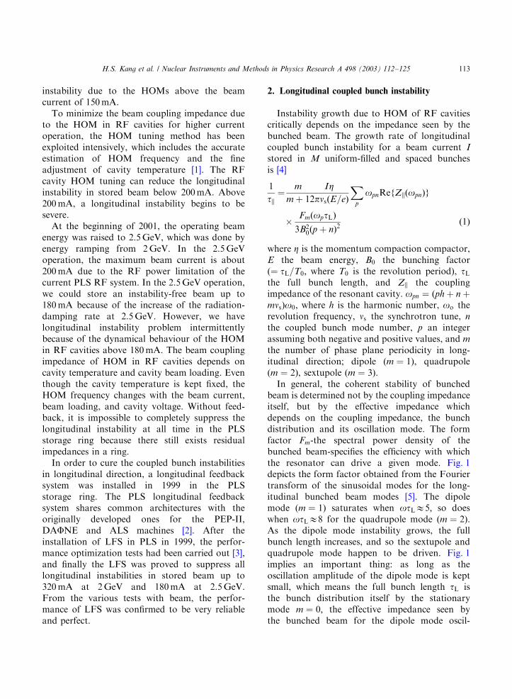
In general, the coherent stability of bunchedbeam is determined not by the coupling impedanceitself, but by the effective impedance whichdepends on the coupling impedance, the bunchdistribution and its oscillation mode. The formfactor Fm-the spectral power density of thebunched beam-specifies the efficiency with whichthe resonator can drive a given mode. Fig. 1depicts the form factor obtained from the Fouriertransform of the sinusoidal modes for the long-itudinal bunched beam modes [5]. The dipolemode (m ¼ 1) saturates when otLE5; so doeswhen otLE8 for the quadrupole mode (m ¼ 2).As the dipole mode instability grows, the fullbunch length increases, and so the sextupole andquadrupole mode happen to be driven. Fig. 1implies an important thing: as long as theoscillation amplitude of the dipole mode is keptsmall, which means the full bunch length tL isthe bunch distribution itself by the stationarymode m ¼ 0; the effective impedance seen bythe bunched beam for the dipole mode oscil-
H.S. Kang et al. / Nuclear Instruments and Methods in Physics Research A 498 (2003) 112–125 113
lation is too small to override the radiationdamping.
The PLS RF system consists of four RF cavitiesand four 60 kW klystrons. A very accuratetemperature control system controls the inletcooling water temperatures for each cavity in therange of 351C to 601C and maintain the tempera-ture within 70.051C. The PLS storage ring RFcavities have many HOM with large shuntimpedance. The dominant modes are TM011(758MHz), TM020 (1300MHz), TM213(1670MHz), TM021 (1326MHz), and TM013(1707MHz) [1]. By optimising the cavity tempera-ture of each cavity the amplitudes of these HOMcan be reduced to some level, but not perfectly,with the beam up to 200mA at 2GeV. However,above 200mA, a strong longitudinal instabilityappears.
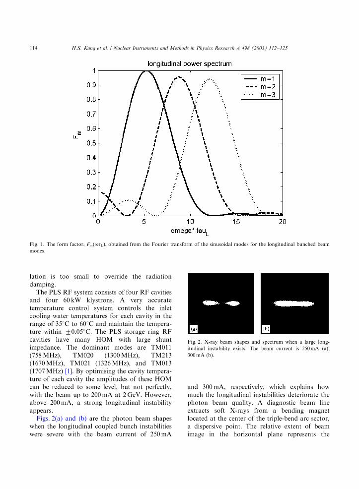
Figs. 2(a) and (b) are the photon beam shapeswhen the longitudinal coupled bunch instabilitieswere severe with the beam current of 250mA
and 300mA, respectively, which explains howmuch the longitudinal instabilities deteriorate thephoton beam quality. A diagnostic beam lineextracts soft X-rays from a bending magnetlocated at the center of the triple-bend arc sector,a dispersive point. The relative extent of beamimage in the horizontal plane represents the
Fig. 1. The form factor, FmðotLÞ; obtained from the Fourier transform of the sinusoidal modes for the longitudinal bunched beam
modes.
Fig. 2. X-ray beam shapes and spectrum when a large long-
itudinal instability exists. The beam current is 250mA (a),
300mA (b).
H.S. Kang et al. / Nuclear Instruments and Methods in Physics Research A 498 (2003) 112–125114
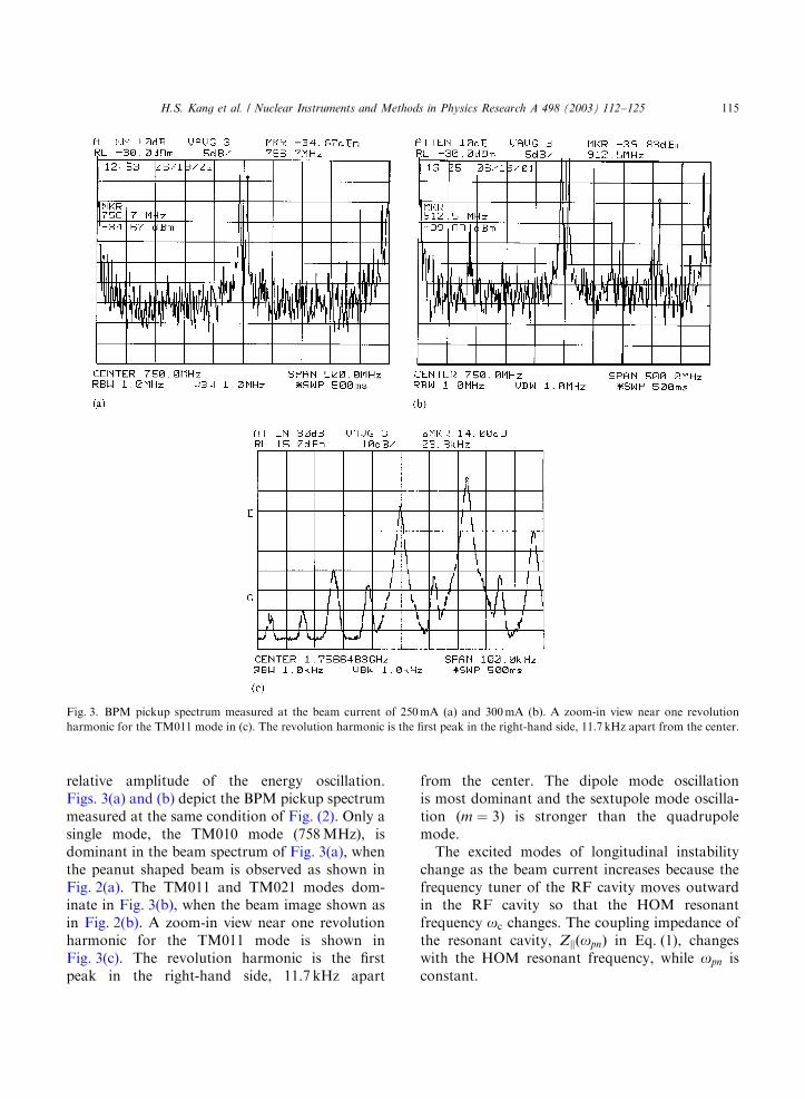
relative amplitude of the energy oscillation.Figs. 3(a) and (b) depict the BPM pickup spectrummeasured at the same condition of Fig. (2). Only asingle mode, the TM010 mode (758MHz), isdominant in the beam spectrum of Fig. 3(a), whenthe peanut shaped beam is observed as shown inFig. 2(a). The TM011 and TM021 modes dom-inate in Fig. 3(b), when the beam image shown asin Fig. 2(b). A zoom-in view near one revolutionharmonic for the TM011 mode is shown inFig. 3(c). The revolution harmonic is the firstpeak in the right-hand side, 11.7 kHz apart
from the center. The dipole mode oscillationis most dominant and the sextupole mode oscilla-tion (m ¼ 3) is stronger than the quadrupolemode.
The excited modes of longitudinal instabilitychange as the beam current increases because thefrequency tuner of the RF cavity moves outwardin the RF cavity so that the HOM resonantfrequency oc changes. The coupling impedance ofthe resonant cavity, ZjjðopnÞ in Eq. (1), changeswith the HOM resonant frequency, while opn isconstant.
Fig. 3. BPM pickup spectrum measured at the beam current of 250mA (a) and 300mA (b). A zoom-in view near one revolution
harmonic for the TM011 mode in (c). The revolution harmonic is the first peak in the right-hand side, 11.7 kHz apart from the center.
H.S. Kang et al. / Nuclear Instruments and Methods in Physics Research A 498 (2003) 112–125 115
3. Longitudinal feedback system
3.1. System description
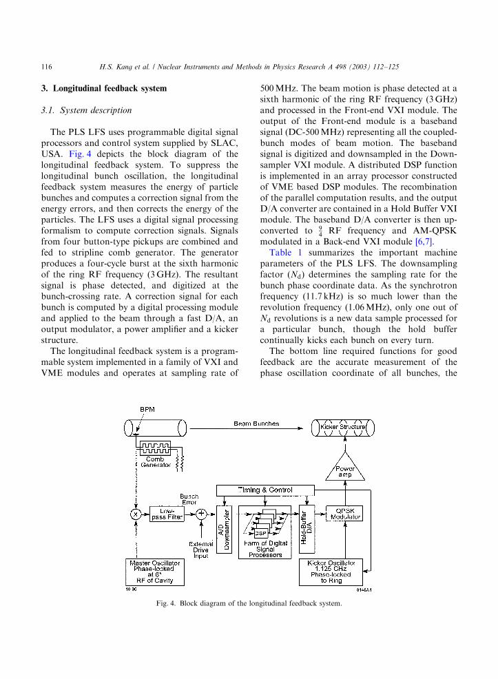
The PLS LFS uses programmable digital signalprocessors and control system supplied by SLAC,USA. Fig. 4 depicts the block diagram of thelongitudinal feedback system. To suppress thelongitudinal bunch oscillation, the longitudinalfeedback system measures the energy of particlebunches and computes a correction signal from theenergy errors, and then corrects the energy of theparticles. The LFS uses a digital signal processingformalism to compute correction signals. Signalsfrom four button-type pickups are combined andfed to stripline comb generator. The generatorproduces a four-cycle burst at the sixth harmonicof the ring RF frequency (3GHz). The resultantsignal is phase detected, and digitized at thebunch-crossing rate. A correction signal for eachbunch is computed by a digital processing moduleand applied to the beam through a fast D/A, anoutput modulator, a power amplifier and a kickerstructure.
The longitudinal feedback system is a program-mable system implemented in a family of VXI andVME modules and operates at sampling rate of
500MHz. The beam motion is phase detected at asixth harmonic of the ring RF frequency (3GHz)and processed in the Front-end VXI module. Theoutput of the Front-end module is a basebandsignal (DC-500MHz) representing all the coupled-bunch modes of beam motion. The basebandsignal is digitized and downsampled in the Down-sampler VXI module. A distributed DSP functionis implemented in an array processor constructedof VME based DSP modules. The recombinationof the parallel computation results, and the outputD/A converter are contained in a Hold Buffer VXImodule. The baseband D/A converter is then up-converted to 9
4RF frequency and AM-QPSK
modulated in a Back-end VXI module [6,7].Table 1 summarizes the important machine
parameters of the PLS LFS. The downsamplingfactor (Nd) determines the sampling rate for thebunch phase coordinate data. As the synchrotronfrequency (11.7 kHz) is so much lower than therevolution frequency (1.06MHz), only one out ofNd revolutions is a new data sample processed fora particular bunch, though the hold buffercontinually kicks each bunch on every turn.
The bottom line required functions for goodfeedback are the accurate measurement of thephase oscillation coordinate of all bunches, the
Fig. 4. Block diagram of the longitudinal feedback system.
H.S. Kang et al. / Nuclear Instruments and Methods in Physics Research A 498 (2003) 112–125116
calculation of an appropriate correction signal foreach bunch, and the application of that correctionsignal to the proper bunch. The main causes ofoperational difficulties at the PLS turned out to bea problem with the external fiducial signal appliedto the feedback processing system, and RF cavitygap voltage variation, especially during beaminjection. The variation of the RF cavity voltagecauses the synchronous phase position of thebunches to move too far from the allowabletiming margin of the feedback processing andfeedback kicker, as described in Section 4.
The external fiducial signal from the timingsystem to the LFS timing module helps the LFS torecognize the first bunch in a bunch train. An ECLfan out module was added into the PLS timingsystem, which can provide a very stable externalfiducial signal to the LFS timing module. Itenables the LFS to be exactly timed to the rightbunch position.
3.2. FIR filter
The feedback kick is computed using a finiteimpulse response (FIR) filter with the followingalgorithm:
uiðnÞ ¼XN
k¼1
hðkÞ fiðn kÞ ð2aÞ
hðkÞ ¼ gðkÞ 1
N
XN
k¼1
gðkÞ ð2bÞ
gðkÞ ¼ 2Gs G sin 2pk
Nþ
j360
� �ð2cÞ
where fðn kÞ is the phase error, Gs the postmultiply accumulated shift gain of the filter, G thegain of filter, j the phase of filter, and N thenumber of filter taps. This equation represents adiscrete-time convolution in which the correctionsignal ui of the ith bunch at turn n is computedusing weighted average of several past mea-surements, fiðn NÞ;y;fiðn 1Þ; of the phaseof only that bunch. The filter coefficients,hð1Þ;y; hðNÞ; are selected to provide zero DCresponse and maximum gain Gfb at fs: A sine-shaped envelope of the sequence of the impulseresponse hðkÞ makes the filter more easily tosuppress the DC component, i.e.,
PNk¼1 hðkÞ ¼ 0:
The number of taps N is variable from 2 to12 [8].
The frequency response of the filter is given by
HðoÞ ¼XN
k¼1
hðkÞejok: ð3Þ
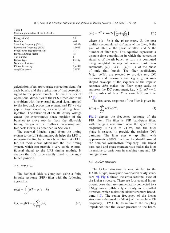
Fig. 5 depicts the frequency response of theFIR filter. The filter is FIR band-pass filter,with the gain maximized near the synchrotronfrequency 11.7 kHz at 2GeV, and the filterphase is selected to provide the resistive (901)damping. The filter uses 6 tap filter, withapproximately 100% fractional bandwidth aroundthe nominal synchrotron frequency. The broadpass-band and phase characteristic makes the filterinsensitive to variations in machine tune and RFconfiguration.
3.3. Kicker structure
The kicker structure is very similar to theDAFNE type, waveguide overloaded cavity struc-ture [9]. Fig. 6 shows the cross-sectional view ofthe kicker structure. There are four coaxial input/output ports that are symmetrically connected to aTM010 mode pill-box type cavity in azimuthaldirection, which makes the kicker structure broad-band [10]. The center frequency of the kickerstructure is designed to fall at 9
4of the machine RF
frequency, 1.125GHz, to minimize the couplingimpedance that the kicker presents to the beam.
Table 1
Machine parameters of the PLS LFS
Energy (GeV) 2.0
Bunches 468
Sampling frequency (MHz) 500.076
Revolution frequency (MHz) 1.0685
Synchrotron frequency (kHz) 11.7
Down-sampling factor 15
Tap number 6
Kicker type Cavity
Number of kickers 1
Kicker frequency 9/4 RF
Amplifier power 250W
H.S. Kang et al. / Nuclear Instruments and Methods in Physics Research A 498 (2003) 112–125 117
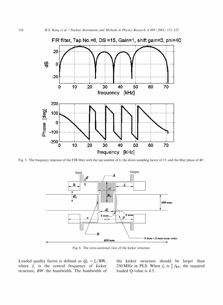
Loaded quality factor is defined as QL ¼ fc=BW;where fc is the central frequency of kickerstructure, BW the bandwidth. The bandwidth of
the kicker structure should be larger than250MHz in PLS. When fc is 9
4fRF; the required
loaded Q-value is 4.5.
Fig. 5. The frequency response of the FIR filter with the tap number of 6, the down sampling factor of 15, and the filter phase of 401.
Fig. 6. The cross-sectional view of the kicker structure.
H.S. Kang et al. / Nuclear Instruments and Methods in Physics Research A 498 (2003) 112–125118
The damping rate of the longitudinal feedbacksystem can be expressed as [11]
1
tfb¼
fRFa2ðE=eÞns
Gfb ð4Þ
where Gfb ¼ DU=Df is the feedback gain, i.e.,the kick voltage per unit phase deviation (radian).The maximum available kick voltage U0 is definedas
U0 ¼ffiffiffiffiffiffiffiffiffiffiffiffiffiffiffiffiffi2PmaxRs
pð5Þ
where Pmax is the maximum forward RF power atthe kicker input and Rs the shunt impedance of thekicker structure in rms circuit definition:
Rs ¼V 2
g
2Pin¼
1
2
R
QQL ð6Þ
where Vg is the peak gap voltage, Pin the forwardRF power, QL the loaded Q-value, and R=Q is inthe definition of accelerating cavity. The shuntimpedance of the kicker structure is 450O, and thecavity filling time is 1.27 ns.
Noise floors in the feedback system limiting themaximum feedback gain are about 0.21 at the RFfrequency as shown in Fig. 11(b). Assuming a250W amplifier and a 3 dB loss in cables themaximum damping rate is 2000 s1 (tfb ¼ 0:5 ms)at 2GeV [12]. The radiation damping times (tr) inlongitudinal direction are 8.3ms and 4.2ms at2GeV and 2.5GeV, respectively. To suppress theinstability, the total damping rate should be higherthan the instability growth rate (ti): 1=tio1=tr þ1=tfb:
4. Suppression of instability
4.1. Suppression of longitudinal instabilities by LFS
After the performance optimization tests, wefound that the system functioned acceptably overthe parameter ranges listed in Table 2: FIR filterparameters (filter phase, shift gain, down samplingfactor, and tap number) and analog (front andbackend delays) and digital signal delays (hold-buffer offset). Even though the LFS employs thedigital electronics and the DSP filter algorithm, theanalog signal delays are necessary for fine adjust-ment of BPM pickup signal at the front-end andthe kick signal at the kicker structure with respectto the reference RF signal.
The required precision of the back-end phasingis set by the operating frequency of the kickerstructures. To get the maximum gain, the bunchpassage must fall on a voltage maximum of thekicker response, and so the effective gain falls offlike cosðdfÞ; where df is the phase differencebetween the arriving particle and the voltagemaximum on the kicker at the kicker centrefrequency. A 7451 offset of arriving time(7111 ps) drops the gain by 3 dB, and an offsetof 901 (7222 ps) drops the gain to zero [13].
The data in Table 2 were measured at the beamcurrent of 140mA. The front-end that measuresthe energy of each bunch has a limit of referenceposition drift about 851 at 500MHz. But the fulloperating range of the energy measurement of thefront-end is only 301 (166 ps) at 500MHz. Theback-end delay making the exact timing betweenthe kick signal and the exact bunch has a verynarrow stable range, which means a very preciseback-end timing is absolutely necessary. The
Table 2
Setting parameters for the LFS to suppress the instabilities at the PLS
Module Setting parameter Operating range Span
Filter Phase 101-851 951
Shift gain 3–5
Down sampler Synchrotron frequency 6.0-16 kHz 10kHz
Front-end Phase shift 81-391 471 (851 at 500MHz)
Delay Back-end 7413-7737ps 320 ps
Front-end 7700-8000ps 300 ps
H.S. Kang et al. / Nuclear Instruments and Methods in Physics Research A 498 (2003) 112–125 119
back-end timing span is about 320 ps correspond-ing to 7651 from the crest of 1125MHz kickerfrequency, which is slightly larger than 7451arrival offset (7111 ps). Of course, this spandecreases as the instability growth rate increaseswith the beam current. On the other hand, thefilter and the down sampler that compute acorrection signal have a large operation range.The filter phase for damping is in the range from101 to 851.
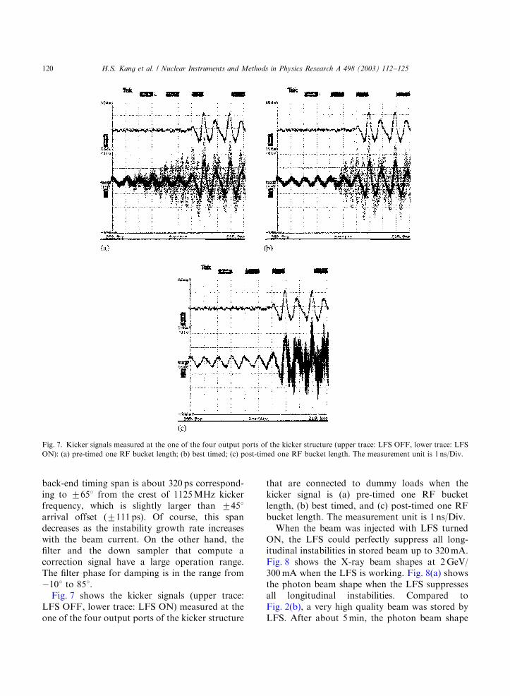
Fig. 7 shows the kicker signals (upper trace:LFS OFF, lower trace: LFS ON) measured at theone of the four output ports of the kicker structure
that are connected to dummy loads when thekicker signal is (a) pre-timed one RF bucketlength, (b) best timed, and (c) post-timed one RFbucket length. The measurement unit is 1 ns/Div.
When the beam was injected with LFS turnedON, the LFS could perfectly suppress all long-itudinal instabilities in stored beam up to 320mA.Fig. 8 shows the X-ray beam shapes at 2GeV/300mA when the LFS is working. Fig. 8(a) showsthe photon beam shape when the LFS suppressesall longitudinal instabilities. Compared toFig. 2(b), a very high quality beam was stored byLFS. After about 5min, the photon beam shape
Fig. 7. Kicker signals measured at the one of the four output ports of the kicker structure (upper trace: LFS OFF, lower trace: LFS
ON): (a) pre-timed one RF bucket length; (b) best timed; (c) post-timed one RF bucket length. The measurement unit is 1 ns/Div.
H.S. Kang et al. / Nuclear Instruments and Methods in Physics Research A 498 (2003) 112–125120
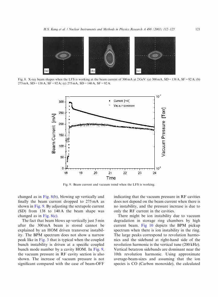
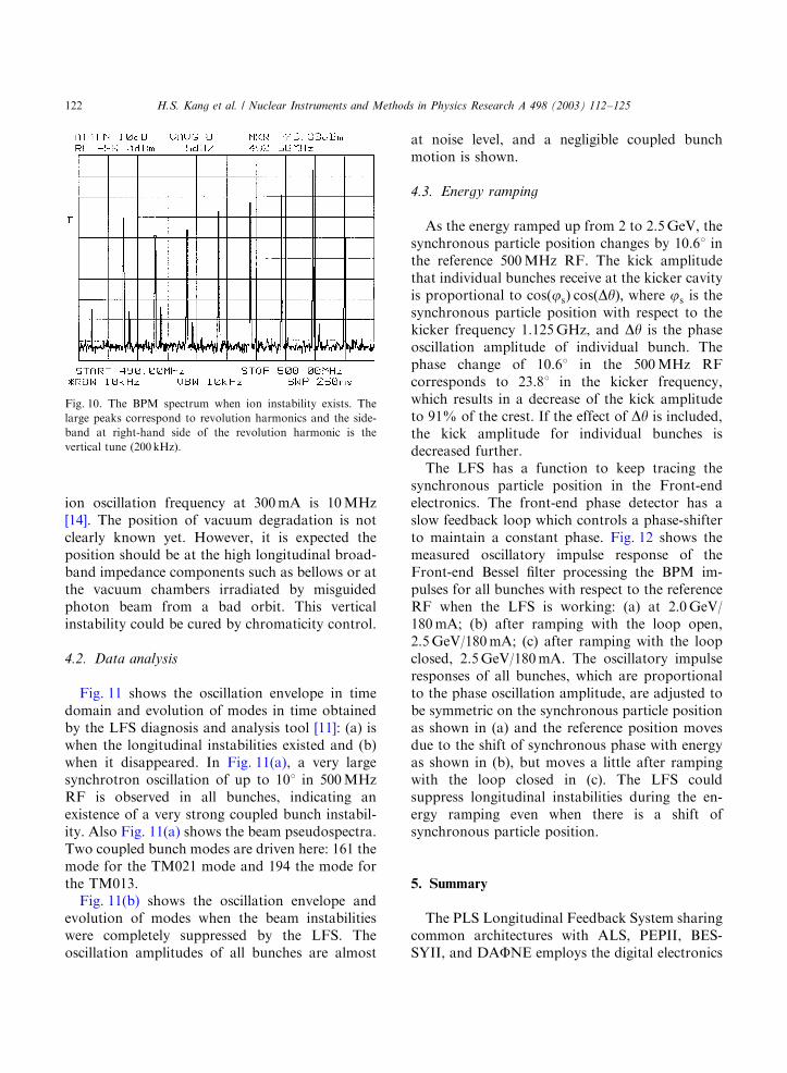
changed as in Fig. 8(b), blowing up vertically andfinally the beam current dropped to 275mA asshown in Fig. 9. By adjusting the sextupole current(SD) from 138 to 140A the beam shape waschanged as in Fig. 8(c).
The fact that beam blows up vertically just 5minafter the 300mA beam is stored cannot beexplained by an HOM driven transverse instabil-ity. The BPM spectrum does not show a narrowpeak like in Fig. 3 that is typical when the coupledbunch instability is driven at a specific coupledbunch mode number by a cavity HOM. In Fig. 9,the vacuum pressure in RF cavity section is alsoshown. The increase of vacuum pressure is notsignificant compared with the case of beam-OFF
indicating that the vacuum pressure in RF cavitiesdoes not depend on the beam current when there isno instability, and the pressure increase is due toonly the RF current in the cavities.
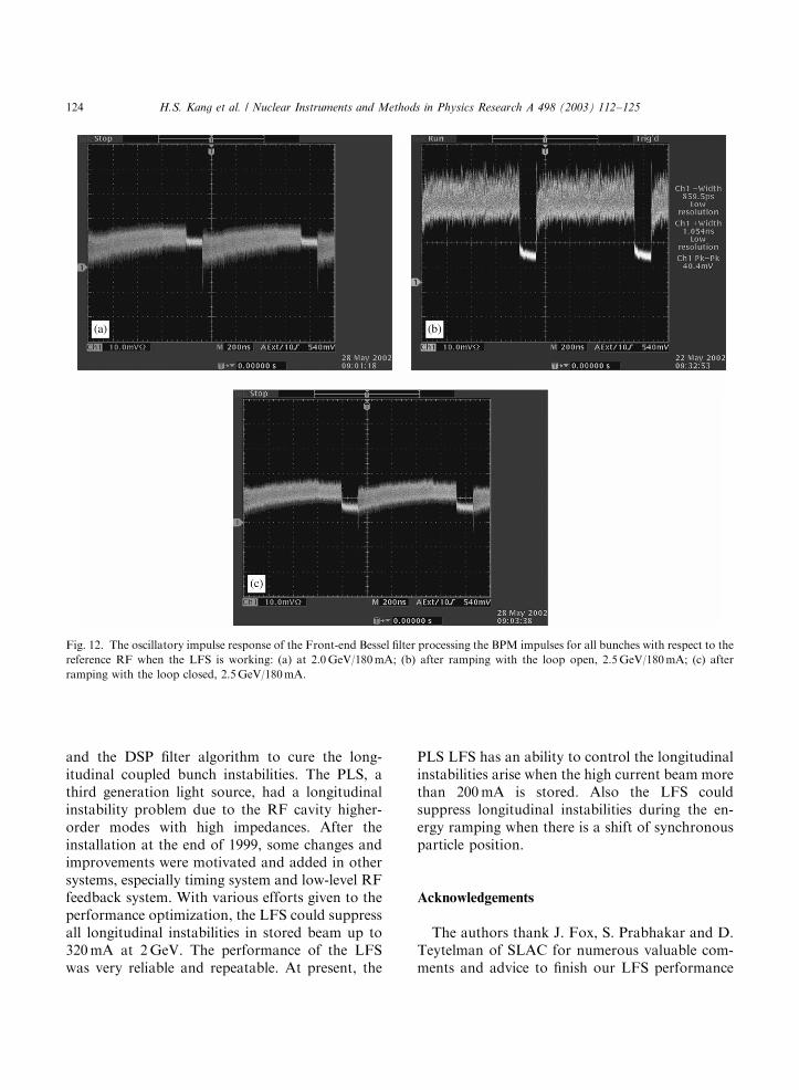
There might be ion instability due to vacuumdegradation in storage ring chambers by highcurrent beam. Fig 10 depicts the BPM pickupspectrum when there is ion instability in the ring.The large peaks correspond to revolution harmo-nics and the sideband at right-hand side of therevolution harmonic is the vertical tune (200 kHz).Vertical betatron sidebands are dominant near the10th revolution harmonic. Using approximateaverage-beam-sizes and assuming that the ionspecies is CO (Carbon monoxide), the calculated
Fig. 8. X-ray beam shapes when the LFS is working at the beam current of 300mA at 2GeV: (a) 300mA, SD=138A, SF=92A; (b)
275mA, SD=138A, SF=92A; (c) 275mA, SD=140A, SF=92A.
Fig. 9. Beam current and vacuum trend when the LFS is working.
H.S. Kang et al. / Nuclear Instruments and Methods in Physics Research A 498 (2003) 112–125 121
ion oscillation frequency at 300mA is 10MHz[14]. The position of vacuum degradation is notclearly known yet. However, it is expected theposition should be at the high longitudinal broad-band impedance components such as bellows or atthe vacuum chambers irradiated by misguidedphoton beam from a bad orbit. This verticalinstability could be cured by chromaticity control.
4.2. Data analysis
Fig. 11 shows the oscillation envelope in timedomain and evolution of modes in time obtainedby the LFS diagnosis and analysis tool [11]: (a) iswhen the longitudinal instabilities existed and (b)when it disappeared. In Fig. 11(a), a very largesynchrotron oscillation of up to 101 in 500MHzRF is observed in all bunches, indicating anexistence of a very strong coupled bunch instabil-ity. Also Fig. 11(a) shows the beam pseudospectra.Two coupled bunch modes are driven here: 161 themode for the TM021 mode and 194 the mode forthe TM013.
Fig. 11(b) shows the oscillation envelope andevolution of modes when the beam instabilitieswere completely suppressed by the LFS. Theoscillation amplitudes of all bunches are almost
at noise level, and a negligible coupled bunchmotion is shown.
4.3. Energy ramping
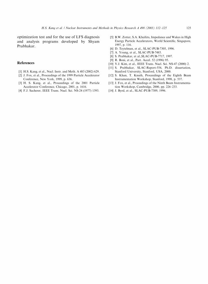
As the energy ramped up from 2 to 2.5GeV, thesynchronous particle position changes by 10.61 inthe reference 500MHz RF. The kick amplitudethat individual bunches receive at the kicker cavityis proportional to cosðjsÞ cosðDyÞ; where js is thesynchronous particle position with respect to thekicker frequency 1.125GHz, and Dy is the phaseoscillation amplitude of individual bunch. Thephase change of 10.61 in the 500MHz RFcorresponds to 23.81 in the kicker frequency,which results in a decrease of the kick amplitudeto 91% of the crest. If the effect of Dy is included,the kick amplitude for individual bunches isdecreased further.
The LFS has a function to keep tracing thesynchronous particle position in the Front-endelectronics. The front-end phase detector has aslow feedback loop which controls a phase-shifterto maintain a constant phase. Fig. 12 shows themeasured oscillatory impulse response of theFront-end Bessel filter processing the BPM im-pulses for all bunches with respect to the referenceRF when the LFS is working: (a) at 2.0GeV/180mA; (b) after ramping with the loop open,2.5GeV/180mA; (c) after ramping with the loopclosed, 2.5GeV/180mA. The oscillatory impulseresponses of all bunches, which are proportionalto the phase oscillation amplitude, are adjusted tobe symmetric on the synchronous particle positionas shown in (a) and the reference position movesdue to the shift of synchronous phase with energyas shown in (b), but moves a little after rampingwith the loop closed in (c). The LFS couldsuppress longitudinal instabilities during the en-ergy ramping even when there is a shift ofsynchronous particle position.
5. Summary
The PLS Longitudinal Feedback System sharingcommon architectures with ALS, PEPII, BES-SYII, and DAFNE employs the digital electronics
Fig. 10. The BPM spectrum when ion instability exists. The
large peaks correspond to revolution harmonics and the side-
band at right-hand side of the revolution harmonic is the
vertical tune (200 kHz).
H.S. Kang et al. / Nuclear Instruments and Methods in Physics Research A 498 (2003) 112–125122

Fig. 11. Data analysis result by the LFS diagnosis and analysis tool: (a) when the longitudinal instabilities exist and (b) when
disappeared at 2GeV, 300mA.
H.S. Kang et al. / Nuclear Instruments and Methods in Physics Research A 498 (2003) 112–125 123
and the DSP filter algorithm to cure the long-itudinal coupled bunch instabilities. The PLS, athird generation light source, had a longitudinalinstability problem due to the RF cavity higher-order modes with high impedances. After theinstallation at the end of 1999, some changes andimprovements were motivated and added in othersystems, especially timing system and low-level RFfeedback system. With various efforts given to theperformance optimization, the LFS could suppressall longitudinal instabilities in stored beam up to320mA at 2GeV. The performance of the LFSwas very reliable and repeatable. At present, the
PLS LFS has an ability to control the longitudinalinstabilities arise when the high current beam morethan 200mA is stored. Also the LFS couldsuppress longitudinal instabilities during the en-ergy ramping when there is a shift of synchronousparticle position.
Acknowledgements
The authors thank J. Fox, S. Prabhakar and D.Teytelman of SLAC for numerous valuable com-ments and advice to finish our LFS performance
Fig. 12. The oscillatory impulse response of the Front-end Bessel filter processing the BPM impulses for all bunches with respect to the
reference RF when the LFS is working: (a) at 2.0GeV/180mA; (b) after ramping with the loop open, 2.5GeV/180mA; (c) after
ramping with the loop closed, 2.5GeV/180mA.
H.S. Kang et al. / Nuclear Instruments and Methods in Physics Research A 498 (2003) 112–125124
optimization test and for the use of LFS diagnosisand analysis programs developed by ShyamPrabhakar.
References
[1] H.S. Kang, et al., Nucl. Instr. and Meth. A 483 (2002) 629.
[2] J. Fox, et al., Proceedings of the 1999 Particle Accelerator
Conference, New York, 1999, p. 636.
[3] H. S. Kang, et al., Proceedings of the 2001 Particle
Accelerator Conference, Chicago, 2001, p. 1616.
[4] F.J. Sacherer, IEEE Trans. Nucl. Sci. NS-24 (1977) 1393.
[5] B.W. Zotter, S.A. Kheifets, Impedance and Wakes in High
Energy Particle Accelerators, World Scientific, Singapore,
1997, p. 116.
[6] D. Teytelman, et al., SLAC-PUB-7305, 1996.
[7] A. Young, et al., SLAC-PUB-7485.
[8] S. Prabhakar, et al.,SLAC-PUB-7717, 1997.
[9] R. Boni, et al., Part. Accel. 52 (1996) 95.
[10] Y.J. Kim, et al., IEEE Trans. Nucl. Sci. NS-47 (2000) 2.
[11] S. Prabhakar, SLAC-Report-554, Ph.D. dissertation,
Stanford University, Stanford, USA, 2000.
[12] S. Khan, T. Knuth, Proceedings of the Eighth Beam
Instrumentation Workshop, Stanford, 1998, p. 537.
[13] J. Fox, et al., Proceedings of the Ninth Beam Instrumenta-
tion Workshop, Cambridge, 2000, pp. 226–233.
[14] J. Byrd, et al., SLAC-PUB-7389, 1996.
H.S. Kang et al. / Nuclear Instruments and Methods in Physics Research A 498 (2003) 112–125 125