stress concentration factors in thick walled cylinders with ...
20
181 STRESS CONCENTRATION FACTORS IN THICK WALLED CYLINDERS WITH ELLIPTICAL CROSS-BORES C. A. Adenya and J. M. Kihiu Department of Mechanical Engineering, Jomo Kenyatta University of Agriculture and Technology, Nairobi, Kenya E-mail: [email protected] Abstract Computer simulations were conducted to determine the elastic stress concentration factors in the vicinity of an elliptical cross-bore in a closed ended thick walled cylinder. The orientation of the elliptical cross-bore with respect to the meridional plane was varied. Various cross-bore to cylinder bore radius ratios and various geometries of the elliptical cross-bore were investigated. A three-dimensional finite element method (FEM) computer programme in FORTRAN code was developed and used to carry out the investigations. The displacement formulation was used. Cylinder geometries of thickness ratios k = 2.0, 2.25 and 2.5 were considered. Cylinder length was taken to be 9 times the wall thickness to avoid the end effects. The maximum stress concentration factor was experienced when the major axis of the elliptical cross-bore lay in the meridional plane. The minimum stress concentration factor was experienced when the major axis of the elliptical cross-bore lay in the transverse plane. For an elliptical cross-bore of cross-sectional area equivalent to that of a circular cross-bore of cross-bore to cylinder bore radius ratio of d = 0.15, the stress concentration factor (SCF) was a constant at 2.1 for angle of rotation (AOR) of 74.5°. For an elliptical cross-bore of cross- sectional area equivalent to that of a circular cross-bore of d = 0.20, the SCF was a constant at 2.1 for AOR = 73°. For an elliptical cross-bore of cross-sectional area equivalent to that of a circular cross-bore of d = 0.25, the SCF was a constant at 2.1 for AOR = 72.5°. When the elliptical cross-bore had its major axis perpendicular to the cylinder axis the SCF was a minimum, i.e., 2.0 and below. The SCF for a circular cross-bore was 3.0. Therefore an elliptical cross-bore offered the lowest SCF when compared to a circular cross-bore. The information on SCF constants obtained will enable quick design of thick walled cylinders with elliptical cross- bore. Key words: Thick walled cylinder, elliptical cross-bore, stress concentration factor, finite element method
-
Upload
khangminh22 -
Category
Documents
-
view
8 -
download
0
Transcript of stress concentration factors in thick walled cylinders with ...

181
STRESS CONCENTRATION FACTORS IN THICK WALLED CYLINDERS WITH ELLIPTICAL CROSS-BORES C. A. Adenya and J. M. Kihiu Department of Mechanical Engineering, Jomo Kenyatta University of Agriculture and Technology, Nairobi, Kenya E-mail: [email protected] Abstract Computer simulations were conducted to determine the elastic stress concentration factors in the vicinity of an elliptical cross-bore in a closed ended thick walled cylinder. The orientation of the elliptical cross-bore with respect to the meridional plane was varied. Various cross-bore to cylinder bore radius ratios and various geometries of the elliptical cross-bore were investigated. A three-dimensional finite element method (FEM) computer programme in FORTRAN code was developed and used to carry out the investigations. The displacement formulation was used. Cylinder geometries of thickness ratios k = 2.0, 2.25 and 2.5 were considered. Cylinder length was taken to be 9 times the wall thickness to avoid the end effects. The maximum stress concentration factor was experienced when the major axis of the elliptical cross-bore lay in the meridional plane. The minimum stress concentration factor was experienced when the major axis of the elliptical cross-bore lay in the transverse plane. For an elliptical cross-bore of cross-sectional area equivalent to that of a circular cross-bore of cross-bore to cylinder bore radius ratio of d = 0.15, the stress concentration factor (SCF) was a constant at 2.1 for angle of rotation (AOR) of 74.5°. For an elliptical cross-bore of cross-sectional area equivalent to that of a circular cross-bore of d = 0.20, the SCF was a constant at 2.1 for AOR = 73°. For an elliptical cross-bore of cross-sectional area equivalent to that of a circular cross-bore of d = 0.25, the SCF was a constant at 2.1 for AOR = 72.5°. When the elliptical cross-bore had its major axis perpendicular to the cylinder axis the SCF was a minimum, i.e., 2.0 and below. The SCF for a circular cross-bore was 3.0. Therefore an elliptical cross-bore offered the lowest SCF when compared to a circular cross-bore. The information on SCF constants obtained will enable quick design of thick walled cylinders with elliptical cross-bore. Key words: Thick walled cylinder, elliptical cross-bore, stress concentration factor, finite element method
182
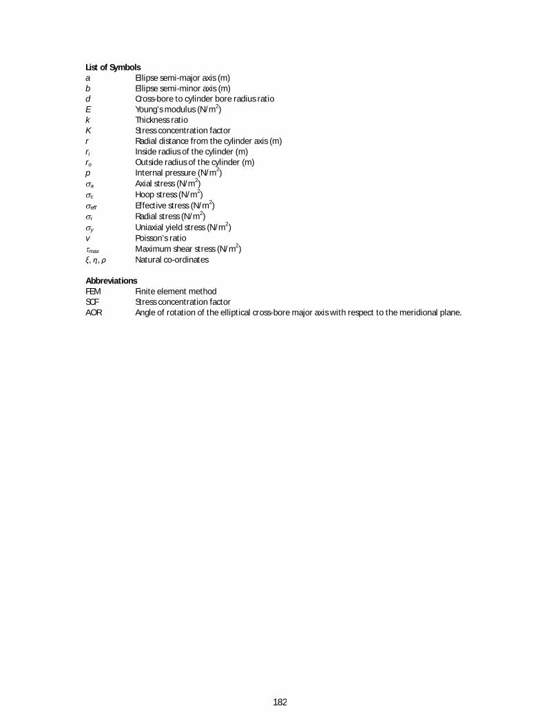
List of Symbols a Ellipse semi-major axis (m) b Ellipse semi-minor axis (m) d Cross-bore to cylinder bore radius ratio E Young’s modulus (N/m2) k Thickness ratio K Stress concentration factor r Radial distance from the cylinder axis (m) ri Inside radius of the cylinder (m) ro Outside radius of the cylinder (m) p Internal pressure (N/m2) a Axial stress (N/m2) c Hoop stress (N/m2) eff Effective stress (N/m2) r Radial stress (N/m2) y Uniaxial yield stress (N/m2) v Poisson’s ratio max Maximum shear stress (N/m2) ξ, η, ρ Natural co-ordinates Abbreviations FEM Finite element method SCF Stress concentration factor AOR Angle of rotation of the elliptical cross-bore major axis with respect to the meridional plane.
183
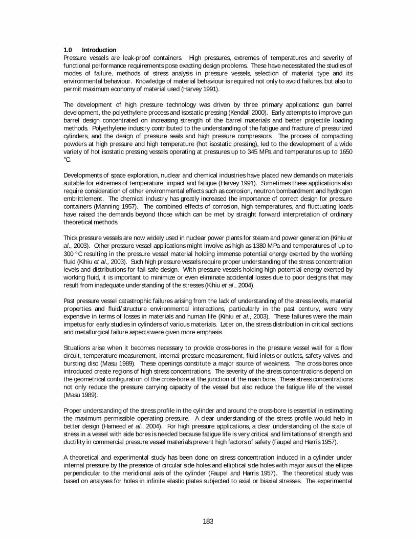
1.0 Introduction Pressure vessels are leak-proof containers. High pressures, extremes of temperatures and severity of functional performance requirements pose exacting design problems. These have necessitated the studies of modes of failure, methods of stress analysis in pressure vessels, selection of material type and its environmental behaviour. Knowledge of material behaviour is required not only to avoid failures, but also to permit maximum economy of material used (Harvey 1991). The development of high pressure technology was driven by three primary applications: gun barrel development, the polyethylene process and isostatic pressing (Kendall 2000). Early attempts to improve gun barrel design concentrated on increasing strength of the barrel materials and better projectile loading methods. Polyethylene industry contributed to the understanding of the fatigue and fracture of pressurized cylinders, and the design of pressure seals and high pressure compressors. The process of compacting powders at high pressure and high temperature (hot isostatic pressing), led to the development of a wide variety of hot isostatic pressing vessels operating at pressures up to 345 MPa and temperatures up to 1650 °C. Developments of space exploration, nuclear and chemical industries have placed new demands on materials suitable for extremes of temperature, impact and fatigue (Harvey 1991). Sometimes these applications also require consideration of other environmental effects such as corrosion, neutron bombardment and hydrogen embrittlement. The chemical industry has greatly increased the importance of correct design for pressure containers (Manning 1957). The combined effects of corrosion, high temperatures, and fluctuating loads have raised the demands beyond those which can be met by straight forward interpretation of ordinary theoretical methods. Thick pressure vessels are now widely used in nuclear power plants for steam and power generation (Kihiu et al., 2003). Other pressure vessel applications might involve as high as 1380 MPa and temperatures of up to 300 C resulting in the pressure vessel material holding immense potential energy exerted by the working fluid (Kihiu et al., 2003). Such high pressure vessels require proper understanding of the stress concentration levels and distributions for fail-safe design. With pressure vessels holding high potential energy exerted by working fluid, it is important to minimize or even eliminate accidental losses due to poor designs that may result from inadequate understanding of the stresses (Kihiu et al., 2004). Past pressure vessel catastrophic failures arising from the lack of understanding of the stress levels, material properties and fluid/structure environmental interactions, particularly in the past century, were very expensive in terms of losses in materials and human life (Kihiu et al., 2003). These failures were the main impetus for early studies in cylinders of various materials. Later on, the stress distribution in critical sections and metallurgical failure aspects were given more emphasis. Situations arise when it becomes necessary to provide cross-bores in the pressure vessel wall for a flow circuit, temperature measurement, internal pressure measurement, fluid inlets or outlets, safety valves, and bursting disc (Masu 1989). These openings constitute a major source of weakness. The cross-bores once introduced create regions of high stress concentrations. The severity of the stress concentrations depend on the geometrical configuration of the cross-bore at the junction of the main bore. These stress concentrations not only reduce the pressure carrying capacity of the vessel but also reduce the fatigue life of the vessel (Masu 1989). Proper understanding of the stress profile in the cylinder and around the cross-bore is essential in estimating the maximum permissible operating pressure. A clear understanding of the stress profile would help in better design (Hameed et al., 2004). For high pressure applications, a clear understanding of the state of stress in a vessel with side bores is needed because fatigue life is very critical and limitations of strength and ductility in commercial pressure vessel materials prevent high factors of safety (Faupel and Harris 1957). A theoretical and experimental study has been done on stress concentration induced in a cylinder under internal pressure by the presence of circular side holes and elliptical side holes with major axis of the ellipse perpendicular to the meridional axis of the cylinder (Faupel and Harris 1957). The theoretical study was based on analyses for holes in infinite elastic plates subjected to axial or biaxial stresses. The experimental

184
analysis was done using both strain gauges and photo-elasticity method. Hoop stress concentration factor for closed-ended cylinder with a small circular cross-bore was found to be 2.5. Research has been done to establish and quantify the influence of cross-bore entry geometry on the elastic and elastic-plastic stresses and their distribution in thick walled cylinders under internal pressure (Kihiu 2002). The analysis was done by computer simulation using 3-dimensional FEM procedures. Pressure vessel material was high strength SA-372 steel. Model cylinders had varying thickness ratio, varying cross-bore diameters, and cross-bores with varying cross-bore to main bore entry geometry. Plain cross-bores, radiused cross-bores and chamfered cross-bores were considered. For plain cross-bored cylinders, for thickness ratio between 1.75 and 3, the stress concentration factor was determined as a constant value of 2.753 for cross-bore to main bore radius ratio of 0.2. When the cross-bore to main bore radius ratio was less than 0.2, the stress concentration factor increased with increasing thickness ratio, whereas, when the cross-bore to main bore radius ratio was more than 0.2, the stress concentration factor increased with decrease in thickness ratio. For radiused entry cross-bored cylinder the stress concentration factors and stress gradients were lower than those of an equivalent plain cross-bored cylinder. Maximum hoop stress was located near the upper end of the entry radius in the meridional plane. Stress concentration factor reduced with increase in cross-bore entry radius. For chamfered entry cross-bore, varying the chamfer angles may result in minimum stress concentration factor lower than those in an equivalent plain cross-bored cylinder, but higher than those in an equivalent radiused entry cross-bored cylinder. A 3-dimensional FEM computer program was developed to establish the stress distribution and stress concentration factors in thick walled cylinders with plain cross-bores under internal pressure (Kihiu et al. 2003). The displacement formulation and eight nodded brick isoparametric elements were used. The frontal solution technique was used. For a thickness ratio of less than 1.75, cross-bore to main bore radius ratio was a found to be a geometric constant equal to 0.11 where the stress concentration factor was 2.67. For a thickness ratio of more than 1.75, cross-bore to main bore radius ratio was found to be a geometric constant equal to 0.2 where the stress concentration factor was 2.734. Limited study has been done on of the elastic stress profiles and the SCF in a thick walled cylinder with a radial elliptical cross-bore whose orientation with respect to the cylinder axis is varying. To avoid the enormous losses of property and human life that may occur due to a high pressure vessel failure, it is imperative to know the stress concentration factors and the stress profiles that arise in the vicinity of the elliptical cross-bore when the cylinder is loaded with an internal pressure while in service 1.1 Theoretical Background The shape of an ellipse with centre located at (0, 0) is given by (Wikipedia):
122 byax ………………………………………….…………………………………………………….……………………..………….(1) The area of an ellipse is given by (Wikipedia): Aellipse = πab …………………………………………………….………………………………………………………………….…………………………….(2) The eccentricity e of an ellipse is given by (Wikipedia):
21 abe ……………………………………………………………….………………………………...…………………………………………(3) Using von Mises yield criterion, the effective stress is given by (Dowling 1993):
2213
232
221 eff ………………..……………………………………………………………(4
) SCF can be defined as the ratio of the peak stress in the body to some other stress taken as a reference (Pilkey and Pilkey 2008). The hoop stress concentration factor is the ratio of the maximum hoop stress at the intersection of the cross-bore and the cylinder bore to the Lame’s hoop stress at the bore of a vessel without a cross-bore (Dixon et al. 2004):
hoopslamehooptK 'max ……………………………………………………………………………………………………….………………..(
5)
185
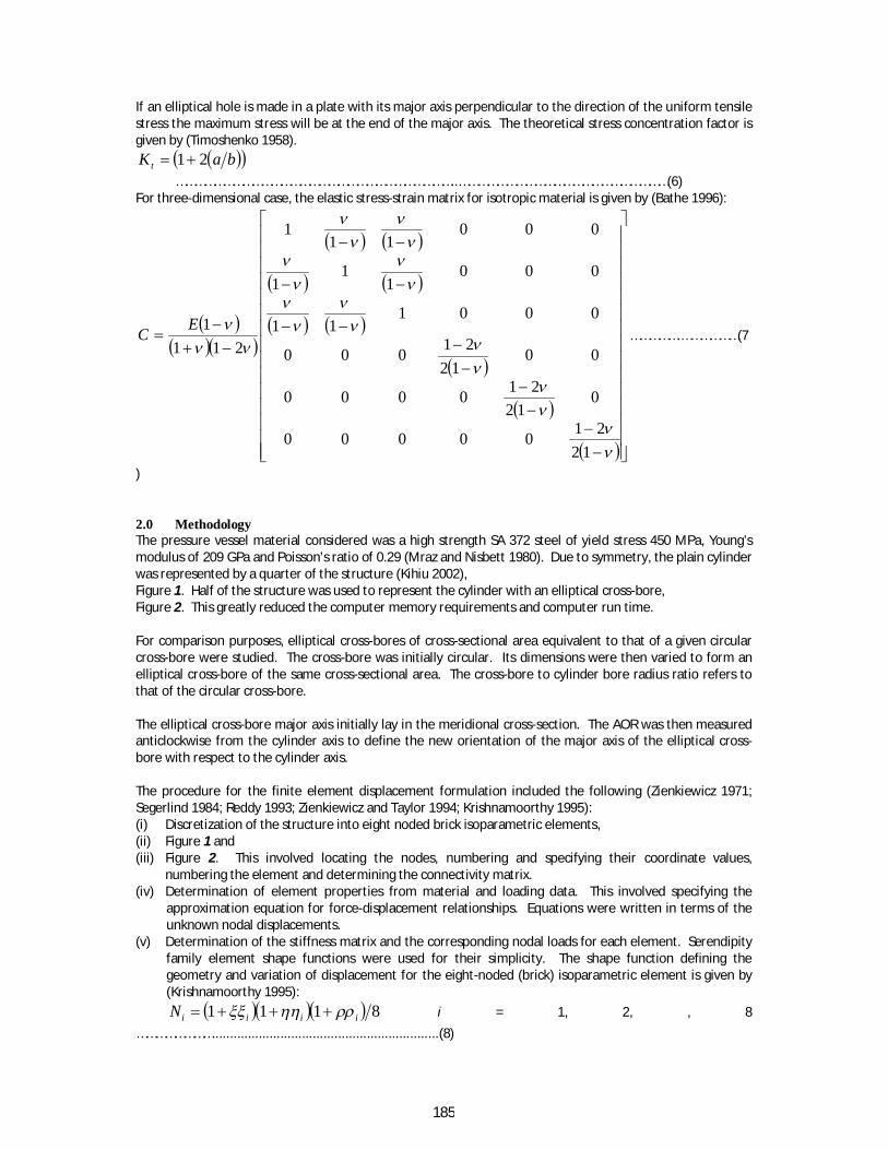
If an elliptical hole is made in a plate with its major axis perpendicular to the direction of the uniform tensile stress the maximum stress will be at the end of the major axis. The theoretical stress concentration factor is given by (Timoshenko 1958).
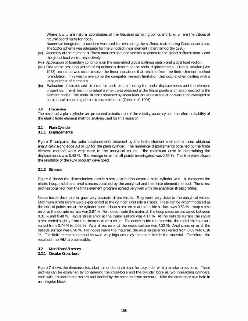
baK t 21 ……………………………………………………………………………..…………………………………………………………(6) For three-dimensional case, the elastic stress-strain matrix for isotropic material is given by (Bathe 1996):
122100000
012
210000
0012
21000
000111
0001
11
00011
1
2111EC …………….………………(7
)
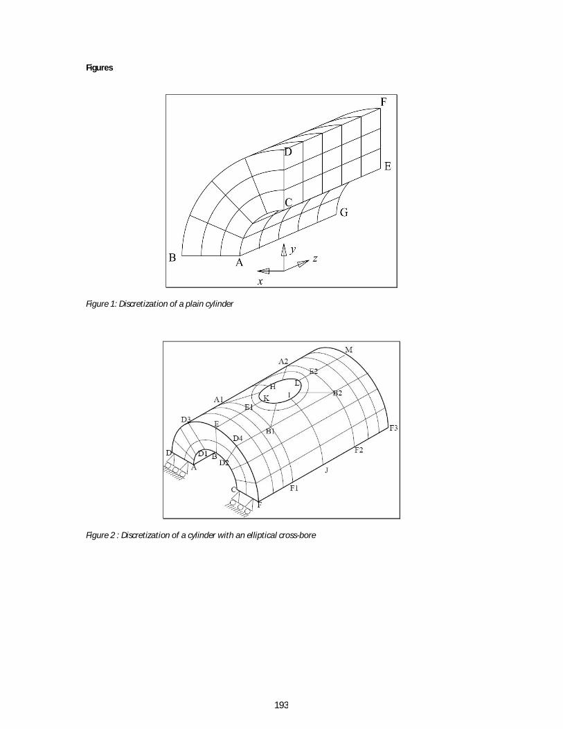
2.0 Methodology The pressure vessel material considered was a high strength SA 372 steel of yield stress 450 MPa, Young’s modulus of 209 GPa and Poisson’s ratio of 0.29 (Mraz and Nisbett 1980). Due to symmetry, the plain cylinder was represented by a quarter of the structure (Kihiu 2002), Figure 1. Half of the structure was used to represent the cylinder with an elliptical cross-bore, Figure 2. This greatly reduced the computer memory requirements and computer run time. For comparison purposes, elliptical cross-bores of cross-sectional area equivalent to that of a given circular cross-bore were studied. The cross-bore was initially circular. Its dimensions were then varied to form an elliptical cross-bore of the same cross-sectional area. The cross-bore to cylinder bore radius ratio refers to that of the circular cross-bore. The elliptical cross-bore major axis initially lay in the meridional cross-section. The AOR was then measured anticlockwise from the cylinder axis to define the new orientation of the major axis of the elliptical cross-bore with respect to the cylinder axis. The procedure for the finite element displacement formulation included the following (Zienkiewicz 1971; Segerlind 1984; Reddy 1993; Zienkiewicz and Taylor 1994; Krishnamoorthy 1995): (i) Discretization of the structure into eight noded brick isoparametric elements, (ii) Figure 1 and (iii) Figure 2. This involved locating the nodes, numbering and specifying their coordinate values,
numbering the element and determining the connectivity matrix. (iv) Determination of element properties from material and loading data. This involved specifying the
approximation equation for force-displacement relationships. Equations were written in terms of the unknown nodal displacements.
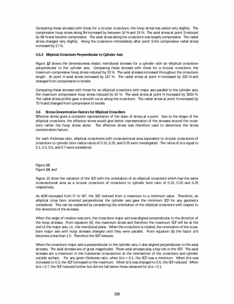
(v) Determination of the stiffness matrix and the corresponding nodal loads for each element. Serendipity family element shape functions were used for their simplicity. The shape function defining the geometry and variation of displacement for the eight-noded (brick) isoparametric element is given by (Krishnamoorthy 1995):
8111 iiiiN i = 1, 2, , 8 ……………………...............................................................(8)
186
Where ξ, η, ρ are natural coordinates of the Gaussian sampling points and ξi, ηi, ρi are the values of natural coordinates for node i. Numerical integration procedure was used for evaluating the stiffness matrix using Gauss quadrature. The 2x2x2 scheme was adequate for the 8-noded linear element (Krishnamoorthy 1995).
(vi) Assembly of the element stiffness matrices and load vectors to generate the global stiffness matrix and the global load vector respectively.
(vii) Application of boundary conditions on the assembled global stiffness matrix and global load vector. (viii) Solving the resulting system of equations to determine the nodal displacements. Frontal solution (Yeo
1973) technique was used to solve the linear equations that resulted from the finite element method formulation. This was to overcome the computer memory limitation that occurs when dealing with a large number of elements.
(ix) Evaluation of strains and stresses for each element using the nodal displacements and the element properties. The stress in individual element was obtained at the Gauss points and then projected to the element nodes. The nodal stresses obtained by linear least-square extrapolation were then averaged to obtain local smoothing of the stress distribution (Chen et al. 1996).
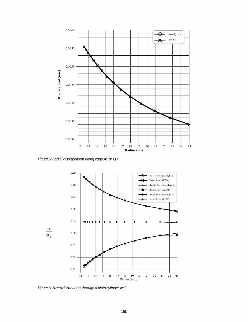
3.0 Discussion The results of a plain cylinder are presented as indication of the validity, accuracy and, therefore, reliability of the elastic finite element method analysis used for this research. 3.1 Plain Cylinder 3.1.1 Displacements Figure 5 compares the radial displacements obtained by the finite element method to those obtained analytically along edge AB or CD for the plain cylinder. The numerical displacements obtained by the finite element method were very close to the analytical values. The maximum error in determining the displacements was 0.40 %. The average error for all points investigated was 0.39 %. This therefore shows the reliability of the FEM program developed 3.1.2 Stresses Figure 6 shows the dimensionless elastic stress distribution across a plain cylinder wall. It compares the elastic hoop, radial and axial stresses obtained by the analytical and the finite element method. The stress profiles obtained from the finite element program agreed very well with the analytical stress profiles. Nodes inside the material gave very accurate stress values. They were very close to the analytical values. Maximum stress errors were experienced at the cylinder’s outside surfaces. These can be accommodated as the critical points are at the cylinder bore. Hoop stress error at the inside surface was 0.53 %. Hoop stress error at the outside surface was 3.87 %. For nodes inside the material, the hoop stress errors varied between 0.31 % and 0.48 %. Radial stress error at the inside surface was 4.17 %. At the outside surface the radial stress varied slightly from the theoretical zero value. For nodes inside the material, the radial stress errors varied from 0.74 % to 2.02 %. Axial stress error at the inside surface was 4.32 %. Axial stress error at the outside surface was 6.96 %. For nodes inside the material, the axial stress errors varied from 0.03 % to 0.18 %. The finite element method showed very high accuracy for nodes inside the material. Therefore, the results of the FEM are admissible. 3.2 Meridional Stresses 3.2.1 Circular Cross-bore Figure 7 shows the dimensionless elastic meridional stresses for a cylinder with a circular cross-bore. These profiles can be explained by considering the cross-bore and the cylinder bore as two interacting cylinders, each with its coordinate system and loaded by the same internal pressure. Take the cross-bore as a hole in an irregular block.

187
Approaching the cross-bore, the hoop stress increased tremendously. This occurred because in the meridional plane, the hoop stresses due to the two cylinders superimpose positively. From N to K the magnitude of the hoop stress reduces since the hoop stress due to the cylinder bore loading reduces. Approaching the cross-bore, the radial stress reduces sharply and then reduces very slowly. The interaction of the cylinder axial stress and the cross-bore radial stress in the meridional plane is negative. The magnitude of the tensile axial stress is reduced by the compressive radial stress arising due to the loading of the cross-bore. Along NK the radial stresses due to the loading of the cylinder bore are experienced. There is no interaction with any other stresses arising from the loading of the cross-bore. Therefore the profile obtained is that for radial stress in an internally loaded cylinder. 3.3 Elliptical Cross-bore Parallel to Cylinder Axis Figure 8 shows the dimensionless elastic meridional stresses for a cylinder with an elliptical cross-bore parallel to the cylinder axis. The ratio of b/a = 0.5 was considered. Comparing these stresses to those of the circular cross-bore of same area the maximum hoop stress increased by 70 %. The hoop stress at the intersection of cross-bore and cylinder outside surface increased by 113 %. The maximum axial stress (compressive) reduced by half. The maximum radial stress increased by 540 %. 3.4 Elliptical Cross-bore Perpendicular to Cylinder Axis Figure 9 shows the dimensionless elastic meridional stresses for a cylinder with an elliptical cross-bore perpendicular to the cylinder axis. Comparing these stresses with those for an elliptical cross-bore with major axis parallel to the cylinder axis, the maximum hoop stress reduced by 67 %. The hoop stress at point K reduced by 81 %. The maximum compressive axial stress at point K increased by 130 %. The radial stress at point K reduced by 84 % and changed from tensile to compressive. Comparing these stresses with those for a circular cross-bore, the maximum hoop stress reduced by 43 %. Hoop stress at point K reduced by 60 %. The maximum compressive axial stress increased by 15 %. The radial stress at point K increased by 17 %.
3.5 Transverse Stresses 3.5.1 Circular Cross-bore Figure 10 shows the dimensionless elastic transverse stresses for a cylinder with a circular cross-bore along the surface RSH. These stress profiles are explained by considering the cross-bore and the cylinder bore as two interacting cylinders, each with its coordinate system and loaded by the same internal pressure. Take the cross-bore as a hole in an irregular block. Approaching the cross-bore, the hoop stress dropped sharply from tensile to compressive. This is due to its interaction with the compressive radial stresses arising from the loading of the cross-bore. The compressive radial stresses counter the tensile hoop stresses arising from the cylinder bore loading. Axial stress increased when approaching the cross-bore. At the cross-bore these stresses interact with the hoop stresses arising from the cross-bore loading. Since both stresses are tensile, they positively add up. Radial stress does not interact directly with the other stresses arising due to the cross-bore loading. Therefore it takes the same profile of the radial stresses in an internally loaded cylinder. 3.5.2 Elliptical Cross-bore Parallel to Cylinder Axis Figure 11 shows the dimensionless elastic meridional stresses for a cylinder with an elliptical cross-bore parallel to the cylinder axis.
y
188
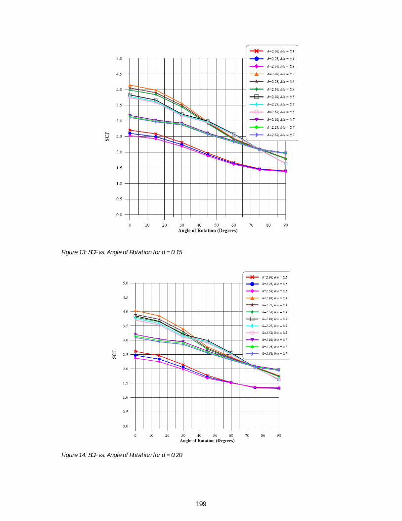
Comparing these stresses with those for a circular cross-bore, the hoop stress has varied very slightly. The compressive hoop stress along SH increased by between 16 % and 19 %. The axial stress at point S reduced by 98 % and became compressive. The axial stress along the cross-bore was largely compressive. The radial stress changed very slightly. Along the cross-bore immediately after point S the compressive radial stress increased by 17 %. 3.5.3 Elliptical Cross-bore Perpendicular to Cylinder Axis Figure 12 shows the dimensionless elastic meridional stresses for a cylinder with an elliptical cross-bore perpendicular to the cylinder axis. Comparing these stresses with those for a circular cross-bore, the maximum compressive hoop stress reduced by 33 %. The axial stresses increased throughout the cross-bore length. At point H axial stress increased by 167 %. The radial stress at point H increased by 320 % and changed from compressive to tensile. Comparing these stresses with those for an elliptical cross-bore with major axis parallel to the cylinder axis, the maximum compressive hoop stress reduced by 42 %. The axial stress at point H increased by 2833 %. The radial stress profile gave a smooth curve along the cross-bore. The radial stress at point H increased by 75 % and changed from compressive to tensile 3.6 Stress Concentration Factors for Elliptical Cross-Bore Effective stress gives a complete representation of the state of stress at a point. Due to the shape of the elliptical cross-bore, the effective stress would give better representation of the stresses around the cross-bore rather the hoop stress alone. The effective stress was therefore used to determine the stress concentration factors. For each thickness ratio, elliptical cross-bores with cross-sectional area equivalent to circular cross-bores of cross-bore to cylinder bore radius ratios of 0.15, 0.20, and 0.25 were investigated. The ratios of b/a equal to 0.1, 0.3, 0.5, and 0.7 were considered. Figure 13, Figure 14, and Figure 15 show the variation of the SCF with the orientation of an elliptical cross-bore which had the same cross-sectional area as a circular cross-bore of cross-bore to cylinder bore ratio of 0.15, 0.20 and 0.25 respectively. As AOR increased from 0° to 90°, the SCF reduced from a maximum to a minimum value. Therefore, an elliptical cross bore oriented perpendicular the cylinder axis gave the minimum SCF for any geometry considered. This can be explained by considering the orientation of the elliptical cross-bore with respect to the directions of the stresses. When the angle of rotation was zero, the cross-bore major axis was aligned perpendicular to the direction of the hoop stresses. From equation (6), the maximum stress and therefore the maximum SCF will be at the end of the major axis, i.e., the meridional plane. When the cross-bore is rotated, the orientation of the cross-bore major axis with hoop stresses changed until they were parallel. From equation (6) the factor a/b becomes a less than 1.0. Therefore the SCF reduces. When the cross-bore major axis is perpendicular to the cylinder axis, it also aligned perpendicular to the axial stresses. The axial stresses are of great magnitudes. These axial stresses play a big role in the SCF. The axial stresses are a maximum in the transverse cross-section at the intersection of the cross-bore and cylinder outside surface. For any given thickness ratio, when b/a = 0.1, the SCF was a minimum. When b/a was increased to 0.3, the SCF increased to the maximum. When b/a was changed to 0.5, the SCF reduced. When b/a = 0.7, the SCF reduced further but did not fall below those obtained for b/a = 0.1.
189
Thus the size and orientation of geometric discontinuities with respect to applied stress play a large role in determining the stress concentration. Stress concentration factor is a function of the type of discontinuity (hole, fillet, or groove), the geometry of the discontinuity, and the type of loading being experienced (Hamrock et al., 2004). When the thickness ratio was increased from 2.00 to 2.25 to 2.50, the SCF decreased. The magnitude of the difference declined as the angle of rotation changed from 0° to 90°. This trend continued as the cross-bore was rotated, until when nearing angle 90° when the reverse occurred for some cases of cross-bore to cylinder bore radius ratios of 0.2 and 0.25. Considering Figure 13, thickness ratio d = 0.15, when b/a = 0.1, as the AOR changed from 0° to 90°, SCF decreased from 2.7 to 1.4. These values of SCF are below that of a circular cross-bore of 3.0. When b/a = 0.3, as the AOR changed from 0° to 90°, SCF decreased from 4.2 to 1.8. At AOR of above 45°, the SCF was below 3.0. When b/a = 0.5, as the AOR changed from 0° to 90°, SCF decreased from 3.7 to 1.6. At AOR of above 45°, the SCF was below 3.0. When b/a = 0.7, as the AOR changed from 0° to 90°, SCF decreased from 3.2 to 2.0. At AOR of above 15°, the SCF was below 3.0. This trend was replicated for the other thickness ratios investigated. From Figure 13, for cylinder of thickness ratios of 2.0, 2.25, and 2.5, and an elliptical cross-bore, whose cross-sectional area is equivalent to a circular cross-bore of cross-bore to cylinder bore radius ratio of 0.15, the SCF was a constant at 2.1 when the cross-bore major axis was rotated 74.5°, with respect to the cylinder axis, for values of b/a of 0.3, 0.5, and 0.7. From Figure 14, for cylinder of thickness ratios of 2.0, 2.25, and 2.5, and an elliptical cross-bore, whose cross-sectional area is equivalent to a circular cross-bore of cross-bore to cylinder bore radius ratio of 0.20, the SCF was a constant at 2.1 when the cross-bore major axis was rotated 73°, with respect to the cylinder axis, for values of b/a of 0.3, 0.5, and 0.7. For b/a of 0.1, the SCF was a constant at 1.45 when the cross-bore major axis was rotated 66° with respect to the cylinder axis. From Figure 15, for cylinder of thickness ratios of 2.0, 2.25, and 2.5, and an elliptical cross-bore, whose cross-sectional area is equivalent to a circular cross-bore of cross-bore to cylinder bore radius ratio of 0.25, the SCF was a constant at 2.1 when the cross-bore major axis was rotated 72.5°, with respect to the cylinder axis, for values of b/a of 0.3, 0.5, and 0.7. For b/a of 0.1 the SCF was a constant at 1.55 when the cross-bore major axis was rotated 66° with respect to the cylinder axis. 4.0 Conclusion This study involved the development a finite element method computer program to analyze elastic stresses in a thick walled cylinder with an elliptical cross-bore. Investigations were carried out to determine the stress profiles and stress concentration factors for various cross-bore geometries and for various cross-bore orientations with respect to the cylinder axis. The stress profiles and the stress concentration factors indicate the critical points to be considered when designing a cylinder with an elliptical cross-bore. The results obtained from this research give details on the stress profiles and SCF that arise for a radial elliptical cross-bore at any orientation with respect to the cylinder axis. These results form a good basis for re-evaluating existing data for design of cylinders with elliptical cross-bores. The program developed can be modified further, commercialized and used to collect more data for design. The data obtained in this research will be used in guiding the design of pressure vessels with elliptical cross-bores. The data obtained on SCF constants should be used to enable quick design of thick walled cylinders with elliptical cross-bore.

190
From this investigation, the elliptical cross-bore is advantageous over the circular cross-bore, of the same cross sectional area. When the elliptical cross-bore had its major axis oriented perpendicular to the cylinder axis the SCF obtained was a minimum, that is, 2.0 and below. This is commendable compared to the average SCF for a circular cross-bore of 3.0. Thickness ratio of d = 0.20 and b/a = 0.1 resulted in the least values of SCF of between 2.5 and 1.3. For the thickness ratios investigated with b/a = 0.3 and b/a = 0.5, the SCF was below 3.0 for AOR above 45°, where as for b/a = 0.7, the SCF was below 3.0 for AOR above 20°. Acknowledgement We are grateful to the management of Jomo Kenyatta University of Agriculture and Technology for enabling us carry out this research work.

191
References Bathe, K. J. (1996). Finite Element Procedures, Prentice Hall, Englewood Cliffs, New Jersey. Chen, D. J., Shah, D. K. and Chan, W. S. (1996). "Using Stress Smoothing for Interlaminar Stress Distribution in Finite Element Analysis of Composite Laminates." Key Engineering Material, 121-122, pp 203-224. Dixon, R. D., Peters, D. T. and Keltjens, J. G. M. (2004). "Stress Concentration Factors of Cross-Bores in Thick Walled Cylinders and Blocks." Transactions of ASME, Journal of Pressure Vessel Technology, 126, pp 184 - 187. Dowling, N. E. (1993). Mechanical Behaviour of Materials - Engineering Methods for Deformation, Fracture and Fatigue, Prentice Hall International Editions. Faupel, J. H. and Harris, D. B. (1957). "Stress Concentration in Heavy-Walled Cylindrical Pressure Vessels." Industrial and Engineering Chemistry, 49(12), pp 1979 - 1986. Hameed, A., Brown, R. D. and Hetherington, J. (2004). "A Study of the Residual Stress Distribution in an Autofrettaged, Thick-Walled Cylinder with Cross-Bore." Journal of Pressure Vessel Technology, 126, pp 497 - 503. Hamrock, B. J., Schmid, S. R. and Jacobson, B. O. (2004). Fundamentals of Machine Elements, McGraw-Hill Professional. Harvey, J. F. (1991). Theory and Design of Pressure Vessels, Chapman & Hall. Kendall, D. P. (2000). "A Short History of High Pressure Technology From Bridgham to Division 3." Journal of Pressure Vessel Technology, 122, pp 229 - 233. Kihiu, J. M. (2002). Numerical Stress Characterization in Cross-Bored Thick walled Cylinders Under Internal Pressure, The University of Nairobi. Kihiu, J. M., Mutuli, S. M. and Rading, G. O. (2003). "Stress Characterization of Autofrettaged Thick Walled Cylinders." International Journal of Mechanical Engineering Education, 31(4), pp 370 - 389. Kihiu, J. M., Rading, G. O. and Mutuli, S. M. (2003). "Geometric Constants in Plain Cross Bore Cylinders." Journal of Pressure Vessel Technology, 125, pp 446 - 453. Kihiu, J. M., Rading, G. O. and Mutuli, S. M. (2004). "Overstraining of Flush Plain Cross-Bored Cylinders." Proceedings of Institution of Mechanical Engineers, Part C: Journal of Mechanical Engineering Science 218, pp 143-153. Krishnamoorthy, C. S. (1995). Finite Element Analysis - Theory and Programming, Tata McGraw-Hill Publishing Company Limited, New Delhi. Manning, W. R. D. (1957). "Strength of Cylinders." Industrial and Engineering Chemistry, 49(12), pp 1969 - 1978. Masu, L. M. (1989). The Effect of Cross Bore Geometry on the Strength of Pressure Vessels, The University of Leeds. Mraz, G. J. and Nisbett, E. G. (1980). "Design, Manufacture and Safety Aspects of Forged Vessels for High-Pressure Services." Transactions of ASME, Journal of Pressure Vessel Technology, 102, pp 98 - 106. Pilkey, W. D. and Pilkey, D. F. (2008). Peterson's Stress Concentration Factors, John Wiley and Sons. Reddy, J. N. (1993). An Introduction to the Finite Element Method, McGraw Hill International.

192
Segerlind, L. J. (1984). Applied Finite Element Analysis, John Wiley and Sons, New York. Timoshenko, S. P. (1958). Strength of Materials Part II: Advanced Theory and Problems, Krieger. Wikipedia http://en.wikipedia.org/wiki/Ellipse. Yeo, M. F. (1973). "A More Efficient Front Solution: Allocating Assembly Locations by Longevity Considerations." International Journal for Numerical Methods in Engineering, 7, pp 570 - 573. Zienkiewicz, O. C. (1971). The Finite Element Method in Engineering Science, McGraw-Hill, London. Zienkiewicz, O. C. and Taylor, R. L. (1994). The Finite Element Method, McGraw-Hill Book Company, London.
193
Figures
Figure 1: Discretization of a plain cylinder
Figure 2 : Discretization of a cylinder with an elliptical cross-bore
194
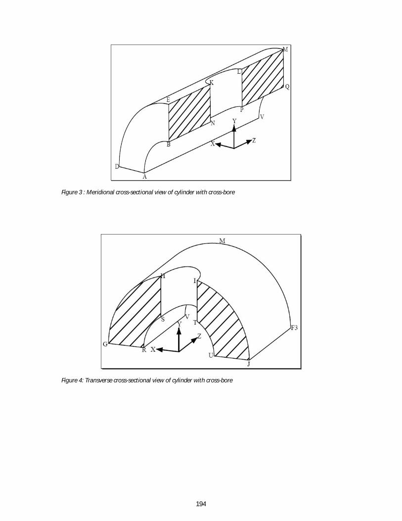
Figure 3 : Meridional cross-sectional view of cylinder with cross-bore
Figure 4: Transverse cross-sectional view of cylinder with cross-bore
195
Figure 5: Radial displacement along edge AB or CD
Figure 6: Stress distribution through a plain cylinder wall
y

196
Figure 7: Meridional stresses: circular cross-bore
Figure 8: Meridional stresses: parallel elliptical cross-bore
B N K
y
B N K
y

197
Figure 9: Meridional stresses: perpendicular elliptical cross-bore
Figure 10: Transverse stresses: circular cross-bore
R S H
B N K
y
y

198
Figure 11: Transverse stresses: parallel elliptical cross-bore
Figure 12: Transverse stresses: perpendicular elliptical cross-bore
R S H
R S H
y
y
199
Figure 13: SCF vs. Angle of Rotation for d = 0.15
Figure 14: SCF vs. Angle of Rotation for d = 0.20

200
Figure 15: SCF vs. Angle of Rotation for d = 0.25