
OSP-P Pneumatic Rodless Cylinders and Linear Guides
148
aerospace climate control electromechanical filtration fluid & gas handling hydraulics pneumatics process control sealing & shielding ORIGA OSP-P Pneumatic Rodless Cylinders and Linear Guides Catalog 0980 www.comoso.com
-
Upload
khangminh22 -
Category
Documents
-
view
1 -
download
0
Transcript of OSP-P Pneumatic Rodless Cylinders and Linear Guides
aerospaceclimate controlelectromechanicalfiltrationfluid & gas handlinghydraulicspneumaticsprocess controlsealing & shielding
ORIGA
OSP-P Pneumatic Rodless Cylinders and Linear GuidesCatalog 0980
www.comoso.com

Parker Hannifin CorporationParker-OrigaGlendale Heights, Illinoiswww.parker.com/pneu/rodless
ORIGA
! WARNINGFAILURE OR IMPROPER SELECTION OR IMPROPER USE OF THE PRODUCTS AND/OR SYSTEMS DESCRIBED HEREIN OR RELATED ITEMS CAN CAUSE DEATH, PERSONAL INJURY AND PROPERTY DAMAGE.This document and other information from Parker Hannifin Corporation, its subsidiaries and authorized distributors provide product and/or system options for further investigation by users having technical expertise. It is important that you analyze all aspects of your application including consequences of any failure, and review the information concerning the product or system in the current product catalog. Due to the variety of operating conditions and applications for these products or systems, the user, through its own analysis and testing, is solely responsible for making the final selection of the products and systems and assuring that all performance, safety and warning requirements of the application are met.The products described herein, including without limitation, product features, specifications, designs, availability and pricing, are subject to change by Parker Hannifin Corporation and its subsidiaries at any time without notice.
Offer of SaleThe items described in this document are hereby offered for sale by Parker Hannifin Corporation, its subsidiaries or its autho-rized distributors. This offer and its acceptance are governed by the provisions stated on the separate page of this document entitled “Offer of Sale”.
© Copyright 2009 Parker Hannifin Corporation. All Rights Reserved
Catalog 0980
Warning, Offer of SaleOSP-P Pneumatic Rodless Cylinders and Linear Guides
www.comoso.com

A1 Parker Hannifin CorporationParker-OrigaGlendale Heights, Illinoiswww.parker.com/pneu/rodless
ORIGA
A
Catalog 0980
IndexOSP-P Pneumatic Rodless Cylinders and Linear Guides
Introduction
• Conversion Tables
• System Concept
• Modular Components Overview
• Control Examples
• Application Examples
A
Intr
oduc
tion
Rodless Pneumatic Cylinders Series OSP-P
• Overview
• Rodless Pneumatic Cylinders
• Rodless Pneumatic Cylinders with Guides
• OSP-P Sensors & Service Parts
• Origa SENSOFLEX Measuring System
B
Rod
less
Cyl
inde
rs
Seri
es O
SP-P
Aluminum Roller Guides Series GDL
• Linear Guide Features
• GDL Product Line Overview
• GDL Roller Guides / Accessories
• Wipers / Butt-jointed Rail Options
C
Alum
inum
Rol
ler G
uide
s Se
ries
GD
L
Safety Guide, Offer of Sale D
Safe
ty G
uide
, Off
er o
f Sal
e
www.comoso.com

A2 Parker Hannifin CorporationParker-OrigaGlendale Heights, Illinoiswww.parker.com/pneu/rodless
ORIGA
A
AtteNtION!
Contact PARKER-ORIGA for sizing software and/or technical assistance
630-871-8300
All dimensions are in European-Standard. Please convert all in US-Standard.
Conversion table
Multiply By to ObtainMillimeters .03937 InchesNewtons .2248 Lbs.(F)Newton-Meters 8.8512 In-LbsKilograms 2.205 Lbs.
Inches 25.4 MillimetersLbs.(F) 4.448 NewtonsIn-Lbs .113 Newtons-MetersLbs. .45359 Kilograms
2D & 3DCAD Drawings
can be downloaded from website
www.parker.com/pneu/rodless
�����������
����
���
ELECTRIC ACTUATOR
OSP-P Pneumatic Rodless Cylinders and Linear GuidesCatalog 0980
Conversion table
www.comoso.com

A3 Parker Hannifin CorporationParker-OrigaGlendale Heights, Illinoiswww.parker.com/pneu/rodless
ORIGA
A
OSP-P Pneumatic Rodless Cylinders and Linear GuidesCatalog 0980
Certifications
PARKER-ORIGA rodless pneumatic cylinders are the first rodless cylinders that have been approved for use in potentially explosive atmospheres in Equipment Group II, Category 2 GDThe Cylinders are to the ATEX Certification 94/9/EG (ATEX 95) for Pneumatic Components.For ATEX Certification, consult factory for ordering assistance.
for use in Ex-Areas
for Clean Room Applicationscertified to DIN EN ISO 14644-1
with special pneumatic cushioning system for cycle time optimization,for Ø 16 to 50 mm– on request
Stainless steel version for special applications
High Temperature Version for temperatures up to +120°C
+120°C
-40°C
Low Temperature Version for temperatures up to -40°C
0.005 m/sSlow Speed Versionv = 0.005 – 0.2 m/s
< 30 m/sHigh Speed Versionvmax. = 30 m/s
ORIGA
www.comoso.com

A4 Parker Hannifin CorporationParker-OrigaGlendale Heights, Illinoiswww.parker.com/pneu/rodless
ORIGA
A
Based on the ORIGA rodless cylinder, proven in world wide markets, PARKER-ORIGA now offers the complete solution for linear drive systems. Designed for absolute reliability, high performance, ease of use and optimized engineering the ORIGA SYSTEM PLUS satisfies even the most demanding applications.
ORIGA SYSteM PLUS
is a totally modular concept which offers the choice of pneumatic or electric actuation, with guidance and control modules to suit the exact needs of individual installations.
• Different guidance options provide the necessary level of precision, performance and duty for various applications.
• Compact solutions, which are simple to install and can be easily retrofitted.
• Valves and control options can be directly mounted to the actuator system.
• Diverse mounting options to provide total installation flexibility.
SYSteM MODULARItY• Pneumatic Drive – For all round versatility and convenience, combining ease of control and broad performance capability. Ideally suited for point-to point operations, reciprocating movements and simple traverse / transfer applications.
• ElectricScrewDrive – For high force capability and accurate path and position control.
• ElectricBeltDrive – For high speed appli cations, accurate path and position control and longer strokes.
For additional information on electric linear actuators, please contact factory for OSP-e literature.
The actuators at the core of the system all have a common aluminum extruded profile, with double dovetail mounting rails on three sides, these
are the principle building blocks of the system to which all modular options are directly attached.
OSP-P Pneumatic Rodless Cylinders and Linear Guides One Concept – three Drive Options
Catalog 0980
the System Concept
www.comoso.com

A5 Parker Hannifin CorporationParker-OrigaGlendale Heights, Illinoiswww.parker.com/pneu/rodless
ORIGA
ABasic Linear Drive Standard Version••
•
Series OSP-PSeries OSP-E* Belt drive Belt drive with integrated Guides Vertical belt drive with recirculating ball bearing guideSeries OSP-E* Screw drive (Ball Screw, Trapezoidal Screw)
Air Connection on the End-face or both at One End
• Series OSP-P
Clean Room Cylinder certified to DIN EN ISO 146644-1••
Series OSP-PSeries OSP-E..SB
Bi-parting Version
• Series OSP-P
Integrated 3/2 Way Valves
• Series OSP-P
Clevis Mounting
•••
Series OSP-PSeries OSP-E Belt drive* Series OSP-E Screw drive*
End Cap Mounting
•••
Series OSP-PSeries OSP-E Belt drive*Series OSP-E Screw drive*
Mid-Section Support
•••
Series OSP-PSeries OSP-E Belt drive* Series OSP-E Screw drive*
Inversion Mounting
•••
Series OSP-PSeries OSP-E Belt drive* Series OSP-E Screw drive*
Standard Version
• Series OSP-P
Multiplex Connection
• Series OSP-P
Linear Guides– SLIDELINE
••
Series OSP-P Series OSP-E Screw drive*
Linear Guides– POWERSLIDE •••
Series OSP-PSeries OSP-E Belt drive* Series OSP-E Screw drive*
Linear Guides– PROLINE•••
Series OSP-PSeries OSP-E Belt drive* Series OSP-E Screw drive*
Linear Guides– STARLINE
• Series OSP-P
Linear Guides– KF
• Series OSP-P
Heavy Duty Linear Guides– HD
••
Series OSP-PSeries OSP-E Screw drive*
Intermediate Stop Module– ZSM
• Series OSP-P
Brakes
•
•
Active Brakes
Passive Brakes
Magnetic Switches
•••
Series OSP-PSeries OSP-E Belt drive* Series OSP-E Screw drive*
SENSOFLEX – Measuring System
• Series SFI-plus
Variable Stop VS
• Series OSP-Pwith Linear Guide STL, KF, HD
* For information on electric Linear Drives, contact factory for literature
OSP-P Pneumatic Rodless Cylinders and Linear GuidesOne Concept – three Drive Options
Catalog 0980
the System Concept
www.comoso.com

A6 Parker Hannifin CorporationParker-OrigaGlendale Heights, Illinoiswww.parker.com/pneu/rodless
ORIGA
A
OSP-P Pneumatic Rodless Cylinders and Linear GuidesRodless Cylinders Series OSP-P
Catalog 0980
Modular Components Overview
Linear Drives OSP-P10 OSP-P16 OSP-P25 OSP-P32 OSP-P40 OSP-P50 OSP-P63 OSP-P80 Theoretical Force at 6 bar (N) 47 120 295 483 754 1178 1870 3010Effective Force at 6 bar (N) 32 78 250 420 640 1000 1550 2600Velocity v (m/s) > 0.005 > 0.005 > 0.005 > 0.005 > 0.005 > 0.005 > 0.005 > 0.005Magnetic Piston (three sides) ✕ ❑ ❑ ❑ ❑ ❑ ❑ ❑
Lubrication - Prelubricated ❑ ❑ ❑ ❑ ❑ ❑ ❑ ❑
Multiple Air Ports ( 4 x 90° ) ✕ ❑ ❑ ❑ ❑ ❑ ❑ ❑
Both Air Connections at End-face ✕ ❍ ❍ ❍ ❍ ❍ ❍ ❍
Air Connection on the End-face ✕ ❍ ❍ ❍ ❍ ❍ ❍ ❍
Cushioning ❑ ❑ ❑ ❑ ❑ ❑ ❑ ❑
Cushioning Length (mm) 2,50 11 17 20 27 30 32 39Stroke Length (mm) ▲ 1 - 6000 1 - 6000 1 - 6000 1 - 6000 1 - 6000 1 - 6000 1 - 6000 1 - 6000Pressure Range pmax (bar) 8.0 8.0 8.0 8.0 8.0 8.0 8.0 8.0 Temperature Range (°C) ❊ -10 – + 80 -10 – + 80 -10 – + 80 -10 – + 80 -10 – + 80 -10 – + 80 -10 – + 80 -10 – + 80Viton / Chemical Resistance ❍ ❍ ❍ ❍ ❍ ❍ ❍ ❍
Stainless Steel Parts ❍ ❍ ❍ ❍ ❍ ❍ ❍ ❍
Clevis Mounting ❍ ❍ ❍ ❍ ❍ ❍ ❍ ❍
Slow Speed Lubrication ❍ ❍ ❍ ❍ ❍ ❍ ❍ ❍
Duplex Connection / Multiplex Connection ✕ on request ❍ ❍ ❍ ❍ on request on requestTandem Piston ❍ ❍ ❍ ❍ ❍ ❍ ❍ ❍
Basic CylinderF (N) 20 120 300 450 750 1200 1650 2400Mx (Nm) 0.2 0.45 1.5 3 6 10 12 24My (Nm) 1 4 15 30 60 115 200 360Mz (Nm) 0.3 0.5 3 5 8 15 24 48SLIDeLINeF (N) ✕ 325 675 925 1500 2000 2500 2500Mx (Nm) ✕ 6 14 29 50 77 120 120My (Nm) ✕ 11 34 60 110 180 260 260Mz (Nm) ✕ 11 34 60 110 180 260 260PROLINeF (N) ✕ 542 857 1171 2074 3111 ✕ ✕
Mx (Nm) ✕ 8 16 29 57 111 ✕ ✕
My (Nm) ✕ 12 39 73 158 249 ✕ ✕
Mz (Nm) ✕ 12 39 73 158 249 ✕ ✕
POWeRSLIDeF (N) ✕ 1400 1400 - 3000 1400 - 3000 3000 3000 - 4000 ✕ ✕
Mx (Nm) ✕ 14 14 - 65 20 - 65 65 - 90 90 - 140 ✕ ✕
My (Nm) ✕ 45 63 - 175 70 - 175 175 - 250 250 - 350 ✕ ✕
Mz (Nm) ✕ 45 63 - 175 70 - 175 175 - 250 250 - 350 ✕ ✕
StARLINeF (N) ✕ 1000 3100 3100 4000-7500 4000-7500 ✕ ✕
Mx (Nm) ✕ 15 50 62 150 210 ✕ ✕
My (Nm) ✕ 30 110 160 400 580 ✕ ✕
Mz (Nm) ✕ 30 110 160 400 580 ✕ ✕
– Variable Stop ✕ ❍ ❍ ❍ ❍ ❍ ✕ ✕
KF GuideF (N) ✕ 1000 3100 3100 4000-7500 4000-7500 ✕ ✕
Mx (Nm) ✕ 12 35 44 119 170 ✕ ✕
My (Nm) ✕ 25 90 133 346 480 ✕ ✕
Mz (Nm) ✕ 25 90 133 346 480 ✕ ✕
– Variable Stop ✕ ❍ ❍ ❍ ❍ ❍ ✕ ✕
www.comoso.com

A7 Parker Hannifin CorporationParker-OrigaGlendale Heights, Illinoiswww.parker.com/pneu/rodless
ORIGA
A
OSP-P Pneumatic Rodless Cylinders and Linear GuidesRodless Cylinders Series OSP-P
Catalog 0980
Modular Components Overview
Linear Drives OSP-P10 OSP-P16 OSP-P25 OSP-P32 OSP-P40 OSP-P50 OSP-P63 OSP-P80
HD Heavy Duty Guide
F (N) ✕ ✕ 6000 6000 15000 18000 ✕ ✕
Mx (Nm) ✕ ✕ 260 285 800 1100 ✕ ✕
My (Nm) ✕ ✕ 320 475 1100 1400 ✕ ✕
Mz (Nm) ✕ ✕ 320 475 1100 1400 ✕ ✕
– Variable Stop ✕ ✕ ❍ ❍ ❍ ❍ ✕ ✕
– Intermediate Stop Module ✕ ✕ ❍ ✕ ✕ ✕ ✕ ✕
Active Brake
Braking Force at 6 bar (brake surface dry) (N) ✕ ✕ 350 590 900 1400 2170 4000
SLIDeLINe SL / PROLINe PL with Brakes
Active Brake
SL Braking Force at 6 bar (brake surface dry) (N) ✕ ✕ 325 545 835 1200 ✕ ✕
PL Braking Force at 6 bar (brake surface dry) (N) ✕ ✕ on request on request on request on request ✕ ✕
Passive Brake Multibrake
SL Braking Force at 6 bar (brake surface dry) (N) ✕ ✕ 470 790 1200 1870 2900 2900
PL Braking Force at 6 bar (brake surface dry) (N) ✕ ✕ 315 490 715 1100 – –
Magnetic Switches
Standard Version ❍ ❍ ❍ ❍ ❍ ❍ ❍ ❍
T-Nut Version ❍ ❍ ❍ ❍ ❍ ❍ ❍ ❍
Displacement Measuring Systems
SFI-plus Incremental ✕ ✕ ❍ ❍ ❍ ❍ ❍ ❍
Integrated Valves 3/2 WV NO VOe ✕ ✕ ❍ ❍ ❍ ❍ on request on request
Mountings
End Cap Mounting / Mid-Section Support ❍ ❍ ❍ ❍ ❍ ❍ ❍ ❍
Inversion Mounting ✕ ❍ ❍ ❍ ❍ ❍ ❍ ❍
Shock Absorber for Intermediate Positioning ✕ ✕ on request on request on request on request ✕ ✕
Adaptor Profile / T-Nut Profile ✕ ❍ ❍ ❍ ❍ ❍ ✕ ✕
Special Cylinders
Special Pneumatical Cushioning System ✕ on request on request on request on request on request ✕ ✕
Clean Room Cylinders to DIN EN ISO 14644-1 ✕ ❍ ❍ ❍ ✕ ✕ ✕ ✕
Bi-parting Version ✕ ✕ ✕ ✕ ❍ ✕ ✕ ✕
High-Speed up to 30 m/s ✕ on request on request on request ✕ ✕ ✕ ✕
❑ = Standard Version ▲ = Longer Strokes on Request❊ = other temperature Ranges on Request ❍ = OptionX = Not Applicable
www.comoso.com

A8 Parker Hannifin CorporationParker-OrigaGlendale Heights, Illinoiswww.parker.com/pneu/rodless
ORIGA
A
Circuit diagram for end of stroke application. Intermediate positioning is also possible.
The cylinder is controlled by two 3/2-way valves (normally open). The speed can be adjusted independently for both directions.
Circuit diagram for end of stroke application. Intermediate positioning is also possible.
The cylinder is controlled by a 5/3-way valve (middle position pressurized).The speed can be adjusted independently for both directions.
The optional integrated VOE Valves offer optimal control, and allow accurate positioning of intermediate positions and the lowest possible speeds.
The combination of an OSP-cylinder with the passive MULTIBRAKE as shown here, allows accurate positioning and safety in case of loss of pneumatic air pressure.
Fast/Slow speed cycle control with pneumatic brake for accurate positioning at high velocities. Additional 3/2-way valves with adjustable throttle valves at the exhaust of the standard directional control valves for two displacement speeds in each direction of the piston’s travel. The valve controlling the brake is activated after the slow speed cycle is activated.
OSP-P Pneumatic Rodless Cylinders and Linear GuidesControl examples for OSP-P
Catalog 0980
examples
www.comoso.com

A9 Parker Hannifin CorporationParker-OrigaGlendale Heights, Illinoiswww.parker.com/pneu/rodless
ORIGA
AThe high load capacity of the piston can cope with high bending moments without additional guides.
ORIGA SYSteM PLUS – rodless linear drives offer maximum flexibility for any application.
The mechanical design of the OSP-P allows synchronized movement of two cylinders.
For further information and assembly instructions, please contact your local
PARKER-ORIGA dealer.
Optimal system performance by combining multi-axis cylinder combinations.
Integrated guides offer optimal guidance for applications requiring high performance, easy assembly and maintenance free operation.
When using external guides, the clevis mounting is used to compensate for deviations in parallelism.
SLIDELINE
POWERSLIDE
STARLINE
PROLINE
HD-Guide
OSP-P Pneumatic Rodless Cylinders and Linear GuidesOSP-P Application examples
Catalog 0980
examples
www.comoso.com

A10 Parker Hannifin CorporationParker-OrigaGlendale Heights, Illinoiswww.parker.com/pneu/rodless
ORIGA
A
OSP-P Pneumatic Rodless Cylinders and Linear GuidesCatalog 0980
Notes
www.comoso.com

B1 Parker Hannifin CorporationParker-OrigaGlendale Heights, Illinoiswww.parker.com/pneu/rodless
ORIGA
ORIGA
B
Rodless Pneumatic CylindersSeries OSP-P
Standard Rodless Pneumatic Cylinders System Concepts & Components .................... B2-B5 Technical Data ................................................ B7-B9 Dimensions................................................... B10-B15 Active Brakes................................................ B16-B19 Accessories (Mounts & Supports) ................ B20-B29 Ordering Information ............................................B30
Clean Room Cylinders Technical Data ............................................ B31-B32 Dimensions...........................................................B33 Ordering Information ............................................B34
Bi-parting Rodless Cylinders Technical Data ....................................................B35 Dimensions...........................................................B36 Ordering Information ............................................B37
www.comoso.com

B2 Parker Hannifin CorporationParker-OrigaGlendale Heights, Illinoiswww.parker.com/pneu/rodless
ORIGA
B
A completely new generation of linear drives which can be simply and neatly integrated into any machine layout.
ORIGA SYSTEM PLUS
– INNOVATION FROM A PROVEN DESIGN
A NEW MODULAR LINEAR DRIVESYSTEM
With this second generation linear drive PARKER-ORIGA offers design engineers complete flexibility.The well known ORIGA cylinder has been further developed into a com-bined linear actuator, guidance and control package. It forms the basis for the new, versatile ORIGA SYSTEM PLUS linear drive system.
All additional functions are designed into modular system components which replace the previous series of cylinders.
MOUNTING RAILS ON 3 SIDES
Mounting rails on 3 sides of the cylinder enable modular components such as linear guides, brakes, valves, magnetic switches etc. to be fitted to the cylinder itself. This solves many installation problems, especially where space is limited.
Stainless steelscrews optional.
end cap can be rotated to any one of the four positions (before or after delivery) so that the air connection can be in any desired position.
Combined clamping for inner and outer sealing band with dust cover.
Corrosion resistant steel outer sealing band and robust wiper system on the carrier for use in aggressive environments.
Proven corrosion resistant steel inner sealing band for optimum sealing and extremely low friction.
Magnetic piston as standard - for contactless position sensing on three sides of the cylinder.
Optimized cylinder profile for maximum stiffness and minimum weight. Integral air passages enable both air connections to be positioned at one end, if desired.
The modular system concept forms an ideal basis for additional customer-specific functions.
Low friction piston seals for optimized running characteristics
OSP-P Pneumatic Rodless Cylinders and Linear GuidesStandard Rodless Pneumatic Cylinders
Catalog 0980
System Concept & Components
www.comoso.com

B3 Parker Hannifin CorporationParker-OrigaGlendale Heights, Illinoiswww.parker.com/pneu/rodless
ORIGA
B
Adjustable end cushioning at both ends are standard.
New low profilepiston / carrier design.
Integral dovetail rails on three sides provide many adaptation possibilities (linear guides, magnetic switches, etc.).
Modular system components are simply clamped on.
POWeRSLIDeRoller bearing precision guidance for smooth travel and high dynamic or static loads.
SLIDeLINeCombination with linear guides provides for heavier loads.
HeAVY DUtY GUIDe HD for heavy duty applications.
PROLINethe compact aluminum roller guide for high loads and velocities.
Passive pneumatic brake reacts automati cally to pressure failure.
Active pneumatic brake for secure, positive stopping at any position.
StARLINeRecirculating ball bearing guide for very high loads and precision
SeNSOFLeX SFI-plus incremental measuring system with 0.1 (1.0) mm resolution
Clean Room Versioncertified to DIN eN ISO 14644-1
INteGRAteDVOe VALVeSthe complete compact solution for optimal cylinder control.
VARIABLe StOP VSthe variable stop provides simple stroke limitation.
Rodless Cylinder for synchronized bi-parting movements
OSP-P Pneumatic Rodless Cylinders and Linear GuidesStandard Rodless Pneumatic Cylinders
Catalog 0980
System Concept & Components
KF GUIDeRecirculating ball bearing guide – the mounting dimensions correspond to FeStO type: DGPL-KF
www.comoso.com

B4 Parker Hannifin CorporationParker-OrigaGlendale Heights, Illinoiswww.parker.com/pneu/rodless
ORIGA
B
OPTIONS AND ACCESSORIES FOR SYSTEM VERSATILITY
SLOW SPEED OPTIONS
Specially formulated grease lubrication facilitates slow, smooth and uniform piston travel in the speed range from 0.005 to 0.2 m/s.
Minimum achievable speeds are dependent on several factors. Please consult our technical department.
Slow speed lubrication in combination with Viton® on demand.
Oil free operation preferred.
VITON® VERSION
For use in an environment with high temperatures or in chemically aggressive areas.
All seals are made of Viton®.
Sealing bands: Stainless steel
END-FACE AIR CONNECTION
Page B12
To solve special installation problems.
BOTH AIR CONNECTIONS AT ONE END
Page B13
For simplified tubing connections and space saving.
SERIES OSP-PSTANDARD VERSIONS OSP-P10 to P80Pages B7-B15
Standard carrier with integral guidance. End cap can be rotated 4 x 90° to position air connection on any side. Magnetic piston as standard. Dovetail profile for mounting of accessories and the cylinder itself.
BASIC CYLINDER OPTIONSCLEAN ROOM CYLINDERS
Page B31-B34
For use in clean room applications, certified with the IPA-Certificate (to DIN EN ISO 14644-1).
The special design of the linear drive enables all emissions to be led away.
STAINLESS VERSION
For use in constantly damp or wet environments. All screws are A2 quality stainless steel
INTEGRATED VOE VALVES
Page B14
The complete compact solution for optimal cylinder control.
JOINT CLAMP CONNECTION
Page B28
The joint clamp connection combines two OSP-P cylinders of the same size into a compact unit with high performance.
MULTIPLEX CONNECTION
Page B29
The multiplex connection combines two or more OSP-P cylinders of the same size into one unit.
The orientation of the carriers can be freely selected.
0.005 m/s
Catalog 0980
AccessoriesOSP-P Pneumatic Rodless Cylinders and Linear GuidesStandard Rodless Pneumatic Cylinders
www.comoso.com

B5 Parker Hannifin CorporationParker-OrigaGlendale Heights, Illinoiswww.parker.com/pneu/rodless
ORIGA
B
ACCESSORIESMAGNETIC SWITCHES TYPE RS, ES, RST, EST
Pages B102-B108
For electrical sensing of end and intermediate piston positions, also in EX-Areas.
CLEVIS MOUNTING
Page B20-B21
Carrier with tolerance and parallelism compensation for driving loads supported by external linear guides.
INVERSION MOUNTING
Page B22
The inversion mounting transfers the driving force to the opposite side, e. g. for dirty environments.
Catalog 0980
Accessories
END CAP MOUNTING
Page B23
For end-mounting of the cylinder.
MID-SECTION SUPPORT
Page B24
For supporting long cylinders or mounting the cylinder by its dovetail rails.
OSP-P Pneumatic Rodless Cylinders and Linear GuidesStandard Rodless Pneumatic Cylinders
www.comoso.com

B6 Parker Hannifin CorporationParker-OrigaGlendale Heights, Illinoiswww.parker.com/pneu/rodless
ORIGA
B
Catalog 0980
NotesOSP-P Pneumatic Rodless Cylinders and Linear GuidesStandard Rodless Pneumatic Cylinders
www.comoso.com

B7 Parker Hannifin CorporationParker-OrigaGlendale Heights, Illinoiswww.parker.com/pneu/rodless
ORIGA
B
RodlessPneumatic Cylinder ø 10-80 mm
Series OSP-P..
Standard Versions:• Double-acting with adjustable end cushioning
• With magnetic piston for position sensing
• Long-Stroke Cylinders for stroke lengths up to 41m (consult factory)
Special Versions:• With special pneumatic cushioning system (on request)
• Clean room cylinders (see page B31-B34)
• Stainless steel screws
• Slow speed lubrication
• Viton® seals
• Both air connections on one end • Air connection on the end-face
• Integrated Valves
Weight (mass) kg
Cylinder series(Basic cylinder)
Weight (Mass) kg
At 0 mm stroke per 100 mm stroke
OSP-P10 0.087 0.052
OSP-P16 0.22 0.1
OSP-P25 0.65 0.197
OSP-P32 1.44 0.354
OSP-P40 1.95 0.415
OSP-P50 3.53 0.566
OSP-P63 6.41 0.925
OSP-P80 12.46 1.262
Size Comparison
P10 P16 P25 P32 P40 P50 P63 P80
Characteristics Pressures quoted as gauge pressure
Characteristics Symbol Unit Description
General Features
Type Rodless cylinder
Series OSP-P
System Double-acting, with cushioning, position sensing capability
Mounting See drawings
Air Connection Threaded
Ambient Tmin °C -10 Other temperature ranges temperature range Tmax °C +80 on request
Weight (mass) kg See table below
Installation In any position
Medium Filtered, unlubricated compressed air (other media on request) Lubrication Permanent grease lubrication (additional oil mist lubrication not required) Option: special slow speed grease
Cylinder Profile Anodized aluminum
Carrier (piston) Anodized aluminum
End caps Aluminum, lacquered / Plastic (P10)
Sealing bands Corrosion resistant steel
Seals NBR (Option: Viton®)
Screws Galvanized steel Option: stainless steel
Dust covers, Plastic wipers
Max. operating pressure pmax bar 8
Mat
eria
l
�����������
����
���
Catalog 0980
technical Data
• End cap can be rotated 4 x 90° to position air connection as desired• Free choice of stroke length up to 6000 mm, Long-Stroke version (Ø50-80mm) for stroke lengths up to 41m
OSP-P Pneumatic Rodless Cylinders and Linear GuidesStandard Rodless Pneumatic Cylinders
www.comoso.com

B8 Parker Hannifin CorporationParker-OrigaGlendale Heights, Illinoiswww.parker.com/pneu/rodless
ORIGA
B
Cylinder Series(mm Ø)
theoretical Action
Force at 6 bar (N)
effective Action Force
FA at 6 bar (N)
max. Moments max. LoadF (N)
CushionLength(mm)
Mx (Nm)
My(Nm)
Mz(Nm)
OSP-P10 47 32 0.2 1 0.3 20 2.5 *
OSP-P16 120 78 0.45 4 0.5 120 11
OSP-P25 295 250 1.5 15 3 300 17
OSP-P32 483 420 3 30 5 450 20
OSP-P40 754 640 6 60 8 750 27
OSP-P50 1178 1000 10 115 15 1200 30
OSP-P63 1870 1550 12 200 24 1650 32
OSP-P80 3016 2600 24 360 48 2400 39
Loads, Forces and MomentsChoice of cylinder is decided by:• Permissible loads, forces and moments• Performance of the pneumatic end cushions. The main factors here are the mass to be cushioned and the piston speed at start of cushioning (unless external cushioning is used, e. g. hydraulic shock absorbers).
The adjacent table shows the maximum values for light, shock-free operation, which must not be exceeded even in dynamic operation. Load and moment data are based on speeds v ≤ 0.5 m/s.When working out the action force required, it is essential to take into account the friction forces generated by the specific application or load.
Cushioning DiagramWork out your expected moving mass and read off the maximum permissible speed at start of cushioning. Alternatively, take your desired speed and expected mass and find the cylinder size required.
Please note that piston speed at start of cushioning is typically ca. 50% higher than the average speed, and that it is this higher speed which determines the choice of cylinder. If these maximum permissible values are exceeded, additional shock absorbers must be used.
M = F ·l Bending moments are calculated from the center of the linear actuator
* A rubber element (non-adjustable) is used for end cushioning. To deform the rubber element enough to reach the absolute end position would require a Dp of 4 bar!
* For cylinders with linear guides or brakes, please be sure to take the mass of the carriage or the brake housing into account.
������������
�
���
����
��� ������ ��� � � � � �� ��� ����
���
��
���
���
���������
������
���
Max
. per
mis
sibl
e pi
ston
spe
ed
at s
tart
of c
ushi
onin
g
Mass to be cushioned *
If the permitted limit values are exceeded, either additional shock absorbers should be fitted in the area of the center of gravity or you can consult us about our special cushioning system – we shall be happy to advise you on your specific application.
��
��
��
���
�
Catalog 0980
technical DataOSP-P Pneumatic Rodless Cylinders and Linear GuidesStandard Rodless Pneumatic Cylinders
www.comoso.com

B9 Parker Hannifin CorporationParker-OrigaGlendale Heights, Illinoiswww.parker.com/pneu/rodless
ORIGA
B
Mid-Section SupportsTo avoid excessive bending and oscillation of the cylinder, mid-section supports are required dependent on specified stroke lengths and applied loads. The diagrams show the maximum possible support spacings depending on the load. Bending up to max. 0.5 mm is permissible between supports. The mid-section supports are clamped on to the dovetail profile of the cylinder tube. They are also able to take the axial forces.
���
���
����
�
���� ��� ��� ���
���
���
���
���
����
����
����
Distance k
Load
FPermissible Support Spacings: OSP - P10 - P32
� �
��
�
� � �
������
����
���
�������
��� ��� ��� ��� ��� ��� ��� ��� ��� ��� ��� ���
����
����
����������������������������
��� ��� ���
����
����
�
�
Distance k
Load
F
Permissible Support Spacings: OSP - P40 - P80
� �
��
�
Catalog 0980
technical DataOSP-P Pneumatic Rodless Cylinders and Linear GuidesStandard Rodless Pneumatic Cylinders
www.comoso.com

B10 Parker Hannifin CorporationParker-OrigaGlendale Heights, Illinoiswww.parker.com/pneu/rodless
ORIGA
B
Dimensions of Basic Cylinder OSP-P10Cylinder Stroke and Dead Length A• Free choice of stroke length up to
6000 mm in 1 mm steps.• Longer strokes on request.
tandem CylinderTwo pistons are fitted: dimension “Z” is optional. (Please note minimum distance “Zmin”).
• Free choice of stroke length up to 6000 mm in 1 mm steps.
• Longer strokes on request.
• Stroke length to order is stroke + dimension “Z”
Please note: to avoid multiple actuation of magnetic switches, the second piston is not equipped with magnets.
Stroke
Stroke + 2 x A
Stroke
Stroke + 2 x A + Z
end Cap/Air ConnectionSeries OSP -P10
CarrierSeries OSP-P10
Dimension table (mm)
Cylinder Series
A B C D e G H I J K L M N P R S W X Y Zmin CF eM eN FB FH ZZ
OSP-P10 44.5 12 19 M5 12 M3 5 6 60 8.5 22 22.5 17.5 10.5 3.4 16 22.5 31 M3 64 32 9.5 2 17 17 6
Catalog 0980
Dimensions OSP-P Pneumatic Rodless Cylinders and Linear GuidesStandard Rodless Pneumatic Cylinders
www.comoso.com

B11 Parker Hannifin CorporationParker-OrigaGlendale Heights, Illinoiswww.parker.com/pneu/rodless
ORIGA
B� �� �
�� � ��
��
��
��
�
�
�
��
��
� �
�
�
�����
Dimension table (mm)
CylinderSeries A B C D e G H I J K M O S V X Y Z BW BX BY CF eN FB FH ZZ
OSP-P16 65 14 30 M5 18 M3 9 5.5 69 15 23 33.2 22 16.5 36 M4 81 10.8 1.8 28.4 38 3 30 27.2 7OSP-P25 100 22 41 G1/8 27 M5 15 9 117 21.5 31 47 33 25 65 M5 128 17.5 2.2 40 52.5 3.6 40 39.5 8OSP-P32 125 25.5 52 G1/4 36 M6 15 11.5 152 28.5 38 59 36 27 90 M6 170 20.5 2.5 44 66.5 5.5 52 51.7 1OSP-P40 150 28 69 G1/4 54 M6 15 12 152 34 44 72 36 27 90 M6 212 21 3 54 78.5 7.5 62 63 10OSP-P50 175 33 87 G1/4 70 M6 15 14.5 200 43 49 86 36 27 110 M6 251 27 – 59 92.5 11 76 77 10OSP-P63 215 38 106 G3/8 78 M8 21 14.5 256 54 63 107 50 34 140 M8 313 30 – 64 117 12 96 96 16OSP-P80 260 47 132 G1/2 96 M10 25 22 348 67 80 133 52 36 190 M10 384 37.5 – 73 147 16.5 122 122 20
end Cap/Air Connection can be rotated 4 x 90°Series OSP-P16 to P32
end Cap/Air Connection can be rotated 4 x 90°Series OSP-P40 to P80
CarrierSeries OSP-P16 to P80
Dimensions of Basic Cylinder OSP - P16-P80 Cylinder Stroke and Dead Length A• Free choice of stroke length up to
6000 mm in 1 mm steps.
• Longer strokes on request.
tandem CylinderTwo pistons are fitted: dimension “Z” is optional. (Please note minimum distance “Zmin”).
• Free choice of stroke length up to 6000 mm in 1 mm steps.
• Longer strokes on request.
• Stroke length to order is stroke + dimension “Z”
Please note: to avoid multiple actuation of magnetic switches, the second piston is not equipped with magnets.
Stroke
Stroke + 2 x A
�
�
������
��
�
Air connection D
Cushion adjustment screw
Air connection D
Cushion adjustment screw
Stroke
Stroke + 2 x A + Z
Catalog 0980
DimensionsOSP-P Pneumatic Rodless Cylinders and Linear GuidesStandard Rodless Pneumatic Cylinders
www.comoso.com

B12 Parker Hannifin CorporationParker-OrigaGlendale Heights, Illinoiswww.parker.com/pneu/rodless
ORIGA
B ��
�
��
� �
�
�
�����
Air connection D
Dimension table (mm)
Cylinder B C D e G H BX BW Series
OSP-P16 14 30 M5 18 M3 9 1.8 10.8
OSP-P25 22 41 G1/8 27 M5 15 2.2 17.5
OSP-P32 25.5 52 G1/4 36 M6 15 2.5 20.5
OSP-P40 28 69 G1/4 54 M6 15 3 21
OSP-P50 33 87 G1/4 70 M6 15 – 27
OSP-P63 38 106 G3/8 78 M8 21 – 30
OSP-P80 47 132 G1/2 96 M10 25 – 37.5
Series OSP-P40 to P80
Series OSP-P16 to P32Air Connection on the end-Face #5In some situations it is necessary or desirable to fit a special end cap with the air connection on the end-face instead of the standard end cap with the air connection on the side. The special end cap can also be rotated 4 x 90° to locate the cushion adjustment screw as desired. Supplied in pairs.
Cushion adjustment screw
Cushion adjustment screw
Air connection D
1
2
3
4
5
Note: Position #2 is the standard location.
Catalog 0980
Dimensions OSP-P Pneumatic Rodless Cylinders and Linear GuidesStandard Rodless Pneumatic Cylinders
www.comoso.com

B13 Parker Hannifin CorporationParker-OrigaGlendale Heights, Illinoiswww.parker.com/pneu/rodless
ORIGA
B
��
�
��
� �
�
�
�����
����
��
��
��
��
���
���
Cushion adjustment screw
Air connection D
��
�
��
��
��
����
��
� ��
��
��
��
��
�
Series OSP-P16 Single end PortingA special end cap with both air connections on one side is available for situations where shortage of space, simplicity of installation or the nature of the process make it desirable. Air supply to the other end is via internal air passages (OSP-P25 to P80) or via a hollow aluminum profile fitted externally (OSP-P16).In this case the end caps cannot be rotated.
Dimension table (mm)
Cylinder B C D e G H I1 I2 BX BW eN eN1 eN2 FA FB FC Fe FG FL FN Series
OSP-P16 14 30 M5 18 M3 9 5.5 – 1.8 10.8 3 – – 12.6 12.6 4 27 21 36 –
OSP-P25 22 41 G1/8 27 M5 15 9 – 2.2 17.5 – 3.6 3.9 – – – – – – –
OSP-P32 25.5 52 G1/8 36 M6 15 12.2 10.5 – 20.5 – – – – – – – – – 15.2
OSP-P40 28 69 G1/8 54 M6 15 12 12 – 21 – – – – – – – – – 17
OSP-P50 33 87 G1/4 70 M6 15 14.5 14.5 – 27 – – – – – – – – – 22
OSP-P63 38 106 G3/8 78 M8 21 16.5 13.5 – 30 – – – – – – – – – 25
OSP-P80 47 132 G1/2 96 M10 25 22 17 – 37.5 – – – – – – – – – 34.5
Series OSP-P25
Series OSP-P32 to P80
* Versions of Air Connection Positions: 1 → 1 or 2 → 2
Cushion adjustment screw
Air connection D
OSP-P40 to P80 OSP-P32
Please note:When combining the OSP-P16 single end porting with inversion mountings, RS magnetic switches can only be mounted directly opposite to the external air-supply profile.
Cushion adjustment screw
Air connection D
Air
conn
ectio
n D
Catalog 0980
DimensionsOSP-P Pneumatic Rodless Cylinders and Linear GuidesStandard Rodless Pneumatic Cylinders
www.comoso.com

B14 Parker Hannifin CorporationParker-OrigaGlendale Heights, Illinoiswww.parker.com/pneu/rodless
ORIGA
B
Integrated 3/2 Way Valves VOe Series OSP-P25, P32, P40 and P50Integrated 3/2 Way Valves VOeFor optimal control of the OSP-P cylinder, 3/2 way valves integrated into the cylinder's end caps can be used as a compact and complete solution.They allow for easy positioning of the cylinder, smooth operation at the lowest speeds and fast response, making them ideally suited for the direct control of production and automation processes.
Characteristics:• Complete compact solution• Various connection possibilities:
Free choice of air connection with rotating end caps with VOE valves, Air connection can be rotated 4 x 90°, Solenoid can be rotated 4 x 90°, Pilot Valve can be rotated 180°
• High piston velocities can be achieved with max. 3 exhaust ports
• Minimal installation requirements• Requires just one air connection per
valve• Optimal control of the OSP-P cylinder• Excellent positioning characteristics• Integrated operation indicator• Integrated exhaust throttle valve • Manual override - indexed • Adjustable end cushioning • Easily retrofitted – please note the
increase in the overall length of the cylinder!
Characteristics 3/2 Way Valves VOe
Characteristics 3/2 Way Valves with spring return
Pneumatic diagram
Type VOE-25 VOE-32 VOE-40 VOE-50
Actuation electrical
Basic position P → A open, R closed
Type Poppet valve, non overlapping
Mounting integrated in end cap
Installation in any position
Port size G 1/8 G 1/4 G 3/8 G 3/8
Temperature -10°C to +50°C *
Operating pressure 2-8 bar
Nominal voltage 24 V DC / 230 V AC, 50 Hz
Power consumption 2,5 W / 6 VA
Duty cycle 100%
Electrical Protection IP 65 DIN 40050
* other temperature ranges on request
�����
���� �����
�����
���� �����
Catalog 0980
Dimensions OSP-P Pneumatic Rodless Cylinders and Linear GuidesStandard Rodless Pneumatic Cylinders
www.comoso.com

B15 Parker Hannifin CorporationParker-OrigaGlendale Heights, Illinoiswww.parker.com/pneu/rodless
ORIGA
B
����
�������
���
���
���
������
�����
���
��
��������
�
�����
�� ��� ���
���
��
Dimensions VOe Valves OSP-P40 and P50
Dimension table (mm)
Cylinder AV BV C CV DV V1 V2 V3 V4 V5 V6 V7 V8 V9 V10 V11 V12 V13 V14 V15 V16 V17 V18 V19 Series
OSP-P40 170 48 69 81 G3/8 24 46 103 22 33 M5 6.7 24 42 8.3 8.3 24 39 42 32 7.5 6 18 G1/4
OSP-P50 190 48 87 82 G3/8 24 46 102 22 33 M5 4.5 24 42 12.2 12.2 24 38 44 32 7.5 6 18 G1/4
Dimensions VOe Valves OSP-P25 and P32
Dimension table (mm)
Cylinder AV BV C CV DV V1 V2 V3 V4 V5 V8 V9 V10 V11 V12 V13 V14 V15 V16 V17 V18 V19 Series
OSP-P25 115 37 41 47 G1/8 11 46 90.5 22 30 18.5 32.5 2.5 3.3 18.5 26.5 20.5 24 5 4 14 G1/8
OSP-P32 139 39.5 52 58 G1/4 20.5 46 96 22 32 20.5 34.7 6 5 20.5 32 26 32 7.5 6 18 G1/4
Connector - rotated 180° Possiblepositions ofthe exhaustthrottle valve
Integrated exhaustthrottle valve
���
���
���
���
������
��
�
�
������
��
��
�������
��
�������
���
��
��
�� ��
�� ��
Possiblepositions ofthe exhaustthrottle valve
Integrated exhaust throttle valve
Connector - rotated 180°
*End cap can be rotated 4x90°
* End cap can be rotated 4x90°
Catalog 0980
DimensionsOSP-P Pneumatic Rodless Cylinders and Linear GuidesStandard Rodless Pneumatic Cylinders
www.comoso.com

B16 Parker Hannifin CorporationParker-OrigaGlendale Heights, Illinoiswww.parker.com/pneu/rodless
ORIGA
B
Active Brake
Series AB 25 to 80for linear drive •SeriesOSP-P
Features:• Actuated by pressurization• Released by spring actuation• Completely stainless version• Holds position, even under changing
load conditions
For further technical data, please refer to the data sheets for linear drives OSP-P (page B7)
Note: For combinations Active Brake AB + SFI-plus + Magnetic Switch contact our technical department please.
Function
Air Connection
Pressure Plate
Spring
Brake Lining
Brake PistonO-Ring for Brake Piston
Brake Housing
Cylinder Barrel OSP-P
* Please Note: The mass of the brake has to be added to the total moving mass when using the cushioning diagram.
(1 – at 6 bar both chambers pressurized with 6 bar Braking surface dry – oil on the braking surface will reduce the braking force
Forces and Weights Series For Max. Brake pad Mass (kg) Order No. linear drive braking way (mm) Linear drive with brake brake* Active force 0 mm increase per brake (N) (1 stroke 100mm stroke
AB 25 OSP-P25 350 2.5 1.0 0.197 0.35 20806
AB 32 OSP-P32 590 2.5 2.02 0.354 0.58 20807
AB 40 OSP-P40 900 2.5 2.83 0.415 0.88 20808
AB 50 OSP-P50 1400 2.5 5.03 0.566 1.50 20809
AB 63 OSP-P63 2170 3.0 9.45 0.925 3.04 20810
AB 80 OSP-P80 4000 3.0 18.28 1.262 5.82 20811
�����������
����
���
OSP-P Pneumatic Rodless Cylinders and Linear GuidesActive Brakes
Catalog 0980
technical Data
www.comoso.com

B17 Parker Hannifin CorporationParker-OrigaGlendale Heights, Illinoiswww.parker.com/pneu/rodless
ORIGA
B
Dimension table (mm)
Series A B J X Y Z CF DA DB Ft
AB 25 100 22 117 29.5 43 13 74 4 M5 50
AB 32 125 25.5 151.4 36 50 15 88 4 M5 62
AB 40 150 28 151.4 45 58 22 102 7 M5 79.5
AB 50 175 33 200 54 69.5 23 118.5 7.5 M5 97.5
AB 63 215 38 256 67 88 28 151 9 G1/8 120
AB 80 260 47 348 83 105 32 185 10 G1/8 149
Series OSP-P40, P50, P63, P80 with Active Brake AB
Series OSP-P25 and P32 with Active Brake AB
�
�
� ��
��
��
� �
����
�
�
� �
�
����
� �
��
��
Stroke
Stroke + 2 x A
Stroke
Stroke + 2 x A
Air connection
Air connection
OSP-P Pneumatic Rodless Cylinders and Linear GuidesActive Brakes
Catalog 0980
Dimensions
www.comoso.com

B18 Parker Hannifin CorporationParker-OrigaGlendale Heights, Illinoiswww.parker.com/pneu/rodless
ORIGA
B
Series OSP – P25 and P32 with Active Brake AB: type A3
Series OSP – P40 , P50, P63, P80 with Active Brake AB: type C3
end Cap MountingsOn the end-face of each cylinder end cap there are four threaded holes for mounting the cylinder. The hole layout is square, so that the mounting can be fitted to the bottom, top or either side.
Material: Series OSP-P25, P32: Galvanized steel
The mountings are supplied in pairs.
Material: Series OSP-P40,P50, P63, P80: Anodized aluminum
The mountings are supplied in pairs.
Stainless steel version on request.
�
��
��
��
�� ��
��
�
��
�
��
�� �
�
��
��
��
��
��
Dimension table (mm)
Series e øU AB AC AD Ae AF CL DG Order No. type A3 type C3
AB 25 27 5.8 27 16 22 45 49 2.5 39 2060 –
AB 32 36 6.6 36 18 26 42 52 3 50 3060 –
AB 40 54 9 30 12.5 24 46 60 – 68 – 20339
AB 50 70 9 40 12.5 24 54 72 – 86 – 20350
AB 63 78 11 48 15 30 76 93 – 104 – 20821
AB 80 96 14 60 17.5 35 88 110 – 130 – 20822
OSP-P Pneumatic Rodless Cylinders and Linear Guidesend Cap Mountings
Catalog 0980
Dimensions
www.comoso.com

B19 Parker Hannifin CorporationParker-OrigaGlendale Heights, Illinoiswww.parker.com/pneu/rodless
ORIGA
B� � �
������
����
���
�������
��� ��� ��� ��� ��� ��� ��� ��� ��� ��� ��� ���
����
����
��������
����������������������������
��� ��� ���
����
����
�
�
��
��
��
��
��
��
��
��
��
��
��
���
��
Dimension table (mm)
Series U UU AF De DH DK DM DN DO DP DQ DR DS Order No. type e3
AB 25 5.5 10 49 16 65 26 40 47.5 36 50 34.5 35 5.7 20353
AB 32 5.5 10 52 16 68 27 46 54.5 36 50 40.5 32 5.7 20356
AB 40 7 – 60 23 83 34 53 60 45 60 45 32 – 20359
AB 50 7 – 72 23 95 34 59 67 45 60 52 31 – 20362
AB 63 9 – 93 34 127 44 73 83 45 65 63 48 – 20453
AB 80 11 – 110 39.5 149.5 63 97 112 55 80 81 53 – 20819
Series OSP-P25 to P80 with Active Brake AB: type e3 (Mounting from above / below with through-bolt)
� �
��
�
Mid-Section SupportMid-section supports are required from a certain stroke length to prevent excessive deflection and vibration of the linear drive.
The diagrams show the maximum permissible unsupported length in relation to loading. Deflection of 0.5 mm max. between supports is permissible.
The Mid-Section supports are attached to the dovetail rails, and can take axial loads.
Mid-Section SupportsNote to Type E3:
Mid-Section supports can only be mounted opposite of the brake housing.
Stainless steel version available on request.
Distance k
Load
F
Accessories for linear drives with Active Brakes – please order separately
Description For detailed information, see page no.
Clevis mounting B21
Adaptor profile B25
T-groove profile B26
Connection profile B27
Magnetic switch (can only be mounted opposite of the brake housing) B102-B108
Incremental displacement measuring system SFI-plus B113-B115
OSP-P Pneumatic Rodless Cylinders and Linear GuidesActive Brakes
Catalog 0980
Mid-Section Supports
www.comoso.com

B20 Parker Hannifin CorporationParker-OrigaGlendale Heights, Illinoiswww.parker.com/pneu/rodless
ORIGA
B
Series OSP-P10Linear DriveAccessoriesø 10 mmClevis Mounting
For Linear-drive• SeriesOSP-P
When external guides are used, parallelism deviations can lead to mechanical strain on the piston. This can be avoided by the use of a clevis mounting.In the drive direction, the mounting has very little play.Freedom of movement is provided as follows:
• Tiltingindirectionofmovement
• Verticalcompensation
• Tiltingsideways
• Horizontalcompensation
Dimension table (mm)
Series ø R V AR AS HH KK LL MM NN* PP SS tt Order No. Standard StainlessOSP-P10 3.4 3.5 2 27 2 26 19 11.5 1 24 20 10 20971 –
* Dimension NN gives the possible plus and minus play in horizontal and vertical movement, which also makes tilting sideways possible.
Tilting sidewaysTilting in direction of movement
Vertical compensation Horizontal compensation
�����������
����
���
OSP-P Pneumatic Rodless Cylinders and Linear GuidesLinear Drive Accessories
Catalog 0980
Clevis Mounting
www.comoso.com

B21 Parker Hannifin CorporationParker-OrigaGlendale Heights, Illinoiswww.parker.com/pneu/rodless
ORIGA
B
Linear Drive Accessoriesø 16-80 mmClevis Mounting
For Linear-drive• SeriesOSP-P
When external guides are used, parallelism deviations can lead to mechanical strain on the piston. This can be avoided by the use of a clevis mounting.In the drive direction, the mounting has very little play.Freedom of movement is provided as follows:
• Tiltingindirectionofmovement
• Verticalcompensation
• Tiltingsideways
• Horizontalcompensation
A stainless steel version is also available.
Dimension table (mm)
Series J Q t ø R HH KK LL MM NN* OO PP SS St tt UU Order No. Standard StainlessOSP-P16 69 10 M4 4.5 3 34 26.6 10 1 8.5 26 28 20 10 11 20462 20463OSP-P25 117 16 M5 5.5 3.5 52 39 19 2 9 38 40 30 16 21 20005 20092OSP-P32 152 25 M6 6.6 6 68 50 28 2 13 62 60 46 40 30 20096 20094OSP-P40 152 25 M6 – 6 74 56 28 2 13 62 60 46 – 30 20024 20093OSP-P50 200 25 M6 – 6 79 61 28 2 13 62 60 46 – 30 20097 20095OSP-P63 256 37 M8 – 8 100 76 34 3 17 80 80 65 – 37 20466 20467OSP-P80 348 38 M10 – 8 122 96 42 3 16 88 90 70 – 42 20477 20478
* Dimension NN gives the possible plus and minus play in horizontal and vertical movement, which also makes tilting sideways possible.
Series OSP-P16 to 32
Series OSP-P40 to 80
��������
��
��
���
��
�
��
��
��
��
��
��
��
��
��
Tilting sidewaysTilting in direction of movement
Vertical compensation Horizontal compensation
�����������
����
���
OSP-P Pneumatic Rodless Cylinders and Linear GuidesLinear Drive Accessories
Catalog 0980
Clevis Mountings
Please note:When using additional inversion mountings, take into account the dimensions in page B22.
www.comoso.com

B22 Parker Hannifin CorporationParker-OrigaGlendale Heights, Illinoiswww.parker.com/pneu/rodless
ORIGA
B
Dimension table (mm)
Series V X Y BC Be BH BJ ZZ Order No.
OSP-P16 16.5 36 M4 69 23 33 25 4 20446
OSP-P25 25 65 M5 117 31 44 33.5 6 20037
OSP-P32 27 90 M6 150 38 52 39.5 6 20161
OSP-P40 27 90 M6 150 46 60 45 8 20039
OSP-P50 27 110 M6 200 55 65 52 8 20166
OSP-P63 34 140 M8 255 68 83.5 64 10 20459
OSP-P80 36 190 M10 347 88 107.5 82 15 20490
Linear DriveAccessoriesø 16-80 mmInversion Mounting
For Linear-drive• SeriesOSP-P
In dirty environments, or where there are special space problems, inversion of the cylinder is recom mended. The inversion bracket transfers the driving force to the opposite side of the cylinder. The size and position of the mounting holes are the same as on the standard cylinder.
Stainless steel version on demand.Please note: Other components of the OSP system such as mid-section supports, magnetic switches and the external air passage for the P16, can still be mounted on the free side of the cylinder.
When combining single end porting with inversion mountings, RS magnetic switches can only be mounted directly opposite to the external air-supply profile.Important Note:May be used in combination with Clevis Mounting, ref. dimensions in pages B20-B21.
Series OSP-P40 to 80
Series OSP-P16 to 32
�����������
����
����
�
��
��
��
��
������
OSP-P Pneumatic Rodless Cylinders and Linear GuidesLinear Drive Accessories
Catalog 0980
Inversion Mounting
www.comoso.com

B23 Parker Hannifin CorporationParker-OrigaGlendale Heights, Illinoiswww.parker.com/pneu/rodless
ORIGA
BSeries OSP-P16 to 32: type A1
Series OSP-P10 : type A1 Linear Drive Accessoriesø 10-80 mmend Cap Mountings
For Linear-drive• SeriesOSP-P
On the end-face of each end cap there are four threaded holes for mounting the actuator. The hole lay out is square, so that the mounting can be fitted to the bottom, top or either side, regardless of the position chosen for the air connection.
Material: Series OSP-P10 – P32: Galvanized steel.Series OSP-P40 – P80: Anodized aluminum.
The mountings are supplied in pairs.
��
��
�
��
��
��
��
��
��
Dimension table (mm)
Series e ØU AB AC AD Ae AF CL DG Order No. (* type A1 type C1 OSP-P10 - 3.6 12 10 14 20.2 11 1.6 18.4 0 240 –OSP-P16 18 3.6 18 10 14 12.5 15 1.6 26 20408 –OSP-P25 27 5.8 27 16 22 18 22 2.5 39 2010 –OSP-P32 36 6.6 36 18 26 20 30 3 50 3010 –OSP-P40 54 9 30 12.5 24 24 38 – 68 – 4010OSP-P50 70 9 40 12.5 24 30 48 – 86 – 5010OSP-P63 78 11 48 15 30 40 57 – 104 – 6010OSP-P80 96 14 60 17.5 35 50 72 – 130 – 8010
(*= Pair
Series OSP-P40 to 80: type C1
��
��
��
�
��
�
��
��
��
�����������
����
���
OSP-P Pneumatic Rodless Cylinders and Linear GuidesLinear Drive Accessories
Catalog 0980
end Cap Mountings
www.comoso.com

B24 Parker Hannifin CorporationParker-OrigaGlendale Heights, Illinoiswww.parker.com/pneu/rodless
ORIGA
B
Series OSP-16 to 80, type D1 (Mountings from below with 2 screws)
�� ��
�
����
��
��
��
��
��
��
Series OSP-P16 to P80: type e1 (Mounting from above / below using a cap screw)
Linear DriveAccessoriesø 10-80 mmMid-Section Support
For Linear-drive• SeriesOSP-P
Note on Types E1 and D1 (P16 – P80): The mid-section support can also be moun ted on the underside of the actuator, in which case its distance from the center of the actuator is different.
Stainless steel version on demand.
Dimension table (mm) – Series OSP-P16 to P80
Series R U UU AF DF DH DK DM DN DO DP DQ DR DS Dt eF eM eN eQ Order No. type e1 type D1
OSP-P16 M3 3.4 6 15 20 29.2 24 32 36.4 18 30 27 6 3.4 6.5 32 20 36.4 27 20435 20434OSP-P25 M5 5.5 10 22 27 38 26 40 47.5 36 50 34.5 8 5.7 10 41.5 28.5 49 36 20009 20008OSP-P32 M5 5.5 10 30 33 46 27 46 54.5 36 50 40.5 10 5.7 10 48.5 35.5 57 43 20158 20157OSP-P40 M6 7 – 38 35 61 34 53 60 45 60 45 10 – 11 56 38 63 48 20028 20027OSP-P50 M6 7 – 48 40 71 34 59 67 45 60 52 10 – 11 64 45 72 57 20163 20162OSP-P63 M8 9 – 57 47.5 91 44 73 83 45 65 63 12 – 16 79 53.5 89 69 20452 20451OSP-P80 M10 11 – 72 60 111.5 63 97 112 55 80 81 15 – 25 103 66 118 87 20482 20480
Series OSP-10, type e1 (Mounting from above / below using a cap screw)
Dimension table (mm) Series OSP-P10
Series U AF AH AJ AK AN Order No. type e1 type D1OSP-P10 3.6 11 25.4 33.4 3.5 12 0250 -
��
��
�� ��
��
��
��
��
��
��
��
��
��
���
��
�����������
����
���
OSP-P Pneumatic Rodless Cylinders and Linear GuidesLinear Drive Accessories
Catalog 0980
Mid-Section Support
www.comoso.com

B25 Parker Hannifin CorporationParker-OrigaGlendale Heights, Illinoiswww.parker.com/pneu/rodless
ORIGA
B
Dimensions Linear DriveAccessoriesø 16-50 mmAdaptor Profile
For Linear-drive• SeriesOSP-P
Adaptor Profile OSP• A universal attachment for moun ting of valves etc.• Solid material
Drive Profile
Dimension table (mm)
Series A B C D e F L X Order No. Standard Stainless
OSP-P16 14 20.5 28 M3 12 27 50 38 20432 20438
OSP-P25 16 23 32 M5 10.5 30.5 50 36 20006 20186
OSP-P32 16 23 32 M5 10.5 36.5 50 36 20006 20186
OSP-P40 20 33 43 M6 14 45 80 65 20025 20267
OSP-P50 20 33 43 M6 14 52 80 65 20025 20267
�����������
����
���
�
�
�
�
�
�
�
�
OSP-P Pneumatic Rodless Cylinders and Linear GuidesLinear Drive Accessories
Catalog 0980
Adaptor Profile
www.comoso.com

B26 Parker Hannifin CorporationParker-OrigaGlendale Heights, Illinoiswww.parker.com/pneu/rodless
ORIGA
B
Linear DriveAccessoriesø 16-50 mmt-Slot Profile
For Linear-drive
• SeriesOSP-P
t-Slot Profile OSP
• A universal attachment for mounting with standard T-Nuts
Dimensions
Dimension table (mm)
Series tA tB tC tD te tF tG tH tL Order No. Standard Stainless
OSP-P16 5 11.5 14 28 1.8 6.4 12 27 50 20433 20439
OSP-P25 5 11.5 16 32 1.8 6.4 14.5 34.5 50 20007 20187
OSP-P32 5 11.5 16 32 1.8 6.4 14.5 40.5 50 20007 20187
OSP-P40 8.2 20 20 43 4.5 12.3 20 51 80 20026 20268
OSP-P50 8.2 20 20 43 4.5 12.3 20 58 80 20026 20268
Drive Profile
��
��
��
��
�����
��
��
��
��
�����������
����
���
OSP-P Pneumatic Rodless Cylinders and Linear GuidesLinear Drive Accessories
Catalog 0980
t-Slot Profile
www.comoso.com

B27 Parker Hannifin CorporationParker-OrigaGlendale Heights, Illinoiswww.parker.com/pneu/rodless
ORIGA
B
Drive Profile
Dimension table (mm)
Cylinder for mounting A B C D e F G H L X Order No. Series on the carrier of
OSP-P16 OSP25 14 20.5 28 8.5 12 27 5.5 10 50 25 20849
OSP-P25 OSP32-50 16 23 32 8.5 10.5 30.5 6.6 11 60 27 20850
OSP-P32 OSP32-50 16 23 32 8.5 10.5 36.5 6.6 11 60 27 20850
OSP-P40 OSP32-50 20 33 43 8 14 45 6.6 11 60 27 20851
OSP-P50 OSP32-50 20 33 43 8 14 52 6.6 11 60 27 20851
Dimensions Linear DriveAccessoriesø 16-50 mmConnection Profile
For combining
• SeriesOSP-Pwithsystemprofiles
• SeriesOSP-PwithSeriesOSP-P
Possible Combinations
Combination of Series OSP-P with system profiles
Combination of Series OSP-P with Series OSP-P
�����������
����
���
OSP-P Pneumatic Rodless Cylinders and Linear GuidesLinear Drive Accessories
Catalog 0980
Connection Profile
www.comoso.com

B28 Parker Hannifin CorporationParker-OrigaGlendale Heights, Illinoiswww.parker.com/pneu/rodless
ORIGA
B
Linear DriveAccessoriesø 25-50 mmJoint Clamp Connection
For connection of cylinders of theSeries OSP-P
The joint clamp connection combines two OSP-P cylinders of the same size into a compact unit with high performance.
Features• Increased load and torque capacity• Higher driving forces
Included in delivery:2 clamping profiles with screws 1 mounting plate with fixings
Dimensions
Dimension table (mm)
CylinderSeries C J LA LB LC LD Le LF LG LH
OSP-P25 41 117 52 86 10 41 M5 100 70 85
OSP-P32 52 152 64 101 12 50 M6 130 80 100
OSP-P40 69 152 74 111 12 56 M6 130 90 110
OSP-P50 87 200 88 125 12 61 M6 180 100 124
�
��
����
��
��
��
��
��
�
�
air supply air supply
air supply air supply
�����������
����
���
OSP-P Pneumatic Rodless Cylinders and Linear GuidesLinear Drive Accessories
Catalog 0980
Joint Clamp Connection
www.comoso.com

B29 Parker Hannifin CorporationParker-OrigaGlendale Heights, Illinoiswww.parker.com/pneu/rodless
ORIGA
B
Dimensions
Installation: Top carrier/Top carrier
Installation: Top carrier/Side carrier
Linear DriveAccessoriesø 25-50 mmMultiplex Connection
For connection of cylinders of the Series OSP-P
The multiplex connection combines two or more OSP-P cylinders of the same size into on unit.
Features
• The orientation of the carriers can be freely selected
Included in delivery:
2 clamping profiles with clamping screwsDimension table (mm)
CylinderSeries
C M LA Le XLAOrder No.
Standard Stainless
OSP-P25 41 31 52 84.5 53.5 20035 20193
OSP-P32 52 38 64 104.5 66.5 20167 20265
OSP-P40 69 44 74 121.5 77.5 20036 20275
OSP-P50 87 49 88 142.5 93.5 20168 20283
�����������
����
���
OSP-P Pneumatic Rodless Cylinders and Linear GuidesLinear Drive Accessories
Catalog 0980
Multiplex Connection
www.comoso.com

B30 Parker Hannifin CorporationParker-OrigaGlendale Heights, Illinoiswww.parker.com/pneu/rodless
ORIGA
B
Bore1016253240506380
Piston Style0 Standard1 TandemS Special
Air Connections / Porting0 Standard (position #2)1 End Face (position #5)2 Single End Porting3 Left Stand (pos #2),
Right End Face (pos #5)4 Right Stand (pos #2),
Left End Face (pos #5)6 Single End Porting
End FaceA 3/2 Way Valve VOE
24V = (25,32,40,50)B 3/2 Way Valve VOE
220V~/110V= (25,32,40,50)C 3/2 Way Valve VOE
48V=(25,32,40,50)e 3/2 Way Valve VOE
110V~ (25,32,40,50)S Special
Notes: 10mm bore can only have standard port locations.Single End Porting on 16mm bore, then end caps cannot be rotated.
Seals0 Standard1 VitonS Special
Lubrication0 Standard1 Slow Speed4 Food 5 Clean RoomS Special
Corrosion Resist, Hardware
0 Standard1 StainlessS Special
Strokex x x x x
end Cap Position0 l+r 0° = In Front (pos #2)1 l+r 90° = Underneath (pos #3)2 l+r 180° = At the Back (pos # 4)3 l+r 270° = Same Face as Outerband (pos #2,1)4 l 90° = Underneath; r 0° = In Front (pos #3,2)5 l 180° = At the Back; r 0° = In Front (pos #4,2)6 l 270° = Same Face as Outerband; r 0° = In Front (pos #1,2)7 l 0° = In Front; r 90° = Underneath (pos #2, 3)8 l 180° = At the Back; r 90° = Underneath (pos #4,3)9 l 270° = Same Face as Outerband; r 90° = Underneath (pos #1,3)A l 0° = In Front; r 180° = At the Back (pos #2,4)B l 90° = Underneath; r 180° = At the Back (pos #3,4)C l 270° = Same Face as Outerband; r 180° = At the Back (pos #1,4)D l 0° = In Front; r 270° = Same Face as Outerband (pos #2,1)e l 90° = Underneath; r 270° = Same Face as Outerband (pos #3,1)F l 180° = At the Back; r 270° = Same Face as Outerband (pos #4,1)S Special
Cushioning / Stops0 StandardS Special
Piston Mountings
0 None
1Floating Mount (NR25)
8
Joint Clamp Plate (NR24)
S Special
Guides / Brakes / Inversion Mounts0 Non eA AB ActivebrakeM Inversion (NR30)N Joint Clamp
(25,32,40,50)S Special
add. Carriage0 WithoutS Special
Dovetail Cover
0 StandardX Without
Cover Rail
S Special
OSPP 25 0 0 1 0 0 01100 0 0 1 0 0 0 0 0 0
6 7 8 9 10 11 12-16 17 18 19 20 21 22 23 24 25
Catalog 0980
Ordering Information OSP-P Pneumatic Rodless Cylinders and Linear GuidesRodless Standard Pneumatic Cylinders
Ordering Instructions / Part Numbering System for OSP-P Rodless Basic Pneumatic Series
Version
end Cap Mounts0 Without1 A1 (10,16,25,32)2 A2 (16,25,32)3 A3 (25,32)4 B1 (25,32)6 B3 (16)7 B4 (25,32)8 B5 (32)9 C1 (40,50,63,80)A C2 (40,50)B C3 (40,50,63,80)C C4 (40,50)
Note: Comes in pairs
Switches /Measuring
System0 none1 NO Reed-
KL3045 (All except 10mm)Qty. 2
2 NC Reed-KL3048 (All except 10mm)Qty. 2
3 PNP KL3054+4041 (All except 10mm) Qty. 2
4 NPN KL3060+4041 (All except 10mm) Qty. 2
5 NO Reed-KL3045 (10mm only)
6 PNP 3049+4041 (10mm only)Qty. 2
7 PNP 3753+4041 (10mm only)Qty. 2
X 21240 SFI 0,1mm
Y 21241 SFI 1mm
Z 4650 SFAS Special
Note: 2 switches will be supplied. For different quantity, please order as a separate line item.
1
2
3
4
5
Note: Position #2 is the standard location.
www.comoso.com

B31 Parker Hannifin CorporationParker-OrigaGlendale Heights, Illinoiswww.parker.com/pneu/rodless
ORIGA
B
Weight (Mass) kg Cylinder series Weight (Mass) kg (basic cylinder) at 0 mm stroke per 100 mm stroke
OSP-P16 0.22 0.1
OSP-P25 0.65 0.197
OSP-P32 1.44 0.354
Size Comparison
P16 P25 P32
Characteristics Pressure quoted as gauge pressure
Characteristics Symbol Unit Description
General Features
Type Rodless Cylinder
Series OSP-PSystem Double-acting, with cushioning, position sensing capability
Mounting see drawings
Air connection Threaded
Ambient and Tmin °C -10 – other temperature ranges medium temperature Tmax °C +80 on requestrange
Weight (Mass) kg See table below
Installation In any position
Medium Filtered, unlubricated compressed air (other media on request) Lubrication Permanent grease lubrication (additional oil mist lubrication not required) Option: special slow speed grease
Cylinder profile Anodized aluminum Carrier Anodized aluminum (piston)
End caps Aluminum, lacquered
Sealing bands Corrosion resistant steel
Seals NBR (Option: Viton®)
Screws Stainless steel
Covers Anodized aluminum
Guide plate Plastic
Max. operating pressure* pmax bar 8
* Pressure quoted as gauge pressure
Mat
eria
l
Series OSP-P..
Standard Versions:• Double-acting with adjustable end cushioning
• With magnetic piston for position sensing
• Stainless steel screws
Special Versions:• Slow speed lubrication
• Viton® seals
Clean Room Cylinderø 16 – 32 mm
Rodless Cylinder
certified toDIN eN ISO 14644-1
Features:· Clean room classification ISO Class 4 at vm = 0.14 m/s ISO Class 5 at vm = 0.5 m/s· Suitable for smooth slow speed operation up to vmin = 0.005 m/s· Optional stroke length up to 1200 mm (longer strokes on request)· Low maintenance· Compact design with equal force and velocity in both directions· Aluminum piston with bearing rings to support high direct and cantilever loads
�����������
����
���
OSP-P Pneumatic Rodless Cylinders and Linear GuidesClean Room Cylinders
Catalog 0980
technical Data
www.comoso.com

B32 Parker Hannifin CorporationParker-OrigaGlendale Heights, Illinoiswww.parker.com/pneu/rodless
ORIGA
B
Function:The clean room cylinders of the ORIGA SYSTEM PLUS (OSP-P) combines the efficiency of the PARKER-ORIGA slot seal system with vacuum protection against progressive wear and contamination from the sliding components. A partial vacuum drawn between inner and outer sealing bands prevents emission into the clean room. To achieve the necessary vacuum a suction flow of ca. 4 m3/h is required.
Certification
Based on the PARKER-ORIGA rodless cylinder, proven in world wide markets, PARKER-ORIGA now offers the only rodless cylinder on the market with a certification from IPA Institute for the cleanroom specification according to DIN EN ISO 14644-1.
Cylinder effective Max. Moment Max. Load Cushion Series Force length (mm Ø) at 6 bar (N) Mx (Nm) My (Nm) Mz (Nm) Fz (N) (mm)
OSP-P16 78 0.45 4 0.5 120 11
OSP-P25 250 1.5 15 3.0 300 17
OSP-P32 420 3.0 30 5.0 450 20 Load and moment data are based on speeds v ≤ 0.2 m/s.
The adjacent table shows the maximum values for light, shock-free operation which must not be exceeded even in dynamic operation.
Function Diagram
Mx = F . lMy = F . lMz = F . l
Loads, Forces and Moments
��
��
��
���
�
OSP-P Pneumatic Rodless Cylinders and Linear GuidesClean Room Cylinders
Catalog 0980
technical Data
www.comoso.com

B33 Parker Hannifin CorporationParker-OrigaGlendale Heights, Illinoiswww.parker.com/pneu/rodless
ORIGA
B
Dimension table (mm)
Cylinder A B C D e G H I J K M O S Series
OSP-P16 65 14 30 M5 18 M3 9 5.5 69 15 25 31 24
OSP-P25 100 22 41 G1/8 27 M5 15 9 117 21.5 33 48.5 35
OSP-P32 125 25.5 52 G1/4 36 M6 15 11.5 152 28.5 40 53.6 38
Cylinder t V X Y BW BX BY CF eN FB FH GP ZZ Series
OSP-P16 29.6 16.5 36 M4 10.8 1.8 28.5 40 3 30 27.2 25.7 7
OSP-P25 40.6 25 65 M5 17.5 2.2 40.5 54.5 3.6 40 39.5 41 8
OSP-P32 45 27 90 M6 20.5 2.5 47.1 68.5 5.5 52 51.7 46.2 10
� �
���
��
�
��
����
���
�
�
��
�
�
��
�
��
��
�
�
���
��
�
��
�
�
�
�
��
��
Stroke
Stroke + 2 x A
Vacuum connectionInternal diameter
Cyl. Ø16 = 4 mmCyl. Ø25 = 6 mmCyl. Ø32 = 6 mm
Cushioning screw
Air connection D
Note:end caps are not turnable.
Dimensions (mm)
OSP-P Pneumatic Rodless Cylinders and Linear GuidesClean Room Cylinders
Catalog 0980
Dimensions
www.comoso.com

B34 Parker Hannifin CorporationParker-OrigaGlendale Heights, Illinoiswww.parker.com/pneu/rodless
ORIGA
B
OSP-P Pneumatic Rodless Cylinders and Linear GuidesClean Room Cylinders
Catalog 0980
Ordering Information
Ordering Instructions / Part Numbering System for OSP-P Clean Room Series
add. Carriage0 Without
Bore162532
Piston Style0 Standard
Air Connection / Porting
7 Clean Room
Seals0 Standard1 VitonS Special
Corrosion Resist, Hardware
0 Standard1 StainlessS Special
Strokex x x x x
end Cap Position0 l+r 0° = In Front (pos #2)
Cushioning / Stops
0 Standard
Piston Mountings0 None
Dovetail Cover
0 StandardX Without
Cover Rail
S Special
Version
end Cap Mounts0 Without1 A1 (16,25,32)2 A2 (16,25,32)3 A3 (25,32)4 B1 (25,32)6 B3 (16)7 B4 (25,32)8 B5 (32)
Note: Comes in pairs
OSPP 32 0 0 0 0 S 02500 0 0 0 G 0 0 2 0 0
6 7 8 9 10 11 12-16 17 18 19 20 21 22 23 24 25
Lubrication0 Standard1 Slow Speed4 Food 5 Clean RoomS Special
Guides / Brakes0 None
Switches /Measuring
System0 none1 NO Reed-
KL3045 Qty. 22 NC Reed-
KL3048 Qty. 23 PNP
KL3054+4041 Qty. 2
4 NPN KL3060+4041 Qty. 2
Note: 2 switches will be supplied. For different quantity, please order as a separate line item.
1
2
3
4
5
Note: Position #2 is the standard location.
www.comoso.com

B35 Parker Hannifin CorporationParker-OrigaGlendale Heights, Illinoiswww.parker.com/pneu/rodless
ORIGA
B
Rodless Cylinder Ø 40 mmfor synchronized bi-parting movements
type OSP-P40-SL-BP
Features:• Accurate bi-parting movement
through toothed belt synchronization
• Optimum slow speed performance• Increased action force• Anodized aluminum guide rail with
prism-form slideway arrangement• Adjustable polymer slide units• Combined sealing system with polymer and felt elements to
remove dirt and lubricate the slideway
• Integrated grease nipples for guide lubrication
Applications:• Opening and closing operations• Gripping of workpieces – outside• Gripping of hollow workpieces
– inside• Gripping underneath larger objects• Clamping force adjustable via
pressure regulator
�����������
����
���
Characteristics
Characteristics Symbol Unit Description
General Features
Type Rodless cylinder for synchronized bi-parting movements
Series OSP-P
System Double acting with end cushioning.For contactless position sensing
Guide Slideline SL40
Synchronization Toothed belt
Mounting See drawings
Ambient temperaturerange
Tmin
Tmax
°C°C
-10+60
Weight (Mass) kg see table page B36
Medium Filtered, unlubricated compressed air (other media on request)
Lubrication Special slow speed grease – additional oil mist lubrication not required
Material
Toothed Belt Steel-corded polyurethane
Belt wheel Aluminum
Operating pressure range pmax bar 6
Cushioning middle position
Elastic buffer
Max. Speed vmax m/s 0.2
Max. stroke of each stroke
mm 500
Max. mass per guide carrier
kg 25
Max. moments on guide carrier
lateral moment Mxmax Nm 25
axial moment Mymax Nm 46
rotating moment Mzmax Nm 46
For more technical information see pages B41
Applications
Gripping – outside Gripping – inside
Gripping – underneath Door opening and closing
OSP-P Pneumatic Rodless Cylinders and Linear GuidesBi-Parting Rodless Cylinders
Catalog 0980
technical Data
www.comoso.com

B36 Parker Hannifin CorporationParker-OrigaGlendale Heights, Illinoiswww.parker.com/pneu/rodless
ORIGA
B
Dimensions (mm)
For more dimensions see pages B11 and B42
��� ��� ��� ���
��
��
� � �
��
��
���
����
���
�
Port size G1/4End cap can be rotated 4x90°
Port size G1/4 Port size G1/4End cap can be rotated 4x90°
Air connections:
To drive the guide carriers to the middle position:pressurize ports 1 and 3.
To drive the guide carriers to the end positions:pressurize port 2.
StrokeStroke
590 + 2x Stroke
Function:The OSP-P40-SL-BP bidirectional linear drive is based on the OSP-P40 rodless pneumatic cylinder and adapted SLIDELINE SL40 polymer plain-bearing guides.Two pistons in the cylinder bore are connected via yokes and carriers to the SLIDELINE guide carriers, which handle the forces and moments generated.The bi-parting movements of the guide carriers are accurately synchronized by a recirculating toothed belt.
The two pistons are driven from the middle to the end positions via a common G1/4 air connection in the middle of the cylinder, and are driven from the end positions to the middle via an air connection in each end cap.End position cushioning is provided by adjustable air cushioning in the end caps, and middle position cushioning by rubber buffers.
Weight (mass) kg
Cylinder series(Basic cylinder)
Weight (Mass) kg At 0 mm stroke per 100 mm stroke
OSP-P40-SL-BP 10.334 2.134
Middle position
OSP-P Pneumatic Rodless Cylinders and Linear GuidesBi-Parting Rodless Cylinders
Catalog 0980
Dimensions
www.comoso.com

B37 Parker Hannifin CorporationParker-OrigaGlendale Heights, Illinoiswww.parker.com/pneu/rodless
ORIGA
B
OSP-P Pneumatic Rodless Cylinders and Linear GuidesBi-Parting Rodless Cylinders
Catalog 0980
Ordering Information
Ordering Instructions / Part Numbering System for OSP-P Bi-Parting Rodless Cylinders Series
Guides / Brakes 0 None
add. Carriage0 Without
Bore40
Piston StyleN Bi-Parting
Air Connections / Porting
0 Standard (position #2)
1 End Face (position #52 Single End Porting3 Left Stand (pos #2),
Right End Face (pos #5)4 Right Stand (pos #2),
Left End Face (pos #5)6 Single End Porting
End FaceS Special
Seals0 Standard
Lubrication0 Standard
Corrosion Resist, Hardware
0 Standard1 StainlessS Special
Strokex x x x x
Cushioning / Stops
0 Standard
Piston Mountings0 None
Dovetail Cover
0 StandardX Without
Cover Rail
S Special
Version
end Cap Mounts0 Without9 C1A C2B C3C C4
Note: Comes in pairs
OSPP 40 N 7 0 5 0 01000 0 0 0 0 0 0 9 0 0
6 7 8 9 10 11 12-16 17 18 19 20 21 22 23 24 25
end Cap Position0 l+r 0° = In Front (pos #2)1 l+r 90° = Underneath (pos #3)2 l+r 180° = At the Back (pos # 4)3 l+r 270° = Same Face as Outerband (pos #2,1)4 l 90° = Underneath; r 0° = In Front (pos #3,2)5 l 180° = At the Back; r 0° = In Front (pos #4,2)6 l 270° = Same Face as Outerband; r 0° = In Front (pos #1,2)7 l 0° = In Front; r 90° = Underneath (pos #2, 3)8 l 180° = At the Back; r 90° = Underneath (pos #4,3)9 l 270° = Same Face as Outerband; r 90° = Underneath (pos #1,3)A l 0° = In Front; r 180° = At the Back (pos #2,4)B l 90° = Underneath; r 180° = At the Back (pos #3,4)C l 270° = Same Face as Outerband; r 180° = At the Back (pos #1,4)D l 0° = In Front; r 270° = Same Face as Outerband (pos #2,1)e l 90° = Underneath; r 270° = Same Face as Outerband (pos #3,1)F l 180° = At the Back; r 270° = Same Face as Outerband (pos #4,1)S Special
Switches /Measuring
System0 none1 NO Reed-
KL3045 Qty. 22 NC Reed-
KL3048 Qty. 23 PNP
KL3054+4041 Qty. 2
4 NPN KL3060+4041 Qty. 2
Note: 2 switches will be supplied. For different quantity, please order as a separate line item.
1
2
3
4
5
Note: Position #2 is the standard location.
www.comoso.com

B38 Parker Hannifin CorporationParker-OrigaGlendale Heights, Illinoiswww.parker.com/pneu/rodless
ORIGA
B
OSP-P Pneumatic Rodless Cylinders and Linear GuidesBi-Parting Rodless Cylinders
Catalog 0980
Notes
www.comoso.com

B39 Parker Hannifin CorporationParker-OrigaGlendale Heights, Illinoiswww.parker.com/pneu/rodless
ORIGA
ORIGA
B
Linear Guides forSeries OSP-P
Overview ............................................................................................... B40Plain Bearing Guide SLIDELINE
Technical .......................................................................................... B41 Dimensions ...................................................................................... B42 Multi-Brakes ..............................................................................B43-B46 Accessories (Mountings & Supports) ........................................B47-B49 Ordering Information ........................................................................ B50
Roller Guide POWERSLIDE Technical ...................................................................................B51-B54 Dimensions ...................................................................................... B52 Accessories (Mountings & Supports) ........................................B55-B57 Ordering Information ........................................................................ B58
Aluminum Roller Guide PROLINE Technical .......................................................................................... B59 Dimensions ...................................................................................... B60 Multi-Brakes ..............................................................................B61-B63 Accessories (Mountings & Supports) ........................................B64-B66 Ordering Information ........................................................................ B67
Recirculating Ball Bearing Guide STARLINE Technical ...................................................................................B68-B70 Dimensions ...................................................................................... B69 Variable Stops ...........................................................................B71-B73 Accessories (Mountings & Supports) ........................................B74-B77 Ordering Information ........................................................................ B78
Recirculating Ball Bearing Guide KF Technical ...................................................................................B79-B81 Dimensions ...................................................................................... B80 Variable Stops ...........................................................................B82-B84 Accessories (Mountings & Supports) ........................................B85-B90 Ordering Information ........................................................................ B91
Heavy Duty Guide HD Technical .......................................................................................... B92 Dimensions ...............................................................................B93-B94 Variable Stops .................................................................................. B95 Intermediate Stop ......................................................................B96-B98 Ordering Information ........................................................................ B99
www.comoso.com

B40 Parker Hannifin CorporationParker-OrigaGlendale Heights, Illinoiswww.parker.com/pneu/rodless
ORIGA
BAdaptive modular systemThe Origa system plus – OSP – provides a comprehensive range of linear guides for the pneumatic and electric linear drives.
Advantages: • Takes high loads and forces • High precision• Smooth operation• Can be retrofitted• Can be installed in any position
Linear Guides
POWeRSLIDe The roller guide for heavy loads and hard application conditions
Piston diameters 16 – 50 mm
SLIDeLINe The cost-effective plain bearing guide for medium loads. Active/ Passive Brake optional. Piston diameters 16 – 80 mm
HD HeAVY DUtY GUIDe The ball bushing guide for the heavy loads and greatest accuracy.
Piston diameters 25 – 50 mm
PROLINe The compact aluminum roller guide for high loads and velocities. Active/ Passive Brake optional. Piston diameters 16 – 50 mm
StARLINe Recirculating ball bearing guide for very high loads and precision
Piston diameters 16 – 50 mm
�����������
����
���OSP-P Pneumatic Rodless Cylinders and Linear GuidesLinear Guides
Catalog 0980
Overview
Rodless Pneumatic Cylinder Series OSP - P Piston diameters 10 – 80 mm
See page: B7 (Standard)
KF GUIDe Recirculating ball bearing guide for highest loads and precision. Correspond to FESTO dimensions (Type DGPL-KF)
Piston diameters 16 – 50 mm
www.comoso.com

B41 Parker Hannifin CorporationParker-OrigaGlendale Heights, Illinoiswww.parker.com/pneu/rodless
ORIGA
B
Plain Bearing GuideSLIDeLINe
Series SL 16 to 80for Linear-drive •SeriesOSP-P
Features:• Adjustable plastic slide elements – optional with integral brake• Composite sealing system with plastic and felt wiper elements to remove dirt and lubricate the slideways.• Corrosion resistant version available on request.• Any length of stroke up to 5500 mm (longer strokes on request)
Integrated Brake (optional)for series OSP-P25 to OSP-P50:• Actuated by pressure• Released by exhausting and spring return
For further technical data see also linear drives OSP-P (page B7)
technical Data
The table shows the maximum permissible values for smooth operation, which should not be exceeded even under dynamic conditions.
�����������
����
���
Series For Max. moments Max. Maximum Mass of linear drive Mass * linear (Nm) loads braking force with guide of guide drive (N) at 6 bar (kg) carriage (N) 1) (kg) with increase per Mx My Mz Fy, Fz 0 mm stroke 100 mm stroke
SL16 OSP-P16 6 11 11 325 – 0.57 0.22 0.23
SL 25 OSP-P25 14 34 34 675 325 1.55 0.39 0.61
SL 32 OSP-P32 29 60 60 925 545 2.98 0.65 0.95
SL 40 OSP-P40 50 110 110 1500 835 4.05 0.78 1.22
SL50 OSP-P50 77 180 180 2000 1200 6.72 0.97 2.06
SL63 OSP-P63 120 260 260 2500 – 11.66 1.47 3.32
SL80 OSP-P80 120 260 260 2500 – 15.71 1.81 3.32
1) Only with integrated brake: Braking force on dry oil-free surface Values are decreased for lubricated slideways2) Corrosion resistant fixtures available on request
for pneumatic linear drive: Series OSP-P
Versions
Option – Integrated Brake
spring return
brake piston with friction lining
brake air connection
��
��
��
��
���
�
Loads, Forces and Moments
The load and moment figures apply to speeds v < 0.2 m/s.
* Please note: In the cushioning diagram, add the mass of the guide carriage to the mass to be cushioned.
OSP-P Pneumatic Rodless Cylinders and Linear GuidesPlain Bearing Guide SLIDeLINe
Catalog 0980
technical Data
plastic wiper
oiled felt wiper
aluminium guide carriage
aluminium guide rail
slide adjustment elements
pressure plate and adjustment screws
grease nipple
www.comoso.com

B42 Parker Hannifin CorporationParker-OrigaGlendale Heights, Illinoiswww.parker.com/pneu/rodless
ORIGA
B
����
���
���
���
���
���
���
���
���
���
�
���
���
���
���
���
���
���
���
���
���
���
�
�
Dimension table (mm)
Series A B J M Z AA BB DB DD CF eC eD ee eG eJ eK eL eW FF Ft FS GG JJ ZZ
SL 16 65 14 69 31 M4 106 88 – 30 55 36 8 40 30 – – – 22 48 55 14 36 70 8
SL 25 100 22 117 40.5 M6 162 142 M5 60 72.5 47 12 53 39 22 6 6 30 64 73.5 20 50 120 12
SL 32 125 25.5 152 49 M6 205 185 M5 80 91 67 14 62 48 32 6 6 33 84 88 21 64 160 12
SL 40 150 28 152 55 M6 240 220 M5 100 102 77 14 64 50 58 6 6 34 94 98.5 21.5 78 200 12
SL 50 175 33 200 62 M6 284 264 M5 120 117 94 14 75 56 81 6 6 39 110 118.5 26 90 240 16
SL 63 215 38 256 79 M8 312 292 – 130 152 116 18 86 66 – – – 46 152 139 29 120 260 14
SL 80 260 47 348 96 M8 312 292 – 130 169 116 18 99 79 – – – 46 152 165 29 120 260 14
permissable unsupported length: SL 16, SL 25, SL 32
distance between supports k
Load
F
Dimensions
Series OSP-P
For further information and technical data see data sheets for linear drives OSP-P (page B7)
Mid-Section Support(for versions see pages B47)
Mid-section supports are required from a certain stroke length to prevent exces sive deflection and vibration of the line ar drive. The diagrams show the maxi mum permissible unsupported length in relation to loading. A distinc tion must be drawn between loading 1 and loading 2.Deflection of 0.5 mm max. between supports is permissible.
Note:For speeds v > 0.5 m/s the distance between supports should not exceed 1 m.
��
loading 1 loading 2
For further mounting elements and options see accessories.
Stroke + 2 x AStroke
Air connection for brake (Option)
Air connection for brake (Option)
� �
Load
F
distance between supports k
SL 16 Loading 1 SL 16 Loading 2SL 25 Loading 2SL 25 Loading 1SL 32 Loading 2SL 32 Loading 1
type SL25 to SL80 type SL16
�
��� �
���
���
���
���
����
����
����
����
����
����
���
���
���
���
���
���
���
���
���
���
���
�
����
����
����
���
���
���
���
SL40 Loading 2SL40 Loading 1SL50 Loading 2SL50 Loading 1SL63 Loading 2SL63 Loading 1SL80 Loading 2SL80 Loading 1
permissable unsupported length: SL40, SL50, SL63, SL80
OSP-P Pneumatic Rodless Cylinders and Linear GuidesPlain Bearing Guide SLIDeLINe
Catalog 0980
Dimensions
www.comoso.com

B43 Parker Hannifin CorporationParker-OrigaGlendale Heights, Illinoiswww.parker.com/pneu/rodless
ORIGA
B
Features:• Brake operated by spring actuation• Brake release by pressurization • Optional sensor to indicate brake lining wear• Anodized aluminum rail, with prism shaped slide elements• Adjustable plastic slide elements• Composite sealing system with plastic and felt wiper elements to remove dirt and lubricate the slideway• Replenishable guide lubrication by integrated grease nipples• Blocking function in case of pressure loss• Intermediate stops possible
1) Braking surface dry – oil on the braking surface will reduce the braking force* Please note: in the cushioning diagram, the mass of the guide carriage has to be added to the total moving mass.
Series MB-SL 25 to 80 for Linear-drive • SeriesOSP-P
Series For Max. Max. Max. Mass of linear drive Mass* linear moments loads brake force with guide (kg) guide drive (Nm) (N) (N) 1) with 0 mm increase per carriage Mx My Mz Ly, Lz stroke 100 mm stroke (kg)
MB-SL 25 OSP-P25 14 34 34 675 470 2.04 0.39 1.10
MB-SL 32 OSP-P32 29 60 60 925 790 3.82 0.65 1.79
MB-SL 40 OSP-P40 50 110 110 1500 1200 5.16 0.78 2.34
MB-SL 50 OSP-P50 77 180 180 2000 1870 8.29 0.97 3.63
MB-SL 63 OSP-P63 120 260 260 2500 2900 13.31 1.47 4.97
MB-SL 80 OSP-P80 120 260 260 2500 2900 17.36 1.81 4.97
technical Data:The table shows the maximum values for light, shock-free operation, which must not be exceeded even in dynamic operation.Load and moment data are based on speeds v < 0.2 m/s.
Multi-BrakePassive Brakewith plain bearing guide Slideline SL
�����������
����
���
Function:The Multi-Brake is a passive device. When the air pressure is removed the brake is actuated and movement of the cylinder is blocked. The brake is released by pressurization.
Versions
Plastic wiper with oiled felt wiper
AL guide carriageAL guide rail
Adjustment screws
Grease nippleAluminum plain bearing guide Slidelinefor high loads and moments
Springs for maximum brake forces
Brake piston
Wear resistant brake lining, for long service life
Sensor for wear indication (option)
Function
Loads, Forces and Moments
��
��
��
����
�
�
The high friction, wear resistant brake linings allow the Multi-Brake to be used as a dynamic brake to stop cylinder movement in the shortest possible time. The powerful springs also allow the Multi-Brake to be used effectively in positioning applications.
Operating pressure 4.5 - 8 bar A pressure of 4.5 bar is required to release the brake.For further technical information, please refer to the data sheets for linear drives OSP-P (page B7)
OSP-P Pneumatic Rodless Cylinders and Linear GuidesPassive Brakes
Catalog 0980
Features & Ordering Information
www.comoso.com

B44 Parker Hannifin CorporationParker-OrigaGlendale Heights, Illinoiswww.parker.com/pneu/rodless
ORIGA
B
�����
�
�
��
� �
����
�������
��
��
�� �
�
��
�
��
��
��
����
��
��
��
��
�
Series OSP-P with Passive Brake MB-SL
Dimension table (mm)
Series A B J M Z AA BB DB DD CF eC eD ee eG eK eL eM eW FF Ft FS GG JJ ZZ
MB-SL25 100 22 117 40,5 M6 162 142 M5 60 72.5 47 12 53 39 9 5 73 30 64 93.5 20 50 120 12
MB-SL32 125 25.5 152 49 M6 205 185 G1/8 80 91 67 14 62 48 7 10 82 33 84 108 21 64 160 12
MB-SL40 150 28 152 55 M6 240 220 G1/8 100 102 77 14 64 50 6.5 10 84 34 94 118.5 21.5 78 200 12
MB-SL50 175 33 200 62 M6 284 264 G1/8 120 117 94 14 75 56 10 12 95 39 110 138.5 26 90 240 12
MB-SL63 215 38 256 79 M8 312 292 G1/8 130 152 116 18 86 66 11 12 106 46 152 159 29 120 260 13
MB-SL80 260 47 348 96 M8 312 292 G1/8 130 169 116 18 99 79 11 12 119 46 152 185 29 120 260 13
Air connection
Stroke+ 2xA
OSP-P Pneumatic Rodless Cylinders and Linear GuidesPassive Brakes
Catalog 0980
Dimensions
www.comoso.com

B45 Parker Hannifin CorporationParker-OrigaGlendale Heights, Illinoiswww.parker.com/pneu/rodless
ORIGA
B
Mid Section Support(for versions see page B47) Mid-Section supports are required from a certain stroke length to prevent excessive deflection and vibration of the linear drive. The diagrams show the maximum permissible unsupported length in relation to loading. A distinction must be drawn between loading 1 and loading 2. Deflection of 0.5 mm max. between supports is permissable.
Note: For speeds v > 0.5 m/s the distance between supports should not exceed 1 m.
Loading
Permissible Unsupported Length MB-SL40, MB-SL50, MB-SL63 and MB-SL80
Loading 1 Loading 2
����
���
���
���
���
���
���
���
���
���
�
���
���
���
���
���
���
���
���
���
���
���
�
�
Load
F
Distance k
MB-SL25 Loading 2MB-SL25 Loading 1MB-SL32 Loading 2MB-SL32 Loading 1
Permissible Unsupported Length MB-SL25, MB-SL32
� �
� �
�
��� �
���
���
���
���
����
����
����
����
����
����
���
���
���
���
���
���
���
���
���
���
���
�
����
����
����
���
���
���
���
Load
F
Distance k
MB-SL40 Loading 2MB-SL40 Loading 1MB-SL50 Loading 2MB-SL50 Loading 1MB-SL63 Loading 2MB-SL63 Loading 1MB-SL80 Loading 2MB-SL80 Loading 1
OSP-P Pneumatic Rodless Cylinders and Linear GuidesPassive Brakes
Catalog 0980
Mid-Section Support
www.comoso.com

B46 Parker Hannifin CorporationParker-OrigaGlendale Heights, Illinoiswww.parker.com/pneu/rodless
ORIGA
B
�
� �
�
� �
�
� �
�
����
Application example - Vertical Application
�
� �
�
� �
�
� �
�
����
Control of a cylinder with 3/2 way valves. Basic position – exhausted
Control of a cylinder with 3/2 way valves. Basic position – pressurized
up
Control examples
Under normal operating circumstances the pressure switch is closed and the air flows through the 3/2 way solenoid valves from port 1 to 2, thus lifting the brake from the rail (operating condition).
The brake is pressurized by means of a 3/2 way valve in combination with a pressure switch. When there is a pressure loss, the brake is actuated by the pressure switch.
When the air pressure is restored to both cylinder chambers, the brake is lifted and the linear drive can be moved again.
The speed regulating valves D1 and D2 control the speed of the linear drive, and have no influence on the brake. The two non-return valves give the system a higher stability.
The pressure regulating valve is used to compensate for the downward force in this vertical application.
Please note:
Before the brake is lifted, make sure that both air chambers of the linear drive are pressurized.
Small diameter tubing, fittings and valves with a nominal diameter, and tubing that is too long all change the reaction time of the brake!
* tip:
The pressure switch actuates the brake when the pressure drops below the set value.
For accessories, such as tubing and fittings, please refer to our separate catalogue.
down
�
updown
**
Required Components
Way Valves
Port size
M5, G1/8
G1/4, G1/2
Pressure Regulating Valves
G1/8 - G3/8
Pneumatic Accessories
P/E-Switch
Non-Return
Valves
G1/8 - G3/8
Screw-in
Speed Regulating
Valves
M5 - G1/4
Contact factory for literature on the above valves/accessories
OSP-P Pneumatic Rodless Cylinders and Linear GuidesApplication example
Catalog 0980
technical Data
www.comoso.com

B47 Parker Hannifin CorporationParker-OrigaGlendale Heights, Illinoiswww.parker.com/pneu/rodless
ORIGA
B
Linear DriveAccessoriesMountings for Linear Drives fitted with OSP-Guides
For Linear-drives• SeriesOSP-P
Overview
Mounting Type Type – OSP GuidesType SLIDELINE POWERSLIDE PROLINE MULTIBRAKE 16 1) 25 32 40 50 63 1) 80 1) 16/ 25/ 25/ 25/ 32/ 32/ 40/ 40/ 50/ 50/ 25 25 35 44 35 44 44 60 60 76
End cap mounting Type A1 X X
Type A2 O O O
Type A3 O O O
End cap mounting, Type B1 X X X X X X X reinforced
Type B3 O
Type B4 O O
Type B5
End cap mounting Type C1 X X X X X X X X
Type C2 O O
Type C3 O O O O
Type C4 O O
Mid-Section support, Type D1 X X X X X X X X X X X X X X X X Xsmall
Mid-Section support, Type E1 X X X X X X X X X X X X X X X X Xwide
Type E2 O O O O O
Type E3 O O O O O O O O
Type E4 O O O O
Type E5
X = carriage mounted in top
(12 o'clock position)
O = carriage mounted in lateral
(3 or 9 o'clock position)
= available components
1) = not available for all sizes
�����������
����
���
OSP-P Pneumatic Rodless Cylinders and Linear GuidesLinear Drive Accessories
Catalog 0980
OSP-Guide Mountings
www.comoso.com

B48 Parker Hannifin CorporationParker-OrigaGlendale Heights, Illinoiswww.parker.com/pneu/rodless
ORIGA
B
��
��
��
��
��
��
�
��
�
��
��
��
��
��
��
��
��
�
�� ��
��
��
��
��
��
��
��
��
��
��
��
��
�
�� ��
��
��
��
��
��
��
��
��
Dimension table (mm)
Series e øU AB AC AD CL DG
OSP-P16 18 3.6 18 10 14 1.6 26
OSP-P25 27 5.8 27 16 22 2.5 39
OSP-P32 36 6.6 36 18 26 3 50
OSP-P40 54 9 30 12.5 24 - 68
OSP-P50 70 9 40 12.5 24 - 86
OSP-P63 78 11 48 15 30 - 104
OSP-P80 96 14 60 17.5 35 - 130
Series OSP-P16, 25, 32: type A
Series OSP-P40, 50, 63, 80: type C
end Cap MountingsFour internal screw threads are located in the end faces of all OSP actuators for mounting the drive unit. End cap mountings may be secured across any two adjacent screws.
Material: Series OSP-16, 25, 32:
Galvanized steel
Series OSP-40,50, 63, 80:
Anodized aluminum
The mountings are supplied in pairs.
Type A1
Type A2
Type A3
Type B1
Type B3
Type B4
Type B5
Type C1
Type C2
Type C3
Type C4
Dimension table (mm) – Dimensions Ae and AF (Dependent on the mounting type)
Mount. Dimensions type Ae AF for size for size 16 25 32 40 50 63 80 16 25 32 40 50 63 80A1 12.5 18 20 – – – – 15 22 30 – – – –A2 27.5 33 34 – – – – 30 37 44 – – – –A3 – 45 42 – – – – – 49 52 – – – –B1 – 42 55 – – – – – 22 30 – – – –B3 55 – – – – – – 42 – – – – – –B4 – 80 85 – – – – – 60 60 – – – –B5 – – 90 – – – – – – 65 – – – –C1 – – – 24 30 40 50 – – – 38 48 57 72C2 – – – 37 39 – – – – – 51 57 – –C3 – – – 46 54 76 88 – – – 60 72 93 110C4 – – – 56 77 – – – – – 70 95 – –
Series OSP-P16, 25, 32: type B
OSP-P Pneumatic Rodless Cylinders and Linear GuidesLinear Drive Accessories
Catalog 0980
end Cap Mountings
www.comoso.com

B49 Parker Hannifin CorporationParker-OrigaGlendale Heights, Illinoiswww.parker.com/pneu/rodless
ORIGA
B
Ordering information for mountings type A – type B – type C – type D – type eMounting
type(versions)
Order No.
size
16 25 32 40 50 63 80A1 *) 20408 2010 3010 – – – –
A2 *) 20464 2040 3040 – – – –
A3 *) – 2060 3060 – – – –B1 *) – 20311 20313 – – – –B3 *) 20465 – – – – – –B4 *) – 20312 20314 – – – –B5 *) – – 20976 – – – –C1 *) – – – 4010 5010 6010 8010C2 *) – – – 20338 20349 – –C3 *) – – – 20339 20350 20821 20822C4 *) – – – 20340 20351 – –D1 20434 20008 20157 20027 20162 20451 20480e1 20435 20009 20158 20028 20163 20452 20482e2 20436 20352 20355 20358 20361 – –e3 20437 20353 20356 20359 20362 20453 20819e4 – 20354 20357 20360 20363 – –e5 – – 20977 – – – –
(* Pair
��
��
��
��
��
��
��
��
��
��
��
��
��
��
��
��
��
��
��
��
�����
��
��
Series OSP-P16 to 80: type D1 (Mounting from below with thread screw)
Series OSP-P16 to 80: type e (Mounting from above / below using a cap screw)
Mid-Section SupportInformation regarding type E1 and D1:
Mounting of the Mid-Section supports is also possible on the lower side of the drive. In this case, please note the new center line dimensions.Stainless steel version on request.
Dimension table (mm)
Series R U UU De DF DH DK DM DN DO DP DQ DS Dt eF eM eN eQ
OSP-P16 M3 3.4 6 14.2 20 29.2 24 32 36.4 18 30 27 3.4 6.5 32 20 36.4 27
OSP-P25 M5 5.5 10 16 27 38 26 40 47.5 36 50 34.5 5.7 10 41.5 28.5 49 36
OSP-P32 M5 5.5 10 16 33 46 27 46 54.5 36 50 40.5 5.7 10 48.5 35.5 57 43
OSP-P40 M6 7 – 23 35 61 34 53 60 45 60 45 – 11 56 38 63 48
OSP-P50 M6 7 – 23 40 71 34 59 67 45 60 52 – 11 64 45 72 57
OSP-P63 M8 9 – 34 47.5 91 44 73 83 45 65 63 – 16 79 53.5 89 69
OSP-P80 M10 11 – 39.5 60 111.5 63 97 112 55 80 81 – 25 103 66 118 87
Dimension table (mm) – Dimensions AF and DR (Dependent on the mounting type)
Mount. Dimensions DR Dimensions AFtype for size for size 16 25 32 40 50 63 80 16 25 32 40 50 63 80D1 – – – – – – – 15 22 30 38 48 57 72e1 6 8 10 10 10 12 15 15 22 30 38 48 57 72e2 21 23 24 23 19 – – 30 37 44 51 57 – –e3 33 35 32 32 34 48 53 42 49 52 60 72 93 110e4 – 46 40 42 57 – – – 60 60 70 95 – –e5 – – 45 – – – – – – 65 – – – –
�� ��
�
����
��
��
��
��
��
��
Type E1
Type E2
Type E3
Type E4
Type E5
OSP-P Pneumatic Rodless Cylinders and Linear GuidesLinear Drive Accessories
Catalog 0980
Mid-Section Support
www.comoso.com

B50 Parker Hannifin CorporationParker-OrigaGlendale Heights, Illinoiswww.parker.com/pneu/rodless
ORIGA
B
Ordering Instructions / Part Numbering System for OSP-P SLIDeLINe Series
Catalog 0980
Ordering InformationOSP-P Pneumatic Rodless Cylinders and Linear GuidesPlain Bearing Guide SLIDeLINe
Guides / Brakes2 SL Slideline3 SL Slideline with
Activebrake4 SL Slideline with
Multibrake (without sensors)
add. Carriage0 without2 Guide Carriage
Slideline SL3 Guide Carriage
SL-AB4 Guide Carriage
SL-MBM Guide Carriage
SL-MB without Brake Function
Bore16253240506380
Piston Style0 Standard1 TandemS Special
Air Connections / Porting0 Standard (position #2)1 end face (position #5)2 single end porting3 left stand (pos #2),
right end face (pos#5)4 right stand (pos #2),
left end face (pos #5)6 single end porting end faceA 3/2 Way valve VOE
24V = (25,32,40,50)B 3/2 Way valve VOE
220V~/110V= (25,32,40,50)C 3/2 Way valve VOE
48V=(25,32,40,50)e 3/2 Way valve VOE
110V~ (25,32,40,50)S Special
Note: Single End Porting on 16mm bore, then end caps cannot be rotated.
Seals0 Standard1 VitonS Special
Corrosion Resist, Hardware
0 Standard1 StainlessS Special
Strokex x x x x
end Cap Position0 l+r 0° = in front (pos #2)1 l+r 90° = underneath (pos #3)2 l+r 180° = at the back (pos # 4)3 l+r 270° = same face as outerband (pos #2,1)4 l 90° = underneath; r 0° = in front (pos #3,2)5 l 180° = at the back; r 0° = in front (pos #4,2)6 l 270° = same face as outerband; r 0° = in front (pos #1,2)7 l 0° = in front; r 90° = underneath (pos #2, 3)8 l 180° = at the back; r 90° = underneath (pos #4,3)9 l 270° = same face as outerband; r 90° = underneath (pos #1,3)A l 0° = in front; r 180° = at the back (pos #2,4)B l 90° = underneath; r 180° = at the back (pos #3,4)C l 270° = same face as outerband; r 180° = at the back (pos #1,4)D l 0° = in front; r 270° = same face as outerband (pos #2,1)e l 90° = underneath; r 270° = same face as outerband (pos #3,1)F l 180° = at the back; r 270° = same face as outerband (pos #4,1)S Special
Piston Mountings0 none
Dovetail Cover
0 StandardX Without
Cover Rail
S Special
Version
OSPP 25 0 2 0 0 0 01500 0 0 0 2 0 0 0 0 0
6 7 8 9 10 11 12-16 17 18 19 20 21 22 23 24 25
Cushioning / Stops0 StandardS Special
end Cap Mounts0 without1 A1 (16,25,32)2 A2 (16,25,32)3 A3 (25,32)4 B1 (25,32)6 B3 (16)7 B4 (25,32)8 B5 (32)9 C1 (40,50,63,80)A C2 (40,50)B C3 (40,50,63,80)C C4 (40,50)
Note: Comes in pairs
Lubrication0 Standard1 Slow Speed4 Food 5 Clean RoomS Special
Switches /Measuring
System0 none1 NO Reed-
KL3045 Qty. 22 NC Reed-
KL3048 Qty. 23 PNP
KL3054+4041 Qty. 2
4 NPN KL3060+4041 Qty. 2
X 21240 SFI 0,1mm
Y 21241 SFI 1mm
Z 4650 SFAS Special
Note: 2 switches will be supplied. For different quantity, please order as a separate line item.
1
2
3
4
5
Note: Position #2 is the standard location.
www.comoso.com

B51 Parker Hannifin CorporationParker-OrigaGlendale Heights, Illinoiswww.parker.com/pneu/rodless
ORIGA
B
Series For linear Max. moments Max. load Mass of linear drive Mass * drive (Nm) (N) with guide of guide (kg) carriage with increase per (kg) Mx My Mz Fy, Fz 0 mm stroke 100 mm stroke
PS 16/25 OSP-P16 14 45 45 1400 0.93 0.24 0.7
PS 25/25 OSP-P25 14 63 63 1400 1.5 0.4 0.7
PS 25/35 OSP-P25 20 70 70 1400 1.7 0.4 0.8
PS 25/44 OSP-P25 65 175 175 3000 2.6 0.5 1.5
PS 32/35 OSP-P32 20 70 70 1400 2.6 0.6 0.8
PS 32/44 OSP-P32 65 175 175 3000 3.4 0.7 1.5
PS 40/44 OSP-P40 65 175 175 3000 4.6 1.1 1.5
PS 40/60 OSP-P40 90 250 250 3000 6 1.3 2.2
PS 50/60 OSP-P50 90 250 250 3000 7.6 1.4 2.3
PS 50/76 OSP-P50 140 350 350 4000 11.5 1.8 4.91) corrosion resistance version available on request (max. loads and moments are 25% lower)
Roller GuidePOWeR-SLIDe
Series PS 16 to 50 for Linear-drive • SeriesOSP-P
Features:• Anodized aluminum guide carriage with vee rollers having 2 rows of ball bearings• Hardened steel guide rail• Several guide sizes can be used on the same drive• Corrosion resistance version available on request • Max. speed v = 3 m/s,• Tough roller cover with wiper and grease nipple• Any length of stroke up to 3500 mm, (longer strokes on request)
for pneumatic linear drive: Series OSP-P
Versions
aluminum clamping rail
hardened steel rail
roller
cover with wiper and grease nipple
aluminum guide carriage
Example: PS 25/35
width of guide rail (35 mm)
size of drive OSP-P25
Loads, Forces and Moments
�����������
����
���
��
��
����
���
�
OSP-P Pneumatic Rodless Cylinders and Linear GuidesRoller Guide POWeRSLIDe
Catalog 0980
technical Data
technical DataThe Table shows the maximum permissible values for smooth operation, which should not be exceeded even under dynamic conditions.For further information and technical data see page B7 for linear drives OSP-P
* Please note: In the cushioning diagram, add the mass of the guide carriage to the mass to be cushioned.
www.comoso.com

B52 Parker Hannifin CorporationParker-OrigaGlendale Heights, Illinoiswww.parker.com/pneu/rodless
ORIGA
B
Series OSP-P
Dimensions
Stroke + 2 x A
Stroke
Threaded holes Z x EF deep
Dimension table (mm)
Series A B Z AA BB CC CF ee eF eG FF FS Ft GG JJ
PS 16/25 65 14 4xM6 120 65 47 80 49 12 35 80 21 64 64 100
PS 25/25 100 22 6xM6 145 90 47 79.5 53 11 39 80 20 73.5 64 125
PS 25/35 100 22 6xM6 156 100 57 89.5 52.5 12.5 37.5 95 21.5 73 80 140
PS 25/44 100 22 6xM8 190 118 73 100 58 15 39 116 26 78.5 96 164
PS 32/35 125 25.5 6xM6 156 100 57 95.5 58.5 12.5 43.5 95 21.5 84.5 80 140
PS 32/44 125 25.5 6xM8 190 118 73 107 64 15 45 116 26 90 96 164
PS 40/44 150 28 6xM8 190 118 73 112.5 75 15 56 116 26 109.5 96 164
PS 40/60 150 28 6xM8 240 167 89 122.5 74 17 54 135 28.5 108.5 115 216
PS 50/60 175 33 6xM8 240 167 89 130.5 81 17 61 135 28.5 123.5 115 216
PS 50/76 175 33 6xM10 280 178 119 155.5 93 20 64 185 39 135.5 160 250
OSP-P Pneumatic Rodless Cylinders and Linear GuidesRoller Guide POWeRSLIDe
Catalog 0980
Dimensions
www.comoso.com

B53 Parker Hannifin CorporationParker-OrigaGlendale Heights, Illinoiswww.parker.com/pneu/rodless
ORIGA
B
�
�
�
���
���
����
����
����
����
����
����
����
���
���
���
���
���
���
���
���
���
���
���
���
���
���
���
���
���
���
���
���
���
�
�
�
���
����
����
����
����
���
���
���
���
���
���
���
���
���
����
���
���
���
���
���
���
���
���
���
���
���
���
�
�
�
���
����
����
����
����
���
���
���
���
���
���
���
���
���
������
�
���
���
���
���
���
���
���
���
���
���
���
�
���
�
�
���
����
����
����
����
���
���
���
���
���
���
���
���
���
����
���
���
���
���
���
���
���
���
���
���
Mid-Section Support(for versions, see accessories)
Mid-Section supports are required from a certain stroke length to prevent exces sive deflection and vibration of the linear drive. The diagrams show the maximum permissible unsupported length in relation to loading.A distinction must be drawn between loading 1 and loading 2.Deflection of 0.5 mm max. between supports is permissible.
NoteFor speeds v > 0.5 m/s the distance between supports should not exceed 1m.
permissable unsupported length: PS 16/25, PS 25/25, PS 25/35, PS 25/44L
oad
F
PS 16/25 Loading 1PS 16/25 Loading 2PS 25/25 Loading 1PS 25/25 Loading 2PS 25/35 Loading 1PS 25/35 Loading 2PS 25/44 Loading 1PS 25/44 Loading 2
Lo
ad F
PS 32/35 Loading 1
PS 32/35 Loading 2
PS 32/44 Loading 1
PS 32/44 Loading 2
permissable unsupported length: PS 40/44, PS 40/60
Lo
ad F
PS 40/44 Loading 1
PS 40/44 Loading 2
PS 40/60 Loading 1
PS 40/60 Loading 2
permissable unsupported length: PS 32/35, PS 32/44
permissable unsupported length: PS 50/60, PS 50/76
distance between supports k
Lo
ad F
PS 50/60 Loading 1
PS 50/60 Loading 2
PS 50/76 Loading 1
PS 50/76 Loading 2
� �
�
�
loading 1 loading 2
distance between supports k
distance between supports k
distance between supports k
OSP-P Pneumatic Rodless Cylinders and Linear GuidesRoller Guide POWeRSLIDe
Catalog 0980
technical Data
www.comoso.com

B54 Parker Hannifin CorporationParker-OrigaGlendale Heights, Illinoiswww.parker.com/pneu/rodless
ORIGA
B
Service LifeCalculation of service life is achieved in two stages:
• Determination of load factor LF from the loads to be carried
• Calculation of service life in km
1. Calculation of load factor LF
LF= + + + +
with combined loads, LF should not exceed the value 1.
Mx
Mxmax
My
Mymax
Mz
Mz max
Fy
Fymax
Fz
Fzmax
2. Service life calculation
•For PS 16/25, PS 25/25, PS 25/35, Service life (km) = and PS 32/35
• For PS 25/44, PS 32/44, PS 40/44, Service life (km) = PS 40/60 and PS 50/60:
•For PS 50/76: Service life (km) =
106
(LF + 0,02)3
314
(LF + 0,015)3
680
(LF + 0,015)3
LubricationFor maximum system life, lubrication of the rollers must be maintained at all times. Only high quality Lithium based greases should be used.Lubrication intervals are dependent on environmental conditions (temperature, running speed, grease quality etc.) therefore the installation should be regularly inspected.
OSP-P Pneumatic Rodless Cylinders and Linear GuidesRoller Guide POWeRSLIDe
Catalog 0980
technical Data
www.comoso.com

B55 Parker Hannifin CorporationParker-OrigaGlendale Heights, Illinoiswww.parker.com/pneu/rodless
ORIGA
B
Linear DriveAccessoriesMountings for Linear Drives fitted with OSP-Guides
For Linear-drives• SeriesOSP-P
Overview
Mounting Type Type – OSP GuidesType SLIDELINE POWERSLIDE PROLINE MULTIBRAKE 16 1) 25 32 40 50 63 1) 80 1) 16/ 25/ 25/ 25/ 32/ 32/ 40/ 40/ 50/ 50/ 25 25 35 44 35 44 44 60 60 76
End cap mounting Type A1 X X
Type A2 O O O
Type A3 O O O
End cap mounting, Type B1 X X X X X X X reinforced
Type B3 O
Type B4 O O
Type B5
End cap mounting Type C1 X X X X X X X X
Type C2 O O
Type C3 O O O O
Type C4 O O
Mid-Section support, Type D1 X X X X X X X X X X X X X X X X Xsmall
Mid-Section support, Type E1 X X X X X X X X X X X X X X X X Xwide
Type E2 O O O O O
Type E3 O O O O O O O O
Type E4 O O O O
Type E5
X = carriage mounted in top
(12 o'clock position)
O = carriage mounted in lateral
(3 or 9 o'clock position)
= available components
1) = not available for all sizes
�����������
����
���
OSP-P Pneumatic Rodless Cylinders and Linear GuidesLinear Drive Accessories
Catalog 0980
OSP-Guide Mountings
www.comoso.com

B56 Parker Hannifin CorporationParker-OrigaGlendale Heights, Illinoiswww.parker.com/pneu/rodless
ORIGA
B
��
��
��
��
��
��
�
��
�
��
��
��
��
��
��
��
��
�
�� ��
��
��
��
��
��
��
��
��
��
��
��
��
�
�� ��
��
��
��
��
��
��
��
��
Dimension table (mm)
Series e øU AB AC AD CL DG
OSP-P16 18 3.6 18 10 14 1.6 26
OSP-P25 27 5.8 27 16 22 2.5 39
OSP-P32 36 6.6 36 18 26 3 50
OSP-P40 54 9 30 12.5 24 - 68
OSP-P50 70 9 40 12.5 24 - 86
OSP-P63 78 11 48 15 30 - 104
OSP-P80 96 14 60 17.5 35 - 130
Series OSP-P16, 25, 32: type A
Series OSP-P40, 50, 63, 80: type C
end Cap MountingsFour internal screw threads are located in the end faces of all OSP actuators for mounting the drive unit. End cap mountings may be secured across any two adjacent screws.
Material: Series OSP-16, 25, 32:
Galvanized steel
Series OSP-40,50, 63, 80:
Anodized aluminum
The mountings are supplied in pairs.
Type A1
Type A2
Type A3
Type B1
Type B3
Type B4
Type B5
Type C1
Type C2
Type C3
Type C4
Dimension table (mm) – Dimensions Ae and AF (Dependent on the mounting type)
Mount. Dimensions type Ae AF for size for size 16 25 32 40 50 63 80 16 25 32 40 50 63 80A1 12.5 18 20 – – – – 15 22 30 – – – –A2 27.5 33 34 – – – – 30 37 44 – – – –A3 – 45 42 – – – – – 49 52 – – – –B1 – 42 55 – – – – – 22 30 – – – –B3 55 – – – – – – 42 – – – – – –B4 – 80 85 – – – – – 60 60 – – – –B5 – – 90 – – – – – – 65 – – – –C1 – – – 24 30 40 50 – – – 38 48 57 72C2 – – – 37 39 – – – – – 51 57 – –C3 – – – 46 54 76 88 – – – 60 72 93 110C4 – – – 56 77 – – – – – 70 95 – –
Series OSP-P16, 25, 32: type B
OSP-P Pneumatic Rodless Cylinders and Linear GuidesLinear Drive Accessories
Catalog 0980
end Cap Mountings
www.comoso.com

B57 Parker Hannifin CorporationParker-OrigaGlendale Heights, Illinoiswww.parker.com/pneu/rodless
ORIGA
B
Ordering information for mountings type A – type B – type C – type D – type eMounting
type(versions)
Order No.
size
16 25 32 40 50 63 80A1 *) 20408 2010 3010 – – – –
A2 *) 20464 2040 3040 – – – –
A3 *) – 2060 3060 – – – –B1 *) – 20311 20313 – – – –B3 *) 20465 – – – – – –B4 *) – 20312 20314 – – – –B5 *) – – 20976 – – – –C1 *) – – – 4010 5010 6010 8010C2 *) – – – 20338 20349 – –C3 *) – – – 20339 20350 20821 20822C4 *) – – – 20340 20351 – –D1 20434 20008 20157 20027 20162 20451 20480e1 20435 20009 20158 20028 20163 20452 20482e2 20436 20352 20355 20358 20361 – –e3 20437 20353 20356 20359 20362 20453 20819e4 – 20354 20357 20360 20363 – –e5 – – 20977 – – – –
(* Pair
��
��
��
��
��
��
��
��
��
��
��
��
��
��
��
��
��
��
��
��
�����
��
��
Series OSP-P16 to 80: type D1 (Mounting from below with thread screw)
Series OSP-P16 to 80: type e (Mounting from above / below using a cap screw)
Mid-Section SupportInformation regarding type E1 and D1:Mounting of the Mid-Section supports is also possible on the lower side of the drive. In this case, please note the new center line dimensions.Stainless steel version on request.
Dimension table (mm)
Series R U UU De DF DH DK DM DN DO DP DQ DS Dt eF eM eN eQ
OSP-P16 M3 3.4 6 14.2 20 29.2 24 32 36.4 18 30 27 3.4 6.5 32 20 36.4 27
OSP-P25 M5 5.5 10 16 27 38 26 40 47.5 36 50 34.5 5.7 10 41.5 28.5 49 36
OSP-P32 M5 5.5 10 16 33 46 27 46 54.5 36 50 40.5 5.7 10 48.5 35.5 57 43
OSP-P40 M6 7 – 23 35 61 34 53 60 45 60 45 – 11 56 38 63 48
OSP-P50 M6 7 – 23 40 71 34 59 67 45 60 52 – 11 64 45 72 57
OSP-P63 M8 9 – 34 47.5 91 44 73 83 45 65 63 – 16 79 53.5 89 69
OSP-P80 M10 11 – 39.5 60 111.5 63 97 112 55 80 81 – 25 103 66 118 87
Dimension table (mm) – Dimensions AF and DR (Dependent on the mounting type)
Mount. Dimensions DR Dimensions AFtype for size for size 16 25 32 40 50 63 80 16 25 32 40 50 63 80D1 – – – – – – – 15 22 30 38 48 57 72e1 6 8 10 10 10 12 15 15 22 30 38 48 57 72e2 21 23 24 23 19 – – 30 37 44 51 57 – –e3 33 35 32 32 34 48 53 42 49 52 60 72 93 110e4 – 46 40 42 57 – – – 60 60 70 95 – –e5 – – 45 – – – – – – 65 – – – –
�� ��
�
����
��
��
��
��
��
��
Type E1
Type E2
Type E3
Type E4
Type E5
OSP-P Pneumatic Rodless Cylinders and Linear GuidesLinear Drive Accessories
Catalog 0980
Mid-Section Support
www.comoso.com

B58 Parker Hannifin CorporationParker-OrigaGlendale Heights, Illinoiswww.parker.com/pneu/rodless
ORIGA
B
Ordering Instructions / Part Numbering System for OSP-P POWeRSLIDe Series
OSP-P Pneumatic Rodless Cylinders and Linear GuidesRoller Guide POWeRSLIDe
Catalog 0980
Ordering Information
Guides / Brakese PSXX/25 Powerslide
(16,25)F PSXX/35 Powerslide
(25,32)G PSXX/44 Powerslide
(25,32,40)H PSXX/60 Powerslide
(40,50)I PSXX/76 Powerslide (50)
add. Carriage0 withoute Guide Carriage Powerslide PSXX/25 (16,25)F Guide Carriage Powerslide PSXX/35 (25,32)G Guide Carriage Powerslide PSXX/44 (25,32,40)H Guide Carriage Powerslide PSXX/60 (40,50)
Bore1625324050
Piston Style0 Standard1 TandemS Special
Air Connections / Porting0 Standard (position #2)1 end face (position #5)2 single end porting3 left stand (pos #2),
right end face (pos#5)4 right stand (pos #2),
left end face (pos #5)6 single end porting end faceA 3/2 Way valve VOE
24V = (25,32,40,50)B 3/2 Way valve VOE
220V~/110V= (25,32,40,50)C 3/2 Way valve VOE
48V=(25,32,40,50)e 3/2 Way valve VOE
110V~ (25,32,40,50)S Special
Note: Single End Porting on 16mm bore, then end caps cannot be rotated.
Seals0 Standard1 VitonS Special
Corrosion Resist, Hardware
0 Standard1 StainlessS Special
Strokex x x x x
end Cap Position0 l+r 0° = in front (pos #2)1 l+r 90° = underneath (pos #3)2 l+r 180° = at the back (pos # 4)3 l+r 270° = same face as outerband (pos #2,1)4 l 90° = underneath; r 0° = in front (pos #3,2)5 l 180° = at the back; r 0° = in front (pos #4,2)6 l 270° = same face as outerband; r 0° = in front (pos #1,2)7 l 0° = in front; r 90° = underneath (pos #2, 3)8 l 180° = at the back; r 90° = underneath (pos #4,3)9 l 270° = same face as outerband; r 90° = underneath (pos #1,3)A l 0° = in front; r 180° = at the back (pos #2,4)B l 90° = underneath; r 180° = at the back (pos #3,4)C l 270° = same face as outerband; r 180° = at the back (pos #1,4)D l 0° = in front; r 270° = same face as outerband (pos #2,1)e l 90° = underneath; r 270° = same face as outerband (pos #3,1)F l 180° = at the back; r 270° = same face as outerband (pos #4,1)S Special
Cushioning / Stops
0 StandardS Special
Piston Mountings0 none
Dovetail Cover
0 StandardX Without
Cover Rail
S Special
Version
end Cap Mounts0 without1 A1 (16,25,32)2 A2 (16,25,32)3 A3 (25,32)4 B1 (25,32)6 B3 (16)7 B4 (25,32)8 B5 (32)9 C1 (40,50)A C2 (40,50)B C3 (40,50)C C4 (40,50)
Note: Comes in pairs
OSPP 32 0 0 0 0 S 02500 0 0 0 G 0 0 2 0 0
6 7 8 9 10 11 12-16 17 18 19 20 21 22 23 24 25
Lubrication0 Standard1 Slow Speed4 Food 5 Clean RoomS Special
Switches /Measuring
System0 none1 NO Reed-
KL3045 Qty. 22 NC Reed-
KL3048 Qty. 23 PNP
KL3054+4041 Qty. 2
4 NPN KL3060+4041 Qty. 2
X 21240 SFI 0,1mm
Y 21241 SFI 1mm
Z 4650 SFAS Special
Note: 2 switches will be supplied. For different quantity, please order as a separate line item.
1
2
3
4
5
Note: Position #2 is the standard location.
www.comoso.com

B59 Parker Hannifin CorporationParker-OrigaGlendale Heights, Illinoiswww.parker.com/pneu/rodless
ORIGA
B
Series For Max. Max. Maximum Mass of linear drive Mass * linear moments loads braking force with guide (kg) guide drive (Nm) (N) at 6 bar with increase per carriage (N) 1) 0 mm 100 mm (kg) Mx My Mz Fy, Fz stroke stroke
PL 16 OSP-P16 8 12 12 542 – 0.55 0.19 0.24
PL 25 OSP-P25 16 39 39 857 on request 1.65 0.40 0.75
PL 32 OSP-P32 29 73 73 1171 on request 3.24 0.62 1.18
PL 40 OSP-P40 57 158 158 2074 on request 4.35 0.70 1.70
PL 50 OSP-P50 111 249 249 3111 on request 7.03 0.95 2.501) Only for version with brake: Braking surface dry – oiled surface reduces the effective braking force.
for pneumatic linear drive: Series OSP-P
Aluminum Roller GuidePROLINe
Series PL 16 to 50 for Linear-drive• SeriesOSP-P
Features:• High precision• High velocities (10 m/s)• Smooth operation - low noise• Integated wiper system• Long life lubrication• Compact dimensions - compatible to Slideline plain bearing guide• Any length of stroke up to 3750 mm
Integrated Brake (optional) for Series OSP-P25 to OSP-P50:• Actuated by pressurization• Release by depressurization and
spring actuation
* Please note: The mass of the carriage has to be
added to the total moving mass when using the cushioning diagram.
Versions
wiper cover
lateral felt scraper
aluminumroller shoe
aluminum guide rail
aluminum carriage
ground and calibrated tracks
plastic cap plugs
plastic wiper
crosswise arrangedrollers on needle bearings
technical Data
The table shows the maximal permissible loads. If multiple moments and forces act upon the cylinder simultaneously, the following equation applies:
The table shows the maximum permissible values for light, shock-free operation, which must not be exceeded even under dynamic conditions.
the sum of the loads should not exceed >1.With a load factor of less than 1, service life is 8000 km
≤ 1Mz
Mz max
Fz
Fzmax
Mx
Mxmax
My
My max
Fy
Fymax+ + + +
�����������
����
���
Loads, Forces and Moments
��
��
��
��
���
�
Option – Integrated Brake
cover plate for return spring
brake lining
brake air connection
brake piston
return spring
OSP-P Pneumatic Rodless Cylinders and Linear GuidesAluminum Roller Guide PROLINe
Catalog 0980
technical Data
www.comoso.com

B60 Parker Hannifin CorporationParker-OrigaGlendale Heights, Illinoiswww.parker.com/pneu/rodless
ORIGA
B
Dimension table (mm) Series OSP-P PL16,PL25, PL32, PL40, PL50
Series A B J M Z AA BB DB DD CF eC ee eG eJ eK eL FF FS Ft GG JJ ZZ PL16 65 14 69 31 M4 98 88 - 30 55 23 40 30 - - - 48 17 55 36 70 8 PL25 100 22 117 40.5 M6 154 144 M5 60 72.5 32.5 53 39 22 6 6 64 23 73.5 50 120 12PL32 125 25.5 152 49 M6 197 187 M5 80 91 42 62 48 32 6 6 84 25 88 64 160 12 PL40 150 28 152 55 M6 232 222 M5 100 102 47 64 50.5 58 6 6 94 23.5 98.5 78 200 12PL50 175 33 200 62 M6 276 266 M5 120 117 63 75 57 81 6 6 110 29 118.5 90 240 16
Dimension table (mm) Series OSP-P PL16, PL25, PL32, PL40, PL50
Stroke + 2x AStroke
Mid-Section Support(For versions, see page B64)Mid-section supports are required from a certain stroke length to prevent excessive deflection and vibration of the linear drive. The diagrams show the maximum permissible unsupported length in relation to loading. A distinction must be drawn between loading 1 and loading 2. Deflection of 0.5 mm max. between supports is permissible.
Loading 1
��
� �
Air connection for brake (Option)
Note:For speeds v > 0.5 m/s the distance between supports should not exceed 1 m.
Loading 2
�� �
���
����
����
����
����
����
����
����
��� ��� ��� ��� ��� ��� ��� ��� ��� ��� ���
Load
F (
N)
Distance between supports k (m)
Permissible Unsupported Length PL16, PL25, PL32, PL40 and PL50
PL50 Loading 1PL50 Loading 2PL40 Loading 1PL40 Loading 2PL32 Loading 1PL32 Loading 2PL25 Loading 1PL25 Loading 2PL16 Loading 1PL16 Loading 2
type PL25 to PL50 type PL16
OSP-P Pneumatic Rodless Cylinders and Linear GuidesAluminum Roller Guide PROLINe
Catalog 0980
Dimensions & technical Data
www.comoso.com

B61 Parker Hannifin CorporationParker-OrigaGlendale Heights, Illinoiswww.parker.com/pneu/rodless
ORIGA
B
Features:
• Brake operated by spring actuation• Brake release by pressurization • Optional sensor to indicate brake lining wear• Composite sealing system with plastic and felt wiper elements to remove dirt and lubricate the slideway• Blocking function in case of pressure loss• Intermediate stops possible
1) Braking surface dry – oil on the braking surface will reduce the braking force* Please note: In the cushioning diagram, the mass of the guide carriage has to be added to the total moving mass.
Series For Max. Max. Max. Mass of linear drive Mass* linear moments loads brake force with guide (kg) guide drive (Nm) (N) (N) 1) with increase per carriage Mx My Mz Fy, Fz 0 mm stroke 100 mm stroke (kg)
MB-PL25 OSP-P25 16 39 39 857 315 2.14 0.40 1.24
MB-PL32 OSP-P32 29 73 73 1171 490 4.08 0.62 2.02
MB-PL40 OSP-P40 57 158 158 2074 715 5.46 0.70 2.82
MB-PL50 OSP-P50 111 249 249 3111 1100 8.60 0.95 4.07
Multi-BrakePassive Brakewith Aluminum Roller Guide Proline PL
Series MB-PL 25 to 50for Linear-drive• Series OSP-P
technical DataThe table shows the maximal permissible loads. If multiple moments and forces act upon the cylinder simultaneously, the following equation applies:
the sum of the loads should not exceed >1.With a load factor of less than 1, service life is 8000 km
≤ 1Mz
Mz max
Lz
Lzmax
Mx
Mx max
My
My max
Ly
Lymax+ + + +
�����������
����
���
Function:
The Multi-Brake is a passive device. When the air pressure is removed the brake is actuated and movement of the cylinder is blocked. The brake is released by pressurization.
Loads, Forces and Moments
Versions
Plastic wiper with oiled felt wiper
AL guide carriage withrollers on needle bearings AL guide rail
on ground andcalibrated tracks
��
��
��
����
�
�
Roller guide Proline for high precision and velocities
Springs for maximum brake forces
Brake piston
Wear resistant brake lining, for long service life
Function
The high friction, wear resistant brake linings allow the Multi-Brake to be used as a dynamic brake to stop cylinder movement in the shortest possible time. The powerful springs also allow the Multi-Brake to be used effectively in positioning applications.
The table shows the maximum permissible values for light, shock-free operation, which must not be exceeded even under dynamic conditions. Operating Pressure 4.5 - 8 bar.A pressure of min. 4.5 bar release the brake.
OSP-P Pneumatic Rodless Cylinders and Linear GuidesPassive Brakes
Catalog 0980
Features & Ordering Information
www.comoso.com

B62 Parker Hannifin CorporationParker-OrigaGlendale Heights, Illinoiswww.parker.com/pneu/rodless
ORIGA
B
�
���
����
����
����
����
����
����
����
��� ��� ��� ��� ��� ��� ��� ��� ��� ��� ���
Permissible Unsupported Length OSP-P MB-PL25, MB-PL32, MB-PL40, MB-PL50
Mid Section Support(for versions see page B66) Mid-Section supports are required from a certain stroke length to prevent excessive deflection and vibration of the linear drive. The diagrams show the maximum permissible unsupported length in relation to loading. A distinction must be drawn between loading 1 and loading 2. Deflection of 0.5 mm max. between supports is permissible.
Series OSP-P with Passive Brake MB-PL
MB-PL50 Loading 1MB-PL50 Loading 2MB-PL40 Loading 1MB-PL40 Loading 2MB-PL32 Loading 1MB-PL32 Loading 2MB-PL25 Loading 1MB-PL25 Loading 2
� �
Dimension table (mm) Series OSP-P MB-PL25, MB-PL32, MB-PL40, MB-PL50
Series A B J M Z AA BB DB DD CF eC ee eG eK eL eM FF FS Ft GG JJ ZZ MB-PL25 100 22 117 40.5 M6 154 144 M5 60 72.5 32.5 53 39 9 5 73 64 23 93.5 50 120 12 MB-PL32 125 25.5 152 49 M6 197 187 G1/8 80 91 42 62 48 7 10 82 84 25 108 64 160 12MB-PL40 150 28 152 55 M6 232 222 G1/8 100 102 47 64 50.5 6.5 10 84 94 23.5 118.5 78 200 12 MB-PL50 175 33 200 62 M6 276 266 G1/8 120 117 63 75 57 10 12 95 110 29 138.5 90 240 16
Air connection
Loading 1 Loading 2
� �
Load
F (
N)
Distance k (m)
Note:For speeds v > 0.5 m/s the distance between supports should not exceed 1 m.
Stroke + 2 x A
OSP-P Pneumatic Rodless Cylinders and Linear GuidesMid-Section Support
Catalog 0980
Dimensions & technical Data
��
www.comoso.com

B63 Parker Hannifin CorporationParker-OrigaGlendale Heights, Illinoiswww.parker.com/pneu/rodless
ORIGA
B
Control of a cylinder with 3/2 way valves. Basic position – pressurized
Control of a cylinder with 3/2 way valves. Basic position – exhausted
Application example - Vertical Application
�
� �
�
� �
�
� �
�
����
�
� �
�
� �
�
� �
�
����
Control examples
Under normal operating circumstances the pressure switch is closed and the air flows through the 3/2 way solenoid valves from port 1 to 2, thus lifting the brake from the rail (operating condition).
The brake is pressurized by means of a 3/2 way valve in combination with a pressure switch. When there is a pressure loss, the brake is actuated by the pressure switch.
When the air pressure is restored to both cylinder chambers, the brake is lifted and the linear drive can be moved again.
The speed regulating valves D1 and D2 control the speed of the linear drive, and have no influence on the brake. The two non-return valves give the system a higher stability.
The pressure regulating valve is used to compensate for the downward force in this vertical application.
Please note:
Before the brake is lifted, make sure that both air chambers of the linear drive are pressurized.
Small diameter tubing, fittings and valves with a nominal diameter, and tubing that is too long all change the reaction time of the brake!
* tip:
The pressure switch actuates the brake when the pressure drops below the set value.
updown
�
updown
**
Required Components
Way Valves
Port size
M5, G1/8
G1/4, G1/2
Pressure Regulating Valves
G1/8 - G3/8
Pneumatic Accessories
P/E-Switch
Non-Return
Valves
G1/8 - G3/8
Screw-in
Speed Regulating
Valves
M5 - G1/4
Contact factory for literature on the above valves/accessories
OSP-P Pneumatic Rodless Cylinders and Linear GuidesApplication example
Catalog 0980
technical Data
www.comoso.com

B64 Parker Hannifin CorporationParker-OrigaGlendale Heights, Illinoiswww.parker.com/pneu/rodless
ORIGA
B
Linear DriveAccessoriesMountings for Linear Drives fitted with OSP-Guides
For Linear-drives• SeriesOSP-P
Overview
Mounting Type Type – OSP GuidesType SLIDELINE POWERSLIDE PROLINE MULTIBRAKE 16 1) 25 32 40 50 63 1) 80 1) 16/ 25/ 25/ 25/ 32/ 32/ 40/ 40/ 50/ 50/ 25 25 35 44 35 44 44 60 60 76
End cap mounting Type A1 X X
Type A2 O O O
Type A3 O O O
End cap mounting, Type B1 X X X X X X X reinforced
Type B3 O
Type B4 O O
Type B5
End cap mounting Type C1 X X X X X X X X
Type C2 O O
Type C3 O O O O
Type C4 O O
Mid-Section support, Type D1 X X X X X X X X X X X X X X X X Xsmall
Mid-Section support, Type E1 X X X X X X X X X X X X X X X X Xwide
Type E2 O O O O O
Type E3 O O O O O O O O
Type E4 O O O O
Type E5
X = carriage mounted in top
(12 o'clock position)
O = carriage mounted in lateral
(3 or 9 o'clock position)
= available components
1) = not available for all sizes
�����������
����
���
OSP-P Pneumatic Rodless Cylinders and Linear GuidesLinear Drive Accessories
Catalog 0980
OSP-Guide Mountings
www.comoso.com

B65 Parker Hannifin CorporationParker-OrigaGlendale Heights, Illinoiswww.parker.com/pneu/rodless
ORIGA
B
��
��
��
��
��
��
�
��
�
��
��
��
��
��
��
��
��
�
�� ��
��
��
��
��
��
��
��
��
��
��
��
��
�
�� ��
��
��
��
��
��
��
��
��
Dimension table (mm)
Series e øU AB AC AD CL DG
OSP-P16 18 3.6 18 10 14 1.6 26
OSP-P25 27 5.8 27 16 22 2.5 39
OSP-P32 36 6.6 36 18 26 3 50
OSP-P40 54 9 30 12.5 24 - 68
OSP-P50 70 9 40 12.5 24 - 86
OSP-P63 78 11 48 15 30 - 104
OSP-P80 96 14 60 17.5 35 - 130
Series OSP-P16, 25, 32: type A
Series OSP-P40, 50, 63, 80: type C
end Cap MountingsFour internal screw threads are located in the end faces of all OSP actuators for mounting the drive unit. End cap mountings may be secured across any two adjacent screws.
Material: Series OSP-16, 25, 32: Galvanized steel
Series OSP-40,50, 63, 80: Anodized aluminum
The mountings are supplied in pairs.
Type A1
Type A2
Type A3
Type B1
Type B3
Type B4
Type B5
Type C1
Type C2
Type C3
Type C4
Dimension table (mm) – Dimensions Ae and AF (Dependent on the mounting type)
Mount. Dimensions type Ae AF for size for size 16 25 32 40 50 63 80 16 25 32 40 50 63 80A1 12.5 18 20 – – – – 15 22 30 – – – –A2 27.5 33 34 – – – – 30 37 44 – – – –A3 – 45 42 – – – – – 49 52 – – – –B1 – 42 55 – – – – – 22 30 – – – –B3 55 – – – – – – 42 – – – – – –B4 – 80 85 – – – – – 60 60 – – – –B5 – – 90 – – – – – – 65 – – – –C1 – – – 24 30 40 50 – – – 38 48 57 72C2 – – – 37 39 – – – – – 51 57 – –C3 – – – 46 54 76 88 – – – 60 72 93 110C4 – – – 56 77 – – – – – 70 95 – –
Series OSP-P16, 25, 32: type B
OSP-P Pneumatic Rodless Cylinders and Linear GuidesLinear Drive Accessories
Catalog 0980
end Cap Mountings
www.comoso.com

B66 Parker Hannifin CorporationParker-OrigaGlendale Heights, Illinoiswww.parker.com/pneu/rodless
ORIGA
B
Ordering information for mountings type A – type B – type C – type D – type eMounting
type(versions)
Order No.
size
16 25 32 40 50 63 80A1 *) 20408 2010 3010 – – – –
A2 *) 20464 2040 3040 – – – –
A3 *) – 2060 3060 – – – –B1 *) – 20311 20313 – – – –B3 *) 20465 – – – – – –B4 *) – 20312 20314 – – – –B5 *) – – 20976 – – – –C1 *) – – – 4010 5010 6010 8010C2 *) – – – 20338 20349 – –C3 *) – – – 20339 20350 20821 20822C4 *) – – – 20340 20351 – –D1 20434 20008 20157 20027 20162 20451 20480e1 20435 20009 20158 20028 20163 20452 20482e2 20436 20352 20355 20358 20361 – –e3 20437 20353 20356 20359 20362 20453 20819e4 – 20354 20357 20360 20363 – –e5 – – 20977 – – – –
(* Pair
��
��
��
��
��
��
��
��
��
��
��
��
��
��
��
��
��
��
��
��
�����
��
��
Series OSP-P16 to 80: type D1 (Mounting from below with thread screw)
Series OSP-P16 to 80: type e (Mounting from above / below using a cap screw)
Mid-Section SupportInformation regarding type E1 and D1:Mounting of the Mid-Section supports is also possible on the lower side of the drive. In this case, please note the new center line dimensions.Stainless steel version on request.
Dimension table (mm)
Series R U UU De DF DH DK DM DN DO DP DQ DS Dt eF eM eN eQ
OSP-P16 M3 3.4 6 14.2 20 29.2 24 32 36.4 18 30 27 3.4 6.5 32 20 36.4 27
OSP-P25 M5 5.5 10 16 27 38 26 40 47.5 36 50 34.5 5.7 10 41.5 28.5 49 36
OSP-P32 M5 5.5 10 16 33 46 27 46 54.5 36 50 40.5 5.7 10 48.5 35.5 57 43
OSP-P40 M6 7 – 23 35 61 34 53 60 45 60 45 – 11 56 38 63 48
OSP-P50 M6 7 – 23 40 71 34 59 67 45 60 52 – 11 64 45 72 57
OSP-P63 M8 9 – 34 47.5 91 44 73 83 45 65 63 – 16 79 53.5 89 69
OSP-P80 M10 11 – 39.5 60 111.5 63 97 112 55 80 81 – 25 103 66 118 87
Dimension table (mm) – Dimensions AF and DR (Dependent on the mounting type)
Mount. Dimensions DR Dimensions AFtype for size for size 16 25 32 40 50 63 80 16 25 32 40 50 63 80D1 – – – – – – – 15 22 30 38 48 57 72e1 6 8 10 10 10 12 15 15 22 30 38 48 57 72e2 21 23 24 23 19 – – 30 37 44 51 57 – –e3 33 35 32 32 34 48 53 42 49 52 60 72 93 110e4 – 46 40 42 57 – – – 60 60 70 95 – –e5 – – 45 – – – – – – 65 – – – –
�� ��
�
����
��
��
��
��
��
��
Type E1
Type E2
Type E3
Type E4
Type E5
OSP-P Pneumatic Rodless Cylinders and Linear GuidesLinear Drive Accessories
Catalog 0980
Mid-Section Support
www.comoso.com

B67 Parker Hannifin CorporationParker-OrigaGlendale Heights, Illinoiswww.parker.com/pneu/rodless
ORIGA
B
Ordering Instructions / Part Numbering System for OSP-P PROLINe Series
Catalog 0980
Ordering Information
Guides / Brakes6 PL Proline7 PL Proline with
Activebrake8 PL Proline with
Multibrake
add. Carriage0 without2 Guide Carriage
Proline PL3 Guide Carriage
PL-AB4 Guide Carriage
PL-MBM Guide Carriage
PL-MB without Brake Function
Bore1625324050
Piston Style0 Standard1 TandemS Special
Air Connections / Porting0 Standard (position #2)1 end face (position #5)2 single end porting3 left stand (pos #2),
right end face (pos#5)4 right stand (pos #2),
left end face (pos #5)6 single end porting end faceA 3/2 Way valve VOE
24V = (25,32,40,50)B 3/2 Way valve VOE
220V~/110V= (25,32,40,50)C 3/2 Way valve VOE
48V=(25,32,40,50)e 3/2 Way valve VOE
110V~ (25,32,40,50)S Special
Note: Single End Porting on 16mm bore, then end caps cannot be rotated.
Seals0 Standard1 VitonS Special
Corrosion Resist, Hardware
0 Standard1 StainlessS Special
Strokex x x x x
end Cap Position0 l+r 0° = in front (pos #2)1 l+r 90° = underneath (pos #3)2 l+r 180° = at the back (pos # 4)3 l+r 270° = same face as outerband (pos #2,1)4 l 90° = underneath; r 0° = in front (pos #3,2)5 l 180° = at the back; r 0° = in front (pos #4,2)6 l 270° = same face as outerband; r 0° = in front (pos #1,2)7 l 0° = in front; r 90° = underneath (pos #2, 3)8 l 180° = at the back; r 90° = underneath (pos #4,3)9 l 270° = same face as outerband; r 90° = underneath (pos #1,3)A l 0° = in front; r 180° = at the back (pos #2,4)B l 90° = underneath; r 180° = at the back (pos #3,4)C l 270° = same face as outerband; r 180° = at the back (pos #1,4)D l 0° = in front; r 270° = same face as outerband (pos #2,1)e l 90° = underneath; r 270° = same face as outerband (pos #3,1)F l 180° = at the back; r 270° = same face as outerband (pos #4,1)S Special
Piston Mountings0 none
Dovetail Cover
0 StandardX Without
Cover Rail
S Special
Version
OSPP 32 0 0 0 0 0 02500 0 0 0 6 0 0 0 0 0
6 7 8 9 10 11 12-16 17 18 19 20 21 22 23 24 25
Cushioning / Stops0 StandardS Special
end Cap Mounts0 without1 A1 (16,25,32)2 A2 (16,25,32)3 A3 (25,32)4 B1 (25,32)6 B3 (16)7 B4 (25,32)8 B5 (32)9 C1 (40,50)A C2 (40,50)B C3 (40,50)C C4 (40,50)
Note: Comes in pairs
OSP-P Pneumatic Rodless Cylinders and Linear GuidesAluminum Roller Guide PROLINe
Lubrication0 Standard1 Slow Speed4 Food 5 Clean RoomS Special
Switches /Measuring
System0 none1 NO Reed-
KL3045 Qty. 22 NC Reed-
KL3048 Qty. 23 PNP
KL3054+4041 Qty. 2
4 NPN KL3060+4041 Qty. 2
X 21240 SFI 0,1mm
Y 21241 SFI 1mm
Z 4650 SFAS Special
Note: 2 switches will be supplied. For different quantity, please order as a separate line item.
1
2
3
4
5
Note: Position #2 is the standard location.
www.comoso.com
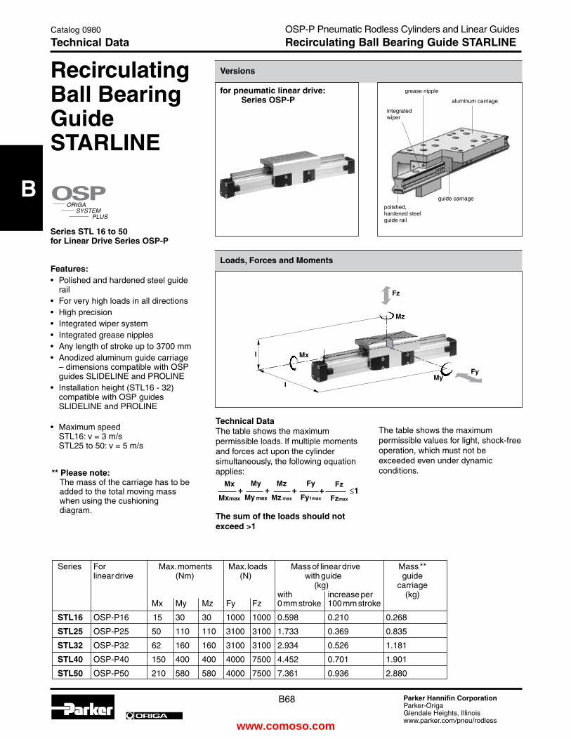
B68 Parker Hannifin CorporationParker-OrigaGlendale Heights, Illinoiswww.parker.com/pneu/rodless
ORIGA
B
Series For Max. moments Max. loads Mass of linear drive Mass ** linear drive (Nm) (N) with guide guide (kg) carriage with increase per (kg) Mx My Mz Fy Fz 0 mm stroke 100 mm stroke
StL16 OSP-P16 15 30 30 1000 1000 0.598 0.210 0.268
StL25 OSP-P25 50 110 110 3100 3100 1.733 0.369 0.835
StL32 OSP-P32 62 160 160 3100 3100 2.934 0.526 1.181
StL40 OSP-P40 150 400 400 4000 7500 4.452 0.701 1.901
StL50 OSP-P50 210 580 580 4000 7500 7.361 0.936 2.880
Recirculating Ball Bearing GuideStARLINe
Series StL 16 to 50for Linear Drive Series OSP-P
Features:• Polished and hardened steel guide rail• For very high loads in all directions• High precision• Integrated wiper system• Integrated grease nipples• Any length of stroke up to 3700 mm• Anodized aluminum guide carriage – dimensions compatible with OSP guides SLIDELINE and PROLINE• Installation height (STL16 - 32) compatible with OSP guides SLIDELINE and PROLINE • Maximum speed STL16: v = 3 m/s STL25 to 50: v = 5 m/s
technical DataThe table shows the maximum permissible loads. If multiple moments and forces act upon the cylinder simultaneously, the following equation applies:
the sum of the loads should not exceed >1
�����������
����
���
≤1Mz
Mz max
Fz
Fzmax
Mx
Mxmax
My
My max
Fy
Fy1max+ + + +
for pneumatic linear drive: Series OSP-P
Loads, Forces and Moments
Versions
grease nipple
��
��
��
��
��
�
�
integratedwiper
aluminum carriage
polished, hardened steel guide rail
guide carriage
** Please note: The mass of the carriage has to be added to the total moving mass when using the cushioning diagram.
The table shows the maximum permissible values for light, shock-free operation, which must not be exceeded even under dynamic conditions.
OSP-P Pneumatic Rodless Cylinders and Linear GuidesRecirculating Ball Bearing Guide StARLINe
Catalog 0980
technical Data
www.comoso.com

B69 Parker Hannifin CorporationParker-OrigaGlendale Heights, Illinoiswww.parker.com/pneu/rodless
ORIGA
B
� �
��
���
� �
��
��
��
��
��
��
��
��
��
��
��
��
��
��
��
��
Dimension table (mm) Series OSP-P StL16 to StL50
Series A B J M Z AA BB CF DD eC ee eG FF FS Ft GG JJ ZZ
StL16 65 14 69 31 M4 93 90 55 30 15 40 24.6 48 18 55 36 70 8
StL25 100 22 117 40.5 M6 146.6 144 72.5 60 15 53 36.2 64 23.2 73.5 50 120 12
StL32 125 25.5 152 49 M6 186.6 184 91 80 15 62 42.2 84 26.2 88 64 160 12
StL40 150 28 152 55 M6 231 226 102 100 20 72 51.6 94 28.5 106.5 78 200 12
StL50 175 33 200 62 M6 270.9 266 117 120 23 85 62.3 110 32.5 128.5 90 240 16
Dimensions Series OSP-P StL16 to StL 50
Stroke + 2x A
Stroke
type StL25 to PL50 type StL16
OSP-P Pneumatic Rodless Cylinders and Linear GuidesRecirculating Ball Bearing Guide StARLINe
Catalog 0980
Dimensions
www.comoso.com

B70 Parker Hannifin CorporationParker-OrigaGlendale Heights, Illinoiswww.parker.com/pneu/rodless
ORIGA
B
�
���
����
����
����
����
����
����
����
����
����
����
����
����
����
����
����
��� ��� ��� ��� ��� ��� ��� ��� ��� ��� ���
�����
�����
��
�
�
�
�
���
����
����
����
����
����
����
����
����
����
����
����
����
����
����
����
��� ��� ��� ��� ��� ��� ��� ��� ��� ��� ���
�����
�����
�� �
��
Mid-Section Support(For versions, see pages B76-B77)
Mid-section supports are required from a certain stroke length to prevent excessive deflection and vibration of the linear drive. The diagrams show the maximum permissible unsupported length in relation to loading. A distinction must be drawn between loading 1 and loading 2. Deflection of 0.5 mm max. between supports is permissible.
Note:For speeds v > 0.5 m/s the distance between supports should not exceed 1 m.
��
Load
F
Distance between supports
Permissible Unsupported Length StL16 to StL50
Loading 1 – Top carrier
Load
F
Distance between supports
Permissible Unsupported Length StL16 to StL50
Loading 2 – Side carrier
��
1 = OSP-P STL 16 2 = OSP-P STL 25 3 = OSP-P STL 32 4 = OSP-P STL 40 5 = OSP-P STL 50
1 = OSP-P STL 16 2 = OSP-P STL 25 3 = OSP-P STL 32 4 = OSP-P STL 40 5 = OSP-P STL 50
Loading 1 Top carrier
Loading 2Side carrier
��
OSP-P Pneumatic Rodless Cylinders and Linear GuidesRecirculating Ball Bearing Guide StARLINe
Catalog 0980
technical Data
www.comoso.com

B71 Parker Hannifin CorporationParker-OrigaGlendale Heights, Illinoiswww.parker.com/pneu/rodless
ORIGA
B
�
�
�
���������� �� ���
�
�
�
��� ��� � � � � �� �� �� ����� �
�����������
���
���
���
���
��� ������ ��� � � � � �
Shock Absorber Selection in Dependence on Mass and Speed for Series OSP-StL16
Spe
ed (
m/s
)
Mass (kg)
Shock Absorber Selection in Dependence on Mass and Speed for Series OSP-StL25
Spe
ed (
m/s
)
Mass (kg)
type SA10
type SA10S
type SA12
type SA12S
Variable Stop type VS16 to VS50
Stop
Shock absorber holder with shock absorber
Shock absorber with plastic cap
Arrangement with two variable stops
Variable StopThe variable stop Type VS provides simple stroke limitation.It can be retrofitted and positioned anywhere along the stroke length.For every cylinder diameter two types of shock absorber are available – see “Shock Absorber Selection” below.Mid-section supports and magnetic switches can still be fitted on the same side as the variable stop.Depending on the application, two variable stops can be fitted if required.
Shock Absorber SelectionThe shock absorber is selected in dependence on the mass and speed.The mass of the carrier itself must be taken into account.
The values relate to an effective driving force of 78 N (6 bar)
The values relate to an effective driving force of 250 N (6 bar)
OSP-P Pneumatic Rodless Cylinders and Linear GuidesRecirculating Ball Bearing Guide StARLINe
Catalog 0980
technical Data
www.comoso.com

B72 Parker Hannifin CorporationParker-OrigaGlendale Heights, Illinoiswww.parker.com/pneu/rodless
ORIGA
B
�
�
�
���������� �� ���
�
�
�
���
���
���
���
���
��� ������� ��� ��� � � � � �� �� ������
�
�
�
���������� �� ���
�
�
�
���
���
���
���
���
��� ���������� ��� � � � � �� �� ���
�
�
�
���������� �� ���
�
�
�
���
���
���
���
���
��� ��� ��� � � � � �� �� �� ��
Shock Absorber Selection in Dependence on Mass and Speed for Series OSP-StL32
Spe
ed (
m/s
)
Mass (kg)
Shock Absorber Selection in Dependence on Mass and Speed for Series OSP-StL40
Spe
ed (
m/s
)
Mass (kg)
Shock Absorber Selection in Dependence on Mass and Speed for Series OSP-StL50
Spe
ed (
m/s
)
Mass (kg)
type SA14
type SA14S
type SA20
type SA20S
type SAI25
type SAI25S
The values relate to an effective driving force of 420 N (6 bar)
The values relate to an effective driving force of 640 N (6 bar)
The values relate to an effective driving force of 1000 N (6 bar)
OSP-P Pneumatic Rodless Cylinders and Linear GuidesRecirculating Ball Bearing Guide StARLINe
Catalog 0980
technical Data
www.comoso.com
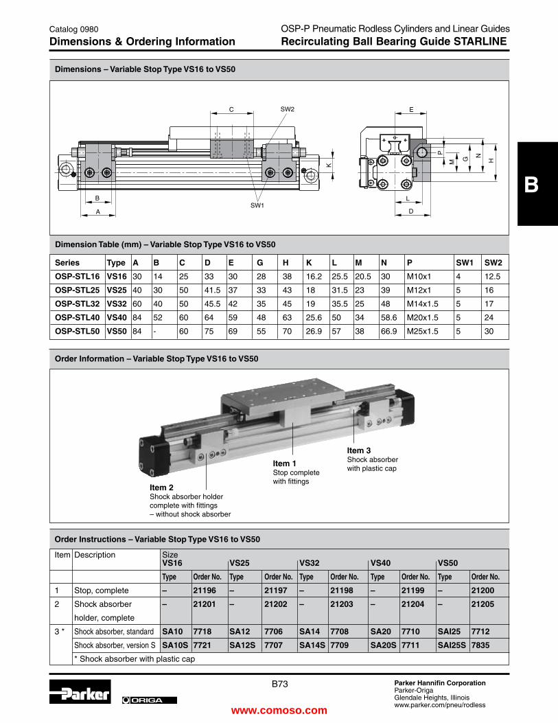
B73 Parker Hannifin CorporationParker-OrigaGlendale Heights, Illinoiswww.parker.com/pneu/rodless
ORIGA
B
Dimension table (mm) – Variable Stop type VS16 to VS50
Series type A B C D e G H K L M N P SW1 SW2
OSP-StL16 VS16 30 14 25 33 30 28 38 16.2 25.5 20.5 30 M10x1 4 12.5
OSP-StL25 VS25 40 30 50 41.5 37 33 43 18 31.5 23 39 M12x1 5 16
OSP-StL32 VS32 60 40 50 45.5 42 35 45 19 35.5 25 48 M14x1.5 5 17
OSP-StL40 VS40 84 52 60 64 59 48 63 25.6 50 34 58.6 M20x1.5 5 24
OSP-StL50 VS50 84 - 60 75 69 55 70 26.9 57 38 66.9 M25x1.5 5 30
Dimensions – Variable Stop type VS16 to VS50
Order Instructions – Variable Stop type VS16 to VS50
Item Description Size VS16 VS25 VS32 VS40 VS50
type Order No. type Order No. type Order No. type Order No. type Order No.
1 Stop, complete – 21196 – 21197 – 21198 – 21199 – 21200
2 Shock absorber – 21201 – 21202 – 21203 – 21204 – 21205
holder, complete
3 * Shock absorber, standard SA10 7718 SA12 7706 SA14 7708 SA20 7710 SAI25 7712
Shock absorber, version S SA10S 7721 SA12S 7707 SA14S 7709 SA20S 7711 SAI25S 7835
* Shock absorber with plastic cap
Order Information – Variable Stop type VS16 to VS50
�
�
�
�
�
�
�
�
�
� �
�
���
���
Item 1Stop completewith fittings
Item 2Shock absorber holder complete with fittings– without shock absorber
Item 3Shock absorber with plastic cap
OSP-P Pneumatic Rodless Cylinders and Linear GuidesRecirculating Ball Bearing Guide StARLINe
Catalog 0980
Dimensions & Ordering Information
www.comoso.com

B74 Parker Hannifin CorporationParker-OrigaGlendale Heights, Illinoiswww.parker.com/pneu/rodless
ORIGA
B
Dimension table (mm) for end Cap Mounting type: B1 to B5 Series Mounting e ØU AB AC AD Ae AF CL DG Order No. type (pair)
OSP-P StL16 B1 18 3.6 18 10 14 28 15 2 26 21135 OSP-P KF16 B2 18 3.6 18 10 14 43 30 17 26 21136 B3 18 3.6 18 10 14 55 42 29 26 21137 OSP-P StL25 B1 27 5.8 27 16 22 42 22 2.5 39 20311 OSP-P KF25 B2 27 5.8 27 16 22 57 37 17.5 39 21138 B3 27 5.8 27 16 22 69 49 29.5 39 21139 OSP-P StL32 B1 36 6.6 36 18 26 55 30 3 50 20313 OSP-P KF32 B2 36 6.6 36 18 26 69 44 17 50 21140 B5 36 6.6 36 18 26 90 65 9 50 21141
Type B1
Type B3 – Ø 16Type B3 – Ø 25Type B5 – Ø 32
Type B2
OSP-P Pneumatic Rodless Cylinders and Linear GuidesLinear Drive Accessories
Catalog 0980
end Cap Mounting type B
Linear DriveAccessoriesØ 16 to 32 mmend Cap Mountingtype: B
for Linear Drives with Recirculating Ball Bearing Guide
• SeriesOSP-PSTL• SeriesOSP-PKF
Material: Galvanized steelAnodized aluminum
The mountings are supplied in pairs.
Series OSP-P StL16, StL25, StL32: type B3 (Ø 32:B5)Series OSP-P KF16, KF25, KF32: type B3 (Ø 32:B5)Installation: Side carrierPiston below
Series OSP-P StL16, StL25, StL32: type B2Series OSP-P KF16, KF25, KF32: type B2Installation: Side carriertop piston
Drawing shows: Mounting with Guide Type STL
Drawing shows: Mounting with Guide Type STL
Series OSP-P StL40, StL50: type C1Series OSP-P KF40, KF50: type C1
Installation:
top carrier Side piston
Drawing shows: Mounting with Guide Type STL
www.comoso.com

B75 Parker Hannifin CorporationParker-OrigaGlendale Heights, Illinoiswww.parker.com/pneu/rodless
ORIGA
B
Ø 40 to 50 mmend Cap Mountingtype: C
for Linear Drives with Recirculating Ball Bearing Guide
• SeriesOSP-PSTL• SeriesOSP-PKF
Material:Anodized aluminum
The mountings are supplied in pairs.
Type C1
Type C4 – Ø 40Type C3 – Ø 50
Type C2
Dimension table (mm) for end Cap Mounting type: C1 to C4 Series Mounting e ØU AB AC AD Ae AF DG Order No. type (pair)
OSP-P StL40 C1 54 9 30 12.5 24 24 38 68 4010 OSP-P KF40 C2 54 9 30 12.5 24 37 51 68 20338 C4 54 9 30 12.5 24 56 70 68 20340 OSP-P StL50 C1 70 9 40 12.5 24 30 48 86 5010 OSP-P KF50 C2 70 9 40 12.5 24 39 57 86 20349 C3 70 9 40 12.5 24 54 72 86 20350
OSP-P Pneumatic Rodless Cylinders and Linear GuidesLinear Drive Accessories
Catalog 0980
end Cap Mounting type C
Series OSP-P StL40, StL50: type C4 (Ø 50: C3)Series OSP-P KF40, KF50: type C4 (Ø 50: C3)Installation: Side carrierPiston below
Series OSP-P StL40, StL50: type C1Series OSP-P KF40, KF50: type C1Installation: top carrierSide piston
Series OSP-P StL40, StL50: type C2Series OSP-P KF40, KF50: type C2Installation: Side carriertop piston
Drawing shows: Mounting with Guide Type STL
Drawing showes: Mounting with Guide Type STL
Drawing showes: Mounting with Guide Type STL
www.comoso.com

B76 Parker Hannifin CorporationParker-OrigaGlendale Heights, Illinoiswww.parker.com/pneu/rodless
ORIGA
B
Type E1ST
Linear DriveAccessoriesØ 16 to 50Mid-Section Supporttype: D1St for Linear Drives with Recirculating Ball Bearing Guide
• SeriesOSP-PSTL• SeriesOSP-PKF
Note on Types D1STThe mid-section support can also be moun ted on the underside of the actuator, in which case its distance from the center of the actuator is different.
For design notes, see pageB70 (Series OSP-P STL)B81 (Series OSP-P KF)
Series Mounting R AF De DH DL DO DP Dt eM eQ Order No. OSP-P ..... type
StL/KF16 D1St M3 15 14.2 29.2 14.6 18 30 6.5 20 27 21125 StL/KF25 D1St M5 22 16 38 13 36 50 10 28.5 36 21126 StL/KF32 D1St M5 30 16 46 13 36 60 10 35.5 43 21127 StL/KF40 D1St M6 38 23 61 19 45 60 11 38 48 21128 StL/KF50 D1St M6 48 23 71 19 45 60 11 45 57 21129 Order example: type D1St16 Order No. 21125
Dimension table (mm) Mid-Section Support D1St
Mid-Section Supporttype: e1St to e5St
for Linear Drives with Recirculating Ball Bearing Guide
• SeriesOSP-PSTL• SeriesOSP-PKF
Mountings from below with 2 screws
Mounting from above / below using a cap screw
OSP-P Pneumatic Rodless Cylinders and Linear GuidesLinear Drive Accessories
Catalog 0980
Mid-Section Support type D1St
Series OSP-P StL16 to StL50: type D1St Series OSP-P KF16 to KF50: type D1St
Drawing shows: Mounting with Guide Type STL
Series OSP-P StL16 to StL50: type e1St Series OSP-P KF16 to KF50: type e1St
Installation: top carrierSide position
Drawing shows: Mounting with Guide Type STL
www.comoso.com

B77 Parker Hannifin CorporationParker-OrigaGlendale Heights, Illinoiswww.parker.com/pneu/rodless
ORIGA
B
Series Mounting ØU ØUU AF De DH DK DM DN DO DP DR DQ DS eF eN eQ Order OSP-P ..... type No. StL/KF16 e1St 3.4 6 15 14.2 29.2 24 32 36.4 18 30 6 27 3.4 32 36.4 27 21130 StL/KF16 e2St 3.4 6 30 14.2 29.2 24 32 36.4 18 30 21 27 3.4 32 36.4 27 21142 StL/KF25 e1St 5.5 10 22 16 38 26 40 47.5 36 50 8 34.5 5.7 41.5 49 36 21131 StL/KF25 e2St 5.5 10 37 16 38 26 40 47.5 36 50 23 34.5 5.7 41.5 49 36 21143 StL/KF25 e3St 5.5 10 49 16 38 26 40 47.5 36 50 35 34.5 5.7 41.5 49 36 21148 StL/KF32 e1St 5.5 10 30 16 46 27 46 54.5 36 60 10 40.5 5.7 48.5 57 43 21132 StL/KF32 e2St 5.5 10 44 16 46 27 46 54.5 36 60 24 40.5 5.7 48.5 57 43 21144 StL/KF32 e5St 5.5 10 65 16 46 27 46 54.5 36 60 45 40.5 5.7 48.5 57 43 21151 StL/KF40 e1St 7 - 38 23 61 34 53 60 45 60 10 45 - 56 63 48 21133 StL/KF40 e2St 7 - 51 23 61 34 53 60 45 60 23 45 - 56 63 48 21145 StL/KF40 e4St 7 - 70 23 61 34 53 60 45 60 42 45 - 56 63 48 21150 StL/KF50 e1St 7 - 48 23 71 34 59 67 45 60 10 52 - 64 72 57 21134 StL/KF50 e2St 7 - 57 23 71 34 59 67 45 60 19 52 - 64 72 57 21146 StL/KF50 e3St 7 - 72 23 71 34 59 67 45 60 34 52 - 64 72 57 21149 Order example: type e1St16 Order No. 21130
Dimension table (mm) for Mid-Section Support e1St to e5St
Series OSP-P StL25 to StL50: type e3St, e4St, e5St Series OSP-P StL25 to StL50: type e3St, e4St, e5St
Installation: Side carrierPiston below
Type E3ST – Ø25Type E5ST – Ø32Type E4ST – Ø40Type E3ST – Ø50
Type E2STType E2ST
Mid-Section Supporttype: e1St to e5St
for Linear Drives with Recirculating Ball Bearing Guide
• SeriesOSP-PSTL• SeriesOSP-PKF
Mounting from above / below using a cap screw
Mounting from above / below using a cap screwMounting from above / below using a cap screw
OSP-P Pneumatic Rodless Cylinders and Linear GuidesLinear Drive Accessories
Catalog 0980
Mid-Section Support type e1St - e5St
Series OSP-P StL16 to StL50: type e2St Series OSP-P KF16 to KFL50: type e2St
Installation: Side carriertop piston
Drawing shows: Mounting with Guide Type STL
Drawing shows: Mounting with Guide Type STL
www.comoso.com

B78 Parker Hannifin CorporationParker-OrigaGlendale Heights, Illinoiswww.parker.com/pneu/rodless
ORIGA
B
Ordering Instructions / Part Numbering System for OSP-P StARLINe Series
Catalog 0980
Ordering InformationOSP-P Pneumatic Rodless Cylinders and Linear GuidesRecirculating Ball Bearing Guide StARLINe
Bore1625324050
Piston Style0 Standard1 TandemS Special
Air Connections / Porting0 Standard (position #2)1 end face (position #5)2 single end porting3 left stand (pos #2),
right end face (pos#5)4 right stand (pos #2),
left end face (pos #5)6 single end porting end faceA 3/2 Way valve VOE
24V = (25,32,40,50)B 3/2 Way valve VOE
220V~/110V= (25,32,40,50)C 3/2 Way valve VOE
48V=(25,32,40,50)e 3/2 Way valve VOE
110V~ (25,32,40,50)S Special
Note: Single End Porting on 16mm bore, then end caps cannot be rotated.
Seals0 Standard1 VitonS Special
Corrosion Resist, Hardware
0 Standard1 StainlessS Special
Strokex x x x x
end Cap Position0 l+r 0° = in front (pos #2)1 l+r 90° = underneath (pos #3)2 l+r 180° = at the back (pos # 4)3 l+r 270° = same face as outerband (pos #2,1)4 l 90° = underneath; r 0° = in front (pos #3,2)5 l 180° = at the back; r 0° = in front (pos #4,2)6 l 270° = same face as outerband; r 0° = in front (pos #1,2)7 l 0° = in front; r 90° = underneath (pos #2, 3)8 l 180° = at the back; r 90° = underneath (pos #4,3)9 l 270° = same face as outerband; r 90° = underneath (pos #1,3)A l 0° = in front; r 180° = at the back (pos #2,4)B l 90° = underneath; r 180° = at the back (pos #3,4)C l 270° = same face as outerband; r 180° = at the back (pos #1,4)D l 0° = in front; r 270° = same face as outerband (pos #2,1)e l 90° = underneath; r 270° = same face as outerband (pos #3,1)F l 180° = at the back; r 270° = same face as outerband (pos #4,1)S Special
Guides / BrakesB STL Starline
add. Carriage0 withoutB Guide Carriage Starline STL
Dovetail Cover
0 StandardX Without
Cover Rail
S Special
Version
end Cap Mounts0 without4 B1 (16,25,32)5 B2 (16,25,32)6 B3 (16,25)8 B5 (32)9 C1 (40,50)A C2 (40,50)B C3 (50)C C4 (40)
Note: Comes in pairs
OSPP 32 0 0 0 0 0 02500 0 2 0 B 0 0 0 0 0
6 7 8 9 10 11 12-16 17 18 19 20 21 22 23 24 25
Piston Mountings0 none
Cushioning / Stops0 Standard2 VS soft left3 VS hard left4 VS soft right5 VS hard right6 VS soft both sides7 VS hard both sidesS Special
Lubrication0 Standard1 Slow Speed4 Food 5 Clean RoomS Special
Switches /Measuring
System0 none1 NO Reed-
KL3045 Qty. 22 NC Reed-
KL3048 Qty. 23 PNP
KL3054+4041 Qty. 2
4 NPN KL3060+4041 Qty. 2
X 21240 SFI 0,1mm
Y 21241 SFI 1mm
Z 4650 SFAS Special
Note: 2 switches will be supplied. For different quantity, please order as a separate line item.
1
2
3
4
5
Note: Position #2 is the standard location.
www.comoso.com
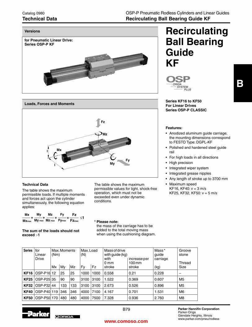
B79 Parker Hannifin CorporationParker-OrigaGlendale Heights, Illinoiswww.parker.com/pneu/rodless
ORIGA
B
for Pneumatic Linear Drive: Series OSP-P KF
technical Data
The table shows the maximum permissible loads. If multiple moments and forces act upon the cylinder simultaneously, the following equation applies:
Loads, Forces and Moments
Versions
the sum of the loads should not exceed >1
Series for Max. Moments Max. Load Mass of drive Mass * Groove Linear (Nm) (N) with guide (kg) guide stone Drive with increase per carriage 0 mm 100 mm Thread Mx My Mz Fy Fz stroke stroke (kg) Size
KF16 OSP-P16 12 25 25 1000 1000 0.558 0.21 0.228 –
KF25 OSP-P25 35 90 90 3100 3100 1.522 0.369 0.607 M5
KF32 OSP-P32 44 133 133 3100 3100 2.673 0.526 0.896 M5
KF40 OSP-P40 119 346 346 4000 7100 4.167 0.701 1.531 M6
KF50 OSP-P50 170 480 480 4000 7500 7.328 0.936 2.760 M8
The table shows the maximum permissible values for light, shock-freeoperation, which must not be exceeded even under dynamic conditions.
* Please note: the mass of the carriage has to be added to the total moving mass when using the cushioning diagram.
Recirculating Ball Bearing Guide KF
Series KF16 to KF50For Linear Drives Series OSP-P CLASSIC
Features:• Anodized aluminum guide carriage,
the mounting dimensions correspond to FESTO Type: DGPL-KF
• Polished and hardened steel guide rail
• For high loads in all directions• High precision• Integrated wiper system• Integrated grease nipples• Any length of stroke up to 3700 mm• Maximum speed
KF16, KF40: v = 3 m/s KF25, KF32, KF50: v = 5 m/s
�����������
����
���
≤1Mz
Mz max
Fz
Fzmax
Mx
Mxmax
My
My max
Fy
Fymax+ + + +
��
��
��
��
��
�
�
OSP-P Pneumatic Rodless Cylinders and Linear GuidesRecirculating Ball Bearing Guide KF
Catalog 0980
technical Data
www.comoso.com

B80 Parker Hannifin CorporationParker-OrigaGlendale Heights, Illinoiswww.parker.com/pneu/rodless
ORIGA
B
Dimension table (mm) Series OSP-P KF16, KF25, KF32, KF40, KF50 Series A B J AA BB CF DD eC ee eG eW JJ GG M KF16 65 14 76 93 85 48 50 15 41 24.6 10 – 25 30 KF25 100 22 120 120.2 105 72.5 40 15 54.5 36.2 23.5 – – 46 KF32 125 25.5 160 146.2 131 93.8 40 15 60.5 42.2 23.5 – 20 59.8 KF40 150 28 150 188.5 167 103.3 40 20 69.5 51.6 26.5 120 20 60.8 KF50 175 33 180 220.2 202 121 40 23 90.5 62.3 32.5 120 40 69
Stroke + 2x A
Stroke
Series FA FB FC FD Ft FS tA tB te tF tG tH tJ tK KF16 17.7 29 16.5 – 56 19 – – – – – – – – KF25 26.5 39 24 14 G7 75 24.7 5 12.1 2.3 6.9 M5 11.5 4 32 KF32 34 53.8 34 25 G7 86.5 24.7 5 12.1 1.8 6.4 M5 11.5 4 47 KF40 42.5 56.8 41 25 G7 104 26 6 12.8 1.8 8.4 M6 17 5.5 55 KF50 52 65 50 25 G7 134 38 8 21.1 4.5 12.5 M8 23 7.5 72
Partial view A(with T-nut)
T-nut
6 x M4,10 deep
2 x M5,10 deep
2 x ∅5H7, 3 deep
Size OSP-P KF25
Size OSP-P KF32 to KF50
Size OSP-P KF16
Dimensions Series OSP-P KF16 to KF50
OSP-P Pneumatic Rodless Cylinders and Linear GuidesRecirculating Ball Bearing Guide KF
Catalog 0980
Dimensions
�
����
���
��
���
�
�
��
��
��
�
�� ��
��
��
��
�
��
��
��
��
�
��
��
��
�� �
�
��
��
��
��
��
��
��
��
��
��
��
����
����
��
�
www.comoso.com

B81 Parker Hannifin CorporationParker-OrigaGlendale Heights, Illinoiswww.parker.com/pneu/rodless
ORIGA
B
�
���
����
����
����
����
����
����
����
����
����
����
����
����
����
����
����
��� ��� ��� ��� ��� ��� ��� ��� ��� ��� ���
�����
�����
�
�
�
�
�
�
���
����
����
����
����
����
����
����
����
����
����
����
����
����
����
����
��� ��� ��� ��� ��� ��� ��� ��� ��� ��� ���
�����
�����
��
�� �
Load
F
Distance between supports
Permissible Unsupported Length OSP-P KF16 to KF50
1 = OSP-P KF162 = OSP-P KF253 = OSP-P KF324 = OSP-P KF405 = OSP-P KF50
Loading 1 – Top carrier
Load
F
Distance between supports
Permissible Unsupported Length OSP-P KF16 to KF50
1 = OSP-P KF162 = OSP-P KF253 = OSP-P KF324 = OSP-P KF405 = OSP-P KF50
Loading 2 – Side carrier
Mid-Section Support(For versions, see pages B87-B88)Mid-section supports are required from a certain stroke length to prevent excessive deflection and vibration of the linear drive. The diagrams show the maximum permissible unsupported length in relation to loading. A distinction must be drawn between loading 1 and loading 2. Deflection of 0.5 mm max. between supports is permissible.
Note:For speeds v > 0.5 m/s the distance between supports should not exceed 1 m.
Loading 1 Top carrier
��
Loading 2Side carrier
��
����
OSP-P Pneumatic Rodless Cylinders and Linear GuidesRecirculating Ball Bearing Guide KF
Catalog 0980
technical Data
www.comoso.com

B82 Parker Hannifin CorporationParker-OrigaGlendale Heights, Illinoiswww.parker.com/pneu/rodless
ORIGA
B
Shock Absorber Selection in Dependence on Mass and Speed for Series OSP-KF16
Spe
ed (
m/s
)
Mass (kg)
Shock Absorber Selection in Dependence on Mass and Speed for Series OSP-KF25
Spe
ed (
m/s
)
Mass (kg)
Variable Stop type VS16 to VS50
Stop
Shock absorber holder with shock absorber
Shock absorber with plastic cap
Arrangement with two variable stops
Variable StopThe variable stop Type VS provides simple stroke limitation.It can be retrofitted and positioned anywhere along the stroke length. For every cylinder diameter two types of shock absorber are available – see “Shock Absorber Selection” below.Mid-section supports and magnetic switches can still be fitted on the same side as the variable stop.Depending on the application, two variable stops can be fitted if required.
Shock Absorber SelectionThe shock absorber is selected in dependence on the mass and speed.The mass of the carrier itself must be taken into account.
The values relate to an effective driving force of 78 N (6 bar)
The values relate to an effective driving force of 250 N (6 bar)
�����������
���
���
���
���
��� ������ ��� � � � � �
type SA10SN
type SA10S2N
�
�
�
���������� �� ���
�
��� � � � � �� �� ����� ���
���
���
���
typ SA12S2N
typ SA12S
OSP-P Pneumatic Rodless Cylinders and Linear GuidesRecirculating Ball Bearing Guide KF
Catalog 0980
technical Data
www.comoso.com
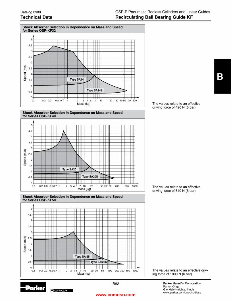
B83 Parker Hannifin CorporationParker-OrigaGlendale Heights, Illinoiswww.parker.com/pneu/rodless
ORIGA
B
OSP-P Pneumatic Rodless Cylinders and Linear GuidesRecirculating Ball Bearing Guide KF
Catalog 0980
technical Data
�
�
�
���������� �� ���
�
�
�
���
���
���
���
���
��� ������� ��� ��� � � � � �� �� ������
�
�
�
���������� �� ���
�
�
�
���
���
���
���
���
��� ���������� ��� � � � � �� �� ���
�
�
�
���������� �� ���
�
�
�
���
���
���
���
���
��� ��� ��� � � � � �� �� �� ��
Shock Absorber Selection in Dependence on Mass and Speed for Series OSP-KF32
Spe
ed (
m/s
)
Mass (kg)
Shock Absorber Selection in Dependence on Mass and Speed for Series OSP-KF40
Spe
ed (
m/s
)
Mass (kg)
Shock Absorber Selection in Dependence on Mass and Speed for Series OSP-KF50
Spe
ed (
m/s
)
Mass (kg)
type SA14
type SA14S
type SA20
type SA20S
type SAI25
type SAI25S
The values relate to an effective driving force of 420 N (6 bar)
The values relate to an effective driving force of 640 N (6 bar)
The values relate to an effective driv-ing force of 1000 N (6 bar)
www.comoso.com

B84 Parker Hannifin CorporationParker-OrigaGlendale Heights, Illinoiswww.parker.com/pneu/rodless
ORIGA
B
Dimensions – Variable Stop type VS16 to VS50
Order Instructions – Variable Stop type VS16 to VS50
Item Description Size VS16 VS25 VS32 VS40 VS50
type Order No. type Order No. type Order No. type Order No. type Order No.
1 Stop, complete – 21186 – 21187 – 21188 – 21189 – 21190
2 Shock absorber – 21201 – 21202 – 21203 – 21204 – 21205
holder, complete
3 * Shock absorber, standard SA10SN 7718 SA12S2N 7723 SA14 7708 SA20 7710 SAI25 7712
Shock absorber, version S SA10S2N 7721 SA12S 7707 SA14S 7709 SA20S 7711 SAI25S 7713
* Shock absorber with plastic cap
Order Information – Variable Stop type VS16 to VS50
Item 1Stop completewith fittings
Item 2Shock absorber holder complete with fittings– without shock absorber
Item 3Shock absorber with plastic cap
Dimension table (mm) – Variable Stop type VS16 to VS50
Series type A B C C1 D e G H K L M N P SW1 SW2
OSP-KF16 VS16 30 14 50 25 33 29.7 28 38 16.2 25.5 20.5 40.5 M10 x 1 4 12.5
OSP-KF25 VS25 40 30 75 50 41.5 37 33 43 18 31.5 23 48 M12 x 1 5 16
OSP-KF32 VS32 60 40 50 - 45.5 41.5 35 45 19 35.5 25 37 M14 x 1.5 5 17
OSP-KF40 VS40 84 52 60 - 64 59 48 63 25.5 50 34 43 M20 x 1.5 5 24
OSP-KF50 VS50 84 - 60 - 75 69 55 70 26.9 57 38 58 M25 x 1.5 5 30�
�
�
�
�� �
�
�
� � �
�
�
���
���
OSP-P Pneumatic Rodless Cylinders and Linear GuidesRecirculating Ball Bearing Guide KF
Catalog 0980
Dimensions & Ordering Information
www.comoso.com
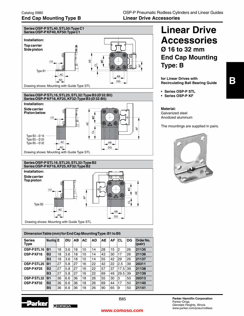
B85 Parker Hannifin CorporationParker-OrigaGlendale Heights, Illinoiswww.parker.com/pneu/rodless
ORIGA
B
Dimension table (mm) for end Cap Mounting type: B1 to B5 Series Mounting e ØU AB AC AD Ae AF CL DG Order No. type (pair)
OSP-P StL16 B1 18 3.6 18 10 14 28 15 2 26 21135 OSP-P KF16 B2 18 3.6 18 10 14 43 30 17 26 21136 B3 18 3.6 18 10 14 55 42 29 26 21137 OSP-P StL25 B1 27 5.8 27 16 22 42 22 2.5 39 20311 OSP-P KF25 B2 27 5.8 27 16 22 57 37 17.5 39 21138 B3 27 5.8 27 16 22 69 49 29.5 39 21139 OSP-P StL32 B1 36 6.6 36 18 26 55 30 3 50 20313 OSP-P KF32 B2 36 6.6 36 18 26 69 44 17 50 21140 B5 36 6.6 36 18 26 90 65 9 50 21141
Type B1
Type B3 – Ø 16Type B3 – Ø 25Type B5 – Ø 32
Type B2
OSP-P Pneumatic Rodless Cylinders and Linear GuidesLinear Drive Accessories
Catalog 0980
end Cap Mounting type B
Linear DriveAccessoriesØ 16 to 32 mmend Cap Mountingtype: B
for Linear Drives with Recirculating Ball Bearing Guide
• SeriesOSP-PSTL• SeriesOSP-PKF
Material: Galvanized steelAnodized aluminum
The mountings are supplied in pairs.
Series OSP-P StL16, StL25, StL32: type B3 (Ø 32:B5)Series OSP-P KF16, KF25, KF32: type B3 (Ø 32:B5)Installation: Side carrierPiston below
Series OSP-P StL16, StL25, StL32: type B2Series OSP-P KF16, KF25, KF32: type B2Installation: Side carriertop piston
Drawing shows: Mounting with Guide Type STL
Drawing shows: Mounting with Guide Type STL
Series OSP-P StL40, StL50: type C1Series OSP-P KF40, KF50: type C1
Installation:
top carrier Side piston
Drawing shows: Mounting with Guide Type STL
www.comoso.com
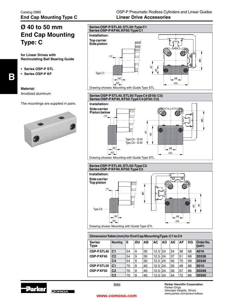
B86 Parker Hannifin CorporationParker-OrigaGlendale Heights, Illinoiswww.parker.com/pneu/rodless
ORIGA
B
Ø 40 to 50 mmend Cap Mountingtype: C
for Linear Drives with Recirculating Ball Bearing Guide
• SeriesOSP-PSTL• SeriesOSP-PKF
Material:Anodized aluminum
The mountings are supplied in pairs.
Type C1
Type C4 – Ø 40Type C3 – Ø 50
Type C2
Dimension table (mm) for end Cap Mounting type: C1 to C4 Series Mounting e ØU AB AC AD Ae AF DG Order No. type (pair)
OSP-P StL40 C1 54 9 30 12.5 24 24 38 68 4010 OSP-P KF40 C2 54 9 30 12.5 24 37 51 68 20338 C4 54 9 30 12.5 24 56 70 68 20340 OSP-P StL50 C1 70 9 40 12.5 24 30 48 86 5010 OSP-P KF50 C2 70 9 40 12.5 24 39 57 86 20349 C3 70 9 40 12.5 24 54 72 86 20350
OSP-P Pneumatic Rodless Cylinders and Linear GuidesLinear Drive Accessories
Catalog 0980
end Cap Mounting type C
Series OSP-P StL40, StL50: type C4 (Ø 50: C3)Series OSP-P KF40, KF50: type C4 (Ø 50: C3)Installation: Side carrierPiston below
Series OSP-P StL40, StL50: type C1Series OSP-P KF40, KF50: type C1Installation: top carrierSide piston
Series OSP-P StL40, StL50: type C2Series OSP-P KF40, KF50: type C2Installation: Side carriertop piston
Drawing shows: Mounting with Guide Type STL
Drawing showes: Mounting with Guide Type STL
Drawing showes: Mounting with Guide Type STL
www.comoso.com

B87 Parker Hannifin CorporationParker-OrigaGlendale Heights, Illinoiswww.parker.com/pneu/rodless
ORIGA
B
Type E1ST
Linear DriveAccessoriesØ 16 to 50Mid-Section Supporttype: D1St for Linear Drives with Recirculating Ball Bearing Guide
• SeriesOSP-PSTL• SeriesOSP-PKF
Note on Types D1STThe mid-section support can also be moun ted on the underside of the actuator, in which case its distance from the center of the actuator is different.
For design notes, see pageB70 (Series OSP-P STL)B81 (Series OSP-P KF)
Series Mounting R AF De DH DL DO DP Dt eM eQ Order No. OSP-P ..... type
StL/KF16 D1St M3 15 14.2 29.2 14.6 18 30 6.5 20 27 21125 StL/KF25 D1St M5 22 16 38 13 36 50 10 28.5 36 21126 StL/KF32 D1St M5 30 16 46 13 36 60 10 35.5 43 21127 StL/KF40 D1St M6 38 23 61 19 45 60 11 38 48 21128 StL/KF50 D1St M6 48 23 71 19 45 60 11 45 57 21129 Order example: type D1St16 Order No. 21125
Dimension table (mm) Mid-Section Support D1St
Mid-Section Supporttype: e1St to e5St
for Linear Drives with Recirculating Ball Bearing Guide
• SeriesOSP-PSTL• SeriesOSP-PKF
Mountings from below with 2 screws
Mounting from above / below using a cap screw
OSP-P Pneumatic Rodless Cylinders and Linear GuidesLinear Drive Accessories
Catalog 0980
Mid-Section Support type D1St
Series OSP-P StL16 to StL50: type D1St Series OSP-P KF16 to KF50: type D1St
Drawing shows: Mounting with Guide Type STL
Series OSP-P StL16 to StL50: type e1St Series OSP-P KF16 to KF50: type e1St
Installation: top carrierSide position
Drawing shows: Mounting with Guide Type STL
www.comoso.com

B88 Parker Hannifin CorporationParker-OrigaGlendale Heights, Illinoiswww.parker.com/pneu/rodless
ORIGA
B
Series Mounting ØU ØUU AF De DH DK DM DN DO DP DR DQ DS eF eN eQ Order OSP-P ..... type No. StL/KF16 e1St 3.4 6 15 14.2 29.2 24 32 36.4 18 30 6 27 3.4 32 36.4 27 21130 StL/KF16 e2St 3.4 6 30 14.2 29.2 24 32 36.4 18 30 21 27 3.4 32 36.4 27 21142 StL/KF25 e1St 5.5 10 22 16 38 26 40 47.5 36 50 8 34.5 5.7 41.5 49 36 21131 StL/KF25 e2St 5.5 10 37 16 38 26 40 47.5 36 50 23 34.5 5.7 41.5 49 36 21143 StL/KF25 e3St 5.5 10 49 16 38 26 40 47.5 36 50 35 34.5 5.7 41.5 49 36 21148 StL/KF32 e1St 5.5 10 30 16 46 27 46 54.5 36 60 10 40.5 5.7 48.5 57 43 21132 StL/KF32 e2St 5.5 10 44 16 46 27 46 54.5 36 60 24 40.5 5.7 48.5 57 43 21144 StL/KF32 e5St 5.5 10 65 16 46 27 46 54.5 36 60 45 40.5 5.7 48.5 57 43 21151 StL/KF40 e1St 7 - 38 23 61 34 53 60 45 60 10 45 - 56 63 48 21133 StL/KF40 e2St 7 - 51 23 61 34 53 60 45 60 23 45 - 56 63 48 21145 StL/KF40 e4St 7 - 70 23 61 34 53 60 45 60 42 45 - 56 63 48 21150 StL/KF50 e1St 7 - 48 23 71 34 59 67 45 60 10 52 - 64 72 57 21134 StL/KF50 e2St 7 - 57 23 71 34 59 67 45 60 19 52 - 64 72 57 21146 StL/KF50 e3St 7 - 72 23 71 34 59 67 45 60 34 52 - 64 72 57 21149 Order example: type e1St16 Order No. 21130
Dimension table (mm) for Mid-Section Support e1St to e5St
Series OSP-P StL25 to StL50: type e3St, e4St, e5St Series OSP-P StL25 to StL50: type e3St, e4St, e5St
Installation: Side carrierPiston below
Type E3ST – Ø25Type E5ST – Ø32Type E4ST – Ø40Type E3ST – Ø50
Type E2ST
Mid-Section Supporttype: e1St to e5St
for Linear Drives with Recirculating Ball Bearing Guide
• SeriesOSP-PSTL• SeriesOSP-PKF
Mounting from above / below using a cap screw
Mounting from above / below using a cap screwMounting from above / below using a cap screw
OSP-P Pneumatic Rodless Cylinders and Linear GuidesLinear Drive Accessories
Catalog 0980
Mid-Section Support type e1St - e5St
Series OSP-P StL16 to StL50: type e2St Series OSP-P KF16 to KFL50: type e2St
Installation: Side carriertop piston
Drawing shows: Mounting with Guide Type STL
Drawing shows: Mounting with Guide Type STL
www.comoso.com

B89 Parker Hannifin CorporationParker-OrigaGlendale Heights, Illinoiswww.parker.com/pneu/rodless
ORIGA
B
��
�� ����
��
��
��
��
��
���
Linear DriveAccessories
Ø 25-50 mmend Cap Mountingcorrespond to FeStO dimensionsHP25 – 50
for Linear Drives with Recirculating Ball Bearing Guide
• SeriesOSP-PKF
On the end-face of each end cap there are four threaded holes for mounting the actuator.
Material:Series OSP-P KF25 – 50:Anodized aluminum.
The mountings are supplied in pairs.
Series OSP-P KF25 to KF50: type HP (Correspond to FeStO dimensions)
Dimension table (mm)
Series ØU AB AC AD AE AF DG DS FT ØUU Order No.
HP25 5.5 32.5 13 19 20 21 44 2 75.5 10 21107
HP32 6.6 38 17 24 24 27 52 3 87.5 11 21108
HP40 6.6 45 17.5 24 24 35 68 2 104.5 11 21109
HP50 9 65 25 35 35 48 86 6 138.5 15 21110
Note:Correspond to FESTO DGPL-KF, when the End Cap Mountings HP are mounted on the opposite side to the carriage(see drawing)
OSP-P Pneumatic Rodless Cylinders and Linear GuidesLinear Drive Accessories
Catalog 0980
end Cap Mountings
www.comoso.com
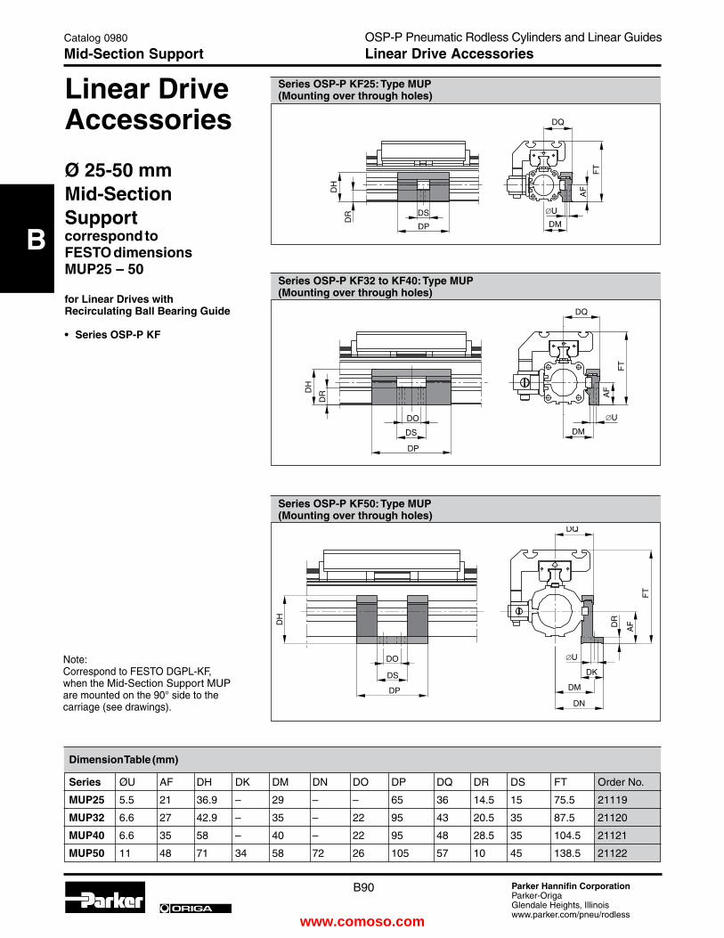
B90 Parker Hannifin CorporationParker-OrigaGlendale Heights, Illinoiswww.parker.com/pneu/rodless
ORIGA
B
Series OSP-P KF25: type MUP (Mounting over through holes)
��
��
�� ��
��
��
��
��
��
��
��
��
��
��
��
��
��
��
��
��
��
��
��
��
��
��
��
��
��
��
��
Series OSP-P KF32 to KF40: type MUP (Mounting over through holes)
Series OSP-P KF50: type MUP (Mounting over through holes)
Linear DriveAccessories
Ø 25-50 mmMid-Section Supportcorrespond to FeStO dimensionsMUP25 – 50
for Linear Drives with Recirculating Ball Bearing Guide
• SeriesOSP-PKF
Dimension table (mm)
Series ØU AF DH DK DM DN DO DP DQ DR DS FT Order No.
MUP25 5.5 21 36.9 – 29 – – 65 36 14.5 15 75.5 21119
MUP32 6.6 27 42.9 – 35 – 22 95 43 20.5 35 87.5 21120
MUP40 6.6 35 58 – 40 – 22 95 48 28.5 35 104.5 21121
MUP50 11 48 71 34 58 72 26 105 57 10 45 138.5 21122
Note:Correspond to FESTO DGPL-KF, when the Mid-Section Support MUP are mounted on the 90° side to the carriage (see drawings).
OSP-P Pneumatic Rodless Cylinders and Linear GuidesLinear Drive Accessories
Catalog 0980
Mid-Section Support
www.comoso.com

B91 Parker Hannifin CorporationParker-OrigaGlendale Heights, Illinoiswww.parker.com/pneu/rodless
ORIGA
B
Ordering Instructions / Part Numbering System for OSP-P KF Series
Catalog 0980
Ordering InformationOSP-P Pneumatic Rodless Cylinders and Linear GuidesRecirculating Ball Bearing Guide KF
Guides / BrakesC KF
add. Carriage0 withoutC Guide Carriage KF
Bore1625324050
Piston Style0 Standard1 TandemS Special
Air Connections / Porting0 Standard (position #2)1 end face (position #5)2 single end porting3 left stand (pos #2),
right end face (pos#5)4 right stand (pos #2),
left end face (pos #5)6 single end porting end faceA 3/2 Way valve VOE
24V = (25,32,40,50)B 3/2 Way valve VOE
220V~/110V= (25,32,40,50)C 3/2 Way valve VOE
48V=(25,32,40,50)e 3/2 Way valve VOE
110V~ (25,32,40,50)S Special
Note: Single End Porting on 16mm bore, then end caps cannot be rotated.
Seals0 Standard1 VitonS Special
Corrosion Resist, Hardware
0 Standard1 StainlessS Special
Strokex x x x x
end Cap Position0 l+r 0° = in front (pos #2)1 l+r 90° = underneath (pos #3)2 l+r 180° = at the back (pos # 4)3 l+r 270° = same face as outerband (pos #2,1)4 l 90° = underneath; r 0° = in front (pos #3,2)5 l 180° = at the back; r 0° = in front (pos #4,2)6 l 270° = same face as outerband; r 0° = in front (pos #1,2)7 l 0° = in front; r 90° = underneath (pos #2, 3)8 l 180° = at the back; r 90° = underneath (pos #4,3)9 l 270° = same face as outerband; r 90° = underneath (pos #1,3)A l 0° = in front; r 180° = at the back (pos #2,4)B l 90° = underneath; r 180° = at the back (pos #3,4)C l 270° = same face as outerband; r 180° = at the back (pos #1,4)D l 0° = in front; r 270° = same face as outerband (pos #2,1)e l 90° = underneath; r 270° = same face as outerband (pos #3,1)F l 180° = at the back; r 270° = same face as outerband (pos #4,1)S Special
Piston Mountings0 none
Dovetail Cover
0 StandardX Without
Cover Rail
S Special
Version
end Cap Mounts0 without4 B1 (16,25,32)5 B2 (16,25,32)6 B3 (16,25)8 B5 (32)9 C1 (40,50)A C2 (40,50)B C3 (50)C C4 (40)D HP (25,32,40,50)
Note: Comes in pairs
OSPP 32 0 0 0 0 0 02500 0 2 0 C 0 0 5 0 0
6 7 8 9 10 11 12-16 17 18 19 20 21 22 23 24 25
Cushioning / Stops0 Standard2 VS soft left3 VS hard left4 VS soft right5 VS hard right6 VS soft both sides7 VS hard both sidesS Special
Lubrication0 Standard1 Slow Speed4 Food 5 Clean RoomS Special
Switches /Measuring
System0 none1 NO Reed-
KL3045 Qty. 22 NC Reed-
KL3048 Qty. 23 PNP
KL3054+4041 Qty. 2
4 NPN KL3060+4041 Qty. 2
X 21240 SFI 0,1mm
Y 21241 SFI 1mm
Z 4650 SFAS Special
Note: 2 switches will be supplied. For different quantity, please order as a separate line item.
1
2
3
4
5
Note: Position #2 is the standard location.
www.comoso.com

B92 Parker Hannifin CorporationParker-OrigaGlendale Heights, Illinoiswww.parker.com/pneu/rodless
ORIGA
B
Heavy Duty-Guide HD
Series HD 25 to 50for Linear Drive Series OSP-P
Features:• Guide system: 4-row recirculating ball bearing guide• Polished and hardened steel guide rail• For highest loads in all directions• Highest precision• Integrated wiper system• Integrated grease nipples• Any lengths of stroke up to 3700 mm (longer strokes on request)• Anodized aluminum guide carriage - dimensions compatible with OSP guide GUIDELINE • Maximum speed v = 5 m/s
Version with Pneumatic Linear Drive Series OSP-P
�����������
����
���
Series for Max. moments Max. loads Mass of the linear drive Mass * linear (Nm) (N) with guide guide drive (kg) carriage with increase per (kg) Mx My Mz Fy Fz 0 mm stroke 100 mm strokeHD 25 OSP-P25 260 320 320 6000 6000 3.065 0.924 1.289 HD 32 OSP-P32 285 475 475 6000 6000 4.308 1.112 1.367 HD 40 OSP-P40 800 1100 1100 15000 15000 7.901 1.748 2.712HD 50 OSP-P50 1100 1400 1400 18000 18000 11.648 2.180 3.551
aluminum carriage
integrated wiper
T-nut mounting
guide carriage
technical Data
The table shows the maximum permissible loads. If multiple moments and forces act upon the cylinder simultaneously, the following equation applies:
the sum of the loads should not >1
The table shows the maximum permissible values for light, shock-free operation which must not be exeeded even under dynamic conditions.
* Please note: The mass of the carriage does not
have to be added to the total moving mass when using the cushioning diagram.
magnet for electric sensing with magnetic switches
polished, hardened steel guide rail
≤1Mz
Mz max
Fz
Fzmax
Mx
Mxmax
My
Mymax
Fy
Fymax
+ + + +
Loads. Forces and Moments
��
��
��
��
��
�
�
OSP-P Pneumatic Rodless Cylinders and Linear GuidesHeavy Duty Guide HD
Catalog 0980
technical Data
www.comoso.com

B93 Parker Hannifin CorporationParker-OrigaGlendale Heights, Illinoiswww.parker.com/pneu/rodless
ORIGA
B
�
�� �� �� ��
�
��
��
��
��
��
��
��
��
��
��
��
��
��
��
��
��
��
���
��
��
��
��
��
Series OSP-P
Dimensions
Note:
The HD heavy duty guide must be mounted on a flat surface for its entire length.
Arrangement of magnetic switches:Magnetic switches can be fitted anywhere on either side.For further information see following data sheets:Magnetic Switches see pages B102-B108Dovetail Cover see page B109
Stroke + 2 x A
Stroke
Magnetic switch
Incremental displacement measuring system ORIGA-SensoflexSeries SFI-plus can be supplied mounted on the right or left, as required.For further information see page B113
Sensing head
Measuring scale
Variable Stoptype VS25 to VS50The variable stop provides simple stroke limitation and can be supplied mounted on the right or left, as required.For further information see following data sheets:For dimensions and order instructions see page B95For shock absorber selection see pages B71-B72
Stop
Shock absorber holder
Shock absorber
Option: Cable cover
If T-grooves or T-bolts are used, the distance between them should not exceed 100 mm.
OSP-P Pneumatic Rodless Cylinders and Linear GuidesHeavy Duty Guide HD
Catalog 0980
Dimensions
www.comoso.com

B94 Parker Hannifin CorporationParker-OrigaGlendale Heights, Illinoiswww.parker.com/pneu/rodless
ORIGA
B
x HD25 HD32 HD40 HD50 00 50.0 75.0 50.0 75.0 01 50.5 75.5 50.5 75.5 02 51.0 76.0 51.0 76.0 03 51.5 76.5 51.5 76.5 04 52.0 77.0 52.0 77.0 05 52.5 77.5 52.5 77.5 06 53.0 78.0 53.0 78.0 07 53.5 78.5 53.5 78.5 08 54.0 79.0 54.0 79.0 09 54.5 79.5 54.5 79.5 10 55.0 80.0 55.0 80.0 11 55.5 80.5 55.5 80.5 12 56.0 81.0 56.0 81.0 13 56.5 81.5 56.5 81.5 14 57.0 82.0 57.0 82.0 15 57.5 82.5 57.5 82.5 16 58.0 83.0 58.0 83.0 17 58.5 83.5 58.5 83.5 18 59.0 84.0 59.0 84.0 19 59.5 84.5 59.5 84.5 20 60.0 85.0 60.0 85.0 21 60.5 85.5 60.5 85.5 22 61.0 36.0 61.0 86.0 23 61.5 36.5 61.5 86.5 24 62.0 37.0 62.0 87.0 25 62.5 37.5 62.5 87.5 26 63.0 38.0 63.0 88.0 27 63.5 38.5 63.5 88.5 28 64.0 39.0 64.0 89.0 29 64.5 39.5 64.5 89.5 30 65.0 40.0 65.0 90.0 31 65.5 40.5 65.5 90.5 32 66.0 41.0 66.0 91.0 33 66.5 41.5 66.5 91.5
x HD25 HD32 HD40 HD5068 34.0 59.0 84.0 59.0 69 34.5 59.5 84.5 59.570 35.0 60.0 85.0 60.0 71 35.5 60.5 85.5 60.5 72 36.0 61.0 86.0 61.0 73 36.5 61.5 86.5 61.5 74 37.0 62.0 87.0 62.0 75 37.5 62.5 87.5 62.5 76 38.0 63.0 88.0 63.0 77 38.5 63.5 38.5 63.5 78 39.0 64.0 39.0 64.0 79 39.5 64.5 39.5 64.5 80 40.0 65.0 40.0 65.0 81 40.5 65.5 40.5 65.5 82 41.0 66.0 41.0 66.0 83 41.5 66.5 41.5 66.5 84 42.0 67.0 42.0 67.0 85 42.5 67.5 42.5 67.5 86 43.0 68.0 43.0 68.0 87 43.5 68.5 43.5 68.5 88 44.0 69.0 44.0 69.0 89 44.5 69.5 44.5 69.5 90 45.0 70.0 45.0 70.0 91 45.5 70.5 45.5 70.5 92 46.0 71.0 46.0 71.0 93 46.5 71.5 46.5 71.5 94 47.0 72.0 47.0 72.0 95 47.5 72.5 47.5 72.5 96 48.0 73.0 48.0 73.0 97 48.5 73.5 48.5 73.5 98 49.0 74.0 49.0 74.0 99 49.5 74.5 49.5 74.5
Dimension table (mm)
OSP-P OSP-POSP-P
Note:
the dimension FO is derived from the last two digits of the stroke:
example:
Stroke 1525 mm
X
FO FOFO
Series A B AF FB FC FD Fe FF FG FH FI FJ ØFL
HD25 100 22 22 120 145 110 70 M6 11 78 100 73 6
HD32 125 25.5 30 120 170 140 80 M6 11 86 112 85 6
HD40 150 28 38 160 180 140 110 M8 14 108 132 104 7.5
HD50 175 33 48 180 200 160 120 M8 14 118 150 118 7.5
Series FM FN FP FQ FR FS Ft FU tA tB te tF tH
HD25 17.5 8 100 45 31 25 59 28 5.2 11.5 1.8 6.4 50
HD32 17.5 8 100 45 31 25 63 30 5.2 11.5 1.8 6.4 60
HD40 22 10 100 58 40 31.5 76 30 8.2 20 4.5 12.3 66
HD50 22 10 100 58 44 35.5 89 30 8.2 20 4.5 12.3 76
x HD25 HD32 HD40 HD50 34 67.0 42.0 67.0 92.0 35 67.5 42.5 67.5 92.5 36 68.0 43.0 68.0 93.0 37 68.5 43.5 68.5 43.5 38 69.0 44.0 69.0 44.0 39 69.5 44.5 69.5 44.5 40 70.0 45.0 70.0 45.0 41 70.5 45.5 70.5 45.5 42 71.0 46.0 71.0 46.0 43 71.5 46.5 71.5 46.5 44 72.0 47.0 72.0 47.0 45 72.5 47.5 72.5 47.5 46 73.0 48.0 73.0 48.0 47 73.5 48.5 73.5 48.5 48 74.0 49.0 74.0 49.0 49 74.5 49.5 74.5 49.550 75.0 50.0 75.0 50.0 51 75.5 50.5 75.5 50.5 52 76.0 51.0 76.0 51.0 53 76.5 51.5 76.5 51.5 54 77.0 52.0 77.0 52.0 55 77.5 52.5 77.5 52.5 56 78.0 53.0 78.0 53.0 57 78.5 53.5 78.5 53.5 58 79.0 54.0 79.0 54.0 59 79.5 54.5 79.5 54.5 60 80.0 55.0 80.5 55.0 61 80.5 55.5 80.5 55.5 62 81.0 56.0 81.0 56.0 63 81.5 56.5 81.5 56.5 64 82.0 57.0 82.0 57.0 65 32.5 57.5 82.5 57.5 66 33.0 58.0 83.0 58.0 67 33.5 58.5 83.5 58.5
For a cylinder OSP-P25 the adjacent table indicates that for x = 25 mm:
FO = 62.5 mm
OSP-P Pneumatic Rodless Cylinders and Linear GuidesHeavy Duty Guide HD
Catalog 0980
Dimensions
www.comoso.com

B95 Parker Hannifin CorporationParker-OrigaGlendale Heights, Illinoiswww.parker.com/pneu/rodless
ORIGA
B
Series type A B C D e G K L M N P SW1 SW2
OSP-HD25 VS25 40 30 50 70 65.5 42 26 60 32 42 M12 x 1 5 16
OSP-HD32 VS32 60 40 54 73 71 44 28 63 34 53 M14 x 1.5 5 17
OSP-HD40 VS40 84 52 55 96 92 59 35 82 45 61 M20 x 1.5 5 24
OSP-HD50 VS50 84 - 60 107 105 66 37 89 49 66 M25 x 1.5 5 30
Dimensions – Variable Stop type VS25 to VS50
Order Information – Variable Stop type VS25 to VS50
Order Instructions – Variable Stop type VS25 to VS50
Item Description Size VS25 VS32 VS40 VS50
type Order No. type Order No. type Order No. type Order No.
1 Stop, complete – 21257 – 21258 – 21259 – 21260
2 Shock absorber – 21202 – 21203 – 21204 – 21205
holder, complete
3 * Shock absorber, standard SA12 7706 SA14 7708 SA20 7710 SAI25 7712
Shock absorber, version S SA12S 7707 SA14S 7709 SA20S 7711 SAI25S 7835
* Shock absorber with plastic cap (see pages B82-B83)
Item 1Stop completewith fittings
Item 2Shock absorber holder complete with fittings– without shock absorber
Shock Absorber Selection
For shock absorber selection in dependence on mass and speed see pages B82-B83
Dimension table (mm) – Variable Stop type VS25 to VS50
Item 3Shock absorber with plastic cap
OSP-P Pneumatic Rodless Cylinders and Linear GuidesHeavy Duty Guide HD
Catalog 0980
Dimensions & Ordering Information
www.comoso.com

B96 Parker Hannifin CorporationParker-OrigaGlendale Heights, Illinoiswww.parker.com/pneu/rodless
ORIGA
B
OSP-P Pneumatic Rodless Cylinders and Linear GuidesHeavy Duty Guide HD - Intermediate Stop
Catalog 0980
technical Data
Intermediate Stop Module The intermediate stop module ZSM allows the guide carriage to stop at any desired intermediate positions with high accuracy. It can be retrofitted. Depending on the application, i.e. the number of intermediate stops, one or more intermediate position stops can be used. The intermediate position stops can be retracted and extended without the need for the guide carriage to be moved back out of position. Therefore the guide carriage can be made to stop at the defined intermediate positions in any order.
ORIGA intermediate stop module ZSM: • Allows stopping at any intermediate
positions• Intermediate position stops can be
located steplessly anywhere along the whole stroke length
• Movement to the next position without reverse stroke
• Compact unit• Cost-effective positioning module
without electrical or electronic components
• Option: end stop with fine adjustment
technical Data
Temperature range -10°C to +70°C
Operating pressure range 4 – 8 bar
Intermediate position grid 85 mm
Intermediate Stop Module type ZSM..HD
Shock absorber holder with shock absorber
Intermediate position stop completewith/without magnetic switch option
End stop with fine adjustment
Shock Absorber Type SA14S
The values relate to an effective driving force of 250 N (6 bar)
Spe
ed (
m/s
)
Mass (kg)
���
�
���
���
� �� ���� � � � �� �� �� �� ��� � � �
Type SA14S
www.comoso.com

B97 Parker Hannifin CorporationParker-OrigaGlendale Heights, Illinoiswww.parker.com/pneu/rodless
ORIGA
B
Shock absorberShock absorber holder, right, Order No. 21342R
End stop or intermediate position stop
Shock Absorber Arrangement in Dependence on Direction of Movement
From right to left
In both directions
From left to right Shock absorber Shock absorber holder, left, Order No. 21342L
End stop or intermediate position stop
End stop or intermediate position stop
Shock absorberShock absorber
Shock absorber holder, both sides, Order No. 21342B
Dimensions – intermediate stop module type ZSM..HD
Dimension table (mm) – intermediate Stop Module type ZSM..HD
Series A B C D E F G H I K L M N O P R S T U V W
ZSM25 94 35 78 224 145 39 40 41 104 M5 5 60 45 8 66 70 26 60 93 6 45
�
�
�
�
�����
�
�
�
�
�
�
�
�
�
�
�
�
�
�
�
�
�
�
�
�
�
�
�����
�
�
�
�
�
�
�
�
�
�
�
�
�
�
�
�
�
�
�
�
�
�
�����
�
�
�
�
�
�
�
�
�
�
�
�
�
�
�
�
�
�
Intermediate position stop End stop with fine adjustment
View with end stopView with intermediate position stop
Shock absorber holder
Magnet for sensing carriage position
Magnetic switch only possible on side opposite shock absorber holder!
OSP-P Pneumatic Rodless Cylinders and Linear GuidesHeavy Duty Guide HD - Intermediate Stop
Catalog 0980
Dimensions
www.comoso.com

B98 Parker Hannifin CorporationParker-OrigaGlendale Heights, Illinoiswww.parker.com/pneu/rodless
ORIGA
B
Order Instructions – intermediate Stop Module type ZSM..HD
Illustration shows version with shock absorber holder for movement in both directions and magnetic switch option with T-slot switches.
Order instructions – intermediate stop module Type ZSM..HD
Item Description For intermediate stop module
Order-No.
1* Shock absorber holder with shock absorber SA14S, both sides ZSM25HD 21342B
2* Shock absorber holder with shock absorber SA14S, left ZSM25HD 21342L
3* Shock absorber holder with shock absorber SA14S, right ZSM25HD 21342R
4 Intermediate position stop complete, without magnetic switch option ZSM25HD 21343
5 Intermediate position stop complete, with magnetic switch option ZSM25HD 21344
6 End stop with fine adjustment ZSM25HD 21346
* The shock absorbers are installed in the shock absorber holder and adjusted in our workshop.
Item 1, 2, 3Shock absorber holder with shock absorber SA14S optionally for movements to the left or right or in both directions
Item 4, 5Intermediate position stop, complete, with/without magnetic switch option
Item 6End stop with fine adjustment
Note:For movement onwards from the intermediate position, the intermediate position stop must advance.
The intermediate position stop can only advance if both cylinder chambers of the OSP-P cylinder are pressurized.
OSP-P Pneumatic Rodless Cylinders and Linear GuidesHeavy Duty Guide HD - Intermediate Stop
Catalog 0980
Ordering Information
www.comoso.com

B99 Parker Hannifin CorporationParker-OrigaGlendale Heights, Illinoiswww.parker.com/pneu/rodless
ORIGA
B
OSP-P Pneumatic Rodless Cylinders and Linear GuidesHeavy Duty Guide HD
Ordering Instructions / Part Numbering System for OSP-P HD Series
Catalog 0980
Ordering Information
Guides / BrakesD HD Heavy Duty
add. Carriage0 withoutD Guide Carriage
Heavy Duty HD
Bore25324050
Piston Style0 Standard1 TandemS Special
Air Connections / Porting0 Standard (position #2)1 end face (position #5)2 single end porting3 left stand (pos #2),
right end face (pos#5)4 right stand (pos #2),
left end face (pos #5)6 single end porting end faceA 3/2 Way valve VOE
24V = (25,32,40,50)B 3/2 Way valve VOE
220V~/110V= (25,32,40,50)C 3/2 Way valve VOE
48V=(25,32,40,50)e 3/2 Way valve VOE
110V~ (25,32,40,50)S Special
Seals0 Standard1 VitonS Special
Corrosion Resist, Hardware
0 Standard1 StainlessS Special
Strokex x x x x
end Cap Position0 l+r 0° = in front (pos #2)1 l+r 90° = underneath (pos #3)2 l+r 180° = at the back (pos # 4)3 l+r 270° = same face as outerband (pos #2,1)4 l 90° = underneath; r 0° = in front (pos #3,2)5 l 180° = at the back; r 0° = in front (pos #4,2)6 l 270° = same face as outerband; r 0° = in front (pos #1,2)7 l 0° = in front; r 90° = underneath (pos #2, 3)8 l 180° = at the back; r 90° = underneath (pos #4,3)9 l 270° = same face as outerband; r 90° = underneath (pos #1,3)A l 0° = in front; r 180° = at the back (pos #2,4)B l 90° = underneath; r 180° = at the back (pos #3,4)C l 270° = same face as outerband; r 180° = at the back (pos #1,4)D l 0° = in front; r 270° = same face as outerband (pos #2,1)e l 90° = underneath; r 270° = same face as outerband (pos #3,1)F l 180° = at the back; r 270° = same face as outerband (pos #4,1)S Special
Piston Mountings0 none
Dovetail Cover
0 StandardX Without
Cover Rail
S Special
Version
end Cap Mounts0 without
OSPP 50 0 0 0 0 0 02500 0 3 0 D 0 0 0 0 0
6 7 8 9 10 11 12-16 17 18 19 20 21 22 23 24 25
Cushioning / Stops0 Standard2 VS soft left3 VS hard left4 VS soft right5 VS hard right6 VS soft both sides7 VS hard both sidesS Special
Lubrication0 Standard1 Slow Speed4 Food 5 Clean RoomS Special
Switches /Measuring
System0 none1 NO Reed-
KL3045 Qty. 22 NC Reed-
KL3048 Qty. 23 PNP
KL3054+4041 Qty. 2
4 NPN KL3060+4041 Qty. 2
X 21240 SFI 0,1mm
Y 21241 SFI 1mm
Z 4650 SFAS Special
Note: 2 switches will be supplied. For different quantity, please order as a separate line item.
1
2
3
4
5
Note: Position #2 is the standard location.
www.comoso.com

B100 Parker Hannifin CorporationParker-OrigaGlendale Heights, Illinoiswww.parker.com/pneu/rodless
ORIGA
B
OSP-P Pneumatic Rodless Cylinders and Linear GuidesHeavy Duty Guide HD Series
Catalog 0980
Notes
www.comoso.com
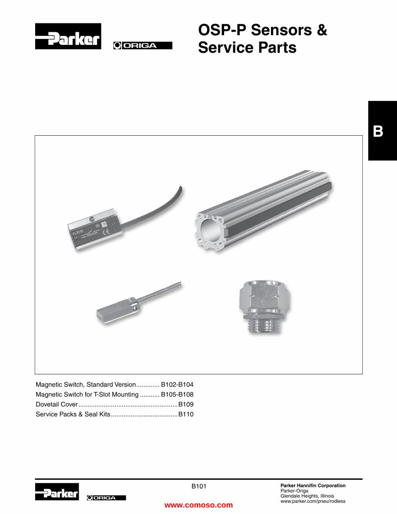
B101 Parker Hannifin CorporationParker-OrigaGlendale Heights, Illinoiswww.parker.com/pneu/rodless
ORIGA
ORIGA
B
OSP-P Sensors & Service Parts
Magnetic Switch, Standard Version ............. B102-B104
Magnetic Switch for T-Slot Mounting ........... B105-B108
Dovetail Cover .......................................................B109
Service Packs & Seal Kits .....................................B110
www.comoso.com

B102 Parker Hannifin CorporationParker-OrigaGlendale Heights, Illinoiswww.parker.com/pneu/rodless
ORIGA
B
Characteristics
Characteristics Unit Description
electrical Characteristics type RS type eS
Switching output Reed PNP, NPNOperating voltage V 10-240 AC/DC (NO) 10-30 DC 10-150 AC/DC (NC)
Residual voltage V < 3 < 3
Connection Two wire Three wireOutput function normally open normally open normally closed
Permanent current mA 200 200
Max. switching capacity VA (W) 10 VA —Power consumption mA — < 20without load
Function indicator LED, yellow
Typical switching time ms On: < 2 On: < 2
Switch-off delay ms — ca. 25Pole reversal LED —does not work
Pole reversal protection — Built in
Short-circuit protection — Built in
Switchable capacity load µF 0.1 at 100 W, 24
VDC
Switching point accuracy mm ± 0,2
Switching distance mm ca. 15 ca. 15
Hysteresis for OSP mm ca. 8 ca. 3Lifetime 3 x 10⁶, up to Theoretically 6 x 10⁶ cycles unlimited
Mechanical Characteristics
Housing Makrolon, smoke color
Cable cross section mm2 2 x 0.14 3 x 0.14
Cable type *) PVC PUR, black
Bending radius fixed mm ≥ 20 moving mm ≥ 70
Weight (Mass) kg 0.012
Degree of protection IP 67 to DIN EN 60529
Ambient °C -25 other temperature ranges temperature range *)1) °C +80 on request
Shock resistance m/s2 100 500 (contact switches)
*) other versions on request1) for the magnetic switch temperature range, please take into account the surface temperature and the self-heating properties of the linear drive.
Linear DriveAccessories ø 10-80 mmMagnetic Switches
For electrical sensing of the carrier position, e.g. at the end positions, magnetic switches may be fitted.Position sensing is contactless and is based on magnets fitted as standard to the carrier. A yellow LED indicates operating status.
The universal magnetic switches are suitable for all PARKER-ORIGA OSP-Actuators and aluminum profile rod type cylinders.
Piston, speed and switching distance affect signal duration and should be considered in conjunction with the minimum reaction time of ancillary control equipment.
Switching distance Min. reaction time = Piston speed
�����������
����
���
OSP-P Pneumatic Rodless Cylinders and Linear GuidesOSP-P Sensors
Catalog 0980
Magnetic Switches
www.comoso.com
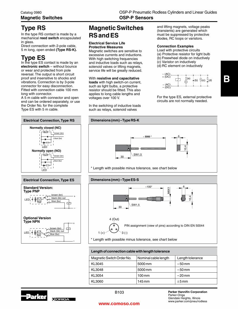
B103 Parker Hannifin CorporationParker-OrigaGlendale Heights, Illinoiswww.parker.com/pneu/rodless
ORIGA
B
and lifting magnets, voltage peaks (transients) are generated which must be suppressed by protective diodes, RC loops or varistors.
Connection examplesLoad with protective circuits(a) Protective resistor for light bulb(b) Freewheel diode on inductively(c) Varistor on inductively(d) RC element on inductively
For the type ES, external protective circuits are not normally needed.
type RSIn the type RS contact is made by a mechanical reed switch encapsulated in glass. Direct connection with 2-pole cable, 5 m long, open ended (type RS-K).
type eSIn the type ES contact is made by an electronic switch – without bounce or wear and protected from pole reversal. The output is short circuit proof and insensitive to shocks and vibrations. Connection is by 3-pole connector for easy disconnection.Fitted with connection cable 100 mm long with connector. A 5 m cable with connector and open end can be ordered separately, or use the Order No. for the complete Type ES with 5 m cable.
electrical Connection, type RS
������������
������������
������ ��� ���
Dimensions (mm) – type RS-K
* Length with possible minus tolerance, see chart below
Dimensions (mm) – type eS-S
PIN assignment (view of pins) according to DIN EN 50044
4 (Out)
1 (+) 3 (-)
electrical Connection, type eS
���
�
�
������
���
�
�
������
Length of connection cable with length tolerance
Magnetic Switch Order No. Nominal cable length Length tolerance
KL3045 5000 mm – 50 mm
KL3048 5000 mm – 50 mm
KL3054 100 mm – 20 mm
KL3060 145 mm ± 5 mm
���
���
��
�
����
�����
~ 5000 *blue (bu)
brown (bn)
Normally closed (NC)
blue (bu)
brown (bn)
Normally open (NO)
Standard Version:type PNP
Optional Versiontype NPN
brown (bn)black (bk) outblue (bu)
* Length with possible minus tolerance, see chart below
Magnetic Switches RS and eSelectrical Service LifeProtective MeasuresMagnetic switches are sensitive to excessive currents and inductions. With high switching frequencies and inductive loads such as relays, solenoid valves or lifting magnets, service life will be greatly reduced.
With resistive and capacitative loads with high switch-on current, such as light bulbs, a protective resistor should be fitted. This also applies to long cable lengths and voltages over 100 V.
In the switching of inductive loads such as relays, solenoid valves
brown (bn)black (bk) outblue (bu)
OSP-P Pneumatic Rodless Cylinders and Linear GuidesOSP-P Sensors
Catalog 0980
Magnetic Switches
www.comoso.com

B104 Parker Hannifin CorporationParker-OrigaGlendale Heights, Illinoiswww.parker.com/pneu/rodless
ORIGA
B ��
��
Dimensions Series OSP-P16 to 80 Dimensions Series OSP-P10
Note:Sensors can not be mounted directly opposite of the carrier
Dimension table (mm) and Order Instructions
Series Dimensions Order No.
RS closer RS opener eS eS compl. with 5 m cable Adapter RC RD Normally open Normally closed PNP NPN PNP NPN only for OSP-P10)
OSP-P10 – – type: type: type: type: type: type: 20968
OSP-P16 20 20.5 RS-K RS-K eS-S eS-S eS-S eS-S
OSP-P25 25 27 KL3045 KL 3048 KL 3054 KL 3060 KL 3054 + 4041 KL 3060 + 4041
OSP-P32 31 34
OSP-P40 36 39
OSP-P50 43 48
OSP-P63 53 59
OSP-P80 66 72 Cable 5 m with connector and with 4041open end for magnetic switches type eS-S
please order separately
OSP-P Pneumatic Rodless Cylinders and Linear GuidesOSP-P Sensors
Catalog 0980
Dimensions & Ordering Information
www.comoso.com

B105 Parker Hannifin CorporationParker-OrigaGlendale Heights, Illinoiswww.parker.com/pneu/rodless
ORIGA
B
Linear DriveAccessories ø 10-80 mmMagnetic Switches for t-Slot
Series RSt eSt
Magnetic switches are used for electrical sensing of the position of the piston, e.g. at its end positions. They can also be used for sensing of intermediate positions.
Sensing is contactless, based on magnets which are built-in as
standard. A yellow LED indicates operating status.
The universal magnetic switches are suitable for all PARKER-ORIGA OSP-Actuators and aluminum profile rod type cylinders.
1) for the magnetic switch temperature range, please take into account the surface temperature and the self- heating properties of the linear drive.
�����������
����
���
Characteristics
Characteristics Unit Description
electrical Characteristics type RSt type eSt
Switching output Reed PNP
Operating voltage V 10-30 AC/DC 10-30 DC
Ripple - ≤ 10%
Voltage drop V ≤ 3 ≤ 2
Electrical configuration 2 wire 3 wireOutput function normally open normally open normally closed
Permanent current mA ≤ 100 ≤ 100
Breaking capacity W ≤ 6 peak -
Power consumption, mA - ≤ 10at UB = 24V, switched on, without load
Function indicator LED, yellow (not for normally closed)
Response time ms ≤ 2 ≤ 0.5
Sensitivity mT 2 – 4 2 – 4
Time delay before availability ms - ≤ 2
Reverse polarity prot. yes yes
Short-circuit protection no yes (pulsed)
Switchable capacity load µF 0.1 at 100 W, 24 VDC
Switching frequency Hz ≤ 400 ≤ 5 k
Repeatability mm ≤ 0.2 ≤ 0.2
Hysteresis mm ≤ 1.5 ≤ 1.5
EMC EN 60947-5-2
Lifetime ≥ 35 Mio. cycles unlimited with PLC load
Power-up pulse - yessuppression
Protection for - yesinductive load
Mechanical Characteristics
Housing Plastic / PA66 + PA6I red
Cable cross section mm2 2 x 0.14 3 x 0.14
Cable type PUR, black PUR, black
Bending radius mm ≥ 36 ≥ 30
Weight kg ca. 0.030 RST-K ca. 0.030 EST-K ca. 0.010 RST-S ca. 0.010 EST-S
Degree of protection IP 67 to EN 60529
Ambient °C -25 to +80 -25 to +75 temperature range 1) at UB=10 – 30 V -25 to +80 at UB=10 – 28 V
– with adapter °C -25 to +60
Adapter Nm 0.15 (tightening torque of screwing adapter tightening torque on to magnetic switch)
Shock resistance
Vibration to EN 60068-2-6 G 15, 11 ms, 10 to 55 Hz, 1 mm
Shock to EN 60068-2-27 G 50, 11 ms
Bump to EN 60068-2-29 G 30, 11 ms, 1000 bumps each axis
OSP-P Pneumatic Rodless Cylinders and Linear GuidesOSP-P Sensors
Catalog 0980
Magnetic Switches
www.comoso.com

B106 Parker Hannifin CorporationParker-OrigaGlendale Heights, Illinoiswww.parker.com/pneu/rodless
ORIGA
B
type RStIn the type RST contact is made by a mechanical reed switch encapsulated in glass.
type eStIn the type EST contact is made by an electronic switch – without bounce or wear and protected from pole reversal. The output is short circuit proof and insensitive to shocks and vibrations. Connection is by 3-pole connector for easy disconnection.Fitted with connection cable 100 mm long with connector. A 5 m cable with connector and open end can be ordered separately, or use the Order No. for the complete Type ES with 5 m cable.
electrical Connection type RSt-K
������������
������������
������ ��� ���
������������
�����
������������
�����
electrical Connection type eSt-K
electrical Connection type RSt-S
������������
�����
��
electrical Connection type eSt-S
��
�
�
�
��
Normally closed
Normally open
��
�
�
Magnetic Switches RSt and eStelectrical Service LifeProtective MeasuresMagnetic switches are sensitive to excessive currents and inductions. With high switching frequencies and inductive loads such as relays, solenoid valves or lifting magnets, service life will be greatly reduced.
With resistive and capacitative loads with high switch-on current, such as light bulbs, a protective resistor should be fitted. This also applies to long cable lengths and voltages over 100 V.
In the switching of inductive loads such as relays, solenoid valves
and lifting magnets, voltage peaks (transients) are generated which must be suppressed by protective diodes, RC loops or varistors.
Connection examplesLoad with protective circuits(a) Protective resistor for light bulb(b) Freewheel diode on inductively(c) Varistor on inductively(d) RC element on inductively
For the type EST, external protective circuits are not normally needed.
brown (bn)
blue (bu)
brown (bn)
blue (bu)
brown (bn)
blue (bu)
brown (bn)black (bk)
blue (bu)
brown (bn)black (bk)
blue (bu)
OSP-P Pneumatic Rodless Cylinders and Linear GuidesOSP-P Sensors
Catalog 0980
Magnetic Switches
www.comoso.com

B107 Parker Hannifin CorporationParker-OrigaGlendale Heights, Illinoiswww.parker.com/pneu/rodless
ORIGA
B
Dimensions (mm) – type RSt-K, eSt-K
* Cable lengths available: 5000 mm ± 75 mm 2000 mm ± 40 mm** Switching point: Type RST-K Normally closed 14 mm Type RST-K Normally open 12.3 mm Type EST-K Normally open 8.1 mm
Dimensions (mm) – type RSt-S, eSt-S
4 (out)
1(+) 3(-)* ± 6 mm** Switching point: Type RST-K Normally closed 14 mm Type RST-K Normally open 12.3 mm Type EST-K Normally open 8.1 mm
Installation
42
30,5
M3SW 1,5
∅2,
9
6,1
4,3
*
**
36-40240 *M3SW 1,5
29-37
∅2,
9
6,1
4,3
M8x
1
M8x
130,5
**
PIN assignment (view of pins) to DIN EN 50044
SW = 1.5 mm
bn / bn
bl / bu AC / DC+ / -
- / +
Insert adapter into cylinder dovetail slot
Tighten screw:torque 1.5 Nm
bn / bn
bl / bu AC / DC+ / -
- / +
Insertmagnetic switch
Rotatemagnetic switch
Secure magnetic switch
mark for switching point
Screw connector
Snap connector
Insert magnetic switch into adapter
Dimensions of Adapter for Magnetic Switch
OSP-P Pneumatic Rodless Cylinders and Linear GuidesOSP-P Sensors
Catalog 0980
Magnetic Switches – Dimensions
www.comoso.com

B108 Parker Hannifin CorporationParker-OrigaGlendale Heights, Illinoiswww.parker.com/pneu/rodless
ORIGA
B
Accessories
Description type Order No. Cable M8, 2.5 m KS 25 KY 3240 without lock nut
Cable M8, 5.0 m KS 50 KY 3241 without lock nut
Cable M8, 10.0 m KS 100 KY 3140 without lock nut
Cable M8, 2.5 m KSG 25 KC 3102with lock nut
Cable M8, 5.0 m KSG 50 KC 3104with lock nut
Adapter for dovetail groove KL 3333 (pack of 10)
Order Instructions
Version Voltage type Order No.
10-30 V AC / DC RSt-K KL 3301
10-30 V AC / DC RSt-K KL 3300
10-30 V AC / DC RSt-S KL 3302
10-30 V AC / DC RSt-S KL 3303
10-30 V AC / DC RSt-K KL 3305
10-30 V DC eSt-K KL 3308
10-30 V DC eSt-K KL 3309
10-30 V DC eSt-S KL 3312
10-30 V DC eSt-S KL 3306
Included in delivery: 1 magnetic switch 1 adapter for dovetail groove mounting
Magnetic switch,reed contact, normally open, LED indicator, cable 2 m
Magnetic switch,reed contact, normally open, LED indicator, cable 5 m
Magnetic switch,reed contact, normally open, snap connector M8, LED indicator, cable 0.24 m
Magnetic switch,reed contact, normally open, screw connector M8,LED indicator, cable 0.24 m
Magnetic switch, electronic, PNPLED indicator, cable 2 m
Magnetic switch, electronic, PNPLED indicator, cable 5 m
Magnetic switch,electronic, PNPsnap connector M8,LED indicator
Magnetic switch, electronic, PNPscrew connector M8,LED indicator
Magnetic switch,reed contact, normally closed, cable 5 m
OSP-P Pneumatic Rodless Cylinders and Linear GuidesOSP-P Sensors
Catalog 0980
Magnetic Switches – Ordering
www.comoso.com

B109 Parker Hannifin CorporationParker-OrigaGlendale Heights, Illinoiswww.parker.com/pneu/rodless
ORIGA
B
Linear DriveAccessories ø 16-80 mmDovetail Cover
For clean guidance of magnetic switch cables along the cylinder body.
Contains a maximum of 3 cables with diameter 3 mm.
Material: Plastic
Color: Red
Temperature Range: –10 to +80°C
Dimensions (mm)
Dimension table (mm) and Order Instructions
Series Dimensions (mm) Order No. RC RD
OSP-P16 18.5 19 13039
OSP-P25 23.5 25.5
OSP-P32 29.5 32
OSP-P40 34.5 37.5
OSP-P50 41.5 46.5
OSP-P63 51.5 57.5
OSP-P80 64.5 70.5
Minimal length: 1m Max. profile length: 2mMultiple profiles can be used.
Metric Conversion FittingsOrder Number Port Size Bore Size
2521-1/8-02 G1/8 to 1/8" NPT P25
2521-1/4-04 G1/4 to 1/4" NPT P32, P40, P50
2521-3/8-06 G3/8 to 3/8" NPT P63
2521-1/2-08 G1/2 to 1/2" NPT P80
OSP-P Pneumatic Rodless Cylinders and Linear GuidesOSP-P Sensors
Catalog 0980
Wireway Cover
www.comoso.com

B110 Parker Hannifin CorporationParker-OrigaGlendale Heights, Illinoiswww.parker.com/pneu/rodless
ORIGA
B
Service Packs Bore Sizes 16mm 25mm 32mm 40mm 50mm 63mm 80mm BUNA Service Pack Part Number 11111 11112 11113 11114 11115 11116 11118 Single Piston Viton Service Pack Part Number 11121 11122 11123 11124 11125 11126 11128 Single Piston
BUNA Service Pack Part Number 11131 11132 11133 11134 11135 11136 11138 Single Piston - Slow Speed Grease Viton Service Pack Part Number 11141 11142 11143 11144 11145 11146 11148 Single Piston - Slow Speed Grease
*Behind part number, please add stroke length in mm
Service Pack InformationService Packs, containing all the components necessary to completely rebuild a Parker-Origa rodless cylinder, are available. Each pack contains a complete seal kit, inner and outer bands, Parker-Origa grease tube, cleaning tool and repair instructions. It’s all packaged in an easy-to-ship, easy-to-store box clearly labeled to indicate the cylinder type, bore and stroke for which it is intended. Contact your local Parker-Origa distributor for more information.
Seal Kits Bore Sizes 16mm 25mm 32mm 40mm 50mm 63mm 80mm BUNA Seal Kit - Standard Cylinder Part Number 11052 11053 11054 11055 11056 11057 11058 Viton Seal Kit - Standard Cylinder Part Number 11059 11060 11061 11062 11063 11064 11065
Seal Kit - Sideline Carriage Part Number 11066 11067 11068 11069 11070 – –
Seal Kit Active Brake - Part Number – 11822 11823 11824 11825 11826 11827 Standard Cylinder
Seal Kit - Multibrake Part Number – 11089 11090 11091 11092 11093 –
OSP-P Pneumatic Rodless Cylinders and Linear GuidesOSP-P Service Parts
Catalog 0980
Service Packs & Seal Kits
www.comoso.com

B111 Parker Hannifin CorporationParker-OrigaGlendale Heights, Illinoiswww.parker.com/pneu/rodless
ORIGA
ORIGA
B
ORIGA-SeNSOFLeXDisplacement Measuring Systemfor Cylinder Series OSP-P
Overview ................................................................B112
Technical Data SFI-plus .........................................B113
Dimensions SFI-plus ............................................B114
Order Information .................................................B115
www.comoso.com

B112 Parker Hannifin CorporationParker-OrigaGlendale Heights, Illinoiswww.parker.com/pneu/rodless
ORIGA
B
ORIGA-SensoflexDisplacement measuring system
for automated movement
Series SFI-plus
(incremental measuring system)
for cylinder series
•OSP-P...
Characteristics
• Contactless magnetic displacement measurement system
• Displacement length up to 32 m
• Resolution 0.1 mm (option: 1 mm)
• Displacement speed up to 10 m/s
• For linear and non-linear rotary motion
• Suitable for almost any control or display unit with a counter input
The SFI-plus magnetic displacement measuring system consists of 2 main components.
• Measuring Scale
Self-adhesive magnetic measuring scale
• Sensing Head
Converts the magnetic poles into electrical signals which are then processed by counter inputs downstream
(e.g. PLC, PC, digital counter)
OSP-P Pneumatic Rodless Cylinders and Linear GuidesMeasuring System
Catalog 0980
Sensoflex
www.comoso.com

B113 Parker Hannifin CorporationParker-OrigaGlendale Heights, Illinoiswww.parker.com/pneu/rodless
ORIGA
B
Displacement Measuring Systemfor automated movement
ORIGA-Sensoflex(incremental displacement measuring system)
Series SFI-plus for cylinder series
• OSP-P...
Note:
For combinations Active Brake AB + SFI-plus + Magnetic Switch contact our technical department please.
Characteristics
Characteristics Unit Descriptiontype 21210 21211Output FunctionResolution mm 0.1 1Pole lengths magnetic scale mm 5Maximum speed m/s 10Repeat accuracy ± 1 Increment
Distance between sensor and scale mm ≤ 4Tangential deviation ≤ 5°
Lateral deviation mm ≤ ± 1.5
Switching output PNPelectrical CharacteristicsOperating voltage Ub V DC 18 – 30Voltage drop V ≤ 2
Continuous current for each output mA ≤ 20
Power consumption at Ub = 24V, switched on, without load mA ≤ 50
Short-circuit protection yesReverse polarity protection yesProtection from inductive load yesPower-up pulse suppression yeseMCElectrostatic discharge immunity kV 6, B, to EN 61000-4-2Electromagnetic field immunity V/m 10, A, to EN61000-4-3Electrical fast transient/burst immunity (for signal connections) kV 1, B, to EN 61000-4-4
Electrical fast transient/burst immunity (for DC connections) kV 2, B, to EN 61000-4-4
Surge immunity (for signal connections) kV 1, B, to EN 61000-4-5
Surge immunity (for DC connections) kV 0,5, B, to EN 61000-4-5
Immunity to conducted disturbances V 10, A, to EN 61000-4-6Power frequency magnetic field immunity at 50 Hz A/m 30, A, to EN 61000-4-8Emission standard for residential to EN 61000-6-4Radio disturbance characteristics to EN 55011, Group 1, AMechanical CharacteristicsHousing AluminumCable length m 5.0 – fixed, open endCable cross section mm2 4 x 0.14Cable type PUR, blackBending radius mm ≥ 36Weigth (mass) kg ca. 0.165environmental Conditions / Shock ResistanceDegree of protection IP 67 to EN60529Ambient temperature range °C -25 to +80Broad-band random vibration to EN 60068-2-64 g 5, 5 Hz to 2 kHz, 0.5 h each axis
Vibration stress to EN 60068-2-6 g 12, 10 Hz to 2 kHz, 2 mm, 5 h each axis
Shock to EN 60068-2-27 g 100, 6 ms, 50 bumps each axisBump to EN 60068-2-29 g 5, 2 ms, 8000 bumps each axis
OSP-P Pneumatic Rodless Cylinders and Linear GuidesMeasuring System
Catalog 0980
Sensoflex – technical Data
www.comoso.com

B114 Parker Hannifin CorporationParker-OrigaGlendale Heights, Illinoiswww.parker.com/pneu/rodless
ORIGA
B
electrical Connection
Color Description
bn = brown + DC
bu = blue – DC
bl = black Phase A
wt = white Phase B
Output signal – Sensing Head
Ua = Ue
Dimensions (mm) – Sensing HeadSensing Head
The sensing head provides two pulsating, 90° out of phase counter signals (phase A/B) with a 0.4 mm resolution (option 4 mm). External processing can improve the resolution to 0.1 mm (option 1 mm). The counting direction can be determined automatically from the phase variance of the counter signals.
Dimension table (mm)
Series A B C D F G H
OSP-P25 32 39 23 50 38 5.5 40
OSP-P32 37.5 46 30 50 38 6.5 40
OSP-P40 42.5 50 34 50 38 6.5 40
OSP-P50 49.5 55 39 50 38 6.5 40
OSP-P63 59.5 65 49 50 38 10 40
OSP-P80 72.5 80 64 50 38 12 40
Dimensions – in combination with OSP-P cylindersSFI-plus mounted on a rodless cylinder series OSP-P
The SFI-plus system can be mounted directly on a rodless OSP-P cylinder with the special mounting kit.The position of the sensing head is generally 90° to the carrier.
Combinations consisting of SFI-plus and OSP-P Cylinders with guides are available on request.
�
�
�
�
�
��
��
��
��
��
���
����
��
�����������
��
��
�
���
����
�
* Maximum thread depth 4mm
Position of the active switching area (opposite to the type label )
Phase B Ua1 0°
Phase A Ua2 90°
0.1 mm (option 1 mm)
0.4 mm (option 4 mm)
OSP-P Pneumatic Rodless Cylinders and Linear GuidesMeasuring System
Catalog 0980
Sensoflex – Dimensions
www.comoso.com
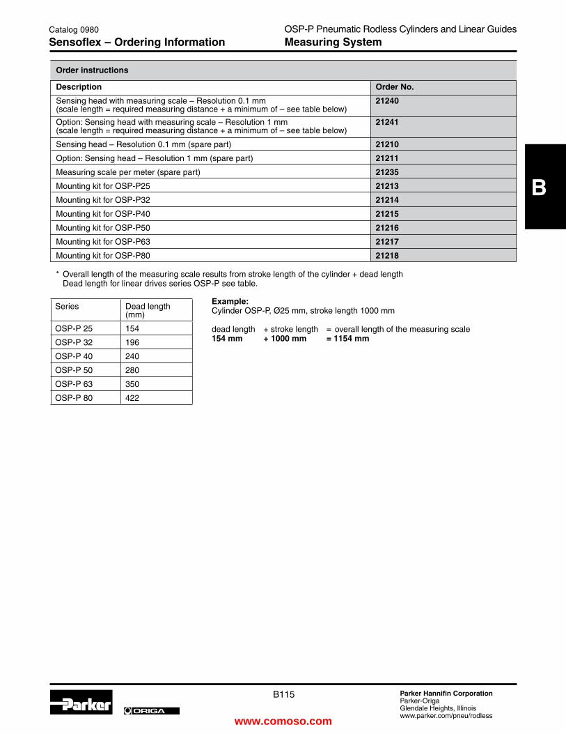
B115 Parker Hannifin CorporationParker-OrigaGlendale Heights, Illinoiswww.parker.com/pneu/rodless
ORIGA
B
Order instructions
Description Order No.
Sensing head with measuring scale – Resolution 0.1 mm 21240(scale length = required measuring distance + a minimum of – see table below) Option: Sensing head with measuring scale – Resolution 1 mm 21241(scale length = required measuring distance + a minimum of – see table below)
Sensing head – Resolution 0.1 mm (spare part) 21210
Option: Sensing head – Resolution 1 mm (spare part) 21211
Measuring scale per meter (spare part) 21235
Mounting kit for OSP-P25 21213
Mounting kit for OSP-P32 21214
Mounting kit for OSP-P40 21215
Mounting kit for OSP-P50 21216
Mounting kit for OSP-P63 21217
Mounting kit for OSP-P80 21218
* Overall length of the measuring scale results from stroke length of the cylinder + dead length Dead length for linear drives series OSP-P see table.
Series Dead length (mm)
OSP-P 25 154
OSP-P 32 196
OSP-P 40 240
OSP-P 50 280
OSP-P 63 350
OSP-P 80 422
example:Cylinder OSP-P, Ø25 mm, stroke length 1000 mm
dead length + stroke length = overall length of the measuring scale154 mm + 1000 mm = 1154 mm
OSP-P Pneumatic Rodless Cylinders and Linear GuidesMeasuring System
Catalog 0980
Sensoflex – Ordering Information
www.comoso.com

B116 Parker Hannifin CorporationParker-OrigaGlendale Heights, Illinoiswww.parker.com/pneu/rodless
ORIGA
B
OSP-P Pneumatic Rodless Cylinders and Linear GuidesCatalog 0980
Notes
www.comoso.com

C
C1 Parker Hannifin CorporationParker-OrigaGlendale Heights, Illinoiswww.parker.com/pneu/rodless
ORIGA
ORIGA
The Guideline Concept ............................................. C2
The Guideline System .............................................. C3
Overview & Descriptions .......................................... C4
General Facts & Dimensions .................................... C5
Load and Moment Ratings ....................................... C6
GDL Roller Guides / Accessories ............................. C7
Wipers / Butt-jointed Rail Options ............................. C8
Conversion Tables .................................................... C9
GDL Aluminum Roller Guides
Technical information .......................................C10-C13
Ordering Information............................................... C14
GDL Application Sheet ........................................... C15
www.comoso.com

C
C2 Parker Hannifin CorporationParker-OrigaGlendale Heights, Illinoiswww.parker.com/pneu/rodless
ORIGA
Single rail and roller shoe versions of the aluminum roller guide in a handling arrangement for stacks of paper. Various fittings and limit stops for stacking are moved on two axes horizontally and vertically. The robustness and reliability of the roller guides allows for continuous operation under high load conditions.
(Solms company photo)
Aluminum roller guides in the sliding carriage of a machine for producing cables. The projecting arm of the carriage is guided by two double rails each with two roller cassettes and can be moved manually with minimal force because of the low friction properties.
(Kabelmat company photo)
Handling units for medical equipment. Smooth, easy movement with guideline roller guides.
(Dräger company photo)
Aluminum roller guides in an automatic vibrator for flattening printed sheets of paper. To guarantee even pressure on the sheets of paper, the roller bridge is supported by precision roller guides.
(Baumann company photo)
Aluminum roller guides in a cutting machine for spectacle lenses. Both the work piece carriers and the motorized X - Y table axis are equipped with roller guides. The smooth operation and precision of the equipment ensures a fine cutting action.
• Light weight (anodized aluminum)
• Smooth and quiet operation
• Speeds up to 10 m/s
• Acceleration/deceleration up to 40 m/s2
• Loading from any direction
• Permanently lubricated guidance system
• Broad product range in various series high performance, standard and stainless steel versions
• High load and moment capacities
• Very cost effective
• Flexible mounting dimensions
Light, Smooth and FASt
GDL Aluminum Roller GuidesCatalog 0980
Features
www.comoso.com

C
C3 Parker Hannifin CorporationParker-OrigaGlendale Heights, Illinoiswww.parker.com/pneu/rodless
ORIGA
GDL Linear Guides Offer a Variety of Series and Options — High Performance... “Smooth Guidance”Aluminum roller guides provide smooth operation and high load carrying capacity for industrial automation.
By the use of lightweight aluminum components the moving masses are minimized, travel speeds are increased and actuation energy is saved.
Aluminum roller guides are available in sizes 12, 15, 20, 25, 35 and 45mm. Rail lengths are from 200 mm to 4000 mm. For longer travel lengths, guide rails can be butt-jointed together.
Axial needle roller bearings of High Performance roller cassette.
Rail profiles and roller cassettesmade of anodized aluminum
Precision polished and calibrated guideways
High Performance Rollers on needle bearings for smooth operation at speeds up to 10 m/s. Acceleration / deceleration up to 40 m/s2.
Rollers arranged crosswiseto handle loading from any direction
Aluminum roller guides are designed to carry medium weight loads economically. Their smooth action and speeds up to 10 m/s make them ideal for widespread use in many areas of application.
Aside from a main featured High Performance guide, others such as the Standard, Corrosion Resistant, High Dynamics and Grease-free versions are also available.
Catalog 0980
FeaturesGDL Aluminum Roller Guides
www.comoso.com

C
C4 Parker Hannifin CorporationParker-OrigaGlendale Heights, Illinoiswww.parker.com/pneu/rodless
ORIGA
Descriptions of the Various GDL Series Available:High Performance Series: (Sizes FDC12HP-... thru FDC45HP-...)
The High Performance series is the basis for GDL’s development, which is used in the majority of applications. High Performance guides consist of 8 axial needle roller bearings, running on precision polished and hardened alloy spring steel guideways. These guide bearings are grease packed and shielded, while offering the highest load and moment rating capacities within the GDL product line.
Standard Performance Series: (Sizes FDC12SP-... thru FDC45SP-...)
The Standard Performance series is intended for minor loads and moments for particularly economical guidance solutions. Standard Performance guides consist of 8 radial ball roller bearings, running on precision polished and hardened alloy spring steel guideways. These guide bearings are grease packed and sealed, while offering the lowest load and moment ratings available within the GDL product line, with the exception of the Grease-Free and the Anti-Friction / Corrosion Resistant series. Standard Performance series is the second most commonly used GDL guides for various applications and also provides excellent running behavior.
GDL Aluminum Roller GuidesDescriptions
Catalog 0980
Product Overview
GDL Product Line Overview
Characteristic Unit Description
Full profile wipers Rollershoes and cassette are provided with snap-on full profile wipers. The snap-on full profile wipers are easily replaceable with available wipers kits. See page 8 for respective wiper kit order numbers.
Mounting Rollershoes and cassettes use ISO screw quality 8.8 and DIN 433 washers. ISO screw quality 8.8 is recommended for mounting the rails also.
Loads See load and moment rating tables on page 6 for respective load, moment and weight data per size and series.
Acceleration and Deceleration
m/s2 (ft/sec2)
40 m/s2 maximum (131 ft/s2 maximum)
Guide installation Possible in any position. See technical information on page 10 for specific instructions on installing vari-ous guide configurations.
Drag adjustment set screw
Cassettes can be adjusted at the factory or by the customer.
Rollershoes can be set-up by the customer to incorporate the drag adjustment set screw feature. The drag adjustment set screw components are supplied with each pair of rollershoes.
Coefficient of friction Variable, but .001 set at standard slide resistance adjustment.
Standard Lubrication Lifetime lubrication with standard grease-packed roller bearings.
Speed m/s (ft/s) Up to 10 m/s (or up to 33 ft/s)
Materials for High Performance or Standard versions
Rail: Aluminum alloy
Guideways: Hardened high alloy spring steel
Cassettes/rollershoes/top plates: Aluminum alloy
Rollers: Bearing steel
Materials for Corrosion Resistant High Performance & Standard versions
Rail: Aluminum alloy
Guideways: Stainless steel spring steel
Cassettes/rollershoes/top plates: Aluminum alloy
Rollers: Stainless steel bearing steel
Bearing types Steel axial needle, Specials on request (ex: anti-magnetic, grease free, high dynamics) - consult factory
Operating temperature C (F) -10° to 80°C (+14 to 176°F) temperature range
Specials available
Custom length cassettes and rollershoes for 100 piece lots minimum.
Keyed butt-jointed rail sections for continuous rail lengths over 4000mm.
Solid continuous length rails between 4000.
Offset or non-standard “L11” dimensions on opposite ends of cut rails.
Integrated metal scraper with standard full profile wiper currently available.
Rail underside blind mounting holes.
www.comoso.com

C
C5 Parker Hannifin CorporationParker-OrigaGlendale Heights, Illinoiswww.parker.com/pneu/rodless
ORIGA
Snap-on full profile wipers: Rollershoes and cassettes can be provided with snap-on full profile wipers. The snap-on full profile wipers are easily replaceable with available wiper kits. See page C14 for respective wiper kit order numbers.
Cassette adjustment: Cassettes can be adjusted at the factory or by the customer.
Fasteners: Rollershoes and cassettes use ISO screw quality 8.8 and DIN 433 washers. ISO screw quality 8.8 is recommended for mounting the rails also. Special stainless steel fasteners can be requested as necessary.
General Facts Pertaining to all Series:Carrying Capacity: See load and moment rating tables on page C6 for your guide series of interest.
Guide mounting position: Optional.
Lengths: For longer than standard rail lengths, see keyed butt-jointed rail option on page C8.
Lubrication: GDL Aluminum Roller Guides are permanently lubricated with contained roller bearings grease.
See part numbering schemes on pages C14 to define your desired GDL guide features for ordering.
as
fs
Fixed sidewith respectto dim. “e”
h11
x 45
∞
t3
Datum side withdepth groove
B ±0,15
N1
h10
h8
h9±0
,1
BS
e
h3
Ls
5
d2
D2
L12
z x L12Drag adjustment set screw
t2
L11 min.
L max. = 4000
Drawing for Cassette with Double Sided Rail
Dimensions for both Underside Mounting Hole FDC Version Guides(Ref. ordering instructions)
Dimensions (mm)
Dimensions (mm)
SizeLength
LsWidth BE B BS B1
Height B2 h1 h3 h9 as d2 D2 e fs h7 h8 h10 h11 L8 L9
L11 min.
L12 t2 t3 N1 N2 N3 PF1 PF2 S1 S2 S3
12 64 12.00 12.0 37 24.4 11.9 15.0 14.7 19 30 3.4 6 12.50 25 6.0 8 4.0 6 29 57 10 40 5.5 1.4 M4 M3 M4 5.5 3.4 3.4 4.9 9.7
15 78 15.25 15.5 47 30.9 15.2 19.0 18.7 24 38 4.5 8 15.75 30 7.5 10 5.0 8 34 68 10 60 6.0 2.0 M5 M4 M6 7.0 4.4 4.9 5.9 12.4
20 92 20.00 21.0 63 40.9 20.4 23.0 22.6 30 53 5.5 10 21.00 40 8.0 12 7.0 11 42 80 10 60 7.0 2.0 M6 M5 M6 9.5 4.9 5.9 5.9 16.9
25 98 25.00 23.0 70 48.4 22.9 27.5 27.0 36 57 6.6 11 23.50 45 5.0 16 8.5 13 48 84 10 60 10.0 2.5 M8 M5 M8 12.0 6.4 7.4 8.9 19.4
35 135 35.00 32.0 100 68.9 32.9 37.5 37.0 48 82 9.0 15 34.00 62 7.5 20 10.5 20 67 117 12 80 11.5 3.5 M10 M6 M8 17.0 8.9 8.9 8.9 28.4
45 165 45.00 45.0 120 82.4 36.4 46.5 46.0 60 100 11.0 18 37.50 80 9.5 24 13.5 22 83 146 16 105 14.5 4.0 M12 M8 M8 22.0 9.9 9.9 8.9 30.9
SizeLength
LsWidth BE B BS B1
Height B2 h1 h3 h9 as d2 D2 e fs h7 h8 h10 h11 L8 L9
L11 min.
L12 t2 t3 N1 N2 N3 PF1 PF2 S1 S2 S3
12 64 12.00 12.0 37 24.4 11.9 15.0 14.7 19 30 3.4 6 12.50 29 6.0 8 4.0 6 29 57 10 40 5.5 1.4 M4 M3 M4 5.5 3.4 3.4 4.9 9.7
15 78 15.25 15.5 47 30.9 15.2 19.0 18.7 24 38 4.5 8 15.75 34 7.5 10 5.0 8 34 68 10 60 6.0 2.0 M5 M4 M6 7.0 4.4 4.9 5.9 12.4
20 92 20.00 21.0 63 40.9 20.4 23.0 22.6 30 53 5.5 10 21.00 40 8.0 12 7.0 11 42 80 10 60 7.0 2.0 M6 M5 M6 9.5 4.9 5.9 5.9 16.9
25 98 25.00 23.0 70 48.4 22.9 27.5 27.0 36 57 6.6 11 23.50 45 5.0 16 8.5 13 48 84 10 60 10.0 2.5 M8 M5 M8 12.0 6.4 7.4 8.9 19.4
35 135 35.00 32.0 100 68.9 32.9 37.5 37.0 48 82 9.0 15 34.00 62 7.5 20 10.5 20 67 117 12 80 11.5 3.5 M10 M6 M8 17.0 8.9 8.9 8.9 28.4
45 165 45.00 45.0 120 82.4 36.4 46.5 46.0 60 100 11.0 18 37.50 90 9.5 24 13.5 22 83 146 16 105 14.5 4.0 M12 M8 M8 22.0 9.9 9.9 8.9 30.9
Dimensions for both Standard FDC Version Guides
Catalog 0980
FeaturesGDL Aluminum Roller GuidesApplication engineering Data
www.comoso.com
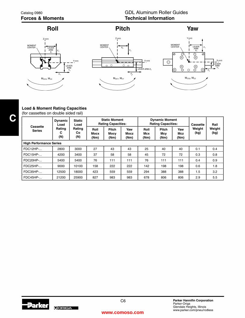
C
C6 Parker Hannifin CorporationParker-OrigaGlendale Heights, Illinoiswww.parker.com/pneu/rodless
ORIGA
MOCY, MCY
FX
LEVER ARM ZX
X-AXIS
Z-AXIS
XZ
FZ
MOMENTCENTER
FY
LEVER ARM
ZY
LEVER ARM
YZ
Y-AXIS
Z-AXIS
FZ
MOCX, MCX
MOMENTCENTER
FX
LEVER ARM
XY
LEVER ARM
YX
X-AXIS
Y-AXIS
FY
MCOZ, MCZ
MOMENTCENTER
Load & Moment Rating Capacities(for cassettes on double sided rail)
CassetteSeries
DynamicLoad
RatingC
(N)
Static Load
RatingCo(N)
Static Moment Rating Capacities:
Dynamic Moment Rating Capacities: Cassette
Weight (kg)
Rail Weight
(kg)Roll
Mocx (Nm)
Pitch Mocy (Nm)
Yaw Mocz (Nm)
Roll Mcx (Nm)
Pitch Mcy (Nm)
Yaw Mcz (Nm)
High Performance Series
FDC12HP-... 2800 3000 27 43 43 25 40 40 0.1 0.4
FDC15HP-... 4200 3400 37 58 58 45 72 72 0.3 0.8
FDC20HP-... 5400 5400 76 111 111 76 111 111 0.4 0.9
FDC25HP-... 9000 10100 158 222 222 142 198 198 0.6 1.8
FDC35HP-... 12500 18000 423 559 559 294 388 388 1.5 3.2
FDC45HP-... 21200 25900 827 983 983 678 806 806 2.9 5.5
GDL Aluminum Roller Guidestechnical Information
Catalog 0980
Forces & Moments
Roll Pitch Yaw
www.comoso.com

C
C7 Parker Hannifin CorporationParker-OrigaGlendale Heights, Illinoiswww.parker.com/pneu/rodless
ORIGA
GDL Aluminum Roller Guides
End of Stroke Stop screws
Size d D K L11 min. P Order
Number12 M5 12 8 15.0 6.0 63504A
15 M5 12 8 16.0 6.0 63504A
20 M5 12 8 17.0 6.0 63504A
25 M6 15 10 20.5 7.5 63505A
35 M8 19 13 26.5 9.5 63506A
45 M10 24 16 33.0 12.0 63507A
The stop screws are scre wed in to threads (op tion) on the gui de rails. The end of stroke stop ping ener gy is reduced by a rubber cap. With gui de rails whe re the L11 is less than the standard minimum, we off set the mounting hole by half of its diameter.
Note: Customer must drill and tap the holes for the stop screws.
GDL AccessoriesRail Mounting Screw Covers
SizeCylindrical
Screw DIN912
D OrderNumber
12 M3 6 87752A
15 M4 8 87753A
20 M5 10 87754A
25 M6 11 87755A
35 M8 15 87756A
45 M10 18 87757A
Dimensions (mm)
Dimensions (mm)
Ma te ri al: We ar re si stant pla stic, re si stant to oil and aging.
Moun ting: Put a pla stic pla te on top and pound in uniform ly. Re mo ve re si du al burrs with a soft brush or fingernail.
Note: Use respective order numbers for ordering separately or include in rail part number.
Special cassette types
b
Øa
h
b
hhl
Dimensions (mm), Force (N) with normal manual tightening.
High Performance cassettes with lock device
The locking cassette with star grip handle can be stopped at any desired location on the rail. The clamping device does not exert forces on the rail guideways.
The clamping device is used in fixtures which are movable manually, clamping and stop ledgers, feeding of tools and work pieces. Also available with L-ratchet handle.
Star Grip Handle Dimensions
Size Ø a b h Clamp Force
Part Numbers Star grip knob
12 N/A
15 25 41 19.0 200 FDC15HP-00020000
20 25 49 23.0 250 FDC20HP-00020000
25 32 56 28.0 250 FDC25HP-00020000
35 50 83 38.5 350 FDC35HP-00020000
45 63 101 48.0 750 FDC45HP-00020000
L-Ratchet Handle Dimensions
Size l b h Clamp Force
Part Numbers L-ratchet handle
12 N/A
15 45 59.5 19.0 200 FDC15HP-00010000
20 45 67.5 23.0 250 FDC20HP-00010000
25 45 71 28.0 250 FDC25HP-00010000
35 63 96 38.5 350 FDC35HP-0001000045 78 116 48.0 750 FDC45HP-00010000
Catalog 0980
DimensionsGDL Aluminum Roller GuidesAccessories
www.comoso.com

C
C8 Parker Hannifin CorporationParker-OrigaGlendale Heights, Illinoiswww.parker.com/pneu/rodless
ORIGA
Version with wipersIntegrated into an additional cover, a felt wiper is saturated with oil. Although dependent on the degree of contaminants, these wipers last for some 6000km, after which the
Order numbers for replacement wiper kits
FDC Series and Size Respective Order Number12 84457B15 84480B20 84481B25 84482B35 84483B45 84484B
Cassette with full profile snap-on wipers
*wiper kits are sold in pairs
NOTE: Use respective order numbers for ordering separately as replacements, or specify in cassette part number. See cassette part numbering on pages C14.
GUIDELINE rails can be precisely fastened together using a factory offered keyed butt-joint option for continuous rail lengths, as shown in Figures 1 & 2.
Two rail sections are clamped together with mating round bar stock pieces that seat tangent to both rail section guideways on each side of the rail. While the rail sections are clamped together, a keyway slot is machined in the top and bottom sides of the rail, across the butt- joint. Screw holes are then drilled through the rail inside the keyway slot, so the opposing keyways can be drawn together tightly with screws. The round bar stock clamp is then removed, providing a rigid and well aligned keyed butt-joint.
The keyed butt-joint option provides optimum alignment of all guideways from one rail section to the next. This allows for optimum “smooth” guidance of the cassette bearings, while crossing rail butt-joints.
The keyed butt-jointed rail option is currently available in the FDR version 25, 35, & 45 mm rail sizes. For a keyed butt-joint on rail sizes 25, 35 or 45 mm, specify P/N:# GDL-BJK
Consult factory for other size possibilities.
GDL’s Keyed Butt-Jointed Rail Option
Figure 1
Figure 2
GDL Coupled with structural aluminum extrusion material and OSP-E actuator
Figure 3
GDL linear guides couple well with various structural aluminum extrusions and Parker-Origa OSP-P and OSP-E actuators. Mounting can be easily accomplished using standard fasteners and mounting brackets. See Figure 3 above.
felt wipers can either be washed or replaced.For optimal cassette rolling performance, all holes in the guide rails should be filled with the plastic rail mounting screw covers (see page C7).
Full profile snap-on wiper
GDL Aluminum Roller Guidestechnical Information
Catalog 0980
Options
GDL Aluminum Roller Guides
www.comoso.com

C
C9 Parker Hannifin CorporationParker-OrigaGlendale Heights, Illinoiswww.parker.com/pneu/rodless
ORIGA
Units Conversion tables
Force Conversions:
MultiplyBy Conversion
FactorResult
pound-force 4.448 Newton
Newton 0.225 pound-force
kilogram-force 9.807 Newton
Newton 0.102 kilogram-force
Acceleration Conversions:
MultiplyBy Conversion
FactorResult
feet/section2 0.305 meter/second2
meter/second2 3.281 feet/second2
inch/second2 0.025 meter/second2
meter/second2 39.370 inch/second2
Bending Moment or torque Conversions:
MultiplyBy Conversion
FactorResult
pound-foot 1.356 Newton-meter
Newton-meter 0.737 pound-foot
Newton-meter 0.102 kilogram-meter
Kilogram-meter 9.807 Newton-meter
Mass Conversions:
MultiplyBy Conversion
FactorResult
ounce 28.349 gram
gram 0.035 ounce
kilogram 35.279 ounce
gram 0.001 kilgram
pound 0.453 kilogram
kilogram 2.205 pound
Velocity conversions:
MultiplyBy Conversion
FactorResult
mile/hour 1.609 kilometer/hour
kilometer/hour 0.621 mile/hour
feet/second 0.305 meter/second
meter/second 3.281 feet/second
inch/minute 0.025 meter/minute
meter/minute 39.370 inch/minute
Length conversions:
MultiplyBy Conversion
FactorResult
inch 25.4 millimeter
millimeter 0.039 inch
inch 0.025 meter
meter 39.370 inch
foot 0.305 meter
meter 3.281 foot
Catalog 0980
Conversion tablesGDL Aluminum Roller Guidestechnical Information
www.comoso.com

C
C10 Parker Hannifin CorporationParker-OrigaGlendale Heights, Illinoiswww.parker.com/pneu/rodless
ORIGA
7. Slide Resistance / AdjustmentFollow the steps on how to adjust GDL cassettes to the rail.
The new GDL catalog has many changes due to an expanded product line. The change to feature descriptive part numbering was done to accommodate all current and future offerings of the GDL product. The goal is to have standard features and options available, for a perfect fit into your application.
Included in the chart below are hex sizes, drag resistance and torque ratings for adjusting the cassette.
7.1 GDL Adjustment Procedure
Do not measure sliding resistance with wipers on.
1) Lay the rail out on the flat surface with the datum line facing away from you. Anchor the rail to keep it from shifting when sliding resistance is applied to the cassette.
The datum line is a reference groove on one side of the rail.
2) Set the roller cassette on the rail with the adjustment screw facing towards you, while the datum line on the rail is away from you. Do not install the wipers on the cassette yet.
Do not install the wipers yet.
3) Make sure the four bolts on the adjustable side of the cassette are slightly loose and the bolts on the fixed side are tight before adjusting the drag screw.
One side of the cassette is fixed and the other side is floating.
4) The drag hex screw is located on one side of the cassette. Adjust the screw in for more drag and out for less. Do not try to adjust cassette with top plates bolts tight.
See the chart for drag adjustment hex screw size.
5) Adjust the drag on the cassette by sliding as it slides down the rail. Feel for an even amount of resistance as you turn the hex screw in and out.
6) Tighten down the top plate bolts to the proper torque specification. The tightening of the top plate bolts will add some resistance. If necessary, the adjustment procedure can be repeated for better sliding resistance for your application.
See the chart for top plate hex size and torque rating.7) If the adjustment is done without a scale, it should move
evenly. Some examples of improper adjustment are: If the
1. Features of the Guide SystemAluminum roller guides consist of a double sided rail and a roller cassette or two single sided rails and two roller shoes. Aluminum rol ler gui de rails and cas set tes are ma de of aluminum alloy. The rol lers are very smooth run ning on precision polished guideways made of high al loy spring steel. The spe ci al cross pattern orientation of the run ning rol lers provides high lo ad and moment ca pa ci ty in all di rec tions.
Their special features are: light weight, small dimensions, and high speed of displacement. Aluminum roller guides are economical and universal handling components, which are mostly or all corrosion-resistant and available at a favorable price.
2. Size of the Guide SystemTo select the right guide size, first the moments and forces acting on the bearing have to be determined.
Recommended safety factors (with ISO screws quality 8.8):
Thrust load S > 1.3
Tensile load S > 4.0
Moment load S > 6.0
3. MaterialThe basic body of GDL aluminum roller guides is made of aluminum alloy. The guideways consist of hardened, high alloy spring steel or of stainless steel. By using basic bodies of aluminum, the moved masses are reduced which allows light-weight construction requiring lower moving forces and reduced energy consumption. Still the integrated GDL system sustains high load and moment ratings.
4. Operating temperatureGDL linear guides can be operated within a temperature range from -10° C up to + 80° C. For other temperatures, please consult factory.
5. Screwed ConnectionsGDL linear guides are fixed to the mating structure by the mounting holes in the rails and the cassettes. ISO screw quality 8.8 should be used with DIN 433 washers.
To secure the screwed connections, we recommend that suitable locking means be utilized as necessary.
Mounting screw torque specifications:
6. WipersThe guideways of aluminum roller guides are equipped with wipers to protect against coarse environmental contamination.
Quality 8.8 (Nm)
M3 1.1
M4 2.5
M5 5.0
M6 8.5
M8 21.0
M10 41.0
M12 71.0
GDL CHARt
FDC 12
FDC 15
FDC 20
FDC 25
FDC 35
FDC 45
Top plate hex (mm) 2 3 4 4 5 6
Top plate torque (in lbs) n/a 22.1 44.3 44.3 75.2 186
Adjustment hex (mm) 1 3 3 4 4 4
Drag resistance (oz) HP, HC, GF, VA
1.8- 7.9
3.6- 10.8
5.4- 16.2
7.2- 21.6
10.8- 32.4
12.6- 37.7
Drag resistance (oz) SP & SC
.7- 1.8
1.8- 3.6
3.6- 7.2
5.4- 10.8
7.2-14.4
9- 18
Drag resistance (oz) HD n/a n/a n/a 9-
1814.4 25
18- 28.7
GDL Aluminum Roller Guidestechnical Data
Catalog 0980
technical Information
www.comoso.com

C
C11 Parker Hannifin CorporationParker-OrigaGlendale Heights, Illinoiswww.parker.com/pneu/rodless
ORIGA
To change the cle a ran ce set ting, first the slave adjustable shoe screws on the cas set te top pla te are slight ly loosened. Af terwards, the drag adjustment set screw is turned to increase or decrease slide resistance of the cassette. Tur ning the drag adjustment set screw ef fects a di spla ce ment of the rol ler shoe in re la tion to the cas set te top pla te.
Af ter re-tigh te ning of the cas set te top pla te, the sli de resistance can be checked. This procedure can be repeated until the desired slide resistance is achieved.
7.4 Rails and Rollershoes
When installing, it is important to distinguish between the master fixed side and the slave adjustable side rollershoe and rail. The rail on the master fixed side is aligned to the mating structure and fastened securely by all screws.
The rail on the slave adjustable side should be lightly tightened and movable with light force during initial alignment of parallel rails. Gauge blocks should be used between the parallel rails, by locating off the aligned and mounted master rail, in order to align the slave rail parallel to the master rail. Slave rail mounting bolts should be tightened as the slave rail is aligned at each bolt position. See paragraph 11.3 for further instructions on mounting parallel single sided rails.
7.5 Centering Groove on the Master Fixed Shoe and Custom Top Plate
Each pair of rollershoes are provided with centering grooves for optimum alignment to their mating top plate during mounting. One rollershoe should be designated as the master fixed rollershoe, even though both are designed with a centering groove on their top surface. The other shoe will serve as the slave adjustable side rollershoe. The mating customized top plate should be machined with a centering shoulder according to the following data.
Slide resistance adjusment tolerance (N)
SeriesFDC__HP, FDC__HC, FDC__AM, FDC__GF,
FDC__VAFDC__SP, FDC__SC FDC__HD
Size 12 15 20 25 35 45 12 15 20 25 35 45 25 35 45
Adjust. value 0.5 1.0 1.5 2.0 3.0 3.5 0.2 0.5 1.0 1.5 2.0 2.5 2.5 4.0 5.0
Max. value 2.0 3.0 4.5 6.0 9.0 10.5 0.5 1.0 2.0 3.0 4.0 5.0 5.0 7.0 8.0
All values are without wipers
cassette “hops”, it is too tight. If it is too loose, the top plate of the cassette will have play. Try to be in the middle.
8) To check your settings use a pull or push style scale. Slide the cassette down the entire rail at an even speed, measuring the drag resistance. Your highest drag rating should be referenced when looking at the chart.
See the chart for drag resistance ratings for the size and type of cassette.
9) Install the clip on wipers. The wipers will add between 1-3 ounces of resistance. The wipers do not add any additional roller preload to the rail.
The clip on wipers can be installed at this time.
7.2 Double Sided Rail and Cassette
Aluminum roller guides are adjusted in such a way that the required stiffness under load is obtained. If self adjustment is preferred, we recommend that you measure the slide resistance as shown below. Before doing so, the mating structure should be checked for dimensional accuracy and flatness.
The cas set tes which are moun ted on the rails are ad ju sted cle a rance-free, without play. This ad ju sting method is required at the po int on the rail whe re the cas set te travels with the least slide resistance. Ad just ment is completed in the non-lo a ded con di tion. The tolerances below re fer to this con di tion.
Tolerances in the guide system may cause slight variations in the slide resistance, when the adjusted cassette is moved along the guide rail.
7.3 Dou ble Sided Rail and Rol ler Cas set te
Drag adjustmentset screw
Master fixed shoe Slave adjustable shoe
- 0,02- 0,05
a
b ± 0,03
0,4 -
0,1
Customized top plate
Size a b
12 4,5 9,6
15 5,0 12,6
20 7,5 16,1
25 10,5 17,6
35 12,5 26,1
Catalog 0980
technical InformationGDL Aluminum Roller Guidestechnical Data
www.comoso.com

C
C12 Parker Hannifin CorporationParker-OrigaGlendale Heights, Illinoiswww.parker.com/pneu/rodless
ORIGA
7.6 Adjusting Cassette Built with Rollershoes and Custom Top Plate
The centering shoulder on the top plate should be assembled with its respective fixed rollershoe centering groove and securely torqued to recommended specification. See cassette screw torque specifications under step 5, on page C10.
Assemble the adjustable rollershoe to the top plate also, parallel to the fixed rollershoe on the same side of the top plate. Its fasteners should be lightly tightened so that the adjustable rollershoe can be moved with light finger pressure.
As assembled cassette can then be slid onto parallel rails, while keeping the fixed rollershoe on the master fixed rail side. The incorporated drag adjustment set screw can then be turned clockwise to remove cassette play, or counter clockwise to reduce slide resistance while maintaining zero play.
Once the desired slide resistance is achieved with no cassette play, the adjustable rollershoe fasteners can also be torqued to specification.
8. Running accuracyThe running accuracy is measured from the top plate surface of the cassette, to the ideal straight line of travel. Running accuracy of the cassette to the rail is +/- .03mm (.0012”) per meter, granted no greater than (.0024”) straightness deviation per meter is maintained when mounting the rail.
9. Contact and support surfacesThe contact and support surfaces have a substantial influence on functioning and precision of linear guides. Depending on the functional requirements of the system, the mating structure has to be machined with the corresponding degree of precision. Machining errors on the mating structure will otherwise add to the running error of the guide system. In order to assure troublefree functioning, we recommend that a max. straightness deviation of ≤ 0.1 mm (.0039”) per running meter be maintained when mounting the rail.
10. Design hints10.1 Parallel double sided rails and cassettes
The master fixed rail should always be established straight and true first, within the maximum straightness deviation specified in paragraph 9. With parallel rail arrangements, both rails should be mounted on the same mounting surface elevation and treated with equal surface preparation and
tolerancing practices. Precise alignment in terms of spacing, parallelism and height is very important.
When coupled parallel to a driving actuator system, the adjustable side of the cassette should be placed on the side closest to the driving actuator. This will minimize driving actuator torque transferred to the adjustable side of the cassette.
11. Guide mounting instructionsThe useable load capacity is influenced by the connection between the guide elements and the mating structure. For this reason, a flat, straight and solid secure mounting surface should be provided. Adequate support of qualified loads and moments can then be achieved, along with desired running accuracy.11.1 Mounting Double Sided Rails and CassetteDepending on the load situation, certain double sided rails should either be screwed or screwed and dowelled, and respectively put into grooves or against a shoulder.
The rails can be secured best against shoulders and are screwed or screwed and dowelled to the mating structure. After final adjustment of rail straightness and parallelism, the rail mounting screws are tightened starting in the middle of the rail length. Rail mounting bolts should be torqued to specification by alternating between each bolt. The installer should start with the bolt in the center of the rail length and proceed by alternating between each bolt left of center and each bolt right of center, while working towards both ends of the rail.Afterwards, the cassette should be moved back and forth along the total stroke distance of the rail. If the cassette travels smoothly, the mounting process can proceed or be completed.11.2 Mounting Parallel Double Sided Rails and CassettesWith parallel double sided rail arrangements, we recommend that the master fixed rail side and slave adjustment rail sides of the guide system be identified. This allows optimum tolerances in parallelism to be achieved best by adjusting the slave adjustable rail, parallel to the master rail. The master fixed rail side should be mounted first to achieve the initial line of straight travel.
GDL Aluminum Roller Guidestechnical Data
Catalog 0980
technical Information
Datum and contact side with depth
1. Rest surface 2. Rest and contact surface
Screwed ScrewedScrewed and
Doweled
www.comoso.com

C
C13 Parker Hannifin CorporationParker-OrigaGlendale Heights, Illinoiswww.parker.com/pneu/rodless
ORIGA
The example below displays a convenient method for adjusting the slave adjustable rail parallel to the fixed master rail. Once the cassette travel is smooth, without play, one can proceed with rail mounting.
Note that the top plate spanning across the cassettes on opposite rails is completely bolted down to the cassette on the master fixed side only. The top plate end over the slave adjustable side is only bolted in one location, in the center of the slave adjustment side cassette. With one bolt holding the top plate to the slave adjustment side cassette, this cassette can pivot while the slave adjustable rail self-aligns parallel to the fixed master rail side. The floating top plate setup is stroked along the entire rail length, to establish the parallelism between the two rails.
Calibrated gauge blocks can also be used to establish equal integrity in rail parallelism. The installer should seat and temporarily clamp short pieces of precision ground round stock, tangent to the two guideways on the inside of each rail.
The calibrated gauge blocks can then be used, to locate off the precision round stock on the master fixed rail, in order to set the slave adjustable rail parallel. The gauge blocks are then locating the same way that the floating top plate is, by referencing both the master and slave rail guideway surfaces to establish parallelism.
Once the slave adjustable rail has been self-aligned, its bolts should also be torqued to specification in the order mentioned in paragraph 11.1. The top spanning across both cassettes on opposite rails, can then be securely fastened using all cassette mounting bolt holes.
12. Keyed Butt-jointing of Rail Sections12.1 Rail Hole Spacing
Butt-jointed rails over L = 4000 mm are sectioned together according to the GDL standard. See “GDL’s Keyed Butt-Jointed Rail Option” on page C8. Butt-jointed rails sections are cut so that the standard rail mounting hole spacing is maintained across all butt-joints.
Keyed butt-jointed rails are usually shipped completely assembled, but sometimes must be shipped partially assembled, due to shipping length limitations and shipping care. Partially assembled butt-jointed rails are supplied with a butt-jointing clamping fixture and the keyways and screws for fastening rail section together.
12.2 Mounting of butt-jointed rails
Clean mounting surfaces, then place rail sections loose on the guide path, one behind the other. Lay the rails in their correct sequence of the system design (i.e.: 1, 2, 3, 4…etc.). The orientation of the depth groove on the lower surface of the rail should always be on the same side for all rail sections being butt-jointed.
Any non-assembled rail sections should be aligned with the factory supplied butt-joint clamping fixture as displayed below.
See explanation of “GDL’s Keyed Butt-Jointed Rail Option” on page C8.
Once all rail sections are assembled, the complete guide path can be aligned and fastened. Alignment and fastening should be conducted according to the applicable guide arrangement and steps previously described in this technical information section.
RailSize
Precision Round Stock Sizes Ømm
12 11
15 11
20 14
25 16
35 27
45 35
MasterFixed Side
Slave Adjustable
Side
Catalog 0980
technical InformationGDL Aluminum Roller Guidestechnical Data
www.comoso.com
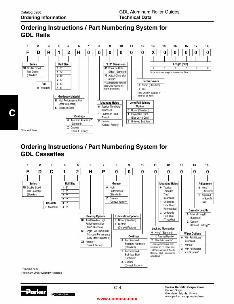
C
C14 Parker Hannifin CorporationParker-OrigaGlendale Heights, Illinoiswww.parker.com/pneu/rodless
ORIGA
Ordering Instructions / Part Numbering System for GDL Rails
Length (mm)X 0 0 0 0 0
Note: Maximum length is 4 meters on Size 12.
RailR Standard
CassetteC Standard
Adjustment0 None*
(Standard)1 Adjusted
to Specific Rail*
Rail Size1 2*1 5*2 0*2 5*3 5*4 5*
Rail Size1 2*1 5*2 0*2 5*3 5*4 5*
SeriesFD Double Sided
Rail Guide* (Standard
SeriesFD Double Sided
Rail Cassette* (Standard
“L11” Dimension00 Equal on Both
Sides* (Standard)?? Actual Dimension
(mm)**** As measured from left side while viewing the depth groove line.
Guideway MaterialH High Performance Alloy
Steel* (Standard)S Stainless Steel
Bearing OptionsHP Axial Needle - High
Performance Alloy Steel* (Standard)
SP Single Row Radial Ball - Standard Performance - Alloy Steel* (Standard)
ZZ Factory** (Consult Factory
Coatings0 Anodized Aluminum*
(Standard)Z Custom
(Consult Factory)
Coatings0 Anodized and
Standard Hardware* (Standard)
1 Anodized and Stainless Steel Hardware*
Z Custom (Consult Factory)
Grease0 High
Performance* (Standard)
Z Custom (Consult Factory)
Mounting Holes0 Topside Thru Hole*
(Standard)1 Underside Blind
ThreadZ Custom
(Consult Factory)
Mounting Holes0 Topside
Threaded Thru* (Standard)
1 Underside Hole Thru (Unthreaded)
2 Underside Hole Thru (Threaded)
Wiper Options0 With Felt Wipers*
(Standard)1 Without*2 With Felt Wipers
and Scrapers*
Screw Covers0 None* (Standard)1 Yes*
Note: Quantity supplied to cover all rail holes.
Locking Mechanism0 None* (Standard)1 “L” Ratchet Handle*2 Star Grip Handle*
* Locking mechanism only available on FD Series size 15 thru 45 with Axial Needle Bearing - High Performance - Alloy Steel.
Long Rail Joining Option
0 None* (Standard)1 Keyed Butt Joint
(Size 25-45 Only)2 Unkeyed Butt Joint
Lubrication Options0 None* (Standard)Z Custom
(Consult Factory)**
Cassette Length0 Normal Length*
(Standard)Z Custom
(Consult Factory)**
F D R 1 2 H 0 0 0 0 0 0 X 0 0 0 0 0
F D C 1 2 H P 0 0 0 0 0 0 0 0
1 2 3 4 5 6 7 8 9 10 11 12 13 14 15 16 17 18
1 2 3 4 5 6 7 8 9 10 11 12 13 14 15
**Stocked Item**Minimum Order Quantity Required
*Stocked Item
GDL Aluminum Roller GuidesTechnical Data
Catalog 0980
Ordering Information
Ordering Instructions / Part Numbering System for GDL Cassettes
www.comoso.com

C
C15 Parker Hannifin CorporationParker-OrigaGlendale Heights, Illinoiswww.parker.com/pneu/rodless
ORIGA
GDL Application Sheet
Distributor: ____________________________________________End-User: ____________________________________
Salesperson: __________________________________________________
Phone: _____________________________ Fax: __________________________ e-mail: __________________________
Other Information: ___________________________________________________________________________________
Roll
FY
LEVER ARM
ZY
LEVER ARM
YZ
Y-AXIS
Z-AXIS
FZ
MOCX, MCX
MOMENTCENTER
Pitch
MOCY, MCY
FX
LEVER ARM ZX
X-AXIS
Z-AXIS
XZ
FZ
MOMENTCENTER
Yaw
FX
LEVER ARM
XY
LEVER ARM
YX
X-AXIS
Y-AXIS
FY
MCOZ, MCZ
MOMENTCENTER
Roll load _________________________
X - Distance ____________________
Y - Distance ____________________
Z - Distance ____________________
Pitch load ________________________
X - Distance ____________________
Y - Distance ____________________
Z - Distance ____________________
Yaw load ________________________
X - Distance ____________________
Y - Distance ____________________
Z - Distance ____________________
Length of rails _______________
Distance between rails ________
Distance between cassettes on each rail _________________
technical Data:
Stroke _____________________
Horizontal __________________
Vertical _____________________
Velocity / Speed ______________
Acceleration _________________
Load / Mass _________________
Load Distances ______________
Lifetime Desired ______________
environment:(Dirt, Humidity...)
GDL Aluminum Roller GuidesCatalog 0980
Application Sheet
www.comoso.com

D
D1 Parker Hannifin CorporationParker-OrigaGlendale Heights, Illinoiswww.parker.com/pneu/rodless
ORIGA
Before selecting or using Parker (The Company) cylinders or related accessories, it is important that you read, understand and follow the following safety information. Training is advised before selecting and using The Company’s products.
1.0 General Instructions
1.1 Scope – This safety guide provides instructions for selecting and using (including assembling, installing, and maintaining) cylinder products. This safety guide is a supplement to and is to be used with the specific Company publications for the specific cylinder products that are being considered for use.
1.2 Fail Safe – Cylinder products can and do fail without warning for many reasons. All systems and equipment should be designed in a fail-safe mode so that if the failure of a cylinder product occurs people and property won’t be endangered.
1.3 Distribution – Provide a free copy of this safety guide to each person responsible for selecting or using cylinder products. Do not select or use The Company’s cylinders without thoroughly reading and understanding this safety guide as well as the specific Company publications for the products considered or selected.
1.4 User Responsibility – Due to very wide variety of cylinder applications and cylinder operating conditions, The Company does not warrant that any particular cylinder is suitable for any specific application. This safety guide does not analyze all technical parameters that must be considered in selecting a product. The hydraulic and pneumatic cylinders outlined in this catalog are designed to The Company’s design guidelines and do not necessarily meet the design guideline of other agencies such as American Bureau of Shipping, ASME Pressure Vessel Code etc. The user, through its own analysis and testing, is solely responsible for:
• Making the final selection of the cylinders and related accessories.
• Determining if the cylinders are required to meet specific design requirements as required by the Agency(s) or industry standards covering the design of the user’s equipment.
• Assuring that the user’s requirements are met, OSHA requirements are met, and safety guidelines from the applicable agencies such as but not limited to ANSI are followed and that the use presents no health or safety hazards.
• Providing all appropriate health and safety warnings on the equipment on which the cylinders are used.
1.5 Additional Questions – Call the appropriate Company technical service department if you have any questions or require any additional information. See the Company publication for the product being considered or used, or call 1-800-CPARKER, or go to www.parker.com, for telephone numbers of the appropriate technical service department.
2.0 Cylinder and Accessories Selection
2.1 Seals – Part of the process of selecting a cylinder is the selection of seal compounds. Before making this selection, consult the “seal information page(s)” of the publication for the series of cylinders of interest.
The application of cylinders may allow fluids such as cutting fluids, wash down fluids etc. to come in contact with the external area of the cylinder. These fluids may attack the piston rod wiper and or the primary seal and must be taken into account when selecting and specifying seal compounds.
Dynamic seals will wear. The rate of wear will depend on many operating factors. Wear can be rapid if a cylinder is misaligned or if the cylinder has been improperly serviced. The user must take seal wear into consideration in the application of cylinders.
2.2 Piston Rods – Possible consequences of piston rod failure or separation of the piston rod from the piston include, but are not limited to are:
• Piston rod and or attached load thrown off at high speed.
• High velocity fluid discharge.
• Piston rod extending when pressure is applied in the piston retract mode.
Piston rods or machine members attached to the piston rod may move suddenly and without warning as a consequence of other conditions occurring to the machine such as, but not limited to:
• Unexpected detachment of the machine member from the piston rod.
• Failure of the pressurized fluid delivery system (hoses, fittings, valves, pumps, compressors) which maintain cylinder position.
• Catastrophic cylinder seal failure leading to sudden loss of pressurized fluid.
• Failure of the machine control system.
Follow the recommendations of the “Piston Rod Selection Chart and Data” in the publication for the series of cylinders of interest. The suggested piston rod diameter in these charts must be followed in order to avoid piston rod buckling.
Piston rods are not normally designed to absorb bending moments or loads which are perpendicular to the axis of piston rod motion. These additional loads can cause the piston rod to fail. If these types of additional loads are expected to be imposed on the piston rod, their magnitude should be made known to our engineering department.
The cylinder user should always make sure that the piston rod is securely attached to the machine member.
On occasion cylinders are ordered with double rods (a piston rod extended from both ends of the cylinder). In some cases a stop is threaded on to one of the piston rods and used as an external stroke adjuster. On occasions spacers are attached to the machine member connected to the piston rod and also used as a stroke adjuster. In both cases the stops will create a pinch point and the user should consider appropriate use of guards. If these external stops are not perpendicular to the mating contact surface, or if debris is trapped between the contact surfaces, a bending moment will be placed on the piston rod, which can lead to piston rod failure. An external stop will also negate the effect of cushioning and will subject the piston rod to impact loading. Those two (2) conditions can cause piston rod failure. Internal stroke adjusters are available with and without cushions. The use of external stroke adjusters should be reviewed with our engineering department.
The piston rod to piston and the stud to piston rod threaded connections are secured with an anaerobic adhesive. The strength of the adhesive decreases with increasing temperature. Cylinders which can be exposed to temperatures above +250°F (+121°C) are to be ordered with a non studded piston rod and a pinned piston to rod joint.
2.3 Cushions – Cushions should be considered for cylinder applications when the piston velocity is expected to be over 4 inches/second.
Cylinder cushions are normally designed to absorb the energy of a linear applied load. A rotating mass has considerably more energy than the same mass moving in a linear mode. Cushioning for a rotating mass application should be review by our engineering department.
2.4 Cylinder Mountings – Some cylinder mounting configurations may have certain limitations such as but not limited to minimum stroke for side or foot mounting cylinders or pressure de-ratings for certain mounts. Carefully review the catalog for these types of restrictions.
Always mount cylinders using the largest possible high tensile alloy steel socket head cap screws that can fit in the cylinder mounting holes and torque them to the manufacturer’s recommendations for their size.
2.5 Port Fittings – Hydraulic cylinders applied with meter out or deceleration circuits are subject to intensified pressure at piston rod end.
The rod end pressure is approximately equal to:
operating pressure x effective cap end area
effective rod end piston area
Contact your connector supplier for the pressure rating of individual connectors.
3.0 Cylinder and Accessories Installation and Mounting
3.1 Installation
3.1.1 – Cleanliness is an important consideration, and cylinders are shipped with the ports plugged to protect them from contaminants
Safety Guide for Selecting and Using Hydraulic, Pneumatic Cylinders and their Accessories
WARNING: FAILURe OF tHe CYLINDeR, ItS PARtS, ItS MOUNtING, ItS CONNeCtIONS tO OtHeR OBJeCtS, OR ItS CONtROLS CAN ReSULt IN: •Unanticipatedoruncontrolledmovementofthecylinderorobjectsconnectedtoit. •Fallingofthecylinderorobjectsheldupbyit. •Fluidescapingfromthecylinder,potentiallyathighvelocity.tHeSe eVeNtS COULD CAUSe DeAtH OR PeRSONAL INJURY BY, FOR eXAMPLe, PeRSONS FALLING FROM HIGH LOCAtIONS, BeING CRUSHeD OR StRUCK BY HeAVY OR FASt MOVING OBJeCtS, BeING PUSHeD INtO DANGeROUS eQUIPMeNt OR SItUAtIONS, OR SLIPPING ON eSCAPeD FLUID.
!
OSP-P Pneumatic Rodless Cylinders and Linear GuidesCatalog 0980
Safety Guide
www.comoso.com

D
D2 Parker Hannifin CorporationParker-OrigaGlendale Heights, Illinoiswww.parker.com/pneu/rodless
ORIGA
entering the ports. These plugs should not be removed until the piping is to be installed. Before making the connection to the cylinder ports, piping should be thoroughly cleaned to remove all chips or burrs which might have resulted from threading or flaring operations.
3.1.2 – Cylinders operating in an environment where air drying materials are present such as fast-drying chemicals, paint, or weld splatter, or other hazardous conditions such as excessive heat, should have shields installed to prevent damage to the piston rod and piston rod seals.
3.1.3 – Proper alignment of the cylinder piston rod and its mating component on the machine should be checked in both the extended and retracted positions. Improper alignment will result in excessive rod gland and/or cylinder bore wear. On fixed mounting cylinders attaching the piston rod while the rod is retracted will help in achieving proper alignment.
3.1.4 – Sometimes it may be necessary to rotate the piston rod in order to thread the piston rod into the machine member. This operation must always be done with zero pressure being applied to either side of the piston. Failure to follow this procedure may result in loosening the piston to rod-threaded connection. In some rare cases the turning of the piston rod may rotate a threaded piston rod gland and loosen it from the cylinder head. Confirm that this condition is not occurring. If it does, re-tighten the piston rod gland firmly against the cylinder head.
For double rod cylinders it is also important that when attaching or detaching the piston rod from the machine member that the torque be applied to the piston rod end of the cylinder that is directly attaching to the machine member with the opposite end unrestrained. If the design of the machine is such that only the rod end of the cylinder opposite to where the rod attaches to the machine member can be rotated, consult the factory for further instructions.
3.2 Mounting Recommendations
3.2.1 – Always mount cylinders using the largest possible high tensile alloy steel socket head screws that can fit in the cylinder mounting holes and torque them to the manufacturer’s recommendations for their size.
3.2.2 – Side-Mounted Cylinders – In addition to the mounting bolts, cylinders of this type should be equipped with thrust keys or dowel pins located so as to resist the major load.
3.2.3 – Tie Rod Mounting – Cylinders with tie rod mountings are recommended for applications where mounting space is limited. The standard tie rod extension is shown as BB in dimension tables. Longer or shorter extensions can be supplied. Nuts used for this mounting style should be torqued to the same value as the tie rods for that bore size.
3.2.4 – Flange Mount Cylinders – The controlled diameter of the rod gland extension on head end flange mount cylinders can be used as a pilot to locate the cylinders in relation to the machine. After alignment has been obtained, the flanges may be drilled for pins or dowels to prevent shifting.
3.2.5 – Trunnion Mountings – Cylinders require lubricated bearing blocks with minimum bearing clearances. Bearing blocks should be carefully aligned and rigidly mounted so the trunnions will not be subjected to bending moments. The rod end should also be pivoted with the pivot pin in line and parallel to axis of the trunnion pins.
3.2.6 – Clevis Mountings – Cylinders should be pivoted at both ends with centerline of pins parallel to each other. After cylinder is mounted, be sure to check to assure that the cylinder is free to swing through its working arc without interference from other machine parts.
4.0 Cylinder and Accessories Maintenance, troubleshooting and Replacement
4.1 Storage – At times cylinders are delivered before a customer is ready to install them and must be stored for a period of time. When storage is required the following procedures are recommended.
4.1.1 – Store the cylinders in an indoor area which has a dry, clean and noncorrosive atmosphere. Take care to protect the cylinder from both internal corrosion and external damage.
4.1.2 – Whenever possible cylinders should be stored in a vertical position (piston rod up). This will minimize corrosion due to possible condensation which could occur inside the cylinder. This will also minimize seal damage.
4.1.3 – Port protector plugs should be left in the cylinder until the time of installation.
4.1.4 – If a cylinder is stored full of hydraulic fluid, expansion of the fluid due to temperature changes must be considered. Installing a check valve with free flow out of the cylinder is one method.
4.1.5 – When cylinders are mounted on equipment that is stored outside for extended periods, exposed unpainted surfaces, e.g. piston rod, must be coated with a rust-inhibiting compound to prevent corrosion.
4.2 Cylinder trouble Shooting
4.2.1 – external Leakage
4.2.1.1 – Rod seal leakage can generally be traced to worn or damaged seals. Examine the piston rod for dents, gouges or score marks, and replace piston rod if surface is rough.
Rod seal leakage could also be traced to gland wear. If clearance is excessive, replace rod bushing and seal. Rod seal leakage can also be traced to seal deterioration. If seals are soft or gummy or brittle, check compatibility of seal material with lubricant used if air cylinder, or operating fluid if hydraulic cylinder. Replace with seal material, which is compatible with these fluids. If the seals are hard or have lost elasticity, it is usually due to exposure to temperatures in excess of 165°F. (+74°C). Shield the cylinder from the heat source to limit temperature to 350°F. (+177°C.) and replace with fluorocarbon seals.
4.2.1.2 – Cylinder body seal leak can generally be traced to loose tie rods. Torque the tie rods to manufacturer’s recommendation for that bore size.
Excessive pressure can also result in cylinder body seal leak. Determine maximum pressure to rated limits. Replace seals and retorque tie rods as in paragraph above. Excessive pressure can also result in cylinder body seal leak. Determine if the pressure rating of the cylinder has been exceeded. If so, bring the operating pressure down to the rating of the cylinder and have the tie rods replaced.
Pinched or extruded cylinder body seal will also result in a leak. Replace cylinder body seal and retorque as in paragraph above.
Cylinder body seal leakage due to loss of radial squeeze which shows up in the form of flat spots or due to wear on the O.D. or I.D. – Either of these are symptoms of normal wear due to high cycle rate or length of service. Replace seals as per paragraph above.
4.2.2 – Internal Leakage
4.2.2.1 – Piston seal leak (by-pass) 1 to 3 cubic inches per minute leakage is considered normal for piston ring construction. Virtually no static leak with lipseal type seals on piston should be expected. Piston seal wear is a usual cause of piston seal leakage. Replace seals as required.
4.2.2.2 – With lipseal type piston seals excessive back pressure due to over-adjustment of speed control valves could be a direct cause of rapid seal wear. Contamination in a hydraulic system can result in a scored cylinder bore, resulting in rapid seal wear. In either case, replace piston seals as required.
4.2.2.3 – What appears to be piston seal leak, evidenced by the fact that the cylinder drifts, is not always traceable to the piston. To make sure, it is suggested that one side of the cylinder piston be pressurized and the fluid line at the opposite port be disconnected. Observe leakage. If none is evident, seek the cause of cylinder drift in other component parts in the circuit.
4.2.3 – Cylinder Fails to Move the Load
4.2.3.1 – Pneumatic or hydraulic pressure is too low. Check the pressure at the cylinder to make sure it is to circuit requirements.
4.2.3.2 – Piston Seal Leak – Operate the valve to cycle the cylinder and observe fluid flow at valve exhaust ports at end of cylinder stroke. Replace piston seals if flow is excessive.
4.2.3.3 – Cylinder is undersized for the load – Replace cylinder with one of a larger bore size.
4.3 erratic or Chatter Operation
4.3.1 – Excessive friction at rod gland or piston bearing due to load misalignment – Correct cylinder-to-load alignment.
4.3.2 – Cylinder sized too close to load requirements – Reduce load or install larger cylinder.
4.3.3 – Erratic operation could be traced to the difference between static and kinetic friction. Install speed control valves to provide a back pressure to control the stroke.
4.4 Cylinder Modifications, Repairs, or Failed Component – Cylinders as shipped from the factory are not to be disassembled and or modified. If cylinders require modifications, these modifications must be done at company locations or by The Company’s certified facilities. The Cylinder Division Engineering Department must be notified in the event of a mechanical fracture or permanent deformation of any cylinder component (excluding seals). This includes a broken piston rod, tie rod, mounting accessory or any other cylinder component. The notification should include all operation and application details. This information will be used to provide an engineered repair that will prevent recurrence of the failure.
It is allowed to disassemble cylinders for the purpose of replacing seals or seal assemblies. However, this work must be done by strictly following all the instructions provided with the seal kits.
OSP-P Pneumatic Rodless Cylinders and Linear GuidesCatalog 0980
Safety Guide
www.comoso.com

D
D3 Parker Hannifin CorporationParker-OrigaGlendale Heights, Illinoiswww.parker.com/pneu/rodless
ORIGA
OSP-P Pneumatic Rodless Cylinders and Linear GuidesCatalog 0980
Offer of Sale
the items described in this document and other documents or descriptions provided by Parker Hannifin Corporation, its subsidiaries and its authorized distributors, are hereby offered for sale at prices to be established by Parker Hannifin Corporation, its subsidiaries and its authorized distributors. this offer and its acceptance by any customer (“Buyer”) shall be governed by all of the following terms and Conditions. Buyer’s order for any such item, when communicated to Parker Hannifin Corporation, its subsidiaries or an authorized distributor (“Seller”) verbally or in writing, shall constitute acceptance of this offer.1. terms and Conditions of Sale: All descriptions, quotations, proposals, offers, acknowledgments, acceptances and sales of Seller’s products are subject to and shall be governed exclusively by the terms and conditions stated herein. Buyer’s acceptance of any offer to sell is limited to these terms and conditions. Any terms or conditions in addition to, or inconsistent with those stated herein, proposed by Buyer in any acceptance of an offer by Seller, are hereby objected to. No such additional, different or inconsistent terms and conditions shall become part of the contract between Buyer and Seller unless expressly accepted in writing by Seller. Seller’s acceptance of any offer to purchase by Buyer is expressly conditional upon Buyer’s assent to all the terms and conditions stated herein, including any terms in addition to, or inconsistent with those contained in Buyer’s offer. Acceptance of Seller’s products shall in all events constitute such assent.2. Payment: Payment shall be made by Buyer net 30 days from the date of delivery of the items purchased hereunder. Amounts not timely paid shall bear interest at the maximum rate permitted by law for each month or portion thereof that the Buyer is late in making payment. Any claims by Buyer for omissions or shortages in a shipment shall be waived unless Seller receives notice thereof within 30 days after Buyer’s receipt of the shipment.3. Delivery: Unless otherwise provided on the face hereof, delivery shall be made F.O.B. Seller’s plant. Regardless of the method of delivery, however, risk of loss shall pass to Buyer upon Seller’s delivery to a carrier. Any delivery dates shown are approximate only and Seller shall have no liability for any delays in delivery.4. Warranty: Seller warrants that the items sold hereunder shall be free from defects in material or workmanship for a period of 18 months from date of shipment from Parker Hannifin Corporation. THIS WARRANTY COMPRISES THE SOLE AND ENTIRE WARRANTY PERTAINING TO ITEMS PROVIDED HEREUNDER. SELLER MAKES NO OTHER WARRANTY, GUARANTEE, OR REPRESENTATION OF ANY KIND WHATSOEVER. ALL OTHER WARRANTIES, INCLUDING BUT NOT LIMITED TO, MERCHANTABILITY AND FITNESS FOR PURPOSE, WHETHER EXPRESS, IMPLIED, OR ARISING BY OPERATION OF LAW, TRADE USAGE, OR COURSE OF DEALING ARE HEREBY DISCLAIMED.NOTWITHSTANDING THE FOREGOING, THERE ARE NO WARRANTIES WHATSOEVER ON ITEMS BUILT OR ACQUIRED WHOLLY OR PARTIALLY, TO BUYER’S DESIGN OR SPECIFICATIONS.5. Limitation of Remedy: SELLER’S LIABILITY ARISING FROM OR IN ANY WAY CONNECTED WITH THE ITEMS SOLD OR THIS CONTRACT SHALL BE LIMITED EXCLUSIVELY TO REPAIR OR REPLACEMENT OF THE ITEMS SOLD OR REFUND OF THE PURCHASE PRICE PAID BY BUYER, AT SELLER’S SOLE OPTION. IN NO EVENT SHALL SELLER BE LIABLE FOR ANY INCIDENTAL, CONSEQUENTIAL OR SPECIAL DAMAGES OF ANY KIND OR NATURE WHATSOEVER, INCLUDING BUT NOT LIMITED TO LOST PROFITS ARISING FROM OR IN ANY WAY CONNECTED WITH THIS AGREEMENT OR ITEMS SOLD HEREUNDER, WHETHER ALLEGED TO ARISE FROM BREACH OF CONTRACT, EXPRESS OR IMPLIED WARRANTY, OR IN TORT, INCLUDING WITHOUT LIMITATION, NEGLIGENCE, FAILURE TO WARN OR STRICT LIABILITY.6. Changes, Reschedules and Cancellations: Buyer may request to modify the designs or specifications for the items sold hereunder as well as the quantities and delivery dates thereof, or may request to cancel all or part of this order, however, no such requested modification or cancellation shall become part of the contract between Buyer and Seller unless accepted by Seller in a written amendment to this Agreement. Acceptance of any such requested modification or cancellation shall be at Seller’s discretion, and shall be upon such terms and conditions as Seller may require.7. Special tooling: A tooling charge may be imposed for any special tooling, including without limitations, dies, fixtures, molds and patterns, acquired to manufacture items sold pursuant to this contract. Such special tooling shall be and remain Seller’s property notwithstanding payment of any charges by Buyer. In no event will Buyer acquire any interest in apparatus belonging to Seller which is utilized in the manufacture of the items sold hereunder, even if such apparatus has been specially converted or adapted for such manufacture and notwithstanding any
charges paid by Buyer. Unless otherwise agreed, Seller shall have the right to alter, discard or otherwise dispose of any special tooling or other property in its sole discretion at any time.
8. Buyer’s Property: Any designs, tools, patterns, materials, drawings, confidential information or equipment furnished by Buyer, or any other items which become Buyer’s property, may be considered obsolete and may be destroyed by Seller after two (2) consecutive years have elapsed without Buyer placing an order for the items which are manufactured using such property. Seller shall not be responsible for any loss or damage to such property while it is in Seller’s possession or control.
9. taxes: Unless otherwise indicated on the face hereof, all prices and charges are exclusive of excise, sales, use, property, occupational or like taxes which may be imposed by any taxing authority upon the manufacture, sale or delivery of the items sold hereunder. If any such taxes must be paid by Seller or if Seller is liable for the collection of such tax, the amount thereof shall be in addition to the amounts for the items sold. Buyer agrees to pay all such taxes or to reimburse Seller therefore upon receipt of its invoice. If Buyer claims exemption from any sales, use or other tax imposed by any taxing authority, Buyer shall save Seller harmless from and against any such tax, together with any interest or penalties thereon which may be assessed if the items are held to be taxable.
10. Indemnity For Infringement of Intellectual Property Rights: Seller shall have no liability for infringement of any patents, trademarks, copyrights, trade dress, trade secrets or similar rights except as provided in this Part 10. Seller will defend and indemnify Buyer against allegations of infringement of U.S. patents, U.S. trademarks, copyrights, trade dress and trade secrets (hereinafter “Intellectual Property Rights”). Seller will defend at its expense and will pay the cost of any settlement or damages awarded in an action brought against Buyer based on an allegation that an item sold pursuant to this contract infringes the Intellectual Property Rights of a third party. Seller’s obligation to defend and indemnify Buyer is contingent on Buyer notifying Seller within ten (10) days after Buyer becomes aware of such allegations of infringement, and Seller having sole control over the defense of any allegations or actions including all negotiations for settlement or compromise. If an item sold hereunder is subject to a claim that it infringes the Intellectual Property Rights of a third party, Seller may, at its sole expense and option, procure for Buyer the right to continue using said item, replace or modify said item so as to make it noninfringing, or offer to accept return of said item and return the purchase price less a reasonable allowance for depreciation. Notwithstanding the foregoing, Seller shall have no liability for claims of infringement based on information provided by Buyer, or directed to items delivered hereunder for which the designs are specified in whole or part by Buyer, or infringements resulting from the modification, combination or use in a system of any item sold hereunder. The foregoing provisions of this Part 10 shall constitute Seller’s sole and exclusive liability and Buyer’s sole and exclusive remedy for infringement of Intellectual Property Rights.
If a claim is based on information provided by Buyer or if the design for an item delivered hereunder is specified in whole or in part by Buyer, Buyer shall defend and indemnify Seller for all costs, expenses or judgements resulting from any claim that such item infringes any patent, trademark, copyright, trade dress, trade secret or any similar right.
11. Force Majeure: Seller does not assume the risk of and shall not be liable for delay or failure to perform any of Seller’s obligations by reason of circumstances beyond the reasonable control of Seller (hereinafter “Events of Force Majeure”). Events of Force Majeure shall include without limitation, accidents, acts of God, strikes or labor disputes, acts, laws, rules or regulations of any government or government agency, fires, floods, delays or failures in delivery of carriers or suppliers, shortages of materials and any other cause beyond Seller’s control.
12. entire Agreement/Governing Law: The terms and conditions set forth herein, together with any amendments, modifications and any different terms or conditions expressly accepted by Seller in writing, shall constitute the entire Agreement concerning the items sold, and there are no oral or other representations or agreements which pertain thereto. This Agreement shall be governed in all respects by the law of the State of Ohio. No actions arising out of sale of the items sold hereunder or this Agreement may be brought by either party more than two (2) years after the cause of action accrues.
www.comoso.com

www.comoso.com

Catalog 0980 4/2009
Phone 630-871-8300 fax 630-871-1515 toll free 800-695-5984 email: [email protected] website www.parker.com/pneu/rodless
Parker Hannifin CorporationParker-Origa100 West Lake DriveGlendale Heights, IL 60139 USA
ORIGA
www.comoso.com