Buckling analysis of thin-walled metal liner of cylindrical ...
Upload
khangminh22Category
view
3download
0
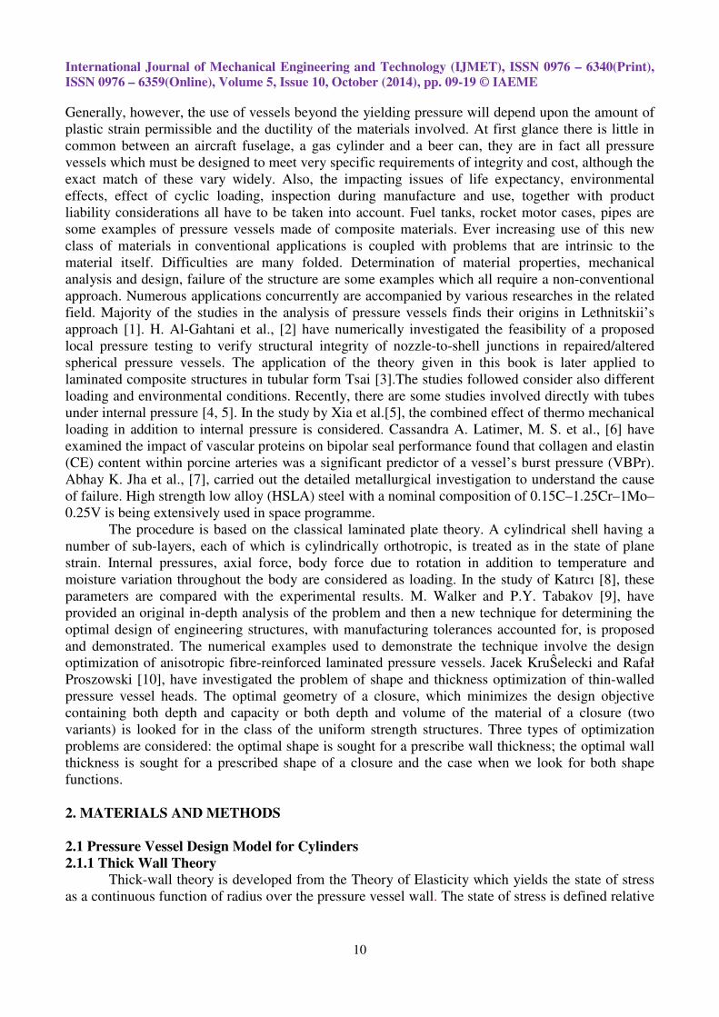
International Journal of Mechanical Engineering and Technology (IJMET), ISSN 0976 – 6340(Print),
ISSN 0976 – 6359(Online), Volume 5, Issue 10, October (2014), pp. 09-19 © IAEME
9
ANALYSIS OF A THIN AND THICK WALLED PRESSURE
VESSEL FOR DIFFERENT MATERIALS
1Qayssar Saeed Masikh,
2Dr. Mohammad Tariq,
3Er. Prabhat Kumar Sinha
1Local Administration, Karbala Governorate, Republic of Iraq
2, 3Assistant Prof., Department of Mechanical Engineering, SSET, SHIATS-DU, Allahabad, India
ABSTRACT
In the present work the problem of calculation of the stress developed in the thin and thick
cylindrical pressure vessels is numerically solved by using software in C++. The analysis has been
done for two different materials pressure vessels. The variations in the thickness of the pressure
vessels have been considered for the analysis for different internal pressures. The common
characteristic of the pressure vessels solved is that the radial and tangential stresses vary in the same
nature of curve for different thickness of vessels. Lame’s equations, maximum normal stress theory,
maximum shear stress theory have been applied for the analysis of the thick walled pressure vessels
of brittle and ductile materials. Analysis also performed for open and closed end cylinders by using
Burnie’s equation and shear strain theory. Barlow’s equation has been applied for the calculation and
analysis of the high pressure oil and gas pipe analysis. The yield point stress and ultimate stresses
have been considered for the ductile and brittle material respectively. The modeling details of the
methodology, employed in the analysis, are extensively discussed and the numerical approach is
proven to be very efficient for the software developed of pressure vessel for thin and thick cylinders.
Keywords: Thick Walled Cylinder, Pressure Vessels, Thin Walled Cylinder, Ductile Material,
Brittle Material.
1. INTRODUCTION
The design of pressure vessels for operation at very high pressures is a complex problem
involving many considerations including definition of the operating and permissible stress levels,
criteria of failure, material behavior, etc. For the purpose of developing the design philosophy and
the relative operational limitations of various approaches, the elastic strength or yielding pressure of
the vessel will be used as the criterion of failure. It should be noted, however, that some designs can
be used at pressures in excess of that at which yielding of one or more components is predicted.
INTERNATIONAL JOURNAL OF MECHANICAL ENGINEERING
AND TECHNOLOGY (IJMET)
ISSN 0976 – 6340 (Print)
ISSN 0976 – 6359 (Online)
Volume 5, Issue 10, October (2014), pp. 09-19
© IAEME: www.iaeme.com/IJMET.asp
Journal Impact Factor (2014): 7.5377 (Calculated by GISI)
www.jifactor.com
IJMET
© I A E M E
International Journal of Mechanical Engineering and Technology (IJMET), ISSN 0976 – 6340(Print),
ISSN 0976 – 6359(Online), Volume 5, Issue 10, October (2014), pp. 09-19 © IAEME
10
Generally, however, the use of vessels beyond the yielding pressure will depend upon the amount of
plastic strain permissible and the ductility of the materials involved. At first glance there is little in
common between an aircraft fuselage, a gas cylinder and a beer can, they are in fact all pressure
vessels which must be designed to meet very specific requirements of integrity and cost, although the
exact match of these vary widely. Also, the impacting issues of life expectancy, environmental
effects, effect of cyclic loading, inspection during manufacture and use, together with product
liability considerations all have to be taken into account. Fuel tanks, rocket motor cases, pipes are
some examples of pressure vessels made of composite materials. Ever increasing use of this new
class of materials in conventional applications is coupled with problems that are intrinsic to the
material itself. Difficulties are many folded. Determination of material properties, mechanical
analysis and design, failure of the structure are some examples which all require a non-conventional
approach. Numerous applications concurrently are accompanied by various researches in the related
field. Majority of the studies in the analysis of pressure vessels finds their origins in Lethnitskii’s
approach [1]. H. Al-Gahtani et al., [2] have numerically investigated the feasibility of a proposed
local pressure testing to verify structural integrity of nozzle-to-shell junctions in repaired/altered
spherical pressure vessels. The application of the theory given in this book is later applied to
laminated composite structures in tubular form Tsai [3].The studies followed consider also different
loading and environmental conditions. Recently, there are some studies involved directly with tubes
under internal pressure [4, 5]. In the study by Xia et al.[5], the combined effect of thermo mechanical
loading in addition to internal pressure is considered. Cassandra A. Latimer, M. S. et al., [6] have
examined the impact of vascular proteins on bipolar seal performance found that collagen and elastin
(CE) content within porcine arteries was a significant predictor of a vessel’s burst pressure (VBPr).
Abhay K. Jha et al., [7], carried out the detailed metallurgical investigation to understand the cause
of failure. High strength low alloy (HSLA) steel with a nominal composition of 0.15C–1.25Cr–1Mo–
0.25V is being extensively used in space programme.
The procedure is based on the classical laminated plate theory. A cylindrical shell having a
number of sub-layers, each of which is cylindrically orthotropic, is treated as in the state of plane
strain. Internal pressures, axial force, body force due to rotation in addition to temperature and
moisture variation throughout the body are considered as loading. In the study of Katırcı [8], these
parameters are compared with the experimental results. M. Walker and P.Y. Tabakov [9], have
provided an original in-depth analysis of the problem and then a new technique for determining the
optimal design of engineering structures, with manufacturing tolerances accounted for, is proposed
and demonstrated. The numerical examples used to demonstrate the technique involve the design
optimization of anisotropic fibre-reinforced laminated pressure vessels. Jacek KruŜelecki and Rafał
Proszowski [10], have investigated the problem of shape and thickness optimization of thin-walled
pressure vessel heads. The optimal geometry of a closure, which minimizes the design objective
containing both depth and capacity or both depth and volume of the material of a closure (two
variants) is looked for in the class of the uniform strength structures. Three types of optimization
problems are considered: the optimal shape is sought for a prescribe wall thickness; the optimal wall
thickness is sought for a prescribed shape of a closure and the case when we look for both shape
functions.
2. MATERIALS AND METHODS
2.1 Pressure Vessel Design Model for Cylinders
2.1.1 Thick Wall Theory
Thick-wall theory is developed from the Theory of Elasticity which yields the state of stress
as a continuous function of radius over the pressure vessel wall. The state of stress is defined relative
International Journal of Mechanical Engineering and Technology (IJMET), ISSN 0976 – 6340(Print),
ISSN 0976 – 6359(Online), Volume 5, Issue 10, October (2014), pp. 09-19 © IAEME
11
to a convenient cylindrical coordinate system:σ�, σ�, σ�. These are tangential, radial and
longitudinal stresses respectively.
Stresses in a cylindrical pressure vessel depend upon the ratio of the inner radius to the outer
radius (ro / ri) rather than the size of the cylinder.
Principal Stresses (σ�, σ�, σ�)
1. Determined without computation of Mohr’s Circle;
2. Equivalent to cylindrical stresses (σ�, σ�, σ�) Applicable for any wall thickness-to-radius ratio
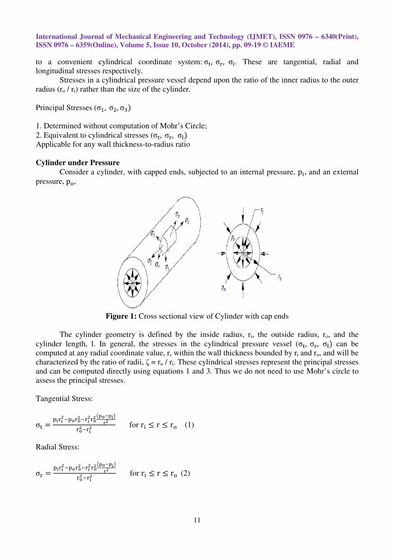
Cylinder under Pressure
Consider a cylinder, with capped ends, subjected to an internal pressure, p�, and an external
pressure,p�,
Figure 1: Cross sectional view of Cylinder with cap ends
The cylinder geometry is defined by the inside radius, ri, the outside radius, ro, and the
cylinder length, l. In general, the stresses in the cylindrical pressure vessel (σ�, σ�, σ�) can be
computed at any radial coordinate value, r, within the wall thickness bounded by ri and ro, and will be
characterized by the ratio of radii, ζ = ro / ri. These cylindrical stresses represent the principal stresses
and can be computed directly using equations 1 and 3. Thus we do not need to use Mohr’s circle to
assess the principal stresses.
Tangential Stress:
σ� =����
��������������
�������
��
������
� for r� ≤ r ≤ r� (1)
Radial Stress:
σ� =����
��������������
�������
��
������
� for r� ≤ r ≤ r� (2)
International Journal of Mechanical Engineering and Technology (IJMET), ISSN 0976 – 6340(Print),
ISSN 0976 – 6359(Online), Volume 5, Issue 10, October (2014), pp. 09-19 © IAEME
12
Longitudinal Stress:
• Applicable to cases where the cylinder carries the longitudinal load, such as capped ends.
• Only valid far away from end caps where bending, nonlinearities and stress concentrations are
not significant.
σ� =����
�������
������
� for r� ≤ r ≤ r� (3)
Two Mechanical Design Cases
1. Internal Pressure Only (p� = 0) 2. External Pressure Only (p� = 0)
Design Case 1: Internal Pressure Only
Only one case to consider — the critical section which exists at ro/ri
Substituting po = 0 in to eqs. (1 and 2) and incorporating ζ = ro / ri , the largest value of each stress
component is found at the inner surface:
σ��r = r�) = σ�,��� = p�������
�
������
� = p���
��
= p�C��
Where
C�� =��
��
= �������
������
� is a function of cylinder geometry only
σ��r = r�) = σ�,��� = −p�
Natural Boundary Condition
Longitudinal stress depends upon end conditions
σ� = p�C�� for capped ends
σ� = 0 for uncapped ends
Where C�� =�
��
2.1.2 The Thin-walled Pressure Vessel Theory
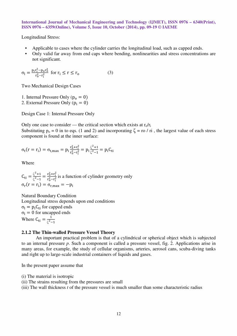
An important practical problem is that of a cylindrical or spherical object which is subjected
to an internal pressure p. Such a component is called a pressure vessel, fig. 2. Applications arise in
many areas, for example, the study of cellular organisms, arteries, aerosol cans, scuba-diving tanks
and right up to large-scale industrial containers of liquids and gases.
In the present paper assume that
(i) The material is isotropic
(ii) The strains resulting from the pressures are small
(iii) The wall thickness t of the pressure vessel is much smaller than some characteristic radius
International Journal of Mechanical Engineering and Technology (IJMET), ISSN 0976
ISSN 0976 – 6359(Online), Volume 5, Issue 10, October (2014), pp. 0
Figure 2
Because of (i, ii), the isotropic linear elastic model is used. Because of (iii), it will be
assumed that there is negligible variation in the stress field across the thickness of the vessel.
As a rule of thumb, if the thickness is
stress will vary by less than about 5% through the thickness, and in these cases the constant stress
assumption is valid.
Thin-wall theory is developed from a Strength of Materials solution which yie
stress as an average over the pressure vessel wall.
Use restricted by wall thickness-to
� According to theory, Thin-wall Theory is justified for
� In practice, typically use a less conservative rule,
State of Stress Definition
1. Hoop Stress, σ�, assumed to be uniform across wall thickness.
2. Radial Stress is insignificant compared to tangential stress, thus,
3. Longitudinal Stress, σ�
• Exists for cylinders with capped ends;
• Assumed to be uniformly distributed across wall thickness;
• This approximation for the longitudinal stress is only valid far away from the end
4. These cylindrical stresses (σ� ,without computation of Mohr’s circle plot.
• Analysis of Cylinder Section
International Journal of Mechanical Engineering and Technology (IJMET), ISSN 0976
6359(Online), Volume 5, Issue 10, October (2014), pp. 09-19 © IAEME
13
2: A pressure vessels (cross-sectional view)
ii), the isotropic linear elastic model is used. Because of (iii), it will be
assumed that there is negligible variation in the stress field across the thickness of the vessel.
As a rule of thumb, if the thickness is less than a tenth of the vessel radius, then the actual
stress will vary by less than about 5% through the thickness, and in these cases the constant stress
wall theory is developed from a Strength of Materials solution which yie
stress as an average over the pressure vessel wall.
to-radius ratio:
wall Theory is justified for �
�≤ �
�"
In practice, typically use a less conservative rule, �
�≤ �
�"
, assumed to be uniform across wall thickness.
2. Radial Stress is insignificant compared to tangential stress, thus, σ� = 0
Exists for cylinders with capped ends;
distributed across wall thickness;
This approximation for the longitudinal stress is only valid far away from the end
σ� ,σ� ) are principal stresses (σ� ,σ� ,σ� ) which can be determined
Mohr’s circle plot.
International Journal of Mechanical Engineering and Technology (IJMET), ISSN 0976 – 6340(Print),
© IAEME
ii), the isotropic linear elastic model is used. Because of (iii), it will be
assumed that there is negligible variation in the stress field across the thickness of the vessel.
less than a tenth of the vessel radius, then the actual
stress will vary by less than about 5% through the thickness, and in these cases the constant stress
wall theory is developed from a Strength of Materials solution which yields the state of
This approximation for the longitudinal stress is only valid far away from the end-caps.
) which can be determined
International Journal of Mechanical Engineering and Technology (IJMET), ISSN 0976 – 6340(Print),
ISSN 0976 – 6359(Online), Volume 5, Issue 10, October (2014), pp. 09-19 © IAEME
14
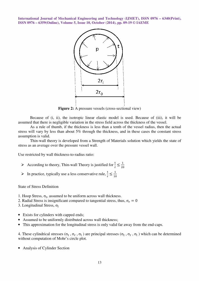
The internal pressure exerts a vertical force, FV, on the cylinder wall which is balanced by
the tangential hoop stress, FHop.
F$ = pA���& = p'�d�)�1)* = pd� (4)
F+��� = σ�A,��-,,-. = σ�'�t)�1)* = σ�t (5)
∑F1 = 0 =F$ − 2F+��� = pd� − 2σ�t (6)
Solving for the tangential stress,
Comparison of state of stress for cylinder under internal pressure verses external pressure:
Internal Pressure Only
σ� =�.���
Hoop stress
σ� = 0 By definition
σ� =�.�3�
= σ4�
Capped case
External Pressure Only
σ� =�.���
Hoop stress
σ� = 0 By definition
σ� =�.�3�
= σ4�
Capped case
3. RESULTS AND DISCUSSIONS
The results of the present work have been listed in the following paragraphs in the form of
graphs. The effects of internal pressure of the fluid in the pressure vessels and their thickness have
been considered to find the optimum condition of the design. Software has been developed in C++
for the analysis of the cylinders. Afterwards, the graphs have been plotted in origin 50, a menu
driven software. The design for both the thin and thick wall cylinders have been taken into account in
the present work. The thin walled cylinders have limited application while the thick walled cylinders
are useful for high pressure fluid flow, especially in the oil and gas pipe design.
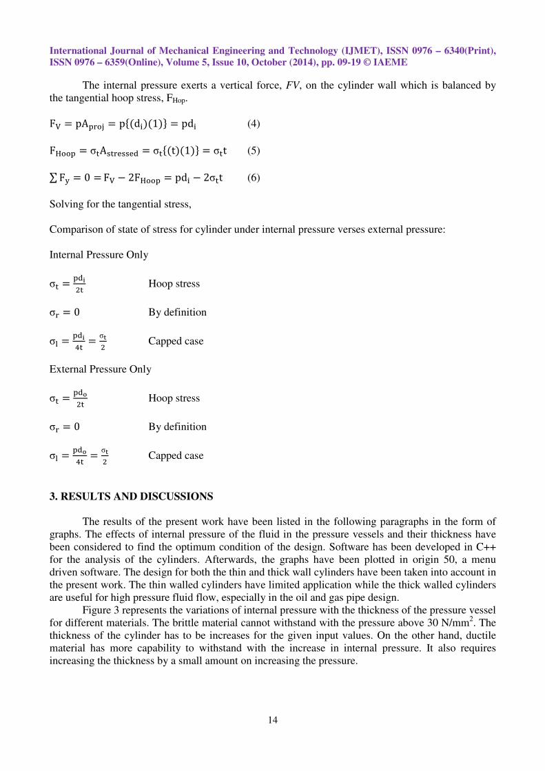
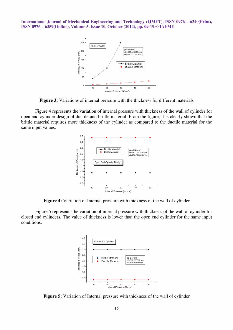
Figure 3 represents the variations of internal pressure with the thickness of the pressure vessel
for different materials. The brittle material cannot withstand with the pressure above 30 N/mm2. The
thickness of the cylinder has to be increases for the given input values. On the other hand, ductile
material has more capability to withstand with the increase in internal pressure. It also requires
increasing the thickness by a small amount on increasing the pressure.
International Journal of Mechanical Engineering and Technology (IJMET), ISSN 0976 – 6340(Print),
ISSN 0976 – 6359(Online), Volume 5, Issue 10, October (2014), pp. 09-19 © IAEME
15
10 20 30 40 50
0
50
100
150
200
250
p0=0 N/mm2
d0=300.000000 mm
di=250.000000 mm
Thick Cylinder
Brittle Material
Ductile Material
Thic
kne
ss o
f V
essel (m
m)
Internal Pressure (N/mm2)
Figure 3: Variations of internal pressure with the thickness for different materials
Figure 4 represents the variation of internal pressure with thickness of the wall of cylinder for
open end cylinder design of ductile and brittle material. From the figure, it is clearly shown that the
brittle material requires more thickness of the cylinder as compared to the ductile material for the
same input values.
10 20 30 40 50
-0.5
0.0
0.5
1.0
1.5
2.0
2.5
3.0
3.5
p0=0 N/mm2
d0=300.000000 mm
di=250.000000 mm
Open End Cylinder Design
Th
ickness o
f V
essel (m
m)
Internal Pressure (N/mm2)
Ductile Material
Brittle Material
Figure 4: Variation of Internal pressure with thickness of the wall of cylinder
Figure 5 represents the variation of internal pressure with thickness of the wall of cylinder for
closed end cylinders. The value of thickness is lower than the open end cylinder for the same input
conditions.
10 20 30 40 50
0.5
1.0
1.5
2.0
2.5
3.0
3.5
4.0
p0=0 N/mm2
d0=300.000000 mm
di=250.000000 mm
Thic
kness o
f V
esse
l (m
m)
Internal Pressure (N/mm2)
Colsed End Cylinder
Brittle Material
Ductile Material
Figure 5: Variation of Internal pressure with thickness of the wall of cylinder
International Journal of Mechanical Engineering and Technology (IJMET), ISSN 0976 – 6340(Print),
ISSN 0976 – 6359(Online), Volume 5, Issue 10, October (2014), pp. 09-19 © IAEME
16
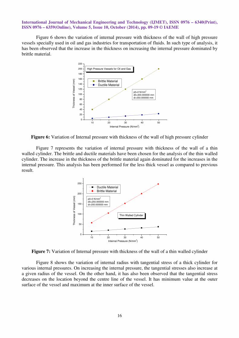
Figure 6 shows the variation of internal pressure with thickness of the wall of high pressure
vessels specially used in oil and gas industries for transportation of fluids. In such type of analysis, it
has been observed that the increase in the thickness on increasing the internal pressure dominated by
brittle material.
10 20 30 40 50
0
20
40
60
80
100
120
140
160
180
200
220
p0=0 N/mm2
d0=300.000000 mm
di=250.000000 mm
High Pressure Vessels for Oil and Gas
Thic
kne
ss o
f V
esse
l (m
m)
Internal Pressure (N/mm2)
Brittle Material
Ductile Material
Figure 6: Variation of Internal pressure with thickness of the wall of high pressure cylinder
Figure 7 represents the variation of internal pressure with thickness of the wall of a thin
walled cylinder. The brittle and ductile materials have been chosen for the analysis of the thin walled
cylinder. The increase in the thickness of the brittle material again dominated for the increases in the
internal pressure. This analysis has been performed for the less thick vessel as compared to previous
result.
10 20 30 40 50
0
50
100
150
200
250
p0=0 N/mm2
d0=250.000000 mm
di=200.000000 mm
Th
ickne
ss o
f V
essel (m
m)
Internal Pressure (N/mm2)
Thin Walled Cylinder
Ductile Material
Brittle Material
Figure 7: Variation of Internal pressure with thickness of the wall of a thin walled cylinder
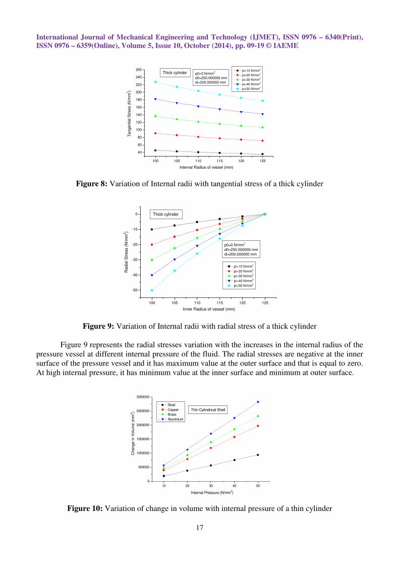
Figure 8 shows the variation of internal radius with tangential stress of a thick cylinder for
various internal pressures. On increasing the internal pressure, the tangential stresses also increase at
a given radius of the vessel. On the other hand, it has also been observed that the tangential stress
decreases on the location beyond the centre line of the vessel. It has minimum value at the outer
surface of the vessel and maximum at the inner surface of the vessel.
International Journal of Mechanical Engineering and Technology (IJMET), ISSN 0976 – 6340(Print),
ISSN 0976 – 6359(Online), Volume 5, Issue 10, October (2014), pp. 09-19 © IAEME
17
100 105 110 115 120 125
40
60
80
100
120
140
160
180
200
220
240
260p0=0 N/mm
2
d0=250.000000 mm
di=200.000000 mm
Thick cylinder pi=10 N/mm
2
pi=20 N/mm2
pi=30 N/mm2
pi=40 N/mm2
pi=50 N/mm2
Ta
ngential S
tress (
N/m
m2)
Internal Radius of vessel (mm)
Figure 8: Variation of Internal radii with tangential stress of a thick cylinder
100 105 110 115 120 125
-50
-40
-30
-20
-10
0
p0=0 N/mm2
d0=250.000000 mm
di=200.000000 mm
Thick cylinder
Radia
l S
tress (
N/m
m2)
Inner Radius of vessel (mm)
pi=10 N/mm2
pi=20 N/mm2
pi=30 N/mm2
pi=40 N/mm2
pi=50 N/mm2
Figure 9: Variation of Internal radii with radial stress of a thick cylinder
Figure 9 represents the radial stresses variation with the increases in the internal radius of the
pressure vessel at different internal pressure of the fluid. The radial stresses are negative at the inner
surface of the pressure vessel and it has maximum value at the outer surface and that is equal to zero.
At high internal pressure, it has minimum value at the inner surface and minimum at outer surface.
10 20 30 40 50
0
500000
1000000
1500000
2000000
2500000
3000000
Thin Cylindrical Shell
Internal Pressure (N/mm2)
Steel
Copper
Brass
Aluminium
Cha
ng
e in
Vo
lum
e (
mm
3)
Figure 10: Variation of change in volume with internal pressure of a thin cylinder
International Journal of Mechanical Engineering and Technology (IJMET), ISSN 0976 – 6340(Print),
ISSN 0976 – 6359(Online), Volume 5, Issue 10, October (2014), pp. 09-19 © IAEME
18
Figure 10 represents the variation of change in volume with internal pressure of a thin
cylinder for four different types of material. The material has different properties. Due to these
material properties, it has been observed that the increases in the volume of pressure vessels made of
aluminium are dominated by the other materials on increases in the internal pressure. Among all the
four materials pressure vessels, steel has minimum influenced of change in volume due to increase in
the internal pressure of the fluid. The other two materials, namely brass and copper, exist between
steel and aluminium. The input conditions are the same for the analysis.
4. CONCLUSION
In this paper, optimization study of pressure vessels is conducted considering a model of the
entire pressure vessel with the help of software in C++. A method has been applied and implemented
for the optimization of the thickness of pressure vessels on the basis of its thickness variation. The
results are calculated for thick and thin cylinders and applied maximum normal stress theory for
brittle material and maximum shear stress theory for ductile material. The analysis has also been
made for open end and closed end cylinders. Birnie’s equations and maximum strain theory applied
for closed and open end cylinders design respectively. For very high pressure oil and gas pipes,
Barlow’s equations have been applied. A calculation for thin walled pressure vessel has been made
for a fixed length of pipe i.e. 10000 mm.
For both the ductile and brittle material, the thickness of the vessels should be increases on
increasing the internal pressure of the fluid. For all types of design, the brittle material should be
thicker than that of ductile material. By comparing the standard result of radial and tangential
stresses for thick and thin cylinders, it has been found that the nature of curve is similar to the present
result. The property of material is different; hence one can say that the material optimization is
correct and authentic.
REFERENCES
[1] Lekhnitskii S. G., “Anisotropic plates”, New York, NY: Gordon and Breach Science
Publishers; 1968.
[2] H. Al-Gahtani et al., “Local pressure testing of spherical vessels”, International Journal of
Pressure Vessels and Piping 114-115 (2014) 61-68.
[3] Tsai SW., “Composites design”, USA, Think Composites, 1985.
[4] Xia M, Takayanagi H, Kemmochi K., “Analysis of multi-layered filament-wound composite
pipes under internal pressure”, Composite Structure 2001; 53 (4) : 483–91.
[5] Xia M, Kemmochi K, Takayanagi H., “Analysis of filament-wound fiber-reinforced
sandwich pipe under combined internal pressure and thermomechanical loading”, Composite
Structure 2001;51(3):273–83.
[6] Cassandra A. Latimer, M. S., et al., “Effect of collagen and elastic content on the burst
pressure of human blood vessel seals formed with a bipolar tissue sealing system”, journal of
surgical research 186 (2014) 73-80.
[7] Abhay K. Jha et al., “Failure analysis of a high strength low alloy 0.15C–1.25Cr–1Mo–0.25V
steel pressure vessel”, Case Studies in Engineering Failure Analysis 1 (2013) 265–272.
[8] Katırcı N., “Design of fiber reinforced composite pressure vessels”, M. S. Thesis, Middle
East Technical University, Turkey, 1998.
[9] M. Walker and P.Y. Tabakov, “Design optimization of anisotropic pressure vessels with
manufacturing uncertainties accounted for”, International Journal of Pressure Vessels and
Piping 104 (2013) 96-104.
International Journal of Mechanical Engineering and Technology (IJMET), ISSN 0976 – 6340(Print),
ISSN 0976 – 6359(Online), Volume 5, Issue 10, October (2014), pp. 09-19 © IAEME
19
[10] Jacek KruŜelecki and Rafał Proszowski, “Shape and thickness optimization of thin-walled
pressure vessel end closures”, Eng Opt 2012 – 3rd International Conference on Engineering
Optimization, Rio de Janeiro, Brazil, 01 - 05 July 2012.
[11] I.M.Jamadar, S.M.Patil, S.S.Chavan, G.B.Pawar and G.N.Rakate, “Thickness Optimization
of Inclined Pressure Vessel using Non Linear Finite Element Analysis using Design by
Analysis Approach”, International Journal of Mechanical Engineering & Technology
(IJMET), Volume 3, Issue 3, 2012, pp. 682 - 689, ISSN Print: 0976 – 6340, ISSN Online:
0976 – 6359.
[12] Mukund Kavekar, Vinayak H.Khatawate and Gajendra V. Patil, “Weight Reduction of
Pressure Vessel using FRP Composite Material”, International Journal of Mechanical
Engineering & Technology (IJMET), Volume 4, Issue 4, 2013, pp. 300 - 310, ISSN Print:
0976 – 6340, ISSN Online: 0976 – 6359.
[13] Mane S.S and Prof. Wankhede P.A, “The Design of Vertical Pressure Vessels Subjected to
Applied Forces and Vibrational Conditions”, International Journal of Mechanical
Engineering & Technology (IJMET), Volume 3, Issue 2, 2012, pp. 38 - 45, ISSN Print:
0976 – 6340, ISSN Online: 0976 – 6359.
AUTHOR’S DETAIL
I am Qayssar Saeed Masikh, I am working as an Engineer at Karbala
Governorate, Local Administration, Department of Projects. I have completed
my Bachelor at College of Engineering, The University of Mustansiriya,
Baghdad, Republic of Iraq and I am going to complete M. Tech. in Mechanical
Engineering (CAD/CAM)) in SSET, Faculty of Engineering, Sam Higginbottom
Institute of Agriculture, Technology & Sciences, Allahabad, India.
I am Dr. Mohammad Tariq working as an Assistant Professor (Senior) in the
Department of Mechanical Engineering, Shepherd School of Engineering and
Technology, SHIATS-DU, Allahabad. I have published more than 35 research
papers in National/International Journals. I have guided more than 25 students
for M. Tech.
Copyright © 2022 FDOKUMEN