6-1 Difference in treatment between thin and thick cylinders
13
Thick Cylinders 1 Lecture No. 6 -Thick Cylinders- 6-1 Difference in treatment between thin and thick cylinders - basic assumptions: The theoretical treatment of thin cylinders assumes that the hoop stress is constant across the thickness of the cylinder wall (Fig. 6.1), and also that there is no pressure gradient across the wall. Neither of these assumptions can be used for thick cylinders for which the variation of hoop and radial stresses is shown in (Fig. 6.2), their values being given by the Lame equations: - =+ 2 ...6.1 =− 2 ...6.2 Where: - = Hoop stress ( 2 = ). = Radial stress ( 2 = ). R= Radius (m). A and B are Constants. Figure 6.1: - Thin cylinder subjected to internal pressure.
-
Upload
khangminh22 -
Category
Documents
-
view
0 -
download
0
Transcript of 6-1 Difference in treatment between thin and thick cylinders
Thick Cylinders
1
Lecture No. 6
-Thick Cylinders-
6-1 Difference in treatment between thin and thick cylinders - basic assumptions:
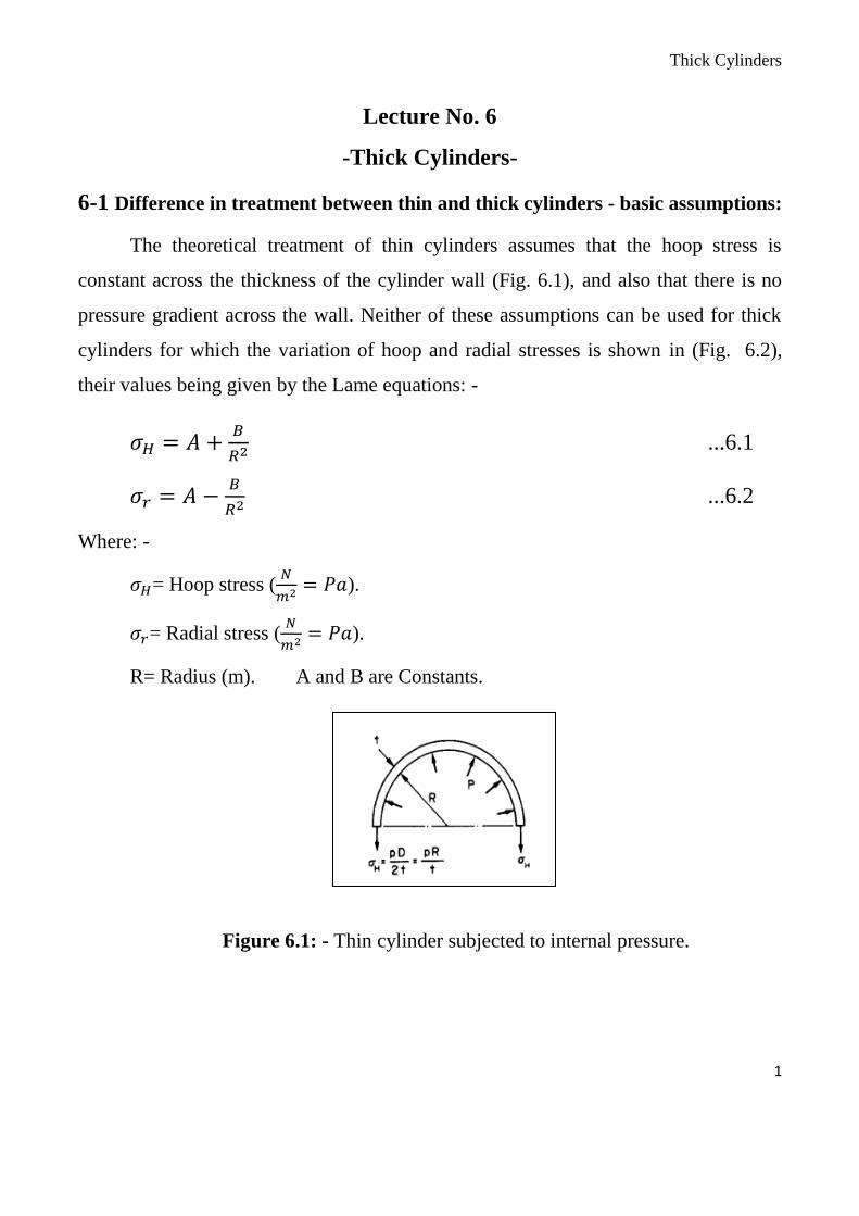
The theoretical treatment of thin cylinders assumes that the hoop stress is
constant across the thickness of the cylinder wall (Fig. 6.1), and also that there is no
pressure gradient across the wall. Neither of these assumptions can be used for thick
cylinders for which the variation of hoop and radial stresses is shown in (Fig. 6.2),
their values being given by the Lame equations: -
𝜎𝐻 = 𝐴 +𝐵
𝑅2 ...6.1
𝜎𝑟 = 𝐴 −𝐵
𝑅2 ...6.2
Where: -
𝜎𝐻= Hoop stress (𝑁
𝑚2= 𝑃𝑎).
𝜎𝑟= Radial stress (𝑁
𝑚2= 𝑃𝑎).
R= Radius (m). A and B are Constants.
Figure 6.1: - Thin cylinder subjected to internal pressure.
Thick Cylinders
2
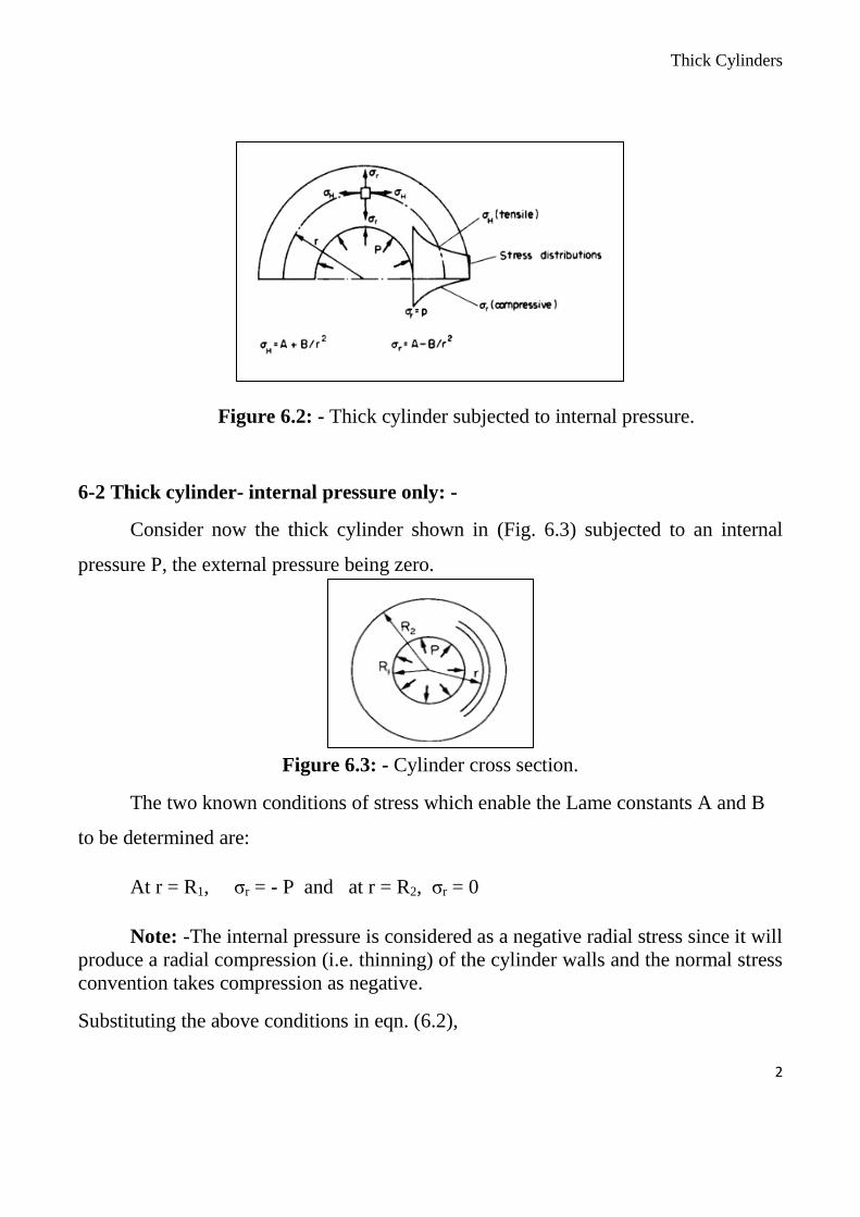
Figure 6.2: - Thick cylinder subjected to internal pressure.
6-2 Thick cylinder- internal pressure only: -
Consider now the thick cylinder shown in (Fig. 6.3) subjected to an internal
pressure P, the external pressure being zero.
Figure 6.3: - Cylinder cross section.
The two known conditions of stress which enable the Lame constants A and B
to be determined are:
At r = R1, σr = - P and at r = R2, σr = 0
Note: -The internal pressure is considered as a negative radial stress since it will
produce a radial compression (i.e. thinning) of the cylinder walls and the normal stress
convention takes compression as negative.
Substituting the above conditions in eqn. (6.2),
Thick Cylinders
3
𝜎𝑟 = 𝐴 −𝐵
𝑟2
−𝑃 = 𝐴 −𝐵
𝑅12 and 0 = 𝐴 −
𝐵
𝑅22
Then 𝐴 =𝑃𝑅1
2
(𝑅22−𝑅1
2) and 𝐵 =
𝑃𝑅12𝑅2
2
(𝑅22−𝑅1
2)
Substituting A and B in equations 6.1 and 6.2,
𝜎𝑟 =𝑃𝑅1
2
(𝑅22−𝑅1
2)[1 −
𝑅22
𝑟2 ] ...6.3
𝜎𝐻 =𝑃𝑅1
2
(𝑅22−𝑅1
2)[1 +
𝑅22
𝑟2 ] ...6.4
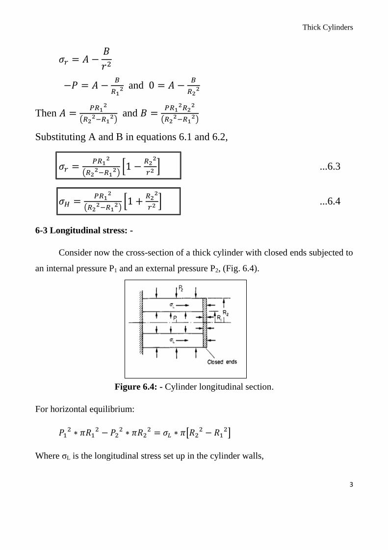
6-3 Longitudinal stress: -
Consider now the cross-section of a thick cylinder with closed ends subjected to
an internal pressure P1 and an external pressure P2, (Fig. 6.4).
Figure 6.4: - Cylinder longitudinal section.
For horizontal equilibrium:
𝑃12 ∗ 𝜋𝑅1
2 − 𝑃22 ∗ 𝜋𝑅2
2 = 𝜎𝐿 ∗ 𝜋[𝑅22 − 𝑅1
2]
Where σL is the longitudinal stress set up in the cylinder walls,

Thick Cylinders
4
Longitudinal stress,
𝜎𝐿 = 𝑃1𝑅1
2−𝑃2𝑅22
(𝑅22−𝑅1
2) ….6.5
But for P2 =0 (no external pressure),
𝜎𝐿 = 𝑃1𝑅1
2
(𝑅22−𝑅1
2) = A, constant of the Lame equations. ….6.6
6-4 Maximum shear stress: -
It has been stated in section 6.1 that the stresses on an element at any point in
the cylinder wall are principal stresses.
It follows, therefore, that the maximum shear stress at any point will be given
by equation of Tresca theory as,
𝜎𝑦
2= 𝜏𝑚𝑎𝑥 =
𝜎1−𝜎3
2 ….6.7
𝜏𝑚𝑎𝑥 =𝜎𝐻−𝜎𝑟
2 ….6.8
𝜏𝑚𝑎𝑥 =1
2[(𝐴 +
𝐵
𝑟2) − (𝐴 −𝐵
𝑟2)] ….6.9
𝜏𝑚𝑎𝑥 =𝐵
𝑟2 ….6.10
6-5 Change of diameter: -
It has been shown that the diametral strain on a cylinder equals the hoop or
circumferential strain.
Change of diameter = diametral strain x original diameter.
= circumferential strain x original diameter.

Thick Cylinders
5
With the principal stress system of hoop, radial and longitudinal stresses, all
assumed tensile, the circumferential strain is given by
𝜖𝐻 =1
𝐸(𝜎𝐻 − 𝜐𝜎𝑟 − 𝜐𝜎𝐿) ….6.11
𝛿𝐷 =𝐷
𝐸(𝜎𝐻 − 𝜐𝜎𝑟 − 𝜐𝜎𝐿) ….6.12
Similarly, the change of length of the cylinder is given by,
𝛿𝐿 =𝐿
𝐸(𝜎𝐿 − 𝜐𝜎𝑟 − 𝜐𝜎𝐻) ….6.13
6-6 Comparison with thin cylinder theory: -
In order to determine the limits of D/t ratio within which it is safe to use the
simple thin cylinder theory, it is necessary to compare the values of stress given by
both thin and thick cylinder theory for given pressures and D/t values. Since the
maximum hoop stress is normally the limiting factor, it is this stress which will be
considered.
Thus for various D/t ratios the stress values from the two theories may be
plotted and compared; this is shown in (Fig. 6.5).
Also indicated in (Fig. 6.5) is the percentage error involved in using the thin
cylinder theory.
It will be seen that the error will be held within 5 % if D/t ratios in excess of 15 are
used.

Thick Cylinders
6
Figure 6.5: - Comparison of thin and thick cylinder theories for various
diameter/thickness ratios.
6-7 Compound cylinders:-
From the sketch of the stress distributions in Figure 6.6 it is evident
that there is a large variation in hoop stress across the wall of a cylinder
subjected to internal pressure. The material of the cylinder is not therefore
used to its best advantage. To obtain a more uniform hoop stress
distribution, cylinders are often built up by shrinking one tube on to the
outside of another. When the outer tube contracts on cooling the inner tube
is brought into a state of compression. The outer tube will conversely be
brought into a state of tension. If this compound cylinder is now subjected
to internal pressure the resultant hoop stresses will be the algebraic sum of
those resulting from internal pressure and those resulting from shrinkage as

Thick Cylinders
7
drawn in Fig. 6.6; thus a much smaller total fluctuation of hoop stress is
obtained. A similar effect is obtained if a cylinder is wound with wire or
steel tape under tension.
Figure 6.6: - Compound cylinders-combined internal pressure and shrinkage effects.
The method of solution for compound cylinders constructed from similar
materials is to break the problem down into three separate effects:
(a) shrinkage pressure only on the inside cylinder.
(b) shrinkage pressure only on the outside cylinder.
(c) internal pressure only on the complete cylinder.
For each of the resulting load conditions there are two known values of radial
stress which enable the Lame constants to be determined in each case
condition (a) shrinkage - internal cylinder:
At r = R1, σr = 0
At r = Rc, σr = - p (compressive since it tends to reduce the wall
thickness)
condition (b) shrinkage - external cylinder:
At r = R2, σr =0

Thick Cylinders
8
At r = Rc, σr = - p
condition (c) internal pressure - compound cylinder:
At r = R2, σr = 0
At r = R1, σr = -P1
Thus for each condition the hoop and radial stresses at any radius can be
evaluated and the principle of superposition applied, i.e. the various stresses are then
combined algebraically to produce the stresses in the compound cylinder subjected to
both shrinkage and internal pressure. In practice this means that the compound
cylinder is able to withstand greater internal pressures before failure occurs or,
alternatively, that a thinner compound cylinder (with the associated reduction in
material cost) may be used to withstand the same internal pressure as the single thick
cylinder it replaces.
Figure 6.7: - Distribution of hoop and radial stresses through the walls of a compound
cylinder.
Thick Cylinders
9
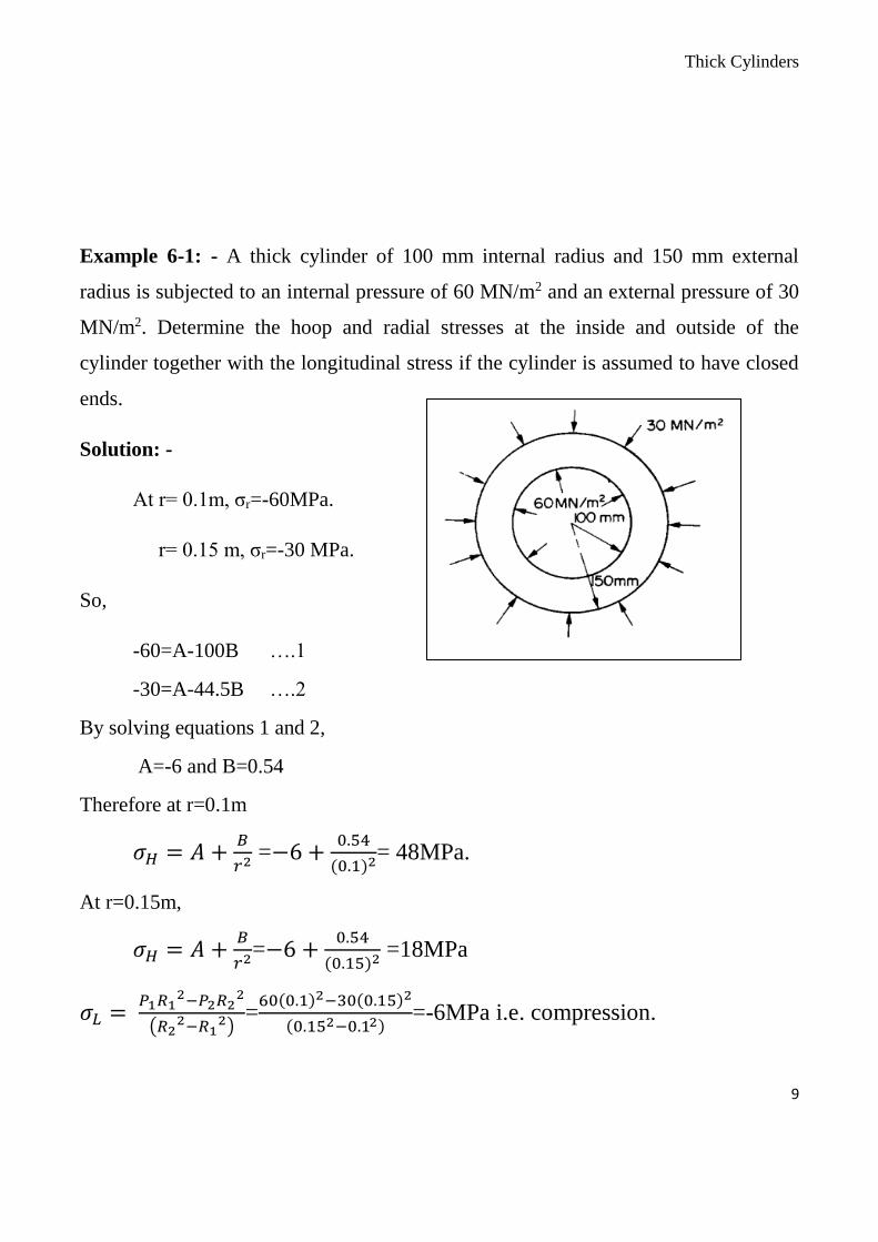
Example 6-1: - A thick cylinder of 100 mm internal radius and 150 mm external
radius is subjected to an internal pressure of 60 MN/m2 and an external pressure of 30
MN/m2. Determine the hoop and radial stresses at the inside and outside of the
cylinder together with the longitudinal stress if the cylinder is assumed to have closed
ends.
Solution: -
At r= 0.1m, σr=-60MPa.
r= 0.15 m, σr=-30 MPa.
So,
-60=A-100B ….1
-30=A-44.5B ….2
By solving equations 1 and 2,
A=-6 and B=0.54
Therefore at r=0.1m
𝜎𝐻 = 𝐴 +𝐵
𝑟2 =−6 +0.54
(0.1)2= 48MPa.
At r=0.15m,
𝜎𝐻 = 𝐴 +𝐵
𝑟2=−6 +0.54
(0.15)2 =18MPa
𝜎𝐿 = 𝑃1𝑅1
2−𝑃2𝑅22
(𝑅22−𝑅1
2)=
60(0.1)2−30(0.15)2
(0.152−0.12)=-6MPa i.e. compression.
Thick Cylinders
10
Example 6-2: - An external pressure of 10 MN/m2 is applied to a thick cylinder of
internal diameter 160 mm and external diameter 320 mm. If the maximum hoop stress
permitted on the inside wall of the cylinder is limited to 30 MN/m2, what maximum
internal pressure can be applied assuming the cylinder has closed ends? What will be
the change in outside diameter when this pressure is applied? E = 207 GN/m2, v =
0.29.
Solution: -
At r =0.08m, σr=-P, 1
𝑟2=156
At r = 0.16 m, σr= -10, 1
𝑟2=39
And at r =0.08m, σH= 30MPa
- 10 = A - 39B ….(1) 30 = A + 156B ….(2)
Subtracting (1) from (2), A=-2 and B=0.205
Therefore, at r = 0.08, σr = - p = A -156B= -2-156*0.205 = -34MPa.
i.e. the allowable internal pressure is 34 MN/m2.
The change in diameter is given by
𝛿𝐷 =𝐷
𝐸(𝜎𝐻 − 𝜐𝜎𝑟 − 𝜐𝜎𝐿) …. (3)
But σr = - 10 MN/m2, 𝜎𝐻 = 𝐴 +𝐵
𝑟2=-2+39*0.205=6 MN/m2
Thick Cylinders
11
And finally, 𝜎𝐿 = 𝑃1𝑅1
2−𝑃2𝑅22
(𝑅22−𝑅1
2) =
(34∗0.082−10∗0.162)
(0.162−0.082)= -1.98 MPa i.e
compressive.
Substitute σr, 𝜎𝐻and 𝜎𝐿in eqn. 3,
𝛿𝐷 =0.32
207∗109[6 − 0.29(−10) − 0.29(−1.98)]106 =14.7µm
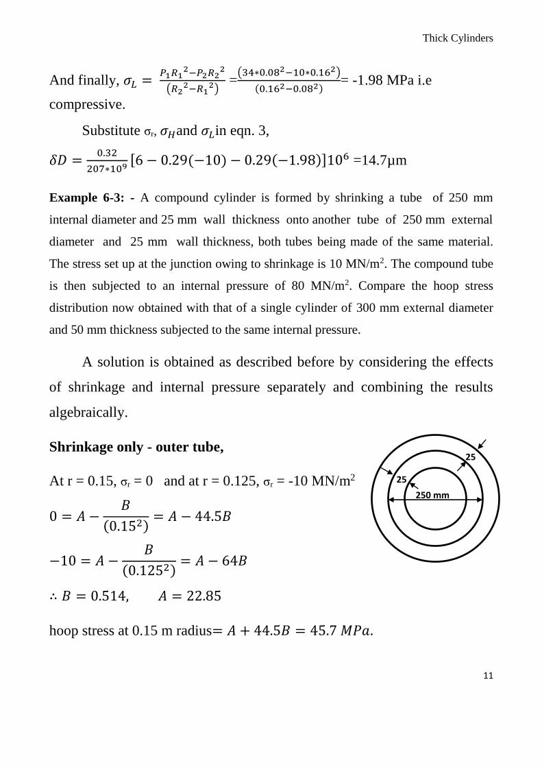
Example 6-3: - A compound cylinder is formed by shrinking a tube of 250 mm
internal diameter and 25 mm wall thickness onto another tube of 250 mm external
diameter and 25 mm wall thickness, both tubes being made of the same material.
The stress set up at the junction owing to shrinkage is 10 MN/m2. The compound tube
is then subjected to an internal pressure of 80 MN/m2. Compare the hoop stress
distribution now obtained with that of a single cylinder of 300 mm external diameter
and 50 mm thickness subjected to the same internal pressure.
A solution is obtained as described before by considering the effects
of shrinkage and internal pressure separately and combining the results
algebraically.
Shrinkage only - outer tube,
At r = 0.15, σr = 0 and at r = 0.125, σr = -10 MN/m2
0 = 𝐴 −𝐵
(0.152)= 𝐴 − 44.5𝐵
−10 = 𝐴 −𝐵
(0.1252)= 𝐴 − 64𝐵
∴ 𝐵 = 0.514, 𝐴 = 22.85
hoop stress at 0.15 m radius= 𝐴 + 44.5𝐵 = 45.7 𝑀𝑃𝑎.
250 mm
25
25
Thick Cylinders
12
hoop stress at 0.125 m radius= 𝐴 + 64𝐵 = 55.75𝑀𝑃𝑎.
Shrinkage only- inner tube,
At r = 0.10, σr = 0 and at r = 0.125, σr = - 10 MN/m2
0 = 𝐴 −𝐵
(0.12)= 𝐴 − 100𝐵
−10 = 𝐴 −𝐵
(0.1252)= 𝐴 − 64𝐵
∴ 𝐵 = −0.278, 𝐴 = −27.8
hoop stress at 0.125 m radius= 𝐴 + 64𝐵 = −45.6 𝑀𝑃𝑎.
hoop stress at 0.10 m radius= 𝐴 + 100𝐵 = −55.6 𝑀𝑃𝑎.
Considering internal pressure only (on complete cylinder)
At r = 0.15, σr = 0 and at r = 0.10, σr = -80
0 = 𝐴 −𝐵
(0.152)= 𝐴 − 44.5𝐵
−80 = 𝐴 −𝐵
(0.12)= 𝐴 − 100𝐵
∴ 𝐵 = 1.44, 𝐴 = 64.2
At r = 0.15 m, σH = A + 44.5B = 128.4 MN/m2
r= 0.125m, σH = A + 64B = 156.4 MN/m2
r= 0.1m , σH = A + 100B = 208.2 MN/m2
The resultant stresses for combined shrinkage and internal pressure are
then:
outer tube: r = 0.15 σH = 128.4 +45.7 = 174.1 MN/m2 .
Thick Cylinders
13
r = 0.125 σH = 156.4+ 55.75 = 212.15 MN/m2 .
inner tube: r = 0.125 σH = 156.4-45.6 = 110.8 MN/m2 .
r = 0.1 σH = 208.2 - 55.6 = 152.6 MN/m2 .
….…………………….END…………………………