Good vibrations, bad vibrations: Oscillatory brain activity in the attentional blink

ARTICLE IN PRESS
JOURNAL OFSOUND ANDVIBRATION
0022-460X/$ - s
doi:10.1016/j.js
�Correspond11 de Abril 461
E-mail addr
(V.H. Cortınez
Journal of Sound and Vibration 316 (2008) 298–316
www.elsevier.com/locate/jsvi
Exact solutions for coupled free vibrations of taperedshear-flexible thin-walled composite beams
Marcelo T. Piovana,b,�, Carlos P. Filipicha,c, Vıctor H. Cortıneza,b
aCentro de Investigaciones de Mecanica Teorica y Aplicada, Universidad Tecnologica Nacional FRBB, 11 de Abril 461,
B8000LMI Bahıa Blanca, BA, ArgentinabConsejo Nacional de Investigaciones Cientıficas y Tecnologicas (CONICET), Argentina
cDepartamento de Ingenierıa, Universidad Nacional del Sur, Argentina
Received 20 June 2007; received in revised form 15 February 2008; accepted 18 February 2008
Handling Editor: S. Bolton
Abstract
In this paper, analytical solutions for the free vibration analysis of tapered thin-walled laminated-composite beams with
both closed and open cross-sections are developed. The present study is based on a recently developed model that
incorporates in a full form the shear flexibility. The model considers shear flexibility due to bending as well as warping
related to non-uniform torsion. The theory is briefly reviewed with the aim to present the equilibrium equations, the related
boundary conditions and the constitutive equations. The stacking sequences in the panels of the cross-sections are selected
in order to behave according to certain elastic coupling features. Typical laminations for a box-beam such as
circumferentially uniform stiffness (CUS) or circumferentially asymmetric stiffness (CAS) configurations are adopted. For
open cross-sections, special laminations behaving elastically like the CAS and CUS configurations of closed sections are
also taken into account.
The exact values (i.e. with arbitrary precision) of frequencies are obtained by means of a generalized power series
methodology. A recurrence scheme is introduced with the aim to simplify the algebraic manipulation by shrinking the
number of unknown variables. A parametric analysis for different taper ratios, slenderness ratios and stacking sequences
is performed. Numerical examples are also carried out focusing attention in the validation of the present theory with
respect to 2D FEM computational approaches, as well as to serve as quality test and convergence test of former finite
elements schemes.
r 2008 Elsevier Ltd. All rights reserved.
1. Introduction
The increasing employment of composite materials, instead of isotropic materials, in structural componentsis motivated due to the evidence that composite structures have many advantages with respect to the isotropic
ee front matter r 2008 Elsevier Ltd. All rights reserved.
v.2008.02.044
ing author at: Centro de Investigaciones de Mecanica Teorica y Aplicada, Universidad Tecnologica Nacional FRBB,
, B8000LMI Bahıa Blanca, BA, Argentina. Tel.: +54 291 4555 220; fax: +54 291 4555 311.
esses: [email protected] (M.T. Piovan), [email protected] (C.P. Filipich), [email protected]
).

ARTICLE IN PRESSM.T. Piovan et al. / Journal of Sound and Vibration 316 (2008) 298–316 299
counterparts. The most well known features of composite materials are high strength and stiffness propertiestogether with a low weight, good corrosion resistance, enhanced fatigue life and low thermal expansionproperties among others [1]. Another interesting aspect of composite materials is the very low machining costwith respect to the common machining procedures for isotropic materials such as steel, aluminum or titanium[2]. As a result of the mentioned context, the analysis of the static and dynamic behavior of composite thin-walled beams is the subject of deep investigation. Many research activities have been devoted toward thedevelopment of theoretical and computational methods for the appropriate analysis of such members.
The first consistent study dealing with the static structural behavior of thin-walled composite-orthotropicmembers under various loading patterns was carried out by Bauld and Tzeng [3]. These authors employedVlasov hypotheses in order to derive a beam theory for the analysis of fiber-reinforced members featuringopen cross-sections with symmetric laminates. This theory for non-shear deformable thin-walled beam wasrestricted to structural members constructed with special orthotropic stacking sequences and employed onlyfor static analysis. However, further contributions of many authors since the early eighties until the presenttime have made possible to extend Vlasov models by considering shear deformability due to bending, warpingeffects, among others. The resulting models have been employed in many problems such as free/forcedvibration, elastic stability, etc.
Models for thin-walled composite beams allowing for some effects of shear deformability were alreadypresented in the middle eighties by Giavotto et al. [4] and Bauchau [5]. In these works the effect of thewarping-torsion shear deformability was not appropriately taken into. The issues related to sheardeformability in composite beams were slightly studied in a few problems of static’s and dynamics.
In the late eighties and the nineties a considerable number of new models and uses were developed. Someresearchers [6–9] studied the non-conventional effects of constitutive elastic couplings (such as bending–bend-ing coupling or bending–shear coupling, etc.) in the mechanics of cantilever box-beams considering only thebending component of shear flexibility whereas the warping torsion shear flexibility was neglected. However,in these models [6–9] new extensions such as the consideration of the thickness effects in shear and warpingdeformations, among others were introduced. Moreover, new studies devoted to the dynamical aspects ofelastic couplings were performed.
Recently, Cortınez and Piovan [10] employed the Hellinger–Reissner principle to derive a theory of thin-walled beams with symmetric balanced laminates, in which the full shear flexibility was considered. This modelcovered topics of dynamics under states of initial normal stresses, also accounting for in-thickness shearflexibility and warping.
Many of the aforementioned models were employed for eigenvalue calculation, among other problems.However, in those numerical studies only beams with uniform cross-section were considered. There is evidenceof some works devoted to the free vibration analysis of tapered beams with thin-walled cross-sections made ofisotropic material [11] and with solid cross-section made of composite materials [12]. However, despite theimportance of the vibratory problems in robotic arms and rotor-blades among other applications, there isscarce evidence [13] of studies focused in the free vibrations of thin-walled tapered beams made of compositematerials with elastic coupling effects.
In the present work, a power series methodology is employed to calculate the exact (or with arbitraryprecision) free vibration frequencies of composite thin-walled tapered beams allowing for shear flexibility dueto bending as well as non-uniform torsion warping. Several studies for box-beams and I-beams with speciallamination are carried out. The effects of taper and the elastic couplings are analyzed and their influence in thefree vibration patterns of the beam structures appropriately enhanced. In order to show the accuracy andpractical effectiveness of the model and present series approach, some comparisons with former finite elementapproaches, as well as shell finite elements of the commercial program COSMOS/M are performed.
2. Description of the model
In Fig. 1 a sketch of a thin-walled beam is shown. In this figure, it is possible to see the reference points Cand B. The main reference point C is located at the geometric center of the cross-section, where the x-axis isparallel to the longitudinal axis of the beam, while y-axis and z-axis are the axes associated to the cross-section, but not necessarily the principal ones. The point B is a generic point belonging to the middle line of the

ARTICLE IN PRESS
Fig. 1. Sketch of the thin-walled beam.
Fig. 2. (a) Description of cross-section geometrical entities and (b) displacement parameters. Secondary or lamination reference systems
for the segments of open (c) and closed (d) cross-sections, respectively.
M.T. Piovan et al. / Journal of Sound and Vibration 316 (2008) 298–316300
cross-sectional wall (see Fig. 2a); its co-ordinates are denoted as Y(s) and Z(s). The Fig. 2b shows thedisplacement parameters of the model. Fig. 2c and d show the reference system for each laminated segment ofopen and closed cross-sections, respectively.
The beam model employed in this study has been developed [10,14,17] under the following hypotheses:(a) the cross-section contour is rigid in its own plane; (b) the warping distribution is assumed to be composedby contour (or primary) and thickness (or secondary) components; (c) in the panels, the shell force and shellmoment corresponding to the hoop stress sss and the force resultant corresponding to the in-thickness stresssns are neglected; (d) the radius of curvature at any point of the shell is neglected; (e) twisting curvature of theshell is expressed according to the classical plate theory, but bending curvature is expressed according to thefirst-order shear deformation theory; (f) special stacking sequences are adopted such as circumferentially

ARTICLE IN PRESSM.T. Piovan et al. / Journal of Sound and Vibration 316 (2008) 298–316 301
uniform stiffness (CUS) or circumferentially asymmetric stiffness (CAS) or any other lamination scheme thatprovides a specialized elastic coupling among twisting, bending and/or extension; (g) taking into account thecomparative evidence of previous theoretical beam models [16] with experimental data and 2D–3Dcomputational approaches, the shear flexibility due to in-thickness strains is neglected.
Under this context, the mechanics of a thin-walled beammodel allowing for shear flexibility due to bending andwarping can be described, in terms of beam-stress-resultants, with the following differential equations [10,14]:
�qQX
qxþ M1ðxÞ ¼ 0; �
qQY
qxþ M2ðxÞ ¼ 0;
qMZ
qx�QY þ M3ðxÞ ¼ 0, (1a2c)
�qQZ
qxþ M4ðxÞ ¼ 0;
qMY
qx�QZ þ M5ðxÞ ¼ 0, (1d2e)
�qqx
TSV þ TW½ � þ M6ðxÞ ¼ 0;qB
qx� TW þ M7ðxÞ ¼ 0, (1f2g)
where QX is the axial force; QY and QZ are shear forces; MY and MZ are bending moments, B is the bimoment,TSV is the twisting moment due to pure torsion and TW is the flexural–torsional moment, due to warping torsion.Mj, j ¼ 1,y,7 are the inertial forces. Eq. (1) define the extensional motion; Eqs. (1b) and (1c) define the bendingmotion in the plane XY; Eqs. (1d) and (1e) define the bending motion in the plane XZ; Eqs. (1f) and (1g) definethe warping and twisting motion.
These differential equations may be subjected to the following boundary conditions:
(a)
Clamped–clamped:uxc ¼ uyc ¼ uzc ¼ yz ¼ yy ¼ fx ¼ yx ¼ 0 at x ¼ 0 and x ¼ L. (2a,b)
(b)
Clamped–free:uxc ¼ uyc ¼ uzc ¼ yz ¼ yy ¼ fx ¼ yx ¼ 0 at x ¼ 0,
QX ¼ QY ¼ QZ ¼MY ¼MZ ¼ TSV þ TW ¼ B ¼ 0 at x ¼ L. (3a,b)
(c)
Simply supported for bending, free to warp and free to extend at one end:uxc ¼ uyc ¼ uzc ¼ fx ¼MY ¼MZ ¼ B ¼ 0 at x ¼ 0,
uyc ¼ uzc ¼ fx ¼ QX ¼MY ¼MZ ¼ B ¼ 0 at x ¼ L. (4a,b)
In the previous equations, uxc is the axial displacement of the centroid, uyc and uzc are lateral displacementsof the centroid, yy and yz are the bending rotation parameters, fx is the twisting angle and yx is the warpingintensity variable. In Appendix B, one can find a brief deduction of the differential equations (1) starting fromthe displacement field defined in Refs. [14,17].
For a general lamination, the aforementioned beam-stress-resultants are related to the displacementvariables by means of the following expression [14,17]:
QX
MY
MZ
B
QY
QZ
TW
TSV
8>>>>>>>>>>>>>><>>>>>>>>>>>>>>:
9>>>>>>>>>>>>>>=>>>>>>>>>>>>>>;
¼
J1111 J11
12 J1113 J11
14 J1615 J16
16 J1617 J16
18
J1122 J11
23 J1124 J16
25 J1626 J16
27 J1628
J1133 J11
34 J1635 J16
36 J1637 J16
38
J1144 J16
45 J1646 J16
47 J1648
J6655 J66
56 J6657 J66
58
sym J6666 J66
67 J6668
J6677 J66
78
J6688
2666666666666664
3777777777777775
u0xc
�y0y�y0z�y0x
u0yc � yz
u0zc � yy
f0x � yx
f0x
8>>>>>>>>>>>>>><>>>>>>>>>>>>>>:
9>>>>>>>>>>>>>>=>>>>>>>>>>>>>>;
(5)

ARTICLE IN PRESSM.T. Piovan et al. / Journal of Sound and Vibration 316 (2008) 298–316302
and the inertia terms are expressed as follows:
M1
M2
M3
M4
M5
M6
M7
8>>>>>>>>>>><>>>>>>>>>>>:
9>>>>>>>>>>>=>>>>>>>>>>>;
¼
Jr11 0 0 0 0 0 0
Jr11 0 0 0 0 0
Jr33 0 0 0 0
Jr11 0 0 0
Jr22 0 0
sym Jr22 þ J
r33 0
Jr44
2666666666664
3777777777775
€uxc
€uyc
€yz
€uzc
€yy
€fx
€yx
8>>>>>>>>>>>><>>>>>>>>>>>>:
9>>>>>>>>>>>>=>>>>>>>>>>>>;
. (6)
The stiffness coefficients in Eq. (5) and the inertia coefficients in Eq. (6) are obtained as follows:
Jkhij ¼
ZS
Akh gðaÞi gðaÞj
� �þ Bkh g
ðaÞi gðcÞj þ g
ðcÞi gðaÞj
� �þ Dkh g
ðcÞi gðcÞj
� �h ids,
Jrij ¼
ZA
rgðdÞi gðdÞj dsdn, (7a,b)
where the vectors gðjÞ are defined as follows:
gðaÞ ¼ 1;ZðsÞ;Y ðsÞ;oP;dY
ds;dZ
ds; rðsÞ þ cðsÞ;cðsÞ
� �,
gðcÞ ¼ 0;dY
ds;�
dZ
ds; lðsÞ; 0; 0; 1;�2
� �; gðdÞ ¼ 1;ZðsÞ þ n
dY
ds;Y ðsÞ � n
dZ
ds;oðsÞ
� �. (8a 2 c)
In the Eq. (7), r is the density and Aij , Bij and Dij are modified elastics coefficients (see Appendix B, [10,14]),whereas o is the whole warping function, which is composed by two terms: primary or contour warping (op)and secondary or thickness warping (os) defined by
o ¼ opðsÞ þ osðs; nÞ; opðsÞ ¼
Z s
s0
½rðsÞ þ cðsÞ�ds�DC ; osðs; nÞ ¼ nlðsÞ. (9)
The function c(s) is the shear flow of pure torsion (or Saint Venant torsion) for a closed contour section. Itaccounts for variable laminates along the contour and it is defined as follows:
cðsÞ ¼1
A66ðsÞ
RsrðsÞdsH
Sð1=A66ðsÞÞds
" #; DC ¼
HS½rðsÞ þ cðsÞ�A11ðsÞdsH
SA11ðsÞds
. (10a,b)
In the case of an open cross-section c(s) ¼ 0. The functions r(s) and l(s) are defined as follows:
rðsÞ ¼ ZðsÞdY
ds� Y ðsÞ
dZ
ds; lðsÞ ¼ Y ðsÞ
dY
dsþ ZðsÞ
dZ
ds, (11a,b)
The stacking sequences of hypothesis (f) provide selective elastic couplings such as torsion-extension orbending-torsion even for cases of cross-section with double symmetry. The configurations CUS and CAS wereadopted specifically for closed cross-sections by Rehfield et al. [6]. There are many different stacking sequencesthat show evidence of the elastic couplings manifested by CUS and CAS configurations. In Fig. 3a and b onecan see a class of CUS and CAS configurations, respectively. The fiber-reinforcement angle a is arrangedaccording Fig. 2d.

ARTICLE IN PRESS
Fig. 3. (a) CUS and (b) CAS lamination for closed rectangular section. (c) CUS-like and (d) CAS-like lamination for open I-cross-section.
M.T. Piovan et al. / Journal of Sound and Vibration 316 (2008) 298–316 303
The CAS configuration has the following beam stress–strain relations [14]:
QX
MY
MZ
B
QY
QZ
TW
TSV
8>>>>>>>>>>>>>><>>>>>>>>>>>>>>:
9>>>>>>>>>>>>>>=>>>>>>>>>>>>>>;
¼
J1111 0 0 0 J16
15 J1616 0 0
0 J1122 0 0 0 0 J16
27 J1628
0 0 J1133 0 0 0 J16
37 J1638
0 0 0 J1144 0 0 0 0
J1615 0 0 0 J66
55 0 0 0
J1616 0 0 0 0 J66
66 0 0
0 J1627 J16
37 0 0 0 J6677 J66
78
0 J1628 J16
38 0 0 0 J6678 J66
88
2666666666666664
3777777777777775
u0xc
�y0y�y0z�y0x
u0yc � yz
u0zc � yy
f0x � yx
f0x
8>>>>>>>>>>>>>><>>>>>>>>>>>>>>:
9>>>>>>>>>>>>>>=>>>>>>>>>>>>>>;
. (12)
This expression implies, according to the constitutive behavior, that torsion induces fully coupledbending and extension. In fact, the CAS configuration shown in Fig. 3b, produces elastic couplingsbetween extension and shear forces because J15
166¼0 and J16
166¼0. The torsion motion is coupled with the
bending moments due to the non-vanishing coefficients J2716, J28
16, J3716 and J38
16. In a few words, thetorsion moments (and fx and yx) are elastically coupled with the bending moments (and yy and yz) that byequilibrium are connected with the shear forces (and uy and uz) that are elastically coupled with the extensionalforce (and ux).

ARTICLE IN PRESSM.T. Piovan et al. / Journal of Sound and Vibration 316 (2008) 298–316304
The CUS configuration has the following beam stress–strain relations [14]:
QX
MY
MZ
B
QY
QZ
TW
TSV
8>>>>>>>>>>>>>><>>>>>>>>>>>>>>:
9>>>>>>>>>>>>>>=>>>>>>>>>>>>>>;
¼
J1111 0 0 0 0 0 J16
17 J1618
0 J1122 0 0 J16
25 0 0 0
0 0 J1133 0 0 J16
36 0 0
0 0 0 J1144 0 0 0 0
0 J1625 0 0 J66
55 0 0 0
0 0 J1636 0 0 J66
66 0 0
J1617 0 0 0 0 0 J66
77 J6678
J1618 0 0 0 0 0 J66
78 J6688
2666666666666664
3777777777777775
u0xc
�y0y�y0z�y0x
u0yc � yz
u0zc � yy
f0x � yx
f0x
8>>>>>>>>>>>>>><>>>>>>>>>>>>>>:
9>>>>>>>>>>>>>>=>>>>>>>>>>>>>>;
. (13)
Eq. (13) indicates that extension induces torsion. In this case, the axial force QX is coupled with the torsionalmoments TW and TSV due to the non-vanishing coefficients J17
16 and J1816. On the other hand the bending
moments MZ and MY are coupled with the shear forces QZ and QY, by means of the non-vanishing coefficientsJ2516 and J36
16, respectively. Thus, a bending action (force or moment) in the XY plane induces bending in the XZ
plane and vice versa.Although the names CUS and CAS are proper denominations for stacking sequences of closed cross-
sections, the lamination sequence of the open cross-sections can be arranged in order to have the same orsimilar elastic couplings of the closed cross-section counterpart. Thus, the stacking sequences of Fig. 3c and dhave a similar elastic behavior as the CUS and CAS configurations, respectively. In fact, according to thestacking sequence of Fig. 3c one has an elastic coupling quite similar to the CUS configuration because thetorsion moments are coupled with the axial force QX by means of the non-vanishing coefficients J17
16 and J1816,
and the bending moment MY is coupled with the shear force QY by means of non-vanishing coefficient J2516.
On the other hand, the stacking sequence of Fig. 3d manifests an elastic coupling quite similar to theCAS configuration because the torsion moments are coupled with the bending moment MY by meansof the coefficients J27
16 and J2816, and the axial force QX is coupled with the shear force QY by means of the
coefficient J1516.
If a ¼ 901 or a ¼ 01, the CAS and CUS configurations of Fig. 3 coincide with a cross-ply configurationwhich decouples the bending, extensional and torsion movements because in this case the coefficients ofconstitutive matrix in Eq. (5) are such that Jij
16¼ 0 and Jij
66¼ 0 8iaj, but J78
666¼0 (this is inherent to the model
as one can see in Refs. [10,14]). Then, under these circumstances, the eigenvalues for CAS, CUS and cross-plyconfigurations are the same.
3. Power series methodology
The exact solution of the present eigenvalue problem is carried out by means of a generalization of thepower series scheme developed originally by Filipich et al. [18,19] and Rosales and Filipich [20] for structuralproblems involving isotropic materials. The methodology requires a previous non-dimensional re-definition ofthe differential equations, which implies that x 2 ½0; 1�, with x ¼ x=L [18].
The displacement variables have the common harmonic motion:
fuxc; uyc; yz; uzc; yy;fx; yxg ¼ fu1; u2; u3; u4; u5; u6; u7g eiOt ¼ ueiOt, (14)
where O is the circular frequency measured in rad/seg, t is the temporal variable and i ¼ffiffiffiffiffiffiffi�1p
, whereas thegeneric displacement uiðxÞ is expanded with the following power series:
ui ¼XMk¼0
_
Cikxk; i ¼ 1; . . . ; 7, (15)
where the_
Cik’s are unknowns coefficients. Theoretically M-N, however, for practical purposes M may bean arbitrary large integer.

ARTICLE IN PRESSM.T. Piovan et al. / Journal of Sound and Vibration 316 (2008) 298–316 305
Now, taking into account the harmonic motion of Eq. (14) and the non-dimensional re-definition of thedomain and variables, the eigenvalue problem derived from Eq. (1) may be written in the following second-order differential system:
X7j¼1
f ijðxÞu00j ðxÞ þ F iðu; u
0Þ þ luiðxÞ ¼ 0; i ¼ 1; . . . ; 7 and x 2 ½0; 1�. (16)
The functions f ijðxÞ and F iðu; u0Þ which are considered analytic 8x 2 ½0; 1� condense the variation of thecross-section geometric properties (width and/or height) together with the Eq. (5). These functions can bedefined in the following form:
f ijðxÞ ¼XMk¼0
aijkxk; i; j ¼ 1; . . . ; 7, (17)
F iðu; u0Þ ¼
X7j¼1
½wijðxÞu0iðxÞ þ vijðxÞuiðxÞ�; i ¼ 1; . . . ; 7, (18)
where wijðxÞ and vijðxÞ are functions depending on the cross-sectional dimensions and lamination type. Theeigenvalue l is related to the circular frequency by means of the following expression:
l ¼ OffiffiffiffiffiffiffiffireL
p. (19)
The boundary conditions can be expressed in the following generic form:
a0iuið0Þ þ b0iu0ið0Þ ¼ 0; i ¼ 1; . . . ; 7, (20a)
a1iuið1Þ þ b1iu0ið1Þ ¼ 0; i ¼ 1; . . . ; 7, (20b)
where the coefficients ani and bni, n ¼ 0,1, i ¼ 1,y,7 are given according to Eqs. (2)–(4).Now, substituting Eq. (15) in Eq. (20) one has the equations of boundary conditions described in terms of
the unknown coefficients_
Cik’s, as shown in the following equation:
a0i
_
Ci0 þ b0i
_
Ci1 ¼ 0; i ¼ 1; . . . ; 7, (21a)
a1i
XMk¼0
_
Cik þ b1i
XM�1k¼0
ðk þ 1Þ_
Ciðkþ1Þ ¼ 0; i ¼ 1; . . . ; 7. (21b)
In view of the fact that in the present problem the cross-section properties vary continuously along thedomain leading to a second-order differential system with variable coefficients, therefore one has to employpower series products together with the power series form of higher derivatives. Then it is important to keep inmind the following two remarks:
Remark 1. If h1ðxÞ; h2ðxÞ and h3ðxÞ are analytic functions defined by the following power series:
hnðxÞ ¼XMk¼0
Cnkxk; n ¼ 1; 2; 3, (22)
and if hnðxÞ, n ¼ 1,2,3 are such that h3ðxÞ ¼ h1ðxÞh2ðxÞ and remembering the concept of Cauchy products, thenone can easily see that:
C3k ¼Xk
m¼0
C1mC2ðk�mÞ ¼Xk
m¼0
C2mC1ðk�mÞ. (23)
Remark 2. If h1ðxÞ is defined according to Eq. (22), then the mth-order derivative is given by
dmh1ðxÞ
dxm¼XM�m
k¼0
jmkC1ðmþkÞxk; where jmk ¼ ðk þ 1Þðk þ 2Þ . . . ðk þmÞ ¼
ðk þmÞ!
k!, (24)

ARTICLE IN PRESSM.T. Piovan et al. / Journal of Sound and Vibration 316 (2008) 298–316306
Now, substituting Eq. (15) into Eq. (16) one can simplify the terms as follows:X7j¼1
f ijðxÞu00j ðxÞ ¼
XM�2k¼0
Pikxk; i ¼ 1; . . . ; 7, (25a)
X7j¼1
½wijðxÞu0jðxÞ þ vijðxÞujðxÞ� ¼
XM�1k¼0
Fikxk; i ¼ 1; . . . ; 7, (25b)
where
Pik ¼Xk
r¼0
j2r
X7j¼1
_
Cjðrþ2Þaijðk�rÞ; i ¼ 1; . . . ; 7; k ¼ 0; 1; . . .M � 2 (26)
and the differential system can be expressed, in terms of the unknown coefficients_
Cik’s, in the following form(for Fik see Remark 1):
Pik þ F ik þ l_
Cik ¼ 0; i ¼ 1; . . . ; 7; k ¼ 0; 1; . . .M � 2. (27)
Now, to obtain a recurrence scheme for the_
Cik’s, note that Eq. (26) may be expressed as
Pik ¼ P�ik þ j2k
X7j¼1
_
Cjðkþ2Þaij0; i ¼ 1; . . . ; 7; k ¼ 0; 1; . . . ;M � 2 (28)
with
P�ik ¼Xk�1r¼0
j2r
X7j¼1
_
Cjðrþ2Þaijðk�rÞ; i ¼ 1; . . . ; 7; k ¼ 0; 1; . . . ;M � 2. (29)
Note that Eq. (29) is simply the Eq. (26) where the upper limit of the summation in r is reduced in one.Then, the system defined in Eq. (27) can be rearranged in terms of the
_
Cjðrþ2Þ’s asX7j¼1
_
Cjðkþ2Þaij0 ¼ �1
j2k
ðP�ik þ Fik þ l_
CikÞ; i ¼ 1; . . . ; 7; k ¼ 0; 1; . . .M � 2. (30)
Now solving, for each ‘‘k’’, the 7� 7 system defined in Eq. (30) in the unknowns_
Cjðkþ2Þ, j ¼ 1,y,7 oneobtains the aforementioned recurrence scheme. Note that the recurrence scheme implies that for each ‘‘k’’,
the coefficients_
Ciðkþ2Þ, i ¼ 1,y,7, depends on the other coefficients_
Cin, i ¼ 1,y,7, with nok+2. At the
beginning when k ¼ 0, one needs to know the fourteen coefficients_
Ci0 and_
Ci1, i ¼ 1,y,7 involved in theboundary condition of Eq. (21a), and simultaneously one has to satisfy the Eq. (21b). Then one can proceed asfollows:
(1)
Seven of the fourteen coefficients_Ci0 and_
Ci1, i ¼ 1,y,7, are conveniently selected (i.e. according to theform of the boundary equation). These seven coefficients denominated ‘‘free coefficients’’, are defined as gi,i ¼ 1,y,7.
(2)
According to the linearity of the present problem one can appeal to the principle of superposition,performing alternatively the following seven forms:g1 ¼ 1; g2 ¼ g3 ¼ g4 ¼ g5 ¼ g6 ¼ g7 ¼ 0;
g2 ¼ 1; g1 ¼ g3 ¼ g4 ¼ g5 ¼ g6 ¼ g7 ¼ 0;
g3 ¼ 1; g1 ¼ g2 ¼ g4 ¼ g5 ¼ g6 ¼ g7 ¼ 0;
g4 ¼ 1; g1 ¼ g2 ¼ g3 ¼ g5 ¼ g6 ¼ g7 ¼ 0;
g5 ¼ 1; g1 ¼ g2 ¼ g3 ¼ g4 ¼ g6 ¼ g7 ¼ 0;
g6 ¼ 1; g1 ¼ g2 ¼ g3 ¼ g4 ¼ g5 ¼ g7 ¼ 0;
g7 ¼ 1; g1 ¼ g2 ¼ g3 ¼ g4 ¼ g5 ¼ g6 ¼ 0:
(31)

ARTICLE IN PRESSM.T. Piovan et al. / Journal of Sound and Vibration 316 (2008) 298–316 307
For each of the seven alternatives described in Eq. (31), one can apply the recurrence form defined in Eq.
(3) (30) for a given value of l to obtain_
Ci2;_
Ci3; . . . ;_
Cin, i ¼ 1,y,7, which afterwards are substituted in theseven boundary conditions of Eq. (21b). The resulting expressions of these boundary conditions leads tothe following homogeneous system in the unknowns gi, i ¼ 1,y,7:
�11 lð Þ �12 lð Þ �13 lð Þ �14 lð Þ �15 lð Þ �16 lð Þ �17 lð Þ
�21ðlÞ �22ðlÞ �23ðlÞ �24ðlÞ �25ðlÞ �26ðlÞ �27ðlÞ
�31ðlÞ �32ðlÞ �33ðlÞ �34ðlÞ �35ðlÞ �36ðlÞ �37ðlÞ
�41ðlÞ �42ðlÞ �43ðlÞ �44ðlÞ �45ðlÞ �46ðlÞ �47ðlÞ
�51ðlÞ �52ðlÞ �53ðlÞ �54ðlÞ �55ðlÞ �56ðlÞ �57ðlÞ
�61ðlÞ �62ðlÞ �63ðlÞ �64ðlÞ �65ðlÞ �66ðlÞ �67ðlÞ
�71ðlÞ �72ðlÞ �73ðlÞ �74ðlÞ �75ðlÞ �76ðlÞ �77ðlÞ
2666666666664
3777777777775
g1g2g3g4g5g6g7
8>>>>>>>>>>><>>>>>>>>>>>:
9>>>>>>>>>>>=>>>>>>>>>>>;
¼
0
0
0
0
0
0
0
8>>>>>>>>>>><>>>>>>>>>>>:
9>>>>>>>>>>>=>>>>>>>>>>>;
, (32)
where eij(l) represent the ith boundary condition defined according to Eq. (21b) that corresponds to the jthalternative of Eq. (31).
(4)
Finally, if l is the appropriate eigenvalue, then the following characteristic equation is satisfied:det½�ijðlÞ� ¼ 0. (33)
The recurrence scheme, as shown in the previous paragraphs, allows to shrink the algebraic problem from7(M+1) to only 7 unknown coefficients that can be selected according to the boundary equations.
It has to be pointed out that the present power series scheme can be strongly simplified in some cases ofstacking sequences. This fact leads to the handling of two, three or four subsystems. For example in the case ofspecial orthotropic configurations one can handle three subsystems of two equations (twisting motion,flapwise motion and chordwise motion) and the remaining equation (for extension). In the case of a CUSconfiguration one can handle two subsystems, i.e. a subsystem with three equations (extension and twistingdue to pure torsion and warping torsion) and a subsystem with four equations (flapwise bending, chordwisebending, flapwise shear and chordwise shear). General configurations and even the CAS configuration lead toa full coupling (extensional, twisting, flapwise-chordwise bending and shear), and therefore to the handling ofthe full system of seven equations. On the other hand due to the linearity of the present model the principle ofsuperposition has been employed in the power series methodology.
4. Numerical studies and analysis
In this section numerical studies on beams that have a variable web height h and constant flanges b andthickness e are performed. The height for both open and closed cross-sections is assumed to have the linearvariation given in the following expression:
hðxÞ ¼ ho � bx. (34)
The beam has a unit length and many height/length, width/height and thickness/height ratios are employed.In the calculation scheme, power series of 50 terms (M ¼ 50) are employed. In Table 1 the properties of thegraphite fiber reinforced epoxy AS4/3501-6 are summarized.
4.1. Comparisons of models and tests of earlier finite element procedures
Table 2 shows the first five frequencies of a tapered composite box-beam with a particular CUSstacking sequence of {0/�45/45/90}S calculated with 400 SHELL4T elements of COSMOS/M and with thepresent power series solution (M ¼ 50) of the beam model. The geometric properties are such that ho/L ¼ 0.1,b/ho ¼ 0.6, e/ho ¼ 0.06 and b ¼ 0.04. One can see a good agreement between the solution of the beam modeland the shell approach, even in the case of an important taper ratio.

ARTICLE IN PRESSM.T. Piovan et al. / Journal of Sound and Vibration 316 (2008) 298–316308
The eigenvalues with the power series methodology are a straightforward test for the quality of finiteelements. Thus, in Table 3 a study of the convergence quality of a finite element previously developed [17]for the present beam model is carried out. The geometric properties are such that ho/L ¼ 0.1, b/ho ¼ 0.6,e/ho ¼ 0.03, b ¼ 0.04 and a ¼ 151 in the CAS lamination of Fig. 3b. One can see that the eigenvaluescalculated with the finite element approach converge monotonically to the exact solution furnished with thepower series methodology. Moreover, although the finite element approach is good enough for practicalpurposes, even with 200 elements the approximation doesn’t reach the exact values given by the power seriesmethodology. Now, in the following paragraphs new parametric studies of the effect of taper, laminationsequences and slenderness in the coupled vibrations of thin-walled composite beams are offered.
4.2. Analysis of elastic couplings in closed cross-section
In Table 4 the circular frequencies for clamped–free beams with closed cross-section (b/ho ¼ 0.6,e/ho ¼ 0.06, b ¼ 0.04 and a ¼ 151) with CUS and CAS configuration and for different slenderness ratiosho/L are summarized. It is interesting to note that the eigenvalues of CAS and CUS configurations manifestdifferences of no more than 10% between them. However the mode shapes of the corresponding frequencies of
Table 1
Mechanic properties of the materials employed in the paper
E1 ¼ 144GPa, E2 ¼ 9.68GPa
G12 ¼ G13 ¼ 4.14GPa, G23 ¼ 3.45GPa
n12 ¼ 0.3, n23 ¼ 0.5
r ¼ 1389 kg/m3
Table 2
Comparison of a two-dimensional shell model and the one-dimensional beam model, for a tapered composite box-beam
Boundaries Method O1 O2 O3 O4 O5
Clamped–clamped Shell: COSMOS/M 3234.3 3954.9 8049.9 9814.6 10004.5
Beam: Power series 3237.0 3925.0 8114.3 9721.2 10262.1
Clamped–Free Shell: COSMOS/M 614.3 842.9 3353.8 4266.7 5945.4
Beam: Power series 613.0 836.8 3362.8 4232.8 5999.8
Natural frequencies Ok in rad/s.
Table 3
Convergence analysis of a former finite element [17]
Number of elements [14] O1 O2 O3 O4 O5
5 3538.8 4182.6 6416.4 7906.6 9266.4
10 3500.1 4128.9 6332.9 7628.9 8930.3
20 3483.0 4108.4 6311.6 7545.4 8835.9
30 3478.1 4103.4 6307.3 7524.7 8815.0
40 3475.9 4101.5 6305.5 7516.1 8806.8
60 3473.8 4100.0 6303.9 7509.1 8800.4
80 3472.8 4099.4 6303.1 7506.5 8798.1
100 3472.2 4099.1 6302.6 7505.2 8796.9
200 3471.1 4098.7 6301.5 7503.3 8795.3
Series 3469.8 4097.6 6301.3 7502.5 8794.5
Natural frequencies Ok in rad/s.

ARTICLE IN PRESSM.T. Piovan et al. / Journal of Sound and Vibration 316 (2008) 298–316 309
CAS and CUS configurations are quite different due to the elastic coupling allowed. Thus, Figs. 4 and 5depict, for CAS and CUS configurations respectively, the variation of the frequencies (associated to a givenmode shape) with respect to the slenderness ratio ho/L. The frequencies and their associated modes shapescorrespond to the example given in Table 4. The acronyms employed in Figs. 4 and 5 can be understood in thefollowing way: the number indicates the frequency order (first, second, etc.); the first capital letter indicatesthe main contribution to the motion (T, F, E mean twisting motion, flexural motion, extensional motion); theletters after the hyphen indicate the motion direction and/or the kind of coupling: capitalized letters imply thedirection of the main coupling. If capitalized letters appear alone, the mode shape is not coupled. That is, Y (orZ) alone implies the direction (normally for decoupled flexural modes), but xYz means coupled motiondominant in the y-direction). Thus, for the case ho/L ¼ 0.1 (b/ho ¼ 0.6, e/ho ¼ 0.06, b ¼ 0.04 and a ¼ 151),Fig. 6a shows the second fully coupled torsional/flexural/extensional mode (21T-xYz) which has a coupledmotion dominated by twisting and bending in the y-direction. The mode 21T-xYz is typical of the CASconfiguration. Fig. 6b shows the second coupled flexural mode (21F-yZ) which has a motion patterndominated by bending in the z-direction. The mode 21F-yZ appears in CUS configurations. Fig. 6c shows thefully coupled first torsional/flexural/extensional mode (11T-xyz) of the CAS configuration. The mode 11T-xyz
Table 4
Natural frequencies of beams with closed sections having circumferentially asymmetric stiffness (CAS) and circumferentially uniform
stiffness (CUS) laminations
Natural frequency (rad/s) Type of lamination ho/L
0.050 0.075 0.100 0.125 0.150
O1 CAS 488.0 663.7 836.3 996.8 1142.0
CUS 479.2 653.1 821.1 976.1 1116.0
O2 CAS 611.1 886.5 1136.6 1358.6 1551.1
CUS 598.4 875.3 1123.6 1342.7 1532.8
O3 CAS 2409.3 3229.2 3605.0 3549.2 3469.5
CUS 2354.8 3237.5 3377.6 3248.7 3168.2
O4 CAS 2516.3 3793.9 3981.2 4313.6 4604.8
CUS 2493.4 3612.7 3867.0 4322.9 4658.3
O5 CAS 4724.5 4172.9 4776.6 5360.8 5788.1
CUS 4179.0 3852.5 4768.3 5391.0 5831.2
Natural frequencies Ok in rad/s. ho/L is the slenderness ratio.
0
2000
4000
6000
8000
10000
12000
0.050
ho/L
Ω
0.075 0.100 0.125 0.150
Fig. 4. Variation of frequencies associated to mode shapes with respect to the ho/L ratio for a beam with closed cross-section with CAS
configuration: ( ) 11F-xYz; ( ) 11F-xyZ; ( ) 21F-xYz; ( ) 11T-xyz; ( ) 21F-xyZ; ( ) 21T-xYZ; ( ) 21T-
xYz; ( ) 31T-xYz.

ARTICLE IN PRESS
0
2000
4000
6000
8000
10000
12000
0.050ho/L
Ω
0.075 0.100 0.125 0.150
Fig. 5. Variation of frequencies associated to mode shapes with respect to the ho/L ratio for a beam with closed cross-section with CUS
configuration: ( ) 11F-Yz; ( ) 11F-yZ; ( ) 21F-Yz; ( ) 21F-yZ; ( ) 11T-E; ( ) 31F-Yz; ( ) 31F-yZ;
( ) 21T-E.
Fig. 6. (a) 21T-xYz mode of the CAS configuration. (b) 21F-yZ mode of the CUS configuration. (c) 11T-xyz mode of the CAS
configuration. (d) 11T-E mode of the CUS configuration. All cases correspond to ho/L ¼ 0.1, b/ho ¼ 0.6, e/ho ¼ 0.06, b ¼ 0.04 and
a ¼ 151. ( ) uxc; ( ) uyc; (’) yz; ( ) uzc; (B)yy; ( ) fx; ( ) yx.
M.T. Piovan et al. / Journal of Sound and Vibration 316 (2008) 298–316310
has a coupled motion dominated by twisting. Finally Fig. 6d shows the first torsional/extensional (11T-E)mode of the CUS configuration (where the extensional displacement uxc is plotted with a 100� magnificationin order to reveal the intensity of twisting/extension coupling). Moreover, in Figs. 4 and 5 one can see thephenomenon of mode crossover, which means that for a given order number of frequency its associated mode

ARTICLE IN PRESSM.T. Piovan et al. / Journal of Sound and Vibration 316 (2008) 298–316 311
shape experiments a qualitative change with the variation of a geometric parameter such as the slendernessratio ho/L.
Figs. 7 and 8 depict the variation of frequencies (associated to a specified mode) with respect to thetaper ratio parameter b for clamped–free and clamped–clamped ends, respectively. The box-beam is such thatho/L ¼ 0.05, b/ho ¼ 0.6, e/ho ¼ 0.06, and a ¼ 01. Note that in the case with clamped–free ends; the twistingmode 11T has two mode-crossovers with the bending modes 21F-Y and 21F-Z along the variation of the taper.In the case of the clamped–clamped ends the bending modes 11F-Y and 11F-Z and the bending modes 21F-Yand 21F-Z have mode-crossovers at b ¼ 0.035. In Fig. 9 one can see the variation of frequencies with respectto the taper ratio for a clamped–clamped box-beam with the following features: b/ho ¼ 0.6, e/ho ¼ 0.06, CASlamination with a ¼ 301, for ho/L ¼ 0.05 and ho/L ¼ 0.15. Now in Fig. 10 the variation of frequencies relatedto a given mode shape for a clamped–free box-beam is plotted. The geometric and lamination properties ofthis last case are: b/ho ¼ 0.6, e/ho ¼ 0.06, a ¼ 01.
After an examination of the evidence revealed in Figs. 4, 5, and 7–10 one can say that the presence of modecrossovers overlapping among the first frequencies of composite thin-walled tapered box-beams is connectedwith lower slenderness ratios, higher taper ratios and less restrictive boundary conditions.
4.3. Analysis of thin-walled beams with open cross-section
In Fig. 11 the variation of frequencies with respect to the taper ratio b of a clamped–free I-beam with aCUS-like stacking sequence is plotted. The beam is such that ho/L ¼ 0.05, b/ho ¼ 0.6, e/ho ¼ 0.06. Three
0
500
1000
1500
2000
2500
3000
3500
4000
0
Ω
0.01 0.02 0.03 0.04�
Fig. 7. Variation of frequencies with the taper ratio parameter b of a box-beam with a ¼ 0 and clamped–free boundary conditions:
( ) 11F-Y; ( ) 11F-Z; ( ) 11T; ( ) 21F-Y; ( ) 21F-Z.
0
1000
2000
3000
4000
5000
6000
7000
8000
0
Ω
0,01 0,02 0,03 0,04
�
Fig. 8. Variation of frequencies with the taper ratio parameter b of a box-beam with a ¼ 0 and clamped–clamped boundary conditions:
( ) 11F-Y; ( ) 11F-Z; ( ) 11T; ( ) 21F-Y; ( ) 21F-Z.

ARTICLE IN PRESS
Ω
4000
5000
6000
7000
8000
9000
10000
11000
12000
0 0.01 0.02 0.03 0.04
�
Fig. 9. Variation of frequencies with the taper ratio parameter b of a clamped–clamped box-beam with different slenderness ratios for
CAS lamination a ¼ 301: continuous lines h/L ¼ 0.05; dotted lines h/L ¼ 0.15; (n) 11T; (B) 21F-Y; (&) 21F-Z.
Ω
2000
2500
3000
3500
4000
4500
5000
5500
0
�
0.01 0.02 0.03 0.04
Fig. 10. Variation of frequencies with the taper ratio parameter b of a clamped–free box-beam with different slenderness ratios for a ¼ 01:
continuous lines h/L ¼ 0.05; dotted lines h/L ¼ 0.15; (n) 11T; (B) 21F-Y; (&) 21F-Z.
M.T. Piovan et al. / Journal of Sound and Vibration 316 (2008) 298–316312
different orientation angles are employed. Note the strong influence of the taper ratio in the twisting modes foreach one of the stacking sequences studied. The frequencies related to the first twisting mode (11T) for taperedbeams can reach an increase of about 90% with respect to the uniform beam. On the other hand thefrequencies related to the first flexural mode in the y-direction (11F-Y) reach increments of about 18% andthe frequencies associated to the first flexural mode in z-direction (11F-Z) decrease in 6%. One can see thepresence of a mode-crossover between 11T and 11F-Z modes in each stacking sequence.
In Fig. 12 the variation of frequencies with respect to the taper ratio b of a simply supported beam with aCAS-like configuration is shown. The geometric properties and the lamination features of this example aretaken from the previous one. As it is possible to see, the frequencies associated to the first flexural mode in they-direction (11F-Y) reach increments of about 10% with respect to the uniform beam and the frequenciesassociated to the first flexural mode in the z-direction (11F-Z) decrease about 40%, whereas frequencies relatedto the first twisting mode (11T) can reach an increase of about 25% with respect to the case of uniform beam.In this case the mode-crossover between 11T and 11F-Z modes appear at higher values of the taper ratio b.
5. Conclusions
In this article quantitative and qualitative studies of the free vibrations of thin-walled tapered box-beamsconstructed with composite materials have been performed. Laminates providing special elastic couplings, likeCUS and CAS stacking sequences have been employed. The effect of taper in the free vibrations of composite

ARTICLE IN PRESS
Ω
100
200
300
400
500
600
700
800
0 0.01 0.02 0.03 0.04
β
Fig. 11. Variation of frequencies with the taper ratio parameter b of a clamped–free I-beam with a CUS-like configuration for a
slenderness ratio of ho/L ¼ 0.05: continuous lines a ¼ 01; dashed lines a ¼ 151; dotted lines a ¼ 451; (n) 11F-Z; (B) 11F-Y; (&) 11T.
Ω
400
600
800
1000
1200
1400
1600
0 0.01 0.02 0.03 0.04
�
Fig. 12. Variation of frequencies with the taper ratio parameter b of a simply supported I-beam with a CAS-like configuration for a
slenderness ratio of ho/L ¼ 0.05: continuous lines a ¼ 01; dashed lines a ¼ 151; dotted lines a ¼ 451; (n) 11F-Z; (B) 11F-Y; (&) 11T.
M.T. Piovan et al. / Journal of Sound and Vibration 316 (2008) 298–316 313
thin-walled beams has been analyzed. The calculation process has been carried out appealing to a power seriesmethodology, which gives exact (or with arbitrary precision) eigenvalues. In the calculation of the eigenvaluesof composite tapered beams with linear or other functional variation along the domain, the power seriesmethodology can offer advantages with respect to conventional finite element schemes where very fine mesheshave to be used to get accurate results, especially to extract the higher modes. New parametric studies on thesubject have been performed. These studies allow the qualitative analysis of composite tapered beams havingthe same dimensions but different elastic couplings. The tapering together with the coupling effects increasethe presence of mode-crossovers between torsion dominant and bending dominant modes, in higher modesand even in lower modes. This fact is especially evident in the case of slender beams (i.e. for lower ratiosof ho/L), higher taper ratios and less restrictive boundary conditions.
Acknowledgments
The support of Secretarıa de Ciencia y Tecnologıa de la Universidad Tecnologica Nacional and CONICETis greatly recognized.
Appendix A. Brief deduction of motion equations
The differential equations of this problem can be obtained be means of the principle of virtual work with anappropriate displacement field. The displacement field, compatible with the hypotheses summarized in the

ARTICLE IN PRESSM.T. Piovan et al. / Journal of Sound and Vibration 316 (2008) 298–316314
second paragraph, is given in the following expression [14,17]:
uxðx; y; z; tÞ ¼ uxcðx; tÞ � yzðx; tÞy� yyðx; tÞz� yxðx; tÞoðs; nÞ,
uyðx; y; z; tÞ ¼ uycðx; tÞ � fxðx; tÞz,
uzðx; y; z; tÞ ¼ uzcðx; tÞ þ fxðx; tÞy. (A.1)
The expression of the Principle of Virtual Work, compatible with the present problem, isZZZV
½sxxd�Lxx þ sxydgL
xy þ sxzdgLxz�dV þ
ZZZV
r½ €uxdux þ €uyduy þ €uzduz�dV ¼ 0, (A.2)
where sxx, sxy and sxz are the stress components considered, r is the mass density, �Lxx, g
Lxy and gL
xz are thecomponents of the linear strain tensor that are given in terms of the displacement field variables by means ofthe following expression [14]:
�Lxx ¼ u0xc � y0zy� y0yz� y0xo,
gLxy ¼ ðu
0yc � yzÞ � ðzþ qo=qyÞf0x þ qo=qyðf0x � yxÞ,
gLxz ¼ ðu
0zc � yyÞ þ ðy� qo=qzÞf0x þ qo=qzðf0x � yxÞ. (A.3)
Remember that in Eqs. (A.2) and (A.3) the dots and apostrophes mean derivation with respect to thetemporal variable ‘t’ and spatial variable ‘x’, respectively. It is useful to define the beam stress resultants (orgeneralized forces and moment) in the following form:
fQX ;My;Mz;Bg ¼
ZZA
sxxf1; z; y;ogdA,
fQy;Qzg ¼
ZZA
fsxy;sxzgdA,
fTSV;TW g ¼
ZZA
fsxzðy� qo=qzÞ � sxyðzþ qo=qyÞ;sxyqo=qyþ sxzqo=qzgdA. (A.4)
Then, substituting (A.1), (A.3) and (A.4) in (A.2), collecting the like terms one has the following expression:ZL
½QXdu0xc þQydðu0yc � yzÞ þQzdðu
0zx � yyÞ þ TWdðf0x � yxÞ�dxþ
ZL
½TWdf0x � Bdy0x �Mydy0y �Mzdy
0z�dx
þ
ZL
½M1duxc þ M2duyc þ M3dyz þ M4duzc þ M5dyy þ M6dfx þ M7dyx�dx ¼ 0. (A.5)
Finally, after performing in (A.5) the conventional steps of the variational calculus [14–17] one has the set ofdifferential equations given in Eq. (1).
Appendix B. Reduced elastic coefficients
The stress–strain relations for a composite ply can be expressed in the following form [1,2]:
sxx
sss
snn
ssn
sxn
sxs
8>>>>>>>>><>>>>>>>>>:
9>>>>>>>>>=>>>>>>>>>;¼
Q11 Q12 Q13 0 0 Q16
Q12 Q22 Q23 0 0 Q26
Q13 Q23 Q33 0 0 Q36
0 0 0 Q44 Q45 0
0 0 0 Q45 Q55 0
Q16 Q26 Q36 0 0 Q66
26666666664
37777777775
�xx
�ss
�nn
gsn
gxn
gxs
8>>>>>>>>><>>>>>>>>>:
9>>>>>>>>>=>>>>>>>>>;. (B.1)
In the above equation Qij are components of the transformed stiffness matrix defined [1,2] in terms of theelastic properties (elasticity moduli and Poisson coefficients) and fiber orientation of the ply [1,2]. Employing(B.1) and with the definition of shell stress resultants (B.2) and neglecting normal effects in thickness(i.e. snn ¼ enn ¼ 0) it is possible to obtain a constitutive form (B.3) in terms of shell stress resultants and shell

ARTICLE IN PRESSM.T. Piovan et al. / Journal of Sound and Vibration 316 (2008) 298–316 315
strain components [1]
fNxx;Nss;Nxs;Nxn;Nsn;Mxx;Mss;Mxsg ¼
Z e=2
�e=2fsxx; sss;sxs;sxn;ssn;sxxn; sssn;sxsngdn (B.2)
Nxx
Nss
Nxs
Nsn
Nxn
Mxx
Mss
Mxs
8>>>>>>>>>>>>>><>>>>>>>>>>>>>>:
9>>>>>>>>>>>>>>=>>>>>>>>>>>>>>;
¼
A11 A12 A16 0 0 B11 B12 B16
A12 A22 A26 0 0 B12 B22 B26
A16 A16 A66 0 0 B16 B26 B66
0 0 0 AðHÞ44 A
ðHÞ45 0 0 0
0 0 0 AðHÞ45 A
ðHÞ55 0 0 0
B11 B12 B16 0 0 D11 D12 D16
B12 B22 B26 0 0 D12 D22 D26
B16 B26 B66 0 0 D16 D26 D66
2666666666666664
3777777777777775
�xx
�ss
gxs
gsn
gxn
kxx
kss
kxs
8>>>>>>>>>>>>>><>>>>>>>>>>>>>>:
9>>>>>>>>>>>>>>=>>>>>>>>>>>>>>;
, (B.3)
where Nxx, Nss, and Nxs are axial, hoop and shear-membrane shell forces, respectively; Nxn, Nsn are transverseshear shell forces; and Mxx, Mss and Mxs are axial and hoop bending and twisting shell moments, respectively;whereas exx and ess are axial and hoop normal shell strains, respectively; gxs, gsn and gsn are shear shell strains;kxx, kss and kxs are axial, hoop and twisting curvatures, respectively. The coefficients Aij, Bij, Dij and Aij
(H)areshell stiffness-coefficients integrated in the thickness domain as defined in References [1,2]. Now, fromexpression (B.3) and neglecting hoop, thickness and inter-laminar shell-stress-resultants (Nss ¼ Nsn ¼
Nxn ¼Mss ¼ 0) and rearranging the shell strains ess and kss in the remaining equations, it is possible to obtainthe basic constitutive relations:
Nxx
Nxs
Mxx
Mxs
8>>><>>>:
9>>>=>>>;¼
A11 A16 B11 B16
A66 B�
16 B66
D11 D16
sym D66
266664
377775
�xx
gxs
kxx
kxs
8>>><>>>:
9>>>=>>>;, (B.4)
where Aij are the components of the reduced bending–extension coupling matrix, Bij are components of thereduced bending–extension coupling matrix, Dij are components of the reduced bending stiffness matrix.These coefficients are given by the following expressions:
A11 ¼ A11 þð2A12B12B22 � A22B2
12 �D22A212Þ
A22D22 � B222
,
A16 ¼ A16 þðA26B12B22 � A22B12B26 þ A12B26B22 � A12B26D22Þ
A22D22 � B222
,
A66 ¼ A66 þð2A26B26B22 � A22B2
26 �D22A226Þ
A22D22 � B222
,
B11 ¼ B11 þðB12B2
22 � A22B12D12 þ A12B22D12 � A12D22B12Þ
A22D22 � B222
,
B16 ¼ B16 þðB12B22B26 � A12B26D22 � A22B12D26 þ A12D26B22Þ
A22D22 � B222
,
B�
16 ¼ B16 þðB12B22B26 �D12B26A22 �D22B12A26 þD12A26B22Þ
A22D22 � B222
,
ARTICLE IN PRESSM.T. Piovan et al. / Journal of Sound and Vibration 316 (2008) 298–316316
B66 ¼ B66 þðB22B2
26 � A26B26D22 þ A26B22D26 � A22D26B26Þ
A22D22 � B222
,
D11 ¼ D11 þð2B12B22D12 � A22D2
12 �D22B212Þ
A22D22 � B222
,
D16 ¼ D16 þðB26B22D12 � B12B26D22 þ B12B22D26 � A22B26D12Þ
A22D22 � B222
,
D66 ¼ D66 þð2B26B22D26 � A22D2
26 �D22B226Þ
A22D22 � B222
. (B.5)
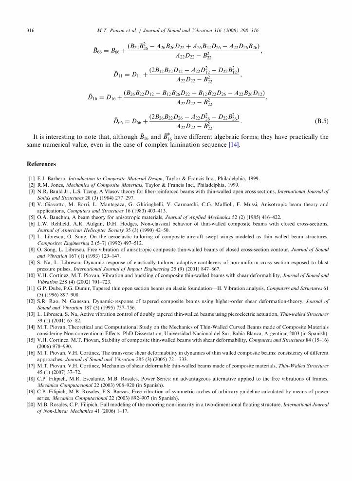
It is interesting to note that, although B16 and Bn
16 have different algebraic forms; they have practically thesame numerical value, even in the case of complex lamination sequence [14].
References
[1] E.J. Barbero, Introduction to Composite Material Design, Taylor & Francis Inc., Philadelphia, 1999.
[2] R.M. Jones, Mechanics of Composite Materials, Taylor & Francis Inc., Philadelphia, 1999.
[3] N.R. Bauld Jr., L.S. Tzeng, A Vlasov theory for fiber-reinforced beams with thin-walled open cross sections, International Journal of
Solids and Structures 20 (3) (1984) 277–297.
[4] V. Giavotto, M. Borri, L. Mantegaza, G. Ghiringhelli, V. Carmaschi, C.G. Maffioli, F. Mussi, Anisotropic beam theory and
applications, Computers and Structures 16 (1983) 403–413.
[5] O.A. Bauchau, A beam theory for anisotropic materials, Journal of Applied Mechanics 52 (2) (1985) 416–422.
[6] L.W. Rehfield, A.R. Atilgan, D.H. Hodges, Non-classical behavior of thin-walled composite beams with closed cross-sections,
Journal of American Helicopter Society 35 (3) (1990) 42–50.
[7] L. Librescu, O. Song, On the aeroelastic tailoring of composite aircraft swept wings modeled as thin walled beam structures,
Composites Engineering 2 (5–7) (1992) 497–512.
[8] O. Song, L. Librescu, Free vibration of anisotropic composite thin-walled beams of closed cross-section contour, Journal of Sound
and Vibration 167 (1) (1993) 129–147.
[9] S. Na, L. Librescu, Dynamic response of elastically tailored adaptive cantilevers of non-uniform cross section exposed to blast
pressure pulses, International Journal of Impact Engineering 25 (9) (2001) 847–867.
[10] V.H. Cortınez, M.T. Piovan, Vibration and buckling of composite thin-walled beams with shear deformability, Journal of Sound and
Vibration 258 (4) (2002) 701–723.
[11] G.P. Dube, P.G. Dumir, Tapered thin open section beams on elastic foundation—II. Vibration analysis, Computers and Structures 61
(5) (1996) 897–908.
[12] S.R. Rao, N. Ganesan, Dynamic-response of tapered composite beams using higher-order shear deformation-theory, Journal of
Sound and Vibration 187 (5) (1995) 737–756.
[13] L. Librescu, S. Na, Active vibration control of doubly tapered thin-walled beams using piezoelectric actuation, Thin-walled Structures
39 (1) (2001) 65–82.
[14] M.T. Piovan, Theoretical and Computational Study on the Mechanics of Thin-Walled Curved Beams made of Composite Materials
considering Non-conventional Effects. PhD Dissertation, Universidad Nacional del Sur, Bahıa Blanca, Argentina, 2003 (in Spanish).
[15] V.H. Cortınez, M.T. Piovan, Stability of composite thin-walled beams with shear deformability, Computers and Structures 84 (15–16)
(2006) 978–990.
[16] M.T. Piovan, V.H. Cortınez, The transverse shear deformability in dynamics of thin walled composite beams: consistency of different
approaches, Journal of Sound and Vibration 285 (3) (2005) 721–733.
[17] M.T. Piovan, V.H. Cortınez, Mechanics of shear deformable thin-walled beams made of composite materials, Thin-Walled Structures
45 (1) (2007) 37–72.
[18] C.P. Filipich, M.R. Escalante, M.B. Rosales, Power Series: an advantageous alternative applied to the free vibrations of frames,
Mecanica Computacional 22 (2003) 908–920 (in Spanish).
[19] C.P. Filipich, M.B. Rosales, F.S. Buezas, Free vibration of symmetric arches of arbitrary guideline calculated by means of power
series, Mecanica Computacional 22 (2003) 892–907 (in Spanish).
[20] M.B. Rosales, C.P. Filipich, Full modeling of the mooring non-linearity in a two-dimensional floating structure, International Journal
of Non-Linear Mechanics 41 (2006) 1–17.
Copyright © 2022 FDOKUMEN