Design and characteristics study of an aircraft tapered wing
16
Copyrights @Kalahari Journals Vol. 7 No. 1 (January, 2022) International Journal of Mechanical Engineering 6985 ISSN: 0974-5823 Vol. 7 No. 1 January, 2022 International Journal of Mechanical Engineering Design and characteristics study of an aircraft tapered wing R. Gayathri 1 Karunya Institute of Technology and Sciences G. Jims John Wessley 2 , R. Mercy Shanthi 3 ,D. Ponmary Pushpa Latha 4 and Robinsingh Gamit 5 Karunya Institute of Technology and Sciences Abstract - In this research work, an attempt is made to understand the characteristics of a tapered wing that can fly at a Mach number of 0.75. The weight estimation of Bombardier LEARJET 70 aircraft is carried out to attain the optimal design goals. Two cases such as wing under uniformly distributed load and varying load are considered to estimate the lift force on the aircraft wing. Tapered wing with NASA SC (2)-0612 airfoil is investigated to understand the necessary aerodynamic behavioural changes that correspond to each design parameters such as taper ratio ranging from 0.1 to 0.3 and wing setting angle from 0 to 2. FEA modelling is performed in ANSYS Workbench with materials such as aluminum 7178 alloy, aluminum 6064 alloy, and T300 Carbon under constant pressure load over the entire wing. The study reveals that aluminum 6064 alloy has better stability in flight than T300 Carbon from the analysis of the stress, strain, and natural frequency distributions throughout the semi-span of the wing. Index Terms - AHP, ANSYS, rib, tapered wing, wing load. INTRODUCTION When the speed of aircraft increases, due to increased air friction around the wings, the aerodynamic parameters like turbulence and drag also increase. Hence, tapering a wing planform results in significant aerodynamic and structural advantages. Since tapering increases the aspect ratio of the wing, the lift generated also increases. Also, the reduction in the wing-tip size reduces the induced drag caused by wing-tip vortices. However, the use of tapered wing has also its limitations and cannot be used extensively. In most cases, vibrations are unwanted as they lead to energy losses and noises and can be minimized by designing these parts carefully. The normal aerodynamic force: lift; generated over a wing surface when it moves in the direction of motion in air or other gaseous medium. The wing used to generate this lift has a special aerodynamic profile with a high rigidity to weight ratio to overcome unexpected loads due to manoeuvring and sudden bursts of wind. Therefore, the design of the wing is done keeping in mind these design parameters. Ayse Kucuk Yilmaz et al [3] performed analysis on the process involved in the selection of aircraft types in relation to the sensitivity of alternative ratings by adopting different pair wise comparisons. Jahnavi and Avinash [4] designed an algorithm for gross weight estimation of few modes of transports and general aviation designs, including the home-built ones. Junyao Zhang [9] implemented the least squares method to calculate the weight of the aircraft and ignored the fuel weight ratio coefficient in the actual aircraft design. Kautuk Sinha et al [2] demonstrated the optimal high aspect ratio composite aircraft wing to satisfy the various manoeuvre and gust conditions. Ghassan M. Atmeh et al [5] estimated the area of booms based on the bending stress and thickness of the skin considering the shear flow. The structural analysis was performed using COMSOL Multiphysics to envision the wing as a respectable candidate for an airplane. S. Solomon Raj [1] performed FEA analysis on wings with and without ribs and spars and it was revealed that reduction in weight associated with improved stiffness in the wing with ribs and spars. Shengyong Zhang, Mike Mikulich [6] developed the integrated CAD and FEA approach for the preliminary design of the aircraft wind and highlighted how the number of ribs and position of spars affected the performance of a wing. Salu Kumar Das, Sandipan Roy [7] performed an analysis on a trainer aircraft with 15 ribs and 2 spars to estimate the deformation, stress, strain, natural frequency of vibration using modal analysis for a pressure load of 50 MPa along with fatigue life. Ernnie Illyani Basri et al [8] incorporated the theories of laminated composites and numerical simulations of FEA to understand the structural response of a multi-layered composite wing. The structural analysis by Yassir Abbas [10] on a typical transport aircraft wing using CFD Fluent and ANSYS shows that the aerodynamic loads were within the prescribed limits and failure due to buckling was not noticed. The paper was structured as follows. Section 1 highlights the various aspects accompanied by the successful design of the aircraft wing and also the different approaches made by the researchers in the past. Section 2 helps to predict the weight of the wing by considering the changes during the flight. Section 3 explains the Analytic Hierarchy Process (AHP) to derive the wing design parameters. Section 4 imparts the methods to predict the loads such as UDL and varying load on the wing and MATLAB code results depict the optimal design for the chosen design inputs. Section 5 explains the CFD simulation procedures to extract wing
-
Upload
khangminh22 -
Category
Documents
-
view
1 -
download
0
Transcript of Design and characteristics study of an aircraft tapered wing

Copyrights @Kalahari Journals Vol. 7 No. 1 (January, 2022)
International Journal of Mechanical Engineering
6985
ISSN: 0974-5823 Vol. 7 No. 1 January, 2022
International Journal of Mechanical Engineering
Design and characteristics study of an aircraft tapered
wing R. Gayathri1
Karunya Institute of Technology and Sciences
G. Jims John Wessley2, R. Mercy Shanthi3,D. Ponmary Pushpa Latha4 and Robinsingh Gamit5
Karunya Institute of Technology and Sciences
Abstract - In this research work, an attempt is made to understand the characteristics of a tapered wing that can fly at a Mach
number of 0.75. The weight estimation of Bombardier LEARJET 70 aircraft is carried out to attain the optimal design goals. Two
cases such as wing under uniformly distributed load and varying load are considered to estimate the lift force on the aircraft wing.
Tapered wing with NASA SC (2)-0612 airfoil is investigated to understand the necessary aerodynamic behavioural changes that
correspond to each design parameters such as taper ratio ranging from 0.1 to 0.3 and wing setting angle from 0 to 2. FEA
modelling is performed in ANSYS Workbench with materials such as aluminum 7178 alloy, aluminum 6064 alloy, and T300
Carbon under constant pressure load over the entire wing. The study reveals that aluminum 6064 alloy has better stability in flight
than T300 Carbon from the analysis of the stress, strain, and natural frequency distributions throughout the semi-span of the wing.
Index Terms - AHP, ANSYS, rib, tapered wing, wing load.
INTRODUCTION
When the speed of aircraft increases, due to increased air friction around the wings, the aerodynamic parameters like turbulence
and drag also increase. Hence, tapering a wing planform results in significant aerodynamic and structural advantages. Since
tapering increases the aspect ratio of the wing, the lift generated also increases. Also, the reduction in the wing-tip size reduces the
induced drag caused by wing-tip vortices. However, the use of tapered wing has also its limitations and cannot be used
extensively. In most cases, vibrations are unwanted as they lead to energy losses and noises and can be minimized by designing
these parts carefully. The normal aerodynamic force: lift; generated over a wing surface when it moves in the direction of motion
in air or other gaseous medium. The wing used to generate this lift has a special aerodynamic profile with a high rigidity to weight
ratio to overcome unexpected loads due to manoeuvring and sudden bursts of wind. Therefore, the design of the wing is done
keeping in mind these design parameters.
Ayse Kucuk Yilmaz et al [3] performed analysis on the process involved in the selection of aircraft types in relation to the
sensitivity of alternative ratings by adopting different pair wise comparisons. Jahnavi and Avinash [4] designed an algorithm for
gross weight estimation of few modes of transports and general aviation designs, including the home-built ones. Junyao Zhang [9]
implemented the least squares method to calculate the weight of the aircraft and ignored the fuel weight ratio coefficient in the
actual aircraft design. Kautuk Sinha et al [2] demonstrated the optimal high aspect ratio composite aircraft wing to satisfy the
various manoeuvre and gust conditions.
Ghassan M. Atmeh et al [5] estimated the area of booms based on the bending stress and thickness of the skin considering the
shear flow. The structural analysis was performed using COMSOL Multiphysics to envision the wing as a respectable candidate
for an airplane. S. Solomon Raj [1] performed FEA analysis on wings with and without ribs and spars and it was revealed that
reduction in weight associated with improved stiffness in the wing with ribs and spars. Shengyong Zhang, Mike Mikulich [6]
developed the integrated CAD and FEA approach for the preliminary design of the aircraft wind and highlighted how the number
of ribs and position of spars affected the performance of a wing.
Salu Kumar Das, Sandipan Roy [7] performed an analysis on a trainer aircraft with 15 ribs and 2 spars to estimate the
deformation, stress, strain, natural frequency of vibration using modal analysis for a pressure load of 50 MPa along with fatigue
life. Ernnie Illyani Basri et al [8] incorporated the theories of laminated composites and numerical simulations of FEA to
understand the structural response of a multi-layered composite wing. The structural analysis by Yassir Abbas [10] on a typical
transport aircraft wing using CFD Fluent and ANSYS shows that the aerodynamic loads were within the prescribed limits and
failure due to buckling was not noticed.
The paper was structured as follows. Section 1 highlights the various aspects accompanied by the successful design of the aircraft
wing and also the different approaches made by the researchers in the past. Section 2 helps to predict the weight of the wing by
considering the changes during the flight. Section 3 explains the Analytic Hierarchy Process (AHP) to derive the wing design
parameters. Section 4 imparts the methods to predict the loads such as UDL and varying load on the wing and MATLAB code
results depict the optimal design for the chosen design inputs. Section 5 explains the CFD simulation procedures to extract wing

Copyrights @Kalahari Journals Vol. 7 No. 1 (January, 2022)
International Journal of Mechanical Engineering
6986
performance parameters. Section 6 is the preliminary stage of FEA simulation in which the sizing and position of internal
components of wing are done. Section 7 compares the structural integrity and vibration behavior of the wing. Section 8 explains
the comparative study of the materials.
AIRCRAFT WEIGHT ESTIMATION
The design of an aircraft from conceptual stage to the deployment includes a stringent and complex process that satisfies a host of
design requirements as per the statutory requirements and the expectations of the customers. The gross weight of the aircraft
includes the weights of the crew, payload, fuel, and structure. The initial estimation of the gross weight of the aircraft is an
important aspect that influences the design process, material selection and the outcomes. Also, the design consideration
encompasses the fact that, the gross weight of the aircraft decreases during the course of the flight due to the consumption of fuel
in a commercial aircraft and due to the release of arms and ammunition in a military aircraft. The estimation of design Gross
weight W0 and other parameters for a crew of 2 members is as below:
Crew weight Wc = 70X2 = 140 kg
Payload weight Wp = 1036 kg
Empty weight We = 7257 kg
Fuel weight Wf = 2750 kg
Therefore, W5/W4 = 0.995, W3/W2 = e (-RC/V(L/D)
Range (R) = 3778 km
C = 0.000025/s (specific fuel consumption)
V = 230.44 m/s
L/D = 14.722
Therefore, W3/W2 = 0.973
Now, W4/W3 = e-EC/(L/D) max
E = 14492 s, C = 0.00022/s, L/Dmax =23.62
Therefore, W4/W3 = 0.8289
By substituting all the ratios in equation W0,
W5/W0 = 0.766
W0 = 9738 kg
Therefore, We/W0 = 0.077
W2 = 0.970*0.985*21469 = 9304.61 kg Thus, the maximum weight of the aircraft is estimated to be 9738 kg.
W0 = (Wc+Wp)/(1-(Wf/W0)- (We/W0)
Now, W5/W0 = W1/W0*W2/W1*W3/W2*W4/W3*W5/W4
W1/W0 = 0.970, W2/W1 = 0.985
ANALYTIC HIERARCHY PROCESS (AHP)
Bombardier LEARJET 70 is selected for the study using the Analytic Hierarchy Process (AHP). Accordingly, the design
parameters are selected and prioritized, in this study. Figure 1 depicts the AHP approach process in the selection of the reference
aircraft.
FIGURE 1 AHP APPROACH FOR REFERENCE AIRCRAFT SELECTION

Copyrights @Kalahari Journals Vol. 7 No. 1 (January, 2022)
International Journal of Mechanical Engineering
6987
The parameters considered in design of wing in this study are listed in the Table 1 as below.
TABLE 1. FEATURES OF LEARJET 70
Parameters Value
Wing span 15.5 m
Wing area S 28.7 m2
Aspect ratio AR 8.37
Empty weight 6300 kg
Take-off weight 9738 kg
Cruise speed 0.75 Mach
Maximum speed 0.81 Mach
Wing loading 339.79 kg/m2
Capacity 7
Payload 1036 kg
Range 3815 km
Maximum altitude 15545 m
Cruise altitude 13716 m
Length 17.1 m
Height 4.3 m
I. Airfoil selection
The cross-section of the aircraft wing is primarily in the shape of an airfoil structure. The airfoil, while moving through the air
stream, generates lift and also ensures stability and directional control of a flying aircraft. The basic parameters of an airfoil are
shown in Figure 5.
FIGURE 2 BASIC PARAMETERS OF AIRFOIL
The airfoil selection is preceded by the calculation of the Reynolds number of the flow. The detailed process involving the
selection of an Airfoil is shown in Fig 3.
Copyrights @Kalahari Journals Vol. 7 No. 1 (January, 2022)
International Journal of Mechanical Engineering
6988
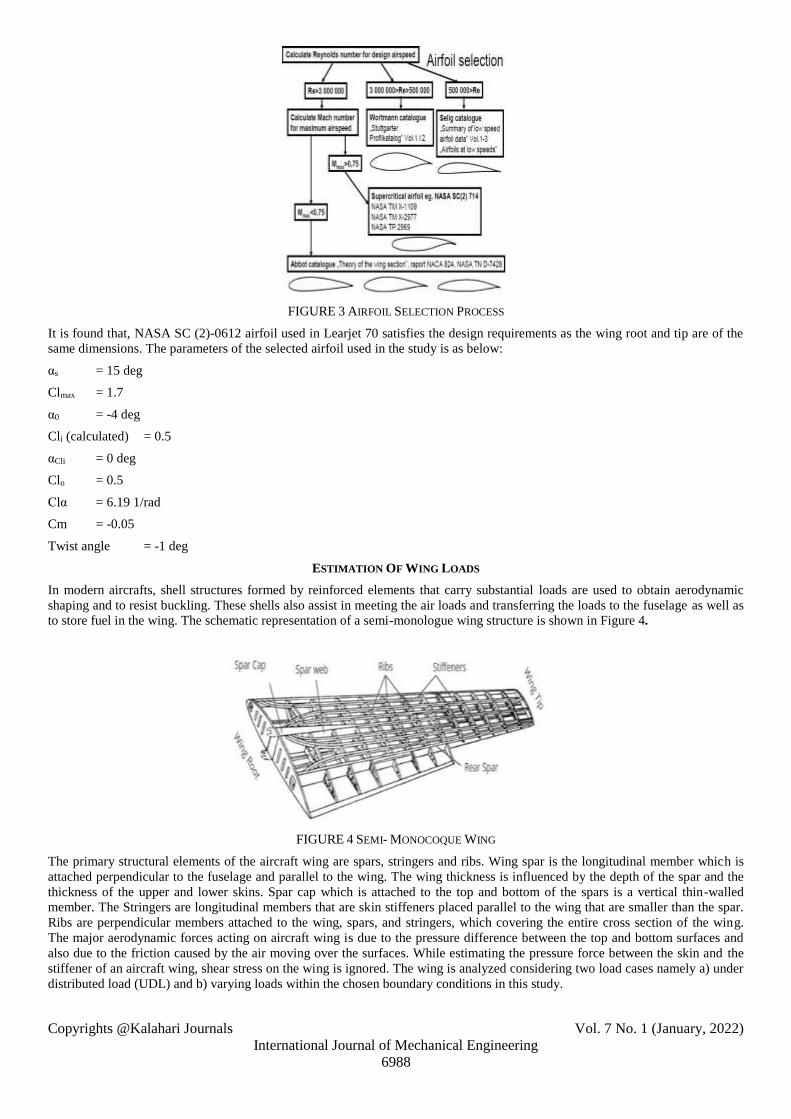
FIGURE 3 AIRFOIL SELECTION PROCESS
It is found that, NASA SC (2)-0612 airfoil used in Learjet 70 satisfies the design requirements as the wing root and tip are of the
same dimensions. The parameters of the selected airfoil used in the study is as below:
αs = 15 deg
Clmax = 1.7
α0 = -4 deg
Cli (calculated) = 0.5
αCli = 0 deg
Clo = 0.5
Clα = 6.19 1/rad
Cm = -0.05
Twist angle = -1 deg
ESTIMATION OF WING LOADS
In modern aircrafts, shell structures formed by reinforced elements that carry substantial loads are used to obtain aerodynamic
shaping and to resist buckling. These shells also assist in meeting the air loads and transferring the loads to the fuselage as well as
to store fuel in the wing. The schematic representation of a semi-monologue wing structure is shown in Figure 4.
FIGURE 4 SEMI- MONOCOQUE WING
The primary structural elements of the aircraft wing are spars, stringers and ribs. Wing spar is the longitudinal member which is
attached perpendicular to the fuselage and parallel to the wing. The wing thickness is influenced by the depth of the spar and the
thickness of the upper and lower skins. Spar cap which is attached to the top and bottom of the spars is a vertical thin-walled
member. The Stringers are longitudinal members that are skin stiffeners placed parallel to the wing that are smaller than the spar.
Ribs are perpendicular members attached to the wing, spars, and stringers, which covering the entire cross section of the wing.
The major aerodynamic forces acting on aircraft wing is due to the pressure difference between the top and bottom surfaces and
also due to the friction caused by the air moving over the surfaces. While estimating the pressure force between the skin and the
stiffener of an aircraft wing, shear stress on the wing is ignored. The wing is analyzed considering two load cases namely a) under
distributed load (UDL) and b) varying loads within the chosen boundary conditions in this study.

Copyrights @Kalahari Journals Vol. 7 No. 1 (January, 2022)
International Journal of Mechanical Engineering
6989
I. Wing under UDL
In the structural analysis of wing under UDL, the following assumptions are made.
1. The wing is a cantilever beam under UDL.
2. Bending is assumed to occur along the span wise direction.
3. The load factor is chosen to vary from nmin = -0.5 G to nmax = 3.5 G.
4. It is assumed that each wing accounts to 40% of the total weight so that the wings account for 80% of the total weight, while
the remaining 20% of the weight is shared by the fuselage and rear wing.
5. Skin and stringers are machined together.
Factor of safety (FoS) is the factor used to reduce the risk of dangers caused by structural failure. It is usually estimated by the
interpretation of known parameters of the structures or chosen appropriately based on the in-depth knowledge of the designer. The
designer carefully estimates the overload conditions possible in the structure and thus fixes the FoS in order to avoid structural
failure even at the time of unexpected overload. In this study, FoS is chosen as 1.5, thus the generated lift per wing is calculated to
be:
Lift per wing = nmax X FoS X 40% weight
=3.5X1.5X0.4X9,738X9.81
= 204.5kN
Area of the wing =10.915 m2
Pressure of the lift load on the lower surface of the wing,
P = lift/wing area= 0.0187 MPa.
II. Wing under varying load
Lifting- line theory is used in the wing design process. The algorithm is explained below.
1.Start
2.Divide the span in segments(N=19), and identify geometry (chord and span) and aerodynamic properties (α, α0, and Clα) for
each segment. S = 28.7 m2, AR = 8.37, λ = 0.25, Twist = -1 degrees, iw = 0 degree, αo =−4 deg,
Clα =6.19 1/rad.
3. Calculate the corresponding angle (θ) for each segment till last. These are the function of lift distribution along the span.
4. Solve the following group of equations to find A1 to An:
5. The parameter µ is defined as follows:
6. Each segment’s lift coefficient is calculated by
7. Determine the wing total lift coefficient using the following equation: Lw 1C .AR.Ap=
8. Print the value of CL
9. Stop
Copyrights @Kalahari Journals Vol. 7 No. 1 (January, 2022)
International Journal of Mechanical Engineering
6990
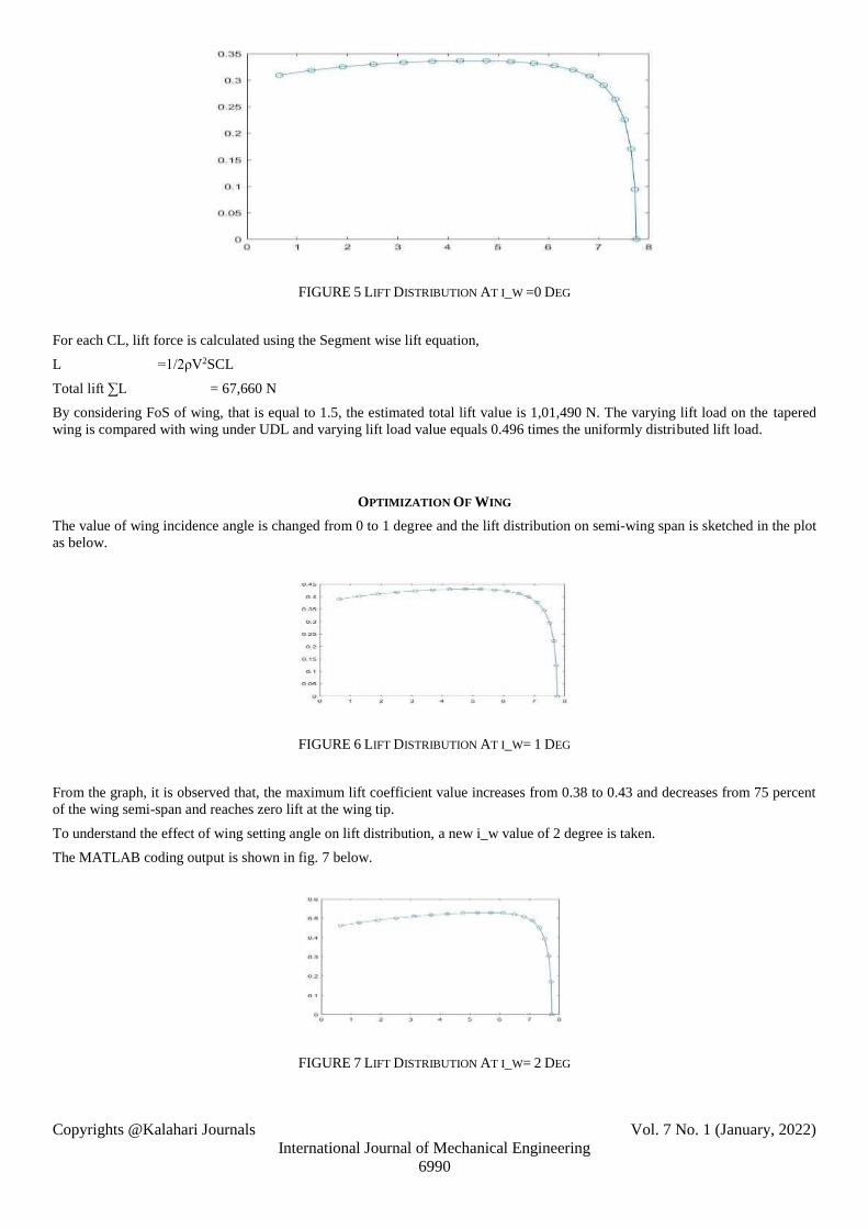
FIGURE 5 LIFT DISTRIBUTION AT I_W =0 DEG
For each CL, lift force is calculated using the Segment wise lift equation,
L =1/2ρV2SCL
Total lift ∑L = 67,660 N
By considering FoS of wing, that is equal to 1.5, the estimated total lift value is 1,01,490 N. The varying lift load on the tapered
wing is compared with wing under UDL and varying lift load value equals 0.496 times the uniformly distributed lift load.
OPTIMIZATION OF WING
The value of wing incidence angle is changed from 0 to 1 degree and the lift distribution on semi-wing span is sketched in the plot
as below.
FIGURE 6 LIFT DISTRIBUTION AT I_W= 1 DEG
From the graph, it is observed that, the maximum lift coefficient value increases from 0.38 to 0.43 and decreases from 75 percent
of the wing semi-span and reaches zero lift at the wing tip.
To understand the effect of wing setting angle on lift distribution, a new i_w value of 2 degree is taken.
The MATLAB coding output is shown in fig. 7 below.
FIGURE 7 LIFT DISTRIBUTION AT I_W= 2 DEG

Copyrights @Kalahari Journals Vol. 7 No. 1 (January, 2022)
International Journal of Mechanical Engineering
6991
The latest modification in wing incidence angle results in an increase of lift coefficient from 0.48 to 0.52 and then decreases from
80 percent of semi-wing span to wing tip where lift coefficient value reaches zero.
Steeper curve corresponds to unstable wing condition as
i_w increases.
FIGURE 8 LIFT DISTRIBUTION AT Λ = 0.1
The reduction of taper ratio from 0.25 to 0.1 shows the steep slope angle increase from 50 percent of semi-wing span. The
maximum CL reaches 0.5.
FIGURE 9 LIFT DISTRIBUTION AT Λ = 0.3
The taper ratio of 0.3 exhibits stable flight behaviour, as the lift curve at λ=0.25. The result reveals that taper ratio should be from
0.2 to 0.3 for cruise Mach number ranges from 0.65 to 0.95.
CFD SIMULATION
NASA SC (2)-0612 airfoil coordinates are imported into SOLIDWORKS and the airfoil is extruded up to 7.75 m (semi-
wingspan).
Outer rectangle with dimensions as below is created.
Length = 10+2.9+15=27.9 m
Width = 10+0.1782+10=20.1782 m
Extrude boss depth = 9 m.
The flow analysis starts with Boolean operation which subtracts the wing from the outer domain. The flow domains are identified
in such a way that pressure far field is applied at inlet, top, bottom, front and back surfaces and pressure outlet is applied at outlet.
Meshing is done using 20,52,314 tetrahedral elements and 4,53,249 nodes.
The viscous (k-omega) model was selected with ideal gas option. At 13,716 m, pressure and temperature values were 15327 N/m2
and 216 K respectively. The simulation was computed from inlet with area = 28.7 m2 and chord length= 2.96m.
Lift force on wall-wing was noted using report plot by setting X=0, Y=1, Z=0. The pressure distribution plot over the tapered
wing was taken to display the maximum and minimum values.

Copyrights @Kalahari Journals Vol. 7 No. 1 (January, 2022)
International Journal of Mechanical Engineering
6992
FIGURE 10 LIFT COEFFICIENT FROM ANSYS FLUENT
The maximum lift coefficient value from CFD simulation is 0.33.
FIGURE 11 TOTAL LIFT VALUE FROM ANSYS FLUENT
The total lift value from the transonic flow simulation was 1,33,257.99N.
FIGURE 12 TOTAL PRESSURE DISTRIBUTION
The red region depicts the maximum total pressure on the wing and the value is about 5.34X10⁴ N/m2.

Copyrights @Kalahari Journals Vol. 7 No. 1 (January, 2022)
International Journal of Mechanical Engineering
6993
FIGURE 13 MAXIMUM TOTAL PRESSURE NEAR LEADING EDGE
Fig 13 displays the variation of total pressure over the wing surface in which the maximum total pressure is maximum near wing
root and leading edge. The minimum total pressure value is about -3X10⁴ N/m2.
The pressure which is obtained by subtracting dynamic pressure from total pressure is the static pressure and its variation is
sketched as below.
FIGURE 14 STATIC PRESSURE DISTRIBUTION
The maximum static pressure value over the wing surface is 4.59X10⁴ N/m2. The minimum value for the same is -6.08X10⁴ N/m2.
SKIN AND RIB THICKNESS
The ribs and spars increase the accuracy of FEA simulation results and position of spars is shown in Table 2.
TABLE 2
POSITION OF SPARS
Rectangular spar I-section spar
RIB HEIGHT WIDTH HEIGHT FLANGES
1 325 mm 160 mm 262mm 45mm
2 313.3 mm 154.24 mm 252.56 mm 43.38 mm
3 300.95 mm 148.16 mm 242.61 mm 41.67 mm
4 287.95 mm 141.76 mm 232.13 mm 39.87 mm
5 274.95 mm 135.36 mm 221.65 mm 38.07 mm
6 262.27 mm 129.12 mm 211.43 mm 36.315 mm

Copyrights @Kalahari Journals Vol. 7 No. 1 (January, 2022)
International Journal of Mechanical Engineering
6994
7 249.27 mm 122.72 mm 200.95 mm 34.51 mm
8 236.6 mm 116.48 mm 190.73 mm 32.76 mm
9 223.6 mm 110.08 mm 180.25 mm 30.96 mm
10 210.6 mm 103.68 mm 169.77 mm 29.16 mm
11 197.6 mm 97.28 mm 159.29 mm 27.36 mm
12 184.92 mm 91.04 mm 149.07 mm 25.60 mm
13 171.92 mm 84.64 mm 1338.59 mm 23.80 mm
14 158.92 mm 78.24 mm 128.11 mm 22 mm
15 146.25 mm 72 mm 117.9 mm 20.25 mm
16 133.25 mm 65.6 mm 107.42 mm 18.45 mm
17 120.25 mm 59.2 mm 96.94 mm 16.65 mm
18 107.57 mm 52.96 mm 86.72 mm 14.89 mm
19 94.57 mm 46.56 mm 76.24 mm 13.09 mm
20 81.25 mm 40 mm 65.5 mm 11.25 mm
By means of referring the reported literatures, the skin thickness is taken as 2.54 mm and 16 mm for rib. Two spars are placed in
our wing at 12% of chord from leading edge and at 71% of chord from leading edge. The leading-edge spar has rectangular
section whereas the trailing edge spar has an I-section spar. The position of ribs was in the table 3 below. Each chord length
shown in the table is considered as a segment length of wing with varying load calculation in which nineteen segments are
considered excluding the wing-root.
I. Design of Tapered wing internal components
Figure 15 NASA SC (2) – 0612 Airfoil

Copyrights @Kalahari Journals Vol. 7 No. 1 (January, 2022)
International Journal of Mechanical Engineering
6995
TABLE 3
POSITION OF RIBS AND ITS CHORD
RIBS LOCATION (X) LOCATION
(Y) CHORD LENGTH
1 0 0 2.96m
2 0.37 m 0.0168 m 2.85 m
3 0.76 m 0.0345 m 2.74 m
4 1.17 m 0.0531 m 2.62 m
5 1.58 m 0.0717 m 2.50 m
6 1.99 m 0.0903 m 2.38 m
7 2.4 m 0.1089 m 2.27 m
8 2.81 m 0.1276 m 2.15 m
9 3.22 m 0.1462 m 2.03 m
10 3.63 m 0.1648 m 1.92 m
11 4.04 m 0.1834 m 1.80 m
12 4.45 m 0.2020 m 1.68 m
13 4.86 m 0.2206 m 1.56 m
14 5.27 m 0.2393 m 1.45 m
15 5.68 m 0.2579 m 1.33 m
16 6.09 m 0.2579 m 1.21 m
17 6.5 m 0.2765 m 1.09 m
18 6.91 m 0.2951 m 0.98 m
19 7.32 m 0.3323 m 0.86 m
20 7.75 m 0.3519 m 0.74 m
The airfoil coordinates are connected using spline in such a way that the profile ends up at the trailing edge (y=0). Tip airfoil is
also made on a new plane offset with a semi-span distance.
2D sketch of rectangular and I-section spars are created with respect to the leading edge of the root airfoil and it was extended up
to tip section. The rib sections between wing root and wing tip are sketched in accordance with Table 3.
FIGURE 16 CREATING SPAR SECTION
The boundary command in features manager helps to make the skin of the wing. The spars and ribs were added in order to increase
the accuracy of the FEA result and the final wing is brought in the ANSYS Workbench to perform the structural simulation.

Copyrights @Kalahari Journals Vol. 7 No. 1 (January, 2022)
International Journal of Mechanical Engineering
6996
FEA SIMULATION
ANSYS FEA simulation helps to understand the structural behaviour of component and displays the relevant results to ensure its
structural integrity.
After solid modelling, meshing was done and 1297759 triangular elements and 1984947 nodes were created. Wing root was fixed
and wing tip was considered as free end. Pressure load of 2430.74 N/m2was applied over the entire surface of wing because it was
the most dominant force acting on the wing.
TABLE 4
PROPERTIES OF MATERIALS
S.No Material Density in
g/cm3
Melting point
in oC
Elastic
Modulus in
Gpa
Poisson’s
Ratio
1. Al 7178 alloy
2.82 482 70 – 80 0.33
2. Al 6064 alloy
2.7 582 68.9 0.33
3. T300 Carbon 1.76 1500 1500 0.26
I. AL 7178 Alloy
FIGURE 17 VON-MISES STRESS DISTRIBUTION
Every material is unique and Al 7178 stress distribution shows that stress value decreases from root to tip to satisfy the design
constraints. The wing root is attached to fuselage and it has zero degree of freedom. The maximum stress value of AL 7178 alloy is
3.76 MPa.
The total deformation is sketched in fig below.
FIGURE 18 TOTAL DEFORMATION
Copyrights @Kalahari Journals Vol. 7 No. 1 (January, 2022)
International Journal of Mechanical Engineering
6997
Total deformation reaches the maximum value near the wing-tip as it is a free end. The maximum value of deformation from the
simulation is 9.28 mm.
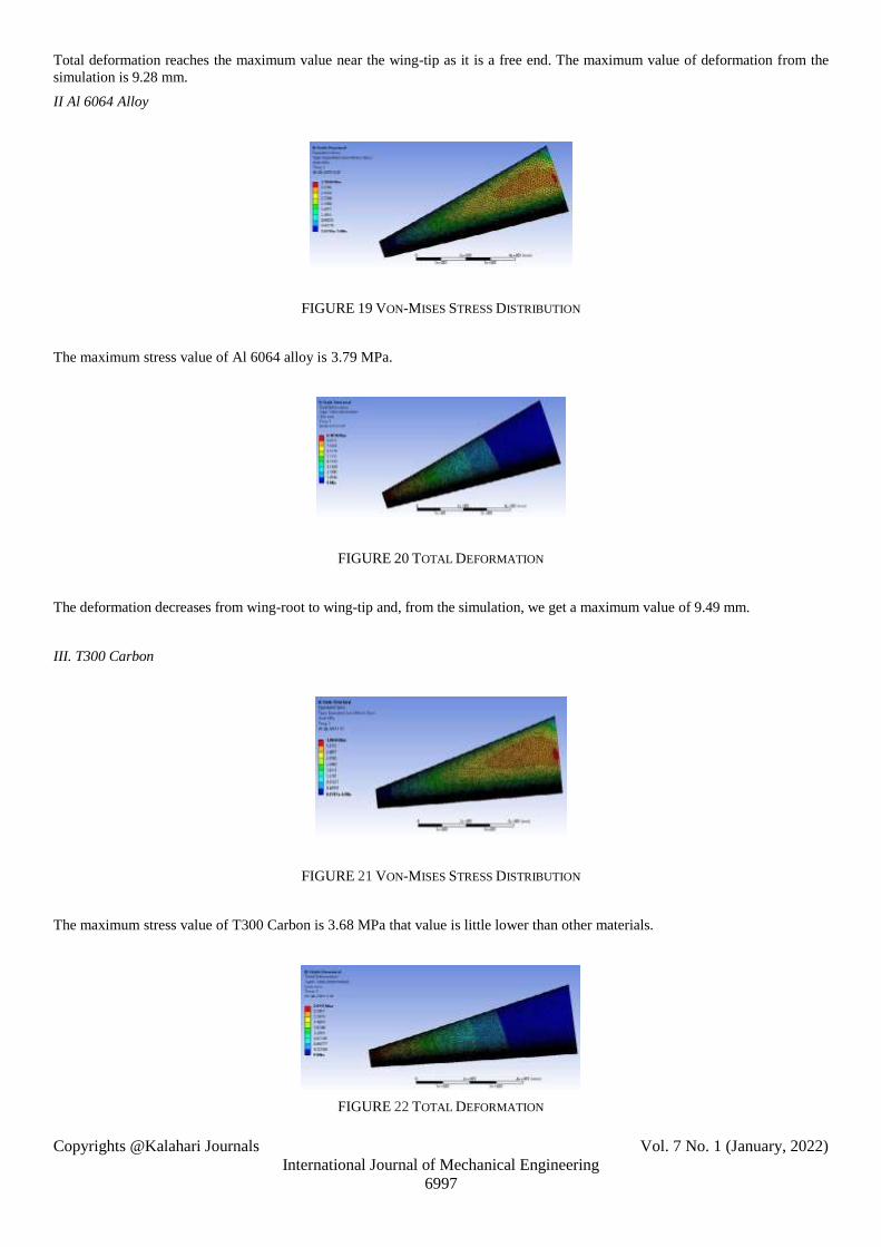
II Al 6064 Alloy
FIGURE 19 VON-MISES STRESS DISTRIBUTION
The maximum stress value of Al 6064 alloy is 3.79 MPa.
FIGURE 20 TOTAL DEFORMATION
The deformation decreases from wing-root to wing-tip and, from the simulation, we get a maximum value of 9.49 mm.
III. T300 Carbon
FIGURE 21 VON-MISES STRESS DISTRIBUTION
The maximum stress value of T300 Carbon is 3.68 MPa that value is little lower than other materials.
FIGURE 22 TOTAL DEFORMATION

Copyrights @Kalahari Journals Vol. 7 No. 1 (January, 2022)
International Journal of Mechanical Engineering
6998
Total deformation of T300 Carbon is 2.91 mm because it is a thermoset polymer matrix composite sheet reinforced with
68% carbon fiber.
IV. Modal Analysis
Modal analysis in the ANSYS reveals only linear behaviour of aircraft wing and displays the natural frequencies and mode shapes
of the same that are base parameters for transient vibration behaviour.
FIGURE 23 TOTAL DEFORMATION FOR MODE 1 OF AL 7178 ALLOY
The modal analysis result depicts the natural frequency of Al 7178 alloy and it is 6.6607 Hz.
FIGURE 24 TOTAL DEFORMATION FOR MODE 1 OF AL 6064 ALLOY
The natural frequency of Al 6064 alloy is 6.6675 Hz and it is little higher than Al 7178 alloy.
FIGURE 25 TOTAL DEFORMATION FOR MODE 1 OF T300 CARBON
The modal analysis displays the natural frequency of T300 Carbon in fig 31 and it is found to be 15.045 Hz. The common
observation in each modal plot is increasing total deformation near wing tip. Total deformation is in the decreasing order from Al
7178 alloy to T300 Carbon. Three modes are extracted for each material and the first modal frequency (natural frequency) results
are depicted in fig. 23, 24 and 25. The maximum displacement value of Al 7178 alloy is 0.0407m and it seems quite high. The
lowest value of deformation is noted in Al 6064 alloy.
Conclusion
The optimal taper wing configuration was found out using MATLAB coding. The uniformly distributed load and varying load
over the wing are estimated and the results are validated using CFD simulation. The structural analysis of wing was carried out for
three materials such as Al 7178 alloy, Al 6064 alloy and T300 carbon is almost the same.

Copyrights @Kalahari Journals Vol. 7 No. 1 (January, 2022)
International Journal of Mechanical Engineering
6999
The natural frequency is lowered with an increase in mass and increased with an increase in stiffness. The natural frequency from
modal analysis proves that T300 carbon has the highest natural frequency value. The smaller deformation of Al 6064 and its
benefits outweighed the T300 carbon. It is concluded that Al 6064 has better stability in flight than T300 Carbon by examining all
mechanical and vibrational parameters such as stress, strain and natural frequency distributions over the semi-span on the wing.
.
Acknowledgments
The authors would like to thank the editor and anonymous reviewers for their valuable comments that helped improve the quality
of this work.
References
[1] Solomon Raj, S, Venkata Sushma Chinta, Zain Afridi, “Numerical Analysis of an Aircraft Wing”, Turkish Journal of
Computer and Mathematics Education, Vol.12, No.11,2021, pp. 3760-3766.
[2] Kautuk Sinha, Thomas Klimmek, Matthias Schulze, Vega Handojo, “Loads analysis and structural optimization of a high
aspect ratio, composite wing aircraft”, CEAS Aeronautical Journal, Vol.12,2021, pp. 233–243.
[3] Ayse Kucuk Yilmaz, Konstantinos Malagas, Muhammad Jawad & Nikitas Nikitakos, “Aircraft selection process with
technique for order preference by similarity to ideal solution and AHP integration,” International Journal of Sustainable
Aviation, Vol.6, No.3,2020, pp. 220-235.
[4] Jahnavi & Avinash, “Aircraft design and weight estimation nomenclature”,Global Journal of Researches in Engineering: B
Automotive Engineering, Vol.14, No.4, 2020, pp. 35-39.
[5] Ghassan M. Atmeh, Zeaid Hasan & Feras Darwish, “Design and stress analysis of a general aviation aircraft wing”, the
COMSOL Conference 2010, Boston, 2019, pp. 1-7.
[6] Shengyong Zhang & Mike Mikulich, “Parametric CAD Modelling of Aircraft Wings for FEA Vibration Analysis”, Journal
of Applied Mathematics and Physics, Vol.9, 2021, pp. 889-900.
[7] Salu Kumar Das & Sandipan Roy, “Finite element analysis of aircraft wing using carbon fiber reinforced polymer and glass
fiber reinforced polymer”, IOP Conf. Series: Materials Science and Engineering, Vol. 402,2018, pp.1-12.
[8] Ernnie Illyani Basri, Mohamed Thariq Hameed Sultan, Adi Azriff Basri, Faizal Mustapha & Kamarul Arifin Ahmad,”
Consideration of Lamination Structural Analysis in a Multi-Layered Composite and Failure Analysis on Wing Design
Application”, Materials, Vol.14, 2021, pp.1-22.
[9] Junyao Zhang, Gang Tong, Feng Wang, Quoqing Zhou, “Calculation Method of Take-off Weight for Single-seat Ultralight
General Aircraft”, IOP Conf. Series: Materials Science and Engineering, Vol. 782, 2020, pp.1-8.
[10] Yassir Abbas, Tariq Elsonni, Abdul Aziz Abdulmajid, Alnazir Khalafallhi & Mohammed Alnazir. “Structural analysis of a
transport aircraft Wing”, INCAS BULLETIN, Vol. No1, 2021, pp.3 – 9.
[11] Sommerwerk,K., Michels,B., Lindhorst, K., Haupt, M.C., Horst,P. “Application of efficient surrogate modeling to aero
elastic analyses of an aircraft wing”. Aerospace Science and Technology, Vol. 55, 2018, pp.314–323.
[12] Ramesh Kumar, A., Balakrishnan, S.R., Balaj, S. “Design of An Aircraft Wing Structure for Static Analysis and Fatigue Life
Prediction”. International Journal of Engineering Research & Technology, Vol. 2, No.5, 2013, pp.1154-58.
[13] Jahnavi, Avinash. “Aircraft Design and Weight Estimation Nomenclature”, Global Journal of Researches in Engineering: B
Automotive Engineering, Vol.14, No. 4, 2014, pp.35-39.
[14] Veeranjaneyulu Kalavagunta & Shaik Hussain, “Wing Rib Stress Analysis of DLR-F6 aircraft”, Materials Science and
Engineering, Vol. 455, 2018, pp.1-7.
[15] Tang Jiapeng, Xi Ping, Zhang Baoyuan & Hu Bifu, “A finite element parametric modeling technique of aircraft wing
structures”, Chinese Journal of Aeronautics, Vol.26, No.5, 2013, pp.1202- 1210.
[16] Muhammad Amir Mirza Bin Mohd Zakuan, Abdul Aabid, Sher Afghan Khan, “Modelling and Structural Analysis of Three
Dimensional Wing”, International Journal of Engineering and Advanced Technology, Vol.9, No.1, 2019, pp.6820-6828.
[17] Jan E. K. Hoogervorst & AliElham, “Wing aerostructural optimization using the Individual Discipline Feasible
Architecture”, Aerospace Science and Technology, Vol. 65, 2019, pp.90-99.
[18] Guan, Z.Q., Gu, Y.X., Zhang, H.W., Li, Y.P., Zhao, G. Z., Kang, Z., Xing, B.C., “Parameterized method for 3D finite
element modeling based on CAD/CAE integration”, Computer Integrated Manufacturing Sytems, Vol.9, No.12, 2003,
pp.1112 – 1119.
[19] Haocheng, LUO Mingqiang, LIU Hu & WU Zhe, “A Knowledge-based and Extensible Aircraft Conceptual Design
Environment”, Chinese Journal of Aeronautics, Vol.24,2011, pp.709-719.

Copyrights @Kalahari Journals Vol. 7 No. 1 (January, 2022)
International Journal of Mechanical Engineering
7000
[20] R. Rajappan & V. Pugazhenthi, “Finite Element Analysis of Aircraft Wing Using Composite Structure”, The International
Journal of Engineering and Science, Vol.2, No.2, 2013, pp.74-80.
[21] Yang, Z. R., Jiang, Y. & Huang, C., “The Thickness of an Aircraft Wing Skins Optimization Based on ABAQUS”, Applied
Mechanics and Materials, 716–717, 2015, pp.679-681.
[22] W Kuntjoroa, AMH Abdul Jalilb & J Mahmud, “Wing Structure Static Analysis using Superelement”, Elsevier, Vol.
41,2012, pp.1600-1606.
[23] S. R. Zaweri & Nikhil A. Khadse, “Modal Analysis of Aircraft Wing using Ansys Workbench Software Package”,
International Journal of Engineering Research & Technology (IJERT), Vol. 4, No. 7, 2015, pp.225- 230.
[24] N. S. Nirmal Raj, Halesh Koti & Halesh Koti, “Static Stress Analysis for Aircraft Wing and Its Weight Reduction using
Composite Material”, International Journal of Engineering Research & Technology (IJERT), Vol. 3, No. 4, 2014, pp.2300-
2303.
[25] Slavica Dožić & Milica Kalić, “An AHP approach to aircraft selection process”, Transportation Research Procedia, Vol.3,
2014, pp.165-174.