MAINTENANCE MANUAL - Cruiser Aircraft
342
CR-MM-1-0-00 Date of issue: 2020-11-19 Revision No.: 24 i This document is prepared in accordance with the AP DOA Approval No. AP.507 PS-28 Cruiser MAINTENANCE MANUAL Copy No.: This document contains EASA approved Chapter 2A – Airworthiness Limitation Section.
-
Upload
khangminh22 -
Category
Documents
-
view
2 -
download
0
Transcript of MAINTENANCE MANUAL - Cruiser Aircraft

CR-MM-1-0-00
Date of issue: 2020-11-19 Revision No.: 24 i
This document is prepared in accordance with the AP DOA Approval No. AP.507
PS-28 Cruiser
MAINTENANCE MANUAL
Copy No.:
This document contains EASA approved Chapter 2A – Airworthiness Limitation Section.

CR-MM-1-0-00
Revision No.: 24 Date of issue: 2020-11-19 ii
INTENTIONALLY LEFT BLANK

CR-MM-1-0-00
Date of issue: 2020-11-19 Revision No.: 24 iii
This document is prepared in accordance with the AP DOA Approval No. AP.507
PS-28 Cruiser
MAINTENANCE MANUAL
PS-28 Cruiser aircraft
is designed and manufactured by
Czech Aircraft Group s.r.o. Na Záhonech 212, 686 04 Kunovice
Czech Republic
Website: www.cruiseraircraft.cz E-mail: [email protected]
This document contains EASA approved Chapter 2A – Airworthiness Limitation Section.

CR-MM-1-0-00
Revision No.: 24 Date of issue: 2020-11-19 iv
INTENTIONALLY LEFT BLANK
CR-MM-1-0-00
PS-28 Cruiser RECORD OF REVISION
Date of issue: 2017-12-05 Revision No.: 20 0 - 1
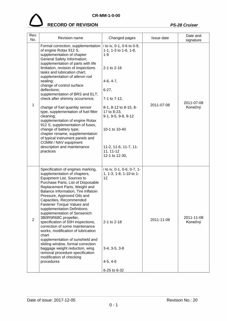
Rev.No. Revision name Changed pages Issue date Date and
signature
1
Formal correction, supplementation of engine Rotax 912 S, supplementation of chapter General Safety Information; supplementation of parts with life limitation, revision of inspections tasks and lubrication chart; supplementation of aileron rod sealing; change of control surface deflections; supplementation of BRS and ELT; check after shimmy occurrence; change of fuel quantity sensor type, supplementation of fuel filter cleaning; supplementation of engine Rotax 912 S, supplementation of fuses, change of battery type; chapter rename, supplementation of typical instrument panels and COMM / NAV equipment description and maintenance practices
i to iv, 0-1, 0-6 to 0-9, 1-1, 1-3 to 1-6, 1-8, 1-9 2-1 to 2-16 4-6, 4-7, 6-27, 7-1 to 7-12, 8-1, 8-12 to 8-15, 8-17 to 8-23, 9-1, 9-5, 9-8, 9-12 10-1 to 10-40 11-2, 11-6, 11-7, 11-11, 11-12 12-1 to 12-30,
2011-07-08 2011-07-08 Konečný
2
Specification of engines marking, supplementation of chapters, Equipment List, Sources to Purchase Parts, List of Disposable Replacement Parts, Weight and Balance Information, Tire Inflatoin Pressure, Approved Oils and Capacities, Recommended Fastener Torque Values and supplementation Definitions. supplementation of Sensenich 3B0R5R68C propeller, specification of 50H inspections, correction of some maintenance works, modification of lubrication chart supplementation of sunshield and sliding window, formal correction baggage weight reduction, wing removal procedure specification modification of checking procedures
i to iv, 0-1, 0-6, 0-7, 1-1, 1-3, 1-8, 1-10 to 1-12 2-1 to 2-18 3-4, 3-5, 3-8 4-5, 4-6 6-25 to 6-32
2011-11-08 2011-11-08 Konečný

PS-28 Cruiser
CR-MM-1-0-00
RECORD OF REVISION
Revision No.: 20 Date of issue: 2017-12-05 0 - 2
Rev.No. Revision name Changed pages Issue date Date and
signature
2
Supplementation of Loctite threadlocker, supplementation of procedure of lubrication correction of fuel scheme supplementation of Sensenich 3B0R5R68C propeller and appropriate maintenance practices supplementation of switches / circuit breakers, battery life supplementation of PS-28 Cruiser instrument panels
8-1, 8-18, 8-23 9-1 to 9-3 10-1 to 10-42 11-4 to 11-6 12-1 to 12-32
2011-11-08 2011-11-08 Konečný
3
Formal correction, supplementation of definition, specification of battery life limitation, supplementation of EFIS D-100 battery, supplementation of propeller Special Scheduled Inspection, supplementation of brake pad check, supplementation of EFIS D-100 battery capacity test, supplementation of cross reference specification of safety harnesses, supplementation of the third friction washer on nose gear leg supplementation of fuel scheme, modification of the fuel system tighthess check correction of Rotax manuals section, torque moment and exhaust installation, correction of engine test report, supplementation of Klassic 170/3/R propeller inspections supplementation of SkyView system switches / circuit breakers, supplementation of SkyView system description and maintenance practices, supplementation of EFIS D100, EMS D120 firmware upgrade
i to iv, 0-2, 0-6 to 0-9 1-10 2-1 to 2-3, 2-5 to 2-7, 2-13, 2-14 7-2, 7-4, 7-5 8-18 9-2 to 9-5, 9-7, 9-13 10-2, 10-3 to 10-5, 10-9, 10-10, 10-12 to 10-14, 10-28, 10-29, 10-37 to 10-46, 10-48 11-4 to 11-7, 11-14 12-1 to 12-46
2012-05-28
EASA Minor Change Approval 10041497 21. 9. 2012
4
Supplementation of GTN 650 / 750 description and maintenance practices, supplementation of GPS antenna maintenance practices, supplementation of reference to avionics manufacturer documentation, supplementation of Dynon avionics pitot / static test,
i to iv, 0-2, 0-3, 0-6 to 0-9 12-1 to 12-54
2012-12-10
EASA Minor Change Approval 10043463 30. 1. 2013

CR-MM-1-0-00
PS-28 Cruiser RECORD OF REVISION
Date of issue: 2015-05-24 Revision No.: 13 0 - 3
Rev.No. Revision name Changed pages Issue date Date and
signature
4
supplementation of GTN post installation checkout log
17-1, 17-2, 17-6 to 17-10
2012-12-10
EASA Minor Change Approval 10043463 30. 1. 2013
5
Supplementation of stall warning system description and maintenance practices
i to iv, 0-3 to 0-6, 0-8, 0-9, 12-1, 12-2, 12-9, 12-20, 12-21, 12-53 2013-02-04
EASA Major Change Approval 10043557 6. 2. 2013
6
Supplementation of efficient heating system and carbon monoxide detector installation.
i to iv, 0-3, 0-6, 0-9, 0-10, 13-1 to 13-10
2013-03-11
EASA Minor Change Approval 10045960 31. 7. 2013
7 Check of nose landing gear leg for cracks
i to iv, 0-3, 0-6, 0-7, 2-7, 2-11, 8-1, 8-17 to 8-26
2013-10-09 2013-10-09 Konečný
8
Supplementation of Sensenich 3B0R5R68C propeller installation on PS-28 airplanes
i to iv, 0-3, 0-6, 0-8, 10-2, 10-3, 10-8, 10-11, 10-24, 10-43 2014-01-30
EASA Major Change Approval 10047966 31. 1. 2014
9
Correction of cross reference, supplementation of improved nose landing gear and modification of relevant maintenance practices
i to iv, 0-3, 0-6, 0-7, 2-5, 2-7, 2-11, 2-12, 8-4, 8-5, 8-19 2014-02-17
EASA Minor Change Approval 10048185 18. 2. 2014
10
Supplementation of balance ballast description and installation.
i to iv, 0-3, 0-6, 3-1, 3-5, 3-10, 3-11
2014-08-22
EASA Minor Change Approval 10050318 27. 8. 2014
11
Revision of SkyView system, supplementation of SkyView system adjustment, extension of nose landing gear leg check for cracks, supplementation of ELT Kannad 406, supplementation of XPDR control unit TC20.
i to iv, 0-3, 0-6 to 0-9, 2-2, 7-1, 7-3, 7-4, 7-10 to 12, 8-1, 8-18, 8-19, 8-20, 12-2, 12-8 to 10, 12-12, 12-17, 12-18, 12-38 to 44, 12-46 to 49, 12-54 to 62
2014-10-29
EASA Major Change Approval 10051301
21. 11. 2014
12
Increasing of the airframe service life, improvement of 100 h / annual inspection in fuselage and wing area
i to iv, 0-3, 0-6, 2-2, 2-8, 2-9
2014-11-24
EASA Major Change Approval 10051602
11. 12. 2014
13 Supplementation of Scheduled Inspection after 25 H concerning NLG No SG0270N.
i to iv, 0-3, 0-6, 2-1, 2-3, 2-4, 2-7, 2-8, 2-20
2015-05-24
EASA Major Change Approval 10053460 29.5.2015

PS-28 Cruiser
CR-MM-1-0-00
RECORD OF REVISION
Revision No.: 22 Date of issue: 2018-09-27 0 - 4
Rev.No. Revision name Changed pages Issue date Date and
signature
14 Change of the circuit breaker value for Attitude Indicator and Directional Gyro
i, ii, iii, iv, 0-4, 0-6, 0-8, 11-6 2015-09-07
EASA Minor Change Approval 10054830 22.09.2015
15
Coolant Temperature (CT) as an alternative to the Cylinder Head Temperature (CHT) added for cases that the engine is equipped with new cylinder heads design acc.to the SB-912-066 and SB-912-066UL Rotax bulletin
i to iv, 0-4, 0-6, 0-8, 0-9, 0-10, 1-10, 10-3, 10-4, 10-5, 10-6, 10-38, 10-46, 12-3, 12-4, 12-5, 12-6, 12-7, 12-8, 12-12, 12-18, 12-42, 17-5
2015-09-23
EASA Major Change Approval 10055978 11.12.2015
16
New / updated propeller limits (inspections, works) for: Woodcomp Klassic 170/3/R Sensenich 3B0R5R68C
i to iv 0-4, 0-6, 0-8, 2-2, 2-3, 2-7, 2-8, 2-14 10-1, 10-2, 10-39, 10-40, 10-41, 10-42, 10-43
2016-02-19
EASA Major Change Approval 10057611 30.3.2016
17
Landing Light Replacement added – type TrailTech 4213-SX replaced by type Kuntzleman 11-06854
- valid from S/N 0571
i to iv 0-4, 0-6, 0-8 11-5, 11-6
2016-08-17
EASA Minor Change Approval 10059451 16.9.2016
18 Dual Circuit Thermostat Hektik F1107 in the PS-28 Cruiser Engine Liquid Cooling System
i to iv 0-4, 0-8 10-1, 10-2, 10-6, 10-7, 10-47
2016-10-24
EASA Major Change Approval 10060546 21.12.2016
19 Installation of ELT Kannad 406 AF Compact in Airplanes with Analog Equipment
i to iv 0-4, 0-6, 0-7 7-1, 7-3, 7-10, 7-12
2017-06-06
EASA Minor Change Approval 10062712 24.7.2017
20
Supplementation of TrailTech D112-SX landing light Supplementation of oil filter information Administrative corrections
i to iv 0-4, 0-6, 0-7, 0-8, 1-3, 1-8, 2-1, 2-3, 2-8, 10-1, 10-2, 10-11, 10-17, 10-33, 10-34, 10-37, 10-40, 10-41, 10-42, 11-1, 11-4, 11-5, 11-6, 11-12, 11-13, 11-14
2017-12-05
EASA Minor Change Approval 10065161 6.4.2018
21 Administrative correction: Chapter 18 – Valid Supplements page added
i to iv 0-4, 0-10, 1-1, 18-1, 18-2, 18-3, 18-4
2018-04-13
EASA Major Change Approval 10066844 11.9.2018
22
Installation of the SG0160L/P reinforced main gear leg and info on torque moments, locknuts, spacer added. Number of washers on stabilizer and on wing updated.
i to iv 0-4 to 0-9, 1-1, 2-1, 2-4, 2-9, 2-16, 3-1, 3-10, 4-1, 4-5 to 4-10, 5-1, 5-6 to 5-11, 6-1, 6-7, 6-8, 6-10 to 6-15,
2018-09-27
EASA Major Change Approval 10070985 17.9.2019

CR-MM-1-0-00
PS-28 Cruiser RECORD OF REVISION
Date of issue: 2020-11-19 Revision No.: 24 0 - 5
Rev.No. Revision name Changed pages Issue date Date and
signature
22
Redundant washer from landing gear wheel deleted. Caution for engine test updated. New page 0-5 added. Repairman (LS-M) or Mechanic (A&P) was replaced by new definition.
6-17, 6-18, 6-21, 7-1, 7-5, 7-7, 7-9, 7-10, 8-1, 8-3, 8-7 to 8-9, 8-12 to 8-14, 8-22, 9-1, 9-8 to 9-10, 10-1, 10-2, 10-12, 10-13, 10-15, 10-16, 10-18, 10-19, 10-22, 10-23, 10-28, 10-29, 10-32, 11-1, 11-12, 11-13, 12-1, 12-2, 12-19 to 12-23, 12-25, 12-26, 12-28 to 12-43, 12-45 to 12-50
2018-09-27
EASA Major Change Approval 10070985 17.9.2019
23 Inspection and lubrication of Gerdes or ACS ignition switches
i to iv 0-5, 0-6,0-8, 0-9, 2-8, 12-2, 12-62 to 12-66
2020-01-15
EASA Minor Change Approval 10072846 18.03.2020
24
Airworthiness Limitation Section (ALS) integration
i to iv 0-5, 0-6, 0-7, 0-8, 0-10 1-1, 1-4, 1-7, 1-8, 1-10, 1-11, 1-12, 1-13, 1-14 2-1, 2-2, 2-3, 2-4, 2-5, 2-6, 2-7, 2-8, 2-9, 2-10, 2-11, 2-12, 2-13, 2-14, 2-15, 2-16, 2-17, 2-18, 2-19, 2-20 3-1, 3-5, 3-6, 3-12 6-2 7-3, 7-7, 7-9 9-3, 9-5 10-1, 10-2, 10-10, 10-17, 10-18, 10-19, 10-35, 10-36, 10-37, 10-38 17-2, 17-3, 17-5
2020-11-19
EASA Major Change Approval 10075099 07.12.2020
25

PS-28 Cruiser
CR-MM-1-0-00
LIST OF EFFECTIVE PAGES
Revision No.: 24 Date of issue: 2020-11-19 0 - 6
Chapter Page Date Chapter Page Date Title Page i 2020-11-19 2 2-14 2020-11-19
ii 2020-11-19 2-15 2020-11-19 iii 2020-11-19 2-16 2020-11-19 iv 2020-11-19 2-17 2020-11-19 2-18 2020-11-19
RoR 0-1 2017-12-05 2-19 2020-11-19 0-2 2017-12-05 2-20 2020-11-19 0-3 2015-05-24 0-4 2018-09-27 3 3-1 2020-11-19 0-5 2020-11-19 3-2 2011-03-08 2-3 2011-03-08
LoEP 0-6 2020-11-19 3-4 2012-12-10 0-7 2020-11-19 3-5 2020-11-19 0-8 2020-11-19 3-6 2020-11-19 0-9 2020-01-15 3-7 2011-03-08 0-10 2020-11-19 3-8 2011-11-08 3-9 2011-03-08 3-10 2018-09-27 1 1-1 2020-11-19 3-11 2014-08-22 1-2 2011-03-08 3-12 2020-11-19 1-3 2017-12-05 1-4 2020-11-19 4 4-1 2018-09-27 1-5 2011-07-08 4-2 2011-03-08 1-6 2011-07-08 4-3 2011-03-08 1-7 2020-11-19 4-4 2011-03-08 1-8 2020-11-19 4-5 2018-09-27 1-9 2011-07-08 4-6 2018-09-27 1-10 2020-11-19 4-7 2018-09-27 1-11 2020-11-19 4-8 2018-09-27 1-12 2020-11-19 4-9 2018-09-27 1-13 2020-11-19 4-10 2018-09-27 1-14 2020-11-19 4-11 2011-03-08 4-12 2011-03-08 2 2-1 2020-11-19 2-2 2020-11-19 5 5-1 2018-09-27 2-3 2020-11-19 5-5 2011-03-08 2-4 2020-11-19 5-3 2011-03-08 2-5 2020-11-19 5-4 2011-03-08 2-6 2020-11-19 5-5 2011-03-08 2-7 2020-11-19 5-6 2018-09-27 2-8 2020-11-19 5-7 2018-09-27 2-9 2020-11-19 5-8 2018-09-27 2-10 2020-11-19 5-9 2018-09-27 2-11 2020-11-19 5-10 2018-09-27 2-12 2020-11-19 5-11 2018-09-27 2-13 2020-11-19 5-12 2011-03-08

CR-MM-1-0-00
PS-28 Cruiser LIST OF EFFECTIVE PAGES
Date of issue: 2020-11-19 Revision No.: 24 0 - 7
Chapter Page Date Chapter Page Date 6 6-1 2018-09-27 7 7-12 2017-06-06 6-2 2020-11-19 6-3 2011-03-08 6-4 2011-03-08 8 8-1 2018-09-27 6-5 2011-03-08 8-2 2011-03-08 6-6 2018-09-27 8-3 2018-09-27 6-7 2018-09-27 8-4 2014-02-17 6-8 2011-03-08 8-5 2014-02-17 6-9 2018-09-27 8-6 2011-03-08 6-10 2018-09-27 8-7 2018-09-27 6-11 2018-09-27 8-8 2018-09-27 6-12 2018-09-27 8-9 2018-09-27 6-13 2018-09-27 8-10 2011-03-08 6-14 2018-09-27 8-11 2011-03-08 6-15 2011-03-08 8-12 2018-09-27 6-16 2018-09-27 8-13 2018-09-27 6-17 2018-09-27 8-14 2018-09-27 6-18 2011-03-08 8-15 2011-03-08 6-19 2011-03-08 8-16 2011-03-08 6-20 2011-11-08 8-17 2017-12-05 6-21 2011-11-08 8-18 2017-12-05 6-22 2011-11-08 8-19 2014-10-29 6-23 2011-11-08 8-20 2014-10-29 6-24 2011-11-08 8-21 2013-10-09 6-25 2011-11-08 8-22 2018-09-27 6-26 2011-11-08 8-23 2013-10-09 8-24 2013-10-09 8-25 2013-10-09 8-26 2013-10-09 9 9-1 2018-09-27 9-2 2012-05-28 9-3 2020-11-19 7 7-1 2018-09-27 9-4 2012-05-28 7-2 2012-05-28 9-5 2020-11-19 7-3 2020-11-19 9-6 2011-03-08 7-4 2014-10-29 9-7 2012-05-28 7-5 2018-09-27 9-8 2018-09-27 7-6 2011-07-08 9-9 2018-09-27 7-7 2020-11-19 9-10 2018-09-27 7-8 2011-07-08 9-11 2011-03-08 7-9 2020-11-19 9-12 2011-03-08 7-10 2018-09-27 9-13 2012-05-28 7-11 2014-10-29 9-14 2011-03-08

PS-28 Cruiser
CR-MM-1-0-00
LIST OF EFFECTIVE PAGES
Revision No.: 24 Date of issue: 2020-11-19 0 - 8
Chapter Page Date Chapter Page Date 9-15 2011-07-08 10-41 2015-09-23 9-16 2011-11-08 10-42 2017-12-05 10-43 2017-12-05
10 10-1 2020-11-19 10-44 2017-12-05 10-2 2020-11-19 10-3 2015-09-23 10-4 2015-09-23 10-5 2015-09-23 11 11-1 2018-09-27 10-6 2016-10-24 11-2 2011-07-08 10-7 2016-10-24 11-3 2011-03-08 10-8 2011-07-08 11-4 2017-12-05 10-9 2014-01-30 11-5 2017-12-05 10-10 2020-11-19 11-6 2017-12-05 10-11 2017-12-05 11-7 2012-05-28 10-12 2018-09-27 11-8 2011-11-08 10-13 2018-09-27 11-9 2011-03-08 10-14 2012-05-28 11-10 2011-03-08 10-15 2018-09-27 11-11 2011-03-08 10-16 2018-09-27 11-12 2018-09-27 10-17 2020-11-19 11-13 2018-09-27 10-18 2020-11-19 11-14 2017-12-05 10-19 2020-11-19 10-20 2018-09-27 10-21 2018-09-27 10-22 2011-11-08 12 12-1 2018-09-27 10-23 2011-11-08 12-2 2020-01-15 10-24 2018-09-27 12-3 2015-09-07 10-25 2018-09-27 12-4 2012-12-10 10-26 2012-05-28 12-5 2015-09-07 10-27 2011-11-08 12-6 2012-12-10 10-28 2011-11-08 12-7 2015-09-07 10-29 2011-11-08 12-8 2014-10-29 10-30 2018-09-27 12-9 2014-10-29 10-31 2018-09-27 12-10 2014-10-29 10-32 2011-11-08 12-11 2012-12-10 10-33 2011-11-08 12-12 2015-09-07 10-34 2018-09-27 12-13 2012-12-10 10-35 2020-11-19 12-14 2012-12-10 10-36 2020-11-19 12-15 2012-12-10 10-37 2020-11-19 12-16 2012-12-10 10-38 2020-11-19 12-17 2014-10-29 10-39 2017-12-05 12-18 2015-09-23 10-40 2014-01-30 12-19 2018-09-27

CR-MM-1-0-00
PS-28 Cruiser LIST OF EFFECTIVE PAGES
Date of issue: 2020-01-15 Revision No.: 23 0 - 9
Chapter Page Date Chapter Page Date 12 12-20 2018-09-27 12 12-62 2020-01-15 12-21 2018-09-27 12-63 2020-01-15 12-22 2018-09-27 12-64 2020-01-15 12-23 2018-09-27 12-65 2020-01-15 12-24 2012-12-10 12-66 2020-01-15 12-25 2018-09-27 12-26 2018-09-27 13 13-1 2013-01-11 12-27 2012-12-10 13-2 2013-01-11 12-28 2018-09-27 13-3 2013-01-11 12-29 2018-09-27 13-4 2013-01-11 12-30 2018-09-27 13-5 2013-01-11 12-31 2018-09-27 13-6 2013-01-11 12-32 2018-09-27 13-7 2013-01-11 12-33 2018-09-27 13-8 2013-01-11 12-34 2018-09-27 13-9 2013-01-11 12-35 2018-09-27 13-10 2013-01-11 12-36 2018-09-27 12-37 2018-09-27 14 14-1 2011-03-08 12-38 2018-09-27 14-2 2011-03-08 12-39 2018-09-27 14-3 2011-03-08 12-40 2018-09-27 14-4 2011-03-08 12-41 2018-09-27 12-42 2018-09-27 12-43 2018-09-27 12-44 2014-10-29 15 15-1 2011-07-08 12-45 2018-09-27 15-2 2011-03-08 12-46 2018-09-27 15-3 2011-03-08 12-47 2018-09-27 15-4 2011-03-08 12-48 2018-09-27 15-5 2011-03-08 12-49 2018-09-27 15-6 2011-03-08 12-50 2018-09-27 15-7 2011-03-08 12-51 2012-12-10 15-8 2011-03-08 12-52 2012-12-10 15-9 2011-03-08 12-53 2012-12-10 15-10 2011-03-08 12-54 2014-10-29 15-11 2011-03-08 12-55 2014-10-29 15-12 2011-03-08 12-56 2014-10-29 15-13 2011-03-08 12-57 2014-10-29 15-14 2011-03-08 12-58 2014-10-29 15-15 2011-03-08 12-59 2014-10-29 15-16 2011-03-08 12-60 2014-10-29 15-17 2011-03-08 12-61 2014-10-29 15-18 2011-03-08
PS-28 Cruiser
CR-MM-1-0-00
LIST OF EFFECTIVE PAGES
Revision No.: 24 Date of issue: 2020-11-19 0 - 10
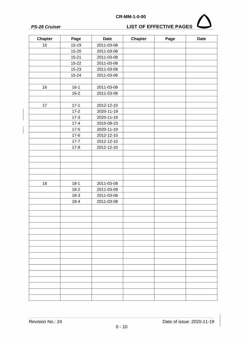
Chapter Page Date Chapter Page Date 15 15-19 2011-03-08 15-20 2011-03-08 15-21 2011-03-08 15-22 2011-03-08 15-23 2011-03-08 15-24 2011-03-08
16 16-1 2011-03-08 16-2 2011-03-08
17 17-1 2012-12-10 17-2 2020-11-19 17-3 2020-11-19 17-4 2015-09-23 17-5 2020-11-19 17-6 2012-12-10 17-7 2012-12-10 17-8 2012-12-10
18 18-1 2011-03-08 18-2 2011-03-08 18-3 2011-03-08 18-4 2011-03-08

CR-MM-1-0-00
PS-28 Cruiser CHAPTER 1 – GENERAL
Date of issue: 2020-11-19 Revision No.: 24 1 - 1
CHAPTER 1 GENERAL ............................................................................ 1-3
CHAPTER 2 TIME LIMITS / MAINTENANCE CHECKS ............................ 2-1
CHAPTER 2A AIRWORTHINESS LIMITATION SECTION ..................... 2-2
CHAPTER 2B INSPECTION AND MAINTENANCE ................................ 2-3
CHAPTER 3 FUSELAGE .......................................................................... 3-1
CHAPTER 4 WING .................................................................................... 4-1
CHAPTER 5 TAIL UNIT ............................................................................ 5-1
CHAPTER 6 CONTROL SYSTEM ............................................................. 6-1
CHAPTER 7 EQUIPMENT ......................................................................... 7-1
CHAPTER 8 LANDING GEAR .................................................................. 8-1
CHAPTER 9 FUEL SYSTEM ..................................................................... 9-1
CHAPTER 10 POWERPLANT .................................................................. 10-1
CHAPTER 11 ELECTRICAL SYSTEM ...................................................... 11-1
CHAPTER 12 INSTRUMENTS AND AVIONICS ....................................... 12-1
CHAPTER 13 VENTING / HEATING ......................................................... 13-1
CHAPTER 14 AIRPLANE HANDLING ...................................................... 14-1
CHAPTER 15 AIRPLANE REPAIRS ......................................................... 15-1
CHAPTER 16 WIRING DIAGRAMS .......................................................... 16-1
CHAPTER 17 APPENDICES ..................................................................... 17-1
CHAPTER 18 VALID SUPPLEMENTS PAGE........................................... 18-1
PS-28 Cruiser
CR-MM-1-0-00
CHAPTER 1 – GENERAL
Revision No.: - Date of issue: 2011-03-08 1 - 2
INTENTIONALLY LEFT BLANK
CR-MM-1-0-00
PS-28 Cruiser CHAPTER 1 – GENERAL
Date of issue: 2017-12-05 Revision No.: 20 1 - 3
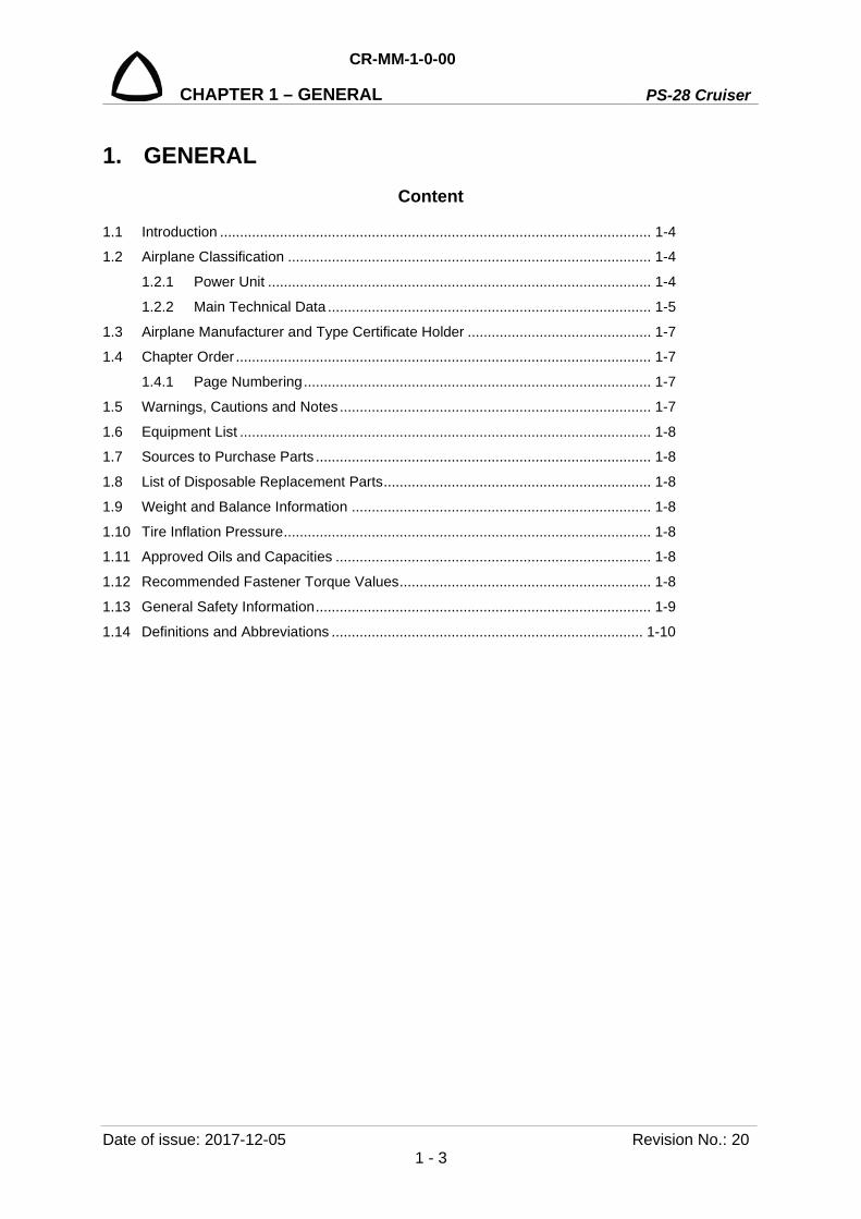
1. GENERAL Content
1.1 Introduction ............................................................................................................ 1-4
1.2 Airplane Classification ........................................................................................... 1-4
1.2.1 Power Unit ................................................................................................ 1-4
1.2.2 Main Technical Data ................................................................................. 1-5
1.3 Airplane Manufacturer and Type Certificate Holder .............................................. 1-7
1.4 Chapter Order ........................................................................................................ 1-7
1.4.1 Page Numbering ....................................................................................... 1-7
1.5 Warnings, Cautions and Notes .............................................................................. 1-7
1.6 Equipment List ....................................................................................................... 1-8
1.7 Sources to Purchase Parts .................................................................................... 1-8
1.8 List of Disposable Replacement Parts ................................................................... 1-8
1.9 Weight and Balance Information ........................................................................... 1-8
1.10 Tire Inflation Pressure ............................................................................................ 1-8
1.11 Approved Oils and Capacities ............................................................................... 1-8
1.12 Recommended Fastener Torque Values ............................................................... 1-8
1.13 General Safety Information .................................................................................... 1-9
1.14 Definitions and Abbreviations .............................................................................. 1-10

PS-28 Cruiser
CR-MM-1-0-00
CHAPTER 1 – GENERAL
Revision No.: 24 Date of issue: 2020-11-19 1 - 4
1.1 Introduction In accordance with requirements of the ASTM LSA regulations, the Czech Aircraft Group s.r.o.,
as manufacturer of PS-28 Cruiser airplane, provides information on maintaining airworthiness
of the PS-28 Cruiser airplane. Information is also contained in the following manuals issued by
airplane manufacturer or by manufacturers of equipment used on the airplane:
• Pilot Operating Handbook
• Maintenance Manual
• Illustrated Parts Catalog
• Operator's Manual for ROTAX Engine Type 912 Series
• Maintenance Manual for ROTAX Engine Type 912 Series
• Technical description and operation instructions for the propeller
This Maintenance Manual contains information on airplane maintenance including description
of airplane structure and function.
1.2 Airplane Classification PS-28 Cruiser airplane is two-seat, single engine, low-wing, all-metal airplane with fixed three-
wheel landing gear.
The airplane is designed for basic and advanced training and for leisure time flying.
1.2.1 Power Unit Power unit consists of:
• Four-stroke, four-cylinder engine with opposite pistons Rotax 912 S2 / 912 ULS2 with max.
continuous power of 69 kW (92.5 hp) at 5,500 RPM.
• Three-blade, ground adjustable propeller or
• Two-blade, ground adjustable propeller or
• Two-blade, in flight adjustable propeller.
CR-MM-1-0-00
PS-28 Cruiser CHAPTER 1 – GENERAL
Date of issue: 2011-07-08 Revision No.: 1 1 - 5
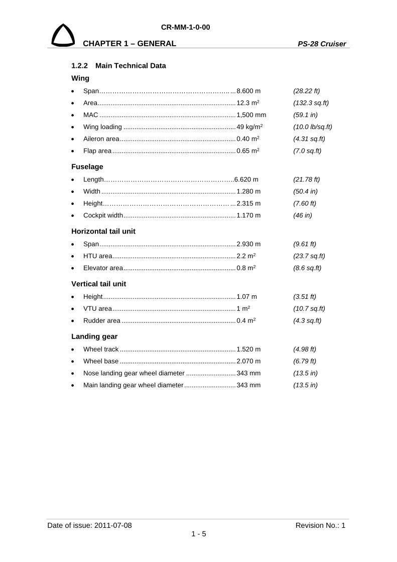
1.2.2 Main Technical Data Wing • Span………………………………………………….. ... 8.600 m (28.22 ft)
• Area ........................................................................... 12.3 m2 (132.3 sq.ft)
• MAC .......................................................................... 1,500 mm (59.1 in)
• Wing loading ............................................................. 49 kg/m2 (10.0 lb/sq.ft)
• Aileron area ............................................................... 0.40 m2 (4.31 sq.ft)
• Flap area ................................................................... 0.65 m2 (7.0 sq.ft)
Fuselage • Length…………………………………………………..6.620 m (21.78 ft)
• Width ......................................................................... 1.280 m (50.4 in)
• Height………………………………………………… ... 2.315 m (7.60 ft)
• Cockpit width ............................................................. 1.170 m (46 in)
Horizontal tail unit • Span .......................................................................... 2.930 m (9.61 ft)
• HTU area ................................................................... 2.2 m2 (23.7 sq.ft)
• Elevator area ............................................................. 0.8 m2 (8.6 sq.ft)
Vertical tail unit • Height ........................................................................ 1.07 m (3.51 ft)
• VTU area ................................................................... 1 m2 (10.7 sq.ft)
• Rudder area .............................................................. 0.4 m2 (4.3 sq.ft)
Landing gear • Wheel track ............................................................... 1.520 m (4.98 ft)
• Wheel base ............................................................... 2.070 m (6.79 ft)
• Nose landing gear wheel diameter ........................... 343 mm (13.5 in)
• Main landing gear wheel diameter ............................ 343 mm (13.5 in)

PS-28 Cruiser
CR-MM-1-0-00
CHAPTER 1 – GENERAL
Revision No.: 1 Date of issue: 2011-07-08 1 - 6
Fig. 1-1: Three-view drawing

CR-MM-1-0-00
PS-28 Cruiser CHAPTER 1 – GENERAL
Date of issue: 2020-11-19 Revision No.: 24 1 - 7
1.3 Airplane Manufacturer and Type Certificate Holder
Czech Aircraft Group s.r.o. Na Záhonech 212, 686 04 Kunovice
Czech Republic
Website: www.cruiseraircraft.cz
E-mail: [email protected]
1.4 Chapter Order Chapters in this manual are ordered in ascending sequence from No. 1. Every chapter describes
one system or assembly.
1.4.1 Page Numbering Example:
1.5 Warnings, Cautions, and Notes WARNING: MEANS THAT NON-OBSERVATION OF THE CORRESPONDING
OPERATING INSTRUCTION, INSPECTION OR MAINTENANCE PROCEDURE CAN LEAD TO INJURY OR DEATH OF PERSONS.
CAUTION: MEANS THAT NON-OBSERVATION OF THE CORRESPONDING OPERATING INSTRUCTION, INSPECTION OR MAINTENANCE PROCEDURE CAN LEAD TO DAMAGE OR DESTRUCTION OF DEVICE.
NOTE: Means that the corresponding operating instruction, inspection or maintenance procedure is considered to be important.

PS-28 Cruiser
CR-MM-1-0-00
CHAPTER 1 – GENERAL
Revision No.: 24 Date of issue: 2020-11-19 1 - 8
1.6 Equipment List Refer to the PS-28 Cruiser Pilot′s Operating Handbook, Section 9 for actual Equipment list.
1.7 Sources to Purchase Parts Spare parts ca be ordered from CAG through the PS-28 Cruiser Illustrated Parts Catalogue
(Doc. No. CR-IPC-1-0-00).
1.8 List of Disposable Replacement Parts
ITEM PART NUMBER SOURCE
Air filter 825710 Czech Aircraft Group BRP-Powertrain
Fuel filter 10543-1 Czech Aircraft Group Aircraft Parts Store
Oil filter 825701, 825012, 825016 Czech Aircraft Group BRP-Powertrain
Tire and tube Goodyear Flight Special II – 5.00-5
Czech Aircraft Group Aircraft Parts Store
Brake lining WHLM66-106 Czech Aircraft Group Aircraft Parts Store
1.9 Weight and Balance Information Refer to PS-28 Cruiser Pilot′s Operating Handbook, Section 6 for the Weight and Balance Data.
1.10 Tire Inflation Pressure Refer to Section 8.5.1 of this manual for the tire inflation data.
1.11 Approved Oils and Capacities Refer to the PS-28 Cruiser Pilot′s Operating Handbook, Section 9 or Section 17.5 of this manual
for the approved oil and capacity data.
1.12 Recommended Fastener Torque Values Refer to Section 15.7 of this manual for the torque moments.

CR-MM-1-0-00
PS-28 Cruiser CHAPTER 1 – GENERAL
Date of issue: 2011-07-08 Revision No.: 1 1 - 9
1.13 General Safety Information Safety must be considered the first priority when performing maintenance or service on an
aircraft or part. To minimize the risk to both yourself and others, begin by thinking through each
task that is to be performed before starting any work. Using common sense, think of ways to
avoid these hazards. Be sure to also use the right tool for the task at hand and to use the proper
personal protective equipment. Such equipment may include, but is not limited to:
• Eye protection – safety glasses, goggles, and face shield
• Gloves
• Hearing protection – ear plugs or muffs
• Apron
• Protective footwear with non-slip soles
Some other general rules to follow are:
• Prior to performing maintenance or repair always disconnect the negative (-) battery cable
from the battery.
• During all service and repair work beware of activating the BRS rocket (if installed).
• Never leave the ignition switch or the master switch turned on when the engine is not
running. While running the engine on the ground, keep away from the propeller.
• Remove any loose clothing, such as neckties and scarves. Tuck in your shirt and secure
any long hair to prevent them from becoming tangled in power tools.
• Remove all jewelry. Not only can items such as rings, watches, and necklaces become
caught in rotating tools, they can also conduct electricity and may cause a short circuit. This
could result in burns or damage to electrical circuits.
• Aviation gasoline is also highly flammable. When working with the fuel system, always work
in a well-ventilated environment. Any nearby source of ignition such as sparks or an open
flame can result in a fire or explosion. Keep all ignition sources away. Always ground the
airframe to a suitable earth ground during fueling/defueling operations to reduce the risk of
a static discharge ignition source.
• When working with the landing gear, always support the aircraft properly with jacks. Do not
work underneath the aircraft unless it is properly supported.

PS-28 Cruiser
CR-MM-1-0-00
CHAPTER 1 – GENERAL
Revision No.: 24 Date of issue: 2020-11-19 1 - 10
1.14 Definitions and abbreviations °C Temperature in degree of Celsius (1°C = (°F - 32) / 1.8)
°F Temperature in degree of Fahrenheit (1°F = (°C x 1.8) + 32)
100-h inspection same as an annual condition inspection, except the interval of inspection is
100h of operation instead of 12 calendar months. This inspection is utilized
when the LSA is being used for commercial operations such as flight instruction
or rental, or both
ACCU Accumulator
ADAHRS Air Data Attitude and Heading Reference System
A&P airframe and powerplant mechanic as defined by Part 66 or 14 CFR Part 65
AEPS Aircraft Emergency Parachute System
ALT Altimeter
Annual condition inspection
detailed inspection accomplished once a year on a LSA in accordance with
instructions provided in the maintenance manual supplied with the aircraft. The
purpose of the inspection is to look for any wear, corrosion, or damage that
would cause an aircraft to not be in a condition for safe operation.
ATC Air Traffic Control
bar Pressure unit (1 bar = 14.5037 psi)
BEACON Anti-collision beacon
BRS Ballistic Recovery System
CAG Czech Aircraft Group s.r.o.
CAS Calibrated Airspeed
COMM Communication transmitter
Cycle Flight
CHT/CT Cylinder Head Temperature / Coolant Temperature
EASA European Aviation Safety Agency
EFIS Electronic Flight Instrument System
ELT Emergency Locator Transmitter
EMS Engine Monitoring System
FAA United States Federal Aviation Administration
FH Flight hours
ft foot / feet (1 ft = 12 in = 0.3048 m = 304.8 mm)
ft/min Vertical speed in feet per minute
GPS Global Positioning System
Heavy maintenance any maintenance, inspection, repair, or alteration a manufacturer has
designated that requires specialized training, equipment, or facilities
hp Power unit (1 hp = 0.7457 kW)
HTU Horizontal Tail Unit

CR-MM-1-0-00
PS-28 Cruiser CHAPTER 1 – GENERAL
Date of issue: 2020-11-19 Revision No.: 24 1 - 11
IAS Indicated Airspeed
IC Intercom
IFR Instrument Flight Rules
in inch (1 in = 25.4 mm)
ISA International Standard Atmosphere
KCAS Calibrated Airspeed in knots
kg kilogram (1 kg = 2.2046 lb)
KIAS Indicated Airspeed in knots
km/h Speed in kilometer per hour
knot Speed in NM per hour
kW Power unit (1 kW = 1.341 hp)
l liter (1 l = 0.22 UK gal = 0.264 US gal)
lb pounds (1 lb = 0.4536 kg)
lbf force unit (1 lbf = 4.45 N)
Line maintenance any repair, maintenance, scheduled checks, servicing, inspections, or
alterations not considered heavy maintenance that is approved by the
manufacturer and is specified in the manufacturer’s maintenance manual
LoEP List of Effective Pages
LSA Airplane (Light Sport Aircraft Airplane)
a powered fixed wing aircraft designed per CS-LSA / Specification F2245
LSA Repairman Inspection
U.S. FAA certificated repairman (light sport aircraft) with an inspection rating,
defined by 14 CFR Part 65, authorized to perform the annual condition
inspection on experimental light sport aircraft, or an equivalent rating issued by
other civil aviation authorities
LSA Repairman Maintenance
U.S. FAA certificated repairman (light sport aircraft) with a maintenance rating
as defined by 14 CPR Part 65, authorized to perform line maintenance on
aircraft certificated as special LSA aircraft. Authorized to perform the annual
condition/100-hour inspection on an LSA, or an equivalent rating issued by
other civil aviation authorities
m meter (1 m = 1,000 mm = 3.28 ft = 39.37 in)
MAC Mean Aerodynamic Chord
Maintenance manual manual provided by an LSA manufacturer or supplier that specifies all
maintenance, repairs, and alterations authorized by the manufacturer
Major repair, alteration, or maintenance
any repair, alteration, or maintenance for which instructions to complete the task
excluded from the maintenance manual(s) supplied to the consumer are
considered major
PS-28 Cruiser
CR-MM-1-0-00
CHAPTER 1 – GENERAL
Revision No.: 24 Date of issue: 2020-11-19 1 - 12
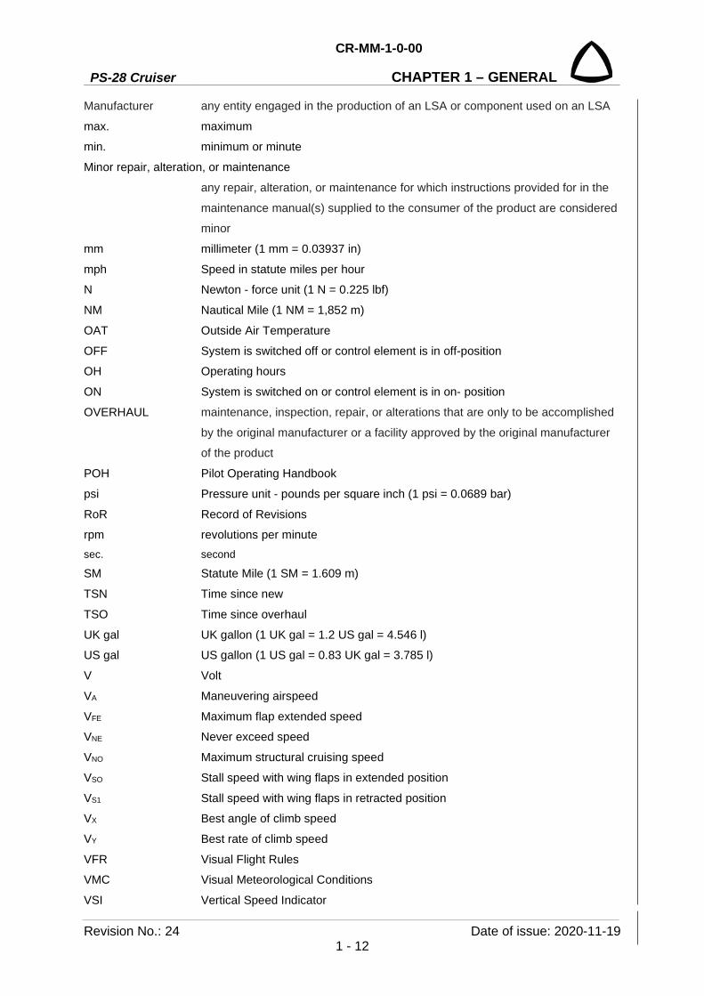
Manufacturer any entity engaged in the production of an LSA or component used on an LSA
max. maximum
min. minimum or minute
Minor repair, alteration, or maintenance
any repair, alteration, or maintenance for which instructions provided for in the
maintenance manual(s) supplied to the consumer of the product are considered
minor
mm millimeter (1 mm = 0.03937 in)
mph Speed in statute miles per hour
N Newton - force unit (1 N = 0.225 lbf)
NM Nautical Mile (1 NM = 1,852 m)
OAT Outside Air Temperature
OFF System is switched off or control element is in off-position
OH Operating hours
ON System is switched on or control element is in on- position
OVERHAUL maintenance, inspection, repair, or alterations that are only to be accomplished
by the original manufacturer or a facility approved by the original manufacturer
of the product
POH Pilot Operating Handbook
psi Pressure unit - pounds per square inch (1 psi = 0.0689 bar)
RoR Record of Revisions
rpm revolutions per minute sec. second
SM Statute Mile (1 SM = 1.609 m)
TSN Time since new
TSO Time since overhaul
UK gal UK gallon (1 UK gal = 1.2 US gal = 4.546 l)
US gal US gallon (1 US gal = 0.83 UK gal = 3.785 l)
V Volt
VA Maneuvering airspeed
VFE Maximum flap extended speed
VNE Never exceed speed
VNO Maximum structural cruising speed
VSO Stall speed with wing flaps in extended position
VS1 Stall speed with wing flaps in retracted position
VX Best angle of climb speed
VY Best rate of climb speed
VFR Visual Flight Rules
VMC Visual Meteorological Conditions
VSI Vertical Speed Indicator

CR-MM-1-0-00
PS-28 Cruiser CHAPTER 1 – GENERAL
Date of issue: 2020-11-19 Revision No.: 24 1 - 13
VTU Vertical Tail Unit
XPDR Secondary radar transponder
PS-28 Cruiser
CR-MM-1-0-00
CHAPTER 1 – GENERAL
Revision No.: 24 Date of issue: 2020-11-19 1 - 14
INTENTIONALLY LEFT BLANK
CR-MM-1-0-00
PS-28 Cruiser CHAPTER 2 – TIME LIMITS / MAINTENANCE CHECKS
Date of issue: 2020-11-19 Revision No.: 24 2 - 1
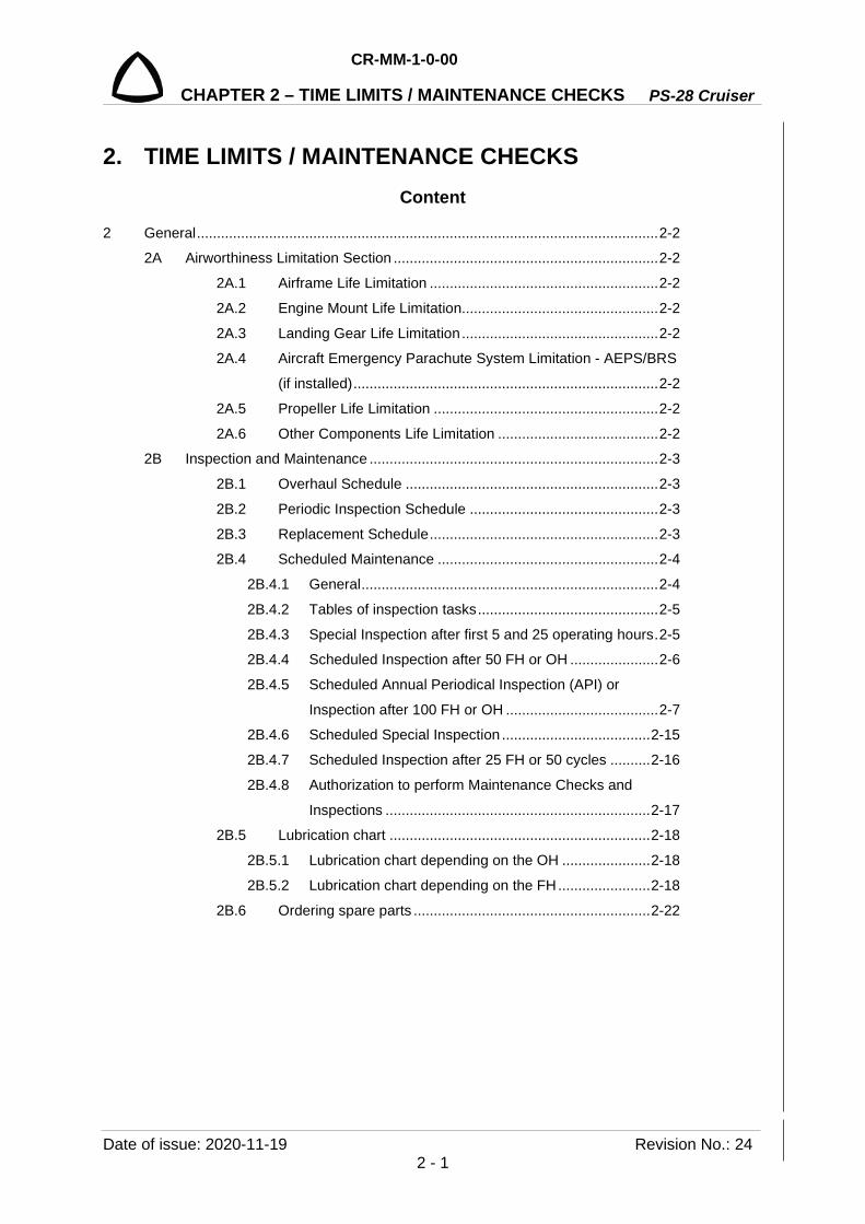
2. TIME LIMITS / MAINTENANCE CHECKS Content
2 General ................................................................................................................... 2-2
2A Airworthiness Limitation Section .................................................................. 2-2
2A.1 Airframe Life Limitation ......................................................... 2-2
2A.2 Engine Mount Life Limitation................................................. 2-2
2A.3 Landing Gear Life Limitation ................................................. 2-2
2A.4 Aircraft Emergency Parachute System Limitation - AEPS/BRS
(if installed) ............................................................................ 2-2
2A.5 Propeller Life Limitation ........................................................ 2-2
2A.6 Other Components Life Limitation ........................................ 2-2
2B Inspection and Maintenance ........................................................................ 2-3
2B.1 Overhaul Schedule ............................................................... 2-3
2B.2 Periodic Inspection Schedule ............................................... 2-3
2B.3 Replacement Schedule ......................................................... 2-3
2B.4 Scheduled Maintenance ....................................................... 2-4
2B.4.1 General .......................................................................... 2-4
2B.4.2 Tables of inspection tasks ............................................. 2-5
2B.4.3 Special Inspection after first 5 and 25 operating hours . 2-5
2B.4.4 Scheduled Inspection after 50 FH or OH ...................... 2-6
2B.4.5 Scheduled Annual Periodical Inspection (API) or
Inspection after 100 FH or OH ...................................... 2-7
2B.4.6 Scheduled Special Inspection ..................................... 2-15
2B.4.7 Scheduled Inspection after 25 FH or 50 cycles .......... 2-16
2B.4.8 Authorization to perform Maintenance Checks and
Inspections .................................................................. 2-17
2B.5 Lubrication chart ................................................................. 2-18
2B.5.1 Lubrication chart depending on the OH ...................... 2-18
2B.5.2 Lubrication chart depending on the FH ....................... 2-18
2B.6 Ordering spare parts ........................................................... 2-22
PS-28 Cruiser
CR-MM-1-0-00
CHAPTER 2 – TIME LIMITS / MAINTENANCE CHECKS
Revision No.: 24 Date of issue: 2020-11-19 2 - 2
EASA approved page
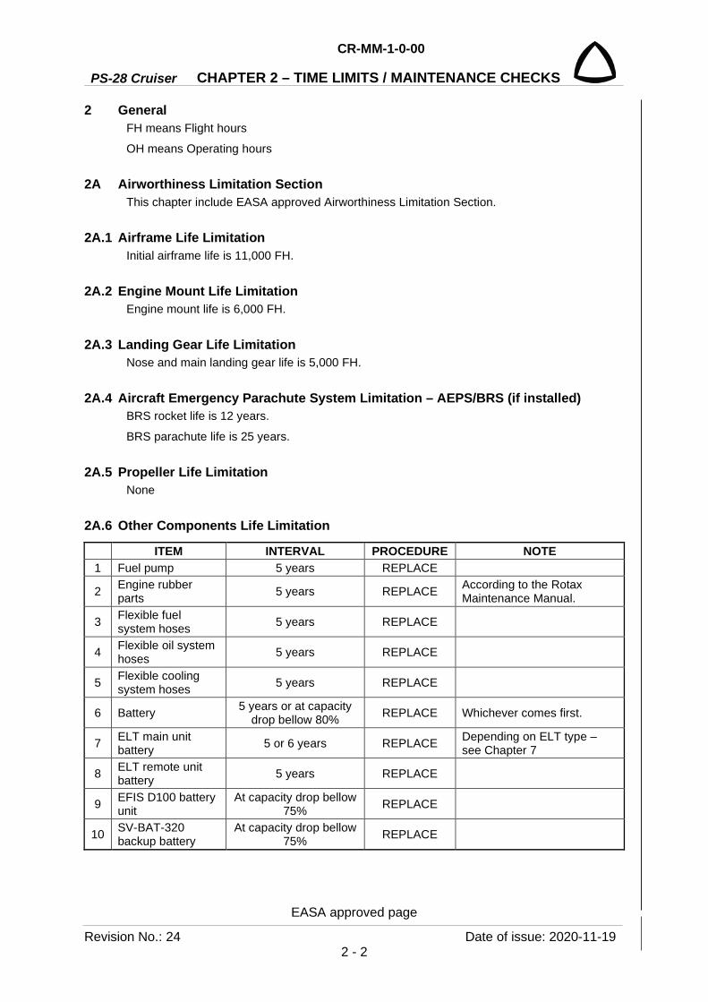
2 General FH means Flight hours
OH means Operating hours
2A Airworthiness Limitation Section This chapter include EASA approved Airworthiness Limitation Section.
2A.1 Airframe Life Limitation Initial airframe life is 11,000 FH.
2A.2 Engine Mount Life Limitation Engine mount life is 6,000 FH.
2A.3 Landing Gear Life Limitation Nose and main landing gear life is 5,000 FH.
2A.4 Aircraft Emergency Parachute System Limitation – AEPS/BRS (if installed) BRS rocket life is 12 years.
BRS parachute life is 25 years.
2A.5 Propeller Life Limitation None
2A.6 Other Components Life Limitation
ITEM INTERVAL PROCEDURE NOTE 1 Fuel pump 5 years REPLACE
2 Engine rubber parts 5 years REPLACE According to the Rotax
Maintenance Manual.
3 Flexible fuel system hoses 5 years REPLACE
4 Flexible oil system hoses 5 years REPLACE
5 Flexible cooling system hoses 5 years REPLACE
6 Battery 5 years or at capacity drop bellow 80% REPLACE Whichever comes first.
7 ELT main unit battery 5 or 6 years REPLACE Depending on ELT type –
see Chapter 7
8 ELT remote unit battery 5 years REPLACE
9 EFIS D100 battery unit
At capacity drop bellow 75% REPLACE
10 SV-BAT-320 backup battery
At capacity drop bellow 75% REPLACE
CR-MM-1-0-00
PS-28 Cruiser CHAPTER 2 – TIME LIMITS / MAINTENANCE CHECKS
Date of issue: 2020-11-19 Revision No.: 24 2 - 3
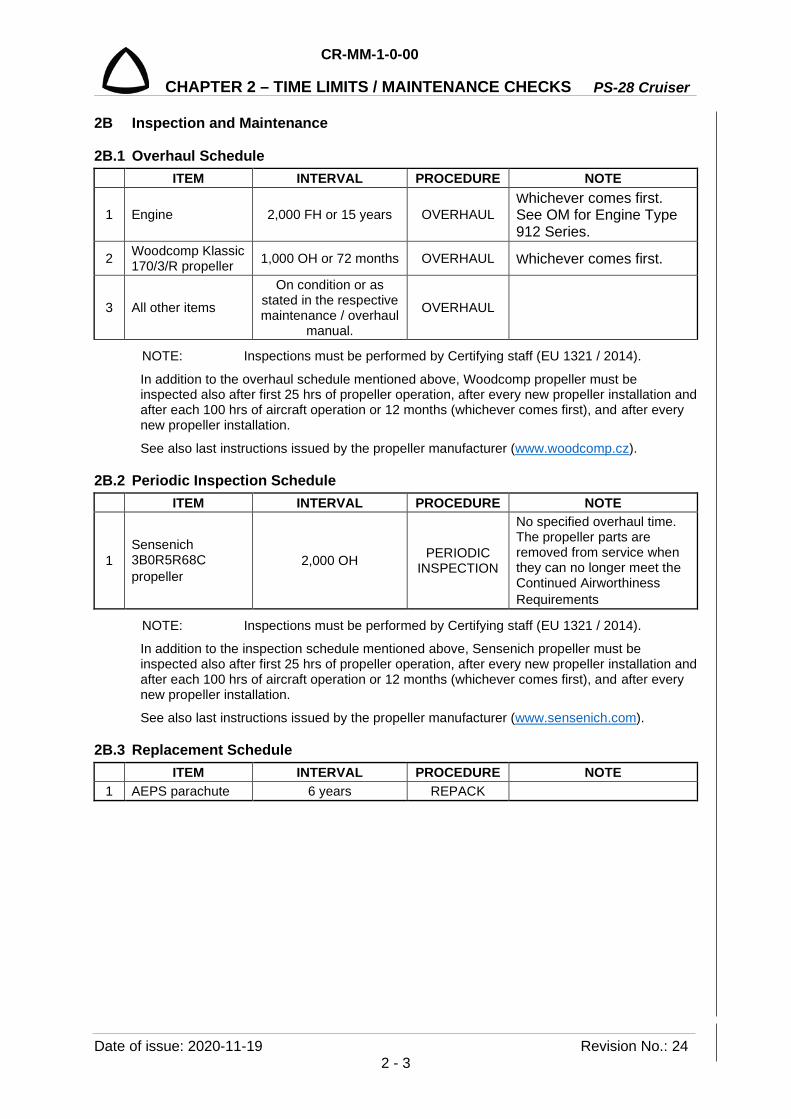
2B Inspection and Maintenance
2B.1 Overhaul Schedule ITEM INTERVAL PROCEDURE NOTE
1 Engine 2,000 FH or 15 years OVERHAUL Whichever comes first. See OM for Engine Type 912 Series.
2 Woodcomp Klassic 170/3/R propeller 1,000 OH or 72 months OVERHAUL Whichever comes first.
3 All other items
On condition or as stated in the respective maintenance / overhaul
manual.
OVERHAUL
NOTE: Inspections must be performed by Certifying staff (EU 1321 / 2014).
In addition to the overhaul schedule mentioned above, Woodcomp propeller must be inspected also after first 25 hrs of propeller operation, after every new propeller installation and after each 100 hrs of aircraft operation or 12 months (whichever comes first), and after every new propeller installation.
See also last instructions issued by the propeller manufacturer (www.woodcomp.cz).
2B.2 Periodic Inspection Schedule ITEM INTERVAL PROCEDURE NOTE
1 Sensenich 3B0R5R68C propeller
2,000 OH PERIODIC INSPECTION
No specified overhaul time. The propeller parts are removed from service when they can no longer meet the Continued Airworthiness Requirements
NOTE: Inspections must be performed by Certifying staff (EU 1321 / 2014).
In addition to the inspection schedule mentioned above, Sensenich propeller must be inspected also after first 25 hrs of propeller operation, after every new propeller installation and after each 100 hrs of aircraft operation or 12 months (whichever comes first), and after every new propeller installation.
See also last instructions issued by the propeller manufacturer (www.sensenich.com).
2B.3 Replacement Schedule ITEM INTERVAL PROCEDURE NOTE 1 AEPS parachute 6 years REPACK

PS-28 Cruiser
CR-MM-1-0-00
CHAPTER 2 – TIME LIMITS / MAINTENANCE CHECKS
Revision No.: 24 Date of issue: 2020-11-19 2 - 4
2B.4 Scheduled Maintenance This section is setting the system of maintenance recommended by the aircraft manufacturer.
2B.4.1 General Maintenance system serves to maintain flight airworthiness of the PS-28 Cruiser airplane. Maintenance system is composed of special and scheduled inspections, which must be performed at least in the following intervals:
CAUTION: ALL OF THE MAINTENANCE INTERVALS FOR ENGINE AND PROPELLER SUCH AS THE 100 HOURS INSPECTION AND TBO RELATE TO OPERATING HOURS OH (= HOBBS) OF THE ENGINE OR PROPELLER. OPERATING HOURS ARE COUNTED IRRESPECTIVE OF THE LOAD FACTOR OF THE ENGINE OR PROPELLER, SUCH AS IDLING OR TAKE-OFF POWER.
THE INTERVALS OF ENGINE INSPECTIONS AND THE LIST OF WORKS ARE SHOWN IN THE MAINTENANCE MANUAL (LINE MAINTENANCE) FOR INSTALLED ENGINE. THE INTERVALS OF PROPELLER INSPECTIONS AND THE LIST OF WORKS ARE SHOWN IN INSTALLATION AND OPERATION INSTRUCTIONS FOR THE INSTALLED PROPELLER.
IF THE PERIODICAL INSPECTION IS PERFORMED BEFORE REACHING THE SPECIFIED TIME INTERVAL, THEN THE FOLLOWING INSPECTION MUST BE PERFORMED AT THE LATEST WITHIN THE SPECIFIED TIME INTERVAL FROM THIS INSPECTION (E.G. IF THE FIRST 100-H INSPECTION IS PERFORMED AFTER 87 H THEN THE FOLLOWING 100-H INSPECTION MUST BE PERFORMED AT THE LATEST AFTER 187 H).
(a) Preflight inspection is performed within the scope given in the POH, Section 4. (b) Scheduled special propeller inspection after 25, 50 and 150 OH (see Installation and
Operating Instructions for installed propeller).
NOTE: To be performed with a newly installed propeller or with the propeller that was dismantled and reinstalled on the airplane.
(c) Special engine inspection after the first 25 OH.
CAUTION: INSPECTION AFTER THE FIRST 25 OH TO BE PERFORMED WITH THE NEW ENGINE OR WITH THE ENGINE AFTER OVERHAUL.
(d) Scheduled inspection after 25 FH or 50 cycles whatever occurs first - inspection of the NLG leg Dwg.No.SG0270N.
(e) Scheduled inspection after 50 FH/OH - inspection of engine compartment, NLG leg Dwg.No.SG0300N and appropriate propeller.
(f) Scheduled inspection after 100+5 FH/OH - airframe and propeller inspections, engine inspection according to maintenance system, which is described in Maintenance Manual (Line Maintenance) for installed engine.
CAUTION: 100-FH/OH LIMIT CAN BE EXCEEDED MAX. BY 5 FH/OH PROVIDING THAT THIS EXCEEDING WILL BE JUST TO FINISH FLIGHT WHICH STARTED BEFORE REACHING 100-FH/OH TERM OR FOR FLIGHT WITH THE PURPOSE TO REACH A PLACE WHERE THE INSPECTION WILL BE CARRIED OUT. OPERATION TIME, WHICH EXCEEDED 100-FH/OH INTERVAL, MUST BE INCLUDED AS A TIME FLOWN FOR DETERMINATION OF THE NEXT 100-FH/OH INSPECTION.
(g) Scheduled annual inspection contains works of 100-FH/OH inspection and other specified works (inspections of airframe, engine and propeller).

CR-MM-1-0-00
PS-28 Cruiser CHAPTER 2 – TIME LIMITS / MAINTENANCE CHECKS
Date of issue: 2020-11-19 Revision No.: 24 2 - 5
2B.4.2 Tables of inspection tasks Tables of inspection tasks include the list of all works, which are performed during inspection. Number of chapter is indicated in the first column of this Maintenance Manual where you can also find more detailed information for performing individual works. The description of works, which are performed during inspection, is indicated in the second column.
CAUTION: ALL DEFECTS FOUND OUT DURING AIRCRAFT INSPECTIONS MUST BE ELIMINATED!
2B.4.3 Special Inspection after first 5 and 25 operating hours SPECIAL INSPECTION AFTER
FIRST 5 AND 25 OPERATING HOURS Aircraft S/N: …………………. TSN (OH): ………………….
Registration mark: …………………. TSN (cycles): …………………. Page: 1 of 1
Chpt. Prescribed works Made by Checked by
10
Engine and propeller List of performed operations for engine is shown in Maintenance Manual (Line Maintenance) for ROTAX Engine Type 912 Series (MML-912).
Remove and check engine cowlings for evident signs of heat damage or cracks.
Inspect and check tightening and securing bolts on the engine brackets and the engine mount.
Check the engine mount for occurrence of cracks.
Check the exhaust system (and its attachment) for occurrence of cracks on the exhaust system and welds (see 10.4.8).
Remove and clean the fuel filter screen inserted in gascolator.
Fuel system - visual check of tightness. Oil system - visual check of tightness. Cooling system - visual check of all parts, check of tightness and sufficient distance of cooling tubes from exhaust and other parts (see also SB-CR-071, last revision).
Notes:
Date: …………………. Signature: ………………….
PS-28 Cruiser
CR-MM-1-0-00
CHAPTER 2 – TIME LIMITS / MAINTENANCE CHECKS
Revision No.: 24 Date of issue: 2020-11-19 2 - 6
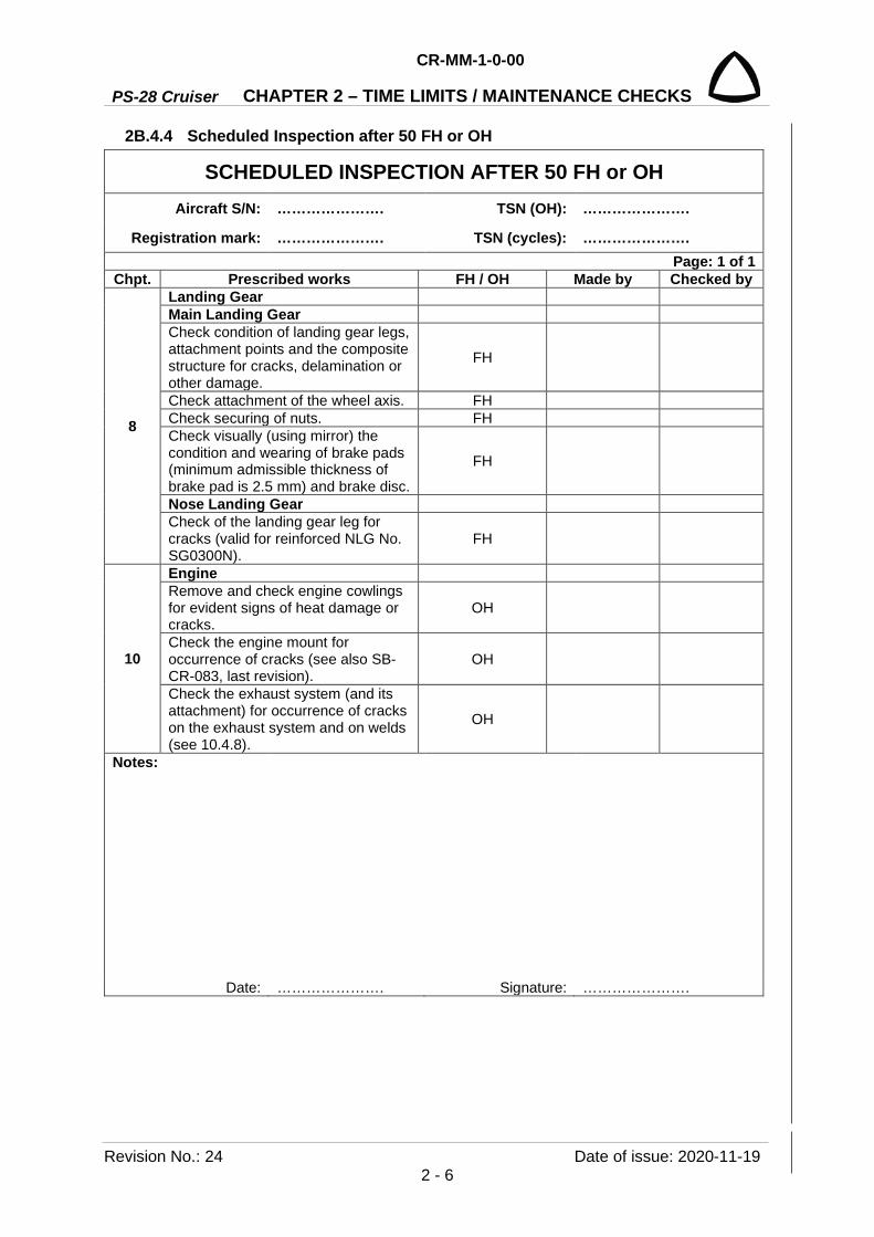
2B.4.4 Scheduled Inspection after 50 FH or OH
SCHEDULED INSPECTION AFTER 50 FH or OH Aircraft S/N: …………………. TSN (OH): ………………….
Registration mark: …………………. TSN (cycles): …………………. Page: 1 of 1
Chpt. Prescribed works FH / OH Made by Checked by
8
Landing Gear Main Landing Gear Check condition of landing gear legs, attachment points and the composite structure for cracks, delamination or other damage.
FH
Check attachment of the wheel axis. FH Check securing of nuts. FH Check visually (using mirror) the condition and wearing of brake pads (minimum admissible thickness of brake pad is 2.5 mm) and brake disc.
FH
Nose Landing Gear Check of the landing gear leg for cracks (valid for reinforced NLG No. SG0300N).
FH
10
Engine Remove and check engine cowlings for evident signs of heat damage or cracks.
OH
Check the engine mount for occurrence of cracks (see also SB-CR-083, last revision).
OH
Check the exhaust system (and its attachment) for occurrence of cracks on the exhaust system and on welds (see 10.4.8).
OH
Notes:
Date: …………………. Signature: ………………….

CR-MM-1-0-00
PS-28 Cruiser CHAPTER 2 – TIME LIMITS / MAINTENANCE CHECKS
Date of issue: 2020-11-19 Revision No.: 24 2 - 7
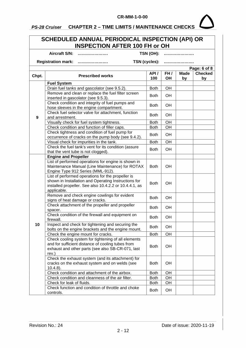
2B.4.5 Scheduled Annual Periodical Inspection (API) or Inspection after 100 FH or OH
SCHEDULED ANNUAL PERIODICAL INSPECTION (API) OR INSPECTION AFTER 100 FH or OH
Aircraft S/N: …………………. TSN (OH): ………………….
Registration mark: …………………. TSN (cycles): …………………. Page: 1 of 8
Chpt. Prescribed works API / 100
FH / OH
Made by
Checked by
General Check the aircraft’s logbooks (excluding engine and propeller) for condition and check if all prescribed records are current (airplane log book, airplane parts, etc.).
Both* FH
Check the engine and propeller logbooks for condition and check if all prescribed records are current.
Both OH
Check the remaining service life of life limited items (excluding engine and propeller). Both FH
Check the remaining service life of life limited items (parts related to engine and propeller). Both OH
Check that the replacement or overhaul of life limited parts (excluding engine and propeller) has been in accordance to their specified intervals.
Both FH
Check that the replacement or overhaul of life limited parts (parts related to engine and propeller) has been in accordance to their specified intervals.
Both OH
Assure that replacements of the parts (excluding engine and propeller) are performed in appropriate intervals.
Both FH
Assure that replacements of the parts (related to engine and propeller) are performed in appropriate intervals.
Both OH
Check all issued Airworthiness Directives for their accomplishment (excluding engine and propeller). Both FH
Check all issued Airworthiness Directives for their accomplishment (related to engine and propeller). Both OH
Check all aircraft service bulletins for their accomplishment (excluding engine and propeller). Both FH
Check all aircraft service bulletins for their accomplishment (related to engine and propeller). Both OH
Clean the cockpit carefully. Both FH Clean the aircraft’s exterior, engine and propeller carefully. Both FH,
OH
Check all exterior and interior markings and placards for their condition (legibility, placement and security). Both FH
Remove and/or open all required covers and hatches. Both FH
Jack and support the aircraft. Both FH *) “Both” means at Annual Periodical Inspection (API) and also at 100 hrs inspection
PS-28 Cruiser
CR-MM-1-0-00
CHAPTER 2 – TIME LIMITS / MAINTENANCE CHECKS
Revision No.: 24 Date of issue: 2020-11-19 2 - 8
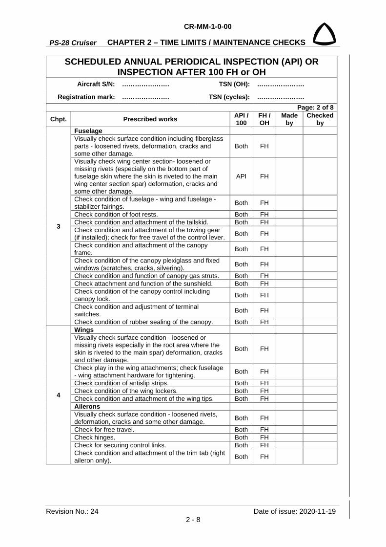
SCHEDULED ANNUAL PERIODICAL INSPECTION (API) OR INSPECTION AFTER 100 FH or OH
Aircraft S/N: …………………. TSN (OH): ………………….
Registration mark: …………………. TSN (cycles): …………………. Page: 2 of 8
Chpt. Prescribed works API / 100
FH / OH
Made by
Checked by
3
Fuselage Visually check surface condition including fiberglass parts - loosened rivets, deformation, cracks and some other damage.
Both FH
Visually check wing center section- loosened or missing rivets (especially on the bottom part of fuselage skin where the skin is riveted to the main wing center section spar) deformation, cracks and some other damage.
API FH
Check condition of fuselage - wing and fuselage - stabilizer fairings. Both FH
Check condition of foot rests. Both FH Check condition and attachment of the tailskid. Both FH Check condition and attachment of the towing gear (if installed); check for free travel of the control lever. Both FH
Check condition and attachment of the canopy frame. Both FH
Check condition of the canopy plexiglass and fixed windows (scratches, cracks, silvering). Both FH
Check condition and function of canopy gas struts. Both FH Check attachment and function of the sunshield. Both FH Check condition of the canopy control including canopy lock. Both FH
Check condition and adjustment of terminal switches. Both FH
Check condition of rubber sealing of the canopy. Both FH
4
Wings Visually check surface condition - loosened or missing rivets especially in the root area where the skin is riveted to the main spar) deformation, cracks and other damage.
Both FH
Check play in the wing attachments; check fuselage - wing attachment hardware for tightening. Both FH
Check condition of antislip strips. Both FH Check condition of the wing lockers. Both FH Check condition and attachment of the wing tips. Both FH Ailerons Visually check surface condition - loosened rivets, deformation, cracks and some other damage. Both FH
Check for free travel. Both FH Check hinges. Both FH Check for securing control links. Both FH Check condition and attachment of the trim tab (right aileron only). Both FH

CR-MM-1-0-00
PS-28 Cruiser CHAPTER 2 – TIME LIMITS / MAINTENANCE CHECKS
Date of issue: 2020-11-19 Revision No.: 24 2 - 9
SCHEDULED ANNUAL PERIODICAL INSPECTION (API) OR INSPECTION AFTER 100 FH or OH
Aircraft S/N: …………………. TSN (OH): ………………….
Registration mark: …………………. TSN (cycles): …………………. Page: 3 of 8
Chpt. Prescribed works API / 100
FH / OH
Made by
Checked by
4
Flaps Visually check surface condition - loosened rivets, deformation, cracks and some other damage. Both FH
Check for free travel. Both FH Check hinges. Both FH Check condition of the control rods and actuator. Both FH
5
Tail Unit HTU Visually check surface condition - loosened rivets, deformation, cracks and some other damage. Both FH
Check horizontal stabilizer attachment and securing. Both FH Check elevator attachment and securing. Both FH Check condition and attachment of elevator tips. Both FH Check free travel of the elevator. Both FH Check condition of stop (elevator fully deflected down). Both FH
Check condition and attachment of the trim tab. Both FH Check trim tab actuator connector for connection and securing. Both FH
Check condition and attachment of the balance tab. Both FH Check condition and securing of the elevator control rod and the trim tab control actuator. Both FH
VTU Visually check surface condition - loosened rivets, deformation, cracks and some other damage. Both FH
Check attachment and securing of the rudder lower hinge. Both FH
Check for free travel of the rudder. Both FH Check condition of the stops on the vertical fin. Both FH Check attachment and securing of rudder cables. Both FH Check run cables over pulleys, securing of the pulleys. Both FH

PS-28 Cruiser
CR-MM-1-0-00
CHAPTER 2 – TIME LIMITS / MAINTENANCE CHECKS
Revision No.: 24 Date of issue: 2020-11-19 2 - 10
SCHEDULED ANNUAL PERIODICAL INSPECTION (API) OR INSPECTION AFTER 100 FH or OH
Aircraft S/N: …………………. TSN (OH): ………………….
Registration mark: …………………. TSN (cycles): …………………. Page: 4 of 8
Chpt. Prescribed works API / 100
FH / OH
Made by
Checked by
6
Control Ailerons and Elevator Control Both FH Check for free travel of control (see 6.4.2). Both FH Check plays (see 6.4.1). Both FH Check securing of links. Both FH Check condition of the stops. Both FH Rudder Control Check free play of control (see 6.4.2). Both FH Check plays (see 6.4.1). Both FH Check securing of turnbuckles. Both FH Check condition and attachment of pedal springs. Both FH Check condition and tension of cables (see 6.4.5). Both FH Check adjustment of pedals and full deflections in all position. Both FH
Flaps Control Check for free travel of the control lever. Both FH Check securing of links. Both FH Check condition of control actuator and position indicator. Both FH
Control of the Pitch and Roll Trim Tab Check condition of the control actuators and position indicators. Both FH
Check plays (see 6.4.1). Both FH Check securing of links. Both FH Check trim tab neutral position adjustment. Both FH
7
Equipment Check cleanness and condition of upholstery. Both FH Check condition of seats. Both FH Check condition, damage, function and attachment of safety harnesses and straps in baggage compartment.
Both FH
Check condition and attachment of ELT. Both FH Check attachment and security of BRS parachute container and rocket. Both FH
Check security and routing of airframe BRS bridles. Both FH Check attachment, security and routing of BRS activating handle. Both FH
Check attachment of egress cover. Both FH

CR-MM-1-0-00
PS-28 Cruiser CHAPTER 2 – TIME LIMITS / MAINTENANCE CHECKS
Date of issue: 2020-11-19 Revision No.: 24 2 - 11
SCHEDULED ANNUAL PERIODICAL INSPECTION (API) OR INSPECTION AFTER 100 FH or OH
Aircraft S/N: …………………. TSN (OH): ………………….
Registration mark: …………………. TSN (cycles): …………………. Page: 5 of 8
Chpt. Prescribed works API / 100
FH / OH
Made by
Checked by
8
Landing Gear Main Landing Gear Check condition of landing gear legs and attachment points. Both FH
Check attachment of the wheel axis. Both FH Remove and disassemble wheel, clean and lubricate the bearings; reassemble it and install back. Both FH
Check condition, wear and inflation of tires. Both FH Check condition of the wheel disk for occurrence of cracks. Both FH
Check securing of bolts. Both FH Check wheel for free rotation. Both FH Check condition and attachment of wheel fairings. Both FH Check function of brakes and parking brake. Both FH Check condition and attachment of brake hoses. Both FH Check visually (using mirror) condition and wearing of brake pads and brake disc. Min. admissible thickness of brake pad is 2.5 mm (0.1 in), min. admissible thickness of brake disc is 4.25 mm (0.167 in).
Both FH
Check brake fluid leakage - brake fluid hoses, brake pumps, brake cylinders. Replenish brake fluid as needed (see 8.5.4).
Both FH
Exchange brake fluid - applied for annual inspection only (see 8.5.4). API FH
Nose Landing Gear Check condition and attachment points of landing gear leg in fuselage. Both FH
Check the landing gear leg for cracks (for non - reinforced NLG No. SG0270N follow 8.4.3). Both FH
Remove and disassemble wheel, clean and lubricate the bearings; reassemble it and install back. Both FH
Check condition, wear and inflation of tire. Both FH Check condition of wheel disk and for occurrence of cracks. Both FH
Check securing of bolts. Both FH Check for free travel of wheel rotation. Both FH Check of friction shock absorber, check friction torque; as necessary tighten the nut (see 8.4.2). Both FH
Check condition and attachment of wheel fairing. Both FH Check depression of nose wheel absorber (see 8.4.1). Both FH
PS-28 Cruiser
CR-MM-1-0-00
CHAPTER 2 – TIME LIMITS / MAINTENANCE CHECKS
Revision No.: 24 Date of issue: 2020-11-19 2 - 12
SCHEDULED ANNUAL PERIODICAL INSPECTION (API) OR INSPECTION AFTER 100 FH or OH
Aircraft S/N: …………………. TSN (OH): ………………….
Registration mark: …………………. TSN (cycles): …………………. Page: 6 of 8
Chpt. Prescribed works API / 100
FH / OH
Made by
Checked by
9
Fuel System Drain fuel tanks and gascolator (see 9.5.2). Both OH Remove and clean or replace the fuel filter screen inserted in gascolator (see 9.5.3). Both OH
Check condition and integrity of fuel pumps and hose sleeves in the engine compartment. Both OH
Check fuel selector valve for attachment, function and arrestment. Both OH
Visually check for fuel system tightness. Both OH Check condition and function of filler caps. Both OH Check tightness and condition of fuel pump for occurrence of cracks on the pump body (see 9.4.2). Both OH
Visual check for impurities in the tank. Both OH Check the fuel tank’s vent for its condition (assure that the vent tube is not clogged). Both OH
10
Engine and Propeller List of performed operations for engine is shown in Maintenance Manual (Line Maintenance) for ROTAX Engine Type 912 Series (MML-912).
Both OH
List of performed operations for the propeller is shown in Installation and Operating Instructions for installed propeller. See also 10.4.2.2 or 10.4.4.1, as applicable.
Both OH
Remove and check engine cowlings for evident signs of heat damage or cracks. Both OH
Check attachment of the propeller and propeller spacer. Both OH
Check condition of the firewall and equipment on firewall. Both OH
Inspect and check for tightening and securing the bolts on the engine brackets and the engine mount. Both OH
Check the engine mount for cracks. Both OH Check cooling system for tightening of all elements and for sufficient distance of cooling tubes from exhaust and other parts (see also SB-CR-071, last rev.)
Both OH
Check the exhaust system (and its attachment) for cracks on the exhaust system and on welds (see 10.4.8).
Both OH
Check condition and attachment of the airbox. Both OH Check condition and cleanness of the air filter. Both OH Check for leak of fluids. Both OH Check function and condition of throttle and choke controls. Both OH

CR-MM-1-0-00
PS-28 Cruiser CHAPTER 2 – TIME LIMITS / MAINTENANCE CHECKS
Date of issue: 2020-11-19 Revision No.: 24 2 - 13
SCHEDULED ANNUAL PERIODICAL INSPECTION (API) OR INSPECTION AFTER 100 FH or OH
Aircraft S/N: …………………. TSN (OH): ………………….
Registration mark: …………………. TSN (cycles): …………………. Page: 7 of 8
Chpt. Prescribed works API / 100
FH / OH
Made by
Checked by
10 Engine and Propeller - continued Remove and clean oil tank; install the tank back - applied for annual inspection only. API OH
11
Electrical System Check attachment and condition of battery. Both FH Check level of battery charge. Both FH Perform battery capacity test - applied for annual inspection only. API FH
Check condition, attachment and integrity of wiring. Both FH Check condition and securing of plug/socket outlets. Both FH Check condition of switches, fuses and circuit breakers. Both FH
Check condition of the landing light. Both FH Check condition of the position / strobe lights. Both FH
12
Instruments and Avionics Check general condition and attachment of the instrument panel. Both FH
Check condition and attachment of instruments. Both FH Check condition and attachment of the pitot tube. Both FH Check cleanness of air inlet holes of pitot tube. Both FH Check attachment and securing of hoses to the instruments. Both FH
Check for pitot-static system tightness (see 12.4.1) (with 2 years periodicity). 2 yr FH
Visually check condition of navigation and communication instruments. Both FH
Perform compensation of magnetic and EFIS compass - applied for annual inspection only. API FH
Check condition of COMM, ELT, XPDR, NAV antennas and OAT probe. Both FH
Check capacity of EFIS D100 internal emergency battery (a low battery warning is displayed at a drop below 13V) - applied for annual inspection only.
API FH
Perform capacity test of SV-D1000 / SV-HDX1100 internal emergency battery - applied for annual inspection only.
API FH
13
Heating and Ventilation System Check cleanness and passage of air inlet holes. Both FH Check line and integrity of the heating and ventilation system hoses. Both FH
Check condition and attachment of the heat exchanger. Both FH
Check functionality of rod and flap. Both FH

PS-28 Cruiser
CR-MM-1-0-00
CHAPTER 2 – TIME LIMITS / MAINTENANCE CHECKS
Revision No.: 24 Date of issue: 2020-11-19 2 - 14
SCHEDULED ANNUAL PERIODICAL INSPECTION (API) OR INSPECTION AFTER 100 FH or OH
Aircraft S/N: …………………. TSN (OH): ………………….
Registration mark: …………………. TSN (cycles): …………………. Page: 8 of 8
Chpt. Prescribed works API / 100
FH / OH
Made by
Checked by
All
Check for corrosion. Both FH Check for hard handling. Both FH Operational and Functional Tests Check function of the interior and exterior lighting. Both FH Check function of the “canopy closed” signalization. Both FH Check function of the flap control actuator including signalization. Both FH
Check function of the roll and pitch control actuators including signalization. Both FH
Check function of navigation and communication instruments - in accordance with all valid and applicable regulations - applied for annual inspection only.
API FH
ELT - perform a functional test according to the applicable regulations Both FH
Check function of the signaling / warning lights. Both FH Check all instruments for their function. Both FH Close up Tasks Lubricate all items according to the lubrication chart. Both FH Install and close all covers and hatches. Both FH Lower the aircraft. Both FH Carry out an engine performance check and verify the engine’s power (see 10.4.1). Both OH
After engine run-up, test and visually check the fuel and oil system for leakage and their security of all components.
Both OH
Check the removal of all detected defects. Both Both Fill out the required logbook entries. Both Both
Notes:
Date: …………………. Signature: ………………….

CR-MM-1-0-00
PS-28 Cruiser CHAPTER 2 – TIME LIMITS / MAINTENANCE CHECKS
Date of issue: 2020-11-19 Revision No.: 24 2 - 15
2B.4.6 Scheduled Special Inspection
SCHEDULED SPECIAL INSPECTION Aircraft S/N: …………………. TSN (OH): ………………….
Registration mark: …………………. TSN (cycles): …………………. Page: 1 of 1
Chpt. Prescribed works Made by Checked by
10
Klassic 170/3/R propeller Inspection after the first 25 hrs of operation (see 10.4.2.2)
Remove the propeller spinner. Visually check the propeller. Tighten the fixing bolts and bolts on spokes of the hub.
Install the propeller spinner. Inspection after 100 hrs of operation or 12 months * (see 10.4.2.2)
Remove the propeller spinner. Visually check the propeller and check the grip. Visually check the propeller hub. Tighten the fixing bolts and bolts on spokes of the hub.
Install the propeller spinner. Inspection after 500 hrs of operation or 36 months*
Remove the propeller and send it to the manufacturer/authorized service organization - checking of propeller after 500 hrs is done at manufacturer or his authorized service organization.
Inspection after 1,000 hrs of operation or 72 months*
Remove the propeller and send it to the manufacturer/authorized service organization - checking of propeller after 1,000 hrs is done at manufacturer or his authorized service organization.
Sensenich 3B0R5R68C propeller Inspection after the first 25 hrs of operation. See the propeller manufacturer documentation - Sensenich Three/Two Blade Composite Aircraft Propeller Installation and Operation Instructions for Rotax Engines.
Inspection after 1,000 hrs of operation or 12 months*
See the propeller manufacturer documentation - Sensenich Three Blade Composite Aircraft Propeller Installation and Operation Instructions for Rotax Engines
Notes: *) hrs of operation or months, whichever comes first
Date: …………………. Signature: ………………….

PS-28 Cruiser
CR-MM-1-0-00
CHAPTER 2 – TIME LIMITS / MAINTENANCE CHECKS
Revision No.: 24 Date of issue: 2020-11-19 2 - 16
SCHEDULED SPECIAL INSPECTION-continue Aircraft S/N: …………………. TSN (OH): ………………….
Registration mark: …………………. TSN (cycles): …………………. Page: 1 of 1
Chpt. Prescribed works Made by Checked by
10
Sensenich 3B0R5R68C propeller-continued Major inspection after 2000 hrs of operation Remove the propeller and send it to the manufacturer/authorized service organization - checking of propeller after 2000 hrs is done at manufacturer or his authorized service organization.
12 Ignition switch: inspection and lubrication after every 2000 hours of operation
For detail work procedure, see section 12.4.10. Notes:
Date: …………………. Signature: ………………….
2B.4.7 Scheduled Inspection after 25 FH or 50 cycles SCHEDULED INSPECTION AFTER
25 FH or 50 cycles (whichever comes first) Aircraft S/N: …………………. TSN (OH): ………………….
Registration mark: …………………. TSN (cycles): …………………. Page: 1 of 1
Chpt. Prescribed works Made by Checked by
8
Landing gear Nose Landing Gear Check of the landing gear leg for cracks (valid only for non - reinforced NLG No.SG0270N) (see 8.4.3).
Notes:
Date: …………………. Signature: ………………….
CR-MM-1-0-00
PS-28 Cruiser CHAPTER 2 – TIME LIMITS / MAINTENANCE CHECKS
Date of issue: 2020-11-19 Revision No.: 24 2 - 17
2B.4.8 Authorization to perform Maintenance Checks and Inspections Maintenance certifying staff (EU 1321/2014) in accordance with relevant EU Commission Regulation on the Continuing airworthiness of aircraft and aeronautical products, parts and appliances, and on the approval of organizations and personnel involved in these tasks.

PS-28 Cruiser
CR-MM-1-0-00
CHAPTER 2 – TIME LIMITS / MAINTENANCE CHECKS
Revision No.: 24 Date of issue: 2020-11-19 2 - 18
2B.5 Lubrication chart 2B.5.1 Lubrication chart depending on the OH Unit Area of lubrication After first
25 OH Every
100 OH Every
500 OH Lubricant
Engine
Throttle control cable on the inlet into terminal (in the engine compartment).
X X X LPS1
Choke control cable on the inlet into terminal (in the engine compartment).
X X X LPS1
2B.5.2 Lubrication chart depending on the FH Unit Area of lubrication After first
25 FH Every
100 FH Every 500 FH Lubricant
Nose Landing
Gear
Landing gear leg in the area of mounting (lubricator) and the axis of rotation (see 8.5.4).
X X X AeroShell Grease 22
CR-MM-1-0-00
PS-28 Cruiser CHAPTER 2 – TIME LIMITS / MAINTENANCE CHECKS
Date of issue: 2020-11-19 Revision No.: 24 2 - 19
Unit Area of lubrication After first 25 FH
Every 100 FH
Every 500 FH Lubricant
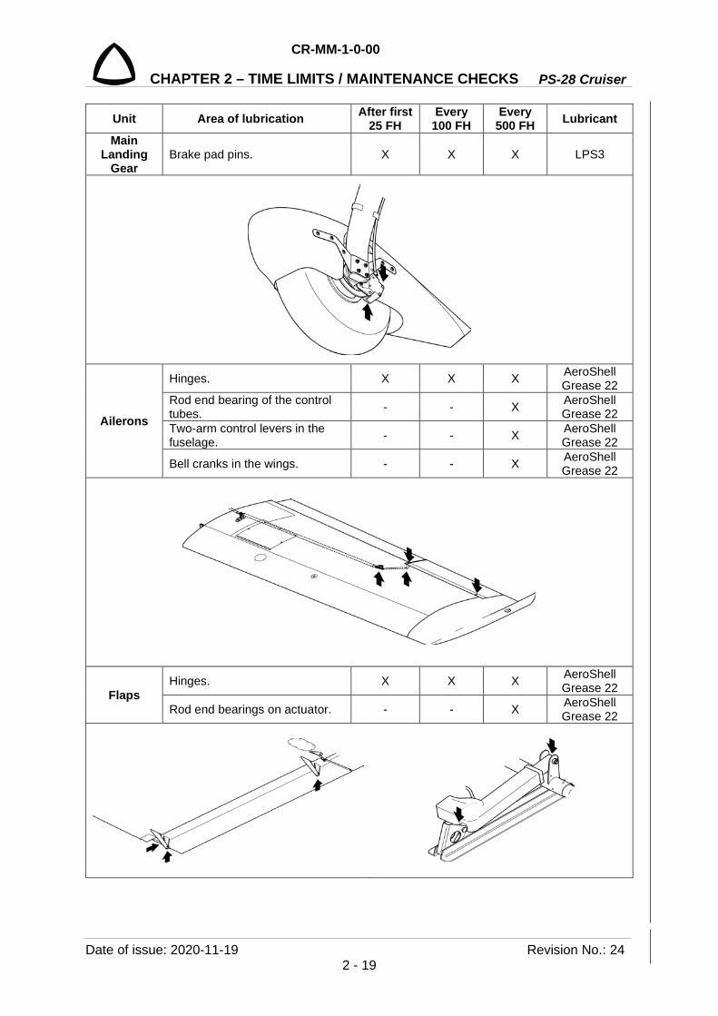
Main Landing
Gear Brake pad pins. X X X LPS3
Ailerons
Hinges. X X X AeroShell Grease 22
Rod end bearing of the control tubes. - - X AeroShell
Grease 22 Two-arm control levers in the fuselage. - - X AeroShell
Grease 22
Bell cranks in the wings. - - X AeroShell Grease 22
Flaps Hinges. X X X AeroShell
Grease 22
Rod end bearings on actuator. - - X AeroShell Grease 22

PS-28 Cruiser
CR-MM-1-0-00
CHAPTER 2 – TIME LIMITS / MAINTENANCE CHECKS
Revision No.: 24 Date of issue: 2020-11-19 2 - 20
Unit Area of lubrication After first 25 FH
Every 100 FH
Every 500 FH Lubricant
HTU
Elevator hinges. X X X AeroShell Grease 22
Rod end bearing of the elevator control tubes. - - X AeroShell
Grease 22
Pins (front stabilizer hinge). - Annual insp. - LPS3
VTU Rudder hinges. X X X AeroShell
Grease 22 Cable shackles on the rudder control cables. X X X AeroShell
Grease 22
Trim and balance
tabs
Tabs hinges. X X X LPS1
Rod end on actuators. X X X AeroShell Grease 22

CR-MM-1-0-00
PS-28 Cruiser CHAPTER 2 – TIME LIMITS / MAINTENANCE CHECKS
Date of issue: 2020-11-19 Revision No.: 24 2 - 21
Unit Area of lubrication After first 25 FH
Every 100 FH
Every 500 FH Lubricant
Aileron, elevator control
All movable links in the cockpit. - - X AeroShell Grease 22
Rudder control
All movable links in the cockpit. - - X AeroShell Grease 22
Cable shackles of rudder control. X - X AeroShell
Grease 22

PS-28 Cruiser
CR-MM-1-0-00
CHAPTER 2 – TIME LIMITS / MAINTENANCE CHECKS
Revision No.: 24 Date of issue: 2020-11-19 2 - 22
2B.6 Ordering spare parts Order spare parts through the Airplane failures card - see Section 17.4.
NOTE: Spare parts for the engine shall be provided with EASA Form One (issued by Rotax or CAG) unless they are identified as a standard part (valid only for certified PS-28 Cruiser airplanes).

CR-MM-1-0-00
PS-28 Cruiser CHAPTER 3 – FUSELAGE
Date of issue: 2020-11-19 Revision No.: 24 3 - 1
3. FUSELAGE
Content
3.1 General ................................................................................................................... 3-2 3.2 Description and operation ...................................................................................... 3-2
3.2.1 Front part of the fuselage ..................................................................... 3-2 3.2.2 Rear part of the fuselage ..................................................................... 3-2 3.2.3 Cockpit ................................................................................................. 3-3 3.2.4 Baggage compartment ........................................................................ 3-4 3.2.5 Crew canopy ........................................................................................ 3-4
3.2.5.1 Canopy.................................................................................. 3-5 3.2.5.2 Rear fixed canopy windows .................................................. 3-5
3.2.6 INTENTIONALLY LEFT EMPTY ......................................................... 3-5 3.3 Removal / Installation ............................................................................................. 3-7
3.3.1 Canopy removal ................................................................................... 3-7 3.3.2 Canopy installation .............................................................................. 3-7 3.3.3 Gas strut removal ................................................................................ 3-8 3.3.4 Gas strut installation ............................................................................ 3-9 3.3.5 Cabin lock removal .............................................................................. 3-9 3.3.6 Cabin lock installation ........................................................................ 3-10 3.3.7 Balance ballast installation ................................................................ 3-10
3.4 Check / Adjustment .............................................................................................. 3-12 3.4.1 Canopy lock adjustment .................................................................... 3-12 3.4.2 INTENTIONALLY LEFT EMPTY ....................................................... 3-12
3.5 Exchanges / Service information .......................................................................... 3-12 3.5.1 Canopy glass cleaning ....................................................................... 3-12
PS-28 Cruiser
CR-MM-1-0-00
CHAPTER 3 – FUSELAGE
Revision No.: - Date of issue: 2011-03-08 3 - 2
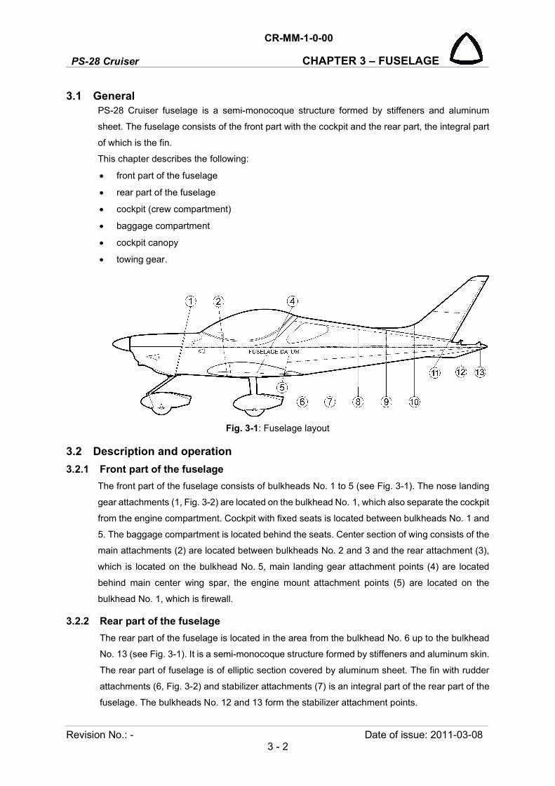
3.1 General PS-28 Cruiser fuselage is a semi-monocoque structure formed by stiffeners and aluminum
sheet. The fuselage consists of the front part with the cockpit and the rear part, the integral part
of which is the fin.
This chapter describes the following:
front part of the fuselage
rear part of the fuselage
cockpit (crew compartment)
baggage compartment
cockpit canopy
towing gear.
Fig. 3-1: Fuselage layout
3.2 Description and operation
3.2.1 Front part of the fuselage
The front part of the fuselage consists of bulkheads No. 1 to 5 (see Fig. 3-1). The nose landing
gear attachments (1, Fig. 3-2) are located on the bulkhead No. 1, which also separate the cockpit
from the engine compartment. Cockpit with fixed seats is located between bulkheads No. 1 and
5. The baggage compartment is located behind the seats. Center section of wing consists of the
main attachments (2) are located between bulkheads No. 2 and 3 and the rear attachment (3),
which is located on the bulkhead No. 5, main landing gear attachment points (4) are located
behind main center wing spar, the engine mount attachment points (5) are located on the
bulkhead No. 1, which is firewall.
3.2.2 Rear part of the fuselage
The rear part of the fuselage is located in the area from the bulkhead No. 6 up to the bulkhead
No. 13 (see Fig. 3-1). It is a semi-monocoque structure formed by stiffeners and aluminum skin.
The rear part of fuselage is of elliptic section covered by aluminum sheet. The fin with rudder
attachments (6, Fig. 3-2) and stabilizer attachments (7) is an integral part of the rear part of the
fuselage. The bulkheads No. 12 and 13 form the stabilizer attachment points.

CR-MM-1-0-00
PS-28 Cruiser CHAPTER 3 – FUSELAGE
Date of issue: 2011-03-08 Revision No.: - 3 - 3
Fig. 3-2: Fuselage monocoque
3.2.3 Cockpit
The cockpit (see Fig. 3-1) is located in the front part of the fuselage between the bulkheads
No. 1 and 5. The instrument panel is located between bulkhead No. 1 and frame No. 2. In the
middle of the cockpit there is a middle console with control elements. The cockpit is equipped
with two fixed seats.
NOTE: Current instrument panel arrangement is stated in the Pilots Operation Handbook, Supplement No. 1.
The cockpit floor and baggage compartment is covered with a removable carpet and the middle
console is covered with thin upholstery. The interior cockpit sides are covered with padded
panels containing pockets and armrests.
1 Nose landing gear attachments
2 Wing attachment, main
3 Wing attachment, rear
4 Main landing gear attachments
5 Engine mount attachments
6 Rudder attachments
7 Stabilizer attachments

PS-28 Cruiser
CR-MM-1-0-00
CHAPTER 3 – FUSELAGE
Revision No.: 2 Date of issue: 2012-12-10 3 - 4
3.2.4 Baggage compartment
Baggage compartment (8, Fig. 3-3) is located between the seats and the bulkhead No. 7. Max.
baggage weight transported in the baggage compartment is 18 kg (40 lbs).
3.2.5 Crew canopy
The crew canopy is produced of organic glass and consists of opening canopy and rear fixed
canopy windows.
1 Canopy 6 Locking lever
2 Canopy hinge 7 Rear canopy window
3 Gas strut 8 Baggage compartment
4 Canopy lock 9 Sunshield
5 Inside opening lever 10 Sliding side ventilation window
Fig. 3-3: Canopy, rear canopy window
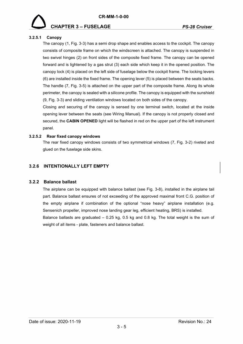
CR-MM-1-0-00
PS-28 Cruiser CHAPTER 3 – FUSELAGE
Date of issue: 2020-11-19 Revision No.: 24 3 - 5
3.2.5.1 Canopy
The canopy (1, Fig. 3-3) has a semi drop shape and enables access to the cockpit. The canopy
consists of composite frame on which the windscreen is attached. The canopy is suspended in
two swivel hinges (2) on front sides of the composite fixed frame. The canopy can be opened
forward and is lightened by a gas strut (3) each side which keep it in the opened position. The
canopy lock (4) is placed on the left side of fuselage below the cockpit frame. The locking levers
(6) are installed inside the fixed frame. The opening lever (5) is placed between the seats backs.
The handle (7, Fig. 3-5) is attached on the upper part of the composite frame. Along its whole
perimeter, the canopy is sealed with a silicone profile. The canopy is equipped with the sunshield
(9, Fig. 3-3) and sliding ventilation windows located on both sides of the canopy.
Closing and securing of the canopy is sensed by one terminal switch, located at the inside
opening lever between the seats (see Wiring Manual). If the canopy is not properly closed and
secured, the CABIN OPENED light will be flashed in red on the upper part of the left instrument
panel.
3.2.5.2 Rear fixed canopy windows
The rear fixed canopy windows consists of two symmetrical windows (7, Fig. 3-2) riveted and
glued on the fuselage side skins.
3.2.6 INTENTIONALLY LEFT EMPTY
3.2.2 Balance ballast
The airplane can be equipped with balance ballast (see Fig. 3-8), installed in the airplane tail
part. Balance ballast ensures of not exceeding of the approved maximal front C.G. position of
the empty airplane if combination of the optional “nose heavy” airplane installation (e.g.
Sensenich propeller, improved nose landing gear leg, efficient heating, BRS) is installed.
Balance ballasts are graduated – 0.25 kg, 0.5 kg and 0.8 kg. The total weight is the sum of
weight of all items - plate, fasteners and balance ballast.

PS-28 Cruiser
CR-MM-1-0-00
CHAPTER 3 – FUSELAGE
Revision No.: 24 Date of issue: 2020-11-19 3 - 6
INTENTIONALLY LEFT BLANK

CR-MM-1-0-00
PS-28 Cruiser CHAPTER 3 – FUSELAGE
Date of issue: 2011-03-08 Revision No.: - 3 - 7
3.3 Removal / Installation
3.3.1 Canopy removal
Type of maintenance: line
Authorization to perform:
- Sport pilot or higher
Tools needed:
- socket wrench 7/16”
- screwdriver
- pliers
CAUTION: DURING CANOPY REMOVAL BE CAREFULLY TO AVOID SCRATCHING THE GLASS.
NOTE: For canopy removal two persons are requested.
(a) Open the canopy (1, Fig. 3-5).
(b) Remove the dummy plugs (3).
(c) Disconnect upper end of the gas struts (2) on both sides of canopy (1) (see 3.3.3).
(d) Hold the canopy.
(e) Unscrew the nuts (5), remove the washers (6) and the bolts (4).
(f) Carefully remove the canopy (1) and store it in a safe place so that windscreen damage
cannot occur.
3.3.2 Canopy installation
Type of maintenance: line
Authorization to perform:
- Sport pilot or higher
Tools needed:
- Socket wrench size 7/16
- screwdriver
- pliers
CAUTION: DURING CANOPY INSTALLATION BE CAREFULLY TO AVOID SCRATCHING THE GLASS.
NOTE: For canopy installation two persons are requested.
(a) Set the canopy (1, Fig. 3-5) on the fixed frame.
(b) Insert the bolts (4) into the hinges, install the washers (6), screw and tighten the nuts (5).
(c) Open the canopy (1) and hold it.
(d) Connect upper end of the gas struts (2) on both sides of canopy (1) (see 3.3.4).
(e) Install new dummy plugs (3).

PS-28 Cruiser
CR-MM-1-0-00
CHAPTER 3 – FUSELAGE
Revision No.: 2 Date of issue: 2011-11-08 3 - 8
1 Canopy 5 Nut
2 Gas strut 6 Washer
3 Dummy plug 7 Handle
4 Bolt
Fig. 3-5: Canopy removal / installation
3.3.3 Gas strut removal
Type of maintenance: line
Authorization to perform:
- Sport pilot or higher
Tools needed:
- screwdriver
- pliers
(a) Open the canopy (5, Fig. 3-6); hold it.
(b) Remove the safety clip (3) from the ball joint end fittings (2) on the canopy frame (5) and on
the fixed frame (6).
(c) Remove the gas strut (1).
NOTE Access to the nuts (5) and washers (6) is from the cockpit.

CR-MM-1-0-00
PS-28 Cruiser CHAPTER 3 – FUSELAGE
Date of issue: 2011-03-08 Revision No.: - 3 - 9
Fig. 3-6: Gas strut removal / installation
3.3.4 Gas strut installation
Type of maintenance: line
Authorization to perform:
- Sport pilot or higher
Tools needed:
- pliers
(a) Inspect the strut (1, Fig. 3-6) whether it is not damaged.
(b) Insert top ball joint end fitting (2) on the ball stud (4) on the canopy frame (5), and bottom
ball joint end fitting (2) on the ball stud (4) on the fixed frame (6)
(c) Secure the joints with safety clips (3).
3.3.5 Cabin lock removal
Type of maintenance: line
Authorization to perform:
- Sport pilot or higher
Tools needed:
- screwdriver
(a) Unscrew the screw (2, Fig. 3-7) attaching the lock (1) to the fuselage skin.
1 Gas strut
2 Ball joint end fitting
3 Safety clip
4 Ball stud
5 Canopy frame
6 Fixed frame

PS-28 Cruiser
CR-MM-1-0-00
CHAPTER 3 – FUSELAGE
Revision No.: 22 Date of issue: 2018-09-27 3 - 10
(b) Remove the lock (1).
1 Lock 2 Screw
Fig. 3-7: Canopy lock removal / installation
3.3.6 Cabin lock installation
Type of maintenance: line
Authorization to perform:
- Sport pilot or higher
Tools needed:
- screwdriver
(a) Put the lock (1, Fig. 3-7) in to the hole in the fuselage skin.
(b) Screw the screw (3) attaching lock to the fuselage skin.
3.3.7 Balance ballast installation
Type of maintenance: heavy
Authorization to perform:
See point 2.5.3.
Tools needed:
- wrench size 3/8, 7/16 in
- screwdriver
- pliers
- electric drill
- drill bit 4.8 mm (7/16 in)
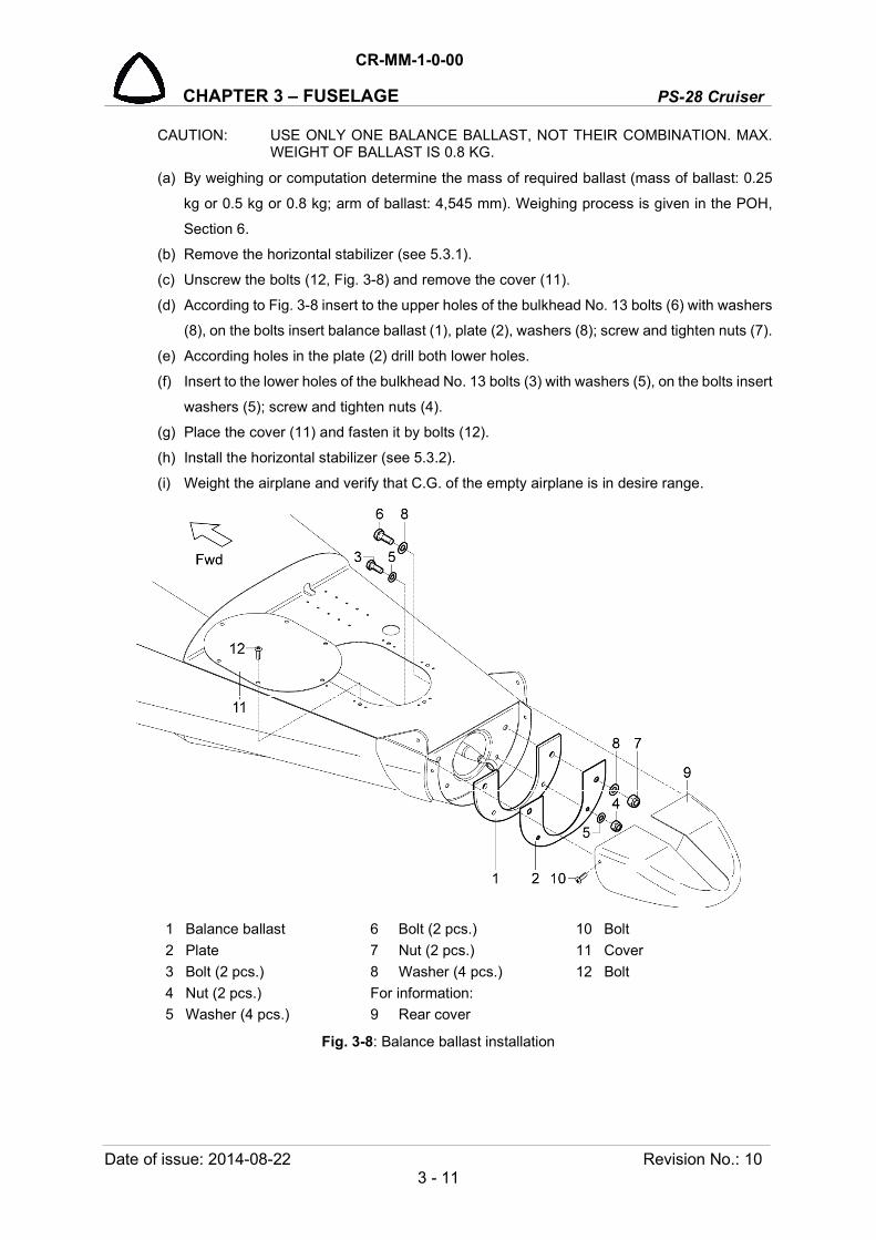
CR-MM-1-0-00
PS-28 Cruiser CHAPTER 3 – FUSELAGE
Date of issue: 2014-08-22 Revision No.: 10 3 - 11
CAUTION: USE ONLY ONE BALANCE BALLAST, NOT THEIR COMBINATION. MAX. WEIGHT OF BALLAST IS 0.8 KG.
(a) By weighing or computation determine the mass of required ballast (mass of ballast: 0.25
kg or 0.5 kg or 0.8 kg; arm of ballast: 4,545 mm). Weighing process is given in the POH,
Section 6.
(b) Remove the horizontal stabilizer (see 5.3.1).
(c) Unscrew the bolts (12, Fig. 3-8) and remove the cover (11).
(d) According to Fig. 3-8 insert to the upper holes of the bulkhead No. 13 bolts (6) with washers
(8), on the bolts insert balance ballast (1), plate (2), washers (8); screw and tighten nuts (7).
(e) According holes in the plate (2) drill both lower holes.
(f) Insert to the lower holes of the bulkhead No. 13 bolts (3) with washers (5), on the bolts insert
washers (5); screw and tighten nuts (4).
(g) Place the cover (11) and fasten it by bolts (12).
(h) Install the horizontal stabilizer (see 5.3.2).
(i) Weight the airplane and verify that C.G. of the empty airplane is in desire range.
1 Balance ballast 6 Bolt (2 pcs.) 10 Bolt
2 Plate 7 Nut (2 pcs.) 11 Cover
3 Bolt (2 pcs.) 8 Washer (4 pcs.) 12 Bolt
4 Nut (2 pcs.) For information:
5 Washer (4 pcs.) 9 Rear cover
Fig. 3-8: Balance ballast installation
PS-28 Cruiser
CR-MM-1-0-00
CHAPTER 3 – FUSELAGE
Revision No.: 24 Date of issue: 2020-11-19 3 - 12
3.4 Check / Adjustment
3.4.1 Canopy lock adjustment
Adjust the locks so that the canopy could be locked freely.
Set the length of the rod.
3.4.2 INTENTIONALLY LEFT EMPTY
3.5 Exchanges / Service information
3.5.1 Canopy glass cleaning
Canopy glass cannot be cleaned by the alcohol-based cleaner.
CR-MM-1-0-00
PS-28 Cruiser CHAPTER 4 – WING
Date of issue: 2018-09-27 Revision No.: 22 4 - 1
4. WING
Content
4.1 General .................................................................................................................. 4-2
4.2 Description and operation ...................................................................................... 4-2
4.2.1 Wing ...................................................................................................... 4-2
4.2.2 Wing flaps .............................................................................................. 4-3
4.2.3 Ailerons .................................................................................................. 4-4
4.2.4 Fuel tanks .............................................................................................. 4-4
4.2.5 Wing lockers .......................................................................................... 4-5
4.3 Removal / Installation ............................................................................................ 4-5
4.3.1 Wing removal ......................................................................................... 4-5
4.3.2 Wing installation .................................................................................... 4-6
4.3.3 Wing flap removal .................................................................................. 4-8
4.3.4 Wing flap installation.............................................................................. 4-9
4.3.5 Aileron removal ...................................................................................... 4-9
4.3.6 Aileron installation ............................................................................... 4-10
4.4 Check / Adjustment .............................................................................................. 4-11
4.5 Exchanges / Service information ......................................................................... 4-11

PS-28 Cruiser
CR-MM-1-0-00
CHAPTER 4 – WING
Revision No.: - Date of issue: 2011-03-08 4 - 2
4.1 General
PS-28 Cruiser wing is an aluminum structure and is equipped with flaps, ailerons and fuel tanks.
This chapter describes the structure of:
wings
wing flaps
ailerons
fuel tanks
Fig. 4-1: Wing layout
4.2 Description and operation
4.2.1 Wing
The wing of the airplane is formed from center section of wing made as main and rear spar,
which is integrated part of fuselage (Fig. 3-1), and from outer wings placed between ribs No. 1
and 9, which have trapezoid shape (Fig. 4-1). The wing is of all-metal main spar structure with
a rear spar. In the outer wings are installed between ribs No. 4 and 6a leading edge fuel tanks,
on the aft spar there are hinged ailerons (1, Fig. 4-2) and flaps (2). The wing tips (3), made out
of fiberglass, are riveted on the wing ribs No. 9. On wing tips are installed the position lights (6).
The outer wing is attached to the center section by means of 6 bolts (4) and the rear attachment
(5) (positioned on the rear spar). The aileron control push rods are lead between the spars. The
aileron trim tab is installed on the right aileron.
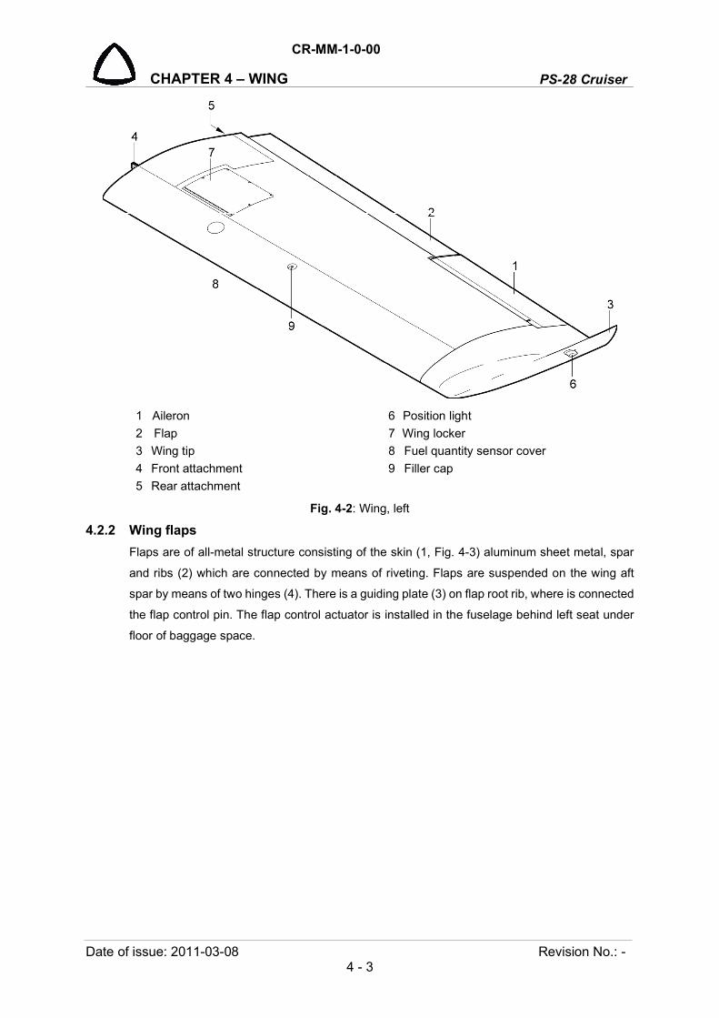
CR-MM-1-0-00
PS-28 Cruiser CHAPTER 4 – WING
Date of issue: 2011-03-08 Revision No.: - 4 - 3
1 Aileron 6 Position light
2 Flap 7 Wing locker
3 Wing tip 8 Fuel quantity sensor cover
4 Front attachment 9 Filler cap
5 Rear attachment
Fig. 4-2: Wing, left
4.2.2 Wing flaps
Flaps are of all-metal structure consisting of the skin (1, Fig. 4-3) aluminum sheet metal, spar
and ribs (2) which are connected by means of riveting. Flaps are suspended on the wing aft
spar by means of two hinges (4). There is a guiding plate (3) on flap root rib, where is connected
the flap control pin. The flap control actuator is installed in the fuselage behind left seat under
floor of baggage space.
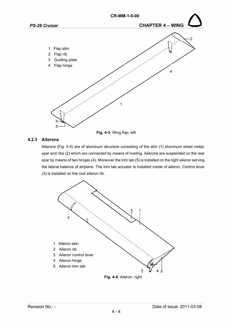
PS-28 Cruiser
CR-MM-1-0-00
CHAPTER 4 – WING
Revision No.: - Date of issue: 2011-03-08 4 - 4
Fig. 4-3: Wing flap, left
4.2.3 Ailerons
Ailerons (Fig. 4-4) are of aluminum structure consisting of the skin (1) aluminum sheet metal,
spar and ribs (2) which are connected by means of riveting. Ailerons are suspended on the rear
spar by means of two hinges (4). Moreover the trim tab (5) is installed on the right aileron serving
the lateral balance of airplane. The trim tab actuator is installed inside of aileron. Control lever
(3) is installed on the root aileron rib.
Fig. 4-4: Aileron, right
1 Flap skin
2 Flap rib
3 Guiding plate
4 Flap hinge
1 Aileron skin
2 Aileron rib
3 Aileron control lever
4 Aileron hinge
5 Aileron trim tab

CR-MM-1-0-00
PS-28 Cruiser CHAPTER 4 – WING
Date of issue: 2018-09-27 Revision No.: 22 4 - 5
4.2.4 Fuel tanks
Fuel tanks are of welded all-metal structure consisting of aluminum sheet metal skin (1, Fig. 4-
5) and two ribs (2). There are on each tank filler neck (3), fuel quantity sensor (4), venting tube
(5), finger screen (6) and drain valve (7).
1 Metal skin 5 Venting tube
2 Rib 6 Finger screen
3 Filler neck 7 Drain valve
4 Fuel quantity sensor
Fig. 4-5: Fuel tank, right
4.2.5 Wing lockers
Wings are equipped with wing locker (7, Fig. 4-2) placed between ribs No.4 and 5 behind main
spar. Capacity of each wing locker is 10 kg (22 lbs). Access doors installed on piano hinge are
locked per quick fasteners.
4.3 Removal / Installation
4.3.1 Wing removal
Type of maintenance: heavy
Authorization to perform:
See point 2.5.3.
Tools needed:
- wrench size 7/16 in, 1/2 in
- Phillips PH2 screwdriver
- cutting pliers
- hammer
(a) Remove the seats and access cover plates on the seats floor.
(b) Disconnect whole 6 nuts from the attachment bolts on the main spar and remove 6 bolts.
(c) Disconnect aileron control push rod on the control lever in fuselage behind the seats.
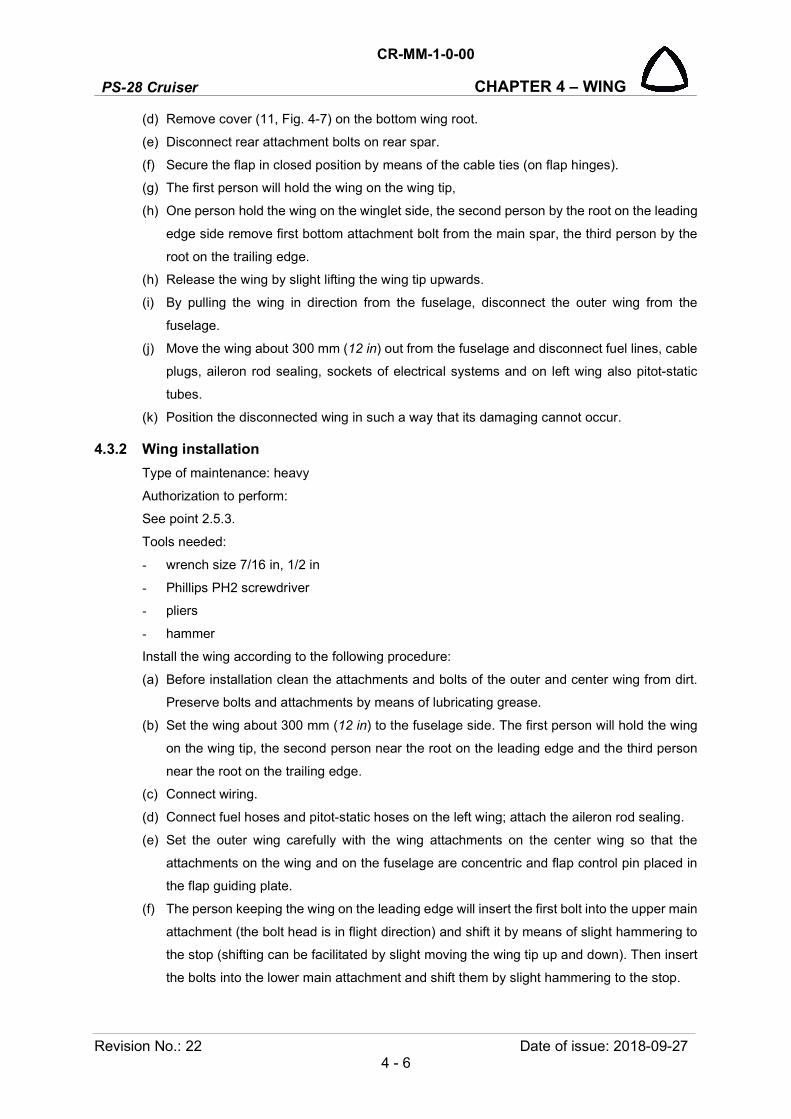
PS-28 Cruiser
CR-MM-1-0-00
CHAPTER 4 – WING
Revision No.: 22 Date of issue: 2018-09-27 4 - 6
(d) Remove cover (11, Fig. 4-7) on the bottom wing root.
(e) Disconnect rear attachment bolts on rear spar.
(f) Secure the flap in closed position by means of the cable ties (on flap hinges).
(g) The first person will hold the wing on the wing tip,
(h) One person hold the wing on the winglet side, the second person by the root on the leading
edge side remove first bottom attachment bolt from the main spar, the third person by the
root on the trailing edge.
(h) Release the wing by slight lifting the wing tip upwards.
(i) By pulling the wing in direction from the fuselage, disconnect the outer wing from the
fuselage.
(j) Move the wing about 300 mm (12 in) out from the fuselage and disconnect fuel lines, cable
plugs, aileron rod sealing, sockets of electrical systems and on left wing also pitot-static
tubes.
(k) Position the disconnected wing in such a way that its damaging cannot occur.
4.3.2 Wing installation
Type of maintenance: heavy
Authorization to perform:
See point 2.5.3.
Tools needed:
- wrench size 7/16 in, 1/2 in
- Phillips PH2 screwdriver
- pliers
- hammer
Install the wing according to the following procedure:
(a) Before installation clean the attachments and bolts of the outer and center wing from dirt.
Preserve bolts and attachments by means of lubricating grease.
(b) Set the wing about 300 mm (12 in) to the fuselage side. The first person will hold the wing
on the wing tip, the second person near the root on the leading edge and the third person
near the root on the trailing edge.
(c) Connect wiring.
(d) Connect fuel hoses and pitot-static hoses on the left wing; attach the aileron rod sealing.
(e) Set the outer wing carefully with the wing attachments on the center wing so that the
attachments on the wing and on the fuselage are concentric and flap control pin placed in
the flap guiding plate.
(f) The person keeping the wing on the leading edge will insert the first bolt into the upper main
attachment (the bolt head is in flight direction) and shift it by means of slight hammering to
the stop (shifting can be facilitated by slight moving the wing tip up and down). Then insert
the bolts into the lower main attachment and shift them by slight hammering to the stop.

CR-MM-1-0-00
PS-28 Cruiser CHAPTER 4 – WING
Date of issue: 2018-09-27 Revision No.: 22 4 - 7
(g) Attach the bolt and nut into the rear attachment of the wing and tight it with the tightening
moment 11 – 16 Nm (100 – 140 inch.lb).
(i) Put the washers on all of 6 attachment bolts of the wing and screw the nuts on them.
(j) Connect the aileron control push rod on control lever behind the seats and perform
tightening up to the tightening torque.
(k) Perform check the trim tab operation, flaps and ailerons deflections (see 6.4.3), possibly
adjusting of theirs deflections (see 6.4.4).
(l) Install access cover plates on the seats floor and access cover on the bottom wing root.
1 Wing, left 14 Pitot static hose
2 Bolt (6 pcs) 15 Hose connector
3 Nut (6 pcs) 16 Fuel quantity sensor wiring
4 Washer (10 pcs)* 17 Aileron trim tab wiring (only right side)
5 Bolt 18 Position light wiring
6 Nut 19 Front attachment
7 Washer 20 Front attachment
8 Bolt 21 Rear attachment
9 Nut 22 Control lever
10 Washer 23 Aileron rod sealing
11 Fuel hose 24 Bush (2 pcs.)
12 Hose connector 25 Cable tie (2 pcs.)
13 Hose clamp
Fig. 4-6: Wing removal / installation
* There are one or two washers used depending on bolt thread protrusion (2 washers for less protruding two bolts and 8 washers for the other four bolts).
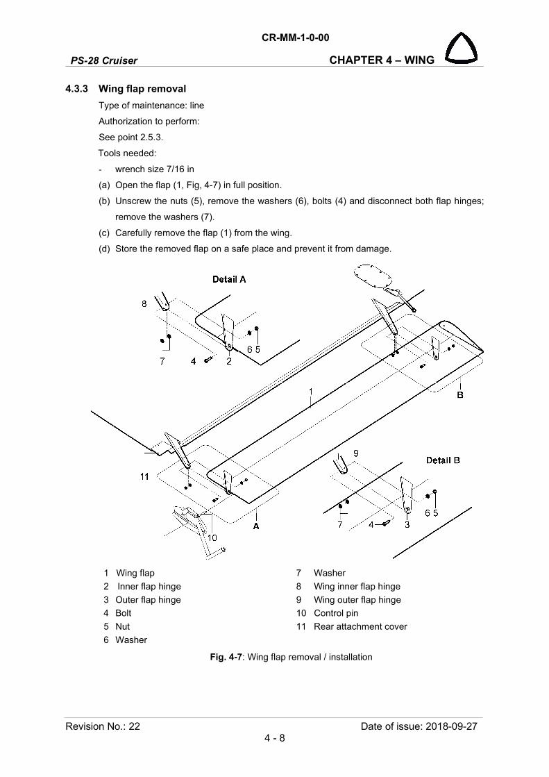
PS-28 Cruiser
CR-MM-1-0-00
CHAPTER 4 – WING
Revision No.: 22 Date of issue: 2018-09-27 4 - 8
4.3.3 Wing flap removal
Type of maintenance: line
Authorization to perform:
See point 2.5.3.
Tools needed:
- wrench size 7/16 in
(a) Open the flap (1, Fig, 4-7) in full position.
(b) Unscrew the nuts (5), remove the washers (6), bolts (4) and disconnect both flap hinges;
remove the washers (7).
(c) Carefully remove the flap (1) from the wing.
(d) Store the removed flap on a safe place and prevent it from damage.
1 Wing flap 7 Washer
2 Inner flap hinge 8 Wing inner flap hinge
3 Outer flap hinge 9 Wing outer flap hinge
4 Bolt 10 Control pin
5 Nut 11 Rear attachment cover
6 Washer
Fig. 4-7: Wing flap removal / installation

CR-MM-1-0-00
PS-28 Cruiser CHAPTER 4 – WING
Date of issue: 2018-09-27 Revision No.: 22 4 - 9
4.3.4 Wing flap installation
Type of maintenance: line
Authorization to perform:
See point 2.5.3.
Tools needed:
- wrench size 7/16 in
(a) Clean all attachments and apply lubricant on it (see 2.6). Do the same for the hinges on the
wing.
(b) Set the flap hinges (2; 3, Fig. 4-7) in to the wing hinges (8; 9) and control pin (10) in to the
guiding plate.
(c) Insert the bolts (4) and the washers (7) in to the hinges.
(d) Install the washers (6) and the nuts (5); tight the nuts with prescribed tightening moment 5.5
– 8 Nm (50 – 70 inch lb).
(e) Close the flap in the zero (up) position.
(f) Perform check the wing flaps operation and their deflections (see 6.4.3).
4.3.5 Aileron removal
Type of maintenance: heavy
Authorization to perform:
See point 2.5.3.
Tools needed:
- wrench size 7/16 in
- cutting pliers
(a) Disconnect the control rod with control lever.
(b) On the right aileron only:
remove the cover (10, Fig, 6-8) from the hole for access to trim tab actuator (1)
disconnect trim tab actuator wires (2).
(c) Unscrew the nuts (4, Fig. 4-8), remove the washers (5), bolts (3) and disconnect both aileron
hinges.
(d) Carefully remove the aileron (1) from the wing.
(e) Store the removed aileron on a safe place and prevent it from damage.

PS-28 Cruiser
CR-MM-1-0-00
CHAPTER 4 – WING
Revision No.: 22 Date of issue: 2018-09-27 4 - 10
4.3.6 Aileron installation
Type of maintenance: heavy
Authorization to perform:
See point 2.5.3.
- Tools needed:
- wrench size 7/16 in
- pliers
(a) Clean all attachments and apply lubricant on it (see 2.6). Do the same for the hinges on the
wing.
(b) Set the aileron (1, Fig. 4-8) on the wing in to the both hinges.
(c) Insert trim tab actuator wires (2, Fig. 6-8) going out from wing to the aileron.
(d) Insert the bolts (3, Fig. 4-8) in to the hinges, install the washers (5) and screw the nuts (4).
(e) Connect the control rod (6) with aileron control lever (2) by means of bolt (7), nut (8) and
washer (9).
(f) Connect trim tab actuator wires (2, Fig. 6, 8); close the access hole with cover (10) - on the
right aileron only (see Wiring Manual).
(g) Perform check the trim tab operation and aileron deflections (see 6.4.3), possibly adjusting
of aileron deflections (see 6.4.4).
1 Aileron 6 Control rod
2 Control lever 7 Bolt
3 Bolt 8 Nut
4 Nut 9 Washer
5 Washer
Fig. 4-8: Aileron removal / installation
CR-MM-1-0-00
PS-28 Cruiser CHAPTER 4 – WING
Date of issue: 2011-03-08 Revision No.: - 4 - 11
4.4 Check / Adjustment
No procedures included.
4.5 Exchanges / Service information
No procedures included.
PS-28 Cruiser
CR-MM-1-0-00
CHAPTER 4 – WING
Revision No.: - Date of issue: 2011-03-08 4 - 12
INTENTIONALLY LEFT BLANK

CR-MM-1-0-00
PS-28 Cruiser CHAPTER 5 – TAIL UNIT
Date of issue: 2018-09-27 Revision No.: 22 5 - 1
5. TAIL UNIT
Content
5.1 General .................................................................................................................. 5-2
5.2 Description and operation ...................................................................................... 5-2
5.2.1 Stabilizer ................................................................................................ 5-2
5.2.2 Elevator with tabs .................................................................................. 5-3
5.2.3 Fin .......................................................................................................... 5-4
5.2.4 Rudder ................................................................................................... 5-5
5.3 Removal / Installation ............................................................................................ 5-6
5.3.1 Horizontal stabilizer removal ................................................................. 5-6
5.3.2 Horizontal stabilizer installation ............................................................. 5-6
5.3.3 Elevator removal .................................................................................... 5-8
5.3.4 Elevator installation ............................................................................... 5-8
5.3.5 Trim tab removal .................................................................................... 5-9
5.3.6 Trim tab installation ............................................................................. 5-10
5.3.7 Balance tab removal ............................................................................ 5-10
5.3.8 Balance tab installation ....................................................................... 5-10
5.3.9 Rudder removal ................................................................................... 5-11
5.3.10 Rudder installation ............................................................................... 5-11
5.4 Check / Adjustment .............................................................................................. 5-12
5.5 Exchanges / Service information ......................................................................... 5-12
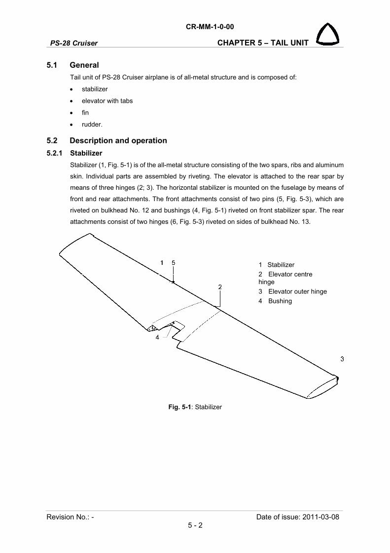
PS-28 Cruiser
CR-MM-1-0-00
CHAPTER 5 – TAIL UNIT
Revision No.: - Date of issue: 2011-03-08 5 - 2
5.1 General
Tail unit of PS-28 Cruiser airplane is of all-metal structure and is composed of:
stabilizer
elevator with tabs
fin
rudder.
5.2 Description and operation
5.2.1 Stabilizer
Stabilizer (1, Fig. 5-1) is of the all-metal structure consisting of the two spars, ribs and aluminum
skin. Individual parts are assembled by riveting. The elevator is attached to the rear spar by
means of three hinges (2; 3). The horizontal stabilizer is mounted on the fuselage by means of
front and rear attachments. The front attachments consist of two pins (5, Fig. 5-3), which are
riveted on bulkhead No. 12 and bushings (4, Fig. 5-1) riveted on front stabilizer spar. The rear
attachments consist of two hinges (6, Fig. 5-3) riveted on sides of bulkhead No. 13.
Fig. 5-1: Stabilizer
1 Stabilizer
2 Elevator centre hinge
3 Elevator outer hinge
4 Bushing

CR-MM-1-0-00
PS-28 Cruiser CHAPTER 5 – TAIL UNIT
Date of issue: 2011-03-08 Revision No.: - 5 - 3
5.2.2 Elevator with tabs
Elevator (1, Fig.5-2) is of all-metal structure and consists of aluminum skin, spar and ribs.
Individual parts are assembled by riveting. Control lever (5) is riveted on middle elevator rib.
Mass balances (6) are riveted at the both elevator ends and covered composite tips (7). The
elevator is equipped with the trim (2) and balance (3) tabs; both are hinged by means of the
piano hinge on the rear spar close to the trailing edge of the elevator. The balance tab (3) is
interconnected by means of the rod with the hinge (5, Fig. 5-1) on the stabilizer. The tabs are
made of aluminum sheet.
Fig. 5-2: Elevator
1 Elevator
2 Trim tab
3 Balance tab
4 Outer hinge
5 Centre hinge
6 Control lever
7 Mass balance
8 Elevator tip

PS-28 Cruiser
CR-MM-1-0-00
CHAPTER 5 – TAIL UNIT
Revision No.: - Date of issue: 2011-03-08 5 - 4
5.2.3 Fin
The vertical fin (1, Fig. 5-3) is of an aluminum structure and is an integral part with the rear part
of the fuselage. The fin consists of stiffeners, spar, ribs and aluminum skin. Individual parts are
assembled by riveting. The fin tip (4) is made of fiberglass. On the spar are two rudder hinges,
lower one (3) and upper one (2).
1 Fin 4 Fin tip
2 Rudder upper hinge 5 Pin - front stabilizer hinge
3 Rudder lower hinge 6 Rear stabilizer hinge
Fig. 5-3: Fin

CR-MM-1-0-00
PS-28 Cruiser CHAPTER 5 – TAIL UNIT
Date of issue: 2011-03-08 Revision No.: - 5 - 5
5.2.4 Rudder
The rudder (1, Fig. 5-4) is of aluminum structure and consists of spar, ribs and aluminum skin.
Individual parts are assembled by riveting. On the spar are two attachments lower one (3) and
upper one (2) for the rudder suspension on the fin. Control lever (4) is riveted on root rib. On
the trailing edge is riveted fixed trim tab (6).
Fig. 5-4: Rudder
1 Rudder
2 Upper hinge
3 Lower hinge
4 Control lever
5 Rudder tip
6 Fixed trim tab
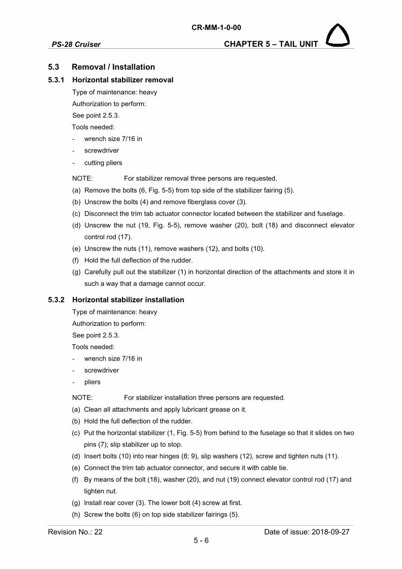
PS-28 Cruiser
CR-MM-1-0-00
CHAPTER 5 – TAIL UNIT
Revision No.: 22 Date of issue: 2018-09-27 5 - 6
5.3 Removal / Installation
5.3.1 Horizontal stabilizer removal
Type of maintenance: heavy
Authorization to perform:
See point 2.5.3.
Tools needed:
- wrench size 7/16 in
- screwdriver
- cutting pliers
NOTE: For stabilizer removal three persons are requested.
(a) Remove the bolts (6, Fig. 5-5) from top side of the stabilizer fairing (5).
(b) Unscrew the bolts (4) and remove fiberglass cover (3).
(c) Disconnect the trim tab actuator connector located between the stabilizer and fuselage.
(d) Unscrew the nut (19, Fig. 5-5), remove washer (20), bolt (18) and disconnect elevator
control rod (17).
(e) Unscrew the nuts (11), remove washers (12), and bolts (10).
(f) Hold the full deflection of the rudder.
(g) Carefully pull out the stabilizer (1) in horizontal direction of the attachments and store it in
such a way that a damage cannot occur.
5.3.2 Horizontal stabilizer installation
Type of maintenance: heavy
Authorization to perform:
See point 2.5.3.
Tools needed:
- wrench size 7/16 in
- screwdriver
- pliers
NOTE: For stabilizer installation three persons are requested.
(a) Clean all attachments and apply lubricant grease on it.
(b) Hold the full deflection of the rudder.
(c) Put the horizontal stabilizer (1, Fig. 5-5) from behind to the fuselage so that it slides on two
pins (7); slip stabilizer up to stop.
(d) Insert bolts (10) into rear hinges (8; 9), slip washers (12), screw and tighten nuts (11).
(e) Connect the trim tab actuator connector, and secure it with cable tie.
(f) By means of the bolt (18), washer (20), and nut (19) connect elevator control rod (17) and
tighten nut.
(g) Install rear cover (3). The lower bolt (4) screw at first.
(h) Screw the bolts (6) on top side stabilizer fairings (5).

CR-MM-1-0-00
PS-28 Cruiser CHAPTER 5 – TAIL UNIT
Date of issue: 2018-09-27 Revision No.: 22 5 - 7
(i) Perform check the trim tab operation and elevator deflections (see 6.4.3), possibly
adjusting of elevator deflections (see 6.4.4).
1 Stabilizer 14 Nut
2 Elevator 15 Washer
3 Rear cover 16 Bolt
4 Bolt 17 Elevator control rod
5 Stabilizer fairing 18 Bolt
6 Bolt 19 Nut
7 Pin - front stabilizer hinge 20 Washer
8 Rear stabilizer hinge 21 Cover
9 Rear hinge 22 Balance tab control rod
10 Bolt 23 Balance tab rod hinge
11 Nut 24 Pin
12 Washer 25 Washer
13 Bolt 26 Cotter pin
Fig. 5-5: Stabilizer, elevator removal / installation

PS-28 Cruiser
CR-MM-1-0-00
CHAPTER 5 – TAIL UNIT
Revision No.: 22 Date of issue: 2018-09-27 5 - 8
5.3.3 Elevator removal
Type of maintenance: heavy
Authorization to perform:
See point 2.5.3.
Tools needed:
- wrench size 7/16 in
- cutting pliers
NOTE: For elevator removal two persons are requested.
(a) Remove the cover (21, Fig. 5-5) from the bottom elevator surface (see 6.3.6).
(b) Disconnect the trim tab actuator connector (see Fig 6-8).
(c) Unscrew the bolts (4, Fig. 5-5) and remove fiberglass cover (3).
(d) Unscrew the nut (19), remove washer (20), bolt (18) and disconnect elevator control rod
(17).
(e) Remove the cotter pin (26), washers (25), pin (24) and disconnect the rod (22) from the
hinge (23).
(f) Unscrew the nuts (14), remove washers (15), and bolts (13; 16) from all three hinges.
(g) Carefully remove the elevator (2) from the stabilizer (1) and store it in such a way that a
damage cannot occur.
5.3.4 Elevator installation
Type of maintenance: heavy
Authorization to perform:
See point 2.5.3.
Tools needed:
- wrench size 7/16 in
- pliers
NOTE: For elevator installation two persons are requested.
(a) Inspect the hinges on the elevator, clean them and apply lubricant on them (see 2.6). Do
the same for the hinges on the stabilizer.
(b) Put the elevator (2, Fig. 5-5) in all three hinges on the stabilizer (1).
(c) Insert the trim tab actuator wires going from the stabilizer to the elevator.
(d) Insert bolts (13; 16) into all three hinges, slip washers (15), screw and tighten nuts (14).
(e) Fit the rod (22) to the hinge (23), insert pin (24) with washer (25) into the hole, insert the
washer (25) and secure with the new cotter pin (26).
(f) By means of the bolt (18), washers (20), and nut (19) connect elevator control rod (17)
and tighten nut.
(g) Install rear cover (3). The lower bolt (4) screw at first.
(h) Connect the trim tab actuator wires (see Fig.6-8).
(i) Install the cover (21, Fig. 5-5) on the bottom elevator surface (see 6.3.7).

CR-MM-1-0-00
PS-28 Cruiser CHAPTER 5 – TAIL UNIT
Date of issue: 2018-09-27 Revision No.: 22 5 - 9
(j) Perform check the trim tab operation and elevator deflections (see 6.4.3), possibly
adjusting of elevator deflections (see 6.4.4).
5.3.5 Trim tab removal
Type of maintenance: heavy
Authorization to perform:
See point 2.5.3.
Tools needed:
- pliers, cutting pliers
- electric drill, drill diam. 3.2 mm (1/8 in)
(a) Remove cotter pin (5, Fig. 5-6), washers (4), pin (3) and disconnect control rod (6) from
the trim tab control lever (2).
(b) Drill out the rivets (8) connecting the piano hinge with elevator.
(c) Remove the trim tab (1) with piano hinge (7) from elevator.
1 Trim tab 7 Piano hinge
2 Control lever 8 Rivet
3 Pin 9 Balance tab
4 Washer 10 Control lever
5 Cotter pin 11 Control rod
6 Control rod
Fig. 5-6: Elevator tabs removal / installation

PS-28 Cruiser
CR-MM-1-0-00
CHAPTER 5 – TAIL UNIT
Revision No.: 22 Date of issue: 2018-09-27 5 - 10
5.3.6 Trim tab installation
Type of maintenance: heavy
Authorization to perform:
See point 2.5.3.
Tools needed:
- pliers, cutting pliers
- pliers for riveting
(a) Put the trim tab (1, Fig. 5-6) with piano hinge (7) in appropriate position to the elevator.
(b) Rivet the piano hinge into the elevator.
(c) Check for free rotation of the trim tab.
(d) By means of the pin (3), washers (4) connect control rod (6) to the control lever (2); secure
the pin with the new cotter pin (5). At installation follow instructions in 6.3.1.
(e) Perform check (see 6.4.3), possibly adjustment (see 6.4.4) of trim tab deflections.
5.3.7 Balance tab removal
Type of maintenance: heavy
Authorization to perform:
See point 2.5.3.
Tools needed:
- pliers, cutting pliers
- electric drill, drill diam. 3.2 mm (1/8 in)
(d) Remove cotter pin (5, Fig. 5-6), washers (4), pin (3) and disconnect control rod (11) from
the tab control lever (10).
(e) Drill out the rivets (8) connecting the piano hinge with elevator.
(f) Remove the balance tab (9) with piano hinge from elevator.
5.3.8 Balance tab installation
Type of maintenance: heavy
Authorization to perform:
See point 2.5.3.
Tools needed:
- pliers, cutting pliers
- pliers for riveting
(f) Put the balance tab (9, Fig. 5-6) with piano hinge in appropriate position to the elevator.
(g) Rivet the piano hinge into the elevator.
(h) Check for free rotation of the tab.
(i) By means of the pin (3), washers (4) connect control rod (11) to the control lever (10);
secure the pin with the new cotter pin (5).
(j) Perform check (see 6.4.3), possibly adjustment (see 6.4.4) of balance tab deflections.
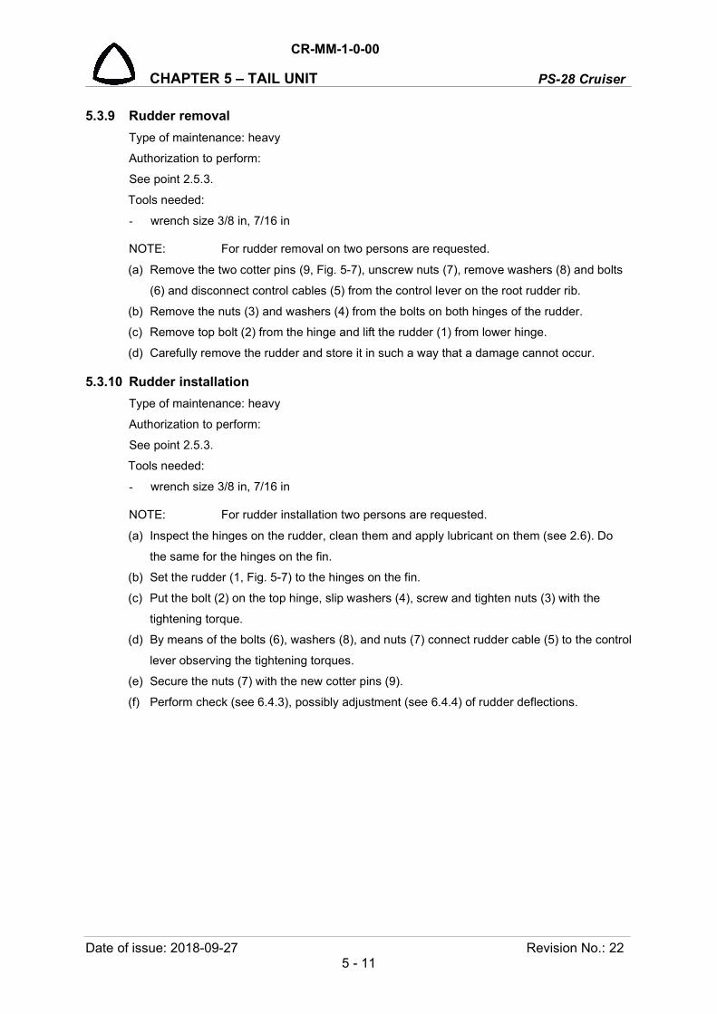
CR-MM-1-0-00
PS-28 Cruiser CHAPTER 5 – TAIL UNIT
Date of issue: 2018-09-27 Revision No.: 22 5 - 11
5.3.9 Rudder removal
Type of maintenance: heavy
Authorization to perform:
See point 2.5.3.
Tools needed:
- wrench size 3/8 in, 7/16 in
NOTE: For rudder removal on two persons are requested.
(a) Remove the two cotter pins (9, Fig. 5-7), unscrew nuts (7), remove washers (8) and bolts
(6) and disconnect control cables (5) from the control lever on the root rudder rib.
(b) Remove the nuts (3) and washers (4) from the bolts on both hinges of the rudder.
(c) Remove top bolt (2) from the hinge and lift the rudder (1) from lower hinge.
(d) Carefully remove the rudder and store it in such a way that a damage cannot occur.
5.3.10 Rudder installation
Type of maintenance: heavy
Authorization to perform:
See point 2.5.3.
Tools needed:
- wrench size 3/8 in, 7/16 in
NOTE: For rudder installation two persons are requested.
(a) Inspect the hinges on the rudder, clean them and apply lubricant on them (see 2.6). Do
the same for the hinges on the fin.
(b) Set the rudder (1, Fig. 5-7) to the hinges on the fin.
(c) Put the bolt (2) on the top hinge, slip washers (4), screw and tighten nuts (3) with the
tightening torque.
(d) By means of the bolts (6), washers (8), and nuts (7) connect rudder cable (5) to the control
lever observing the tightening torques.
(e) Secure the nuts (7) with the new cotter pins (9).
(f) Perform check (see 6.4.3), possibly adjustment (see 6.4.4) of rudder deflections.
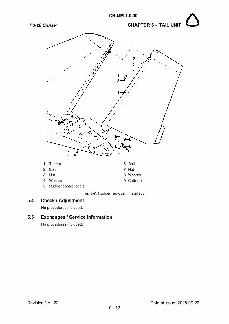
PS-28 Cruiser
CR-MM-1-0-00
CHAPTER 5 – TAIL UNIT
Revision No.: 22 Date of issue: 2018-09-27 5 - 12
1 Rudder 6 Bolt
2 Bolt 7 Nut
3 Nut 8 Washer
4 Washer 9 Cotter pin
5 Rudder control cable
Fig. 5-7: Rudder removal / installation
5.4 Check / Adjustment
No procedures included.
5.5 Exchanges / Service information
No procedures included.
CR-MM-1-0-00
PS-28 Cruiser CHAPTER 6 – CONTROL SYSTEM
Date of issue: 2018-09-27 Revision No.: 22 6 - 1
6. CONTROL SYSTEM
Content
6.1 General ................................................................................................................... 6-2
6.2 Description and operation ..................................................................................... 6-2
6.2.1 Lateral control ........................................................................................... 6-2
6.2.2 Longitudinal control .................................................................................. 6-3
6.2.3 Directional control ..................................................................................... 6-3
6.2.4 Elevator and aileron trim tab control ......................................................... 6-4
6.2.5 Wing flap control ....................................................................................... 6-5
6.3 Removal / Installation ............................................................................................ 6-6
6.3.1 General principles for work on control system ......................................... 6-6
6.3.2 Control stick removal ................................................................................ 6-6
6.3.3 Control stick installation ............................................................................ 6-7
6.3.4 Flap control actuator removal ................................................................... 6-9
6.3.5 Flap control actuator installation ............................................................. 6-10
6.3.6 Trim tab control actuator removal ........................................................... 6-10
6.3.7 Trim tab control actuator installation....................................................... 6-11
6.3.8 Removal of aileron control lever behind the seats ................................. 6-12
6.3.9 Installation of aileron control lever behind the seats .............................. 6-13
6.3.10 Removal of aileron control bell crank in the wing ................................... 6-14
6.3.11 Installation of aileron control bell crank in the wing ................................ 6-16
6.3.12 Removal of two-arm levers in the fuselage ............................................ 6-16
6.3.13 Installation of two-arm levers in the fuselage ......................................... 6-17
6.3.14 INTENTIONALLY LEFT BLANK ............................................................. 6-20
6.3.15 INTENTIONALLY LEFT BLANK ............................................................. 6-20
6.4 Check / Adjustment ............................................................................................. 6-20
6.4.1 Check of play in control .......................................................................... 6-20
6.4.2 Check of friction in control system .......................................................... 6-21
6.4.3 Check of control surface deflections....................................................... 6-22
6.4.4 Adjustment of control surface deflections ............................................... 6-23
6.4.5 Checking condition of rudder control cables. ......................................... 6-24
6.5 Exchanges / Service information ......................................................................... 6-25
6.5.1 Rudder control cable exchange .............................................................. 6-25
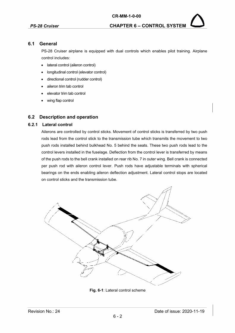
PS-28 Cruiser
CR-MM-1-0-00
CHAPTER 6 – CONTROL SYSTEM
Revision No.: 24 Date of issue: 2020-11-19 6 - 2
6.1 General
PS-28 Cruiser airplane is equipped with dual controls which enables pilot training. Airplane
control includes:
lateral control (aileron control)
longitudinal control (elevator control)
directional control (rudder control)
aileron trim tab control
elevator trim tab control
wing flap control
6.2 Description and operation
6.2.1 Lateral control
Ailerons are controlled by control sticks. Movement of control sticks is transferred by two push
rods lead from the control stick to the transmission tube which transmits the movement to two
push rods installed behind bulkhead No. 5 behind the seats. These two push rods lead to the
control levers installed in the fuselage. Deflection from the control lever is transferred by means
of the push rods to the bell crank installed on rear rib No. 7 in outer wing. Bell crank is connected
per push rod with aileron control lever. Push rods have adjustable terminals with spherical
bearings on the ends enabling aileron deflection adjustment. Lateral control stops are located
on control sticks and the transmission tube.
Fig. 6-1: Lateral control scheme

CR-MM-1-0-00
PS-28 Cruiser CHAPTER 6 – CONTROL SYSTEM
Date of issue: 2011-03-08 Revision No.: - 6 - 3
6.2.2 Longitudinal control
The elevator is controlled by control sticks. Movement of control sticks is transferred by system
of transmission levers and push rods to the elevator. Forward and backward movement of the
control stick is transferred by the push rod lead through the central channel between seats to
the two-arm lever which is located under the baggage floor. Lever deflection is transferred to the
movement of the push rods in the rear part of fuselage to the elevator. Push rods have adjustable
terminals with spherical bearings on the ends enabling elevator deflection adjustment.
Fig. 6-2: Longitudinal control scheme
6.2.3 Directional control
The rudder control is controlled by means of foot control pedals. Pedal deflections of foot control
are transferred by means of steel cables to the rudder. Steel cables are lead through middle
channel of the fuselage. Cable ends are bent over the pulleys installed on bulkhead No. 12 and
attached to the rudder control lever installed on root rudder rib. Other cable end is connected
with foot control pedals.
Foot control pedals are setting to three positions (back, middle and front) by means of control
lever PEDAL SETTING located on the side wall of fuselage under instrument panel.

PS-28 Cruiser
CR-MM-1-0-00
CHAPTER 6 – CONTROL SYSTEM
Revision No.: - Date of issue: 2011-03-08 6 - 4
Fig. 6-3: Directional control scheme
6.2.4 Elevator and aileron trim tab control
The elevator and aileron trim tabs are controlled by the electrical actuators installed in
elevator/right aileron and connected per threaded rod with trim tab. Control switches are
integrated part of grips. Trim tabs position is displayed either on the two separate indicators or
on the EFIS.
Fig. 6-4: Trim tabs control scheme

CR-MM-1-0-00
PS-28 Cruiser CHAPTER 6 – CONTROL SYSTEM
Date of issue: 2011-03-08 Revision No.: - 6 - 5
6.2.5 Wing flap control
Wing flaps are controlled by electric flaps actuator connected with flaps per torque tube with
control pins on each end. The flaps actuator located in fuselage under floor of baggage space
and is controlled by a rocker switch located in cockpit. A LED position indicator is installed
together with the rocker switch (with positions FLAPS DOWN, FLAPS UP) on the middle
channel under instrument panel. It is possible to set the wing flaps to whatever position from 0°
to 30°.
Fig. 6-5: Wing flap control scheme

PS-28 Cruiser
CR-MM-1-0-00
CHAPTER 6 – CONTROL SYSTEM
Revision No.: 22 Date of issue: 2018-09-27 6 - 6
6.3 Removal / Installation
6.3.1 General principles for work on control system
Push rod assembly
Type of maintenance: heavy
Authorization to perform:
See point 2.5.3.
Tools needed:
wrench size 7/16 in
Set the push rods to the prescribed length before assembling, tighten the nuts slightly, and do
not secure them for the time being. It is necessary to keep the following principles:
a) Terminal thread must overlap the inspection hole in the push rod
b) Terminals of all push rods must be uniformly screwed for setting the neutral position
that serve for adjustment of control.
Grease bearings with lubricant grease before installing the push rods into airplane unless
otherwise stated by the bearing manufacturer. Do not grease nor rinse the bearings with
permanent filing that are covered by metal or plastic covers. Do not rinse bearings and
articulated joints with technical gasoline. Mechanically remove contaminated lubricant grease
carefully and refill the clean one.
Orientation of bolts and cotter pins
Put the bolts to the joint on the basis of “top-down” rule or “From the front to the back" with
regard to the flight direction. This rule decreases possibility of spontaneous bolt falling out of the
clamp joint in case that nut unlocking and falling out occurs in the course of operation. Follow
the same rule also in case of securing nuts by securing pins or by cotter pins, with the exception
of those cases when it is not possible to install the bolt for design or operation limitation reasons.
Lubrication
At assembling parts grease al joints and friction surfaces (bolts, pins, and threads) after
mechanical or chemical cleaning by lubricant grease.
6.3.2 Control stick removal
Type of maintenance: heavy
Authorization to perform:
See point 2.5.3.
Tools needed:
wrench size 7/16 in, 3/8 in
cutting pliers
a) Unscrew the nut (6, Fig. 6-7), remove the washers (7), bolt (5) and disconnect the elevator
control rod (26) and fork on the transmission tube (1).

CR-MM-1-0-00
PS-28 Cruiser CHAPTER 6 – CONTROL SYSTEM
Date of issue: 2018-09-27 Revision No.: 22 6 - 7
b) Unscrew the nuts (17), remove the washers (18) and disconnect the aileron control rods (4)
from sticks (2); remove the cases (19).
c) Remove the grips (3) and disconnect wires (24) for trim tab switches and PTT on the grips.
d) Remove the cotter pins (16), unscrew the nuts (13), remove the washers (14), bolts (12) and
washers (15).
e) Carefully remove the control sticks assembly from the cockpit.
f) Remove the cotter pin (23), unscrew the nut (21), remove the washers (22) and bolt (20);
turn the stick (2) 90 degree and remove it from the transmission tube (1).
6.3.3 Control stick installation
Type of maintenance: heavy
Authorization to perform:
See point 2.5.3.
Tools needed:
- wrench size 7/16 in, 3/8 in
- pliers
a) Put the stick (2, Fig. 6-7) in the transmission tube (1).
b) Turn the stick (2) 90 degree and insert the bolt (20) with the washer (22) into the transmission
tube (1) and stick (2), insert the washers (22), screw and carefully tighten the nut (21).
c) Secure the nut (21) with the new cotter pin (23).
d) Put the control stick assembly with the washers (17) between the brackets (25).
e) Insert the bolts (12) into the holes, insert the washers (14), screw and carefully tighten the
nuts (13).
f) Secure the nuts (13) with the new cotter pin (16).
g) Connect the wires (24) for trim tab switches and PTT on the grips (3); install grips (see Wiring
Manual).
h) On the control sticks screw insert the cases (19), aileron rods (4), and washers (18), screw
and tighten the nuts (17).
i) Put the control rod (26) to the fork on the transmission tube (1), insert the bolt (5) with washer
(7) into the hole, insert the washer (7), screw and carefully tighten the nut (6).
j) Check aileron and elevator deflections (see 6.4.3) and check plays in control (see 6.4.1).
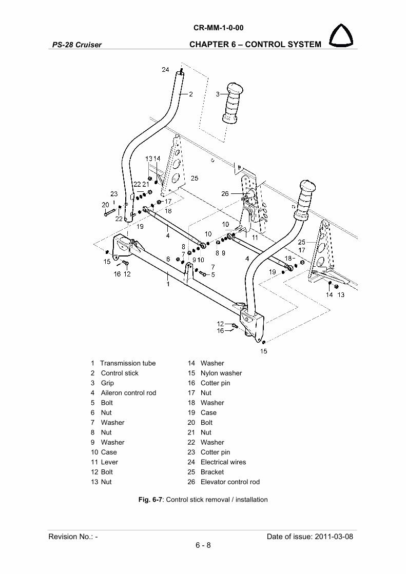
PS-28 Cruiser
CR-MM-1-0-00
CHAPTER 6 – CONTROL SYSTEM
Revision No.: - Date of issue: 2011-03-08 6 - 8
1 Transmission tube 14 Washer
2 Control stick 15 Nylon washer
3 Grip 16 Cotter pin
4 Aileron control rod 17 Nut
5 Bolt 18 Washer
6 Nut 19 Case
7 Washer 20 Bolt
8 Nut 21 Nut
9 Washer 22 Washer
10 Case 23 Cotter pin
11 Lever 24 Electrical wires
12 Bolt 25 Bracket
13 Nut 26 Elevator control rod
Fig. 6-7: Control stick removal / installation

CR-MM-1-0-00
PS-28 Cruiser CHAPTER 6 – CONTROL SYSTEM
Date of issue: 2018-09-27 Revision No.: 22 6 - 9
6.3.4 Flap control actuator removal
Type of maintenance: line
Authorization to perform:
See point 2.5.3.
Tools needed:
- wrench size 7/16 in, 1/2 in,
- screwdriver
a) Set the flap to the landing position; switch off electrical power of the airplane.
b) Open the cover behind the left seat on the floor of baggage space.
c) Disconnect flap actuator wire (2, Fig. 6-8).
d) Remove the cotter pin (9), unscrew the nut (7), remove the washer (8), bolt (6) and
disconnect flap arm (11) from the flap actuator (1).
e) Unscrew the nut (4), remove the washer (5), bolt (3), and disconnect actuator (1) from the
actuator hinge (10).
f) Remove the flap actuator (1).
Fig. 6-8: Flap control actuator removal / installation
1 Flap actuator
2 Actuator wire
3 Bolt
4 Nut
5 Washer
6 Bolt
7 Nut
8 Washer
9 Cotter pin
For information:
10 Actuator hinge
11 Flap control arm

PS-28 Cruiser
CR-MM-1-0-00
CHAPTER 6 – CONTROL SYSTEM
Revision No.: 22 Date of issue: 2018-09-27 6 - 10
6.3.5 Flap control actuator installation
Type of maintenance: line
Authorization to perform:
See point 2.5.3.
Tools needed:
- wrench size 7/16 in, 1/2 in,
- screwdriver
a) Fit the flap actuator (1, Fig. 6-8) to the actuator hinge (10), insert the bolt (3) to the hole,
install the washer (5), screw and tighten the nut (4).
b) Fit the actuator rod to the flap arm (11), insert the bolt (6) to the hole, install washer (8),
screw and slightly tighten the nut (7).
c) Secure the nut (7) with the new cotter pin (9).
d) Connect the actuator wire (2) (see Wiring Manual).
e) Check the flap operation and deflections (see 6.4.3).
f) Install the cover on the floor of baggage space.
6.3.6 Trim tab control actuator removal
Type of maintenance: heavy
Authorization to perform:
See point 2.5.3.
Tools needed:
- wrench size No.5
- screwdriver
- cutting pliers, pliers
- electric drill, drill diam. 3.2 mm (1/8 in)
NOTE: The trim tab control actuator is located in the elevator and the right aileron.
a) Drill out the rivets (11, Fig. 6-9) and remove the cover (10) from the access hole.
b) Disconnect the trim tab actuator wires (2).
c) Remove the cotter pin (9), washers (8), pin (7) and disconnect the actuator rod (5) from the
trim tab control lever (12).
d) Unscrew the nuts (4), remove washers (5) and carefully remove the actuator (1) from the
elevator or aileron through access hole.
e) As requirement, remove the cotter pin (9), wasters (8), pin (7) and disconnect the actuator
rod (5) from the actuator (1).
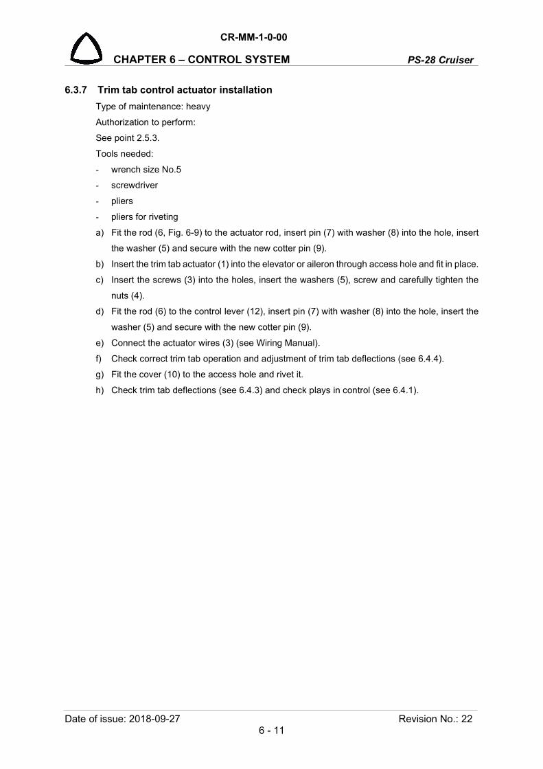
CR-MM-1-0-00
PS-28 Cruiser CHAPTER 6 – CONTROL SYSTEM
Date of issue: 2018-09-27 Revision No.: 22 6 - 11
6.3.7 Trim tab control actuator installation
Type of maintenance: heavy
Authorization to perform:
See point 2.5.3.
Tools needed:
- wrench size No.5
- screwdriver
- pliers
- pliers for riveting
a) Fit the rod (6, Fig. 6-9) to the actuator rod, insert pin (7) with washer (8) into the hole, insert
the washer (5) and secure with the new cotter pin (9).
b) Insert the trim tab actuator (1) into the elevator or aileron through access hole and fit in place.
c) Insert the screws (3) into the holes, insert the washers (5), screw and carefully tighten the
nuts (4).
d) Fit the rod (6) to the control lever (12), insert pin (7) with washer (8) into the hole, insert the
washer (5) and secure with the new cotter pin (9).
e) Connect the actuator wires (3) (see Wiring Manual).
f) Check correct trim tab operation and adjustment of trim tab deflections (see 6.4.4).
g) Fit the cover (10) to the access hole and rivet it.
h) Check trim tab deflections (see 6.4.3) and check plays in control (see 6.4.1).
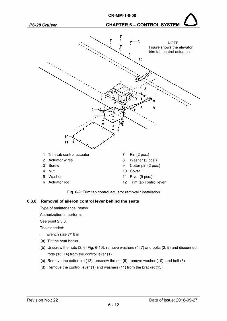
PS-28 Cruiser
CR-MM-1-0-00
CHAPTER 6 – CONTROL SYSTEM
Revision No.: 22 Date of issue: 2018-09-27 6 - 12
1 Trim tab control actuator 7 Pin (2 pcs.)
2 Actuator wires 8 Washer (2 pcs.)
3 Screw 9 Cotter pin (2 pcs.)
4 Nut 10 Cover
5 Washer 11 Rivet (9 pcs.)
6 Actuator rod 12 Trim tab control lever
Fig. 6-9: Trim tab control actuator removal / installation
6.3.8 Removal of aileron control lever behind the seats
Type of maintenance: heavy
Authorization to perform:
See point 2.5.3.
Tools needed:
- wrench size 7/16 in
(a) Tilt the seat backs.
(b) Unscrew the nuts (3; 6, Fig. 6-10), remove washers (4; 7) and bolts (2; 5) and disconnect
rods (13; 14) from the control lever (1).
(c) Remove the cotter pin (12), unscrew the nut (9), remove washer (10), and bolt (8).
(d) Remove the control lever (1) and washers (11) from the bracket (15)
.
NOTE Figure shows the elevator trim tab control actuator.
CR-MM-1-0-00
PS-28 Cruiser CHAPTER 6 – CONTROL SYSTEM
Date of issue: 2018-09-27 Revision No.: 22 6 - 13
6.3.9 Installation of aileron control lever behind the seats
Type of maintenance: heavy
Authorization to perform:
See point 2.5.3.
Tools needed:
- wrench size 7/16 in
(a) Check condition of the control lever and lubrication of the friction surfaces. If the friction
surfaces are contaminated, then carefully remove contamination and grease them with
lubricant (see 2.6).
(b) Fit the control lever (1, Fig. 6-10) with the nylon washers (11) to the bracket (15), insert the
bolt (8) to the hole, install washer (10), screw and slightly tighten the nut (9).
(c) Secure the nut (9) with the new cotter pin (12).
NOTE: The control lever must not show axial play after installing and its travel must be continuous without dragging.
(d) Fit the rods (13; 14) to the control lever (1), insert the bolts (2; 5) with the first washers (4;
7) to the holes, install the second washers (4; 7), screw and tighten the nuts (3; 6).
(e) Tilt the seat backs to backwards.
(f) Check aileron deflections (see 6.4.3) and check plays in control (see 6.4.1).

PS-28 Cruiser
CR-MM-1-0-00
CHAPTER 6 – CONTROL SYSTEM
Revision No.: 22 Date of issue: 2018-09-27 6 - 14
1 Two-arm lever 9 Nut
2 Bolt 10 Washer
3 Nut 11 Nylon washer
4 Washer 12 Cotter pin
5 Bolt 13 Control rod I
6 Nut 14 Control rod II
7 Washer For information:
8 Bolt 15 Bracket
Fig. 6-10: Aileron control lever behind the seats removal / installation
6.3.10 Removal of aileron control bell crank in the wing
Type of maintenance: heavy
Authorization to perform:
See point 2.5.3.
Tools needed:
- wrench size 7/16 in
- screwdriver
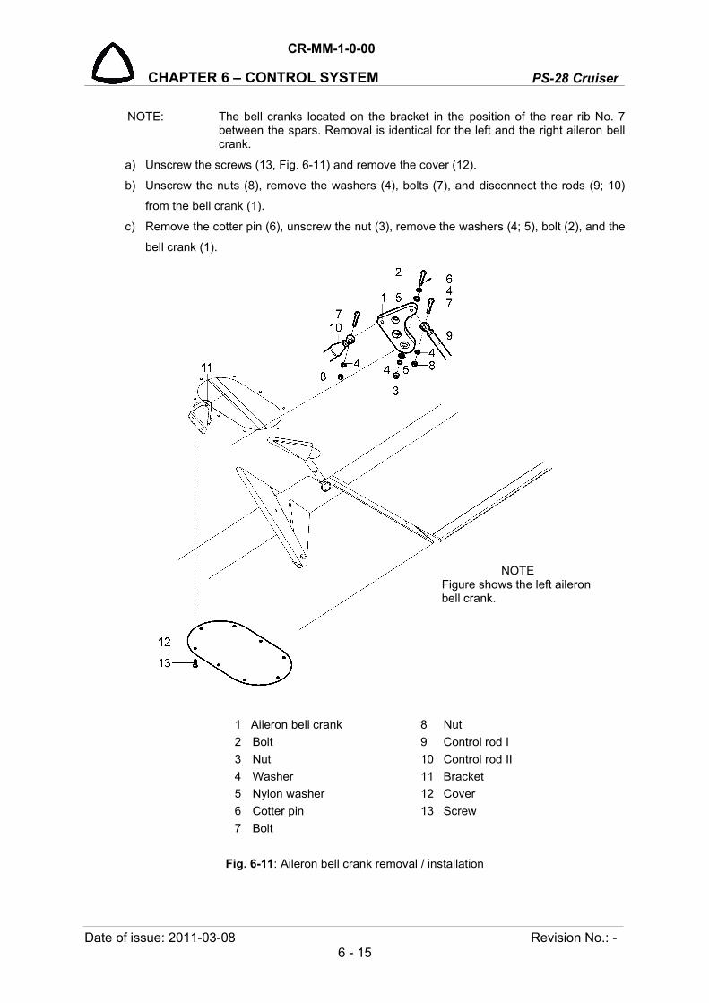
CR-MM-1-0-00
PS-28 Cruiser CHAPTER 6 – CONTROL SYSTEM
Date of issue: 2011-03-08 Revision No.: - 6 - 15
NOTE: The bell cranks located on the bracket in the position of the rear rib No. 7 between the spars. Removal is identical for the left and the right aileron bell crank.
a) Unscrew the screws (13, Fig. 6-11) and remove the cover (12).
b) Unscrew the nuts (8), remove the washers (4), bolts (7), and disconnect the rods (9; 10)
from the bell crank (1).
c) Remove the cotter pin (6), unscrew the nut (3), remove the washers (4; 5), bolt (2), and the
bell crank (1).
1 Aileron bell crank 8 Nut
2 Bolt 9 Control rod I
3 Nut 10 Control rod II
4 Washer 11 Bracket
5 Nylon washer 12 Cover
6 Cotter pin 13 Screw
7 Bolt
Fig. 6-11: Aileron bell crank removal / installation
NOTE Figure shows the left aileron bell crank.
PS-28 Cruiser
CR-MM-1-0-00
CHAPTER 6 – CONTROL SYSTEM
Revision No.: 22 Date of issue: 2018-09-27 6 - 16
6.3.11 Installation of aileron control bell crank in the wing
Type of maintenance: heavy
Authorization to perform:
See point 2.5.3.
Tools needed:
- wrench size 7/16 in
- screwdriver
NOTE: Installation is identical for the left and the right aileron bell crank.
a) Check condition and lubrication of bell crank bearings. If the bearings are contaminated,
then carefully eliminate the contamination and grease them with lubricant (see 2.6).
b) Fit the bell crank (1, Fig. 6-11) with the nylon washers (5) to the bracket (11), insert the bolt
(8) with the first washer (4) to the hole, install the second washer (4), screw and slightly
tighten the nut (3).
c) Secure the nut (3) with the new cotter pin (6).
NOTE: The bell crank must not show axial play after installing and its travel must be continuous without dragging.
d) Fit the rods (9; 10) to the bell crank, insert the bolts (7) to the holes, install the washers (4),
screw and tighten the nuts (8).
e) Check aileron deflections (see 6.4.3) and check plays in control (see 6.4.1).
6.3.12 Removal of two-arm levers in the fuselage
Type of maintenance: heavy
Authorization to perform:
- See point 2.5.3.
- Tools needed:
- wrench size 7/16 in
- screwdriver
- pliers
6.3.12.1 Removal of the front two-arm lever
a) Remove the cover on the floor of baggage compartment.
b) Unscrew the nuts (5, Fig. 6-12), remove washers (6) and bolts (4) and disconnect rods (12;
13) from the control lever (1).
c) Remove the cotter pin (11), unscrew the nut (8), remove washer (9), and bolt (7).
d) Remove the control lever (1) and washers (10) from the bracket (16).

CR-MM-1-0-00
PS-28 Cruiser CHAPTER 6 – CONTROL SYSTEM
Date of issue: 2018-09-27 Revision No.: 22 6 - 17
6.3.12.2 Removal of the middle two-arm lever
(a) Remove the front cover (between bulkheads No. 8 and 9) at the bottom of the fuselage
rear part.
(b) Unscrew the nuts (5, Fig. 6-12), remove washers (6) and bolts (4) and disconnect rods
(13; 14) from the control lever (2).
(c) Remove the cotter pin (11), unscrew the nut (8), remove washer (9), and bolt (7).
(d) Remove the control lever (2) and washers (10) from the bracket (17).
6.3.12.3 Removal of the rear two-arm lever
(a) Remove the rear cover (between bulkheads No. 10 and 11) at the bottom of the fuselage
rear part.
(b) Unscrew the nuts (5, Fig. 6-12), remove washers (6) and bolts (4) and disconnect rods
(14; 15) from the control lever (3).
(c) Remove the cotter pin (11), unscrew the nut (8), remove washer (9), and bolt (7).
(d) Remove the control lever (3) and washers (10) from the bracket (18).
6.3.13 Installation of two-arm levers in the fuselage
Type of maintenance: heavy
Authorization to perform:
See point 2.5.3.
Tools needed:
- wrench size 7/16 in
- screwdriver
- pliers
6.3.13.1 Installation of front two-arm lever
(a) Check condition of the control lever and lubrication of the friction surfaces. If the friction
surfaces are contaminated, then carefully remove contamination and grease them with
lubricant (see 2.6).
(b) Fit the control lever (1, Fig. 6-12) with the nylon washers (10) to the bracket (16), insert the
bolt (7) to the hole, install washer (9), screw and slightly tighten the nut (8).
(c) Secure the nut (8) with the new cotter pin (11).
NOTE: The lever after installing must not show axial play and its travel must be smooth without dragging.
(d) Fit the rods (12; 13) to the control lever (1), insert the bolts (4) with the first washers (6) to
the holes, install the second washers (6), screw and tighten the nuts (5).
(e) Check elevator deflections (see 6.4.3) and check plays in control (see 6.4.1).
PS-28 Cruiser
CR-MM-1-0-00
CHAPTER 6 – CONTROL SYSTEM
Revision No.: - Date of issue: 2011-03-08 6 - 18
6.3.13.2 Installation of middle two-arm lever
(a) Check condition of the control lever and lubrication of the friction surfaces. If the friction
surfaces are contaminated, then carefully remove contamination and grease them with
lubricant (see 2.6).
(b) Fit the control lever (2, Fig. 6-12) with the nylon washers (10) to the bracket (17), insert the
bolt (7) to the hole, install washer (9), screw and slightly tighten the nut (8).
(c) Secure the nut (8) with the new cotter pin (11).
NOTE: The lever after installing must not show axial play and its travel must be smooth without dragging.
(d) Fit the rods (13; 14) to the control lever (2), insert the bolts (4) with the first washers (6) to
the holes, install the second washers (6), screw and tighten the nuts (5).
(e) Check elevator deflections (see 6.4.3) and check plays in control (see 6.4.1).
6.3.13.3 Installation of rear two-arm lever
(a) Check condition of the control lever and lubrication of the friction surfaces. If the friction
surfaces are contaminated, then carefully remove contamination and grease them with
lubricant (see 2.6).
(b) Fit the control lever (3, Fig. 6-12) with the nylon washers (10) to the bracket (18), insert the
bolt (7) to the hole, install washer (9), screw and slightly tighten the nut (8).
(c) Secure the nut (8) with the new cotter pin (11).
NOTE: The lever after installing must not show axial play and its travel must be smooth without dragging.
(d) Fit the rods (14; 15) to the control lever (3), insert the bolts (4) with the first washers (6) to
the holes, install the second washers (6), screw and tighten the nuts (5).
(e) Check elevator deflections (see 6.4.3) and check plays in control (see 6.4.1).
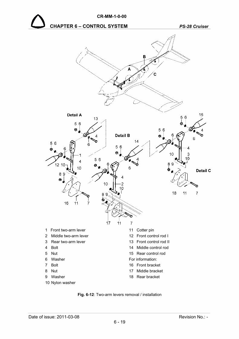
CR-MM-1-0-00
PS-28 Cruiser CHAPTER 6 – CONTROL SYSTEM
Date of issue: 2011-03-08 Revision No.: - 6 - 19
1 Front two-arm lever 11 Cotter pin
2 Middle two-arm lever 12 Front control rod I
3 Rear two-arm lever 13 Front control rod II
4 Bolt 14 Middle control rod
5 Nut 15 Rear control rod
6 Washer For information:
7 Bolt 16 Front bracket
8 Nut 17 Middle bracket
9 Washer 18 Rear bracket
10 Nylon washer
Fig. 6-12: Two-arm levers removal / installation

PS-28 Cruiser
CR-MM-1-0-00
CHAPTER 6 – CONTROL SYSTEM
Revision No.: 2 Date of issue: 2011-11-08 6 - 20
6.3.14 INTENTIONALLY LEFT BLANK
6.3.15 INTENTIONALLY LEFT BLANK
6.4 Check / Adjustment
6.4.1 Check of play in control
Admissible plays in control are mentioned in the following table:
Control Admissible play Area to measure play
longitudinal max 4 mm (5/32 in) at the end of the control stick in longitudinal axis of the airplane
lateral max 4 mm (5/32 in) at the end of the control stick in lateral axis of the airplane
directional max 4.8 mm (3/16 in) on pedals in longitudinal axis of the airplane
trim tabs max 3.2 mm (1/8 in) at the end of the trim tab
wing flaps max 3.2 mm (1/8 in) at the end of the wing flap
CAUTION: IF THE MEASURED PLAYS EXCEED VALUES MENTIONED IN THE TABLE THEN ELIMINATE THE CAUSE OF IT AND REPEAT MEASURING.
Measuring procedure
a) Measure all plays three times and write down average values.
b) Perform measuring with the blocked control surfaces. Before measuring it is necessary to push
down the control surface by hand several times (max force of 5 kg (11 lbs) in the direction of the
control surface deflection, so that the control system is unblocked and plays can be more easily
identified.
c) Push on the control stick or the pedal by force of 3 kg (6.6 lbs). Deflect the controlling element to
one side and read the deflection. Then push the control stick to the other side and read the
deflection. Sum of deflections presents plays in control.
Longitudinal control
Measure play at the end of the control stick at the blocked elevator in the neutral position. The
total play must not exceed 4 mm (5/32 in) at the end of the control stick (see Fig. 6-15).
Fig. 6-15: Play in longitudinal control

CR-MM-1-0-00
PS-28 Cruiser CHAPTER 6 – CONTROL SYSTEM
Date of issue: 2011-11-08 Revision No.: 2 6 - 21
Lateral control
Measure play at the end of the control stick by the measuring instrument from the fuselage side
at blocked ailerons in the neutral position. First block the right aileron and measure play on the
control stick, then measure play at the blocked left aileron. Total play of the control stick must
not exceed 4 mm (5/32 in) at the end of the control stick.
Play in foot control pedals
Measure play at the end of pedals by the measuring instrument from the inner wall of the
bulkhead No.1 at the blocked rudder at neutral position. Mutual total play between pedals must
not exceed 4.8 mm (3/16 in) on the pedal tube.
Play in trim tab control
Measure play in elevator neutral position. Set the balance tab to position “max on head" and
measure play at the end of the trim tab. Max play of the trim tab measured at the end of the
trailing edge must not exceed 3.2 mm (1/8 in).
Play in wing flap control
Measure play in individual position of wing flaps (0°, 10°, 20° and 30°). Set the flap actuator to
individual positions. Measure play in wing flap control on the wing flap trailing edge. Max play of
the wing flap measured on the trailing edge must not exceed 4.8 mm (3/16 in).
6.4.2 Check of friction in control system
Control system must function smoothly within the whole scope of deflections. There must not be
excessive friction or hitching in the control system. In case of failure detection, find out the cause
and eliminate the defect.
Friction in the longitudinal control system
a) Balance elevator through the pulley to get it to neutral position.
b) Measure force by the dynamometer attached on the end of the control stick. Move the
control stick from fully forward position to neutral and measure force. Then slowly move
stick forward and measure force. Substract forces from each other. Max. force can be
0.9 kg (2 lbs).
Friction in lateral control system
a) Set ailerons to neutral position.
b) Measure force at the moment od aileron deflection from neutral position by the
dynamometer attached on the end of the control stick. Max. force can be 0.6 kg
(1.3 lbs).
Friction in directional control system
a) Pushing move the rudder to max. L / R position.
b) Slowly move the rudder back to neutral position. Maximal permissible residual deflection of
the rudder is on edge of central covering sheet (see Fig. 6-16).
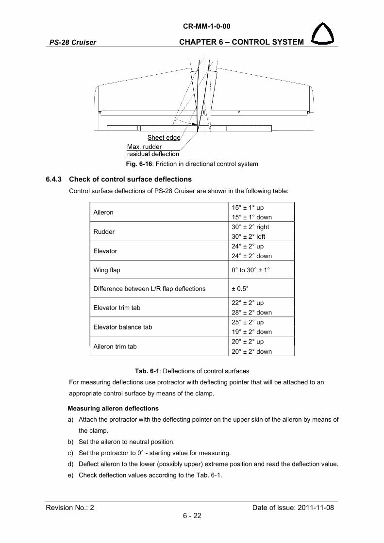
PS-28 Cruiser
CR-MM-1-0-00
CHAPTER 6 – CONTROL SYSTEM
Revision No.: 2 Date of issue: 2011-11-08 6 - 22
Fig. 6-16: Friction in directional control system
6.4.3 Check of control surface deflections
Control surface deflections of PS-28 Cruiser are shown in the following table:
Aileron 15° ± 1° up
15° ± 1° down
Rudder 30° ± 2° right
30° ± 2° left
Elevator 24° ± 2° up
24° ± 2° down
Wing flap 0° to 30° ± 1°
Difference between L/R flap deflections ± 0.5°
Elevator trim tab 22° ± 2° up
28° ± 2° down
Elevator balance tab 25° ± 2° up
19° ± 2° down
Aileron trim tab 20° ± 2° up
20° ± 2° down
Tab. 6-1: Deflections of control surfaces
For measuring deflections use protractor with deflecting pointer that will be attached to an
appropriate control surface by means of the clamp.
Measuring aileron deflections
a) Attach the protractor with the deflecting pointer on the upper skin of the aileron by means of
the clamp.
b) Set the aileron to neutral position.
c) Set the protractor to 0° - starting value for measuring.
d) Deflect aileron to the lower (possibly upper) extreme position and read the deflection value.
e) Check deflection values according to the Tab. 6-1.

CR-MM-1-0-00
PS-28 Cruiser CHAPTER 6 – CONTROL SYSTEM
Date of issue: 2011-11-08 Revision No.: 2 6 - 23
Measuring wing flap deflections
a) Attach the protractor with the deflecting pointer on the upper flap skin by means of the clamp.
b) Set the wing flap to the 0°position.
c) Set the protractor to 0° - starting value of measuring.
d) Extend the flaps by means of the flap actuator to individual positions and read the deflection.
e) Check deflection values according to the Tab. 6-1.
Measuring elevator deflections
a) Set the protractor with the deflecting pointer on the trailing edge of the elevator by means of
the clamps.
b) Set the elevator to neutral position.
c) Set the protractor to 0° - starting value of measuring.
d) Deflect the elevator to extreme positions by means of the control stick and read the
deflection.
e) Check values of deflections according to the Tab. 6-1.
Measuring rudder deflections
The airplane manufacturer uses a special jig for measuring rudder deflections that is slid on the
vertical tail unit and it is possible directly to read the rudder deflection. If you do not have this
special jig, use the alternative procedure:
a) Set the rudder to neutral position.
b) Put the rod to the trailing edge of the rudder and mark the lower margin of the rudder trailing
edge.
c) Deflect the rudder to extreme positions and with the rule measure distance from the sign to
the lower margin of the rudder trailing edge.
d) Calculate angle and compare it with the value mentioned in the Tab. 6-1.
Measuring trim tab deflections
a) Set the protractor with the deflecting pointer to the trailing edge of the trim tab by means of
the clamp.
b) Set the trim tab to neutral position.
c) Set the protractor to 0° - starting value of measuring.
d) By means of the trim control actuator deflect the trim tab to extreme positions and read the
deflection.
e) Check values of deflections according to the Tab. 6-1.
6.4.4 Adjustment of control surface deflections
Adjustment of control surface deflections to be made to the values showed in the Tab. 6-1. At
adjusting the airplane control, neutral position of the control surfaces is taken as the starting
point.
CAUTION: AFTER ADJUSTMENT OF CONTROL SURFACE DEFLECTIONS CHECK, IF THE END PIECES ARE SEEN THROUGH THE INSPECTION HOLE OF CONTROL RODS.
PS-28 Cruiser
CR-MM-1-0-00
CHAPTER 6 – CONTROL SYSTEM
Revision No.: 2 Date of issue: 2011-11-08 6 - 24
Adjusting aileron deflections
a) Aileron deflections up and down (different) are adjusted at the manufacturer.
b) For re-adjustment of the aileron neutral position:
- Set control sticks to neutral position;
- Through the adjustment of the end piece of the end control rod - set the left aileron to
the neutral position.
- Through the adjustment of the end piece of the end control rod - set the right aileron to
the neutral position.
c) Adjust the range of deflections (if applicable) through the stops at control sticks.
Adjusting wing flap deflections
Wing flap deflections are given by the torque tube and actuator positioning in the fuselage. It is
not possible to adjust flap deflection outside manufacturing company.
Adjust flap deflections through eccentric parts of pins.
Adjusting elevator deflections
Range of elevator deflections is given by setting the push rod terminals in the fuselage. At
adjusting elevator deflections, proceed as follows:
a) Remove the chosen push rod from the bell crank.
b) Adjust the upper deflection as needed by means of the push rod terminal (or by means of
push rod terminal on the elevator lever).
c) Put push rod end back and check if the deflections corresponds to the values mentioned in
the Tab. 6-1.
Adjusting rudder deflections
Rudder deflections are given by setting the stops on the rudder control lever installed on root
rudder rib.
a) Set the foot control pedals to neutral position and check if the rudder is in the neutral position.
b) Carry out correction of rudder deflection setting by adjusting the turnbuckles on the foot
pedal side in cockpit.
Adjusting trim tab deflections
Trim tab deflections are given by control actuator and they are fixed.
6.4.5 Checking condition of rudder control cables.
a) Carefully inspect the control cable especially on the following areas:
in the area of cable attachment on the rudder control pedals
in the area of cable attachment on rudder lever
in the area of cable inlet on rear fuselage
b) Check for the following defects on the cable:
burst cable wires
CR-MM-1-0-00
PS-28 Cruiser CHAPTER 6 – CONTROL SYSTEM
Date of issue: 2011-11-08 Revision No.: 2 6 - 25
evidence of sleeves deformation and damage on cable surface
evidence of cable corrosion
cable distortion
c) Exchange the cable in cases as follows:
broken any wire
wear of cable surface resulted in permanent deformation of cable section.
it is not possible to set the rudder to neutral position (see 6.4.4)
d) Check rudder deflections (see 6.4.3).
6.5 Exchanges / Service information
6.5.1 Rudder control cable exchange
a) Remove the lockwire from the turnbuckle (4; 5; 6, Fig. 6-17).
b) Cut the control cable (1) in the cockpit behind the rudder pedals.
c) Remove the cotter pin (15), unscrew the nut (13), remove the washer (14), bolt (12) and
disconnect the cable shackle (11) from the rudder lever (3).
d) Remove cable on the rudder side from the fuselage.
NOTE: Grease the new cable with lubricant grease before installing it to the fuselage.
e) Insert the new cable (1) from the rudder side into the fuselage.
f) Set Nicopress sleeve (3) on the cable end in cockpit.
g) Bend the cable end in cockpit around the cable thimble (2), insert the turnbuckle eye (4) to
the cable thimble (2), set Nicopress sleeve (3) close to the cable thimble and press
Nicopress sleeve by Nicopress pliers (see 15.10).
h) Connect new cable with turnbuckle (5; 6) installed on rudder pedal (16).
i) Set the rudder and the pedal and secure them in neutral position.
j) Set on rear end of cable thimble (2) and cable shackle (11) and connect cable shackle with
rudder lever (17) by means of the bolt (12).
k) Remove the cable from the rudder lever (17), cut the cable end to fit to the marked length
and by means of Nicopress pliers (see 15.10) install the Nicopress sleeve (3).
l) Fit the cable shackle (11) to the rudder lever (17), insert the bolt (12) to the hole, install
washer (14), screw and slightly tighten the nut (13).
m) Secure the nut (13) with the new cotter pin (15).
n) Check (see 6.4.3) and adjust (see 6.4.4) rudder deflections.
o) Secure the turnbuckle (4; 5; 6) with the lockwire.

PS-28 Cruiser
CR-MM-1-0-00
CHAPTER 6 – CONTROL SYSTEM
Revision No.: 2 Date of issue: 2011-11-08 6 - 26
1 Control cable 10 Cotter pin
2 Cable thimble 11 Cable shackle
3 Nicopress sleeve 12 Bolt
4 Turnbuckle eye 13 Nut
5 Turnbuckle barrel 14 Washer
6 Turnbuckle fork 15 Cotter pin
7 Bolt For information:
8 Nut 16 Rudder pedals
9 Washer 17 Rudder lever
Fig. 6-17: Rudder control cable exchange

CR-MM-1-0-00
PS-28 Cruiser CHAPTER 7 – EQUIPMENT
Date of issue: 2018-09-27 Revision No.: 22 7 - 1
7. EQUIPMENT
Content
7.1 General .................................................................................................................. 7-2
7.2 Description and operation ...................................................................................... 7-2
7.2.1 Seats ..................................................................................................... 7-2
7.2.2 Safety harnesses ................................................................................... 7-2
7.2.3 Ballistic Recovery System ..................................................................... 7-3
7.2.4 Emergency Locator Transmitter ............................................................ 7-3
7.3 Removal / Installation ............................................................................................ 7-4
7.3.1 Seats removal ........................................................................................ 7-4
7.3.2 Safety harnesses removal ..................................................................... 7-4
7.3.3 Safety harnesses installation ................................................................. 7-4
7.3.4 BRS parachute removal ........................................................................ 7-5
7.3.5 BRS parachute installation .................................................................... 7-7
7.3.6 BRS rocket removal............................................................................... 7-7
7.3.7 BRS rocket installation .......................................................................... 7-9
7.3.8 ELT antenna removal ............................................................................ 7-9
7.3.9 ELT antenna installation ...................................................................... 7-10
7.4 Check / Adjustment .............................................................................................. 7-12
7.4.1 Checking of safety harnesses ............................................................. 7-12
7.5 Exchanges / Service information ......................................................................... 7-12
7.5.1 Cleaning seat covers and upholstery .................................................. 7-12
7.5.2 ELT main unit / remote unit battery replacement ................................ 7-12
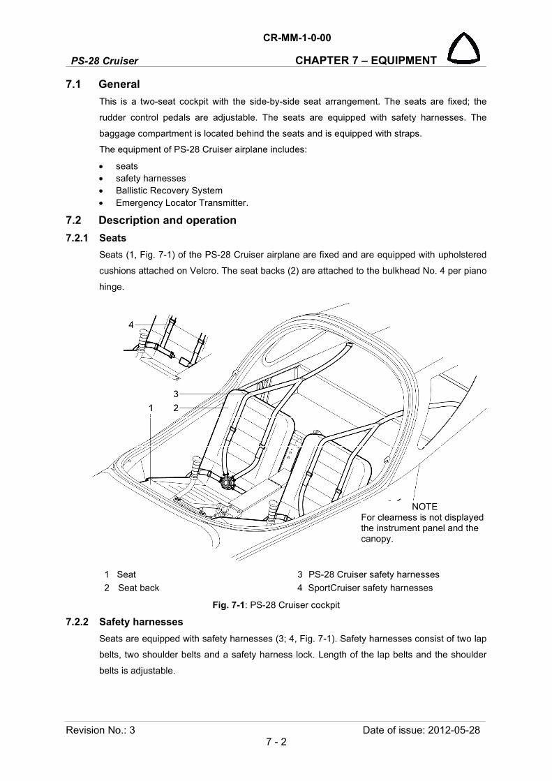
PS-28 Cruiser
CR-MM-1-0-00
CHAPTER 7 – EQUIPMENT
Revision No.: 3 Date of issue: 2012-05-28 7 - 2
7.1 General
This is a two-seat cockpit with the side-by-side seat arrangement. The seats are fixed; the
rudder control pedals are adjustable. The seats are equipped with safety harnesses. The
baggage compartment is located behind the seats and is equipped with straps.
The equipment of PS-28 Cruiser airplane includes:
seats safety harnesses Ballistic Recovery System Emergency Locator Transmitter.
7.2 Description and operation
7.2.1 Seats
Seats (1, Fig. 7-1) of the PS-28 Cruiser airplane are fixed and are equipped with upholstered
cushions attached on Velcro. The seat backs (2) are attached to the bulkhead No. 4 per piano
hinge.
1 Seat 3 PS-28 Cruiser safety harnesses
2 Seat back 4 SportCruiser safety harnesses
Fig. 7-1: PS-28 Cruiser cockpit
7.2.2 Safety harnesses
Seats are equipped with safety harnesses (3; 4, Fig. 7-1). Safety harnesses consist of two lap
belts, two shoulder belts and a safety harness lock. Length of the lap belts and the shoulder
belts is adjustable.
NOTE For clearness is not displayed the instrument panel and the canopy.

CR-MM-1-0-00
PS-28 Cruiser CHAPTER 7 – EQUIPMENT
Date of issue: 2020-11-19 Revision No.: 24 7 - 3
7.2.3 Ballistic Recovery System
The aircraft can be equipped (optional) with BRS emergency parachute system. BRS utilize a manually activated, solid propellant rocket motor to extract a round, non-steerable parachute and recover the aircraft in life-threatening emergency situations. The parachute with harnesses and the rocket are installed aft of the firewall. Activating handle is located on the middle channel.
NOTE: For detailed information refer to Owner's Manual for BRS-6 Emergency Parachute Recovery Systems (Doc. No. 020000-03).
1 Parachute 4 Rear attachment cable
2 Harnesses 5 Handle
3 Rocket
Fig. 7-2: BRS scheme
7.2.4 Emergency Locator Transmitter
The aircraft is equipped with the AK-451 ELT or Kannad 406 AF Compact Emergency Locator Transmitter.
IMPORTANT: The AK-451 ELT model produced, delivered or fitted after 28 December 2015 is not FAA / EASA approved any more. That ELT model is recommended to be replaced. The ELT Kannad 406 AF is an approved replacement.
The ELT is micro controller based, batteries operated and self contained equipment. The ELT is designed only for emergency use. The ELT consists of an ELT main unit with a mounting tray, an aircraft-fixed antenna, remote switch unit, an audible buzzer monitor, and interconnecting cables (see Fig. 7-6).
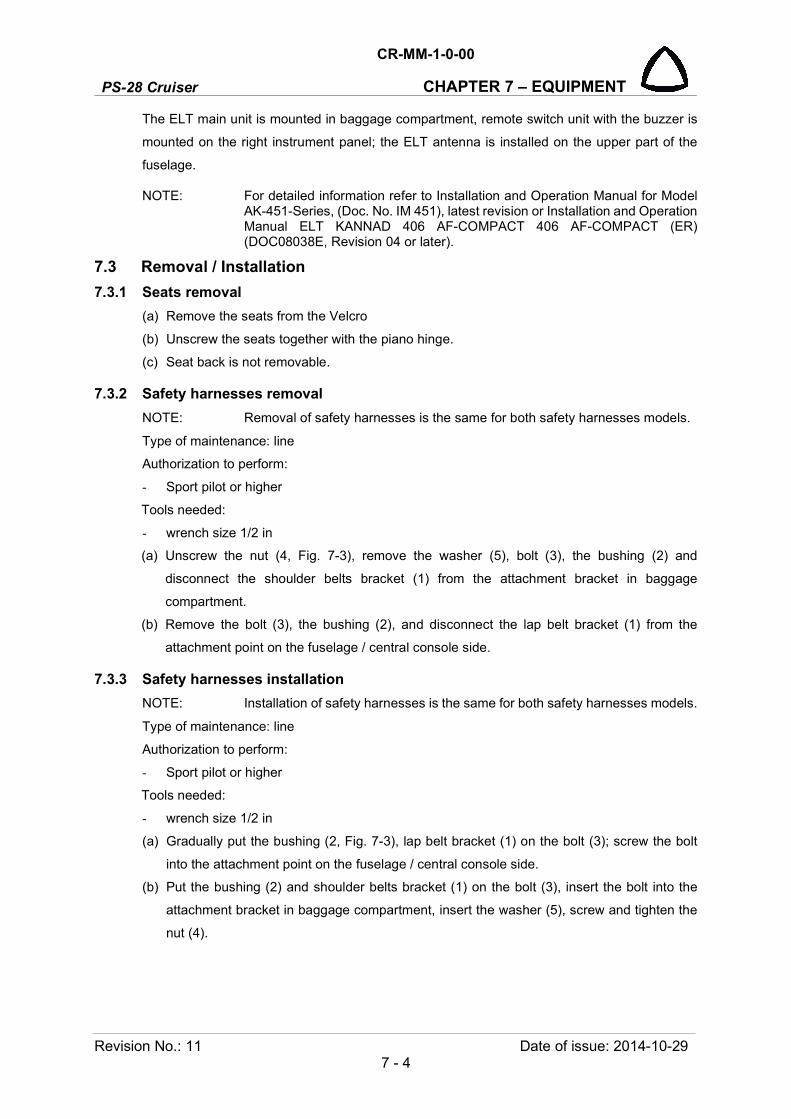
PS-28 Cruiser
CR-MM-1-0-00
CHAPTER 7 – EQUIPMENT
Revision No.: 11 Date of issue: 2014-10-29 7 - 4
The ELT main unit is mounted in baggage compartment, remote switch unit with the buzzer is
mounted on the right instrument panel; the ELT antenna is installed on the upper part of the
fuselage.
NOTE: For detailed information refer to Installation and Operation Manual for Model AK-451-Series, (Doc. No. IM 451), latest revision or Installation and Operation Manual ELT KANNAD 406 AF-COMPACT 406 AF-COMPACT (ER) (DOC08038E, Revision 04 or later).
7.3 Removal / Installation
7.3.1 Seats removal
(a) Remove the seats from the Velcro
(b) Unscrew the seats together with the piano hinge.
(c) Seat back is not removable.
7.3.2 Safety harnesses removal
NOTE: Removal of safety harnesses is the same for both safety harnesses models.
Type of maintenance: line
Authorization to perform:
- Sport pilot or higher
Tools needed:
- wrench size 1/2 in
(a) Unscrew the nut (4, Fig. 7-3), remove the washer (5), bolt (3), the bushing (2) and
disconnect the shoulder belts bracket (1) from the attachment bracket in baggage
compartment.
(b) Remove the bolt (3), the bushing (2), and disconnect the lap belt bracket (1) from the
attachment point on the fuselage / central console side.
7.3.3 Safety harnesses installation
NOTE: Installation of safety harnesses is the same for both safety harnesses models.
Type of maintenance: line
Authorization to perform:
- Sport pilot or higher
Tools needed:
- wrench size 1/2 in
(a) Gradually put the bushing (2, Fig. 7-3), lap belt bracket (1) on the bolt (3); screw the bolt
into the attachment point on the fuselage / central console side.
(b) Put the bushing (2) and shoulder belts bracket (1) on the bolt (3), insert the bolt into the
attachment bracket in baggage compartment, insert the washer (5), screw and tighten the
nut (4).

CR-MM-1-0-00
PS-28 Cruiser CHAPTER 7 – EQUIPMENT
Date of issue: 2018-09-27 Revision No.: 22 7 - 5
1 Attachment bracket 4 Nut
2 Bushing 5 Washer
3 Bolt
Fig. 7-3: Safety harnesses removal / installation
7.3.4 BRS parachute removal
Type of maintenance: heavy
Authorization to perform:
See point 2.5.3.
Tools needed:
- screwdriver, Philips screwdriver
- wrench size No.7
- cutting pliers, pliers
- Allen wrench size 1/8 in, 1/4 in

PS-28 Cruiser
CR-MM-1-0-00
CHAPTER 7 – EQUIPMENT
Revision No.: 1 Date of issue: 2011-07-08 7 - 6
WARNING: UNAUTHORIZED PERSONNEL SHOULD NOT ATTEMPT TO MODIFY, REPAIR, OR DISASSEMBLE BRS SYSTEM AT ANY TIME. DURING ALL SERVICE WORK BEWARE OF ACTIVATING THE BRS ROCKET!
NOTE: BRS parachute must be removed from the aircraft for repacking. This service date is printed on placards located on the side of centre panel and on the parachute.
(a) Carefully unglue the cover over parachute on the canopy fixed frame.
(b) Remove both instrument panels and disconnect all cable and pitot-static connection.
(c) Remove COMM/NAV equipment from the centre panel and disassemble it.
(d) Pull open the front flap of the parachute (1, Fig. 7-4) and expose the small link; unscrew
the link nut and disconnect the rocket lanyards (5).
(e) Carefully remove the BRS rocket (see 7.3.6).
(f) Cut-off cable ties (4) securing link (3) to the tray.
(g) Unscrew the link (3) nut and disconnect the loop of the main brindle (6).
(h) Disengage all four Velcro retaining straps.
(i) Carefully remove parachute (1) from the tray (2).
(j) Repack the parachute by the authorized person.
1 Parachute 4 Cable tie
2 Tray 5 Rocket lanyards
3 Link 6 Main bridle loop
Fig. 7-4: BRS parachute removal / installation

CR-MM-1-0-00
PS-28 Cruiser CHAPTER 7 – EQUIPMENT
Date of issue: 2020-11-19 Revision No.: 24 7 - 7
7.3.5 BRS parachute installation
Type of maintenance: heavy
Authorization to perform:
See point 2.5.3.
Tools needed:
- screwdriver, Philips screwdriver
- wrench size No.7
- cutting pliers, pliers
- Allen wrench size 1/8 in, 1/4 in
WARNING: UNAUTHORIZED PERSONNEL SHOULD NOT ATTEMPT TO MODIFY, REPAIR, OR DISASSEMBLE BRS SYSTEMS AT ANY TIME. DURING ALL SERVICE WORK BEWARE OF ACTIVATING THE BRS ROCKET!
(a) Install the parachute.
(b) Install the BRS rocket (see 7.3.7)
(c) Assemble centre panel and install COMM/NAV equipment.
(d) Connect all cable and pitot-static connection and install both instrument panels.
(e) Glue (by means of the Emfimastic PU 50 sealant) the cover over parachute on the
canopy fixed frame.
(f) Perform pitot-static leak test (see Chapter 12.4.1) and check correct function
appropriate instruments and systems.
7.3.6 BRS rocket removal
Type of maintenance: heavy
Authorization to perform:
See point 2.5.3.
Tools needed:
- screwdriver, Philips screwdriver
- cutting pliers, pliers
- Allen wrench size 1/8 in, 1/4 in
WARNING: UNAUTHORIZED PERSONNEL SHOULD NOT ATTEMPT TO MODIFY, REPAIR, OR DISASSEMBLE BRS SYSTEM AT ANY TIME. DURING ALL SERVICE WORK BEWARE OF ACTIVATING THE BRS ROCKET!
NOTE: BRS rocket motor must be replaced by its date of expiry. This service date is printed on placards located on the side of centre panel and on the rocket.
(a) Carefully unglue the cover over parachute on the canopy fixed frame.
(k) Pull open the front flap of the parachute (16, Fig. 7-5) and expose the small link;
unscrew the link nut and disconnect the rocket lanyards (2).
(b) Cut-off cable ties securing lanyards.

PS-28 Cruiser
CR-MM-1-0-00
CHAPTER 7 – EQUIPMENT
Revision No.: 1 Date of issue: 2011-07-08 7 - 8
WARNING: NEVER POINT ROCKET AT ANYONE. ACCIDENTAL ACTIVATION MAY CAUSE DEATH OR SERIOUS INJURY!
ASSEMBLY MUST BE DONE IN THIS SEQUENCE. IF DONE INCORRECTLY, ACCIDENTAL DISCHARGE OF ROCKET MAY OCCUR AND MAY CAUSE DEATH OR SERIOUS INJURY!
(c) Remove plastic cap (6).
CAUTION: KEEP ALLEN WRENCH VERTICAL. BE CAREFUL NOT LO "LEVER" WRENCH AGAINST SIDE, SO AS TO NOT ACCIDENTLY ACTIVATE ROCKET!
(d) Remove screw (7) with 1/8 Allen wrench.
(e) Unscrew adapter (4) from rocket. Carefully remove housing (3) from rocket by turning
entire housing assembly.
(f) Loose set screws (10).
(g) Carefully remove the BRS rocket.
(h) As necessary, remove right side panel of the middle channel, unscrew the nut (14),
remove the washer (15), bolt (13) and activation housing (3).
Fig. 7-5: BRS rocket removal / installation
1 BRS rocket
2 Rocket lanyards
3 Activation housing
4 Cone adapter
5 Steel cable
6 Plastic cap
7 Screw
8 Star washer
9 Bracket
10 Set screw
11 Rocket pedestal
12 Bracket
13 Bolt
14 Nut
15 Washer
For information:
16 Parachute

CR-MM-1-0-00
PS-28 Cruiser CHAPTER 7 – EQUIPMENT
Date of issue: 2020-11-19 Revision No.: 24 7 - 9
7.3.7 BRS rocket installation
Type of maintenance: heavy
Authorization to perform:
See point 2.5.3.
Tools needed:
- screwdriver, Philips screwdriver
- cutting pliers, pliers
- Allen wrench size 1/8 in, 1/4 in
WARNING: UNAUTHORIZED PERSONNEL SHOULD NOT ATTEMPT TO MODIFY, REPAIR, OR DISASSEMBLE BRS SYSTEM AT ANY TIME. DURING ALL SERVICE WORK BEWARE OF ACTIVATING THE BRS ROCKET!
(a) Carefully unglue the cover over parachute on the canopy fixed frame.
(b) As necessary, install the activation housing (3) to the middle channel; fasten handle by
means of the bolt (13), washer (15) and nut (14); install right side panel of the middle
channel.
(c) Route the housing in a gentle arc to the base on the rocket. The housing cable should
have no abrupt bends.
(d) Install the rocket.
(e) Connect the activation housing to the rocket.
(f) Glue (by means of the Emfimastic PU 50 sealant) the cover over parachute on the
canopy fixed frame.
7.3.8 ELT antenna removal
Type of maintenance: line
Authorization to perform:
See point 2.5.3.
Tools needed:
- wrench No. 3/4 in
(a) Remove the circular cover on the aft wall of the baggage compartment.
(b) Set the MASTER BAT switch to OFF.
(c) Disconnect the connector (2, Fig. 7-6) from the antenna.
(d) Unscrew the nut (5), remove the washer (6) and the antenna (4).
(e) Install the protective cover on the antenna connector.
PS-28 Cruiser
CR-MM-1-0-00
CHAPTER 7 – EQUIPMENT
Revision No.: 22 Date of issue: 2018-09-27 7 - 10
7.3.9 ELT antenna installation
Type of maintenance: line
Authorization to perform:
See point 2.5.3.
Tools needed:
- wrench No. 3/4 in
(a) Remove the protective cover from the antenna connector.
(b) Insert the antenna (4, Fig. 7-6) to the hole in the fuselage upper part (7).
(c) Insert the washer (6), screw and tighten the nut (5) to between 25 to 30 inch lbs.
(d) Connect the connector (2) to the antenna (4).
(e) Install the circular cover on the aft wall of the baggage compartment.
(f) Do an operational test.
IMPORTANT: The AK-451 ELT model produced, delivered or fitted after 28 December
2015 is not FAA / EASA approved any more. That ELT model is recommended to be
replaced. The ELT Kannad 406 AF is an approved replacement.

CR-MM-1-0-00
PS-28 Cruiser CHAPTER 7 – EQUIPMENT
Date of issue: 2014-10-29 Revision No.: 11 7 - 11
1 ELT main unit 5 Nut
2 Cable connector 6 Lockwasher
3 Mounting tray For information:
4 ELT antenna 7 Fuselage upper part
Fig. 7-6: ELT antenna removal / installation
PS-28 Cruiser
CR-MM-1-0-00
CHAPTER 7 – EQUIPMENT
Revision No.: 19 Date of issue: 2017-06-06 7 - 12
7.4 Check / Adjustment
7.4.1 Checking of safety harnesses
Check harnesses surface for any damages. Check the lock system function. Check the
attachment points of shoulder and side harnesses for any damages or corrosion.
7.5 Exchanges / Service information
7.5.1 Cleaning seat covers and upholstery
(a) Take upholstery and covers out of the airplane.
(b) Brush impurities, possibly clean with warm water with addition of a suitable detergent.
(c) Before reinstalling upholstery and seats in the airplane, let it thoroughly dry.
7.5.2 ELT main unit / remote unit battery replacement
ELT AK-451
NOTE: The battery pack has a 5 years useful life or batteries must be replaced when the transmitter has been in use for more than one cumulative hour. This service date is printed on placards located on ELT main unit.
For battery replacement refer to Installation and Operation Manual for Model AK-451-( ) Series,
(Doc. No. IM 451), latest revision.
IMPORTANT: The AK-451 ELT model produced, delivered or fitted after 28 December
2015 is not FAA / EASA approved any more. That ELT model is recommended to be
replaced. The ELT Kannad 406 AF is an approved replacement.
ELT KANNAD 406
The transmitter battery expiry date is fixed at 6 years after manufacturing. If no activation of the
ELT occurs during the battery lifetime, it shall be replaced 6 years after date of manufacture
Battery replacement is mandatory:
• after more than 1 hour of real transmission (cumulated duration); • before or on the battery expiration date; • after use in an emergency; • after an inadvertant activation of unknown duration.
CAUTION: ONLY ORIGINAL AND APPROVED BATTERY PACK INCLUDED IN BATTERY KIT BAT200 (P/N S1840510-01) SUPPLIED BY KANNAD CAN BE INSTALLED. [SAFT-FRIWO , LITHIUM MANGANESE DIOXIDE, 2 X M20 (D-TYPE) CELLS]
For battery replacement refer to Installation and Operation Manual ELT KANNAD 406 AF-COMPACT 406 AF-COMPACT (ER) (DOC08038E, Revision 04 or later).
CR-MM-1-0-00
PS-28 Cruiser CHAPTER 8 – LANDING GEAR
Date of issue: 2018-09-27 Revision No.: 22 8 - 1
8. LANDING GEAR
Content
8.1 General .................................................................................................................. 8-2
8.2 Description and operation ...................................................................................... 8-2
8.2.1 Main landing gear .................................................................................. 8-2
8.2.1.1 Main landing gear wheel ........................................................... 8-3
8.2.2 Nose landing gear ................................................................................. 8-3
8.2.2.1 Nose landing gear wheel ........................................................... 8-4
8.2.3 Brake system ......................................................................................... 8-6
8.2.3.1 Parking brake ............................................................................ 8-6
8.2.4 Wheel fairings ........................................................................................ 8-6
8.3 Removal / Installation ............................................................................................ 8-7
8.3.1 Removal of main wheel fairing .............................................................. 8-7
8.3.2 Installation of main wheel fairing ........................................................... 8-7
8.3.3 Removal of main landing gear wheel .................................................... 8-8
8.3.4 Installation of main landing gear wheel ................................................. 8-9
8.3.5 Removal of nose wheel fairing .............................................................. 8-9
8.3.6 Installation of nose wheel fairing ......................................................... 8-10
8.3.7 Removal of nose landing gear wheel .................................................. 8-11
8.3.8 Installation of nose landing gear wheel ............................................... 8-12
8.3.9 Removal of the main landing gear leg ................................................. 8-12
8.3.10 Installation of the main landing gear leg .............................................. 8-13
8.3.11 Removal of nose landing gear leg ....................................................... 8-14
8.3.12 Installation of nose landing gear leg .................................................... 8-14
8.3.13 Removal of brake pumps .................................................................... 8-15
8.3.14 Installation of brake pumps ................................................................. 8-15
8.4 Check / Adjustment .............................................................................................. 8-17
8.4.1 Check of nose landing gear shock absorber ...................................... 8-17
8.4.2 Check of nose landing gear after shimmy occurrence ........................ 8-17
8.4.3 Check of nose landing gear leg for cracks .......................................... 8-18
8.5 Changes / Service information............................................................................. 8-21
8.5.1 Tire change .......................................................................................... 8-21
8.5.2 Change of nose landing gear shock absorber dumping elements ...... 8-22
8.5.3 Change of brake lining ........................................................................ 8-24
8.5.4 Lubrication of axis of rotation of nose landing gear ............................. 8-25
8.5.5 Refilling / exchanging brake fluid ......................................................... 8-26

PS-28 Cruiser
CR-MM-1-0-00
CHAPTER 8 – LANDING GEAR
Revision No.: - Date of issue: 2011-03-08 8 - 2
8.1 General
PS-28 Cruiser airplane landing gear is of three-wheel fixed design and consists of the main
landing gear and the nose landing gear. The nose landing gear is freely rotatable. The main
landing gear wheels are equipped with hydraulic disc brakes.
Type and dimension of wheels (manufacturer Matco mfg):
Main wheel - MHE51CZ (5 in)
Nose wheel - WHLNW51CC.75R (5 in)
Tire and tube - Goodyear FLIGHT SPECIAL II – 5.00-5 in (or equivalent aircraft grade).
This chapter provides information on:
main landing gear
nose landing gear
brake system
wheel fairings
8.2 Description and operation
8.2.1 Main landing gear
The main landing gear consists of the composite landing gear leg (1, Fig. 8-1), wheel axle and
wheel (2) equipped with the disc brake (3). The landing gear legs are inserted in the gear
channel under the seats, where they are attached by two bolts (5) and stirrup (6).
1 Main landing gear leg 4 Wheel fairing
2 Wheel 5 Bolt
3 Disc brake 6 Stirrup
Fig. 8-1: Main landing gear, right
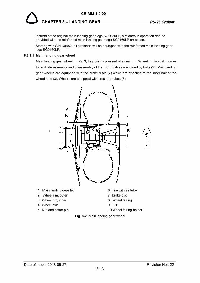
CR-MM-1-0-00
PS-28 Cruiser CHAPTER 8 – LANDING GEAR
Date of issue: 2018-09-27 Revision No.: 22 8 - 3
Instead of the original main landing gear legs SG0030LP, airplanes in operation can be provided with the reinforced main landing gear legs SG0160LP on option.
Starting with S/N C0652, all airplanes will be equipped with the reinforced main landing gear legs SG0160LP.
8.2.1.1 Main landing gear wheel
Main landing gear wheel rim (2; 3, Fig. 8-2) is pressed of aluminum. Wheel rim is split in order
to facilitate assembly and disassembly of tire. Both halves are joined by bolts (9). Main landing
gear wheels are equipped with the brake discs (7) which are attached to the inner half of the
wheel rims (3). Wheels are equipped with tires and tubes (6).
1 Main landing gear leg 6 Tire with air tube
2 Wheel rim, outer 7 Brake disc
3 Wheel rim, inner 8 Wheel fairing
4 Wheel axle 9 Bolt
5 Nut and cotter pin 10 Wheel fairing holder
Fig. 8-2: Main landing gear wheel
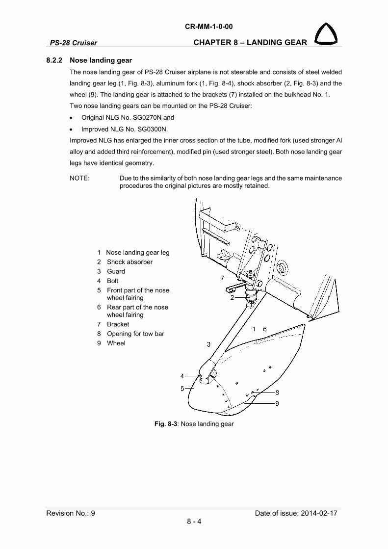
PS-28 Cruiser
CR-MM-1-0-00
CHAPTER 8 – LANDING GEAR
Revision No.: 9 Date of issue: 2014-02-17 8 - 4
8.2.2 Nose landing gear
The nose landing gear of PS-28 Cruiser airplane is not steerable and consists of steel welded
landing gear leg (1, Fig. 8-3), aluminum fork (1, Fig. 8-4), shock absorber (2, Fig. 8-3) and the
wheel (9). The landing gear is attached to the brackets (7) installed on the bulkhead No. 1.
Two nose landing gears can be mounted on the PS-28 Cruiser:
Original NLG No. SG0270N and
Improved NLG No. SG0300N.
Improved NLG has enlarged the inner cross section of the tube, modified fork (used stronger Al
alloy and added third reinforcement), modified pin (used stronger steel). Both nose landing gear
legs have identical geometry.
NOTE: Due to the similarity of both nose landing gear legs and the same maintenance procedures the original pictures are mostly retained.
Fig. 8-3: Nose landing gear
1 Nose landing gear leg
2 Shock absorber
3 Guard
4 Bolt
5 Front part of the nose wheel fairing
6 Rear part of the nose wheel fairing
7 Bracket
8 Opening for tow bar
9 Wheel

CR-MM-1-0-00
PS-28 Cruiser CHAPTER 8 – LANDING GEAR
Date of issue: 2014-02-17 Revision No.: 9 8 - 5
8.2.2.1 Nose landing gear wheel
The nose landing gear wheel rim (2; 3, Fig. 8-4) is pressed of aluminum. Wheel rim is split in
order to facilitate assembly and disassembly of tire. Both halves are connected by bolts (9). The
wheel is equipped with tire and tube (6). Wheel rims are split in order to facilitate assembly and
disassembly of tires
1 Wheel fork 7 Wheel fairing bracket
2 Wheel rim, left 8 Wheel fairing
3 Wheel rim, right 9 Bolt
4 Wheel axle 10 Spacer
5 Nut and cotter pin 11 Tow bracket
6 Tire with air tube
Fig. 8-4: Nose landing gear wheel

PS-28 Cruiser
CR-MM-1-0-00
CHAPTER 8 – LANDING GEAR
Revision No.: - Date of issue: 2011-03-08 8 - 6
8.2.3 Brake system
PS-28 Cruiser airplane is equipped with hydraulic disc brakes on the main landing gear wheels.
Brake system consists of the brake pedals (part of rudder control pedals, see Fig. 8-9), brake
pumps, parking brake valve, hoses for brake fluid supply, brake calipers and brake pads. By
depressing pedals, brake pumps are compressed and pressure generated in the brake circuit
and the calipers pushes the brake pads onto the brake discs. Braking pressure can be controlled
by force of brake pedal depressing.
1 Pilot brake pump, left 5 Disc brake, left
2 Pilot brake pump, right 6 Disc brake, right
3 Copilot brake pump, left 7 Parking brake valve
4 Copilot brake pump, right
Fig. 8-5: Brake system scheme
8.2.3.1 Parking brake
The airplane is equipped with the hydraulic manually controlled parking brake. The PARKING
BRAKE handle is located on the left instrument panel. The handle is mechanically connected
with the stop valve. By depressing the brake pedals and by turning the handle from PUSH OFF
to PULL ON position the brake hoses are locked and the pressure hold brake pads pressed on
brake discs.
8.2.4 Wheel fairings
Airplane is equipped with composite wheel fairings that decrease air drag and improve
aerodynamic properties of the airplane. The wheel fairings are installed on the brackets per
bolts.

CR-MM-1-0-00
PS-28 Cruiser CHAPTER 8 – LANDING GEAR
Date of issue: 2018-09-27 Revision No.: 22 8 - 7
8.3 Removal / Installation
8.3.1 Removal of main wheel fairing
Type of maintenance: line
Authorization to perform:
- Sport pilot or higher
Tools needed:
- Phillips PH2 screwdriver
(a) Unscrew the bolts (4, Fig. 8-6) with the washers (5) attaching the wheel fairing (1) on the
brackets (2; 3).
(b) Remove the fairing (1).
8.3.2 Installation of main wheel fairing
Type of maintenance: line
Authorization to perform:
- Sport pilot or higher
Tools needed:
- Phillips PH2 screwdriver
(a) Set the wheel fairing (1, Fig. 8-6) to appropriate position.
(b) Attach the fairing (1) with bolts (4) and the washers (5) to the brackets (3).
(c) Attach the fairing (1) with bolts (4) and the washers (5) to the bracket (2).
Fig. 8-6: Main wheel fairing removal / installation
1 Main wheel fairing
2 Outer bracket
3 Inner brackets
4 Bolt (7 pcs.)
5 Washer (7 pcs.) 6 Stiffener of the main
wheel fairing
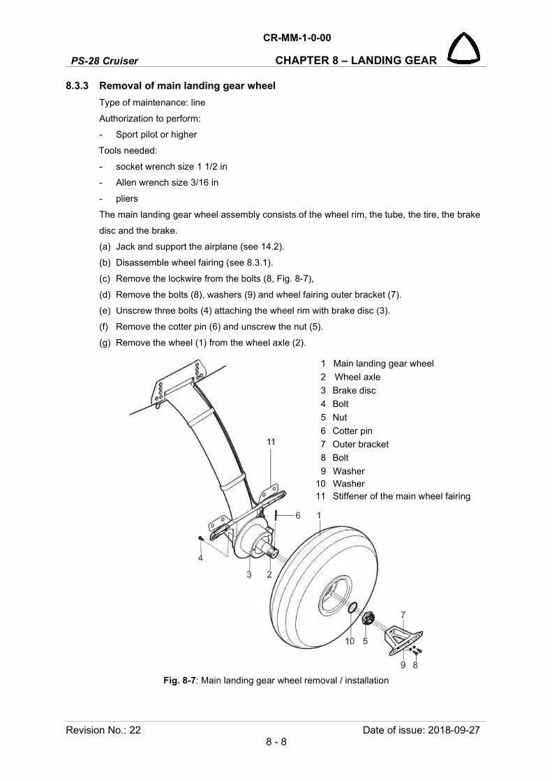
PS-28 Cruiser
CR-MM-1-0-00
CHAPTER 8 – LANDING GEAR
Revision No.: 22 Date of issue: 2018-09-27 8 - 8
8.3.3 Removal of main landing gear wheel
Type of maintenance: line
Authorization to perform:
- Sport pilot or higher
Tools needed:
- socket wrench size 1 1/2 in
- Allen wrench size 3/16 in
- pliers
The main landing gear wheel assembly consists of the wheel rim, the tube, the tire, the brake
disc and the brake.
(a) Jack and support the airplane (see 14.2).
(b) Disassemble wheel fairing (see 8.3.1).
(c) Remove the lockwire from the bolts (8, Fig. 8-7),
(d) Remove the bolts (8), washers (9) and wheel fairing outer bracket (7).
(e) Unscrew three bolts (4) attaching the wheel rim with brake disc (3).
(f) Remove the cotter pin (6) and unscrew the nut (5).
(g) Remove the wheel (1) from the wheel axle (2).
Fig. 8-7: Main landing gear wheel removal / installation
1 Main landing gear wheel
2 Wheel axle
3 Brake disc
4 Bolt
5 Nut
6 Cotter pin
7 Outer bracket
8 Bolt
9 Washer 10 Washer 11 Stiffener of the main wheel fairing

CR-MM-1-0-00
PS-28 Cruiser CHAPTER 8 – LANDING GEAR
Date of issue: 2018-09-27 Revision No.: 22 8 - 9
8.3.4 Installation of main landing gear wheel
Type of maintenance: line
Authorization to perform:
- Sport pilot or higher
Tools needed:
- socket wrench size 1 1/2 in
- Allen wrench size 3/16 in
- pliers
(a) Clear the wheel axle (2, Fig. 8-7) of impurities and apply slight layer of grease on it.
(b) Put the wheel (1) on the axle (2).
(c) Apply the securing liquid (blue Loctite 243) on the bolts threads (4) and attach with it the
wheel rim and brake disc (3).
(d) Screw and tighten the nut (5) on the wheel axle (2).
(e) Secure the nut (5) with the new cotter pin (6).
(f) Attach fairing outer bracket (7) with bolts (8) and washers (9) to the axle (2); secure bolts
with the lockwire.
(g) Install the wheel fairing (see 8.3.2).
8.3.5 Removal of nose wheel fairing
Type of maintenance: line
Authorization to perform:
- Sport pilot or higher
Tools needed:
- Phillips PH2 screwdriver
(a) Unscrew the bolts (3, Fig. 8-8) with the washers (7) attaching the front (1) and rear part of
the nose wheel fairing (2); remove front part (1).
(b) Unscrew the bolts (4) with the washers (7) and remove the rear part of the nose wheel
fairing (2).
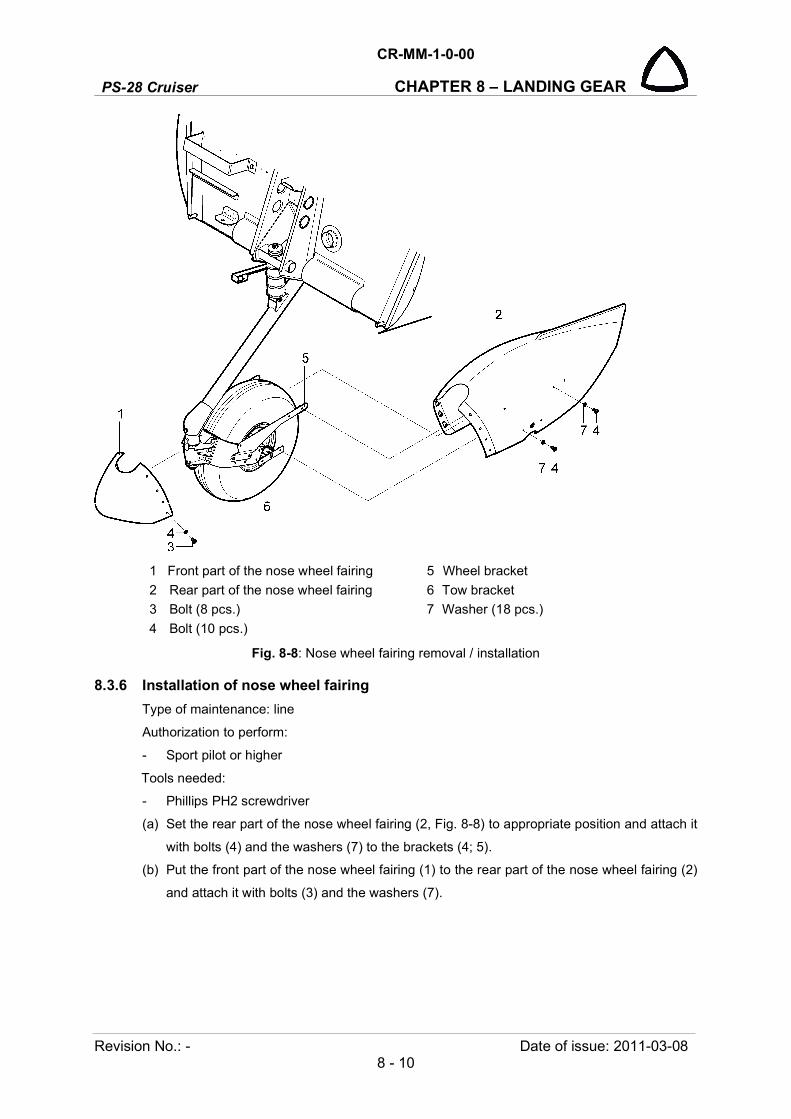
PS-28 Cruiser
CR-MM-1-0-00
CHAPTER 8 – LANDING GEAR
Revision No.: - Date of issue: 2011-03-08 8 - 10
1 Front part of the nose wheel fairing 5 Wheel bracket
2 Rear part of the nose wheel fairing 6 Tow bracket
3 Bolt (8 pcs.) 7 Washer (18 pcs.)
4 Bolt (10 pcs.)
Fig. 8-8: Nose wheel fairing removal / installation
8.3.6 Installation of nose wheel fairing
Type of maintenance: line
Authorization to perform:
- Sport pilot or higher
Tools needed:
- Phillips PH2 screwdriver
(a) Set the rear part of the nose wheel fairing (2, Fig. 8-8) to appropriate position and attach it
with bolts (4) and the washers (7) to the brackets (4; 5).
(b) Put the front part of the nose wheel fairing (1) to the rear part of the nose wheel fairing (2)
and attach it with bolts (3) and the washers (7).

CR-MM-1-0-00
PS-28 Cruiser CHAPTER 8 – LANDING GEAR
Date of issue: 2011-03-08 Revision No.: - 8 - 11
8.3.7 Removal of nose landing gear wheel
Type of maintenance: line
Authorization to perform:
- Sport pilot or higher
Tools needed:
- wrench size 1 1/8 in
- pliers
(a) Jack and support the airplane (see 14.2).
(b) Disassemble wheel fairing (see 8.3.6).
(c) Remove the cotter pin (6, Fig. 8-9) securing nut (4) on wheel axle (2) – on one side only.
(d) Remove the nut (4), washer and tow bracket (8) from wheel axle (2).
(e) Release the wheel axle (2) from the wheel (1), bushings (3) and the wheel fork eyes (8).
Fig. 8-9: Nose landing gear wheel removal / installation
1 Nose landing gear wheel
2 Wheel axle
3 Bushing
4 Nut
5 Washer
6 Cotter pin
7 Tow bracket
8 Wheel fork

PS-28 Cruiser
CR-MM-1-0-00
CHAPTER 8 – LANDING GEAR
Revision No.: 22 Date of issue: 2018-09-27 8 - 12
8.3.8 Installation of nose landing gear wheel
Type of maintenance: line
Authorization to perform:
- Sport pilot or higher
Tools needed:
- wrench size 1 1/8 in
- pliers
(a) Clear the wheel axle (2, Fig. 8-9) of impurities and grease it slightly.
(b) From one side shift the axle (2) into the wheel fork eye (8).
(c) Gradually put first bushing (3), nose wheel (1) and second bushing (3) on the wheel axle
(2) and tow bracket (7) according to the figure.
(d) From one side install washer (5), screw nut (3) - set the tow brackets (7) so that the axes of
holes for bolts fastening fairings were horizontally; tighten nut (3).
(e) Check for free turning of the nose wheel (turning must be continual without catching).
(f) Secure the nut (3) with the new cotter pin (6).
(g) Install wheel fairing (see 8.3.6).
8.3.9 Removal of the main landing gear leg
Type of maintenance: heavy
Authorization to perform:
See point 2.5.3.
Tools needed:
- wrench size 9/16 in, 1/2 in
(a) Jack and support the airplane (see 14.2).
(b) Remove appropriate seat (see 7.3.1).
(c) Disconnect the brake line.
(d) Unscrew the nuts (8, Fig. 8-10), and remove the washers (9) and bolts (7).
(e) Unscrew the nuts (4), and remove the washers (5) and tube (3); remove the spacer (10).
(f) Remove the landing gear leg (1) from the chamber (6) and put it on a suitable place.

CR-MM-1-0-00
PS-28 Cruiser CHAPTER 8 – LANDING GEAR
Date of issue: 2018-09-27 Revision No.: 22 8 - 13
1 Main landing gear leg 6 Chamber
2 Main gear attachment 7 Bolt
3 Tube 8 Locknut
4 Locknut 9 Washer
5 Washer 10 Spacer
Fig. 8-10: Main landing gear leg removal / installation
8.3.10 Installation of the main landing gear leg
Type of maintenance: heavy
Authorization to perform:
See point 2.5.3.
Tools needed:
- wrench size 9/16 in, 1/2 in
(a) Check outer surface of the composite landing gear leg (1, Fig. 8-10) for occurrence of cracks
and whether the axle connection is not damaged before installing the landing gear leg.
CAUTION: IF THE ORIGINAL SG0030L/P MAIN LANGING GEAR LEG (1) IS INSTALLED, THE SG0158L/P SPACER (10) MUST BE USED.
IF THE REINFORCED SG0160L/P MAIN LANGING GEAR LEG (1) IS INSTALLED, THE SG0159L/P SPACER (10) MUST BE USED.
NOTE For clearness is not displayed the channel cover.
PS-28 Cruiser
CR-MM-1-0-00
CHAPTER 8 – LANDING GEAR
Revision No.: 22 Date of issue: 2018-09-27 8 - 14
(b) Insert the landing gear leg (1) with the spacer (10) into the chamber (6) in attachment
channel on fuselage and fit the leg in main gear attachment (2). New spacer (10) is
recommended at each replacement of the landing gear leg.
(c) On the main gear attachment bolts (2) install the tube (3), washers (5), and slightly tighten
the nuts (4).
(d) Insert the bolts (7) through spacer (10), chamber (6) and leg (1), install the washers (9) and
tighten nuts (8; 4). For the nut (8) use torque moment of 11.3-15.8 Nm (100-140 in lb), for
the nut (4) use torque moment of 18.1-21.5 Nm (160-190 in lb), see the table 15-9, point
15.7 “Torque moments” in Chapter 15. Always use new locknuts (8; 4) at replacement.
(e) Connect the brake lines.
(f) Install seat.
(g) Fill brake system with brake liquid and air-bleed it (see 8.5.4).
8.3.11 Removal of nose landing gear leg
Type of maintenance: heavy
Authorization to perform:
See point 2.5.3.
Tools needed:
- wrench size 1/2 in, No.17
(a) Jack and support the airplane, (see 14.2).
(b) Remove the lockwire from the bolts (6, Fig. 8-11),
(c) Remove the bolts (6) and washers (7).
(d) Remove the tube (5) from the leg bracket (9).
(e) Remove the cotter pin (9), unscrew the nut (3), remove washers (4), bolt (2) and disconnect
the shock absorber (8) from the bracket on the nose gear leg (1).
(f) Remove the gear leg (1) from the fuselage and put it on a suitable place.(d)
8.3.12 Installation of nose landing gear leg
Type of maintenance: heavy
Authorization to perform:
See point 2.5.3.
Tools needed:
- wrench size 1/2 in, No.17
(a) Check the welds of the gear leg for occurrence of cracks and corrosion and whether the
bearings are not damaged before installing the gear leg.
(b) Insert the gear leg (1, Fig, 8-11) into the bracket (9).
(c) Insert the tube (5) to the hole in the bracket (9).
(d) Screw the bolts (6) with the nuts (7) to the tube; tighten the bolts slightly; secure bolts with
the lockwire.
(e) Put the lower end of the shock absorber (8) to the bracket on the nose gear leg (1); install
the bolt (2) with the nut (3) and washers (4), secure the nut with the new cotter pin (9).

CR-MM-1-0-00
PS-28 Cruiser CHAPTER 8 – LANDING GEAR
Date of issue: 2011-03-08 Revision No.: - 8 - 15
Fig. 8-11: Nose landing gear leg removal / installation.
8.3.13 Removal of brake pumps
Type of maintenance: line
Authorization to perform:
- Sport pilot or higher
Tools needed:
- wrench size 1/2 in, 3/8 in
(a) Disconnect the brake system hose from the brake cylinder on the main landing gear wheel
and let brake fluid drain to a previously prepared can from that system line in which you
want to remove the brake pump.
(b) Disconnect the brake system hose (3, Fig. 8-12) from the brake pump (1; 2).
(c) Remove cotter pin (7), unscrew nut (11), remove washer (12), spacers (9; 10), bolt (8) and
disconnect brake pump rod eye from the rudder pedal (14).
(d) Remove cotter pin (7), unscrew nut (5), remove washer (6), bolt (4) and disconnect brake
pump from the bracket (13) on the floor.
1 Nose landing gear leg
2 Bolt
3 Nut
4 Washer
5 Tube
6 Bolt
7 Washer
8 Shock absorber
9 Cotter pin
For information:
10 Bracket
NOTE Access to the bolts (6) is from the cockpit.

PS-28 Cruiser
CR-MM-1-0-00
CHAPTER 8 – LANDING GEAR
Revision No.: - Date of issue: 2011-03-08 8 - 16
8.3.14 Installation of brake pumps
Type of maintenance: line
Authorization to perform:
- Sport pilot or higher
Tools needed:
- wrench size 1/2 in, 3/8 in
(a) Insert the brake pump (1; 2, Fig. 8-12) according to the figure to the floor bracket (14) and
install the bolt (4) with the nut (5) and washer (6); secure the nut by the new cotter pin (7).
(b) Connect brake pump rod end eye with pedal (14) by means of the bolt (8) with the nut (11),
spacers (9; 10) and washer (12); secure the nut by the new cotter pin (7).
(c) Reinstall the brake system hose (3) on the brake pump (1; 2) and on the brake cylinder on
main landing gear.
(d) Fill the brake system with brake fluid and air-bleed it (see 8.5.4.).
1 Pilot brake pump 9 Spacer
2 Copilot brake pump 10 Spacer
3 Brake hose 11 Nut
4 Bolt 12 Washer
5 Nut For information:
6 Washer 13 Bracket
7 Cotter pin 14 Rudder pedal
8 Bolt
Fig. 8-12: Brake pumps removal / installation

CR-MM-1-0-00
PS-28 Cruiser CHAPTER 8 – LANDING GEAR
Date of issue: 2017-12-05 Revision No.: 20 8 - 17
8.4 Check / Adjustment
8.4.1 Check of nose landing gear shock absorber
(a) Several times hoist and lower the nose landing gear of the airplane.
(b) Measure value of absorber and nose landing gear compression according to Fig. 8-13.
Perform measuring in vertical direction between the bottom of the engine cowl and the lower
shock absorber attachment. The minimum value is 50 mm (2 in). If this value is lower than
change the dumping elements (see 8.5.2).
Fig. 8-13: Check of nose landing gear shock absorber
8.4.2 Check of nose landing gear leg after shimmy occurrence
(a) Remove the nose wheel fairing (see 8.3.5).
(b) Remove the nose wheel (see 8.3.7).
(c) Remove the cover (7, Fig. 8-14) and unload nose landing gear.
(d) Check condition of the fork, leg, and shock absorber for cracks (see Fig. 8-14). Use
magnifying glass.
(e) Check tire worn and specified inflation (1.2 + 0.1 bar (17.4 + 1.5 psi)).
CAUTION: DO NOT EXCESS SPECIFIED TIRE PRESSURE OVERPRESSURED TIRE CAUSED SHIMMY.
(f) Check condition of spring washers (3). Keep washers free of lubricants. Remove cotter pin
(6), loose nut (5) and clean washers (2; 3; 4) if necessary, use some solvent for degreasing.
(g) Attach spring scale (10) to fork.
(h) Torque castellated nut (5) so a constant force of 70 - 90 N is required to rotate nose wheel
fork.
(i) Install new cotter pin (6).
(j) As necessary, grease the axle per grease nipple.
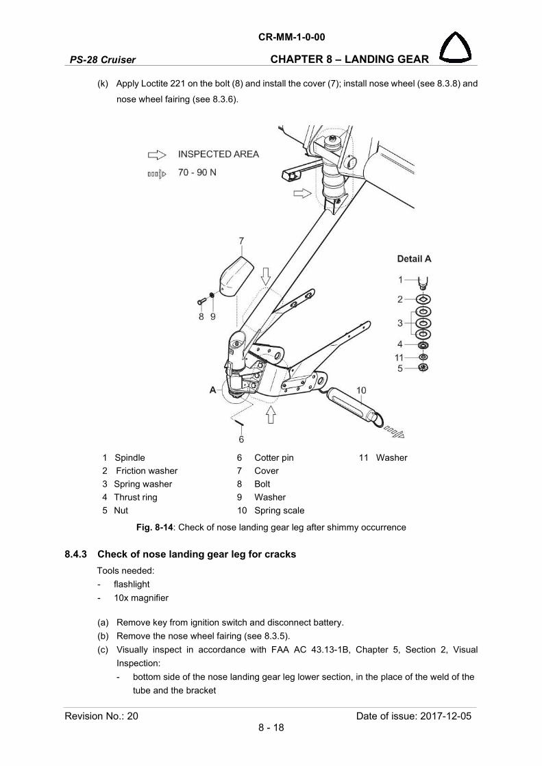
PS-28 Cruiser
CR-MM-1-0-00
CHAPTER 8 – LANDING GEAR
Revision No.: 20 Date of issue: 2017-12-05 8 - 18
(k) Apply Loctite 221 on the bolt (8) and install the cover (7); install nose wheel (see 8.3.8) and
nose wheel fairing (see 8.3.6).
1 Spindle 6 Cotter pin 11 Washer
2 Friction washer 7 Cover
3 Spring washer 8 Bolt
4 Thrust ring 9 Washer
5 Nut 10 Spring scale
Fig. 8-14: Check of nose landing gear leg after shimmy occurrence
8.4.3 Check of nose landing gear leg for cracks
Tools needed:
- flashlight
- 10x magnifier
(a) Remove key from ignition switch and disconnect battery.
(b) Remove the nose wheel fairing (see 8.3.5).
(c) Visually inspect in accordance with FAA AC 43.13-1B, Chapter 5, Section 2, Visual
Inspection:
- bottom side of the nose landing gear leg lower section, in the place of the weld of the
tube and the bracket

CR-MM-1-0-00
PS-28 Cruiser CHAPTER 8 – LANDING GEAR
Date of issue: 2014-10-29 Revision No.: 11 8 - 19
- the pivot in the area the pivot shoulder
- the fork in the place of the bolts mounting the fork to the landing gear.
(d) Using flashlight and 10x magnifier, visually inspect nose landing gear leg lower section and
verify there is no evidence of cracking in paint on or around place of the weld of the tube
and the bracket.
(e) Using flashlight and 10x magnifier, visually inspect the fork in the place of the bolts
mounting the fork to the landing gear and verify there is no evidence of cracking in paint.
(f) Visually inspect pivot and verify there is no evidence of bending.
(g) If no cracking or pivot bending is evident, perform the following steps:
1. Install nose wheel fairing (see 8.3.6).
2. Connect battery and restore aircraft to the airworthy condition.
(h) If an evidence of cracking is badly identified, perform the following steps for confirmation /
not confirmation of cracking:
1. Remove nose landing gear leg (see 8.3.11).
2. Using NDT Penetration Check Kit perform a NDT penetration check in accordance with
FAA AC 43.13-1B, Chapter 5, Section 5, Penetrant Inspection.
(i) In case of non confirmation of cracking, install nose landing gear leg back (see 8.3.12),
install nose wheel fairing (see 8.3.6), connect battery and restore aircraft to the airworthy
condition.
(j) In case of confirmation of cracking or pivot bending, perform the following steps:
1. Assure Aircraft on Ground (AOG).
2. Report this occurrence to the manufacturer (CAG) within 72 hours.
3. Ask the manufacturer (CAG) for the NLG No. SG0300N.
4. Install new nose landing leg (see 8.3.12).
5. Install nose wheel fairing (see 8.3.6), connect battery and restore aircraft to the
airworthy condition.

PS-28 Cruiser
CR-MM-1-0-00
CHAPTER 8 – LANDING GEAR
Revision No.: 11 Date of issue: 2014-10-29 8 - 20
Fig. 8-15: Inspected area of the nose landing gear leg
CR-MM-1-0-00
PS-28 Cruiser CHAPTER 8 – LANDING GEAR
Date of issue: 2013-10-09 Revision No.: 7 8 - 21
8.5 Changes / Service information
8.5.1 Tire change
Type of maintenance: line
Authorization to perform:
- Sport pilot or higher
Tools needed:
- wrench size 1/2 in
- Allen wrench size 1/4 in
(a) Jack and support the airplane (see 14.2).
(b) Remove the wheel fairing (see 8.3.1 / 8.3.5).
(c) Remove the main landing gear wheel (see 8.3.3) or the nose landing gear wheel
(see 8.3.7).
(d) Deflate the tire.
(e) Unscrew the bolts (1, Fig. 8-16).
(f) Set apart both halves of the rim (1; 2) and remove the tire (10) with the air tube (11).
(g) Exchange the air tube or the tire, if necessary.
(h) Put the air tube (11) into the tire (10) and inflate it slightly.
(i) Put the inner tube on that half of the rim, which has the hole for the valve.
(j) Put the other half of the rim on this unit. Join both halves of the rim with bolts – torque value
11.3 Nm (100 in lbs).
(k) Inflate tires to the prescribed pressure:
- nose wheel 1.2 + 0.1 bar (17.4 + 1.5 psi)
- main wheel 1.8 + 0.2 bar (26.1 + 2.9 psi)
(l) Mark position of the rim and the tire by redline overreaching about 10 mm (3/8 in) to the rim
and the tire (serves for checking the tire slewing against the wheel rim in operation).

PS-28 Cruiser
CR-MM-1-0-00
CHAPTER 8 – LANDING GEAR
Revision No.: 22 Date of issue: 2018-09-27 8 - 22
1 Wheel rim, outer 7 Lock nut
2 Wheel rim, inner 8 Washer
3 Hub 9 Washer
4 Brake disc 10 Tire
5 Bolt 11 Air tube
6 Bolt
Fig. 8-16: Tire change
8.5.2 Change of nose landing gear shock absorber dumping elements
Type of maintenance: heavy
Authorization to perform:
See point 2.5.3.
Tools needed:
- wrench size 1/2 in
(a) Jack and support the airplane (see 14.2).
(b) Remove the cotter pin (10, Fig. 8-17), unscrew the nut (13), remove the washers (12), bolt
(11) and disconnect tube (1) from the bracket (2) on the nose gear leg.
(c) Remove the cotter pin (10), unscrew the nut (9) and remove the washers (8; 6; 7; 5).
(d) Turn the tube (1) forward and remove tube (1), dumping elements (2) and washers (3).
(e) As needed, remove the cotter pins (15), push out the tube (14) and remove profile (18) and
case (19).
(f) Replace damaged dumping elements (3).
(g) Gradually put on the tube (1) shock absorbers (2), washers (3) and insert tube into the hole
on the tube (14) according to the figure.
NOTE Figure shows the replacement tire of the main landing gear wheel.

CR-MM-1-0-00
PS-28 Cruiser CHAPTER 8 – LANDING GEAR
Date of issue: 2013-10-09 Revision No.: 7 8 - 23
(h) Gradually install on the tube end (1) washers (5; 7; 6; 8), screw and tighten the nut (9);
secure it with the new cotter pin (10).
(i) Put the lower end of the tube (1) to the bracket (16); install the bolt (11) with the nut (13)
and washers (12), secure nut with the new cotter pin (10).
(j) Lower the airplane on jacks.
1 Tube 11 Bolt
2 Shock absorber 12 Washer
3 Washer 13 Nut
4 Washer 14 Tube
5 Washer 15 Cotter pin
6 Washer 16 Nose leg bracket
7 Rubber washer 17 Bracket
8 Washer 18 Profile
9 Nut 19 Case
10 Cotter pin
Fig. 8-17: Change of the dumping elements in the nose landing gear
PS-28 Cruiser
CR-MM-1-0-00
CHAPTER 8 – LANDING GEAR
Revision No.: 7 Date of issue: 2013-10-09 8 - 24
8.5.3 Change of brake lining
Type of maintenance: line
Authorization to perform:
- Sport pilot or higher
Tools needed:
- wrench size 7/16 in
- drill # 25
- electric drill
- brake relining tool, pneumatic press
CAUTION: EXCHANGE ALWAYS BOTH BRAKE PADS!
(a) Jack and support the airplane (see 14.2).
(b) Remove the main landing gear wheel (see 8.3.3).
(c) Remove the caliper from the wheel by removing the two bolts (1, Fig. 8-18) that hold in on.
(d) Remove old linings (4) by drilling the crimped side of the rivet (Do not use punch and
hammer). Using a # 25 drill (0.1495 in. diameter), drill through rivet taking care to avoid
damaging the rivet hole.
(e) After drilling crimped edge off rivets, lift old lining and remaining rivet pieces from the brake
shoe.
(f) Inspect the brake shoe (2; 3) for any bending or other damage that may have occurred
during service. A shoe with more than 0.010 in bend should be replaced. Inspect rivet holes
to ensure that no damage has occurred during removal.
(g) Using a brake relining tool or pneumatic press, replace the lining using brass rivet (5).
(h) Insert the brake disc and screw them with the caliper.
(i) Reinstall the main landing gear wheel (see 8.3.4).
(j) Check the brake function.

CR-MM-1-0-00
PS-28 Cruiser CHAPTER 8 – LANDING GEAR
Date of issue: 2013-10-09 Revision No.: 7 8 - 25
NOTE: The lining requires replacement when the wear indicator is no longer visible.
Fig. 8-18: Change of brake lining
8.5.4 Lubrication of axis of rotation of nose landing gear
Type of maintenance: line
Authorization to perform:
- Sport pilot or higher
Tools needed:
- wrench size 1/2 in
- grease gun
(a) Uncscrew and remove the bolt (8, Fig. 8-14) with the washer (9) and remove cover (7).
(b) By means of the grease gun lubricate axis of rotation.
CAUTION: AVOID TO GREASE CONTAMINATES THE FRICTION AREAS!
(c) Apply Loctite 221 on the bolt (8) with the washer (9) and install the cover (7).
1 Bolt
2 Movable brake shoe
3 Stationary brake shoe
4 Lining
5 River
PS-28 Cruiser
CR-MM-1-0-00
CHAPTER 8 – LANDING GEAR
Revision No.: 7 Date of issue: 2013-10-09 8 - 26
8.5.5 Refilling / exchanging brake fluid
Draining brake fluid from brake system
Type of maintenance: line
Authorization to perform:
- Sport pilot or higher
Tools needed:
- wrench size 7/16”
(a) Disconnect the brake hose from the brake cylinder and let brake fluid drain into the
previously prepared can.
(b) You can accelerate brake fluid draining by compressing the relevant brake pedal.
Filing brake fluid into brake system
NOTE: Brake fluid used by aircraft manufacturer is shown in Section 17.5.
(a) Fix the aircraft with help wedges.
(b) Release the parking brake.
(c) Bleed the hose of the filling equipment and connect it to the filling hole of the left wheel
brake.
(d) Unscrew the plug of the left brake cylinder with reservoir using the socket wrench.
(e) Slowly fill the brake system with hydraulic fluid.
(f) Repeatedly push the brake pedal.
(g) Check the brake hose from the point of view of occurrence of bubbles.
(h) Continuous occurrence of bubbles indicates a failure of the filling equipment.
(i) After the reservoir is filled up to the filler hole – stop the filling through closing of the filling
valve of the filling equipment.
(j) Disconnect the hose of the filling equipment.
(k) Suck off 20 ml of hydraulic fluid using the syrette.
(l) Screw down the closing plug using the socket wrench.
(m) Repeat the same procedure for the right brake cylinder.
(n) Check the proper resistance of pedals.
(o) Pull the parking brake.
By this way, both wheels must be braked equally.
(p) Remove the wedges.
Refilling brake fluid into brake system
For the refilling – use the procedure for filling (see above).

CR-MM-1-0-00
PS-28 Cruiser CHAPTER 9 – FUEL SYSTEM
Date of issue: 2018-09-27 Revision No.: 22 9 - 1
9. FUEL SYSTEM
Content
9.1 General ....................................................................................................................................... 9-2
9.2 Description and operation .......................................................................................................... 9-6
9.2.1 Fuel storage ................................................................................................................ 9-6
9.2.2 Fuel distribution ........................................................................................................... 9-6
9.2.3 Indication of fuel quantity and pressure ...................................................................... 9-7
9.3 Removal / Installation ................................................................................................................. 9-8
9.3.1 Fuel tank removal ....................................................................................................... 9-8
9.3.2 Fuel tank installation ................................................................................................... 9-9
9.3.3 Removal of the finger screen ...................................................................................... 9-9
9.3.4 Installation of the finger screen ................................................................................. 9-10
9.3.5 Fuel quantity sensor removal .................................................................................... 9-10
9.3.6 Fuel quantity sensor installation ............................................................................... 9-11
9.3.7 Fuel drain valve removal ........................................................................................... 9-12
9.3.8 Fuel drain valve installation ...................................................................................... 9-13
9.4 Check / Adjustment .................................................................................................................. 9-13
9.4.1 Checking fuel system tightness ................................................................................ 9-13
9.4.2 Fuel pump check....................................................................................................... 9-13
9.5 Exchanges / Service information .............................................................................................. 9-14
9.5.1 Fuel tank filling .......................................................................................................... 9-14
9.5.2 Draining fuel system ................................................................................................. 9-14
9.5.3 Fuel filter cleaning ..................................................................................................... 9-14

PS-28 Cruiser
CR-MM-1-0-00
CHAPTER 9 – FUEL SYSTEM
Revision No.: 3 Date of issue: 2012-05-28 9 - 2
9.1 General
The fuel system (see Fig. 9.1) is used for storing fuel in the airplane and it’s delivering to the
engine. The fuel system of PS-28 Cruiser airplane consists of the following parts: two fuel tanks,
fuel tubing, selector valve, gascolator, mechanical fuel pump (located on the engine), electrical
fuel pump, fuel quantity sensor, fuel flow-meter, fuel pressure sensor and drain valves of the fuel
tanks.
Fig. 9-1: Fuel system layout (page 1 of 4)
Inst
rum
ent p
anel
with
EF
IS /
EMS
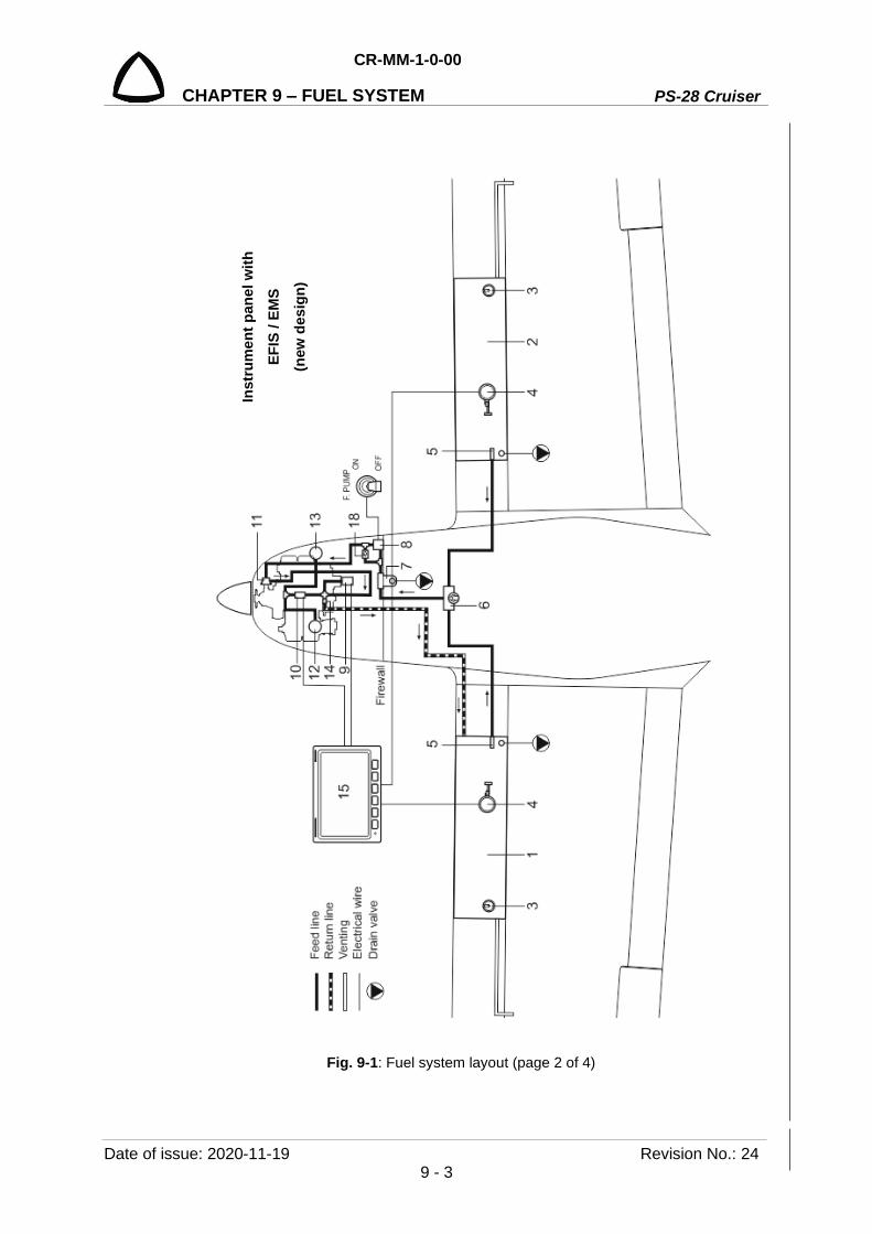
CR-MM-1-0-00
PS-28 Cruiser CHAPTER 9 – FUEL SYSTEM
Date of issue: 2020-11-19 Revision No.: 24 9 - 3
Fig. 9-1: Fuel system layout (page 2 of 4)
Inst
rum
ent p
anel
with
EF
IS /
EMS
(new
des
ign)

PS-28 Cruiser
CR-MM-1-0-00
CHAPTER 9 – FUEL SYSTEM
Revision No.: 3 Date of issue: 2012-05-28 9 - 4
Fig. 9-1: Fuel system layout (page 3 of 4)
Inst
rum
ent p
anel
with
an
alog
inst
rum
ents

CR-MM-1-0-00
PS-28 Cruiser CHAPTER 9 – FUEL SYSTEM
Date of issue: 2020-11-19 Revision No.: 24 9 - 5
Fig. 9-1: Fuel system layout (page 4 of 4)
1 F
uel t
ank,
left
6
Fue
l sel
ecto
r val
ve
11
Mec
h. fu
el p
ump
16
Fue
l qua
ntity
indi
c.
2 F
uel t
ank,
righ
t
7 G
asco
lato
r
12
Car
bure
tor,
left
17
Fue
l pre
ssur
e in
dic.
3
Fille
r cap
8
El.
fuel
pum
p
13 C
arbu
reto
r, rig
ht
18
Che
ck v
alve
4 F
uel q
uant
ity s
enso
r
9 F
uel p
ress
ure
sens
or
14 R
estri
ctor
jet
5 F
inge
r scr
een
10 F
uel f
low
met
er
15
EM
S
Inst
rum
ent p
anel
with
an
alog
inst
rum
ents
(n
ew d
esig
n)
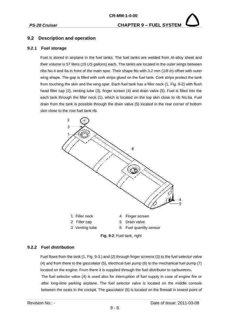
PS-28 Cruiser
CR-MM-1-0-00
CHAPTER 9 – FUEL SYSTEM
Revision No.: - Date of issue: 2011-03-08 9 - 6
9.2 Description and operation
9.2.1 Fuel storage
Fuel is stored in airplane in the fuel tanks. The fuel tanks are welded from Al-alloy sheet and
their volume is 57 liters (15 US gallons) each. The tanks are located in the outer wings between
ribs No.4 and 6a in front of the main spar. Their shape fits with 3.2 mm (1/8 in) offset with outer
wing shape. The gap is filled with cork strips glued on the fuel tank. Cork strips protect the tank
from touching the skin and the wing spar. Each fuel tank has a filler neck (1, Fig. 9-2) with flush
head filler cap (2), venting tube (3), finger screen (4) and drain valve (5). Fuel is filled into the
each tank through the filler neck (1), which is located on the top skin close to rib No.6a. Fuel
drain from the tank is possible through the drain valve (5) located in the rear corner of bottom
skin close to the root fuel tank rib.
1 Filler neck 4 Finger screen 2 Filler cap 5 Drain valve 3 Venting tube 6 Fuel quantity sensor
Fig. 9-2: Fuel tank, right
9.2.2 Fuel distribution
Fuel flows from the tank (1, Fig. 9-3.) and (2) through finger screens (3) to the fuel selector valve
(4) and from there to the gascolator (5), electrical fuel pump (6) to the mechanical fuel pump (7)
located on the engine. From there it is supplied through the fuel distributor to carburetors.
The fuel selector valve (4) is used also for interruption of fuel supply in case of engine fire or
after long-time parking airplane. The fuel selector valve is located on the middle console
between the seats in the cockpit. The gascolator (5) is located on the firewall in lowest point of

CR-MM-1-0-00
PS-28 Cruiser CHAPTER 9 – FUEL SYSTEM
Date of issue: 2012-05-28 Revision No.: 3 9 - 7
fuel system and eliminates all mechanical impurities. The electrical fuel pump (6) is located on
the firewall above the gascolator.
1 Fuel tank, left 5 Gascolator
2 Fuel tank, right 6 Electrical fuel pump
3 Finger screen 7 Mechanical fuel pump
4 Fuel selector valve
Fig. 9-3: Fuel system installation diagram
9.2.3 Indication of fuel quantity and pressure
Fuel quantity is measured by the fuel float sensor (see Fig. 9-4). The float position is converted
to an electrical signal and fuel quantity in the tank is indicated either on the EMS or on the
classical analog instruments (see Fig. 9-1).
Fuel pressure is measured by the electrical fuel pressure sensor. Electrical signal from the
sensor is indicated either on the EMS or on the classical analog instruments (see Fig. 9-1).

PS-28 Cruiser
CR-MM-1-0-00
CHAPTER 9 – FUEL SYSTEM
Revision No.: 22 Date of issue: 2018-09-27 9 - 8
Fig. 9-4: Float mechanism
9.3 Removal / Installation
9.3.1 Fuel tank removal
Type of maintenance: heavy
Authorization to perform:
See point 2.5.3.
Tools needed:
- wrench size No. 8, 1/2 in,
- screwdriver
- drill diam. 3.2 mm (1/8 in), 4.1 mm (5/32 in)
- electric drill
- cutting pliers, pliers
(a) Disconnect the battery.
(b) Drain fuel from the fuel system by the tank drain valve.
(c) Unscrew the filler cap.
(d) Remove the wing (see 4.3.1) and put it on the table.
(e) Drill out the top half of the leading edge skin.
(f) Disconnect wiring from fuel quantity sensor.
(g) Disconnect fuel line.
(h) Carefully remove the tank and store it. Seal the tank holes as needed.

CR-MM-1-0-00
PS-28 Cruiser CHAPTER 9 – FUEL SYSTEM
Date of issue: 2018-09-27 Revision No.: 22 9 - 9
9.3.2 Fuel tank installation
Type of maintenance: heavy
Authorization to perform:
See point 2.5.3.
Tools needed:
- wrench size No. 8, 1/2 in,
- screwdriver
- riveting pliers
- cutting pliers, pliers
(a) Remove any hole seals from the tank.
(b) Set the tank to the position between the ribs No.4 and 6a. Before installing the tank, check
the cork bands for completeness and damage. Change them, if needed.
(c) Connect fuel quantity sensor wire, insert the finger screen – use LOCTITE 565 or equivalent
sealant.
(d) Close the leading edge skin on the wing and fit it to the spars and ribs per clecos each
second hole through of securing harnesses.
(e) Rivet the skin on the ribs and spar.
(f) Screw back filler cap - use silicon to make connection of filler cap flange and wing skin
watertight.
(g) Install the wing (see 4.3.2).
(h) Check the fuel system (see 9.4.1).
(i) Connect the battery ground.
9.3.3 Removal of the finger screen
Type of maintenance: line
Authorization to perform:
See point 2.5.3.
Tools needed:
- screwdriver
- socket wrench 11/16 inch
NOTE: The finger screen is located in the root tank rib.
(a) Drain fuel from the fuel system.
(b) Remove the wing (see 4.3.1).
(c) Remove the hose clamp (3, Fig. 9-5) and disconnect the fuel hose (4).
(d) Remove the finger screen (2).

PS-28 Cruiser
CR-MM-1-0-00
CHAPTER 9 – FUEL SYSTEM
Revision No.: 22 Date of issue: 2018-09-27 9 - 10
9.3.4 Installation of the finger screen
Type of maintenance: line
Authorization to perform:
See point 2.5.3.
Tools needed:
- Screwdriver
- Socket wrench 11/16 inch
(a) Screw the finger screen (2, Fig. 9-5) into the root tank rib – use LOCTITE 565 or equivalent
sealant on finger screen thread.
(b) Connect fuel hose (4) on the finger screen; tighten the hose clamp (3).
(c) Install the wing (see 4.3.2).
(d) Check fuel system tightness (see 9.4.1).
Fig. 9-5: Finger screen removal / installation
9.3.5 Fuel quantity sensor removal
Type of maintenance: line
Authorization to perform:
- Sport pilot or higher
Tools needed:
- electric drill
- drill diam. 3.2 mm (1/8 in)
- screwdriver
- cutting pliers, pliers
(a) Remove (drill off) the fuel quantity cover plate (6, Fig. 9-6).
(b) Disconnect fuel level sender wire (5).
(c) Unscrew bolts (3), remove washers (4) and fuel quantity sensor (1) and gasket (2).
1 Fuel tank
2 Fingers screen
3 Clamp
4 Fuel hose
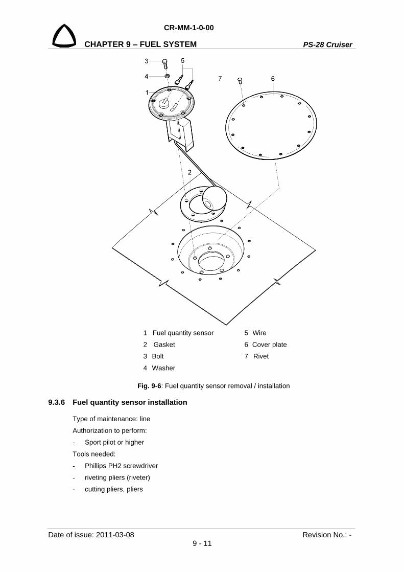
CR-MM-1-0-00
PS-28 Cruiser CHAPTER 9 – FUEL SYSTEM
Date of issue: 2011-03-08 Revision No.: - 9 - 11
1 Fuel quantity sensor 5 Wire
2 Gasket 6 Cover plate
3 Bolt 7 Rivet
4 Washer
Fig. 9-6: Fuel quantity sensor removal / installation
9.3.6 Fuel quantity sensor installation
Type of maintenance: line
Authorization to perform:
- Sport pilot or higher
Tools needed:
- Phillips PH2 screwdriver
- riveting pliers (riveter)
- cutting pliers, pliers
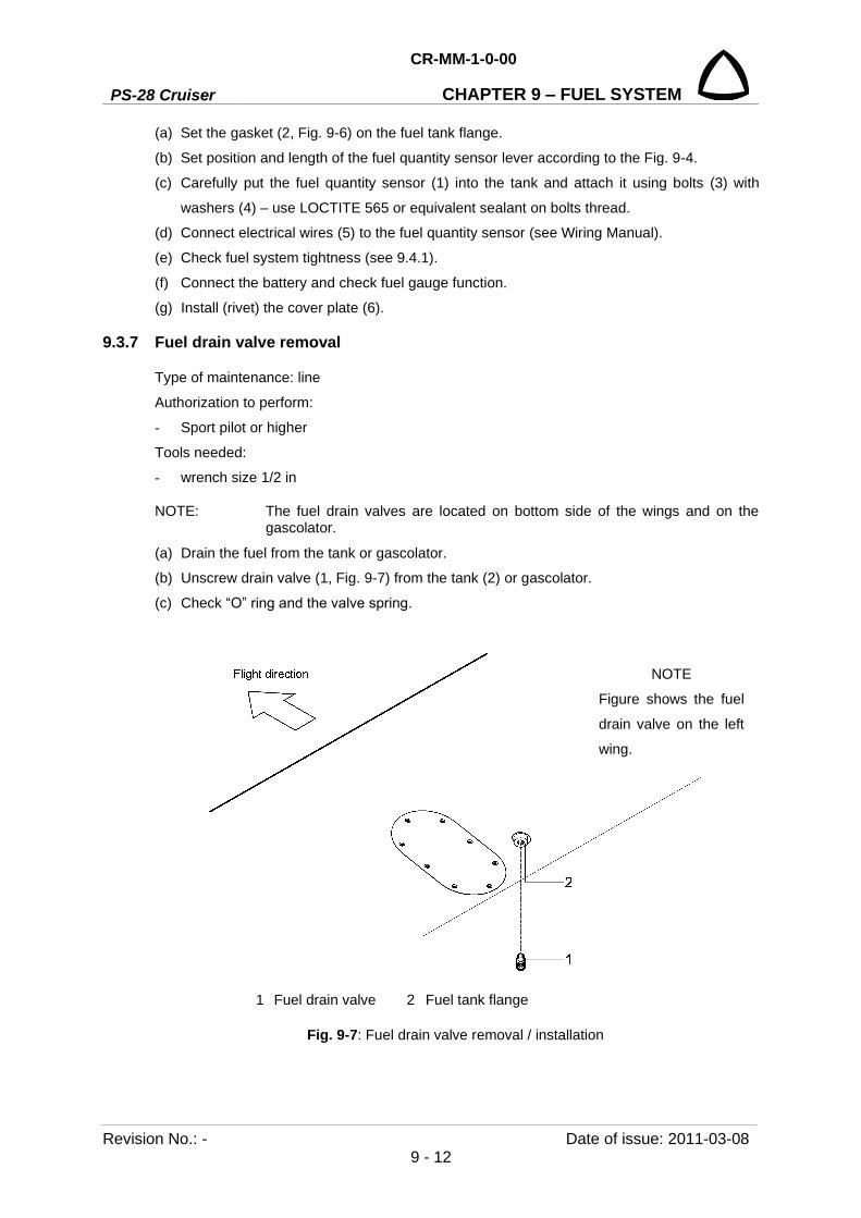
PS-28 Cruiser
CR-MM-1-0-00
CHAPTER 9 – FUEL SYSTEM
Revision No.: - Date of issue: 2011-03-08 9 - 12
(a) Set the gasket (2, Fig. 9-6) on the fuel tank flange.
(b) Set position and length of the fuel quantity sensor lever according to the Fig. 9-4.
(c) Carefully put the fuel quantity sensor (1) into the tank and attach it using bolts (3) with
washers (4) – use LOCTITE 565 or equivalent sealant on bolts thread.
(d) Connect electrical wires (5) to the fuel quantity sensor (see Wiring Manual).
(e) Check fuel system tightness (see 9.4.1).
(f) Connect the battery and check fuel gauge function.
(g) Install (rivet) the cover plate (6).
9.3.7 Fuel drain valve removal
Type of maintenance: line
Authorization to perform:
- Sport pilot or higher
Tools needed:
- wrench size 1/2 in
NOTE: The fuel drain valves are located on bottom side of the wings and on the gascolator.
(a) Drain the fuel from the tank or gascolator.
(b) Unscrew drain valve (1, Fig. 9-7) from the tank (2) or gascolator.
(c) Check “O” ring and the valve spring.
1 Fuel drain valve 2 Fuel tank flange
Fig. 9-7: Fuel drain valve removal / installation
NOTE
Figure shows the fuel
drain valve on the left
wing.
CR-MM-1-0-00
PS-28 Cruiser CHAPTER 9 – FUEL SYSTEM
Date of issue: 2012-05-28 Revision No.: 3 9 - 13
9.3.8 Fuel drain valve installation
Type of maintenance: line Authorization to perform: - Sport pilot or higher Tools needed: - wrench size 1/2 in (a) Screw the drain valve (1, Fig. 9-7) in the tank (2) or gascolator – use LOCTITE 565 or
equivalent sealant on the drain valve thread. (b) Fill the tank with fuel and check drain valve tightness.
9.4 Check / Adjustment
9.4.1 Checking fuel system tightness
NOTE: Tightness is checked by pressurized air. When performing a specific tightness check, outside temperature fluctuations must not be bigger than ± 5 °C (± 9 °F). Reseal the found out leakage by a suitable method - by tightening, by using a suitable sealing.
Checking airplane fuel system tightness by air
(a) Remove upper engine cowling. (b) Close the fuel tank filler caps. (c) Fuel selector valve - OFF position. (d) Connect the pressurization equipment hose to the venting tube outlet on the L/R wing
bottom side. (e) Disconnect the hoses from the carburetors and return line; blind them by plugs. (f) Set the fuel selector valve to LEFT / RIGHT position (choose the tank). (g) Supply air pressure of 2 kPa (0.02 bar; 0.29 psi) to the appropriate fuel tank by means of
the pressurization equipment. (h) Shut the air pressure supply. During 15 minutes there must not be any loss in pressure.
Find out leakage by listening to and by soap water. (i) As necessary, repeat procedure fot the second fuel tank. (j) Remove plugs from the hoses and reconnect them to the carburetors and return line. (k) Install upper engine cowling.
9.4.2 Fuel pump check
Check for cracks
Check the fuel pump body for cracks, including the inlet and the outlet hose. If cracks are detected, immediately exchange the fuel pump for the new pump.
Checking fuel leakage
Perform engine inspection and check the fuel pump body, including inlet and outlet hose, for fuel leakage. In case of fuel leakage, find out the reason and if necessary exchange the fuel pump for the new pump.

PS-28 Cruiser
CR-MM-1-0-00
CHAPTER 9 – FUEL SYSTEM
Revision No.: - Date of issue: 2011-03-08 9 - 14
9.5 Exchanges / Service information
9.5.1 Fuel tank filling
CAUTION: WHEN FILLING FUEL IN THE AIRPLANE, USE ONLY APPROVED KINDS OF FUEL MENTIONED IN THIS MANUAL IN 10.2.1, IN THE POH SECTION 2.4, IN THE ROTAX OPERATOR’S MANUAL SECTION 10.2.2 FUEL, IN THE ROTAX SERVICE INSTRUCTIONS SI-912-016. SAFETY INSTRUCTIONS FOR FILLING FUEL INTO THE AIRPLANE TANKS
(a) The fuel tanks can be filed with fuel only by persons who are fully instructed and familiarized with safety instructions.
(b) It is prohibited to fill the fuel tank: • during rain and storm • in a closed space • when the engine is operating or with electric system switched on.
(c) A person filling the fuel tank must not be wearing polyester clothing or any clothing from a material which creates static electricity.
(d) It is prohibited to smoke or handle with open fire.
Procedure of fuel tank filing
(a) Ground the airplane. The airplane ground point is located on the nose landing gear leg. (b) Open the fuel tank filler cap. (c) Fill necessary quantity of fuel.
CAUTION: WHEN FILLING FUEL INTO THE AIRPLANE, AVOID THE CONTACT OF FUEL WITH THE AIRPLANE SURFACE – IT WOULD CAUSE DAMAGE TO SURFACE TREATMENT OF THE AIRPLANE.
(d) When the airplane is filled with fuel, wipe the filler neck of the rest of fuel and close the fuel neck filler cap.
(e) Remove conductive interconnection between the filling device and the airplane. (f) Sludge the fuel tank.
9.5.2 Draining fuel system
Perform draining the fuel tanks and gascolator after every filling the tank with fuel before the first flight of the day. The fuel tank draining points are on bottom side of the wings and on the firewall.
Draining procedure
(a) Open the drain valve by pressing up. (b) Drain required quantity of fuel.
NOTE: Draining serves for elimination of impurities and sediments from fuel. Drain so long unless clean fuel flows from the drain valve.
(c) Close the drain valve by releasing pressure.
(d) Check the purity of drained fuel (sediment, water).
9.5.3 Fuel filter cleaning
Perform fuel filter cleaning at each scheduled maintenance or signs of irregular engine running.

CR-MM-1-0-00
PS-28 Cruiser CHAPTER 9 – FUEL SYSTEM
Date of issue: 2011-07-08 Revision No.: 1 9 - 15
Cleaning procedure
(a) Move the fuel selector valve to the OFF position.
(b) Use the drain valve to drain the existing fuel from the gascolator bowl.
(c) Remove the lockwire from nut (3. Fig. 9-8).
(d) Loose the nut (3) and remove the gascolator bowl (4) and the gasket (5).
(e) Use a small pointed tool to lift the edge of the filter screen (6) and carefully remove it for
cleaning.
(f) Clean the filter screen (6) by washing in fuel, or it can be blown off using an air line; inspect
bowl (4) and clean if required.
(g) Carefully install the filter screen (6) to the gascolator body, insert the gasket (5) and the
gascolator bowl (4); make sure to correct installation.
(h) Tighten the nut (3) and secure it by lockwire.
(i) Move the fuel selector valve to LEFT / RIGHT position; check the gascolator for fuel leak.
Fig. 9-8: Fuel filter cleaning
1 Gascolator body 2 Stirrup 3 Nut 4 Gascolator bowl 5 Gasket 6 Filter screen

PS-28 Cruiser
CR-MM-1-0-00
CHAPTER 9 – FUEL SYSTEM
Revision No.: 2 Date of issue: 2011-11-08 9 - 16
INTENTIONALLY LEFT BLANK

CR-MM-1-0-00
PS-28 Cruiser CHAPTER 10 – POWERPLANT
Date of issue: 2020-11-19 Revision No.: 24 10 - 1
10. POWERPLANT
Content
10.1 General ................................................................................................................. 10-3
10.2 Description and operation .................................................................................... 10-3
10.2.1 Engine ................................................................................................... 10-3
10.2.1.1 Engine mount ...................................................................... 10-4
10.2.1.2 Engine cowling .................................................................... 10-5
10.2.1.3 Engine control...................................................................... 10-5
10.2.1.4 Engine instruments .............................................................. 10-6
10.2.1.5 Engine cooling system ........................................................ 10-6
10.2.1.6 Engine lubrication system ................................................... 10-8
10.2.1.7 Engine air inlet system ........................................................ 10-8
10.2.1.8 Exhaust system ................................................................... 10-9
10.2.1.9 Ignition system................................................................... 10-10
10.2.2 Propeller .............................................................................................. 10-11
10.3 Removal / Installation ......................................................................................... 10-12
10.3.1 Removal of the engine from the airplane ............................................ 10-12
10.3.2 Installation of the engine on the airplane ............................................ 10-13
10.3.3 Klassic 170/3/R propeller removal ...................................................... 10-15
10.3.4 Klassic 170/3/R propeller installation .................................................. 10-16
10.3.5 Engine mount removal ........................................................................ 10-17
10.3.6 Engine mount installation .................................................................... 10-17
10.3.7 INTENTIONALLY LEFT EMPTY ........................................................ 10-19
10.3.8 INTENTIONALLY LEFT EMPTY ........................................................ 10-19
10.3.9 3B0R5R68C propeller removal ........................................................... 10-20
10.3.10 3B0R5R68C propeller installation ....................................................... 10-21
10.3.11 Air intake system removal ................................................................... 10-22
10.3.12 Air intake system installation .............................................................. 10-23
10.3.13 Exhaust system removal ..................................................................... 10-24
10.3.14 Exhaust system installation ................................................................ 10-25
10.3.15 Oil cooler removal ............................................................................... 10-26
10.3.16 Oil cooler installation ........................................................................... 10-27

PS-28 Cruiser
CR-MM-1-0-00
CHAPTER 10 – POWERPLANT
Revision No.: 24 Date of issue: 2020-11-19 10 - 2
10.3.17 Water cooler removal .......................................................................... 10-28
10.3.18 Water cooler installation...................................................................... 10-30
10.3.19 Throttle and choke control levers removal .......................................... 10-30
10.3.20 Throttle and choke control levers installation ..................................... 10-31
10.3.21 Carburetors heating knob removal ..................................................... 10-32
10.3.22 Carburetors heating knob installation ................................................. 10-33
10.4 Check / Adjustment ............................................................................................ 10-34
10.4.1 Engine test .......................................................................................... 10-34
10.4.2 Klassic 170/3/R propeller - inspections, repairs, works ..................... 10-36
10.4.2.1 Summary of propeller periodical inspection ...................... 10-36
10.4.2.2 Prescribed inspection works .............................................. 10-36
10.4.2.3 Klassic 170/3/R propeller blades pitch setting .................. 10-39
10.4.3 INTENTIONALLY LEFT EMPTY ........................................................ 10-39
10.4.4 3B0R5R68C propeller inspections ...................................................... 10-39
10.4.4.1 Summary of propeller periodical inspection ...................... 10-39
10.4.5 Adjusting throttle control ..................................................................... 10-39
10.4.6 Adjusting choke control ....................................................................... 10-39
10.4.7 Adjusting carburetors heating control ................................................. 10-40
10.4.8 Checking exhaust system ................................................................... 10-40
10.5 Exchanges / Service information ........................................................................ 10-40
10.5.1 Exchange / Refilling oil........................................................................ 10-40
10.5.2 Exchange / Refilling cooling liquid ...................................................... 10-41
10.5.3 Exchange / Check of oil filter .............................................................. 10-42
10.5.4 Exchange / Check of air filter .............................................................. 10-43

CR-MM-1-0-00
PS-28 Cruiser CHAPTER 10 – POWERPLANT
Date of issue: 2015-09-23 Revision No.: 15 10 - 3
10.1 General Power unit of PS-28 Cruiser airplane is the ROTAX 912 S2 or 912 ULS2 engine and - Woodcomp Klassic 170/3/R ground adjustable 3-blade propeller or - Sensenich 3B0R5R68C ground adjustable 3-blade propeller
10.2 Description and operation
10.2.1 Engine
The engine ROTAX 912 S2 / 912 ULS2 is a four-stroke, four-cylinder, opposed - cylinder engine, central cam shaft and OHV - mechanism with maximal power of 73.5 kW (98.6 HP) at 5,800 rpm.
Technical data of the engine: Engine manufacturer: BRP-Powertrain GmbH&Co.KG Engine type: ROTAX 912 S2; 912 ULS2 Power: max. take-off 73.5 kW (98.6 hp) max. continuous 69.0 kW (92.5 hp) RPM: max. take-off 5,800 rpm max. 5 minutes max. continuous 5,500 rpm idle 1,400 rpm Cylinder head temperature CHT: max. 135 °C (275 °F)
Coolant Temperature CT: * max. 120 °C (248 °F)
Oil temperature: max. 130 °C (266 °F) optimum operation 90 – 110 °C (190 – 230 °F) Oil pressure: max. 7 bar (102 psi) min. 0.8 bar (12 psi) optimum operation 2 - 5 bar (29 - 73 psi) Fuel pressure: max. 0.4 bar (5.8 psi) min. 0.15 bar (2.2 psi)
* With the change to a new cylinder heads design (for the ROTAX 912 ULS2 engines from S/N 6 781 410 inclusive and for 912 S2 engines from S/N 4 924 544 inclusive, or on all engines with type designation followed by suffix-01, or on all engines which have been later equipped with the new cylinder heads design of P/N 413185 at cylinder head position 2/3), no longer the cylinder head temperature (CHT) is measured, but the coolant temperature (CT).
Coolant type:
Refer to the Rotax Operator’s Manual, Section 2.2 Operating limits, and Section 2.3 Operating media - Coolant; the Rotax Installation Manual - Cooling System; Rotax Service Instruction SI-912-016.
Old cylinder head design:
(CHT measurement method, engine type marking without suffix -01)
In principle, 2 different types of coolant are permitted:
• Conventional coolant based on ethylene glycol (with 50% of water) • Waterless coolant based on propylene glycol

PS-28 Cruiser
CR-MM-1-0-00
CHAPTER 10 – POWERPLANT
Revision No.: 15 Date of issue: 2015-09-23 10 - 4
WARNING: THE COOLANT CONCENTRATE (PROPYLENE GLYCOL) MAY NOT BE MIXED WITH CONVENTIONAL (GLYCOL/WATER) COOLANT OR WITH ADDITIVES! NON OBSERVANCE CAN LEAD TO DAMAGES TO THE COOLING SYSTEM AND ENGINE!
CAUTION: THE CONVENTIONAL GLYCOL/WATER COOLANT REDUCE TO APPLY MAXIMUM PERMISSIBLE COOLANT EXIT TEMPERATURE.
New cylinder head design
(CT measurement method, engine type marking with suffix -01, P/N 413185 for 2/3 cylinder head)
Only one type of coolant is permitted: • Conventional coolant based on ethylene glycol (with 50% of water)
CAUTION: WATERLESS COOLANT ARE NOT ALLOWED TO BE USED FOR ROTAX ENGINES WITH NEW CYLINDER HEAD DESIGN.
Type of coolant used by the aircraft manufacturer is shown in the Section 17.5.
Fuel type:
MOGAS (EN228 Super or EN 228 Super plus with max. 5% ethanol blend, min RON 95; ASTM D4814, min. AKI 91); AVGAS (100LL; ASTM D910; ASTM D7547). (refer to the Rotax Operator’s Manual, Section 2.4 Operating media - Fuel, Rotax Service Instructions SI-912-016)
Oil type:
(refer to the Rotax Operator’s Manual, Section 2.5 Operating media – Lubricants, Rotax Service Instructions SI-912-016)
10.2.1.1 Engine mount The engine mount serves for mounting the power unit to the airplane. It is welded from 4130 steel tubes and is attached to the firewall and to the engine by means of bolts. The engine mount is installed on the firewall by four attachments. The scheme of engine mount attachment to the firewall and to the engine is shown in the Fig. 10-1.
1 Firewall 2 Engine mount
3 Attachment bolt 4 Nut
Fig. 10-1: Engine mount

CR-MM-1-0-00
PS-28 Cruiser CHAPTER 10 – POWERPLANT
Date of issue: 2015-09-23 Revision No.: 15 10 - 5
10.2.1.2 Engine cowling The engine cowling (Fig. 10-2) consists of two parts: upper cowling and lower cowling. The upper cowling (1) is attached by means of quick fasteners (4) to the firewall and to the lower cowling (2). Unlock the quick fasteners by turning the bolt by 90° counter-clockwise. The access cover (5), which is located on the upper cowling on the left in front of the firewall enables to check oil quantity in the oil tank without removing the upper cowling. The lower cowling (2) is attached by means of quick fasteners (4) to the firewall and to the upper cowling (1). In the front part of the lower cowling (2), there is an oval hole (3) for air inlet to the radiator. In the bottom part of the lower cowling (2), there is a hole for air inlet to the oil cooler. On the left side in the lower cowling (2) there is a hole (6) for air inlet to the air filter to the engine inlet system.
1 Upper engine cowling 5 Access cover 2 Lower engine cowling* 6 Air inlet hole for engine inlet system 3 Air inlet hole for radiator 7 Landing light 4 Quick fasteners 8 Air inlet hole for cylinder cooling
Fig. 10-2: Engine cowling
10.2.1.3 Engine control Engine power is controlled by means of the throttle control lever which is positioned on the middle channel between the seats and which controls engine power from idle up to max. take-off power. Engine power control lever is mechanically connected (by cable) to the carburetors.

PS-28 Cruiser
CR-MM-1-0-00
CHAPTER 10 – POWERPLANT
Revision No.: 18 Date of issue: 2016-10-24 10 - 6
If the control lever is fully pushed, this position corresponds to max. take-off power of the engine. If the control lever is fully pulled, this position corresponds to idle. Changes in the engine power setting can be made by moving of the control lever forward and backward.
10.2.1.4 Engine instruments Engine parameters (RPM, CHT or CT*, EGT, oil pressure and temperature, fuel pressure, manifold pressure) are displayed either on the EMS or on the classical analog instruments.
* - in case the engine is equipped with new cylinder heads - P/N 413185 for 2/3 cylinder head,
coolant temperature CT instead of cylinder head temperature CHT is measured
- on the EMS-D120 screen the coolant temperature is indicated further using the
abbreviation „CHT“.
10.2.1.5 Engine cooling system Engine cooling is combined, cylinder heads are liquid cooled, and cylinders are air cooled. Cooling circuit of cylinder heads is made as a closed system containing the pump (5, Fig. 10-3), expansion tank (4) with the pressure cap (3), cooler (2), thermostatic valve (6)* and the overflow bottle (1).
1 Overflow bottle 4 Expansion tank 2 Cooler 5 Pump 3 Pressure cap 6 One circuit thermostatic valve *
Fig. 10-3a: Cooling system with one-circuit thermostatic valve
*) cooling system with dual circuit thermostatic valve is shown in Fig.10-3b below. This is valid for airplane S/N C0547, all airplanes since S/N C0589 or all other airplanes which have been later equipped with dual circuit thermostatic valve.

CR-MM-1-0-00
PS-28 Cruiser CHAPTER 10 – POWERPLANT
Date of issue: 2016-10-24 Revision No.: 18 10 - 7
1 Overflow bottle 4 Expansion tank
2 Cooler 5 Pump
3 Pressure cap 6 Dual circuit thermostatic valve
Fig. 10-3b: Cooling system with dual circuit thermostatic valve
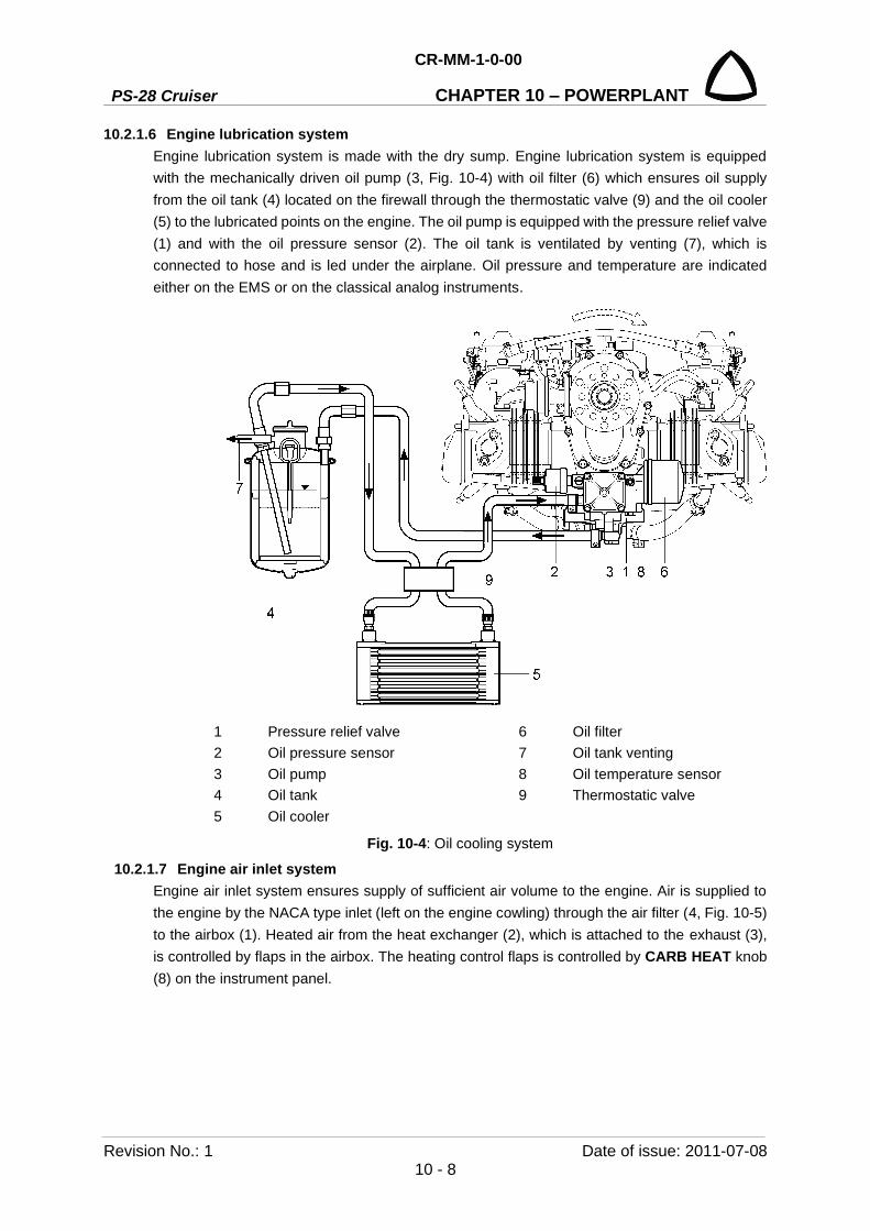
PS-28 Cruiser
CR-MM-1-0-00
CHAPTER 10 – POWERPLANT
Revision No.: 1 Date of issue: 2011-07-08 10 - 8
10.2.1.6 Engine lubrication system Engine lubrication system is made with the dry sump. Engine lubrication system is equipped with the mechanically driven oil pump (3, Fig. 10-4) with oil filter (6) which ensures oil supply from the oil tank (4) located on the firewall through the thermostatic valve (9) and the oil cooler (5) to the lubricated points on the engine. The oil pump is equipped with the pressure relief valve (1) and with the oil pressure sensor (2). The oil tank is ventilated by venting (7), which is connected to hose and is led under the airplane. Oil pressure and temperature are indicated either on the EMS or on the classical analog instruments.
1 Pressure relief valve 6 Oil filter 2 Oil pressure sensor 7 Oil tank venting 3 Oil pump 8 Oil temperature sensor 4 Oil tank 9 Thermostatic valve 5 Oil cooler
Fig. 10-4: Oil cooling system
10.2.1.7 Engine air inlet system Engine air inlet system ensures supply of sufficient air volume to the engine. Air is supplied to the engine by the NACA type inlet (left on the engine cowling) through the air filter (4, Fig. 10-5) to the airbox (1). Heated air from the heat exchanger (2), which is attached to the exhaust (3), is controlled by flaps in the airbox. The heating control flaps is controlled by CARB HEAT knob (8) on the instrument panel.

CR-MM-1-0-00
PS-28 Cruiser CHAPTER 10 – POWERPLANT
Date of issue: 2014-01-30 Revision No.: 8 10 - 9
1 Airbox 5 Oil cooler 2 Heat exchanger 6 Water cooler 3 Exhaust 7 CABIN HEATING knob 4 Air filter 8 CARB HEAT knob
Fig. 10-5: Air inlet system
10.2.1.8 Exhaust system Exhaust system of PS-28 Cruiser / SportCruiser airplane consist of four exhaust tubes (1, Fig. 10-6) which lead exhaust gases from individual cylinders to the muffler (2). The muffler serves at the same time as a silencer. Exhaust gases are led from there by the exhaust tube (3) down the airplane. On the muffler there is a heat exchanger (5) from which is taken the warm air for the carburetor preheating and for the cockpit. The whole exhaust system is manufactured by welding from the stainless steel sheet. PS-28 Cruiser aircraft fitted with the propeller Sensenich 3B0R5R68C may have installed after-muffler that reduces the noise level.
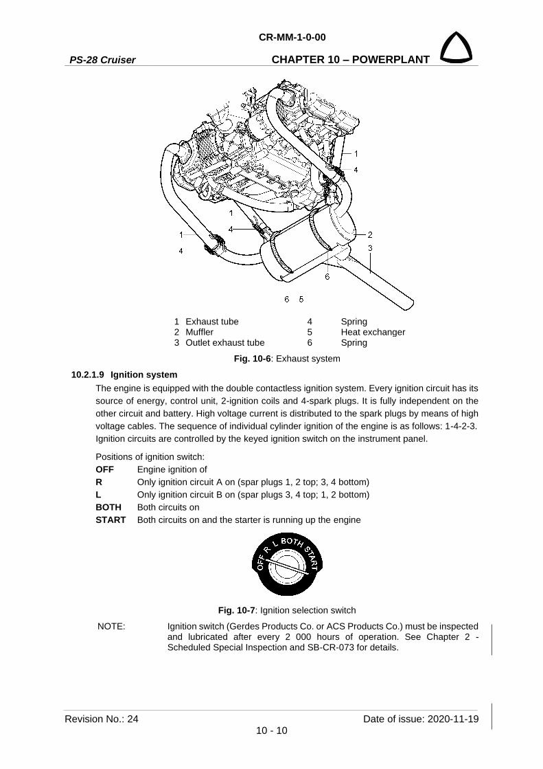
PS-28 Cruiser
CR-MM-1-0-00
CHAPTER 10 – POWERPLANT
Revision No.: 24 Date of issue: 2020-11-19 10 - 10
1 Exhaust tube 4 Spring 2 Muffler 5 Heat exchanger 3 Outlet exhaust tube 6 Spring
Fig. 10-6: Exhaust system
10.2.1.9 Ignition system The engine is equipped with the double contactless ignition system. Every ignition circuit has its source of energy, control unit, 2-ignition coils and 4-spark plugs. It is fully independent on the other circuit and battery. High voltage current is distributed to the spark plugs by means of high voltage cables. The sequence of individual cylinder ignition of the engine is as follows: 1-4-2-3. Ignition circuits are controlled by the keyed ignition switch on the instrument panel.
Positions of ignition switch: OFF Engine ignition of R Only ignition circuit A on (spar plugs 1, 2 top; 3, 4 bottom) L Only ignition circuit B on (spar plugs 3, 4 top; 1, 2 bottom) BOTH Both circuits on START Both circuits on and the starter is running up the engine
Fig. 10-7: Ignition selection switch
NOTE: Ignition switch (Gerdes Products Co. or ACS Products Co.) must be inspected and lubricated after every 2 000 hours of operation. See Chapter 2 - Scheduled Special Inspection and SB-CR-073 for details.

CR-MM-1-0-00
PS-28 Cruiser CHAPTER 10 – POWERPLANT
Date of issue: 2017-12-05 Revision No.: 20 10 - 11
10.2.2 Propeller
The Woodcomp Klassic is a three-blade ground adjustable composite propeller designed for the airplanes with piston engines with power up to 75 kW (100 hp) and max. propeller speed up to 2,600 rpm. The Sensenich 3B0R5R68C propeller is a three-blade ground adjustable composite propeller designed for the airplanes equipped with engines Rotax 912 / 914 series. The leading edge of the propeller blades is protected from damaging side by polyurethane tape (Woodcomp) and co-cured bonded stainless steel (Sensenich). The propeller surface is provided with a sprayed-on coat of resistant polyurethane varnish. The composite propeller spinner is a part of the propeller. The propeller is attached to the engine by means of bolts.
Technical data of the propellers:
Woodcomp propellers Propeller manufacturer: Woodcomp s.r.o.
Propeller type: Klassic 170/3/R
Max. speed: 2,600 rpm
Diameter: 1.712 m (67.4 in)
Pitch setting: 17.5° ± 0.5°
Sensenich propeller Propeller manufacturer: Sensenich Propeller Manufacturing Co., Inc. Propeller type: 3B0R5R68C
Max. speed: 5,800 rpm engine
Diameter: 1.727 m (68 in)
Pitch setting: No. 3 (18.3 ± 0.5°)
NOTE: For detail information refer to: - Sensenich Three Blade Composite Aircraft Propeller Installation and Operation Instructions for Rotax Engines (Doc. No. 3b0r5).

PS-28 Cruiser
CR-MM-1-0-00
CHAPTER 10 – POWERPLANT
Revision No.: 22 Date of issue: 2018-09-27 10 - 12
10.3 Removal / Installation
10.3.1 Removal of the engine from the airplane
Type of maintenance: heavy
Authorization to perform:
See point 2.5.3.
Tools needed:
- wrench size No.8, No.9, 3/8”, 7/16”, 9/16”
- Allen wrench size No.4
- screwdriver
- cutting pliers, pliers
- Cobra pliers (for clamps)
(a) Remove engine cowling.
(b) Disconnect and remove the battery (see 11.3.2).
(c) Remove the propeller (see 10.3.3 or 10.3.5 or 10.3.7).
(d) Disconnect all electrical system wires and bonding between the engine mount and the firewall.
(e) Shut the fuel selector valve (possibly drain fuel from the fuel installation).
(f) Drain oil from the engine (see 10.5.1) and cooling liquid (see 10.5.2).
(g) Disconnect hoses of the oil and the cooling system.
(h) Remove the oil cooler (see 10.3.13) and the water cooler (see 10.3.15).
(i) Disconnect control of carburetors and carburetors heating.
(j) Remove air intake (see 10.3.9).
(k) Remove the exhaust system (see 10.3.11).
(l) Blind all the holes on the engine so that no debris can get into the engine.
(m) Cut off the wire securing the bolt heads (2, Fig. 10-8).
(n) Remove bolts (2) and washers (3) attaching the engine to the engine mount (4).
(o) Take the engine (1) away from the engine mount by the crane or with help 2 assistants.
(p) Store the removed engine on a safe place on a suitable support and prevent it from damage.
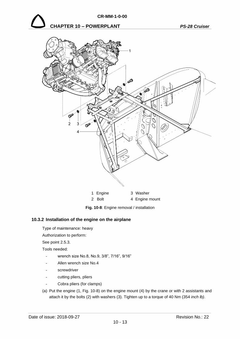
CR-MM-1-0-00
PS-28 Cruiser CHAPTER 10 – POWERPLANT
Date of issue: 2018-09-27 Revision No.: 22 10 - 13
1 Engine 3 Washer 2 Bolt 4 Engine mount
Fig. 10-8: Engine removal / installation
10.3.2 Installation of the engine on the airplane
Type of maintenance: heavy
Authorization to perform:
See point 2.5.3.
Tools needed:
- wrench size No.8, No.9, 3/8”, 7/16”, 9/16”
- Allen wrench size No.4
- screwdriver
- cutting pliers, pliers
- Cobra pliers (for clamps)
(a) Put the engine (1, Fig. 10-8) on the engine mount (4) by the crane or with 2 assistants and attach it by the bolts (2) with washers (3). Tighten up to a torque of 40 Nm (354 inch lb).
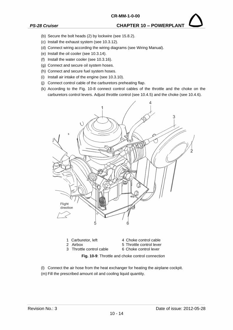
PS-28 Cruiser
CR-MM-1-0-00
CHAPTER 10 – POWERPLANT
Revision No.: 3 Date of issue: 2012-05-28 10 - 14
(b) Secure the bolt heads (2) by lockwire (see 15.8.2). (c) Install the exhaust system (see 10.3.12). (d) Connect wiring according the wiring diagrams (see Wiring Manual). (e) Install the oil cooler (see 10.3.14). (f) Install the water cooler (see 10.3.16). (g) Connect and secure oil system hoses. (h) Connect and secure fuel system hoses. (i) Install air intake of the engine (see 10.3.10). (j) Connect control cable of the carburetors preheating flap. (k) According to the Fig. 10-8 connect control cables of the throttle and the choke on the
carburetors control levers. Adjust throttle control (see 10.4.5) and the choke (see 10.4.6).
1 Carburetor, left 4 Choke control cable 2 Airbox 5 Throttle control lever 3 Throttle control cable 6 Choke control lever
Fig. 10-9: Throttle and choke control connection
(l) Connect the air hose from the heat exchanger for heating the airplane cockpit. (m) Fill the prescribed amount oil and cooling liquid quantity.

CR-MM-1-0-00
PS-28 Cruiser CHAPTER 10 – POWERPLANT
Date of issue: 2020-11-19 Revision No.: 24 10 - 15
(n) Check fuel system tightness (see 9.4.1).
(o) Install the propeller (see 10.3.4 or 10.3.6 or 10.3.8).
(p) Install and connect the battery (see 11.3.3).
(q) Install engine cowlings.
(r) Perform engine test (see 10.4.1).
10.3.3 Klassic 170/3/R propeller removal
Type of maintenance: line
Authorization to perform:
See point 2.5.3.
Tools needed:
- wrench size No.13, No. 16 (5/8”)
- Allen wrench size No. 6
- screwdriver
- cutting pliers, pliers
WARNING: ENGINE IGNITION MUST BE SWITCHED OFF! (a) Disconnect the battery and remove upper line of spark plugs from the engine. (b) Unscrew the screws (11, Fig. 10-10) with the washers (12) and remove the propeller spinner
(2). (c) Cut of the lockwire securing the bolt heads (7). (d) Unscrew and remove the bolts (7) with the washers (10) and take out the propeller along
with spinner flange (9) from the spacer (3). (e) Put the protective covers on the propeller blades and store the propeller on a safe place so
that no damage can occur.
Fig. 10-10: Klassic 170/3/R propeller removal / installation
1 Propeller 2 Propeller spinner 3 Spacer 4 Drive bushing (6 pcs.) 5 Bolt (6 pcs.) 6 Propeller flange
7 Bolt (6 pcs.) 8 Nut (6 pcs.) 9 Spinner flange 10 Washer (12 pcs) 11 Screw (6 pcs.) 12 Washer (6 pcs.)

PS-28 Cruiser
CR-MM-1-0-00
CHAPTER 10 – POWERPLANT
Revision No.: 3 Date of issue: 2012-05-28 10 - 16
10.3.4 Klassic 170/3/R propeller installation
Type of maintenance: line
Authorization to perform:
See point 2.5.3.
Tools needed:
- wrench size No.13, No. 16 (5/8”)
- Allen wrench size No. 6
- screwdriver
- cutting pliers, pliers
WARNING: ENGINE IGNITION MUST BE SWITCHED OFF! (a) Disconnect the battery and remove upper line of spark plugs from the engine. (b) Check the contacting areas of the spacer propeller shaft flange (3, Fig. 10-10) and the
propeller. Clear of all impurities. (c) Remove protective covers from the propeller blades and carry out visual check of the
propeller integrity and condition. (d) Check out possibly adjust the blades pitch of propeller according to the propeller manual.
NOTE: Propeller pitch is factory set to 17.5° ± 0.5°.
(e) Attach the propeller (1) and the propeller flange (9) to the spacer (3) on the engine flange (6) by means of the bolts (7) with washers (10).
(f) Secure the airplane against its movement (see 14.5). (g) Tighten the bolts (7) using a star pattern (Fig.10-11) with torque 22 Nm (16.2 ft.lb.) and
measure the difference in distance of individual blade tips from marking (see Fig. 10-12).
Fig. 10-11: Bolt tightening sequence

CR-MM-1-0-00
PS-28 Cruiser CHAPTER 10 – POWERPLANT
Date of issue: 2020-11-19 Revision No.: 24 10 - 17
(h) The difference can be max. 1.5 mm (0.06 in). Possible bigger differences can be corrected by repetition the procedure from point (g).
Fig. 10-12: Check of axial propeller running-out
(i) Secure bolt heads (7, Fig. 10-10) by lockwire (see 15.8.2).
(j) Put the propeller spinner (2) on the propeller and attach it with bolts (11) with washers (12).
(k) Install spark plugs to the engine. Tighten up with torque 20 Nm (15 ft.lb); connect the battery.
10.3.5 Engine mount removal
Type of maintenance: heavy
Authorization to perform:
See point 2.5.3.
Tools needed:
- wrench size 9/16”
- screwdriver
- torque wrench
- cutting pliers, pliers
WARNING: ENGINE IGNITION MUST BE SWITCHED OFF! (a) Remove engine cowlings(b) Disconnect the battery and remove upper line of spark plugs from the engine.

PS-28 Cruiser
CR-MM-1-0-00
CHAPTER 10 – POWERPLANT
Revision No.: 24 Date of issue: 2020-11-19 10 - 18
(c) Remove the engine and all other parts on the engine mount (see CR-MM-1-0-00, chapter 10.3.1, the latest revision)
(d) Unscrew the nuts (2, Fig. 10-13) and remove the engine mount (1).
Fig. 10-13: Engine mount removal / installation
10.3.6 Engine mount installation
Type of maintenance: heavy
Authorization to perform:
See point 2.5.3.
Tools needed:
- wrench size 9/16”
- screwdriver
- torque wrench
- cutting pliers, pliers
WARNING: ENGINE IGNITION MUST BE SWITCHED OFF! (a) Install the engine mount (1, Fig. 10-13) and screw self-lock nuts (2). Tighten up to a torque
of 20 Nm (177 inch lb). (b) Install the engine and all other parts (see CR-MM-1-0-00, chapter 10.3.2, the latest revision). (c) Mount all cables by the cable tie. (d) Connect the battery and install upper line of spark plugs to the engine. (e) Install the engine cowlings.
1 Engine mount 2 Nuts (4 pcs.)
1 2
2

CR-MM-1-0-00
PS-28 Cruiser CHAPTER 10 – POWERPLANT
Date of issue: 2020-11-19 Revision No.: 24 10 - 19
(f) Restore the aircraft to the airworthy condition. (g) Perform engine run test (see CR-MM-1-0-00, the latest revision). (h) Complete the aircraft records.
10.3.7 INTENTIONALLY LEFT EMPTY
10.3.8 INTENTIONALLY LEFT EMPTY

PS-28 Cruiser
CR-MM-1-0-00
CHAPTER 10 – POWERPLANT
Revision No.: 22 Date of issue: 2018-09-27 10 - 20
10.3.9 3B0R5R68C propeller removal
Type of maintenance: line
Authorization to perform:
See point 2.5.3.
Tools needed:
- wrench size No.13
- Allen wrench size No. 6
- screwdriver
WARNING: ENGINE IGNITION MUST BE SWITCHED OFF! (a) Disconnect the battery and remove upper line of spark plugs from the engine.
(b) Unscrew the screws (10, Fig. 10-14) with the washers (11) and remove the propeller spinner
(2).
(c) Unscrew and remove the nuts (6), the washers (7) and take out the propeller (1) along with
the spinner flange (9) and spacer (3) from the propeller flange (12).
(d) Put the protective covers on the propeller blades and store the propeller on a safe place so
that no damage can occur.
Fig. 10-14: 3B0R5R68C propeller removal / installation
1 Propeller 2 Propeller spinner 3 Spacer 4 Drive bushing (6 pcs.) 5 Bolt (6 pcs.) 6 Nut (6 pcs.)
7 Lock washer (36 pcs.) 8 Spacer bushing (6 pcs.) 9 Spinner flange 10 Screw (6 pcs.) 11 Washers (6 pieces) 12 Propeller flange
CR-MM-1-0-00
PS-28 Cruiser CHAPTER 10 – POWERPLANT
Date of issue: 2018-09-27 Revision No.: 22 10 - 21
10.3.10 3B0R5R68C propeller installation
Type of maintenance: line
Authorization to perform:
See point 2.5.3.
Tools needed:
- wrench size No.13
- Allen wrench size No. 6
- screwdriver
WARNING: ENGINE IGNITION MUST BE SWITCHED OFF! (a) Disconnect the battery and remove upper line of spark plugs from the engine. (b) Check the contacting areas of the propeller flange (12, Fig. 10-14), propeller (1) and spacer
(3). Clear of all impurities. (c) Remove protective covers from the propeller blades and carry out visual check of the
propeller integrity and condition. (d) Check out possibly adjust the blades pitch of propeller according to the propeller manual.
NOTE: Propeller pitch is factory set to No. 3.
(e) Insert bushings (8) into the propeller hub from the back side. (f) Place washers (7) on the bolts (5) and insert the bolts through the assembled propeller hub.
NOTE: Each washer (7) works in pairs with the “ramped” sides facing each other. No other washers may be used in combination with those washers.
(g) Insert bushings (4) into the engine flange (12) from the back side, protruding into the spacer. (h) Place spinner flange (9), spacer (3) and the assembled propeller (1) on the propeller
mounting flange (12). The hub must sit flush on the mounting flange.
CAUTION: THE HUB MUST SIT FLUSH AGAINST THE MOUNTING FLANGE. BOLT BREAKAGE WILL OCCUR IF NOT FLUSH.
(i) Place washers (7) on the bolt threads (5) and hand thread the nuts (6) up to the plastic stops. (j) Using a calibrated torque wrench, torque the bolts (5) evenly using a star pattern. Tighten
the bolts in several increments up to full torque, such as 50 %, 75 %, and full torque 24 – 27 Nm (18 – 20 ft.lb).
(k) Check the propeller blades for track. The blades should track within 3/16” (4.8 mm) of each
other at the tip (see Fig. 10-12). Setting the pitch accurately is more important than track from blade to blade.
(l) Install spark plugs to the engine. Tighten up with torque 20 Nm (15 ft.lb.); connect the battery.

PS-28 Cruiser
CR-MM-1-0-00
CHAPTER 10 – POWERPLANT
Revision No.: 2 Date of issue: 2011-11-08 10 - 22
(m) Run the propeller for approximately 5 minutes at 50% of the desired rpm. Check the clamping bolts to see if they have lost torque. If they have, it is because the blades have firmly seated themselves. Tighten again to the proper torque.
NOTE: This torque value should be checked after the first 5 hours of operation and every 25 hours thereafter.
(n) Put the propeller spinner (2, Fig. 10-14) on the propeller and attach it with screws (10) and washers (11).
10.3.11 Air intake system removal
Type of maintenance: line
Authorization to perform:
- Sport pilot or higher
Tools needed:
- wrench size No.8, No.10
- screwdriver
WARNING: ENGINE IGNITION MUST BE SWITCHED OFF! (a) Remove the upper engine cowling. (b) Disconnect the control cable (13, Fig. 10-17) from the air intake changeover lever (14) and
from the holder. (c) Remove the hose fasteners (4; 5; 16) and disconnect hoses (2; 3), drain hoses (6; 7), and
air hoses (8; 15). (d) Unscrew nut (12), remove washer (11), silentblock (9), and disconnect the bracket (10). (e) Remove the airbox from the engine and store it.
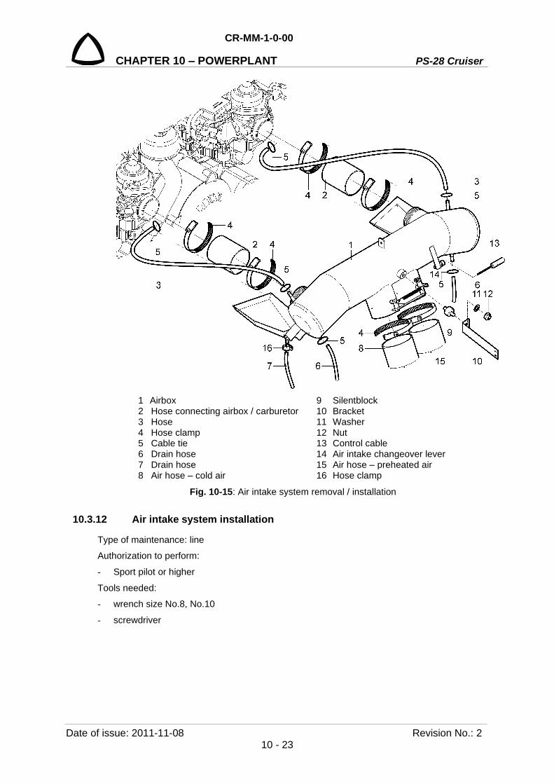
CR-MM-1-0-00
PS-28 Cruiser CHAPTER 10 – POWERPLANT
Date of issue: 2011-11-08 Revision No.: 2 10 - 23
1 Airbox 9 Silentblock
2 2 Hose connecting airbox / carburetor 10 Bracket 3 Hose 11 Washer 4 Hose clamp 12 Nut 5 Cable tie 13 Control cable 6 Drain hose 14 Air intake changeover lever 7 Drain hose 15 Air hose – preheated air 8 Air hose – cold air 16 Hose clamp
Fig. 10-15: Air intake system removal / installation
10.3.12 Air intake system installation
Type of maintenance: line
Authorization to perform:
- Sport pilot or higher
Tools needed:
- wrench size No.8, No.10
- screwdriver

PS-28 Cruiser
CR-MM-1-0-00
CHAPTER 10 – POWERPLANT
Revision No.: 22 Date of issue: 2018-09-27 10 - 24
WARNING: ENGINE IGNITION MUST BE SWITCHED OFF! (a) Attach the outlet pipe of the airbox (1, Fig. 10-17) to the hoses (2) on the carburetor inlet
necks; secure it by means of the hose clamps (4).
(b) Fix the airbox by means of the bracket (10), silentblock (9), nut (12) and washer (11) to the
firewall.
(c) Connect the air intake hoses to the airbox (1), one (8) from the air filter on the lower engine
cowling and the other (15) from the heat exchanger; secure them by hose clamps (4).
CAUTION: DO NOT CONFUSE THESE HOSES!
(d) Connect drain hoses (6) to the airbox (1) and the drain hoses (7) to the drip trays under
carburetors - lead them on the engine mount in direction down the airplane and secure them
by hose fasteners (5; 16). (fix them by cable ties on the engine mount).
(e) Connect the carburetors control cable of (13) to the lever (14); adjust function of carburetors
heating knob.
(f) Install the upper engine cowling.
10.3.13 Exhaust system removal
Type of maintenance: line
Authorization to perform:
See point 2.5.3.
Tools needed:
- wrench size No.13
- pliers
- small wire hook (spring removal/assembly jig)
WARNING: ENGINE IGNITION MUST BE SWITCHED OFF! (a) Remove engine cowlings.
(b) Disconnect air hoses from the heat exchanger (8, Fig. 10-18) (see 10.3.11).
(c) Remove lockwire securing the springs (9).
(d) Remove the springs (9) and dismantle the heat exchanger (8) from the muffler (1).
(e) Remove the springs (6) from the individual exhaust tubes (2; 3; 4; 5) and carefully remove
muffler (1).
(f) Unscrew nut (7) and remove exhaust tubes (2; 3; 4; 5) from the necks on the engine.

CR-MM-1-0-00
PS-28 Cruiser CHAPTER 10 – POWERPLANT
Date of issue: 2018-09-27 Revision No.: 22 10 - 25
1 Muffler 6 Spring 2 Exhaust tube 1 7 Locknut 3 Exhaust tube 2 8 Heat exchanger 4 Exhaust tube 3 9 Spring 5 Exhaust tube 4
Fig. 10-16: Exhaust system removal / installation
10.3.14 Exhaust system installation
Type of maintenance: line
Authorization to perform:
See point 2.5.3.
Tools needed:
- wrench size No.13
- pliers
- small wire hook (spring removal/assembly jig)
WARNING: ENGINE IGNITION MUST BE SWITCHED OFF!

PS-28 Cruiser
CR-MM-1-0-00
CHAPTER 10 – POWERPLANT
Revision No.: 3 Date of issue: 2012-05-28 10 - 26
(a) Install the exhaust tubes (2; 3; 4; 5, Fig. 10-16) to the engine necks.
Mind a proper arrangement, each tube is designed for specific necks.
Screw the nuts (7) on the bolts of the engine exhaust necks, do not tighten the nuts.
(b) To all muffler ball joints apply heat resistant lubricant (e.g. Loctite Antiseize).
(c) Install the muffler (1) to the exhaust tubes (2; 3; 4; 5) and secure the tubes by means of the
springs (6); secure springs with the lockwire (see 15.8.2).
(d) Gradually tighten all nuts (7) of the flanges on the engine necks – tightening torque 12 – 20
Nm (9 – 14 ft.lb)
NOTE: Ensure the sufficient space between the exhaust pipes and the other installed parts.
(e) Put on muffler (1) heat exchanger (8) and secure it by means of springs (9).
(f) Install air hoses on the heat exchanger (see 10.3.12).
(g) Install engine cowlings.
10.3.15 Oil cooler removal
Type of maintenance: line
Authorization to perform:
Sport pilot or higher
Tools needed:
- wrench size No.19, No.30
WARNING: ENGINE IGNITION MUST BE SWITCHED OFF! (a) Remove the upper and lower engine cowling.
(b) Drain oil from the oil system (see 10.5.1).
NOTE: It is also possible to pump oil from the cooler to the oil tank. You can do it by manual running the engine by means of the propeller, whereas from the oil tank you will remove the hose leading to the oil cooler.
(c) Remove lockwire securing banjo bolts (6, Fig. 10-17).
(d) Loose hose clamps (9), and disconnect hoses (8) from the banjo fittings (5).
(e) Remove banjo bolts (6), banjo fittings (5), and sealing rings (7) from the oil cooler necks.
(f) Unscrew nuts (4), remove the upper pairs of washers (2; 3), and cooler (1).
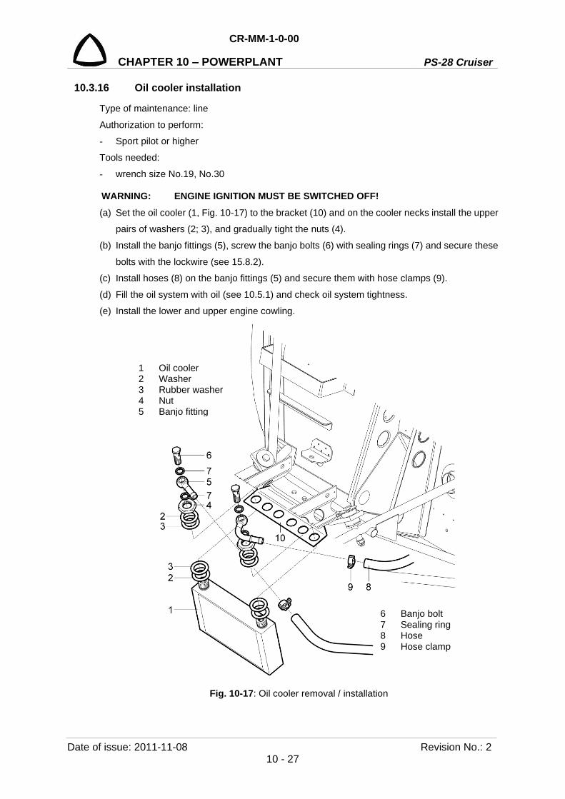
CR-MM-1-0-00
PS-28 Cruiser CHAPTER 10 – POWERPLANT
Date of issue: 2011-11-08 Revision No.: 2 10 - 27
10.3.16 Oil cooler installation
Type of maintenance: line
Authorization to perform:
- Sport pilot or higher
Tools needed:
- wrench size No.19, No.30
WARNING: ENGINE IGNITION MUST BE SWITCHED OFF! (a) Set the oil cooler (1, Fig. 10-17) to the bracket (10) and on the cooler necks install the upper
pairs of washers (2; 3), and gradually tight the nuts (4).
(b) Install the banjo fittings (5), screw the banjo bolts (6) with sealing rings (7) and secure these
bolts with the lockwire (see 15.8.2).
(c) Install hoses (8) on the banjo fittings (5) and secure them with hose clamps (9).
(d) Fill the oil system with oil (see 10.5.1) and check oil system tightness.
(e) Install the lower and upper engine cowling.
Fig. 10-17: Oil cooler removal / installation
1 Oil cooler 2 Washer 3 Rubber washer 4 Nut 5 Banjo fitting
6 Banjo bolt 7 Sealing ring 8 Hose 9 Hose clamp

PS-28 Cruiser
CR-MM-1-0-00
CHAPTER 10 – POWERPLANT
Revision No.: 2 Date of issue: 2011-11-08 10 - 28
10.3.17 Water cooler removal
Type of maintenance: line
Authorization to perform:
- Sport pilot or higher
Tools needed:
- wrench size No.10, No.17
- screwdriver
WARNING: ENGINE IGNITION MUST BE SWITCHED OFF! (a) Remove the upper and lower engine cowling.
(b) Drain the cooling liquid from the cooling system (see 10.5.2).
(c) Remove the hose clamps (9, Fig. 10-15) and disconnect hoses (10; 12) from the cooler
outlets.
(d) Loose the bolts (7).
(e) Remove four nuts (5), washers (6) and cooler (1).
(f) As necessary, remove the silentblocks (4) from the cooler.

CR-MM-1-0-00
PS-28 Cruiser CHAPTER 10 – POWERPLANT
Date of issue: 2011-11-08 Revision No.: 2 10 - 29
1 Cooler 8 Washer 2 Lower bracket 9 Hose clamp 3 Upper bracket 10 Hose 4 Silentblock 11 Tube 5 Cap nut 12 Hose 6 Lock washer 13 Tube 7 Bolt
Fig. 10-18: Water cooler removal / installation

PS-28 Cruiser
CR-MM-1-0-00
CHAPTER 10 – POWERPLANT
Revision No.: 22 Date of issue: 2018-09-27 10 - 30
10.3.18 Water cooler installation
Type of maintenance: line
Authorization to perform:
- Sport pilot or higher
Tools needed:
- wrench size No.10, No.17
- screwdriver
WARNING: ENGINE IGNITION MUST BE SWITCHED OFF! (a) As necessary, screw the silentblocks (4, Fig. 10-18) to the cooler.
(b) Put the cooler on the lower (2) and the upper brackets (3).
(c) Install the washers (6), screw and tighten the nuts (5); tighten the bolts (7).
(d) Install hoses (10) on the cooler outlets and secure them with hose clamps (9).
(e) Fill the cooling system with cooling liquid (see 10.5.2) and check system tightness.
(f) Install the lower and upper engine cowling.
10.3.19 Throttle and choke control levers removal
Type of maintenance: line
Authorization to perform:
See point 2.5.3.
Tools needed:
- wrench size No.14
- Allen wrench size No. 2
- screwdriver
- cutting pliers
WARNING: ENGINE IGNITION MUST BE SWITCHED OFF! (a) Remove the cover (11, Fig. 10-19) from the middle channel.
(b) Remove the upper engine cowling.
(c) Disconnect the throttle (7) and choke (9) cables from carburetor levers (12; 3) and from the
throttle and choke control levers (1).
(d) Unscrew the nuts (5), remove washers (6), bolts (2), bushings (3; 4) and the throttle control
lever witch choke (1) from the middle channel.
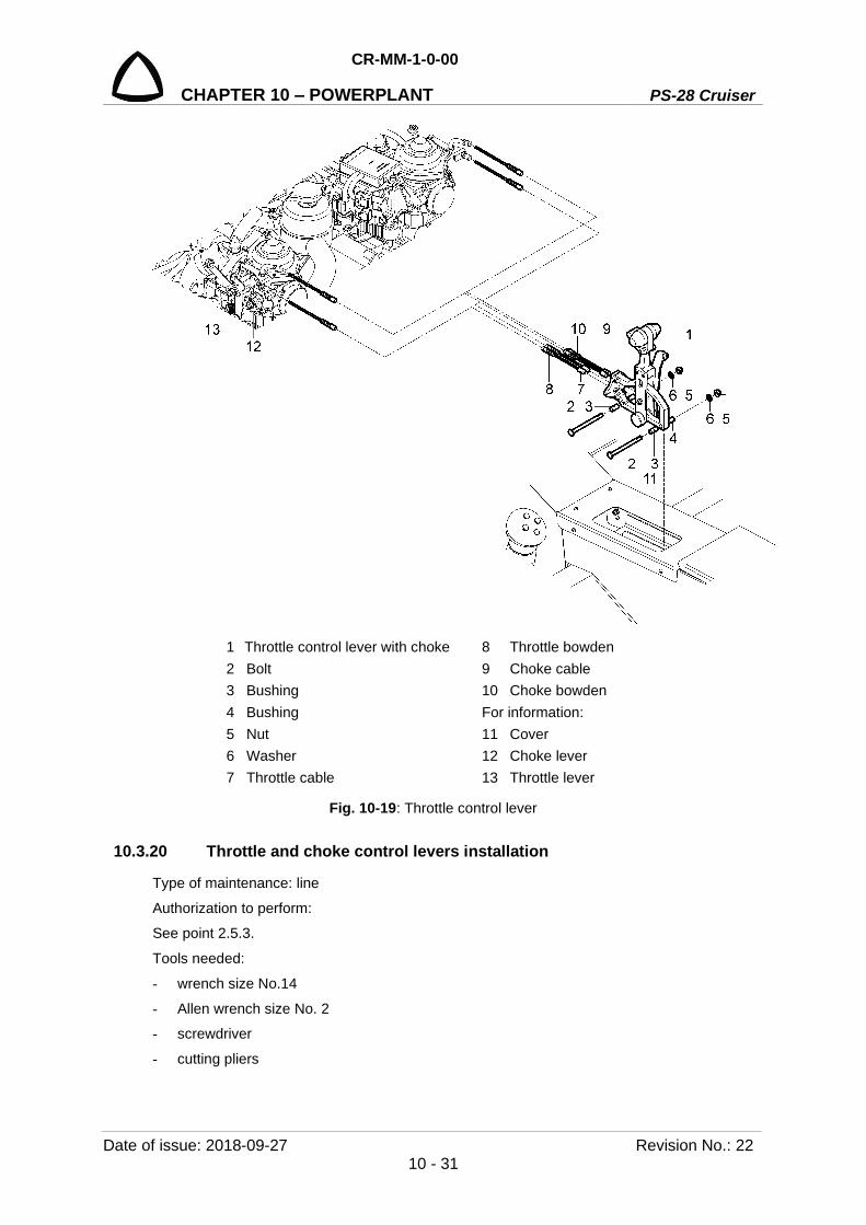
CR-MM-1-0-00
PS-28 Cruiser CHAPTER 10 – POWERPLANT
Date of issue: 2018-09-27 Revision No.: 22 10 - 31
1 Throttle control lever with choke 8 Throttle bowden 2 Bolt 9 Choke cable 3 Bushing 10 Choke bowden 4 Bushing For information: 5 Nut 11 Cover 6 Washer 12 Choke lever 7 Throttle cable 13 Throttle lever
Fig. 10-19: Throttle control lever
10.3.20 Throttle and choke control levers installation
Type of maintenance: line
Authorization to perform:
See point 2.5.3.
Tools needed:
- wrench size No.14
- Allen wrench size No. 2
- screwdriver
- cutting pliers
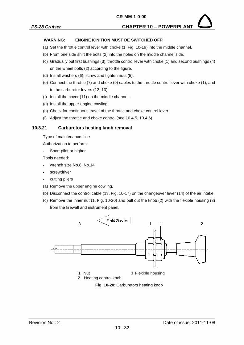
PS-28 Cruiser
CR-MM-1-0-00
CHAPTER 10 – POWERPLANT
Revision No.: 2 Date of issue: 2011-11-08 10 - 32
WARNING: ENGINE IGNITION MUST BE SWITCHED OFF! (a) Set the throttle control lever with choke (1, Fig, 10-19) into the middle channel.
(b) From one side shift the bolts (2) into the holes on the middle channel side.
(c) Gradually put first bushings (3), throttle control lever with choke (1) and second bushings (4)
on the wheel bolts (2) according to the figure.
(d) Install washers (6), screw and tighten nuts (5).
(e) Connect the throttle (7) and choke (9) cables to the throttle control lever with choke (1), and
to the carburetor levers (12; 13).
(f) Install the cover (11) on the middle channel.
(g) Install the upper engine cowling.
(h) Check for continuous travel of the throttle and choke control lever.
(i) Adjust the throttle and choke control (see 10.4.5, 10.4.6).
10.3.21 Carburetors heating knob removal
Type of maintenance: line
Authorization to perform:
- Sport pilot or higher
Tools needed:
- wrench size No.8, No.14
- screwdriver
- cutting pliers
(a) Remove the upper engine cowling.
(b) Disconnect the control cable (13, Fig. 10-17) on the changeover lever (14) of the air intake.
(c) Remove the inner nut (1, Fig. 10-20) and pull out the knob (2) with the flexible housing (3)
from the firewall and instrument panel.
1 Nut 3 Flexible housing 2 Heating control knob
Fig. 10-20: Carburetors heating knob

CR-MM-1-0-00
PS-28 Cruiser CHAPTER 10 – POWERPLANT
Date of issue: 2011-11-08 Revision No.: 2 10 - 33
10.3.22 Carburetors heating knob installation
Type of maintenance: line
Authorization to perform:
- Sport pilot or higher
Tools needed:
- wrench size No.8, No.14
- screwdriver
- cutting pliers
(a) Put the flexible housing (3, Fig. 10-20) with knob (2) into the hole in the instrument panel
and firewall from behind and fasten it from both sides of the instrument panel by the nuts (6).
(b) Fasten the knob from both sides of the instrument panel by the nuts (1).
(c) Connect the control cable (13 Fig. 10-19) on the changeover lever (14) of the air intake.
(d) Adjust carburetors heating control (see 10.4.4).

PS-28 Cruiser
CR-MM-1-0-00
CHAPTER 10 – POWERPLANT
Revision No.: 22 Date of issue: 2018-09-27 10 - 34
10.4 Check / Adjustment
10.4.1 Engine test
CAUTION: THE PERSON PERFORMING THE ENGINE TEST MUST BE REPAIRMAN/ A&P WITH A VALID CERTIFICATE AND WITH REGISTERED ENGINE TYPE ROTAX 912 S2 / ULS2.
(a) Perform the test out of the buildings at the place assigned for performing engine tests in broad daylight.
(b) Test place must be equipped with extinguisher which is suitable for extinguishing burning liquids and electrical installation.
(c) Brake the airplane and put the chocks under the landing gear wheels. (d) Before performing engine test, carry out engine and propeller preflight check in the range
shown in the POH, Section 4.1, and the Rotax Operator’s Manual, Section 3. (e) Start the engine according to the POH, Section 4.2 and the Rotax Operator’s Manual,
Section 3. - activate starter for max.10 sec. only, followed by a cooling period of 2 min.
- as soon as engine runs, adjust throttle to achieved smooth running at approximate 2,500 rpm
- check if oil pressure has risen within 10 sec. and monitor oil pressure
NOTE: If oil pressure do not rise within 10 sec. above min. pressure 0.8 bar (12 psi), switch off the engine. Is admissible max. oil pressure 7 bar (102 psi) for a short period at cold start. Fuel pressure has been in range from 0.15 to 0.4 bar (2.2 to 5.8 psi).
(f) Engine warm up according to the POH, Section 4.2.3 and the Rotax Operator’s Manual, Section 3. As soon as oil pressure will be in range from 2 to 5 bar (29 to 73 psi) start warming up period
at 2,000 rpm for approx. 2 minutes, continue at 2,500 rpm, duration depending on ambient
temperature, until oil temperature reaches 50°C (122°F).
(g) Choke – during engine warm up - OFF.
NOTE: Watch engine instruments and record the values of oil pressure, oil temperature and head cylinder temperature into the Engine test report, see the Tab. 10-1.
(h) Ignition check: Engine speed .............................. 4,000 rpm Ignition switch .............................. switch from position BOTH to L, record rpm drop Ignition switch .............................. switch from position BOTH to R, record rpm drop
NOTE: Rpm drop between position BOTH and L or R must not exceed 300 rpm. Mutual difference between ignition circuits L and R must not exceed 115 rpm. Write down results into the engine test report, see the Tab. 10-1.
(i) Test of max. rpm on the ground:
Throttle ........................................ MAX
NOTE: Record max. rpm into the engine test report, see the Tab. 10-1.

CR-MM-1-0-00
PS-28 Cruiser CHAPTER 10 – POWERPLANT
Date of issue: 2020-11-19 Revision No.: 24 10 - 35
ENGINE TEST REPORT
Aircraft PS-28 Cruiser Registration Serial No.
Engine ROTAX Type 912 S2 / ULS2 Serial No.
Propeller Type Serial No.
Activity Set down values Measured values Starting up the engine
1. Min. oil pressure up to 10 sec. 0.8 bar (12 psi) 2. Max. oil pressure* 7 bar (102 psi) 3. Min. fuel pressure 0.15 bar (2.2 psi)
4. Increase rpm as soon as oil pressure reaches 2 bar (29 psi)
5. Warming up the engine at 2,000 – 2,500 rpm smooth running
6. Voltage 12.4 – 14.4 V Engine test
7. Min. oil temperature 50°C (122°F) 8. Oil pressure 2-5 bar (29-73 psi) 9. Max. cylinder head temperature CHT 135°C (275°F) 10 Max. coolant temperature CT **** 120°C (248°F)
11. Rpm drop between ignition position BOTH and L/R at 4,000 rpm
max. 300 (115 rpm**)
12. Acceleration 2 – 3 sec. 13. Max. ground engine speed *** 14. Idle ***
Defects:
* During cold start for a short term only ** RPM drop between ignition position BOTH and position L or R must not exceed 300 rpm. Mutual
difference between left (L) and right (R) ignition circuit must not exceed 115 rpm. *** Max. ground engine speed and idle varies according to the type of propeller:
Klassic 170/3/R max. 5,000 100 rpm; idle 1,650 50 rpm 3B0RTR68C max. 4,950 100 rpm; idle 1,650 50 rpm
**** With the change to a new cylinder heads design (applicable for ROTAX 912 ULS2 engines from S/N 6 781 410 inclusive and for 912 S2 engines from S/N 4 924 544 inclusive, or on all engines with type designation followed by suffix-01, or on all engines which have been later equipped with the new cylinder heads design of P/N 413185 at cylinder head position 2/3), no longer the cylinder head temperature is measured, but the coolant temperature. Coolant temperature is displayed as “CHT” on Dynon EMS–120 display.
Conclusion Complying – Non-complying Complying if the measured values are not out of the range of the prescribed values.
Elaborated by: Signature: Date: Checked by: Signature: Date:
Tab. 10-1: Engine test report

PS-28 Cruiser
CR-MM-1-0-00
CHAPTER 10 – POWERPLANT
Revision No.: 24 Date of issue: 2020-11-19 10 - 36
(j) Shut engine down.
NOTE: On switching off the engine switch off ignition and withdraw the ignition key.
(k) Inspect rotary seal for leakage.
NOTE: Due to the design of rotary seal, a certain amount of leakage is tolerated. If the leakage is in excess of the limit rotary seal must be renewed.
Tolerated leakage: For this check the engine must be operated until all temperatures have stabilized for a period of 5 minutes. At that point shut down engine and ensure the ignition is switched off and engine secured against unintentional operation. Coolant must not drip through leakage bore, located at the base of the ignition housing, for a period of 1 minute after the engine has been stopped. In case this leakage test cannot be passed, the rotary seal must be renewed.
10.4.2 Klassic 170/3/R propeller - inspections, repairs, works
10.4.2.1 Summary of propeller periodical inspection (see also 2.3.2. for details) • Inspection of propeller after the first 25 hours of operation. • Inspection of propeller after 100 hours of operation or 12 months *, • Inspection of propeller after 500 hours of operation or 36 months *, • Inspection of propeller after 1000 hours of operation or 72 months *,
*) hours of operation or months, whichever comes first.
NOTE: Inspection/overhaul of propeller must also be performed in the following cases:
- The propeller has contacted the ground and/or foreign object, - The propeller has been overspeed (see max operating RPM in User’s Manual), - The propeller has been damaged - The propeller has no record of operating hours and/or calendar months.
10.4.2.2 Prescribed inspection works
NOTE: Inspection of propeller after the first 25 and after 100 hours of operation may be performed by aircraft engineer or certifying staff, see 2.5.1.
Medium repair / overhaul after 500 and after 1000 hours of operation may be performed by manufacturer or his authorized service organization only.
All works / operations must be performed in accordance with the respective maintenance manuals, contact the manufacturer or authorized service organization for details.
Inspection of propeller after the first 25 hours of operation (see also the Operator’s manual UM-07 or relevant instructions on the Woodcomp websites for details) (a) Remove the propeller spinner. (b) Visually check of propeller surface – propeller must not have apparent damages, breakings
and deformations. (c) Check the propeller blades pitch setting and correct if needed, see 10.4.2.3. (d) Cut off the lock wire securing the fixing bolt heads. (e) Tighten the fixing bolts (Fig. 10-21) M8 by moment 22 Nm (16.2 ft.lb.).Tighten also the fixing
bolts of spacer In case it is used. (f) Tighten the bolts M6 on spokes of the hub by moment 10 Nm (7.4 ft.lb.).

CR-MM-1-0-00
PS-28 Cruiser CHAPTER 10 – POWERPLANT
Date of issue: 2020-11-19 Revision No.: 24 10 - 37
Fig. 10-21: Torque moments
(g) Secure fixing bolt heads by lock wire (see 15.8.2). (h) Install the propeller spinner.
Inspection of propeller after 100 hours of operation or 12 months
(a) Remove the propeller spinner. (b) Cut off the lock wire securing the fixing bolt heads. (c) Check the propeller blades pitch setting and correct if needed, see 10.4.2.3. (d) Tighten the fixing bolts (Fig. 10-21) M8 by moment 22 Nm (16.2 ft.lb.) (e) Tighten the bolts M6 on spokes of the hub by moment 10 Nm (7.4 ft.lb.). (f) Inspect firm seating of all blades, - blades must not show any signs of movement or play in
the hub. (g) Visually inspect the blades for damage due to a direct strike (rock, bolt, etc.) or traces of
damage or deformation. As a damage, it is not mentioned the usual operational wear (by friction, operation, washing, etc). Relevant findings of failures must not be of a higher extent than stated in the Operator’s manual UM-07, see the latest issue on the Woodcomp websites. The small failures stated in the Operators manual can be repaired by the Certifying staff (EU1321/2014), see 2.5.1 for details.
(h) If the inspection doesn’t bring satisfactory results, stop using the propeller immediately and have the propeller inspected/repaired by authorized service organization or by the manufacturer.
(i) If the inspection is without findings, secure fixing bolt heads by lock wire (see 15.8.2). (j) Install the propeller spinner.
Inspection of propeller after 500 hours of operation or 36 months
Remove the propeller and send to the manufacturer or his authorized organization
Inspection of propeller on 1,000 hours of operation or 72 months
Remove the propeller and send to the manufacturer or his authorized organization
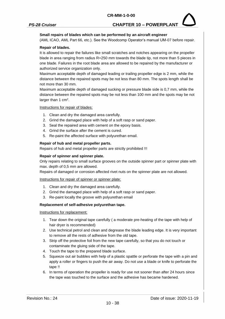
PS-28 Cruiser
CR-MM-1-0-00
CHAPTER 10 – POWERPLANT
Revision No.: 24 Date of issue: 2020-11-19 10 - 38
Small repairs of blades which can be performed by an aircraft engineer (AML ICAO, AML Part 66, etc.). See the Woodcomp Operator’s manual UM-07 before repair.
Repair of blades. It is allowed to repair the failures like small scratches and notches appearing on the propeller blade in area ranging from radius R=250 mm towards the blade tip, not more than 5 pieces in one blade. Failures in the root blade area are allowed to be repaired by the manufacturer or authorized service organization only. Maximum acceptable depth of damaged leading or trailing propeller edge is 2 mm, while the distance between the repaired spots may be not less than 80 mm. The spots length shall be not more than 30 mm. Maximum acceptable depth of damaged sucking or pressure blade side is 0,7 mm, while the distance between the repaired spots may be not less than 100 mm and the spots may be not larger than 1 cm2.
Instructions for repair of blades:
1. Clean and dry the damaged area carefully. 2. Grind the damaged place with help of a soft rasp or sand paper. 3. Seal the repaired area with cement on the epoxy basis. 4. Grind the surface after the cement is cured. 5. Re-paint the affected surface with polyurethan email.
Repair of hub and metal propeller parts. Repairs of hub and metal propeller parts are strictly prohibited !!!
Repair of spinner and spinner plate. Only repairs relating to small surface grooves on the outside spinner part or spinner plate with max. depth of 0,5 mm are allowed. Repairs of damaged or corrosion affected rivet nuts on the spinner plate are not allowed.
Instructions for repair of spinner or spinner plate:
1. Clean and dry the damaged area carefully. 2. Grind the damaged place with help of a soft rasp or sand paper. 3. Re-paint locally the groove with polyurethan email
Replacement of self-adhesive polyurethan tape.
Instructions for replacement:
1. Tear down the original tape carefully ( a moderate pre-heating of the tape with help of hair dryer is recommended)
2. Use technical petrol and clean and degrease the blade leading edge. It is very important to remove all the rests of adhesive from the old tape.
3. Strip off the protective foil from the new tape carefully, so that you do not touch or contaminate the gluing side of the tape.
4. Touch the tape to the prepared blade surface. 5. Squeeze out air bubbles with help of a plastic spattle or perforate the tape with a pin and
apply a roller or fingers to push the air away. Do not use a blade or knife to perforate the tape !!
6. In terms of operation the propeller is ready for use not sooner than after 24 hours since the tape was touched to the surface and the adhesive has became hardened.
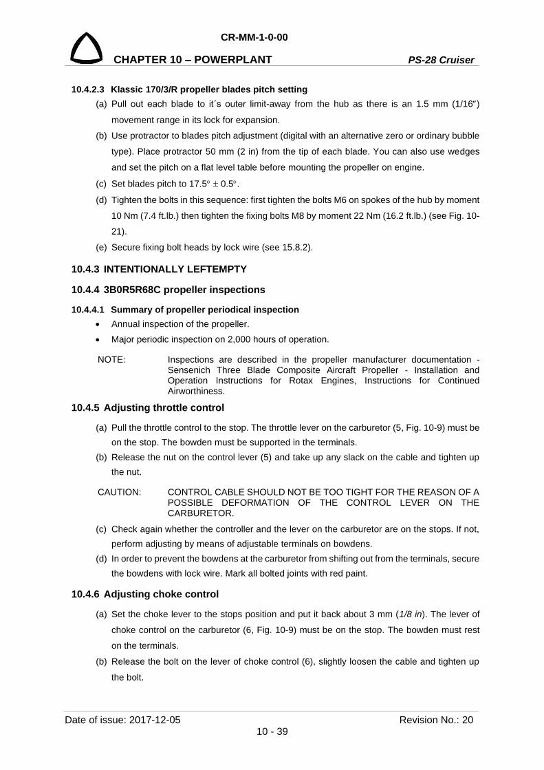
CR-MM-1-0-00
PS-28 Cruiser CHAPTER 10 – POWERPLANT
Date of issue: 2017-12-05 Revision No.: 20 10 - 39
10.4.2.3 Klassic 170/3/R propeller blades pitch setting (a) Pull out each blade to it´s outer limit-away from the hub as there is an 1.5 mm (1/16)
movement range in its lock for expansion.
(b) Use protractor to blades pitch adjustment (digital with an alternative zero or ordinary bubble
type). Place protractor 50 mm (2 in) from the tip of each blade. You can also use wedges
and set the pitch on a flat level table before mounting the propeller on engine.
(c) Set blades pitch to 17.5 0.5.
(d) Tighten the bolts in this sequence: first tighten the bolts M6 on spokes of the hub by moment
10 Nm (7.4 ft.lb.) then tighten the fixing bolts M8 by moment 22 Nm (16.2 ft.lb.) (see Fig. 10-
21).
(e) Secure fixing bolt heads by lock wire (see 15.8.2).
10.4.3 INTENTIONALLY LEFTEMPTY
10.4.4 3B0R5R68C propeller inspections
10.4.4.1 Summary of propeller periodical inspection • Annual inspection of the propeller. • Major periodic inspection on 2,000 hours of operation.
NOTE: Inspections are described in the propeller manufacturer documentation - Sensenich Three Blade Composite Aircraft Propeller - Installation and Operation Instructions for Rotax Engines, Instructions for Continued Airworthiness.
10.4.5 Adjusting throttle control
(a) Pull the throttle control to the stop. The throttle lever on the carburetor (5, Fig. 10-9) must be on the stop. The bowden must be supported in the terminals.
(b) Release the nut on the control lever (5) and take up any slack on the cable and tighten up the nut.
CAUTION: CONTROL CABLE SHOULD NOT BE TOO TIGHT FOR THE REASON OF A POSSIBLE DEFORMATION OF THE CONTROL LEVER ON THE CARBURETOR.
(c) Check again whether the controller and the lever on the carburetor are on the stops. If not, perform adjusting by means of adjustable terminals on bowdens.
(d) In order to prevent the bowdens at the carburetor from shifting out from the terminals, secure the bowdens with lock wire. Mark all bolted joints with red paint.
10.4.6 Adjusting choke control
(a) Set the choke lever to the stops position and put it back about 3 mm (1/8 in). The lever of
choke control on the carburetor (6, Fig. 10-9) must be on the stop. The bowden must rest
on the terminals.
(b) Release the bolt on the lever of choke control (6), slightly loosen the cable and tighten up
the bolt.

PS-28 Cruiser
CR-MM-1-0-00
CHAPTER 10 – POWERPLANT
Revision No.: 8 Date of issue: 2014-01-30 10 - 40
(c) Check again if the choke lever and the lever on the carburetor are on the stops. If not, carry out adjustment by adjustable bowden terminals.
(d) To prevent the bowdens at the carburetor from shifting out of the terminal, secure the bowdens with lock wire. Mark all bolted joints with red paint.
10.4.7 Adjusting carburetors heating control
(a) Push in the carburetor heating knob to the stop and pull it out by about 3 mm (1/8 in). The changeover lever (14, Fig. 10-17) on the air intake must be on the stop. The bowden must rest on the terminal.
(b) Release the bolt on the changeover lever (14), slightly stretch the cable and tighten up the bolt.
(c) Check again whether the knob and the lever on the air intake are on the stops. If not, carry out adjustment by adjustable bowden terminals.
(d) To prevent the bowdens from shifting out of the terminal, secure the bowdens with lock wire. Mark all bolted joints with red paint.
10.4.8 Checking exhaust system
WARNING: CHECK OF EXHAUST SYSTEM VERY CAREFULLY. THE BURST OR LEAKY EXHAUST CAN EXPOSE THE CREW TO DANGER PRESENTED BY CARBON MONOXIDE OR CAN RESULT IN ENGINE POWER LOSS, POSSIBLY FIRE.
Check the exhaust system for cracks. Pay special attention to the following areas:
• muffler in the area of the input and the output pipe and the collector head • all welds and their immediate surrounding • carefully check all areas showing local overheating caused by exhaust gases • remove the heat exchanger and check muffler area located under it • check the whole exhaust pipe between the engine and the muffler including its attachment
to the engine • check outlet pipe from the muffler • check retaining springs for cracks.
10.5 Exchanges / Service information
10.5.1 Exchange / Refilling oil
- refer to the Rotax Maintenance Manual, Chapter 12-00-00, Section 5 Lubrication System.
NOTE: Recommended kinds of oil are mentioned in the Rotax Operator's Manual, Section 10.2.3 Lubricants, in the Rotax Service Instructions SI-912-016.
Type of oil used by the aircraft manufacturer is shown in section 17.5 Operating Liquids.
Oil volume

CR-MM-1-0-00
PS-28 Cruiser CHAPTER 10 – POWERPLANT
Date of issue: 2015-09-23 Revision No.: 15 10 - 41
Total oil volume in the lubrication system of Rotax 912 S2 / ULS2 engine is approximately 3.8 litres (1 US gallon).
Check oil volume preferably after running the propeller by hand in the sense of engine rotation so that oil can fill in the engine space or operate the engine for 1 minute in idle mode.
WARNING: SWITCH OFF IGNITION BEFORE MANUALLY TURNING THE ENGINE! The oil tank is located in the engine compartment and oil dipstick is accessible after opening the lid on the upper engine cowling (see 10.2.1.2). Oil level must lie between min and max marks (flattening) on the dipstick and must not drop below min mark.
Fig. 10-22: Oil volume check
Oil draining Drain oil from the oil tank by unscrewing the plug (wrench size No.17) on the lower side of the oil tank. It is possible to drain oil from the engine after unscrewing the plug in the lower part of the engine at the hose of the return branch of oil flow. It is recommended to drain oil immediately after engine test or after finishing the operation when oil is sufficiently hot and better flows both from the engine and from the tank. Clean the tank before filing it with new oil - see the Rotax Maintenance Manual.
Refilling oil Refill oil in the oil tank that is located on the firewall.
Venting of the lubrication system
After short idling, stop engine and replenish oil to max. mark on dipstick. Never overfill otherwise oil would escape through the vent tube during operation. At oil level inspect, do not exceed the max. mark.
10.5.2 Exchange / Refilling cooling liquid
Refer to the Rotax Maintenance Manual - Cooling System.
1 Oil tank
2 Cap
3 Dipstick

PS-28 Cruiser
CR-MM-1-0-00
CHAPTER 10 – POWERPLANT
Revision No.: 20 Date of issue: 2017-12-05 10 - 42
NOTE: Recommended types of coolant are shown in the Rotax Operator's Manual, Section 2.3 Coolant, Rotax Installation Manual - Cooling System, Rotax Service Instructions SI-912-016
Type of coolant used by aircraft manufacturer is shown in section 17.5 Operating liquids.
Cooling liquid volume Total volume of coolant in the engine is approximately 2.6 litres (0.69 US gallons)*.
*) Total volume of coolant for airplanes equipped with dual circuit thermostatic valve is approximately 2.9 litres (0.77 US gallons) - valid for airplane S/N C0547, all airplanes since S/N C0589 or all other airplanes which have been later equipped with dual circuit thermostatic valve.
Drainage of cooling liquid Disconnect the hose supplying liquid from the radiator to the pump (at the lowest point of the system) and drain cooling liquid into the prepared vessel.
Refilling cooling liquid Refill cooling liquid into the expansion tank in the engine compartment. In addition to this there is a overflow bottle which collects cooling liquid in case of engine overheating and is attached to the fire wall.
10.5.3 Exchange / Check of oil filter
Refer to the Rotax Maintenance Manual, Chapter 12-00-00, Section 5 Oil System
NOTE: Carry out at every oil exchange.
WARNING: RISK OF SCALDS AND BURNS! Always allow the engine to cool down to ambient temperature before starting work. Proceed with this work only in non-smoking area and not close to sparks or open flames. Switch off ignition and secure engine against unintentional operation. Secure aircraft against unauthorized operation.
(a) Disconnect negative terminal of aircraft battery. (b) Remove the oil filter. (c) Remove the filter insert, cut of the upper and the lower lid of the insert. Remove the middle
part of the insert, disassemble and check for metal chips, foreign corpuscles and contamination.
CAUTION: IF YOU DETECT AN INCREASED QUANTITY OF METAL PARTICLES (BRASS OR BRONZE CHIPS OR BEARING ABRASIVE), FIND OUT THE REASON AND ELIMINATE IT.
(d) Install the new oil filter. Slightly lubricate the sealing ring of the new filter with engine oil and tighten it up manually by a normal force.
(e) Restore the aircraft to original operating configuration
(f) Connect negative terninal of aircraft battery. (g) Conduct engine test according to point 10.4.1.
Replenish engine oil and coolant as required once engine has cooled down.
NOTE: Re-tighten by hand after the engine test on a cold engine.
CR-MM-1-0-00
PS-28 Cruiser CHAPTER 10 – POWERPLANT
Date of issue: 2017-12-05 Revision No.: 20 10 - 43
10.5.4 Exchange / Check of air filter
(a) Remove the hose fastener and the bracket attaching the air filter to the left side lower engine cowling and remove the air filter.
(b) Inspect the air filter and if contaminated, clean it according to instructions in the Rotax Maintenance Manual, Chapter 12-00-00, Section 2.4.
(c) Attach the cleaned or the new filter to the hole on the left side of lower engine cowling by means of the bracket and hose fastener.

PS-28 Cruiser
CR-MM-1-0-00
CHAPTER 10 – POWERPLANT
Revision No.: 20 Date of issue: 2017-12-05 10 - 44
INTENTIONALLY LEFT BLANK

CR-MM-1-0-00
PS-28 Cruiser CHAPTER 11 – ELECTRICAL SYSTEM
Date of issue: 2018-09-27 Revision No.: 22 11 - 1
11. ELECTRICAL SYSTEM Content
11.1 General ................................................................................................................ 11-2
11.2 Description and operation .................................................................................... 11-2
11.2.1 Switches .............................................................................................. 11-4
11.2.2 Circuit breakers ................................................................................... 11-5
11.2.3 Fuses ................................................................................................... 11-7
11.2.4 Generator ............................................................................................ 11-7
11.2.5 Battery ................................................................................................. 11-8
11.2.6 Lighting ................................................................................................ 11-8
11.3 Removal / Installation .......................................................................................... 11-9
11.3.1 Electrical safety ................................................................................... 11-9
11.3.2 Battery removal ................................................................................... 11-9
11.3.3 Battery installation ............................................................................... 11-9
11.3.4 Position / strobe light removal ........................................................... 11-10
11.3.5 Position / strobe light installation ....................................................... 11-11
11.3.6 D112-SX landing light removal .......................................................... 11-12
11.3.7 D112-SX landing light installation ...................................................... 11-13
11.4 Exchanges / Service information ....................................................................... 11-13
11.4.1 Charging the battery .......................................................................... 11-13

PS-28 Cruiser
CR-MM-1-0-00
CHAPTER 11 – ELECTRICAL SYSTEM
Revision No.: 1 Date of issue: 2011-07-08 11 - 2
11.1 General Electrical system of PS-28 Cruiser airplane serves for supplying electrical current to the
instruments.
11.2 Description and operation The airplane is equipped with 14 VDC electrical installations with grounded negative pole (see
Fig. 11-1). Primary source of electrical energy is formed by the generator. The secondary
source of electrical energy is the battery 12 V, which is located on the firewall. It is used for
starting the engine and in the case of generator failure as a back-up source of electric energy.
DC voltage is distributed to the individual systems by means of the main busbar. Systems are
protected by circuit breakers which are permanently ON and switches-circuit breakers which
are turning ON as needed. If some of the circuit is overloaded, then the circuit breaker
disconnects the circuit. Some circuits are protected by the fuses.
After switching the MASTER BAT switch ON and by turning the ignition key to the position
START the starter is activated. The starter is supplied from the battery before starting the
engine. After starting up the engine and reaching the idle rpm and switching the MASTER GEN switch ON, the generator starts supplying current to the electrical network.
Information about voltage in the main busbar is indicated by EMS or by the analog voltmeter
on the instrument panel.
NOTE: Valid wiring diagrams are mentioned in PS-28 Cruiser Wiring Manual.

CR-MM-1-0-00
PS-28 Cruiser CHAPTER 11 – ELECTRICAL SYSTEM
Date of issue: 2011-03-08 Revision No.: - 11 - 3
Fig. 11-1: Electrical system scheme
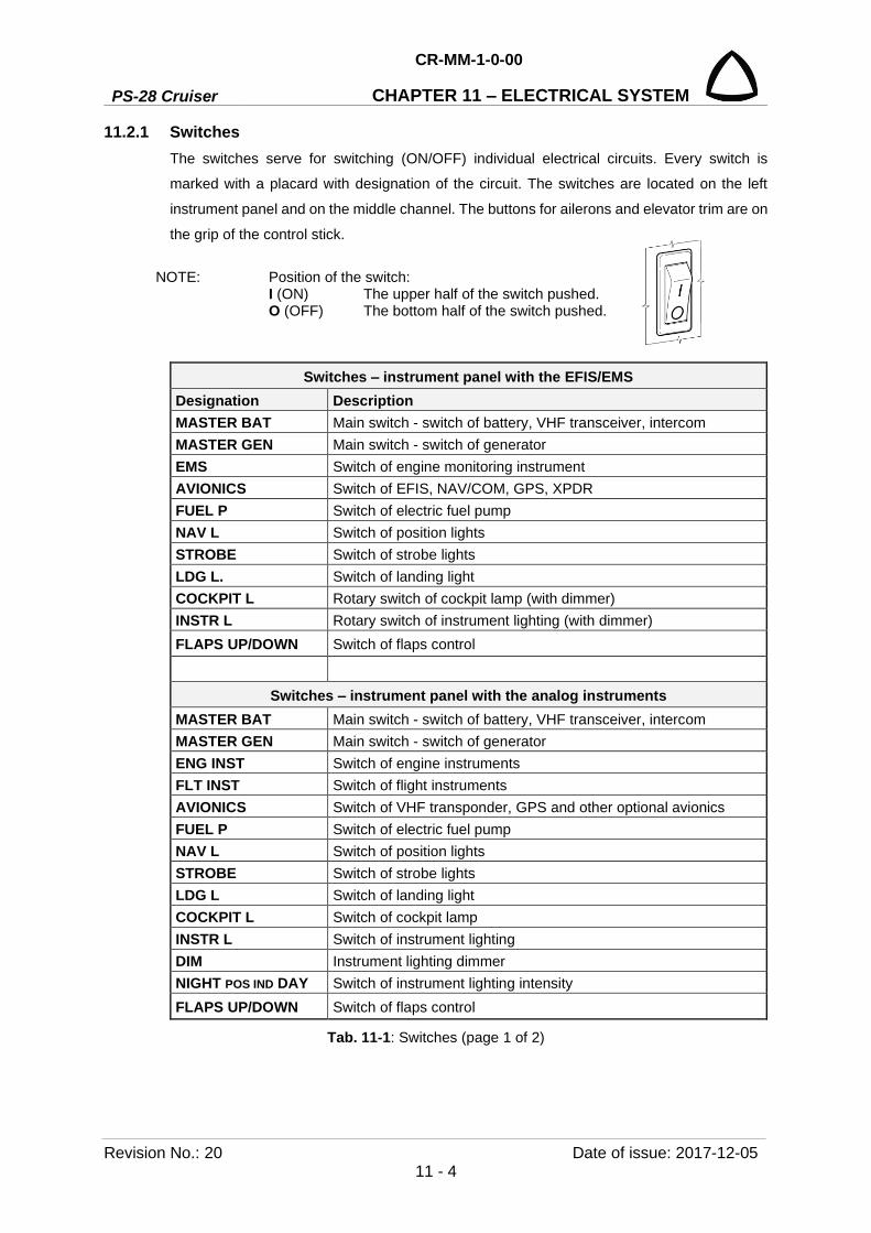
PS-28 Cruiser
CR-MM-1-0-00
CHAPTER 11 – ELECTRICAL SYSTEM
Revision No.: 20 Date of issue: 2017-12-05 11 - 4
11.2.1 Switches The switches serve for switching (ON/OFF) individual electrical circuits. Every switch is
marked with a placard with designation of the circuit. The switches are located on the left
instrument panel and on the middle channel. The buttons for ailerons and elevator trim are on
the grip of the control stick.
NOTE: Position of the switch: I (ON) The upper half of the switch pushed. O (OFF) The bottom half of the switch pushed.
Switches – instrument panel with the EFIS/EMS Designation Description MASTER BAT Main switch - switch of battery, VHF transceiver, intercom MASTER GEN Main switch - switch of generator EMS Switch of engine monitoring instrument AVIONICS Switch of EFIS, NAV/COM, GPS, XPDR FUEL P Switch of electric fuel pump NAV L Switch of position lights STROBE Switch of strobe lights LDG L. Switch of landing light COCKPIT L Rotary switch of cockpit lamp (with dimmer) INSTR L Rotary switch of instrument lighting (with dimmer) FLAPS UP/DOWN Switch of flaps control
Switches – instrument panel with the analog instruments MASTER BAT Main switch - switch of battery, VHF transceiver, intercom MASTER GEN Main switch - switch of generator ENG INST Switch of engine instruments FLT INST Switch of flight instruments AVIONICS Switch of VHF transponder, GPS and other optional avionics FUEL P Switch of electric fuel pump NAV L Switch of position lights STROBE Switch of strobe lights LDG L Switch of landing light COCKPIT L Switch of cockpit lamp INSTR L Switch of instrument lighting DIM Instrument lighting dimmer NIGHT POS IND DAY Switch of instrument lighting intensity FLAPS UP/DOWN Switch of flaps control
Tab. 11-1: Switches (page 1 of 2)

CR-MM-1-0-00
PS-28 Cruiser CHAPTER 11 – ELECTRICAL SYSTEM
Date of issue: 2017-12-05 Revision No.: 20 11 - 5
Switches – instrument panel with the Skyview Designation Description MASTER BAT Main switch - switch of battery, VHF transceiver, intercom MASTER GEN Main switch - switch of generator EFIS1 Switch of EFIS 1 display EFIS2 Switch of EFIS 2 (EMS) display AVIONICS Switch of EFIS, NAV/COM, GPS, XPDR FUEL P Switch of electric fuel pump NAV L Switch of position lights STROBE Switch of strobe lights LDG L. Switch of landing light COCKPIT L Rotary switch of cockpit lamp (with dimmer) INSTR L Rotary switch of instrument lighting (with dimmer) FLAPS UP/DOWN Switch of flaps control
Tab. 11-1: Switches (page 2 of 2)
11.2.2 Circuit breakers Circuit breakers serve for protecting individual electrical circuits from overloading. Every circuit breaker is marked by the placard with a circuit designation. Circuit breakers are located on the right instrument panel.
Circuit breakers – instrument panel with the EFIS/EMS Designation Value Description COMM 5A Circuit breaker of VHF transceiver IC 1A Circuit breaker of intercom EMS 2A Circuit breaker of engine monitoring system display NAV 2A Circuit breaker of optional navigation device EFIS 3A Circuit breaker of flight instrument system display HS34 1A Circuit breaker of HSI navigation interface GPS 4A Circuit breaker of GPS XPDR 5A Circuit breaker of transponder FUEL P 3A Circuit breaker of electric fuel pump FLAPS 3A Circuit breaker of flaps TRIM 1A Circuit breaker of trims NAV L 5A Circuit breaker of position lights STROBE 5A Circuit breaker of strobe lights
LDG L 4A 3A
Circuit breaker of landing light – till S/N 0570 Circuit breaker of landing light – from S/N 0571 or for replacement by Kuntzleman 11-06854 / TrailTech D112-SX landing light
INT L 2A Circuit breaker of instrument lighting and cockpit lamp 12V 5A Circuit breaker of 12V socket

PS-28 Cruiser
CR-MM-1-0-00
CHAPTER 11 – ELECTRICAL SYSTEM
Revision No.: 20 Date of issue: 2017-12-05 11 - 6
Tab. 11-2: Circuit breakers
Circuit breakers – instrument panel with the analog instruments COMM 5A Circuit breaker of VHF transceiver IC 1A Circuit breaker of intercom ENG INSTR 1A Circuit breaker of engine instruments NAV 2A Circuit breaker of optional navigation device GPS 3A Circuit breaker of GPS XPDR 5A Circuit breaker of transponder ATT 2A Circuit breaker of attitude indicator DG 4A Circuit breaker of directional gyro TURN IND 1A Circuit breaker of turn bank indicator FUEL P 3A Circuit breaker of electric fuel pump FLAPS 3A Circuit breaker of flaps TRIM 2A Circuit breaker of trims STROBE 5A Circuit breaker of strobe lights NAV L 5A Circuit breaker of position lights
LDG L 4A 3A
Circuit breaker of landing light – till S/N 0570 Circuit breaker of landing light – from S/N 0571 or for replacement by Kuntzleman 11-06854 / TrailTech D112-SX landing light
INT L 2A Circuit breaker of instrument lighting and cockpit lamp 12V 5A Circuit breaker of 12V socket
Circuit breakers – instrument panel with the Skyview Designation Value Description COMM 5A Circuit breaker of VHF transceiver IC 1A Circuit breaker of intercom NAV 2A Circuit breaker of optional navigation device EFIS1 5A Circuit breaker of EFIS 1 display EFIS2 5A Circuit breaker of EFIS 2 (EMS) display FUEL P 3A Circuit breaker of electric fuel pump FLAPS 3A Circuit breaker of flaps TRIM 1A Circuit breaker of trims STROBE 5A Circuit breaker of strobe lights GPS 4A Circuit breaker of GPS XPDR 5A Circuit breaker of transponder NAV L 5A Circuit breaker of position lights
LDG L 4A 3A
Circuit breaker of landing light – till S/N 0570 Circuit breaker of landing light – from S/N 0571 or for replacement by Kuntzleman 11-06854 / TrailTech D112-SX landing light
INT L 2A Circuit breaker of instrument lighting and cockpit lamp

CR-MM-1-0-00
PS-28 Cruiser CHAPTER 11 – ELECTRICAL SYSTEM
Date of issue: 2012-05-28 Revision No.: 3 11 - 7
11.2.3 Fuses Fuses serve for protecting individual electrical circuits from overloading. The box with the fuses is
located on the firewall in the engine compartment.
Fuses – instrument panel with the EFIS/EMS Designation Description 1A SIGN. DOOR Fuse of unlocked canopy signaling system
25A DC GEN Fuse of generator 25 A BATTERY Fuse of battery
Fuses – instrument panel with the analog instruments
Designation Description 1A SIGN. DOOR Fuse of unlocked canopy signaling system
1A VOLTMETER Fuse of voltmeter
1A ENGIN. INSTR. Fuse of engine instruments 25A DC GEN Fuse of generator
25 A BATTERY Fuse of battery
Fuses – instrument panel with the Skyview Designation Description 1A SIGN. DOOR Fuse of unlocked canopy signaling system
25A DC GEN Fuse of generator 25 A BATTERY Fuse of battery
11.2.4 Generator The generator is a part of the engine which supplies electric current through the rectifier.
Regulator supplies electric current of 14 V voltage to onboard network.
Technical parameters of generator:
Maximum output power: 12 V / 20 A at 5,000 rpm
Technical parameters of rectifier - regulator:
Type: electronic
Output voltage: 14 ± 0.3 V (from 1,000 ± 250 rpm)
Range of operation temperatures: min. – 25 °C (- 13 °F)
max. + 90 °C (+ 194 °F)
Weight: 0.3 kg (0.66 lbs)

PS-28 Cruiser
CR-MM-1-0-00
CHAPTER 11 – ELECTRICAL SYSTEM
Revision No.: 2 Date of issue: 2011-11-08 11 - 8
11.2.5 Battery Lead-acid maintenance-free battery is installed on firewall. Battery can be charged directly in
the airplane after its disconnecting from the onboard electrical system.
Technical parameters:
Voltage 12 V
Nominal capacity 20 Ah
Max. discharge current 300 A (5 s)
Short circuit current 1,000 A
Range of operation temperatures - 20 to + 60 °C (-4 to + 140 °F)
Service life is about 3 - 5 years or at capacity drop below 80 %
Weight: 6 kg (13 lbs)
If the airplane is not operated for more than one month, then remove the battery from the
airplane and store it.
Always store the battery fully charged at temperature of 20 °C (68 °F). Daily discharging is
less than 0.1 % of battery nominal capacity.
Regularly recharge it up to the full capacity of charging once a month.
11.2.6 Lighting External lighting consists of the LED position / strobe lights which are located in the wing tips
and of the landing light which is located in the lower engine cowling. Position lights are
switched by the switch NAV L and strobe lights are switched by the switch STROBE. The
landing light is switched by the switch LDG L.
Internal lighting consists of the instrument lighting and of the cockpit lamp, which is located
on the instrument panel. The instrument lighting (illumination of the altimeter and the airspeed
indicator) is switched / controlled by the switch INSTR L. The cockpit lamp is switched /
controlled by the switch COCKPIT L.
CR-MM-1-0-00
PS-28 Cruiser CHAPTER 11 – ELECTRICAL SYSTEM
Date of issue: 2011-03-08 Revision No.: - 11 - 9
11.3 Removal / Installation 11.3.1 Electrical Safety
The aircraft has a low-voltage DC electrical system. When correctly maintained it is safe to
work on. But the battery can supply heavy current through low-resistance circuits (for
example, if you ground the positive output with a wrench by accident).
Always follow the usual safety practices for working on electrical equipment. Allow only
qualified persons to maintain the electrical system.
CAUTION: DISCONNECT THE BATTERY BEFORE DOING MAINTENANCE ON THE ELECTRICAL SYSTEM. MAKE SURE TO DISCONNECT THE NEGATIVE LEAD FIRST.
CAUTION: USE ONLY AIRCRAFT SPARE PARTS APPROVED BY THE MANUFACTURER.
11.3.2 Battery removal Type of maintenance: line
Authorization to perform:
- Sports pilot or higher
Tools needed:
- screwdriver
- wrench size No.8
(a) Set the MASTER BAT, MASTER GEN switches to OFF.
(b) Remove engine cowlings.
(c) Unscrew the bolts (5, Fig. 11-2) with washers (6) and disconnect the wires (2; 3; 4) from
the battery contacts; make sure to disconnect the negative lead first.
(d) Unscrew the bolts (8) with washers (9), disconnect the battery strap (7) and remove the
battery (1) from the airplane.
11.3.3 Battery installation Type of maintenance: line
Authorization to perform:
- Sports pilot or higher
Tools needed:
- screwdriver
- wrench size No.8
(a) Install the battery (1, Fig. 11-2) into the bracket on the firewall (10).
(b) Fasten it with battery strap (7), bolts (8), and washers (9); tighten bolts so that the battery
cannot move in the bracket.
(c) Install the wires (2; 3; 4) by means of bolts (5) with washers (6); make sure you connect
the positive lead first.
(d) Grease the battery contacts with lubricating grease.
(e) Install the engine cowlings.
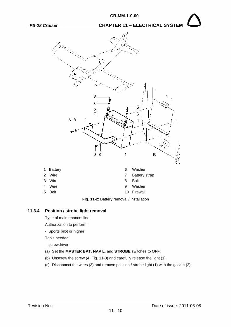
PS-28 Cruiser
CR-MM-1-0-00
CHAPTER 11 – ELECTRICAL SYSTEM
Revision No.: - Date of issue: 2011-03-08 11 - 10
1 Battery 6 Washer 2 Wire 7 Battery strap 3 Wire 8 Bolt 4 Wire 9 Washer 5 Bolt 10 Firewall
Fig. 11-2: Battery removal / installation
11.3.4 Position / strobe light removal Type of maintenance: line
Authorization to perform:
- Sports pilot or higher
Tools needed:
- screwdriver
(a) Set the MASTER BAT, NAV L, and STROBE switches to OFF.
(b) Unscrew the screw (4, Fig. 11-3) and carefully release the light (1).
(c) Disconnect the wires (3) and remove position / strobe light (1) with the gasket (2).
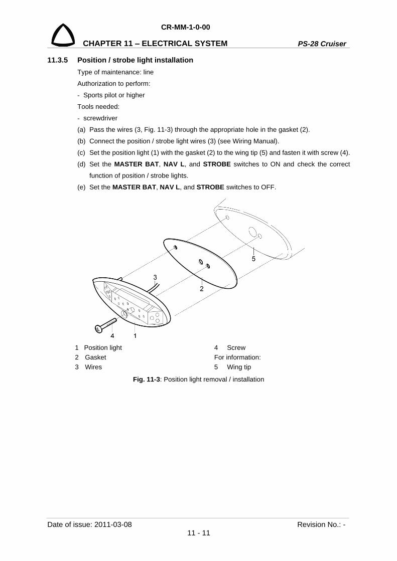
CR-MM-1-0-00
PS-28 Cruiser CHAPTER 11 – ELECTRICAL SYSTEM
Date of issue: 2011-03-08 Revision No.: - 11 - 11
11.3.5 Position / strobe light installation Type of maintenance: line
Authorization to perform:
- Sports pilot or higher
Tools needed:
- screwdriver
(a) Pass the wires (3, Fig. 11-3) through the appropriate hole in the gasket (2).
(b) Connect the position / strobe light wires (3) (see Wiring Manual).
(c) Set the position light (1) with the gasket (2) to the wing tip (5) and fasten it with screw (4).
(d) Set the MASTER BAT, NAV L, and STROBE switches to ON and check the correct
function of position / strobe lights.
(e) Set the MASTER BAT, NAV L, and STROBE switches to OFF.
1 Position light 4 Screw 2 Gasket For information: 3 Wires 5 Wing tip
Fig. 11-3: Position light removal / installation
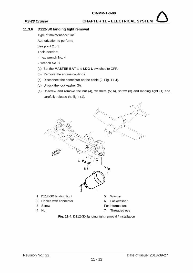
PS-28 Cruiser
CR-MM-1-0-00
CHAPTER 11 – ELECTRICAL SYSTEM
Revision No.: 22 Date of issue: 2018-09-27 11 - 12
11.3.6 D112-SX landing light removal Type of maintenance: line
Authorization to perform:
See point 2.5.3.
Tools needed:
- hex wrench No. 4
- wrench No. 8
(a) Set the MASTER BAT and LDG L switches to OFF.
(b) Remove the engine cowlings.
(c) Disconnect the connector on the cable (2, Fig. 11-4).
(d) Unlock the lockwasher (6).
(e) Unscrew and remove the nut (4), washers (5; 6), screw (3) and landing light (1) and
carefully release the light (1).
1 D112-SX landing light 5 Washer 2 Cables with connector 6 Lockwasher 3 Screw For information: 4 Nut 7 Threaded eye
Fig. 11-4: D112-SX landing light removal / installation
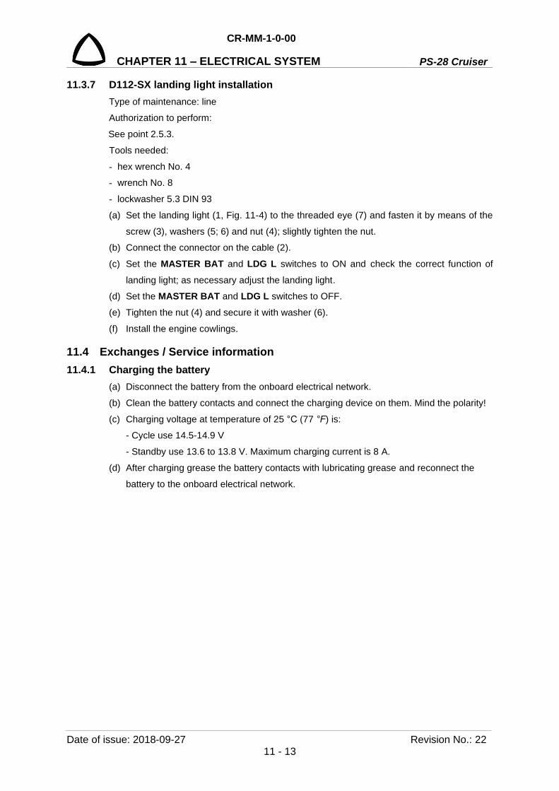
CR-MM-1-0-00
PS-28 Cruiser CHAPTER 11 – ELECTRICAL SYSTEM
Date of issue: 2018-09-27 Revision No.: 22 11 - 13
11.3.7 D112-SX landing light installation Type of maintenance: line
Authorization to perform:
See point 2.5.3.
Tools needed:
- hex wrench No. 4
- wrench No. 8
- lockwasher 5.3 DIN 93
(a) Set the landing light (1, Fig. 11-4) to the threaded eye (7) and fasten it by means of the
screw (3), washers (5; 6) and nut (4); slightly tighten the nut.
(b) Connect the connector on the cable (2).
(c) Set the MASTER BAT and LDG L switches to ON and check the correct function of
landing light; as necessary adjust the landing light.
(d) Set the MASTER BAT and LDG L switches to OFF.
(e) Tighten the nut (4) and secure it with washer (6).
(f) Install the engine cowlings.
11.4 Exchanges / Service information 11.4.1 Charging the battery
(a) Disconnect the battery from the onboard electrical network.
(b) Clean the battery contacts and connect the charging device on them. Mind the polarity!
(c) Charging voltage at temperature of 25 °C (77 °F) is:
- Cycle use 14.5-14.9 V
- Standby use 13.6 to 13.8 V. Maximum charging current is 8 A.
(d) After charging grease the battery contacts with lubricating grease and reconnect the
battery to the onboard electrical network.

PS-28 Cruiser
CR-MM-1-0-00
CHAPTER 11 – ELECTRICAL SYSTEM
Revision No.: 20 Date of issue: 2017-12-05 11 - 14
Fig. 11-5: Battery characteristics

CR-MM-1-0-00
PS-28 Cruiser CHAPTER 12 – INSTRUMENTS AND AVIONICS
Date of issue: 2018-09-27 Revision No.: 22 12 - 1
12. INSTRUMENTS AND AVIONICS Content
12.1 General ................................................................................................................. 12-3
12.2 Description and operation .................................................................................... 12-9
12.2.1 Pitot-static system ............................................................................... 12-9
12.2.2 Stall warning system ........................................................................... 12-9
12.2.3 Flight instruments ............................................................................. 12-11
12.2.4 Engine instruments ........................................................................... 12-12
12.2.5 Avionics ............................................................................................. 12-12
12.2.6 Dynon SkyView system .................................................................... 12-17
12.3 Removal / Installation ......................................................................................... 12-19
12.3.1 Removal of the pitot-static tube ........................................................ 12-19
12.3.2 Installation of the pitot-static tube ..................................................... 12-19
12.3.3 Removal of the stall warning system lift detector ............................. 12-20
12.3.4 Installation of the stall warning system lift detector .......................... 12-20
12.3.5 Removal of the flight instruments ..................................................... 12-21
12.3.6 Installation of the flight instruments .................................................. 12-22
12.3.7 Removal of the EFIS D100 ............................................................... 12-23
12.3.8 Installation of the EFIS D100 ............................................................ 12-25
12.3.9 Removal of EDC-10A remote compass module ............................... 12-25
12.3.10 Installation of EDC-10A remote compass module ............................ 12-26
12.3.11 Removal of the EMS D120 ............................................................... 12-26
12.3.12 Installation of the EMS D120 ............................................................ 12-28
12.3.13 Removal of transponder ................................................................... 12-28
12.3.14 Installation of transponder ................................................................ 12-28
12.3.15 Removal of COMM, COMM / NAV ................................................... 12-29
12.3.16 Installation of COMM, COMM / NAV ................................................ 12-30
12.3.17 Removal of intercom ......................................................................... 12-31
12.3.18 Installation of intercom ...................................................................... 12-31
12.3.19 Removal of GPS / NAV COM ........................................................... 12-32
12.3.20 Installation of GPS / NAV COM ........................................................ 12-33
12.3.21 Removal of COMM antenna ............................................................. 12-34
12.3.22 Installation of COMM antenna .......................................................... 12-35
12.3.23 Removal of NAV antenna ................................................................. 12-35
12.3.24 Installation of NAV antenna .............................................................. 12-36
12.3.25 Removal of transponder antenna ..................................................... 12-37
12.3.26 Installation of transponder antenna .................................................. 12-37
12.3.27 Removal of GPS antenna ................................................................. 12-38
12.3.28 Installation of GPS antenna .............................................................. 12-39

PS-28 Cruiser
CR-MM-1-0-00
CHAPTER 12 – INSTRUMENTS AND AVIONICS
Revision No.: 23 Date of issue: 2020-01-15 12 - 2
12.3.29 Removal of the SV-D1000 display .................................................... 12-39
12.3.30 Installation of SV-D1000 display ....................................................... 12-40
12.3.31 Removal of SV-BAT-320 backup batteries ....................................... 12-41
12.3.32 Installation of SV-BAT-320 backup batteries .................................... 12-41
12.3.33 Removal of SV-EMS-220 module ..................................................... 12-41
12.3.34 Installation of SV-EMS-220 module .................................................. 12-42
12.3.35 Removal of SV-ADAHRS-200 module ............................................. 12-43
12.3.36 Installation of SV-ADAHRS-200 module .......................................... 12-43
12.3.37 Removal of SV-OAT-340 probe ........................................................ 12-45
12.3.38 Installation of SV-OAT-340 probe ..................................................... 12-45
12.3.39 Removal of TT21 transponder .......................................................... 12-46
12.3.40 Installation of TT21 transponder ....................................................... 12-46
12.3.41 Removal of drain sump ..................................................................... 12-46
12.3.42 Installation of drain sump .................................................................. 12-47
12.3.43 Draining of drain sumps .................................................................... 12-47
12.3.44 Removal of TC20 transponder control unit ....................................... 12-48
12.3.45 Installation of TC20 transponder control unit .................................... 12-49
12.4 Check / Adjustment ............................................................................................ 12-50
12.4.1 Check of pitot-static system tightness .............................................. 12-50
12.4.2 Dynon avionics pitot / static test ....................................................... 12-50
12.4.3 Magnetic compass compensation .................................................... 12-51
12.4.4 EFIS compass heading calibration ................................................... 12-51
12.4.5 ADHRS magnetic heading calibration .............................................. 12-51
12.4.6 EFIS D100 internal emergency battery check .................................. 12-54
12.4.7 EFIS D100, EMS D120 firmware upgrade ........................................ 12-54
12.4.8 Flight test for the verification of the stall warning system ................. 12-55
12.4.9 SkyView system adjustment ............................................................. 12-55
12.4.9.1 SkyView system upgrade ................................................. 12-55
12.4.9.2 SkyView system calibration procedures ........................... 12-58
12.4.9.3 SV-BAT-320 backup battery test ...................................... 12-62
12.4.10 Inspection and lubrication of Gerdes or ACS ignition switch ............ 12-62
12.4.10.1 Disassembly ..................................................................... 12-62
12.4.10.2 Cleaning ........................................................................... 12-63
12.4.10.3 Inspection ......................................................................... 12-63
12.4.10.4 Lubrication ........................................................................ 12-63
12.4.10.5 Reassembly ...................................................................... 12-63
12.4.10.6 Check of the ignition switch for presence of starter solenoid surge suppressor diode (diode assembly) and its installation, if missing. ............................................................................ 12-64
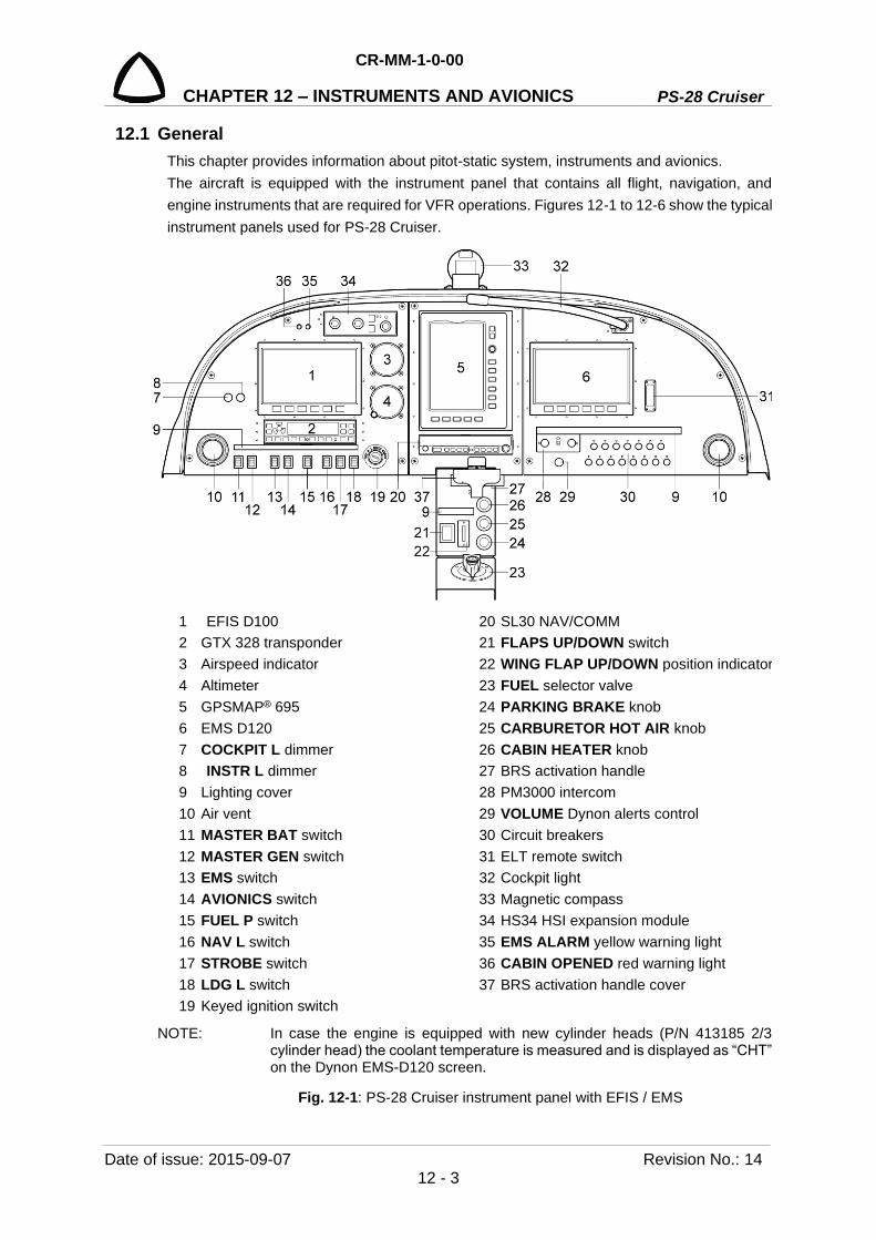
CR-MM-1-0-00
PS-28 Cruiser CHAPTER 12 – INSTRUMENTS AND AVIONICS
Date of issue: 2015-09-07 Revision No.: 14 12 - 3
12.1 General This chapter provides information about pitot-static system, instruments and avionics. The aircraft is equipped with the instrument panel that contains all flight, navigation, and engine instruments that are required for VFR operations. Figures 12-1 to 12-6 show the typical instrument panels used for PS-28 Cruiser.
1 EFIS D100 20 SL30 NAV/COMM 2 GTX 328 transponder 21 FLAPS UP/DOWN switch 3 Airspeed indicator 22 WING FLAP UP/DOWN position indicator 4 Altimeter 23 FUEL selector valve 5 GPSMAP® 695 24 PARKING BRAKE knob 6 EMS D120 25 CARBURETOR HOT AIR knob 7 COCKPIT L dimmer 26 CABIN HEATER knob 8 INSTR L dimmer 27 BRS activation handle 9 Lighting cover 28 PM3000 intercom 10 Air vent 29 VOLUME Dynon alerts control 11 MASTER BAT switch 30 Circuit breakers 12 MASTER GEN switch 31 ELT remote switch 13 EMS switch 32 Cockpit light 14 AVIONICS switch 33 Magnetic compass 15 FUEL P switch 34 HS34 HSI expansion module 16 NAV L switch 35 EMS ALARM yellow warning light 17 STROBE switch 36 CABIN OPENED red warning light 18 LDG L switch 37 BRS activation handle cover 19 Keyed ignition switch
NOTE: In case the engine is equipped with new cylinder heads (P/N 413185 2/3 cylinder head) the coolant temperature is measured and is displayed as “CHT” on the Dynon EMS-D120 screen.
Fig. 12-1: PS-28 Cruiser instrument panel with EFIS / EMS

PS-28 Cruiser
CR-MM-1-0-00
CHAPTER 12 – INSTRUMENTS AND AVIONICS
Revision No.: 4 Date of issue: 2012-12-10 12 - 4
1 EFIS D100 19 Keyed ignition switch 2 GTX 328 transponder 20 FLAPS UP/DOWN switch 3 Airspeed indicator 21 WING FLAP UP/DOWN position indicator 4 Altimeter 22 FUEL selector valve 5 GPS / NAV / COMM GTN 750 23 PARKING BRAKE knob 6 EMS D120 24 CARBURETOR HOT AIR knob 7 COCKPIT L dimmer 25 CABIN HEATER knob 8 INSTR L dimmer 26 BRS activation handle 9 Lighting cover 27 PM3000 intercom 10 Air vent 28 VOLUME Dynon alerts control 11 MASTER BAT switch 29 Circuit breakers 12 MASTER GEN switch 30 ELT remote switch 13 EMS switch 31 Cockpit light 14 AVIONICS switch 32 Magnetic compass 15 FUEL P switch 33 HS34 HSI expansion module 16 NAV L switch 34 EMS ALARM yellow warning light 17 STROBE switch 35 CABIN OPENED red warning light 18 LDG L switch 36 BRS activation handle cover
NOTE: In case the engine is equipped with new cylinder heads (P/N 413185 2/3 cylinder head) the coolant temperature is measured and is displayed as “CHT” on the Dynon EMS-D120 screen.
Fig. 12-2: PS-28 Cruiser instrument panel with EFIS / EMS and GTN 750
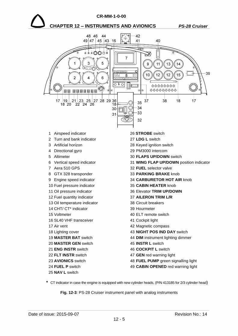
CR-MM-1-0-00
PS-28 Cruiser CHAPTER 12 – INSTRUMENTS AND AVIONICS
Date of issue: 2015-09-07 Revision No.: 14 12 - 5
1 Airspeed indicator 26 STROBE switch 2 Turn and bank indicator 27 LDG L switch 3 Artificial horizon 28 Keyed ignition switch 4 Directional gyro 29 PM3000 intercom 5 Altimeter 30 FLAPS UP/DOWN switch 6 Vertical speed indicator 31 WING FLAP UP/DOWN position indicator 7 Aera 510 GPS 32 FUEL selector valve 8 GTX 328 transponder 33 PARKING BRAKE knob 9 Engine speed indicator 34 CARBURETOR HOT AIR knob 10 Fuel pressure indicator 35 CABIN HEATER knob 11 Oil pressure indicator 36 Elevator TRIM UP/DOWN 12 Fuel quantity indicator 37 AILERON TRIM L/R 13 Oil temperature indicator 38 Circuit breakers 14 CHT/ CT* indicator 39 Hourmeter 15 Voltmeter 40 ELT remote switch 16 SL40 VHF transceiver 41 Cockpit light 17 Air vent 42 Magnetic compass 18 Lighting cover 43 NIGHT POS IND DAY switch 19 MASTER BAT switch 44 DIM instrument lighting dimmer 20 MASTER GEN switch 45 INSTR L switch 21 ENG INSTR switch 46 COCKPIT L switch 22 FLT INSTR switch 47 GEN red warning light 23 AVIONICS switch 48 FUEL PUMP green signalling light 24 FUEL P switch 49 CABIN OPENED red warning light 25 NAV L switch
* CT indicator in case the engine is equipped with new cylinder heads, (P/N 413185 for 2/3 cylinder head)
Fig. 12-3: PS-28 Cruiser instrument panel with analog instruments

PS-28 Cruiser
CR-MM-1-0-00
CHAPTER 12 – INSTRUMENTS AND AVIONICS
Revision No.: 4 Date of issue: 2012-12-10 12 - 6
INTENTIONALLY LEFT BLANK
CR-MM-1-0-00
PS-28 Cruiser CHAPTER 12 – INSTRUMENTS AND AVIONICS
Date of issue: 2015-09-07 Revision No.: 14 12 - 7
INTENTIONALLY LEFT BLANK

PS-28 Cruiser
CR-MM-1-0-00
CHAPTER 12 – INSTRUMENTS AND AVIONICS
Revision No.: 4 Date of issue: 2012-12-10 12 - 8
1 PFD SV-D1000 18 COCKPIT L switch 2 Airspeed indicator 19 Keyed ignition switch 3 GNC 255A NAV/COM 20 PM3000 intercom 4 Altimeter 21 BRS activation handle cover (option) 5 EMS SV-D1000 22 FLAPS UP/DOWN switch 6 Lighting cover (option) 23 FUEL selector valve 7 LH D1000 USB port 24 PARKING BRAKE knob 8 Air vent 25 CARBURETOR HOT AIR knob 9 MASTER BAT switch 26 CABIN HEATER knob 10 MASTER GEN switch 27 BRS activation handle (option) 11 EFIS 1 circuit breaker 28 INSTR L dimmer (option) 12 EFIS 2 circuit breaker 29 Circuit breakers 13 AVIONICS switch 30 RH D1000 USB port 14 FUEL P circuit breaker 31 ELT remote switch 15 NAV L circuit breaker 32 Socket 12 V 16 STROBE circuit breaker 33 Transponder control unit 17 LDG L circuit breaker 34 EMS ALARM yellow warning light
NOTE: In case the engine is equipped with new cylinder heads (P/N 413185 2/3 cylinder head) the coolant temperature (CT) instead of Cylinder Head temperature (CHT) is measured.
Fig. 12-6: PS-28 Cruiser typical instrument panel with Skyview system
NOTE: Current instrument panel arrangement is stated in the Pilots Operation Handbook.
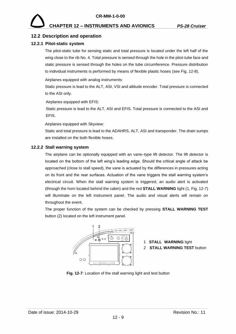
CR-MM-1-0-00
PS-28 Cruiser CHAPTER 12 – INSTRUMENTS AND AVIONICS
Date of issue: 2014-10-29 Revision No.: 11 12 - 9
12.2 Description and operation 12.2.1 Pitot-static system
The pitot-static tube for sensing static and total pressure is located under the left half of the
wing close to the rib No. 4. Total pressure is sensed through the hole in the pitot-tube face and
static pressure is sensed through the holes on the tube circumference. Pressure distribution
to individual instruments is performed by means of flexible plastic hoses (see Fig. 12-8).
Airplanes equipped with analog instruments:
Static pressure is lead to the ALT, ASI, VSI and altitude encoder. Total pressure is connected
to the ASI only.
Airplanes equipped with EFIS:
Static pressure is lead to the ALT, ASI and EFIS. Total pressure is connected to the ASI and
EFIS.
Airplanes equipped with Skyview:
Static and total pressure is lead to the ADAHRS, ALT, ASI and transponder. The drain sumps
are installed on the both flexible hoses.
12.2.2 Stall warning system The airplane can be optionally equipped with an vane–type lift detector. The lift detector is
located on the bottom of the left wing’s leading edge. Should the critical angle of attack be
approached (close to stall speed), the vane is actuated by the differences in pressures acting
on its front and the rear surfaces. Actuation of the vane triggers the stall warning system’s
electrical circuit. When the stall warning system is triggered, an audio alert is activated
(through the horn located behind the cabin) and the red STALL WARNING light (1, Fig. 12-7)
will illuminate on the left instrument panel. The audio and visual alerts will remain on
throughout the event.
The proper function of the system can be checked by pressing STALL WARNING TEST button (2) located on the left instrument panel.
Fig. 12-7: Location of the stall warning light and test button
1 STALL WARNING light 2 STALL WARNING TEST button
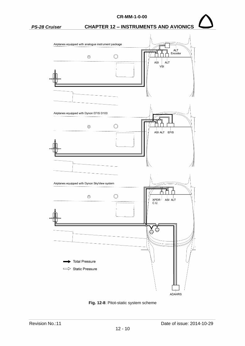
PS-28 Cruiser
CR-MM-1-0-00
CHAPTER 12 – INSTRUMENTS AND AVIONICS
Revision No.:11 Date of issue: 2014-10-29 12 - 10
Fig. 12-8: Pitot-static system scheme
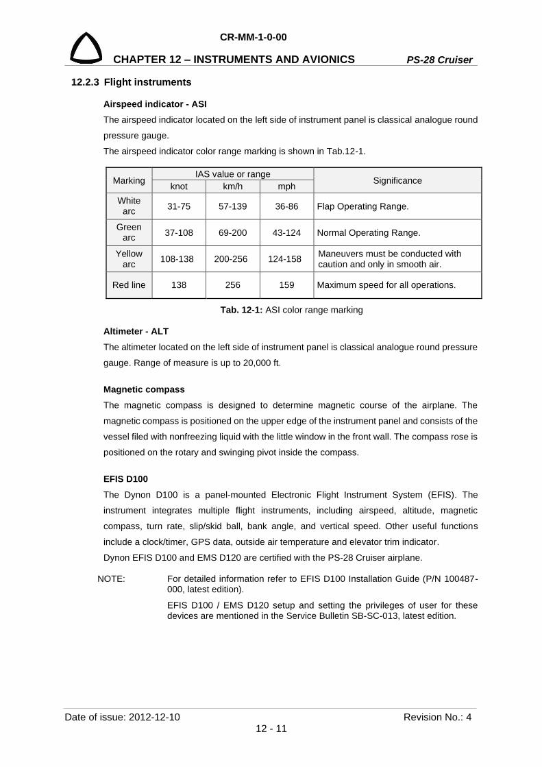
CR-MM-1-0-00
PS-28 Cruiser CHAPTER 12 – INSTRUMENTS AND AVIONICS
Date of issue: 2012-12-10 Revision No.: 4 12 - 11
12.2.3 Flight instruments
Airspeed indicator - ASI The airspeed indicator located on the left side of instrument panel is classical analogue round
pressure gauge.
The airspeed indicator color range marking is shown in Tab.12-1.
Marking IAS value or range
Significance knot km/h mph White
arc 31-75 57-139 36-86 Flap Operating Range.
Green arc 37-108 69-200 43-124 Normal Operating Range.
Yellow arc 108-138 200-256 124-158 Maneuvers must be conducted with
caution and only in smooth air.
Red line 138 256 159 Maximum speed for all operations.
Tab. 12-1: ASI color range marking
Altimeter - ALT The altimeter located on the left side of instrument panel is classical analogue round pressure
gauge. Range of measure is up to 20,000 ft.
Magnetic compass The magnetic compass is designed to determine magnetic course of the airplane. The
magnetic compass is positioned on the upper edge of the instrument panel and consists of the
vessel filed with nonfreezing liquid with the little window in the front wall. The compass rose is
positioned on the rotary and swinging pivot inside the compass.
EFIS D100 The Dynon D100 is a panel-mounted Electronic Flight Instrument System (EFIS). The
instrument integrates multiple flight instruments, including airspeed, altitude, magnetic
compass, turn rate, slip/skid ball, bank angle, and vertical speed. Other useful functions
include a clock/timer, GPS data, outside air temperature and elevator trim indicator.
Dynon EFIS D100 and EMS D120 are certified with the PS-28 Cruiser airplane.
NOTE: For detailed information refer to EFIS D100 Installation Guide (P/N 100487-000, latest edition).
EFIS D100 / EMS D120 setup and setting the privileges of user for these devices are mentioned in the Service Bulletin SB-SC-013, latest edition.
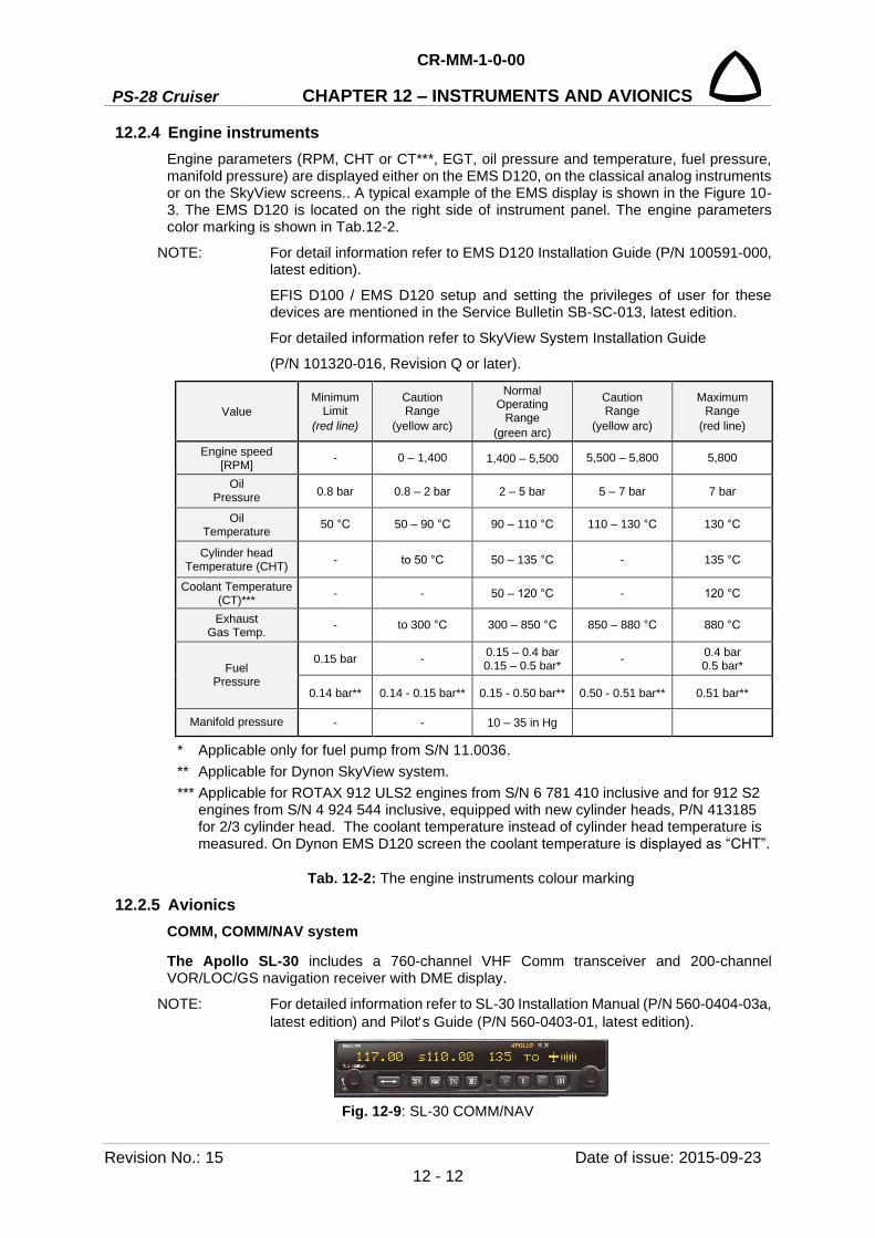
PS-28 Cruiser
CR-MM-1-0-00
CHAPTER 12 – INSTRUMENTS AND AVIONICS
Revision No.: 15 Date of issue: 2015-09-23 12 - 12
12.2.4 Engine instruments Engine parameters (RPM, CHT or CT***, EGT, oil pressure and temperature, fuel pressure, manifold pressure) are displayed either on the EMS D120, on the classical analog instruments or on the SkyView screens.. A typical example of the EMS display is shown in the Figure 10-3. The EMS D120 is located on the right side of instrument panel. The engine parameters color marking is shown in Tab.12-2.
NOTE: For detail information refer to EMS D120 Installation Guide (P/N 100591-000, latest edition).
EFIS D100 / EMS D120 setup and setting the privileges of user for these devices are mentioned in the Service Bulletin SB-SC-013, latest edition.
For detailed information refer to SkyView System Installation Guide
(P/N 101320-016, Revision Q or later).
Value Minimum
Limit (red line)
Caution Range
(yellow arc)
Normal Operating
Range (green arc)
Caution Range
(yellow arc)
Maximum Range
(red line)
Engine speed [RPM] - 0 – 1,400 1,400 – 5,500 5,500 – 5,800 5,800
Oil Pressure 0.8 bar 0.8 – 2 bar 2 – 5 bar 5 – 7 bar 7 bar
Oil Temperature 50 °C 50 – 90 °C 90 – 110 °C 110 – 130 °C 130 °C
Cylinder head Temperature (CHT) - to 50 °C 50 – 135 °C - 135 °C
Coolant Temperature (CT)*** - - 50 – 120 °C - 120 °C
Exhaust Gas Temp. - to 300 °C 300 – 850 °C 850 – 880 °C 880 °C
Fuel Pressure
0.15 bar - 0.15 – 0.4 bar 0.15 – 0.5 bar* - 0.4 bar
0.5 bar*
0.14 bar** 0.14 - 0.15 bar** 0.15 - 0.50 bar** 0.50 - 0.51 bar** 0.51 bar**
Manifold pressure - - 10 – 35 in Hg
* Applicable only for fuel pump from S/N 11.0036. ** Applicable for Dynon SkyView system. *** Applicable for ROTAX 912 ULS2 engines from S/N 6 781 410 inclusive and for 912 S2
engines from S/N 4 924 544 inclusive, equipped with new cylinder heads, P/N 413185 for 2/3 cylinder head. The coolant temperature instead of cylinder head temperature is measured. On Dynon EMS D120 screen the coolant temperature is displayed as “CHT”.
Tab. 12-2: The engine instruments colour marking
12.2.5 Avionics COMM, COMM/NAV system
The Apollo SL-30 includes a 760-channel VHF Comm transceiver and 200-channel VOR/LOC/GS navigation receiver with DME display.
NOTE: For detailed information refer to SL-30 Installation Manual (P/N 560-0404-03a, latest edition) and Pilots Guide (P/N 560-0403-01, latest edition).
Fig. 12-9: SL-30 COMM/NAV
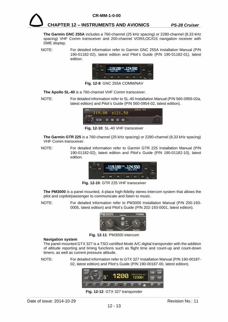
CR-MM-1-0-00
PS-28 Cruiser CHAPTER 12 – INSTRUMENTS AND AVIONICS
Date of issue: 2014-10-29 Revision No.: 11 12 - 13
The Garmin GNC 255A includes a 760-channel (25 kHz spacing) or 2280-channel (8,33 kHz spacing) VHF Comm transceiver and 200-channel VOR/LOC/GS navigation receiver with DME display.
NOTE: For detailed information refer to Garmin GNC 255A Installation Manual (P/N 190-01182-02), latest edition and Pilots Guide (P/N 190-01182-01), latest edition.
Fig. 12-9: GNC 255A COMM/NAV
The Apollo SL-40 is a 760-channel VHF Comm transceiver.
NOTE: For detailed information refer to SL-40 Installation Manual (P/N 560-0956-02a, latest edition) and Pilots Guide (P/N 560-0954-02, latest edition).
Fig. 12-10: SL-40 VHF transceiver
The Garmin GTR 225 is a 760-channel (25 kHz spacing) or 2280-channel (8,33 kHz spacing) VHF Comm transceiver.
NOTE: For detailed information refer to Garmin GTR 225 Installation Manual (P/N 190-01182-02), latest edition and Pilots Guide (P/N 190-01182-10), latest edition.
Fig. 12-10: GTR 225 VHF transceiver
The PM3000 is a panel mounted, 4-place high-fidelity stereo intercom system that allows the pilot and copilot/passenger to communicate and listen to music.
NOTE: For detailed information refer to PM3000 Installation Manual (P/N 200-193-0005, latest edition) and Pilots Guide (P/N 202-193-0001, latest edition).
Fig. 12-11: PM3000 intercom
Navigation system The panel-mounted GTX 327 is a TSO-certified Mode A/C digital transponder with the addition of altitude reporting and timing functions such as flight time and count-up and count-down timers, as well as current pressure altitude.
NOTE: For detailed information refer to GTX 327 Installation Manual (P/N 190-00187-02, latest edition) and Pilots Guide (P/N 190-00187-00, latest edition).
Fig. 12-12: GTX 327 transponder

PS-28 Cruiser
CR-MM-1-0-00
CHAPTER 12 – INSTRUMENTS AND AVIONICS
Revision No.: 15 Date of issue: 2015-09-23 12 - 14
The panel-mounted GTX 328 is a TSO-certified Mode S digital transponder. In addition to
displaying the code, reply symbol and mode of operation, the GTX 328 screen displays
pressure altitude, density altitude, temperature, and timer functions, depending on equipment
connections and configuration selection. The unit also features an altitude monitor and flight
timers. A voice or tone audio output announces altitude deviation and count down timer
expiration.
NOTE: For detailed information refer to GTX 328 Maintenance Manual (P/N 190-00420-05, latest edition) and Pilots Guide (P/N 190-00420-03, latest edition).
Fig. 12-13: GTX 328 transponder
The panel-mounted GTX 330 is a TSO-certified Mode S digital transponder. In addition to
displaying the code, reply symbol and mode of operation, the GTX 330 screen displays
pressure altitude, density altitude, temperature, and timer functions, depending on equipment
connections and configuration selection. The unit also features an altitude monitor, TIS traffic
advisories and flight timers. A voice or tone audio output announces altitude deviation, TIS
traffic advisory and count down timer expiration.
NOTE: For detailed information refer to GTX 330 Installation Manual (P/N 190-00207-02, latest edition) and Pilots Guide (P/N 190-00207-00, latest edition).
Fig. 12-14: GTX 330 transponder
The GPSMAP 695/696 is the ultimate portable MFD. This portable GPS navigator presents
GPS-derived analog flight instrumentation, position, navigation, and hazard avoidance
information to the pilot using a bright 7-inch diagonal high-definition sunlight readable color
display.
NOTE: For detailed information refer to GPS 695/696 Owners Manual (P/N 190-00919-00, latest edition).

CR-MM-1-0-00
PS-28 Cruiser CHAPTER 12 – INSTRUMENTS AND AVIONICS
Date of issue: 2014-10-29 Revision No.: 11 12 - 15
Fig. 12-15: GPSMAP 695/696
The Aera 510 presents GPS-derived analog flight instrumentation, position, navigation, and
hazard avoidance information to the pilot using a bright 4.3-inch diagonal high-definition
sunlight readable color display with touch screen.
NOTE: For detailed information refer to Aera Models 500, 510, 550, 560 Owners Manual (P/N 190-01117-00, latest edition).
Fig. 12-16: GPS Aera 510
The GTN 650 unit is a panel mounted GPS / NAV / COM navigator. The GTN 650 unit is 6.25
in wide and 2.65 in tall. It features a 600 by 266 pixel color LCD touchscreen. The GTN 750 is
a GPS / SBAS unit that meets requirements TSO-C146c and may be approved for IFR en
route, terminal, oceanic, non precision and precision approach operations. The GTN 650 unit

PS-28 Cruiser
CR-MM-1-0-00
CHAPTER 12 – INSTRUMENTS AND AVIONICS
Revision No.: 15 Date of issue: 2015-09-23 12 - 16
includes an airborne VHF communications transceiver and airborne VOR / LOC and G / S
receivers.
NOTE: For detailed information refer to GTN 6XX/ 7XX AML STC Installation Manual (P/N 190-01007-A3, latest edition) and Pilots Guide (P/N 190-01004-03, latest edition).
Fig. 12-18: GPS / NAV / COM GTN 650
The GTN 750 unit is a panel mounted GPS / NAV / COM navigator. The GTN 750 unit is 6.25
in wide and 6.00 in tall. It features a 600 by 708 pixel color LCD touchscreen which provides
a rich and intuitive user interface. The GTN 750 is a GPS / SBAS unit that meets requirements
TSO-C146c and may be approved for IFR en route, terminal, oceanic, non precision and
precision approach operations. The GTN 750 unit includes an airborne VHF communications
transceiver and airborne VOR / LOC and G / S receivers.
NOTE: For detailed information refer to GTN 6XX/ 7XX AML STC Installation Manual (P/N 190-01007-A3, latest edition) and Pilots Guide (P/N 190-01007-03, latest edition).
Fig. 12-18: GPS / NAV / COM GTN 750

CR-MM-1-0-00
PS-28 Cruiser CHAPTER 12 – INSTRUMENTS AND AVIONICS
Date of issue: 2014-10-29 Revision No.: 11 12 - 17
Antennas Fig. 12-19 shows the antenna locations. The COMM antenna (1) is installed on the upper part
of the fuselage behind the canopy. The ELT antenna (3) is installed directly in the rear of the
COMM antenna. The NAV antenna (2) is installed on the top of the fin. The transponder
antenna (4) is installed on the bottom part of the fuselage. The GPS antenna (for GPSMAP
695/696 and GPS Aera 510) is attached to the upper side of the instrument panel cover; GPS
antenna (5) for GTN 750 GPS / NAV / COM or Skyview System is installed on the upper part
of the fuselage in front of canopy.
Fig. 12-19: Antenna locations
12.2.6 Dynon SkyView system Dynon SkyView system is the next generation of glass panel avionics for light sport aircraft.
The system architecture is shown on Fig. 12-20.
The SV-D1000 displays are very bright, high-resolution screens and contain the main control
CPU, graphics processor, and terrain data-base. Displays can act as a Primary Flight Display
(PFD) with Synthetic Vision, an Engine Monitoring System (EMS), and a Moving Map in a
variety of customizable screen layouts.
The most used functions are accessed via two rotary/multi-direction joysticks. Almost all other
in flight commands are all available via eight buttons.
Every SkyView system display and module is connected by two independent power and data
buses. The failure of any bus connection or module results in automatic fail-over to a working
bus or module.
1 COMM antenna 2 NAV antenna 3 ELT antenna 4 XPDR antenna 5 GPS antenna

PS-28 Cruiser
CR-MM-1-0-00
CHAPTER 12 – INSTRUMENTS AND AVIONICS
Revision No.: 15 Date of issue: 2015-09-23 12 - 18
Two SV-BAT-320 Backup Batteries provides over an hour of backup power to displays and
modules.
SV-EMS-220 engine module measures engine parameters - engine speed, manifold pressure,
oil temperature and pressure, exhaust gas temperature, cylinder head/coolant* temperature,
fuel quantity, voltage, current, fuel pressure, fuel flow, flap and trim position.
The SV-ADAHRS-200 is a complete MEMS-based attitude reference and air data computer,
integrated with a digital compass. This allows easier mounting and higher accuracy calibration
between the system components.
* Coolant temperature in case the engine is equipped with new cylinder heads;
P/N 413185 for 2/3 cylinder head. The GPS position is provided by the SV-GPS-250 module.
Convenient program and data updates via USB memory stick
NOTE: For detailed information refer to SkyView System Installation Guide (P/N 101320-016, Revision Q or later) and and SkyView Pilots User Guide (P/N 101321-016, Revision Q or later).
Fig. 12-20: SkyView system architecture
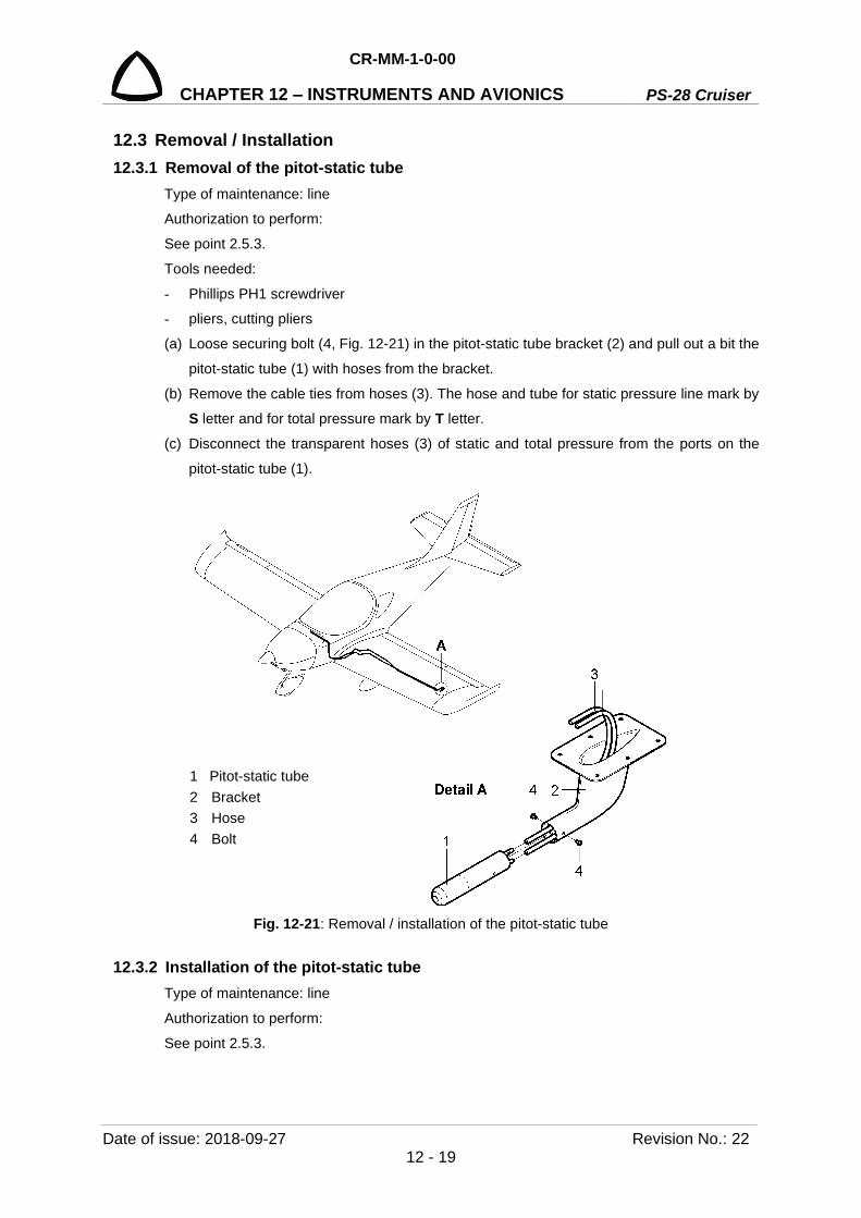
CR-MM-1-0-00
PS-28 Cruiser CHAPTER 12 – INSTRUMENTS AND AVIONICS
Date of issue: 2018-09-27 Revision No.: 22 12 - 19
12.3 Removal / Installation 12.3.1 Removal of the pitot-static tube
Type of maintenance: line
Authorization to perform:
See point 2.5.3.
Tools needed:
- Phillips PH1 screwdriver
- pliers, cutting pliers
(a) Loose securing bolt (4, Fig. 12-21) in the pitot-static tube bracket (2) and pull out a bit the
pitot-static tube (1) with hoses from the bracket.
(b) Remove the cable ties from hoses (3). The hose and tube for static pressure line mark by
S letter and for total pressure mark by T letter.
(c) Disconnect the transparent hoses (3) of static and total pressure from the ports on the
pitot-static tube (1).
Fig. 12-21: Removal / installation of the pitot-static tube
12.3.2 Installation of the pitot-static tube Type of maintenance: line
Authorization to perform:
See point 2.5.3.
1 Pitot-static tube 2 Bracket 3 Hose 4 Bolt

PS-28 Cruiser
CR-MM-1-0-00
CHAPTER 12 – INSTRUMENTS AND AVIONICS
Revision No.: 22 Date of issue: 2018-09-27 12 - 20
Tools needed:
- Phillips PH1 screwdriver
- pliers, cutting pliers
(a) Connect the hoses (3, Fig. 12-21) to the ports on the pitot-static tube (1) and secure them
with cable ties.
WARNING: WHEN CONNECTING THE PITOT-STATIC SYSTEM HOSES PAY INCREASED ATTENTION. THERE MUST NOT BE ANY INCORRECT CONNECTION! CONNECT THE HOSE MARKED S LETTER TO THE PORT MARKED BY S LETTER AND THE HOSE MARKED T LETTER TO THE PORT MARKED BY T LETTER.
(b) Insert the pitot-static tube (1) in the bracket (2).
(c) Secure pitot-static tube by means of securing bolt (4).
(d) Carry out check of pitot-static system tightness / Dynon avionics pitot / static test (see
12.4.1, 12.4.2).
(e) Check, that pitot-tube is parallel to bottom wing skin.
12.3.3 Removal of the stall warning system lift detector Type of maintenance: line
Authorization to perform:
See point 2.5.3.
Tools needed:
- Phillips PH2 screwdriver, screwdriver
(a) Set the MASTER BAT, AVIONICS switches to OFF.
(b) Remove the cover on the underside of the wing near the lift detector.
(c) Remove the screws (4, Fig. 12-22) and carefully pull the lift detector (1).
(d) Remove the screws (3) and disconnect the wires (2).
12.3.4 Installation of the stall warning system lift detector Type of maintenance: line
Authorization to perform:
See point 2.5.3.
Tools needed:
Phillips PH2 screwdriver, screwdriver
(a) Connect the wires (2, Fig. 12-22) to the appropriate points on the lift detector (see Wiring
Manual); screw and tighten the screws (3).
(b) Insert the lift detector (1) into the hole in the wing leading edge (5). (c) Align the detector (1) so that the tab was located 8 mm from the leading edge (see Fig.
12-22); screw and tighten the screws (4).
(d) Set the MASTER BAT, AVIONICS switches to ON, press STALL WARNING TEST button
and check test of the system.
(e) Carry out flight test, verify stall warning speed (see 12.4.8.).

CR-MM-1-0-00
PS-28 Cruiser CHAPTER 12 – INSTRUMENTS AND AVIONICS
Date of issue: 2018-09-27 Revision No.: 22 12 - 21
Fig. 12-22: Lift detector removal / installation
12.3.5 Removal of the flight instruments Type of maintenance: line
Authorization to perform:
See point 2.5.3.
Tools needed:
- Phillips PH1 screwdriver
- pliers, cutting pliers
(a) Remove bolts securing the left instrument panel and carefully pull out and hold the
instrument panel.
(b) Remove the cable ties (9, Fig. 12-23) from the hoses (7; 8).
(c) Disconnect the hoses (7; 8) of static and total pressure from the rear ports on the
appropriate indicator (1; 2).
(d) Disconnect the wires (10) from the illuminator (3).
(e) Unscrew the nuts (5), remove the washers (6) and bolts (4).
(f) Remove the instrument (1; 2) and illuminator (3) from the panel.
(g) Install the protective cover on the rear ports of the instrument.
1 Lift detector 2 Wire 3 Screw 4 Screw (4 pcs.) 5. Leading edge
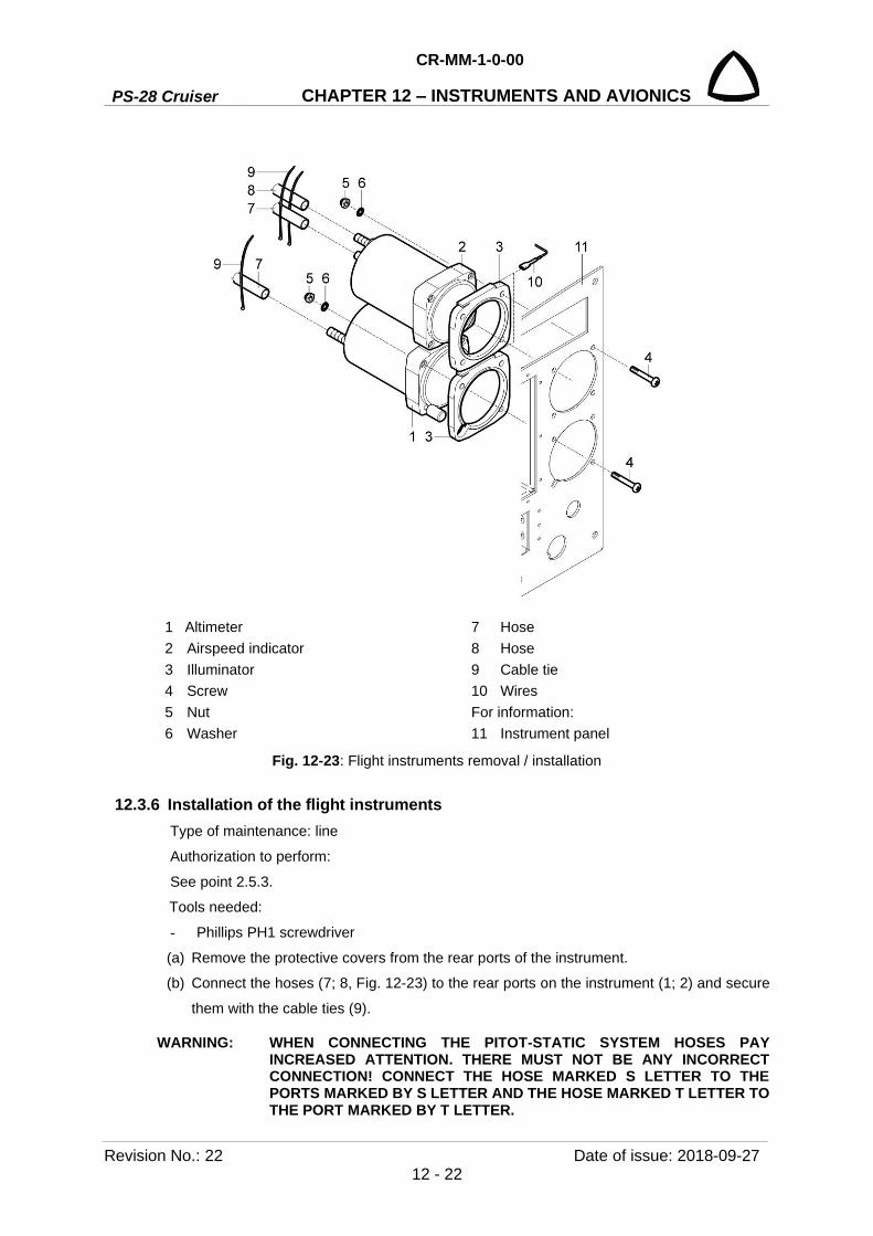
PS-28 Cruiser
CR-MM-1-0-00
CHAPTER 12 – INSTRUMENTS AND AVIONICS
Revision No.: 22 Date of issue: 2018-09-27 12 - 22
1 Altimeter 7 Hose 2 Airspeed indicator 8 Hose 3 Illuminator 9 Cable tie 4 Screw 10 Wires 5 Nut For information: 6 Washer 11 Instrument panel
Fig. 12-23: Flight instruments removal / installation
12.3.6 Installation of the flight instruments Type of maintenance: line
Authorization to perform:
See point 2.5.3.
Tools needed:
- Phillips PH1 screwdriver
(a) Remove the protective covers from the rear ports of the instrument.
(b) Connect the hoses (7; 8, Fig. 12-23) to the rear ports on the instrument (1; 2) and secure
them with the cable ties (9).
WARNING: WHEN CONNECTING THE PITOT-STATIC SYSTEM HOSES PAY INCREASED ATTENTION. THERE MUST NOT BE ANY INCORRECT CONNECTION! CONNECT THE HOSE MARKED S LETTER TO THE PORTS MARKED BY S LETTER AND THE HOSE MARKED T LETTER TO THE PORT MARKED BY T LETTER.
CR-MM-1-0-00
PS-28 Cruiser CHAPTER 12 – INSTRUMENTS AND AVIONICS
Date of issue: 2018-09-27 Revision No.: 22 12 - 23
NOTE: The hose for static pressure line mark by S letter and for total pressure mark by T letter.
(c) Connect the wires (10) to the illuminator (3).
(d) Put the instrument (1; 2) and illuminator (3) in position in the panel (11).
(e) Attach the instrument (1; 2) with the illuminator (3) by means of the bolts (4), nuts (5) and
washers (6).
(f) Install the left instrument panel (10).
(g) Carry out check of pitot-static system tightness / Dynon avionics pitot / static test (see
12.4.1, 12.4.2).
12.3.7 Removal of the EFIS D100 Type of maintenance: line
Authorization to perform:
See point 2.5.3.
Tools needed:
- 7/64 Allen wrench
- cutting pliers
(a) Set the MASTER BAT, AVIONICS switches to OFF.
(b) Put a 7/64 Allen wrench into the access hole (2, Fig. 12-24) for the locking screw; engage
the screw.
(c) Turn the screw counter-clockwise until the unit disengages from the mounting rack.
CAUTION: DO NOT PRY THE FACE-PLATE. YOU CAN DAMAGE THE UNIT.
(d) Pull gently on the sides of the unit (1) to remove it from the mounting rack (9).
(e) Remove the cable ties (7) from hoses (5; 6).
(f) Disconnect the hoses (5; 6) of static and total pressure from the rear ports (3; 4) on the unit.
(g) Disconnect the connector (4) from the unit.
(h) Install the protective cover on the rear ports (3; 4) of the unit.

PS-28 Cruiser
CR-MM-1-0-00
CHAPTER 12 – INSTRUMENTS AND AVIONICS
Revision No.: 4 Date of issue: 2012-12-10 12 - 24
1 EFIS D100 6 Hose 2 Access hole of the locking screw 7 Cable tie 3 Static port 8 Connector 4 Pitot port For information: 5 Hose 9 Mounting rack
Fig. 12-24: EFIS D100 removal / installation

CR-MM-1-0-00
PS-28 Cruiser CHAPTER 12 – INSTRUMENTS AND AVIONICS
Date of issue: 2018-09-27 Revision No.: 22 12 - 25
12.3.8 Installation of the EFIS D100 Type of maintenance: line
Authorization to perform:
See point 2.5.3.
Tools needed:
- 7/64 Allen wrench
(a) Remove the protective covers from the rear ports on the unit.
(b) Connect the hoses (5; 6, Fig. 12-24) to the rear ports (3; 4) on the unit (1) and secure them
with cable ties (7).
WARNING: WHEN CONNECTING THE PITOT-STATIC SYSTEM HOSES PAY INCREASED ATTENTION. THERE MUST NOT BE ANY INCORRECT CONNECTION! CONNECT THE HOSE MARKED S LETTER TO THE PORTS MARKED BY STATIC AND THE HOSE MARKED T LETTER TO THE PORT MARKED BY PITOT.
NOTE: The hose for static pressure line mark by S letter and for total pressure mark by T letter.
(c) Connect the connector (4) to the unit.
(d) Slide the unit (1) into the rack (9). Engage the locking screw so that the latch front lobe
touches the rack.
(e) Turn the locking screw clockwise so that the rear lobe engages the mounting rack.
CAUTION: DO NOT OVER-TIGHTEN THE LOCKING SCREW. YOU CAN DAMAGE THE LOCKING MECHANISM.
(f) Continue to turn the screw until the unit is fully installed in the mounting rack.
(g) Carry out check of pitot-static system tightness / Dynon avionics pitot / static test (see
12.4.1, 12.4.2).
(h) Set the MASTER BAT, AVIONICS switches to ON and do an operational test of the
system.
12.3.9 Removal of EDC-10A remote compass module Type of maintenance: line
Authorization to perform:
See point 2.5.3.
Tools needed:
- screwdriver
CAUTION: DO NOT USE STANDARD MOUNTING HARDWARE. ALL MOUNTING HARDWARE IS MADE FROM BRASS – NON FERROUS MATERIAL.
(a) Set the MASTER BAT, AVIONICS switches to OFF.
(b) Remove the cover on the bottom of the fuselage rear part.
(c) Disconnect the connector (2, Fig. 12-25) from the compass module.
(d) Unscrew the screws (3) with the washers (4) and remove the compass module (1).

PS-28 Cruiser
CR-MM-1-0-00
CHAPTER 12 – INSTRUMENTS AND AVIONICS
Revision No.: 22 Date of issue: 2018-09-27 12 - 26
Fig. 12-25: NAV antenna removal / installation
12.3.10 Installation of EDC-10A remote compass module Type of maintenance: line
Authorization to perform:
See point 2.5.3.
Tools needed:
- screwdriver
CAUTION: DO NOT USE STANDARD MOUNTING HARDWARE. ALL MOUNTING HARDWARE IS MADE FROM BRASS – NON FERROUS MATERIAL.
(a) Place the compass module (1, Fig. 12-25) on the bracket (5) and fasten it by means of the
screws (3) with the washers (4).
(b) Connect the connector (2) to the compass module.
(c) Install the cover on the bottom of the fuselage rear part.
(d) Perform EFIS compass heading calibration (see Chapter 12.4.4).
12.3.11 Removal of the EMS D120 Type of maintenance: line
Authorization to perform:
See point 2.5.3.
Tools needed:
- 7/64 Allen wrench
- cutting pliers
1 Remote compass module 2 Connector 3 Screw (4 pcs.) 4 Washer (2 pcs.) For information: 5 Bracket
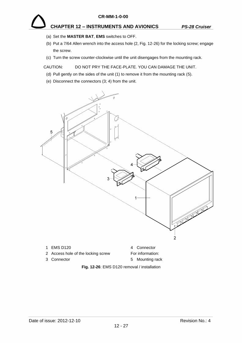
CR-MM-1-0-00
PS-28 Cruiser CHAPTER 12 – INSTRUMENTS AND AVIONICS
Date of issue: 2012-12-10 Revision No.: 4 12 - 27
(a) Set the MASTER BAT, EMS switches to OFF.
(b) Put a 7/64 Allen wrench into the access hole (2, Fig. 12-26) for the locking screw; engage
the screw.
(c) Turn the screw counter-clockwise until the unit disengages from the mounting rack.
CAUTION: DO NOT PRY THE FACE-PLATE. YOU CAN DAMAGE THE UNIT.
(d) Pull gently on the sides of the unit (1) to remove it from the mounting rack (5).
(e) Disconnect the connectors (3; 4) from the unit.
1 EMS D120 4 Connector 2 Access hole of the locking screw For information: 3 Connector 5 Mounting rack
Fig. 12-26: EMS D120 removal / installation

PS-28 Cruiser
CR-MM-1-0-00
CHAPTER 12 – INSTRUMENTS AND AVIONICS
Revision No.: 22 Date of issue: 2018-09-27 12 - 28
12.3.12 Installation of the EMS D120 Type of maintenance: line
Authorization to perform:
See point 2.5.3.
Tools needed:
- 7/64 Allen wrench
(a) Connect the connectors (3; 4, Fig. 12-26) to the unit (1).
(b) Slide the unit (1) into the rack (5). Engage the locking screw so that the latch front lobe
touches the rack.
(c) Turn the locking screw clockwise so that the rear lobe engages the mounting rack.
CAUTION: DO NOT OVER-TIGHTEN THE LOCKING SCREW. YOU CAN DAMAGE THE LOCKING MECHANISM.
(d) Continue to turn the screw until the unit is fully installed in the mounting rack.
(e) Set the MASTER BAT, EMS switches to ON and do an operational test of the system.
12.3.13 Removal of transponder Type of maintenance: line
Authorization to perform:
See point 2.5.3.
Tools needed:
- 3/32 Allen wrench
(a) Set the MASTER BAT, AVIONICS switches to OFF.
(b) Put a 3/32 Allen wrench into the access hole (2, Fig. 12-27) for the locking screw; engage
the screw.
(c) Turn the screw counter-clockwise until the transponder (1) disengages from the mounting
rack.
CAUTION: DO NOT TOUCH THE CONNECTOR CARD AT THE REAR OF THE UNIT. THE ELECTROSTATIC CHARGE ON YOUR BODY CAN DAMAGE THE UNIT.
(d) Pull gently on the sides of the transponder (1) to remove it from the mounting rack (3).
(e) Install the protective covers on the rear connectors of the transponder.
12.3.14 Installation of transponder Type of maintenance: line
Authorization to perform:
See point 2.5.3.
Tools needed:
- 3/32 Allen wrench
(f) Remove the protective covers from the connectors on the transponder.
(g) Looking at the bottom of the unit, make sure the front lobe of the locking mechanism is in
a vertical positron.

CR-MM-1-0-00
PS-28 Cruiser CHAPTER 12 – INSTRUMENTS AND AVIONICS
Date of issue: 2018-09-27 Revision No.: 22 12 - 29
(a) Slide the transponder (1, Fig. 12-27) into the rack (3). Engage the locking screw so that
the latch front lobe touches the rack.
(b) Turn the locking screw clockwise so that the rear lobe engages the mounting rack.
CAUTION: DO NOT OVER-TIGHTEN THE LOCKING SCREW. YOU CAN DAMAGE THE LOCKING MECHANISM.
(c) Continue to turn the screw until the transponder is fully installed in the mounting rack.
(d) Set the MASTER BAT, AVIONICS switches to ON and do an operational test.
1 Transponder For information: 2 Access hole of the locking screw 3 Mounting rack
Fig. 12-27: Transponder removal / installation
12.3.15 Removal of COMM, COMM / NAV Type of maintenance: line
Authorization to perform:
See point 2.5.3.
Tools needed:
- 3/32 Allen wrench
(a) Set the MASTER BAT, AVIONICS switches to OFF.
(b) Put a 3/32 Allen wrench into the access hole (2, Fig. 12-28) for the locking screw; engage
the screw.
(c) Turn the screw counter-clockwise until the unit (1) disengages from the mounting rack.
NOTE The location of the transponder may be different.

PS-28 Cruiser
CR-MM-1-0-00
CHAPTER 12 – INSTRUMENTS AND AVIONICS
Revision No.: 22 Date of issue: 2018-09-27 12 - 30
CAUTION: DO NOT PULL ON THE KNOBS. DO NOT PRY THE FACE-PLATE. YOU CAN DAMAGE THE UNIT.
DO NOT TOUCH THE CONNECTOR CARD AT THE REAR OF THE UNIT. THE ELECTROSTATIC CHARGE ON YOUR BODY CAN DAMAGE THE UNIT.
(d) Pull gently on the sides of the unit (1) to remove it from the mounting rack (3).
(e) Install the protective covers on the rear connectors of the unit.
Fig. 12-28: COMM / NAV unit removal / installation
12.3.16 Installation of COMM, COMM / NAV Type of maintenance: line
Authorization to perform:
See point 2.5.3.
Tools needed:
- 3/32 Allen wrench
(a) Remove the protective covers from the connectors on the unit.
(b) Looking at the bottom of the unit, make sure the front lobe of the locking mechanism is in
a vertical positron.
(c) Slide the unit (1, Fig. 12-28) into the rack (3). Engage the locking screw so that the latch
front lobe touches the rack.
(d) Turn the locking screw clockwise so that the rear lobe engages the mounting rack.
(e) Continue to turn the screw until the unit is fully installed in the mounting rack.
1 COMM/NAV unit 2 Access hole of the locking screw For information: 3 Mounting rack

CR-MM-1-0-00
PS-28 Cruiser CHAPTER 12 – INSTRUMENTS AND AVIONICS
Date of issue: 2018-09-27 Revision No.: 22 12 - 31
CAUTION: DO NOT OVER-TIGHTEN THE LOCKING SCREW. YOU CAN DAMAGE THE LOCKING MECHANISM.
(f) Set the MASTER BAT, AVIONICS switches to ON and do an operational test.
12.3.17 Removal of intercom Type of maintenance: line
Authorization to perform:
See point 2.5.3.
Tools needed:
- Phillips PH1 screwdriver
(a) Set the MASTER BAT, AVIONICS switches to OFF.
(b) Disconnect the connector (5, Fig. 12-29) from the unit.
(c) Remove the knobs (2) from the volume and squelch control shafts.
(d) Unscrew the screws (4) and remove the faceplate (3).
(e) Carefully remove the unit (1).
CAUTION: DO NOT TOUCH THE CONNECTOR CARD AT THE REAR OF THE UNIT. THE ELECTROSTATIC CHARGE ON YOUR BODY CAN DAMAGE THE UNIT.
(f) Install the protective cover on the rear connector of the unit.
12.3.18 Installation of intercom Type of maintenance: line
Authorization to perform:
See point 2.5.3.
Tools needed:
- Phillips PH1 screwdriver
(a) Remove the protective cover from the connector on the unit.
(b) Insert the unit (1, Fig. 12-29) from behind the instrument panel, aligning the holes for the
knobs, LED, and switch.
(c) Place the faceplate (3) over the knob shafts and secure it by means of the two screws
(4).
(d) Install the knobs (2) over the volume and squelch control shafts.
(e) Connect the connector (5) to the unit (1).
(f) Set the MASTER BAT, AVIONICS switches to ON and do an operational test.

PS-28 Cruiser
CR-MM-1-0-00
CHAPTER 12 – INSTRUMENTS AND AVIONICS
Revision No.: 22 Date of issue: 2018-09-27 12 - 32
1 Intercom 5 Connector 2 Knob For information: 3 Faceplate 6 Instrument panel 4 Screw
Fig. 12-29: Intercom removal / installation
12.3.19 Removal of GPS / NAV COM Type of maintenance: line
Authorization to perform:
See point 2.5.3.
Tools needed:
- 3/32 Allen wrench
NOTE: The procedure of removal / installation is the same for both units (GTN 650 and GTN 750).
(a) Set the MASTER BAT, GPS switches to OFF.
(b) Put a 3/32 Allen wrench into the access hole (2, Fig. 12-30) for the locking screw; engage
the screw.
(c) Turn the screw counter-clockwise until the unit (1) is forced out about 9.5 mm (3/8 in) and
can be freely pulled from the mounting rack.
CAUTION: DO NOT PULL ON THE KNOBS. DO NOT PRY THE FACE-PLATE. YOUCAN DAMAGE THE UNIT.
DO NOT TOUCH THE CONNECTOR CARD AT THE REAR OF THE UNIT. THE ELECTROSTATIC CHARGE ON YOUR BODY CAN DAMAGE THE UNIT.
(d) Pull gently on the sides of the unit (1) to remove it from the mounting rack (3).
(e) Install the protective covers on the rear connectors of the unit.

CR-MM-1-0-00
PS-28 Cruiser CHAPTER 12 – INSTRUMENTS AND AVIONICS
Date of issue: 2018-09-27 Revision No.: 22 12 - 33
Fig. 12-30: GPS / NAV / COM unit removal / installation
12.3.20 Installation of GPS / NAV COM Type of maintenance: line
Authorization to perform:
See point 2.5.3.
Tools needed:
- 3/32 Allen wrench
NOTE: The procedure of removal / installation is the same for both units (GTN 650 and GTN 750).
(a) Remove the protective covers from the connectors on the unit.
(b) Looking at the bottom of the unit, make sure the front lobe of the locking mechanism is in
a vertical positron.
(c) Slide the unit (1, Fig. 12-30) straight in the rack until it stops about 25 mm (1 in) short of
the final position.
(d) Insert Allen wrench into access hole (2).
(e) Turn the locking screw clockwise while press on the left side of the bezel unit until the unit
is firmly seated in the rack the mounting rack.
CAUTION: DO NOT OVER-TIGHTEN THE LOCKING SCREW. THE APPLICATION OF THE ALLEN WRENCH TORQUE EXCEEDING 0.01 NM (15 LB IN) CAN DAMAGE THE LOCKING MECHANISM.
1 GPS / NAV / COM unit 2 Access hole of the locking screw For information: 3 Mounting rack

PS-28 Cruiser
CR-MM-1-0-00
CHAPTER 12 – INSTRUMENTS AND AVIONICS
Revision No.: 22 Date of issue: 2018-09-27 12 - 34
(f) Set the MASTER BAT, GPS switches to ON and do a post installation (see 17.6) and
operational test.
12.3.21 Removal of COMM antenna Type of maintenance: line
Authorization to perform:
See point 2.5.3.
Tools needed:
- screwdriver
- wrench No. 7
(a) Set the MASTER BAT, AVIONICS switches to OFF.
(b) Disconnect the connector (4, Fig. 12-31) from the antenna.
(c) Remove the nuts (4) with the washers (5)
(d) Remove the antenna (1) with the gasket (2), screws (3) and washers (6).
(e) Install the protective cover on the antenna connector.
Fig. 12-31: COMM antenna removal / installation
1 COMM antenna 2 Gasket 3 Screw (4 pcs.) 4 Nut (4 pcs.) 5 Washer (4 pcs.) 6 Tooth washer (4 pcs.) 7 Cable connector For information: 8 Fuselage upper part
CR-MM-1-0-00
PS-28 Cruiser CHAPTER 12 – INSTRUMENTS AND AVIONICS
Date of issue: 2018-09-27 Revision No.: 22 12 - 35
12.3.22 Installation of COMM antenna Type of maintenance: line
Authorization to perform:
See point 2.5.3.
Tools needed:
- screwdriver
- wrench No. 7
(a) Remove the protective cover from the antenna connector.
(b) Place the antenna (1, Fig. 12-31) with the gasket (2) on the fuselage (8).
(c) Insert the screws (3) with washers (6) to the holes in the antenna body (1); install the
washers (5), screw and tighten the nuts (4).
(d) Connect the connector (7) to the antenna (1).
(e) Set the MASTER BAT, AVIONICS switches to ON and do an operational test.
12.3.23 Removal of NAV antenna Type of maintenance: line
Authorization to perform:
See point 2.5.3.
Tools needed:
- Phillips PH2 screwdriver
- wrench No. 8
(a) Set the MASTER BAT, AVIONICS switches to OFF.
(b) Unscrew the screws (7, Fig. 12-32) and remove the fin tip (6).
(c) Remove the nuts (4) and disconnect the cables (5) from antenna studs.
(d) Unscrew the screws (2) with the washers (3) and remove the antenna (1).

PS-28 Cruiser
CR-MM-1-0-00
CHAPTER 12 – INSTRUMENTS AND AVIONICS
Revision No.: 22 Date of issue: 2018-09-27 12 - 36
Fig. 12-32: NAV antenna removal / installation
12.3.24 Installation of NAV antenna Type of maintenance: line
Authorization to perform:
See point 2.5.3.
Tools needed:
- Phillips PH2 screwdriver
- wrench No. 8
(a) Place the antenna (1, Fig. 12-32) on the bracket and fasten it by means of the screws (2)
with the washers (3).
(b) Connect the cables (5) to the antenna studs; screw and fasten the nuts (4).
(c) Place the fin tip (6) on the fin (8) and fasten it by means of the screws (7).
(d) Set the MASTER BAT, AVIONICS switches to ON and do an operational test.
1 NAV antenna 2 Screw (2 pcs.) 3 Washer (2 pcs.) 4 Nut (2 pcs.) 5 Cable (2 pcs.) 6 Fin tip 7 Screw (8 pcs.) For information: 8 Fin

CR-MM-1-0-00
PS-28 Cruiser CHAPTER 12 – INSTRUMENTS AND AVIONICS
Date of issue: 2018-09-27 Revision No.: 22 12 - 37
12.3.25 Removal of transponder antenna Type of maintenance: line
Authorization to perform:
See point 2.5.3.
Tools needed:
- wrench No. 3/4 in
(a) Tilt forward the right seat back.
(b) Set the MASTER BAT, AVIONICS switches to OFF.
(c) Disconnect the connector (4, Fig. 12-33) from the antenna.
(d) Unscrew the nut (2), remove the washer (3) and the antenna (1).
(e) Install the protective cover on the antenna connector.
Fig. 12-33: Transponder antenna removal / installation
12.3.26 Installation of transponder antenna Type of maintenance: line
Authorization to perform:
See point 2.5.3.
Tools needed:
- wrench No. 3/4 in
(a) Remove the protective cover from the antenna connector.
(b) Insert the antenna (1, Fig. 12-33) to the hole in the fuselage bottom part (5).
(c) Insert the washer (3), screw and tighten the nut (2).
(d) Connect the connector (4) to the antenna (1).
1 XPDR antenna 2 Nut 3 Lockwasher 4 Cable connector For information: 5 Fuselage bottom part

PS-28 Cruiser
CR-MM-1-0-00
CHAPTER 12 – INSTRUMENTS AND AVIONICS
Revision No.: 22 Date of issue: 2018-09-27 12 - 38
(e) Place the fin tip (6) on the fin (8) and fasten it by means of the screws (7).
• Tilt backward the right seat back.
• Set the MASTER BAT, AVIONICS switches to ON and do an operational test.
12.3.27 Removal of GPS antenna Type of maintenance: line
Authorization to perform:
See point 2.5.3.
Tools needed:
- Phillips PH2 screwdriver
NOTE: This type of antenna is used when GPS / NAV / COM unit or SkyView system is installed.
(a) Set the MASTER BAT, GPS switches to OFF.
(b) Disconnect the connector (4, Fig. 12-34) from the antenna.
(c) Remove the sealant around the antenna.
(d) Remove the screws (2) with and the antenna (1).
(e) Clean sealant residues.
(f) Install the protective cover on the antenna connector.
Fig. 12-34: GPS antenna removal / installation
1 GPS antenna 2 Screw 3 Cable connector For information: 4 Fuselage upper part

CR-MM-1-0-00
PS-28 Cruiser CHAPTER 12 – INSTRUMENTS AND AVIONICS
Date of issue: 2018-09-27 Revision No.: 22 12 - 39
12.3.28 Installation of GPS antenna Type of maintenance: line
Authorization to perform:
See point 2.5.3.
Tools needed:
- Phillips PH2 screwdriver
NOTE: This type of antenna is used when GPS / NAV / COM unit or SkyView system is installed.
(a) Remove the protective cover from the antenna connector.
(b) Place the antenna (1, Fig. 12-34) on the fuselage (4).
(c) Insert the screws (3) to the holes in the antenna body (1); screw and tighten the screws.
(d) Apply sealant (Emfimastic PU-50, white) around the antenna. (e) Connect the connector (3) to the antenna (1).
(f) Set the MASTER BAT, GPS switches to ON and do an operational test.
12.3.29 Removal of the SV-D1000 display Type of maintenance: line
Authorization to perform:
See point 2.5.3.
Tools needed:
- 5/64” hex drive tool
- Screwdriver
NOTE: Removal is the same for both displays.
(a) Set the MASTER BAT, EFIS1 / EFIS 2 switches to OFF.
(b) Unscrew the screws (6, Fig. 12-35) and release the display (1).
(c) Pull gently on the sides of the display (1) and carefully remove it.
(d) Disconnect the connectors (2; 3; 4; 5) from the display.
(e) Install the protective covers on the rear connectors of the display.

PS-28 Cruiser
CR-MM-1-0-00
CHAPTER 12 – INSTRUMENTS AND AVIONICS
Revision No.: 22 Date of issue: 2018-09-27 12 - 40
1 SV-D1000 display 5 Ethernet connector 2 DB37 display connector 6 Screw (6 pcs.) 3 SkyView network connector For information: 4 USB connector 7 Instrument panel
Fig. 12-35: SV-D1000 display removal / installation
12.3.30 Installation of SV-D1000 display Type of maintenance: line
Authorization to perform:
See point 2.5.3.
Tools needed:
- 5/64” hex drive tool
- Screwdriver
NOTE: Installation is the same for both displays.
(a) Connect the connectors (2; 3; 4; 5, Fig. 12-35) to the display (1).
(b) Slide the display (1) to the panel (7) and fasten it by means of the screws (7).
(c) Set the MASTER BAT, EFIS1 / EFIS 2 switches to ON and do an operational test of the
system.
CR-MM-1-0-00
PS-28 Cruiser CHAPTER 12 – INSTRUMENTS AND AVIONICS
Date of issue: 2018-09-27 Revision No.: 22 12 - 41
12.3.31 Removal of SV-BAT-320 backup batteries Type of maintenance: line
Authorization to perform:
See point 2.5.3.
Tools needed:
- Phillips PH2 screwdriver
NOTE: Removal is the same for both batteries.
(a) Set the MASTER BAT, EFIS1 / EFIS 2 switches to OFF.
(b) Disconnect the connector (7, Fig. 12-36) from the backup battery (6).
(c) Unscrew the screws (8) and remove the backup battery (6).
12.3.32 Installation of SV-BAT-320 backup batteries Type of maintenance: line
Authorization to perform:
See point 2.5.3.
Tools needed:
- Phillips PH2 screwdriver
NOTE: Installation is the same for both batteries.
(a) Place the backup battery (6, Fig. 12-36) on the bracket (10) and fasten it by means of the
screws (8).
(b) Connect the connector (2) to the backup battery.
(c) Set the MASTER BAT, EFIS1 / EFIS 2 switches to ON and check backup battery function.
12.3.33 Removal of SV-EMS-220 module Type of maintenance: line
Authorization to perform:
See point 2.5.3.
Tools needed:
- Phillips PH2 screwdriver
(a) Set the MASTER BAT, EFIS1 / EFIS 2 switches to OFF.
(b) Disconnect the connectors (2; 3; 4, Fig. 12-36) from the EMS module (1).
(c) Unscrew the screws (5) and remove the EMS module (1).
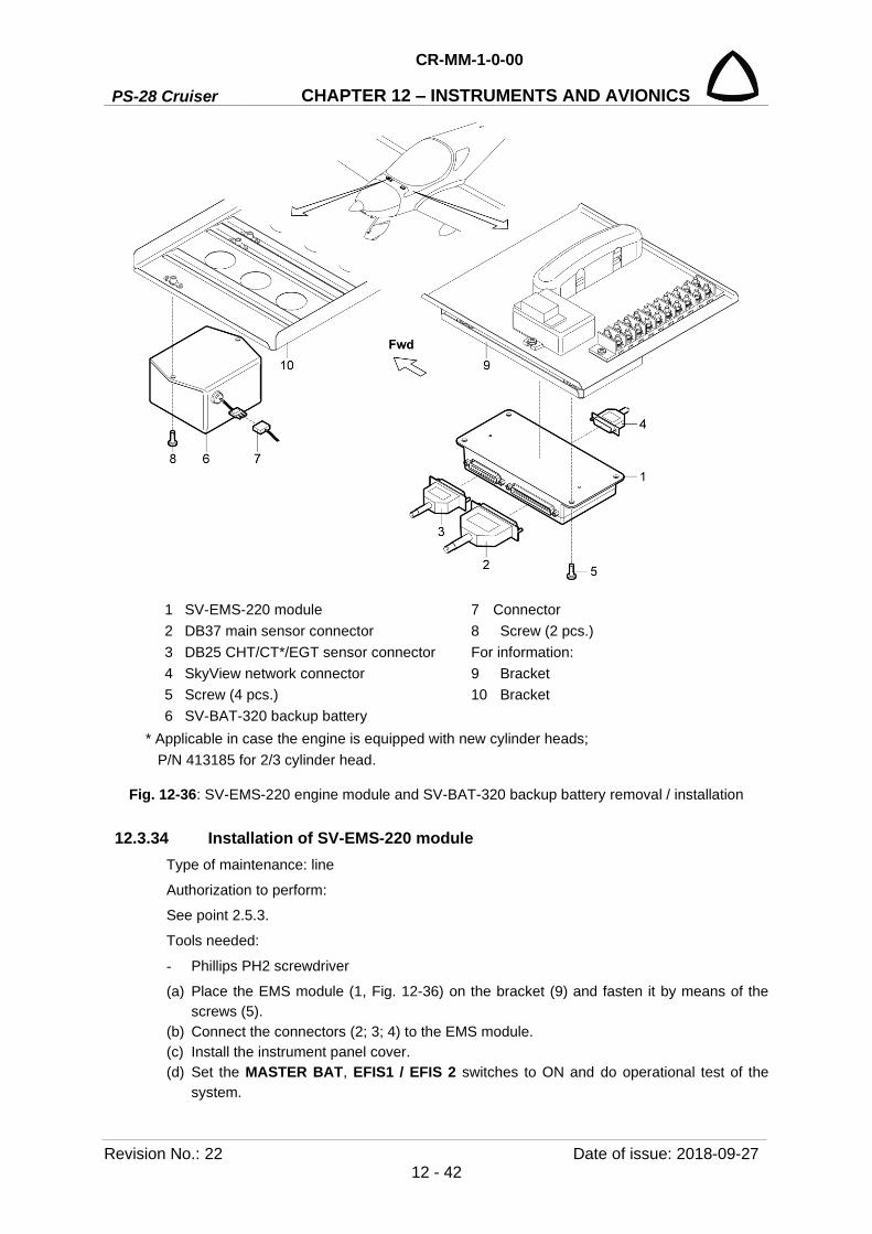
PS-28 Cruiser
CR-MM-1-0-00
CHAPTER 12 – INSTRUMENTS AND AVIONICS
Revision No.: 22 Date of issue: 2018-09-27 12 - 42
1 SV-EMS-220 module 7 Connector 2 DB37 main sensor connector 8 Screw (2 pcs.) 3 DB25 CHT/CT*/EGT sensor connector For information: 4 SkyView network connector 9 Bracket 5 Screw (4 pcs.) 10 Bracket 6 SV-BAT-320 backup battery
* Applicable in case the engine is equipped with new cylinder heads; P/N 413185 for 2/3 cylinder head.
Fig. 12-36: SV-EMS-220 engine module and SV-BAT-320 backup battery removal / installation
12.3.34 Installation of SV-EMS-220 module Type of maintenance: line
Authorization to perform:
See point 2.5.3.
Tools needed:
- Phillips PH2 screwdriver
(a) Place the EMS module (1, Fig. 12-36) on the bracket (9) and fasten it by means of the screws (5).
(b) Connect the connectors (2; 3; 4) to the EMS module. (c) Install the instrument panel cover. (d) Set the MASTER BAT, EFIS1 / EFIS 2 switches to ON and do operational test of the
system.

CR-MM-1-0-00
PS-28 Cruiser CHAPTER 12 – INSTRUMENTS AND AVIONICS
Date of issue: 2018-09-27 Revision No.: 22 12 - 43
12.3.35 Removal of SV-ADAHRS-200 module Type of maintenance: heavy
Authorization to perform:
See point 2.5.3.
Tools needed:
- wrench No. 7
- Cobra hose clip pliers
CAUTION: DO NOT USE STANDARD MOUNTING HARDWARE. ALL MOUNTING HARDWARE IS MADE FROM BRASS – NON FERROUS MATERIAL.
(a) Set the MASTER BAT, EFIS1 / EFIS 2 switches to OFF.
(b) Remove the covers on the bottom of the fuselage rear part.
(c) Disconnect the connectors (2; 3, Fig. 12-37) from the ADAHRS module (1).
(d) Remove the hose clips (7) from hoses (5; 6).
(e) Disconnect hoses (6) of static and total pressure from the ports (4; 5) on the ADAHRS
module.
(f) Loose nuts (9), unscrew and remove the screws (8), nuts (9), washers (10) and the
ADAHRS module (1).
(g) Install the protective cover on the ports (4; 5) of the module.
12.3.36 Installation of SV-ADAHRS-200 module Type of maintenance: heavy
Authorization to perform:
See point 2.5.3.
Tools needed:
- wrench No. 7
- Cobra hose clip pliers
CAUTION: DO NOT USE STANDARD MOUNTING HARDWARE. ALL MOUNTING HARDWARE IS MADE FROM BRASS – NON FERROUS MATERIAL.
(a) Remove the protective covers from the ports on the module.
(b) Insert the screws (8, Fig. 12-37) into ADAHRS module (1) mounting holes, place washers
(10) and screw the nuts (9); do not tighten it.
(c) Place the ADAHRS module (1) on the bracket (14) and fasten it by means of the screws
(8).
(d) Set the module (1) using the screws (8) so that the module is parallel to the fuselage basic
level, tighten the nuts (9). An ADAHRS module should be mounted within one degree of
parallel to all three aircraft axes.
(e) Connect the hoses (6) to the ports (3; 4) on the ADAHRS module (1) and secure them with
cable clips (7)
.
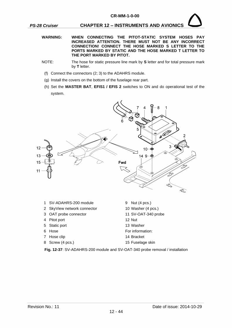
PS-28 Cruiser
CR-MM-1-0-00
CHAPTER 12 – INSTRUMENTS AND AVIONICS
Revision No.: 11 Date of issue: 2014-10-29 12 - 44
WARNING: WHEN CONNECTING THE PITOT-STATIC SYSTEM HOSES PAY INCREASED ATTENTION. THERE MUST NOT BE ANY INCORRECT CONNECTION! CONNECT THE HOSE MARKED S LETTER TO THE PORTS MARKED BY STATIC AND THE HOSE MARKED T LETTER TO THE PORT MARKED BY PITOT.
NOTE: The hose for static pressure line mark by S letter and for total pressure mark by T letter.
(f) Connect the connectors (2; 3) to the ADAHRS module.
(g) Install the covers on the bottom of the fuselage rear part.
(h) Set the MASTER BAT, EFIS1 / EFIS 2 switches to ON and do operational test of the
system.
1 SV-ADAHRS-200 module 9 Nut (4 pcs.) 2 SkyView network connector 10 Washer (4 pcs.) 3 OAT probe connector 11 SV-OAT-340 probe 4 Pitot port 12 Nut 5 Static port 13 Washer 6 Hose For information: 7 Hose clip 14 Bracket 8 Screw (4 pcs.) 15 Fuselage skin
Fig. 12-37: SV-ADAHRS-200 module and SV-OAT-340 probe removal / installation

CR-MM-1-0-00
PS-28 Cruiser CHAPTER 12 – INSTRUMENTS AND AVIONICS
Date of issue: 2018-09-27 Revision No.: 22 12 - 45
12.3.37 Removal of SV-OAT-340 probe Type of maintenance: line
Authorization to perform:
See point 2.5.3.
Tools needed:
- wrench No. 9/16 in
(a) Set the MASTER BAT, EFIS1 / EFIS 2 switches to OFF.
(b) Remove the covers on the bottom of the fuselage rear part.
(c) Disconnect connector (3, Fig. 12-37) from the ADAHRS module (1).
(d) Remove fastening members of the probe wires.
(e) Remove the connector (3) and pins from the probe wires
(f) Unscrew the nut (12), remove the washer (13) and pull out the probe (11).
12.3.38 Installation of SV-OAT-340 probe Type of maintenance: line
Authorization to perform:
See point 2.5.3.
Tools needed:
- wrench No. 9/16 in
NOTE: Do not insert the pins on the ends of the OAT probe wires into the connector until you are done running probe wires through the aircraft.
(a) On the outside of the fuselage, insert the wires and the probe (1, Fig. 12-37) through the
hole on the fuselage bottom skin (15).
(b) On the inside of the fuselage, insert the washer (13) and the nut (12) over the wires.
(c) Hand-thread the nut (12) onto the probe (11). At this point, the washer (13) should be
sandwiched between the nut (12) and the fuselage bottom skin (15); then carefully tighten
the nut using the wrench.
(d) Route and secure the probe wires to the location of the ADAHRS module.
(e) Carefully insert the pins on the wires into the connector. Pins are not polarized and lock
into place when inserted correctly.
(f) Connect the connector (3) to the ADAHRS module (1).
(g) Install the covers on the bottom of the fuselage rear part.
(h) Set the MASTER BAT, AVIONICS switches to ON and do an operational test.
PS-28 Cruiser
CR-MM-1-0-00
CHAPTER 12 – INSTRUMENTS AND AVIONICS
Revision No.: 22 Date of issue: 2018-09-27 12 - 46
12.3.39 Removal of TT21 transponder Type of maintenance: line
Authorization to perform:
See point 2.5.3.
Tools needed:
- screwdriver
NOTE: TT21 transponder is not a part of SkyView system.
(a) Set the MASTER BAT, AVIONICS switches to OFF.
(b) Disconnect the connectors (2; 3, Fig. 12-38) from the transponder (1).
(c) Unlock the retaining wire and remove the transponder (1) from the mounting tray (airplane
has mounting tray installed from bellow the bracket (12)).
(d) Install the protective cover on the antenna connector.
12.3.40 Installation of TT21 transponder NOTE: TT21 transponder is not a part of SkyView system.
Type of maintenance: line
Authorization to perform:
See point 2.5.3.
Tools needed:
- screwdriver
NOTE: TT21 transponder is not a part of SkyView system.
(a) Remove the protective cover from the antenna connector
(b) Put the transponder (1, Fig. 12-38) into the mounting tray by hooking the connector end
under the lip on the tray.
(c) Lock the transponder (1) into the mounting tray by clipping the retaining wire over the lugs
on the opposite end (airplane has mounting tray installed from bellow the bracket (12)).
(d) Connect the connectors (2; 3) to the transponder.
(e) Set the MASTER BAT, AVIONICS switches to ON and do an operational test.
12.3.41 Removal of drain sump Type of maintenance: line
Authorization to perform:
See point 2.5.3.
Tools needed:
- Cobra hose clip pliers
- wrench No. 27
(a) Tilt forward the left seat back.
(b) Remove the hose clips (4, Fig. 12-38) from hoses (5).

CR-MM-1-0-00
PS-28 Cruiser CHAPTER 12 – INSTRUMENTS AND AVIONICS
Date of issue: 2018-09-27 Revision No.: 22 12 - 47
(c) Disconnect hoses (5) of from the drain sump body (6); install protective covers on the
hoses and hose ports of the drain sump body.
(d) Unscrew and remove the nut (10) with the drain sump bowl (9); unscrew and remove the
nut (7) and remove the drain sump body (6) from the bracket (11).
12.3.42 Installation of drain sump Type of maintenance: line
Authorization to perform:
See point 2.5.3.
Tools needed:
- Cobra hose clip pliers
- wrench No. 27
(a) Tilt forward the left seat back. (b) Insert the drain sump body (6, Fig. 12-38) into the hole in the bracket (11) and fasten it
with the nut (7). (c) Check the condition of the O-ring (8) a transparent drain sump bowl (9) - replace damaged
parts. (d) Insert the O-ring (8) to the drain sump body (6), set the drain sump bowl (9) to the drain
sump body, screw and carefully tighten the nut (10).
CAUTION: DURING INSTALLATION OF THE DRAIN SUMP AVOID INCORRECT SEATING OF THE O-RING BETWEEN THE DRAIN SUMP BODY AND THE DRAIN SUMP BOWL.
(e) Remove the protective covers from the hoses and hose sockets of the drain sump body. (f) Connect the hoses (5) to the ports on the drain sump body (6) and secure them with hose
clips (4). (g) Carry out check of pitot-static system tightness test (see 12.4.1).
12.3.43 Draining of drain sumps NOTE: If you find impurities or water in pitot-static system drain sumps, these sumps
must be drain.
Tools needed:
- wrench No. 27
(a) Tilt forward the left seat back.
(b) Unscrew and remove the nut (10, Fig. 12-38) with the drain sump bowl (9).
(c) Clean and dry the drain sump bowl (9).
(d) Check the condition of the O-ring (8) a transparent drain sump bowl (9) - replace damaged
parts.
(e) Insert the O-ring (8) to the drain sump body (6), set the drain sump bowl (9) to the drain
sump body, screw and carefully tighten the nut (10).
CAUTION: DURING INSTALLATION OF THE DRAIN SUMP AVOID INCORRECT SEATING OF THE O-RING BETWEEN THE DRAIN SUMP BODY AND THE DRAIN SUMP BOWL.

PS-28 Cruiser
CR-MM-1-0-00
CHAPTER 12 – INSTRUMENTS AND AVIONICS
Revision No.: 22 Date of issue: 2018-09-27 12 - 48
(f) Tilt backward the left seat back and carry out check of pitot-static system tightness test
(see 12.4.1).
Fig. 12-38: TT21 transponder and drain sumps removal / installation
12.3.44 Removal of TC20 transponder control unit Type of maintenance: line
Authorization to perform:
See point 2.5.3.
Tools needed:
- Phillips PH1 screwdriver
- Cobra hose clip pliers, cutting pliers
(a) Set the MASTER BAT, AVIONICS switches to OFF.
(b) Remove bolts securing the left instrument panel and carefully pull out and hold the
instrument panel. (c) Remove the hose clip (4, Fig. 12-39) from the hose (3).
(d) Disconnect the hose (3) of static pressure from the rear port on the control unit (1).
(e) Disconnect the connector (2) from the control unit.
1 SV-XPDR-261 transponder 8 O-ring 2 SkyView network connector 9 Drain sump bowl 3 Antenna connector 10 Nut 4 Hose clip For information: 5 Hose 11 Bracket 6 Drain sump body 12 Bracket 7 Nut

CR-MM-1-0-00
PS-28 Cruiser CHAPTER 12 – INSTRUMENTS AND AVIONICS
Date of issue: 2018-09-27 Revision No.: 22 12 - 49
(f) Unscrew screws (5) and remove the control unit (1) from the panel.
(g) Install the protective covers on the connector and rear port of the control unit.
12.3.45 Installation of TC20 transponder control unit Type of maintenance: line
Authorization to perform:
See point 2.5.3.
Tools needed:
- Phillips PH1 screwdriver
- Cobra hose clip pliers
(a) Remove the protective covers from the connector and rear port of the control unit.
(b) Connect the hose (3, Fig. 13-39) to the rear port of the control unit (1) and secure it with
the cable clips (4).
(c) Connect the connector (2) to the control unit.
(d) Put the control unit (1) in position in the panel (5).
(e) Attach the control unit (1) by means of screws (5).
(f) Install the left instrument panel (6).
(g) Carry out check of pitot-static system tightness / Dynon avionics pitot / static test (see
12.4.1, 12.4.2)
(h) Set the MASTER BAT, AVIONICS switches to ON and do an operational test.
Fig. 12-39: TT20 transponder control unit removal / installation
1 TT20 transponder control unit 2 Connector 3 Hose 4 Hose clip 5 Screw For information: 5 Instrument panel
PS-28 Cruiser
CR-MM-1-0-00
CHAPTER 12 – INSTRUMENTS AND AVIONICS
Revision No.: 22 Date of issue: 2018-09-27 12 - 50
12.4 Check / Adjustment Type of maintenance: line
Authorization to perform: See point 2.5.3.
12.4.1 Check of pitot-static system tightness (a) In the static pressure system create the under pressure by means of an appropriate
instrument corresponding to altitude of 1,000 ft. Drop in the indicated altitude per one
minute must not exceed 100 ft.
(b) In the system of total pressure create the overpressure corresponding to speed of
140 knots (260 km/h, 161 mph) by means of a suitable instrument. Drop in speed during
3 minutes must not exceed 2.3 knots (4.4 km/h, 2.7 mph).
12.4.2 Dynon avionics pitot / static test Dynon ADAHRS / EFIS units use airspeed (or GPS ground speed when airspeed is
unavailable) in the calculation of attitude. The internal rate sensors that are used to determine
attitude are monitored and calibrated in-flight by using feedback from the accelerometers and
from airspeed to achieve a highly accurate attitude solution.
When a pitot or static test is performed, the ADAHRS / EFIS is being exposed to dynamics
that are impossible to achieve in a real airplane flight environment – namely, there are large
airspeed changes without the accompanying accelerations and rotations. This false condition
will cause a well-calibrated unit to incorrectly adjust its calibration. Furthermore, when a unit
is in a test situation a change in applied pitot or static pressure will cause the attitude to pitch
up or down. This is expected.
Performing the Dynon prescribed pitot and static test procedure to a Dynon ADAHRS or EFIS
will prevent problems with the unit’s performance in flight.
Dynon pitot / static test Instructions
Basic principles:
• Ensure unit is warmed up during each test reading.
• Unit should be powered off when changing pressures.
• Keep aircraft still (do not move) when pressure is applied.
Steps:
(a) The airplane itself should be temperature stable. For example, if the aircraft is moved from
outside in the sun to a hangar for testing, tests should not be started until the airplane has
stabilized at the hangar temperature.
(b) Turn EFIS on and let it warm up until the altitude reading is stabilized. This period should
be at least 5 minutes, but may take longer depending on environmental conditions.
(c) Turn EFIS off.
(d) While the EFIS is off, apply the pressure required by your test to pitot and / or static port
via your test equipment
.
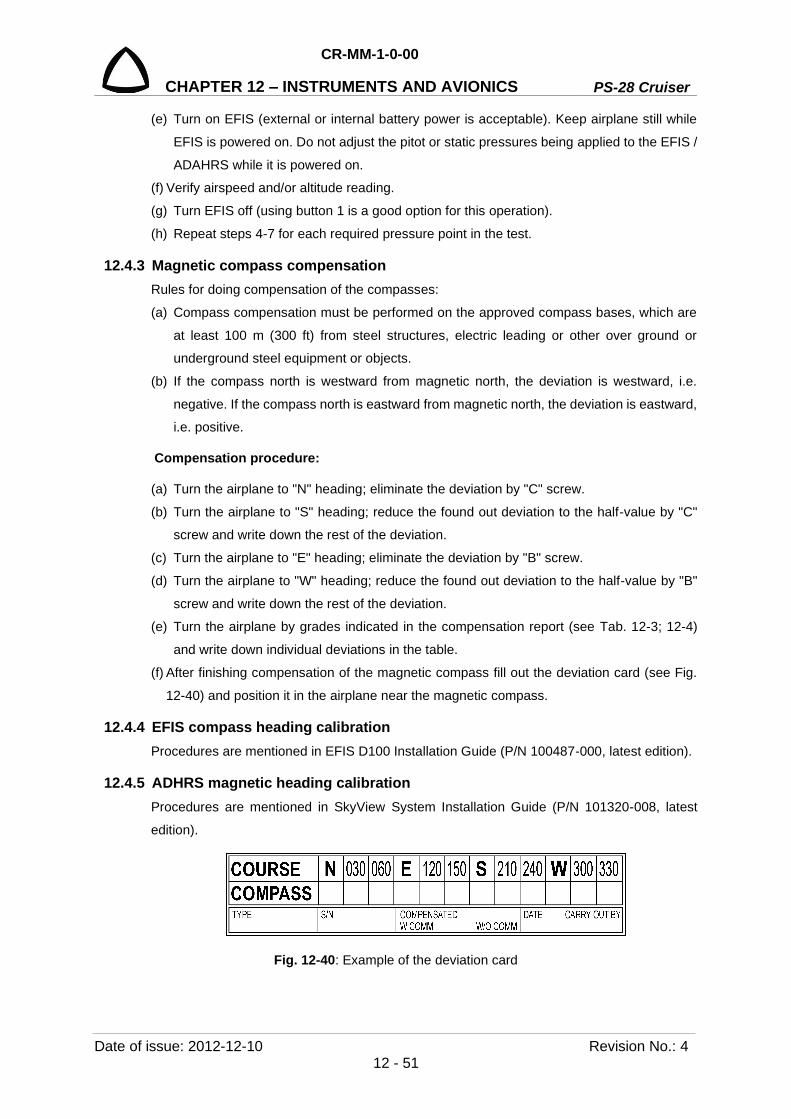
CR-MM-1-0-00
PS-28 Cruiser CHAPTER 12 – INSTRUMENTS AND AVIONICS
Date of issue: 2012-12-10 Revision No.: 4 12 - 51
(e) Turn on EFIS (external or internal battery power is acceptable). Keep airplane still while
EFIS is powered on. Do not adjust the pitot or static pressures being applied to the EFIS /
ADAHRS while it is powered on.
(f) Verify airspeed and/or altitude reading.
(g) Turn EFIS off (using button 1 is a good option for this operation).
(h) Repeat steps 4-7 for each required pressure point in the test.
12.4.3 Magnetic compass compensation Rules for doing compensation of the compasses:
(a) Compass compensation must be performed on the approved compass bases, which are
at least 100 m (300 ft) from steel structures, electric leading or other over ground or
underground steel equipment or objects.
(b) If the compass north is westward from magnetic north, the deviation is westward, i.e.
negative. If the compass north is eastward from magnetic north, the deviation is eastward,
i.e. positive.
Compensation procedure:
(a) Turn the airplane to "N" heading; eliminate the deviation by "C" screw.
(b) Turn the airplane to "S" heading; reduce the found out deviation to the half-value by "C"
screw and write down the rest of the deviation.
(c) Turn the airplane to "E" heading; eliminate the deviation by "B" screw.
(d) Turn the airplane to "W" heading; reduce the found out deviation to the half-value by "B"
screw and write down the rest of the deviation.
(e) Turn the airplane by grades indicated in the compensation report (see Tab. 12-3; 12-4)
and write down individual deviations in the table.
(f) After finishing compensation of the magnetic compass fill out the deviation card (see Fig.
12-40) and position it in the airplane near the magnetic compass.
12.4.4 EFIS compass heading calibration Procedures are mentioned in EFIS D100 Installation Guide (P/N 100487-000, latest edition).
12.4.5 ADHRS magnetic heading calibration Procedures are mentioned in SkyView System Installation Guide (P/N 101320-008, latest
edition).
Fig. 12-40: Example of the deviation card

PS-28 Cruiser
CR-MM-1-0-00
CHAPTER 12 – INSTRUMENTS AND AVIONICS
Revision No.: 4 Date of issue: 2012-12-10 12 - 52
REPORT OF MAGNETIC COMPASS SWING Aircraft Aircraft S/N
Compass type Compass S/N Check 1. All electrical equipment ON and operating
The engine running, idle
Fuselage placed in flying attitude XPDR ON, XCVR receiving
Check 2. Switched ON just those instruments, which are necessary for VFR flight. COM, NAV, XPDR, lights - switched OFF The engine running, idle
Fuselage placed in flying attitude
Heading Measured Deviation
1. 2. 1. 2. N 000 030 060
E 090 120 150
S 180 210 240
W 270 300 330
Maximal allowed deviation ± 10°
If the compass deviations are not identical for both checks, two separate compass correction cards should be done.
Note:
General evaluation Complied Failed
Performed by: Elaborated by: Date:
Tab. 12-3: Report of magnetic compass compensation
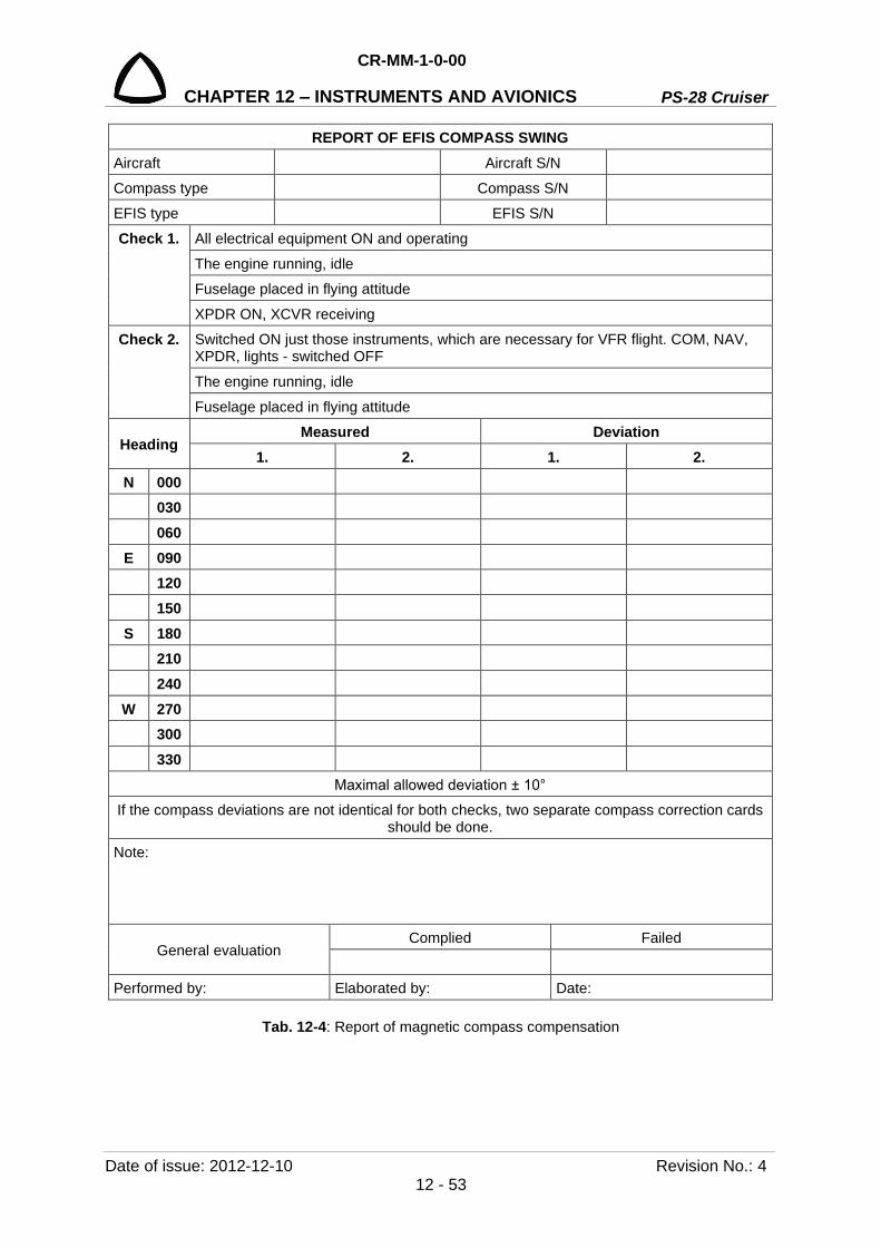
CR-MM-1-0-00
PS-28 Cruiser CHAPTER 12 – INSTRUMENTS AND AVIONICS
Date of issue: 2012-12-10 Revision No.: 4 12 - 53
REPORT OF EFIS COMPASS SWING Aircraft Aircraft S/N
Compass type Compass S/N EFIS type EFIS S/N
Check 1. All electrical equipment ON and operating
The engine running, idle Fuselage placed in flying attitude
XPDR ON, XCVR receiving
Check 2. Switched ON just those instruments, which are necessary for VFR flight. COM, NAV, XPDR, lights - switched OFF
The engine running, idle
Fuselage placed in flying attitude
Heading Measured Deviation
1. 2. 1. 2. N 000 030 060
E 090 120 150
S 180 210 240
W 270 300 330
Maximal allowed deviation ± 10° If the compass deviations are not identical for both checks, two separate compass correction cards
should be done.
Note:
General evaluation Complied Failed
Performed by: Elaborated by: Date:
Tab. 12-4: Report of magnetic compass compensation

PS-28 Cruiser
CR-MM-1-0-00
CHAPTER 12 – INSTRUMENTS AND AVIONICS
Revision No.: 11 Date of issue: 2014-10-29 12 - 54
12.4.6 EFIS D100 internal emergency battery check EFIS-D100 has a rechargeable internal emergency battery, it is necessary to ensure that the
battery capacity is such that it will last at least 2 hours on a full charge. Once per year, perform
the battery capacity test. Procedure and replacing the battery pack is mentioned in EFIS D100
Installation Guide (P/N 100487-000, latest edition).
12.4.7 EFIS D100, EMS D120 firmware upgrade CAUTION: RANDOM AND UNAUTHORIZED MANIPULATION OF THE SYSTEM
SETTINGS IS PREVENTED BY THE SYSTEM LOCK FEATURES AND BY A PASSWORD PROHIBITING AN ACCESS TO THE SYSTEM SETTINGS.
WARNING: UNAUTHORIZED ENTRY TO THE SYSTEM SETTINGS AND A FAILURE TO FOLLOW PROCEDURES FOR SYSTEM ACTUALIZATION MAY CAUSE INCORRECT FUNCTIONALITY OR TOTAL FAILURE OF THE WHOLE SYSTEM!
Dynon Avionics provides free firmware updates for all its products, and continues to add new
features periodically. CAG will check whether latest Dynon firmware is compatible with CAG
settings and through Service Bulletin SB-SC-013 (latest edition) informs the owners /
operators.
Each Dynon EMS or EFIS must be individually upgraded by connecting a PC to that
instrument’s serial port (see Fig. 12-41). The HS34 also must be individually upgraded via its
Serial 1 port. Firmware upgrades to EDC-D10A is performed automatically during firmware
upgrades of the attached EFIS product.
Fig. 12-41: Points for computer connection
(a) Check Dynon Avionics web pages for latest Dynon firmware.
(b) Download last revision of Service Bulletin SB-SC-013 from CAG web pages.
(c) Check if the latest Dynon firmware is authorized with the CAG.

CR-MM-1-0-00
PS-28 Cruiser CHAPTER 12 – INSTRUMENTS AND AVIONICS
Date of issue: 2014-10-29 Revision No.: 11 12 - 55
(d) Download the appropriate firmware version from downloads.dynonavionics.com
(e) Install software according EFIS-D100 Installation Guide.
(f) Check correct function of instruments and avionics.
12.4.8 Flight test for the verification of the stall warning system Fly the airplane at a safe altitude in a heavy / forward CG configuration, since this configuration
has the narrowest stall margin. The airplane should have flaps retracted.
Note the airspeed at which the stall warning is activated vs the known stall speed of the
aircraft. The stall margin should be approximately 5 kts. If it is not, proceed as follows.
• If the stall warning is too late:
If stall warning comes on too late, the position of the lift detector should be moved forward
if possible. Moving the detector forward will allow the detector to be activated at a faster
speed. A 6.3 mm (1/4 in) movement of the lift detector will change the stall warning
activation point approximately 5 knots.
• If the stall warning is too early:
If stall warning comes on too early, the position of the lift detector should be moved
backward, if possible. Moving the detector backward will allow the detector to be activated
at a slower speed. A 6.3 mm (1/4 in) movement of the lift detector will change the stall
warning activation point approximately 5 knots.
When the adjustments are complete, fly the aircraft in heavy / aft, light / forward and light aft
to ensure that the stall warning margin is at least that which was obtained in the heavy / forward
configuration. Finally, ensure that no false warnings occur during a normal, stabilized
approach.
12.4.9 SkyView system adjustment 12.4.9.1 SkyView system upgrade
Dynon Avionics provides a free-of-charge upgrade of a firmware for all Dynon’s products and
is continuously adding new functions to these products and enhances its properties. These activities are monitored by Czech Aircraft Group which also evaluates whether the last Dynon firmware versions is compatible with CAG’s airplane SkyView settings and through the Service Bulletin SB-PS-025 issuance (newest firmware version publication) CAG will inform airplane operators regarding the related system changes and actualization procedures to update SkyView system. SkyView SV-D1000 screen firmware upgrade automatically updates all related modules connected to the internal network with the SkyView screens. That’s why all devices connected
within the system have to be turned on during the actualization procedure. The firmware actualization has to be performed separately on each screen SV-D1000 screen (Left – EFIS1, Right – EFIS2). The actualization procedure requires to copy all upgrade related files to the SkyView screen from a given USB flash drives (separately for each screen due to different setting of each screen) which have to be plugged into the related USB ports (marked as EFIS1, EFIS2).
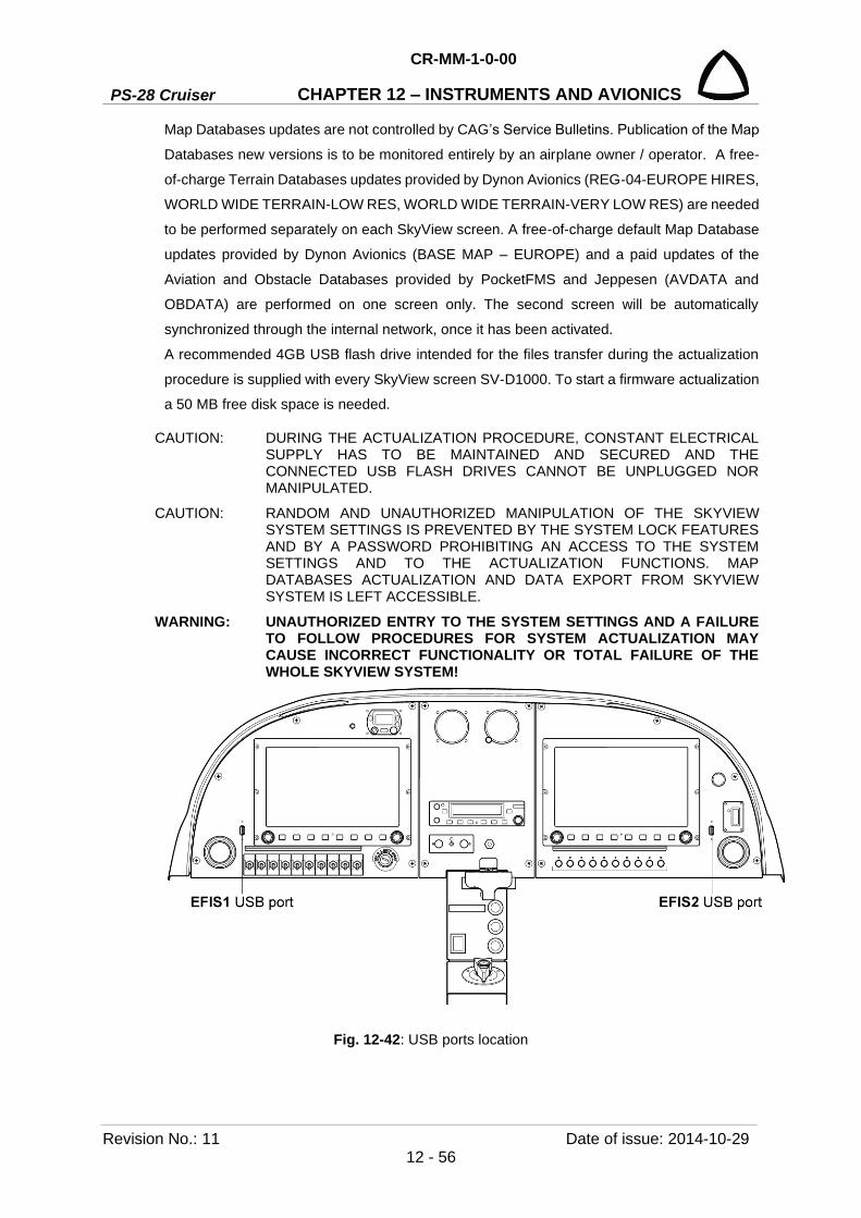
PS-28 Cruiser
CR-MM-1-0-00
CHAPTER 12 – INSTRUMENTS AND AVIONICS
Revision No.: 11 Date of issue: 2014-10-29 12 - 56
Map Databases updates are not controlled by CAG’s Service Bulletins. Publication of the Map
Databases new versions is to be monitored entirely by an airplane owner / operator. A free-
of-charge Terrain Databases updates provided by Dynon Avionics (REG-04-EUROPE HIRES,
WORLD WIDE TERRAIN-LOW RES, WORLD WIDE TERRAIN-VERY LOW RES) are needed
to be performed separately on each SkyView screen. A free-of-charge default Map Database
updates provided by Dynon Avionics (BASE MAP – EUROPE) and a paid updates of the
Aviation and Obstacle Databases provided by PocketFMS and Jeppesen (AVDATA and
OBDATA) are performed on one screen only. The second screen will be automatically
synchronized through the internal network, once it has been activated.
A recommended 4GB USB flash drive intended for the files transfer during the actualization
procedure is supplied with every SkyView screen SV-D1000. To start a firmware actualization
a 50 MB free disk space is needed.
CAUTION: DURING THE ACTUALIZATION PROCEDURE, CONSTANT ELECTRICAL SUPPLY HAS TO BE MAINTAINED AND SECURED AND THE CONNECTED USB FLASH DRIVES CANNOT BE UNPLUGGED NOR MANIPULATED.
CAUTION: RANDOM AND UNAUTHORIZED MANIPULATION OF THE SKYVIEW SYSTEM SETTINGS IS PREVENTED BY THE SYSTEM LOCK FEATURES AND BY A PASSWORD PROHIBITING AN ACCESS TO THE SYSTEM SETTINGS AND TO THE ACTUALIZATION FUNCTIONS. MAP DATABASES ACTUALIZATION AND DATA EXPORT FROM SKYVIEW SYSTEM IS LEFT ACCESSIBLE.
WARNING: UNAUTHORIZED ENTRY TO THE SYSTEM SETTINGS AND A FAILURE TO FOLLOW PROCEDURES FOR SYSTEM ACTUALIZATION MAY CAUSE INCORRECT FUNCTIONALITY OR TOTAL FAILURE OF THE WHOLE SKYVIEW SYSTEM!
Fig. 12-42: USB ports location

CR-MM-1-0-00
PS-28 Cruiser CHAPTER 12 – INSTRUMENTS AND AVIONICS
Date of issue: 2014-10-29 Revision No.: 11 12 - 57
Procedure to perform SkyView system upgrade:
(a) Check the issuance of the actual revision of the Service Bulletin SB-SC-xxx from CAG
website.
(b) Follow the instructions specified in the Service Bulletin SB-PS-025.
Procedure to perform Map Databases update:
(a) Check the issuance of actual revisions for the map databases from providers‘ websites.
(b) Download the required databases and save them to the given USB flash drive.
(c) Turn on MASTER BAT and screen EFIS1. Once the screen started, plug in the USB flash
drive to the USB port EFIS1 and press and hold buttons 7 and 8 until the menu SYSTEM
SOFTWARE (LOAD and EXPORT) for file transfer appears.
(d) With a given cursor, activate a function LOAD FILES and select related files to transfer.
By pressing button 8 LOAD, download related files from USB drive to the screen system.
Once files are downloaded, press the button 8 DONE to return to the menu.
(e) Continue update procedure of other databases according to the paragraph (d).
(f) To complete the update procedure, press button 2 EXIT.
(g) Turn on screen EFIS2. Once the screen started, wait until the transfer updated map
database from the screen EFIS1.
(h) To download the update terrain databases to EFIS2 screen plug in the USB flash
drive to the USB port EFIS2 and press and hold buttons 7 and 8 until the menu SYSTEM
SOFTWARE (LOAD and EXPORT) for file transfer appears and then proceed according
to point (d) to (f). (i) Turn off screen EFIS1, EFIS2 and MASTER BAT.
Checking the last versions of the Map Databases within the SkyView system:
1. Turn on MASTER BAT, press button 7 and turn on EFIS1. Hold button 7 during the system
booting sequence until the SETUP MENU for system setting appears.
2. With a given cursor activate a function LOCAL DISPLAY SETUP and then INSTALLED
DATABASES.
3. Check the last installed databases.
4. The complete the last installed database check, press button 2 EXIT.
5. Press button 7 and turn on EFIS2. Hold button 7 during the system booting sequence until
the SETUP MENU for system setting appears and then proceed according to point (2) to
(4).
6. Turn off screen EFIS1, EFIS2 and MASTER BAT.

PS-28 Cruiser
CR-MM-1-0-00
CHAPTER 12 – INSTRUMENTS AND AVIONICS
Revision No.: 11 Date of issue: 2014-10-29 12 - 58
12.4.9.2 SkyView system calibration procedures
CAUTION: DURING THE CALIBRATION PROCEDURE, CONSTANT ELECTRICAL SUPPLY HAS TO BE MAINTAINED AND SECURED.
CAUTION: RANDOM AND NON-QUALIFIED MANIPULATION OF THE SKYVIEW SYSTEM SETTINGS IS PREVENTED BY THE SYSTEM LOCK FEATURES AND BY A PASSWORD PROHIBITING AN ACCESS TO THE SYSTEM SETTINGS AND TO THE ACTUALIZATION FUNCTIONS.
ACCESSING THE CALIBRATION FUNCTIONS IS POSSIBLE WITH A PROCEDURE DESCRIBED BELOW.
(a) Switch on MASTER BAT, press button 7 and turn on EFIS1. Hold button 7 during system
booting sequence until the SETUP MENU for setting up the system appears.
(b) With a cursor in the section „HARDWARE CALIBRATION“ choose:
1. EMS CALIBRATION for calibration of the following:
- AILERN CALIBRATION
- ELEV CALIBRATION
- FLAPS CALIBRATION
- FUEL TANK 1 (LEFT) CALIBRATION
- FUEL TANK 2 (RIGHT) CALIBRATION
- FUEL FLOW CALIBRATION
- TACHOMETER CALIBRATION
2. ADAHRS CALIBRATION“ for calibration of the following:
- ALTITUDE ADJUST
- COMPASS CALIBRATION
- OAT OFFSET
- ZERO PRESSURE AIRSPEED CALIBRATION
(c) According to the instructions displayed on the screen and described below, perform the
required calibration.
(d) Once calibration is done, exit the SETUP MENU by pressing the button 2 EXIT.
(e) Turn off screen EFIS1 and MASTER BAT.
Aileron trim calibration
1. With a cursor, select an option AILERN CALIBRATION.
2. Press button 8 RECAL.
3. Set the aileron trim tab to the max. upper position (FULL RIGHT WING UP).
4. Press button 8 SET.
5. Set the aileron trim tab to the max. lowest position (FULL RIGHT WING DOWN).
6. Press button 8 SET.
7. Set the aileron trim tab to the center position (TAKE-OFF).
8. Press button 8 DONE to complete the calibration procedure.

CR-MM-1-0-00
PS-28 Cruiser CHAPTER 12 – INSTRUMENTS AND AVIONICS
Date of issue: 2014-10-29 Revision No.: 11 12 - 59
Elevator trim calibration
1. With a cursor, select an option ELEV CALIBRATION.
2. Press button 8 RECAL.
3. Set the elevator trim tab to the max. lowest position (FULL DOWN).
4. Press button 8 SET.
5. Set the elevator trim tab to the max. upper position (FULL UP).
6. Press button 8 SET.
7. Set the elevator trim tab to the center position (TAKE-OFF).
8. Press button 8 DONE to complete the calibration procedure.
Flaps calibration
1. With a cursor, select an option FLAPS CALIBRATION.
2. Press button 8 RECAL.
3. Set the flaps to the 0° - max. upper position (FLAP STOP 1).
4. With a cursor, fill in a value for flaps settings to 0° +00.
5. Press button 8 SET.
6. Set the flaps to the 12° - take-off position (FLAP STOP 2).
NOTE: To set flaps to the 12° angle, use appropriate protractor.
7. With a cursor, fill in a value for flaps settings to 12° +12.
8. Press button 8 SET.
9. Set the flaps to the 30° - max. lowest position (FLAP STOP 3).
10. With a cursor, fill in a value for flaps settings to 30° +30.
11. Press button 8 SET.
12. Press button 7 DONE to complete the filling procedure of the values for flaps settings.
13. Press button 8 DONE to complete the calibration procedure.
Fuel sensors calibration
1. Drain all fuel from both fuel tanks (see Chapter 9.5.2).
2. With a cursor, select an option FUEL TANK 1 (LEFT) CALIBRATION.
3. Press button 8 RECAL.
4. With a cursor, fill in a value for total volume of the fuel tank. 57 liters 057.
5. Press button 8 NEXT.
6. Check whether the left tank is empty.
7. Press button 8 START.
8. To the left tank add exactly 5 liters of fuel.
9. Let the fuel level to stabilize.
10. Press button 8 ADD.
11. Check the value in the upper right corner of the screen TOTAL LITERS ADDED for the
total amount of added fuel.

PS-28 Cruiser
CR-MM-1-0-00
CHAPTER 12 – INSTRUMENTS AND AVIONICS
Revision No.: 11 Date of issue: 2014-10-29 12 - 60
12. Repeat the procedure according to the point 8 till 11 until the 50 liters are displayed. In
that moment a warning will appear informing that the sensor measuring value (voltage)
has not been changed and to confirm that 5 liters have been added.
13. Press button 8 YES.
14. Press button 7 FULL.
15. Press button 8 DONE.
NOTE: Repeat the same procedure also for the right fuel tank FUEL TANK 2 (RIGHT) CALIBRATION.
Fuel flow calibration
NOTE: A standard fuel flow meter Electronics International Red Cube FT-60 is installed in the airplane for which a calibration constant 68000 is set as default.
CAUTION: TO ADJUST THE CALIBRATION CONSTANT FOR BETTER PRECISION PLEASE REFER TO THE INSTRUCTIONS SPECIFIED IN THE SKYVIEW INSTALLATION GUIDE, DOCUMENT 101320-016, REVISION Q OR LATER, SECTION„ SV-EMS-220/221 INSTALLATION AND CONFIGURATION, CHAPTER FUEL COMPUTER CONFIGURATION.
1. With a cursor, select an option FUEL FLOW CALIBRATION.
2. In the parameter PUL/GAL (PIN C37 P14) set the new value for calibration constant.
3. Press button 8 ACCEPT.
Tachometer calibration
CAUTION: FOR A STANDARD ENGINE INSTALLATION ROTAX 912 S/ULS A DEFAULT VALUE 1.00 IS SET FOR THE SYSTEM TO BE ABLE TO PRECISELY MEASURE THE RPM OF THE ENGINE. THIS VALUE CANNOT BE CHANGED.
1. With a cursor, select an option TACHOMETER CALIBRATION.
2. Set the value to 1.00.
3. Press button 8 ACCEPT.
Altitude adjustment
1. Check the internal tightness of the pitot-static system.
2. Warm up the SkyView system for a 30 min period.
3. According to the procedures for checking and adjusting altimeters find out the proper value
for a correct altitude indication.
CAUTION: TO FIGURE OUT THE PROPER VALUE FOLLOW THE INSTRUCTIONS SPECIFIED IN THE SKYVIEW INSTALLATION GUIDE, DOCUMENT 101320-016, REVISION Q OR LATER, SECTION SV-ADAHRS-200/201 INSTALLATION AND CONFIGURATION, CHAPTER PERFORMING PITOT-STATIC CHECKS.
4. With a cursor, select an option ALTITUDE ADJUST.
5. Set the proper value for a correct altitude indication (with adding or subtracting from the
actual value)
6. Press button 8 ACCEPT.

CR-MM-1-0-00
PS-28 Cruiser CHAPTER 12 – INSTRUMENTS AND AVIONICS
Date of issue: 2014-10-29 Revision No.: 11 12 - 61
Compass calibration
CAUTION: COMPASS CALIBRATION OF THE SKYVIEW SYSTEM HAS TO BE PERFORMED IN THE AREA SPECIFICALLY DESIGNATED FOR THESE ACTIVITIES. (WITHOUT ANY METAL CONSTRUCTIONS, ELECTRICAL WIRINGS, NATURAL IRON ORE DEPOSITS IN VICINITY OF THE AREA, ETC.). FOR EXAMPLE COMPENSATING CIRCLE ON THE AIRPORT.
DURING THE COMPASS CALIBRATION PROCEDURE, ENGINE HAS TO BE RUNNING AND ALL ELECTRICAL DEVICES ON BOARD HAVE TO BE TURNED ON.
1. Warm up the SkyView system for a 5 min period. 2. With a cursor, select an option COMPASS CALIBRATION. 3. Functionality check of SV-GPS-250 – all information about the magnetic intensity,
magnetic inclination, magnetic declination, information about the location, time and date have to be displayed in green.
4. Place the aircraft precisely to the magnetic north direction and lock it against any movement.
5. Press button 4 NORTH and wait for the system to compensate the data. 6. Place the aircraft precisely to the magnetic east direction and lock it against any
movement. 7. Press button 5 EAST and wait for the system to compensate the data. 8. Place the aircraft precisely to the magnetic south direction and lock it against any
movement. 9. Press button 6 SOUTH and wait for the system to compensate the data. 10. Place the aircraft precisely to the magnetic west direction and lock it against any
movement. 11. Press button 7 WEST and wait for the system to compensate the data. 12. Press button 8 SAVE. 13. Press button 8 FINISH.
OAT offset
1. Find out the value for the correction of the temperature (in comparison with appropriate calibrated thermometer).
2. With a cursor, select an option OAT OFFSET. 3. Set the proper value for a correct temperature indication (+/-). 4. Press button 8 ACCEPT.
Zero pressure airspeed calibration
NOTE: This calibration can improve the accuracy of indication at very low airspeeds.

PS-28 Cruiser
CR-MM-1-0-00
CHAPTER 12 – INSTRUMENTS AND AVIONICS
Revision No.: 23 Date of issue: 2020-01-15 12 - 62
CAUTION: BEFORE PERFORMING THE CALIBRATION THE AIRPLANE MUST BE LOCATED IN ABSOLUTE CALMLY SPACE (WITHOUT WIND AND DRAUGHT) AND MUST BE CHECKED FOR TIGHTNESS OF THE PITOT-STATIC SYSTEM.
1. Warm up the SkyView system for a 30 min period.
2. With a cursor, select an option ZERO PRESSURE AIRSPEED CALIBRATION.
3. Press button 7 ACQUIRE.
4. Press button 8 SAVE.
5. Press button 1 BACK.
Note: By pressing the button 6 RESET the system returns to its original factory settings.
12.4.9.3 SV-BAT-320 backup battery test Each SV-D1000 screen has a rechargeable emergency battery, it is necessary to ensure that
the battery capacity is such that it will last at least 60 minutes on a full charge. Once per year,
perform the battery capacity test. Procedure and replacing the battery pack is mentioned in
SkyView Installation Guide, Document 101320-016, Revision Q or later.
12.4.10 Inspection and lubrication of Gerdes or ACS ignition switch Type of maintenance: Line
Authorization to perform: See point 2.5.3
Tools needed: Common tools for aircraft maintenance
General Ignition switch of Gerdes or ACS company is used in PS-28 Cruiser airplane.
This section contains instructions for inspection and lubrication of the ignition switch and for
installation of a diode across the starter solenoid coil, if the diode is missing.
12.4.10.1 Disassembly 1. Move the aircraft to a suitable place to perform the work
2. Remove engine upper cowling
3. Disconnect battery terminals
4. Remove the ignition switch from the instrument panel
5. Disconnect all wires for re-installation
CAUTION: WHEN THE IGNITION SWITCH WIRES ARE DISCONNECTED, OR WHEN THE IGNITION SWITCH IS DISASSEMBLED (STEP 6, BELLOW), BOTH MAGNETOS ARE “HOT”. IF THE PROPELLER IS MOVED DURING THIS TIME, THE ENGINE MAY FIRE AND CAUSE SERIOUSOR OR FATAL INJURY TO PERSONNEL.
6. Hold the switch assembly with the terminal board on top. Remove two screws and two
washers from the terminal board. Lift the terminal board from the switch body, being careful
not to lose the springs and triangular caps.
7. Remove the three springs and three triangular caps from the switch body.
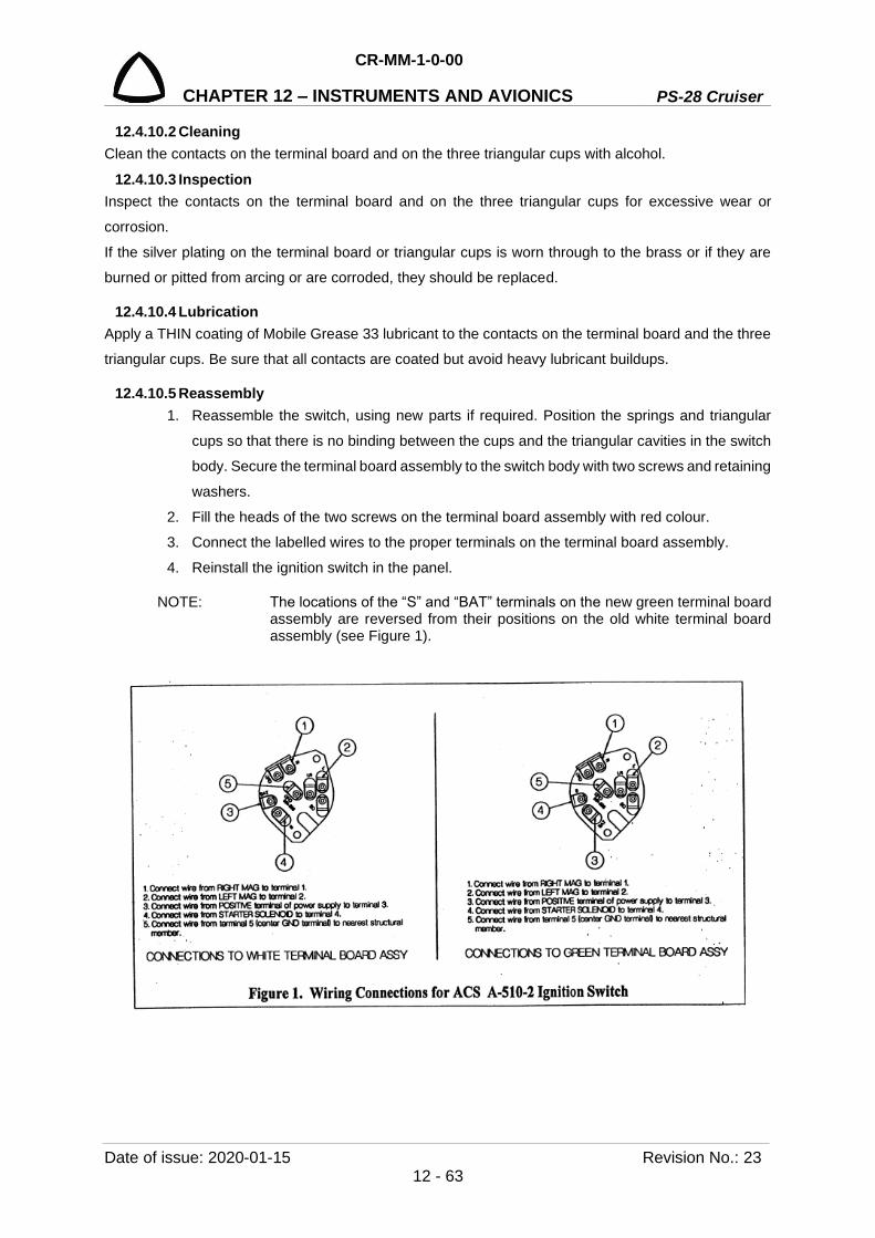
CR-MM-1-0-00
PS-28 Cruiser CHAPTER 12 – INSTRUMENTS AND AVIONICS
Date of issue: 2020-01-15 Revision No.: 23 12 - 63
12.4.10.2 Cleaning Clean the contacts on the terminal board and on the three triangular cups with alcohol.
12.4.10.3 Inspection Inspect the contacts on the terminal board and on the three triangular cups for excessive wear or
corrosion.
If the silver plating on the terminal board or triangular cups is worn through to the brass or if they are
burned or pitted from arcing or are corroded, they should be replaced.
12.4.10.4 Lubrication Apply a THIN coating of Mobile Grease 33 lubricant to the contacts on the terminal board and the three
triangular cups. Be sure that all contacts are coated but avoid heavy lubricant buildups.
12.4.10.5 Reassembly 1. Reassemble the switch, using new parts if required. Position the springs and triangular
cups so that there is no binding between the cups and the triangular cavities in the switch
body. Secure the terminal board assembly to the switch body with two screws and retaining
washers.
2. Fill the heads of the two screws on the terminal board assembly with red colour.
3. Connect the labelled wires to the proper terminals on the terminal board assembly.
4. Reinstall the ignition switch in the panel.
NOTE: The locations of the “S” and “BAT” terminals on the new green terminal board assembly are reversed from their positions on the old white terminal board assembly (see Figure 1).
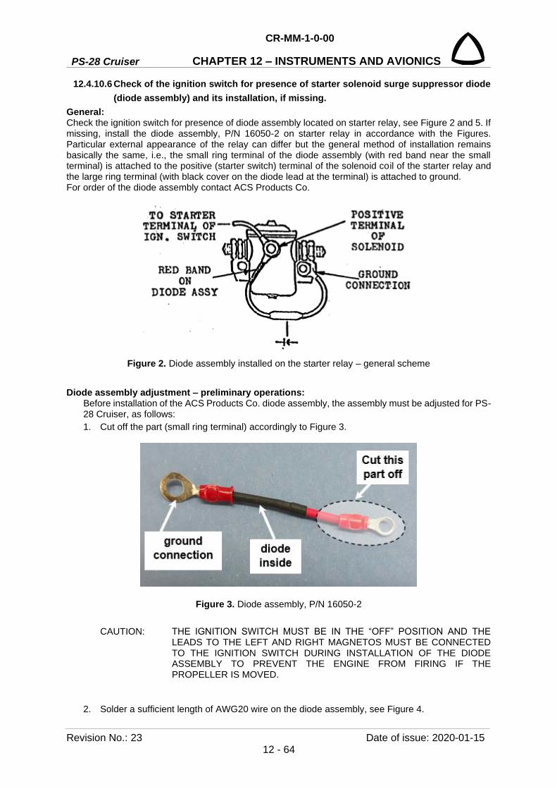
PS-28 Cruiser
CR-MM-1-0-00
CHAPTER 12 – INSTRUMENTS AND AVIONICS
Revision No.: 23 Date of issue: 2020-01-15 12 - 64
12.4.10.6 Check of the ignition switch for presence of starter solenoid surge suppressor diode (diode assembly) and its installation, if missing.
General: Check the ignition switch for presence of diode assembly located on starter relay, see Figure 2 and 5. If missing, install the diode assembly, P/N 16050-2 on starter relay in accordance with the Figures. Particular external appearance of the relay can differ but the general method of installation remains basically the same, i.e., the small ring terminal of the diode assembly (with red band near the small terminal) is attached to the positive (starter switch) terminal of the solenoid coil of the starter relay and the large ring terminal (with black cover on the diode lead at the terminal) is attached to ground. For order of the diode assembly contact ACS Products Co.
Figure 2. Diode assembly installed on the starter relay – general scheme
Diode assembly adjustment – preliminary operations: Before installation of the ACS Products Co. diode assembly, the assembly must be adjusted for PS-28 Cruiser, as follows: 1. Cut off the part (small ring terminal) accordingly to Figure 3.
Figure 3. Diode assembly, P/N 16050-2
CAUTION: THE IGNITION SWITCH MUST BE IN THE “OFF” POSITION AND THE LEADS TO THE LEFT AND RIGHT MAGNETOS MUST BE CONNECTED TO THE IGNITION SWITCH DURING INSTALLATION OF THE DIODE ASSEMBLY TO PREVENT THE ENGINE FROM FIRING IF THE PROPELLER IS MOVED.
2. Solder a sufficient length of AWG20 wire on the diode assembly, see Figure 4.

CR-MM-1-0-00
PS-28 Cruiser CHAPTER 12 – INSTRUMENTS AND AVIONICS
Date of issue: 2020-01-15 Revision No.: 23 12 - 65
Figure 4. Diode assembly adjusted for installation on PS-28 Cruiser
Diode assembly installation (refer to Figure 5): 1. Remove connector (female Faston) from the positive terminal on the starter relay and cut the
connector away from the wiring. Remove fixing stripes of the wiring as needed and add the soldered AWG20 wiring of the diode assembly and complete new connector. Use fixing stripes as needed to tie the wiring.
2. Install the connector back in the positive terminal of the starter relay. 3. Remove one mounting bolt and hardware from the starter relay mounting base. 4. Place the ground connection ring terminal of the diode assembly on the mounting bolt and
reinstall the bolt through the starter relay base. The bolt is now the “ground” connection for the
diode assembly, see Figure 5.
Functional check: 5. Reconnect the battery. 6. Perform a functional check of the switch by starting the engine and checking the magnetos for
normal engine drop. Reduce engine RPM to idle and turn the switch off momentarily to verify that the „Off“ position stops the engine.
7. Restore aircraft to original operating configuration.
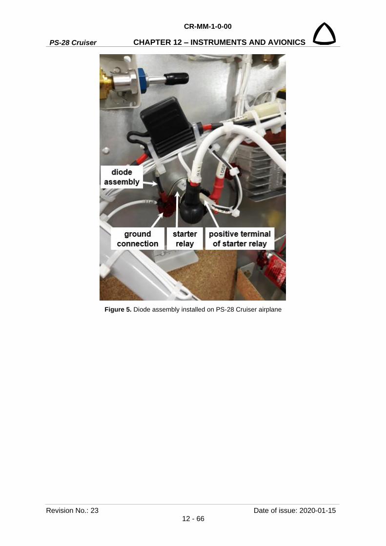
PS-28 Cruiser
CR-MM-1-0-00
CHAPTER 12 – INSTRUMENTS AND AVIONICS
Revision No.: 23 Date of issue: 2020-01-15 12 - 66
Figure 5. Diode assembly installed on PS-28 Cruiser airplane
CR-MM-1-0-00
PS-28 Cruiser CHAPTER 13 – VENTING / HEATING
Date of issue: 2013-01-11 Revision No.: 6 13 - 1
13. VENTING / HEATING
Content
13.1 General ................................................................................................................ 13-2
13.2 Description and operation ................................................................................... 13-2
13.2.1 Venting system .................................................................................... 13-2
13.2.2 Heating system .................................................................................... 13-2
13.2.2.1 Standard heating system ................................................. 13-2
13.2.2.2 Efficient heating system ................................................... 13-3
13.2.3 Carbon monoxide detector .................................................................. 13-4
13.3 Removal / Installation .......................................................................................... 13-5
13.3.1 Heating control knob removal .............................................................. 13-5
13.3.2 Heating control knob installation ......................................................... 13-4
13.3.3 Air vents removal ................................................................................. 13-6
13.3.4 Air vents installation............................................................................. 13-6
13.3.5 Heat exchanger removal ..................................................................... 13-6
13.3.6 Heat exchanger installation ................................................................. 13-7
13.3.7 Defogging blowers removal ................................................................. 13-8
13.3.8 Defogging blowers installation ............................................................. 13-8
13.4 Check / Adjustment ............................................................................................ 13-10
13.4.1 Adjusting the heating control ............................................................. 13-10
13.5 Exchanges / Service information ....................................................................... 13-10
13.5.1 Carbon monoxide detector replacement ........................................... 13-10
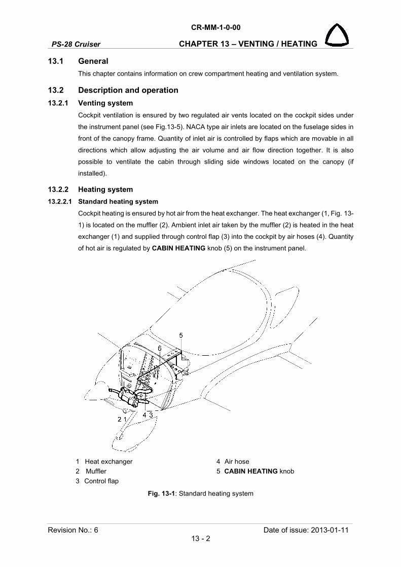
PS-28 Cruiser
CR-MM-1-0-00
CHAPTER 13 – VENTING / HEATING
Revision No.: 6 Date of issue: 2013-01-11 13 - 2
13.1 General
This chapter contains information on crew compartment heating and ventilation system.
13.2 Description and operation
13.2.1 Venting system
Cockpit ventilation is ensured by two regulated air vents located on the cockpit sides under
the instrument panel (see Fig.13-5). NACA type air inlets are located on the fuselage sides in
front of the canopy frame. Quantity of inlet air is controlled by flaps which are movable in all
directions which allow adjusting the air volume and air flow direction together. It is also
possible to ventilate the cabin through sliding side windows located on the canopy (if
installed).
13.2.2 Heating system
13.2.2.1 Standard heating system
Cockpit heating is ensured by hot air from the heat exchanger. The heat exchanger (1, Fig. 13-
1) is located on the muffler (2). Ambient inlet air taken by the muffler (2) is heated in the heat
exchanger (1) and supplied through control flap (3) into the cockpit by air hoses (4). Quantity
of hot air is regulated by CABIN HEATING knob (5) on the instrument panel.
1 Heat exchanger 4 Air hose
2 Muffler 5 CABIN HEATING knob
3 Control flap
Fig. 13-1: Standard heating system

CR-MM-1-0-00
PS-28 Cruiser CHAPTER 13 – VENTING / HEATING
Date of issue: 2013-01-11 Revision No.: 6 13 - 3
13.2.2.2 Efficient heating system
Cockpit heating is ensured by hot air from the heat exchanger (1, Fig. 13-2). This heat
exchanger has a larger area compared with standard heat exchanger. The heat exchanger is
located on the muffler (2). Ambient air is supplied to the heat exchanger via air hose (4) from
the NACA inlet located on the right side of the lower engine cowling. Air is heated in the heat
exchanger (1) and supplied through control box (3) into the cockpit by air hose (5). Quantity
of hot air is regulated by CABIN HEATING knob (5) located on the central panel. If the control
flap in the control box is closed, the warm air flows through the hole in the box body under the
airplane.
Furthermore is installed defogging of the windshield by means of two electric blowers that
supply the air from the cockpit compartment via two air channels (6) on the windshield. The
blowers are not connected to the supply air from the heat exchanger and switch on by means
of the BLOWERS switch located on the right part of the instrument panel (see Fig. 13-3).
1 Heat exchanger 5 Hot air hose
2 Muffler 6 Air channel
3 Control box 7 CABIN HEATING knob
4 Cold air hose 8 Blower
Fig. 13-2: Efficient heating system

PS-28 Cruiser
CR-MM-1-0-00
CHAPTER 13 – VENTING / HEATING
Revision No.: 6 Date of issue: 2013-01-11 13 - 4
13.2.3 Carbon monoxide detector
The airplane is equipped with Quantum Eye carbon monoxide (CO) detector, if the efficient
heating system is installed.
The Quantum Eye is a multi-level carbon monoxide detector. It provides a visual indication of
carbon monoxide contamination. Each detector is packaged in a protective bag then when
opened activates it. Once activated the minimum product lifetime is 18 months. The detector
in installed on the instrument panel.
Condition color: Normal - Yellow
Caution - Green
Danger - Dark blue.
Sensor regeneration:
from caution - 2 hours
from danger - 6 hours
CAUTION: WATCH THE DATE ON THE DETECTOR AND WHEN NECESSARY REPLACE IT. MARK THE DATE WHEN INSTALL THE NEW ONE.
NOTE: For details information refer to the detector manufacturer website www.qginc.com.
Fig. 13-3: Quantum Eye CO detector / blowers switch typically location
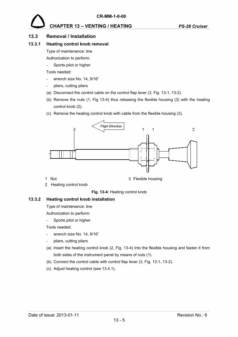
CR-MM-1-0-00
PS-28 Cruiser CHAPTER 13 – VENTING / HEATING
Date of issue: 2013-01-11 Revision No.: 6 13 - 5
13.3 Removal / Installation
13.3.1 Heating control knob removal
Type of maintenance: line
Authorization to perform:
- Sports pilot or higher
Tools needed:
- wrench size No. 14, 9/16”
- pliers, cutting pliers
(a) Disconnect the control cable on the control flap lever (3, Fig. 13-1, 13-2).
(b) Remove the nuts (1, Fig 13-4) thus releasing the flexible housing (3) with the heating
control knob (2).
(c) Remove the heating control knob with cable from the flexible housing (3).
1 Nut 3 Flexible housing
2 Heating control knob
Fig. 13-4: Heating control knob
13.3.2 Heating control knob installation
Type of maintenance: line
Authorization to perform:
- Sports pilot or higher
Tools needed:
- wrench size No. 14, 9/16”
- pliers, cutting pliers
(a) Insert the heating control knob (2, Fig. 13-4) into the flexible housing and fasten it from
both sides of the instrument panel by means of nuts (1).
(b) Connect the control cable with control flap lever (3, Fig. 13-1, 13-2).
(c) Adjust heating control (see 13.4.1).

PS-28 Cruiser
CR-MM-1-0-00
CHAPTER 13 – VENTING / HEATING
Revision No.: 6 Date of issue: 2013-01-11 13 - 6
13.3.3 Air vents removal
(a) Unscrew the vent (1, Fig. 13-5) and remove it.
(b) Push back the tube (2), remove the cable tie (4) and pull the hose (3) out from the tube
(2).
Fig. 13-5: Air vents removal / installation
13.3.4 Air vents installation
(a) Put the hose (3, Fig. 13-5) to the tube (2) and secure with the cable tie (4).
(b) Insert the tube (2) to the hole in the instrument panel (5), screw and tighten the vent (1).
(c) Check the vent (1) movement.
13.3.5 Heat exchanger removal
NOTE: Removal of the standard heat exchanger is shown in Section 10.3.13.
Type of maintenance: line
Authorization to perform:
- Sports pilot or higher
Tools needed:
- Screwdriver, pliers, cutting pliers
1 Vent
2 Tube
3 Hose
4 Cable tie
For information:
5 Instrument
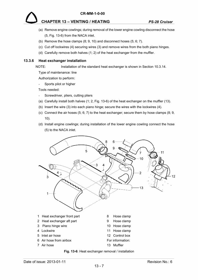
CR-MM-1-0-00
PS-28 Cruiser CHAPTER 13 – VENTING / HEATING
Date of issue: 2013-01-11 Revision No.: 6 13 - 7
(a) Remove engine cowlings; during removal of the lower engine cowling disconnect the hose
(5, Fig. 13-6) from the NACA inlet.
(b) Remove the hose clamps (8; 9, 10) and disconnect hoses (5; 6; 7).
(c) Cut off lockwires (4) securing wires (3) and remove wires from the both piano hinges.
(d) Carefully remove both halves (1; 2) of the heat exchanger from the muffler.
13.3.6 Heat exchanger installation
NOTE: Installation of the standard heat exchanger is shown in Section 10.3.14.
Type of maintenance: line
Authorization to perform:
- Sports pilot or higher
Tools needed:
- Screwdriver, pliers, cutting pliers
(a) Carefully install both halves (1; 2, Fig. 13-6) of the heat exchanger on the muffler (13).
(b) Insert the wire (3) into each piano hinge; secure the wires with the lockwires (4).
(c) Connect the air hoses (5; 6; 7) to the heat exchanger; secure them by hose clamps (8; 9,
10).
(d) Install engine cowlings; during installation of the lower engine cowling connect the hose
(5) to the NACA inlet.
1 Heat exchanger front part 8 Hose clamp
2 Heat exchanger aft part 9 Hose clamp
3 Piano hinge wire 10 Hose clamp
4 Lockwire 11 Hose clamp
5 Inlet air hose 12 Control box
6 Air hose from airbox For information:
7 Air hose 13 Muffler
Fig. 13-6: Heat exchanger removal / installation

PS-28 Cruiser
CR-MM-1-0-00
CHAPTER 13 – VENTING / HEATING
Revision No.: 6 Date of issue: 2013-01-11 13 - 8
13.3.7 Defogging blowers removal
Type of maintenance: line
Authorization to perform:
- Sports pilot or higher
Tools needed:
- Screwdriver, pliers, cutting pliers
(a) Set the MASTER BAT, BLOWERS switches to OFF.
(b) As required, remove the instrument panel cover (9) and hoses (5; 6).
(c) Disconnect the blower wires from the wiring harness.
(d) Unscrew and remove the screws (4, Fig. 13-7), blower guard (2), spacers (3); and remove
the blower (1).
13.3.8 Defogging blowers installation
Type of maintenance: line
Authorization to perform:
- Sports pilot or higher
Tools needed:
- Screwdriver, pliers, cutting pliers
(a) Align the guard (2, Fig. 13-7) on the blower (1), insert the screws (4) into the holes and
install the spacers (3).
(b) Parts align to the appropriate place and tighten the screws (4).
(c) Connect the blower wires to the wiring harness (see Wiring Manual).
(e) As required, install hoses (5; 6) and the instrument panel cover (9).
(f) Set the MASTER BAT, BLOWERS switches to ON and carry out operational test.
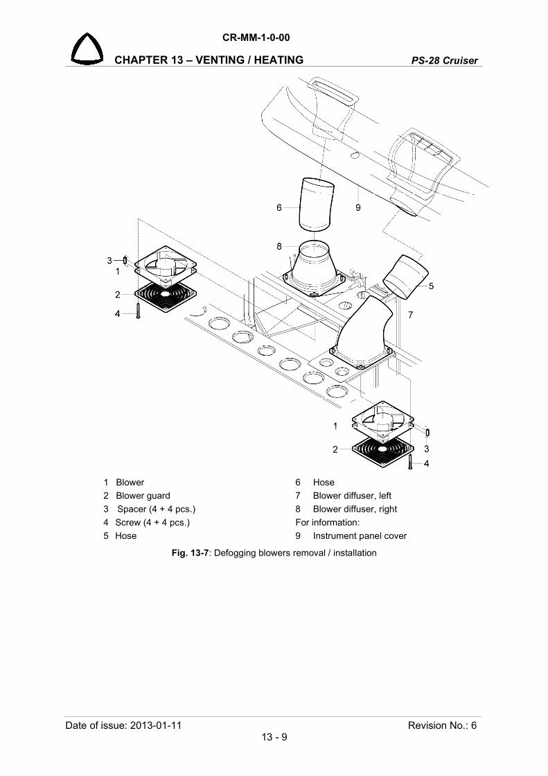
CR-MM-1-0-00
PS-28 Cruiser CHAPTER 13 – VENTING / HEATING
Date of issue: 2013-01-11 Revision No.: 6 13 - 9
1 Blower 6 Hose
2 Blower guard 7 Blower diffuser, left
3 Spacer (4 + 4 pcs.) 8 Blower diffuser, right
4 Screw (4 + 4 pcs.) For information:
5 Hose 9 Instrument panel cover
Fig. 13-7: Defogging blowers removal / installation

PS-28 Cruiser
CR-MM-1-0-00
CHAPTER 13 – VENTING / HEATING
Revision No.: 6 Date of issue: 2013-01-11 13 - 10
13.4 Check / Adjustment
13.4.1 Adjusting the heating control
(a) Adjust the control by screwing or unscrewing the control cable terminal from the control
flap.
(b) After adjustment of the control, mark the mutual position of the control cable terminal and
the flap controller with red color.
13.5 Exchanges / Service information
13.5.1 Carbon monoxide detector replacement
The Quantum Eye has an 18-month product life once it has been activated. Excessive dos-
ages, multiple exposures, or use after the expiration date may cause the sensor to turn
permanently dark. If the sensor turns any color other than those shown, it has been
contaminated and must be replaced.
Keep the sensor away from water, grease, solvents, dirt, hot surfaces, cleaning solutions, and
other contaminants, which may destroy or shorten the life of the sensor. Carbon monoxide
(CO) is an insidious and cumulative poison. It is a colorless, odorless and tasteless gas
produced by the incomplete combustion of fuel.
Instructions:
(a) Activate detector by removing it from the plastic bag.
(b) Attach the detector on the instrument panel.
(c) If carbon monoxide is present the sensor changes color (see Chapter 13.2.3).
(d) When the air freshens, the sensor will regenerate to its original color and will be ready to
use again (unless it has been overexposed).

CR-MM-1-0-00
PS-28 Cruiser CHAPTER 14 – AIRPLANE HANDLING
Date of issue: 2011-03-08 Revision No.: - 14 - 1
14. AIRPLANE HANDLING Content
14.1 General ................................................................................................................ 14-2
14.2 Jacking and supporting the airplane ................................................................... 14-2
14.3 Airplane towing .................................................................................................... 14-2
14.4 Airplane parking .................................................................................................. 14-2
14.5 Airplane anchoring .............................................................................................. 14-3

PS-28 Cruiser
CR-MM-1-0-00
CHAPTER 14 – AIRPLANE HANDLING
Revision No.: - Date of issue: 2011-03-08 14 - 2
14.1 General This chapter contains information on airplane handling - jacking, parking and anchoring.
14.2 Jacking and supporting the airplane Due to the relatively low empty weight, the airplane jacking can be carried out by two persons.
There are three supporting points (see Fig.14-1), two of them are under upper ends of main
landing gear legs (1); third one is on bottom skin of fuselage behind nose gear leg (2).
1 Main landing gear leg jack/support point 2 Front fuselage jack/support point
Fig. 14-1: The airplane jack/support points
14.3 Airplane towing The airplane can be moved by tow bar inserted into the bracket mounted on nose wheel fork,
by main gear legs, or pushing on the wing root.
WARNING: SWITCH OFF THE IGNITION BEFORE HANDLING THE AIRPLANE ON THE GROUND!
CAUTION: AVOID EXERTING EXCESSIVE PRESSURE ON THE AIRFRAME STRUCTURE, ESPECIALLY ON THE WING ENDS, FLAPS, AILERONS, HTU, VTU, ETC.
CAUTION: DO NOT USE THE PROPELLER AS TOW BAR TO MOVE AIRPLANE.
14.4 Airplane parking The airplane should be preferably placed in the hangar, possibly in another covered space
with stable temperature, good ventilation, low humidity and dust free environment. In case of
parking outside the hangar it is necessary to anchor the airplane and to cover the canopy or
the whole airplane with suitable tarpaulins for long-term parking.
CAUTION: USE THE PARKING BRAKE ONLY FOR SHORT-TERM PARKING BETWEEN FLIGHTS DURING THE DAY. WHEN THE FLIGHT DAY IS OVER OR UNDER LOW AIR TEMPERATURES, DO NOT USE THE PARKING BRAKE AND APPLY THE WHEEL CHOCKS INSTEAD.

CR-MM-1-0-00
PS-28 Cruiser CHAPTER 14 – AIRPLANE HANDLING
Date of issue: 2011-03-08 Revision No.: - 14 - 3
14.5 Airplane anchoring When parking, the airplane outside the hangar after flight day, the airplane should be
anchored to the ground. It is necessary to anchor the airplane in order to protect it from a
possible damaging caused by wind and gusts. For this reason the airplane is equipped with
anchoring eyes on the lower side of wings and on rear part of fuselage.
Procedure:
• check the fuel selector valve is OFF, switch OFF all switches, remove key from the ignition
switch
• block the control stick, e.g. by using safety harnesses
• release the parking brake if it was braked
• close the vents
• close and lock the canopy
• park the aircraft into wind
• insert the wheel chocks
• anchor the airplane to the ground by means of cables pulled through the anchoring eyes
on the lower side of the wings and on the rear part of fuselage; as necessary anchor the
airplane at the nose landing gear leg (see Fig. 14-2).
Fig. 14-2: Airplane anchoring

PS-28 Cruiser
CR-MM-1-0-00
CHAPTER 14 – AIRPLANE HANDLING
Revision No.: - Date of issue: 2011-03-08 14 - 4
INTENTIONALLY LEFT BLANK

CR-MM-1-0-00
PS-28 Cruiser CHAPTER 15 – AIRPLANE REPAIRS
Date of issue: 2011-03-08 Revision No.: - 15 - 1
15. AIRPLANE REPAIRS Content
15.1 General ................................................................................................................ 15-3
15.2 Removing rivets ................................................................................................... 15-3
15.3 Riveting ............................................................................................................... 15-4
15.3.1 General ................................................................................................ 15-4
15.3.2 Riveting procedure .............................................................................. 15-4
15.4 Skin repairs ......................................................................................................... 15-5
15.4.1 Removing damaged skins ................................................................... 15-5
15.4.2 Division of damaging into groups ........................................................ 15-5
15.4.3 Principles for repair method determination ......................................... 15-5
15.4.4 Angle repair ......................................................................................... 15-6
15.4.5 Skin repair ........................................................................................... 15-7
15.4.5.1 Stopping cracks and blinding small holes ........................ 15-7
15.4.5.2 Repairing the skins with patches ..................................... 15-7
15.5 Repair of fiberglass parts .................................................................................. 15-10
15.5.1 Damage classification ....................................................................... 15-10
15.5.2 General .............................................................................................. 15-10
15.5.3 Parts of external appearance ............................................................ 15-10
15.5.3.1 Small damage ................................................................ 15-10
15.5.3.2 Medium damage ............................................................ 15-11
15.5.3.3 Major damage ................................................................ 15-13
15.5.4 Structural parts .................................................................................. 15-13
15.6 Paint repairs ...................................................................................................... 15-13
15.6.1 Safety rules ........................................................................................ 15-13
15.6.2 Recommendation for additional surface treatment
of the airplane surface ....................................................................... 15-13
15.6.2.1 Washing and degreasing ............................................... 15-13
15.6.2.2 Bonding rivet heads, big irregularities
and material transitions .................................................. 15-14
15.6.2.3 Application of primer (paint) ........................................... 15-16
15.6.2.4 Bonding .......................................................................... 15-16
15.6.2.5 Application of top coat.................................................... 15-16
PS-28 Cruiser
CR-MM-1-0-00
CHAPTER 15 – AIRPLANE REPAIRS
Revision No.: - Date of issue: 2011-03-08 15 - 2
15.6.3 Small damage .................................................................................... 15-17
15.6.3.1 General .......................................................................... 15-17
15.6.3.2 Sanding .......................................................................... 15-17
15.6.3.3 Degreasing ..................................................................... 15-17
15.6.3.4 Application of primer ...................................................... 15-17
15.6.3.5 Application of top coat.................................................... 15-18
15.7 Torque moments ............................................................................................... 15-19
15.8 Securing the bolt joints ...................................................................................... 15-19
15.8.1 General .............................................................................................. 15-19
15.8.2 Bolt joint securing by locking wire ..................................................... 15-19
15.8.3 Bolt joint securing by cotter pin ......................................................... 15-21
15.9 Bonding repairs ................................................................................................. 15-21
15.9.1 General ................................................................................................... 15-21
15.9.2 Removal and installation ........................................................................ 15-21
15.10 Installing clamps by Nicopress pliers ................................................................ 15-22
CR-MM-1-0-00
PS-28 Cruiser CHAPTER 15 – AIRPLANE REPAIRS
Date of issue: 2011-03-08 Revision No.: - 15 - 3
15.1 General This chapter contains information about standard procedures for performing common
repairs of the airplane. These repairs can be made by an authorized organization. Other
procedures for repairing individual airplane systems you can find in the appropriate chapter
describing the system. Unless specified otherwise in this Chapter all airplane repairs shall
be done in accordance to the most current edition of FAA AC 43.13-1B and AC 43.13-2A,
Acceptable Methods, Techniques, and Practices - Aircraft Inspection and Repair.
CAUTION: BEFORE CARRYING OUT ANY STRUCTURAL REPAIRS TO CONTACT THE RELEVANT AIRWORTHINESS AUTHORITY FOR APPROVAL.
This chapter describes the following procedures:
• Removing rivets
• Riveting
• Repair of skins
• Repair of fiberglass parts
• Recommendation for repairing surface protection of the airplane
• Torque moments
• Securing bolt joints and screwed fittings
• Repairs of bonding
• Installing clamps by Nicopress pliers
15.2 Removing rivets Remove rivets from the side of the rivet, which is more accessible. Drill out the rivet head
and drive out the shank.
NOTE: Center-dot heads of solid rivets, which shall be drilled off.
Use a drill bit by 0.6 mm (0.025 in) diameter smaller than the rivet shank and drill up to the
depth of 2/3 of the total depth riveted parts. Remove the drilled heads with a sharp cuter.
Drive out the shank with the soft material mandrel diameter by 0.1 mm (0.004 in) smaller
than rivet shank diameter. The rivets, which cannot be driven out should be drilled out full
depth. When removing rivets be careful that chips and rivets do not fall down to areas were
sensitive mechanisms are located, e.g. guides, control bearings etc.

PS-28 Cruiser
CR-MM-1-0-00
CHAPTER 15 – AIRPLANE REPAIRS
Revision No.: - Date of issue: 2011-03-08 15 - 4
Fig. 15-1: Drilling of rivets (solid rivet displayed)
15.3 Riveting 15.3.1 General
Riveted parts are used in design of PS-28 Cruiser airplane for whole fuselage, wings, flaps,
ailerons and tail unit.
In the following table there is a survey of rivets that are used on PS-28 Cruiser airplane
structure.
Type of rivets Designation Use
AVEX Aluminium rivet on steel stem
Fuselage, wing, stabilizer, elevator , rudder, flaps, ailerons
MS20426AD Aluminium rivet with countersunk head
MS20470AD Aluminium rivets with universal head
Tab. 15-1: Survey of rivets used in airplane structure
In case that different replacement rivets are used than shown in the Tab. 15-1 then rivet
dimensions must be identical with originally used rivets and material of rivets must fulfill the
same material characteristics.
15.3.2 Riveting procedure (a) Fit the parts being connected and drill them together. Hole diameter must be by
0.1 mm (0.004 in) bigger than rivet shank diameter.
NOTE: When drilling, fix by clamps or clecos mutual position of assembled parts. Holes of higher diameters pre-drill with a drill bit of smaller diameter and then redrill them to the final size.
(b) Disassemble the parts and deburr the holes.
NOTE: For sunken rivets perform conical countersinking of the rivet head by 5° smaller apex angle (e.g. the head with angle of 100° will have countersinking of 95°±1°). After countersinking, the cylindrical part of hole with min. length of 0.3 mm (0.012 in) must remain in material. Countersinking must be performed

CR-MM-1-0-00
PS-28 Cruiser CHAPTER 15 – AIRPLANE REPAIRS
Date of issue: 2011-03-08 Revision No.: - 15 - 5
in such a way that the rivets head overruns the area before riveting max. by 0.2 mm (0.008 in), the rivet head must not be under the surface level (sunk).
(c) Before applying the bonding sealant carefully clean the connected parts of impurities
and degrease contact surfaces by appropriate agent, e.g. industrial spirit.
NOTE: For cleaning and degreasing use a clean paper towel or cloth. After wiping, the towel or cloth must not show any contamination. For perfect degreasing the whole surface, clean always smaller part of surface, after its perfect cleaning continue on. Cleaning liquid always apply on the cloth only and wipe it off from the surface before its evaporating.
(d) Apply bonding sealant on one of the surfaces, which should be sealed together. Apply
the adhesive directly from the packing by means of the extrusion gun, plastic spatula or
paintbrush in such a way that the layer of sealant is equally thick and integral, without
bubbles or uncovered areas. The optimum thickness of the applied coat is 0.25 mm
(0.01 in).
NOTE: The surfaces that are to be connected must be dry and clean before application of bonding sealant.
(e) After applying bonding sealant connect both parts together, fix them by clecos and rivet
them.
NOTE: After proper riveting the continual bur of adhesive is created on the edge of connected surfaces. If this bur is big, it is possible to wipe it off with the plastic spatula and finally with cloth dipped in degreasing agent.
(f) After riveting, seal rivet heads, there, where are used pop rivets - see 15.6.2.2
15.4 Skin repairs 15.4.1 Removing damaged skins
In case that it is necessary to remove bigger part of the skin, ensure reliable support of the
structure. Appropriately support the damaged part of the fuselage monocoque or the wing
by supports located in the area of fuselage frames or wing ribs. The shape of supports must
correspond with the shape of supported place and must be supplemented by cushion (or
with other suitable material), so that airplane skin surface cannot be damaged. Remove
rivets according to Section 15.2.
15.4.2 Division of damaging into groups To determine way of repair, find out by inspection the scope of structural damage, also in
case of possible unriveting the skin.
Damage can be divided into the following groups:
(a) Little damage, which do not have to be repaired, such as local small impacts, scratches
in the skin not exceeding thickness of the zinc chromated layer, appearance defects of
paint coat etc.
(b) Damage, which can be eliminated by airplane operator. Methods of elimination are
describer further in the text.
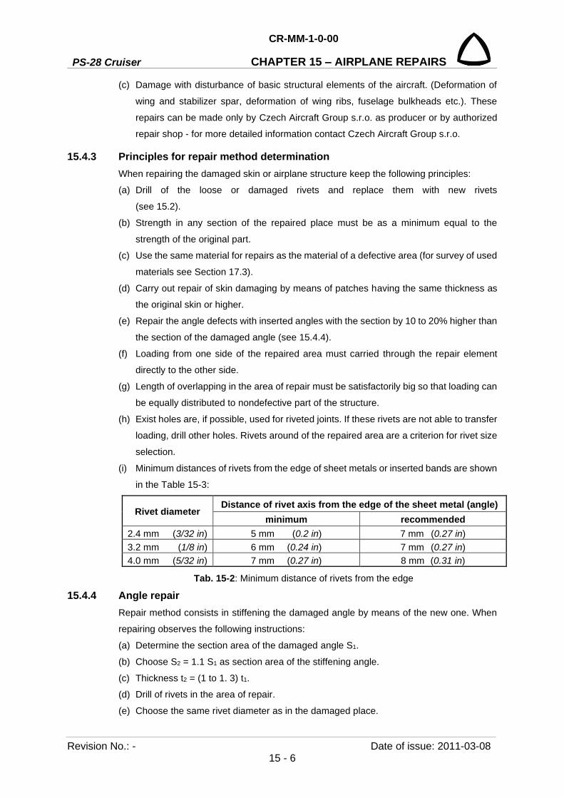
PS-28 Cruiser
CR-MM-1-0-00
CHAPTER 15 – AIRPLANE REPAIRS
Revision No.: - Date of issue: 2011-03-08 15 - 6
(c) Damage with disturbance of basic structural elements of the aircraft. (Deformation of
wing and stabilizer spar, deformation of wing ribs, fuselage bulkheads etc.). These
repairs can be made only by Czech Aircraft Group s.r.o. as producer or by authorized
repair shop - for more detailed information contact Czech Aircraft Group s.r.o.
15.4.3 Principles for repair method determination When repairing the damaged skin or airplane structure keep the following principles:
(a) Drill of the loose or damaged rivets and replace them with new rivets
(see 15.2).
(b) Strength in any section of the repaired place must be as a minimum equal to the
strength of the original part.
(c) Use the same material for repairs as the material of a defective area (for survey of used
materials see Section 17.3).
(d) Carry out repair of skin damaging by means of patches having the same thickness as
the original skin or higher.
(e) Repair the angle defects with inserted angles with the section by 10 to 20% higher than
the section of the damaged angle (see 15.4.4).
(f) Loading from one side of the repaired area must carried through the repair element
directly to the other side.
(g) Length of overlapping in the area of repair must be satisfactorily big so that loading can
be equally distributed to nondefective part of the structure.
(h) Exist holes are, if possible, used for riveted joints. If these rivets are not able to transfer
loading, drill other holes. Rivets around of the repaired area are a criterion for rivet size
selection.
(i) Minimum distances of rivets from the edge of sheet metals or inserted bands are shown
in the Table 15-3:
Rivet diameter Distance of rivet axis from the edge of the sheet metal (angle)
minimum recommended 2.4 mm (3/32 in) 5 mm (0.2 in) 7 mm (0.27 in) 3.2 mm (1/8 in) 6 mm (0.24 in) 7 mm (0.27 in) 4.0 mm (5/32 in) 7 mm (0.27 in) 8 mm (0.31 in)
Tab. 15-2: Minimum distance of rivets from the edge
15.4.4 Angle repair Repair method consists in stiffening the damaged angle by means of the new one. When
repairing observes the following instructions:
(a) Determine the section area of the damaged angle S1.
(b) Choose S2 = 1.1 S1 as section area of the stiffening angle.
(c) Thickness t2 = (1 to 1. 3) t1.
(d) Drill of rivets in the area of repair.
(e) Choose the same rivet diameter as in the damaged place.
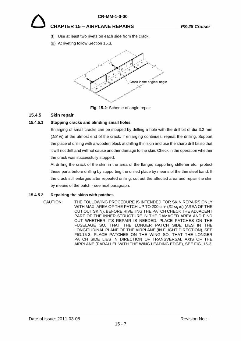
CR-MM-1-0-00
PS-28 Cruiser CHAPTER 15 – AIRPLANE REPAIRS
Date of issue: 2011-03-08 Revision No.: - 15 - 7
(f) Use at least two rivets on each side from the crack.
(g) At riveting follow Section 15.3.
Fig. 15-2: Scheme of angle repair
15.4.5 Skin repair 15.4.5.1 Stopping cracks and blinding small holes
Enlarging of small cracks can be stopped by drilling a hole with the drill bit of dia 3.2 mm
(1/8 in) at the utmost end of the crack. If enlarging continues, repeat the drilling. Support
the place of drilling with a wooden block at drilling thin skin and use the sharp drill bit so that
it will not drift and will not cause another damage to the skin. Check in the operation whether
the crack was successfully stopped.
At drilling the crack of the skin in the area of the flange, supporting stiffener etc., protect
these parts before drilling by supporting the drilled place by means of the thin steel band. If
the crack still enlarges after repeated drilling, cut out the affected area and repair the skin
by means of the patch - see next paragraph.
15.4.5.2 Repairing the skins with patches CAUTION: THE FOLLOWING PROCEDURE IS INTENDED FOR SKIN REPAIRS ONLY
WITH MAX. AREA OF THE PATCH UP TO 200 cm2 (31 sq in) (AREA OF THE CUT OUT SKIN). BEFORE RIVETING THE PATCH CHECK THE ADJACENT PART OF THE INNER STRUCTURE IN THE DAMAGED AREA AND FIND OUT WHETHER ITS REPAIR IS NEEDED. PLACE PATCHES ON THE FUSELAGE SO, THAT THE LONGER PATCH SIDE LIES IN THE LONGITUDINAL PLANE OF THE AIRPLANE (IN FLIGHT DIRECTION), SEE FIG.15-3. PLACE PATCHES ON THE WING SO, THAT THE LONGER PATCH SIDE LIES IN DIRECTION OF TRANSVERSAL AXIS OF THE AIRPLANE (PARALLEL WITH THE WING LEADING EDGE), SEE FIG. 15-3.

PS-28 Cruiser
CR-MM-1-0-00
CHAPTER 15 – AIRPLANE REPAIRS
Revision No.: - Date of issue: 2011-03-08 15 - 8
1 Correctly located patch 2 Incorrectly located patch
Fig. 15-3: Location of patches on the airplane skin
Mark the damaged surface area (preferably by spirit felt tip) and cut out the most suitable
geometrical shape (circle, square, rectangle).
Be careful that all cracks as well as adjacent corroded areas are cutted out. Corners of cut
out holes in the skin must have minimum radius of 12.7 mm (0.5 in) and their edges must
be smoothly filed off.
Size of patch overlapping depends on the cut out of skin area:
(a) Patch up to the area of 51.6 cm2 (8 in2) - rivet by one row of rivets, the patch edge
must overlap the edge of the cut out hole by minimum 19 mm (0.75 in).
(b) Patch with the area over 51.6 cm2 (8 in2) - rivet by two rows of rivets, the patch edge
must overlap the cut out hole by minimum 32 mm (1.25 in).
Both ways of patching are shown on Fig. 15-5.
If the damaged area is located near the spars and frames, choose such patch dimension
so that it covers all these elements of structure and it is possible to rivet it (Fig.15-4).
Types of patches, according to their position on the airframe structure.
(a) Surface patches - These can be used in the areas where surface smoothness is not
important
(b) Sunk patches - Use for patches on the wing, tail unit and control surfaces.
(c) Surface patches across obstacles and stiffeners in the skin - pay special attention
to drilling the patch together with the surrounding structure. Attach the patch in several
points and then drill holes for rivets from inner side (if possible). Use original holes in
frames and stiffeners.

CR-MM-1-0-00
PS-28 Cruiser CHAPTER 15 – AIRPLANE REPAIRS
Date of issue: 2011-03-08 Revision No.: - 15 - 9
1 Skin 3 Stiffening frame 2 Patch
Fig. 15-4: Repair of the punctured skin in the frame area
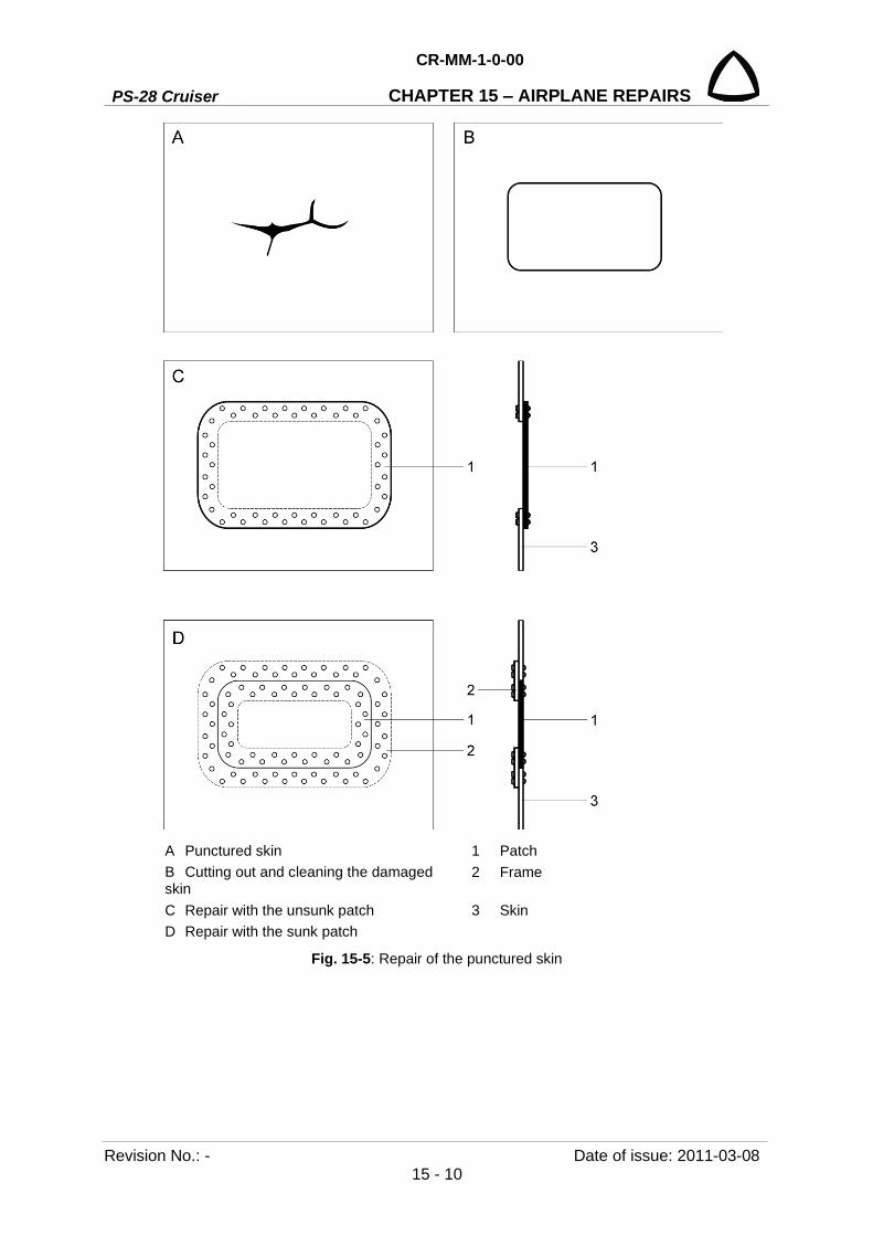
PS-28 Cruiser
CR-MM-1-0-00
CHAPTER 15 – AIRPLANE REPAIRS
Revision No.: - Date of issue: 2011-03-08 15 - 10
A Punctured skin 1 Patch B Cutting out and cleaning the damaged skin
2 Frame
C Repair with the unsunk patch 3 Skin D Repair with the sunk patch
Fig. 15-5: Repair of the punctured skin

CR-MM-1-0-00
PS-28 Cruiser CHAPTER 15 – AIRPLANE REPAIRS
Date of issue: 2011-03-08 Revision No.: - 15 - 11
15.5 Repair of fiberglass parts 15.5.1 Damage classification
Any damage of parts from reinforced plastics with epoxy matrix leads to increased
saturation of the matrix with humidity and subsequently to loss of properties. Therefore we
recommend carry out their repair as soon as possible after the damage has occurred.
Two kinds of parts are made from these materials in the airplane:
• structural, load-bearing parts (canopy frame)
• design appearance, non load-bearing parts (fairings)
According to the damage size we can divide repairs into:
• small damage (surface defects, not affecting the stiffeners)
• medium damage (not more than 2/3 of stiffener thickness damaged)
• big damage
We recommend carry out repairs by means of epoxy resin and glass or carbon stiffeners.
15.5.2 General Epoxy resin mixtures are prepared in a given mass ratio by means of weighing (accuracy
of scales 1 gram (0.002 lbs)).
15.5.3 Parts of external appearance 15.5.3.1 Small damage
Repair of damage just by application of mastic and by varnish repair.
Preparatory grinding For a good adhesion of repair layers it is necessary to carry out surface sanding at the
utmost up to the depth of contact with the stiffener (do not damage). It is necessary to do
surface sanding with overrun of 51 mm (2 in) from the damage location smoothly to the top
layer. It is suitable to do sanding with grain size of 160. Dry sanding equipment with suction
from the sanding area is used. Al2O3 or equivalent (fused corundum) can be used as
sanding material.
Dust removing
It is made by wiping with clean and dry brush or by a vacuum cleaner.
Application of smoothing layer After preparation of mixture (for material recommendation see the Tab. 15-4) and its
eventual thickening, to enhance the noncurtaining capability (for vertical or lower areas) is
performed its application onto the repair area by means of a plastic spatula. For better
distribution of deposited material on irregular surface it is possible to form it through the laid
PE or PP transparent polyethylene. After proper application the layer is without bubbles.
Deposit thickness is given by necessary thickness of surrounding layers (leveling) and
ranges from 0.2 to 12.7 mm (0.008 to 0.5 in) in one deposit.

PS-28 Cruiser
CR-MM-1-0-00
CHAPTER 15 – AIRPLANE REPAIRS
Revision No.: - Date of issue: 2011-03-08 15 - 12
Manufacturer, name Type Mixing
ratio Delay Rate of setting
Time of setting Temperature Fillers
MGS, A: L285 B: Hardener 285
epoxy A:B 100:40
to be processed within 50 min (for 0.2 kg
(0.44lbs) mixture)
40% 16 FH
(32 FH) 20-35°C 68-95°F
(17-20°C) (62-68°F) thickening: Aerosil, microballs 100%
26 FH (72 FH) (2 FH)
20-35°C 68-95°F (17-20°C) (62-68°F) (80°C) (176°F)
Tab. 15-3: Recommended materials for mixture preparation for application of leveling layer
Sanding
Sanding or eventually sealing the surface is made after setting the mixture and possible
tearing of the used polyethylene. It is suitable to start sanding with grain size up to 160 and
finish with grain size of at least 400. It is carried out by dry sanding equipment with suction
from the sanding area. Al2O3 or equivalent (fused corundum) can be used as sanding
material. Basic material of the part must not be diminished at sanding.
NOTE: Especially in case of C/K (carbon/Kevlar) stiffener in the basic part, sanding through up to the stiffener must not occur (complication - see note about preparatory sanding at medium damage).
Finishing
See section 15.6 - Paint repairs
15.5.3.2 Medium damage Repair of damage by replacing the stiffener part, by mastic and varnish repair. At such repair
it is necessary to distinguish type of used stiffener (especially for sanding):
• C/K (carbon/Kevlar), roving of fabric of black color (C) take turns with yellowish (K)
• G (glass), rovings from milky white to transparent
Preparatory sanding For good adhesion of repair layers it is necessary to do sanding up to the depth of damage.
It is necessary to do surface sanding from the damage area with overrun at the least 25 mm
(1 in) for every damaged stiffener layer smoothly up to the top layer and then about 51 mm
(2 in) for finishing and mastic application. It is convenient to do sanding with sanding
material having grain size of 160. It is carried out by dry sanding equipment with suction
from sanding area. Al2O3 or equivalent (fused corundum) can be used as sanding material.
NOTE: In case of C/K stiffener K roving tend to rise up from the surface at sanding - it is difficult to sand them, we recommend using diamond sanding tool and one-way sanding.
Dust removing
Dust is removed by wiping with a clean and dry brush or by a vacuum cleaner.
CR-MM-1-0-00
PS-28 Cruiser CHAPTER 15 – AIRPLANE REPAIRS
Date of issue: 2011-03-08 Revision No.: - 15 - 13
Stiffener preparation
For this kind of repairs we recommend the stiffener G (glass) with plain weave 150 g/m2
(0.037 lb/ft2), with surface protection for epoxy resins. Number of needed stiffener layers
depends on depth of damage. It is possible to say that each layer of the mentioned fabric
represents at proper saturation by matrix resin thickness of 0.5 mm (0.020 in).
Stiffener layers must be prepared (cut out) gradually from the smallest (the lowest) up to
the bigger (upper), each with overrun of 19 mm (0.75 in).
Putting layers
After preparing lamination mixture (for recommendation of material see the Tab. 15-4), it is
applied to the place of repair by means of rigid brush. The first stiffener is laid into the
deposit and it is again saturated by brush. Another layer of stiffener is laid and saturated.
When putting the last layer it is necessary to pay attention to a proper saturation and
compression of stiffeners so that they cannot „come up" to the surface and subsequent
useless damage at final grinding. For better saturation of the surface by resin and securing
against curtaining it is possible to put PE or PP transparent foil across the surface. When
applied properly, the layer is without bubbles. Repair thickness should exceed surrounding
surface in this phase by about 0.5 to 1 mm (0.02 in to 0.04 in) for finishing.
Sanding
Carry out sanding and eventually apply mastic on the surface after setting, eventually
tearing of the foil (see small damage). It is suitable to begin sanding by abrasive with grain
size of 160 and finish by grain size of at least 400. Dry sanding equipment is used with
suction from the sanding area. Al2O3 or equivalent can be used as sanding material. It is
important not to diminish basic material of the part at sanding.
NOTE: Especially in case of c/k stiffener in the basic part there must not be any sanding through up to the stiffener (complication - see the note about preparatory sanding).
Finishing
See Section 15.6 - Paint repairs
15.5.3.3 Major damage At such damage we recommend to change the part or to do this repair in a professional
facility. Use instructions in chapter about medium damage as recommendation for used
materials.

PS-28 Cruiser
CR-MM-1-0-00
CHAPTER 15 – AIRPLANE REPAIRS
Revision No.: - Date of issue: 2011-03-08 15 - 14
15.5.4 Structural parts On these parts we do not recommend to do other as small damages repair. In case of the
other damage we recommend to contact Czech Aircraft Group s.r.o. as manufacturer.
CAUTION: WHEN REPAIRING, IT IS NECESSARY TO PAY ATTENTION TO TIMELY REPAIR (SEE THE TEXT ABOUT LOW OF PROPERTIES AT HUMIDITY EFFECT AT THE BEGINNING OF 15.5.1)!
Small damage
Repairs are made according to instructions with appearance parts.
CAUTION: WHEN REPAIRING, IT IS NECESSARY TO CAREFULLY PAY ATTENTION NOT TO DAMAGE THE STIFFENERS!
15.6 Paint repairs 15.6.1 Safety rules
When working with paints, thinners and solvents follow the following safety rules:
• it is necessary to follow safety rules for working with flammable and volatile substances
• working area must be properly aerated
• it is prohibited to smoke and anyway handle with free fire in a working area
• use protective working means such as goggles, gloves, respirator, etc.
15.6.2 Recommendation for additional surface treatment of the airplane surface CAUTION: BY APPLYING PERMANENT PROTECTIVE COATS WEIGHT OF
AIRPLANE IS INCREASED AND GRAVITY CENTER POSITION IS CHANGED. INCREASE IN WEIGHT DEPENDS ON TYPE OF COAT AND ITS THICKNESS.
15.6.2.1 Washing and degreasing It is possible to use both organic solvents and solvents based on water.
(a) Organic solvents acetone, metyetylketone (MEK), benzine, toluene,
BASF Glasurit 360-4
• Applied by spraying on washed surfaces (e.g. mechanical sprayer, jet ejector) or
by wiping with wet (by pouring, not by dipping because it would contaminate the
whole volume of solvent) textile wad. After applying it, the agent is wiped of by clean
absorbing material before solvent evaporation.
• Advantages: fast and reliable evaporation even from the corners and borders
without additional warming
• Disadvantages: it must be used without other dilution (expensive); not ecological
(danger of water contamination); detrimental to health (must be carried out in an
aerated area with personal protective means); waste (including dripping from the
area) must be eliminated in the incinerating plants.
• Use: for Al-alloys surfaces, epoxy fiberglass
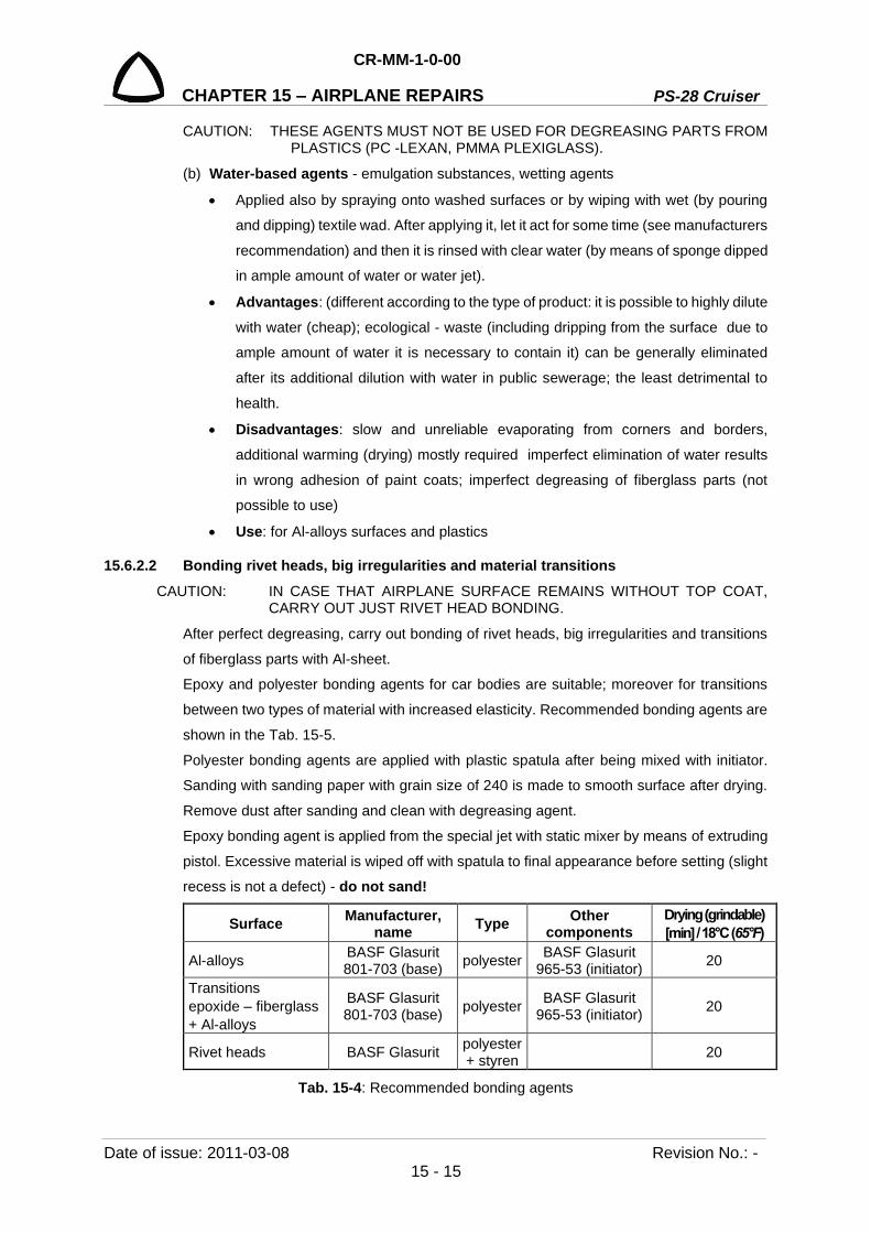
CR-MM-1-0-00
PS-28 Cruiser CHAPTER 15 – AIRPLANE REPAIRS
Date of issue: 2011-03-08 Revision No.: - 15 - 15
CAUTION: THESE AGENTS MUST NOT BE USED FOR DEGREASING PARTS FROM PLASTICS (PC -LEXAN, PMMA PLEXIGLASS).
(b) Water-based agents - emulgation substances, wetting agents
• Applied also by spraying onto washed surfaces or by wiping with wet (by pouring
and dipping) textile wad. After applying it, let it act for some time (see manufacturers
recommendation) and then it is rinsed with clear water (by means of sponge dipped
in ample amount of water or water jet).
• Advantages: (different according to the type of product: it is possible to highly dilute
with water (cheap); ecological - waste (including dripping from the surface due to
ample amount of water it is necessary to contain it) can be generally eliminated
after its additional dilution with water in public sewerage; the least detrimental to
health.
• Disadvantages: slow and unreliable evaporating from corners and borders,
additional warming (drying) mostly required imperfect elimination of water results
in wrong adhesion of paint coats; imperfect degreasing of fiberglass parts (not
possible to use)
• Use: for Al-alloys surfaces and plastics
15.6.2.2 Bonding rivet heads, big irregularities and material transitions CAUTION: IN CASE THAT AIRPLANE SURFACE REMAINS WITHOUT TOP COAT,
CARRY OUT JUST RIVET HEAD BONDING. After perfect degreasing, carry out bonding of rivet heads, big irregularities and transitions
of fiberglass parts with Al-sheet.
Epoxy and polyester bonding agents for car bodies are suitable; moreover for transitions
between two types of material with increased elasticity. Recommended bonding agents are
shown in the Tab. 15-5.
Polyester bonding agents are applied with plastic spatula after being mixed with initiator.
Sanding with sanding paper with grain size of 240 is made to smooth surface after drying.
Remove dust after sanding and clean with degreasing agent.
Epoxy bonding agent is applied from the special jet with static mixer by means of extruding
pistol. Excessive material is wiped off with spatula to final appearance before setting (slight
recess is not a defect) - do not sand!
Surface Manufacturer, name Type Other
components Drying (grindable) [min] / 18°C (65°F)
Al-alloys BASF Glasurit 801-703 (base) polyester BASF Glasurit
965-53 (initiator) 20
Transitions epoxide – fiberglass + Al-alloys
BASF Glasurit 801-703 (base) polyester BASF Glasurit
965-53 (initiator) 20
Rivet heads BASF Glasurit polyester + styren 20
Tab. 15-4: Recommended bonding agents
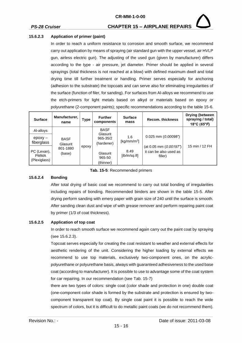
PS-28 Cruiser
CR-MM-1-0-00
CHAPTER 15 – AIRPLANE REPAIRS
Revision No.: - Date of issue: 2011-03-08 15 - 16
15.6.2.3 Application of primer (paint) In order to reach a uniform resistance to corrosion and smooth surface, we recommend
carry out application by means of spraying (air standard gun with the upper vessel, air HVLP
gun, airless electric gun). The adjusting of the used gun (given by manufacturer) differs
according to the type - air pressure, jet diameter. Primer should be applied in several
sprayings (total thickness is not reached at a blow) with defined maximum dwell and total
drying time till further treatment or handling. Primer serves especially for anchoring
(adhesion to the substrate) the topcoats and can serve also for eliminating irregularities of
the surface (function of filer, for sanding). For surfaces from Al-alloys we recommend to use
the etch-primers for light metals based on alkyd or materials based on epoxy or
polyurethane (2-component paints); specific recommendations according to the table 15-6.
Surface Manufacturer, name Type Further
components Surface
mass Recom. thickness Drying (between spraying / total)
18°C (65°F) Al-alloys
BASF Glasurit
801-1880 (base)
epoxy
BASF Glasurit 965-35/2
(hardener)
Glasurit 965-50
(thinner)
1.6 [kg/mm/m2]
8.49
[lb/in/sq.ft]
0.025 mm (0.00098”)
(at 0.05 mm (0.00197”) it can be also used as
filler)
15 min / 12 FH
epoxy – fiberglass
PC (Lexan), PMMA
(Plexiglass)
Tab. 15-5: Recommended primers
15.6.2.4 Bonding After total drying of basic coat we recommend to carry out total bonding of irregularities
including repairs of bonding. Recommended binders are shown in the table 15-5. After
drying perform sanding with emery paper with grain size of 240 until the surface is smooth.
After sanding clean dust and wipe of with grease remover and perform repairing paint coat
by primer (1/3 of coat thickness).
15.6.2.5 Application of top coat In order to reach smooth surface we recommend again carry out the paint coat by spraying
(see 15.6.2.3).
Topcoat serves especially for creating the coat resistant to weather and external effects for
aesthetic rendering of the unit. Considering the higher loading by external effects we
recommend to use top materials, exclusively two-component ones, on the acrylic-
polyurethane or polyurethane basis, always with guaranteed adhesiveness to the used base
coat (according to manufacturer). It is possible to use to advantage some of the coat system
for car repairing. In our recommendation (see Tab. 15-7)
there are two types of colors: single coat (color shade and protection in one) double coat
(one-component color shade is formed by the substrate and protection is ensured by two-
component transparent top coat). By single coat paint it is possible to reach the wide
spectrum of colors, but it is difficult to do metallic paint coats (we do not recommend them).

CR-MM-1-0-00
PS-28 Cruiser CHAPTER 15 – AIRPLANE REPAIRS
Date of issue: 2011-03-08 Revision No.: - 15 - 17
Color type
Manufacturer, name Type Other
items Surface
mass Recom. thickness Drying (between spraying / total)
18°C (65°F)
Single coat
BASF Glasurit R-68 / shade
(base)
acrylic – polyurethane
BASF Glasurit 922-36
(standard hardener)
Glasurit 352-91
(standard thinner)
1-1.6 [kg/mm/m2]
5.24-8.38 [lb/inch/ft2]
(by shade)
0.02-0.04 mm
(0.00078-0.00157”) 15 min / 16 hrs
Double coat
base color coat: BASF
Glasurit R-55 / shade
(base)
acrylic – polyurethane
BASF Glasurit 352-216 (thinner,
long)
1.2-1.4 [kg/mm/m2]
6.29-7.33 [lb/inch/ft2]
(by shade)
0.015-0.02 mm
(0.00059-0.00078”) 10 min / 20 min
Top coat, bright:
BASF Glasurit 923-155 (base)
acrylic – polyurethane
BASF Glasurit 929-93
(standard hardener) Glasurit 352-91
(standard thinner)
0.9 [kg/mm/m2]
4.82
[lb/inch/ft2]
0.03-0.04 mm
(0.00118-0.00157”) 5 min / 5 hrs
Tab. 15-6: Recommended paints
15.6.3 Small damage 15.6.3.1 General
Small damage is a deterioration of corrosion resistance. At repair the situation is made more
difficult by the fact that the substrate for repair coats is not a compact surface of basic
material but mostly al coats of surface protection (after sanding), of which not al are suitable
for (in ageing stage) for good adhesion of paint coats. Therefore we recommend to carry
out such repairs by a verified system.
Before repairing it is necessary to differentiate the type of the existing topcoat, single coat
and two-coat (with the top coat). For repair it is necessary to follow the used type of color.
It is suitable to choose the delimited area (e.g. connection of sheets, wing edge) for the
scope of the place, which is being repaired transition, is then better blended. In the case
that it is not possible to choose the area in this way, it is necessary to take into consideration
the higher difficulty of the procedure as for the uniformity of shade and elaboration of coat
transition.
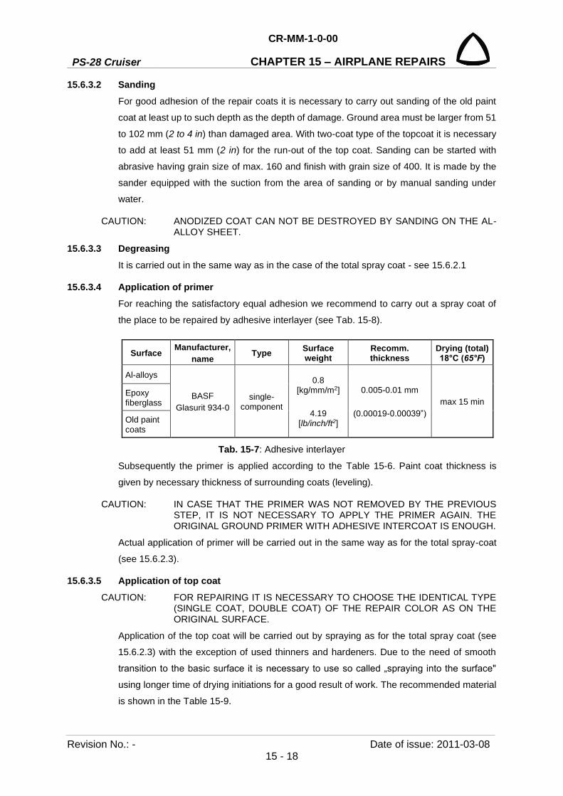
PS-28 Cruiser
CR-MM-1-0-00
CHAPTER 15 – AIRPLANE REPAIRS
Revision No.: - Date of issue: 2011-03-08 15 - 18
15.6.3.2 Sanding For good adhesion of the repair coats it is necessary to carry out sanding of the old paint
coat at least up to such depth as the depth of damage. Ground area must be larger from 51
to 102 mm (2 to 4 in) than damaged area. With two-coat type of the topcoat it is necessary
to add at least 51 mm (2 in) for the run-out of the top coat. Sanding can be started with
abrasive having grain size of max. 160 and finish with grain size of 400. It is made by the
sander equipped with the suction from the area of sanding or by manual sanding under
water.
CAUTION: ANODIZED COAT CAN NOT BE DESTROYED BY SANDING ON THE AL-ALLOY SHEET.
15.6.3.3 Degreasing It is carried out in the same way as in the case of the total spray coat - see 15.6.2.1
15.6.3.4 Application of primer For reaching the satisfactory equal adhesion we recommend to carry out a spray coat of
the place to be repaired by adhesive interlayer (see Tab. 15-8).
Surface Manufacturer, name Type Surface
weight Recomm. thickness
Drying (total) 18°C (65°F)
Al-alloys
BASF Glasurit 934-0
single-component
0.8 [kg/mm/m2]
4.19
[lb/inch/ft2]
0.005-0.01 mm
(0.00019-0.00039”) max 15 min
Epoxy fiberglass
Old paint coats
Tab. 15-7: Adhesive interlayer
Subsequently the primer is applied according to the Table 15-6. Paint coat thickness is
given by necessary thickness of surrounding coats (leveling).
CAUTION: IN CASE THAT THE PRIMER WAS NOT REMOVED BY THE PREVIOUS STEP, IT IS NOT NECESSARY TO APPLY THE PRIMER AGAIN. THE ORIGINAL GROUND PRIMER WITH ADHESIVE INTERCOAT IS ENOUGH.
Actual application of primer will be carried out in the same way as for the total spray-coat
(see 15.6.2.3).
15.6.3.5 Application of top coat CAUTION: FOR REPAIRING IT IS NECESSARY TO CHOOSE THE IDENTICAL TYPE
(SINGLE COAT, DOUBLE COAT) OF THE REPAIR COLOR AS ON THE ORIGINAL SURFACE.
Application of the top coat will be carried out by spraying as for the total spray coat (see
15.6.2.3) with the exception of used thinners and hardeners. Due to the need of smooth
transition to the basic surface it is necessary to use so called „spraying into the surface"
using longer time of drying initiations for a good result of work. The recommended material
is shown in the Table 15-9.

CR-MM-1-0-00
PS-28 Cruiser CHAPTER 15 – AIRPLANE REPAIRS
Date of issue: 2011-03-08 Revision No.: - 15 - 19
Color type
Manufacturer, name Type Other
components Surface
mass Recomm. thickness
Drying (between spray
coats / total) 18°C (65°F)
single coat
BASF Glasurit R-68 / shade
(base)
acrylic –polyurethane
BASF Glasurit 922-36
(standard hardener) Glasurit 352-319
(extra long thinner)
1-1.6 [kg/mm/m2]
5.24-8.38 [lb/inch/ft2]
(according to shade)
0.02-0.04 mm
(0.00078-0.00157”) 15 min / 19 hrs
doublecoat
basic color code: BASF
Glasurit R- 55 / hade
(base)
acrylic –polyurethane
BASF Glasurit 352-216
(long thinner)
1.2-1.4 [kg/mm/m2]
6.29-7.33 [lb/inch/ft2]
(according to shade)
0.015-0.02 mm
(0.00059-0.00078”) 10 min / 20 min
Glossy top coat:
BASF Glasurit 923-155 (base)
acrylic –polyurethane
BASF Glasurit 929-93
(standard hardener) Glasurit 352-400
(extra long thinner)
0.9 [kg/mm/m2]
4.82
[lb/inch/ft2]
0.03-0.04 mm
(0.00118-0.00157”) 5 min / 6 hrs
Tab. 15-8: Recommended colors
15.7 Torque moments Unless otherwise prescribed, the torque moments shown in the following table can be used.
When tightening follows several rules:
(a) Unless specifically stated do not grease neither nut nor bolt.
(b) If possible always tighten the nut. If for some space reasons it is necessary to tighten
the bolt head and the scope of tightening moment is defined. Use higher moment for
tightening.
(c) Maximum moments are used only for the materials and surfaces, which have a
sufficient thickness, area and strength resistant to bursting, warping or other damage.
Maximum tightening moments must not be exceeded.

PS-28 Cruiser
CR-MM-1-0-00
CHAPTER 15 – AIRPLANE REPAIRS
Revision No.: - Date of issue: 2011-03-08 15 - 20
Bolt size Torque limits recomended Max. allowable torque limits
Nm in lb Nm in lb
AN3 2.3 - 2.8 20 - 25 4.5 40
AN4 5.7 - 7.9 50 - 70 11.3 100
AN5 11.3 - 15.8 100 - 140 25.4 225
AN6 18.1 - 21.5 160 - 190 44.1 390
AN7 50.9 - 56.5 450 - 500 94.9 840
AN8 54.2 - 78 480 - 690 124.3 1100
AN9 90.4 - 113 800 - 1000 180.8 1600
Tab. 15-9: Recommended torque values for oil-free, cadmium-plated threads
15.8 Securing the bolt joints 15.8.1 General
Bolt joint securing is used in order to prevent from their loosening due to vibration or force
action on the connected parts, which could result in the damage of the connected parts.
Three ways of bolt joint securing are used on the airplane: locking wire, cotter pin and
locking washer.
15.8.2 Bolt joint securing by locking wire Procedure of bolt joint securing is shown on the Fig.15-6 and Fig.15-7. The zinc-coated or
stainless steel wire having diameter of 0.8 mm (0.032in) is used for securing.
Fig. 15-6: Ways of bolt joint securing

CR-MM-1-0-00
PS-28 Cruiser CHAPTER 15 – AIRPLANE REPAIRS
Date of issue: 2011-03-08 Revision No.: - 15 - 21
1. Adjust the correct position of holes for locking wire.
6. Pull the upper wire through the hole in the other bolt. Hold the wire end by pliers and tighten it firm.
2. Pull the locking wire through the hole in one bolt to be secured.
7. Hold the free end of wire by hand, bend it around the bolt head and along with the other end twist it counterclockwise.
3. Hold the upper end of the wire and wind it around the bolt head and then by the other end of the wire. Make sure that the wire is properly tightened around the head.
8. Hold the twisted end by pliers and twist it tight.
4. Twist the wire to the hole in the next bolt so tight as possible.
9. Bend the end of the wire under the bolt head.
5. Tighten the wire and at the same time continue its twisting unless perfectly tightened. The twisted wire can have approximately from 3 to 4 threads on the length of 10 mm (0,4 in).
10. Cut off the surplus wire.
Fig. 15-7: Procedure for securing the bolt joint with locking wire
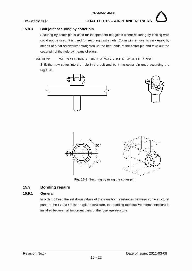
PS-28 Cruiser
CR-MM-1-0-00
CHAPTER 15 – AIRPLANE REPAIRS
Revision No.: - Date of issue: 2011-03-08 15 - 22
15.8.3 Bolt joint securing by cotter pin Securing by cotter pin is used for independent bolt joints where securing by locking wire
could not be used. It is used for securing castle nuts. Cotter pin removal is very easy: by
means of a flat screwdriver straighten up the bent ends of the cotter pin and take out the
cotter pin of the hole by means of pliers.
CAUTION: WHEN SECURING JOINTS ALWAYS USE NEW COTTER PINS.
Shift the new cotter into the hole in the bolt and bent the cotter pin ends according the
Fig.15-8.
Fig. 15-8: Securing by using the cotter pin.
15.9 Bonding repairs 15.9.1 General
In order to keep the set down values of the transition resistances between some stuctural
parts of the PS-28 Cruiser airplane structure, the bonding (conductive interconnection) is
installed between all important parts of the fuselage structure.

CR-MM-1-0-00
PS-28 Cruiser CHAPTER 15 – AIRPLANE REPAIRS
Date of issue: 2011-03-08 Revision No.: - 15 - 23
15.9.2 Removal and installation Before installing the bonding remove the paint coat which protects the joint. Principles for
repeated installation of the bonding:
(a) Carefully clean the whole bonding including the washers, bolts and nuts from all
impurities, if necessary degrease the contacting surfaces on the connecting material.
(b) Carefully check whether wires of bonding band are not torn off. Change the damaged
band.
(c) Carefully clean and degrease contacting surfaces on the airplane structure. Clean
corroded surfaces with emery paper to the metallic luster.
CAUTION: IF A NEW PART WAS INSTALLED INTO THE AIRPLANE, ITS SURFACE IS PROVIDED BY NON-CONDUCTIVE SURFACE PROTECTION (FOR EXAMPLE ANODIZING), THIS SURFACE PROTECTION MUST BE REMOVED FROM THE AREA OF BONDING INSTALLATION.
(d) The threaded joints, which fulfill a function of bonding, cannot be lubricated.
(e) On the same areas of the airplane structure install the same type of bonding which you
removed.
(f) After repeated bonding installation coat the remaining metallically clean surface of the
contact area, as well as protruding heads of bolts and nuts with protective paint.
15.10 Installing clamps by Nicopress pliers Procedure of clamp installation by Nicopress pliers is shown on the Fig. 15-10.
First pull the cable through the clamp, make a loop around the thumb and pull the cable end
back through the clamp. The cable end should overlap by about 32 mm (1.25 in) from the
clamp after its puling through. The overlapping will ensure that the cable end will not be
pulled back into the clamp during the clamp squeezing. Before actual squeezing the clamp
it is also necessary to verify which cable terminal will be used, whether thimble or
suspension eye, because some terminals must be put into the cable before actual clamp
squeezing.
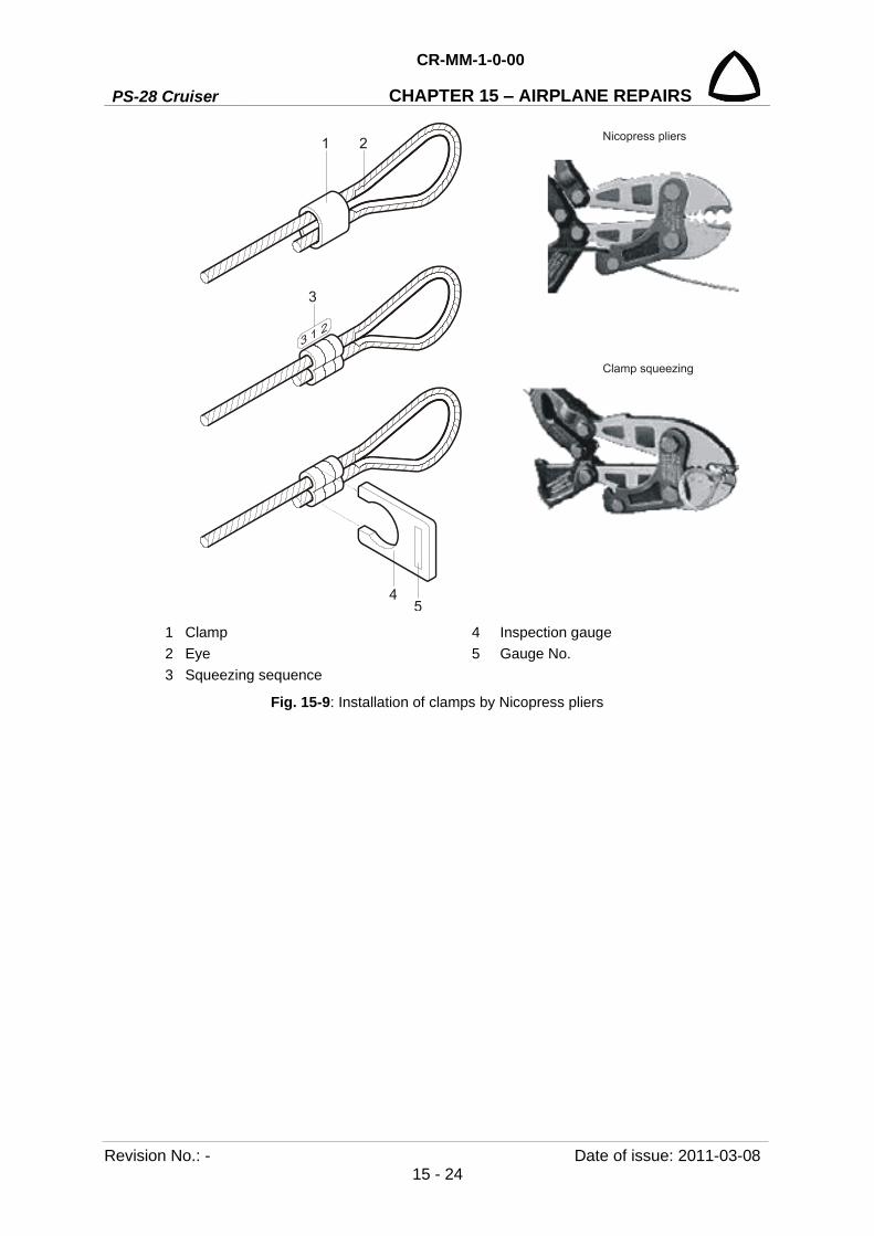
PS-28 Cruiser
CR-MM-1-0-00
CHAPTER 15 – AIRPLANE REPAIRS
Revision No.: - Date of issue: 2011-03-08 15 - 24
1 Clamp 4 Inspection gauge 2 Eye 5 Gauge No. 3 Squeezing sequence
Fig. 15-9: Installation of clamps by Nicopress pliers

CR-MM-1-0-00
PS-28 Cruiser CHAPTER 16 – WIRING DIAGRAMS
Date of issue: 2011-03-08 Revision No.: - 16 - 1
16. WIRING DIAGRAMS Content
Chapter 16 – See – Wiring Manual
PS-28 Cruiser
CR-MM-1-0-00
CHAPTER 16 – WIRING DIAGRAMS
Revision No.: - Date of issue: 2011-03-08 16 - 2
INTENTIONALLY LEFT BLANK
CR-MM-1-0-00
PS-28 Cruiser CHAPTER 17 – APPENDICES
Date of issue: 2012-10-10 Revision No.: 4 17 - 1
17. APPENDICES Content
17.1 General ................................................................................................................. 17-2
17.2 List of appendices ................................................................................................ 17-2
17.3 List of used materials for airframe production ...................................................... 17-2
17.4 Airplane failure card ............................................................................................. 17-3
17.5 Operating liquids .................................................................................................. 17-4
17.6 GTN 650 / 750 Post-Installation Checkout Log .................................................... 17-5
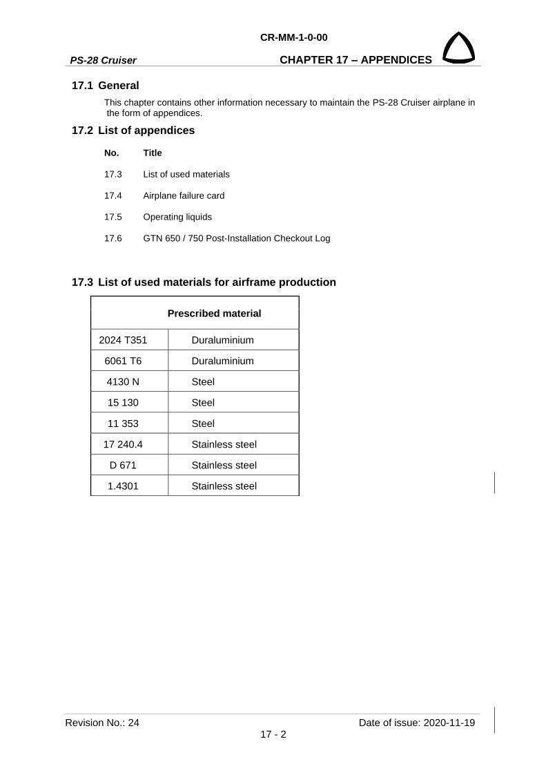
PS-28 Cruiser
CR-MM-1-0-00
CHAPTER 17 – APPENDICES
Revision No.: 24 Date of issue: 2020-11-19 17 - 2
17.1 General This chapter contains other information necessary to maintain the PS-28 Cruiser airplane in the form of appendices.
17.2 List of appendices
No. Title
17.3 List of used materials
17.4 Airplane failure card
17.5 Operating liquids
17.6 GTN 650 / 750 Post-Installation Checkout Log
17.3 List of used materials for airframe production
Prescribed material
2024 T351 Duraluminium
6061 T6 Duraluminium
4130 N Steel
15 130 Steel
11 353 Steel
17 240.4 Stainless steel
D 671 Stainless steel
1.4301 Stainless steel

CR-MM-1-0-00
PS-28 Cruiser CHAPTER 17 – APPENDICES
Date of issue: 2020-11-19 Revision No.: 24 17 - 3
17.4 Airplane failure card
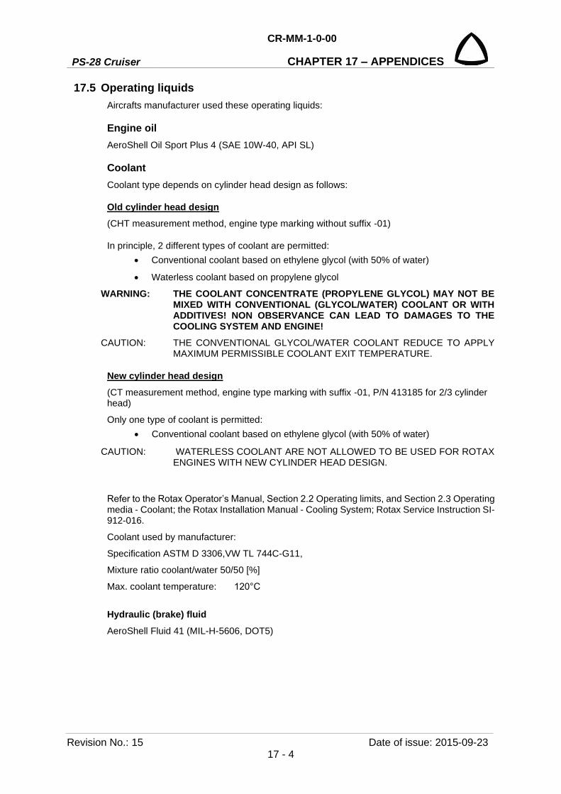
PS-28 Cruiser
CR-MM-1-0-00
CHAPTER 17 – APPENDICES
Revision No.: 15 Date of issue: 2015-09-23 17 - 4
17.5 Operating liquids Aircrafts manufacturer used these operating liquids:
Engine oil AeroShell Oil Sport Plus 4 (SAE 10W-40, API SL)
Coolant Coolant type depends on cylinder head design as follows:
Old cylinder head design (CHT measurement method, engine type marking without suffix -01)
In principle, 2 different types of coolant are permitted: • Conventional coolant based on ethylene glycol (with 50% of water)
• Waterless coolant based on propylene glycol
WARNING: THE COOLANT CONCENTRATE (PROPYLENE GLYCOL) MAY NOT BE MIXED WITH CONVENTIONAL (GLYCOL/WATER) COOLANT OR WITH ADDITIVES! NON OBSERVANCE CAN LEAD TO DAMAGES TO THE COOLING SYSTEM AND ENGINE!
CAUTION: THE CONVENTIONAL GLYCOL/WATER COOLANT REDUCE TO APPLY MAXIMUM PERMISSIBLE COOLANT EXIT TEMPERATURE.
New cylinder head design (CT measurement method, engine type marking with suffix -01, P/N 413185 for 2/3 cylinder head)
Only one type of coolant is permitted: • Conventional coolant based on ethylene glycol (with 50% of water)
CAUTION: WATERLESS COOLANT ARE NOT ALLOWED TO BE USED FOR ROTAX ENGINES WITH NEW CYLINDER HEAD DESIGN.
Refer to the Rotax Operator’s Manual, Section 2.2 Operating limits, and Section 2.3 Operating media - Coolant; the Rotax Installation Manual - Cooling System; Rotax Service Instruction SI-912-016.
Coolant used by manufacturer:
Specification ASTM D 3306,VW TL 744C-G11,
Mixture ratio coolant/water 50/50 [%]
Max. coolant temperature: 120°C
Hydraulic (brake) fluid AeroShell Fluid 41 (MIL-H-5606, DOT5)
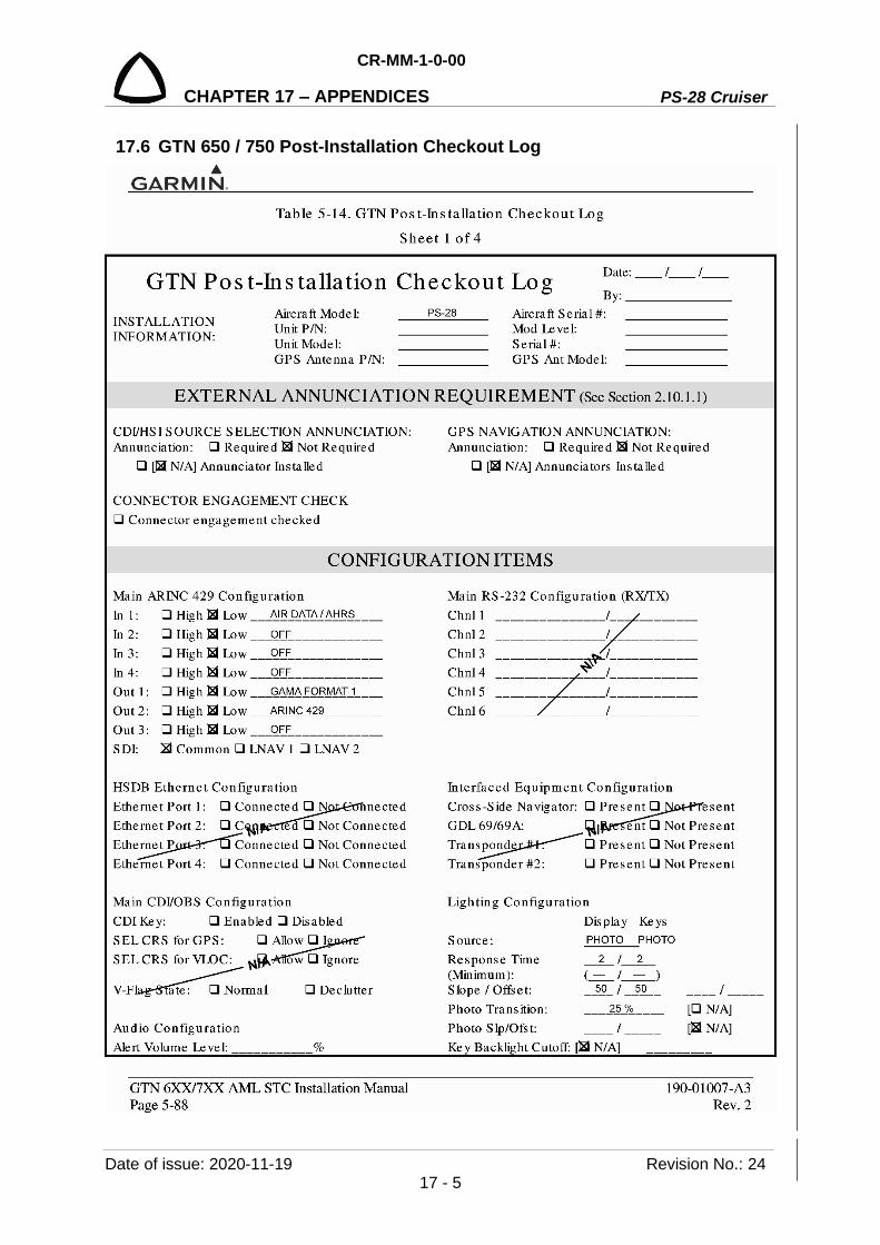
CR-MM-1-0-00
PS-28 Cruiser CHAPTER 17 – APPENDICES
Date of issue: 2020-11-19 Revision No.: 24 17 - 5
17.6 GTN 650 / 750 Post-Installation Checkout Log

PS-28 Cruiser
CR-MM-1-0-00
CHAPTER 17 – APPENDICES
Revision No.: 4 Date of issue: 2012-12-10 17 - 6

CR-MM-1-0-00
PS-28 Cruiser CHAPTER 17 – APPENDICES
Date of issue: 2012-12-10 Revision No.: 4 17 - 7

PS-28 Cruiser
CR-MM-1-0-00
CHAPTER 17 – APPENDICES
Revision No.: 4 Date of issue: 2012-12-10 17 - 8

CR-MM-1-0-00
PS-28 Cruiser CHAPTER 18 – VALID SUPPLEMENTS PAGE
Date of issue: 2011-03-08 Revision No.: - 18 - 1
18. VALID SUPPLEMENTS PAGE
Content
18.1 General ................................................................................................................. 18-2
18.2 List of supplements valid for the individual airplane ............................................. 18-2
PS-28 Cruiser
CR-MM-1-0-00
CHAPTER 18 – VALID SUPPLEMENTS PAGE
Revision No.: - Date of issue: 2011-03-08 18 - 2
18.1 General This chapter serves to airplane owner and contains other information necessary to maintain
the individual PS-28 Cruiser airplane in the form of valid supplements.
18.2 List of supplements valid for the individual airplane (To be filled up by the aircraft owner)
Suppl. No. Title Note

CR-MM-1-0-00
PS-28 Cruiser CHAPTER 18 – VALID SUPPLEMENTS PAGE
Date of issue: 2011-03-08 Revision No.: - 18 - 3
18.2 List of supplements valid for the individual airplane - continue
Suppl. No. Title Note
PS-28 Cruiser
CR-MM-1-0-00
CHAPTER 18 – VALID SUPPLEMENTS PAGE
Revision No.: - Date of issue: 2011-03-08 18 - 4
18.2 List of supplements valid for the individual airplane - continue
Suppl. No. Title Note