1574446568 maintenance
1002
Transcript of 1574446568 maintenance


POWER ENGINEERING
Series EditorH. Lee Willis
Quanta TechnologyRaleigh, North Carolina
Advisory EditorMuhammad H. Rashid
University of West FloridaPensacola, Florida
1. Power Distribution Planning Reference Book, H. Lee Willis2. Transmission Network Protection: Theory and Practice,
Y. G. Paithankar3. Electrical Insulation in Power Systems, N. H. Malik,
A. A. Al-Arainy, and M. I. Qureshi4. Electrical Power Equipment Maintenance and Testing,
Paul Gill5. Protective Relaying: Principles and Applications,
Second Edition, J. Lewis Blackburn6. Understanding Electric Utilities and De-Regulation,
Lorrin Philipson and H. Lee Willis7. Electrical Power Cable Engineering, William A. Thue8. Electric Systems, Dynamics, and Stability with Artificial
Intelligence Applications, James A. Momoh and Mohamed E. El-Hawary
9. Insulation Coordination for Power Systems, Andrew R. Hileman
10. Distributed Power Generation: Planning and Evaluation, H. Lee Willis and Walter G. Scott
11. Electric Power System Applications of Optimization, James A. Momoh
12. Aging Power Delivery Infrastructures, H. Lee Willis,Gregory V. Welch, and Randall R. Schrieber
13. Restructured Electrical Power Systems: Operation, Trading,and Volatility, Mohammad Shahidehpour and Muwaffaq Alomoush
14. Electric Power Distribution Reliability, Richard E. Brown15. Computer-Aided Power System Analysis,
Ramasamy Natarajan
DK4058_C000.indd iDK4058_C000.indd i 11/20/2008 10:17:56 AM11/20/2008 10:17:56 AM
16. Power System Analysis: Short-Circuit Load Flow and Harmonics, J. C. Das
17. Power Transformers: Principles and Applications, John J. Winders, Jr.
18. Spatial Electric Load Forecasting: Second Edition, Revised and Expanded, H. Lee Willis
19. Dielectrics in Electric Fields, Gorur G. Raju20. Protection Devices and Systems for High-Voltage
Applications, Vladimir Gurevich21. Electrical Power Cable Engineering, Second Edition,
William Thue22. Vehicular Electric Power Systems: Land, Sea, Air,
and Space Vehicles, Ali Emadi, Mehrdad Ehsani, and John Miller
23. Power Distribution Planning Reference Book, Second Edition, H. Lee Willis
24. Power System State Estimation: Theory and Implementation, Ali Abur
25. Transformer Engineering: Design and Practice, S.V. Kulkarni and S. A. Khaparde
26. Power System Capacitors, Ramasamy Natarajan27. Understanding Electric Utilities and De-regulation:
Second Edition, Lorrin Philipson and H. Lee Willis28. Control and Automation of Electric Power Distribution
Systems, James Northcote-Green and Robert G. Wilson29. Protective Relaying for Power Generation Systems,
Donald Reimert30. Protective Relaying: Principles and Applications,
Third Edition, J. Lewis Blackburn and Thomas J. Domin31. Electric Power Distribution Reliability, Second Edition,
Richard E. Brown32. Electrical Power Equipment Maintenance and Testing,
Second Edition, Paul Gill
DK4058_C000.indd iiDK4058_C000.indd ii 11/20/2008 10:17:57 AM11/20/2008 10:17:57 AM

ELECTRICAL POWER EQUIPMENT MAINTENANCE AND TESTING
SECOND EDITION
Paul Gill
CRC Press is an imprint of theTaylor & Francis Group, an informa business
Boca Raton London New York
DK4058_C000.indd iiiDK4058_C000.indd iii 11/20/2008 10:17:57 AM11/20/2008 10:17:57 AM
CRC PressTaylor & Francis Group6000 Broken Sound Parkway NW, Suite 300Boca Raton, FL 33487-2742
© 2009 by Taylor & Francis Group, LLC CRC Press is an imprint of Taylor & Francis Group, an Informa business
No claim to original U.S. Government worksPrinted in the United States of America on acid-free paper10 9 8 7 6 5 4 3 2 1
International Standard Book Number-13: 978-1-57444-656-2 (Hardcover)
This book contains information obtained from authentic and highly regarded sources. Reasonable efforts have been made to publish reliable data and information, but the author and publisher cannot assume responsibility for the valid-ity of all materials or the consequences of their use. The authors and publishers have attempted to trace the copyright holders of all material reproduced in this publication and apologize to copyright holders if permission to publish in this form has not been obtained. If any copyright material has not been acknowledged please write and let us know so we may rectify in any future reprint.
Except as permitted under U.S. Copyright Law, no part of this book may be reprinted, reproduced, transmitted, or uti-lized in any form by any electronic, mechanical, or other means, now known or hereafter invented, including photocopy-ing, microfilming, and recording, or in any information storage or retrieval system, without written permission from the publishers.
For permission to photocopy or use material electronically from this work, please access www.copyright.com (http://www.copyright.com/) or contact the Copyright Clearance Center, Inc. (CCC), 222 Rosewood Drive, Danvers, MA 01923, 978-750-8400. CCC is a not-for-profit organization that provides licenses and registration for a variety of users. For orga-nizations that have been granted a photocopy license by the CCC, a separate system of payment has been arranged.
Trademark Notice: Product or corporate names may be trademarks or registered trademarks, and are used only for identification and explanation without intent to infringe.
Library of Congress Cataloging-in-Publication Data
Gill, Paul, 1942-Electrical power equipment maintenance and testing / Paul Gill. -- 2nd ed.
p. cm.ISBN 978-1-57444-656-2 (alk. paper)1. Electric power systems--Testing. 2. Electric power systems--Maintenance and repair. I. Title.
TK401.G55 2008621.31’0420287--dc22 2008029371
Visit the Taylor & Francis Web site athttp://www.taylorandfrancis.com
and the CRC Press Web site athttp://www.crcpress.com
DK4058_C000.indd ivDK4058_C000.indd iv 11/20/2008 10:17:57 AM11/20/2008 10:17:57 AM

v
Liability
This textbook and instructions offered in it are designed to acquaint students and readers with accepted good practice for maintenance, operation, and testing of electrical equipment and/or systems. This book does not purport to be complete nor is it intended to be specifi c for the products of any manu-facturer, testing procedures, or maintenance routines. The publisher, the author, companies, and other organizations referenced in this book will not accept any responsibility and liability whatsoever for work undertaken on the basis of this text. The sole purpose of this book is to impart knowledge on the subjects covered in the book. All work undertaken based on this text is the sole responsibility of the reader and user of the book. The manufac-turer’s operating, maintenance, and testing procedures are the only reliable guide in any specifi c instance and, therefore, they should be consulted before undertaking any work on electrical equipment.
The contents of this book do not represent a U.S. Nuclear Regulatory Commission (USNRC) position on the subjects covered in the book.
DK4058_C000.indd vDK4058_C000.indd v 11/20/2008 10:17:57 AM11/20/2008 10:17:57 AM

DK4058_C000.indd viDK4058_C000.indd vi 11/20/2008 10:17:57 AM11/20/2008 10:17:57 AM

Dedication
In memory of my parents—Jasbir Singh and Amar Kaur
To my wife Patricia—for her patience and understanding to make
this work possible
To my children/spouses—Shaun/Debra, Rajan/Larie, Jason/Deanna, and
Rania/Alden and to my beautiful grandchildren Collin, Andrew, Ryan,
Timothy, Owen, Henry, Jack, Maya, Chani, Paul, and Lauryn
who keep me young and bring boundless joy to my journey in life
DK4058_C000.indd viiDK4058_C000.indd vii 11/20/2008 10:17:57 AM11/20/2008 10:17:57 AM

DK4058_C000.indd viiiDK4058_C000.indd viii 11/20/2008 10:17:57 AM11/20/2008 10:17:57 AM

ix
Contents
Series Introduction ..................................................................................xxixForeword .................................................................................................xxxiPreface .................................................................................................. xxxiiiAcknowledgments .............................................................................. xxxvii
Chapter 1 Maintenance Strategies, Dielectric Theory, Insulating Materials, Failure Modes, and Maintenance Impact on Arc-Flash Hazards
1.1 Introduction ...........................................................................................11.2 Why Maintain and Test .......................................................................11.3 Overview of Electrical Maintenance and Testing Strategies .........2
1.3.1 Key Factors in EPM Optimization Decisions ...................... 121.3.2 General Criteria for an Effective EPM
and Testing Program ............................................................... 121.3.3 Qualifi cations of EPM Personnel .......................................... 131.3.4 Optimization of PM Intervals ............................................... 141.3.5 Trending of Test Results ......................................................... 151.3.6 Systematic Failure Analysis Approach ................................ 15
1.3.6.1 Postmaintenance Testing ......................................... 161.3.6.2 Engineering Support ................................................ 161.3.6.3 Summary .................................................................... 17
1.4 Planning an EPM Program ............................................................... 181.4.1 Maintenance Management Considerations ......................... 18
1.4.1.1 Responsibilities .......................................................... 191.4.1.2 Inspection ................................................................... 191.4.1.3 Scheduling .................................................................. 191.4.1.4 Work Orders ............................................................... 201.4.1.5 Record Keeping ......................................................... 20
1.4.2 Technical Requirements ......................................................... 201.4.2.1 Survey of Plant Equipment ...................................... 201.4.2.2 Listing of Plant Equipment in the Order
of Critical Importance ..............................................231.4.2.3 Plan to Perform EPM on Regular Frequency ........ 241.4.2.4 Development of Instruction and Procedures
for the EPM Program................................................ 241.4.3 What Should Be Included in the EPM Program .................25
1.4.3.1 EPM and Testing .......................................................251.4.3.2 Electrical Repairs ......................................................251.4.3.3 Analysis of Failures ..................................................251.4.3.4 Trending of Maintenance and Testing Data......... 261.4.3.5 Computerized Maintenance
Management System ................................................ 26
DK4058_C000.indd ixDK4058_C000.indd ix 11/20/2008 10:17:57 AM11/20/2008 10:17:57 AM
Novin Pendar
Highlight

x Contents
1.5 Overview of Testing and Test Methods ..........................................281.5.1 Types of Tests ...........................................................................28
1.5.1.1 Acceptance Tests ........................................................281.5.1.2 Routine Maintenance Tests ......................................281.5.1.3 Special Maintenance Tests ....................................... 29
1.5.2 Types of Testing Methods ...................................................... 291.5.2.1 Solid Insulation Testing ........................................... 291.5.2.2 Insulating Liquid Testing ........................................301.5.2.3 Protective Device Testing ........................................301.5.2.4 Circuit Breaker Time–Travel Analysis ................... 311.5.2.5 Grounding Electrode
Resistance Testing ..................................................... 311.5.2.6 Fault Gas Analysis Testing ...................................... 311.5.2.7 Infrared Inspection Testing ..................................... 32
1.6 Review of Dielectric Theory and Practice ....................................... 321.6.1 Characteristics of Dielectrics (Insulation) ...........................34
1.6.1.1 Dielectric Loss ............................................................351.6.1.2 PF and DF ...................................................................351.6.1.3 Capacitance ................................................................35
1.6.2 Insulation as a Capacitor ........................................................361.6.3 DC Voltage versus AC Voltage Tests .................................... 37
1.6.3.1 DC Voltage Tests ........................................................381.6.3.2 AC Voltage Tests ........................................................38
1.6.4 Insulation Breakdown Modes ............................................... 391.7 Insulating Materials for Electrical
Power Equipment ................................................................................401.7.1 Rigid Laminates Sheet, Rod, and Tube ................................. 411.7.2 Glass Polyester Products ........................................................ 411.7.3 Flexible Laminates and Films ................................................ 411.7.4 Insulation Temperature Ratings ............................................46
1.8 Causes of Insulation Degradation and Failure Modes of Electrical Equipment ..................................................................... 471.8.1 Failure Modes—Electrical Power Equipment ..................... 51
1.8.1.1 Transformers .............................................................. 511.8.1.2 Switchgear and Circuit Breakers ............................561.8.1.3 Relays ..........................................................................641.8.1.4 Switchgear Buses .......................................................651.8.1.5 Cables and Connectors ............................................. 691.8.1.6 Rotating Machines .................................................... 71
1.9 Maintenance of Protective Devices and their Impact on Arc-Flash Hazard Analysis ......................................................... 811.9.1 Bases of Maintenance and Testing
of Protective Devices ............................................................... 811.9.2 Failure Statistics ....................................................................... 911.9.3 Flash Hazard Analysis ........................................................... 92
DK4058_C000.indd xDK4058_C000.indd x 11/20/2008 10:17:57 AM11/20/2008 10:17:57 AM

Contents xi
Chapter 2 Direct-Current Voltage Testing of Electrical Equipment
2.1 Introduction ......................................................................................... 972.2 DC Voltage Testing of Insulation ..................................................... 98
2.2.1 Dielectric Phenomena and Polarization ............................ 1002.2.2 Advantages and Disadvantages of DC
Voltage Testing ...................................................................... 101 2.2.2.1 Advantages .............................................................. 101 2.2.2.2 Disadvantages ........................................................ 102
2.3 DC Testing Methods ........................................................................ 1022.3.1 Insulation Resistance Testing .............................................. 102
2.3.1.1 Short-Time Readings .............................................. 103 2.3.1.2 Time–Resistance Readings .................................... 103 2.3.1.3 PI Test ....................................................................... 105 2.3.1.4 Step-Voltage Readings
(DC Voltage Tip-Up Test) ....................................... 1052.3.2 High-Potential Voltage Test ................................................. 105
2.4 Transformers ..................................................................................... 1062.4.1 Insulation Resistance Measurement .................................. 1062.4.2 Dielectric Absorption Test ................................................... 1102.4.3 DC High-Potential Test ........................................................ 111
2.5 Cables and Accessories .................................................................... 1132.5.1 Insulation Resistance Measurement Test .......................... 1132.5.2 DC Overpotential Testing.................................................... 1172.5.3 Voltage versus Leakage Current Test
(Step-Voltage Test) .................................................................. 1192.5.4 Leakage Current versus Time Test ..................................... 1212.5.5 Go, No-Go Overpotential Test ............................................ 1212.5.6 DC Overpotential Test Connections and Procedures ..... 121
2.6 Electrical Switchgear and Circuit Breakers .................................. 1242.6.1 Insulation Resistance Measurement Test .......................... 1242.6.2 DC High-Potential Test ........................................................ 1262.6.3 Circuit Breaker Contact Resistance Measurement Test ... 127
2.7 Motors and Generators .................................................................... 1272.7.1 Insulation Resistance Test .................................................... 128
2.7.1.1 Field-Winding Test Procedures ............................. 128 2.7.1.2 Overall Stator (Armature Windings) Test ........... 129 2.7.1.3 Overall System Test for the
Motor or Generator................................................. 130 2.7.1.4 Individual Stator Winding Test ............................. 130
2.7.2 DC Overpotential Test .......................................................... 1332.7.3 Voltage versus Leakage Current Test
(Step-Voltage Test) .................................................................. 1332.7.4 Leakage Current versus Time Test ..................................... 134
2.8 Lightning Arresters .......................................................................... 136
DK4058_C000.indd xiDK4058_C000.indd xi 11/20/2008 10:17:57 AM11/20/2008 10:17:57 AM
Novin Pendar
Highlight
xii Contents
2.9 Capacitors ........................................................................................ 1372.9.1 Tests to Check the Condition of New Capacitor
Units before Placing in Service ....................................... 1372.9.2 Tests to Check the Condition of a Capacitor Unit
after It Has Been in Service ............................................. 1372.10 Evaluation of Test Data Readings ................................................. 139
2.10.1 Acceptance Criteria for Rating Insulation ..................... 1402.11 Precautions When Making DC Tests ........................................... 143
Chapter 3 Power Factor and Dissipation Factor Testing Methods3.1 Introduction ..................................................................................... 1453.2 PF and DF Test Methods ................................................................ 146
3.2.1 General ................................................................................ 1463.2.2 Principles of PF/DF Testing ............................................. 1473.2.3 Factors That Infl uence PF Measurements ...................... 148
3.3 Description of the PF Test Equipment ......................................... 1493.3.1 PF and DF Test Set ............................................................. 1493.3.2 General Instructions for the Operation
of the Megger Test Set ....................................................... 1523.3.3 Doble PF Test Set ............................................................... 1533.3.4 Operation of Doble PF Test Set ........................................ 153
3.4 Basic Test Connections (Test Modes) for PF Testing .................. 1543.4.1 Grounded-Specimen Test Mode ...................................... 1543.4.2 GST Mode with Guard (GST-G) ...................................... 1543.4.3 Ungrounded-Specimen Test Mode ................................. 155
3.5 Safety Cautions with PF Testing .................................................. 1553.6 PF Testing of Electrical Apparatus Insulation ............................ 157
3.6.1 Transformers ...................................................................... 158 3.6.1.1 Two-Winding Transformers .............................. 158 3.6.1.2 Three-Winding Transformers ........................... 161 3.6.1.3 Autotransformers ................................................ 163 3.6.1.4 PTs ......................................................................... 163
3.6.2 Transformer Bushing ........................................................ 164 3.6.2.1 Hot-Collar Tests of Noncondenser-Type
Bushings ............................................................... 1673.6.3 Transformer Excitation Current Test .............................. 1683.6.4 Transformer Insulating Oils and Fluids ........................ 1703.6.5 Lightning Arrestors .......................................................... 1713.6.6 Circuit Breakers ................................................................. 171
3.6.6.1 Medium-Voltage Circuit Breakers .................... 172 3.6.6.2 Oil Circuit Breakers (OCBs) ............................... 173
3.6.7 SF6 Breaker .......................................................................... 1773.6.8 Rotating Machinery .......................................................... 177
3.6.8.1 PF Tip-Up Test ..................................................... 1783.6.9 Cables and Accessories ..................................................... 180
3.6.9.1 Shielded or Sheathed Cable ............................... 181 3.6.9.2 Unshielded and Unsheathed Cables ................ 181
DK4058_C000.indd xiiDK4058_C000.indd xii 11/20/2008 10:17:57 AM11/20/2008 10:17:57 AM
Novin Pendar
Highlight

Contents xiii
3.6.10 PF Correction Capacitors and Surge Capacitors ............. 182 3.6.10.1 Bus Insulators....................................................... 183 3.6.10.2 Miscellaneous Equipment.................................. 183
3.7 Evaluation and Grading of PF and DF Test Results .......................................................................... 1843.7.1 General .................................................................................. 1843.7.2 Analysis of the Results ....................................................... 185
3.7.2.1 Transformers ........................................................ 185 3.7.2.2 Bushings ............................................................... 187 3.7.2.3 Lightning and Surge Arrestors ......................... 188 3.7.2.4 Medium-Voltage Circuit Breakers ..................... 188 3.7.2.5 OCB ....................................................................... 189 3.7.2.6 SF6 Breakers .......................................................... 189 3.7.2.7 Rotating Machines .............................................. 190 3.7.2.8 Cables and Accessories ....................................... 190 3.7.2.9 Capacitors ............................................................. 190
Chapter 4 Insulating Oils, Fluids, and Gases4.1 Introduction ....................................................................................... 1934.2 Insulating Oil .................................................................................... 193
4.2.1 Deterioration of Insulating Oil .......................................... 194 4.2.1.1 Effect of Oxygen on Oil ...................................... 194 4.2.1.2 Moisture in Oil .................................................... 194 4.2.1.3 Oil Deterioration in Transformers .................... 195 4.2.1.4 Absorption of Moisture by
Insulating Materials ........................................... 196 4.2.1.5 Absorption of Nitrogen by Oil .......................... 196
4.2.2 Insulating Oil Testing ......................................................... 196 4.2.2.1 Dielectric Breakdown
Voltage Test (Cup Tests) ...................................... 197 4.2.2.2 Acidity Test ...........................................................200 4.2.2.3 Interfacial Tension (IFT) ..................................... 201 4.2.2.4 Color Test .............................................................. 201 4.2.2.5 Power Factor Test ................................................. 201 4.2.2.6 Specifi c Gravity .................................................... 202 4.2.2.7 Water Content Test (Karl Fisher Method) ........ 202
4.2.3 Combustible Gas Analysis of Insulating Oil ................... 203 4.2.3.1 Introduction .......................................................... 203 4.2.3.2 TCG ........................................................................ 203 4.2.3.3 DGA ....................................................................... 204 4.2.3.4 Comparing the Two Methods ............................ 204 4.2.3.5 Interpretation of Gas Analysis ........................... 204 4.2.3.6 Assessing the Transformer Condition
Using the TCGA in the Gas Space .................... 206 4.2.3.7 Assessing the Transformer Condition
Using the DGA Method...................................... 207 4.2.3.8 Fault Types and Associated Key Gases ............ 208
DK4058_C000.indd xiiiDK4058_C000.indd xiii 11/20/2008 10:17:57 AM11/20/2008 10:17:57 AM
Novin Pendar
Highlight
xiv Contents
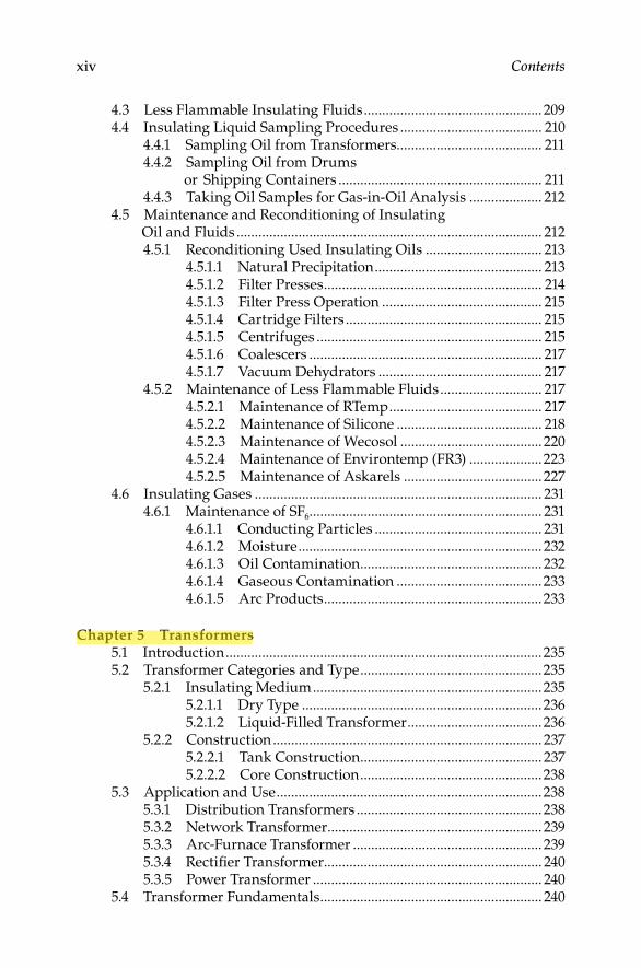
4.3 Less Flammable Insulating Fluids ................................................. 2094.4 Insulating Liquid Sampling Procedures ....................................... 210
4.4.1 Sampling Oil from Transformers........................................ 2114.4.2 Sampling Oil from Drums
or Shipping Containers ........................................................ 2114.4.3 Taking Oil Samples for Gas-in-Oil Analysis .................... 212
4.5 Maintenance and Reconditioning of Insulating Oil and Fluids .................................................................................... 2124.5.1 Reconditioning Used Insulating Oils ................................ 213
4.5.1.1 Natural Precipitation .............................................. 213 4.5.1.2 Filter Presses ............................................................ 214 4.5.1.3 Filter Press Operation ............................................ 215 4.5.1.4 Cartridge Filters ...................................................... 215 4.5.1.5 Centrifuges .............................................................. 215 4.5.1.6 Coalescers ................................................................ 217 4.5.1.7 Vacuum Dehydrators ............................................. 217
4.5.2 Maintenance of Less Flammable Fluids ............................ 217 4.5.2.1 Maintenance of RTemp .......................................... 217 4.5.2.2 Maintenance of Silicone ........................................ 218 4.5.2.3 Maintenance of Wecosol ....................................... 220 4.5.2.4 Maintenance of Environtemp (FR3) ....................223 4.5.2.5 Maintenance of Askarels ......................................227
4.6 Insulating Gases ............................................................................... 2314.6.1 Maintenance of SF6 ................................................................ 231
4.6.1.1 Conducting Particles .............................................. 231 4.6.1.2 Moisture ................................................................... 232 4.6.1.3 Oil Contamination .................................................. 232 4.6.1.4 Gaseous Contamination ........................................233 4.6.1.5 Arc Products ............................................................233
Chapter 5 Transformers5.1 Introduction .......................................................................................2355.2 Transformer Categories and Type ..................................................235
5.2.1 Insulating Medium ...............................................................235 5.2.1.1 Dry Type ..................................................................236 5.2.1.2 Liquid-Filled Transformer .....................................236
5.2.2 Construction .......................................................................... 237 5.2.2.1 Tank Construction .................................................. 237 5.2.2.2 Core Construction ..................................................238
5.3 Application and Use .........................................................................2385.3.1 Distribution Transformers ...................................................2385.3.2 Network Transformer ........................................................... 2395.3.3 Arc-Furnace Transformer .................................................... 2395.3.4 Rectifi er Transformer............................................................ 2405.3.5 Power Transformer ............................................................... 240
5.4 Transformer Fundamentals ............................................................. 240
DK4058_C000.indd xivDK4058_C000.indd xiv 11/20/2008 10:17:57 AM11/20/2008 10:17:57 AM
Novin Pendar
Highlight

Contents xv
5.4.1 Voltage Relationship ............................................................. 2445.4.2 Current Relationship ............................................................ 2445.4.3 Impedance Relationship ...................................................... 2445.4.4 Summary ................................................................................ 245
5.5 Transformer Polarity, Terminal Markings, and Connections ............................................................................... 2465.5.1 Single-Phase Transformers .................................................. 246
5.5.1.1 Subtractive Polarity ................................................. 246 5.5.1.2 Additive Polarity ..................................................... 247
5.5.2 Three-Phase Transformers .................................................. 2475.6 Transformer Characteristics ............................................................2505.7 Preventive Maintenance of Transformers .....................................253
5.7.1 Transformer Installation, Acceptance, and Maintenance ..................................................................254
5.7.1.1 Unscheduled Maintenance ....................................254 5.7.1.2 Ordinary Maintenance ...........................................254 5.7.1.3 Protective Maintenance ..........................................254
5.7.2 Dry-Type Transformers ........................................................255 5.7.2.1 Installation ...............................................................255 5.7.2.2 Inspection ................................................................. 257 5.7.2.3 Acceptance Tests ......................................................258 5.7.2.4 Maintenance ............................................................. 260 5.7.2.5 Drying-Out Methods .............................................. 261 5.7.2.6 Storage ....................................................................... 263
5.7.3 Liquid-Type Transformer ..................................................... 263 5.7.3.1 Installation ............................................................... 263 5.7.3.2 Inspection ................................................................. 265 5.7.3.3 Acceptance Tests ...................................................... 265 5.7.3.4 Maintenance ............................................................. 267 5.7.3.5 Drying-Out Methods .............................................. 271 5.7.3.6 Storage ....................................................................... 273 5.7.3.7 Transformer Diagnostic Guide .............................. 273
5.8 Transformer Testing ......................................................................... 2755.8.1 AC Hi-Pot Test ....................................................................... 2765.8.2 TTR Test .................................................................................. 276
5.8.2.1 Alternative Test for TTR ......................................... 279 5.8.2.2 TTR Capacitor ..........................................................280
5.8.3 Polarity Test ........................................................................... 2815.8.4 Induced Potential Test .......................................................... 2815.8.5 FRA ......................................................................................... 2825.8.6 DC Winding Resistance .......................................................2855.8.7 Transformer Core Ground Test ........................................... 2865.8.8 Polarization Recovery Voltage Test .................................... 286
5.8.8.1 The Measuring Instrument .................................... 287 5.8.8.2 Test Setup for Recovery Voltage Measurement
on Power Transformers ..........................................288
DK4058_C000.indd xvDK4058_C000.indd xv 11/20/2008 10:17:57 AM11/20/2008 10:17:57 AM

xvi Contents
5.8.8.3 Evaluation of Measured Polarization Spectra .......................................... 290
5.9 Online Condition Monitoring of Transformers.......................... 2915.9.1 Online Monitoring of Transformers ............................... 292
5.10 Online Monitoring of Bushings and Lightning Arrestors ........ 296
Chapter 6 Cables and Accessories6.1 Introduction ..................................................................................... 2996.2 Cable Construction and Classifi cation ......................................... 299
6.2.1 Types of Conductors ..........................................................3006.2.2 Conductor Arrangement ................................................... 3016.2.3 Cable Types ......................................................................... 3016.2.4 Insulations ...........................................................................3026.2.5 Shielding and Semiconducting Tape...............................3056.2.6 Finishes and Jackets ...........................................................3066.2.7 Cable Construction ............................................................ 307
6.3 Cable Characteristics ......................................................................3086.4 Electrical Constants ........................................................................ 3126.5 Cable Ratings ................................................................................... 3146.6 Cable Selection and Application ................................................... 3176.7 Installation of Cables ...................................................................... 322
6.7.1 Outdoor Installations ........................................................ 3226.7.2 Indoor Installations ........................................................... 3236.7.3 Bending Data ...................................................................... 3236.7.4 Pulling Tensions ................................................................. 323
6.8 Maintenance of Cables ................................................................... 3256.9 Cable Failures and Their Analysis ............................................... 3266.10 Field Testing of Medium-Voltage Cables .....................................330
6.10.1 Cable Degradation and Diagnostic Tests .......................3306.10.2 Safety Practices and Grounding ......................................3346.10.3 Cable Testing Methods .....................................................335
6.10.3.1 Insulation Resistance and DC Hi-Pot Testing .....................................................335
6.10.3.2 AC Hi-Pot Testing ..............................................3366.10.3.3 PF and DF Testing ............................................. 3376.10.3.4 VLF Tests .............................................................3386.10.3.5 PD Test ................................................................ 3416.10.3.6 AC Resonance Test ............................................3466.10.3.7 Summary of Testing Methods .........................348
6.11 Latest Trends in Cable Condition Monitoring and Aging Assessment ................................................................... 3526.11.1 Electronic Characterization and
Diagnostic (ECAD®
) System ............................................ 3526.11.2 Cable Indentor .................................................................... 3526.11.3 Oscillating Wave (OSW) Testing .....................................353
DK4058_C000.indd xviDK4058_C000.indd xvi 11/20/2008 10:17:58 AM11/20/2008 10:17:58 AM
Novin Pendar
Highlight

Contents xvii
6.11.4 Broadband Impedance Spectroscopy Prognostic/Diagnostic Technique ..................................354
6.12 Cable Fault Locating Methods ...................................................... 3566.12.1 Terminal Techniques ........................................................ 3566.12.2 Tracer Techniques ............................................................. 3626.12.3 Application Guide for Cable Fault Locating ................. 367
Chapter 7 Medium-Voltage Switchgear and Circuit Breakers
7.1 General .............................................................................................. 3777.2 Medium-Voltage Switchgear ......................................................... 377
7.2.1 Construction Features ...................................................... 3777.2.1.1 Metal-Clad Switchgear ....................................... 3787.2.1.2 Metal-Enclosed Interrupter Switchgear ........... 3827.2.1.3 Station-Type Cubicle ........................................... 382
7.2.2 Short-Circuit Considerations and Power Circuit Breaker Ratings ..................................................................383
7.2.3 Selection and Application of Power Circuit Breakers ................................................................. 392
7.3 Electrical Switchgear Maintenance and Care ............................. 3937.3.1 MV Switchgear ................................................................... 393
7.3.1.1 Power Circuit Breakers ....................................... 3937.3.1.2 Maintenance ........................................................ 395
7.3.2 Air-Magnetic Circuit Breakers ........................................ 3967.3.3 Oil Circuit Breaker ............................................................ 3987.3.4 Vacuum Circuit Breaker ................................................... 3997.3.5 Switchgear Enclosure and Bus ........................................400
7.4 Electrical Switchgear Testing ........................................................4037.4.1 Insulation Resistance Measurement Test .......................4037.4.2 DC Hi-Pot Test ...................................................................4057.4.3 AC Hi-Pot Test ....................................................................4057.4.4 Power Factor Testing ......................................................... 4077.4.5 Circuit Breaker Contact Resistance
Measurement Test.............................................................. 4077.4.6 Circuit Breaker Time–Travel Analysis ............................ 4077.4.7 Dynamic Capacitance Measurement of HV Breaker ... 413
7.5 Control Power for Switchgear ....................................................... 4157.5.1 Control Power Requirements ........................................... 415
7.5.1.1 Circuit Breaker Tripping .................................... 4167.5.1.2 DC Battery Trip ................................................... 4167.5.1.3 Capacitor Trip ...................................................... 4167.5.1.4 AC Methods of Tripping .................................... 4187.5.1.5 Circuit Breaker Closing ...................................... 418
7.6 DC (Battery) Control Power Equipment ......................................420
7.6.1 Sizing ....................................................................................420
DK4058_C000.indd xviiDK4058_C000.indd xvii 11/20/2008 10:17:58 AM11/20/2008 10:17:58 AM
Novin Pendar
Highlight

xviii Contents
7.6.2 Types of Batteries .................................................................. 4217.6.3 Battery Chargers ...................................................................422
7.7 AC Control Power Equipment .........................................................422
7.7.1 Sizing ......................................................................................422
7.7.2 Application ............................................................................4237.8 Maintenance and Care of Batteries
for Switchgear Applications ............................................................423
7.8.1 Inspections .............................................................................4237.8.2 Equalizing Charge ................................................................ 4247.8.3 Battery Tests ...........................................................................425
7.8.3.1 Acceptance Test ......................................................4257.8.3.2 Performance Test ....................................................4257.8.3.3 Battery Service Test (Load Test) ............................4267.8.3.4 Connection Resistance Test ...................................4277.8.3.5 Battery Impedance Test .........................................427
7.8.4 Addition of Water .................................................................4277.8.5 Acid Spillage ..........................................................................4287.8.6 Loose Connections ...............................................................4297.8.7 Corrosion ...............................................................................4297.8.9 Other Maintenance Hints ....................................................429
Chapter 8 Low-Voltage Switchgear and Circuit Breakers8.1 Low-Voltage Switchgear ................................................................... 4318.2 Low-Voltage Circuit Breakers ......................................................... 432
8.2.1 MCCBs ....................................................................................4338.2.2 Insulated-Case Circuit Breakers .........................................4338.2.3 Power Circuit Breakers ........................................................4338.2.4 Fused Power Circuit Breakers .............................................434
8.3 Overcurrent Protective Devices .....................................................4348.3.1 Direct-Acting Trip .................................................................4348.3.2 Static- and Electronic-Trip Units .........................................4358.3.3 Monitoring and Protection Packages ................................. 439
8.4 Fuses ................................................................................................... 4398.4.1 Low-Voltage Fuses ................................................................440
8.5 Disconnect Switches ......................................................................... 4418.5.1 Low-Voltage Switches ........................................................... 441
8.6 Selection and Application of Low-Voltage Equipment ...............4428.6.1 Assessing Service Life of Low-Voltage Breakers ..............444
8.6.1.1 Maximum Voltage Rating or Nominal Voltage Class ...........................................................444
8.6.1.2 Continuous Current Rating ..................................4448.6.1.3 Rated Short-Circuit Current
(Circuit Breakers) ....................................................4458.6.1.4 Short-Circuit Current Ratings—Panelboards,
MCCs, and Switchgear Assemblies .....................4478.6.1.5 Endurance Requirements
for Low-Voltage Breakers ......................................448
DK4058_C000.indd xviiiDK4058_C000.indd xviii 11/20/2008 10:17:58 AM11/20/2008 10:17:58 AM
Novin Pendar
Highlight
Contents xix
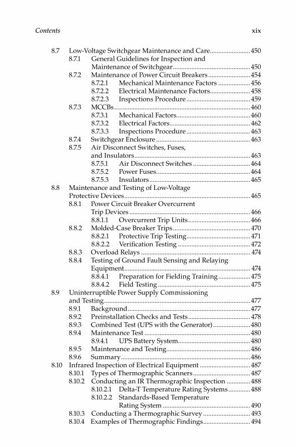
8.7 Low-Voltage Switchgear Maintenance and Care ........................4508.7.1 General Guidelines for Inspection and
Maintenance of Switchgear ..............................................4508.7.2 Maintenance of Power Circuit Breakers .........................454
8.7.2.1 Mechanical Maintenance Factors ...................4568.7.2.2 Electrical Maintenance Factors ........................ 4588.7.2.3 Inspections Procedure ...................................... 459
8.7.3 MCCBs .................................................................................4608.7.3.1 Mechanical Factors............................................4608.7.3.2 Electrical Factors ................................................ 4628.7.3.3 Inspections Procedure ......................................463
8.7.4 Switchgear Enclosure ........................................................4638.7.5 Air Disconnect Switches, Fuses,
and Insulators .....................................................................4638.7.5.1 Air Disconnect Switches ..................................4648.7.5.2 Power Fuses ........................................................4648.7.5.3 Insulators ............................................................465
8.8 Maintenance and Testing of Low-Voltage Protective Devices ...........................................................................4658.8.1 Power Circuit Breaker Overcurrent
Trip Devices ........................................................................4668.8.1.1 Overcurrent Trip Units .....................................466
8.8.2 Molded-Case Breaker Trips .............................................. 4708.8.2.1 Protective Trip Testing ...................................... 4718.8.2.2 Verifi cation Testing ........................................... 472
8.8.3 Overload Relays ................................................................. 4748.8.4 Testing of Ground Fault Sensing and Relaying
Equipment ........................................................................... 4748.8.4.1 Preparation for Fielding Training ................... 4758.8.4.2 Field Testing ....................................................... 475
8.9 Uninterruptible Power Supply Commissioning and Testing .......................................................................................4778.9.1 Background .........................................................................4778.9.2 Preinstallation Checks and Tests ..................................... 4788.9.3 Combined Test (UPS with the Generator) ......................4808.9.4 Maintenance Test ...............................................................480
8.9.4.1 UPS Battery System ...........................................4808.9.5 Maintenance and Testing..................................................4868.9.6 Summary .............................................................................486
8.10 Infrared Inspection of Electrical Equipment .............................. 4878.10.1 Types of Thermographic Scanners .................................. 4878.10.2 Conducting an IR Thermographic Inspection ..............488
8.10.2.1 Delta-T Temperature Rating Systems .............4888.10.2.2 Standards-Based Temperature
Rating System .................................................... 4908.10.3 Conducting a Thermographic Survey ............................ 4938.10.4 Examples of Thermographic Findings ............................ 494
DK4058_C000.indd xixDK4058_C000.indd xix 11/20/2008 10:17:58 AM11/20/2008 10:17:58 AM
xx Contents
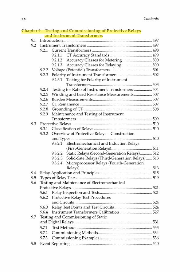
Chapter 9 Testing and Commissioning of Protective Relays and Instrument Transformers
9.1 Introduction ....................................................................................... 4979.2 Instrument Transformers ................................................................ 497
9.2.1 Current Transformers ........................................................... 4989.2.1.1 CT Accuracy Standards ......................................... 4999.2.1.2 Accuracy Classes for Metering .............................5009.2.1.3 Accuracy Classes for Relaying ..............................500
9.2.2 Voltage (Potential) Transformers ......................................... 5019.2.3 Polarity of Instrument Transformers ..................................502
9.2.3.1 Testing for Polarity of Instrument Transformers ............................................................503
9.2.4 Testing for Ratio of Instrument Transformers ..................5049.2.5 Winding and Lead Resistance Measurements .................. 5079.2.6 Burden Measurements .......................................................... 5079.2.7 CT Remanence ....................................................................... 5079.2.8 Grounding of CT ...................................................................5089.2.9 Maintenance and Testing of Instrument
Transformers ..........................................................................5099.3 Protective Relays ............................................................................... 510
9.3.1 Classifi cation of Relays ......................................................... 5109.3.2 Overview of Protective Relays—Construction
and Types ................................................................................ 5109.3.2.1 Electromechanical and Induction Relays
(First-Generation Relays) ........................................ 5119.3.2.2 Static Relays (Second-Generation Relays) ............ 5129.3.2.3 Solid-Sate Relays (Third-Generation Relays) ...... 5139.3.2.4 Microprocessor Relays (Fourth-Generation
Relays) ....................................................................... 5139.4 Relay Application and Principles ................................................... 5159.5 Types of Relay Tests .......................................................................... 5199.6 Testing and Maintenance of Electromechanical
Protective Relays ............................................................................... 5219.6.1 Relay Inspection and Tests ................................................... 5219.6.2 Protective Relay Test Procedures
and Circuits ............................................................................ 5249.6.3 Relay Test Points and Test Circuits ..................................... 5249.6.4 Instrument Transformers Calibration ................................ 527
9.7 Testing and Commissioning of Static and Digital Relays ............................................................................ 531
9.7.1 Test Methods ..........................................................................533
9.7.2 Commissioning Methods .....................................................534
9.7.3 Commissioning Examples ................................................... 536
9.8 Event Reporting ................................................................................540
DK4058_C000.indd xxDK4058_C000.indd xx 11/20/2008 10:17:58 AM11/20/2008 10:17:58 AM
Novin Pendar
Highlight
Contents xxi
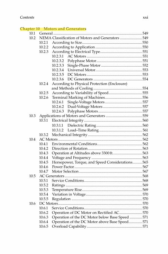
Chapter 10 Motors and Generators10.1 General .............................................................................................54910.2 NEMA Classifi cation of Motors and Generators .......................549
10.2.1 According to Size ...............................................................55010.2.2 According to Application .................................................55010.2.3 According to Electrical Type ............................................ 551
10.2.3.1 AC Motors .......................................................... 55110.2.3.2 Polyphase Motor ................................................ 55110.2.3.3 Single-Phase Motor ........................................... 55210.2.3.4 Universal Motor ................................................. 55310.2.3.5 DC Motors .......................................................... 55310.2.3.6 DC Generators ...................................................554
10.2.4 According to Physical Protection (Enclosure) and Methods of Cooling ...................................................554
10.2.5 According to Variability of Speed ................................... 55510.2.6 Terminal Marking of Machines ....................................... 556
10.2.6.1 Single-Voltage Motors ....................................... 55710.2.6.2 Dual-Voltage Motors ......................................... 55710.2.6.3 Polyphase Motors .............................................. 557
10.3 Applications of Motors and Generators ...................................... 55910.3.1 Electrical Integrity .............................................................560
10.3.1.1 Dielectric Rating ................................................560
10.3.1.2 Load–Time Rating ............................................. 56110.3.2 Mechanical Integrity ......................................................... 562
10.4 AC Motors ........................................................................................ 56210.4.1 Environmental Conditions ............................................... 56210.4.2 Direction of Rotation .........................................................56310.4.3 Operation at Altitudes above 3300 ft. ..............................56310.4.4 Voltage and Frequency .....................................................56310.4.5 Horsepower, Torque, and Speed Considerations ..........56510.4.6 Power Factor ....................................................................... 56710.4.7 Motor Selection .................................................................. 567
10.5 AC Generators .................................................................................56810.5.1 Service Conditions .............................................................56810.5.2 Ratings ................................................................................ 56910.5.3 Temperature Rise ............................................................... 56910.5.4 Variation in Voltage ........................................................... 57010.5.5 Regulation .......................................................................... 570
10.6 DC Motors ........................................................................................ 57010.6.1 Service Conditions ............................................................. 57010.6.2 Operation of DC Motor on Rectifi ed AC ........................ 57010.6.3 Operation of the DC Motor below Base Speed ............. 57110.6.4 Operation of the DC Motor above Base Speed .............. 57110.6.5 Overload Capability .......................................................... 571
DK4058_C000.indd xxiDK4058_C000.indd xxi 11/20/2008 10:17:58 AM11/20/2008 10:17:58 AM
Novin Pendar
Highlight

xxii Contents
10.7 DC Generators ................................................................................. 572
10.7.1 Service Conditions ........................................................... 57210.7.2 Ratings ............................................................................... 57210.7.3 Temperature Rise ............................................................. 57210.7.4 Overload Capability ......................................................... 57210.7.5 Voltage Excitation ............................................................. 57210.7.6 Overspeed ......................................................................... 572
10.8 Motor and Generator Insulation Systems ................................... 57210.8.1 Machine Insulation System ............................................ 572
10.9 Motor and Generator Maintenance .............................................. 57610.9.1 Failure Mechanisms ........................................................ 576
10.9.1.1 Stator-Winding Insulation ............................. 57610.9.1.2 Rotor-Winding Insulation ............................. 57710.9.1.3 Exciter Insulation ............................................ 577
10.9.2 General Inspection ........................................................... 57710.9.2.1 Visual Inspection ............................................ 578
10.9.3 DC Motors and Generators and Repulsion-Induction Motors ..........................................580
10.9.3.1 Cleanliness ......................................................58010.9.3.2 Armature ......................................................... 58110.9.3.4 Field Windings ................................................ 587
10.9.4 Induction Motor ................................................................58810.9.4.1 Stator Windings .............................................. 58910.9.4.2 Air Gap ............................................................. 58910.9.4.3 Wound-Rotor Windings ................................ 59010.9.4.4 Brushes and Rings .......................................... 59110.9.4.5 Centrifugal Switches ...................................... 59110.9.4.6 Squirrel-Cage Rotors ...................................... 591
10.9.5 Synchronous Motors and Generators ........................... 59210.9.6 Cleaning and Varnishing
of Machine Windings ...................................................... 59310.9.6.1 Cleaning ........................................................... 59310.9.6.2 Drying .............................................................. 59410.9.6.3 Varnish ............................................................. 595
10.9.7 Lubrication, Bearings, and Oil Seals ............................. 59610.9.7.1 Lubrication ....................................................... 59610.9.7.2 Sleeve Bearings ............................................... 59610.9.7.3 Antifriction Bearings ..................................... 59810.9.7.4 Installation of Oil Seals .................................. 599
10.9.8 Brushes ..............................................................................60010.9.8.1 Brush Adjustment ........................................... 601
10.9.9 Balancing ........................................................................... 60210.9.9.1 Need for Balancing .........................................60310.9.9.2 Imbalance Measurement ...............................603
10.9.10 Belts, Gears, and Pinions .................................................60310.9.10.1 Belts...................................................................60310.9.10.2 Gears and Pinions ..........................................604
DK4058_C000.indd xxiiDK4058_C000.indd xxii 11/20/2008 10:17:58 AM11/20/2008 10:17:58 AM

Contents xxiii
10.10 Predictive Maintenance Guide on Motors and Variable Frequency Drives ...................................................604
10.10.1 Power Quality .................................................................60510.10.2 Power Circuit................................................................... 61110.10.3 Insulation Condition ...................................................... 61510.10.4 Stator Condition .............................................................. 62110.10.5 Rotor Condition .............................................................. 62510.10.6 Air Gap.............................................................................630
10.11 Testing of Motors and Generators ..............................................64310.11.1 Insulation Resistance and Dielectric
Absorption Tests .............................................................65010.11.2 High-Potential Test .........................................................65010.11.3 PF Test .............................................................................. 65210.11.4 Dissipation Factor Tan d Test ........................................65310.11.5 Partial Discharge Test ....................................................65410.11.6 Slot Discharge Test ......................................................... 65710.11.7 Conductor Insulation Tests ........................................... 65710.11.8 Motor and Generator Component Tests ...................... 65710.11.9 Voltage Surge Comparison Test ................................... 659
10.12 Other Insulation Test Methods ...................................................66010.12.1 Very Low Frequency Testing ........................................66010.12.2 Series Resonant Testing ................................................. 662
10.13 Vibration Analysis ........................................................................663
Chapter 11 Electrical Power System Grounding and Ground Resistance Measurements
11.1 Introduction ...................................................................................66511.2 Selection of Grounding Method .................................................666
11.2.1 Ungrounded Systems ....................................................66611.2.2 Solidly Grounded Systems ............................................66811.2.3 Reactance and Resistance Grounded Systems ........... 66911.2.4 Resonant Grounding ...................................................... 67211.2.5 Grounding Ungrounded Systems ................................ 673
11.3 Selection of Grounding System ................................................... 67611.3.1 Solidly Grounded System .............................................. 67711.3.2 Low-Resistance Grounding .......................................... 67811.3.3 High-Resistance Grounding ......................................... 67911.3.4 Reactance Grounding .................................................... 67911.3.5 Ground-Fault Neutralizers (Resonant Grounded) .... 679
11.4 Understanding Ground Resistance ............................................68011.4.1 Grounding Electrode Resistance ..................................68011.4.2 Effect of Ground Electrode Size and Depth
on Resistance ................................................................... 68211.4.3 Effect of Soil Resistivity on Ground
Electrode Resistance.......................................................68411.4.4 Factors Affecting Soil Resistivity .................................68411.4.5 Effect of Ground Electrode Depth on Resistance ...... 687
DK4058_C000.indd xxiiiDK4058_C000.indd xxiii 11/20/2008 10:17:58 AM11/20/2008 10:17:58 AM
Novin Pendar
Highlight

xxiv Contents
11.5 Ground Resistance Values ............................................................. 68711.6 Ground Resistance Measurements .............................................. 689
11.6.1 Two-Point Method ............................................................ 68911.6.2 Three-Point Method ......................................................... 69011.6.3 Fall-of-Potential Method .................................................. 692
11.6.3.1 Position of the Auxiliary Electrodes on Measurements .............................................. 693
11.6.3.2 Measuring Resistance of Ground Electrodes (62% Method) ................................. 694
11.6.3.3 Auxiliary Electrode Spacing ........................... 69611.6.3.4 Multiple Electrode System ............................... 697
11.6.4 Ratio Method ..................................................................... 70011.6.5 Soil Resistivity Measurements (Four-Point
Measurement) .................................................................... 70111.6.6 Touch Potential Measurements ....................................... 70211.6.7 Clamp-On Ground Resistance Measurement ............... 704
11.6.7.1 Principle of Operation ...................................... 70411.6.7.2 In-Field Measurement ...................................... 70511.6.7.3 Transmission Towers ........................................ 70911.6.7.4 Central Offi ce Locations .................................. 710
11.7 Ground Grid Integrity Measurements ........................................ 710
Chapter 12 Power Quality, Harmonics, and Predictive Maintenance
12.1 Background ..................................................................................... 71512.2 PQ Concept and Fundamentals ................................................... 716
12.2.1 Types and Consequences of Electrical Disturbances .. 71712.3 Origins of PQ Problems and Harmonics .................................... 72612.4 Characteristics of Typical Linear and Nonlinear Loads ........... 729
12.4.1 Voltage and Current Characteristics of Nonlinear Loads ........................................................... 731
12.4.1.1 HD Terminology ............................................... 73112.4.1.2 Types of Nonlinear Loads ............................... 73212.4.1.3 PF Characteristics of Loads ............................. 73512.4.1.4 Phase Sequence of Harmonics ........................ 73912.4.1.5 Harmonic Generating Characteristics ........... 74212.4.1.6 Sensitivity to Harmonics ................................. 74212.4.1.7 Sensitivity to Voltage Variation ...................... 74312.4.1.8 Sensitivity to Voltage Flicker ........................... 74312.4.1.9 Sensitivity to Noise ........................................... 743
12.5 Effects of Harmonic on Power System Equipment and Loads ........................................................................................ 743
12.5.1 Basic Concepts on Effects of Harmonics ....................... 74412.5.1.1 Thermal Stress................................................... 74512.5.1.2 Insulation Stress ................................................ 74712.5.1.3 Load Disruption ................................................ 747
DK4058_C000.indd xxivDK4058_C000.indd xxiv 11/20/2008 10:17:58 AM11/20/2008 10:17:58 AM
Novin Pendar
Highlight

Contents xxv
12.5.2 Harmonic Effects on Power System Equipment ............................................................ 748
12.5.2.1 Transformers ................................................... 74812.5.2.2 Rotating Machines ......................................... 75112.5.2.3 Capacitor Banks .............................................. 75312.5.2.4 Switchgear ....................................................... 75612.5.2.5 Protective Relays ............................................ 75712.5.2.6 Metering Devices ............................................ 75812.5.2.7 Electronic Equipment .................................... 75812.5.2.8 Lighting Devices ............................................. 759
12.6 Predictive Maintenance and PQ Measurements ........................ 75912.6.1 Introduction ....................................................................... 75912.6.2 Safety Standards for Test Instruments .......................... 760
12.6.2.1 Test Instrument Standards ............................ 76012.6.2.2 Instruments for PQ Measurements ............. 762
12.6.3 PQ Measurement Guidelines .......................................... 76412.6.3.1 Preparation for Conducting
Measurements ................................................. 76412.6.3.2 Basic Power Measurements ........................... 76612.6.3.3 Measurements at the Receptacle
of a Branch Circuit .......................................... 76812.6.3.4 Measurement at the Service Panel ............... 77412.6.3.5 Measurements at the Transformer ............... 77812.6.3.6 Electrical Noise ............................................... 78712.6.3.7 Transients ......................................................... 79112.6.3.8 Lightning ......................................................... 79412.6.3.9 Polyphase Induction Motors ......................... 79512.6.3.10 PQ Measurements of VFDs ........................... 79812.6.3.11 Power System Resonance ...............................80012.6.3.12 Commercial Lighting Load ...........................80312.6.3.13 Summary of PQ Problems .............................804
12.7 PQ Solution and Power Treatment Devices ................................80612.7.1 Voltage Disturbances and Noise .....................................807
12.7.1.1 Noise Filters (Electronic Filters) ...................80812.7.1.2 TVSS ..................................................................80812.7.1.3 Voltage Regulators ..........................................80912.7.1.4 Isolation Transformers ................................... 81212.7.1.5 Power Conditioners ........................................ 81212.7.1.6 UPS ................................................................... 815
12.7.2 HDs ..................................................................................... 81712.7.2.1 Industry Standards on Limits
of Harmonics ................................................... 81812.7.2.2 Evaluating System Harmonics ...................... 81812.7.2.3 Harmonic Solutions—Mitigation
Devices and Methods ..................................... 82012.7.3 Wiring and Grounding Problems .................................. 823
DK4058_C000.indd xxvDK4058_C000.indd xxv 11/20/2008 10:17:58 AM11/20/2008 10:17:58 AM

xxvi Contents
Chapter 13 Electrical Safety, Arc-Flash Hazard, Switching Practices, and Precautions
13.1 Introduction ..................................................................................... 82713.2 Industry Standards and Regulatory Requirements
for Safety .......................................................................................... 82813.2.1 ANSI C2: The National Electrical
Safety Code-2007.............................................................. 82813.2.2 ANSI/National Fire Protection Association
(NFPA) 70, National Electrical Code (NEC)-2008 ........ 82913.2.3 ANSI/NFPA 70B, Standard for Electrical
Equipment Maintenance-2006 .......................................83013.2.4 ANSI/NFPA 70E, Standard for Electrical Safety
in the Workplace-2004 .....................................................83013.2.5 Occupational Safety and Health Administration
(OSHA) Standards ........................................................... 83713.3 Arc-Flash Hazard and Regulatory Requirements ..................... 839
13.3.1 Summary of NFPA 70, 70E, and OSHA Requirements ...................................................................... 841
13.3.2 Overview of Arc-Flash Hazard ..................................... 84113.3.3 Arc-Flash Analysis ..........................................................842
13.4 Electrical Safety Practices and Precautions ................................84413.4.1 Electrical Safety ...............................................................84413.4.2 “On-Site” Electrical Safety..............................................84413.4.3 “On-Site” Safety Kit .........................................................84513.4.4 Work Area Control ..........................................................84613.4.5 Lock-Out and/or Tagging ..............................................84813.4.6 Protective Apparel-Operating
Electrical Equipment .......................................................84913.4.7 Testing of Electrical Circuits
and/or Equipment ...........................................................85013.4.8 Rubber Gloves for Electrical Work-Use and Care ....... 85113.4.9 Low-Voltage Tester ..........................................................85413.4.10 Medium- and HV-Detectors ..........................................85513.4.11 Grounds-Personnel Protection ...................................... 857
13.5 Electrical Switching Practices and Precautions ......................... 85913.5.1 On-Site Circuit Breaker Maintenance
Safety Checklists ..............................................................85913.5.2 Confi ned Spaces—Procedure for Entering ..................86413.5.3 Electrical Precautions ...................................................... 869
13.5.3.1 General Precautions ........................................ 86913.5.3.2 Loads and Currents ........................................ 86913.5.3.3 Switch Sticks .................................................... 87013.5.3.4 Opening Disconnects by Using
the “Inching” Method .................................... 87113.5.3.5 Selector Disconnects ....................................... 87213.5.3.6 Circuit Breaker Disconnects .......................... 87213.5.3.7 Interrupter Switches ....................................... 873
DK4058_C000.indd xxviDK4058_C000.indd xxvi 11/20/2008 10:17:58 AM11/20/2008 10:17:58 AM
Novin Pendar
Highlight

Contents xxvii
13.5.3.8 Closing Disconnects under Load Conditions ............................................ 873
13.5.3.9 Air Break Switches ........................................ 87313.5.3.10 Protection against Air Break Flashover...... 87413.5.3.11 Motor-Controlled Disconnects
and Air Breaks ............................................... 87513.6 Electrical Fire Emergencies ........................................................... 875
13.6.1 Never Make Direct Contact with Any Energized Object .............................................................. 875
13.6.2 Stay Clear of Vicinity of Any Faulty Energized Object ............................................................. 876
13.6.3 Be Alert in Vicinity of Any Energized Object ............ 87613.6.3.1 Beware of Covered Wires ............................. 87713.6.3.2 Beware of Telephone Cables ........................ 877
13.6.4 Assume Every Fallen Wire Is Energized and Dangerous ................................................................. 877
13.6.4.1 Wire on Ground............................................. 87713.6.4.2 Wire on Object ............................................... 87713.6.4.3 Wire on Vehicle .............................................. 878
13.6.5 Never Cut Wires Except to Protect Life ....................... 87813.6.5.1 Take Care after Cutting ................................ 87813.6.5.2 Cutting Service Wires ................................... 878
13.6.6 Use Approved Procedures and Equipment If You Must Work Near Energized Facilities ............... 879
13.6.7 Avoid Using Hose Streams on Energized Facilities .........................................................880
13.6.8 Be Equally Alert Indoors and Outdoors ......................88013.6.9 Protect People and Property in Surrounding
Area and Do Not Fight Fires on Electric Equipment Until an Electric Company Representative Arrives ........ 881
13.6.10 Hose Streams May Be More Hazardous than Helpful Until Any Underground Fault Is De-Energized ...................................................... 882
13.7 Effects of Electrical Shock ..............................................................88313.8 First Aid............................................................................................884
13.8.1 Shock .................................................................................88513.8.2 Resuscitation .....................................................................88513.8.3 Resuscitation—Mouth-to-Mouth (Nose) Method .......88613.8.4 Important Points to Remember .....................................88613.8.5 Two-Victim Method of Resuscitation—Mouth-to
Mouth (Nose) ....................................................................88713.8.6 External Heart Compression .......................................... 887
Appendix A ............................................................................................... 889Appendix B ................................................................................................ 913Bibliography .............................................................................................. 917Index .......................................................................................................... 935
DK4058_C000.indd xxviiDK4058_C000.indd xxvii 11/20/2008 10:17:58 AM11/20/2008 10:17:58 AM

DK4058_C000.indd xxviiiDK4058_C000.indd xxviii 11/20/2008 10:17:58 AM11/20/2008 10:17:58 AM

xxix
Series Introduction
When the fi rst edition of this book was published 10 years ago, it was a particularly timely addition to the Marcel Dekker series on power system engineering. The power industry was beginning to be challenged by “aging infrastructures”—areas within local and regional power grids where a good deal of equipment was quite old and in a few cases much deteriorated. Maintenance, particularly testing to determine condition and prescribe proper service and refurbishment, was receiving more attention than it had in decades.
But now, more than ever, there are factors beyond just the need to evaluate old equipment that are creating a heightened focus on sound maintenance and testing throughout the electric power industry. Equipment manufactur-ers have honed computer-aided design models to the point where they can shave design margins and engineer wear and deterioration rates with great precision, all to the purpose of reducing fi rst cost, something they are forced to do in a world where much of the market buys mostly on the basis of lowest fi rst cost. This means that comprehensive testing and “by the book” mainte-nance of equipment are critical earlier in the life cycle, because today’s new equipment has little margin for skipped maintenance or continued deterio-ration; it works well only if maintained in good condition. In addition, new materials, designs, and testing methods mean the proper matching of testing and maintenance to specifi c equipment is more intricate and involved than ever. New technologies like online condition monitoring create opportuni-ties to improve operations and effi ciency. Finally, evolving concerns and standards, such as those regarding arc-fl ash, create a need for renewed focus in some areas.
Electric Power Equipment Maintenance and Testing, Second Edition is a thorough update of the fi rst edition, with revised material and additions throughout, including new discussions on arc-fl ash, online condition monitoring, uninter-ruptible power supply testing, motor vibration analysis, and current industry safety requirements to name just a few. In addition, it has two new chapters that provide enhanced focus on a pair of critical areas in power system testing: testing and commissioning of protective relays and instrument transformers; and power quality and harmonics, and their effects on electrical equipment.
As the editor of the Power Engineering Series, I am proud to include Electric Power and Equipment Maintenance and Testing, Second Edition among this important group of books. During the past decade, I found the fi rst edition to be among those I most often used in my work. This second edition is as well organized and indexed as the fi rst, so that it will make a good reference in day-to-day work, with key material easy to fi nd and concisely presented. Yet it is written in an accessible, linear style so that it is also a good tutorial
DK4058_C000.indd xxixDK4058_C000.indd xxix 11/20/2008 10:17:58 AM11/20/2008 10:17:58 AM

xxx Series Introduction
for those who are not familiar with the material. Since these are qualities I strive for in my books, I know how diffi cult it is for an author to achieve them well and as a result value Paul Gill’s new book all the more.
Like all the books in the Power Engineering Series, Electric Power Equipment Maintenance and Testing, Second Edition puts modern technology in a context of proven, practical application; useful as a reference book as well as for self-study and advanced classroom use. The Power Engineering Series includes books covering the entire fi eld of power engineering, in all of its specialties and subgenres, all aimed at providing practicing power engineers with the knowledge and techniques they need to meet the electric industry’s chal-lenges in the twenty-fi rst century.
H. Lee Willis
DK4058_C000.indd xxxDK4058_C000.indd xxx 11/20/2008 10:17:58 AM11/20/2008 10:17:58 AM
xxxi
Foreword
Paul Gill’s original book, Electrical Equipment Testing and Maintenance (1982), and the fi rst edition, Electrical Power Equipment Maintenance and Testing published in 1997, were the fi rst two books that addressed the practical aspects of electrical testing and maintenance of power system equipment and apparatus. Both books presented testing methodologies and engineering basics on the subject of electrical testing and maintenance in one volume. Considered the electrical test-ing and maintenance “bible,” Electrical Power Equipment Maintenance and Testing has been the leading treatise on the subject and an essential reference book for engineers and technicians concerned with the maintenance and testing of elec-trical power system equipment and apparatus. Both of these textbooks were a must read for the plant electrical engineer and plant maintenance technician as well as for electrical engineering graduates and students. The fi rst edition has become a required reading for institutions offering electrical testing and main-tenance curricula. The fi rst edition has also been an invaluable aid for techni-cians studying for the InterNational Electrical Testing Association’s (NETA) levels II, III, and IV test technician examinations and is a valued reference for engineers and technicians in the electrical testing industry.
The second edition contains major revisions and is an improvement of the fi rst edition. It represents a great deal of effort and study on the part of the author to compile, sort, and apply information and data supplied by manufac-turers and allied industries together with that made available by relevant industry standards, institutions, and associations. The second edition is an invaluable book for practicing engineers, technicians, managers, and others who are involved in the testing, maintenance, and care of electrical equip-ment and apparatus, as well as engineering students pursuing further studies in this fi eld. This new book has been substantially enhanced by the addition of updated information on various subjects.
For example, Chapter 1 has been revised to include information on reliability centered maintenance (RCM), insulating materials and insulation systems of electrical equipment, causes of insulation failure and failure modes of electrical equipment, temperature ratings, and the relationship between maintenance and arc-fl ash hazard. Chapter 5 has been revised to include the latest tests per-formed on transformers including online monitoring tests. Chapter 6 has been revised to include cable degradation and diagnostic online and off-line tests such as PF, VLF, and partial discharge; summary/comparison of various fi eld tests; and latest trends in cable diagnostic testing. Major revisions have been made to Chapter 7; the section on circuit breaker time travel has been expanded to fully cover how the test is to be conducted and evaluated, and the protective relays and instrument transformers previously covered in this chapter are now covered in a separate chapter. The revisions to Chapter 8 include assessing ser-vice life and endurance requirements for low-voltage breakers, mechanical
DK4058_C000.indd xxxiDK4058_C000.indd xxxi 11/20/2008 10:17:58 AM11/20/2008 10:17:58 AM
xxxii Foreword
maintenance factors such as lubrication, electrical maintenance factors, and information on how to conduct thermographic surveys. The original Chapter 9 now covers testing and commissioning of protective relays and instrument transformers. Instrument transformers and electromechanical, solid-state, static and microprocessor relays including event reporting have been cov-ered in greater detail with examples in Chapter 9. Chapter 10 now covers motors and generators, and it has been revised to include an extensive guide on preventative maintenance of motors and variable frequency drives. In this chapter, a discussion section has been added on the online and off-line partial discharge testing and vibration analysis of motors. A new Chapter 12 has been added to cover power quality and hormonic issues and their rela-tionship to predictive maintenance since many causes of equipment failure are being attributed to poor power quality. A new Chapter 13 covers the contents of the original Chapter 11. This chapter now includes a detailed discussion on arc-fl ash hazard regulatory basis, and how to perform an arc-fl ash hazard study.
The revised second edition contains a wealth of new information, along with the original information in the fi rst edition, with tables, formulas, dia-grams, line drawings, and photographs. Also, in this book, the text has been consolidated under each subject heading to facilitate easier reading and to locate information. The original chapters have been updated to include the latest information on testing and test methods and two new chapters have been added to cover additional subjects. The whole book has been orga-nized to make it reader-friendly. The information contained herein will prove even more useful than that contained in the fi rst edition. The reader will fi nd this book an invaluable resource on insulation materials and sys-tems, aging stressors and failure modes of power equipment, and for rou-tine fi eld (in situ) testing of electrical power system equipment and apparatus. Also, in the revised second edition, the author has superbly explained the relationship between poor power quality and harmonics result-ing from the application of nonlinear loads, and how it can impact insulation systems of power apparatus. In this book, the author has explained various rules of thumb that exist in the industry for evaluating insulation test results and why they should not be followed blindly. We believe this is the only book that makes a signifi cant attempt to address this issue. We congratulate Gill for superbly improving on an excellent original book. We wholeheartedly recommend the new book to the reader.
Alan D. PetersonTechnical Committee Chairman
InterNational Electrical Testing Association
Jayne TanzExecutive Director
InterNational Electrical Testing Association
DK4058_C000.indd xxxiiDK4058_C000.indd xxxii 11/20/2008 10:17:58 AM11/20/2008 10:17:58 AM

xxxiii
Preface
This edition has been devoted to the subject of maintenance and testing of electrical power equipment and apparatus. It covers all types of apparatus and equipment found in electrical power systems serving industrial and commercial facilities, large institutional complexes and offi ce buildings, and utility type substations and generating plants. This book is an outgrowth of my work teaching courses on maintenance and testing of electrical power system apparatus and equipment over the last 30 years. Electrical equip-ment maintenance and testing are subjects that have assumed greater impor-tance these days because of the detailed attention they are receiving from professional societies, insurance companies, government regulators, manu-facturers, and owners. There exists considerable interest among people who operate and maintain electrical power systems in a wide range of topics relating to equipment maintenance and testing. This is because condition and reliability are directly related to maintenance and testing. To obtain maximum life from electrical equipment, maintain its reliability, and minimize repair costs, it is necessary to service and test it periodically to predict its condition. More attention is being directed to the maintenance and safe operation of electrical equipment. Many municipalities are mandating regulations and codes for periodic inspection and testing of large electrical facilities under their jurisdictions; the federal government has passed laws for the mainte-nance of commercial nuclear power plants (maintenance rule), and insur-ance companies are basing their premiums on the quality of a facility’s maintenance program and equipment condition. Attitudes are changing and it is no longer true that maintenance is something the industry must tolerate and learn to live with; preventive and predictive maintenance instead of “necessary” maintenance is now the preferable option and is being increasingly adopted.
In the past, the subject of electrical equipment maintenance and testing was promoted mostly by electrical power equipment and electrical test equipment manufacturers, utilities, and professional societies and organi-zations, such as the IEEE, ANSI, NEMA, and others. These bodies and enti-ties continue to publish a majority of the requirements for maintenance and testing. To the best of my knowledge, there is no comprehensive book that addresses this subject to the level previous editions of my book have covered. There are other books on the market that address maintenance of individual equipment but I am not aware of any book that covers the subject as com-prehensively as this book does. Although many of the basic principles, including theory and practices, have not been affected by the latest techno-logical advancements in this fi eld, there have been changes in the practices of certain applications and instrumentation. In this revised edition, I have attempted to consolidate and coordinate the latest advances in the fi eld into
DK4058_C000.indd xxxiiiDK4058_C000.indd xxxiii 11/20/2008 10:17:58 AM11/20/2008 10:17:58 AM

xxxiv Preface
a comprehensive and understandable text. In addition, this book provides a guide for evaluating the test results of each category of testing. This infor-mation is not usually found in other publications, and I consider it the strength of this book.
This book also provides practical information on the maintenance and test-ing of electrical equipment for maintenance personnel who install and main-tain such equipment. The scope of this book is both very broad and specialized. Therefore, to carry out the test procedures and maintenance practices discussed in this book, one must either have or acquire the necessary knowledge to carry them out successfully and safely. The original Chapter 1 has been expanded to include information on reliability center maintenance (RCM), insulating mate-rials and insulation systems of electrical equipment, causes of insulation fail-ures and failure modes of electrical equipment, temperature ratings, and the relationship between maintenance and arc-fl ash hazard analysis. It retains the original material on dielectric theory, testing methods, and maintenance plan-ning. The new material provides a clear understanding concerning what fails within power equipment and how the equipment fails. Once a clear under-standing of the failure modes of equipment is established, correct maintenance strategies can be developed to address such failures before they happen. Also, an extensive discussion has been undertaken on the basis of maintenance of protective devices and how such maintenance, or lack of such maintenance, will impact the arc-fl ash hazard exposure, hazard labeling of equipment, and personnel protective equipment. Chapter 2 has been devoted to testing with direct current (DC) voltage of various types of electrical equipment and appa-ratus, including its advantages and disadvantages. Chapter 3 deals with testing with alternating current (AC) voltage, for example, power factor (Doble) and dissipation factor (Tan Delta) test methods. Advantages as well as limitations of the AC voltage methods are discussed to provide a thorough understanding of this subject. Chapter 4 covers the testing of oil and insulating fl uids used in electrical apparatus such as transformers and circuit breakers. The description of maintenance and test methods includes typical problems found in these types of insulation systems.
In Chapter 5, information on transformer maintenance and testing, includ-ing installation, application, and operation as it relates to the reliability of transformers, is discussed. This chapter has been expanded to include the latest tests performed on transformers including online monitoring and diagnostic tests. Chapter 6 has been devoted to the discussion of cables, including their construction, application, failure modes, and testing, as well as cable fault locating methods. The section on cable testing in this revision now includes information on cable degradation and diagnostic tests; online and off-line tests such as PF, VLF, partial discharge, and AC resonance; a summary of comparison of various fi eld tests; and latest trends in cable diagnostic testing. Chapter 7 has been revised to solely cover inspection, maintenance, and testing of medium- and high-voltage switchgear and con-trol power. Information has also been provided on the rating system used for circuit breakers and how these are selected and applied in switchgear
DK4058_C000.indd xxxivDK4058_C000.indd xxxiv 11/20/2008 10:17:58 AM11/20/2008 10:17:58 AM

Preface xxxv
applications. Additional information has been provided on circuit breaker time travel analysis to explain this test in more detail and how this test can be used to ensure the reliability of medium- and high-voltage breakers. Chapter 8 is devoted to the maintenance and testing of low-voltage (below 1000 V) switchgear and circuit breakers. This chapter provides information on Underwriters Laboratories’ testing, labeling, and verifi cation of these break-ers in the fi eld. Additional information has been provided in this chapter on assessing service life and endurance requirement for low-voltage breakers, mechanical maintenance factors such as lubrication, electrical maintenance factors, and information on how to conduct thermographic surveys.
A new Chapter 9 covers instrument transformers and testing and commis-sioning of protective relays. The information in this chapter explains the theory, application, and testing of instrument transformers, and electrome-chanical, solid-state, static, and microprocessor relays. The commissioning of microprocessor relays including event reporting has been covered in greater detail with examples of commissioning microprocessor relays in this chapter. The protective relays, especially microprocessor relays, are an important part of the power system; hence they are retained in the respective chapter in this edition. The maintenance and testing of motors and generators, including the makeup of the insulation systems used in these machines and their tempera-ture rating system, are covered in the new Chapter 10. This chapter has been revised to include an extensive guide on preventative maintenance of motors and variable frequency drives. In this chapter, a detailed discussion has been added on online and off-line partial discharge testing and vibration analysis of motors. The original Chapter 10 has been renumbered as Chapter 11, which covers electrical power system grounding and ground resistance measure-ments. Various grounding systems are described to provide an understand-ing on what is a good ground and how to obtain it. A new Chapter 12 has been added in this revision to cover power quality and harmonic issues and their relationship to predictive maintenance since many of the causes of equipment failures are now being attributed to poor power quality and har-monics. It is expected that the information in this chapter will help the reader understand poor power quality and how it can affect the health and reliabil-ity of electrical equipment and apparatus. It is hoped that the monitoring of power quality will receive the required attention so corrective actions can be implemented to minimize equipment degradation and failures.
On-site safety and switching practices required during maintenance and testing of electrical equipment are now covered in Chapter 13, as are National Electrical Code (NEC), National Safety Code, and OSHA requirements as they relate to the maintenance and testing of electrical equipment as well as arc-fl ash hazard analysis and exposure. A new section has been added in this chapter on arc-fl ash hazard regulatory basis, what it is, and how to perform an arc-fl ash hazard study.
It is hoped that this book will serve as a practical guide that engineers and technicians can use for the maintenance and testing of electrical equip-ment. To make this book useful, many tables, test connection diagrams, and
DK4058_C000.indd xxxvDK4058_C000.indd xxxv 11/20/2008 10:17:58 AM11/20/2008 10:17:58 AM

xxxvi Preface
photographs are provided throughout the book. One of the complicated aspects of testing is the interpretation of test results—it is diffi cult to judge how good or bad test results are unless the previous year’s test results are available for comparison. Various minimum values are used as rules of thumb for assessing the relative health of the insulation of electrical equip-ment. In this book, I have provided some insights on these rules of thumb and why they should not be followed blindly. It is my belief that the knack for interpreting test results can be gained only by acquiring this knowledge and hopefully this book fulfi lls this need. To a great extent this is the only book that makes a signifi cant attempt to address this issue.
I hope that this book may prove useful both to budding and experienced engineers alike. With this book they can acquire the needed knowledge and application to pursue further studies in this fi eld. I believe that most aspects of this subject that were thought to be necessary are covered in this revision. It is possible that some aspects of this subject are not covered, or in detail to the extent necessary for a good understanding of the subject. I would welcome and appreciate any suggestions from readers to make this book even more useful and current.
Paul Gill, P.E.
DK4058_C000.indd xxxviDK4058_C000.indd xxxvi 11/20/2008 10:17:58 AM11/20/2008 10:17:58 AM

xxxvii
Acknowledgments
This book is based on my notes and my previous two volumes, Electrical Equipment Testing and Maintenance (1982), and Electrical Power Equipment Maintenance and Testing (1997), which were used in teaching a course on elec-trical equipment maintenance and testing at the George Washington University and at IBEW Local 26. The production of a book requires the coop-eration and effort of many people and institutions. It is diffi cult to appropri-ately acknowledge all the organizations and individuals who helped in the development of a book of this type.
I would particularly like to thank the major electrical manufacturers, test-ing services companies, electrical test equipment manufacturers, various private and government organizations, and professional societies and orga-nizations for making information available. Where possible, I have tried to give recognition to the source of the information obtained.
I wish to acknowledge explicitly the following organizations and persons for their review and support in the development of this book. The staff of Megger Incorporated, Valley Forge, Pennsylvania (formerly AVO Inter-national, Dallas, Texas) reviewed and provided comments on Chapters 2 and 6. Additionally, I thank the various staff at Megger Incorporated for help-ing to teach cable fault locating in a course on maintenance and testing at the George Washington University and providing review comments on the section on cable fault locating in Chapter 6. The information on power factor testing in Chapter 3 is based on the Double Engineering Company’s litera-ture and their past contributions in teaching maintenance and testing courses at the George Washington University. I am also grateful to them for review-ing and commenting on Chapter 3. The information in Chapter 4 on dis-solved gas analysis is condensed from the IEEE std. C57.104-1991. I thank the personnel of Baron USA, Inc., Cookville, Tennessee for providing an overall review and comments on Chapter 4. Alan Peterson of Utility Services and chairman of the NETA Technical Committee peer-reviewed many chapters for this revision and I thank him for his support. The information on ground resistance measurements and testing was supplied by AEMC Instruments, Boston, Massachusetts, and for which I thank them.
In addition, I want to thank the following persons and organizations for contributing and providing information, material, and doing the peer review for the following portions of the book in this revision: Joe Mooney, manager of Power Engineering, Schweitzer Engineering Laboratories (SEL) who helped in writing, commissioning, and testing of microprocessor relays in Chapter 9 and reviewing that chapter; Noah Bethel of PdMA for providing material on the predictive maintenance guide on motors and variable fre-quency drives including photographs and illustrations, and for reviewing this section in Chapter 10; Dennis K. Neitzel, director of AVO Training
DK4058_C000.indd xxxviiDK4058_C000.indd xxxvii 11/20/2008 10:17:58 AM11/20/2008 10:17:58 AM

xxxviii Acknowledgments
Institute, Dallas, Texas, for providing information and reviewing the write-up on the bases of maintenance and testing of protective devices as they relate to arc-fl ash hazard described in Chapter 1; Ed St. Germain of EMR for providing material on the RCM program and its implementation; Mark Meyer and Mike Hensley of Megger Incorporated for providing photographs of Megger instruments and contributing to the section on circuit breaker time-travel analysis given in Chapter 7; Eric Black of Black and Associates for pro-viding photographs of the thermographic surveys in Chapter 8; Ashok Anand of On-line Monitoring Incorporated for providing information and photo-graphs on the online monitoring system for bushings and lightning arrestors; Siemens Corporation for providing information and photographs on the online monitoring of transformers in Chapter 5; Jonathan Blaisdell and Leah Mattheis of Fluke Instruments for providing information and reviewing Chapter 12 on power quality; and Alan Peterson of Utility Services and chairperson of the NETA Technical Committee for peer- reviewing various chapters of the book.
I also wish to thank Alan D. Peterson and Jayne Tanz of the InterNational Electrical Testing Association for writing the Foreword and recommending the book. Finally, I thank all my students who have taken the maintenance and testing course at the George Washington University and the IBEW Local 26 who made it possible for me to teach and write this book in the fi rst place.
DK4058_C000.indd xxxviiiDK4058_C000.indd xxxviii 11/20/2008 10:17:58 AM11/20/2008 10:17:58 AM
1
1Maintenance Strategies, Dielectric Theory, Insulating Materials, Failure Modes, and Maintenance Impact on Arc-Flash Hazards
1.1 Introduction
The deterioration of electrical equipment is normal, and this process begins as soon as the equipment is installed. If deterioration is not checked, it can cause electrical failures and malfunctions. In addition, load changes or circuit alterations may be made without overall design coordination, which can result in improper selection of equipment, or settings of protective devices, or wrong trip devices installed in the circuits. The purpose of an electrical preventive maintenance (EPM) and testing program should be to recognize these factors and provide means for correcting them. With an EPM and testing program, potential hazards that can cause failure of equipment or interruption of electrical service can be discovered and corrected. Also, the EPM program will minimize the hazards to life and equipment that can result from failure of equipment when it is not properly maintained. Properly maintained equipment reduces downtime by minimizing catastrophic fail-ures. To carry out the successful operation of electrical equipment and appa-ratus, it is essential to set up an effective maintenance and testing program. This program can be implemented by setting up a maintenance department or by contracting the work to a private company engaged in this practice.
The EPM program should consist of conducting routine inspections, tests, repairs, and service of electrical power system apparatus such as transformers, cables, circuit breakers, switchgear assemblies, and the like, along with associ-ated equipment comprised of control wiring, protective devices and relays, supervisory equipment, and indicating and metering instruments.
1.2 Why Maintain and Test
A well-organized and implemented program minimizes accidents, reduces unplanned shutdowns, and lengthens the mean time between failures (MTBF) of electrical equipment. Benefi ts of EPM can be categorized as direct
DK4058_C001.indd 1DK4058_C001.indd 1 11/17/2008 12:17:14 PM11/17/2008 12:17:14 PM

2 Electrical Power Equipment Maintenance and Testing
and indirect. Direct benefi ts are derived from reduced cost of repairs, reduced downtime of equipment, and improved safety of personnel and property. Indirect benefi ts can be related to improved morale of employees, better workmanship, increased productivity, and the discovery of defi ciencies in the system that were either designed into the original system or caused by later changes made in the system.
1.3 Overview of Electrical Maintenance
and Testing Strategies
Much of the essence of effective electrical equipment preventive maintenance (PM) can be summarized by four rules:
Keep it dry.•
Keep it clean.•
Keep it cool.•
Keep it tight.•
More specifi cally, most electrical power and control equipment is susceptible to a relatively small number of mechanisms of degradation, and the purpose of most EPM activities is to prevent them, retard them, or mitigate their effects. There are number of traditional philosophical approaches to electrical maintenance, such as run-to-failure (RTF), maintain as necessary, perform maintenance on fi xed time schedules, and predictive maintenance, which are briefl y summarized in the following sections. The reliability-centered main-tenance (RCM) program is gaining favor because it combines the strengths of reactive, preventive, predictive, and proactive maintenance strategies. The RCM approach to electrical equipment is discussed in a greater detail than other maintenance strategies because it is becoming a maintenance program of choice. However, most power utilities, manufacturing fi rms, and owners of plant facilities utilize a combination of these programs. The decision as to which approach to adopt is largely dependent on the scope of system and equipment, as well as a function of how management views the cost and benefi ts of maintenance.
RTFIn this approach, EPM per se is not performed at all. Degraded equipment is only repaired or replaced when the effect of degradation on process output becomes unacceptable. (For most types of electric power equipment, this coincides with catastrophic failure.) No explicit attempt is made to monitor performance or to avert failure, and the risks associated with ultimate failure are accepted. Because of the generally high reliability of electric power equip-ment installed in a benign environment, the RTF approach often provides satisfactory power reliability and availability in noncritical applications.
DK4058_C001.indd 2DK4058_C001.indd 2 11/17/2008 12:17:14 PM11/17/2008 12:17:14 PM

Maintenance Strategies, Dielectric Theory 3
Small organizations which lack dedicated maintenance staffs often utilize this approach by default, and larger and more sophisticated organizations in the manufacturing sector also frequently apply it to noncritical equipment and sys-tems. This maintenance strategy is also referred to as reactive maintenance.
Inspect and service as necessaryThis approach is an advance beyond RTF wherein plant operating or maintenance personnel inspect electrical equipment on a more or less regular schedule (often during regular rounds of the plant). Under this approach, incipient failures are usually corrected before they become catastrophic, espe-cially if the impact of a failure is considered unacceptable, and there is often some informal monitoring of performance to predict future failures. Many industrial manufacturing plants use this approach and fi nd it satisfactory.
Time-based maintenanceThe time-based maintenance (TBM) strategy is also known as scheduled PM. In this approach, established EPM activities are performed at fi xed intervals of calendar time, operating hours, or operating cycles. Both procedures and schedules are usually based on manufacturers’ recommendations or industry standards. While the scheduled EPM approach ensures that equipment gets periodic attention, it does not necessarily prioritize EPM according to safety or productivity signifi cance, nor does it optimize the application of limited EPM resources or take advantage of lessons learned from plant and industry experience. Scheduled EPM currently is the predominant approach among relatively sophisticated operators of plants where productivity and safety is a serious concern.
Condition-based maintenanceThe condition-based maintenance (CBM) strategy is also called predictive maintenance. It is an extension of the TBM strategy and uses nonintrusive testing techniques to assess equipment condition. It uses planned mainte-nance tasks that are based on equipment’s previous operating history, and trending of the maintenance data. It is most effective when combined with a PM program because it prioritizes EPM based on criticality of equipment, productivity, resources, or lessons learned from experience.
RCMIt is a maintenance strategy where equipment condition, criticality, failure history, and life cycle cost are integrated to develop logically the most effec-tive maintenance methods for each system, subsystem, and components. RCM capitalizes on the respective strengths of reactive, preventive, predic-tive, and proactive maintenance methods to maximize equipment reliability and availability. It is an ongoing process that continuously refi nes and rede-fi nes each maintenance activity.
The RCM process reduces the uncertainty inherently associated with the operational reliability of equipment by managing the risk through the peri-odic assessment of equipment condition. By using the proper instrumenta-tion, the ability to determine the current equipment condition, changes from
DK4058_C001.indd 3DK4058_C001.indd 3 11/17/2008 12:17:14 PM11/17/2008 12:17:14 PM

4 Electrical Power Equipment Maintenance and Testing
the baseline, and margin to failure, limits are readily determined. This allows the maintenance and operations staff to quantify the risk associated with continued operation or maintenance deferment, and to identify the most probable cause of the problem to the component level. In the majority of cases, condition testing is nonintrusive, allowing equipment condition assessments to be performed with the equipment operating under normal, loaded conditions.
The concept of RCM has evolved considerably over time when one applies it to facility maintenance. Historically, there was an intuitive belief that because mechanical parts wear out over time, equipment reliability is directly related to operating age. The belief was that the more frequently that equip-ment was overhauled, the better protected it would be against failure. Industry increased PM to include nearly everything.
In the 1970s, the airline industry found that many types of failure could not be prevented regardless of the intensity of maintenance. Actuarial analysis of failure data suggested that PM was ineffective by itself in controlling failure rates. And for many items, failure rates did not increase with increased oper-ational use. In the 1980s, early forms of condition monitoring devices came on the market and coincided with microprocessors and a new computer literacy . RCM theory was refi ned and adopted by the US Navy’s submarine fl eet. It was shown that in many cases, scheduled overhaul increases the overall failure rate by introducing new infant mortality probability into an otherwise stable system.
What has evolved is a complementary program—rigorous and stream-lined—that has its most appropriate applications based on the consequences of failure, the probability of failure, historical data, and the amount of risk willing to be tolerated.
Rigorous RCM in its original concept involves a heavy reliance on detailed failure modes and effects analyses; math-calculated probabilities of failure; model development and accumulation of historical data. It provides the most detailed knowledge on a specific system and component and provides the most detailed documentation. Because of the detail involved, it is highly labor intensive, time-consuming, and comparatively expensive. The most appropriate applications of RCM are when the consequences of failure would result in a catastrophic risk to personal safety and health, to the environment, or could result in complete economic failure of an organization.
Plant managers adopted a streamlined RCM approach recognizing its benefi ts while realizing that few building mechanical and electrical sys-tems carry the catastrophic risk addressed in the rigorous RCM process. Lower intensity more in line with the scale of a facility’s infrastructure also meant lower costs. Streamlined RCM targets systems and components in order of criticality. It relies heavily on condition-based tasks and elimi-nates low-value maintenance tasks altogether based on maintenance and operations staff input and historical data. It minimizes extensive analysis in favor of fi nding the most obvious, costly problems early-on, capitalizes on the early successes, and then expands outward in a continuous fashion.
DK4058_C001.indd 4DK4058_C001.indd 4 11/17/2008 12:17:14 PM11/17/2008 12:17:14 PM

Maintenance Strategies, Dielectric Theory 5
Streamlined RCM requires a thorough understanding of condition monitoring technologies as well as analytical techniques, including root cause failure analysis (RCFA), trend analysis, and failure modes and effects analysis (FMEA). With some exceptions streamlined RCM is the philosophy of choice in plant maintenance programs.
Failure: RCM defi nes failure as any unsatisfactory condition. It may be a loss of function, where a system or component stops running altogether, or it may be a loss of acceptable quality, where operation continues, but at a substandard or inadequate quality. A failure may be catastrophic or merely out of tolerance.
As stated, RCM seeks the optimum mix of four maintenance strategies: reactive (RTF), preventive (time-directed), predictive (condition-directed), and proactive (failure-fi nding). Most common elements of each maintenance strategy are illustrated in Figure 1.1. The application of the various elements of the four maintenance strategies for an automobile RCM program is shown in Figure 1.2.
The mix: Maintenance activity at facilities typically run about 80%–85% reactive (service requests, trouble calls, repairs), 15% preventive, 1% predic-tive, and 1% proactive. Goals for effective maintenance programs should be in the range of 30%–35% for reactive maintenance, 30%–35% for PM, 25% for predictive maintenance, and 10% for proactive maintenance.
In addition to improving reliability, this maintenance mix will have a size-able impact on the cost of maintenance: breakdowns and repairs typically cost about $17–18 per installed horsepower (hp)/year, preventive costs about $11–13 per installed hp/year, and predictive maintenance costs about $7–9 per installed hp/year.
FIGURE 1.1Common applications of maintenance strategies for RCM program. (From St. Germain, E. and
Pride, A., NASA Facilities RCM Guide, 1996, p. 1-1. With permission.)
Reliabilitycentered
maintenance
Reactivemaintenance
(run-to-failure)(RTF)
Preventivemaintenance(time based)
Predictivemaintenance
(conditionbased)
Small items;noncritical;inconsequential;unlikely to fail;redundancy
Subject to wear;consumablereplacement;known failurepattern
Random failurepatterns;not subject towear;PM-inducedfailures
RCFA;A&E design;age exploration;FMEA
Typically:
Proactivemaintenance
(improvement)
DK4058_C001.indd 5DK4058_C001.indd 5 11/17/2008 12:17:14 PM11/17/2008 12:17:14 PM

6 Electrical Power Equipment Maintenance and Testing
A decision logic tree shown in Figure 1.3 may be used as a starting point to determine the appropriate maintenance strategy for a given system or compo-nent. Various maintenance strategies are discussed in the following sections.
Reactive maintenance: It involves repair or replacement only when deteriora-tion of the condition causes a functional failure. The unit breaks down. Reactive maintenance assumes that failure is equally likely to occur in any part, component, or system. If an item fails and parts are not available, delay will occur. Management has no infl uence on when the failure will occur (usually at the most inopportune time) and a premium will be paid for urgent attention. When this is the sole type of maintenance practiced, there is typi-cally a high percentage of unplanned maintenance, a large replacement parts
RTF-wipers
Time-oil change
RTF-lamps
Time-inspect belts
Time-inspect fluids
Time-inspect tread Condition-replacepads, turn rotor
Condition-replace tire
Proactivelessonslearned incorporatedinto next year’s model;failure research; userfeedback and trends
RTF-lamps
Time-inspect exhaust
Condition-wash and wax
FIGURE 1.2An example of proactive maintenance applied to an automobile. (From St. Germain, E. and
Pride, A., NASA Facilities RCM Guide, 1998, p. 1-7. With permission.)
No
Yes
Yes
Yes
NoNo
No
No
Yes
Yes
Yes
Will failure have a direct andadverse impact on environ.,health, security, and safety?
Run to fail?Redesign system;accept failure or
risk; installredundancy
Develop andperform
interval-basedtask
Performcondition-based task
Will failure result in higheconomic loss?
Will failure have a direct andadverse impact on mission?
Is there an effective CMapproach?
Is there an effective interval-based task?
Develop and schedule CM task tomonitor condition
FIGURE 1.3A decision logic tree for maintenance strategy. (From St. Germain, E. and Pride, A., NASA
Facilities RCM Guide, 1996, p. 2-3. With permission.)
DK4058_C001.indd 6DK4058_C001.indd 6 11/17/2008 12:17:14 PM11/17/2008 12:17:14 PM

Maintenance Strategies, Dielectric Theory 7
inventory must be maintained, and it is an ineffi cient use of the workforce. An appropriate application of reactive maintenance is when a failure of the system or component poses little risk to operations, is inconsequential, and the costs of maintenance outweigh the items replacement cost. Examples include the replacement of failed fuses, incandescent lamps, and repair equipment when it breaks down. Reactive maintenance strategy is similar to RTF strategy discussed earlier.
PM: It consists of the regularly scheduled inspection, adjustments, cleaning, lubrication, parts replacement, and repair of components. It is performed on an arbitrary time basis without regard for equipment condition. Maintenance intervals are normally predefi ned by the manufacturer (who may have a protective self-interest at stake and a lesser regard for costs to the plant). Regularly scheduled PM can result in unnecessary, even damaging, maintenance. Maintenance-induced failures and high maintenance costs typify this strategy. An example is overhauling a properly functioning motor generator set based on a manufacturer recommended timetable. PM strategy is the same as scheduled PM discussed earlier.
Predictive maintenance or condition monitoring: It uses nonintrusive testing techniques, visual inspection, performance data, and data analysis to assess equipment condition. It replaces arbitrarily scheduled maintenance tasks with maintenance tasks that are driven by the item’s condition. Trending analysis of data is used for planning and to establish schedules. Since the technology is not applicable to all types of equipment or possible failure modes, it should not be the sole maintenance strategy employed. It is most effective when used in conjunction with a preventive program. Examples are detection of high- resistance electrical connections by infrared thermography, bearing defi ciencies by vibration analysis, and motor winding problems by motor signature analysis.
Vibration monitoring: It is perhaps the most familiar and most benefi cial of the mainline techniques for rotating apparatus such as motors. It should be applied to all large (> 7.5 hp), high-cost, and critical rotating equipment to monitor wear, imbalance, misalignment, mechanical looseness, bearing damage, belt fl aws, sheave and pulley fl aws, gear damage, fl ow turbulence, cavitation, structural resonance, mounting defi ciencies, and fatigue. It can take several weeks or months of warning before failure occurs, thereby allowing the remedial task to be planned during a convenient time and logistically prepared. It has an accuracy rate of as high as 92% when applied correctly and a false alarm rate of about 8%. The vibration analysis can be performed in-house by technicians who have a good understanding of vibra-tion theory and adequate equipment or it can be outsourced.
Infrared thermography: It has numerous applications in checking electrical systems (connections, unbalanced loads, and overheating), mechanical systems (blocked fl ow, binding, bearings, fl uid levels, and thermal effi ciency), and structural systems (roof leaks, building envelope integrity, and insulation). Equipment varies from contact devices to imaging infrared cameras, coupled
DK4058_C001.indd 7DK4058_C001.indd 7 11/17/2008 12:17:15 PM11/17/2008 12:17:15 PM

8 Electrical Power Equipment Maintenance and Testing
with appropriate analysis software. Analysis can be a challenge, based on part by environmental factors that infl uence the data, so a technician with level I or II thermography certifi cation should be employed to perform this survey. These services can be outsourced. Thermographic fi nds are invaluable from a safety perspective and typically result in a cost recovery within 1 year.
Passive airborne ultrasonic: It is a low-cost tool for detecting pressure and vacuum leaks in piping, steam traps, pressure vessels, and valves; mechanical systems bearings, lubrication, and mechanical rubbing; and electrical systems arching and corona. Ultrasonic devices are becoming increasingly popular by technicians performing lubrication tasks to determine appropri-ate lubrication levels. Operators require little training or prior experience and scanners cost as little as $1000.
Lubrication oil analysis: It is often performed on large or critical machines to determine its mechanical wear, the condition of lubricant, if the lubricant has become contaminated, and the condition and appropriateness of the lubri-cant additives. Lube oil packages include checking for visual condition and odor, viscosity, water content, acidity, alkalinity, and metallic and nonmetallic contamination. Precise procedures must be followed in obtaining clean, representative samples; however, analysis is performed in a laboratory at reasonable costs ($10–$100 per test). A single failure detected could pay for the program for several years.
Electrical condition monitoring techniques: It should be applied to electrical distribution cabling, panels, and connections; switchgear and controllers; transformers; electric motors; and generators. It is estimated that 95% of all electrical problems are due to connections (loose, corroded, under-sized, and over tightened), unbalanced load, inductive heating, spiral heating in multistrand wires, slip rings, commutators, and brush riggings. Condition monitoring detects abnormal temperature, voltage, current, resistance, complex impedance, insulation integrity, phase imbalance, mechanical binding, and the presence of arching. The most common predictive tests are
Infrared thermography—To detect temperature differences and the • overheating of circuits (see Chapter 8 for more detail)
Insulation power factor (PF)—Measures power loss through insula-• tion to ground (see Chapter 3 for more detail)
Insulation oil analysis—Detects transformer, switch, breaker insula-• tion oil condition, and contamination (see Chapter 4 for more detail)
Dissolved gas analysis—Trends the amount of nine gases in trans-• former oil formed by transformer age and stress (carbon monoxide [CO] and carbon dioxide [CO2] to detect overheating of windings; CO, CO2, and methane [CH4] to detect hot spots in insulation; hydro-gen, ethane, ethylene, and methane (H2, C2H6, C2H4, and CH4) to detect overheating of oil and/or corona discharge; and acetylene (C2H2) to detect internal arching) (see Chapter 4 for more detail)
DK4058_C001.indd 8DK4058_C001.indd 8 11/17/2008 12:17:15 PM11/17/2008 12:17:15 PM

Maintenance Strategies, Dielectric Theory 9
Megohmmeter testing—Measures insulation resistance phase to • phase or phase to ground (see Chapters 2 and 3 for more detail)
High-potential (hi-pot) testing—Go/no-go test of the insulation•
Airborne ultrasonic noise—Detects electrical arching and corona • discharges
Battery impedance—Checks impedance between terminals and com-• pares the same battery against previous readings (should be within 5%), compares the battery with others in the bank (within 10%), inter-nal short (impedance > 0), open circuit (impedance > infi nity), and premature aging due to heat/discharges (fast rise in capacity loss) (see Chapter 8 for more detail)
Surge testing—Go/no-go test of winding insulation•
Motor circuit analysis (MCA)—Measures motor circuit resistance, • capacitance, imbalance, and rotor infl uence (see Chapter 10 for details)
Motor current signature analysis (MCSA)—Provides signatures of • motor current variations (see Chapter 10 for details)
Electric motor phase voltage unbalances affect the phase current unbalances, cause motors to run hotter, and reduce the motor’s ability to produce torque. For every 10°F increase in operating temperature, it is estimated that the life of the equipment is reduced by half (H.W. Penrose, White Paper, Test methods for determining the impact of motor condition on motor effi ciency and reliability).
Some of these electrical tests require the circuits to be energized, and others not. Some tests require specifi c initial conditions, such as normal operating temperature. Whereas some high loads amplify problems, low load allows for their nondetection.
Electricians, technicians, and electrical engineers trained in electrical predictive techniques can perform the testing. A comprehensive testing program toolbox would include an infrared camera, ultrasonic detector, multimeter/voltohmmeter, clamp-on current transformer, an insulation and PF test set, battery impedance test set, MCSA test set, and MCA tester.
Proactive maintenance: It improves equipment condition and rate of degrada-tion through better design, installation procedures, failure analysis, workman-ship, and scheduling. Its procedures and technologies are used during forensic evaluations to determine the cause of failure. Proactive maintenance uses feed-back to ensure that changes from lessons learned and best practices are incor-porated in future designs and procedures. It employs a life-cycle view of maintenance, ensures that nothing affecting maintenance is done in isola-tion, and integrates maintenance support functions into maintenance plan-ning. It uses RCFA and predictive technologies to maximize maintenance effectiveness. Common proactive techniques are:
RCM specifi cations: Specifi cations that incorporate RCM philosophy and techniques are prepared for new and rebuilt equipment. These specifi cations include vibration, alignment, and balance standards; electrical testing criteria;
DK4058_C001.indd 9DK4058_C001.indd 9 11/17/2008 12:17:15 PM11/17/2008 12:17:15 PM

10 Electrical Power Equipment Maintenance and Testing
lube oil testing requirements; and commissioning and acceptance testing requirements. Operator and maintenance feedback and RCM analysis docu-mentation provide designers with justifi cation for equipment upgrades and modernization. New and replacement units’ design should refl ect lessons learned and best practices for improvements on operability, maintainability, and reliability.
Failed part analysis: Involves visually inspecting failed parts to identify the root cause of the failure. It looks at forensic scoring, color, and pitting, par-ticularly of bearings, which are generally the equipment’s weakest compo-nents and achieve only 10%–20% of their design life.
RCFA: Maintenance technicians usually repair symptoms, although recur-ring problems are symptomatic of more severe problems. The end result is high cost, questionable mission reliability, strained user goodwill, and safety hazards. RCFA seeks to fi nd the cause, not just the effect, quickly, effi ciently, and economically. Predictive maintenance techniques detect and correct prob-lems before failure, but do not act on the root cause. RCFA provide the infor-mation to eliminate the recurrence and instill the mentality of “fi x forever.”
FMEA: Similar to RCFA, but performed prior to failure. Its goal is to iden-tify potential failures and failure modes to take action to prevent the failure, detect the failure earlier, and reduce the consequences of failure. For each affected equipment, it describes the function, identifi es failure modes and the effects of failure, the probability and criticality of failure, and suggests a maintenance approach.
Reliability engineering: It involves the redesign, modifi cation, and replace-ment of components with superior components, such as sealed bearings, upgraded metal, and lubricant additives.
Age exploration: Determines the optimal maintenance frequency. Starts with the manufacturer’s recommendations, then adjusts the frequency based on equipment histories and observations and condition assessments during PMs and “open and inspects.”
Recurrence control: A repetitive failure is the recurring inability of a system, subsystem, structure, or component to perform the required function. The process analyzes the repeated failure of the same component, repeated fail-ure of various components of the same system, and the repeated failure of the same component of various systems. Historical maintenance and trend data would be monitored to determine if recurring component problems might be symptomatic of possible genetic problems and/or procedures of system aging, corrosion, wear, design, operations, the work environment, or maintenance application (or misapplication).
Program implementation: The planning of a maintenance program should include considerations for proper test equipment, tools, trained per-sonnel to carry out the maintenance tasks, and time required to perform inspections, tests, and maintenance routines. Also, consideration should be
DK4058_C001.indd 10DK4058_C001.indd 10 11/17/2008 12:17:15 PM11/17/2008 12:17:15 PM

Maintenance Strategies, Dielectric Theory 11
given to record-keeping systems that range from computerized maintenance management systems (CMMSs) to manual fi le systems. There are number of companies that offer computerized maintenance management programs as stand alone programs or they can be incorporated into the facility opera-tional programs. The reader is encouraged to look into this programs since they are not fully covered in this book.
The following are the steps in implementing an effective maintenance program:
1. Determine the objectives and long-range goals of the maintenance program.
2. Survey and consolidate data on equipment breakdowns.
3. Determine equipment criticalities.
4. Determine the risk and the amount of risk that you are willing to tolerate.
5. Establish metrics and key performance indicators (KPIs) to track and trend performance.
6. Establish the best maintenance techniques within your resources to mitigate the risk. Determine the maintenance procedures and frequencies.
7. Schedule and implement the program, starting with the most critical systems and those with the fastest, most benefi cial paybacks fi rst.
8. Publicize successes; provide trends, metrics, and KPIs to top man-agement to gain management support.
9. Repeat the cycle.
Maintenance analyst: The quality of the maintenance program is refl ective of the skill of the maintenance technicians, their workmanship, quality of the supporting documentation, procedures, and the technologies used.
A position for maintenance analyst should be included in an RCM pro-gram. This person should be able to detect the equipment condition, must have the skill to analyze the condition, must be able to diagnose the machine or system operation and develop a course of action, and must take the action needed to prevent failure (or allow RTF). The analyst would be responsible for monitoring and analyzing data for the mechanical systems. He or she would receive all work orders, trouble calls, KPIs, and test results and would provide continuous oversight and analysis.
Plant databases: CMMSs, building management systems (BMSs), and energy management systems (EMSs) provide invaluable historical data to the mainte-nance analyst. Historical data from these provide information on age–reliability relationships, data to trend and forecast impending failure, test results, perfor-mance data, and feedback to improve performance and to document condition.
RCM involves specifying and scheduling EPM activities in accordance with the statistical failure rate and/or life expectancy of the equipment being
DK4058_C001.indd 11DK4058_C001.indd 11 11/17/2008 12:17:15 PM11/17/2008 12:17:15 PM

12 Electrical Power Equipment Maintenance and Testing
maintained and its criticality and productivity, and continually updating EPM procedures and schedules to refl ect actual maintenance experience in the plant. RCM is the most cost-effective of the alternative approaches because it improves plant safety, reliability, and availability while reducing mainte-nance costs by concentrating limited maintenance resources on items which are the most important and/or troublesome, and reducing or eliminating unnecessary maintenance on items which are of little signifi cance and/or highly reliable. A comprehensive RCM program also incorporates structured provisions for failure root cause investigation and correction and for perfor-mance monitoring to predict failures. RCM is used extensively in the military and is gaining acceptance among both nuclear utilities and manufacturing plant operators as its advantages are increasingly recognized.
1.3.1 Key Factors in EPM Optimization Decisions
The optimum EPM approach for any specifi c plant, system, and/or piece of equipment depends on a variety of factors, including the following:
Safety impact of equipment failure•
Productivity and profi tability impact of equipment failure (includ-• ing costs of lost production as well as failed equipment repair or replacement)
Cost of PM•
Failure rate and/or anticipated life of equipment•
Predictability of failure (either from accumulated operating time or • cycles or from discernible clues to impending failure)
Likelihood of inducing equipment damage or system problems • during maintenance and testing
Technical sophistication of the plant maintenance staff•
Availability of equipment reliability data to support RCM•
1.3.2 General Criteria for an Effective EPM and Testing Program
Effective electrical equipment and subsystem PM and testing programs should satisfy the criteria listed below.
First and most fundamental, a structured EPM program should actually exist. That is, EPM should be performed as follows:
Under formal management control•
In accordance with defi ned practices and schedules•
By clearly designated persons•
Specifi cally:
Management should assign a high priority to EPM. As a corollary, ade-quate resources—personnel, facilities, tools, test equipment, training,
DK4058_C001.indd 12DK4058_C001.indd 12 11/17/2008 12:17:15 PM11/17/2008 12:17:15 PM

Maintenance Strategies, Dielectric Theory 13
engineering, and administrative support—should be devoted to EPM. Adequate support from design engineering and operations are especially important.
EPM activities should be prioritized according to the criticality of the systems and equipment involved, with the highest resource intensity and scheduling priority assigned to equipment, subsystems, and systems important to safety.
EPM should be performed according to unambiguous written proce-dures based on specifi c consideration of equipment, application, and environmental characteristics.
EPM procedures and schedules should be maintained and reviewed in order to ensure engineering review of procedural changes and the incorporation of plant modifi cations.
The EPM program should have provisions to take effective advan-tage of actual experience accumulated both in the plant and else-where (e.g., as professional society and industry association publications, and informal communications with other interested organizations).
The EPM program should incorporate effective provisions for failure root cause analysis, correction, and recurrence control.
Information systems should be in place to record and update the plant maintenance, testing, and operating history, and to facilitate trend-ing of test data, in support of the previous two criteria.
EPM should be performed only by appropriately qualifi ed personnel. (See Section 1.3.3.)
Management should continually monitor and reevaluate the effective-ness of the EPM program, and make appropriate changes in response to identifi ed programmatic problems and advances in maintenance technology.
By clear implication, the “RTF” and “inspect and service as necessary” phi-losophies described earlier fail to provide enough structure, direction, and monitoring to satisfy the criteria for a sound EPM approach. These philoso-phies are not acceptable for important equipment and systems. At a mini-mum, a scheduled EPM program is clearly necessary.
1.3.3 Qualifications of EPM Personnel
The minimum acceptable qualifi cations for personnel assigned to perform EPM depend on the type of maintenance and the type of the equipment to be maintained. It is normally acceptable for nonspecialists personnel to perform superfi cial inspections and other undemanding EPM tasks when guided by defi ned procedures and acceptance criteria. However, effective administrative controls should be in place to ensure that critical PM tasks on important equip-ment and systems are performed only by—or at least under the immediate and active supervision of—appropriately trained and experienced maintenance
DK4058_C001.indd 13DK4058_C001.indd 13 11/17/2008 12:17:15 PM11/17/2008 12:17:15 PM

14 Electrical Power Equipment Maintenance and Testing
technicians. Such tasks typically include internal inspection, testing, calibration, and refurbishment.
Training for critical EPM work on important equipment and systems should include at least the following:
The fundamentals of electrical power technology•
General electrical maintenance techniques•
Electrical safety methods and practices•
The design and operation of the equipment and system to be • maintained
The applicable maintenance and testing procedures required for the • maintenance and testing of the equipment
For critical tasks, technicians’ experience should include similar work on the same or closely comparable equipment, preferably in an operational environ-ment, although experience acquired in a training environment under direct supervision of experienced instructors is acceptable.
With regard to electrical safety methods and practices, the National Fire Protection Association (NFPA) and the Occupational Safety and Health Administration (OSHA) have promulgated new guidelines and require-ments to protect workers from shock and fl ash hazards. The NFPA 70E, Article 110.8 (B) (1) requires safety-related work practices to be used to pro-tect employees who might be exposed to the electrical hazards involved when working on live parts operating at 50 V or more. Appropriate safety-related work practices shall be determined before any person approaches exposed live parts within the limited approach boundary by using both shock hazard and fl ash hazard analyses. Similarly, OSHA 1910.335(a)(1)(i) requires employees working in areas where there are potential electrical hazards to be provided with, and to use, electrical protective equipment that is appropriate for the specifi c parts of the body to be protected and for the work to be performed. Also in accordance with OSHA 1910.132(d), the employer is required to assess the workplace hazard to determine the use of personal protective equipment (PPE) required to protect the worker from shock and fl ash hazards. The NFPA 70E and OSHA requirements for shock and arc-fl ash hazards and guidelines for performing such an analysis are covered in more detail in Chapter 13, Sections 13.2 and 13.3. The mainte-nance of protective devices and its impact on arc-fl ash hazard are covered in Section 1.7 of Chapter 1.
1.3.4 Optimization of PM Intervals
Experience in a variety of industries demonstrates that performing PM on an absolutely fi xed schedule rarely results in the optimum balance among the costs of preventive and corrective maintenance and the safety and produc-tivity benefi ts of equipment reliability and availability. Given an adequate
DK4058_C001.indd 14DK4058_C001.indd 14 11/17/2008 12:17:15 PM11/17/2008 12:17:15 PM

Maintenance Strategies, Dielectric Theory 15
historical failure and maintenance database, reasonably straightforward methods can be used to optimize the PM cycle.
Also, several industry standards such as National Electrical Code (NEC) Standard 70B, National Electrical Testing Association (NETA) maintenance specifi cations, and others including manufacturer’s recommendations pro-vide guidelines on the frequency of maintenance of electrical equipment which could be used to establish EPM cycle.
1.3.5 Trending of Test Results
Systematic trending of EPM test results is a key element of a high-quality electrical maintenance program. This is true because the magnitudes (pass or fail value) of many of the parameters measured during EPM tests on equipment are poor predictors of future failures, unless they are so far out of the normal range that they indicate imminent and probably irretrievable failure. Examples include insulation resistance, leakage current, capaci-tance, PF, and dissipation factor (DF); bearing temperature and vibration; and winding temperature. However, a degrading trend in these parame-ters strongly indicates impending trouble, especially if the trend is acceler-ating. A sound trending program can often alert the maintenance and operations staff of the plant in time to arrest the degradation and avert the failure, or at least to minimize the effect of the failure on safety and productivity.
To provide meaningful information, the trending program must be structured to screen the effects of external factors which affect the mea-sured results but which are irrelevant to the actual condition of the equip-ment health and reliability. Test procedures should mandate precautions to ensure that the external conditions which can affect the test results remain the same from test to test, or to correct the results when this is impractical. (For example, insulation resistances readings taken at vary-ing temperatures are corrected to a common base temperature.) Typical irrelevant external conditions that affect electrical test results include tem-perature, humidity, and load.
1.3.6 Systematic Failure Analysis Approach
Failure analysis and root cause investigation should be an integral part of any EPM program. The steps to be taken after a failure is observed are
1. Use a failure cause analysis to determine the proximate cause of the failure. The proximate cause is expressed in terms of the piece-part-level failure, e.g., relay XX failed to transfer due to corroded contacts.
2. Compare the proximate cause to past failures or conditions on the same and similar equipment to determine if the problem has a
DK4058_C001.indd 15DK4058_C001.indd 15 11/17/2008 12:17:15 PM11/17/2008 12:17:15 PM

16 Electrical Power Equipment Maintenance and Testing
systematic root cause, e.g., a chemically active environment in the example cited above.
3. If there appears to be no systematic root cause, correct the failure, resume operation, and continue performance monitoring. If there is a discernible root cause, initiate a structured root cause investigation.
4. If the problem is generic, contact other affected plants and manufac-turers of the equipment to determine if they have taken any effective corrective actions. If so, adapt these actions to the specifi c circum-stances of the affected equipment; if not, proceed to the next step.
5. If the problem is plant-specifi c, or if it is generic but no effective solution has been developed elsewhere, determine if it is attributable to a unique system design, to application or environmental factors, or to operational factors such as maintenance, testing, and operations practices.
6. If the problem is determined to be related to system design, equip-ment application, or environment, determine the specifi c defi ciency (through special tests performance monitoring, environmental mon-itoring, etc.), and make appropriate corrections.
7. If the problem is related to faulty operations, identify and correct the specifi c procedures involved.
8. Determine whether the root cause of the problem is a programmatic defi ciency, e.g., in procedures writing, training, supervision, or ade-quacy of resources, and make appropriate corrections.
9. Perform the necessary postcorrection testing and monitoring to close out the problem and ensure that it is corrected.
1.3.6.1 Postmaintenance Testing
Postmaintenance testing provides the best assurance that maintenance actions were accomplished correctly and that the system or component was returned to functional condition. Postmaintenance testing is heavily emphasized in the better-performing plants. In these organizations, postmaintenance tests are performed following any action that potentially affects the operability of a com-ponent/subsystem/system and the scope of the testing is broad enough to con-fi rm all of the potentially affected functions. Associated systems, subsystems, or components are tested along with the systems, subsystems, or components which initiated the process if an engineering analysis indicates that the mainte-nance action could have a signifi cant impact on these associated items.
1.3.6.2 Engineering Support
Engineering support is intended to ensure that the PM program properly addresses the engineering and logistical aspects of maintenance. In view of this broad objective, engineering support of maintenance encompasses much of the engineering and management activity that takes place in a plant. This includes at least the following functions:
DK4058_C001.indd 16DK4058_C001.indd 16 11/17/2008 12:17:15 PM11/17/2008 12:17:15 PM

Maintenance Strategies, Dielectric Theory 17
Maintenance engineering•
System engineering•
Design engineering•
Training•
Spare parts and materials management•
Quality assurance•
Quality control•
There are, of course, many other areas of maintenance involvement with engineering support groups. The intent here is to show areas which stand out in the better-performing plants and which tend to be missing or under-developed in other organizations.
Maintenance engineering is the engineering support activity most directly involved with PM. This function is present in all of the better-performing plants, although its name and where it fi ts into the organization vary widely from plant to plant. Its purpose is to optimize the maintenance program through planning, feedback, continual evaluation, and periodic updating of policies and procedures. The functions of a maintenance engineering group typically include
Maintenance procedure development and control•
Periodic review and updating of maintenance practices and • procedures
Maintenance recordkeeping•
In-service inspection and testing (ISI/IST) program development•
Providing guidance to the training staff on maintenance training•
Collecting and trending equipment failure, reliability, availability, • and maintainability data
Tracking and trending the corrective- to preventive-maintenance ratio•
Failure root cause analysis•
Tracking, trending, and analysis of nonconformances•
Identifying and monitoring maintenance-related equipment perfor-• mance parameters, especially failure precursors
Identifying and monitoring maintenance performance indicators•
1.3.6.3 Summary
The foregoing has been a brief look at the features of the EPM program. There are many ways to effect improvements in an organization, but probably the dominant cause of failing to improve is resistance to change. In the plants that have outstanding maintenance organizations, upper management has
DK4058_C001.indd 17DK4058_C001.indd 17 11/17/2008 12:17:16 PM11/17/2008 12:17:16 PM

18 Electrical Power Equipment Maintenance and Testing
overcome this resistance by direct, long-term involvement in establishing and implementing policies leading to improved maintenance. Perceptible improvements in reliability, availability, and thermal effi ciency have gener-ally resulted; the indirect results have been both greater safety and higher profi ts. The changes in these organizations were not easy and required both time and dedication to implement. Effective management appears to be the key to an effective overall maintenance organization, not the number of programs management has in place.
1.4 Planning an EPM Program
There are management, economic, and technical considerations as discussed in Section 1.3 along with other requirements that need to be understood in order to develop an effective maintenance program. Let us review these items from the viewpoint of developing an effective and comprehensive mainte-nance program. The main parts of the maintenance program can be classifi ed into maintenance management considerations, technical requirements, and those items that should be included in the EPM program.
1.4.1 Maintenance Management Considerations
The design of any maintenance program must meet the ultimate goals of plant management. Maintenance is like an insurance policy: it has no direct payback, yet it is a cost that adds to the cost of the fi nal product. However, one must hasten to say that it has inherent paybacks such as those listed in Section 1.2. It is generally observed that management resists the investment in a main-tenance program even though they realize the need for good maintenance. In view of this, it is up to electrical personnel to show management how a properly planned electrical maintenance and testing program is justifi able.
The planning of EPM programs should then include the advantages of a well-planned maintenance along with cost data for lost production due to equipment failure versus cost of budgeted PM. Any maintenance program should prove that it is cost effective and minimizes equipment failure. The planning of the program should include considerations for proper test equip-ment, tools, trained personnel to carry out maintenance tasks, and time required to perform inspections, tests, and maintenance routines. Also, con-sideration should be given to record keeping systems, which can range from fully computerized to manual fi le systems. To set up an EPM and test pro-gram, the following steps may be undertaken:
Determine the factors that will form the basis of the maintenance pro-• gram, such as the necessity for continuous production, management policy on budgeting for planned maintenance versus replacement of equipment, and the like.
DK4058_C001.indd 18DK4058_C001.indd 18 11/17/2008 12:17:16 PM11/17/2008 12:17:16 PM
Maintenance Strategies, Dielectric Theory 19
Survey and consolidate data on equipment breakdowns and cost of • lost production. Make an analysis of the cost data to convince man-agement of the benefi ts of planned maintenance.
Establish electrical maintenance priorities. These consist of on-line • production sequence, most important to least important equipment, weighing the reliability of the equipment, and other factors.
Establish the best maintenance techniques. This involves selecting • the best maintenance method and personnel for the various types of equipment and systems.
Schedule and implement the program. Monitor its benefi ts and costs. • Analyze program functions periodically for improvement of the program.
After the program has been set up, it is essential that it consist of elements that will prove it to be a success such as responsibilities, inspection, scheduling, work orders, and record keeping.
1.4.1.1 Responsibilities
The responsibilities of the maintenance organization should be clearly defi ned by organization charts with functional work statements for each unit. The functional work statements must be established by management as a matter of policy. Every other department must be informed of the respon-sibilities assigned to maintenance organizations. The effectiveness of the maintenance departments will depend upon how well they are organized and how well personnel are utilized.
1.4.1.2 Inspection
Inspection is the key to the success of any maintenance program. Suffi cient time should be allocated for inspection to verify the condition of new and installed equipment. The purpose of inspection is to provide advance warn-ing as to the condition of the equipment under investigation. When inspection is performed on defi nite cycles by qualifi ed people, impending deterioration can be detected in advance so that repair or replacement can be made before failure of the equipment occurs.
1.4.1.3 Scheduling
To perform maintenance, a defi nite schedule of work to be performed must be established. Maintenance schedules must be based upon minimum downtime for the various operating segments. The schedule for inspection, routine main-tenance, and other work may vary for different equipment and will depend upon many factors. These factors can be age of equipment, frequency of service, hours of operation, environmental conditions, damage due to abuse, and safety requirements. Frequency of scheduling of all tasks should be adjusted as data
DK4058_C001.indd 19DK4058_C001.indd 19 11/17/2008 12:17:16 PM11/17/2008 12:17:16 PM

20 Electrical Power Equipment Maintenance and Testing
on various equipment are recorded and analyzed to provide a balance between cost of maintenance and replacement cost of the equipment.
1.4.1.4 Work Orders
Work orders are job requests that need action for completion. Work orders can be established for all inspection service and other work on equipment in terms of routines. Any of these routines should include information on when such work is to be performed, where it is to be performed, and exactly what has to be done. These routines can be generated by a computer-based main-tenance system. The routines should include all the pertinent information concerning the equipment.
1.4.1.5 Record Keeping
The success of a planned maintenance program depends upon the impetus given by top management and the interest of the maintenance personnel in the program. To have an effective program, it is imperative that maintenance and test inventory data on all equipment should be complete and readily available throughout the service life of the equipment. To that end, record keeping is very important. All forms and reports should be organized to provide ready accessibility to data when needed and to fl ag down problem areas. Such data may also be used over the years to analyze trends for equip-ment deterioration. If data are not recorded and maintained properly, the whole purpose of planned maintenance is lost.
1.4.2 Technical Requirements
Technical requirements can be stated as follows:
Survey of plant equipment•
Listing of plant equipment in the order of critical importance•
Plan to perform EPM on a regular frequency•
Development of instructions and procedures for the EPM program•
1.4.2.1 Survey of Plant Equipment
To perform an effective EPM program, it is necessary to have accurate data about the electrical power system. This may include one-line diagrams, short-circuit coordination study, wiring and control diagrams, and other data that can be used as a reference point for future maintenance and testing. The purpose of these diagrams is to document and serve as an offi cial record of equipment and circuit installation. The National Electrical Manufacturer’s Association (NEMA) has established standards for diagram symbols, device designations, and electrical symbols. The types of diagrams and drawings in common use are the following:
DK4058_C001.indd 20DK4058_C001.indd 20 11/17/2008 12:17:16 PM11/17/2008 12:17:16 PM

Maintenance Strategies, Dielectric Theory 21
Process or fl ow diagram: A conceptual diagram of the functional interrela-tionship of subsystems in pictorial form.
Block diagram: A group of interconnected blocks, each of which represents a device or subsystem.
One-line (single-line) diagram: It shows, by means of single lines and graphic symbols, the fl ow of electrical power or the course of electrical circuits and how they are connected. In this diagram, physical relationships are usually disregarded. A typical one-line diagram is shown in Figure 1.4.
Schematic (elementary) diagram: It shows all circuits and device elements of the equipment. This diagram emphasizes the device elements and their
13,800 V
14,400/120 V
51 N
500 MVA13.8 KV
1000 KVA
480/120 V
3–1500/5
1600 A1600
480 V 480 V1200 A
500 A600 A200 A200 A
150 hp
480–208Y/120 VZ = 5.75%
150 KVA
FeederNo. 1
FeederNo. 2
FeederNo. 3
FeederNo. 4
112.5 KVA480–208Y/120 VZ = 5.75%
M300 hp
M
500600200200
N . O .
WHMA V
OutdoorIndoor
1 13
3
13,800–480Y/277 V
1200 A
Z = 5.75%
50
3–100/551
3 1
13,800 V
14,400/120 V
51 N
500 MVA13.8 KV
1000 KVA
480/120 V
3–1500/5
1600 A1600
150 A400 A600 A400 A150400600400
WHMA V1 1
3
3
13,800–480Y/277 V
1200 A
Z = 5.75%
50
3–100/551
3 1
FIGURE 1.4Typical one-line diagram of a power distribution system.
DK4058_C001.indd 21DK4058_C001.indd 21 11/17/2008 12:17:16 PM11/17/2008 12:17:16 PM

22 Electrical Power Equipment Maintenance and Testing
functions, and it is always drawn with all devices shown in de-energized mode. A typical elementary diagram is shown in Figure 1.5a.
Control sequence (truth-table) diagram: A description of the contact positions, or connections, that are made for each position of control action or device.
Wiring diagram (connection diagram): It locates and identifi es electrical devices, terminals, and interconnecting wires in an assembly. This diagram may show interconnecting wiring by lines or terminal designations. A typical wiring diagram is shown in Figure 1.5b.
Source
Source
CT
FU 1
3 2
2
AM
AM
51 N
5 126
5 126
5 126
51 51D E
C
F AF5
F2F2
F1
E6UA2UA3UA1
E5D5A5
D6
C1
Devicefunctionnumber
Deviceindentification
letterA1
1 A81 A2
1 D1UA4
1 E1
2 E22 D2
5 A3 5 A16 C26 F6
2 A63 A74 F1
1 E12 E25 A46 E6
2 F6
A2A3
A4A5
UA
A6
1
1
HI HI
3 2
2
2
1
1 1 1 3
+
2 4
1
1
1
1
Unit 6 Unit 7
6 � 38 � 4
Unit 8 Unit 9
1
(+) 48 V( ) source
2
2
23
1234
1To governormotor
To currenttransformers
( )RL
234N
2
3
3
4
4
56
Panel-back view
78
TB
TB
RB
B B
TB
X
17 � 37 � 4
23
4
X
1
HI HI
XIXI
XIXI
PM
PM
Inductionmotor 600 hp
Inductionmotor 600 hp
200/5
CT200/5
51
(+)
( )
+3
1
1
1 1
2
2
(a)
(b)
(c)
For internal connections ofunits see respective
unit drawings
51
52
5233
35
TC
5252 I52TC
FU−1
33FU 1
51
51 Short circuiting barTarget holding coil
Operatingcoil
Internal device diagramback view
51 N
51 N2 2
6
Contact open when deviceis in de-energized or
nonoperated position
Coil Fuse
5 2 1
4
46 Vsource
52
51 N5
5 6
6
5 6
Power trans13800 − 2300 V7500 kVA60 cycle
Power trans13800–2300 V750 kVA60 cycle
FIGURE 1.5Typical electrical (a) elementary control, (b) connection, and (c) interconnection diagrams.
DK4058_C001.indd 22DK4058_C001.indd 22 11/17/2008 12:17:16 PM11/17/2008 12:17:16 PM

Maintenance Strategies, Dielectric Theory 23
Interconnection diagram: It shows only the external connections between controllers and associated equipment or between various housing units of an assembly of switchgear apparatus as shown in Figure 1.5c.
Circuit layout and routing diagram: They show the physical layout of the facility and equipment and how the circuit to the various equipment is run.
Short-circuit coordination study: An electrical power system data, diagrams, and drawings are needed during maintenance and testing of electrical equip-ment. This may involve information and data relating to protective devices and relays. Such data are usually found in a short-circuit coordination study and usually encompass all the short-circuit values available in the power system, relays, and trip device settings. Normally, this study is performed during the construction and commissioning phase of the facility. It would be much more desirable to perform this engineering study as part of the initial facility design, and then validate it during the construction phase to assure that equipment and values specifi ed have been met. When accepting the facility, this study data should be used as a benchmark, and any changes that may have been made during construction in the system should be incorpo-rated to update the study for future references.
System diagrams: In addition to other data assembled, system diagrams will generally be needed for large systems. Such diagrams may consist of the following:
Control and monitoring system
Lighting system
Ventilation system
Heating and air conditioning system
Emergency system
Other systems
All the system diagrams may interface with one another, such as electrical diagrams, fi re and security diagrams, emergency power, hydraulic, pneumatic, and/or mechanical systems. Therefore, it is important to know how these inter-faces work and how they can be coordinated in the maintenance program.
1.4.2.2 Listing of Plant Equipment in the Orderof Critical Importance
Electrical power system equipment, like any other plant equipment, is vital to the operation of the plant or facility. Failure of the power system may be considered a serious threat to people and property. The listing may be diffi -cult to accomplish because the criticalness of any piece of equipment will vary for each plant or facility. Therefore, a team to mutually identify and list the critical equipment (electrical and other) vital to the operation of a facility may be necessary. The team should consist of representatives from each area
DK4058_C001.indd 23DK4058_C001.indd 23 11/17/2008 12:17:16 PM11/17/2008 12:17:16 PM

24 Electrical Power Equipment Maintenance and Testing
of expertise involved in the operation of the plant. All the critical equipment and/or systems should be identifi ed on the drawings. The maintenance department should understand each of these systems, equipment, and/or their functions and how they may affect or interface with other systems. The more knowledgeable the maintenance members are about their system, the better job they will perform in their duties.
1.4.2.3 Plan to Perform EPM on Regular Frequency
Several factors should be considered in establishing the frequency with which equipment is to be maintained:
Environmental conditions•
Load conditions•
Duty requirements•
Critical nature of the equipment•
The purpose of the maintenance schedule is to establish the condition of the equipment and determine what work will be required before its next scheduled maintenance. Usually, manufacturers’ service manuals specify recommended frequency of maintenance and/or inspection. These time intervals are based upon standard operating conditions and environments. If these standard conditions change for the equipment, then the frequency should be modifi ed accordingly. However, once the frequency of scheduled maintenance is established, this schedule should be adhered to for at least several maintenance cycles. The schedule should be adjusted if the equip-ment begins to experience unexpected failures. The frequency in this case can be reduced by as much as 50%. On the other hand, if the equipment does not require maintenance for more than two inspections, the period of fre-quency for that equipment can be increased by as much as 50%. Adjustment should be continued until the optimum interval is found. Generally, the test frequency can vary from 6 months to 3 years.
1.4.2.4 Development of Instruction and Procedures for the EPM Program
The fi nal technical function in developing an EPM program involves estab-lishment of instructions, procedures, and methods to ensure that the equip-ment and system components operate without failure. The maintenance department should have fully developed procedures and instructions for thoroughly servicing all equipment and components. In addition, the main-tenance department should also develop shutdown procedures, safeguards, interlocking of equipment, alarms, and methods of recording data (forms) and reporting unusual conditions to the proper authority. The maintenance records should be further utilized to evaluate results and as an indicator of
DK4058_C001.indd 24DK4058_C001.indd 24 11/17/2008 12:17:16 PM11/17/2008 12:17:16 PM

Maintenance Strategies, Dielectric Theory 25
possible modifi cations or changes in the maintenance program. In other words, the recorded information should be used as historical data and for feedback to modify the maintenance program.
1.4.3 What Should Be Included in the EPM Program
The EPM and testing program should encompass the following activities:
EPM and testing•
Electrical repairs•
Analysis of failures•
Trending of maintenance and testing data•
To have an effective and effi cient operation, it is essential to carry out these four activities.
1.4.3.1 EPM and Testing
This activity involves inspection, cleaning and adjustment, and testing of equipment to ensure trouble-free operation until its next scheduled mainte-nance. PM and testing also allow the prediction of impending failure of a particular piece of equipment so that plans can be made to replace it without catastrophic results. The information on testing can be obtained from several different sources such as manufacturer’s manuals, published literature on specifi c equipment, and industry standards. The relevant industry standards are: the Insulated Cable Engineering Association (ICEA), NFPA, Institute of Electrical and Electronic Engineers (IEEE), American National Standard Institute (ANSI), NEMA, NETA, Insurance Company Manuals (ICMs), and others, depending on the equipment to be tested.
1.4.3.2 Electrical Repairs
The repair of electrical equipment and related machinery associated with plant production is the fundamental requirement of good maintenance pro-grams. The maintenance should be performed economically and expedi-tiously. The basic objective of the maintenance program should be to avoid unexpected breakdowns of equipment. Furthermore, when breakdowns occur, spare parts should be on hand to make the necessary repairs. The mainte-nance personnel should be properly trained to perform the repairs promptly and correctly in order to minimize the downtime of the equipment.
1.4.3.3 Analysis of Failures
The failure of electrical equipment should be analyzed to assess reasons for its breakdown. Unless the cause is obvious, the equipment quality may be questioned. Reliability can be built into the equipment, but it requires upkeep
DK4058_C001.indd 25DK4058_C001.indd 25 11/17/2008 12:17:16 PM11/17/2008 12:17:16 PM

26 Electrical Power Equipment Maintenance and Testing
to retain it. The tendency to ignore regular maintenance and testing generally prevails over regularly scheduled maintenance because regular maintenance may be considered unnecessary and too expensive. Therefore, the best designed and built equipment may break down through lack of attention. Every failure should be analyzed for its cause so that corrective measures can be implemented to prevent similar breakdowns.
1.4.3.4 Trending of Maintenance and Testing Data
Systematic trending of maintenance and testing data (see Section 1.3.5) can alert the maintenance staff of degrading equipment. This allows the mainte-nance staff to monitor such equipment more closely or take corrective actions to avert a catastrophic failure.
1.4.3.5 Computerized Maintenance Management System
It is essential to have a CMMS for implementing an effective maintenance program. In the past, the maintenance data were manually recorded and managed. It was time consuming and diffi cult to record data and perform trend analysis of the maintenance test results. Today, most maintenance tasks can be automated with the use of commercially available CMMS programs and a desktop or a laptop computer. The job of maintaining and managing maintenance and test data has become much easier compared to the past. A CMMS is essential for improving performance, analyzing data for key trends and anomalies, forecasting reliability issues, and in making forward-looking decisions that deliver improved bottom-line results. A comprehensive CMMS program can incorporate all of the elements dis-cussed in Sections 1.4.1.2 through 1.4.3.4 and make the electrical mainte-nance department an effective organization. Typical key functions of CMMS include the following:
Work orders—scheduling jobs, assigning personnel, reserving materials, and recording costs.
PM—keeping track of PM inspections, tests, and jobs, including step-by-step instructions or checklists, lists of materials required, and other pertinent details.
Asset management—recording data on equipment including specifi ca-tions, nameplate information, purchase date, maintenance history, inspection and test data, and so on.
Inventory control—management of spare parts, tools, and other materials.
Critical equipment listing and inventory—list of critical equipment vital to the operation of the facility.
Root cause analysis of failures—analysis of failures and their causes so that corrective measures can be implemented to prevent similar failures.
DK4058_C001.indd 26DK4058_C001.indd 26 11/17/2008 12:17:16 PM11/17/2008 12:17:16 PM
Maintenance Strategies, Dielectric Theory 27
Advanced reporting and analytics—creating customized reports and analyses that can be used to forecast likely problems in time to prevent them.
There are number of vendors that offer CMMS for the management of electrical maintenance and testing data and reporting such as Megger “PowerDB,” Service Automation Technologies “EPower Forms,” and Optima-SMS. For example, PowerDB∗ is a powerful software package for entry and management of acceptance (start-up) and maintenance test data, storage and reporting. The system allows the user to defi ne data forms for different equipment types. When testing equipment, these forms are used to facilitate data entry, on-screen data presentation, and report printing. Equipment is organized in an organization scheme of up to fi ve levels. This software is designed to work as the Equipment Tree. The Equipment Tree levels are labeled as customer, user, plant, substation, and position. Data entry and reporting for one or more pieces of equipment are organized into jobs. PowerDB stores information in a database. Subsets of the database may be made for fi eld-testing. Results, changes, and additions to the subset may be merged with the master database. All types of test results can be entered and stored into the software for generating formal reports and a permanent historical record. The PowerDB CMMS program is designed to record and manage the maintenance and test data for the many of the electrical equip-ment including the following: batteries, cables, circuit breakers, coordination data, disconnects, generators and motors, power transformers, insulation fl uids, loadbreak switches, motor control centers (MCCs), relays, PF tests, switchboards, transfer switches, watt-hour meters transducers, ground fault tests; ground mat/grid tests; instrument transformers, and so on.
The user interface for viewing or recalling information is also the actual test or inspection entry form. Various forms for each type of apparatus allow input of inspection and electrical test data. Over 200 standard tests forms currently exist in PowerDB, and customized forms can be generated using a built-in forms editor. Archived test results can be trended and compared with newly entered information for quick analysis of equipment condition. Forms include embedded equation calculations as well as functional scripts for operating electrical and electronic fi eld test sets. This capability allows for automated testing and capturing of test results into the database. Customer and contract information is quickly sorted and searched. Opening a specifi c record shows detailed information about the job, such as type of service, order date, sales contact, and invoice information. Job information and related test results can be transferred between fi eld-use databases and a master database. Job and device productivity reports track the time spent on testing and evaluation of equipment. Test data entry screens and printed
∗ This CMMS program is cited here as an example of one of several such programs. This listing
is not intended as an endorsement of this program by the author or publisher.
DK4058_C001.indd 27DK4058_C001.indd 27 11/17/2008 12:17:16 PM11/17/2008 12:17:16 PM

28 Electrical Power Equipment Maintenance and Testing
forms are identical allowing intuitive operation. Entire test documentation packages consisting of test reports, comment and defi ciency summaries, table of contents, and fi eld service reports are created easily.
1.5 Overview of Testing and Test Methods
Testing of electrical equipment is usually performed in the fi eld on new equip-ment after installation and on existing equipment to assess its condition. The manufacturer conducts electrical tests on equipment before it leaves the factory; these tests, known as factory tests, are outside the scope of this text and therefore will not be discussed. Field tests are conducted to see whether newly installed equipment has been damaged, to indicate whether any correc-tive maintenance or replacement is necessary on existing equipment, to indi-cate if the equipment can continue to perform its design functions safely and adequately, to chart the gradual deterioration of the equipment over its service life, and to check new equipment before energization. In view of these objec-tives, the electrical testing of equipment can be divided into the following:
Types of tests•
Types of testing methods•
1.5.1 Types of Tests
The types of fi eld tests are acceptance tests, routine maintenance tests, and special maintenance tests that are conducted for specifi c purposes.
1.5.1.1 Acceptance Tests
These tests are known as start-up or commissioning tests and are performed on new equipment, usually after installation and prior to energization. When these tests are repeated within a year, that is before the warranty period expires, then these tests are referred to as proof tests. Tests of this type are made at 80% of the fi nal factory test voltage value. They are run to determine the following:
Whether the equipment is in compliance with the specifi cation
To establish a benchmark for future tests
To determine that the equipment has been installed without damage
To verify whether the equipment meets its design intent and limit
1.5.1.2 Routine Maintenance Tests
These tests are performed at regular intervals over the service life of the equipment. They are made concurrently with PM and at 60% of the fi nal factory test voltage value. In the course of routine maintenance tests, it is
DK4058_C001.indd 28DK4058_C001.indd 28 11/17/2008 12:17:17 PM11/17/2008 12:17:17 PM

Maintenance Strategies, Dielectric Theory 29
very helpful to record the information as it is found on the equipment and to also record the condition in which the equipment is left. Therefore, these tests can be further subdivided into the following:
As-found tests: These tests are performed on equipment on receipt or after it has been taken out of service for maintenance, but before any maintenance work is done.
As-left tests: These tests are performed after maintenance has been performed and just before reenergization. They can indicate the degree of improvement in the equipment and service as a benchmark for comparison for future tests.
1.5.1.3 Special Maintenance Tests
These tests are performed on equipment that is known to be defective or has been subjected to adverse conditions that may affect its operating char-acteristics. An example might be the fault interruption by a circuit breaker, which requires inspection, maintenance, and tests before it can be put back into service.
1.5.2 Types of Testing Methods
The testing of electrical power system equipment involves checking the insu-lation system, electrical properties, and other factors as they relate to the overall operation of the power system. Therefore, testing of electrical equip-ment can be divided into the following types:
Solid insulation testing•
Insulating liquid testing•
Relay and protective device testing•
Circuit breaker time–travel analysis•
Grounding electrode resistance testing•
Fault gas analysis testing•
Infrared inspection testing•
1.5.2.1 Solid Insulation Testing
Insulation can be either solid, liquid, or gaseous dielectric materials that prevent the fl ow of electricity between points of different potential. Insulation testing is done to determine the integrity of the insulating medium. This usually consists of applying a high potential (hi-pot) voltage to the sample under test and determining the leakage current that may fl ow under test conditions. Excessive leakage current fl ows may indicate a deteriorated condition or impending failure of the insulation. Insulation testing can be performed by applying either direct current (DC) voltage or alternating
DK4058_C001.indd 29DK4058_C001.indd 29 11/17/2008 12:17:17 PM11/17/2008 12:17:17 PM

30 Electrical Power Equipment Maintenance and Testing
current (AC) voltage. The testing of solid insulation with these voltages can be categorized as nondestructive testing and destructive testing, respec-tively. The destructive test may cause equipment under test to fail or render it unsuitable for further service. Nondestructive tests are performed at low-voltage stress, and the equipment under test is rarely damaged.
The AC hi-pot test is primarily a “go” or “no-go” test. The voltage is raised to a specifi ed level. If the equipment fails or shows excessive leakage current, the equipment under test is unusable. If the equipment does not fail, it has passed the test. This test can only indicate whether the equipment is good or bad. It cannot indicate with what safety margin the test was passed. However, there are nondestructive tests that can be performed with AC voltage, such as power factor (PF), dissipation factor (DF), capacitance, etc., which are dis-cussed in greater detail in Chapter 3.
The DC hi-pot test can indicate more than a “go” or “no-go” condition. It can indicate that equipment is all right at the present time but may fail in the future. DC testing is done to obtain information for comparative analysis on a periodic basis. With dc testing, the leakage current is measured during the progress of the test and compared to leakage current values of previous tests. However, the DC hi-pot test is considered to be a destructive test if the test voltage is not applied in a predetermined control-voltage steps. The DC voltage tests can be performed at lower voltages, which are nondestructive tests, such as insulation resistance, dielectric absorption ratio, and polariza-tion index. These tests are discussed in more detail in Chapter 2.
1.5.2.2 Insulating Liquid Testing
Insulating liquids used in transformers or other electrical apparatus are sub-ject to deterioration and contamination over a period of time. These contami-nants have a detrimental effect on the insulating properties of the fl uid, as well as on the solid insulation system of the transformer winding. Basically, the elements that cause the deterioration of the insulating fl uids are mois-ture, heat, oxygen, and other catalysts that result in a chemical reaction that produces acid and sludge, which in turn attack the insulating fl uids. The main insulating fl uids that are in use today for transformers are oil, silicone, and RTemp and Wecosol. Askarel was used in the past, but its use was banned by federal regulations owing to its high toxicity; however, there may be installations that still may have this fl uid at their plant sites. Regular tests are recommended to monitor the condition of the insulating liquid. Samples should be taken from the transformers on periodic basis to perform various tests in accordance with American Society of Testing Materials (ASTM) methods, which are discussed in detail in Chapter 4.
1.5.2.3 Protective Device Testing
Protective device testing involves the testing and maintenance of protective relays, low-voltage draw out power circuit breakers, low-voltage molded-case
DK4058_C001.indd 30DK4058_C001.indd 30 11/17/2008 12:17:17 PM11/17/2008 12:17:17 PM

Maintenance Strategies, Dielectric Theory 31
breakers, and associated equipment such as instrument transformers and wiring. The function of protective relays and devices maintenance and test-ing is to assure that a particular breaker or protective relay is able to perform its basic protective function under actual operating conditions. The tests on relays, protective trip devices, and circuit breakers can be classifi ed as com-missioning tests, routine maintenance testing, and verifi cation testing. These tests are discussed in more detail in Chapters 7 through 9.
1.5.2.4 Circuit Breaker Time–Travel Analysis
The circuit breaker time–travel analysis test is performed to determine if the operating mechanism of the circuit breaker is operating properly. This test is usually performed on medium- and high-voltage circuit breakers and depicts the position of breaker contacts with relation to time. This relationship can then be used to determine the operating speed of the circuit breaker for opening and closing and contact bounce, and the interval time for closing and tripping. The breaker operating time data can be used to evaluate the condition of mechanical parts of breakers, such as closing mechanism, springs, and shock absorbers. Circuit breaker time–travel analysis test is described in greater detail in Chapter 7.
1.5.2.5 Grounding Electrode Resistance Testing
The integrity of the grounding system is very important in an electrical power system for the following reasons:
To maintain a reference point of potential (ground) for equipment and personnel safety
To provide a discharge point for traveling waves due to lightning
To prevent excessive high voltage due to induced voltages on the power system
Therefore, to maintain ground potential effectiveness, periodic testing of grounding electrodes and the grounding system is required. Electrical power system grounding and ground resistance measurements are discussed in greater detail in Chapter 11.
1.5.2.6 Fault Gas Analysis Testing
Fault gas analysis testing comprises of dissolved gas analysis and total com-bustible gas tests. The dissolved-gas analysis provides information on the individual combustible gases dissolved in the insulating oil. The total com-bustible fault gas analysis test provides information on incipient faults in oil-fi lled transformers by measuring the total combustible gases present in the nitrogen cap of the transformer. Because of excessive heat due to loading of
DK4058_C001.indd 31DK4058_C001.indd 31 11/17/2008 12:17:17 PM11/17/2008 12:17:17 PM

32 Electrical Power Equipment Maintenance and Testing
the transformer, or arcing and sparking inside the transformer insulating oil, some of the oil in the transformer decomposes and generates combustible gases, which then are dissolved in the oil, and eventually become liberated where they mix with the nitrogen above the top oil. The dissolved oil gas and total combustible gas test methods are discussed in more detail in Chapter 4.
1.5.2.7 Infrared Inspection Testing
There are many different devices available using infrared technology to check hot spots in switchgear and other energized parts of the power system. They are very useful in routine maintenance and inspection for fi nding bad connections and joints and overloaded terminals or lines. The infrared inspection testing is discussed in greater detail in Chapter 8.
1.6 Review of Dielectric Theory and Practice
All electrical circuits use insulation which is suppose to be nonconductive and confi nes and guides the electric current to the inside of the circuit. Therefore, the electrical insulation materials should exhibit (1) high resis-tance to the fl ow of electrical current, (2) high strength to withstand electrical stress, and (3) excellent heat-conducting properties. There are three funda-mental electrical circuits and they are (1) the electric circuit, (2) the dielectric circuit, and (3) the magnetic circuit. These three circuits are analogous in many respects and are all governed by Ohm’s law. For example, each of the three circuits can be written as follows:
The electric circuit is
EI
R=
The dielectric circuit is =
ES
y
The magnetic circuit is = F
R∨Φ
whereE is the electromotive forceF is the magnetic motive forceR is the electrical resistanceS is the dielectric resistance
∨
R is the magnetic resistance (reluctance)I is the current in the electrical circuity is the electrical fl ux in the dielectric circuitΦ is the magnetic fl ux in the magnetic circuit
DK4058_C001.indd 32DK4058_C001.indd 32 11/17/2008 12:17:17 PM11/17/2008 12:17:17 PM

Maintenance Strategies, Dielectric Theory 33
Correspondingly, the formulas for electrical, dielectric, and magnetic resistance are also similar; that is
r(1/ )( / )S e L A=
r(1/ )( / )R u L A∨
=
= ( / )R L Ar
wherer is the resistivityer is the relative capacitivity (dielectric constant)ur is the relative permeability
Although these circuits are analogous to one another, they differ in actual practice. In the electrical circuit, the circuit is confi ned to the inside of the conductor and its path is along the conductor, where as in the dielectric and magnetic circuits the length of the path is short, irregular, and there is a large proportion of leakage fl ux usually into the air. In practice, it is much more diffi cult to make precise calculations for the dielectric and magnetic circuits than it is for the electric circuits. Furthermore, the current in the electric cir-cuit can be measured very readily where as it is much more diffi cult to make similar measurements in the dielectric and magnetic circuits. In particular, the dielectric circuit differs further from an electric and magnetic circuit is in its design, predictability, and reliability. The dielectric circuit involves several terms and parameters that need to be understood in order to assess the characteristics and performance of the dielectric circuit. These terms are discussed as follows:
Dielectric: Dielectric is a term used to identify a medium, such as insulation in which an electric fi eld charge can be produced and maintained. The energy required to charge the dielectric is recover-able, in whole or in part, when the charge is removed.
Dielectric constant: Dielectric constant is known as specifi c inductive capacitance, capacitivity, or permittivity. The dielectric constant of any medium or material is defi ned as the ratio of the capacitance of a given confi guration of electrodes with the medium as a dielectric, to the capacitance of the same confi guration with a vacuum (or air) as the dielectric between the electrodes.
Dielectric absorption: Dielectric absorption is a phenomenon which occurs in dielectrics whereby positive and negative charges are separated to respective polarity when a DC voltage is applied to the dielectric. This phenomenon is time-dependent and usually manifests itself as a gradually decreasing current with time after application of DC voltage.
DK4058_C001.indd 33DK4058_C001.indd 33 11/17/2008 12:17:18 PM11/17/2008 12:17:18 PM

34 Electrical Power Equipment Maintenance and Testing
Dielectric loss: Dielectric loss is the time rate at which electric energy is transformed into heat in a dielectric when it is subjected to an electric fi eld. Dielectric loss is associated with real component (watts) losses in a dielectric.
Dielectric PF: The dielectric PF of a material is the ratio of the power dissipated in the material in watts (watt loss) to the effective volt-amperes (effective voltage × current) when tested with sinusoidal (AC) voltage. Numerically, it is expressed as a cosine of the dielectric phase angle (q) or cos q.
Dielectric DF: The dielectric DF is the tangent of the loss angle (90 − q). It is commonly referred to as tan d (tan delta).
Dielectric loss factor or dielectric loss index: The dielectric loss factor of any material is the product of its dielectric constant and its DF.
Dielectric strength: The dielectric strength of a material is the potential gradient (voltage) at which breakdown (electrical failure) occurs and is a function of the material thickness and its electrical properties.
Voltage gradient: A voltage gradient is defi ned as the electrical intensity at a point in an electric fi eld, that is, force exerted on unit charge at a point. Numerically, it is equal to the density of the electric fl ux divided by the dielectric constant.
1.6.1 Characteristics of Dielectrics (Insulation)
Dielectrics (insulation) for electrical equipment and apparatus is used for many different applications. It is expressed for a wide range of environmental conditions such as temperature, moisture, chemicals, other contaminants, and exposure to weather. One major factor affecting insulation life is ther-mal degradation, although moisture, contamination, voltage stress, and other factors may also contribute to its degradation. In addition, the life of an insulating material depends on the degree of loading, the type of service to which the equipment is subjected, the care it receives during installation and operation, and mechanical vibration and forces to which it is subjected.
The properties of insulating materials that are necessary and desirable are surface leakage, resistance to moisture, chemicals, oils and other contami-nants, and mechanical properties. The important electrical characteristics of insulation are volume resistivity, PF, DF, capacitivity, dielectric constant, and dielectric strength. These characteristics, except for dielectric strength, can be assessed by nondestructive testing. These tests are
1. AC dielectric loss
2. PF or DF (tan d )
3. Capacitance
4. AC resistance
5. Radio interference voltage (RIV)
DK4058_C001.indd 34DK4058_C001.indd 34 11/17/2008 12:17:18 PM11/17/2008 12:17:18 PM

Maintenance Strategies, Dielectric Theory 35
6. DC insulation resistance
7. DC dielectric absorption
1.6.1.1 Dielectric Loss
All solid and liquid insulations have some measurable loss since there is no perfect insulator. These losses are usually very small in the insulations typi-cally used in electrical equipment and apparatus, and these losses vary as the square of the applied voltage. Gaseous insulations, such as air, do not have a measurable loss until they become overstressed or ionized. Dielectric loss is measured in watts (resistive components) and is a measure of energy dissi-pation through and over the surface of the insulation. The dielectric losses of most insulations increases with increase in temperature, moisture, and corona. Insulations may fail due to the cumulative effect of temperature, that is, rise in temperature causes an increase in dielectric loss which in turn results in a further rise in temperature. This phenomenon is self-perpetuating and continues until the insulation fails.
1.6.1.2 PF and DF
The PF of insulation is defi ned as the ratio of watt loss to total charging volt-amperes, or the cosine of the angle q between total current vector (IT) and the impressed voltage vector. It is a measure of the energy component (resistive component) of the charging current. The DF is defi ned as the ratio of the watt loss to charging amperes, or the tangent of the angle d between the total current vector and the capacitive current vector. The angle d is the complementary angle of the PF angle q. Although, the charging volt- amperes and watt loss increase as the volume of insulation being tested increases at a given test voltage, the ratio of watt loss to the volt-amperes (PF or DF) remains the same regardless of the volume of insulation tested. Therefore, the basic relationship of PF or DF eliminates the effect of the volume of insu-lation—that is, the size of the electrical equipment or apparatus tested. This simplifi es the problem of establishing normal insulation values for most types of electrical equipment. PF and DF testing is discussed in greater detail in Chapter 3.
1.6.1.3 Capacitance
In a capacitor, the charge Q (amount of electricity) is proportional to the volt-age E. The expression for this relationship can be written as
Q CE=
where C is a constant called capacitance. The capacitance of any electrical equipment, including capacitors, may be calculated from their geometry.
DK4058_C001.indd 35DK4058_C001.indd 35 11/17/2008 12:17:19 PM11/17/2008 12:17:19 PM
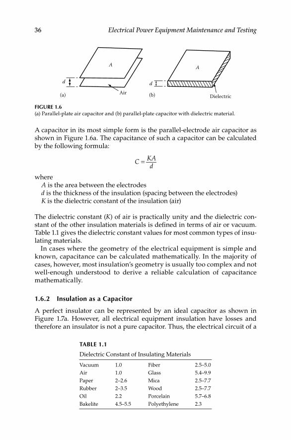
36 Electrical Power Equipment Maintenance and Testing
A capacitor in its most simple form is the parallel-electrode air capacitor as shown in Figure 1.6a. The capacitance of such a capacitor can be calculated by the following formula:
KACd
=
whereA is the area between the electrodesd is the thickness of the insulation (spacing between the electrodes)K is the dielectric constant of the insulation (air)
The dielectric constant (K) of air is practically unity and the dielectric con-stant of the other insulation materials is defi ned in terms of air or vacuum. Table 1.1 gives the dielectric constant values for most common types of insu-lating materials.
In cases where the geometry of the electrical equipment is simple and known, capacitance can be calculated mathematically. In the majority of cases, however, most insulation’s geometry is usually too complex and not well-enough understood to derive a reliable calculation of capacitance mathematically.
1.6.2 Insulation as a Capacitor
A perfect insulator can be represented by an ideal capacitor as shown in Figure 1.7a. However, all electrical equipment insulation have losses and therefore an insulator is not a pure capacitor. Thus, the electrical circuit of a
A
d
(a) (b)Air
A
d
Dielectric
FIGURE 1.6(a) Parallel-plate air capacitor and (b) parallel-plate capacitor with dielectric material.
TABLE 1.1
Dielectric Constant of Insulating Materials
Vacuum 1.0 Fiber 2.5–5.0
Air 1.0 Glass 5.4–9.9
Paper 2–2.6 Mica 2.5–7.7
Rubber 2–3.5 Wood 2.5–7.7
Oil 2.2 Porcelain 5.7–6.8
Bakelite 4.5–5.5 Polyethylene 2.3
DK4058_C001.indd 36DK4058_C001.indd 36 11/17/2008 12:17:19 PM11/17/2008 12:17:19 PM

Maintenance Strategies, Dielectric Theory 37
practical insulator can be represented by a capacitor with a small resistance in parallel with it, as shown in Figure 1.7b.
The nature of insulation materials is such that 60 Hz current does not easily fl ow through them and therefore their purpose is to guide the current to the inside of the conductor. When voltage is applied to the conductor, two fi elds are established; one due to the current fl ow (magnetic fi eld) and the other due to the voltage (dielectric or electrostatic fi eld). The lines of magnetic fl ux around the conductor are concentric circles, whereas the lines of the dielectric fl ux around the conductor are radial. The resulting voltage stress due to the dielectric fi eld varies inversely with the distance between equipotential lines.
The dielectric constant of an insulator is an indication of how much dielec-tric fl ux the insulation will allow through it. Under identical conditions insu-lation with a higher dielectric constant will pass more dielectric fl ux through it than another insulation having a lower dielectric constant. The dielectric constant for most commercial insulations varies from 2.0 to 7.0 as indicated in Table 1.1. It should be noted that the dielectric constant of water is 81 and generally when insulation becomes wet, its dielectric constant increases along with its capacitance, thus resulting in greater dielectric loss. An ideal insulation can be represented as a capacitor because its behavior is similar to that of a capacitor. Two of the most common confi gurations considered for insulators are parallel-plate and cylindrical capacitors. For example, the par-allel-plate capacitor represents an insulation system of a transformer or a machine winding, whereas the cylindrical capacitor represents an insulation system of a cable or a bushing.
1.6.3 DC Voltage versus AC Voltage Tests
When voltage is applied to the insulation, a current is established consisting of a charging current (IC) and an in-phase component current (IR). As shown in Figure 1.7b, the charging current leads the in-phase component current by 90°. The vector sum of the charging current and the in-phase component current
(a)
IC
IC
E
IC
IT
IT
Eq
IC IR
(b)
FIGURE 1.7Electrical representation of insulation: (a) perfect and (b) practical.
DK4058_C001.indd 37DK4058_C001.indd 37 11/17/2008 12:17:19 PM11/17/2008 12:17:19 PM

38 Electrical Power Equipment Maintenance and Testing
is the total current (IT) drawn by the insulation specimen. The in-phase component current is also referred to as the resistive current, loss current, or conduction current. The ideal insulation (ideal capacitor) behaves some-what differently under the application of DC versus AC voltages which are discussed below.
1.6.3.1 DC Voltage Tests
When a DC voltage is applied to the insulation, a large current is drawn at the beginning to provide the charging energy, however, this current decreases to a minimum level over time. The minimum current is due to continuous leakage or watt loss through the insulation. The energy required to charge an insulation is known as the dielectric absorption phenomenon.
In actual practice, the losses from dielectric absorption (i.e., the absorption current) are much higher than the continuous leakage losses. In the case of DC voltage testing, the effect of dielectric absorption becomes minimum over time and therefore measurements of continuous leakage current can be made. Dielectric absorption losses are very sensitive to changes in moisture content of an insulation, as well as the presence of other contaminants. Small increases in moisture content of an insulation cause a large increase in dielectric absorp-tion. The fact that dielectric losses are due to dielectric absorption makes the dielectric loss, PF, or DF test a very sensitive test for detecting moisture in the insulation. When a DC voltage is applied to an insulation, the total current drawn by the insulation is comprised of capacitance charging current, dielec-tric absorption current, and continuous leakage currents. These currents and their behavior are discussed in greater detail in Chapter 2.
1.6.3.2 AC Voltage Tests
In the case of AC voltage application to an insulation, a large current is drawn which remains constant as the AC current alternately charges and discharges the insulation. The effect of dielectric absorption currents remains high because the dielectric fi eld never becomes fully established due to the polarity of the current reversing each half cycle. When an AC voltage is applied to an insulation, the currents drawn by the insulation are due to capacitance charging, dielectric absorption, continuous leakage current, and corona which are discussed below:
Capacitance charging current: In the case of AC voltage, this current is constant and is a function of voltage, the dielectric constant of the insulating material, and the geometry of the insulation.
Dielectric absorption current: When an electric fi eld is set up across an insulation, the dipole molecules try to align with the fi eld. Since the molecules in an AC fi eld are continually reversing and never fully align, the energy required is a function of material, contamination, (such as water), and electrical frequency. It is not a function of time.
Leakage current (conductivity): All insulation materials will conduct some current. If voltage is increased beyond a certain level, electrons will
DK4058_C001.indd 38DK4058_C001.indd 38 11/17/2008 12:17:19 PM11/17/2008 12:17:19 PM
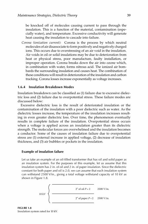
Maintenance Strategies, Dielectric Theory 39
be knocked off of molecules causing current to pass through the insulation. This is a function of the material, contamination (espe-cially water), and temperature. Excessive conductivity will generate heat causing the insulation to cascade into failure.
Corona (ionization current): Corona is the process by which neutral molecules of air disassociate to form positively and negatively charged ions. This occurs due to overstressing of an air void in the insulation. Air voids in oil or solid insulations may be due to deterioration from heat or physical stress, poor manufacture, faulty installation, or improper operation. Corona breaks down the air into ozone which, in combination with water, forms nitrous acid. The ionized air bom-bards the surrounding insulation and causes heat. The combination of these conditions will result in deterioration of the insulation and carbon tracking. Corona losses increase exponentially as voltage increases.
1.6.4 Insulation Breakdown Modes
Insulation breakdown can be classifi ed as (1) failure due to excessive dielec-tric loss and (2) failure due to overpotential stress. These failure modes are discussed below:
Excessive dielectric loss is the result of deteriorated insulation or the contamination of the insulation with a poor dielectric such as water. As the dielectric losses increase, the temperature of the insulation increases result-ing in even greater dielectric loss. Over time, the phenomenon eventually results in complete failure of the insulation. Overpotential stress occurs when a voltage is applied across an insulation greater than its dielectric strength. The molecular forces are overwhelmed and the insulation becomes a conductor. Some of the causes of insulation failure due to overpotential stress are (1) external increase in applied voltage, (2) decrease of insulation thickness, and (3) air bubbles or pockets in the insulation.
Example of insulation failure
Let us take an example of an oil-fi lled transformer that has oil and solid paper as an insulation system. For the purposes of this example, let us assume that this insulation system has 2 in. of oil and 2 in. of paper insulation. Since the dielectric constant for both paper and oil is 2.0, we can assume that each insulation system can withstand 2500 V/in., giving a total voltage withstand capacity of 10 kV as shown in Figure 1.8.
10 kV
2� of oil P = 2
2� of paper P = 2
2500 V/in.
2500 V/in.
FIGURE 1.8Insulation system rated for 10 kV.
DK4058_C001.indd 39DK4058_C001.indd 39 11/17/2008 12:17:19 PM11/17/2008 12:17:19 PM
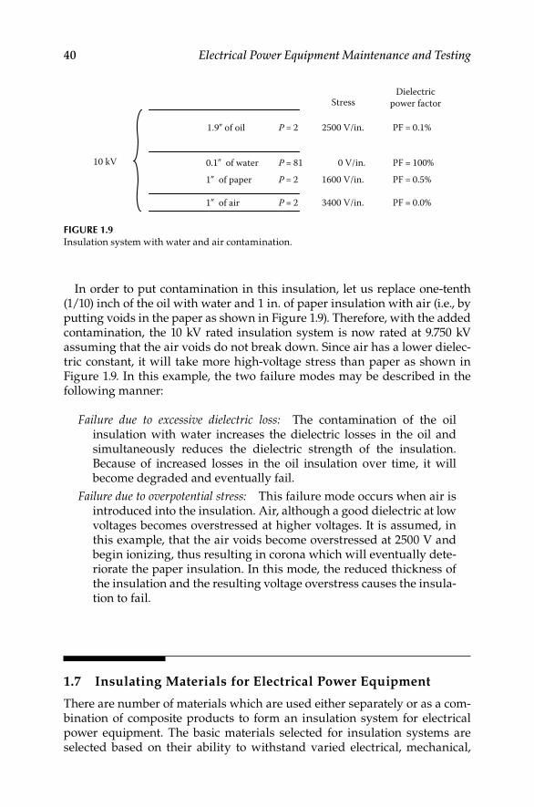
40 Electrical Power Equipment Maintenance and Testing
In order to put contamination in this insulation, let us replace one-tenth (1/10) inch of the oil with water and 1 in. of paper insulation with air (i.e., by putting voids in the paper as shown in Figure 1.9). Therefore, with the added contamination, the 10 kV rated insulation system is now rated at 9.750 kV assuming that the air voids do not break down. Since air has a lower dielec-tric constant, it will take more high-voltage stress than paper as shown in Figure 1.9. In this example, the two failure modes may be described in the following manner:
Failure due to excessive dielectric loss: The contamination of the oil insulation with water increases the dielectric losses in the oil and simultaneously reduces the dielectric strength of the insulation. Because of increased losses in the oil insulation over time, it will become degraded and eventually fail.
Failure due to overpotential stress: This failure mode occurs when air is introduced into the insulation. Air, although a good dielectric at low voltages becomes overstressed at higher voltages. It is assumed, in this example, that the air voids become overstressed at 2500 V and begin ionizing, thus resulting in corona which will eventually dete-riorate the paper insulation. In this mode, the reduced thickness of the insulation and the resulting voltage overstress causes the insula-tion to fail.
1.7 Insulating Materials for Electrical Power Equipment
There are number of materials which are used either separately or as a com-bination of composite products to form an insulation system for electrical power equipment. The basic materials selected for insulation systems are selected based on their ability to withstand varied electrical, mechanical,
10 kV
1.9� of oil P = 2 PF = 0.1%
PF = 100%PF = 0.5%
PF = 0.0%
P = 2
P = 2
P = 81
2500 V/in.
0.1� of water1� of paper
1� of air
0 V/in.1600 V/in.
3400 V/in.
StressDielectric
power factor
FIGURE 1.9Insulation system with water and air contamination.
DK4058_C001.indd 40DK4058_C001.indd 40 11/17/2008 12:17:19 PM11/17/2008 12:17:19 PM

Maintenance Strategies, Dielectric Theory 41
and thermal stresses during the life of the equipment. Listed below is a partial summary of the materials and products used for insulating electrical power equipment.
1.7.1 Rigid Laminates Sheet, Rod, and Tube
Canvas-based phenolic laminate•
Paper-based phenolic laminate•
Glass melamine laminate•
Glass silicone laminate•
Glass epoxy laminate•
Cogetherm mica-based laminate•
Mica epoxy laminate•
Transite HT and NAD-11 high-temperature cement boards•
1.7.2 Glass Polyester Products
Glass polyester sheet•
Glass polyester channels and angles•
Glass polyester stand-off insulators•
Glass polyester rods•
Specialty glass polyester•
1.7.3 Flexible Laminates and Films
Diamond-coated kraft paper•
Vulcanized fi ber sheets, rods, and tubes•
Kraft pressboard products•
COPACO rag paper•
Quin-T family of fl exible laminates•
Melinex polyester fi lm•
Mylar polyester fi lm•
Dacron–Mylar–Dacron•
Kapton polyimide fi lm•
Nomex aramid paper•
Nomex–Polyester–Nomex•
Rag Mylar and Rag–Mylar–Rag•
Over the years organic insulating materials have been replaced with inor-ganic materials and this progression is still continuing. There are number of
DK4058_C001.indd 41DK4058_C001.indd 41 11/17/2008 12:17:20 PM11/17/2008 12:17:20 PM

42 Electrical Power Equipment Maintenance and Testing
organic and inorganic insulating materials that are used in electric power equipment. Although this listing discussed in this section is somewhat long, it is not all encompassing because the choices of available insulating materi-als are many. The use of the trade names in the listing given here does not represent a particular brand preference but are included for clarity. The characteristics of various insulating materials are discussed as follows.
Cotton: Cotton has been used extensively in electrical insulation because of its low cost, strength, elasticity, fl exibility, and adaptability to size require-ments and manufacturing process. However, cotton has a tendency to absorb moisture and limited thermal capability. Cotton is always used with varnish or resin impregnation to obtain good dielectric strength and moisture resis-tance. The use of cotton is restricted to 105°C (Class A insulation system) because temperatures higher than class A cause decomposition of the cotton fi bers with resulting embrittlement and loss of mechanical strength.
Cotton fabrics: There are many varieties of treated fabrics that are funda-mental Class A insulating materials. Untreated cotton fabrics that have been thoroughly dried are used for oil transformer insulation. These fabrics are quickly impregnated when the transformer is fi lled with oil, thereby providing excellent physical and dielectric properties. Two most commonly used fabrics are tan-varnish treated cloths and black-varnish treated cloths.
Paper: Many types of paper are used in insulating electrical equipment. These varieties include Japanese tissues, cotton rags, manila (hemp), the kraft (wood pulp), jute, fi shpaper (gray cotton rag), fuller board, and the like. Rag and kraft paper often called transformer paper is used to separate windings in a transformer or in applications where there are no sharp edges that might poke through the relatively weak paper. Fishpaper is usually vulcanized and often laminated with Mylar giving it excellent resistance to tear and punc-ture. The paper–Mylar laminates resist soldering heat better since paper does not melt and the Mylar resist moisture best. Papers made with temperature resistance nylon and/or glass weaves have excellent electrical properties and good temperature resistance. Paper posses similar properties as cotton cloth, but because of its structure it has higher dielectric strength than cotton. The thermal stability and moisture absorption properties of paper are similar to cotton; however, paper does not possess the high mechanical strength of cloth. Untreated paper has little insulating value because of its extreme ten-dency to absorb moisture.
Asbestos: Recent restriction placed by Environmental Protection Agency (EPA) and OSHA has limited the use of the asbestos as an insulating mate-rial. It is used in the form of asbestos paper or asbestos tape, asbestos mill board or asbestos lumber for electrical insulating purposes. In such forms, it may contain 10%–20% wood pulp and glue to give it strength. Asbestos is generally heat resistance, but if heated excessively asbestos loses its hygro-scopic moisture and therefore becomes brittle. Asbestos absorbs moisture from the surrounding atmosphere which makes it a less effective insulator.
DK4058_C001.indd 42DK4058_C001.indd 42 11/17/2008 12:17:20 PM11/17/2008 12:17:20 PM

Maintenance Strategies, Dielectric Theory 43
Glass: Glass insulation comes in a wide variety of forms including solid glass, fi ber tapes, fi berglass sheets and mats, woven tubing and cloth, and various composites. The most common form of glass used in electrical equip-ment is fi berglass. Fiberglass is available as fi berglass yarns for insulating materials. Today, fi berglass cloths and tapes are widely used in high-temperature applications. Two types of fi berglass yarns commonly used for electrical insulation are continuous fi lament and staple fi ber yarns. The con-tinuous fi lament yarns have the appearance of natural silk or linen whereas the staple fi ber yarns exhibit a considerable degree of fuzziness similar to wool yarns. Fiberglass has advantages of high thermal endurance, high chem-ical resistance, high moisture resistance, good tensile strength, and good thermal conductivity when impregnated or coated with varnish or resin. Glass fi bers exhibit poor abrasion resistance therefore fi bers must be lubri-cated before they are woven into cloth. Varnish treatment of glass cloths greatly increases the abrasion resistance. Untreated glass cloth is used pri-marily as a spacing insulation and when the cloth is impregnated and coated with an insulating resin or varnish it becomes an effective dielectric barrier. Among the many uses of fi berglass are covering of wire, binder tapes for coils, and backing for mica tapes. It is also used as ground insulation and insulation for stator coil connections, leads, ring supports, etc. when treated with oleor-resinous and other varnishes. Fiberglass, varnish-treated fi berglass, and nonwoven forms are thermally stable, resistance to solvent depending on the type of varnish used. It is more secure spacer insulation than cotton or paper.
Synthetic textiles and fi lms: Numerous synthetic fi ber textiles are in use as electrical insulation. These are either continuous monofi laments of resins, or short fi bers made of resins that are spun into threads and woven into fabrics. They have to be coated or impregnated with varnish to become effective dielectric barriers. The thermal ability of these materials lies between cellu-lose fabrics and glass fabrics and depends on the type of resin coating or impregnating material used more than their own characteristics. Examples of synthetic fi ber cloth and mats are Dacron, other polyesters, aromatic nylons, such as Nomex, Kelvar, and others. They have thermal stability, sol-vent resistance, and lack of fusibility. Several polyester fi lms exhibit excellent electrical and physical properties, such as Mylar which enjoys widespread use in a variety of insulation systems.
Polyester fi lms: They are used at temperatures above 105°C–125°C and have fair solvent resistance. Some specially formulated polyester varieties are used for service up to 180°C. The common uses of polyester fi lms such as Mylar and others are slot liners, layer insulation in transformers, capacitors, and as laminated backing of paper insulation.
Aromatic polyimide (Kapton, Nomex, and others): It is used at temperatures of 180°C–220°C. It has excellent resistance to solvents and has good heat resis-tance and superb mechanical and electrical properties. Nomex is a Dupont aromatic polyamide with a temperature rating above 220°C and has high voltage breakdown strength.
DK4058_C001.indd 43DK4058_C001.indd 43 11/17/2008 12:17:20 PM11/17/2008 12:17:20 PM

44 Electrical Power Equipment Maintenance and Testing
Polyolefi ns: Polypropylene and polyethylene are two known polyolefi ns that are available with ultrahigh molecular grade matching the strength of steel. Polypropylene is used for insulation not to exceed temperatures above 105°C whereas polyethylene fi lm has limited use such as class O insulation system since it softens at temperatures higher than 70°C.
Polycarbonate: Common trade names for it are Lexan and Merlon and are used for insulation system rated at temperatures 105°C and below. It has excellent electrical insulating properties and has good oil resistance but poor solvent resistance.
Polysulfone: This is another thermoplastic that include polyetherimide, polyamide, and polyphenylene with trade names like Noryl, Udel, Vespel, and Torlon. These materials are used at temperatures from 105°C to 130°C and have good oil resistance but not chlorinated solvent resistance.
Polytetrafl uoroethylene (Tefl on): It is an excellent high-temperature insulation with excellent electrical insulating properties and is used at temperatures of 220°C and higher. Tefl on tubing and wire insulation is available in a variety of colors and typically feels slippery. It has good resistance to moisture.
Nylon: Nylon has good resistance to abrasion, chemicals, and high voltages and is often used to fashion electromechanical components. Nylon is extruded and cast and is fi lled with a variety of other materials to improve weathering, impact resistance, coeffi cient of friction, and stiffness.
Phenolics: Phenolic laminated sheets are usually brown or black and have excellent mechanical properties. Phenolics are commonly used in the manu-facture of switches and similar components because it is easily machined and provides excellent insulation. Phenolic laminates are widely used for terminal boards, connectors, boxes, and components.
Polyvinylcloride (PVC): PVC is perhaps the most common insulating mate-rial. Most wiring is insulated with PVC including house wiring. Irradiated PVC has superior strength and resistance to heat. PVC tapes and tubing are also quite common. Electrical and electronic housings are commonly molded from PVC.
Acrylic: Lucite and Plexiglas are trade names for acrylic which has wide-spread use where toughness and transparency are required.
Beryllium oxide: A hard white ceramic-like material used as an electrical insulator where high thermal conductivity is required. Beryllium oxide is highly toxic in powder form and should never be fi led or sanded and conse-quently has fallen out of common use. Power semiconductor heat sinks can still be found with beryllium oxide spacers for electrical insulation.
Ceramic: Ceramics are used to fabricate insulators, components, and circuit boards. The good electrical insulating properties are complemented by the high thermal conductivity.
DK4058_C001.indd 44DK4058_C001.indd 44 11/17/2008 12:17:20 PM11/17/2008 12:17:20 PM

Maintenance Strategies, Dielectric Theory 45
Melamine: Melamine laminated with woven glass makes a very hard laminate with good dimensional stability and arc resistance. It is used in combination with mica to form rigid fi ber laminates.
Mica: Mica sheets or stove mica is used for electrical insulation where high temperatures are encountered. Two kinds of mica, Muscovite (white or India mica) and phlogopite (amber mica) are generally used for insulating pur-poses. Mica and reconstituted mica paper are inorganic and infusible. Mica has high dielectric strength, high insulation resistance, low dielectric loss, good mechanical strength, good dielectric constant (specifi c inductive capacity), and good heat conductivity. Puncture resistance is good but the edges of the mica should be fl ush against a fl at surface to prevent fl aking. Mica fi nds uses in composite tapes and sheets which are useful up to 600°C with excellent corona resistance. Sheets and rods of mica bonded with glass can tolerate extreme temperatures, radiation, high voltage, and moisture. It is also available as mica paper where tiny mica fl akes are made into paper like structure and reinforced with fi ber, glass, or polyester.
Rigid fi ber laminates: They are made of layers of cloth (glass, cotton, poly-ester, etc.) or paper with resin (phenolic, melamine, polyester, and epoxy) impregnation. They are supplied as thermosetting, thermoforming, and postforming materials used as insulators.
Micarta: It is rigid fi ber laminate made of cloth, paper, or wood saturated with either a synthetic or organic resin, and then compressed under heat. This process makes the resin permanently hard and therefore Micarta becomes impermeable to heat, pressure, and solvents. Originally, Micarta was devel-oped as an insulator but today it has many applications. Micarta is mechanically strong, rigid, and nonmagnetic. It is less susceptible to mois-ture and most acids. Micarta is used for insulating washers, controller panels and cams, slot wedges, brush rigging, bus bar supports, insulating barriers, and transformer insulation.
Synthetic resins: Synthetic resins are used extensively in varnish manu-facture. The polyester and epoxy types are representative of heat hardening resins. Varnishes containing such resins are thermosetting and will cure by heat alone and do not require oxygen. Other synthetic resins are phenolic resins suitable for molding and bonding; alkyd type resins are being substi-tuted for the old black varnishes and compounds; melamine resins are used for making laminates and molded compounds; and vinyl resins are used in the compounding of plastics and rubber substitutes.
Varnish: Insulating varnishes are of great importance in the mainte-nance of electrical equipment and apparatus. An insulating varnish is a chemical compound of synthetic resins or varnish gums and drying oils, having high dielectric strength and other properties that protect electri-cal equipment. Varnishes provide important insulating and protective functions, which are
DK4058_C001.indd 45DK4058_C001.indd 45 11/17/2008 12:17:20 PM11/17/2008 12:17:20 PM

46 Electrical Power Equipment Maintenance and Testing
Protect the insulation and equipment against moisture•
Electrically and thermally enhance other insulating materials•
Add mechanical strength to other components of the insulation•
Minimize the accumulation of dust and contaminants, and improve • heat dissipation by fi lling voids
Enhance and increase the life of insulating materials•
Adhesive-coated tapes: Many of the insulating fi lms and fabrics described above can be obtained and used with adhesive backing that are usually ther-moset or heat curable.
Rubber: Natural or Buna S rubber is not normally used for insulation these days because it is affected by ozone and has poor thermal stability. On the other hand, butyl and ethylene propylene rubbers are ozone resistance and more thermally stable. These are used for molded parts, cable insulation, and lead insulation in motors.
Silicone rubber: A variety of silicone foam rubbers are available as an insulating material. Silicone rubbers exhibit characteristics of superb chemical resistance, high-temperature performance, good thermal and electrical resis-tance, long-term resiliency, and easy fabrication. Liquid silicone rubbers are available in electrical grades for conformal coating, potting, and gluing. Silicone rubbers have excellent thermal stability and ozone resistance, but only fair mechanical strength and abrasion resistance.
Silicone/fi berglass: Glass cloth impregnated with a silicone resin binder makes an excellent laminate with good dielectric loss when dry.
1.7.4 Insulation Temperature Ratings
An insulation system is an assembly of insulating materials in association with the conductors and supporting structural parts of an electrical equip-ment and apparatus. Insulation systems for electrical equipment may be classifi ed as solid, liquid, air and vacuum, and gases. The liquid insula-tion system comprise of mineral oil, silicone, and other less-fl ammable fl uids. The gas that is primarily used for electrical insulation is SF6 gas known as sulfur hexafl uoride gas. The liquids and gases used as insulat-ing medium in electrical system and equipment are covered in Chapter 4. The air and vacuum insulation system has been used from the very begin-ning and its characteristics are well documented and understood. The ability of insulating materials or an insulation system to perform its intended function is impacted by other aging factors. The major aging factors are electrical stresses, mechanical stresses, environmental stresses, and thermal stresses. Mechanical stresses imposed upon the system and its supporting structure by vibration and differential thermal expansion may become of increasing importance as the size of the apparatus increases. Electrical stresses will be more signifi cant with high-voltage
DK4058_C001.indd 46DK4058_C001.indd 46 11/17/2008 12:17:20 PM11/17/2008 12:17:20 PM

Maintenance Strategies, Dielectric Theory 47
apparatus or with equipment exposed to voltage transients. Environmental stresses will have an impact depending on the presence of moisture, dirt, chemicals, radiation, or other contaminants. Thermal stresses depend upon environmental conditions (high ambient), loading, and ability to dissipate heat. All such factors should be taken into account when select-ing insulating materials and/or insulation systems. To help the user, IEEE Standard 1-2001, “IEEE recommended practice—General principles for temperature limits in the rating of electrical equipment and for the evalu-ation of electrical insulation,” has established the temperature rating for solid insulation systems of electrical equipment and apparatus. The IEEE Standard 1-2001 takes into account these factors in establishing the stan-dards of temperature limits for particular classes of apparatus. Thus, for temperature rating purposes insulation systems are divided into classes according to the thermal endurance of the system.
According to IEEE Standard 1-2000, insulation system classes may be designated by letters and may be defi ned as assemblies of electrical insulating materials in association with equipment parts. These systems may be assigned temperature rating based on service experience or on an accepted test proce-dure that can demonstrate an equivalent life expectancy. The thermal classi-fi cation of electrical insulating systems established by IEEE Standard 1-2000 is given in Table 1.2.
1.8 Causes of Insulation Degradation and Failure Modes
of Electrical Equipment
The electrical insulation of equipment is usually made up of many different components selected to withstand the widely different electrical, mechanical,
TABLE 1.2
Thermal Classifi cation of Electrical Insulating Systems
Thermal Classifi cation Class Temperature (°C)
A 105
E 120
B 130
F 155
H 180
N 200
R 220
S 250
C >250
Source: From IEEE Standard 1-2000.
DK4058_C001.indd 47DK4058_C001.indd 47 11/17/2008 12:17:20 PM11/17/2008 12:17:20 PM
48 Electrical Power Equipment Maintenance and Testing
thermal, and environmental stresses occurring in different parts of the structure. The level of maintenance required for electrical equipment will depend on the effectiveness of the physical support for the insulation, the severity of the forces acting on it and the insulating materials themselves, and the service environ-ment. Therefore, the length of useful life of the insulation depends on the arrangement of individual components, their interactions upon one another, contribution of each component to the electrical and mechanical integrity of the system, and the process used in manufacturing the equipment. Historically, functional evaluation of insulation was based primarily on thermal stresses. However, with many types of equipment, other aging stresses or factors, such as mechanical, electrical, and environmental may be dominant and signifi cantly infl uence service life. The following are the major causes of insulation degrada-tion and eventual failure.
Mechanical stress: Mechanical stress can be caused by power frequency transient currents such as when switching on power equipment, such as a motor or a transformer, that give rise to transient power frequency cur-rents. In the case of a motor, this transient current may be as high as six times the normal frequency current. In the case of a transformer, the power frequency current may be as high as 10–12 times the normal cur-rent. The magnetically induced mechanical forces in the equipment are the square of the transient current, therefore a motor experiences mechan-ical forces 36 or more times and a transformer experiences 100 or more times stronger than normal service . If these transient occur frequently, such as frequent starting of motors or energizing of transformers and these forces cannot be withstood it would eventually lead to mechanical damage. Also, insulation can be damaged by mechanical vibration and expansion and contraction at power frequency operation. For example, when current is applied, the end turns of motor windings are twisted. If the twisting force is strong enough to break the bond of insulating var-nish, the turns of magnetic wire will wear against each other and cause a turn-to-turn short. Once the turns are shorted, localized heating is caused by the current induced onto the closed loop. This heat rapidly degrades the surrounding insulation and over time destroys the groundwall insula-tion. A similar example may be applied to a transformer inrush current or through fault currents that can begin as mechanical damage in the turns and eventually manifest as winding faults.
Temperature hot spots: The value of temperature coeffi cient of resistance of an insulating material is negative and relatively large. Therefore, even a small increase in temperature will cause a large decrease in the insulation resistance. The current distribution over a given insulation is not uniform, therefore the weak part of the insulation carries more current and heated more than other parts, as long as the insulation or adjacent structures can conduct the heat away as fast as it is generated, the temperature will remain stable. However, if the heat is not dissipated as fast as it is generated the weaker spots in the insulation will become increasingly hotter until thermal breakdown occurs.
DK4058_C001.indd 48DK4058_C001.indd 48 11/17/2008 12:17:20 PM11/17/2008 12:17:20 PM

Maintenance Strategies, Dielectric Theory 49
Environmental (moisture, chemicals, dirt, and oils): The environmental factors that degrade insulation over time are moisture, dirt, dust, oils, acids, and alkalies. Moisture is conductive because it contains impurities. When insula-tion absorbs or is laden with moisture it decreases the insulation resistance. The moisture penetrates the cracks and pores of the insulation, especially older insulation, and provides low resistance paths for creepage currents and potential sources of dielectric failure. Chemical fumes such as acids and alkalies often found in the industrial environment directly attack insulation and permanently lower its insulation resistance. Similarly, oil fi lms will cover the internal surfaces of insulation of a machine. The oil may come from the environment or a leaking bearing seal. It will tend to lower the insulation resistance, reduce the ability to dissipate heat, and promote thermal aging and eventual failure. Dirt and dust in combination with moisture can become conductive and therefore cause creepage currents and insulation degrada-tion as well as reduce the ability of the insulation to dissipate heat. The life of equipment is dependent to a considerable extent upon the degree of exclusion of oxygen, moisture, dirt, and chemicals from the interior of the insulating structure. At a given temperature, therefore, the life of equipment may be longer if the insulation is suitably protected than if it were freely exposed to industrial atmospheres.
Electrical stresses (corona, surges, and partial discharges): Electrical equipment is always subjected to internally generated or external voltage and current surges. A physical rupture of insulation with the destruction of molecular bonds might occur during a voltage surge due to switching of a large induc-tive load or lightning. This transitory overpotential stresses the molecular structure of the insulating material causing ionization and failure of the insulating material itself. Corona is defi ned as the form of electrical dis-charge that occurs when the critical (corona inception) voltage is reached, thus causing air to breakdown. Corona by itself is not harmful to insulation however corona produces ozone which accelerates the oxidation of the organic materials of insulation. Further, the nitrogen oxides produced by the ionization of air form acids when combined with moisture also degrade the insulation. The voids in the cable-extruded insulation once electrifi ed begin to conduct and grow larger. This phenomenon is known as partial dis-charge in the cable insulation and over time makes the void to grow larger and eventually cause cable to fail. Electrical stresses will be more signifi cant with high-voltage apparatus or with equipment exposed to voltage transients.
Thermal aging: The temperature at which an insulation operates determines its useful life. Thermal stress is the single most recognized cause of insula-tion degradation. Insulation does not always fail when reaching some criti-cal temperature, but by gradual mechanical deterioration with time at an elevated temperature. The time–temperature relationship determines the rate at which the mechanical strength of organic material decreases. Thereafter, electrical failure may occur because of physical disintegration of the insulating materials. Typical thermal aging mechanisms include
DK4058_C001.indd 49DK4058_C001.indd 49 11/17/2008 12:17:20 PM11/17/2008 12:17:20 PM

50 Electrical Power Equipment Maintenance and Testing
(a) loss of volatile constituents, (b) oxidation that can lead to molecular cross-linking and embrittlement, (c) hydrolytic degradation in which mois-ture reacts with the insulation under the infl uence of heat, pressure, and other factors to cause molecular deterioration, and (d) chemical breakdown of constituents with formation of products that act to degrade the material further, such as hydrochloric acid. The electrical and mechanical properties of insulating materials and insulation systems may be infl uenced in differ-ent ways and to different degrees as a function of temperature and with thermal aging. Thermal aging progressively decreases elongation to rupture so that embrittlement fi nally leads to cracking and that may contribute to electrical failure. Thus, how long insulation is going to last depends not only upon the materials used, but also upon the effectiveness of the physi-cal support for the insulation and the severity of the forces tending to dis-rupt it. Even though portions of insulation structures may have become embrittled under the infl uence of high temperature, successful operation of the equipment may continue for years if the insulation is not disturbed. Because of the effect of mechanical stress, the forces of thermal expansion and contraction may impose temperature limitations on large equipment even though higher temperature limits proved satisfactory in small equip-ment when similar insulating materials were used. The rate of physical deterioration of insulation under thermal aging increases rapidly with an increase in temperature. The oxidation of the insulating materials is a chemical reaction in which the rate of reaction is given by Arrhenius law. In his paper, “Electrical insulation deterioration treated as a chemical rate phenomenon,” AIEE Transaction, 67 (Part 1) (1948) 113–122, T.W. Dakin real-ized the relationship between the thermal aging phenomenon and the Arrhenius law of chemical reaction rates. The life of insulation is related to temperature and can be expressed by
/
H e E RTL A −=
whereLH is life in hours (or the specifi c reaction rate)A is the frequency of molecular encountersE is the activation energy (constant for a given reaction)R is the universal gas constantT is the absolute temperature (K)
The above equation can be simplifi ed as
/
H eB TL A=
where A and B are constants.An approximation of the above equation states that life of insulation will
be reduced by half for every 10°C rise in temperature. From the above equa-tion, it is apparent that higher the temperature, the shorter the expected life of the insulation.
DK4058_C001.indd 50DK4058_C001.indd 50 11/17/2008 12:17:20 PM11/17/2008 12:17:20 PM
Maintenance Strategies, Dielectric Theory 51
1.8.1 Failure Modes—Electrical Power Equipment
Failures can occur in any electrical equipment at any time. The major power equipment considered for discussion are transformers, switchgear breakers, switchgear buses, electromechanical relays, cables, and rotating machines. The insulation systems makeup of the above referenced equipment contains dielectric materials which are the key components for gauging its reliability. A failure in insulation, or an insulation system, is failure of the power equip-ment. Therefore, we will briefl y review the insulation systems of major elec-trical equipment and apparatus for an understanding why and how power equipment fails. A better understanding of the failure modes and effects will help broaden the understanding in the care and servicing of electrical power equipment.
1.8.1.1 Transformers
Major components that make up a transformer are primary winding, secondary winding, magnetic iron core, coolant (air, gas, oil, or synthetic fl uid), bushings, and tank. The insulating materials used in the makeup of transformer insulation system are enameled conductors (wire), kraft paper, glass, thermoplastic insulating tape, presswood, glass fabric, wood, resins, porcelain, cements, polymer coatings, gasket materials, internal paints, and mineral oil or synthetic fl uid. The iron core with its clamping structure, the primary and secondary windings with their clamping arrangement, and leads and tapping from windings together with their supporting structure complete the construction components of a transformer. Insulating materials used in the manufacturing of bushing are porcelain, glass, thermosetting cast resins, paper tape, and oil. The paper used in bushing is usually oil- impregnated paper, resin-impregnated paper, or resin-bonded paper. The feed-through lead conductor with its insulation system is enclosed in porcelain or glass housing. Bushings are constructed as condenser bushing or noncondenser bushing (see Section 3.6.2 for more detail). The condenser bushings are used in transformers with primary voltage rating above 50 kV whereas the noncondenser type bushings are used below 50 kV applications.
Transformer failures, while infrequent, are usually the culmination of a series of events: unusual loading, impressed surges (from protective circuitry failure or local switching), or improper maintenance. Nearly always, incipi-ent failures can be determined by testing, and PM performed to correct the condition. If, however, the transformer does fault, other connected or adja-cent equipment is protected by the sensing elements and circuit breakers. Any fl uid spill or fi re activates the fi re extinguishing system if installed. There is very little probability that even a major transformer fault will mechanically damage any equipment other than itself. The mechanical damage will largely be confi ned to nearby piping, support structures, or electrical connections. The possible spill of fl aming transformer oil into a trench carrying either oil-fi lled cables, hydrogen supply lines, or the transformer oil-fi ltering piping could easily involve areas and elements of
DK4058_C001.indd 51DK4058_C001.indd 51 11/17/2008 12:17:21 PM11/17/2008 12:17:21 PM

52 Electrical Power Equipment Maintenance and Testing
equipment not electrical in nature. There is, of course, a small chance that projectiles from the bushings could impact on ceramic supports or feed through of other nearby equipment and contribute to their failure. If the transformer fault involves arcing between the high- and low-voltage wind-ings, the physical damage resulting from the fault may well extend into the low-voltage bus work and connections.
Table 1.3 displays results of Harford Steam Boiler Insurance Company (HSB) 1998 study on the causes of transformer failures. Table 1.4 displays the results of HSB 2003 study on distribution of transformer failures. For the causes of failures reported line surge/through faults are the number one cause for all types of failures. Insulation failure was the second leading cause of trans-former failures and these failures were attributed to defective installation,
TABLE 1.3
Causes of Transformer Failures
Cause of Failure % Failures (1998 study)
Insulation failure 13.0
Design/materials/
workmanship
2.9
All others 24.2
Overloading 2.4
Line surge/thru faults 21.5
Improper maintenance/
operation
11.3
Loose connection 6.0
Lightning 12.4
Moisture 6.3
Source: From Hartford Steam Boiler Insurance Company’s article-
Analysis of transformer failures, Part 2-causes, prevention
and maximum service life, William H. Bartley.
TABLE 1.4
Distribution of Failures by Age of Transformers rated at 25 MVA and above
Age at Failure Number of Failure
0–5 years 9
6–10 years 6
11–15 years 9
16–20 years 9
21–25 years 10
Over 25 years 16
Age unknown 35
Source: From Hartford Steam Boiler Insurance
Company’s transformer data for the period
1997 through 2001.
DK4058_C001.indd 52DK4058_C001.indd 52 11/17/2008 12:17:21 PM11/17/2008 12:17:21 PM

Maintenance Strategies, Dielectric Theory 53
insulation deterioration, and short circuits. For failures due to aging, the winding insulation looses mechanical and dielectric withstand strength over time and therefore is weakened to the point where it can no longer sustain the high radial and compressive forces induced by a line surge, or an internal or through fault. Also, as the load increases due to system expansion, the operat-ing stresses increase in a transformer.
Large power transformers used in the medium-voltage electrical distribu-tion system are typically of liquid-immersed type. The primary and secondary coils are immersed in oil, which acts to insulate as well as cool the coils. The coils are wrapped on an iron core, which is enclosed in a tank and fi lled with oil. A dedicated cooling system consisting of fi nned radiators with temperature-controlled cooling fans will be provided to remove heat from the internals. In addition, some cooling systems include one or more circulating pumps to increase the fl ow of oil through the heat exchanger and provide more effi cient core cooling. The insulating oil is circulated through the trans-former tank and heat is rejected via the heat exchanger. The power for the circulating pumps and cooling fans is typically 480 V AC. Smaller power transformers, such as those found in load center switchgear, may be either oil-fi lled or dry-type units. Dry-type transformers may be air-cooled with natural circulation alone, or more typically, forced-air-cooled with temperature- controlled cooling fans. Power connections to electrical buses and cables are routed through insulated bushings to the interior transformer windings.
Age-related degradation of transformers is primarily associated with the coils and the electrical connections. Degradation of the coils can occur due to continual exposure to elevated temperature, or degradation of the insulating oil. When the oil starts to degrade, gas is generated, which will accumulate inside the transformer tank. Checking for gas content in the oil is one method of transformer condition monitoring. Moisture intrusion is also a concern since entrained moisture can cause the formation of bubbles in the insulat-ing oil during transformer operation. Formation of bubbles can degrade the performance of the transformer. Some examples of failure causes of power transformers are the following:
Short circuit to ground•
Turn-to-turn short•
Primary to secondary short•
External oil leakage•
Degraded or inoperable cooling system (reduces transformer million • volt amperes (MVA) rating)
To develop and implement a rigorous PM program, an understanding of trans-former failure modes is necessary. The transformers can fail from any combi-nation of electrical, mechanical, and thermal factors. Actual transformer failures as listed above involve breakdown of the insulation system which may result from any of the factors (failure modes) just mentioned above. Table 1.5 summarizes the stressors, failure modes and effects of power transformers.
DK4058_C001.indd 53DK4058_C001.indd 53 11/17/2008 12:17:21 PM11/17/2008 12:17:21 PM

54 Electrical Power Equipment Maintenance and Testing
TAB
LE 1
.5
Fail
ure
Mo
des
, S
tres
sors
, an
d E
ffec
ts o
f T
ran
sfo
rmer
s
Co
mp
on
en
tM
ate
rial
Str
ess
ors
Fail
ure
Mo
de
Eff
ect
s
En
clo
sure
Str
uct
ura
l st
eel
Mo
istu
re/
hu
mid
ity
Co
rro
sio
nL
oss
of
stru
ctu
ral
inte
gri
ty
Mec
han
ical
stre
ssO
xid
ati
on
Dir
t/m
ois
ture
in
tru
sio
n
Cra
ckin
g o
f w
eld
sO
il l
eak
ag
e
Sei
smic
/v
ibra
tio
n-i
nd
uce
d
dam
ag
e
Co
ils
Cel
lulo
sic
insu
lati
on
Ele
vate
d t
emp
eratu
reE
mb
ritt
lem
ent/
crack
ing
of
insu
lati
on
Lo
ss o
f d
iele
ctri
c in
teg
rity
Fib
erg
lass
Oh
mic
hea
tin
gC
orr
osi
on
/o
xid
ati
on
of
wir
eT
urn
-to
-tu
rn s
ho
rts
Ep
ox
ies
Mo
istu
re/
hu
mid
ity
Wea
r o
f in
sula
tio
nS
ho
rt c
ircu
it t
o g
rou
nd
Varn
ish
Ele
ctro
mag
net
ic
cycl
ing
Co
pp
er w
ire
Ele
ctri
cal
tran
sien
ts
Co
reIr
on
Hu
mid
ity
/m
ois
ture
Co
rro
sio
nD
egra
ded
op
erati
on
of
tran
sfo
rmer
Ele
ctro
mag
net
ic
cycl
ing
Ox
idati
on
Ele
ctri
cal
tran
sien
tsD
elam
inati
on
Ele
ctri
cal
con
nec
tio
ns
Co
pp
er, alu
min
um
, p
hen
oli
c,
cera
mic
in
sula
tors
Ele
vate
d t
emp
eratu
reC
orr
osi
on
Deg
rad
ed t
ran
sfo
rmer
op
erati
on
DK4058_C001.indd 54DK4058_C001.indd 54 11/17/2008 12:17:21 PM11/17/2008 12:17:21 PM

Maintenance Strategies, Dielectric Theory 55O
hm
ic h
eati
ng
Ox
idati
on
Fau
lt t
o g
rou
nd
Mo
istu
re/
hu
mid
ity
Cra
ckin
g o
f w
eld
s an
d i
nsu
lato
rsL
oss
of
tran
sfo
rmer
fu
nct
ion
Vib
rati
on
Sei
smic
/v
ibra
tio
n-i
nd
uce
d d
am
ag
e
Lo
ose
nin
g o
f p
art
s
Insu
lati
ng
oil
Min
eral
oil
, sy
nth
etic
tra
nsf
orm
er
oil
(si
lico
ne
an
d o
ther
s)
Mo
istu
re/
hu
mid
ity
Ox
idati
on
/co
nta
min
ati
on
of
oil
Lo
ss o
f d
iele
ctri
c st
ren
gth
Dir
t/co
nta
min
ati
on
Deg
rad
ati
on
of
insu
lati
ng
oil
pro
per
ties
Lo
ss o
f co
oli
ng
pro
per
ties
Slu
dg
e fo
rmati
on
in
tan
kG
ener
ati
on
of
gas
in o
il
Mo
istu
re i
n o
ilD
egra
ded
du
e to
mo
istu
re
Ter
min
als
Alu
min
um
, co
pp
er c
on
du
cto
rs,
po
rcel
ain
in
sula
tors
Mo
istu
re/
hu
mid
ity
Ox
idati
on
/co
rro
sio
nA
rcin
g
Dir
t/co
nta
min
ati
on
Cra
ckin
g/
mec
han
ical
dam
ag
e to
insu
lato
rs
Fau
lt t
o g
rou
nd
Vib
rati
on
/m
ech
an
ical
stre
ss
Tap
ch
an
ger
Alu
min
um
, co
pp
er, p
orc
elain
insu
lato
rs, p
hen
oli
c
Mo
istu
re/
hu
mid
ity
Ox
idati
on
/co
rro
sio
n o
f th
e
con
du
cto
rs
Arc
ing
Dir
t/co
nta
min
ati
on
Cra
ckin
g/
mec
han
ical
dam
ag
e to
insu
lato
rs
Fau
lt t
o g
rou
nd
Vib
rati
on
/m
ech
an
ical
stre
ss
DK4058_C001.indd 55DK4058_C001.indd 55 11/17/2008 12:17:21 PM11/17/2008 12:17:21 PM
56 Electrical Power Equipment Maintenance and Testing
Electrically induced failures: These involve transient or sustained overvoltage conditions, lightning and switching surges, partial discharges, and static electrifi cation. The partial discharges may be caused by poor insulation system design, by manufacturing defects or by contamination of the insula-tion system (both oil and solid insulation).
Mechanically induced failures: A mechanically induced failure is due to deform-ing of a transformer’s windings that eventually results in the abrasion or rupturing of its paper insulation. Transformer winding deformation happens in either during shipping or during magnetically induced electromechanical forces. When a transformer experiences an internal or heavy through fault, the windings are subjected to electromechanical forces that are beyond their design capability. When this happens, it can cause hoop (inward radial) buckling of the innermost windings, conductor tipping, conductor telescoping, spiral tightening, end ring crushing, and/or failure of the coil clamping system.
Thermally induced failures: Thermal degradation causes the paper insulation of the windings to loose its physical strength to the point where it can no longer withstand the vibration and mechanical movement that occur inside a transformer. The thermally induced failures are due to overloading beyond its design capability for long period of time, failure of the cooling system to dissipate heat, blockage of axial oil duct spaces, operating the transformer in an overexcited condition, and/or excessive ambient temperature conditions. Refer to Section 5.7.3.7 for more details on causes of transformer failures.
An anatomy of a transformer failure is illustrated in Figure 1.10 based on a root cause analysis of a station service transformer that failed in service cata-strophically. The transformer was about 7 years old when it failed as a result of through fault because it had an incipient turn-to-turn fault in one of the phase winding. Because of lack of preventive and/or predictive maintenance testing over the 7 years, the fault went undetected until one day the transformer failed with dire consequences. As illustrated in Figure 1.10a, the original fault was a minor fault and was inconsequential to normal operation of the transformer. However, as the current dramatically increased under a through fault condi-tion, the minor fault developed into a major fault (Figure 1.10b and c).
1.8.1.2 Switchgear and Circuit Breakers
The insulating materials used for bus bar insulation and mechanical support in switchgear and circuit breakers are ceramics, epoxy resins, epoxy resin bonded glass fi ber, polyester resins, vulcanized fi ber, and synthetic resins bonded paper. In low-voltage breakers, synthetic resin moldings are used as insulating materials for the metallic parts. The modern practice is to use thermosetting plastics for bus bar mounting in switchgear to better withstand electromechanical and electrodynamic forces arising out of system faults. The thermosetting compounds are known as dough molding compounds (DMCs) and sheet molding compounds (SMCs). These compounds are basically made up of fi ber- or glass-reinforced thermosetting plastics that
DK4058_C001.indd 56DK4058_C001.indd 56 11/17/2008 12:17:21 PM11/17/2008 12:17:21 PM

Maintenance Strategies, Dielectric Theory 57
posses good physical and thermal stability, high mechanical strength, and excellent electrical properties. These compounds have essentially replaced the older insulating materials such as bakelite (phenol formaldehyde) and veneered impregnated wood used in switchgear applications.
The SF6 gas, air, vacuum, and oil are used as arc-quenching medium in circuit breakers. The mechanisms vary depending on voltage rating, the type, and vintage of circuit breakers. For breakers, the reliability concerns extend
FIGURE 1.10Anatomy of a failed transformer: (a) stages 1 and 2, (b) stages 3 and 4, and (c) fi nal stage—
transformer engulfed in fi re.
3. Third stageTo
tapchanger Coil
Coil
From FA
Coil ejection
Major faulting, melting
4. Fourth stageTo tapchanger
(b)
From FA
+o
fault
ø to ground faultagainst tank wall
ø
ø
Tank topseam
Oil3
6 6
1. Fault initiation2. Gas bubble3. Normal oil level4. Oil piston to tank top5. Oil pressure to seams6. Ruptures top and bottom7. Explosion fire when top leaks expose fault to air
Core(top)
Core(bottom)
(c)Coils
655
6
4
2
1
Tapchanger
1. Probable initiation
2. Second stage
Turn to turn short (22 V)(very low impact during operation)
Coil to coil short (330 V)
Coil
This was probably initiated by the through fault. It causes massive heating in the winding. This heating results in conductor melt, turn and coil movement, and subsequent increase in local electromagnetic forces.(a)
(significant impact during operation—failure initiation during through fault)
DK4058_C001.indd 57DK4058_C001.indd 57 11/17/2008 12:17:21 PM11/17/2008 12:17:21 PM
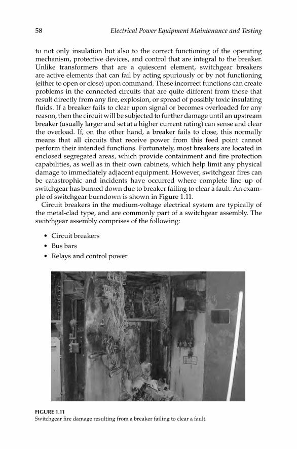
58 Electrical Power Equipment Maintenance and Testing
to not only insulation but also to the correct functioning of the operating mechanism, protective devices, and control that are integral to the breaker. Unlike transformers that are a quiescent element, switchgear breakers are active elements that can fail by acting spuriously or by not functioning (either to open or close) upon command. These incorrect functions can create problems in the connected circuits that are quite different from those that result directly from any fi re, explosion, or spread of possibly toxic insulating fl uids. If a breaker fails to clear upon signal or becomes overloaded for any reason, then the circuit will be subjected to further damage until an upstream breaker (usually larger and set at a higher current rating) can sense and clear the overload. If, on the other hand, a breaker fails to close, this normally means that all circuits that receive power from this feed point cannot perform their intended functions. Fortunately, most breakers are located in enclosed segregated areas, which provide containment and fi re protection capabilities, as well as in their own cabinets, which help limit any physical damage to immediately adjacent equipment. However, switchgear fi res can be catastrophic and incidents have occurred where complete line up of switchgear has burned down due to breaker failing to clear a fault. An exam-ple of switchgear burndown is shown in Figure 1.11.
Circuit breakers in the medium-voltage electrical system are typically of the metal-clad type, and are commonly part of a switchgear assembly. The switchgear assembly comprises of the following:
Circuit breakers•
Bus bars•
Relays and control power•
FIGURE 1.11Switchgear fi re damage resulting from a breaker failing to clear a fault.
DK4058_C001.indd 58DK4058_C001.indd 58 11/17/2008 12:17:22 PM11/17/2008 12:17:22 PM

Maintenance Strategies, Dielectric Theory 59
The circuit breakers are constructed of a number of different mechanical and electrical subsystems, all of which are contained in a metal enclosure. Typically, switchgear and circuit breakers are located in a mild environment such as a switchgear room therefore, they would not be exposed to harsh environment. However, space heaters are always installed in circuit breaker cubicles to pre-vent moisture and condensation when it is not carrying load. The predominant stressors are expected to be operational stressors, such as mechanical wear of the moving parts and electrical cycling, as well as exposure to contaminants such as dust and dirt. Operation of the circuit breakers requires a number of mechanical, as well as electrical systems. Mechanical linkages, together with springs and latches are used to open and close the breaker. Repeated operation of the breaker can lead to wear of these components over time. Electrical tran-sients can generate substantial electromagnetic forces that act on circuit breaker components and supports. Powerful vibrations are produced when a circuit breaker mechanism opens to interrupt an electrical arc. This can result in misalignment, bending, twisting, binding, or even breakage of the various mechanical components resulting in degraded performance or loss of function. Electrical cycling of the power path in the breaker can also lead to degrada-tion of the various electrical components, such as the contacts and arc extin-guishing components. When the contacts arc during breaker operation, small amounts of metal are vaporized and deposited on the arc chutes. As these deposits build up over time, they can increase the conductivity of the chutes and diminish their ability to extinguish the arcs. Another electrical system that can lead to breaker failure is the control power system. Typically, 125 V DC control power is used for a line up of switchgear breakers for tripping, closing, and to operate the peripheral equipment such as the spring charging motor. The closing and peripheral control power circuit normally includes a fuse. Degradation of this circuit, as well as the fuse and fuse holder can lead to loss of control power to the breaker and, thus, loss of breaker function. Failure modes for medium-voltage circuit breakers are the following:
Failure to close•
Failure to open•
Spurious opening•
Spurious closure•
Failure to operate as required•
Failure to recharge closing spring•
Slow operation•
Short circuit to ground•
Out of calibration•
Intermittent operation•
In a recent study of medium- and low-voltage circuit breakers used in nuclear power plants world wide, 104 events were identifi ed with respect to failure
DK4058_C001.indd 59DK4058_C001.indd 59 11/17/2008 12:17:22 PM11/17/2008 12:17:22 PM

60 Electrical Power Equipment Maintenance and Testing
TABLE 1.6
Overview of Affected Components of the Breaker
Pieces/Parts Number of Events
Bearing 1
Circuit board/command circuit (diodes) 1
Closing mechanism (in general) 9
Coil (undervoltage coil, shunt coil, trip coil) 11
Contacts 5
Digital trip unit 1
Enclosure (case, frame, casket) 2
Fuse 2
Latching mechanism 21
Limit switches 3
Lockout/interlock mechanism 1
Opening mechanism (in general)/trip device 10
Protection systems (instrumentation: sensors) 9
Relays 12
Spring 3
Switch (cell, cutoff) 3
Timer 1
Wires 4
Other (breaker in general) 1
Other (other component) 4
Total 104
modes as shown in Table 1.6. The following failure symptom categories were identifi ed as being important:
Movement of the breaker mechanism is impeded by insuffi cient or • inadequate lubrication
Movement of the breaker mechanism is impeded by broken, bent, or • loose parts, friction, binding, resulting from excessive stress, wear, or faulty installation
Operation of the breaker is impeded by incorrect adjustment of set • points/limit switches
Various electrical problems caused, e.g., by defective coils, defective • command circuits, wiring faults, loose wires, poor contacts, and blown fuses
Others (e.g., dirt, pollution, and corrosion)•
As result of this investigation two principal categories of failure causes were identifi ed. They are
DK4058_C001.indd 60DK4058_C001.indd 60 11/17/2008 12:17:22 PM11/17/2008 12:17:22 PM

Maintenance Strategies, Dielectric Theory 61
Defi ciencies in operation: This group comprises all events that involve human errors, expressed by a human error related root cause.
Three failure cause categories were identifi ed as being important in this group:
Defi cient procedures for maintenance and/or testing•
Insuffi cient attention to aging of piece parts•
Operator performance error during maintenance/test activities•
Defi ciencies in design, construction, and manufacturing: This group comprises all events with hardware related root causes. Two failure cause categories were defi ned for this group as being important:
Defi ciency in design of hardware•
Defi ciency in construction or manufacturing of hardware•
Many breakers sit in open or closed position for long periods of time without having to change their state. Therefore, it is diffi cult to assess whether a breaker is trouble free and will respond correctly when called upon to perform its intended function. It is imperative that a clear understanding exists on how and what fails within a circuit breaker. Once the failure modes are identifi ed then a method can be developed that can detect these failures modes before an actual failure occurs. The level of monitoring (maintenance and testing) for a particular type of circuit breaker is dependent on the circuit breaker age, type, application, and the risks associated with the loss of function of the circuit breaker including its associated power or protection and control support com-ponents (Table 1.7). The circuit breaker failure modes are discussed as follows:
Insuffi cient or inadequate lubrication: Movement of the breaker mechanism is impeded by lack of lubrication, more than half of them affecting the latching mechanism. This suggests that improvements in the maintenance practices should be concentrated upon checking the status of lubrication more regularly.
Mechanical wear: Movement of the breaker mechanism is impeded by wear, broken, bent, or loose parts, friction, binding, resulting from excessive stress, or faulty installation. Mechanical wear is the dominant failure mechanism in this failure symptom/manifestation category. Wear mostly affected the latching mechanism, coils, and relays. Besides defi cient maintenance/test procedures and practices, insuffi cient awareness of aging of breaker piece parts also contributes signifi cantly to this category.
Various electrical problems: This failure cause could be defective coils and command circuits, wiring faults, loose wires, blown fuses, and poor con-tacts. Defective coils and defective command circuits are the dominant failure mechanisms in this category. The events are mostly caused by defi -ciencies in design, construction, and manufacturing.
DK4058_C001.indd 61DK4058_C001.indd 61 11/17/2008 12:17:22 PM11/17/2008 12:17:22 PM
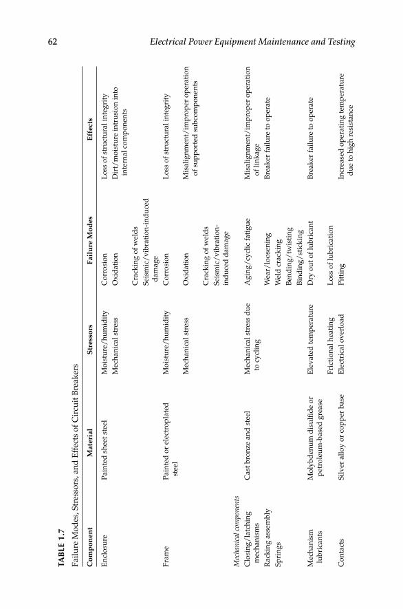
62 Electrical Power Equipment Maintenance and Testing
TAB
LE 1
.7
Fail
ure
Mo
des
, S
tres
sors
, an
d E
ffec
ts o
f C
ircu
it B
reak
ers
Co
mp
on
en
tM
ate
rial
Str
ess
ors
Fail
ure
Mo
des
Eff
ect
s
En
clo
sure
Pain
ted
sh
eet
stee
lM
ois
ture
/h
um
idit
yC
orr
osi
on
Lo
ss o
f st
ruct
ura
l in
teg
rity
Mec
han
ical
stre
ssO
xid
ati
on
Dir
t/m
ois
ture
in
tru
sio
n i
nto
inte
rnal
com
po
nen
ts
Cra
ckin
g o
f w
eld
s
Sei
smic
/v
ibra
tio
n-i
nd
uce
d
dam
ag
e
Fra
me
Pain
ted
or
elec
tro
pla
ted
stee
l
Mo
istu
re/
hu
mid
ity
Co
rro
sio
nL
oss
of
stru
ctu
ral
inte
gri
ty
Mec
han
ical
stre
ssO
xid
ati
on
Mis
ali
gn
men
t/im
pro
per
op
erati
on
of
sup
po
rted
su
bco
mp
on
ents
Cra
ckin
g o
f w
eld
s
Sei
smic
/v
ibra
tio
n-
ind
uce
d d
am
ag
e
Mec
hani
cal c
ompo
nent
sC
losi
ng
/la
tch
ing
mec
han
ism
s
Cast
bro
nze
an
d s
teel
Mec
han
ical
stre
ss d
ue
to c
ycl
ing
Ag
ing
/cy
clic
fati
gu
eM
isali
gn
men
t/im
pro
per
op
erati
on
of
lin
kag
e
Rack
ing
ass
emb
lyW
ear/
loo
sen
ing
Bre
ak
er f
ail
ure
to
op
erate
Sp
rin
gs
Wel
d c
rack
ing
Ben
din
g/
twis
tin
g
Bin
din
g/
stic
kin
g
Mec
han
ism
lub
rica
nts
Mo
lyb
den
um
dis
ulfi
de
or
pet
role
um
-base
d g
rease
Ele
vate
d t
emp
eratu
reD
ry o
ut
of
lub
rica
nt
Bre
ak
er f
ail
ure
to
op
erate
Fri
ctio
nal
hea
tin
gL
oss
of
lub
rica
tio
n
Co
nta
cts
Sil
ver
all
oy
or
cop
per
base
Ele
ctri
cal
ov
erlo
ad
Pit
tin
gIn
crea
sed
op
erati
ng
tem
per
atu
re
du
e to
hig
h r
esis
tan
ce
DK4058_C001.indd 62DK4058_C001.indd 62 11/17/2008 12:17:22 PM11/17/2008 12:17:22 PM

Maintenance Strategies, Dielectric Theory 63M
ois
ture
/h
um
idit
yC
orr
osi
on
/o
xid
ati
on
Imp
rop
er o
per
ati
on
of
bre
ak
er
du
e to
mis
ali
gn
men
t o
f co
nta
cts
Vib
rati
on
Ch
att
er-i
nd
uce
d d
am
ag
eL
oss
of
bre
ak
er f
un
ctio
n
Mec
han
ical
stre
ssB
end
ing
/tw
isti
ng
of
lin
kag
e
Ele
ctri
cal
arc
ing
an
d c
ycl
ing
Insu
lati
on
alo
ng
po
wer
path
Po
lyes
ter,
gla
ss fi
ber
-fi l
led
epo
xy
res
in, o
r p
hen
oli
c
Ele
ctri
cal
arc
ing
Em
bri
ttle
men
t/cr
ack
ing
Lo
ss o
f in
sula
tin
g p
rop
erti
es
Ele
vate
d t
emp
eratu
reD
epo
siti
on
of
con
du
ctin
g
mate
rial
Lo
ss o
f ab
ilit
y t
o e
xti
ng
uis
h a
rc
Mo
istu
re/
hu
mid
ity
Ele
ctri
cal c
ontr
ol c
ircu
its
Cir
cuit
card
sP
oly
mer
in
sula
tio
n,
cop
per
wir
e, f
use
s,
soli
d-s
tate
ele
ctro
nic
s
Ele
ctri
cal
cycl
ing
Em
bri
ttle
men
t/cr
ack
ing
of
wir
e in
sula
tio
n
Lo
ss o
f co
ntr
ol
po
wer
to
th
e
bre
ak
er
Res
isto
rsE
lect
rica
l o
ver
load
Deg
rad
ati
on
of
fuse
sL
oss
of
bre
ak
er f
un
ctio
n
Rel
ay
sE
lev
ate
d t
emp
eratu
reF
ail
ure
to
rec
harg
e cl
osi
ng
sp
rin
g
Insu
lato
rsM
ois
ture
/h
um
idit
y
Bis
tab
le/
swit
ches
Fu
ses
Ele
ctri
cal
stab
con
nec
tors
Bro
nze,
co
pp
erE
lect
rica
l cy
clin
gC
orr
osi
on
/o
xid
ati
on
Incr
ease
d o
per
ati
ng
tem
per
atu
re
du
e to
hig
h r
esis
tan
ce
Ele
ctri
cal
ov
erlo
ad
Lo
ose
nin
gIm
pro
per
op
erati
on
of
bre
ak
er d
ue
to m
isali
gn
men
t o
f co
nn
ecto
rs
Mo
istu
re/
hu
mid
ity
Ben
din
g/
twis
tin
g o
f
con
nec
tors
Lo
ss o
f fu
nct
ion
of
bre
ak
er
Vib
rati
on
Mec
han
ical
stre
ss d
ue
to
rep
eate
d r
emo
val/
inse
rtio
n
DK4058_C001.indd 63DK4058_C001.indd 63 11/17/2008 12:17:22 PM11/17/2008 12:17:22 PM
64 Electrical Power Equipment Maintenance and Testing
Fails to open: The breaker does not open the circuit when commanded manually or by automatic signal or by protective device. The failure cause probably could be inadequate lubrication of the trip latch or trip mechanism, control circuit failure, open and shorted coil, mechanism linkage failure between operating mechanism and interrupters, trip latch surface wear, deteriorated bearings, deformation of trip latch fl at surfaces, or external cir-cuit failure including wiring and battery.
Opens but fails to interrupt circuit: The breaker opens but is unable to interrupt the current and/or open contacts. For vacuum type breakers, the cause could be loss of vacuum in the vacuum bottle. For stored energy type breakers, the cause could be failure of arc chutes, puffer failure, or mechanical failure. For oil type breakers, it could be contaminated or bad oil. For SF6 breakers, it may be low gas pressure or density. It could be altogether misapplication of the breaker. In the case of when the breaker fails to maintain the required dielec-tric isolation of contacts after opening operation, the failure cause could be the voltage exceeds the circuit breaker capability, lightning, loss of gas pressure, loss of vacuum, or the mechanism did not travel complete distance.
Nuisance tripping: In this case, the breaker trips unintentionally and interrupts the circuit. The failure cause could be trip latch not secure, ground on the trip circuit, stray current in the trip circuit, inadequate protective relay settings, or relay malfunction.
Fails to close: The breaker does not close the circuit to conduct current when commanded manually or by automatic signal or by protective device. The failure cause could be defective closing coil or solenoid, loss of stored energy, inap-propriate lubrication, control circuit failure, contacts burned away, mechanical linkage to contacts broken, or loss of overtravel full contact closing.
Degraded or lack of dielectric: The breaker does not have suffi cient insulation for the circuit either for three-phase or line-to-ground voltage. The failure cause could be loss of or degraded dielectric medium, such as oil, moisture in gas, vacuum, wear generated particles in interrupter, lightning, fl ashover due to system transient, damage to the insulation of the breaker, excessive overvoltage, or water/moisture infi ltration.
1.8.1.3 Relays
The failure modes of electromechanical and induction type relays are addressed here. Relays parts include both electrical parts, in the form of coils, connectors, and contacts, as well as mechanical parts, such as contact carriers, linkages, and supports. Wear of both the electrical and mechanical parts can occur due to repeated cycling of the relay. Degradation to the mechanical parts can result in misalignment, bending, or twisting of the parts. Degradation of the electrical components can include shorting of the coils or pitting of the contacts. This degradation may result in degraded relay performance or complete loss of function. Switchgear relays are often mounted in switchgear assembly cabinet doors along with other electrical
DK4058_C001.indd 64DK4058_C001.indd 64 11/17/2008 12:17:22 PM11/17/2008 12:17:22 PM

Maintenance Strategies, Dielectric Theory 65
components. The heat generated from the components, combined with the effects of being in a confi ned space can often lead to temperatures that are signifi cantly higher than ambient. Therefore, even though the relays may not be in a harsh location, a signifi cant stressor for these components is elevated temperature. Also, relays that are constantly energized will experience an increased level of thermal degradation of temperature-sensitive materials. The coil insulation is the primary concern for degradation due to elevated temperature. Continual cycling of relays can result in loosening of parts or electrical connections, or weakening of springs. If electrical connections become loose, this can lead to increased resistance and higher operating temperatures. Failure modes for relays are
Failure to close•
Failure to open•
Spurious signal•
Failure to operate as required•
Out of calibration•
Table 1.8 summarizes the failure modes and characteristics of switchgear relays.
1.8.1.4 Switchgear Buses
Electrical buses are an integral part of the medium-voltage switchgear and are used as a connection point to distribute electric power to various parts of the facility. A bus consists of metallic bus bars which are energized at the rated nominal system voltage level. The bus bars are usually made of solid copper metal bar that are silver and/or zinc plated, metal tubing, or fl exible cable and are supported by insulators. Depending on the voltage and current levels at which they will operate, the bus bars may be wrapped in insulation or enclosed is a separate duct. Cable leads are attached to the bus to connect the various loads to be supplied. Aging stressors that may cause degradation of electrical buses primarily include exposure to moist or humid air, which can lead to corrosion of the metallic components, as well as exposure to high-voltage arcing, which can degrade the various insulators used to support and isolate the bus bars. Vibration and thermal cycling can also lead to loos-ening of connections. Electrical transients can produce substantial electro-magnetic forces that can crack, damage, or displace bus support insulators, connections, and associated hardware to secure these supports. Some exam-ples of failure causes for electrical buses are listed below. Table 1.9 summa-rizes the aging characteristics of electrical buses.
Short to ground•
Phase-to-phase short•
Corona and tracking•
DK4058_C001.indd 65DK4058_C001.indd 65 11/17/2008 12:17:23 PM11/17/2008 12:17:23 PM

66 Electrical Power Equipment Maintenance and Testing
TAB
LE 1
.8
Fail
ure
Mo
des
, S
tres
sors
, an
d E
ffec
ts o
f M
ediu
m-V
olt
ag
e S
wit
chg
ear
Rel
ay
s
Co
mp
on
en
tM
ate
rial
Str
ess
ors
Fail
ure
Mo
des
Eff
ect
s
En
clo
sure
Ph
eno
lic,
Lex
an
,
alu
min
um
, st
eel
Ele
vate
d t
emp
eratu
reC
orr
osi
on
Lo
ss o
f st
ruct
ura
l in
teg
rity
Mo
istu
re/
hu
mid
ity
Ox
idati
on
Dir
t/m
ois
ture
in
tru
sio
n i
nto
inte
rnal
com
po
nen
ts
Mec
han
ical
stre
ssC
rack
ing
of
wel
ds
Sei
smic
/v
ibra
tio
n-i
nd
uce
d
dam
ag
e
Co
il w
ire
Po
lyam
ide/
po
lyim
ide
insu
lati
on
, co
pp
er
mag
net
wir
e
Ele
vate
d t
emp
eratu
reE
mb
ritt
lem
ent/
crack
ing
of
insu
lati
on
Lo
ss o
f d
iele
ctri
c in
teg
rity
Oh
mic
hea
tin
gC
orr
osi
on
/o
xid
ati
on
of
wir
e
Mo
istu
re/
hu
mid
ity
Co
il s
po
ol
Zy
tel,
Ny
lon
, L
exan
Ele
vate
d t
emp
eratu
reA
gin
g/
cycl
ic f
ati
gu
e,
wea
r/lo
ose
nin
g
Imp
rop
er o
per
ati
on
of
rela
y
Mec
han
ical
stre
ss d
ue
to
cycl
ing
Co
il c
oati
ng
Po
lyes
ter
or
fi b
erg
lass
tap
e v
arn
ish
Ele
vate
d t
emp
eratu
reE
mb
ritt
lem
ent/
crack
ing
Imp
rop
er o
per
ati
on
of
rela
y
Oh
mic
hea
tin
g
Co
nta
cts
Sil
ver
Ele
ctri
cal
arc
ing
/cy
clin
gP
itti
ng
Incr
ease
d t
emp
eratu
re d
ue
to h
igh
res
ista
nce
Ele
ctri
cal
ov
erlo
ad
Co
rro
sio
n/
ox
idati
on
Imp
rop
er o
per
ati
on
du
e to
mis
ali
gn
men
t o
f co
nta
cts
Mo
istu
re/
hu
mid
ity
Ch
att
er-i
nd
uce
d d
am
ag
e
DK4058_C001.indd 66DK4058_C001.indd 66 11/17/2008 12:17:23 PM11/17/2008 12:17:23 PM

Maintenance Strategies, Dielectric Theory 67V
ibra
tio
nB
end
ing
/tw
isti
ng
of
lin
kag
e
Mec
han
ical
stre
ss
Co
nta
ct
carr
ier/
arm
Ph
eno
lic,
Zy
tel,
Del
rin
, N
ylo
n
Mec
han
ical
stre
ss d
ue
to
cycl
ing
Em
bri
ttle
men
t/cr
ack
ing
Imp
rop
er/
loss
of
rela
y f
un
ctio
n
Dis
tort
ion
Co
il l
ead
wir
es
cap
aci
tors
Tefl
on
, si
lico
n r
ub
ber
,
Tef
zel
, in
sula
tio
n
Ele
ctri
cal
cycl
ing
Em
bri
ttle
men
t/cr
ack
ing
of
wir
e
insu
lati
on
Imp
rop
er/
loss
of
rela
y f
un
ctio
n
Ele
ctri
cal
ov
erlo
ad
Deg
rad
ati
on
of
fuse
s
Ele
vate
d t
emp
eratu
reW
ear/
loo
sen
ing
of
con
nec
tio
ns
Mo
istu
re/
hu
mid
ity
Vib
rati
on
in
du
ced
Sli
p m
oto
r
roto
r/b
eari
ng
s
Bro
nze,
co
pp
erM
ois
ture
/h
um
idit
yC
orr
osi
on
/o
xid
ati
on
Imp
rop
er/
loss
of
rela
y f
un
ctio
n
Mec
han
ical
stre
ssB
end
ing
/tw
isti
ng
Dam
pin
g
mag
net
Mag
net
ic s
teel
Mo
istu
re/
hu
mid
ity
Co
rro
sio
n/
ox
idati
on
Imp
rop
er/
loss
of
rela
y f
un
ctio
n
Mec
han
ical
stre
ss
Tim
ing
mo
tor/
bea
rin
gs
Mag
net
wir
e w
ith
form
al
varn
ish
Ele
vate
d t
emp
eratu
reE
mb
ritt
lem
ent/
crack
ing
of
win
din
g i
nsu
lati
on
Lo
ss o
f re
lay
fu
nct
ion
du
e to
sho
rin
g o
f m
oto
r w
ind
ing
s
Mo
istu
re/
hu
mid
ity
Cam
sD
elri
n, M
etal
Mo
istu
re/
hu
mid
ity
Co
rro
sio
n/
ox
idati
on
Imp
rop
er/
loss
of
rela
y
fun
ctio
n
Tim
ing
dia
ph
rag
ms
Sil
ico
n r
ub
ber
Ele
vate
d t
emp
eratu
reE
mb
ritt
lem
ent/
crack
ing
Imp
rop
er/
loss
of
rela
y
fun
ctio
n
Mec
han
ical
stre
ss d
ue
to
cycl
ing
DK4058_C001.indd 67DK4058_C001.indd 67 11/17/2008 12:17:23 PM11/17/2008 12:17:23 PM
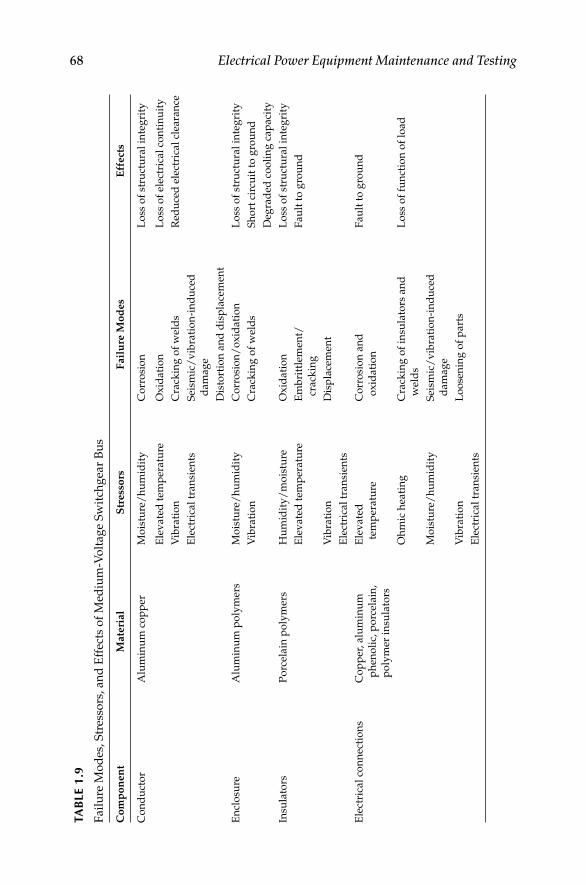
68 Electrical Power Equipment Maintenance and TestingTA
BLE
1.9
Fail
ure
Mo
des
, S
tres
sors
, an
d E
ffec
ts o
f M
ediu
m-V
olt
ag
e S
wit
chg
ear
Bu
s
Co
mp
on
en
tM
ate
rial
Str
ess
ors
Fail
ure
Mo
des
Eff
ect
s
Co
nd
uct
or
Alu
min
um
co
pp
erM
ois
ture
/h
um
idit
yC
orr
osi
on
Lo
ss o
f st
ruct
ura
l in
teg
rity
Ele
vate
d t
emp
eratu
reO
xid
ati
on
Lo
ss o
f el
ectr
ical
con
tin
uit
y
Vib
rati
on
Cra
ckin
g o
f w
eld
sR
edu
ced
ele
ctri
cal
clea
ran
ce
Ele
ctri
cal
tran
sien
tsS
eism
ic/
vib
rati
on
-in
du
ced
dam
ag
e
Dis
tort
ion
an
d d
isp
lace
men
t
En
clo
sure
Alu
min
um
po
lym
ers
Mo
istu
re/
hu
mid
ity
Co
rro
sio
n/
ox
idati
on
Lo
ss o
f st
ruct
ura
l in
teg
rity
Vib
rati
on
Cra
ckin
g o
f w
eld
sS
ho
rt c
ircu
it t
o g
rou
nd
Deg
rad
ed c
oo
lin
g c
ap
aci
ty
Insu
lato
rsP
orc
elain
po
lym
ers
Hu
mid
ity
/m
ois
ture
Ox
idati
on
Lo
ss o
f st
ruct
ura
l in
teg
rity
Ele
vate
d t
emp
eratu
reE
mb
ritt
lem
ent/
crack
ing
Fau
lt t
o g
rou
nd
Vib
rati
on
Dis
pla
cem
ent
Ele
ctri
cal
tran
sien
ts
Ele
ctri
cal
con
nec
tio
ns
Co
pp
er, alu
min
um
ph
eno
lic,
po
rcel
ain
,
po
lym
er i
nsu
lato
rs
Ele
vate
d
tem
per
atu
re
Co
rro
sio
n a
nd
ox
idati
on
Fau
lt t
o g
rou
nd
Oh
mic
hea
tin
gC
rack
ing
of
insu
lato
rs a
nd
wel
ds
Lo
ss o
f fu
nct
ion
of
load
Mo
istu
re/
hu
mid
ity
Sei
smic
/v
ibra
tio
n-i
nd
uce
d
dam
ag
e
Vib
rati
on
Lo
ose
nin
g o
f p
art
s
Ele
ctri
cal
tran
sien
ts
DK4058_C001.indd 68DK4058_C001.indd 68 11/17/2008 12:17:23 PM11/17/2008 12:17:23 PM

Maintenance Strategies, Dielectric Theory 69
1.8.1.5 Cables and Connectors
Cables and connectors properly installed and not subjected to mechanical forces, moisture, or extreme temperatures have a predictable long service lifetime. This life of cable is dominated by the aging of cable insulation system. Cable faults, very random in nature, normally only affect a short length of a specifi c cable and are cleared by the protective relaying and supply circuit breakers. Usually, if required, the cable can be repaired by splicing and replaced in service. In conduit, cables seldom can involve other cables or equipment, but when the cable is in an open tray with other cables, it can directly affect others through mechanical motion or by heating (fi re). Protective relays properly designed, installed, and kept calibrated, should clear cable faults in a short time and thus restrict the damage to the faulting cable. The cables can fail from any combination of electrical, mechanical, and thermal factors. A brief review of the insulating materials used for cables is needed in order to better understand cable failure modes. Insulating materi-als for cables may be classifi ed into two categories: (1) impregnated paper insulation and (2) polymeric insulation and sheathing materials. Today, syn-thetic polymers have replaced natural materials such as paper, mineral oil, and natural rubber for the cable insulation and over sheathing of cables.
Impregnated paper insulation: Paper insulation consists of a felted mat of long cellulose fi bers derived by chemical treatment of wood pulp. Paper is impreg-nated with suitable oils and compounds to give it good electrical properties and help reduce moisture absorption. A variation of paper insulation is poly-propylene paper laminate known as PPL or PPLP is used in tape form. It is comprised of a layer of extruded polypropylene in which two thin layers of insulting paper are bonded. The combination of polypropylene and paper has insulation properties of low dielectric loss, high permittivity, high oper-ating temperature, high mechanical strength, low elasticity and high tensile strength, and high resistance to partial discharges.
Polymeric insulation: In cable industry, polymeric materials are taken to be poly-mers which are plastics or rubbers. Rubbers are considered to be elastomer materials (elastic properties) that are materials which return to their original shape easily. In cable insulation terminology, the term rubbers and elastomer are used interchangeably although rubbers may imply natural rubber to many. Polymeric insulation may be classifi ed as thermoplastic and thermosetting. The thermoplastic insulations are polyvinyl chloride (PVC), polyethylene, polypro-pylene, nylon, polyurethanes, polyester, block copolymers, Buna rubber, and fl uorinated polymers. The thermosetting insulations are ethylene–propylene rubber (EPR), cross-linked polyethylene (XLPE), cross-linked ethylene vinyl acetate, and silicone rubber. The reader is urged to refer to Section 6.2.4 for further description of thermoplastic and thermosetting insulation types. The polymer-type insulations are known as polyolefi ns and are the preferred insulating mate-rials for cables because they have superior properties than paper insulation. The polyolefi ns have low dielectric constant, low DF, high dielectric strength, excel-lent resistance to moisture, and high resistance to chemicals and solvents.
DK4058_C001.indd 69DK4058_C001.indd 69 11/17/2008 12:17:23 PM11/17/2008 12:17:23 PM

70 Electrical Power Equipment Maintenance and Testing
The service environments in which power cables operate are varied and may include mild environments, as well as harsh environments with high temperature levels. Power cables used to energize medium-voltage equipment, such as pump motors and switchgear, must operate at voltages and currents that are signifi cantly higher than cables for control and instru-mentation. Because medium-voltage power cables operate at higher voltages, there is an increased stress on the cables, which could accelerate aging degra-dation due to internal ohmic heating and partial discharges (corona). In addi-tion, medium-voltage cables are susceptible to unique aging mechanisms, such as water treeing, that low-voltage cables (600 V) do not experience. Placement in conduit, raceways, underground ducts, and cable trays affects the service conditions under which the cables must operate. Routing in densely fi lled cable trays, enclosed ducts, or fi re-wrapped cable trays, together with other continuous duty power cables, will result in elevated operating temperatures. Exposure to elevated temperatures can also be caused by the location, such as for cables installed in close proximity to high-temperature steam lines. Aging due to elevated temperatures will cause the various poly-mers used to insulate the cables to degrade, resulting in loss of elongation, embrittlement, and eventual cracking over long exposure periods.
Exposure to moisture can also degrade power cables. This can occur for cables installed below grade in ducts or conduits that are susceptible to water intrusion, or for cables buried directly in the ground. Cables exposed to water while energized are susceptible to a phenomenon called water treeing in which tree-like microcracks are formed in the insulation due to electrochemi-cal reactions. The reactions are caused by the presence of water and the rela-tively high electrical stress on the insulation at local imperfections within the insulating material, such as voids and contaminant sites that effectively increase the voltage stress at that point in the insulation. Moisture can also cause corrosion of the various metallic components in the cable, such as metal-lic shields or the conductor. In general, aging degradation of the insulating material is of the most concern for medium-voltage power cables. The other subcomponents are also susceptible to aging degradation due to the various stressors to which they are exposed; however, their degradation rate is usually minimal. Some specifi c causes of power cable failures are the following:
Short to ground•
Conductor-to-conductor short•
Reduced insulation resistance•
Reduced dielectric strength•
Excessive partial discharge•
The failure modes of the cable insulation are dependent on many factors that determine the maximum operating temperature. For most thermoset materials life is determined by the susceptibility of the material to thermal degradation at elevated temperatures (heat) and oxygen. Hydrocarbon polymers oxidize thermally which then cause large changes in mechanical and electrical properties.
DK4058_C001.indd 70DK4058_C001.indd 70 11/17/2008 12:17:23 PM11/17/2008 12:17:23 PM

Maintenance Strategies, Dielectric Theory 71
For some thermoplastics, such as polyethylene, the main determining factor is resistance to deformation. The failure modes of cables are
Electrically induced failures: These involve lightning, switching surges, and partial discharges. The partial discharges may be caused by poor insu-lation system design or by manufacturing defects. The partial discharge phenomenon is well known for the XLPE cable and is discussed in more detail in Section 6.10.1.
Mechanically induced failures: A mechanically induced failure can occur during installation by using excessive pulling tension and/or exceeding minimum bending radii. Cable can also be damaged during construction when earth moving equipment can dig into the cable or cable duct banks. Repeated bending and twisting during installation or in service can result in irreversible straining of conductor wires.
Thermally induced failures: Thermal degradation causes the insulation of the cable to loose its physical properties. The thermally induced failures are due to overloading beyond its design capability for extended periods and/or excessive ambient temperature conditions.
Metallic (semiconducting) shield damage: This failure mode describes where the shield ceases to perform its function. In order for the shield to perform its function, its volume resistivity must always remain suffi ciently low. However, when metallic shield is damaged or corroded its volume resistivity is impacted by temperature. At higher temperatures, the volume resistivity of the metallic shield increases signifi cantly (due to peak loads, unbalance cur-rents, or circulating currents) giving rise to high voltage gradients at sharp metal edges that will lead to corona and arcing damage (from outside in). The corona and arcing will lead to eventual cable insulation failure.
Poor metallic shield contact: This is the case where the metallic shield is insulated from the semiconducting tape shield because of poor contact. This can be caused by a layer of corrosion or scale buildup on the metallic shield. Such a condition will give rise to a potential difference between the semiconducting shield and the metallic shield that will cause arcing between the two shields. This will lead to arcing damage from the outside into semiconducting shield and insulation and eventual cable failure. This situation is more severe if there are multiple areas of poor contact or breaks between the two shield systems. The reader should refer to Section 6.9 for more details on causes of cable failures and analyses. Failure modes stressors and effects of medium-voltage cables are summarized in Table 1.10.
1.8.1.6 Rotating Machines
Insulation is an inherent component of the machine windings (motors and generators). The purpose of the insulation system is to prevent circulating currents fl owing between various conductors in the machine windings and to prevent short circuits between respective phases and phase to ground.
DK4058_C001.indd 71DK4058_C001.indd 71 11/17/2008 12:17:23 PM11/17/2008 12:17:23 PM

72 Electrical Power Equipment Maintenance and Testing
TAB
LE 1
.10
Fail
ure
Mo
des
, S
tres
sors
, an
d E
ffec
ts o
f C
ab
les
Co
mp
on
en
tM
ate
rial
Str
ess
ors
Fail
ure
Mo
des
Eff
ect
s
Insu
lati
on
Vari
ou
s p
oly
mer
mate
rials
(e.g
., X
LP
E, E
PR
)
Ele
vate
d t
emp
eratu
reE
mb
ritt
lem
ent
Dec
rease
in
die
lect
ric
stre
ng
th
Cra
ckin
gIn
crea
se i
n l
eak
ag
e cu
rren
ts
Ev
entu
al
fail
ure
Vari
ou
s p
oly
mer
mate
rials
th
at
are
per
mea
ble
to
mo
istu
re
Wet
tin
gM
ois
ture
in
tru
sio
nD
ecre
ase
in
die
lect
ric
stre
ng
th
Incr
ease
in
lea
kag
e cu
rren
ts
Ev
entu
al
fail
ure
Vari
ou
s p
oly
mer
mate
rials
that
do
no
t co
nta
in a
tre
e
reta
rdan
t ad
dit
ive
Wet
tin
g c
on
curr
ent
wit
h
vo
ltag
e
Ele
ctro
chem
ical
react
ion
sD
ecre
ase
in
die
lect
ric
stre
ng
th
Wate
r tr
eein
gIn
crea
se i
n l
eak
ag
e cu
rren
ts
Ev
entu
al
fail
ure
Vari
ou
s p
oly
mer
mate
rials
that
hav
e v
oid
s o
r o
ther
imp
erfe
ctio
ns
Vo
ltag
eP
art
ial
dis
charg
eD
ecre
ase
in
die
lect
ric
stre
ng
th
Ele
ctri
cal
tree
ing
Incr
ease
in
lea
kag
e cu
rren
ts
Ev
entu
al
fail
ure
Jack
etV
ari
ou
s p
oly
mer
mate
rials
(e.g
., C
SP
E, N
eop
ren
e)
Ele
vate
d t
emp
eratu
reE
mb
ritt
lem
ent
Lo
ss o
f st
ruct
ura
l in
teg
rity
Cra
ckin
gIn
crea
sed
in
tru
sio
n o
f
mo
istu
re a
nd
co
nta
min
an
ts
to c
ab
le i
nte
rio
r
Vari
ou
s p
oly
mer
mate
rials
(e.g
., C
SP
E, N
eop
ren
e)
Han
dli
ng
or
ab
use
du
rin
g
main
ten
an
ce, te
stin
g a
ctiv
itie
s
Mec
han
ical
dam
ag
e
incl
ud
ing
cru
shin
g,
ben
din
g, cu
ttin
g, ab
rasi
on
Lo
ss o
f st
ruct
ura
l in
teg
rity
DK4058_C001.indd 72DK4058_C001.indd 72 11/17/2008 12:17:23 PM11/17/2008 12:17:23 PM

Maintenance Strategies, Dielectric Theory 73In
crea
sed
in
tru
sio
n o
f
mo
istu
re a
nd
co
nta
min
an
ts
to c
ab
le i
nte
rio
r
Vari
ou
s p
oly
mer
mate
rials
(e.g
., C
SP
E, N
eop
ren
e)
Vib
rati
on
Mec
han
ical
dam
ag
e
incl
ud
ing
cu
ttin
g,
ab
rasi
on
Lo
ss o
f st
ruct
ura
l in
teg
rity
Incr
ease
d i
ntr
usi
on
of
mo
istu
re a
nd
co
nta
min
an
ts
to c
ab
le i
nte
rio
r
Co
nd
uct
or
Co
pp
erW
etti
ng
du
e to
mo
istu
re
intr
usi
on
Co
rro
sio
nIn
crea
sed
res
ista
nce
to
cu
rren
t
fl o
w
Ox
ide
form
ati
on
Incr
ease
d o
hm
ic h
eati
ng
Alu
min
um
Vib
rati
on
Lo
ose
nin
g o
f co
nn
ecto
rsL
oss
of
stru
ctu
ral
inte
gri
ty
Met
al
fati
gu
eD
egra
ded
co
nn
ecto
r co
nta
ct
Alu
min
um
Co
mp
ress
ive
forc
esC
old
fl o
wL
oss
of
con
tact
on
co
nn
ecto
rs
Lo
ose
nin
g o
f co
nn
ecto
rsIn
crea
sed
res
ista
nce
to
cu
rren
t
fl o
w
Incr
ease
d o
hm
ic h
eati
ng
Sh
ield
Co
pp
er t
ap
eW
etti
ng
du
e to
mo
istu
re
intr
usi
on
Co
rro
sio
nL
oss
of
stru
ctu
ral
inte
gri
ty
Ox
ide
form
ati
on
Incr
ease
d i
nsu
lati
on
deg
rad
ati
on
du
e to
part
ial
dis
charg
es
Sem
ico
nd
uct
ing
po
lym
ers
Ele
vate
d t
emp
eratu
reE
mb
ritt
lem
ent
Lo
ss o
f st
ruct
ura
l in
teg
rity
Cra
ckin
gIn
crea
sed
in
sula
tio
n
deg
rad
ati
on
du
e to
part
ial
dis
charg
es
Sh
eath
Lea
dA
lkali
ne
env
iro
nm
ent
(e.g
., f
ree
lim
e fr
om
con
cret
e d
uct
s)
Co
rro
sio
nL
oss
of
stru
ctu
ral
inte
gri
ty
Incr
ease
d i
ntr
usi
on
of
mo
istu
re a
nd
co
nta
min
an
ts
to c
ab
le i
nte
rio
r
DK4058_C001.indd 73DK4058_C001.indd 73 11/17/2008 12:17:23 PM11/17/2008 12:17:23 PM

74 Electrical Power Equipment Maintenance and Testing
In an AC machine, there are three major components of insulation systems: (1) the stator winding, (2) the rotor, and (3) the steel laminations in the stator and the rotor cores. The insulation systems for the stator windings are dis-cussed in more detail in Section 10.8.1. The rotor of an induction motor is not insulated because there is no voltage directly applied to it and the induced voltage is only a few volts. For AC synchronous machines and wound rotor induction motors, a voltage (less than the voltage of the stator windings) is applied to the rotor, therefore, the rotors of these machines have insulated windings. Majority of the insulation used in machine windings (stator and rotor) comprises of organic materials, such as varnish, polyester, and epoxy rated for an in-service operating temperature. Table 1.2 provides information on the various types of insulation systems classifi cation established by IEEE Standard 1-2000. Refer to Section 10.8.1 for the insulating materials used in the make up of each insulation classifi cation. Machine stator insulation can be broadly classifi ed into random-wound stators and form-wound stators. Random-wound windings are used for low-voltage machines (2300 V and below), usually for 600 V class motors. Form-wound stator windings are used for high-voltage machines where the coils are preformed and shaped into rectangle (diamond) and then inserted into slots of the machine stator. The major difference between the form-wound and random-wound machines is that the form-wound machine has separate turn insulation and ground insulation. The stator of random-wound machine consists of strand (or conductor) insulation, ground insulation, coil separators, phase insulation, wedges, tapes and tie cords, varnishes, and resins. Form-wound machines stator insulation consists of preinsulated coils, strand and turn insulation, groundwall insulation, wedges, blocking and bracing, and semiconducting coating for control of partial discharges. In the formation of the form-wound stators, four manufacturing processes are used. They are (1) vacuum pressure impregnation (VPI) of individual coils and bars, (2) global VPI of whole stator, (3) hydraulic molding of individual coils and bars with resin rich tapes, and (4) press curing of individual coils and bars. Also, over the years several trademarked insulation systems have evolved for form-wound stator insulation system. The trademarked insulation systems are unique to each manufacturer and are beyond the scope of this book.
Machine design, insulation system, and the care and maintenance including condition monitoring of the machine are the main factors in determining how long the machine will last. One of the questions often asked is what is the expected service life of a machine (motor)? It is diffi cult to answer this ques-tion defi nitively. In view of the diffi culties in predicting motor life, data do exist in various texts that indicate the average motor life as a function of hp. One such data are given in Table 1.11. There are many critical factors that can affect the motor life. Manufacturers design and build their motors to last a specifi ed number of years based on the materials used, operating conditions, and the correct maintenance and care. However, before the insulation system of the motor can wear out, it is prematurely destroyed by misuse and/or misapplication, electrical stresses, thermal stresses, mechanical stresses, and hostile environment conditions.
DK4058_C001.indd 74DK4058_C001.indd 74 11/17/2008 12:17:23 PM11/17/2008 12:17:23 PM

Maintenance Strategies, Dielectric Theory 75
The insulation system of a machine stator winding is complex and com-prises of many insulating materials. The machine insulation system must be able to withstand continuous and transient stresses simultaneously imposed on it. These stresses are electrical, thermal, mechanical, and environmental and these stresses gradually degrade the insulation over its life. The electrical stresses can be dielectric aging, tracking, corona, poor connections, and transients (surges). The thermal stresses are aging, voltage unbalance and variations, cycling, loading, lack of ventilation, and excessive ambient tem-perature. The mechanical stresses are coil movement, rotor strikes, defective rotor, fl ying objects, and lugging of leads. The environmental stresses are moisture, chemical spills, abrasion, damaged parts, and restricted ventilation. The effect of these stresses lead to degradation and failure of the stator windings that can be classifi ed as failure modes. The reader should refer to Section 10.9 for additional information and inspection for evaluating the condition of machine insulation. The failure modes are discussed under each category of stress.
Electrical failure modes: Machine stator windings are exposed to surges that are due to lightning, ground faults, inductive load switching, closing of breakers under out of phase conditions, and variable speed drives (VFDs). The voltage between turns under normal operating conditions is relatively low (usually <100 V). Repetitive voltage surges gradually deteriorate turn-to-turn insulation, groundwall insulation, and semiconductive and grading coatings. Surges pro-duced by VFDs and other sources can create voltage transient with very fast rise times that can generate frequencies in the megahertz range. The high frequen-cies in the stator cause nonlinear distribution of voltage with a much greater percentage of the voltage appearing across the turn in the fi rst coil connected to the phase terminal. The end result is that a very large voltage (as much as 40% of surge voltage) is impressed across the fi rst turn. This voltage can be as high as several kilovolts across the turn insulation for a short time. The high voltage gives rise to partial discharges in the voids in the vicinity of the copper turns. Random-wound stators with magnetic wire are very susceptible to this mode of failure. Also, VFDs can create high-voltage surges due to voltage refl ections
TABLE 1.11
Average Electric Motor Life
Range (hp) Average Life (Years) Life Range (Years)
<1 12.9 10–15
1–5 17.1 13–19
6–20 19.4 16–20
21–50 21.8 18–26
51–125 28.5 24–33
>125 29.3 25–38
Source: From Andreas, J.C., Energy-Effi cient Electric Motors: Selection and Application, Marcel Dekker, Inc., New York, 1982.
DK4058_C001.indd 75DK4058_C001.indd 75 11/17/2008 12:17:23 PM11/17/2008 12:17:23 PM

76 Electrical Power Equipment Maintenance and Testing
between the power cable and the motor surge impedance. This phenomenon also can lead to partial discharges that can degrade the ground and phase insu-lation. Electrical tracking is the formation of carbonized (conductive) path over the insulation surface in the end winding region of the stator. Tracking can result due to contaminated surfaces that enable the current to fl ow on the surface of the insulation of the end windings. These conductive regions will pick up capacitive charge from the high-voltage windings of the machine. Consequently, leakage current will begin to fl ow in the conductive paths on adjacent paths or from these paths to the core with sparking at the surface discontinuities. The sparking currents degrade the insulation and create conductive carbonized paths to ground and between phases. This failure mode causes the groundwall and/or phase insulation to fail. Another failure mode can be attributed to air pockets within the stator insulation. These air pockets are formed during make up of formed coils and/or installation of coils in the stator slots. Also excessive heating will degrade the organic insulation and it will delaminate creating air pockets within the groundwall insulation. The dielectric strength of the insula-tion with air pockets will be reduced by as much as a four factor to that of air. If the voltage is high enough, the electric stress across the void will be high and a spark will occur in the void since the breakdown voltage of the air is much lower than the breakdown voltage of the solid insulation. This phenomenon is known as partial discharging in the voids and is stopped by groundwall insula-tion. However, repeated sparking will gradually break down the groundwall insulation. Many electrical connections are required for the coils and windings in the construction of a typical machine stator winding. Generally, form-wound stator insulation tends to have more voids than the random-wound stator insu-lation, and therefore is more susceptible to partial discharges. If the connections are made poorly the resistance of these connection will be high that will lead to overheating of the joints which then can degrade the insulation. Form-wound stator windings are more susceptible to this phenomenon since there are more joints that are required between coils and bars. However, any stator windings can have this problem that can eventually lead to failure of the machine.
Thermal failure modes: Thermal stresses are evidenced by looseness of the wind-ings, adhesion of insulating materials and components, and loss of resistance to moisture. The I 2R losses (load losses) and eddy current losses in the windings, the stator core losses and the dielectric losses in the groundwall insulation give rise to the temperature of the copper conductors, core, and insulation. However, the temperature at the strand insulation is higher than the groundwall insula-tion. The temperature of stator windings can be higher than normal for several reasons. The temperature of air circulating to cool the machine increases above normal because of clogged plugged fi lters, air ducts, or heat exchanger prob-lems. Another reason for the increase in winding temperature could be due to overloading the motor, or too frequent starting without allowing suffi cient time between starts to allow the windings to cool down. Negative sequence currents in the will fl ow in the windings due to unbalance supply voltages to a machine. The negative currents create an opposing torque which the machine has to over-come by increasing current in the windings. Therefore, the negative sequence
DK4058_C001.indd 76DK4058_C001.indd 76 11/17/2008 12:17:23 PM11/17/2008 12:17:23 PM
Maintenance Strategies, Dielectric Theory 77
currents cause additional heating in the winding. Similarly, single phasing (loss of a phase) in the power supply to the motor can cause increase in current by as much as 200% of rated phase current. The continuous overheating can result in failure of the interstrand and strand-to-groundwall bonds because the strength of the bonds (both thermoplastic and thermosetting) decreases as the tempera-ture increases. As the bonds fail, individual copper strands become loose. Thermal and magnetic forces in the machine windings cause the strands move-ment resulting in abrasion of the strand insulation and reduced heat transfer between the conductors and groundwall insulation. This process leads to turn-to-turn failures due to insulation abrasions or mechanical failure. Also, continu-ous operation at elevated temperatures will cause the epoxy and polyester to become brittle and shrink somewhat. The embrittlement and shrinkage will cause abrasions and cracking of the groundwall insulation during machine starting. The machine operation at the high temperatures will similarly cause the end winding blocking and bracing to slowly shrink and become brittle. During motor starting, the looseness can then lead to movement of the coils causing abrasion and/or cracking of the insulation. Another failure mode can be attributed to thermal cycling by starting motors too frequently. Because of different coeffi cient of thermal expansion for copper and insulation materials, the difference in expansion between these materials creates shear stress. As a result of weakened strength of bond materials due to higher operating tempera-tures, the bond between the copper and the groundwall is lost creating gaps and delamination in the insulation. Thermal cycling can also weaken the bonds between the coils and the blocking and bracing in the endwinding. This will cause components to become loose and lead to abrasion of the insulation.
Mechanical failure modes: Mechanical forces in the stator windings are generated by currents fl owing in the magnetic circuit of the machine stator, and from ther-mal expansion due to normal load currents. Magnetic forces are produced in the stator coils from the interaction of the rotor poles and stator slots which will tend to move the coils. This electromagnetic phenomenon occurs at twice normal frequency and is referred to as 120 Hz vibrations. The force produced by the above phenomenon is proportional to the square of the current. The mechan-ical forces are more pronounced in coils that are near the surface of the stator, i.e., adjacent to the air gap. Also, additional mechanical forces are generated between adjacent coils as a result of current fl owing in each coil. Form-wound stator windings using thermoset insulation system are more susceptible to these cyclic forces because they are less fl exible and it is more diffi cult to ensure that the coils are tightly wedged in the slots. Stator windings using thermoplastic insulation system are less susceptible to this phenomenon because the insula-tion is more fl exible and tends to restrict coil movement by swelling and fl owing to fi ll the slot. The conductor and groundwall insulation are cyclically stressed by compression and fl exing because of coil movement resulting from these forces. The insulation may be damaged by the relative movement of strands and/or coils in the slots. The normal 60 Hz current fl owing through the stator coils and bars creates magnetic forces at the rate of 120 Hz that causes relative movement between coils and/or bracing points in the end windings. If the end
DK4058_C001.indd 77DK4058_C001.indd 77 11/17/2008 12:17:23 PM11/17/2008 12:17:23 PM

78 Electrical Power Equipment Maintenance and Testing
windings are not secured adequately they will rub against each other which will gradually abrade the insulation and lead to eventual failure. This failure mode also cause cracking of groundwall insulation which can lead to a ground fault, or abrasion of strand and conductor insulation resulting in turn-to-turn faults, or loss of semiconducting coating (if present) due to abrasions in the groundwall insulation, thus leading to partial discharges that can fail the groundwall insulation.
Environmental failure modes: The life of the machine winding insulation is dependent upon the environment in which it operates. The major environmen-tal factors that can lead to a failure of the insulation were previously listed as moisture, chemicals, abrasive particles, contamination, and restricted ventila-tion. If there is excessive moisture, contamination (dust, dirt, and oil) combined with chemicals on the windings, and particularly on the end windings, can lead to electrical tracking or loss of insulation resistance and dielectric strength. The tracking failure mode was discussed under electrical failure modes. The loss of insulation resistance can lead to increased leakage currents in the insulation that will translate into higher temperatures. The higher temperatures in turn will lead to lower insulation resistance and so on. This phenomenon is self-perpetuating and if allowed to continue will cause machine failure. Similarly, the combination of moisture, dust, and other contaminants degrade the insula-tion’s mechanical and electrical properties. As a result of this contamination, the dielectric strength of the insulation system is reduced and thereby making it susceptible to failure by switching surges as was discussed under electrical failure modes. Another environmental factor is ambient that has signifi cance for machines that are cooled by ambient air only. As the ambient temperature increases above the rated machine design ambient temperature, so will the winding temperature. If the total resulting temperature (ambient plus rise) is higher than the insulation rated temperature, it will degrade the insulation and failure may occur as was discussed under thermal failure modes. Abrasive par-ticles in the cooling air (or closed cooling system) can cause erosion from impingement of the stator winding insulation. This problem is most likely to occur on open ventilated machines installed in dirty and abrasive environ-ments. The insulation degradation from abrasive particles (dirty environment) can lead to interturn, ground or phase-to-phase faults. Chemicals can deterio-rate the insulation if the insulation is exposed to acids, alkalis, paints, solvents, and the like. In some industries motors operate in such environments and therefore are susceptible to chemical attacks. This problem can also occur if the machine was cleaned with chemicals that are not combatable with the machine insulation system. Some older insulation systems using asphalt, varnish, and early polyesters as bonding agents are prone to softening, swelling, and loss of mechanical and electrical strength from exposure to certain chemicals. Modern stator windings insulation systems are less prone to chemical attacks. The most important means of preventing winding failure by this mechanism are to use totally enclosed machine, oil and grease leaks are contained, and that correct chemicals are used in cleaning of the windings. Table 1.12 summarizes the fail-ure modes, aging stressors, and effects of machines.
DK4058_C001.indd 78DK4058_C001.indd 78 11/17/2008 12:17:24 PM11/17/2008 12:17:24 PM
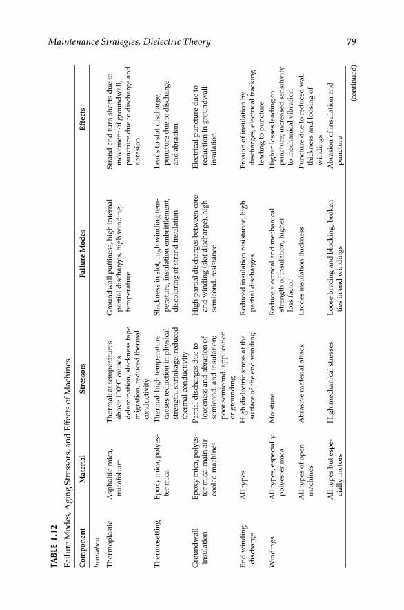
Maintenance Strategies, Dielectric Theory 79TA
BLE
1.1
2
Fa
ilu
re M
od
es, A
gin
g S
tres
sors
, a
nd
Eff
ects
of
Ma
chin
es
Co
mp
on
en
tM
ate
rial
Str
ess
ors
Fail
ure
Mo
des
Eff
ect
s
Insu
lati
on
Th
erm
op
last
icA
sph
alt
ic-m
ica,
mic
afo
liu
m
Th
erm
al:
at
tem
per
atu
res
ab
ov
e 100°C
cau
ses
del
am
inati
on
, sl
ack
nes
s ta
pe
mig
rati
on
, re
du
ced
th
erm
al
con
du
ctiv
ity
Gro
un
dw
all
pu
ffi n
ess,
hig
h i
nte
rnal
part
ial
dis
charg
es, h
igh
win
din
g
tem
per
atu
re
Str
an
d a
nd
tu
rn s
ho
rts
du
e to
mo
vem
ent
of
gro
un
dw
all
,
pu
nct
ure
du
e to
dis
charg
e an
d
ab
rasi
on
Th
erm
ose
ttin
gE
po
xy
mic
a, p
oly
es-
ter
mic
a
Th
erm
al:
hig
h t
emp
eratu
re
cau
ses
red
uct
ion
in
ph
ysi
cal
stre
ng
th, sh
rin
kag
e, r
edu
ced
ther
mal
con
du
ctiv
ity
Sla
ckn
ess
in s
lot,
hig
h w
ind
ing
tem
-
per
atu
re, in
sula
tio
n e
mb
ritt
lem
ent,
dis
colo
rin
g o
f st
ran
d i
nsu
lati
on
Lea
ds
to s
lot
dis
charg
e,
pu
nct
ure
du
e to
dis
charg
e
an
d a
bra
sio
n
Gro
un
dw
all
insu
lati
on
Ep
ox
y m
ica, p
oly
es-
ter
mic
a, m
ain
air
coo
led
mach
ines
Part
ial
dis
charg
es d
ue
to
loo
sen
ess
an
d a
bra
sio
n o
f
sem
ico
nd
. an
d i
nsu
lati
on
;
po
or
sem
ico
nd
. ap
pli
cati
on
or
gro
un
din
g
Hig
h p
art
ial
dis
charg
es b
etw
een
co
re
an
d w
ind
ing
(sl
ot
dis
charg
e), h
igh
sem
ico
nd
. re
sist
an
ce
Ele
ctri
cal
pu
nct
ure
du
e to
red
uct
ion
in
gro
un
dw
all
insu
lati
on
En
d w
ind
ing
dis
charg
e
All
ty
pes
Hig
h d
iele
ctri
c st
ress
at
the
surf
ace
of
the
end
win
din
g
Red
uce
d i
nsu
lati
on
res
ista
nce
, h
igh
part
ial
dis
charg
es
Ero
sio
n o
f in
sula
tio
n b
y
dis
charg
es, el
ectr
ical
track
ing
lead
ing
to
pu
nct
ure
Win
din
gs
All
ty
pes
, es
pec
iall
y
po
lyes
ter
mic
a
Mo
istu
reR
edu
ce e
lect
rica
l an
d m
ech
an
ical
stre
ng
th o
f in
sula
tio
n, h
igh
er
loss
fact
or
Hig
her
lo
sses
lea
din
g t
o
pu
nct
ure
; in
crea
sed
sen
siti
vit
y
to m
ech
an
ical
vib
rati
on
All
ty
pes
of
op
en
mach
ines
Ab
rasi
ve
mate
rial
att
ack
Ero
des
in
sula
tio
n t
hic
kn
ess
Pu
nct
ure
du
e to
red
uce
d w
all
thic
kn
ess
an
d l
oo
sin
g o
f
win
din
gs
All
ty
pes
bu
t es
pe-
ciall
y m
oto
rs
Hig
h m
ech
an
ical
stre
sses
Lo
ose
bra
cin
g a
nd
blo
ckin
g, b
rok
en
ties
in
en
d w
ind
ing
s
Ab
rasi
on
of
insu
lati
on
an
d
pu
nct
ure
(co
nti
nu
ed)
DK4058_C001.indd 79DK4058_C001.indd 79 11/17/2008 12:17:24 PM11/17/2008 12:17:24 PM
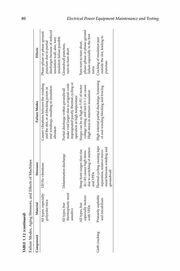
80 Electrical Power Equipment Maintenance and TestingTA
BLE
1.1
2 (c
onti
nued
)
Fa
ilu
re M
od
es, A
gin
g S
tres
sors
, a
nd
Eff
ects
of
Ma
chin
es
Co
mp
on
en
tM
ate
rial
Str
ess
ors
Fail
ure
Mo
des
Eff
ect
s
All
ty
pes
, es
pec
iall
y
po
lyes
ter
mic
a
120 H
z v
ibra
tio
ns
Cau
ses
vib
rati
on
s b
etw
een
th
e w
ind
ing
an
d t
he
slo
t, o
r at
blo
ckin
g p
oin
ts i
n
end
win
din
gs,
res
ult
ing
in
in
sula
tio
n
ab
rasi
on
Ph
ase
–p
hase
or
ph
ase
–g
rou
nd
pu
nct
ure
du
e to
part
ial
dis
charg
es b
ecau
se o
f re
du
ced
insu
lati
on
wall
; als
o, tu
rn
insu
lati
on
fail
ure
po
ssib
le
All
ty
pes
, b
ut
ther
mo
pla
stic
mo
st
sen
siti
ve
Del
am
inati
on
dis
charg
eP
art
ial
dis
charg
e w
ith
in g
rou
nd
wall
mak
e v
oid
larg
er d
ue
to o
rig
inal
vo
ids
imp
reg
nate
d p
oo
rly,
th
erm
al
cycl
ing
or
op
erati
on
at
hig
h t
emp
eratu
re
Gro
un
dw
all
pu
nct
ure
,
turn
-to
-tu
rn s
ho
rt
All
ty
pes
, b
ut
esp
ecia
lly
mo
tors
wit
h V
FD
s
Ste
ep f
ron
t su
rges
(fa
st r
ise
dv/
dt)
cau
ses
hig
h s
tres
s
du
e to
sw
itch
ing
of
start
ers
an
d V
FD
s
Su
rges
can
be
as
hig
h a
s 5 P
U o
f m
oto
r
vo
ltag
e ra
tin
g, an
d l
ast
0.1
–1 μ
s ca
use
Hig
h s
tres
s in
in
tert
urn
in
sula
tio
n
Tu
rn-t
urn
-to
-tu
rn s
ho
rt,
ph
ase
–p
hase
or
ph
ase
–g
rou
nd
fail
ure
esp
ecia
lly
in
th
e fi
rst
turn
s
Gir
th c
rack
ing
Pri
mari
ly a
sph
alt
ic
an
d m
icafo
liu
m
Th
erm
al
cycl
ing
cau
sin
g t
ap
e
sep
ara
tio
n, re
lati
ve
mo
ve-
men
t b
etw
een
win
din
g a
nd
gro
un
dw
all
Hig
h i
nte
rnal
part
ial
dis
charg
e, l
oo
sen
ing
of
end
win
din
g b
lock
ing
an
d b
raci
ng
Cra
ckin
g o
f in
sula
tio
n ju
st
ou
tsid
e th
e sl
ot,
lea
din
g t
o
pu
nct
ure
DK4058_C001.indd 80DK4058_C001.indd 80 11/17/2008 12:17:24 PM11/17/2008 12:17:24 PM

Maintenance Strategies, Dielectric Theory 81
1.9 Maintenance of Protective Devices and their
Impact on Arc-Flash Hazard Analysis
EPM and testing is not only important for the reliability and integrity of electrical distribution systems, but also for the safety and protection of people. PM of overcurrent protective devices and breakers, is often overlooked, performed infrequently, or is performed improperly. This maintenance and testing of the protective devices has taken on a greater importance because the operating times of these devices are credited in the arc-fl ash hazard anal-ysis, the selection of personal protective equipment (PPE) and protecting the worker from shock and arc-fl ash hazards. To show why the maintenance and reliability of protective devices has become extremely important for protect-ing workers from arc-fl ash hazard and for labeling of electrical equipment to warn workers of such hazard, we will review and discuss the following:
1. Industry practice and regulatory bases for maintenance and testing of
Molded-case circuit breakers•
Low-voltage power circuit breakers•
Medium-voltage circuit breakers•
Protective relays•
2. Failure statistics for overcurrent protective devices
3. Impact of overcurrent protective devices on arc-fl ash hazards
1.9.1 Bases of Maintenance and Testing of Protective Devices
The NEC Articles 210-20, 215-3, 240-1, and 240-3 specify requirements for the protection of electrical equipment and conductors. The Fine Print Note (FPN) to Article 240-1, Scope, states, “Overcurrent protection for conductors and equipment is provided to open the circuit if the current reaches a value that will cause an excessive or dangerous temperature in conductors or conductor insu-lation.” To protect against overcurrent conditions, the only way to ensure that circuit breakers, overcurrent relays, and protective devices are working cor-rectly is through regular maintenance and testing of these devices. There are several steps that must be taken in order to establish an effective maintenance program for the breakers and overcurrent protective devices. The fi rst step in correctly maintaining electrical equipment and overcurrent protective devices is to understand the requirements and recommendations for electrical equip-ment maintenance from various sources. Examples of such sources include, but are not limited to, the manufacturer’s instructions, NFPA 70B, IEEE Standard 902 (Yellow Book), NEMA AB-4, NETA Specs, NFPA 70E and this book.
The second step in performing maintenance and testing is to provide adequate training and qualifi cation for employees. NFPA 70E, Section 205.1 states, “Employees who perform maintenance on electrical equipment and installations shall be qualifi ed persons … and shall be trained in and be
DK4058_C001.indd 81DK4058_C001.indd 81 11/17/2008 12:17:24 PM11/17/2008 12:17:24 PM

82 Electrical Power Equipment Maintenance and Testing
familiar with the specifi c maintenance procedures and tests required.” The NEC defi nes a qualifi ed person as “One who has skills and knowledge related to the construction and operation of the electrical equipment and installations and has received safety training on the hazards involved.” It is vitally impor-tant that employees be properly trained and qualifi ed to maintain electrical equipment in order to increase the equipment and system reliability, as well as the employee’s safety.
The third step is to have a written, effective EPM program. NFPA 70B makes several very clear statements about an effective EPM program. These statements include
1. Deterioration of electrical equipment is a normal process, but that does not mean that equipment failure is eminent. If unchecked, dete-rioration will eventually cause equipment malfunction or complete failure. There are several factors that can accelerate the deterioration process, such as the environment, overload conditions, or severe duty cycles. An effective EPM program will help to identify and correct any or all of these conditions.
2. In addition to the deterioration problem, there are several other potential causes of equipment failure. These causes include, but are not limited to, load changes, circuit alterations, improper or misad-justed settings of protective devices, improperly selected protective devices, and changing voltage conditions.
3. With the absence of an effective EPM program, management assumes a greater responsibility for and an increased risk of a serious electrical failure, as well as the consequences.
4. An effective EPM program, that is administered properly, will reduce costly shutdowns and outages, reduce accidents, and save lives. These programs will identify impending troubles and apply solutions to correct them, before they become major problems that require time consuming and more expensive solutions.
IEEE Standard 902 states: “In planning an EPM program, consideration must be given to the costs of safety, the costs associated with direct losses due to equipment damage, and the indirect costs associated with downtime or lost or ineffi cient production.”
The forth step is that all maintenance and testing of electrical protective devices must be accomplished in accordance with the manufacturer’s instruc-tions. NFPA 70E adds to this by stating: “Protective devices shall be maintained to adequately withstand or interrupt available fault current.” It goes on to state, “Circuit breakers that interrupt faults approaching their ratings shall be inspected and tested in accordance with the manufacturers’ instructions.” In the absence of the manufacturer’s instructions, the NETA Maintenance Testing Specifi cations for Electrical Power Distribution Equipment and Systems is an excellent source of information for performing the required maintenance and testing of these devices. However, the manufacturer’s
DK4058_C001.indd 82DK4058_C001.indd 82 11/17/2008 12:17:24 PM11/17/2008 12:17:24 PM

Maintenance Strategies, Dielectric Theory 83
time–current curves would also be required in order to properly test each protective device.
The fi fth and fi nal step that will be addressed here is the arc-fl ash hazard considerations. One of the key components of the fl ash hazard analysis, which is required by NFPA 70E and OSHA, is the clearing time of the protective devices, primarily circuit breakers, fuses, and protective relays. Fuses, although they are protective devices, they do not have operating mecha-nisms that would require periodic maintenance. However, fuses should be inspected to verify that they are in good working condition.
We will address some of the issues concerning maintenance and testing of the protective devices, according to the manufacturer’s instructions. We will also address how protective device maintenance relates to the electrical arc-fl ash hazard.
Molded-case circuit breakers:∗ Generally, maintenance on molded-case circuit breakers is limited to mechanical mounting, electrical connections, and periodic manual operation. Most lighting, appliance, and power panel circuit breakers have riveted frames and are not designed to be opened for internal inspection or maintenance. All other molded-case circuit breakers that are Underwriters Laboratory (UL) approved are factory-sealed to prevent access to the calibrated elements. An unbroken seal indicates that the mechanism has not been tam-pered with and that it should function as specifi ed by UL or its manufacture. A broken seal voids the UL and the manufacturers’ warranty of the device. In this case, the integrity of the device would be questionable. The only excep-tion to this would be a seal being broken by a manufacturer’s authorized facil-ity. Molded-case circuit breakers receive extensive testing and calibration at the manufacturers’ plants. These tests are performed in accordance with UL 489, Standard for Safety, Molded-Case Circuit Breakers, Molded-Case Switches and Circuit Breaker Enclosures. Molded-case circuit breakers, other than the riveted frame types, are permitted to be reconditioned and returned to the manufacturer’s original condition. In order to conform to the manufacturer’s original design, circuit breakers must be reconditioned according to recognized standards. The Professional Electrical Apparatus Recyclers League (PEARL) companies follow rigid standards to recondition low-voltage industrial and commercial molded-case circuit breakers. It is highly recommended that only authorized profes-sionals recondition molded-case circuit breakers. Circuit breakers installed in a system are often forgotten. Even though the breakers have been sitting in place supplying power to a circuit for years, there are several things that can go wrong. The circuit breaker can fail to open due to a burned out trip coil or because the mechanism is frozen due to dirt, dried lubricant, or corrosion. The overcurrent device can fail due to inactivity or a burned out electronic compo-nent. Many problems can occur when proper maintenance is not performed and the breaker fails to open under fault conditions. This combination of events can result in fi res, damage to equipment, or injuries to personnel.
∗ Text from here to Section 1.9.2 is used with permission from D.K. Neitzel. Article is titled
Protective Devices Maintenance as it applies to the arc/fl ash hazard.
DK4058_C001.indd 83DK4058_C001.indd 83 11/17/2008 12:17:24 PM11/17/2008 12:17:24 PM
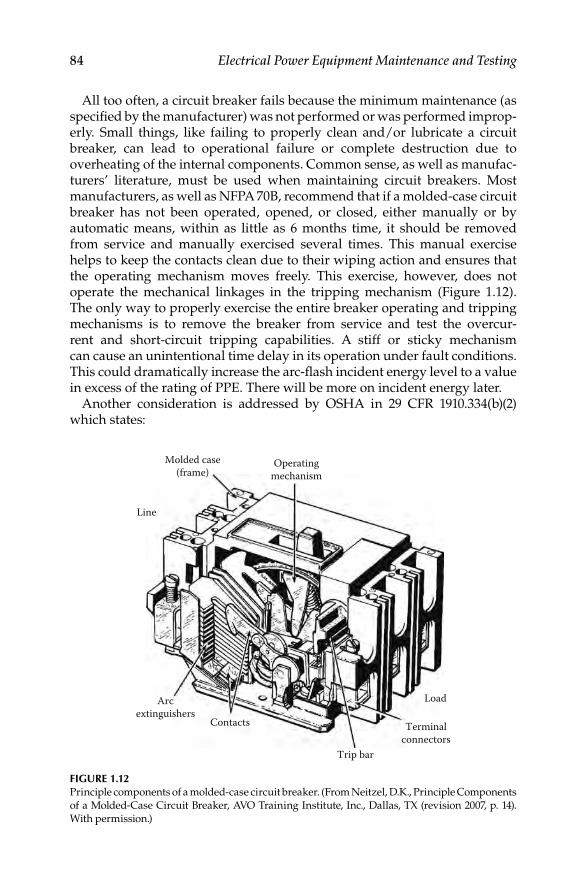
84 Electrical Power Equipment Maintenance and Testing
All too often, a circuit breaker fails because the minimum maintenance (as specifi ed by the manufacturer) was not performed or was performed improp-erly. Small things, like failing to properly clean and/or lubricate a circuit breaker, can lead to operational failure or complete destruction due to overheating of the internal components. Common sense, as well as manufac-turers’ literature, must be used when maintaining circuit breakers. Most manufacturers, as well as NFPA 70B, recommend that if a molded-case circuit breaker has not been operated, opened, or closed, either manually or by automatic means, within as little as 6 months time, it should be removed from service and manually exercised several times. This manual exercise helps to keep the contacts clean due to their wiping action and ensures that the operating mechanism moves freely. This exercise, however, does not operate the mechanical linkages in the tripping mechanism (Figure 1.12). The only way to properly exercise the entire breaker operating and tripping mechanisms is to remove the breaker from service and test the overcur-rent and short-circuit tripping capabilities. A stiff or sticky mechanism can cause an unintentional time delay in its operation under fault conditions. This could dramatically increase the arc-fl ash incident energy level to a value in excess of the rating of PPE. There will be more on incident energy later.
Another consideration is addressed by OSHA in 29 CFR 1910.334(b)(2) which states:
Molded case(frame)
Operatingmechanism
Line
LoadArcextinguishers
Contacts
Trip bar
Terminalconnectors
FIGURE 1.12Principle components of a molded-case circuit breaker. (From Neitzel, D.K., Principle Components
of a Molded-Case Circuit Breaker, AVO Training Institute, Inc., Dallas, TX (revision 2007, p. 14).
With permission.)
DK4058_C001.indd 84DK4058_C001.indd 84 11/17/2008 12:17:24 PM11/17/2008 12:17:24 PM

Maintenance Strategies, Dielectric Theory 85
Reclosing circuits after protective device operation. After a circuit is de-energized by a circuit protective device, the circuit may NOT be manually reenergized until it has been determined that the equipment and circuit can be safely reenergized. The repetitive manual reclosing of circuit breakers or reenergizing circuits through replaced fuses is prohibited.
Note. When it can be determined from the design of the circuit and the overcurrent devices involved and that the automatic operation of a device was caused by an overload rather than a fault condition, no examination of the circuit or connected equipment is needed before the circuit is reenergized.
The safety of the employee, manually operating the circuit breaker, is at risk if the short-circuit condition still exists when reclosing the breaker. OSHA no longer allows the past practice of resetting circuit breaker one, two, or three times before investigating the cause of the trip. This previous practice has caused numerous burn injuries that resulted from the explo-sion of electrical equipment. Before resetting a circuit breaker, it, along with the circuit and equipment, must be tested and inspected, by a quali-fi ed person, to ensure a short-circuit condition does not exist and that it is safe to reset.
Any time a circuit breaker has operated and the reason is unknown, the breaker must be inspected. Melted arc chutes will not interrupt fault currents. If the breaker cannot interrupt a second fault, it will fail and may destroy its enclosure and create a hazard for anyone working near the equipment.
To further emphasize this point the following quote from the NEMA is provided:
After a high level fault has occurred in equipment that is properly rated and installed, it is not always clear to investigating electricians what damage has occurred inside encased equipment. The circuit breaker may well appear virtually clean while its internal condition is unknown. For such situations, the NEMA AB4 “Guidelines for Inspection and Preventive Maintenance of MCCBs Used in Commercial and Industrial Applications” may be of help. Circuit breakers unsuitable for continued service may be identifi ed by simple inspection under these guidelines. Testing outlined in the document is another and more defi nite step that will help to identify circuit breakers that are not suitable for continued service.
After the occurrence of a short circuit, it is important that the cause be investigated and repaired and that the condition of the installed equip-ment be investigated. A circuit breaker may require replacement just as any other switching device, wiring or electrical equipment in the circuit that has been exposed to a short circuit. Questionable circuit breakers must be replaced for continued, dependable circuit protection.
The condition of the circuit breaker must be known to ensure that it functions properly and safely before it is put back into service.
DK4058_C001.indd 85DK4058_C001.indd 85 11/17/2008 12:17:24 PM11/17/2008 12:17:24 PM

86 Electrical Power Equipment Maintenance and Testing
Low-voltage power circuit breakers: Low-voltage power circuit breakers are manufactured under a high degree of quality control, of the best materials available, and with a high degree of tooling for operational accuracy. Manufacturer’s tests show these circuit breakers have durability beyond the minimum standards requirements. All of these factors give these circuit breakers a very high reliability rating. However, because of the varying application conditions and the dependence placed upon them for protection of electrical systems and equipment as well as the assurance of service continuity, inspections and maintenance checks must be made on a regular basis. Several studies have shown that low-voltage power circuit breakers, which were not maintained within a 5-year period, have an average of a 50% failure rate. Maintenance of these breakers will generally consist of keeping them clean and properly lubricated. The frequency of maintenance will depend to some extent on the cleanliness of the surrounding area. If there were very much dust, lint, moisture, or other foreign matter present then obviously more frequent maintenance would be required. Industry stan-dards for, as well as manufacturers of, low-voltage power circuit breakers recommend a general inspection and lubrication after a specifi ed number of operations or at least once per year, whichever comes fi rst. Some manufac-turers also recommend this same inspection and maintenance be performed after the fi rst 6 months of service regardless of the number of operations. If the breaker remains open or closed for a long period of time, it is recom-mended that arrangements be made to open and close the breaker several times in succession, preferably under load conditions. Environmental condi-tions play a major role in the scheduling of inspections and maintenance. If the initial inspection indicates that maintenance is not required at that time, the period may be extended to a more economical point. However, more frequent inspections and maintenance may be required if severe load conditions exist or if an inspection reveals heavy accumulations of dirt, moisture, or other foreign matter that might cause mechanical, insulation, or electrical failure. Mechanical failure would include an unintentional time delay in the circuit breakers tripping operation due to dry, dirty, or corroded pivot points or by hardened or sticky lubricant in the moving parts of the operating mechanism. The manufacturer’s instructions must be followed in order to minimize the risk of any unintentional time delay. Figure 1.13 provides an illustration of the numerous points where lubrication would be required and where dirt, moisture, corrosion, or other foreign matter could accumulate causing a time delay in, or complete failure of, the circuit breaker operation.
Medium-voltage power circuit breakers: Most of the inspection and mainte-nance requirements for low-voltage power circuit breakers also apply to medium-voltage power circuit breakers. Manufacturers recommend that these breakers be removed from service and inspected at least once per year. They also state that the number and severity of interruptions may indicate the need for more frequent maintenance checks. Always follow the manufacturer’s instructions because every breaker is different.
DK4058_C001.indd 86DK4058_C001.indd 86 11/17/2008 12:17:24 PM11/17/2008 12:17:24 PM
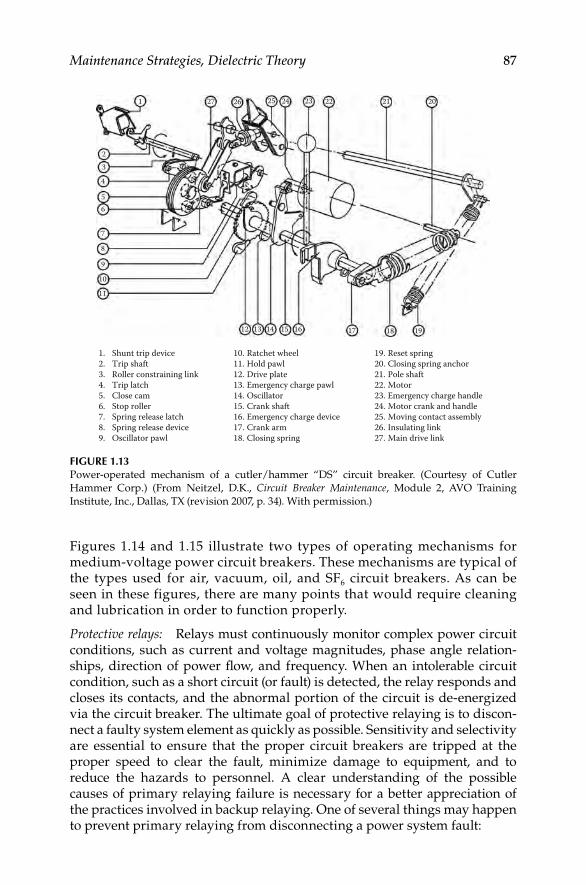
Maintenance Strategies, Dielectric Theory 87
FIGURE 1.13Power-operated mechanism of a cutler/hammer “DS” circuit breaker. (Courtesy of Cutler
Hammer Corp.) (From Neitzel, D.K., Circuit Breaker Maintenance, Module 2, AVO Training
Institute, Inc., Dallas, TX ( revision 2007, p. 34). With permission.)
1
23
4
56
7
8
9
10
11
12 13 14 15 16 17 18 19
1. Shunt trip device2. Trip shaft3. Roller constraining link4. Trip latch5. Close cam6. Stop roller7. Spring release latch8. Spring release device9. Oscillator pawl
19. Reset spring20. Closing spring anchor21. Pole shaft22. Motor23. Emergency charge handle24. Motor crank and handle25. Moving contact assembly26. Insulating link27. Main drive link
10. Ratchet wheel11. Hold pawl12. Drive plate13. Emergency charge pawl14. Oscillator15. Crank shaft16. Emergency charge device17. Crank arm18. Closing spring
27 26 25 24 23 22 21 20
Figures 1.14 and 1.15 illustrate two types of operating mechanisms for medium-voltage power circuit breakers. These mechanisms are typical of the types used for air, vacuum, oil, and SF6 circuit breakers. As can be seen in these figures, there are many points that would require cleaning and lubrication in order to function properly.
Protective relays: Relays must continuously monitor complex power circuit conditions, such as current and voltage magnitudes, phase angle relation-ships, direction of power fl ow, and frequency. When an intolerable circuit condition, such as a short circuit (or fault) is detected, the relay responds and closes its contacts, and the abnormal portion of the circuit is de- energized via the circuit breaker. The ultimate goal of protective relaying is to discon-nect a faulty system element as quickly as possible. Sensitivity and selectivity are essential to ensure that the proper circuit breakers are tripped at the proper speed to clear the fault, minimize damage to equipment, and to reduce the hazards to personnel. A clear understanding of the possible causes of primary relaying failure is necessary for a better appreciation of the practices involved in backup relaying. One of several things may happen to prevent primary relaying from disconnecting a power system fault:
DK4058_C001.indd 87DK4058_C001.indd 87 11/17/2008 12:17:24 PM11/17/2008 12:17:24 PM

88 Electrical Power Equipment Maintenance and Testing
Main crank
Trip coil
Trip latch
Three linkmechanism
Plunger
FIGURE 1.15Solenoid-operated mechanism. (From Neitzel, D.K., Circuit Breaker Maintenance, Chapter 1, AVO
Training Institute, Inc., Dallas, TX (revision 2006, p. 1-10). With permission.)
FIGURE 1.14Operating mechanism of stored energy air circuit breaker. (From Neitzel, D.K., Circuit Breaker Maintenance, Chapter 4, AVO Training Institute, Inc., Dallas, TX (revision 2006, p. 4-18). With
permission.)
18
12
1
10
15
16
17
1. Tripping magnet2. Tripping latch3. Center pole unit lever4. Main contact operating rod5. Main link6. Closing cam following roller7. Closing cam8. Crank shaft9. Tripping cam
10. Tripping trigger11. Tripping cam connecting link12. Front panel13. Mech back plate14. Bumper15. Dolly bracket16. Tripping cam adjusting screw17. Locking nut18. Trip latch roller
9 11 8 7
6
5
14
13
218
12
1
10
15
16
17
3 4
DK4058_C001.indd 88DK4058_C001.indd 88 11/17/2008 12:17:25 PM11/17/2008 12:17:25 PM
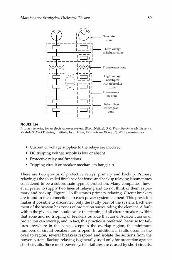
Maintenance Strategies, Dielectric Theory 89
Generatorzone
Low-voltageswitchgear zone
Transformer zone
High-voltageswitchgear
zone
Transmissionline zone
High-voltageswitchgear
with tiebreakerzone
FIGURE 1.16Primary relaying for an electric power system. (From Neitzel, D.K., Protective Relay Maintenance, Module 3, AVO Training Institute, Inc., Dallas, TX (revision 2006, p. 5). With permission.)
Current or voltage supplies to the relays are incorrect•
DC tripping voltage supply is low or absent•
Protective relay malfunctions•
Tripping circuit or breaker mechanism hangs up•
There are two groups of protective relays: primary and backup. Primary relaying is the so-called fi rst line of defense, and backup relaying is sometimes considered to be a subordinate type of protection. Many companies, how-ever, prefer to supply two lines of relaying and do not think of them as pri-mary and backup. Figure 1.16 illustrates primary relaying. Circuit breakers are found in the connections to each power system element. This provision makes it possible to disconnect only the faulty part of the system. Each ele-ment of the system has zones of protection surrounding the element. A fault within the given zone should cause the tripping of all circuit breakers within that zone and no tripping of breakers outside that zone. Adjacent zones of protection can overlap, and in fact, this practice is preferred, because for fail-ures anywhere in the zone, except in the overlap region, the minimum numbers of circuit breakers are tripped. In addition, if faults occur in the overlap region, several breakers respond and isolate the sections from the power system. Backup relaying is generally used only for protection against short circuits. Since most power system failures are caused by short circuits,
DK4058_C001.indd 89DK4058_C001.indd 89 11/17/2008 12:17:25 PM11/17/2008 12:17:25 PM

90 Electrical Power Equipment Maintenance and Testing
short-circuit primary relaying is called on more often than most other types. Therefore, short-circuit primary relaying is more likely to fail.
Voltage and current transformers play a vital role in the power protection scheme. These transformers are used to convert primary current and voltages to secondary (120 V) current and voltages, and to allow current and voltage sensing devices, such as relays, meters, and other instruments to be isolated from the primary circuit. It should be clearly understood that the performance of a relay is only as good as the voltage and current transformers connected to it. A basic understanding of the operating characteristics, application, and function of instrument transformers is essential to a relay technician. Some overcurrent relays are equipped with an instantaneous overcurrent unit, which operates when the current reaches its minimum pickup point (see Figure 1.17). An instantaneous unit is a relay having no intentional time delay. Should an overcurrent of suffi cient magnitude be applied to the relay, the instantaneous unit will operate and will trip the circuit breaker.
The instantaneous trip unit is a small, AC-operated clapper device. A mag-netic armature, to which leaf-spring-mounted contacts are attached, is attracted to the magnetic core upon energization. When the instantaneous unit closes, the moving contacts bridge two stationary contacts and complete the trip circuit. The core screw, accessible from the top of the unit, provides the adjustable pickup range. Newer designs also feature tapped coils to allow even greater ranges of adjustment. The instantaneous unit, like the one
40302010
FIGURE 1.17Instantaneous trip unit. (From Neitzel, D.K., Protective Relay Maintenance, Module 3, AVO
Training Institute, Inc., Dallas, TX (revision 2006, p. 24). With permission.)
DK4058_C001.indd 90DK4058_C001.indd 90 11/17/2008 12:17:26 PM11/17/2008 12:17:26 PM

Maintenance Strategies, Dielectric Theory 91
shown in Figure 1.17, is equipped with an indicator target. This indication shows that the relay has operated. It is important to know which relay has operated, and no relay target should be reset without the supervisor’s knowledge and permission, or after it has been determined which relay oper-ated to clear the fault. As can be seen, several things can go wrong that would prevent the instantaneous unit from operating properly. These things include an open or shunted current transformer, open coil, or dirty contacts. Protective relays, like circuit breakers, require periodic inspection, maintenance, and testing to function properly. Most manufacturers recommend that periodic inspections and maintenance on the induction and electromagnetic type relays be performed at intervals of 1–2 years. The intervals between periodic inspection and maintenance will vary depending upon environment, type of relay, and the user’s experience with periodic testing. The periodic inspec-tions, maintenance, and testing are intended to ensure that the protective relays are functioning properly and have not deviated from the design set-tings. If deviations are found, the relay must be retested and serviced as described in the manufacturer’s instructions.
1.9.2 Failure Statistics
Several studies on electrical equipment failures have been completed over the years by IEEE. These studies have generated failure statistics on electrical distribution system equipment and components. IEEE Standard 493 (Gold Book) “IEEE Recommended Practice for the Design of Reliable Industrial and Commercial Power Systems” contains the information and statistics from these studies and can be used to provide failure data of electrical equipment and components such as circuit breakers. One key study that was completed and yields reliability data on circuit breakers was completed in 1974. The results of this study were based on low- and medium-voltage power circuit breakers (draw out and fi xed) as well as fi xed mounted molded-case circuit breakers. The results of the study indicated that
32% of all circuit breakers failed while in service•
9% of all circuit breakers failed while opening•
7% of all circuit breakers failed due to damage while successfully • opening
42% of all circuit breakers failed by opening when it should not have • opened
77% of fi xed mounted circuit breakers (0–600 V including molded • case) failed while in service
18% of all circuit breakers had a mechanical failure•
28% of all circuit breakers had an electric-protective device failure•
23% of all circuit breakers failures were suspected to be caused by • manufacturer defective component
DK4058_C001.indd 91DK4058_C001.indd 91 11/17/2008 12:17:26 PM11/17/2008 12:17:26 PM

92 Electrical Power Equipment Maintenance and Testing
23% of all circuit breaker failures were suspected to be caused by • inadequate maintenance
73% of all circuit breaker failures required round-the-clock all-out efforts•
A 1996 IEEE survey was conducted on low-voltage power circuit breakers and the results concluded that
19.4% of low-voltage power circuit breakers with electromechanical • trip units had unacceptable operation
10.7% of low-voltage power circuit breakers with solid-state trip • units had unacceptable operation
Reviewing the data from the IEEE studies, it can be seen that nearly one-third of all circuit breakers failed while in service and thus would not have been identifi ed unless proper maintenance was performed. In addition, 16% of all circuit breakers failed or were damaged while opening. The fact that 42% of all circuit breakers failed, by opening when they should not have opened, suggests improper circuit breaker settings or a lack of selective coordination to be the problem. This type of circuit breaker failure can signifi cantly affect plant processes and could result in a total plant shutdown. Also of signifi cance is that a very large percentage of fi xed mounted circuit breakers, including molded-case had a very high failure rate of 77.8%. This is most likely due to the fact that maintenance of this style of device is often overlooked, but cer-tainly is just as important. The fact that 18% of all circuit breakers had a mechanical failure and 28% had an electrical protective device failure sug-gests that both the mechanical linkages, as well as the trip units, need to be maintained. Furthermore, although mechanical maintenance is important, proper testing of the trip unit is much more critical. Also of importance, is the realization that maintenance and testing is needed because nearly one- quarter of all circuit breaker failures were caused by a manufacturer’s defective com-ponent and nearly another one-quarter of all circuit breaker failures were due to inadequate maintenance. Thus, if proper maintenance and testing is per-formed, potentially 50% of failures could be eliminated or identifi ed before a problem occurs. But perhaps the most important issue for an end user is downtime. With regard to this concern, the study indicated 73% of all circuit breaker failures required round-the-clock all-out efforts. This could most likely be greatly reduced if PM was performed on a regular basis. The results from the 1996 IEEE study show that technology has improved the failure rate of low-voltage power circuit breakers and could potentially be cut by almost half, but maintenance and testing would still be needed.
1.9.3 Flash Hazard Analysis
Maintenance and testing is also essential to ensure proper protection of equipment and personnel. With regard to personnel protection, NFPA 70E and OSHA require a flash hazard analysis be performed before
DK4058_C001.indd 92DK4058_C001.indd 92 11/17/2008 12:17:26 PM11/17/2008 12:17:26 PM

Maintenance Strategies, Dielectric Theory 93
anyone approaches exposed electrical conductors or circuit parts that have not been placed in an electrically safe work condition. In addition, it requires a flash protection boundary be established. All calculations for determining the incident energy of an arc, and for establishing a flash protection boundary, require the arc clearing time. This clearing time is derived from the engineering coordination study which is based on what the protective devices are supposed to do. If, for example, a low-voltage power circuit breaker had not been operated or maintained for several years and the lubrication had become sticky or hardened, the circuit breaker could take several additional cycles, seconds, minutes, or longer to clear a fault condition. The following are two specifi c examples that illustrate the important role protective trip devices play in the calculation of incident energy:
For the two examples, fl ash hazard analyses will be performed using a 20,000 A short circuit with the worker being 18 in. from the arc for a condition “arc in a cubic box” as described in Appendix D.6.2 of NFPA 70E-2004:
Example #1:
In this example, the breaker opening time is assumed to be fi ve cycles, or 0.083 s (83 ms). The estimated incident energy for an arc in a cube box (20 in. on each side, open on one end) is applicable to an arc fl ashes emanating from within a switch-gear, MCC, or other electrical equipment enclosure. The incident energy is given by the following equation:
−= − +1.4738 2
MB B A1038.7 [0.0093 0.3453 5.9675]E D t F F
where
EMB is the maximum 20 in. cubic box incident energy (cal/cm2)DB is the distance from arc electrodes (for distances 18 in. and greater) (in.)tA is the arc duration (s)F is the short-circuit current (for the range of 16–50 kA) (kA)For example #1, the following data apply:DB = 18 in.tA = 0.083 s (fi ve cycles)F = 20 kA (assume)Substituting the data in the above equation:
−= × × − +
= × × × − × +
= × = /
21.4738MB
2
1038.7 18 0.083 [0.0093 0.3453 5.9675]
1038.7 0.0141 0.083[0.0093 400 0.3453 20 5.9675]
1.4636 [2.7815] 3.5 cal cm
E F F
From NFPA 70E, Table 130.7(C)(11), we fi nd that it requires category 1 protection (FR shirt and FR pants or FR coverall) plus a hard hat and safety glasses to work at this location.
DK4058_C001.indd 93DK4058_C001.indd 93 11/17/2008 12:17:26 PM11/17/2008 12:17:26 PM

94 Electrical Power Equipment Maintenance and Testing
Example #2:
In example 2, all data remain same except for the breaker which, due to a sticky mechanism, now takes an unintentional time delay of 30 cycles, i.e., 0.5 s (500 ms) to open.
Substituting the new breaker opening time in the above equation:
−= × × − +
= × × × − × += × =
21.4738MB
2
1038.7 18 0.5 [0.0093 0.3453 5.9675]
1038.7 0.0141 0.5[0.0093 400 0.3453 20 5.9675]
7.323 [2.7815] 20.37 cal / cm
E F F
From NFPA 70E, Table 130.7(C)(11), we fi nd that it now requires category 3 protec-tion (cotton underwear plus FR shirt and FR pants plus FR coverall, or cotton under-wear plus two FR coveralls); category 3 also requires a hard hat, safety glasses or goggles, fl ash suit hood, hearing protection, leather gloves, and leather work shoes.
Based on the calculation of example 1, the worker is protected by using PPE category 1 based on what the system (breaker opening) is supposed to do (i.e., open in 0.083 s or fi ve cycles); however, as a result of an unintentional time delay, due to lack of maintenance, the breaker opens in 0.5 s (30 cycles) instead of 0.083 s, the worker could be seriously injured or killed because he or she was underprotected because the worker is not wearing the correct PPE category 3.
As can be seen from this simple example, maintenance now becomes extremely important to an electrical safety program. Maintenance must be performed according to the manufacturer’s instructions in order to minimize the risk of having an unintentional time delay in the operation of the circuit protective devices and breakers.
Additionally, Section 110.16 of the NEC titled Flash Protection states: “Switchboards, panelboards, industrial control panels, meter socket enclosures, and MCCs that are in other than dwelling occupancies and are likely to require examination, adjustment, servicing, or maintenance while energized shall be fi eld marked to warn qualifi ed persons of potential electric arc-fl ash hazards. The marking shall be located so as to be clearly visible to qualifi ed persons before examination, adjustment, servicing, or maintenance of the equipment.”
“FPN No. 1: NFPA 70E, Standard for Electrical Safety in the Workplace, provides assistance in determining severity of potential exposure, planning safe work practices, and selecting personal protective equipment.”
Figure 1.18 is an illustration of the minimum label that would be required based on the NEC 110.16. However, the minimum label does not provide suffi cient information for the worker therefore the label shown in Figure 1.19 is recommended as a minimum.
In view of the regulatory requirements and labeling of electrical equipment for arc-fl ash hazard, it has now become extremely important to properly
DK4058_C001.indd 94DK4058_C001.indd 94 11/17/2008 12:17:26 PM11/17/2008 12:17:26 PM
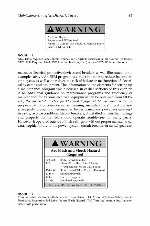
Maintenance Strategies, Dielectric Theory 95
302 Inch Flash Hazard Boundary76.1 cal/cm2 Flash Hazard at 18 Inches ****Dangerous!!! No FR Class Found450 VAC Shock Hazard When Cover Is Removed42 Inch Limited Approach12 Inch Restricted Approach1 Inch Prohibited Approach
WARNING!Arc Flash and Shock Hazard
Required
Bus name: B6-480, Prot Device: SUB-C MAIN
FIGURE 1.19Recommended label for arc-fl ash hazard. (From Neitzel, D.K., Various Electrical Safety Course
Textbooks, Recommended Label for Arc-Flash Hazard, AVO Training Institute, Inc. (revision
2007). With permission.)
maintain electrical protective devices and breakers as was illustrated in the examples above. An EPM program is a must in order to reduce hazards to employees, as well as to reduce the risk of failure or malfunction of electri-cal systems and equipment. The information on the elements for setting up a maintenance program was discussed in earlier sections of this chapter. Also, additional guidance on maintenance programs and frequency of maintenance for various electrical equipment can be obtained from NFPA 70B, Recommended Practice for Electrical Equipment Maintenance. With the proper mixture of common sense, training, manufacturers’ literature, and spare parts, proper maintenance can be performed and power systems kept in a safe, reliable condition. Circuit breakers, if installed within their ratings and properly maintained, should operate trouble-free for many years. However, if operated outside of their ratings or without proper maintenance, catastrophic failure of the power system, circuit breaker, or switchgear can
WARNINGArc Flash Hazard.Appropriate PPE Required.Failure To Comply Can Result In Death Or Injury.Refer To NFPA 70 E.
!
FIGURE 1.18NEC 110.16 required label. (From Neitzel, D.K., Various Electrical Safety Course Textbooks, NEC 110.16 Required label, AVO Training Institute, Inc. (revision 2007). With permission.)
DK4058_C001.indd 95DK4058_C001.indd 95 11/17/2008 12:17:27 PM11/17/2008 12:17:27 PM

96 Electrical Power Equipment Maintenance and Testing
occur causing not only the destruction of the equipment but serious injury or even death of employees working in the area. In order to protect electrical equipment and people, proper electrical equipment PM must be performed. In addition to the manufacture’s literature, industry standards and guides and books, such as this book, exist to assist users with electrical equipment maintenance and testing. When the overcurrent protective devices are prop-erly maintained and tested for proper calibration and operation, equipment damage and arc-fl ash hazards can be minimized as expected. The regula-tory requirements on arc-fl ash hazard and how to perform arc-fl ash hazard analysis are given in Sections 13.2 and 13.3, respectively.
DK4058_C001.indd 96DK4058_C001.indd 96 11/17/2008 12:17:27 PM11/17/2008 12:17:27 PM

97
2Direct-Current Voltage Testing of Electrical Equipment
2.1 Introduction
This chapter covers direct current (DC) tests ordinarily performed in the fi eld for acceptance and maintenance of electrical equipment and apparatus. The information provided by these tests will indicate whether any corrective maintenance or replacement of installed equipment is necessary, assess if the newly installed equipment can be safely energized, and chart the gradual deterioration of the equipment over its service life.
The DC test methods discussed in this chapter cover transformers, insulating liquids, cables, switchgear, motors, and generators. It is important to have the proper equipment and trained operators when conducting these tests. Also, if any test is to provide optimum benefi ts, it is essential to record all test data and maintenance actions for further analysis and future reference. Furthermore, the test equipment should be maintained in good condition and used by qualifi ed operators. When test equipment is used to calibrate other equipment, it should have twice the accuracy of the equipment under test. Moreover, the test equipment should be calibrated at regular intervals to assure the accuracy of test data.
The test voltage levels and methods, as described in this chapter, are mostly in accordance with industry standards for the types of equipment discussed. The DC voltage values correspond to the alternating current (AC) test volt-ages as specifi ed by the applicable industry standards. It is recommended that the manufacturer of the equipment be consulted for specifi c test and test voltage levels when the exact construction of the equipment under test is not known. Where defi nitive information for a particular equipment cannot be obtained, it is advised that the suggested DC test voltage be based on the rated AC circuit voltage in order to avoid possible damage to the insulation system. It is also important to observe certain additional precautions when conducting DC high-voltage tests; these are listed in Section 2.11.
Electrical phenomena in insulation when subjected to DC voltage were briefl y discussed in Chapter 1. Before discussing various DC voltage tests, we need to understand better the electrical phenomena in dielectrics when subjected to DC voltage, which are discussed in the following section.
DK4058_C002.indd 97DK4058_C002.indd 97 11/8/2008 12:14:18 PM11/8/2008 12:14:18 PM

98 Electrical Power Equipment Maintenance and Testing
2.2 DC Voltage Testing of Insulation
When DC voltage is applied to an insulation, the electric fi eld stress gives rise to current conduction and electrical polarization. Consider an elementary circuit as shown in Figure 2.1, which shows a DC voltage source, a switch, and an insulation specimen. When the switch is closed, the insulation becomes electrifi ed and a very high current fl ows at the instant the switch is closed. However, this current immediately drops in value, and then decreases at a slower rate until it reaches a nearly constant value. The current drawn by the insulation may be analyzed into several components as follows:
Capacitance charging current•
Dielectric absorption current•
Surface leakage current•
Partial discharge current (corona)•
Volumetric leakage current•
Capacitance charging current: The capacitance charging current is high as the DC voltage is applied and can be calculated by the formula
−⎛ ⎞= ⎜ ⎟⎝ ⎠/
e e t RCEi
R
DC voltagesource
RL
C
C represents charging currentRA represents absorption currentRL represents volumetric leakage current (dielectric loss)
S
RA
FIGURE 2.1Electrical circuit of insulation under DC voltage test.
DK4058_C002.indd 98DK4058_C002.indd 98 11/8/2008 12:14:18 PM11/8/2008 12:14:18 PM
Direct-Current Voltage Testing of Electrical Equipment 99
whereie is the capacitance charging currentE is the voltage in kilovoltsR is the resistance in megohmsC is the capacitance in microfaradst is the time in secondse is Napierian logarithmic base
The charging current is a function of time and will decrease as the time of the application of voltage increases. It is the initial charging current when voltage is applied and therefore not of any value for test evaluation. Test readings should not be taken until this current has decreased to a suffi ciently low value.
Dielectric absorption current: The dielectric absorption current is also high as the test voltage is applied and decreases as the voltage application time increases, but at a slower rate than the capacitance charging current. This current is not as high as the capacitance charging current. The absorption current can be divided into two currents called reversible and irreversible charging currents. This reversible charging current can be calculated by the formula:
−=a
ni VCDT
whereia is the dielectric absorption currentV is the test voltage in kilovoltsC is the capacitance in microfaradsD is the proportionately constantT is the time in secondsn is a constant
The irreversible charging current is of the same general form as the revers-ible charging current, but is much smaller in magnitude. The irreversible charging current is lost in the insulation and thus is not recoverable. Again, suffi cient time should be allowed before recording test data so that the revers-ible absorption current has decreased to a low value.
Surface leakage: The surface leakage current is due to the conduction on the surface of the insulation where the conductor emerges and points of ground potential. This current is not desired in the test results and should therefore be eliminated by carefully cleaning the surface of the conductor to elimi-nate the leakage paths, or should be captured and guarded out of the meter reading.
Partial discharge current: The partial discharge current, also known as corona current, is caused by overstressing of air at sharp corners of the conductor due to high test voltage. This current is not desirable and should
DK4058_C002.indd 99DK4058_C002.indd 99 11/8/2008 12:14:18 PM11/8/2008 12:14:18 PM

100 Electrical Power Equipment Maintenance and Testing
be eliminated by the use of stress control shielding at such points during tests. This current does not occur at lower voltages (below 4000 volts), such as insulation resistance test voltages.
Volumetric leakage current: The volumetric leakage current that fl ows through the insulation volume itself is of primary importance. This is the current that is used to evaluate the conditions of the insulation system under test. Suffi cient time should be allowed for the volumetric current to stabilize before test readings are recorded. The total current, consisting of various leakage currents as described above, is shown in Figure 2.2.
2.2.1 Dielectric Phenomena and Polarization
The dielectrics have the property of both temporary and permanent absorp-tion of electrical charges and property of conduction. When a voltage is applied to a dielectric, forces on the positive and negative charges inherent in the particles which make up the dielectric tend to orient the particles in line with the applied fi eld. Some dielectric materials have molecules that have uneven number of atoms, that is, having asymmetrical arrangement of charges. When such a molecule is placed in an electrical fi eld, it will migrate
1009080706050
40
3025
20
15
1098765
4
32.5
1.5
10.1 0.15 0.2 0.25 0.3 0.4 0.5 0.6 0.7 0.80.91.0 1.5 2.5 3 4 5 6 7 8 9 102
2
Capacitancecharging current
DC voltage testing of electrical equipment
Curr
ent,
μA
Total current
Absorptioncurrent
Seconds
Conductionor leakage
current
FIGURE 2.2Various leakage currents due to the application of DC high voltage to an insulation system.
DK4058_C002.indd 100DK4058_C002.indd 100 11/8/2008 12:14:18 PM11/8/2008 12:14:18 PM

Direct-Current Voltage Testing of Electrical Equipment 101
in an electric fi eld, thus become polarized with the electric fi eld. Such a molecule is called a dipole. Dipoles play an important role in the electrical characteristics of the insulation. A dipole may be represented by a particle having small positive charge at one end and a small negative charge at the other end. When these dipoles are subjected to DC voltage, they are polar-ized and become aligned with respect to positive and negative polarity of the DC voltage. This phenomenon is known as dipole polarization. Polarization phenomenon is infl uenced strongly by the material properties, structure, and condition of the insulation.
On the other hand, charged particles, that is, particles with positive and negative charges, which are not interrupted by interfacial barriers, and can travel through the dielectric from one electrode to the other, constitute the leakage current, and are not part of the polarization phenomenon.
After a time when the applied voltage is removed from the dielectric, the polarized molecules will eventually revert to their initial random arrange-ment so that the polarization approaches zero. The time it takes for the polarization to drop to zero when the dielectric is short-circuited is known as relaxation time. It should be noted that the large dielectrics have a much longer relaxation time, and appropriate measures should be taken to dis-charge the released energy (voltage and current) to ground, which is given by the polarized molecules when they revert to their original state.
2.2.2 Advantages and Disadvantages of DC Voltage Testing
DC voltage testing is commonly used for testing of electrical equipment and apparatus. DC voltage testing has advantages and disadvantages which vary in importance with the specifi c circumstances. The advantages and disad-vantages of DC voltage are summarized below.
2.2.2.1 Advantages
DC test is preferred on equipment whose charging capacitance is • very high, such as cables.
DC voltage stress is considered much less damaging to insulation • than AC voltages.
Time of voltage application is not as critical with DC voltage as with • AC voltage.Test can be stopped before equipment failure occurs.•
Measurements can be taken concurrently.•
Historical data can be compiled and made available for evaluation.•
It is not necessary to make a separate insulation resistance test prior • to making a DC overpotential test.
Size and weight of equipment is signifi cantly reduced compared to • AC voltage test.
DK4058_C002.indd 101DK4058_C002.indd 101 11/8/2008 12:14:19 PM11/8/2008 12:14:19 PM

102 Electrical Power Equipment Maintenance and Testing
2.2.2.2 Disadvantages
Stress distribution for transformers, motors, and generator winding • is different for DC voltage than is for AC voltage.
Residual charge after a DC voltage test must be carefully discharged.•
Time required to conduct a DC high-potential (hi-pot) test is longer • than for an AC hi-pot test.
Literature governing DC testing of cables suggest possible harmful • effects hi-pot DC testing may have on some types of cables.
Defects, undetectable with DC, can cause failure under AC voltage test.•
Voltage may not stress uniformly the insulation system.•
Temperature and voltage dependence of resistivity.•
Space charge formation—future potential failures.•
2.3 DC Testing Methods
After seeing how insulation behaves when DC voltage is applied to it, let us now take a look at the various tests that are conducted with this voltage. Two tests can be conducted on solid insulation with the application of DC voltage:
Insulation resistance testing•
High-potential (Hi-pot) voltage testing•
2.3.1 Insulation Resistance Testing
This test may be conducted at applied voltages of 100–15,000 V. The instru-ment used is a megohmmeter, either hand cranked, motor driven, or elec-tronic, which indicates the insulation resistance in megohms. An electronic megohmmeter is shown in Figure 2.3a. The quality of insulation is a variable, dependent upon temperature, humidity, and other environmental factors. Therefore, all readings must be corrected to the standard temperature for the class of equipment under test. The temperature correction factors for various electrical apparatus are shown in Table 2.1. The megohm value of insulation resistance is inversely proportional to the volume of insulation being tested. As an example, a cable 100 ft. long would have one-tenth the insulation resistance of cable 1000 ft. long, provided other conditions were identical. This test can be useful in giving an indication of deteriorating trends in the insulation system. The insulation resistance values by them-selves neither indicate the weakness of the insulation nor its total dielectric strength. However, they can indicate the contamination of the insulation and trouble ahead within the insulation system if a downward trend contin-ued in the insulation resistance values.
DK4058_C002.indd 102DK4058_C002.indd 102 11/8/2008 12:14:19 PM11/8/2008 12:14:19 PM
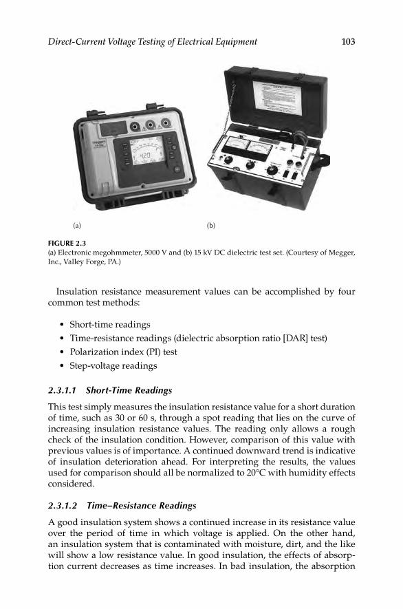
Direct-Current Voltage Testing of Electrical Equipment 103
(a) (b)
FIGURE 2.3(a) Electronic megohmmeter, 5000 V and (b) 15 kV DC dielectric test set. (Courtesy of Megger,
Inc., Valley Forge, PA.)
Insulation resistance measurement values can be accomplished by four common test methods:
Short-time readings•
Time-resistance readings (dielectric absorption ratio [DAR] test)•
Polarization index (PI) test•
Step-voltage readings•
2.3.1.1 Short-Time Readings
This test simply measures the insulation resistance value for a short duration of time, such as 30 or 60 s, through a spot reading that lies on the curve of increasing insulation resistance values. The reading only allows a rough check of the insulation condition. However, comparison of this value with previous values is of importance. A continued downward trend is indicative of insulation deterioration ahead. For interpreting the results, the values used for comparison should all be normalized to 20°C with humidity effects considered.
2.3.1.2 Time–Resistance Readings
A good insulation system shows a continued increase in its resistance value over the period of time in which voltage is applied. On the other hand, an insulation system that is contaminated with moisture, dirt, and the like will show a low resistance value. In good insulation, the effects of absorp-tion current decreases as time increases. In bad insulation, the absorption
DK4058_C002.indd 103DK4058_C002.indd 103 11/8/2008 12:14:19 PM11/8/2008 12:14:19 PM
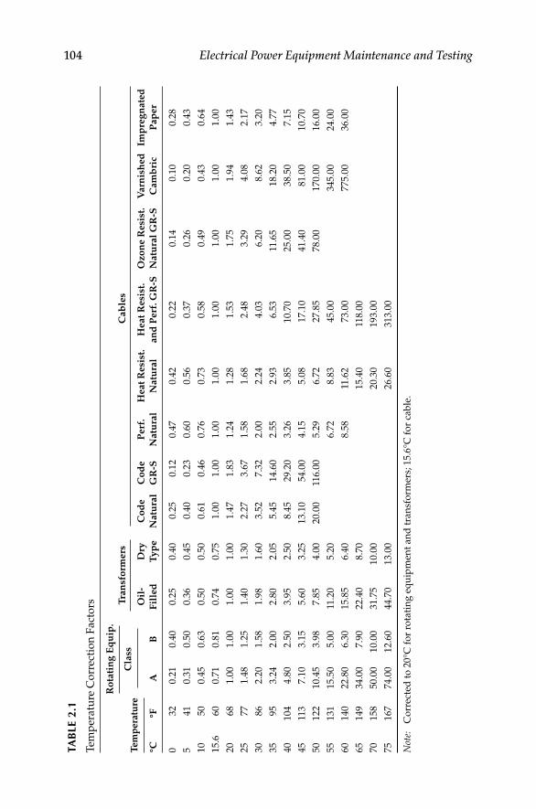
104 Electrical Power Equipment Maintenance and TestingTA
BLE
2.1
Tem
per
atu
re C
orr
ecti
on
Fact
ors
Tem
per
atu
re
Ro
tati
ng
Eq
uip
.
Tra
nsf
orm
ers
Cab
les
Cla
ss
°C°F
AB
Oil
-
Fil
led
Dry
Ty
pe
Co
de
Natu
ral
Co
de
GR
-S
Perf
.
Natu
ral
Heat
Resi
st.
Natu
ral
Heat
Resi
st.
an
d P
erf
. G
R-S
Ozo
ne R
esi
st.
Natu
ral
GR
-S
Varn
ish
ed
Cam
bri
c
Imp
reg
nate
d
Pap
er
0 32
0.2
10.4
00.2
50.4
00.2
50.1
20.4
70.4
20.2
20.1
40.1
00.2
8
5 41
0.3
10.5
00.3
60.4
50.4
00.2
30.6
00.5
60.3
70.2
60.2
00.4
3
10
50
0.4
50.6
30.5
00.5
00.6
10.4
60.7
60.7
30.5
80.4
90.4
30.6
4
15.6
60
0.7
10.8
10.7
40.7
51.0
01.0
01.0
01.0
01.0
01.0
01.0
01.0
0
20
68
1.0
01.0
01.0
01.0
01.4
71.8
31.2
41.2
81.5
31.7
51.9
41.4
3
25
77
1.4
81.2
51.4
01.3
02.2
73.6
71.5
81.6
82.4
83.2
94.0
82.1
7
30
86
2.2
01.5
81.9
81.6
03.5
27.3
22.0
02.2
44.0
36.2
08.6
23.2
0
35
95
3.2
42.0
02.8
02.0
55.4
514.6
02.5
52.9
36.5
311
.65
18.2
04.7
7
40
104
4.8
02.5
03.9
52.5
08.4
529.2
03.2
63.8
510.7
025.0
038.5
07.1
5
45
113
7.1
03.1
55.6
03.2
513.1
054.0
04.1
55.0
817.1
041.4
081.0
010.7
0
50
122
10.4
53.9
87.8
54.0
020.0
011
6.0
05.2
96.7
227.8
578.0
0170.0
016.0
0
55
131
15.5
05.0
011
.20
5.2
06.7
28.8
345.0
0345.0
024.0
0
60
140
22.8
06.3
015.8
56.4
08.5
811
.62
73.0
0775.0
036.0
0
65
149
34.0
07.9
022.4
08.7
015.4
011
8.0
0
70
158
50.0
010.0
031.7
510.0
020.3
0193.0
0
75
167
74.0
012.6
044.7
013.0
026.6
0313.0
0
Not
e:
Co
rrec
ted
to
20°C
fo
r ro
tati
ng
eq
uip
men
t an
d t
ran
sfo
rmer
s; 1
5.6
°C f
or
cab
le.
DK4058_C002.indd 104DK4058_C002.indd 104 11/8/2008 12:14:20 PM11/8/2008 12:14:20 PM

Direct-Current Voltage Testing of Electrical Equipment 105
effect is perpetuated by high leakage current. The time-resistance method is independent of temperature and equipment size. It can provide conclusive results as to the condition of the insulation. The ratio of time-resistance read-ings can be used to indicate the condition of the insulation system. The ratio of a 60 s reading to a 30 s reading is called the DAR:
=Resistance reading at 60 s
DARResistance reading at 30 s
A DAR ratio below 1.25 is cause for investigation and possible repair of the electrical apparatus. Usually, the DAR readings are confi ned to the hand-driven megohmmeter.
2.3.1.3 PI Test
The PI test is a specialized application of the dielectric absorption test. The PI is the ratio of the insulation resistance at 10 min to the insulation resistance at 1 min. A PI of less than 1 indicates equipment deterioration and the need for immediate maintenance. This test is used for dry insulation systems such as dry type transformers, cables, rotating machines, etc.
2.3.1.4 Step-Voltage Readings (DC Voltage Tip-Up Test)
In this method, voltage is applied in steps to the insulation under test by a way of a controlled voltage method. As voltage is increased, the weak insulation will show lower resistance that was not obvious at lower voltage levels. Moisture, dirt, and other contaminants can be detected at lower voltage levels, that is, below operating voltages, whereas aging and physical damage in clean, dry insulation systems can only be revealed at higher voltages. The step-voltage test is very valuable when conducted on a regular periodic basis.
2.3.2 High-Potential Voltage Test
A DC hi-pot voltage test is a voltage applied across the insulation at or above the DC equivalent of the 60 Hz operating crest voltage (i.e., DC value = 1.41 times RMS value). This test can be applied as a step-voltage test. When the high-potential voltage is applied as a dielectric absorption test, the maximum voltage is applied gradually over a period of 60–90 s. The maximum voltage is then held for 5 min with leakage current readings taken each minute. When this test is applied as a step-voltage test, the maximum voltage is applied in a number of equal increments, usually not less than eight, with each voltage step being held for an equal interval of time. The time interval between each step should be 1–4 min. At the end of each interval, a leakage current or insulation resistance reading is taken before proceeding to the next step. A plot of test voltage versus
DK4058_C002.indd 105DK4058_C002.indd 105 11/8/2008 12:14:20 PM11/8/2008 12:14:20 PM

106 Electrical Power Equipment Maintenance and Testing
leakage current or insulation resistance can then be drawn to indicate the condition of the insulation system. Routine maintenance tests are conducted with a maximum voltage at or below 75% of the maximum test voltage per-mitted for acceptance tests, or at 60% of the factory test voltage. A 15 kV DC dielectric test set is shown in Figure 2.3b.
Dielectric absorption test: The dielectric absorption test is conducted at volt-ages much higher than the usual insulation resistance test values and can exceed 100 kV. This test is an extension of the hi-pot test. Under this test, the voltage is applied for an extended period of time, from 5 to 15 min. Periodic readings are taken of the insulation resistance or leakage current. The test is evaluated on the basis of insulation resistance. If insulation is in good condi-tion, the apparent insulation resistance will increase as the test progresses. The dielectric absorption tests are independent of the volume and the tem-perature of the insulation under test.
2.4 Transformers
The DC testing of transformers involves testing of the solid winding insula-tion and the insulating fl uids used in transformers. The testing of insulating fl uids is covered in Chapter 4. The testing of solid winding insulation complements other transformer testing. The solid winding insulation tests are not conclusive in themselves, but provide valuable information on winding conditions, such as moisture content, and carbonization. The DC tests are con-sidered nondestructive even though at times they may cause a winding fail-ure. It should be pointed out that a winding failure results from an incipient failure that the test was supposed to detect. If it had gone undetected, it might have occurred at an unplanned time. The DC tests conducted for transformer winding insulation are discussed in the following section.
2.4.1 Insulation Resistance Measurement
This test is performed at or above rated voltage to determine if there are low resistance paths to ground or between winding to winding as a result of winding insulation deterioration. The test measurement values are affected by variables such as temperature, humidity, test voltage, and size of trans-former. This test should be conducted before and after repair or when main-tenance is performed. The test data should be recorded for future comparative purposes. The test values should be normalized to 20°C for comparison pur-poses. The general rule of thumb that is used for acceptable values for safe energization is 1 MΩ per 1000 V of applied test voltage plus 1 MΩ. Sample resistance values of good insulation systems are shown in Table 2.2. The test procedures are as follows:
DK4058_C002.indd 106DK4058_C002.indd 106 11/8/2008 12:14:20 PM11/8/2008 12:14:20 PM

Direct-Current Voltage Testing of Electrical Equipment 107
1. Do not disconnect the ground connection to the transformer tank and core. Make sure that the transformer tank and core are grounded.
2. Disconnect all high-voltage, low-voltage, and neutral connections, lightning arresters, fan systems, meters, or any low-voltage control systems that are connected to the transformer winding.
3. Before beginning the test, jumper together all high-voltage bush-ings, making sure that the jumpers are clear of all metal and grounded parts. Also jumper together all low-voltage and neutral bushings, making sure jumpers are clear of all metal and grounded parts.
4. Use a megohmmeter with a minimum scale of 20,000 MΩ.
5. Resistance measurements are then made between each set of wind-ings and ground. The windings that are to be measured must have its ground removed in order to measure its insulation resistance.
6. Megohmmeter reading should be maintained for a period of 1 min. Make the following readings for two-winding transformers:
a. High-voltage winding to low-voltage winding and to ground
b. High-voltage winding to ground
c. Low-voltage winding to high-voltage winding and to ground
d. Low-voltage winding to ground
e. High-voltage winding to low-voltage winding
The connections for these tests are shown in Figures 2.4a through e and 2.5a through e for single-phase and three-phase transformers, respectively.
Megohmmeter readings should be recorded along with the test temperature (°C). The readings should be corrected to 20°C by the correction factors shown in Table 2.1. If the corrected fi eld test values are one-half or more of the factory insulation readings or 1000 MΩ, whichever is less, the transformer insulation system is considered safe for a hi-pot test.
TABLE 2.2
Typical Insulation Resistance Values for Power and Distribution Transformers
Transformer Winding
Voltage (kV)
Winding Ground (MΩ)
20°C 30°C 40°C 50°C 60° C
6.6 400 200 100 50 25
6.6–19 800 400 200 100 50
22–45 1000 500 250 125 65
≥66 1200 600 300 100 75
DK4058_C002.indd 107DK4058_C002.indd 107 11/8/2008 12:14:20 PM11/8/2008 12:14:20 PM

108 Electrical Power Equipment Maintenance and Testing
For three-winding transformers, test should be made as follows:
High to low, tertiary and ground (H-LTG)•
Tertiary to high, low and ground (T-HLG)•
Low to high, tertiary and ground (L-HTG)•
High, low, and tertiary to ground (HLT-G)•
High and tertiary to low and ground (HT-LG)•
Low and tertiary to high and ground (LT-HG)•
High and low to tertiary and ground (HL-TG)•
Do not make the megohm test of the transformer winding without the trans-former liquid because the values of insulation resistance in air will be much less than in the liquid. Also, do not make the insulation resistance test of the transformer when it is under vacuum because of the possibility of fl ashover to ground.
The test connections shown in Figure 2.5a, c, and e are most frequently used. The test connections in Figure 2.5b and d give more precise results. The readings obtained in the connections in Figure 2.5a and b are practically equal to readings in test connections in Figure 2.5c and d, respectively.
X3
X2
X1
H1
H2
G L E
(a)
X3
X2
X1
H1
H2
G L E
(b)
X3
X2
X1
H1
H2
G L E(e)
X3
X2
X1
H1
H2
G L E
(c)
X3
X2
X1
H1
H2
G L E
(d)
FIGURE 2.4Test connections for insulation resistance of a single-phase transformer. Note: In fi gure (e)
reverse the L and E leads to measure from high-winding to low-winding.
DK4058_C002.indd 108DK4058_C002.indd 108 11/8/2008 12:14:20 PM11/8/2008 12:14:20 PM

Direct-Current Voltage Testing of Electrical Equipment 109
L
GRD
EG
H3 X3X2X1X0
H2H1
L
GRD
X3X2X1X0
H3H2H1
EG
GRD
X3X2X1X0
H3H2H1
L EG
DC voltage testing of electrical equipment
Winding connections Megohmmeter
(a)
(b)
(c)
TransformerLine
L
X, GRD
GRD
H, GRD
X
X
H
H
E G
Earth Guard
GRD
X3X2X1X0
H3H2H1
L EG
GRD
X3X2X1X0
H3H2H1
L EG
(d)
(e)
GRDX
X
H
H
FIGURE 2.5Test connections for insulation resistance of a three-phase transformer: (a) connection for high
winding to low winding to ground; (b) connection for high winding to ground and low
winding guarded; (c) connection for low winding to high winding to ground; (d) connection
for low winding to ground and high winding guarded; and (e) connection for high winding
to low winding.
DK4058_C002.indd 109DK4058_C002.indd 109 11/8/2008 12:14:20 PM11/8/2008 12:14:20 PM

110 Electrical Power Equipment Maintenance and Testing
Acceptable insulation resistance values for dry and compound-fi lled transformers should be comparable to those for Class A rotating machin-ery, although no standard minimum values are available.
Oil-fi lled transformers or voltage regulators present a special problem in that the condition of the oil has a marked infl uence on the insulation resis-tance of the windings.
In the absence of more reliable data the following formula is suggested:
=
√IR
kVA
CE
whereIR is the minimum 1 min 500 V DC insulation resistance in megohms
from winding to ground, with other winding or windings guarded, or from winding to winding with core guarded
C is a constant for 20°C measurements
E is the voltage rating of winding under test
kVA is the rated capacity of winding under test
Values of C at 20°C
60 Hz 25 Hz
Tanked oil-fi lled type 1.5 1.0
Untanked oil-fi lled type 30.0 20.0
Dry or compound-fi lled type 30.0 20.0
This formula is intended for single-phase transformers. If the transformers under test is one of the three-phase type, and the three individual windings are being tested as one, then
E is the voltage rating of one of the single-phase windings (phase to phase for delta connected units and phase to neutral or star connected units)
kVA is the rated capacity of the completed three-phase winding under test
2.4.2 Dielectric Absorption Test
The dielectric absorption test is an extension of the transformer winding insulation resistance measurement test. The test consists of applying voltage for 10 min and taking readings of resistance measurements at 1 min intervals. The resistance values measured during this test are plotted on log–log paper with coordinates of resistance versus time. The slope of the curve for a good insulation system is a straight line increasing with respect to time, whereas a poor insulation system will have a curve that fl attens out with respect to time. There are two tests that are conducted under dielectric absorption test. These are PI and DAR tests, which are discussed in Section 2.3.
DK4058_C002.indd 110DK4058_C002.indd 110 11/8/2008 12:14:21 PM11/8/2008 12:14:21 PM

Direct-Current Voltage Testing of Electrical Equipment 111
TABLE 2.3
Dielectric Test Values for Routine Maintenanceof Liquid-Filled Transformers
Transformer Winding
Rated Voltage (kV)
Factory Test AC
Voltage (kV)
Routine Maintenance DC
Voltage (kV)
1.2 10 10.40
2.4 15 15.60
4.8 19 19.76
8.7 26 27.04
15.0 34 35.36
18.0 40 41.60
25.0 50 52.00
34.5 70 72.80
2.4.3 DC High-Potential Test
The DC hi-pot test is applied at above the rated voltage of a transformer to evaluate the condition of winding insulation. The DC high-voltage test is not recommended on power transformers above 34.5 kV; instead the AC hi-pot test should be used. Generally, for routine maintenance of transformers, this test is not employed because of the possibility of damage to the winding insulation. However, this test is made for acceptance and after repair of trans-formers. If the hi-pot test is to be conducted for routine maintenance, the AC test values should not exceed 65% of factory AC test value. The routine main-tenance AC voltage value should be converted to an equivalent DC voltage value by multiplying it by 1.6, that is, 1.6 times the AC value for periodic test-ing (i.e., 1.6 × 65 = 104% of AC factory test value). The DC hi-pot test can be applied as a step-voltage test where readings of leakage current are taken for each step. If excessive leakage current is noticed, voltage can be backed off before further damage takes place. For this reason, the DC hi-pot test is con-sidered to be a nondestructive test. Some companies conduct the AC hi-pot test at rated voltage for 3 min for periodic testing instead of the 65% of factory test voltage. The hi-pot test values for DC voltages are shown in Table 2.3.
The procedure for conducting this test is as follows (refer to Figure 2.6a and b for test connections):
Transformer must have passed the insulation resistance test imme-• diately prior to starting this test.
Make sure transformer case and core are grounded.•
Disconnect all high-voltage, low-voltage, and neutral connections, • low-voltage control systems, fan systems, and meters connected to the transformer winding and core.
Short-circuit with jumpers together all high-voltage bushings and • all low-voltage bushings to ground as discussed under “Insulation resistance measurements.”
DK4058_C002.indd 111DK4058_C002.indd 111 11/8/2008 12:14:21 PM11/8/2008 12:14:21 PM

112 Electrical Power Equipment Maintenance and Testing
Connect hi-pot test set between high-voltage winding and ground. • Gradually increase test voltage to the desired value. Allow test voltage duration of 1 min, after which gradually decrease voltage to zero.
Remove low-voltage to ground jumper and connect hi-pot test set • between low-voltage winding and ground. Also connect the short-circuited high-voltage winding to ground. Gradually increase test voltage to desired value. Allow the test voltage duration of 1 min, after which gradually decrease voltage to zero.
If the preceding two tests do not produce breakdowns or failures, the • transformer is considered satisfactory and can be energized.
Remove all jumpers and reconnect primary and secondary connec-• tions and other system equipment that may have been disconnected.
The following are some cautions and considerations in performing hi-pot tests:
In liquid-fi lled transformers two insulation systems are in series, that is, solid insulation with oil or synthetic fl uid. When AC or DC hi-pot test voltage is applied, the voltage drops are distributed as follows:
Control unit
AM
120 V60 Hz
120 V60 Hz
AM
AC or DC Hi-pottest-set
Transformerunder test
Transformer case(a)
(b)
Transformer case
H3
H3
X3
X2
X1
X0
X3
X2
X1
X0
H2
H2
H1
H1
V
V
FIGURE 2.6Transformer high voltage (hi-pot) test connection: (a) high winding hi-pot test connection and
(b) low winding hi-pot test connections.
DK4058_C002.indd 112DK4058_C002.indd 112 11/8/2008 12:14:21 PM11/8/2008 12:14:21 PM
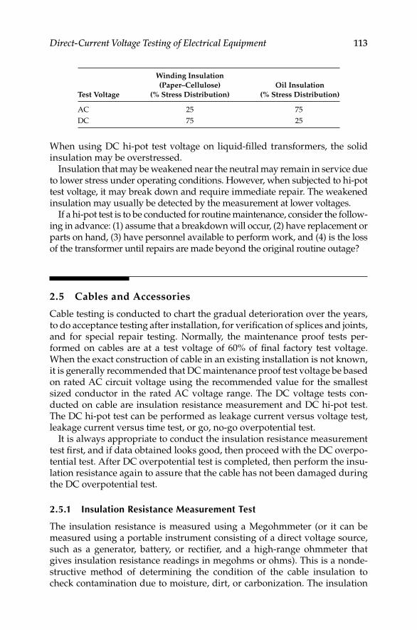
Direct-Current Voltage Testing of Electrical Equipment 113
When using DC hi-pot test voltage on liquid-fi lled transformers, the solid insulation may be overstressed.
Insulation that may be weakened near the neutral may remain in service due to lower stress under operating conditions. However, when subjected to hi-pot test voltage, it may break down and require immediate repair. The weakened insulation may usually be detected by the measurement at lower voltages.
If a hi-pot test is to be conducted for routine maintenance, consider the follow-ing in advance: (1) assume that a breakdown will occur, (2) have replacement or parts on hand, (3) have personnel available to perform work, and (4) is the loss of the transformer until repairs are made beyond the original routine outage?
2.5 Cables and Accessories
Cable testing is conducted to chart the gradual deterioration over the years, to do acceptance testing after installation, for verifi cation of splices and joints, and for special repair testing. Normally, the maintenance proof tests per-formed on cables are at a test voltage of 60% of fi nal factory test voltage. When the exact construction of cable in an existing installation is not known, it is generally recommended that DC maintenance proof test voltage be based on rated AC circuit voltage using the recommended value for the smallest sized conductor in the rated AC voltage range. The DC voltage tests con-ducted on cable are insulation resistance measurement and DC hi-pot test. The DC hi-pot test can be performed as leakage current versus voltage test, leakage current versus time test, or go, no-go overpotential test.
It is always appropriate to conduct the insulation resistance measurement test fi rst, and if data obtained looks good, then proceed with the DC overpo-tential test. After DC overpotential test is completed, then perform the insu-lation resistance again to assure that the cable has not been damaged during the DC overpotential test.
2.5.1 Insulation Resistance Measurement Test
The insulation resistance is measured using a Megohmmeter (or it can be measured using a portable instrument consisting of a direct voltage source, such as a generator, battery, or rectifi er, and a high-range ohmmeter that gives insulation resistance readings in megohms or ohms). This is a nonde-structive method of determining the condition of the cable insulation to check contamination due to moisture, dirt, or carbonization. The insulation
Test Voltage
Winding Insulation
(Paper–Cellulose)
(% Stress Distribution)
Oil Insulation
(% Stress Distribution)
AC 25 75
DC 75 25
DK4058_C002.indd 113DK4058_C002.indd 113 11/8/2008 12:14:21 PM11/8/2008 12:14:21 PM
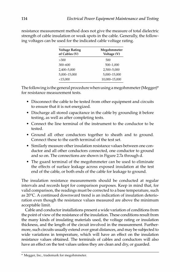
114 Electrical Power Equipment Maintenance and Testing
resistance measurement method does not give the measure of total dielectric strength of cable insulation or weak spots in the cable. Generally, the follow-ing voltages can be used for the indicated cable voltage rating.
The following is the general procedure when using a megohmmeter (Megger)* for resistance measurement tests.
Disconnect the cable to be tested from other equipment and circuits • to ensure that it is not energized.
Discharge all stored capacitance in the cable by grounding it before • testing, as well as after completing tests.
Connect the line terminal of the instrument to the conductor to be • tested.
Ground all other conductors together to sheath and to ground. • Connect these to the earth terminal of the test set.
Similarly measure other insulation resistance values between one con-• ductor and all other conductors connected, one conductor to ground and so on. The connections are shown in Figure 2.7a through d.
The guard terminal of the megohmmeter can be used to eliminate • the effects of surface leakage across exposed insulation at the test end of the cable, or both ends of the cable for leakage to ground.
The insulation resistance measurements should be conducted at regular intervals and records kept for comparison purposes. Keep in mind that, for valid comparison, the readings must be corrected to a base temperature, such as 20°C. A continued downward trend is an indication of insulation deterio-ration even though the resistance values measured are above the minimum acceptable limit.
Cable and conductor installations present a wide variation of conditions from the point of view of the resistance of the insulation. These conditions result from the many kinds of insulating materials used, the voltage rating or insulation thickness, and the length of the circuit involved in the measurement. Further-more, such circuits usually extend over great distances, and may be subjected to wide variations in temperature, which will have an effect on the insulation resistance values obtained. The terminals of cables and conductors will also have an effect on the test values unless they are clean and dry, or guarded.
Voltage Rating
of Cables (V)
Megohmmeter
Voltage (V)
>300 500
300–600 500–1,000
2,400–5,000 2,500–5,000
5,000–15,000 5,000–15,000
<15,000 10,000–15,000
* Megger, Inc., trademark for megohmmeter.
DK4058_C002.indd 114DK4058_C002.indd 114 11/8/2008 12:14:21 PM11/8/2008 12:14:21 PM

Direct-Current Voltage Testing of Electrical Equipment 115
G L
Megohmmeter
(a)
(b)
(c)
Megohm-meter
Megohmmeter
Insulation Conductor
Three-conductorcable
Ground sheath-single conductor
E
G L E
G L E
G L E
(d)
Megohm-meter
Three-conductorcable
FIGURE 2.7Cable test connections for insulation resistance measurement: (a) connection for single-con-
ductor cable, one conductor to ground test; (b) connection for three-conductor cable, one
conductor to other conductors and sheath to ground; (c) connection for three-conductor cable,
one conductor to sheath and to ground and two conductors guarded; and (d) connection for
three-conductor cable, one conductor to all other conductors without leakage to ground.
The Insulated Cable Engineers Association (ICEA) gives minimum values of insulation resistance in its specifi cations for various types of cables and conductors. These minimum values are for new, single-conductor wire
DK4058_C002.indd 115DK4058_C002.indd 115 11/8/2008 12:14:21 PM11/8/2008 12:14:21 PM
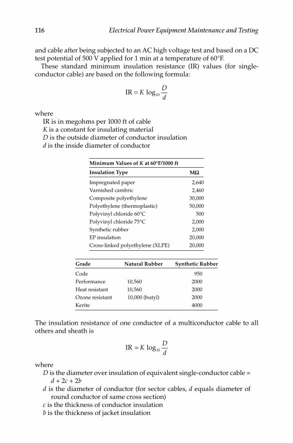
116 Electrical Power Equipment Maintenance and Testing
and cable after being subjected to an AC high voltage test and based on a DC test potential of 500 V applied for 1 min at a temperature of 60°F.
These standard minimum insulation resistance (IR) values (for single- conductor cable) are based on the following formula:
= 10IR log
DK
d
whereIR is in megohms per 1000 ft of cableK is a constant for insulating materialD is the outside diameter of conductor insulationd is the inside diameter of conductor
Grade Natural Rubber Synthetic Rubber
Code 950
Performance 10,560 2000
Heat resistant 10,560 2000
Ozone resistant 10,000 (butyl) 2000
Kerite 4000
Minimum Values of K at 60°F/1000 ft
Insulation Type MW
Impregnated paper 2,640
Varnished cambric 2,460
Composite polyethylene 30,000
Polyethylene (thermoplastic) 50,000
Polyvinyl chloride 60°C 500
Polyvinyl chloride 75°C 2,000
Synthetic rubber 2,000
EP insulation 20,000
Cross-linked polyethylene (XLPE) 20,000
The insulation resistance of one conductor of a multiconductor cable to all others and sheath is
= 10IR log
DK
d
whereD is the diameter over insulation of equivalent single-conductor cable =
d + 2c + 2bd is the diameter of conductor (for sector cables, d equals diameter of
round conductor of same cross section)c is the thickness of conductor insulationb is the thickness of jacket insulation
DK4058_C002.indd 116DK4058_C002.indd 116 11/8/2008 12:14:21 PM11/8/2008 12:14:21 PM
Direct-Current Voltage Testing of Electrical Equipment 117
Also, the IEEE standard 690-1984* and 422-1986† recommended an insulation resistance fi eld acceptance limit of
( )+⎡ ⎤= ⎢ ⎥⎣ ⎦
10IR 1000
kVL
whereL is the cable length in feetkV is the insulation voltage rating
2.5.2 DC Overpotential Testing
In the past, this test has been extensively used for acceptance and maintenance of cables. Recent studies of cable failures indicate that the DC overpotential test may be causing more damage to some cable insulation, such as cross-link polyethylene, than the benefi t obtained from such test-ing (see Chapter 6 for more details). It can indicate the relative condition of the insulation at voltages above or near operating levels. This test can be used for identifi cation of weakness in the cable insulation and can also be used to break down an incipient fault. A typical DC test set is shown in Figure 2.8. Generally, it is not recommended that this test be used for breakdown of incipient faults even though some test engineers use it for this purpose. Therefore, the incipient fault breakdown probability should be anticipated before and during the hi-pot test. The impending cable fail-ure will usually be indicated by sudden changes in the leakage current, and before insulation is damaged, the test can be stopped. The test voltage values for DC hi-pot tests are based upon fi nal factory test voltage, which is determined by the type and thickness of insulation, the size of conduc-tors, the construction of cable, and applicable industry standards. The DC test values corresponding to AC factory proof test voltages specifi ed by the industry standards are usually expressed in terms of the ratio of DC to AC voltage for each insulation system. This ratio is designated as K, which when multiplied by the acceptance test factor of 80% and maintenance factor of 60% yields the conversion factors to obtain the DC test voltages for hi-pot tests. These recommended test voltage conversion factors are shown in Table 2.4. Also, the IEEE standard 400.1–2007 lists the voltage values for conducting hi-pot acceptance and maintenance tests in the fi eld for laminated shielded power cables, which are shown in Table 2.5.
Many factors should be considered in selecting the right voltage for existing cables that are in service. As a general rule, for existing cables, the highest values for maintenance should not exceed 60% of fi nal factory test voltage,
* The IEEE 690-2004 version does not contain this acceptance limit.† The IEEE 422-1986 was withdrawn in 1996.
DK4058_C002.indd 117DK4058_C002.indd 117 11/8/2008 12:14:22 PM11/8/2008 12:14:22 PM
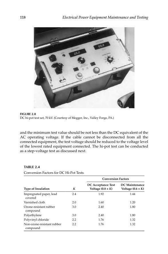
118 Electrical Power Equipment Maintenance and Testing
and the minimum test value should be not less than the DC equivalent of the AC operating voltage. If the cable cannot be disconnected from all the connected equipment, the test voltage should be reduced to the voltage level of the lowest rated equipment connected. The hi-pot test can be conducted as a step-voltage test as discussed next.
FIGURE 2.8DC hi-pot test set, 70 kV. (Courtesy of Megger, Inc., Valley Forge, PA.)
TABLE 2.4
Conversion Factors for DC Hi-Pot Tests
Conversion Factors
Type of Insulation KDC Acceptance Test
Voltage (0.8 × K)
DC Maintenance
Voltage (0.6 × K)
Impregnated paper, lead
covered
2.4 1.92 1.44
Varnished cloth 2.0 1.60 1.20
Ozone-resistant rubber
compound
3.0 2.40 1.80
Polyethylene 3.0 2.40 1.80
Polyvinyl chloride 2.2 1.76 1.32
Non-ozone-resistant rubber
compound
2.2 1.76 1.32
DK4058_C002.indd 118DK4058_C002.indd 118 11/8/2008 12:14:22 PM11/8/2008 12:14:22 PM

Direct-Current Voltage Testing of Electrical Equipment 119
2.5.3 Voltage versus Leakage Current Test (Step-Voltage Test)
In this test, the voltage is raised in equal steps and time is allowed between each step for leakage current to become stable. As explained in Chapter 1, the current is relatively high as a voltage is applied owing to capacitance charging current and dielectric absorption currents. As time passes, these transient currents become minimum with the steady-state current remaining, which is the actual leakage current and a very small amount of absorption current. At each step of voltage, the leakage current reading is taken before proceeding to the next step. Usually, it is recommended that at least eight equal steps of voltage be used and at least 1–4 min be allowed between each step. The leakage current versus voltage are then plotted as a curve. As long as this plotted curve is linear for each step, the insulation system is in good condition. At some value of step voltage, if the leakage current begins to increase noticeably, an increase in the slope of the curve will be noticed, as shown in Figure 2.9. If the test is continued beyond this test voltage, the leakage current will increase even more rapidly and immediate breakdown may occur in the cable insulation. Unless breakdown is desired, the test should be stopped as soon as the increase of slope is noticed in the voltage versus leakage current curve.
Maximum leakage current allowable for new cables acceptance can be determined from the ICEA formula for minimum allowable insulation
TABLE 2.5
Field Test Voltages for Laminated Shielded Cables up to 69 kV System Voltage
System Voltage,
kV RMS (Phase
to Phase)
System BIL, kV
(Peak)
Installation Test Voltage,a
kV (Direct Voltage,
Phase to Ground)
Maintenance Test Voltage,a
kV (Direct Voltage,
Phase to Ground)
5 75 28 23
8 95 36 29
15 110 56 46
25 150 75 61
28 170 85 68
35 200 100 75
46 250 125 95
69 350 175 130
Source: From IEEE Std 400.1–2007.
Note: Voltages higher those listed, up to 80% of system BIL for installation and maintenance
testing may be considered in consultation with the suppliers of cable and the accessories.
When equipment, such as transformers, motors, etc., is connected to the cable circuit
undergoing a test, voltages lower than recommended values may be used to comply with
the limitations imposed by the connected equipment.a Maintained for a duration of 15 min.
DK4058_C002.indd 119DK4058_C002.indd 119 11/8/2008 12:14:22 PM11/8/2008 12:14:22 PM
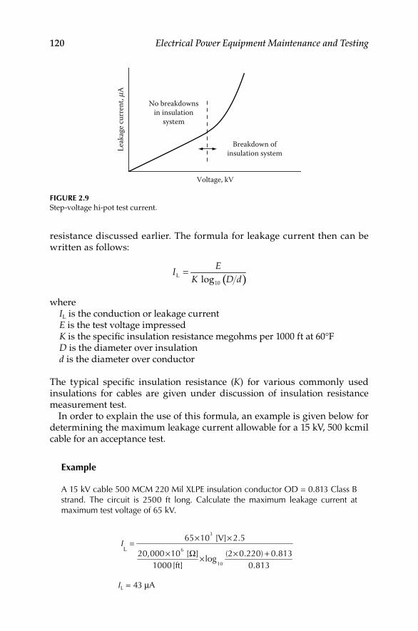
120 Electrical Power Equipment Maintenance and Testing
resistance discussed earlier. The formula for leakage current then can be written as follows:
( )=L
10 log
EI
K D d
whereIL is the conduction or leakage currentE is the test voltage impressedK is the specifi c insulation resistance megohms per 1000 ft at 60°FD is the diameter over insulationd is the diameter over conductor
The typical specifi c insulation resistance (K) for various commonly used insulations for cables are given under discussion of insulation resistance measurement test.
In order to explain the use of this formula, an example is given below for determining the maximum leakage current allowable for a 15 kV, 500 kcmil cable for an acceptance test.
Example
A 15 kV cable 500 MCM 220 Mil XLPE insulation conductor OD = 0.813 Class B strand. The circuit is 2500 ft long. Calculate the maximum leakage current at maximum test voltage of 65 kV.
L
× ×
× Ω × +×
3
6
10
65 10 [V] 2.5=
20,000 10 [ ] (2 0.220) 0.813log
1000 [ft] 0.813
I
IL = 43 μA
No breakdownsin insulation
system
Breakdown ofinsulation system
Voltage, kV
Leak
age c
urre
nt, m
A
FIGURE 2.9Step-voltage hi-pot test current.
DK4058_C002.indd 120DK4058_C002.indd 120 11/8/2008 12:14:22 PM11/8/2008 12:14:22 PM

Direct-Current Voltage Testing of Electrical Equipment 121
2.5.4 Leakage Current versus Time Test
When the fi nal test voltage of leakage current versus voltage test is reached, it can be left on for at least 5 min, and the leakage current versus time can be plotted for fi xed intervals of time as the leakage current during this step reduces from an initial high value to a steady-state value. A curve for good cables will generally indicate a continuous decrease in leakage current with respect to time or steady-state value without any increase of current during the test. This curve is shown in Figure 2.10.
2.5.5 Go, No-Go Overpotential Test
The hi-pot test can be conducted as a go, no-go overpotential test. In this test the voltage is gradually applied to the specifi ed value. The rate of rise of the test voltage is maintained to provide a steady leakage current until fi nal test voltage is reached. Usually, 1–1.5 min is considered suffi cient for reaching the fi nal test voltage. The fi nal test voltage can then be held for 5 min, and if there is no abrupt increase in current suffi cient to trip the test set, the test has been successfully passed. This test does not provide a thorough analysis of cable condition, but provides suffi cient information as to whether the cable meets a specifi c high-voltage breakdown strength requirement. This type of test is usually performed after installation and repair, where only cable that can withstand strength verifi cation without a breakdown is to be certifi ed.
2.5.6 DC Overpotential Test Connections and Procedures
The test connections for this test are similar to test connections shown in Figure 2.7a, and for three-conductor cable are similar to those shown in Figure 2.7b and c. The test procedures are the following:
Initial current at maximum voltage
Steady-statecurrent value
Time (min)
Leak
age c
urre
nt (μ
A)
FIGURE 2.10Leakage current versus time.
DK4058_C002.indd 121DK4058_C002.indd 121 11/8/2008 12:14:23 PM11/8/2008 12:14:23 PM

122 Electrical Power Equipment Maintenance and Testing
Cable to be tested must be de-energized, opened at both ends, and • grounded to discharge any electrostatic charge on the cable. Switches, potential transformers, lightning arresters, jumpers from potheads to feeders, fuses, cutouts, and any switchgear should be discon-nected. If impossible to disconnect any or some of connected equip-ment, the test voltage should not exceed the value that could overstress these devices connected to the cable. See Figure 2.11 for equipment to be disconnected.
DC test voltage should be applied from phase to ground on each • conductor with other conductors, shields, and metallic sheath con-nected to ground or other conductors guarded with shield and metallic sheath grounded.
Ensure that the hi-pot set main “on–off” switch is in off position and • the high-voltage on switch is in the off position with voltage control switch turned to zero position before beginning the tests.
Connect the hi-pot test set safety ground stud to a good electrical ground • and make sure the connections are tight. Never operate the DC hi-pot test set without this ground connection. Also connect the shield ground strap of the shielded cable under test to the test set ground stud.
Connect the return line from other conductors not under test to • the earth ground terminal or to the guard terminal of the test set as desired. The hi-pot grounding switch should be switched into the appropriate position. Normally, 100 V insulation is required on the return line. Connect the shield and sheath to ground and also to the ground terminal of test set. The guard terminal is provided to bypass the current due to corona and surface leakage around the microammeter so that corona and surface leakage cur-rents are not included in the test readings.
Connect one end of the output or line cable to the desired phase of • the cable under test, making sure that the connections are tight and without any sharp edges. Where corona currents may be expected owing to the application of high voltages, it is recommended that the connections be taped, covered over with clear plastic bags, or use a corona ring or corona shield. The other end of the output or line cable is connected to the output or line stud of the test set.
Cable used for connecting the hi-pot test set to the cable under test, that • is, the line or output cable, should be short and direct and supported along its length so that it is not touching the ground or grounding materials or surfaces. If extension cables are to be used with the output or line cable to reach the cable under test, shielded cable should prefer-ably be used for this purpose. The shields of the extension cable and hi-pot cable should be connected with a shield jumper, which should be run away from the splice to prevent leakage. In case of the extension cable being nonshielded, care should be taken to keep the nonshielded wire away from the grounding surfaces as explained previously.
DK4058_C002.indd 122DK4058_C002.indd 122 11/8/2008 12:14:23 PM11/8/2008 12:14:23 PM

Direct-Current Voltage Testing of Electrical Equipment 123
TransformerZone E
Disc
onne
ctfu
ses a
ndci
rcui
tbr
eake
rs
Circ
uit
brea
ker
and/
orfu
ses
Zone
Chi
-pot
test
sam
eas Zo
ne A
Disc
onne
ctlig
htni
ngar
rest
ers,
circ
uit b
reak
ers,
and
pote
ntia
ltr
ansfo
rmer
sM
ediu
m-v
olta
gesw
itchg
ear Z
one A
hi-p
ot te
st
1. T
est f
or p
hase
to
pha
se2.
Tes
t for
pha
se to
g
roun
d3.
Tes
t tim
e, 1
min
Curr
ent t
rans
form
erm
ay b
e lef
tco
nnec
ted
Med
ium
-vol
tage
cabl
e Zon
e Bhi
-pot
test
1. T
est f
or p
hase
to
pha
se2.
Tes
t tim
e, 5
min
Disc
onne
ctlig
htni
ngar
rest
ers
Med
ium
-vo
ltage
cabl
e Zon
eD
hi-p
otte
st
Sam
e as
Zone B
Hi-pot testTest for phase to groundfor high and low side
Low
-vol
tage
switc
hgea
rZo
ne F
Test
for
insu
latio
nre
sista
nce
only
FIG
UR
E 2.
11H
i-p
ot
test
fo
r ca
ble
s a
nd
ass
oci
ated
eq
uip
men
t, a
nd
eq
uip
men
t to
be
dis
con
nec
ted
du
rin
g t
ests
.
DK4058_C002.indd 123DK4058_C002.indd 123 11/8/2008 12:14:23 PM11/8/2008 12:14:23 PM
124 Electrical Power Equipment Maintenance and Testing
When shielded cable is being tested, it is recommended that the shield • be trimmed back about 1 in. for every 10 kV. The shield on the test set end of the cable is connected to ground as explained previously. The shield on the other end of cable can be taped and left hanging without any connections made to it.
Test set now should be plugged into a 115 V, 60 Hz outlet. It is • important that the AC supply voltage have good line regulation, because the DC output voltage of the test set depends upon the AC line input voltage. The test voltage kilovolt range should be selected before beginning the test. The power now can be turned on and the test begun either as step-voltage or as a go, no-go test.
After the test is completed, turn the high-voltage switch of the test • set to off position. Allow the cable just tested to discharge either through the internal test set discharge circuit or external ground applied to the cable by means of hot stick at 2 kV or below. Do not touch the cable until it is fully discharged.
Connect a ground to the cable that was tested and leave it connected • for at least four times the length of the test time or until the cable is connected into the system.
2.6 Electrical Switchgear and Circuit Breakers
The DC testing of electrical switchgear and circuit breakers involves the following:
Insulation resistance measurement test•
DC hi-pot test•
Circuit breaker contact resistance test•
The insulation resistance measurement test may be conducted on all types of electrical switchgear and circuit breakers using the insulation resistance megohmmeter commonly known as the Megger.
2.6.1 Insulation Resistance Measurement Test
The insulation resistance test consists of applying voltage (500–15,000 V DC) to the apparatus to determine the megohm value of resistance. This test does not indicate the quality of primary insulation. Several factors should be remembered when performing this test. The fi rst is that this test can indicate low values of insulation resistance because of many parallel paths. The other is that an insulation system having low dielectric strength may indicate high
DK4058_C002.indd 124DK4058_C002.indd 124 11/8/2008 12:14:23 PM11/8/2008 12:14:23 PM

Direct-Current Voltage Testing of Electrical Equipment 125
resistance values. In view of this, the test results should only be interpreted for comparative purposes. This does not indicate the quality of the primary insulation system with regard to the dielectric strength to withstand high voltages. The connection diagram for making this test on a power circuit breaker is shown in Figure 2.12. The connection diagram for testing the insulation resistance of each branch circuit in a distribution panel is shown in Figure 2.13. When performing insulation testing, it is recommended that auxiliary equipment, such as potential transformers and lightning arresters, be isolated from the stationary switchgear.
Insulation resistance tests are made with the circuit breaker in open and closed position, whereas the insulation test for the switchgear bus is made with one phase to ground at a time, with the other two phases grounded. The procedure for this test is as follows:
Circuit breaker open: • Connect high-voltage lead to pole 1. Ground or guard all other poles. Repeat for poles 2 through 6, in turn, with other poles grounded.
Megohmmeter
High-voltage lead
Circuit breaker
5 6
3
1 2
4G L E
FIGURE 2.12Typical connection for insulation resistance test of circuit breaker in open position.
Megohmmeter
Conduit
Main panel
Open circuit breaker
To load
Distributionpanel
G L E
FIGURE 2.13Insulation resistance testing of branch circuit to ground of a distribution panel.
DK4058_C002.indd 125DK4058_C002.indd 125 11/8/2008 12:14:23 PM11/8/2008 12:14:23 PM

126 Electrical Power Equipment Maintenance and Testing
Circuit breaker closed: • Connect high-voltage lead to pole 1, with either pole of phase 2 and 3 grounded. Repeat for phases 2 and 3 with other phases grounded.
Stationary gear (buses): • Connect high-voltage lead to phase 1 with phases 2 and 3 grounded or guarded. Repeat the same for phases 2 and 3 with other phases grounded. Repeat this test for checking the insu-lation resistance between phase 1 to 2, phase 2 to 3, and phase 3 to 1.
In the case of outdoor oil circuit breaker bushings, experience has shown that any bushing, with its assembled associated insulating members, should, for reliable operation, have an insulation resistance value above 10,000 MΩ at 20°C. This assumes that the oil within the tank is in good condition, that the breaker is separated from its external connections to other equipment, and that the porcelain weather shield is guarded. This means that each compo-nent such as the stripped bushing itself, cross-member, lift rod, lower arcing shield, etc. should have an insulation resistance in excess of that value.
Any components that are superfi cially clean and dry and have values less than 10,000 MΩ are usually deteriorated internally, by the presence of mois-ture or carbonized paths, to such an extent that they are not reliable for good service unless reconditioned. This is particularly so when operating under surge conditions such as during lightning disturbances. In the case of the stripped bushing itself, the lower stem and upper weather shield must be either perfectly clean or guarded before it is condemned as unreliable because of an insulation resistance value less than 10,000 MΩ.
Since bushings and other associated members have very high insulation resistance values normally, a megohmmeter insulation tester having a range of at least 10,000 MΩ is necessary to test such equipment. Megohmmeter instru-ments having ranges up to 50,000 MΩ will permit observation of deteriorating trends in bushings before they reach the questionable value of 10,000 MΩ.
2.6.2 DC High-Potential Test
The hi-pot testing of switchgear involves testing of the circuit breakers and switchgear buses separately. This is a major test and determines the condition of the insulation of the switchgear assembly. The DC hi-pot test is not preferred for testing AC switchgear because the application of DC voltage does not pro-duce similar stress in the insulation system as is produced under operating conditions. Moreover, the DC hi-pot test produces corona and tracking owing to concentration of stress at sharp edges or endpoints of buses. The corona and tracking are more pronounced in older equipment, and it is therefore recommended that DC hi-pot testing be avoided on such equipment.
The test procedures for DC hi-pot testing are similar to those of AC hi-pot testing. If DC hi-pot testing is to be performed, the DC voltage test values shown in Table 2.6 are recommended for various voltage-class equipment.
The hi-pot test should be conducted under conditions similar to those of commercial testing. The switchgear should be wiped, cleaned, and restored
DK4058_C002.indd 126DK4058_C002.indd 126 11/8/2008 12:14:23 PM11/8/2008 12:14:23 PM

Direct-Current Voltage Testing of Electrical Equipment 127
to good condition before the hi-pot test is conducted. Temperature and humidity readings should be recorded and the test reading corrected when conducting DC tests.
2.6.3 Circuit Breaker Contact Resistance Measurement Test
Stationary and moving contacts are built from materials that provide good resistance to arcing. However, if contacts are not maintained on a regular basis, resistance due to repeated arcing builds up resulting in the contacts ability to carry current. Excessive corrosion of contacts is detrimental to the breaker performance. One way to check contacts is to apply DC current and measure the contact resistance or voltage drop across the closed contacts.
The breaker contact resistance should be measured from bushing terminal to bushing terminal with the breaker in closed position. It is recommended that for medium and high voltages the resistance test be made with a micro-ohmmeter having at least 100 A DC output. The use of a higher current value gives more reliable results than using lower current values. The resistance value is usually measured in micro-ohms (μΩ).
2.7 Motors and Generators
The electrical insulation system is the most prominent part of motors and generators that needs periodic maintenance and testing. The insulation system of machines is subjected to varying degrees of mechanical, thermal, and electrical stresses. The reliability of a machine depends upon the integ-rity of its insulation system. Therefore, a preventive maintenance program should include an effective testing program, along with visual inspection and routine maintenance, to evaluate the insulating system.
TABLE 2.6
DC Hi-Pot Maintenance Test Values
Rating Operating
Voltage (V)
1 Min DC Test
Voltage
240 1,600
480 2,100
600 2,300
2,400 15,900
4,160 20,100
7,200 27,600
13,800 38,200
23,000 63,600
34,500 84,800
DK4058_C002.indd 127DK4058_C002.indd 127 11/8/2008 12:14:23 PM11/8/2008 12:14:23 PM
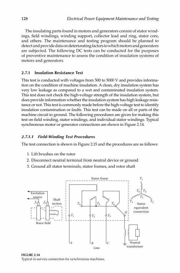
128 Electrical Power Equipment Maintenance and Testing
The insulating parts found in motors and generators consist of stator wind-ings, fi eld windings, winding support, collector lead and ring, stator core, and others. The maintenance and testing program should be planned to detect and provide data on deteriorating factors to which motors and generators are subjected. The following DC tests can be conducted for the purposes of preventive maintenance to assess the condition of insulation systems of motors and generators.
2.7.1 Insulation Resistance Test
This test is conducted with voltages from 500 to 5000 V and provides informa-tion on the condition of machine insulation. A clean, dry insulation system has very low leakage as compared to a wet and contaminated insulation system. This test does not check the high-voltage strength of the insulation system, but does provide information whether the insulation system has high leakage resis-tance or not. This test is commonly made before the high-voltage test to identify insulation contamination or faults. This test can be made on all or parts of the machine circuit to ground. The following procedures are given for making this test on fi eld winding, stator windings, and individual stator windings. Typical synchronous motor or generator connections are shown in Figure 2.14.
2.7.1.1 Field-Winding Test Procedures
The test connection is shown in Figure 2.15 and the procedures are as follows:
1. Lift brushes on the rotor
2. Disconnect neutral terminal from neutral device or ground
3. Ground all stator terminals, stator frames, and rotor shaft
Excitationsource
Shaftsection
Stator frame
Statorequivalentconnection
NeutraltransformerLine
Rotor field
f1 f2 T4 T5T3
T5
T4T6
T1
T2T6
T3T2T1
A B C
N
FIGURE 2.14Typical in-service connection for synchronous machines.
DK4058_C002.indd 128DK4058_C002.indd 128 11/8/2008 12:14:24 PM11/8/2008 12:14:24 PM

Direct-Current Voltage Testing of Electrical Equipment 129
4. Ground f1 and f2 for 30 min before conducting test to completely discharge winding
5. Disconnect ground from f1 and f2, connect test instrument (megohm-meter) ground terminal to ground, and test voltage lead to f1 and f2
6. Perform one of the following:
a. Ten minute test to determine PI
b. One minute test to determine DAR
c. One minute test to determine insulation resistance value
2.7.1.2 Overall Stator (Armature Windings) Test
The following procedures are given for conducting this test, and the connec-tion diagram is shown in Figure 2.16.
1. Check that stator frame and rotor shafts are grounded
2. Ground rotor terminals f1 and f2
3. Connect ground terminal of instrument to ground and connect test voltage lead to all motor terminals that are connected together
4. Remove ground connection from stator winding
5. Perform the following:
a. Ten minute test, that is, PI test
b. One minute test, that is, DAR test
c. One minute test, that is, insulation resistance value
MotorG L E
Megohmmeter(motor driven)
1Field
Stator
f1 f2
T4 T5 T6
T3T1 T2 N
FIGURE 2.15Test connections for fi eld winding insulation resistance measurement.
DK4058_C002.indd 129DK4058_C002.indd 129 11/8/2008 12:14:24 PM11/8/2008 12:14:24 PM

130 Electrical Power Equipment Maintenance and Testing
2.7.1.3 Overall System Test for the Motor or Generator
The overall system test includes generator neutral, transformer, all stator windings, isolated phase bus, and low side windings of generator step-up transformer. This test is performed as a screening test after an abnormal occurrence on the machine. If the reading is satisfactory, no further tests are made. If the reading is questionable or lower, the machine terminals are disconnected and further isolation performed to locate the source of the trou-ble. Similarly, it may be desirable to test a motor including its cables to pre-vent disconnection of motor terminals unnecessarily. The connection diagrams are shown in Figure 2.17a and b for generator system and a motor, respectively.
2.7.1.4 Individual Stator Winding Test
The following procedures are given for conducting this test, and the test con-nection diagram is shown in Figure 2.18.
Ground stator terminals for 30 min•
Disconnect all stator terminals • T1 through T6 and leave neutral ter-minal disconnected
Test • T1–T4 winding with T2–T5, T3–T6, and rotor grounded
Test • T2–T5 winding with T3–T6, T1–T4, and rotor grounded
Test • T3–T6 winding with T1–T4, T2–T5, and rotor grounded
MotorG L EMegohmmeter(motor driven)
Field
Shaft section
Stator
f1 f2
T4T5 T6
T3T1 T2
N
FIGURE 2.16Test connection for overall stator winding test.
DK4058_C002.indd 130DK4058_C002.indd 130 11/8/2008 12:14:24 PM11/8/2008 12:14:24 PM

Direct-Current Voltage Testing of Electrical Equipment 131
(a)
(b)
G L
R
ET1 X1
X3 X2
H1
H2
H3
T6 T4
T2T3
MegohmmeterIsolatedphasebus
Delta-wyegenerator step-up
transformer
G L E
MegohmmeterBus
OpenMotor
FIGURE 2.17Test connection for an overall system for generator or motor: (a) generator system and (b) motor.
f1
T4
G L E
NT5
T3T2
T6
T1
f2 Field
Motor
Megohmmeter(motor driven)
Stator
FIGURE 2.18Connection diagram for individual stator winding test.
The connections for the four insulation resistance measurement tests are summarized in Table 2.7.
The IEEE standard 43-2000, “Recommended Practices for Testing Insulation Resistance of Rotating Machinery,” provides information on making and
DK4058_C002.indd 131DK4058_C002.indd 131 11/8/2008 12:14:24 PM11/8/2008 12:14:24 PM

132 Electrical Power Equipment Maintenance and Testing
TABLE 2.7
Insulation Resistance Test Connections
Winding Under Test Connect Test Voltage Ground Figures
Rotor fi eld f1, f2 Shaft, stator frame, T1, T4,
T2, T5, T3, T6
2.15
All stator armature T1, T4, T3, T5, T3, T6 Shaft, stator frame, f1, f2 2.16
Overall stator, conductors,
primary transformer
Neutral transformer Shaft, stator frame, f1, f2 2.14, 2.17
Individual stator windings
T1–T4 T1, T4 Shaft, stator frame, f1, f2, T2,
T5, T3, T6
2.18
T2–T5 T2, T5 Shaft, stator frame, T1, T4,
T3, T6
T3–T6 T3, T6 Shaft, stator frame, f1, f2, T1,
T4, T2, T5
interpreting insulation resistance measurements for rotating machinery. It reviews the factors that affect or change insulation resistance characteris-tics, outlines and recommends uniform methods for making tests, and pres-ents formulas for the calculation of approximate minimum insulation resistance values for various types of AC and DC rotating machinery. The guide states:
The recommended minimum insulation resistance Rm for AC and DC machine armature windings and for fi eld windings of AC and DC machines can be determined by
= +m kV 1R
whereRm = recommended minimum insulation resistance in megohms at
40°C of the entire machine windingkV = rated machine terminal to terminal potential, in kilovolts
In applications where the machine is vital, it has been considered good practice to initiate reconditioning should the insulation resistance, having been well above the minimum value, drop appreciably to near that level.
The PI value of 2 or more is acceptable for insulating systems such as varnish-impregnated windings and asphalt windings, whereas thermoplastic insulation systems have a higher value than 2. A PI value of less than 1.0
DK4058_C002.indd 132DK4058_C002.indd 132 11/8/2008 12:14:24 PM11/8/2008 12:14:24 PM

Direct-Current Voltage Testing of Electrical Equipment 133
indicates deterioration of the windings, which should be investigated. A very high PI value (above 5) indicates dried out, brittle windings such as is the case in very old machines.
2.7.2 DC Overpotential Test
The DC overpotential test is conducted on motors and generators to assess the insulation dielectric strength. This test can be made during routine main-tenance or after repairs have been made on the machine. Either all or parts of the machine can be tested to ground to ensure that the insulation system has suffi ciently high dielectric strength for safe operation.
As a general rule, the AC voltage used for the factory proof testing of the machine windings of motors or generators is based upon the rated operating voltages of the machine. A commonly used rule for establishing factory test values for stator windings is two times rated voltage (E) plus 1000 V. For DC fi eld winding it is 10 times the excitation voltage. To convert these value to DC overpotential test values, the multiplying factor is 1.7. The recommended DC acceptance test voltage is 75% of the equipment AC voltage used for the factory proof test, whereas the recommended DC maintenance test voltage is 65% of the factory proof test value. These values can be represented by the following equations:
{ }
{ }
DC acceptance test voltage [(2 ) 1000] 1.7 0.75 V
(2.55 1.275) V
DC maintenance test voltage [(2 ) 1000] 1.7 0.65 V
(2.21 1.105) V
E
E
E
E
= × + × ×= += × + × ×= +
The values mentioned may be varied depending upon the type and size of the machine. The standard duration of the DC overpotential test is usually 1–5 min for most electrical machines but may be varied depending upon the type and size. The reader is urged to consult IEEE standard 95-2007, Guide for Insulation Testing of AC Electric Machinery (2300 V and above) with High Direct Voltage, for further information on this subject. To obtain mean-ingful results, the DC maintenance test voltage should not be below 50% of the equipment AC factory test value.
2.7.3 Voltage versus Leakage Current Test (Step-Voltage Test)
The DC overpotential test is a controlled test; that is, the increase in applied voltage is controlled by monitoring the leakage current to identify any impending failures of the winding insulation with the intention of stopping the test before the breakdown occurs. This test is commonly known as the
DK4058_C002.indd 133DK4058_C002.indd 133 11/8/2008 12:14:25 PM11/8/2008 12:14:25 PM

134 Electrical Power Equipment Maintenance and Testing
step-voltage test, and the test connection diagram is shown in Figure 2.19. This test procedure may be described as follows:
First voltage step is usually one-third of the calculated test voltage, • which is applied to the machine. Readings are taken at 1 min inter-vals up to a maximum of 10 min.
Next step is to increase the test voltage in about-equal 1000 V steps • and record the leakage current value for each step. Allow suffi cient time between each step for leakage current to become stable.
At each step, plot the values of leakage current on the vertical axis • versus the applied test voltage on the horizontal axis. For a good insu-lation system, the curve generated by the readings will be smooth with rising slope. Any sudden changes in curve characteristics are indications of impending winding failure.
Take steps to eliminate the possibility of excessive leakage due to • ionization in order to measure the true leakage current.
2.7.4 Leakage Current versus Time Test
This test can be made in lieu of the voltage versus leakage current test. In this test, the point is to separate the absorption current from the total leakage current. In this test, reasonable time is allowed during each step of applied test voltage to allow the absorption current to disappear before read-ings are taken. To completely eliminate the absorption current, many hours of test time will be necessary. Therefore, a reasonable time interval is taken to be a 10 min waiting period during each step of applied voltage. The IEEE standard 95 describes this test in its appendix; which may be summarized as follows:
Phase windingunder test
Sphere gapvoltmeter
DC High-voltagetest set120/240 or 480 V
60 Hz Supply
Phase windings
Grounded
FIGURE 2.19DC overpotential test connections for an AC machine armature (stator).
DK4058_C002.indd 134DK4058_C002.indd 134 11/8/2008 12:14:25 PM11/8/2008 12:14:25 PM

Direct-Current Voltage Testing of Electrical Equipment 135
Apply an initial voltage of about 30% on the machine winding and • hold for 10 min. The readings are taken at regular intervals and are plotted on a log–log graph, with leakage current on the vertical axis and time on the horizontal axis.
A curve is generated by the points plotted on the graph. This curve • is used to calculate the conduction component (leakage current) of measured current. The total current readings at time intervals of, say, 1, 3, and 10 min are used and substituted into the following for-mula for calculation of the conduction component (C):
× −=
+ −
21.0 10.0 3
1.0 10.0 3
( ) ( )
( ) 2
i i iC
i i i
wherei1.0 is the 1 min total currenti3.0 is the 3 min total currenti10.0 is the 10 min total current
The value of • C as calculated from this formula is subtracted from the total current at 1 and 10 min interval readings. The difference of the current readings gives the current due to absorption. These values are used to calculate the absorption ration N, which is equal to
= a1.0
a10.0
iN
i
whereia1.0 is the absorption current at 1 minia10.0 is the absorption current at 10 min
The absorption ratio • N is then used to select the time intervals from a precalculated schedule, as shown in IEEE standard 95.
The test now may be carried out for the remaining steps of test volt-• age using the precalculated values of time steps. The readings of leakage current versus voltage are taken at the end of each step.
A new curve may be generated by plotting the leakage current on • the vertical axis and voltage on the horizontal axis. The curve obtained should be a straight line with rising slope if the rate of increase of conduction current component is linear. Moisture in the insulation system will produce a continuous upward slope, whereas void ionization will exhibit minor breaks in the slope of the curve. However, a sharp break in the curve will usually indicate an impending failure.
DK4058_C002.indd 135DK4058_C002.indd 135 11/8/2008 12:14:25 PM11/8/2008 12:14:25 PM
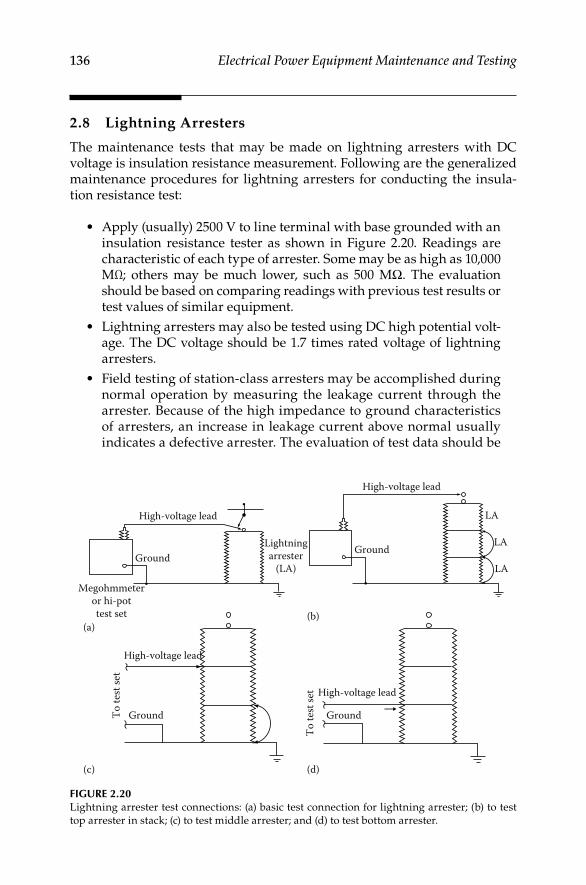
136 Electrical Power Equipment Maintenance and Testing
2.8 Lightning Arresters
The maintenance tests that may be made on lightning arresters with DC voltage is insulation resistance measurement. Following are the generalized maintenance procedures for lightning arresters for conducting the insula-tion resistance test:
Apply (usually) 2500 V to line terminal with base grounded with an • insulation resistance tester as shown in Figure 2.20. Readings are characteristic of each type of arrester. Some may be as high as 10,000 MΩ; others may be much lower, such as 500 MΩ. The evaluation should be based on comparing readings with previous test results or test values of similar equipment.
Lightning arresters may also be tested using DC high potential volt-• age. The DC voltage should be 1.7 times rated voltage of lightning arresters.
Field testing of station-class arresters may be accomplished during • normal operation by measuring the leakage current through the arrester. Because of the high impedance to ground characteristics of arresters, an increase in leakage current above normal usually indicates a defective arrester. The evaluation of test data should be
High-voltage lead
Ground
(a)
Lightningarrester
(LA)
Megohmmeteror hi-pottest set (b)
High-voltage lead
LA
LA
LA
Ground
High-voltage lead
High-voltage lead
Ground Ground
To te
st se
t
To te
st se
t
(c) (d)
FIGURE 2.20Lightning arrester test connections: (a) basic test connection for lightning arrester; (b) to test
top arrester in stack; (c) to test middle arrester; and (d) to test bottom arrester.
DK4058_C002.indd 136DK4058_C002.indd 136 11/8/2008 12:14:25 PM11/8/2008 12:14:25 PM

Direct-Current Voltage Testing of Electrical Equipment 137
based upon comparing the leakage current values with previous values or measurements obtained on similar units or comparative values of the three single-pole arresters in the single installation. It is also recommended that oscillographic measurements be made, if possible, because this will provide the most complete information, which allows for the best comparison.
2.9 Capacitors
Several different tests may be performed on power-factor correction capaci-tors to determine their suitability for service. From these, users may select tests that they deem practical and necessary. Factors that infl uence the selection of tests may be the type of banks, such as substation banks or dis-tribution lines, electrical arrangements, failure rate experiences, and others. NEMA Standards Publication CP1-1977, Section 6.06, “Field Test on Capacitor Units,” listed the two options: (1) checking new capacitor units before plac-ing in service and (2) after they have been placed in service. For historical perspective, the requirements for checking the capacitor units before placing them in service were the following:
2.9.1 Tests to Check the Condition of New Capacitor Units before Placing in Service
Perform the following tests:
Terminal-to-terminal AC or DC high-voltage test at 75% of factory • routine (production) test voltage.
Short-circuited terminal-to-case (two-terminal units only) per-• form impulse and DC high-voltage test according to voltage rating table given in the old standard. This section also states, “Experience has shown that these tests are not necessary on all capacitor units.”
The most current standard, CP1-2000, lists only one option for checking the new capacitor units after they are placed in service. These requirements are the following.
2.9.2 Tests to Check the Condition of a Capacitor Unit after It Has Been in Service
Serviceability of a capacitor unit may be determined by one or more of the following tests in case of trouble or after exposure to possible damage:
DK4058_C002.indd 137DK4058_C002.indd 137 11/8/2008 12:14:25 PM11/8/2008 12:14:25 PM

138 Electrical Power Equipment Maintenance and Testing
Capacitance measurements by current measurement at known voltage • and rated frequency, or by a low voltage capacitance meter. These tests will generally indicate a short-circuited capacitor or open-circuited capacitor.
Line-to-line internal discharge resistor may be checked with a suit-• able bridge or calculated from DC voltage and current readings.
Line-to-case insulation resistance measurements may be made to deter-• mine the condition of the insulating terminals and dielectric insulation to case. The resistance measured should be not less than 1000 MΩ. This test is not applicable to single bushing capacitors. Measuring the line-to-case power factor or dielectric loss is another means of determining the condition of the line insulating terminals and insulation to case.
Measurable characteristics of properly applied and installed capaci-• tors, which are hermetically sealed, are not expected to change with time. Therefore, periodic testing may not be necessary. However,
TABLE 2.8
Capacitor AC to DC High-Voltage Field Tests
Line to line
AC and DC test voltage = 75% of factory routine (production) test
AC: 0.75 × 2E V = 1.5E V (E, nameplate rating); AC volts should be sinusoidal, 20–70 Hz
and 10 s withstand; energize and de-energize capacitor at voltage not to exceed E DC: 0.75 × 4.3E V = 3.2E V; duration of test including time to charge capacitor should not
exceed 15 s to avoid possibility of damaging built-in discharge resistors
Line-to-case DC voltages per CP1-1977
Capacitor Rating (V) DC Field Test (V)
216–1,199 15,000a
1,2 00–5,000 28,500
5,001–15,000 39,000
13,200–22,000 45,000
Apply DC volts according to following tabulation (AC volts are not listed in this table)
Line-to-case AC voltages per CP1-2000
Apply AC volts according to following tabulation (DC volts are not listed in this table)
AC Field Test (V)
Capacitor Rating (V) BIL Indoor Outdoor
0–300 30b 3,000 10,000
301–1,199 30b 5,000 10,000
1,200–5,000 75c 11,000 26,000
5,001–15,000 95 — 34,000
13,200–22,000 125 — 40,000
a For indoor units, only 7500 should be used.b Housed equipment also included.c Outdoor capacitors only.
DK4058_C002.indd 138DK4058_C002.indd 138 11/8/2008 12:14:25 PM11/8/2008 12:14:25 PM

Direct-Current Voltage Testing of Electrical Equipment 139
operating conditions may change, resulting in damage and short life; hence, periodic inspection and check of such operating condi-tions as outlined previously in this section are highly desirable.
Liquid tightness at 50°C may be used if manufacturer’s limit is not • available.
NEMA standard CP1-2000 provides options that enable a user to develop a test program suitable to its needs. The discharge resistor measurements and calcu-lations from current measurements at low voltage can be compared readily with manufacturers’ values and serve as a reference for future comparison.
Current measurements at low voltage have proven value for two other purposes:
Detection of short-circuited sections in a capacitor•
Predetermination and correction of unbalanced current in split-wye • banks during installation
The test programs for substation and distribution lines have proved to be realistic during installation and in service situations. Table 2.8 references NEMA recommended test values in the older CP1-1977 and the latest CP1-2000 standards.
2.10 Evaluation of Test Data Readings
Insulation resistance measurements, coupled with other information, can serve as a guide to determine what actions to take on electrical apparatus or cables. The choices are as follows:
Place or restore the circuit to service until the next scheduled • inspection.
Restore the circuit to service now, but plan to perform indicated • repairs as soon as possible.
Leave out of service until repairs have been made.•
What factors should be considered to determine whether insulation is good or bad?
Rule of thumb: Minimum acceptable value of insulation to place • equipment in service is 1 MΩ per rated kilovolt plus 1 MΩ. This is based upon experience rather than the characteristics of insulation. The insulation resistance should never be less than 1 MΩ for all equipment.
DK4058_C002.indd 139DK4058_C002.indd 139 11/8/2008 12:14:26 PM11/8/2008 12:14:26 PM

140 Electrical Power Equipment Maintenance and Testing
Manufacturers’ information when available.•
Comparison with values obtained at acceptance or installation.•
Comparison with values from previous routine tests.•
Comparison with values of several similar units.•
What physical factors may infl uence the readings?
Contamination including dirt, moisture, acids, and salts.•
Contamination at terminal connection or at an end point can cause a • low reading, and the true reading of a winding or cable will be unknown.
Readings should be compared at a common temperature base, for • example, 20°C. Different insulating materials have different tempera-ture correction tables, which are available in manufacturers’ literature.
2.10.1 Acceptance Criteria for Rating Insulation
The minimum acceptable insulation resistance for safe energization of power equipment of each nominal voltage class is listed in Table 2.9. Values below these minimums indicate moisture, substantial thermal or chemical degra-dation, contamination, or physical damage. Equipment whose insulation resistance is less than the appropriate minimum is susceptible to disruptive failure and must not be energized for safety as well as economic reasons. Table 2.15 lists the insulation resistance values that are considered acceptable for healthy insulation. By examining the data given in Tables 2.9 and 2.15, the
TABLE 2.9
Minimum Acceptable Insulation Resistance at 20°C for Safely Energizing Electric Power Equipment
Nominal Voltage Class Typical System Voltagea
Minimum Acceptable
Resistance (MΩ)b
600 V 120, 240, 480 V AC; 125, 250 V DC 1.5
2.4 kV 2.4 kV 3.4
5 kV 4.16 kV 5.16
7.2 kV 6.9 kV 8.2
15 kV 13.8 kV 14.8
36 kV 20–25, 34.5 kV 35.0
72 kV 69 kV 70.0
145 kV 115, 138 kV 139.0
242 kV 230 kV 231.0
550 kV 500 kV 501.0
a RMS AC except as shown.b Resistances above these values do not necessarily indicate sound insulation condition, but
only that the equipment may be energized without signifi cant risk of disruptive failure.
DK4058_C002.indd 140DK4058_C002.indd 140 11/8/2008 12:14:26 PM11/8/2008 12:14:26 PM

Direct-Current Voltage Testing of Electrical Equipment 141
difference should be obvious to the reader between what is considered a good value versus the absolute minimum value when evaluating the health of an insulation system.
An insulation resistance above the minimum in the table indicates only that the severely degraded conditions mentioned above do not exist and that the equipment may be energized safely. This does not necessarily mean that the insulation has acceptable dielectric strength, or that it is free of deterioration. A clean, dry insulation system in excellent condition should have a resistance several orders of magnitude larger than the mini-mum required for safe energization. For instance, the resistance of good 600 V class insulation is typically in the 100–1000 MΩ range.
In reality, the measured insulation resistance is of little signifi cance on a one-time basis as long as it is well above the acceptance level. However, a long-term trend toward lower resistance strongly indicates progressive deterioration, which should be investigated and corrected.
To allow meaningful trending, the infl uence of irrelevant factors must be eliminated from the series of insulation resistance readings. The primary such factor is temperature. The measured resistance of a solid insulation system can change by as much two orders of magnitude as its temperature varies from the bottom to the top of the rated operating temperature range of the equipment. To eliminate this effect, tests whose results will be used for trending either should always be performed at essentially the same insu-lation temperature, or the results converted to a common temperature base. Insulation testing and test trending procedures for equipment should be written accordingly.
In practice, the fi rst alternative implies either testing the insulation when it is at nearly normal operating temperature, that is, as soon as possible after a period of normal, stable loading, or after the insulation has cooled to an ambient temperature, which is above the dew point and remains reasonably stable from test to test. In the second, more common approach, the resistances measured at varying temperatures are con-verted to a common standard temperature of 20°C using tables of empiri-cally based correction factors given in the literature. Temperature coeffi cients of resistance vary greatly with the chemical composition of the insulation, so different corrections are required for different insula-tion systems. The equipment manufacturers’ literature is the best source of temperature correction information.
Humidity also affects the measured insulation resistance, but not nearly as much as temperature if the insulation system is reasonably clean. In fact, large variations in insulation resistance with ambient humidity, in the absence of other explanations, indicate a possibility of contamination, which should be investigated. It is not normally necessary to correct for humidity effects.
Tables 2.10 through 2.15 provide examples of rating insulation for various apparatus and equipment as to whether it is good, bad, or needs further investigation.
DK4058_C002.indd 141DK4058_C002.indd 141 11/8/2008 12:14:26 PM11/8/2008 12:14:26 PM

142 Electrical Power Equipment Maintenance and Testing
TABLE 2.10
Example of Evaluating 15 kV Cable Readings
Megohm Values
Test Phase 1 Phase 2 Phase 3 Good Bad Investigate
1 4000 4500 3500 X
2 4000 800 3500 X
3 4000 50 3500 X
4 4000 200 3500 X
5 4000 1000 3500 X
6 4000 4000 3500 X
Note: Test 4 indicates a low value and upon investigation indicated a cracked sheath. Test 5,
which was conducted on the second day on the same cable, indicated a higher
value of resistance due to drying out. Test 6, conducted on the third day, indicated
normal values because of further drying, but sheath crack still was not repaired.
TABLE 2.11
Example for a Lightning Arrester Might Be as Follows
Megohm Value
Test Phase 1 Phase 2 Phase 3
1 8,000 8,000 50,000
Note: The 50,000 MΩ value is too high and could indicate damage to the
lightning arrester, such as missing elements. The 8,000 MΩ value is good.
TABLE 2.12
Example for a Generator Might Be as Follows
Test Type
Generator Criteria
Stator Rotor Good Bad Investigate
1 PI 4.1 2.6 X
2 PI 4.1 1.2 X
3 PI 4.1 7.0 X
Note: Test 2 indicates moisture or contamination, whereas test 3
indicates rotor insulation embrittled by heat.
TABLE 2.13
Example of Insulation Resistance Values for Transformers
Transformer Condition
1 Min Readings in Megohms
(Corrected to 20°C)
New mineral-oil transformers 1000 and above
Service-aged transformers 100–1000
Investigate below 100
Askarel-fi lled transformer with
high-voltage switch
10–50
DK4058_C002.indd 142DK4058_C002.indd 142 11/8/2008 12:14:26 PM11/8/2008 12:14:26 PM

Direct-Current Voltage Testing of Electrical Equipment 143
TABLE 2.14
Example of DAR and PI for Motors and Generators
Criteria
Test Test Type Good Fair Questionable Poor
1 DAR ≥1.4 1.25–1.4 1.1–1.25 <1.1
2 PI ≥3 2–3 1.5–2 <1.5
2.11 Precautions When Making DC Tests
DC overpotential test can be conducted any time an equipment is • taken out of service for a few hours; however, it is preferred that the test be planned in conjunction with a periodic dismantled inspection of the equipment. This will allow time to investigate the cause of unsatisfactory test results and make necessary repairs with a mini-mum of interference to normal production.
TABLE 2.15
Representative Insulation Resistance Values for Electrical Apparatus
Nominal Rating of
Equipment (V)
Minimum Test Voltage
(DCV)
Recommended Minimum
Insulation Resistance (MΩ)
250 500 25
600 1,000 100
1,000 1,000 100
2,500 1,000 500
5,000 2,500 1,000
8,000 2,500 2,000
15,000 2,500 5,000
25,000 5,000 20,000
34,500 and above 15,000 100,000
Source: From NETA Maintenance Testing Specifi cations, Table 100-1, International
Electrical Testing Association, Portage, MI, 2005. With permission.
Note: In the absence of consensus standards dealing with insulation–resistance tests,
the NETA Standards Review Council suggests the above representative values.
Note that the insulation resistance values given in Table 2.15 are much higher
than the insulation resistance values of Table 2.9 because the values in Table 2.15
are desired minimum values whereas the values in Table 2.9 are the absolute
minimum for energizing equipment without a high risk of fl ashover. Test results
are dependent on the temperature of the insulating material and the humidity
of the surrounding environment at the time of the test. Insulation–resistance test
data may be used to establish a trending pattern. Deviations from the baseline
information permit evaluation of the insulation. See Table 2.1 for temperature
correction factors.
DK4058_C002.indd 143DK4058_C002.indd 143 11/8/2008 12:14:26 PM11/8/2008 12:14:26 PM
144 Electrical Power Equipment Maintenance and Testing
Equipment should be taken off the line suffi ciently in advance of the • test to permit it to cool below 40°C (104°F). Testing at ambient tem-perature is preferred.
Insulation of windings should be relatively clean and dry. If exces-• sive foreign matter is present, the windings should be cleaned prior to conducting the test. Any cleaning solvent used should be allowed to evaporate thoroughly so that the surface of the insulation is dry; otherwise, false leakage current readings may result.
Where it is possible to do so, especially with large rotating machines, • phase connections should be opened in order to test each phase separately, phase to phase and phase to ground. All windings not under test should be short-circuited and grounded to the machine frame.
As a safety precaution, before any DC voltage tests are conducted, a • ground should be applied to the unit or cable to be tested.
Allow the DC voltage to discharge suffi ciently, especially in cables • after tests have been concluded. A common rule of thumb is that the discharge time should be four times the charge time.
All components require de-energizing and solid grounding before • being tested. Check with a reliable voltage indicator that responds to alternating current (AC) and DC voltage before testing to ensure all equipment is deenergized.
All cable termination ends as well as all connecting leads of components • being tested should be guarded from accidental contact by barriers, enclosures, or a watchman at all points. The cable ends should be sepa-rated from all elements not being tested by distances at least 0.1 in/kV of test potential for voltages upto 100 kV and at least 0.2 in/kV for higher test voltages.
Breakdown may generate traveling waves into the cable that can be • high enough to cause degradation or breakdown of the insulation being tested. Installation of suitable rod gaps should be considered according to IEEE Std 4 for DC voltages to provide protection. A damping resistor may be installed to reduce oscillations and refl ection voltages into the insulation being tested.
DK4058_C002.indd 144DK4058_C002.indd 144 11/8/2008 12:14:26 PM11/8/2008 12:14:26 PM
145
3Power Factor and Dissipation Factor Testing Methods
3.1 Introduction
This chapter covers the power factor (PF) and dissipation factor (DF) tests that are ordinarily conducted in the fi eld for acceptance (start-up) and routine fi eld (maintenance) testing of insulation of electrical equipment and appara-tus. The PF and DF tests are conducted using the 60 Hz power frequency voltages, therefore these tests may be referred to as alternating current (AC) voltage tests. The purpose of conducting these tests is to identify if the equip-ment has been installed properly, determine if corrective maintenance and repair is needed, and/or track the gradual deterioration of the equipment over its life. The question might be asked, why conduct these tests? The answer is obvious because the equipment to be tested is normally energized with 60 Hz AC voltage, therefore testing with the same type of voltage that the equipment sees in service provides the best information on the condition of that equipment. By applying an AC voltage test potential across a series of insulations (insulation system), the voltage drop across each layer of insula-tion and the resulting measured losses can be equated to true operating con-ditions. The voltage drop is proportional to the dielectric constant of the insulation layers. There are other AC voltage tests that may be performed along with PF and DF tests. The AC voltage tests can be classifi ed into the categories as listed below:
1. PF and DF
2. AC high potential tests
3. Very low frequency (VLF)
4. AC series resonant
5. Induced frequency
6. Partial discharge (PD)
7. Impulse tests
The AC tests may be classifi ed as destructive and nondestructive tests. The PF and DF tests are considered nondestructive since the test voltages used in
DK4058_C003.indd 145DK4058_C003.indd 145 11/8/2008 12:15:34 PM11/8/2008 12:15:34 PM
146 Electrical Power Equipment Maintenance and Testing
performing these tests do not exceed line-to-neutral voltages of the equipment being tested. The basic principle of the nondestructive testing is the detection of a change in the measurable characteristics of an insulation that can be associ-ated with the effects of contaminants and destructive agents without over- stressing the insulation. The AC high potential, VLF, and AC series resonant tests may be classifi ed as destructive since the test voltages associated with these tests are higher than normal operating voltages which may overstress the insulation. The effect of repeated high voltage (HV) tests on insulation are cumulative and therefore thoughtful consideration should be given on the ben-efi ts of these tests for routine fi eld and maintenance testing, except for special investigations or for acceptance testing. The induced frequency, PD, and impulse tests are primarily conducted at the factory during manufacturing of electrical apparatus and equipment. However, for special investigations these tests may be performed in the fi eld but will require special test equipment and setup. The AC high potential, AC series resonant, VLF, PD, induced frequency, and impulse tests are covered in other chapters under respective equipment category. This chapter is exclusively devoted to PF and DF testing methods.
3.2 PF and DF Test Methods
3.2.1 General
The PF insulation tests were used in the laboratory since the early 1900s by cable manufactures, and in the fi eld for testing bushing since 1929. The DF is based on the Schering bridge which was developed also in the early 1900s to evaluate insulation by separating the capacitive and real components of the charging current. Today, the PF and DF tests are considered to be synony-mous because they both refer to the AC dielectric loss test. PF and DF are but two of the several measurable characteristics that can be obtained from an AC dielectric loss test used for evaluating the condition of the insulation system. Both of these tests are effective in locating weaknesses in the electri-cal insulation and hazard in the power apparatus before impending failure. PF and DF tests are not go-no-go tests, and can measure dielectric loss, capac-itance, and AC resistance of the insulation of the electrical apparatus. These tests can measure the presence of bad insulation even when there may be a layer of good insulation in series with the bad insulation. These tests pro-vide information on the overall condition of the insulation in terms of a ratio (i.e., PF or DF value of insulation) that is independent of the volume of the insulation being tested. Moreover, they provide assessment of the insulation under normal frequency (60 Hz) operating conditions which is not time dependent like the direct current (DC) voltage tests. The PF and DF tests do not overstress the insulation and can determine if the insulation is slowly degrading by comparison with previous year’s test results, or with test results of similar equipment.
DK4058_C003.indd 146DK4058_C003.indd 146 11/8/2008 12:15:34 PM11/8/2008 12:15:34 PM

Power Factor and Dissipation Factor Testing Methods 147
3.2.2 Principles of PF/DF Testing
The PF/DF tests measure insulation capacitance, AC dielectric losses, and the ratio of the measured quantities. When insulation is energized with an AC voltage, the insulation draws a charging current. This charging cur-rent comprises of two components called capacitive current and resistive current. The capacitive current leads the applied test voltage by 90°, whereas the resistive current is in phase with the voltage as shown in Figure 3.1. The capacitive current is directly proportional to the dielectric constant, area, and voltage and inversely proportional to the thickness of the insulation under test. The capacitive current may calculated by the following formula:
= =cap
c
EI E C
Xw
The above equation may be written as:
p
12
ca 0 r2 0.08854 10 r
AA E fI Edd
−⎡ ⎤⎛ ⎞⎛ ⎞ × × × ×= = ⎜ ⎟⎜ ⎟ ⎢ ⎥⎝ ⎠⎝ ⎠ ⎣ ⎦p ewe e
whereE is the test voltageC = e0e r(A/d)e0 is the dielectric constant of vacuum (0.08854 × 10⁻¹² F/cm)e r is the dielectric constant of the insulationA is the area (cm2)d is the thickness of insulationf is the frequency
E
q
d
IR (W)
(Vars)
IcapIT
FIGURE 3.1Vector relationship of voltage, resistive, and capacitive current (IT, total current; Icap, capacitive
current; IR, resistive current; q, PF angle; and d, dissipation angle).
DK4058_C003.indd 147DK4058_C003.indd 147 11/8/2008 12:15:34 PM11/8/2008 12:15:34 PM

148 Electrical Power Equipment Maintenance and Testing
Changes in the capacitive current indicate degradation in the insulation, such as wetness or shorted layers, or change in the geometry of the insulation. The resistive current supplies the energy lost due to dielectric losses such as carbon tracking, volumetric leakage, surface conduction, and corona. Dielectric losses due to water contamination or carbon tracking or other forms of deterioration increase by the square of the voltage, where as dielec-tric losses due to corona increase exponentially as the voltage increases. PF/DF testing is sensitive enough to detect a deteriorated moisture problem in the insulation compared to an insulation resistance test.
Although there are several manufacturers of PF/DF test equipment, this text describes PF test methods and procedures based on the PF test equip-ment of Megger Incorporated (originally Megger Instruments), Valley Forge, Pennsylvania and Doble Engineering Company, Watertown, Massachusetts. The PF methods, theory, and principles discussed in this text are also applicable to the PF test equipment of other manufactures. It should be noted that in the electrical industry, especially in the utility transmission and dis-tribution (T&D) arena, the PF test may be referred to as Doble test* because of the use of the Doble test sets when performing PF tests. The terms PF test and Doble test are one and the same.
3.2.3 Factors That Influence PF Measurements
The PF measurement is a searching diagnostic tool for evaluating insulation condition. It is a fundamental concept that changes in insulation quality result in measurable changes in some of the basic electrical characteristics of the insulation, such as capacitance, dielectric loss, or PF. Therefore, by mea-suring these electrical characteristics over time, changes in the integrity of the insulation can be assessed. Unfortunately, PF tests cannot always be con-ducted under the desired or same conditions because the equipment may be located outdoors or the environment may be different from test to test. There are two environmental variables which cannot be controlled easily; they are temperature and humidity. Also, depending on the cleanliness of the insula-tion and relative humidity, surface leakage current can also have an effect on the PF measurements. The electrical characteristics of most insulation materi-als vary with temperature. In order to compare the results of routine PF tests measurements taken at different temperatures for the same equipment, it is necessary to normalize the results to a common base temperature. It is a rec-ommended practice to convert the measured PF values to a common base temperature of 20°C. When equipment is tested near freezing temperatures where a large correction factor may cause the resultant PF to be unacceptably high, then the equipment should be retested at a higher temperature before the equipment is condemned. Similarly, when high PF results are encountered at high temperature, the equipment should be retested after it has been allowed to cool down. Also, PF tests should not be performed for detection of presence of moisture in the insulation when the temperatures are much below freezing,
* Registered name of Doble Engineering Co., Watertown, Massachusetts.
DK4058_C003.indd 148DK4058_C003.indd 148 11/8/2008 12:15:34 PM11/8/2008 12:15:34 PM

Power Factor and Dissipation Factor Testing Methods 149
because the ice has a resistivity of approximately 144 times that of water. Although, the temperature correction factors have been developed for correcting the measured PF results to a common base temperature, no such factors are available for humidity effects because of other variable effects. One of variables that affects the insulation measurement is surface leakage, which is dependent upon the moisture and the cleanliness of the surface of the specimen under test. When making PF tests, the effects of surface leakage (due to humidity, dirt, etc.) should be recognized and addressed accordingly. The effects of surface leakage current may be minimized by cleaning and drying external surfaces to reduce the losses, or using guard collars to divert the surface leakage current from the measuring circuit, or using the combina-tion of the two approaches. Some cases may be handled quite easily with no thought or effort as to control of surface leakage, while others may require an extra effort to produce good results. It should also be recognized that there will be times when it will be best to postpone tests until another day. Refer to Section 3.7 for further discussion of variables affecting PF measurements.
The PF test results may be converted to the reference temperature of 20°C (68°F) using the conversion factors given in the test manual. The procedure for normalizing the test results to 20°C consists of (1) determine the test specimen PF, (2) measure the test specimen temperature, (3) obtain the appropriate correc-tion factor from the table corresponding to the specimen temperature, and (4) multiply the calculated PF value with the correction factor.
3.3 Description of the PF Test Equipment
3.3.1 PF and DF Test Set
There are several manufacturers of the PF/DF test equipment. However, there are two main suppliers of PF/DF instruments in the United States, and they are Megger Incorporated, Valley Forge, Pennsylvania and Doble Engineering, Watertown, Massachusetts. The test sets listed below are in use for performing PF/DF tests on electric power system apparatus.
Megger Incorporated, Valley
Forge, PA Voltage
Model CB-100, Cat. No. 810130 28 V
Semi-automatic, Cat. No. 670025 2.5 kV
Semi-automatic, Cat. No.
670065
12 kV
Extended semi-automatic, Cat.
No. 670070
12 kV
Model Delta-2000, Cat. No.
672001
12 kV
Model Delta-3000, Cat. No.
673001
12 kV
DK4058_C003.indd 149DK4058_C003.indd 149 11/8/2008 12:15:34 PM11/8/2008 12:15:34 PM

150 Electrical Power Equipment Maintenance and Testing
This section briefl y describes the Megger DF test equipment, its theory, and its operation for performing PF tests. The description of theory and opera-tion for all types listed are essentially the same. A transformer ratio-arm bridge circuit is used as shown in the simplifi ed diagram of Figure 3.2.
The circuit consists of a standard reference capacitor (CS) and the insula-tion under test (CX). A special multiwinding transformer is the characteristic feature of the circuit. A voltage is applied to both CS and CX. The ratio arms, NS and NX are adjusted to balance capacitive current, and the variable resis-tor (RS) is adjusted to balance resistive current. The null indicator is used to determine when the bridge circuit is balanced. The values of NS and NX are used to determine capacitance and the value of RS correlates to power ( dissipation) factor of the test insulation.
Model CB-100 is a low voltage (LV) bridge which is manually balanced for both capacitance and DF, but it is direct reading. The semiautomatic models require manual balancing for capacitance, but they provide a direct digital readout of DF. Model Delta-3000 is automatic balancing for both capacitance and PF, and can also display DF directly (Figure 3.3).
Some of the major features of the Delta-3000 test set are listed below:
Completely self-contained test set including 0 to 12 kV power supply, standard capacitor, instrumentation, test leads, and printer
It is simple to operate, providing automatic balancing and digital display for voltage, current, dielectric loss (in watts), capacitance, and PF. Readings are adjusted to equivalent values of 10 or 2.5 kV
Doble Engineering,
Watertown, MA Voltage (kV)
MEU 2.5
M2H-MCM—fully
automated
12
Type M4000/4100 12
ACsource
Null detector
Cs Cx
Rs Rx
Ns Nx
FIGURE 3.2Simplifi ed circuit diagram of Megger DF test set (transformer ratio-arm bridge.)
DK4058_C003.indd 150DK4058_C003.indd 150 11/8/2008 12:15:34 PM11/8/2008 12:15:34 PM

Power Factor and Dissipation Factor Testing Methods 151
Readings may be recorded on a thermal printer for hardcopy, and/or on a removable data key for download at a later time to a standard PC
It achieves high accuracy under severe electrostatic and electromagnetic interference conditions, such as encountered in HV substations
Safety features include two hand-operated interlock switches, open ground detection circuitry and zero voltage initiation of tests
Built-in diagnostic and calibration self-check
The formulas used for calculating the PF or DF are illustrated by using an example (Figure 3.4) with an insulation of PF = 1.0%. The value of PF is given by the cosine of the q angle, or the equation can be written as
dielectric lossesPF cos
charging volt-amps
watts (W)
volt-amps (VA)
0.01 (1%)
= =
=
=
q
= °arc cos (0.01) 89.43
Also, PF is approximately equal to DF when PF and DF <10.0%, that is
= δ =cos tan cotanq q
FIGURE 3.3The Delta-3000 test set. (Courtesy of Megger, Inc., Valley Forge, PA.)
DK4058_C003.indd 151DK4058_C003.indd 151 11/8/2008 12:15:35 PM11/8/2008 12:15:35 PM
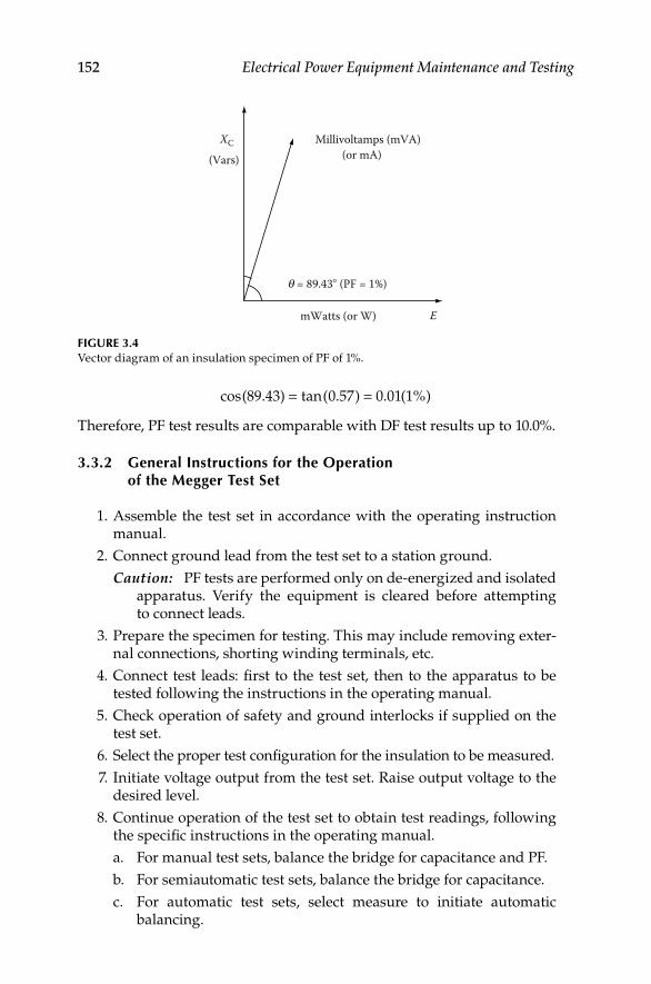
152 Electrical Power Equipment Maintenance and Testing
= =cos(89.43) tan(0.57) 0.01(1%)
Therefore, PF test results are comparable with DF test results up to 10.0%.
3.3.2 General Instructions for the Operation of the Megger Test Set
1. Assemble the test set in accordance with the operating instruction manual.
2. Connect ground lead from the test set to a station ground.
Caution: PF tests are performed only on de-energized and isolated apparatus. Verify the equipment is cleared before attempting to connect leads.
3. Prepare the specimen for testing. This may include removing exter-nal connections, shorting winding terminals, etc.
4. Connect test leads: fi rst to the test set, then to the apparatus to be tested following the instructions in the operating manual.
5. Check operation of safety and ground interlocks if supplied on the test set.
6. Select the proper test confi guration for the insulation to be measured.
7. Initiate voltage output from the test set. Raise output voltage to the desired level.
8. Continue operation of the test set to obtain test readings, following the specifi c instructions in the operating manual.
a. For manual test sets, balance the bridge for capacitance and PF.
b. For semiautomatic test sets, balance the bridge for capacitance.
c. For automatic test sets, select measure to initiate automatic balancing.
E
Millivoltamps (mVA)
mWatts (or W)
(or mA)
q = 89.43� (PF = 1%)
(Vars)
XC
FIGURE 3.4Vector diagram of an insulation specimen of PF of 1%.
DK4058_C003.indd 152DK4058_C003.indd 152 11/8/2008 12:15:35 PM11/8/2008 12:15:35 PM
Power Factor and Dissipation Factor Testing Methods 153
9. Reduce voltage to zero, or lowest setting and deinitiate voltage output.
10. Record all values as provided by the test set: test voltage, current, watts-loss, capacitance, and PF.
For specifi c operating instructions for any Megger test set, the reader is advised to follow the instructions given in the appropriate test set operating manual.
3.3.3 Doble PF Test Set
This section briefl y describes the Doble Engineering Company test equip-ment, its theory, and operation for performing PF tests. The description of theory and operation is based on the MEU test set, but the theory and opera-tion of the other test sets is the same for all test sets as manufactured by Doble Engineering. The type MEU test set has special measuring circuit in which the total current (IT) of the insulation specimen is measured. Then a balancing network is switched into the measuring circuit and the capacitive component (IC) of the specimen current is balanced out. The in-phase compo-nent (IR) of the specimen current is then measured.
The formulas used for calculating the PF or DF are illustrated by using the example of Figure 3.4 with an insulation of PF of 1.0%. The value of PF is given by the cosine q, or the equation can be written as given below for the 2.5 kV MEU and 10 kV M2H test set:
Doble MEU test set:
×%PF = (mW 100)/(mVA)
×%PF = [(dielectric losses in milliwatts)/(milliv oltam ps)] 100
Doble M2H test set:
% PF = (W 10)/(mA)×
×%PF = [(dielectric losses in watts)/(charging milliamps)] 10
3.3.4 Operation of Doble PF Test Set
The following is a set of general instructions which describe the procedure for operating the Doble test sets:
1. Assemble test set in accordance with the instruction book.
2. Check the ground and the HV connections and safety switches.
3. Connect specimen for the desired test. Raise test voltage to desired level.
4. Adjust the meter reading to full scale. The test set is ready to use and to record the test current and dielectric loss for the specimen.
DK4058_C003.indd 153DK4058_C003.indd 153 11/8/2008 12:15:36 PM11/8/2008 12:15:36 PM

154 Electrical Power Equipment Maintenance and Testing
5. Measure total charging current as the product of the meter reading and a multiplier within the proper range.
6. Specimen loss is measured by turning the milliwatts-adjust which cancels the capacitive reactance. When the capacitive reactance is cancelled the meter will be at minimum reading. This meter reading and the proper multiplier provides the milliwatt for the dielectric loss in the insulation.
7. The capacitance of the specimen is automatically obtained as a prod-uct of capacitance multiplier and capacitance dial reading at mini-mum milliwatts balance.
8. The product of the meter reading and the meter multiplier is the mil-liwatts loss of the specimen.
9. The power supply polarity is reversed to cancel the effect of electro-static interference. The average of the two milliwatts results is calcu-lated as the specimen milliwatts loss.
10. The test set has shielding to minimize the effect of electrostatic interference, as well as electromagnetic interference. For cases where high interference is encountered, a special interference cancellation circuit is available with the 10 kV test sets from Doble Engineering. The more advanced design of the Doble M4000 test set does not require interference cancellation circuit.
3.4 Basic Test Connections (Test Modes) for PF Testing
To help understand the PF test operation, it is convenient to consider the rela-tive connections of the AC source, the bridge circuit, and the test specimen with respect to ground and the LV lead(s). Figure 3.5a through c shows basic test confi gurations that simplify testing on complicated insulation systems inside HV apparatus.
3.4.1 Grounded-Specimen Test Mode
In grounded-specimen test (GST) mode, all current between the AC source and ground (through CX) is measured by the bridge (Figure 3.5a). GST is used when one terminal of the insulation to be measured is permanently connected to ground, such as a bushing fl ange, transformer tank, or grounded apparatus frame. GST mode also connects the LV lead(s) directly to ground. This enables the lead(s) to be used to ground a specimen terminal that is not normally grounded.
3.4.2 GST Mode with Guard (GST-G)
In Doble test sets this connection is referred to as guard-specimen test mode. In this mode, all current between the AC source and ground (through CX)
DK4058_C003.indd 154DK4058_C003.indd 154 11/8/2008 12:15:36 PM11/8/2008 12:15:36 PM

Power Factor and Dissipation Factor Testing Methods 155
is measured by the bridge (Figure 3.5b). The LV lead(s) may be connected to the test circuit guard. Any current present on the LV lead(s) during the test are bypassed directly to the AC source return, and are eliminated from the measurement. GST-G mode is used to isolate an individual section of insula-tion and test it without measuring other connected insulation.
3.4.3 Ungrounded-Specimen Test Mode
In ungrounded-specimen test (UST) Mode, only current between the AC source and the LV lead (through CX)is measured (Figure 3.5c). Any current fl owing to a grounded terminal is bypassed directly to the AC source return, and is eliminated from the measurement. UST mode is only used to measure insulation between two ungrounded terminals of the apparatus. In UST mode, ground is considered guard since grounded terminals are not mea-sured. UST mode is used to isolate an individual section of insulation and test it without measuring other connected insulation.
3.5 Safety Cautions with PF Testing
Safety cannot be overstressed when working with and around HV. Companies that work with HV should and do have precise rules for working in and around
HV lead HV lead
LV lead LV lead
Cx CxCx
(a) (b)
Cx
HV lead
LV lead
Cx
(c)
Cx
FIGURE 3.5Test circuit modes of the PF test set (typical). (a) GST; (b) GST-G connection; and (c) UST connection.
DK4058_C003.indd 155DK4058_C003.indd 155 11/8/2008 12:15:36 PM11/8/2008 12:15:36 PM

156 Electrical Power Equipment Maintenance and Testing
the various types of HV apparatus and their associated lines and conductors. The purpose of these instructions is to reemphasize some gener-ally acknowledged rules to be observed, and to outline some specifi c rules which must be adhered to strictly when making tests with PF test equipment.
All PF tests are performed with the apparatus to be tested completely de-energized and isolated from the power system. In addition, the apparatus housing or tank must be properly grounded. There is no substitute for a visual check to ensure that the apparatus terminals are isolated from the power source. For example, each pole of a three phase disconnect switch should be checked individually because there have been cases where one pole of a gang-operated disconnect failed to open with the others. Strictly observe all company rules and procedures for tagging and isolating the apparatus.
It is possible for the apparatus insulation to retain some charge after being switched out of service. Also, since fi eld testing usually involves work in the vicinity of energized lines and apparatus, it is possible for relatively HVs to be induced in supposedly de-energized apparatus; this is particularly true when long lengths of bus are left connected to the de-energized apparatus. Trapped charges and induced voltages may not, by themselves, be suffi cient to cause serious injury. Even relatively low energy charges are potentially hazardous in that an unexpected shock may cause a person to jump or fall from the apparatus. Therefore, safety grounds should be applied to all apparatus terminals before doing any work on them, and before connecting and disconnecting the PF test leads.
The PF test set should be located where the operator will have an unob-structed view of the apparatus under test and of various personnel assisting in the tests. Consideration should also be taken to place the equipment such that proper clearance is maintained between the test set and apparatus; in particular, it should be recognized that damaged or defective apparatus may fail during test.
Before proceeding with a test, the operator should discuss with his assis-tants the general plan for conducting the tests, voltages applied, precautions to be observed, and proper use of the safety devices.
PF fi eld test sets are equipped with ground-relay that prevents test voltage being applied until the following preliminary conditions have been established:
1. A heavy-duty safety (station ground) has been applied to the ground receptacle of the test set.
2. The test case has been grounded through the 120 V supply cord.
3. The voltage control is at the fully counterclockwise zero voltage stop.
After the test set is properly grounded, the remaining test leads and HV test cable are plugged into their receptacles. Do not connect test leads to the appa-ratus terminals unless the leads are already connected to the PF test set.
DK4058_C003.indd 156DK4058_C003.indd 156 11/8/2008 12:15:36 PM11/8/2008 12:15:36 PM

Power Factor and Dissipation Factor Testing Methods 157
The PF test set require two-person operation, and therefore two safety switches (deadman switches) are provided with the test set. These switches are of the spring-release type for quick action. With either switch off, all volt-age to the HV test cable is removed. The test person operating the PF test set has one of the safety switch, known as the local operator switch; the safety supervisor or the person assisting in PF testing should hold the second safety switch, known as the extension safety switch. The safety supervisor or the assisting person should be in position to observe all terminals of the appara-tus under test. If this is not possible, then the out-of-sight terminals should be roped off with caution labels appropriately placed, and a person posted in the vicinity to ensure safety.
Each time the test equipment is set up, prior to making the fi rst test both safety switch operators should jointly verify the correct operation of both switches.
It is apparent that the operator of the second safety switch should not close the switch until all personnel are safely in the clear; personnel should not be permitted to remain atop the apparatus as it is being tested. Also, if unau-thorized personnel should enter the area, or if some other undesirable situa-tion should occur, the extension-safety switch operator should release the switch immediately and then notify the test set operator.
Both safety switches must be used at all times. Never short circuit them and do not use fi xed mechanical locking means for depressing the switch button. The switch must be manually operated at all times.
The HV test cable used with PF test equipment is a double shielded cable in which the HV is exposed only at the outboard pothead tip. Nevertheless, it is recommended that the HV test cable not be handled while it is energized. The cable may be suspended or tied off in such a manner as to avoid handing.
The test set operator and assistant should follow a uniform system of visual and oral signals in order to prevent confusion when conducting the tests. After the tests are completed all test leads should be removed from the equip-ment terminals and brought down to the ground before they are discon-nected from the test set. The heavy-duty test set ground is the last lead to be removed from the test set. “Remember, safety, fi rst, last, always.”
3.6 PF Testing of Electrical Apparatus Insulation
PF testing is normally used for acceptance testing, preventing maintenance, and post maintenance insulation assessment, and for condition trending. The test voltage used for PF testing should be suffi cient to detect any latent weaknesses in the insulation, but since the test is intended to be nondestruc-tive, the voltage should not exceed normal line-to-neutral or line-to-ground operating voltage of the apparatus under test. Below, the PF testing of various electrical apparatus and equipment is discussed.
DK4058_C003.indd 157DK4058_C003.indd 157 11/8/2008 12:15:37 PM11/8/2008 12:15:37 PM
158 Electrical Power Equipment Maintenance and Testing
3.6.1 Transformers
Power and distribution transformers may be either single-phase or three-phase and may be either dry-type, or oil or synthetic-liquid fi lled. Transformers may be installed indoors or outdoors depending upon application. The PF test as applied to transformers is the most comprehensive test for detecting insulation degradation, usually caused by moisture, carbonization, and other forms of contamination. Depending on the type, size, and voltage rating of transformer, the PF test may be performed as an overall transformer PF test, or on individual components of the transformer to localize the dielectric cir-cuit for effective analysis of the test results; that is deterioration in the solid winding, bushing, and liquid insulation can be localized by separate tests on these components. Generally, it is common practice to perform PF tests of the bushing and the solid winding together on medium-voltage transformers that have solid porcelain-type bushings. On HV transformers with condens-er-type bushings, the PF tests are performed on the individual bushings by the UST method. On all other bushings, hot-collar tests are performed by the GST method.
The types of transformers considered for the purposes of PF testing are
1. Two-winding transformers
2. Three-winding transformers
3. Autotransformers
4. Potential transformers (PTs)
When performing PF tests on transformers, the below listed conditions should be observed:
1. Transformer is de-energized and completely isolated from the power source.
2. Transformer housing is properly grounded.
3. All bushing of HV and LV winding, including the neutral are shorted to make them into an equivalent HV and LV bushings. Neutrals must be ungrounded.
4. Transformers equipped with load-tap-changers should be set to some position off neutral, and this position should be noted on the test data sheet.
3.6.1.1 Two-Winding Transformers
In a three-phase or a single-phase two-winding transformer, the transformer winding insulation system comprises of three insulation system; that is, CH HV winding insulation, CL LV winding insulation, and CHL high-to-low winding insulation. The three insulation systems are shown in Figure 3.6.
DK4058_C003.indd 158DK4058_C003.indd 158 11/8/2008 12:15:37 PM11/8/2008 12:15:37 PM

Power Factor and Dissipation Factor Testing Methods 159
When performing PF tests, the HV bushing of the three phase units are shorted together to make them into an equivalent single bushing. Similarly, the LV bushing of three phase unit are also shorted together to make them into an equivalent bushing. Four PF tests of the windings are made as shown in Table 3.1. As shown in the Table 3.1, results of test 1 minus test 2, and test 3 minus test 4 are calculated to validate that the PF test have been made correctly.
Calculated results of Table 3.1: test 1 minus test 2
1. Subtract charging current of test 2 from test 1
2. Subtract watt loss of test 2 from test 1
3. Then calculate the PF, that is
+ − =H HL H HL[ ] [ ]C C C C
High Tankandcore
CL
CH
CHL
Low
FIGURE 3.6Insulation circuit of two winding transformer.
TABLE 3.1
PF Tests for Two-Winding Transformers
Test No.
Winding
Energized
Winding
Grounded
Winding
Guarded
Insulation
Measured
1 HV LV — CH plus CHL
2 HV — LV CH
3 LV HV — CL plus CHL
4 LV — HV CL
DK4058_C003.indd 159DK4058_C003.indd 159 11/8/2008 12:15:37 PM11/8/2008 12:15:37 PM
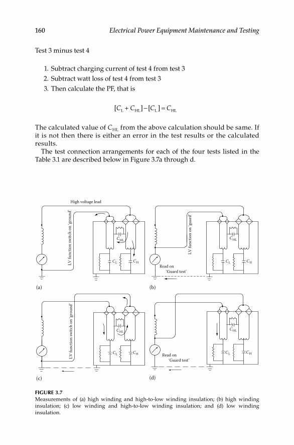
160 Electrical Power Equipment Maintenance and Testing
Test 3 minus test 4
1. Subtract charging current of test 4 from test 3
2. Subtract watt loss of test 4 from test 3
3. Then calculate the PF, that is
L HL L HL[ + ] [ ]C C C C− =
The calculated value of CHL from the above calculation should be same. If it is not then there is either an error in the test results or the calculated results.
The test connection arrangements for each of the four tests listed in the Table 3.1 are described below in Figure 3.7a through d.
LV fu
nctio
n sw
itch
on ‘g
roun
d’
High voltage lead
(a)
CHCL
CHL CHL
CHCL
CHL
Read on‘Guard test’
Read on‘Guard test’
(d)
LV fu
nctio
n on
‘gua
rd’
(b)
CHCL
CHCL
CHL
LV fu
nctio
n sw
itch
on ‘g
roun
d’
(c)
FIGURE 3.7Measurements of (a) high winding and high-to-low winding insulation; (b) high winding
insulation; (c) low winding and high-to-low winding insulation; and (d) low winding
insulation.
DK4058_C003.indd 160DK4058_C003.indd 160 11/8/2008 12:15:37 PM11/8/2008 12:15:37 PM

Power Factor and Dissipation Factor Testing Methods 161
Test #1: Grounded test mode (GST)
HV winding is energizedLV winding is groundedThe meter reads CH plus CHL
Test #2: Guard test mode (GST)
HV winding is energizedLV winding is guardedThe meter reads CH
Test #3: Grounded test mode (GST)
LV winding is energizedHV winding is groundedThe meter reads CL plus CHL
Test #4: (Guard test mode)
LV winding is energizedHV winding is guardedThe meter reads CL
3.6.1.2 Three-Winding Transformers
The equivalent circuit of a three-winding transformer insulation system is shown in Figure 3.8. The insulation system in a three-winding transformer
HV
LV
Tert.
CH
CL
CT
CHT
CHL
CLT
FIGURE 3.8Insulation circuit of three-winding transformer.
DK4058_C003.indd 161DK4058_C003.indd 161 11/8/2008 12:15:37 PM11/8/2008 12:15:37 PM

162 Electrical Power Equipment Maintenance and Testing
is similar to the two-winding transformer except that there is an additional winding in the transformer. The standard test procedure for a three-wind-ing transformers is given in Table 3.2. This test technique for three-winding transformers is an extension of the two-winding transformers.
TABLE 3.2
PF Tests for Three-Winding Transformers
Test
No.
Winding
Energized
Winding
Grounded
Winding
Guarded
Insulation
Measured
1 HV LV Tert. CH plus CHL
2 HV — LV and tert. CH
3 LV Tert. HV CL plus CLT
4 LV — HV and tert. CL
5 Tert. HV LV CT plus CHT
6 Tert. — HV and LV CT
7 ALL — — CH, CL, and CT
Note: Calculations: CHL, test 1 minus test 2; CLT, test 3 minus test 4; CHT, test 5 minus
test 6.
Check tests: Energize HV, UST LV, and read CHL direct; Energize HV, UST Tert., and
read CHT direct; Energize LV, UST Tert., and read CLT direct.
CH
CHT
H0 X0
CT
HV
LV
Tert.
FIGURE 3.9Insulation circuit of an autotransformer.
DK4058_C003.indd 162DK4058_C003.indd 162 11/8/2008 12:15:37 PM11/8/2008 12:15:37 PM

Power Factor and Dissipation Factor Testing Methods 163
3.6.1.3 Autotransformers
The equivalent circuit of an autotransformer insulation system is shown in Figure 3.9. The PF tests that are conducted on an autotransformer are shown in Table 3.3. For test purposes, an autotransformer is considered the same as the two winding transformer with the exceptions that the HV is a combination of HV and LV winding which cannot be separated physically. To short circuit the HV winding on a three-phase unit all seven bushings are shorted together when performing PF tests; H1, H2, H3, X1, X2, X3, and H0, X0.
3.6.1.4 PTs
PTs are used on HV systems for metering and relaying applications. Because of LV rating of the PTs, the PF tests are routinely performed only on the pri-mary winding of the PTs. Care should be exercised when performing PF tests on PTs to ensure that the PT is completely and effectively isolated from the power source before any tests are conducted. The test connections for conducting PF tests are shown in Figure 3.10. The tests that are conducted on PTs are shown in Table 3.4.
TABLE 3.3
PF Tests for an Autotransformers
Test
No.
Winding
Energized
Winding
Grounded
Winding
Guarded
Insulation
Measured
1 HV and LV Tert. — CH plus CHT
2 HV and LV — Tert. CH
3 Tert. HV and LV — CT plus CHT
4 Tert. — HV and LV CT
Note: Calculations: CHT, test 1 minus test 2; CHT, test 3 minus test 4.
H0
H1
CHT
X1
X2
H0
H1
CHT
X1
X2
FIGURE 3.10PF test connections for a single-phase PT.
DK4058_C003.indd 163DK4058_C003.indd 163 11/8/2008 12:15:38 PM11/8/2008 12:15:38 PM

164 Electrical Power Equipment Maintenance and Testing
3.6.2 Transformer Bushing
Transformer bushing may be classifi ed into condenser and noncondenser type. The condenser-type bushing consists of oil-impregnated paper insula-tion or resin-bonded paper insulation with interspersed conducting (condenser) layers. The noncondenser-type bushing consists of solid core, alternate layers of solid and liquid insulation, homogeneous insulating materials, or gas-fi lled insulation. Bushing may be further classifi ed as having capacitance taps or PF taps. Bushing rated at 69 kV and above have capacitance taps where as bush-ing 23 to 69 kV have PF test taps. A condenser-type bushing is usually used on transformers above 50 kV. The condenser-type bushing is made up of equal capacitance layers (concentric capacitors) between the center conductor and ground fl ange. These concentric capacitors provide equal voltage steps; that is a uniform voltage gradient. As shown in Figure 3.11, the condenser-type bush-ing consists of 10 equal capacitance layers and each layer has a capacitance of 1 pico-farad (pf). Therefore the total capacitance (C) is equal to 0.1 pf. For example, if one capacitance layer breaks down then the capacitance of the bushing would be one-ninth or 0.11 pf; or an increase in bushing capacitance of 0.01 pf, or 10% increase. Figure 3.11 also shows the various insulations asso-ciated with the condenser-type bushing. The main insulation C1 is the insula-tion from conductor to the tap electrode or shield layer; the tap insulation C2 is between tap electrode and ground or fl ange; and C3 is the overall insulation to ground of the upper and lower porcelain.
PF tests on bushing are usually performed by energizing the bushing con-ductor and measuring the test current and loss for the insulation system between the conductor and grounded fl ange. Many modern bushings have capacitance taps or PF test taps. Test on bushings with taps can separately determine the core insulation (C1) from the tap insulation (C2). The various insulation systems of the bushing with taps are shown in Figure 3.12.
TABLE 3.4
PF Tests for PT
Test No.
Winding
Energized
Winding
Grounded
Winding
Guarded
Winding
UST
Insulation
Measured
1. Overall H1 and H0 X2 — — HV to GRD
2. H1 cross-check H1 X2 H0 — To GRD
3. H0 cross-check H0 X2 H1 — To GRD
4. H1–H0 excitation H1 X2 — H0 IEX
5. H0—H1 excitation H0 X2 — H1 IEX
6. Hot-collar tests (see hot-collar tests in Section 3.6.2)
Notes: 1. On tests 1, 3, 4, and 5 limit the test voltage to the rating of the H0 bushing, usually
5 kV; check the literature of the manufacturer of the PTs.
2. Tests 4 and 5 must be performed at the same voltage.
3. Remove ground from H0 when performing tests.
4. Secondary winding of PTs need not be shorted; ground one end of the secondary
winding only.
5. Tests 1, 2, 3, and 6 are standard tests for PTs.
6. Correct measured PF values to 20°C; use air temperature.
DK4058_C003.indd 164DK4058_C003.indd 164 11/8/2008 12:15:38 PM11/8/2008 12:15:38 PM

Power Factor and Dissipation Factor Testing Methods 165
CACA = CB = CC = CD = CE = CF = CG = CH=CI = CJ
V1=V2=V3=V4=V5=V6=V7=V8=V9=V10
C1 C2
CKCBCCCD
CECFCG
CK
CJ
CI
CH
Tap electrodegrounded
layer/flangeGroundedlayer/flange
Cent
er co
nduc
tor
Center conductor
Groundedlayer/flange
Maininsulation
Line-to-ground system voltage
C3 overall insulation to groundof upper and lower porcelain
Tapinsulation
Tapelectrode(normallygrounded)
FIGURE 3.11Equivalent diagram of a condenser-type bushing.
FIGURE 3.12Measurements of (a) main insulation (C1); (b) tap insulation (C2); and (c) insulation of a bushing
without taps.
HV lead
LV lead
(a)
HV lead
LV le
ad
(b)
HV lead
LV lead
(c)
DK4058_C003.indd 165DK4058_C003.indd 165 11/8/2008 12:15:38 PM11/8/2008 12:15:38 PM

166 Electrical Power Equipment Maintenance and Testing
The test connections for performing PF test on bushing are given below. It should be noted that all bushing except the bushing under test are shorted and grounded.
Test No. 1: This test measures the C1 insulation of the bushing (see Figure 3.12a).
1. Remove capacitance (or PF tap) tap cover from the bushing under test and make connections as shown.
2. Put LV switch of PF test in UST mode.
3. Measure charging current and watt loss.
4. Calculate PF and capacitance; correct to 20°C.
5. Compare results to manufacturers PF and capacitance on nameplate.
6. Capacitance should be ±10% of nameplate and PF depends on manufacturer (<1%).
Test No. 2: This test measures the C2 insulation of the bushing (see Figure 3.12b).
1. Remove capacitance (or PF tap) tap cover from the bushing under test and make connections as shown.
2. Put LV switch of PF test in guard mode.
3. Guard C1 insulation as shown in the diagram.
4. Measure charging current and watt loss.
5. Calculate PF and capacitance; correct to 20°C.
6. Compare results to manufacturer’s PF and capacitance on nameplate.
7. Capacitance should be ±10% of nameplate and PF depends on manu-facturer (<1%).
8. Limit test voltages to 500 V for bushing less than 69 kV.
9. Limit test voltages to 5000 V for bushing greater than 115 kV.
10. Limit test voltages to 2000 V for Westinghouse “O”-plus bushing.
Test No. 3: This test measures the C1 and C2 insulation of the bushing (optional test).
1. Remove capacitance (or PF tap) tap cover from the bushing under test and make connections of the HV lead as shown in Figure 3.12b.
2. Put LV switch of PF test in ground mode, i.e., C1 is not guarded out as was the case in Test No. 2, i.e., the low voltage lead is connected to ground side of the meter.
3. Limit test voltages as shown in Test No. 2.
4. This test measures C1 and C2, but C1 is very small compared to C2, therefore measures C2.
DK4058_C003.indd 166DK4058_C003.indd 166 11/8/2008 12:15:38 PM11/8/2008 12:15:38 PM
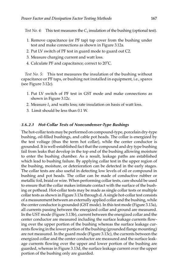
Power Factor and Dissipation Factor Testing Methods 167
Test No. 4: This test measures the C3 insulation of the bushing (optional test).
1. Remove capacitance (or PF tap) tap cover from the bushing under test and make connections as shown in Figure 3.12a.
2. Put LV switch of PF test in guard mode to guard out C2.
3. Measure charging current and watt loss.
4. Calculate PF and capacitance; correct to 20oC.
Test No. 5: This test measures the insulation of the bushing without capacitance or PF taps, or bushing not installed in equipment, i.e., spares (see Figure 3.12c).
1. Put LV switch of PF test in GST mode and make connections as shown in Figure 3.12c.
2. Measure IT and watts loss; rate insulation on basis of watt loss.
3. Limit should be less than 0.1 W.
3.6.2.1 Hot-Collar Tests of Noncondenser-Type Bushings
The hot-collar tests may be performed on compound-type, porcelain dry-type bushing, oil-fi lled bushings, and cable pot heads. The collar is energized by the test voltage (thus the term hot collar), while the center conductor is grounded. It is well-established fact that the compound and dry type bushing fail from leaks that develop in the top end of the bushing allowing moisture to enter the bushing chamber. As a result, leakage paths are established which lead to bushing failure. By applying collar test in the upper region of the bushing, moisture, or deterioration can be detected in the early stages. The collar tests are also useful in detecting low levels of oil or compound in bushing and pot heads. The collar can be made of conductive rubber or metallic foil, braid or wire. When performing collar tests, care should be used to ensure that the collar makes intimate contact with the surface of the bush-ing or pothead. Hot-collar tests may be made as single collar tests or multiple collar tests as shown in Figure 3.13a through d. A single hot-collar test consists of a measurement between an externally applied collar and the bushing, while the center conductor is grounded (GST mode). In this test mode (Figure 3.13a), all currents passing between the energized collar and ground are measured. In the UST mode (Figure 3.13b), current between the energized collar and the center conductor are measured including the surface leakage currents fl ow-ing over the upper portion of the bushing whereas the surface leakage cur-rents fl owing in the lower portion of the bushing (grounded fl ange mounting) are not measured. In the guard mode (Figure 3.13c), the currents between the energized collar and the center conductor are measured and the surface leak-age currents fl owing over the upper and lower portion of the bushing are guarded, whereas in Figure 3.13d, the surface leakage current over the upper portion of the bushing only are guarded.
DK4058_C003.indd 167DK4058_C003.indd 167 11/8/2008 12:15:38 PM11/8/2008 12:15:38 PM

168 Electrical Power Equipment Maintenance and Testing
3.6.3 Transformer Excitation Current Test
Transformer excitation current test is another test that can be performed with the PF test equipment. Excitation current is also known as the no-load or magnetizing current of the transformer. In this test, voltage is applied to the primary windings one at time with all other windings left open. The excitation current of a transformer is the current the transformer draws when voltage is applied to its primary terminals with the secondary terminal open. The excitation current test, when used in routine preventive maintenance or fi eld acceptance testing of transformers, provides means of detection for winding problems, such as short-circuited or open turns, poor joints or con-tacts, core problems, etc.
The excitation current test is conducted on each phase winding at a time, that is only one winding is under test with the other winding including the secondary winding are fl oating. When performing this test, the bushings are not shorted
HV cable
To guardGuard
(GST)
mVA andmW meter
Hotcollar
Guardcollar
(a)
HV cable
(UST)
LV lead
mVAandmW
meter
Hotcollar
To grounded-guard
grounded-guard
Guardcollar
(b)
HV cable
Guard
(GST)
mVA and mW
meter
Hotcollar
Guardcollar
Guardcollar
Toguard
(c)
Guardcollar
To guardHV cable
Guard
(GST)
mVA andmW meter
Hotcollar
(d)
FIGURE 3.13Hot-collar test of bushings in (a) GST mode; (b) UST mode; (c) guard mode, guard above and
below; and (d) guard mode, guard above.
DK4058_C003.indd 168DK4058_C003.indd 168 11/8/2008 12:15:38 PM11/8/2008 12:15:38 PM
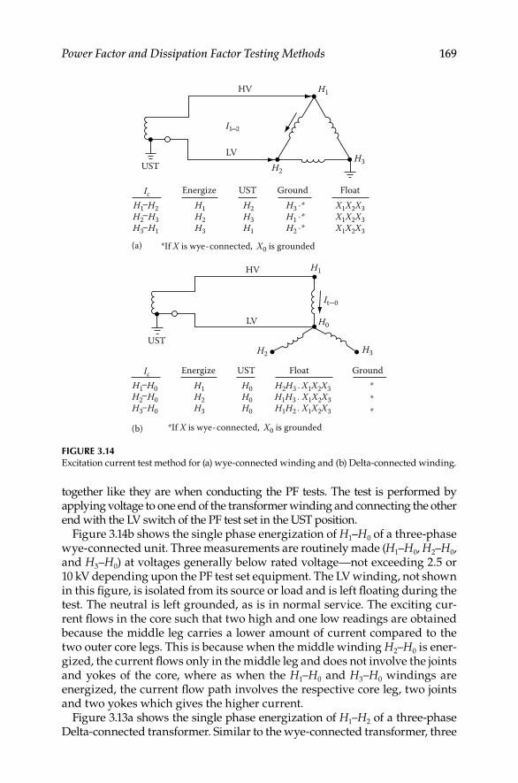
Power Factor and Dissipation Factor Testing Methods 169
together like they are when conducting the PF tests. The test is performed by applying voltage to one end of the transformer winding and connecting the other end with the LV switch of the PF test set in the UST position.
Figure 3.14b shows the single phase energization of H1–H0 of a three-phase wye-connected unit. Three measurements are routinely made (H1–H0, H2–H0, and H3–H0) at voltages generally below rated voltage—not exceeding 2.5 or 10 kV depending upon the PF test set equipment. The LV winding, not shown in this fi gure, is isolated from its source or load and is left fl oating during the test. The neutral is left grounded, as is in normal service. The exciting cur-rent fl ows in the core such that two high and one low readings are obtained because the middle leg carries a lower amount of current compared to the two outer core legs. This is because when the middle winding H2–H0 is ener-gized, the current fl ows only in the middle leg and does not involve the joints and yokes of the core, where as when the H1–H0 and H3–H0 windings are energized, the current fl ow path involves the respective core leg, two joints and two yokes which gives the higher current.
Figure 3.13a shows the single phase energization of H1–H2 of a three-phase Delta-connected transformer. Similar to the wye-connected transformer, three
FIGURE 3.14Excitation current test method for (a) wye-connected winding and (b) Delta-connected winding.
UST
*If X is wye-connected, X0 is grounded(a)
(b) *If X is wye-connected, X0 is grounded
LV
HV
H2H3
H1
UST
LV
HV
H2 H3
H1
H0
It 0
IcH1 H2H2 H3H3 H1
EnergizeH1H2H3
GroundH3 *H1 *H2 *
FloatX1X2X3X1X2X3X1X2X3
USTH2H3H1
Ic EnergizeH1H2H3
Ground * * *
USTH0H0H0
I1 2
H1 H0H2 H0H3 H0
FloatH2H3 X1X2X3H1H3 X1X2X3H1H2 X1X2X3
DK4058_C003.indd 169DK4058_C003.indd 169 11/8/2008 12:15:38 PM11/8/2008 12:15:38 PM

170 Electrical Power Equipment Maintenance and Testing
readings are routinely made (H1–H2, H2–H3, and H3–H1) and measurement recorded. In this case, the readings of the exciting current are two low and one high reading because of the current fl ow path in the core. When H1–H2 winding is energized, the current fl ows in two core legs, four joints, and four yokes thereby giving a high current. Whereas when H2–H3 and H3–H1 windings are energized, the current path involves two core legs, four joints, and two yokes which give a lower current measurement. When evaluating excitation current test results, it is important to remember that the excitation current measure-ments should have a pattern of two high and one low, or two low and one high reading depending upon the transformer winding connections.
3.6.4 Transformer Insulating Oils and Fluids
In order to perform PF tests on transformer oils and fl uids with the PF test set, a special cell is provided with the test set. The cell is essentially a capaci-tor which utilizes the insulating liquid as the dielectric. In order to make this test, a sample of the insulating fl uid or oil should be obtained from the transformer by opening the sample valve. Remember to fl ush approximately one-quart of oil or fl uid into a bucket to clean any contaminants from the valve housing. Once this is done, then fi ll cell with oil sample to just above the raised center of the cell to prevent any sparking due to insuffi cient amount of oil. This cell holds approximately one-quart of fl uid. Make con-nections of the cell as shown in Figure 3.15. The test voltage should be 2.5 or 10 kV depending upon the PF test being used. The test voltage should be raised gradually to the desired level. Readings should be taken, and PF value calculated in the normal manner as is done with the solid insulation
HV lead
IL charge
Gua
rd
Guarding ring
Insulations
FIGURE 3.15Power factor testing of the insulating liquid.
DK4058_C003.indd 170DK4058_C003.indd 170 11/8/2008 12:15:38 PM11/8/2008 12:15:38 PM

Power Factor and Dissipation Factor Testing Methods 171
tests. Take the temperature of the oil or fl uid sample immediately after the test completion. Correct the measured PF to 20°C.
3.6.5 Lightning Arrestors
Most station and intermediate class arrestors are of unit design, where gap and valve elements are enclosed in a single porcelain housing. These employ a series of gap elements with shunting resistors to shield the gaps and to pro-vide uniform voltage distribution across the individual gaps and unit. The arrestor has electrical characteristics, such as AC grading current and dielec-tric loss, which is measurable. Failure of the arrestors can be attributed to sev-eral causes, such as damaged, defective or contaminated units, lightning strokes, long-duration surges due to switching and misapplication. Arrestors have low capacitance and experience has shown that the measurement of dielectric loss is effective in detecting defective, contaminated, and deterio-rated arrestors. The dielectric loss indicates the mechanical condition and insulating qualities of the arrestor. Arrestors may consists of single units or assemblies (stacked units) depending on application for a given equipment rating. Arrestors are tested as single units to assure that the arrestor’s mechan-ical and insulation integrity is intact so that it can perform its intended func-tion. Before conducting any tests on arrestors, the line connected to the arrestor should be fi rst de-energized and grounded, then disconnected from the arres-tors. Arrestor assemblies consisting of single units are fi rst disconnected from the bus and then tested by the GST method as shown in Figure 3.16a. Assemblies consisting of two or more units are tested using a combination of GST method and UST method as shown in Figure 3.16b. In case of assemblies of three or more units per phase, it is only necessary to de-energize the line and ground the top of the arrestor stack. In this case the bus need not be disconnected from the arrestor stack.
Since the arresters exhibit nonlinear characteristics, the losses may vary depending upon the applied test voltages. In order to compare dielectric losses for the various units, all tests must be performed at prescribed voltages. The Table 3.5 gives the recommended voltages for testing lightning arresters.
3.6.6 Circuit Breakers
Circuit breakers vary from very simple designs to large and very elaborate designs. The main purpose of the circuit breaker is not only to carry and interrupt load currents but also to interrupt abnormally high currents that fl ow during fault conditions. Circuit breakers are designed to conform to the particular characteristics of the power system to which they are applied. The voltage of a given power system determines the insulating requirements needed for the circuit breakers used in the system. Therefore many different principles and insulating mediums are used in the construction of the circuit breakers. The principal insulation mediums used for circuit breakers are air, oil, vacuum, and sulfur hexafl uoride (SF6) gas. The PF tests for circuit breakers are described in Sections 3.6.6.1 through 3.6.6.3.
DK4058_C003.indd 171DK4058_C003.indd 171 11/8/2008 12:15:39 PM11/8/2008 12:15:39 PM

172 Electrical Power Equipment Maintenance and Testing
3.6.6.1 Medium-Voltage Circuit Breakers
The circuit breakers covered in this group are air magnetic, air blast, and vacuum-type circuit breakers usually applied at voltages 1000 V and above. The air magnetic and air blast breakers use arc chutes that are installed over the breaker contacts for arc interruption where as vacuum breaker contact assembly is housed in a vacuum bottle. A circuit breaker is a gang-operated device, that is the three-phase contacts are opened and closed
Test connections
Energize Ground Guard UST MeasureTestkV10 2
233 1
1 A
A
B
1
2
3
37 kV
37 kVB10
(a)
Test connections
Energize Ground Guard UST MeasureTestkV
10101010
8 2 34
4
44
ABCDE
1.6
1.61.6
1.6.21.6.2
3355
ASwitch
insulator
1
2
3
4
5
6
B
C
D
E
8 kV
12 kV
12 kV
12 kV
12 kV
(b)
FIGURE 3.16PF measurements of (a) two-stack arrestors and (b) multistacked arrestors.
TABLE 3.5
Recommended Test Voltages for Lightning Arresters
Arrestor Unit (kV) Test Potential (kV)
3.0 2.5
4.5 4.0
6.0 5.0
7.5 7.0
9.0 7.5
12 and greater 10.0
DK4058_C003.indd 172DK4058_C003.indd 172 11/8/2008 12:15:39 PM11/8/2008 12:15:39 PM

Power Factor and Dissipation Factor Testing Methods 173
simultaneously. The breaker three-phase bushing are numbered 1 through 6 with phase A numbered as 1 and 2, phase B numbered as 3 and 4, and phase C numbered as 5 and 6. The PF tests are performed on the circuit breaker as shown in Table 3.6 with the circuit breaker in open position. In order to eliminate the infl uence of the arc chutes on the bushings and other ground insulation, it is recommended to make tests 1 through 6 with the arc chutes raised or removed. The breaker frame must be properly grounded in order to obtained good test data. Since circuit breakers have very small capacitance, PF is not calculated, instead evaluation of the results is based on current and dielectric loss measurements. The test connections for test 1 through 6 are shown in Figure 3.17a and for tests 7 through 9 in Figure 3.17b.
3.6.6.2 Oil Circuit Breakers (OCBs)
An OCB consists of gang-operated three single-pole switches whose contacts are immersed in oil. Most units have one grounded tank per phase although some designs may have all three phases housed in a single tank. Major com-ponents of a circuit breaker are
Two bushing per phase mounted in an oil-fi lled grounded tank•
A contact assembly (interrupter) mounted on the bottom terminal of • each bushing
An insulating operating rod to open and close breaker contacts•
An insulated guide assembly to keep the operating rod in proper • alignment
Tank containing a volume of insulating oil to provide arc quenching•
Some breakers may have tank liners, shunt resistors across the interrupters, and other auxiliary components. The primary object of the insulation test on
TABLE 3.6
PF Tests Procedure for Medium-Voltage Circuit Breakers
Test No.
Break
Position
Bushing
Energize
Bushing
Guarded
Bushing
UST
1 Open 1 2 —
2 Open 2 1 —
3 Open 3 4 —
4 Open 4 3 —
5 Open 5 6 —
6 Open 6 5 —
7 Open 1 — 2
8 Open 3 — 4
9 Open 5 — 6
DK4058_C003.indd 173DK4058_C003.indd 173 11/8/2008 12:15:39 PM11/8/2008 12:15:39 PM
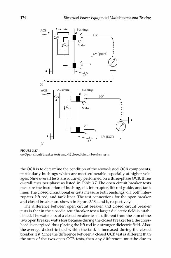
174 Electrical Power Equipment Maintenance and Testing
the OCB is to determine the condition of the above-listed OCB components, particularly bushings which are most vulnerable especially at higher volt-ages. Nine overall tests are routinely performed on a three-phase OCB, three overall tests per phase as listed in Table 3.7. The open circuit breaker tests measure the insulation of bushing, oil, interrupter, lift rod guide, and tank liner. The closed circuit breaker tests measure both bushings, oil, both inter-rupters, lift rod, and tank liner. The test connections for the open breaker and closed breaker are shown in Figure 3.18a and b, respectively.
The difference between open circuit breaker and closed circuit breaker tests is that in the closed circuit breaker test a larger dielectric fi eld is estab-lished. The watts loss of a closed breaker test is different from the sum of the two open breaker watts loss because during the closed breaker test, the cross-head is energized thus placing the lift rod in a stronger dielectric fi eld. Also, the average dielectric fi eld within the tank is increased during the closed breaker test. Since the difference between a closed OCB test is different than the sum of the two open OCB tests, then any differences must be due to
Arc chuteACBframe CCR
CCU
Bushings
Stabs
LV (guard)
HV
(a)
CCR
CCU
Arc chuteACBframe
Bushings
Stabs
LV (UST)
HV
(b)
FIGURE 3.17(a) Open circuit breaker tests and (b) closed circuit breaker tests.
DK4058_C003.indd 174DK4058_C003.indd 174 11/8/2008 12:15:39 PM11/8/2008 12:15:39 PM

Power Factor and Dissipation Factor Testing Methods 175
losses in the auxiliary insulations which are not stressed the same for both conditions. The amount of such differences can be used to evaluate the con-dition of the auxiliary insulation, and is referred to as the tank loss index (TLI) test. TLI test is defi ned as the difference in watts loss between closed breaker test minus the sum of the two open breaker tests, or TLI can be writ-ten as the following:
= −TLI Closed breaker loss sum of open breaker losses
The polarity sign of the loss measurement for the TLI should be noted in order to indicate the type of problem with the circuit breaker. Table 3.8 gives the guidance for investigating abnormal TLI values for the OCB. When it is indicated that auxiliary insulation of the OCB requires further investigation
TABLE 3.7
PF Tests Procedure for OCB
Test No.
OCB
Position
Test
Mode
Bushing
Energized
Bushing
Floating
1 Open GST 1 2
2 Open GST 2 1
3 Open GST 3 4
4 Open GST 4 3
5 Open GST 5 6
6 Open GST 6 5
7 Closed GST 1 and 2 —
8 Closed GST 3 and 4 —
9 Closed GST 5 and 6 —
HV cable
(a)
LV cable
(b)
HV cable
FIGURE 3.18(a) OCB open breaker tests and (b) OCB closed breaker tests.
DK4058_C003.indd 175DK4058_C003.indd 175 11/8/2008 12:15:39 PM11/8/2008 12:15:39 PM

176 Electrical Power Equipment Maintenance and Testing
then the interrupter and lift rod can be tested as shown on Figure 3.19a and b. With tank down, or oil removed from the OCB, perform the following test on the interrupter assembly.
UST Test-OCB Interrupter Assembly:
1. Energize HV bushing
2. LV lead on hot-collar strap around interrupter
3. Measure current and watt loss; calculate PF
UST Test-Lift Rod Assembly:
1. Use 10 kV test set
2. Stress insulation to 40 kV per foot
3. Measure current and watt loss; calculate PF
TABLE 3.8
Guide for Investigating Abnormal TLI of OCB
10 kV
More than
−0.25 W −0.25 to −0.15 W +0.15 to +0.25 W >+0.25 W
2.5 kV
More than
−15.6 mW −15.6 to 9.4 mW +9.4 to +15.6 mW >+15.6 mW
Procedure
Investigate as
soon as possible
Investigate at
next regular
maintenance period
Investigate at
next regular
maintenance period
Investigate
as soon as
possible
Guide assembly,
contact assembly,
and upper portion
of the lift rod
Guide assembly,
contact assembly,
and upper portion
of the lift rod
Lift rod, tank oil,
tank liner, and
auxiliary contact
insulation
Lift rod, tank oil,
tank liner, and
auxiliary tank
insulation
LV lead
(a)
HV
3�
3�
LV
(b)
FIGURE 3.19(a) PF tests of OCB interrupter assembly and (b) dielectric loss test of OCB lift rod assembly.
DK4058_C003.indd 176DK4058_C003.indd 176 11/8/2008 12:15:40 PM11/8/2008 12:15:40 PM
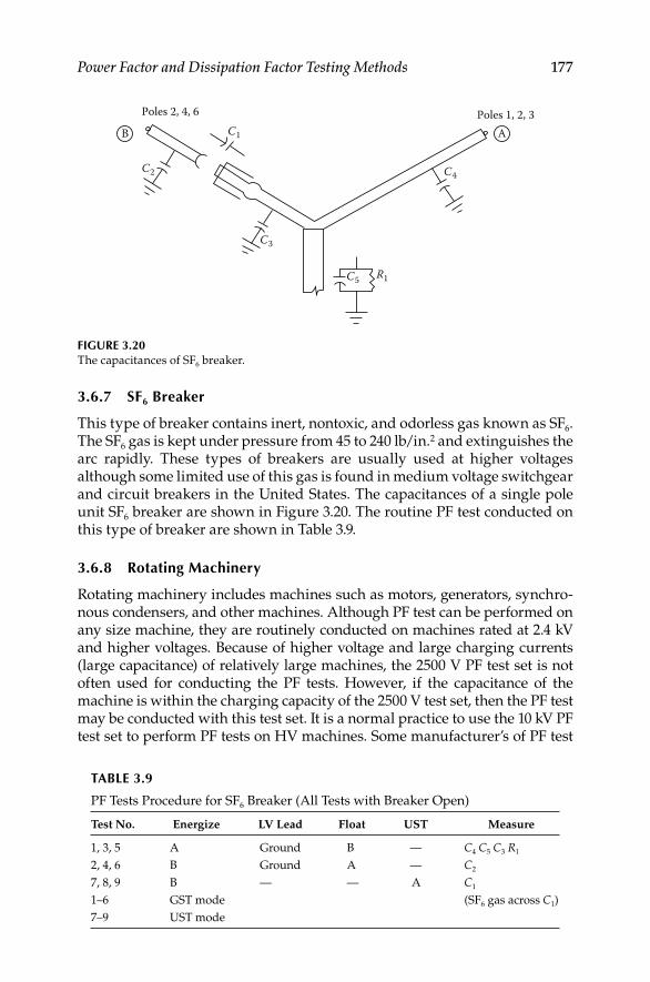
Power Factor and Dissipation Factor Testing Methods 177
3.6.7 SF6 Breaker
This type of breaker contains inert, nontoxic, and odorless gas known as SF6. The SF6 gas is kept under pressure from 45 to 240 lb/in.2 and extinguishes the arc rapidly. These types of breakers are usually used at higher voltages although some limited use of this gas is found in medium voltage switchgear and circuit breakers in the United States. The capacitances of a single pole unit SF6 breaker are shown in Figure 3.20. The routine PF test conducted on this type of breaker are shown in Table 3.9.
3.6.8 Rotating Machinery
Rotating machinery includes machines such as motors, generators, synchro-nous condensers, and other machines. Although PF test can be performed on any size machine, they are routinely conducted on machines rated at 2.4 kV and higher voltages. Because of higher voltage and large charging currents (large capacitance) of relatively large machines, the 2500 V PF test set is not often used for conducting the PF tests. However, if the capacitance of the machine is within the charging capacity of the 2500 V test set, then the PF test may be conducted with this test set. It is a normal practice to use the 10 kV PF test set to perform PF tests on HV machines. Some manufacturer’s of PF test
Poles 2, 4, 6 Poles 1, 2, 3C1
C2
C3
C4
C5 R1
B A
FIGURE 3.20The capacitances of SF6 breaker.
TABLE 3.9
PF Tests Procedure for SF6 Breaker (All Tests with Breaker Open)
Test No. Energize LV Lead Float UST Measure
1, 3, 5 A Ground B — C4 C5 C3 R1
2, 4, 6 B Ground A — C2
7, 8, 9 B — — A C1
1–6 GST mode (SF6 gas across C1)
7–9 UST mode
DK4058_C003.indd 177DK4058_C003.indd 177 11/8/2008 12:15:40 PM11/8/2008 12:15:40 PM

178 Electrical Power Equipment Maintenance and Testing
set supply a special resonator (inductive unit) with the 10 kV test sets for testing very large capacitance machines which normally could not be tested otherwise. A three-phase machine insulation is complex since it is made up of several insulation systems, but for test purposes the machine insulation can be con-sidered to have two insulation systems. These two insulations are phase-to-ground insulation known as ground-wall insulation, and interphase insulation which is known as end-turn insulation. These two insulations are represented as capacitances and are shown below, and in Figure 3.21.
f 3
f 3
f 2
f 2C1 3
C2 3
C1 C2 C3
C1 2
f 1
f 1
FIGURE 3.21Insulation systems of a machine.
Machine Insulation Systems
C1–3, Ground-wall insulation, phase-to-ground
C1−2, End-turn insulation, phase-to-phase
C2−3, End-turn insulation, phase-to-phase
C1−3, End-turn insulation, phase-to-phase
The PF tests of machine insulation provide indication of the overall general condition of the insulation; that is the presence of contamination, moisture, corona (ionization), or other forms of contamination. The applied test voltage for the PF tests usually can be used up to the machine phase-to-neutral rating. It is recommended that two sets of tests be performed on the machine wind-ing; that is fi rst measure the ground-wall insulation and second measure the end-turn insulation. The test connections for conducting the ground-wall and end-turn insulations on a machine winding are shown in Figures 3.22 and 3.23, respectively.
3.6.8.1 PF Tip-Up Test
Another variation of the PF tests on machine winding insulation may be performed as a PF tip-up test. The PF tip-up is defi ned as the increase in the PF as the voltage is increased from an initial test value to the maximum test value. The PF tip-up test can be performed on any dry-type insulation,
DK4058_C003.indd 178DK4058_C003.indd 178 11/8/2008 12:15:40 PM11/8/2008 12:15:40 PM
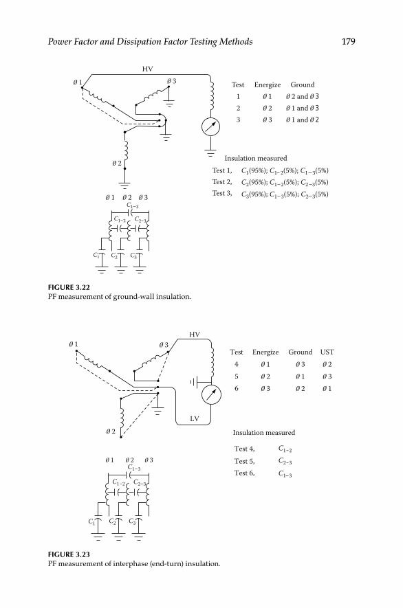
Power Factor and Dissipation Factor Testing Methods 179
1 3HV
Test
Test 1,C2(95%); C1 2(5%); C2 3(5%)C3(95%); C1 3(5%); C2 3(5%)
C1(95%); C1 2(5%); C1 3(5%)Insulation measured
Test 2,Test 3,
123
1 2 3
2 and 3 1 and 3 1 and 2
Energize Ground
2
3 2C1 3
C2 3
C1 C2 C3
C1 2
1
FIGURE 3.22PF measurement of ground-wall insulation.
3HV
LV
Test
Test 4, C1 2
C2 3
C1 3
Test 5,Test 6,
4 1 1
1 2
2
2
3
3 35
6
Energize
Insulation measured
Ground UST
3
2
2C1 3
C2 3
C1 C2 C3
C1 2
1
1
FIGURE 3.23PF measurement of interphase (end-turn) insulation.
DK4058_C003.indd 179DK4058_C003.indd 179 11/8/2008 12:15:40 PM11/8/2008 12:15:40 PM

180 Electrical Power Equipment Maintenance and Testing
that is insulation not immersed in insulating oil, such as dry-type transformers, motors, etc. The PF tip-up test indicates the nature of insulation contamina-tion and degradation which is voltage dependent, such as carbonization and ionization. It shows the increase in dielectric loss as a function of voltage, thereby indicating the cause of the increased losses. The PF tip-up test is illustrated by an example given in Table 3.10. In this example, PF tests are conducted starting at an initial voltage value of 2 kV, with fi ve steps of 2 kV each to a maximum value of 10 kV. The PF test voltages and corresponding measured PF values for each test are shown in Table 3.10. The PF tip-up between test 1 and test 5 is 0.8% (test 5 minus test 1). Similarly PF tip-up can be calculated for each succeeding test to determine the PF tip-up. Increasing value of PF tip-up indicates increased dielectric losses due to increased voltage, thus indicating degradation that is sensitive to increasing voltage. If the tip-up value is small or the increase in tip-up value is small, it indi-cates that the insulation degradation is not voltage dependent, such as the case when the winding insulation is wet or contaminated with moisture.
3.6.9 Cables and Accessories
PF testing of cables requires additional precautions since cables are run in duct banks and conduits or are directly buried in ground, and are not visible other than the ends of the cable. Therefore both ends of the cable under test should be clearly identifi ed and isolated. Additional concern involves the ground return path of the current to the test set. Effective PF test can only be performed for the shielded and sheathed cables. It is recommended that PF test for unshielded or unsheathed cables should only be performed if a defi nite ground return path can be provided back to the test set. Also, because of the long lengths of cables (large capacitance), the charging cur-rent of these cables may be very large and beyond the capacity of the PF test set. As a result, the PF tests can be performed on relatively short lengths of cables. PF tests are not very effective in detecting localized faults as the length of the cable under test increases. However, PF tests are useful in indicating general deterioration and contamination of the cable. The hot-collar tests discussed earlier in this chapter under bushings are most effec-tive tests for cable accessories, such as pot heads. The PF tests for cables are
TABLE 3.10
PF Tip-Up Test of a Machine Winding
Test No. Test Voltage (kV) PF Value (%)
1 2 1.0
2 4 1.1
3 6 1.3
4 8 1.5
5 10 1.8
DK4058_C003.indd 180DK4058_C003.indd 180 11/8/2008 12:15:40 PM11/8/2008 12:15:40 PM
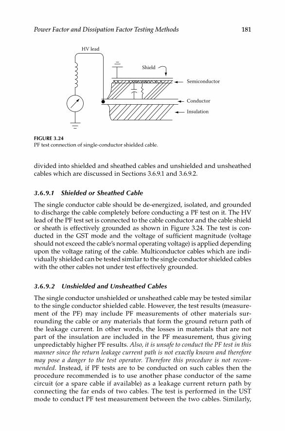
Power Factor and Dissipation Factor Testing Methods 181
divided into shielded and sheathed cables and unshielded and unsheathed cables which are discussed in Sections 3.6.9.1 and 3.6.9.2.
3.6.9.1 Shielded or Sheathed Cable
The single conductor cable should be de-energized, isolated, and grounded to discharge the cable completely before conducting a PF test on it. The HV lead of the PF test set is connected to the cable conductor and the cable shield or sheath is effectively grounded as shown in Figure 3.24. The test is con-ducted in the GST mode and the voltage of suffi cient magnitude (voltage should not exceed the cable’s normal operating voltage) is applied depending upon the voltage rating of the cable. Multiconductor cables which are indi-vidually shielded can be tested similar to the single conductor shielded cables with the other cables not under test effectively grounded.
3.6.9.2 Unshielded and Unsheathed Cables
The single conductor unshielded or unsheathed cable may be tested similar to the single conductor shielded cable. However, the test results (measure-ment of the PF) may include PF measurements of other materials sur-rounding the cable or any materials that form the ground return path of the leakage current. In other words, the losses in materials that are not part of the insulation are included in the PF measurement, thus giving unpredictably higher PF results. Also, it is unsafe to conduct the PF test in this manner since the return leakage current path is not exactly known and therefore may pose a danger to the test operator. Therefore this procedure is not recom-mended. Instead, if PF tests are to be conducted on such cables then the procedure recommended is to use another phase conductor of the same circuit (or a spare cable if available) as a leakage current return path by connecting the far ends of two cables. The test is performed in the UST mode to conduct PF test measurement between the two cables. Similarly,
Shield
HV lead
Semiconductor
Conductor
Insulation
FIGURE 3.24PF test connection of single-conductor shielded cable.
DK4058_C003.indd 181DK4058_C003.indd 181 11/8/2008 12:15:40 PM11/8/2008 12:15:40 PM

182 Electrical Power Equipment Maintenance and Testing
multiconductor unshielded or unsheathed cables may be tested in this manner. Any other cables not included in the test should be effectively grounded. This procedure is repeated to include all conductors in at least one measurement.
3.6.10 PF Correction Capacitors and Surge Capacitors
The PF capacitors are used to improve system (load) PF or phase angle. The surge capacitors are used with surge arrestors to protect motors by changing the slope of the wave front of voltage surges. Both of these types of capacitors have relatively high capacitances. The PF correction capaci-tors are either a single or two bushing design, while the surge capacitors are always a single bushing design. The two bushing capacitor has capac-itances known as main capacitance C1 which is between the two bushing; ground capacitance C1g between bushing one and ground; ground capaci-tance C2g between bushing two and ground which are shown in Figure 3.25a. The main capacitance C1 because of its largeness is generally beyond the range of the 2.5 kV PF test set, but the ground capacitance of two bushing can be tested with the 2.5 kV PF test set as shown in Figure 3.25b. Although this method does not measure the main insulation, it is effec-tive in detecting problems associated with the bushing and internal
C1
C1g C2g
(a)
HV cable
(GST)
GuardmVA and
mW meter C1g
C1
C2g
(b)
FIGURE 3.25(a) Capacitance associated with a two bushing capacitor; (b) PF test connections for measuring
ground insulation of a two bushing capacitor.
DK4058_C003.indd 182DK4058_C003.indd 182 11/8/2008 12:15:41 PM11/8/2008 12:15:41 PM
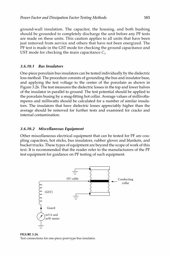
Power Factor and Dissipation Factor Testing Methods 183
ground-wall insulation. The capacitor, the housing, and both bushing should be grounded to completely discharge the unit before any PF tests are made on these units. This caution applies to all units that have been just removed from service and others that have not been energized. The PF test is made in the GST mode for checking the ground capacitance and UST mode for checking the main capacitance C1.
3.6.10.1 Bus Insulators
One-piece porcelain bus insulators can be tested individually by the dielectric loss method. The procedure consists of grounding the bus and insulator base, and applying the test voltage to the center of the porcelain as shown in Figure 3.26. The test measures the dielectric losses in the top and lower halves of the insulator in parallel to ground. The test potential should be applied to the porcelain busing by a snug-fi tting hot collar. Average values of millivolta-mperes and milliwatts should be calculated for a number of similar insula-tors. The insulators that have dielectric losses appreciably higher than the average should be removed for further tests and examined for cracks and internal contamination.
3.6.10.2 Miscellaneous Equipment
Other miscellaneous electrical equipment that can be tested for PF are cou-pling capacitors, hot sticks, bus insulators, rubber gloves and blankets, and bucket trucks. These types of equipment are beyond the scope of work of this text. It is recommended that the reader refer to the manufacturers of the PF test equipment for guidance on PF testing of such equipment.
Conductingcollar
HV cable
(GST)
Guard
mVA and mW meter
FIGURE 3.26Test connections for one-piece post-type bus insulator.
DK4058_C003.indd 183DK4058_C003.indd 183 11/8/2008 12:15:41 PM11/8/2008 12:15:41 PM

184 Electrical Power Equipment Maintenance and Testing
3.7 Evaluation and Grading of PF and DF Test Results
3.7.1 General
After the PF tests are completed and results obtained, each apparatus and equipment insulation should be evaluated to its serviceability. The evaluation criteria may be divided into four categories. They are
1 Good Insulation condition is good and suitable for continued service
2 Deteriorated Insulation condition is satisfactory for service but should be checked
within six months to see if the condition has further degraded
3 Marginal Insulation condition is not satisfactory for service—immediate
investigation of the degraded conditions should be begun and if
this is not possible then it should be begun as soon as possible
4 Bad Remove from service and recondition to restore insulation to good
condition, if not possible, then replace
The recommended practice for evaluating test results is not only to assess whether the test results fall into one of the four categories mentioned above, but also to compare the test results with previous year’s results to see how much change has occurred in the condition of the insulation since the last test. This is to say that the year-to-year test results are compared for trending purposes to signify any changes in the health of the insulation due to normal aging, but as well as other causes. Any sudden and large changes in test results between two test intervals should be a cause of concern and should be investigated before putting equipment back in service.
Usually, the failure hazards of electrical equipment are expressed in terms of maximum allowable PF values, however changes in the normal dielectric losses (watts loss), capacitance, and AC resistance are also used for indicat-ing problems in the insulation. Depending upon the type of equipment, many manufacturers publish factory and operating limits for PF or capaci-tance values for their equipment which can then be used for evaluating the test results. The normal test values for various types of equipment used in the industry, and discussed in this text have been obtained from testing sim-ilar equipment in the fi eld and factory over many years. The abnormal or unsafe limits have been established from correlation of known test values at which equipment insulation has failed in service. Insulation in deteriorated condition may operate for a period of time without a failure depending upon its exposure to abnormal operating conditions, such as voltage and current transients, short circuits, temperature, etc. However, it should be recognized that deteriorated insulation creates a defi nite operating hazard and if goes uncorrected will result in service interruptions and equipment damage. If deteriorated insulation is removed before failure, it may be reconditioned and restored to service with substantial savings in equipment cost and unnecessary service outages.
DK4058_C003.indd 184DK4058_C003.indd 184 11/8/2008 12:15:41 PM11/8/2008 12:15:41 PM

Power Factor and Dissipation Factor Testing Methods 185
Whenever the test results are questionable or marginal, it is generally recommended to perform tests on more frequent basis in order to keep abreast of the condition and to establish a trend. A gradual and consistent increase in PF may be due to contamination, deterioration, or normal aging, where as a sudden increase in the PF is a cause of immediate concern even when the absolute PF value is not considered excessive. Whenever an increas-ing trend is established, then the equipment should be removed from service as soon as practical for inspection to determine the cause of the problem and to make appropriate repairs.
3.7.2 Analysis of the Results
The electrical characteristics of the insulation vary with temperature. In order to compare PF and DF test results on a periodic basis of given equip-ment or apparatus, the PF and DF values should be converted to base tem-perature of 20°C as was discussed in Section 3.2.3. The reader is referred to Doble Engineering Company’s Power Factor Test Data Reference Book for more details on the effects of temperature and correction factors. The analysis of the PF test results for the various types of equipment and apparatus is dis-cussed below and is condensed from the Doble Engineering Company’s ref-erence manuals.
3.7.2.1 Transformers
Typical problems in transformers that are found with PF (and DF) and excita-tion current tests are
Wet insulation•
Short circuit windings and/or turns•
Corona damage and carbonization•
Contamination from sludge, varnishes, etc.•
Displaced windings and core damage•
The appraisal of PF and DF test results is divided into oil-fi lled and dry-type transformers. Also, further reference to the term DF is not made in this dis-cussion since PF and DF are the same for evaluating the condition of the insulation.
3.7.2.1.1 Oil-Filled Power and Distribution Transformers
The overall PF test results of oil-fi lled power and distribution transformers indicate the insulation condition of the solid windings, oil, barriers, bush-ings, etc. The overall PF value for individual windings-to-ground and interwindings insulation of modern oil-fi lled transformers should be 0.5% or less, corrected to 20°C. Service-aged power transformers will have some-what higher PF values due to normal aging, loading (heat), and voltage stress.
DK4058_C003.indd 185DK4058_C003.indd 185 11/8/2008 12:15:41 PM11/8/2008 12:15:41 PM

186 Electrical Power Equipment Maintenance and Testing
A PF value as high as 1% is considered acceptable for older transformers when previous history or knowledge of PF value of the transformer, or similar trans-formers is not available. However, when the PF value of one insulation system of the transformer is higher than the others, for example, HV winding insu-lation PF is higher than the LV and interwinding insulation PF, then causes of the higher PF should be investigated. A PF value of 2% for extremely old power transformers may be considered acceptable. In the case of older transformers that utilized varnished-cambric or varnish insulation, these transformers may have normal PF values in the range of 4% to 5% at 20°C.
Transformers that are subjected to excessive internal forces due to possible through-faults or other causes may have windings that are physically dis-torted, that is the core–coil assembly confi guration has changed from its original design confi guration. If this should happen, then capacitance of the winding-to-ground and interwinding (i.e., CH, CL, and CHL) would have changed. Therefore measuring the capacitance of the individual winding is also important in judging the condition of the winding insulation. Also, the transformer excitation current test discussed in Section 3.6.3 is extremely effective in revealing damage to the core, core–coil assembly, tap changer, and short circuited turn-to-turn insulation. In evaluating excitation current test results for three-phase transformers, evaluation is based on a normal pattern of excitation current readings, that is either a two high and one low reading, or two low and one high reading depending on the transformer winding connections. A change in this pattern is a cause for investigation. Also, if benchmark data, such as factory or fi eld acceptance data are avail-able, then the evaluation should be based on comparing the test results with the benchmark data.
3.7.2.1.2 Dry-Type Power and Distribution Transformers
The PF of dry-type transformers varies over a relatively wide range due to in part to the insulation of support insulators, bus work, and insulation materials. Corona is a greater possibility in HV dry-type transformers and the test procedure should include provisions for checking it. This can be done by making PF tip-up tests on the dry-type transformers. PF tip-up test is described in Section 3.6.7.1 under rotating machine testing. An abnormal increase in the tip-up value may be an indication of excessive corona or voids in the insulation. A comparison of the PF and PF tip-up test values with benchmark data if available, or with test results of similar units tested under similar conditions is recommended in evaluating the insulation con-dition of the dry-type transformers. It is not unreasonable to expect a PF of 2% or less for new modern dry-type transformers. However, PF may increase with age of the transformer, and may increase to 5%–8%. PF values substantially higher than the values discussed here should be investigated to determine the cause of the high PF. A better approach for appraisal of transformer insulation is to use the PF data recorded during the initial tests on the transformer, such as acceptance testing, as a benchmark for com-parison with subsequent test results.
DK4058_C003.indd 186DK4058_C003.indd 186 11/8/2008 12:15:41 PM11/8/2008 12:15:41 PM

Power Factor and Dissipation Factor Testing Methods 187
3.7.2.1.3 Transformer Insulating Fluids (Oil)
The PF of good, new oil is expected to be 0.05% or less at 20°C. Used oil in good condition should have a PF of 0.5% or less at 20°C, and if the PF exceeds 0.5% then the oil is considered questionable for continued use. Oil having PF greater than 1.0% at 20°C should be investigated or reconditioned, or replaced. A high PF of the oil is an indication of the presence of contamination, such as moisture, carbon, acids, polar contaminants, etc.
3.7.2.2 Bushings
The problems found in bushing are
Cracks•
Dirty bushings•
Loss of oil or compound•
Short-circuited condenser bushings•
Wet or deteriorated bushings or tap insulation•
Dirty tap insulation•
Corona in bushing insulation system•
The PF tests including the hot-collar tests performed on similar types of bushing under the same test and weather conditions should test similarly, and be within acceptable limits. When PF of a clean bushing increases signifi cantly from its initial value, it is usually due to the effect of con-tamination, such as moisture which lowers the dielectric strength of the bushing. The possibility of the failure of the bushing in service increases as its dielectric strength decreases due to the effect of contamination. PF tests, made on a regular basis, have been used in assessing the service-ability of the bushing over the years. To decide whether a bushing should be removed from service because it has a slightly higher PF than normal depends upon the magnitude of the overall PF and hot-collar test results. However, a bushing that shows a substantial increase in PF each year is an indication of potential failure hazard. It is recommended that the bushing insulation should be evaluated based on the results of PF, capacitance, and hot-collar test results.
With regard to hot-collar test, higher than normal losses are indicative of contamination or deterioration of bushing insulation. Any bushing differing signifi cantly from others by few milliwatts (up to one-tenth of a watt for the 10 kV test) should be investigated. The watts loss limit in bushing for the 2.5 kV test is approximately 0.15 W. The loss of oil or compound may be detected by comparing the hot-collar test current rather than the PF value. Abnormally low test current (10%–15%) may indicate absence of compound or oil. Testing under successively lower petticoats (skirts) will show normal current reading when compound or oil is reached.
DK4058_C003.indd 187DK4058_C003.indd 187 11/8/2008 12:15:41 PM11/8/2008 12:15:41 PM

188 Electrical Power Equipment Maintenance and Testing
Modern oil-impregnated paper insulated condenser type bushings have PF of 0.5% or less at 20°C. Any such bushing which shows a signifi cant increase should be investigated. Usually the capacitance and/or PF value of a bushing are provided by the manufacture on the nameplate of the bushing which should be used for grading the PF and capacitance test results. Also, the previous year’s test results if available may be used in evaluating the fi eld test results.
3.7.2.3 Lightning and Surge Arrestors
The insulating quality of lightning and surge arrestors is affected by con-tamination, such as moisture, dirt, and/or corrosion. Other problems experi-enced with lightning and surge arrestors may be mechanical defects such as broken shunting resistors, broken preionizing elements, and/or misassem-bly. PF tests are effective in detecting these problems in lightning and surge arrestors. The lightning and surge arrestors are evaluated on the basis of dielectric loss (milliwatts or watts) of comparable units or previous year’s benchmark test data. The PF is normally not calculated for these devices since their capacitance is very small. Abnormal dielectric losses can be divided into higher-than-normal and lower-than-normal and which are indicative of the problems as listed below:
1. Higher-than-normal losses
a. Contamination by moisture and/or dirt or dust deposits on the inside surfaces of the porcelain housing or on the outside sur-faces of sealed gap housing
b. Corroded gaps
c. Deposits of aluminum salts apparently caused by the interaction between moisture and products resulting from corona
d. Cracked porcelain housing
2. Lower-than-normal losses
a. Broken shunting resistors
b. Broken preionizing elements
c. Misassembly
3.7.2.4 Medium-Voltage Circuit Breakers
The problems that may be identifi ed with PF testing of medium-voltage circuit breakers are wet bushings, wet or damaged arc chutes, tracking across insulators, bushing and arc-chutes, etc. The PF test results evaluation for these breakers should be based on the basis of dielectric loss (milliwatts or watts) and not PF. These types of breakers have low capacitance and that small changes in the low test currents and losses can result in misleading changes in calculated PF values. The analysis of the test results should be
DK4058_C003.indd 188DK4058_C003.indd 188 11/8/2008 12:15:41 PM11/8/2008 12:15:41 PM

Power Factor and Dissipation Factor Testing Methods 189
based on a comparison of the test currents and losses of similar units or previous years test data on the same breaker.
3.7.2.5 OCB
The results of OCB depend upon the insulation condition of the bushings, oil and tank members. Therefore, the PF test results of an OCB should be evalu-ated for the condition of the bushings, tank insulation and oil.
The bushing are graded based on the analysis of open and closed circuit breaker tests including supplementary hot-collar test results. Tank insula-tion is evaluated based on TLI test. Oil is evaluated on PF and dielectric strength tests, and by a battery of other tests including visual inspection for carbon and other particulate matter.
The open breaker test provides information on the insulation condition of bushings, interrupters, lift rod guide, upper lift rod guide, oil (some), and tank liner (some). Whereas the closed circuit breaker test provides informa-tion on the insulation condition of bushings (both), oil, lower part of the lift rod assembly, and tank liner. What is then the difference between the open and closed circuit breaker tests. The major difference is that in the closed cir-cuit breaker test, a larger dielectric fi eld is established, and therefore the dielec-tric losses of the closed circuit breaker test will be different from the sum of the two open circuit breaker dielectric losses. In addition, in the closed circuit breaker test the cross head is energized, therefore a stronger dielectric fi eld is established on the lift rod assembly. Also, a stronger dielectric fi eld is established in the tank in the closed circuit breaker test compared to the open circuit breaker test. However, the dielectric fi eld is decreased between the interrupters in the closed circuit breaker test. In summary, the closed circuit breaker test basically measures the lift rod assembly and tank insulation, where as the open circuit breaker measures bushing insulation.
Since open breaker test basically measures bushing losses, the PF test results should be compared to the results obtained on other bushing of the same breaker, or bushing results of other similar bushings. If PF results are high, then perform additional tests on the individual bushing by using the UST method and operate the breaker several times and retest. If the PF is still high, then check the interrupters and lift rod guide. The criteria used for grading interrupters is that if the PF is between 0% and 35% then the inter-rupters are good; if the PF is between 35% and 50%, the interrupters are marginal; and if the PF is above 50% the interrupters are wet, dirty, or just bad. The criteria for grading lift rods are that the watts loss obtained from the UST test for the lift rod should be 0.1 W or less.
3.7.2.6 SF6 Breakers
The analysis for the SF6 breakers is similar to that of the oil circuit breakers. However, it should be noted that the SF6 breakers have very low dielectric loss, and therefore they should be evaluated based on only watts loss and
DK4058_C003.indd 189DK4058_C003.indd 189 11/8/2008 12:15:41 PM11/8/2008 12:15:41 PM

190 Electrical Power Equipment Maintenance and Testing
capacitance measurements. All test results should be corrected to 20°C and compared with the data recorded for similar tests on the same breaker or breakers of similar model, make, manufacture and vintage.
3.7.2.7 Rotating Machines
The PF tests are made on rotating machines to detect contamination, such as moisture, dirt, dust, of the stator winding insulation and materials, and pres-ence of corona at operating voltages. The typical PF values are of the order of 1.0% or less for large modern machines. The typical PF tip-up values are usu-ally between 0.5% and 1.0%. A better way of evaluating fi eld test results are to compare with previous year’s results or benchmark test results from the factory, or acceptance tests which were conducted when the equipment was commissioned and was relatively new.
3.7.2.8 Cables and Accessories
The overall PF value of a cable is a function of insulation type, length, size, installation (whether it is installed in metallic or nonmetallic conduit), and voltage. Therefore, the evaluation of the fi eld PF test results should be based on comparison with previously recorded tests on the cable when it was put in service and was relatively new, such as during acceptance testing. Typical PF values at 20°C for cable insulation system as listed in the Doble Engineering Company reference book are:
Insulation Type PF Value (%)
Paper ≤0.5
Cross-link polyethylene 0.05–1.0
Ethylene/propylene rubber 0.5–1.0
Rubber (older type) 3.0–5.0
Varnished cambric 4.0–8.0
It should be noted that cables without metallic sheath or grounded shield, but are installed in metallic raceway may have PF higher than the values listed above.
The results of the hot-collar tests on potheads are evaluated by comparing fi eld test results on similar type of potheads, or previous years recorded test results. The evaluation is based on watts loss and current, and PF. Abnormally high dielectric loss and current indicate the presence of moisture. Below than normal test current indicates the absence of compound or oil in the pothead. Increase in watts loss with increased test voltage (PF tip-up) indicates the presence of corona.
3.7.2.9 Capacitors
The main capacitance of the PF and surge capacitors is quite large and may be tested at reduced voltages. The PF of these capacitors should be of
DK4058_C003.indd 190DK4058_C003.indd 190 11/8/2008 12:15:41 PM11/8/2008 12:15:41 PM

Power Factor and Dissipation Factor Testing Methods 191
the order of 0.5% or less, and the capacitance should compare with the nameplate information. The ground-wall insulation of a two bushing PF capacitor is in the order of 0.5%. The ground-wall insulation measure-ments and hot-collar test results should be compared with previously recorded data on these units.
Coupling capacitors are evaluated on the basis of capacitance (charging current) and PF which are compared with the nameplate data and those recorded with similar units. Typically the PF values are around 0.25% and units with PF value of 0.5% are recommended to be removed from service. An increase in the capacitance above 2% is a cause for concern and may indicate shorted elements. A decrease in capacitance may indicate an open circuit or high resistance connection between condenser foil layers.
DK4058_C003.indd 191DK4058_C003.indd 191 11/8/2008 12:15:41 PM11/8/2008 12:15:41 PM

DK4058_C003.indd 192DK4058_C003.indd 192 11/8/2008 12:15:41 PM11/8/2008 12:15:41 PM
193
4Insulating Oils, Fluids, and Gases
4.1 Introduction
Insulating oils, fl uids, and gases are used as dielectrics in the electrical equip-ment and apparatus. The liquids used in the transformers are mineral oil and synthetic fl uids, such as askarel, silicone, RTemp, Wecosal, Alpha 1, and GE R113. (The synthetic fl uids such as askarel, silicone, RTemp, etc. have a fi re point of not less than 300°C and are classifi ed as less fl ammable insulat-ing fl uids by the National Electric Code, NEC.) Mineral oil is also used as a dielectric in circuit breakers, reclosers, interrupters, and the like. The most common insulating gas used in circuit breakers and completely enclosed substations is sulfur hexafl uoride (SF6). This chapter covers electrical, chemi-cal, and visual tests which are normally conducted for the maintenance of transformer oils and fl uids. Also, this chapter includes a discussion on the inspection, handling, and reconditioning of insulating oil, fl uids, and gases used in electrical equipment.
The ability of insulating oils, fl uids, and gases to serve as effective dielec-tric and coolant is adversely affected by their deterioration. The deterioration of insulating oil, fl uids, and gases is due to contamination, overheating, elec-trical stress, and oxidation. Moisture is the most common contaminant which adversely affects the insulating properties of these liquids and gases. High temperatures from increased load and/or environmental conditions acceler-ate the deterioration process. To assure continuity of service, safety, and maintenance, a condition monitoring program, consisting of electrical and chemical testing, is necessary for these dielectrics.
4.2 Insulating Oil
Hydrocarbon (mineral oil #10) oil is used as an insulating fl uid in transformers and circuit breakers because of its high dielectric strength and chemical stability. To properly maintain the transformer oil free of contaminants, regular inspection of the transformer and purifi cation of the oil is needed. A brief discussion on the deterioration of the insulating oil is undertaken for maintenance purposes.
DK4058_C004.indd 193DK4058_C004.indd 193 11/8/2008 12:16:25 PM11/8/2008 12:16:25 PM
194 Electrical Power Equipment Maintenance and Testing
4.2.1 Deterioration of Insulating Oil
4.2.1.1 Effect of Oxygen on Oil
Moisture contamination is the most common cause of deterioration in the insulating quality of oil. This contamination can be readily corrected by purifi cation. A slow but more serious deterioration, the formation of acids and sludge, is caused by oxidation. Thus, the exclusion of oxygen is of prime importance. In open-breather transformers, the oxygen supply is virtually unlimited and oxidative deterioration is faster than sealed trans-formers. Atmospheric oxygen and oxygen contained in water are the sources available for the oxidation of insulating oils. When water is present in insulating oils, oxidation of the oil will take place. Therefore, leaking gaskets and seals constitute a very real hazard since a water leak is, in effect, an oxygen leak. The rate of oxidation also depends on the temperature of the oil; the higher the temperature is, the faster the oxidative breakdown. An increase in temperature of 10°C (50°F) generally doubles the rate of oxidation. The fact points to the importance of avoiding overloading of transformers, especially in the summertime. Oxidation results in the for-mation of acids in the insulating oil and the formation of sludge at a more advance state of oxidation.
4.2.1.2 Moisture in Oil
Water can be present in oil in a dissolved form, as tiny droplets mixed with the oil (emulsion), or in a free state at the bottom of the container holding the oil. Demulsifi cation occurs when the tiny droplets unite to form larger drops, which sink to the bottom and form a pool of free water. Emulsifi ed water typically requires vacuum dehydration, as the emulsifi cation cannot typi-cally be broken by fi ltration or by excellerated gravity (centrifuge). Water in the free state may be readily removed by fi ltering or centrifugal treatment. However, dissolved water is not removed by centrifugal treatment; the fi ltra-tion process can partially remove dissolved water if the fi lter papers are thor-oughly dried before fi ltration, but the effi ciency of the fi ltration process depends upon oil temperature and fi ltration media.
The effect of moisture on the insulating properties of oil depends upon the form in which the moisture exists. A very small amount of emulsifi ed water has a marked infl uence in reducing dielectric strength of oil. Free moisture in oil usually shows up above 50 to 60 ppm depending upon temperature. Accepted levels of water in oil are shown in Table 4.1. The amount of moisture that can be dissolved in oil increases rapidly as the oil temperature increases, as shown in Figure 4.1. Therefore, an insulating oil purifi ed at too high a temperature may lose a large percentage of its dielectric strength on cooling, because the dissolved moisture is then changed to an emulsion, unless vacuum dehydration is used as the puri-fi cation process.
DK4058_C004.indd 194DK4058_C004.indd 194 11/8/2008 12:16:25 PM11/8/2008 12:16:25 PM

Insulating Oils, Fluids, and Gases 195
4.2.1.3 Oil Deterioration in Transformers
In transformers, sludge sticks to the surface through which heat should be dissipated; the sludge forms a blanket barrier to the fl ow of heat from the oil to the coolant and from the core and coils to the cool oil. If allowed to con-tinue long enough, the sludge may even block off the fl ow of oil through the cooling ducts. As a result, the transformer insulation gets too hot and is dam-aged, particularly between turns of the windings. Deterioration of the turn insulation may eventually lead to short circuits between turns and the break-down of the transformer. When oxidation progresses to the point where sludge is being precipitated, the fi rst step should be to remove the sludge from the transformer by a high-pressure stream of oil or hot oil circulation to dissolve the sludge, or to either replace the sludged oil or treat it with acti-vated clay to remove the acid. Under favorable conditions, complete treatment of the oil is less costly than replacing it with new oil.
TABLE 4.1
Maximum Allowable Moisture in Oil
Voltage Level (kV) Maximum Moisture (ppm)
5 30
15 30
35 25
69 20
138 and up 15
240
200
160
120
80
40
0 10 20Temperature (�C)
Part
s per
mill
ion
(ppm
) by v
olum
e
30 40 50
FIGURE 4.1Maximum amount of water dissolved in mineral oil as affected by temperature.
DK4058_C004.indd 195DK4058_C004.indd 195 11/8/2008 12:16:25 PM11/8/2008 12:16:25 PM

196 Electrical Power Equipment Maintenance and Testing
4.2.1.4 Absorption of Moisture by Insulating Materials
Solid insulation (paper insulation) in transformers is very porous and thirstily absorbs water. Some of the water that is dissolved in the oil is absorbed from the oil by the cellouse (paper) winding insulation. As more water is dissolved in the oil, more water is absorbed by the insulation of the transformer wind-ings. Once absorbed, it is diffi cult to remove. The most effective method for drying out the insulation in transformers is with heat and vacuum. Sometimes a vacuum cannot be applied in the fi eld; then the transformer insulation must be dried by circulation of hot, dry oil. This oil should then be cooled and dried. Since the dielectric strength of insulation is reduced by absorption of moisture, it is important that the insulation not be allowed to absorb it in the fi rst place.
4.2.1.5 Absorption of Nitrogen by Oil
Special precaution should be taken in operating transformers with nitrogen over the oil to avoid bubbling of the oil due to release of dissolved nitrogen when the pressure drops. Experience has shown that the automatic gas-pressure regulating system should be adjusted to limit the nitrogen pressure range from 1/2 to 3 psi (lb/in.2) gauge to avoid formation of these bubbles and subsequent troubles due to corona deterioration.
4.2.2 Insulating Oil Testing
Transformer oil reacts with oxygen to form organic acids, esters, and phenolic compounds which ultimately leads to sludging of the transformer. The rate of this phenomena increases with an increased exposure to air and temperature. Also it should be noted that oxygen is more soluble in oil than found in air. Not only will the sludge adversely affect the dielectric properties of the oil, but it will also interfere with dissipation of heat within the transformer. The pur-pose of these tests are to chart the gradual deterioration and take preventative measures before insulating oil reaches a point where failure of the transformer is inevitable. The routine tests and sampling procedures that are conducted on insulating oil are shown in Table 4.2, and are discussed in text of this chapter.
TABLE 4.2
ASTM Method of Test for Insulating Liquids
Test ASTM Test Method
Color D1500
Dielectric breakdown voltage D877, D1816
Visual examination D1524
IFT (oil only) D971, D2285
Neutralization number (acidity) D974, D664, D1534
Power factor/dissipation factor D924
Moisture (Karl Fischer method) D1533
Specifi c gravity D1298
Viscosity D445, D2161
Sedimentation D-1698
DK4058_C004.indd 196DK4058_C004.indd 196 11/8/2008 12:16:25 PM11/8/2008 12:16:25 PM

Insulating Oils, Fluids, and Gases 197
4.2.2.1 Dielectric Breakdown Voltage Test (Cup Tests)
This is an AC overvoltage test applied to the insulating liquids to detect their breakdown strength. A typical test set is shown in Figure 4.2. The American Society for Testing and Materials (ASTM) has established test standards for these liquids, which are listed in Table 4.2. The dielectric test simply consists of placing a liquid sample from the transformer or (circuit breaker) in a cup containing two electrodes of specifi ed gap. High voltage is then applied to the sample. The test is repeated for a least fi ve different samples to determine the average dielectric strength. The minimum accepted values for the various liquids are listed in Table 4.3.
Two different electrodes are used in these tests, one for mineral-based oils and the other for mineral-based oils and synthetic liquids. The Verband Dentschev Elektrotechniker (VDE) cup is used for mineral-based oils; it has
FIGURE 4.2Oil dielectric test set 60 kV. (Courtesy of Megger, Inc., Valley Forge, PA.)
TABLE 4.3
Acceptance Test Values for Transformers Insulating Oil
Liquid Type Test Satisfactory Needs Reconditioning
Oil Neutralization number
(acidity)
0.4 0.4 to 1.0
IFT (dyn/cm) 40 dyn/cm Below 40
Color 3.5 Above 3.5
Dielectric strength 23 kV Less than 23 kV
Power factor Up to 0.5% Above 0.5%
DK4058_C004.indd 197DK4058_C004.indd 197 11/8/2008 12:16:25 PM11/8/2008 12:16:25 PM
198 Electrical Power Equipment Maintenance and Testing
a gap of 0.04 to 0.08 in. (1–2 mm) with a rate of voltage rise of 500 V/s. The disk cup is used for mineral-based oils and synthetic liquids such as askarel, silicone, and others. It has a gap of 0.1 in. with rate of rise of 3000 V/s. The step-by-step procedures for conducting these tests are described next.
Dielectric test ASTM D-877 (disk electrodes): Portable oil dielectric testers are usually used for making dielectric tests on oils in the fi eld. Units with a vari-able high voltage of 40 kV or greater between the electrodes and which have Bakelite test cups are considered satisfactory. Instructions and procedures are as follows:
The electrodes and the test cup should be wiped clean with dry, calen-dered tissue paper or with a clean, dry chamois. The spacing of the elec-trodes should be checked with a standard round gauge having a diameter of 0.1 in. (2.5 mm) or with fl at steel go and no-go gauges having thicknesses of 0.0995 and 0.1005 in., respectively; the electrodes should be locked in posi-tion. It is important to avoid touching the electrodes or the cleaned gauge with the fi ngers or with portions of the tissue paper or chamois that have been in contact with the hands.
The electrodes and test cup should be rinsed with dry, lead-free gasoline or other suitable solvent until they are entirely clean. To avoid any possible contamination, care should be taken to avoid touching the electrodes or the inside of the cup after cleaning.
After a thorough cleaning, the test cup is fi lled with a sample of the cleaning fl uid; voltage is applied and uniformly increased at a rate of approximately 3 kV/s (rms value) until breakdown occurs. If the breakdown is not less than the established value of the oil being tested, the test cup should be consid-ered in suitable condition for testing. If a lower value is obtained, the cup should again be thoroughly cleaned and the test repeated. A cleaning fl uid whose breakdown is not less than the established value of the oil being tested must be used.
At the beginning of each test, the electrodes should be examined for pitting and carbon accumulation and the electrode spacing should be checked. The test cup should be thoroughly cleaned and tested as described previously. It should then be fl ushed with a portion of the sample to be tested before it is fi lled for the test.
If the test of a sample is below the breakdown value being used by the oper-ator as a minimum satisfactory value, the cup should be cleaned and prepared before testing the next sample. Evaporation of the cleaning fl uid from the elec-trodes may chill them suffi ciently to cause moisture to condense on their sur-faces. For this reason, after the fi nal rinsing with cleaning fl uid, the cup must immediately be fl ushed with the oil to be tested and then fi lled for the test.
The dielectric strength of liquid dielectrics may be markedly altered by the migration of impurities through the liquid. To obtain representative test specimens, the sample container should be gently tilted or inverted and the oil swirled several times before each fi lling of the test cup, in such a way that any impurities present will be thoroughly mixed with the liquid dielectric.
DK4058_C004.indd 198DK4058_C004.indd 198 11/8/2008 12:16:26 PM11/8/2008 12:16:26 PM

Insulating Oils, Fluids, and Gases 199
Too rapid agitation is undesirable, since it introduces an excessive amount of air into the liquid. Immediately after agitating, the test cup should be fi lled with oil to a height of not less than 20 mm (0.787 in.) above the top of the electrodes. To prevent the escape of entrapped air, the container should be gently rocked a few times and the oil allowed to stand in the cup for 3 min before voltage is applied.
The temperature of the sample when tested should be the same as that of the room, but not less than 20°C (68°F). Testing of oil at a lower than the room temperature is likely to give variable results, which may be misleading.
Voltage should be applied and increased at a uniform rate of 3 kV/s from zero until breakdown occurs, as indicated by a continuous discharge across the gap. Occasional momentary discharges that do not result in a permanent arc may occur; they should be disregarded.
Referee testing: When it is desired to determine the dielectric breakdown voltage of a new liquid for referee purposes, one breakdown should be made on each of fi ve successive fi llings of the test cup. If the fi ve values meet the minimum dielectric values, the average should be reported as the dielectric breakdown voltage of the sample. If they do not meet the minimum dielec-tric values, one breakdown on each of fi ve additional cup fi llings should be made and the average of the 10 breakdowns reported as the dielectric break-down voltage of the sample. No breakdown should be discarded.
Routine testing: When it is desired to determine the dielectric breakdown voltage of a liquid on a routine basis, one breakdown may be made on each of two fi llings of the test cup. If no value is below the specifi ed acceptance value, the oil may be considered satisfactory, and no further tests are required. If either of the values is less than the specifi ed value, a breakdown should be made on each of three additional cup fi llings, and the test results analyzed.
Alternative method: When it is desired to determine the dielectric breakdown voltage of a liquid on a routine basis, fi ve breakdowns may be made on one cup fi lling with 1 min intervals between breakdowns. The average of the fi ve break-downs should be considered the dielectric breakdown voltage of the sample, provided the breakdown values meet the criterion for statistical consistency. If the breakdown voltages do not meet this criterion, the contents of the cup should be discarded, the sample container again gently inverted and swirled, the cup again fi lled, and fi ve breakdowns made on this second cup fi lling. The average of the 10 breakdowns should be considered as the dielectric break-down voltage of the sample. No breakdown should be discarded.
Criterion for statistical consistency: Compute the range of the fi ve breakdowns (maximum breakdown voltage minus minimum breakdown voltage), and multiply this range by three. If the value obtained is greater than the next to the lowest breakdown voltage, it is probable that the standard deviation of the fi ve breakdowns is excessive, and therefore the probable error of their average is also excessive.
DK4058_C004.indd 199DK4058_C004.indd 199 11/8/2008 12:16:26 PM11/8/2008 12:16:26 PM

200 Electrical Power Equipment Maintenance and Testing
Dielectric test ASTM D-1816 (VDE electrode): The present ASTM D-877 gap consists of 1 in. diameter disk, square-edged electrodes spaced at 0.1 in. The use of this test gap results in a uniform electrostatic fi eld at the center line of the test disks and a highly nonuniform fi eld at the edges of the disk. To attain uniform fi eld strength at all points, spherical electrodes would have to be used. Between these extremes of a highly distorted fi eld and an ideal uni-form fi eld, a third gap confi guration, designated as VDE, has been used. The VDE gap specifi cations call for a sector diameter of 36 mm and a 25 mm radius of curvature for the spherically capped electrodes. A gap of about 0.08 in. between electrodes has been found to give about the same breakdown volt-age relationships in the 25–30 kV range as the ASTM D-877 confi guration. Tests have shown the following:
VDE confi guration depicts more accurately the average electric strength and scatter of the oil as the transformer sees it
VDE gap is relatively sensitive to oil quality
ASTM D-877 is less sensitive
Point electrodes are almost completely insensitive to oil quality
The VDE cell, in which a quart of oil is tested between VDE electrodes, while being mildly circulated, realistically measures changes in oil strength, which determine the electrical strength of typical transformer construction. This test method (ASTM D-1816) is similar to ASTM D-877. The procedure for the VDE (ASTM D-1816) test is the same as for the disk electrodes (ASTM D-877).
4.2.2.2 Acidity Test
New transformer liquids contain practically no acids if properly refi ned. The acidity test measures the content of acids formed by oxidation. The acids are directly responsible for sludge formation. These acids precipitate out, as their concentration increases, and become sludge. They also react with metals to form another form of sludge in the transformer. The ASTM D974 and D664 are laboratory tests whereas D1534 is a fi eld test which determines the approximate total acid value of the oil.
The acid number of the neutralization number is the milligrams (mg) of potassium hydroxide (KOH) required to neutralize the acid contained in 1 g of transformer liquid. Test data indicate that the acidity is proportional to the amount of oxygen absorbed by the liquid. Therefore, different trans-formers would take different periods of time before sledge would begin to appear. Transformers with free air access would have formation of sludge before transformers with conservators; and transformers with conservators would have sludge before transformers bolted tight; and transformers bolted tight would have sludge before transformers with nitrogen over oil. Refer to Table 4.3 for acceptable values of the naturalization number for the transformer oil.
DK4058_C004.indd 200DK4058_C004.indd 200 11/8/2008 12:16:26 PM11/8/2008 12:16:26 PM

Insulating Oils, Fluids, and Gases 201
The following is a brief description of the ASTM D1534 (Gervin) method for the neutralization number test: Pour the oil sample into a glass cylinder furnished with the Gervin test kit. Single doses of KOH are furnished in sealed ampules with the dosage indicated on the ampules. For example, if the oil level in the glass cylinder is up to mark 10, then number 3 ampules equals 0.3 mg of KOH gram of oil; a number 6 ampules equals 0.6 mg of KOH, and a number 15 equals 1.5 mg of KOH.
The pint bottles contain neutral solution to be put in the measured sample before adding the KOH. This solution washes the oil and the KOH can then act on the acids more readily. The neutral solution contains a color-changing indicator. If any KOH is left after the acids are neutralized, the indicator is pink. But if the KOH is all used up, the indicator is colorless like water.
4.2.2.3 Interfacial Tension (IFT)
It should be recognized that the acidity test alone determines conditions under which sludge may form, but does not necessarily indicate that actual sludging conditions exist. The IFT test is employed as an indication of the sludging char-acteristics of power transformer insulating liquid. It is a test of IFT of water against liquid, which is different from surface tension in that the surface of the water is in contact with liquid instead of air. The attraction between the water molecules at the interface is infl uenced by the presence of polar molecules in the liquid in such a way that the presence of more polar compounds causes lower IFT. The polar compounds are sludge particles or their predecessors.
The test measures the concentration of polar molecules in suspension and in solution in the liquids and thus gives an accurate measurement of dissolved sludge components in the liquid long before any sludge is precipitated. It has been established that an IFT of less than 15 dyn/cm almost invariably shows sludging. An IFT of 15–22 dyn/cm is generally indicative of no sludging. For maintenance purposes IFT values are shown in Table 4.3 for transformer oil.
4.2.2.4 Color Test
This test consists of transmitting light through oil samples and comparing the color observed with a standard color chart. The color chart ranges from 0.5 to 8, with the color number 1 used for new oil. Color test values are listed in Table 4.3.
4.2.2.5 Power Factor Test
The power factor of an insulating liquid is the cosine of the phase angle between applied sinusoidal voltage and resulting current. The power factor indicates the dielectric loss of the liquid and thus its dielectric heating. The power factor test is widely used as an acceptance and preventive mainte-nance test for insulating liquid. Liquid power factor testing in the fi eld is usually done with portable, direct-reading power factor measuring test
DK4058_C004.indd 201DK4058_C004.indd 201 11/8/2008 12:16:26 PM11/8/2008 12:16:26 PM

202 Electrical Power Equipment Maintenance and Testing
equipment, which is available from several companies, who provide this service. Power factor tests on oil and transformer liquids are commonly made with ASTM D-924 test cell.
Good new oil has a power factor of 0.05% or less at 20°C. Higher power factors indicate deterioration and/or contamination with moisture, carbon or other conducting matter, varnish, glyptal, sodium soaps asphalt compounds, or deterioration products. Carbon or asphalt in oil can cause discoloration. Carbon in oil will not necessarily increase the power factor of the oil unless moisture is also present. It is suggested that the following serve as guides for grading oil by power factor tests.
Oil having a power factor of less than 0.5% at 20°C is usually consid-ered satisfactory for service.
Oil having a power factor between 0.5% and 2% at 20°C should be con-sidered as being in doubtful condition and at least some type of investigation should be made.
Oil having a power factor of over 2% at 20°C should be investigated and should be reconditioned or replaced.
The preceding guides may be elaborated on by saying that good new oil has a power factor of approximately 0.05% or less at 20°C and that the power factor can gradually increase in service to a value as high as 0.5% at 20°C without, in most cases, indicating deterioration. When the power factor exceeds 0.5%, an investigation is indicated. The question of what decision to make regarding disposition of the oil depends on what is causing the high power factor. Dielectric strength tests should be made to determine the pres-ence of moisture. The necessity for further tests will depend to a large extent on the magnitude of the power factors, the importance of the apparatus in which the oil is used, its rating, and the quantity of oil involved.
4.2.2.6 Specific Gravity
Specifi c gravity of oil is defi ned as the ratio of the mass of a given volume of oil to the mass of an equal volume of oil of water at a specifi ed temperature. This test is conducted by fl oating a hydrometer in oil and taking the reading at the meniscus. For oil free of contaminants, such as water, askarel, or silicone, the reading should be less than 0.84.
4.2.2.7 Water Content Test (Karl Fisher Method)
This test is based on the reduction of iodine according to the traditional Karl Fisher reaction. Three methods are used to conduct this test. Methods A and C utilize iodine present in a titration solution while Method B elec-trically generates the iodine in the equipment. Moisture content of 69 kV and higher voltage transformers should be measured regularly and lower voltage transformers on indication of fl ow dielectric strength of the oil.
DK4058_C004.indd 202DK4058_C004.indd 202 11/8/2008 12:16:26 PM11/8/2008 12:16:26 PM

Insulating Oils, Fluids, and Gases 203
4.2.3 Combustible Gas Analysis of Insulating Oil
4.2.3.1 Introduction
An oil-fi lled transformer insulation system consists of insulating oil and cellulose (paper) materials. Under normal use, transformer insulation dete-riorates and generates certain combustible and noncombustible gases. This effect becomes more pronounced when the transformer insulation is exposed to higher temperatures. When cellulose insulation (i.e., winding insulation) is overheated to temperatures as low as 140°C, carbon monoxide (CO), carbon dioxide (CO2), and some hydrogen (H) or methane (CH4) are liberated. The rate at which these gases are liberated depends exponentially on the tem-perature and directly on the volume of the insulation at that temperature. When insulating oil is overheated to temperatures up to 500°C, ethylene (C2H4), ethane (C2H6), and methane (CH4) are liberated. When oil is heated to extreme temperatures, such as an electrical arc, hydrogen (H) and acetylene (C2H4) are liberated in addition to the above mentioned gases.
The main cause of gas formation in a transformer is due to the heating of paper and oil insulation and electrical problems inside the transformer tank. The electrical problems can be classifi ed as low-energy phenomena, such as corona, or high-energy phenomena, such as an electrical arc. The interpreta-tion of the test data in terms of the specifi c cause (or causes) is based on the type of gas (or gases) and the quantity of that gas found in the transformer. The detection, analysis, and identifi cation of these gases can be very helpful in determining the condition of the transformer. Establishing a baseline data as a reference point for new transformers and then comparing with future routine maintenance test results is a key element in the application of this test method. However, monitoring or assessing the condition of a transformer using this method can start at anytime even if the reference data is not avail-able. There are two methods for detecting these gases: (1) total combustible gas analysis (TCGA), and (2) dissolved gas analysis (DGA).
4.2.3.2 TCG
TCG can be determined in the fi eld or analyzed in the laboratory from a sample of gas drawn from the gas space above the oil. The method is appli-cable to power transformers with a nitrogen blanket or conservator system. To facilitate the combustible gas testing, all transformers using a nitrogen blanket should have a gas sampling line installed from the upper portion of the tank to a ground-level sampling valve. Transformers having a conservator tank should have a gas sampling line installed from its gas accumulation relay to a ground-level sampling valve. The equipment used for measuring TCG is basically a Wheatstone bridge circuit. A combination of air and com-bustible gas sample is passed over a resistor where catalytic burning takes place on the resistor, which causes a proportional change in resistance. Based on the change in resistance of the resistor, the TCG is measured in percent.
DK4058_C004.indd 203DK4058_C004.indd 203 11/8/2008 12:16:26 PM11/8/2008 12:16:26 PM

204 Electrical Power Equipment Maintenance and Testing
4.2.3.3 DGA
The DGA is basically a laboratory test using an oil sample taken from a trans-former. The oil sample is subjected to a vacuum to remove the combustible gases. These gases are then passed through a gas chromatograph and each gas is then extracted and analyzed for type and quantity. The quantity of each gas is given in part per million (ppm) or percent of the total gas present. The analysis of each gas present provides a useful tool in determining the condition of the transformer. The interpretation of the analysis has not yet been perfected to an exact science and is therefore subject to interpretation.
4.2.3.4 Comparing the Two Methods
The total fault gas analysis (TCGA) is probably the most widely used in the fi eld. Its major advantages are that it is quick and can be used in the fi eld or may be used to continuously monitor the transformer. Its disadvantages are that it provides only a single value of oil combustible gases and does not identify or quantify what gases are present, and detect gases that are avail-able freely in the free space above the oil. As shown in Table 4.4, some of these gases are very soluble in oil and may not be liberated to the free space until the oil is fully saturated with the gas. Also, the solubility of these gases varies with temperature and pressure.
The DGA is the most informative method of detecting combustible gases. Although this is a laboratory method, it provides the earliest possible detection of any abnormal conditions in the transformer. Since diffusion of gases from liquid to gaseous space takes time, the TCGA method is not as sensitive as the DGA method and serious equipment damage could occur undetected if only the TCGA method is employed in assessing the serviceability of the transformer.
4.2.3.5 Interpretation of Gas Analysis
As discussed earlier, decomposition of paper insulation produces CO, CO2, and water vapor at temperatures much lower than that for decomposition of oil.
TABLE 4.4
Solubility of Gases in Transformer Oil
Hydrogen 7.0% by volume
Nitrogen 8.6% by volume
Carbon monoxide 9.0% by volume
Oxygen 16.0% by volume
Methane 30.0% by volume
Carbon dioxide 120.0% by volume
Ethane 280.0% by volume
Ethylene 280.0% by volume
Acetylene 400.0% by volume
Note: Static equilibrium at 760 mm Hg and 25°C.
DK4058_C004.indd 204DK4058_C004.indd 204 11/8/2008 12:16:26 PM11/8/2008 12:16:26 PM

Insulating Oils, Fluids, and Gases 205
This is because the paper begins to degrade at lower temperatures than the oil and its gaseous byproducts are found at normal operating temperatures in the transformer. It is not unusual for a transformer that operates at or near its nameplate rating to normally generate several hundred ppm of CO and several thousand ppm of CO2 without excessive hot spots.
The decomposition of oil at temperatures from 150°C to 500°C produces large quantities of hydrogen and methane, and trace quantities of ethylene and ethane. As the oil temperature increases to modest temperatures, the more hydrogen gas is liberated than methane, higher quantities of ethane, and ethylene. As the temperature increases further, increasing quantities of hydrogen and ethylene are produced. Low-level intermittent arcing and par-tial discharges (corona) produce mainly hydrogen, with small quantities of methane and trace quantities of acetylene. The quantities of acetylene become pronounced only when high-intensity arcing (700°C–1800°C) occurs inside the transformer tank.
The success of fault gas analysis is based on detecting the combustible gases at the earliest possible time and then taking steps to correcting the problem. The Institute of Electrical and Electronic Engineers (IEEE) Standard C57.104-1991, “IEEE guide for the interpretation of gases generated in oil-immersed transformers,” suggests the following procedure for the detection and analysis of combustible gases.
Direct measurement of the amount of TCG in the gas space above • the oil and the rate of generation of these gases
Direct measurement of the amount of combustible gases dissolved • in the oil (gas-in-oil) and the rate of generation of these gases
Gas chromatographic separation and analysis of individual gases • and the rate of generation of each gas
The rate of gas generation in gas space above the oil can be calculated by taking the sum of the gas concentrations of all combustible gases in the fi rst and second samples and using the equation* given below:
6T o( ) 10
7.5
S S VR
T
−− × ×=×
whereR is the rate of gas generation (ft 3/day)So is the concentration of fi rst sample (ppm)ST is the concentration of second sample (ppm)V is the volume of the oil in tank (gal)T is the time (days)
* Reproduced with permission from IEEE Standard C57.104-1991. This standard was with-
drawn by IEEE in 2006, however it is a current ANSI standard.
DK4058_C004.indd 205DK4058_C004.indd 205 11/8/2008 12:16:26 PM11/8/2008 12:16:26 PM

206 Electrical Power Equipment Maintenance and Testing
Similarly, to determine the volume in gallons of fault gas dissolved in insulating oil, the following equation can be used:
v
FG( )TCG
1,000,000
V=
whereFG is the sum of all combustible gases (ppm)V is the volume of oil in transformer (gal)TCGV is the total dissolved combustible gas (gal)
4.2.3.6 Assessing the Transformer Condition Usingthe TCGA in the Gas Space
A new transformer should be tested within a week after energization. If it is not gassing and does not start gassing, subsequent tests should be made pro-gressively increasing intervals until the 12-month normal interval is reached. When sudden increases in the combustible gas quantities or generating rates in the gas space of an operating transfer occur and internal fault is suspected, IEEE Standard C57.104-1991 recommends the procedure to be used as shown in Table 4.5.
TABLE 4.5
Actions Based on TCG
Sampling Intervals and Operating Procedures for
Gas Generation Rules
Condition
TCG
Levels (%)
TCG Rate
(%/Day) Sampling Interval Operating Procedures
4 ≥5 >0.03 Daily Consider removal from service
0.01–0.03 Daily Advise manufacturer
<0.01 Weekly Exercise extreme caution
Analyze for individual gases
Plan outage
Advise manufacturer
3 <5 to ≥2 >0.03 Weekly Exercise extreme caution
0.03–0.01 Weekly Analyze for individual gases
<0.01 Monthly Plan outage
Advise manufacturer
2 <2 to ≥0.5 >0.03 Monthly Exercise caution
0.03–0.01 Monthly Analyze for individual gases
<0.01 Quarterly Determine load dependence
>0.03 Monthly Exercise caution
Analyze for individual gases
1 <0.5 0.03–0.01 Quarterly Determine load dependence
<0.01 Annual Continue normal operation
DK4058_C004.indd 206DK4058_C004.indd 206 11/8/2008 12:16:26 PM11/8/2008 12:16:26 PM

Insulating Oils, Fluids, and Gases 207
4.2.3.7 Assessing the Transformer Condition Using the DGA Method
As indicated in Section 4.2.3.6 on TCGA evaluation, a new transformer should be tested for combustible gases within a week after energization, and continued with testing until the 12-month normal interval is reached. However, if there is no previous DGA history on the transformer, then it can be diffi cult to determine whether a transformer is operating normally or not. The IEEE Standard C57.104-1991 has established a four-level criterion to classify risk to transformers, when there is no previous DGA history, for continued use at various combustible gas levels. The IEEE criterion is shown in Table 4.6 below, which shows the individual gases and TDGA.
When sudden increases in the dissolved gas quantity of the oil in a normally operating transformer is noted and an internal fault is suspected, the IEEE
TABLE 4.6
Dissolved Gas Concentrations
Dissolved Key Gas Concentration Limits (ppm)a
Status H2 CH4 C2H2 C2H4 C2H6 CO CO2 TDCGb
Condition 1 100 120 35 50 65 350 2,500 720
Condition 2 101–700 121–400 50 51–100 66–100 351–570 2,500–
4,000
721–
1920
Condition 3 701–1800 401–1000 51–80 101–200 101–150 571–1400 4,001–
10,000
1921–
4630
Condition 4 >1800 >1000 >80 >200 >150 >1400 >10,000 >4630
Notes: Table 4.1 assumes that no previous tests on the transformer for DGA have been made or
that no recent history exists. If a previous analysis exists, it should be reviewed to deter-
mine if the situation is stable or unstable. Refer to Tables 4.5 and 4.7 for appropriate
action(s) to be taken. An ASTM round robin indicated variability in gas analysis between
laboratories. This should be considered when having gas analysis made by different labo-
ratories. Condition 1: TDCG below this level indicates the transformer is operating satis-
factorily. Any individual combustible gas exceeding specifi ed level should prompt
additional investigation. Condition 2: TDCG within this range indicates greater than
normal combustible gas level. Any individual combustible gas exceeding specifi ed levels
should prompt additional investigation. Condition 3: TDCG within this range indicates
higher level of decomposition. Any individual combustible gas exceeding specifi ed levels
should be taken to establish a trend. Faults are probably present inside the transformer.
Take action as specifi ed in Tables 4.5 and 4.7. Condition 4: TDCG within this range indi-
cates excessive decomposition. Continued operation could result in failure of the trans-
former. Proceed immediately and with caution with actions specifi ed in Tables 4.5 and 4.7.
Faults are probably present in the transformer.a The numbers shown in Table 4.6 are in parts of gas per million parts of oil (ppm) volumetri-
cally and are based on a large power transformer with several thousand gallons of oil. With a
smaller oil volume, the same volume of gas will give a higher gas concentration. Small distri-
bution transformers and voltage regulators may contain combustible gases because of the
operation of internal expulsion fuses or load break switches. The status codes in Table 4.6 are
also not applicable to other apparatus in which load break switches operate under oil.b The TDCG value does not include CO2, which is not a combustible gas.
DK4058_C004.indd 207DK4058_C004.indd 207 11/8/2008 12:16:26 PM11/8/2008 12:16:26 PM
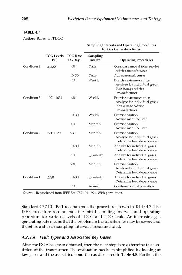
208 Electrical Power Equipment Maintenance and Testing
Standard C57.104-1991 recommends the procedure shown in Table 4.7. The IEEE procedure recommends the initial sampling intervals and operating procedure for various levels of TDCG and TDCG rate. An increasing gas generating rate means that the problem in the transformer may be severe and therefore a shorter sampling interval is recommended.
4.2.3.8 Fault Types and Associated Key Gases
After the DGA has been obtained, then the next step is to determine the con-dition of the transformer. The evaluation has been simplifi ed by looking at key gases and the associated condition as discussed in Table 4.8. Further, the
TABLE 4.7
Actions Based on TDCG
Sampling Intervals and Operating Procedures
for Gas Generation Rules
TCG Levels
(%)
TCG Rate
(%/Day)
Sampling
Interval Operating Procedures
Condition 4 ≥4630 >30 Daily Consider removal from service
Advise manufacturer
10–30 Daily Advise manufacturer
<10 Weekly Exercise extreme caution
Analyze for individual gases
Plan outage Advise
manufacturer
Condition 3 1921–4630 >30 Weekly Exercise extreme caution
Analyze for individual gases
Plan outage Advise
manufacturer
10–30 Weekly Exercise caution
Advise manufacturer
<10 Monthly Exercise caution
Advise manufacturer
Condition 2 721–1920 >30 Monthly Exercise caution
Analyze for individual gases
Determine load dependence
10–30 Monthly Analyze for individual gases
Determine load dependence
<10 Quarterly Analyze for individual gases
Determine load dependence
>30 Monthly Exercise caution
Analyze for individual gases
Determine load dependence
Condition 1 ≤720 10–30 Quarterly Analyze for individual gases
Determine load dependence
<10 Annual Continue normal operation
Source: Reproduced from IEEE Std C57.104-1991. With permission.
DK4058_C004.indd 208DK4058_C004.indd 208 11/8/2008 12:16:27 PM11/8/2008 12:16:27 PM

Insulating Oils, Fluids, and Gases 209
use of combustible gas ratios to indicate possible fault type was developed by Doernenburg and subsequently confi rmed by Rogers on European system. These methods are known as Rogers ratio and Doernenburg ratio methods and are beyond the scope of this book.
4.3 Less Flammable Insulating Fluids
There has been a great increase in the use of less fl ammable liquids as an insulating and cooling medium in transformers. As these liquids are chemi-cally different from mineral oils, they cannot be substituted in equipment designed for the use of mineral-oil type liquid. The NEC has offi cially desig-nated these synthetic liquids as less fl ammable. They are askarels, silicone, RTemp, Wecosol R113, envirotemp (FR-3), and others. As is the case with mineral oil, the dielectric strength of askarels, silicone, RTemp, Wecosol, and other less fl ammable fl uids is reduced by the presence of emulsifi ed water. Silicone, Wecosol, and RTemp characteristics are similar to those of askarel.
The maintenance and testing of less fl ammable insulating fl uids is similar to oil. The inspection and maintenance of these fl uids are discussed in Section 4.5. The battery of tests (screening tests) that are normally performed on these fl uids are listed in Table 4.2. These fl uids should be maintained and tested on the same frequency as used for insulating oil. The oil sample for conducting the tests should be taken from the bottom of the transformer tank for RTemp, and from the top of the tank for silicone and askarel. The test limits for acidity, IFT, dielectric breakdown voltage, power factor, and color for service-aged less fl ammable fl uids are given in Table 4.9. It should be noted that the dielectric breakdown voltage test limit given in Table 4.9 for these fl uids is for the ASTMD877 method using disk electrodes.
TABLE 4.8
Types of Faults and Key Gases
Operating Condition Interpretations
1. Nitrogen plus 5% or less oxygen Normal operation
2. Nitrogen, carbon monoxide, and carbon
dioxide
Transformer winding insulation overheated;
key gas is carbon monoxide
3. Nitrogen, ethylene, and methane—some
hydrogen and ethane
Transformer oil is overheated; minor fault
causing oil breakdown. Key gas is ethylene
4. Nitrogen, hydrogen, small quantities of
ethane and ethylene
Corona discharge in oil; key gas is hydrogen
5. Same as #4 with carbon dioxide and
carbon monoxide
Corona involving paper insulation; key gas is
hydrogen
6. Nitrogen, high hydrogen and acetylene;
minor quantities of methane and ethylene
High-energy arcing; key gas is acetylene
7. Same as #6 with carbon dioxide and
carbon monoxide
High-energy arcing involves paper insulation
of winding; key gas is acetylene
DK4058_C004.indd 209DK4058_C004.indd 209 11/8/2008 12:16:27 PM11/8/2008 12:16:27 PM
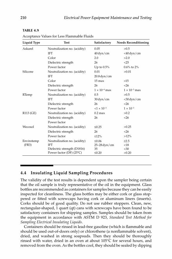
210 Electrical Power Equipment Maintenance and Testing
4.4 Insulating Liquid Sampling Procedures
The validity of the test results is dependent upon the sampler being certain that the oil sample is truly representative of the oil in the equipment. Glass bottles are recommended as containers for samples because they can be easily inspected for cleanliness. The glass bottles may be either cork or glass stop-pered or fi tted with screwcaps having cork or aluminum liners (inserts). Corks should be of good quality. Do not use rubber stoppers. Clean, new, rectangular-shaped, 1 quart (qt) cans with screwcaps have been found to be satisfactory containers for shipping samples. Samples should be taken from the equipment in accordance with ASTM D 923, Standard Test Method for Sampling Electrical Insulating Liquids.
Containers should be rinsed in lead-free gasoline (which is fl ammable and should be used out-of-doors only) or chlorothene (a nonfl ammable solvent), dried, and washed in strong soapsuds. Then they should be thoroughly rinsed with water, dried in an oven at about 105°C for several hours, and removed from the oven. As the bottles cool, they should be sealed by dipping
TABLE 4.9
Acceptance Values for Less Flammable Fluids
Liquid Type Test Satisfactory Needs Reconditioning
Askarel Neutralization no. (acidity) 0.05 >0.5
IFT 40 dyn/cm <40 dyn/cm
Color 2.0 >2.0
Dielectric strength 26 <25
Power factor Up to 0.5% 0.6% to 2%
Silicone Neutralization no. (acidity) 0.01 >0.01
IFT 20.8 dyn/cm
Color 15 max >15
Dielectric strength 26 <26
Power factor 1 × 10−4 max 1 × 10−3 max
RTemp Neutralization no. (acidity) 0.5 >0.5
IFT 30 dyn/cm <30 dyn/cm
Dielectric strength 26 <26
Power factor <1 × 10⁻³ 1 × 10⁻³
R113 (GE) Neutralization no. (acidity) 0.2 max >0.2
Dielectric strength 26 <26
Power factor
Wecosol Neutralization no. (acidity) ≤0.25 >0.25
Dielectric strength 26 <26
Power factor ≤12% >12%
Envirotemp
(FR3)
Neutralization no. (acidity)
IFT
Dielectric strength (D1816)
Power factor (DF) (25oC)
≤0.06
25–28 dyn/cm
35
≤0.20
≥2.5
<18
<30
>0.20
DK4058_C004.indd 210DK4058_C004.indd 210 11/8/2008 12:16:27 PM11/8/2008 12:16:27 PM

Insulating Oils, Fluids, and Gases 211
the necks in wax, and then stored for future use. These bottles should be opened only when the bottle temperature and the ambient temperature are the same or nearly so.
4.4.1 Sampling Oil from Transformers
General sampling instructions are as follows:
At least 2 qt of oil should be taken as a sample for dielectric, acidity, and IFT tests. Allow space at the top of the container for expansion. If two 1 qt bottles are used for a sample, label the bottles as 1 of 2 and 2 of 2.
Samples from outdoor apparatus should be taken on clear days when the humidity is near normal and the oil is at least as warm, or warmer than the surrounding air. Cold oil may condense enough moisture from a humid atmosphere to seriously affect its insulating properties. Therefore, this precaution must be observed in sampling spare transformers.
Samples should never be drawn in rain or when the relative humidity of the atmosphere exceeds 70%.
Guard against wind and dust.
When taking samples from an opening, such as a valve, clean the valve thoroughly and allow enough liquid to run out (about 1 qt) to remove any moisture or foreign material.
In a sealed transformer, which has a vacuum, be sure to vent the trans-former before drawing the sample.
Place the sample in the freezing compartment of a refrigerator overnight. If the sample is cloudy when viewed the next day, it contains free water. Since free water is undesirable, take another sample to deter-mine whether water is in the oil or was in the sample container.
4.4.2 Sampling Oil from Drums or Shipping Containers
The oil drum should remain undisturbed for several hours before drawing the sample.
A glass or Pyrex thief is recommended for sampling because it can be easily inspected for cleanliness. A glass tube approximately 36 in. long, 1 in. in diameter, and tapered at both ends is recommended for the sampling thief.
The thief should be cleaned before and after sampling in the same manner as for cleaning sample containers. When not being used, the thief should be corked at both ends.
Discard the fi rst full thief of oil.
Draw the sample in the following manner:
With the top end covered with the thumb, lower the tube to within approximately 1/8 in. from the bottom of the drum.
DK4058_C004.indd 211DK4058_C004.indd 211 11/8/2008 12:16:27 PM11/8/2008 12:16:27 PM

212 Electrical Power Equipment Maintenance and Testing
Remove the thumb from the top opening until the thief is fi lled with oil.
Replace thumb over top of thief and remove thief full of oil to the sample container. Release thumb to permit oil to run into the container.
4.4.3 Taking Oil Samples for Gas-in-Oil Analysis
This procedure has been developed to maintain uniformity of all oil samples taken in the fi eld for a laboratory gas-in-oil analysis. Special stainless-steel containers are used for collecting samples of oil for gas-in-oil analysis using gas chromatograph. These stainless-steel containers are not to be used for any other purpose and should be kept clean to eliminate all contaminants and purged with dry air for shipment to the fi eld.
Use a can to catch overfl ow oil from the stainless-steel container.
Obtain two lengths of Tygon clear plastic tubing and attach one to each end of the stainless-steel container. Make certain that the tubing between transformer and container is as short as possible.
Attach the tubing from one end of the stainless-steel container to the sample valve cock on the transformer.
Hold the stainless-steel container in a vertical position with the length of tubing on the outlet end in the can to catch the overfl ow oil.
Open the sampling valve on the transformer.
Open valve on the inlet side of container.
Open valve on the outlet side of container and allow the stainless-steel container to fi ll and overfl ow into can. At least 1 pint should over-fl ow to assure removal of all bubbles in the sampling system.
Close top valve (outlet side) fi rst to ensure a contamination-free sample.
Close bottom valve (inlet side) and then close sampling valve on the transformer.
Do not wrap any kind of tape around valves or nozzles of the stainless-steel container.
Forward the sample to the laboratory.
4.5 Maintenance and Reconditioning
of Insulating Oil and Fluids
This section covers the maintenance and reconditioning of the oils and less fl ammable fl uids such as silicone, RTemp, and Wecosol. As discussed earlier, moisture and oxygen are the most prevalent contaminants present in transformer oil and fl uids. As a result of these contaminants and other catalysts and accelerators, oxidation of these liquids takes place. Overtime oxidation results in deterioration of the transformer insulating system. If this degradation is not corrected in time, it eventually leads to terminal
DK4058_C004.indd 212DK4058_C004.indd 212 11/8/2008 12:16:27 PM11/8/2008 12:16:27 PM

Insulating Oils, Fluids, and Gases 213
stage of deterioration called sludge. Sludge is a resinous, partially conductive substance that eventually causes the transformer to fail. Before this condi-tion is reached, it is imperative that the oil should be maintained so that this condition does not occur. However, all is not lost; even badly deteriorated oils can be reconditioned and reclaimed by removing the oxidation prod-ucts and other contaminants.
4.5.1 Reconditioning Used Insulating Oils
All known oil purifi cation methods are shown in Table 4.10. Modern vacuum oil purifi cation systems with integral Fuller’s earth or activated alumina can correct all contamination conditions of deteriorated oils. First the contami-nated oil condition has to be identifi ed and then an appropriate method or combinations of the methods are used for a complete purifi cation of the oil.
TABLE 4.10
Oil Purifi cation Practices
Types of Contamination Removed
Oil-Purifi cation
Practices
Water Acids, Sludge, Etc.
Solid Free Soluble Air and Gas Volatile Other
Precipitation
(settling)
Yes Yes No No No No
Centrifuging Yes Yes No No No No
Absorption—fi lter
process
Yes Yes limited Yes partial No No No
Cartridge Yes Yes limited Yes partial No No No
Filter/dryer
Absorptive type
Mechanical
fi ltration
Yes No No No No No
Pleated and depth
types
Coalescing fi lter Yes Yes No No No No
Electrophoresis Yes Yes No No No No
Dry gas purge No Yes Yes No Some No
Low-vacuum
treatment
No Yes Yes partial Yes partial Some No
High-vacuum
treatment
(degasifi cation)
No No Yes Yes Yes No
Modern degasifi era Yes Yes Yes Yes Yes No
Fuller’s earth
treatment or
activated alumina
No, some
colloids
Yes limited No No Yes Yes
Source: Reproduced from Baranowski, L. and Kelly, J., An Update on the Reclamation of Insulation Oil, Minutes of the 44th Annual International Conference of Doble Clients,
1977, Doble Engineering, Watertown, MA.
Note: Modern oil purifi cation system (includes fuller’s earth or activated alumina system).
DK4058_C004.indd 213DK4058_C004.indd 213 11/8/2008 12:16:27 PM11/8/2008 12:16:27 PM
214 Electrical Power Equipment Maintenance and Testing
4.5.1.1 Natural Precipitation
Oil that has low dielectric strength or contains deposits of sludge or other contamination should receive maintenance attention. Low dielectric strength indicates the need for drying by mechanical fi lter or vacuum dehydrator. High acidity, high power factor, or low IFT values indicate the need for reclaim-ing treatment. When used, insulating oils are to be subjected to reconditioning and/or reclaiming processes, every advantage possible should be taken of natu-ral precipitation. Considerable savings can frequently be realized in processing used oil if it is allowed to remain in its container undisturbed for at least 24 h so that water and suspended solids can settle out. The oil can then be removed without disturbing the residue in the bottom of the container, thus obviating the necessity of removing the residue from the processing machinery.
4.5.1.2 Filter Presses
Filter presses (Figure 4.3) vary somewhat in form, but are based upon the principle of forcing oil under pressure through a series of absorbing materials, such as paper, Fuller’s earth, etc. Filters of this type are capable of removing carbon, water, sludge, and the like, when they are in suspension, but except for certain special arrangements, they cannot remove them effectively when they are dissolved or in colloidal form. These devices (particularly those with centri-fuges) will not remove air, but, in fact, tend to aerate the oil. Experience has shown that the most effi cient temperature at which to fi lter insulating oil is between 20°C and 40°C. Below 20°C, the viscosity increases rapidly, while at temperatures above 40°C the moisture is more diffi cult to separate from the oil.
4.5.1.3 Filter Press Operation
When the oil is to be purifi ed by the use of a fi lter press using blotting paper, the paper should be well dried to obtain the most effi cient operation; other-wise, the paper may actually add moisture to the oil. An oven should be used for drying the paper, and the sheets should be separated as they are hung on rods in the oven to permit free circulation of air and to ensure the most rapid drying. The fi lter paper should be dried from 6 to 12 h at a temperature of 101°C to 105°C. After drying, the paper should be taken from the oven directly to the fi lter, or it may be stored in dry transformer oil for future use. When transferring the paper, care should be taken to handle it as little as pos-sible to avoid the absorption of moisture from the hands and to minimize the time of exposure to the air.
When purifying very wet oil with a fi lter press, the back pressure will not increase appreciably as the fi lter paper absorbs moisture. Therefore, the operator should make frequent dielectric tests of the oil discharged from the fi lter press to determine when the paper should be replaced. When purifying oil containing materials such as sludge or small carbon particles, consider-able back pressure will develop as the fi ltering progresses because of the materials clogging up the fi lter paper. When the back pressure reaches about 75 psi, the paper should be replaced.
DK4058_C004.indd 214DK4058_C004.indd 214 11/8/2008 12:16:27 PM11/8/2008 12:16:27 PM
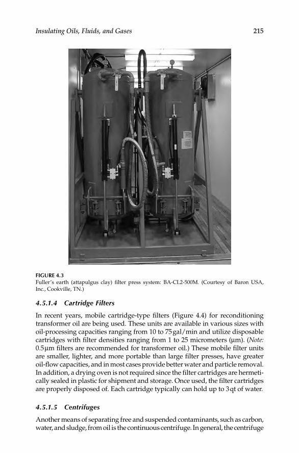
Insulating Oils, Fluids, and Gases 215
4.5.1.4 Cartridge Filters
In recent years, mobile cartridge-type fi lters (Figure 4.4) for reconditioning transformer oil are being used. These units are available in various sizes with oil-processing capacities ranging from 10 to 75 gal/min and utilize disposable cartridges with fi lter densities ranging from 1 to 25 micrometers (μm). (Note: 0.5 μm fi lters are recommended for transformer oil.) These mobile fi lter units are smaller, lighter, and more portable than large fi lter presses, have greater oil-fl ow capacities, and in most cases provide better water and particle removal. In addition, a drying oven is not required since the fi lter cartridges are hermeti-cally sealed in plastic for shipment and storage. Once used, the fi lter cartridges are properly disposed of. Each cartridge typically can hold up to 3 qt of water.
4.5.1.5 Centrifuges
Another means of separating free and suspended contaminants, such as carbon, water, and sludge, from oil is the continuous centrifuge. In general, the centrifuge
FIGURE 4.3Fuller’s earth (attapulgus clay) fi lter press system: BA-CL2-500M. (Courtesy of Baron USA,
Inc., Cookville, TN.)
DK4058_C004.indd 215DK4058_C004.indd 215 11/8/2008 12:16:27 PM11/8/2008 12:16:27 PM

216 Electrical Power Equipment Maintenance and Testing
FIGURE 4.4Mobile fi lter cartridge blotter-paper type dryer fi lter press Model BA-2FC2-20. (Courtesy of
Baron USA, Inc., Cookville, TN.)
can handle much greater concentrations than can the conventional fi lter press, but it cannot remove some of the contaminants as completely as a fi lter press. Consequently, the centrifuge is generally used for rough bulk cleaning where large amounts of contaminated oil are to be handled.
Frequently, the output of the centrifuge is put through a fi lter press for the fi nal cleanup. The centrifuge cannot remove dissolved water from oil; since the fi nal centrifuge is sealed with water, the oil leaving the centrifuge may be saturated at the temperature of operation and conceivably could contain more dissolved water than when it entered. Neither the centrifuge nor the fi lter press is designed to treat oil chemically.
4.5.1.6 Coalescers
Throughout the power industry, coalescers are replacing centrifuges for use in removing free water from both lubricating and insulating oils. Coalescing is a technique that has been borrowed from the aviation fueling fi eld. Fiberglass cartridges trap small water particles; increasing differential pres-sure across the fi lter media forces the particles of water together, and the large water drops are extruded at the outer surface of the fi berglass element. Large water drops are retained within a water-repellent separator screen and collect, by gravity, at the bottom of the fi lter while dry oil passes through the
DK4058_C004.indd 216DK4058_C004.indd 216 11/8/2008 12:16:28 PM11/8/2008 12:16:28 PM
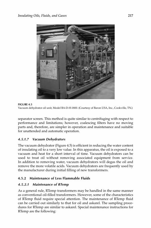
Insulating Oils, Fluids, and Gases 217
separator screen. This method is quite similar to centrifuging with respect to performance and limitations; however, coalescing fi lters have no moving parts and, therefore, are simpler in operation and maintenance and suitable for unattended and automatic operation.
4.5.1.7 Vacuum Dehydrators
The vacuum dehydrator (Figure 4.5) is effi cient in reducing the water content of insulating oil to a very low value. In this apparatus, the oil is exposed to a vacuum and heat for a short interval of time. Vacuum dehydrators can be used to treat oil without removing associated equipment from service. In addition to removing water, vacuum dehydrators will degas the oil and remove the more volatile acids. Vacuum dehydrators are frequently used by the manufacturer during initial fi lling of new transformers.
4.5.2 Maintenance of Less Flammable Fluids
4.5.2.1 Maintenance of RTemp
As a general rule, RTemp transformers may be handled in the same manner as conventional oil-fi lled transformers. However, some of the characteristics of RTemp fl uid require special attention. The maintenance of RTemp fl uid can be carried out similarly to that for oil and askarel. The sampling proce-dures for RTemp are similar to askarel. Special maintenance instructions for RTemp are the following:
FIGURE 4.5Vacuum dehydrator oil unit, Model BA-D-H-1800. (Courtesy of Baron USA, Inc., Cookville, TN.)
DK4058_C004.indd 217DK4058_C004.indd 217 11/8/2008 12:16:29 PM11/8/2008 12:16:29 PM
218 Electrical Power Equipment Maintenance and Testing
Filtering: If it is necessary to fi lter RTemp fl uid to remove excess moisture, sludge, and the like, it can be fi ltered through conventional fi ltration systems. The fi ltering system should be fl ushed before connection.
Care should be taken to assure that the pump has suffi cient capacity to handle the relatively high viscosity of RTemp fl uid at lower temperatures. The heating of the fl uid and piping system will increase the speed and ease of fi ltration and is completely acceptable.
Cold start: RTemp fl uid has a pour point of −30°C. At this point, the dielec-tric strength is still suffi cient to allow safe energization of the transformer. Because the possibility exists of energizing a transformer into a fault, RTemp transformers should not be energized if the fl uid temperature (top oil) is below −15°C. At −15°C top oil temperature or above, full load may be applied to the transformer.
If the top oil temperature is below −15°C, immersion heaters placed near the bottom of the tank, external heating blankets, or some other means should be used to raise the top oil temperature to −15°C, thus assuring ade-quate cold spot temperature.
Precautions: RTemp transformers are high-fi re point liquid-insulated trans-formers. Relatively small quantities of conventional transformer oil or other low-fi re point materials can substantially reduce the fi re point of RTemp fl uid. Care must be taken in processing and handling RTemp transformers not to introduce such contaminants. External systems, such as fi ltration sys-tems, should be thoroughly fl ushed with RTemp fl uid before connection to a RTemp transformer.
4.5.2.2 Maintenance of Silicone
Silicone insulating fl uid is used in transformers to provide heat transfer. Transformers containing silicone should be installed, operated, and serviced by competent and trained maintenance personnel who are familiar with good safety practices. The sampling procedures for silicone are similar to askarel. The following are special maintenance instructions relating to silicone-fi lled transformers.
Receiving and handling: Immediately upon receipt of shipping drums or a transformer fi lled with silicone fl uid, an examination should be made for leaks. If leakage is evident either at this time or at any time thereafter, the cause should be corrected and the spillage soaked up with absorbent materials such as saw-dust or fuller’s earth, followed by a cleanup of the affected area with rags soaked with kerosene or other approved solvent, such as 1,1,1-trichloroethane. Adequate ventilation must be provided when using such solvents.
On those infrequent occasions when silicone fl uid is removed for shipment, the transformer may be shipped gas fi lled and is to be liquid fi lled at instal-lation. If the transformer is located outdoors, adequate precautions must be taken to ensure that no dirt or moisture enters the liquid during the fi lling operation. Before opening a container of silicone fl uid, allow it to stand until the liquid is at least as warm as the surrounding air.
DK4058_C004.indd 218DK4058_C004.indd 218 11/8/2008 12:16:29 PM11/8/2008 12:16:29 PM
Insulating Oils, Fluids, and Gases 219
Before placing the liquid in the transformer, take a sample from each con-tainer and make dielectric tests as outlined under Section 4.2.2.1. If the tests are unsatisfactory, restore the dielectric strength by fi ltering before placing the liquid in the transformer. When transferring from containers to the trans-former, it is recommended that the liquid be passed through a fi lter press to remove any undetected moisture or sediment that may be present. A vacuum purifi er is also commonly used.
Silicone fl uid must be handled in containers, pipes, oil-resistant hoses, and the like, that are free from oil, grease, pitch, or other foreign materials, since these contaminate the liquid and decrease its nonfl ammable properties. All apparatus used in sampling, fi ltering, storing, or transporting silicone fl uid must be maintained for exclusive use with silicone fl uid, since it is extremely diffi cult to remove all traces of oil or other silicone fl uid contami-nants from equipment of this type. Also, mineral oil is completely miscible in silicone fl uid, and it is practically impossible to separate the two liquids after they have been mixed.
Use kerosene or other approved solvent to remove all traces of silicone fl uid on the outside of the transformer tank. This precaution should be taken since silicone fl uid has a tendency to affect adhesion of additional coats of paint.
Storage: Shipping drums should be stored indoors in an area specially selected for this purpose. If it is necessary to store drums or cans containing silicone fl uid outdoors, protect the containers from the weather and direct contact with water. Regardless of location, all drums should be stored in a position that results in the bungs being under a positive pressure. Do not open a drum or can until the liquid is actually needed. Any change in tem-perature while the containers are open will cause an exchange of air, with the possibility of moisture entering the liquid. Partially emptied drums must be tightly resealed and stored in the same manner outlined previously.
Periodic inspection: The insulating liquid must be maintained at the proper level, and for the longest possible service life of the transformer, the dielec-tric strength of the silicone fl uid should be maintained at a high value. It is recommended, therefore, that the liquid be sampled and tested after the fi rst few days of operation, again after 6 months, and yearly thereafter. Keep accurate records of the tests, and fi lter or replace the liquid as indicated. The entire transformer should also be thoroughly checked for leaks at these same intervals. If the pressure-vacuum gauge consistently reads zero, a leak in the gas space is indicated. If there is any reason to believe that water may have entered the transformer, check a top sample immediately for water.
Filtering: If test results indicate that moisture or other contaminants are present, they can usually be removed by passing the insulating liquid through a fi lter press. This device may be used either as a paper fi lter press for drying or with fuller’s earth and paper for purifying. All apparatus used in sam-pling, fi ltering, storing, or transporting silicone fl uid must be maintained for exclusive use with silicone fl uid, since it is extremely diffi cult to remove all traces of oil or other silicone fl uid contaminants from equipment of this type.
DK4058_C004.indd 219DK4058_C004.indd 219 11/8/2008 12:16:30 PM11/8/2008 12:16:30 PM

220 Electrical Power Equipment Maintenance and Testing
Filtration can be accomplished in the transformer or other container by circu-lating the silicone fl uid from the bottom to the top through a fi lter press. Filtering can be done faster and more effi ciently by passing the liquid from the transformer through the fi lter and into a separate, clean, dry container and then back through the fi lter again to refi ll the transformer. In this manner all the liquid will be given two complete passes through the fi lter press. If additional fi ltering is still required, the entire procedure can be repeated. As moisture is extracted from the liquid during the fi ltering process, the fi lter-ing medium will become wet. Frequent samples of the outgoing liquid should be tested to determine when the fi ltering medium should be replaced.
The fi lter press will not remove large quantities of free water from the silicone fl uid. When a large quantity of free water is introduced into the fi lter, it will be passed on through, emerging as fi nely divided droplets dispersed throughout the liquid. Therefore, if free water is present, it should be removed before fi ltering is started. A transformer contaminated with moisture may not only have moisture suspended in the insulating liquid, but also in the windings and insulation. The most effi cient temperature for fi ltering mois-ture from the liquid is between 20°C and 40°C, but at this temperature the transfer of moisture from the windings and insulation to the insulating liquid is quite slow. If free water is present in the transformer or if the dielectric strength of the silicone fl uid is still below 30 kV after fi ltering, consult the nearest offi ce of the transformer manufacturer for additional information.
Safety precautions: As a class, silicone liquids are nontoxic. Silicone fl uid in contact with the eyes may cause local irritation, but this irritation is only temporary. If desired, eyes may be irrigated with water, and if irritation per-sists, consult a physician.
Precautions: Static charges can be developed when silicone fl uid fl ows in pipes, hoses, and tanks. Fluid leaving a fi lter press may be charged to over 50,000 V. To accelerate dissipation of the charge in the liquid, ground the fi lter press, the piping, the transformer tank, and all bushings or the winding leads during fl ow into any tank. Conduction through silicone fl uid is slow; therefore, it is desirable to maintain these grounds for at least 1 h after the fl ow has been stopped.
Arcs can occur from the free surface of the charged liquid even though the previous grounding precautions have been taken. Therefore, explosive gas mixture should be removed from all containers into which liquid is fl owing.
4.5.2.3 Maintenance of Wecosol
Wecosol fl uid is a transformer grade of tetrachloroethylene (sometimes called perchloroethylene). Wecosol fl uid will slowly evaporate to produce Wecosol vapors. It is necessary to use the proper safety procedures to prevent adverse effects resulting from vapor inhalation and skin contact with fl uid. Overexposure to Wecosol vapors will result in symptoms such as headaches, confusion, nausea, and lack of coordination. Extreme overexposure to Wecosol vapors could result in fatal personal injury. The fl uid is considered as
DK4058_C004.indd 220DK4058_C004.indd 220 11/8/2008 12:16:30 PM11/8/2008 12:16:30 PM

Insulating Oils, Fluids, and Gases 221
less than 50 ppm polychlorinated biphenyl (PCB) dielectric fl uid in accordance with Federal PCB regulations 40 CFR 761, dated July 01, 2002. It is considered as a nonfl ammable fl uid with boiling point of 121°C at atmospheric pressure. The safe limits of vapor exposure are shown in Table 4.11.
Low lying areas such as pits can slowly accumulate vapors which are nearly six times heavier than air. The tank should not be opened in those areas which may accumulate the vapors to prevent excessive vapor concentrations. The odor of Wecosol vapors is noticeable at concentrations of 50 ppm and often as low as 10 ppm. Do not use odor to determine vapor concentrations since odor threshold varies between individuals. Also, the ability to recognize Wecosol vapors diminishes after exposure, due to temporary desensitization.
Wecosol fl uid is a solvent. Like any solvent, contact will dry out the skin by removing its natural oils. The natural oils can be replaced by the use of common hand lotions. Gloves resistant to Wecosol fl uid should be worn to avoid skin contact and transformer fl uid contamination.
Fluid splashed into the eyes may cause pain and irritation. Safety goggles should be worn if tasks to be performed risk splashing of fl uid into the eyes. If the fl uid is splashed into the eyes, fl ush the eyes with water for approxi-mately 15 min and consult a physician. The following are special mainte-nance instructions for Wecosol.
Receiving and handling: Immediately upon receipt of drums or a transformer fi lled with Wecosol fl uid, examine for leaks. Take the necessary action and precautions so that PCB contamination is not introduced from the leaks or any fi lling or maintenance of the transformer. If the fl uid is received in drums, they must be stored in ventilated dry area in an upright position. Before a drum is used to fi ll the transformer, it must be sampled and tested for dielectric strength. The dielectric strength must be at least 30 kV for drummed fl uid to be used.
Sampling: Samples should be taken to prevent air from entering the tank. To prevent air from being drawn into the tank, the tank pressure must be greater than zero psi. If necessary, increase the tank pressure by injecting dry
TABLE 4.11
Maximum Wecosol Vapor Exposure
Parts Per Million (ppm) Hours Per Day
33 24
50 16
80 10
100 8
133 6
200 4
Greater than 200 0
Note: Reference OSHA Standards Part 1910.1000, Table Z2.
DK4058_C004.indd 221DK4058_C004.indd 221 11/8/2008 12:16:30 PM11/8/2008 12:16:30 PM

222 Electrical Power Equipment Maintenance and Testing
nitrogen until a positive pressure of about one half psi is reached. The sample should be taken when the unit is warmer than the air to avoid condensation.
Care should be taken to procure a sample which fairly represents the liquid in the tank. All samples must be taken from the top liquid sampler near the top fl uid level. A suffi cient amount of liquid should therefore be drawn off before the sample is taken to insure that the sample will not be that which is stored in the liquid sampler. If the sample taken contains free water, it is not suitable for dielectric tests and the sample must be discarded. A second sample should then be taken after at least 2 qt of liquid have been withdrawn. If free water still exists, all transformer fl uid must be dried as explained in the following section.
Drying: The transformer fl uid can be dried by either chemical drying or insulation drying methods. Take the necessary precautions so that PCB con-tamination is not introduced during fi eld fi lling or maintenance of the trans-former. In the chemical drying method use hoses, gaskets, and threaded fi tting seals made of viton rubber and Tefl on-lined copper or steel. The liquid temperature must be less than 60°C for chemical drying procedure to be used. Circulate the tank fl uid through glass or paper fi lters and calcium sul-fate. The fi lters should be a 50 μm fi lter on the calcium sulfate inlet with a 1 μm absolute on the exit (fi lter will pass no particle larger than 1 μm). Continue the drying process until the water content is less than 35 ppm, and the dielectric breakdown is greater than 26 kV.
In the insulation drying method, the windings, insulation, and fl uid can be dried by circulating current through the windings. The tank coolers must be blanketed off to reduce heat loss. The low-voltage winding is short circuited and suffi cient voltage is impressed across the high-voltage winding to circu-late current through the windings to maintain a liquid temperature between 90°C and 100°C. The voltage necessary to accomplish this task is approxi-mately one-third the rated impedance divided by 100 and multiplied by the rated voltage. Current requirements are approximately one-third the rated current. During the heating, monitor the liquid level to make certain the liquid level is at least to the 25°C level. Stop the heating if the liquid level falls below the 25°C level. When the liquid has reached the required tempera-tures, purge the gas space with dry nitrogen. Minimize the Wecosol vapor exhaust. Continue the purging and heating until the liquid water content is less than 35 ppm, and dielectric breakdown is greater than 26 kV.
Reprocessing: If necessary the Wecosol fl uid can be reprocessed by fi ltering. When reprocessing, use hoses and tubing lined with Tefl on or made of copper or steel. All gaskets and threaded fi tting seals used during this pro-cess must be made of viton rubber. Circulate the fl uid through paper or glass fi lters and fuller’s earth. The inlet fi lter should be a 50 μm fi lter. The exhaust fi lter must be a 5 μm absolute fi lter.
Inspection and maintenance: Periodic inspection and maintenance test should be conducted to determine whether a transformer fl uid should continue to be used, dried, or reprocessed.
DK4058_C004.indd 222DK4058_C004.indd 222 11/8/2008 12:16:30 PM11/8/2008 12:16:30 PM

Insulating Oils, Fluids, and Gases 223
4.5.2.4 Maintenance of Environtemp (FR3)
This section discusses natural ester-based transformer insulating fl uid known as Envirotemp® (FR3) and offers a guide on testing and evaluation, as well as criteria and methods of maintenance for it. These base fl uids are also known as vegetable seed oils. These fl uids are currently being used in the range of small distribution class transformers to medium power transformers. They are being applied in new equipment and for retrofi lling existing equipment. The dielectric fl uid FR3 has been available for transformers in the last several years and today this fl uid is being used in transformers produced by many manufactures. This fl uid is soy-based product and has an exceptionally high fi re point of 360°C and fl ash point of 330°C. The chemical composition of FR3 fl uid is a mixture of triglycerides (long-chain fatty acid ester molecules) that are relatively polar, are less prone to saturate, and readily form hydrogen bonds. It has the highest ignition resistance of less-fl ammable fl uids currently available. It is referred to as a high fi re point or “less-fl ammable” fl uid, and is listed as a less-fl ammable dielectric liquid by Underwriters Laboratories (UL) for use in complying with the NEC and insurance requirements. Because FR3 fl uid is derived from 100% edible seed oils and uses food-grade additives, its environmental and health profi le is unmatched by other dielectric coolants. Its biodegradation rate and completeness meets the U.S. EPA criteria for “ulti-mate biodegradability” classifi cation.” The manufacturer (Cooper Power System, USA) also claims FR3 fl uid extends insulation life by a factor of as much as 5–8 times because it has the unique ability to draw out retained mois-ture and absorb water driven off by aging paper. It also helps prevent paper molecules from severing when exposed to heat. These properties can result in increase ability to overload or longer transformer insulation life, resulting in both lower life cycle costs and delayed asset replacement. FR3 fl uid is fully miscible with conventional mineral oil or R-Temp®, and may be used to retro-fi ll or top off units fi lled with these fl uid types. It appears the only negative that can be attributed to this fl uid is the fact that it has a relatively high fi rst cost relative to mineral oil and could easily add 15%–30% to the transformer fi rst cost. FR3 fl uid is a fi re-resistant natural ester dielectric coolant specifi -cally formulated for use in distribution and power transformers where its unique environmental, fi re safety, chemical, and electrical properties are advantageous. Because of its excellent environmental, fi re safety, and perfor-mance characteristics, applications for FR3 fl uid have expanded into a variety of other applications, including power transformers, voltage regulators, sectionalizing switches, transformer rectifi ers, electromagnets, and voltage supply circuits for luminaries. The fl uid is also used in retrofi ll applications for transformers and other fl uid-fi lled distribution and power equipment.
Storage and handling: The same basic procedures for storing and handling conventional transformer oil should be followed with FR3 fl uid. To maintain the extremely low percent moisture saturation at time of fl uid manufacture, it is recommended that exposure time to air be as minimal as practical. Drum and tote storage should be indoors or outdoors protected from the elements. To maintain the optimal fl uid properties for its intended use as an
DK4058_C004.indd 223DK4058_C004.indd 223 11/8/2008 12:16:30 PM11/8/2008 12:16:30 PM

224 Electrical Power Equipment Maintenance and Testing
electrical insulating fl uid, exposure to oxygen, moisture, and other contami-nants must be minimized. Except for short storage periods, material that has been immersed in FR3 fl uid should not be exposed to air. Thin fi lms of natural esters tend to polymerize much faster than conventional transformer oil. For equipment drained of FR3 fl uid, it is recommended that the equipment be placed in an inert gas environment or be reimmersed as soon as is practical. Hot air drying is an unacceptable process for assemblies already impreg-nated with a natural ester fl uid. For impregnated assemblies that require additional drying, a method of drying that does not expose the impregnated insulation to air is required to avoid polymerization of the dielectric fl uid. Avoid extremes of temperature of storage. FR3 fl uid should be stored in labeled, tightly closed containers at 10°C–40°C in dry and well-ventilated areas away from sources of ignition or heat.
Fluid maintenance tests: Physical, chemical, and electrical properties are used to evaluate new and in-service electrical insulating fl uids. Periodic mainte-nance tests for FR3 fl uid-fi lled equipment should follow the same schedule used for transformers fi lled with conventional transformer oil. However, some traditionally acceptable indicators of mineral oil performance may not apply or may have different values for Envirotemp FR3 fl uid. When compar-ing the standard ASTM tests and mineral oil specifi cations to those for natu-ral esters indicate that many tests may require special consideration. The battery of tests may be separated into performance, quality, and diagnostic. These tests are discussed below.
Performance testsInsulating fl uids provide both electrical insulation and cooling for the electrical apparatus. The dielectric breakdown voltage and viscosity are two key properties that affect the function and performance of an electrical insu-lating fl uid. The dielectric breakdown voltage measures the integrity of the insulation. The viscosity infl uences the cooling performance.
Dielectric breakdown voltage tests: The dielectric breakdown voltage tests that are conducted for insulating fl uids are ASTM D1816 and D877. The only modifi cation to the D816 test method is the stand time before the test. The stand time for the mineral oil is between 3 and 5 min. Because of the viscosity of the FR3 fl uid is higher than the mineral oil, a 15 min stand time is recom-mended between pouring the room temperature equilibrated fl uid sample and the start time of the test. This added time gives the entrained air suffi -cient time to escape after pouring of the sample. The stand time recom-mended for the D877 is 2–3 min. The D1816 is the preferred test for FR3 even though D877 test works well for this fl uid. The reason is that the D877 test is less sensitive to dissolved gas, water, and particulate than the D1816.
Viscosity: The kinematic viscosity of the FR3 fl uid is the lowest of the less-fl ammable fl uids, and is higher than that of mineral oil. The viscosity test using ASTM D445 may be performed without any modifi cation.
DK4058_C004.indd 224DK4058_C004.indd 224 11/8/2008 12:16:30 PM11/8/2008 12:16:30 PM

Insulating Oils, Fluids, and Gases 225
Quality testsThese tests are conducted to give indicators of changes in the electrical insulating fl uid over time due the operation of the equipment. Their usefulness is not so much in the test values (pass or fail) themselves, but in the trends over time. The quality of FR3 fl uid is measured using the same battery of tests that are used for oil. However due to the differences in the chemistry of FR3 and mineral oil, the normal base line values are different for certain properties. For example, dissipation factor (power factor), water content, pour point, and acid (neutralization) number are typically higher than those of mineral oil. Interfacial tension, gassing, and resistivity are normally lower than that of oil. These tests provide a good indication of possible fl uid contamination or unusual degradation. Acceptable limits for continued use of service-aged FR3 fl uid-fi lled equip-ment are listed Table 4.12.
Dielectric strength per ASTM D1816 and D877: The acceptable limit for continued use of service-aged FR3 fl uid is 30 kV minimum for equipment rated 69 kV and below. For applications greater than 69 kV line voltage con-tact manufacturer for recommendations. As was discussed above the stand time for the D1816 should be 15 min to allow entrapped air to escape before the test is conducted.
TABLE 4.12
Envirotemp (FR3) Fluid Acceptance Limits
Property ASTM Method
Typical
Envirotemp
FR3 Fluid
New Fluid As
Received in
Drums
Continued
Use of
Service-Aged
Fluid
Dielectric strength D1816(1 mm) 28–33 ≥30 ≥30
D1816(2 mm) 60–70 ≥35 ≥35
D877 50–55 ≥40 ≥30
Dissipation 25°C
factor (%) 100°C
D924 0.02–.06 ≤0.20 ≤1.0
1–3 ≤4.0
Neutralization number
(mg KOH/g)
D974 0.01–0.03 ≤0.06 ≤2.5
Interfacial tension
(dyne/cm)
D971 25–28 25–28 ≥18
Flash point (°C) D92 ≥300 —
Fire point (°C) D92 ≥340 ≥300
Viscosity (cSt) 100°C
40°C
D445 ≤10 —
≤40
Pour point (°C) D97 ≤−18 —
Moisture content
(mg/kg)
D1533B 20–30 ≤200 ≤400
DK4058_C004.indd 225DK4058_C004.indd 225 11/8/2008 12:16:30 PM11/8/2008 12:16:30 PM
226 Electrical Power Equipment Maintenance and Testing
Water content: The ASTM D1533 method can be used for the FR3 fl uid with-out modifi cation. If erratic or unusual results are observed while conducting this test, then use the Karl Fisher reagents for aldehydes and ketones instead of those used for mineral oil. The high capacity for water (1100 versus 60 mg/kg for mineral oil) is one of the important attributes of FR3 fl uid that gives kraft paper insulation longer life in it compared to its life in mineral oil. New FR3 fl uid typically contains 20–60 mg/kg of water, and standard specifi cation for natural ester fl uids used in electrical apparatus allow up to 200 mg/kg.
Dissipation factor: The ASTM D924 method can be used without modifi ca-tion. When using the same test cell for both mineral oil and FR3 fl uid dissi-pation measurements, it is of utmost importance to clean the test cell meticulously when changing from one type of fl uid to another. This is espe-cially true when measuring FR3 fl uid after mineral oil, otherwise high values may be seen if the cell is not suffi ciently cleaned. Also, clean the test equipment immediately after completion of the test due to the higher tendency of thin fi lms of natural esters to oxidize and eventually polymerize when exposed to air. A 0.05% value at 25°C for new FR3 fl uid is typical and values up to 0.2% are acceptable per ASTM D6871.
Acid number: The ASTM D974 can be used without modifi cation for deter-mining the neutralization (acid) number for FR3 fl uid. Because new FR3 fl uid contain small amounts of free fatty acids that result in acid neutralization number being higher than seen in mineral oil. As the FR3 fl uid ages, it reacts with water (hydrolysis), generating additional long chain fatty acids that are considered to be noncorrosive and milder than short chain organic acids found in mineral oil.
IFT: The IFT can be measured in the same manner as for mineral oil using STM D971 method. The FR3 fl uid has an inherently lower IFT value com-pared to mineral oil. It is considered that IFT should be as useful for FR3 fl uid as it is for mineral oil however more test data is needed to establish safe limits for in-service FR3 fl uid.
Color: A low color number of FR3 insulating fl uid is desirable to permit inspection of assembled apparatus in a tank. An increase in color number during service is an indicator of oil deterioration or contamination. New FR3 may initially be slightly darker in color, typically a slight amber appear-ance, than highly refi ned new mineral oil. Other tests (such as dissipation factor and neutralization number) are better measures of fl uid deterioration or contamination. Note that natural ester fl uid manufacturers may add clear colorants for identifi cation purposes. Such tints should not impact the ASTM color and visual examinations.
Diagnostic tests
Three tests are important for diagnostic and safety purposes. Flash and fi re point analyses per ASTM D92 serves both for quality verifi cation of new FR3 fl uid and diagnostics and safety evaluation of in-service fl uid.
DK4058_C004.indd 226DK4058_C004.indd 226 11/8/2008 12:16:30 PM11/8/2008 12:16:30 PM

Insulating Oils, Fluids, and Gases 227
The lower fl ash and fi re point values indicate contamination by more volatile fl uids. Flash point values can be used to estimate the amount of mineral oil in transformers that are retrofi lled with FR3 fl uid.
Flash point and fi re point: Relatively small amounts of conventional oil should not signifi cantly reduce the fl ash point and fi re point of Envirotemp FR3 fl uid. Contamination above 7.5% may reduce the fi re point to below 300°C. If it is suspected that the fl uid may be contaminated, fl ash point and fi re point should be measured in accordance with ASTM D92.
Dissolved gas analysis: This test is recommended particularly for high value equipment or equipment servicing critical loads. ANSI/IEEE guide C57.104-1991 for detection and analysis of generated gases can be applied, except the use of ratio methods. Limited testing and fi eld experience indicates that the same fault gases are produced in FR3 (natural esters) as are produced in mineral oil. Under the same magnitude of electrical overstress, natural esters typically produce somewhat less volume of the gases compared to mineral oil. Under the same thermal overstress, natural esters typically produce sig-nifi cantly more volume of the gases. There are differences in gas solubility coeffi cients between natural esters and mineral oils and their respective values should be used for data interpretation. There are differences between mineral oil and natural ester gassing tendency per ASTM D2300. During normal operation, the levels of dissolved hydrogen and ethane gases can increase at a rate greater than the typical rate in mineral oil.
Safety and care proceduresTypically, natural esters covered have been formulated to minimize health and environmental hazards. Although no known hazard is involved in the normal handling and use of natural ester fl uids, additives to the base oil may differ. Users should obtain a material safety data sheet (MSDS) for each natural ester fl uid in use. Follow the manufacturer’s instructions at all times. Personnel should avoid eye/fl uid contact and inhalation of spray mists, and take appropriate steps if such incidents occur. MSDSs should provide appro-priate guidelines with respect to handling these fl uids. Although not listed as a hazardous substance or waste by any federal agency, disposal of natural ester fl uids may require certain precautions. Currently, the U.S. EPA Spill Prevention, Control, and Countermeasure (SPCC) regulation (40CFR112) makes no practical distinction between mineral oils and vegetable oils, except for possible reduction in spill remediation requirements. Refer to IEEE Std C57.147-2008, IEEE Guide for Acceptance and Maintenance of Natural Ester Fluids in Transformers, for more details.
4.5.2.5 Maintenance of Askarels
Askarel is a generic name for PCBs which were used extensively in electrical transformers, capacitors, and other equipment since the 1940s. Askarel was used by many electrical equipment manufacturers under their own trade
DK4058_C004.indd 227DK4058_C004.indd 227 11/8/2008 12:16:31 PM11/8/2008 12:16:31 PM

228 Electrical Power Equipment Maintenance and Testing
name such as Pyranol (GE), Inerteen (Westinghouse), and so on. The open use of askarel was banned in electrical equipment in the early 1980s by the Environmental Protection Agency (EPA) in the United States. The use of askarel in closed systems in some industries may still be allowed with man-dated procedures for handling and disposal of askarel and askarel-contaminated materials. The discussion of maintenance of askarel is undertaken here for those facilities that are still allowed to use askarel as a dielectric medium for electrical equipment.
Inspection: Visual inspection and dielectric strength tests should be made on askarel when installing equipment and on a regular schedule at 1-year intervals thereafter. Visual inspection that reveals a clear, faint yellow or light brown color indicates good askarel condition. The presence of a green, red, or blue cast, cloudiness, or turbidity indicates the presence of insulation or moisture contamination, and further tests on the askarel and inspection of the associated equipment should defi nitely be made. If the askarel sample appears black or contains suspended carbon particles, severe arcing has occurred. The askarel should be discarded and a thorough inspection of the equipment performed.
Sampling: Samples of askarel should be taken in a clean, dry glass quart bottle. If the sample is to be stored indefi nitely or sent to a service labora-tory for moisture content tests, the bottle should be fi lled only to within 1 in. of the top; the sample should be sealed by wrapping the top and the threads of the jar with aluminum foil before tightly securing the cap. When the sample is to be sent to a laboratory, indicate the temperature of the askarel when the sample was taken. Samples of askarel should be taken when the relative humidity of the environment is low and when the temperature of the askarel is as high or higher than the surrounding air. It is best to take the sample when the unit is near operating or maximum temperature. Samples taken during regularly scheduled intervals should be taken at nearly the same temperature as previous samples. Samples should be taken as close to the top of the liquid surface as possible because askarel is heavier than water.
Testing: The testing procedure for askarel is the same as for mineral oil, but care should be taken to see that there is no mineral oil in the test cup. The dielectric strength test for askarel is the most important maintenance test. A higher dielectric strength indicates that the insulating effi ciency of the askarel is high and that any cloudiness or turbidity present is not due to dam-aging moisture contamination. If the dielectric strength of the askarel decreases abruptly or a decreasing trend is observed, inspections should be made at more frequent intervals. When the dielectric strength is 26 kV or less, a sample of askarel should be sent to a laboratory for a moisture test (ASTM D 1533, Karl Fischer method). A high power factor alone is an insuffi cient criterion for replacing or reconditioning askarel; however, where abnormally low values of dielectric strength occur, the power factor of the askarel can be expected to
DK4058_C004.indd 228DK4058_C004.indd 228 11/8/2008 12:16:31 PM11/8/2008 12:16:31 PM
Insulating Oils, Fluids, and Gases 229
abnormally high. Power factors of 20% and more are frequently encountered in askarel transformers during normal service. Although this is an indication that some contamination has occurred, experience has shown that askarel is serviceable long after power factor test values increase greatly. Again, the determining criterion that indicates the serviceability of askarel is the dielec-tric strength. Reconditioning askarel to obtain a lower power factor is usually not justifi able.
Contamination: Water contamination is the primary cause of deterioration of askarel dielectric strength. Inspect all askarel-fi lled equipment for possible areas that would allow the equipment to breathe moisture-laden air. Numerous sealing compounds are available for sealing these areas. Where gaskets are located, use silastic seals at the fl anges, viton for an elastomeric seal, and Tefl on tape on pipe threads. On older equipment, cork-type gaskets should have the outside edges sealed with epoxy cement.
Reconditioning askarel: The fact that the transformer tanks are generally sealed and that any condensation will fl oat on top of askarel makes fi ltering by a blot-ter press rarely necessary. If such fi ltering is necessary, it can be done with an ordinary press from which all mineral oil has been removed. A centrifugal purifi er designed for mineral oil will not function on askarel. Special combina-tion activated clay purifi ers and blotter presses are manufactured for askarel.
Handling and disposal of askarel: While askarel is generally considered to be noncombustible, under arcing conditions gases are produced that consist predominately of noncombustible hydrogen chloride and varying amounts of combustible gases depending on the askarel composition. Care should therefore be taken to handle askarel-fi lled apparatus as potentially combus-tible when accumulated gases are released.
Askarels (PCBs) have been used in many applications for over 40 years, but in the 1980s evidence was discovered that PCBs were widely dispersed in the environment. Studies have shown that PCBs are an environmental contami-nant. Simultaneously, signifi cant steps have been taken by the EPA to limit fur-ther releases of PCBs to the environment. The National Electrical Manufacturers Association (NEMA) prepared Publication No. TR-P6-1973 (January 25, 1973), “Proposed American National Standard Guidelines for Handling and Disposal of Capacitor and Transformer-Grade Askarels Containing Polychlorinated Biphenyls.” The guidelines in this offi cial standard should be rigidly followed by all personnel when handling or disposing of askarel-soaked materials.
The following excerpts from the offi cial standard are presented as a handy reference:
Safety precautions: Based on about 40 years of industrial usage, askarels are considered harmful materials to humans. There has been no known instance of human injury when askarels are used under the normally prescribed con-ditions of precaution and handling. Nevertheless, exposure to askarel should be avoided at all times.
DK4058_C004.indd 229DK4058_C004.indd 229 11/8/2008 12:16:31 PM11/8/2008 12:16:31 PM

230 Electrical Power Equipment Maintenance and Testing
Vapors: The odor of askarel is noticeable well below the maximum safe air concentrations. Depending upon the composition of the askarel used, from 0.5 to 1.0 mg/m3 of air has been determined to be the upper safe level of expo-sure during an 8 h workday. (See American Industrial Hygiene Associa tion Hygienic Guide Series January/February, 1965.) Breathing vapor or fumes from heated askarels should be avoided. High concentrations of vapors can cause irritation of the eyes, nose, throat, and upper respiratory tract. Provision should be made for adequate ventilation and regulation of manufacturing operations to avoid open exposure of hot askarels (55°C or higher). The gases produced when askarel is decomposed by very high temperature (such as that of an electric arc) in the presence of air or organic insulating materials contain a high percentage of hydrogen chloride and small percentages of other gases. Minute concentrations of this combination of gases are very unpleasant and irritating, thus giving ample warning of their presence.
If exposure to high concentrations of askarel or its arced products is necessary under emergency conditions, an approved gas mask of the organic canister-type or self-contained breathing apparatus must be worn. Such exposure should be under the surveillance of other personnel capable of rescue in case of accident. If the odor of askarel or its arced products is detected by the person wearing protective equipment, he should immediately go into fresh air. All gas masks, respirators, and replacement parts should be approved for the purpose and be maintained on a regular schedule in accordance with the manufacturer’s recommendation.
Liquid: Unlike mineral insulating oil, there is no fi re hazard in handling askarels. A limited solvent action (similar to that for paint thinner) on the fats and oils of the skin with prolonged contact may lead to drying and chap-ping of the skin. As with insulating oil, some people are allergic to askarel, and continued exposure may result in skin irritation. Both the liquid and vapor are moderately irritating to eye tissue.
Operating procedures should require avoidance of contact with any askarels. The use of porous gloves that can absorb and retain askarels is to be avoided. Resistant gloves and aprons of the neoprene, polyethylene, or viton type should be used if contact is unavoidable. In case of spillage, clothing should be removed as soon as practical, the skin washed, and the clothing discarded. Medicinal washes or mild detergents followed by the application of cold cream will reduce the irritation resulting from the contact of an open cut or abrasion with askarel.
Safety glasses with side shields or face shield should be worn when han-dling askarel. Eyes that have been exposed to liquid askarel should be irri-gated immediately with long quantities of running water for 15 min and then examined by a physician if the irritation persists. (A drop of castor oil has been found to reduce irritation.)
Persons developing a skin irritation or respiratory tract irritation while working with askarels should be placed under supervision of a physician. Ingestion or swallowing of askarels is not generally regarded as a problem of the industry. Should accidental ingestion occur, consult a physician immediately.
DK4058_C004.indd 230DK4058_C004.indd 230 11/8/2008 12:16:31 PM11/8/2008 12:16:31 PM

Insulating Oils, Fluids, and Gases 231
Hands should be washed with warm water and soap before eating, drinking, smoking, or using toilet facilities.
4.6 Insulating Gases
Insulating gases, such as SF6, N2, fl uorocarbons (freons), H2, and CO2 are used in varying degrees as insulating medium in electrical equipment and apparatus. Since SF6 is used as the principal insulation in high- and medium-voltage circuit breakers, information is provided on this gas in this section.
SF6 in its normal state is odorless, tasteless, nontoxic, noncorrosive, non-fl ammable, and inert. Its dielectric strength is 2–3 times that of air, has high thermal stability, and good arc extinguishing properties. In circuit breakers, its self-healing properties enable it to regenerate itself following an AC inter-ruption. The SF6 liquefi es at a temperature of below 50°F at a pressure of 220 psig, and on the lower end of the vapor pressure curve the gas becomes a liquid at −20°C at a pressure of 50 psig.
4.6.1 Maintenance of SF6
One maintenance item of concern is to monitor the leakage of SF6 gas from the electrical apparatus. This can be easily accomplished by using a refriger-ator-type freon detector. This is a fl ameless detector that can detect leaks as small as one ounce per year. The other concern is the contamination of the gas. There are fi ve types of contaminants in the SF6 gas that must be identifi ed which will require corrective actions. These contaminants are conducting particles, moisture, oil contamination, gaseous contamination, and arc-decomposition products. The SF6 gas shipped form the manufacturer is in pure state and is practically free from contamination. However, in the factory some contamination may be introduced in the preparation of gas-fi lled com-ponents for shipment. To minimize contamination during installation in the fi eld manufacturers’ handling procedures should be followed. The various contaminants in the SF6 gas are discussed in Sections 4.6.1.1 through 4.6.1.5.
4.6.1.1 Conducting Particles
Particles of metallic or carbonaceous matter may be found in the gas, espe-cially in the gas-insulated bus. At normal operating voltages these particles may cause local ionization of the gas. Under normal circumstances no internal fl ashover results from this ionization because the SF6 gas will absorb the free electrons as rapidly as they are generated. However, if the voltage gradient gets high enough, ionization proceeds faster than the ions can be absorbed by the gas molecules, and ion avalanche leads to an internal fl ashover. The free conducting particles are introduced in the gas from various sources, such as improper handling at the factory, vibrations in shipment, during
DK4058_C004.indd 231DK4058_C004.indd 231 11/8/2008 12:16:31 PM11/8/2008 12:16:31 PM

232 Electrical Power Equipment Maintenance and Testing
installation, and from moving contacts. To detect free conducting particles inside a gas-insulated apparatus or equipment in the fi eld is by performing g a 60 Hz high potential test at the manufacturers’ recommended test voltage. Another method of locating conducting particles in the fi eld is to use an ultrasonic translator detector which includes a microphone, an amplifi er, and an ultrasonic signal generator.
4.6.1.2 Moisture
The SF6 gas shipped from the factory has very low moisture content, less than 40 ppm by volume. Moisture is usually introduced into the gas during installation by inadequate evacuation of the equipment before fi lling. Water molecules adhering to the solid surfaces inside the equipment will diffuse into the gas after fi lling. Normally the gas-insulated equipment is evacuated to about 200 μm (0.2 mm Hg) before fi lling, and then checked for moisture content within a few days. It should be recognized that the relative humidity will change with variations in temperature and pressure. The moisture con-tent of the gas is higher during summer months when the temperature is high and lower in winter when more moisture adheres to solid surfaces than the gas. It is not a simple process to determine the moisture content in SF6 gas, therefore several factors should be considered. They are sensitivity and accuracy of the measuring equipment, operating pressure of the instrument and the system being tested, temperature, moisture absorption by the solid insulating components, sampling method being used, and manufacturers’ operating requirements. There are several instruments and methods for detecting moisture in the gas. The most common techniques and instruments are (1) dew point method, (2) electrolytic cell method, and (3) capacitance method using aluminum oxide hygrometer or silicone hygrometer. After the moisture content of the SF6 has been determined, the next step is to deter-mine the adequacy of the gas dryness. Therefore, this has to be compared against the manufacturer of the equipment maximum allowable moisture level for safe operation of the equipment. In general the SF6 gas is considered to be acceptably dry when the probability of moisture condensation in form of water at all foreseeable operating temperatures and pressures is very low. When taking samples of the gas for moisture determination, certain precau-tions should be followed. These are (1) all electrical safety rules must be fol-lowed, (2) ensure that the system is not subject to wide variations in temperature, (3) keep the whole system temperature well above the highest temperature at which water can condense from the gas, and (4) sampling lines should be kept as short and simple as possible.
4.6.1.3 Oil Contamination
Oil and oil vapor containing free carbon molecules can cause fl ashover of the SF6 gas. Operating experience has shown that clean oil and oil vapor free of carbon does not degrade the performance of the gas-insulated equipment in any way.
DK4058_C004.indd 232DK4058_C004.indd 232 11/8/2008 12:16:31 PM11/8/2008 12:16:31 PM

Insulating Oils, Fluids, and Gases 233
4.6.1.4 Gaseous Contamination
The gaseous contamination in the SF6 gas may result from three different sources. The fi rst source of contamination is from the factory where it may have been introduced into the gas. The second source of contamination is in fi lling or operation of the gas-insulated equipment due to improper handling and procedures. The third source is due to arc decomposition products. The gaseous contamination may be checked by performing mass spectroscopy or gas chromatography in the laboratory. The laboratory will usually provide the metal sample cylinders for gas sampling with sampling instructions. Also, a fi eld test for excessive oxygen content may be performed with any simple instrument designed for this purpose.
4.6.1.5 Arc Products
The SF6 gas is referred to as a self-healing gas. This is because the gas absorbs the free electrons generated by the arc which causes the gas to ionize. These ions recombine to reform the SF6 gas. Not all of the ions and free atoms recombine properly and some permanent breakdown products can form. Therefore, all arced SF6 gas should be regarded as containing toxic byprod-ucts. The byproducts are usually lower fl uorides of sulfur.
After a major fault, the gas will usually exhibit the smell of rotten eggs. If this odor is present, the following precautions should be taken before working on the equipment.
1. Remove the gas from the equipment, keep personnel clear of discharge.
2. Open doors, purge the enclosure, and provide forced ventilation.
3. Remove the arc products (solids) as much as possible before entering the equipment. Appropriate protective clothing and other equip-ment should be worn when entering the equipment.
4. The arc products should be deposited in plastic containers and placed in sealable containers to be deposed of in a safe manner.
DK4058_C004.indd 233DK4058_C004.indd 233 11/8/2008 12:16:31 PM11/8/2008 12:16:31 PM

DK4058_C004.indd 234DK4058_C004.indd 234 11/8/2008 12:16:31 PM11/8/2008 12:16:31 PM

235
5Transformers
5.1 Introduction
This chapter covers information on the maintenance and testing of power transformers. To ensure trouble-free service over the life of the transformer, it has to be maintained regularly, but equally important it must be operated properly. Therefore this chapter provides information on the basic design, construction, application, and operation of power distribution transformers with the expectation that this information will help toward better care and maintenance of transformers.
A transformer is an energy transformation device that transforms alternating current (AC) or voltage at one level to AC and voltage at another level. A trans-former can economically convert voltage or current from low to high levels, or from high to low levels. The transformer usually consists of two or more insulated windings on a common iron core. In industrial and commercial appli-cations, transformers are used to step down voltages from utility service voltage to lower distribution voltage levels or lower utilization voltages that may be required for a facility or a plant. Transformers are very reliable devices and can provide service for a long time if maintained and serviced regularly. Transformer failures, when they occur, are usually of a very serious nature, which may require costly repairs and long downtime. The best insurance against transformer failure is to ensure that they are properly installed and maintained.
5.2 Transformer Categories and Type
For consideration of maintenance requirements, transformers can be divided into the following categories:
Insulating mediumConstructionApplication and use
5.2.1 Insulating Medium
The transformer’s insulating medium can be subdivided into two types: dry and liquid fi lled.
DK4058_C005.indd 235DK4058_C005.indd 235 11/8/2008 11:58:41 AM11/8/2008 11:58:41 AM

236 Electrical Power Equipment Maintenance and Testing
5.2.1.1 Dry Type
Dry-type transformers are usually air cooled with winding insulation of class A, B, C, or H. The dry-type transformer can be either self-cooled or forced air cooled.
Self-cooled: A self-cooled transformer of the dry type is cooled by natural circulation of air through the transformer case. The cooling class designation for this transformer is AA.
Forced air cooled: A forced air-cooled transformer of dry type is cooled by means of forced circulation of air through the case. Transformers of this type have air-blast equipment such as fans with louvered or screened openings. These transformers are rated at 133% of the rating of the self-cooled dry-type transformers. The cooling class designation for this transformer is FA. Dry-type transformers can be obtained with both self-cooled and forced air-cooled rating. The designation for such a transformer is AA/FA. Dry-type trans-formers can also be cooled by gas instead of air. For such transformers, a sealed tank is required.
5.2.1.2 Liquid-Filled Transformer
In this type of transformer, the windings and core are totally immersed in a liquid contained in the transformer tank. The tank is equipped with cooling fi ns for circulation of the transformer liquid. The transformer liquid provides an insulating medium for the coils as well as for dissipation of heat. Two liquids have been used extensively in the past for transformers: mineral oils and polychlorinated biphenyls (PCB), commonly known as askarel. Askarel was extensively used in transformers for indoor applications because it is a nonfl ammable synthetic insulating fl uid. Askarel is a nonbiodegradable and toxic. Environmental Protection Agency (EPA) banned the use of askeral in transformers and other electrical equipment, and its availability for reuse or for use in new applications is almost nonexistent. Newer fl uids have been introduced, such as silicone, RTemp, Wecosal, and Alpha 1 for replacement of askarel. Others are still in developmental stages. Regardless of what new fl uids come on the market for transformer applications, they would still have to be maintained and tested to assure transformer integrity.
Several cooling methods are used for liquid-fi lled transformers.
Self-cooled: A self-cooled transformer uses the natural circulation of the insulating liquid. Heat in the transformer tank is dissipated by convection currents set up in the liquid, which circulates through the tank and cooling fi ns. The cooling class designation for this transformer is oil natural, air natural OA.
Forced air cooled: In this type of transformer, air is forced over the cooling surface of the tank to supplement the self-cooled rating. The supplemental air is provided by fans that are mounted on the transformer tank and which can be
DK4058_C005.indd 236DK4058_C005.indd 236 11/8/2008 11:58:41 AM11/8/2008 11:58:41 AM

Transformers 237
manually or automatically controlled. The cooling class designation for this type of transformer is OA/FA.
Forced air cooled and forced oil cooled: This transformer uses a pump to circulate oil through a heat exchanger to increase heat dissipation, which supplements the self-cooling and forced air cooling. The cooling class designation for this transformer is OA/FA/FOA.
Water cooled: This transformer uses water instead of air to provide the cooling. The cooling system consists of a heat exchange by means of water pumped through a pipe coil installed inside or outside the transformer tank. The cooling class designation for this transformer is FOW.
5.2.2 Construction
Transformers can be classifi ed by tank construction and core construction.
5.2.2.1 Tank Construction
Several types of transformer tank construction are used to prevent exposing liquid to the atmosphere. These types are as follows:
Free breathing: This type is open to the atmosphere (i.e., the airspace above the liquid is at atmospheric pressure). The transformer breathes as the air pres-sure and temperature change outside the tank. Some of these transformers can be equipped with dehydrating compounds in the breather.
Conservator or expansion-tank: These transformers are equipped with small expansion tanks above the transformer tank. The transformer tank is com-pletely fi lled with oil, and the transformer breathes by means of this small tank, usually through a dehydrating compound. The purpose of the small tank is to seal the transformer fl uid from the atmosphere and to reduce oxidization and formation of sludge.
Sealed tank: These transformers are equipped with an inert gas, such as nitrogen that is under pressure above the liquid in the transformer tank. Generally, the pressure range for this type of transformer is −8 to +8 lb/in.2
Gas-oil sealed: These transformers have an auxiliary tank to completely seal the interior tank, containing transformer liquid, from the atmosphere.
Vaporization: This type of transformer uses a special nonfl ammable insu-lating fl uid, such as fl orocarbon (General Electric R-113), which is nonfl am-mable, and a special condenser assembly welded on top of the transformer tank. The cooling tube ends are swaged and welded to tube headers. This transformer uses the technique of sprayed liquid on core and coil assembly (i.e., vaporization cooling known as pool boiling). The purpose of the con-denser is to cool the boiling vapor into liquid for continued circulation of the fl uid.
DK4058_C005.indd 237DK4058_C005.indd 237 11/8/2008 11:58:41 AM11/8/2008 11:58:41 AM

238 Electrical Power Equipment Maintenance and Testing
1 2 3
FIGURE 5.1Three-phase core construction.
5.2.2.2 Core Construction
Transformers employ basically two types of core construction techniques.
Core type: In core-type construction, the transformer winding surrounds the laminated core. The coils can be cylindrical, fl at, or disk shaped. They can be arranged to fi t around the rectangle or square cross section of the core, as shown in Figure 5.1. Core-type construction provides a single-path magnetic circuit through the magnetic core. Most small distribution transformers are of this construction.
Shell type: In shell-type construction, the magnetic core surrounds the wind-ings, as shown in Figure 5.2. The primary and secondary windings may be interspaced side by side or circularly stacked one above the other. Some large power transformers have this form of construction. One advantage of the shell type is that it offers a separate path for the zero-sequence currents through the core, as compared to the core type in which the zero-sequence path exists only through the transformer tank and end connections.
5.3 Application and Use
Transformers used for converting energy can be classifi ed into fi ve catego-ries according to their application and use.
5.3.1 Distribution Transformers
A distribution transformer has a rating from 3 to 500 kVA. There are various types of distribution transformers, depending upon the cooling and insulat-ing medium, service application, and mounting method. Transformers with
DK4058_C005.indd 238DK4058_C005.indd 238 11/8/2008 11:58:41 AM11/8/2008 11:58:41 AM

Transformers 239
voltage ratings of as high as 34,500 V are available. Virtually all distribution transformers are self-cooled.
5.3.2 Network Transformer
This is considered a distribution transformer per National Electrical Manufacturers Association (NEMA) standards and has characteristics similar to the distribution transformer. However, its application is different. It has special and severe requirements for network service, such as ventilation, vault size, submersibility, and short-circuit requirements. Network transformers can have kVA ratings in excess of 500 kVA and primary voltage up to 23 kV.
5.3.3 Arc-Furnace Transformer
The arc-furnace transformer is a special purpose transformer used in process industries. It is a low-voltage and high-amperage transformer and is specially braced to withstand mechanical stresses caused by fl uctuating current requirements. Due to distorted waveform because of arcs, it has extra winding insulation.
1 2 3
1 2 3
FIGURE 5.2Three-phase and three single-phase shell type of construction.
DK4058_C005.indd 239DK4058_C005.indd 239 11/8/2008 11:58:41 AM11/8/2008 11:58:41 AM

240 Electrical Power Equipment Maintenance and Testing
5.3.4 Rectifier Transformer
The rectifi er transformer is also a special purpose transformer used in the rectifi cation of AC to direct current (DC) applications in the process industry. These transformers are specially braced to withstand mechanical stresses produced by high currents.
5.3.5 Power Transformer
The power transformer has a rating in excess of 500 kVA and is primarily used in transforming energy from generating stations to transmission lines, from transmission lines to distribution substations, or from utility service lines to plant distribution substations.
5.4 Transformer Fundamentals
The transformer was invented in 1886 by William Stanley and is a very useful device. A transformer can be divided into three parts: primary wind-ing, secondary winding, and core. The primary and secondary windings are linked by common fl ux produced in the iron core, as shown in Figure 5.3. The following symbols are used for transformer voltages, currents, and impedances.
Ip
Ip
Is
Is
Vp
Vp
Np
Ep Es
Ns Vs
Vs
Load
Load
f
FIGURE 5.3Connection and circuit diagram of a simple transformer.
DK4058_C005.indd 240DK4058_C005.indd 240 11/8/2008 11:58:41 AM11/8/2008 11:58:41 AM

Transformers 241
Primary side:
Vp is the primary voltageNp is the primary turnsZps is the leakage impedance (Ω)Ip is the primary current
Secondary side:
Vs is the secondary voltageNs is the secondary turnsZsp is the leakage impedance (Ω)Is is the secondary current
Let us assume that the primary winding is energized by connecting it to an AC supply voltage, Vp. This sets up the primary current, which produces an alternating magnetic fi eld in the iron core that is continually building up and collapsing in both positive and negative directions. The instantaneous induced voltage in the primary winding can be expressed by Faraday’s law as
−Φ= − 8p p
d10 V
de N
t
where Φ = Φmax = sin wt and Φmax = maximum instantaneous fl ux in the core. The rms value of this voltage can be expressed as
8
p maxp4.44 10 Ve fN AB −=
wheref is the frequencyNp is the number of turns in primary windingA is the area of the coreBmax is the maximum fl ux density
The alternating fl ux produced by the primary winding in the core links the secondary winding and thus induces an alternating voltage in the secondary winding, which can also be expressed as
8
s s max4.44 10 Ve fN AB −=
where es is secondary voltageAssuming that the secondary winding is open (no-load condition, Is = 0) and the transformer is energized from the primary side, a small current, In, will fl ow in the primary winding. This current is called exciting current and sets up the alternating fl ux consisting of the following:
Mutual fl ux whose path is through the core•
Leakage fl ux whose path is through the air•
DK4058_C005.indd 241DK4058_C005.indd 241 11/8/2008 11:58:41 AM11/8/2008 11:58:41 AM

242 Electrical Power Equipment Maintenance and Testing
In commercial power transformers, the leakage fl ux is very small and is often neglected. The alternating fl ux in the iron core induces voltage in the primary and secondary windings. The induced voltage in the second-ary produces a back electromotive force (emf) due to self-inductance. According to Lenz’s law, the back emf is equal to applied voltage to the primary winding under no-load conditions. The applied voltage can be expressed as follows:
Applied voltage = total induced voltage – resistance drop in the primary winding
Neglecting the resistance drop in the primary winding, we can write
Applied voltage = induced voltage
=p pV e
When load is applied to the secondary winding, a proportional primary cur-rent will fl ow corresponding to the secondary current. As the load is applied to the transformer, the voltage transformation ratio will deviate from the true transformer winding turns ratio. These small errors can generally be neglected in power transformers. In addition to the voltage drop in primary and secondary windings, losses due to the exciting current and load current have to be considered. Transformer losses can be divided in two types:
Copper loss (I2R): This is power loss in the resistance of the primary and secondary winding due to load and magnetizing current of transformer.
Core loss: This is power loss in the transformer core and is due to the exciting current. The core loss can be subdivided into eddy current and hysteresis losses. Eddy current losses are due to eddy and small circulating currents in the core, whereas hysteresis losses are caused by the energy required to align the domains in the magnetic core material. Core loss is continuous as long as the transformer is energized.
A two-winding power transformer can be represented by an equivalent circuit diagram as shown in Figure 5.4. The exciting current of the transformer, represented by In, is shown as fl owing to the magnetizing branch of shunt conductance and susceptance. The exciting current for power transformers usually ranges from 3% to 6%. To simplify the equivalent circuit, the exciting current may be neglected. Furthermore, the equivalent circuit diagram can be based upon the primary or secondary voltage. Figure 5.5a shows the equivalent circuit diagram of a transformer based on the secondary side. Sometimes it is desirable to represent a transformer by vector diagrams (the relationship of the primary and secondary currents and voltages). The vector diagram shown in the Figure 5.5b is based upon the equivalent circuit diagram shown in Figure 5.5a.
DK4058_C005.indd 242DK4058_C005.indd 242 11/8/2008 11:58:41 AM11/8/2008 11:58:41 AM

Transformers 243
Vp
Vp = primary applied voltage
Rp
Rp = primary resistance
Xp
Xp = primary reactance
Gn
Gn = magnetic conductance
Bn
Bn = magnetic susceptance
Ep
Ep = primary induced voltage
Es
Es = secondary induced voltage
Vs
Vs = secondary load voltage
Xs
Xs = secondary reactance
Load
N: 1
N = transformer turns ratio
Rs
Rs = secondary resistance
Is
Is = secondary current
In
In = exciting current
Ip
Ip = primary current
I�p
I�p = (Ip In) current
FIGURE 5.4Transformer equivalent diagram.
Vs
Is
Xs
Es = Ep/N
Vp/N
IpRpIpXp
IsXsIsRs
Is
qVs
N N
Rs
Load
Rp Xp
Vp
Ip N
NN2 N2
(a)
(b)
FIGURE 5.5(a) Simplifi ed equivalent diagram of transformer and (b) simplifi ed vector diagram of transformer.
DK4058_C005.indd 243DK4058_C005.indd 243 11/8/2008 11:58:41 AM11/8/2008 11:58:41 AM

244 Electrical Power Equipment Maintenance and Testing
It is important to know the relationship between transformer voltage and current as energy is transformed from one voltage level to another. Consider the transformer shown in Figure 5.6. The voltage, current, and impedance are expressed as follows:
5.4.1 Voltage Relationship
According to Faraday’s law,
( )( )
p p p
s s
p p p
s s s
p p s s
p p s s
ps s
p s p
dd
dd
d d
d d
1
s
V e Nt
V e Nt
V N t NN
V N t NV I V I
N I N I
IV NV I N N
⎛ ⎞⎜ ⎟⎜ ⎟⎝ ⎠
⎛ ⎞⎜ ⎟⎜ ⎟⎝ ⎠
Φ= =
Φ= =
Φ= = =
Φ==
= = =
5.4.2 Current Relationship
Power in = power out (ideal transformer)
p p s s
p p s s
ps s
p s p
1
V I V I
N I N I
IV NV I N N
=
=
== = =
5.4.3 Impedance Relationship
Zps is defi ned as the leakage impedance between primary and secondary winding measured in ohms on the primary winding with the secondary winding short circuited. The value of Zps is given by the following:
Np NsVp
N: 1 Is
Vs
Ip
FIGURE 5.6Graphical representation of a power transformer.
DK4058_C005.indd 244DK4058_C005.indd 244 11/8/2008 11:58:42 AM11/8/2008 11:58:42 AM

Transformers 245
p
psp
VZ
I=
Zsp is defi ned as the leakage impedance between secondary and primary winding measured in ohms on the secondary winding with the primary wind-ing short circuited. The value of Zsp is given by the following:
s
sps
VZ
I=
5.4.4 Summary
The voltage, current, and impedance equations for the transformer can be rewritten as follows:
p ps
s p s
p ssp p s s
s p
2 2s sps sp
s s
or
and
(1/ )
V NIN
V I N
N N IV V I I I
N N N
NV VZ N N Z
N I I
= = =
⎛ ⎞⎛ ⎞ ⎛ ⎞= = =⎜ ⎟⎜ ⎟ ⎜ ⎟⎜ ⎟ ⎝ ⎠⎝ ⎠ ⎝ ⎠⎛ ⎞
= = =⎜ ⎟⎝ ⎠
conversely,
psp s2
1Z Z
N⎛ ⎞= ⎜ ⎟⎝ ⎠
Generally, for power transformers the impedance is specifi ed in a percentage rather than actual ohms. The percentage of impedance of a transformer can be expressed as
⎛ ⎞×= ×⎜ ⎟⎜ ⎟⎝ ⎠= ×
rated ps
ps
prated
% 100
(voltage dropat rated voltage/rated voltage) 100
I ZZ
V
The percentage of impedance can be expressed independently of the terminal voltages and is based on the kVA rating of the transformer. The equivalent circuit diagram of a transformer on a percentage basis is shown in Figure 5.7.
DK4058_C005.indd 245DK4058_C005.indd 245 11/8/2008 11:58:42 AM11/8/2008 11:58:42 AM

246 Electrical Power Equipment Maintenance and Testing
5.5 Transformer Polarity, Terminal Markings,
and Connections
5.5.1 Single-Phase Transformers
Primary and secondary terminals of a single-phase transformer have the same polarity when the current enters the primary terminal and at the same time leaves the secondary terminal. Transformers are constructed with subtractive and additive polarities.
5.5.1.1 Subtractive Polarity
When the high-side lead, H1 and low-side lead, X1, are brought out on the same side of the transformer, the polarity is said to be subtractive, as shown in Figure 5.8a. If leads H1 and X1 are connected and the high side is energized with a given voltage, the resulting voltage, which appears across the H2 and X2 leads, will be less than the applied voltage (see Figure 5.8b). This is due to the fact that in this series connection the low-voltage winding opposes
~
V
H1
H1X1X1X1
H1H2
H2X2X2X2
H2
(a) (b) (c)
FIGURE 5.8(a) Subtractive polarity of single-phase transformer, (b) connection for polarity test, and
(c) resultant voltage across H1 and X1.
Is%Ip%
Vp% Vs%
Zps%
FIGURE 5.7Percentage equivalent circuit of transformer.
DK4058_C005.indd 246DK4058_C005.indd 246 11/8/2008 11:58:42 AM11/8/2008 11:58:42 AM

Transformers 247
the high-voltage (HV) winding, and thus the low voltage is subtracted from the HV (see Figure 5.8c).
5.5.1.2 Additive Polarity
When the high-side lead, H1, and low-side lead, X2, are brought out on the same side of the transformer, the polarity is said to be additive. If the leads H1 and X2 are connected and a given voltage is applied to the high side, the resultant voltage across the H2 and X1 leads is the sum of the high- and low-voltage windings. Additive polarity is shown in Figure 5.9.
In general, polarity is not indicative of a higher or lower arrangement of potential stresses within a transformer or arrangement of windings. Both sub-tractive and additive polarities are found in transformers. Additive polarity is more prevalent in distribution-type transformers and subtractive polarity in power transformers.
The connections of single-phase distribution transformers usually have their windings divided into two or more sections. When the two secondary wind-ings are connected in parallel, their currents add, and if the two windings are connected in series, their voltages add. The connection output is the same in both cases: for example, for series connection each secondary winding rated at 115 V and 100 A, therefore the output is equal to 230 × 100 = 23,000 VA or 23 kVA; and for parallel connection it is equal to 115 × 200 = 23,000 VA or 23 kVA. These connections are shown in Figure 5.10.
5.5.2 Three-Phase Transformers
The polarity of three-phase transformers is fi xed by the connections between phases, as well as by the relative locations of leads, and can be designated by a sketch showing lead markings and a vector diagram showing the electrical
~
V
H1
H1X2X2X2
H1H2
H2X1X1X1
H2
(a) (b) (c)
FIGURE 5.9(a) Additive polarity of single-phase transformer, (b) connection for polarity test, and (c) resul-
tant voltage across H1 and X2.
DK4058_C005.indd 247DK4058_C005.indd 247 11/8/2008 11:58:42 AM11/8/2008 11:58:42 AM
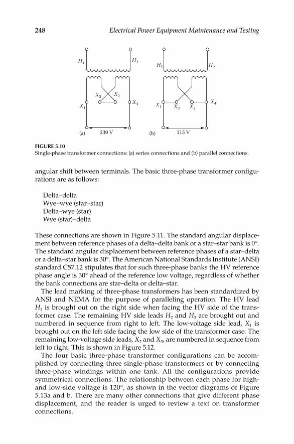
248 Electrical Power Equipment Maintenance and Testing
angular shift between terminals. The basic three-phase transformer confi gu-rations are as follows:
Delta–deltaWye–wye (star–star)Delta–wye (star)Wye (star)–delta
These connections are shown in Figure 5.11. The standard angular displace-ment between reference phases of a delta–delta bank or a star–star bank is 0°. The standard angular displacement between reference phases of a star–delta or a delta–star bank is 30°. The American National Standards Institute (ANSI) standard C57.12 stipulates that for such three-phase banks the HV reference phase angle is 30° ahead of the reference low voltage, regardless of whether the bank connections are star–delta or delta–star.
The lead marking of three-phase transformers has been standardized by ANSI and NEMA for the purpose of paralleling operation. The HV lead H1 is brought out on the right side when facing the HV side of the trans-former case. The remaining HV side leads H2 and H3 are brought out and numbered in sequence from right to left. The low-voltage side lead, X1 is brought out on the left side facing the low side of the transformer case. The remaining low-voltage side leads, X2 and X3, are numbered in sequence from left to right. This is shown in Figure 5.12.
The four basic three-phase transformer confi gurations can be accom-plished by connecting three single-phase transformers or by connecting three-phase windings within one tank. All the confi gurations provide symmetrical connections. The relationship between each phase for high- and low-side voltage is 120°, as shown in the vector diagrams of Figure 5.13a and b. There are many other connections that give different phase displacement, and the reader is urged to review a text on transformer connections.
230 V(a) (b) 115 V
X4 X2X4X1 X3
H1H1 H2 H2
X2X3
X1
FIGURE 5.10Single-phase transformer connections: (a) series connections and (b) parallel connections.
DK4058_C005.indd 248DK4058_C005.indd 248 11/8/2008 11:58:42 AM11/8/2008 11:58:42 AM

Transformers 249
High side Low side Angular displacement
Connections
Delta–Delta
Delta–Wye
0�
0�
30�
30�
Wye Wye
Wye Delta
H1
H2
H3
H1
H1
H1
H2
H2
H2
H3
H3
H3
X1
X1
X1
X1
X3
X3
X3
X3
X2
X2
X2
X2
FIGURE 5.11Three-phase connection and angular displacement.
For parallel operation of single- or three-phase transformers, it is essential that certain conditions be maintained. For example, when placing single-phase transformers in parallel, it is important to have the same voltage ratios and impedances. Similarly, the like polarities of each transformer must be connected together when placing single-phase transformers in parallel. One should be very careful in paralleling transformers, because many problems
DK4058_C005.indd 249DK4058_C005.indd 249 11/8/2008 11:58:42 AM11/8/2008 11:58:42 AM

250 Electrical Power Equipment Maintenance and Testing
can arise if proper consideration is not given to the transformer connections and characteristics. Some of the problems in paralleling transformers that require careful analysis are the following:
Paralleling transformers having different winding connections
Transformers with different impedances or turns ratio or different primary voltages
Transformers of different polarity and phase displacement
The reader is urged to consult a transformer text before paralleling transformers.
5.6 Transformer Characteristics
Most transformers used in industrial and commercial facilities range from 500 to 2500 kVA and are three-phase, liquid-fi lled or dry type located indoors.
H2 H2
H3H3H1
H1
X2X2
X3
X3
X1
X1120� 120�
120�
30�
120�
120�
(a) (b)
FIGURE 5.13Phasor relationship of high- and low-side voltages: (a) delta–delta or wye–wye connection;
(b) delta–wye or wye–delta connection.
H1 H2 H3
X1 X2
X0
X3
FIGURE 5.12Three-phase transformer terminal marking.
DK4058_C005.indd 250DK4058_C005.indd 250 11/8/2008 11:58:42 AM11/8/2008 11:58:42 AM

Transformers 251
These transformers are part of secondary unit substations supplying service to load centers. Transformers used for the distribution of power in plants and buildings have similar characteristics, which have been standardized as follows:
kVA rating: The rating must be adequate to carry the connected load.
Voltage ratings: The voltage rating provides the primary and secondary volt-age to transform electrical energy from primary voltage to secondary voltage. This rating is associated with the winding turns ratios of the primary and secondary windings. Some examples of standard voltage ratings for power transformers are shown in Table 5.1.
Cooling: The type of cooling determines the method of medium used to dissipate heat generated in the transformer. Transformer kVA rating is speci-fi ed based upon the temperature rise allowed for a given transformer.
TABLE 5.1
Three-Phase Transformer Standard Voltage Ratings
High-Side Voltage Low-Side Voltage
Secondary substation
15 kV class insulation 600 V class insulation
13,800 600
13,200 480
12,000 480Y/277
7,200 240
6,900 208Y/120
5 kV class insulation
4,800
4,160
2,400
Primary substations
69 kV class insulation 15 kV class insulation 5 kV class insulation
67,000 14,400 4800
13,800 4360
46 kV class insulation 13,200 4160
43,800 13,090 2520
12,600 2400
12,470
34.5 kV class insulation 12,000
34,400 8,720
26,400 8,320
7,560
7,200
25 kV insulation 6,900
22,900 5,040
DK4058_C005.indd 251DK4058_C005.indd 251 11/8/2008 11:58:43 AM11/8/2008 11:58:43 AM

252 Electrical Power Equipment Maintenance and Testing
Insulation class: The insulation class of a transformer is based upon the nominal voltage levels at which the system voltages and currents are transformed. For example, the ANSI standard C57.12 secondary and primary substation voltage ratings are listed in Table 5.1 for the various insulation-class levels.
Impedance level: The impedance of a transformer can be expressed as an imped-ance drop expressed in percent. This is equal to impedance drop voltage expressed as a percentage of rated terminal voltage. For most power transformers, the imped-ance can be considered equal to the reactance since the resistance component is very small. The NEMA has standardized the impedance values for transformers that are built in accordance with NEMA standards, which are shown in Table 5.2.
Short-circuit conditions: The ANSI standard C57.12 defi nes the short-circuit withstand capability of a transformer as the ability to withstand without- injury short circuits on any external terminals, with rated line voltages
Symmetrical Current Time (s)
25 rated current 2
20 rated current 3
16.6 rated current 4
14.3 rated current 5
TABLE 5.2
NEMA Standard Impedance Values for Transformers
Transformers 500 kVA and above
HV Ratings Low Voltage Rated at 2400 V or
Higher (%)
Low Voltage Rated at
480 or 208 V (%)
2.4–22.9 5.5 5.75
Up to 34.4 6.0 6.25
Up to 69 7.0 6.75
Transformers below 500 kVa
112.5 through 225 kVA: not less than 2%
300 through 500 kVA: not less than 4.5%
maintained on all terminals intended for connection to sources of power. The duration and values of short circuit are limited by ANSI as follows:
Voltage taps: Many power transformers for industrial applications are equipped with voltage ratio tap changers. The tap changer is used to main-tain a constant secondary voltage with variable primary voltage or to control the secondary voltage with a fi xed primary voltage. Usually, most transform-ers will have two 5% taps or four 2.5% taps on the HV side for adjustment to maintain constant secondary voltage.
Sound level: All transformers hum and create noise when they are ener-gized. This noise is generated by vibrations in the laminated core, and the
DK4058_C005.indd 252DK4058_C005.indd 252 11/8/2008 11:58:43 AM11/8/2008 11:58:43 AM

Transformers 253
noise frequency is double the fundamental frequency. The noise level of transformers should be considered during installation in order not to exceed Occupational Safety and Health Administration (OSHA) regulations. Typical ratings for distribution transformers are listed as follows:
Basic impulse insulation level (BIL): BIL is the crest value of the impulse voltage that the transformer is required to withstand without failure. The transformer BIL impulse duration is 1.2 × 50 μs. That is, the impulse reaches its peak value in 1.2 μs and then decays to 50% of its peak value in 50 μs. In addition to full BIL value, transformers are tested for chopped-wave with-stand (115% of BIL) and front-of-the-wave withstand (160% of BIL). These tests are intended to simulate conditions that can occur when transformers are subjected to lightning surges.
5.7 Preventive Maintenance of Transformers
The objective of this section is to outline the recommended work practices that are usually performed for preventive maintenance of transformers. The recommended procedures specifi ed in this chapter do not pertain to the major overhaul and repair of a transformer. However, many tasks performed during routine maintenance and major overhaul of a transformer may be the same. The maintenance practices discussed in this section are applicable to a transformer that has not reached an advanced stage of deterioration. Moreover, these recommendations are written for the average conditions under which the transformer is required to perform and operate. It is further implied that all personnel associated with the maintenance are suitably trained and have experience in the maintenance of transformers.
The recommended practices offered in this section are similar to those that manufacturers recommend for their equipment. If detailed instructions
Audible Sound Levels for Liquid-Immersed Distribution Transformers and Network Transformers
kVA (15 k and Below) Average Sound Level (dB)
0–50 48
51–100 51
101–300 55
301–500 56
750 57
1000 58
1500 60
2000 61
2500 62
Source: NEMA TR1-2000.
DK4058_C005.indd 253DK4058_C005.indd 253 11/8/2008 11:58:43 AM11/8/2008 11:58:43 AM

254 Electrical Power Equipment Maintenance and Testing
are required, the reader should consult the instructions manual of the manufacturer. The preventative maintenance of transformer involves rou-tine inspection, adjustment, testing, minor repairs, and special handling instructions. In addition, the trouble-free operation of the equipment over its life is dependent upon proper installation, operation, and maintenance, which are discussed in Section 5.7.1.
5.7.1 Transformer Installation, Acceptance, and Maintenance
The successful operation of transformers is dependent on proper installation, loading, and maintenance, as well as on proper design and manufacture. As is with all electrical apparatus, neglecting of certain fundamental requirements may lead to serious troubles, if not to the loss of the equipment. The objective of transformer maintenance philosophy can be described as follows:
5.7.1.1 Unscheduled Maintenance
This philosophy is based on reactionary mode of operation. That is to say, maintain the equipment when it breaks down, otherwise leave it alone.
5.7.1.2 Ordinary Maintenance
This philosophy subscribes to making irregular visual inspection and making repairs, adjustments, and replacements as necessary.
5.7.1.3 Protective Maintenance
This philosophy consists of performing preventive maintenance, predictive maintenance, and corrective maintenance. The preventive maintenance involves schedule maintenance and testing on a regular basis. Predictive main-tenance involves additional monitoring and testing, where as corrective maintenance involves repairing and restoring transformer integrity to its origi-nal condition when degraded conditions are discovered.
The objective of the protective maintenance of transformers is to control and prevent severe oil and winding (paper) insulation deterioration. Mineral oil and paper insulation of the winding are affected by moisture, oxygen, heat, and other catalytic agents such as copper, iron, electric stress, and so on. The end result is that oxidation takes place in the oil which leads to sludging of the transformer. In sealed units ingress of moisture via atmo-sphere or seal leaks must be prevented. Moisture will reduce the dielectric strength of both the oil and the winding insulation systems. In addition, excessive heating of the transformer will cause the paper (winding insula-tion) to decompose (accelerate aging) which in-turn produces moisture (i.e., break up of cellulose fi bres results in freeing hydrogen and oxygen atoms which combine to form H2O). Increased moisture formed in the paper
DK4058_C005.indd 254DK4058_C005.indd 254 11/8/2008 11:58:43 AM11/8/2008 11:58:43 AM
Transformers 255
not only reduces the insulating strength of the paper but also, as temperature rises, the moisture will migrate from the paper insulation to the oil and decreasing its dielectric strength.
The fi rst step is to build transformer designs to keep moisture and oxygen out of transformers. The next step is to operate transformers so that they are not operated beyond their temperature ratings and limits. In addition to the above, the severity of deterioration should be controlled by monitoring and testing transformer insulation systems on periodic basis, and take corrective actions to restore transformer to its original condition. This philosophy can be summarized by the following:
1. Control transformer heat
2. Inspect and maintain transformer auxiliary devices
3. Test and maintain transformer insulation systems
4. Maintain transformer bushing insulation
5. Maintain transformer protective coating
These topics are discussed next under installation, maintenance, and testing of transformers. The transformers are divided into dry and liquid types for the purposes of this chapter.
5.7.2 Dry-Type Transformers
5.7.2.1 Installation
Factors that should be kept clearly in mind in locating dry-type transformers are accessibility, ventilation, and atmospheric conditions. Ventilated dry-type transformers (Figure 5.14) normally are designed for application indoors in dry locations. They will operate successfully where the humidity may be high, but under this condition it may be necessary to take precautions to keep them dry if they are shut down for appreciable periods. Locations where there is dripping water should be avoided. If this is not possible, suitable protection should be provided to prevent water from entering the transformer case. Precautions should be taken to guard against accidental entrance of water, such as might occur from an open window, by a break in a water or steam line, or from use of water near the transformers. Adequate ventilation is essential for the proper cooling of transformers. Clean, dry air is desirable. Filtered air may reduce maintenance if the location presents a particular problem. When transformers are installed in vaults or other restricted spaces, suffi cient ven-tilation should be provided to hold the air temperature within established limits when measured near the transformer inlets. This usually will require a minimum of 100 ft3 of air per minute per kilowatt (kW) of transformer loss. The area of ventilating openings required depends on the height of vault. The location of openings, and the maximum loads to be carried by the transform-ers. For self-cooled transformers, the required effective area should be at least
DK4058_C005.indd 255DK4058_C005.indd 255 11/8/2008 11:58:43 AM11/8/2008 11:58:43 AM

256 Electrical Power Equipment Maintenance and Testing
1 ft for each inlet and outlet per 100 kVA of rated transformer capacity, after deduction of the area occupied by screens, gratings, or louvers.
Ventilated dry-type transformers should be installed in locations free from unusual dust-producing mediums or chemical fumes. Transformers above 75 kVA should be located at least 12 in. from walls or other obstructions that might prevent free circulation of air through and around each unit. The dis-tance between adjacent transformers should not be less than this value. Smaller transformers can be mounted directly on the wall but should still be mounted at least 12 in. apart. Also, accessibility for maintenance should be taken into account in locating a transformer. If the transformer is to be located near combustible materials, the minimum separations established by the National Electrical Code (NEC) should be maintained.
The transformer case is designed to prevent the entrance of most small animals and foreign objects. However, in some locations it may be necessary to give consideration to additional protection. In general, a fl at, level indus-trial fl oor is adequate and no special preparation is necessary because of the base construction used on these transformers, which completely eliminates the complicated process of grouting sills into concrete fl oors. If noise is a factor in the location and operation of any transformer, special consideration should be given to the installation of the equipment.
The impulse strength of these transformers is less than that of liquid immersed units of the same voltage class. If there is any likelihood that trans-formers will be exposed to lightning or severe switching surges, adequate protective equipment should be provided.
FIGURE 5.14A 150 kVA ventilated dry-type general purpose transformer with front cover removed to show
core-coil assembly.
DK4058_C005.indd 256DK4058_C005.indd 256 11/8/2008 11:58:43 AM11/8/2008 11:58:43 AM

Transformers 257
Transformers of standard temperature rise are designed to operate at altitudes up to and including 3300 ft. Dry-type transformers are dependent upon air for dissipation of their heat losses; consequently, the effect of decreased air density due to high altitude will increase the transformer tem-perature. Standard transformers can be used at altitudes greater than 3300 ft if the load to be carried is reduced below nameplate rating as follows:
If the transformer is dry type, self-cooled, class AA, reduce the nameplate rating by 0.3% for each 330 ft above the altitude of 3300 ft.
If the transformer is dry type, forced air cooled, class AA/FA, reduce the nameplate rating by 0.5% for each 330 ft above the altitude of 3300 ft.
If the maximum 24 h average temperature of the cooling air is reduced below design levels, the altitude limitation of 3300 ft can be safely exceeded without reducing the nameplate rating of the transformer within the limita-tions of Table 5.3.
5.7.2.2 Inspection
New transformers should be inspected for damage during shipment when received. Examination should be made before removing from cars or trucks, and if any injury is evident or any indication of rough handling is visible, a claim should be fi led with the carrier at once and the manufacturer should be notifi ed.
Subsequently, covers or panels should be removed and an internal inspec-tion made for injury or displacement of parts, loose or broken connections, cracked porcelain, dirt or foreign material, and for the presence of free water or moisture. Corrective measures should be taken where necessary. Shipping braces should be removed if provided. After a transformer is moved, or if it is stored before installation, this inspection should be repeated before placing the transformer in service.
TABLE 5.3
Maximum 24 h Average Temperature of Cooling Air (°C)
AltitudeType of
Apparatus 3300 ft (1000 m) 6600 ft (2000 m) 9900 ft (3000 m) 13,200 ft (4000 m)
Dry-type, class AA
80°C rise
115°C rise 30 26 22 18
150°C rise 30 24 18 12
30 22 15 7
Dry-type, class AA/FA
80°C rise 30 22 14 6
115°C rise 30 18 7 −5
150°C rise 30 15 0 −15
DK4058_C005.indd 257DK4058_C005.indd 257 11/8/2008 11:58:43 AM11/8/2008 11:58:43 AM
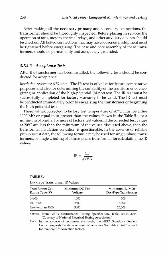
258 Electrical Power Equipment Maintenance and Testing
After making all the necessary primary and secondary connections, the transformer should be thoroughly inspected. Before placing in service, the operation of fans, motors, thermal relays, and other auxiliary devices should be checked. All bolted connections that may have loosened in shipment must be tightened before energizing. The case and core assembly of these trans-formers should be permanently and adequately grounded.
5.7.2.3 Acceptance Tests
After the transformer has been installed, the following tests should be con-ducted for acceptance:
Insulation resistance (IR) test: The IR test is of value for future comparative purposes and also for determining the suitability of the transformer of ener-gizing or application of the high-potential (hi-pot) test. The IR test must be successfully completed for factory warranty to be valid. The IR test must be conducted immediately prior to energizing the transformer or beginning the high potential test.
These values, corrected to factory test temperature of 20°C, must be either 1000 MΩ or equal to or greater than the values shown in the Table 5.4, or a minimum of one half or more of factory test values. If the corrected test values at 20°C are less than the minimum of the values discussed above, then the transformer insulation condition is questionable. In the absence of reliable previous test data, the following formula may be used for single-phase trans-formers, or single winding of a three-phase transformer for calculating the IR values.
=IR
kVA
CE
TABLE 5.4
Dry-Type Transformer IR Values
Transformer Coil
Rating Type (V)
Minimum DC Test
Voltage
Minimum IR (MΩ)
Dry-Type Transformer
0–600 1000 500
601–5000 2500 5,000
Greater than 5000 5000 25,000
Source: From NETA Maintenance Testing Specifi cation, Table 100-5, 2005.
(Courtesy of National Electrical Testing Association.)
Note: In the absence of consensus standards, the NETA Standards Review
Council suggests the above representative values. See Table 2.1 in Chapter 2
for temperature correction factors.
DK4058_C005.indd 258DK4058_C005.indd 258 11/8/2008 11:58:43 AM11/8/2008 11:58:43 AM

Transformers 259
whereIR is the minimum 1 min 500 V DC IR in MΩ from winding to ground,
with other winding or windings guarded, or winding to winding with core guarded
C = 30 at 20°C measurements (C = 16 for tests of winding with other winding or windings grounded)
E is the voltage rating of winding under testkVA is the rated capacity of winding under test
If the transformer under test is of the three-phase type, and all three indi-vidual windings are being tested as one, then:
E is the voltage rating of one of the single-phase windings (phase-to-phase for delta-connected units and phase-to-neutral for star-connected units
kVA is the rated capacity of the three-phase winding under test
Polarization index (PI) test: This is an extension of the IR test. In this test, the two IR measurements are taken, the fi rst reading at 1 min and the second reading at 10 min. Then the ratio of the 10 min reading to 1 min reading is calculated to give the PI dielectric absorption value. A PI of winding-to-winding and winding-to-ground should be deter-mined. A PI below 2 is indicative of insulation deterioration and cause for further investigation.
AC hi-pot (dielectric) test: The dielectric test imposes a stress on the insulation since the dielectric test voltage is higher than the normal operating voltage. The IR test must be successfully completed imme-diately before performing the dielectric test to prevent the possibility of transformer failure due to moisture. The dielectric test supple-ments the IR tests by determining the suitability of the transformer for operation at rated voltage. Field test voltages should not exceed 75% of factory test values. The hi-pot test set must be variable to allow a gradual increase of test voltage from zero and a gradual decrease after the test is completed. These test values are shown in Table 5.5.
Transformer turns ratio (TTR) test: The TTR test is used to determine the turns ratio of the transformer. It measures the number of turns of the primary winding with respect to the number of turns in second-ary winding. The accepted values of the TTR test shall be not greater than 0.5% as compared with calculated values.
Insulation power factor (PF) (dissipation factor) test: This test measures the watt loss in the insulation under test. Since it is an AC voltage test, it accurately indicates the wetness of the winding insulation and corona problems. This test can be conducted as PF tip-up test for dry type transformers to further distinguish between a moisture or car-bonization problem (see Chapter 3).
DK4058_C005.indd 259DK4058_C005.indd 259 11/8/2008 11:58:43 AM11/8/2008 11:58:43 AM

260 Electrical Power Equipment Maintenance and Testing
5.7.2.4 Maintenance
Like other electric equipment, these transformers require maintenance from time to time to assure successful operation. Inspection should be made at regular intervals and corrective measures taken when necessary to assure the most satisfactory service from this equipment. The frequency of inspection depends on operating conditions. For clean, dry locations, an inspection annually, or after a longer period, may be suffi cient. However, for other loca-tions, such as may be encountered where the air is contaminated with dust or chemical fumes, an inspection at 3 or 6 month intervals may be required. Usually, after the fi rst few inspection periods, a defi nite schedule can be set up based on the existing conditions.
With the transformer de-energized, covers over openings in the case should be removed. Inspections should be made for dirt, especially accumulations in insulating surfaces or those which tend to restrict air fl ow, for loose connec-tions, for the condition of tap changers or terminal boards, and for the general condition of the transformer. Observation should be made for signs of over-heating and of voltage creepage over insulating surfaces, as evidenced by tracking or carbonization. Evidence of rusting, corrosion, and deterioration of the paint should be checked and corrective measures taken where necessary. Fans, motors, and other auxiliary devices should be inspected and serviced.
Cleaning: If excessive accumulations of dirt are found on the transformer windings or insulators when the transformer is inspected, the dirt should be removed to permit free circulation of air and to guard against the possibility of insulation breakdowns. Particular attention should be given to cleaning top and bottom ends of winding assemblies and to cleaning out ventilating ducts.
TABLE 5.5
Dielectric Test Value for Acceptance and Periodic Maintenance of Dry-Type Transformers
Transformer, Winding
Rated, AC Voltage (kV)
Factory Test, AC
Voltage (kV)
Acceptance Field
Test, AC Voltage
(75%) (kV)
Maintenance Periodic
Test, AC Voltage
(65%) (kV)
1.2 and below 4 3.0 2.6
2.4 10 7.5 6.5
4.16 12 9.0 7.8
4.8 12 9.0 7.8
6.9 19 14.25 12.35
7.2 19 14.25 12.35
8.32 19 14.25 12.35
12.0 31 23.25 20.15
12.47 31 23.25 20.15
13.2 31 23.25 20.15
13.8 31 23.25 20.15
DK4058_C005.indd 260DK4058_C005.indd 260 11/8/2008 11:58:43 AM11/8/2008 11:58:43 AM

Transformers 261
The windings may be cleaned with a vacuum cleaner, blower, or with compressed air. The use of a vacuum cleaner is preferred as the fi rst step in cleaning, followed by the use of compressed air or nitrogen. The com-pressed air or nitrogen should be clean and dry and should be applied at a relatively low pressure (not over 25 psi). Lead supports, tap changers and terminal boards, bushings, and other major insulating surfaces should be brushed or wiped with a dry cloth. The use of liquid cleaners is undesirable because some of them have a solvent or deteriorating effect on most insu-lating materials.
Testing for routine maintenance: Following are the tests that are required for routine maintenance of dry-type transformers.
IR test of winding-to-winding and winding-to-ground. This test is • similar to the test listed under installation and acceptance.
Dielectric absorption test should be made winding-to-winding and • winding-to-ground for 10 min. The PI should be above 2.0 for accept-able limits.
Turns ratio test (TTR) should be conducted similarly to that under • acceptance.
AC overpotential test should be made on all high- and low-voltage • windings-to-ground. This is an optional test for routine maintenance testing. The recommended values of test voltage are shown in Table 5.4.
Insulation PF test can be conducted for each winding-to-ground and • winding-to-winding. The acceptable value is less than 3%.
5.7.2.5 Drying-Out Methods
For the purpose of drying out, transformers can be considered as consisting of core and coil assembly. When it is necessary to dry out a transformer before installation or after an extended shutdown under relatively high humidity conditions, one of the following methods may be used.
External heat•
Internal heat•
External and internal heat•
Before applying any of these methods, free moisture should be blown or wiped off the windings to reduce the time of the drying period.
Drying by external heat: External heat may be applied to the transformer by one of the following methods:
By directing heated air into the bottom air inlets of the transformer case
DK4058_C005.indd 261DK4058_C005.indd 261 11/8/2008 11:58:44 AM11/8/2008 11:58:44 AM

262 Electrical Power Equipment Maintenance and Testing
By placing the core and coil assembly in a nonfl ammable box with openings at the top and bottom through which heated air can be circulated
By placing the core and coil assembly in a suitably ventilated oven
By placing incandescent lamps in the transformer enclosure
It is important that most of the heated air be blown through the winding ducts and not around the sides. Good ventilation is essential in order that condensation will not take place in the transformer itself or inside the case. A suffi cient quantity of air should be used to assure approximately equal inlet and outlet temperatures.
When using either of the fi rst two external heating methods, heat may be obtained by the use of resistance grids or space heaters. These may either be located inside the case or box or may be placed outside and the heat blown into the bottom of the case or box. The core or coil assembly should be care-fully protected against direct radiation from the heaters. It is recommended that the air temperature should not exceed 110°C.
Drying by internal heat: This method is relatively slow and should not be used if one of the other two methods is available. The transformer should be located to allow free circulation of air through the coils from the bottom to the top of the case. One winding should be short circuited, and suffi cient voltage at normal frequency should be applied to the other winding to circu-late approximately normal current.
It is recommended that the winding temperature not be allowed to exceed 100°C, as measured by resistance or by thermometers placed in the ducts between the windings. The thermometers should be of the spirit type, because mercury thermometers give erroneous readings due to the generation of heat in the mercury as a result of induced eddy currents. The end terminals of the windings (and not the taps) must be used in order to circulate current through the entire winding. Proper precautions should be taken to protect the operator from dangerous voltages.
Drying by external and internal heat: This is a combination of the two meth-ods previously described and is by far the quickest method. The transformer core and coil assembly should be placed in a nonfl ammable box, or kept in its own case if suitable; external heat is applied as described in the fi rst method, and current is circulated through the windings as described in the second method. The current required will be considerably less than when no exter-nal heating is used but should be suffi cient to produce the desired tempera-ture of the windings. It is recommended that the temperatures attained do not exceed those stated in previous two methods. Drying time depends on the condition of the transformer, size, voltage, amount of moisture absorbed, and the method of drying used.
The measurement of IR is of value in determining the status of drying. Measurements should be taken before starting the drying process and at 2 h intervals during drying. The initial value, if taken at ordinary temperatures,
DK4058_C005.indd 262DK4058_C005.indd 262 11/8/2008 11:58:44 AM11/8/2008 11:58:44 AM

Transformers 263
may be high even though the insulation may not be dry. Because IR varies inversely with temperature, the transformer temperature should be kept approximately constant during the drying period to obtain comparative read-ings. As the transformer is heated, the presence of moisture will be evident by the rapid drop in resistance measurement. Following this period the IR will generally increase gradually until near the end of the drying period, when it will increase more rapidly. Sometimes it will rise and fall through a short range before steadying, because moisture in the interior of the insulation is working out through the initially dried portions. A curve with time as abscissa and resistance as ordinate should be plotted and the run should be continued until the resistance levels off and remains relatively constant for 3 to 4 h.
IR measurements should be taken for each winding-to-ground, with all wind-ings grounded except the one being tested. Before taking IR measurements, the current should be interrupted and the winding should be short circuited and grounded for at least 1 min to drain off any static charge. All readings should be for the same time of application of test voltage, preferably 1 min.
Constant attendance during the drying process is desirable. It is advisable to have a suitable fi re extinguisher convenient for use in the event of an emergency.
5.7.2.6 Storage
Ventilated dry-type transformers preferably should be stored in a warm dry location with uniform temperature. Ventilating openings should be covered to keep out dust. If it is necessary to leave a transformer outdoors, it should be thoroughly protected to prevent moisture and foreign material from enter-ing. Condensation and the absorption of moisture can be prevented or greatly reduced by the immediate installation of space heaters or other small electric heaters. If more convenient, incandescent lamps may be substituted for the space heaters. For three-phase transformer rated at 750 kVA and below, use six 150 W lamps; above 750 kVA three phase, use six 300 W lamps or the equivalent. Two lamps should be located under each coil, one on each side of the core. Lamps or heaters should be kept 4–6 in. from transformer coils and should never be allowed to come in contact with transformer coil insulation.
5.7.3 Liquid-Type Transformer
The following guide covers general recommendations for installation and maintenance of liquid-fi lled transformers. Many factors listed for dry-type transformers are also applicable to liquid-fi lled transformers and will not be discussed further.
5.7.3.1 Installation
The transformer should be installed in accordance with National Fire Protection Association (NFPA) Document 70, NEC Article 450. Because of the ban on askarel for use as a transformer insulating fl uid, liquids such
DK4058_C005.indd 263DK4058_C005.indd 263 11/8/2008 11:58:44 AM11/8/2008 11:58:44 AM
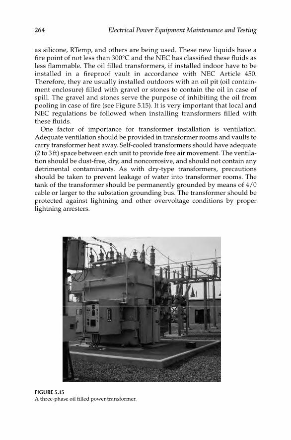
264 Electrical Power Equipment Maintenance and Testing
as silicone, RTemp, and others are being used. These new liquids have a fi re point of not less than 300°C and the NEC has classifi ed these fl uids as less fl ammable. The oil fi lled transformers, if installed indoor have to be installed in a fi reproof vault in accordance with NEC Article 450. Therefore, they are usually installed outdoors with an oil pit (oil contain-ment enclosure) fi lled with gravel or stones to contain the oil in case of spill. The gravel and stones serve the purpose of inhibiting the oil from pooling in case of fi re (see Figure 5.15). It is very important that local and NEC regulations be followed when installing transformers fi lled with these fl uids.
One factor of importance for transformer installation is ventilation. Adequate ventilation should be provided in transformer rooms and vaults to carry transformer heat away. Self-cooled transformers should have adequate (2 to 3 ft) space between each unit to provide free air movement. The ventila-tion should be dust-free, dry, and noncorrosive, and should not contain any detrimental contaminants. As with dry-type transformers, precautions should be taken to prevent leakage of water into transformer rooms. The tank of the transformer should be permanently grounded by means of 4/0 cable or larger to the substation grounding bus. The transformer should be protected against lightning and other overvoltage conditions by proper lightning arresters.
FIGURE 5.15A three-phase oil fi lled power transformer.
DK4058_C005.indd 264DK4058_C005.indd 264 11/8/2008 11:58:44 AM11/8/2008 11:58:44 AM
Transformers 265
5.7.3.2 Inspection
New transformers should be inspected when received for damage during transit. Examination should be made before unloading from the shipping carrier for indication of rough handling and injury to the transformer. After the transformer is removed from the truck or railcar, an internal inspection should be made for displacement of parts, broken or loose connections, dirt or foreign material, and the presence of water or moisture. If oil or transformer fl uid was installed at the factory, check the transformer for leaks. Also check for positive gas pressure if the transformer is equipped with an inert gas. Inspection should include the examination of the transformer case, bushings, anchor and tie rods, grounding straps, drains, covers, valves, and other accessories shipped with the transformer. If internal inspection of the transformer tank is to be conducted, make sure there is enough ventila-tion in the transformer tank before entering the tank. It is essential that there be at least 16% oxygen content before entering the transformer tank. The inspection port cover should not be opened under wet conditions. It is good practice not to expose the transformer liquid to the atmosphere if the relative humidity is above 65%.
5.7.3.3 Acceptance Tests
Before a transformer is energized, it should be given the following tests for acceptance.
IR test: The IR test is valuable for determining if the transformer is in good condition and also to establish a benchmark for future comparative tests. The IR values measured are a function of temperature, whether the coils are immersed in the transformer liquid or not, or whether the windings are cold or hot. The measured values should be corrected to 20°C by multiplying them by correction factors given in Table 2.1 of Chapter 2. The method of measuring IR is by a megohmmeter, commonly called Megger, which indi-cates the IR directly in million of ohms (or megohms). A Megger having a minimum voltage range of Table 5.6 is recommended for the various voltage- rated transformers. In the absence of consensus standards on what consti-tutes a good IR value, the Nation Electrical Testing Association (NETA) sug-gests the values of Table 5.6 be used for acceptance and maintenance testing of transformers.
The measured IR values should be compared to factory test values if avail-able for purposes of evaluating the results. It is advisable to watch for the trend to asses whether the measured values remain stable or are heading downward. Although the measured values may be above the minimum value, a downward trend over a period of time may indicate changes which justify further investigation. In the absence of reliable previous test data, the following formula may be used for single-phase transformers, or single transformer winding of three-phase transformer
DK4058_C005.indd 265DK4058_C005.indd 265 11/8/2008 11:58:44 AM11/8/2008 11:58:44 AM

266 Electrical Power Equipment Maintenance and Testing
IR =
kVA
CE
whereIR is the minimum 1 min 500 V DC IR in megohms from winding-
to-ground, with other winding or windings guarded, or winding-to-winding with core guarded
C = 30 at 20°C measurements (C = 0.8 for tests of winding with other winding or windings grounded)
E is the voltage rating of winding under testkVA is the rated capacity of winding under test
If the transformer under test is of the three-phase type, and all three indi-vidual windings are being tested as one, then:
E is the voltage rating of one of the single-phase windings (phase-to-phase for delta-connected units and phase-to-neutral for star-connected units
kVA is the rated capacity of the three phase winding under test
Insulating liquid dielectric test: The insulating liquid should be sampled in accordance with ASTM D-923 standard and tested for determination of its dielectric strength, acidity, moisture, interfacial tension, color, and PF. These tests are performed to ensure that the insulating liquid has not varied from its established levels or that the dielectric strength has not been lowered through accumulation of contaminants and deterioration. The samples for oil and Rtemp are taken from the bottom of the tank, where as the samples for askarel and silicone are taken from the top of the tank.
TTR: The TTR is performed to ensure that the turns ratio of the trans-former is correct, that is, none of the transformer windings are shorted out. Basically it compares the number of turns in winding 1
TABLE 5.6
Liquid-Filled Transformer IR Values
Minimum IR (MΩ)
Transformer Coil Rating
Type (V)
Minimum DC Test
Voltage
Liquid-Filled
Transformer
0–600 1000 100
601–5000 2500 1000
Greater than 5000 5000 5000
Source: From NETA Maintenance Testing Specifi cation, Table 100-5, 2005. (Courtesy
of National Electrical Testing Association.)
Note: In the absence of consensus standards, the NETA Standards Review Council
suggests the above representative values. See Table 2.1 in Chapter 2 for
temperature correction factors.
DK4058_C005.indd 266DK4058_C005.indd 266 11/8/2008 11:58:44 AM11/8/2008 11:58:44 AM

Transformers 267
with the number of turns in winding 2. The test should be performed for each tap position for transformers equipped with tap changers. The TTR test can also verify the polarity of the transformer. The TTR test value for acceptance should not be greater than 0.5% as com-pared to calculated values (see Section 5.8.2).
Hi-pot test: The hi-pot test (also called the overpotential test) should be made on all high- and low-voltage windings of the transformer to ground. Either AC or DC voltage can be used. However, the accepted practice is to apply either an AC or DC hi-pot test to transformers up to 34 kV. For transformers above 34 kV, only the AC hi-pot test is used. For acceptance of the transformer, the AC hi-pot test can be applied at rated transformer voltage for 3 min. This is a go or no-go test. If the hi-pot voltage is held without any failure or malfunction of the transformer, the transformer is considered to have passed the test (see Section 5.8.1).
PF (dissipation factor) test: This test should be performed on important and/or large transformers. This test stresses the insulation in pro-portion to the stresses produced in normal service because it is an AC voltage test. The PF tests are discussed in great detail in Chapter 3 and the reader is urged to refer it (see Section 3.6.1).
Frequency response analysis (FRA): FRA is performed on large power transformers to assess mechanical properties of the windings and core. The purpose of the test is to detect changes in the physical char-acteristics of the transformer caused by through faults, shipment, repair, or other forces. A voltage signal is applied to the transformer terminals over a wide frequency range and the refl ected response is measured. Various techniques for this test are currently being studied. Even so, FRA is beginning to gain wide acceptance in the industry. Refer to Section 5.8.5 for additional information on FRA.
5.7.3.4 Maintenance
The objective of transformer maintenance is to safeguard against breakdowns by detecting potential causes and eliminating them. Therefore, periodic trans-former maintenance will ensure many years of trouble-free operation. The transformer is a very simple, rugged device and is often ignored and forgot-ten until transformer failure occurs. However, transformers are a vital link in the electrical distribution system and should be given proper care and atten-tion. Transformer maintenance schedules should be determined according to the critical or noncritical nature of the transformer and the load that is connected to it. Large power transformers are obviously more important than small lighting and distribution transformers; thus they warrant more atten-tion and care. Proper maintenance of the transformer should include routine inspection and repair, transformer liquid maintenance and testing, trans-former winding insulation maintenance and testing, and any other special
DK4058_C005.indd 267DK4058_C005.indd 267 11/8/2008 11:58:44 AM11/8/2008 11:58:44 AM

268 Electrical Power Equipment Maintenance and Testing
maintenance that is recommended by the manufacturer of the transformer. A power transformer maintenance and testing guide with recommended frequency is given in Table 5.7.
Routine inspection and repair: Routine inspection and repair of the trans-former involve the visual observation of the operating conditions of the transformer and necessary repair. The frequency of these observations depends upon the critical importance of the transformer, the environmental
TABLE 5.7
Transformer Inspection and Maintenance Checklist
General inspection items Frequency
Load current Hourly or use recording meters
Voltage Hourly or use recording meters
Liquid level Hourly or use recording meters
Temperature Hourly or use recording meters
Protective devices Yearly
Protective alarms Monthly
Ground connections Every 6 months
Tap changer Every 6 months
Lightning arresters Every 6 months
Pressure-relief devices Every 3 months
Breather Monthly
Auxiliary equipment Annually
External inspection Every 6 months
Internal inspection 5 to 10 years
Insulating liquid FrequencyDielectric strength Annually
Color Annually
Neutralization number Annually
Interfacial tension Annually
PF test Annually
Moisture content Annually
Gas-analysis test Annually
Solid insulation (winding) FrequencyIR Annually
PF Annually
FRA Annually
PI Annually
Hi-pot (AC or DC) Five years or more
Induced voltage Five years or more
Polarization recovery voltage Annually
DC winding resistance Annually
DK4058_C005.indd 268DK4058_C005.indd 268 11/8/2008 11:58:44 AM11/8/2008 11:58:44 AM

Transformers 269
conditions, and/or the operating conditions. Various organizations such as the NFPA, NETA, and manufacturers of transformers have published guides for interval of inspection and what to inspect. Following are typical sched-ules for conducting a routine inspection.
Load current: The transformer loading determines the heating of the trans-former. The temperature of the transformer determines its life expectancy, and it is important on large units to monitor load on an hourly basis. For proper loading of transformers, refer to ANSI standard C57.92 for liquid-immersed transformers and ANSI C57.96 for dry-type transformers. For small power transformers, a reading can be taken on a daily or weekly basis.
Voltage: The voltage of the transformer should be monitored similarly to load current. To maintain rated secondary voltage, proper primary voltage would have to be applied. Voltage readings can be taken in conjunction with load current or recording voltmeters can be used. On transformers of lesser importance, voltage readings can be taken on a weekly basis.
Liquid level: Liquid level is important since it not only supplies the cooling medium but also insulates the windings. Liquid loss may occur due to the evaporation of the fl uid or due to leakage. Liquid-level readings can be taken when load readings are being taken. Any liquid lost by the transformer should be replaced promptly.
Temperature: The load-carrying ability of the transformer is dependent upon its thermal capability. The total temperature of the transformer is the sum of the ambient temperature, winding insulation temperature, and hot-spot tem-perature. Normally, the average ambient is 30°C; the temperature rise above ambient for class A insulation is 55°C with a permissible hot-spot rise of an additional 15°C, which then gives a total temperature of 100°C. Any time the transformer is operated above its temperature rating, loss in transformer life can be expected. An 8°C rule or class A insulation and 12°C rule for class B insulation are quoted in the industry for determining the transformer life. In other words, if transformers with class A insulation are operated above their temperature ratings by 8°C, the transformer life can be expected to be cut in half; likewise, operating transformers with class B insulation 12°C above their temperature ratings will cut the transformer life in half. To moni-tor the temperature for large critical transformers, it is recommended that the following readings be taken on a daily basis.
Liquid temperatureAmbient air temperatureWater temperature (for water-cooled transformers)Oil temperature (for forced oil-cooled transformers)
Protective devices: Basic transformer protection is covered by the NEC. This protection is supplemented with additional protective relays and devices.
DK4058_C005.indd 269DK4058_C005.indd 269 11/8/2008 11:58:44 AM11/8/2008 11:58:44 AM
270 Electrical Power Equipment Maintenance and Testing
It is important that protective devices are inspected and maintained on a regular basis to ensure that these devices will operate in case of transformer malfunction or failure. The following protective devices along with other protective devices not listed here should be inspected and maintained on an annual basis.
Overcurrent phase and ground relaysDifferential relaysSudden pressure relaysUnder- and overvoltage relaysAlarm and auxiliary relaysWiring and current-transformer associated with the protective relays
Protective alarms: Transformers come with various types of alarms, such as overtemperature, liquid temperature, and pressure-relief devices. These are usually open-type contacts that can be connected to either alarm or trip the circuit breaker. The alarm contact and associated wiring should be inspected on a monthly basis.
Ground connections: The transformer tank is always solidly grounded to eliminate electric shock per the NEC. The grounding straps for transformer tanks should be checked for loose, broken, or corroded connections. The ground resistance of the substation will depend upon the type and size of the substation. The ground resistance may vary from less than 1 Ω for large-sized substations to 25 Ω for very small-sized substations. The frequency of this inspection and test should be annual.
Lightning arrester: When transformers are supplied from overhead lines, lightning arresters are used to protect the transformer from lightning and other surges. Lightning arresters should be inspected for looseness, broken parts, dirt, and other deposits. All dirt and deposit should be cleaned, loose connections tightened, and broken parts replaced during this check. The inspection of the lightning arrestor and its grounding system should be done annually.
Pressure-relief device: Most sealed transformers are equipped with pres-sure-relief devices to relieve excessive pressure in the tank due to the internal arcing. This device is set to open at a pressure of 10–15 psi. Routine inspection of pressure-relief devices should include checking for leaks around joints, diaphragm cracking, and the like. This inspection should be done quarterly.
Breather: Many transformers have breathers of either the open type or dehy-drating type. The function of the dehydrating agent is to prevent moisture from entering the transformer tank. Most dehydrating breathers contain silica gel, which will change from blue when dry to pale pink when wet. Inspection can be made through a glass window provided for the purpose. The breathers should be checked monthly and the dehydrating agent replaced or reconditioned if found restrictive or wet.
DK4058_C005.indd 270DK4058_C005.indd 270 11/8/2008 11:58:44 AM11/8/2008 11:58:44 AM

Transformers 271
Auxiliary equipment: Auxiliary equipment required for cooling, such as fans. oil pumps, control devices, and wiring, should be checked on an annual basis. The equipment should be cleaned and damaged parts replaced.
External inspection: The transformer should be given an external inspec-tion on a semiannual basis. The inspection should include checking the tank, radiators, auxiliary equipment, gasket leakage, and metal parts for corrosion. Also, the electrical connection should be checked for tightness and overheating. Transformer bushings should be checked for mechanical damage, cleanness, and leakage. Bushings should be wiped clean on a regu-lar basis to minimize fl ashovers.
Internal inspection: This inspection involves the internal investigation of the tank and core. On liquid-fi lled transformers, the covers can be removed to examine for evidence of moisture or rust around the bushing supports and transformer top cover. To examine the tank and core, the liquid can be drained out. Examination of the core should be made to check for sludge deposits, loose connections, and any damage to the transformer parts. Evidence of carbon may indicate internal problems. The winding inspection should be checked for damage to terminal panels, barriers, loose connec-tions, and overall connection of the winding. Obviously, such things as untanking the transformer for internal inspection would have to be judi-ciously made and would depend on the age of the transformer and its over-loading and trouble history. The frequency of this inspection should be 5 to 10 years or more.
Transformer fl uid: All transformer fl uids are subject to deterioration, and the main contaminants are air, moisture, and heat. These contaminants react with transformer fl uid and produce acids and sludge. The acid, in turn, attacks the winding insulation, and sludge deposits tend to decrease cool-ing. Moisture in the transformer fl uid tends to lower the dielectric strength of the fl uid, which combined with sludge, will lower the fl ashover value of insulators and terminal boards inside the transformer tank. As discussed earlier, regular inspection of the transformer is needed to maintain the fl uid in a contaminant-free state. For proper maintenance of insulating fl uids refer to Chapter 4.
5.7.3.5 Drying-Out Methods
Similar to dry-type transformers, the liquid insulating transformer can be considered as consisting of core and coil assembly, except that the assembly is immersed in an insulating fl uid. Elaborate measures are taken to prevent and detect the infi ltration and increase of moisture con-tent in the transformer. Before the transformer liquid becomes saturated with water, the paper insulation of the winding in a transformer has already absorbed a concentration of moisture because of its great affi nity for water. The water in the paper insulation accelerates the degradation of the insulation and lowers its electrical integrity.
DK4058_C005.indd 271DK4058_C005.indd 271 11/8/2008 11:58:45 AM11/8/2008 11:58:45 AM
272 Electrical Power Equipment Maintenance and Testing
We have discussed in the previous sections several tests to judge the dryness of the transformer, such as IR, PI, and PF. One simple method for detecting the water content in the transformer oil can be made by an approximate method known as the cloud test. It consists of cooling a test tube sample of oil in an ice bath. If a cloud appears in the test tube above 0°C, the transformer contains excessive moisture. Confi rmation of the water content in the transformer can be made by a laboratory test.
The distribution of moisture in the transformer is always in a state of unequilibrium. Through the cooler range of temperatures, the solid insulation of the transformer winding will tend to absorb more moisture than the trans-former liquid. However, as the transformer is loaded, the rise in winding tem-perature will release this moisture. This change due to varying loads and temperature is constant, regardless of whether there is an excess of water or only a very small quantity of moisture in the transformer. Also, transformer liquids such as oil tend to hold more water with an increase in temperature. In other words, there will be more moisture in the transformer oil when it is carrying a load than when it is unloaded. Other factors, such as decomposition of paper insulation and contaminants, will tend to generate more moisture in the trans-former liquid. When it becomes necessary to dry out liquid transformers, the following methods can be used: (1) heat alone, or (2) heat followed by vacuum.
Heat alone: This method involves application of heat to the transformer alone. One form of heat application is oven drying, which can be done at any of the service shops of major manufacturers. When the transformer is oven dried in the service shop, it is important to monitor the winding resistance to see when the transformer, reaches oven temperature (100°C–120°C). PF and IR measurements should be made at about 6 h intervals to see when drying is achieved, that is, when at least four readings are of the same value.
Heat followed by vacuum: The heating of the transformer with liquid can be performed by applying short circuit to the transformer or by circulating hot oil by means of an external system. As in the previous method, PF and IR measurement should be made at about 6 h intervals. Completed drying is indicated by at least four readings that are the same. The fi eld drying methods may involve heating the transformer liquid, removing the liquid, and immediately applying high vacuum. Another method may involve removing the liquid and heating the transformer by circulation of hot air. Once the winding reaches 90°C–100°C a high vacuum of about 0.5 Torr is applied. When the temperature drops below 50°C, drying is stopped. The normal length of time to apply heat and vacuum may be a week or more, depending on the size of the transformer. Once the transformer is dried and the vacuum pulled, clean transformer liquid can be introduced into the transformer. Precautions to observe during this process are as follows:
Before the vacuum is pulled, make sure the tank is braced for full vacuum
The air temperature for drying should not exceed 100°C
DK4058_C005.indd 272DK4058_C005.indd 272 11/8/2008 11:58:45 AM11/8/2008 11:58:45 AM

Transformers 273
If new undried coils are used for replacement purposes, the coil clamps should be checked after drying is complete since shrinkage may occur during drying.
When drying is performed on an energized transformer, precautions should be taken to prevent formation of bubbles during the degassing phase. Otherwise, immediate failure may occur.
The transformer liquid level should be carefully watched because uninten-tional lowering of transformer liquid level may cause a transformer failure.
5.7.3.6 Storage
Transformers should be stored in a safe, dry, ventilated location with uniform temperature. In locations where no controls for uniform temperature exist, condensation and absorption of water can be minimized by installation of space heaters or incandescent lamps.
Because of new regulations on the use, disposal, and storage of askarel, transformers using askarel as an insulating liquid will require special storage facilities. The reader is urged to consult regulations put out by the EPA.
5.7.3.7 Transformer Diagnostic Guide
For troubleshooting purposes, a diagnostic guide and causes of transformer failures (Table 5.8) are provided. This information is by no means complete, and the reader is urged to check and test for the problem and its cause. Refer to Section 1.8.2 for failure modes of transformers. In general, the following conditions will cause the troubles indicated:
Overtemperature: Overtemperature can be caused by an overcurrent, over-voltage, insuffi cient cooling, low liquid level, sludge in the transformer liquid, high ambient, or short-circuited core. In dry-type transformers, this condition can be due to clogged ducts.
Winding insulation failure: This is an electrical fault in the transformer winding insulation where it can involve phase-to-ground, phase-to-phase, three-phase and/or ground, or turn-to-turn-type short circuit. The causes for this type of failure may be due to a short-circuit fault, lightning, overload or overcurrent condition, or transformer liquid containing moisture and contaminants.
Incorrect secondary voltage: This condition can be due to improper turns ratio, abnormal primary voltage, and/or shorted turns in the transformer.
Bushing failure: Bushing failure can be caused by fl ashover due to dirt accu-mulation and/or lightning strikes.
Internal arcing: Internal arcing can be caused by low liquid level exposing live parts of the transformer, loose connections, or failure of the transformer dielec-tric. Usually, internal arcing can become audible and cause radio interference.
Core failure: This condition is due to the failure of core laminations, core, bolts, clamps, and so on.
DK4058_C005.indd 273DK4058_C005.indd 273 11/8/2008 11:58:45 AM11/8/2008 11:58:45 AM
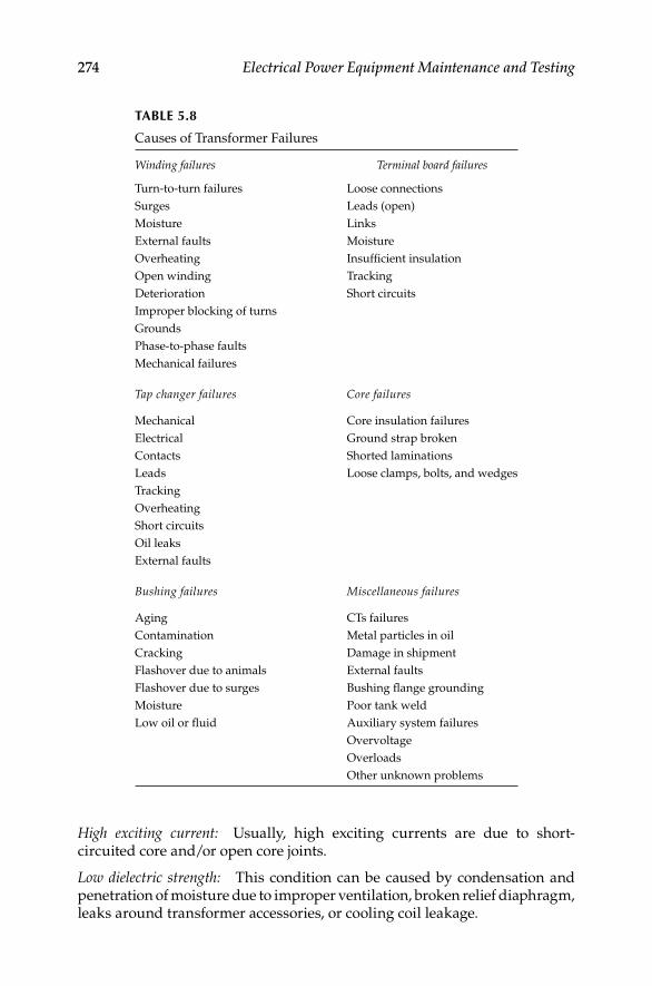
274 Electrical Power Equipment Maintenance and Testing
High exciting current: Usually, high exciting currents are due to short-circuited core and/or open core joints.
Low dielectric strength: This condition can be caused by condensation and penetration of moisture due to improper ventilation, broken relief diaphragm, leaks around transformer accessories, or cooling coil leakage.
TABLE 5.8
Causes of Transformer Failures
Winding failures Terminal board failures
Turn-to-turn failures Loose connections
Surges Leads (open)
Moisture Links
External faults Moisture
Overheating Insuffi cient insulation
Open winding Tracking
Deterioration Short circuits
Improper blocking of turns
Grounds
Phase-to-phase faults
Mechanical failures
Tap changer failures Core failures
Mechanical Core insulation failures
Electrical Ground strap broken
Contacts Shorted laminations
Leads Loose clamps, bolts, and wedges
Tracking
Overheating
Short circuits
Oil leaks
External faults
Bushing failures Miscellaneous failures
Aging CTs failures
Contamination Metal particles in oil
Cracking Damage in shipment
Flashover due to animals External faults
Flashover due to surges Bushing fl ange grounding
Moisture Poor tank weld
Low oil or fl uid Auxiliary system failures
Overvoltage
Overloads
Other unknown problems
DK4058_C005.indd 274DK4058_C005.indd 274 11/8/2008 11:58:45 AM11/8/2008 11:58:45 AM

Transformers 275
Oxidation of oil: Oxidation usually results in the formation of acids and sludge in the transformer liquid. It is mainly due to exposure to air and high operating temperatures.
Pressure-relief diaphragm broken: This is due to an internal fault causing excessive internal pressures or the transformer liquid level being too high or excessive internal pressure due to loading of transformer.
Discoloration of transformer liquid: Discoloration is mainly caused by carbon-ization of the liquid due to switching, core failure, or contaminations.
Leakage of transformer liquid: Leakage can occur through screw joints, around gaskets, welds, casting, pressure-relief device, and so on. The main causes are improper assembly of mechanical parts, improper fi lters, poor joints, improper fi nishing of surfaces, defects in the material used, or insuffi cient tightness of mechanical parts.
Moisture condensation: The main causes for moisture condensation are improper ventilation in open-type transformers and a cracked diaphragm or leaking gaskets in sealed-type transformer.
Gas-sealed transformer troubles: In gas-sealed transformers, additional prob-lems can be the loss of gas, oxygen content above 5%, or gas regulator mal-functions. These problems are caused by gas leaks above the oil, leaky valve seats, insuffi cient gas space, and/or insuffi cient fl ushing of gas space with nitrogen.
Transformer switching equipment troubles: Many transformers are equipped with tap chargers and other switching equipment. The problems associated with these transformers may be excessive wearing of contacts, mechanism overtravel, moisture condensation in mechanism liquid, and others. Excessive contact wear is due to loss of contact pressure from weakened springs or a contact-making voltmeter set at too narrow a bandwidth or insuffi cient time delay. Mechanism overtravel usually is due to defective or improper adjustment of controller contacts. Moisture condensation is due to improper ventilation, and carbonization is due to excessive operation and lack of fi ltering. Other problems such as control fuse blowing and mechanism motor stalling are due to short circuits in the control circuit, mechanical binding, or low-voltage conditions in the control circuitry.
5.8 Transformer Testing
Transformers may be tested with AC or DC voltage. Overall, AC voltage is preferable to DC voltage for testing transformers because AC voltage simu-lates the internal stress that the transformers experience during operating conditions.
DK4058_C005.indd 275DK4058_C005.indd 275 11/8/2008 11:58:45 AM11/8/2008 11:58:45 AM

276 Electrical Power Equipment Maintenance and Testing
The following tests are routinely conducted in the fi eld on the transformer:
IR testAC or DC hi-pot test (optional)Insulation PF testTTR testPolarity testExcitation current testInduced potential test (optional)Insulating fl uid dielectric testsDissolved gas analysis (DGA) testsPolarization recovery voltage testTransformer core ground testFrequency response analyzer (FRA)/sweep FRA (SFRA)DC winding resistance
The IR and DC hi-pot tests are discussed in Chapter 2; the PF and excitation tests are discussed in Chapter 3; the transformer insulating fl uid and dis-solved gas tests are discussed in Chapter 4; and the remaining tests listed above are discussed next.
5.8.1 AC Hi-Pot Test
The AC hi-pot test is applied to evaluate the condition of transformer wind-ings. This test is recommended for all voltages, especially those above 34.5 kV. For routine maintenance testing of transformers, the test voltage should not exceed 65% of factory test voltage. However, the hi-pot test for routine maintenance is generally not employed on transformers because of the possibility of damage to the winding insulation. This test is commonly used for acceptance testing or after repair testing of transformers. The AC HV test value should not exceed 75% of the factory test value. When AC hi-pot testing is to be used for routine maintenance, the transformer can be tested at rated voltage for 3 min instead of testing at 65% of factory test voltage. The AC hi-pot test values for voltage systems up to 69 kV are shown in Table 5.9. Testing procedures and test connections are similar to the DC hi-pot tests described in Chapter 2.
5.8.2 TTR Test
The TTR test applies voltage to one winding of a transformer and detects the voltage being generated on another winding on the same core.
In the case of a low voltage hand-crank powered TTR, 8 V AC is applied to the low-voltage winding of the transformer under test and a reference transformer in the TTR set. The HV windings of the transformer under test and the TTR reference transformer are connected through a null detecting instrument. After polarity has been established at 8 V, when the null reading is zero, the dial readings indicate the ratio of the transformer under test.
DK4058_C005.indd 276DK4058_C005.indd 276 11/8/2008 11:58:45 AM11/8/2008 11:58:45 AM

Transformers 277
In the case of an electronic TTR test set, a voltage (typically 80 V AC) is applied to the HV winding of the transformer under test. The voltage gener-ated on the low-voltage winding is measured and the voltage ratio between high and low windings is calculated. Voltage ratio is proportionally equal to turns ratio. The hand-crank powered TTR, the handheld electronic TTR, and the three-phase electronic TTR are shown in Figure 5.16a through c, respectively.
The TTR test provides the following information:
It determines the turns ratio and polarity of single- and three-phase • transformers, one phase at a time.
It confi rms nameplate ratio, polarity, and vectors.•
It determines the ratio and polarity (but not voltage rating) of • transformers without markings. Tests include all no-load tap positions on a transformer. Tests include all load taps on load, tap changer (LTC) transformers if connected for voltage ratio control. On LTC trans-formers connected for phase angle control, ratio and polarity are per-formed in neutral positions only. If tested on load taps, readings may be taken for reference for future comparison, but will deviate from nameplate ratings. LTC taps may be confi rmed by application of low three-phase voltage and reading volts and the phase angle for each.
Identify trouble in transformer windings, such as open-circuit and • short-circuits of turn-to-turn sensitivity. The standard deviation as defi ned by ANSI/IEEE C57.12.00-2006, Section 9.1 states that results should be within 0.5% of nameplate markings, with rated voltage applied to one winding. The TTR with accuracy of 0.1% is accepted as a referee.
TABLE 5.9
AC Dielectric Test for Acceptance and Routine Maintenancefor Liquid-Filled Transformers
Transformer Winding
Rated Voltage (kV)
Factory Test AC
Voltage (kV)
Acceptance Field Test
AC Voltage, 75% (kV)
Maintenance Periodic
Test, 65% (kV)
1.20 10 7.50 6.50
2.40 15 11.20 9.75
4.80 19 14.25 12.35
8.70 26 19.50 16.90
15.00 34 25.50 22.10
18.00 40 30.00 26.00
25.00 50 37.50 32.50
34.50 70 52.50 45.50
46.00 95 71.25 61.75
69.00 140 105.00 91.00
DK4058_C005.indd 277DK4058_C005.indd 277 11/8/2008 11:58:45 AM11/8/2008 11:58:45 AM

278 Electrical Power Equipment Maintenance and Testing
The following procedures are used for conducting the TTR test:
Transformer is isolated and tagged and leads disconnectedRead transformer nameplateObserve the polarities and vectors (phasors)Calculate ratios for each no-load and load tap position
Set up data test form as follows:Make the null check, zero ratio check, and unity ratio check on the hand-
crank TTR.
(a) (b)
(c)
FIGURE 5.16TTR testers: (a) hand-crank TTR; (b) handheld electronic TTR; and (c) three-phase electronic
TTR. (Courtesy of Megger Inc., Valley Forge, PA.)
DK4058_C005.indd 278DK4058_C005.indd 278 11/8/2008 11:58:45 AM11/8/2008 11:58:45 AM
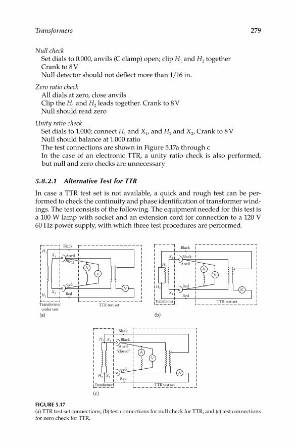
Transformers 279
Null checkSet dials to 0.000, anvils (C clamp) open; clip H1 and H2 togetherCrank to 8 VNull detector should not defl ect more than 1/16 in.
Zero ratio checkAll dials at zero, close anvilsClip the H1 and H2 leads together. Crank to 8 VNull should read zero
Unity ratio checkSet dials to 1.000; connect H1 and X1, and H2 and X2, Crank to 8 VNull should balance at 1.000 ratioThe test connections are shown in Figure 5.17a through cIn the case of an electronic TTR, a unity ratio check is also performed,
but null and zero checks are unnecessary
5.8.2.1 Alternative Test for TTR
In case a TTR test set is not available, a quick and rough test can be per-formed to check the continuity and phase identifi cation of transformer wind-ings. The test consists of the following. The equipment needed for this test is a 100 W lamp with socket and an extension cord for connection to a 120 V 60 Hz power supply, with which three test procedures are performed.
FIGURE 5.17(a) TTR test set connections; (b) test connections for null check for TTR; and (c) test connections
for zero check for TTR.
Black
Black
Red
Anvil
Anvil
Anvil“closed”
Red
(a) (b)
(c)
Red
Red
Red
Red
Black
Black
Black
Black
Transformerunder test
Transformer
Transformer
TTR test setTTR test set
TTR test set
N N
N
V
VA
AAV
H1
H2
H2
H2
H2
H1
X1
X2
X1
X1
X1
X2
DK4058_C005.indd 279DK4058_C005.indd 279 11/8/2008 11:58:46 AM11/8/2008 11:58:46 AM

280 Electrical Power Equipment Maintenance and Testing
Test 1: Connect the 120 V, 60 Hz power through the lamp to the trans-former primary, terminals as shown in Figure 5.18a. Leave the transformer secondary winding open. The lamp will burn dimly.
Test 2: Maintain connections as described in test 1, but now short the secondary winding. The lamp should burn with great brilliance. If the lamp still burns with somewhat less than full brilliance, inves-tigate for problems in the transformer winding. Connections for this test are shown in Figure 5.18b.
Test 3: This test is similar to tests 1 and 2, but as applied to a three-phase transformer for phase identifi cation and phase continuity check. Conduct tests 1 and 2 for each winding of a three-phase trans-former individually with the remaining windings left open. The test connections are shown in Figure 5.18c.
5.8.2.2 TTR Capacitor
The TTR test may be performed at higher voltages using a capacitor in combination with the PF test set. With the addition of the TTR capacitor,
H1
H2120 V60 Hz
(a)
100W
X2
X1
H1
H3
H2120 V60 Hz
(b)
100W
X2
X1
H1
H2120 V60 Hz
(c)
100W
X3
X2
X1
X0
FIGURE 5.18(a and b) Continuity check for transformer winding; (c) continuity and phase check for three-
winding transformer.
DK4058_C005.indd 280DK4058_C005.indd 280 11/8/2008 11:58:46 AM11/8/2008 11:58:46 AM

Transformers 281
the Doble’s PF test set M4100 (discussed in Chapter 3) can measure the turns ratio of power transformers at potentials up to 10 kV. Using the capacitor in place of the standard TTR test set, allows a higher test voltage, up to 10 kV, to be applied to the primary winding. Most TTR test sets are limited to less than 100 V which greatly reduces the voltage on the secondary windings. The benefi ts of the HV TTR tests are that it identifi es problems and anomalies in the electric and magnetic circuit (i.e., core and coils) of the transformer that are not revealed with the low-voltage TTR tests.
5.8.3 Polarity Test
The polarity test can be performed with the TTR on power, distribution, and potential transformers. However, for current transformers the TTR test is not used. Instead a test commonly known as the kick test, consisting of applying a DC battery and multimeter is used. The kick test can also be used for power distribution, and potential transformers; however, the TTR test is preferred. The connections for a kick test for a current transformer are shown in Figure 5.19. The DC battery voltage is usually about 7.5 V, and the multimeter volt-age range is set for 3 V full-scale. The negative terminal of the battery is con-nected to current transformer terminal H2 and the positive side is left hanging for the time being. The multimeter positive terminal is connected to the trans-former secondary terminal X1 and negative terminal to X2. To conduct the test, touch the positive side battery jumper to transformer terminal H1 and notice the multimeter scale indication, if the multimeter scale kick is up scale, the transformer is connected in subtractive polarity. If the kick is down scale, it is connected in additive polarity.
5.8.4 Induced Potential Test
The induced potential test is a proof test and performed at higher voltage levels than normal operating voltages. Under this test, turn-to-turn insulation and phase-to-phase insulation are stressed at 65% of factory test voltage at higher frequency than 60 Hz, such as 200–300 Hz. The frequency of conduct-ing this test should be 5 years or more for large transformers.
The induced potential test for transformers which receive the full standard applied potential test is made by applying between the terminals of one
X2
Multimeter
−ve
+ve
H2
H1X1
FIGURE 5.19Polarity check using the kick method.
DK4058_C005.indd 281DK4058_C005.indd 281 11/8/2008 11:58:46 AM11/8/2008 11:58:46 AM

282 Electrical Power Equipment Maintenance and Testing
winding a voltage of twice the normal voltage developed in the windings. It is applied for 7200 cycles, and the duration should not exceed 60 s.
As the induced potential test overexcites the transformer, the frequency of the applied potential should be high enough to prevent the exciting current of the transformer under test from exceeding about 30% of its rated load current. Ordinarily this requirement necessitates the use of a frequency of 120 Hz or more, when testing 60 Hz units.
When frequencies higher than 120 Hz are used, the severity of the test is abnormally increased and for this reason the duration of the test should be reduced as shown in Table 5.10.
The voltage should be started at one-quarter or less of the full value and be brought up gradually to full value in not more than 15 s. After being held for the time specifi ed in Table 5.10, it should be reduced slowly (in not more than 5 s) to one-quarter of the maximum value or less, and the circuit opened.
When transformers have one winding grounded for operation on a grounded-neutral system, special care should be taken to avoid high electro-static stresses between the other windings and ground.
In the case of transformers having one end of the HV winding grounded during the induced potential test, the ground on each winding may be made at a selected point of the winding itself or of the winding of a step-up transformer which is used to supply the voltage or which is merely connected for the purpose of furnishing the ground.
Three-phase transformers may be tested with single-phase voltage. The specifi ed test voltage is induced, successively, from each line terminal to ground and to adjacent line terminals. The neutrals of the windings may or may not be held at ground potential during these tests.
When the induced test on the winding results in a voltage between termi-nals of other windings in excess of the low-frequency test voltage specifi ed, the other windings may be sectionalized and grounded. Additional induced tests should then be made to give the required test voltage between termi-nals of windings that were sectionalized.
5.8.5 FRA
The FRA test may be performed as an impulse response or as a SFRA test. The impulse method estimates the frequency response whereas sweep
TABLE 5.10
Frequency versus Duration of Test
Frequency (Hz) Duration (s)
120 and less 60
180 40
240 30
300 20
400 18
DK4058_C005.indd 282DK4058_C005.indd 282 11/8/2008 11:58:47 AM11/8/2008 11:58:47 AM

Transformers 283
frequency response method measures the response over a range of frequencies of interest. Both the FRA and SFRA methods are nondestructive tests used to detect if deformation (displacement) of core and coils has taken place. Sweep frequency response is a major advance in transformer condition analysis, allowing visualization of the inside of the transformer’s tank without costly detanking. The standard defi nition of FRA is the ratio of a steady sinusoidal output from a test object subjected to a steady sinusoidal input. SFRA is a proven technique for making accurate and repeatable measurements. There is a direct relationship between the geometric confi guration of the winding and core, and the series and parallel impedance network of inductance, capacitance, and resistance. This network can be identifi ed by its frequency-dependent transfer function.
FRA testing by the sweep frequency response method uses network analysis tools to determine the transfer function. Changes in the geometric confi guration alter the impedance network, and in turn alter the transfer function. This enables a wide range of failure modes to be identifi ed. Analysis of SFRA test results relies, in part, on comparison between phases and against previous test results. Commonality between transformers of the same design is also expected. The SFRA tests are actually a series of many tests over a band of frequencies from 20 Hz to 2 MHz. The SFRA test results can be referred to as traces that are shown on a graph. The x-axis of the graphs is the test frequency and the y-axis is the magnitude in decibels (db). These traces show the ratio of the output voltage to the input voltage of the transformer circuit under test at each of the frequencies. It has been shown that these traces are a signature that is related to the distributed resistance, inductance, and capacitance (RLC) of the components within the transformer. They should follow certain general shapes and favorable comparisons should exist among the phases of a transformer, with previous test results, and among transformers of identical design. The fi rst, or benchmark, traces also provide a valuable tool to identify winding movement in the future.
As compared to the “impulse” technique, SFRA is preferred for frequency domain measurements. It covers the full dynamic range and maintains the same energy level for each frequency, providing accurate, consistent results. A high signal-to-noise ratio across the entire 20 Hz to 2 MHz frequency range ensures valid measurements. Sweep frequency response analyzers (Figure 5.20) detect mechanical failure or movement of windings due to short circuits, mechan-ical stresses, or transportation. These tests are used to ensure transformer perfor-mance, reduce maintenance cost, and increase service life. System faults, short circuits, aging, or even handling during transportation can compromise a transformer’s mechanical structure. Since these problems are diffi cult to detect, they usually go unnoticed and worsen over time, leading to loss of per-formance and possibly failure. Until recently, the options for dealing with these critical problems were limited. If such damage was suspected in a transformer, the options were limited. These problems could be ignored and hope for the best, or detank the transformer to make a costly and time-consuming visual inspection. Even that might not reveal the damage.
DK4058_C005.indd 283DK4058_C005.indd 283 11/8/2008 11:58:47 AM11/8/2008 11:58:47 AM
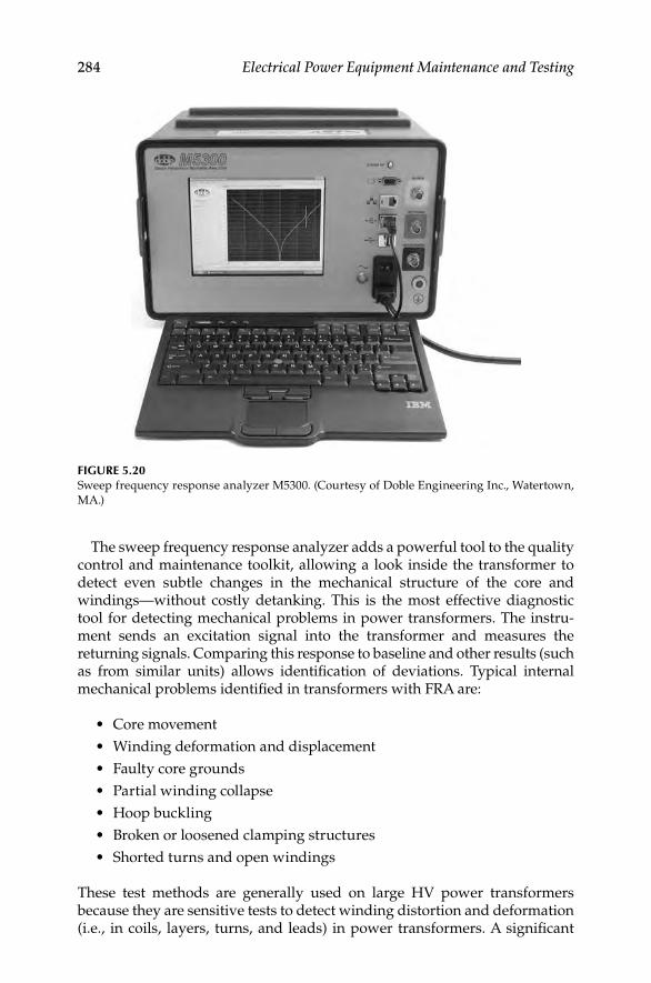
284 Electrical Power Equipment Maintenance and Testing
The sweep frequency response analyzer adds a powerful tool to the quality control and maintenance toolkit, allowing a look inside the transformer to detect even subtle changes in the mechanical structure of the core and windings—without costly detanking. This is the most effective diagnostic tool for detecting mechanical problems in power transformers. The instru-ment sends an excitation signal into the transformer and measures the returning signals. Comparing this response to baseline and other results (such as from similar units) allows identifi cation of deviations. Typical internal mechanical problems identifi ed in transformers with FRA are:
Core movement•
Winding deformation and displacement•
Faulty core grounds•
Partial winding collapse•
Hoop buckling•
Broken or loosened clamping structures•
Shorted turns and open windings•
These test methods are generally used on large HV power transformers because they are sensitive tests to detect winding distortion and deformation (i.e., in coils, layers, turns, and leads) in power transformers. A signifi cant
FIGURE 5.20Sweep frequency response analyzer M5300. (Courtesy of Doble Engineering Inc., Watertown,
MA.)
DK4058_C005.indd 284DK4058_C005.indd 284 11/8/2008 11:58:47 AM11/8/2008 11:58:47 AM

Transformers 285
amount of deformation can occur in the windings as a result of high through fault currents which can go undetected before an actual failure occurs. The voltage stress changes in the winding insulation structure after the onset of initial winding deformation. Over time the winding deformation will lead to partial discharges and gassing. However, by the time partial discharge and subsequent gassing appear degradation of the transformer has already occurred. Winding deformation is one of the fi rst and fundamental precur-sors to indicate a degraded condition in the transformer windings. The FRA tests are performed at the factory and also in the fi eld on transformers off-line. The results are compared to determine if changes have occurred in the transformer. Specialized test equipment is required to perform FRA or SFRA tests. In general, the procedure requires the transformer to be de-energized and isolated. Each individual phase of every winding is tested. One set of tests is done by injecting the signal at one end of the winding and measuring the other end. Another test is done by injecting the signal at one end of a primary winding and measuring the corresponding secondary winding.
5.8.6 DC Winding Resistance
This test measures the DC resistance of the transformer leads and windings and is made with a low-resistance ohmmeter or a Kelvin bridge. Winding resis-tance will change due to shorted turns, loose connections, or deteriorating con-tacts in tap changers. One of the problems associated with measuring the DC resistance of a transformer is the inductive circuit that must be energized. The inductance must be charged and stabilized in order to allow an accurate read-ing to be made. Special low-resistance ohmmeters are available specifi cally for the purpose of performing this test. A low-resistance ohmmeter specifi cally made for measuring transformers winding resistance is shown in Figure 5.21.
FIGURE 5.21Low-resistance transformer ohmmeter. (Courtesy of Megger Inc., Valley Forge, PA.)
DK4058_C005.indd 285DK4058_C005.indd 285 11/8/2008 11:58:47 AM11/8/2008 11:58:47 AM

286 Electrical Power Equipment Maintenance and Testing
The test procedure for measuring DC winding resistance requires the trans-former to be de-energized and isolated. Both the primary and secondary ter-minals should be isolated from external connections, and measurements made on each phase of all windings. The measured resistance should be corrected to a common temperature such as 75°C or 85°C using the following formula:
⎛ ⎞⎜ ⎟⎜ ⎟⎝ ⎠
×=C M
CF + CT
CF +WTR R
whereRC is the corrected resistanceRM is the measured resistanceCF is the correction factor for copper (234.5) or aluminum (225) windingsCT is the corrected temperature (75°C or 85°C)WT is the winding temperature (°C) at time of test
Measurements should be made on all tap changer positions (if present) and compared to previous or factory test values. The test values after temperature correction should be compared with the factory test values or previous years’ test results for evaluating the condition of the transformer windings and leads. The acceptance criteria for the fi eld-measured values after temperature correction should be within 2% of the factory values. A change greater than the acceptance criteria is indicative of short-circuited turns, poor joints, or bad tap changer contacts. This test should be performed during acceptance testing and when other maintenance electrical tests are conducted.
5.8.7 Transformer Core Ground Test
An IR measurement is made to determine the presence of unintentional core grounds. In general, the laminated cores of power transformers are insu-lated from ground, and intentionally grounded at a single point. Typically this grounding point can be accessed at the top of the transformer, either externally at a small bushing or internally behind a manhole cover.
Unintentional core grounds can develop due to shipping damage, though faults, or deterioration of core insulation. Any of these factors can cause exces-sive localized heating through circulating currents in the core and surrounding structure, leading to the generation of specifi c gases in the insulating oil.
The procedure for the test requires the transformer to be de-energized and isolated. The intentional core ground connection is lifted and the DC IR test is made between the core connection and the grounded transformer enclo-sure. Acceptable readings are 100 MΩ or greater. An IR tester (megohmmeter or Megger) for performing this test is shown in Figure 5.22.
5.8.8 Polarization Recovery Voltage Test
The transformer insulation systems are composites of two insulating materials: cellulose fi ber (paper) and insulating oil. This structure shows
DK4058_C005.indd 286DK4058_C005.indd 286 11/8/2008 11:58:49 AM11/8/2008 11:58:49 AM
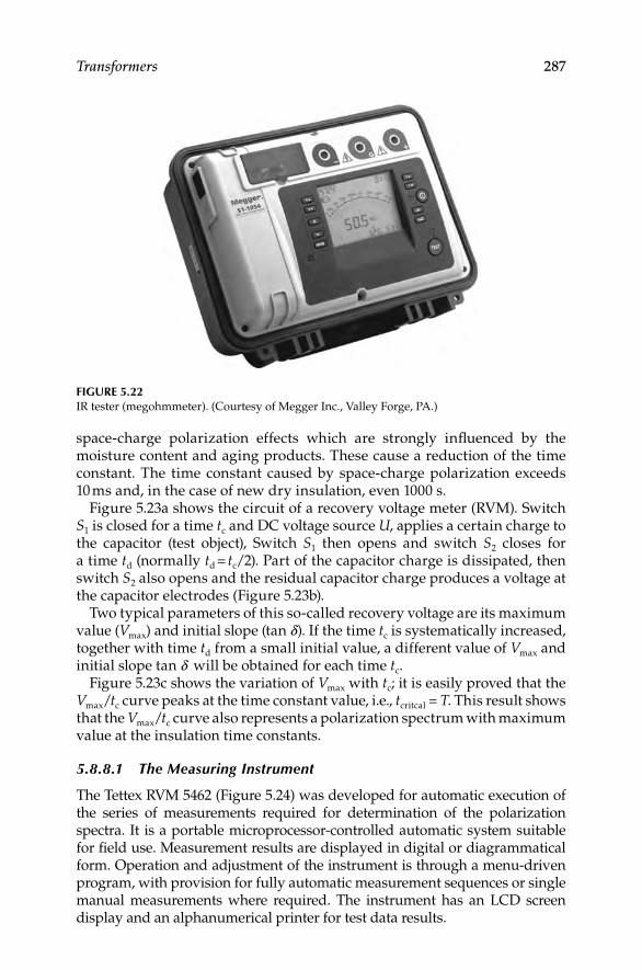
Transformers 287
FIGURE 5.22IR tester (megohmmeter). (Courtesy of Megger Inc., Valley Forge, PA.)
space-charge polarization effects which are strongly infl uenced by the moisture content and aging products. These cause a reduction of the time constant. The time constant caused by space-charge polarization exceeds 10 ms and, in the case of new dry insulation, even 1000 s.
Figure 5.23a shows the circuit of a recovery voltage meter (RVM). Switch S1 is closed for a time tc and DC voltage source U, applies a certain charge to the capacitor (test object), Switch S1 then opens and switch S2 closes for a time td (normally td = tc/2). Part of the capacitor charge is dissipated, then switch S2 also opens and the residual capacitor charge produces a voltage at the capacitor electrodes (Figure 5.23b).
Two typical parameters of this so-called recovery voltage are its maximum value (Vmax) and initial slope (tan d). If the time tc is systematically increased, together with time td from a small initial value, a different value of Vmax and initial slope tan d will be obtained for each time tc.
Figure 5.23c shows the variation of Vmax with tc; it is easily proved that the Vmax/tc curve peaks at the time constant value, i.e., tcritcal = T. This result shows that the Vmax/tc curve also represents a polarization spectrum with maximum value at the insulation time constants.
5.8.8.1 The Measuring Instrument
The Tettex RVM 5462 (Figure 5.24) was developed for automatic execution of the series of measurements required for determination of the polarization spectra. It is a portable microprocessor-controlled automatic system suitable for fi eld use. Measurement results are displayed in digital or diagrammatical form. Operation and adjustment of the instrument is through a menu-driven program, with provision for fully automatic measurement sequences or single manual measurements where required. The instrument has an LCD screen display and an alphanumerical printer for test data results.
DK4058_C005.indd 287DK4058_C005.indd 287 11/8/2008 11:58:49 AM11/8/2008 11:58:49 AM
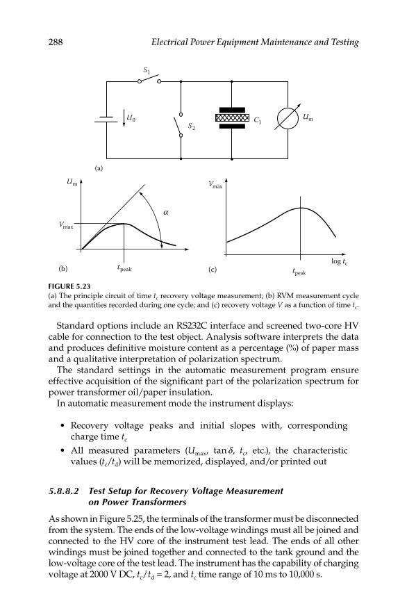
288 Electrical Power Equipment Maintenance and Testing
FIGURE 5.23(a) The principle circuit of time tc recovery voltage measurement; (b) RVM measurement cycle
and the quantities recorded during one cycle; and (c) recovery voltage V as a function of time tc.
S2
S1
C1U0 Um
(a)
Um
tpeak
aVmax
(b) tpeak
Vmax
log tc(c)
Standard options include an RS232C interface and screened two-core HV cable for connection to the test object. Analysis software interprets the data and produces defi nitive moisture content as a percentage (%) of paper mass and a qualitative interpretation of polarization spectrum.
The standard settings in the automatic measurement program ensure effective acquisition of the signifi cant part of the polarization spectrum for power transformer oil/paper insulation.
In automatic measurement mode the instrument displays:
Recovery voltage peaks and initial slopes with, corresponding • charge time tc
All measured parameters (• Umax, tan d, tc, etc.), the characteristic values (tc/td) will be memorized, displayed, and/or printed out
5.8.8.2 Test Setup for Recovery Voltage Measurementon Power Transformers
As shown in Figure 5.25, the terminals of the transformer must be disconnected from the system. The ends of the low-voltage windings must all be joined and connected to the HV core of the instrument test lead. The ends of all other windings must be joined together and connected to the tank ground and the low-voltage core of the test lead. The instrument has the capability of charging voltage at 2000 V DC, tc/td = 2, and tc time range of 10 ms to 10,000 s.
DK4058_C005.indd 288DK4058_C005.indd 288 11/8/2008 11:58:49 AM11/8/2008 11:58:49 AM

Transformers 289
FIGURE 5.24Recovery voltage meter RVM 5462. (Courtesy of Haefely Technology/Tettex Instruments,
Basel, Switzerland.)
FIGURE 5.25Test setup of RVM on a power transformer.
Test object
Test cable
Type 5462RVM
DK4058_C005.indd 289DK4058_C005.indd 289 11/8/2008 11:58:49 AM11/8/2008 11:58:49 AM

290 Electrical Power Equipment Maintenance and Testing
5.8.8.3 Evaluation of Measured Polarization Spectra
The electrical properties and reliability of the oil/paper insulation used on most power transformers depend very heavily on the state (aging and mois-ture content) of the oil and, even more so, on that of the paper. Oil state is fairly easily assessed by conventional oil sample analysis methods such as Karl-Fischer moisture measurement, PF, etc., but these provide very little information on the state of the paper insulation.
As will be seen from the following examples, the state of oil-impregnated paper can be ascertained directly from the polarization spectrum without any need to take and analyze an oil sample.
Figure 5.26 shows spectra measured at constant temperature on oil-impregnated paper insulation laboratory models.
The curves in Figure 5.26a show spectra recorded at varying moisture content on the insulation model. Figure 5.26b shows similar curves obtained under artifi cial aging of varying duration.
1000
Vr (V)
T (s)(a) Temperature: 25�C
4% 3%2%
100
0.01 0.1 1 10 100 1000
10
1
New2000 h
4000 h
1000
100
0.01 0.1 1 10 100 1000
10
1
Vr (V)
T (s)(b) Aging on 120�C
FIGURE 5.26Polarization spectral curves relative to (a) moisture at 25°C and (b) aging at 120°C.
DK4058_C005.indd 290DK4058_C005.indd 290 11/8/2008 11:58:50 AM11/8/2008 11:58:50 AM

Transformers 291
These curves clearly show that the behavior of the spectrum (especially displacement of the curve peak toward small time constants) closely refl ects changes of state, i.e., degradation of the dielectric, i.e., oil/paper insulation.
5.9 Online Condition Monitoring of Transformers
Power transformers are critical and costly assets in the electric power system beginning with the grid, transmission, and down to the plant. They are one of the most important electric apparatus for providing reliable energy fl ow. As an asset class, transformers constitute one of the largest investments in a util-ity’s system or in an industrial complex. For this reason transformer condition assessment and management is a high priority. Each entity is unique and investment levels in asset condition and assessment management varies according to risk level and investment return models. While the models are different for each entity, the common element in them is that transformers are stratifi ed according to the criticality of individual transformers. The variability and uniqueness lies in where the prioritization lines are drawn and the invest-ment amounts allocated for condition monitoring for each level. Typically this approach has the most critical transformers receiving the highest investment of condition assessment and management tools and less-critical or noncritical transformers receiving decreasing level of asset allocations.
A simplifi ed model below shows one approach to transformer condition management:
Critical: Those transformers that, if failed, would have a large negative impact on grid stability, utility revenue, and service reliability of the critical facility. For example, generator step-up transformers (GSU) and transmis-sion transformers that are part of critical power fl ows fall in this level, or the main transformers in a critical facility.
Important: Those transformers that, if failed, would have a signifi cant negative impact on revenue and service reliability of a utility system, or the production of the plant. Transmission substation transformers and major dis-tribution substation transformers are generally in this level.
Recoverable: Those transformers that, if failed, would have low impact on revenue and reliability or the production of the plant. These are mainly smaller distribution substation transformers.
Transformer reliability is more important today than was in the past. Transformers do not last as long they used to in the past. In the United States, the average life of a transformer is 40 years, and many transformers installed in the 1960s and 1970s are now approaching the end of their design life. Higher loads placed on transformers, in a market that demands more electricity, have also taken their toll on transformer longevity. Because of consolidation and
DK4058_C005.indd 291DK4058_C005.indd 291 11/8/2008 11:58:50 AM11/8/2008 11:58:50 AM

292 Electrical Power Equipment Maintenance and Testing
deregulation of the electric industry, the budgets for maintenance and condition monitoring have been reduced. Therefore, the need to more closely manage transformer assets becomes even more important these days. Utility and plant managers by choosing the appropriate transformer condition moni-toring tools can avoid unplanned failures, lower maintenance costs, and defer capital expenditures in replacement cost. Condition management is all about choosing the right monitoring tools for transformers.
5.9.1 Online Monitoring of Transformers
There are several online monitoring systems that can be used for continuously assessing the condition of large important and critical power transformers. The online monitoring systems that are available on the market are DGA, PF monitoring of bushing, leakage current monitoring of lightening arrestors, and FRA of transformer windings. The bushing and lightening arrestors are externally mounted auxiliaries on a transformer therefore they are more sus-ceptible to varying environmental conditions. A failure in the bushing or light-ening arrestor of a transformer is a failure of the transformer. As discussed earlier, the online testing offers yet another management tool for condition monitoring and assessment of the most critical and important transformers.
DGA: The DGA is one of the many tests that are used in monitoring the health of oil-fi lled power transformers. The off-line DGA tests are discussed in Chapter 4. The off-line DGA tests have been traditionally carried out using labo-ratory DGA analysis performed at periodic intervals, such as on quarterly, semi-annually, or yearly basis. DGA of transformer oil is the single best indicator of overall condition of the transformer and is carried out without taking it out of service. This is a universal practice today that got started in earnest in the 1960s. The following is a brief summary of the evolution of the practice of DGA.
While laboratory or portable DGA is the traditional practice, the use of online DGA tools has gained in popularity. The reason for this is the need for utilities to maintain or improve their reliability in the presence of decreased capital expenditures and an aging infrastructure. Something more than periodic laboratory or portable DGA is needed to be successful in the current environment and the two approaches (online DGA and laboratory DGA) now coexist at many utilities. Online DGA helps utilities avoid unplanned failures, adopt lower cost condition-based maintenance, and defer capital expenditures by extending the transformer’s useful life.
First generation products (1970s), as well as some current online DGA prod-ucts available today, provided total combustible gas (TCG) or single gas (hydro-gen) monitoring. These products provide indication of developing problems in the transformer but offer no legitimate diagnostic capability. Online DGA offer-ings in the market have evolved from this early approach to include multigas monitors that detect and analyze some or all of the eight fault gases identifi ed in the IEEE standards as well as provide diagnostic capability.
Newer online DGA products have the unique ability to continuously trend multiple transformer gases and correlate them with other key parameters such as
DK4058_C005.indd 292DK4058_C005.indd 292 11/8/2008 11:58:50 AM11/8/2008 11:58:50 AM

Transformers 293
transformer load, oil, and ambient temperatures as well as customer-specifi ed sensor inputs. This capability enables utilities to relate gassing to external events, a key to meeting utility reliability and fi nancial goals in the current environment. In fact, some online DGA tools may offer better accuracy and repeatability than laboratory DGA. This can improve the transformer asset manager’s decision timeliness and confi dence when incipient faults are detected.
With the advent of online DGA monitoring, there has also been new learn-ing about the nature of developing faults in transformers. Online DGA mon-itoring has produced multiple case studies that document the development of critical faults, which could cause catastrophic transformer failure if left undetected, in timeframes from a few days to a few weeks. There is a low probability of capturing these rapidly developing fault conditions with a laboratory or portable-based transformer DGA testing program.
Recently, the ability to automatically supplement traditional DGA diagnostic tests with online DGA tests is available in the market. This new development offers users of online DGA monitors unprecedented insight into the nature and identifi cation of developing faults. The tools are typically ratio-based and the online data set enables trending of fault gas ratios over time rather than the traditional static snapshots. Diagnostic outcomes can now be determined quickly and with more certainty than in the past. Neural network diagnostic approaches utilizing DGA data are also new to the market and promise more accurate diagnoses but have not yet been included in industry standards.
One of the online tools that have recently become available for condition monitoring of transformers is the online DGA, such as Siemens Gas Guard 8 and TMDS 2000 L shown in Figures 5.27 and 5.28, respectively. The Gas Guard 8 is a self-contained fully automated closed-loop gas chromatograph designed to be mounted on or near the subject transformer. Through chro-matography the Gas Guard 8 generates individual measurements of each of the eight critical fault gases (hydrogen, nitrogen, carbon monoxide, carbon dioxide, methane, ethane, ethylene, and acetylene) found in transformer oil. The accuracy of the measurements are commensurate with what one would expect to receive from a traditional laboratory.
The TDMS 2000 L DGA monitoring system allows condition assessment data to be incorporated into the confi guration of alarms and recommended loading to mitigate the risk of failure while preserving operation. Although no system, including the TMDS 2000 L, can guarantee avoidance of failure, the TMDS 2000 L can utilize the results of fi eld-based condition assessments and advanced monitoring and diagnostic technology to provide a compre-hensive tool to support any asset management strategy. The TMDS 2000 system provides contextual information on maintenance activity to address abnormal operation, on potentially related or causal relationships between transformer components and the alarmed condition, reduces time consum-ing data analysis and delivers statistically relevant abnormal operating data and alarm conditions.
The following discussion provides some of the decision criteria for employing online DGA monitors.
DK4058_C005.indd 293DK4058_C005.indd 293 11/8/2008 11:58:50 AM11/8/2008 11:58:50 AM
294 Electrical Power Equipment Maintenance and Testing
Legacy transformer monitoringand diagnostic system
Hot spotBushing monitor and load
Bottom oil temp
Fan and coolingefficiency
Moisture in oil8 dissolved gas monitorAmbient air tempTop oil tempBuchholz gas accumulator
FIGURE 5.28The TDMS 2000 L diagnostic system for monitoring transformer. (Courtesy of Siemens USA
Corp., Atlanta, GA.)
FIGURE 5.27Gas Guard 8 monitor. (Courtesy of Siemens USA Corp., Atlanta, GA.)
Selecting online DGA tools: The last few years have seen a new array of DGA tools enter the market and this poses challenges for utility and plant managers to understand and choose an approach that best meets their needs. Transformer asset managers have important decisions to make based
DK4058_C005.indd 294DK4058_C005.indd 294 11/8/2008 11:58:50 AM11/8/2008 11:58:50 AM
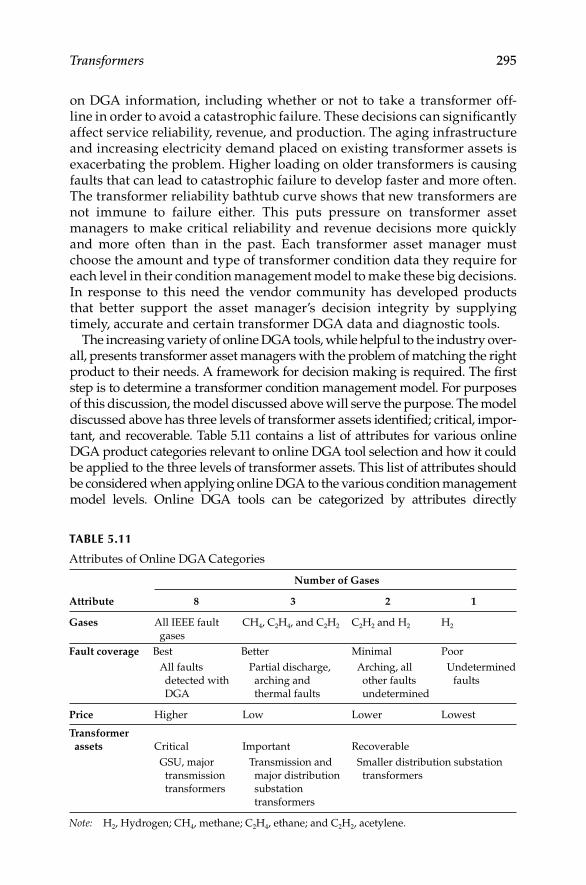
Transformers 295
on DGA information, including whether or not to take a transformer off-line in order to avoid a catastrophic failure. These decisions can signifi cantly affect service reliability, revenue, and production. The aging infrastructure and increasing electricity demand placed on existing transformer assets is exacerbating the problem. Higher loading on older transformers is causing faults that can lead to catastrophic failure to develop faster and more often. The transformer reliability bathtub curve shows that new transformers are not immune to failure either. This puts pressure on transformer asset managers to make critical reliability and revenue decisions more quickly and more often than in the past. Each transformer asset manager must choose the amount and type of transformer condition data they require for each level in their condition management model to make these big decisions. In response to this need the vendor community has developed products that better support the asset manager’s decision integrity by supplying timely, accurate and certain transformer DGA data and diagnostic tools.
The increasing variety of online DGA tools, while helpful to the industry over-all, presents transformer asset managers with the problem of matching the right product to their needs. A framework for decision making is required. The fi rst step is to determine a transformer condition management model. For purposes of this discussion, the model discussed above will serve the purpose. The model discussed above has three levels of transformer assets identifi ed; critical, impor-tant, and recoverable. Table 5.11 contains a list of attributes for various online DGA product categories relevant to online DGA tool selection and how it could be applied to the three levels of transformer assets. This list of attributes should be considered when applying online DGA to the various condition management model levels. Online DGA tools can be categorized by attributes directly
TABLE 5.11
Attributes of Online DGA Categories
Attribute
Number of Gases
8 3 2 1
Gases All IEEE fault
gases
CH4, C2H4, and C2H2 C2H2 and H2 H2
Fault coverage Best Better Minimal Poor
All faults
detected with
DGA
Partial discharge,
arching and
thermal faults
Arching, all
other faults
undetermined
Undetermined
faults
Price Higher Low Lower Lowest
Transformer
assets Critical Important Recoverable
GSU, major
transmission
transformers
Transmission and
major distribution
substation
transformers
Smaller distribution substation
transformers
Note: H2, Hydrogen; CH4, methane; C2H4, ethane; and C2H2, acetylene.
DK4058_C005.indd 295DK4058_C005.indd 295 11/8/2008 11:58:50 AM11/8/2008 11:58:50 AM

296 Electrical Power Equipment Maintenance and Testing
resulting from the number of gases measured. Most modern online DGA tools offer the ability to measure other parameters such as moisture-in-oil. These other parameters are not included in the table as they are common for most.
Diagnostics: Fault coverage and diagnostics capabilities are the critical attributes that transformer asset managers should consider when choosing online DGA tools for the various levels in their stratifi cation models. Price is also a consideration, but the relative value of the solution, as defi ned by the fault coverage and diagnostic capabilities, is the more important measure. In other words, some solutions may have a higher price, but the value provided (through superior transformer condition knowledge) in terms of improved utility service reliability and revenue far outweighs the higher price.
The selection of online DGA tools for each level of transformer assets identi-fi ed refl ects the approach of making the highest investment in online DGA tools for the most critical transformers and less investment in tools for lower levels in the stratifi cation model. Notice that this approach utilizes the online DGA tools with the most fault coverage and diagnostics for the critical and important transformers in the fl eet. Utilities will fi nd more appropriate returns on investment for their critical and important transformers with online DGA tools that offer good fault coverage and diagnostics capability rather than with the lowest cost, poor fault coverage tools that lack diagnostic support.
The current environment of higher loading on aging transformers, deferred capital expenditures as well as increased service reliability requirements sug-gests that transformer asset managers should take advantage of the improved online DGA offerings (i.e., better fault coverage and diagnostics) in the market to get the best protection for its biggest asset class—at all levels. Appropriate online DGA monitoring and diagnostic tools will help utilities avoid unplanned failures, lower maintenance costs, and extend transformer useful life.
5.10 Online Monitoring of Bushings
and Lightning Arrestors
The deterioration of oil and paper insulation in HV equipment is a matter of continuous concern. Normal aging of HV equipment is a slow process that takes place over 30–40 years due to thermal, electrical, and environmental effects. With regard to transformer bushings, the most common type of bush-ing failure occurs due to a failure in the internal bushing capacitive layers. These failures occur slowly over time with one layer slowly failing and burn-ing through the kraft paper. A failed capacitive (condenser) bushing is shown in Figure 5.29. Premature failure on the other hand is often a relatively sudden process that is not detected by periodic off-line tests discussed in Sections 3.6.2 and 3.6.5 in Chapter 3. The use of the Scherring bridge technique using the voltage is very responsive to type of condition, and can detect these mil-livolt level changes. The millivolt level changes are far too small for an off-line test to detect and react to it in the early stages of failure. This prompted
DK4058_C005.indd 296DK4058_C005.indd 296 11/8/2008 11:58:50 AM11/8/2008 11:58:50 AM

Transformers 297
the need for continuous online insulation condition monitoring to manage the risk of premature bushing failures and to initiate maintenance procedures based on the condition of the bushing insulation.
The On-Line Monitoring Corporation has developed PF Live Plus system for online PF (tan d) testing of transformer bushings and lightening arres-tors while the transformer remains energized. The PF calculation in the PF Live Plus system is based on the conventional Schering bridge used in labo-ratories. Data is acquired under software control from transducers con-nected to the bushing PF/capacitive tap associated with a transformer and then the data is compared to data from another electrical phase to produce a PF value. Damaged or deteriorated dielectric is associated with increased dielectric losses (I2R) with other sources of heating that may eventually fuel a mechanism of thermal runaway. The eventual breakdown of insulation is a rapid avalanche of failing dielectric layers. PF is a measure of dielectric losses, partial discharges, and treeing. High levels of partial discharge are refl ected in the PF and are usually only present just after lightning or switching impulses and just before and during insulation failure.
The PF Live Plus is a continuous online monitoring system, for monitoring PF in HV capacitive bushings, and is now available with an optional leakage current monitor for HV lightning arresters. The system includes a minimum set of three sensors permanently connected to a series of capacitive bushing taps, or lightning arresters. It is based on the fi eld proven SOS Tan Delta system. The system is capable of monitoring up to 32 direct-connected sensors, and up to 256 wireless sensors. The system acquires, analyzes, and trends data pertain-ing to AC insulation PF of bushings and/or HV current transformers, and leak-age current of lightning arresters. The PF Live Plus system can also interface to signals from other devices, or IED’s, such as: temperature sensors, DGA, or any 0–10 V DC, 10 V peak, 4–20 mA, or 0–1 mA signal, providing a single point access of transformer mounted sensors. Data can be downloaded on-site, or remotely. The concept of measuring PF is based on the derivation of the phase shift between two voltage signals. The method is similar to the standard bridge
FIGURE 5.29A failed capacitive (condenser) bushing. (Courtesy of On-Line Monitoring Corp., Exton, PA.)
DK4058_C005.indd 297DK4058_C005.indd 297 11/8/2008 11:58:50 AM11/8/2008 11:58:50 AM

298 Electrical Power Equipment Maintenance and Testing
methods, but software is used for angle difference determination. The measure-ment of PF of insulation is accepted as part of well-established laboratory testing procedures to determine the quality of insulation at the factory before commis-sioning new and refurbished HV equipment. PF as a parameter is by nature a relatively slow-changing value and is an integral characteristic depending on
Design, materials, and production technology•
Operating voltages and temperatures•
Aging of insulation related to design and operating conditions such • as overvoltages, loading conditions, etc.
Climatic/weather-related phenomenon•
The system calculates the PF of a unit as a relative value compared with a ref-erence voltage from another unit in service, thereby eliminating the need for a standard capacitor. The reference device does not have to be associated with the same phase since PF Live Plus will automatically make the proper phase angle adjustments. Relative measurements and evaluation can reduce the effect of infl uences such as ambient temperature, operating voltages, loading conditions, different aging characteristics, different designs, operating condi-tions, etc. The system uses a principle of cross-referencing units in a closed loop to confi rm all measurements and increase the confi dence of isolating a defective unit. Because the system uses relative measurements, the minimum number of units to be monitored is three. All measurements are tested for integrity against three parameters: rms and mean of the signal, and the PF value calculated. Only measurements passing the integrity tests are stored in the database. The default monitoring period is once every 5 min. This setting can be changed from once a minute, to once per day. The sensors are confi g-ured into the graphical user interface by the user during installation. Each monitored device is entered into the database with an acquisition channel number, and descriptive text. The condition of each monitored device is dis-played on the monitor screen.
FRA: The off-line FRA test is discussed in Section 5.8.5. Recently, the National Electric Energy Testing, Research and Application Center (NEETRAC) has developed a method to perform this test while the transformer is in service. Online FRA data can provide an up-to-date condition assessment of large, essential transformers. Online FRA provides yet another tool to analyze the physical structure of the coils and their dielectric surroundings while the transformer remains in service. NEETRAC’s online FRA method uses normal system-switching operations, such as capacitor bank and reactor operations, along with lightning from local thunderstorms for the FRA test-signal source. NEETRAC’s patented technology can perform FRA signatures on transformer windings using a variety of input waveforms with different time and amplitude characteristics.
DK4058_C005.indd 298DK4058_C005.indd 298 11/8/2008 11:58:51 AM11/8/2008 11:58:51 AM

299
6Cables and Accessories
6.1 Introduction
The generation, transmission, and distribution of power involve electrical facilities, apparatus, and components to carry the electrical energy from its generating site to where it is utilized. An important part of this power system is the medium-voltage cable system that is used exclusively to carry power from the main substation to secondary substations at load centers. Low-voltage cable is used to distribute power from the load centers in conduits and ducts, even though other methods such as cable trays, direct burial for outdoor applications, and aerial cable are used. Electrical, mechanical, and environmental considerations are the main factors in selecting and applying cable systems for distribution and utilization of electrical power. The splices and terminations of medium-voltage cables or connections of different type of cables (such as aluminum and copper) require careful consideration and evaluation during installation, as well as throughout their service life. Correct installation and preventive maintenance of cable systems will assure contin-ued electrical power service.
6.2 Cable Construction and Classification
It is diffi cult to select and apply cables to power systems without some knowl-edge of the cable insulation system and of cable components. Therefore, it is important to review some basic considerations and fundamentals of cables for their application to power systems. The following materials are presently used for cables.
Copper conductorThe copper material used in the manufacture of cable is pure electrolytic copper, which has 100% conductivity. This means that a wire 1 ft long and one circular mil (1/1000 of in.) in cross-sectional area has a resistance of 10.371 Ω at 20°C. Tinning of copper is also required for many rubber and rubber-like insulation compounds to prevent corrosion of copper due to the sulfur that is used in the vulcanizing process.
DK4058_C006.indd 299DK4058_C006.indd 299 11/8/2008 12:41:09 PM11/8/2008 12:41:09 PM

300 Electrical Power Equipment Maintenance and Testing
Aluminum conductorAluminum conductors are made from 99% pure aluminum, which has a conductivity of 61%. Normally, three-fourths aluminum is used for construc-tion of aluminum conductors. Three-fourths hard drawn aluminum has strength of 17,000–22,000 psi. Some of the disadvantages of aluminum are low conductivity; high resistance of aluminum oxide, which forms very rap-idly when aluminum is exposed to air; cold fl ow characteristics; and galvanic action when connected to dissimilar materials.
6.2.1 Types of Conductors
The following types of conductors are in use in power distribution systems.
Solid conductors: Normally, solid conductors are available up to size 6 American wire gauge (AWG). However, they can be made available up to size 4/0 AWG.
Stranded conductor: Most systems use concentric stranding for the applications discussed here.
Overhead cable conductorsThe strandings available for this application are type AA and A confi ned to bare conductors.
Power cable conductorsThe concentric stranding is most commonly used for power cable conduc-tors. The construction of concentric-type cable consists of a central core sur-rounded by one or more layers of helically applied wires. The fi rst layer has six wires and each subsequent layer has six more wires than the preceding layer. In this type of cable construction, the core consists of single wire and all of the strands have the same diameter. The fi rst layer over the core con-tains 6 wires, the second contains 12 wires, the third 18, and so on. The fol-lowing types of strandings are used in this application.
Class B: This class of stranding is used exclusively for industrial power cables for application in 600 V, 5 kV, and 15 kV power systems. The cable stranding usually consists of 7 (#2 AWG), 19 (#4/0 AWG), 37 (500 kcmil), or 61 (750 kcmil) strands.
Classes C and D: These classes are used where a more fl exible cable is required. Class C uses 19, 37, 61, or 91 strands and class D uses 37, 61, 91, or 127 strands for the #2 AWG, #4/0 AWG, 500 kcmil, and 750 kcmil cable construction, respectively.
Classes G and H: These classes are used to provide more fl exible cable than class D. Classes G and H are also known by rope or bunch stranding. Class G uses 133 strands and class H uses 259 strands for cable construction. Examples of cables in these classes are welding and portable wire for special apparatus or large cables.
DK4058_C006.indd 300DK4058_C006.indd 300 11/8/2008 12:41:09 PM11/8/2008 12:41:09 PM

Cables and Accessories 301
Utility-type cableCables used for utility systems are of somewhat specialized construction. Some of these are as follows:
Compact strand (compact round): This type of construction allows for smaller diameter and less weight than solid conductor.
Annular: This construction uses a hollow space or rope core in the center of the cable.
Segmental: Consists of four segments stranded together and operated in parallel.
Concentric cable: Consists of an inner and outer conductor with equiv-alent cross sections, which are separated by insulation.
Sector: A multiconductor cable in which the conductor is shaped like a sector in a circle.
6.2.2 Conductor Arrangement
Conductors may be arranged in various ways to form a cable. The common arrangements used in power system applications are the following:
Single-conductor cable: A single conductor of either shielded or nonshielded construction.
Three-conductor cable: Three single conductors bound together with a nonmetallic tape. Three-conductor cables may also be bound together by interlocking galvanized steel, aluminum, or bronze tape. This type of cable is known as interlocked armor cable. Three-conductor cables may come with ground wires, which are used for system ground or equipment ground. Ground wires are usually located in the interstices of the three-conductor cable. Three-conductor cable can be either shielded or nonshielded.
6.2.3 Cable Types
Power cables are classifi ed with respect to insulation as follows:
Laminated type: This type of cable uses paper, varnished cambric, polypropylene, or other types of tape insulation material. Insulation formed in layers, typically from tapes of paper or other materials or combination of them. An example of this type of cable is the paper-insulated lead-covered (PILC) cable.
Extruded type: This type of cable uses rubber and rubber-like compounds, such as polyethylene (PE), cross-linked polyethylene (XLPE), ethylene propylene rubber (EPR), etc., applied using an extrusion process for the insulation system.
DK4058_C006.indd 301DK4058_C006.indd 301 11/8/2008 12:41:09 PM11/8/2008 12:41:09 PM

302 Electrical Power Equipment Maintenance and Testing
6.2.4 Insulations
The 2008 National Electrical Code (NEC), Table 310-13A, “Conductor Application and Insulations Rated 600 Volts” lists insulation types including the trade names (type letter), polymer name, maximum operating tempera-ture, sizes of conductors, thickness of insulation in mils, jackets, and applica-tion. Similarly, NEC Table 310-13C, lists similar information for conductor application and insulation rated 2001 V and higher. In general, cables are classifi ed according to their insulation system as follows:
1. Paper
2. Varnished cambric
3. Asbestos
4. Rubber and rubber-like compounds (polymeric insulation)
5. Mineral-insulated (MI) cables
6. Tefl on
Each of these materials has unique characteristics that render it suitable for a given application.
Paper insulationPaper can be wound onto a conductor in successive layers to achieve a required dielectric strength, and this insulation is generally used for cables operating at 10,000 V and higher. Paper can be impregnated in different ways, and, accord-ingly, cables so insulated can be subdivided into solid and oil-fi lled types.
Solid paper: Insulated cables are built up of layers of paper tape wound onto the conductor and impregnated with viscous oil over which is applied a tight-fi tting, extended lead sheath. The three-conductor cables are of either belted or shielded construction.
Belted construction: Consists of three separately insulated conductor cables wrapped together with another layer of impregnated paper or belt, before the sheath is applied.
Shielded construction: Each conductor is individually insulated and concentrically covered with a thin overlapping metallic nonmag-netic shielding tape; the three conductors are then cabled together, wrapped with metallic or nonmetallic binder tape, and sheathed. The purpose of the metallic shielding tape around each conductor is to control electrostatic stress, reduce corona formation, decrease thermal resistance, minimize circulating currents, and limit power under normal operating conditions. Shielding tape of only 3 mils thickness is used in cable construction.
Oil-fi lled cables: Oil-fi lled paper-insulated cables are available in single- or three-conductor cables. Single-conductor oil-fi lled cable consists of a concentric stranded conductor built around an open helical spring core,
DK4058_C006.indd 302DK4058_C006.indd 302 11/8/2008 12:41:09 PM11/8/2008 12:41:09 PM

Cables and Accessories 303
which serves as a channel for the fl ow of low-viscosity oil. This cable is insulated and sheathed in the same manner as the solid paper- insulated cable. Three-conductor oil-fi lled cables are all of shielded design and have three oil channels composed of helical springs that extend through the cable in the space normally occupied by fi ller material.
Varnished cambricA thin plain cotton or linen fabric of fi ne, close weave that is applied as tape; it has a high dielectric strength, low dielectric losses, excellent resistance, good fl exibility, good mechanical strength, and fair resistance to moisture. It can be used outdoors above ground and is always covered with an impervious jacket, such as fl amenol. Underground installations using this type of cable require a lead sheath. It has a maximum operating temperature of 85°C at 5 kV and below 77°C at 15 kV. The maximum short-circuit is 200°C for this cable.
AsbestosAsbestos-insulated wire and cable can have their principal usefulness in locations where the ambient temperature is high (over 50°C or 60°C). Their use is imperative in ambient over 85°C since this is the maximum safe operating temperature of most commonly used insulating materials, except silicone insulation.
Rubber and rubber-like compounds (polymeric insulation)This type of cable can be classifi ed as follows:
1. NEC compounds
2. Elastomers
3. Thermoplastics
4. Thermosettings
The rubber and rubber-like insulated cables enjoy their popularity owing to moisture resistance, ease of handling, ease of splicing, and extreme fl exibility. Elastomers are materials that can be compressed, stretched, or deformed like rubber and yet retain their original shape. The thermoplastics materials soften when they are reheated, whereas thermosetting-type insulation has very little tendency to soften upon reheating after vulcanization. The earlier oil-based natural rubber compounds have been replaced by synthetic materi-als, which have better electrical and mechanical characteristics. The follow-ing synthetic rubber-like compounds are in use today:
Ethylene propylene rubber (EPR), an elastomer compound: EPR is com-monly used in power cables, but is also gaining use in telecommuni-cations and other types of cables. EPR possesses good chemical, mechanical, and electrical properties. However, it is not inherently fl ame retardant. It has a maximum operating temperature of 90°C, and maximum rated voltage (phase–phase) of 138 kV.
DK4058_C006.indd 303DK4058_C006.indd 303 11/8/2008 12:41:09 PM11/8/2008 12:41:09 PM
304 Electrical Power Equipment Maintenance and Testing
Neoprene, an elastomer compound: Neoprene is one of the most common materials in use for cable jackets. It is used where service conditions are usually abrasive. Since neoprene is not inherently fl ame retard-ing, it is usually compounded with the necessary fl ame retarding chemicals when used as cable jackets.
Hypalon, an elastomer compound: Hypalon is also a commonly used material for cable jackets. It has properties similar to neoprene, and in addition exhibits better thermal stability and resistance to ozone and oxidation.
Polyvinyl chloride (PVC), a thermoplastic compound: It is fl exible, has good electrical properties, and requires no external jacket. Cables using this insulation are rated up to 600 V; maximum operating temperature is 60°C for power applications; maximum short-circuit rating temperature is 150°C. NEC designation is T, TW. It is avail-able in several colors and is mainly used as low-voltage cable systems.
Polyethylene (PE), a thermoplastic compound: It melts at very low temper-atures (i.e., 110°C). It is also severely affected by corona. It has a high coeffi cient of thermal expansion. However, it has excellent electrical and moisture-resistance properties. It has a low cost. Its maximum operating temperature is 75°C and maximum short-circuit tempera-ture is 150°C. It is used in low- and medium-voltage applications.
Buna, a thermosetting compound: It combines the most desirable prop-erties of low-voltage insulation. It has the advantages of heat and moisture resistance, excellent aging qualities, and good electrical characteristics. However, it lacks resistance to ozone. NEC designa-tion is RHW. Its maximum operating temperature is 75°C and short-circuit temperature is 200°C.
Butyl, a thermosetting compound: It has a high resistance to moisture, heat, and ozone. NEC designation is RHH. It has a maximum operat-ing temperature of 90°C and short-circuit temperature of 200°C.
Silicone rubber, a thermosetting compound: It is extremely resistant to fl ame, ozone, and corona. It has a maximum operating temperature of 125°C and a maximum short-circuit temperature of 250°C. It has poor mechanical strength.
XLPE, a thermosetting compound: It has excellent electrical properties and high resistance to moisture and chemical contaminants. It is severely affected by corona and has an operating temperature of 90°C. Its short-circuit temperature is 250°C. It can be applied on up to 35 kV distribution systems.
Mineral insulated (MI) cablesThe design of MI cable differs very widely from conventional types of cable. Basically, it consists of a single- or multiple-conductor insulated cable with
DK4058_C006.indd 304DK4058_C006.indd 304 11/8/2008 12:41:10 PM11/8/2008 12:41:10 PM

Cables and Accessories 305
magnesium oxide and sheathed with copper tubing. NEC operating temperature designation for this cable is 85°C. However, it can be used up to 250°C operating temperature.
Tefl onTefl on is used where high temperatures, moisture, and chemicals are pres-ent. Tefl on is also resistant to oils. It is rated up to 200°C.
6.2.5 Shielding and Semiconducting Tape
Power cables at voltages above 2000 V usually have shielding and semi-conducting tape. Cable shielding system consists of “strand shield” and “ insulation shield system.”
Insulation shield systemThe insulation shield system is comprised of two conductive components: a semi-conductive layer called “semi-con” and metallic (conductive) layer. The insulation shield system is installed on the outer surface of the insulation and hence is called “the outer shield.” The purpose of the semi-con is to remove air voids between the metallic shield and the insulation.
Shielding is accomplished by wrapping a thin (0.005 in.) copper tape spi-rally around the insulation to form a continuous shield along the entire length of the cable. This tape may or may not be perforated to reduce losses and is held to ground potential by suitable grounding.
Shielding is necessary on medium and HV cables to
1. Prevent damage from corona.
2. Confi ne dielectric fi eld to the inside of cables or conductor insulation.
3. Give symmetrical stress.
4. Reduce induced voltages.
5. Provide increased safety to human life.
The shield must be grounded at one end and preferably at more than one point. The usual practice is to ground the shield at each termination and splice. Shielding is discussed in more detail under Section 6.6.
Strand shielding (semiconducting tape)Except on 600 V rubber and varnished cambric cables, semiconducting tape is used to separate the conductor from the rubber insulation to prevent possible damage of the insulation from corona and ionization. The solid line in Figure 6.1 shows how voltage stress may develop in the air spaces between conductor strands and insulation, thereby causing the ionization of air and breakdown of cable insulation. The application of semiconducting tape smooths the voltage stress, as shown by the dashed lines, and keeps such voltage stress constant and to a minimum. This application of the semicon-ducting tape is known as “strand shielding.” Modern cables are generally constructed with an extruded strand shield.
DK4058_C006.indd 305DK4058_C006.indd 305 11/8/2008 12:41:10 PM11/8/2008 12:41:10 PM
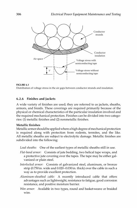
306 Electrical Power Equipment Maintenance and Testing
6.2.6 Finishes and Jackets
A wide variety of fi nishes are used; they are referred to as jackets, sheaths, armors, and braids. These coverings are required primarily because of the physical or chemical characteristics of the particular insulation involved and the required mechanical protection. Finishes can be divided into two catego-ries: (1) metallic fi nishes and (2) nonmetallic fi nishes.
Metallic fi nishesMetallic armor should be applied where a high degree of mechanical protection is required along with protection from rodents, termites, and the like. All metallic sheaths are subject to electrolytic damage. Metallic fi nishes are subdivided into the following:
Lead sheaths: One of the earliest types of metallic sheaths still in use.
Flat-band armor: Consists of jute bedding, two helical tape wraps, and a protective jute covering over the tapes. The tape may be either gal-vanized or plain steel.
Interlocked armor: Consists of galvanized steel, aluminum, or bronze strip (0.750 in. wide and 0.020–0.030 in. thick) over the cable in such a way as to provide excellent protection.
Aluminum-sheathed cable: A recently introduced cable that offers advantages such as lightweight, resistance to fatigue, good corrosion resistance, and positive moisture barrier.
Wire armor: Available in two types, round and basket-weave or braided wire.
Air space
V
Conductorinsulation
Conductorstrands
Voltage stress withsemiconducting tape
Voltage stress withoutsemiconducting tape
FIGURE 6.1Distribution of voltage stress in the air gaps between conductor strands and insulation.
DK4058_C006.indd 306DK4058_C006.indd 306 11/8/2008 12:41:10 PM11/8/2008 12:41:10 PM
Cables and Accessories 307
Round wire armor offers extremely strong cable and has high tensile strength for vertical applications. Braided or basket-weave wire armor consists of a braid of metal wire woven directly over the cable as an outer covering where additional mechanical strength is required.
Nonmetallic fi nishesMost of the nonmetallic fi nishes include PVC, PE, neoprene, hyplon, and EPR.
1. PVC: This covering (i.e., fi nish) offers excellent moisture-resistance characteristics, but does not provide mechanical protection.
2. PE: It has excellent resistance to water, ozone, and oxidation. It is resistant to gasoline, solvents, and fl ames.
3. Neoprene: It is commonly recommended where service conditions are usually abrasive and extreme. By itself, it is not fl ame retardant.
4. Hyplon: It possesses similar properties as neoprene, but also has better thermal stability and resistance to ozone and oxidation.
5. EPR: It exhibits excellent weathering properties and is resistant to ozone. It has good chemical and mechanical properties, but is not inherently fl ame retardant.
6. Braids: Generally, present-day trends are away from the use of non-metallic braid coverings. Braids may be of the following types:
a. Heat- and moisture-resistant cotton braid
b. Flame-resistant cotton braid
c. Asbestos braid
6.2.7 Cable Construction
Low-voltage cables (less than 2000 V): The low-voltage cable consists of the center conductor surrounded by an insulation layer which provides the electrical insulation. The insulation may be covered by a protective jacket. This type of cable construction is also known as nonshielded construction.
Medium-voltage cables (2001–35,000 V): The majority of medium-voltage cables are constructed as shield construction. However, it is not uncommon to fi nd medium-voltage cables up to 5 kV being of nonshielded construction. The shielded construction cable can be classifi ed into two major types. For direct burial use, such as underground rural distribution (URD), the cable is known as concentric neutral cable. It consists of the conductor, strand shield (semiconductor), insulation, neutral, and jacket as shown in Figure 6.2a. The other shielded construction-type cable consists of the conductor, strand shield (semiconductor), insulation, insulation shield (semiconductor), metallic shield, and jacket as shown in Figure 6.2b. The purpose of the strand shield is to minimize corona by equalizing the voltage gradients across the air gap
DK4058_C006.indd 307DK4058_C006.indd 307 11/8/2008 12:41:10 PM11/8/2008 12:41:10 PM

308 Electrical Power Equipment Maintenance and Testing
between the conductor strands as explained in Section 6.2.5. The semicon-ductor over the insulation serves a similar purpose as the strand shield by enclosing the insulation completely and equalizing the electric fi eld within the cable. The metallic shield serves as an electric shield which equalizes and confi nes the electric fi eld inside the cable. By equalizing the electric fi eld in the cable, the voltage stress is uniformly distributed around the cable, thereby eliminating any high points of voltage stress in the cable. This enhances the cable life and reliability.
6.3 Cable Characteristics
The electrical characteristics of cables are concerned with the electrical constants most commonly required for power system calculations. These electrical constants, such as positive sequence impedance (Z1), negative sequence impedance (Z2), and zero sequence (Z0), are used in the applica-tion of symmetrical components for calculations of short-circuit currents, unbalanced voltages, and their phase relationships among sheaths and conductors, which are important in the calculation of reactance, capacitance, insulation resistance, and dielectric loss. The cable geometry for single- and three-conductor cable is shown in Figure 6.3. The cable
Extrudedconducting layer Conducting tape Tape separator
Classs Bcompressed
stranding
Bare copper tapeXLP (or EPR) insulation
ConductorJacketNeutral
(a)
(b)
SemiconductorInsulation
Strandedbare copper
Sunlight-resistantPVC jacket
FIGURE 6.2(a) Concentric neutral cable and (b) medium-voltage shielded cable.
DK4058_C006.indd 308DK4058_C006.indd 308 11/8/2008 12:41:10 PM11/8/2008 12:41:10 PM

Cables and Accessories 309
ratings provide the basic information regarding its application and use. A basic knowledge of cable ratings is essential for correct selection and application of cables. Exceeding cable ratings or their misapplication can be hazardous to property and personnel, as well as to successful operation of the plant or facility.
Cable propertiesThe two properties of cables, as mentioned, are geometry of cables and elec-trical constants. A general rule is that regardless of the complexity of mutual inductive relations between component parts of individual phases, the method of symmetrical components can be applied rigorously whenever there is symmetry among phases. All three-conductor cables satisfy this condition by the nature of their construction; single conductor cable may or may not. However, the error is very small when they are treated similarly as three-conductor cables. The space relationship among sheaths and conductors in a cable circuit is a major factor in determining reactance, capacitance, charging current, insulation resistance, dielectric loss, and thermal resistance. The physical characteristics of cables can be determined from the geometry of cables, which is described next.
Geometric mean radiusThe geometric mean radius (GMR) is a property usually applied to the conductor alone, and depends on the material and stranding used in its con-struction. One component of conductor reactance is normally calculated by evaluating the integrated fl ux linkages both inside and outside the conductor within an overall 12 in. radius. Consider a solid conductor that has some of
Lead sheath
Belt insulation
(a) (b)
Conductorinsulation
S S
S
L
S S
ST
T
ri
ri
ro
ro
L
D
d
FIGURE 6.3Cable geometry: (a) single-conductor cable and (b) three-conductor cable.
DK4058_C006.indd 309DK4058_C006.indd 309 11/8/2008 12:41:10 PM11/8/2008 12:41:10 PM

310 Electrical Power Equipment Maintenance and Testing
the fl ux lines lying within the conductor and contributing to the total fl ux linkages, even though they link only a portion of the total conductor current. Now consider a tubular conductor having an infi nitely thin wall substituted for the solid conductor; it has a fl ux that would necessarily lie external to the tube. Therefore, a theoretical tubular conductor, to be inductively equivalent to a solid conductor, must have a smaller radius so that the fl ux linkages present inside the solid conductor, but absent within the tube, will be replaced by additional linkages between the tube surface and the limiting cylinder of 12 in. radius. A solid copper conductor of radius d/2 is equivalent to a tubular conductor radius 0.779d/2. This equivalent radius is called the GMR of the actual conductor. This quantity can be used in reactance calculations with-out further reference to the shape or makeup of the conductor. The factor by which actual radius must be multiplied to obtain GMR varies with stranding and hollow-core construction.
Geometric mean distance (GMD)Spacing among conductors or between conductors and sheaths is important in determining total circuit reactance. The total fl ux linkage surrounding a conductor can be divided into two components, one extending inward from the cylinder of 12 in. radius and the other extending outward from this cylinder to the current return path beyond which there are no net fl ux linkages.
The fl ux linkages per unit conductor current between the 12 in. cylinder and the return path are functions of the separation of the conductor and its return path. GMD is therefore a term that can be used in the expression for the external fl ux linkages, not only in the simple case of two adjacent conductors, where it is equal to the distance between conductor centers, but also in the more complex case where two circuits, each composed of several conductors, are separated by an equivalent GMD.
The positive or negative sequence reactance of a three-phase circuit depends on separation among phase conductors. If the conductors are equilaterally spaced, the distance from one conductor center to another is equal to the GMD among conductors for that circuit. The GMD for three-conductor cable is GMD3c = S for an equilateral circuit where S is the dis-tance between each conductor. If the conductors are arranged other than equilaterally as shown in Figure 6.4, but transposed along their length to produce a balanced circuit, the equivalent separation may be calculated by deriving the GMD from the cube root of three distance products. This is expressed as follows:
3
3cGMD = ab bc caS S S
The component of circuit reactance caused by fl ux outside a 12 in. radius is widely identifi ed as the reactance spacing factor (Xd) and can be calculated directly from GMD.
DK4058_C006.indd 310DK4058_C006.indd 310 11/8/2008 12:41:10 PM11/8/2008 12:41:10 PM

Cables and Accessories 311
3cd 10
GMD0.2794 log /phase mile
60 12
fX = Ω
When equivalent separation is less than 12 in., as can occur in cable circuits, the reactance spacing factor is negative so as to subtract from the component of conductor reactance due to fl ux out to a 12 in. radius.
The zero-sequence reactance of a three-phase circuit may depend on spac-ing among conductors and sheath.
Geometric factorThe relation in space between the cylinders formed by the sheath internal surface and conductor external surface in a single-conductor lead-sheath cable can be expressed as a geometric factor. The factor is applicable to the calculation of cable characteristics such as capacitance, charging current, dielectric loss, leakage current, and heat transfer. The mathematical expression for geometric factor G in a single-conductor cable is
i10
22.303 log
rG
d=
where
ri is the inside radius of sheathd is the outside diameter of conductor
Phase c
Phase b Phase a
ScaSbc
Sab
FIGURE 6.4Single-conductor cable unsymmetrically spaced but perfectly transposed.
DK4058_C006.indd 311DK4058_C006.indd 311 11/8/2008 12:41:10 PM11/8/2008 12:41:10 PM

312 Electrical Power Equipment Maintenance and Testing
6.4 Electrical Constants
The following electrical constants are used in the application of power cables.
Positive- and negative-sequence resistanceThe resistance of a conductor to positive- and negative-sequence currents is affected by the following factors.
Skin effect: This effect is due to unequal distribution of alternating current (AC) fl owing in a conductor because of the tendency of the current to fl ow more on the outside than inside strands of the con-ductor. This results in a higher resistance to AC than direct current (DC). Usually this effect can be neglected in smaller conductors.
Proximity effect: This effect is due to alternating magnetic fl ux produced by circulating current in a conductor caused by the current fl owing in a neighboring conductor. This effect increases the resistance of a conductor. It can become pronounced where cables are installed parallel to metal beams, plates, walls, and the like.
Sheath currents: The alternating current (AC) fl owing in a sheathed single conductor induces voltage in the sheath. Since the sheath is bonded and grounded at both ends, currents fl ow longitudinally, causing I2R losses. One way to account for these losses is to increase the resistance of the conductor.
Positive- and negative-sequence reactanceThe reactance of a single lead-sheath conductor to positive- and negative-
sequence current can be calculated by taking into account the effect of sheath currents. It can be expressed mathematically by the following:
1 2 a d s /mile/phaseX X X X X= = + − Ω
whereX1 is the positive-sequence reactanceX2 is the negative-sequence reactanceXa is the self-reactance of conductor at 1 ft radiusXd is the reactance of conductor beyond 1 ft radiusXs is the equivalent reactance value due to sheath currents
For three-phase conductors, Xs can be neglected and the positive and negative reactances are X1 = X2 = Xa + Xd Ω/mile/phase.
Zero-sequence resistance and reactanceWhen zero-sequence currents fl ow in the three-phase system, the return path is usually either through the earth ground, sheath, ground wire, or
DK4058_C006.indd 312DK4058_C006.indd 312 11/8/2008 12:41:11 PM11/8/2008 12:41:11 PM

Cables and Accessories 313
a combination of these paths. In actual installation, the following combination of paths should be considered:
1. All currents in the ground, none in sheath
2. All currents in the sheath, none in ground
3. All currents in sheath and ground
When low-voltage cables are installed in magnetic ducts, the zero-sequence resistance and reactance are infl uenced by the magnetic material surrounding the conductor. No methods have been developed yet to accurately calculate the zero-sequence impedance. However, test data are available to give the required zero-sequence impedance data in standard reference handbooks on transmission and distribution of electrical power for various sizes of cables.
Shunt capacitance reactanceThe positive-, negative-, and zero-sequence shunt capacitive reactances of cable are the same and can be expressed mathematically as follows:
1 2 0
1 2 0
0.0892= = = F/phase/mile
or
1.79M /phase/mile
KC C C
G
GX X X
f K
μ
= = = Ω
whereK is the dielectric constantX1, X2, and X0 are positive-, negative-, and zero-sequence reactancesC1, C2, and C0 are positive-, negative-, and zero-sequence capacitive
reactancesG is the conductance of the cablef is the frequency of the power system
1 2
0.97 kVA/phase/mile
1000
f KI I
G= =
0
0
0.323 kVA/phase/mile
1000
f KI
G=
where I1, I2, and I0 are positive-, negative-, and zero-sequence charging currents.
Insulation resistanceThe insulation resistance of the cable is very diffi cult to calculate because of varying insulation properties. However, a generalized formula can be expressed in terms of the power factor (PF) of the insulation system. For single-conductor cable,
DK4058_C006.indd 313DK4058_C006.indd 313 11/8/2008 12:41:11 PM11/8/2008 12:41:11 PM

314 Electrical Power Equipment Maintenance and Testing
×= = =0
6
1 2
0.597 10
cos
Gr r r
fK q
and for three-conductor belted cable,
×= =
6
1 2
0.597 10
cosZ
Gr r
fK q
wherer1, r2, and r0 are positive-, negative-, and zero-sequence shunt resistancesG is the geometric factorK is the dielectric constantcos q is the insulation PF per unit
6.5 Cable Ratings
A basic knowledge of cable ratings is very important in order to select and apply cables for distribution and utilization of power. The following brief description of cable ratings will provide the basis for selecting and applying cables.
Continuous current-carrying ratingThe current-carrying capacity of cable is affected by several factors:
1. Maximum allowable temperature
2. Total watt loss (I2Rc) of the cable
3. Ability to dissipate heat
4. Ambient temperature
The maximum conductor temperature is determined by the maximum temperature the insulation system can withstand for extended periods of time without damage. The maximum temperature in turn can be affected by the ability to dissipate heat and the ambient temperature of the medium in which the cable is installed to operate. The sum of ambient temperature and temperature rise in the insulation system should not exceed the total allowable temperature of the conductor for safe operation. Aluminum conductors can be expressed in terms of copper conductors for purposes of current-carrying capacity. The conversion factors to convert the current capacity of the same size aluminum conductor as copper can be expressed in terms of the resis-tance ratio of copper to aluminum, that is, RCu/RAl, where RCu and RAl are, respectively, the resistance of copper and aluminum conductors at rated tem-perature. The effect of temperature on current rating is shown in Figure 6.5. As the temperature of the conductor goes up, so does its resistance. The total loss of the cable is a function of the effective resistance of the conductor at maximum allowable temperature.
DK4058_C006.indd 314DK4058_C006.indd 314 11/8/2008 12:41:11 PM11/8/2008 12:41:11 PM

Cables and Accessories 315
Emergency current-carrying ratingThe service life of cable is based upon its normal loading limits and normal operating temperature. The normal life expectancy of a cable insulation system is approximately 30 years. However, if the cable system is operated at 5°C–10°C above its temperature rating, it is to be expected that the cable life expectancy will be halved and its average rate of failure doubled. Another disadvantage in operating cables over their temperature rating is that copper loss is directly proportional to the square of current and resistance. Furthermore, because of increased resistance and current, the voltage drop may be excessive and may jeopardize equipment and service continuity. Any program to operate the cables beyond the limit of their current and tempera-ture ratings must be judiciously undertaken. To calculate the emergency rating of cables, the following formula may be used:
( )( )
0 a c0 c
c a 0
t t RJ j
t t R
−= ×
−
where:Jo is the emergency overload currentjc is the continuous currentto is the emergency overload temperatureta is the ambient temperaturetc is the maximum operating temperatureRc is the conductor resistance at maximum operating temperatureRo is the conductor resistance at emergency overload temperature
Overloading should be less than 100 h/year. Rubber-insulated cables may be operated at overloading temperature in accordance with Table 6.1.
0
50
100
150
200
250
Am
pere
s
Cable size, AWG or MCM
300
350
400
4 1 2/0 4/0 300 400
60�C
50�C40�C
30�C
500 600
FIGURE 6.5Effect of ambient temperature on current rating. (From G.E. Cable Data Book.)
DK4058_C006.indd 315DK4058_C006.indd 315 11/8/2008 12:41:12 PM11/8/2008 12:41:12 PM

316 Electrical Power Equipment Maintenance and Testing
Voltage ratingThe voltage ratings of cables are specifi ed as the line-to-line voltage that they can withstand. However, the insulation thickness is based upon line-to-ground voltage. To specify the system voltage for procurement and installa-tion of cables is not suffi cient. It is necessary to specify also the type of system that the cable will use. Assume a cable application on a grounded 15 kV system, for which the insulation will be based upon line-to-ground voltage, that is 15/1.73 = 8.66 kV. Whereas on a 15 kV ungrounded system, the insula-tion thickness will be based on 15 kV because that is the voltage imposed on unfaulted conductors. The basis for voltage thickness for 15 kV belted cable operating at 13.8 kV grounded system is illustrated in Figure 6.6.
Short-circuit ratingAll cable systems have thermal limitations, which are specifi ed in terms of short-circuit withstand temperatures and current ratings. Under a short- circuit condition, the temperature of the conductor rises very rapidly. If the conductor is not sized to withstand the available short-circuit current, it will melt, resulting in cable failure. Because of the insulation sheath surrounding the conductor and its characteristics, it will cool off very slowly after the fault has been removed. The temperatures shown in Table 6.1 should not be exceeded per standards of the Insulated Cable Engineering Association (ICEA) for more than 10 s. Cable manufacturers publish current-withstand ratings for all sizes of conductors. The NEC requires that systems should be designed to have full withstand capability. Every cable installation should be checked for short-circuit withstand rating; otherwise, severe damage or complete failure may result. Failure may be accompanied by fi re and smoke, thus resulting in danger to personnel and property. Also, because of thermal expansion due to intense heat under short-circuit conditions, the cable may be permanently damaged if not correctly selected for this purpose.
TABLE 6.1
Emergency Overload Temperature of Rubber-Insulated Cables
Voltage Rating Type of Cable
Maximum Operating
Temperature (°C)
Emergency
Overloading
Temperature (°C)
600 V PVC 60 75
Butyl 90 125
Silicone 125 150
Polyethylene 75 85
1–5 kV PVC 75 85
Butyl 90 125
Silicone 125 150
15 kV Butyl 85 105
Silicone 125 150
DK4058_C006.indd 316DK4058_C006.indd 316 11/8/2008 12:41:12 PM11/8/2008 12:41:12 PM

Cables and Accessories 317
6.6 Cable Selection and Application
It is essential to know cable construction, characteristics, and ratings to understand problems related to cable systems. However, to correctly select a cable system and assure its satisfactory operation, additional knowledge is required. This knowledge may consist of service conditions, type of load served, mode of operation and maintenance, and the like. The key to the suc-cessful operation of a cable system is to select the most suitable cable for the application, make a correct installation, and perform the required mainte-nance. In this section, discussion is based on the correct selection and appli-cation of a cable system for power distribution and utilization. Cable selection can be based upon the following fi ve factors:
1. Cable installation
2. Cable construction
3. Cable operation (voltage and current)
4. Cable size
5. Shielding requirements
Cable installationCables can be used for outdoor or indoor installations depending upon the distribution system and the load served. Installation of a cable system will be discussed later.
FIGURE 6.6Insulation thickness for three-phase belted cable.
A B
In this type of construction each conductor insulation isbased on one-half line-to-linevoltage.The belt insulation is based upon the difference of line-to-ground voltageminus one-half the line-to-line voltage. The overall thickness of insulation is the sum of the belt and con-ductor thickness.Insulation required at A andB is:A = 13.8 kV - 13.8 kV = 2.0 kV
1.73 2
2B = 13.8 = 6.7 kV
The insulation thickness required for the 13.8 kV grounded systemis A + B = (2.0 + 6.7) kV = 8.7 kV
DK4058_C006.indd 317DK4058_C006.indd 317 11/8/2008 12:41:12 PM11/8/2008 12:41:12 PM
318 Electrical Power Equipment Maintenance and Testing
Cable constructionSelection and application of cable involves the type of cable construction needed for a particular installation. Cable construction involves conductors, cable arrangement, and insulation and fi nish covering.
ConductorsConductor materials such as copper and aluminum should be given consider-ation with regard to workmanship, environmental conditions, and maintenance. The requirements for aluminum conductors with regard to these factors are more critical than for copper conductors. Cable conductors should be selected based upon the class of stranding required for a particular installation.
Cable arrangementConductors can be arranged to form single-conductor or three-conductor cable. There are certain advantages and disadvantages to both types of arrangements. Single conductors are easier to install, easier to splice, and allow the formation of multiple-cable circuits. On the other hand, they have higher reactance than three-conductor cable. Shielded single conductors carry high shield currents, and consideration must be given to preventing overheating of the cable. Single-conductor cables are subject to considerable movement owing to the mechanical stresses produced by the short-circuit currents or high inrush currents. Three-conductor cable with an overall jacket has the lowest reactance, and voltage stress distribution is balanced owing to equivalent spacing between conductors.
The availability of ground wire in three-conductor cable or a separate ground wire with single-conductor cable is an important consideration. Since the ground conductor in three-conductor cable construction provides the lowest impedance path, it offers a good system ground. Similarly, a sepa-rate ground in the same conduit as the power conductors provides a better ground return path than a ground path via the equipment or building steel. The selection and application of a cable system should be based on correct selection of the type of cable arrangement required for the purpose.
Insulation and fi nish coveringThe selection of cable insulation and fi nish covering is normally based on the type of installation, ambient operating temperature, service conditions, type of load served, and other criteria as applicable. In many installations unusual conditions may be prevalent, such as corrosive atmosphere, high ambient temperature, insect and rodent hazard, presence of oil and solvents, pres-ence of ozone, and extreme cold. In certain applications, two or more of these unusual conditions may be present, in which case the selection of suitable cables becomes much more diffi cult.
Cable operationThe insulation of the cable must be able to withstand the voltage stresses experienced during normal and abnormal operating conditions. Therefore the selection of the cable insulation should be made on the basis of the applicable phase-to-phase voltage and the general system category which
DK4058_C006.indd 318DK4058_C006.indd 318 11/8/2008 12:41:12 PM11/8/2008 12:41:12 PM
Cables and Accessories 319
are classifi ed as either 100%, 133%, or 173% insulation levels. These insulation levels are discussed as follows:
100% level: Cables in this category may be applied where the system is provided with relay protection which normally clears ground faults within 1 min. This category is usually referred to as the grounded systems.
133% level: Cables in this category may be applied where the system is provided with relay protection which normally clears ground faults within 1 h. This category is usually referred to as the low resistance grounded, or ungrounded systems.
173% level: Cables in this category may be applied where the time needed to de-energize the ground fault is indefi nite. This level is rec-ommended for ungrounded and for resonant grounded systems.
The current capacity that the cable needs to carry is determined by the load it serves. The NEC is very specifi c in terms of sizing conductors for systems operating below 600 V. The current-carrying ability of cable is based upon an operating ambient temperature. When cables are installed in multiple duct banks, it is essential to derate the cable current capacity in order not to exceed its thermal rating. In cases where cables may be load cycled, the current-carrying capacity may be calculated by the following formula:
eq
2tEIIT
=
whereIeq is the equivalent current-carrying capacityI is the constant current for a particular time periodt is the time period of constant currentT is the total time of duty cycleE is the voltage of the cable
The equivalent current-carrying capacity should be used for selecting the conductor size for thermal withstand.
Cable sizeThe selection of cable size is based upon the following factors:
1. Current-carrying capacity
2. Voltage regulation
3. Short-circuit rating
These factors should be evaluated before selecting a cable size. In many instances voltage regulation and short-circuit rating factors are overlooked. This oversight can result in danger to property and personnel, as well as destruction of the cable itself.
DK4058_C006.indd 319DK4058_C006.indd 319 11/8/2008 12:41:12 PM11/8/2008 12:41:12 PM

320 Electrical Power Equipment Maintenance and Testing
Current-carrying capacityThe current-carrying capacity of a cable is based upon its thermal heating. The NEC publishes tables listing the current capacity for various-sized cables. The ICEA publishes current ratings for various types of insulations and installation conditions. If it is required to carry capacity larger than 500 MCM, it is normal practice to parallel two smaller conductors. The current rating of cable is based upon certain spacing to permit thermal dissipation. If this spacing is smaller where the cable is to be installed, then derating of cable is required.
Voltage regulationIn correctly designed electrical power systems, voltage regulation is usually not a problem. Voltage drops for excessively long runs at low voltage should be checked to ensure correct load voltage. In rotating loads, checks should be made both on steady-state voltage regulation and during starting. The NEC specifi es a 5% limit of voltage drop for electrical power distribution systems.
Short-circuit ratingThe cable size selected should be checked for short-circuit withstand capabil-ity, which should be based upon the circuit opening time for short-circuit condition. In other words, the cable should hold without any thermal damage to it until such time as the fault can be removed by the switching device, such as a circuit breaker or fuse.
ShieldingIn selecting and applying cables at medium voltage, a major consideration involves whether the cable should be shielded or nonshielded. Shielding was briefl y discussed previously in Section 6.2.5 as to why it is necessary at medium voltages. The conditions under which shielded cable is to be selected and applied need further discussion. The application of shielded cable involves the following considerations:
1. Type of insulation system
2. Whether the system neutral is grounded or ungrounded
3. Safety and reliability requirements of the system
In power systems where there is no shield or metallic covering, the electric fi eld is partly in the air and partly in the insulation system. If the electric fi eld is intense, such as in the case of high and medium voltage, surface discharges will take place and cause ionization of the air particles. The ionization of air causes ozone generation, which can deteriorate certain insulations and fi nish cover-ings. In the application of nonshielded cable on ungrounded systems, damage to insulation or jackets can be caused by leakage current if the surface of the cable is moist or covered with soot, grease, dirt, or other conducting fi lm.
In duct-type installations where nonshielded, nonmetallic cable is used, the external electric fi eld may be high enough to pose a safety hazard to
DK4058_C006.indd 320DK4058_C006.indd 320 11/8/2008 12:41:13 PM11/8/2008 12:41:13 PM

Cables and Accessories 321
personnel working on single cable in multicircuit installations. In cases where portable cables, cable assemblies, or exposed overhead cable installa-tions are used and may be handled by personnel, serious safety hazards may exist if nonshielded cable is used. Shielding should be considered for nonmetallic cable operating in excess of 2 kV where any of the following conditions exist:
1. Damp conduits
2. Connection to aerial wires
3. Transition from a conducting to a nonconducting environment, such as from moist to dry earth
4. Dry soil
5. Dirty environment containing soot, salt, and other contaminants
6. Where safety to personnel is required
7. Where radio interference is expected
The ICEA has set up voltage limits above which insulation shielding is required for rubber and thermoplastic-insulated cables. These values are shown in Table 6.2. The insulation shield must be grounded at least at one end and preferably at two or more points. The cable shield must be grounded also at all terminations, splices, and taps with stress cones. The shield should be operated at ground potential. Multiple grounding will ensure safety and reliability of the cable circuits. The ground path from the shield should be of low resistance to keep the shield near ground potential.
TABLE 6.2
Insulation Shielding Requirements for Rubber and Thermoplastic-Insulated Cables
Single Conductor Three Conductor
No. Cable Type
Grounded
(kV)
Ungrounded
(kV)
Grounded
(kV)
Ungrounded
(kV)
1 Sheathed cable 5 5 5 5
2 Interlocked cable 5 5 5 5
3 Fibrous covered cable 2 2 2 2
4 Nonozone resistant 2 2 2 2
5 Ozone resistant
In metallic conduits 5 3 5 5
Ungrounded conduits 3 3 5 5
Aerially in ties 3 3 5 5
Aerially with metallic
binder
5 5 5 5
Direct buried 3 3 5 5
DK4058_C006.indd 321DK4058_C006.indd 321 11/8/2008 12:41:13 PM11/8/2008 12:41:13 PM

322 Electrical Power Equipment Maintenance and Testing
6.7 Installation of Cables
After having made the correct selection of cable to meet load requirements and other system characteristics, it is important that cables be installed and main-tained correctly. A good understanding of local conditions, installation crews, and maintenance personnel is essential to assure that the selected cable system will operate satisfactorily. Many times cable insulation is damaged or weakened during installation by applying the incorrect pulling tensions. Designs of con-duit systems not only should minimize the number of conduit bends and distances between manholes but also should specify the pulling tensions. The inspection personnel should ensure that installation crews do not exceed these values during installations. It is also important that correct bending radius be maintained in order to avoid unnecessary stress points. Once a cor-rect installation is made, routine inspection, testing, and maintenance should be carried out on a regular basis to chart the gradual deterioration and upkeep of the cable system. Cable systems are the arteries of the electric power distri-bution system and carry the energy required for the successful operation of a plant. Following is a brief discussion on cable installation and maintenance.
There are several types of cable systems available for carrying electrical energy in a given distribution system. The selection of a particular system may be infl uenced by local conditions, existing company policies, or past experience. No set standards or established guidelines can be given for the selection of a particular system. Following is a general discussion of the various types of instal-lations, bending data, and pulling tensions that, combined with sound engineer-ing judgment, will be helpful in selecting a system for a particular installation.
6.7.1 Outdoor Installations
Cable can be installed underground or overhead. Today most cable is installed underground in conduit banks or direct burial, even though the trend for outdoor overhead installation is becoming popular. The underground installation of cables in nonmetallic ducts will result in smaller impedance than for cables in metallic ducts. Since conduits may become fl ooded, only cable insulations approved for this purpose should be installed in ducts. Cable failures in underground ducts are diffi cult to locate and repair. Therefore, maintenance personnel should be trained and equipped with cor-rect equipment to troubleshoot cable faults and make repairs.
Several types of cable construction are available for direct-burial service. Cable selected for direct-burial service should have excellent mechanical strength in order to withstand rough environmental surroundings. Cables without jackets should be avoided for direct-burial service.
Low- and medium-voltage aerial cable lashed to a supporting steel mes-senger cable is becoming popular for overhead installations because of its many advantages, such as low reactance, adaptability, better appearance, and voltage regulation. Another type of overhead installation that is gaining popularity is interlocked armor installed in racks or cable trays because of
DK4058_C006.indd 322DK4058_C006.indd 322 11/8/2008 12:41:13 PM11/8/2008 12:41:13 PM

Cables and Accessories 323
advantages such as fl exibility, ease of installation, and good mechanical and chemical protection.
6.7.2 Indoor Installations
The conventional installation of indoor cables has been in conduit (Figure 6.7a). However, interlocked armor cable is gaining popularity recently, especially in industrial plants. This cable can be installed overhead in racks or cable trays (Figure 6.7b), thus eliminating the expensive conduit systems. The racks bonded together provide the ground circuit similar to the conduit system.
Because of this cable being installed in open air, it has higher current rating. An overall jacket of PVC is available for this cable for installations where corrosive atmosphere may be present.
6.7.3 Bending Data
The ICEA recommended values of minimum bending radii for rubber and rubber-like compounds and varnished cambric cables are given in Table 6.3. As mentioned before, it is important to install cables without sharp bends to minimize stress points. The ICEA recommended bending data do not apply to conduits in which cables may be pulled under tension. In cases of conduit bends, larger radius bend should be required.
6.7.4 Pulling Tensions
Since cables can be damaged by applying excessive pulling tension or by sharp bends in poorly constructed duct banks, the following are some of the cautions that should be considered to minimize damage to cables during installation.
1. Do not exceed the required fi ll as set by the NEC.
2. Calculate the jam ratio for the selected cable and conduit sizes.
3. Avoid sharp bends of the cable during pulling.
4. Use adequate lubrication to avoid friction. (Use the correct kind of lubricant.)
(a) (b)
FIGURE 6.7(a) Cable in conduit and (b) interlocked armor cable in racks.
DK4058_C006.indd 323DK4058_C006.indd 323 11/8/2008 12:41:13 PM11/8/2008 12:41:13 PM

324 Electrical Power Equipment Maintenance and Testing
5. Check end seals for intactness after installation.
6. In rack-type installation, use rollers to prevent cable from dragging on the rack.
In duct and conduit runs, the tension for a straight pull can be calculated by the formula
T Lwf=
whereT is the pulling weightL is the length to feet pulledw is the weight of cable (lb/ft)f is the friction coeffi cient, approximately = 0.5
To pull cables in conduits and ducts, the cables can be gripped directly by a pulling eye or basket-weave pulling grip. The basket-weave grip is usually used for relatively light pulls, whereas pulling eye is used for heavier pulls. The following tension limitations apply when pulling cables:
TABLE 6.3
Recommended Bending Data for Cable
Minimum Bending Radii as a Multiple
of Cable Diameter
Type of Cable
Insulation
Thickness (in.) 1 in. or less 1.01–2.00 in.
2.00 in. and
over
Thermosetting and
thermoplastic
without metallic
shielding
10/64 and less
11/64 to 20/64
21/64 and over
4
5
—
5
7
7
6
7
8
Varnished cambric
cable without
armor, single
conductor, and
nonbelted
multiconductor
Up to 10/64
11/64 to 20/64
Over 20/64
5
6
6.5
6
6.5
7
7
7
7
Multiconductor All thicknesses 5 6 7
Thermoplastic and thermosetting with shielding or armor
Multiconductor
interlocked armor,
7× diameter
Flat tape and
wire armored,
12× diameter
Tape shield, 12×
diameter up to
15 kV; 10× diameter
up to 35 kV
Portable cable
over 5 kV,
8× diameter
Portable cable
below 5 kV,
6× diameter
Varnished cambric armored cables
Interlocked armor
cambric, 7×
diameter
Flat tape and wire
armored cable,
12× diameter
DK4058_C006.indd 324DK4058_C006.indd 324 11/8/2008 12:41:13 PM11/8/2008 12:41:13 PM

Cables and Accessories 325
Direct pull of conductor: When pulling force is applied directly to the conductor, the maximum pull should not exceed 0.008 lb/circu-lar mil area of cross section for copper 0.008 for hard-drawn, 0.006–0.008 for three-fourth hard-drawn, 0.003–0.004 for one-half hard-drawn, 0.002–0.004 for soft aluminum and 0.75 for hard-drawn aluminum.
Grip over lead sheath: When a grip is applied over lead-sheathed cables, the pulling force shall be limited to 1500 psi of sheath cross section.
Grip over nonmetallic sheath: When a grip is applied over a nonmetallic sheathed cable, the pulling force should not be over 1000 lb provided it does not exceed the force calculated in a direct pull of conductor.
Pulling around bends: The pulling force around bends in conduit should not exceed 300 times the radius of the bend in feet.
6.8 Maintenance of Cables
Visual inspection of the cable, conduit, manholes, and so on, and electrical maintenance testing are the major maintenance procedures for cable systems.
Visual inspectionVisual inspection can be made on energized cables, but if cables are to be touched or moved they should be de-energized. Cables in vaults, substations rooms, manholes, and at other locations should be inspected for the following on a yearly basis:
1. Physical damage, sharp bends, and excessive tension
2. Oil leaks, soft spots, and insulation swelling
3. Poor ground connections, metallic-sheath bonding deterioration, corroded cable supports, and continuity of main grounding system
4. Cracked jackets of nonleaded cables
5. Damage to fi reproofi ng
6. Tracking or corona
7. Soft spots in terminations and splices
8. Inspect the manhole for spalling concrete and standing water
9. Potheads should be inspected for oil or compound leaks (dirt and grime should be cleaned off and connections checked for tightness)
Aerial cables should be inspected for mechanical damage caused by vibration or deterioration of support and suspension system. Inspection should be made of cables for insulation abrasion and cable being bent or pinched.
DK4058_C006.indd 325DK4058_C006.indd 325 11/8/2008 12:41:13 PM11/8/2008 12:41:13 PM

326 Electrical Power Equipment Maintenance and Testing
6.9 Cable Failures and Their Analysis
Cables can fail due to many reasons. The cable failure modes, stressors and effects were discussed in Section 1.8.1.5 in Chapter 1 to provide some insights on cable failures. Some of the major causes for cable failures are discussed next.
Mechanical failuresMechanical failures can be due to breaks and defects of sheath material, mechanical punctures by people or machines, or cracks due to sharp bending or vibration. Whenever mechanical damage occurs in the cable sheath, the entrance of moisture will produce slow deterioration of insulation material, resulting in eventual failure of the cable. It is important therefore to take every precaution that either direct or indirect mechanical damage be eliminated or minimized by correct selection, installation, and maintenance of cable systems.
Corrosion of sheathSheath corrosion can occur due to the following factors:
1. Dissimilar soil effects
2. Galvanic action
3. Acidity and alkali in conduits
4. Chemical contamination in the soil
Corrosion of sheath will eventually allow moisture to penetrate into the insulation system and cause an eventual failure. Sheath corrosion can be minimized by correct application of cathodic protection, application of insulating paints, providing adequate drainage, and removing the source of chemical contamination.
Moisture in the insulationBecause of mechanical damage or for other reasons, entrance of moisture into the insulation system will deteriorate the cable, and all precautions should be taken to prevent such entrance. Damage due to moisture can be indicated by the following:
1. Bleached or soggy paper
2. Resistance to tearing of tapes
3. Stain on the inside surface of the sheath
4. Visible water
5. Whitish powder on aluminum conductor
Heating of cablesAs explained in the Section 6.5 on cable rating, increased heat rise in the cable results in insulation degradation. Heat can be due to overloading, high ambi-ent temperatures, insuffi cient ventilation, manual heating due to cables being
DK4058_C006.indd 326DK4058_C006.indd 326 11/8/2008 12:41:13 PM11/8/2008 12:41:13 PM
Cables and Accessories 327
installed too close to each other, or external sources of heat. Care must be taken not to exceed the temperature rise of the cable insulation system. This can be done by fi rst identifying the various environmental and operating factors that will determine the correct selection of the cable insulation and conductor size. Once correct selection and installation are made, routine maintenance and inspection of cable will ensure safe and long operating life of the cable.
Fire and lightning surgesFire in conduit or manholes can cause cable failure in adjacent manholes and junction boxes. Barriers can be installed between large groups of conductors to prevent fi re damage. Lightning arresters should be installed to protect the cable where it is connected to overhead lines to minimize failures of cable due to lightning surges.
Electrical punctureOnce the insulation is weakened owing to any of the reasons already discussed, it may fail electrically. That is, the insulation system cannot con-fi ne the fl ow of electrical current to the conductor inside the insulation system. Failure may be line-to-ground or three line-to-ground or line-to-line faults. Obviously, if the failure is a short-circuit due to defective conductors, it will be detected by the circuit protective device. Some of the not-so-easy-to- detect electrical failures can be indicated by the following:
1. Bulging of the sheath
2. Tree design marking (dendritic)
3. Polymerized compound (wax)
4. Lack of compound in the insulation
The cable failures discussed in Section 6.9 can be further classifi ed into two classes as follows: (1) inherent causes and (2) noninherent causes.
Inherent causesInherent causes can be classifi ed as follows:
1. Sheath or jacket defects
2. Insulation defects
3. Conductor defects
Sheath or jacket defectsSheath defects are due to the following:
1. Thin lead (splits under pressure)
2. Eccentric lead thickness less than 85%
3. Structural defects: radial splits, laminations, gas pockets, and others
4. Cracked, embrittled, soft sports, bulge, cuts, bruises, or gauges
DK4058_C006.indd 327DK4058_C006.indd 327 11/8/2008 12:41:13 PM11/8/2008 12:41:13 PM

328 Electrical Power Equipment Maintenance and Testing
Insulation defectsThese defects are due to the following:
Defects in workmanship: These can be indicated by the following:
1. Wrinkling or creasing of tapes
2. Torn tapes
3. Excessive registrations
4. Knotted or misplaced fi llers
5. Soft walls
High dielectric loss: This can be indicated by the following:
1. Scorching or carbonizing of paper
2. Happens in one or more spots
3. Can be determined by PF at 60°C or higher
Incomplete saturation: This can be indicated by the following:
1. Scarcity of the compound in spaces between adjacent tape edges and surfaces
2. Paper is void of the compound
Unstable compound: This can be indicated by the following:
1. Visible change in the compound
2. Wax, in case of mineral oil
Ionization: This can be indicated by the following:
1. Carbonized paths (tree design)
2. Strings or fl akes of darkened wax containing carbon
Conductor defectsConductor defects can be indicated by the following:
1. Irregular strands
2. Sharp corners
3. Missing strands
4. Burrs on the strands
5. Poor brazing
Noninherent causesCorrosion of sheath: Corrosion usually proceeds either to complete penetra-tion of the sheath or weakness of the sheath, so that the sheath breaks open.
DK4058_C006.indd 328DK4058_C006.indd 328 11/8/2008 12:41:13 PM11/8/2008 12:41:13 PM

Cables and Accessories 329
Electrical breakdown takes place owing to admission of moisture. Corrosion of the sheath can be due to the following:
1. Positive potential (anodic), indicated by rough, pitted surface and very thin deposits of white crystals
2. Negative potential (cathodic), indicated by heavy deposit of lead oxides colored red, yellow, or orange
3. Local galvanic action
4. Chemical action
5. Other causes
Local galvanic actionGalvanic corrosion may occur in the presence of an electrolyte and some other metal that is connected electrically to the sheath elsewhere. Such failures are indicated by corroded sheath, which may be identical with either type of corrosion depending on whether the sheath is anode or cathode.
Chemical actionChemicals such as alkali attack cable insulation, which comes about from incompletely cured concrete; acetic acid, rotting wood, jute, and other mate-rials. Usually, these can be identifi ed by the chemical known to be present for a particular installation.
External fi re and HV surgesThese are due to fi re in cable circuits and lightning strikes and surges.
OverheatingThis is mainly due to heating of a cable that is overloaded or external heat and high temperature.
Mechanical damageMechanical damage can be due to the following:
1. Vibration
2. Expansion and contraction
3. External causes
4. Injury during installation
Other causesThese can be classifi ed as follows:
1. High internal pressure
2. Migration of compound on a slope or riser
3. Moisture admitted through defective joints, terminations, and bonds
DK4058_C006.indd 329DK4058_C006.indd 329 11/8/2008 12:41:13 PM11/8/2008 12:41:13 PM

330 Electrical Power Equipment Maintenance and Testing
6.10 Field Testing of Medium-Voltage Cables
6.10.1 Cable Degradation and Diagnostic Tests
This overview is provided as an insight into understanding of the nature of in-service cable degradation and some of the more commonly used diagnos-tic techniques commercially available for performing tests in the fi eld on extruded, medium-voltage, shielded power cables. The objective of any diag-nostic test is to identify, in a nondestructive way, a potential problem that may exist with a cable, so that preventative action can be taken to avoid a possible in-service failure of that cable. This assessment applies to cable sys-tems comprising of the cable itself and the associated accessories such as splices and terminations. Field diagnostic tests can be performed on cables during various stages of their existence. The IEEE std 400-2001 defi nes these tests as follows:
Installation test: Conducted after the cable is installed but before any acces-sories (joints/splices and terminations) are installed. These tests are intended to detect any manufacturing, transport, and installation damage that may have occurred to the cable.
Acceptance test: Performed after the installation of all cable and accessories, but before energizing the cable with system voltage. Its purpose is to detect installation damage in both the cable and cable accessories.
Maintenance test: Also referred to as after-laying tests that are performed during the operating life of the cable system. Its purpose is to assess the con-dition and check the serviceability of the cable system so that suitable main-tenance procedures can be initiated.
The IEEE std 400-2001 also defi nes cable fi eld tests into two main groups, Type 1 and Type 2 tests.
Type 1 fi eld tests: These tests are normally performed at elevated voltages and are a pass/fail type test. The traditional high-potential (hi-pot) test is an example of a Type 1 fi eld test. The cable either passes or fails the test, but one establishes little knowledge of the condition of the cable other than whether the cable system withstood the voltage for the duration of the test or not. This test is benefi cial in that it is normally able to root out severe defects in a cable. Many defects, however, may pass undetected during a pure voltage-with-stand test.
Type 2 fi eld tests: These cable diagnostic tests are performed at test voltages above and/or below the normal operating voltage of the cable. These tests assess the condition of the cable system and try to establish the remaining service life. There are two categories of Type 2 cable diagnostic tests available: (1) Tests that assess the overall (integral) condition of the cable; and (2) tests that detect and locate discrete defect locations in a cable system.
DK4058_C006.indd 330DK4058_C006.indd 330 11/8/2008 12:41:14 PM11/8/2008 12:41:14 PM
Cables and Accessories 331
In recent years, a great deal of research and development has focused on fi eld cable diagnostic tests. This effort was due in part to the fact that many of the new PE and XLPE cable systems installed in the late 1960s, 1970s, and early 1980s were prematurely failing as compared to the PILC predecessors. Traditional DC hi-pot testing was not only found to be ineffective in trying to diagnose the failure mechanism before cable failure occurred, but the presence of these elevated DC test voltages was also found to be potentially damaging to PE and XLPE service-aged cables. Whereas many PILC cables were lasting well over 50 years before being replaced, some of the originally installed PE/XLPE cables were experiencing failures within 10–12 years of their service life. A concerted effort to determine and diagnose the root cause of these cable failures in the fi eld was therefore undertaken. To determine which cable diagnostic technique to apply to a particular cable system, the type of cable insulation is an important criterion. Cables are classifi ed into two main cable insulation groups:
Extruded/solid dielectric cable: These cables are whose insulation is extruded on the conductor and include cables, such as PE, XLPE, and EPR cables.
Laminated cable: These are cables whose insulation is made up of lami-nated layers, such as PILC cable.
The research investigating the premature failure of extruded dielectric insulated cables pointed to water tress and partial discharges (PDs) in the void cavity of the insulation as the main cause of these cable failures. Water trees are tree-like structures which, through a process of electrophoresis, grow and mature in extruded cables. Water trees do not occur in laminated insulated cables because these laminated cables do not have cavity voids as the extruded insulated cables.
The extruded solid dielectric cables are susceptible to voids during manu-facturing of these cables. After these cables are installed in the ground (i.e., in duct banks or direct buried), the voids over time will fi ll-up with water or water vapor. Therefore, water fi lled voids in the extruded insulation are referred to as water trees because these voids when examined under a microscope resemble like a tree, i.e., each void has a trunk and branches. Research has shown that water treeing is the most important form of degra-dation that may affl ict older XLPE and high-molecular weight PE-extruded cables. As a result, the phenomenon of water treeing has been studied exten-sively, including means by which the degree of water tree-induced degrada-tion can be assessed. Water treeing can be described as a self-propagating dendritic pattern of electrooxidation, which reduces the AC and impulse breakdown strengths of extruded insulation and is the primary mechanism of degradation of extruded medium-voltage power cables. Although studied extensively, the initiation and growth mechanisms of water treeing are not clearly understood; they are not a single mechanism but complex interactions
DK4058_C006.indd 331DK4058_C006.indd 331 11/8/2008 12:41:14 PM11/8/2008 12:41:14 PM

332 Electrical Power Equipment Maintenance and Testing
of chemical, electrical, and mechanical phenomena that depend on the mate-rial and applied stresses. The visible manifestation of water treeing is strings of water-fi lled microcavities. The water-fi lled microcavities are connected by electrooxidized tracks, which are usually less than 0.1 μm in diameter, which is too small to see.
Water trees do not generate partial discharges (PD) by themselves. However water trees can lead to electrical trees as a result of a lightning impulse, or applied AC voltage, or during fault locating activities, or during DC high-voltage (HV) testing. The likelihood of causing a preexisting water tree to lead to an electrical tree may increase during a cable testing with high test voltages and the test duration. In general, electrical trees are more diffi cult to initiate than to grow, so that an electrical tree, once initiated, tends to grow to failure by PDs. Thus one can conclude that growing water trees do not gener-ate PD signals, unless they give rise to an electrical tree. Any PDs at a water tree imply the existence of one or more electrical trees at that water tree. In order for water trees to grow in extruded insulated cables, four factors need to be present in extruded cable insulation. These four factors are electrical fi eld, time, water in void cavity, and entry point into the cable. Water trees slowly migrate across the insulation, ultimately bridging adjacent voids across the insulation of the cable. Literally thousands of these trees grow to form electrooxidized channels which are extremely small in diameter. Intuitively, as these water tree channels start to bridge the insulation, the losses dissipated through the insulation increases and thus lead to cable fail-ure over time.
This loss can be determined by measuring the dissipation factor (DF). Although other methods are available to determine the degree of water tree-ing in cables, the most widely used method is the measurement of DF (or PF) of the cable insulation. A perfect cable can be electrically modeled by a single capacitor. The longer the cable, the larger the capacitance of this capacitor. As water trees start to bridge the once-perfect cable insulation, this capacitor now starts to have some resistive (water tree) paths in parallel with it. The result is that the resistive loss component (in-phase component) of the total current loss increases which is measurable by measuring the DF or the PF of the cable. The DF readings (measurements) can be compared with previous test mea-surements and trended to assess the cable health. The reader should refer to Chapter 3 for further reading on DF and PF testing of an insulation system.
In performing a DF test, the applied voltage is usually stepped up from below operating voltage to slightly above operating voltage. Cables with poor insulation have higher DF (tan d) values than normal, and will exhibit higher changes in the tangent delta values with changes in applied voltage levels. Good cables have low individual tangent delta values and low changes in tangent delta values with higher applied voltages levels. In practice a very low-frequency (VLF) HV test is often used as the voltage excitation source to perform the tangent delta tests. VLF as an energizer source is preferred for two reasons: (1) the increased load capability in fi eld applications in which 60 Hz is too bulky and expensive, and (2) the increased sensitivity and
DK4058_C006.indd 332DK4058_C006.indd 332 11/8/2008 12:41:14 PM11/8/2008 12:41:14 PM

Cables and Accessories 333
effectiveness of measuring DF in the low frequency range for extruded cable. Tangent delta testing is also independent of the length of the cable, as it is a ratio of resistive losses to capacitive losses (the cable itself). Since XLPE and some EPR cables have very low tangent delta values when in good condition, the tangent delta resolution of the measurement equipment should be at least 1 × 10⁻⁴ to get accurate, meaningful results. In addition, a guard circuit to drain off surface leakage currents at the terminations should be used to give true tangent delta results during a measurement. This normally requires a VLF test instrument with a virtual ground return, instead of a solidly grounded VLF generator. Refer to Section 6.10.3.4 for detail discussion on VLF and tan d tests.
PD is defi ned as a localized electrical discharge that only partially bridges the insulation between two electrodes/conductors. It is important to note that this is a partial breakdown in the insulation of a cable and, therefore, would not be detectable using conventional fault location equipment. PD can occur from a number of locations within a cable system, such as within gas voids, in an electrical tree channel, along an interface (e.g., in a splice), between the concentric neutral to outer semiconducting layer, etc. When these PDs occur within the insulation section of XLPE cables, complete cable failure is imminent. During off-line fi eld testing of cables with PD equip-ment, it is possible to elevate the applied voltage to detect one or multiple PD sites that may only discharge above certain voltage levels. The voltage at which a site starts to partially discharge is called the PD inception voltage (PDIV). If the PDIV values approach close to system-operating voltage levels, the cable will probably fail in service.
The erosion of the insulation by PD activity leads to what is referred to as an electrical tree. The PD and subsequent electrical trees rapidly lead to com-plete cable failure within XLPE cables. It should be noted, however, that some materials are more resistant to PD than others. Joints and terminations, for example, have a great ability, at least for a while, to fend off PDs in their insu-lation. Therefore, the location of the PD site is an important criterion to deter-mine whether that site will lead to imminent failure or not.
PD measurements on cables traditionally were performed by cable manu-facturers as a fi nal quality control test. The PD tests are usually conducted in a shielded PD free test room. It is only within the last 5–10 years that advances in technology have allowed this diagnostic method to be used in the very noisy fi eld environments. The ability to detect and locate sites of PDs down to 10 pC in cables in the fi eld is now available. It should be noted that there are no PDs associated with water trees by themselves unless the water trees become electric trees. Therefore, unless water tree in the cable becomes an electrical tree (due to excessive electric stresses being present on the tree structure), PD testing is not able to detect it. Electrical trees and water trees have completely different properties, and the diagnostic methods used to detect them are also completely different. In many cases, cables with very poor DF test results, indicating the presence of severe water treeing, show no PD activity. PD is useful in fi nding installation defects in the cable system
DK4058_C006.indd 333DK4058_C006.indd 333 11/8/2008 12:41:14 PM11/8/2008 12:41:14 PM

334 Electrical Power Equipment Maintenance and Testing
and, in particular, in the accessories, however, PDs must be present in order to detect any PD. A wet splice may, for example, have a high leakage current but may not exhibit any PD. So, which method should be used to determine the health of the cable system? The diagnostic method applied will depend on a number of factors, including the age of the cable, type of insulation, mainte-nance strategy, etc. In order to diagnose the condition of a new installation, a PD test is very effective in locating installation defects that may have occurred. A poorly installed splice or an outer shield compromised during the installa-tion of the cable will lend itself more to a PD test than a tangent delta test, since no insulation aging (such as water trees) would be present in the new cable. For maintenance testing of older installations, a tangent delta test would be of most benefi cial to determine the degree of insulation aging in the cable. If the cable is very critical in nature and even a single cable fault is to be avoided, then a combination of a PD and a tangent delta test is the best option.
Most utilities/cable owners are concerned about spending large amounts of unnecessary resources repairing cables that have a succession of repetitive failures. This is particularly true if the cable is globally deteriorated. The util-ities/cable owners would rather replace such a cable at the outset. In such a case, a tangent delta test will be most benefi cial. Although it may not detect a singular defect in an otherwise good cable, it will detect a globally aged cable that could be the source of many future failures. As in most effective maintenance strategies, a combination of more than one diagnostic test is often the best way of establishing the condition of a cable system. Cable diag-nostic systems that include a combination of both tangent delta and PD diagnostic measurements in one integrated test instrument are now available to fulfi ll all these requirements.
6.10.2 Safety Practices and Grounding
When testing cables, personnel safety is of utmost importance. All cable and equipment tests shall be performed on isolated and de-energized systems, except where otherwise specifi cally required and authorized. Some switches may be connected to a cable end and serve to isolate the cable from the rest of the system. The ability of the switch to sustain the VLF test voltage while the other end is under normal operating voltage shall be checked with the manufacturer. The safety practices shall include, but not be limited to, the following requirements:
1. Applicable user safety operating procedures
2. IEEE std 510-1983 (reaffi rmed in 1992)
3. NFPA 70E Standard for Electrical safety requirements for employee workplaces
4. Applicable state and local safety operating procedures
5. Protection of utility and customer property while testing, one or more cable ends will be remote from the testing site, therefore, before testing is begun, the following precautions shall be taken:
DK4058_C006.indd 334DK4058_C006.indd 334 11/8/2008 12:41:14 PM11/8/2008 12:41:14 PM

Cables and Accessories 335
a. Cable ends under test must be cleared and guarded
b. Cables must be de-energized and grounded
c. At the conclusion of HV testing, attention should be given to dis-charge cables and cable systems including test equipment
d. Grounding requirements for cables and test equipment to elimi-nate the aftereffects of recharging the cables due to dielectric absorption and capacitance characteristics
Cable systems can be considered de-energized and grounded when a con-ductor and metallic shield are connected to system ground at the test site and, if possible, at the far end of the cable.
When testing, a single system ground at the test site is recommended. The shield or concentric conductor of the cable to be tested is connected to a system ground. If this connection is missing, deteriorated, or has been removed, it must be replaced at this time. A safety ground cable must connect the instrument case with the system ground. If the test instrument is a HV device, the safety ground cable should be at least a braided or stranded #2 AWG (34 mm2) copper cable capable of carrying available fault current. Only after the safety ground cable is in place, should the test cable be connected to the conductor and metallic shield; the conductor-to-ground connection shall now be removed. Should a local ground be advisable or required for the test equip-ment, the case ground must remain connected to the system ground in order to maintain an acceptable single-ground potential. Care should be taken to ensure that all ground connections could not be disconnected accidentally.
6.10.3 Cable Testing Methods
After a new cable has been installed and before it is energized, acceptance proof testing (HV tests) should be performed. In general, acceptance proof test are conducted at 80% of fi nal factory test voltage. Also, routine mainte-nance HV tests may be conducted in the fi eld on installed cables as maintenance tests. The maintenance HV tests are conducted at 60% of fi nal factory test voltage. The following tests may be performed in the fi eld for acceptance and maintenance of cables.
6.10.3.1 Insulation Resistance and DC Hi-Pot Testing
In the past, insulation resistance and DC HV (hi-pot) tests have been used for acceptance (proof) and maintenance testing of cables. When testing cables with DC voltage, it should be understood that DC voltage creates within the cable insulation system an electrical fi eld determined by the conductance and the geometry of the cable insulation system. However, the normal service voltage applied to cable is AC 60 Hz voltage, thus during normal service conditions the AC voltage creates an electrical fi eld that is determined by the dielectric constant (capacitance) of the insulation system. Therefore the electric stress distribution with DC voltage will be different than with AC voltage. Further, conductivity is
DK4058_C006.indd 335DK4058_C006.indd 335 11/8/2008 12:41:14 PM11/8/2008 12:41:14 PM
336 Electrical Power Equipment Maintenance and Testing
infl uenced by temperature to a greater extent rather than the dielectric constant, therefore comparative electric stress distribution under DC and AC voltages will be affected differently by changes in temperature in the insulation. The DC voltage tests are effective in detecting failures that are triggered by thermal mechanism. The value of the DC voltage diagnostic tests for extruded-type insulation are somewhat limited because failures under service AC voltage con-ditions are most likely to be caused by PDs in the voids of extruded insulation rather than by thermal mechanism. On the other hand, the DC voltage diagnos-tic tests are very meaningful for laminated-type insulation system where the failure is most likely to be triggered by thermal mechanism. The current trend is to minimize the use the DC hi-pot tests on extruded insulation for the reasons discussed above and because of potential adverse charging effects of DC hi-pot tests on extruded insulation. The reader should refer to Section 2.5 for perform-ing insulation resistance and the DC hi-pot tests on cables.
6.10.3.2 AC Hi-Pot Testing
Cables and accessories may also be fi eld tested with 60 Hz AC voltage, although this is normally not done because of the requirement for heavy, bulky, and expensive test equipment that may not be readily available or transportable to a fi eld site. The most common fi eld tests performed on cables are DC hi-pot or VLF tests, such as one-tenth of hertz frequency tests in lieu of AC hi-pot tests. However, if AC hi-pot acceptance and mainte-nance tests are to be conducted on cables, then it should be borne in mind that this test is not very practical in the fi eld. Further, the AC hi-pot test can only be conducted as go-no-go test, and therefore it may cause extensive damage should the cable under test fails, i.e., a disruptive discharge through the insulation takes place during the test. On the other hand, AC hi-pot test has a distinct advantage over other test methods of stressing the insulation comparably to normal operating voltage. Further, this test replicates the fac-tory test performed on the new cable. When performing the AC 60 Hz hi-pot test consideration should be given to the adequacy of the test equipment for successfully charging the test specimen. The AC test equipment should have adequate volt-ampere (VA) capacity to supply the required cable charg-ing current requirements of the cable under test. The VA capacity of the AC hi-pot test equipment may be determined by the following formula.
2 2 3VA 2 or kVA 2 10fcE fcEπ π −= = ×
wherec is capacitance (μf/mile)f is the frequency (Hz)E is the test voltage (kV) of the test set
The test voltage values recommended for acceptance and maintenance tests are 80% and 60%, respectively, of the fi nal factory test voltage. The test
DK4058_C006.indd 336DK4058_C006.indd 336 11/8/2008 12:41:14 PM11/8/2008 12:41:14 PM

Cables and Accessories 337
When a voltage V is applied to the loss-free insulation system (dielectric), the total current IT drawn by the dielectric is the sum of the capacitive charging current IC and loss current (resistive) IR. As was discussed in Section 3.2.2, Figure 3.1, the angle formed by the current IT and IC is d, and the angle formed by the IT and voltage E is q where cos q is the PF of the dielectric. The DF (tan d) test allows an evaluation of an insulation system at operating voltage level and frequency. The tan d test can also be performed at frequency other
connections are similar to the connections indicated in Section 2.5, for DC testing of cables.
6.10.3.3 PF and DF Testing
PF and DF may be performed on shielded cable systems to determine insula-tion degradation to reduce in-service cable failures. The PF tests for shielded or sheathed cables and accessories are discussed in Section 3.6.8. These tests are described as diagnostic testing techniques for fi eld testing of service-aged cable systems. For lossless insulation, the cable capacitance (C) per unit length can be defi ned by the following equation:
i0
c
lnd
C 2 ked
⎛ ⎞= ⎜ ⎟⎝ ⎠p
wherek is the dielectric constant of the insulatione0 is the permittivity (capacitance) of free space (air)di is the diameter over the insulationdc is the diameter of the conductorln is the natural logarithm (log to the base e)
For cable with conventional insulating materials, the cable conductance (G) per unit length can be defi ned by the following equation:
π=G 2 tanfC d
The quantity tan d gives the losses in the insulation when subjected to an electric fi eld and is known as DF or the loss angle of insulating material. The table below provides typical values of dielectric constant k and tan d.
Type of Insulation k tan d
Impregnated paper 3.5 2.3 × 10⁻³
Impregnated PPP 2.7 0.7 × 10⁻³
PVC 5.8 0.7 × 10⁻²
XLPE 2.3 0.1 × 10⁻³
HDPE 2.3 0.1 × 10⁻³
EPR 2.8 3.5 × 10⁻³
DK4058_C006.indd 337DK4058_C006.indd 337 11/8/2008 12:41:14 PM11/8/2008 12:41:14 PM

338 Electrical Power Equipment Maintenance and Testing
than 60 Hz, such as at VLF of 0.1 Hz during proof test conducted at such fre-quency. According to IEEE std 400-2001, tests conducted on 1500 miles of XLPE insulated cable have established a fi gure of merit for XLPE at tan d = 2.2 × 10⁻³. If the measured tan d is greater than 2.2 × 10⁻³, then the cable insula-tion is degraded by moisture in the form of water trees (voids in the insula-tion fi lled with water), and it is recommended that additional hi-pot tests, such as VLF test be conducted to identify the defects in the cable insulation. The tan d test for each conductor with respect to ground should be made. The evaluation should be based upon comparative analysis with previous test results or correlated with test results of similar types of cables.
6.10.3.4 VLF Tests
Very low frequency (VLF) test is conducted with an AC voltage at frequency ranging from 0.01 to 1 Hz. VLF test can be classifi ed as withstand or diagnostic test, i.e., it may be performed as a proof test for acceptance or as a maintenance test for assessing the condition of the cable condition.
For the withstand test, the insulation under test must withstand a speci-fi ed applied voltage that is higher than the service voltage across the insulation for a specifi ed period of time without breakdown of the insula-tion. The magnitude of the withstand voltage is usually greater than that of the operating voltage. If the VLF test is performed as a diagnostic test, it is performed at lower voltages than withstand tests, and therefore may be considered as nondestructive test. Diagnostic testing allows the determi-nation of the relative amount of degradation of a cable system, and by com-parison with previous test data, whether a cable system is likely to continue to perform correctly in service. It should be noted that values of the diagnostic quantity measurements obtained during VLF tests may not cor-relate with those obtained during power frequency tests. For example, the PF and DF tests are conducted at power frequency (60 Hz) which is much higher than at 0.1 Hz, and PD may differ in terms of magnitude and incep-tion voltage. When a cable system insulation is in an advanced condition of degradation, the VLF diagnostic tests can cause breakdown of the cable before the test can be terminated. The VLF withstand test for cable systems may be conducted with the following waveforms:
1. With cosine-rectangular waveform
2. With sinusoidal waveform
3. With bipolar rectangular waveform
4. With alternating regulated positive and negative DC step voltages
The diagnostic test using VLF methods for cable systems are
VLF dissipation factor (tan • d) measurement (VLF-DF)
VLF differential dissipation factor measurement (VLF-DTD)•
DK4058_C006.indd 338DK4058_C006.indd 338 11/8/2008 12:41:14 PM11/8/2008 12:41:14 PM
Cables and Accessories 339
VLF dielectric spectroscopy (VLF-DS)•
VLF loss current harmonics (VLF-LCH)•
VLF leakage current (VLF-LC)•
VLF partial discharge measurement (VLF-PD)•
The most commonly used, commercially available VLF test frequency is 0.1 Hz. Other commercially available frequencies are in the range of 0.0001–1 Hz. These frequencies may be useful for diagnosing cable systems where the length of the cable system exceeds the limitations of the test system at 0.1 Hz, although there is evidence that testing below 0.1 Hz may increase the risk of failure in service following the test. The internal impedance of the test set can limit the available charging current, preventing the cable under test from reaching the required test voltage. Cable manufacturer may be consulted when selecting an initial test voltage level and testing time dura-tion for a particular cable length. VLF test voltages with cosine-rectangular and the sinusoidal wave shapes are most commonly used. While other VLF wave shapes are available for testing of cable systems, recommended test voltage levels have not been established.
During a VLF test an electrical tree at the site of an insulation defect is forced to penetrate the insulation. Inception of an electrical tree and channel growth time are functions of test signal frequency and amplitude. For an electrical tree to completely penetrate the insulation during the test duration, VLF test voltage levels and testing time durations have been established for the two most commonly used test signals, the cosine-rectangular and the sinusoidal wave shapes.
The voltage levels (installation and acceptance) are based on most-used practices worldwide of between two times rated voltage and three times rated voltage for cables rated between 5 and 35 kV. The maintenance test level is about 80% of the acceptance test level. One can reduce the test voltage another 20% if more test cycles are applied. Tables 6.4 and 6.5 list vol-tage levels for VLF withstand testing of shielded power cable systems using cosine-rectangular and sinusoidal waveforms. For a sinusoidal waveform, the rms is 0.707 of the peak value if the distortion is less than 5%.
The recommended testing time varies between 15 and 60 min, although the average testing time of 30 min is usually used. The actual testing time and voltage may be defi ned by the supplier and user and depend on the test-ing philosophy, cable system, insulation condition, how frequently the test is conducted, and the selected test method. When a VLF test is interrupted, it is recommended that the testing timer be reset to the original time when the VLF test is restarted.
The tan d may be performed with VLF equipment at 0.1 Hz sinusoidal to monitor the aging and degradation of extruded insulated cables. The tan d test provides an assessment of the water tree damage in the cable insulation. The tan d measurement with 0.1 Hz sinusoidal waveform provides compara-tive assessment of the aging condition of PE-, XLPE-, and EPR-type insulation
DK4058_C006.indd 339DK4058_C006.indd 339 11/8/2008 12:41:15 PM11/8/2008 12:41:15 PM
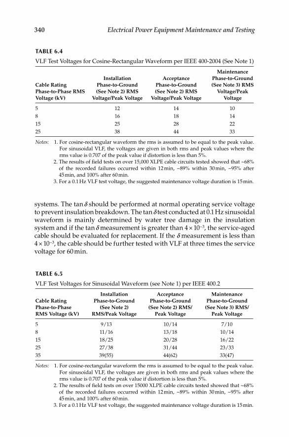
340 Electrical Power Equipment Maintenance and Testing
systems. The tan d should be performed at normal operating service voltage to prevent insulation breakdown. The tan d test conducted at 0.1 Hz sinusoidal waveform is mainly determined by water tree damage in the insulation system and if the tan d measurement is greater than 4 × 10⁻³, the service-aged cable should be evaluated for replacement. If the d measurement is less than 4 × 10⁻³, the cable should be further tested with VLF at three times the service voltage for 60 min.
TABLE 6.4
VLF Test Voltages for Cosine-Rectangular Waveform per IEEE 400-2004 (See Note 1)
Cable Rating
Phase-to-Phase RMS
Voltage (kV)
Installation
Phase-to-Ground
(See Note 2) RMS
Voltage/Peak Voltage
Acceptance
Phase-to-Ground
(See Note 2) RMS
Voltage/Peak Voltage
Maintenance
Phase-to-Ground
(See Note 3) RMS
Voltage/Peak
Voltage
5 12 14 10
8 16 18 14
15 25 28 22
25 38 44 33
Notes: 1. For cosine-rectangular waveform the rms is assumed to be equal to the peak value.
For sinusoidal VLF, the voltages are given in both rms and peak values where the
rms value is 0.707 of the peak value if distortion is less than 5%.
2. The results of fi eld tests on over 15,000 XLPE cable circuits tested showed that ~68%
of the recorded failures occurred within 12 min, ~89% within 30 min, ~95% after
45 min, and 100% after 60 min.
3. For a 0.1 Hz VLF test voltage, the suggested maintenance voltage duration is 15 min.
TABLE 6.5
VLF Test Voltages for Sinusoidal Waveform (see Note 1) per IEEE 400.2
Cable Rating
Phase-to-Phase
RMS Voltage (kV)
Installation
Phase-to-Ground
(See Note 2)
RMS/Peak Voltage
Acceptance
Phase-to-Ground
(See Note 2) RMS/
Peak Voltage
Maintenance
Phase-to-Ground
(See Note 3) RMS/
Peak Voltage
5 9/13 10/14 7/10
8 11/16 13/18 10/14
15 18/25 20/28 16/22
25 27/38 31/44 23/33
35 39(55) 44(62) 33(47)
Notes: 1. For cosine-rectangular waveform the rms is assumed to be equal to the peak value.
For sinusoidal VLF, the voltages are given in both rms and peak values where the
rms value is 0.707 of the peak value if distortion is less than 5%.
2. The results of fi eld tests on over 15000 XLPE cable circuits tested showed that ~68%
of the recorded failures occurred within 12 min, ~89% within 30 min, ~95% after
45 min, and 100% after 60 min.
3. For a 0.1 Hz VLF test voltage, the suggested maintenance voltage duration is 15 min.
DK4058_C006.indd 340DK4058_C006.indd 340 11/8/2008 12:41:15 PM11/8/2008 12:41:15 PM

Cables and Accessories 341
The advantages and disadvantages of VLF testing are listed below.
Advantages
The 0.1 Hz cosine-rectangular waveform has polarity changes • similar to those at power frequency. Because of the sinusoidal tran-sitions between the positive and negative polarities, traveling waves are not generated, and because of continuous polarity changes, dangerous space charges are less likely to be developed in the insulation.
Leakage current can be measured.•
Cables may be tested with an AC voltage approximately three times • the rated conductor-to-ground voltage with a device comparable in size, weight, and power requirements to a DC test set.
The VLF test can be used to test cable systems with extruded and • laminated dielectric insulation.
The VLF test with cosine-rectangular/bipolar pulse and sinusoidal • waveform works best when trying to locate a few defects from oth-erwise good cable insulation.
Disadvantages
When testing cables with extensive water tree degradation or PDs in • the insulation, low frequency withstand testing alone may not be conclusive. Additional diagnostic tests that measure the extent of insulation losses will be necessary.
Cables must be taken out of service for testing.•
6.10.3.5 PD Test
A PD is an electrical discharge that occurs in a void within the extruded cable insulation, at interfaces or surfaces such as shield protrusion and the insulation, or in a water tree within cable insulation when subjected to moderately HV. PD occurs as a series of PD pulses during each half cycle of an AC waveform. The rise time of the PD pulses is in the order of nanoseconds to tens of nano-seconds. The PD pulses tend to set an electromagnetic fi eld which propagates in both directions along the cable with a velocity of propagation based on the dielectric constant of cable insulation. PD characteristics depend on the type, size and location of the defects, insulation type, voltage, and cable tempera-ture. The insulation of full reels of extruded cables is tested for PDs at the factory at power frequency. This test is known to detect small imperfections in the insulation such as voids or skips in the insulation shield layer. It seems logical to perform PD measurements on newly installed and service-aged cables to detect any damage done during the installation of new cable or in-service degradation of cable insulation due to PDs.
DK4058_C006.indd 341DK4058_C006.indd 341 11/8/2008 12:41:15 PM11/8/2008 12:41:15 PM

342 Electrical Power Equipment Maintenance and Testing
There are two approaches that can be used for detecting PDs from installed cables in the fi eld. They are on- and off-line detection system. There are sev-eral commercial off-line systems available for measuring PD in medium-voltage systems (up to 35 kV). The online measuring system is based on measuring PDs at the cable-operating voltage. On the other hand, in the off-line system the PD measurements are done at a higher voltage than cable-operating voltage. This is due to the fact that the off-line testing requires the cable to be de-energized which results in cessation of any active PD activity. In order to activate the PD activity again in the de-energized cable during off-line testing, a higher voltage is needed to reinitiate the PD activity. The test instruments for PD testing for online or off-line comprise of the power supply, sensors and noise reduction, signal detection, and signal processing equipment. The power supply can be 60 Hz voltage, oscillating voltage, or VLF (0.1 Hz) voltage source. The sensors can be inductive couplers, capacitive couplers, or an antenna along with noise treatment and amplifi cation equip-ment. The signal detection and processing equipment includes digital oscil-loscope, spectrum analyzer, wave form digitizer, time-domain refl ectometer (TDR) (time resolved) and/or frequency resolved.
Although it is diffi cult to conduct a PD measurement in the fi eld because of external noise, this test can be performed in the fi eld where conditions warrant it is worth the time and expense to do so. The PD test gives the most convincing evidence whether the cable is in good condition and suit-able for service or needs to be repaired or replaced. The PD test is useful for both the laminated and extruded cable insulation systems. This test can be performed at power frequency or at any other frequency, such as 0.1 Hz (VLF).
To perform an off-line PD test the cable is disconnected from the network at both ends and correctly isolated. A voltage source and a coupling device, or sensor, are connected at one of the ends (near end), whereas the remote end is left open. The coupling device could be capacitive or inductive. The coupling device is connected to the PD detecting and processing systems. Variations of this setup include a measuring system with sensors at both ends and means to communicate the far end data to the near end processing devices or, in the case of a branched system, sensors placed at the end of each branch. Multiterminal testing also has the advantage of greater sensi-tivity in the PD testing of very long cable lengths as the pulse travel dis-tances are considerably shorter and consequently the related attenuation of pulse amplitude will be less. The following steps are implemented:
1. Low-voltage TDR is used to locate cable joints (splices) and other irregularities
2. Sensitivity assessment
3. PD magnitude calibration
4. PD testing under voltage stress
5. Test data analysis and documentation
DK4058_C006.indd 342DK4058_C006.indd 342 11/8/2008 12:41:15 PM11/8/2008 12:41:15 PM

Cables and Accessories 343
Sensitivity assessmentThe purpose of this step is to determine the value in picoCoulomb (pC) of the smallest PD signal detectable under the test conditions. In extruded dielectric cables PD activity in the range of several pCs is required, other-wise inadequate detection sensitivity may mask the existence of serious defects with low PD magnitudes. Inability to detect low levels of PD may result in false-negative situations that are expected to lead to unexpected post-testing service failures. In addition incorrectly identifi ed PD may lead to false-positive situations leading to unnecessary cable replacement. Therefore, a calibrated pulse, such as 5 pC, is injected at the near end. The PD estimator detects and records the response. If the refl ected signal cannot be seen above the fi ltered noise level, a larger signal, such as 10 pC, is injected. This process is repeated until the refl ected signal is observable. This deter-mines the smallest PD signal that can be resolved under the test conditions.
PD magnitude calibrationThe calibrated pulse generator is connected to the cable remote end. A large signal, such as 50 or 100 pC, is injected. The corresponding signal recorded at the near end is evaluated by integrating it with respect to time. The con-stant k is adjusted until the PD magnitude read is 50 or 100 pC. The instru-ment is now calibrated for measuring the apparent charge, q, of the PD.
PD testing under voltage stressOff-line tests can be carried out using different voltage sources. There is a good technical basis for testing up to 1.5 to 2.5 times of rated voltage to ensure that the PDIV of the cable is suffi ciently high enough to activate the PD activity. There is an increased risk of initiating damage at defects in aged cable systems that are innocuous at operating voltage if testing is car-ried out at voltages greater than 2.5 times of rated voltage. There is also an increased risk of failures during the PD testing. However, some utilities will request testing up to a maximum of three times of rated voltage on new cables, either on the reel or newly installed, to ensure that there was no damage during transportation or installation. In addition, some utili-ties will test up to three times of rated voltage, even though there is a sig-nifi cantly higher probability of failure during the testing, of the following cable systems:
Cable circuits with generic defects that may cause high failure rates, • e.g., some silane-cured cables can cause severe corrosion of alumi-num conductors.
Cable circuits that are being considered for silicone injection, the • rationale being that all cables with electrical trees will fail at higher test voltages. The higher test voltages could also initiate new electrical trees.
Cable circuits that may have suspect accessories and/or cables to • ensure operation during high load periods, e.g., during the summer months in some urban areas. The voltage in power frequency tests
DK4058_C006.indd 343DK4058_C006.indd 343 11/8/2008 12:41:15 PM11/8/2008 12:41:15 PM
344 Electrical Power Equipment Maintenance and Testing
may be applied for up to a maximum of 15 min to ensure that elec-trons are available in cavities to initiate PD. However, once PDs are detected, the voltage should be applied long enough to collect suffi -cient data up to a maximum of 15 s. Some PD testing organizations will decrease the voltage very soon after the onset of steady PD when testing extruded dielectric cable circuits.
As an example, the following steps are conducted for testing for voltage stress. The voltage is rapidly raised to the cable operating level (1.0 p.u.) at which it is maintained for several minutes as a conditioning step. The voltage is ramped to its maximum value (such as 2.0 or 2.5 p.u.). It then is returned to zero as quickly as possible. During this stress cycle, several sets of data are captured, each set encompasses an entire 60 Hz period. The rising and falling parts of the voltage help determine the PDIV and PD extinction voltage (PDEV), respectively. It should be apparent that off-line testing using higher voltages (elevated stress) than cable operating voltage may be a destructive test.
In summary, it is not possible to standardize a specifi c test protocol at the current time for either online or off-line tests. This may become possible as more data are collected. For off-line tests, the amplitude of the test voltage can be varied. For heavily aged systems, a maximum test voltage of 2 p.u. is suggested. As the anticipated condition of the cable improves, the test volt-age may be increased to as much as 2.5 p.u. New cables, either on the reel or newly installed, may be tested to a maximum of 3 p.u. at the concurrence of the cable owner and cable manufacturer. The test duration should be long enough to allow the availability of electrons to initiate PDs, but once PDs are detected, the voltage should be applied long enough to collect suffi cient PD data.
PD test data analysis and documentationThe PD test provider should provide cable users with a report of the cables tested and the PD test results. The PD test provider should give the cable user recommendations on possible corrective action to be taken. The report of the test results should include the value of PD detection sensitivity and a refer-ence to the method used in obtaining this value. The PD site location results must also be provided with an assessment of the accuracy limits within which these results can be interpreted under the conditions of the specifi c test. This becomes critical where the location is at or near a splice. Details to be included in the report are as follows:
Cable system identifi cation
1. Name of cable manufacturer
2. Cable section identifi cation (i.e., substation name, from switch number to switch number)
3. Cable voltage class
4. Cable insulation (if mixed, specify)
DK4058_C006.indd 344DK4058_C006.indd 344 11/8/2008 12:41:15 PM11/8/2008 12:41:15 PM

Cables and Accessories 345
5. Operating voltage (phase-to-neutral)
6. Conductor type and size (if mixed, specify)
7. Cable length
8. Location of splices
9. Cable vintage or year placed in service
10. Neutral type, for example, concentric wires, metal tapes, or fl at strap, and size
11. Type of construction, i.e., direct buried, duct, aerial, jacketed, unjack-eted, and so on
12. Splice type, if available
13. Termination type, i.e., pole-top, switching cabinet live-front/dead front, premolded, heat-shrink, and so on
PD test results
1. Test date.
2. Date of the most recent previous test.
3. Estimated cable length.
4. Splice location.
5. Background noise level.
6. Minimum resolvable PD signal pC magnitude (sensitivity) and how it was determined. If the sensitivity is lower than expected, provide the reason(s).
7. Test voltage levels.
8. At each test voltage level, the location of each PD site, along with the limits of accuracy.
9. At each voltage and site location, the number of PD events per second or per cycle of a sinusoidal excitation voltage.
10. At each voltage and site location, a phase-resolved PD representation (pC vs. phase angle for each PD event recorded), provided the excita-tion voltage is sinusoidal. Specify the number of cycles included in the phase-resolved diagram.
11. For a frequency-domain measurement, describe the spectral charac-teristics and the estimated location for each PD site. Specify the limits of accuracy.
12. Any other diagnostic results pertinent to the test method used.
13. An indication of the severity of the PD behavior, if PDs are detected, and recommendations on possible corrective action to be taken.
14. The format of data reporting may vary. For instance, some prefer reporting individual PD events in a three-dimensional (3D) form
DK4058_C006.indd 345DK4058_C006.indd 345 11/8/2008 12:41:15 PM11/8/2008 12:41:15 PM

346 Electrical Power Equipment Maintenance and Testing
with location, pC level, and phase angle at which each PD is initiated.
15. Variations of this 3D representation are also possible. Others prefer a set of two-dimensional representations, showing PD location with PDIV, and apparent charge (pC) versus phase angle for each PD site, at each voltage level, and PD repetition rate for each PD site at each voltage level.
6.10.3.6 AC Resonance Test
The resonant test systems are used to test cable and other electrical apparatus with AC voltage at power frequencies (50 or 60 Hz). This method has the advantage over other test methods, of stressing the insulation similar to normal operating conditions. In the past to test electrical apparatus at power frequency required bulky and expensive test equipment that was not porta-ble for on-site fi eld testing applications. The resonant test systems were developed that can be handled easily on-site for testing. Since the mid-1990s, the resonant test systems have been used for testing medium and HV cables in Europe and United States. This method can be used to test cable consisting of either XLPE, oil-impregnated paper and EPR, or a combination of these insulating materials. As the name implies, this test method is based on using AC at the operating frequency (50 or 60 Hz) as a test source using the princi-ple of resonance. Resonance is defi ned as the condition at which the net inductive reactance cancels the net capacitive reactance at operating fre-quency. The resonant circuit must have both capacitance provided by the cable under test and inductance provided by the reactor of the test set. When resonance occurs, the energy absorbed at any instant by one reactive element is exactly equal to that released by another reactive element within the system. In other words, energy pulsates from one reactive element to the other. Therefore once the system has reached a state of resonance, it requires no further reactive power since it is self-sustaining. The total apparent power is then simply equal to the average power dissipated by the resistive ele-ments in the inductor and cable system. Either parallel or series resonant circuits are normally used for conducting this test.
The series resonant test consists of a voltage regulator of an autotrans-former type (Toroidal, CTVT or Thoma) is connected to the supply volt-age. The regulator provides a variable voltage to the exciter transformer. The exciter transformer is fed by the output of the voltage regulator. This transformer steps the voltage up to a usable value by the HV portion of the circuit. The HV reactor L and the load capacitance C represent the HV por-tion of the circuit. The inductance of the HV reactor can be varied by changing the air gap of the iron core. The load capacitance C consists of the capacitance of the load. The coupling capacitance for PD measurement, stray capacitance and, in the case of tank-type (T) sets, the HV bushing. When testing, the HV reactor is adjusted so that the impedance of
DK4058_C006.indd 346DK4058_C006.indd 346 11/8/2008 12:41:15 PM11/8/2008 12:41:15 PM

Cables and Accessories 347
L corresponds to the impedance of C at the frequency of the supply voltage. Thus the circuit is tuned to series resonance at 50 or 60 Hz. The Q of the basic resonant circuit or with a low loss test specimen (e.g., XLPE cable, sulfur hexafl ouride switchgear, bushing, etc.) is typically 50 to 80. The HV reactor is designed for a minimum Q of 40. The system Q is designed around the anticipated load. In case of a fl ashover during testing on the HV side, the resonant circuit is detuned and the test voltage collapses immediately. The short-circuit current is limited by the impedance of the HV reactor. This means that the short-circuit current of a series resonant system with a Q of 40 is 2.5% of the load current to which it is tuned. The series resonant mode is well suited for sensitive PD measurements. Harmonics from the supply are better suppressed than in parallel mode.
The parallel resonant mode provides a more stable output voltage with test specimens, such as large generator windings, or other specimens with corona losses. The test voltage rate of rise is stable in parallel mode, independent of the degree of tuning and the Q of the circuit. Furthermore, parallel mode allows the test set to be energized to full voltage without a load. This is useful for calibrating the instrumentation and checking for the PD level of the test equipment. The test voltage rate of rise is stable in parallel mode, independent of the degree of tuning and the Q of the cir-cuit. Furthermore, parallel mode allows the test set to be energized to full voltage without a load. This is useful for calibrating the instrumentation and checking for the PD level of the test equipment. The average power absorbed by the system will also be at a maximum at resonance. The com-monly used measure of the quality in a resonant circuit is the quality factor, or Q. The power source of resonant circuits operating in the reso-nant mode (exciter and regulator) is used to supply the dissipated energy. Q is approximately equivalent to the ratio of the output kVA to the input kVA. Given kVA requirements of the load and the Q of the test system, the input power can be obtained by dividing the kVA by the Q. The correct mode of operation must be chosen according to the test objects and the measurements to be carried out. The parallel resonant mode provides a more stable output voltage with test specimens, such as large generator windings, or other specimens with corona losses.
Resonant test system are available that use variable inductance and vari-able frequency resonant and pulsed resonant test sources. A brief descrip-tion of the variable frequency resonant test system is as follows. The resonant test system with variable frequency mainly consists of the fre-quency converter, the exciting transformer, the coupling capacitors, and HV reactors with fi xed inductance. The frequency converter generates a variable voltage and frequency output which is applied to the exciter transformer. The exciter transformer excites the series resonant circuit consisting of the reactor’s inductance L and the cable capacitance C. The resonance is adjusted by tuning the frequency of the frequency converter according the formula:
DK4058_C006.indd 347DK4058_C006.indd 347 11/8/2008 12:41:15 PM11/8/2008 12:41:15 PM

348 Electrical Power Equipment Maintenance and Testing
= 1/21
( )2
f LCp
The tuning range of the test system is determined by the converter’s frequency range:
2
maxmax
minmin
fCfC
⎛ ⎞= ⎜ ⎟
⎝ ⎠
The average power absorbed by the system will also be at a maximum at reso-nance. The commonly used measure of the quality in a resonant circuit is the quality factor, or Q. The power source of resonant circuits operating in the reso-nant mode (exciter and regulator) is used to supply the dissipated energy. Q is approximately equivalent to the ratio of the output kVA to the input kVA. Given kVA requirements of the load and the Q of the test system, the input power can be obtained by dividing the kVA by the Q. The correct mode of operation must be chosen according to the test objects and the measurements to be carried out. The series resonant mode is well suited for sensitive PD measurements as well.
6.10.3.7 Summary of Testing Methods
The purpose of summarizing cable testing methods is to cite the advantages and disadvantages of these tests so that the reader can quickly determine the test method best suited for his application. The cable tests can be categorized into three categories: (1) hi-pot withstand tests, (2) general condition assessment (GCA) tests, and (3) PD tests. These tests can further be viewed from the perspec-tive of being destructive or nondestructive tests. Any test that uses the test source voltage to be higher than the in-service operating voltage could be classifi ed as destructive test because during testing the cable insulation will be subjected to a higher voltage than what it will see in service. Therefore, all hi-pot withstand tests would fall into this category. However, during a hi-pot test, if the voltage is applied in a steps and the leakage current is monitored, then the test may be clas-sifi ed as being nondestructive. The reasoning for this is that the test can be aborted before the insulation gets to a failure point since at every step of voltage application the leakage current is being monitored and evaluated before pro-ceeding to the next step. An application of this test procedure is the step-voltage DC hi-pot withstand test. The same cannot be said of AC hi-pot withstand test since there is no way to evaluate the leakage current, therefore this test would be considered as go-no-go test and considered to be destructive. The GCA tests and PD tests are classifi ed as nondestructive since the voltage applied during these tests is either the same, or lower than, or slightly above the in-service operating voltage. The advantages and disadvantages of the tests are as follow:
Hi-pot withstand testsUnder this category, cable tests that use HV source are listed. These tests are: DC hi-pot tests, AC hi-pot, AC resonant test, and VLF test. The advantages and disadvantages of the test that use hi-pot voltage source are
DK4058_C006.indd 348DK4058_C006.indd 348 11/8/2008 12:41:15 PM11/8/2008 12:41:15 PM

Cables and Accessories 349
DC hi-pot test:Advantages:
1. Has a long history of use
2. Very portable and convenient for fi eld test
3. Low power requirements
4. Is a good for conductive type defects (water in laminar cables)
Disadvantages:
Demonstrated to induce space charge which aggravates defects in • aged extruded cable long after the test’s conclusion
Is blind to high impedance defects such as voids and cuts•
Stress distribution is not the same as in-service conditions•
Cannot be compared to factory tests•
60 Hz hi-pot test and AC resonant testAdvantages:
Is good for conductive and high impedance defects•
Does not induce space charge, thereby minimizes the propagation of • defects in extruded cable
Replicates steady-state in-service conditions•
Can be compared to factory tests•
Disadvantages:
Most expensive and not practical for fi eld tests•
Highest power requirement except for AC resonant test•
Grows certain type of defects•
VLF hi-pot testsAdvantages:
Portable for fi eld testing•
Relatively low power requirements•
Is a good for conductive-type defect and high-impedance defects•
Does not induce as much space charge as DC hi-pot in aged extruded • cable
Causes some defects to grow rapidly resulting in shorter test time•
DK4058_C006.indd 349DK4058_C006.indd 349 11/8/2008 12:41:15 PM11/8/2008 12:41:15 PM

350 Electrical Power Equipment Maintenance and Testing
Disadvantages:
Aggravate defects in aged cable without failing them•
Does not replicate service conditions•
Cannot be directly compared to factory tests•
Not recommended for aged cable with multiple defects•
Stress distribution is not the same as in-service conditions•
Does not replicate normal stress distribution conditions with wet • regions
GCA testsGCA tests are those which determine the overall health of the cable insula-tion. These tests include: DF/tan d/PF, PD tests, dielectric spectroscopy, depolarization-return voltage, and depolarization-relaxation current. Each of these tests has their own advantages and disadvantages. Some of these tests are not covered in this book since they are beyond the scope. In general, the following can be stated for PF/DF and PD tests.
PF/DF (tan d)Advantages:
Considered to be nondestructive to cable insulation•
Tests are conducted at in-service voltage levels•
Monitor the overall condition of the cable insulation•
Effective in detecting and assessing conduction-type defects•
Can be compared to factory tests•
Portable for fi eld testing•
Disadvantages:
Require prior cable types and data for comparison•
Temperature dependant in extruded cables•
Blind to high-impedance defects such as cuts, voids, and PD•
Cannot detect singular defects in extruded insulation, such as water • tree
Not an effective test for mixed dielectric or newly installed cable•
Equipment is costly compared to hi-pot equipment•
PD testsTwo type of PD tests are considered, that is online PD testing and off-line PD testing. PD diagnostics tests are considered to be effective in locating defects in shielded power cables.
DK4058_C006.indd 350DK4058_C006.indd 350 11/8/2008 12:41:15 PM11/8/2008 12:41:15 PM

Cables and Accessories 351
PD diagnostics testsAdvantages:
Considered to be nondestructive•
Can detect and locate high-impedance defects such as void, cuts, • electrical trees, and tracking
Can be performed online in limited applications•
Effective at locating defects in mixed dielectric systems•
Disadvantages:
Limited to cables with a continuous neutral shield•
Requires a trained analyst to interpret measurements•
Cannot detect or locate conduction-type defects•
Not effective for branched network applications•
Online PD diagnosticsAdvantages:
Performed while circuit is energized•
Detect and locate some accessory defects and some cable defects•
Does not require an external voltage source•
Disadvantages:
Detects only 3% or less of cable insulation defects in extruded cable•
Not a calibrated test, therefore the test results are not objective•
Cannot be compared to factory tests•
Not effective by statistically signifi cant data correlating results to • actual cable system defects or failures
Requires access to the cable every few hundred feet depending on • the cable construction
Requires that manholes be pumped to access cable•
Cannot be applied to long directly buried cables•
Off-line PD diagnosticsAdvantages:
Can be readily compared to factory baseline tests•
Replicates steady-state and transient operating conditions•
Can locate electrical trees with PDs•
Locates all defect sites in one test from one end of the cable•
DK4058_C006.indd 351DK4058_C006.indd 351 11/8/2008 12:41:16 PM11/8/2008 12:41:16 PM

352 Electrical Power Equipment Maintenance and Testing
Is effective with mixed dielectric cables•
Can test up to 1 to 3 miles of cable depending on the cable construction•
Provides onsite report of the test results•
Disadvantages:
Need circuit outage for test to be performed•
Equipment is expensive when compared to other tests•
6.11 Latest Trends in Cable Condition Monitoring
and Aging Assessment
6.11.1 Electronic Characterization and Diagnostic (ECAD®) System
The ECAD system is a fully automated electrical characterization and diagnos-tic system that is used in the nuclear industry for monitoring the conditions of the instrumentation and control cables installed in nuclear power plants. The ECAD system, is a PC-driven data acquisition system. It measures various standard electrical characteristics as well as providing the TDR signature. The ECAD system measures DC and AC resistance, impedance, capacitance, DF, inductance, quality factor, phase angle, and TDR signature of the cables. This computer-based storage/retrieval system provides capability for accurate, lumped data comparison with previous historical information on the same device. The TDR signature permits easy and quick identifi cation of faults in both magnitude and location of the cable. The ECAD system can be used for condition monitoring, troubleshooting, and trending of the measured data. The ECAD system maintains the data in a retrievable format. Reports can be generated quickly with built-in analysis packages to perform the necessary checks on each type of circuit.
6.11.2 Cable Indentor
Traditional electrical tests, such as insulation resistance and hi-pot testing, are not sensitive enough to detect the level of age-related deterioration in cables. Present electrical tests do not detect aging-induced cracks in the insulation that penetrate to the conductor if the cable is dry. Therefore, mea-surement of the mechanical properties of the cable polymers is the best way to track the vulnerability of cables to age-induced cracking, which could lead to a cable failure in a moist or wet environment. The cable indentor aging monitor developed by the Franklin Research Center and the Electric Power Research Institute (EPRI) is used to perform the in situ, nondestruc-tive test for assessing age-induced degradation. The cable indentor consists
DK4058_C006.indd 352DK4058_C006.indd 352 11/8/2008 12:41:16 PM11/8/2008 12:41:16 PM

Cables and Accessories 353
of an anvil that is pushed against the surface of the cable jacket or insulation and, depending on the depth of penetration of the indentor for a given force, the hardness of the cable insulation is determined. It is expected that the depth of penetration for a given force will decrease as the cable materials age, thereby indicating the age of the cable insulation.
6.11.3 Oscillating Wave (OSW) Testing
This method was selected by a CIGRE task force as an acceptable compro-mise using the following criteria:
1. Ability to detect defects in the insulation that will be detrimental to the cable system under service conditions, without creating new defects or causing any aging
2. Degree of conformity between the results of tests and the results of 50 or 60 Hz tests
3. Complexity of the testing method
4. Commercial availability and costs of the testing equipment
The purpose of the OSW testing method is to detect defects that may cause failures during service life without creating new defects that may threaten the life of the cable system. Although OSW testing does not have a wide reputation with respect to cable testing, it is already used for testing in met-al-clad substations and is being recommended for gas-insulated cable test-ing. The following description is based on the information given in IEEE std 400-2001, “IEEE guide for fi eld testing and evaluation of the insulation of shielded power cables systems.”
General description of test methodThe test circuit consists of a DC voltage supply that charges a capacitance and a cable capacitance. After the test voltage has been reached, the capaci-tance is discharged over an air core coil with a low inductance. This causes an oscillating voltage in the kilohertz range. The choice of and depends on the value of to obtain a frequency between 1 and 10 kHz.
Advantages:
OSW method is based on an intrinsic AC mechanism•
Principal disadvantages of DC (fi eld distribution, space charge) do • not occur
Method is easy to apply•
Method is relatively inexpensive•
For both HV and MV cable systems, • f * OSW/DC is low (0.2 to 0.8), indicating the superiority of OSW over DC voltage testing
DK4058_C006.indd 353DK4058_C006.indd 353 11/8/2008 12:41:16 PM11/8/2008 12:41:16 PM

354 Electrical Power Equipment Maintenance and Testing
Disadvantages:
Effectiveness of the OSW test method in detecting defects is better • than with DC but worse when compared with AC (60 Hz)
In particular for medium-voltage cable systems, the factor • f * OSW/60 Hz voltage is approaching 1, indicating the mutual equivalence
For HV cable systems, • f * OSW/60 Hz is signifi cantly higher (1.2–1.9), which means that OSW is less effective than 60 Hz
Note: f * OSW/60 Hz is the ratio of breakdown values for a dielectric containing a standard defect when using, respectively, OSW voltage and 60 Hz voltage.
Test apparatusThe cable is charged with a DC voltage and discharged through a sphere gap into an inductance of appropriate value so as to obtain the desired frequency. The voltage applied to the cable is expressed as:
= − π1( ) exp( ) cos(2 )V t V e tLC fta
whereV1 is the charging voltage provided by the generatora is the damping ratioC is C1 + C2f is 1/2π(LC)1/2
Test procedureMost of the tests carried out so far are of an experimental nature. Artifi cial defects like knife cuts, wrong positions of joints, and voids in the insulation were created and subjected to different testing procedures of which one method was the OSW testing. These test procedures were intended to obtain breakdown as a criterion for comparison. The general testing procedure is as follows:
1. Start to charge the cable with a DC voltage of about one or two times the operating voltage
2. Increase with steps of 20–30 kV
3. Produce 50 shots at each voltage level
4. Time interval between shots to be 2–3 min
5. Proceed until breakdown occurs
6.11.4 Broadband Impedance Spectroscopy Prognostic/Diagnostic Technique
The broadband impedance spectroscopy (BIS) technique was developed by the Boeing Company under the sponsorship of the U.S. Federal Aviation Administration (FAA) to monitor the condition of installed aircraft wiring.
DK4058_C006.indd 354DK4058_C006.indd 354 11/8/2008 12:41:16 PM11/8/2008 12:41:16 PM
Cables and Accessories 355
Under the sponsorship of the U.S. Nuclear Regulatory Commission (NRC), the BIS technique was evaluated for application to electric cables used in nuclear power plants. Cable samples, which are representative of a commonly used type of low voltage instrumentation and control cable in nuclear power plants, were prepared and received accelerated aging to simulate various types of deg-radation expected in actual plant service conditions, including the following:
Global thermal degradation•
Global thermal degradation plus localized hot spots•
Thermal degradation with cracking•
Abrasion damage•
The cable samples were then tested in the laboratory using the BIS method, and the data were analyzed to draw conclusions on the effectiveness of the method. Several test confi gurations were evaluated, including
Constant temperature and humidity along the cable with no load • attached
Constant temperature and humidity along the cable with a load • attached
Varying environments along the length of the cable with no load attached•
The results of the NRC sponsored research demonstrated that the BIS method can be used on nuclear power plant cables, or on cables used in industrial plants. This method may represent a breakthrough in the prognostics and diagnostics of installed cable systems. The technique provides a nondestruc-tive means of monitoring cable systems in their installed confi guration. Age-related degradation can be detected in an incipient stage prior to failure.
The following are the specifi c conclusions from this research:
The BIS method was clearly able to detect the presence of thermal deg-• radation associated with the cables used in this study. Specifi cally, the impedance phase spectra of the cables tested were observed to increase as the amount of thermal degradation on the cable increased. This increase can be used as an indicator of global thermal degradation.
The BIS method was able to detect the presence of localized thermal • degradation, or hot spots on the cables. Specifi cally, a shift in the zero crossings of the impedance phase spectra was observed when a hot spot was present on the cable.
An approach was developed for locating hot spots within a cable • using models of the cable electrical properties. The models were able to predict the hot spot locations within ±10%.
The BIS method was not sensitive enough to distinguish between • the different severities and sizes of hot spots simulated at low
DK4058_C006.indd 355DK4058_C006.indd 355 11/8/2008 12:41:16 PM11/8/2008 12:41:16 PM
356 Electrical Power Equipment Maintenance and Testing
frequencies. However, high-frequency data were able to distinguish between the severity levels. Additional research is warranted to establish the sensitivity limits for this technique.
The BIS method was able to detect and locate the presence of abrasion-• related damage on a cable. The models and approach used are similar to that for detecting and locating thermal hot spots.
The BIS method was demonstrated to be effective for detecting and • locating degradation on cables with an attached load. This is impor-tant since it is desirable to have a technique that can test cables in their installed confi guration, without having to disconnect them from attached equipment.
The BIS method was able to detect simulated cracking damage on • cables. However, the simulation method used in this study was determined not to accurately represent the cracking phenomena. Additional research is warranted to more accurately evaluate the BIS method on actual cable cracking.
The BIS method was able to detect the presence of localized thermal • degradation, or hot spots on the cables even with a varying environ-ment along the external surface of the cables.
While the BIS method shows great promise as a prognostic and diagnostic technique for installed cable systems, additional research is continuing before this method can be applied in the fi eld to power cables.
6.12 Cable Fault Locating Methods
This section describes the existing methods and techniques used for fault loca-tion. Faults may vary widely, and similar faults may exhibit different symp-toms depending upon the cable type, operating voltage, soil condition, and so on. Basically, faults can be considered to be shorts, opens, or nonlinear. A short is defi ned as a fault when the conductor is shorted to the ground, neutral, or another phase with a low impedance path. This type of fault is also referred to as a shunt fault. An open fault is defi ned as when the conductor is physically broken and no current fl ows at or beyond the point of break. The nonlinear type of fault exhibits the characteristics of an unfaulted conductor at low voltages but shows a short at operating or higher voltages. This nonlinear fault is also known as a high-resistance fault. These fault types are shown in Figure 6.8.
Fault location methods can be divided into two general categories: terminal techniques and tracing techniques.
6.12.1 Terminal Techniques
These involve measuring some electrical characteristics of the faulted conductor from one of the cable terminals and comparing it with unfaulted
DK4058_C006.indd 356DK4058_C006.indd 356 11/8/2008 12:41:16 PM11/8/2008 12:41:16 PM

Cables and Accessories 357
conductor characteristics in terms of the distance of the fault. The effective-ness of this method is a function of the accuracy of installation records. The terminal techniques category can be further subdivided in terms of the actual methods employed, which are bridge, radar, and resonance methods. Terminal methods do not pinpoint faults, however they localize faults.
Bridge methodsVarious types of bridge confi gurations may be used to locate faults. The most common are the Murry loop and the capacitance bridge. The Murry loop bridge uses a proportional measure so that it is not necessary to know the actual cable resistance. Its principle of operation involves a continuous loop of cable to form the two arms of the bridge. It is necessary to have an unfaulted conductor available to form such a loop. Also, it requires a low-resistance jumper to be installed at the far end of the cable. The Murry loop bridge connections are shown in Figure 6.9. When the bridge is balanced, the distance to the fault can be found by the following expression:
Short
Shunt faults
High-impedance nonlinear
Open conductor faults
RF
RF1 RF2
Note: Either RF1, RF2 or/both faultresistances can be low enough to
constitute a short.
RF3
FIGURE 6.8Types of cable faults.
x L–x
A
B
G L
Point offault
Faulted conductor
Good conductorJumper
FIGURE 6.9Murry loop bridge method.
DK4058_C006.indd 357DK4058_C006.indd 357 11/8/2008 12:41:16 PM11/8/2008 12:41:16 PM
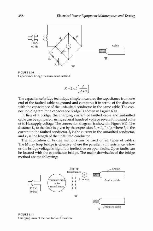
358 Electrical Power Equipment Maintenance and Testing
120 V60 Hz Cable
A B
R2
R1
Cs
D
FIGURE 6.10Capacitance bridge measurement method.
Faulted cable
Unfaulted cable
Sheath
Ammeter
Step-uptransformer
Variable ratioauto
transformer120 V60 Hz
FIGURE 6.11Charging current method for fault location.
2
+
AX L
A B⎛ ⎞= × ⎜ ⎟⎝ ⎠
The capacitance bridge technique simply measures the capacitance from one end of the faulted cable to ground and compares it in terms of the distance with the capacitance of the unfaulted conductor in the same cable. The con-nection diagram for a capacitance bridge is shown in Figure 6.10.
In lieu of a bridge, the charging current of faulted cable and unfaulted cable can be compared, using several hundred volts or several thousand volts of 60 Hz supply voltage. The connection diagram is shown in Figure 6.11. The distance L1 to the fault is given by the expression L1 = L2(I1/I2), where I1 is the current in the faulted conductor, I2 is the current in the unfaulted conductor, and L2 is the length of the unfaulted conductor.
The application of bridge methods can be used on all types of cables. The Murry loop bridge is effective where the parallel fault resistance is low or the bridge voltage is high. It is ineffective on open faults. Open faults can be located with the capacitance bridge. The major drawbacks of the bridge method are the following:
DK4058_C006.indd 358DK4058_C006.indd 358 11/8/2008 12:41:16 PM11/8/2008 12:41:16 PM
Cables and Accessories 359
1. Requires access to both ends of the cable
2. Connection must be of low resistance
3. All lead lengths must be accounted for
4. Cables must be of the same size
5. Requires considerable operator skill
6. Diffi cult to use on branched systems
Radar methodThe radar (refl ection or pulse-echo) method is based upon the measurement of the time that it takes the pulse to reach a fault and refl ect back. The dis-tance d of the fault for uniform cable can be obtained from the expression d = vt/2, where v is propagation velocity and t is the time it takes for the pulse to travel to the fault and back. There are two types of output pulse duration employed in radar methods.
The short duration pulse type is most commonly used in radar test sets for testing power cables. The pulse duration is short in comparison to propagation time to the fault. The width of the pulse is usually wide enough to be able to be observed on the oscilloscope. Practically, the pulse width must be greater than 1% of the transit time for the entire cable length under test. Most com-mercial equipment has provisions for changing the pulse width depending on cable length. The pulse magnitudes are very small, usually on the order of few volts. The short pulse does not lend itself well to the interpretation of data because of refl ections from splices or the nonuniformity of cable size.
The long-pulse system employs long step pulses as compared to the tran-sit time of signal from one end of the cable to the fault and back. Any discon-tinuities in cable are seen as changes in the voltage level of the step pulse. It is easier to interpret the data in a long-pulse system; that is, the faults can be differentiated from splices, and changes in cable size can be easily observed.
In radar systems the scope trace shows the transmitted and refl ected signal. The separation of the two signals is measured and multiplied by the scope calibration to give the transit time. The refl ected wave can be expressed in terms of the transmitted wave and circuit constants as follows:
−=
+ tr
R Zl l
R Z
wherelr is the refl ected wavelt is the transmitted waveR is the resistance at the end of the lineZ is the impedance of the line
If the line is open-circuited, then R = ∝ and the refl ected wave is lr = lt. Therefore, the refl ected wave is of the same magnitude and same polarity as the transmitted wave. If the line is short-circuited, R = 0 and the refl ected
DK4058_C006.indd 359DK4058_C006.indd 359 11/8/2008 12:41:17 PM11/8/2008 12:41:17 PM

360 Electrical Power Equipment Maintenance and Testing
wave is lr = −lt. Therefore, the refl ected wave in this case is of equal magnitude to the transmitted wave but 180° out of phase. These two conditions are shown in Figure 6.12.
The radar can be applied to all types of cable systems provided the propaga-tion velocity is constant along the length of the cable. The radar system does not work very well with nonlinear faults. However, it can be used when the nonlinear fault impedance is burned to a low resistance value. To provide this fl exibility, three major variations of radar systems are available: the arc radar system, the free oscillation system, and the differential radar system. The arc radar uses a HV pulse system so that the high-impedance (nonlinear) faults can be burned down until they appear as shorts and the radar pulse can be refl ected from the arc short. The free oscillation system is also used for high-impedance faults in which the breakdown of the arc causes a pulse to be transmitted down the cable. In this method the cable end at which measure-ments are made is terminated in a high impedance (i.e., open) so that the pulse formed at the arc is refl ected from the open end to the short at the arc and back to the open end. This refl ection back and forth continues until the energy is completely absorbed by the cable. The period of signal is four times the transit time of the pulse as it travels the distance of the fault. Therefore, the distance to the fault is one-fourth the product of the propagation velocity and transit time. Differential radar is applicable for fault location on branched systems. It is based on the fact that a faulted cable phase is almost always paralleled by an identical unfaulted phase. The radar prints of two phases will be identical, except that part of the print associated with the fault itself. The differential radar signal is applied to both phases simultaneously and the return signals are subtracted. The radar pulse input shows at the point of the fault.
Transmitted pulse
Transmitted pulse
Reflected pulse
Reflected pulse
Open in thecable
Short inthe cable
Splices
Splices
FIGURE 6.12Typical wave forms for open- and short-circuit conditions in cable.
DK4058_C006.indd 360DK4058_C006.indd 360 11/8/2008 12:41:17 PM11/8/2008 12:41:17 PM

Cables and Accessories 361
Resonance methodThe resonance technique is based on the principle of wave refl ection. The resonance method for fault location measures the frequency at which the length of the cable between the terminal and the fault resonate. The reso-nant frequency is inversely proportional to the wavelength. The distance d of the fault can be determined by the following expression:
r
Vd
f N=
whereV is the propagation velocityfr is the resonant frequencyN is the number of quarter- or half-wavelengths
Normally, quarter-wave resonance is used for locating shorts, in which case N = 4, and half-wave resonance is used for locating opens, in which case N = 2. The resonance technique uses a frequency generator (or oscilla-tor), which is connected to the end of the faulted cable. The frequency is varied until resonance is reached. At resonance, the voltage changes rap-idly from voltage at nonresonance frequency. The voltage will increase for shorts and decrease for opens, respectively.
The minimum frequency required is determined by the cable length, and the maximum frequency is determined by the distance to the nearest point at which a fault may occur. For insulated cable the phase shift governs the speed of the transmitted and refl ected wave to the fault and back. The phase shift is a function of the dielectric constant of the insulating material. Usually, the velocity of propagation for insulated cables varies between one-third and one-fourth of the velocity of propagation of bare conductors, which is 984 ft./μs. Therefore, the velocity for cable will be somewhere between 328 and 246 ft./μs. Therefore, for each insulating medium its dielectric constant must be known for fault location. The relationship between frequency and dis-tance to the fault is given by the following expression:
r
466Nd
f K=
whereN is the number of quarter- or half-wavelengthsfr is the resonance frequency (MHz)K is the dielectric constant of cabled is the distance to the fault
This method can be used on all types of cables and works will on branched systems. It does not work very well with nonlinear faults.
DK4058_C006.indd 361DK4058_C006.indd 361 11/8/2008 12:41:17 PM11/8/2008 12:41:17 PM

362 Electrical Power Equipment Maintenance and Testing
6.12.2 Tracer Techniques
Trace techniques are those that involve placing an electrical signal on the faulted feeder from one or both ends, which can be traced along the cable length and detected at the fault by a change in signal characteristics. The fol-lowing methods are available under this classifi cation:
1. Tracing current
2. Audio frequency (tone tracing)
3. Impulse (thumper) voltage
4. Earth gradient
Tracing current methodIn this application both DC and AC methods are employed. This method can be used for fault location on a branched system as well as on a straight uni-form cable system. The fault current is injected into the circuit formed by the faulted conductor and the ground, and a detector is then used to measure the cable current at selected manhole locations. This technique is applicable where fault resistance is low or the voltage of the test set is high enough to send suffi cient current through the faulted conductor. This method is mostly applicable for duct line installations because it is suffi cient to know the fault between manholes, since the entire section of cable between manholes must be replaced when faulted.
The major consideration for use of this method is to assure that substantial amount of return current is via the ground path rather than the neutral. If all the current fl ows through the neutral, current seen by the detector is canceled for three-conductor cables, and there is no output from detector. This is very important for insulated neutral cables, such as PILC, where it is necessary to assure neutral to ground contact between the point of the measurement and the fault.
The tracing DC method uses a modulated DC power supply ranging from 500 V to 20 kV and current ranging from 0.25 to 12.5 A. The detector can be either an electromagnetically coupled circuit using a pickup coil and a galvanometer to detect directional signal, or test prods may be used on the cable sheath, using a drop-of-potential circuit with a galvanometer for signal-direction detection.
The tracing AC method uses a 25 or 60 Hz modulated transmitter consist-ing of 100% induction regulation or a constant-current transformer. The detectors can consist of either a split core current transformer and an amme-ter or a sheath drop detection circuit consisting of test prods and a millivolt meter. The test set range is from 15 to 450 kVA, and audio amplifi ers are avail-able with output meters, headsets, or speakers.
This method applies to direct buried, insulated cable for a short-to-ground fault. It is not very effective for other types of faults or cable confi gurations. Audio frequency (tone tracing) can be used to locate phase-to-ground faults (or to neutral) in concentric neutral cables if the neutral can be isolated from
DK4058_C006.indd 362DK4058_C006.indd 362 11/8/2008 12:41:17 PM11/8/2008 12:41:17 PM

Cables and Accessories 363
the ground so that the fault return current fl ows through the ground. If the neutral cannot be isolated, substantial fault return current may fl ow through the neutral, canceling the magnetic fi elds and thus reducing the pickup sen-sitivity. This technique can be used equally well to locate and identify cables. Because of its application to insulated cable, audio frequency is most com-monly used for fi nding secondary faults. This method is very effective for faults that are near zero resistance. It is not as effective for resistance faults above a few ohms. This method is particularly applicable to low-voltage class systems.
Audio frequency (tone tracing) methodIn this method, audio frequency is injected in the fault circuit formed by the faulted cable and the ground. The fl ow of current through the conductor causes a magnetic fi eld, which exists both in air and ground. The magnetic fi eld can be sensed by using a simple magnetic loop antenna. Moreover, the magnetic fi eld can be resolved into horizontal and vertical components for predicting antenna orientation. The loop antenna that responds to the hori-zontal component of the magnetic fi eld has maximum excitation directly above the cable, whereas the loop antenna that responds to the vertical com-ponent of the magnetic fi eld has minimum excitation. Also, the magnetic fi eld varies in the vicinity of the fault. The magnetic fi eld characteristics change beyond the fault because of no current fl ow, and therefore the hori-zontally polarized antenna output falls off rapidly. The change in character-istics of the vertical component of the magnetic fi eld is not as pronounced when moving beyond the point of the fault location. The magnetic fi elds are a function of the current in the cable and therefore essentially constant along the cable route.
The receiver sensitivity is a function of antenna gain to obtain maximum output. The receiver employs high-gain amplifi ers for the same purpose. The detectors are usually made of exploring coils.
Impulse (thumper) methodThis method consists of using a charge capacitor to transmit a high-energy pulse between the faulted conductor and ground. The pulse creates an arc at the fault, which in turn heats the surrounding air, and the energy is released as an audible thump. The fault location can be found by listen-ing to the acoustical thump or by tracing the magnetic fi eld generated by the arc. A functional diagram of fault location using the impulse is shown in Figure 6.13.
The impulse source is a capacitive discharge circuit consisting of power supply, capacitor bank, and HV switch. Typical capacitor discharge (thumper) test sets are shown in Figure 6.14. The impulse signal can be detected by means of a magnetic loop antenna, a microphone, an earth gradient detector, or a seismic transducer. The relationship between signal loudness and duration depends on the physical sensation. The tendency is for the loudness to increase with the duration; however, beyond a certain point the impact on the loudness is negligible. This method has been applied to both secondary and HV systems.
DK4058_C006.indd 363DK4058_C006.indd 363 11/8/2008 12:41:18 PM11/8/2008 12:41:18 PM

364 Electrical Power Equipment Maintenance and Testing
The major application of the impulse method is to faults where an arc is read-ily formed. This method can be made effective for faults down to zero resis-tance (dead shorts), depending upon the source of surge tracing methods because a dead short fault does not produce a thump. Signal detection can be divided into the following methods:
FIGURE 6.13Impulse (thumper) method for fault location.
FIGURE 6.14Capacitor discharge (thumper) test sets, 20 kV with 60 mA burn capacity. (Courtesy of Megger,
Inc., Valley Forge, PA.)
DK4058_C006.indd 364DK4058_C006.indd 364 11/8/2008 12:41:18 PM11/8/2008 12:41:18 PM
Cables and Accessories 365
Acoustic signal pickup: In this case the fault of high resistance is arcing over due to the periodic voltage pulses, which makes a very loud thumping sound. Detection can be very simply accomplished by patrolling the line and listening to the noise of the voltage discharge. Audio amplifi ers with suitable pickup of electronic type, head-phones, or a stethoscope can be used.
Electromagnetic pickup: When a fault of zero resistance (i.e., fault impedance is low compared to surge impedance) is being located, then of course there will be no noise. Also, even faults of high resis-tance when surrounded by mud and water will not give off loud noise. Faults of line-to-line or conductor-to-sheath, where the outer sheath is not broken, will not give off any loud noise. For these cases, a detector that traces the impulse signal to the fault by electromag-netic coupling can be used. It consists of pickup coil and a detector. The detector amplifi es the signal, and detection can then be made by galvanometer. It is effective for duct lay and nonlead buried cable.
Impulse current pickup: In this method impulse current signals are derived from a linear coupler, which can be incorporated in the surge generator, or an external linear coupler can be used with any surge generator or HV DC test set. The linear coupler in both cases is in the earth return (cable sheath) circuit to the surge generator or HV DC test set. High-resistance, fl ashing, and intermittent fl ashing faults are located using the external pulses generated by the HV surge generator. The signals generate1d are stored digitally in the memory of the test set. The stored wave form can be extracted con-tinuously from the digital memory and displayed on a low-speed oscilloscope. Measurements of fault position can be directly mea-sured digitally in microseconds, thus calculating an accurate esti-mate of the distance of the fault location by the following formula:
pDistance to fault
2
T VL
×=
where T is in microsecondsL is in feetVp is the velocity of propagation of electromagnetic waves for the cable
dielectric. It should be noted that the propagation factor varies with distance to the fault. Consequently this weakness in the method limits the accuracy.
Arc-refl ection methodThe arc-refl ection method combines an impulse generator to a TDR through an arc refl ection fi lter. This combination of equipment provides an inte-grated system to locate all cable faults. For high resistance (nonlinear) faults,
DK4058_C006.indd 365DK4058_C006.indd 365 11/8/2008 12:41:18 PM11/8/2008 12:41:18 PM
366 Electrical Power Equipment Maintenance and Testing
arc refl ection applies an oscillatory, HV impulse to the cable under test. The high impulse causes the high-resistance fault to break down, thus causing a low- resistance arc at the fault. The arc-refl ection analyzer simultaneously applies high-frequency, low-voltage pulses to the cable to refl ect from the low- resistance arc. The refl ected pulses are displaced as intermittent negative refl ections on the arc-analyzer screen. The arc refl ection fi lter protects the analyzer against the HV of the impulse generator. The fi lter also limits the applied HV to just enough to create breakdown at the point of the fault. The arc-refl ection method can detect open neutrals or phases, low-resistance faults (<200 Ω) between phases or between a phase and the neutral, water saturation, and good versus bad splices. The trace on the analyzer screen will display a charac-teristic signature for each of the above conditions. To determine the location of the fault, the refl ection analyzer will automatically display the distance to the fault in feet or meters based on the velocity propagation constant of the cable.
Earth gradient methodThis method locates faults by injecting a fault current into the faulted circuit formed by the conductor and earth return. The current spreads into the ground, and potential is developed in the ground between fault and current injection point. The voltage drop between any two points on the ground sur-face can be measured. Usually, the direction of the voltage drop points toward the fault location. As the fault is approached by moving along the cable length, the voltmeter defl ection decreases until the null point is achieved directly over the fault location. However, when the fault location is passed, the voltmeter defl ection increases again. In this method precise loca-tion of the cable is necessary for pinpointing the fault location.
Where precise routing of cable is not known, a DC or pulsed fault current source may be used to locate the fault using the earth gradient technique. In this case the meter direction will always be toward the fault location. To minimize diffi culties and make judicious use of time in locating the fault, a simple procedure is usually followed; the negative probe is always inserted fi rst and the positive probe is moved to obtain maximum positive defl ection of the voltmeter. By following this procedure the defl ection will then always be in the general direction of the fault, and fault tracing can proceed in sequence until the fault is located. This method at best is time consuming, and at worst it will not work at all, especially when cable lay is not known. The limitation of this method is the measurement sensitivity, because ground potential is a function of both cable depth and fault distance.
The fault current source can be an AC tone, a pulse, or DC voltage. With an AC tone, the voltmeter will show an amplitude of large magnitude on either side of the fault, whereas the amplitude will fall off as the fault location is passed. Also, care must be taken to minimize 60 Hz interference. The DC source is most commonly used, which provides suffi cient current fl ow through nonlinear faults. The pulse source is also similar to the DC source, except that it offers higher fault currents. The earth gradient technique is used to locate conductor-to-ground faults. This method may not be applicable
DK4058_C006.indd 366DK4058_C006.indd 366 11/8/2008 12:41:18 PM11/8/2008 12:41:18 PM

Cables and Accessories 367
to concentric neutral cables because much of the current returns through the neutral rather than the ground, making measurements rather diffi cult. Therefore, the earth gradient method is most applicable to insulated wire cables, which are usually found in secondary distribution systems.
A special application of the earth gradient method is the DC sheath poten-tial difference method. In this method a DC from a 6 V battery is passed through a short length of a faulted lead sheath cable. A voltage drop appears between the faulted conductor and the lead sheath, which can be measured at one of the cable terminals. This connection is shown in Figure 6.15. If the fault resistance is low enough or the internal resistance of the voltmeter is high enough, a voltage will be measured on the unfaulted side of the battery. Therefore, to locate the fault the battery contacts can be moved in the fault direction until fault is located.
6.12.3 Application Guide for Cable Fault Locating
Cable fault locating in the past has been more of an art than a science. The tools used were megohmmeter, shovels, and hacksaws. The common tech-nique for locating faults was the halving technique, which can be described as follows: “Cut cable at halfway point after excavation of a hole, check resis-tance with a megohmmeter. If the value of resistance is acceptable, move to one-quarter the length of the line, then to one-eighth length, and so on. Repeat the same procedure on the second half of the remaining length of the cable until the precise point of fault is found.” The halving technique is time consuming and costly compared to the modern methods that are now available for fault location. Instruments are available today to, fi rst, fi nd the fault, second localize the fault, and third, pinpoint the fault. To achieve these objectives, the following practical application guide is offered for fault locat-ing using the terminal and tracer methods on transmission and distribution circuits. A summary is given in Table 6.6.
Locate faults in primary cableThe strategy for fi nding cable faults in primary cable consists of the follow-ing steps:
VProds
Fault
Sheath
Conductor
FIGURE 6.15DC sheath potential difference method.
DK4058_C006.indd 367DK4058_C006.indd 367 11/8/2008 12:41:18 PM11/8/2008 12:41:18 PM

368 Electrical Power Equipment Maintenance and Testing
1. Test using an insulation resistance tester
2. Analyze
3. Localize
4. Locate
After a section of cable has been de-energized and isolated in preparation for cable fault locating, it is strongly recommended that a fi xed strategic plan be followed for locating the fault. Although most faults are “shorts” between conductor and ground, conductor-to-conductor “shorts” and series opens also occur. Helpful information can be gathered by characterizing the fault with an insulation resistance tester.
Make a series of measurements with the insulation resistance tester using Figure 6.16 as follows:
TABLE 6.6
Summary of Cable Fault Locating Methods
Method Criteria Parallel Fault (Shorts) Series Fault (Open)
Terminal measurement techniques
Bridge: Murry loop Uses cable length
sensitivity
Low resistance
(≤ 200 ΜΩ)
—
Capacitance bridge Uses capacitance from
conductor to sheath
High resistance High resistance
Radar: Pulse Produces a short-
duration pulse
Low resistance
(≤ 200 ΜΩ)
High resistance
Resonance Produces a standing
wave
Low resistance High resistance
Tracer techniquesTracing current DC current Low resistance —
AC current Low resistance —
Audio frequency Transmitting audio
tones
Low resistance —
Impulse (thumper) Transmission of
high-energy pulse
Low resistance High resistance
Earth gradient Drop at potential Low resistance —
End A End BMegger test from end “A” indicates a short-circuit.Megger test from end “B” indicates an open-circuit.
FIGURE 6.16Locate fault in primary cable.
DK4058_C006.indd 368DK4058_C006.indd 368 11/8/2008 12:41:18 PM11/8/2008 12:41:18 PM

Cables and Accessories 369
1. From side “A,” connect the insulation resistance tester between the faulted conductor and ground (sheath or concentric neutral and ground if the outside layer of cable is jacketed). Record the reading.
2. From side A connect the insulation resistance tester between each of the other phases (one at a time) and ground (if the cable is three-phase).
3. Repeat all insulation resistance tests from side “B” and record all readings.
Analyze the dataIf the insulation resistance of the faulted conductor is less than 50 Ω or more than 1 MΩ, the fault will be relatively easy to locate. For values between 50 Ω
and 1 MΩ, the fault will be more diffi cult to locate. Some reasons for the diffi culty with these faults are the possible presence of oil or water in the faulted cavity and the presence of multiple faults. Multiple faults are frequently encountered on buried cable that has been abandoned for several years or more.
If the insulation resistance tester indicates insulation resistance values less than 10 Ω, it may not be possible to create a fl ashover at the fault site when subsequent capacitive discharge methods are used. This type of fault is often referred to as a bolted or metal-to-metal fault.
Whenever possible, perform insulation resistance tests from both ends of the cable. Test results will often allow the user to improve his or her under-standing of the characteristics of the fault. For example, if a measurement of 10 Ω is made from side A and 250 MΩ from side B, it could be reasoned that the cable is blown open (severed) and that the part connected to side A is shorting to ground but side B is not shorted. Thumping from side B would likely produce better results.
Localize the fault (prelocate/approximate)Selection of a localizing technique is based on the character of the fault. Several techniques will be discussed as follows:
1. Divide and conquer—all faults
2. Bridge-single shorts <200 MΩ
3. TDR—shorts <200 Ω and all opens
4. Arc refl ection—all faults that will breakdown
5. Surge current refl ection—all faults that will breakdown
6. Electromagnetic impulse detection—all shorts and some opens
1. Divide and conquer—all faults
1. This technique was described as the “halving technique” in Section 6.12.3. Refer to Figure 6.17 and locate a position halfway down the cable path and dig down to the cable.
2. Cut the cable and perform insulation resistance tests each way. Record readings and splice the cable.
DK4058_C006.indd 369DK4058_C006.indd 369 11/8/2008 12:41:18 PM11/8/2008 12:41:18 PM

370 Electrical Power Equipment Maintenance and Testing
3. Locate a position halfway down the cable path in the direction indi-cated by the insulation resistance test set to contain the fault.
4. Continue the above until the fault is isolated on a very short portion of the cable.
Advantages:
All you need is a hacksaw, a shovel, a splice kit, an insulation resis-• tance tester, and a lot of time.
Disadvantages:
Expensive, destructive, time consuming, and ineffi cient.•
2. Bridge-single short to ground <200 M ΩIn order to make use of a bridge, often referred to as the resistance ratio method, the fault must be a fault to ground and only one fault is allowed on the section of cable under test. Also, a good second conductor, prefera-bly the same size, must be available to provide the return path in parallel with the faulted conductor. When these conditions are met, the measure-ment can be made in only a few steps with most modern high resistance manually operated bridges. Although some automatic resistance bridges are available, they are limited to faults of a few megohms. When all condi-tions are met, a good manually operated bridge can provide accuracies in the order of 6 in. in a loop length of 500 ft (for example). The bridge method is shown in Figure 6.18.
Advantages:
Localizes faults to ground with resistance up to 200 M• Ω
Disadvantages: The accuracy of this method is affected by
Presence of more than one fault•
Variations in cable size along the loop•
FIGURE 6.17Divide and conquer method.
Trialcut1
Trialcut3
Trialcut2
RF
LL/2 L/8 L/4
DK4058_C006.indd 370DK4058_C006.indd 370 11/8/2008 12:41:18 PM11/8/2008 12:41:18 PM
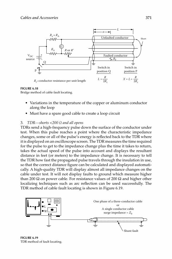
Cables and Accessories 371
Variations in the temperature of the copper or aluminum conductor • along the loop
Must have a spare good cable to create a loop circuit•
3. TDR—shorts <200 Ω and all opensTDRs send a high-frequency pulse down the surface of the conductor under test. When this pulse reaches a point where the characteristic impedance changes, some or all of the pulse’s energy is refl ected back to the TDR where it is displayed on an oscilloscope screen. The TDR measures the time required for the pulse to get to the impedance change plus the time it takes to return, takes the actual speed of the pulse into account and displays the resultant distance in feet (or meters) to the impedance change. It is necessary to tell the TDR how fast the propagated pulse travels through the insulation in use, so that the correct distance fi gure can be calculated and displayed automati-cally. A high-quality TDR will display almost all impedance changes on the cable under test. It will not display faults to ground which measure higher than 200 Ω on power cable. For resistance values of 200 Ω and higher other localizing techniques such as arc refl ection can be used successfully. The TDR method of cable fault locating is shown in Figure 6.19.
VDCsource
+−
Short
Lx
Unfaulted conductor
Faulted conductorRF
RA
Rx = RA
R or R�
Switch inposition P
Switch inposition Q
Rc=conductor resistance per unit length L = R2Rc
G
X = L = R2Rc
Q
P
FIGURE 6.18Bridge method of cable fault locating.
LW
Shunt fault
One phase of a three-conductor cableor
A single conductor cablesurge impedance = Z0
FIGURE 6.19TDR method of fault locating.
DK4058_C006.indd 371DK4058_C006.indd 371 11/8/2008 12:41:19 PM11/8/2008 12:41:19 PM

372 Electrical Power Equipment Maintenance and Testing
As explained earlier, it is a good idea to shoot the cable from both sides. The extra effort often rewards the user with critical additional information.
Advantages:
Easy and fast fault fi nding•
Safe low test voltage•
Disadvantages:
Cannot fi nd faults to ground with resistance greater than about 200 • Ω
4. Arc refl ection—all fl ashing faultsA fault that can be broken down, sometimes referred to as a fl ashing fault, is essentially a zero resistance fault for the duration of the fl ash (sometimes referred to as arc over). With this in mind, a fi lter was designed that allows the TDR to send pulses down a faulted conductor at the same time that an impulse generator sends a breakdown voltage down the same conductor. The TDR’s pulse is refl ected from the momentary arc and is subsequently displayed momentarily on the TDR screen. In this way, the TDR is able to refl ect pulses from all faults that can be broken down. The arc-refl ection method is shown in Figure 6.20.
Advantages:
All faults that can be broken down can be localized.•
The number of capacitive discharges required for subsequent pin-• pointing is minimized.
Shunt faultRadar set
Arcreflectionfilter orcoupler
Impulsegenerator(thumper)
One phase of a three-conductor cableor
a single conductor cablesurge impedance = Z0
x
FIGURE 6.20Arc-refl ection method of fault locating.
DK4058_C006.indd 372DK4058_C006.indd 372 11/8/2008 12:41:19 PM11/8/2008 12:41:19 PM
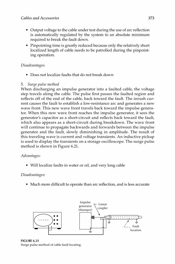
Cables and Accessories 373
Output voltage to the cable under test during the use of arc refl ection • is automatically regulated by the system to an absolute minimum required to break the fault down.
Pinpointing time is greatly reduced because only the relatively short • localized length of cable needs to be patrolled during the pinpoint-ing operation.
Disadvantages:
Does not localize faults that do not break down•
5. Surge pulse methodWhen discharging an impulse generator into a faulted cable, the voltage step travels along the cable. The pulse fi rst passes the faulted region and refl ects off of the end of the cable, back toward the fault. The inrush cur-rent causes the fault to establish a low-resistance arc and generates a new wave front. This new wave front travels back toward the impulse genera-tor. When this new wave front reaches the impulse generator, it sees the generator’s capacitor as a short-circuit and refl ects back toward the fault, which also appears as a short-circuit during breakdown. The wave front will continue to propagate backwards and forwards between the impulse generator and the fault, slowly diminishing in amplitude. The result of this traveling wave is current and voltage transients. An inductive pickup is used to display the transients on a storage oscilloscope. The surge pulse method is shown in Figure 6.21.
Advantages:
Will localize faults in water or oil, and very long cable•
Disadvantages:
Much more diffi cult to operate than arc refl ection, and is less accurate•
Faultlocation
Impulsegenerator(thumper)
Linearcoupler
x
FIGURE 6.21Surge pulse method of cable fault locating.
DK4058_C006.indd 373DK4058_C006.indd 373 11/8/2008 12:41:19 PM11/8/2008 12:41:19 PM

374 Electrical Power Equipment Maintenance and Testing
OpenFault
Earth level
Headphones(sensor)
+kVsource
−
FIGURE 6.23Electromagnetic impulse detection technique.
FIGURE 6.22Electromagnetic impulse detection technique using a polarized meter and seismic transducer.
Mute
Controls
Phones
Gain Electomagneticpulse lamp Magnetic Batt test
Pick-up
Acousticbatt check
Gain
Amplifier(controls)
Headphones
Extensionhandle
Seismictransducer
FD 202C Seismophone
DK4058_C006.indd 374DK4058_C006.indd 374 11/8/2008 12:41:19 PM11/8/2008 12:41:19 PM

Cables and Accessories 375
6. Electromagnetic impulse detectionThe impulse current from an impulse generator follows the center conductor, goes through the fault to the lead sheath and ground bonds and subsequently returns to the thumper. The magnitude of the current going out on the center conductor differs from the current returning on the lead sheath by the cur-rent leaving through the ground bonds just ahead of and just after the fault. The net electromagnetic fi eld produced is detected by the sheath coil and is displayed on a zero-center meter. Through careful application of the sheath coil and by productive interpretation of the polarized meter indication, the operator can identify the section of cable with the fault. The electromagnetic impulse detection technique is shown in Figure 6.22 using a polarized meter and seismic transducer.
Locate or pinpoint faults in primary cableLocating, often referred to as pinpointing, is necessary before digging up direct buried cable. After the fault has been localized, an impulse generator is connected to one end of the faulted cable. A second repairman proceeds to the localized area and listens for the telltale thump from the fault. When the thump is not loud enough to hear, it may be necessary to use an acoustic impulse detector to fi nally pinpoint the fault as shown in Figure 6.23.
Locate faults in buried secondary cableVoltage gradient test sets are effective in fi nding faults on direct-buried sec-ondary cable. This method depends on the fault occurring between conduc-tor and Mother Earth. When the cable is contained within conduit, a different method must be used. TDRs fi nd faults when they occur between two con-ductors or between conductor and metal conduit. When a single conductor is contained within a plastic conduit, shorts cannot occur unless water gains access through a crack or other entry point. When a fault develops, leakage current fl ows from the conductor through the break in insulation, and then follows the water to the break in the conduit to earth. If voltage gradient is used, the location of the crack in the conduit could be found, but the location of the fault in the insulation would remain unknown. The voltage gradient method is shown in Figure 6.24.
FIGURE 6.24Voltage gradient method.
+
Micro-voltmeter or micro-ammeter
Source
Remote ground
Leakage current
Earth levelProbe
OpenFault
−
DK4058_C006.indd 375DK4058_C006.indd 375 11/8/2008 12:41:20 PM11/8/2008 12:41:20 PM

DK4058_C006.indd 376DK4058_C006.indd 376 11/8/2008 12:41:20 PM11/8/2008 12:41:20 PM

377
7Medium-Voltage Switchgear and Circuit Breakers
7.1 General
Switchgear is a commonly used name for metal-enclosed distribution appa-ratus of modular, cubicle-type construction. Despite this commonly used name, there are technical and physical distinctions between various classes of switchgear assemblies. The American National Standards Institute (ANSI) and National Electrical Manufacturers Association (NEMA) have published standards for electrical equipment. These standards are followed by most manufacturers of electrical switchgear. The ANSI lists switchgear assemblies into three main categories, which are further classifi ed into subcategories as shown in Table 7.1.
7.2 Medium-Voltage Switchgear
Medium-voltage (MV) metal-enclosed power switchgear is defi ned as a switch-gear assembly completely enclosed on all sides and top with sheet metal (except for ventilating and inspection openings) containing primary power circuit switching and/or interrupting devices with buses and connections, and may include control and auxiliary devices. The rated voltage and insulation levels for MV-class metal-enclosed switchgear assemblies are shown in Table 7.2.
7.2.1 Construction Features
Switchgear is a general term used to defi ne switching (and/or interrupting), protective, regulating, and metering devices, including all associated con-trols and interconnections, and accessories used for generation, transmis-sion, and distribution of electrical power. As shown in Table 7.1, switchgear equipment comes in various forms and ratings that can be used to perform particular functions. There are some fundamental differences among the various types of equipment available in the MV class. These differences are important from a maintenance and operation point of view and are dis-cussed in the following sections.
DK4058_C007.indd 377DK4058_C007.indd 377 11/8/2008 12:41:39 PM11/8/2008 12:41:39 PM
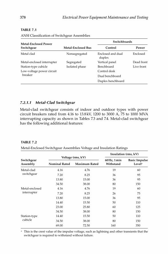
378 Electrical Power Equipment Maintenance and Testing
7.2.1.1 Metal-Clad Switchgear
Metal-clad switchgear consists of indoor and outdoor types with power circuit breakers rated from 4.16 to 13.8 kV, 1200 to 3000 A, 75 to 1000 MVA interrupting capacity as shown in Tables 7.3 and 7.4. Metal-clad switchgear has the following additional features:
TABLE 7.1
ANSI Classifi cation of Switchgear Assemblies
SwitchboardsMetal-Enclosed Power
Switchgear Metal-Enclosed Bus Control Power
Metal clad Nonsegregated Enclosed and dual
duplex
Enclosed
Metal-enclosed interrupter Segregated Vertical panel Dead front
Station-type cubicle Isolated phase Benchboard Live front
Low-voltage power circuit
breaker
Control desk
Dual benchboard
Duplex benchboard
TABLE 7.2
Metal-Enclosed Switchgear Assemblies Voltage and Insulation Ratings
Voltage (rms, kV)Insulation (rms, kV)
Switchgear
Assembly Nominal Rated Maximum Rated
60 Hz, 1 min
Withstand
Basic Impulse
Levela
Metal-clad
switchgear
4.16
7.20
4.76
8.25
19
36
60
95
13.80 15.00 36 95
34.50 38.00 80 150
Metal-enclosed
interrupter
4.16
7.20
4.76
8.25
19
26
60
75
13.80 15.00 36 95
14.40 15.50 50 110
23.00 25.80 60 125
34.50 38.00 80 150
Station-type
cubicle
14.40
34.50
15.50
38.00
50
80
110
150
69.00 72.50 160 350
a This is the crest value of the impulse voltage, such as lightning and other transients that the
switchgear is required to withstand without failure.
DK4058_C007.indd 378DK4058_C007.indd 378 11/8/2008 12:41:39 PM11/8/2008 12:41:39 PM

Medium-Voltage Switchgear and Circuit Breakers 379
Cu
rren
t V
alu
es
Vo
ltag
e
Insu
lati
on
Lev
el
Cu
rren
t
Rate
d W
ith
stan
d
Test
Vo
ltag
e
TAB
LE 7
.3
Po
wer
Cir
cuit
Bre
ak
er R
ati
ng
s an
d C
hara
cter
isti
cs, A
NS
I C
37.0
6-1
971
Iden
tifi
cati
on
Rate
d V
alu
es
Rela
ted
Req
uir
ed
Cap
ab
ilit
ies
Rate
d
Maxim
um
Vo
ltag
ea
(rm
s, k
V)
Rate
d
Vo
ltag
e
Ran
ge
Fact
or,
Kb
Rate
d
Co
nti
nu
ou
s
Cu
rren
t at
60 H
z
(rm
s, A
)
Rate
d
Sh
ort
-
Cir
cuit
Cu
rren
t
(at
Rate
d
Maxim
um
kV
)c,d
(rm
s, k
A)
Rela
ted
Inte
rru
pti
ng
Tim
e C
ycl
es
Rate
d
Perm
issi
ble
Tri
pp
ing
Dela
y, Y
(s)
Rate
d
Maxim
um
Vo
ltag
e
Div
ided
by
K
(rm
s, k
V)
K T
imes
Rate
d
Sh
ort
-Cir
cuit
Cu
rren
t
Clo
sin
g
an
d
Latc
hin
g
Cap
ab
ilit
y
1.6
K T
imes
Rate
d
Sh
ort
-
Cir
cuit
Cu
rren
t
(rm
s, k
A)
AN
SI
Lin
e
Nu
mb
er
No
min
al
Vo
ltag
e
Cla
ss
(rm
s, k
V)
No
min
al
Th
ree-
Ph
ase
MV
A
Cla
ss
Lo
w
Fre
qu
en
cy
Imp
uls
e
kV
Cre
st
Maxim
um
Sy
mm
etr
ical
Inte
rru
pti
ng
Cap
ab
ilit
ye
(rm
s, k
A)
3 s
Sh
ort
-Tim
e
Cu
rren
t-
Carr
yin
g
Cap
ab
ilit
y
(rm
s, k
A)
1
4.1
675
4.7
61.3
619
60
1200
8.8
52
3.5
12
12
19
3
4.1
6250
4.7
61.2
419
60
1200
29.0
52
3.8
536
36
58
4
4.1
6250
4.7
61.2
419
60
2000
29.0
52
3.8
536
36
58
5
4.1
6350
4.7
61.1
919
60
1200
41.0
52
4.0
49
49
78
6
4.1
6350
4.7
61.1
919
60
3000
41.0
52
4.0
49
49
78
8
7.2
0500
8.2
51.2
536
95
1200
33.0
52
6.6
41
41
66
9
7.2
0500
8.2
51.2
536
95
2000
33.0
52
6.6
41
41
66
11
13.8
0500
15.0
01.3
036
95
1200
18.0
52
11.5
23
23
37
12
13
.80
500
15.0
01.3
036
95
2000
18.0
52
11.5
23
23
37
13
13
.80
750
15.0
01.3
036
95
1200
28.0
52
11.5
36
36
58
14
13.8
0750
15.0
01.3
036
95
2000
28.0
52
11.5
36
36
58
(con
tinu
ed)
DK4058_C007.indd 379DK4058_C007.indd 379 11/8/2008 12:41:39 PM11/8/2008 12:41:39 PM

380 Electrical Power Equipment Maintenance and Testing
15
13
.80
1000
15.0
01.3
036
95
1200
37.0
52
11.5
48
48
77
16
13
.80
1000
15.0
01.3
036
95
3000
37.0
52
11.5
48
48
77
Not
e:
AN
SI
C37.0
6 s
ym
met
rica
l ra
tin
g b
asi
s is
su
pp
lem
enta
ry t
o A
NS
I C
37.6
(to
tal
curr
ent
rati
ng
basi
s) a
nd
do
es n
ot
rep
lace
it.
Wh
en a
ch
an
geo
ver
fro
m
the
tota
l cu
rren
t b
asi
s o
f ra
tin
g t
o t
he
sym
met
rica
l b
asi
s o
f ra
tin
g i
s aff
ecte
d, t
he
old
er s
tan
dard
s w
ill
be
wit
hd
raw
n. I
n a
cco
rdan
ce w
ith
AN
SI
C37.0
6,
use
rs s
ho
uld
co
nfe
r w
ith
th
e m
an
ufa
ctu
rer
on
th
e st
atu
s o
f th
e v
ari
ou
s ci
rcu
it b
reak
er r
ati
ng
s.a
Max
imu
m v
olt
ag
e fo
r w
hic
h t
he
bre
ak
er i
s d
esig
ned
an
d t
he
up
per
lim
it f
or
op
erati
on
.b
K i
s th
e ra
tio
of
rate
d m
ax
imu
m v
olt
ag
e to
th
e lo
wer
lim
it o
f th
e ra
ng
e o
f o
per
ati
ng
vo
ltag
e in
wh
ich
th
e re
qu
ired
sy
mm
etri
cal
inte
rru
pti
ng
cap
ab
ilit
ies
vary
in
in
ver
se p
rop
ort
ion
to
th
e o
per
ati
ng
vo
ltag
e.c
To
ob
tain
th
e re
qu
ired
sy
mm
etri
cal
inte
rru
pti
ng
cap
ab
ilit
y o
f a c
ircu
it b
reak
er a
t an
op
erati
ng
vo
ltag
e b
etw
een
1/
K t
imes
rate
d m
ax
imu
m v
olt
ag
e an
d
rate
d m
ax
imu
m v
olt
ag
e, t
he
foll
ow
ing
fo
rmu
la s
ho
uld
be
use
d:
×
Req
uir
ed s
ym
met
rica
l in
terr
up
tin
g c
ap
ab
ilit
y =
rate
d s
ho
rt-c
ircu
it c
urr
ent
(rate
d m
ax
imu
m v
olt
ag
e/o
per
ati
ng
vo
ltag
e)
Fo
r o
per
ati
ng
vo
ltag
es b
elo
w 1
/K
tim
es r
ate
d m
ax
imu
m v
olt
ag
e, t
he
req
uir
ed s
ym
met
rica
l in
terr
up
tin
g c
ap
ab
ilit
y o
f th
e ci
rcu
it b
reak
er s
hall
be
equ
al
to
K t
imes
rate
d s
ho
rt-c
ircu
it c
urr
ent.
d
Wit
h t
he
lim
itati
on
sta
ted
in
04-4
.5 o
f A
NS
I C
37.0
4,
all
valu
es a
pp
ly f
or
po
lyp
hase
an
d l
ine-
to-l
ine
fau
lts.
Fo
r si
ng
le p
hase
-to
-gro
un
d f
au
lts,
th
e sp
ecifi
c
con
dit
ion
s st
ate
d i
n 0
4-4
.5.2
.3 o
f A
NS
I C
37.0
4 a
pp
ly.
e C
urr
ent
valu
es i
n t
his
co
lum
n a
re n
ot
to b
e ex
ceed
ed e
ven
fo
r o
per
ati
ng
vo
ltag
es b
elo
w 1
/K
tim
es r
ate
d m
ax
imu
m v
olt
ag
e. F
or
vo
ltag
es b
etw
een
rate
d
max
imu
m v
olt
ag
e an
d 1
/K
tim
es r
ate
d m
ax
imu
m v
olt
ag
e, f
oll
ow
fo
otn
ote
3 a
bo
ve.
Rate
d
Maxim
um
Vo
ltag
ea
(rm
s, k
V)
Rate
d
Vo
ltag
e
Ran
ge
Fact
or,
Kb
Rate
d
Co
nti
nu
ou
s
Cu
rren
t at
60 H
z
(rm
s, A
)
Rate
d
Sh
ort
-
Cir
cuit
Cu
rren
t
(at
Rate
d
Maxim
um
kV
)c,d
(rm
s, k
A)
Rela
ted
Inte
rru
pti
ng
Tim
e C
ycl
es
Rate
d
Perm
issi
ble
Tri
pp
ing
Dela
y, Y
(s)
Rate
d
Maxim
um
Vo
ltag
e
Div
ided
by
K
(rm
s, k
V)
K T
imes
Rate
d
Sh
ort
-Cir
cuit
Cu
rren
t
Clo
sin
g
an
d
Latc
hin
g
Cap
ab
ilit
y
1.6
K T
imes
Rate
d
Sh
ort
-
Cir
cuit
Cu
rren
t
(rm
s, k
A)
AN
SI
Lin
e
Nu
mb
er
No
min
al
Vo
ltag
e
Cla
ss
(rm
s, k
V)
No
min
al
Th
ree-
Ph
ase
MV
A
Cla
ss
Lo
w
Fre
qu
en
cy
Imp
uls
e
kV
Cre
st
Maxim
um
Sy
mm
etr
ical
Inte
rru
pti
ng
Cap
ab
ilit
ye
(rm
s, k
A)
3 s
Sh
ort
-Tim
e
Cu
rren
t-
Carr
yin
g
Cap
ab
ilit
y
(rm
s, k
A)
Insu
lati
on
Lev
el
Cu
rren
t
Rate
d W
ith
stan
d
Test
Vo
ltag
e
TAB
LE 7
.3 (
cont
inue
d)
Po
wer
Cir
cuit
Bre
ak
er R
ati
ng
s an
d C
hara
cter
isti
cs, A
NS
I C
37.0
6-1
971
Iden
tifi
cati
on
Rate
d V
alu
es
Rela
ted
Req
uir
ed
Cap
ab
ilit
ies
Cu
rren
t V
alu
es
Vo
ltag
e
DK4058_C007.indd 380DK4058_C007.indd 380 11/8/2008 12:41:39 PM11/8/2008 12:41:39 PM

Medium-Voltage Switchgear and Circuit Breakers 381
TAB
LE 7
.4
Po
wer
Cir
cuit
Bre
ak
er R
ati
ng
an
d C
hara
cter
isti
cs, A
NS
I C
37.6
-1964
No
min
al
Th
ree-
Ph
ase
MV
A
Cla
ss
Rate
d
(kV
)
Maxim
um
Desi
gn
(kV
)
Min
imu
m
Op
era
tin
g
kV
at
Rate
d M
VA
Insu
lati
on
Lev
el
Cu
rren
t R
ati
ng
s (A
)
Inte
rru
pti
ng
Rati
ng
s
Rate
d
Inte
rru
pti
ng
Tim
e C
ycl
es
(60-C
ycl
es
Basi
s)
Wit
hst
an
d T
est
Co
nt.
at
60 C
ycl
es
Sh
ort
-Tim
eT
hre
e-P
hase
Rate
d M
VA
In r
ms
To
tal
Am
pere
sL
ow
Fre
qu
en
cy
(rm
s, k
V)
Imp
uls
e
Cre
st (
kV
)M
om
en
tary
4 s
At
Rate
d
Vo
ltag
e
Maxim
um
Rati
ng
50
4.1
64.7
62.3
19
60
(600)
20,0
00
12,5
00
50
7,0
00
12,5
00
8
(1200)
100/
150
2.4
/4.1
64.7
62.3
/3.5
19
60
(600)
40,0
00
25,0
00
100/
150
21,0
00
25,0
00
8
(1200)
(2000)
150/
250
2.4
/4.1
64.7
62.3
/3.5
19
60
(1200)
60,0
00
37,5
00
150/
250
35,0
00
37,5
00
8
(2000)
250
7.2
8.2
54.6
36
95
(1200)
51,0
00
32,0
00
250
20,0
00
32,0
00
8
(2000)
300
7.2
8.2
56.6
36
95
(1200)
70,0
00
44,0
00
500
40,0
00
44,0
00
8
(2000)
150
13.8
15.0
6.6
36
95
(600)
20,0
00
13,0
00
150
6,3
00
13,0
00
8
(1200)
250
13.8
15.0
6.6
36
95
(1200)
35,0
00
22,0
00
250
10,6
00
22,0
00
8
(2000)
500
13.8
15.0
11.5
36
95
(1200)
40,0
00
25,0
00
500
21,0
00
25,0
00
8
(2000)
DK4058_C007.indd 381DK4058_C007.indd 381 11/8/2008 12:41:39 PM11/8/2008 12:41:39 PM

382 Electrical Power Equipment Maintenance and Testing
The interrupting and switching device (i.e., breaker) is removable and • can be physically moved into disconnect, test, or operating position.
The primary bus conductors and connections are insulated.•
All live parts are enclosed within grounded metal compartments.•
Automatic shutters close off and prevent exposure of the primary • circuit elements when the circuit breaker is removed from operating position.
The primary and secondary contacts are self-aligning and self-• coupling.
Mechanical interlocks are provided to ensure a proper and safe • operation.
The circuit breaker housing cell door may be used to mount relays, • instruments, and wiring. The relays, control devices, and associated wiring are isolated by grounded metal barriers from primary conductors.
The elements of primary circuits such as circuit breakers, buses, and • potential transformers are completely enclosed by grounded metal barriers.
7.2.1.2 Metal-Enclosed Interrupter Switchgear
Metal-enclosed interrupter switchgear consists of indoor and outdoor types with or without power fuses, voltage rating from 4.16 to 34.5 kV, and current rating of upto 1200 A. This switchgear is characterized by the following features:
The primary buses and connections are uninsulated.•
The disconnecting device is an interrupter switch that may be remov-• able or stationary.
This switchgear may have instrument transformers, control wiring, • and accessory devices.
7.2.1.3 Station-Type Cubicle
The station-type cubicle switchgear consists of indoor and outdoor types with power circuit breakers rated from 14.4 to 34.5 kV, 1200 to 5000 A, 1500 to 2500 MVA interrupting capacity. This switchgear has the following features:
Power-operated stationary circuit breaker•
Bare buses having continuous carrying capacity equal to the service • required
Bare connections having current-carrying capacity equal to that of • the power circuit breaker
DK4058_C007.indd 382DK4058_C007.indd 382 11/8/2008 12:41:39 PM11/8/2008 12:41:39 PM

Medium-Voltage Switchgear and Circuit Breakers 383
Each phase of primary is segregated and enclosed by metal•
Three-pole, single-throw, group-operated disconnect switches that • are interlocked between power circuit breaker and front door giving access to primary compartment
A set of instrument transformers•
Control wiring, terminal blocks, ground bus, and accessory devices•
7.2.2 Short-Circuit Considerations and Power Circuit
Breaker Ratings
To understand the rating basis of power circuit breakers, it is important to understand how the circuit breaker will perform under conditions where the short-circuit current varies with time. The rating structure of a power circuit breaker is complicated because of the opening time of the circuit breaker during a short-circuit condition. The total operating time of the circuit breaker is based on the following:
Protective relay operation time•
Circuit breaker operation time•
The protective relay operation time is a function of relay type and its setting. The types of relays and their operating characteristics are discussed in Chapter 9. The breaker operation time (i.e., mechanical time) consists of the following:
Circuit breaker trip coil to energize its operating mechanism•
Circuit breaker contact parting time•
Circuit breaker to quench the arc in the arc chamber (or in the • vacuum bottle in case of vacuum interrupters)
High mechanical stresses are produced instantaneously in the circuit breaker during the interruption of a short circuit. These stresses vary as the square of the current and are greatest at maximum current. The fault current magnitude varies from short-circuit inception to the time when it reaches a steady-state condition. This variation depends on the instanta-neous value of the system voltages at the instant the fault occurs, also known as the closing angle; the dynamic change in alternating current (AC) impedance as the energy balance changes and the decay in the direct current (DC) component of the fault current. Consequently, the circuit breaker interrupts the fault current at some time (usually a few cycles) after the short circuit occurred. Therefore, power circuit breaker ratings are established on two bases:
DK4058_C007.indd 383DK4058_C007.indd 383 11/8/2008 12:41:39 PM11/8/2008 12:41:39 PM
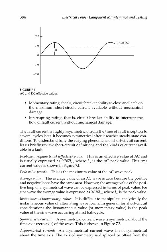
384 Electrical Power Equipment Maintenance and Testing
Momentary rating, that is, circuit breaker ability to close and latch on • the maximum short-circuit current available without mechanical damage.
Interrupting rating, that is, circuit breaker ability to interrupt the • fl ow of fault current without mechanical damage.
The fault current is highly asymmetrical from the time of fault inception to several cycles later. It becomes symmetrical after it reaches steady-state con-ditions. To understand fully the varying phenomena of short-circuit current, let us briefl y review short-circuit defi nitions and the kinds of current avail-able in a fault.
Root-mean-square (rms) (effective) value: This is an effective value of AC and is usually expressed as 0.707Im, where Im is the AC peak value. This rms current value is shown in Figure 7.1.
Peak value (crest): This is the maximum value of the AC wave peak.
Average value: The average value of an AC wave is zero because the positive and negative loops have the same area. However, the average value of the posi-tive loop of a symmetrical wave can be expressed in terms of peak value. For sine wave the average value is expressed as 0.636Im, where Im is the peak value.
Instantaneous (momentary) value: It is diffi cult to manipulate analytically the instantaneous value of alternating wave forms. In general, for short-circuit considerations the instantaneous value (or momentary value) is the peak value of the sine wave occurring at fi rst half-cycle.
Symmetrical current: A symmetrical current wave is symmetrical about the time axis (zero axis) of the wave. This is shown in Figure 7.2.
Asymmetrical current: An asymmetrical current wave is not symmetrical about the time axis. The axis of symmetry is displaced or offset from the
0
1.01.41
1 A of DC
2.0
1.0
2.0
FIGURE 7.1AC and DC effective values.
DK4058_C007.indd 384DK4058_C007.indd 384 11/8/2008 12:41:39 PM11/8/2008 12:41:39 PM

Medium-Voltage Switchgear and Circuit Breakers 385
time axis. This is shown in Figure 7.3. An asymmetrical wave can be partially offset or fully offset. Offset waves are sometimes called displaced waves.
DC component: The axis of symmetry of an offset wave resembles a DC, and symmetrical currents can be readily handled if considered to have an AC and a DC component. Both of these components are theoretical. The DC component is generated within the AC system and has no external source. Figure 7.4 shows a fully offset asymmetrical current with a steady DC com-ponent as its axis of symmetry. The symmetrical component has the zero axis as its axis of symmetry. If the rms or effective value of the symmetrical current is 1, the peak of the symmetrical current is 1.41. This is also the effec-tive value of the DC component. We can add these two effective currents together by the square root of the sum of the squares and get the effective or rms value of asymmetrical current.
The rms value of a fully offset asymmetrical current is 1.73 times the symmetrical rms current. It is readily apparent that the peak asymmetrical current is twice the peak symmetrical current: 2 × 1.41 = 2.82.
Total current: The term total current is used to express the total or sum of the AC and DC components of an asymmetrical current. Total current and total asymmetrical current have the same meaning and may be expressed in peak or rms amperes.
Frequency
Am
pere
s
FIGURE 7.2Symmetrical current wave.
Frequency
Am
pere
s
Axis ofsymmetry
FIGURE 7.3Asymmetrical current wave, fully offset.
DK4058_C007.indd 385DK4058_C007.indd 385 11/8/2008 12:41:40 PM11/8/2008 12:41:40 PM

386 Electrical Power Equipment Maintenance and Testing
Decay: Unfortunately, fault currents are neither symmetrical nor fully asymmetrical but somewhere in between. The DC component is usually short-lived and decays after several cycles. In Figure 7.5, the DC compo-nent decays to zero in about four cycles. The rate of decay is called decre-ment, and depends upon the circuit constants. The DC component would never decay in a circuit having reactance but zero resistance and would remain constant forever. In a circuit having resistance but zero reactance, the component would decay instantly. These are theoretical conditions; all practical circuits have some resistance and reactance, and the DC compo-nent disappears in a few cycles. In practice when performing short circuit analyses the X/R ratio is computed to give a practical estimate for determining how quickly the DC component will decay. For more detail, see defi nition of X/R in this chapter.
Closing angle: A short-circuit fault can occur at any point on the voltage wave. So far we have avoided discussing voltage characteristics, but the volt-age wave resembles the current wave. The two waves may be in phase or out
Frequency
Peak (asymmetrical)2.82
1.731.41
Am
pere
s
1.0
–1.0
0
rms (asymmetrical)
rms (symmetrical)
Zero axis
Symmetrical component
DC component
FIGURE 7.4Fully offset asymmetrical wave with DC component.
Am
pere
s
Total current
DC component
AC component Four cycles
Frequency
Peak asymmetrical
rms asymmetrical
FIGURE 7.5DC and AC component currents.
DK4058_C007.indd 386DK4058_C007.indd 386 11/8/2008 12:41:40 PM11/8/2008 12:41:40 PM

Medium-Voltage Switchgear and Circuit Breakers 387
of phase, and the magnitude and symmetry of the current wave of a short circuit depends on the point on the voltage wave at which the fault occurs. This is known as the closing angle of the fault.
Random closing: In real life, faults occur at any and every point on the volt-age wave. In a laboratory, this can be duplicated by closing the circuit at random. This is known as random closing. The following is true of a short circuit having negligible resistance:
If the fault occurs at zero voltage, the current wave is fully asym-• metrical, as shown in Figure 7.6
If the fault occurs at maximum voltage, the current wave is com-• pletely symmetrical, as shown in Figure 7.7
Most natural faults occur somewhere in between these two extremes.
Available short circuit (fi rst half-cycle current): What is the available short- circuit current value of a wave that is neither symmetrical nor asymmetrical? Referring to Figure 7.8, the current wave is symmetrical about four cycles after the DC component becomes zero. We can also determine the total rms asymmetrical current at one, two, or three cycles or at any other time after the short circuit started. The accepted practice is to use the current that is available one half-cycle after the short circuit starts. For a fully offset wave, the maximum current
Am
pere
sShort-circuit current
Generated voltage
Frequency
FIGURE 7.6Asymmetrical current wave when fault occurs at zero voltage.
Short-circuitcurrent
Am
pere
s
Generatedvoltage
Frequency
FIGURE 7.7Symmetrical current wave when fault occurs at maximum voltage.
DK4058_C007.indd 387DK4058_C007.indd 387 11/8/2008 12:41:40 PM11/8/2008 12:41:40 PM

388 Electrical Power Equipment Maintenance and Testing
does occur at the end of the fi rst half-cycle of time. Because this is the worst case, we should determine the peak and rms currents at this point.
As already mentioned, the rate of decay depends upon the circuit constants. A study of actual circuits of 600 V or less indicates that the proper half-cycle value for rms asymmetrical current is 1.4 times the rms symmetrical current, and the peak instantaneous current is 1.7 times the rms asymmetrical current. Half-cycle available current is 1.7 × 1.4 = 2.4 rms symmetrical current.
Current limitation: Current-limiting fuses and circuit breakers do not allow the short-circuit current to reach the full available value. They interrupt the circuit in less than one half-cycle before the current builds up to the maxi-mum value. The various times associated with fuses are the following:
Melting time:• Time required to melt the fusible link
Arcing time:• Time required for the arc to burn back the fusible link and reduce the current to zero
Total clearing time:• Sum of the melting and arcing times, or the time from fault initiation to extinction
Figure 7.9 shows the current-limiting action of the fuse.
Half-cycle current
2.4
1.41
0
Peak asymmetricalTotal rms asymmetrical
rms symmetrical
Am
pere
s
Frequency1
FIGURE 7.8First half-cycle current.
Half-cycle current
Peak let-through current
Totalclearing
time
TimeAm
pere
s
FIGURE 7.9Current-limiting fuse action.
DK4058_C007.indd 388DK4058_C007.indd 388 11/8/2008 12:41:40 PM11/8/2008 12:41:40 PM

Medium-Voltage Switchgear and Circuit Breakers 389
Let-through current: The maximum instantaneous or peak current that passes through the fuse is called the let-through current. This can be expressed in rms amperes, also.
Triangular wave: The rise and fall of the current through a current- limiting fuse resembles an isosceles triangle, and can be assumed to be a triangle without introducing appreciable error. Since this is not a sine wave, the rms value of the let-through current cannot be determined by taking 0.707 of the peak value as is done for a sine wave. The effective or rms value of a triangular wave is equal to the peak value divided by 3.
= =peak peak
rms1.733
I II
The let-through current of a current-limiting fuse varies with the design, ampere rating, and available short-circuit current. Fuse manufacturers furnish let-through curves for the various types of current-limiting fuses.
Three-phase short circuit: Three-phase short-circuit currents can be deter-mined in exactly the same way as single-phase currents if we assume the three phases are symmetrical. The three phases have different current values at any instant. Only one can be fully asymmetrical at a given time. This is called the maximum or worst phase, and its rms current value can be found by multiplying the symmetrical rms current by the proper factor. The currents in three phases can be averaged, and the average three-phase rms amperes can be determined by multiplying the symmetrical rms current by the proper factor, which is determined by the X/R ratio of the power system.
X/R ratio: Every practical circuit contains resistance (R) and inductive reac-tance (X). These are electrically in series. Their combined effect is called impedance (Z). When current fl ows through an inductance (coil), the voltage leads the current by 90°, and when current fl ows through a resistance, the voltage and current are in phase. This means that X and R must be combined vectorially to obtain impedance. The impedance triangle relating X, R, and Z is shown in Figure 7.10.
The resultant angle q is the angle between the voltage and current waves and is called the phase angle. The voltage leads the current or the current lags the voltage by an amount equal to the phase angle. The asymmetrical current may be obtained from known symmetrical current by multiply-ing with a multiplying factor for a known X/R ratio. The multiplying
XZ
R
qFIGURE 7.10Impedance triangle.
DK4058_C007.indd 389DK4058_C007.indd 389 11/8/2008 12:41:41 PM11/8/2008 12:41:41 PM

390 Electrical Power Equipment Maintenance and Testing
factors for commercial and industrial systems vary between 1.0 and 1.6 depending on the X/R ratio.
Power factor: Power factor is defi ned as the ratio of real power (kW) to appar-ent power (kVA).
= =
real power kWPF
kVA apparent power
Kilowatts are measured with a wattmeter. Kilovolt-amperes are determined with a voltmeter and an ammeter, and the voltage and current waves may be in phase or out of phase. The relationship of kilowatts, kilovars, and kilovolt-amperes is shown in Figure 7.11.
Power circuit breaker rating: The ANSI ratings for power circuit breakers are expressed by two rating structures. The older standard ANSI C37.6 expresses the interrupting rating of AC high-voltage (HV) breakers megavolt-amperes (MVA) based on total or asymmetrical current at the time of contact parting. The newer standard ANSI C37.06, which was introduced in 1964, expresses the interrupting of AC HV breakers based on total rms symmetrical currents at the time of contact parting. The rating and characteristics of the ANSI C37.06 and ANSI C37.6 are shown in Tables 7.3 and 7.4, respectively.
The standards defi ne that a circuit breaker shall be capable of performing the following in succession:
1. Close and immediately latch at normal frequency current, which does not exceed its momentary capability
2. Carry its maximum rated symmetrical current at specifi ed operat-ing voltage for duration of its rated permissible tripping delay
3. Interrupt all currents not greater than its rated symmetrical inter-rupting current at a specifi ed operating voltage and its related asym-metrical current based on its rated contact parting time
The typical short-circuit current consists of the following:
1. Symmetrical AC wave shape
2. DC component
3. Total current
kVARkVA
kW
qFIGURE 7.11Power triangle.
DK4058_C007.indd 390DK4058_C007.indd 390 11/8/2008 12:41:41 PM11/8/2008 12:41:41 PM
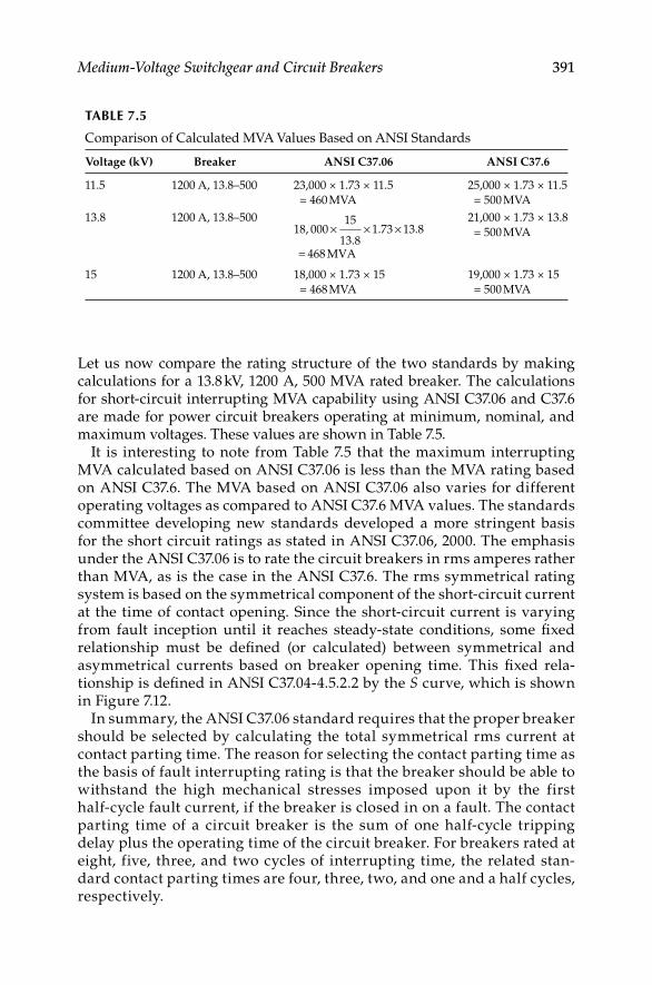
Medium-Voltage Switchgear and Circuit Breakers 391
Let us now compare the rating structure of the two standards by making calculations for a 13.8 kV, 1200 A, 500 MVA rated breaker. The calculations for short-circuit interrupting MVA capability using ANSI C37.06 and C37.6 are made for power circuit breakers operating at minimum, nominal, and maximum voltages. These values are shown in Table 7.5.
It is interesting to note from Table 7.5 that the maximum interrupting MVA calculated based on ANSI C37.06 is less than the MVA rating based on ANSI C37.6. The MVA based on ANSI C37.06 also varies for different operating voltages as compared to ANSI C37.6 MVA values. The standards committee developing new standards developed a more stringent basis for the short circuit ratings as stated in ANSI C37.06, 2000. The emphasis under the ANSI C37.06 is to rate the circuit breakers in rms amperes rather than MVA, as is the case in the ANSI C37.6. The rms symmetrical rating system is based on the symmetrical component of the short-circuit current at the time of contact opening. Since the short-circuit current is varying from fault inception until it reaches steady-state conditions, some fi xed relationship must be defi ned (or calculated) between symmetrical and asymmetrical currents based on breaker opening time. This fi xed rela-tionship is defi ned in ANSI C37.04-4.5.2.2 by the S curve, which is shown in Figure 7.12.
In summary, the ANSI C37.06 standard requires that the proper breaker should be selected by calculating the total symmetrical rms current at contact parting time. The reason for selecting the contact parting time as the basis of fault interrupting rating is that the breaker should be able to withstand the high mechanical stresses imposed upon it by the first half-cycle fault current, if the breaker is closed in on a fault. The contact parting time of a circuit breaker is the sum of one half-cycle tripping delay plus the operating time of the circuit breaker. For breakers rated at eight, five, three, and two cycles of interrupting time, the related stan-dard contact parting times are four, three, two, and one and a half cycles, respect ively.
TABLE 7.5
Comparison of Calculated MVA Values Based on ANSI Standards
Voltage (kV) Breaker ANSI C37.06 ANSI C37.6
11.5 1200 A, 13.8–500 23,000 × 1.73 × 11.5
= 460 MVA
25,000 × 1.73 × 11.5
= 500 MVA
13.8 1200 A, 13.8–500× × ×
=
1518, 000 1.73 13.8
13.8468 MVA
21,000 × 1.73 × 13.8
= 500 MVA
15 1200 A, 13.8–500 18,000 × 1.73 × 15
= 468 MVA
19,000 × 1.73 × 15
= 500 MVA
DK4058_C007.indd 391DK4058_C007.indd 391 11/8/2008 12:41:41 PM11/8/2008 12:41:41 PM

392 Electrical Power Equipment Maintenance and Testing
7.2.3 Selection and Application of Power Circuit Breakers
The application of power switchgear is relatively a simple procedure in most cases whether the switchgear is metal-clad or fused interrupter switches. The following steps are usually considered in applying this equipment:
Selection of switching scheme•
Calculation of available fault current for breaker or fused interrupter • selection
Main bus continuous current rating selection•
Current and potential transformer selection•
Protective relay selection•
Circuit breaker control power selection•
Other special considerations•
Many different switching schemes are available in power switchgear to meet the desired reliability or operational fl exibility. A choice should be made based on system requirements, maintenance considerations, reliability, and future expansion.
The selection of the power circuit breaker or fused interrupter switch involves the calculation of available fault current for interrupting duty pur-poses. Insofar as the interrupting of the circuit breaker is concerned, the following limits should not be exceeded:
S curve
1.4
1.3
1.2
1.1
1.0
1.0 2.0 3.0 4.0
Symmetrical interruptingcapability at
specified voltage
Circuit breaker contact parting time
Ratio
of c
ircui
t bre
aker
asym
met
rical
tosy
mm
etric
al in
terr
uptin
g ca
pabi
lity
FIGURE 7.12S curve per ANSI C37.04-4.
DK4058_C007.indd 392DK4058_C007.indd 392 11/8/2008 12:41:42 PM11/8/2008 12:41:42 PM
Medium-Voltage Switchgear and Circuit Breakers 393
Interrupting rms symmetrical amperes between the operating voltage • limits.
Total fault current that is available at contact parting time in terms • of symmetrical rms amperes.
Momentary current that is available during the fi rst half-cycle. The • standards allow the momentary rating of circuit breakers to be 1.6 times the rms interrupting rating at an X/R ratio of 10. In general industrial systems, where X/R ratios can approach 15–20, the next higher (standard) interrupting duty may have to be applied even though the RMS sym-metrical currents may be similar to those where the X/R is 10 or less.
The continuous current that the breaker is rated to carry.•
The operating voltage limits, that is, the minimum and maximum • design voltages of the circuit breaker.
The breakers used for reclosing or repetitive duty should be derated • in accordance with NEMA SG 4-2005 standards in order to be applied properly.
7.3 Electrical Switchgear Maintenance and Care
Switchgear components, such as circuit breakers, disconnect switches, fuses, and insulators, require regular inspection and maintenance. Switchgear can be of indoor or outdoor type and can be from different manufacturers. However, the maintenance of all types of switchgear can be carried out by following the basic maintenance operations. Also refer to Section 8.7.1, Chapter 8 on general guidelines for inspection of switchgear that may be used when inspecting medium voltage switchgear. This section provides the fundamental maintenance instructions for an overall maintenance program for switchgear. In cases where detailed instructions are required, the reader is advised to consult the recommendations of the manufacturer of the par-ticular equipment under consideration for maintenance.
7.3.1 MV Switchgear
7.3.1.1 Power Circuit Breakers
MV circuit breakers consist of air-magnetic circuit breakers either of hori-zontal drawout type or vertical lift type, oil circuit breakers, and vacuum circuit breakers. The following procedures should be carried out before new power circuit breakers are placed in service.
a. Receiving, handling, and storage
Inspect the circuit breaker for damage that may have occurred in • transit. Check the nameplate data and the packing list provided with the equipment delivered.
DK4058_C007.indd 393DK4058_C007.indd 393 11/8/2008 12:41:42 PM11/8/2008 12:41:42 PM
394 Electrical Power Equipment Maintenance and Testing
Inspect the arc chutes of the air-magnetic breaker for cracks, • damage, or foreign material.
Inspect the shield on each of the fi xed arcing contacts of the • air-magnetic breaker for cracks.
Lift and let down circuit breakers slowly. Do not use the bushing • as handles when handling the breaker. Always roll and maneuver the breaker by grasping the top edge of the breaker cover. Avoid any sudden jerks when moving the breaker.
If the breaker must be stored before it is put into service, keep it in • a clean, dry, and noncorrosive place. Coat all bare metal surfaces with grease to prevent rusting or oxidation. If the breaker is to be installed outdoors, make sure power is available for space heaters and that they are working.
In cases where a breaker is stored for a long period of time, • it should be inspected regularly for rusting.
b. Installation
Make an overall examination of the entire breaker to ensure that • there are no damaged parts.
Use a dry, clean cloth to remove dirt and moisture that might have • collected on the circuit breaker.
Cycle the breaker by opening and closing the breaker manually • and electrically. Check for proper operation.
To ensure that no damage has occurred during shipment, perform • a high-potential (hi-pot) test on each breaker pole (or vacuum interrupter) while the breaker is in the open position. Test results should be evaluated on a go, no-go basis by slowly raising the test voltage to the values shown in Table 7.6. Hold the fi nal test value for 1 min, if using an AC test method. If you are using a DC test method, you can operate the test using a Megger Vidar that takes only 5–10 s. If you do not get good results when testing a vaccum interrupter using the DC method, then fi rst retest the vacuum bottle using reverse polarity. At that point, if the bottle fails again, then you will have to check it with an AC hi-pot instrument.
Visually inspect the breaker before installation to make sure that • all test jumpers or leads, specialized breaker tools or maintenance accessories have been removed before installing the breaker in its cubicle.
Install the breaker into its cubicle in accordance with manufac-• turer’s instructions. Check for proper operation by manually cycling the breaker with control power off. This should be done while the breaker is in the test or disconnected position.
DK4058_C007.indd 394DK4058_C007.indd 394 11/8/2008 12:41:42 PM11/8/2008 12:41:42 PM

Medium-Voltage Switchgear and Circuit Breakers 395
7.3.1.2 Maintenance
Power circuit breakers, like other electrical equipment, require preventive maintenance to avoid equipment problems. The schedule for preventive maintenance can vary for each facility depending upon operating and envi-ronmental conditions. Frequent inspection and maintenance should be performed if the following factors are present:
Corrosive atmosphere•
Excessive dust or dirt•
High ambient temperature and high humidity•
Older equipment•
Excessive repetitive duty•
Frequent fault interruption•
Generally, the frequency of inspection should be based upon service and operating conditions. As a guide, inspect equipment about 6 months after it is installed and the follow up with scheduled maintenance every 1–3 years. In the performance of maintenance routines, all safety precautions should be followed.
Preventive maintenance should include the following areas:
1. Circuit breaker
a. Contacts
b. Arc chutes
c. Mechanical parts
d. Auxiliary equipment
TABLE 7.6
Hi-Pot Values for Acceptance Testing of Breakersa
Voltage Class (kV) Test Value (AC) (kV)b
Test Value (DC) (kV)c
5.0 14 20
7.2 27 37
13.8 27 37
23.0 45 —
38.0 60 —
Over 38.0 Consult manufacturer —
a Caution: Some manufacturers discourage the use of high DC voltages when
testing circuit breakers with vacuum bottles. Consult the manufacturer’s
installation and maintenance instructions manual for specifi c details regarding
the acceptance tests when vacuum interrupter assemblies are involved.b The values shown in this column are 75% of the factory AC voltage test values.c The values shown in this column are DC equivalent of 75% of the factory
AC voltage test values.
DK4058_C007.indd 395DK4058_C007.indd 395 11/8/2008 12:41:42 PM11/8/2008 12:41:42 PM

396 Electrical Power Equipment Maintenance and Testing
2. Cell enclosure
a. Cell joints (i.e., bus joints)
b. Cell contacts
c. Insulation
The following routine maintenance instructions are offered as a general guide for the maintenance of power circuit breakers. If special detailed instructions are required, consult the manufacturer.
7.3.2 Air-Magnetic Circuit Breakers
Before inspecting or performing any maintenance on either the breaker or its mechanism, be sure the breaker is in the open position, is disconnected from all electrical sources, and is removed from the cubicle (Figure 7.13a, b, and c). Both the closing and opening, springs should be discharged or blocked mechanically before any maintenance is done. The old air magnetic breakers, in many cases have been retrofi tted (replaced) with vacuum breakers in the same switchgear. The vacuum breaker retrofi t is a direct one-for-one replace-ment without involving any other equipment conversions. For maintenance of vacuum breakers in retrofi t applications, refer to Section 7.3.4 for guide-lines and instructions on vacuum breakers.
1. Record the number of operations and perform a general visual inspection of the breaker. Report any unusual signs of problems.
2. Put circuit breaker in test position and, using a test coupler, operate breaker electrically. Check the operation of all electrical relays, sole-noid switches, motors, control switches, and indicating devices.
3. Remove circuit breaker from enclosure and perform visual inspection as follows:
FIGURE 7.13An ITE air magnetic breaker components. (a) Front view showing arc-chutes, (b) side view
showing bushing and operating mechanism, and (c) back view showing disconnecting stubs
and cluster fi ngers.
(a) (b) (c)
DK4058_C007.indd 396DK4058_C007.indd 396 11/8/2008 12:41:42 PM11/8/2008 12:41:42 PM

Medium-Voltage Switchgear and Circuit Breakers 397
a. Remove box barriers.
b. Wipe clean of smoke deposit and dust from all insulating parts, including the bushings and the inside of the box barrier. Use a clean, dry, lint-free cloth; a vacuum cleaner would be helpful.
c. Inspect the condition of bushing primary disconnect stubs and fi nger cluster.
d. Inspect the condition of bushing insulation; it should be clean, dry, smooth, hard, and unmarred.
e. Check breaker and operating mechanism carefully for loose nuts, bolts, or retaining rings, and ensure that mechanical link-age is secure.
f. Inspect insulation and outside of arc chutes for holes or breaks; small cracks are normal.
g. Inspect magnetic blowout coils (if used) for damage.
h. Inspect all current-carrying parts for evidence of overheating.
Functional inspection
Sand throat area of arc chutes with garnet paper or other noncon-• ductive, abrasive paper until thoroughly clean.
Ensure that arc chutes are clear of contamination and have no sig-• nifi cant damage on grids or ceramics. If ceramics or fi ns are broken, replace arc chutes.
Ensure that all brazed, soldered, or bolted electrical connections are • tight.
Inspect contacts of control relays for wear and clean as necessary.•
Check actuator relays, charging motor, and secondary disconnects • for damage, evidence of overheating, or insulation breakdown.
Check that all wiring connections are tight and for any possible • damage to the insulation.
Replace any wire that has worn insulation.•
On stored-energy breakers, operate the breaker slowly. By using the • spring blocking device, check for binding or friction and correct if necessary. Make sure contacts can be opened or closed fully.
Inspect the arcing contacts for uneven wear or damage. Replace • badly worn contacts. Measure the arcing contact wire, using an ohm-meter. Make adjustment if necessary. Refer to the appropriate instruc-tion book.
Inspect primary contacts for burns or pitting. Wipe contacts with • clean cloth. Replace badly burned or pitted contacts. Rough or galled contacts should be smoothed with a crocus cloth or fi le lightly. Resilver where necessary.
DK4058_C007.indd 397DK4058_C007.indd 397 11/8/2008 12:41:43 PM11/8/2008 12:41:43 PM

398 Electrical Power Equipment Maintenance and Testing
Inspect primary disconnect studs for arcing or burning. Clean and • lightly grease arcing contacts.
Check primary contact gap and wipe. Make adjustment as per appro-• priate instruction book. Grease contacts with an approved grease and operate breaker several times.
Check operation and clearance of trip armature travel and release • latch as per appropriate instruction book. Replace worn parts.
Inspect all bearings, cams, rollers, latches, and buffer blocks for wear. • Tefl on-coated sleeve bearings do not require lubrication. All other sleeve bearings, rollers, and needle bearings should be lubricated with SAE 20 or 30 machine oil. All ground surfaces coated with dark molyb-denum disulfi de do not require lubrication. Lubricate all other ground surfaces such as latches, rollers, or props with an approved grease.
Install box barriers.•
Measure insulation resistance of each bushing terminal to ground and • phase to phase. Record readings along with temperature and humidity.
Perform hi-pot test for breaker bushing insulation (optional).•
Check closed breaker contact resistance (optional).•
Perform power factor test (optional).•
Perform corona test (optional).•
Using test box, operate breaker both electrically and manually. Check • all interlocks.
Insert and operate breaker in cabinet. Watch for proper operation of • the positive interlock trip-free mechanism. (Breaker should trip if not fully in or in test position.)
Remove breaker from cubicle and check primary disconnect wipe; • refer to appropriate instruction book.
Perform visual inspection and check for proper operation as dis-• cussed under Section 7.3.1.1.b before inserting breaker into cubicle ready for energization.
7.3.3 Oil Circuit Breaker
The oil circuit breaker should be maintained on a periodic basis similar to the air-magnetic circuit breakers. To maintain the circuit breaker, mount it on the inspection rack and untank it to expose the internal parts. Check for the follow-ing and make adjustments and repairs in accordance with the instruction book.
Wipe clean all parts, including any carbon markings. Insulating • parts should be inspected for damage such as warp age and cracks; replace damaged parts.
Inspect the contacts for alignment and wear. Replace pitted and • burned contacts and fi le rough contacts. Adjust contacts to ensure that contacts bear with fi rm and even pressure.
DK4058_C007.indd 398DK4058_C007.indd 398 11/8/2008 12:41:44 PM11/8/2008 12:41:44 PM

Medium-Voltage Switchgear and Circuit Breakers 399
Take an oil sample and make a dielectric test as explained in Chapter 4 • under testing of insulating liquids. If visible carbon particles are evident in the oil, fi lter oil regardless of the dielectric strength.
Wipe inside of tank, barriers, and tank linings to remove carbon.•
Inspect and clean operating mechanism similar to that described in • Section 7.3.2.
Check the breaker operation by slowly closing with the closing • device similar to the air-magnetic breaker. Also check its electrical operation.
Replace tank with proper oil level and make sure that all gaskets, • tank nuts, and fl ange nuts are tightened properly to prevent leakage.
7.3.4 Vacuum Circuit Breaker
The vacuum circuit breaker (Figure 7.14a and b) maintenance schedule should be based upon operating experience and environmental conditions. If such a schedule has not been determined, it is recommended that the breaker be inspected at least once a year or every 2000 operations, whichever occurs earlier. However, a breaker should be inspected every time after a severe fault interruption. The following checks should be performed for the vacuum circuit breaker:
Check for contact erosion. To determine contact erosion, remove • breaker from enclosure. Close the breaker and measure the spring plate overtravel. Consult the manufacturer’s instruction book for allowable overtravel. If the specifi ed overtravel is exceeded, the vacuum interrupter must be replaced.
To check the condition of the vacuum, perform a hi-pot rest. Consult • the manufacturer’s instruction book for test value or use 60% of the fi nal factory test value.
Using a clean, dry cloth remove all dirt and moisture from the • outside of vacuum interrupters and all insulating parts.
Check the entire operating mechanism similar to the air-magnetic • circuit breaker.
Lubricate ground surfaces such as cams, gear teeth, rollers, and • pawls when performing maintenance. See the manufacturer’s guide on lubrication methods and time periods.
Operate the breaker manually and electrically several times to make • sure that the breaker is operating properly.
Electrical tests of the vacuum bottle integrity can be performed using either an AC or DC method. Also, vacuum bottle integrity can be checked using a DC Megger Vidar Instrument. The test using a Vidar only takes 5–10 s. A Megger Vidar instrument is shown in Figure 7.15.
DK4058_C007.indd 399DK4058_C007.indd 399 11/8/2008 12:41:44 PM11/8/2008 12:41:44 PM
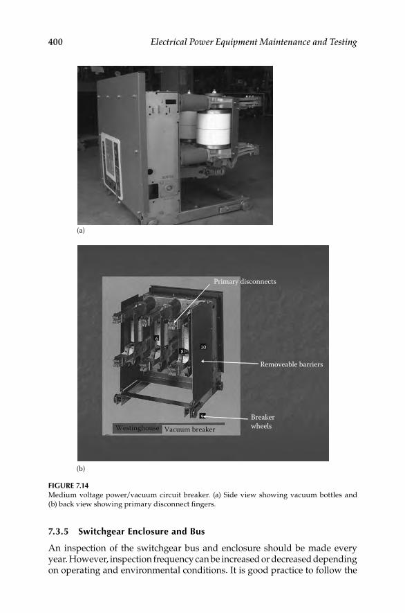
400 Electrical Power Equipment Maintenance and Testing
7.3.5 Switchgear Enclosure and Bus
An inspection of the switchgear bus and enclosure should be made every year. However, inspection frequency can be increased or decreased depending on operating and environmental conditions. It is good practice to follow the
FIGURE 7.14Medium voltage power/vacuum circuit breaker. (a) Side view showing vacuum bottles and
(b) back view showing primary disconnect fi ngers.
(a)
108
9
6
BreakerwheelsVacuum breakerWestinghouse
Removeable barriers
Primary disconnects
(b)
DK4058_C007.indd 400DK4058_C007.indd 400 11/8/2008 12:41:44 PM11/8/2008 12:41:44 PM

Medium-Voltage Switchgear and Circuit Breakers 401
manufacturer’s recommendations regarding maintenance procedures. The fol-lowing are suggestions to supplement the manufacturer’s recommendations:
Check the enclosure housing to ensure that all hardware is in place • and in good condition. The purpose of enclosure is to protect the equipment from outside contaminants and prevent exposure of per-sonnel to live parts. A maintenance program should assure that these features are maintained. Lubricate hinges, locks, latches, and so on.
For outdoor assemblies, check for roof or wall leaks, as well as for • damage from previous leaks.
After the power has been turned off and the bus has been grounded, • remove dust and dirt by wiping with a dry, clean cloth or by vacuuming.
Check for all unnecessary fl oor openings and any water pools at the • base of enclosures. Seal such openings with duct seal. Check for signs of moisture accumulation, such as droplet depression on dust-laden surfaces and dust patterns. Prevent moisture accumulation by providing heat and ventilation. Therefore, make sure that space heat-ers and fans are functioning properly.
Check that ventilators are clear of obstruction and air fi lters are clean • and in good condition.
The surface of all insulating members should be inspected before • any cleaning or dusting, as well as after cleaning for signs of electrical
FIGURE 7.15A DC Megger Vidar instrument. (Courtesy of Megger/Programma, Valley Forge, PA.)
DK4058_C007.indd 401DK4058_C007.indd 401 11/8/2008 12:41:45 PM11/8/2008 12:41:45 PM

402 Electrical Power Equipment Maintenance and Testing
distress, tracking, corona, and thermal heating. Damage caused by electrical distress will usually be evident on the insulating surface as corona markings or tracking parts. The areas most susceptible to electrical distress are
a. Splices and junction points
b. Boundaries between adjoining insulators
c. Edges of insulation surrounding mounting hardware grounded to the metal structure
d. Bridging paths across insulating surface
e. Boundaries between an insulating member and the grounded metal surface
f. Hidden surfaces such as adjacent edges between upper and lower members of split bus supports
g. Sharp edges in switchgear that are not insulated
Check for loose bolted connections in bus bars, splices, and the like, • for signs of heating. Tighten in accordance with manufacturer’s recommendations.
Examine grounding connections and ground bus for tightness and • cleanliness.
Check alignment and contacts of primary disconnecting devices • for abnormal wear or damage. Check for sulfi de deposits and use a solvent such as alcohol for removal of these deposits.
Remove any paint damage or fi nishes.•
After cleaning and adjusting, run an insulation resistance test to • measure resistance to ground. Compare the values of test readings with previous readings for any sign of weakening of the insulation system. Readings should be normalized to a common temperature and humidity base before comparison is made.
Compare equipment nameplate information with latest one-line • diagram and report discrepancies.
Check tightness of accessible bolted bus joints by calibrated wrench • method. Refer to manufacturer recommendations for proper torque values.
Test key interlock systems physically to ensure the following:•
a. Closure attempt should be made on locked-open devices
b. Opening attempt should be made on locked-closed devices
c. Key exchange should be made with devices operated in off-normal positions
Check for cracks in extruded red sleeving bus insulation made from • Lexan or Noryl. Repair cracked insulation according to manufacturer’s recommendations.
DK4058_C007.indd 402DK4058_C007.indd 402 11/8/2008 12:41:45 PM11/8/2008 12:41:45 PM
Medium-Voltage Switchgear and Circuit Breakers 403
7.4 Electrical Switchgear Testing
The design of the insulation system for metal-enclosed switchgear is based upon life expectancy of about 30 years. However, environmental conditions such as dirt, moisture, and corrosive atmosphere can shorten the design life. Moisture combined with dirt is the greatest deteriorating factor for insulation systems because of leakage and tracking, which will result in eventual failure. Therefore, it is important to maintain the switchgear insulation and to chart the condition of the primary insulation system by routine testing.
The electrical switchgear may be tested with AC or DC voltage to check the condition of the insulation of switchgear and circuit breakers. Before con-ducting any other tests, an insulation resistance test (Megger) should always be conducted fi rst to determine if it is safe to conduct other HV tests. Also when testing circuit breakers, it is important to check the condition of the circuit breaker contacts and circuit breaker operating mechanism to assure that the circuit breaker is opening and closing as designed. These tests are listed and discussed as follows:
Insulation resistance test•
DC or AC hi-pot test•
Power factor or dielectric loss test•
Circuit breaker contact resistance test•
Circuit breaker time–travel analysis test•
7.4.1 Insulation Resistance Measurement Test
The insulation resistance measurement test may be conducted on all types of electrical switchgear using the insulation resistance megohmmeter com-monly known as the MEGGER.* The Megger S1-5010 is shown in Figure 7.16 that may be used to perform this test.
The insulation resistance test consists of applying voltage (600–10,000 V DC) to the apparatus to determine the megohm value of resistance. This test does not indicate the quality of primary insulation. Several factors should be remembered when performing this test. The fi rst is that this test can indicate low values of insulation resistance because of many parallel paths. The other is that an insulation system having low dielectric strength may indicate high resistance values. In view of this, the test results should only be interpreted for comparative purposes. This does not indicate the quality of the primary insulation system from the point of view of dielectric withstandability. The connection diagram for making this test on a power circuit breaker is shown in Figure 7.17. When performing insulation testing, it is recommended that auxiliary equipment, such as potential transformers and lightning arresters, be removed from the stationary switchgear.
* Megger trademark for megohmmeter.
DK4058_C007.indd 403DK4058_C007.indd 403 11/8/2008 12:41:45 PM11/8/2008 12:41:45 PM

404 Electrical Power Equipment Maintenance and Testing
Circuit breaker
Megohmmeter
High-voltage lead
5
G L E
6
43
1 2
FIGURE 7.17Typical connection for insulation resistance test of circuit breaker in open position.
(a) (b)
FIGURE 7.16Megger S1-5010 for making insulation resistance tests. (a) Megger S1-5010; (b) Megger S1-5010
being used in the fi eld. (Courtesy of Megger, Inc., Valley Forge, PA.)
Insulation resistance tests are made with the circuit breaker in open and closed position, whereas the insulation test for the switchgear bus is made with one phase to ground at a time, with the other two phases grounded. The procedure for this test is as follows:
Circuit breaker open: • Connect HV lead to pole 1. Ground all other poles. Repeat for poles 2 through 6, in turn, with other poles grounded.
Circuit breaker closed: • Connect HV lead to pole 1 or 2, as convenient, with either pole of phase 2 and 3 grounded. Repeat for phases 2 and 3 with other phases grounded.
Stationary gear (buses): • Connect HV lead to phase 1 with phases 2 and 3 grounded. Repeat the same for phases 2 and 3 with other phases grounded. Also, perform IR tests between phase 1 and 2 with phase 3
DK4058_C007.indd 404DK4058_C007.indd 404 11/8/2008 12:41:45 PM11/8/2008 12:41:45 PM

Medium-Voltage Switchgear and Circuit Breakers 405
grounded, phase 2 and phase 3 with phase 1 grounded, and phase 3 and 1 with phase 2 grounded.
7.4.2 DC Hi-Pot Test
The DC hi-pot test is normally not made for AC electrical switchgear and therefore may be considered only when AC hi-pot cannot be performed. The hi-pot testing of switchgear involves testing of the circuit breakers and switch-gear buses separately. This is a major test and determines the condition of the insulation of the switchgear assembly. The DC hi-pot test is not preferred for testing AC switchgear because the application of DC voltage does not pro-duce similar stress in the insulation system as is produced under operating conditions. Moreover, the DC hi-pot test produces corona and tracking owing to concentration of stress at sharp edges or end points of buses. The corona and tracking are more pronounced in older equipment, and it is therefore recommended that DC hi-pot testing be avoided on such equipment.
The test procedures for DC hi-pot testing are similar to those of AC hi-pot testing and are described in detail in Chapter 2. If DC hi-pot testing is to be performed, the DC voltage test values shown in Table 7.7 are recommended for various voltage-class equipment.
The hi-pot test should be conducted under conditions similar to those of commercial testing. The switchgear should be wiped, cleaned, and restored to good condition before the hi-pot test is conducted. Temperature and humidity readings should be recorded and the test reading corrected when conducting DC tests.
7.4.3 AC Hi-Pot Test
This test should be conducted separately for circuit breakers and switchgear buses (stationary gear). It should be made only after the DC insulation resis-tance measurement test has been passed satisfactorily and all cleanup has been fi nished. The AC test will stress the switchgear insulation similarly to the
TABLE 7.7
DC Hi-Pot Maintenance Test Values
Rated Operating
Voltage (V) 1 min DC Test Voltage
240 1,600
480 2,100
600 2,300
2,400 15,900
4,160 20,100
7,200 27,600
13,800 38,200
23,000 63,600
34,500 84,800
DK4058_C007.indd 405DK4058_C007.indd 405 11/8/2008 12:41:47 PM11/8/2008 12:41:47 PM

406 Electrical Power Equipment Maintenance and Testing
stresses found during operating conditions. The maintenance test voltages should be 75% of fi nal factory test voltage. These values are shown in Table 7.8.
Hi-pot tests are made with the circuit breaker in both open and closed positions. The hi-pot test should be the last test conducted after all repairs have been made, cleanup is fi nished, and the insulation resistance test has been successfully passed. Procedures for the hi-pot test of the circuit breaker are as follows:
The test connection for the hi-pot test is as shown in Figure 7.18.•
Circuit breaker in open position: • Connect HV lead to pole 6. Ground all other poles. Repeat for poles 1 through 5, in turn, with all other poles grounded. Apply the desired high voltage in each case in accordance with Table 7.8.
Circuit breaker in closed position: • Connect HV lead to pole 1 or 2 or phase 1 as convenient with either pole of phases 2 and 3 grounded. Repeat for test for phases 2 and 3 with other phases grounded.
TABLE 7.8
Hi-Pot Test Values
Rated Operating
Voltage (V)
AC Factory Proof
Test (V)
AC Test Maintenance
Values (V)
240 1,500 1,130
480 2,000 1,500
600 2,200 1,650
2,400 15,000 11,300
4,160 19,000 14,250
7,200 26,000 19,500
13,800 36,000 27,000
14,400 50,000 37,500
23,000 60,000 45,000
34,500 80,000 60,000
Circuit breaker(closed)
Hi-pottransformer
HV lead
Controlunit
120, 240, or 480 Vsupply
5 6
4
21
3A
V
FIGURE 7.18Typical connection for hi-pot test for circuit breaker in closed position.
DK4058_C007.indd 406DK4058_C007.indd 406 11/8/2008 12:41:47 PM11/8/2008 12:41:47 PM

Medium-Voltage Switchgear and Circuit Breakers 407
Stationary gear (buses):• Connect HV lead to phase 1 as convenient with phases 2 and 3 grounded. Apply the recommended voltage. Repeat the test for phases 2 and 3 with other phases grounded.
7.4.4 Power Factor Testing
The power factor testing of an insulation system is useful in fi nding signs of insulation deterioration. The absolute values of power factor measured have little signifi cance. However, comparative analysis of values from year to year may very well show insulation deterioration. Therefore, when a power factor test is made, it should be made under the same conditions of temperature and humidity. If differences exist in the temperature and humidity from year to year, this should be taken into consideration when evaluating the test data. Generally, higher temperature and humidity result in higher power factor values. As a general rule, only the air circuit breaker bushing should be power factored, and the arc chutes, operating rods, and so on, should be disconnected when conducting this test. A signifi cant change, especially an increase in watts loss or percent of power factor indicates deterioration, which should be monitored. As a general rule, a power factor below 1% indi-cates good insulation. Any value above 1% warrants investigation. Power factor tests are discussed in more detail in Chapter 3.
7.4.5 Circuit Breaker Contact Resistance Measurement Test
Stationary and moving contacts are built from alloys that are formulated to endure the stresses of electrical arcing. However, if contacts are not main-tained on a regular basis, their electrical resistance due to repeated arcing builds up, resulting in a signifi cant decrease in the contact’s ability to carry current. Excessive corrosion of contacts is detrimental to the breaker perfor-mance. One way to check contacts is to apply DC and measure the contact resistance or voltage drop across the closed contacts. The breaker contact resistance should be measured from bushing terminal to bushing terminal with the breaker in closed position. It is recommended that for MV and HV the resistance test be made with 100 A or higher DC. The use of a higher current value gives more reliable results than using lower current values. The resistance value is usually measured in microohms (μΩ). The average resistance value for 15 kV class circuit breakers is approximately between 200 and 250 μΩ. Several companies make good, reliable microohmmeters to perform this testing. One such instrument is the Megger DLRO 200. It can generate test currents from 10 to 200 A and can measure resistances ranging from 0.1 μΩ to 1 Ω. The Megger DLRO 200 is shown in Figure 7.19.
7.4.6 Circuit Breaker Time–Travel Analysis
This test is usually performed on MV and HV circuit breakers, usually 34 kV and above, to detect problems in the breaker operating mechanism. This test can be conducted with a mechanical or electronic time–travel analyzer. Today, the electronic time–travel analyzers are replacing the old mechanical
DK4058_C007.indd 407DK4058_C007.indd 407 11/8/2008 12:41:47 PM11/8/2008 12:41:47 PM
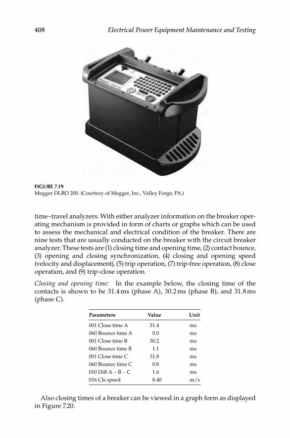
408 Electrical Power Equipment Maintenance and Testing
time–travel analyzers. With either analyzer information on the breaker oper-ating mechanism is provided in form of charts or graphs which can be used to assess the mechanical and electrical condition of the breaker. There are nine tests that are usually conducted on the breaker with the circuit breaker analyzer. These tests are (1) closing time and opening time, (2) contact bounce, (3) opening and closing synchronization, (4) closing and opening speed (velocity and displacement), (5) trip operation, (7) trip-free operation, (8) close operation, and (9) trip-close operation.
Closing and opening time: In the example below, the closing time of the contacts is shown to be 31.4 ms (phase A), 30.2 ms (phase B), and 31.8 ms (phase C).
Also closing times of a breaker can be viewed in a graph form as displayed in Figure 7.20.
FIGURE 7.19Megger DLRO 200. (Courtesy of Megger, Inc., Valley Forge, PA.)
Parameters Value Unit
001 Close time A 31.4 ms
060 Bounce time A 0.0 ms
001 Close time B 30.2 ms
060 Bounce time B 1.1 ms
001 Close time C 31.8 ms
060 Bounce time C 0.8 ms
010 Diff A − B − C 1.6 ms
016 Cls speed 8.40 m/s
DK4058_C007.indd 408DK4058_C007.indd 408 11/8/2008 12:41:47 PM11/8/2008 12:41:47 PM
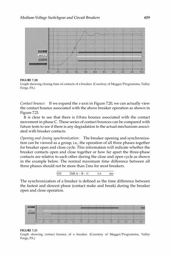
Medium-Voltage Switchgear and Circuit Breakers 409
Contact bounce: If we expand the x-axis in Figure 7.20, we can actually view the contact bounce associated with the above breaker operation as shown in Figure 7.21.
It is clear to see that there is 0.8 ms bounce associated with the contact movement in phase C. These series of contact bounces can be compared with future tests to see if there is any degradation to the actual mechanism associ-ated with breaker contacts.
Opening and closing synchronization: The breaker opening and synchroniza-tion can be viewed as a group, i.e., the operation of all three phases together for breaker open and close cycle. This information will indicate whether the breaker contacts open and close together or how far apart the three-phase contacts are relative to each other during the close and open cycle as shown in the example below. The normal maximum time difference between all three phases should not be more than 2 ms for most breakers.
010 Diff A − B − C 1.6 ms
The synchronization of a breaker is defi ned as the time difference between the fastest and slowest phase (contact make and break) during the breaker open and close operation.
FIGURE 7.20Graph showing closing time of contacts of a breaker. (Courtesy of Megger/Programma, Valley
Forge, PA.)
FIGURE 7.21Graph showing contact bounce of a breaker. (Courtesy of Megger/Programma, Valley
Forge, PA.)
DK4058_C007.indd 409DK4058_C007.indd 409 11/8/2008 12:41:48 PM11/8/2008 12:41:48 PM

410 Electrical Power Equipment Maintenance and Testing
Total opening and closing speed: All breakers have specifi c speed, opening and closing times; therefore, it is important that breakers operate within their opening and closing time. For example, if a breaker is slow to open due to ageing or degradation, it may compromise the protection and coordination scheme of the protective relays, and thereby cause unwanted power inter-ruption and equipment damage. Further, all breakers have specifi ed closing speed which is defi ned as the average speed calculated between two defi ned points on the motion curve as indicated below.
016 Cls speed 8.40 m/s
These two points will be specifi ed by the breaker manufacturer and defi ne where to set both points for accurate speed measurements. For example, they will defi ne the fi rst point to be set to a distance above the open position and a distance below the upper point where the contact motion stops as indicated below.
Upper point Lower point
Distance above open position 80.0 mm Distance below upper point 20.0 mm
Distance below closed position 10.0 mm Distance below upper point 10.0 mm
Trip operation: The trip operation of a breaker is another name for an open operation. Most utility companies and plant owners want to perform a trip (or open) operation to monitor the speed of the opening mechanism and contacts to make sure there is enough energy in the spring mechanism to open under a fault condition. The graph for a trip is similar to the one for a close operation, except the motion of the mechanism is going in the oppo-site direction, i.e., from closed contacts to fully open position as seen in Figure 7.22.
FIGURE 7.22Graph showing speed of the contacts opening for trip (or open) operation of a breaker. (Courtesy
of Megger/Programma, Valley Forge, PA.)
DK4058_C007.indd 410DK4058_C007.indd 410 11/8/2008 12:41:48 PM11/8/2008 12:41:48 PM

Medium-Voltage Switchgear and Circuit Breakers 411
Trip-free operation: This operation simulates the condition when an open breaker is closed into a fault and then it is tripped free by a protective relay. Trip-free is an operation where the breaker contacts are in the open position and the breaker is operated to perform a close–open sequence. In this oper-ation, the breaker is closed and then immediately sent a control command to open. This operation confi rms whether a breaker, if closed into a fault, can clear it. The graph for a trip-free operation is shown in Figure 7.23.
Close operation: This test is performed to verify a breaker’s closing mecha-nism. The graph for close operation of a breaker is shown in Figure 7.24 which is similar to the graph of Figure 7.20.
Trip-reclose operation: In this test, the reclose operation of the breaker is checked to assure that the breaker closing time is within specifi ed limits after a trip operation. The reclose time is measured either in milliseconds or cycles. The trip-reclose operation of the breaker is shown in Figure 7.25.
The problems usually detected with this test are faulty dashpots, faulty adjustments, weak accelerating springs, defective shock absorbers, buffers and
FIGURE 7.23Graph showing trip-free operation of a breaker. (Courtesy of Megger/Programma, Valley
Forge, PA.)
FIGURE 7.24Graph showing close operation of a breaker. (Courtesy of Megger/Programma, Valley
Forge, PA.)
DK4058_C007.indd 411DK4058_C007.indd 411 11/8/2008 12:41:48 PM11/8/2008 12:41:48 PM

412 Electrical Power Equipment Maintenance and Testing
closing mechanisms, or broken parts. This test should be performed during acceptance tests and then during maintenance tests about every 3 years.
The breaker opening and closing parameters can easily be measured with a Megger Programma EGIL breaker analyzer or its equivalent manufactured by other vendors. The EGIL is designed to test MV breakers that have a common operating mechanism and a single break per phase. All three phases can be tested at the same time giving both individual phase timing and com-bined measurements for all three phases. The EGIL analyzer is shown in Figure 7.26.
FIGURE 7.26The EGIL breaker analyzer. (Courtesy of Megger/Programma, Valley Forge, PA.)
FIGURE 7.25Graph showing trip-reclose operation of a breaker. (Courtesy of Megger/Programma, Valley
Forge, PA.)
DK4058_C007.indd 412DK4058_C007.indd 412 11/8/2008 12:41:49 PM11/8/2008 12:41:49 PM

Medium-Voltage Switchgear and Circuit Breakers 413
7.4.7 Dynamic Capacitance Measurement of HV Breakers
The latest trend in HV circuit breaker timing is DualGround testing using a method called dynamic capacitance measurement (DCM). DualGround is the trade name of Megger Programma, but other manufacturers making a similar instrument may call it Dual Earth testing. The DCM method can be explained as follows.
All HV circuit breakers exhibit the characteristics of a capacitive circuit when they are in the open state. As the breaker contacts start to move, the capacitance changes accordingly until the time at which they make contact and the circuit becomes a resistive circuit. The DCM test method measures the change in capacitance of the breaker during close cycle and quantifi es it so it can be displayed with other breaker timing measurements. This DCM test may be performed with a full featured circuit breaker analyzer such as the Programma TM-1800 shown in Figure 7.27.
The DCM method of breaker timing is primarily used for HV breakers, such as 220 kV and above. The test results of a DCM test are presented in the same manner as a normal breaker tests. A typical timing graph of a HV breaker is shown in Figure 7.28.
This test method was developed to improve the safety of the test person-nel in the HV substations. When using this method, safety grounds are placed on both sides of the breaker while performing the test as is shown in Figure 7.29.
FIGURE 7.27The Programma TM-1800 for testing HV circuit breakers. (Courtesy of Megger/Programma,
Valley Forge, PA.)
DK4058_C007.indd 413DK4058_C007.indd 413 11/8/2008 12:41:49 PM11/8/2008 12:41:49 PM

414 Electrical Power Equipment Maintenance and Testing
Inducedcurrent
Grounding
Station earth (ground)
Protective earthcable
Inducedcurrent
High voltageUp to several kV
if not earthed (grounded)
Grounding
Testequipment
FIGURE 7.29Safety grounds being applied for testing of the HV breaker. (Courtesy of Megger/Programma,
Valley Forge, PA.)
FIGURE 7.28Graph showing the breaker timing of a HV breaker. (Courtesy of Megger/Programma, Valley
Forge, PA.)
DK4058_C007.indd 414DK4058_C007.indd 414 11/8/2008 12:41:50 PM11/8/2008 12:41:50 PM

Medium-Voltage Switchgear and Circuit Breakers 415
By leaving both grounds in place while testing, an effective safe zone is created around the breaker for the test personnel. This will protect both the test equipment and more importantly protect the test personnel from any unwanted induced currents and voltages in the test circuit from adjacent energized lines.
7.5. Control Power for Switchgear
This section covers the requirements, selection, and maintenance of control power for MV switchgear.
7.5.1 Control Power Requirements
The requirements for any control power equipment are that it has suffi cient capacity to deliver maximum power at rated voltage under all operating con-ditions. This can be particularly troublesome in locations where the incoming line voltages are subject to large fl uctuations or where reliable control is needed for energizing a downstream piece of equipment that has an unusually large inrush current, or need to trip a breaker during a fault conditions. Although standards are in place for circuit breaker close and trip coils, they do not cover many of the interposing devices that may be found in modern sequence and control schemes. The most important requirement of a control power source is that it must provide tripping power to circuit breakers. In addition to tripping power, it should also provide closing power. It is not uncommon to include other loads, such as indicating lamps, emergency lights, excitation power to synchronous motors, space heaters, fans, and remote lights, in the control power requirements. All these requirements must be con-sidered when selecting a control power system.
Two main types of control voltages are used for MV switchgear: (1) DC control and (2) AC control. The source of DC control is storage batteries, whereas transformers are used for AC control. When AC control is used for closing, the tripping power is obtained from a capacitor trip device or a sepa-rate tripping battery. The choice between AC and DC control power depends on the following factors:
Number of circuit breakers in the switchgear•
Number of breakers operating simultaneously•
Number of auxiliary equipment connected•
Degree of reliability required•
Future expansion requirements•
Environmental conditions•
Maintenance of system•
Cost of the system•
DK4058_C007.indd 415DK4058_C007.indd 415 11/8/2008 12:41:51 PM11/8/2008 12:41:51 PM

416 Electrical Power Equipment Maintenance and Testing
NEMA standards have established standard voltages and operating ranges for the switchgear circuit breakers, which are shown in Table 7.9.
7.5.1.1 Circuit Breaker Tripping
Power circuit breakers are equipped for manual tripping (pistol-grip handle or push button) and for electrically actuated tripping via a trip coil. The trip coil opens the breaker automatically when energized by a protective relay or manually by an operator via the manual handle. Tripping devices used for power circuit breakers are discussed as follows.
7.5.1.2 DC Battery Trip
The battery is probably the most reliable source of control power when it is properly maintained and serviced. It uses single contact protective relays to energize the breaker trip coil. It is unaffected by voltages and current during fault conditions. Generally, a 125 or 250 V battery is recommended for MV switchgear when both closing and tripping is required. When such is not available, a 48 V battery may be used for tripping only. However, it must be sized to meet the required load of the switchgear. A battery trip circuit is shown in Figure 7.30a. Long service can be obtained from batteries when they are serviced regularly, fully charged, and the electrolyte level maintained at the proper level.
7.5.1.3 Capacitor Trip
The capacitor trip device is commonly used where a DC battery source is not available or uneconomical, such as in outdoor switchgear or where only few circuit breakers are installed. The capacitor device simply consists of a capacitor and half-wave rectifi er charged from an AC control power trans-former. When using a capacitor trip device, a separate capacitor trip unit is required for each breaker.
TABLE 7.9
NEMA Standard Voltages and Operating Ranges for Power Circuit Breakers
Nominal Control
Voltage (V)
Operating Ranges (V)
Stored-Energy Mechanism
Solenoid MechanismSpring Motor and
Closing Spring
Release Coil Tripping Coil Closing Coil Tripping Coil
DC 24 — 14–30 — 14–30
48 36–52 28–60 — 28–60
125 90–130 70–140 90–130 70–140
250 180–260 140–280 180–260 140–280
AC 115 95–125 95–125 — 95–125
230 190–250 190–250 190–250 190–250
DK4058_C007.indd 416DK4058_C007.indd 416 11/8/2008 12:41:51 PM11/8/2008 12:41:51 PM

Medium-Voltage Switchgear and Circuit Breakers 417
The capacitor trip device comes in two types: nonautocharge and autocharge. The nonautocharge retains adequate charge for a short time (about 30 s) after the AC supply is lost. The autocharge consists of a regulated charge. It con-tains a voltage amplifi er, a battery, and a battery charger. In case of loss of
FIGURE 7.30Various methods of tripping for circuit breakers: (a) battery trip; (b) capacitor trip device; (c) AC
shunt trip coil, (d) circuit opening relays; and (e) tripping transformer relay.
Protectiverelay
Transformer
Trip coil
Trip coil
Protectiverelay
Protectiverelay
Protectiverelay
AC shunttrip coil
DC battery
AC supply
Cap
Controltransformer
Protective relay
(d)
(c)
(a)
(b)
CT
CT
CTLGT
R
CT
(e)
CT
Trip coil
Trip coil
DK4058_C007.indd 417DK4058_C007.indd 417 11/8/2008 12:41:51 PM11/8/2008 12:41:51 PM

418 Electrical Power Equipment Maintenance and Testing
AC supply, the voltage amplifi er steps up the battery voltage to maintain an adequate charge of the capacitor for several days. The simple capacitor trip device circuit is shown in Figure 7.30b.
7.5.1.4 AC Methods of Tripping
The AC methods of tripping are used when suffi cient current is always available during fault conditions. The tripping energy is obtained from the faulted circuit via the current transformers. This tripping is always associated with overcurrent protection. A potential trip coil is provided for each breaker for normal switching operations through a breaker control switch. The following AC trips are used in switchgear:
AC shunt trip•
Circuit opening relays•
Tripping transformers•
In the AC tripping schemes, three AC trip coils are used, one in each phase to ensure that under all fault conditions the breaker will have adequate cur-rent to trip. The AC trip circuits are shown in Figure 7.30c through e.
7.5.1.5 Circuit Breaker Closing
The closing power for a circuit breaker can be either DC or AC voltage. However, it is desirable to have closing power independent of voltage conditions on the power system. For this reason the DC battery is a preferable source of closing power. The choice may be dependent on economics, par-ticularly where the switchgear consists of only a few circuit breakers or the investment in battery power could not be justifi ed. The factors that infl uence the choice of closing power are the following:
Need to close breakers with power system de-energized•
Maintenance of the closing power•
Availability of space to house the control power equipment•
Degree of reliability required•
Expansion plans•
All these factors must be considered in the evaluation of the closing power before a fi nal decision is made on what equipment is best suited for a particular installation. The following basic methods for closing power are available for switchgear applications:
1. Stored-energy mechanism
a. DC battery
b. 230 V control power transformer
c. 230 V lighting or power panel
DK4058_C007.indd 418DK4058_C007.indd 418 11/8/2008 12:41:51 PM11/8/2008 12:41:51 PM

Medium-Voltage Switchgear and Circuit Breakers 419
2. Solenoid-operated mechanism
a. Manually (stored-energy close)
b. DC battery close
c. 230 V AC rectifi er close
The basic methods of closing circuit breakers are shown in Figure 7.31a through f. The current required for closing of stored-energy-mechanism breakers can be either DC or AC. The power required for the next close operation is stored in the springs with the preceding close operation of the breaker. The AC power must be present to initiate the control circuit to the spring-release solenoid for automatic close operation of the breaker. For non-automatic operation, the spring release can be initiated manually. If needed, the stored-energy breaker close mechanism can be manually charged. The AC source for solenoid breakers requires a separate closing rectifi er for each breaker.
When selecting a control power source for breaker closing, the maximum closing load must be calculated. The number of breakers required for simultane-ous closing must be known so that the system can provide the required energy. In addition, any other loads that are connected to the system must be known. The selection of control power involves the sizing and selection of DC battery and AC control power transformer equipment.
FIGURE 7.31Basic control closing methods of circuit breakers: (a) DC battery close; (b) 230 V close; (c) 230 V
close; (d) manually close; (e) DC battery close; and (f) AC rectifi er close.
AC charger
CPT
AC charger
Manuallycharged
230 VLighting
panel
(a)
(b)
(c) (f)
(e)
(d)
CPT
DK4058_C007.indd 419DK4058_C007.indd 419 11/8/2008 12:41:51 PM11/8/2008 12:41:51 PM

420 Electrical Power Equipment Maintenance and Testing
7.6 DC (Battery) Control Power Equipment
The following is offered as a general guide for the selection and application of DC battery equipment.
7.6.1 Sizing
The duty cycle imposed on the battery will depend on the DC system design and the load requirements. The duty cycle showing the battery loads in amperes and the lengths of time for which they must be supported will determine the sizing of the battery. Loads may be classifi ed as continuous or noncontinuous. Continuous loads are classifi ed as steady-state loads and noncontinuous loads lasting 1 min or less are known as momentary loads or short-time loads. Continuous loads are energized throughout the duty cycle and are normally supplied by the battery charger. Examples of typical continuous loads are
Lighting•
Indicating lights•
Continuously energized coils and operating motors•
Inverters and annunciator loads•
Examples of typical noncontinuous loads are
Circuit breaker operations•
Motor operated valves•
Inrush currents of motors or other devices•
Field fl ashing of generators or synchronous motors•
To size a control power source, each type of load must be known. For batteries, the steady-state and short-time loads must be converted to a common rate base. Also, the long-time loads must have specifi ed time periods, since the battery is not a continuous source when the charger is off. After all the loads have been totaled, the next higher size of control power source should be selected. The reader is urged to consult IEEE standard 485-1997 (P485/D5, May 2008), “IEEE recommended practice for sizing large lead storage batteries for generating stations and substations” when selecting a battery for control power or other usage.
The capacity of the battery is usually expressed in ampere-hours, that is, the product of discharge current and time in hours. The basic rate is normally expressed for 8 h; however, many other rates are used to express battery capacity. In switchgear application, the short-time rates, such as 1 min rate per cell, is frequently used to express the terminal voltage drop early in the discharge period. The manufacturer’s data are usually given for cells at 25°C (77°F), and when the battery is at a lower temperature than the stated tem-perature, the battery rating must be reduced. The voltage drop due to discharge
DK4058_C007.indd 420DK4058_C007.indd 420 11/8/2008 12:41:51 PM11/8/2008 12:41:51 PM

Medium-Voltage Switchgear and Circuit Breakers 421
current specifi ed in terms of 1 min rate per cell for a nickel–cadmium battery is 1.14 V, and 1.75 V for the lead–acid battery, at 25°C.
To convert the 1 min rate loads to the equivalent ampere-hours rate, the battery or switchgear manufacturer should be consulted. For sizing the capacity of a battery for switchgear, the worst case should be assumed. The worst case occurs when the battery has carried steady-state load for 8 h and then is sub-jected to maximum load involving 1 min rate. However, it is not uncommon for some installations to require batteries to be sized to carry the anticipated control and tripping loads for up to 24 h. For indoor locations, the battery temperature is assumed to be 25°C, and for outdoor application, −10°C.
7.6.2 Types of Batteries
For switchgear applications, two types of batteries are used: lead–acid batteries (fl ooded cells and valve regulated) and nickel–cadmium batteries. Lead–acid batteries are made in several types:
Pasted plate with lead–antimony grids:• This is a basic lead–acid battery, similar to the common automobile battery. However, for switchgear control work thicker plates and lower gravity of acid pro-vide longer life. It is also suitable for long-time fl oat charging. The expected life of this battery is from 6 to 14 years depending upon the plate thickness. It is also the lowest-cost battery.
Lead–calcium:• This is basically pasted-plate construction, with antimony replaced by calcium for additional grid strength. It has an expected life of about 25 years. Because of pure lead electrochemical characteristics, it requires slightly different charging voltages.
Tubular positive:• This is also known as an iron-clad battery. These bat-teries are suitable for large stations and long-time load applications.
Plante:• This is a long-life battery, with expected life of 20–25 years. In this battery, the positive plate is formed form pure lead. Its short-term rates are somewhat higher and ampere-hours slightly less as compared to pasted-plate types. This is the most expensive lead–acid battery.
Valve-regulated lead–acid (VRLA):• This is also known as maintenance-free battery. The cells of this battery are sealed with the exception of a valve that opens to atmospheric pressure by a preselected amount. This battery provides means for recombination of internally generated oxygen and the suppression of hydrogen to limit water usage. The cells of this battery are sealed from the environment unless internal pressure operates the release valve.
Round cell battery:• This is a pure lead–acid battery which has round cells instead of rectangular cells as found in the conventional battery. The geometrical shape assures uniform growth, while the pure lead grid provides for slower plate growth as compared to lead–calcium or lead–antimony.
DK4058_C007.indd 421DK4058_C007.indd 421 11/8/2008 12:41:51 PM11/8/2008 12:41:51 PM

422 Electrical Power Equipment Maintenance and Testing
The nickel–cadmium battery is constructed with pocket-plate cells for switchgear applications. The battery plates have three different construction thicknesses. Medium or thin plate construction is used for switchgear applications. The maintenance of nickel–cadmium battery is less than the maintenance for lead–acid. Its low-temperature discharge currents are higher, and it can be charged more rapidly than lead–acid batteries. The cost of the nickel– cadmium battery is higher than the lead–acid battery.
7.6.3 Battery Chargers
Two types of battery chargers are available for switchgear control power. One is known as the trickle-charge, which is the unregulated type, and the other is the regulated type. The regulated charger provides longer life, espe-cially for lead–acid batteries. The regulated charger is recommended for switchgear applications. The selection of charger equipment should satisfy the following functions simultaneously:
Steady-state loads on the battery•
Self-discharge losses of the battery•
Equalizing charges•
Steady-state loads are those that require power continuously. Self-discharge losses are due to trickle current, which starts at about 0.25% of the 8 h rate for lead–acid batteries. Self-discharge losses increase with the age of the battery. The equalizing charge is an extended normal charge and is given periodically to ensure that the cells are restored to the maximum specifi c gravity. All lead–acid batteries require a monthly equalizing charge except the lead– calcium type. Nickel–cadmium batteries do not require the equalizing charge; however, it is recommended for occasional boosting. In the sizing of charger equipment, the steady-state loads, equalizing-charge current, and self- discharge current should be added to arrive at the capacity of the charger. Select a charger with ratings that exceed or equal the sum of currents required.
7.7 AC Control Power Equipment
The following is a general guide for the selection and application of AC control power equipment.
7.7.1 Sizing
For sizing the capacity of an AC control potential transformer, all the loads should be totaled. These loads may be steady state, breaker closing, and tripping. If the tripping is provided by a capacitor trip device, the tripping demand may not be included. The closing demand of breakers that require simultane-ous closing should be totaled and included in sizing the control transformer.
DK4058_C007.indd 422DK4058_C007.indd 422 11/8/2008 12:41:51 PM11/8/2008 12:41:51 PM

Medium-Voltage Switchgear and Circuit Breakers 423
The total load should then be compared to the available sizes of control power transformers, and the next larger size should be selected.
7.7.2 Application
It is recommended that the control power be supplied from a separate trans-former strictly used for control purposes. This will minimize inadvertent loss of control power. The transformer should be connected to the bus or the line side of the circuit to minimize control power interruption. For multiple services, each service should have its own control power source. Circuits that are not exclusively associated with either source should be supplied control power automatically from either of the control power transformers in case of loss of one control source.
7.8 Maintenance and Care of Batteries
for Switchgear Applications
The monitoring and maintenance of batteries for switchgear applications is very important from the point of view of service reliability. The consequences of electrical failures are catastrophic in cases where no control power is avail-able for tripping the circuit breakers. Proper maintenance is the key to depend-able battery operation. The reader is referred to IEEE standard 450-2002, “IEEE recommended practice for maintenance, testing, and replacement of vented lead–acid batteries for stationary applications” for maintenance and testing procedures that can be used to care for these batteries. The following is a summary of battery maintenance procedures derived from the above referenced standard that are offered as a guide to ensure long life and depend-able service. Refer to Section 8.9 for detailed inspection checklist on batteries installed for UPS applications since there are many similarities common to both of these battery systems.
7.8.1 Inspections
Periodic inspection can provide information on the battery conditions and its state of health. All inspections should be made under normal fl oat conditions. Inspection should be made at least once a month (and more frequently, such as weekly depending on service), and should include the following checks:
Float voltage at battery terminals•
Charger output current and voltage•
General appearance and cleanliness of the battery•
Electrolyte levels, cracks in jars, and leakage of electrolyte•
Evidence of corrosion at terminals, connectors, racks, or cabinets•
DK4058_C007.indd 423DK4058_C007.indd 423 11/8/2008 12:41:51 PM11/8/2008 12:41:51 PM
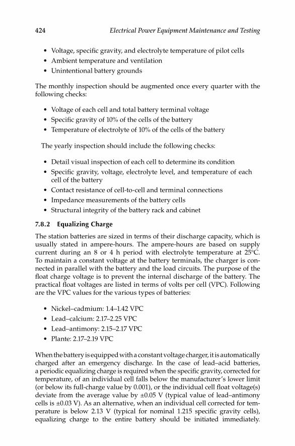
424 Electrical Power Equipment Maintenance and Testing
Voltage, specifi c gravity, and electrolyte temperature of pilot cells•
Ambient temperature and ventilation•
Unintentional battery grounds•
The monthly inspection should be augmented once every quarter with the following checks:
Voltage of each cell and total battery terminal voltage•
Specifi c gravity of 10% of the cells of the battery•
Temperature of electrolyte of 10% of the cells of the battery•
The yearly inspection should include the following checks:
Detail visual inspection of each cell to determine its condition•
Specifi c gravity, voltage, electrolyte level, and temperature of each • cell of the battery
Contact resistance of cell-to-cell and terminal connections•
Impedance measurements of the battery cells•
Structural integrity of the battery rack and cabinet•
7.8.2 Equalizing Charge
The station batteries are sized in terms of their discharge capacity, which is usually stated in ampere-hours. The ampere-hours are based on supply current during an 8 or 4 h period with electrolyte temperature at 25°C. To maintain a constant voltage at the battery terminals, the charger is con-nected in parallel with the battery and the load circuits. The purpose of the fl oat charge voltage is to prevent the internal discharge of the battery. The practical fl oat voltages are listed in terms of volts per cell (VPC). Following are the VPC values for the various types of batteries:
Nickel–cadmium: 1.4–1.42 VPC•
Lead–calcium: 2.17–2.25 VPC•
Lead–antimony: 2.15–2.17 VPC•
Plante: 2.17–2.19 VPC•
When the battery is equipped with a constant voltage charger, it is automatically charged after an emergency discharge. In the case of lead–acid batteries, a periodic equalizing charge is required when the specifi c gravity, corrected for temperature, of an individual cell falls below the manufacturer’s lower limit (or below its full-charge value by 0.001), or the individual cell fl oat voltage(s) deviate from the average value by ±0.05 V (typical value of lead–antimony cells is ±0.03 V). As an alternative, when an individual cell corrected for tem-perature is below 2.13 V (typical for nominal 1.215 specifi c gravity cells), equalizing charge to the entire battery should be initiated immediately.
DK4058_C007.indd 424DK4058_C007.indd 424 11/8/2008 12:41:51 PM11/8/2008 12:41:51 PM

Medium-Voltage Switchgear and Circuit Breakers 425
However, it is often more convenient to apply the equalizing charge to the individual cell if there is one or few cells out of limit. The frequency for equalizing charging varies, but is usually from a minimum of 3 months to 1 year. Also, an equalizing charge should be given to a battery after the addition of water to the battery. Different types of batteries require different lengths of time for the equalizing charge. The length of time is a function of cell tempera-tures. A normal electrolyte value for specifi c gravity based on a temperature of 77°F is taken to be 1.15 for a fully charged lead–acid battery. Battery perfor-mance is affected by electrolyte temperature. Generally, for every 3°F below 77°F, the battery performance can be evaluated by subtracting 0.001 from the specifi c gravity. Similarly, for every 3°F above 77°F, add 0.001 to the specifi c gravity. Specifi c gravity readings may not accurately indicate state of battery charge following discharge or following addition of water. The most accurate indicator of return to full charge is stabilized charging or fl oat current.
7.8.3 Battery Tests
The following tests are performed to
Determine whether the battery meets its specifi cations or the • manufacturer’s rating or both
Periodically determine whether the performance of the battery, as • found, is within acceptable limits
Determine whether the battery, as found, meets the design • requirements of the system to which it is connected, i.e., whether it has the capacity and capability to power the loads connected to it
7.8.3.1 Acceptance Test
This is the test to determine whether the battery meets a specifi c discharge rate and duration in accordance with manufacturer’s ratings. This test is nor-mally made at the factory or upon initial installation.
7.8.3.2 Performance Test
In IEEE standard 450-2002, it is recommended that the battery capacity test should be made within the fi rst 2 years and followed by a test interval not to be greater than 25% of the expected service life. Assuming a service life of 25 years for a vented cell battery, then this test should be conducted every 5 years or less until the battery shows signs of degradation. Similarly, in IEEE standard 1188-2005 it is recommended that the performance test interval for VRLA batteries should not be greater than 25% of the expected service life or 2 years, whichever is less. Further, annual performance test should be con-ducted on any battery that shows signs of degradation or has reached 85% of its service life. Degradation is indicated if the battery capacity falls more than 10% from its capacity on the previous performance test, or 90% of the manufacturer’s rating.
DK4058_C007.indd 425DK4058_C007.indd 425 11/8/2008 12:41:51 PM11/8/2008 12:41:51 PM
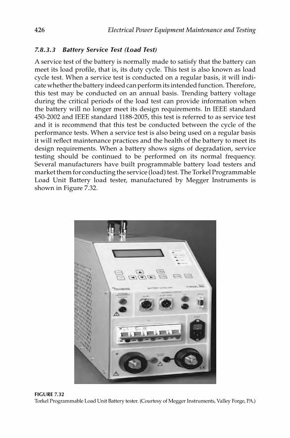
426 Electrical Power Equipment Maintenance and Testing
7.8.3.3 Battery Service Test (Load Test)
A service test of the battery is normally made to satisfy that the battery can meet its load profi le, that is, its duty cycle. This test is also known as load cycle test. When a service test is conducted on a regular basis, it will indi-cate whether the battery indeed can perform its intended function. Therefore, this test may be conducted on an annual basis. Trending battery voltage during the critical periods of the load test can provide information when the battery will no longer meet its design requirements. In IEEE standard 450-2002 and IEEE standard 1188-2005, this test is referred to as service test and it is recommend that this test be conducted between the cycle of the performance tests. When a service test is also being used on a regular basis it will refl ect maintenance practices and the health of the battery to meet its design requirements. When a battery shows signs of degradation, service testing should be continued to be performed on its normal frequency. Several manufacturers have built programmable battery load testers and market them for conducting the service (load) test. The Torkel Programmable Load Unit Battery load tester, manufactured by Megger Instruments is shown in Figure 7.32.
FIGURE 7.32Torkel Programmable Load Unit Battery tester. (Courtesy of Megger Instruments, Valley Forge, PA.)
DK4058_C007.indd 426DK4058_C007.indd 426 11/8/2008 12:41:51 PM11/8/2008 12:41:51 PM

Medium-Voltage Switchgear and Circuit Breakers 427
7.8.3.4 Connection Resistance Test
The connection resistance of the intercell connections and terminal connec-tions can be made with the use of digital low-resistance ohmmeter to assess the integrity of the current (conduction) path. Normal connection resistance varies with the cell size and connection type, and ranges from less than 10 μΩ for a large battery to as much as 100 μΩ for a smaller battery. Periodic mea-surements should be made, such as annually, and compared to previous years value to determine the need for corrective action for maintenance. A 20% change from the previous years baseline values, or values that exceed the manufacturer’s limits should initiate the need for corrective action. Refer to IEEE standard 450-2002 for more details on this method.
7.8.3.5 Battery Impedance Test
This test is based on the principle that the electrical properties of the battery, such as impedance changes proportionally with a battery’s age and discharge history. The relative internal impedance of a cell increases due mainly to losses of active material as its capacity decreases. As the cells age naturally, a life curve can be plotted for a cell and compared to a generic curve of similar cell to indicate degradation or life expectancy. The intercell impedance can be measured by using a low-frequency current source. The object of the test is to pass current through the battery string and measure the resultant voltage drop across each cell, and then compute the cell impedance. This test can be performed during fl oat conditions without disconnecting the battery. The impedance tester, manufactured by Megger Instruments is shown in Figure 7.33. When interpreting test results, it should be noted that change in cell imped-ance is also affected by other factors, such as temperature, state of the charge, load conditions, or combination of all these. These conditions should be monitored and recorded before making measurements.
Impedance readings for the individual cells can be used in the short-term to compare with the average impedance reading for the entire battery. Individual cell values that vary by more than ±20% of the battery average typically indicate a problem with that cell. Impedance readings of the entire battery can be used in the long-term to determine the need for replacement. Battery cell impedance values should be recorded and compared to previous readings to determine the position of the cell on the curve of impedance versus cell life. A sample curve for a generic lead–acid cell is shown in Figure 7.34. Curves may differ for other man-ufacturer batteries and battery chemistries. The reader may want to consult Megger Instruments who maintains a database of cell impedance values for many battery manufacturers at various temperatures, applications, and cell age.
7.8.4 Addition of Water
Due to charging, the battery will normally lose water through evaporation and chemical action. Distilled water must be added to the battery, preferably before the equalizing charge is applied.
DK4058_C007.indd 427DK4058_C007.indd 427 11/8/2008 12:41:52 PM11/8/2008 12:41:52 PM

428 Electrical Power Equipment Maintenance and Testing
1.4
Nor
mal
ized
impe
danc
e
1.2 Poorcell
Normal lifecell
Shortedcell
1.0
0.8
20 40 60 80% Life
100 120
0.6
FIGURE 7.34Impedance versus cell life (lead–acid battery). (Courtesy of Megger, Inc., Dallas, TX.)
FIGURE 7.33Battery impedance tester (BITE). (Courtesy of Megger, Inc., Dallas, TX.)
7.8.5 Acid Spillage
When acid is spilled on the battery exterior, it should be wiped clean with a cloth dampened in baking soda solution. Furthermore, the battery exterior
DK4058_C007.indd 428DK4058_C007.indd 428 11/8/2008 12:41:52 PM11/8/2008 12:41:52 PM

Medium-Voltage Switchgear and Circuit Breakers 429
should be wiped dry after wiping with a water-dampened cloth following the initial cleaning.
7.8.6 Loose Connections
Battery terminal connections and intercell connections should be checked periodically as discussed in Section 7.8.3.4.
7.8.7 Corrosion
All corrosion on battery terminals should be removed by applying baking soda solution and the terminals cleaned by using a brass brush. Antioxidant coating should be applied before reconnecting.
7.8.9 Other Maintenance Hints
Do not ground the electric storage battery, because a second acciden-• tal ground on the ungrounded polarity of any circuit fed by the bat-tery would cause the control circuit fuse to blow
New batteries after initial charge should be kept on fl oat charge for • a week
Take weekly readings of the voltage of selected cells and total bat-• tery voltage
Take monthly readings of electrolyte level, cell voltage, specifi c grav-• ity, and temperature
Every 3 months to 1 year, take a complete set of cell readings•
DK4058_C007.indd 429DK4058_C007.indd 429 11/8/2008 12:41:52 PM11/8/2008 12:41:52 PM

DK4058_C007.indd 430DK4058_C007.indd 430 11/8/2008 12:41:52 PM11/8/2008 12:41:52 PM

431
8Low-Voltage Switchgear and Circuit Breakers
8.1 Low-Voltage Switchgear
Low-voltage switchgear is a commonly used name for metal-enclosed or metal-clad low-voltage power circuit breaker switchgear rated for 600 V alternating current (AC) and below. The metal-enclosed switchgear assembly is completely enclosed on all sides and top with sheet metal (except for ven-tilating openings and inspection windows) and contains stationary primary power circuit switching or interrupting devices, or both, with buses and con-nections. The metal-clad low-voltage switchgear contains circuit breakers of removable (rack-out) types which are housed in individual grounded metal compartments. The construction features of metal-enclosed and metal-clad switchgear were described previously in Chapter 7. The service conditions for the design and performance of low-voltage switchgear are based upon ambient temperature from −30°C to +40°C, altitude not to exceed 6000 ft, and switchgear installed in nonexplosive atmosphere.
There are two basic types of low-voltage switchgear structures, they are indoor and outdoor types. Indoor switchgear consists of a front section con-taining circuit breakers, meters, relays and controls, bus section, and cable entrance section. The outdoor section is similar to the indoor switchgear except a structure that is provided around it for weatherproofi ng. Bus bars are available either in copper or aluminum. When aluminum bus is s pecifi ed, bolted joints should be made with Belleville washers to minimize cold fl ow characteristics and maintain tight connections. Generally, bare bus bars are used. However, insulation can be specifi ed on special orders. The normal clearance between phase to phase and phase to ground is 2 in. to minimize creepage for 600 V rated equipment. The standard high-voltage withstand is 2200 V AC for phase to phase and phase to ground for a period of 1 min.
Totally enclosed low-voltage switchgear, in its present form, began to gain acceptance through the 1950s. The manufacturers of the time marketed three-pole circuit breakers and their enclosures as equipment that was safer for the user’s personnel, more reliable, and as having advantages over fuses; namely, prevention of single phasing on three-phase AC systems. Today, low-voltage switchgear takes on many specialized forms and functions that combine meter-ing, monitoring, control, protection, and distribution. Major manufacturers,
DK4058_C008.indd 431DK4058_C008.indd 431 11/8/2008 12:42:10 PM11/8/2008 12:42:10 PM

432 Electrical Power Equipment Maintenance and Testing
i.e., original equipment manufacturers (OEMs), and specialty panel shops now provide a wide variety of low-voltage switchgear designs, some of them very custom, to suit the user’s needs. These may or may not be Underwriters Laboratory (UL)-labeled. It is common to fi nd installations where several different kinds of circuit breakers, automatic controls, and monitoring devices, and even automatic transfer switches, will be combined in the same line-up.
This trend in integration has started to confuse the issue as to what low-voltage switchgear really is. It should be borne in mind that switchgear is still some principal combination of metal enclosures with multipole circuit breakers. There are many metal-enclosed, dead front, assemblies offered that are switch and fuse combinations. Although they look like and commonly are referred to as switchgear, they are really modern versions of equipment known as switchboards, and are called that by most manufacturers. Like their forerunners, these switchboards do not address the problems with single phasing on branch feeders due to a blown fuse; however, the incoming device may have phase loss or blown fuse detection included in it. Regarding current-carrying capacity, both fuses and switches have roughly kept pace with the developments in circuit breaker technology.
Low-voltage AC switchgear designs are still widely applied to low-voltage direct current (DC) distribution centers up to 250 V. Previously, manufacturers provided two-pole, draw-out circuit breakers for DC switchgear. Today, the same three-pole design, and three-phase bus arrangement, is provided for both DC and AC applications; with the extra pole either unused or placed in series with one of the others according to the particular manufacturer’s appli-cation preferences. As of this writing, direct-acting overcurrent trip devices are not offered for the new low voltage power circuit breakers. The direct-acting and electromechanical trip devices have been replaced by micropro-cessor based (electronic) trip devices for overcurrent protection. However, in the molded and insulated case low voltage circuit breakers both electronic and thermal-magnetic overcurrent trip devices are offered. The electro-mechanical and dicect-acting trip devices are still available in the secondary market as replacement for the older low voltage power circuit breakers.
Low-voltage generator paralleling switchgear continues to become more com-monplace as utilities and consumers strike agreements for cogeneration or load curtailment contracts. Although similar in form to unit substation type switchgear, it is vastly more sophisticated in the areas of protection and control. It is common today to see low-voltage switchgear with protective relaying that used to be found only on medium-voltage switchgear in a utility’s generating station.
8.2 Low-Voltage Circuit Breakers
Low-voltage circuit breakers that may be found in switchgear, distribution centers, and service entrance equipment are of three types: (1) molded-case circuit breakers (MCCBs); (2) insulated-case circuit breakers; and (3) fi xed or draw-out power circuit breakers.
DK4058_C008.indd 432DK4058_C008.indd 432 11/8/2008 12:42:10 PM11/8/2008 12:42:10 PM

Low-Voltage Switchgear and Circuit Breakers 433
8.2.1 MCCBs
MCCBs are available in a wide range of ratings and are generally used for low-current, low-energy power circuits. The breakers have self-contained overcurrent trip elements. Conventional thermal-magnetic circuit breakers employ a thermal bimetallic element that has inverse time–current characteris-tics for overload protection and a magnetic trip element for short-circuit protection. Conventional MCCBs with thermal-magnetic trip elements depend on the total thermal mass for their proper tripping characteristics. This means that the proper sized wire and lug assemblies, which correspond to the rating of the trip element, must be used on the load terminals of such breakers. Many manufacturers are now switching over from bimetallic elements to power sensor (electronic) type trip elements. Magnetic-trip-only breakers have no thermal element. Such break-ers are principally used only for short-circuit protection. Molded-case breakers with magnetic only trips fi nd their application in motor circuit protection. This arrangement is desirable for smaller motors where their inrush current can ruin a delicate thermal element but where protection for winding failure is still needed. The breaker provides the instantaneous (INST) protection and fault interruption, and other overload devices in the starter handle the long-time overload protec-tion. Nonautomatic circuit breakers have no overload or short-circuit protection. They are primarily used for manual switching and isolation.
8.2.2 Insulated-Case Circuit Breakers
Insulated-case circuit breakers are molded-case breakers using glass- reinforced insulating material for increased dielectric strength. In addition, they have push-to-open button, rotary-operated low-torque handles with independent spring-charged mechanism providing quick-make, quick-break protection. A choice of various automatic trip units is available in the insulated-case breakers. Continuous current ratings range up to 4000 A with interrupting capacities through 200,000 A. The principal differences between insulated-case breakers and heavy-duty power circuit breakers are cost, physical size, and ease of maintenance. Insulated-case breakers are not designed with easy troubleshooting or repairs as the principal feature; whereas, draw-out power circuit breakers are. To partially compensate for this drawback, many manufacturers now offer a variety of accessories for insulated-case breakers that can duplicate the features of their more expensive counterparts. Nevertheless, insulated-case breakers are gener-ally suited to light industry or commercial buildings where frequent or numerous operations are not expected.
8.2.3 Power Circuit Breakers
Heavy-duty power circuit breakers employ spring-operated, stored-energy mechanisms for quick-make, quick-break manual or electric operation. Generally, these breakers have draw-out features whereby individual breakers can be put into test and fully de-energized position for testing and maintenance purposes. The electrically operated breakers are actuated
DK4058_C008.indd 433DK4058_C008.indd 433 11/8/2008 12:42:10 PM11/8/2008 12:42:10 PM

434 Electrical Power Equipment Maintenance and Testing
by a motor and cam system or a spring release solenoid for closing. Tripping action is actuated by one or more trip solenoids (shunt trip coil) or fl ux-operated devices; generally one for the protective devices on the breaker itself, and another for externally mounted controls or protective devices. The continuous frame ratings for these breakers range from 400 to 4000 A. Some manufacturers have introduced breakers with 5000 and 6000 A frames; how-ever, the long-term benefi ts and overall reliability of these designs have yet to be proven in the fi eld. Short-circuit interrupting capabilities for these break-ers are usually 50,000–85,000 A root-mean-square (rms) for frame sizes up to 4000 A. Larger designs have approached 100 kA. These breakers can be extended for applications up to 200 kA interrupting when equipped with assemblies or trucks designed to hold Class L, current-limiting power fuses.
8.2.4 Fused Power Circuit Breakers
The trend toward larger unit substation transformers and larger connected kVA loads on such substations has given way to power circuit breakers in tested combination with current-limiting fuses. This is routinely done in order to increase the short-circuit interrupting rating of the switchgear. This combination can be used for all frame sizes. The fuses cause the same prob-lems with single phasing as fuses in the switchboards; however, there are numerous features that compensate for this problem. First, most fuse assem-blies are attached directly to the breakers themselves so fuses cannot be removed or installed unless the breaker is out of service. Most manufacturers solve the single-phasing problem by either an electrical or a mechanical means of blown fuse detection, which in turn causes the breaker to trip immediately after the fuse has cleared. On the largest frame sizes, where the fuses must be mounted apart from the breaker cubicle, the fuse assembly is on a truck or roll-out which is mechanically interlocked with the breaker it serves. It should be noted that the overcurrent protection for overloads is still handled by the breaker’s overcurrent trip devices, and that the fuse is not expected to clear except for the most severe short circuits.
8.3 Overcurrent Protective Devices
The low-voltage overcurrent protective devices are direct-acting (electro-mechanical) trip (series trip) and static (electronic) trip. These overcurrent protective devices are used in the power circuit breakers as discussed above.
8.3.1 Direct-Acting Trip
The direct acting overcurrent trip device is also known as series trip, electro-mechanical and dashpot trip device This device utilizes the force created
DK4058_C008.indd 434DK4058_C008.indd 434 11/8/2008 12:42:10 PM11/8/2008 12:42:10 PM

Low-Voltage Switchgear and Circuit Breakers 435
by the short-circuit current fl owing through it to trip its circuit breaker by direct mechanical action. These devices are operated by (1) an electromag-netic force created by the short-circuit current fl owing through the trip device coil (the trip coil is usually connected in series with the electrical circuit or in some instances to the secondary of current transformers) or (2) a bimetallic strip actuated by the head generated by the fault current. The bimetallic strip is usually connected in series with the circuit.
A combination of thermal (bimetallic strip or equivalent) and INST magnetic trip is commonly used on molded-case breakers to provide time delay operation for moderate overcurrents (overloads) and INST operation for high- magnitude of short-circuit current. The thermal trip is usually nonadjustable in the fi eld or there are some devices that have limited range of adjustment, such as 0.8 to 1.25, whereas the instantaneous (INST) trip is available as adjustable or nonadjust-able. The adjustable-trip range varies from low to high with several intermediate steps. The number of steps available may vary for different designs and sizes.
Direct-acting trips on insulated-case and heavy-duty power circuit breakers are of the electromagnetic type. Three trip devices are available: (1) long time delay (LTD), (2) short time delay (STD), and (3) INST. Any com-bination of the three types is available to provide protection for overcur-rents. A trip device is installed in each phase of the electrical circuit. The LTD, STD, and INST trip devices are available in minimum, intermediate, and maximum time bands to facilitate the coordination of various trip devices in series. All these units have adjustable settings.
The time delay bands are accomplished by the action of the solenoid’s pull against springs, pneumatic, or hydraulic devices. Since these elements are purely mechanical, different characteristics cannot be supplied in a single trip device. Although some calibration points and some effects on the time can be changed by adjustments, completely different delay bands can be selected only by physically changing out the trip devices with others of the desired type. Direct-acting trips are still used on some applications, and are still required on power circuit breakers used on DC unit substations.
8.3.2 Static- and Electronic-Trip Units
Static-trip devices are completely static; that is, there are no moving parts. These devices use semiconductor-integrated circuits, capacitors, transformers, and other electric components. Static-trip devices operate to open the circuit breaker when the current–time relationship exceeds a preselected value. The energy required to trip the breaker is obtained from the circuit being protected. No external power, such as DC batteries, is required. The complete static-trip system is comprised of (1) primary circuit current transformers, (2) the static logic box, and (3) the tripping actuator (a magnetically held latch device).
The current transformer sensors are of toroidal type mounted one per phase on the primary studs of the circuit breaker. These transformers pro-vide a signal to the static-trip device proportional to the primary current.
DK4058_C008.indd 435DK4058_C008.indd 435 11/8/2008 12:42:10 PM11/8/2008 12:42:10 PM

436 Electrical Power Equipment Maintenance and Testing
The static logic box receives the signal from the primary current transformer. It monitors the signal, senses overloads or faults, and executes the required action in accordance with preselected settings. The tripping actuator receives the output signal from the static logic box and in turn causes the circuit breaker contacts to open.
Manufacturers have made great strides in the development and application of solid-state trip devices over the past 10 years or so. The motivation for this effort has been to bring protective devices to market that offer improved features over the original direct-acting designs yet preserve the totally self-contained concept exhibited by their forerunners. When the static trips were fi rst introduced, manufacturers struggled to provide reliable and repeatable devices that would prove to be lower maintenance items than the ones they replaced. Their diffi culties were not easy to overcome. The main problem has always been related to a consistent and accurate method to both derive operational power from the signals resulting from current fl owing through the breaker, and to accurately measure the current at the same time. The developments came one by one. For some time, most manufacturers still had to rely on a magnetic device to get an INST function. The designs of that time did not allow an electronic device to build up suffi cient power to trip the actuator fast enough to be called INST.
Some designs have used (and may still use) two sets of current sensors, or one set of sensors with dual secondary windings, in order to derive a signal to monitor and another to act as the power supply. Additional sensors may be required for a function that direct-acting trips could not offer—ground fault. Both three-phase, three-wire; and three-phase, four-wire ground fault detection systems are offered. The signals from either the three or four sensors are processed to determine if all INST currents add up to zero (Kirchoff’s current law applied to three-phase AC systems). Therefore, it should be apparent that if grounding conductors are used, they should not be included along with any neutral connections. When current returns to its source via a ground conductor, the monitored currents no longer add up to zero and the trip device activates. The connections and current sensors used for a three-phase, four-wire, plus ground conductor on a feeder breaker are shown in Figure 8.1.
Advances and enhancements are continually being made on static and elec-tronic-trip devices. For example, the older type static- and electronic-trip ele-ments measured peak and/or average currents and then scaled these currents to rms values based on the properties of pure sine wave. Therefore, the older static- and electronic-trip elements along with the electromechanical analog-type trip elements are susceptible to tripping problems due to harmonic cur-rents generated by nonlinear loads. The nonlinear loads are variable speed drives, switch-mode power supplies, electronic ballasts, and the like. The cur-rent electronic units are truly microprocessor based and are programmed to sample the current waveform at required intervals to calculate the effective rms value of the load currents. Microprocessor trip elements with rms sens-ing avoid false tripping problems due to harmonic current peaks and sense
DK4058_C008.indd 436DK4058_C008.indd 436 11/8/2008 12:42:10 PM11/8/2008 12:42:10 PM

Low-Voltage Switchgear and Circuit Breakers 437
the true heating current in the circuit. In addition, microprocessor trip elements provide the capability for digital readouts of voltage, currents, kilo-watts, kilowatt demands, kilowatt hours, kilovars, power factor, frequency, and so on. These readouts can be local or can be interfaced to a remote loca-tion via digital communication network. Some microprocessor protection packages can provide additional protection features that were originally available only by means of installing additional protective relays.
Also, the current microprocessor trip elements have less energy require-ments for static-trip logic. In general, most designs now use fewer and smaller current sensors than would have been supplied for the breaker whose sche-matic is shown in Figure 8.1. A good example of a modern static-trip device is the Micro-VersaTrip, RMS-9 Programmer (MVT) offered by General Electric distribution and control which is shown in Figure 8.2. Not only does this device offer all of the features mentioned above but also it has the ability to measure the true rms current. This makes the breaker immune to false trip-ping due to current waveforms with high distortion or harmonic content. The MVT system consists of the following parts.
Ground bus
Neutral bus
Phase 1
Phase 2
Phase 3
Tripping actuator (solenoid)
Phaselogicbox
Groundlogicbox
Powersupply
Tripcircuit
box
FIGURE 8.1Functional diagram of static-trip device.
DK4058_C008.indd 437DK4058_C008.indd 437 11/8/2008 12:42:11 PM11/8/2008 12:42:11 PM

438 Electrical Power Equipment Maintenance and Testing
Three current sensors are mounted on the breaker and provide the self-powered input to the protection programmer. Where four-wire ground fault is specifi ed, a fourth current sensor is mounted near the neutral bar in the cable compartment. Sensors are constructed of molded epoxy for added protection against damage and moisture. Optional current sensors with four taps are available to increase the fl exibility and range of the system. In the current designs rating plug is provided for a given sensor and breaker to establish the continuous current carrying capability (rating) of the breaker.
A fl ux-shift device is automatically powered and controlled by the protection programmer and causes the breaker to trip on command. This low-energy positive action tripping device is located near the trip bar on the breaker. This device automatically resets when the moving contacts on the breaker have fully opened.
The protection programmer has a programmable microelectronic proces-sor with laser-trimmed custom-integrated chips that form the basis of the fl exible, precise MVT protection system. MVT protection programmers may be furnished with
Up to nine adjustable time–current functions•
Three local and remote mechanical fault indicators•
L• ocal and remote long-time pickup light emiting diode (LED) indicator
FIGURE 8.2Micro-VersaTrip Plus, static-trip device.
DK4058_C008.indd 438DK4058_C008.indd 438 11/8/2008 12:42:11 PM11/8/2008 12:42:11 PM

Low-Voltage Switchgear and Circuit Breakers 439
Zone selective interlocking•
Integral ground-fault trip•
All adjustable programmer functions are automatic and self-contained and require no external relaying, power supply, or accessories.
8.3.3 Monitoring and Protection Packages
A natural outgrowth of the move to static-trip devices has been to provide devices that can display the quantities they are monitoring. This trend has come in response to user’s concerns regarding the convenience in monitoring loads and in troubleshooting a given distribution system. Low-voltage switchgear generally has space constraints within its breaker cubicles; consequently, mount-ing space (if any) for additional current transformers is limited. Manufacturers are beginning to offer monitoring packages that take advantage of the signals already made available by the protection devices. The information can be dis-played on the trip device or sent to a cubicle door mounted display. Automated data processing centers and cogeneration sites have set up elaborate monitoring systems by taking advantage of the communications functions that are now offered. Almost every feeder at a user’s site can be monitored and all of its electri-cal performance data sent back to a central system. The trend in interfacing this basic electrical monitoring with communications to fi eld programming units (FPUs); remote terminal units (RTUs), programmable controllers (PLCs) used as sequence controllers, data collectors, or concentrators; and sequence control and data acquisition (SCADA) systems is expected to continue. Many of the elements used in these systems are now installed directly in the switchgear.
8.4 Fuses
Two basic families of fuses are current limiting and noncurrent limiting. The current-limiting fuse melts and extinguishes the arc in a half-cycle or less. The noncurrent-limiting type may melt in less than a half-cycle when subjected to very high values of short-circuit current, but is unable to extinguish the arc in a half-cycle. Since the arc is a fl exible conductor, the noncurrent-limiting-type fuse will allow the short-circuit current to reach its maximum peak value. The current-limiting type of fuses are constructed with mechanisms to extinguish the arc, thereby preventing the short-circuit cur-rent from reaching its maximum peak value. The fuses are used in conjunc-tion with circuit breakers, motor starters, disconnect switches, and the like to provide protection similar to the circuit breaker overcurrent trip devices. However, fuses have fi xed time–current relationships and therefore do not provide the same fl exibility as the overcurrent relationships and therefore do not provide the same fl exibility as the overcurrent trip devices. Fuses cannot open and close a circuit by themselves. They must be combined with some supplementary device, such as a disconnect switch, a circuit breaker, or a contactor. Fuses can be divided into medium- and low-voltage fuses.
DK4058_C008.indd 439DK4058_C008.indd 439 11/8/2008 12:42:11 PM11/8/2008 12:42:11 PM
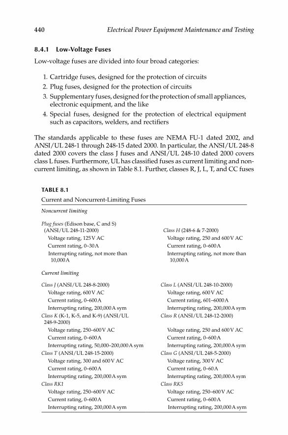
440 Electrical Power Equipment Maintenance and Testing
8.4.1 Low-Voltage Fuses
Low-voltage fuses are divided into four broad categories:
1. Cartridge fuses, designed for the protection of circuits
2. Plug fuses, designed for the protection of circuits
3. Supplementary fuses, designed for the protection of small appliances, electronic equipment, and the like
4. Special fuses, designed for the protection of electrical equipment such as capacitors, welders, and rectifi ers
The standards applicable to these fuses are NEMA FU-1 dated 2002, and ANSI/UL 248-1 through 248-15 dated 2000. In particular, the ANSI/UL 248-8 dated 2000 covers the class J fuses and ANSI/UL 248-10 dated 2000 covers class L fuses. Furthermore, UL has classifi ed fuses as current limiting and non-current limiting, as shown in Table 8.1. Further, classes R, J, L, T, and CC fuses
TABLE 8.1
Current and Noncurrent-Limiting Fuses
Noncurrent limiting
Plug fuses (Edison base, C and S)
(ANSI/UL 248-11-2000) Class H (248-6 & 7-2000)
Voltage rating, 125 V AC Voltage rating, 250 and 600 V AC
Current rating, 0–30 A Current rating, 0–600 A
Interrupting rating, not more than
10,000 A
Interrupting rating, not more than
10,000 A
Current limiting
Class J (ANSI/UL 248-8-2000) Class L (ANSI/UL 248-10-2000)
Voltage rating, 600 V AC Voltage rating, 600 V AC
Current rating, 0–600 A Current rating, 601–6000 A
Interrupting rating, 200,000 A sym Interrupting rating, 200,000 A sym
Class K (K-1, K-5, and K-9) (ANSI/UL
248-9-2000)
Class R (ANSI/UL 248-12-2000)
Voltage rating, 250–600 V AC Voltage rating, 250 and 600 V AC
Current rating, 0–600 A Current rating, 0–600 A
Interrupting rating, 50,000–200,000 A sym Interrupting rating, 200,000 A sym
Class T (ANSI/UL 248-15-2000) Class G (ANSI/UL 248-5-2000)
Voltage rating, 300 and 600 V AC Voltage rating, 300 V AC
Current rating, 0–600 A Current rating, 0–60 A
Interrupting rating, 200,000 A sym Interrupting rating, 200,000 A sym
Class RK1 Class RK5Voltage rating, 250–600 V AC Voltage rating, 250–600 V AC
Current rating, 0–600 A Current rating, 0–600 A
Interrupting rating, 200,000 A sym Interrupting rating, 200,000 A sym
DK4058_C008.indd 440DK4058_C008.indd 440 11/8/2008 12:42:11 PM11/8/2008 12:42:11 PM

Low-Voltage Switchgear and Circuit Breakers 441
are designated as branch circuit fuses suitable for protection of distribution systems, wiring, or equipment.
Because fuses are single-phase interrupters, they provide good protection for single-phase circuits. However, for multiphase circuits, these single-phase interrupters can cause problems such as single phasing, backfeeding, and ferroresonance. Single phasing can be detrimental to motors owing to the fl ow of negative-sequence currents, which can cause excessive heating of the motor rotor, causing motor failure or reducing its normal life. The degree of motor life reduction is a function of motor temperature and elapsed time between single-phase occurrence and motor de-energization.
The term back feeding is used to describe the condition when fault current continues to fl ow from the remaining energized phases, most probably at a reduced value owing to the additional impedance that has been inserted in the current path. The degree of fault current reduction will determine the time of response of the fuses in the remaining phases. As fuse interrupting time increases, the degree of damage also increases. Today’s switchgear designs employing fuses as overcurrent protective devices use anti-single phase protection features. The anti-single phase feature in the fused switch-gear open all three phases due to a single fuse blowing, thereby averting the adverse effects of single phasing discussed earlier.
8.5 Disconnect Switches
Disconnect switches are commonly used in low- and medium-voltage systems. The application of disconnect switches can be divided into low- voltage (600 V and below) and medium-voltage (601 V through 15 kV) classes. The medium-voltage switches are discussed in Chapter 7.
8.5.1 Low-Voltage Switches
Low-voltage switches can be classifi ed into three broad categories: (1) isolating switches, (2) safety switches, and (3) interrupter switches. The isolating
TABLE 8.1 (continued)
Current and Noncurrent-Limiting Fuses
Class CC (ANSI/UL 248-4-2000) Class C (ANSI/UL 248-2-2000)
Voltage rating, 600 V AC Voltage rating, 600 V AC
Current rating, 0–30 A Current rating, 0–1200 A
Interrupting rating, 200,000 A sym Interrupting rating, 200,000 A sym
Class CA/CB (ANSI/UL 248-3-2000)
Voltage rating, 300 or 600 V AC
Current rating, CA: 0–30 A; CB: 0–60 A
Interrupting rating, 200,000 A sym
Source: From UL 248.1–248.16-2000, UL Standard for Safety for Low-Voltage Fuses,
Part 1–Part 16.
DK4058_C008.indd 441DK4058_C008.indd 441 11/8/2008 12:42:11 PM11/8/2008 12:42:11 PM

442 Electrical Power Equipment Maintenance and Testing
switch has no interrupting or load-carrying capability. It serves only to provide isolation of the circuit or load by manual means after the power fl ow is cut off by the circuit protective device.
The safety switch is a load-break switch having a quick-make and quick-break contact mechanism. Safety switches are used in small power systems with limited short-circuit capacity. The safety switch may be fused or unfused.
The interrupter switch is of quick-make, quick-break type and is capable of interrupting at least 12 times its continuous current rating. They are assigned horsepower rating. These switches are available in continuous rating from 30 to 1200 A and can be installed in switchboards, panelboards, and grouped motor control centers. The interrupter switch may be utilized with or without fuses depending upon the application.
Some light industrial systems or commercial buildings will use switchgear or switchboards with a high pressure or bolted pressure, three-pole switch acting as incoming service main disconnects. The principal feature of these switches is their continuous current capacities of up to 3000 or 4000 A. At these currents, very high contact pressure is required on the conducting surfaces in order to hold temperature rises to reasonable levels. The switches themselves carry an interrupting rating similar to those for three-pole interrupter switches but not as high as that for power circuit breakers. Interrupting capa-bility for short circuits is almost always handled by current-limiting fuses, which are an integral part of the switch. Most manufacturers provide single phase, blown fuse, and ground fault accessories so that the switches can be used on low-voltage service entrances. Unlike trip devices applied to circuit breakers, these protective devices are not self- powered. Rather, they take oper-ating voltage from a small control power transformer on the source side of the switch. Generally, the mechanical design of these switches is based on a min-imum of operations. The number of operations is expected to be less than for insulated-case breakers; usually limited to isolation during maintenance or for serious ground faults not cleared successfully by other means.
8.6 Selection and Application of Low-Voltage Equipment
The modern distribution system has high short-circuit current available and therefore requires special consideration so that equipment may be applied within its rating. Furthermore, the switchgear should be protected against all types of faults, from low-level arcing faults to bolted faults. The protec-tion system should be selective; that is, the fault at a remote location in the system should be localized without unnecessary tripping of either the main breaker system or any intermediate breakers. The distribution system should be planned to provide continuity and reliability of service. This can be achieved by using two or more separate distribution systems instead of one large system. The continuous current rating of the main protective device should be adequate for the load to be served. Protective devices should not be paralleled to obtain a higher rating. As a general rule, the bus bars are
DK4058_C008.indd 442DK4058_C008.indd 442 11/8/2008 12:42:11 PM11/8/2008 12:42:11 PM

Low-Voltage Switchgear and Circuit Breakers 443
rated on the basis of not more than 800 A/in.2 of aluminum or 1000 A/in.2 of copper. The operation of protective devices is based upon an ambient tem-perature of 40 °C, and if these devices are to be applied at higher tempera-ture, the manufacturer should be consulted. The short-circuit rating of a bus is limited to the interrupting rating of the lowest rated protective device, and the available short-circuit current should not exceed this value.
The application of circuit breakers and fuses must be considered to determine which offers the most appropriate protection. Consideration should be given to anti-single-phase devices when three-pole interrupter swit ches with fuses are used, because fuses are single-pole interrupter switches. An arcing fault may not be stopped by a single-pole interruption. It can be backfed from the other energized phases. Because of this condition, severe equipment burn-downs may occur. Ferroresonance is the result of interaction between the reac-tance of a saturable magnetic device, such as a transformer, and system capacitance. Ferroresonance can also occur due to a single phasing condition. This phenomenon occurs mostly in high- and medium-voltage systems and results in a very high voltage on the order of three to fi ve normal system volt-age which is imposed on the circuit involved, causing equipment failure.
Always keep in mind that fuses should be applied in systems where the system voltage is compatible with the fuse voltage rating. The reason for this is that the arc voltage generated by a fuse when interrupting is several times its voltage rating and, if misapplied, could subject the system to overvoltage conditions, causing equipment failure.
The current-limiting features of current-limiting fuses are defi nite strong pluses for many applications; however, use the fact wisely, for they do not limit current for all values of fault current. If the fault current magnitude is equal to or greater than the fuse threshold current, they will always be current limiting. However, if the fault current magnitude is less than the fuse threshold current, but greater than the current magnitude indicated at the intersection of the maximum peak current curve and fuse curve, the fuse may or may not be cur-rent limiting. For fault current magnitude indicated by the above curve inter-section, the fuse is never current limiting.
For this reason and arc-voltage considerations, when applying current-limiting fuses to increase the interrupting rating of other protectors, the fusing recommendations of the product manufacturers, not the fuse manu-facturer, should be followed. Fused equipment can be opened and closed manually or electrically to provide circuit protection. However, the fuse and equipment should be coordinated and tested as a combination. The fuse’s adequate performance as a circuit protector and switching device should be certifi ed by one manufacturer.
When fused switches are electrically controlled, caution is required not to let the switch open due to fault conditions. The fault current, if not suffi cient to cause interruption before the switch contacts or blades open, could be greater than the contacts’ or blades’ interrupting capability. This would result in a hazardous condition. Fused switches basically require the same application considerations as previously outlined in this section.
DK4058_C008.indd 443DK4058_C008.indd 443 11/8/2008 12:42:12 PM11/8/2008 12:42:12 PM

444 Electrical Power Equipment Maintenance and Testing
Fused motor starters applied in medium- and low-voltage systems avoid the ferroresonance problem owing to their location in the system. Auxiliary devices can be supplied with motor starters to provide a complete overload protection and anti-single-phasing protection. The selection and application of switchgear should be approached on an engineering basis. To provide reliability, ease of maintenance, and continuity of service, properly rated equipment and adequate circuit protection are necessary throughout the entire system, from the place where the power system enters the facility down to the smallest load.
8.6.1 Assessing Service Life of Low-Voltage Breakers
The National Electrical Manufacturers Association (NEMA), American Standards National Institute (ANSI), and Institute of Electrical and Electronic Engineers (IEEE) standards for low-voltage power circuit breakers and MCCBs contain performance criteria for assessing the service life of manufactured products. The pertinent industry standards for low-voltage breakers are ANSI/IEEE C37.16-2000, C37.26-2003, C37.50-2000, C37.51-2003, NEMA AB-1-2002, and AB-4-2003. In addition, the MCCBs are tested at the manufacturer’s production facility and/or at UL facilities in accordance with standards promulgated by the industry and UL-489-2002. The performance criteria contained in these standards can also help users anticipate the need for maintenance testing, inspections, refurbishment, and/or replacement of the manufactured prod-ucts. This section provides an overview of the requirements covered in the referenced industry standards and the methods typically used by manufac-turers in making the products. It is expected that an understanding of the endurance requirements covered in the standards should provide insights that can be used to inspect and evaluate the health for continued reliable operation (i.e., the service life) of low-voltage power circuit breakers and MCCBs. There are four basic electrical ratings and endurance requirements for switchgear components and assemblies such as circuit breakers.
8.6.1.1 Maximum Voltage Rating or Nominal Voltage Class
Low-voltage power circuit breakers are marked with the maximum system voltage at which they can be applied. Standard maximum voltage ratings are 635, 508, and 254 V for application of the breakers in 575, 480, and 208 V electrical power systems, respectively. A low-voltage breaker can be used in a circuit that has a nominal voltage rating less than the breaker’s maximum voltage rating. For example, a 635 V rated circuit breaker can be applied in a 208, 240, 480, or 600 V rated circuit. For fused breakers, the 635 V maximum voltage rating becomes 600 V to match the voltage rating of the fuses.
8.6.1.2 Continuous Current Rating
The continuous current rating of a circuit breaker, isolator switch, load-break switch, switchgear assembly, or motor control center is the number of
DK4058_C008.indd 444DK4058_C008.indd 444 11/8/2008 12:42:12 PM11/8/2008 12:42:12 PM

Low-Voltage Switchgear and Circuit Breakers 445
amperes; that the device can carry continuously without the temperature of any insulation component becoming greater than its rated temperature. For low-voltage power circuit breakers and MCCBs, the continuous current rating of the breaker’s frame is called the frame size. For any low-voltage power circuit breaker that can accept a replaceable trip device, installation of a trip device that has a continuous current rating that is less than the frame size reduces the continuous rating of the circuit breaker. It is not permissible to install a trip device that has a continuous current rating that is greater than the breaker’s frame size.
8.6.1.3 Rated Short-Circuit Current (Circuit Breakers)
Low-voltage circuit breakers are designed and manufactured with one or more interrupting ratings (rated short-circuit current), often called interrupting ampere capability (AIC). These interrupting ratings are the maximum values of available (prospective) short-circuit current (fault) that the breaker is able to interrupt (short-circuit duty cycle) at different maxi-mum voltage values. Available current is defi ned in the industry standards as the expected rms symmetrical value of current at a time one half-cycle after short-circuit initiation. The maximum fault in a power system occurs at one half-cycle time. The low-voltage breakers are fast acting and begin to part contacts at about one half-cycle time which is point of maximum short-circuit current. Therefore, as the breaker contacts begin to part, i.e., as the breaker begins to interrupt the short-circuit current it is subjected to the maximum asymmetrical current. The asymmetry of the short-circuit current is a function of the X/R ratio, or the power factor of the short-circuit current. The ANSI/UL standard 489, “Standard for molded case circuit breakers and circuit breaker enclosures” along with AB-1 contain the criteria for perform-ing interrupting ability tests for molded-case breakers. These standards specify the power factor of the test circuit with the required current fl owing that is to be used for establishing the asymmetry of the short-circuit current. The NEMA AB-1-2002 and UL 489-2002 standards have established three asymmetry categories (i.e., power factor) of short-circuit current interrupting capabilities. The three asymmetry categories (short-circuit current and power factor) given in NEMA AB-1 and UL 489 are shown in fi rst two columns of Table 8.2. The associated X/R ratio and the accompanying multiplying fac-tors are shown in columns 3 and 4 of Table 8.2. What the UL 489 and relevant industry standards are saying is that the asymmetry is greater for fault cur-rents at the locations where the short- circuit current is high, and it is smaller at locations where the short-circuit current is less. Another way of stating this criterion is to say that the breakers applied closer to the substations will experience higher short-circuit currents with higher asymmetry in the fault current, thereby subjecting a breaker to undergo a higher short-circuit duty while interrupting the fault. The opposite is true for breakers applied further away (downstream) from the substation because such breakers will see lower short-circuit currents and lower asymmetry in the short-circuit current.
DK4058_C008.indd 445DK4058_C008.indd 445 11/8/2008 12:42:12 PM11/8/2008 12:42:12 PM

446 Electrical Power Equipment Maintenance and Testing
What this all means is that power factor is lower (or X/R ratio is higher) near the substations and power factor is higher (or X/R ratio is lower) further away from the substation. It should be noted that the maximum asymmetry for the low-voltage circuit breakers is capped at power factor of 0.15, X/R ratio of 6.6. However, examination of the manufacturer and UL data shows that most breakers are tested at a maximum power factor of 0.20 or X/R ratio of 4.87. The low-voltage breaker’s short- circuit interrupting capability is indicated in sym-metrical amperes since the asymmetry is already included in the test circuit current when the breakers are tested for interrupting capability. Also, note that the short circuit duty cycle is a specifi c test that is performed on a prototype model of a circuit breaker. A detailed explanation of this test can be found in ANSI/IEEE standards C37.16, C37.50, UL 489, and NEMA AB-1. Table 8.3 shows
TABLE 8.2
Power Factor of Test Circuits—NEMA-AB-1-2002 and UL-489-2002
Test Circuit (A) Power Factor X/R
Multiplying Factors
MA MM
NEMA-AB-1-2002
10,000 or less 0.50 1.732 1.026 1.013
10,001–20,000 0.30 3.15 1.130 1.064
Over 20,000 0.20 4.87 1.247 1.127
UL-489-2002
10,000 or less 0.45–0.50 1.98–1.732 1.041–1.026 1.021–1.013
10,001–20,000 0.25–0.30 3.87–3.15 1.181–1.130 1.092–1.064
Over 20,000 0.15–0.20 6.60–4.87 1.331–1.247 1.172–1.127
Sources: From NEMA-AB-1-2002, Molded Case Circuit Breakers and Molded
Case Switches and UL-489-2002, Standard for Safety Molded-Case Circuit
Breakers, Molded-Case Switches, and Circuit-Breaker Enclosures.
Note: MA (three-phase fault) = (Average three-phases − asymmetrical rms amperes)/
(Average three-phases − symmetrical rms amperes). MM (1 − phase fault) = (Asym-
metrical rms amperes)/(symmetrical rms amperes).
TABLE 8.3
Preferred Short Circuit Ratings in rms Symmetrical Amperes
7,500 20,000 35,000 85,000 200,000
10,000 22,000 42,000 100,000
14,000 25,000 50,000 125,000
18,000 30,000 65,000 150,000
Sources: From NEMA-AB-1, Molded Case Circuit
Breakers and Molded Case Switches.
DK4058_C008.indd 446DK4058_C008.indd 446 11/8/2008 12:42:12 PM11/8/2008 12:42:12 PM

Low-Voltage Switchgear and Circuit Breakers 447
the interrupting symmetrical ampere capabilities published in NEMA AB-1 for the breakers manufactured by NEMA member companies.
Each model of circuit breaker can have a different set of interrupting current capabilities listed in Table 8.3. The interrupting capability of a low-voltage breaker varies with the applied voltage. For example, a 1600 A-rated breaker applied at 240 V might have an interrupting capability of 65 kA at 240 V, whereas the same breaker applied at 480 V would have an interrupt-ing capability of 50 kA. The interrupting capability also changes if the break-er’s automatic trip device has a short-time trip function rather than an INST trip function. For example, a 4000 A-rated circuit breaker that has an INST trip might have an interrupting capability of 150 kA at 240 V, whereas the same breaker equipped with a short-time trip has an interrupting capability of 85 kA at 240 V. Any low-voltage power circuit breaker that is equipped with current-limiting fuses (current limiters) has short-circuit current rating equal to 200 kA. Rated short-circuit current is also infl uenced by the ability of a circuit breaker to close and latch against, carry, and subsequently interrupt, a fault current. Breakers have closing and latching capabilities, sometimes called momentary rating, relate to the breaker’s ability to withstand the mechanical and thermal stress of the fi rst half-cycle of a fault current, i.e., asymmetrical short-circuit current. Low-voltage power circuit breakers and MCCBs display no nameplate information concerning momentary rating. These types of breakers are tradi-tionally tested and applied according to their interrupting current capability in RMS amperes. The reason that momentary ratings do not appear on their nameplates is that these breakers are tested with the asymmetry already included in the symmetrical amperes of the test circuit that was discussed earlier. For those few system applications that have a greater asymmetrical value than the asymmetry of test circuit current (i.e., X/R = 6.6), a circuit breaker of higher interrupting current rating should be applied.
8.6.1.4 Short-Circuit Current Ratings—Panelboards, MCCs,and Switchgear Assemblies
A panelboard has a short-circuit current rating shown on its nameplate. A pan-elboard is not allowed to be applied in any circuit whose available fault cur-rent is greater than its short-circuit current rating. The short-circuit current rating of a panelboard is limited to the lowest value of rated short-circuit current for any circuit breaker that is installed within the panelboard. The short circuit withstand rating of a motor control center is the average rms current that its busses can carry for 2 s. A motor control center is not allo-wed to be applied in any circuit whose available fault current is greater than its short-circuit withstand rating. The rated momentary current of metal-enclosed or metal-clad switchgear represents the maximum rms current that it is required to withstand during a test of 10 cycles duration. This test is conducted on a prototype model. The rated short-time current of metal- enclosed or metal-clad switchgear is the average rms current that it can carry for a period of 2 s.
DK4058_C008.indd 447DK4058_C008.indd 447 11/8/2008 12:42:12 PM11/8/2008 12:42:12 PM

448 Electrical Power Equipment Maintenance and Testing
8.6.1.5 Endurance Requirements for Low-Voltage Breakers
The ANSI/IEEE standard for switchgear C37.16-2000 provides endurance requirements of low-voltage power circuit breakers and AC power circuit protectors. Although primarily used by manufacturers who have an interest in assuring a durable product, these endurance requirements can also help equipment users to anticipate the need for maintenance or replacement. In order to verify that a particular design of circuit breaker meets the endur-ance requirements, a manufacturer performs all endurance tests on a single circuit breaker. Table 8.4 appears in the standard and represents the number of times that the circuit breaker is required to make and subsequently break line currents that are 600% of the breaker’s rated continuous current. The test method includes specifi cations for how much time can elapse between switching operations. The breaker components that are most likely to become worn during this endurance test are arcing tip and arc chutes.
Table 8.5 also appears in the ANSI 37.16-2000 and represents the number of open–close or close–open operations that the breaker’s operating mechanism is required to endure when making and breaking 100% of its rated current (electrical endurance) and no current (mechanical endurance). The components that are most likely to become worn during this endurance test are latches, cam, rollers, bearings, pins, clamps, and threaded hardware. In order to pass this test, adjusting, cleaning, lubricating, and tightening are allowed at the intervals shown in column 2 of Table 8.5. The numbers in this column contain a clear implication that maintenance is required in order to allow a circuit breaker’s operating mechanism to realize its full lifetime. An examination of the Annex A ANSIC37.16-2000 reveals several comments that relate strongly to breaker maintenance. These comments are (1) The circuit breaker should be in a condition to carry its rated continuous current
TABLE 8.4
Overload Switching Requirements for LowVoltage AC Circuit Breakers
Line No.
Frame Size
Amperes
Number of Make–Break
Operations
1 225 50
2 600 50
3 800 50
4 1600 38
5 2000 38
6 3000 —
7 3200 —
Source: From ANSI 37.16-2000, Low-Voltage Power
Circuit Breakers and AC Power Cicuit Protectors
Preferred Ratings, Related Requirements, and
Application Recommendations.
DK4058_C008.indd 448DK4058_C008.indd 448 11/8/2008 12:42:12 PM11/8/2008 12:42:12 PM
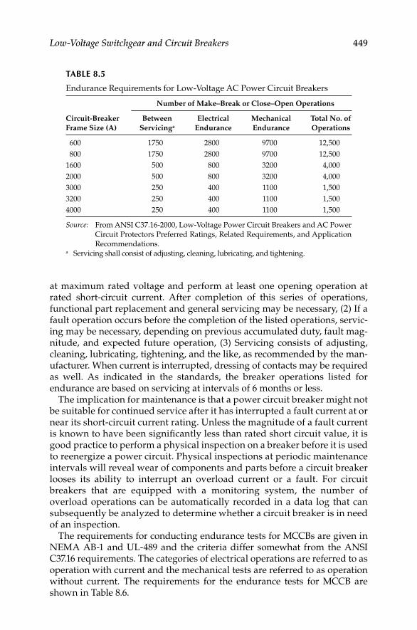
Low-Voltage Switchgear and Circuit Breakers 449
at maximum rated voltage and perform at least one opening operation at rated short- circuit current. After completion of this series of operations, functional part replacement and general servicing may be necessary, (2) If a fault operation occurs before the completion of the listed operations, servic-ing may be necessary, depending on previous accumulated duty, fault mag-nitude, and expected future operation, (3) Servicing consists of adjusting, cleaning, lubricating, tightening, and the like, as recommended by the man-ufacturer. When current is interrupted, dressing of contacts may be required as well. As indicated in the standards, the breaker operations listed for endurance are based on servicing at intervals of 6 months or less.
The implication for maintenance is that a power circuit breaker might not be suitable for continued service after it has interrupted a fault current at or near its short-circuit current rating. Unless the magnitude of a fault current is known to have been signifi cantly less than rated short circuit value, it is good practice to perform a physical inspection on a breaker before it is used to reenergize a power circuit. Physical inspections at periodic maintenance intervals will reveal wear of components and parts before a circuit breaker looses its ability to interrupt an overload current or a fault. For circuit breakers that are equipped with a monitoring system, the number of overload operations can be automatically recorded in a data log that can subsequently be analyzed to determine whether a circuit breaker is in need of an inspection.
The requirements for conducting endurance tests for MCCBs are given in NEMA AB-1 and UL-489 and the criteria differ somewhat from the ANSI C37.16 requirements. The categories of electrical operations are referred to as operation with current and the mechanical tests are referred to as operation without current. The requirements for the endurance tests for MCCB are shown in Table 8.6.
TABLE 8.5
Endurance Requirements for Low-Voltage AC Power Circuit Breakers
Circuit-Breaker
Frame Size (A)
Number of Make–Break or Close–Open Operations
Between
Servicinga
Electrical
Endurance
Mechanical
Endurance
Total No. of
Operations
600 1750 2800 9700 12,500
800 1750 2800 9700 12,500
1600 500 800 3200 4,000
2000 500 800 3200 4,000
3000 250 400 1100 1,500
3200 250 400 1100 1,500
4000 250 400 1100 1,500
Source: From ANSI C37.16-2000, Low-Voltage Power Circuit Breakers and AC Power
Circuit Protectors Preferred Ratings, Related Requirements, and Application
Recommendations.a Servicing shall consist of adjusting, cleaning, lubricating, and tightening.
DK4058_C008.indd 449DK4058_C008.indd 449 11/8/2008 12:42:12 PM11/8/2008 12:42:12 PM

450 Electrical Power Equipment Maintenance and Testing
8.7 Low-Voltage Switchgear Maintenance and Care
The low-voltage switchgear discussed in this section involves power circuit breakers and enclosures of indoor or outdoor type. The frequency of inspection and maintenance should be 3–6 months when new equipment is installed and 1–2 years for existing equipment. However, if problems with switchgear are encountered, the frequency can be shortened. Similarly to medium- voltage switchgear, the conditions that call for frequent inspection and maintenance are high humidity and temperature, corrosive atmosphere, excessive dirt or dust, frequent fault interruption, and age of the equipment. The following guide is provided for the general maintenance of low-voltage equipment; where neces-sary it should be supplemented by the manufacturer’s detailed instructions.
8.7.1 General Guidelines for Inspection and Maintenance of Switchgear
The ultimate long-term performance of switchgear depends on the reliability of its insulation system. An important factor in the insulation reliability is its regular switchgear inspection and maintenance program. The frequency of inspection should be based on the number of scheduled shutdowns, frequent emergency shutdowns, long periods of sustained overloading or abnormal operating conditions, numerous switching operations, number of fault occurrences, and extremes in atmospheric conditions. The following guide is
TABLE 8.6
Endurance Requirements for MCCBs
MCCB Frame
Size (A)
Number of Make–Break or Close–Open Operations
No. of Operations/
Minutea With Current Without Current Total
100 6 6000 4000 10,000
150 5 4000b 4000 8,000b
225 5 4000 4000 8,000
600 1 500 3000 3,500
1200 1 500 2000 2,500
2500 1 500 2000 2,500
6000 1c 400 1100 1,500
Source: From UL-489-1991, Standard for Safety Molded-Case Cricuit Breakers,
Molded-Case Switches, and Circuit-Breaker Enclosures.a For circuit breakers rated more than 800 A, the endurance test may, at the option of
the manufacturer, be conducted in groups of 100 load operations. No-load opera-
tions may be conducted between groups of load operations at the option of the
manufacturer.b Where tests are required on samples having ratings of 100 A or less, 250 V or less,
the number of operations is to be the same as for the 100 A frame.c Rate of operation: 1 cycle per minute for fi rst 10 operations; thereafter in groups of 5,
at 1 cycle per minute, with an interval between groups that is agreeable to the
submitter and the testing agency.
DK4058_C008.indd 450DK4058_C008.indd 450 11/8/2008 12:42:12 PM11/8/2008 12:42:12 PM

Low-Voltage Switchgear and Circuit Breakers 451
offered on how to inspect and what to look for when inspecting switchgear. This guide may also be used for inspecting medium-voltage switchgear.
On energized equipment
Listen for popping, spitting, or cracking sounds produced by • electrical discharges—also humming noises or vibration produced by resonance.
With lights out, look for blue or purple corona halos. Orange or red • sputter arcs are created by intermittent sparking.
Ozone, produced by corona or overheating of organic materials, can • usually be detected by their odors.
On de-energized equipment
Look for physical damage—cracks, breaks, delaminations, warping, • blisters, fl aking, or crazing of insulated parts.
Check for foreign objects and loose hardware, warped or distorted • insulated bus, and rusty or bent structural framework.
Powdery deposits, carbon tracks, moisture stains or rust, fl aking • paint, or varnish are signs that moisture is, or has been, present; look for probable source of entry.
Specifi c areas to inspectAlthough the inspector should check the whole insulating structure, there are a number of specifi c areas where distress is more likely to occur.
Boundaries between two contiguous insulating members•
Boundaries between an insulating member and the grounded metal • structure
Taped or compounded splices or junctions•
Bridging paths across insulating surfaces; either phase-to-phase or • phase-to-ground
Hidden surfaces, such as the adjacent edges between the upper and • lower members of split type bus supports, or the edges of a slot through which a bus bar protrudes
Edges of insulation surrounding mounting hardware—either grounded • to the metal structure or fl oating within the insulating member
Physical damageBroken or cracked insulating supports can allow the supported components to be subjected to mechanical stresses for which they were not designed, resulting in ultimate failure. Damaged or contaminated insulation materially reduces voltage striking and creepage distances, ultimately resulting in a fl ashover.Physical damage can stem from several causes:
DK4058_C008.indd 451DK4058_C008.indd 451 11/8/2008 12:42:12 PM11/8/2008 12:42:12 PM
452 Electrical Power Equipment Maintenance and Testing
Mishandling of the switchgear during shipment, installation, over-• loading, or maintenance
Mechanical forces induced by heavy faults•
Thermal cycling of insulating members•
Strains induced by improper mounting of insulating members•
Combinations of the above•
HeatTemperatures (even slightly over design levels) for prolonged periods can signifi cantly shorten the electrical life of organic insulating materials. A pro-longed exposure to higher than rated temperatures will cause physical deterioration of organic materials, resulting in lower mechanical strength. Localized heating (hot spots) sometimes occur. They are hard to detect because the overall temperature of the surroundings is not raised appreciably. Loosely bolted connections in a bus bar splice or void spaces (dead air) in a taped assembly are examples of this.
Since power is usually removed prior to inspection, it is unlikely that apparatus temperature can be relied upon as an indicator of damaging heat. But observed conditions can be used as the basis for determining heat damage. The signs of heating are as follows:
Discoloration—usually a darkening of materials or fi nishes•
Crazing, cracking, or fl aking of varnish coatings•
Embrittlement of tapes and cable insulation•
Delamination of taped conductors or laminated insulation•
Generalized carbonization of materials or fi nishes•
Melting, oozing, or exuding of substances from within an insulating • assembly
MoistureThe term moisture, usually associated with water, includes vapors which can readily conduct leakage currents. They are often present as air pollutants in industrial atmospheres. The main source of moisture is highly humid air which is subject to climatic type cycling. The drop in temperature between daytime and dark can cause relatively still air to pass through a dew-point, resulting in condensation. Sudden temperature drops can cause condensation, even inside of buildings housing switchgear. Detection of moisture usually depends on signs, rather than the presence of actual moisture. Look for these indications:
Droplet depressions (or craters) on a heavily dust-laden bus•
Dust patterns, similar to those on an auto subjected to a light rain • shower after driving on a dusty road
Deposits which remain if a fi lm of dirty water evaporates on a fl at • surface
DK4058_C008.indd 452DK4058_C008.indd 452 11/8/2008 12:42:12 PM11/8/2008 12:42:12 PM

Low-Voltage Switchgear and Circuit Breakers 453
Excessive rust anywhere in the metal housing•
Actual condensation on metallic surfaces, even though the insulation • is apparently dry
TrackingTracking is an electrical discharge phenomenon caused by voltage bridging insulating members—phase-to-phase or phase-to-ground. Normally consid-ered to be a surface phenomenon, it can occur internally in some materials. Materials that are known to track internally are never applied in metal-clad switchgear. Tracking may be detected in various ways:
Active streamers or sputter arcs may occur on insulating surfaces • adjacent to high-voltage conductors. These arcs are very tiny, usually intermittent or random in nature, and of variable intensity. One or more irregular carbon lines (trees) eroded into the insulating surface is a sign that tracking has occurred.
Materials specifi cally designed for track resistance seldom, if ever, • exhibit carbon lines. Instead, these materials usually develop ero-sion craters after extensive bombardment by electrical discharges.
Tracking can propagate from either the high voltage or ground ter-• minal. It will not necessarily progress in a regular pattern or by the shortest possible path.
For tracking to occur, fi ve conditions must exist simultaneously. Remove any one condition and tracking will cease. These conditions are
Appropriate temperature•
High local fi eld intensity or gradient•
Contamination on the insulating surface•
Moisture on the insulation surface•
Susceptible insulating material, forming a bridging link over which • leakage current can fl ow; phase-to-phase or phase-to-ground
Corona*Corona is an electrical discharge phenomenon occurring in gaseous substances. High electrical gradients, exceeding the breakdown level of the gas, lead to corona discharges. Pressure, temperature, humidity, and the type of gas affect breakdown levels. In metal-clad switchgear, corona (if it occurs) is usually localized in the tiny air gaps between the high-voltage bus bar and its insulation or between to contiguous insulating members or at sharp
* It should be noted that corona usually occurs in switchgear rated at 5 kV and higher. Corona
is not a problem in 600 V switchgear. The inspection for corona is listed here only for
completeness since this inspection guide may also be used for inspecting medium- and high-
voltage switchgear.
DK4058_C008.indd 453DK4058_C008.indd 453 11/8/2008 12:42:12 PM11/8/2008 12:42:12 PM
454 Electrical Power Equipment Maintenance and Testing
corners of the uninsulated bus bars. Corona can be detected in various ways without using instruments as follows:
A visible, pulsating, blue or purple haze (or halo) may surround the • overstressed air gap. The halo is generally of low light intensity and invisible, except in the dark.
Popping, spitting, crackling, or frying noises may accompany the • corona discharge.
Corona ionizes the surrounding air, converting the oxygen to ozone. • It has a distinctive penetrating odor.
Its presence may be indicated by erosion of the organic materials • adjacent to an overstressed air gap. A white powdery deposit is often present along the edges of the eroded area. In some materials, corona deterioration has the appearance of worm-eaten wood.
Interference with radio reception may be a sign of corona. If the • audible noise level increases as a radio is moved closer to switchgear, corona could be the cause.
Corona discharges create problems in a number of different ways:
Ionization of the air releases ions and electrons. These bombard near-• by organic materials affecting their molecular or chemical structure.
Ozone, formed by corona, is a strong oxidizing agent; it can also • react with many materials.
Nitrogen in the air will also react to ionizing. When ionized under • humid conditions, it forms nitric acid which is harmful to insulation.
Insulations are generally selected from materials having acid resistance, but acids can become the conducting fl uids causing the tracking phenomenon. Although switchgear is designed for corona-free performance, there have been cases, in specifi c applications, where corona has developed.
8.7.2 Maintenance of Power Circuit Breakers
It is generally recommended that low-voltage power breakers (see Figure 8.3) should be maintained annually. Moreover, a breaker should be serviced after a severe fault interruption. The inspection, maintenance, and tests can be classifi ed as mechanical and electrical and should be conducted on the breaker (the testing of protective devices is covered separately in Section 8.8) on a regular (such as annual) basis.
Mechanical maintenance factors:
Operating mechanism•
Contact pressure and alignment•
Contact erosion•
DK4058_C008.indd 454DK4058_C008.indd 454 11/8/2008 12:42:12 PM11/8/2008 12:42:12 PM

Low-Voltage Switchgear and Circuit Breakers 455
Lubrication of the operating mechanism•
Lubrication of the current-carrying components•
Arc chute and interphase inspection•
FIGURE 8.3Low-voltage draw-out power circuit breaker. (a) Front view showing name plate of CH-DSLII
and protective trip devices, (b) side view showing operating mechanism, and (c) back view
showing disconnect stubs and fi nger cluster, and CLF fuses.
(a)
(b)
(c)
DK4058_C008.indd 455DK4058_C008.indd 455 11/8/2008 12:42:13 PM11/8/2008 12:42:13 PM
456 Electrical Power Equipment Maintenance and Testing
Electrical maintenance factors:
Primary circuit (contact) resistance test•
Insulation resistance test•
AC or DC dielectric withstand test•
The described mechanical and electrical maintenance factors are in Section 8.7.2.1.
8.7.2.1 Mechanical Maintenance Factors
8.7.2.1.1 Operating Mechanism
The operating mechanism of a circuit breaker is typically checked by performing the following operations:
Closing and opening the breaker’s interrupters several times to • verify consistency of operation.
Verifying the trip-free function (when applicable).•
Adjusting the trip latch overlap (when applicable).•
Adjusting the spring release or close latch overlap (when applicable). • Consistency of operation is defi ned by the mechanism’s ability to successfully latch closed and trip open every time a manual or electrical signal is initiated. Trip-free operation is verifi ed by attempting to close the interrupters while maintaining a trip signal at the same time. The main contacts should not touch as the stored energy of the breaker’s mechanism discharges. The trip-free feature may not be a part of every circuit breaker. Some circuit breaker’s main contacts will momentarily touch if a closing signal is initiated at the same time as a tripping signal. The specifi c procedure for adjusting trip latch overlap or close latch overlap is different for each model of circuit breaker. If these latches are not correctly adjusted, a circuit breaker might not latch when a close signal is initiated (a rapid close–open action) or might fail to trip when a trip signal is initiated. Some power circuit breakers have a trip latch or close latch adjustment.
8.7.2.1.2 Contact Pressure and Alignment
Consult the manufacturer’s instructional manual for specifi c procedures of inspecting and adjusting the pressure and alignment of the main and arcing contact of a power circuit breaker. Pressure inspections do not necessarily involve an actual measurement of force or pressure. More typically, dimensional measurements are specifi ed that assure contact springs are compressed to an adequate amount. Additionally, springs are visually inspected to verify that they have a normal color. Discoloration indicates that the metallurgical properties of a spring are compromised. Alignment checks are typically
DK4058_C008.indd 456DK4058_C008.indd 456 11/8/2008 12:42:14 PM11/8/2008 12:42:14 PM
Low-Voltage Switchgear and Circuit Breakers 457
dimensional measurements that assure suffi cient penetration of moving contacts into the areas of fi xed contacts.
8.7.2.1.3 Contact Erosion
Air circuit breakers and magnetic-air circuit breakers have separately replace-able sets of arcing and main contacts. The arcing contacts are expected to erode at a rate that depends on the number of interruptions and the value of current that is interrupted. The main contacts are not expected to erode. The arcing contacts should be replaced when they are eroded badly. The main contacts should be inspected for discoloration, pitting, burning, and deposits of foreign materials. The main contact should not be sanded but they could be dressed with a burnishing tool. If the main contacts are severely pitted, burned, or eroded, they should be replaced.
8.7.2.1.4 Lubrication of the Mechanism
Mechanism of all power circuit breakers need periodic renewal of lubrication. There are several factors that infl uence how often breaker mechanism need to be lubricated. These factors are
Continuous current rating of the circuit breaker•
Number of operations (close–open) and time since last lubrication•
Environment where breaker is installed•
The ANSI/IEEE C37.16 establishes endurance requirements for low-voltage power circuit breakers and were discussed in Section 8.6.1. These requirements relate the minimum number of close–open operations that a breaker must be able to accomplish before requiring service. One of the limiting factors is the need to renew lubrication in a circuit breaker’s mechanism. In general, the larger the breaker, the more frequent is the need for the required breaker service and lubrication. The manufacturer’s manual for the breaker may sug-gest a higher number of operations than the number given in the ANSI/IEEE standards. For example, although an 800 A rated circuit breaker is required by the ANSI/IEEE standard to endure 500 operations before service is needed, the manufacturer’s instruction book indicate that an 800 A would require renewal of lubrication after 1750 operations. If a circuit breaker operates only a few times each year, a 500- or 1750-operation count might never happen within the useful life of the breaker. However, a need to renew lubrication will be needed owing to the fact that lubrication materials deteriorate over time when exposed to environment. The deterioration of the replacement materials, such as lubricants, is accelerated by harsh environmental conditions such as elevated ambient temperature or the existence of airborne contaminants. Most users establish programs to lubricate critical circuit breakers based on a fi xed time interval. Many breaker malfunctions and/or failures have been attributed due to lack of, or dried, lubrication in as little as 5 years of normal service. The lubrication points that typically require critical attention are a circuit breaker’s trip latch, spring-release latch, and cam- follow roller.
DK4058_C008.indd 457DK4058_C008.indd 457 11/8/2008 12:42:14 PM11/8/2008 12:42:14 PM

458 Electrical Power Equipment Maintenance and Testing
In all cases, the manufacturer’s instructional literature should be consulted to determine which components require lubrication. There is a large variety of materials that are used to lubricate a circuit breaker’s mechanism. More than one type of lubrication might be used in the same mechanism at different specifi c points. Additionally, the material that is recommended for renewal of lubrication is sometimes not the same material that was installed at the factory. For example, many models of circuit breakers have molybdenum disulfi de in a lithium base installed at the factory, but the breaker’s instruction book recommends light machine oil to be applied to these same lubrication points for maintenance. In all cases, it is important to use the material that is specifi ed in a circuit breaker’s instruction book. Although newer and better lubrication materials are available on the market, circuit breaker manufacturers seldom requalify circuit breakers using new lubricants by conducting standard endurance tests after the time of initial introduction for sale.
8.7.2.1.5 Lubrication of Current-Carrying Components
A manufacturer’s breaker manual sometimes recommends renewal of lubrication for specifi c current-carrying components of a circuit breaker. These components include main contacts, primary-circuit fi nger clusters and bus studs. Care must be taken when assessing which current-carrying components should be lubricated and which components should not be. Manufacturer’s instruction book on the particular breaker type should be consulted for lubrication of current-carrying components.
8.7.2.1.6 Arc Chute and Interphase
The arc chutes and interphase barriers of a circuit breaker are inspected visually to detect broken or contaminated components. Broken components are replaced. The contamination that is caused by arc products can be cleaned by various methods such as sand blasting or using a fl exible aluminum-oxide coated paper disc. Soot and dust is typically removed with a pressure-regulated jet of air. Some arc chutes may contain asbestos components such as rope, cement, or shields. Arc chutes having asbestos components should not be cleaned unless correct breathing apparatus is worn by the personnel cleaning the arc chutes.
8.7.2.2 Electrical Maintenance Factors
8.7.2.2.1 Primary Circuit Resistance Check
This test is also known as millivolt drop test or contact resistance (DC resistance) measurement test. This test is performed to assess the condition of the main contacts and connections of the current-carrying components of a breaker. If desired, the DC resistance of the primary circuit may be measured by closing the breaker and passing DC current (at least 100 A) through the breaker. With a low-resistance instrument, measure resistance across the studs on the breaker side for each pole. The resistance should not exceed 60, 40, and 20 μΩ for 1200, 2000, and 3000 A breakers, respectively. If no data is given in a manufacturer’s instructional literature on primary circuit resistance (contact resistance) values,
DK4058_C008.indd 458DK4058_C008.indd 458 11/8/2008 12:42:14 PM11/8/2008 12:42:14 PM

Low-Voltage Switchgear and Circuit Breakers 459
then evaluate by comparing readings of the past years test readings with present readings to detect a trend. A reading that increases by a factor of 2 is considered a signifi cant sign of deterioration. Also, compare the primary circuit resistance of the three poles against each other and readings that differ by more than 50% should be investigated. Primary circuit resistance measurements are generally made before and after cleaning operations are performed on the main contacts.
8.7.2.2.2 Insulation Resistance Tests
Insulation resistance measurements of the primary insulation of a power cir-cuit breaker can be used to detect deterioration such as absorption of moisture, contamination, or thermal aging. This test is performed to check the insulation integrity of the breaker, i.e., the insulation of the bushing, interphase barriers, and arc chutes. Measurements taken over a period of months or years can reveal a deteriorating trend. A change representing a factor of 10 over a period of 1 year is considered a reason to conduct additional inspections of an insula-tion system such as visual inspections or applied-potential tests. Insulation resistance tests are useful just before returning a circuit breaker to service is to confi rm that moisture has not condensed on insulation surfaces and compo-nents of the breaker. A typical criterion for returning a breaker to service is that its insulation resistance should not be less than 90% of the value that was measured in previous years when the insulation was new and known to be dry. Refer to Section 2.10 and Table 2.8 for additional information on insulation resistance testing and quantifying good insulation resistance values.
8.7.2.2.3 AC Dielectric Withstand and Low-Frequency Withstand Tests
An AC dielectric withstand test, known as a low-frequency withstand test, an applied potential test, or a high-potential (hi-pot) test, can be used to detect a gross failure of an insulation, the presence of a foreign object within an insulation system, or insuffi cient clearance between energized components and ground. Breaker manufacturer’s literature typically recommends that an AC dielectric withstand test should be conducted on a circuit breaker before initially placing it into service, after repairs, and on a periodic basis as part of a maintenance inspection. There are several ways for conducting a dielectric withstand test. The method outlined in ANSI/IEEE standard C37.50-2000, recommends that with the circuit breaker in open position, apply the desired test voltage to (1) all upper and lower primary terminals (six breaker bush-ings) with respect to the metal parts (frame or ground), (2) all primary termi-nals with respect to the secondary terminals, and (3) all upper primary terminals with respect to all lower terminals of the breaker. The test procedure is similar to the procedure for conducting insulation resistance measurement test. Refer to Sections 2.6 and 7.4 for test method and connections.
8.7.2.3 Inspections Procedure
To conduct maintenance and inspection, withdraw the circuit breaker from its enclosure and perform the following:
DK4058_C008.indd 459DK4058_C008.indd 459 11/8/2008 12:42:14 PM11/8/2008 12:42:14 PM

460 Electrical Power Equipment Maintenance and Testing
Inspect alignment of movable and stationary contacts. Make adjust-• ments as recommended in manufacturer’s book. Do not unnecessarily fi le butt-type contacts. Silver-plated contacts should never be fi led, if these contacts are in degraded condition they should be replaced.
Wipe bushings, barriers, and insulating parts. Remove dust, smoke, • and deposits.
Check arc chutes for damage and blow-out dust (refer to Section • 8.7.2.1.6 regarding arc chutes containing asbestos). Replace damaged, cracked, or broken arc chutes.
Refer to Section 8.7.2 for inspection of breaker-operating mechanism • for broken, loose, or excessively worn parts. Clean and relubricate operating mechanism with light machine oil. Use nonhardening grease for lubrication of rollers, cams, latches, and the like. Adjust breaker operating mechanism if required.
Check control devices and replace if needed. Also replace badly • worn contacts.
Check breaker control wiring and ensure that all connections are • tight.
Operate breaker in fully opened and closed positions after it has • been serviced. Check for any binding, and operate breaker manually and electrically before putting back in service.
Check other items, such as switches, relays, and instruments, during • servicing of the breaker.
8.7.3 MCCBs
The maintenance of molded-case breakers consists of inspection of the breaker, its mounting, electrical connections, and electrical tests. The reader is referred to NEMA standard publication AB-4-2003, Guidelines for Inspec-tion and Preventive Maintenance of Molded Case Circuit Breakers Used in Commercial and Industrial Applications, for more detail list on preventive maintenance of MCCB. Similar to the low-voltage power circuit breakers, the maintenance of MCCB can be addressed as mechanical and electrical factors. The following steps are recommended as a guide:
8.7.3.1 Mechanical Factors
8.7.3.1.1 Repair or Replacement of UL Listed Components
The majority of MCCBs have labels (paper sticker or silver-white stencil) that identify them as being listed or approved for use in a listed assembly by the UL. For listed or approved breakers, the kinds of repairs or component replacements that can be made by the user are limited. The presence of a paper label that would have to be broken to remove a cover or mounting screw of a breaker is an indication that no components under that label can be replaced or repaired without making the breaker’s UL listing or approval void. This UL label is not the same as the factory warranty label that might also be present.
DK4058_C008.indd 460DK4058_C008.indd 460 11/8/2008 12:42:15 PM11/8/2008 12:42:15 PM

Low-Voltage Switchgear and Circuit Breakers 461
A hard putty sealant over any screw head has the same function. The basic set of components that can be replaced by the user typically includes replaceable types of terminals (including lugs), replaceable types of trip devices, and rating plugs. Some manufacturers and independent service organizations offer repair services that include a revalidation of the UL labeling. MCCBs that are not labeled have a greater variety of internal components that can be replaced.
Any component of a UL-listed panelboard or motor starter must be replaced with a component of the same manufacturer and same type.
8.7.3.1.2 Replacement Circuit Breakers
A replacement circuit breaker is a MCCB that is manufactured specifi cally to fi t into an obsolete style electrical assembly without the need to physically or electrically modify the assembly. It is not permissible to install a replacement circuit breaker into a newly constructed assembly.
8.7.3.1.3 Replacement of an Automatic Trip Device or Rating Plug
Some MCCBs have a replaceable automatic trip device (thermal-magnetic types) or a replaceable rating plug (solid-state types). The ability to replace trip devices provides a fl exible system for the application of circuit breakers according to National Electrical Code. An additional benefi t is the ability to replace an automatic trip device that has become defective. Most MCCBs have built-in safeguards that prevents the installation of a trip device whose continuous-current rating is greater than the continuous-current rating of the breaker’s frame.
8.7.3.1.4 Tightening of Connectors
The compression screws of the terminals (lugs) or bus connectors of a MCCB should be tightened periodically. Any terminal kit of recent manufacture is supplied with a paper label that lists the appropriate lb-ft or Newton-meter values of torque for each compression screw. This label has an adhesive back and is intended to be affi xed onto the inside of the sheet metal cover of the compartment in which the circuit breaker is installed. Compression screws and mounting bolts are not intended to be tightened while a circuit breaker is energized.
8.7.3.1.5 Periodic Exercising
A MCCB must be operated open and closed with suffi cient frequency to ensure that its main contacts are cleaned by wiping action and that the lubrication materials within its mechanism remain evenly spread. For any circuit breaker that is not operated in its normal service, a periodic open–close exercise should be implemented. Most of the failures and/or malfunction of MCCBs are due to lack of exercise of the operating mechanism.
8.7.3.1.6 Mechanical Operation
Before making any electrical connections, the circuit breaker should be checked by manually turning the breaker on and off several times. This check is to ensure that all mechanical linkages are operating.
DK4058_C008.indd 461DK4058_C008.indd 461 11/8/2008 12:42:15 PM11/8/2008 12:42:15 PM

462 Electrical Power Equipment Maintenance and Testing
8.7.3.1.7 Connection Test
This is a visual test that is conducted to assure that there is no overheating and/or that arcing is present in the electrical joints. An infrared (IR) gun may also be used to spot heated joints instead of visual observation. If signs of arcing or excessive heating are present, the connections should be removed and thoroughly cleaned. Also, during installation, proper attention should be given to electrical connections to minimize damage to the aluminum lugs and conductors.
8.7.3.2 Electrical Factors
8.7.3.2.1 Insulation Resistance Measurement Test
This test is made to verify the condition of the insulation of the circuit breaker. A minimum of 1000 V test voltage should be used for low-voltage (600 V class) breakers for making this test. It would be preferable to use a DC test voltage that is at least 1.5–1.6 times the peak AC voltage of the circuit breaker. Tests should be made between pole to ground, between adjacent poles with circuit breaker contacts closed, and between phase-to-load terminal with breaker in open position. A minimum value of 1 MΩ is considered safe to prevent a fl ashover. Resistance values below 1 MΩ should be investigated for possible trouble.
8.7.3.2.2 Millivolt Drop Test (Contact Resistance)
This is the primary circuit resistance test that was discussed in Section 8.7.2 for low-voltage power circuit breakers. This test consists of applying a DC across the closed circuit breaker contacts and measuring the voltage drop due to the contact resistance. Excessive voltage drop indicates abnormal conditions such as contact and/or connection erosion and contamination. This test is similar to the circuit breaker contact resistance measurement test described in Section 7.4.5 for medium-voltage breakers. The manufacturers of MCCBs should be consulted in order to fi nd the acceptable millivolt drop values for particular breakers being tested. It is recommended that large breakers be tested with DC of at least 100 A and smaller breakers be tested at rated (or below rated) currents. The measured values should be compared among three phases of the breaker under test, or with values of breakers of similar size or with manufacturer’s recommended values to assess whether the contacts need to be replaced or dressed.
8.7.3.2.3 AC Dielectric Withstand Tests
This is the same test that was discussed in Section 8.7.2.2 for low-voltage power circuit breakers. This is a hi-pot test, and conducted to detect a gross failure of an insulation, the presence of a foreign object within an insulation system, or insuffi cient clearance between energized components and ground. This test maybe conducted to verify the MCCB withstand voltage capability.
DK4058_C008.indd 462DK4058_C008.indd 462 11/8/2008 12:42:15 PM11/8/2008 12:42:15 PM
Low-Voltage Switchgear and Circuit Breakers 463
8.7.3.3 Inspections Procedure
To conduct maintenance and inspection of MCCB, perform the following:
Clean all external contamination to permit internal heat dissipation.•
Inspect all surfaces for cracks or damage.•
Check for loose connections, and tighten circuit breaker terminals • and bus bar connections. Use the manufacturer’s recommended torque values.
Manually switch on and off the breaker in order to exercise the • mechanism.
Check for high-humidity conditions since high humidity will dete-• riorate the insulation system.
Check for hot spots typically caused by overheating due to termi-• nation or connections being loose, high contact resistance, or inade-quate ventilation.
8.7.4 Switchgear Enclosure
The following steps are recommended for servicing the switchgear enclosure, in addition to the maintenance recommendations made under medium- voltage switchgear:
Turn power off and ground the bus. All dust and dirt should be • vacuumed from the switchgear enclosure and components. Wipe clean buses, insulators, cables, and the like.
Inspect bus work and disconnect for overheating. Tighten all mounting • and splice bolts. Examine all connections for tightness.
Check for alignment and seating of contacts of disconnecting devices. • Look for abnormal wear or damage.
Clean and lubricate draw-out mechanism. Check operation of shutters, • interlocks, and auxiliary devices.
Clean ventilating openings and fi lters.•
After servicing, perform an insulation resistance test from phase to • ground on each bus. Compare the results with previous tests to see any weakening tendency.
Refi nish damaged paint surfaces.•
8.7.5 Air Disconnect Switches, Fuses, and Insulators
The low-voltage class electrical distribution system is comprised of equipment such as disconnects, fuses, insulators, lightning arresters, in addition to transformers, circuit breakers, and the like. The recommended frequency for maintenance of electrical equipment is a function of environmental conditions.
DK4058_C008.indd 463DK4058_C008.indd 463 11/8/2008 12:42:15 PM11/8/2008 12:42:15 PM
464 Electrical Power Equipment Maintenance and Testing
The frequency of maintenance for equipment in dirty, wet, and corrosive environments will always be more frequent than for equipment in clean areas. A general guide for maintaining this equipment is given in the following section.
8.7.5.1 Air Disconnect Switches
Air disconnect switches come in many varieties and ratings. The disconnect switches are normally not de-energized during routine maintenance of substations and therefore should be approached with caution. Also, service disconnect switches are seldom operated. However, the interrupter switches are specifi cally designed for making and breaking specifi ed current. The function of the interrupter switch is similar to the circuit breaker, and the maintenance of this switch should be similar to the procedures listed under power circuit breakers.
The air disconnect switch should be inspected and maintained as follows:
Close the switch several times to ensure the simultaneous closing of • the blades and complete seating of the contacts. Check to see if the closing latch is in the fully closed position. Make adjustments if required in accordance with the instruction manual.
Inspect the contacts for burns, pitting, pressure, and alignment. Also • inspect arcing horns for excessive burn marks. If the contacts show minor damage, dress the contact surface with smooth sandpaper. Badly burned contacts and arcing horns should be replaced.
Inspect the linkages and operating rod for bending or distortion.•
Check all safety interlocks for proper operation.•
Check for any abnormal conditions such as insulation cracks, chemical • deposits if the switch is installed in a corrosive environment, fl exible braids, and slip ring contacts.
Perform special inspection and maintenance when the switch has • carried heavy short-circuit current.
8.7.5.2 Power Fuses
The application of power fuses in electrical distribution system is quite common. There are many classes of fuses, such as current limiting or non-current limiting with various time–current characteristics, silver sand, liquid fi lled, or vented expulsion type. The frequency of fuse inspection and maintenance must be determined depending upon the environmental con-ditions of fuse location. Before fuses are removed or installed, de-energize the fuse holders (i.e., the total fuse assembly is disconnected from the power source). The following general procedures are suggested for inspection and maintenance of power fuses.
DK4058_C008.indd 464DK4058_C008.indd 464 11/8/2008 12:42:15 PM11/8/2008 12:42:15 PM

Low-Voltage Switchgear and Circuit Breakers 465
Inspect the fuse unit and renewable element (if the fuse is a renewable • type) for corrosion, tracking, and dirt. Replace those units that indicate deteriorated condition.
Inspect for dirt, dust, salt deposits, and the like, on insulators for the • holders to prevent fl ashover. Also look for cracks or burn marks on insulators.
Inspect the seal on the expulsion chamber for vented expulsion-type • fuses to ensure that no moisture has entered the interrupting chamber of the fuse.
Check for any missing or damaged hardware, such as nuts, bolts, • washers, and pins.
Clean and polish contact surfaces of clips and fuse terminals that are • corroded or oxidized.
Tighten all loose connections and check to see if the fuse clips exert • suffi cient pressure to maintain good contact.
Generally fuses that show signs of deterioration, such as loose • connections, discoloration, or damaged casing, should be replaced.
8.7.5.3 Insulators
Insulators are used in all switchgear assemblies and equipment. Insulators separate the current-carrying parts from noncurrent-carrying parts. The integrity of insulators is therefore very important. The following procedures are recommended for maintaining insulators.
Inspect insulators for physical damage such as cracks or broken • parts. Replace those parts that have incurred damage.
Inspect insulators for surface contamination such as dirt, grime, and • dust. Wipe clean all contaminated insulators.
Check for all hardware to ensure that the insulators mounting • assembly is tight.
8.8 Maintenance and Testing of Low-Voltage Protective Devices
Low-voltage protective devices consist of protective devices for low-voltage MCCBs, insulated case circuit breakers, draw-out power circuit breakers, overload relays, and ground fault protective (GFP) devices. The protective devices are integral parts of the circuit breakers, and motor starters and their maintenance and testing should be coordinated with the maintenance of the circuit breakers, motor starters, and switchgear assemblies. Low-voltage pro-tective devices are classifi ed as low-voltage power circuit breaker trips, MCCB trips, overload relays, and ground fault sensing and relaying equipment.
DK4058_C008.indd 465DK4058_C008.indd 465 11/8/2008 12:42:15 PM11/8/2008 12:42:15 PM

466 Electrical Power Equipment Maintenance and Testing
8.8.1 Power Circuit Breaker Overcurrent Trip Devices
Protective devices for power circuit breakers consist of electromechanical type and solid-state (electronic) types. The routine maintenance tests for these breaker overcurrent trip devices comprise of testing overcurrent trip units, insulation integrity, and quality of contacts.
8.8.1.1 Overcurrent Trip Units
8.8.1.1.1 Electromechanical Trips
These are hermetically sealed units that provide time-delay and INST overcurrent protection. The maintenance and testing of these devices involve checking the operation of the trip device and evaluating their trip characteristics. Before any fi eld tests are made, the tester should be thoroughly familiar with the operating and maintenance procedures of these devices. He should also check that the breaker mechanism and trip latch are properly functioning. Ensure that the breaker is de-energized and perform the following maintenance and tests:
Mechanical check: Perform a mechanical check on the trip device to assure a successful tripping operating just before the armature reaches its fully closed air gap position. Consult the manufacturer’s information on the unit under test for conducting this check. Also assure that the time-delay escapement is operative. Visually check for missing hardware, evidence of leaking oil, and cracked trip paddles. Use manufacturers’ manuals for cleaning methods for trip units.
Overcurrent test: The purpose of this test is to determine that the trip device will open the circuit breaker to which it is applied. This test can usually be per-formed by injecting 150%–300% current of the coil rating into the trip coil. The test equipment used should be able to produce the required current and be rea-sonably sinusoidal. Two low-voltage AC test sets, one capable of testing small size breakers and the other large frame breakers, are shown in Figures 8.4 and 8.5. The following test procedure is offered as a general guide.
Connect the test set to the upper and lower studs of one pole of the • breaker. Set the LTD trip unit at 100% setting. Close the breaker and adjust the current of the test set to the desired value (i.e., 150%–300%) required for the particular trip device. Consult the manufacturers’ recommendations for exact values of the test current value.
Shut off the test set and allow the trip device to reset. After the trip • device has reset, again apply the current to it until it trips. Record the trip time and trip current.
If repeat tests are required, allow the device to cool suffi ciently • between each test.
Compare the trip time measured at the test current values with the • manufacturer’s curve for the trip device being tested. Make adjust-ments to bring the trip device within factory trip curve values. However, do not exceed adjustable ranges of the trip unit when making fi eld adjustments.
DK4058_C008.indd 466DK4058_C008.indd 466 11/8/2008 12:42:15 PM11/8/2008 12:42:15 PM

Low-Voltage Switchgear and Circuit Breakers 467
FIGURE 8.4Low-voltage AC high current injection test set, Programma Model Oden At, capable of
producing 20,000 A and testing up to 1600 AF breakers. (Courtesy of Megger/Programma,
Valley Forge, PA.)
FIGURE 8.5Low-voltage AC high current injection test set, Model DDA 6000, capable of producing 100,000 A
and testing up to 6000 AF breakers. (Courtesy of Megger/Programma, Valley Forge, PA.)
DK4058_C008.indd 467DK4058_C008.indd 467 11/8/2008 12:42:15 PM11/8/2008 12:42:15 PM

468 Electrical Power Equipment Maintenance and Testing
In view of the wide variation in test conditions between fi eld tests and factory tests, it will be diffi cult to duplicate the factory trip curves. Judgment should be used when evaluating the test data as to whether the trip unit is function-ing within specifi ed limits. The STD and INST tripping units may be tested similarly. The setting of these units should not be indiscriminately changed because the protection provided by these units may be compromised.
8.8.1.1.2 Solid-State Trip Units
The fi eld testing and calibration of solid-state trip units can be performed by either primary current injection method or secondary current injection method.
Primary current injection testsThe primary current injection method is usually preferred because it is expected that this method verifi es the current sensors, wiring, and the current conduction path in the breaker. However, this method has a shortcoming in that it will not detect sensor wiring and polarity problems. This is because the primary injection test is conducted on one phase of the breaker at a time, whereas the solid-state trip logic of the breaker works on processing the signals from the three-phase sensors simultaneously. In order to identify sensor- and wiring-related problems, it is recommended that the primary current injection test be conducted simultaneously on all three phases when testing breakers with solid-state trip units. If three-phase primary injection test cannot be con-ducted, then it is recommended that the sensors and wiring of the breaker be tested separately to ensure that these components are working properly.
The correct functioning of the trip devices of low-voltage power circuit breakers can be tested using primary current injection as discussed above. However, because primary current injection testing is a relatively expensive service, it is usually performed only on circuit breakers that are components of a critical process or engineered safety system. Circuit breakers that have thermal-magnetic or electropneumatic trip devices are more likely to be tested using primary current injection because it is the only means available for verifying their correct functioning. Circuit breakers that have solid-state trip systems can be tested using secondary current injection, which is less expensive and uses less time to perform the test. Since, secondary current injection test cannot verify the correct functioning of the current sensors of a solid-state trip system, primary current injection is used during commis-sioning (start-up) to supplement a program of periodic secondary-current testing. The method of primary current injection testing is to make a programmed sequence of overload and fault magnitude currents fl ow in a circuit breaker and measure the periods of time that are required for the trip device to activate. When these tests are performed at a factory or repair facil-ity, current is injected into all three poles of a circuit breaker at the same time. Start-up and maintenance tests are performed using a primary current injection test set that is specifi cally designed to be lighter in weight and more portable than factory test equipment. Consequently, this portable test set has insuffi cient capacity, in most cases, to inject current into all three interrupters
DK4058_C008.indd 468DK4058_C008.indd 468 11/8/2008 12:42:15 PM11/8/2008 12:42:15 PM

Low-Voltage Switchgear and Circuit Breakers 469
of a circuit breaker simultaneously. Because of this shortcoming and other factors that make fi eld testing generally less accurate than factory testing, single-pole testing of low-voltage circuit breakers is almost universally accepted as a reasonable compromise. A complete description of the methods and interpretation of fi eld testing of MCCBs can be found in NEMA standard AB-4-2003. The test set has a built-in high-current transformer that supplies the simulated overload or fault current. Test sets are built with current ratings ranging from 500 to 100,000 A.
Secondary current injectionThe secondary current injection test of solid-state units can be performed by a specially designed power supply unit. It should be noted that the secondary current injection method only tests the solid-state trip unit logic and compo-nents, and does not test the current sensors, wiring, or the breaker’s current-carrying components as is done during primary current injection method. Therefore, in this respect the primary current injection test method is superior to the secondary current injection method. Most solid-state trip units have terminal blocks that are equipped with test plug terminals for making the calibration test. The test set allows checking of the solid-state trip unit opera-tion without using primary current method. The test set will pass enough current to check any desired calibration point. The breaker must be discon-nected from the bus before checking the operation of the solid-state trip units. If the test set shows that the solid-state trip unit is not functioning properly, the trip unit should be replaced and the defective unit returned to the manu-facturer for repairs. It is recommended that the reader refer to the instructions of a particular secondary current injection test set for operating procedures.
Secondary current injection tests are performed for the same reason as pri-mary current injection current tests, i.e., to verify the correct functioning of breaker trip devices during startup inspections or maintenance inspections. Secondary current tests can be performed on the solid-state trip and electronic trip devices as follows:
Using the self-test facilities of solid-state trip devices: Solid-state trip devices and protective relays of recent manufacture contain built-in self-test facili-ties. Typically, a self-test can be conducted in two different modes:
1. No-trip mode: The trip functions of the solid-state electronic trip device can be tested, but the trip device will not send a trip signal to the circuit breaker’s trip actuator. Because a no-trip test will not cause the circuit breaker interrupters to open, it can be performed while the circuit breaker is energized (i.e., carrying load current).
2. Trip mode: The functions of the solid-state electronic circuit are tested in the same way as in a no-trip mode test, but the trip device will send a trip signal to the circuit breaker’s trip actuator. Because a trip test will open a circuit breaker, it is typically performed only when a circuit breaker is withdrawn from its compartment and therefore disconnected from the switchgear bus. For a circuit breaker
DK4058_C008.indd 469DK4058_C008.indd 469 11/8/2008 12:42:15 PM11/8/2008 12:42:15 PM
470 Electrical Power Equipment Maintenance and Testing
that cannot be withdrawn from its compartment, an interruption of power must be expected. Self-tests are easier to perform and can be performed more frequently. For example, no-trip tests can be per-formed monthly. A trip test is very useful for troubleshooting a suspected circuit breaker malfunction. Like secondary current injec-tion tests, self-tests do not verify the correct functioning of the trip system’s current sensors and the associated current wiring. Additionally, some of the internal components of the trip device that carry secondary current cannot be functionally tested. For these reasons, self-testing is occasionally supplemented with secondary current injection testing or primary current injection testing. Many modern solid-state trip devices continually execute a programmed sequence of self-diagnostic checks. A distinguishable change on the display panel of the trip device, such as the cessation of the fl ashing of a status lamp or the appearance of an alpha-numeric fault mes-sage is an indication of potential problems in the trip unit. Additionally, the trip device is able to communicate its alarm or fault condition via a built-in relay contact or digital communication system if such a feature is bought with the trip unit.
Functional tests of the electric controls: Before installing a new circuit breaker or returning it to service after a maintenance inspection, it should be installed in its test position in its compartment and operated closed and open electri-cally from as many control devices as practical. Checking the correct func-tioning of a circuit breaker’s electric control verifi es the integrity of control wiring, control components, and the source of control power. When a circuit breaker is in its test position in its compartment, closing its interrupters will not connect the associated load circuit with the switchgear’s power source circuit. It should be noted that the functional testing described in this section may not be performed while personnel are performing work on electrical equipment that is connected to the breaker’s load circuit.
8.8.2 Molded-Case Breaker Trips
MCCBs are low-voltage protective devices that are available in a wide range of sizes and ratings. They are used widely in the industry to provide a reset-table circuit interrupting device. MCCBs have a good record of reliability when they are maintained and calibrated regularly and properly. A general guide on the fi eld and verifi cation testing of MCCBs is offered below. For a more detail discussion on the test procedures on MCCBs, the reader is referred to NEMA standard AB-4-2003, “Guidelines for inspection and preventive maintenance of molded case circuit breakers used in commercial and industrial applications.” MCCBs having thermal-magnetic trips are tested with primary current injection method. Unlike other circuit breakers, the tolerances for minimum trip current values and trip times that are dis-played on the time–current plots provided by the breaker’s manufacturer
DK4058_C008.indd 470DK4058_C008.indd 470 11/8/2008 12:42:16 PM11/8/2008 12:42:16 PM

Low-Voltage Switchgear and Circuit Breakers 471
cannot be accurately replicated using fi eld test methods and fi eld test equipment. For this reason, NEMA standards publication AB-4-2003 should be used as a guide for fi eld testing of MCCBs.
MCCBs that have solid-state trip devices can be tested by secondary current injection using a test set made specifi cally for this purpose by the breaker’s manufacturer, or primary current injection method. The primary current injec-tion method for testing MCCBs is described in more detail in the following sections.
8.8.2.1 Protective Trip Testing
The testing of protective trips involves the calibration of overload (thermal) and magnetic overcurrent trips to verify that the trip units are functioning as expected and open the circuit breaker automatically. This is important from the viewpoint of protection and system selectivity.
8.8.2.1.1 Overload (Thermal Element) Test
The overload trip characteristics (i.e., time–current relationship) can be verifi ed by selecting a certain percentage of breaker current rating, such as 300%, and applying this current to each pole of the circuit breaker to determine if the breaker will open in accordance with the manufacturer’s specifi ed time. The obvious goal is to see if the circuit breaker will automati-cally open and, further, to see if it opens within the minimum and maximum range of operating time bands. For example, ANSI/IEEE standard 242-2001, Section 15.3 specifi es a test tolerance of −15% for the minimum operating time band and +15% for the maximum operating time band.
For specifi c values of operating times, refer to the manufacturer’s manual for breakers under test. The evaluation of test results is based upon the following:
Minimum trip times: If the minimum tripping times are lower than indi-cated by the manufacturer’s published data plus −15% for the breaker under test, the breaker should be retested after it has been cooled to 25°C. If the values obtained are still lower after retest, the breaker manufacturer should be consulted before reenergizing.
Maximum tripping time: If trip time of the breaker exceeds the maximum tripping time as indicated in the manufacturer’s published data plus +15% for the breaker under test, recheck the test procedure and conditions (as shown under verifi cation testing), and retest. If the test still indicates higher values than maximum tripping, further check the breaker for maximum allowable tripping time.
Maximum allowable tripping time: If the breaker does not trip within the allowable maximum time, the breaker should be replaced. However, if the breaker tripping time is below the maximum allowable but higher than the maximum tripping time, the breaker should be checked to see if it is below the tripping time for cable damage. If so, the breaker is providing an acceptable level of precaution.
DK4058_C008.indd 471DK4058_C008.indd 471 11/8/2008 12:42:16 PM11/8/2008 12:42:16 PM
472 Electrical Power Equipment Maintenance and Testing
8.8.2.1.2 INST (Magnetic) Test
The magnetic (INST) trip should be checked by selecting suitable current to ensure that the breaker magnetic feature is working. The diffi culty in conducting this test is the availability of obtaining the required high value of test current. Again, to verify the breaker trip characteristics, precise control of test conditions is necessary; otherwise, different test results will be obtained. Moreover, due to large values of test current, the trip characteristics of the breaker can be infl uenced by stray magnetic fi elds. Also, the current wave shape can infl uence the test results. Therefore, when conducting this test, stray magnetic fi elds should be minimized and true sinusoidal test wave shape should be used. The magnetic trip unit may be tested as follows:
In the run-up method, one pole of the breaker is connected to the test equipment and approximately 70% of the tripping current is injected into the breaker gradually until the breaker trips. The injection of current into the breaker has to be done skillfully so that it is neither too slow nor too fast. If the injection of current is too slow, the breaker may trip owing to the thermal effect and not provide a true value of tripping current. Whereas if the current is injected too quickly, the meter reading will lag the actual current owing to damping of the meter and thus provide an erroneous test result. It is very diffi cult to obtain true test results from this test.
The pulse method requires equipment with a pointer stop ammeter or an image-retaining oscilloscope. This method is generally considered more accurate than the run-up method. The current to the circuit breaker under test is applied in short pulses of 5- to 10-cycle duration until the breaker trips. The current is then reduced just below this value, and the pointer stop on the ammeter is adjusted by repeated pulses until the pointer movement is barely noticeable. The current is then raised slightly and the tripping value of current rechecked. One disadvantage of this test is that it is subject to DC offset when conducted in the fi eld. The DC offset may be as high as 20%, and therefore the tripping current indicated by the ammeter may be 20% lower.
Because of the inherent errors in the fi eld testing of protective trips, test results may vary from the manufacturer’s published values. Therefore, the main thrust of any fi eld testing of molded-case breakers should be to ensure, fi rst, that the breaker is functional and, second, that its trip characteristics are within the range of values for that particular type of circuit breaker. NEMA AB-4-2003 provides recommended tolerances for testing INST trip units in the fi eld. These tolerances are summarized in Table 8.7.
8.8.2.2 Verification Testing
The verifi cation testing of MCCBs in the fi eld is intended to check the circuit breaker performance against manufacturer’s published test data. When performing fi eld verifi cation testing of MCCBs the important issue is how fi eld testing is conducted compared to the testing done at the factory to develop the MCCB time–current curves. All low-voltage MCCBs that are UL listed are tested in accordance with UL standard 489 and NEMA AB-1.
DK4058_C008.indd 472DK4058_C008.indd 472 11/8/2008 12:42:16 PM11/8/2008 12:42:16 PM
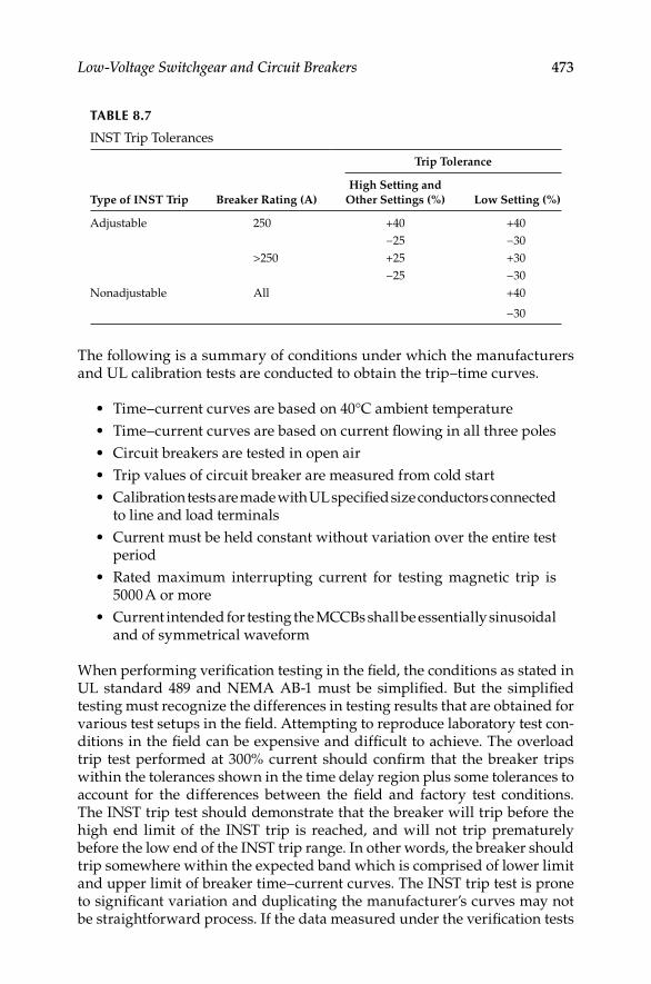
Low-Voltage Switchgear and Circuit Breakers 473
The following is a summary of conditions under which the manufacturers and UL calibration tests are conducted to obtain the trip–time curves.
Time–current curves are based on 40°C ambient temperature•
Time–current curves are based on current fl owing in all three poles•
Circuit breakers are tested in open air•
Trip values of circuit breaker are measured from cold start•
Calibration tests are made with UL specifi ed size conductors connected • to line and load terminals
Current must be held constant without variation over the entire test • period
Rated maximum interrupting current for testing magnetic trip is • 5000 A or more
Current intended for testing the MCCBs shall be essentially sinusoidal • and of symmetrical waveform
When performing verifi cation testing in the fi eld, the conditions as stated in UL standard 489 and NEMA AB-1 must be simplifi ed. But the simplifi ed testing must recognize the differences in testing results that are obtained for various test setups in the fi eld. Attempting to reproduce laboratory test con-ditions in the fi eld can be expensive and diffi cult to achieve. The overload trip test performed at 300% current should confi rm that the breaker trips within the tolerances shown in the time delay region plus some tolerances to account for the differences between the fi eld and factory test conditions. The INST trip test should demonstrate that the breaker will trip before the high end limit of the INST trip is reached, and will not trip prematurely before the low end of the INST trip range. In other words, the breaker should trip somewhere within the expected band which is comprised of lower limit and upper limit of breaker time–current curves. The INST trip test is prone to signifi cant variation and duplicating the manufacturer’s curves may not be straightforward process. If the data measured under the verifi cation tests
TABLE 8.7
INST Trip Tolerances
Type of INST Trip Breaker Rating (A)
Trip Tolerance
High Setting and
Other Settings (%) Low Setting (%)
Adjustable 250 +40 +40
−25 −30
>250 +25 +30
−25 −30
Nonadjustable All +40
−30
DK4058_C008.indd 473DK4058_C008.indd 473 11/8/2008 12:42:16 PM11/8/2008 12:42:16 PM

474 Electrical Power Equipment Maintenance and Testing
vary signifi cantly for the INST trip, the test conditions must be verifi ed or the manufacturer should be consulted before discarding the breaker.
8.8.3 Overload Relays
Overload relays usually found in motor starters or other low-voltage appli-cations require the same attention and calibration as do low-voltage circuit breaker trips. Overload relays should be given an overcurrent test to deter-mine that the overloads will open the starter contacts to provide protection to the motor at its overload pickup value. These test procedures are similar to the test conducted for low-voltage circuit breakers, except that the current injected into the overload relay should be limited to 350% or less. The fre-quency for testing and calibration should be checked to assure that it is selected properly. In addition, the trip setting of the relay should be evaluated to account for any ambient variations between motor location and starter location. A motor overload test set is shown in Figure 8.6.
8.8.4 Testing of Ground Fault Sensing and Relaying Equipment
Ground fault sensing and relaying equipment is covered by UL standard 1053. It classifi es ground fault protection into class I and class II. Class I
FIGURE 8.6A motor overload test set, Model MS-2, capable of producing 750 A. (Courtesy of Megger/
Programma, Valley Forge, PA.)
DK4058_C008.indd 474DK4058_C008.indd 474 11/8/2008 12:42:16 PM11/8/2008 12:42:16 PM

Low-Voltage Switchgear and Circuit Breakers 475
ground fault protection is intended to be used with disconnecting devices at high levels of fault current, whereas class II ground fault protection is used with disconnecting devices with limited interrupting current capacity. This testing application guidance is directed toward class I ground fault relaying.
In accordance with NEMA Publication PB2.2-2004 (Application Guide for Ground Fault Protective Device and Equipment), manufacturers are required to perform design and production tests. The design tests include calibration, temperature rise, overvoltage, overload, dielectric withstand, endurance, and the like. The production tests are conducted to determine if calibration settings are within performance limits, control circuits are working properly, and current sensors have correct turns ratio. The fi eld testing of GFP relaying equipment is discussed in the following section.
8.8.4.1 Preparation for Fielding Training
Review the electrical drawings for the power system, as well as the • manufacturer equipment drawings, to ensure that ground fault equipment is installed as designed.
With the power off, remove the disconnect link on the switchboard • to isolate the neutral of the wiring system from both supply and ground. Measure the insulation resistance of the neutral to ground with the main disconnect open to ensure that no ground connections exist downstream of the GFP devices being checked. For a dual fed (double-ended) power system, remove all the disconnect links to isolate the neutral from both the supply and ground before measuring the insulation resistance.
Visually inspect the wiring system to confi rm there is an adequate • grounding connection at the service equipment upstream of any ground fault sensor, and that the neutral connection is run from the supply transformer to the service equipment in accor-dance with the National Electric Code. Where dual power sources are involved, confi rm that the main grounding connection at the service equipment is in accordance with manufacturer’s recommendations.
Once these steps have been accomplished, return all neutral and • ground connections to their normal intended operating condition.
8.8.4.2 Field Testing
Field testing should be limited to only those tests that are necessary • to determine that the installation is correct and the ground fault protection system is operational. Because of the many variables involved, fi eld testing cannot be considered as an accurate check of the calibration of any sensing relay. Field test current sources can
DK4058_C008.indd 475DK4058_C008.indd 475 11/8/2008 12:42:16 PM11/8/2008 12:42:16 PM

476 Electrical Power Equipment Maintenance and Testing
introduce errors owing to nonsinusoidal wave shapes, power source regulation problems, and metering accuracy. In addition, timing measurements often include additional delay times owing to the use of auxiliary relays and timers. Field testing should be limited to a go/no-go type of testing, which confi rms the serviceability of the system involved.
Before fi eld testing is initiated on any ground fault sensing and • relaying equipment, the manufacturer’s installation and instruction literature should be reviewed and understood. The manufacturer’s fi eld test recommendations should be followed. Although some manufacturer’s test setups may be diffi cult to perform in the fi eld, the confi guration is very important in order to obtain good results. If a particular device is self-powered, considerable current (100–700 A for a 4000 A device) may be required to activate it. This is especially true where multiple sensors are being used in a vector summation scheme. It should not be assumed that inducing current on a ground return or neutral sensor alone will be suffi cient to activate the device and get accurate time–current characteristics. This practice can lead to fi nding a device defective when nothing is actually wrong with it. However, as noted below, there are systems that use external control power for which this practice is acceptable.
Ground fault sensing and relaying equipment utilizing either ground • return or vectorial summation sensing methods can be checked in the fi eld by passing a measured test current directly through the sensing transformer or test windings. To confi rm the proper func-tioning of the equipment while it is installed in the switchboard or panelboard. The following tests can be performed.
Simulated ground fault test using sensors without built-in test windings
Turn off all power to the switchboard section or panelboard. Set the • relay to its minimum current setting.
Loop a test coil of wire having suffi cient current-carrying capacity • through the sensor window. Prefabricated multiturn test cables may be used for convenience.
Provide control power only and close the disconnect associated with • the GFP device being tested.
Apply suffi cient test current so that the ampere turns of the test wind-• ing numerically equal or exceed 125% of the relay current setting. The relay should trip the disconnect. Immediately return the test current to zero.
Turn off all power, remove the test winding, and restore all equipment • to the operating condition.
Reset the relay to the predetermined setting, reestablish control • power, and turn on main power as needed.
DK4058_C008.indd 476DK4058_C008.indd 476 11/8/2008 12:42:16 PM11/8/2008 12:42:16 PM
Low-Voltage Switchgear and Circuit Breakers 477
Simulated ground fault test using sensors with integral (built-in) test windingsA go/no-go test for the proper tripping of the GFP devices and the intercon-nections between the sensor, the relay, and the disconnect mechanism can be made by following manufacturer’s test instructions. The manufacturer usually provides for a test current >125% of the maximum current setting, so a test can be made anytime without disturbing the current settings. If there is any question concerning the ability of the GFP device to operate at its minimum setting and for low ground fault currents, a test as described in simulated ground fault tests using sensors without built-in test windings can be made immediately following installation. Periodic tests using the manufacturer’s test circuit should be adequate after installation.
Equipment with built-in test circuitry but without a built-in test windingFollowing installation, the GFP devices should be tested in accordance with “Simulated ground fault test using sensors without built-in test windings” to confi rm that sensors and interconnections to the ground fault relay are functioning. Thereafter, the manufacturer’s test circuit can be used to check the operation of the GFP relay and the tripping circuitry.
Test buttons and indicatorsOperate test buttons to check the functions described in the manufacturer’s instructions. Pilot lights and other indicators should signal ground-fault tripping or other functions as described in the manufacturer’s instructions.
Zone selective interlocking functionThe manufacturer should be consulted for specifi c instructions when this test is to be performed in the fi eld.
8.9 Uninterruptible Power Supply Commissioning
and Testing
8.9.1 Background
It cannot be guaranteed that an electrical power supply that is free from voltage and frequency variations is going to be available during all times. The occurrence of faults or other electrical anomalies in the users’ installations or in the utility distribution system is undeniable and unpre-dictable. Since data centers for information technology (IT) and other high-technology companies’ installations are particularly sensitive to power supply fl uctuations and distortions, they typically rely on an uninterruptible power supply (UPS) for clean power and as well as for backup or standby power. Some installations even include a second UPS supplied by a separate feeder, and a standby generator that can be set to start automatically few minutes after detecting a power interruption. If the risk from weather or other local occurrences is great enough, some facilities will manually switch
DK4058_C008.indd 477DK4058_C008.indd 477 11/8/2008 12:42:16 PM11/8/2008 12:42:16 PM

478 Electrical Power Equipment Maintenance and Testing
over to backup generation, ahead of time. Figure 8.7 illustrates a typical UPS-standby generator system confi guration for supplying backup power to critical installations. To assure that the UPS system will function as designed, the following tests should be performed during installation and then periodically (monthly or quarterly, depending on contractual agree-ments) after the system is commissioned. Tests during installation phase are divided into two stages:
1. Preinstallation (or commissioning)—test before connecting the criti-cal loads
2. Combined—connect critical loads and test while cutting standby generator in and out
8.9.2 Preinstallation Checks and Tests
UPS functional and alarms tests: The purpose of this test is to check the UPS functionality, LED display, and alarm messages.
Normalsource
NormalAC input
Pg
td
G
UPS
Manualmaintenance
bypass
Static bypass
Load (output to load)Pn
Genset
BypassAC input
Ic+Ib
Pe
Ib (recharge)Rectifier/charger
THDI
THDU
Rectifier inputcurrent
Battery
Inverter
Load
Filter
FIGURE 8.7System confi guration diagram for a UPS-standby generator combination.
DK4058_C008.indd 478DK4058_C008.indd 478 11/8/2008 12:42:17 PM11/8/2008 12:42:17 PM

Low-Voltage Switchgear and Circuit Breakers 479
UPS specifi cation test: The purpose of this test is to check the UPS specifi cations to ensure that the installed equipment meets the hardware and functional requirements. Perform the test using two three-phase power ana-lyzer instruments, such Fluke 435s, or equal. The procedure is outlined as follows: record voltage, current, real power, apparent power, power factor, voltage, and current total harmonic distortion (THD) at both the input and output. Vary the loads from 0% to 100% in 25% steps for balanced load test-ing. For unbalanced load testing, follow the load matrix shown in Table 8.8.
UPS burn-in test: The purpose of this is to verify that the UPS system can operate at the rated load under ambient room temperature conditions.Procedure: Load the UPS to rated load and operate for 8–24 h, depending on contractual requirements. Monitor phase currents, voltages, power, and attri-butes mentioned earlier including the temperature.
UPS step load and bypass loss transient tests: The purpose of this test is to demonstrate the transient response of the UPS module. During this test, the three phase voltage should remain stable and not vary much despite the changes in load current. Record data and compare against specifi cation for deviations.Procedure: Measure UPS transient response for
1. 0% to 100% to 0% load steps
2. 0% to 50% to 0% load steps
3. 50% to 100% to 50% load steps
4. UPS running with loss of bypass mains
UPS start and stop test: The purpose of this test is to demonstrate the correct operation when the UPS is switched on and off with full load.
Procedure: With the module running at 50% and 100% load, switch the inverter OFF and ON. Record transients, load voltage, load current, mains 2 current, and mains 1 current.
UPS full load battery discharge test: The purpose of this test is to demonstrate the correct UPS operation for the time duration of the UPS batteries (such as 15 min) at full load during a power failure.
Procedure: Measure battery cells before and after discharge using a battery monitoring system.
TABLE 8.8
Unbalanced Load Testing Sequence
Sequence Phase 1 (%) Phase 2 (%) Phase 3 (%)
1 100 100 0
2 0 0 100
3 100 50 100
4 50 100 50
DK4058_C008.indd 479DK4058_C008.indd 479 11/8/2008 12:42:17 PM11/8/2008 12:42:17 PM

480 Electrical Power Equipment Maintenance and Testing
UPS loss and return of mains test: The purpose of this test is to demonstrate the correct operation during loss and return of the mains.
Procedure: Run module at normal load and switch the UPS main input ON and OFF. Record transients, load voltage, load current, and mains 1 current.
UPS loss and return of battery test: The purpose of this test is to demonstrate the correct operation during loss and return of UPS batteries.
Procedure: Run module at normal load and switch the UPS main battery breaker ON and OFF. Record transients, load voltage, load current, and mains 1 current.
UPS load transfer test: The purpose of this test is to demonstrate the correct operation during load transfer.
Procedure: Run module at normal load and switch UPS OFF and ON until the load is on static bypass. This procedure is reversed from static bypass to UPS. Record load voltage, load current, and bypass current.
UPS transfer to bypass and back test: The purpose of this test is to demon-strate the correct operation with external bypass.
Procedure: Transfer the load to external bypass and back to UPS. Record load voltage and load current.
8.9.3 Combined Test (UPS with the Generator)
Connect the critical loads and standby generator and repeat the same tests discussed above at 0% and 100% load conditions. Monitor transfer between the mains supply, UPS, and standby generator to ensure that transients and waveform distortion stays within acceptable limits.
8.9.4 Maintenance Test
Conduct periodic (monthly) maintenance tests throughout the life of the UPS-generator power supply system. Follow the combined test procedure for every-thing except the standby generator—it may not need to be tested as frequently as the other components of the UPS system including its battery system.
8.9.4.1 UPS Battery System
In a critical power system, knowing and understanding the condition of a stationary battery is important. Inspection and testing of the battery system should be undertaken to assess the following:
Interconnection integrity•
State of charge•
The overall correctness of the installation•
Benchmark values for comparison to future tests•
Data to aid troubleshooting when performance is less than designed • or anticipated
DK4058_C008.indd 480DK4058_C008.indd 480 11/8/2008 12:42:17 PM11/8/2008 12:42:17 PM
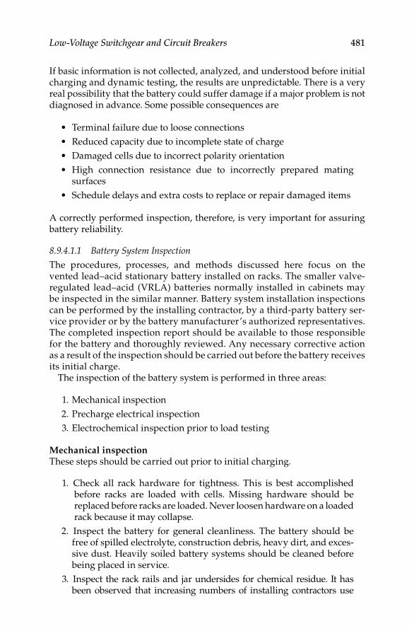
Low-Voltage Switchgear and Circuit Breakers 481
If basic information is not collected, analyzed, and understood before initial charging and dynamic testing, the results are unpredictable. There is a very real possibility that the battery could suffer damage if a major problem is not diagnosed in advance. Some possible consequences are
Terminal failure due to loose connections•
Reduced capacity due to incomplete state of charge•
Damaged cells due to incorrect polarity orientation•
High connection resistance due to incorrectly prepared mating • surfaces
Schedule delays and extra costs to replace or repair damaged items•
A correctly performed inspection, therefore, is very important for assuring battery reliability.
8.9.4.1.1 Battery System Inspection
The procedures, processes, and methods discussed here focus on the vented lead–acid stationary battery installed on racks. The smaller valve-regulated lead–acid (VRLA) batteries normally installed in cabinets may be inspected in the similar manner. Battery system installation inspections can be performed by the installing contractor, by a third-party battery ser-vice provider or by the battery manufacturer’s authorized representatives. The completed inspection report should be available to those responsible for the battery and thoroughly reviewed. Any necessary corrective action as a result of the inspection should be carried out before the battery receives its initial charge.
The inspection of the battery system is performed in three areas:
1. Mechanical inspection
2. Precharge electrical inspection
3. Electrochemical inspection prior to load testing
Mechanical inspectionThese steps should be carried out prior to initial charging.
1. Check all rack hardware for tightness. This is best accomplished before racks are loaded with cells. Missing hardware should be replaced before racks are loaded. Never loosen hardware on a loaded rack because it may collapse.
2. Inspect the battery for general cleanliness. The battery should be free of spilled electrolyte, construction debris, heavy dirt, and exces-sive dust. Heavily soiled battery systems should be cleaned before being placed in service.
3. Inspect the rack rails and jar undersides for chemical residue. It has been observed that increasing numbers of installing contractors use
DK4058_C008.indd 481DK4058_C008.indd 481 11/8/2008 12:42:17 PM11/8/2008 12:42:17 PM

482 Electrical Power Equipment Maintenance and Testing
various compounds to lubricate the tops of the rails. This practice makes it easier to slide jars along the rails. Unfortunately, not all compounds react benignly with jar materials. Most oil-based products—even those as mild as cooking spray—react with jar materials. In one well-publicized case, a contractor used cable-pulling grease on the frame rails; within weeks, virtually all the jars were leaking. The fi rst sign of such a reaction is the cracking and crazing of the plastic jar mate-rial. Generally, once a reaction is observed, the cell must be replaced. To avoid this situation, installers must be familiar with the battery makers’ recommendations and use only compounds approved or recommended by them. To be on the safe side, many manufacturers recommend using plain water; it provides some amount of lubrica-tion and evaporates afterward without leaving an oily residue.
4. All jars and covers should be examined for cracks and leaks. Leaking cells should be replaced at the earliest possible time. Leaking cells quickly contaminate racks. This can cause ground fault alarms to trip and present a safety hazard to service personnel.
5. All fl ame arrestors should be intact and installed securely. Batteries should never be charged unless all fl ame arrestors are properly installed. VRLA battery pressure relief valves should be in place and secure as well. The perimeter of the vent well and fl ame arrestor seal ring should be clean and dry before fl ame arrestors are installed. This will prevent electrolyte migration from inside the cell to outside the gasket area.
6. Check all intertier, interrack, and interaisle connecting cables for excessive stress on terminals, as evidenced by twisting and leaning of posts and terminals. Cable must not cause stress to these compo-nents. Corrective action is necessary when stress is observed.
7. A corrosion inhibiting compound is generally supplied with a battery and should be applied per manufacturer instructions. “No-Oxide A” grease is commonly used, although some manufacturers specify the use of other similar compounds. The primary function of these com-pounds is to seal the critical contact area from oxygen exposure, thereby slowing the corrosion process. This can increase the time intervals between costly system interconnection reworks. Proper contact surface preparation is very important.
Precharge electrical inspectionAfter the mechanical inspection is complete and prior to charging the battery, the following steps should be performed:
1. Verify that all cells are arranged in the proper series connection. A common installation error is interconnecting cells with like polarities.
2. Check all bolted interconnections for tightness to the proper value per manufacturer specifi cations. Errors have been observed to include
DK4058_C008.indd 482DK4058_C008.indd 482 11/8/2008 12:42:17 PM11/8/2008 12:42:17 PM

Low-Voltage Switchgear and Circuit Breakers 483
(a) an incorrect torque setting and (b) a wrench graduated in foot pounds instead of the more common inch-pounds unit of measure.
3. Establish a connection resistance benchmark. This is very important. It is recommended that a technician disassemble, clean, and remake several intercell connections at random. This will verify the effectiveness of the preparation method used by installation personnel. Average the sum of the readings of the specimen connections and use that value as the system benchmark. IEEE 484-2002, “IEEE recommended practice for installation design and installation of vented lead–acid batteries for stationary applications,” recommends a 10% allowable upward deviation from the average. For example, a system whose intercell connection average value is 40 μΩ can tolerate a maximum of 44 μΩ. Reworking the connection usually reduces an out-of-tolerance resis-tance. This procedure should be conducted for intertier, interrack, and interaisle cable connections also. Only connections of the same geometry can be compared to one another.
4. After a resistance benchmark has been established, measure and record all interconnection resistances.
5. Reference the readings to the benchmark standards and make note of any connections requiring corrective action based on the accep-tance criteria from item 3 above.
6. Measure and record total battery voltage at the open circuit potential. Divide that reading by number of cells in the string. The resulting per-cell value should be close to the calculated open circuit voltage (OCV) as given in Table 8.9. If the tasks above have been completed and meet the acceptance criteria, initial charging of the battery may then begin. Items that do not conform to the battery manufacturer or IEEE standards must be noted on the inspection report and corrected. Corrective action should be taken as soon as possible. The amount of time a battery requires to reach a fully charged state for testing is a function of several conditions:
Applied charging voltage•
Ambient temperature•
TABLE 8.9
Gravity versus OCV
Rated Gravity OCV
1.170 2.010
1.215 2.055
1.225 2.065
1.250 2.090
1.275 2.115
1.300 2.140
DK4058_C008.indd 483DK4058_C008.indd 483 11/8/2008 12:42:17 PM11/8/2008 12:42:17 PM

484 Electrical Power Equipment Maintenance and Testing
Battery state of charge prior to commissioning•
Physical size of the cells•
The commissioning charge, also referred to as a freshening or initial charge should be determined based on the requirements and tolerances of both bat-tery and the equipment to which it is connected. Determine the required applied voltage by multiplying the number of cells by the per-cell charge recommendations in the battery manufacturer operating instructions. This value must not exceed the charging system capability.
Electrochemical pretestingIn pretest, the following tasks should always be completed prior to load testing the battery system:
1. Before load tests can take place, the battery must be fully charged and the state of charge must be verifi ed. This cannot be overemphasized. Generally, a battery is considered to be fully charged when the voltage of lowest cell in the string stops rising over three consecutive hourly readings while on equalize charge and the lowest specifi c gravity measurement is within the nominal rating by ±10 (0.010) specifi c grav-ity points. This can be used as a guideline during charging. Refer to the battery manufacturer’s specifi c instructions for more detail.
2. Find the lowest cell and verify the state of charge as described above. If the cell voltage continues to rise with the next hourly reading, continue the equalize charge until it stops rising. When that cell voltage stops rising, the battery should then be returned to normal fl oat status. Monitor cell temperature while on charge. Do not exceed the maxi-mum allowable temperature or cells may be damaged.
3. IEEE 450-2002, “IEEE recommended practice for maintenance, testing, and replacement of vented lead–acid batteries for stationary applications,” states a battery should receive an equalize charge and be returned to normal fl oat potential for no less than 3 days, but not longer than 30 days prior to testing. This 3 day period will allow time for all the hydrogen gas bubbles (formed on the plates during equalize charging) to be released from the surface of the plates. Until all the bubbles are released, the full surface area of the plates is not available for chemical interaction with the electrolyte, and the battery could appear to have diminished capacity.
4. When items 2 and 3 are satisfi ed, measure and record the specifi c gravity of each cell in the battery just prior to the load test. If the gravity readings are within the manufacturer’s recommended values, (usually ±10 points), they are considered acceptable. For specifi c details regarding allowable gravity values, refer to the battery man-ufacturer installation and operating instructions.
5. Measure and record the electrolyte temperature of every sixth cell, with not less than 10% of the total number of cells in the battery. Battery
DK4058_C008.indd 484DK4058_C008.indd 484 11/8/2008 12:42:17 PM11/8/2008 12:42:17 PM

Low-Voltage Switchgear and Circuit Breakers 485
performance data is referenced to 77°F (25°C). Cooler temperatures will cause diminished battery capacity. Higher temperatures will result in increased capacity, but reduce service life. Temperature considerations are a frequently overlooked when load testing the battery system.
Correcting for temperatureIf the cell temperature is other than 77°F, some amount of compensation should be factored into the load test procedure. Unless the purchase specifi -cation called for a different operating temperature, the UPS battery was sized by the manufacturer for operation at 77°F. Therefore, battery perfor-mance will be diminished at cooler temperatures and artifi cially increased at higher temperatures. The simplest way to compensate for temperature is to increase or decrease the kW setting of the load bank and then testing to see if the batteries meets the originally specifi ed time duration before being fully discharged. Correction factors for cell temperature are listed in Table 8.10. To illustrate their use, let us take a sample UPS system rated at 750 kVA and 600 kW (rated kW), and assume the cell electrolyte temperature was mea-sured at 67°F. Table 8.10 shows a temperature correction factor (Tc) of 1.064. Load bank setting (AC kW) can be expressed by the formula:
TABLE 8.10
Temperature Correction Factors for Lead–Acid Batteries
Cell TemperatureCorrection
Factor (Tc)
Cell TemperatureCorrection
Factor (Tc)°C °F °C °F
−3.9 25 1.520 25.6 78 0.994
−1.1 30 1.430 26.1 79 0.987
1.7 35 1.350 26.7 80 0.980
4.4 40 1.300 27.2 81 0.976
7.2 45 1.250 27.8 82 0.972
10.0 50 1.190 28.3 83 0.968
12.8 55 1.150 28.9 84 0.964
15.6 60 1.110 29.4 85 0.960
18.3 65 1.080 30.0 86 0.956
18.9 66 1.072 30.6 87 0.952
19.4 67 1.064 31.1 88 0.948
20.0 68 1.056 31.6 89 0.944
20.6 69 1.048 32.2 90 0.940
21.1 70 1.040 35.0 95 0.930
21.7 71 1.034 37.8 100 0.910
22.2 72 1.029 40.6 105 0.890
22.8 73 1.023 43.3 110 0.880
23.4 74 1.017 46.1 115 0.870
23.9 75 1.011 48.9 120 0.860
24.5 76 1.006 51.7 125 0.850
25.0 77 1.000
DK4058_C008.indd 485DK4058_C008.indd 485 11/8/2008 12:42:17 PM11/8/2008 12:42:17 PM

486 Electrical Power Equipment Maintenance and Testing
AC kW = Rated kWTc
AC kW = 600 kW1.064
AC kW = 564 kW
The original 77°F AC kW would have been 600 kW. The corrected load bank setting indicates a difference of 36 kW (6% of rated capacity). Had the battery been tested at the full 600 kW load, the battery would have lasted less than the time specifi ed, i.e., it would have reached its discharged state before its specifi ed time.
8.9.5 Maintenance and Testing
Refer to Section 7.8 on routine maintenance and testing of switchgear batteries since there are many similarities that are common to the UPS battery systems. The battery tests listed in Section 7.8 are applicable to the UPS batteries.
8.9.6 Summary
Many tests are involved when commissioning and maintaining an UPS system. Many parameters (three-phase voltage and current, power, power factor, harmonics, and transients) must be logged simultaneously over 8–24 h and documented in report format. Use a power quality analyzer with data logging and reporting capabilities, such as the Fluke 435 or an equal to make the required tests.
Also, it is critical to ensure battery system integrity before it is load tested. It must be fully charged, properly installed and its condition verifi ed in order to minimize the likelihood of retests and equipment damage. When com-pared with the cost of downtime, delays, retests, and hardware failures, the cost of battery inspection is a bargain, well worth the expense and time added to a project. The above installation and maintenance guide is based on vented lead–acid batteries; however, many facilities may have VRLA batteries for their UPS installations. Many of the checklist items listed for the vented lead–acid batteries also apply to the VRLA batteries. It is recommended that the IEEE standards on the VRLA batteries be consulted for installation and maintenance. These standards are
1. IEEE 1187-2002, “IEEE recommended practice for installation design and installation of valve regulated lead–acid batteries for stationary applications.”
2. IEEE 1189-2007, “IEEE recommended practice for maintenance, testing, and replacement of valve regulated lead–acid batteries for stationary applications.”
3. IEEE 1189-2007, “IEEE guide for selection of valve regulated lead–acid batteries for stationary applications.”
DK4058_C008.indd 486DK4058_C008.indd 486 11/8/2008 12:42:17 PM11/8/2008 12:42:17 PM
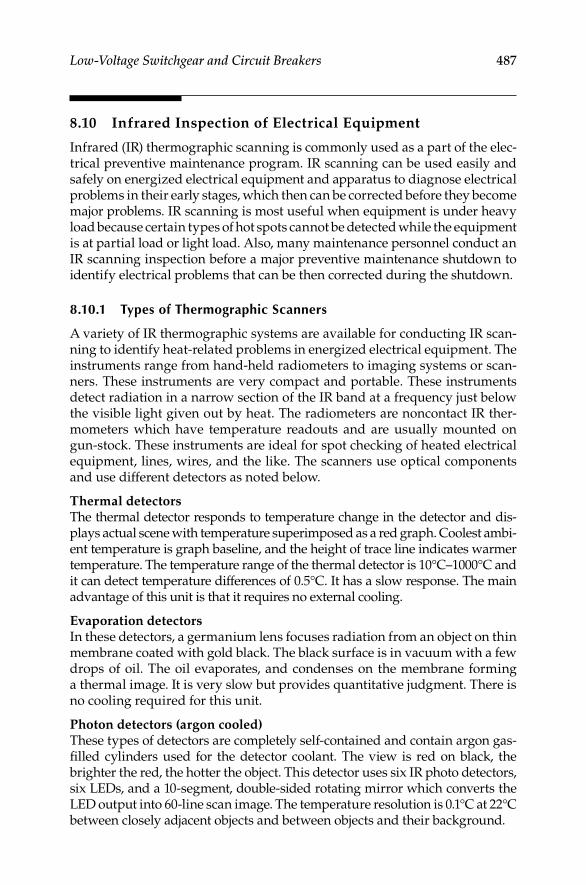
Low-Voltage Switchgear and Circuit Breakers 487
8.10 Infrared Inspection of Electrical Equipment
Infrared (IR) thermographic scanning is commonly used as a part of the elec-trical preventive maintenance program. IR scanning can be used easily and safely on energized electrical equipment and apparatus to diagnose electrical problems in their early stages, which then can be corrected before they become major problems. IR scanning is most useful when equipment is under heavy load because certain types of hot spots cannot be detected while the equipment is at partial load or light load. Also, many maintenance personnel conduct an IR scanning inspection before a major preventive maintenance shutdown to identify electrical problems that can be then corrected during the shutdown.
8.10.1 Types of Thermographic Scanners
A variety of IR thermographic systems are available for conducting IR scan-ning to identify heat-related problems in energized electrical equipment. The instruments range from hand-held radiometers to imaging systems or scan-ners. These instruments are very compact and portable. These instruments detect radiation in a narrow section of the IR band at a frequency just below the visible light given out by heat. The radiometers are noncontact IR ther-mometers which have temperature readouts and are usually mounted on gun-stock. These instruments are ideal for spot checking of heated electrical equipment, lines, wires, and the like. The scanners use optical components and use different detectors as noted below.
Thermal detectorsThe thermal detector responds to temperature change in the detector and dis-plays actual scene with temperature superimposed as a red graph. Coolest ambi-ent temperature is graph baseline, and the height of trace line indicates warmer temperature. The temperature range of the thermal detector is 10°C–1000°C and it can detect temperature differences of 0.5°C. It has a slow response. The main advantage of this unit is that it requires no external cooling.
Evaporation detectorsIn these detectors, a germanium lens focuses radiation from an object on thin membrane coated with gold black. The black surface is in vacuum with a few drops of oil. The oil evaporates, and condenses on the membrane forming a thermal image. It is very slow but provides quantitative judgment. There is no cooling required for this unit.
Photon detectors (argon cooled)These types of detectors are completely self-contained and contain argon gas-fi lled cylinders used for the detector coolant. The view is red on black, the brighter the red, the hotter the object. This detector uses six IR photo detectors, six LEDs, and a 10-segment, double-sided rotating mirror which converts the LED output into 60-line scan image. The temperature resolution is 0.1°C at 22°C between closely adjacent objects and between objects and their background.
DK4058_C008.indd 487DK4058_C008.indd 487 11/8/2008 12:42:17 PM11/8/2008 12:42:17 PM

488 Electrical Power Equipment Maintenance and Testing
Photon detector (nitrogen cooled)These detectors use liquid nitrogen to cool the detector. The view is white on black, the brighter the white, the hotter the object. Also, these detectors come where the view is in color. The temperature resolution is 0.2°C. These units use camera scanner and video display. The brightness can be referenced to actual temperature.
Photon detectorThese units are similar to the above units, but the image is green on black. These units do not have reference graph between brightness and temperature. These units do not require external cooling.
8.10.2 Conducting an IR Thermographic Inspection
When an IR inspection is conducted, it is recommended to follow the current path, and it should be done under normal operating conditions—the heavier the loading the better an indication of the hot spots. During these surveys, it is obvious that the IR scanner detects temperature differences. A hot spot detected in an electrical equipment can be caused not only by excessive tem-perature due to faulty equipment (excessive resistance) but also may come about due to refl ections, solar gain, normal loading, emissivity variations, and eddy current inductive heating. The person conducting IR scanning sur-veys should be familiar and be aware of these factors in order to identify a true hot spot. Also, additional factors such as wind, rain, snow, and strong magnetic fi elds can affect the IR survey results when conducting an IR scan of outdoor substations and switchyards.
After the IR survey is completed, the appraisal of the IR scan data is normally evaluated to assess whether the equipment surveyed is working properly or whether it has problem areas due to overheating. Over the years, different appraisal systems and techniques have evolved which maintenance personnel have used to determine priority of maintenance and repair actions. These are discussed next and have been summarized from a paper* presented at the National Electrical Testing Association (NETA) Annual Conference.
8.10.2.1 Delta-T Temperature Rating Systems
For years, IR thermographers have used delta-T temperature ratings to assess the severity of overheating electrical components. These tables are commonly broken into three or four severity categories that indicate repair priorities: the larger the temperature rise above a similar component or ambient tem-perature, the greater potential for failure. There are a wide variety of delta-T charts versus severity/repair urgency charts commonly used by thermogra-phers. Table 8.11 shows a delta-T temperature rating chart commonly used
* Paper presented by Paul Grover, Director of Infraspection Institute at the NETA Annual
Conference, 1993.
DK4058_C008.indd 488DK4058_C008.indd 488 11/8/2008 12:42:17 PM11/8/2008 12:42:17 PM

Low-Voltage Switchgear and Circuit Breakers 489
in the electrical industry whereas Table 8.12 shows the delta-T criteria used by the NETA and similar criteria given in Section 21.17.5.6 of NFPA 70B, “Electrical equipment maintenance.”
On the plus side, such delta-T ratings have worked quite well in the fi eld. They do indicate some relative degree of severity that enable repairs to be prioritized. On the negative side, there are a great number of temperature classifi cations and none of them are traceable to nationally recognized stan-dards for electrical equipment. This lack of traceability has been questioned in some industries, such as in the highly regulated nuclear power industry. The other major shortcoming of using delta-T classifi cation systems is that they do not account for the actual load and ambient temperature upon the equipment at the time of the IR inspection. For example, an overheating cable under 70% load would be assigned the same severity rating if it was under a 10% load. Ideally, load and ambient temperature differences should be accounted for in a temperature rating system for determining accurate repair priorities.
TABLE 8.11
An Example of Delta-T Temperature Criteria to Determine Priority of Maintenance Scheduling Based on Temperature Rise of Component Relative to Ambient Temperature
Temperature Rise of Component
Relative to Ambient Temperature Recommended Actions
High-voltage power distribution equipment
0°C–10°C Corrective measures should be
taken at next maintenance period
10°C–20°C Corrective measures required as
scheduling permits
20°C–40°C Corrective measures required ASAP
depending upon the class of load carried
and the severity of temperature rise in
this range
40°C and above Corrective measures required
IMMEDIATELY
Low-voltage distribution and control equipment
0°C–10°C Corrective measures required at next
scheduled maintenance period or as
scheduling permits
10°C–20°C Corrective measures required on a
PRIORITY scheduling basis
20°C–30°C Corrective measures required ASAP
30°C and above Corrective measures required
IMMEDIATELY
DK4058_C008.indd 489DK4058_C008.indd 489 11/8/2008 12:42:17 PM11/8/2008 12:42:17 PM

490 Electrical Power Equipment Maintenance and Testing
8.10.2.2 Standards-Based Temperature Rating System
In the United States, there are over 26 organizations that publish temperature standards for electrical equipment. However, ANSI, IEEE, and NEMA are particularly well known and referenced. The standards published by these organizations on various electrical equipment contain temperature data which consists of the standard ambient temperature, the maximum tempera-ture rise allowed above the ambient, and the total allowed temperature, which is the sum of the ambient and the maximum temperature rise allowed. A typical electrical equipment standard might be expressed as follows:
The key formula: Mostly all temperature standards specify the standard ambient temperature and they assume that the circuit is under 100% load. However, electrical equipment is often run in a different ambient temperature and is rarely at 100% of rated load. So, for these standards to be meaningful,
TABLE 8.12
Thermographic Survey Suggested Actions Based on Temperature Rise
Temperature Difference
(T) Based on Comparisons
between Similar Components
under Similar Loading
Temperature Difference
(T) Based on Comparisons
between Component and
Ambient Air Temperatures Recommended Action
1°C–3°C 1°C–10°C Possible defi ciency;
warrants investigation
4°C–15°C 11°C–20°C Indicates probable
defi ciency; repair as time
permits
— 21°C–40°C Monitor until corrective
measures can be
accomplished
>15°C >40°C Major discrepancy; repair
immediately
Source: From NETA MTS-2005, Table 100.18. With permission.
Note: Temperature specifi cations vary depending on the exact type of equipment. Even in the
same class of equipment (i.e., cables) there are various temperature ratings. Heating is
generally related to the square of the current; therefore, the load current will have a major
impact on ΔT. In the absence of consensus standards for ΔT, the values in this table will
provide reasonable guidelines.
Equipment Component
Rated Temperature (°C)
Ambient Rise Total
Cable insulation,
thermoplastic
All polyethylene 30a
45 75
Source: From ANSI/IEEE Std 242-2001, IEEE Recommended Prac-
tice for Protection and Coordination of Industrial and
Commercial Power Systems.a Note that 30°C ambient is for tray and conduit installation.
DK4058_C008.indd 490DK4058_C008.indd 490 11/8/2008 12:42:17 PM11/8/2008 12:42:17 PM
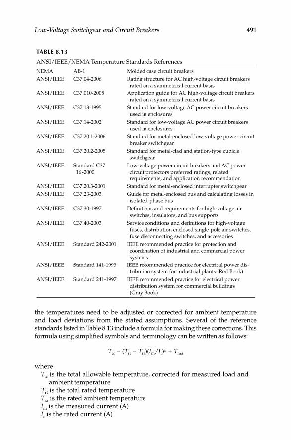
Low-Voltage Switchgear and Circuit Breakers 491
the temperatures need to be adjusted or corrected for ambient temperature and load deviations from the stated assumptions. Several of the reference standards listed in Table 8.13 include a formula for making these corrections. This formula using simplifi ed symbols and terminology can be written as follows:
Ttc = (Trt − Tra)(Im/Ir)n + Tma
whereTtc is the total allowable temperature, corrected for measured load and
ambient temperatureTrt is the total rated temperatureTra is the rated ambient temperatureIm is the measured current (A)Ir is the rated current (A)
TABLE 8.13
ANSI/IEEE/NEMA Temperature Standards References
NEMA AB-1 Molded case circuit breakers
ANSI/IEEE C37.04-2006 Rating structure for AC high-voltage circuit breakers
rated on a symmetrical current basis
ANSI/IEEE C37.010-2005 Application guide for AC high-voltage circuit breakers
rated on a symmetrical current basis
ANSI/IEEE C37.13-1995 Standard for low-voltage AC power circuit breakers
used in enclosures
ANSI/IEEE C37.14-2002 Standard for low-voltage AC power circuit breakers
used in enclosures
ANSI/IEEE C37.20.1-2006 Standard for metal-enclosed low-voltage power circuit
breaker switchgear
ANSI/IEEE C37.20.2-2005 Standard for metal-clad and station-type cubicle
switchgear
ANSI/IEEE Standard C37.
16 -2000
Low-voltage power circuit breakers and AC power
circuit protectors preferred ratings, related
requirements, and application recommendation
ANSI/IEEE C37.20.3-2001 Standard for metal-enclosed interrupter switchgear
ANSI/IEEE C37.23-2003 Guide for metal-enclosed bus and calculating losses in
isolated-phase bus
ANSI/IEEE C37.30-1997 Defi nitions and requirements for high-voltage air
switches, insulators, and bus supports
ANSI/IEEE C37.40-2003 Service conditions and defi nitions for high-voltage
fuses, distribution enclosed single-pole air switches,
fuse disconnecting switches, and accessories
ANSI/IEEE Standard 242-2001 IEEE recommended practice for protection and
coordination of industrial and commercial power
systems
ANSI/IEEE Standard 141-1993 IEEE recommended practice for electrical power dis-
tribution system for industrial plants (Red Book)
ANSI/IEEE Standard 241-1997 IEEE recommended practice for electrical power
distribution system for commercial buildings
(Gray Book)
DK4058_C008.indd 491DK4058_C008.indd 491 11/8/2008 12:42:18 PM11/8/2008 12:42:18 PM
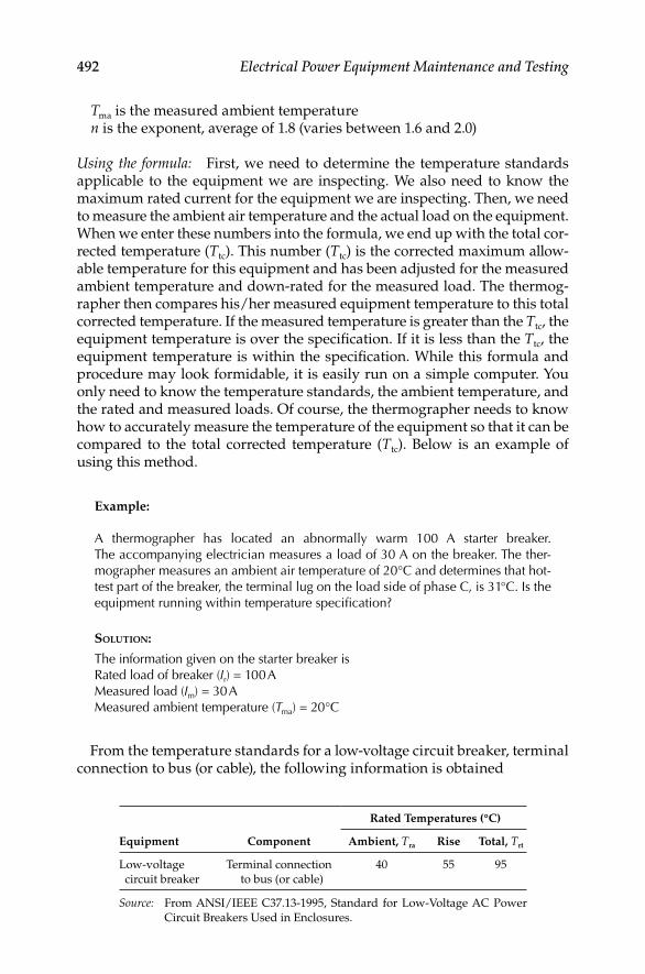
492 Electrical Power Equipment Maintenance and Testing
Tma is the measured ambient temperaturen is the exponent, average of 1.8 (varies between 1.6 and 2.0)
Using the formula: First, we need to determine the temperature standards applicable to the equipment we are inspecting. We also need to know the maximum rated current for the equipment we are inspecting. Then, we need to measure the ambient air temperature and the actual load on the equipment. When we enter these numbers into the formula, we end up with the total cor-rected temperature (Ttc). This number (Ttc) is the corrected maximum allow-able temperature for this equipment and has been adjusted for the measured ambient temperature and down-rated for the measured load. The thermog-rapher then compares his/her measured equipment temperature to this total corrected temperature. If the measured temperature is greater than the Ttc, the equipment temperature is over the specifi cation. If it is less than the Ttc, the equipment temperature is within the specifi cation. While this formula and procedure may look formidable, it is easily run on a simple computer. You only need to know the temperature standards, the ambient temperature, and the rated and measured loads. Of course, the thermographer needs to know how to accurately measure the temperature of the equipment so that it can be compared to the total corrected temperature (Ttc). Below is an example of using this method.
Example:
A thermographer has located an abnormally warm 100 A starter breaker. The accompanying electrician measures a load of 30 A on the breaker. The ther-mographer measures an ambient air temperature of 20°C and determines that hot-test part of the breaker, the terminal lug on the load side of phase C, is 31 °C. Is the equipment running within temperature specifi cation?
SOLUTION:
The information given on the starter breaker isRated load of breaker (Ir) = 100 AMeasured load (Im) = 30 AMeasured ambient temperature (Tma) = 20°C
From the temperature standards for a low-voltage circuit breaker, terminal connection to bus (or cable), the following information is obtained
Equipment Component
Rated Temperatures (°C)
Ambient, Tra Rise Total, Trt
Low-voltage
circuit breaker
Terminal connection
to bus (or cable)
40 55 95
Source: From ANSI/IEEE C37.13-1995, Standard for Low-Voltage AC Power
Circuit Breakers Used in Enclosures.
DK4058_C008.indd 492DK4058_C008.indd 492 11/8/2008 12:42:18 PM11/8/2008 12:42:18 PM

Low-Voltage Switchgear and Circuit Breakers 493
Using the formula:
Ttc = (Trt − Tra) (Im/Ir)2 + Tma (for illustration, we use an exponent of 2)
Ttc = (95 – 40) (30/100)2 + 20
Ttc = (55) (.3)2 + 20Ttc = (55) (.09) + 20Ttc = (4.95) + 20 = 24.95°C
We compare our measured temperature of 31°C to the Ttc of 24.95 and fi nd that the heated terminal is 6.05°C above the Ttc specifi cation which was cor-rected for measured ambient temperature and load.
Therefore, this example illustrates that there is a problem with this breaker and this problem will get worse as the load or the ambient temperature increases on the 100 A starter breaker.
Comparing the rating systems: Assuming that the temperatures of other two phases of this breaker were at ambient temperature, you will note that the Delta-T method of rating this potential problem would give you a tempera-ture difference of 31 − 20 = 11°C. In most Delta-T classifi cations, this would warrant a low-to-moderate severity rating. The standards-based system and formula has determined that the equipment is over specifi cation. In compar-ing the two rating systems to many similar problems, we fi nd that that the standards-based system is almost always more conservative than the Delta-T system. In other words, the standards-based system will almost identify a problem before the Delta-T system will.
8.10.3 Conducting a Thermographic Survey
The NETA (2005 NETA Maintenance Testing Specifi cations, Section 9) and NFPA 70B (Section 20.17) contain guidance for conducting thermographic (IR) sur-veys and inspection. It is a necessary requirement that the person performing the thermographic inspection be thoroughly trained and experienced in the apparatus and systems being evaluated, as well as knowledgeable of thermo-graphic principles and methodology.
The following summary of the NETA and NFPA guidance on thermo-graphic surveys and inspection is offered for the reader.
Visual and mechanical inspection: Inspect distribution systems with imaging equipment capable of detecting a minimum temperature difference of 1°C at 30°C. Equipment shall be capable of detecting emitted radiation and convert detected radiation to visual signals. Perform thermographic surveys under maximum loading conditions. Remove all necessary covers prior to perform-ing IR inspection. Use appropriate caution, safety devices, and personal protective equipment when conducting the thermographic surveys.
Report: Provide a report of the thermographic survey and result including the following: description of equipment to be tested; discrepancies found; temperature difference found between the area of concern and the reference area and ambient temperature; provide probable cause of temperature
DK4058_C008.indd 493DK4058_C008.indd 493 11/8/2008 12:42:18 PM11/8/2008 12:42:18 PM

494 Electrical Power Equipment Maintenance and Testing
difference as witnessed during the survey; identify inaccessible and/or unobservable areas and/or equipment and identify load conditions at time of inspection. Provide photographs and/or thermograms of the areas of con-cern with recommended actions.
8.10.4 Examples of Thermographic Findings
Three examples of thermographic fi ndings are documented to familiarize the reader with the overheating problems relating to electrical equipment.
88.19
84.78
81.36
77.95
74.54
71.13
67.71
64.30
60.89
57.47
54.06
58.4680.76
�F
FIGURE 8.8Thermographic picture of a transformer radiators. (Courtesy of Black and Associates, Inc.,
Sparks, MD.)
202.019118117116115114113112111110197.0
C phase98.0
+
A phaseMax = 201.3
�F
FIGURE 8.9Thermographic picture of a three-phase 480 V breaker lug overheating. (Courtesy of Black and
Associates, Inc., Sparks, MD.)
DK4058_C008.indd 494DK4058_C008.indd 494 11/8/2008 12:42:18 PM11/8/2008 12:42:18 PM

Low-Voltage Switchgear and Circuit Breakers 495
1. The fi rst example is shown in Figure 8.8 which shows transformer radiators being blocked. As can be seen in the survey photograph, the radiators showing darker color are not carrying any oil, i.e., these radiators are blocked. The temperature of radiators on the left-hand side of transformer is measured to be 80.76°F compared to the tem-perature of 58.46°F for the radiators in blue color. If this condition is not corrected, then over time more radiators become blocked and the transformer will overheat.
2. The second example shows an overheated three-phase 480 V breaker in Figure 8.9. In this picture, phase A conductor and lug are overheated and show a temperature of 201.3°F compared to 98°F for the other two phases. Apparently the phase A lug and conductor are overheated which could be due to loose connections or high resistance built up at the lug. As discussed earlier just comparing the temperature of the three phases will be a good indication of the actual conditions. However, the Delta-T temperature, or standard-based temperature rating system could be used to provide more detail analysis of the problem.
3. The third example of three motor controllers is shown in Figure 8.10a and b. In Figure 8.10a, three motor controllers are shown mounted side by side and were surveyed with IR camera without removing the covers. In Figure 8.10a, the left hand side controller supplies chilled water pump, the middle controller supplies condensate pump and the right hand side controller supplies auxiliary fan. It is appar-ent from the thermographic picture, as shown in Figure 8.10b, the auxiliary fan controller has excessive heat compared to the other two controllers. Note that the excessive heat is not visible to the naked eye in the picture shown in Figure 8.10a, but is very apparent in the ther-mographic picture shown in Figure 8.10b. It is obvious that the auxil-iary fan controller needs further investigation to determine the cause of excessive heating.
(a)
89.9688.5287.0885.6484.2082.7781.3379.8978.4577.0175.57
�F(b)
FIGURE 8.10Thermographic picture of an overheated motor controller. (Courtesy of Black and Associates, Inc.,
Sparks, MD.)
DK4058_C008.indd 495DK4058_C008.indd 495 11/8/2008 12:42:19 PM11/8/2008 12:42:19 PM

DK4058_C008.indd 496DK4058_C008.indd 496 11/8/2008 12:42:19 PM11/8/2008 12:42:19 PM

497
9Testing and Commissioning of Protective Relays and Instrument Transformers
9.1 Introduction
This chapter outlines a program for testing and commissioning of protective and overcurrent relays and instrument transformers used in switchgear and/or standalone applications. The frequency of testing of these devices may be dependent upon many factors; however, an annual schedule of inspection and maintenance is recommended for electromechanical and induction relays; and inspection and testing of solid-state and microprocessor relays when trouble is indicated or upon unanticipated operation of these relays. Before a successful maintenance and inspection program can be imple-mented, it is essential that the personnel performing or evaluating inspec-tion and maintenance should be thoroughly familiar with the types of protective relays, devices, and auxiliary equipment. Therefore, in this section a brief overview of protective and overcurrent relays, and instrument trans-formers is given for the reader to become familiar with the system equip-ment. The maintenance and testing of electromechanical and induction relays involves inspection, mechanical adjustment, and electrical tests. Similarly, the maintenance and testing of solid-state and microprocessor relays involves inspection and self-diagnostics and tests. Since the protective equipment plays such an important role for the safety of personnel and property, they should be given special attention. Moreover, since these devices operate during abnormal conditions on the power system, the only way to assure correct operation is by a comprehensive inspection, mainte-nance, and testing program.
9.2 Instrument Transformers
Instrument transformers are essential parts of many electrical metering and relaying systems. The quality of instrument transformers will affect directly the overall accuracy and performance of these systems. Instrument transformer
DK4058_C009.indd 497DK4058_C009.indd 497 11/8/2008 12:42:39 PM11/8/2008 12:42:39 PM

498 Electrical Power Equipment Maintenance and Testing
performance is critical in protective relaying, since the relays can only be as good as the instrument transformers. They serve two basic functions:
To change the magnitude (but not the nature) of primary voltage • and current to secondary values to 120 V and 5 or 1 A where relays, meters, or other devices can be applied
To provide isolation between primary and secondary circuit for • equipment and safety of personnel
When relays compare the sum or difference of two or more currents or the inter-action of voltages and currents, the relative direction of the current must be known. The direction of current fl ow can be determined by knowing the instru-ment transformer polarity. Polarity markings are normally shown on instrument transformers; however, they can be determined in the fi eld if necessary. Several aspects of current and voltage instrument transformers are discussed next.
9.2.1 Current Transformers
Current transformers (CTs) are designed for connection in the primary cir-cuit (either in series or around the primary circuit). The secondary current of the transformer bears a known relationship with the primary current. Any change in the primary current is refl ected in the secondary circuit. Relays, meters, and other devices are connected to the secondary terminals of the CTs. CTs are made in many different ratios, different voltage insulation sys-tems, and for different environmental conditions such as indoor or outdoor use. Generally, the following types of construction are used for CTs.
Wound type:• In this type more than one primary turn is frequently used to obtain low exciting current and high accuracy. The usual current ratings for this type of transformer are 800 A and below.
Bar-primary type:• In this type, the primary consists of a single bar extending through the core, which is connected in series with the circuit conductor. This type of construction is suited to withstand the stresses of heavy overcurrent. The usual current rating for this type of transformer is 1200 A or above in order to provide suffi cient ampere-turns for good accuracy.
Window type:• The window-type CT contains no primary winding. The CT has an insulated hole through the core and secondary wind-ings. The circuit conductor is inserted through the window of the CT, and thus this conductor then becomes the primary of the CT.
Bushing type:• The bushing-type CT is similar to the window-type. It has a circular core that is designed to fi t on the bushing of a power transformer, circuit breaker, or other apparatus. The secondary wind-ings are wound on the circular core and can be tapped to give multiple ratios. This transformer is mostly used for relaying purposes where high accuracy at normal current value is not extremely important.
DK4058_C009.indd 498DK4058_C009.indd 498 11/8/2008 12:42:39 PM11/8/2008 12:42:39 PM
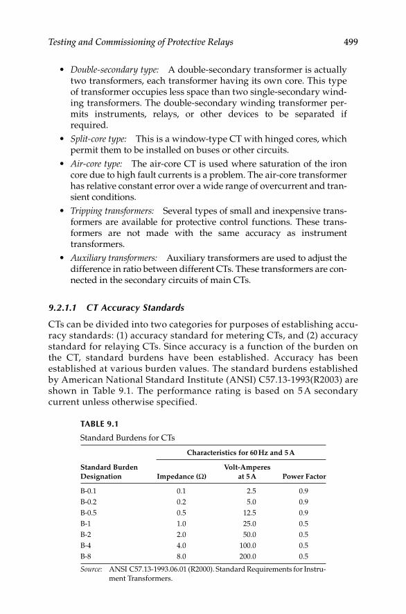
Testing and Commissioning of Protective Relays 499
Double-secondary type:• A double-secondary transformer is actually two transformers, each transformer having its own core. This type of transformer occupies less space than two single-secondary wind-ing transformers. The double-secondary winding transformer per-mits instruments, relays, or other devices to be separated if required.
Split-core type:• This is a window-type CT with hinged cores, which permit them to be installed on buses or other circuits.
Air-core type:• The air-core CT is used where saturation of the iron core due to high fault currents is a problem. The air-core transformer has relative constant error over a wide range of overcurrent and tran-sient conditions.
Tripping transformers:• Several types of small and inexpensive trans-formers are available for protective control functions. These trans-formers are not made with the same accuracy as instrument transformers.
Auxiliary transformers:• Auxiliary transformers are used to adjust the difference in ratio between different CTs. These transformers are con-nected in the secondary circuits of main CTs.
9.2.1.1 CT Accuracy Standards
CTs can be divided into two categories for purposes of establishing accu-racy standards: (1) accuracy standard for metering CTs, and (2) accuracy standard for relaying CTs. Since accuracy is a function of the burden on the CT, standard burdens have been established. Accuracy has been established at various burden values. The standard burdens established by American National Standard Institute (ANSI) C57.13-1993(R2003) are shown in Table 9.1. The performance rating is based on 5 A secondary current unless otherwise specified.
TABLE 9.1
Standard Burdens for CTs
Standard Burden
Designation
Characteristics for 60 Hz and 5 A
Impedance (Ω)
Volt-Amperes
at 5 A Power Factor
B-0.1 0.1 2.5 0.9
B-0.2 0.2 5.0 0.9
B-0.5 0.5 12.5 0.9
B-1 1.0 25.0 0.5
B-2 2.0 50.0 0.5
B-4 4.0 100.0 0.5
B-8 8.0 200.0 0.5
Source: ANSI C57.13-1993.06.01 (R2000). Standard Requirements for Instru-
ment Transformers.
DK4058_C009.indd 499DK4058_C009.indd 499 11/8/2008 12:42:39 PM11/8/2008 12:42:39 PM

500 Electrical Power Equipment Maintenance and Testing
9.2.1.2 Accuracy Classes for Metering
The ANSI accuracy classes for metering state that the transformer correction factor (TCF) should be within specifi ed limits when the power factor of the metered load is from 0.6 to 1.0 lagging for a specifi ed standard burden, at 100% of rated primary current. CTs for metering service have accuracy classes of 0.3%, 0.6%, and 1.2%.
9.2.1.3 Accuracy Classes for Relaying
The ANSI standard 57.13-1993 has standardized on the accuracy classes and the conditions under which instrument transformers are to be applied. Prior to 1968, the accuracy classes and the conditions under which the instrument trans-formers were applied were based on ANSI standard C57.13-1954. The ANSI standard 57.13-1954 was revised in 1968 and this standard set one accuracy class, instead of the two that was in the older standard. The revised standard also changed the designations for the older class of CTs. Hence, the ANSI 57.13-1968 standard is different than the older standard of ANSI 57.13-1954 in many respects. Since many older CTs and voltage transformers (VTs) are still in use today, it is appropriate to discuss the older and revised ANSI C57.13 standards.
Older standard (ANSI C57.13-1954): In this standard, the accuracy ratings were on the basis of the standard secondary terminal voltage, a transformer would deliver without exceeding a standard percent ratio error. The classifi ca-tion of CT performance was based on the ratio error at 5 to 20 times secondary current. Therefore, the CTs were divided into classes, H and L. Class H had a nearly constant percentage ratio error when delivering a fi xed secondary volt-age over a wide range of secondary current. Class L had a nearly constant magnitude error (variable percentage error) when delivering a fi xed secondary voltage over a wide range of secondary current. Standard percent ratio error classes for class H CTs were 2.5% and 10%, whereas for class L CTs, the stan-dard percent ratio error was 10%. Secondary voltages were 10, 20, 50, 100, 200, 400, and 800 V. For example, CTs were classifi ed as 2.5 H 200 or 10 L 200. The fi rst term described the maximum percent ratio error, the second term (H or L) described the transformer performance characteristics, and the third term described the secondary voltage. The class H transformer could deliver a secondary voltage equal to its voltage class at 5 to 20 times secondary rated current. A class L CT, on the other hand, could only deliver a secondary volt-age within its voltage class at 5 to 20 times secondary rated current at fi xed burden. In other words, class L cannot be used with proportionately higher burdens at lower secondary current without exceeding its classifi ed ratio error.
Newer standard (ANSI 57.13-1968): A relaying accuracy under the new stan-dard is designated by symbols C and T.
C-type CTs have single primary turn and distributed secondary • windings. For C-type CTs the ratio error can be calculated. Majority of
DK4058_C009.indd 500DK4058_C009.indd 500 11/8/2008 12:42:39 PM11/8/2008 12:42:39 PM

Testing and Commissioning of Protective Relays 501
these CTs are bushing type and are rated at 600 V since they do not have any physical connection with the primary circuit.
T-type CTs are constructed with more than one primary turn and • undistributed windings. The primary windings are insulated and braced for the primary voltage. Because of the physical space required and the fringing effects of nonuniformly distributed winding, because there is fl ux that does not link both the primary and secondary wind-ings. The leakage fl ux has signifi cant effect on the CT performance and it is not possible to calculate the ratio correction error using the burden and excitation characteristics. Therefore, the ratio correction must be determined by test for the T-type CTs.
The secondary terminal voltage rating for the C-type and T-type CTs • is the voltage which the transformer will deliver to a standard burden (as listed in Table 9.1) at 20 times normal secondary current.
The transformer ratio error must be limited to 10% for all currents • from 1 to 20 times normal current for burdens not to exceed those listed in Table 9.1.
K-type:• The K classifi cation was established in the 1993 revision of the C57.13 standard. The K-type CTs are designed to have knee-point voltage at least 70% of the secondary terminal voltage rating. The K-type is similar to C-type CTs, i.e., their design is based on the principle that the leakage fl ux in the core does not have an appreciable effect on the ratio of the CT within the limits of current and burden.
To specify a CT under the new standards, one needs only to select either a class C or T transformer and then specify the burden. The fi rst term of the burden classifi cation of a CT identifi es the construction type of CTs as dis-cussed in Section 9.2.1, and the second term describes the voltage rating that can be delivered by the full winding at 20 times rated secondary current with-out exceeding 10% ratio correction (error). The ANSI voltage rating applies to the full winding, and if less than full winding is used, the voltage rating is then reduced in proportion to turns used. As an example, a CT C200 or T200 means that a ratio correction error will not exceed 10% for values from 1 to 20 times rated secondary current (5 A) with a standard 2.0 Ω burden.
The C classifi cation covers bushing transformers, and the T classifi -• cation covers any other transformer
The secondary voltage values are 10, 20, 50, 100, 200, 400, and 800 V based • on 1 to 20 times the normal current standard burdens listed in Table 9.1
9.2.2 Voltage (Potential) Transformers
VTs are designed for connecting line-to-line or line-to-neutral. The purpose of the VT is to provide an isolated secondary voltage that is an exact
DK4058_C009.indd 501DK4058_C009.indd 501 11/8/2008 12:42:39 PM11/8/2008 12:42:39 PM

502 Electrical Power Equipment Maintenance and Testing
proportionate representation of primary voltage. However, transformers draw core-magnetizing current from the primary circuit, and a constant error results independent of the burden connected to it. Also, variable error results due to load or burden current fl owing through the effective imped-ance of the transformer. The total error is the sum of these two errors under any burden condition. The ANSI standard C57.13-1993(R2003) lists the clas-sifi cation of VTs encountered in service as W, X, Y, Z, and ZZ. The standard burden designations are shown in Table 9.2 for these VTs.
Accuracy classes are based on the requirement that the TCF be within speci-fi ed limits when the power factor of the metered load is between 0.6 and 1.0 lagging for a specifi ed burden and at voltages from 90% to 110% of rated trans-former voltage. The ANSI accuracy classes for VTs are shown in Table 9.3.
The ratings of VTs encompass the following:
Insulation class and basic impulse level•
Rated primary voltage and ratio•
Accuracy ratings at standard burdens•
Thermal burden, that is, the maximum burden the transformer can • carry at rated secondary voltage without exceeding its temperature rise, above 30°C ambient
9.2.3 Polarity of Instrument Transformers
Instrument transformers are marked to indicate the instantaneous direction of primary and secondary currents. Usually, one primary and one secondary
TABLE 9.3
ANSI Accuracy Classes for VTs
Accuracy
Class (%) Limits of TCF
Limits of Power
Factor of Metered
Load
1.2 1.012–0.998 0.6–1.0
0.6 1.006–0.994 0.6–1.0
0.3 1.003–0.997 0.6–1.0
TABLE 9.2
ANSI Standard Burdens for VTs
Burden
Volt-Amperes
at 120 V
Burden Power
Factor
W 12.5 0.70
X 25.0 0.70
Y 75.0 0.85
Z 200.0 0.85
ZZ 400.0 0.85
DK4058_C009.indd 502DK4058_C009.indd 502 11/8/2008 12:42:39 PM11/8/2008 12:42:39 PM
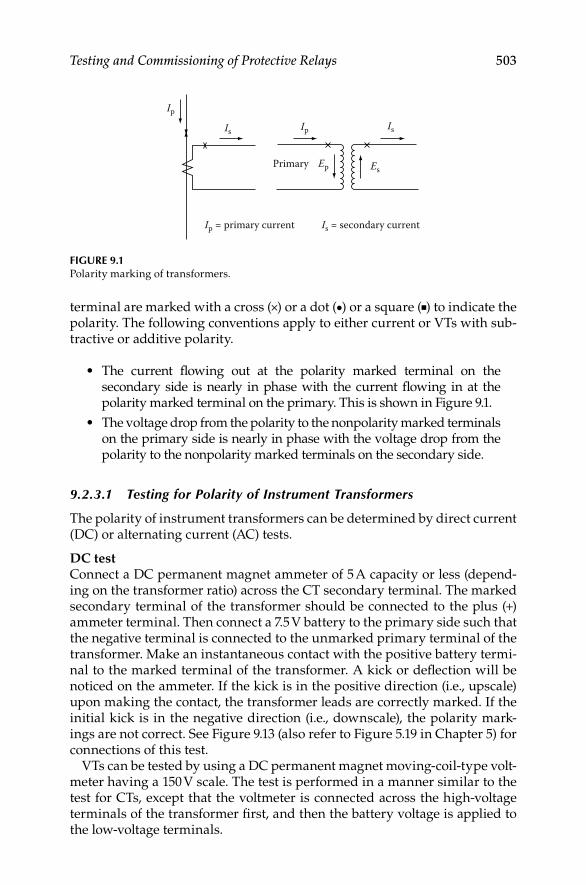
Testing and Commissioning of Protective Relays 503
terminal are marked with a cross (×) or a dot (•) or a square (■) to indicate the polarity. The following conventions apply to either current or VTs with sub-tractive or additive polarity.
The current fl owing out at the polarity marked terminal on the • secondary side is nearly in phase with the current fl owing in at the polarity marked terminal on the primary. This is shown in Figure 9.1.
The voltage drop from the polarity to the nonpolarity marked terminals • on the primary side is nearly in phase with the voltage drop from the polarity to the nonpolarity marked terminals on the secondary side.
9.2.3.1 Testing for Polarity of Instrument Transformers
The polarity of instrument transformers can be determined by direct current (DC) or alternating current (AC) tests.
DC testConnect a DC permanent magnet ammeter of 5 A capacity or less (depend-ing on the transformer ratio) across the CT secondary terminal. The marked secondary terminal of the transformer should be connected to the plus (+) ammeter terminal. Then connect a 7.5 V battery to the primary side such that the negative terminal is connected to the unmarked primary terminal of the transformer. Make an instantaneous contact with the positive battery termi-nal to the marked terminal of the transformer. A kick or defl ection will be noticed on the ammeter. If the kick is in the positive direction (i.e., upscale) upon making the contact, the transformer leads are correctly marked. If the initial kick is in the negative direction (i.e., downscale), the polarity mark-ings are not correct. See Figure 9.13 (also refer to Figure 5.19 in Chapter 5) for connections of this test.
VTs can be tested by using a DC permanent magnet moving-coil-type volt-meter having a 150 V scale. The test is performed in a manner similar to the test for CTs, except that the voltmeter is connected across the high-voltage terminals of the transformer fi rst, and then the battery voltage is applied to the low-voltage terminals.
Ip
Is Ip
Ip = primary current Is = secondary current
Is
EsEpPrimary
FIGURE 9.1Polarity marking of transformers.
DK4058_C009.indd 503DK4058_C009.indd 503 11/8/2008 12:42:39 PM11/8/2008 12:42:39 PM
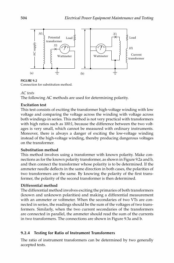
504 Electrical Power Equipment Maintenance and Testing
AC testsThe following AC methods are used for determining polarity.
Excitation testThis test consists of exciting the transformer high-voltage winding with low voltage and comparing the voltage across the winding with voltage across both windings in series. This method is not very practical with transformers with high ratios such as 100:1, because the difference between the two volt-ages is very small, which cannot be measured with ordinary instruments. Moreover, there is always a danger of exciting the low-voltage winding instead of the high-voltage winding, thereby producing dangerous voltages on the transformer.
Substitution methodThis method involves using a transformer with known polarity. Make con-nections as for the known polarity transformer, as shown in Figure 9.2a and b, and then connect the transformer whose polarity is to be determined. If the ammeter needle defl ects in the same direction in both cases, the polarities of two transformers are the same. By knowing the polarity of the fi rst trans-former, the polarity of the second transformer is then determined.
Differential methodThe differential method involves exciting the primaries of both transformers (known and unknown polarities) and making a differential measurement with an ammeter or voltmeter. When the secondaries of two VTs are con-nected in series, the readings should be the sum of the voltages of two trans-formers. Similarly, when the two current secondaries of the transformers are connected in parallel, the ammeter should read the sum of the currents in two transformers. The connections are shown in Figure 9.3a and b.
9.2.4 Testing for Ratio of Instrument Transformers
The ratio of instrument transformers can be determined by two generally accepted tests.
Load
Wattmeter Wattmeter
Load
Currenttransformer
(a) (b)
X1
X1H1
H1
Potentialtransformer
AC
supp
ly
FIGURE 9.2Connection for substitution method.
DK4058_C009.indd 504DK4058_C009.indd 504 11/8/2008 12:42:39 PM11/8/2008 12:42:39 PM

Testing and Commissioning of Protective Relays 505
Voltage method testA suitable AC voltage, below saturation i.e., below the knee point of the CT saturation curve, is connected to the full secondary winding and a high impedance (20,000 Ω/V or greater) low-range voltmeter is connected in the primary of the CT. The primary voltage is read on the low-range voltmeter as the secondary voltage is applied to the CT. The turn ratio is approximately equal to the voltage ratio. In most low and medium-ratio bushing CTs, the saturation level is achieved at about 1 V per turn. The saturation level may be lower than 0.5 V per turn in high-ratio generator CTs and window-type CTs used in metal clad switchgear. For very high-ratio CTs, an application of test voltage even lower than 0.5 V per turn may be required to avoid personnel hazard and possible damage to equipment.
Current method testThis method requires a source of high current and an additional CT of known ratio with its own ammeter and a second ammeter for the CT under test. The test is conducted by injecting the high current test source to a series of values over the desired range and recording the two secondary current readings. The ratio of the CT under test is equal to the turns ratio of the reference CT multiplied by the ratio of the reference CT secondary current to the test transformer secondary current. When conducting this test avoid using mul-tiple turns of the test conductor through the center of the window-type CT to reduce its ratio because it may produce an abnormal secondary leakage reac-tance and misleading results in the ratio measurement. The effect is unpre-dictable and although small with distributed winding CTs with low secondary burden, it may be produce a large error in older CTs particularly when high burdens are connected.
Excitation testExcitation voltage and current tests can be made on both C (distributed winding) and T class (nondistributed winding) CTs in order to assess if the CT is performing correctly and to determine if deviations are present. To perform this test, an AC voltage is applied to the secondary winding
H1 H1 H2
E1
X1 X1E2
H1
AC supply AC supply
Standardpotential
transformer
Standardcurrent
transformer
(a) Test
pot
entia
l tra
nsfo
rmer
Test
curr
ent t
rans
form
er
V (b) A
FIGURE 9.3Connection for differential method.
DK4058_C009.indd 505DK4058_C009.indd 505 11/8/2008 12:42:40 PM11/8/2008 12:42:40 PM

506 Electrical Power Equipment Maintenance and Testing
with the primary winding open-circuited as is shown in Figure 9.4. The voltage applied to the secondary winding is varied, and the current drawn by the winding at each selected voltage value is recorded. A curve is plot-ted of the secondary voltage versus current for comparison with the origi-nal manufacturer’s excitation (saturation) curve. A sample of excitation curves of multiratio CT are shown in Figure 9.5. The readings near the
X1 H1
Opencircuit
PrimarySec.
A
Digital ammeter 0–10 A
0–1000 Vvoltmeter V
Ø
Ø
FIGURE 9.4Excitation test circuit of a CT.
Currentratio
100:5 0.033
Secondarywinding
resistance(Ohms@75�C)
150:5 0.052200:5 0.070250:5 0.087300:5 0.104400:5 0.139500:5 0.174600:5 0.209750:5 0.261800:5 0.278
1000:5 0.3481200:5 0.3921500:5 0.4901600:5 0.5222000:5 0.6532500:5 0.8073000:5 0.969
3000:52500:5
2000:51500:51200:5
1000:5800:5750:5600:5
250:5200:5150:5100:5
.01
10
100
100
Seco
ndar
y vol
tage
60
Hz
100
.02 .05 0.1 0.2Secondary exciting current 60 Hz
0.5 1.0 2 5 10
300:5400:5500:5
FIGURE 9.5Typical excitation curve for C class, multiratio CT. (Courtesy of Instrument Transformers, Inc.,
Clearwater, FL.)
DK4058_C009.indd 506DK4058_C009.indd 506 11/8/2008 12:42:40 PM11/8/2008 12:42:40 PM
Testing and Commissioning of Protective Relays 507
knee of the excitation curve are important when plotting this curve. For multitap ratio CTs, the highest tap should be used provided that the cur-rent transformer can be saturated at the selected tap with the test equipment available. The ammeter used for this test should be an root-mean-square (rms) instrument and the voltmeter should be an average reading voltmeter calibrated to give the same numerical indication as an rms voltmeter. Deviations from expected results or in comparison to the manufacturer data may indicate a turn-to-turn short, distorted wave-form of test voltage, or the presence of a conducting path around the CT core. Caution should be taken to minimize energizing the CT at voltages above the knee of the excitation curve any longer than is necessary to take the readings. This test can also be conducted by energizing the CT primary winding from a high-current test source and plotting the data as primary exciting current versus secondary open-circuited voltage. The current must be divided by the CT ratio for comparison with the manu-facturer’s excitation curve data.
9.2.5 Winding and Lead Resistance Measurements
The internal resistance of CT windings and external impedance (including lead resistance) are required for relay setting calculations, and for calculating ratio correction error when applying CTs. The internal winding resistance and the lead resistance can be calculated or measured with a resistance bridge. If it is desired to separate the winding resistance and lead resistance, the resistance of a full winding and of a tap then should be measured. All measurements should be made at the CT short-circuiting terminal block. After completion of this test, the CT should be demagnitized to remove any residual magnetism as discussed under Section 9.2.7.
9.2.6 Burden Measurements
For relay applications and for calculating CT ratio correction factors, burden measurements may be necessary. In such cases, the total burden of the circuit, which is the sum of the internal CT burden and the external connected burden must be determined. The internal burden is the resistance of secondary wind-ing and the lead resistance from the winding to the short-circuiting terminal block as discussed in Section 9.2.5. The internal burden can be converted to volt-amperes at rated secondary current. The external burden can be mea-sured in volt-amperes by measuring the voltage required to drive the rated current through the connected burden (load).
9.2.7 CT Remanence
The residual magnetism of a CT is known as remanence. The performance of both class C and T CTs is infl uenced by remanence. The core of the CT
DK4058_C009.indd 507DK4058_C009.indd 507 11/8/2008 12:42:40 PM11/8/2008 12:42:40 PM

508 Electrical Power Equipment Maintenance and Testing
is subject to hysteresis, i.e., when current is interrupted the fl ux density in the core does not become zero when current does. When fl ux in the core is high due to high current or because the current contains a high DC component and when this current is interrupted, the residual magnetism in the core will be high, possibly being above the fl ux equivalent of the knee point on the excitation curve as shown in Figure 9.5. When the CT is next energized, the fl ux changes will begin from the remanence value and therefore may lead to the saturation of the CT. When this occurs, much of the primary current is used for exciting the core, and thereby signifi cantly reducing and distorting the secondary output. This condition can be corrected by demagnitizing the core of the CT. This can be accomplished by applying a suitable variable alternating voltage to the secondary, with initial magnitude suffi cient to force the fl ux density above the saturation point, and then decreasing the applied voltage slowly and continuously to zero. Test connections are identical to those as shown in Figure 9.4 for performing this test.
9.2.8 Grounding of CT
It is common practice to connect the secondary of the instrument (current and voltage) transformers to the station or substation ground system. The primary purpose of grounding is for personnel safety and correct perfor-mance of the instrument transformers, relays, meters, and other equipment connected to the instrument transformer secondaries. The grounding point in the instrument transformer secondary circuit should be located electrically at one end of the secondary winding of each instrument transformer and physically at the fi rst point of switchboard or relay panel of the instrument transformer secondary circuit. The following are some examples for ground-ing instrument transformers.
1. A single instrument transformer secondary winding should be con-nected to a single ground.
2. Where more than one instrument transformer is used, such as three single-phase transformers wye-connected to form a three-phase connection, the common point of the secondary windings of all instrument transformers should be connected to a single ground.
3. The secondary circuit of multi-instrument transformers where no common point of connection is available for all of the transformer secondaries, such as delta-connected transformers, should have the common point between the greatest number of the secondary wind-ings connected to ground.
4. When secondary windings of more than one instrument transformers are interconnected and do not have a common neutral connection, then the common secondary neutral connection for the greatest number of these transformers should be the point of connection to ground.
5. The grounding conductor for instrument transformers should be as large, or larger than the secondary phase conductors. The grounding
DK4058_C009.indd 508DK4058_C009.indd 508 11/8/2008 12:42:40 PM11/8/2008 12:42:40 PM

Testing and Commissioning of Protective Relays 509
conductor should never be smaller than number 12 AWG copper, or equal, for grounding of instrument transformers.
6. CTs that are not used should have the full winding shorted at the CT location and grounded.
9.2.9 Maintenance and Testing of Instrument Transformers
The following general recommendations are offered to supplement the manufacturer’s instructions.
General maintenance
If instrument transformers are allowed to remain out of service for a • long period of time, they should be dried before being put into service
Instrument transformers containing oil or synthetic dielectrics • should be tested periodically to determine the breakdown voltage remains at 26 kV or above
The secondaries of CTs that are not connected to relays, meters, and • the like, should have their secondaries shorted and grounded as mentioned in Section 9.2.8
The secondary circuits and cases of all instrument transformers • should be grounded with at least a number 12 AWG conductor as discussed earlier in Section 9.2.8
TestingRoutine testing as described below should be performed on instrument transformers.
General purpose instrument transformers
Ratio and phase angle tests should be made on CTs for metering at • 100% and 10% of rated primary current, when energized at rated frequency with maximum standard burden for which the transformer is rated
The turns ratio and polarity tests should be made on CTs for relaying • to ensure that they have the correct turns ratio and relaying accuracy
Revenue metering instrument transformer
Calibrate all meters at 10%, 50%, and 90% of full scale. Instruments • used for calibration of test equipment should have precision of no more than 50% of the instrument being tested.
Calibrate watt-hour meters to 0.5%.•
Verify all instrument multipliers.•
DK4058_C009.indd 509DK4058_C009.indd 509 11/8/2008 12:42:40 PM11/8/2008 12:42:40 PM

510 Electrical Power Equipment Maintenance and Testing
9.3 Protective Relays
Protective relays are used in power systems to assure maximum continuity of service. They are constantly monitoring the power system to detect unwanted conditions that can cause damage to property and life. They can be consid-ered as a form of insurance designed to provide protection against property and personnel loss and as devices responsible for maintaining maximum possible continuity of service. Protective relays are found throughout small and large power systems from generation through transmission, distribu-tion, and utilization. A better understanding of their application, operation, and maintenance is essential for the operating and maintenance personnel in order to understand how they fi t into modern power systems.
9.3.1 Classification of Relays
ANSI C37.90 classifi es relays associated with power apparatus into the following categories:
Protective relays•
Auxiliary (slave) relays•
Programming relays•
Verifi cation relays•
Monitoring relays•
In addition to these generalized categories, protective relays can be further divided by input, operating principles, and performance characteristics. The input can consist of current, voltage, pressure, temperature, frequency, and so on; the operating principles can consist of thermal, electromagnetic, product of voltage and current, percentage, restraint, and so on; and the per-formance characteristics can consist of time delay, directional, differential, distance, phase or ground, comparison of operating quantities, and so on.
9.3.2 Overview of Protective Relays—Construction and Types
The evolution of protective relays from the perspective of construction and application can be described by four generations of relay designs. The four generations are categorized as following:
Electromechanical and induction relays (fi rst generation)•
Static relays (second generation)•
Solid-state relays with integrated circuits (third generation)•
Microprocessor relays (fourth generation)•
The construction types of the above listed categories are discussed as follows:
DK4058_C009.indd 510DK4058_C009.indd 510 11/8/2008 12:42:40 PM11/8/2008 12:42:40 PM

Testing and Commissioning of Protective Relays 511
9.3.2.1 Electromechanical and Induction Relays(First-Generation Relays)
Electromechanical and induction protective relays have lot of mechanical parts. These relays do not have the capabilities of autotesting of internal parts or providing an alarm in case a failure. The electromechanical and induction protective relay construction principles are based upon basic fault-detecting units, which are called basic relay units. The electromagnetic and induction relay chassis can be removed from the fl exitest case for testing and mainte-nance purposes.
Most relays of this type used either electromagnetic attraction or electromag-netic induction principle for their operation. The electromagnetic, such as plunger type were instantaneous-type relays used for detecting overcurrent conditions. The induction-type relays provided overcurrent protection with time delays. Two or three input induction-type relays are used for directional or distance protection. Balanced-beam relays are used for differential protection, distance protection, or for overcurrent protection with low relay burden. For a general discussion, electromechanical relays can be classifi ed into instanta-neous (magnetic attraction) and time-delay (torque-controlled) units.
Instantaneous unitsThis type of relay unit consists of the plunger, solenoid, hinged armature, and balance beam types in which by magnetic attraction the armature is attracted into a coil or to a pole face of an electromagnet. Relays of this construction type can be applied in either AC or DC power systems. The plunger-type construction is shown in Figure 9.6.
Time-delay unitsThis type of induction-disk unit consists of the induction-disk or induction-cup type in which, owing to magnetic induction, a torque is produced in a movable rotor (i.e., disk or cup), which rotates between two pole faces of an
Plunger
Contacts
Coils
Magnetic frame
FIGURE 9.6Plunger-type relay.
DK4058_C009.indd 511DK4058_C009.indd 511 11/8/2008 12:42:40 PM11/8/2008 12:42:40 PM
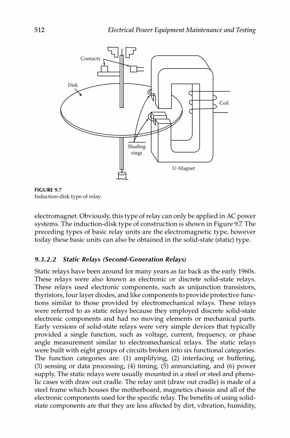
512 Electrical Power Equipment Maintenance and Testing
electromagnet. Obviously, this type of relay can only be applied in AC power systems. The induction-disk type of construction is shown in Figure 9.7. The preceding types of basic relay units are the electromagnetic type, however today these basic units can also be obtained in the solid-state (static) type.
9.3.2.2 Static Relays (Second-Generation Relays)
Static relays have been around for many years as far back as the early 1960s. These relays were also known as electronic or discrete solid-state relays. These relays used electronic components, such as unijunction transistors, thyristors, four layer diodes, and like components to provide protective func-tions similar to those provided by electromechanical relays. These relays were referred to as static relays because they employed discrete solid-state electronic components and had no moving elements or mechanical parts. Early versions of solid-state relays were very simple devices that typically provided a single function, such as voltage, current, frequency, or phase angle measurement similar to electromechanical relays. The static relays were built with eight groups of circuits broken into six functional categories. The function categories are: (1) amplifying, (2) interfacing or buffering, (3) sensing or data processing, (4) timing, (5) annunciating, and (6) power supply. The static relays were usually mounted in a steel or steel and pheno-lic cases with draw out cradle. The relay unit (draw out cradle) is made of a steel frame which houses the motherboard, magnetics chassis and all of the electronic components used for the specifi c relay. The benefi ts of using solid-state components are that they are less affected by dirt, vibration, humidity,
Contacts
Disk
Coil
U-Magnet
Shadingrings
FIGURE 9.7Induction-disk type of relay.
DK4058_C009.indd 512DK4058_C009.indd 512 11/8/2008 12:42:40 PM11/8/2008 12:42:40 PM

Testing and Commissioning of Protective Relays 513
and other environmental conditions. As the technology improved, solid-state relays began to include multiple functions, such as distance measurements and reclosing. The complexity of these devices also increased dramatically. Most of the static relays employ series shunt, or switch mode power supplies for their operation. Most static relays do not have the capability to detect failure of power supply and autotesting of internal parts, or provide an alarm in case a failure is detected.
9.3.2.3 Solid-Sate Relays (Third-Generation Relays)
These relays were introduced in the 1970s. These relays utilized integrated circuit boards and were more complex than the static relays. These relays performed many different functions for logic and control. As technology advanced, microprocessors were used to monitor certain conditions of the solid-state relay, such as power supply output voltages. As much of the logic was done in the microprocessor, these relays became smaller and more compact. In addition, they provided many more functions such as scheme selection, back up elements like time overcurrent elements, and control. The use of these relays was relatively short lived as digital relays became much more accepted. Solid-state relays came rack mounted, con-sisting of many printed circuit boards, as compared to electromagnetic and static types, which are permanently mounted on a switchboard. The solid state relay printed card can be removed from the case for testing and main-tenance purposes. For example, in the late 1960s, solid-state protection schemes were developed that required an entire 19 in. wide, 7 ft tall rack to contain all of the components and logic cards. The schemes were extremely fast and were primarily used on extra-high-voltage (EHV) circuits. These relays do not have the capability to detect failure of power supply and autotesting of internal parts, or provide an alarm in case a failure is detected similar to the second generation of solid-state relays.
9.3.2.4 Microprocessor Relays (Fourth-Generation Relays)
Microprocessor-based or digital relays were marketed in the 1980s. However, these relays did not incorporate the complex algorithms of today in the earlier designs of these relays for protection. Over time these relays began incorpo-rating multifunction protective functions that reduced the product and installation cost drastically. Today these relays include common hardware platforms, software platforms to perform many different functions and inte-grating protection with substation control. Although the basic protection principles have remained the same, the evolution of the digital relays using microprocessors has provided many benefi ts with a few shortcomings. Microprocessor relays are also referred to as numerical relays especially if they calculate the algorithms numerically. Digital relays are built using a microprocessor, an AC signal data acquisition system, memory components containing the relay algorithms, contact inputs to control the relay, and contact
DK4058_C009.indd 513DK4058_C009.indd 513 11/8/2008 12:42:41 PM11/8/2008 12:42:41 PM

514 Electrical Power Equipment Maintenance and Testing
outputs to control other equipment. The algorithms and settings contained in the relay memory defi ne the protection characteristics. Figure 9.8 shows a hardware block diagram for a typical digital relay design.
Analog values, currents and voltages are connected to the data acquisition and fi ltering block. Here the voltages and currents are reduced to low-level signals, typically ±5 V, so they can be converted to digital signals. Step-down instrument transformers provide isolation and from high voltage transients that may occur on the secondary wiring. The analog signals are fi ltered using a low-pass fi lter to remove high-frequency components and to prevent aliasing in the digital fi ltering process. The signals are then converted to digital values through an analog-to-digital (a/d) converter and multichannel multiplexer.
The output of the data acquisition block is mapped to memory areas. The data are stored for later use and are also passed to the processing block. The processing block reads and writes data to the memory block. This data is internal relay element status, digital input status, and digital output status. The processing unit also monitors the human machine interface (HMI), which typically consists of targeting light-emitting diodes (LEDs), pushbuttons, and a liquid crystal display (LCD). The power supply provides all of the control voltages that are required for operation of the electronic circuitry. Digital relays usually include automatic self-test func-tions. These self-tests verify correct operation of critical relay components. If a self-test detects an abnormal condition, the relay can close an output contact, send a message, or provide some other indication of the failure. The relay disables trip and control functions on detection of certain self-test failures. Since self-tests are executed often in the digital relay, they detect component failures soon after they occur. As a minimum, digital relay self-tests include tests of memory chips, a/d converter, power supply, and microprocessor. Figure 9.9 shows a high-speed line protection (SEL-421) digital relay manufactured by Schweitzer Engineering Laboratories, Incorporated (SEL).
Dataacquisition
andfiltering
Memory Processing
Inputs Outputs Powersupply
HMIAnaloginputs
Digitalinputs
Digitaloutputs
FIGURE 9.8Simplifi ed digital relay block diagram.
DK4058_C009.indd 514DK4058_C009.indd 514 11/8/2008 12:42:41 PM11/8/2008 12:42:41 PM
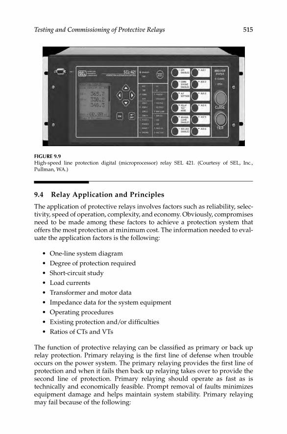
Testing and Commissioning of Protective Relays 515
9.4 Relay Application and Principles
The application of protective relays involves factors such as reliability, selec-tivity, speed of operation, complexity, and economy. Obviously, compromises need to be made among these factors to achieve a protection system that offers the most protection at minimum cost. The information needed to eval-uate the application factors is the following:
One-line system diagram•
Degree of protection required•
Short-circuit study•
Load currents•
Transformer and motor data•
Impedance data for the system equipment•
Operating procedures•
Existing protection and/or diffi culties•
Ratios of CTs and VTs•
The function of protective relaying can be classifi ed as primary or back up relay protection. Primary relaying is the fi rst line of defense when trouble occurs on the power system. The primary relaying provides the fi rst line of protection and when it fails then back up relaying takes over to provide the second line of protection. Primary relaying should operate as fast as is technically and economically feasible. Prompt removal of faults minimizes equipment damage and helps maintain system stability. Primary relaying may fail because of the following:
FIGURE 9.9High-speed line protection digital (microprocessor) relay SEL 421. (Courtesy of SEL, Inc.,
Pullman, WA.)
DK4058_C009.indd 515DK4058_C009.indd 515 11/8/2008 12:42:41 PM11/8/2008 12:42:41 PM
516 Electrical Power Equipment Maintenance and Testing
Control power for tripping failure•
Protective relay malfunction•
Breaker failure to open•
Relay and control wiring failure•
C• T and/or VT failure
Therefore, back up relaying should be arranged so that anything that causes primary relaying to fail will not cause the back up relaying to fail. Back up relaying should be as completely separated from primary relaying as is pos-sible, including control power, control circuits, and instrument transformers.
The relay operation is a function of the input quantities, such as current, volt-age, impedance, and/or phase angle. The relay can be made to respond to either a single quantity or combination of two or all input quantities. When the relay is operated by a single quantity, its response is strictly a function of time, whereas when the relay is operated upon by two or more quantities, its opera-tion is a function of the relative magnitude and phase angle difference of those quantities. Each relay then can be made to respond to its input quantities, known as the operating or relay characteristics. Relay characteristics are very useful in determining the relay setting, which in turn will determine relay speed, sensitivity, and selectivity for protection from power system short-circuits.
Relay application practices can be classifi ed according to relay characteristics and the special requirements of various elements. They are discussed next.
Overcurrent relaysWhen excessive current fl ows in a circuit, it is necessary to trip the circuit breaker protecting that circuit. This type of protection is usually provided by either time delay or instantaneous overcurrent relays. The instantaneous relay, although inherently fast, requires a short time to operate, whereas time-delay relays have intentional time delay built into them to provide coor-dination with other overcurrent relays for selectivity. The selectivity is obtained by adjustment of current setting (sensitivity) and time, using the most applicable of several time characteristics. The relay time characteristics differ by the rate at which the time of operation of the relay decreases as the current increases. The time characteristics for each family of overcurrent relay consist of inverse, very inverse, extremely inverse, defi nite time, short time, and long time. These curves are shown in Figure 9.10. The application of overcurrent relay is generally more diffi cult and less permanent than that of other types of relaying. This is because the operation of overcurrent relays is affected by variations of short-circuit current magnitudes. These magni-tude variations in short-circuit current are caused by changes in power system elements, operation, and system confi guration.
Over–under voltage relaysThe over–under voltage relays have characteristics similar to the overcurrent relays. The actuating quality in the operating element is voltage instead of current. Voltage relays often combine the under–over voltage elements in one relay, with contacts for either an undervoltage or overvoltage condition. These relays
DK4058_C009.indd 516DK4058_C009.indd 516 11/8/2008 12:42:41 PM11/8/2008 12:42:41 PM

Testing and Commissioning of Protective Relays 517
may be used to trip the breaker or sound an alarm in case of the voltage exceeding a predetermined limit or falling below a predetermined value.
Directional relaysDirectional relays are used when it is desirable to trip the circuit breaker for current fl ow in one direction only. That is, the direction is made responsive to the directional fl ow of power or current. This is achieved by making the relay distinguish certain differences in phase angle between current and reference voltage or current. The directional relay has a current winding and directional winding. The current winding is connected to the CT, whereas the directional winding is connected to the VTs to provide the circuit voltage for polarizing the unit. Therefore, the pickup of the relay is dependent on the magnitude of current and voltage and the phase relationship between them. The directional relay thus establishes one boundary of the protected zone; that is, it protects the circuit only in one direction. Directional relaying is often used where coor-dination becomes a problem, such as in tie lines between two supply substa-tions or to provide protection against the motoring of a generator.
Current- or voltage-balance relaysCurrent-balance relays compare the magnitudes of current (or voltage) in two circuits (where these quantities vary within restricted limits) to detect an abnormal condition. The current-balance relay has two torque-producing elements actuated by currents (or voltage) from two different circuits or phases. Current-balance relaying between the phases of a motor is used to
Instantaneous
Multiples of pickup current
Tim
e (s)
200
0.2
1.0
Inverse
Very inverse
Extremely inverseModeratelyinverse
FIGURE 9.10Time–current characteristics of various families of overcurrent relays.
DK4058_C009.indd 517DK4058_C009.indd 517 11/8/2008 12:42:41 PM11/8/2008 12:42:41 PM
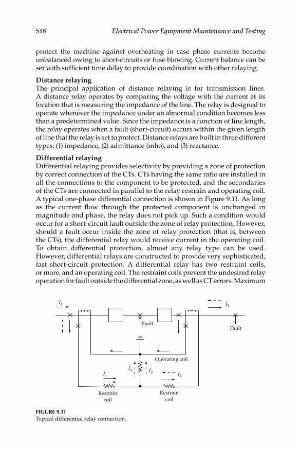
518 Electrical Power Equipment Maintenance and Testing
protect the machine against overheating in case phase currents become unbalanced owing to short-circuits or fuse blowing. Current balance can be set with suffi cient time delay to provide coordination with other relaying.
Distance relayingThe principal application of distance relaying is for transmission lines. A distance relay operates by comparing the voltage with the current at its location that is measuring the impedance of the line. The relay is designed to operate whenever the impedance under an abnormal condition becomes less than a predetermined value. Since the impedance is a function of line length, the relay operates when a fault (short-circuit) occurs within the given length of line that the relay is set to protect. Distance relays are built in three different types: (1) impedance, (2) admittance (mho), and (3) reactance.
Differential relayingDifferential relaying provides selectivity by providing a zone of protection by correct connection of the CTs. CTs having the same ratio are installed in all the connections to the component to be protected, and the secondaries of the CTs are connected in parallel to the relay restrain and operating coil. A typical one-phase differential connection is shown in Figure 9.11. As long as the current fl ow through the protected component is unchanged in magnitude and phase, the relay does not pick up. Such a condition would occur for a short-circuit fault outside the zone of relay protection. However, should a fault occur inside the zone of relay protection (that is, between the CTs), the differential relay would receive current in the operating coil. To obtain differential protection, almost any relay type can be used. However, differential relays are constructed to provide very sophisticated, fast short-circuit protection. A differential relay has two restraint coils, or more, and an operating coil. The restraint coils prevent the undesired relay operation for fault outside the differential zone, as well as CT errors. Maximum
FaultFault
I2
I2 I2
I1
I1I1
Operating coil
Restraincoil
Restraincoil
FIGURE 9.11Typical differential relay connection.
DK4058_C009.indd 518DK4058_C009.indd 518 11/8/2008 12:42:42 PM11/8/2008 12:42:42 PM

Testing and Commissioning of Protective Relays 519
restraint is produced if the current is in the same direction in the two restraint coils, and minimum restraint is produced if currents are in oppo-site directions in the two restraint coils. The current fl owing through the operating coils (i.e., I1 − I2) must exceed a certain percentage of the through current (I2) before the relay will operate. Because it is inherently selective, differential relaying is used as primary relaying on power system compo-nents and equipment.
Pilot wire relayingPilot wire relaying is a form of differential relaying normally used for pro-tection of longer lines. The pilot wire employs a wire channel to compare currents entering and leaving the protected line between two terminals. The wire pilot channel can consist of the following:
Wire pilot• , consisting of a two-wire circuit between the ends of the line.
Carrier-current pilot• , wherein one conductor of the line and the earth comprise a pilot circuit for superimposed high-frequency currents.
Microwave pilot• , which is an ultrahigh-frequency radio channel between the ends of the line.
For external faults the currents are balanced at the two terminals of the line, whereas for internal faults the currents are not balanced and therefore relay pickup would occur.
9.5 Types of Relay Tests
The goal of protective relay testing is to maximize the availability of the pro-tection and minimize the risk of undesired operation. Therefore, we must defi ne adequate testing and monitoring methods with appropriate intervals to ensure availability and security are maximized. An electromechanical relay can fail without any external indication. Typically, the only way to detect a failure in an electromechanical relay is through routine maintenance or an undesired operation (i.e., a nuisance-trip or failure to trip). A modern digital relay performs self-diagnostics on key elements to ensure reliable operation. As a minimum, digital relay self-tests include tests of memory chips, a/d con-verter, power supply, and microprocessor. However, a digital relay failure may result in an undesired operation if the self-test routines do not detect the failure in time. Most failures are signifi cant enough to either generate a self-test failure or cause the user to recognize the problem during routine operation.
Acceptance testsWhen a utility engineer selects a new relay design, it is essential to perform tests of the selected relay to ensure correct operation for the intended applica-tion. These tests are referred to as type tests and are usually implemented on a
DK4058_C009.indd 519DK4058_C009.indd 519 11/8/2008 12:42:42 PM11/8/2008 12:42:42 PM

520 Electrical Power Equipment Maintenance and Testing
single representative relay from the manufacturer. During type tests, utility staff is introduced to new relay models and functions. If there are specifi c appli-cation questions, utility staff discusses these questions with the relay manufac-turer until there is a clear understanding of all the protective functions. Type tests include detailed tests of the relay characteristics such as mho circle plots, time–overcurrent curve plots, relay element accuracy, etc. The main objec-tive of the type test is verifi cation of the relay algorithms and characteristics.
Commissioning and start-up testsUtilities typically require tests of each relay prior to placing relays in service. These tests are referred to as commissioning or installation tests. Once the utility accepts the results of the digital relay type tests, the requirement for commissioning testing is reduced. The operating characteristics of micropro-cessor-based relays are consistent. This allows us to rely on the type tests for detailed characteristic tests and focus the commissioning tests on simple tests of the relay hardware and implementation of the settings in accordance with the coordination study for the facility or substation.
Relay commissioning tests may be limited to include tests for calibration for implementing the new settings, input/output functionality, simple element accuracy tests, etc. Commissioning tests should also verify the effectiveness of calculated relay element and logic settings. Greater reliance on the type tests for the detailed relay characteristic tests is well justifi ed because those characteristics are fi xed in the relay algorithms.
Maintenance testsThe goal of routine maintenance is to verify that the protective relay will not operate unnecessarily and will operate when required. How can routine test-ing fi nd problems in protective relays? In order to fi nd problems that might be present, it is helpful to examine the type of problems that can occur in both classes of relays. Then, examine the types of tests being performed to see if they are exercising the relays in meaningful ways. Routine maintenance is necessary for the electromechanical relays since these relays are susceptible to environmental contamination and drift over time. These relays should be inspected, cleaned, and calibrated every year or every two years to ensure that they are functioning correctly. The maintenance frequency may be adjusted based on the problems found during the fi rst few maintenance cycles.
TroubleshootingDigital relays do not require any adjustment or calibration. The manufac-turer performs all calibration before the product is delivered, fi eld calibra-tion or adjustment is not required. Digital relays usually include automatic self-test functions. These self-tests verify correct operation of critical relay components. If a self-test detects an abnormal condition, the relay can close an output contact, send a message, or provide some other indication of the failure. The digital relay disables trip and control functions on detection of certain self-test failures. On self-test failure, the relay should be removed from service and returned to the manufacturer for repair.
DK4058_C009.indd 520DK4058_C009.indd 520 11/8/2008 12:42:42 PM11/8/2008 12:42:42 PM

Testing and Commissioning of Protective Relays 521
Electromechanical relays require periodic inspection, calibration, and adjustment. These adjustments may simply be adjustment of the spring tension or as complex as replacing coil, resistors, or capacitors. Electromechanical relays have been in use for many years and users have developed instructions for troubleshooting techniques for these relays. Another good source of information is the manufacturer’s documentation for a particular device.
9.6 Testing and Maintenance of Electromechanical
Protective Relays
The reliability of protective relays in isolating faulted equipment is dependent on correct installation and maintenance. After protective relays are correctly installed and tested, the maintenance testing objective should be to achieve maximum performance with minimum testing. Relays usually operate for an extremely short time during their long life. Therefore, the question arises as to whether the relay will operate under fault conditions. The answer is to rou-tinely test all protective relays. However, overtesting should be avoided, because testing can potentially add more trouble than is corrected. All relay test programs should include tests that simulate normal operating conditions. The test program should include acceptance, installation, routine, and repair. Before meaningful tests can be conducted, advance preparation should be undertaken in order that the testing personnel become familiar with the relays or relay systems.
9.6.1 Relay Inspection and Tests
GeneralThe installation, maintenance, and small repair testing are done in the fi eld, whereas acceptance and major repair testing are conducted in the laboratory. To minimize the potential liability of adding trouble to the relays or relay system, the following general procedures are recommended.
Advance preparation
Study the protection scheme (station prints, relay instruction manuals)•
Obtain and review results of previous tests and other pertinent • information
Arrange for test equipment to perform all tests•
Make outage request and switching arrangements•
Schedule remote tripping and load tests, when required•
DK4058_C009.indd 521DK4058_C009.indd 521 11/8/2008 12:42:42 PM11/8/2008 12:42:42 PM

522 Electrical Power Equipment Maintenance and Testing
Daily preparation
Set up test equipment. Observe precautions in selection and connec-• tion to low-voltage service
Operating or test personnel perform switching, as arranged, according • to approved outage requests
Open and isolate, TEST DEAD, and ground if required; place “Keep Out” tag, and report “On” the circuit; complete operating log entries.
If test personnel are not present when switching is performed, verify the isolation, grounding, tag placement, and TEST DEAD before reporting “On” the circuit.
Isolate control circuits; that is, remove control fuses, open test switches, • and/or operate selector controls as required. Caution: Be aware of overlapping and interconnecting protective circuits associated with operating equipment. Take measures necessary to keep such schemes in operation. Isolate control, current, and voltage transformer secondary circuits to protect against an unintentional operation from tests on the tagged circuit.
Tests and inspections
Perform and record results of as found tests. Confi rm calibrations • and settings with a system protection study or relay setting and man-ufacturer’s instructions. Record any defects found; discrepancies should be reported promptly to a supervisor or person in charge and resolved, if necessary.
Verify printed information on the routine inspection sheet (RIS) test • forms from previous tests. Prepare other RIS forms, if required.
Perform visual and mechanical inspections.•
Check tightness, clearance of exposed lugs, and condition of wiring on panels and switchboards. Check clips of fuse holders for tightness and alignment. Inspect and perform minor repairs on relays and auxiliary devices. Observe clearances, mechanical freedom, condition of contacts and control springs, condition of internal insulation, and tightness of internal connections. Clean magnets. Check targets and reset mechanisms. Clean glass covers, inspect and replace cover gaskets as needed.
Inspect and test CT and VT, related auxiliaries, and associated wiring.•
Inspect for evidence of corona.•
Check nameplate information with test forms and other data sources • available on the equipment.
Perform CT secondary winding impedance and continuity (backfeed • test).
DK4058_C009.indd 522DK4058_C009.indd 522 11/8/2008 12:42:42 PM11/8/2008 12:42:42 PM
Testing and Commissioning of Protective Relays 523
Electrical tests on VT secondary windings normally are not necessary. VT performance is assured by in-service observations and primary fuse monitoring schemes.
Perform “as left” relay tests. Record results on test forms. Make neces-• sary electrical and mechanical adjustments to achieve desired results.
Calibrate local indicating and recording instruments, and adjust as • necessary. Record results on instrument test forms. Calibrate and adjust supervisory telemetering transducers.
Perform complete tripping and operational tests to verify all control • and protective functions and alarms. Include supervisory, remote tripping, and bus differential trip circuits.
Complete test forms. Make necessary corrections for circuit designation • changes and other changes that may have occurred but were not previously recorded. Include man-hours required to make the tests.
After completion
Replace covers, switchgear plates, remove test leads, jumpers, and • separators, close test switches, replace fuses, inspect circuit equipment, and set up control and selector switches preparatory to switching.
Make inventory of tools, jumpers, separators, instruments, and other • equipment used. When completed, instruct crew members to con-sider the circuit as energized and the tag holder to advise that he is ready to report “Off” the circuit.
Report “Off” the circuit and arrange for circuit restoration.•
Operating or testing personnel remove protective grounds and per-• form switching to restore the circuit to service.
Perform desired tests under load. Replace covers when completed.•
Restore all station controls to normal, complete station operating log • and “Keep Out” tag entries.
After tests completed on all circuits
Most of the following items may be performed progressively during • the total test period.
Make necessary fi eld corrections to station prints. Arrange for follow • up in order that corrections are made in permanent records.
Arrange for necessary changes or additions to panel or other circuit • designations.
Complete entry of the relay test records in station ledger if such a • ledger is available.
Prepare a list of items that were not complete or tests not performed. • Include items that may need to be referred to other groups. Submit
DK4058_C009.indd 523DK4058_C009.indd 523 11/8/2008 12:42:42 PM11/8/2008 12:42:42 PM
524 Electrical Power Equipment Maintenance and Testing
this list along with completed test forms to your supervisor or persons in charge.
Inspect station to confi rm that prints and records are secured and • various equipment accessories and spare parts are correctly stored.
9.6.2 Protective Relay Test Procedures and Circuits
The testing of protective relays and associated circuitry can be carried out by following recommendations outlined in manufacturer’s bulletins or the user’s own test procedures. These procedures should always be updated based upon a review of past relay performance, test equipment evaluation, and testing methods.
The test interval can be adjusted based upon experience. Otherwise, testing of relays on a yearly or two yearly bases is recommended. The test methods used for relay testing consist of relay functional tests (i.e., relay equipment is separated from power equipment) and only secondary tests are made. The following general guidelines are recommended for electrical testing of pro-tective relays, associated instrument transformers, and wiring.
General protective relay calibration and checklist
Perform insulation resistance test on each relay coil to frame. Do not • perform this test on solid-state relays. Check manufacturer’s instruc-tions to verify if any other precautions are required.
Perform the following tests on the nominal settings specifi ed.•
Pickup parameters on each operating element.
Timing tests should be performed at three points on the time dial curve.
Pickup target and seal-in units.
Special tests as required to check operation of restraint, directional, and other elements per manufacturer’s instruction manual.
A zero check test should be conducted on any relay that has a time • dial. The purpose is to determine proper time dial position when the relay is fi xed and moving contacts are closed by the manual rotation of the time dial toward zero.
Perform phase angle and magnitude contribution tests on all differ-• ential- and directional-type relays after energizing to vectorially provide correct polarity and connection.
9.6.3 Relay Test Points and Test Circuits
Time Overcurrent RelaysMost of the time overcurrent relays have three torque-producing elements. They are control spring which restrains the unit from operating and is the fi ne adjustment for pickup current; the drag magnet which retards the unit’s
DK4058_C009.indd 524DK4058_C009.indd 524 11/8/2008 12:42:42 PM11/8/2008 12:42:42 PM

Testing and Commissioning of Protective Relays 525
operating time; the “U” or the electromagnetic which produces operating torque and is the coarse adjustment for pickup. The shape of the time–current curve is essentially a function of the electromagnetic iron circuit. As the cur-rent through the coil increases, the fl ux increases, thereby increasing the torque and thus decreasing the operating time. However, at current levels above pickup, the iron begins to saturate, resulting in less torque (fl ux) being produced for a corresponding increase in current. Also, the effect of iron saturation is to produce nonsinusoidal currents. Thus the relay operating time becomes fi xed (i.e., time–current curve fl attens out) regardless of cur-rent magnitude. The saturation of the iron increases the reluctance of the iron and thus fl ux is spilled out of the iron. The relay case normally acts as a shunt for this fl ux and the fl ux is passed through the case and not through the relay disk. If the relay is tested in its case, the relay published time–current curves will be duplicated and in-service conditions duplicated as well. However, if the relay is tested outside its case, the published time–current curves may not be duplicated including the service conditions accurately. Therefore, from a preventive maintenance point of view, testing the relay out of the case can yield results that will not check the performance of the relay accurately for in-service conditions, or previous and future results.
The fi rst test on the overcurrent relay should be to check minimum pickup. Pickup is defi ned as that value of current which will just close the relay con-tacts with the relay set at the lowest time dial position. The minimum pickup should be within ±5%.
The next test should be to check the relay calibration at minimum of three timing points, such as at 2 × tap, 4.5 × tap, and 6 × tap settings. The periodic inspection pickup tolerance is ±5% of tap value for nongeared relays and ±7% for geared relays. For new relays, the tolerance is ±1% of tap value. Check the relay for dropout or reset by reducing the current until the relay drops out or fully resets. This test will indicate excessive friction in the jewel bearing. If the relay is sluggish in resetting or fails to reset completely, then the jewel bearing and pivot should be inspected for cracks in the jewel and dirt. If dirt is the problem, the jewel can be cleaned with an orange stick while the pivot can be wiped clean with a soft, lint free cloth.
Check the instantaneous unit pickup by gradually applying the current. Also check the target seal-in unit by blocking the main overcurrent contacts. The testing of an overcurrent relay is done one phase at a time. The ground relay is tested similarly to the phase relays.
Directional overcurrent relaysThe overcurrent unit of a directional relay should be checked similarly to the overcurrent relay, with the directional unit blocked closed. The directional relay should be tested for minimum pickup, maximum torque angle, contact gap, and clutch pressure. If the phase power supply is not available, the direc-tional unit can be tested by applying single-phase voltage and current in phase. Usually, this test will give large variations in in-phase pickup, because of in-phase angle being far different from maximum torque angle.
DK4058_C009.indd 525DK4058_C009.indd 525 11/8/2008 12:42:42 PM11/8/2008 12:42:42 PM

526 Electrical Power Equipment Maintenance and Testing
Differential relaysThe test conducted on differential relays is to check minimum pickup values using operating and differential currents. The slope (differential characteristic) and harmonic restraint should also be checked. It may also be desirable to trip all circuit breakers from differential relays as a regular testing procedure.
Distance relaysThe distance characteristics of the relay are checked near the fault and load angles. Similar to the directional overcurrent relays, the pickup, maximum torque angle, clutch pressure, and contact gap tests should be made.
Pilot wire relaysThe pilot wire relay schemes should be tested for shorts, continuity, and grounds in the pilot wires. The operating values are checked along with supervisory and alarm relays used in pilot wire schemes.
Plunger-type relaysThese types of relays are instantaneous and/or auxiliary relays, such as PJC, SC, HFA, etc. These relays are tested for operating pickup and dropout values by gradually increasing of decreasing the operating current or voltage.
Current-balance relaysCheck pickup of each coil as explained under section on overcurrent relays. Check for no-trip condition by applying equal amounts of current to oppos-ing coils. Also check operation of the target indicator coil similar to an over-current relay.
Overvoltage relayCheck minimum pickup of overvoltage coil similar to overcurrent relays. Select three timing points on the specifi ed time dial. Pickup and timing points should be within ±1% for new installations and within ±5% on existing installations. Check the instantaneous (if applicable) pickup and target indicator coil.
Undervoltage relayCheck dropout of relay and time relay trip when voltage is suddenly reduced from rated voltage to dropout voltage settings or to zero. Dropout and timing points should be within ±1% for new installations and within ±5% for exist-ing installations. The instantaneous unit should be checked for dropout and target indicator coil.
Thermal overload relaysThe thermal overload relays minimum pickup value should be checked using some convenient multiple of tap settings. Because of long time charac-teristics, the relay pickup point below 200% of tap setting may take a consid-erable time. Therefore, for test purposes, check pickup at about 200% to 400% of tap settings. Similar to overcurrent relays, the relay time should be checked for several points on the time dial curve. The acceptable time should be within ±10% of specifi ed values. Also check the instantaneous pickup values and target indicator coil.
DK4058_C009.indd 526DK4058_C009.indd 526 11/8/2008 12:42:42 PM11/8/2008 12:42:42 PM

Testing and Commissioning of Protective Relays 527
Voltage-restrained or voltage-controlled overcurrent relaysThe overcurrent unit is checked and calibrated much the same as a simple time overcurrent relay. In the case of a voltage-restrained relay, the current pickup of the relay will change with the voltage applied to the voltage sensing coil. In the case of the voltage- or torque-controlled relay, the overcurrent element will not function at all until the voltage element drops out. Care should be taken when working with any of the voltage circuits on switchgear where these relays are applied because loss of sensing voltages will cause the relays to oper-ate on what would otherwise be considered normal current fl ow.
Under–over frequency relaysThe settings for these relays must be derived by a careful, engineering analysis; and not be guessed at or estimated as they will affect the entire system’s conti-nuity of service. The relays generally require three calibration functions: (1) voltage cutoff or drop out; (2) over or under frequency pickup points; and (3) time delay before trip after frequency set point has been sensed. The delay times are not necessarily equal.
Synchronism check relaysSetting and calibrating these relays requires test equipment similar to that used in distance relaying. The permissible window of the angle between the bus and line voltages must be accurately determined during the calibration or maintenance tests. These relays generally have delay times associated with the angle pickup points, and a set of condition switches that dictate relay action when one or more of the sensing voltages is (are) not present.
9.6.4 Instrument Transformers Calibration
As part of the relay testing and calibration, instrument transformers, such as CT, VT, and capacitive potential devices, should be given excitation, ratio, polarity, and continuity checks. These tests are discussed in detail in Section 9.2 however a brief overview of these tests is as follows:
Ratio check—CTsThe connections for the ratio check test are shown in Figure 9.12. Apply current to the primary to give 1 A in the secondary. For example, in the connection dia-gram, 120 A is applied to the primary of a 600/5 CT. For a correct ratio check, 1 A should be measured by the ammeter connected in the CT secondary circuit.
Polarity checkThe connection diagram for polarity check is shown in Figure 9.13. The negative side of the 7.5 V battery is connected to the nonpolarity side of the CT. Connect a DC voltmeter or low-reading ammeter in the secondary of the CT; the posi-tive side of the battery terminal is left unconnected. To verify polarity connec-tions, momentarily touch the battery positive terminal as shown in the diagram. If the meter needle defl ects in the positive direction, polarity is true as con-nected. If the meter needle defl ects in the negative direction, then polarity connections are not as shown connected.
DK4058_C009.indd 527DK4058_C009.indd 527 11/8/2008 12:42:42 PM11/8/2008 12:42:42 PM

528 Electrical Power Equipment Maintenance and Testing
The tests for CTs discussed above may be conducted using a CT test sets made by Megger Limited. These test sets are model CTER-91 and MCT-1600 which are very portable, and use the voltage comparison method for testing CTs. Both of these models can be used to test single and multiratio CTs in accordance with IEEE Standard C57.13.1 using a variable voltage source and precision instrumentation.
These test sets can automatically perform saturation, ratio, and polarity tests all at the same time and display results, including saturation curves on a graph-ical display. Test results can also be printed directly or stored in an electronic fi le for future comparison or trending purposes. The MCT-1600 is a newer test set which can produce up to 1 A at 1600 V and up to 5 A at 40 V. This allows satu-ration testing of most large bushing CTs and burden testing of external CT load circuits. Multiratio CTs should be tested on the individual taps to verify specifi c saturation and ratio settings applicable to desired relaying schemes.
All of the three tests discussed above, saturation, ratio, and polarity, can be performed without changing any leads. The advantage of using these test sets is that CTs may be tested in their equipment confi guration, such as being
Primaryconductor
Ammeterread 1 A
600/5
120 A
FIGURE 9.12CT ratio check.
Primaryconductor
+ -DCVM
FIGURE 9.13CT polarity check.
DK4058_C009.indd 528DK4058_C009.indd 528 11/8/2008 12:42:42 PM11/8/2008 12:42:42 PM
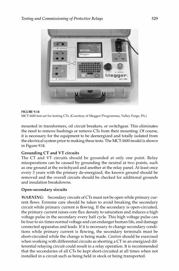
Testing and Commissioning of Protective Relays 529
mounted in transformers, oil circuit breakers, or switchgear. This eliminates the need to remove bushings or remove CTs from their mounting. Of course, it is necessary for the equipment to be deenergized and totally isolated from the electrical system prior to making these tests. The MCT-1600 model is shown in Figure 9.14.
Grounding CT and VT circuitsThe CT and VT circuits should be grounded at only one point. Relay misoperations can be caused by grounding the neutral at two points, such as one ground at the switchyard and another at the relay panel. At least once every 3 years with the primary de-energized, the known ground should be removed and the overall circuits should be checked for additional grounds and insulation breakdowns.
Open-secondary sircuits
WARNING: Secondary circuits of CTs must not be open while primary cur-rent fl ows. Extreme care should be taken to avoid breaking the secondary circuit while primary current is fl owing. If the secondary is open-circuited, the primary current raises core fl ux density to saturation and induces a high voltage pulse in the secondary every half cycle. This high voltage pulse can be four to six times normal voltage and can endanger human life, and damage connected apparatus and leads. If it is necessary to change secondary condi-tions while primary current is fl owing, the secondary terminals must be short-circuited while the change is being made. Caution should be exercised when working with differential circuits as shorting a CT in an energized dif-ferential relaying circuit could result in a relay operation. It is recommended that the secondaries of all CTs be kept short-circuited at all times when not installed in a circuit such as being held in stock or being transported.
FIGURE 9.14MCT-1600 test set for testing CTs. (Courtesy of Megger/Programma, Valley Forge, PA.)
DK4058_C009.indd 529DK4058_C009.indd 529 11/8/2008 12:42:42 PM11/8/2008 12:42:42 PM

530 Electrical Power Equipment Maintenance and Testing
Continuity check (backfeed test)This test is conducted to check the CT windings and the wiring from test switch to CT (backfeed) for the three phases. The relay test connection dia-gram is shown in Figure 9.15. Conduct tests as follows:
Apply 120 V low current (about 3 A) or a 20 V source with a 100 W • lamp at point A. Point A is the test switch location where the protec-tive relay is isolated from CTs with the relay ground maintained. If the lamp has no glow or no current reading is observed, the CT windings are checked.
Next, jumper to ground the hot side of the CT. The lamp will glow • brightly (or 3 A will read on low-ampere source). This indicates that relay circuit wiring is continuous without any shorts or open.
Measure the insulation resistance of transformer secondary wind-• ings and CT leads with a 500 V megohmmeter.
Measure the transformer primary insulation with applicable poten-• tial test apparatus.
Repeat the preceding test to check all three phases.•
Verify the connection of the secondary VT leads by applying a low volt-• age to the leads and checking for this voltage at applicable devices.
Check for a VT secondary load with secondary voltage and cur-• rent measurements. Make sure that the load is less than the rating of the VT.
1
2
Test switches
120 Vsource
LGT
Phaseovercurrent
relays
Ground relay
CTS
“A”
3
51
51
51N
51
FIGURE 9.15Continuity check for CTs and associated wiring.
DK4058_C009.indd 530DK4058_C009.indd 530 11/8/2008 12:42:43 PM11/8/2008 12:42:43 PM
Testing and Commissioning of Protective Relays 531
9.7 Testing and Commissioning of Static and Digital Relays
The differences between static (second and third generation) and digital relays (fourth generation) were listed in Sections 9.3.2.2 through 9.3.2.4, respectively. As it was mentioned, the earlier versions of static relays are not equipped with automatic self-test features therefore they may require more attention than the digital relays having self-test features. The inspection and maintenance of static and digital relays can be addressed under each relay type. The following is a guide for inspecting and testing static relays.
Static relaysStatic relays should be tested in accordance with manufacturer’s recommen-dations given in relay instruction books. As there are no moving parts in static relays, there is no physical wear due to usage and no need for lubricants. Prime causes of failure in electronic components are heat, vibration, and moisture. Overheating can be caused by voltage transients, current surges, excessive power, or high ambient temperature. Vibration can loosen or break leads and connections and can crack component casings or insulation result-ing in equipment failure. Moisture can result in corrosion of metallic elements which can result in circuit discontinuities, poor contact, or shorts. Preventive maintenance of static relays should be directed toward removing causes of failure listed above by doing the following:
Keep equipment clean by periodic vacuuming or blowing out of dirt, • dust, and other surface contaminants
Keep the equipment dry and protected against moisture and • corrosion
Inspect to see that all connections, leads, and contacts are tight and • free as possible from effects of vibration
Check to see that there is adequate ventilation to conduct heat away • effi ciently
Preventive measures should not be applied unnecessarily as this may con-tribute to failures. For example, printed circuit cards should not be pulled from their racks to be inspected if there is no real need. Operating test switches unnecessarily may introduce damaging voltage transients.
Digital relaysDigital relays are built using a microprocessor, an AC signal data acquisition system, memory components containing the relay algorithms, contact inputs to control the relay, and contact outputs to control other equipment. Digital relay operating characteristics are defi ned by the algorithms and settings contained in the relay memory.
As mentioned earlier, digital relays are often equipped with automatic self-test functions. These self-tests verify correct operation of critical relay com-ponents. If a self-test detects an abnormal condition, it can close an output
DK4058_C009.indd 531DK4058_C009.indd 531 11/8/2008 12:42:43 PM11/8/2008 12:42:43 PM

532 Electrical Power Equipment Maintenance and Testing
contact, send a message, or provide some other indication of the failure. When the alarm occurs, a technician can be dispatched to repair or replace the device quickly.
The analog input section is typically monitored by automatic self-testing. This may be somewhat limited because a steady-state condition cannot be fully defi ned. With a protective relay, there are often many steady-state conditions possible under each mode of operation. Since the analog input portion of the digital relay is only partially self-tested, routine maintenance assists in verifi cation of the analog measuring components.
Many digital relays offer metering features which give the user a conve-nient means of verifying the accuracy of the relay analog input section. The user can verify metering quantities and be assured the relay is using valid data for its relay element computations. This practice is sound if the digital relay uses the same measuring circuitry for both metering and relaying. On the other hand, if the relay uses separate circuitry for its metering func-tions, the metering data checks only the components common to both the metering and relaying circuitry.
The contact input/output circuitry is another part of the digital relay which allows only partial automatic testing. For this reason, it may be appropriate to implement a routine trip check. Many digital relays provide a trip feature which allows the user to locally or remotely trip the relay. The trip check verifi es the trip circuit wiring and the integrity of the trip coil. This trip com-mand feature provides a convenient means of tripping the circuit breaker without the need to inject a simulated fault to the relay. If the relay is routinely operating for faults, the actual relay operations may be adequate verifi cation of the relay input/output functions.
The digital processing section, typically a microprocessor, is the interface between the analog input section and the contact input/output section. Since the analog and contact input/output sections cannot function without the processing section, normal relay use and maintenance checks act as rou-tine verifi cation of the microprocessor. Additionally, manufacturers are able to offer very thorough self-tests to continually monitor the status of the computer.
Engineers should work closely with relay vendors to determine what relay functions are not checked by relay self-tests and how those functions should be checked in the fi eld. In the case of the processing section, there are typi-cally no special tests required.
Many of the maintenance features are executable by remote command and often could replace routine maintenance altogether. Also, consider the analysis of digital relay fault data comparable to routine relay maintenance. Those relays which do not encounter faults may require more thorough routine maintenance checks.
Digital relay routine testing practices should verify relay functions that cannot be fully verifi ed by the relay self-testing. Figure 9.16 shows how all relay failures can be detected using a regime consisting of:
DK4058_C009.indd 532DK4058_C009.indd 532 11/8/2008 12:42:43 PM11/8/2008 12:42:43 PM

Testing and Commissioning of Protective Relays 533
Self-test alarm monitoring•
Loss of signal (loss of voltage [LOV] and loss of current [LOI]) • monitoring
Review of relay event reports•
Periodic checks of relay inputs and outputs•
Periodic calibration check by comparison•
Relay self-testing and event data analysis detect the majority of relay fail-ures. Monitoring LOV and LOI functions, executing meter tests and input/output checks verify the balance of relay functions. Taken together, this regime replaces complex routine tests. These simple tests can be performed quickly, minimizing the need for complex test equipment.
9.7.1 Test Methods
Test methods can be separated into three primary categories:
Steady-state testing•
Dynamic testing•
End-to-end testing•
Steady-state testing is the most common method for testing a digital relay. As the name implies, steady-state values are applied to characterize the
All other failures75%–85%
Self-tests
Meter testsEvent analysis
AC input failures ~15%
I/O failures <10%
Routine tests
I/O checks
LOV/LOI monitoring
FIGURE 9.16Digital relay self-testing and monitoring functions entirely replace traditional routine tests.
(From Kumm, J., et al., Assessing the effectiveness of self-tests and other monitoring means in
protective relays, SEL Technical Papers, p. 4, 1995. Courtesy of SEL, Inc., Pullman, WA.)
DK4058_C009.indd 533DK4058_C009.indd 533 11/8/2008 12:42:43 PM11/8/2008 12:42:43 PM

534 Electrical Power Equipment Maintenance and Testing
relay performance or verify settings. For example, when testing a distance element a fi xed voltage level is applied to the relay and the current is slowly increased until the element operates. The relay accuracy, characteristics, timing, and operation of internal logic can easily be verifi ed. Note that steady-state testing does not truly represent a faulted condition on the power system. Sudden changes in current and voltage magnitudes, phase angles, and DC offset are not used.
Steady-state testing requires that the tester or the test developer have an understanding of the internal relay logic, especially in a multifunction digital relays. Again, referring to the distance element example, many supervisory elements are included in the distance element fi nal output. If the relay experiences a loss of the source voltage, the distance element is blocked from operation. During steady-state testing it is likely that a loss of voltage element would set and block the distance element output thus making it appear that it is not operating correctly. Fortunately, most digi-tal relays allow the user to disable these supervisory functions for test purposes.
Dynamic testing is designed to represent the actual power system conditions the relay may see in the application. In this case, normal load conditions are applied to the relay before a fault is applied. Normal load conditions could mean nominal voltages and currents, or just nominal current, depending upon the type of relay. Power system parameters are used to determine the fault quantities. Line and source impedances are entered into a program to calculate the fault currents and voltages at certain locations on the protected line. The test is performed by applying the prefault current and voltages for a period of time, then suddenly changing to the fault values. Some test sets have the capability of supply DC offset current to more accurately represent the power system conditions.
End-to-end testing is similar to dynamic testing. The same types of signals that are used to perform dynamic testing are also used for end-to-end testing. The primary difference is that the relays are tested at their respective instal-lation sites with all of the equipment connected to the relay. For example, circuit breakers, communications equipments, and other auxiliary devices. The test sets are time synchronized using a satellite clock signal providing a high accuracy time source. The test sequences are initiated at all locations simultaneously and the response of the relay is evaluated as if the test were an actual fault condition.
9.7.2 Commissioning Methods
The purpose of commission tests is to verify that the relay has been set cor-rectly and that all functionality is operating as expected. Unlike electrome-chanical relays, the operating characteristic of the digital relay does not change, therefore, it is unnecessary to do a complete series of test verifying all of the operating characteristics. Commissioning tests should be focused in the following areas:
DK4058_C009.indd 534DK4058_C009.indd 534 11/8/2008 12:42:43 PM11/8/2008 12:42:43 PM
Testing and Commissioning of Protective Relays 535
Settings•
Protection function checks•
Communication checks•
Auxiliary power checks•
Other checks•
Testing should be complete enough to verify that the relay settings have been entered correctly. Comparison of the expected settings against the entered setting is relatively easy to do with the support of a settings manager or program. Tests should verify that the elements operate at the specifi ed settings. Check pickup of overcurrent elements, time delays, dis-tance element reaches, and custom logic. It is not necessary to check unused functions. In addition, testing should be limited to that required to verify settings, it is not necessary to test the complete operating character-istic of the relay. For example, it is not necessary to test the entire circular characteristic of a mho distance element. The pickup at the maximum reach and the maximum torque angle setting only need to be checked. Another example would be a time overcurrent element. Check pickup set-ting and two or three points on the timing curve to verify that the correct curve shape and time dial have been selected.
Digital relays include many functions and features, this is one of the advantages of using digital relays, however, it can also make them somewhat complex and diffi cult to test. Testing should be focused on the functions that are used in the specifi c application. In many cases, customized logic is implemented to meet specifi c application needs. As recommended previously, it is unnecessary to test all of the internal protection logic. Instead, test the logic that requires user input, for example, output logic, trip logic, input logic, etc.
Digital relays also provide various means of communications. Communi-cations can be used for data and status information for a SCADA system, engineering access for events and setting changes, and communications between devices for high-speed protection schemes. Communication is typi-cally via a serial port, either RS232 or RS485, however, many relays also offer Ethernet communications. Communications logic and data should be verifi ed through the entire system. For example, SCADA communications through a DNP master should be verifi ed to the control center. The appropriate informa-tion and data should be sent and confi rmed. Digital communications between devices should also be verifi ed. Some schemes require delays to account for communications channel and these should be checked to ensure secure operation.
Verify the battery system and all connected devices. Also verify the cur-rent and voltage circuits, this includes checking monitoring functions like loss-of-potential detection.
Develop a test plan when testing digital relays. A well thought out test plan ensures that all of the aspects of the scheme will be correctly tested and docu-mented. Use AC and DC schematics, communications diagrams, and the
DK4058_C009.indd 535DK4058_C009.indd 535 11/8/2008 12:42:43 PM11/8/2008 12:42:43 PM

536 Electrical Power Equipment Maintenance and Testing
relay settings to determine what and how the relay should be tested. Developing a checklist for verifi cation and testing is very helpful in assuring that everything is thoroughly tested and documented. For example, a test list for a line protection system may include items such as
Primary protection function checkout•
Auxiliary protection function checkout•
Control functions•
Relay logic; fi xed and user programmed•
Physical mounting•
Electrical connections•
Setting verifi cation•
Communications; protection and data monitoring•
Security•
In-service checks•
Customize the checklist to suite the specifi c application. A well thought out test program will have long-term benefi ts in reuse and troubleshooting in the future.
9.7.3 Commissioning Examples
The following two examples show commissioning practices for a bus protec-tion scheme and a transformer differential scheme.
Bus protection schemeThe fi rst example illustrates commissioning of microprocessor relays for a fast bus transfer protection system using a protection processor. Figure. 9.17 shows a one-line diagram of a distribution bus protection scheme using a fast bus trip scheme.
B3
67
B2
67
85/69B6
67
Protectionlogic
processor
FIGURE. 9.17Fast bus trip one-line diagram. (From Zimmerman, K., Commissioning of protective relay
systems, SEL Technical Papers, p. 1, 2007. Courtesy of SEL, Inc., Pullman, WA.)
DK4058_C009.indd 536DK4058_C009.indd 536 11/8/2008 12:42:44 PM11/8/2008 12:42:44 PM
Testing and Commissioning of Protective Relays 537
Most of the logic for the protection of this scheme is developed in the settings of a protection logic processor (85/69 device). Thus, to successfully commis-sion this scheme, we need to verify the performance of the following:
Directional overcurrent elements (67)•
Performance of the communications path•
CT and VT connections and polarities of the inputs to the 67 devices•
Fast bus trip and block logic settings in relays and protection logic • processor
Breaker trip/DC control circuit•
The directional overcurrent elements can be tested and validated by apply-ing test values from system faults (e.g., internal bus fault, external line faults).
CT and VT polarities, phasing, and ratios are usually checked through manual fi eld measurements at commissioning. One improvement is to use synchrophasor data from the relays, if available. Phasor measurements take a precise snapshot of the currents and voltages at the same instant in time.
Commissioning the communications path and logic settings is more com-plex and requires that the logic be broken out into logic diagrams.
Ideally, we would like to test the scheme all the way through. The best environment for this is a laboratory simulation with all three relays and the protection logic processor connected with complete AC voltage and current and the entire communications scheme connected.
For example, individually test directional overcurrent elements (67) for breakers 2, 3, and 6. Then apply fault simulations for each scenario to verify the internal and external fault logic (expected results are shown in parentheses):
1. Breakers 3, 6 internal, breaker 2 external (no trip).
2. Breakers 2, 6 internal, breaker 3 external (no trip).
3. Breakers 2, 3 internal, breaker 6 external (no trip).
4. Breakers 2, 3, 6 internal (trip within 25 ms).
5. Verify transient reversal block logic by applying test 1, then test 4 in short intervals, e.g., apply test 1 for two cycles, then test 4 for four cycles, etc. (no trip).
6. Verify disable fast bus trip logic by applying loss of potential (LOP) and relay out of service conditions, then apply test 4 (no trip).
By performing a thorough laboratory simulation of the complete logic, we can then install and commission this system. In the fi eld, we check the CTs and VTs, verify the integrity of the communications path, and perform breaker trip tests to validate the DC control circuit.
DK4058_C009.indd 537DK4058_C009.indd 537 11/8/2008 12:42:44 PM11/8/2008 12:42:44 PM

538 Electrical Power Equipment Maintenance and Testing
Transformer differential schemeThe example shows a method for commissioning microprocessor relays for a transformer differential scheme. Commissioning transformer differential protection schemes involves several levels of testing:
Hardware tests verify transformer turns ratio, CT turns ratios, and • CT polarity.
Functional tests validate the performance of the relay elements • with the installed settings and test the DC control circuits. Trip tests verify that the relay operates the correct lockout relays and breakers.
In-service or commissioning tests verify the primary and secondary • AC current circuits. We must take into account the transformer ratio and connection; the CT ratio, wiring, and connections; and the relay settings.
The last item is, by far, the most challenging aspect of assuring certainty in commissioning. modern transformer differential relays have settings that compensate for the difference in the secondary currents, adjusting for the transformer connection (e.g., delta–wye) and removing zero-sequence current.
In order to perform commissioning tests, we must apply balanced three-phase currents to the primary system. Some users energize the transformer to the system and begin to apply load. Ideally, we prefer to perform this test without connecting to the power system. For example, use a portable generator or a station service transformer to supply a reduced voltage three-phase power supply to one of the windings of the transformer and apply a short-circuit to the remaining winding. An example test setup is shown in Figure 9.18.
Through this procedure, we can check the following:
The phase rotation and angle of the currents•
Secondary current magnitudes•
The relationship of the high-side currents to the low-side currents•
The operating or differential current (should be nearly zero)•
For the transformer shown in Figure 9.18, given a 240 V AC source, we can calculate expected relay currents (magnitude and angle). Using relay meter-ing data, we then observe the measured currents, as shown in Table 9.4. If the measured (actual) currents do not match the calculated (expected) currents and/or we observe differential current, we must perform troubleshooting to systematically check CT wiring, connections, and relay settings to correct the discrepancy.
DK4058_C009.indd 538DK4058_C009.indd 538 11/8/2008 12:42:44 PM11/8/2008 12:42:44 PM

Testing and Commissioning of Protective Relays 539
H1 H2 H3
X1 X2 X3 X0
IAW1
IBW1
ICW1
IAW2
IBW2
ICW2
24 MVA132–13.2 kVDelta–WyeZ% = 15.5%
600:5 MR300
2500:5
TS 1–1 TS 1–1
E
G
I
D
F
H
TS 1–2 TS 1–2
E
G
I
D
F
H
AC temporary source
Temporary jumpersto ground
ICTH1
ICTH2
ICTH3
ICTX3
ICTX2
ICTX1
I X1
I X2
I X3
I H1
I H2
I H3
FIGURE 9.18Three-line diagram of primary injection test. (From Zimmerman, K., Commissioning of protec-
tive relay systems, SEL Technical Papers, p. 4, 2007. Courtesy of SEL, Inc., Pullman, WA.)
DK4058_C009.indd 539DK4058_C009.indd 539 11/8/2008 12:42:44 PM11/8/2008 12:42:44 PM

540 Electrical Power Equipment Maintenance and Testing
Sometimes it helps to plot the currents, as shown in Figure 9.19. Winding 2 B-phase and C-phase currents in this system appear to be reversed.
9.8 Event Reporting
Event reporting is a standard feature in most microprocessor-based protec-tive relays. The data and information saved in these reports are valuable for testing, measuring performance, analyzing problems, and identifying defi -ciencies before they cause future misoperations.
Event reports indicate whether the protective relay operated as expected. In addition, analysis identifi es whether all associated components of the protection system were installed and operated correctly. Power system models, settings, wiring, auxiliary relays, circuit breakers, current and VTs, commu-nications equipment, the DC battery system, and connected loads can all be measured and monitored by analyzing event report data.
Every time the power system faults and relays capture data, you have readymade test reports. By analyzing actual relay and system performance, you can save money by extending or eliminating traditional routine tests.
TABLE 9.4
Commissioning Test Worksheet Quantities:Compare Expected Currents with Actual Currents
Expected Currents Actual Currents
ICTX1 (IAW2) 246 mA at +150° 0.27 at 149.7°
ICTX2 (IBW2) 246 mA at +30° 0.25 at −90.5°
ICTX3 (ICW2) 246 mA at −90° 0.25 at 29.8°
ICTH1 (IAW1) 205 mA at 0° 0.22 at 0.0°
ICTH2 (IBW1) 205 mA at −120° 0.21 at −119.7°
ICTH3 (ICW1) 205 mA at +120° 0.21 at 120.3°
IBW2
IBW1
IAW1
ICW2
ICW1
IAW2
FIGURE 9.19Plots of measured currents during commissioning test. (From Zimmerman, K., Commissioning
of protective relay systems, SEL Technical Papers, p. 5, 2007. Courtesy of SEL, Inc., Pullman, WA.)
DK4058_C009.indd 540DK4058_C009.indd 540 11/8/2008 12:42:44 PM11/8/2008 12:42:44 PM

Testing and Commissioning of Protective Relays 541
FIGURE 9.20Example of an event report. (From Costello, D., Understanding and analyzing event report infor-
mation (WPRC 2000), SEL Technical Papers, p. 2–4, 2000. Courtesy of SEL, Inc., Pullman, WA.)
(continued)
STATION A FEEDER 1
FID = SEL-351-X111-Vf-D970128 CID = 1F00 Firmware checksum identifier
Date : 02/11/97 Time: 09:54:14.881
Currents (Amps Pri) Voltages (kV Pri)
[1]
One cycle of data
[Cycles 2 and 3 not shown in this example] [4]
> Arrow indicates trigger rowcorresponding to the date andtime stamp above
[5] Trip by inst phase o/celement, OUT1 closes
[Cycle 6 not shown in this example]
[7]
[8]
See Figure 2 and 3 for details on one cycle of phase A(channel IA) current
[9] * Star indicates maximum phase current row forsummary below
IA IB IC IN IG VA VB VC VS Vdc Freq 24680A 2468
188 -291 102 0 -1 8.0 -11.8 3.8 0.0 126 60.00 ...... b...
226 50 -278 0 -2 9.0 2.5 -11.5 -0.0 126 60.00 ...... b...
189 290 102 -1 -1 -8.0 11.8 -3.8 -0.0 126 60.00 ...... b...
-227 -51 277 -1 -1 -9.0 -2.5 11.5 0.0 126 60.00 ...... b...
190 -290 100 0 -1 8.1 -11.8 3.7 0.0 126 60.00 ...... b...
225 52 -279 0 -2 9.0 2.6 -11.5 -0.0 126 60.00 ...... b...
437 269 -84 -1 622 -7.6 11.7 -3.8 0.0 126 60.00 ...... b...
-914 -52 251 0 -716 -7.7 -3.1 11.0 0.0 126 60.00> ...... b...
-1228 -227 68 0 -1387 5.8 -11.0 4.2 0.0 126 59.72 ......b...
1985 47 -211 -1 1821 6.0 3.8 -10.3 0.0 126 59.72 1 .....b...
1390 205 -71 -1 1524 -4.5 10.5 -4.7 -0.0 125 59.72 1 ..... b...
-2369 -43 196 0 –2216 -5.7 -4.0 10.2 0.0 124 59.72 1 ..... b...
-1382 -206 70 0 -1519 4.5 -10.4 4.6 0.0 120 60.02 1 ......b...
2373 43 -197 0 2219 5.7 4.0 -10.2 -0.0 120 60.02 1 .....b...
1379 205 -70 -1 1514 -4.5 10.4 -4.6 -0.0 120 60.00 1 ..... b...
-2376 -44 196 0 –2224 -5.7 -4.0 10.2 0.0 120 60.00 1 ..... b...
-1375 -206 69 0 -1511 4.5 -10.4 4.6 -0.0 120 60.00 1 ......b...
2380 44 -197 0 2226 5.6 4.1 -10.2 0.0 120 60.00 1 .....b...
1367 205 -69 -1 1503 -4.6 10.4 -4.6 -0.0 120 60.00 1 ..... b...
-2385 -45 197 -1 –2233 -5.6 -4.1 10.2 0.0 120 60.00 1 ..... b...
135791 1357 Out In
-1358 -205 68 0 -1495 4.6 -10.4 4.5 0.0 120 60.00 1 ......b...
Firmware identifier
DK4058_C009.indd 541DK4058_C009.indd 541 11/8/2008 12:42:44 PM11/8/2008 12:42:44 PM

542 Electrical Power Equipment Maintenance and Testing
FIGURE 9.20 (continued)
[10]
IN1 deasserts indicating the breaker has opened
[Cycles 11 through 15 not shown in this example]
2391 45 -198 0 2238 5.6 4.1 -10.2 - 0.0 121 60.00* 1..... b...
737 150 -28 -1 859 -5.1 10.6 -4.4 0.0 122 60.00 1..... b...
-1592 -37 130 -1 –1499 -6.9 -3.7 10.8 0.0 123 60.00 1..... b...
-62 -48 -6 0 -116 7.0 -11.2 3.8 0.0 124 60.32 1..... b...
394 14 -32 0 376 8.4 3.0 -11.5 -0.0 125 60.32 1..... b...
0 -1 -1 -1 -1 -8.4 11.8 -3.4 -0.0 126 60.32 1..... 2...
-1 -1 -1 -1 -2 -8.7 -2.9 11.6 -0.0 126 60.32 1..... 2...
Protection and Control Elements
ABCPNGQPP QG PNGQ QG PPSPPQNS VFA B246 9et dPc 24682468C2468 1234567890123456
[1]
[Cycles 2 and 3 not shown in this example]
[4]
[Cycles 6 through 15 not shown in this example]
51 50 32 67 Dm 27 59 25 81 TS Lcl Rem Ltch SELogic
V 5 2 ih ZLV Variable
P PN PN P P1 9S 7135 7mo lOd 13571357O1357
Overcurrent elements asserting; reclosing element [5]changes from reset to cycle
......... .. .... .. ........ ... .... R.0 ... ............. ................
......... .. .... .. ........ ... .... R.0 ... ............. ................
......... .. .... .. ........ ... .... R.0 ... ............. ................
......... .. .... .. ........ ... .... R.0 ... ............. ................
......... .. .... .. ........ ... .... R.0 ... ............. ................
......... .. .... .. ........ ... .... R.0 ... ............. ................
.....p... .. .... .. ........ ... .... R.0 ... ............. ................
...p.p... .. .... .. ........ ... .... R.0 ... ............. ................
...p.p... .. .... .. ........ ... .... R.0 ... ............. ................
...p.p.A. .. 1... .. ........ ... .... C.0 ... ............. p...............
...p.p.A. .. 1... .. ........ ... .... Cr0 ... ............. p...............
...p.p.A. .. 1... .. ........ ... .... Cr0 ... ............. p...............
DK4058_C009.indd 542DK4058_C009.indd 542 11/8/2008 12:42:45 PM11/8/2008 12:42:45 PM

Testing and Commissioning of Protective Relays 543
(continued)FIGURE 9.20 (continued)
Communication Elements
[1]
[2]
[Cycles 3 through 15 not shown in this example]
Event: AG T Location: 2.41 Shot: 0 Frequency: 60.00
Targets: INST 50
Currents (A Pri), ABCNGQ: 2749 210 209 0 2690 2688
Summary information, includes phases involved, front -panel targets, fault location, and maximum currents
Group 1
Group Settings: Event data are followed by relay settings
RID = FEEDER 1 TID = STATION A
CTR = 120 CTRN = 120 PTR = 180 PTRS = 180
Z1MAG = 2.14 Z1ANG = 68.86
Z0MAG = 6.38 Z0ANG = 72.47 LL = 4.84
E50P = 1 E50N = N E50G = N E50Q = N
E51P = 1 E51N = N E51G = Y E51Q = N
E32 = N ELOAD = N ESOTF = N EVOLT = N
E25 = N EFLOC = Y ELOP = Y ECOMM = N
E81 = 1 E79 = 2 ESV = 1 EDEM = THM
S PZ EE ZDNS TMB RMB TMB RMB RRCL PWR
3O T3KKCWU 3SSTB A A B B OBBB A B C
PT PRREETFB XTTOT 1357 1357 1357 1357 KAAO 131313
OF TXBYYTCB TRRPX 2468 2468 2468 2468 DDK 242424
.. ........ ..... .... .... .... .... b... ......
.. ........ ..... .... .... .... .... b... ......
.. ........ ..... .... .... .... .... b... ......
.. ........ ..... .... .... .... .... b... ......
.. ........ ..... .... .... .... .... b... ......
.. ........ ..... .... .... .... .... b... ......
.. ........ ..... .... .... .... .... b... ......
.. ........ ..... .... .... .... .... b... ......
DK4058_C009.indd 543DK4058_C009.indd 543 11/8/2008 12:42:45 PM11/8/2008 12:42:45 PM

544 Electrical Power Equipment Maintenance and Testing
FIGURE 9.20 (continued)
[Remainder of settings not shown in this example]
SELogic group 1
SELogic Control Equations:
Settings are followed by Boolean logic programmable equations
[Remainder of logic settings not shown in this example]
TR =51PT + 51GT + 81D1T + LB3 + 50P1 * SH0 + OC
TRCOMM=0
TRSOTF =0
DTT =0
ULTR =!(51P + 51G)
When faults or other system events occur, protective relays record sampled analog currents and voltages, the status of optoisolated inputs and output contacts, the state of all relay elements and programmable logic, and the relay settings. The result is an event report, a stored record of what the relay saw and how it responded. With readily available information from product instruction manuals, the user is provided with all the necessary tools to determine if the response of the relay and the protection system was correct for the given system conditions.
Event reports are formatted ASCII text fi les that are read vertically. Time increments as we read down the page, and data are displayed in columns. Each horizontal row represents a particular point in time. Figure 9.20 displays an example event report from a distribution relay.
The analog data in Figure 9.20 are reported every quarter-cycle or 90 electrical degrees. This makes it simple to take one sample, the oldest or pre-vious, as the y-component and the next sample, the newest or present, as the x-component of a phasor current or voltage. Modern relays, including the one that generated the event report in Figure 9.20, are capable of sampling much faster, as much as 16 to 64 samples per cycle, for better resolution and oscillography. However, the relays continue to offer the analyst a choice of display rates: 16 samples per cycle for generating detailed oscillography or four samples per cycle for quick visual analysis.
Figure 9.21 shows how the event report AC current column data relate to the actual sampled waveform and rms values. Note that any two rows of data, taken one quarter-cycle apart, can be used to calculate rms values. If an event report is displayed in a 16-sample per cycle format, every fourth row of data
DK4058_C009.indd 544DK4058_C009.indd 544 11/8/2008 12:42:45 PM11/8/2008 12:42:45 PM

Testing and Commissioning of Protective Relays 545
IA
t
cyc
IApeak = 3887 Apeak
3366
−194
5
−336
0
1950
Multiply by
1379
DTG: M351137
−237
6
−137
5
2380
12
14
Multiply by
3887 Apeak = 2748 ARMS
12
2
1379IA
1379
2380
Event report column
−2376
−1375
−2376
−1375
2380(−1375)2 + (2380)2 = 2749
(−2376)2 + (−1375)2 = 2745
(1379)2 + (−2376)2 = 2747
FIGURE 9.21Derivation of current and rms current values from sampled waveform. (From Costello, D.,
Understanding and analyzing event report information (WPRC 2000), SEL Technical Papers, p. 5,
2000. Courtesy of SEL, Inc., Pullman, WA.)
could be used to calculate rms values. Figure 9.22 shows how to convert the event report current column data to phasor rms values. Process voltages similarly.
Event report analysis can reveal problems with power system models, settings, breakers and auxiliary contacts, instrument transformers, and more. In the past, these problems would go undetected until they were either caught during routine maintenance or more serious consequences
DK4058_C009.indd 545DK4058_C009.indd 545 11/8/2008 12:42:46 PM11/8/2008 12:42:46 PM

546 Electrical Power Equipment Maintenance and Testing
IA
IA
cyc
t
Y =previous¼ cycle
X = present sample
Event report column
2380
X = 2380 Real axis
Angle = arctan YX
= arctan
= −30.0�
−1375
−23761379
14
−13752380
Magnitude =
DTG: M351130
(−1375)2 + (2380)2
= 2749
Imag
inar
yax
isY
= −1
375
)))
)
FIGURE 9.22Derivation of phasor rms current values from sampled waveform. (From Costello, D., Under-
standing and analyzing event report information (WPRC 2000), SEL Technical Papers, p. 6, 2000.
Courtesy of SEL, Inc., Pullman, WA.)
DK4058_C009.indd 546DK4058_C009.indd 546 11/8/2008 12:42:46 PM11/8/2008 12:42:46 PM

Testing and Commissioning of Protective Relays 547
51P p79 LOUT T&C CIN 1&2 1IN 3&4 3IN 5&6 6
−500
0
500
−5000
0
5000
−1 0 1 2 3 4 5 6 7 8 9 10 11
IA IB
ICV
A V
B V
CD
igita
ls
Cycles
IA IB IC VA VB VC
FIGURE 9.23Manual close of a failed distribution recloser. (From Costello, D., Understanding and analyzing
event report information (WPRC 2000), SEL Technical Papers, p. 28, 2000. Courtesy of SEL, Inc.,
Pullman, WA.)
occurred. It is a good practice to examine every event report to see if the operation was normal or exceptional.
The Figure 9.23 shows a graphical plot of a typical event report. Analog and digital information can be analyzed using readily available software. The graphical plots are very useful for observing the actual waveforms and timing of the digital elements.
Event reports are useful in monitoring the following protection system components: protective relays, substation batteries, DC wiring, auxiliary tripping relays, circuit breakers, trip and close coils, breaker auxiliary con-tacts, CTs, AC wiring, VTs, communications equipment, settings and logic, power system models, and more.
DK4058_C009.indd 547DK4058_C009.indd 547 11/8/2008 12:42:46 PM11/8/2008 12:42:46 PM

DK4058_C009.indd 548DK4058_C009.indd 548 11/8/2008 12:42:46 PM11/8/2008 12:42:46 PM

549
10Motors and Generators
10.1 General
Motors and generators must be installed, operated, and maintained correctly. Motors and generator are referred to as rotating machines or rotating appara-tus. The rotating apparatus ranges from very small to very large machines. Consequently, the attention and care provided in the selection, installation, operation, and maintenance varies for different units. Many precautions must be taken, especially for large rotating apparatus, to avoid damage because most of this equipment is expensive and hard to replace. The scheduled main-tenance, overhauls, or repair of large rotating apparatus may require partial or extensive disassembly. Therefore, maintenance personnel assigned to perform the work should be familiar and knowledgeable with all aspects of the apparatus. This chapter discusses the selection, application, mechanics, maintenance, troubleshooting and testing of motors and generators.
The rotating apparatus is an energy-conversion device. That is, it converts mechanical energy into electrical energy, or vice versa. It can be designed pre-cisely to perform the service expected. But to perform best, it must be correctly installed, protected, ventilated, and maintained. The objective in applying a motor or generator is to select rating and features so that it can carry the load without exceeding its temperature limits. Since many motor and generator applications will have a bearing on other equipment, it is important to review the engineering information on it. The National Electrical Manufacturers Association (NEMA) has published standards titled MG1-2006, Motors and Generators, that list all the pertinent details of this equipment.
10.2 NEMA Classification of Motors and Generators
Under NEMA MG1 standards, all machines are classifi ed according to size, application, electrical type, environmental protection and method of cool-ing, and variability of speed. A machine is an electrical apparatus which depends on electromagnetic induction for its operation and which has one or more component members capable of rotary movement. These machines are generally referred to as motors and generators.
DK4058_C010.indd 549DK4058_C010.indd 549 11/8/2008 12:19:32 PM11/8/2008 12:19:32 PM

550 Electrical Power Equipment Maintenance and Testing
10.2.1 According to Size
Small (fractional) machine: • A machine built with frame size having two-digit numbers or a machine built in a frame smaller than that of an integral-horsepower motor.
Medium (integeral) machine: • is an alternating-current (AC) or direct current (DC) medium machine, (1) built in a three-or four-digit frame number series. The AC medium machines have synchronous speed from 451 to 3600 RPM, continuous rating from 125 HP up to 500 HP for motors, and 100 kW up to 400 kW for generators. The DC medium machines have continuous rating up to and including 1.25 HP per rpm for motors or 1.0 kW per rpm for generators.
Large machine: • An AC large machine is a machine having a conti-nuous power rating greater than that of medium machine for syn-chronous speed ratings above 450 rpm; or having a continuous power rating greater than that of small machine for synchronous speed ratings equal to or below 450 rpm.
A direct-current large machine is a machine having a continuous rating greater than 1.25 horsepower per rpm for motors or 1.0 kilowatt per rpm for generators.
10.2.2 According to Application
General-purpose AC motor: • An induction motor, rated at 200 hp or less, and of open construction; it is continuously rated, has a service factor of 1.15 for integral-horsepower motors, and has class B insula-tion system.
General-purpose DC motor: • An integral-horsepower motor of mechanical construction suitable for industrial applications under usual service conditions and has ratings and constructional and per-formance characteristics applying to direct-current small motors.
General-purpose generator: • is a synchronous generator of mechanical construction suitable for general use and has ratings and construc-tional characteristics for performance under usual service conditions.
Industrial DC generator: • A generator of mechanical construction suitable for industrial application under usual conditions.
Defi nite-purpose motor: • A motor designed and constructed in stan-dard ratings for service conditions other than usual or for use on a particular type of application.
Part-winding-start motor: • A motor arranged to start with part of the winding, subsequently energizing the remainder of the winding in one or more steps.
Special-purpose motor: • A motor with special characteristics and/or mechanical construction and not falling under the defi nition of a general-purpose and defi nite-purpose motor.
DK4058_C010.indd 550DK4058_C010.indd 550 11/8/2008 12:19:32 PM11/8/2008 12:19:32 PM

Motors and Generators 551
General DC industrial motor: • Motors designed for all general indus-trial service with speed operation (when specifi ed) above base speed by fi eld weakening.
Metal rolling mill motor: • Motors designed for metal rolling mill service and known as class N or S types.
Reversing hot mill motor: • Motors designed for application to reversing hot mills.
10.2.3 According to Electrical Type
10.2.3.1 AC Motors
AC motors are of three types: induction motors, synchronous motors, and series motors. They can be defi ned as follows:
Induction motor: • An AC motor in which the primary winding (the stator) is connected to the electric power source and the secondary winding (the rotor) carries induced current. Induction motors are of two types: squirrel-cage induction motors and wound-rotor motors. In the squirrel-cage induction motor, the secondary circuit consists of a squirrel-cage winding suitably dispersed in slots in the secondary core. In the wound-rotor induction motor, the secondary circuit consists of polyphase windings or coils whose terminals are either short circuited or closed through suitable external circuits.
Synchronous motor: • An induction motor that is equipped with fi eld windings in the secondary circuit and excited with DC voltage. The synchronous motor is started as an induction motor and synchro-nized with the rotating magnetic fi eld after the rotor circuit reaches excitation at the appropriate time. It is operated at synchronous speed (i.e., at the speed of the rotating magnetic fi eld).
Series-wound motor: • A motor in which the fi eld circuit and armature circuit are connected in series.
Both induction and synchronous motors are built as polyphase or single-phase motors.
10.2.3.2 Polyphase Motor
Polyphase motors are constructed with multiphase stator windings and rotor. The rotor is constructed in two types: the cage rotor and the form-wound rotor. Both types of rotor have a laminated cylindrical core with parallel slots in the outside circumference to hold the windings in place. The cage rotor has an uninsulated bar winding, whereas the form-wound rotor has a two-layer distributed winding with preformed coils. In the polyphase motor, the rotor currents are supplied by electromagnetic induction. The stator windings contain two or more out-of-time-phase currents, which produce correspond-ing magnetomotive forces (mmfs). These mmfs establish a rotating magnetic fi eld across the air gap. This magnetic fi eld rotates continuously at constant
DK4058_C010.indd 551DK4058_C010.indd 551 11/8/2008 12:19:32 PM11/8/2008 12:19:32 PM
552 Electrical Power Equipment Maintenance and Testing
speed regardless of the load on the motors. The revolving magnetic fi eld produced by the stator cuts across the rotor conductors, inducing a voltage in the conductors. This induced voltage causes rotor currents to fl ow. This action is known as mutual induction (similar to transformer action), which takes place between the stator and the rotor under operating conditions.
Polyphase motors range in horsepower rating from fractional- to integral-horsepower to large-apparatus motors. The fractional- and integral-horse-power motors are generally cage-rotor type. Large-apparatus induction motors are of cage-and would-rotor types, where the synchronous motors are of the salient pole and cylindrical rotor type.
In accordance with NEMA standards, polyphase squirrel-cage integral-horsepower induction motors are designated by design letters:
Design A: • A squirrel-cage motor designed to withstand full-voltage starting and develop a starting torque of 110%–120%, starting locked rotor current of 6–10 times rated, and having a slip at rated load of less than 5%.
Design B: • Similar to design A motor with the same starting torque, however, the locked rotor current is limited to fi ve times.
Design C: • A squirrel-cage motor designed to withstand full-voltage starting, developing a high starting torque of 200% and locked rotor current less than the standard type of motor, and having a slip at rated load of less than 5%.
Design D: • A squirrel-cage motor designed to withstand full-voltage starting, developing a very high locked rotor torque of 300%, low lock rotor current, and having a slip at rated load of 5% or more.
Design F: • A squirrel-cage motor built to withstand full-voltage starting, developing a low starting torque, very low locked rotor current, and a slip at rated load of less than 5%.
10.2.3.3 Single-Phase Motor
Single-phase motors are not self-starting because they have only one primary (stator) winding and cage rotor. The single primary winding when excited from a single source produces a pulsating magnetic fi eld in the motor air gap, and with the rotor at standstill no breakaway torque is produced. However, if the rotor is brought up to speed by external means, the induced currents in the rotor will combine with the stator currents to produce a revolving fi eld. The revolving fi eld in turn causes the rotor to continue to run in the direction in which it was started. Several methods are used to provide the single-phase induction motor with starting torque. These methods identify the motor as a particular type of single-phase motor. Some of the important single-phase motors are split-phase, capacitor start and run, repulsion, and shaded pole. Single-phase motors are constructed as induction, wound rotor, and synchronous motor types.
DK4058_C010.indd 552DK4058_C010.indd 552 11/8/2008 12:19:32 PM11/8/2008 12:19:32 PM

Motors and Generators 553
Alternating single-phase motors designated by design letters similar to polyphase motors. These design letters are the following:
Design N: • A single-phase fractional-horsepower motor designed to withstand full-voltage starting and with a locked rotor current not to exceed the values shown in NEMA standard MG1.
Design O: • A single-phase fractional-horsepower motor designed to withstand full-voltage starting and with a locked rotor current not to exceed the values shown in MG1.
Design L: • A single-phase integral-horsepower motor designed to withstand full-voltage starting and to develop a breakdown torque as shown in NEMA standards MG1 and locked rotor current not to exceed values shown in MG1.
Design M: • A single-phase integral-horsepower motor designed to withstand full-voltage starting and to develop a breakdown torque as shown in NEMA standards MG1 and locked rotor current not to exceed values shown in MG1.
10.2.3.4 Universal Motor
A universal motor is a series-wound motor designed to operate at approxi-mately the same speed and output on either DC or single-phase AC of fre-quency not to exceed 60 Hz. There are two types of universal motors:
Series-wound motor: • A commutator motor in which the fi eld circuit and armature circuit are connected in series.
Compensated series motor: • A motor with compensating fi eld winding.
10.2.3.5 DC Motors
DC motors are of three types:
Shunt-wound motor: • A shunt-wound motor is either a straight shunt-wound motor or a stabilized shunt-wound motor. The difference between the two shunt fi elds is that the stabilized shunt-wound motor has a light series winding to prevent a rise in speed or to obtain a slight reduction in speed from no-load to full-load conditions.
Series-wound motor: • A series-wound motor has the fi eld circuit and armature circuit in series. The torque and speed are load dependent. Generally, a series-wound motor should not be operated at full volt-age while uncoupled from its load.
Compound-wound motor: • A compound-wound motor has two sepa-rate fi eld windings, one connected in the shunt fi eld and the other connected in series in the armature.
DK4058_C010.indd 553DK4058_C010.indd 553 11/8/2008 12:19:32 PM11/8/2008 12:19:32 PM

554 Electrical Power Equipment Maintenance and Testing
10.2.3.6 DC Generators
DC generators are of two general types:
Shunt-wound generator:• A generator in which the fi eld is connected in parallel with the armature or to a separate source of excitation.
Compound-wound generator: • A generator that has two separate fi eld windings, one usually the predominating fi eld, connected in parallel with the armature and the other connected in series with the armature.
10.2.4 According to Physical Protection (Enclosure) and Methods of Cooling
The machine is provided with an enclosure to give physical protection from external sources of motor damage. The following standard enclosures have been adopted by NEMA:
Open enclosure: • An enclosure with ventilating openings that permit passage of external cooling air over and around the windings of the machine.
Drip-proof enclosure: • An open enclosure in which ventilating openings are so constructed that successful operating is not inter-fered with when drops of liquid or solid particles strike or enter the enclosure at any angle from 0° to 15° downward from the vertical.
Splash-proof enclosure: • An open enclosure in which ventilating openings are constructed so that successful operation is not interfered with when drops of liquid or solid particles strike or enter the enclo-sure at any angle not greater than 100° downward from the vertical.
Guarded enclosure: • An open enclosure in which all openings giving direct access to live metal or rotating parts are limited in size by structural parts or by screens, baffl es, grilles, or other means to prevent accidental contact with hazardous parts.
Externally ventilated enclosure: • An open closure that is ventilated by a separate motor-driven blower mounted on the enclosure.
Pipe-ventilated enclosure: • An open enclosure with provision for connecting inlet ducts or pipes. It is called force-ventilated when the air through the enclosure is driven by an external blower.
Weather-protected type 1 enclosure: • An open enclosure with ventilating passages constructed and arranged to minimize the entrance of rain, snow, and airborne particles to the live and rotating parts.
Weather-protected type 2 enclosure: • An open enclosure with ventilating passages at both intake and discharge constructed and arranged to permit high-velocity air and airborne particles to be discharged without entering the internal ventilating passages of the enclosure.
DK4058_C010.indd 554DK4058_C010.indd 554 11/8/2008 12:19:32 PM11/8/2008 12:19:32 PM
Motors and Generators 555
Totally enclosed enclosure: • This enclosure prevents free exchange of air between the inside and outside of the enclosure. This enclosure is not airtight.
Totally enclosed nonventilated enclosure: • An enclosure that is not equipped for cooling by means external to the enclosing parts.
Totally enclosed fan-cooled enclosure: • An enclosure that is equipped for exterior cooling by means of a fan or fans integral with the enclo-sure but external to the enclosing parts.
Explosion-proof enclosure: • A totally enclosed enclosure designed and constructed to withstand an explosion of a specifi ed gas or vapor that may occur within it and to prevent the ignition of gas or vapor surrounding the machine by sparks.
Dust-ignition-proof enclosure: • A totally enclosed enclosure construc-ted in a manner to exclude ignitable amounts of dust or amounts that might affect the performance or rating, and which will not permit heat, arcs, or sparks liberated inside the enclosure to cause ignition of exterior accumulations or atmospheric suspensions of a specifi c dust on or in the vicinity of the enclosure.
Waterproof enclosure: • A totally enclosed enclosure so constructed that it will exclude water coming externally from a hose. Leakage around the shaft is allowed provided it does not enter the oil reser-voir. A check valve or drain is provided at the lowest part of the enclosure for drainage.
Totally enclosed pipe-ventilated enclosure: • A totally enclosed enclosure except for openings arranged for inlet and out-ducts or pipes for con-nection to the enclosed for admission and discharge of ventilating air.
Totally enclosed water-cooled enclosure: • A totally enclosed enclosure cooled by circulating water or water pipes coming in direct contact with the motor parts.
Totally enclosed water–air-cooled enclosure: • A totally enclosed enclosure cooled by circulating air, which in turn is cooled by circulating water, the heat exchanger medium.
Totally enclosed air–air-cooled enclosure: • A totally enclosed enclosure cooled by circulating internal air through heat exchangers, which, in turn, are cooled by circulating external air.
10.2.5 According to Variability of Speed
Constant-speed motor: • A motor that operates at constant or near constant speed, from no load to full load.
Varying-speed motor: • A motor whose speed varies with the load, ordinarily decreasing as the load increases.
Adjustable-speed motor: • A motor whose speed is adjustable over a considerable range and is not affected by load.
DK4058_C010.indd 555DK4058_C010.indd 555 11/8/2008 12:19:32 PM11/8/2008 12:19:32 PM

556 Electrical Power Equipment Maintenance and Testing
Adjustable varying-speed motor: • An adjustable-speed motor as described previously, but whose speed will vary as a function of load.
Multispeed motor: • A motor that can operate at one or two or more defi nite speeds, each speed being practically independent of the load.
10.2.6 Terminal Marking of Machines
The terminal markings of machines are made in accordance with NEMA standards. Terminal markings use a combination of capital letters and Arabic numerals. The letters and symbols as shown in Table 10.1 are used for AC motors and generators in accordance with NEMA standards. (Refer to NEMA MG1-2006 for A.C. Machines Terminal Markings.)
The terminal markings and connection procedure for single-phase motors is based upon three general principles:
Principle 1: • The main winding of a single-phase motor is designated by T1, T2, T3, and T4. The auxiliary winding is designated by T5, T6, T7, and T8. This is done to distinguish it from a quarter-phase motor, which uses odd numbers for one phase and even numbers for the other phase.
Principle 2: • When odd-numbered terminals of each winding are connected together, they will provide a lower voltage, that is, a parallel connection. When odd-to-even-numbered terminals of each winding are connected to odd-numbered, they will provide a higher voltage, that is, a series connection.
Principle 3: • The rotor of a single-phase motor is represented as a circle, even though there are no external connections to it. It also
TABLE 10.1
Terminal Marking for AC Motors and Generators
Line L1, L2, L3, etc.
Stator T1, T2, T3, etc.
Rotor windings M1, M2, M3, etc.
Resistors R1, R2, R3, etc.
Field F1, F2, F3, etc.
Notes: The numerals 1, 2, 3, etc., indicate the order in which
the voltages of a synchronous motor at the terminals
reach their maximum positive value with clockwise
shaft rotation when facing the connection end of the
coil windings. The terminal markings of polyphase
induction machines are not related to the direction
of rotation. The standard direction of rotation for all
AC single-phase motors, all synchronous motors,
and all universal motors is counterclockwise when
facing the end of the machine opposite the drive.
The standard direction of rotation for alternating
generators is clockwise when facing the end of the
machine opposite the drive.
DK4058_C010.indd 556DK4058_C010.indd 556 11/8/2008 12:19:32 PM11/8/2008 12:19:32 PM
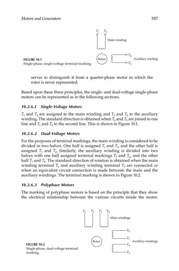
Motors and Generators 557
serves to distinguish it from a quarter-phase motor in which the rotor is never represented.
Based upon these three principles, the single- and dual-voltage single-phase motors can be represented as in the following sections.
10.2.6.1 Single-Voltage Motors
T1 and T4 are assigned to the main winding and T5 and T8 to the auxiliary winding. The standard direction is obtained when T4 and T5 are joined to one line and T1 and T8 to the second line. This is shown in Figure 10.1.
10.2.6.2 Dual-Voltage Motors
For the purposes of terminal markings, the main winding is considered to be divided in two halves. One half is assigned T1 and T2, and the other half is assigned T3 and T4. Similarly, the auxiliary winding is divided into two halves with one half assigned terminal markings T5 and T6, and the other half T7 and T8. The standard direction of rotation is obtained when the main winding terminal T4 and auxiliary winding terminal T5 are connected or when an equivalent circuit connection is made between the main and the auxiliary windings. The terminal marking is shown in Figure 10.2.
10.2.6.3 Polyphase Motors
The marking of polyphase motors is based on the principle that they show the electrical relationship between the various circuits inside the motor.
T1
T8
T5
T4
Main winding
Auxiliary windingRotorFIGURE 10.1Single-phase, single-voltage terminal marking.
T3T2T1
T8
T5
T6
T7
T4
Main windings
Auxiliary windingsRotorFIGURE 10.2Single-phase, dual-voltage terminal
marking.
DK4058_C010.indd 557DK4058_C010.indd 557 11/8/2008 12:19:32 PM11/8/2008 12:19:32 PM

558 Electrical Power Equipment Maintenance and Testing
Therefore, the NEMA standards employ a system that uses a clockwise rotating spiral with T1 and the outer end and fi nishes with the highest number at its inner end as a means of determining the sequence of numerals. Such a numbering system does not imply standardization of the direction of rotation of the motor shaft. This principle will now be used to show the terminal marking of a three-phase single-speed induction motor in Figure 10.3a through f.
Step 1: Draw a schematic vector diagram showing an inverted wye connection with two individual circuits in each phase arranged for series connection with correct polarities.
Step 2: Starting with T1 at the outside and top of the diagram, number the ends of the circuits consecutively in a clockwise direction, proceeding on a spiral toward the center of the diagram. This is shown in Figure 10.3b.
Step 3: Show the schematic vector diagram of the particular intercon-nection of the circuits for the (two circuits per phase) motor and terminal markings as determined in Steps 1 and 2. Arrange the vector diagram to give the correct polarity relation of the circuits. For example, connect the two circuits in parallel per phase; the vector diagram is shown in Figure 10.3c.
Step 4: When two (or more) terminals are permanently connected together, the highest terminal number is dropped and only the lowest number is retained. In our example, suppose that it is desired to have three line leads and three neutral leads brought out; the terminal markings are as shown in Figure 10.3d. If it was desired to have the windings in series or multiple connections with the neutral point brought out, the vector diagram and terminal markings are as shown in Figure 10.3e.
Step 5: Where the ends of three coils are connected together to form a permanent neutral, the terminal markings of the three leads so con-nected are dropped. If the neutral point is brought out, it is always marked as T0.
Step 6: Where the windings are to the connected delta, the inverted-wye diagram shown in Figure 10.3a is rotated 30° counterclockwise. The outer end of the top leg is assigned the terminal marking T1 and the remaining windings are numbered in accordance with Step 2. The vector schematic is then constructed in which the T1 leg of the rotated delta becomes the right side of the delta, the T2 becomes the bottom (horizontal side), and T3 the left side of the delta. This is shown in Figure 10.3f.
Many polyphase motors have dual voltage and are connected as wye or delta connections. The same principles as discussed can be applied to achieve the terminal markings for these types of motors. The wye and delta connections for dual-voltage motors are shown in Figure 10.4a and b.
DK4058_C010.indd 558DK4058_C010.indd 558 11/8/2008 12:19:33 PM11/8/2008 12:19:33 PM

Motors and Generators 559
10.3 Applications of Motors and Generators
Motors and generators are applied on the basis that they can carry the rated load and withstand the environmental conditions during their rated life
(a) (b)
T1
T2T3
T4
T5
T6
T8T9
T10
T11
T12
T7
(c)
T1
T2
T3
T4T5
T6
T8
T9
T10
T11
T12
T7
(d)
T1
T2T3
T4
T5
T6
(e)
T1
T2
T3
T4
T5
T6 T8T9
T10
T7
30�
T1
T1
T2
T2T3
T3
T4
T4T5
T5
T6
T6
T8
T8
T9
T9T11
T10
T10
T11
( f )
T12
T12
T7
T7
FIGURE 10.3(a) Diagram for two circuits per phase (Step 1); (b) terminal markings for two circuits per phase
(Step 2); (c) terminal markings for two circuits in parallel per phase (Step 3); (d) terminal mark-
ings for two windings in parallel per phase, permanently connected (Step 4); (e) terminal
markings with neutral brought out (Step 5); and (f) terminal markings for two circuits per
phase, delta connection (Step 6).
DK4058_C010.indd 559DK4058_C010.indd 559 11/8/2008 12:19:33 PM11/8/2008 12:19:33 PM

560 Electrical Power Equipment Maintenance and Testing
reliably. Because of the different requirements of various industries for motors, each industry has over the years developed different application criteria for motors. Therefore, a wide variety of motor insulation and construction classes are available (manufactured in accordance with NEMA MG1 standards) to satisfy these needs. The actual life and reliability of motors are determined by combining the experience of industry requirements and electrical characteristics. The reliability of a machine can be defi ned in terms of its electrical and mechanical integrity, which are explained next.
10.3.1 Electrical Integrity
The electrical integrity of a machine can be stated in terms of the dielectric and load-time ratings.
10.3.1.1 Dielectric Rating
Dielectric rating can be defi ned as the ability to correctly maintain the separation of the conducting and nonconducting parts from the power system supply voltage. To achieve the required dielectric integrity, various insulation systems are used, depending on the type of motor and service conditions. To provide the highest reliability, insulation materials must have a degree of thermal, voltage, mechanical, and environmental endur-ance. Therefore, insulation systems used for motors and generators are classifi ed on the basis of their ability to withstand the total temperature during the life of the machine without deterioration. The insulation systems of motors and generators are discussed in Section 10.8.
Most equipment manufacturers have standardized on roughly the same set of dielectric strengths for their insulation systems given the operating conditions most frequently encountered, and the requirements of NEMA.
(a) (b)
T1
T1
T2
T2T3T3
T4
T4
T5
T5
T6 T6
T8
T8
T9
T9
T7
T7
FIGURE 10.4(a) Wye-connected dual voltage and (b) delta-connected dual voltage.
DK4058_C010.indd 560DK4058_C010.indd 560 11/8/2008 12:19:33 PM11/8/2008 12:19:33 PM

Motors and Generators 561
For installations where commercial or industrial power sources are used, the established practices have worked very well. Recently, with the introduction of variable frequency induction motor drives using pulse width modulated (PWM) switching technology, some standard 600 V class machines have experienced insulation failures. The reasons for such failures must be evaluated on case by case basis; however, the most common problem results from failure to consider the drives’ modulating frequency and the length of the motor leads between the drive’s output terminals and the motor itself. At frequencies in the several kilohertz to tens of kilohertz range, the supply cables to the motor no longer act as simple conductors as they do at 60 Hz. If the cables are too long, they tend to act as incorrectly tuned transmission lines, which lead to a signifi cant refl ected voltage wave each time the current is switched. This buildup tends to concentrate at the fi rst few turns of the motor winding. Manufacturers are approaching these applications in several ways: (1) by specifying the maximum lead length for a given horsepower, voltage and modulating frequency and using a standard, NEMA design motor; (2) by applying snubber/RC-fi lter assemblies at key locations and keeping the standard, NEMA design motor; (3) by offering motors for PWM service whose dielectric designs have been enhanced in order to withstand the additional electrical stress produced by the PWM sources. In cases where the motor and drive are supplied by different manufacturers, each should be given the full nameplate information of the motor, the approximate length of cable between the controller and the motor, and the nature of the load to be driven. This will allow one or both suppliers to offer components that will work as a coordinated system.
10.3.1.2 Load–Time Rating
The load rating relates to the ability of the machine to carry a load over a period of time. Load ratings can be classifi ed as service-factor duty, short-time duty, and overload duty.
Service-factor duty is defi ned as the multiplier that is multiplied by the nameplate horsepower; the result is used for temperature testing with continuously applied load until the temperature equilibrium is reached. For example, a service factor of 1.0 means that the motor cannot carry an overload on a sustained basis without exceeding the insulation temperature. A service factor of 1.15 has been established as a standard for open and drip-proof general-purpose motors below 200 hp. Larger motors have a service factor of 1.0. A service factor of 1.15 usually translates into a 10°C higher temperature with 15% overload.
Short-time duty is defi ned by a motor operating at continuous load over a period of time less than that required to reach thermal equilibrium. The short-time duty ratings are usually 15, 30, or 60 min. Motors should be allowed to cool down to ambient temperature when they are operated in this manner before the next load cycle is applied; otherwise, the motor will overheat.
DK4058_C010.indd 561DK4058_C010.indd 561 11/8/2008 12:19:33 PM11/8/2008 12:19:33 PM

562 Electrical Power Equipment Maintenance and Testing
Overload duty is defi ned as the ability of the motor to continuously carry an overload for an extended period of time. A common rating is an overload of 25% for 2 h. It is expected that the motor will not reach thermal equilibrium for the time specifi ed for the overload rating.
10.3.2 Mechanical Integrity
Mechanical integrity involves mechanical stresses, vibrational forces, and the ability to keep moving parts separate from stationary parts. The mechanical stresses imposed on motors are due to motor torques and loads. Motors that are switched frequently are more susceptible to these stresses. Vibrations are a result of incorrect alignment, incorrect mounting, and incorrect installation, which will tend to deteriorate the motor life performance.
However, the most critical mechanical part of the motor is the bearings, where stationary and rotating parts meet. To ensure optimum performance, the bearings should be correctly matched to the load, kept clean, lubricated, and aligned correctly. Motor bearings include babbitted, sleeve, and ball types. The fatigue life of ball bearings varies inversely with the cube of the load. The load usually imposes a side force on the shaft extension owing to driven-equipment connections such as belts, gears, or chains. The fatigue life of sleeve bearings is infi nite due to the fact that the oil fi lm supports the shaft; and if maintained correctly, they will last indefi nitely.
Motors and generators conforming to NEMA standards are designed to operate in accordance with ratings under the usual service conditions as listed in NEMA MG1 standards. Motors and generators operated under service conditions other than those specifi ed in NEMA MG1 standards, may involve some hazard. The severity of this hazard depends upon the degree of depar-ture from the usual conditions. Hazards usually result from overheating, abnormal deterioration of the insulation, mechanical failure, corrosion, and fi re. Therefore, the manufacturer should be consulted for further information concerning the usual service conditions.
10.4 AC Motors
Criteria used as guidelines for the application of AC motors are discussed next.
10.4.1 Environmental Conditions
The usual service conditions that a motor is exposed to are the following:
Ambient temperature not to exceed 40°C and areas with adequate • ventilation
Altitude not to exceed 3300 ft•
Machine installed on a rigid mounting and with belt, chain, or gear • drive
DK4058_C010.indd 562DK4058_C010.indd 562 11/8/2008 12:19:34 PM11/8/2008 12:19:34 PM

Motors and Generators 563
Unusual service conditions for motor operation or exposure can be listed as the following:
Combustible, explosive, abrasive, or conducting dust•
Excessively dirty operating conditions where accumulation of dirt • will interfere with motor ventilation
Chemical fumes and explosive or fl ammable gases•
Abnormal shock, vibration, or mechanical loading from external • sources
High humidity areas, oil vapors, steam, or salt-laden air•
Excessive departure from rated voltage, frequency, or both•
Supply voltage is unbalanced•
Operation above rated speed•
Poor ventilation•
10.4.2 Direction of Rotation
Synchronous, universal, single-phase, and nonreversing DC motors have counterclockwise rotation when facing the end of the machine opposite the drive. For AC and DC generators, the rotation is clockwise.
10.4.3 Operation at Altitudes above 3300 ft
The temperature rises for motors and generators are based on a maximum altitude of 3300 ft with a maximum ambient temperature of 40°C. Motors and generators having a Class A or B insulation system will operate satisfactorily at altitudes above 3300 ft with ambient temperatures as shown in Table 10.2.
10.4.4 Voltage and Frequency
General-purpose induction and synchronous motors are designed for • a rated voltage, frequency, and number of phases. The supply voltage must be known in order to select the correct motor. For AC motors, the motor nameplate voltage will normally be less than the nominal power system voltage, as shown in Table 10.3 for three-phase 60 Hz motors.
TABLE 10.2
Ambient Temperature versus Altitude
Ambient Temperature (°C) Maximum Altitude (ft)
40 3300
30 6600
20 9900
DK4058_C010.indd 563DK4058_C010.indd 563 11/8/2008 12:19:34 PM11/8/2008 12:19:34 PM

564 Electrical Power Equipment Maintenance and Testing
Voltage and frequency variations:• When the voltage at the terminals of a motor varies from nameplate rating, the performance or life of the equipment may be sacrifi ced. The effect may be serious or minor depending upon the amount the voltage deviates from the nameplate rating. NEMA standards provide a ±10% tolerance from the nameplate rating for operation of induction general-purpose motors. However, even small deviations of voltage from nameplate ratings have an effect on the performance of the motor. The follow-ing are some of operating results caused by variations of frequency and voltage.
High voltage on induction motor: The most signifi cant effects of too high a voltage are increased torque, starting current, and heat, and decreased power factor (PF).
Low voltage on induction motor: The most signifi cant effects of too low a voltage are reduced starting torque, increased PF, and increased heating. The increased heating at low voltage and full load reduces the life of the insulation system of the motor.
High and low frequency of induction motor: An increased frequency of the induction motor above the rated frequency will usually improve the PF, decrease locked rotor torque, and increase the speed, friction, and wind-age loss. A decreased frequency below nameplate rating will have the opposite effects. When variations of frequency and voltage occur at the same time, the effects are superimposed. NEMA standards allow a combined voltage and frequency deviation of ±10%.
Voltage unbalance: The voltage supplied to the motor should be equal because voltage unbalance will produce circulating negative sequence currents, which in turn produce heating in the motor. Two to three percent unbalance voltages to the motor will produce the same heating as a 10% overload on the motor. A motor should be derated when the unbalance reaches 4%.
TABLE 10.3
Motor Voltage Ratings
Nominal Power System
Voltage (V)
Motor Utilization (Nameplate)
Voltage (V)
208 200
240 230
480 460
600 575
2,400 2,300
4,160 4,000
6,990 6,600
13,800 13,200
DK4058_C010.indd 564DK4058_C010.indd 564 11/8/2008 12:19:34 PM11/8/2008 12:19:34 PM

Motors and Generators 565
10.4.5 Horsepower, Torque, and Speed Considerations
The horsepower of a motor can be defi ned as the capability of the motor to do a given amount of work. Motors are rated as fractional or integral horsepower. The torque of a motor can be defi ned as the turning force developed by the motor, or it can be referred to as the resistance offered to the turning force by the driven load. Usually, torque for motors is expressed in terms of percentage of rated full-load torque. The speed of the motor is expressed as rpm, that is, a rate of measure of motion. The several defi ni-tive speed terms (as outlined in the section on the classifi cation of motors according to variability of speed) that are common to all motors are stan-dardized in order to relate the delivery of torque at a given speed for pur-poses of application. For AC motors the synchronous speed can be calculated as
{ }Synchronous speed (Ns) 120 frequency/(no. of poles)= ×
Induction motors, however, operate at actual speeds that are less than the synchronous speed because of losses in the motor. The difference between synchronous and actual speed is knows as slip. Slip is usually expressed as a percentage of synchronous speed and can be calculated as
Slip (%) {Synchronous rpm actual rpm 100}
/{Synchronous rpm}
= − ×
The horsepower of the motor can be stated in mechanical or electrical terms. One horsepower (1 hp) is equal to 33,000 ft. lb/min. The torque produced by an electric motor can be calculated as
Torque {5252 hp}/{actual speed}= ×
Also
Horsepower (hp) Watts/746 kW/0.746
{torque actual speed}/{5252}
= == ×
A typical torque–speed curve for a motor is shown in Figure 10.5. The various NEMA design motor torque–speed curves are shown in Figure 10.6.
In order to apply motors, the fi rst thing to determine is the desired full-load speed and the desired horsepower at that speed. Other factors required when applying motors are type of torque required by the load and the start-ing current limitations. Motor torque characteristics must match those of the load from starting to the time when the motor reaches its rated speed. The motor must develop net accelerating torque for every point on the load curve in order to reach its actual speed.
DK4058_C010.indd 565DK4058_C010.indd 565 11/8/2008 12:19:34 PM11/8/2008 12:19:34 PM

566 Electrical Power Equipment Maintenance and Testing
To understand the torques developed by the various motors, the following defi nitions are given; they are shown in Figure 10.5 for each design type of motor.
Lock-rotor torque (starting torque):• The minimum torque developed by the motor for all angular positions of the rotor when the primary winding (stator winding) is energized with AC power supply.
Accelerating torque:• The torque developed with rated power input during the period from standstill to full speed. This is the net positive torque available to the motor beyond the torque required by the load.
100Full-load torque
Breakdown torque (pull-out torque)
Pull-up torque (accelerating torque)
Lock-rotor torque (strating torque)
50
Sync
hron
ous s
peed
(%)
0 100 150
Torque percent of full load
200
FIGURE 10.5Typical torque–speed curve.
FIGURE 10.6NEMA design motors torque–speed curves.
NEMA design A
NEMA design B
NEMA design C
NEMA design D
Sync
hron
ous s
peed
(%)
Torque percent of full load current350300250200150100500
20
40
60
80
100
DK4058_C010.indd 566DK4058_C010.indd 566 11/8/2008 12:19:34 PM11/8/2008 12:19:34 PM

Motors and Generators 567
Breakdown torque (maximum torque):• The maximum torque developed by the motor at rated power input without an abrupt change in speed.
Pull-out torque:• The maximum torque developed by a motor for 1 min without stalling. It is frequently referred to as the breakdown torque.
Pull-in torque:• The torque developed during the transition from rated speed (slip speed) to synchronous speed.
Pull-up torque:• The minimum torque developed with rated power input during the period of acceleration from standstill to rated speed.
Full-load torque:• The torque developed at rated speed with rated power input.
Torque characteristics of various motors can best be described by comparing one motor type with another. Torques are classifi ed as very high, high, medium, low, and very low. The torque–speed curves for the various NEMA motor designs as listed under classifi cation according to application shown in Figure 10.6.
10.4.6 Power Factor
The connected motor load in a facility is usually a major factor in determining the system PF. Low system PF results in increased losses in the distribution system. Induction motors inherently cause a lagging system PF and, under certain circumstances, they can cause a very low system PF.
The PF of an induction motor decreases as the load decreases. When the load on the motor is increased, the rated load PF increases; that is, a fully loaded motor has a higher PF. Several induction motors, all operating at light load, can cause the electrical system to have a low PF. The PF of induc-tion motors at rated load is less for low-speed than for high-speed motors.
A small increase in voltage (10%) above rated voltage will decrease the PF, and a small decrease in voltage (10%) below rated voltage will improve the PF of an induction motor. However, other performance characteristics may be adversely affected by such a change in voltage. Therefore, operation as close as possible to the nameplate voltage and horsepower ratings is recommended.
The PF of synchronous motors can range from 1.0 to approximately 0 PF leading, depending on the rated PF and the load for which they are built. Standard designs are usually rated for unity, 0.8 lagging, or 0.8 leading PF. As previously stated, synchronous motors have the capability of improving the PF of the electrical system.
10.4.7 Motor Selection
Induction motor: The selection of the induction motor depends on the performance characteristics of the driven machine, and these, in turn, determine the operating characteristics of the motor. Some machines, such as
DK4058_C010.indd 567DK4058_C010.indd 567 11/8/2008 12:19:34 PM11/8/2008 12:19:34 PM

568 Electrical Power Equipment Maintenance and Testing
most fans, blowers, centrifugal pumps, and unloaded compressors, require a relatively low starting torque. After starting, the required driving torque increases with increasing speed up to the full-load speed and torque. A design B motor is frequently selected to drive this type of application.
Other machines, such as reciprocating air compressors and loaded conveyors, require high starting torque. The torque needed to start the machine is sometimes greater than the torque required at full-load speed. A design C motor is frequently selected to drive this type of application. For driven machines that impose pulsating loads or require frequent starting of the motor, such as punch press and well pumping, and hoist applications, a design D is often used.
Synchronous motors: In general, large synchronous motors can be applied to any load that induction motors with design B or C characteristics can handle. They have a higher effi ciency than an induction motor of the equivalent rating and are capable of improving the system PF. When effi ciency is a primary consideration in choosing a relatively large motor, a 1.0 PF synchro-nous motor may provide the solution. Where system PF improvement is a primary consideration, the use of a 0.8 leading PF synchronous motor may provide the solution.
Multispeed motors: Multispeed motors can be designed to have speed–torque characteristics similar to those of design A, B, C, or D motors of the equiva-lent rating. They can be designed for variable torque, constant torque, or constant horsepower. For the highest effi ciency, it is important to select the correct multispeed motor characteristic for the load at all operating speeds. Typical examples of variable-torque loads are fans and centrifugal pumps. Constant-torque motors are used to drive apparatus such as conveyors, posi-tive displacement pumps, and compressors. Machine tools and winches are examples of drives requiring the use of constant-horsepower motors.
10.5 AC Generators
Application criteria for AC generators are discussed next.
10.5.1 Service Conditions
Ac generators, like AC motors, should be correctly selected with respect to their service conditions. The usual and unusual conditions are the same for genera-tor applications as those listed for AC motors. Some generators may operate in accordance with their ratings under one or more unusual service conditions. However, where some unusual service condition exists, a special-purpose gen-erator may be required. Even though in such cases past experience may be the best guide in selecting the machine, it is recommended that the manufacturer be consulted concerning the mechanical and thermal duty of the machine.
DK4058_C010.indd 568DK4058_C010.indd 568 11/8/2008 12:19:34 PM11/8/2008 12:19:34 PM

Motors and Generators 569
10.5.2 Ratings
The continuous basis of rating synchronous generators is in kilowatts (kW) or kilovolt-amperes (kVA) at 80% PF. The ratings of kVA, speed, voltage, frequency, and so on, are expressed in NEMA MG1 standards for three-phase and single-phase machines. The excitation voltages for the fi eld windings are also stated in the same NEMA standards; they are 62.5, 125, 375, and 500 V DC. These excitation voltages apply to machines with brushes only. Synchronous generators are capable of carrying a 1 min overload of 50% of normal rated current with the fi eld set at normal rated load excitation. A syn-chronous generator is designed to withstand three-phase short-circuit cur-rent at its terminal for 30 s operating at rated kVA and PF, at 5% overvoltage with fi xed excitation. The phase current due to faults other than three-phase faults must be limited by external means to a value that does not exceed the maximum phase currents obtained from three-phase fault.
The kW output of the machine depends upon the voltage, armature cur-rent, and PF. Also, the synchronous generator kVA ratings may be stated at defi nite voltage and frequency. The permissible load output of the synchro-nous generator depends upon the balance of the load. It is maximum for balanced loads and minimum for single-phase loads.
10.5.3 Temperature Rise
The temperature rise under rated load conditions for synchronous generators is based on the insulation system used for the machines. The temperature rise is determined in accordance with the latest IEEE std 115-1995, IEEE guide: Test Procedures for Synchronous Machines. The method of temperature determi-nation may be resistance or embedded resistance temperature detector (RTD). Table 10.4 lists the various temperature rises for the various generator sizes and insulation systems.
TABLE 10.4
Temperature Rise for Synchronous Generators
Temperature
Rise (°C)
Machine Component
Method of Temperature
Measurement A B F H
Armature windings
All kVA ratings Resistance 60 80 105 125
1563 kVA and less RTD 70 90 115 140
Over 1563 kVA
7000 V and less RTD 65 85 110 135
Over 7000 V RTD 60 80 105 125
Field windings Resistance 60 80 105 125
Note: NEMA standard MG1.
DK4058_C010.indd 569DK4058_C010.indd 569 11/8/2008 12:19:34 PM11/8/2008 12:19:34 PM

570 Electrical Power Equipment Maintenance and Testing
The standard ambient temperature is taken as 40°C, and where the ambient temperature is higher than the standard, it is recommended that the temperature rise of generators be reduced as follows:
For increases in ambient temperature above 40°C up to and including • 50°C, decrease the temperature rise by 10°C
For increases in ambient temperature above 50°C up to and including • 60°C, decrease the temperature rise by 20°C
10.5.4 Variation in Voltage
Synchronous generators can operate at rated kVA, frequency, and PF at voltages above and below the rated voltage not to exceed 5%. The maximum voltage any synchronous generator can produce at a defi nite frequency depends upon the permissible pole fl ux and fi eld heating. To maintain a rated voltage output, specifi c fi eld excitation is necessary at some specifi ed load and PF.
10.5.5 Regulation
Regulation of a synchronous generator at any given PF is defi ned as a percentage rise in voltage, a constant frequency at excitation, when rated kVA load is removed. The regulation depends upon armature reactance, arma-ture effective resistance, change in leakage fl ux with change in load, and armature reaction.
10.6 DC Motors
Application criteria for DC motors are discussed next.
10.6.1 Service Conditions
Similar to AC motors, the DC motors should be selected with regard to their environmental conditions. The service conditions may be usual or unusual and may involve environmental as well as operating conditions. The service conditions listed for AC motors also apply to the application of DC motors.
10.6.2 Operation of DC Motor on Rectified AC
The performance of a DC motor operating on rectifi ed AC is different than if it were operating on a DC source having the same effective value of voltage. The reason for this is due to the continuous ripple or pulsation of the output voltage from the rectifi ed AC voltage source. The ripple effect appears in the
DK4058_C010.indd 570DK4058_C010.indd 570 11/8/2008 12:19:34 PM11/8/2008 12:19:34 PM

Motors and Generators 571
motor armature current and thus affects its performance. The effect of the rectifi ed voltage on the motor armature current becomes signifi cant when the rectifi er pulse number is less than 6 or the amount of phase control is more than 15%. Also, when a DC motor is operated from an unfi ltered recti-fi er power supply, bearing currents may result. Ripple currents may fl ow to ground by means of capacitive coupling between rotor winding and core. Even though these currents are small in magnitude, they may cause damage to antifriction and sleeve bearings under certain circumstances. Measures should be taken to minimize these currents to avoid damage to the motor.
10.6.3 Operation of the DC Motor below Base Speed
When a DC motor is operated below base speed by means of reduced armature voltage, the motor will heat up if rated full-load torque is main-tained. To avoid overheating of the motor, reduce the load to compensate for the overheating of the motor. The speed of the DC motor is directly proportional to the armature voltage, and the torque is directly proportional to the armature current. Overheating can result due to the insuffi cient heat dissipating ability of the motor at these speeds.
10.6.4 Operation of the DC Motor above Base Speed
DC motors are built so that in case of an emergency they can withstand an overspeed of 25% above rated full-load speed without mechanical injury.
10.6.5 Overload Capability
The general industrial motors of open, forced ventilation, and totally enclosed water–air-cooled types are capable of carrying, with successful commuta-tion, 115% of rated horsepower load continuously at rated voltage through-out their speed range. Refer to NEMA standard MG1, Sections 23.10, 23.11, and 23.28 for overload capability, momentary load capability, and rate of change of load current, respectively, on these types of motors.
10.7 DC Generators
Application criteria for DC generators are discussed next.
10.7.1 Service Conditions
The DC generators should be correctly selected with respect to their service conditions. These conditions may be usual or unusual, involving environmental and operating conditions. The typical service conditions that have been listed under Section 10.4 also apply to DC generators.
DK4058_C010.indd 571DK4058_C010.indd 571 11/8/2008 12:19:34 PM11/8/2008 12:19:34 PM
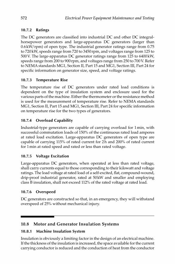
572 Electrical Power Equipment Maintenance and Testing
10.7.2 Ratings
The DC generators are classifi ed into industrial DC and other DC integral-horsepower generators and large-apparatus DC generators (larger than 0.6 kW/rpm) of open type. The industrial generator ratings range from 0.75 to 720 kW, speeds range from 720 to 3450 rpm, and voltages range from 125 to 500 V. The large-apparatus DC generator ratings range from 125 to 6400 kW, speeds range from 200 to 900 rpm, and voltages range from 250 to 700 V. Refer to NEMA standards MG1, Section II, Part 15 and MG1, Section III, Part 24 for specifi c information on generator size, speed, and voltage ratings.
10.7.3 Temperature Rise
The temperature rise of DC generators under rated load conditions is dependent on the type of insulation system and enclosure used for the various parts of the machine. Either the thermometer or the resistance method is used for the measurement of temperature rise. Refer to NEMA standards MG1, Section II, Part 15 and MG1, Section III, Part 24 for specifi c information on temperature rise for the two types of generators.
10.7.4 Overload Capability
Industrial-type generators are capable of carrying overload for 1 min, with successful commutation loads of 150% of the continuous rated load amperes at rated load excitation. Large-apparatus DC generators of open type are capable of carrying 115% of rated current for 2 h and 200% of rated current for 1 min at rated speed and rated or less than rated voltage.
10.7.5 Voltage Excitation
Large-apparatus DC generators, when operated at less than rated voltage, shall carry currents equal to those corresponding to their kilowatt and voltage ratings. The load voltage at rated load of a self-excited, fl at, compound-wound, drip-proof industrial generator, rated at 50 kW and smaller and employing class B insulation, shall not exceed 112% of the rated voltage at rated load.
10.7.6 Overspeed
DC generators are constructed so that, in an emergency, they will withstand overspeed of 25% without mechanical injury.
10.8 Motor and Generator Insulation Systems
10.8.1 Machine Insulation System
Insulation is obviously a limiting factor in the design of an electrical machine. If the thickness of the insulation is increased, the space available for the current carrying conductor is reduced and the conduction of heat from the conductor
DK4058_C010.indd 572DK4058_C010.indd 572 11/8/2008 12:19:34 PM11/8/2008 12:19:34 PM
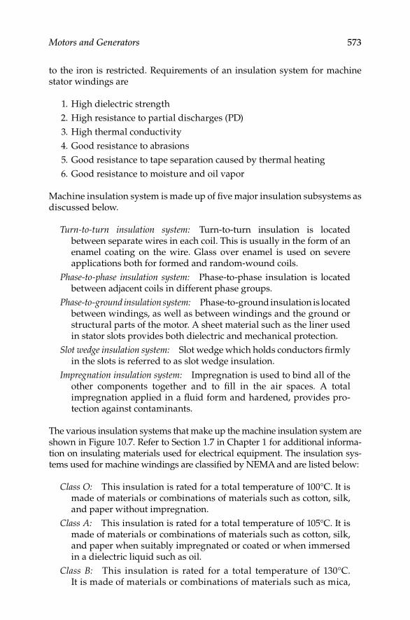
Motors and Generators 573
to the iron is restricted. Requirements of an insulation system for machine stator windings are
1. High dielectric strength
2. High resistance to partial discharges (PD)
3. High thermal conductivity
4. Good resistance to abrasions
5. Good resistance to tape separation caused by thermal heating
6. Good resistance to moisture and oil vapor
Machine insulation system is made up of fi ve major insulation subsystems as discussed below.
Turn-to-turn insulation system: Turn-to-turn insulation is located between separate wires in each coil. This is usually in the form of an enamel coating on the wire. Glass over enamel is used on severe applications both for formed and random-wound coils.
Phase-to-phase insulation system: Phase-to-phase insulation is located between adjacent coils in different phase groups.
Phase-to-ground insulation system: Phase-to-ground insulation is located between windings, as well as between windings and the ground or structural parts of the motor. A sheet material such as the liner used in stator slots provides both dielectric and mechanical protection.
Slot wedge insulation system: Slot wedge which holds conductors fi rmly in the slots is referred to as slot wedge insulation.
Impregnation insulation system: Impregnation is used to bind all of the other components together and to fi ll in the air spaces. A total impregnation applied in a fl uid form and hardened, provides pro-tection against contaminants.
The various insulation systems that make up the machine insulation system are shown in Figure 10.7. Refer to Section 1.7 in Chapter 1 for additional informa-tion on insulating materials used for electrical equipment. The insulation sys-tems used for machine windings are classifi ed by NEMA and are listed below:
Class O: This insulation is rated for a total temperature of 100°C. It is made of materials or combinations of materials such as cotton, silk, and paper without impregnation.
Class A: This insulation is rated for a total temperature of 105°C. It is made of materials or combinations of materials such as cotton, silk, and paper when suitably impregnated or coated or when immersed in a dielectric liquid such as oil.
Class B: This insulation is rated for a total temperature of 130°C. It is made of materials or combinations of materials such as mica,
DK4058_C010.indd 573DK4058_C010.indd 573 11/8/2008 12:19:34 PM11/8/2008 12:19:34 PM
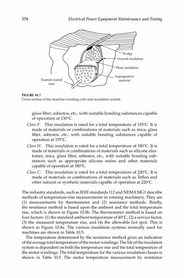
574 Electrical Power Equipment Maintenance and Testing
glass fi ber, asbestos, etc., with suitable bonding substances capable of operation at 130°C.
Class F: This insulation is rated for a total temperature of 155°C. It is made of materials or combinations of materials such as mica, glass fi ber, asbestos, etc., with suitable bonding substances capable of operation at 155°C.
Class H: This insulation is rated for a total temperature of 180°C. It is made of materials or combinations of materials such as silicone elas-tomer, mica, glass fi ber, asbestos, etc., with suitable bonding sub-stances such as appropriate silicone resins and other materials capable of operation at 180°C.
Class C: This insulation is rated for a total temperature of 220°C. It is made of materials or combinations of materials such as Tefl on and other natural or synthetic materials capable of operation at 220°C.
The industry standards, such as IEEE standards 112 and NEMA MG1 describe methods of temperature-rise measurements in rotating machinery. They are (1) measurements by thermometer and (2) resistance methods. Briefl y, the resistance method is based upon the ambient and the total temperature rise, which is shown in Figure 10.8b. The thermometer method is based on four factors: (1) the standard ambient temperature of 40°C, (2) a service factor, (3) the measured temperature rise, and (4) the allowable hot spot. This is shown in Figure 10.8a. The various insulation systems normally used for machines are shown in Table 10.5.
The temperature determined by the resistance method gives an indication of the average total temperature of the motor windings. The life of the insulation system is dependent on both the temperature rise and the total temperature of the motor windings. The total temperature for the various insulation classes is shown in Table 10.5. The motor temperature measurement by resistance
WedgeGround insulation
Phase insulation
ImpregnationmaterialEnamel-coated
wire
FIGURE 10.7Cross section of the machine winding coils and insulation system.
DK4058_C010.indd 574DK4058_C010.indd 574 11/8/2008 12:19:34 PM11/8/2008 12:19:34 PM

Motors and Generators 575
method takes into consideration only two factors: the ambient temperature and the temperature rise measured by resistance at service-factor load. The sum of these two temperatures makes up the basis of total temperature of the insulation system. The resistance method eliminates the consideration of hot spot allowance, the 10°C allowance for service factor, and temperature rise measured by thermometer at nameplate load. Under the resistance method, the insulation system needed for the motor can simply be specifi ed in terms of the operating ambient temperature and the service factor of the motor.
The use of the resistance method for the measurement of insulation temperature does not change the limitation imposed on the various classes of insulation systems. The resistance method has simplifi ed the specifi cation
Service factorAllowablehot spot
Measuredtemperature
rise
Ambienttemperature
(a) (b)
FIGURE 10.8Total temperature measurements by (a) thermometer and (b) resistance methods.
TABLE 10.5
Insulation System Temperatures (°C) for Motors with 1.15 Service Factor
Thermometer Method
Temperature Rise
Insulation
Class
Ambient
Temperature
(Standard)a
Measure
Rise
Service
Factor
Hot Spot
Allowanceb
(Average)
Resistance
Method
Total
Temperature
O 40 50 — — — 90
A 40 40 10 15 65 105
B 40 65 10 15 90 130
F 40 90 10 15 115 155
H 40 115 10 15 140 180
C 40 155 10 15 180 220
a The standard ambient is 40°C, whereas for higher temperature applications, 65°C, 90°C, and
115°C ambient temperatures are standard.b The hot spot allowance is a temperature allowance for the difference between the
measured temperature rise of the winding and the estimated hottest location in the wind-
ing. This number varies from 5°C to 25°C with measured rise, enclosure, and temperature
measurement method.
DK4058_C010.indd 575DK4058_C010.indd 575 11/8/2008 12:19:34 PM11/8/2008 12:19:34 PM

576 Electrical Power Equipment Maintenance and Testing
of the insulation temperature rating system for machine windings. As a result of this change in the temperature measurement method, the class B insulation system has been adopted as a standard for motor windings.
10.9 Motor and Generator Maintenance
This section deals with the inspection and maintenance of motors and generators of all sizes except steam and gas turbines. To obtain maximum effi -ciency and reliability of motors and generators, they have to be operated and maintained correctly. When motors and generators are maintained, many pre-cautions must be followed to avoid damage. Usually this damage results from maintenance personnel lacking thorough knowledge of motor design, con-struction, application, and correct maintenance. The purpose of this section is to provide general maintenance and failure mechanism information common to most types of motors and generators. The information is divided into sev-eral subsections; the fi rst two sections provide information on the failure mechanism and overall general inspection for all types of machines. Also, the reader should refer to Section 1.8 in Chapter 1 for additional information on causes of insulation degradation and failure modes of motors. The remaining sections deal with particular types of machines and components.
10.9.1 Failure Mechanisms
The failure mechanisms of the machine are divided into stator winding, rotor winding, and exciter. These are discussed in Sections 10.9.1.1, 10.9.1.2, and 10.9.1.3.
10.9.1.1 Stator-Winding Insulation
The failure mechanisms of stator winding are (1) age deterioration, (2) elec-trical cause, (3) mechanical causes, (4) thermal causes, and (5) environmental contamination.
The age-related deterioration causes brittleness, shrinkage, and cracks in insulation. The electrical causes are corona, slot discharge, lightning, switching surges, single-phasing, unbalance voltages, overheating effects, and test failures. The single phasing and voltage unbalance can be caused by either problems in the utility distribution system or the in-plant distribution system. Voltage unbalance causes negative sequence currents, which cause overheating of the remaining phase windings and the stator. The negative sequence currents also cause rotor overheating, which in turn causes stator induced currents that can lead to stator-winding failure. Rotor heating may result in rotor vibration and shaft/bearing overheating, which can result in machine-bearing failure. Similarly, the overloading problems can be caused by low voltage on the incoming utility line supplying the plant or facility, or problems in the in-plant distribution system. The effects of overloading
DK4058_C010.indd 576DK4058_C010.indd 576 11/8/2008 12:19:34 PM11/8/2008 12:19:34 PM

Motors and Generators 577
are stator-winding overheating, mechanical stresses on winding end turns and individual coils. This in turn results in deterioration of the turn-to-turn, coil-to-coil, phase-to-phase, and coil-to-ground insulation. The mechanical causes are vibration, loose ties and wedges, broken amortisseur bars, fan blades, loose iron, loose connections, close-in, or out-of-step synchronizing, and foreign objects. The thermal causes are overloading, overheating from short-circuited laminations, thermal cycling, loss of cooling, overheating from failure of strand insulation, and tape separation. The environmental and contamination causes are conducting dust or particles, moisture, oil, and magnetic particles.
10.9.1.2 Rotor-Winding Insulation
The failure mechanisms of rotor insulation are (1) age deterioration, (2) electrical causes, (3) mechanical causes, (4) thermal causes, and (5) environmental contamination.
The age deterioration causes are the same as discussed for the stator. The electrical causes are starting transients, switching surges, and high voltage induced from the stator faults. The mechanical causes are vibrations, high resistance connections, cracked or broken lead support insulators, collar deterioration, broken amortisseur bars, close-in unbalanced faults, broken banding wire, and loose mechanical parts. The thermal causes are excessive fi eld current, loss of cooling and unbalanced faults. The environmental factors are moisture, bridging of magnetic pole gaps, or groups of energized parts by foreign objects or conductive dust.
10.9.1.3 Exciter Insulation
The failure mechanisms of exciter insulation are age deterioration, electrical causes, mechanical causes, thermal causes, and environmental contamina-tion as discussed under stator and rotor insulation.
10.9.2 General Inspection
The fundamental justifi cation for the inspection and maintenance of motors and generators is to prevent service interruptions resulting from equipment failure. A defi nite program of inspection and maintenance should be organized so that all apparatus is assured of attention at stated periods; these periods should be adjusted to meet the actual need that experience over a number of years as indicated is necessary. To assure adequate inspection, it is essential that an inspection record be kept for each piece of apparatus.
Maintenance should be supplemented by visual inspection of all areas that experience has shown to be vulnerable to damage or degradation. Obviously, this necessitates scheduling disassembly of the apparatus at the time the electrical tests are made. Following is a general maintenance guide that is applicable to all motors and generators.
DK4058_C010.indd 577DK4058_C010.indd 577 11/8/2008 12:19:34 PM11/8/2008 12:19:34 PM
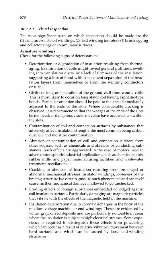
578 Electrical Power Equipment Maintenance and Testing
10.9.2.1 Visual Inspection
The most signifi cant parts on which inspection should be made are the (1) armature (or stator) windings, (2) fi eld winding (or rotor), (3) brush rigging and collector rings or commutator surfaces.
Armature windingsCheck for the following signs of deterioration:
Deterioration or degradation of insulation resulting from thermal • aging. Examination of coils might reveal general puffi ness, swell-ing into ventilation ducts, or a lack of fi rmness of the insulation, suggesting a loss of bond with consequent separation of the insu-lation layers from themselves or from the winding conductors or turns.
Girth cracking or separation of the ground wall from wound coils. • This is most likely to occur on long stator coil having asphaltic-type bonds. Particular attention should be paid to the areas immediately adjacent to the ends of the slots. Where considerable cracking is observed, it is recommended that the wedges at the ends of the slots be removed, as dangerous cracks may also have occurred just within the slots.
Contamination of coil and connection surfaces by substances that • adversely affect insulation strength, the most common being carbon dust, oil, and moisture contamination.
Abrasion or contamination of coil and connection surfaces from • other sources, such as chemicals and abrasive or conducting sub-stances. Such effects are aggravated in the case of motors used in adverse atmospheric industrial applications, such as chemical plants, rubber mills, and paper manufacturing facilities, and wastewater treatment installations.
Cracking or abrasion of insulation resulting from prolonged or • abnormal mechanical stresses. In stator windings, looseness of the bracing structure is a certain guide to such phenomena and can itself cause further mechanical damage if allowed to go unchecked.
Eroding effects of foreign substances embedded or lodged against • coil insulation surfaces. Particularly damaging are magnetic particles that vibrate with the effects of the magnetic fi eld in the machine.
Insulation deterioration due to corona discharges in the body of the • medium voltage machine or end windings. These are evidenced by white, gray, or red deposits and are particularly noticeable in areas where the insulation is subject to high electrical stresses. Some expe-rience is required to distinguish these effects from powdering, which can occur as a result of relative vibratory movement between hard surfaces and which can be caused by loose end-winding structures.
DK4058_C010.indd 578DK4058_C010.indd 578 11/8/2008 12:19:34 PM11/8/2008 12:19:34 PM

Motors and Generators 579
Loose slot wedges or slot fi llers that, if allowed to go uncorrected, • may themselves cause mechanical damage or reduce the effectiveness of stator coil retention against short-circuit and other abnormal mechanical forces.
Effects of overspeeding may be observed on DC armatures by • distortion of the windings or commutator rises, looseness or cracking of the banding, or movement of slot wedges.
Commutators should be checked for uneven discoloration, which • can result from short-circuiting of bars, or for pinholes and burrs resulting from fl ashover.
Risers (connections between commutator bars and coils in slots) may • collect carbon deposits and cause electrical leakage and subsequent failure.
Field windingsIn addition to insulation degradation from causes similar to those listed under armature windings, close attention should be paid to the following in fi eld windings:
Distortion of coils due to the effects of abnormal mechanical, electrical, • or thermal forces. Such distortions might cause failure between turns or to ground.
Shrinkage or looseness of fi eld-coil washers. This permits coil • movement during periods of acceleration and deceleration, with the probability of abrading turn insulation, and breaking or loosening of connections between coils.
Breakage or distortion of damper bars due to overspeed or abnormal • thermal gradients between bars and the connecting end ring. Such breaks are often diffi cult to observe in machines that have operated in contaminated conditions and usually occur near the end ring or at the end of the pole piece. Low-resistance measurements between bar and end ring by means of a micro-ohmmeter, or digital low resistance ohmmeter, or similar instrument provides a means of detection.
Loose damper bars with related burning of the tips of the pole-piece • laminations. Among other cases, this could occur as a result of i ncorrect swaging or other means of retention of the bar during manufacture.
In cylindrical-pole (or round motor) windings, evidence of heating of • wedges at their contact with the retaining-ring body and half-mooning or cracks on the retaining rings can be caused by high circulating currents due to unbalanced operation or sustained single-phase faults close to the generator, such as in the leads or generator bus.
Condition and tightness of end-winding blocking, signs of movement • of the retaining-ring insulating liner, and any other looseness should be noted.
DK4058_C010.indd 579DK4058_C010.indd 579 11/8/2008 12:19:34 PM11/8/2008 12:19:34 PM

580 Electrical Power Equipment Maintenance and Testing
Powered insulation in air ducts is evidence of coil movement. Red • oxide at metallic joints is evidence of metal parts.
Check tightness of fi eld lead connections and condition of collector • lead insulation.
Brush rigging
Brush rigging should be checked for evidence of fl ashover.•
Before disassembly, the brush boxes should be checked to ensure • that the clearance from the collector or commutator surface is in line with the manufacturer’s recommendations. They should be checked to see whether the brushes are free riding and that excessive carbon buildup is not present.
Brushes themselves should be checked to see whether any excessive • edge chipping, grooving, or double facing is evident.
Brush connections should also be checked.•
Voltage checks
Unbalanced voltage or single-phase operation of polyphase machines • may cause excessive heating and ultimate failure. It requires only a slight unbalance of voltage applied to a polyphase machine to cause large unbalanced currents and resultant overheating. In such cases, the power supply should be checked and rectifi ed if even the slight-est unbalance is found.
Single-phase power applied to a three-phase motor will also cause • excessive heating from failure to start or from unbalanced currents.
Unbalanced currents may also be caused by attempts to operate • machines having one or more coils disconnected or cut out of one or more phases. If the unbalance is appreciable, the machine should be rewound.
10.9.3 DC Motors and Generators and Repulsion-Induction Motors
The following recommendations are given for DC motors; they also apply to repulsion-induction motors used on AC circuits.
10.9.3.1 Cleanliness
One of the principal causes of malfunction and eventual failure in DC and repulsion-induction rotating equipment is dirt, either from an accumulation of day-to-day dust or from contamination by particles from nearby machinery, such as metallic dust, lint, oil vapors, and chemicals. This is particularly true of this type of electrical apparatus because of its commutators, brushes, and
DK4058_C010.indd 580DK4058_C010.indd 580 11/8/2008 12:19:34 PM11/8/2008 12:19:34 PM

Motors and Generators 581
brush rigging, which can become fouled with dirt, resulting in unsatisfactory performance, arcing, and subsequent burning.
The electrical conductors in all electrical equipment are separated from the mechanical components by insulation. Insulation is used on coils to isolate individual turns and to separate the coils from the core. Insulation is used in commutators to separate the bars from each other and, on the brush rigging, to isolate it from the frame or end bracket. Here again, the importance of cleanliness must be stressed since electrical insulation materials are noncon-ducting only when clean and dry. Accumulations of dust and dirt not only contribute to insulation breakdown but they operate to increase temperature through the restriction of ventilation and by blocking the dissipation of heat from the winding and frame surfaces.
10.9.3.2 Armature
The armature is the heart of the DC motor. The line current fl ows through the armature and, if the machine is overloaded, it is the fi rst component to show evidence of damage. If given reasonable attention by scheduled peri-odic inspection and cleaning, it should give little or no trouble if the unit is operated within its normal rating. Repairs should be entrusted only to a competent entity.
When the armature is removed from the frame for either maintenance or repair, the following precautions should be observed to ensure that the armature is not damaged:
Steps should be taken at all times to protect the commutator and • shaft-bearing surfaces.
Armature should not be rolled about the fl oor since injury to the • coils or banding may result.
Armature should be supported or lifted only by its shaft if possible. • Otherwise, a lifting belt should be used under the core.
Weight of the armature should never be allowed to rest on the • commutator or coil heads.
Periodic inspection, varnish treatment, and curing will prolong the life of the winding. Loose slot wedges and banding should be replaced before varnish treatment and curing. Cleaning, varnish treatment, and curing should include the operations listed under Section 10.9.6. Treatment of this type is defi nitely recommended for equipment that is subjected to excessive temperatures or contaminants and is desirable even though the equipment is not subject to adverse conditions. Windings dry out and loosen in operation, and loose windings fail rapidly when subjected to centrifugal stresses and vibrations. Varnish treatments fi ll the pores and crevices. They help to preserve fl exibility in the insulation and hold the coils solidly in the slots, thereby keeping failures to a minimum.
DK4058_C010.indd 581DK4058_C010.indd 581 11/8/2008 12:19:35 PM11/8/2008 12:19:35 PM
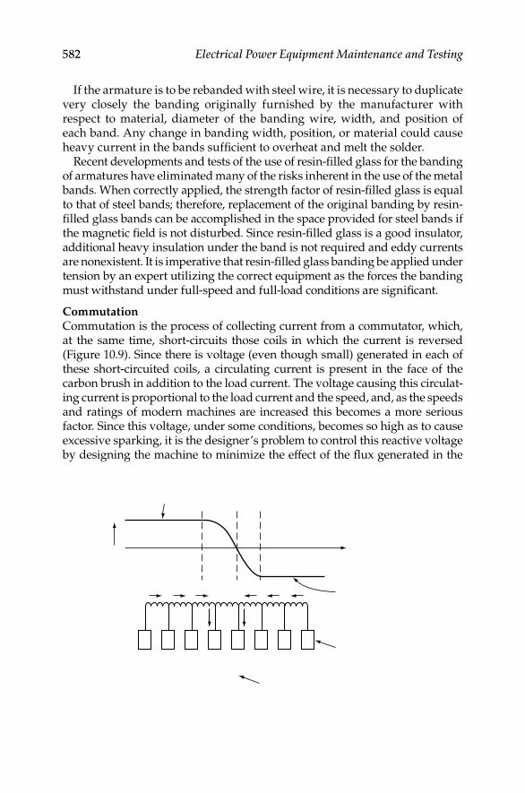
582 Electrical Power Equipment Maintenance and Testing
If the armature is to be rebanded with steel wire, it is necessary to duplicate very closely the banding originally furnished by the manufacturer with respect to material, diameter of the banding wire, width, and position of each band. Any change in banding width, position, or material could cause heavy current in the bands suffi cient to overheat and melt the solder.
Recent developments and tests of the use of resin-fi lled glass for the banding of armatures have eliminated many of the risks inherent in the use of the metal bands. When correctly applied, the strength factor of resin-fi lled glass is equal to that of steel bands; therefore, replacement of the original banding by resin-fi lled glass bands can be accomplished in the space provided for steel bands if the magnetic fi eld is not disturbed. Since resin-fi lled glass is a good insulator, additional heavy insulation under the band is not required and eddy currents are nonexistent. It is imperative that resin-fi lled glass banding be applied under tension by an expert utilizing the correct equipment as the forces the banding must withstand under full-speed and full-load conditions are signifi cant.
CommutationCommutation is the process of collecting current from a commutator, which, at the same time, short-circuits those coils in which the current is reversed (Figure 10.9). Since there is voltage (even though small) generated in each of these short-circuited coils, a circulating current is present in the face of the carbon brush in addition to the load current. The voltage causing this circulat-ing current is proportional to the load current and the speed, and, as the speeds and ratings of modern machines are increased this becomes a more serious factor. Since this voltage, under some conditions, becomes so high as to cause excessive sparking, it is the designer’s problem to control this reactive voltage by designing the machine to minimize the effect of the fl ux generated in the
A
Brush
Commutator bars
Current in right-handside coils
Current in left-handside coils
+ Time
Curr
ent
Direction of rotation
FIGURE 10.9Coil A undergoing commutation.
DK4058_C010.indd 582DK4058_C010.indd 582 11/8/2008 12:19:35 PM11/8/2008 12:19:35 PM

Motors and Generators 583
armature circuit and by the judicious use of commutating poles, sometimes called interpoles. Successful commutation also requires a good continuous contact between the brush and the commutator surface.
It is obvious that successful commutation is not a function of the brush alone or of the commutator or electrical circuit alone but results from optimum electrical and mechanical brush-to-commutator conditions, and the correct electromechanical position of the brush rigging.
Commutation is such a complex problem that it is necessary to keep the many adverse variables at a minimum. Commutation may be adversely affected by dust, dirt, gases, oil vapor, and the like, and varying atmospheric conditions such as high temperature or low humidity. Where a commutation problem exists owing to one or more of these ambient conditions, it is sometimes possible to arrive at a solution by altering the unit to offset the condition. If the commutation of a unit is not satisfactory and a change in brush grade is indicated, the manufacturer should be consulted. However, in general, this is not a true solution.
The mechanical condition of the unit can also greatly affect commutation. Commutators should be periodically checked for high bars, which will cause fl ashing and generally poor commutation. Both commutators and slip rings should be smooth, round, and concentric with the axis of rotation. If there is any appreciable vibration, the cause should be determined and corrected.
Some of the most common service problems with commutator are shown in the commutator check chart (Figure 10.10). Frequent visual inspection of the commutator can indicate when any of the conditions shown in the Figure 10.10 are developing so that corrective actions can be taken. The causes of poor commutator condition are shown in Table 10.6.
Frequent visual inspection of commutator surfaces can warn you when any of the above conditions are developing so that you can take early corrective action. Table 10.6 may indicate some possible causes of these conditions, sug-gesting the correct maintenance. There are several causes of commutator prob-lems. High commutator bars generally produce sparking, noisy operation, and chipped or broken brushes. The causes are usually a loose com mutator, incor-rect undercutting, open or high resistance connections, or electrical shorts. Streaking or threading of the commutator surface causes rough surfaces with associated sparking. Primary faults can be
Low average current density in brushes due to light machine loading•
Contaminated atmosphere•
Oil on commutator or oil mist in air•
Low humidity•
Lack of fi lm-forming properties in brush•
Brushes too abrasive•
Bar etching or burning produces a rough commutator with associated spark-ing and eventual fl ashover. Such burning often results from
DK4058_C010.indd 583DK4058_C010.indd 583 11/8/2008 12:19:35 PM11/8/2008 12:19:35 PM
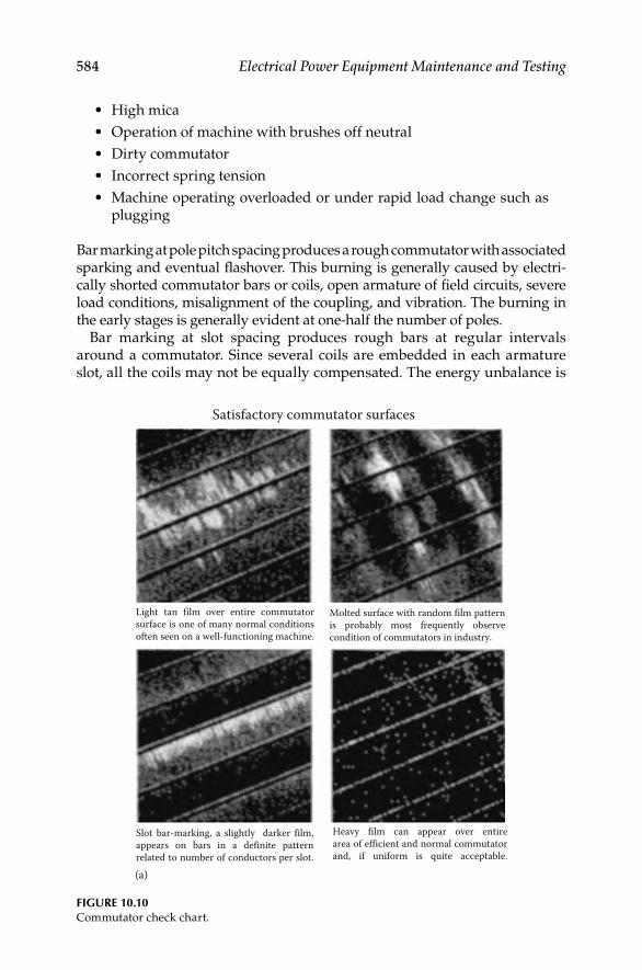
584 Electrical Power Equipment Maintenance and Testing
High mica•
Operation of machine with brushes off neutral•
Dirty commutator•
Incorrect spring tension•
Machine operating overloaded or under rapid load change such as • plugging
Bar marking at pole pitch spacing produces a rough commutator with associated sparking and eventual fl ashover. This burning is generally caused by electri-cally shorted commutator bars or coils, open armature of fi eld circuits, severe load conditions, misalignment of the coupling, and vibration. The burning in the early stages is generally evident at one-half the number of poles.
Bar marking at slot spacing produces rough bars at regular intervals around a commutator. Since several coils are embedded in each armature slot, all the coils may not be equally compensated. The energy unbalance is
FIGURE 10.10Commutator check chart.
(a)
Satisfactory commutator surfaces
Light tan film over entire commutatorsurface is one of many normal conditionsoften seen on a well-functioning machine.
Molted surface with random film pattern is probably most frequently observe condition of commutators in industry.
Slot bar-marking, a slightly darker film, appears on bars in a definite pattern related to number of conductors per slot.
Heavy film can appear over entirearea of efficient and normal commutatorand, if uniform is quite acceptable.
DK4058_C010.indd 584DK4058_C010.indd 584 11/8/2008 12:19:35 PM11/8/2008 12:19:35 PM
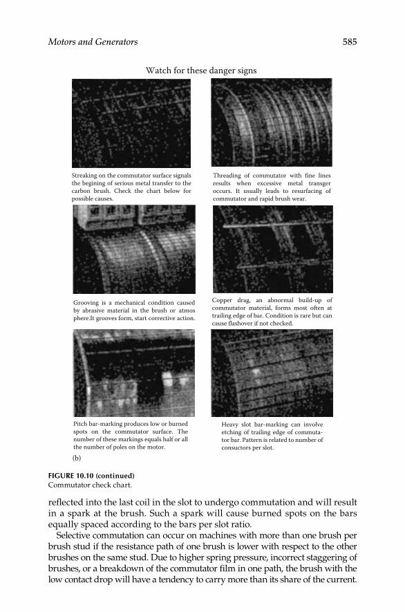
Motors and Generators 585
refl ected into the last coil in the slot to undergo commutation and will result in a spark at the brush. Such a spark will cause burned spots on the bars equally spaced according to the bars per slot ratio.
Selective commutation can occur on machines with more than one brush per brush stud if the resistance path of one brush is lower with respect to the other brushes on the same stud. Due to higher spring pressure, incorrect staggering of brushes, or a breakdown of the commutator fi lm in one path, the brush with the low contact drop will have a tendency to carry more than its share of the current.
FIGURE 10.10 (continued)Commutator check chart.
Watch for these danger signs
(b)
Streaking on the commutator surface signals the begining of serious metal transfer to the carbon brush. Check the chart below for possible causes.
Grooving is a mechanical condition causedby abrasive material in the brush or atmosphere.It grooves form, start corrective action.
Threading of commutator with fine lines results when excessive metal transger occurs. It usually leads to resurfacing of commutator and rapid brush wear.
Copper drag, an abnormal build-up of commutator material, forms most often at trailing edge of bar. Condition is rare but can cause flashover if not checked.
Pitch bar-marking produces low or burned spots on the commutator surface. The number of these markings equals half or all the number of poles on the motor.
Heavy slot bar-marking can involve etching of trailing edge of commuta-tor bar. Pattern is related to number of consuctors per slot.
DK4058_C010.indd 585DK4058_C010.indd 585 11/8/2008 12:19:35 PM11/8/2008 12:19:35 PM

586 Electrical Power Equipment Maintenance and Testing
TAB
LE 1
0.6
Cau
ses
of
Po
or
Co
mm
uta
tor
Co
nd
itio
n
Ty
pe o
f B
rush
in
Use
Co
nta
min
ati
on
Ele
ctri
cal
Eq
uip
men
t
Ele
ctri
cal
Ov
erl
oad
Lig
ht
Ele
ctri
cal
Ov
erl
oad
Arm
atu
re
Co
nn
ect
ion
Un
bala
nce
d
Sh
un
t F
ield
Bru
sh
Pre
ssu
re
(Lig
ht)
Vib
rati
on
Ab
rasi
ve
Bru
sh
Pero
us
Bru
shG
as
Pero
us
Du
st
Str
eak
ing
XX
XX
XX
Th
read
ing
XX
XX
Gro
ov
ing
XX
Co
op
er d
rag
XX
XX
Pit
ch b
ar-
mark
ing
XX
XX
X
Slo
t b
ar-
mark
ing
XX
X
DK4058_C010.indd 586DK4058_C010.indd 586 11/8/2008 12:19:36 PM11/8/2008 12:19:36 PM

Motors and Generators 587
The exposed portion of the front vee-ring insulation is normally the target for moisture, oil, and dirt, which may cause fl ashovers and breakdowns to ground. It is, therefore, essential that the exposed surface of the mica be kept clean and protected by means of other insulation. There are various ways to apply extra insulation at this point, depending upon the individual ideas of the machine designer. In general, however, this consists of a cord or tape of cotton or glass wound in tight layers over the surface of the exposed section of the mica cone or veering. The exposed surface is then treated with several coats of varnish suitable for the operating temperature of the machine. These multiple coats of varnish are applied to obtain a smooth, easily clean-able surface. The purpose is to obtain extra insulation that will protect the vee-ring insulation and, so far as possible, seal the joint between the commutator bars and the vee ring.
10.9.3.4 Field Windings
If the fi eld winding of any type of DC motor is open circuited, the motor will fail to start or it will operate at excessive speed at light loads and serious sparking will occur at the commutator. It should not be concluded that a fi eld is defective until rheostats, switches, and other devices in the motor circuit have been carefully inspected.
To check for grounded fi elds, a conventional high-potential transformer may be used. If the fi eld circuit is free of grounds and shorted shunt fi eld is suspected, comparative resistance measurements should be made of the individual coils and compared with the resistance of a similar coil that is known to be in good condition. Such a comparative check should preferably be made when the fi eld windings are hot or near their normal operating temperature. A shunt fi eld coil may show the correct resistance when it is cold but may show a lower value when it is hot or near its normal operating temperature. This is due to defective insulation between turns of adjacent conductors, and short circuits may not occur until expansion has taken place because of the increased temperature. If the correct resistance value of good coils is not known, comparative checks made with either a Wheatstone bridge or by the voltmeter method will usually provide a reliable indication of shunt fi eld resistance. If neither a bridge nor an ammeter is available, a check as to the condition of the coils may be obtained by connecting all shunt coils in series to a source of constant potential and measuring the voltage drop across individual coils. For short circuits in series and commutating fi eld coils, where the resistance is necessarily low, the use of more sensitive instruments may be necessary to detect defects.
A common cause of fi eld coil failure is overheating, which may result from the following:
Operation of the machine at low speed, preventing correct ventilation•
Full fi eld current left on the machine continuously while it is shutdown•
DK4058_C010.indd 587DK4058_C010.indd 587 11/8/2008 12:19:36 PM11/8/2008 12:19:36 PM

588 Electrical Power Equipment Maintenance and Testing
Excitation voltage too high•
Overloading machine•
High ambient temperature•
Faulty performance, indicated by poor commutation, incorrect speed, and overheating, is frequently traceable to defective fi eld coils or to incorrectly connected fi eld windings.
In removing a shunt or series fi eld coil, the coil should be disconnected from the adjacent coils, and the bolts that secure the pole pieces to the frame should be removed. This will make it possible to remove the pole piece and coil, after which the pole piece, with a new or reinsulated coil, can be installed. Particular care should be taken in replacing the pole with its coil to be sure that the same steel or nonmagnetic shims between the frame and the back of the pole are in the same position to ensure the same air gap that was present in the machine when it was new.
When reconnecting the coil, the correct polarity must be maintained. A simple means of testing the polarity is by the use of a compass, a magne-tized needle, or a piece of magnetized steel wire suspended from the middle by a string. The polarity should be alternatively north and south around the frame. When the compass needle is brought within the magnetic fi eld of any pole, one end of the needle will point toward this pole and this end should be repelled by the next pole, and so on around the frame. If this rever-sal of the needle does not occur, there is a faulty connection of one or more of the fi eld coils.
Since there is a possibility of reversing the poles of a compass with a strong fi eld, similar results can be obtained by putting the compass on a work bench, placing a steel scale against the pole of the machine, and then setting the scale against the compass. The readings will, of course, be reversed as compared to the direct reading with a compass.
10.9.4 Induction Motor
There are two types of AC induction motor construction: squirrel cage and wound rotor. Stator design is the same for both; they differ mainly in rotor design. There are no external rotating or secondary connections on a squir-rel-cage motor; most wound rotors have three-phase winding connected through collector rings to an adjustable secondary resistance.
Today’s induction motor, especially the squirrel-cage type, is a highly effi cient machine whose periods of trouble-free service can be considerably prolonged by systematic care. Correct application and installation will mini-mize maintenance requirements.
Essentially, maintenance of squirrel-cage induction motors centers on the stator windings and bearings. Rotors require little or no special care in normal service, except to make certain that bolts or other fasteners remain tightly secured. For wound-rotor types, rotor construction with the associated brush rigging requires additional maintenance.
DK4058_C010.indd 588DK4058_C010.indd 588 11/8/2008 12:19:36 PM11/8/2008 12:19:36 PM
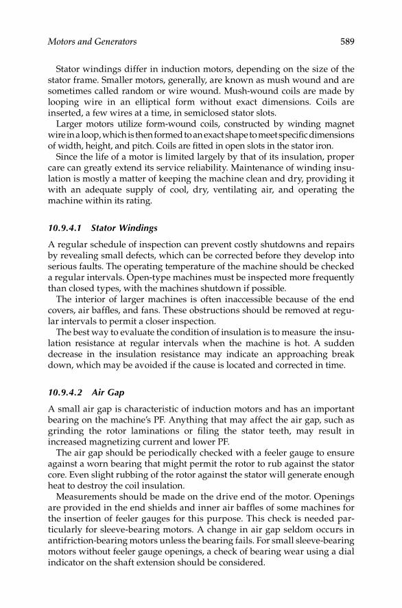
Motors and Generators 589
Stator windings differ in induction motors, depending on the size of the stator frame. Smaller motors, generally, are known as mush wound and are sometimes called random or wire wound. Mush-wound coils are made by looping wire in an elliptical form without exact dimensions. Coils are inserted, a few wires at a time, in semiclosed stator slots.
Larger motors utilize form-wound coils, constructed by winding magnet wire in a loop, which is then formed to an exact shape to meet specifi c dimensions of width, height, and pitch. Coils are fi tted in open slots in the stator iron.
Since the life of a motor is limited largely by that of its insulation, proper care can greatly extend its service reliability. Maintenance of winding insu-lation is mostly a matter of keeping the machine clean and dry, providing it with an adequate supply of cool, dry, ventilating air, and operating the machine within its rating.
10.9.4.1 Stator Windings
A regular schedule of inspection can prevent costly shutdowns and repairs by revealing small defects, which can be corrected before they develop into serious faults. The operating temperature of the machine should be checked a regular intervals. Open-type machines must be inspected more frequently than closed types, with the machines shutdown if possible.
The interior of larger machines is often inaccessible because of the end covers, air baffl es, and fans. These obstructions should be removed at regu-lar intervals to permit a closer inspection.
The best way to evaluate the condition of insulation is to measure the insu-lation resistance at regular intervals when the machine is hot. A sudden decrease in the insulation resistance may indicate an approaching break down, which may be avoided if the cause is located and corrected in time.
10.9.4.2 Air Gap
A small air gap is characteristic of induction motors and has an important bearing on the machine’s PF. Anything that may affect the air gap, such as grinding the rotor laminations or fi ling the stator teeth, may result in increased magnetizing current and lower PF.
The air gap should be periodically checked with a feeler gauge to ensure against a worn bearing that might permit the rotor to rub against the stator core. Even slight rubbing of the rotor against the stator will generate enough heat to destroy the coil insulation.
Measurements should be made on the drive end of the motor. Openings are provided in the end shields and inner air baffl es of some machines for the insertion of feeler gauges for this purpose. This check is needed par-ticularly for sleeve-bearing motors. A change in air gap seldom occurs in antifriction-bearing motors unless the bearing fails. For small sleeve-bearing motors without feeler gauge openings, a check of bearing wear using a dial indicator on the shaft extension should be considered.
DK4058_C010.indd 589DK4058_C010.indd 589 11/8/2008 12:19:36 PM11/8/2008 12:19:36 PM

590 Electrical Power Equipment Maintenance and Testing
A record of air gap checks should be kept, especially on larger machines. Four measurements should be taken approximately 90° apart. One point of the measurements should be made in the direction of load. A comparison of periodic measurements will permit early detection of bearing wear.
10.9.4.3 Wound-Rotor Windings
Rotor windings of wound-rotor motors have many features in common with stator windings, and the same comments apply to their care and mainte-nance. However, the rotor requires additional consideration because it is a rotating element.
Most wound rotors have a three-phase winding and are susceptible to trouble from single-phase operation and open circuits. The fi rst symptoms of these faults are lack of torque, slowing down in speed, growling noise, or perhaps failure to start the load.
The fi rst place to look for an open secondary circuit is in the resistance or the control circuit external to the rotor. Short-circuiting the rotor circuit at the slip rings and then operating the motor will usually determine that the trouble is in the control circuit or in the rotor itself.
Some rotors are wave wound, with windings made up of copper strap coils with clips connecting the top and bottom halves of the coil. These end con-nections should be inspected for possible signs of heating, which could be an indication of a partial open circuit. Faulty end connections are a common source of open circuits in rotor windings. The open circuit may be at one of the stud connections to the collector rings.
A ground in a rotor circuit will not affect motor performance except that in combination with another ground, it might cause the equivalent of a short circuit. This would have the effect of unbalancing the rotor electrically. Reduced torque is a symptom; others might be excessive vibration of the motor, sparking, or uneven wear of the collector rings. A test for this condi-tion can be made with a megohmmeter.
Another fairly successful method of checking for short circuits in the rotor windings is to raise the brushes off the collector rings and energize the stator. A rotor winding that is free from short circuits should have little or no tendency to rotate, even when disconnected from the load. If there is evidence of considerable torque or a tendency to come up to speed, the rotor should be removed and the winding opened and examined for the fault. In making this test, it should be noted that some rotors having a wide tooth design may show a tendency to rotate even though the windings are in good condition.
With the rotor in place, the stator energized, and the brushes raised, the voltages across the collector rings should be check to see if they are balanced. These voltages bear no particular relation to the line voltage and may be con-siderably higher. For example, they may be as high as 500 for a 200 V stator. To make sure that any inequality in voltage measurements is not due to the
DK4058_C010.indd 590DK4058_C010.indd 590 11/8/2008 12:19:36 PM11/8/2008 12:19:36 PM

Motors and Generators 591
relative positions of the rotor and stator phases, the rotor should be moved to several positions in taking these voltage measurements.
10.9.4.4 Brushes and Rings
Brushes and collector rings on wound rotors need special care. Although a certain amount of wear is inevitable, conditions that lead to grooving of rings (concentration of wear in narrow rings or ruts) should be prevented, and abrasive dust should be wiped off the rings at regular intervals.
Rough or uneven ring surfaces should be remedied as soon as possible, before sparing, pitting, and accelerated brush wear result. Allowing the rotor to oscillate axially will distribute wear more evenly. Unevenly worn brushes should be replaced to assure best operation.
10.9.4.5 Centrifugal Switches
Basically, all single-phase motors are designed with a special arrangement of winding for starting. To accomplish this, some method is used to automati-cally change the electrical connections of a motor. This may be one of the following:
Starting and running windings, with centrifugally operated switches • to disconnect the starting winding.
Central switch to disconnect or change capacitor circuits.•
Potential relay (occasionally used instead of centrifugal switches).•
Repulsion-induction-type motor with wound rotor and commutator, • which utilizes a centrifugally operated switch to short-circuit the commutator at a predetermined speed.
Repulsion-inductor-type motor with wound rotor and commutator • and a squirrel-cage rotor winding that automatically come into use near full speed needs no transfer device.
It is usually more practical to replace defective centrifugal switches than to repair them.
10.9.4.6 Squirrel-Cage Rotors
Squirrel-cage rotors are more rugged and, in general, require less mainte-nance than wound rotors. Open circuits or high-resistance joints between the end rings and the rotor bars may give trouble. The symptoms of such conditions are generally the same as with wound-rotor motors, that is, slow-ing down under load and reduced starting torque. Look for evidence of heat-ing at the end ring connections, particularly when shifting down after operating under load.
DK4058_C010.indd 591DK4058_C010.indd 591 11/8/2008 12:19:36 PM11/8/2008 12:19:36 PM
592 Electrical Power Equipment Maintenance and Testing
Fractures in the rotor bars usually occur between the point of connection to the end and the point where the bar leaves the laminations. Discolored rotor bars are evidence of excessive heating.
Brazing or replacing broken bars requires considerable skill. Unless a capa-ble serviceman is available, the manufacturer or an experienced service shop should be consulted before attempting such repairs at the plant.
10.9.5 Synchronous Motors and Generators
The stator of a synchronous machine requires approximately the same care as the stator of an induction motor. In large-sized synchronous machines, the windings are generally more accessible and this facilitates cleaning.
The rotor fi eld coils of a synchronous machine should be cleaned in the same manner as the fi eld coils on a DC machine. Slow-speed synchronous machines have rotor poles held by the spider with studs and nuts, while in high-speed synchronous machines a dovetail construction is utilized with tapered wedges securing the poles.
Some synchronous machines have the poles bolted to the shaft using bolts through the poles. Some 400-cycle synchronous generators utilize a lami-nated fi eld structure with coils placed in slots, each tooth representing a pole. Following is a general maintenance guide for synchronous motors:
During any general overhaul, the nuts on the studs or the wedges for • the dovetail poles should be check for looseness. The amortisseur winding should be checked for loose or cracked connections.
In dusty installations where collector ring enclosures are not used, • the collector rings and brush holders should be blown off weekly with clean dry air. When oil deposits form on the collector ring or brush holder insulation, it should be cleaned by wiping with a suit-able solvent and coated with a high-gloss insulating varnish. When cleaning the brush holders, the brushes should be removed to pre-vent their absorbing the solvent.
Coat all insulated surfaces of the brush holders and slip rings with a • high-gloss insulating varnish. Caution should be exercised. Do not coat brush contact surfaces of the slip rings.
If the collector rings become eccentric, grooved, pitted, or deeply • scratched, this condition can best be corrected by grinding the rings with a rotating-type grinder, with the machine running at rated speed in its own bearing. Fine emery cloth or sandpaper should be used for light scratches on iron or steel rings but not on bronze rings.
Regardless of the method used, rings, should be polished to a high • gloss with crocus cloth and oil. After polishing, the rings should be thoroughly cleaned with a solvent to remove all abrasives and for-eign materials.
DK4058_C010.indd 592DK4058_C010.indd 592 11/8/2008 12:19:37 PM11/8/2008 12:19:37 PM

Motors and Generators 593
In as much as the wear due to electrochemical action is not the same • on both the positive and negative collector rings, it is suggested that the polarity be reversed about every 3 months of operation to com-pensate for this condition.
Field current specifi ed on the nameplate should not be exceeded for • continuous operation.
10.9.6 Cleaning and Varnishing of Machine Windings
The life of a winding depends upon keeping it in its original condition as long as possible. In a new machine, the winding is snug in the slots, and the insulation is fresh and fl exible and has been treated to be resistant to the deteriorating effects of moisture and other foreign matter.
Moisture is one of the most subtle enemies of the machine insulation. Insulation should be kept clean and dry. Certain modern types of the insula-tion are inherently moisture proof and require infrequent varnish treatment, but the great majority, if exposed to a damp atmospheric place, should be given special moisture-resisting treatment.
One condition that frequently hastens winding failure is movement of the coils caused by vibration during operation. After insulation dries out, it loses its fl exibility. Mechanical stresses caused by starting and plugging, as well as natural stresses in operation under load, sometimes precipitate short circuits in the coils and possibly failures from coil to ground, usually at the point where the coil leaves the slot.
Periodic varnish treatment and curing, correctly done so as to fi ll all spaces caused by drying and shrinkage of the insulation, will provide an effective seal against moisture and should be a matter of routine electrical mainte-nance. Varnish treatment and curing of rotating electrical equipment follow a logical procedure.
10.9.6.1 Cleaning
Some machines are exposed to accumulations of materials, such as talc, lint, or cement dust, which although harmless by themselves may obstruct the ventilation. The machine will then operate at higher temperatures than normal, and the life of the insulation will be decreased. Such materials can sometimes be blown out with clean dry compressed air.
The most harmful types of foreign materials include carbon black, metallic dust and chips, and similar substances that not only impair the ventilation but also form a conductive fi lm over the insulation and increase the possibil-ity of insulation failure. Metallic chips may also work themselves into the insulation because of the ventilation and magnetic fi elds. When windings are cleaned, inspection should be made for any signs of deterioration.
Epoxy-encapsulated windings, a construction fi nding increasing favor, are sealed against contaminants. They need little attention other than
DK4058_C010.indd 593DK4058_C010.indd 593 11/8/2008 12:19:37 PM11/8/2008 12:19:37 PM

594 Electrical Power Equipment Maintenance and Testing
removing dirt accumulations. The common practice when such windings are damaged is replacement with a new winding.
It is extremely important that all wound stators and rotors be perfectly clean before varnish treatment and curing. Unless all conducting dirt and grease are removed, the varnish treatment will not be fully effective. Also, after varnish treatment, the leakage path caused by conducting materials will be diffi cult to uncover and remove. Correct cleaning involves the following steps:
Dirt should be removed from all coil surfaces and mechanical parts. • Air vent ducts should be clear. As an alternative, clean, dry air at a pressure of not more than 50 psi may be used. Higher air pressure may damage windings. Do not use air if dust from the machine can damage critical equipment nearby.
As much oil, grease, and dirt as possible should be removed by • wiping the windings with clean, dry cloths and then with clean cloths that have been moistened with a solvent recommended by the coil manufacturer. If the original varnish on the windings is cracked, a brush should be dipped in solvent and used to clean all conducting particles from the cracks.
For cleaning, armatures or wound rotors should be placed in a vertical • position with the commutator or collector ring end up, and a pressure spray gun with solvent should be used to clean under the collecting device and through vent holes. The same procedure should be repeated with the opposite end up, and then repeated again with the commuta-tor or collector ring end up. Most large DC armatures are ventilated through open commutator risers at the front end. The solvent spray should be directed through these risers to reach the inner surface of the armature coils and inner commutator vee-ring extensions.
Silicone-insulated equipment can be cleaned by the same methods • used with other insulation systems. If a liquid cleaner is found to be necessary, the recommendations of the coil manufacturer should be followed.
For windings other than silicone, there are a number of good com-• mercial cleaners on the market. The manufacturer can recommend the one most suitable for the conditions. Plant safety rules concerning the use of fl ammable and toxic solvent should be observed and followed.
Caution should be exercised to remove all liquid cleaners.•
10.9.6.2 Drying
The wound apparatus should be dried in an oven held at a temperature of 115°C–125°C (239°F–257°F) for 6–12 h or until the insulation resistance becomes practically constant. If a vacuum is used, the drying time may be reduced.
DK4058_C010.indd 594DK4058_C010.indd 594 11/8/2008 12:19:37 PM11/8/2008 12:19:37 PM

Motors and Generators 595
The apparatus should be brought up to temperature slowly because excessive moisture may be present in the windings. If heated rapidly, this moisture may vaporize quickly enough to rupture the insulation.
Before treatment, the apparatus should be cooled to within 10°C (50°F) above room temperature, but never to a temperature lower than 25°C (77°F). If the apparatus is cooled to room temperature and allowed to stand, it will take up moisture quickly. If placed in the varnish at a temperature higher than that specifi ed, the varnish will tend to harden.
10.9.6.3 Varnish
The selection of varnish is dependent upon the operating conditions to which the motor is subjected; also, the type of environmental conditions (i.e., mois-ture, corrosion, chemical, abrasion) should be taken into consideration.
Varnish must be compatible with the insulation system with which it is to be used. If it is incompatible, it may not adhere and may not give the desired protection. For most applications, the selection of a general-purpose high bonding, yet resilient, synthetic resin varnish is recommended. The varnish can be either class A, B, or F, depending upon the insulation system rating. On large AC stators using class A insulation, the use of a fl exible asphalt or oleoresinous varnish is suggested; then, if it becomes necessary to lift a coil, the coil will not be destroyed.
Many types of varnishes are available, and when applying the insulating varnish, the recommendation of the manufacturer should be followed with respect to specifi c gravity, viscosity, and curing cycle for the particular var-nish in question. After the varnish has been adjusted to give the desired fi lm build and drainage characteristics, the specifi c gravity and viscosity read-ings should be recorded; then at periodic intervals the varnish should be examined for either specifi c gravity or viscosity, or both, and adjustments should be made to bring it within the original limits.
The units should be cured in a correctly ventilated forced-air circulating oven to remove the solvent vapors. The oven can be either gas fi red or electri-cally heated. Infrared heat can be used if desired.
For the most part, the time and temperature of the cure should follow the varnish manufacturer’s recommendations. The time of cure will vary from short bakes of several hours up through 16–24 h, based on the physical dimensions and makeup of the units, and taking into consideration the particular characteristics of the type of varnish that has been applied to the equipment.
Curing temperatures will vary from 75°C to 125°C (167°F to 257°F) for oleoresinous-type varnishes to 135°C to 155°C (275°F to 311°F) for classes B and F varnishes. Silicone varnishes usually require a cure temperature range of 185°C–200°C (365°F–392°F) or higher.
Complete rewinding jobs should receive at least two coats of varnish. Baking time can usually be reduced on the fi rst or impregnated coat, with an extended period of time used on the fi nal coat. The use of additional
DK4058_C010.indd 595DK4058_C010.indd 595 11/8/2008 12:19:37 PM11/8/2008 12:19:37 PM

596 Electrical Power Equipment Maintenance and Testing
coats is based on what is expected of the unit after it is in operation. If severe conditions are to be encountered, multiple-coat systems are recommended. Also, apparatus such as high-speed armatures should receive multiple coats for the maximum bonding of the conductors. One coat is all that is neces-sary on older units that have been cleaned up on which no rewind work has been done.
In the case of large stators or rotors where the size is such that dipping is not possible, the varnish must be sprayed on the windings. Old winding surfaces must be completely coated.
For most applications, conventional dip methods are recommended. Other accepted methods are brushing and fl ooding. However, if the length or depth of the slots is great and the windings tightly packed, it may be necessary to use a vacuum impregnation system.
10.9.7 Lubrication, Bearings, and Oil Seals
10.9.7.1 Lubrication
Of all the important items of maintenance, lubrication ranks as one of the highest. Incorrect oiling or greasing will produce as disastrous results as any other type of motor mistreatment.
Excess oil may get into the windings where it will collect dust and other foreign matter. Too much grease in antifriction bearings causes heat and sometimes failure of bearings and may also coat the windings. Most manu-facturers furnish data on correct oiling and greasing, and numerous articles have been written on the subject. The important point is to set up a defi nite lubrication schedule and follow it. Years of experience have demonstrated that it is as bad to use too much as too little oil and grease.
Of equal importance is the type of oil or grease used. In general, the rec-ommendations of the manufacturer or experienced oil companies should be followed. In some cases, for design reasons, manufacturers insist on the use of particular lubricants that have been adopted after exhaustive test by the manufacturer. It will pay to follow these recommendations.
10.9.7.2 Sleeve Bearings
Some oil-lubricated machines are shipped without oil and, in the case of large machines, the journals are often packed and treated for protection during shipment. The rotating elements may also be blocked to prevent damage to the bearings and journals during shipment. Where lubrication is required, the bearing must be opened, the packing removed, and the journal cleaned and fl ushed before fi lling the housing with oil. All motor and gen-erator bearings should be checked for oil before starting up.
The bearings of all electrical equipment should be carefully inspected at scheduled periodic intervals in order to obtain maximum life. The frequency of inspection, including the addition of oil, changing the oil, and checking
DK4058_C010.indd 596DK4058_C010.indd 596 11/8/2008 12:19:37 PM11/8/2008 12:19:37 PM

Motors and Generators 597
the bearing wear, is best determined by a study of the particular operating conditions. If makeup oil is required in excessive amounts, an investigation for oil leaks should be started immediately.
The more modern types of sleeve-bearing housings are relatively dust and oil tight and require very little attention, since the oil does not become con-taminated and oil leakage is negligible. Maintenance of the correct oil level is frequently the only upkeep required for years of service with this type of bearing.
Older types of sleeve bearings require more frequent inspection and check-ing for wear, and oil changes should be made more often. Never add oil to bearings when the machine is running.
In most cases, the safe temperature rise for a bearing is considered to be within 40°C above the room ambient.
Small sleeve-bearing motors use either wool packing or fl uid wick for transferring the lubricant to sleeve bearings instead of oil-ring lubrication. Some of these small motors have provision for relubrication.
When electrical equipment must operate under extreme differences in air temperatures, the use of a lighter oil may be found desirable during cold weather.
Care should always be exercised in the use of reclaimed lubricating oils. The fi ltering operation should be positive and should remove all foreign and injurious matter.
A hot bearing is usually due to one of the following causes:
No oil.•
Poor grade of oil or dirty oil.•
Failure of the oil rings to revolve with the shaft.•
Excessive belt tension.•
Rough bearing surface.•
Incorrect fi tting of the bearing.•
Bent shaft.•
Misalignment of shaft and bearing.•
Loose bolts in the bearing cap.•
Excessive end thrust due to incorrect leveling. A bearing may become • warm because of excessive pressure exerted by the shroud of the shaft against the end of the bearing.
Excessive end thrust due to magnetic pull, with the rotating part being • sucked into the stator or fi eld because it extends farther beyond the magnetic structure or fi eld poles at one end than at the other end.
Excessive side pull because the rotating part is out of balance.•
If bearing becomes hot, the load should be reduced if possible and lubricants fed freely, loosening the nuts on the bearing cap. If the machine is belt
DK4058_C010.indd 597DK4058_C010.indd 597 11/8/2008 12:19:37 PM11/8/2008 12:19:37 PM

598 Electrical Power Equipment Maintenance and Testing
connected, the belt should be slackened. In case relief is not afforded, the load should be removed and the machine kept running slowly, where pos-sible, until the shaft is cool in order that the bearing will not freeze. The oil supply should be renewed before starting the machine again.
A new machine should always be run unloaded or at slow speed for an hour or so to make sure that it operates correctly. The bearings should be carefully watched to observe that the oil rings revolve and carry a plentiful supply of oil to the shaft.
10.9.7.3 Antifriction Bearings
Ball or roller bearings carry the load by direct contact, as opposed to sleeve bearings, which carry the load on lubricating fi lm. Lubrication is necessary to minimize the friction and generation of heat caused by the balls rubbing on the outer race as they roll over the top or on the retainer of the cage.
Antifriction bearings require considerable care to prevent loss of end clearance, distortion of balls, and marking of races. If too much force is used in pressing the bearing on the shaft, the clearance may be destroyed. It is recommended that antifriction bearings be heated in a hot bath of clean oil rather than by the use of dry heat. When the bearing is pulled off, with all the stress on the outer race, both races may be damaged, with resultant failure when put back in service. The bearing manufacturer’s recommen-dations should be followed when removing and reapplying this type of bearing.
Bearing manufacturers produce a bearing known as the prelubricated shielded bearing. Several years use of this bearing has demonstrated that, for many applications, no further lubrication is needed. Such bearing construc-tion is usually indicated on the nameplate.
In general, to obtain maximum service, ball-bearing motors should be relubricated at intervals determined by the type, size, and service of the bearing. Many motor manufacturers offer as a guide a table suggesting the intervals between lubrication. These tables show time intervals between greasing that range from 3 months or so for motors operating in very severe service, as in conditions involving dirt or vibrating applications, those where the end of the shaft is hot, or subject to high ambient temperatures, to inter-vals of up to 3 years for easy service, where motors operate for short periods or infrequently.
The bearing housing is usually arranged to introduce new grease and purge the bearing of old grease, allowing it to discharge through a partially restricted escape port or relief hole. This will, in general, allow fi lling to the desired degree, which is one-third to one-half full, leaving some space in the housing to allow for expansion of the grease.
It is again stressed that overgreasing can be just as harmful as undergreas-ing. Overgreasing causes churning and internal friction that can result in heating, separation of the oil and soap, oxidation of the grease, and possible leakage through the retaining seals.
DK4058_C010.indd 598DK4058_C010.indd 598 11/8/2008 12:19:37 PM11/8/2008 12:19:37 PM

Motors and Generators 599
10.9.7.4 Installation of Oil Seals
The importance of correctly installing an oil seal cannot be overemphasized. Failure to observe correct installation procedures probably accounts for more cases of the incorrect functioning of oil seals than any other single cause. To secure the ultimate in satisfactory service, it is recommended that the following precautions be observed.
Correct sealIt is essential that the seal be the correct size for the installation. Oil seals are made for a specifi ed shaft size. When they are installed on a shaft of a larger diameter, there will be drag, frictional heat, and excessive wear on the seal-ing element and shaft. When installed on a shaft having a smaller diameter, immediate leakage can occur.
Fluid contactThe seal should be assembled with the toe or wiping edge of the sealing ele-ment pointing toward the fl uid to be retained. Exceptions for unusual appli-cations must be by specifi cation in manuals or instructions furnished with the assembly.
BoreThe bore should be checked for adequate chamfer (30° angle to a minimum depth of 1/16 in.). The bore should be inspected for scratches and all sharp edges removed. The seal outside diameter should be correct for the bore in the assembly. When a leak at the outer edge of either metal or rubber-covered seals is caused by abrasion of the oil seal, it may be directly related to incor-rect chamfer on the bore of the use of incorrect installation tools.
ShaftThe surface of the shaft should be uniform and free from burrs, nicks, scratches, and grooves. The surface fi nish should be between 10 and 20 μin. and, on a repair job, should be buffed to this thickness with crocus cloth.
LubricationIn all cases, a lubricant should be applied to the shaft or to the sealing element of the oil seal. This aids installation and reduces heat buildup during the fi rst few minutes of run. The application of a lubricant to the outer periphery of a syn-thetic rubber-covered seal will reduce the possibility of shearing or bruising.
Pressing toolsIn pressing the seal into the bore, it is imperative that the correct-sized press-ing tool be used to localize the pressure on the face of the seal and in direct line with the side walls of the seal case to prevent damage and distortion to the seal cases during the installation. When a seal must penetrate the bore below the surface, the correct pressing tool should be 1/32 in. smaller than the bore diameter. On installations where the seal is fl ush with the housing, the correct pressing tool should be at least 1/8 in. larger in diameter, and more if room permits. Care should be taken to avoid hammer blows, uneven pressure on seal surfaces, and cocking of the seal during this operation.
DK4058_C010.indd 599DK4058_C010.indd 599 11/8/2008 12:19:37 PM11/8/2008 12:19:37 PM

600 Electrical Power Equipment Maintenance and Testing
When an oil seal of open channel construction is pressed-fi t heel fi rst into the bore, an installation tool will be helpful. The tool is designed to have contact with the inside diameter of the seal case.
Shaft endIf the seal is to be installed toe fi rst, the end of the shaft should have a 30° by 3/16 in. taper, or an installation tool must be used. If the seal is to be installed heel fi rst, no special precautions are necessary other than to remove burrs or sharp edges from the end of the shaft.
Shaft with keyways and the likeWhen an oil seal is installed over the keyway, splines, and the like, an instal-lation thimble should be used with the outside diameter not more than 1/32 in. over the shaft.
Pressure-lubricated bearingsBecause of speed and bearing loading, it is necessary to pressure lubricate the bearings on some larger motors and generators. Pressure gauge readings may not show the amount of oil fl owing, but machines have a sight oil-fl ow detector where oil fl ow may be checked. Orifi ces in the feed lines may clog, and oil-fl ow detection devices will protect the bearings.
Bearing insulationIf the bearing is insulated, care must be taken so that the insulated bearing is not grounded by bearing temperature detectors or relays.
10.9.8 Brushes
Correct care of brushes, brush rigging, and current-collecting parts is a fun-damental necessity if satisfactory performance is to be obtained. Adequate inspection is essential to the maintenance of this equipment and the follow-ing points should be observed:
Brush holder box should be adjusted between 1/16 and 1/8 in. from • the surface of the commutator.
Care should be taken to see that dirt and particles broken from the • edges of brushes or the commutator have not lodged in the face of the brush.
Brushes must be correctly aligned, and the commutator brushes • must be correctly staggered, pairs of arms (+ or −) being set alternately.
Brush is affected by such adverse conditions as sparking, glowing, • rough commutator, severe chattering, no-load running, overload running, incorrect spring pressure, and selective action.
Brush on a machine that sparks or glows owing to load conditions, • off-neutral operation, or an electrical fault in the machine will be burned and pitted near the sparking edge.
DK4058_C010.indd 600DK4058_C010.indd 600 11/8/2008 12:19:37 PM11/8/2008 12:19:37 PM

Motors and Generators 601
Severe chattering of the brush is caused by a high-friction fi lm on • the surface of the commutator or by incorrect spring pressure.
Brush chattering due to a high-friction fi lm occurs on machines • where there is considerable no-load or light-load running. The char-acteristic curve of friction versus load current is of such a shape that minimum friction can be obtained at approximately 55 A/in.2 and as load current is either reduced or increased, the brush friction is increased. Accordingly, it is sometimes good practice, when a machine is running at very light loads for a considerable period of time, to lift one or more brushes per arm to bring the brush friction into the desir-able range. Cases where the load current is above the normal values are more serious, because the higher currents produce sparking, overheating of the machine and brush chatter simultaneously.
Spring pressure has a direct effect on the riding characteristics of a • brush. A common error is to reduce spring pressure for cases where brush wear or marking of the commutator has been observed. This permits the brush to bounce on the commutator, which, in turn, causes sparking and selective action and produces a rough commu-tator. On the other hand, excessive spring pressure causes brush wear and commutator wear, and usually lowers the electrical contact voltage drop to the point where satisfactory commutation is not obtained. Correct spring pressure should be 2½–5½ lb/in.2 for indus-trial service and 5–10 lb/in.2 for traction service. The lower range on traction work will be found where spring-supported motors are used; axle-hung motors use the higher range.
When checking spring pressure, the action of the brush in the box • should be free. Dirt or gummy oil on the brush or in the brush box sometimes causes the brush to stick and in some cases, to completely break the contact between the brush and the commutator.
Commutator wear in various forms is frequently attributed to a brush • that is too hard. Actually, the abrasiveness of a brush does not result from its hardness. Some of the most abrasive brushes are soft to the touch or low when measured for scleroscopic hardness. The property in a brush of fi ve grade that causes abrasiveness is controlled by the brush manufacturer, who should be consulted for information as to the relative cleaning properties of the various grades.
10.9.8.1 Brush Adjustment
The brushes of a new machine are generally adjusted at the factory to the electrically neutral position, and it should not be necessary to change the adjustment. An exception to this rule may occur on large machines where an off-neutral setting is sometimes used to improve commutation. In any case, the method for identifying the correct brush position is given in the manufacturer’s instruction book. Various methods may be used for
DK4058_C010.indd 601DK4058_C010.indd 601 11/8/2008 12:19:37 PM11/8/2008 12:19:37 PM

602 Electrical Power Equipment Maintenance and Testing
determining the neutral position. The kick method is commonly used as is outlined here.
With all brushes raised from the commutator and the machine standing still, voltages will be induced in the armature by transformer action if the shunt fi eld is excited to about one-half of its normal strength and the fi eld current suddenly broken. It will be found that the induced voltages in con-ductors located at equal distances to the right and left of the main pole cen-ters will be equal in magnitude and opposite in direction.
Hence, if the terminals of a low-reading voltmeter (5 V) are connected to two commutator bars on the opposite side of a main pole and exactly halfway between the centerlines of two main poles, the voltmeter will show no defl ec-tion when the fi eld current is broken. The spacing of these commutator bars is, therefore, the correct distance between brushes on adjacent brush arms.
The most practical method of making this check is to make two pilot brushes of wood or fi ber to fi t the regular brush holder, each brush carrying in its center a piece of copper fi tted for line contact with the commutator bar. With a lead for the connection of adjacent brush arms, the brush rigging may then be shifted slightly forward or backward, as necessary, until breaking the fi eld current produces no defl ection on the voltmeter. By noting the posi-tion at which no defl ection is obtained for each pair of brush arms, the aver-age of the positions of neutral thus obtained will give the correct running location for the brushes.
A quick and convenient method of locating the neutral position on a DC motor and shunt fi elds is to check the speed of the motor in either direction with the same impressed line voltage. The position of the brushes that pro-duces the same speed in either direction under the same voltage conditions is the correct neutral position.
Another shortcut is to take a piece of lamp cord and bend it in the middle, bringing the two ends together. The insulation should be removed for 1/2 in. on each end and the bare wires twisted together, fanning out to form a brush. When this brush is held so that it spans two bars at the outer end of the com-mutator and moved with and against the direction of rotation, the point of least sparking at the ends of the wires is the correct location for the centerline of the brushes.
10.9.9 Balancing
Electrical failures are often ascribed to deteriorated insulation, open circuit, short circuit, and so on, but in many cases, failure of insulation results from mechanical disturbances. Unusual noises in electrical apparatus may be the result of grounds, short-circuited coils, changes in voltage or frequency, rubbing or looseness of parts, vibration, defective bearings, and many other causes.
Any unusual amount of vibration or an increase in machine vibration should be investigated immediately. Common causes of undue vibration, other than imbalance, or bearing wear, dirt accumulation, misalignment,
DK4058_C010.indd 602DK4058_C010.indd 602 11/8/2008 12:19:37 PM11/8/2008 12:19:37 PM

Motors and Generators 603
an incorrect or a settled foundation, uneven air gap, parts rubbing the rotating element, sprung shafting, a short-circuited fi eld coil, or imbalanced stator currents in the case of AC machines. These should be investigated before balance weights are added or shifted. If at any time it should be necessary to remove the balance weights, they should be replaced in the same position.
Before disassembling a pole on high-speed machines, the axial position of that pole should be accurately marked so that it can be replaced in the same position. Should it become necessary to replace a fi eld coil, or a complete pole, the balance must be checked.
10.9.9.1 Need for Balancing
Vibrations produced by unbalanced rotating parts may result in the following:
Excessive bearing wear•
Noisy operation of the equipment•
Failure of structural parts•
Reduced overall mechanical effi ciency•
Vibration of machine parts or the supporting structure•
10.9.9.2 Imbalance Measurement
Imbalance is generally measured in ounce-inches (oz-in.). An imbalance of 1 oz-in. in a rotating body will produce a centrifugal force equivalent to that produced by 1 oz of weight 1 in. from the rotational axis. A rotor weighing 62.5 lb (1000 oz) whose mass center is displaced 0.001 from the rotational axis is 1 oz-in. out of balance.
Only force imbalance is measured by static balancing, which is a single-plane correction. The part being balanced is not rotated. Dynamic balancing of a part by rotation is required when there is appreciable axle length because, by this method, force imbalance, moment imbalance, or a combination of both may be measured. This is a two-plane correction.
The balancing process is not complete until corrections have been applied relative to the size and that the exact location indicated by the balancing machine. Corrections for balance may be made by the addition or removal of metal.
10.9.10 Belts, Gears, and Pinions
10.9.10.1 Belts
In most industrial organizations, installation, adjustment, inspection, and care of belts is the responsibility of a specially trained individual or group. The application of belts involves alignment and belt tension, which affect bearing operation. Maintenance personnel must report belt alignments
DK4058_C010.indd 603DK4058_C010.indd 603 11/8/2008 12:19:37 PM11/8/2008 12:19:37 PM

604 Electrical Power Equipment Maintenance and Testing
that seem inaccurate, tensions that appear excessive, and splices that look doubtful. Drives having upward belt tension may be questioned. Bearing loads on sleeve-bearing motors should not be against that portion of the bearing where the oil is fed into the bearing. Action should be taken to pro-tect the electrical apparatus when there is evidence of belt-produced static.
10.9.10.2 Gears and Pinions
Gears and gear trains are among the principal sources of noise and vibra-tion. In designing such mechanisms, the manufacturer strives for the best tooth term to give the least amount of whip and backlash, with the gear center so located that the teeth mesh at the correct pressure points.
It is essential, therefore, that the bearings be so maintained that these gear center distances do not change. Correct lubrication of gears is essential to keep down the wear of teeth. A gear with worn teeth, even though it appears to have considerable life left in it, should be replaced to keep vibration and noise to a minimum.
10.10 Predictive Maintenance Guide on Motors
and Variable Frequency Drives
Electrical maintenance personnel have for years been limited to trouble-shooting motors with no more than a multimeter and an insulation resis-tance tester (megohmeter). The insulation resistance tester unfortunately does not provide enough information to allow most technicians to feel totally confi dent in determining whether or not an electrical problem exists or not. The troubleshooting of motors has become more diffi cult in recent years since many motors today are coupled to variable frequency drives (VFDs). The VFD itself in many cases can cause problems in the motor since it pro-duces harmonics that pollute the power supply to the motor. At the end of this section, a discussion is offered on VFD and its interaction with the motor to help the reader understand its impact on a motor.
There has always been an on-going struggle to utilize technology to iden-tify problems in motors. Recently technologies, such as vibration analysis has been developed to aid in the identifi cation of problems in motors. When vibration analysis shows a two times line frequency (2 FL) spike, it is assumed that it must mean an electrical problem. However, it must be kept in perspec-tive that there are many other variables that may be responsible for produc-ing a 2 FL spike; therefore, removing a motor from service for an electrical repair due only to a high 2 FL could be a mistake, possibly an expensive one.
Also, just measuring the insulation resistance of motor windings may not be enough to say that the motor is fi ne for continued service or it can be put back in service after it has tripped off-line. The fact is numerous reasons can exist which causes a motor to trip that will not be seen by an insulation test,
DK4058_C010.indd 604DK4058_C010.indd 604 11/8/2008 12:19:37 PM11/8/2008 12:19:37 PM
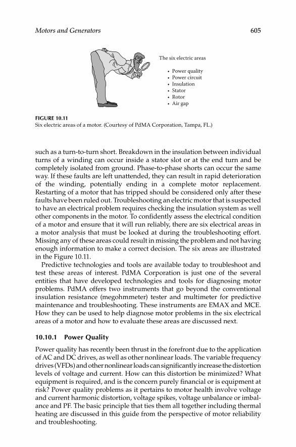
Motors and Generators 605
such as a turn-to-turn short. Breakdown in the insulation between individual turns of a winding can occur inside a stator slot or at the end turn and be completely isolated from ground. Phase-to-phase shorts can occur the same way. If these faults are left unattended, they can result in rapid deterioration of the winding, potentially ending in a complete motor replacement. Restarting of a motor that has tripped should be considered only after these faults have been ruled out. Troubleshooting an electric motor that is suspected to have an electrical problem requires checking the insulation system as well other components in the motor. To confi dently assess the electrical condition of a motor and ensure that it will run reliably, there are six electrical areas in a motor analysis that must be looked at during the troubleshooting effort. Missing any of these areas could result in missing the problem and not having enough information to make a correct decision. The six areas are illustrated in the Figure 10.11.
Predictive technologies and tools are available today to troubleshoot and test these areas of interest. PdMA Corporation is just one of the several entities that have developed technologies and tools for diagnosing motor problems. PdMA offers two instruments that go beyond the conventional insulation resistance (megohmmeter) tester and multimeter for predictive maintenance and troubleshooting. These instruments are EMAX and MCE. How they can be used to help diagnose motor problems in the six electrical areas of a motor and how to evaluate these areas are discussed next.
10.10.1 Power Quality
Power quality has recently been thrust in the forefront due to the application of AC and DC drives, as well as other nonlinear loads. The variable frequency drives (VFDs) and other nonlinear loads can signifi cantly increase the distortion levels of voltage and current. How can this distortion be minimized? What equipment is required, and is the concern purely fi nancial or is equipment at risk? Power quality problems as it pertains to motor health involve voltage and current harmonic distortion, voltage spikes, voltage unbalance or imbal-ance and PF. The basic principle that ties them all together including thermal heating are discussed in this guide from the perspective of motor reliability and troubleshooting.
The six electric areas
• Power quality • Power circuit • Insulation• Stator• Rotor• Air gap
FIGURE 10.11Six electric areas of a motor. (Courtesy of PdMA Corporation, Tampa, FL.)
DK4058_C010.indd 605DK4058_C010.indd 605 11/8/2008 12:19:37 PM11/8/2008 12:19:37 PM

606 Electrical Power Equipment Maintenance and Testing
By developing a methodical step-by-step process, power analysis (PA) tests using a power quality analyzer, such as PdMA’s EMAX shown in Figure 10.12, can be used to get information on quality of the power supply being delivered to the motor. These test results can quickly be used to assess three of the six areas listed above. These areas are derived from the most common electrically related motor failures in an industrial environment. This discussion focuses primarily on the quality of the power supply to the motor, followed by a recommended process on how to evaluate the data recorded during a PA capture.
The EMAX is a dynamic tester that collects data while the motor is operat-ing. This information can be used to evaluate incoming power quality, motor effi ciency, rotor, stator, air gap, and power circuit conditions. It simultane-ously collects all three phases of current and voltage to provide spectral and digital data in the areas of power, motor current, signature analysis, effi -ciency, crest factor (CF), total harmonic distortion (THD), sequence data, PF, impedance, current, and voltage.
Power quality refers to the condition of the voltage and current signals. Single- and three-phase nonlinear loads, VFDs, switch-mode power supplies, starting and stopping of large inductive loads, voltage spikes, and the like that can cause poor power quality. These infl uences can cause excessive harmonics on the electrical distribution system, which can result in overheat-ing of the insulation system and other undesirable effects on the electrical distribution equipment. The term “power quality” is used for defi ning the quality of power supplied to the motor to do its job. But what is being actually
FIGURE 10.12PdMA’s EMAX instrument. (Courtesy of PdMA Corporation, Tampa, FL.)
DK4058_C010.indd 606DK4058_C010.indd 606 11/8/2008 12:19:37 PM11/8/2008 12:19:37 PM

Motors and Generators 607
evaluated is the quality of the voltage that is being supplied to the motor circuit. The power supply system can only control the quality of the voltage; it has no control over the currents that a particular load might draw.
PA test allows a technician to take a power quality snapshot in order to see the condition of the voltage signal and evaluate the effect it will have on the motor. The actual sample time for the simultaneous measurement of the three voltage and current phases takes 0.17 s or less. From this snap-shot, the technician focuses primarily on the three phase-to-phase voltages of the power delivered to the motor and determines what effect they are having on motor performance.
Data used to evaluate power quality is located in the phase-to-phase volt-age section of the results page as is shown in Figure 10.13. In Figure 10.13, the result page shows among other data the input power to the motor, funda-mental root mean square (rms), total rms, CF, and THD for each of the phase-to-phase voltages. The average voltage and percent imbalance are also listed. Additionally, recommended NEMA derating factors are provided for both phase-to-phase voltage imbalance and harmonic voltage factor (HVF).
The motor, or for that matter any three-phase machine, is a symmetrical device and is designed to operate on three-phase balanced sinusoidal volt-ages. When line voltages applied to a motor are not equal, negative sequence currents are introduced into the motor windings. The negative sequence cur-rents fl ow in the windings of the motor in the opposite direction to the normal (positive sequence) currents. Therefore, these negative sequence currents produce an air gap fl ux that rotates in opposite direction to the rota-tion of the motor. This reduces the net motor torque, affecting its operation and increasing the temperature rise of the motor.
NEMA standard MG1-2006 provides a recommended derating factor based on percent voltage imbalance (Figure 10.14). The usual recommendation is to
FIGURE 10.13Phase-to-phase voltage imbalance of a motor—sample result page from PdMA EMAX.
(Courtesy of PdMA Corporation, Tampa, FL.)
DK4058_C010.indd 607DK4058_C010.indd 607 11/8/2008 12:19:38 PM11/8/2008 12:19:38 PM

608 Electrical Power Equipment Maintenance and Testing
not run a motor when the voltage imbalance is greater than 5% (per NEMA MG-1). For a given phase-to-phase voltage imbalance, rated horsepower of an induction motor should be multiplied by the derating factor in accordance with the NEMA MG1-2006 recommendation. If the load on the motor exceeds this derated value, take steps to correct the imbalance, or reduce the load on the motor. Running the motor with the imbalanced voltage will cause exces-sive temperature rise in the windings and damage the insulation.
Terminal VoltageTerminal voltage has a major effect on motor performance. The effect of low voltage on electric motors is well known and understood; however, the effect of high voltage on motors is often misunderstood. The effects of low and high terminal voltages are discussed next.
Effects of low voltageWhen a motor is operated below nameplate rated voltage, some of the motor’s characteristics will change slightly and other characteristics more dramati-cally. To drive a fi xed mechanical load, a motor must draw a fi xed amount of power from the circuit to produce the necessary torque to drive the load. The amount of power is roughly related to the voltage times current. So with a lower voltage, there will be a rise in current to maintain the required power. In terms of torque, the torque produce by the motor is proportional to the square of the voltage. For example, if the voltage to the motor is reduced by 10%, the torque will be reduced by 19%. This in itself is not alarming, unless the torque delivered by the motor is less than the torque required by the fi xed load. In order to produce the necessary torque the motor will draw more current, therefore rise in current may exceed the nameplate current rating of the motor. When this happens the buildup of heat within the motor will damage the insulation system.
Aside from the possibility of overtemperature and shortened insulation life, other important effects on the motor’s performance need to be under-stood. Starting, pull-up, and pull-out torque of induction motors all change based on the applied voltage squared. Thus, a 10% reduction from nameplate
FIGURE 10.14Derating factor chart for voltage unbalance (NEMA MG1-2006). (Courtesy of PdMA Corporation,
Tampa, FL.)
00.7
0.8
0.9
1.0
1 2Percentage voltage imbalance
Der
atin
g fa
ctor
3 4 5
DK4058_C010.indd 608DK4058_C010.indd 608 11/8/2008 12:19:38 PM11/8/2008 12:19:38 PM

Motors and Generators 609
voltage (100%–90%) would reduce the starting, pull-up, and pull-out torque to 81%. At 80% terminal voltage, the motor would produce 64% torque of the nameplate values. Clearly, it would be diffi cult to start those hard-to-start loads under such conditions. Similarly, the motor’s pull-out torque will be much lower than during normal voltage conditions.
Effects of high voltageA common misconception is that high voltage tends to reduce current draw on a motor, since low voltage increases the current. This is not always the case. High voltage on a motor tends to push the magnetic portion of the motor into saturation. This causes the motor to draw excessive current in an effort to magnetize the iron beyond the point to which it can easily be magnetized. Generally, motors will tolerate a certain change above nameplate voltage; however, extremes above this value will cause the amperage to go up with a corresponding increase in heating and a shortening of motor life. For example, motors are generally designed to operate satisfactorily with a band of ±10% in accordance with NEMA standards. Even though this is the so-called tolerance band, the best performance would be at rated terminal voltage. Operation at the ends of this band would put unnecessary stress on the motor.
These tolerance bands are in existence not to set a standard that can be used all the time, but rather to set a range that can be used to accommodate the normal hour-to-hour swings in-plant voltage. Continuous operation at either the low or high end of the band will shorten the life of the motor.
The graph shown in Figure 10.15 is widely used to illustrate the general effects of high and low voltage on the performance of T-frame motors. It is acceptable to show general effects, but remember these effects will change slightly from one motor design to another. High voltages will always tend to
FIGURE 10.15Effects of voltage variation on T-frame motors (NEMA MG1-2006). (Courtesy of PdMA
Corporation, Tampa, FL.)
Full load amperes
1520
15
10
5
0
5
10
15
20
10 5 0Percent voltage variation
Effect of voltage variationon T-frame motors
Starting amperes
Starting amperes
Starti
ng and
max
imum to
rque
Startin
g and
maxi
mum torque
EFF. EFF.
P.F.
P.F.
Perc
ent c
hang
es in
mot
or p
erfo
rman
ce
5 10 15
Full load amperes
DK4058_C010.indd 609DK4058_C010.indd 609 11/8/2008 12:19:38 PM11/8/2008 12:19:38 PM

610 Electrical Power Equipment Maintenance and Testing
reduce PF and increase losses in the system, which results in higher operating cost for the equipment and the system. The following guidelines are pro-vided for assistance in evaluating the voltage of a motor circuit:
Small motors tend to be more sensitive to overvoltage and saturation • than large motors
U-frame motors are less sensitive to overvoltage than T frames•
Premium/high effi ciency motors are less sensitive to overvoltage • than standard effi ciency motors
Overvoltage can drive up amperage and temperature even on lightly • loaded motors; thus, motor life can be shortened by high voltage
Full-load effi ciency drops with either high or low voltage•
PF improves with lower voltage and drops sharply with high voltage•
Inrush current goes up with higher voltage•
Simply put, the best life and effi cient operation of electric motors occurs when motors are operated at voltage as close to nameplate ratings as possible.
HarmonicsThe presence of harmonic distortion in the applied voltage to a motor will
both increase electrical losses and decrease effi ciency. These losses will increase motor temperature, resulting in even further losses. High harmon-ics can result in a temperature rise in motor temperature. NEMA MG1-2006 provides a chart for recommended harmonic derating factor known as HVF to aid in evaluating the harmonic voltage effects on the motor’s performance. Figure 10.16a shows sinusoidal current and voltage waveforms of a linear load such as a motor. Figure 10.16b shows the nonsinusodial current and voltage waveforms of nonlinear load, such as drawn by a VFD.
When performing PA testing of motor circuits, the power analyzer, such as EMAX, samples the applied voltage signal. It analyzes the voltage waveform, identifi es the fundamental frequency and all harmonics present and their percent of the waveform. With this information the HVF is calculated and, if required, recommended derating per NEMA guidelines is provided. The HVF derating curve is shown in Figure 10.17.
There is usually no need to derate motors if the voltage distortion remains within Institute of Electrical and Electronic Engineers (IEEE) Standard 519-1992 limits of 5% THD and 3% for any individual harmonic. Excessive heat-ing problems begin when the voltage distortion reaches 8%–10% and higher. Such distortion should be corrected for long motor life.
The PA test, i.e., snap shot of power quality, provides a wealth of detailed information for identifying the power quality being delivered to the motor in a distribution system. In addition, this simple to perform test also provides the data required for detailed evaluation of motor circuits that utilize VFDs. Phase-to-phase voltage, harmonic distortion, bus voltage, and THD have an effect on the performance and condition of a motor.
DK4058_C010.indd 610DK4058_C010.indd 610 11/8/2008 12:19:38 PM11/8/2008 12:19:38 PM
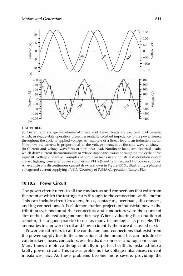
Motors and Generators 611
150
10
(a)
150
100
50
0
Volta
ge (V
)
Curr
ent (
A)
50
100
5
0
0.08
0.10
5
10
0.00
200 4003002001000
0.100.000.08 100
200300400
150100
500
(b)
Curr
ent (
A)
Volta
ge (V
)
50100150200
FIGURE 10.16(a) Current and voltage waveforms of linear load. Linear loads are electrical load devices,
which, in steady-state operation, present essentially constant impedance to the power source
throughout the cycle of applied voltage. An example of a linear load is an induction motor.
Note how the current is proportional to the voltage throughout the sine wave as shown.
(b) Current and voltage waveform of nonlinear load. Nonlinear loads are electrical loads,
which draw current discontinuously or whose impedance varies throughout the cycle of the
input AC voltage sine wave. Examples of nonlinear loads in an industrial distribution system
are arc lighting, converter power supplies for VFDs (6 and 12 pulse), and DC power supplies.
An example of a discontinuous current draw is shown in Figure 10.16b, illustrating a phase of
voltage and current supplying a VFD. (Courtesy of PdMA Corporation, Tampa, FL.)
10.10.2 Power Circuit
The power circuit refers to all the conductors and connections that exist from the point at which the testing starts through to the connections at the motor. This can include circuit breakers, fuses, contactors, overloads, disconnects, and lug connections. A 1994 demonstration project on industrial power dis-tribution systems found that connectors and conductors were the source of 46% of the faults reducing motor effi ciency. When evaluating the condition of a motor, it is a good practice to use as many technologies as possible. The anomalies in a power circuit and how to identify them are discussed next.
Power circuit refers to all the conductors and connections that exist from the power supply bus to the connections at the motor. This can include cir-cuit breakers, fuses, contactors, overloads, disconnects, and lug connections. Many times a motor, although initially in perfect health, is installed into a faulty power circuit. This causes problems like voltage imbalances, current imbalances, etc. As these problems become more severe, providing the
DK4058_C010.indd 611DK4058_C010.indd 611 11/8/2008 12:19:38 PM11/8/2008 12:19:38 PM
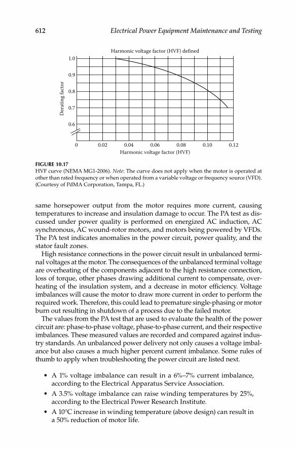
612 Electrical Power Equipment Maintenance and Testing
same horsepower output from the motor requires more current, causing temperatures to increase and insulation damage to occur. The PA test as dis-cussed under power quality is performed on energized AC induction, AC synchronous, AC wound-rotor motors, and motors being powered by VFDs. The PA test indicates anomalies in the power circuit, power quality, and the stator fault zones.
High resistance connections in the power circuit result in unbalanced termi-nal voltages at the motor. The consequences of the unbalanced terminal voltage are overheating of the components adjacent to the high resistance connection, loss of torque, other phases drawing additional current to compensate, over-heating of the insulation system, and a decrease in motor effi ciency. Voltage imbalances will cause the motor to draw more current in order to perform the required work. Therefore, this could lead to premature single-phasing or motor burn out resulting in shutdown of a process due to the failed motor.
The values from the PA test that are used to evaluate the health of the power circuit are: phase-to-phase voltage, phase-to-phase current, and their respective imbalances. These measured values are recorded and compared against indus-try standards. An unbalanced power delivery not only causes a voltage imbal-ance but also causes a much higher percent current imbalance. Some rules of thumb to apply when troubleshooting the power circuit are listed next.
A 1% voltage imbalance can result in a 6%–7% current imbalance, • according to the Electrical Apparatus Service Association.
A 3.5% voltage imbalance can raise winding temperatures by 25%, • according to the Electrical Power Research Institute.
A 10°C increase in winding temperature (above design) can result in • a 50% reduction of motor life.
0
0.6
0.7
0.8
0.9
1.0
0.02 0.04 0.06Harmonic voltage factor (HVF)
Der
atin
g fa
ctor
Harmonic voltage factor (HVF) defined
0.08 0.10 0.12
FIGURE 10.17HVF curve (NEMA MG1-2006). Note: The curve does not apply when the motor is operated at
other than rated frequency or when operated from a variable voltage or frequency source (VFD).
(Courtesy of PdMA Corporation, Tampa, FL.)
DK4058_C010.indd 612DK4058_C010.indd 612 11/8/2008 12:19:38 PM11/8/2008 12:19:38 PM

Motors and Generators 613
Phase voltage unbalance causes three-phase motors to run at temperatures greater than their published ratings. This excessive heating is due mainly to negative sequence currents attempting to cause the motor to turn in a direc-tion opposite to its normal rotation. These higher temperatures soon result in degradation of the motor insulation and shortened motor life. The percent increase in temperature of the highest current winding is approximately two times the square of the voltage unbalance. For example, a 3% voltage unbal-ance will cause a temperature rise of about 18%. The greater the unbalance, the higher the motor winding temperature and the sooner the insulation will fail. NEMA standards recommend a maximum voltage unbalance of 1% without derating the motor. The motor can be derated down to 75% for a maximum of a 5% voltage unbalance. If the voltage unbalance exceeds 5%, it is recommended that the motor not be operated.
The easiest way to test a power circuit is using the PA test while the motor is under normal operating condition. A current imbalance is a possible indi-cation of a high resistance connection. However, a voltage as well as a current imbalance is a better indicator. What determines whether both imbalances are present in the event of a high resistance connection is the test location.
Both voltage and current imbalances are not a requirement in the event of a fault in the power circuit. There can be many different reasons to look for a high resistance connection, a power circuit component failure, or an imbal-ance that points to another fault zone. Trending power circuit anomalies is most effective at similar loads. Higher loads may result in the fault being more obvious due to the stresses being greater at higher loads. The easiest way to verify the current draw of a motor is by looking at the percent full-load amperes (% FLA) in the current section on the results page of the power analyzer as shown in Figure 10.18.
As mentioned earlier, a current imbalance is a possible indicator of a power circuit anomaly. This is because the location of the anomaly in reference to
FIGURE 10.18Motor current in %FLA—sample result page from PdMA EMAX. (Courtesy of PdMA
Corporation, Tampa, FL.)
DK4058_C010.indd 613DK4058_C010.indd 613 11/8/2008 12:19:38 PM11/8/2008 12:19:38 PM

614 Electrical Power Equipment Maintenance and Testing
the voltage test leads will show different imbalances. However, measured current values are consistent regardless of test location. Figure 10.19 shows how voltage readings can change based on test location. If the test is being performed upstream of the anomaly, then there will only be a current imbal-ance, and if the test is downstream, there will be both a current and voltage imbalance.
Loads using three-phase power sources are subject to loss of one of the three phases from the power distribution system. This condition is known as single-phasing of the primary power supply system. The loss of one phase, or leg, of a three-phase line causes voltages to become unbalanced on the secondary distribution power system, thereby causing serious problems for motors. The motor windings will overheat due primarily to the fl ow of nega-tive sequence currents, a condition that exists anytime there is a phase volt-age imbalance. The loss of a phase also inhibits the motor’s ability to operate at its rated horsepower.
In conclusion, a high resistance connection results in voltage and current imbalances, which reduces the horsepower rating signifi cantly. When a good motor is installed into a faulty power circuit, it causes problems with power imbalances, as well as, negative sequence currents. As the problems become more severe, the horsepower rating of the motor drops causing temperatures to increase resulting in overheating of adjacent components, damage to the rotor, stator, insulation, shortened motor life, reduced motor effi ciency, motor failure, or fi re. While damage to the rotor, stator, or insulation might be symptoms of a problem; the root cause still lies with the power circuit.
Current imbalances are measured upstream and downstream
of the fault
Voltage imbalance not measured
High resistance on phase 1
Voltage imbalance measuredDownstream
Upstream
M
FIGURE 10.19Location of testing for motor troubleshooting. (Courtesy of PdMA Corporation, Tampa, FL.)
DK4058_C010.indd 614DK4058_C010.indd 614 11/8/2008 12:19:38 PM11/8/2008 12:19:38 PM

Motors and Generators 615
Replacing the motor without fi xing the high resistance connection causes the failure cycle to begin again.
10.10.3 Insulation Condition
This refers to the insulation between the windings and ground. High tem-peratures, age, moisture, and dirt contamination all lead to shortened insula-tion life. It has been said that if the industry would just use the space heaters available to keep the insulation dry, then doubling the life of our motors would not be out of the question.
The importance of having good electrical insulation systems is obvious. The designs and applications of electrical equipment are almost infi nite in their variety, but all units have one common characteristic. For electrical equipment to operate correctly, one of the most important characteristics is that the fl ow of electricity takes place along well-defi ned paths or circuits. These paths are normally limited to conductors, either internal or external to the electrical component. It is important that the fl ow of current be confi ned to defi ned conducting paths and not leak from one path to another through materials not intended to become conducting paths. Deterioration of insula-tion systems can result in an unsafe situation for personnel exposed to the leakage current.
Despite great strides in electrical equipment design in recent years, the weak link in the chain is still the insulation system. When electrical equip-ment fails, more often than not the fault can be traced to defective insulation. Even though an electric motor is correctly designed and tested prior to instal-lation, there can be no guarantee that a fault in the insulation will not occur at some time in the future.
Many outside infl uences affect the life of electrical insulation systems. Outside infl uences include contamination of the insulation surfaces with chemicals from the surrounding atmosphere that attack and destroy the molecular structure, physical damage due to incorrect handling or acci-dental shock, vibration, and excessive heat from nearby industrial pro-cesses. Voltage transients in the conductors inside the insulation, such as surges or spikes caused by VFDs, can lower the dielectric strength to the point of failure. The deterioration occurs in many ways and in many places at the same time. For example, as chemicals and heat change the molecular structure of the insulating materials, they become semi-conductive, allowing more current to be forced through them by voltage resulting in leakage current.
Correctly conducted insulation system testing, analysis of the data collected, and followed by appropriate corrective actions can minimize the possibility of failures. Therefore, the signifi cance of understanding insulation system testing has never been more important. The reader should refer to Chapters 1 and 2 for detail discussion of insulation (dielectric) theory and practice and conducting tests using DC voltage. A brief overview of the subject matter is offered here from the perspective of motor-winding insulation.
DK4058_C010.indd 615DK4058_C010.indd 615 11/8/2008 12:19:39 PM11/8/2008 12:19:39 PM

616 Electrical Power Equipment Maintenance and Testing
Insulation resistance measurementsThe insulation system of motor windings is often checked using DC voltage tests. One of the most common test conducted is to measure the insulation resistance of the motor windings using an insulation resistance tester. When testing insulation with DC voltage, the total current drawn is the sum of four different currents: surface leakage, geometric capacitance, conductance, and absorption.
The surface leakage current is constant over time. Moisture or some other type of partially conductive contamination present in the machine causes a high surface leakage current, i.e., low insulation resistance.
The geometric capacitance current is a reversible component of the mea-sured current on charge or discharge that is due to the geometric capaci-tance. That is the capacitance as measured with AC of power or higher frequencies. With direct voltage, this current has a very short time constant and does not affect the usual measurement.
The conduction current in well-bonded polyester and epoxy-mica insula-tion systems is essentially zero unless the insulation has become saturated with moisture. Older insulation systems, such as asphaltic-mica or shellac mica-folium may have a natural and higher conduction due to the conductiv-ity of the adhesive tapes used as backing of the mica.
The absorption current is made of two components: the polarization of the insulation material and the gradual drift of electrons and ions through the insulating material. The polarization current is caused by the reorientation of the insulating material. This material, usually epoxy, polyester, or asphalt tends to change the orientation of their molecules when in the presence of a DC electric fi eld. It normally takes a few minutes of applied voltage for the molecules to be reoriented, and thus for the current-supplied polarizing energy to be reduced to almost zero. The absorption current, which is the second com-ponent, is the gradual drift of electrons and ions through the insulating mate-rial. These electrons and ions drift until they become trapped at the mica surfaces usually found in motor insulation systems. The positively and nega-tively charged molecules of an insulation system are shown in Figure 10.19.
Figure 10.20a shows the random orientation of the insulation’s molecules. As DC voltage is applied to the insulation, the molecules start to polarize and align, as shown in Figure 10.20b. The energy required to align the molecules, and subsequently reduce the amount of escaping molecules, is known as absorption current. Since absorption current is a property of the insulation material and the winding temperature, a specifi c absorption current is neither good nor bad. The absorption currents will vary from different insulating material. Prior to 1970, older thermo plastic materials used for motor winding insulation were typically asphalt or shellac, which has a higher absorption current.
After 1970, the shift was made to thermosetting polyester or epoxy-bonded insulating material, which signifi cantly decreased the absorption current. Nonetheless, this does not mean that the more modern insulating materials are better because they have less absorption current. The amount of applied voltage must be appropriate to the nameplate voltage and the basic insulation condition. This is particularly important in small, low-voltage machines
DK4058_C010.indd 616DK4058_C010.indd 616 11/8/2008 12:19:39 PM11/8/2008 12:19:39 PM

Motors and Generators 617
where there is only a single layer of insulation. If test voltages are too high, the applied voltage may over stress the insulation. See Table 10.7 for recom-mended voltage application.
Also, the capacitance value of insulation may be measured to refl ect on the cleanliness of the windings. A buildup of contamination on the surface of the windings results in higher capacitance readings. With a buildup of contamination on the insulation surface, dirty windings produce higher capacitance values than clean ones do. Over time, capacitance values steadily increased indicating an accumulation of dirt and that cleaning is necessary.
(b)
(a)
FIGURE 10.20Positively and negatively charged molecules of an insulation system. (Courtesy of PdMA
Corporation, Tampa, FL.)
TABLE 10.7
Guidelines for DC Voltages for Insulation Resistance Tests
Winding Rated Voltage (V)a
Insulation Resistance
Test Direct Voltageb
<300 500
>300–1,000 500–1,000
1,000–2,500 500–1,000
2,501–5,000 1,000–2,500
5,001–12,000 2,500–5,000
>12,000 5,000–10,000
a Rated line-to-line voltage for three-phase AC machines,
line-to-ground voltage for single-phase machines, and
rated direct voltage for DC machines or fi eld windings.b Refer to IEEE 43-2000 for a guide on DC test voltages.
DK4058_C010.indd 617DK4058_C010.indd 617 11/8/2008 12:19:39 PM11/8/2008 12:19:39 PM
Novin Pendar
Highlight

618 Electrical Power Equipment Maintenance and Testing
Effects of contaminationThere are many factors that can affect insulation resistance. The surface leak-age current is dependant upon foreign matters, such as oil and carbon dust on the winding surfaces outside the stator slot. The surface leakage current may be signifi cantly higher on large turbine generator rotors and DC machines, which have relatively large-exposed creepage surfaces. Dust and salts on insu-lation surfaces, which are ordinarily nonconductive when dry, may become partially conductive when exposed to moisture or oil, and this will cause increased surface leakage current and lower insulation resistance. The reason a motor’s capacitance increases with contamination is because of how a capaci-tor works. Any two conducting materials, called plates, separated from each other by a dielectric material, form a capacitor. A dielectric material is anything that is unable to conduct direct electric current. A cable or motor winding sur-rounded by insulation provides one conductor and the dielectric material. The second plate is formed by the stator core and motor casing iron. It is this second plate that is increased in plate size as contamination builds up.
Effects of temperatureA higher temperature affects the resistance of both the insulation and conduc-tor. There is a term called temperature coeffi cient (KT). A material has either a positive or negative KT. If the material has a positive KT, then with added heat the resistance readings will increase. Inversely, if a material has a negative KT, then the resistance readings will decrease with higher temperature. In metals, i.e., the magnetic wire of the stator, higher temperature introduces greater ther-mal agitation and reduces the movements of free electrons. Because of this reduction in free movement, the resistance readings will increase with added heat and therefore the conductor has a positive KT. However, in insulation, the added heat supplies thermal energy, which frees additional charge carriers and reduces the resistance reading. Therefore, an increase in temperature on insulation reduces the resistance and it is said to have a negative KT. This higher temperature affects every current except the geometric capacitive current.
The recommended method of obtaining data for an insulation resistance versus winding temperature curve is by making measurements at several winding temperatures, all above the dew point, and plotting the results on a semilogarithmic scale. Since this type of temperature coeffi cient plotting is usu-ally not feasible, it is recommended to avoid the effects of temperature in trend analysis, subsequent tests should be conducted when the winding is near the same temperature as the previous tests. Otherwise the insulation test values should be corrected to a common base temperature of 40°C for trend analysis.
Therefore, resistance-to-ground readings must be temperature corrected for trending and comparison purposes. Temperature correction of the reading is required because the temperature of the insulation system under test may vary depending on operating conditions prior to testing, atmospheric condi-tions, or ambient temperature. Insulation material has a negative temperature coeffi cient, which means that the resistance characteristics vary inversely with temperature. In the test setup screen of a standard test, the temperature of the windings will have an effect on the measurement. The measured megohm value is then adjusted to a temperature correction to 40°C. The result is the
DK4058_C010.indd 618DK4058_C010.indd 618 11/8/2008 12:19:39 PM11/8/2008 12:19:39 PM

Motors and Generators 619
corrected megohm readings. To accurately trend resistance reading for a motor over time, keep the test voltage and duration of applied voltage constant.
The temperature-corrected megohm readings should be recorded and graphed for comparison over time. If a downward trend is observed, look for dirt or moisture. A single reading will not have much meaning in regards to the overall health of the insulation system; a reading as low as 5 MΩ may be accept-able if related to a low-voltage application. See Table 10.8 for recommended minimum insulation resistance. Also, refer to Section 2.10.1 in Chapter 2 for additional discussion on recommended minimum insulation resistance values.
This is important because dirt and contamination reduce the motor’s abil-ity to dissipate heat generated by its own operation, resulting in premature aging of the insulation system. A general rule of thumb is that a motor’s life decreases by 50% for every 10°C increase in operating temperature above the design temperature of the insulation system. Heat raises the resistance of conductor materials and reduces the insulation resistance of the winding insulation, and therefore breaks down the insulation. These factors accelerate the development of cracks in the insulation, providing paths for unwanted current to fl ow to ground. The effects from temperature to insulation resis-tance are shown in Figure 10.21.
0.1
1
10
Winding temperature (�C)
Insu
latio
n re
sista
nce
tem
pera
ture
coef
ficie
nt, K
t
20 30 40 50 60
FIGURE 10.21Temperature versus insulation resistance curve. (Courtesy of PdMA Corporation, Tampa, FL.)
TABLE 10.8
Recommended Minimum Insulation Resistance Values at 40°C (All Values in Megohm)
IR1 min = kV + 1 For most windings made before about
1970, all fi eld windings, and others
not described below
IR1 min = 100 For most DC armatures and AC windings built
after 1970 (form-wound coils)
IR 1 min = 5 For most machines with random-wound stator
coils and form-wound coils rated below 1 kV
Source: From IEEE Std 43-2000, IEEE Recommended Practice for
Testing Insulation Resistance of Rotating Machinery.
DK4058_C010.indd 619DK4058_C010.indd 619 11/8/2008 12:19:39 PM11/8/2008 12:19:39 PM
Novin Pendar
Highlight

620 Electrical Power Equipment Maintenance and Testing
Polarization index and dielectric absorptionThe polarization index (PI) and dielectric absorption (DA) tests are performed with a megohmmeter on a deenergized motor. It is not necessary to perform a DA test if a PI test is performed. Refer to Sections 2.3.1.2 and 2.3.1.3 for descrip-tion of DA and PI tests. The purpose of the PI test is to determine whether or not a motor’s insulation system is suitable for continued service. The PI test is not limited to AC induction motors only. It also applies to wound-rotor motors, salient pole machines, and certain DC fi elds. The DC fi eld would have to have conductors that are fully encapsulated in insulation. Therefore, the PI test can be a worthwhile test for multiple type machines. When performing a PI test, it is not necessary to correct for temperature. Since the machine temperature does not change appreciably between the 1 min and the 10 min readings, the effect of temperature on the PI is usually small. However, if the motor recently shut down and a PI test is performed, the results may be a substantial increase in insulation resistance. This would result in an unusually high PI, at which point additional testing should be performed once the windings have cooled to 40°C or lower. Refer to Table 2.14 in Chapter 2 for Interpretation of PI and DA data. Excellent results should indicate a PI ratio of 2–4, achieve higher than minimal insulation resistance values, and should be a nonsporadic rise in the megohm readings as shown in Figure 10.22.
Erratic insulation resistance values occurring at anytime during the test are indicative of short-term current transients. These may be due to contamina-tion or moisture. It is important to know how low the insulation resistance values fall to in order to grade the insulation. For example, the IEEE standards
FIGURE 10.22Graph showing megohm values versus time for calculating PI and DA sample result page from
PdMA MCE. (Courtesy of PdMA Corporation, Tampa, FL.)
DK4058_C010.indd 620DK4058_C010.indd 620 11/8/2008 12:19:39 PM11/8/2008 12:19:39 PM

Motors and Generators 621
recommend minimum insulation resistance value of 100 MΩ for form-wound coils. Figure 10.23 shows insulation resistance values dipping below the sug-gested minimum value of 100 MΩ for a form-wound coil. The PI and DA tests can be both used as go–no-go, based on the minimum insulation resistance readings.
The PI value of greater than 4 does not necessarily mean that the health of the insulation system is good. The higher PI value may indicate other prob-lems with the insulation system, such as being too dry and brittle indicating that it has lost some or all of its mechanical properties. According to the EASA’s principles of large AC motors, it states that PI ratios of greater than 5 should be considered the result of dry or brittle insulation. This may be because of age of the insulation or operating the motor at higher than designed temperatures as shown in Figure 10.24. A very dry or brittle insulation may indicate good insulation resistance but it may not have the necessary dielectric strength and mechanical pliability.
10.10.4 Stator Condition
When discussing the stator, we are referencing the DC or three-phase AC windings, insulation between the turns of the winding, solder joints between the coils, and the stator core or laminations. This fault zone creates a lot of debate as to the cause and rate of failure. The stator fault zone is
FIGURE 10.23Graph showing megohm values falling below the minimum value. Sample result page from
PdMA MCE. (Courtesy of PdMA Corporation, Tampa, FL.)
DK4058_C010.indd 621DK4058_C010.indd 621 11/8/2008 12:19:39 PM11/8/2008 12:19:39 PM

622 Electrical Power Equipment Maintenance and Testing
often considered one of the most controversial areas due to the signifi cant challenge in early fault detection and the prevention of motor failure surrounding the stator windings. This challenge is further intensifi ed in higher voltage machines, where the fault-to-failure time frame becomes much shorter. The stator fault zone is identifi ed as the health and quality of the insulation between the turns and phases of the individual turns and coils inside the motor.
Failure MechanismsThe likely mechanisms of a stator-winding fault are either a turn-to-turn, phase-to-phase, or turn-to-ground short. A turn-to-turn short is identifi ed as a short of one or more windings in a coil. This can develop into a very low impedance loop of wire, which acts as a shorted secondary of a current trans-former. This results in excessive current fl ow through the shorted loop, creat-ing intense heat and insulation damage. Due to the nature of a random wound design, a shorted turn could occur with much higher impedance, allowing the motor to run for extended periods of time before eventually destroying the coil with the high currents. As a result, it is not unusual to fi nd random wound motors still running with bad stator windings. Form-wound coils however, do not exhibit high turn impedances and will there-fore heat up quickly following the presence of a turn-to-turn short. A phase-to-phase short is identifi ed as a short of one or more phases to another phase. This fault can be quite damaging due to the possibility of very large voltage potential existing between phases at the location of the short.
AnalysisThe big controversy, which surrounds the stator fault zone, is whether tech-nology can give ample warning of an impending stator-winding failure. A motor will develop a turn-to-turn, phase-to-phase, or ground short over
FIGURE 10.24Graph showing insulation resistance readings of very dry or brittle insulation. Sample result
page from PdMA MCE. (Courtesy of PdMA Corporation, Tampa, FL.)
DK4058_C010.indd 622DK4058_C010.indd 622 11/8/2008 12:19:39 PM11/8/2008 12:19:39 PM
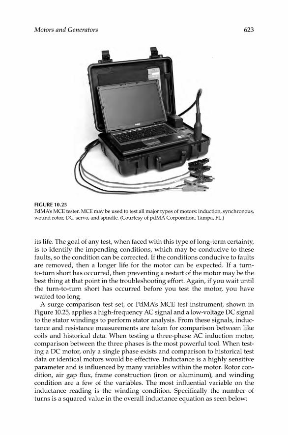
Motors and Generators 623
its life. The goal of any test, when faced with this type of long-term certainty, is to identify the impending conditions, which may be conducive to these faults, so the condition can be corrected. If the conditions conducive to faults are removed, then a longer life for the motor can be expected. If a turn-to-turn short has occurred, then preventing a restart of the motor may be the best thing at that point in the troubleshooting effort. Again, if you wait until the turn-to-turn short has occurred before you test the motor, you have waited too long.
A surge comparison test set, or PdMA’s MCE test instrument, shown in Figure 10.25, applies a high-frequency AC signal and a low-voltage DC signal to the stator windings to perform stator analysis. From these signals, induc-tance and resistance measurements are taken for comparison between like coils and historical data. When testing a three-phase AC induction motor, comparison between the three phases is the most powerful tool. When test-ing a DC motor, only a single phase exists and comparison to historical test data or identical motors would be effective. Inductance is a highly sensitive parameter and is infl uenced by many variables within the motor. Rotor con-dition, air gap fl ux, frame construction (iron or aluminum), and winding condition are a few of the variables. The most infl uential variable on the inductance reading is the winding condition. Specifi cally the number of turns is a squared value in the overall inductance equation as seen below:
FIGURE 10.25PdMA’s MCE tester. MCE may be used to test all major types of motors: induction, synchronous,
wound rotor, DC, servo, and spindle. (Courtesy of pdMA Corporation, Tampa, FL.)
DK4058_C010.indd 623DK4058_C010.indd 623 11/8/2008 12:19:40 PM11/8/2008 12:19:40 PM

624 Electrical Power Equipment Maintenance and Testing
820.4 10N AL
l
−π ×= m
whereL is the inductance (Henerys)N is the number of turns of coilm is the permeability of core in electromagnetic unitsA is the cross-sectional area of core (cm2)l is the mean length of core (cm)
Although it is our goal to prevent a turn-to-turn short from occurring, you can see that a loss of a single turn in a stator winding will have a dramatic effect on the overall inductance of one or more phases based on the coil con-fi guration. In our effort to identify the conditions that are conducive to a turn-to-turn short, we can use other variables in the equation to identify anomalies, which could create stator problems.
Stator faults often end up as a turn-to-turn short, but begin as something else. An example is a motor with excessive vibration, which results in wind-ing movement, friction, and eventually worn insulation between the wind-ing turns. Another example is rotor defects, which create intense heat on the winding surface and eventually create weakened turn insulation or even a ground fault. Core iron defects, such as shorted laminations, will also create additional heat, airfl ow disturbance, and elevated vibration due to imbal-anced magnetic fi elds and air gap fl ux. What infl uence do these situations have on stator inductance? Other than vibration, rotor defects and air gap fl ux anomalies have a direct impact on the permeability ( m) of the stator windings. Changes in m due to a stator core defect will create changes in inductance related to a specifi c group of coils located near the defect. Changes in m due to rotor defects will have a varying infl uence on the stator induc-tance as the rotor position changes. A quick comparison of the inductance and inductive imbalance values between the three phases or to historical data will indicate changes in these variables and prompt further action or testing to be performed in an effort to prevent the turn-to-turn short.
Stator analysis may be performed by evaluating the phase relationship of voltage and current for each of the three phases of an AC induction motor. These values are used to determine the impedance of each phase and dis-play them as an impedance imbalance. Any change in the real or reactive component of one phase that is not duplicated on another phase will indi-cate a change that needs to be investigated. One of the hurdles involved in this type of testing is acquiring this dynamic data at a load substantial enough to allow these values to be affected by the condition of the windings and not the design. An unloaded motor may run with a current imbalance. This creates variations in the phase impedance, which duplicates indications of a stator fault. Therefore, it is important to have approximately 70% load or more to remove the design impact on these values. Testing should not stop at <70% load, but you must use the test data as comparison values only.
DK4058_C010.indd 624DK4058_C010.indd 624 11/8/2008 12:19:40 PM11/8/2008 12:19:40 PM

Motors and Generators 625
A test today at 50%–60% load compared to a test last quarter at 50%–60% load is still a very informative test. The more test points are obtained, the more confi dence there is in the condition of your stator windings.
Another application is the ability to acquire data on current through the start-up cycle of the motor. The motor is under the most stress during start-up and can give many indications of problems existing or developing. Stator defects, as in open or shorted turns, will be identifi ed as a change in the amplitude of the inrush current. The inrush current is the highest ampli-tude of current seen through a start-up and occurs immediately after the motor is energized. This occurs due to the effective locked rotor condition, which the motor is in at start-up. Without rotor movement, the counter elec-tromotive force created by the rotor to reduce current fl ow in the stator does not exist. In fact, the inrush current immediately following the start of a motor is not affected by load at all. Whether at full load or no load during a start-up, the inrush current will be the same. Only line voltage and circuit impedance will have an effect on the inrush current. The current, which exists following the initial inrush however, is greatly affected by the load. If only line voltage and circuit impedance will affect the inrush current value and we generally expect line voltage to be the same, we must rely on circuit impedance as an indicator of stator health. Inrush current is dependent on impedance of the circuit therefore increased inrush current from normal indicates lower circuit impedance. Lower circuit impedance could be caused by weakened turn insulation or shorted turns and an open winding, high resistance connection or even incorrect repair specifi cations may cause higher circuit impedance. If signifi cant temperature variations occur from one test to another, it will have an impact on the overall circuit impedance. The effect of temperature should be considered when evaluating the start-up data including inrush current.
It is important to remember that stator defects do not exist very long before they can become catastrophic. Use all the tools available, know the circum-stances, and act quickly to dismiss or confi rm stator fault indications. The goal of stator analysis is to identify any condition that may lead to a turn-to-turn short so that condition can be corrected before a turn-to-turn short occurs. If turn-to-turn shorts go undetected, then over time they will become bigger faults, such as coil-to-coil short, or phase-to phase short. Refer to Section 10.11.9 on surge comparison tests for detecting turn-to-turn shorts.
10.10.5 Rotor Condition
Rotor condition refers to the rotor bars, the rotor laminations, and the end rings of the rotor. In the 1980s, a joint effort between EPRI and General Electric showed that 10% of motor failures were due to the rotor. The rotor, although a small percentage of the motor problems, can infl uence other areas to fail.
Starting a motor with a broken or cracked rotor bar causes excessive heat to be generated around the vicinity of the broken bar. This can spread to other rotor bars and destroy the insulation around the nearby lamina-tions. It can also affect other parts of the motor. What do we fi nd just a few
DK4058_C010.indd 625DK4058_C010.indd 625 11/8/2008 12:19:40 PM11/8/2008 12:19:40 PM
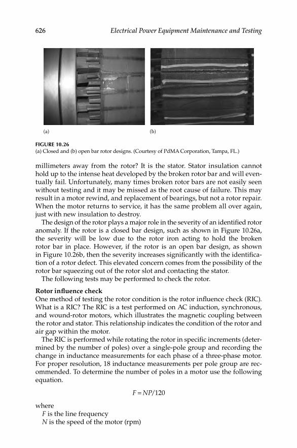
626 Electrical Power Equipment Maintenance and Testing
millimeters away from the rotor? It is the stator. Stator insulation cannot hold up to the intense heat developed by the broken rotor bar and will even-tually fail. Unfortunately, many times broken rotor bars are not easily seen without testing and it may be missed as the root cause of failure. This may result in a motor rewind, and replacement of bearings, but not a rotor repair. When the motor returns to service, it has the same problem all over again, just with new insulation to destroy.
The design of the rotor plays a major role in the severity of an identifi ed rotor anomaly. If the rotor is a closed bar design, such as shown in Figure 10.26a, the severity will be low due to the rotor iron acting to hold the broken rotor bar in place. However, if the rotor is an open bar design, as shown in Figure 10.26b, then the severity increases signifi cantly with the identifi ca-tion of a rotor defect. This elevated concern comes from the possibility of the rotor bar squeezing out of the rotor slot and contacting the stator.
The following tests may be performed to check the rotor.
Rotor infl uence checkOne method of testing the rotor condition is the rotor infl uence check (RIC). What is a RIC? The RIC is a test performed on AC induction, synchronous, and wound-rotor motors, which illustrates the magnetic coupling between the rotor and stator. This relationship indicates the condition of the rotor and air gap within the motor.
The RIC is performed while rotating the rotor in specifi c increments (deter-mined by the number of poles) over a single-pole group and recording the change in inductance measurements for each phase of a three-phase motor. For proper resolution, 18 inductance measurements per pole group are rec-ommended. To determine the number of poles in a motor use the following equation.
/120F NP=
whereF is the line frequencyN is the speed of the motor (rpm)
(a) (b)
FIGURE 10.26(a) Closed and (b) open bar rotor designs. (Courtesy of PdMA Corporation, Tampa, FL.)
DK4058_C010.indd 626DK4058_C010.indd 626 11/8/2008 12:19:40 PM11/8/2008 12:19:40 PM

Motors and Generators 627
P is the number of polesRecalculated for 60 Hz: P = 7200/rpmExample: A motor with nameplate rpm = 1780 would have four poles as
calculated from the above equation.
A RIC must be performed to provide any information about the standard squirrel-cage induction rotor. Faults such as broken rotor bars or damaged laminations can exist even if the balance of inductance is low. Basing the decision to perform a RIC only on how high the balance of inductance is on the baseline test could result in overlooking late stages of rotor bar defect. Figure 10.27 shows the expected inductance changes for a rotor with broken rotor bars. Note the erratic inductance values at the peak of the sine waves for each phase. Broken rotor bars cause a skewing in the fi eld fl ux generated by and around the rotor bars. A normal rotor would have no skewing or erratic inductance patterns, as seen in Figure 10.28.
Numerous methods exist for rotor evaluation with the motor running. These methods are inrush current time domain, spectral, and demodulated forms of the current signal which offer a broad approach to rotor analysis. Equipment from various manufacturers is available to perform such analysis.
Inrush/start-upOne method of evaluating rotor health is the inrush/start-up. Broken rotor bars create higher rotor impedance resulting in higher refl ected impedance onto the stator driving the current and torque down. This can be seen in the before and after inrush examples shown in Figure 10.29.
(Fp) sidebandsAnother method is trending the pole pass sideband frequency (Fp) ampli-tude. Increasing Fp sideband amplitude is indicative of a modulating line current associated with rotor slip. This modulation is often due to a rotor
Rotor bar defects
4.350
4.400
4.450
4.500
4.550
4.600
0 5 10 15 20 25 30 35 40 45 50 55 60 65 70 75 80 85 90Degrees
Indu
ctan
ce (m
H)
FIGURE 10.27Graph showing expected inductance changes for a rotor with broken rotor bars. (Courtesy of
PdMA Corporation, Tampa, FL.)
DK4058_C010.indd 627DK4058_C010.indd 627 11/8/2008 12:19:41 PM11/8/2008 12:19:41 PM

628 Electrical Power Equipment Maintenance and Testing
cage anomaly. Trending the Fp sideband amplitude an determining the differential amplitude as compared to line frequency amplitude allow a predetermined alarm based on well-known industry accepted standards. Figure 10.30 shows an elevated Fp sideband peak above the 36 dB differen-tial from line frequency.
Fifth harmonicThe third method of evaluating rotor health is the high-frequency spectral analysis sometimes referred to as the Swirl effect. Broken or cracked rotor
In rush/start-up -- #10220 10/21/2002 12:25:11 PM
60
50
40
30
20
10
0 1 2 3 4 5 6 7 8 9
I 1Baseline
10 11 12 13 14 15
FIGURE 10.29Graph showing inrush current of the motor relative to the baseline inrush current. (Courtesy
of PdMA Corporation, Tampa, FL.)
Good rotor
20.0022.0024.0026.0028.0030.0032.0034.00
0 30 60 90120
150180
210240
270300
330360
Rotor position (degrees)
Indu
ctan
ce (m
H)
FIGURE 10.28Graph of a good rotor showing no skewing or erratic inductance patterns. (Courtesy of PdMA
Corporation, Tampa, FL.)
DK4058_C010.indd 628DK4058_C010.indd 628 11/8/2008 12:19:41 PM11/8/2008 12:19:41 PM

Motors and Generators 629
bars create a phase shift in the air gap fl ux resulting in multiple Fp sidebands below the end of the fi fth harmonic. Figure 10.31 shows these elevated side-bands beneath the fi fth harmonic.
Current demodulationThe fourth method of evaluating rotor health is the demodulated current spectrum. By removing the components of line frequency from the spec-trum, the noise fl oor drops to a value allowing normally nonvisible peaks to be visible. Relating to rotor health it also allows a fi ltered view of the Fp in a
Hi res spectrum (dB) -- 0250 broken bars 04/15/1998 10:59:32 AM
530
20406080
100
120
Amplitude (dB)
54 55 56 57
56.95363.018
58 59 60Frequency (Hz)
61 62 63 64 65 66 67
l 1
FIGURE 10.30Graph showing an elevated Fp sideband peak. (Courtesy of PdMA Corporation, Tampa, FL.)
FIGURE 10.31Graph showing elevated sidebands beneath the fi fth harmonic. (Courtesy of PdMA Corpo-
ration, Tampa, FL.)
Frequency (Hz)286
0
Amplitude (dB)
20
40
60
80
100
120
288 290 292 294 296 298 300 302 304 306 308 310 312 314
l 1
DK4058_C010.indd 629DK4058_C010.indd 629 11/8/2008 12:19:41 PM11/8/2008 12:19:41 PM

630 Electrical Power Equipment Maintenance and Testing
demodulated spectrum form. Figure 10.32 shows the elevated Fp peak exceeding a predetermined alarm set point. This peak was associated with a broken rotor bar in a large 2-pole motor.
In a study funded by the Electric Power Research Institute, 10% of motor failures were caused by a rotor anomaly. This amounts to a large number of motors in even the average-sized plant. It is important to be aware of the rotor design, utilize the broad spectrum of test methods discussed above to correlate and confi rm, and extend the motor life by fi xing the cause not the symptom.
10.10.6 Air Gap
This relationship references the air gap between the rotor and stator. If this air gap is not evenly distributed around the 360° of the motor, uneven mag-netic fi elds can be produced. These magnetic imbalances can cause move-ment of the stator windings, resulting in winding failure, and electrically induced vibration, resulting in bearing failure.
The air gap fault zone describes the measurable distance between the rotor and stator within the motor. Air gap eccentricity is a condition that occurs when there is nonuniformity in the air gap between the rotor and stator. When there is an eccentricity in the air gap, varying magnetic fl ux within the air gap will create imbalances in the current fl ow, which can be identifi ed in the current spectrum. This unevenness in the space between the rotor and stator will affect the alignment of the RIC results.
Static eccentricity occurs when the centerline of the shaft is at a con-• stant offset from the centerline of the stator. An example is a mis-aligned end bell.
Dynamic eccentricity occurs when the centerline of the shaft is at a vari-• able offset from the centerline of the stator, such as a wiped bearing.
Am
plitu
de (d
B)
0.70.60.50.40.30.20.1
Frequency (Hz)
Demod spectrum -- 2BW BFP 06/10/2003 01:43:32 PM
0 1 2 3 4 5 6 7
FIGURE 10.32Graph showing the elevated Fp peak. (Courtesy of PdMA Corporation, Tampa, FL.)
DK4058_C010.indd 630DK4058_C010.indd 630 11/8/2008 12:19:42 PM11/8/2008 12:19:42 PM

Motors and Generators 631
Failure MechanismsBy defi nition, air gap eccentricity is a mechanical fault with the motor.
There are several possible causes for the presence of variances in the distance between a rotor and a stator. The fi ve basic types of air gap eccentricities that can occur are
Rotor OD is eccentric to the axis of rotation•
Stator bore is eccentric•
Rotor and stator are round, but do not have the same axis of rotation•
Rotor and shaft are round, but do not have the same axis of rotation•
Any combination of the above•
The following are only a few of the possible causes of an air gap eccentricity:
Incorrect mounting of the motor to its bedplate can lead to an air gap • distortion. A loose or missing bolt allows shifting of the motor’s mounting foot during thermal expansion of the frame. This shifting over time could lead to a distortion of the frame and possible eccen-tricity of the stator. The common term for a motor incorrectly mounted is soft foot.
During construction of the motor, out-of-roundness of either the • rotor or stator will lead to an air gap eccentricity. Industry standards recommend that measurements for total indicated roundness should be performed at different locations along the length of each of these components. Couple these measurements with the circumferences of each component, and depending on the speed and size of the motor, there are recommended tolerances from 5% to 20% variation in the air gap.
Eccentricity can develop due to incorrect tensioning of drive belts • coupled to a motor. Incorrect alignment could also lead to a situation similar to this with both leading to a bowing of the rotor during operation.
Distorted end bells, cocked bearings, or a bent shaft will all cause an • air gap eccentricity. During the manufacturing of the rotor, uneven mechanical stresses could be introduced into the cage and lamina-tion stack leading to bowing of the completed rotor.
An air gap eccentricity results in increased levels of vibration due to the uneven magnetic pull it creates between the circumference of the rotor and stator bore. Over time, these elevated levels of vibration can result in exces-sive movement of the stator winding, which could lead to increased friction and eventually a turn-to-turn, coil-to-coil, or ground fault. Additionally, this vibration can accelerate bearing failure, which could seize the shaft and overheat the windings or allow additional movement of the shaft leading to
DK4058_C010.indd 631DK4058_C010.indd 631 11/8/2008 12:19:42 PM11/8/2008 12:19:42 PM
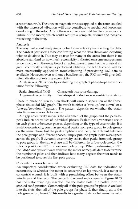
632 Electrical Power Equipment Maintenance and Testing
a rotor/stator rub. The uneven magnetic stresses applied to the rotor coupled with the increased vibration will also contribute to mechanical looseness developing in the rotor. Any of these occurrences could lead to a catastrophic failure of the motor, which could require a complete rewind and possible restacking of the iron.
AnalysisThe easy part about analyzing a motor for eccentricity is collecting the data. The hardest part seems to be confi rming what the data shows and deciding what to do about it. This may be true for many of the areas, but there is no absolute standard on how much eccentricity indicated on a current spectrum is too much, with the exception of an actual measurement of the physical air gap. Eccentricity analysis is performed utilizing the RIC test and will be most successfully applied in troubleshooting if preexisting RIC data is available. However, even without a baseline test, the RIC test will give defi -nite indications of existing eccentricity.
Analysis of a RIC is done by evaluating the graph of phase-to-phase induc-tance for the following:
Scale: sinusoidal Y/N? Characteristics: rotor damageAlignment: eccentricity Peak-to-peak inductance: eccentricity or stator
Phase-to-phase or turn-to-turn shorts will cause a separation of the three-phase sinusoidal RIC graph. The result is either a “two-up/one-down” or a “one-up/two-down” pattern. The pattern depends on whether the stator windings are wye or delta wound.
Air gap eccentricity impacts the alignment of the graph and the peak-to-peak inductance values of individual phases. Peak-to-peak variations occur on each phase or between phases, depending on the type of eccentricity. If it is static eccentricity, you may get equal peaks from pole group to pole group on the same phase, but the peak amplitude will be quite different between the pole groups of different phases. Simply put, the graph looks misaligned across the graph. If dynamic eccentricity exists, then peaks from pole group to pole group in the same phase will be different. In a four-pole motor, the rotor is positioned 90° to cover one pole group. When performing a RIC, the PdMA analysis software will use the motor nameplate data to determine the number of poles and then indicate how many degrees the rotor needs to be positioned to cover the fi rst pole group.
Concentric versus lap woundAn important consideration when evaluating RIC data for indication of eccentricity is whether the motor is concentric or lap wound. If a motor is concentric wound, it is built with a preexisting offset between the stator windings and the rotor. The concentric wound motor seen in Figure 10.33 has the stator windings inserted into the stator slots in a basket form or stacked confi guration. Commonly all of the pole groups for phase A are laid into the slots, then all of the pole groups for phase B, then fi nally all of the pole groups for phase C. This results in a greater distance between the rotor
DK4058_C010.indd 632DK4058_C010.indd 632 11/8/2008 12:19:42 PM11/8/2008 12:19:42 PM

Motors and Generators 633
and the phase A coils than exists between rotor and phase C coils. This results in a natural stair stepping indication of the phase-to-phase values seen in Figure 10.34.
FIGURE 10.33Graph showing concentric wound motor stator windings inserted into the stator slots in a
basket form or stacked confi guration. (Courtesy of PdMA Corporation, Tampa, FL.)
14.114.013.913.813.713.613.513.413.313.2
0 100 200Degrees
300
mH
FIGURE 10.34Graph showing phase-to-phase values of pole group windings. (Courtesy of PdMA Corporation,
Tampa, FL.)
DK4058_C010.indd 633DK4058_C010.indd 633 11/8/2008 12:19:42 PM11/8/2008 12:19:42 PM

634 Electrical Power Equipment Maintenance and Testing
Concentric wound motors by design create RIC results that appear as though there may be an eccentricity between the rotor and stator. Results of a RIC performed on a random concentric wound motor can be seen in Figure 10.35. Notice the peak amplitudes from one pole group to another are basically the same, but different from the other two phases. One phase is always slightly lower and the other phase is always slightly higher.
In a case where concentric wound motors are identifi ed or suspected, the RIC needs to be performed over two pole faces. Place the motor in observe and confi rm any suspected eccentricity with correlating evidence, such as EMAX eccentricity analysis or vibration analysis.
AnalysisFigure 10.35 shows an example of a dynamic eccentricity. Notice how the peak amplitudes of the blue phase vary from pole group to pole group as the rotor is rotated. This occurs for each of the three phases. Dynamic eccentricity is the more severe type of eccentricity due to the increased chance of a rotor/stator rub.
Eccentricity analysis is performed through a high-frequency spectrum of the current signal. When air gap eccentricity exists in a motor, the air gap fl ux will be off balance, causing different levels of voltage to be induced onto the rotor. This results in irregular current fl ow on the rotor and varying levels of counter electromotive force, which is felt by the stator. These vary-ing forces on the stator winding produce changes in the amplitude of the current similar to a load change. By displaying the current in a spectrum format, the modulations can be seen as sideband activity around a location known as the eccentricity frequency (FECC). The FECC is the number of rotor bars multiplied by the shaft frequency (rpm/60) of the motor. The current modulations are seen as peaks on the spectrum, which will be fi rst and third
FIGURE 10.35Graph showing an example of a dynamic eccentricity. (Courtesy of PdMA Corporation,
Tampa, FL.)
0
3.1
3.2mH
3.3
3.4
20 40 60 80 100 120Degrees
140 160 180 200 220 240 260
DK4058_C010.indd 634DK4058_C010.indd 634 11/8/2008 12:19:42 PM11/8/2008 12:19:42 PM

Motors and Generators 635
sidebands of the line frequency powering the motor. In a 60 Hz system these peaks will appear as four peaks, 120 Hz apart, and nonsynchronous to line frequency. The peaks are seen in Figure 10.36.
In Figure 10.36, the large Xs indicate the eccentricity-related peaks. The small xs indicate harmonics of line frequency. The cursor line located at 1180 Hz is the FECC, which is equal to the number of rotor bars times the shaft speed. The speed and rotor bar information is necessary to be able to confi rm that the peaks identifi ed on the spectrum are indeed eccentricity related. If the number of rotor bars and the speed are known, the analyzer software automatically places a red X at the four peak locations that identify eccentricity. Obtaining the speed from the Advance Spectral Analysis current demodulation software, low/high resolution rotor test or via a strobe light is the easy part. The rotor bar count; however, is another matter. First, at the earliest opportunity you should verify that a rotor bar count exists on each of your motor repair specifi cations. The report you get back from the shop should include how many rotor bars and stator slots exist in the motor. Second, utilize the vibration department to assist in the rotor bar count. They may have previously identifi ed the number of rotor bars through spectrum analysis of the vibration signal.
Eccentricities in the air gap will develop uneven magnetic pull between the stator and rotor during operation. This uneven magnetic pull will lead to increased vibration, mechanical wear and tear, and possibly pullover to the point of a rotor/stator rub. It is important to have equipment, which provides the necessary information to make informed maintenance decisions con-cerning the severity of an air gap eccentricity.
Impact of variable frequency drives on motorThe variable frequency drive (VFD) is also called variable speed drive (VSD). The VFD technology has changed how motors are applied today. Many VFDs are being installed today with the motors to gain benefi ts in energy savings and ability to vary or control the speed of the motor. However, this all comes
FIGURE 10.36Graph showing current modulations as peaks on the spectrum. (Courtesy of PdMA Corpo-
ration, Tampa, FL.)
10000
1000.399
1120.657 1180.333
1240.164 1360.4220
40
60
80
100
120
1100 1200Frequency (Hz)
1300
DK4058_C010.indd 635DK4058_C010.indd 635 11/8/2008 12:19:42 PM11/8/2008 12:19:42 PM

636 Electrical Power Equipment Maintenance and Testing
at a cost, since the VFD is a nonlinear load that generates harmonics and therefore pollutes the power supply to the motor and other loads in the elec-trical distribution system. This discussion focuses on the effects of VFDs on motors and how motors are impacted by VFDs.
Excessive heat is the fi rst basic issue to be understand. One concern of VFD is their propensity to destroy motors through overheating. Where does the excessive heat come from? Heat results from excessive current fl owing through the motor in order for the motor to produce the necessary torque to drive its load. When a motor operates as designed, it will deliver a certain torque for a given current input. If the torque demand changes (as in varia-tions in load), the current demand changes. The motor is designed to account for the current required to provide rated torque and the amount of heat transfer required, to prevent the motor from overheating.
If a motor requires more than full-load current to deliver the rated torque or horse power, then there is either a design fl aw with the motor or a problem with the power supply to the motor. Today, motors are designed with longer stretched out frames and much less iron than older designs. A 40 hp motor today is much smaller than the one made years ago. Older motors were able to dissipate heat through the large masses of iron used in their construction. Today, the heat is removed by transfer to the surface of the motor.
If this higher current is not from the load demand or the design of the motor (and these things should both be considered) then attention should be shifted to power quality. Poor power quality can cause a motor to draw excessive current as a result of harmonics, especially the 2nd, 5th, 11th, and so on. The IEEE standard 519-1992 standard on power quality states that the current distortion at the point of common coupling should not exceed a pre-determined value, such as 10% for distribution system rated 15 kV and less.
First, let us understand the power quality problems. Voltage and current har-monic distortion, voltage spikes, voltage unbalance, and PF are a few among the many concerns when discussing power quality. Although all of these are important, we focus on just a few, beginning with harmonic distortion.
From the power quality perspective, the most common reference relating to harmonics is THD. THD is the ratio of the rms of the harmonic content to the rms value of the fundamental quantity, expressed as a percent of the funda-mental. Quite simply it is the rms value of the signal with the fundamental frequency removed. A perfect 60 Hz sine wave would have 0% THD. So higher frequency waveforms, that is, voltage and currents that are multiple of the fundamental frequency (60 Hz) would be considered as harmonic distortion.
The following is a graphic representation showing the basic differences between the fundamental 60 Hz signal and the harmonics of the 60 Hz signal.
Figure 10.37 shows a time domain graph of a three-phase 60 Hz voltage and current signal. Phase 1 has a zero crossing near 0.01 s. The next zero crossing occurs at 180°, just before 0.02 s and completes a cycle at 360°. This is considered the fi rst or fundamental harmonic.
Harmonic distortion is not diffi cult to understand since this distortion is comprised of higher order signals that are multiples of the 60 Hz fundamental
DK4058_C010.indd 636DK4058_C010.indd 636 11/8/2008 12:19:43 PM11/8/2008 12:19:43 PM

Motors and Generators 637
signals. These harmonics can be related to the positive, negative, and zero sequence components that will help in the understanding of why the harmonic distortion causes excessive heating in the motor and other undesirable effects.
In a perfectly balanced three-phase system, only the positive sequence exists. However, when power system becomes unbalanced then all three components exists, i.e., positive, negative, and zero sequence. Similarly, when harmonics are generated by nonlinear load, such as VFD, the electrical distribution system is no longer in balance. As a result, the various order harmonics then can be classifi ed as positive, negative, and zero sequence har-monics because they behave exactly like the original components. Positive sequence harmonics create a magnetic fi eld in the direction of rotation of the fundamental (60 Hz), which is the positive direction of rotation of the motor. Therefore, the fi rst-order harmonic is a positive sequence harmonic.
The second-order harmonic is 120 Hz and rotating in the opposite direction to the fundamental (60 Hz); therefore, it is called the negative sequence har-monic. Negative sequence harmonics develop magnetic fi elds in the opposite direction of rotation of the motor thus producing an opposing torque. The opposing torque reduces net positive torque of the motor. Therefore, the motor current increases to make up the torque required for a given load. The rotation of the magnetic fi eld developed by the second harmonic is in reverse order. The second harmonic sequence is 3, 2, 1. This is in reverse order of the positive sequence and therefore is called negative sequence harmonic.
The third harmonic is called a zero sequence harmonic. This creates a sin-gle-phase signal that does not produce a rotating magnetic fi eld. Though this signal performs no real work, it can still increase overall current demand and generate heat. The third harmonic currents fl ow back to the supply transformer and collect on the neutral leg, creating excessive heat in the transformer. The various order harmonics and their classifi cations as positive, negative, and zero sequence is shown in Table 10.9.
0 900.010.010.01
1801801800.020.020.02
270270270 3603603600.030.030.03
FIGURE 10.37Three-phase 60 Hz fundamental voltage and current waveforms. (Courtesy of PdMA
Corporation, Tampa, FL.)
DK4058_C010.indd 637DK4058_C010.indd 637 11/8/2008 12:19:43 PM11/8/2008 12:19:43 PM

638 Electrical Power Equipment Maintenance and Testing
Harmonics are primarily the result of nonlinear (switching) loads such as computers, fl orescent lighting, and VFDs. The presence of harmonics in a distribution system results in excessive heat from increased current required by the loads. For example, a motor designed to pull 100 A at full load may draw 120 A if the harmonic distortion is high. This additional current can lead to insulation damage and possibly a failure of the motor. The voltage distortion is the primary concern for the motor.
Figure 10.38 shows the general makeup of a drive system consisting of three sections (rectifi er, storage, and inverter sections). The rectifi er section converts the AC signal into a DC signal. The capacitor bank stores this DC power, and the inverter section converts it into a variable AC output. Drives designed to operate DC motors function through similar principles. With DC, the strength of the output signal is regulated instead of the frequency. The focus of this discussion will be on AC drives.
Common classifi cations of VFDs available today are variable voltage inverters (VVI), variable current inverters (VCI), and PWM inverters. Each
TABLE 10.9
Relationship between the Harmonic Order and the Positive, Negative, and Zero Sequence
Harmonic Frequency Sequence Harmonic Frequency Sequence
1 60 + 7 420 +
2 120 − 8 480 −
3 180 0 9 540 0
4 240 + 10 600 +
5 300 − 11 660 −
6 360 0 12 720 0
Source: Courtesy of PdMA Corporation, Tampa, FL.
Line sidetest location
DC bus
ACmotor
Load sidetest location
Input linereactor
(optional)
Diode rectifier Pulse width modulated inverter
FIGURE 10.38Components of a VFD. (Courtesy of PdMA Corporation, Tampa, FL.)
DK4058_C010.indd 638DK4058_C010.indd 638 11/8/2008 12:19:43 PM11/8/2008 12:19:43 PM
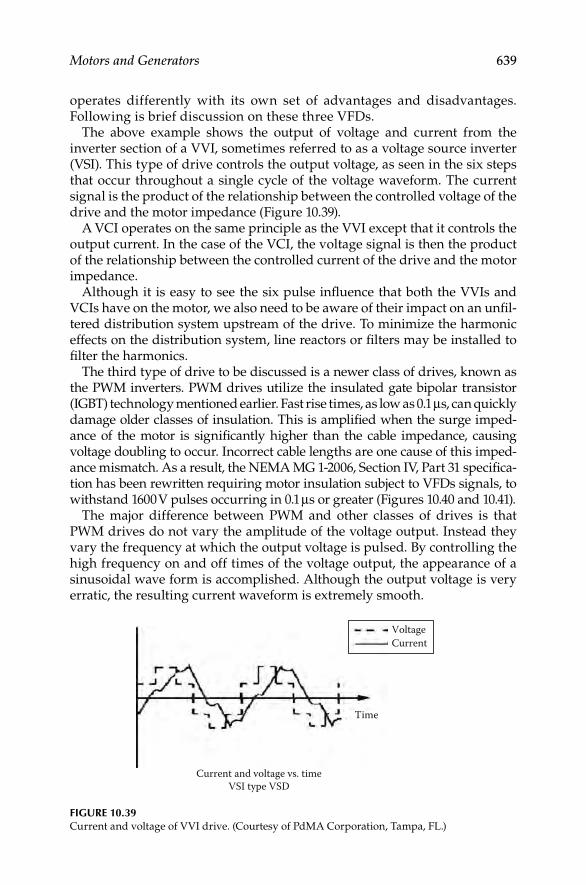
Motors and Generators 639
operates differently with its own set of advantages and disadvantages. Following is brief discussion on these three VFDs.
The above example shows the output of voltage and current from the inverter section of a VVI, sometimes referred to as a voltage source inverter (VSI). This type of drive controls the output voltage, as seen in the six steps that occur throughout a single cycle of the voltage waveform. The current signal is the product of the relationship between the controlled voltage of the drive and the motor impedance (Figure 10.39).
A VCI operates on the same principle as the VVI except that it controls the output current. In the case of the VCI, the voltage signal is then the product of the relationship between the controlled current of the drive and the motor impedance.
Although it is easy to see the six pulse infl uence that both the VVIs and VCIs have on the motor, we also need to be aware of their impact on an unfi l-tered distribution system upstream of the drive. To minimize the harmonic effects on the distribution system, line reactors or fi lters may be installed to fi lter the harmonics.
The third type of drive to be discussed is a newer class of drives, known as the PWM inverters. PWM drives utilize the insulated gate bipolar transistor (IGBT) technology mentioned earlier. Fast rise times, as low as 0.1 μs, can quickly damage older classes of insulation. This is amplifi ed when the surge imped-ance of the motor is signifi cantly higher than the cable impedance, causing voltage doubling to occur. Incorrect cable lengths are one cause of this imped-ance mismatch. As a result, the NEMA MG 1-2006, Section IV, Part 31 specifi ca-tion has been rewritten requiring motor insulation subject to VFDs signals, to withstand 1600 V pulses occurring in 0.1 μs or greater (Figures 10.40 and 10.41).
The major difference between PWM and other classes of drives is that PWM drives do not vary the amplitude of the voltage output. Instead they vary the frequency at which the output voltage is pulsed. By controlling the high frequency on and off times of the voltage output, the appearance of a sinusoidal wave form is accomplished. Although the output voltage is very erratic, the resulting current waveform is extremely smooth.
VoltageCurrent
Time
Current and voltage vs. timeVSI type VSD
FIGURE 10.39Current and voltage of VVI drive. (Courtesy of PdMA Corporation, Tampa, FL.)
DK4058_C010.indd 639DK4058_C010.indd 639 11/8/2008 12:19:43 PM11/8/2008 12:19:43 PM

640 Electrical Power Equipment Maintenance and Testing
Voltage & Current vs Time – 3401001 TWO S-RAND 08/19/1998 9:55:13 AM
60 800
600
400
200
L
0.02
Current 1Voltage 2–3
200
400
600
000
40
20
0
Curr
ent (
A)
Volta
ge (V
)
20
40
60
00
FIGURE 10.40Voltage and current relationship at the output of a PWM drive. (From Naah Bethel/PdMA,
Fault Zone Analysis, Six Part Series on Identifying Motor Defects. Courtesy of PdMA Corporation,
Tampa, FL.)
Voltage & Current vs Time -- 3401001 TWO S-RAND 08/19/1998 9:55:13 AM
60 600
400
200
U
Voltage 1Voltage 2Voltage 3
Volta
ge (V
)
200
400
600
40
20
0
Curr
ent (
A)
20
40
60
80
0.01 0.02 0.03
FIGURE 10.41Line-to-neutral voltage output of a PWM drive. (From Naah Bethel/PdMA, Fault Zone Analysis,
Six Part Series on Identifying Motor Defects. Courtesy of PdMA Corporation, Tampa, FL.)
DK4058_C010.indd 640DK4058_C010.indd 640 11/8/2008 12:19:43 PM11/8/2008 12:19:43 PM
Motors and Generators 641
It is a fact that VFDs can damage the insulation system of a motor. However, with better understanding, it is possible to prevent the premature motor fail-ures. It would be prudent not to install a PWM drive to an aged class B insu-lation system. Drive manufacturers have increased effectiveness through PWM technology to deliver a clean current waveform. But that current comes with the expense of very fast rise time. Consult the drive manufacturer and develop an understanding of the limitations in place for the installation of VFDs. This includes things such as cable length, modulating frequencies, and impedance matching of the motor and circuit and fi ltering to ensure a clean distribution system. VFD technology is here to stay and it will continue to improve. Just like motor insulation, it will get better over time. Information and communication is the key to longer motor life.
Application guide for VFDsAs discussed above, a good understanding of the technology is required when applying VFD to a new and to an existing motor. For VFDs equipped with IGBT technology, the voltage rises from zero to peak in only one-tenth of a microsecond. Unfortunately, there are not many standard design motors, including existing motors that would have suffi cient insulation to withstand such a fast voltage rise. High peak voltages can be experienced at the motor terminals especially when the distance between the inverter (drive) and the motor exceeds about 15 m (50 ft). This is typically caused by the voltage dou-bling phenomenon of a transmission line having unequal line and load impedances. Motor terminal voltage can reach twice the DC bus voltage of the drive in long lead applications. When the characteristic load impedance is greater than the line impedance, then voltage (and current) is refl ected from the load back toward the source (drive). The absolute peak voltage is equal to the sum of the incident peak voltage traveling toward the motor plus the refl ected peak voltage. If the load characteristic impedance is greater than the characteristic line impedance, then the highest peak voltage will be experienced at the load (motor) terminal. If the DC bus voltage of the drive is 850 V, then motor terminal voltage could reach 1700 V peak.
Fast voltage rise times of 1600 V/μs can be typical as the motor lead length exceeds just a few hundred feet. Voltage rise time is referred to as dv/dt (change in voltage versus change in time). When the rise time is very fast, the motor insulation becomes overstressed. Excessively high dv/dt can cause premature breakdown of standard motor insulation. Inverter duty motors typically have more phase-to-phase and slot insulation than the standard duty motors (NEMA design B).
When motors fail due to insulation stress caused by high peak voltage and fast voltage rise times (high dv/dt) they have common symptoms. Most fail-ures of these types occur in the fi rst turn as either a phase-to-phase short or phase-to-ground short. The highest voltage is seen by the fi rst turns of the winding and due to motor inductance and winding capacitance of the motor, the peak voltage and dv/dt decay rapidly as the voltage travels through the winding. Normally, the turn-to-turn voltage in a motor is quite low because there are many turns in the winding. However when the dv/dt is very high,
DK4058_C010.indd 641DK4058_C010.indd 641 11/8/2008 12:19:44 PM11/8/2008 12:19:44 PM

642 Electrical Power Equipment Maintenance and Testing
the voltage gradient between turns and between phase windings can be excessively high, resulting in premature breakdown of the motor insulation system and ultimately motor failure. This problem is most prevalent on 480 V system because the peak terminal voltage experienced often exceeds the insulation breakdown voltage rating of the motor.
The standard motor capabilities established by the NEMA and expressed in the MG-I standard (part 30), indicate that standard NEMA type B motors can withstand 1000 V peak at a minimum rise time of 2 μs. Therefore to pro-tect standard NEMA Design B motors, one should limit peak voltage to 1 kV and reduce the voltage rise to less than 500 V/μs.
There are several solutions available to solve this problem, each offering a different degree of protection at a different price. These solutions are:
Inverter duty motors: New motors specifi cally design for IGBT drive applica-tions should be considered for all new installations. They offer increased winding slot insulation, increased fi rst turn insulation, and increased phase-to-phase turn insulation. These motors are more expensive than standard design B motors but are the best motor for the application when it will be controlled by an IGBT variable frequency inverter. The NEMA Standard MG-I (part 31) indicates that inverter duty motors shall be designed to with-stand 1600 V peak and rise times of greater than 0.1 μs. Always confi rm the actual motor capability with the manufacturer before installation.
Cable length: Minimize the cable between the inverter and motor. Quite often this is not possible, especially when the actual location of motor is at greater distance from the inverter than desired. The longer the cable length, the greater is its capacitance which will result in lower overall cable surge impedance. Therefore, this will result in a greater mismatch between the characteristic impedance of the line (surge impedance) and load imped-ance, thus giving a higher peak voltage at the motor (load) terminals. By minimizing the cable length, this mismatch problem can be minimized.
Tuned inductor and capacitor (LC) fi lters: The LC fi lters are an effective means of cleaning the output voltage waveform and protecting the motor. An LC circuit can result in the best voltage waveform but at a relatively high cost and with some future considerations. The fi lters are low pass shunt-type fi l-ters tuned for a specifi c frequency, often in the range of 1–2 kHz. Because these fi lters have essentially zero impedance at the tuned frequency, it is very important that the inverter switching frequency not be set too low. The threat exists that someone may vary the carrier frequency (at a later date) without consideration for the existence of a low pass fi lter resulting in damage to the drive or fi lter. One should be very careful when applying these types of fi lters on the output of a drive with variable carrier frequency. LC fi lters for these types of applications cost approximately three to four times the cost of a load reactor and do not offer the most optimal solution.
RC snubber networks: The RC networks can reduce the slope of the voltage waveform leading edge and reduce the peak voltage of the waveform but
DK4058_C010.indd 642DK4058_C010.indd 642 11/8/2008 12:19:44 PM11/8/2008 12:19:44 PM
Motors and Generators 643
they have a minimal effect on the actual waveshape. They perform margin-ally when compared to the other solutions. The RC networks are less costly than LC fi lters and they provide marginal benefi ts. The cost of RC network can be —two to three times the cost of a load reactor.
Load reactors: The load reactors offer the most cost-effective means of solving high dv/dt and peak voltage problems associated with IGBT drives. Typical experience shows that peak voltage is limited to 1000 V or less (actual value varies based upon system voltage). Voltage rise time (dv/dt) is typically extended to several microseconds resulting in only about 75–200 V/μs rise times. Usually the load reactor is all that is needed to adequately protect the motor from dv/dt and to allow full warranty of the motor applied in IGBT drive applications. The load reactor may be installed at the drive or at the motor location. It offers the best dv/dt reduction when placed at the drive. Placing the reactor at the drive also provides voltage stress protection for the motor cables. Several man-ufacturers offer line/load reactors that are specially constructed for IGBT drive applications. These reactors have a 4000 V rms (5600 V peak) insulation dielectric strength and are approved by both CSA and UL (UL506 & UL508).
10.11 Testing of Motors and Generators
Today’s machines are subjected to extremely high electrical and mechanical stresses and therefore have shorter life spans as compared to yesterday’s bulky machines. Furthermore, unfavorable operating conditions may lead to unexpected troubles, which can have harmful effects on machine life. The insulation system is extremely important and therefore should be checked on a regular basis. IEEE standard 1415-2006, IEEE Guide for Induction Machinery Maintenance Testing and Failure Analysis provides maintenance testing and failure analysis guidance for form-wound, squirrel cage, induc-tion motors rated up to 15 kV. It addresses the stator (winding and core) rotor (winding and core) vibration and noise bearings and shafts structure, frame ventilation, and accessories. This guide is intended to be used by personnel responsible for the operation and maintenance of large induction machines. Table 10.1 of the IEEE standard 1415-2006, IEEE Guide for Induction Machinery Testing and Failure Analysis, gives a list of the various tests that are in wide-spread use in the industry for testing induction machines. This table lists the test description, effectiveness, typical frequency, and the pertinent IEEE standard reference for each test. The IEEE Table 10.1 is represented in Table 10.10 for reader’s reference. The reader is urged to consult this table and the IEEE standard 1415-2006 when performing test on induction machinery.
The tests listed in Table 10.10 are all encompassing, and many of the nonelec-trical tests are not in the scope of this book. The reader should refer to the last column of the Table 10.10 for additional information on the tests not covered in this chapter. The state of the machine insulation can be checked by means of the tests discussed below:
DK4058_C010.indd 643DK4058_C010.indd 643 11/8/2008 12:19:44 PM11/8/2008 12:19:44 PM

644 Electrical Power Equipment Maintenance and Testing
TAB
LE 1
0.10
Co
mp
ari
son
of
Main
ten
an
ce T
ests
fo
r In
du
ctio
n M
ach
iner
y
Test
Desc
rip
tio
nE
ffect
iven
ess
On
lin
e,
Off
-Lin
e
Ty
pic
al
Test
Fre
qu
en
cy (
Years
)T
est
Pre
cau
tio
ns
Ind
ust
ry
Sta
nd
ard
AC
hig
h p
ote
nti
al
Ov
erv
olt
ag
e te
st a
pp
lied
fro
m c
on
du
cto
r-to
-gro
un
d
to t
est
gro
un
dw
all
in
su-
lati
on
of
the
stato
r w
ind
ing
Pass
/fa
il t
est;
no
t ef
fect
ive
for
tren
din
g
Off
-lin
eF
act
ory
tes
t o
r as
nec
essa
ry
Po
ten
tiall
y
des
tru
ctiv
e
IEE
E 1
12
NE
MA
MG
1
IEE
E 4
IEE
E 9
5
Acc
eler
ati
on
tim
eM
easu
re a
ccel
erati
on
tim
e
start
ing
Dif
fi cu
lt f
or
tren
din
gO
nli
ne
1–2
Bea
rin
g i
nsu
lati
on
Insu
lati
on
res
ista
nce
sh
aft
to
gro
un
d
Pass
/fa
il t
est
Off
-lin
e0.5
–1
IEE
E 4
3
IEE
E 1
12
Bea
rin
g t
emp
eratu
reM
easu
rem
ent
of
bea
rin
g
met
al,
bea
rin
g h
ou
sin
g, o
r
bea
rin
g o
il t
emp
eratu
re.
Ap
pli
es t
o a
ll b
eari
ng
s, o
il
lub
rica
ted
an
d g
rease
lub
rica
ted
Eff
ecti
ve
for
tren
din
g. M
ust
acc
ou
nt
for
am
bie
nt
tem
per
atu
re
On
lin
e0.5
–1
Co
nti
nu
ou
sly
Cap
aci
tan
ceA
C t
est
to m
easu
re i
nsu
-
lati
on
cap
aci
tan
ce l
ine-
to
-gro
un
d
Eff
ecti
ve
on
sin
gle
co
ils
du
rin
g
man
ufa
ctu
rin
g o
f m
ediu
m-v
olt
ag
e
mach
ines
. P
oss
ibly
eff
ecti
ve
for
tren
din
g
Off
-lin
eF
act
ory
1–2
IEE
E 2
86
Co
re l
oss
(lo
op
)T
est
for
sho
rted
sta
tor
core
lam
inati
on
s
Pass
/fa
il t
est;
no
t ty
pic
all
y e
ffec
tiv
e
for
tren
din
g, alt
ho
ug
h u
nd
er
con
tro
lled
co
nd
itio
ns
may
be
use
d
for
tren
din
g
Off
-lin
eT
yp
icall
y d
uri
ng
a r
ewin
d p
roce
ss
Be
pre
pare
d t
o s
top
test
ab
rup
tly
if
core
dam
ag
e
is s
usp
ecte
d
IEE
E 6
2.2
DK4058_C010.indd 644DK4058_C010.indd 644 11/8/2008 12:19:44 PM11/8/2008 12:19:44 PM
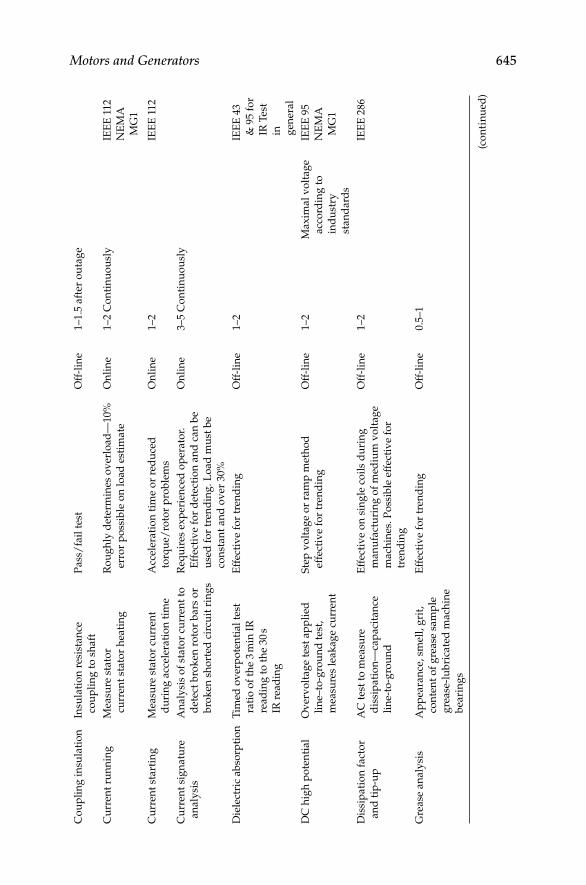
Motors and Generators 645C
ou
pli
ng
in
sula
tio
nIn
sula
tio
n r
esis
tan
ce
cou
pli
ng
to
sh
aft
Pass
/fa
il t
est
Off
-lin
e1–1.5
aft
er o
uta
ge
Cu
rren
t ru
nn
ing
Mea
sure
sta
tor
curr
ent
stato
r h
eati
ng
Ro
ug
hly
det
erm
ines
ov
erlo
ad
—10%
erro
r p
oss
ible
on
lo
ad
est
imate
On
lin
e1–2 C
on
tin
uo
usl
yIE
EE
112
NE
MA
MG
1
Cu
rren
t st
art
ing
Mea
sure
sta
tor
curr
ent
du
rin
g a
ccel
erati
on
tim
e
Acc
eler
ati
on
tim
e o
r re
du
ced
torq
ue/
roto
r p
rob
lem
s
On
lin
e1–2
IEE
E 1
12
Cu
rren
t si
gn
atu
re
an
aly
sis
An
aly
sis
of
stato
r cu
rren
t to
det
ect
bro
ken
ro
tor
bars
or
bro
ken
sh
ort
ed c
ircu
it r
ing
s
Req
uir
es e
xp
erie
nce
d o
per
ato
r.
Eff
ecti
ve
for
det
ecti
on
an
d c
an
be
use
d f
or
tren
din
g. L
oad
mu
st b
e
con
stan
t an
d o
ver
30%
On
lin
e3–5 C
on
tin
uo
usl
y
Die
lect
ric
ab
sorp
tio
nT
imed
ov
erp
ote
nti
al
test
rati
o o
f th
e 3 m
in I
R
read
ing
to
th
e 30 s
IR r
ead
ing
Eff
ecti
ve
for
tren
din
gO
ff-l
ine
1–2
IEE
E 4
3
& 9
5 f
or
IR T
est
in
gen
eral
DC
hig
h p
ote
nti
al
Ov
erv
olt
ag
e te
st a
pp
lied
lin
e–to
-gro
un
d t
est,
mea
sure
s le
ak
ag
e cu
rren
t
Ste
p v
olt
ag
e o
r ra
mp
met
ho
d
effe
ctiv
e fo
r tr
end
ing
Off
-lin
e1–2
Max
imal
vo
ltag
e
acc
ord
ing
to
ind
ust
ry
stan
dard
s
IEE
E 9
5
NE
MA
MG
1
Dis
sip
ati
on
fact
or
an
d t
ip-u
p
AC
tes
t to
mea
sure
dis
sip
ati
on
—ca
paci
tan
ce
lin
e-to
-gro
un
d
Eff
ecti
ve
on
sin
gle
co
ils
du
rin
g
man
ufa
ctu
rin
g o
f m
ediu
m v
olt
ag
e
mach
ines
. P
oss
ible
eff
ecti
ve
for
tren
din
g
Off
-lin
e1–2
IEE
E 2
86
Gre
ase
an
aly
sis
Ap
pea
ran
ce, sm
ell,
gri
t,
con
ten
t o
f g
rease
sam
ple
gre
ase
-lu
bri
cate
d m
ach
ine
bea
rin
gs
Eff
ecti
ve
for
tren
din
gO
ff-l
ine
0.5
–1
(co
nti
nu
ed
)
DK4058_C010.indd 645DK4058_C010.indd 645 11/8/2008 12:19:44 PM11/8/2008 12:19:44 PM

646 Electrical Power Equipment Maintenance and Testing
Test
Desc
rip
tio
nE
ffect
iven
ess
On
lin
e,
Off
-Lin
e
Ty
pic
al
Test
Fre
qu
en
cy (
Years
)T
est
Pre
cau
tio
ns
Ind
ust
ry
Sta
nd
ard
Gro
wle
rT
ests
ro
tors
win
din
gs
inte
gri
ty (
lam
inati
on
s)
roto
r co
re o
f d
isass
emb
led
mach
ine
Pass
/fa
il t
est;
no
t ef
fect
ive
for
tren
din
g
Off
-lin
e5–10
Ph
ase
an
gle
Ele
ctri
cal
evalu
ati
on
of
win
din
gs
usi
ng
lo
w-v
olt
ag
e
AC
mea
sure
men
ts
Po
ssib
ly e
ffec
tiv
e fo
r tr
end
ing
if
corr
ecte
d f
or
win
din
g t
emp
eratu
re
an
d r
oto
r p
osi
tio
n
Off
-lin
e1–2
IEE
E 3
88
AN
SI/
EA
SA
AR
100
Vari
ab
le f
req
uen
cy
test
Co
mp
are
s p
hase
s’ c
om
ple
x
imp
edan
ces
at
dif
fere
nt
freq
uen
cies
. P
oss
ibly
effe
ctiv
e fo
r in
sula
tio
n
dia
gn
ost
ics
Po
ssib
ly e
ffec
tiv
e fo
r tr
end
ing
, if
corr
ecte
d f
or
win
din
g t
emp
eratu
re
an
d r
oto
r p
osi
tio
n
Off
-lin
e1–2
IEE
E 3
89
Ph
ase
bala
nce
AC
tes
t to
mea
sure
sta
tor-
win
din
g b
ala
nce
an
d r
oto
r
circ
uit
co
nd
itio
n
Po
ssib
ly e
ffec
tiv
e fo
r tr
end
ing
if
kep
t at
sam
e ro
tor
po
siti
on
th
an
pre
vio
us
test
s
Off
-lin
e1–2
IEE
E 3
88
IEE
E 3
89
AN
SI/
EA
SA
AR
100
Insu
lati
on
res
ista
nce
Mea
sure
s re
sist
an
ce o
f
insu
lati
on
bet
wee
n
con
du
cto
r an
d g
rou
nd
; to
det
ect
wet
or
dir
ty
insu
lati
on
an
d d
iele
ctri
c
inte
gri
ty
Eff
ecti
ve
for
tren
din
g i
f co
rrec
ted
for
tem
per
atu
re. A
deq
uate
sca
le
ran
ge
req
uir
ed
Off
-lin
e1–2 a
fter
ou
tag
eIE
EE
43
IEE
E 5
6
IEE
E 6
2.2
IEE
E
1432
TAB
LE 1
0.10
(co
ntin
ued)
Co
mp
ari
son
of
Main
ten
an
ce T
ests
fo
r In
du
ctio
n M
ach
iner
y
DK4058_C010.indd 646DK4058_C010.indd 646 11/8/2008 12:19:44 PM11/8/2008 12:19:44 PM

Motors and Generators 647O
il a
naly
sis
An
aly
sis
of
oil
fo
r lu
bri
can
t
chara
cter
isti
cs a
nd
wea
r
part
icle
co
nce
ntr
ati
on
oil
-lu
bri
cate
d m
ach
ine
bea
rin
gs
Eff
ecti
ve
for
tren
din
gO
ff-l
ine
an
aly
sis
sam
ple
can
be
tak
en
on
lin
e
0.5
–1
PD
AC
tes
t to
mea
sure
PD
(co
ron
a)
lin
e-to
-gro
un
d
Req
uir
es e
xp
erie
nce
d o
per
ato
r.
Wit
h s
om
e te
chn
olo
gie
s p
oss
ibly
effe
ctiv
e fo
r tr
end
ing
On
lin
e0.5
–5
Co
nti
nu
ou
sly
IEE
E
1434
PI
Rati
o o
f 10 m
in I
R t
o 1
min
IR
to d
etec
t w
et o
r d
irty
insu
lati
on
an
d p
oss
ibly
ag
ed
insu
lati
on
Eff
ecti
ve
for
tren
din
g m
ach
ines
;
sho
uld
hav
e ad
equ
ate
sca
le r
an
ge
Off
-lin
e1–2
IEE
E 4
3
Imp
edan
ce s
tart
ing
Mo
nit
ors
eq
uiv
ale
nt
com
ple
x
inst
an
tan
eou
s im
ped
an
ce.
Fin
ds
lock
ed o
r st
all
ed
fail
ure
on
sta
rt
Eff
ecti
ve
for
tren
din
gO
nli
ne
1–2
NE
MA
MG
1
Insu
lati
on
PF
PF
an
d
tip
-up
AC
tes
t to
mea
sure
in
sula
tio
n
PF
lin
e-to
-gro
un
d
Eff
ecti
ve
on
sin
gle
co
ils
du
rin
g
man
ufa
ctu
rin
g o
f m
ediu
m v
olt
ag
e
mach
ines
. P
oss
ible
eff
ecti
ve
for
tren
din
g
Off
-lin
eF
act
ory
IEE
E 2
86
Sh
aft
gro
un
din
g
curr
ents
Mea
sure
sh
aft
cu
rren
t an
d
wav
efo
rm o
n o
scil
losc
op
e
shaft
to
gro
un
d
Ind
icato
r o
f ch
an
ge
tren
dab
leO
nli
ne
3–5
IEE
E 1
12
Sh
aft
vo
ltag
eM
easu
re s
haft
vo
ltag
e an
d
wav
efo
rm o
n o
scil
losc
op
e
shaft
to
gro
un
d
Ind
icato
r o
f ch
an
ge
tren
dab
leO
nli
ne
3–5
IEE
E 1
12
Sp
eed
Mea
sure
of
shaft
rp
m s
haft
spee
d
Det
erm
ine
ov
erlo
ad
eff
ecti
ve
for
tren
din
g
On
lin
e3–5
20%
err
or
po
ssib
le
for
load
est
imate
IEE
E 1
12
NE
MA
MG
1
(co
nti
nu
ed
)
DK4058_C010.indd 647DK4058_C010.indd 647 11/8/2008 12:19:44 PM11/8/2008 12:19:44 PM
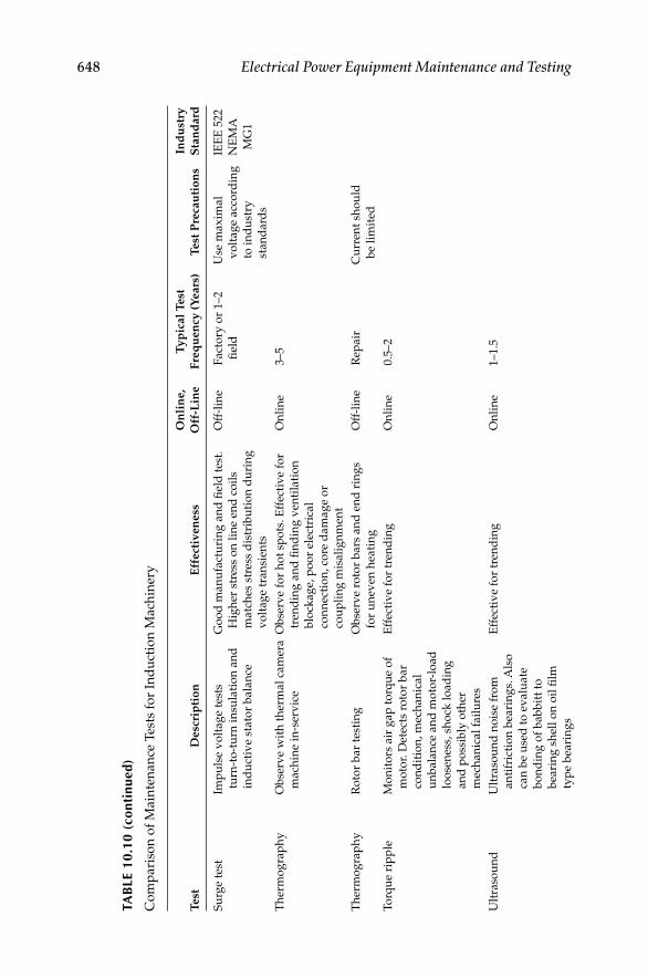
648 Electrical Power Equipment Maintenance and Testing
Test
Desc
rip
tio
nE
ffect
iven
ess
On
lin
e,
Off
-Lin
e
Ty
pic
al
Test
Fre
qu
en
cy (
Years
)T
est
Pre
cau
tio
ns
Ind
ust
ry
Sta
nd
ard
Su
rge
test
Imp
uls
e v
olt
ag
e te
sts
turn
-to
-tu
rn i
nsu
lati
on
an
d
ind
uct
ive
stato
r b
ala
nce
Go
od
man
ufa
ctu
rin
g a
nd
fi e
ld t
est.
Hig
her
str
ess
on
lin
e en
d c
oil
s
matc
hes
str
ess
dis
trib
uti
on
du
rin
g
vo
ltag
e tr
an
sien
ts
Off
-lin
eF
act
ory
or
1–2
fi el
d
Use
max
imal
vo
ltag
e acc
ord
ing
to i
nd
ust
ry
stan
dard
s
IEE
E 5
22
NE
MA
MG
1
Th
erm
og
rap
hy
Ob
serv
e w
ith
th
erm
al
cam
era
mach
ine
in-s
erv
ice
Ob
serv
e fo
r h
ot
spo
ts. E
ffec
tiv
e fo
r
tren
din
g a
nd
fi n
din
g v
enti
lati
on
blo
ckag
e, p
oo
r el
ectr
ical
con
nec
tio
n, co
re d
am
ag
e o
r
cou
pli
ng
mis
ali
gn
men
t
On
lin
e3–5
Th
erm
og
rap
hy
Ro
tor
bar
test
ing
Ob
serv
e ro
tor
bars
an
d e
nd
rin
gs
for
un
even
hea
tin
g
Off
-lin
eR
epair
Cu
rren
t sh
ou
ld
be
lim
ited
To
rqu
e ri
pp
leM
on
ito
rs a
ir g
ap
to
rqu
e o
f
mo
tor.
Det
ects
ro
tor
bar
con
dit
ion
, m
ech
an
ical
un
bala
nce
an
d m
oto
r-lo
ad
loo
sen
ess,
sh
ock
lo
ad
ing
an
d p
oss
ibly
oth
er
mec
han
ical
fail
ure
s
Eff
ecti
ve
for
tren
din
gO
nli
ne
0.5
–2
Ult
raso
un
dU
ltra
sou
nd
no
ise
fro
m
an
tifr
icti
on
bea
rin
gs.
Als
o
can
be
use
d t
o e
valu
ate
bo
nd
ing
of
bab
bit
t to
bea
rin
g s
hel
l o
n o
il fi
lm
typ
e b
eari
ng
s
Eff
ecti
ve
for
tren
din
gO
nli
ne
1–1.5
TAB
LE 1
0.10
(co
ntin
ued)
Co
mp
ari
son
of
Main
ten
an
ce T
ests
fo
r In
du
ctio
n M
ach
iner
y
DK4058_C010.indd 648DK4058_C010.indd 648 11/8/2008 12:19:44 PM11/8/2008 12:19:44 PM

Motors and Generators 649V
ibra
tio
nS
haft
or
bea
rin
g h
ou
sin
g
vib
rati
on
Dir
ect
on
bea
rin
g
Ho
usi
ng
or
pro
xim
ity
to
shaft
Eff
ecti
ve
for
tren
din
gO
nli
ne
0.5
–1
Vo
ltag
e d
rop
Mea
sure
bu
s v
olt
ag
e d
uri
ng
start
ing
Eff
ecti
ve
for
tren
din
gO
nli
ne
3–5
Vo
ltag
e su
pp
lyM
easu
re b
us
vo
ltag
e st
ato
r
hea
tin
g r
oto
r h
eati
ng
Eff
ecti
ve
for
tren
din
gO
nli
ne
Co
nti
nu
ou
sly
IEE
E 1
12
NE
MA
MG
1
Win
din
g r
esis
tan
ce
(in
clu
din
g c
ab
le)
Mea
sure
s w
ind
ing
resi
stan
ce s
tato
r w
ind
ing
s
an
d m
ach
ine
term
inati
on
s
det
ects
po
or
con
nec
tio
ns
Eff
ecti
ve
for
tren
din
g. C
orr
ect
for
tem
per
atu
re o
r p
erce
nt
un
bala
nce
Off
-lin
e1–1.5
IEE
E 1
12
IEE
E 1
18
Win
din
g
tem
per
atu
re
Ind
irec
t m
easu
rem
ent
of
win
din
g t
emp
eratu
re.
Ap
pli
es t
o m
ach
ine
wit
h
bu
ilt-
in R
TD
s o
r
ther
mo
cou
ple
s
Eff
ecti
ve
for
tren
din
g. M
ust
acc
ou
nt
for
am
bie
nt
tem
per
atu
re
an
d l
oad
On
lin
e0.5
–1
Co
nti
nu
ou
sly
Sour
ce:
Fro
m I
EE
E-s
td 1
415–2006, IE
EE
Gu
ide
to I
nd
uct
ion
Mach
iner
y M
ain
ten
an
ce T
esti
ng
an
d F
ail
ure
An
aly
sis.
DK4058_C010.indd 649DK4058_C010.indd 649 11/8/2008 12:19:44 PM11/8/2008 12:19:44 PM

650 Electrical Power Equipment Maintenance and Testing
10.11.1 Insulation Resistance and Dielectric Absorption Tests
The simplest and most basic tests for checking insulation integrity of machines are the insulation resistance and dielectric absorption (DA) tests. Refer to Chapter 2 for details on how to perform these tests.
10.11.2 High-Potential Test
AC or DC voltage high potential test may be performed on machines stator windings. The size of the machine windings (i.e., insulation volume) will deter-mine whether an AC high potential test can be performed in the fi eld because if the machine is very large the fi eld portable AC high potential test set may not have the capability to charge the winding insulation. The DC voltage high-potential test is discussed in Section 2.7 in Chapter 2, therefore this discussion only addresses the AC voltage high potential test for machines.
The high-potential test of the armature (stator) winding of a large motor or generator is preceded by a visual inspection and insulation resistance measure-ments. It provides the moment of truth concerning the condition of insulation.
High-potential tests may be performed with the rotor in place or with it removed. It is advantageous to consult and follow the manufacturer’s recom-mendations and schedules, taking into account the operating history of a machine. For example, it is recommended that on large machines the rotor be removed every 5 years and high-potential tests performed every 2–3 years.
To prepare the tests, the machine terminals are disconnected from the bus bars, the neutral connection is broken so that each phase winding may be subjected to a test voltage with respect to the other phase windings, and the rotor (if in place) is grounded. Protective ground cables should be connected to all disconnected bus bars and the neutral conductor. Each phase winding is short circuited so that uniform test voltage will be applied to each end. A test lead is attached to each phase winding and secured and terminated so that a convenient connection to the high-voltage test lead and to ground can be made. Temporary insulation, plastic bags over sharp points, and tie offs must be arranged to give correct clearance for the test voltage. A minimum of clear-ance of 7 in. per 10 kV, 60 Hz, is recommended for base conductor clearance.
The 60 Hz AC high-potential test applies stresses to machine winding as near as possible to those that normally exist under operating conditions. Even though the 60 Hz test is preferred over DC or 0.1 Hz tests, there are few AC sets of adequate size (kVA) available to perform this test on large machines. The size of the test set may be calculated from the following formula: kVA = 0.377 CE2, where C is the machine winding capacitance in microfarads and E is the maximum test voltage in kilovolts. For example, inservice operation on a 13.8 kV machine, each phase winding is stressed at 13.8/√
—3 or approximately
8 kV to ground with midpoint only at 4 kV to ground. The ends of windings T4, T5, and T6 (Figure 10.42a) are nearly at zero stress. The insulation toward the ends T4, T5, and T6, could be worn and still not fail in service unless damage to the winding becomes severe. During the high-voltage test, the windings are short circuited. The high-voltage lead is connected to both T1 and T4 and later
DK4058_C010.indd 650DK4058_C010.indd 650 11/8/2008 12:19:44 PM11/8/2008 12:19:44 PM
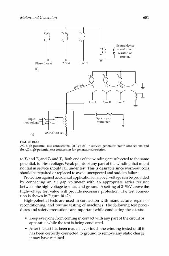
Motors and Generators 651
to T2 and T3 and T5 and T6. Both ends of the winding are subjected to the same potential, full-test voltage. Weak points of any part of the winding that might not fail in service should fail under test. This is desirable since worn-out coils should be repaired or replaced to avoid unexpected and sudden failure.
Protection against accidental application of an overvoltage can be provided by connecting an air gap voltmeter with an appropriate series resistor between the high-voltage test lead and ground. A setting of 2–5 kV above the high-voltage test value will provide necessary protection. The test connec-tion is shown in Figure 10.42b.
High-potential tests are used in connection with manufacture, repair or reconditioning, and routine testing of machines. The following test proce-dures and safety precautions are important while conducting these tests:
Keep everyone from coming in contact with any part of the circuit or • apparatus while the test is being conducted.
After the test has been made, never touch the winding tested until it • has been correctly connected to ground to remove any static charge it may have retained.
Neutral devicetransformerresistor, or
reactor.
(a)
Phase: 1 or A 3 or C2 or B
T4
T1
T5
T2
T6
T3
Sphere gapvoltmeter
ACHV test set
Inputlow voltage
(b)
HV lead
3 or C2 or B1 or A
T4
T1
T5
T2
T6
T3
FIGURE 10.42AC high-potential test connections. (a) Typical in-service generator stator connections and
(b) AC high-potential test connection for generator connection.
DK4058_C010.indd 651DK4058_C010.indd 651 11/8/2008 12:19:44 PM11/8/2008 12:19:44 PM

652 Electrical Power Equipment Maintenance and Testing
All leads to the circuit being tested should be connected to one • terminal of the source of the test voltage. All leads to all other circuits and all metal parts should be connected to ground. No leads are to be left unconnected for high-potential tests as this may cause an extremely severe strain at some point of the winding.
When making an AC voltage high-potential test, the voltage should • be increased to full voltage as rapidly as consistent with its value. This voltage should be maintained for 1 min. After completion of the test, the voltage should be reduced at a rate that will bring it to one-quarter value or less in not more than 15 s.
When making DC voltage high-potential test, the voltage should be • applied in controlled voltage steps. Refer to Chapter 2 for details on performing DC voltage high-potential tests.
Effective AC voltages to apply to motors and generators are listed in • Table 10.11.
10.11.3 PF Test
This method allows successful ground insulation tests on machine individ-ual stator phase windings. This test is usually connected up to and including 100% line-to-ground voltage. The PF is the ratio of the stator insulation loss (watts) and volt-amperes at a specifi ed test voltage. This can be represented by the following equation:
s a aPF { }/{ }W V I=
TABLE 10.11
Alternating High-Voltage Test Values for Motors and Generators
Type of Motor
and Generator
Motors and Generators
Reconditioned but Not
Rewound or Restored
to Original Condition
Motors and Generators Rewound
and Restored to Original
Condition (Acceptance)
Armature Field Armature Field
Above 250 V and
above 0.5 hp
0.67 (2EL−L +
1000) V
Seven times the
excitation
voltage but not
less than 1000 V
or more than
2300 V
(2EL−L + 1000)V Ten times the
excitation
voltage but not
less than
1500 V or more
than 3500 V
Below 250 V and
below 0.5 hp
600 V 600 V 900 V 900 V
a The IEEE standard 1415-2006 provides the following guidance. In the case of failed wind-
ings, where insulation is replaced or a partial rewind is performed, a reduced voltage fi nal
test may be used. Typically, the AC test voltages for these reduced tests are in the range of
125%–135% of rated line-to-line terminal voltage.
DK4058_C010.indd 652DK4058_C010.indd 652 11/8/2008 12:19:44 PM11/8/2008 12:19:44 PM

Motors and Generators 653
whereWs is the watts lossIa is the charging current in milliamperesVa is the test voltage in kilovolts
The evaluation of the test data is best interpreted by comparing with previous test results or by comparing test results among phases or with those test results obtained on units of similar manufacture and rating. It is gener-ally found that machines up to 24 kV will have a PF of 3% or less, depending upon the insulation system. The PF tip-up test may also be performed to further evaluate the insulation system. The tip-up test is defi ned as the increase in PF as voltage is increased from 2 kV to operating voltage. Refer to Section 3.6.7 in Chapter 3 for more details on PF testing.
10.11.4 Dissipation Factor Tan d Test
The machine winding may be considered as consisting of capacitance and resistance.
The active (resistive) power and reactive (capacitive) power can be repre-sented by the following equations:
2 2 2 2
R { }/ / P I R E R R E R= = =
2 2 2 2 2
C C C C C[ ]/ /P I X E X X E X CE= = = = w
where
PR is the active powerPC is the reactive powerC is the capacitance in microfaradsR is the resistance in ohmsXC is the capacitive reactance in ohmsIR is the resistive currentIC is the capacitive currentw is the radian frequency
The active power of the resistance in this equivalent circuit represents all capacitor losses. These losses occur on the surface and in the interior of the dielectric. The power P determines the loss of the capacitor. The dissipation factor tan d measuring bridge (Schering bridge) is designed to simulate the capacitor (the machine winding) by a series connection of resistance Rs and capacitance Cs. The corresponding values for the series connection for a given frequency can be converted by the following formula:
S
2 2 (tan /{1 tan })R R= +d d
S2(1 tan )C C= + d
The losses measured by the Schering bridge and the tan d can be represented as the following:
DK4058_C010.indd 653DK4058_C010.indd 653 11/8/2008 12:19:44 PM11/8/2008 12:19:44 PM

654 Electrical Power Equipment Maintenance and Testing
RP EI=
R Ctan /I I=d
or
C2tan tan P EI E C= =d w d
Substituting the value of CS in the preceding equation, we have
S2 2 {tan }/{1 tan }P C E= +w d d
For small values of tan d (i.e., less than 1), we can neglect tan2 d; we have
S2 tanP C E=w d
The value of CS is measured as Cx by the Schering bridge. The resistance and the inductance of the leads have to be considered for high capacitances and resistances; otherwise they are negligible. The PF and tan d tests are discussed in more detail in Chapter 3.
10.11.5 Partial Discharge Test
One of the causes of machine insulation degradation and failure is due to partial discharge (PD) in the gas-fi lled voids in the stator insulation system. The online or off-line PD test can be used to directly measure the pulse cur-rents generated by PD within a machine winding. The machine-winding insulation has voids that are fi lled with air or gas and they are of varying sizes. The PD pulses are of very short duration (few nanoseconds) because the void cavities are small however some pulses may be larger than other PD pulses. The PD test is applicable to form-wound stator windings of machines rated at 2300 V and above. Each PD pulse current originating in specifi c part of the winding will travels along the coil conductors. The PD current pulses in turn generate voltage pulses because of the surge impedance of the coils in the slots. Any device sensitive to high frequency can detect the PD pulses and thereby these small charge fl uctuations (in coulomb) are measured by testing the corresponding current variations. By this method the weak points of the insulation (location of the PD) are measured. However, this method does not provide information on the condition of insulation at those points where PD has not occurred. PD is an electrical discharge that only partially bridges the insulation between conductors. Especially for machines rated greater than 4 kV, PD can be a sign of deterioration involving external sur-faces (slot or end turn) or of delamination internal to the ground wall. PD current pulses can be measured in two ways: (1) off-line PD measurements and (2) online PD measurements.
The off-line PD test requires a power supply to energize the winding to at least rated phase-to-neutral voltage. It is best to perform this test one phase at a time with the other two phases grounded. The most common
DK4058_C010.indd 654DK4058_C010.indd 654 11/8/2008 12:19:44 PM11/8/2008 12:19:44 PM

Motors and Generators 655
means of detecting the PD current pulses is to use a high-voltage capacitor connected to the stator terminals. The capacitor blocks the normal 60 HZ AC voltage applied to energize the windings while passing the high-frequency PD pulse currents. The output of the high-voltage capacitor is coupled to a resistive or inductive-capacitive load. The PD high-frequency current passing through the capacitor create a voltage pulse across the resistive or inductive-capacitive network which then can be displayed on an oscilloscope, or other display device. Every PD will create its own pulse and the magnitude of a particular PD pulse will be proportional to the size of void cavity.
During the off-line PD test, the applied voltage is gradually raised while monitoring the PD pulses on the oscilloscope at the machine terminals. The voltage at which the PD is fi rst detected is known as PD inception voltage. The voltage is then raised to rated line-to-neutral operating voltage and held for 10 to 15 min while PD pulses are recorded. The voltage is then gradually reduced and the voltage at which the PD is no longer visible is recorded. This voltage is known as the PD extinction voltage. For motors rated 2300–4000 V, the phase-to-neutral voltage may not be suffi cient to produce discharges, therefore some owners will perform the PD test at line-to-line voltage. It should be kept in mind that using line-to-line voltage for PD test exceeds the normal insulation voltage rating of the winding and could lead to wind-ing insulation failure. During off-line PD measurements, it may be possible to measure at the line end and neutral end of the individual circuits or phases with all other circuits grounded or alternatively with all circuits tested in parallel. This will provide an indication as to whether the PD is more pronounced at the line or neutral ends and whether the phase-to-phase insulation is a source of PD activity.
The off-line PD test as discussed above does not pinpoint the location of the PD discharges in the stator windings. To determine the location of the PD discharges in the stator, PD probe test is performed. Two special probes are available to help locate the site of PD in the stator. One probe is designed to detect the electromagnetic (radio frequency) energy and the other to detect acoustic energy. The electromagnetic probe is usually tuned to 5 MHz essen-tially making it a modifi ed AM radio with an antenna mounted on a one end of the probe handle. The probe with the antenna end then can be moved around the stator windings to locate where the PD is occurring. The ultra-sonic probe is a directional microphone that picks up the acoustic pulses that are being generated by the movement of high-velocity electrons and ions due to PD in the stator windings. The ultrasonic sensor, used with appropriate safety precautions, can be useful for locating sites of higher PD activity at specifi c slots in the core of the machine. To perform PD probe test may require partially dismantling the machine, such as removing the rotor.
The online PD test is performed during normal operation when the machine is running at constant operating voltage. The PD monitor directly detects stator winding PD activity thereby including the effects of load, tem-perature, and voltage, which can provide important information as to the
DK4058_C010.indd 655DK4058_C010.indd 655 11/8/2008 12:19:45 PM11/8/2008 12:19:45 PM

656 Electrical Power Equipment Maintenance and Testing
probable cause of the PD activity. The PD activity generates current pulses that are typically of very short duration and propagate throughout the stator windings. Each PD pulse comprises of frequencies ranging from DC to sev-eral hundred megahertz. The online PD test is similar to the off-line PD test in many respects and they require use of sensors, which can take the form of the following:
Coupling capacitors at line terminals•
Radio frequency current transformer on ground wire•
Radio frequency current transformer on ground of insulation shield • of supply cable
Radio frequency current transformer on conductor between neutral • of stator and grounding impedance
Impedance across joint between machine frame and terminal box•
The instrumentation used with these sensors can consist of the following:
Radio noise meter for narrow band measurements between 100 kHz • and several hundreds of megahertz. Each type of PD, such as slot discharge or end arm discharge may have its own unique frequency spectrum.
Broadband measurement using an oscilloscope or pulse height ana-• lyzer to provide an indication as to the number, polarity, and phase position of the PD pulses. Polarity may indicate whether the PD is on a surface or if it is internal. Phase position may indicate whether the PD involves the groundwall, or phase-to-phase insulation.
During online measurements, the operator of the radio noise meter needs to identify RF signals from radio stations and sites of PD activity or sparking external to the machine so as to exclude these data from the analysis. Online PD measurements using broadband detection systems may make use of bandwidth, attenuation, and pulse travel time for noise reduction. Trending of individual machines based on periodic or continuous online PD measure-ments under identical operating conditions, or comparison between similar machines can indicate a need for off-line PD measurements to confi rm and locate the probable source of the discharge activity.
Because of the complexity in which PD pulses propagate within machine windings and the profound effect of bandwidth upon the response of the PD detection instrumentation, it has not been possible to establish mean-ingful limits for the PD magnitudes, which are measured at the terminal of the machine. Comparisons may be possible between machines of the same design using the same sensors and detection instrumentation of identical bandwidth. For additional information, refer to IEEE standard 1434-2000, IEEE Trial-Use Guide to the Measurement of Partial Discharges in Rotating Machinery.
DK4058_C010.indd 656DK4058_C010.indd 656 11/8/2008 12:19:45 PM11/8/2008 12:19:45 PM

Motors and Generators 657
10.11.6 Slot Discharge Test
This test is performed to evaluate the coil surface grounding in the slot portion. The stator coil outer surfaces are painted with conducting varnish in order to make good electrical contact with the machine frame to prevent voids. However, at higher voltages, ionization can take place in the voids, resulting in insulation damage. The slot discharge test consists of applying approximately 7 kV AC and observing the wave form on an oscilloscope. This wave form is compared to a wave form of one coil side arcing to the slot at a single point. The slot discharge phenomena usually consist of high fre-quencies, such as 2500 Hz/s. The line disturbances are usually fi ltered out in order to obtain an accurate slot discharge phenomena.
10.11.7 Conductor Insulation Tests
The insulation failure between conductors of motors and generators depends upon the machine insulation design. Failure between conductors can be as likely as the failure of ground insulation. Coils are tested during manufacture well above the minimum sparking voltage to ensure that the coils do not fail owing to thermal effects, vibrations, and the like. Where a high level of reliability is needed, maintenance testing of conductor insulation should be performed to the level of new coil test values. Normally, this test should be performed at the factory or repair shop facilities. The following test methods are in common use:
Surge comparison test (see Section 10.9.11)•
Induced surge voltage test•
Rotating spark-gap-type high-frequency oscillator•
10.11.8 Motor and Generator Component Tests
These tests include insulation resistance tests on components of motors and generators such as RTDs, exciter windings, stator insulated through bolts, rotor windings, and so on. These tests consist of the following:
1. Resistance measurement and insulation resistance of the RTDs
2. Insulation resistance of insulated stator-through-bolts
3. Test the interlaminar insulation of stator core
4. Rotor winding testsa. Insulation resistance
b. Winding resistance
c. Winding impedance
d. Winding fl ux distribution (pole voltage drop test)
The reader should consult the equipment manufacturer for recommenda-tions or the pertinent IEEE standard such as IEEE-56-1991, IEEE-95-2007, and IEEE-112-2004 on conducting these tests.
DK4058_C010.indd 657DK4058_C010.indd 657 11/8/2008 12:19:45 PM11/8/2008 12:19:45 PM
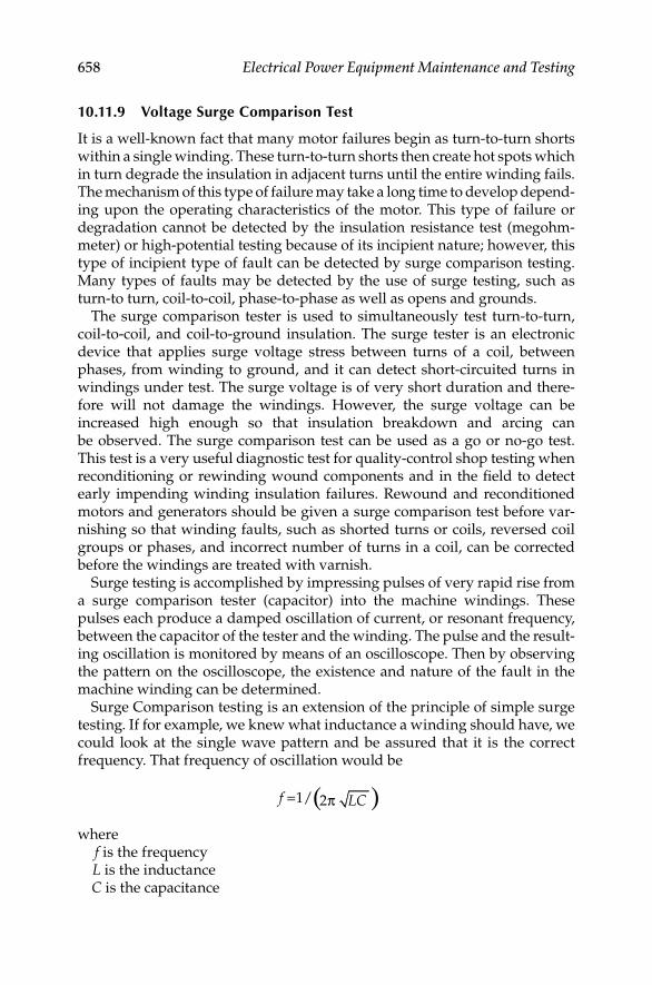
658 Electrical Power Equipment Maintenance and Testing
10.11.9 Voltage Surge Comparison Test
It is a well-known fact that many motor failures begin as turn-to-turn shorts within a single winding. These turn-to-turn shorts then create hot spots which in turn degrade the insulation in adjacent turns until the entire winding fails. The mechanism of this type of failure may take a long time to develop depend-ing upon the operating characteristics of the motor. This type of failure or degradation cannot be detected by the insulation resistance test (megohm-meter) or high-potential testing because of its incipient nature; however, this type of incipient type of fault can be detected by surge comparison testing. Many types of faults may be detected by the use of surge testing, such as turn-to turn, coil-to-coil, phase-to-phase as well as opens and grounds.
The surge comparison tester is used to simultaneously test turn-to-turn, coil-to-coil, and coil-to-ground insulation. The surge tester is an electronic device that applies surge voltage stress between turns of a coil, between phases, from winding to ground, and it can detect short-circuited turns in windings under test. The surge voltage is of very short duration and there-fore will not damage the windings. However, the surge voltage can be increased high enough so that insulation breakdown and arcing can be observed. The surge comparison test can be used as a go or no-go test. This test is a very useful diagnostic test for quality-control shop testing when reconditioning or rewinding wound components and in the fi eld to detect early impending winding insulation failures. Rewound and reconditioned motors and generators should be given a surge comparison test before var-nishing so that winding faults, such as shorted turns or coils, reversed coil groups or phases, and incorrect number of turns in a coil, can be corrected before the windings are treated with varnish.
Surge testing is accomplished by impressing pulses of very rapid rise from a surge comparison tester (capacitor) into the machine windings. These pulses each produce a damped oscillation of current, or resonant frequency, between the capacitor of the tester and the winding. The pulse and the result-ing oscillation is monitored by means of an oscilloscope. Then by observing the pattern on the oscilloscope, the existence and nature of the fault in the machine winding can be determined.
Surge Comparison testing is an extension of the principle of simple surge testing. If for example, we knew what inductance a winding should have, we could look at the single wave pattern and be assured that it is the correct frequency. That frequency of oscillation would be
( ) 1/ 2f LC= π
wheref is the frequencyL is the inductanceC is the capacitance
DK4058_C010.indd 658DK4058_C010.indd 658 11/8/2008 12:19:45 PM11/8/2008 12:19:45 PM

Motors and Generators 659
Since we seldom know the inductance value of a machine winding accurately, we need a more fl exible yet accurate method to analyze a signal trace on the oscilloscope. To do this, we use a dual trace scope and two identical capaci-tance discharge circuits to charge two different machine windings that should match at the same time. For example, in the testing of three-phase machine stator we know that each of the three phases should have the same induc-tance. Consequently, by comparing one phase against another we have two complete, and hopefully, identical L-C circuits for our test to work. A simpli-fi ed schematic of the surge comparison tester is shown in Figure 10.43. Detection of one-turn shorts or grounded coil is possible in all windings of few parallel circuits. Often only a small trace separation may be detectable with a one-turn short in a very large motor that has several parallel paths per phase. However, the winding con nections can be broken to reduce the paral-lel paths in order to obtain a larger trace.
It may be diffi cult to indicate the type of fault from the wave shape observed on the oscilloscope; however, a double trace indicates that a defi nite fault exists, which should be investigated. Double lines at the top of the trace and at the horizontal centerline for formed and mush-wound stators are typical and do not indicate faults.
The surge comparison tester is a universal type instrument capable of test-ing single- and three-phase machine windings. Single-phase windings should be tested in pairs whereas the three-phase windings should be tested two phase windings at a time. Single-phase and three-phase machine windings of various sizes can be tested as shown in the connection diagram of Figure 10.44. The waveshapes for typical winding faults for the wye- and delta-connected machines are shown in Figure 10.45.
Surge tester
HIvoltage
AC
Rectifier
Storagecapacitor 1
Storagecapacitor 2
3 φ stator
Synchronoustrigger
circuit 2
Synchronoustrigger
circuit 1
R1
R2
FIGURE 10.43Simplifi ed voltage surge comparison tester.
DK4058_C010.indd 659DK4058_C010.indd 659 11/8/2008 12:19:45 PM11/8/2008 12:19:45 PM

660 Electrical Power Equipment Maintenance and Testing
21
1
2
1
1
3
3
Testswitch
position
Single phase
Switchposition
Test leads
Surge comparison test connections
ABC
1 2 3HOT
HOTHOT
HOTHOTHOT
HOTGND
GNDGND
GND
HOT GNDGNDGNDGND
GND
Testswitch
position
A
B
C
Ground frameor core ifapplicable
(Black lead)
Three phase
Totest
1 and 2compared
1 and 3compared
2 and 3compared
FIGURE 10.44Typical voltage surge comparison test connections for single- and three-phase machines.
10.12 Other Insulation Test Methods
DC voltage testing has been used extensively for high-capacitance current load such as machine windings and high-voltage cables. However, the stress distri-bution imposed by DC voltage does not stress the insulation system the same as does the AC voltage test. Field testing with AC voltage requires substantially large test equipment (because of the capacitive charging requirements), which is impractical. Therefore, the need for new test methods has led to the develop-ment of the one-tenth hertz test and resonant test methods for testing large machines with AC voltage. These two methods are described briefl y next.
10.12.1 Very Low Frequency Testing
This test is a variation of the 60 Hz AC high-potential test and is referred to as “one-tenth hertz” or very low frequency (VLF) Testing. It utilizes a very
DK4058_C010.indd 660DK4058_C010.indd 660 11/8/2008 12:19:45 PM11/8/2008 12:19:45 PM

Motors and Generators 661
low frequency, such as 0.1 Hz voltage for searching fl aws in the insulation system similar to that of 60 Hz test voltage equipment. The equipment, how-ever, is considerably lighter and easier to handle. By using 0.1 Hz instead of 60 Hz voltage, the size (kVA) of test equipment is reduced by a ratio of 1:600. This is because the capacitive charging current is 1/600 of the current needed at power (60 Hz) frequency. Current VLF test equipment is cost-effective and reasonably portable. Experience with VLF testing indicates that the voltage stress distribution across the groundwall insulation is similar to the power frequency. Therefore, the VLF testing has the same advantages as that of the power frequency AC high-potential testing. The recommended test value for maintenance and acceptance testing is 1.15 times the 60 Hz test value to
Good winding
Wye Delta
Turn-to-turn short
Coil-to-coil short
Reversed coil connection
Open coil connection
Complete ground
Partial ground
Phase-to-phase short
FIGURE 10.45Waveshapes for typical winding faults for the Wye- and Delta-connected machines.
DK4058_C010.indd 661DK4058_C010.indd 661 11/8/2008 12:19:45 PM11/8/2008 12:19:45 PM

662 Electrical Power Equipment Maintenance and Testing
achieve an equal searching effect, that is, 1.15 (1.3E + 1000) and 1.15 (1.5E + 1000) V, respectively, where E is the rated line-to-line rms voltage of the equipment under test. The 1.3 and 1.5 factors correspondence to 65% and 75% multipliers that are used for maintenance and acceptance testing. Refer to Chapter 6 for more detail on VLF testing for cables.
10.12.2 Series Resonant Testing
Series resonant testing is used to test very large machines where power fre-quency (60 Hz) testing cannot be used because of its size and portability. It is been used for fi eld testing of large generators, sulfur hexafl uoride (SF6) bus systems, and switchgear. It can also be used for PF, dielectric loss, cable fault location, and corona with some modifi cations to the test equipment. At series resonance, the energy (I 2R) supplied to the test specimen is dissipated in the insulation system. Energy stored in the tuned circuit (i.e., at resonance) trans-fers back-and-forth between capacitance and inductance each half-cycle. The ratio of energy stored to energy dissipated per half-cycle is known as the qual-ity factor. A higher value of Q gives a low-loss circuit, whereas a low value of Q gives a lossy circuit. Q can be represented by the following equations:
{Maximum energy stored in or during a cycle}
{Energy loss per half cycle in }
1or
Q L C
R
LRC R
=
= ww
At resonance, XL = XC , and in a series resonance circuit of RLC, the voltage across the capacitor is given the following equation:
CC
L C
L
{ }
{ ( )}
{ / }
jX VV
R j X X
jX R V
−=+ −
= −
or I Vc I= QV, where V is the applied voltage. The Q of typical winding sys-tems is 40–80 for high-quality capacitance loads. At resonance the current in the circuit is in phase with the voltage, V. Therefore, input power is P = VI, and the reactive power available to the capacitive load is
kVA QVI QP= =
Therefore,
= =kVA/Q Reactive output power/QP
The power required from the mains is reduced to 1/Q of the reactive load require-ments. This results in a very substantial reduction in input requirements.
DK4058_C010.indd 662DK4058_C010.indd 662 11/8/2008 12:19:45 PM11/8/2008 12:19:45 PM

Motors and Generators 663
The series resonant method consists of low kVA source input driving a LC series circuit. If breakdown in the capacitive load should occur, the fault cur-rent is limited to a low value by the high inductance value in series with the fault. Furthermore, the output wave form is purely sinusoidal because the harmonics of tuned frequency are attenuated. The attenuation of power frequency harmonics makes series resonance testing very attractive for dielectric loss and PD testing. Consult the manufacturer’s instructions on the operation and use of the series resonance test set.
10.13 Vibration Analysis
Vibration monitoring is perhaps the most benefi cial test for rotating machines for identifying mechanical and electrical problems. Vibration analysis can monitor many abnormalities among them being wear, imbal-ance, misalignment, mechanical looseness, bearing damage, structural resonance, fatigue, etc.
Although diagnostics are sometimes based on a single vibration spectrum, as in most preventive and predictive maintenance programs, vibration spec-tra are acquired periodically and stored in a database. The data is then trended by searching for changes in levels at the problem or forcing frequen-cies. It is important that the trended data be acquired at the same location, in the same orientation, under the same operating conditions and with the same analyzer settings (frequency range, window type, number of spectral aver-ages, number of spectral lines, etc.) every time. For this reason, transducer-mounting pads permanently mounted on the machine are a good idea.
The most common transducer is typically an accelerometer. Of the three types of vibration transducers (noncontacting shaft vibration probes with proximeters, velocity pickups, and accelerometers), the accelerometer has the widest bandwidth. It is desirable to securely mount the accelerometer or velocity transducer as close as possible to the bearings. For large high-speed machines with hydrodynamic (sleeve) bearings, the use of noncontacting shaft vibration probes is recommended for vibration analysis.
Some of the mechanical problems detected by vibration spectra are imbal-ance, misalignment, looseness, bent shaft, and bearing problems. Identifi cation of an electrical or mechanical problem depends upon the frequency spectra and the frequency relationship between running speed, electrical vibration, and other machine internal or driven-equipment components. The phase between accelerations at three locations (drive end bearing, opposite drive end bearing, and axial reading) may also be used in the diagnosis of prob-lems. Readings should be taken on all bearings in the horizontal, vertical, and axial directions.
Electrical problems refl ected in vibration spectra include machine out of magnetic center (uneven air gap, rotor not round or bent rotor, rotor and
DK4058_C010.indd 663DK4058_C010.indd 663 11/8/2008 12:19:45 PM11/8/2008 12:19:45 PM
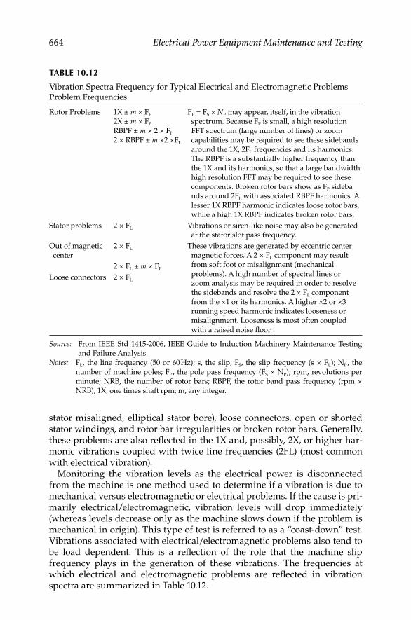
664 Electrical Power Equipment Maintenance and Testing
stator misaligned, elliptical stator bore), loose connectors, open or shorted stator windings, and rotor bar irregularities or broken rotor bars. Generally, these problems are also refl ected in the 1X and, possibly, 2X, or higher har-monic vibrations coupled with twice line frequencies (2FL) (most common with electrical vibration).
Monitoring the vibration levels as the electrical power is disconnected from the machine is one method used to determine if a vibration is due to mechanical versus electromagnetic or electrical problems. If the cause is pri-marily electrical/electromagnetic, vibration levels will drop immediately (whereas levels decrease only as the machine slows down if the problem is mechanical in origin). This type of test is referred to as a “coast-down” test. Vibrations associated with electrical/electromagnetic problems also tend to be load dependent. This is a refl ection of the role that the machine slip frequency plays in the generation of these vibrations. The frequencies at which electrical and electromagnetic problems are refl ected in vibration spectra are summarized in Table 10.12.
TABLE 10.12
Vibration Spectra Frequency for Typical Electrical and Electromagnetic Problems Problem Frequencies
Rotor Problems 1X ± m × FP
2X ± m × FP
RBPF ± m × 2 × FL
2 × RBPF ± m ×2 ×FL
FP = FS × NP may appear, itself, in the vibration
spectrum. Because FP is small, a high resolution
FFT spectrum (large number of lines) or zoom
capabilities may be required to see these sidebands
around the 1X, 2FL frequencies and its harmonics.
The RBPF is a substantially higher frequency than
the 1X and its harmonics, so that a large bandwidth
high resolution FFT may be required to see these
components. Broken rotor bars show as FP sideba
nds around 2FL with associated RBPF harmonics. A
lesser 1X RBPF harmonic indicates loose rotor bars,
while a high 1X RBPF indicates broken rotor bars.
Stator problems 2 × FL Vibrations or siren-like noise may also be generated
at the stator slot pass frequency.
Out of magnetic
center
2 × FL These vibrations are generated by eccentric center
magnetic forces. A 2 × FL component may result
from soft foot or misalignment (mechanical
problems). A high number of spectral lines or
zoom analysis may be required in order to resolve
the sidebands and resolve the 2 × FL component
from the ×1 or its harmonics. A higher ×2 or ×3
running speed harmonic indicates looseness or
misalignment. Looseness is most often coupled
with a raised noise fl oor.
2 × FL ± m × FP
Loose connectors 2 × FL
Source: From IEEE Std 1415-2006, IEEE Guide to Induction Machinery Maintenance Testing
and Failure Analysis.
Notes: FL, the line frequency (50 or 60 Hz); s, the slip; FS, the slip frequency (s × FL); NP , the
number of machine poles; FP , the pole pass frequency (FS × NP); rpm, revolutions per
minute; NRB, the number of rotor bars; RBPF, the rotor band pass frequency (rpm ×
NRB); 1X, one times shaft rpm; m, any integer.
DK4058_C010.indd 664DK4058_C010.indd 664 11/8/2008 12:19:45 PM11/8/2008 12:19:45 PM

665
11Electrical Power System Grounding and Ground Resistance Measurements
11.1 Introduction
System grounding has been used since electrical power systems began. However, many companies and industrial plants have used system ground-ing methods differently. The problem of whether a system neutral should be grounded, and how it should be grounded, has many times been misunder-stood completely. Therefore, grounding of many systems has been based upon past experience rather than engineering analysis.
This chapter provides applicable information for grounding, such as defi nitions, reasons for having a system ground, the most desirable ground-ing method, and so on, and how to measure ground resistance in order to maintain the grounding system.
The defi nition of grounding is commonly used for both, system grounding and equipment grounding. The National Electrical Code (NEC) defi nes system ground as a connection to ground from one of the current-carrying conductors of an electrical power system or of an interior wiring system, whereas an equipment ground is defi ned as a connection to ground from one or more of the noncurrent-carrying metal parts of a wiring system or equipment connected to the system.
The Institute of Electrical and Electronic Engineers (IEEE) and American National Standard Institute (ANSI) standard 142-2007, “IEEE recommended practice for grounding of industrial and commercial power systems” covers system grounding. Many of the following defi nitions are found in this standard in describing power system grounding.
System neutral ground: A connection to ground from the neutral point or points of a circuit, transformer, motor, generator, or system.
Grounded system: A system of conductors in which at least one conductor or point is intentionally grounded.
Ungrounded system: A system of conductors in which there is no intentional connection to ground.
DK4058_C011.indd 665DK4058_C011.indd 665 11/8/2008 12:43:05 PM11/8/2008 12:43:05 PM
666 Electrical Power Equipment Maintenance and Testing
Solidly grounded: A system in which there is no intentional impedance in ground connection; in such a system the line to ground fault currents may equal three-phase fault current.
Resistance grounded: A system grounded through a resistance the value of which can be such as to provide either a low- or high-resistance ground system. The low-resistance ground system can have from 25 to several thousand amperes depending upon the value of the resistance. The high- resistance ground system usually has a value less than 25 A but greater than the value given by XCO/3, where XCO is the charging capacitance of the system.
Reactance grounded: A system grounded through a reactance.
Resonant grounded: The system grounding reactance value is such that the rated frequency fault current fl owing through it is substantially equal to the current fl owing between the conductors and the earth (charging current of the system).
Ground-fault neutralizer: A grounding device that provides an inductive component of current in a ground fault that is substantially equal to, and therefore neutralizes, the rated frequency capacitive component of the ground fault current.
11.2 Selection of Grounding Method
The selection of a method for power system grounding is very diffi cult because a large number of factors must be considered before a power system grounding method can be chosen. The following discussion outlines some problems with various grounding methods and explains how and why grounding systems are applied.
11.2.1 Ungrounded Systems
Early electrical systems were almost universally operated ungrounded. On small systems an insulation failure on one phase did not cause an outage. The failure could probably be found and repaired at a convenient time without a forced outage. This worked well as long as the systems were small. However, as systems increased in size and voltage rating, an increasing number of insulation failures produced multiple failures and major faults. At fi rst, the reasons for these failures were not understood, and considerable work was done to fi nd why they occurred. Figure 11.1 shows a typical ungrounded neutral system. Actually, it is a capacitive grounded neutral system, the capacitance being the conductor capacitance to ground. In normal operation, the capacitive current of all three lines is leading the respective line to neutral voltages by 90°, and the vector sum of all three currents is zero. Figure 11.2 shows what happens when the system
DK4058_C011.indd 666DK4058_C011.indd 666 11/8/2008 12:43:05 PM11/8/2008 12:43:05 PM

Electrical Power System Grounding and Ground Resistance Measurements 667
of Figure 11.1 is accidentally grounded. The charging current of the faulted phase goes to zero because its voltage to ground is zero. The voltages of the unfaulted phases increase to full line-to-line value with respect to ground, and their charging currents increase proportionally. In addition, because of the 30° shift of the line voltages with respect to ground, the charging currents shift accordingly, and the sum of the charging currents in the unfaulted phases is three times the normal value and appears in the ground, returning to the system through the fault. If the fault can be interrupted, it will most likely be done at a current zero. However, since the current leads by 90° in
A A
B
B
IC = 0
I �C I �
B I �A
C C
FIGURE 11.1Ungrounded system—normal condition.
A A
B
B
I �C
IG = I �A + I �
C
I �B = 0 I �
A
C C
Fault
IG
BI
I I I I
is 0 since EB is 0. Voltage across CA and CC now EBA and EBC instead of EA and EC.
A A3 3= ∠ + 0° and C C3= ∠ − 30° . Assume A B C 1PUI I I= = = . Then IA = 1∠+210° and
I
IC = 1∠−30° or A 3 30I = ∠ + °∠ + 210° = 3∠240° and C 3 30 3I = ∠ − °∠30° = ∠ − 60°.
C G 3 BI I I+ = = ∠ −120° + 3∠ − 60° = 3∠ − 90° = −3 of Figure 11.1. A
FIGURE 11.2Ungrounded system—Bφ fault to ground.
DK4058_C011.indd 667DK4058_C011.indd 667 11/8/2008 12:43:05 PM11/8/2008 12:43:05 PM

668 Electrical Power Equipment Maintenance and Testing
the capacitive circuit, current zero occurs at the instant of a voltage maximum; thus, if the fault momentarily clears, a high voltage immediately appears across the fault, and restrike of the fault will probably occur.
In the momentary interval of time that the fault has been cleared the exces-sive voltage charge of the capacitors on the unfaulted lines has been trapped as a direct current (DC) charge. When the arc restrikes again: the capacitors are again recharged by a line-to-ground voltage added to the trapped charge. Thus, a restrike after another current zero clearing is more inevitable, adding another charge. The phenomenon thus probably becomes an oscillating and self-perpetuating buildup in voltage, which eventually will lead to an insula-tion failure on another phase and a major two-phase fault. While the fi rst failure may have been a tree branch in the line, the second failure may occur at some other location entirely, perhaps involving expensive equipment insulation, such as a transformer. Thus, the principal advantage claimed for the ungrounded system actually caused troubles that resulted in its abandonment.
These troubles coupled with other factors led to the adoption of grounded neutral systems in some form. Some of the other factors were as follows:
Because of greater danger to personnel, code authorities frowned on ungrounded systems.
Equipment costs were generally lower for equipment rated for grounded neutral systems because of the reduction in insulation permissible; because graded insulation could be used, single-bushing, single-phase transformers could be used.
At the higher voltages being used today (69 kV and above), material savings in transformer costs can be realized by employing reduced basic insulation level (BIL). These savings are in addition to the modest savings above, and may amount to substantial savings in the cost of transformers in the various voltage classes with reduced insulation. The requirements for safely reducing insulation level demand that system neutrals be grounded. Thus, these savings are not available on the ungrounded system.
11.2.2 Solidly Grounded Systems
The simplest and most effective method of grounding is to solidly connect the neutrals of any wye-connected transformers or generators to ground. This method has two major advantages:
It is simple and inexpensive in that it requires no extra equipment.
It minimizes the magnitude of the overvoltage that will appear on the unfaulted phases during a ground fault, resulting in a reduction in the stress on insulation as compared with other methods.
DK4058_C011.indd 668DK4058_C011.indd 668 11/8/2008 12:43:05 PM11/8/2008 12:43:05 PM
Electrical Power System Grounding and Ground Resistance Measurements 669
This is the reason that solidly grounded neutrals are a necessity where reduced BIL insulation is to be used.
In spite of the advantages of the solidly grounded system, there are associated disadvantages such that other grounding methods are often used. These disadvantages all stem from the fact that a solidly grounded system produces the greatest magnitude of ground fault current when a fault to ground occurs.
It is realized that with a grounded neutral system perhaps 95% or more of all faults start as a single phase to ground fault. If the amount of ground current that fl ows can be controlled and the fault cleared promptly, the amount of damage at the fault will be reduced and the fault probably restricted so as not to involve more than one phase. This may result in preventing bumdowns, reduction in the cost of making repairs, and reduction in the frequency or extent of maintenance on the breakers that interrupt the fault. In the case of machines or transformers, the difference in repair cost may be that of replacing a few damaged coils as compared with completely replacing the machine or transformer, which may be necessary where oil fi res and explosion follow the transformer fault, or where heavy fault currents melt down coils and burn and weld together expensive areas of laminated electrical steel in the transformer core or machine stator iron. Since the damage done is approximately proportional to I2t, it is obvious that much more can be done in the reduction of current than by reduction in time. Figure 11.3 shows the relationship of impedances controlling three- and single-phase to ground faults. Under certain conditions, single phase to ground faults can give rise to short-circuit currents 50% in excess of three-phase short-circuit current. Thus, breakers whose ratings make them entirely capable of inter-rupting three-phase faults may be in severe diffi culty handling a single phase to ground fault. In view of this, the potential savings in damage and repair costs or avoiding the cost of having to install larger breakers may justify avoiding the simple and inexpensive solidly grounded system in favor of a more complex and expensive system that will provide control of the amount of fault current.
11.2.3 Reactance and Resistance Grounded Systems
Reactors are commonly employed as neutral impedance for ground current limitation when the amount of current reduction is small. This is because reactors of low ohmic value to handle large quantities of current can be built quite inexpensively as compared with a resistor for the same current limita-tion. Reactors to provide current limitation to values less than approximately 30%–50% of value are not practical. This is true partly because the high ohmic values necessary to provide the higher current limitation makes them more expensive than resistors, and partly because high values of reactance grounding approach the conditions of ungrounded systems and give rise to high transient voltages.
DK4058_C011.indd 669DK4058_C011.indd 669 11/8/2008 12:43:05 PM11/8/2008 12:43:05 PM

670 Electrical Power Equipment Maintenance and Testing
Resistors are generally used where it is desired to limit fault currents to moderate to small values. The directly connected resistor is not practical for extremes of current limitation. Reactors are used where a small reduction of current is required, because a resistor large enough to handle the large quantities of current remaining would have to have resistor grids of tremendous cross section or many parallel grid paths, and as a result would
FIGURE 11.3Relationship of three- and single-phase to ground faults.
D
Positive-sequenceimpedance system
Negative-sequenceimpedance system
Zero-sequenceimpedance system
Typicalgrounded neutral
system
ZA
ZN
ZT
Z1A Z1T Z1L Z0N Z0T Z0LZ2TZ2A Z2L
ZLEG
EG
Fault(ZON = 3ZN)
Three-phase short-circuit Fault Current 1 Phase to Ground Fault Current
1 GF3
1A 1T 1L
EIZ Z Zf = F1
1A 2A 1T 2T 2L 0
3 G
1L
EILZf =
But Z1A = Z2A; Z1T = Z2T and Z1L = Z2L
2F3
GEI f = GF1
1A 1T 1L 0N 0T 0L
3 2( )
EIZ Z Z Z Z Z
Z ZZ Z Z Z ZZ
f =+
If we assume fault at transformer
secondary, Z1L = Z2L = Z0L = 0.
3 GF3
1A 1T
EIZ Zf =
+G
F11A 1T 0N 0T
3 2( )
EIZ Z Z Zf =
+ + +
++ + + + +
But if Z0N = 0; Z1T = Z0T and Z1T is small
compared to Z1A
4 GF3
1A
EIZf = G
F1 F1 F31A
3 3or2 2
EI I IZ ff = = f
N T
Going back to Equation 3 by changing value of Z0N the 1f fault can be varied from a maximum approaching IF1f = (3/2) IF3 f down to IF1f = 0 for infinite value of Z0N. If fault is out on line from station: since Z0L varies from approximately 3 to 11 times value of Z1L, it follows that IF1f value drops off rapidly with respect to IF3 f as fault location is moved out on line. In a short distance it will become less then IF3f value and on long feeders may approach rated load current values even where Z0N = 0.
1A 1T 1LZ Z Z
+ + ++++++++ 0 0
3f
DK4058_C011.indd 670DK4058_C011.indd 670 11/8/2008 12:43:05 PM11/8/2008 12:43:05 PM

Electrical Power System Grounding and Ground Resistance Measurements 671
be very expensive. On the other hand, if extreme limitation of ground cur-rent by resistors is desired, the resistor again becomes excessively expen-sive. This is because there are maximum values of resistance that it is practical to build into a resistor unit before the cross-sectional area of the resistance conductor becomes so small as to make it too susceptible to mechanical failure from shock, rust, corrosion, and the like. Thus, to get very high values of resistance, the resistor must be made up by connecting a tremendous number of moderate resistance units in series and it becomes expensive and bulky.
A variation of the directly connected resistor is used, where it is desirable and practical to limit ground fault currents to extremely low values, to avoid the expense and diffi culties of the very high value resistance. A distribution transformer is connected between the neutral to be grounded and ground. A resistor is then connected across the secondary of the transformer, as shown in Figure 11.4. The actual 0.25 Ω resistor in the transformer secondary is stepped up in value as it appears to the generator neutral by the square of the transformer ratio of 13,200/240 or 3024 times. Thus, the 1/4 Ω secondary resistor appears as a 756 Ω resistor in the generator neutral. This limits the ground fault current to a maximum of 11.5 A. This represents only a small percent of current on the basis of machine full-load current and of the
FIGURE 11.4High-resistance grounding method. Voltage across transformer primary on solid ground fault =
13,800 V√⎯3 = 7970 V; Resistance of 0.25 Ω resistor to primary circuit = 0.25 × (13,200/240)2 = 756 Ω,
Max IF1φ = E/R = 7970/756 = 11.53 A.
100 kVA13,200/240 Vtransformer
0.25 Ω, 500 Aresistor
DK4058_C011.indd 671DK4058_C011.indd 671 11/8/2008 12:43:06 PM11/8/2008 12:43:06 PM

672 Electrical Power Equipment Maintenance and Testing
A A
B
B
I �C
I G = I �A + I �
C
I �B = 0 I �
A
CC
FaultIG = −3IBIL = 3IB
IL
FIGURE 11.5Resonant grounded system (Bφ fault to ground).
maximum three-phase fault current available. This is representative of the extreme of current limitation. It accomplishes the ultimate in the reduction of fault damage. Further reduction of fault current would be dangerous, because if it were attempted, the capacitance of the generator and step-up transformer windings and the generator lead bus duct would predominate over the higher values of resistance, and the system would approach the characteristics of the original ungrounded system of Figure 11.1 with its dangers of arcing grounds.
11.2.4 Resonant Grounding
One of the earliest methods of attempting to eliminate the faults of the ungrounded system and still retain the claimed advantages for it was by means of resonant grounding using the Peterson coil. This method attempted to eliminate the fault current that could cause the arcing ground condition. Figure 11.5 shows the system of Figures 11.1 and 11.2 with the Peterson coil applied. This is simply a tunable, iron-cored reactor connected between neutral and ground. It is tuned so that the current it furnishes matches the current furnished by line capacitance under fault conditions. Under normal system conditions, it does not carry current. However, upon the occurrence of a fault it contributes a reactive component of current through the fault matching the capacitive component. Since the two currents are 180° out of phase, they cancel. This leaves no current at the fault, minimizes the chance of restrike, and thus eliminates the cause of voltage buildup.
The ground-fault neutralizer is said to be effective in 70%–80% of the faults. It is not in great favor because it is not 111% effective, because of its expense, and because of the expense of the equipment necessary to protect it in the 20%–30% of the cases when it does not work. The principal cause of its failure to work is improper tuning. This might seem to be easily corrected, but when it is realized that retuning would be required upon each feeder extension or
DK4058_C011.indd 672DK4058_C011.indd 672 11/8/2008 12:43:06 PM11/8/2008 12:43:06 PM
Electrical Power System Grounding and Ground Resistance Measurements 673
rearrangement, for each emergency switching condition, or that even if kept properly tuned the system could be detuned by a broken conductor associated with the fault it was to clear, some of the diffi culties of its application can be realized. It can work well in a three-phase radial circuit. However, it is not practical in a tie feeder or network system unless it is blocked off by delta transformers or other zero-sequence impedance isolators so that the tuned setting required can be defi nitely known and is not variable because of system operating conditions. To calculate the reactance value of the neutral reactor, the following equation from Figure 11.2 can be used:
′ ′= + = −G A C B3I I I I
It is desired that IL = 3IB so that IG + IL = 0 at the fault. Voltage across XL = −EB. Call the capacitive reactance of the line XC. Then
−= − = = −B BL B
L C
33
E EI I
X X
− = − = =BB B C B L C L3 or 3 or 3E E X E E X X X
Therefore, for fault current zero,
= − C
L3
XX
11.2.5 Grounding Ungrounded Systems
So far the discussion of grounding has assumed a wye-connected neutral to ground. This is not always the case, and in some cases it is not a three-phase system that it is desired to be grounded. For situations of this kind a ground-ing transformer is used. This may be a conventional wye-delta transformer of suitable rating or a special zigzag wye unit may be used. Once the neutral is established, any of the grounding methods already discussed may be employed, provided the rating of the grounding transformer is adequate for the amount of current permitted by the grounding method used. Figure 11.6 shows the setup of a zigzag wye transformer used for the grounding.
In the selection of grounding equipment and methods, many factors must be considered. It is desirable from the reduction of fault damage, repair costs, and switching equipment maintenance to limit ground fault current as much as possible. However, the greater the limitation of current, the higher the possible transient overvoltages that will be encountered. This will determine the equipment insulation levels required and the rating of lightning arresters required to protect the equipment, and will consequently affect costs. Therefore, these factors are in confl ict with the desire for maxi-mum fault limitation. Whether resistors or reactors are used will determine the degree of overvoltage expected on a given system for a given degree of current limitation and thus affects the selection of the use of resistors or reactors.
DK4058_C011.indd 673DK4058_C011.indd 673 11/8/2008 12:43:06 PM11/8/2008 12:43:06 PM

674 Electrical Power Equipment Maintenance and Testing
Whenever grounding of any kind is used, it is obvious that fault current will fl ow when a normally ungrounded conductor becomes grounded. It is necessary that relays, fuses, or other protective devices sense and operate to clear the fault. Since the degree of current limitation employed may well have a serious effect on the ability of these devices to operate as desired, it follows that the degree of current limitation that can be employed may well be deter-mined by the sensitivity of protective devices used, or, conversely, the type and sensitivity of the protective devices required may be determined by the degree of current limitation selected. However, since a multiplicity of feeders at generator voltage depends upon ground overcurrent relays for their ground fault protection, ground fault current must be kept up to a value that will give
To ground, neutralbus or ground-current
limiting impedance
Normal voltageconditions
on coils
B-phase high-resistance currentlimiting impedance
N
N
BB
B
A
C
Bus
AA
00
CC
a2
a2
a1
a1
a2 c2
b2
b2
a1 c1b1
b2
b1
c1c2
c1
FIGURE 11.6Ground source through a wye-zigzag grounding transformer.
DK4058_C011.indd 674DK4058_C011.indd 674 11/8/2008 12:43:07 PM11/8/2008 12:43:07 PM
Electrical Power System Grounding and Ground Resistance Measurements 675
adequate relay operating torque for any and all ground faults on them, with reasonable current transformer ratios and relay current ranges.
Thus, the selection of the value to which the ground fault is to be limited becomes the problem of making a selection between minimum ground fault current to limit damage, the minimum ground fault that will give adequate protective device operation, and the maximum ground fault current that the generator windings can tolerate before there is danger of the magnetic forces forcing windings out of the generator armature slots. The extreme ground current limitation can be used only where there are no feeders at generator voltage that must have ground fault protection, and delta-wye transformers isolate the zero-sequence network for which ground fault protection at this very low current level must be provided to a very small number of equipment units. Even then, very special relaying methods must be employed.
In conclusion, several important points with respect to impedance grounding of system neutrals are so obvious that they are often overlooked.
1. Since grounding equipment is electrically active in a circuit only during a ground fault, considerable money can be saved by buying equipment rated for short time duty. Grounding equipment for a sta-tion with all underground circuits will be expected to be subjected to very infrequent faults, and since cable faults are usually permanent, repeated reclosing attempts will probably not be made. Under these circumstances a short time rating of the grounding equipment of 11 s or less may be adequate. However, grounding equipment installed in a station having all overhead circuits will be subjected to the cumulative heating effect of perhaps many closely spaced feeder faults during severe storm conditions, each circuit outage being accompanied by several unsuccessful closing attempts. Under these conditions, equip-ment having a rating on a 10 min or more basis may be inadequate.
2. Impedance neutral grounding equipment must always be considered hot because if a ground fault occurs in the system, it will raise the neutral to full phase to ground voltage. This not only poses a safety problem but also creates the problem of how to maintain the equip-ment, unless the machine, bus, or station for which the impedance furnishes the ground is shut down.
3. Where a multiplicity of grounding units is employed, care must be exer-cised in switching facilities for their transfer to avoid the danger that someone will get caught operating disconnects for the transfer just as a ground fault occurs. If multiple units are used, care must be exercised to assure that the protective relaying will operate and coordinate properly through the range of conditions possible with the multiple units.
4. Where impedance grounding is used, no other neutrals in the same zero-sequence system may be grounded except through the same impedance. To do so will shunt or short circuit the original impedance and raise the ground fault current above the desired design value.
DK4058_C011.indd 675DK4058_C011.indd 675 11/8/2008 12:43:07 PM11/8/2008 12:43:07 PM

676 Electrical Power Equipment Maintenance and Testing
11.3 Selection of Grounding System
As discussed earlier, the various methods of grounding commonly used are solidly grounded, resistance grounded, reactance grounded, and ground-fault neutralizer grounded. The ungrounded system, in the true sense of the word, is grounded, because the charging capacitance from the phase conduc-tor to earth acts as the grounding point. The various grounding methods are shown in Figure 11.7.
The selection of a grounding system should be based upon the following systems factors:
Magnitude of the fault current•
Transient overvoltage•
Lightning protection•
Application of protective devices for selective ground fault protection•
Types of load served, such as motors, generators, etc.•
The application limits and a guide for the various grounding methods for consideration of the above-mentioned factors are shown in Table 11.1 and discussed in the following sections.
GX G XG
RNR
G
(a) (b)XG
XN
G
(d)
XG
XNXN
G
(c)
FIGURE 11.7Methods of grounding system neutrals. (a) Solidly grounded; (b) resistance grounded;
(c) reactance grounded; (d) ground-fault neutralizer.
DK4058_C011.indd 676DK4058_C011.indd 676 11/8/2008 12:43:07 PM11/8/2008 12:43:07 PM

Electrical Power System Grounding and Ground Resistance Measurements 677
TABLE 11.1
Grounding Methods for Low- and Medium-Voltage Systems
System Grounding Practice Comments
Medium-voltage system (2,400–13,800 V)
Wye-connected
generator on the
system
Use low-resistance grounding resistor Allows the use of
neutral-type lightning
arresters if X0/X1 ≤ 3
X0/X1 ≤ 10 for limiting
transient overvoltages
Wye-connected
transformer on the
system
Use low-resistance grounding resistor
R
Does not allows the use
of neutral-type
lightning arresters
To limit transient
overvoltage, R0/X0 ≥ 2
System ungrounded
(i.e., no wye-
connected
generators or
transformer)
Use grounding transformer with resistor
Zig-zag transformerR
Some comments as for
wye-connected
transformer
Low-voltage system (120–600 V)
Wye-connected
generator on the
system
Use low-voltage reactance to ground
generator neutral
Ground fault current
should be not less than
25% of three-phase
fault current
Wye-connected
Transformer power
supply system
Ground transformer
neutral solidly to ground
Ground fault current can
be equal to three-phase
fault current (or greater
at the secondary of
delta-wye-connected
transformer)
System ungrounded
(i.e., no wye-
connected
transformer)
Use grounding transformer solidly
grounded
Zig-zag transformer
Ground fault current to
be equal to at lest 25%
of three-phase fault
current
R
G
11.3.1 Solidly Grounded System
A solidly grounded system is one in which a generator, transformer, or grounding transformer neutral is directly grounded to earth or station ground.
DK4058_C011.indd 677DK4058_C011.indd 677 11/8/2008 12:43:07 PM11/8/2008 12:43:07 PM

678 Electrical Power Equipment Maintenance and Testing
Because the reactance of source (generator or transformer) impedance is in series with the neutral circuit, this system cannot be considered a zero impedance circuit. In nearly all grounded systems, it is desirable to have the line to ground fault current in the range of 25%–110% of three-phase fault current in order to prevent the development of high transient over-voltage. The higher the ground fault current, the less are the transient overvoltages.
Ground-neutral-type lightning arresters may be applied on this system provided that the ground fault current is at least 60% of three-phase fault current. Another way of expressing this value is to express the reactance and resistance ratios as follows:
≤0
1
3XX
and
≤0
1
1RX
whereX0 is the zero-sequence reactanceX1 is the positive-sequence reactanceR0 is the zero-sequence resistance
Normally, direct grounding of the generator is not desirable because the ground fault current may exceed three-phase fault current. Since the generator is rated for maximum three-phase fault current, it is not desir-able to have higher ground fault currents than three-phase fault current. Therefore, most grounded systems having generators are grounded through low reactance values to keep ground fault currents less than three-phase fault current. Generally, low-voltage systems (i.e., below 600 V) are solidly grounded. Medium-voltage systems may be either solidly or low resistance grounded.
11.3.2 Low-Resistance Grounding
In low-resistance grounding, the neutral is grounded through a resistance of low ohmic value. The reasons for using the resistance grounding system are the following:
To reduce the ground fault current to prevent damage to switchgear, • motors, cables, and the like
To minimize magnetic and mechanical stresses•
DK4058_C011.indd 678DK4058_C011.indd 678 11/8/2008 12:43:07 PM11/8/2008 12:43:07 PM

Electrical Power System Grounding and Ground Resistance Measurements 679
To minimize stray ground fault currents for personnel safety•
To reduce the momentary line-voltage dips by clearing of ground faults•
The line-to-ground voltage that may exist during fault conditions can be as high as the voltage present on ungrounded systems. However, the transient overvoltages are not so high. If the system is properly grounded by resistance, there is no danger from destructive overtransient voltages.
11.3.3 High-Resistance Grounding
In this system, the neutral is grounded through a resistance of high ohmic value. The line-to-ground voltage of unfaulted phases during a ground fault is nearly equal to line-to-line voltage. If the insulation system was selected for a grounded system, it will be subjected to an overvoltage condition during a line-to-ground fault.
The ground fault current available in this type of system is very small, usually 25 A or less. It should be remembered that when using this system the ground fault current should never be less than the charging current. Moreover, the lightning arresters for this system should be the ungrounded type. This type of system is subject to the following types of overvoltage conditions:
Ferroresonance type, that is, resonance effects of series inductive–• capacitive circuits
Limited transient overvoltage conditions•
Overvoltage conditions due to direct connection to higher voltages•
The reasons for using high-resistance grounding are similar to those for low-resistance grounding except that in this system ground fault current is limited to a very small value.
11.3.4 Reactance Grounding
In a reactance grounded system, the neutral circuit is grounded through a reactor. In general, reactance grounding is used for grounding generator neutrals. The value of the reactor chosen is usually such that the ground fault current is not less than 25% of three-phase fault current to prevent serious transient overvoltages during ground fault clearance. The value of X0 must be less than or equal to 10 times the X1 value for this type of system.
11.3.5 Ground-Fault Neutralizers (Resonant Grounded)
In this system, a reactor having a specially selected high value of reactance is connected in neutral connection to ground. The current that fl ows through the reactor, during a line-to-ground fault condition, is equal to and 180° out
DK4058_C011.indd 679DK4058_C011.indd 679 11/8/2008 12:43:08 PM11/8/2008 12:43:08 PM
680 Electrical Power Equipment Maintenance and Testing
of phase with the charging current that fl ows in two unfaulted phases. Under this condition, the two currents cancel, leaving the faulted current due only to resistance. Because resistive current is in phase with the voltage, the fault current is quenched when both the voltage and fault current pass through zero axis.
A precaution required in this system is that care must be taken to keep the ground-fault neutralizer tuned to the system capacitance. If any switching is done to take circuits out, the neutralizer reactance values must be changed by adjusting neutralizer taps. Ground-fault neutralizers have been used only to a limited extent and are not as common as the other systems of grounding.
11.4 Understanding Ground Resistance
The term ground is defi ned as a conducting connection by which a circuit or equipment is connected to the earth. The connection is used for establishing and maintaining as closely as possible the potential of the earth on the circuit or equipment connected to it. A ground consists of a grounding conductor, a bonding connector, its grounding electrode(s), and the soil in contact with the electrode.
Grounds have several fundamental protection applications. For natural phenomena, such as lightning, grounds are used to provide a discharge path for the current to reduce shock hazard to personnel and to prevent damage to equipment and property.
For induced potentials due to faults in electric power systems with ground returns, grounds help in ensuring rapid operation of the protection relays by providing low resistance fault current paths. This provides for the removal of the induced potential as quickly as possible. The ground should drain the induced potential before personnel are injured and the power or communi-cations system is damaged.
Ideally, to maintain a reference potential for instrument safety, to protect against static electricity, and limit the equipment ground voltage for operator safety, a ground resistance should be 0 Ω. In reality, as explained in this text this value cannot be achieved. However, low ground resistance is required by NEC, OSHA, and other electrical safety codes and standards.
11.4.1 Grounding Electrode Resistance
Figure 11.8 illustrates a grounding rod (electrode). The resistance of the grounding is made up of the following components:
1. Resistance of the electrode itself and that of the connection to it
2. Contact resistance of the surrounding earth to the electrode
DK4058_C011.indd 680DK4058_C011.indd 680 11/8/2008 12:43:08 PM11/8/2008 12:43:08 PM

Electrical Power System Grounding and Ground Resistance Measurements 681
3. Resistance of the earth immediately surrounding the grounding electrode or resistivity of earth, which is often the most signifi cant factor
The grounding electrodes are usually made of a very conductive metal (copper or copper clad) with adequate cross sections so that the overall resistance is negligible. The resistance between the electrode and the sur-rounding earth is negligible if the electrode is free of paint, grease, or other coating, and if the earth is fi rmly packed.
The only component remaining is the resistance of the surrounding earth. The electrode can be thought of as being surrounded by concentric shells of earth or soil, all of the same thickness. The closer the shell to the electrode, the smaller its surface; hence, the greater its resistance. The farther away the shells are from the electrode, the greater the surface of the shell; hence, the lower the resistance. Eventually, adding shells at a distance from the grounding elec-trode will no longer noticeably affect the overall earth resistance surrounding the electrode. The distance at which this effect occurs is referred to as the effective resistance area and is directly dependent on the depth of the ground-ing electrode.
When ground fault current fl ows from a ground rod to earth, it fl ows in all directions through a series of concentric spheres or shells, commonly referred to as effective cylinders of earth, surrounding the rod. The resistance of the closest sphere to the ground rod is the highest because it is the smallest sphere.
Ground rodand clamp
Contactresistance
between rodand soil
Concentricshells of
earth
FIGURE 11.8Grounding electrode.
DK4058_C011.indd 681DK4058_C011.indd 681 11/8/2008 12:43:08 PM11/8/2008 12:43:08 PM

682 Electrical Power Equipment Maintenance and Testing
As the distance from the ground rod is increased, the resistance becomes less because the sphere becomes larger. Eventually, a distance from the electrode is reached where the sphere resistance becomes zero. Therefore, in any ground resistance measurement only the part of earth resistance is considered that contributes a major part of the resistance. Theoretically, the earth resistance of the ground system should be measured up to infi nite distance from the ground rod. However for practical purposes, the effective cylinder of earth (shells) that contributes the major portion of the earth resistance is two times the length of the ground rod.
In theory, the ground resistance may be derived from the general formula:
= L
RA
r
whereR is the ground resistancer is the resistivity of the soilL is the length of grounding electrodeA is the area
This formula illustrates why the shells of concentric earth decrease in resis-tance the farther they are from the ground rod:
= × thickness of shell
Resistivity of soilarea
R
In the case of ground resistance, uniform earth (or soil) resistivity through-out the volume is assumed, although this is seldom the case in nature. The equations for systems of electrodes are very complex and often expressed only as approximations. The most commonly used formula for single-ground electrode systems, developed by Professor H. R. Dwight of the Massachusetts Institute of Technology, is the following:
−= ×
[(ln 4 ) 1]
2
LR
L rrp
whereR is the resistance of the ground rod to the earth (or soil) (Ω)L is the grounding electrode lengthr is the grounding electrode radiusr is the average resistivity(Ω-cm) of soil
11.4.2 Effect of Ground Electrode Size and Depth on Resistance
Size: Increasing the diameter of the rod does not materially reduce its resis-tance. Doubling the diameter of the ground rod reduces resistance by less than 10%, as indicated in Figure 11.9.
DK4058_C011.indd 682DK4058_C011.indd 682 11/8/2008 12:43:08 PM11/8/2008 12:43:08 PM
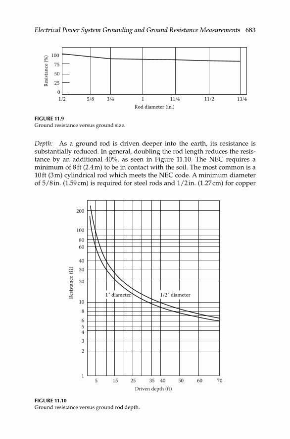
Electrical Power System Grounding and Ground Resistance Measurements 683
Depth: As a ground rod is driven deeper into the earth, its resistance is substantially reduced. In general, doubling the rod length reduces the resis-tance by an additional 40%, as seen in Figure 11.10. The NEC requires a minimum of 8 ft (2.4 m) to be in contact with the soil. The most common is a 10 ft (3 m) cylindrical rod which meets the NEC code. A minimum diameter of 5/8 in. (1.59 cm) is required for steel rods and 1/2 in. (1.27 cm) for copper
100
Resis
tanc
e (%)
755025
01/2 5/8 3/4 1 1 1/4 1 1/2 1 3/4
Rod diameter (in.)
FIGURE 11.9Ground resistance versus ground size.
7060504035Driven depth (ft)
Resis
tanc
e (Ω
)
251551
2
3456
8
10
20
1" diameter 1/2" diameter
3040
6080
100
200
FIGURE 11.10Ground resistance versus ground rod depth.
DK4058_C011.indd 683DK4058_C011.indd 683 11/8/2008 12:43:09 PM11/8/2008 12:43:09 PM

684 Electrical Power Equipment Maintenance and Testing
or copper clad steel rods. Minimum practical diameter for driving limitations for 10 ft (3 m) rods are
1/2 in. (1.27 cm) in average soil•
5/8 in. (1.59 cm) in moist soil•
3/4 in. (1.91 cm) in hard soil or more than 10 ft driving depths•
11.4.3 Effect of Soil Resistivity on Ground Electrode Resistance
Dwight’s formula, cited previously, shows that the resistance of grounding electrodes to earth depends not only on the depth and surface area of ground-ing electrodes, but on soil resistivity as well. Soil resistivity is the key factor that determines what the resistance of a grounding electrode will be, and to what depth it must be driven to obtain low ground resistance. The resistivity of the soil varies widely throughout the world and changes seasonally. Soil resistivity is determined largely by its content of electrolytes, consisting of moisture, minerals, and dissolved salts. A dry soil has high resistivity if it contains no soluble salts, as shown in Table 11.2.
11.4.4 Factors Affecting Soil Resistivity
Two samples of soil, when thoroughly dried, may become in fact very good insulators, having a resistivity in excess of 109 Ω-cm. The resistivity of the soil sample is seen to change quite rapidly until approximately 20% or greater moisture content is reached as indicated in Table 11.3.
The resistivity of the soil is also infl uenced by temperature. Table 11.4 shows the variation of resistivity of sandy loam, containing 15.2% moisture, with temperature changes from 20°C to –15°C. In this temperature range, the resistivity is seen to vary from 7,200 to 330,000 Ω-cm.
Because soil resistivity directly relates to moisture content and tempera-ture, it is reasonable to assume that the resistance of any grounding system will vary throughout the different seasons of the year. Such variations are shown in Figure 11.11. Since both temperature and moisture content become more stable at greater distances below the surface of the earth, it follows
TABLE 11.2
Resistivity of Different Soils
Resistivity (Ω-cm)
Soil Minimum Average Maximum
Ashes, cinders, brine, waste 590 2,370 7,000
Clay, shale, gumbo, loam 340 4,060 16,300
Same, with varying proportions
of sand and gravel
1,020 15,800 135,000
Gravel, sand, stones with little
clay or loam
59,000 94,000 458,000
DK4058_C011.indd 684DK4058_C011.indd 684 11/8/2008 12:43:09 PM11/8/2008 12:43:09 PM

Electrical Power System Grounding and Ground Resistance Measurements 685
TABLE 11.4
Effects of Temperature on Soil Resistivity
Temperature Resistivity (Ω-cm)
°C °F
20 68 7,200
10 50 9,900
0 32 (water) 13,800
0 32 (ice) 30,000
−5 23 79,000
−15 14 330,000
80
Curve 1
Curve 2
60
40
20
0
% Re
sista
nce v
aria
tion
Jan.
Mar
.
May July
Sept
.
Nov
.
Jan.
Mar
.
May July
FIGURE 11.11Seasonal variation of earth resistance with an electrode of 3/4 in. pipe in stony clay soil. Depth
of electrode in earth is 3 ft for curve 1, and 10 ft for curve 2.
TABLE 11.3
Effects of Moisture on Soil Resistivity
Moisture Content
(% by weight)
Resistivity (Ω-cm)
Top Soil Sandy Loam
0.0 <109 <109
2.5 250,000 150,000
5.0 165,000 43,000
10.0 53,000 18,500
15.0 19,000 10,500
20.0 12,000 6,300
30.0 6,400 4,200
DK4058_C011.indd 685DK4058_C011.indd 685 11/8/2008 12:43:09 PM11/8/2008 12:43:09 PM

686 Electrical Power Equipment Maintenance and Testing
that a grounding system to be most effective at all times should be con-structed with the ground rod driven down a considerable distance below the surface of the earth. Best results are obtained if the ground rod reaches the water table.
In some locations, the resistivity of the earth is so high that low-resistance grounding can be obtained only at considerable expense and with an elabo-rate grounding system. In such situations, it may be economical to use a ground rod system of limited size and to reduce the ground resistivity by periodically increasing the soluble chemical content of the soil. Table 11.5 shows the substantial reduction in resistivity of sandy loam brought about by an increase in chemical salt content.
Chemically treated soil is also subject to considerable variation of resistivity with changes in temperature, as shown in Table 11.6. If salt treatment is employed, it is, of course, necessary to use ground rods that will resist corrosion.
TABLE 11.5
Effect of Salta Content on the Resistivity of Soil
Added Salt (% by
weight of moisture) Resistivity (Ω-cm)
0 10,700
0.1 1,800
1.0 460
5.0 190
10.0 130
20.0 100
Note: Sandy loam, moisture content 15% by weight;
temperature, 17°C.a Such as copper sulfate, sodium carbonate, and others. Salts
must be EPA or local ordinance approved prior to use.
TABLE 11.6
Effect of Temperature on theResistivity of Soil Containing Salta
Temperature (°C) Resistivity (Ω-cm)
20 110
10 142
0 190
–5 312
–13 1,440
Note: Sandy loam, 20% moisture, salt 5% of weight of
moisture.a Such as copper sulfate, sodium carbonate, and others.
Salts must be EPA or local ordinance approved prior
to use.
DK4058_C011.indd 686DK4058_C011.indd 686 11/8/2008 12:43:09 PM11/8/2008 12:43:09 PM

Electrical Power System Grounding and Ground Resistance Measurements 687
11.4.5 Effect of Ground Electrode Depth on Resistance
In determining the approximate ground rod depth required to obtain a desired resistance, a grounding nomograph may be used. The nomograph, shown in Figure 11.12, indicates that to obtain a grounding resistance of 20 Ω in a soil with a resistivity of 10,000 Ω-cm, a 5/8 in. OD rod must be driven 20 ft. Note that the values indicated on the nomograph are based on the assumption that the soil is homogenous and, therefore, has uniform resistivity. The nomograph value is an approximation.
11.5 Ground Resistance Values
The NEC code states that the resistance to ground shall not exceed 25 Ω. This is the maximum value of ground resistance and in most applications a much lower ground resistance is required.
Ground rodresistance (Ω)
100
100D
R
P
K
DIA
10000050000
30000
15000
5000
3000
1000
40000
20000
10000
4000
2000
500
90
70
50
30
90
70
50
30
1515
9
7
5
5
3
3
1
1
80
80
60
60
40
40
87
5
3
1.5
3/4
1/2
6
4
2
1
5/8
1/4
20
20
1010
8
6
4
4
2
2
Soil resistivity(Ω-cm)
Rod depth(ft)
Rod diameter(in.)
1. Select required resistance on R scale2. Select apparent resistivity on P scale 3. Lay straightedge on R and P scales, and allow to intersect with K scale 4. Mark K scale point 5. Lay straightedge on K scale point and diameter (DIA) scale, and allow to
intersect with D scale6. Point on D scale will be rod depth required for resistance on R scale
FIGURE 11.12A nomograph showing ground electrode depth versus ground electrode resistance.
DK4058_C011.indd 687DK4058_C011.indd 687 11/8/2008 12:43:09 PM11/8/2008 12:43:09 PM

688 Electrical Power Equipment Maintenance and Testing
“How low a ground resistance should be?” An arbitrary answer to this question is diffi cult. The lower the ground resistance, the safer, and for positive protection of personnel and equipment, it is worth the effort to aim for less than 1 Ω. It is generally impractical to reach such a low resistance along a distribution system or a transmission line or in small substations. In some regions, resistances of 5 Ω or less may be obtained without much trouble. In others, it may be diffi cult to bring resistance of driven grounds below 100 Ω.
Accepted industry standards stipulate that transmission substations should be designed not to exceed 1 Ω resistance. In distribution substations, the maximum recommended resistance is for 5 Ω or even 1 Ω. In most cases, the buried grid system of any substation will provide the desired resistance.
In light industrial or in telecommunication central offi ces, 5 Ω is often the accepted value. For lighting protection, the arrestors should be coupled with a maximum ground resistance of 1 Ω. Table 11.7 shows typical values of ground resistance for various types of installations.
Grounding nomographThese parameters can usually be met with the proper application of basic grounding theory. There will always exist circumstances which will make it diffi cult to obtain the ground resistance required by the NEC or other safety standards. When these situations develop, several methods of lowering the ground resistance can be employed. These include parallel rod systems, deep-driven rod systems utilizing sectional rods and chemical treatment of the soil. Additional methods, discussed in other published data, are buried
TABLE 11.7
Typical Grounding Resistance Values of Substations for Various Installations
Installation Type
Maximum Substation
Grounding Resistance
Valuesa
Commercial Metallic buildings ≤25 Ω (per NEC)
Wet wells, etc.
Homes
Industrial General facilities 5 ΩChemical 3 ΩComputer <1–3 ΩHigh-speed loading
facilities for chemical<1 Ω
Utilities Generating stations 1 Ωa
Large substations 1 ΩDistrict substations 1.5–5 ΩSmall substations 5 Ω
a For solidly grounded systems.
DK4058_C011.indd 688DK4058_C011.indd 688 11/8/2008 12:43:09 PM11/8/2008 12:43:09 PM
Electrical Power System Grounding and Ground Resistance Measurements 689
plates, buried conductors (counterpoise), electrically connected building steel, and electrically connected concrete reinforced steel.
Electrically connecting to existing water and gas distribution systems was often considered to yield low ground resistance; however, recent design changes utilizing nonmetallic pipes and insulating joints have made this method of obtaining a low-resistance ground questionable and in many instances unacceptable.
11.6 Ground Resistance Measurements
To maintain suffi ciently low resistance values of grounding systems, their periodic testing is required. The testing involves measurement to ensure that they do not exceed design limits. The methods of measuring and testing the ground resistance and soil resistivity are as follows:
Two-point method•
Three-point method•
Fall-of-potential method•
Ratio method•
Four-point method•
Touch potential measurements•
Clamp-on method•
The measurement of ground resistances may only be accomplished with specially designed test equipment. The most common method for measuring ground resistance uses the fall-of-potential principle of alternating current (AC) of 60 Hz or some higher frequency circulating between an auxiliary electrode and the ground electrode under test; the reading will be given in ohms and represents the resistance of the ground electrode to the surround-ing earth. Also, one manufacturer has recently introduced a clamp-on ground resistance tester.
11.6.1 Two-Point Method
This method may be used to measure the resistance of a single driven ground rod. It uses an auxiliary ground rod whose resistance is either known or can be measured. The resistance value of the auxiliary ground rod also must be very small compared to the resistance of the driven ground rod so that the measured value can be assumed to be wholly contributed by the driven ground rod. For example, this test might be applicable in the measurement of resistance of the single driven ground rod for a residence or in congested areas where fi nding room to drive two auxiliary rods may be a problem.
DK4058_C011.indd 689DK4058_C011.indd 689 11/8/2008 12:43:09 PM11/8/2008 12:43:09 PM

690 Electrical Power Equipment Maintenance and Testing
In this case, the municipal metallic water supply line can be assumed as the auxiliary ground rod whose resistance value is approximately 1 Ω or less. This value is quite small compared to the value of a single driven ground rod, whose value is in the order of 25 Ω. The reading obtained is that of the two grounds in series. The lead resistances will also be measured and should be deducted from the fi nal measurements. This method is usually adequate where a go, no-go type of test is required. The connections for this test are shown in Figure 11.13.
11.6.2 Three-Point Method
This method is similar to the two-point method except it uses two auxiliary rods. To obtain accurate values of resistance measurements, the resistance of the auxiliary electrodes should be approximately equal to or less than that of the electrode under test. The connections for the three-point method are shown in Figure 11.14.
Either AC of 60 Hz or DC may be used for making this test. The advantage of using AC is that it minimizes the effects of stray currents on measurement readings. However, if stray currents happen to be of the same frequency, error will be introduced in the readings. The use of DC for making this test will totally eliminate the AC stray currents. However, stray DC and formation of gas around the electrodes will introduce error in the readings when using DC
Ground levelUtility pole
Grounding conductor
Ground rod Terminals shortedwith jumper wire
Auxiliary rod(Y-Z shorted)
Butt plate
FIGURE 11.13Two-point ground resistance measurement method.
DK4058_C011.indd 690DK4058_C011.indd 690 11/8/2008 12:43:10 PM11/8/2008 12:43:10 PM

Electrical Power System Grounding and Ground Resistance Measurements 691
for this test. The effect of stray DCs can be minimized by taking readings with current in the opposite direction. The average of the two readings will give an accurate test value. Apply currents only long enough to take readings.
The resistance value of the test electrode can be calculated as follows. Let
11
1
x y
VR R R
A= + =
= + = 22
2
x z
VR R R
A
+ + = 33
3
y z
VR R R
A
Solving these three equations, we have
= −3y ZR R R
= − = − +1 1 3x y zR R R R R R
FIGURE 11.14Three-point test method and its equivalent circuit.
Electrodeunder test
x
Auxiliaryelectrode 1
y
Auxiliaryelectrode 1
Ry
Auxiliaryelectrode 2
Rz
Auxiliaryelectrode 2
z
Testelectrode
Rx
V1 V2
V3
A2A1
A3
DK4058_C011.indd 691DK4058_C011.indd 691 11/8/2008 12:43:10 PM11/8/2008 12:43:10 PM
692 Electrical Power Equipment Maintenance and Testing
Also:
= −2x ZR R R
from which
= + −1 2 32 xR R R R
or
− −= 1 2 3
2x
R R RR
11.6.3 Fall-of-Potential Method
This method measures grounding electrode resistance based upon the principle of potential drop across the resistance. It also uses two auxiliary electrodes (one current rod and the other a potential rod) that are placed at a suffi cient distance from the test electrodes; a current of known magnitude is passed through the electrode under test and one of the auxiliary electrodes (current rod). The drop in potential between the electrode under the test and the second auxiliary electrode (potential rod) is measured. The ratio of volt-age drop (V) to the known current (I) will indicate the resistance of the grounding circuit. Either a DC or AC voltage source may be used for con-ducting this test.
Several problems and errors may be encountered with this method,such as (i) stray currents in earth may cause voltmeter readings to be either high or low and (ii) the resistance of auxiliary electrode and electrical leads may introduce errors in the voltmeter reading. This error can be minimized by using a voltmeter of high impedance value.
This method can be used with either a separate voltmeter and ammeter or a single instrument which provides a reading directly in ohms (see Figure 11.15). To measure the resistance of a grounding electrode, the current electrode is placed at a suitable distance from the grounding electrode under test. As shown in Figure 11.16, the potential difference between rods X and Y is measured by a voltmeter, and the current fl ow between rods X and Z is measured by an ammeter. (Note: X, Y, and Z may be referred to as X, P, and C in a three-point tester or C1, P2, and C2 in a four-point tester.)
By Ohm’s law E = RI or R = E/I. By this formula, we may obtain the ground electrode resistance R. If E = 20 V and I = 1 A, then
= = = Ω20
201
ER
I
DK4058_C011.indd 692DK4058_C011.indd 692 11/8/2008 12:43:11 PM11/8/2008 12:43:11 PM

Electrical Power System Grounding and Ground Resistance Measurements 693
11.6.3.1 Position of the Auxiliary Electrodes on Measurements
The goal in precisely measuring the resistance to ground is to place the aux-iliary current electrode Z far enough from the ground electrode under test so that the auxiliary potential electrode Y will be outside of the effective resis-tance areas (effective cylinder of earth) of both the ground electrode and the
FIGURE 11.15Fall-of-potential method ground resistance instrument. (Courtesy of Megger/Programma,
Valley Forge, PA.)
FIGURE 11.16Fall-of-potential method.
DK4058_C011.indd 693DK4058_C011.indd 693 11/8/2008 12:43:11 PM11/8/2008 12:43:11 PM

694 Electrical Power Equipment Maintenance and Testing
(a)
(b) X–Y distance
Effective resistanceareas (no overlap)
Reading variationResis
tanc
e
Y� YX ZY�
X–Y distance
Y� YX Z
Effective resistanceareas (overlapping)
Reading variation
Resis
tanc
e
Y�
FIGURE 11.17Effective resistance areas (cylinders of earth) (a) overlapping and (b) not overlapping.
auxiliary current electrode. The best way to fi nd out if the auxiliary potential rod Y is outside the effective resistance areas is to move it between X and Z and to take a reading at each location. If the auxiliary potential rod Y is in an effective resistance area (or in both if they overlap as in Figure 11.17a), by displacing it the readings taken will vary noticeably in value. Under these conditions, no exact value for the resistance to ground may be determined.
On the other hand, if the auxiliary potential rod Y is located outside of the effective resistance areas, as in Figure 11.17b, as Y is moved back and forth the reading variation is minimal. The readings taken should be relatively close to each other, and are the best values for the resistance to ground of the ground X. The readings should be plotted to ensure that they lie in a “ plateau” region as shown in Figure 11.17b. The region is often referred to as the 62% area which is discussed in the following section.
11.6.3.2 Measuring Resistance of Ground Electrodes (62% Method)
The 62% method is an extension of the fall-of-potential method and has been adopted after graphical consideration and after actual test. It is the most accu-rate method but is limited by the fact that the ground tested is a single unit. This method applies only when all three electrodes are in a straight line and the ground is a single electrode, pipe, or plate, etc., as is shown in Figure 11.18.
DK4058_C011.indd 694DK4058_C011.indd 694 11/8/2008 12:43:12 PM11/8/2008 12:43:12 PM

Electrical Power System Grounding and Ground Resistance Measurements 695
Consider Figure 11.19, which shows the effective resistance areas ( concentric shells) of the ground electrode X and of the auxiliary current electrode Z. The effective cylinders of earth of the X and Z rods overlap. If readings were taken by moving the auxiliary potential electrode Y toward either X or Z,
X1742X-
YZ
Aligeter clips
Y electrode Z electrode
Z electrodeY electrodeZ
Ground rod
Ground rod
Groundstrip
X Y100% of distancebetween X and Z
-10% 3rdmeasurement
+10% 2ndmeasurement
72%62%52%0%
FIGURE 11.18Fall-of-potential method showing potential rod location at 62% distance from the electrode
under test.
Groundelectrodeunder test
Auxiliarypotentialelectrode
X Y Z
Auxiliarycurrent
electrode
Overlapping effectiveresistance areas
Distance from Y to ground electrode
Resis
tanc
e
FIGURE 11.19Overlapping effective resistance areas.
DK4058_C011.indd 695DK4058_C011.indd 695 11/8/2008 12:43:12 PM11/8/2008 12:43:12 PM

696 Electrical Power Equipment Maintenance and Testing
Distance from Y to ground electrodeResistance of earth electrode
62% of D 38% of DD
Resistance ofauxiliary current
electrode
Effectiveresistanceareas do
not overlap
Auxiliarycurrent
electrode
Auxiliarypotentialelectrode
Groundelectrodeunder test
X Y ZRe
sista
nce
FIGURE 11.20Effective resistance areas not overlapping.
the reading differentials would be great and one could not obtain a reading within a reasonable band of tolerance. The sensitive areas overlap and act constantly to increase resistance as Y is moved away from X.
Now consider Figure 11.20, where the X and Z electrodes are suffi ciently spaced so that the areas of effective resistance do not overlap. If we plot the resistance measured, we fi nd that the measurements level off when Y is placed at 62% of the distance from X to Z, and that the readings on either side of the initial Y setting are most likely to be within the established tolerance band. This tolerance band is defi ned by the user and expressed as a percent of the initial reading: ±2%, ±5%, ±10%, etc.
11.6.3.3 Auxiliary Electrode Spacing
No defi nite distance between X and Z can be given, since this distance is relative to the diameter of the electrode tested, its length, the homogeneity of the soil tested, and particularly, the effective resistance areas. However, an approximate distance may be determined from Table 11.8, which is given for a homogeneous soil and an electrode of 1 in. in diameter. (For a diameter of 1/2 in., reduce the distance by 10%; for a diameter of 2 in. increase the distance by 10%.) It is recommended that the test should be made for ground elec-trode resistance for each season of the year. The data should be retained for each season for comparison and analysis. Serious deviation of the test data from previous years, other than seasonal variations, could mean electrode corrosion.
DK4058_C011.indd 696DK4058_C011.indd 696 11/8/2008 12:43:12 PM11/8/2008 12:43:12 PM
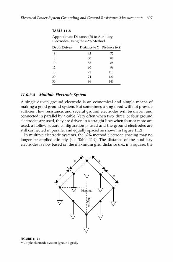
Electrical Power System Grounding and Ground Resistance Measurements 697
11.6.3.4 Multiple Electrode System
A single driven ground electrode is an economical and simple means of making a good ground system. But sometimes a single rod will not provide suffi cient low resistance, and several ground electrodes will be driven and connected in parallel by a cable. Very often when two, three, or four ground electrodes are used, they are driven in a straight line; when four or more are used, a hollow square confi guration is used and the ground electrodes are still connected in parallel and equally spaced as shown in Figure 11.21.
In multiple electrode systems, the 62% method electrode spacing may no longer be applied directly (see Table 11.9). The distance of the auxiliary electrodes is now based on the maximum grid distance (i.e., in a square, the
TABLE 11.8
Approximate Distance (ft) to Auxiliary Electrodes Using the 62% Method
Depth Driven Distance to Y Distance to Z
6 45 72
8 50 80
10 55 88
12 60 96
18 71 115
20 74 120
30 86 140
a
Diagonal
Diagonal
a a
a
FIGURE 11.21Multiple electrode system (ground grid).
DK4058_C011.indd 697DK4058_C011.indd 697 11/8/2008 12:43:12 PM11/8/2008 12:43:12 PM

698 Electrical Power Equipment Maintenance and Testing
TABLE 11.9
Multiple Electrode System Distance (ft)
Maximum Grid
Distance Distance to Y Distance to Z
6 78 125
8 87 140
10 100 160
12 105 170
14 118 190
16 124 200
18 130 210
20 136 220
30 161 260
40 186 300
50 211 340
60 230 370
80 273 440
100 310 500
120 341 550
140 372 600
160 390 630
180 434 700
200 453 730
diagonal; in a line, the total length, e.g., a square having a side of 20 ft will have a diagonal of approximately 28 ft).
Excessive noise. Excessive noise may interfere with testing because of the long leads used to perform a fall-of-potential test. A voltmeter can be utilized to identify this problem. Connect the X, Y, and Z cables to the auxiliary electrodes as for a standard ground resistance test. Use the voltmeter to test the voltage across terminals X and Z as shown in Figure 11.22. The voltage reading should be within the stray voltage tolerances acceptable to the ground tester being used. If the test exceeds this value, try the following techniques:
1. Braid the auxiliary cables together. This often has the effect of cancel-ing out the common mode voltages between these two conductors.
2. If the previous method fails, try changing the alignment of the auxiliary cables so that they are not parallel to power lines above or below the ground.
3. If a satisfactory low voltage value is still not obtained, the use of shielded cables may be required. The shield acts to protect the inner conductor by capturing the voltage and draining it to ground, as shown in Figure 11.23.
DK4058_C011.indd 698DK4058_C011.indd 698 11/8/2008 12:43:13 PM11/8/2008 12:43:13 PM

Electrical Power System Grounding and Ground Resistance Measurements 699
Excessive auxiliary rod resistance. The inherent function of a fall-of-potential ground tester is to input a constant current into the earth and measure the voltage drop by means of auxiliary electrodes. Excessive resistance of one or both auxiliary electrodes can inhibit this function. This is caused by high soil resistivity or poor contact between the auxiliary electrode and the sur-rounding dirt. To ensure good contact with the earth, stamp down the soil directly around the auxiliary electrode to remove air gaps formed when inserting the rod. If soil resistivity is the problem, pour water around the auxiliary electrodes. This reduces the auxiliary electrode’s contact resistance without affecting the measurement.
X1742X-
YZ
Y electrode Z electrode
Ground rod
Groundstrip
1950Vol
FIGURE 11.22Testing for stray voltages.
X1742X-
YZ
Y electrode
Float shield Float shield
Connect all threeshields together Z electrode
Ground rod
Groundshield
Groundstrip
FIGURE 11.23Use of shielded cables to minimize stray voltages.
DK4058_C011.indd 699DK4058_C011.indd 699 11/8/2008 12:43:13 PM11/8/2008 12:43:13 PM

700 Electrical Power Equipment Maintenance and Testing
Tar or concrete mat. Sometimes a test must be performed on a ground rod that is surrounded by a tar or concrete mat, where auxiliary electrodes cannot be driven easily. In such cases, metal screens and water can be used to replace auxiliary electrodes, as shown in Figure 11.24. Place the screens on the fl oor the same distance from the ground rod under test as you would auxiliary electrodes in a standard fall-of-potential test. Pour water on the screens and allow it to soak in. These screens will now perform the same function as would driven auxiliary electrodes.
11.6.4 Ratio Method
This method uses a Wheatstone bridge or an ohmmeter to measure the series resistance of grounding electrode and the auxiliary electrode. The test con-nections are shown in Figure 11.25. A slide wire potentiometer is used with a Wheatstone bridge for this test. The potentiometer is connected across the grounding electrode under test and the fi rst auxiliary electrode. The sliding contact of the potentiometer is connected to the second auxiliary electrode through a detector for determining the null point. The resistance of the test electrode and fi rst auxiliary electrode is measured fi rst by the Wheatstone bridge or ohmmeter. Then, using the potentiometer and Wheatstone bridge, a new null point is determined with the second electrode in the test circuit. The resistance of the grounding electrode is the ratio of the test electrode resistance to the total resistance of the two in series. The procedure and equations are as follows:
Measure • Rx + Ry by means of a Wheatstone bridge or ohmmeter
Determine from the potentiometer the ratio of • RA/(RA + RB)
Insert second auxiliary electrode (• Rz) in test circuit and obtain null point
+ ⎛ ⎞= = + ⎜ ⎟+ +⎝ ⎠
A
A A B
or ( )x yx
x x yA B
R RR RR R R
R R R R R
174.2
Groundrod
XXx
YZ
WaterScreens
FIGURE 11.24Use of screens as auxiliary electrodes.
DK4058_C011.indd 700DK4058_C011.indd 700 11/8/2008 12:43:13 PM11/8/2008 12:43:13 PM
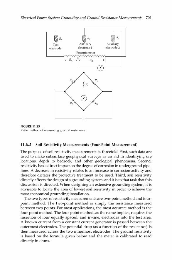
Electrical Power System Grounding and Ground Resistance Measurements 701
11.6.5 Soil Resistivity Measurements (Four-Point Measurement)
The purpose of soil resistivity measurements is threefold. First, such data are used to make subsurface geophysical surveys as an aid in identifying ore locations, depth to bedrock, and other geological phenomena. Second, resistivity has a direct impact on the degree of corrosion in underground pipe-lines. A decrease in resistivity relates to an increase in corrosion activity and therefore dictates the protective treatment to be used. Third, soil resistivity directly affects the design of a grounding system, and it is to that task that this discussion is directed. When designing an extensive grounding system, it is advisable to locate the area of lowest soil resistivity in order to achieve the most economical grounding installation.
The two types of resistivity measurements are two-point method and four-point method. The two-point method is simply the resistance measured between two points. For most applications, the most accurate method is the four-point method. The four-point method, as the name implies, requires the insertion of four equally spaced, and in-line, electrodes into the test area. A known current from a constant current generator is passed between the outermost electrodes. The potential drop (as a function of the resistance) is then measured across the two innermost electrodes. The ground resistivity is based on the formula given below and the meter is calibrated to read directly in ohms.
Potentiometer
Auxiliaryelectrode 1
Auxiliaryelectrode 2
Testelectrode
Ry
Ry
RB
RB
RA
RA
Rx
RxRz
Rz
FIGURE 11.25Ratio method of measuring ground resistance.
DK4058_C011.indd 701DK4058_C011.indd 701 11/8/2008 12:43:14 PM11/8/2008 12:43:14 PM

702 Electrical Power Equipment Maintenance and Testing
This value is the average resistivity of the ground at a depth equivalent to the distance A between two electrodes.
2 22 2
4
1 2 / 2 / 4 44( (( )) ( ))AR
A A A BA B=
+ − ++
pr
whereA is the distance between the electrodes (cm)B is the electrode depth (cm)R is the ohmic value as measured by four-terminal ground testerIf A > 20B, the formula becomes:
( )π= 2 with in cmAR Ar
( )= 191.5 with in ftAR Ar
= Ω soil resistivity ( -cm)r
11.6.6 Touch Potential Measurements
The primary reason for performing ground resistance measurements is to ensure electrical safety of personnel and equipment. Periodic ground elec-trode or grid resistance measurements are recommended when:
1. The electrode/grid is relatively small and can be conveniently disconnected
2. Corrosion induced by low soil resistivity or galvanic action is suspected
3. Ground faults are very unlikely to occur near the ground under test
In certain cases, the degree of electrical safety can be evaluated from a different perspective. Voltage gradient are a safety concern in large high-voltage switchyards and substations. Therefore, the ground grid system of these facilities is designed to ensure that the voltage gradients due to induced or fault currents remain at low value and not pose a danger to personnel or equipment. The maximum limit of voltage for these gradients is defi ned in terms of the following:
Touch potential: Touch potential is the voltage difference between a person’s arm and the feet, caused by the voltage gradient due to fault or induced current. It is assumed that the current passes through the heart and therefore this potential should be kept to near zero to safeguard personnel who might accidentally come in contact with equipment and structures in a switchyard or substations.
DK4058_C011.indd 702DK4058_C011.indd 702 11/8/2008 12:43:14 PM11/8/2008 12:43:14 PM

Electrical Power System Grounding and Ground Resistance Measurements 703
Step potential: Step potential is the voltage difference between a person’s feet, caused by the voltage gradient due to fault or induced current. It is assumed that the current passes through the legs and therefore this potential should be kept to near zero to safeguard personnel.
Touch potential measurements are recommended when the following factors are present.
1. It is physically or economically impossible to disconnect the ground to be tested.
2. Ground faults could reasonably be expected to occur near the ground to be tested, or near equipment grounded by the ground to be tested.
3. The footprint of grounded equipment is comparable to the size of the ground to be tested. (The footprint is the outline of the part of equipment in contact with the earth.)
When performing touch potential measurements, a four-pole ground resistance tester is used. During the test, the instrument induces a low-level fault into the earth at some proximity to the subject ground. The instrument displays touch potential in volts per ampere of fault current. The displayed value is then multiplied by the largest anticipated ground fault current to obtain the worst case touch potential for a given installation.
For example, if the instrument displayed a value of 0.100 when connected to a system where the maximum fault current was expected to be 5000 A, the maximum touch potential would be 500 V.
Touch potential measurements are similar to fall-of-potential measurements in that both measurements require placement of auxiliary electrodes into or on the earth. Spacing the auxiliary electrodes during touch potential measurements differs from fall-of-potential electrode spacing, as shown in Figure 11.26.
C1P1 1742
Connectionsto fence
Anticipatedfault point
Buriedcable
1 m
Driven ground rods
P2C2
FIGURE 11.26Touch potential measurements.
DK4058_C011.indd 703DK4058_C011.indd 703 11/8/2008 12:43:14 PM11/8/2008 12:43:14 PM

704 Electrical Power Equipment Maintenance and Testing
Consider the following scenario: If the buried cable depicted in Figure 11.26 experienced an insulation breakdown near the substation shown, fault currents would travel through the earth toward the substation ground, creating a voltage gradient. This voltage gradient may be hazardous or potentially lethal to personnel who came in contact with the affected ground.
To test for approximate touch potential values in this situation, proceed as follows. Connect cables between the fence of the substation and C1 and P1 of the four-pole earth resistance tester. Position an electrode in the earth at the point at which the ground fault is anticipated to occur, and connect it to C2. In a straight line between the substation fence and the anticipated fault point, position an auxiliary electrode into the earth 1 m (or one arm’s length) away from the substation fence, and connect it to P2. Turn the instrument on, select the 10 mA current range, and observe the measurement. Multiply the dis-played reading by the maximum fault current of the anticipated fault. By positioning the P2 electrode at various positions around the fence adjacent to the anticipated fault line, a voltage gradient map may be obtained.
11.6.7 Clamp-On Ground Resistance Measurement
This measurement method is new and quite unique. It offers the ability to measure the resistance without disconnecting the ground. This type of mea-surement also offers the advantage of including the bonding to ground and the overall grounding connection resistances.
11.6.7.1 Principle of Operation
Usually, a common distribution line grounded system can be simulated as a simple basic circuit as shown in Figure 11.27, or an equivalent circuit as shown in Figure 11.28. If voltage E is applied to any measured grounding pole Rx through a special transformer, current I fl ows through the circuit, thereby establishing the following equation:
FIGURE 11.27Simple basic circuit of distribution grounded system.
Rx
E
I
R1 R2 Rn−1 Rn
DK4058_C011.indd 704DK4058_C011.indd 704 11/8/2008 12:43:15 PM11/8/2008 12:43:15 PM

Electrical Power System Grounding and Ground Resistance Measurements 705
=
= +∑ 1
1
(1/ )x n
kk
ER
I R
where usually:
=
>>∑ 1
1
(1/ )x n
kk
RR
Therefore, E/I = Rx is established. If I is detected with E kept constant, measured grounding pole resistance can be obtained.
Refer again to Figures 11.27 and 11.28. Current is fed to a special transformer via a power amplifi er from a 1.6 kHz constant-voltage oscillator. This current is detected by a detection current transformer (CT). Only the 1.6 kHz signal frequency is amplifi ed by a fi lter amplifi er before being fed into analog/ digital (A/D)-converter, and after synchronous rectifi cation it is displayed on the liquid crystal display (LCD).
The fi lter amplifi er is used to cut off earth current at commercial frequency and high-frequency noise. Voltage is detected by coils wound around the injection CT and then amplifi ed and rectifi ed to be compared by a level comparator. If the clamp is not closed properly, an open jaws annunciator appears on the LCD. The clamp-on ground resistance measurement instrument is shown in Figure 11.29.
11.6.7.2 In-Field Measurement
The following are examples of ground resistance measurements in typical fi eld situations:
Pole-mounted transformer: Remove any molding covering the ground conductor, and provide suffi cient room for the jaws of the clamp-on ground tester. The jaws must be able to close easily around the conductor. The jaws can be placed around the ground rod itself.
Rx
E
I
R1 R2 Rn−1 Rn
FIGURE 11.28Equivalent circuit of simple distribution grounded system.
DK4058_C011.indd 705DK4058_C011.indd 705 11/8/2008 12:43:15 PM11/8/2008 12:43:15 PM

706 Electrical Power Equipment Maintenance and Testing
Note: The clamp must be placed so that the jaws are in electrical path from the system neutral or ground wire to the ground rod or rods as the circuit provides.
Select the current range A. Clamp onto the ground conductor and measure the ground current. The maximum range is 30 A. If the ground current exceeds 30 A, ground resistance measurements are not possible. “Do not proceed further with the measurement.” Having noted the ground current, select the ground resistance range Ω and measure the resistance directly. The reading you measure with the ground tester indicates not just the resistance of the rod, but of the connection to the system neutral and all bonding connections between the neutral and the rod.
Note that in Figure 11.30, there exist both a butt plate and a ground rod. In this type of circuit, it is necessary to place the tester jaws above the bond so that both grounds are included in the test. For future reference, note the date, ohms reading, current reading, and pole number. Replace any molding you may have removed from the conductor.
Note: A high reading indicates one or more of the following:
Poor ground rod.Open ground conductor.High resistance bonds on the rod or splices on the conductor; watch for
buried split butts, clamps, and hammer-on connections.
FIGURE 11.29Clamp-on ground resistance measurement instrument. (From Clem, O., Megger/Programma,
Valley Forge, PA, Used in company catalog, datasheet, and brochure, 2008. With permission.)
DK4058_C011.indd 706DK4058_C011.indd 706 11/8/2008 12:43:15 PM11/8/2008 12:43:15 PM

Electrical Power System Grounding and Ground Resistance Measurements 707
Service entrance or meter: Follow basically the same procedure as in the fi rst example. Notice that Figure 11.31 shows the possibility of multiple ground rods and in Figure 11.32, the ground rods have been replaced with a water pipe ground. You may also have both types acting as a ground. In these cases, it is necessary to make the measurements between the service neutral and both grounded points.
Pad-mounted transformer
Note: Never open transformer enclosures. They are the property of the electrical utility. If the ground test needs to be performed with the utility transformer, coordinate with the utility personnel for such a test.
“Observe all safety requirements—dangerously high voltage is pres-ent.” Locate and number all rods (usually only a single rod is present). If the ground rods are inside the enclosure, refer to Figure 11.33 and if they are outside the enclosure, refer to Figure 11.34. If a single rod is found within the enclosure, the measurement should be taken on the conductor just before the bond on the ground rod. Often, more than one ground conductor is tied to this clamp, looping back to the enclosure or neutral.
In many cases, the best reading can be obtained by clamping the instrument onto the ground rod itself, below the point when the ground conductors are attached to the rod, so that you are measuring the ground circuit. Care must be taken to fi nd a conductor with only one return path to the neutral.
Generally, a very low reading at the measurement indicates that you are on a loop and you need to test closer to the rod. In Figure 11.34, the ground rod
UtilitypoleGround level
Groundrod
Groundingconductor
Butt plate
FIGURE 11.30Ground resistance measurement of pole-mounted transformer.
DK4058_C011.indd 707DK4058_C011.indd 707 11/8/2008 12:43:16 PM11/8/2008 12:43:16 PM

708 Electrical Power Equipment Maintenance and Testing
Ground level
Groundrods
Service meter
Building wall
Pole-mountedtransformer
Service box
FIGURE 11.31Ground resistance measurement of service entrance having multiple ground rods.
Service meter
Water pipe
Building wall
Pole-mountedtransformer
Service box
FIGURE 11.32Ground resistance measurement of service entrance with water pipe ground.
DK4058_C011.indd 708DK4058_C011.indd 708 11/8/2008 12:43:16 PM11/8/2008 12:43:16 PM
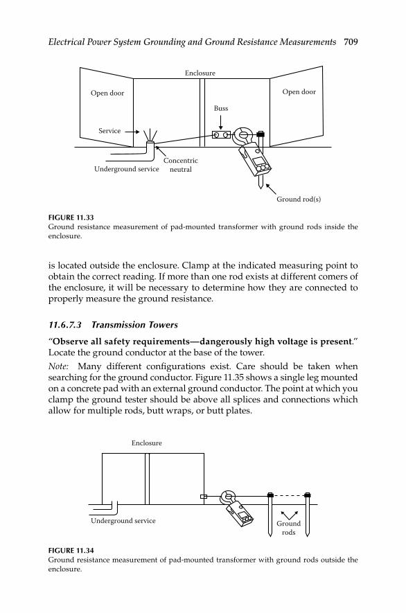
Electrical Power System Grounding and Ground Resistance Measurements 709
is located outside the enclosure. Clamp at the indicated measuring point to obtain the correct reading. If more than one rod exists at different comers of the enclosure, it will be necessary to determine how they are connected to properly measure the ground resistance.
11.6.7.3 Transmission Towers
“Observe all safety requirements—dangerously high voltage is present.” Locate the ground conductor at the base of the tower.
Note: Many different confi gurations exist. Care should be taken when searching for the ground conductor. Figure 11.35 shows a single leg mounted on a concrete pad with an external ground conductor. The point at which you clamp the ground tester should be above all splices and connections which allow for multiple rods, butt wraps, or butt plates.
Open door
Enclosure
Buss
Concentricneutral
Ground rod(s)
Open door
Service
Underground service
FIGURE 11.33Ground resistance measurement of pad-mounted transformer with ground rods inside the
enclosure.
Groundrods
Enclosure
Underground service
FIGURE 11.34Ground resistance measurement of pad-mounted transformer with ground rods outside the
enclosure.
DK4058_C011.indd 709DK4058_C011.indd 709 11/8/2008 12:43:16 PM11/8/2008 12:43:16 PM
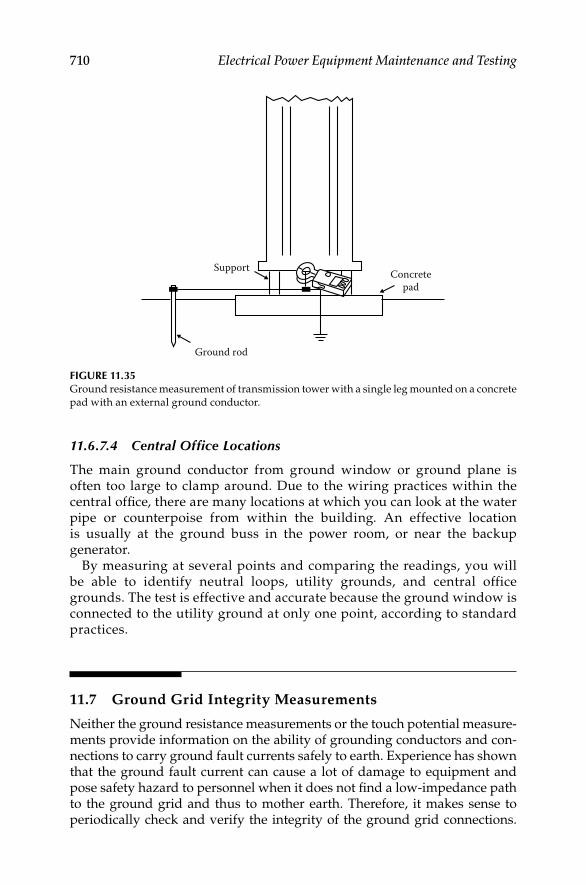
710 Electrical Power Equipment Maintenance and Testing
11.6.7.4 Central Office Locations
The main ground conductor from ground window or ground plane is often too large to clamp around. Due to the wiring practices within the central offi ce, there are many locations at which you can look at the water pipe or counterpoise from within the building. An effective location is usually at the ground buss in the power room, or near the backup generator.
By measuring at several points and comparing the readings, you will be able to identify neutral loops, utility grounds, and central office grounds. The test is effective and accurate because the ground window is connected to the utility ground at only one point, according to standard practices.
11.7 Ground Grid Integrity Measurements
Neither the ground resistance measurements or the touch potential measure-ments provide information on the ability of grounding conductors and con-nections to carry ground fault currents safely to earth. Experience has shown that the ground fault current can cause a lot of damage to equipment and pose safety hazard to personnel when it does not fi nd a low- impedance path to the ground grid and thus to mother earth. Therefore, it makes sense to periodically check and verify the integrity of the ground grid connections.
Concretepad
Ground rod
Support
FIGURE 11.35Ground resistance measurement of transmission tower with a single leg mounted on a concrete
pad with an external ground conductor.
DK4058_C011.indd 710DK4058_C011.indd 710 11/8/2008 12:43:17 PM11/8/2008 12:43:17 PM

Electrical Power System Grounding and Ground Resistance Measurements 711
The objective of this measurement is to determine whether the equipment, frame, structures, or enclosure grounds are connected to the grounding electrode or ground grid with low resistance. The resistance value of such connections is expected to be very low (100 μΩ or less). The best way for making tests for integrity of ground grid connections is to use a large but practical current and some means of detecting the voltage drop caused by this current. A test set is available to conduct this measurement using AC current. This test method is known as the high-current test method. This method consists of passing 300 A through the ground grid between a refer-ence ground (usually a transformer neutral) and the ground (conductor and connections) to be tested. The voltage drop and the current magnitude and direction are monitored to verify the inte-grity of the ground connections. The GTS-300* test set is shown in Figure 11.36. The test connections for conducting this test are shown in Figure 11.37.
The below listed guidelines are offered when using the high-current method of testing the continuity of ground grids and grounds. However, it should be kept in mind that these are only guidelines since each ground has to be considered on its own merits relative to other grounds in the imme-diate vicinity.
* A registered trade name of Megger Inc., Valley Forge, PA.
FIGURE 11.36Ground grid integrity test set, GTS-300. (From Onnie Clem, Megger/Programma, Valley Forge,
PA, Used in company catalog, datasheet, and brochure, 2008. With permission.)
DK4058_C011.indd 711DK4058_C011.indd 711 11/8/2008 12:43:17 PM11/8/2008 12:43:17 PM

712 Electrical Power Equipment Maintenance and Testing
1. The voltage drop of the ground grid rises approximately 1 V for each 50 ft of straight distance from the reference point.
2. On equipment with single ground the ground can be considered satisfactory if the voltage drop is in line with item 1 above and at least 200 A fl ow to the ground conductor under test into the grid. On most equipment of this type, 300 A will fl ow to the grid; however, in some cases current will also fl ow through foundation bolts and or conduits.
3. On equipment with multigrounds, a ground can be considered satisfactory if the voltage drop is in line with item 1 above and at least 150 A fl ow to the ground conductor under test into the grid. If the current to the grid is less than 150 A, the ground should be disconnected from the equipment and 300 A again should be passed through the ground. If the ground passes the 300 A and the voltage drop does not increase more than 0.5 V over the previous level, the ground can be considered satisfactory.
“Caution: Before any ground is removed from an equipment be sure to parallel it with a 2/0 CU temporary ground, such as a truck ground or other grounds before it is disconnected.”
Amps
High-current source
Volts
P1
Clip-onammeter
Clip-onammeter
Substation equipment
Clip-on ammeter Clip-on ammeter
Reference ground Test ground
Potential lead Potential leadCurrent leadCurrent lead
P2C2C1
FIGURE 11.37High-current method of testing ground grid integrity.
DK4058_C011.indd 712DK4058_C011.indd 712 11/8/2008 12:43:17 PM11/8/2008 12:43:17 PM

Electrical Power System Grounding and Ground Resistance Measurements 713
4. To test transformer neutral or reference point pass 300 A through the transformer neutral at a point above grade but below any bonding connections or clamps on the tank. If at least 150 A fl ow to the ground grid, the reference point can be considered satisfactory.
5. Establish a reference ground, preferably a transformer neutral. From a high-current AC source (GTS-300) connect one test lead to ground being tested as shown in Figure 11.37. Connect the test lead at a point above grade but below the bonding connections or clamps. Pass 300 A through the ground grid and record the voltage drop across the grid. Using a clip-on ammeter, measure the amount of test current fl owing above (to the equipment) and below (to the grid) the test lead on the ground being tested. The voltage drop should be in accordance with item 1 above. The test amperes should be in accordance with items 2 and 3 in this list.
DK4058_C011.indd 713DK4058_C011.indd 713 11/8/2008 12:43:17 PM11/8/2008 12:43:17 PM

DK4058_C011.indd 714DK4058_C011.indd 714 11/8/2008 12:43:17 PM11/8/2008 12:43:17 PM
715
12Power Quality, Harmonics, and Predictive Maintenance
12.1 Background
Power quality (PQ) problems can be defi ned as any power problem mani-fested by voltage, current, and frequency deviations that result in failure or misoperation of load or equipment. PQ problems may be classifi ed into two categories: (1) conducted low-frequency phenomena and (2) radiated frequency phenomena. The conducted low-frequency phenomenon is characterized by the following types of PQ problems.
Overvoltage, undervoltage, transients including sags and swells•
Voltage fl uctuations (fl icker)•
Voltage dips and interruptions•
Voltage imbalance or unbalance•
Power frequency variations•
Induced low-frequency voltages•
Harmonics, interharmonics, and harmonic resonance•
The radiated frequency phenomenon known as noise is characterized by the following types of PQ problems.
Magnetic and electric fi elds (electromagnetic interference, EMI)•
Radio frequency interference (RFI)•
Further, the addition of nonlinear (digital and electronic) loads in industrial and commercial power systems have lead to problems in the quality of power that is being delivered to a site. A nonlinear load is defi ned as that which draws a nonsinusoidal current wave when supplied by a sinusoidal voltage source. PQ problems can produce results that range from erratic equipment behavior to complete shut down of a facility. In some cases, the shut down may be accompa-nied by a catastrophic failure costing millions of dollars in some cases. Thus, it is important to understand and solve PQ problems. But, catastrophic failure is just one possible outcome. PQ problems can creep along—silently consuming
DK4058_C012.indd 715DK4058_C012.indd 715 11/8/2008 1:05:20 PM11/8/2008 1:05:20 PM

716 Electrical Power Equipment Maintenance and Testing
maintenance resources for trouble shooting PQ anomalies and at the same time increasing the cost of electrical energy (utility bills) because of ineffi cient use. Things may appear to be normal, but that is only because of a lack of understanding of PQ problems and power anomalies. Like the old saying, what you do not know cannot hurt you. PQ covers a wide range of issues, from volt-age disturbances like sags, swells, outages and transients, to voltage and current harmonics, to performance of wiring and grounding. The concept of load and source compatibility is not new. The need to provide power with steady voltage and frequency was recognized since the early days of the electri-cal power. Some of the early concerns were fl icker of light bulbs due to voltage fl uctuations and overheating of motors due to voltage waveform distortion (harmonics). More recently, transient voltage disturbances associated with lightning and power system switching have emerged as a major concern to manufacturers and users of electronic equipment. The issue of grounding, and how to deal simultaneously with surges, lightning protection (i.e., known as RFI, EMI or noise), and safety is a complicated task because of confl icting philosophies advocated by different professionals. Today’s PQ problems are far more complex. They cannot be handled so easily because of a multitude of dif-ferent causes and a variety of specifi c sensitivities in the end user equipment that is most affected. Because both the causes and consequences of PQ prob-lems are so diverse, they are not amenable to a single solution. The symptoms of poor PQ include intermittent lockups and resets, corrupted data, premature equipment failure, overheating of components for no apparent cause, nuisance tripping of relays and protective devices, etc. The ultimate cost is in downtime, decreased productivity and frustrated personnel.
In this chapter we attempt to provide an understanding of the fundamentals of PQ, harmonics, and their effects on electrical equipment. More importantly, we are going to approach PQ issues from the prospective of predictive mainte-nance so that maintenance personnel can be vigilant and alert in identifying and resolving actual and potential PQ problems before they become a major source of trouble.
12.2 PQ Concept and Fundamentals
The industry standards such as IEEE, ANSI, and NEMA specify steady state voltage tolerances for the electric utility at the point of service to be within ±5% for nonlighting loads. These standards also specify the steady state voltage tolerances at the point of use. Equipment utilizing electricity must be designed to give satisfactory performance throughout the range of +4% to −10%, and acceptable performance in the broader range of +6% to −13%. However, this specifi cation of steady state voltage limits is insuffi cient for today’s microelectronic technology. What constitutes acceptable performance and acceptable PQ for computers is more diffi cult to defi ne. A comprehensive defi nition of PQ is needed. It should be based on consideration of the following:
DK4058_C012.indd 716DK4058_C012.indd 716 11/8/2008 1:05:20 PM11/8/2008 1:05:20 PM

Power Quality, Harmonics, and Predictive Maintenance 717
All types of power disturbances that occur•
Quality of power necessary for successful operation of diverse elec-• trical and electronic equipment
Practical limits to the capability of delivering power of high quality • to diverse customers
Economics of the electric power distribution from both the utility • and customer perspective
One defi nition proposed by the IEEE-1100 describes PQ as a concept of powering and grounding sensitive electronic equipment in a manner that is suitable to the operation of that equipment.
12.2.1 Types and Consequences of Electrical Disturbances
Several different types of electrical disturbances can occur in a power distri-bution system as described briefl y below.
Voltage disturbances: The interaction between sensitive electronic equip-ment, their power sources, and their electrical environment can result in dis-tortions to the alternating current (AC) line voltage. Several common load derived sources of voltage waveform disturbances and their relative charac-teristics are presented below.
Overvoltage: An overvoltage is any change above the prescribed input volt-age range for a given piece of equipment (Figure 12.1). Overvoltages can be caused by many factors in the utility and customer’s supply voltage system, such as incorrect transformer tap settings, improper application of power factor (PF) correction capacitors, and the like. They can cause overheating and reduced life of electrical equipment.
Undervoltage: An undervoltage is any change below the prescribed input voltage range for a given piece of equipment (Figure 12.2). Undervoltages can be caused by many factors in the power supply and/or in the site distri-bution power system. Undervoltage can occur due to overloaded distribu-tion systems or customer wiring, incorrect transformer tap setting, faulty connections or wiring, loose or corroded connections, or unbalanced phase
0Time
Volta
ge p
er u
nit
+1
−1
FIGURE 12.1An overvoltage condition in power distribution system.
DK4058_C012.indd 717DK4058_C012.indd 717 11/8/2008 1:05:20 PM11/8/2008 1:05:20 PM
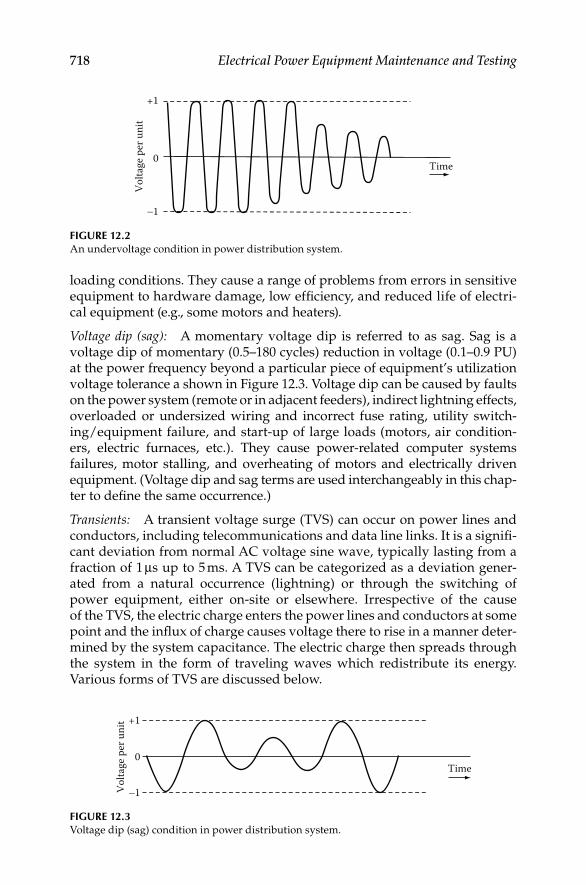
718 Electrical Power Equipment Maintenance and Testing
loading conditions. They cause a range of problems from errors in sensitive equipment to hardware damage, low effi ciency, and reduced life of electri-cal equipment (e.g., some motors and heaters).
Voltage dip (sag): A momentary voltage dip is referred to as sag. Sag is a voltage dip of momentary (0.5–180 cycles) reduction in voltage (0.1–0.9 PU) at the power frequency beyond a particular piece of equipment’s utilization voltage tolerance a shown in Figure 12.3. Voltage dip can be caused by faults on the power system (remote or in adjacent feeders), indirect lightning effects, overloaded or undersized wiring and incorrect fuse rating, utility switch-ing/equipment failure, and start-up of large loads (motors, air condition-ers, electric furnaces, etc.). They cause power-related computer systems failures, motor stalling, and overheating of motors and electrically driven equipment. (Voltage dip and sag terms are used interchangeably in this chap-ter to defi ne the same occurrence.)
Transients: A transient voltage surge (TVS) can occur on power lines and conductors, including telecommunications and data line links. It is a signifi -cant deviation from normal AC voltage sine wave, typically lasting from a fraction of 1 μs up to 5 ms. A TVS can be categorized as a deviation gener-ated from a natural occurrence (lightning) or through the switching of power equipment, either on-site or elsewhere. Irrespective of the cause of the TVS, the electric charge enters the power lines and conductors at some point and the infl ux of charge causes voltage there to rise in a manner deter-mined by the system capacitance. The electric charge then spreads through the system in the form of traveling waves which redistribute its energy. Various forms of TVS are discussed below.
0Time
Volta
ge p
er u
nit
+1
−1
FIGURE 12.2An undervoltage condition in power distribution system.
0Time
Volta
ge p
er u
nit +1
−1
FIGURE 12.3Voltage dip (sag) condition in power distribution system.
DK4058_C012.indd 718DK4058_C012.indd 718 11/8/2008 1:05:20 PM11/8/2008 1:05:20 PM

Power Quality, Harmonics, and Predictive Maintenance 719
Impulse transient: An impulse transient has a fast rise time, fairly rapid decay, and high energy content. Duration can be from a few microseconds up to several hundred microseconds. A typical impulse transient is shown in Figure 12.4. Its impulse magnitude is measured from the point it occurs on the sine wave and not from zero voltage. It is called a spike, if it adds to the sine wave, or a notch, if it subtracts from the sine wave.
The voltage impulse is a high-frequency voltage phenomenon of positive (spike) or negative amplitude (notch). An impulse occurring between current-carrying conductors is known as normal mode event and an impulse common to all current-carrying conductors and involving the ground conductor is referred to as common mode (CM) event. Many impulses have components of both types. Another type of repetitive voltage disturbance is a series of events with discrete components which occur repetitively throughout a single cycle or regu-larly multiple cycles. These repetitive voltage disturbances are usually caused by phase-angle-controlled loads, such as silicon-controlled rectifi ers (SCRs). The impulse factors which affect the loads are impulse amplitude, duration, fre-quency, grounding, etc. Over time the cumulative effect of repetitive voltage disturbances can exceed the energy handling capability of the loads, thus result-ing in a catastrophic failure. The symptoms of this type of disturbance are indi-cated by equipment component failures, hard disk crashes, parity errors, power supply failures, lockup, circuit board failures, surge suppressor failures, etc.
Oscillatory transient: An oscillatory transient has a fast rise time, oscilla-tions that decay exponentially, and a lower energy content than an impulse transient. A typical oscillatory transient can last up to one cycle (16.7 ms) or even longer and can have frequencies from a few hundred hertz to many megahertz. A typical oscillatory transient is shown in Figure 12.5.
Negativeimpulse
Negativenotch
Time
Positiveimpulse Impulse
magnitude
Impulsemagnitude
−1
0
Volta
ge p
er u
nit
+1
Impulsemagnitude
FIGURE 12.4Impulse transient wave.
DK4058_C012.indd 719DK4058_C012.indd 719 11/8/2008 1:05:21 PM11/8/2008 1:05:21 PM

720 Electrical Power Equipment Maintenance and Testing
Switching transient: Switching of power equipment can cause a transient voltage to be generated due to the stored energy contained in the circuit inductances (L) and capacitances (C). The size and duration of the transient depends on the value of inductance and capacitance and the waveform applied. Examples of switching surges are fault clearing, capacitor switch-ing, and switching of inductive loads on and off. Damage from transient overvoltages can be immediate or latent. The latent damage occurs when equipment or components are severely stressed by repeated transient over-voltages or by a single transient overvoltage condition, but not to the point of immediate failure. Each exposure reduces the ability of the equipment or component’s ability to withstand additional stress. At some later time, the equipment or component fails unexpectedly without apparent cause due to its weakened nature from previous transients. This latent effect may not become apparent for some time.
Interruptions: Power interruptions are a complete loss of power lasting for cycles, seconds, minutes, hours, or days (Figure 12.6). A variety of factors can cause power interruptions, such as tripping of the main circuit breaker due to a fault, malfunction or failure of equipment, or operation of protective devices in response to faults that occur due to acts of nature or accidents, or other anomalies in the power supply. These interruptions may cause loss of computer memory, equipment shutdown/failure, hardware damage, and productivity loss.
Frequency variations: A frequency variation is a deviation from a prescribed input frequency range such as 60 Hz (Figure 12.7). This deviation can be either higher or lower than normal. Sudden changes in load, switching of power
Positiveoscillatory Impulse magnitude
Time
+1
0
Volta
ge p
er u
nit
−1
FIGURE 12.5Oscillatory transient.
+1
0Time
Volta
ge p
er u
nit
−1
FIGURE 12.6Power interruption.
DK4058_C012.indd 720DK4058_C012.indd 720 11/8/2008 1:05:21 PM11/8/2008 1:05:21 PM

Power Quality, Harmonics, and Predictive Maintenance 721
between utility and on-site generator, utility generator malfunctions, or mis-match between generation and load can cause such variations.
Harmonics: Harmonics are voltages or currents at frequencies that are integer multiples of 60 Hz frequency (120, 180, 240, 300 Hz, etc.). They are des-ignated by their harmonic number or multiple of the fundamental frequency. For example, a harmonic with a frequency of 180 Hz—(three times the 60 Hz fundamental frequency) is called the third harmonic. As shown in Figure 12.8, harmonics superimpose themselves on the fundamental waveform, distort it, and change its waveform. In industrial power systems, for example, 15%, 20%, or 25% total harmonic current distortion (THD) may be experi-enced. THD can be determined by calculating the square root of the sum of the squares of all harmonics, divided by the nominal 60 Hz value. This yields
Frequency deviation+V
0TimeVo
ltage
−V
FIGURE 12.7Frequency variations.
0−125
−100
−75
−50
−25
0
25
50
75
100
125
5 10 15 20Time (ms)
5thharmonic
waveResultantdistorted
wave
Fundamental(60 Hz) wave
Mag
nitu
de, %
of f
unda
men
tal
25 30 35
FIGURE 12.8HD caused by fi fth harmonic current superimposed on 60 Hz waveform. (Courtesy of Plant
Engineering Magazine, 2000 Clearwater Dr., Oak Brook, IL.)
DK4058_C012.indd 721DK4058_C012.indd 721 11/8/2008 1:05:21 PM11/8/2008 1:05:21 PM
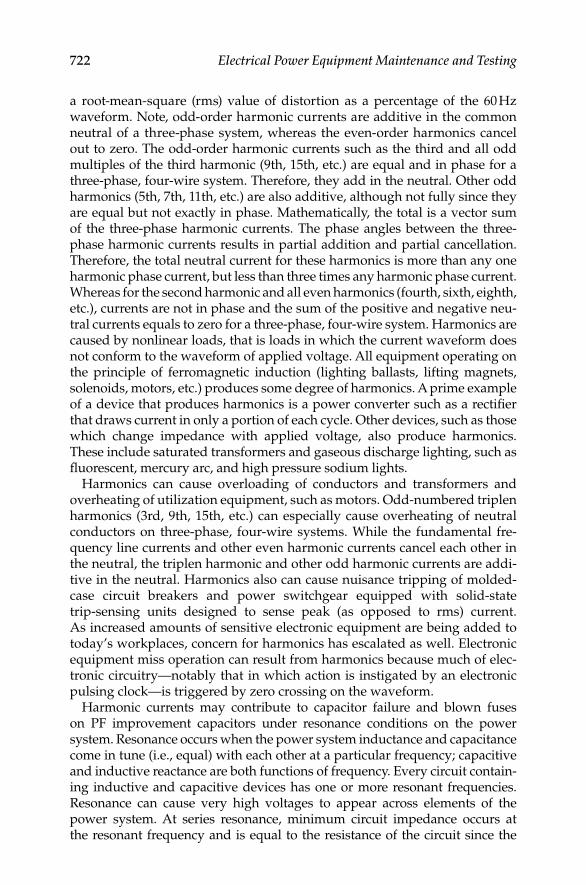
722 Electrical Power Equipment Maintenance and Testing
a root-mean-square (rms) value of distortion as a percentage of the 60 Hz waveform. Note, odd-order harmonic currents are additive in the common neutral of a three-phase system, whereas the even-order harmonics cancel out to zero. The odd-order harmonic currents such as the third and all odd multiples of the third harmonic (9th, 15th, etc.) are equal and in phase for a three-phase, four-wire system. Therefore, they add in the neutral. Other odd harmonics (5th, 7th, 11th, etc.) are also additive, although not fully since they are equal but not exactly in phase. Mathematically, the total is a vector sum of the three-phase harmonic currents. The phase angles between the three-phase harmonic currents results in partial addition and partial cancellation. Therefore, the total neutral current for these harmonics is more than any one harmonic phase current, but less than three times any harmonic phase current. Whereas for the second harmonic and all even harmonics (fourth, sixth, eighth, etc.), currents are not in phase and the sum of the positive and negative neu-tral currents equals to zero for a three-phase, four-wire system. Harmonics are caused by nonlinear loads, that is loads in which the current waveform does not conform to the waveform of applied voltage. All equipment operating on the principle of ferromagnetic induction (lighting ballasts, lifting magnets, solenoids, motors, etc.) produces some degree of harmonics. A prime example of a device that produces harmonics is a power converter such as a rectifi er that draws current in only a portion of each cycle. Other devices, such as those which change impedance with applied voltage, also produce harmonics. These include saturated transformers and gaseous discharge lighting, such as fl uorescent, mercury arc, and high pressure sodium lights.
Harmonics can cause overloading of conductors and transformers and overheating of utilization equipment, such as motors. Odd-numbered triplen harmonics (3rd, 9th, 15th, etc.) can especially cause overheating of neutral conductors on three-phase, four-wire systems. While the fundamental fre-quency line currents and other even harmonic currents cancel each other in the neutral, the triplen harmonic and other odd harmonic currents are addi-tive in the neutral. Harmonics also can cause nuisance tripping of molded-case circuit breakers and power switchgear equipped with solid-state trip-sensing units designed to sense peak (as opposed to rms) current. As increased amounts of sensitive electronic equipment are being added to today’s workplaces, concern for harmonics has escalated as well. Electronic equipment miss operation can result from harmonics because much of elec-tronic circuitry—notably that in which action is instigated by an electronic pulsing clock—is triggered by zero crossing on the waveform.
Harmonic currents may contribute to capacitor failure and blown fuses on PF improvement capacitors under resonance conditions on the power system. Resonance occurs when the power system inductance and capacitance come in tune (i.e., equal) with each other at a particular frequency; capacitive and inductive reactance are both functions of frequency. Every circuit contain-ing inductive and capacitive devices has one or more resonant frequencies. Resonance can cause very high voltages to appear across elements of the power system. At series resonance, minimum circuit impedance occurs at the resonant frequency and is equal to the resistance of the circuit since the
DK4058_C012.indd 722DK4058_C012.indd 722 11/8/2008 1:05:22 PM11/8/2008 1:05:22 PM

Power Quality, Harmonics, and Predictive Maintenance 723
inductive and capacitive impedances are equal. Series resonance provides a low impedance path for the harmonic currents present in the system.
Figure 12.9 illustrates a typical resonant condition on an arc furnace cir-cuit containing PF improvement capacitors. The plot of voltage response versus frequency models the arc furnace as a harmonic current source of varying frequency. A resonance peak occurs at very close to 300 Hz, or the fi fth harmonic. This harmonic source develops excessive voltage at the capacitor terminals, resulting in extremely high current fl ow through the capacitor.
Voltage imbalance: A voltage imbalance is a long term, steady state problem. It is expressed as a percent, i.e., the maximum deviation of voltage from the average of three-phase voltages, multiplied by 100, divided by the average of the voltages. Voltage imbalances are caused by unbalanced phase loading conditions, defective transformers, and ground faults in ungrounded or resis-tive grounded systems. These imbalances usually are caused by large single-phase loads. They cause premature failures of motors and transformers due to overheating. Voltage imbalances only affect three-phase applications.
Electrical noise: Electrical noise is a low-voltage, low-current, high-frequency signal that rides a 60 Hz sine wave, distorting it. Noise may be caused by any of the following: RFI, EMI, harmonics from nonlinear loads, and the like. Even though microprocessor-based equipment is grounded in accordance with National Electric Code (NEC) requirements, some continue to have failures, execution and reading errors, and unpredictable and intermittent operations because of electrical noise. Some manufacturers of microprocessor-based equipment recommend electrical separation to minimize the effects of electri-cal noise, i.e., to locate the microprocessor-based equipment and/or data lines not too close to large power apparatus such as transformers, motors, etc.
060 180 300 420
Frequency (Hz)
Perc
ent v
olts
Arc furnance(harmonic
voltagesource)
Capacitorbank Furnace
leadimped-
ance
Arcfurnacetrans-former
Sourceimpedance
Utility
540 660 780
100
200
300
400
500
FIGURE 12.9Parallel resonance condition indicating very high peak voltages at about 300 Hz.
DK4058_C012.indd 723DK4058_C012.indd 723 11/8/2008 1:05:22 PM11/8/2008 1:05:22 PM

724 Electrical Power Equipment Maintenance and Testing
Two types of electrical noise can occur in a power distribution system. They are normal mode (line-to-neutral, L–N or line-to-line) noise and CM (neutral-to-ground, N–G) noise.
Normal mode noise is measured between the phase (hot) and neutral lines or phase-to-phase. CM noise is a potential difference that occurs between any or all current-carrying conductors and the grounding conduc-tor or earth. In the three-phase, grounded-wye power supplies typical of large computer systems, these disturbances also can be potential differ-ences between neutral and ground. Some computer-based loads are sensi-tive to excessive levels of voltage potential between the neutral and grounding conductors. A ground is used to reference the electronic logic in equipment and should be stable. Equipment manufacturers sometimes specify acceptable limits for neutral to ground voltage, for example, one volt peak to peak. CM disturbances can be generated by a ground potential difference between elements of the computer or remote peripherals con-nected to the computer. This type of disturbance is infl uenced by several factors, including the system confi guration and the impedance of the grounding system. Both of these factors generally are beyond the direct control of the user, except in the construction of a new facility. However, CM noise can be suppressed by the use of an isolation transformer. Equalizing ground potentials is often diffi cult due to the broad frequency band involved in wiring resonances. However, proper computer system grounding, including a signal reference grid (SRG), has been found to be effective against most CM disturbances. CM noise on the primary of the transformer that appears as normal mode noise on the secondary is com-monly referred to as transverse mode or sometimes as intercoupling or dif-ferential mode (DM) noise. CM transient voltages that appear on the transformer primary winding will be coupled through the transformer interwinding capacitance, appearing across the secondary winding as normal mode voltages. Electrical noise typically occurs in the RF MHz range. It also may occur at frequencies below MHz range. The 60 Hz (power) grounding system often is not effective for conducting RF signals to the common reference point grounding electrode. In some cases, computers and peripherals are themselves responsible for generating noise distur-bances. A properly designed power grounding system has suffi ciently low impedance at 60 Hz to maintain enclosures, raceways, and all grounded metals at the same voltage potential (ground reference). But the 60 Hz ground system is unable to provide this equalization at higher frequencies because of the increased impedance caused by inductive reactance and the skin effect. (Skin effect is known as the tendency of current to fl ow more at the surface of the conductor than its center, thereby increasing the AC resis-tance of the conductor). The inductive reactance at a frequency of 30 MHz is 500,000 times as great as that of the same conductor when the applied voltage is at 60 Hz. At microprocessor switching speeds (over 1 to 30 MHz), current penetration in the copper conductor is less than at 60 Hz, with the result that the effective impedance between one point and another is pronounced. Also, as frequency rises, the wavelength proportionally
DK4058_C012.indd 724DK4058_C012.indd 724 11/8/2008 1:05:22 PM11/8/2008 1:05:22 PM

Power Quality, Harmonics, and Predictive Maintenance 725
TABLE 12.1
Electromagnetic Phenomena and Characteristics
Categories Typical Characteristics
Overvoltage
Impulse Nanosecond: 5 ns rise time for <50 ns impulse
Microsecond: 1 μs rise time for of 50 ns–1 ms impulse
Millisecond: 0.1 ms rise time for >1 ms impulse
Oscillatory Low frequency: <5 kHz for 0.3–50 ms at 0–4 PU
Medium frequency: 5–500 kHz for 20 μs at 0–8 PU
High frequency: 0.5–5 MHz for 5 μs at 0–4 PU
Short duration voltage variations
Interruption Momentary: <0.1 PU for 1/2 cycles—3 s
Temporary: <0.1 PU for 3 s–1 min
Voltage dip (sag) Instantaneous: 0.1–0.9 PU for 0.5–30 cycles
Momentary: 0.1–0.9 PU for 30 cycles—3 s
Swell Instantaneous: 1.1–1.8 PU for 0.5–30 cycles
Momentary: 1.1–1.4 PU for 30 cycles—3 s
Temporary: 1.1–1.2 PU for 3 s–1 min
Long duration voltage variations
Interruption Sustained: 0.0 PU for >1 min
Undervoltage 0.8–0.9 PU for >1 min
Overvoltage −1.2 PU for >1 min
Voltage waveform distortions
DC offset 0.0%–0.1%
Harmonics 0.0–100th harmonic order with 0%–20% magnitude
Interharmonics notchings 0.0–6 kHz with 0.0%–2% magnitude
Voltage fluctuations
Intermittent <25 Hz with 0.1%–7% magnitude
decreases. Circulating (noise) currents see an apparent open circuit at inter-vals of one-quarter wavelength, so that the current path is interrupted or becomes unreliable. Some frequencies pass and some do not, causing dis-tortion. Consequently, the long grounding conductors used in the ground-ing systems designed to meet NEC requirements become ineffective for grounding of high-frequency systems. Short returns are always recom-mended for fast-rise circuits to provide effective signal returns at system signal frequencies.
Table 12.1 is a summary of the electromagnetic phenomena categories and their characteristics of the power system.
DK4058_C012.indd 725DK4058_C012.indd 725 11/8/2008 1:05:22 PM11/8/2008 1:05:22 PM

726 Electrical Power Equipment Maintenance and Testing
12.3 Origins of PQ Problems and Harmonics
Power disturbances can originate from many sources external and internal to a facility’s electrical power distribution system. External sources are
Power system faults•
Lightning•
Switching•
Surges•
Accidents involving electric power lines and feeders•
Examples of internal sources are
Line and capacitor switching•
Motor starting or switching of large inductive loads•
Harmonic producing loads (linear and nonlinear (solid-state and • electronic) loads)
The mechanisms involved in generating electrical disturbances often deter-mine whether occurrence of disturbances is random or repeatable, unpredict-able, or easy to fi nd. Untrained users often attribute power disturbances to the utility source. However, recent Electrical Power Research Institute (EPRI) studies indicated that most (up to 80%) electronic system malfunctions attrib-utable to power disturbances are the result of electrical wiring and grounding errors, or interactions of loads within the facility’s distribution system.
A brief description of some of the major sources of power disturbances follows:
Power system faults: Power system faults can cause a momentary voltage reduction to a complete loss of power lasting for a few cycles, seconds, min-utes, hours, or days. Power system faults may be classifi ed as temporary or permanent. Usually the temporary faults are confi ned to overhead distribu-tion lines where a line may suffer a momentary fault which will open the circuit breaker. However, the circuit breaker will reclose immediately to restore the circuit. Permanent faults are confi ned usually to underground feeders. Due to their location, the detection and repair of these types of faults require a considerable amount of time. Also, the power system faults may result from power apparatus failure such as transformers, circuit breakers, etc. which require a longer time to repair or replace.
Lightning surges: Direct lightning strikes to the power system conductors cause overvoltages near their points of impact. Direct hits inject the total lightning surge into the system. As a result, current amplitudes can range from a few thousand amperes to a few hundred thousand amperes. The rapid
DK4058_C012.indd 726DK4058_C012.indd 726 11/8/2008 1:05:22 PM11/8/2008 1:05:22 PM

Power Quality, Harmonics, and Predictive Maintenance 727
change of current through the impedance of the conductors produces a high voltage drop, which causes secondary fl ashover to ground. This diverts current even in the absence of an intentional diverter. Lightning strikes also can activate lightning arrestors and/or surge arrestors. A fl ash-over of line insulators can trip a breaker, with reclosing delayed by several cycles, causing a power interruption. The power system also can be affected indirectly by lightning. These effects include overvoltages in conductors and ground potential rises in grounding grids or the earth.
Load switching and surges: Load switching forms a transient disturbance whenever a circuit containing capacitance and inductance, such as capacitors, starting motors, or switching feeders, is switched on or off. In these circuits, the currents and voltages do not reach their fi nal value instantaneously. The sever-ity of such disturbances depends on the power level of the load being switched and on the available short-circuit current of the power system. Switching large loads on or off can produce long-duration voltage changes beyond the imme-diate transient response of the circuit. More complex switching can produce surge voltages reaching 10 times the normal circuit voltages, involving energy levels determined by the power rating of the elements being switched. Also, energizing loads, such as large motors, may cause voltage dip that can affect operation of microprocessor-based equipment.
Linear and nonlinear loads: The power system harmonic problem is an old problem and, in many instances in the past, we have been able to go around it and reduce its effects. The harmonic producing linear loads are devices such as transformers, generators, motors, electromagnetic ballasts, and saturated magnetic devices that have been around a long time. These are discussed in more detail in Section 12.4. The nonlinear loads are generally classifi ed as those devices that are electronic and solid-state devices used in power conversion and control. It is clear that nonlinear loads draw nonsinu-soidal currents from the power system, even if the power system has a per-fect sinusoidal waveshape. These currents produce nonsinusoidal voltage drops in the system’s source impedance which distorts the sine wave pro-duced by the power source. A typical nonlinear load is a direct current (DC) power supply with capacitor-input fi lter. They are used in most computers and draw current only at the peaks of the voltage sine wave. Nonlinear loads typically result in harmonic distortions (HDs) in the power system. These loads can be broadly classifi ed into four categories as follows.
1. Power electronic devices: Power electronic devices are being employed in small appliances to huge converters on the transmission system. Typical applications of power electronics include switch-mode power supplies (SMPS), adjustable speed drives (ASDs), electronic ballasts, and the like.
2. Saturatable devices: Most saturatable devices are transformers which generate harmonics due to the nonlinearity of the transformer excita-tion. These harmonics are small unless the transformer is overexcited due to high voltage magnitudes.
DK4058_C012.indd 727DK4058_C012.indd 727 11/8/2008 1:05:22 PM11/8/2008 1:05:22 PM

728 Electrical Power Equipment Maintenance and Testing
3. Arcing devices: Arcing devices are used most commonly in fl uores-cent, high and low pressure sodium and mercury-vapor lamps. Other types of these devices include arc furnaces or arc welders.
4. Electrostatic discharges (ESDs): An ESD buildup results from a rub-bing action between two materials (solid or liquid) of different sur-face energy characteristics. This is due to an absence of a conductive path between the two materials. The ESD is quickly released when a conductive path (discharge arc) is established. Such discharges can be harmful to semiconductor devices in sensitive electronic equipment. Discharge voltages often range from 5 to 40 kV.
Grounding design and installation: Improperly grounded systems which have multiple ground points are common causes of PQ disturbances. Grounding systems which do not have suffi ciently low ground impedance do not allow the proper amount of current fl ow necessary for the operation of the circuit protection devices, thereby compromising the safety of personnel and equipment. Such systems also cause failures in electronic equipment due to leakage currents. Leakage currents created by power line noise, coupled with high-ground impedances, cause voltage to develop on the ground conductor that can trigger a failure in electronic equipment. A ground system with multi-ground points can create multiground loops and impose stray currents on the logic chips of microprocessors. Therefore, it is essential that the design and installation of earth grounds and equipment grounds should be done carefully. Since the ground system also serves as an equal potential reference between peripherals, an improperly designed ground can affect microprocessor logic and inject unwanted signals. The logic circuitry of a microprocessor uses the ground system as a zero conductor. See Section 12.7 for a more detailed discus-sion on grounding design and installation.
Wiring design and installation:Wiring design and installation problems can be classifi ed as follows:
1. Problems involving the hot, neutral, and ground wires
2. Missing connections, improper connections, loose connections, open grounds, N–G shorts, two hot wires in an outlet, reversed polarity
3. Lack of an isolated ground (IG) receptacle when called for
Because microprocessors use the ground wire as the zero-voltage reference, stray currents imposed upon it can change information and damage micropro-cessor components. Additional power distribution problems can occur because many pieces of equipment typically are connected together through the build-ing’s grounding system, including conduit or data cables. If the ground paths of individual pieces of equipment are not isolated from one another, currents car-ried on one can affect another’s operation. When a piece of equipment is plugged into a standard wall receptacle without an IG designation, its ground wire is
DK4058_C012.indd 728DK4058_C012.indd 728 11/8/2008 1:05:22 PM11/8/2008 1:05:22 PM

Power Quality, Harmonics, and Predictive Maintenance 729
immediately connected to every other piece of equipment in the building by means of building conduit. This is similar to the manner in which a large radio antenna picks up radio signals it was never meant to receive. Data cables are extremely sensitive to such cross talk.
12.4 Characteristics of Typical Linear
and Nonlinear Loads
The harmonic loads may be classifi ed as linear and nonlinear loads. The linear loads that produce harmonics are iron core devices which operate in the nonlinear (saturated) region of the iron core. Also, depending on the winding pitch, motors and generators may produce harmonics. These sources (loads) have been around since the early days of power systems, but the har-monics produced by these devices have been manageable. The traditional (established) sources of harmonics include the following:
Tooth ripple or ripples in the waveform arising from the rapid pul-• sations and oscillations of the fi eld fl ux caused by movement of the poles in front of the projecting armature teeth cause harmonic output. This tooth ripple causes fl ux distortion in synchronous machines.
Variations in air gap reluctance over the synchronous machine pole • pitch set up a continuous variation in fl ux, which permeates to the waveshape, and leaves harmonics as a result.
Flux distortion in the synchronous machine may be due to load effects. • Sharp variations in the load result in sudden changes in machine speed without changes in fl ux, thus setting up a distorted waveshape.
Generation of nonsinusoidal emf’s are due to nonsinusoidal distri-• bution of the fl ux in the air gap of synchronous machines.
Limited transformer current harmonics, primarily third harmonic, • occur at no load.
Imposition of small and limited amount of nonsinusoidal currents, • although input voltages are pure sine wave, occur in networks con-taining nonlinearity. Typical of these nonlinearities are welders, arc furnaces, voltage controllers, frequency converters, etc.
To a lesser extent, but of importance is the fact that a drastic change in the design philosophy of all power equipment and load equipment has taken place. In the past, manufacturers tended towards underrating or overdesigning most equipment. Now, in order to be competitive, power devices and equipment must be critically designed. In the case of iron core devices, this means that the operating points are more into the nonlinear characteristics, resulting in a sharp rise in harmonics from the established power equipment and load equipment.
DK4058_C012.indd 729DK4058_C012.indd 729 11/8/2008 1:05:22 PM11/8/2008 1:05:22 PM
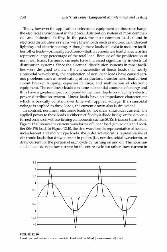
730 Electrical Power Equipment Maintenance and Testing
Today, however the application of electronic equipment continues to change the electrical environment in the power distribution system of most commer-cial and industrial facility. In the past, the most common loads found in electrical distribution systems were linear loads such as motors, incandescent lighting, and electric heating. Although these loads still exist in modern facili-ties, other loads—primarily electronic—that have nonlinear load characteristics represent a large percentage of the total load. Because of the proliferation of nonlinear loads, harmonic currents have increased signifi cantly in electrical distribution systems. Since the electrical distribution systems in most facili-ties were designed to match the characteristics of linear loads (i.e., nearly sinusoidal waveforms), the application of nonlinear loads have caused seri-ous problems such as overheating of conductors, transformers, inadvertent circuit breaker tripping, capacitor failures, and malfunction of electronic equipment. The nonlinear loads consume substantial amounts of energy and thus have a greater impact compared to the linear loads on a facility’s electric power distribution system. Linear loads have an impedance characteristic which is basically constant over time with applied voltage. If a sinusoidal voltage is applied to these loads, the current drawn also is sinusoidal.
In contrast, nonlinear electronic loads do not draw sinusoidal current. The applied power to these loads is either rectifi ed by a diode bridge or the device is turned on and off with switching components such as SCRs, triacs, or transistors. Figure 12.10 shows the current waveforms of linear load (sinusoidal) and recti-fi er (SMPS) load. In Figure 12.10, the sine waveform is representative of heaters, incandescent and motor type loads, the pulse waveform is representative of electronic loads that draw current in pulses (i.e., nonsinusoidal waveform), or draw current for the portion of each cycle by turning on and off. The nonsinu-soidal loads do not draw current for the entire cycle but rather draw current in
2.5
2
1.5
1
0.5
0
−0.5
−1
−1.5
−2
FIGURE 12.10Load current waveforms: sinusoidal load and rectifi ed (nonsinusoidal) load.
DK4058_C012.indd 730DK4058_C012.indd 730 11/8/2008 1:05:22 PM11/8/2008 1:05:22 PM

Power Quality, Harmonics, and Predictive Maintenance 731
small period per cycle or turn on at a specifi c point in the cycle. The current drawn by the electronic loads is in abrupt transitions which interact with system impedance causing voltage loss and transients (impulses).
Some electronic loads are constant power loads, such as SMPS, and for these loads a decrease in voltage within the operating range will cause an increase in current to maintain constant power. Also, the harmonic currents of the load interact with the impedance of the distribution system thereby causing harmonic voltage drops. When the distribution system impedance is high, the harmonic voltage drops are high and the harmonic currents for the nonsinusoidal loads are lower. When the distribution system impedance is low, the harmonic voltage drops are low and harmonic current for the non-linear loads are high. The nonlinear loads when combined with high current inrush and high distribution system impedance tend to cause severe voltage dips and voltage waveform distortion. Under these conditions, the constant power electronic loads attempt to compensate by increasing current draw. The increased current draw interacts with the impedance of the distribution system and adds to the voltage dip, and if the voltage dip is severe enough loads throughout the distribution system will crash. In addition to producing line voltage drops, the third harmonic currents (odd-order triplen harmonics) do not cancel out and fl ow in the neutral circuit of a three-phase, four-wire system. As a result, these currents return back to the power source over the neutral conductor. These currents can be higher than the phase currents and, therefore, create new concerns over the adequacy of the neutral of the three-phase power supply system.
To cope with harmonics problems caused by nonlinear loads, load charac-teristics of system harmonics must be studied and understood. The load characteristics can, for the most part, be determined from an examination of the load response to a distorted voltage waveform at load terminals.
12.4.1 Voltage and Current Characteristics of Nonlinear Loads
12.4.1.1 HD Terminology
The nonsinusoidal periodic waveform of nonlinear loads can be represented through Fourier analysis as the sum of a DC component and sine waves of various amplitudes and phase displacement from some relative angle. The sine waves all have frequencies which are multiple of the fundamental fre-quency of 60 Hz. The voltage and current waveforms can then be represented as the sum of a DC component and sine waves with a fundamental frequency w1 as follows:
0 1
1
( ) sin( )N
h hh
V t V V h t−
= + +∑ w d
and
0 1
1
( ) sin( )N
h hh
I t I I h t−
= + +∑ w q
DK4058_C012.indd 731DK4058_C012.indd 731 11/8/2008 1:05:22 PM11/8/2008 1:05:22 PM

732 Electrical Power Equipment Maintenance and Testing
The voltage and current equations represent sine waves that are multiples of a fundamental frequency, and are called harmonics. The effective value (rms) of current waveform where the amplitude of each harmonics is known can be obtained by the equation as follows:
2rms
1
( )hh
I I∞
=
= ∑
The nonlinearity (i.e., distortion) of the waveform can be determined in terms of THD, crest factor (CF), and form factor. The THD is defi ned as the ratio of the rms value of the total harmonic currents and the rms value of the fundamental current. The THD is expressed as a percentage of the fundamental current is given by the equation:
2
2
1
( )
THD hhI
I=
∞
=∑
The CF is defi ned as the ratio of the peak of a waveform to its rms value and can be written as
peak
rms
Crest factorI
I=
In a purely (i.e., linear) sinusoidal waveform the CF is equal to square root of 2 (i.e., 1/(0.707)), or 1.414. The form factor is defi ned as the ratio of the rms value of a waveform to rms value of the waveform’s fundamental, and can be written as
rms
1
Form factorII
=
12.4.1.2 Types of Nonlinear Loads
Four types of nonlinear power electronic devices are increasingly being used in commercial facilities. These are fl uorescent lighting, ASDs, SMPS, and uninterruptible power supplies (UPS). A brief description of voltage and current characteristics of each is detailed below.
Fluorescent lighting: Fluorescent lighting has overtaken incandescent light-ing as the most popular and widely used lighting system. Light in fl uorescent lamps is generated by gas discharge. The lamps require a ballast to provide proper starting and operating voltages and to limit current during lamp operation. Two types of ballasts are used with fl uorescent lamps: magnetic core–coil and electronic. Both types generate harmonics. Magnetic ballasts generate third HD typically in the range of 13%–20%. In contrast, recent tests
DK4058_C012.indd 732DK4058_C012.indd 732 11/8/2008 1:05:23 PM11/8/2008 1:05:23 PM
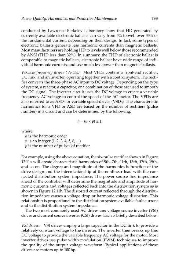
Power Quality, Harmonics, and Predictive Maintenance 733
conducted by Lawrence Berkeley Laboratory show that HD generated by currently available electronic ballasts can vary from 5% to well over 33% of the fundamental current, depending on their design. In fact, some types of electronic ballasts generate less harmonic currents than magnetic ballasts. Most manufacturers are holding HD to levels well below those recommended by ANSI (THD less than 32%). In summary, the THD of electronic ballast is comparable to magnetic ballasts, electronic ballast have wide range of indi-vidual harmonic currents, and use much less power than magnetic ballasts.
Variable frequency drives (VFDs): Most VFDs contain a front-end rectifi er, DC link, and an inverter, operating together with a control system. The recti-fi er converts the three-phase AC input to DC voltage. Depending on the type of system, a reactor, a capacitor, or a combination of these are used to smooth the DC signal. The inverter circuit uses the DC voltage to create a variable frequency AC voltage to control the speed of the AC motor. The VFDs are also referred to as ASDs or variable speed drives (VSDs). The characteristic harmonics for a VFD or ASD are based on the number of rectifi ers (pulse number) in a circuit and can be determined by the following:
h = (n × p) ± 1
whereh is the harmonic ordern is an integer (1, 2, 3, 4, 5, 6, …)p is the number of pulses of rectifi er
For example, using the above equation, the six-pulse rectifi er shown in Figure 12.11a will create characteristic harmonics of 5th, 7th, 11th, 13th, 17th, 19th, and so on. The degree and magnitude of the harmonics is function of the drive design and the interrelationship of the nonlinear load with the con-nected distribution system impedance. The power source line impedance ahead of the controller will determine the magnitude and amplitude of har-monic currents and voltages refl ected back into the distribution system as is shown in Figure 12.11b. The distorted current refl ected through the distribu-tion impedance causes a voltage drop or harmonic voltage distortion. This relationship is proportional to the distribution system available fault current and to the distribution system impedance.
The two most commonly used AC drives are: voltage source inverter (VSI) drives and current source inverter (CSI) drives. Each is briefl y described below.
VSI drives: VSI drives employ a large capacitor in the DC link to provide a relatively constant voltage to the inverter. The inverter then breaks up this DC voltage to provide the variable frequency AC voltage for the motor. Most inverter drives use pulse width modulation (PWM) techniques to improve the quality of the output voltage waveform. Typical applications of these drives are motors up to 100 hp.
DK4058_C012.indd 733DK4058_C012.indd 733 11/8/2008 1:05:23 PM11/8/2008 1:05:23 PM

734 Electrical Power Equipment Maintenance and Testing
CSI drives: CSI drives are typically used for larger motor applications where custom design can be justifi ed. The DC link consists of a large choke to keep the DC current relatively constant. The inverter then breaks up this current waveform to provide the variable frequency AC signal for the motor.
PF characteristics of VFDs also can be very important because the application of capacitors for PF correction can create special problems, including harmonic resonance and transient voltage magnifi cation. The displacement component of the PF is associated with the angle between the voltage and the current. Without any distortion, the PF is equal to the displacement PF (DPF). Both drives have distorted current waveforms, that adds a distortion component to the PF (true PF is real power divided by total apparent power).
The distortion, and therefore the PF, can be considerably worse for VSI-type drives than for most CSI-type drives. Phase-controlled CSI drives have a very poor PF if operated with large rectifi er fi ring delay angles. Transient voltage withstand capability is another important characteristic of VFDs. Power semi-conductor switches that have a peak inverse voltage (PIV) rating of only 1200 V are used in many VFDs. On a 480 V distribution system, this PIV rating equates to 177% of normal system voltage. In most power semiconductor switch assemblies, onboard metal-oxide varistors (MOVs) are utilized for pro-tection purposes. While the MOVs are effective for many low energy tran-sients, they can be destroyed by magnifi ed capacitor switching transients if not sized correctly. Drive topology and the control system characteristics also
DC busA
AC line
BC
(a)
+
−
Load
Power source (voltage) Nonlinear load
Harmoniccurrentsource
R
(b)
XL
XL
Zsource
Zwiring
Zload
R
XL
R
Distorted current
FIGURE 12.11(a) Six-pulse front-end converter for AC drive, and (b) its equivalent circuit.
DK4058_C012.indd 734DK4058_C012.indd 734 11/8/2008 1:05:23 PM11/8/2008 1:05:23 PM
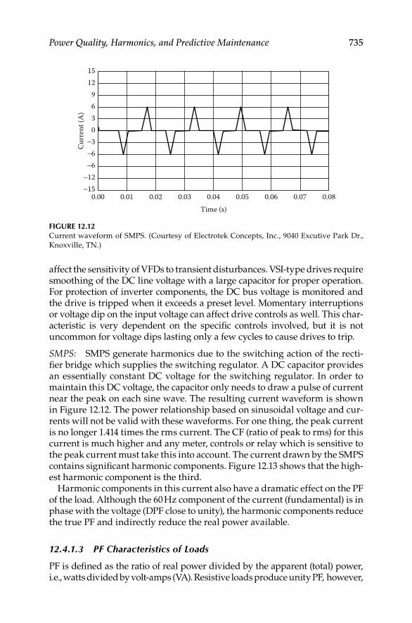
Power Quality, Harmonics, and Predictive Maintenance 735
affect the sensitivity of VFDs to transient disturbances. VSI-type drives require smoothing of the DC line voltage with a large capacitor for proper operation. For protection of inverter components, the DC bus voltage is monitored and the drive is tripped when it exceeds a preset level. Momentary interruptions or voltage dip on the input voltage can affect drive controls as well. This char-acteristic is very dependent on the specifi c controls involved, but it is not uncommon for voltage dips lasting only a few cycles to cause drives to trip.
SMPS: SMPS generate harmonics due to the switching action of the recti-fi er bridge which supplies the switching regulator. A DC capacitor provides an essentially constant DC voltage for the switching regulator. In order to maintain this DC voltage, the capacitor only needs to draw a pulse of current near the peak on each sine wave. The resulting current waveform is shown in Figure 12.12. The power relationship based on sinusoidal voltage and cur-rents will not be valid with these waveforms. For one thing, the peak current is no longer 1.414 times the rms current. The CF (ratio of peak to rms) for this current is much higher and any meter, controls or relay which is sensitive to the peak current must take this into account. The current drawn by the SMPS contains signifi cant harmonic components. Figure 12.13 shows that the high-est harmonic component is the third.
Harmonic components in this current also have a dramatic effect on the PF of the load. Although the 60 Hz component of the current (fundamental) is in phase with the voltage (DPF close to unity), the harmonic components reduce the true PF and indirectly reduce the real power available.
12.4.1.3 PF Characteristics of Loads
PF is defi ned as the ratio of real power divided by the apparent (total) power, i.e., watts divided by volt-amps (VA). Resistive loads produce unity PF, however,
0.00−15−12
−6−6−3
0369
1215
0.01 0.02 0.03 0.04Time (s)
Curr
ent (
A)
0.05 0.06 0.07 0.08
FIGURE 12.12Current waveform of SMPS. (Courtesy of Electrotek Concepts, Inc., 9040 Excutive Park Dr.,
Knoxville, TN.)
DK4058_C012.indd 735DK4058_C012.indd 735 11/8/2008 1:05:24 PM11/8/2008 1:05:24 PM

736 Electrical Power Equipment Maintenance and Testing
all reactive (inductive and capacitive) loads produce nonunity (i.e., less than 1.0) PF. The PF for the linear and nonlinear loads is given by the following expressions:
1. Linear loads
60Hz
Displacement
60Hz
kWPF cos
kVA= = q
where
1 22 260Hz 60 60kVA kW kVAR⎡ ⎤= +⎣ ⎦
2. Nonlinear loads
60 Hz
True
rms
kWp cos (i.e., the true power factor is not equal to cos )F
kVA= ≠ q q
where
( ) ( ) 1 2
2 2 2 2rms 60 har 60 harkVA kW kW kVAR kVAR⎡ ⎤= + + +⎣ ⎦
Uncorrected electronic power supplies exhibit very poor true PF and high harmonics which generate heat in the phase and neutral wires of the electri-cal power distribution system, especially where single-phase 120 V power is supplied from a 208/120 V three-phase wiring system. The PF defi nes how effi ciently a load utilizes the current that it draws from an AC power system. The PF can also be expressed in terms distortion factor to give an assessment
100908070605040302010
060 180 300 420 540
Frequency (Hz)
Fund: 3.456 rms: 139.073% Peak: 124.134% CF: 0.8926 ASUM: 288.262% THD: 96.650% TIF: 305.27 IT: 146.72
% of
fund
amen
tal
660 780 900 1020 1140 1260
FIGURE 12.13Harmonic current of SMPS. (Courtesy of Electrotek Concepts, Inc., 9040 Excutive Park
Dr., Knoxville, TN.)
DK4058_C012.indd 736DK4058_C012.indd 736 11/8/2008 1:05:24 PM11/8/2008 1:05:24 PM

Power Quality, Harmonics, and Predictive Maintenance 737
of the effi ciency of the load utilization in the presence of harmonics. Therefore for a sinusoidal circuit (i.e., no harmonics), we can write voltage and current equations at the load as the following;
1 1 1( ) sin( )V t V t= +w d
and
1 1 1( ) sin( )I t I t= +w q
whereV1 and I1 are peak values of the 60 Hz voltage and currentd1 and q1 are the relative phase angles
The true PF at the load is defi ned as the ratio of the average power to apparent power, or
avg avg
True
rms rms
FPP P
S V I= =
For a purely sinusoidal case, the above equation can be written as;
( )( )
( )( )
1 1avg
True Disp 1 1 1 12 21 1
2 2FPF P cos( ) cos( )2 2
V IP
V IP Q= = = − = −
+d q d q
where PFDisp is commonly known as the DPF, and (d1 − q1) is known as the PF angle. Therefore in a purely sinusoidal situation, there is only one PF because true PF and DPF are equal. However, this is not true in the case of nonsinu-soidal situations because voltages and currents contain harmonics. The aver-age power for a nonsinusoidal situation can be represented by including the signifi cant harmonics such as the third, fi fth, seventh, and so on. We can then write the equation as:
avg hrms hrms h h lavg 2avg 3avg
1
cos( )h
P V I P P P∞
=
− = + +∑ d q
where, each harmonic makes a contribution to the average power. Also, the rms value of the voltage and current can be expressed as following:
22
rms rms1 12
hh
h h
VV V
∞ ∞
= =
= =∑ ∑
22
rms rms1 12
hh
h h
II I
∞ ∞
= =
= =∑ ∑
DK4058_C012.indd 737DK4058_C012.indd 737 11/8/2008 1:05:24 PM11/8/2008 1:05:24 PM

738 Electrical Power Equipment Maintenance and Testing
The above equations can be written in terms of the distortion factor (i.e., THD) as
2rms 1rms
2rms 1rms
1 ( /100)
1 (THD /100)
V
I
V V THD
I I
= +
= +
We can now substitute the above equations in the original equation for true PF at the load.
avg avg
True
rms rms
FPP P
S V I= =
avg
True 2 21rms 1rms
PF1 (THD /100) 1 (THD /100)V I
P
V I=
+ +
The above equation can be expressed as a product of two components as the following:
avg
True 2 21rms 1rms
1PF
1 (THD /100) 1 (THD /100)V I
P
V I= ×
+ +
Also, by assuming that Pavg is approximately equal to P1avg and since usually THDV is less than 10%, Vrms = V1 rms. By incorporating these two assumptions in the above equation, it then can be written as
1
avg
True Disp Dist21rms rms
.1
PF F FP P1 (THD /100)
I
I
P
V I≈ × =
+
where PFDist is the distortion PF.Because DPF (PFDisp) can never be greater than unity, the above equation
shows that the true PF in a nonsinusoidal situations has the upper bound given by the following equation:
True Dist 2
1PF PF
1 (THD /100)I
≤ =+
The above equation provides insights into the nature of the true PF of electronic (nonlinear) loads, especially single-phase loads. It appears from the above equa-tion that higher the HD, lower is the true PF even though the DPF can be very high. The displacement and true PF relationships are shown in Figure 12.14.
The true PF is calculated for a nonlinear load with distortion (THDI %) as shown below:
DK4058_C012.indd 738DK4058_C012.indd 738 11/8/2008 1:05:26 PM11/8/2008 1:05:26 PM
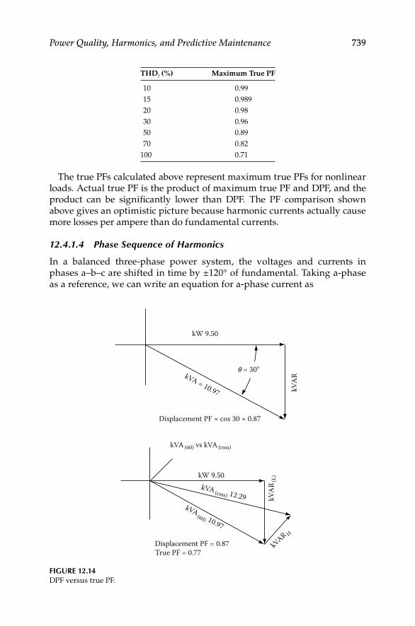
Power Quality, Harmonics, and Predictive Maintenance 739
THDI (%) Maximum True PF
10 0.99
15 0.989
20 0.98
30 0.96
50 0.89
70 0.82
100 0.71
The true PFs calculated above represent maximum true PFs for nonlinear loads. Actual true PF is the product of maximum true PF and DPF, and the product can be signifi cantly lower than DPF. The PF comparison shown above gives an optimistic picture because harmonic currents actually cause more losses per ampere than do fundamental currents.
12.4.1.4 Phase Sequence of Harmonics
In a balanced three-phase power system, the voltages and currents in phases a–b–c are shifted in time by ±120° of fundamental. Taking a-phase as a reference, we can write an equation for a-phase current as
FIGURE 12.14DPF versus true PF.
kW 9.50
Displacement PF = cos 30 = 0.87
kVA
R
q = 30�kVA = 10.97
kW 9.50
kVA(60) vs kVA(rms)
kVA
R(L
)
kVAR H
Displacement PF = 0.87True PF = 0.77
kVA(rms) 12.29kVA (60) 10.97
DK4058_C012.indd 739DK4058_C012.indd 739 11/8/2008 1:05:27 PM11/8/2008 1:05:27 PM
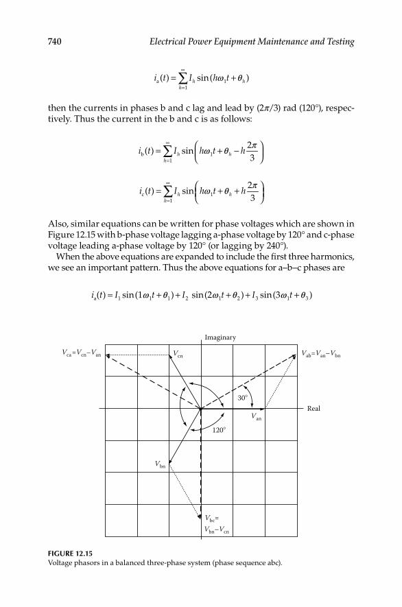
740 Electrical Power Equipment Maintenance and Testing
a 1
1
( ) sin( )h hh
i t I h t∞
=
= +∑ w q
then the currents in phases b and c lag and lead by (2p/3) rad (120°), respec-tively. Thus the current in the b and c is as follows:
b 1
1
2( ) sin
3h h
h
i t I h t h∞
=
⎛ ⎞= + −⎜ ⎟⎝ ⎠∑ pw q
c 1
1
2( ) sin
3h h
h
i t I h t h∞
=
⎛ ⎞= + +⎜ ⎟⎝ ⎠∑ pw q
Also, similar equations can be written for phase voltages which are shown in Figure 12.15 with b-phase voltage lagging a-phase voltage by 120° and c-phase voltage leading a-phase voltage by 120° (or lagging by 240°).
When the above equations are expanded to include the fi rst three harmonics, we see an important pattern. Thus the above equations for a–b–c phases are
a 1 1 1 2 1 2 3 1 3( ) sin(1 ) sin(2 ) sin(3 )i t I t I t I t= + + + + +w q w q w q
Imaginary
Vca=Vcn–Van Vab=Van–Vbn
Vbc=Vbn–Vcn
Real
Vcn
Van
Vbn
30�
120�
FIGURE 12.15Voltage phasors in a balanced three-phase system (phase sequence abc).
DK4058_C012.indd 740DK4058_C012.indd 740 11/8/2008 1:05:27 PM11/8/2008 1:05:27 PM
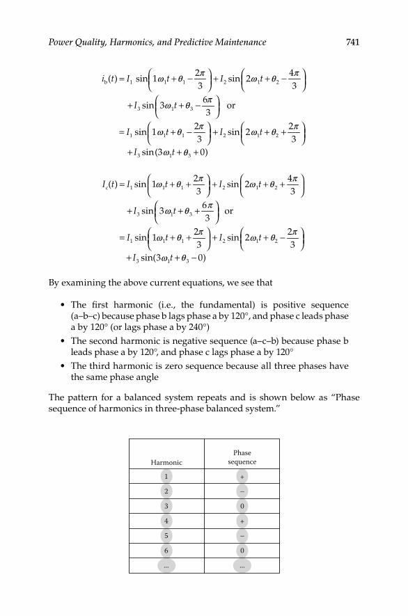
Power Quality, Harmonics, and Predictive Maintenance 741
Harmonic
1
2
3
4
5
6
...
+
−
0
+
−
0
...
Phasesequence
b 1 1 1 2 1 2
3 1 3
1 1 1 2 1 2
3 1 3
2 4( ) sin 1 sin 2
3 3
6sin 3 or
3
2 2sin 1 sin 2
3 3
sin(3 0)
i t I t I t
I t
I t I t
I t
⎛ ⎞ ⎛ ⎞= + − + + −⎜ ⎟ ⎜ ⎟⎝ ⎠ ⎝ ⎠⎛ ⎞+ + −⎜ ⎟⎝ ⎠
⎛ ⎞ ⎛ ⎞= + − + + +⎜ ⎟ ⎜ ⎟⎝ ⎠ ⎝ ⎠+ + +
p pw q w q
pw q
p pw q w q
w q
c 1 1 1 2 1 2
3 1 3
1 1 1 2 1 2
3 1 3
2 4( ) sin 1 sin 2
3 3
6sin 3 or
3
2 2sin 1 sin 2
3 3
sin(3 0)
I t I t I t
I t
I t I t
I t
⎛ ⎞ ⎛ ⎞= + + + + +⎜ ⎟ ⎜ ⎟⎝ ⎠ ⎝ ⎠⎛ ⎞+ + +⎜ ⎟⎝ ⎠
⎛ ⎞ ⎛ ⎞= + + + + −⎜ ⎟ ⎜ ⎟⎝ ⎠ ⎝ ⎠+ + −
p pw q w q
pw q
p pq qw w
qw
By examining the above current equations, we see that
The fi rst harmonic (i.e., the fundamental) is positive sequence • (a–b–c) because phase b lags phase a by 120°, and phase c leads phase a by 120° (or lags phase a by 240°)
The second harmonic is negative sequence (a–c–b) because phase b • leads phase a by 120°, and phase c lags phase a by 120°
The third harmonic is zero sequence because all three phases have • the same phase angle
The pattern for a balanced system repeats and is shown below as “Phase sequence of harmonics in three-phase balanced system.”
DK4058_C012.indd 741DK4058_C012.indd 741 11/8/2008 1:05:28 PM11/8/2008 1:05:28 PM

742 Electrical Power Equipment Maintenance and Testing
If a system is not balanced, then each harmonic can have positive, negative, and zero sequence components. However, in most cases, the pattern shown above can be assumed to be valid.
Because of Kirchhoff’s current law, zero sequence currents cannot fl ow into a three-wire connection such as a delta transformer winding or a delta-connected load. In most cases, systems are fairly well balanced, so that it is common to make the same assumption for third harmonics and other triplens. Thus, a delta-grounded wye transformer at the service point of an industrial facility usually blocks the fl ow of triplen harmonic load currents into the power system. Unfortunately, the transformer does nothing to block the fl ow of any other har-monics, such as fi fth, seventh, and so on. Zero sequence currents fl ow through neutral or grounding paths. Positive and negative sequence currents sum to zero at neutral and grounding points. Another interesting observation can be made about zero sequence harmonics. Line-to-line voltages never have zero sequence components because, according to Kirchhoff’s voltage law, they always sum to zero. For that reason, line-to-line voltages in commercial buildings are missing the third harmonic that dominates L–N voltage waveforms. Thus, the V THD of line-to-line voltages is often considerably less than for L–N voltages.
12.4.1.5 Harmonic Generating Characteristics
In the past, harmonic currents originated primarily from a few major sources, such as arc welders, fl uorescent ballasts and lights, arc furnaces, etc. As explained previously, signifi cant harmonics are being generated by today’s load equipment such as switching power supplies, solid-state controls, and other sensitive electronic equipment. The harmonics in these nonlinear loads cause voltage distortion, poor PF, and stress on supply power system equipment. Harmonics from nonsinusoidal loads interact with elec-trical distribution system impedance, creating heat in electrical distribution equipment. Harmonic voltage distortion limits peak applied voltage and may increase susceptibility to momentary voltage dropouts.
12.4.1.6 Sensitivity to Harmonics
Most electronic equipment is affected by harmonics because high levels of harmonic currents cause problems in the power system that is not designed for nonlinear loads. The problems are:
Overloading of the phase and neutral conductors of the power • distribution system
Overheating of the distribution transformers, where high-frequency • currents can cause higher losses from eddy currents, magnetic hysteresis, and skin effect
Overloading of power sources such as UPS systems and emergency • generators including generator controls
Poor utilization of available power from the branch circuits because • of low PF
DK4058_C012.indd 742DK4058_C012.indd 742 11/8/2008 1:05:28 PM11/8/2008 1:05:28 PM

Power Quality, Harmonics, and Predictive Maintenance 743
Premature failure of PF correction capacitors because of overheating • by harmonic currents
Flat-topping of the voltage waveform caused by high-peak currents • which reduce the ride-through capability of the electronic equipment
12.4.1.7 Sensitivity to Voltage Variation
All electronic equipment is generally sensitive to supply voltage variations. For example, computer systems can experience performance problems if the follow-ing voltage thresholds are exceeded: sags greater than −20% rms, spikes greater than 100% peak, and swells greater than +10% rms. When assessing the impact of voltage variation on electronic equipment, it is helpful to know the related voltage waveforms, that is whether they are swell, sag, impulse, or electrical noise. The effects of power line voltage variation, resulting from a utility’s power system disturbances or interaction of the load and its power source, may appear in many forms. Sensitive electronic equipment may cease to operate, errors may occur in processing and data transfer, or hardware damage may occur.
12.4.1.8 Sensitivity to Voltage Flicker
Voltage changes which are cyclical in nature (occur in the range of 0.5–30 Hz) are commonly referred to as voltage fl icker. Voltage fl icker can be caused by: repetitive motor starting, punch presses, large reciprocating compressors, resistance welders, and arc furnaces. Voltage fl icker can affect the sensitive electronic load equipment, especially if it happens near peak voltage when the DC power supply usually draws AC line current.
12.4.1.9 Sensitivity to Noise
All power lines, motors, generators, and other current handling devices radi-ate magnetic fi elds of varying strengths (electric noise). In addition to the above sources of electrical noise, fault produced transients, surges, and ground potential rises also produce unwanted magnetic fi elds. The gener-ated and radiated magnetic fi elds couple across to other cables (both power and communications) and affect sensitive electronic equipment. The level of electrical noise that is considered acceptable depends on the signal level and accuracy requirements of the load equipment. Separation of the electrical noise sources and load signal cables, proper grounding, and proper cable confi guration are some of the techniques for reducing noise.
12.5 Effects of Harmonic on Power System
Equipment and Loads
The HD of concern here is the nonfundamental periodic voltage resulting from the steady state operation of nonlinear elements connected to the
DK4058_C012.indd 743DK4058_C012.indd 743 11/8/2008 1:05:28 PM11/8/2008 1:05:28 PM
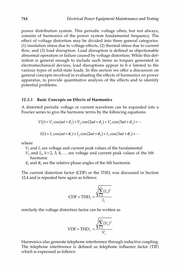
744 Electrical Power Equipment Maintenance and Testing
power distribution system. This periodic voltage often, but not always, consists of harmonics of the power system fundamental frequency. The effect of voltage distortion may be divided into three general categories: (1) insulation stress due to voltage effects, (2) thermal stress due to current fl ow, and (3) load disruption. Load disruption is defi ned as objectionable abnormal operation or failure caused by voltage distortion. While this def-inition is general enough to include such items as torques generated in electromechanical devices, load disruptions appear to b e limited to the various types of solid-state loads. In this section we offer a discussion on general concepts involved in evaluating the effects of harmonics on power apparatus, to provide quantitative analysis of the effects and to identify potential problems.
12.5.1 Basic Concepts on Effects of Harmonics
A distorted periodic voltage or current waveform can be expanded into a Fourier series to give the harmonic terms by the following equations:
1 1 2 2 3 3( ) cos( ) cos(2 ) cos(3 )V t V t V t V t= + + + + + +�w d w d w d
1 1 2 2 3 3( ) cos( ) cos(2 ) cos(3 )I t I t I t I t= + + + + + +�w q w q w q
whereV1 and I1 are voltage and current peak values of the fundamentalVh and Ih, h = 2, 3, 4, … are voltage and current peak values of the hth
harmonicd h and q h are the relative phase angles of the hth harmonic
The current distortion factor (CDF) or the THDI was discussed in Section 12.4 and is repeated here again as follows:
=2
2
1
( )
CDF THDh
hI
I
I
∞
= =∑
similarly the voltage distortion factor can be written as
2
2
1
( )
VDF THDh
hV
V
V
∞
== =∑
Harmonics also generate telephone interference through inductive coupling. The telephone interference is defi ned as telephone infl uence factor (TIF) which is expressed as follows:
DK4058_C012.indd 744DK4058_C012.indd 744 11/8/2008 1:05:28 PM11/8/2008 1:05:28 PM

Power Quality, Harmonics, and Predictive Maintenance 745
2
2
1
( )
TIFh h
h
w I
I
∞
==∑
where wh is a weight factor for audio and inductive coupling effects at the hth harmonic.
The rms value of the voltage distortion does not provide peak voltage levels which are needed to assess the effects HD on insulation. A more meaningful measure for assessing HD on insulation is magnitude factor (MF), which is given by the following equation:
2
1
MFh
h
V
V
∞
==∑
The distortion factors, current, voltage (rms and peak), and telephone infl uence are utilized to describe the quantitative effect of the harmonics on electric loads and other apparatus. For example, the CFD is useful in quantifying the copper losses in a constant resistance load, the TIF to quantify telephone interference, MF in assessing dielectric stress, etc. In general, the diversity of the effects of harmonics makes it extremely unlikely that any one measure of voltage distor-tion will adequately describe all effects. A better approach is to identify the sensitivities of apparatus performance to distortion factors, and thereby, iden-tify the relative usefulness of these parameters. The effects of harmonics on thermal stress, insulation stress, and load disruption are discussed as follows.
12.5.1.1 Thermal Stress
In general, the presence of harmonic current increases the losses and thus the thermal stress of the equipment. The losses are copper losses, iron losses, and dielectric losses. In a given power equipment, one or more of above losses may determine the thermal stress of the device. These losses can be computed as follows:
Copper losses: The copper losses (PC) can be computed with the following general formula
2C
1
2h h
h
P R I∞⎡ ⎤= ⎢ ⎥⎣ ⎦∑
where Ih is the peak value of the hth harmonic current, Rh is the resistance of the apparatus at the hth harmonic.
In cases where resistance of the apparatus is constant (independent of frequency), the copper losses can be written in terms of the CDF as follows;
DK4058_C012.indd 745DK4058_C012.indd 745 11/8/2008 1:05:29 PM11/8/2008 1:05:29 PM

746 Electrical Power Equipment Maintenance and Testing
( )( )22 2C 1
1 11 CDF
2 2h
h
P R I RI∞⎡ ⎤= = +⎢ ⎥⎣ ⎦∑
As shown in the equation above, the CFD determines the increase of copper losses due to the presence of harmonics. In general, however, the resistance of power apparatus increases with frequency because of the skin effect. The impact of skin effect on harmonic losses becomes more important in large diameter conductors and deep bar induction motors.
Iron losses: Iron losses are made up of (1) hysteresis loss and (2) eddy current loss. These losses are given by the following formulas:
Hysteresis loss (Ph) is a function of magnetic material used and frequency of the current. For a given magnetic core, the hysteresis loss is equal to
h h mvP a f B=
whereah is a constant dependent on core dimensionsf is the frequency of electric currentBm is the maximum value of the magnetic fl ux densityv is an exponent dependent on the core material (for commonly used
materials, v = 1.5–2.5)
Eddy current loss (Pe) depends on core material (resistivity of core), thickness of lamination, frequency of electric currents, and magnetic fl ux density. For a given magnetic circuit the eddy current losses are given by
2 2
e e mP a f B=
whereae is a constant dependent on material and thickness of laminationf is the frequency of electric currentBm is the maximum value of the magnetic fl ux density
The total losses are given by the sum of hysteresis and eddy current losses, therefore
( )2 2
ironloss m e mh
vP a f B a f B= +
The total iron loss is a nonlinear function of frequency and maximum magnetic fl ux density. For a given voltage harmonic, the frequency is known and the maximum magnetic fl ux density is proportional to the harmonic current. The constant of proportionality depends on coil and magnetic core
DK4058_C012.indd 746DK4058_C012.indd 746 11/8/2008 1:05:30 PM11/8/2008 1:05:30 PM

Power Quality, Harmonics, and Predictive Maintenance 747
design. The equation for iron loss is valid for a sinusoidal excitation of the power apparatus of frequency f. In case the excitation source is polluted with harmonics, one can cautiously use the equation for iron loss to com-pute the iron loss for each harmonic and add the contributions. This pro-cedure (superposition) is correct only for linear apparatus. Because of magnetic saturation and magnetic hysteresis, magnetic circuits are not exactly linear systems. However, for normally encountered operating con-ditions and level of harmonics, superposition can be used as a reasonable approximation.
Dielectric losses: The dielectric losses are applicable to cables and capacitors and at a given harmonic, h, are given by the following equation
2
e (1/2)(tan )h hP V h C= d w
wherew is the fundamental angular frequencyVh is the peak value of the hth harmonic voltageC is the capacitance of the apparatus(tan d)h is the dielectric loss factor at the hth harmonic
12.5.1.2 Insulation Stress
Insulation stress primarily depends on instantaneous voltage magnitude and voltage rate of increase secondarily. The presence of voltage harmonics can result in an increase of the crest value of the voltage and thus increased insu-lation stress. This increase is not of concern for most power system apparatus because they are insulated for much higher voltage levels than those usually encountered from harmonics. Capacitor banks, however, are very sensitive to overvoltages and must be protected against overvoltages resulting from harmonics. A special discussion is provided later in this section. The voltage rate of increase is important in switchgear and it is discussed in this section also. An area of possible concern is the effect of voltage distortion on surge protective devices, including the sparkover and recovery of gapped surge arresters.
12.5.1.3 Load Disruption
Load disruption is defi ned as objectionable abnormal operation or failure caused by voltage distortion. Many electronic equipment are susceptible to load disruption because their normal operation depends on the existence of a sinusoidal voltage source. The effects of the harmonics on electronic equip-ment are discussed later in this section. Load disruption also includes decreases of useful magnetic electromagnetic torque in electric machinery because of the presence of harmonics. Specifi cally, current harmonics
DK4058_C012.indd 747DK4058_C012.indd 747 11/8/2008 1:05:30 PM11/8/2008 1:05:30 PM

748 Electrical Power Equipment Maintenance and Testing
circulating in the armature of electric machinery may generate pulsating or constant electromagnetic torques. Pulsating torques result in equipment wear and shortening of equipment life. Constant torques, in most cases, reduce the useful electromagnetic torque and, result in reduced effi ciency.
12.5.2 Harmonic Effects on Power System Equipment
12.5.2.1 Transformers
The effects of harmonics on transformers are
Increased copper losses•
Increased iron losses•
Possibly resonance between transformers•
windings and line capacitance•
Insulation stress•
Neutral overheating due to triplen harmonics•
The copper losses and iron losses in the presence of harmonics can be com-puted with the general equations presented in Section 12.5.1.1. The applica-tion of general equations given in Section 12.5.1.1 assumes that the transformer is a linear device which it is not. However, for normal, operating conditions and normal levels of harmonics, this is a reasonable approximation. Similarly, an approximate expression for total hysteresis losses can be determined by using the equations given in Section 12.5.1.1. However, the increase of hyster-esis losses due to harmonics is only a fraction of the eddy current losses.
Voltage harmonics result in higher transformer voltage, therefore higher insulation stress. This is not a problem since most transformers are insu-lated for much higher voltage levels than the overvoltages due to usual levels of harmonics. There is a certain degree of interaction between volt-age and current harmonics for transformers designed to operate near the saturation point (knee of the saturation curve). It is possible a small level of voltage harmonic to generate a high level of current harmonics. This phenomenon depends on specifi c harmonic and phase relationship to the fundamental. To address the overheating of transformers due to harmon-ics, the ANSI/IEEE published a standard C57.110-1998, “Recommended practice for establishing transformer capability when supplying nonsinu-soidal load currents,” which was reaffi rmed in 2004. This standard estab-lishes methods for determining derating factors for transformer capability to carry nonsinusoidal load currents.
In 1990, Underwriters Laboratory (UL) established the method for testing transformers that serve nonlinear loads. The UL test addresses coil heating due to nonlinear loads and overheating of the neutral conductor by assign-ing a “K“ factor to the transformer. The K-factor is meant to apply to trans-formers serving general nonlinear loads. UL has devised the K-factor method for labeling and rating the ability of dry-type transformers to withstand the
DK4058_C012.indd 748DK4058_C012.indd 748 11/8/2008 1:05:30 PM11/8/2008 1:05:30 PM

Power Quality, Harmonics, and Predictive Maintenance 749
effects of harmonics. The K-factor rating indicates the transformer’s ability to tolerate the additional heating caused by harmonics. The K-factor is based on the methodology similar to that discussed in the ANSI/IEEE C57.110 standard. The K-factor can be calculated as the sum of the product of each harmonic current squared and that harmonic number squared for all harmonics from the fundamental to the highest harmonic of conse-quence. When K-factor is multiplied by the stray losses of the transformer, the result represents the total stray losses in the transformer caused by harmonic currents. To obtain the total load losses, the total stray losses are then added to the load losses. It should be obvious that the K-factor for linear loads (absence of harmonics) is 1. Also, the K-factor does not mean that the transformer can eliminate harmonics. Harmonics increase heating losses in all transformers, and some of these losses are deep within the core and windings and some are closer to the surface. Oil-filled trans-formers react differently to the increased heat and are better able to cool whereas dry-type transformers are more susceptible to the harmonic cur-rent effects and are so labeled. The UL test addresses coil heating due to nonlinear loads and overheating of the neutral conductor.
There are two methods for calculating K-factor. They are UL method and normalized method. The UL method, based on the transformer’s rated rms current, is generally used when rms current is measured. The UL method is defi ned as follows:
2 2
(PU)1
hh
K I h∞
=
= ∑
whereh is the harmonic orderIh(PU) is the rms current of the harmonic expressed as a per unit of the
rated rms transformer current
The normalized method is based on the load’s fundamental current. Harmonic measurements are often taken with a harmonic analyzer. A majority of harmonic analyzers output data is in per unit values related to the funda-mental current. Therefore, the normalized method is applicable. The normal-ized method is defi ned as follows:
2 2
1h
h
K f h∞
=
= ∑
where fh is the fundamental current in per unit (the fi rst harmonic = 100%)An example of the two methods for the same harmonic spectrum of data is given in Tables 12.2 and 12.3.
The K-factor rating of dry-type transformers is available from 1 through 50. However, for majority of application rating of 20 or less should suffi ce. Table 12.4 lists the available K-factor rated transformers.
DK4058_C012.indd 749DK4058_C012.indd 749 11/8/2008 1:05:30 PM11/8/2008 1:05:30 PM

750 Electrical Power Equipment Maintenance and Testing
TABLE 12.4
K-Factor Rating of Dry-Type Transformers
K-Factor Comments and Typical Applications
1 Normal transformer for sinusoidal load
applications with a harmonic factor less
than 0.05
4 Welders and induction heaters, high
intensity discharge (HID) and
fl uorescent lighting, solid-state controls
9 Not readily available or usually specifi ed
13 Telecommunications equipment,
classrooms and health care facilities
20 Data processing equipment, ASD
30 Extended range
40 Extended range
50 Extended range
TABLE 12.3
Calculation of K-Factor per Normalized Method
Harmonic fh (PU) fh (PU)2 h2 fh (PU)2 h2
1 1.00 1.00 1 1.00
3 0.72 0.52 9 4.69
5 0.43 0.19 25 4.63
7 0.35 0.12 49 5.91
9 0.21 0.04 81 3.52
11 0.10 0.01 121 1.14
13 0.07 0.00 169 0.82
1.88 21.71
K-factor = 21.71/1.88 = 11.54
TABLE 12.2
Calculation of K-Factor per UL Method
Harmonic Ih (PU) (Measured) Ih (PU)2 h2 Ih (PU)2 h2
1 0.72 0.52 1 0.52
3 0.52 0.27 9 2.43
5 0.31 0.10 25 2.40
7 0.25 0.06 49 3.06
9 0.15 0.02 81 1.82
11 0.07 0.00 121 0.59
13 0.05 0.00 169 0.42
K-factor = 11.24
DK4058_C012.indd 750DK4058_C012.indd 750 11/8/2008 1:05:31 PM11/8/2008 1:05:31 PM

Power Quality, Harmonics, and Predictive Maintenance 751
The basic sources of data for computing K-factor are from measurements or estimates. Exercise care in measuring loads so the data is accurate and simulates the transformer at full load. When estimating loads, the com-puted K-factor is usually overly conservative (large) as it does not take into account potential harmonic phase cancellations. To address this, UL has specifi ed that the rms current of any single harmonic greater than the 10th be considered as no greater than 1/h of the fundamental rms current. This attempts to compensate for otherwise conservative computed impacts of higher frequencies. Equipment manufacturers can be a source of data for nonlinear loads. As K-factor increases, the transformer becomes larger and its impedance decreases markedly. Lower source impedance can result in higher distortion, which can aggravate a problem instead of solving it.
Another problem that occurs with transformers is the overheating of the neutral in a three-phase four-wire power distribution system. When single-phase nonlinear loads are connected to the secondary of a wye–delta trans-former, such as is found in many industrial and commercial applications, the triplen harmonics (third, ninth, and so on) algebraically add up in the neutral of the secondary of the transformer. These currents are often in excess of the phase currents and therefore cause overheating of the neutral conductor, components, bus bars, etc. Also these currents are refl ected back into the delta primary windings where they circulate and cause the trans-former to overheat or fail.
12.5.2.2 Rotating Machines
The effects of harmonics in rotating machinery are increased heating due to copper and iron losses, changes in electromagnetic torque which affect, machine effi ciency and machine torsional oscillations. The level and impor-tance of these effects depend on electric machine design and harmonic source type. Electric machines can be classifi ed as synchronous machines (three-phase), three-phase induction machines and single-phase induction motors. On the other hand, the source of harmonics for three-phase systems may be a balanced three-phase source or may be a single-phase source inject-ing harmonics in one phase only. The latter case can be analyzed with the use of symmetrical components which is applicable to each one harmonic. Thus for three-phase electric machinery only the effects of balanced three-phase harmonic excitation need to be examined. The effects of single-phase harmonic excitation can be deduced from the former. A good understand-ing of the effects of harmonics on rotating machinery requires a good understanding of the electromagnetic fi elds inside the machines due to har-monic currents. Because of the complex construction of rotating machinery, the frequency of the magnetic fl ux may not coincide with the frequency of the armature currents. In addition, at a given harmonic, the frequency of the magnetic fl ux in the rotor is different of the frequency in the stator. The below listed observations can be used for analyzing the effects of harmon-ics on rotating machines.
DK4058_C012.indd 751DK4058_C012.indd 751 11/8/2008 1:05:31 PM11/8/2008 1:05:31 PM

752 Electrical Power Equipment Maintenance and Testing
1. The zero sequence harmonics (h = 3, 6, 9, 12, …) do not produce a net magnetic fl ux density. Thus the only effect they produce is ohmic losses.
2. The positive sequence harmonics (h = 1, 4, 7, 10, 13, …) produce a rotating magnetic fl ux which rotates with speed hw in the positive direction and magnitude proportional to the harmonic current. The relative speed of the rotating magnetic fi eld with respect to the rotor is (h − 1)w [or (h − 1 + S)w for induction machines, S = slip]. Because of induction motor action, an electromagnetic torque will be devel-oped in the direction of rotation. The frequency of the alternating magnetic fl ux is 60 h in the stator and 60(h − 1) in the rotor. These frequencies determine the iron losses which occur partly in the stator and partly in the rotor.
3. The negative sequence harmonics (h = 2, 5, 8, 11, …) produce a rotat-ing magnetic fl ux which rotates with speed −hw (opposite to the direction of rotation) and magnitude proportional to the harmonic current. The relative speed of the rotating magnetic fi eld with respect to the rotor is −(h + 1)w [(or −(h + 1 − S)w for an induction machine, S = slip)]. Because of induction motor action, an electromagnetic torque will be developed in a direction opposite to that of rotation. The frequency of the alternating magnetic fl ux is 60 h in the stator and 60(h + 1) in the rotor.
The performance of an induction motor, operating from a supply voltage rich in harmonics, deteriorates because the presence of negative sequence harmonics generates opposing torque and the presence of any harmonic increases copper and iron losses. These effects result in a net derating of the motor.
Another effect results from the interaction of the magnetic fi eld generated by a harmonic and the fundamental magnetic fi eld. Consider, for example, the seventh harmonic in a synchronous, machine. The seventh harmonic magnetic fi eld rotates, relatively to the rotor fi eld, with a speed (h − 1)w . The interaction of the two fi elds will produce a pulsating torque of fre-quency 60(h − 1) = 360 Hz. In the same way, the fi fth harmonic will gener-ate a pulsating torque of frequency 60(h + 1) = 360 Hz. Thus pairs of harmonics generate pulsating torques of frequency 180, 360, 540 Hz, etc. In a typical system, the 360 Hz pulsating torque is substantial and results in oscillations of the machine shaft. It is possible that the natural fre-quency of the machine is in the vicinity of this frequency. In this case, the fi fth and seventh harmonics may excite a super synchronous resonance condition which involves torsional oscillations of the rotor elements. Supersynchronous resonance occurs when the frequency of a mode of mechanical vibration exists close to the frequency of electrical stimulus. In this case, high resonant mechanical oscillations may be developed which could result in fatigue of the shafts.
DK4058_C012.indd 752DK4058_C012.indd 752 11/8/2008 1:05:31 PM11/8/2008 1:05:31 PM
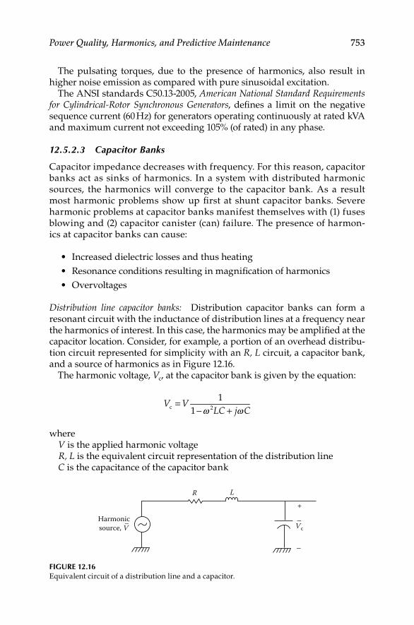
Power Quality, Harmonics, and Predictive Maintenance 753
The pulsating torques, due to the presence of harmonics, also result in higher noise emission as compared with pure sinusoidal excitation.
The ANSI standards C50.13-2005, American National Standard Requirements for Cylindrical-Rotor Synchronous Generators, defi nes a limit on the negative sequence current (60 Hz) for generators operating continuously at rated kVA and maximum current not exceeding 105% (of rated) in any phase.
12.5.2.3 Capacitor Banks
Capacitor impedance decreases with frequency. For this reason, capacitor banks act as sinks of harmonics. In a system with distributed harmonic sources, the harmonics will converge to the capacitor bank. As a result most harmonic problems show up fi rst at shunt capacitor banks. Severe harmonic problems at capacitor banks manifest themselves with (1) fuses blowing and (2) capacitor canister (can) failure. The presence of harmon-ics at capacitor banks can cause:
Increased dielectric losses and thus heating•
Resonance conditions resulting in magnifi cation of harmonics•
Overvoltages•
Distribution line capacitor banks: Distribution capacitor banks can form a resonant circuit with the inductance of distribution lines at a frequency near the harmonics of interest. In this case, the harmonics may be amplifi ed at the capacitor location. Consider, for example, a portion of an overhead distribu-tion circuit represented for simplicity with an R, L circuit, a capacitor bank, and a source of harmonics as in Figure 12.16.
The harmonic voltage, Vc, at the capacitor bank is given by the equation:
c 2
1
1V V
LC j C=
− +w w
whereV is the applied harmonic voltageR, L is the equivalent circuit representation of the distribution lineC is the capacitance of the capacitor bank
Harmonicsource, V–
R L+
−
Vc−
FIGURE 12.16Equivalent circuit of a distribution line and a capacitor.
DK4058_C012.indd 753DK4058_C012.indd 753 11/8/2008 1:05:31 PM11/8/2008 1:05:31 PM
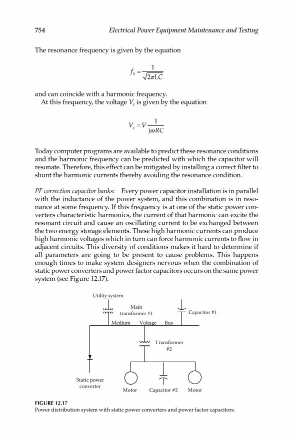
754 Electrical Power Equipment Maintenance and Testing
The resonance frequency is given by the equation
0
1
2f
LC=
p
and can coincide with a harmonic frequency.At this frequency, the voltage Vc is given by the equation
c
1V V
j RC=
w
Today computer programs are available to predict these resonance conditions and the harmonic frequency can be predicted with which the capacitor will resonate. Therefore, this effect can be mitigated by installing a correct fi lter to shunt the harmonic currents thereby avoiding the resonance condition.
PF correction capacitor banks: Every power capacitor installation is in parallel with the inductance of the power system, and this combination is in reso-nance at some frequency. If this frequency is at one of the static power con-verters characteristic harmonics, the current of that harmonic can excite the resonant circuit and cause an oscillating current to be exchanged between the two energy storage elements. These high harmonic currents can produce high harmonic voltages which in turn can force harmonic currents to fl ow in adjacent circuits. This diversity of conditions makes it hard to determine if all parameters are going to be present to cause problems. This happens enough times to make system designers nervous when the combination of static power converters and power factor capacitors occurs on the same power system (see Figure 12.17).
Utility system
Maintransformer #1
Medium Voltage Bus
Capacitor #1
Transformer#2
Static powerconverter
Motor MotorCapacitor #2
FIGURE 12.17Power distribution system with static power converters and power factor capacitors.
DK4058_C012.indd 754DK4058_C012.indd 754 11/8/2008 1:05:31 PM11/8/2008 1:05:31 PM

Power Quality, Harmonics, and Predictive Maintenance 755
Criteria for trouble: There are some quick rules of thumb that might be used to determine if there might be a problem. The fi rst is the resonant value of the combination of the system impedance and the capacitor bank size:
cp
sc
SC MVA
CAP MVAR
Xf
X= =
wherefp is the per unit parallel resonant frequencyXc is the capacitor bank reactance (per unit or ohms)Xsc is the system reactance (per unit or ohms)
A second rule of thumb involves the size of the static power converter with respect to the size of the electrical system feeding the converter. The term short-circuit ratio (SCR) has been used to describe this and is defi ned as
short-circuit MVASCR =
converter MVA
If the converter is small compared to the system capacity, the per-unit harmonic currents will be small and the system impedance will be low, so any harmonic voltage will be insignifi cant. If the SCR is above 20 and the fp is above 8.5, the probability of problems is low. If the SCR is below 20, and if the parallel resonance fp is near one of the converter characteristic harmon-ics, there is a high probability of producing excessive harmonic voltage and high harmonic currents. The increased use of static power converters and power factor capacitors can set up system conditions to cause problems. However, with the judicial design of fi lters using the power factor capacitors to control the harmonic currents from the static power converters, both pieces of equipment can be used to take full advantage of all the economics that both of them offer.
Another effect of the harmonic components on the capacitor bank is to cause additional heating because of increased dielectric losses. The increased losses due to harmonics may be calculated with
( ) 2
2
1tan
2hh
h
L Ch V∞
=
= ∑ d w
whereL is the increase in lossesh is the order of harmonicC is the capacitance(tan d)h is the loss factor at the frequency of the hth harmonicw is the fundamental angular frequencyVh is the peak value of the hth voltage
DK4058_C012.indd 755DK4058_C012.indd 755 11/8/2008 1:05:32 PM11/8/2008 1:05:32 PM

756 Electrical Power Equipment Maintenance and Testing
The overvoltage appearing at a capacitor bank due to the presence of harmonics depends on the phase relationship of harmonic and fundamental voltages. It is possible that the instantaneous overvoltage is greater than the rms overvoltage. As the corona inception and extinguishing voltage levels are a function of peak voltage, and not rms voltage, the life of the capacitor could be affected due to corona discharges. Capacitors, unlike most other power appara-tus, have strict limits on current, kVAR, and voltage. The IEEE 18-2002, “Shunt power capacitors,” specifi es the limit on harmonics that the shunt capacitors can be subjected to under normal operation. The standard states that the capacitor may be continuously operated in the presence of harmonics provided (1) the total reactive power is not greater than 135% of its rated value, (2) the current due to the fundamental and harmonic frequency components does not exceed 180% of rated rms value, and (3) the rms value of the applied voltage is not more than 110% of rated terminal voltage and the crest value (1.2 × (square root of two) ) of the applied voltage does not exceed 120% of rated peak voltage.
12.5.2.4 Switchgear
Harmonic components in the current waveform can affect the interruption capability of the switchgear. This takes place with two distinct mechanisms: (1) the presence of harmonics affects the rate of rise of the transient recovery voltage and the maximum value of the transient voltage and (2) harmonics affect the operation of the blowout coil in the stored-energy breakers. These effects will be discussed next.
The presence of current harmonics may result in high di/dt values at current zero. In this case, the rate of rise of the transient recovery voltage across the breaker will be higher than normal creating the possibility of dielectric failure and restrike. Also, the presence of harmonic currents affects the time that current crosses zero. This time affects the crest value of the transient recovery voltage. For example, if this time coincides with the maxi-mum of the source voltage (fundamental), the crest value of the transient recovery voltage can reach 2.82 E where E is the rms value of the rated volt-age. This value may cause breaker restrike. Circuit breakers have failed to interrupt currents due to the inability of the blowout coils to operate ade-quately in the presence of severe harmonics. As the blowout coil assists in the arc’s movement into the arc chute where the interruption takes place, its ineffi cient operation prolongs arcing and eventually results in breaker fail-ure. Similar problems can exist in other current interrupting devices such as load break switches, circuit switchers, etc. Vacuum breakers are less sensi-tive to harmonic currents. There are no defi nite standards set forth by the industry on the level of harmonic currents that switching devices are required to interrupt. All the interrupting tests are performed at the rated supply fre-quency. The effect of harmonics on transient recovery voltage is by far the most diffi cult because it depends on specifi c system confi guration.
One of the principal problems due to harmonics is the one that occurs within the switchgear neutral of three-phase four-wire systems when harmonics are
DK4058_C012.indd 756DK4058_C012.indd 756 11/8/2008 1:05:32 PM11/8/2008 1:05:32 PM
Power Quality, Harmonics, and Predictive Maintenance 757
present. The problem associated with neutrals is the result of the addition of triplen harmonic currents (i.e., multiple of the third harmonic) to the funda-mental current in the neutral. The result often is that the neutral, which would normally carry very little current in a balanced three-phase system, now carries currents in excess of the phase currents for the system. Since neutral conductors, lugs, bus bars, etc, often are sized smaller than phase conductors and current components, the result is that the neutral system components are overloaded and often overheat, fail, or even burn down.
12.5.2.5 Protective Relays
Relays that depend on voltage/current crest or voltage zeroes for their opera-tion are obviously affected by HD. System harmonics affect relay operation in a very complex manner. The induction disk and electromechanical relays are affected in the following way. The presence of harmonic currents results in additional torque components altering the time delay characteristics of the relays. Ground relays cannot distinguish between zero sequence current and third harmonic current. Thus, the presence of excessive third harmonic cur-rent can cause ground relays to trip. A recent Canadian study documents the effects of harmonics on relay operation as follows:
1. Relays exhibited a tendency to operate slower and/or with higher pickup values rather than to operate faster and/or with lower pickup values.
2. Static underfrequency relays were susceptible to substantial changes in operating characteristics.
3. In most cases, the changes in operating characteristics were relatively small over the moderate range of distortion expected during normal operation.
4. Depending on the manufacturer, the overvoltage and overcurrent relays exhibited various changes in operating characteristics.
5. Depending on harmonic content, operating torques of relays can be reversed.
6. Operating times can vary widely as a function of frequency mix in the metered quantity.
7. Balanced beam impedance relays can exhibit both overreach and underreach.
8. Harmonics can impair the high speed operation of differential relays. Several tests indicated that the relays could exhibit complete restraint.
In general, the harmonic levels required to cause misoperation of relays are greater than levels which would be considered maximum acceptable limits for other equipment. Harmonic levels of 10%–20% are generally required to cause problems with relay operation, except in unusual circumstances.
DK4058_C012.indd 757DK4058_C012.indd 757 11/8/2008 1:05:32 PM11/8/2008 1:05:32 PM

758 Electrical Power Equipment Maintenance and Testing
12.5.2.6 Metering Devices
Metering and instrumentation are affected by the presence of voltage and current harmonics. Induction disk devices, such as watt-hour meters and overcurrent relays, are designed and calibrated only for the fundamental current and voltage. The presence of harmonic currents and voltages gener-ates additional electromagnetic torque on the disk which can cause errone-ous operation. A Canadian study indicates that a 20% fi fth harmonic content can produce 10%–15% error in a two element three-phase watt transducer. Other studies have shown that the error due to harmonics may be positive, negative, or smaller with third harmonics. This, of course, is dependent on the type of meter under consideration. Solid-state meters can measure power based on waveshape. In general, the distortion must be severe (>20%) before signifi cant errors are detected.
12.5.2.7 Electronic Equipment
In many cases, electronic equipment are signifi cant sources of harmonics. On the other hand, the operation of electronic equipment is often depen-dent on accurate determination of voltage zero crossings or other aspects of the voltage waveshape. For example, HD can result in a shifting of the zero crossing of the voltage waveform. This may be critical for many types of electronic circuit controls, and misoperation, such as commutation fail-ures, can result from the shifts of the zero crossing. A large class of loads utilize energy in some form other than at the incoming line frequency, and require rectifi cation or frequency conversion. External distortion may affect the performance of either the power converter or the converter load. The severity of these effects are infl uenced by the equipment design. Analysis of these effects is complicated by the fact that the converter itself is a complex nonlinear apparatus producing its own harmonics. Inverters used for DC to AC conversion or vice versa, generate a voltage notch during commutation. Voltage notching effects are of suffi cient concern that notch limits on distorting apparatus have been included in some standards and guidelines. Voltage and current distortion may lead to dis-ruption of the operation of electronic equipment. These disruptions may be divided into two categories: disruption of the converter operation and disruption of the converter load operation. The diversity of converter designs and the wide range of loads fed by these converters makes any general analysis diffi cult. It can be noted, however, that these disruptions are very much a function of converter design, and that electrical isolation of the sensitive load from loads producing distortion reduces the likeli-hood of disruption. Empirical data and operating experience with steady state voltage and current distortion in industrial plants has led to specifi c design recommendations summarized in the IEEE standard 519-1992, “IEEE guide for harmonic control and reactive compensation of static power converters.”
DK4058_C012.indd 758DK4058_C012.indd 758 11/8/2008 1:05:32 PM11/8/2008 1:05:32 PM

Power Quality, Harmonics, and Predictive Maintenance 759
12.5.2.8 Lighting Devices
Incandescent lamps: The incandescent lamp is one of the devices of this load group which is most sensitive to increased heating effects. A relative equation for bulb life is given by the equation:
( )( )
2
221
1 1
1 DF
nn
LV V V
⎡ ⎤⎡ ⎤ ⎢ ⎥= =⎢ ⎥ ⎢ ⎥⎣ ⎦ +⎣ ⎦
whereL is the PU bulb life (to rated life base)V1 is the PU fundamental voltageV is the PU rms voltage (to rated voltage base)n is a constant (representative value for n is 13)
It can be noted that large distortion factors will signifi cantly shorten the bulb life, and that changes in the fundamental voltage are relatively more signifi -cant than changes in the distortion factor.
Arc lamps: The various types of arc lamps exhibit nonlinear resistance characteristics where the resistance declines as the current increases. The lamps have a safe operating region, and a ballast is required to place the lamp operating point in the safe region for all line voltage conditions throughout the range of various lamp characteristics. During normal lamp operation, the ballast functions as a current-limiting element. With inductive ballasts, the infl uence of voltage distortion would be roughly described by the distortion factor. It would appear that modest distortion factors would not cause a large shift in the lamp-operating point. Capacitive ballasts must be viewed with some concern, however, as the ballast reac-tance would drop as the frequency of the harmonic rises. Because the bulb itself is a highly nonlinear device, it is not at all clear what effect voltage distortion would have on lamps with capacitive ballasts.
12.6 Predictive Maintenance and PQ Measurements*
12.6.1 Introduction
In this section a discussion is provided on PQ measurements that can be used as predictive maintenance of power system and plant equipment. Unexpected failures can be avoided in both production equipment and power system apparatus when basic PQ measurements are added to maintenance
* This predictive PQ guide is based on information provided by Fluke Corporation.
DK4058_C012.indd 759DK4058_C012.indd 759 11/8/2008 1:05:32 PM11/8/2008 1:05:32 PM
760 Electrical Power Equipment Maintenance and Testing
procedures. Insurance claims data in the NFPA 70B indicates that roughly half of the cost associated with electrical failures could be prevented by regular maintenance. A study published in IEEE 493-1997 says that a poorly maintained system can attribute 49% of its failures to lack of maintenance. To determine the cost of a failure, it helps to consider the cost of lost income (gross margin) due to downtime, cost of labor to troubleshoot, patch, clean up, repair and restart, and cost of damaged equipment and materials, including repairs, replacements and scrapped materials.
Predictive maintenance of PQ focuses on a small set of measurements that can predict power distribution or critical load failures. By checking the PQ at critical loads, one can see the effect of the electrical system up to the load. The predictive maintenance inspection program should include motors, genera-tors, pumps, A/C units, fans, gearboxes, or chillers on site. The voltage stability, HD, and unbalance voltages are good indicators of load and distribution system health and can be taken and recorded quickly with little incremental labor. Current measurements can identify changes in the way the load parameters are changing. All of these measurements can be taken without halting opera-tions and measurement data can easily be entered into computer maintenance management software (CMMS) and plotted over time (see Section 1.4.3.5 for information on CMMS). For each measurement point or piece of equipment, limits can be set to trigger corrective action. Limits should be set well below the point of failure, and as time goes on limits may be tightened or loosened by analyzing historical data. The appropriate limits depend somewhat on the ability of the loads to deal with power variation. But for most equipment, the maintenance team can devise a set of default, house limits based on industry standards and experience. The cost of three-phase power analyzers and other PQ tools is lower now than before and measurements discussed in this section should be part of the predictive maintenance program.
12.6.2 Safety Standards for Test Instruments
12.6.2.1 Test Instrument Standards
IEC 61010 establishes international safety requirements for low voltage (1000 V or less) electrical equipment for measurement, control, and laboratory use. The low voltage power distribution system is divided into four categories, based on the proximity to the power source. Within each category are voltage listings—1000, 600, 300 V, etc. The key concept to understand is that you should use a meter rated to the highest category, as well as the highest volt-age, that you might be working in. For PQ troubleshooting, a meter rated to CAT IV-600 V should always be used. The CAT ratings should be marked near the voltage inputs of the instrument. IEC 61010 requires increased pro-tection against the hazards of transient overvoltages. Transients can cause an arc-over inside an inadequately protected meter. When that arc-over occurs in a high energy environment, such as a three-phase feeder circuit, the result can be a dangerous arc blast. The potential exists for serious harm to person-nel as well as damage to the meter. Also, when undertaking PQ measurements,
DK4058_C012.indd 760DK4058_C012.indd 760 11/8/2008 1:05:33 PM11/8/2008 1:05:33 PM

Power Quality, Harmonics, and Predictive Maintenance 761
the personnel should follow the requirements of safety-related work prac-tices listed in Chapter 13 of the NFPA 70E, and rules promulgated by OSHA (Code of Federal Regulations, Title 29, Subtitle B, Chapter XVII, subpart S, paragraph 1910.331–1910.335) for safety-related work practices. Further, the instrument’s manufacturer application notes and information should be con-sulted when making such measurements. The four categories of electrical equipment for measurements are depicted in Figure 12.18.
Manufacturers can self-certify that they meet IEC 61010 specifi cations, but there are obvious pitfalls for the end-user in self-certifi cation. Certifi cation by an independent testing laboratory provides assurance that the meter meets IEC requirements. Before using the test instruments, look for a symbol and listing number of an independent testing laboratory such as UL, CSA, TÜV, VDE, or others.
Overvoltage Category Summary Description
CAT IV Three-phase at utility connection, any outdoors
conductors (under 1000 V)
CAT III Three-phase distribution (under 1000 V), including
single-phase commercial lighting and distribution panels
CAT II Single-phase receptacle connected loads
CAT I Electronic
CAT IV
CAT III
CAT IICAT I
FIGURE 12.18IEC (61010) safety categories of electrical equipment for measurements use. (Courtesy of Fluke
Corporation, Everett, WA.)
DK4058_C012.indd 761DK4058_C012.indd 761 11/8/2008 1:05:33 PM11/8/2008 1:05:33 PM

762 Electrical Power Equipment Maintenance and Testing
12.6.2.2 Instruments for PQ Measurements
PQ monitoring requires a variety of instruments due to the many different mea-surements that must be performed. A general description of test instruments is given in this to make the reader familiar with the instruments that are normally used for PQ surveys and/or measurements. As an example, Table 12.5 lists the test instruments manufactured by Fluke Corporation which are applicable to the type of measurements discussed in this section. Similar instruments are available from other manufactures. Note that a true-rms multimeter, ammeter,
TABLE 12.5
Test Instruments Applicable to PQ Measurements
Test Tools
(Model)a
PQ Analyzer
(43B-Single-
Phase
Analyzer)
Harmonic
Analyzer
(435
Three-Phase
Analyzer)
PQ Recorder
[(Three-Phase-
1750; Single-
Phase–VR1710)]
Rms Digital
Multimeter
(Single-
Phase-87 V)
PQ Clamp
Meter (1f
Power-345)
Power kVA, kW,
kVAR, PF,
DPF
kVA, kW,
kVAR, PF,
DPF
Recording TrendPlot,
PC logging
PC logging 4000 V events
Real-time clock — —
Harmonics To 51st
harmonic
To 50th
harmonic
True-rms volts
and current
True-rms
volts and
current
Voltage
transients
20 ns with
waveform1 μs event
recording
250 μs peak
MIN/MAX
Sags and swells
(voltage only)
Single cycle
MIN/MAX
with trend
Single cycle
event
recording
100 ms MIN/
MAX
Sags and swells
(simultaneous
voltage and
current)
Single cycle
MIN/MAX
Outages Single cycle
MIN/MAX
with trend
Event recording
with duration
100 ms MIN/
MAX
Documentation,
RS232 computer
FlukeView
PQ software
FlukeView PQ
software
EventView
software
Motor in-rush
current
Waveform
with cursors
MIN/MAX MAX hold
Waveform 20 MHz scope Fundamental
Noise —
Peak — — —
True-rms — — — —
Sources: Courtesy of Fluke Corporation, Everett, WA.a Models listed are Fluke Instruments used for PQ measurements. Similar instruments are
available from other PQ instrument manufacturers.
DK4058_C012.indd 762DK4058_C012.indd 762 11/8/2008 1:05:33 PM11/8/2008 1:05:33 PM

Power Quality, Harmonics, and Predictive Maintenance 763
ground impedance tester, and power line monitor/analyzer are absolutely essential equipment for minimum effective power disturbance detection and analysis.
True-rms multimeters: A true-rms digital multimeter is used to measure voltage and continuity.
True-rms clamp-on ammeters: A true-rms clamp-on ammeter is used to mea-sure current and analyze current waveforms, particularly when sinusoidal waveforms are involved. It is recommended due to the ease of use and broad bandwidth characteristics of transformer-based meter designs. Several types of ammeters currently are available such as direct reading and indirect read-ing ammeters.
Ground impedance testers: A ground impedance tester is a multifunctional instru-ment designed to detect wiring and ground problems in low-voltage power dis-tribution systems. Such problems can include: wiring errors, neutral–ground (N–G) shorts and reversals, IG shorts ground, and neutral impedance shorts. Some testers are designed for use on 120 V AC single-phase systems while others can be used on both single and three-phase systems up to 600 V AC.
Earth ground tester: An earth ground tester is used to measure the ground electrode impedance. Ground resistance tests should be conducted with a fall-of-potential method instrument. Clamp-on instruments that do not require the grounding electrode to be isolated from the building may be used with the understanding that these instrument may not give the most accurate readings of the ground electrode impedance.
Oscilloscope: An oscilloscope can be used to detect harmonics in an electri-cal system. It also can be used for noise measurements when combined with a line decoupler. In this case, the input is connected to the voltage of interest with the appropriate lead. If a voltage above the range of the oscilloscope is to be examined, probes with resistance-divider networks are available to extend the range of the instrument.
Spectrum analyzers: A spectrum analyzer equipped with appropriate measurement capabilities can be used to measure harmonics, electrical noise, and frequency deviations. Special-purpose harmonic meters or low fre-quency or broadband spectrum analyzers also can be used to measure these voltage and current disturbances.
Static meters: Static meters typically are used to measure ESD. These are handheld devices.
Psychrometer: A psychrometer is used to measure temperature and humid-ity in the environment, although such measurements also can be made with power monitoring devices equipped with special probes.
Field strength meter: A fi eld strength meter equipped with a special probe can be used to measure electric or magnetic fi eld strength.
DK4058_C012.indd 763DK4058_C012.indd 763 11/8/2008 1:05:33 PM11/8/2008 1:05:33 PM

764 Electrical Power Equipment Maintenance and Testing
Infrared detectors: Infrared detectors can be used to detect overheating of transformers, circuit breakers, and other electrical apparatus.
12.6.3 PQ Measurement Guidelines
PQ covers a wide range of issues, from voltage disturbances like voltage dips (sags), swells, outages and transients, to current harmonics, to performance wiring and grounding. The symptoms of poor PQ include intermittent lock-ups and resets, corrupted data, premature equipment failure, overheating of components for no apparent cause, etc. The ultimate cost is in downtime, decreased productivity, and frustrated personnel. This application note gives information on how to troubleshoot PQ problems. It also gives you informa-tion on how to start fi xing those problems. But before grabbing that meter, the following cautionary notes must be adhered to:
1. Suggested measurements should only be made by qualifi ed personnel who are trained to make these measurements in a safe manner, using proper procedures and test tools rated for work on electrical power circuits.
2. To the best of the author’s knowledge, recommended solutions are consistent with the NEC, but in any case, NFPA 70 (NEC), NFPA 70E, and OSHA requirements must not be violated.
3. The information provided in this guidance is believed to be accurate and current, but it is not intended to be a substitute for the special-ized knowledge and experience of professional PQ practitioners. What this application guide offers is a starter kit, not the fi nal word on PQ predictive maintenance.
12.6.3.1 Preparation for Conducting Measurements
To troubleshoot PQ problems, one approach is to start as close to the problem load as possible. The problem load is the sensitive load, typically electronic, that is somehow malfunctioning. Poor PQ is suspected, but part of your job is to isolate PQ as a cause from other possible causes (hardware, software?). Like any detective, you should start at the scene of the crime. This bottom-up approach can take you a long way. It relies on making use of a sharp eye and on taking some basic measurements. An alternative is to start at the service entrance, using a three-phase monitor, and work back to the problem load. This is most useful if the problems originate with the utility. Yet survey after survey has concluded that the great majority of PQ problems originate in the facility. In fact, as a general rule, PQ is best at the service entrance (connection to utility) and deteriorates as you move downstream through the distribution system. That is because the facility’s own loads are causing the problems. Another illuminating fact is that 75% of PQ problems are related to wiring and grounding problems! For this reason, many PQ
DK4058_C012.indd 764DK4058_C012.indd 764 11/8/2008 1:05:33 PM11/8/2008 1:05:33 PM
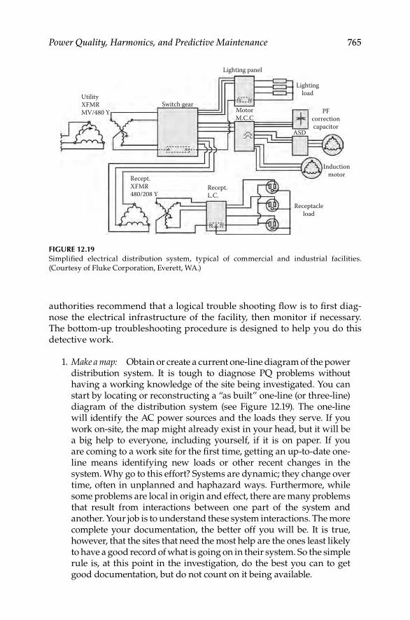
Power Quality, Harmonics, and Predictive Maintenance 765
authorities recommend that a logical trouble shooting fl ow is to fi rst diag-nose the electrical infrastructure of the facility, then monitor if necessary. The bottom-up troubleshooting procedure is designed to help you do this detective work.
1. Make a map: Obtain or create a current one-line diagram of the power distribution system. It is tough to diagnose PQ problems without having a working knowledge of the site being investigated. You can start by locating or reconstructing a “as built” one-line (or three-line) diagram of the distribution system (see Figure 12.19). The one-line will identify the AC power sources and the loads they serve. If you work on-site, the map might already exist in your head, but it will be a big help to everyone, including yourself, if it is on paper. If you are coming to a work site for the fi rst time, getting an up-to-date one-line means identifying new loads or other recent changes in the system. Why go to this effort? Systems are dynamic; they change over time, often in unplanned and haphazard ways. Furthermore, while some problems are local in origin and effect, there are many problems that result from interactions between one part of the system and another. Your job is to understand these system interactions. The more complete your documentation, the better off you will be. It is true, however, that the sites that need the most help are the ones least likely to have a good record of what is going on in their system. So the simple rule is, at this point in the investigation, do the best you can to get good documentation, but do not count on it being available.
UtilityXFMRMV/480 Y
Switch gear
Recept.L.C.
Receptacleload
Inductionmotor
PFcorrectioncapacitor
ASD
MotorM.C.C
Lightingload
Lighting panel
Recept.XFMR480/208 Y
FIGURE 12.19Simplifi ed electrical distribution system, typical of commercial and industrial facilities.
(Courtesy of Fluke Corporation, Everett, WA.)
DK4058_C012.indd 765DK4058_C012.indd 765 11/8/2008 1:05:33 PM11/8/2008 1:05:33 PM

766 Electrical Power Equipment Maintenance and Testing
2. Do a walk around of the site. Sometimes a visual inspection will offer immediate clues:
A transformer that is much too hot•
Wiring or connections discolored from heat•
Receptacles with extension strips daisy-chained to extension strips•
Signal wiring running in the same trays as power cables•
Extra N–G bonds in subpanels•
Grounding conductors connected to pipes that end in midair. At a • minimum, you will get a sense of how the facility is wired and what the typical loads are
3. Interview affected personnel and keep an incident log. Interview the people operating the affected equipment. You will get a description of the problem and often turn up unexpected clues. It is also good practice to keep a record of when problems happen and what the symptoms are. This is most important for problems that are inter-mittent. The goal is to fi nd some pattern that helps correlate the occurrence of the problem in the problem load to a simultaneous event elsewhere. Logically, this trouble-logging is the responsibility of the operator closest to the affected equipment.
4. The typical electrical distribution system for a commercial building or a light industrial facility is shown in Figure 12.19 that can be divided in to two parts: (1) distribution system and (2) three-phase loads. We will start the predictive maintenance from the bottom-up, i.e., starting at the branch circuit and moving up to the service panel, transformer, and then going into three-phase loads as listed below.
Distribution system
Receptacle branch circuit
Service panels
Transformers
Electrical noise and transients
Lightning protection
Three-phase loads
Polyphase induction motors
AC ASD
Commercial lighting
12.6.3.2 Basic Power Measurements
The basic power measurements for assessing PQ problems are phase voltages, neutral-to-ground voltage, phase currents, voltage and current distortion, voltage unbalance or imbalance, etc. The basic power measurements for PQ are listed in Table 12.6
DK4058_C012.indd 766DK4058_C012.indd 766 11/8/2008 1:05:33 PM11/8/2008 1:05:33 PM

Power Quality, Harmonics, and Predictive Maintenance 767
Good voltage level and stability are fundamental requirements for reliable equipment operation. The following power conditions are indicative of PQ problems and should be checked.
Voltage: Running loads at overly high or low voltages causes reliability problems and failures. Verify that line voltage is within 10% of the name-plate’s rating. As connections in the power system deteriorate, the rising impedance will cause drops in voltage. Added loads, especially those with high inrush, will also cause voltage decline over time. The loads farthest from the service entrance or transformer will show the lowest voltage. Neutral-to-ground voltage shows how heavily the power system is loaded and helps quantify the triplen harmonic currents. Neutral-to-ground voltage higher than 3% should trigger further investigation.
Voltage sag count: Taking a single voltage reading tells only part of the story. How is the voltage changing during an hour and during a day? Sags, swells, and transients are short-term variations in voltage. The voltage sag (or dip) is the most common and troublesome variety. Sags indicate that a system is having trouble responding to load requirements and signifi cant sags can interrupt pro-duction. Voltage sags can cause spurious resets on electronic equipment such as computers or controllers, and sag on one phase can cause the other two to over-compensate, potentially tripping the circuit. Sags have several dimensions: depth, duration, and time of day. Utilities use a special index to track the number of sags that occur over a period of time. To gauge the depth of the sags, they count how often voltage drops below various thresholds. The longer and larger the voltage variations more likely the equipment is susceptible to malfunction. For example, the Information Technology Industry Council (ITIC) curve speci-fi es 120 V computer equipment should be able to run as long as voltage does not drop below 96 V for more than 10 s or below 84 V for more than 0.5 s.
Current: Current measurements that trend upward are a key indicator of a problem or degradation in the load. While equipment is running, monitor phase, neutral and ground current over time. Make sure none of the currents are increasing signifi cantly, verify that they are less than the nameplate rating, and keep an eye out for high neutral current, which can indicate harmonics and unbalance.
TABLE 12.6
Basic Power Measurements for Three-Phase Wye Equipment
Voltage measurements Phase-to-neutral voltages
N–G voltages
Voltage sags Phase to neutral sag count
Voltage harmonics Phase voltage THD
Current measurements Phase currents
Voltage unbalance Negative sequence, zero sequence
Sources: Courtesy of Fluke Corporation, Everett, WA.
DK4058_C012.indd 767DK4058_C012.indd 767 11/8/2008 1:05:33 PM11/8/2008 1:05:33 PM

768 Electrical Power Equipment Maintenance and Testing
Voltage unbalance: In a three-phase system, signifi cant differences in phase voltage indicate a problem with the system or a defect in a load. High voltage unbalance causes three-phase loads to draw excessive current and causes motors to deliver lower torque. Also, it causes motor overheating, for exam-ple, 3% unbalance in voltage causes a temperature rise of 25°C. The negative sequence voltage (Vneg) and zero sequence voltage (Vzero) are an indication of voltage asymmetry between phases. It is desirable to keep Vneg to be less than 2%. The negative sequence voltage and zero sequence voltage are also referred to as V2 and V0, respectively.
Voltage HD: HD is a normal consequence of a power system supplying elec-tronic loads such as computers, business machines, electronic lighting bal-lasts, and control systems. Adding or removing loads from the system changes the amount of distortion, so it is a good idea to regularly check har-monics. Harmonics cause heating and reduced life in motor windings and transformers, excessive neutral current, increased susceptibility to voltage sags, and reduced transformer effi ciency. As current harmonics interact with impedance, they are converted into voltage harmonics. THD is a sum of the contributions of all harmonics. By tracking voltage THD over time one can determine if distortion is changing. The voltage harmonic distortion (voltage THD) in accordance with IEEE 519 should be less than 5%.
12.6.3.3 Measurements at the Receptacle of a Branch Circuit
Many PQ problems show up at the branch circuit level. There is a simple reason for this: that is where most of the sensitive loads are located. It is also the end of the line of the electrical distribution system, and the place where shortcomings cannot be hidden. Let us assume you have been called in to solve the problem. You have already talked to the people involved have a rough idea of the symptoms (equipment lockups, intermittent resets or crashes, etc.) and as much sense of the timing and history of the problems as you can get. So it is time to gather hard evidence: it is time to take measure-ments. Our primary focus with troubleshooting at the receptacle level is to determine if the L–N voltage available is of suffi cient stability and amplitude to supply the needs of the load(s). Make the following measurements.
Waveform: The waveform gives us quick snapshot information. An ideal waveform would be a sine wave. In this case, (Figure 12.20) the voltage wave-form is fl at-topped, which is typical of a building with many nonlinear loads such as computers and other offi ce equipment. Our other measurements will tell us whether this fl at-topping is excessive.
Peak voltage: The peak value is critical to electronic loads because the elec-tronic power supply charges its internal capacitors to the peak value of the line voltage. If the peak is too low, it affects the ability of the caps to charge fully and the ability of the power supply to ride through momentary dips in the line voltage. For an rms voltage of 120 V, the peak value for a sine wave
DK4058_C012.indd 768DK4058_C012.indd 768 11/8/2008 1:05:34 PM11/8/2008 1:05:34 PM

Power Quality, Harmonics, and Predictive Maintenance 769
should be 169.7 V (1.414 × 120 V). However, as we see from Figure 12.20, the fl at-topped waveform will have a lower peak value.
The fl at-topped waveform is typical of the voltage in facilities with com-puter loads. What causes fl at-topping? The utility supplies AC power, but electronic equipment runs on DC power. The conversion of AC into DC is done by the power supply (SMPS) of the computer. The SMPS has a diode bridge which turns AC into pulsating DC, which then charges a capacitor. As the load draws the capacitor down, the capacitor recharges. However, the capacitor only takes power from the peak of the wave to replenish itself, since that is the only time the supplied voltage is higher than its own voltage. The capacitor ends up drawing current in pulses at each half-cycle peak of the supplied AC voltage. This is happening with virtually all the electronic loads on the circuit. If the AC power source were perfectly stiff, meaning that it had an infi nite capacity to supply all the current that was required, then there would be no such thing as fl at-topping (or sags or any voltage distortion). There are practical limits to what the AC power source can supply. This limit is usually described by a concept called source impedance, which is the total impedance from the point where the load is located back to the source. There are two major contributors to this source impedance. One is the wiring; the longer the conductor and the smaller the diameter (higher gauge), the higher the impedance. The other factor is the internal impedance of the power supply transformer (or other source equipment). This internal impedance is simply a way of saying that a transformer of a given size/rating can only supply so much current. The source impedance is naturally greatest at the end of a branch circuit, the farthest point from the source. That is the same place where all those electronic loads are demanding current at the peak of the wave. The
04 A
2.251 rmsA~–
0100V
119.6VOLTS/AMPS/HERTZ
119.6 V~–60.0 hz
MAXMIN119.3 V~–
rmsV~–
FIGURE 12.20Flat-topped voltage waveform measured at a receptacle. (Courtesy of Fluke Corporation,
Everett, WA.)
DK4058_C012.indd 769DK4058_C012.indd 769 11/8/2008 1:05:34 PM11/8/2008 1:05:34 PM

770 Electrical Power Equipment Maintenance and Testing
result is that the voltage peak tends to get dragged down—in other words, fl at-topped. The more loads there are, the greater the fl at-topping. Also, the higher the source impedance, the greater the fl at-topping of the voltage wave-form is going to be incurred.
Rms voltage: Nominal line voltage is measured in rms which corresponds to the effective heating value. Equipment is rated in rms, not peak, because their main limitation has to do with heat dissipation. rms voltage can be too high or too low, but it is usually the low voltage that causes problems. Low rms voltage combined with fl at-topping (low peak) is a deadly combination for sensitive loads. Voltage drop is a function of both the loading of the circuit and the source impedance, which in effect means the length and diameter (gauge) of the wire run. The NEC (210-19.a, FPN No. 4) recommends a limit of a 3% voltage drop from the branch circuit breaker to the farthest outlet, and a total voltage drop of less than 5% including the feeder and branch circuit.
Recording (short-term): The limitation of the above measurement is that it is static. Many loads require more current (inrush current) when they are fi rst turned on. This momentary high current may cause a momentary low voltage (sag) because of the additional IR drop through the conductors. Such sags are often caused by loads drawing inrush currents on the same branch circuit, or on the same panelboard. You can measure a worst case sag of 100 ms or more (about six cycles at 60 Hz) by using a rms digital multimeter, while energizing the load. What if you want to know if there are recurring sags? The recurring sags can be recorded by using a PQ analyzer which will continuously capture sags of as little as single cycle duration (17 ms). A 1 h recording time may be enough to indicate if there are recurring sags and swells.
Recording (long-term): For longer term recording an instrument, such as Fluke’s VR1710 voltage event recorder, can be used to record sags, swells, outages, transients, and frequency deviations while plugged into the outlet. The device can be left on-site, unattended, for days and weeks, all the time catching intermittent events. The correlation of equipment malfunction with voltage events is hard evidence of a PQ problem.
N–G voltage: Let us say a simple L–N measurement at the outlet has a low reading. The low reading does not tell if the reading is low because the feeder voltage is low (at the subpanel), or if the branch circuit is overloaded. You could try to measure the voltage at the panel, but it is not always easy to tell which panel feeds the outlet you are measuring and it is also sometimes incon-venient to access a panel. N–G voltage is often an easier way of assuring the loading on a circuit. As the current travels through the circuit, there is a certain amount of voltage drop in the hot conductor and in the neutral conductor. The drop on the hot and neutral conductors will be the same if they are the same gauge and length. The total voltage drop on both conductors is subtracted from the source voltage and is that much less voltage available to the load. The bigger the load, the higher the current, and the greater the N–G voltage drop. Think of N–G voltage as the mirror of L–N voltage: if L–N voltage is low, that will show up as a higher N–G voltage. N–G voltage exists because of
DK4058_C012.indd 770DK4058_C012.indd 770 11/8/2008 1:05:34 PM11/8/2008 1:05:34 PM

Power Quality, Harmonics, and Predictive Maintenance 771
the voltage drop due to the current traveling through the neutral back to the N–G bond. If the system is correctly wired, there should be no N–G bond except at the source transformer (at what the NEC calls the source of the sepa-rately derived system (SDS), which is usually a transformer). Under this situ-ation, the ground conductor should have virtually no current and therefore no voltage drop on it. In effect, the ground wire is available as a long test lead back to the N–G bond.
Shared neutrals: The three-phase circuits are usually wired so that they share a single neutral. The original idea was to duplicate on the branch circuit level the four wire (three phases and a neutral) wiring of panelboards. Theoretically, only unbalanced current should return on the neutral. If the loads supplied from the three-phase circuits are balanced, which is usually the case for linear loads then there should be minimum current returning on the neutral. However, this is not the case with nonlinear (electronic) loads, therefore the single neutral carries a much higher current. This old conventional method of wiring has become a problem with the growth of single-phase nonlinear loads. The problem is that zero sequence current from nonlinear loads, pri-marily third harmonic, will add up arithmetically and return on the neutral. In addition to being a potential safety problem because of overheating of an undersized neutral, the extra neutral current creates a higher N–G voltage. Remember that this N–G voltage subtracts from the L–N voltage available to the load. The measurement of N–G voltage of a shared neutral is shown in Figure 12.21.The following guide is offered on the N–G measurements for assessing and resolving PQ problems.
1. A rule-of-thumb used by the industry is that N–G voltage of 2 V or less at the receptacle is okay, while a few volts or more indicates overloading; 5 V is seen as the upper limit. There is obviously some room for judgment in this measurement.
2. A high reading could indicate a shared branch neutral, i.e., a neutral shared between more than one branch circuit. This shared neutral simply increases the opportunities for overloading as well as for one circuit to affect another.
3. A certain amount of N–G voltage is normal in a loaded circuit. If the reading is stable at close to 0 V, suspect an illegal N–G bond in the receptacle (often due to loose strands of the neutral touching some ground point) or at the subpanel. Any N–G bonds other than those at the transformer source (and/or main panel) should be removed to prevent return currents fl owing through the ground conductors.
4. If N–G voltage is low at the receptacle, you are in good shape. If it is high, then you still have to determine if the problem is mainly at the branch circuit level, or mainly at the panel level. Remember, assum-ing there is no illegal N–G bond in intervening panels or receptacles, your ground test lead goes all the way back to the source, so you are reading voltage drops all the way to the source.
DK4058_C012.indd 771DK4058_C012.indd 771 11/8/2008 1:05:34 PM11/8/2008 1:05:34 PM

772 Electrical Power Equipment Maintenance and Testing
Summary: The PQ measurements on receptacle of branch circuits as discussed above are summarized in the Table 12.7. The quality of power depends on quality wiring which is referred to in the industry as perfor-mance wiring. The basic intent of performance wiring is to maintain or restore correct L–N voltage to the load. There is a distinction between per-formance wiring and code minimum wiring. The NEC sets the absolute minimum requirements for a wiring and is primarily concerned with fi re prevention and personnel safety. The NEC should, of course, never be vio-lated, but it is also important to understand that the Code’s objective is not to establish standards to achieve PQ. However, many facilities are fi nding that it pays to take the extra step and install or even retrofi t facilities with performance wiring for correct operation of nonlinear loads. The attri-butes of performance wiring are listed in Table 12.8. There are also situa-tions where receptacle-installed power conditioning devices are a good solution, either as a complement to the wiring changes or as an economi-cally viable alternative to some wiring changes. By monitoring voltage events at the receptacle, any anomalies in the voltage (phase-neutral and N–G) can be detected. Predictive maintenance of PQ will ensure that that the sensitive loads are receiving the correct voltage.
f1f2f3
f1 f2
f3
To transformerX0
To panelground buss
N–G voltage
FIGURE 12.21Measurement of N–G voltage of a shared neutral. (Courtesy of Fluke Corporation, Everett, WA.)
DK4058_C012.indd 772DK4058_C012.indd 772 11/8/2008 1:05:34 PM11/8/2008 1:05:34 PM

Power Quality, Harmonics, and Predictive Maintenance 773
TABLE 12.7
PQ Measurements on Receptacle of Branch Circuits
Voltage
Measurement Look for Instrument
1. Waveform Snapshot of severity of voltage
distortion
Three-phase or single-phase
analyzer
2. Peak voltage Excessive fl at-topping Three-phase or single-phase
analyzer, rms digital multimeter
(peak min max)
3. Rms voltage Low rms (steady state low
rms or intermittent/
cyclical sags)
Three-phase or single-phase
analyzer, rms digital multimeter
(peak min max)
4. Recording
(short-term)
Sags, swells, interruptions
while troubleshooter remains
on-site (4 min to 1 h typical
recording time)
Three-phase or single-phase
analyzer (sags/swells or transients)
5. Recording
(long-term)
Up to 4000 sags, swells,
outages, transients
Three- or single-phase recorder
6. N–G N–G voltage too high
(or close to zero)
Three-phase or single-phase
analyzer, rms digital multimeter
(peak min max)
Source: Courtesy of Fluke Corporation, Everett, WA.
TABLE 12.8
Suggestions for Performance Wiring of Branch Circuits
Recommendation Reason
Check for loose connections It is easy to overlook the obvious
Eliminate shared neutrals. In new
installations, pull individual neutrals
for each branch circuit
Minimize load interaction and source
impedance
Limit the number of receptacles per
branch circuit to three
Minimize loading and load interaction
Limit length of 120 V branch
circuits to 50 ft (15 m)
Minimize source impedance
Install dedicated branch circuits for all laser
printers and copy machines. Dedicated
circuits should be run in their own conduit
Keep victim loads and culprit loads
separated. Conduit prevents coupling
between circuits
Install a green wire ground (do not just
depend on the conduit connection)
Maintain a continuous, low impedance
ground
Label all panels, circuit breakers,
and receptacles
This would not improve PQ, but it will
sure make life easier for the
troubleshooter and the installer
Source: Courtesy of Fluke Corporation, Everett, WA.
DK4058_C012.indd 773DK4058_C012.indd 773 11/8/2008 1:05:34 PM11/8/2008 1:05:34 PM

774 Electrical Power Equipment Maintenance and Testing
12.6.3.4 Measurement at the Service Panel
In the bottom-up approach, the next step is to inspect and monitor PQ attributes at the service panel. While inspecting, checkout for the following:
Visual inspection•
Feeder conductor current test•
Neutral conductor current test (feeder and branch)•
Phase-to-neutral voltage test (feeder and branch)•
N–G voltage test (feeder)•
Circuit breaker voltage drop and current on branch phase conductors•
The service panel is where the effects of single-phase harmonic loads are easy to measure. A true-rms meter ensures accurate readings of nonlinear volt-ages and currents. Refer to Table 12.9 for comparison of average reading and true-rms reading multimeters.
Visual inspection
Look for an illegal N–G bond in subpanels (see Figure 12.22). This is • a violation of the NEC as well as of PQ wiring. It is also extremely common. If an illegal N–G bond is found in one panel at a site, it is likely to be in any number of them. Who knows why they are there: perhaps the installer was thinking that all panels are wired like resi-dential service panels; or that the quickest way to reduce N–G volt-age was to install a jumper, or that the more grounds the better. In any case, remove all illegal N–G bonds—no exceptions.
Look for signs of overheating, such as discolored connecting lugs. • Loose connections and excessive loading show up as heat. High
TABLE 12.9
Comparison of Average-Responding and True-rms Multimeters
Multimeter Reading
Waveform Description
Average-Sensing
DMM True-rms DMM
Sine wave Correct Correct
Square wave (fl at-top
voltage)
10% high Correct
Current to single-phase
diode rectifi er
40% low Correct
Current to three-phase
diode rectifi er
5%–30% low Correct
Source: Courtesy of Fluke Corporation, Everett, WA.
DK4058_C012.indd 774DK4058_C012.indd 774 11/8/2008 1:05:34 PM11/8/2008 1:05:34 PM
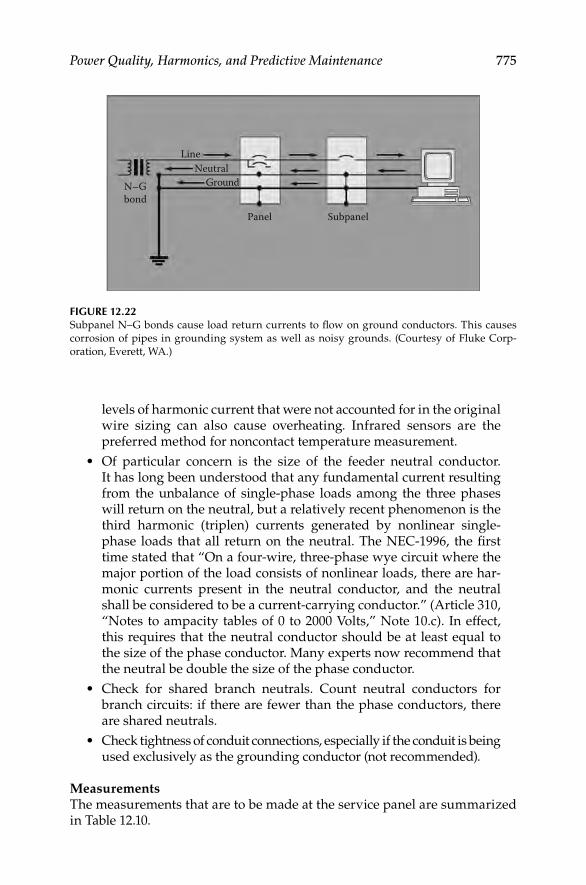
Power Quality, Harmonics, and Predictive Maintenance 775
levels of harmonic current that were not accounted for in the original wire sizing can also cause overheating. Infrared sensors are the preferred method for noncontact temperature measurement.
Of particular concern is the size of the feeder neutral conductor. • It has long been understood that any fundamental current resulting from the unbalance of single-phase loads among the three phases will return on the neutral, but a relatively recent phenomenon is the third harmonic (triplen) currents generated by nonlinear single-phase loads that all return on the neutral. The NEC-1996, the fi rst time stated that “On a four-wire, three-phase wye circuit where the major portion of the load consists of nonlinear loads, there are har-monic currents present in the neutral conductor, and the neutral shall be considered to be a current-carrying conductor.” (Article 310, “Notes to ampacity tables of 0 to 2000 Volts,” Note 10.c). In effect, this requires that the neutral conductor should be at least equal to the size of the phase conductor. Many experts now recommend that the neutral be double the size of the phase conductor.
Check for shared branch neutrals. Count neutral conductors for • branch circuits: if there are fewer than the phase conductors, there are shared neutrals.
Check tightness of conduit connections, especially if the conduit is being • used exclusively as the grounding conductor (not recommended).
MeasurementsThe measurements that are to be made at the service panel are summarized in Table 12.10.
FIGURE 12.22Subpanel N–G bonds cause load return currents to fl ow on ground conductors. This causes
corrosion of pipes in grounding system as well as noisy grounds. (Courtesy of Fluke Corp-
oration, Everett, WA.)
Panel Subpanel
GroundNeutral
Line
N–Gbond
DK4058_C012.indd 775DK4058_C012.indd 775 11/8/2008 1:05:35 PM11/8/2008 1:05:35 PM

776 Electrical Power Equipment Maintenance and Testing
Feeder phase current: Check each phase to make sure it is not overloaded. Also check for excessive unbalance.
Feeder neutral current: Measure the feeder neutral conductor for cumulative neutral current. Third harmonic currents from all three phases will add arith-metically in the neutral.
Feeder N–G voltage test: Measure the neutral-to-ground voltage, excessive N–G voltage indicates overloading. A N–G voltage at or very near zero indi-cates the existence of an illegal N–G bond in a subpanel.
Phase-to-neutral voltage test: Phase-to-neutral voltages are measured and recorded. They can be compared with receptacle L–N voltages to measure voltage drop.
Branch neutral current: Measure each branch neutral for overloading. The neutrals are measured instead of the phase conductors because they might share the return current of several phase conductors, yet they are not pro-tected by breakers.
Circuit breaker voltage drop: The voltage drop across a set of breaker contacts will give you a quick measure of the wear of those contacts. Ideally, the voltage drop should be zero. In practice, there will be some voltage drop in the millivolt range, with the exact value being dependent on the load current. As a general rule, the voltage drop should not exceed 20–100 mV, depending on load. This test can also be performed as contact resistance measurement test. For more details refer to Chapter 8.
Summary: The recommendations for improving PQ at the service panel are summarized in Table 12.11.
TABLE 12.10
Service Panel Measurements
Measurement Look for Instruments
1. Feeder phase current Overloading and balance Three-phase analyzer;
true-rms clamp meter
2. Feeder neutral current High currents from unbalanced
fundamental and
third harmonics
Three-phase analyzer;
rms DMM to fi nd
dominant frequency
3. Feeder N–G voltage High voltage indicates excessive
current, near-zero indicates
possible subpanel N–G bond
Same
4. Branch L–N voltage Low voltage Same
5. Branch neutral current Shared neutrals Same
6. Voltage drop across breaker
contacts. Hot breakers
Worn contacts. Breakers in
need of replacement
Same
Source: Courtesy of Fluke Corporation, Everett, WA.
DK4058_C012.indd 776DK4058_C012.indd 776 11/8/2008 1:05:35 PM11/8/2008 1:05:35 PM

Power Quality, Harmonics, and Predictive Maintenance 777
In addition, the following should be considered to reduce the effects of harmonics if PQ problems are encountered at the service panel:
1. Double the neutral, going beyond the NEC requirements.
2. Use nonlinear load panels.
3. Install zero sequence fi lters. Such a fi lter effectively sinks the third harmonic, preventing overloading on the feeder neutral and the transformer.
4. Install zigzag transformers.
5. Replace older motor drives with newer, harmonics compensated ones.
6. Coping with harmonics involves larger neutrals and other methods of better being able to handle the harmonics that are present. Curing har-monics involves eliminating or reducing harmonics at their source.
7. In some cases, you can try to reduce the spread of harmonics in the system—for example, by putting certain loads on their own trans-former and panel.
8. Many harmonics problems exist because of the way things are wired. Major rewiring is usually expensive in terms of downtime and so it is not normally the fi rst method used to fi ght a harmonics problem.
9. Look carefully at the system before implementing any curing or coping method, so you do not wind up trying one after another until
TABLE 12.11
Service Panel Recommendations for Improving PQ
Recommendation Reason
Limit length of 208 V feeder runs to 120 V
subpanels to 200 ft (65 m)
Minimize source impedance and chance of
voltage sags
Do not cascade (daisy chain) subpanels
off of other subpanels if possible, and
especially if the upstream panel is heavily
loaded or has loads with high inrush currents
Upstream loads can cause voltage sags that
will affect all downstream loads
Install a green wire ground conductor
(do not rely on conduit connections)
Maintain a continuous, low impedance
ground
Minimize heat, voltage sags
Reduce the load on the panel if necessary Reduce neutral return current (of the
fundamental current)
Redistribute branch circuit loads to improve
balance of the three phases
Upsize the feeder neutral if necessary, to
accommodate the third harmonic. This can be
done by running another neutral in parallel.
Prevent overloading and heating of feeder
neutral. Will reduce N–G voltage
Install third harmonic fi lter Reduce neutral current
Nonlinear load panel Manufacturer designed for nonlinear loads
Source: Courtesy of Fluke Corporation, Everett, WA.
DK4058_C012.indd 777DK4058_C012.indd 777 11/8/2008 1:05:35 PM11/8/2008 1:05:35 PM

778 Electrical Power Equipment Maintenance and Testing
you fi nally have to concede you should have rewired to begin with. The trial and error approach to fi xing harmonics-related problems will usually delay an effective remedy, while dramatically raising the total cost of solving the problem.
10. With the right testing on the particular wiring, you can isolate the problem and proceed with reasonable certainty as to whether a wiring change is required or not.
11. To correct phase unbalance:
Redistribute loads to different phases to balance current in three • phases. Look for single-phase loads being fed from primarily one phase in the panel.
This redistribution and balancing has many benefi ts. It reduces • the risk of overheating any particular phase in the transformer, minimizes neutral current, reduces the chances of nuisance breaker tripping, and provides other advantages in terms of main-tenance and reliability.
12. To correct loose connections, use an infrared sensor to check for hot spots. Do not use the method of retorquing to prevent loose connec-tions. This nearly always results in overtorquing. A fastener does its job by stretching to near what is called its elastic limit. Once you exceed this, the fastener can never provide the clamping power it was designed to provide. And the clamping power is what allows that connection to be made tight. Once you exceed the elastic limit of a fastener, you have eliminated its ability to give you a reliable con-nection. Overtorquing can eventually strip threads. But, this does not mean you are okay as long as you do not strip the threads. What matters is how far you stretched the fastener. Once you exceed the torque limit for that fastener, it will no longer fasten properly.
13. Examine connections on wireways. For electrical metallic tubing (EMT), check that the coupling screws are not loose. Do not over-tighten these. You cannot economically tighten conduit, as it is threaded together.
14. For critical circuits, consider installing a bonding jumper around every metallic wireway connection. For example, install a bonding jumper around each conduit coupling or around each EMT fi tting.
15. As already mentioned, remove any load-side N–G bonds.
12.6.3.5 Measurements at the Transformer
Transformers are subject to overheating from harmonic currents. Transformers supplying nonlinear loads should be checked periodically to verify opera-tion is within acceptable limits. Transformers are also critical to the integrity of the grounding system. Table 12.12 lists the various measurements needed for transformers.
DK4058_C012.indd 778DK4058_C012.indd 778 11/8/2008 1:05:35 PM11/8/2008 1:05:35 PM

Power Quality, Harmonics, and Predictive Maintenance 779
Measurements
Transformer loading (kVA): If the transformer has a four-wire wye secondary, which is the standard confi guration for commercial single-phase loads, actual kVA can be easily determined by measuring phase currents supplied from each winding and then calculating each kVA, or measuring directly the kVA in each phase. The sum of individual phase kVA then gives the three-phase kVA of the transformer. Compare actual load kVA measured or calculated against nameplate kVA rating to determine % loading. If the load is balanced, a single measurement is suffi cient. Transformers loaded at less than 50% are generally safe from overheating. However, as loads increase, measurements should be made periodically. At some point the transformer may require der-ating because of nonlinear loading.
Harmonic spectrum: The harmonic spectrum of the secondary (load) current will give an idea of the harmonic orders and amplitudes present:
In a transformer feeding single-phase loads, the principal harmonic of concern is the third. The third will add arithmetically in the neutral and circulate in the delta primary of a delta–wye transformer. The delta–wye connected transformer tends to isolate the rest of the system from the third harmonic currents from the primary system, however it does isolate the fi fth, seventh or other nontriplen harmonics. The third harmonic and
TABLE 12.12
Measurements at the Distribution Transformer
Measurement Look for Instrument
1. kVA Transformer loading. If loading exceeds
50%, check for harmonics and possible
need for derating
Three-phase or
single-phase
analyzer
2. Harmonic spectrum 1. Harmonic orders/amplitudes present:
third harmonic (single-phase loads),
fi fth, seventh (primarily three-phase
loads)
Same
2. Resonance of higher order harmonics
3. Effectiveness of harmonic trap fi lters
3. THD Harmonic loading within limits: voltage
%THD <5%, current %THD <5%–20%
Same
4. K-factor Heating effect on transformer from
harmonic loads
Same
5. Ground currents 1. Objectionable ground currents are not
quantifi ed but are prohibited by the
NEC
Same and true-rms
clamp-on
multimeter
2. N–G bond in place
3. Electrical safety ground (ESG) connector
to ground electrode (typically building
steel) in place
Source: Courtesy of Fluke Corporation, Everett, WA.
DK4058_C012.indd 779DK4058_C012.indd 779 11/8/2008 1:05:35 PM11/8/2008 1:05:35 PM

780 Electrical Power Equipment Maintenance and Testing
triplen harmonic current however will cause additional heating of the transformer.
In a transformer feeding three-phase loads which include drives or UPS sys-tems with six-pulse converters, the fi fth and seventh harmonic will tend to pre-dominate. Excessive fi fth is of particular concern because it is negative sequence. It will tend to produce counter-torque and overheating in polyphase motors.
Harmonic amplitudes normally decrease as the harmonic frequency goes up. If one frequency is signifi cantly higher in amplitude than lower frequen-cies, we can suspect a resonant condition at that frequency. If such a condi-tion is detected, be sure to take readings at capacitor banks to see if the caps are experiencing overcurrent/overvoltage conditions.
Before-and-after harmonic spectrum measurement is extremely valuable to determine if harmonic mitigation techniques, like trap fi lters, which are tuned to specifi c frequencies, are sized properly and are working as expected. Different harmonic frequencies affect equipment in different ways. See Table 12.13 for harmonic sequences and their effects on equipment.
TABLE 12.13
(a) Harmonic Frequencies, Sequences, and (b) Effects
Name First Second Third Fourth Fifth Sixth Seventh Eighth Ninth
(a) Harmonic frequencies and sequences
Frequency 60 120 180 240 300 360 420 480 540
Sequence + − 0 + − 0 + − 0
Sequence Rotation Effects (from skin effect, eddy current etc.)
(b) Effects of harmonic sequences
Positive Forward Heating of conductors, circuit breakers, etc.
Negative Reverse Heating as above + motor heating and problems
Zero None Heating of the neutral conductor, bus and transformer neutral
Rule: If waveforms are symmetrical, even harmonics disappear.
Harmonics are classifi ed as follows:
1. Order or number: Multiple of fundamental, hence, third is three times the funda-mental, or 180 Hz.
2. Odd or even order: Odd harmonics are generated during normal operation of non-linear loads. Even harmonics only appear when there is DC in the system. In power circuits, this only tends to occur when a solid-state component(s), such as a diode or SCR, fails in a converter circuit.
3. Sequence:
a. Positive sequence. Main effect is overheating.
b. Negative sequence. Create counter-torque in motors, i.e., will tend to make motors go backwards, thus causing motor overheating. Mainly fi fth harmonic.
c. Zero sequence. Add in neutral of three-phase, four-wire system. Mainly third harmonic.
Source: Courtesy of Fluke Corporation, Everett, WA.
DK4058_C012.indd 780DK4058_C012.indd 780 11/8/2008 1:05:35 PM11/8/2008 1:05:35 PM

Power Quality, Harmonics, and Predictive Maintenance 781
THD: Check for THD of both voltage and current:For voltage, THD should not exceed 5%. For current, THD should not
exceed 5%–20%.IEEE 519 sets limits for harmonics at the point of common coupling (PCC)
between the utility and customer (EN50160 is the European standard that is equivalent to the IEEE 519). IEEE 519 addresses THD measurements that are taken at the PCC which is usually considered to be the main transformer between the utility and the customer. Therefore the THD measurements are often made at the secondary of the customer’s main transformer, since that is the point most easily accessible to all parties. Some PQ practitioners have broadened the concept of PCC to include points inside the facility, such as on the feeder system, where harmonic currents being generated from one set of loads could affect another set of loads by causing signifi cant voltage distor-tion. The emphasis is on improving in-plant PQ, rather than on simply not affecting utility PQ.
Voltage THD: THD has a long history in the industry. The underlying con-cept is that harmonic currents generated by loads will cause voltage distor-tion as they travel through the system impedance. This voltage distortion then becomes the carrier of harmonics system wide. If for example, the dis-torted voltage serves a linear load like a motor, it will then create harmonic currents in that linear load. By setting maximum limits for voltage distortion, we set limits for the system-wide impact of harmonics.
Voltage distortion, however, depends on source impedance, i.e., on system capacity. It is quite possible for the first (or second or third) cus-tomer to inject significant harmonic currents into the system and not cause voltage THD to exceed 5%. The entire responsibility for harmonic mitigation could fall on the last customers unlucky enough to push volt-age THD over 5%, even if their particular harmonic load was relatively small.
Current THD: To restore some fairness to this situation, standards for maxi-mum current harmonics were added, since current harmonics were under the control of the local facility and equipment manufacturer (remember, harmonic loads act as generators of harmonics). This emphasis on the mitiga-tion of current harmonics at the load, including the not-too-distant require-ment that the load generate virtually no harmonics, has become the prevailing regulatory philosophy. It puts the burden of responsibility on the local site and on the equipment manufacturers. For equipment manufacturers, EN50160, IEC/EN 61010, and IEC/EN 61000-4, are the applicable European standards. To meet requirement for the European market, USA manufactur-ers will have to meet the above listed standards. The limits set in IEEE 519 for harmonic currents depend on the size of the customer relative to the system capacity. The SCR is a measure of the electrical size of the customer in relation to the utility source. The smaller the customer (higher SCR), the less the potential impact on the utility source and the more generous the harmonic
DK4058_C012.indd 781DK4058_C012.indd 781 11/8/2008 1:05:36 PM11/8/2008 1:05:36 PM

782 Electrical Power Equipment Maintenance and Testing
limits. The larger the customer’s power system (smaller SCR), the more stringent the limits on harmonic currents. Refer to Table 12.14 for current harmonic limits at the PCC.
Total demand distortion (TDD) and THD: TDD is the ratio of the current harmonics to the maximum load (IL). It differs from THD in that THD is the ratio of harmonics to the instantaneous load. Why TDD instead of THD? Suppose you were running a light load (using a small fraction of system capacity), but those loads were nonlinear. THD would be relatively high, but the harmonic currents actually being generated would be low, and the effect on the supply system would in fact be negligible. Therefore, TDD allows harmonic load to be referenced to the maximum load: if harmonic load is high at maximum load, then we have to watch out for the effect on the supply source. So where does that leave current THD as a useful mea-surement. The closer the current THD reading(s) is taken to conditions of maximum load, the closer it approximates TDD. The one place not to apply the specs is at the individual harmonic-generating load. This will always be a worst-case distortion and a misleading reading. This is because as harmonics travel upstream, a certain amount of cancellation takes place (due to phase relationships which, for practical purposes, is diffi cult to predict). THD and TDD should be measured at a PCC, or at the source transformer.
K-factor: K-factor is a specifi c measure of the heating effect of harmonics in general and on transformers in particular. It differs from the THD calcula-tion in that it emphasizes the frequency as well as the amplitude of the harmonic order. This is because heating effects increase as the square of the frequency.
TABLE 12.14
IEEE 519 Limits for Harmonic Currents at the PCC
Odd Harmonics
SCR = Isc /IL <11 11–17 17–23 23–35 >35 TDD
<20 4.0% 2.0% 1.5% 0.6% 0.3% 5.0%
20–50 7.0% 3.5% 2.5% 1.0% 0.5% 8.0%
50–100 10.0% 4.5% 4.0% 1.5% 0.7% 12.0%
100–1000 12.0% 5.5% 5.0% 2.0% 1.0% 15.0%
>1000 15.0% 7.0% 6.0% 2.5% 1.4% 20.0%
Source: IEEE Std 519-1992, IEEE Recommended Practices and Requirements for Harmonic
Control in Electric Power Systems.
Note: IEEE allows these limits to be exceeded for up to one hour per day, while IEC allows them
to be exceeded for up to 5% of the time.
DK4058_C012.indd 782DK4058_C012.indd 782 11/8/2008 1:05:36 PM11/8/2008 1:05:36 PM
Power Quality, Harmonics, and Predictive Maintenance 783
A K-4 reading would mean that the stray loss heating effects are four times normal. A standard transformer is, in effect, a K-1 transformer. As with THD, it is misleading to make a K-factor reading at the load or receptacle because there will be a certain amount of upstream cancellation; transformer K-factor is what counts. Once the K-factor is determined, choose the next higher trade size. K-factor rated transformers are available in standard trade sizes of K-4, K-13, K-20, K-30, etc. K-13 is a common rating for a transformer supplying offi ce loads. The higher ratings tend to be packaged into power distribution units (PDUs) which are specially designed to supply computer and other PQ sensitive installations. For additional information on K-rated transformer, refer to Section 12.5.2.1.
Ground currents: Two prime reasons for excessive ground current are illegal N–G bonds (in subpanels, receptacles, or even in equipment) and so-called IG rods:
Subpanel N–G bonds create a parallel path for normal return current to return via the grounding conductor. If the neutral ever becomes open, the equipment safety ground becomes the only return path; if this return path is high impedance, dangerous voltages could develop.
Separate IG rods almost always create two ground references at different potentials, which in turn cause a ground loop current to circulate in an attempt to equalize those potentials. A safety and equipment hazard is also created: in the case of lightning strikes, surge currents traveling to ground at different earth potentials will create hazardous potential differences.
Transformer grounding: The proper grounding of the transformer is critical. NEC Article 250 in general and 250-26 in particular address the grounding requirements of the seperately derived systems (SDS).
A ground reference is established by a grounding connection, typically to building steel (which, in turn, is required to be bonded to all cold water pipe, as well as to any and all earth grounding electrodes). Bonding should be by exothermic weld, not clamps that can loosen over time. The grounding elec-trode conductor itself should have as low a high-frequency impedance as possible (not least because fault current has high frequency components). Wide, fl at conductors are preferred to round ones because they have less inductive reactance at higher frequencies. For the same reason, the distance between the grounding electrode conductor connection to the system (i.e., N–G bond at the transformer) and the grounding electrode (building steel) should be as short as possible.
The neutral and ground should be connected at a point on the transformer neutral bus. Although permitted, it is not advisable to make the N–G bond at the main panel, in order to maintain the segregation of normal return cur-rents and any ground currents. This point at the transformer is the only point on the system where N–G should be bonded. Refer to Table 12.15 for inspec-tion of the transformer grounding related to PQ problems.
DK4058_C012.indd 783DK4058_C012.indd 783 11/8/2008 1:05:36 PM11/8/2008 1:05:36 PM

784 Electrical Power Equipment Maintenance and Testing
Solutions: There are a number of solutions for transformer-related PQ prob-lems. They are
Install additional distribution transformers•
Derate transformers•
Install • K-rated transformers
Used forced air cooling•
SDS: The distribution transformer is the supply for a SDS, a term which is defi ned in the NEC (Article 100). The key idea is that the secondary of this transformer is the new source of power for all its downstream loads: this is a powerful concept in developing a PQ distribution system. The SDS accom-plishes several important objectives, all benefi cial for PQ:
It establishes a new voltage reference. Transformers have taps which • allow the secondary voltage to be stepped up or down to compen-sate for any voltage drop on the feeders.
It lowers source impedance by decreasing, sometimes drastically, • the distance between the load and the source. The potential for volt-age disturbances, notably sags, is minimized.
It achieves isolation. Since there is no electrical connection, only • magnetic coupling, between the primary and secondary, the SDS isolates its loads from the rest of the electrical system. To extend this
TABLE 12.15
Inspection of the Transformer Grounding for PQ Problems
Inspection of Transformer Ground Explanation
Check for N–G bond A high impedance N–G bond will cause voltage
fl uctuation
Check for grounding conductor and
integrity of connection to building
steel (exothermic weld)
Fault currents will return to the source via these
connections, so they should be as low impedance
as possible
Check for tightness of all conduit
connections
If the conduit is not itself grounded, it will tend to
act as a choke for higher frequencies and limit
fault current (remember that fault currents are not
just at 60 Hz but have high-f components)
Measure for ground currents on the
grounding conductor
Ideally there should be none, but there will always
be some ground current due to normal operation
or leakage of protective components (MOVs, etc.)
connected from phase or neutral to ground.
However, anything above an amp should be cause
for suspicion (there is no hard and fast rule, but
experienced PQ troubleshooters develop a feel for
possible problems)
Source: Courtesy of Fluke Corporation, Everett, WA.
DK4058_C012.indd 784DK4058_C012.indd 784 11/8/2008 1:05:36 PM11/8/2008 1:05:36 PM

Power Quality, Harmonics, and Predictive Maintenance 785
isolation to high frequency disturbances, specially constructed isolation transformers provide a shield between the primary and secondary to shunt RF noise to ground. Otherwise, the capacitive coupling between primary and secondary would tend to pass these high-frequency signals right through.
A new ground reference is established. Part of the defi nition of the • SDS is that it “has no direct electrical connection, including a solidly connected grounded circuit conductor, to supply conductors origi-nating in another system.” (NEC 100) The opportunity exists to seg-regate the subsystem served by the SDS from ground loops and ground noise upstream from the SDS, and vice versa.
K-rated transformers: Harmonics cause heating in transformers, at a greater rate than the equivalent fundamental currents would. This is because of their higher frequency. There are three heating effects in transformers that increase with frequency
Hysteresis:• When steel is magnetized, magnetic dipoles all line up, so that the north poles all point one way, the south poles the other. These poles switch with the polarity of the applied current. The higher the frequency, the more often the switching occurs, and, in a process analogous to the effects of friction, heat losses increase.
Eddy currents:• Alternating magnetic fi elds create localized whirl-pools of current that create heat loss. This effect increases as a square of the frequency. For example, a third harmonic current will have nine times the heating effect as the same current at the fundamental.
Skin effect• . As frequency increases, electrons migrate to the outer surface of the conductor. More electrons are using less space, so the effective impedance of the conductor has increased; at the higher fre-quency, the conductor behaves as if it were a lower gauge, lower ampacity, higher impedance wire. The industry has responded with two general solutions to the effects of harmonics on transformers: install a K-factor rated transformer or derate a standard transformer. Let us look at pros and cons of the K-factor approach fi rst. K-factor is a calculation based on the rms value, %HD of the harmonic currents, and the square of the harmonic order (number). It is not necessary to actually perform the calculation because a harmonic analyzer will do that for you. The important thing to understand is that the harmonic order is squared in the equation and that is precisely where the high-frequency heating effects, like eddy current losses, are taken into account. K-rated transformers are designed to minimize and accom-modate the heating effects of harmonics. K-rated transformers do not eliminate harmonics (unless additional elements like fi lters are added).
DK4058_C012.indd 785DK4058_C012.indd 785 11/8/2008 1:05:36 PM11/8/2008 1:05:36 PM
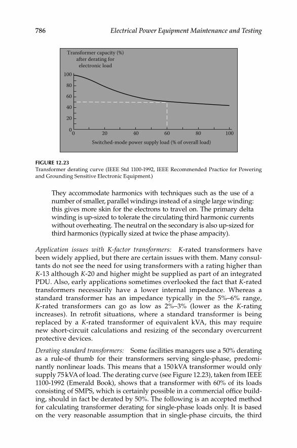
786 Electrical Power Equipment Maintenance and Testing
They accommodate harmonics with techniques such as the use of a number of smaller, parallel windings instead of a single large winding: this gives more skin for the electrons to travel on. The primary delta winding is up-sized to tolerate the circulating third harmonic currents without overheating. The neutral on the secondary is also up-sized for third harmonics (typically sized at twice the phase ampacity).
Application issues with K-factor transformers: K-rated transformers have been widely applied, but there are certain issues with them. Many consul-tants do not see the need for using transformers with a rating higher than K-13 although K-20 and higher might be supplied as part of an integrated PDU. Also, early applications sometimes overlooked the fact that K-rated transformers necessarily have a lower internal impedance. Whereas a standard transformer has an impedance typically in the 5%–6% range, K-rated transformers can go as low as 2%–3% (lower as the K-rating increases). In retrofi t situations, where a standard transformer is being replaced by a K-rated transformer of equivalent kVA, this may require new short-circuit calculations and resizing of the secondary overcurrent protective devices.
Derating standard transformers: Some facilities managers use a 50% derating as a rule-of thumb for their transformers serving single-phase, predomi-nantly nonlinear loads. This means that a 150 kVA transformer would only supply 75 kVA of load. The derating curve (see Figure 12.23), taken from IEEE 1100-1992 (Emerald Book), shows that a transformer with 60% of its loads consisting of SMPS, which is certainly possible in a commercial offi ce build-ing, should in fact be derated by 50%. The following is an accepted method for calculating transformer derating for single-phase loads only. It is based on the very reasonable assumption that in single-phase circuits, the third
00
20
40
60
80
100
Transformer capacity (%)after derating forelectronic load
20 40 60Switched-mode power supply load (% of overall load)
80 100
FIGURE 12.23Transformer derating curve (IEEE Std 1100-1992, IEEE Recommended Practice for Powering
and Grounding Sensitive Electronic Equipment.)
DK4058_C012.indd 786DK4058_C012.indd 786 11/8/2008 1:05:36 PM11/8/2008 1:05:36 PM

Power Quality, Harmonics, and Predictive Maintenance 787
harmonic will predominate and cause the distorted current waveform to look predictably peaked. Use a true-rms meter to make these current measurements:
1. Measure rms and peak current of each secondary phase. (Peak refers to the instantaneous peak, not to the inrush or peak load rms current).
2. Find the arithmetic average of the three rms readings and the three peak currents and use this average in step 3 (if the load is essentially balanced, this step is not necessary).
3. Calculate xformer harmonic derating factor:
xHDF = (1.414 * Irms)/Ipeak
4. Or, since the ratio of peak/rms is defi ned as CF, this equation can be rewritten as:
xHDF = 1.414/CF
If the test instrument has the capability, measure the CF of each phase directly. If the load is unbalanced, fi nd the average of the three phases and use the average in the above formula. Since a sine wave current waveform has a CF = 1.414, it will have an xHDF = 1; there will be no derating. The more the third harmonic, the higher the peak, the higher the CF. If the CF were 2.0, then the xHDF = 1.414/2 = 0.71. A CF = 3 gives us an xHDF = 0.47. A wave with CF = 3 is about as badly distorted a current waveform as you can expect to see on a single-phase distribution transformer.
Caution: This method does not apply to transformers feeding three-phase loads, where harmonics other than the third tend to predominate and CF is not useful as a simple predictor of the amount of distortion. A calculation for three-phase loads is available in ANSI/IEEE C57.110. However, there is some controversy about this calculation since it may underestimate the mechanical resonant vibrations that harmonics can cause, and that accelerate transformer wear above and beyond the effects of heat alone.
12.6.3.6 Electrical Noise
Electrical noise is the result of more or less random electrical signals get-ting coupled into circuits where they are unwanted, i.e., where they disrupt information-carrying signals. Noise occurs on both power and signal circuits, but generally speaking, it becomes a problem when it gets on signal circuits. Signal and data circuits are particularly vulnerable to noise because they operate at fast speeds and with low voltage levels. The lower the signal voltage, the less the amplitude of the noise voltage that can be tolerated.
The signal-to-noise ratio describes how much noise a circuit can tolerate before the valid information, the signal, becomes corrupted. Noise is one of the more mysterious subjects in PQ, especially since it must be considered
DK4058_C012.indd 787DK4058_C012.indd 787 11/8/2008 1:05:36 PM11/8/2008 1:05:36 PM
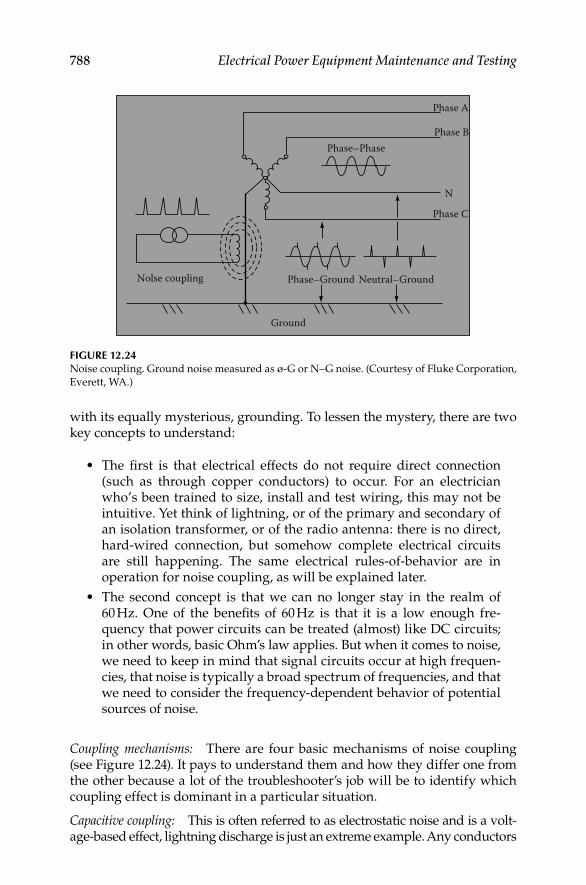
788 Electrical Power Equipment Maintenance and Testing
with its equally mysterious, grounding. To lessen the mystery, there are two key concepts to understand:
The fi rst is that electrical effects do not require direct connection • (such as through copper conductors) to occur. For an electrician who’s been trained to size, install and test wiring, this may not be intuitive. Yet think of lightning, or of the primary and secondary of an isolation transformer, or of the radio antenna: there is no direct, hard-wired connection, but somehow complete electrical circuits are still happening. The same electrical rules-of-behavior are in operation for noise coupling, as will be explained later.
The second concept is that we can no longer stay in the realm of • 60 Hz. One of the benefi ts of 60 Hz is that it is a low enough fre-quency that power circuits can be treated (almost) like DC circuits; in other words, basic Ohm’s law applies. But when it comes to noise, we need to keep in mind that signal circuits occur at high frequen-cies, that noise is typically a broad spectrum of frequencies, and that we need to consider the frequency-dependent behavior of potential sources of noise.
Coupling mechanisms: There are four basic mechanisms of noise coupling (see Figure 12.24). It pays to understand them and how they differ one from the other because a lot of the troubleshooter’s job will be to identify which coupling effect is dominant in a particular situation.
Capacitive coupling: This is often referred to as electrostatic noise and is a volt-age-based effect, lightning discharge is just an extreme example. Any conductors
FIGURE 12.24Noise coupling. Ground noise measured as ø-G or N–G noise. (Courtesy of Fluke Corporation,
Everett, WA.)
Nolse coupling
Ground
Phase–Ground Neutral–Ground
Phase C
N
Phase B
Phase A
Phase–Phase
DK4058_C012.indd 788DK4058_C012.indd 788 11/8/2008 1:05:36 PM11/8/2008 1:05:36 PM

Power Quality, Harmonics, and Predictive Maintenance 789
separated by an insulating material (including air) constitute a capacitor—in other words, capacitance is an inseparable part of any circuit. The potential for capacitive coupling increases as frequency increases (capacitive reactance, which can be thought of as the resistance to capacitive coupling, decreases with frequency).
Inductive coupling: This is magnetic-coupled noise and is a current-based effect. Every conductor with current fl owing through it has an associated magnetic fi eld. A changing current can induce current in another circuit, even if that circuit is a single loop; in other words, the source circuit acts as a transformer primary with the victim circuit being the secondary. The inductive coupling effect increases with the following factors: (1) larger cur-rent fl ow, (2) faster rate of change of current, (3) proximity of the two con-ductors (primary and secondary), and (4) the more the adjacent conductor resembles a coil (round diameter as opposed to fl at, or coiled as opposed to straight). Here are some examples of how inductive coupling can cause noise in power circuits:
Noise in power circuits: A transient surge, especially if it occurs on a high-energy circuit, causes a very fast change in current which can couple into an adjacent conductor. Lightning surges are a worst case, but common switch-ing transients or arcing can do the same thing.
If feeder cables are positioned such that there is a net magnetic fi eld, • then currents can be induced into ground cables that share the raceway.
It is well-known that signal wires and power conductors should not • be laid parallel to each other in the same raceway, which would max-imize their inductive coupling, but instead be separated and crossed at right angles when necessary. Input and output cables should also be isolated from each other in the same manner. Magnetic fi elds are isolated by effective shielding. The material used must be capable of conducting magnetic fi elds (ferrous material as opposed to copper). The reason that a dedicated circuit (hot, neutral, and ground) should be run in its own metal conduit when possible is that is in effect magnetically shielded to minimize inductive coupling effects. Both inductive and capacitive coupling are referred to as near fi eld effects, since they dominate at short distances and distance decreases their coupling effects. This helps explain one of the mysteries of noise—how slight physical repositioning of wiring can have such major effects on coupled noise.
Conducted noise: While all coupled noise ends up as conducted noise, this term is generally used to refer to noise that is coupled by a direct, galvanic (metallic) connection. Included in this category are circuits that have shared conductors (such as shared neutrals or grounds). Conducted noise could be high frequency, but may also be 60 Hz. These are some common examples of connections that put objectionable noise currents directly onto the ground:
DK4058_C012.indd 789DK4058_C012.indd 789 11/8/2008 1:05:37 PM11/8/2008 1:05:37 PM

790 Electrical Power Equipment Maintenance and Testing
Subpanels with extra N–G bonds.•
Receptacles miswired with N and G switched.•
Equipment with internal solid-state protective devices that have • shorted from line or neutral to ground, or that have not failed but have normal leakage current. This leakage current is limited by UL to 3.5 mA for plug-connected equipment, but there is no limit for permanently wired equipment with potentially much higher leak-age currents. (Leakage currents are easy to identify because they will disappear when the device is turned off).
Another common example is the so-called IG rod. When it is at a dif-• ferent earth potential than the source grounding electrode, a ground loop current occurs. This is still conducted noise, even though the direct connection is through the earth.
Datacom connections that provide a metallic path from one terminal • to another can also conduct noise. In the case of single-ended, unbal-anced connections (RS-232), the connection to terminal ground is made at each end of the cable. This offers a path for ground currents if the equipment at each end is referenced to a different power source with a different ground.
RFI: RFI ranges from 10 kHz to the 10s of MHz (and higher). At these frequencies, lengths of wire start acting like transmitting and receiving antennas. The culprit circuit acts as a transmitter and the victim circuit is acting as a receiving antenna. RFI, like the other coupling mechanisms, is a fact of life, but it can be controlled (not without some thought and effort, however).
RFI noise reduction employs a number of strategies:
Fiber optic cable, of course, is immune to electrical noise.•
Shielded cabling (such as coax cables) attempts to break the coupling • between the noise and signal.
Balanced circuits (such as twisted pair) do not break the coupling, • but instead take advantage of the fact that the RFI will be coupled into both conductors (signal and return). This noise (called CM noise) is then subtracted, while the signal is retained. In effect, the balanced circuit creates a high impedance for the coupled noise.
Another example of the high-impedance-to-noise approach is the • use of RF chokes. Whether used with data or power cables, RF chokes can offer effective high-frequency impedance (XL increases with frequency).
A low-impedance path can be used to shunt away the noise. This • is the principle behind fi ltering and the use of decoupling caps (low impedance to high frequency, but open at power line frequen-cies). But a sometimes over looked, yet critical, aspect is that the
DK4058_C012.indd 790DK4058_C012.indd 790 11/8/2008 1:05:37 PM11/8/2008 1:05:37 PM

Power Quality, Harmonics, and Predictive Maintenance 791
ground path and plane must be capable of handling high-fre-quency currents. High-frequency grounding techniques are used to accomplish this. The SRG, fi rst developed for raised fl oor com-puter room installations, is an effective solution. It is essentially an equipotential ground plane at high frequency.
Signal grounding: To understand the importance of clean signal grounds, let us discuss the distinction between DM versus CM signals. Imagine a basic two-wire circuit: supply and return. Any current that circulates or any volt-age read across a load between the two wires is called DM (the terms normal mode, transverse mode, and signal mode are also used). The DM signal is typically the desired signal (just like 120 V at a receptacle). Imagine a third conductor, typically a grounding conductor. Any current that fl ows now through the two original conductors and returns on this third conductor is common to both of the original conductors. The CM current is the noise that the genuine signal has to overcome. CM is all that extra traffi c on the high-way. It could have gotten there through any of the coupling mechanisms, such as magnetic fi eld coupling at power line frequency or RFI at higher fre-quencies. The point is to control or minimize these ground or CM currents, to make life easier for the DM currents.
Measurement: CM currents can be measured with current clamps using the zero-sequence technique. The clamp circles the signal pair (or, in a three-phase circuit, all three-phase conductors and the neutral, if any). If signal and return current are equal, their equal and opposite magnetic fi elds cancel. Any current read must be CM; in other words, any current read is current that is not returning on the signal wires, but via a ground path. This tech-nique applies to signal as well as power conductors. For fundamental cur-rents, a clamp meter or digital multimeter (DMM) + clamp would suffi ce, but for higher frequencies, a high bandwidth instrument like the Fluke 43 PQ analyzer or scope meter should be used with a clamp accessory.
12.6.3.7 Transients
Transients should be distinguished from surges. Surges are a special case of high-energy transient which result from lightning strikes (see Section 12.6.3.8). Voltage transients are lower energy events, typically caused by equipment switching. They are harmful in a number of ways:
They deteriorate solid-state components. Sometimes a single high-• energy transient will puncture a solid-state junction, sometimes repetitive low-energy transients will accomplish the same thing. For example, transients which exceed the PIV rating of diodes are a common cause of diode failure.
Their high-frequency component (fast rise times) cause them to be • capacitively coupled into adjoining conductors. If those conductors
DK4058_C012.indd 791DK4058_C012.indd 791 11/8/2008 1:05:37 PM11/8/2008 1:05:37 PM

792 Electrical Power Equipment Maintenance and Testing
are carrying digital logic, that logic will get trashed. Transients also couple across transformer windings unless special shielding is pro-vided. Fortunately this same high-frequency component causes transients to be relatively localized, since they are damped (attenu-ated) by the impedance of the conductors (inductive reactance increases with frequency).
Utility capacitor switching transients are an example of a com-• monly occurring high-energy transient (still by no means in the class of lightning) that can affect loads at all levels of the distribu-tion system. They are a well known cause of nuisance tripping of VFDs (ASDs): they have enough energy to drive a transient cur-rent into the DC link of the drive and cause an overvoltage trip. Transients can be categorized by waveform. The fi rst category is impulsive transients, commonly called spikes, because a high-frequency spike protrudes from the waveform. The cap switching transient, on the other hand, is an oscillatory transient because a ringing waveform rides on and distorts the normal waveform. It is lower frequency, but higher energy.
Causes: Transients are unavoidable. They are created by the fast switching of relatively high currents. For example, an inductive load like a motor will create a kickback spike when it is turned off. In fact, removing a Wiggy (a solenoid voltage tester) from a high-energy circuit can create a spike of thousands of volts. A capacitor, on the other hand, creates a momentary short circuit when it is turned on. After this sudden collapse of the applied voltage, the voltage rebounds and an oscillating wave occurs. Not all transients are the same, but as a general statement, load switching causes transients. In offi ces, the laser copier/printer is a well-recognized “bad guy” on the offi ce branch circuit. It requires an internal heater to kick in whenever it is used and every 30 s or so when it is not used. This constant switching has two effects: the current surge or inrush can cause repetitive voltage sags; the rapid changes in current also generate transients that can affect other loads on the same branch.
Measurement and recording: Transients can be captured by digital storage oscilloscopes (DSOs). The Fluke 43 PQ analyzer, which includes DSO func-tions, has the ability to capture, store and subsequently display up to 40 tran-sient waveforms. Events are tagged with time and date stamps (real-time stamps). Another voltage event recorder, such as Fluke’s VR101S will also capture transients at the receptacle.
Peak voltage and real-time stamps are provided.
TVS suppressors (TVSS): Fortunately, transient protection is not expensive. Virtually all electronic equipment has (or should have) some level of protec-tion built in. One commonly used protective component is the MOV which clips the excess voltage. TVSS are applied to provide additional transient pro-tection. TVSS are low voltage (600 V) devices and are tested and certifi ed to UL
DK4058_C012.indd 792DK4058_C012.indd 792 11/8/2008 1:05:37 PM11/8/2008 1:05:37 PM

Power Quality, Harmonics, and Predictive Maintenance 793
1449. UL 1449 rates TVSS devices by grade, class, and mode. As an example, the highest rating for a TVSS would be grade A (6000 V, 3000 A), class 1 (let-through voltage of 330 V max), and mode 1 (L–N suppression). The proper rating should be chosen based on the load’s protection needs:
A lower grade might result in a TVSS that lasts 1 year instead of • 10 years. The solid-state components in a TVSS will themselves dete-riorate as they keep on taking hits from transients.
A lower class might permit too much let-through voltage that could • damage the load. Class 1 is recommended for SMPS.
A mode 2 device would pass transients to ground, where they could • disrupt electronic circuit operation.
Voltage susceptibility profi le: The new Information Technology Industry Council (ITIC) profi le (Figure 12.25) is based on extensive research and updates of the Computer Business Equipment Manufacturers Association
Voltage toleranceenvelope
Applicable to 120, 120/208, and120/240 nominal voltage
110 V90 V
1000 c100 c10 c0.5 c 1 c0.1 c0.01 c0.001 c1μs
0
40
708090
100110120140
200
300
400
Perc
ent o
f nom
inal
vol
tage
(rm
s or p
eak
equi
vale
nt)
500
1 ms 3 ms 20 ms 0.5 s SteadystateDuration of disturbance in cycles (c) and seconds (s)
10 s
FIGURE 12.25ITIC susceptibility profi le (curve) for sensitive equipment (electronic equipment). (Courtesy of
Fluke Corporation, Everett, WA.)
DK4058_C012.indd 793DK4058_C012.indd 793 11/8/2008 1:05:37 PM11/8/2008 1:05:37 PM

794 Electrical Power Equipment Maintenance and Testing
(CBEMA) curve. The CBEMA curve now the ITIC curve was the original voltage susceptibility profi le for manufacturers of computers and other sensitive equipment. Similar curves are being developed for 230 V/50 Hz equipment and for ASDs. Sensitive equipment should be able to survive events inside the curve. Events outside of the curve could require addi-tional power conditioning equipment or other remedial action. A major change in ITIC is that the ride-through times for outages as well as the toler-ance for sags have both been increased. The fi eld troubleshooter must keep in mind that the profi les are recommendations and that a particular piece of equipment may or may not match the profi le. The profi les are useful because, when recorded events are plotted against them, they give a general idea of the voltage quality at a particular site.
12.6.3.8 Lightning
Lightning protection plays a vital part in the overall PQ of an installation. Lightning occurrence varies by geography, with Florida being the lightning capital of the United States. Lightning does not have to score a direct hit to be disruptive. It has so much energy that it couples surges into conductors, both those exposed to air and those buried in the ground. Basic lightning protection has two main requirements:
Effective grounding: A low impedance of the grounding electrode system to earth is important. But, equally important is that all parts of the grounding system be bonded together: all ground electrodes are bonded (and extraneous ground rods removed), structural steel is tied to service entrance ground, all grounding connections are tight and free of corrosion, etc. This minimizes the phenomenon called transferred earth potential, where large surge currents create large voltage differences between two ground points with different impedances to earth. This same grounding practice is important for performance reasons, as it tends to minimize ground loop currents that circulate in an attempt to equalize ground potentials.
Surge arrestors: A surge arrestor “is a protective device for limiting surge voltages by discharging or bypassing surge current…,” per NEC Article 280. Since the surge current is bypassed to ground, surge arrestors are only as effective as the grounding system. Surge arrestors are sized for the loca-tion where they are installed. Three categories are defi ned (ANSI/IEEE C62.41-2002).
A surge arrestor at an outside installation is closest to the lightning event and must absorb most of the energy. This is considered a Category C location (corresponding to CAT IV in IEC 61010). Category B refers to feeders and distribution panels (equivalent to CAT III in IEC 61010), and Category A refers to receptacle connected surge arrestors (equivalent to CAT II).
Surge arrestor or TVSS: A surge arrestor is there to protect the insulation and, ultimately, prevent failures that could lead to fi res. It is not necessarily designed
DK4058_C012.indd 794DK4058_C012.indd 794 11/8/2008 1:05:37 PM11/8/2008 1:05:37 PM

Power Quality, Harmonics, and Predictive Maintenance 795
to protect sensitive equipment. That’s the job of the TVSS. Refer to an inspec-tion guide on Inspection of Lightning Protection System which is given in Table 12.16.
12.6.3.9 Polyphase Induction Motors
About two-thirds of the electric power in the United States is consumed by motors, with industrial three-phase motors above 5 hp (7 kW) being by far the bulk of that load. They are linear loads and therefore do not contribute to harmonics. They are, however, the major contributor to reduced DPF, which is a measurement of the effective use of system capacity.
TABLE 12.16
Inspection of Lightning Protection System
Check Look for Reason
Surge arrestors Installed at main service
panel, subpanels, and
critical equipment
Lightning is high energy and
needs multilevel protection
To minimize high
frequency impedance,
leads should be short,
with no bends
Lightning has high frequency
components. Shorter leads
have less XL and less
impedance at high frequency
Grounding electrode
conductors at service
entrance or at SDS
Grounding electrode
connections are not
loose or corroded
Ensure low impedance
ground to minimize
potential to ground with
lightning induced surges
Grounding conductor
should not be coiled or
have unnecessary bends
Minimize impedance to
high-frequency components
of lightning
Grounding electrode
bonding
All grounding electrodes
should be effectively
bonded together (<0.1 W)
Prevent difference in earth
potential between electrodes
in event of lightning
Separately driven (isolated)
electrode
Electrode and equipment
ground should both be
tied to building steel, and
thereby to the service
entrance ground
Same as above—entire
grounding system should be
an equipotential ground
plane for lightning
Datacom cabling that runs
between buildings
Surge arrestors on
datacom cabling or
use of fi ber optic cables
Datacom cabling run between
buildings can be a path for
surge currents, due to
differences between
building earth potentials
Source: Courtesy of Fluke Corporation, Everett, WA.
Note: Lightning protection is covered in a number of standards and codes, including:
NEC: Articles 250 and 280
National Fire Protection Association: NFPA 780
Lightning Protection Institute: LPI-175
UL-96 and UL-96 A
DK4058_C012.indd 795DK4058_C012.indd 795 11/8/2008 1:05:37 PM11/8/2008 1:05:37 PM

796 Electrical Power Equipment Maintenance and Testing
Measurements
Voltage unbalance: Voltage unbalance should not exceed 1%–2% (unless the motor is lightly loaded). The reason for such a small tolerance for voltage unbalance is because it has a very large effect on current unbalance, in the neighborhood of 8:1. In other words, a voltage unbalance of 1% can cause current unbalance of 8%. Current unbalance will cause the motor to draw more current than it otherwise would. Also, the unbalance voltage being delivered to motor terminals will cause the fl ow of negative sequence cur-rents. Negative sequence currents produce opposing torque which the motor has to overcome therefore it will draw more current, thereby overheating the motor. For example a 3% voltage unbalance raises the motor winding temperature by 25% (refer to Section 10.10 in Chapter 10). The net effect of voltage unbalance is more heat and heat is the enemy of motor life, since it deteriorates the winding insulation.
Voltage unbalance can be caused by severe load unbalance but it could just as easily be caused by loose connections and worn contacts. Example of volt-age unbalance calculation can be made as follows:
Example
×Max deviation from average
% = 100unbalance Average(of three phases)V
× = <
3100 0.64% 1%
472
Voltage %THD and harmonic spectrum: Voltage THD should not exceed 5% on any phase. If the voltage distortion on any phase is excessive, it can cause current unbalance. The usual culprit is the fi fth harmonic and therefore the harmonic spectrum should be examined for the fi fth in particular. The fi fth is a negative sequence harmonic which creates counter-torque in the motor. A motor fed by a voltage with high fi fth harmonic content will tend to draw more current than otherwise. This is a major problem when across-the-line or soft-start motors share the same bus with VFDs.
Current unbalance: To fi nd current unbalance, measure amps in all three phases. Do the same calculation as for voltage unbalance. In general, current unbalance should not exceed 10%. However, unbalance can usually be toler-ated if the high leg reading does not exceed the nameplate full load amps (FLA) and service factor (SF). The FLA and SF are available on the motor nameplate. If the voltage unbalance and the voltage THD are within limits, high current unbalance can be an indication of motor problems, such as damaged winding insulation or uneven air gaps. Current measurement will also fi nd single-phasing. If a three-phase motor loses a phase (perhaps caused by a blown fuse or loose connection), it may still try to run single-phase off the remaining two phases. Since the motor acts like a constant
DK4058_C012.indd 796DK4058_C012.indd 796 11/8/2008 1:05:37 PM11/8/2008 1:05:37 PM
Power Quality, Harmonics, and Predictive Maintenance 797
power device, it will simply draw additional current in an attempt to pro-vide suffi cient torque. A voltage measurement alone will not necessarily fi nd this condition, since voltage is induced by the two powered windings into the nonpowered winding.
Loading: Measure current draw of the motor. If the motor is at or near its FLA rating (times the SF multiplier), it will be more sensitive to the addi-tional heating from harmonics, as well as current unbalance. A motor that is only lightly loaded is usually safe from overheating. On the other hand, its effi ciency and DPF are both less than optimal. Most motors reach maximum effi ciency at 60%–80% of full load rating. DPF is maximum at rated load (including SF) and drops off, especially at less than 80% of rated load. This leads to the conclusion that, to the degree a motor load is constant and pre-dictable, 80% of rated load is the most effi cient operating range.
Inrush (lock rotor current): Motors which are started across-the-line (as opposed to those using soft-starts or drives) draw a current inrush, also called locked rotor current. This inrush tapers off to normal running current as the motor comes up to speed.
Older motors draw an inrush of typically 500%–600% of the running • current. Newer energy effi cient designs draw brief inrushes as high as 1200% of running current, a direct result of the lower impedances which help make them more energy effi cient in the fi rst place.
High torque, high horse power motor loads require proportionally • higher inrush.
Motor loads started at the same time will have a cumulative inrush. • Another source of inrush is UPS and VFD systems with diode convert-ers. They draw inrush current as their capacitor banks fi rst charge.
Effects of inrush current:
1. Inrush causes voltage sags if the source voltage is not stiff enough. Therefore, relays and contactor coils might drop out (typically, the sag would have to get as bad as about 70% of normal line voltage); or, if they hold in, their contacts might chatter (especially if the additional load causes a long-term undervoltage). Control circuits might reset or lockup (at 90% and below). Drives might trip off-line (undervoltage trip).
2. High peak demand periods, which may cause higher utility bills.
3. Cycling loads can cause periodic sags, which might show up as fl ick-ering lights.
4. If the motor is required to start up a high torque load, the inrush can be relatively prolonged (e.g., 10 to 20 s or more) and this can cause nuisance tripping as the overload heaters trip the motor starter.
PF: If the PF of the motor is low, it can be improved by applying capacitors to supply the required reactive volt-amperes (kVAR). To size PF correction
DK4058_C012.indd 797DK4058_C012.indd 797 11/8/2008 1:05:38 PM11/8/2008 1:05:38 PM

798 Electrical Power Equipment Maintenance and Testing
capacitors, it is necessary to measure the DPF and active power consump-tion (kW) of the motor load. These measurements assume that the motor voltage and current are balanced. Therefore, before undertaking PF correc-tion, fi rst make sure that voltage and current unbalance are within limits. Either problem can shorten motor life and should take priority over DPF correction.
12.6.3.10 PQ Measurements of VFDs
AC VFDs can be both a source and a victim of poor PQ. VFDs are also referred to as ASDs. Although ASDs are usually depicted as the culprit in the PQ sce-nario, there are ways in which they can be a victim load as well. ASDs can be affected as follows.
Capacitor switching transients: High-energy (relatively low frequency) tran-sients that are characteristic of utility capacitor switching can pass through the service transformer, feeders, and converter front-end of the drive directly to the DC link bus, where it will often cause a DC link overvoltage trip. Input diodes could also be blown out by these transients.
Voltage distortion: If high-voltage distortion shows up as excessive fl at-topping, it will prevent DC link capacitors from charging fully and will diminish the ride-through capability of the drive. Thus a voltage sag which would not normally affect a drive will cause the drive to trip on undervoltage.
Grounding: Improper grounding will affect the internal control circuits of the drive, with unpredictable results.
ASDs as culprit loads: A drive can defi nitely be a culprit load and have a major impact on system PQ. But before discussing the problems, let us put in perspective the positive effects of drives on PQ. First of all, they offer built-in soft-start capabilities. This means there will be no inrush current and no voltage sag effect on the rest of the system. Second, if the drive is of the PWM type, with a diode converter front-end, the DPF is high (com-monly >95% at rated load) and more or less constant throughout the range. This means that drives can reduce energy usage and correct for DPF at the same time. It is a good thing too, because drives and PF correction capaci-tors do not mix. Capacitors are vulnerable to the higher frequency harmonic currents generated by drives, since their impedance decreases as frequency increases. The type of drive has a major impact on the PQ symptoms, because of the different converter designs (converters or rectifi ers turn AC to DC and are the fi rst stage of the drive). There are two major types of con-verter design.
1. SCR converter with VSI/variable voltage inverter (VVI) drivesCommonly called six-step drives, they use SCRs in their converter front-ends (the following discussion also applies to CSI drives, which also use SCRs). VSI (Figure 12.26) and CSI drive designs tended to be applied on larger drives
DK4058_C012.indd 798DK4058_C012.indd 798 11/8/2008 1:05:38 PM11/8/2008 1:05:38 PM

Power Quality, Harmonics, and Predictive Maintenance 799
(>100 hp). SCR converters control the DC link voltage by switching on (or gating) current fl ow for a portion of the applied sine wave and switching off at the zero-crossing points. Unlike diodes, SCRs require control circuits for gate fi ring.
For the SCR converter, there are three main issues that affect line-side PQ:
Commutation notches. SCR switching or commutation is such that • there are brief moments when two phases will both be “ON.” This causes what is in effect a momentary short circuit that tends to collapse the line voltage. This shows up as notches on the voltage waveform. These notches cause both high V-THD and transients. The solution is to place a reactor coil or isolation transformer in series with the drive’s front end to clean up both problems.
DPF declines as drive speed decreases. This is not as serious a prob-• lem as it sounds, because the power requirement of the drive-motor-load decreases even more.
Harmonic currents, typically the fi fth and seventh, are generated by • VSI drives.
2. Diode converter with PWM drivesThe other and more common converter design uses diodes and is used in the PWM drive (Figure 12.27). The diodes require no switching control circuitry. One of the main trends in the industry has been the proliferation of PWM drives, mainly due to the continued development of fast switching, effi cient insulated gate bipolar transistors (IGBTs) used in the inverter section of the drive (inverters turn DC to AC). For all practical purposes, PWM drives are the industry standard. For the diode converter, the main PQ issue is harmon-ics. The actual harmonic orders being generated depend on the number of
Linereactors
Inductionmotor
M
x x x
x x x
FIGURE 12.26Electrical circuit of a VSI drive. (Courtesy of Fluke Corporation, Everett, WA.)
DK4058_C012.indd 799DK4058_C012.indd 799 11/8/2008 1:05:38 PM11/8/2008 1:05:38 PM

800 Electrical Power Equipment Maintenance and Testing
diodes in the front end. For three-phase conversion, a minimum set of six diodes is required. This six-pulse converter will generate fi fth and seventh harmonics. If a 12-pulse converter were used, the 11th and 13th harmonics will be generated instead of the fi fth and sixth—and, very importantly, for the same load, the amplitude of the 11th and 13th would be considerably less than the 5th and 6th. Therefore, the THD would be less. The vast majority of drives, however, are six-pulse PWM style, which is one reason we see so much fi fth harmonic on the system.
Harmonics solutions: There are a number of solutions to mitigating drive-generated harmonics. They are the following:
1. Harmonic trap fi lters (Figure 12.28)These are typically LC networks connected in parallel at the source of the harmonics (in other words, at the drive input). They are tuned to just below the fi fth harmonic (typically 280 Hz) and will tend to sink both fi fth and much of the seventh harmonic. Obviously, they must be sized to the harmonic-generating load.
2. Phase-shift transformersThis can be as simple as a delta–wye transformer feeding one drive(s) and a delta–delta feeding another drive(s). There is a 30° phase-shift effect between these two confi gurations, which effectively results in cancellation of har-monics at the closest upstream PCC. The cancellation effect is optimal when both loads are more or less equal.
12.6.3.11 Power System Resonance
Is it possible to install PF correction capacitors and have PF get worse? It certainly is and a starting place to understanding this puzzle lies in the distinction between DPF and total PF. The penalty for not understanding the
M
PWM inverterDiode rectifier
AC source Induction motor
FIGURE 12.27Electrical circuit of the PWM drive. (Courtesy of Fluke Corporation, Everett, WA.)
DK4058_C012.indd 800DK4058_C012.indd 800 11/8/2008 1:05:38 PM11/8/2008 1:05:38 PM

Power Quality, Harmonics, and Predictive Maintenance 801
difference can be blown capacitors and wasted investment. Total PF and DPF are the same in one basic sense: they are the ratio of real power to apparent power, or watts to VA. DPF is the classic concept of PF. It can be considered as the PF at the fundamental frequency. Total PF now includes the effects of fundamental and of harmonic currents (it is also referred to as true PF or DPF) (see Figure 12.13). It follows that with the presence of harmonics, PF is always lower than DPF and is also a more accurate description of total system effi ciency than DPF alone. Strictly speaking, the term PF refers to total PF, but in practice can also be used to refer to DPF. Needless to say, this introduces some confusion into discussions of PF. You have to be clear which one you are talking about.
DPF: Lower DPF is caused by motor loads which introduce the need for reactive power (VARs). The system has to have the capacity, measured in VA to supply both VARs and watts. The more VARs needed, the larger the VA requirement and the smaller the DPF. The cost of VARs is accounted for in a PF penalty charge.
Utilities often levy additional charges for DPF below a certain level; the actual DPF number varies, but typical numbers are 0.85 to 0.9. To reduce VARs caused by motor loads, PF correction capacitors are installed. Upstream system capacity, both in the plant and at the utility level, is released and avail-able for other uses (Figure 12.29). Historically, this has been the gist of the PF story: a relatively well-known problem with a relatively straightforward solution.
Harmonics and capacitors: Harmonics have had a dramatic impact on the application of PF correction. The motor and capacitor loads described above are all linear and for all practical purposes generate no harmonics. Nonlinear
Line Load
FIGURE 12.28Harmonic trap fi lter. (Courtesy of Fluke Corporation, Everett, WA.)
DK4058_C012.indd 801DK4058_C012.indd 801 11/8/2008 1:05:38 PM11/8/2008 1:05:38 PM
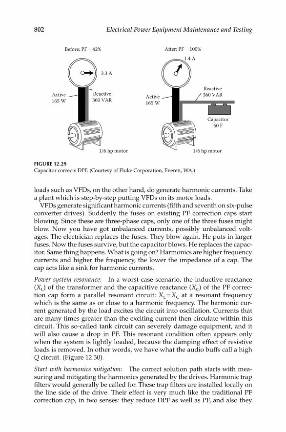
802 Electrical Power Equipment Maintenance and Testing
loads such as VFDs, on the other hand, do generate harmonic currents. Take a plant which is step-by-step putting VFDs on its motor loads.
VFDs generate signifi cant harmonic currents (fi fth and seventh on six-pulse converter drives). Suddenly the fuses on existing PF correction caps start blowing. Since these are three-phase caps, only one of the three fuses might blow. Now you have got unbalanced currents, possibly unbalanced volt-ages. The electrician replaces the fuses. They blow again. He puts in larger fuses. Now the fuses survive, but the capacitor blows. He replaces the capac-itor. Same thing happens. What is going on? Harmonics are higher frequency currents and higher the frequency, the lower the impedance of a cap. The cap acts like a sink for harmonic currents.
Power system resonance: In a worst-case scenario, the inductive reactance (XL) of the transformer and the capacitive reactance (XC) of the PF correc-tion cap form a parallel resonant circuit: XL = XC at a resonant frequency which is the same as or close to a harmonic frequency. The harmonic cur-rent generated by the load excites the circuit into oscillation. Currents that are many times greater than the exciting current then circulate within this circuit. This so-called tank circuit can severely damage equipment, and it will also cause a drop in PF. This resonant condition often appears only when the system is lightly loaded, because the damping effect of resistive loads is removed. In other words, we have what the audio buffs call a high Q circuit. (Figure 12.30).
Start with harmonics mitigation: The correct solution path starts with mea-suring and mitigating the harmonics generated by the drives. Harmonic trap fi lters would generally be called for. These trap fi lters are installed locally on the line side of the drive. Their effect is very much like the traditional PF correction cap, in two senses: they reduce DPF as well as PF, and also they
Before: PF = 42%
3.3 A
Active165 W
Reactive360 VAR
1/6 hp motor
After: PF = 100%
1.4 A
Active165 W
Reactive360 VAR
Capacitor60 F
1/6 hp motor
FIGURE 12.29Capacitor corrects DPF. (Courtesy of Fluke Corporation, Everett, WA.)
DK4058_C012.indd 802DK4058_C012.indd 802 11/8/2008 1:05:38 PM11/8/2008 1:05:38 PM

Power Quality, Harmonics, and Predictive Maintenance 803
localize the circulation of the problem harmonics (generally the fi fth). Harmonics mitigation and traditional DPF correction should be addressed as one systems issue. In other words, manage total PF, not just DPF.
12.6.3.12 Commercial Lighting Load
Lighting loads are a major load for many large facilities. Evaluating these circuits is important for both energy conservation and PQ (see Table 12.17). Keep in mind that commercial lighting loads are wired single phase, with the loads connected from phase-to-neutral. Typically, the phase-to-phase voltage is 480 V, with the phase-to-neutral voltage at 277 V. Measurements must be taken at the lighting panel, one phase at a time, since power con-sumption and PF could vary on each phase. Consider the following factors from the PQ perspective.
System diagram Equivalent circuit
XS
XT
XS
XC
XT
XC
Harmonicsource
(a) (b)
FIGURE 12.30Resonant circuit when XC = (XT + XS). (Courtesy of Fluke Corporation, Everett, WA.)
TABLE 12.17
Measurements on Commercial Lighting Loads
Measurement Look for Instrument
1. Power consumption
(kW)
Balance among three phases Three-phase/
single-phase analyzer
2. DPF and PF Magnetic ballast will have low
DPF Electronic ballast may have
low total PF, although new
generations of ballast often have
harmonic mitigation built-in
Same
3. %THD Current %THD <20% is desirable Same
4. Voltage stability Unstable voltage can cause lights
to fl icker
Same
Source: Courtesy of Fluke Corporation, Everett, WA.
DK4058_C012.indd 803DK4058_C012.indd 803 11/8/2008 1:05:39 PM11/8/2008 1:05:39 PM

804 Electrical Power Equipment Maintenance and Testing
Power consumption: Excessive phase unbalance can cause voltage unbal-ance, which in turn can affect three-phase motor loads.
PF: Ballast with low PF might have lower cost-of-purchase but higher cost-of-operation.
THD: Current THD should be considered when selecting ballast, especially if there is a possibility of transformer overloading.
Voltage stability: The sags and swells mode of the Fluke 43 (or similar instru-ment) is especially useful for recording repetitive voltage sags which can show up as fl ickering lights. Both current and voltage are monitored simul-taneously (Figure 12.31). This helps us to tell if sags are downstream of the measuring point (load related) or upstream (source related). For example, if voltage sags while current swells, a downstream current inrush likely caused the sag. If both voltage and current sag at the same time then some event upstream has caused the sags. It could be an upstream load like a motor on a parallel branch circuit which drew down the feeder voltage. Or it could be source voltage related, for example, a lightning strike or breaker trip/reclo-sure on the utility distribution system.
12.6.3.13 Summary of PQ Problems
The following summary is provided of the PQ problems discussed in this section beginning from utility source all the way down to 120 receptacles. These PQ problems are:
175.0 MAX Apr 03 1998 15:49:35HOLDSAGS and SWELLS
1700
140 V
26.60 MAX
23.80 MIN
35.0 A
20.0 A10 m2 m
24.40 A~–
156.5 MIN171.7 V~–
FIGURE 12.31Fluke 43 trends voltage (top) and current (bottom) simultaneously. Current swells/inrush caused
voltage sags, indicating that a load downstream from the measurement point is the cause of the
disturbance. (Courtesy of Fluke Corporation, Everett, WA.)
DK4058_C012.indd 804DK4058_C012.indd 804 11/8/2008 1:05:39 PM11/8/2008 1:05:39 PM
Power Quality, Harmonics, and Predictive Maintenance 805
Lightning: Can be extremely destructive if proper surge protection is not installed. It also causes sags and undervoltages on the utility line if far away. If close by, it causes swells and overvoltages. But in the fi nal analy-sis, lightning is an act of nature and not in the same category as the damage man does to himself.
Utility automatic breaker reclosure: Causes short duration sags/outages, but better than the alternative, a longer-term outage.
Utility capacitor switching: Causes a high-energy voltage disturbance (looks like an oscillating transient riding on the wave). If the cap bank is near the facility, this transient can propagate all through the building.
Facility without enough distribution transformers: Trying to cut corners in the wrong places; running 208 V feeder up 20 stories is not the road to PQ.
Gen-sets not sized for harmonic loads: Excessive voltage distortion affects elec-tronic control circuits. If SCR converter loads are present, notching can affect frequency control circuits.
PF correction capacitors and the effects of harmonics: Harmonics and caps do not mix. Those bulging capacitors are crying for help.
Inrush currents from high torque motor: Causes voltage sags if the load is too large or the source impedance too great. Staggered motor starts can help.
Undersized neutrals at panelboard: In the era of the third harmonic currents, neutrals can easily carry as much current or more current than the phase conductors. Keeping undersized neutral leads to overheated neutral and lugs, potential fi re hazards, and high N–G voltage.
Running power and signal cables together: Think of the signal cable as a single-wire transformer secondary and the power cable as the primary. The opportunities for coupling are endless.
Loose conduit connections and lack of green wire grounding conductor: Causes open or high impedance ground circuit. Not good for PQ or safety.
Hi-frequency noise: The most effective high frequency grounding technique is the installation of a SRG.
IG rods (Figure 12.32): They are a safety hazard because the earth is a high impedance path and will prevent enough current from fl owing to trip the breaker. They also cause ground loops; after all, every electron still has to go back where it came from. Further, if a person comes in contact with the ground where the step potential is high because of the high impedance path of the earth, the person will get shocked, injured or killed. One of the great mysteries of PQ is how some manufacturers get away with insist-ing that their equipment warranty is void unless an IG rod is installed. This installation is in violation of the NEC requirements for single point grounding.
DK4058_C012.indd 805DK4058_C012.indd 805 11/8/2008 1:05:39 PM11/8/2008 1:05:39 PM

806 Electrical Power Equipment Maintenance and Testing
Shared neutrals on branch circuits: Causes load interaction and overloaded neutrals.
Laser printers and copiers sharing branch circuits with sensitive loads: Guaran-teed periodic voltage sags and switching transients.
Miswired receptacles (N–G swapped): Hard to believe, but they are very common in most facilities. Guaranteed to put return currents on the ground conductor and create a noisy ground.
Data cables connected to different ground references at each end: Shows up as voltage between equipment case and the data cable connector.
Illegal N–G bonds: Guaranteed to put return currents on ground. Not only is it a PQ problem, it is a plumbing problem. Circulating ground currents cause corrosion of water pipes.
12.7 PQ Solution and Power Treatment Devices
In Sections 12.1 through 12.5, we discussed concepts, origins, characteristics and effects of voltage disturbances, and HDs on power system equipment. In Section 12.6 a predictive maintenance and troubleshooting guide was pre-sented to identify and quantify the PQ-related problems. Once the PQ prob-lem is identifi ed and its effects on power equipment are understood, the next obvious step is to fi nd a solution to correct the offending problem? There is no one answer that fi ts all PQ-related solutions. Each type of PQ problem
Load current
Neutral returncurrent error
Separatelyderivedsystem Line
NeutralN–Gbond
Ground
LineNeutral
Ground
Isolated ground,ground rod, cold water pipe, etc.
Earth ground
Panel
FIGURE 12.32IG rod can cause ground loops. Common problem with machine tool installations. (Courtesy
of Fluke Corporation, Everett, WA.)
DK4058_C012.indd 806DK4058_C012.indd 806 11/8/2008 1:05:39 PM11/8/2008 1:05:39 PM
Power Quality, Harmonics, and Predictive Maintenance 807
requires its very own solution or treatment. There are many power treatment devices that refl ect different philosophies advocated by varying PQ profes-sionals. To the user the wide variety of what is available on the market for resolving PQ problems can be confusing and frustrating. However, there are some basic considerations in selecting and applying PQ solutions that all agree upon. First, is there a single problem or multiple problems, and is the nature of the problem(s) understood so an informed solution can be imple-mented; second any solution or treatment device installed has to obey the laws of physics and must be implemented without adversely affecting the loads; third the installation of the treatment device must be done correctly because if improperly installed, it may be detrimental to the system opera-tion as was the original problem; and last the treatment device must be com-patible with the load otherwise it may interact with the load causing a condition that is actually worse than before. The solutions and power treat-ment devices for solving PQ problems can be classifi ed into three problem categories:
1. Voltage disturbances and noise
2. HDs
3. Wiring and grounding
Treatment devices are applied to modify a given electrical power to improve its quality and reliability for correct functioning of its loads. They can perform a range of functions such as voltage regulation, noise elimination, and standby power supply (SPS), among others. Many different types of mitigating devices are available, but specifi cation and selection of mitigat-ing equipment is dependent upon two considerations. First, the type of load to be powered must be considered. Single loads are effectively regulated with the proper mitigating device. However, larger systems that support many loads are far more complex. Requirements of all loads require consid-eration, as well as the potential interaction between them to determine the proper mitigating devices required. Second, the equipment requirements for each application must be considered. Examples of such requirements include PQ requirements of the load, problems (improper wiring and grounding, temperature, humidity, ESD, etc.) which could interfere with proper operation of the critical load, type of conditioning required, future quality and reliability of the power supply, and cost to eliminate or mitigate power-related problems. The most commonly used mitigating devices and their characteristics for the three categories identifi ed above are discussed as follows:
12.7.1 Voltage Disturbances and Noise
The voltage disturbance, such as impulses, transients, swells, voltage dips, and interruptions were discussed in Section 12.2. The treatment devices for mitigating voltage disturbances and noise may be grouped as follows:
DK4058_C012.indd 807DK4058_C012.indd 807 11/8/2008 1:05:40 PM11/8/2008 1:05:40 PM

808 Electrical Power Equipment Maintenance and Testing
Line (noise) fi lters•
TVSS•
Voltage regulators•
Isolation transformers•
Power conditioners•
UPS•
12.7.1.1 Noise Filters (Electronic Filters)
Noise fi lters prevent interference (e.g., conducted EMI and/or RFI) from trav-eling into sensitive electronic equipment from the power source. These fi lters also prevent equipment that generates interference from feeding it back into the power line. Most sensitive electronic equipment utilize some type of noise fi lter. A basic noise fi lter is low pass LC fi lter, that is it passes line fre-quency (60 Hz) and blocks the very high frequencies or steep wave front transients (Figure 12.33). This is accomplished by series inductors followed by capacitors to ground. The inductor forms two impedance paths: one low for the 60 Hz power and one high for the high-frequency noise. The remaining high-frequency noise is conducted by the capacitor to ground before it reaches the load. Many line fi lters are based on surge suppression components, such as surge suppressors but also have components that pro-vide frequency response and waveform tracking. Waveform tracking allows the fi lter to clamp impulses at lower voltages than TVSS. The line fi lters exert more control over normal mode events compared to CM event because of absence of ground isolation capabilities. The line fi lters are listed under UL 1012, Standard for Safety of Power Supplies.
12.7.1.2 TVSS
TVSS protect against voltage spikes and oscillatory-transient voltages. They are either gap type or the clamping type. The gap type is relatively slow acting (microseconds) with large energy handling ability. The clamping type
Line L L
c
Load
FIGURE 12.33Basic noise fi lter without surge suppressors and tracking fi lters. (Courtesy of Fluke Corporation,
Everett, WA.)
DK4058_C012.indd 808DK4058_C012.indd 808 11/8/2008 1:05:40 PM11/8/2008 1:05:40 PM

Power Quality, Harmonics, and Predictive Maintenance 809
is fast acting (nanoseconds) with somewhat smaller energy-handling ability. The gap type units are best used near the power source entrance where as clamping type units are used near the equipment being protected.
The four basic types of equipment used for protection from transients are crowbar devices, voltage-clamping devices, attenuation (fi ltering) devices, and hybrid devices. The crowbar devices include air gaps, gas discharge tubes, lightning arrestors, and switching devices. The voltage-clamping devices consist of varistors (nonlinear resistors), MOVs, zener diodes, and selenium rectifi ers. These devices are unidirectional conductors until a breakdown voltage is reached, at which time they conduct in the reverse direction. Attenuation devices are inserted in a circuit to permit power at line frequency to pass, while attenuating transients. They are referred to as noise fi lters or low-pass fi lters. The attenuating devices are not truly sup-pression devices, but have applications when noise or transients at particu-lar frequencies are found on a specifi c power or data line. Hybrid devices are transient suppressors that combine two or more technologies to provide transient suppression over a wide range of voltages, rates of rise, and energy content. Protecting computers and sensitive electronic equipment against transients is a good installation practice. Careful grounding is necessary for these devices to be effective. Power to computers also should be separated electrically as much as possible from the remainder of building power system. Incoming power lines, data and communications lines entering from outside the building, and those inside the building subjected to transients should have transient protection. Separate protection for individual units may be needed (unless already built into the equipment) for computers and sensitive electronic equipment. In selecting the transient suppression devices, careful consideration should be given to the voltage rating of the devices. The devices selected should have a minimum voltage rating that is higher than the system or data line voltage or phase-to-phase or phase-to-ground voltage. Selecting the energy dissipation rating required is somewhat more diffi cult since it is rarely possible to predict the energy content of the tran-sient that might occur. The device selected must survive the worst possible transient and, at the same time, the clamping voltage must not exceed the withstand voltage rating of the equipment being protected. Transient devices should be installed using the shortest possible conductors, so that its inductive reactance is small at high transient frequencies. UL standard for safety, 1449 provides criteria for safety and performance testing of TVSS. TVSS tested and approved in accordance with this standard list the approval marking and maximum suppression voltage of the device.
12.7.1.3 Voltage Regulators
There are two types of voltage regulators that are available for maintaining correct voltage to the load. They are line voltage regulator and constant volt-age regulator. The line voltage regulators maintain a relatively constant voltage output within a specifi ed range, regardless of input voltage variations.
DK4058_C012.indd 809DK4058_C012.indd 809 11/8/2008 1:05:40 PM11/8/2008 1:05:40 PM
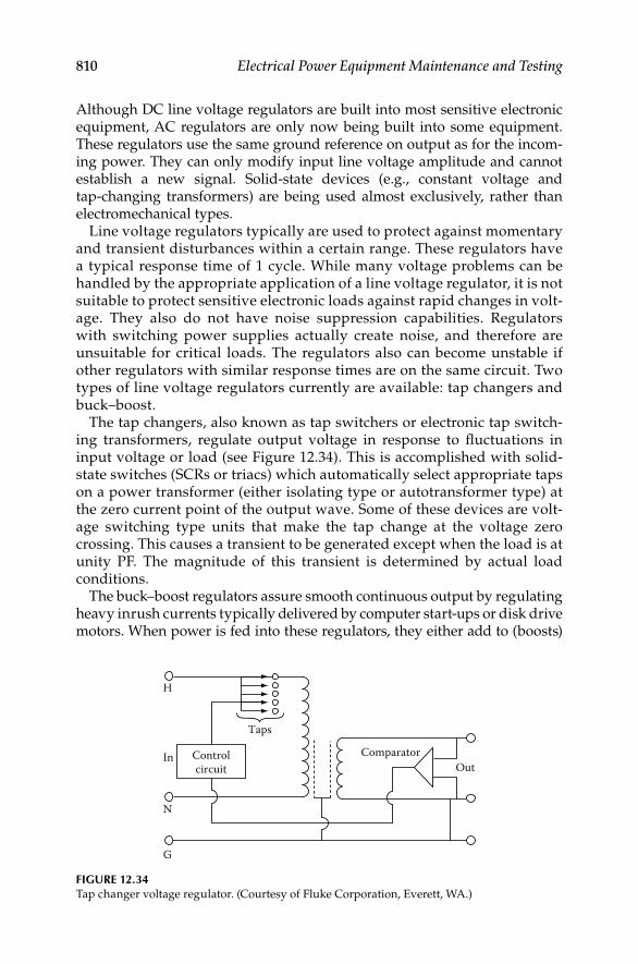
810 Electrical Power Equipment Maintenance and Testing
Although DC line voltage regulators are built into most sensitive electronic equipment, AC regulators are only now being built into some equipment. These regulators use the same ground reference on output as for the incom-ing power. They can only modify input line voltage amplitude and cannot establish a new signal. Solid-state devices (e.g., constant voltage and tap-changing transformers) are being used almost exclusively, rather than electromechanical types.
Line voltage regulators typically are used to protect against momentary and transient disturbances within a certain range. These regulators have a typical response time of 1 cycle. While many voltage problems can be handled by the appropriate application of a line voltage regulator, it is not suitable to protect sensitive electronic loads against rapid changes in volt-age. They also do not have noise suppression capabilities. Regulators with switching power supplies actually create noise, and therefore are unsuitable for critical loads. The regulators also can become unstable if other regulators with similar response times are on the same circuit. Two types of line voltage regulators currently are available: tap changers and buck–boost.
The tap changers, also known as tap switchers or electronic tap switch-ing transformers, regulate output voltage in response to fl uctuations in input voltage or load (see Figure 12.34). This is accomplished with solid-state switches (SCRs or triacs) which automatically select appropriate taps on a power transformer (either isolating type or autotransformer type) at the zero current point of the output wave. Some of these devices are volt-age switching type units that make the tap change at the voltage zero crossing. This causes a transient to be generated except when the load is at unity PF. The magnitude of this transient is determined by actual load conditions.
The buck–boost regulators assure smooth continuous output by regulating heavy inrush currents typically delivered by computer start-ups or disk drive motors. When power is fed into these regulators, they either add to (boosts)
FIGURE 12.34Tap changer voltage regulator. (Courtesy of Fluke Corporation, Everett, WA.)
Controlcircuit
Taps
ComparatorOut
N
G
In
H
DK4058_C012.indd 810DK4058_C012.indd 810 11/8/2008 1:05:40 PM11/8/2008 1:05:40 PM

Power Quality, Harmonics, and Predictive Maintenance 811
or subtract from (bucks) the incoming voltage. These electronic devices elim-inate use of steps as compared to the tap changer. Output is maintained constant for 15%–20% variations of input voltage. This is accomplished by comparing output voltage to the desired (set) level and by the use of feedback to modify the level of boost or buck. A path for nonlinear currents generated by the load and by the regulator itself is provided by a parametric fi lter. An advantage of buck–boost regulators is that they attenuate normal mode noise and surges. In addition, if they are built with isolation and shielding, the regulators can be separately derived source for power grounding, and can provide CM noise reduction.
The constant voltage regulator is typically referred to as ferroresonant regulators or constant voltage transformers (CVTs). This type of regulator is a relatively simple device because it has no moving or active electronic parts. It uses a saturating transformer with a resonant circuit made up of the trans-former’s inductance and a capacitor (Figure 12.35). The unit maintains a nearly constant voltage on the output for input swings of 20%–40%.
CVTs are susceptible to load imbalances and can become unstable. If the load current gets too high, these transformers tend to go out of resonance. They often can only supply 125%–200% of their full load rating. As a result, the CVTs cannot support starting current of motors exceeding these limits without a drastic dip in output voltage. CVTs are very ineffi cient at light loads and less effi cient at all other load levels. Their poor effi ciency is due to the resonant circuit which handles relatively large amounts of current all the time. As a result, the circuit causes the heat loss to be higher than other types of regulators. Noise can be a problem with these transformers requiring spe-cial enclosures. Because of its saturating elements, the CVT is a nonlinear device and introduces harmonic currents on the power source supplying it. The constant voltage regulators should be oversized in order to provide for heavy starting or in-rush currents. This is because output voltage is sig-nifi cantly reduced when these regulators are near their current limits.
Line
Load
FIGURE 12.35Basic constant voltage (ferroresonant) regulator.
DK4058_C012.indd 811DK4058_C012.indd 811 11/8/2008 1:05:40 PM11/8/2008 1:05:40 PM

812 Electrical Power Equipment Maintenance and Testing
The possibility also exists that the output voltage may not be compatible with some loads. In some cases, this can shut down other devices as a result of low output voltage of the CVT.
12.7.1.4 Isolation Transformers
Isolation transformers incorporate separate primary (or input) and second-ary (or output) windings with electrostatic Faraday shielding around the windings. They perform two distinct functions. First, they transform or change the input to secondary output voltage level and/or to compensate for high or low voltage. Second, the transformers establish the power ground reference close to the point of use. Because of this, CM noise induced through ground loops or multiple current paths in the ground circuit upstream of the established reference ground point is signifi cantly reduced.
Isolation transformers introduce minimal magnetizing current distor-tion into the input source. The delta-connected primary winding of the transformer can reduce the balanced third harmonic currents fed back to the source by single-phase nonlinear loads which are supplied from three-phase feeder systems. When a delta primary, wye secondary, isolation transformer is used to power a load such as a single-phase rectifi er, the balanced third harmonic currents circulate in the delta primary so they are not seen by the power source. An isolation transformer may be designed with a simple electrostatic (Faraday) shield between the two sets of wind-ings or they can be equipped with multi shields. Figure 12.36 shows an isolation transformer with three electrostatic Faraday shields, where pri-mary and secondary winding are individually shield with an overall shield system. A single shield is normally adequate in most applications however additional shields increase the CM rejection capabilities of the transformer. This Faraday electrostatic shield comprises of conducting sheets of nonmagnetic material (copper or aluminum) connected to ground. They are designed to improve the isolation characteristics of the transformer. Electrostatic shielding adds little to the cost, size, and weight of the transformer. Isolation transformers can achieve effi ciencies from 95% to 98%. These transformers generate little heat and are relatively quiet. They can be installed separately or with PDUs. Isolation transformers with distribution units have the advantage of being able to be located very close to the critical load.
12.7.1.5 Power Conditioners
Power line conditioners consist of one or more basic power treatment devices as previously discussed in this section. Some power conditioners may provide impulse attenuation, high-frequency fi ltering, isolation and voltage regulation others may not provide these features. Some of the power conditioners are: enhanced isolation transformer, ferroresonant power
DK4058_C012.indd 812DK4058_C012.indd 812 11/8/2008 1:05:40 PM11/8/2008 1:05:40 PM

Power Quality, Harmonics, and Predictive Maintenance 813
conditioner, tap switching power conditioner, magnetic synthesizer, and motor generator (M-G) sets. These conditioners also provide a locally derived source with isolation while providing voltage regulation. Some advanced conditioners contain noise reduction features of isolation trans-formers, fi ltering devices with voltage regulators, or surge suppressors to clamp high voltage surges.
The enhanced isolation transformer uses MOVs and air core wound chokes on the primary and a large capacitor across the secondary. These transform-ers were designed primarily for modern SMPS. The impedance of the transformer is kept low to ensure capability with the high inrush current of the power supply. The enhanced isolation transformers are available with single or multiple shields for improved CM noise attenuation.
The ferroresonant power conditioner is an isolation transformer operating in a saturated mode which was discussed in Section 12.7.1.3. It operates like a ferroresonant regulator with capability to regulate voltage and to a degree
Leakage capacitance
Leakage capacitance
Leakage capacitance
Three electrostaticfaraday shield
FIGURE 12.36Isolation transformer with three electrostatic shields.
DK4058_C012.indd 813DK4058_C012.indd 813 11/8/2008 1:05:40 PM11/8/2008 1:05:40 PM

814 Electrical Power Equipment Maintenance and Testing
perform waveshaping. Also, shielding between the primary and secondary improves the high frequency attenuations capabilities.
The tap switching power conditioner is an isolation transformer with mul-tiple taps for voltage correction. However, some tap switching power condi-tioners do not use isolation transformers, but instead use autotransformer. This power conditioner has the capability to regulate voltage, provide impulse attenuation and fi ltering.
The magnetic synthesizers consist of nonlinear inductors and capacitors in a parallel resonant circuit with six saturating pulse transformers. These synthesizers draw power from the source and generate their output voltage waveform by combining the pulses of the saturating transformers in a step wave manner. They provide noise and surge rejection and regulation of output voltage to within 10% over large swings (50%) input voltage. These units generally include additional fi ltering to eliminate self-induced harmonics and pulse transformer shielding to attenuate CM disturbances. The magnetic synthesizer inherently limits maximum current at full voltage to 125%–200% of the rating. With greater loads, voltage drops off rapidly, producing typically 200%–300% current at short circuit. Large step load changes, even within the unit’s rating, can cause signifi cant voltage and frequency transients in the output of this conditioner. These regulators work best when the load does not make large step changes. Due to the mag-netics involved, these synthesizers tend to be large and heavy. They also can be acoustically noisy without special packaging. Some of the larger units display good effi ciencies, as long as they are operated at close to full load. The magnetic synthesizer introduces current distortion on its input, due to its nonlinear elements, which is at its highest when the conditioner is lightly loaded.
The M-Gs transform AC electrical power to mechanical power, then back to AC electrical power. They consist of an AC powered electric motor driv-ing an AC generator, which then supplies AC power to the load as shown in Figure 12.37. Two types of M-Gs are utilized today. These are shaft or belt isolated M-Gs and rotating transformer M-Gs. In the former, the motor and generator are coupled by a shaft or belts. The latter units have a common rotor, a motor stator, and a generator stator. They generally are small units and have excellent effi ciency values. One disadvantage is that they do not provide the same level of noise and surge isolation between the input and the output as conventional M-Gs. Because of the coupling between the two stators (which are wound one on top of the other), the noise has a path through the unit. Shaft or belt isolated M-Gs are used widely as a source of 415 Hz power for large computers requiring this frequency. They can be easily powered by a single 60 Hz induction motor. As the induction motor speed varies, the output frequency varies with motor speed since the gen-erator output is a function of its shaft speed. However, the output voltage is maintained by controlling the excitation of the fi eld winding of the generator and the generator output voltage is independent of small motor speed changes.
DK4058_C012.indd 814DK4058_C012.indd 814 11/8/2008 1:05:40 PM11/8/2008 1:05:40 PM
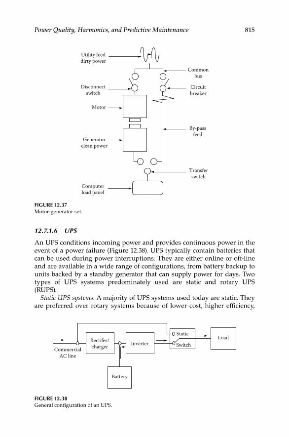
Power Quality, Harmonics, and Predictive Maintenance 815
12.7.1.6 UPS
An UPS conditions incoming power and provides continuous power in the event of a power failure (Figure 12.38). UPS typically contain batteries that can be used during power interruptions. They are either online or off-line and are available in a wide range of confi gurations, from battery backup to units backed by a standby generator that can supply power for days. Two types of UPS systems predominately used are static and rotary UPS (RUPS).
Static UPS systems: A majority of UPS systems used today are static. They are preferred over rotary systems because of lower cost, higher effi ciency,
Static
SwitchLoad
InverterRectifer/chargerCommercial
AC line
Battery
FIGURE 12.38General confi guration of an UPS.
Utility feeddirty power
Disconnectswitch
Motor
Generatorclean power
Computerload panel
Transferswitch
By-passfeed
Circuitbreaker
Commonbus
FIGURE 12.37Motor-generator set.
DK4058_C012.indd 815DK4058_C012.indd 815 11/8/2008 1:05:40 PM11/8/2008 1:05:40 PM

816 Electrical Power Equipment Maintenance and Testing
ease of maintenance, and fewer moving parts. Static UPS systems instantly provide power from battery to the load in the event of a power failure. Batteries used for large installations usually are lead-acid wet cells. Some smaller units use gelled-electrolyte cell or immobilized-electrolyte cell (main-tenance free) batteries. Cost is infl uenced considerably by the length of battery protection time required and load size. In most instances, 15 min of protective time is considered adequate because it permits an orderly shut-down of the load equipment. In many instances, however, the UPS system is used in conjunction with an engine-generator set. As such, the UPS provides instantaneous power until such time as load can be transferred to the engine-generator set. In the event of an inverter failure or while maintenance is being performed on the UPS, a bypass transfer switch is included to allow connec-tion of the utility to the critical load. This load can be transferred without interruption because UPS output is kept in phase with the utility source under normal operation. Static UPS systems can be either fl oat-type (online) or AC-input type.
The RUPS systems can be confi gured in several different ways. In one confi guration, shown in Figure 12.39, the rectifi er of a RUPS is supplied from the utility source while the battery fl oats online. The inverter’s output frequency is slaved to the utility source and follows it exactly. The solid-state rectifi er supplies DC to the inverter and also maintains the battery at appropriate fl oat charge. The step function square wave AC output is used to drive the motor which, in turn, powers the generator. The M-G’s output frequency is maintained at 60 Hz. When the incoming power is interrupted, the high-capacity batteries supply DC to the inverter which, in turn, sup-plies power to the M-G set. The inverter frequency control system main-tains motor frequency within ±0.1% of rated 60 Hz while the batteries supply the load.
Incomingsource N.C. N.C.
Synch-ronousmotor
Alter-nator60 Hz
Com
pute
r loa
ds
N.O.
N.O.60 Hz bypass
feed
Logic andfrequency
control
Rectifier Inverter
Battery
FIGURE 12.39Rotary UPS.
DK4058_C012.indd 816DK4058_C012.indd 816 11/8/2008 1:05:41 PM11/8/2008 1:05:41 PM

Power Quality, Harmonics, and Predictive Maintenance 817
Also, the UPS can be confi gured as SPS systems to provide energy that can be used during power interruptions. SPSs typically comprise of batteries and are either off-line or stand-by type. Two categories of SPSs that are used to supply backup power are rotary and static SPS systems. These systems are designed as standby systems such that during normal operation the power is supplied via the bypass circuit to the loads. If a power interruption occurs, the SPS switches to the battery to supply power to the inverter, which in turn supplies the load.
12.7.2 HDs
The effects of HD on power equipment and circuits were discussed in Section 12.5. High levels of stress due to HD can lead to problems for the utility’s distribution system, plant distribution system and any power equipment serviced by that distribution system. Effects can range from spurious operation of equipment to a shutdown, such as machines or assembly lines, or cata-strophic failure of equipment. Harmonics can lead to power system ineffi ciency as well because increase in HD will decrease true PF. Some of the negative ways that harmonics affect plant equipment are summarized below:
Conductor overheating: Conductor heating is a function of the square of the rms current per unit volume in the conductor. Harmonic currents on under-sized conductors or cables can cause a skin effect, which increases with frequency.
Capacitors: Capacitors are affected by heat increases due to power loss (tem-perature rise) which will shorten life of capacitors. If a capacitor is tuned to one of the characteristic harmonics such as the fi fth or seventh, overvoltages due to resonance can cause dielectric failure or rupture of capacitor.
Fuses and circuit breakers: Harmonics can cause false or spurious operations of relays, breakers and protective trips, damaging or blowing components.
Transformers: Transformers have increased iron and copper losses or eddy cur-rents due to stray fl ux losses. This causes overheating of transformer windings and iron (core).
Generators: Generators experience similar problems as transformers. Sizing and coordination is critical to the operation of the voltage regulator and con-trols. Excessive harmonic voltage distortion will cause multiple zero cross-ings of the current waveform. Multiple zero crossings affect the timing of the voltage regulator, causing interference and operation instability.
Revenue meters: Revenue meters may record measurements incorrectly, resulting in higher billings to user.
Drives/power supplies: VFDs and power supplies can be affected by misop-eration due to multiple zero crossings. Harmonics can cause failure of the commutation circuits, found in DC drives and AC drives with SCRs.
Computers/telephones: These devices may experience interference or failure.
DK4058_C012.indd 817DK4058_C012.indd 817 11/8/2008 1:05:41 PM11/8/2008 1:05:41 PM

818 Electrical Power Equipment Maintenance and Testing
12.7.2.1 Industry Standards on Limits of Harmonics
The most often quoted standard on harmonics in the United States is IEEE 519-1992, “Recommended practices and requirements for harmonic control in electric power systems.” The IEEE 519-1992 attempts to establish reason-able harmonic goals for electrical systems that contain nonlinear (harmonic producing) loads. The objective is to propose steady state harmonic limits that are considered reasonable by both electric utilities and their customers. The underlying philosophy is that
Customers should limit harmonic currents•
Electric utilities should limit harmonic voltages•
Both parties share the responsibility for holding harmonic levels in • check
IEEE 519 applies to all voltage levels, including 120 V single-phase residential service, industrial and commercial entities, and utilities as well. While it does not specifi cally state the highest-order harmonic to limit, the generally accepted range of application is through the 50th harmonic for the industrial and commercial facilities. DC, which is not a harmonic, is also addressed and is prohibited. Since no differentiation is made between single-phase and three-phase systems, the recommended limits apply to both. It is important to remember that IEEE 519-1992 is a recommended practice and not an actual standard or legal document unless it is adopted by the local jurisdiction. Rather, it is intended to provide a reasonable framework within which engi-neers can address and control harmonic problems. It has been adopted by many electric utilities and by several state public utility commissions, such as Texas and Oklahoma states.
According to the IEEE 519-1992 standard, the industrial and commercial entity is responsible for controlling the harmonic currents created in their power systems. Since harmonic currents refl ected through distribution system impedances generate harmonic voltages on the utility distribution systems, the standard proposes guidelines based on industrial distribution system design. The Table 10.3 in IEEE 519-1992, defi nes levels of harmonic currents that indus-trial and commercial customers can inject onto the utility distribution system. The contents of this table are shown in Table 12.18.
Table 11.1 of IEEE 519-1992 defi nes the voltage distortion limits that can be refl ected back onto the utility distribution system. Usually if the industrial or commercial user controls the overall combined current distortion according to Table 10.3 of IEEE 519, this should help the customers meet the limitations set forth in the guidelines of IEEE 519 standard (Table 12.19).
12.7.2.2 Evaluating System Harmonics
In order to prevent or correct harmonic problems within an industrial or com-mercial facility an evaluation of system harmonics should be performed to quantify the problem. The harmonic evaluation can be conducted by either
DK4058_C012.indd 818DK4058_C012.indd 818 11/8/2008 1:05:41 PM11/8/2008 1:05:41 PM
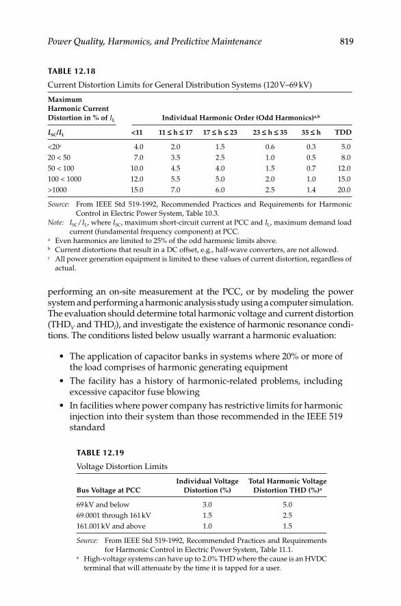
Power Quality, Harmonics, and Predictive Maintenance 819
performing an on-site measurement at the PCC, or by modeling the power system and performing a harmonic analysis study using a computer simulation. The evaluation should determine total harmonic voltage and current distortion (THDV and THDI), and investigate the existence of harmonic resonance condi-tions. The conditions listed below usually warrant a harmonic evaluation:
The application of capacitor banks in systems where 20% or more of • the load comprises of harmonic generating equipment
The facility has a history of harmonic-related problems, including • excessive capacitor fuse blowing
In facilities where power company has restrictive limits for harmonic • injection into their system than those recommended in the IEEE 519 standard
TABLE 12.18
Current Distortion Limits for General Distribution Systems (120 V–69 kV)
Maximum
Harmonic Current
Distortion in % of IL Individual Harmonic Order (Odd Harmonics)a,b
ISC/IL <11 11 £ h £ 17 17 £ h £ 23 23 £ h £ 35 35 £ h TDD
<20c 4.0 2.0 1.5 0.6 0.3 5.0
20 < 50 7.0 3.5 2.5 1.0 0.5 8.0
50 < 100 10.0 4.5 4.0 1.5 0.7 12.0
100 < 1000 12.0 5.5 5.0 2.0 1.0 15.0
>1000 15.0 7.0 6.0 2.5 1.4 20.0
Source: From IEEE Std 519-1992, Recommended Practices and Requirements for Harmonic
Control in Electric Power System, Table 10.3.
Note: ISC/IL, where ISC, maximum short-circuit current at PCC and IL, maximum demand load
current (fundamental frequency component) at PCC.a Even harmonics are limited to 25% of the odd harmonic limits above.b Current distortions that result in a DC offset, e.g., half-wave converters, are not allowed.c All power generation equipment is limited to these values of current distortion, regardless of
actual.
TABLE 12.19
Voltage Distortion Limits
Bus Voltage at PCC
Individual Voltage
Distortion (%)
Total Harmonic Voltage
Distortion THD (%)a
69 kV and below 3.0 5.0
69.0001 through 161 kV 1.5 2.5
161.001 kV and above 1.0 1.5
Source: From IEEE Std 519-1992, Recommended Practices and Requirements
for Harmonic Control in Electric Power System, Table 11.1.a High-voltage systems can have up to 2.0% THD where the cause is an HVDC
terminal that will attenuate by the time it is tapped for a user.
DK4058_C012.indd 819DK4058_C012.indd 819 11/8/2008 1:05:41 PM11/8/2008 1:05:41 PM

820 Electrical Power Equipment Maintenance and Testing
Plant expansions that add signifi cant harmonic generating equip-• ment operating in conjunction with capacitor banks
When coordinating and planning to add an emergency standby gen-• erator as an alternate power source in an industrial facility
Performing a harmonic studyIn order to perform a harmonic study, the power system requires modeling it in the harmonic analysis software program. To conduct this analysis, data are needed on the following as a minimum:
One-line drawings of the power system, showing ratings and con-• nections of all electrical equipment
Location, connection, size, and control method of capacitors•
Conductor sizes, lengths, and impedances•
Location and type of nonlinear loads, including harmonic profi le of • the load. (This can be measured on the equipment or provided by manufacturer of the equipment.)
Overall plant load and load at each bus•
Location, rating, connection, and impedance of transformers•
Available fault duty at PCC location (incoming point of connection • from the utility)
12.7.2.3 Harmonic Solutions—Mitigation Devices and Methods
Harmonic solutions to solve harmonic problems may include using miti-gation devices, such as current-limiting reactors, passive fi lters, active fi l-ters, or other devices that minimize the fl ow of harmonic currents onto the utility’s distribution system and within the power system. Harmonic solution techniques fall into two broad categories, (1) preventive and (2) remedial.
Preventive measures: Preventive measures focus on minimizing the har-monic currents that are injected into power systems. Preventive measures include the following:
Strict adherence to IEEE 519.•
Phase cancellation:• The use of 12-pulse converters instead of six-pulse converters. Most harmonic problems with converters (VFDs and the like) are associated with high fi fth and seventh harmonic currents, and if they are eliminated through phase cancellation, harmonic problems rarely develop. In situations where there are multiple six-pulse convert-ers, serving half of them (in terms of power) through delta–delta or wye–wye transformers, and the other half through delta–wye or wye–delta transformers, achieves net 12-pulse operation.
DK4058_C012.indd 820DK4058_C012.indd 820 11/8/2008 1:05:41 PM11/8/2008 1:05:41 PM
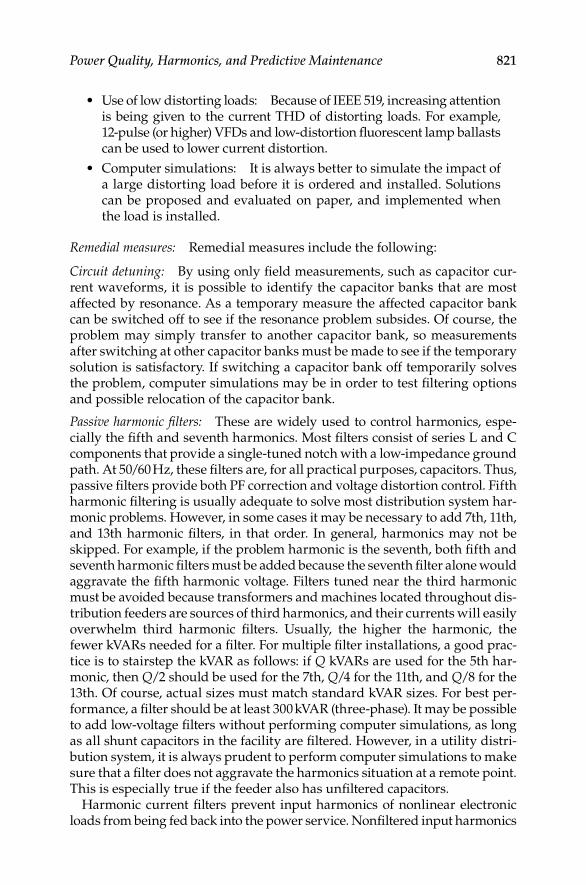
Power Quality, Harmonics, and Predictive Maintenance 821
Use of low distorting loads: Because of IEEE 519, increasing attention • is being given to the current THD of distorting loads. For example, 12-pulse (or higher) VFDs and low-distortion fl uorescent lamp ballasts can be used to lower current distortion.
Computer simulations: It is always better to simulate the impact of • a large distorting load before it is ordered and installed. Solutions can be proposed and evaluated on paper, and implemented when the load is installed.
Remedial measures: Remedial measures include the following:
Circuit detuning: By using only fi eld measurements, such as capacitor cur-rent waveforms, it is possible to identify the capacitor banks that are most affected by resonance. As a temporary measure the affected capacitor bank can be switched off to see if the resonance problem subsides. Of course, the problem may simply transfer to another capacitor bank, so measurements after switching at other capacitor banks must be made to see if the temporary solution is satisfactory. If switching a capacitor bank off temporarily solves the problem, computer simulations may be in order to test fi ltering options and possible relocation of the capacitor bank.
Passive harmonic fi lters: These are widely used to control harmonics, espe-cially the fi fth and seventh harmonics. Most fi lters consist of series L and C components that provide a single-tuned notch with a low-impedance ground path. At 50/60 Hz, these fi lters are, for all practical purposes, capacitors. Thus, passive fi lters provide both PF correction and voltage distortion control. Fifth harmonic fi ltering is usually adequate to solve most distribution system har-monic problems. However, in some cases it may be necessary to add 7th, 11th, and 13th harmonic fi lters, in that order. In general, harmonics may not be skipped. For example, if the problem harmonic is the seventh, both fi fth and seventh harmonic fi lters must be added because the seventh fi lter alone would aggravate the fi fth harmonic voltage. Filters tuned near the third harmonic must be avoided because transformers and machines located throughout dis-tribution feeders are sources of third harmonics, and their currents will easily overwhelm third harmonic fi lters. Usually, the higher the harmonic, the fewer kVARs needed for a fi lter. For multiple fi lter installations, a good prac-tice is to stairstep the kVAR as follows: if Q kVARs are used for the 5th har-monic, then Q/2 should be used for the 7th, Q/4 for the 11th, and Q/8 for the 13th. Of course, actual sizes must match standard kVAR sizes. For best per-formance, a fi lter should be at least 300 kVAR (three-phase). It may be possible to add low-voltage fi lters without performing computer simulations, as long as all shunt capacitors in the facility are fi ltered. However, in a utility distri-bution system, it is always prudent to perform computer simulations to make sure that a fi lter does not aggravate the harmonics situation at a remote point. This is especially true if the feeder also has unfi ltered capacitors.
Harmonic current fi lters prevent input harmonics of nonlinear electronic loads from being fed back into the power service. Nonfi ltered input harmonics
DK4058_C012.indd 821DK4058_C012.indd 821 11/8/2008 1:05:41 PM11/8/2008 1:05:41 PM

822 Electrical Power Equipment Maintenance and Testing
can generate heat which can have an effect on conductors and transformers and cause voltage distortion. The fi lters vary in size from small units for plug-connected loads to larger devices for hard-wired loads. Different types of har-monic current fi lters are illustrated in Figure 12.40. Harmonic current fi lters typically are placed in parallel with the load. If installed and used properly, these fi lters work best at reducing harmonic currents at their source. They also eliminate the need for other changes to compensate for the problems caused by the harmonic currents.
Some problems associated with passive fi lters are that:
Their effectiveness diminishes over time as their capacitors age, • losing μF and thus raising their notch frequency.
They attract harmonic currents from all sources in the network—• new, known, and unknown, so that they may become overloaded.
Active fi lters. This is a new and promising technology, but there are • as yet few distribution feeder installations. Active fi lters are power
C C
L
L
R
R
Single tunedshunt filter
Damped high-pass filter
C1
L1
C2
Serie
stu
ned
Modified high-pass filter
Double tunedshunt filter
L2
Para
llel
tune
dC
LR
FIGURE 12.40Various types of harmonic current fi lters.
DK4058_C012.indd 822DK4058_C012.indd 822 11/8/2008 1:05:41 PM11/8/2008 1:05:41 PM

Power Quality, Harmonics, and Predictive Maintenance 823
electronic converters that inject equal-but-opposite distortion to yield more sinusoidal voltage waveforms throughout a network. Active fi lters have the advantages of
Time-domain operation so that they automatically tune to the prob-• lem harmonic or harmonics
Current-limiting capability to prevent overload by new or unknown • sources of harmonics on the network
Multipoint voltage monitoring so that they can simultaneously min-• imize distortion at local and remote busses
The performance of mitigation equipment must be verifi ed by extensive mon-itoring, both before and after commissioning. At least 2 days of recordings before commissioning, and one week after, should be made to assure that the mitigation equipment is performing as planned. One week of measurements is needed so that the entire weekly load cycle can be observed.
Monitoring should include time traces of voltage and current THD, spectra, sample waveforms, power, and harmonic power.
Delta–delta and delta–wye transformers: This confi guration uses two separate utility feed transformers with equal nonlinear loads. This shifts the phase relationship to various six-pulse converters through cancellation techniques, similar to the 12-pulse confi guration.
Isolation transformers: An isolation transformer provides a good solution in many cases. The advantage is the potential to voltage match by stepping up or stepping down the system voltage, and by providing a N–G reference for nuisance ground faults. This is the best solution when utilizing AC or DC drives that use SCRs as bridge rectifi ers.
Line reactors: More commonly used for size and cost, the line reactor is the best solution for harmonic reduction when compared to an isolation transformer. AC drives that use diode bridge rectifi er front ends are best suited for line reac-tors. Line reactors (commonly referred to as inductors) are available in standard impedance ranges from 1.5%, 3%, 5%, and 7.5%.
12.7.3 Wiring and Grounding Problems
In those facilities that are experiencing equipment problems that appear to be power-related, a on-site inspection will be required to verify that power disturbances are the cause of electronic equipment malfunction or failure. The specifi c objective of such an inspection is to determine condition and adequacy of the wiring and grounding system. This inspection should include the following checks:
Wiring and grounding: Wiring and grounding measurements detect prob-lems in the feeders and branch circuits serving the critical load. The test instruments used to conduct these tests should be selected carefully. Use of
DK4058_C012.indd 823DK4058_C012.indd 823 11/8/2008 1:05:41 PM11/8/2008 1:05:41 PM

824 Electrical Power Equipment Maintenance and Testing
commonly available three-light circuit testers is not recommended. These instruments have limitations and can provide a correct indication when the circuit being tested actually has one or more problems. They also are incapable of indicating the integrity of power conductors. Recommended instruments for these measurements include true-rms multimeter, true-rms clamp-on multimeter, and ground impedance testers. These instruments are described in Section 12.6.
Continuity of conduit/enclosure grounds: Electronic equipment should be grounded with a separate equipment grounding conductor. This conductor can be terminated in an IG system, insulated from the conduit ground, or in the conduit ground system. This is because both are ultimately connected to the building ground systems. However, the IG and conduit ground must terminate at the fi rst upstream N–G bonding point. Ground impedance testers can be used to measure the quality of both the IG and conduit ground systems from the equipment to the power source. To achieve good performance from sensi-tive electronic loads, phase, neutral, and equipment grounding conductors should be routed through continuously grounded metallic conduit. Continuously grounded metal conduit provides a shield for radiated interference.
Load phase and neutral currents: Measurements of load phase and neutral cur-rents are necessary to determine whether the load is sharing a neutral conduc-tor with other loads. They also determine whether the neutral conductor sizing is adequate. When sizing neutral conductors, one should keep in mind that the current in the neutral can exceed current in the phase conductor. This is because three-phase circuits supplying single-phase loads have nonlinear current characteristics and share a common neutral. A true-rms reading clamp-on ammeter must be used to make phase and neutral conductor mea-surements. To determine whether the neutral serving the sensitive electronic load is shared with other loads, check the neutral current with the sensitive load turned off. If the current is not zero, a shared neutral is being used.
N–G bonds: The NEC requires bonding of the neutral and equipment grounding conductor at the main service panel (NEC 250-53) and the sec-ondary side of SDSs (NEC 250-26(a) ). If not properly bonded, N–G bonds create shock hazards for operating personnel, and degrade the performance of sensitive electronic equipment. These bonds can be detected using a wiring and grounding tester. A voltage measurement between neutral and ground at the outlets may indicate voltage from millivolt to few volts range under normal operating conditions. A zero voltage indicates the presence of a nearby N–G bond. Excessive current on equipment grounds in distribution panels also indicates the possibility of a load side N–G bond.
Equipment grounding conductor impedance: The impedance of the equipment grounding conductor is measured using a ground impedance tester. Properly installed and maintained equipment ground conductors exhibit very low impedance levels. A high impedance measurement indicates poor quality connections in the equipment grounding system or an improperly installed
DK4058_C012.indd 824DK4058_C012.indd 824 11/8/2008 1:05:41 PM11/8/2008 1:05:41 PM

Power Quality, Harmonics, and Predictive Maintenance 825
equipment grounding conductor. An open ground measurement reveals no equipment grounding conductor connection. Recommended practice is to verify an impedance level of 0.25 Ω or less. This also helps assure personnel protection under fault conditions.
Neutral conductor impedance: Neutral conductor impedance is measured because a low impedance neutral is essential to minimize N–G potentials at the load and reduce CM noise. A ground impedance tester can be used to conduct these measurements. It is necessary for neutral conductors to have low impedance.
Grounding electrode resistance: The grounding electrode system provides an earth reference point for the facility and a path for lightning and static electricity. This is important because the electrode serves as the connection between the building grounding system and the grounding electrode system. An accurate measurement can be taken only when the grounding electrode is disconnected from all other grounds. For new construction, the resistance of the grounding electrode system is measured with an earth ground tester using the fall-of-po-tential method. It is recommended that the measured resistance be in accordance with the design values and industry standards and codes. For more information on grounding and ground resistance measurements, refer to Chapter 11.
Current fl ow in the grounding electrode conductor can be measured using a clamp-on ammeter. In most cases, small current fl ow will exist. However, zero current fl ow usually indicates an open connection. Current fl ow on the order of the phase currents indicates serious problems or possible fault conditions.
IG and conduit ground systems: The quality of both the IG and conduit ground systems from the equipment to the ground source needs to be mea-sured. This is to ensure that sensitive electronic loads are grounded with a separate equipment grounding conductor and are ultimately connected to the building grounding system. Both ground systems terminate at the fi rst upstream N–G bonding point. The phase, neutral, and equipment ground-ing conductors should be routed through continuously grounded metallic conduit. As a result, better performance of sensitive electronic equipment is achieved. Another benefi t is that safety codes are met.
Dedicated feeders and direct path routing: Measuring phase currents with the critical loads turned off is one way to determine if sensitive electronic loads are being served by dedicated branch feeders with conductor routing in as short and direct a path as possible. If there is any current fl ow, the feeder is being used to serve other loads.
SDSs: No direct electrical connection should exist between SDSs and output and input conductors. SDSs are required by the NEC to have a load-side N–G bond which is connected to the grounding electrode system. All equipment grounding conductors, any IG conductors, neutral conductors, and the metal enclosure of the SDSs are required to be bonded together and bonded to the grounding electrode conductor. Visual inspections and measurements with a ground impedance tester can determine the quality of these connections.
DK4058_C012.indd 825DK4058_C012.indd 825 11/8/2008 1:05:41 PM11/8/2008 1:05:41 PM

DK4058_C012.indd 826DK4058_C012.indd 826 11/8/2008 1:05:42 PM11/8/2008 1:05:42 PM
827
13Electrical Safety, Arc-Flash Hazard, Switching Practices, and Precautions
13.1 Introduction
Safety in electrical systems concerns three different areas: protection of life, protection of property, and protection of uninterrupted productive output. The required investment to accomplish improved safety often consists merely of additional planning effort without any extra equipment invest-ment. The protection of human life is paramount. Electrical plant property can be replaced and lost production can be made up, but human life can never be recovered nor human suffering compensated for. To achieve improved safety to personnel, special attention should be directed to ener-gized equipment, adequate short-circuit protective devices, a good mainte-nance program, simplicity of the electrical system design, and proper training of personnel who work around electricity. Many of the items neces-sary to give improved protection to life will also secure improved protection to plant property and minimize breakdown of electrical system equipment. This chapter deals with electrical safety, switching practices, arc-fl ash hazard analysis, precautions, and accident prevention.
Most electrical companies and plants have safety programs and rules in the workplace and training programs for their employees. Most safety pro-grams embody company safety rules and practices, national and local codes and standards, and federal and state laws. For individuals to carry out their duties, they must be knowledgeable of the rules and standards that apply to their workplace. Electrical safety standards and requirements are varied; some are voluntary while others are laws that are mandatory, and provide guidance for safely working around or on electrical energy. Since the stan-dards are periodically revised, one should always refer to the most recent version of the standard when consulting such a standard. A brief discussion of the safety standards, arc-fl ash hazard analysis and labeling of equipment, and regulations related to these topics and electricity are covered below to familiarize the reader with them.
DK4058_C013.indd 827DK4058_C013.indd 827 11/8/2008 12:24:14 PM11/8/2008 12:24:14 PM

828 Electrical Power Equipment Maintenance and Testing
13.2 Industry Standards and Regulatory
Requirements for Safety
13.2.1 ANSI C2: The National Electrical Safety Code-2007
The National Electrical Safety Code (NESC) is intended to provide practical rules for safeguarding personnel during the installation, operation, or main-tenance of electrical supply and communications lines and associated equip-ment. The NESC rules cover supply and communications lines, equipment, and associated work practices used by both private and public electrical companies (utilities). The NESC covers fi ve major areas as listed below.
Grounding methods for electrical supply and communications • facilities
Rules for installation and maintenance of electrical supply stations • and equipment
Safety rules for the installation and maintenance of overhead electrical • supply and communications lines
Safety rules for the installation and maintenance of underground • electric supply and communications lines
Rules for the operation of electric supply and communications lines • and equipment
Section 410, “General requirements” of NESC-2007 contains information and guidance on electric safety requirements that are necessary for safeguarding employees in the workplace. In accordance with Section 410 the employer is required to inform the employees on safety rules, safety training and arc hazard evaluation including wearing of arc-rated clothing. These require-ments as stated in NESC-2007 standard are as follows:
1. The employer shall inform each employee working on or about communications equipment or electric supply equipment and the associated lines, of the safety rules governing the employee’s con-duct while so engaged. When deemed necessary, the employer shall provide a copy of such rules.
2. The employer shall provide training to all employees who work in the vicinity of exposed energized facilities. The training shall include applicable work rules required by this part and other mandatory referenced standards or rules. The employer shall ensure that each employee has demonstrated profi ciency in required tasks. The employer shall provide retraining for any employee who, as a result of routine observance of work practices, is not following work rules.
3. Effective as of January 1, 2009, the employer shall ensure that an assessment is performed to determine potential exposure to an
DK4058_C013.indd 828DK4058_C013.indd 828 11/8/2008 12:24:14 PM11/8/2008 12:24:14 PM

Electrical Safety, Arc-Flash Hazard, Switching Practices, and Precautions 829
electric arc for employees who work on or near energized parts or equipment. If the assessment determines a potential employee exposure greater than 2 cal/cm2 exists, the employer shall require employees to wear clothing or a clothing system that has an effec-tive arc rating not less than the anticipated level of arc energy. When exposed to an electric arc or fl ame, clothing made from the follow-ing materials shall not be worn: acetate, nylon, polyester, or poly-propylene. The effective arc rating of clothing or a clothing system to be worn at voltages 1000 V and above shall be determined using Tables 410-1 and 410-2 or performing an arc hazard analysis. When an arc hazard analysis is performed, it shall include a calculation of the estimated arc energy based on the available fault current, the duration of the arc (cycles), and the distance from the arc to the employee.
Exception 1: If the clothing required by this rule has the potential to create additional and greater hazards than the possible exposure to the heat energy of the electric arc, then clothing with an arc rating or arc thermal performance value (ATPV) less than that required by the rule can be worn.
Exception 2: For secondary systems below 1000 V, applicable work rules required by this part and engineering controls shall be uti-lized to limit exposure. In lieu of performing an arc hazard analysis, clothing or a clothing system with a minimum effec-tive arc rating of 4 cal/cm2 shall be required to limit the likeli-hood of ignition.
Note 1: A clothing system (multiple layers) that includes an outer layer of fl ame-resistant (FR) material and an inner layer of non-FR material has been shown to block more heat than a single layer. The effect of the combination of these multiple layers can be referred to as the effective arc rating.
Note 2: It is recognized that arc energy levels can be excessive with second-ary systems. Applicable work rules required by this part and engi-neering controls should be utilized.
13.2.2 ANSI/National Fire Protection Association (NFPA) 70, National Electrical Code (NEC)-2008
The NEC NFPA 70 is part of the NFPA codes. The NEC includes information on design, installation and other technical information of electrical facilities and its principle objective is to help minimize the possibility of electric fi res. The NEC or portions of it are adopted as local law in many municipalities, cities, states, and other such areas. Since 2002, the NEC, article 110-16 requires
DK4058_C013.indd 829DK4058_C013.indd 829 11/8/2008 12:24:14 PM11/8/2008 12:24:14 PM

830 Electrical Power Equipment Maintenance and Testing
fl ash hazard labels on electrical equipment to warn personnel of the potential electric arc-fl ash hazards and the personal protective equipment (PPE) they must wear when working on energized equipment. The NEC article 110-16 is listed below for reader’s reference.
110.16—fl ash protection: Electrical equipment, such as switchboards, panel-boards, industrial control panels, meter socket enclosures, and motor control centers, that are in other than dwelling occupancies, and are likely to require examination, adjustment, servicing, or maintenance while energized shall be fi eld marked to warn qualifi ed persons of potential electric arc-fl ash hazards. The marking shall be located so as to be clearly visible to qualifi ed persons before examination, adjustment, servicing, or maintenance of the equipment.
FPN No. 1: NFPA 70E, Standard for Electrical Safety in the Workplace-2004, provides assistance in determining severity of potential expo-sure, planning safe work practices, and selecting PPE.
FPN No. 2: ANSI Z535.4-1998, Product Safety Signs and Labels, provides guidelines for the design of safety signs and labels for applica-tion to products.
13.2.3 ANSI/NFPA 70B, Standard for Electrical Equipment Maintenance-2006
The electrical equipment maintenance is a publication of the NFPA and it contains recommended practice information on maintenance of electric equipment and apparatus. The 70B document covers systems and equipment which are typically installed in industrial plants, commercial buildings, and large family dwellings.
13.2.4 ANSI/NFPA 70E, Standard for Electrical Safetyin the Workplace-2004
The electrical safety requirement in workplaces is a publication of NFPA. This code contains information and guidance on electric safety requirements that are necessary for safeguarding employees in the workplace. The sixth edition, published in 2004, refl ects several signifi cant changes to the older versions of 70E. The major changes emphasize safe work practices. Clarity and usability of the document are also enhanced. The name of the document was changed to NFPA 70E, Standard for Electrical Safety in the Workplace. The existing Parts 1 through 4 were renamed as Chapters 1 through 4 and are reorganized as follows:
Chapter 1 Safety-related work practices
Chapter 2 Safety-related maintenance requirements
Chapter 3 Safety requirements for special equipment
Chapter 4 Installation safety requirements
DK4058_C013.indd 830DK4058_C013.indd 830 11/8/2008 12:24:14 PM11/8/2008 12:24:14 PM

Electrical Safety, Arc-Flash Hazard, Switching Practices, and Precautions 831
This standard is compatible with corresponding provisions of the NEC, but is not intended to, nor can it, be used in lieu of the NEC. Chapter 4 of NFPA 70E is intended to serve a very specifi c need of OSHA and is in no way intended to be used as a substitute for the NEC. NFPA 70E is intended for use by employers, employees, and OSHA.
The chapter on safety-related work practices was reorganized to empha-size working on live parts as the last alternative work practice. Therefore it contains extensive requirements for working on or near electrical conductors or circuit parts that have not been put into an electrically safe work condition. When such work is to be performed, the required electrical hazard analysis has specifi c requirements for the analysis of shock and fl ash hazards. Other sections of the 70E provide guidance on selecting the proper PPE. The signifi cant requirements for the analysis of shock and fl ash hazards are as follows:
The NFPA 70E, Article 110.8 (B) (1) Electrical hazard analysis: If the live parts operating at 50 V or more are not placed in an electrically safe work condition, other safety-related work practices shall be used to protect employees who might be exposed to the electrical hazards involved. Such work practices shall protect each employee from arc fl ash and from contact with live parts operating at 50 V or more directly with any part of the body or indirectly through some other conductive object. Work practices that are used shall be suitable for the conditions under which the work is to be performed and for the voltage level of the live parts. Appropriate safety-related work practices shall be determined before any person approaches exposed live parts within the limited approach boundary by using both shock hazard analysis and fl ash hazard analysis.
(a) Shock hazard analysis. A shock hazard analysis shall determine the volt-age to which personnel will be exposed, boundary requirements, and the PPE necessary in order to minimize the possibility of electrical shock to personnel. (b) Flash hazard analysis. A fl ash hazard analysis shall be done in order to protect personnel from the possibility of being injured by an arc fl ash. The analysis shall determine the fl ash protection boundary and the PPE that people within the fl ash protection boundary shall use.
The NFPA 70E, Article 130.2 Approach boundaries to live parts:
A. Shock hazard analysis: A shock hazard analysis shall determine the voltage to which personnel will be exposed, boundary requirements, and the PPE necessary in order to minimize the possibility of electric shock to personnel.
B. Shock protection boundaries: The shock protection boundaries identi-fi ed as limited, restricted, and prohibited approach boundaries are applicable to the situation in which approaching personnel are exposed to live parts.
C. Approach to exposed live parts operating at 50 V or more: No qualifi ed person shall approach or take any conductive object closer to
DK4058_C013.indd 831DK4058_C013.indd 831 11/8/2008 12:24:14 PM11/8/2008 12:24:14 PM

832 Electrical Power Equipment Maintenance and Testing
exposed live parts operating at 50 V or more than the restricted approach boundary set forth in Table 130.2(C), unless any of the following apply:
1. The qualifi ed person is insulated or guarded from the live parts operating at 50 V or more (insulating gloves or insulating gloves and sleeves are considered insulation only with regard to the ener-gized parts upon which work is being performed), and no part of the qualifi ed person’s body crosses the prohibited approach boundary set forth in Table 130.2(C) which is shown in Table 13.1.
2. The live part operating at 50 V or more is insulated from the qualifi ed person and from any other conductive object at a different potential.
3. The qualifi ed person is insulated from any other conductive object as during live-line bare-hand work.
D. Approach by unqualifi ed persons: Unqualifi ed persons shall not be permitted to enter spaces that are required under 400.16(A) to be accessible to qualifi ed employees only, unless the electric con-ductors and equipment involved are in an electrically safe work condition.
1. Working at or close to the limited approach boundary: Where one or more unqualifi ed persons are working at or close to the limited approach boundary, the designated person in charge of the work space where the electrical hazard exists shall cooperate with the des-ignated person in charge of the unqualifi ed person(s) to ensure that all work can be done safely. This shall include advising the unquali-fi ed person(s) of the electrical hazard and warning him or her to stay outside of the Limited Approach Boundary.
2. Entering the limited approach boundary: Where there is a need for an unqualifi ed person(s) to cross the limited approach boundary, a quali-fi ed person shall advise him or her of the possible hazards and continu-ously escort the unqualifi ed person(s) while inside the limited approach boundary. Under no circumstance shall the escorted unqualifi ed person(s) be permitted to cross the restricted approach boundary.
The requirements stated in NFPA 70E for shock protection and safe distances for qualifi ed and unqualifi ed personnel can be summa-rized as follows:
Flash protection boundary: An approach limit at a distance from exposed live parts within which a person could receive a second-degree burn if an electric arc fl ash were to occur. Appropriate fl ash-fl ame protec-tion equipment must be utilized for persons entering the fl ash pro-tection region. This distance may be outside or inside the following shock protection distances.
DK4058_C013.indd 832DK4058_C013.indd 832 11/8/2008 12:24:14 PM11/8/2008 12:24:14 PM

Electrical Safety, Arc-Flash Hazard, Switching Practices, and Precautions 833
TAB
LE 1
3.1
Ap
pro
ach
Bo
un
dari
es t
o L
ive
Part
s fo
r S
ho
ck P
rote
ctio
n
(1)
(2)
(3)
(4)
(5)
Lim
ited
Ap
pro
ach
Bo
un
dary
aR
est
rict
ed
Ap
pro
ach
Bo
un
dary
a; In
clu
des
Inad
vert
en
t
Mo
vem
en
t A
dd
er
Pro
hib
ited
Ap
pro
ach
Bo
un
dary
a
No
min
al
Sy
stem
Vo
ltag
e
Ran
ge, P
hase
-to
-Ph
ase
Exp
ose
d M
ov
ab
le C
on
du
cto
rE
xp
ose
d F
ixed
Cir
cuit
Part
Les
s th
an
No
t sp
ecifi
ed
No
t sp
ecifi
ed
No
t sp
ecifi
ed
No
t sp
ecifi
ed
50 t
o 3
00
3.0
5 m
(10 ft
0 in
.)1.0
7 m
(3 ft
6 in
.)A
vo
id c
on
tact
Av
oid
co
nta
ct
301 t
o 7
50
3.0
5 m
(10 ft
0 in
.)1.0
7 m
(3 ft
6 in
.)304.8
mm
(1 ft
0 in
.)25.4
mm
(0 ft
1 in
.)
751 t
o 1
5 k
V3.0
5 m
(10 ft
0 in
.)1.5
3 m
(5 ft
0 in
.)660.4
mm
(2 ft
2 in
.)177.8
mm
(0 ft
7 in
.)
15.1
to
36 k
V3.0
5 m
(10 ft
0 in
.)1.8
3 m
(6 ft
0 in
.)787.4
mm
(2 ft
7 in
.)254 m
m (
0 ft
10 in
.)
36.1
to
46 k
V3.0
5 m
(10 ft
0 in
.)2.4
4 m
(8 ft
0 in
.)838.2
mm
(2 ft
9 in
.)431.8
mm
(1 ft
5 in
.)
46.1
to
72.5
kV
3.0
5 m
(10 ft
0 in
.)2.4
4 m
(8 ft
0 in
.)965.2
mm
(3 ft
2 in
.)635 m
m (
2 ft
1 in
.)
72.6
to
121 k
V3.2
5 m
(10 ft
8 in
.)2.4
4 m
(8 ft
0 in
.)991 m
m (
3 ft
3 in
.)812.8
mm
(2 ft
8 in
.)
138 t
o 1
45 k
V3.3
6 m
(11
ft 0
in.)
3.0
5 m
(10 ft
0 in
.)1.0
93 m
(3 ft
7 in
.)939.8
mm
(3 ft
1 in
.)
161 t
o 1
69 k
V3.5
6 m
(11
ft 8
in.)
3.5
6 m
(11
ft 8
in.)
1.2
2 m
(4 ft
0 in
.)1.0
7 m
(3 ft
6 in
.)
230 t
o 2
42 k
V3.9
7 m
(13 ft
0 in
.)3.9
7 m
(13 ft
0 in
.)1.6
m (
5 ft
3 in
.)1.4
5 m
(4 ft
9 in
.)
345 t
o 3
62 k
V4.6
8 m
(15 ft
4 in
.)4.6
8 m
(15 ft
4 in
.)2.5
9 m
(8 ft
6 in
.)2.4
4 m
(8 ft
0 in
.)
500 t
o 5
50 k
V5.8
m (
19 ft
0 in
.)5.8
m (
19 ft
0 in
.)3.4
3 m
(11
ft 3
in.)
3.2
8 m
(10 ft
9 in
.)
765 t
o 8
00 k
V7.2
4 m
(23 ft
9 in
.)7.2
4 m
(23 ft
9 in
.)4.5
5 m
(14 ft
11 in
.)4.4
m (
14 ft
5 in
.)
Sour
ce:
Fro
m N
FP
A 7
0E
, S
tan
dard
fo
r E
lect
rica
l S
afe
ty i
n t
he
Wo
rkp
lace
-2004, T
ab
le 1
30.2
(C).
Not
e:
Fo
r fl
ash
pro
tect
ion
bo
un
dary
, se
e 130.3
(A).
All
dim
ensi
on
s are
dis
tan
ce f
rom
liv
e p
art
to
em
plo
yee
.a
S
ee d
efi n
itio
n i
n A
rtic
le 1
00 a
nd
tex
t in
130.2
(D)(
2)
an
d A
nn
ex C
fo
r el
ab
ora
tio
n.
DK4058_C013.indd 833DK4058_C013.indd 833 11/8/2008 12:24:14 PM11/8/2008 12:24:14 PM
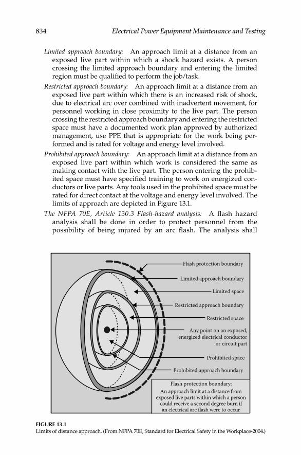
834 Electrical Power Equipment Maintenance and Testing
Limited approach boundary: An approach limit at a distance from an exposed live part within which a shock hazard exists. A person crossing the limited approach boundary and entering the limited region must be qualifi ed to perform the job/task.
Restricted approach boundary: An approach limit at a distance from an exposed live part within which there is an increased risk of shock, due to electrical arc over combined with inadvertent movement, for personnel working in close proximity to the live part. The person crossing the restricted approach boundary and entering the restricted space must have a documented work plan approved by authorized management, use PPE that is appropriate for the work being per-formed and is rated for voltage and energy level involved.
Prohibited approach boundary: An approach limit at a distance from an exposed live part within which work is considered the same as making contact with the live part. The person entering the prohib-ited space must have specifi ed training to work on energized con-ductors or live parts. Any tools used in the prohibited space must be rated for direct contact at the voltage and energy level involved. The limits of approach are depicted in Figure 13.1.
The NFPA 70E, Article 130.3 Flash-hazard analysis: A fl ash hazard analysis shall be done in order to protect personnel from the possibility of being injured by an arc fl ash. The analysis shall
An approach limit at a distance fromexposed live parts within which a person
could receive a second degree burn ifan electrical arc flash were to occur
Limited approach boundary
Limited space
Restricted approach boundary
Restricted space
Prohibited space
Prohibited approach boundary
Any point on an exposed,energized electrical conductor
or circuit part
Flash protection boundary
Flash protection boundary:
FIGURE 13.1Limits of distance approach. (From NFPA 70E, Standard for Electrical Safety in the Workplace-2004.)
DK4058_C013.indd 834DK4058_C013.indd 834 11/8/2008 12:24:14 PM11/8/2008 12:24:14 PM

Electrical Safety, Arc-Flash Hazard, Switching Practices, and Precautions 835
determine the fl ash protection boundary and the PPE that people within the fl ash protection boundary shall use.
Flash protection boundary: For systems that are 600 V or less, the fl ash protection boundary shall be 4.0 ft, based on the product of clearing times of six cycles (0.1 s) and the available bolted fault current of 50 kA or any combination not exceeding 300 kA cycles (5000 A s). For clearing times and bolted fault currents other than 300 kA cycles, or under engineering supervision, the fl ash protection boundary shall alternatively be permitted to be calculated in accordance with the following general formula:
= × × 1/2
c bf[2.65 MVA ]D t
or
= × × 1/2
c [53 MVA ]D t
whereDc distance (ft) from an arc source for a second-degree burnMVAbf is the bolted fault capacity available at point involved (in mega
volt-amps)MVA is the capacity rating of transformer (mega volt-amps). For
transformers with MVA ratings below 0.75 MVA, multiply the transformer MVA rating by 1.25
t is the time of arc exposure (s)
At voltage levels above 600 V, the fl ash protection boundary is the distance at which the incident energy equals 5 J/cm2(1.2 cal/cm2). For situations where fault clearing time is 0.1 s (or faster), the fl ash protection boundary is the distance at which the incident energy level equals 6.24 J/cm2(1.5 cal/cm2).
Protective clothing and PPE for application with a fl ash hazard analysis: Where it has been determined that work will be performed within the fl ash protection boundary by NFPA 70E, Article 130.3(A), the fl ash hazard analysis shall determine, and the employer shall document, the inci-dent energy exposure of the worker (cal/cm2). The incident energy exposure level shall be based on the working distance of the employ-ee’s face and chest areas from a prospective arc source for the specifi c task to be performed. FR clothing and PPE shall be used by the employee based on the incident energy exposure associated with the specifi c task. Recognizing that incident energy increases as the dis-tance from the arc fl ash decreases, additional PPE shall be used for any parts of the body that are closer than the distance at which the incident energy was determined. As an alternative, the PPE requirements of NFPA 70E, Article 130.7(C)(9)(a) shall be permitted to be used in lieu of the detailed fl ash hazard analysis approach described in NFPA 70E, Article 130.3(A).
The NFPA 70E, Article 130.7 (13), Arc fl ash protective equipment: All arc-rated PPE include the ATPV with units in cal/cm2. The required
DK4058_C013.indd 835DK4058_C013.indd 835 11/8/2008 12:24:15 PM11/8/2008 12:24:15 PM

836 Electrical Power Equipment Maintenance and Testing
PPE at specifi c locations is determined by comparing the calculated incident energy to the ratings for specifi c combinations of PPE. NFPA 70E, Table 130.7(C)(11) lists examples of protective clothing systems and typical characteristics including the degree of protection for various clothing. The protective clothing selected for the correspond-ing hazard/risk category number shall have an arc rating of at least the value listed in the last column of NFPA 70E, Table 130.7(C)(11). The NFPA 70E, Table 130.7(C)(11) is shown in Table 13.2 below.
For actual applications, the calculated incident energy must be com-pared to specifi c PPE combinations used at the facility being evalu-ated. The exception to this is the upper limit of 40 cal/cm2. While PPE is available in ATPV values of 100 cal/cm2 or more, values above 40 cal/cm2 are prohibited due to the sound, pressure, and concussive forces. The sound, pressure, and concussive forces are more severe than the thermal values of arc energy greater than 40 cal/cm2. An examination of the categories listed in Table 13.2 implies that each category has range (spread) of arc rating, i.e., for example category 1 range is 4–7.999, category 2 range is 8–24.999, and so on. It should be noted that manufacturers are allowed to label their garments for a given PPE category as long as garment’s thermal value falls within the cat-egory’s range. For example, a garment with an 8 cal/cm2 rating can be labeled category 2 even though the category 2 can go up to 24.99 cal.
TABLE 13.2
PPE Categories
Hazard/Risk
Category
Typical Protective Clothing SystemsRequired Minimum
Arc Rating of PPE
Clothing Description (Typical Number
of Clothing Layers Is Given in Parentheses) J/cm2 cal/cm2
0 Nonmelting, fl ammable materials (i.e., untreated
cotton, wool, rayon, or silk, or blends of these
materials) with a fabric weight at least 4.5 oz/yd2 (1)
N/A N/A
1 FR shirt and FR pants or FR coverall (1) 16.74 4
2 Cotton underwear—conventional short sleeve and
brief/shorts, plus FR shirt and FR pants (1 or 2)
33.47 8
3 Cotton underwear plus FR shirt and FR pants
plus FR coverall, or cotton underwear plus
two FR coveralls (2 or 3)
104.6 25
4 Cotton underwear plus FR shirt and FR pants plus
multilayer fl ash suit (3 or more)
167.36 40
Source: From NFPA 70E-2004, Standard for Electrical Safety in the Workplace-2004, Table
130.7(C)(11).
Note: Arc rating is defi ned in Article 100 and can be either ATPV or EBT. ATPV is defi ned in
ASTM F 1959-99 as the incident energy on a fabric or material that results in suffi cient heat
transfer through the fabric or material to cause the onset of a second-degree burn based on
the Stoll curve. EBT is defi ned in ASTM F 1959-99 as the average of the fi ve highest incident
energy exposure values below the Stoll curve where the specimens do not exhibit break
open. EBT is reported when ATPV cannot be measured due to FR fabric break open.
DK4058_C013.indd 836DK4058_C013.indd 836 11/8/2008 12:24:15 PM11/8/2008 12:24:15 PM

Electrical Safety, Arc-Flash Hazard, Switching Practices, and Precautions 837
It is inappropriate for some manufacturers to promote their safety equipment using lower calorie values for a given category of PPE. Therefore, when selecting PPE, the actual calculated incident energy at the specifi c work location must be compared to specifi c garment thermal rating within the given category to correctly protect the worker from a fl ash hazard.
The NFPA 70E, Article 400.11, Flash Protection: Switchboards, panelboards, industrial control panels, and motor control centers in other than dwell-ing occupancies and are likely to require examination, adjustment, ser-vicing, or maintenance while energized shall be fi eld marked to warn qualifi ed persons of potential electric arc-fl ash hazards. The marking shall be located so as to be clearly visible to qualifi ed persons before examination, adjustment, servicing, or maintenance of the equipment. This is the same requirement stated in Article 110-16 of the NEC-2002.
13.2.5 Occupational Safety and Health Administration (OSHA) Standards
OSHA standards are federal regulations and apply to all covered industries except those states which have adopted safety programs which are approved by the OSHA. A partial listing of industries covered by OSHA is General Industry, Construction Industry, Power Generation, Transmission and Distribution, and Telecommunications. OSHA safety standards are published in the Code of Federal Regulations, Title 29, Subtitle B, Chapter XVII. The OSHA electrical safety standards are in at least four categories similar to the four chapters of NFPA 70E.
These are
Design and installation safety•
Safety-related work practices•
Safety-related maintenance requirements•
Special equipment•
Electrical safety standards for general industry are found in Part 1910, Subpart S, I, and J. A partial listing of subpart S and I is given below.
Title Paragraphs
Design safety standards for
electrical equipment
1910.302–1910.308
Safety-related work practices 1910.331–1910.335
Safety-related maintenance requirements 1910.361–1910.380
Safety requirements for special equipment 1910.381–1910.398
Hazard assessment and equipment selection 1910.132–1910.139
In addition, part 1910.333(a)(1) states that live parts to which an employee may be exposed shall be de-energized before the employee works on or near
DK4058_C013.indd 837DK4058_C013.indd 837 11/8/2008 12:24:15 PM11/8/2008 12:24:15 PM

838 Electrical Power Equipment Maintenance and Testing
them, unless the employer can demonstrate that de-energizing introduces additional or increased hazards or is infeasible due to design or operational limitations. When employees are required to work where there is a potential electrical hazard, part 1910.335 calls for the employer to provide electrical pro-tective equipment that is appropriate for the specifi c parts of the body to be protected and for the work to be performed.
Employers are responsible for performing a hazard assessment in accor-dance with part 1910.132(d)(1) (i–iii). The requirements are as follows:
1910.132(d)(1): The employer shall assess the workplace to determine if hazards are present, or are likely to be present, which necessitate the use of PPE. If such hazards are present, likely to be present, the employer shall:
1910.132(d)(1)(i): Select, and have each affected employee use, the types of PPE that will protect the affected employee from the hazards identifi ed in the hazard assessment
1910.132(d)(1)(ii): Communicate selection decisions to each affected employee
1910.132(d)(1)(iii): Select PPE that properly fi ts each affected employee.
The employer shall verify that the required workplace hazard assess-ment has been performed through a written certifi cation that iden-tifi es the workplace evaluated; the person certifying that the evaluation has been performed; the date(s) of the hazard assess-ment; and, which identifi es the document as a certifi cation of hazard assessment.
1910.335(a)(1)(i) PPE: Employees working in areas where there are potential electrical hazards shall be provided with, and shall use, elec-trical protective equipment that is appropriate for the specifi c parts of the body to be protected and for the work to be performed.
1910.132(f) Training: The employer shall provide training to each employee who is required by this section to use PPE. Each such employee shall be trained to know at least the following: (1) When PPE is necessary; (2) What PPE is necessary; (3) How to properly don, doff, adjust, and wear PPE; (4) The limitations of the PPE; and (5) The proper care, maintenance, useful life, and disposal of the PPE.
Each affected employee shall demonstrate an understanding of the training specifi ed in paragraph (f)(1) of this section, and the ability to use PPE properly, before being allowed to perform work requiring the use of PPE.
1910.132(f)(3) Profi ciency and Retraining: When the employer has reason to believe that any affected employee who has already been trained, but does not have the understanding and skill required by para-graph (f)(2) of this section, the employer shall retrain each such employee. Circumstances where retraining is required include, but are not limited to, situations where: changes in the workplace render
DK4058_C013.indd 838DK4058_C013.indd 838 11/8/2008 12:24:15 PM11/8/2008 12:24:15 PM

Electrical Safety, Arc-Flash Hazard, Switching Practices, and Precautions 839
previous training obsolete; or changes in the types of PPE to be used render previous training obsolete; or inadequacies in an affected employee’s knowledge or use of assigned PPE indicate that the employee has not retained the requisite understanding or skill. The employer shall verify that each affected employee has received and understood the required training through a written certifi cation that contains the name of each employee trained, the date(s) of train-ing, and that identifi es the subject of the certifi cation.
13.3 Arc-Flash Hazard and Regulatory Requirements
The regulatory requirements of OSHA, NFPA 70, and NFPA 70E pertaining to a worker’s safety are described in Section 13.2. The regulatory requirements can be summarized as follows:
1. Determine the risk to personnel from exposure to incident energy released during an arc-fl ash event, i.e., the arc-fl ash hazard must be quantifi ed.
2. Provide appropriate arc-fl ash hazard protection, i.e., correct PPE must be selected for nonprohibited work.
3. The arc fl ash assessment results must be documented and equipment labeled to inform and warn personnel of arc-fl ash hazard.
4. Personnel must be trained, understand the extent of arc-fl ash hazard, and take correct protective actions.
To quantify the hazard for each specifi c location, arc-fl ash analysis should be performed using either the IEEE 1584, IEEE Guide for Performing Arc-Flash Hazard Calculations, methodology or the alternate method given in 70E. The IEEE 1584 and 70E methodologies involve calculating available short-circuit currents for each location, determining the clearing time of protective relays and devices, equipment location type and working distance. See Sections 13.3.2 and 13.3.3 for more details on performing the arc-fl ash analysis study. The correct PPE category is selected based on the results of the arc-fl ash hazard analysis study. After completion of the steps 1 and 2, correct labeling is developed to label the equipment in accordance with NEC and 70E require-ments to warn personnel of the hazard. The labels that are generated from the arc-fl ash analysis programs are color coded to signify the severity of the danger of the incident energy available at the particular location. For exam-ple, the label color codes range from color green for category 0 (minimum severity) to color red (maximum severity) for which no PPE category is avail-able and where no work can be done on energized equipment. A sample of the two labels generated using an arc-fl ash analysis program is shown in Figures 13.2 and 13.3. It should be noted that the text and color of the label in Figure 13.2 signifi es the “Danger” and states “energized work is prohibited” because the arc energy exceeds the 40 cal/cm2 for which no PPE is available.
DK4058_C013.indd 839DK4058_C013.indd 839 11/8/2008 12:24:15 PM11/8/2008 12:24:15 PM

840 Electrical Power Equipment Maintenance and Testing
FIGURE 13.2Arc-fl ash hazard label for no PPE category available.
! DANGERNO PPE AVAILABLE
ENERGIZED WORK PROHIBITED1919 in. Flash Hazard Boundary
Flash Hazard at 36 in.
Dangerous !!! No FR Class Found
13,200 VAC Shock Hazard when cover is removed
2 Glove Class
60 in. Limited Approach (Fixed Circuit)
26 in. Restricted Approach
7 in. Prohibited Approach
Bus: 13.2 KV PRIM Prot: 125E PRIM FU
57.2 cal/cm2
FIGURE 13.3Arc-fl ash hazard label for PPE category 4.
! WARNINGArc Flash and Shock HazardAppropriate PPE Required125 in. Flash Hazard Boundary
Flash Hazard at 18 in.
Class 4Cotton Underwear + FR Shirt and Pant + Multilayer Flash Suit
480 VAC Shock Hazard when cover is removed00 Glove Class42 in. Limited Approach (fixed circuit)12 in. Restricted Approach1 in. Prohibited Approach
Bus: MAIN SWBD BUS Prot: 4000A MAIN BKR
28.6 cal/cm2
DK4058_C013.indd 840DK4058_C013.indd 840 11/8/2008 12:24:15 PM11/8/2008 12:24:15 PM

Electrical Safety, Arc-Flash Hazard, Switching Practices, and Precautions 841
The label shown in Figure 13.3 indicates PPE category 4 that the worker must use to perform work at this location. Both labels show the calculated fl ash protection boundary, incident energy, PPE category, glove classifi cation, and shock protection boundaries per NFPA 70 E. The fi nal step in this pro-cess is to give training to the employees on the arc-fl ash hazard, and how they should protect themselves.
13.3.1 Summary of NFPA 70, 70E, and OSHA Requirements
NFPA 70E and OSHA part 1910-132 require a hazard assessment for electrical equipment and selection of appropriate PPE for the employees if they are to work on energized equipment. Further, NFPA 70 (National Electric Code) requires that the equipment has to be labeled to show the available arc energy and the category of PPE the person needs to wear before working on the equipment. The following overview is offered for the reader in order to under-stand what is required by the above stated NFPA and OSHA requirements.
13.3.2 Overview of Arc-Flash Hazard
Arc-fl ash hazard is defi ned as a dangerous condition associated with the release of energy caused by an electric arc. The arc current creates a brilliant fl ash of light, a loud noise, intense heat, and a rapidly moving pressure wave. The products of arc-fault are ionized gases, metal vapors, molten metal drop-lets, and shrapnel that shower the immediate vicinity of the arcing fault. The electrical arc burns make up a substantial portion of injuries from electrical malfunctions. The extremely high temperatures of the electrical arc can cause fatal and major burns at distances of 5–10 ft from the arcing equip-ment. Therefore, the focus of industry on electrical safety and recognition of arc-fl ash burns as having great signifi cance highlighted the need for protect-ing employees from all arc-fl ash hazards. The NEC-2008, Article 110-16 Flash protection, states in part that switchboards, panelboards, industrial control panels, and motor control centers that are in other than dwelling occupan-cies and are likely to require examination, adjustment, servicing, or mainte-nance while energized shall be fi eld marked to warn qualifi ed persons of potential electric arc-fl ash hazards. It is implied that fl ash protection is required when examining, adjusting, servicing, or maintaining energized equipment. The equipment shall be fi eld marked (labeled) to warn qualifi ed persons of potential electric arc-fl ash hazards. Let us now take a look at how the requirements for fi eld labeling of equipment can be accomplished.
In order to generate an arc fl ash hazard label, an arc-fl ash hazard analysis study has to be conducted to determine the arc energy available at a given equipment. Therefore an arc-fl ash hazard analysis is performed in conjunc-tion with the short-circuit study and protective device coordination study. Results of the short-circuit study are used to calculate the three-phase fault current from which the arcing fault current is determined. Results of protec-tive device coordination study are used to determine the time required for the electrical protective devices to clear the arcing fault current conditions.
DK4058_C013.indd 841DK4058_C013.indd 841 11/8/2008 12:24:16 PM11/8/2008 12:24:16 PM

842 Electrical Power Equipment Maintenance and Testing
Results of both short circuit and protective device coordination studies are used to perform an arc-fl ash hazard analysis. Results of arc-fl ash hazard anal-ysis are used to identify the fl ash protection boundary and the incident energy at assigned working distances for the electrical equipment. The fl ash protec-tion boundary and the incident energy calculated in the arc-fl ash hazard analysis evaluation are based on taking credit for the protective relays and devices in removing the arc. Therefore it is important that these protective devices be kept in good working condition to maintain the validity of the arc-fl ash hazard analysis results. Readers will fi nd useful information in Section 1.9 in Chapter 1, where a discussion is provided on the bases of maintenance and testing of protective devices. In view of the requirements for arc-fl ash hazard analysis, it has become even more important now to maintain and test breakers and protective devices on a regular basis to ensure their reliability.
13.3.3 Arc-Flash Analysis
The arc-fl ash analysis is conducted by using a software program specifi cally developed to do the arc-fl ash analysis. The arc-fl ash software programs are based on the methodologies given in IEEE-1584-2002 and the NFPA 70E methodologies. The arc-fl ash software program is intended to provide guid-ance based on the methodologies given in IEEE-1584–2002 and the NFPA 70E for the calculation of incident energy and arc-fl ash protection boundaries. The results obtained from the arc-fl ash software program can be used as a basis to develop strategies that have the potential of minimizing burn injuries. These strategies include specifying the rating of PPE, working only when the equipment is not energized, applying arc-resistance switchgear, and following other good engineering techniques and work practices. The guide for arc-fl ash analysis presented in the IEEE-1584-2002, is based on testing and analysis of the hazard presented by incident energy. The potentially hazardous effects of molten metal splatter, projectiles, pressure impulses, and toxic arc by-products were not considered in the analysis methodology of IEEE-1584-2002. The soft-ware programs based on the IEEE-1584-2002, provide analysis only for the hazards presented by incident energy and do not cover the potential hazards from molten metal splatter, projectiles, pressure impulses, and toxic arc by-products. The PPE listing documented in the result of the arc-fl ash software program are not intended to prevent all injuries but to mitigate the impact of an arc fl ash upon a person, if one should occur. The selection of a level of PPE is based on NFPA 70E, Table 130.7(C)(11) using the results of the arc-fl ash analysis. For conducting an arc-fl ash analysis, the following steps are required:
Collect the system data•
Determine the system modes of operation•
Calculate the bolted fault currents•
Determine the arcing fault currents•
Determine protective device characteristics and the duration of the • arcs (clearing time of the protective devices)
DK4058_C013.indd 842DK4058_C013.indd 842 11/8/2008 12:24:16 PM11/8/2008 12:24:16 PM
Electrical Safety, Arc-Flash Hazard, Switching Practices, and Precautions 843
Determine the system voltages and classes of equipment•
Select the working distances•
Determine the incident energy for all equipment•
Determine the fl ash boundary for all equipment•
Select PPE from the NFPA 70E-2004•
It should be noted that it takes an experienced engineer to implement the steps listed above for modeling the electrical power system, input the required system data, set the overcurrent relays and protective devices in the software program. After the short circuit and protective device coordination studies are completed then an arc fl ash hazard analysis study is conducted to calculate the various parameters of the arc fl ash hazard. The arc-fl ash software programs available on the market today will generate a report that provides detail information on the various aspects of arc fl ash hazard analysis. A typical arc fl ash evaluation report includes the information listed in Table 13.3.
TABLE 13.3
Typical Arc Flash Evaluation Report Information
Bus name This is the location at which the equipment is being
evaluated.
Prot device name This is protective device that interrupts the arcing current.
Bus (kV) The nominal voltage of the bus or equipment.
Bolted bus fault This is the bolted three-phase fault at the bus or equipment.
Protective device bolted fault This is the bolted fault current through the protective device.
Protective device arcing fault This is the arching fault current through the protective
device.
Trip/delay time The protective device tripping delay time taken from the time
current coordination study.
Breaker opening time The breaker opening time (mechanical time).
Ground The type of system grounding; yes, means solidly grounded;
no, means high-resistance or ungrounded system.
Equipment type This is taken from IEEE std 1584-2002, Table 2.
Gap (mm) Typical bus-to-bus gap taken from IEEE std 1584-2002,
Table 2.
Arc-fl ash boundary (in.) This is an approach limit for fl ash protection from live parts
operating at 50 V or more that are uninsulated or exposed
within which a person could receive a second degree burn
should an arc source develop.
Working distance (in.) The working distance of the head and chest from a potential
arc source.
Incident energy (cal/cm2) This is the incident energy calculated based on the arc
current, the arc time, and the working distance.
Required protective FR
clothing class
Based on the calculated incident energy, a hazard risk
category class is determined for personnel protective
clothing. Refer to NFPA 70E, Tables 130.7(C)(10) and
130.7(C)(11) for complete clothing equipment.
DK4058_C013.indd 843DK4058_C013.indd 843 11/8/2008 12:24:16 PM11/8/2008 12:24:16 PM

844 Electrical Power Equipment Maintenance and Testing
13.4 Electrical Safety Practices and Precautions
The methods and techniques discussed in this chapter are industry accepted practices for working in or around energized electric power lines and cir-cuits, and should be used only as guidelines. National and local codes and rules and regulatory standards should always take precedence over the guidelines discussed in this chapter.
The following rules are basic to electrical accident prevention:
Know the work to be done and how to do it.•
Review working area for hazards of environment or facility design • that may exist in addition to those directly associated with the assigned work objective.
Wear fl ame-retardant coveralls and safety glasses plus other recom-• mended protective devices/equipment. Refer to the PPE categories specifi ed under arc-fl ash hazard analysis for a specifi ed task.
Isolate (de-energize) the circuits and/or equipment to be worked.•
Lock out and tag all power sources and circuits to and from the • equipment/circuit to be worked on.
Test with two pretested testing devices for the presence of electrical • energy on circuits and/or equipment (both primary and secondary) while wearing electrical protective gloves.
Ground all sides of the work area with protective grounds applied • with hot sticks. All grounds must be visible at all times to those in the work area.
Enclose the work area with tape barrier.•
13.4.1 Electrical Safety
The following general guidelines are provided on on-site safety, work area con-trol, lock-out and/or tagging, protective apparel, testing of energized circuits and equipment, rubber gloves, voltage testers and detectors, grounds, circuit breaker maintenance safety checklist, and entering confi ned spaces. These guidelines should be supplemented as required to meet the applicable codes and regulations including the PPE required per arc-fl ash hazard analysis.
13.4.2 “On-Site” Electrical Safety
Prior to going on an “on-site” electrical assignment, each worker should receive the following rules and should review and abide by them while on the assignment.
A foreman or qualifi ed employee should be designated for each on-site assign-ment to provide on-site work direction and safety coordination. All personnel assigned to on-site electrical work should comply with the following directions:
DK4058_C013.indd 844DK4058_C013.indd 844 11/8/2008 12:24:16 PM11/8/2008 12:24:16 PM

Electrical Safety, Arc-Flash Hazard, Switching Practices, and Precautions 845
Know the work content and work sequence, especially all safety • measures.
Know the proper tools and instruments required for the work, that • they have the full capability of safely performing the work, and that they are in good repair and/or are calibrated.
Check to determine that all de-energized circuits and equipment are • locked out and that grounds are placed on all sides of the work area prior to beginning work.
Segregate all work areas with barriers or tapes, confi ne all your activ-• ities to these areas, and prevent unauthorized access to the area.
Insure that all energized circuits and equipment adjacent to the work • area are isolated, protected, or marked by at least two methods (e.g., rubber mats, tapes, signs, etc.) for personnel protection.
Do not perform work on energized circuits and equipment without • the direct authorization of your unit manager. When work on ener-gized circuits and equipment has been authorized, use appropriate PPE required for the task, safety-tested equipment (i.e., rubber gloves, sleeves, mats, insulated tools, etc.).
Your foreman and qualifi ed employee must inform you of all changes • in work conditions. You then must repeat this information to your foreman and qualifi ed employee to insure your recognition and understanding of the condition.
Do not work alone; work with another worker or employee at all • times. Do not enter an energized area without direct permission from your foreman and qualifi ed employee.
Discuss each step of your work with your foreman and qualifi ed • employee before it is begun.
Do not directly touch an unconscious fellow worker since he or she • may be in contact with an energized circuit and equipment. Use an insulated device to remove him or her from the suspect area.
Do not perform, or continue to perform, any work when you are in • doubt about the safety procedure to be followed, the condition of the equipment, or any potential hazards. Perform this work only after you have obtained directions from your foreman and qualifi ed employee.
Do not work on, or adjacent to, any energized circuits and equipment • unless you feel alert and are in good health.
13.4.3 “On-Site” Safety Kit
The following are recommended protective tools to be used in preparation for and in the performance of on-site electrical work:
Red safety tape (300 ft)•
Red fl ashing hazard lights (6)•
DK4058_C013.indd 845DK4058_C013.indd 845 11/8/2008 12:24:16 PM11/8/2008 12:24:16 PM

846 Electrical Power Equipment Maintenance and Testing
Safety cones (6)•
Red “Do Not Operate” tags (15)•
Padlocks, keys, and lock shackle (6)•
Ground fault circuit interrupter-15 A, 125 V (1)•
Fire extinguishers (2)•
PPE•
Flame-retardant coveralls
Safety glasses
Face shields
Hard hats
Other items required for protection on the job
Combustible gas/oxygen detectors•
Portable ventilation blower•
Ground loop impedance tester, ohmmeter (1)•
Voltage detectors•
Statiscope
1. Station type (1)
2. Overhead extension type (1)
Audio
1. Tic Tracer
2. ESP
Voltage/ampere meter (1)•
Amprobe
Simpson
Rubber gloves and protectors of appropriate class•
Grounding clamps, cables•
Hot sticks•
13.4.4 Work Area Control
When workers are setting up the control area, it should be standard pro cedure that the safety coordinator be present and provide the required information.
Tape—solid red: A red tape barrier (with safety cones and red fl ashing lights) must be used to enclose an area in which personnel will be working. Other persons may not enter the isolated area unless they are actively working in conjunction with the personnel on the assigned work.
The purpose of the solid red tape barrier is to enclose and isolate an area in which a hazard might exist for individuals unfamiliar with the equipment enclosed. The only persons permitted within the solid red barrier are indi-viduals knowledgeable in the use and operation of the enclosed equipment.
DK4058_C013.indd 846DK4058_C013.indd 846 11/8/2008 12:24:16 PM11/8/2008 12:24:16 PM

Electrical Safety, Arc-Flash Hazard, Switching Practices, and Precautions 847
For their safety, workers shall not interest themselves in nor enter any area not enclosed by the red tape barrier except for a defi ned route to enter and leave the site.
It is important that the tape barrier is strictly controlled and the restric-tions regarding its use are enforced.When any workers are using solid red tape to enclose an area, the following requirements must be satisfi ed:
Place the tape so that it completely encloses the area or equipment where the hazard exists.
Place the tape so that it is readily visible from all avenues of approach and at such a level that it forms an effective barrier.
Be certain that the area enclosed by the tape is large enough to give adequate clearance between the hazard and any personnel working in the tape enclosed area.
Arrange the tape so any test equipment for the setup can be operated safely from outside the enclosed area.
Use the tape to prevent the area from being entered by persons unfa-miliar with the work and associated hazards. Do not use the tape for any other purpose.
Remove the tape when the hazard no longer exists and the work is completed.
It shall be standard procedure that the workers should consider all areas out-side the red barrier work area as energized and undertake no investigation unless accompanied by a knowledgeable plant employee.
Tape—white with a red stripe: White tape with a red stripe is used to enclose and isolate a temporary hazard (mechanical or electrical). No one is to enter this enclosed area. Obviously, if the enclosing of a hazardous area with tape is to be protective, the use of the tape barrier should be controlled and the restrictions on entering the area strictly enforced.When any personnel are using white tape with a red stripe, the following requirements must be satisfi ed:
Place the tape so that it completely encloses the area or equipment where the hazard exists.
Place the tape so that it is readily visible from all avenues of approach and at such a level that it forms an effective barrier.
Be certain that the area enclosed is large enough to give adequate clear-ance between the hazard and any personnel outside the enclosed area.
Arrange the tape so that the test equipment for the setup can be operated outside the enclosed area.
Use the tape only to isolate a temporary mechanical or electrical hazard; do not use the tape for any other purpose.
DK4058_C013.indd 847DK4058_C013.indd 847 11/8/2008 12:24:16 PM11/8/2008 12:24:16 PM

848 Electrical Power Equipment Maintenance and Testing
Consider a striped tape area similar to an interlocked enclosure and treat as such.
Remove the tape when the hazard no longer exists.
13.4.5 Lock-Out and/or Tagging
For the protection of personnel working on electrical conductor and/or equipment, locks must be placed on all open isolation devices designed to receive them. “DANGER” tags signed by the foreman or qualifi ed employee must also be placed on the open isolation device.
Danger Tags: Danger tags may be applied only by authorized personnel and the tags must be dated and signed by the person applying the tag. The following requirements must be satisfi ed when danger tags are used:
Danger tags are to be used only for personnel protection when the per-sonnel are required to work on or near equipment that, if operated, might cause injury.
Danger tags are attached to primary disconnecting devices as a means of locking out equipment. Tag each source of power to the equipment and asso-ciated feeds (instrumentation circuits, PT’s, CT’s, etc.) to the equipment which is to be locked out.
Danger tags should be left on the equipment only while the personnel are working on the equipment or when a hazard to the personnel exists. A device bearing a danger tag must not be operated at any time (Figure 13.4).
Out of order tags: Out of order tags are used to restrict the operation of equipment which has a mechanical defect or for other reasons that are not related to the safety of personnel. Complete information concerning the rea-sons for the tag and a list of all persons authorized to operate the tagged device must be written on the tag (Figure 13.5).
Out of service tags: Out of service tags are used to indicate equipment that has been taken out of service. It is a white tag with letters on a black background.
FIGURE 13.4A sample of danger tag.
DANGER
DONOTOPERATE
Red
Green
DK4058_C013.indd 848DK4058_C013.indd 848 11/8/2008 12:24:16 PM11/8/2008 12:24:16 PM

Electrical Safety, Arc-Flash Hazard, Switching Practices, and Precautions 849
Caution tags: Caution tags are used to indicate potential hazard or unsafe conditions. These are yellow tags with yellow letters on a black background.
Use of danger tags: Danger tags are authorized for use on any isolation device as a method of locking out equipment. These tags must be hung so there is no doubt as to which device they control. The tags may be used and signed only by authorized personnel, who are designated by the plant manager.
When more than one crew or trade is working on the same equipment, each crew must attach its own tag and place its own lock on the device. Gang lock clips can be used as shown in Figure 13.6 to provide maximum protection to a number of crews working on the same equipment or conductors.
Danger tags may be removed only by the person who originally placed and signed the tag. If that person is absolutely unable to remove the tag, a committee selected by the plant manager will fully investigate the situation. This committee will remove the tag only when they are satisfi ed that they have full knowledge of the intention of the original tagger and that the tag may be removed without endangering anyone.
13.4.6 Protective Apparel-Operating Electrical Equipment
All personnel must wear the PPE i.e., apparel based on the arc-fl ash hazard categories required by NFPA 70E and OSHA regulations (see Sections 13.2 and 13.3) when working on electrical equipment which is, or might be considered, energized, or become energized as a result of the work. Following is a partial list of protective clothing covered in the PPE categories described in NFPA 70E:
FIGURE 13.6A sample of Gang lock clips to lock out equipment.
OUT OFORDER
FIGURE 13.5A sample of out of service tag.
DK4058_C013.indd 849DK4058_C013.indd 849 11/8/2008 12:24:16 PM11/8/2008 12:24:16 PM
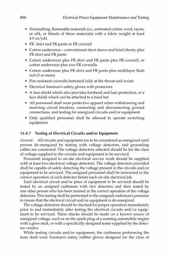
850 Electrical Power Equipment Maintenance and Testing
Nonmelting, fl ammable materials (i.e., untreated cotton, wool, rayon, • or silk, or blends of these materials) with a fabric weight at least 4.5 oz/ydz
FR shirt and FR pants or FR coverall•
Cotton underwear—conventional short sleeve and brief/shorts, plus • FR shirt and FR pants
Cotton underwear plus FR shirt and FR pants plus FR coverall, or • cotton underwear plus two FR coveralls
Cotton underwear plus FR shirt and FR pants plus multilayer fl ash • suit (3 or more)
Fire-resistant coveralls buttoned fully at the throat and wrists•
Electrical lineman’s safety gloves with protectors•
A face shield which also provides forehead and hair protection, or a • face shield which can be attached to a hard hat
All personnel shall wear protective apparel when withdrawing and • inserting circuit breakers, connecting and disconnecting ground connections, and testing for energized circuits and/or equipment
Only qualifi ed personnel shall be allowed to operate switching • equipment
13.4.7 Testing of Electrical Circuits and/or Equipment
General: All circuits and equipment are to be considered as energized until proven de-energized by testing with voltage detectors, and grounding cables are connected. The voltage detectors selected should be for the class of voltage supplied to the circuits and equipment to be serviced.
Personnel assigned to on-site electrical service work should be supplied with at least two electrical voltage detectors. The voltage detectors provided shall be capable of safely detecting the voltage present in the circuits and/or equipment to be serviced. The assigned personnel shall be instructed in the correct operation of each detector before each on-site electrical job.
Each electrical circuit and/or piece of equipment to be serviced should be tested by an assigned craftsman with two detectors and then tested by one other person who has been trained in the correct operation of the voltage detectors. This testing shall be performed in the assigned craftsman’s presence to insure that the electrical circuit and/or equipment is de-energized.
The voltage detectors should be checked for proper operation immediately prior to and immediately after testing the electrical circuits and/or equip-ment to be serviced. These checks should be made on a known source of energized voltage, such as on the spark plug of a running automobile engine with a glow stick, or with a specifi cally designed tester supplied by the detec-tor vendor.
While testing circuits and/or equipment, the craftsman performing the tests shall wear lineman’s safety rubber gloves designed for the class of
DK4058_C013.indd 850DK4058_C013.indd 850 11/8/2008 12:24:17 PM11/8/2008 12:24:17 PM

Electrical Safety, Arc-Flash Hazard, Switching Practices, and Precautions 851
voltage in the circuits and/or equipment to be serviced and other protective equipment for this work.
Capacitors: A capacitor to be serviced must be removed from operation in the following sequence:
Isolate the capacitors by opening the breakers or isolation devices connecting them to the electrical system.
Permit the capacitors to drain off the accumulated charge for 5–10 min. (There is generally a built-in device which accomplishes this drain.)
Short circuit and ground the capacitors in the manner and with the protec-tive equipment noted in Section 13.4.11. While performing these procedures, be very careful that suffi cient distance is maintained from the capacitors with a hot stick in the event the drain-off device is not properly functioning.
Vacuum circuit breaker high-potential testing (hipotting)–cautions: Although the procedure for hipotting a vacuum circuit breaker is similar to that used for any other electrical device, there are two areas that require the exercise of extra caution.
During any hipotting operation, the main shield inside the interrupter can acquire an electrical charge that usually will be retained even after the hipot voltage is removed. This shield is attached to the midband ring of the insu-lating envelope. A grounding stick should always be used to discharge the ring as well as the other metal parts of the assembly before touching the interrupter, connections, or breaker studs.
High voltage (HV) applied across open gaps in a vacuum can produce hazardous X-radiation if the voltage across the contacts exceeds a certain level for a given contact gap. Therefore, do not make hipot tests on an open breaker at voltages higher than the recommended 36 kV alternating current (AC) across each interrupter. During the hipot test, the steel front panel and partial side panels should be assembled to the breaker. Personnel should stand in front of the breaker to take advantage of the shielding afforded by the panels. If this position is not practical, equivalent protection can be pro-vided by limiting personnel exposure to testing four three-phase breakers per hour with the personnel not closer than 3 m (9 ft 10 in.) to the interrupters. During equipment operation in the normal current carrying mode, there is no X-radiation because there are no open contacts.
Electrostatic coupling: When personnel are working on a de-energized circuit that is adjacent to an energized circuit, it is important to be certain that solid grounds are attached to the de-energized circuit at all times. A substantial voltage charge can be generated in a de-energized circuit by electromagnetic coupling with the energized circuit. The solid grounds will drain off this voltage charge.
13.4.8 Rubber Gloves for Electrical Work-Use and Care
Rubber gloves with leather protectors that have been tested to at least 10,000 V must be worn when work is performed on or within reach of
DK4058_C013.indd 851DK4058_C013.indd 851 11/8/2008 12:24:17 PM11/8/2008 12:24:17 PM

852 Electrical Power Equipment Maintenance and Testing
energized conductors and/or equipment. The rubber gloves and protectors of the appropriate class should be available to all trained personnel as part of the safety kit for on-site electrical work.The rubber gloves and protectors are of two types:
1. Low-voltage rubber gloves and protectors (Class 0). These gloves are tested and approved for work on equipment energized at 750 V or less. (Permission should be given by the foreman for the use of low-voltage gloves when working on conductors and/or equipment energized below 750 V.)
2. HV rubber gloves and protectors. The gloves are tested at 10,000 V (Class 1) for use on 5 kV or less, tested for 15,000 V for use on 10 kV or less (Class 2), and at 20,000 V (Class 3) for use on 15 kV or less voltage ratings.
Both HV and low-voltage rubber gloves are of the gauntlet type and are avail-able in various sizes. To get the best possible protection from rubber gloves, and to keep them in a serviceable condition as long as possible, here are a few general rules that apply whenever they are used in electrical work:
Always wear leather protectors over your gloves. Any direct contact • of a rubber glove with sharp or pointed objects may cut, snag, or punc-ture the glove and rob you of the protection you are depending on.
Always wear rubber gloves right side out (serial number and size • to the outside). Turning gloves inside out places a stress on the preformed rubber.
Always keep the gauntlets up. Rolling them down sacrifi ces a valu-• able area of protection.
Always inspect and give a fi eld air test (described later) to your • gloves before using them. Check the inside of the protectors for any bit of metal or short pieces of wire that may have fallen in them.
Always store gloves where they cannot come into contact with sharp • or pointed tools that may cut or puncture them.
All gloves are to be inspected before use.•
HV rubber gloves:
These gloves must be tested before they are issued. All gloves should • be issued in matched pairs in a sealed carton. If received with the seal broken, return them for testing.
When HV gloves are issued to individuals for use over a three month • period, they shall be inspected and tested at least every three months by a certifi ed testing laboratory. All gloves, must be tested when returned to the tool crib after the job is completed.
DK4058_C013.indd 852DK4058_C013.indd 852 11/8/2008 12:24:17 PM11/8/2008 12:24:17 PM

Electrical Safety, Arc-Flash Hazard, Switching Practices, and Precautions 853
Low-voltage rubber gloves:
Low-voltage rubber gloves must be inspected (see inspection of • rubber gloves) before each use
Defective gloves, or gloves in a questionable condition, must be • immediately replaced
Leather protector gloves:
Approved leather protectors must be worn over rubber gloves to • protect them from mechanical injury
Protectors that have been soaked with oil should never be used over • rubber gloves
Protectors that are serviceable for use over rubber gloves are not to • be used as work gloves
Protectors should be replaced if they have faulty or worn stitching, • holes, cuts, abrasions, or if for any other reason, they no longer protect the rubber gloves
Inspection of rubber gloves (all classes): Before rubber gloves are used, a visual inspection and an air test should be made at least once every day and at any other time deemed necessary during the progress of the job.
Visual inspection: When inspecting rubber gloves in the fi eld, stretch a small area at a time (see Figure 13.7), checking to be sure that no defects exist, such as (1) embedded foreign material, (2) deep scratches, (3) pin holes or punctures, (4) snags, or (5) cuts. In addition, look for signs of deterioration caused by oil, tar, grease, insulating compounds, or any other substance which may be injurious to rubber. Inspect the entire glove thoroughly, including the gauntlet.
Gloves that are found to be defective should not be mutilated in the fi eld but should be tagged with a yellow tag and turned in for proper disposal.
Air test: After visually inspecting the glove, other defects may be observed by applying the air test as follows:
FIGURE 13.7Inspecting rubber gloves in the fi eld.
DK4058_C013.indd 853DK4058_C013.indd 853 11/8/2008 12:24:17 PM11/8/2008 12:24:17 PM
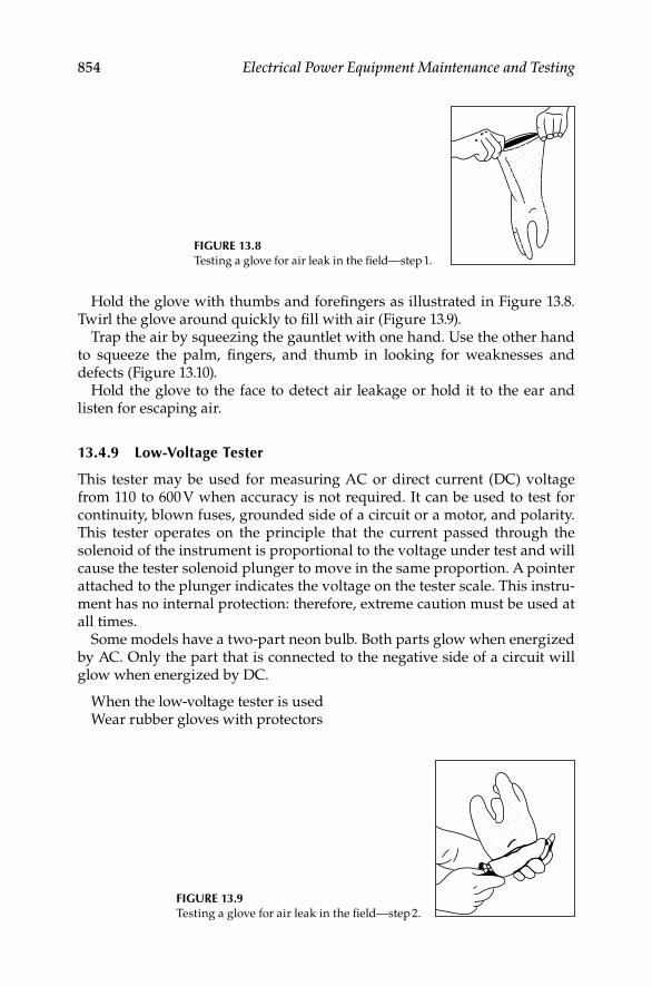
854 Electrical Power Equipment Maintenance and Testing
Hold the glove with thumbs and forefi ngers as illustrated in Figure 13.8. Twirl the glove around quickly to fi ll with air (Figure 13.9).
Trap the air by squeezing the gauntlet with one hand. Use the other hand to squeeze the palm, fi ngers, and thumb in looking for weaknesses and defects (Figure 13.10).
Hold the glove to the face to detect air leakage or hold it to the ear and listen for escaping air.
13.4.9 Low-Voltage Tester
This tester may be used for measuring AC or direct current (DC) voltage from 110 to 600 V when accuracy is not required. It can be used to test for continuity, blown fuses, grounded side of a circuit or a motor, and polarity. This tester operates on the principle that the current passed through the solenoid of the instrument is proportional to the voltage under test and will cause the tester solenoid plunger to move in the same proportion. A pointer attached to the plunger indicates the voltage on the tester scale. This instru-ment has no internal protection: therefore, extreme caution must be used at all times.
Some models have a two-part neon bulb. Both parts glow when energized by AC. Only the part that is connected to the negative side of a circuit will glow when energized by DC.
When the low-voltage tester is usedWear rubber gloves with protectors
FIGURE 13.9Testing a glove for air leak in the fi eld—step 2.
FIGURE 13.8Testing a glove for air leak in the fi eld—step 1.
DK4058_C013.indd 854DK4058_C013.indd 854 11/8/2008 12:24:17 PM11/8/2008 12:24:17 PM

Electrical Safety, Arc-Flash Hazard, Switching Practices, and Precautions 855
Check the operation of the tester by testing a known energized circuit. Assure good contact with the tester probes across the circuit being tested. Read the voltage on the tester.
Because the low-voltage tester is designed for intermittent use only, continuous operation might burn out the solenoid, especially on the higher voltage.
Tic tracer (an audio voltage detector): The tic tracer is an audio voltage detector, which detects the electrostatic fi eld surrounding an energized AC circuit and/or equipment.
This detector will operate only on unshielded AC circuits and/or equipment. It will detect the presence of voltages ranging from approxi-mately 40 up to 600 V when hand held; higher voltages when used with approved hot sticks.
Wear HV rubber gloves and leather protectors when using the tic tracer to test circuits and/or equipment to be serviced.
Turn on the actuating switch on the side of the tic tracer.Check the tracer by bringing it close to a conductor known to be energized.Check for proper tracer operation by placing it near a lighted fl uorescent
bulb or at any known energized conductor of AC voltage.
13.4.10 Medium- and HV-Detectors
Proximity Type: The proximity type HV tester is an instrument intended for use in detecting the electrostatic fi eld surrounding an electrical conductor that is energized with AC at high potential. It is used only on AC circuits and/or equipment. The lowest voltage that can be reliably detected by this device is about 2000 V. Most detectors of this type have hard rubber or plastic tubular cases with one end for testing and a handle at the other end. A neon tube is used for voltage detection. There are several designs in various lengths for use in different situations. When the test end is brought near an uninsu-lated conductor that has been energized with AC at high potential, the neon tube will light with a red glow. A conductor that is surrounded by grounded metal has its electrostatic fi eld effectively limited by the grounded metal; therefore, care should be taken that a conductor under test is not shielded in such a way as to interfere with the operation of the detector.
FIGURE 13.10Testing a glove for air leak in the fi eld—step 3.
DK4058_C013.indd 855DK4058_C013.indd 855 11/8/2008 12:24:17 PM11/8/2008 12:24:17 PM

856 Electrical Power Equipment Maintenance and Testing
Use of a proximity HV detector
Wear HV rubber gloves of the appropriate class with protectors.•
Wipe detector clean and dry. Check detector by bringing the test end • close to an uninsulated conductor known to be energized at HV. Or you can use portable tester (Figure 13.11) by placing the lamp-end metal terminal of the detector against the testing point of the tester and pulling the trigger. If neon bulb of the detector glows, it is in good condition.
To test an uninsulated conductor to determine whether or not it is • energized, bring the test end of the detector close to the conductor. A red glow from the neon tube indicates that the conductor is ener-gized. If there is no red glow from the neon tube, recheck the detector as explained above to make certain that the instrument is properly functioning.
In using the detector, turn the neon tube away from the direct rays of • strong light in order to make the red glow from the tube more visible.
Wear rubber gloves and leather protectors when making tests with • HV detectors and keep hands in back of guards on handles.
The proper type of detector, having suffi cient length or extension, • should be used to maintain proper body clearances for the particular voltage being tested. Some detectors are equipped with a periscope (Figure 13.12) so that the glow from the neon tubes will be visible from a greater distance. Care must be exercised in the use of the peri-scope type so the guard or hand does not block the line of sight.
Direct contact type: The direct contact type HV detector is an instrument intended for use in detecting the presence of an AC voltage with respect to ground by direct contact between the detector and the energized conductor. It is used only on AC circuits and/or equipment. The lowest voltage that can
FIGURE 13.11Proximity type HV detector with
neon tube.
Guard Periscope
FIGURE 13.12Proximity Type HV detector with
periscope.
DK4058_C013.indd 856DK4058_C013.indd 856 11/8/2008 12:24:17 PM11/8/2008 12:24:17 PM

Electrical Safety, Arc-Flash Hazard, Switching Practices, and Precautions 857
be reliably detected by this instrument is about 2400 V to ground. The actual detection is normally done by a neon tube connected to one side of a forked contact terminal. The bulb is illuminated by a very small current fl ow due to the capacitance between an internal electrode and ground. This type of detector should not be used on ungrounded systems.
A special type phasing detector with two HV wands should be used if the system is ungrounded. These two wands are each touched to a different phase and the neon indicator detects phase-to-phase voltage. This device can also be used on grounded systems. The lowest voltage that can be reliably detected by this device is about 2000 V.
Important points to remember:
Assume all circuits to be energized until proven otherwise.•
All protective equipment is to be proof tested for the voltage being • worked.
Maintain all leads, probes, clips, and terminals in good condition. • Repair or replace defective leads.
Wear HV rubber gloves of the appropriate class with protectors.•
13.4.11 Grounds-Personnel Protection
Grounding is installed to provide a metallic connection from ground to de-energized circuit and/or equipment to be serviced. This is for the pur-pose of draining off static and induced electricity but, most importantly, to protect the worker, in the event that the equipment becomes accidentally energized. Before grounds are attached, the cable, bus, or equipment must be de-energized, isolated, locked out, and tagged. It must then be defi nitely established that the equipment to be grounded is de-energized by testing the circuits and/or equipment with voltage detectors.
The selection of the ground clamps is based on both the confi guration and the electrical capacity according to the type of equipment to be grounded. The ground cable is to be a fl exible insulated copper conductor. The rules for sizing the ground cables to be used as protective grounds are:
The minimum size of cable to be used is a No. 1/0 American wire gauge (AWG) conductor.
The size of ground cables to be used must be at least equal to the size of the conductors feeding the circuit and/or equipment to be serviced. When the size of the ground cables or clusters is too large due to the system capacity, then bus sections or similar conducting materials must be used.
The cross-sectional area of the shorting paths and to ground must be suffi cient to carry the short-circuit current. One or several conductors in a cluster may function as the grounding cable to carry the current. (A 4/0 AWG neoprene-insulated welding cable will pass 30,000 A for 0.5 s without melting the insulation.)
DK4058_C013.indd 857DK4058_C013.indd 857 11/8/2008 12:24:18 PM11/8/2008 12:24:18 PM

858 Electrical Power Equipment Maintenance and Testing
When installing ground clamps on electrical circuits and/or equipment, all workers shall use hot sticks rated for the voltage being worked. Several types of hot sticks, 6 to 8 ft in length, are listed as follows:
Rotary blade—universal end•
T• wo-prong—universal end
Fixed blade—universal end•
Rotary prong—universal end•
While grounds are applied, the following protective equipment must be worn:
Flame retardant coveralls•
Safety glasses•
Electrical lineman’s gloves with leather protectors•
Hard hat•
Face shield•
In applying grounds, perform the following steps in sequence:Attach the protective ground cable to the station or building ground grid.
If a ground system is not available, drive ground rods of suffi cient cross sec-tion and number to carry the fault current. Be positive that a solid ground connection is made.
Test the value of the impedance of the ground cable and clamps with an ohm meter. The value should be much less than 1 Ω. Unless this value is extremely low, the ground connection is not adequate for personnel protection.
Connect one ground cable to the closest phase of the system and con-nect each succeeding phase in order of closeness. When removing the grounds, reverse the order so the application or removal of a ground will not require the crossing of an ungrounded-system phase. The grounds are applied to phases A, B, and C, in that order and removed in the reverse order.
Connect grounds to each phase of the circuit and/or equipment.Check to determine that all connected ground cables are visible at all times
when work is being performed.Install grounds on all sides of the work area.
Switchgear ground and test (G&T) device: A G&T device is an auxiliary device, used with metal clad switchgear to ground equipment or to permit various tests, when equipment is out of service. The G&T device resembles a circuit breaker but is not designed to interrupt a circuit.
Switchgear “dummy” element: A dummy element is a device to provide a current path through a breaker compartment. The element frame resembles a breaker. The element is not designed to interrupt a circuit.
DK4058_C013.indd 858DK4058_C013.indd 858 11/8/2008 12:24:18 PM11/8/2008 12:24:18 PM

Electrical Safety, Arc-Flash Hazard, Switching Practices, and Precautions 859
13.5 Electrical Switching Practices and Precautions
13.5.1 On-Site Circuit Breaker Maintenance Safety Checklists
Low voltage (600 V and below) checklist:Preparation:
Telephone channels must be made available to summon emergency • personnel when needed. The telephone must be close to the work site and functional throughout the period during which the work is to be done.
The light level in the work area must be suffi cient to perform the work • safely. (M-G sets, high-powered self-contained lighting systems, and/or emergency feeders will be used/supplied if the electrical shutdown is complete.)
No employee should work on-site for more than 12 h, and the work • period should be preceded and followed by a minimum of 8 h off (rest).
The qualifi ed craftsman should provide technical direction on-site.•
No one shall work alone.•
General workers shall not energize equipment or systems. These • activities are to be performed by an assigned qualifi ed person.
Damp or recently fl ooded areas shall be worked completely • de-energized. Control power also shall be de-energized.
All stationary (bolted-in) and plug-in type circuit breakers (nondraw • out) shall only be worked on when both the line and load sources are de-energized.
When primary power circuits are energized, no conducting materials, • including hardware or tools, shall be inserted in the cubicle.
Examination of equipment/breakers:Prior to working on equipment/breakers, the following precautions must be observed:
On solenoid operating mechanisms, trip the breaker “open.” On • stored energy mechanisms, trip the breaker “open” and completely discharge “stored energy springs.” (See the appropriate breaker instruction book and determine the exact procedure.)
Check for proper operation of mechanical or electrical interlocks. • (All low-voltage draw out power circuit breakers have either mechan-ical or electrical interlocks to protect both personnel and equipment while the breaker is being inserted or withdrawn from its cubicle.) Always check these devices to confi rm their proper operation. In all cases, consult the manufacturer’s instruction to obtain interlock adjustment data (dimensions and tolerances).
DK4058_C013.indd 859DK4058_C013.indd 859 11/8/2008 12:24:18 PM11/8/2008 12:24:18 PM

860 Electrical Power Equipment Maintenance and Testing
Check for defeated or bypassed interlocks. (This condition enables • the circuit breaker to be withdrawn or inserted in a closed position. This is an extremely hazardous condition.) If defeated interlocks are found, the following steps are to be performed:
Reactivate the interlock (or remove the bypass) and test to verify proper performance.
If equipment or materials are not available to make the repair, notify the appropriate person and do not reinsert the circuit breaker. The responsible person informed of the risk should decide whether to have his men reinsert a breaker with defective interlocks.
To minimize personnel and equipment exposure, de-energize the equip-ment (including control power). If this is not possible and the responsible person plans to reinsert the breaker, all other personnel should remove themselves from the immediate area.
Place the keys to interlock on the equipment being worked in the • possession of the qualifi ed craftsman or foreman, providing technical and safety direction for the on-site job.
Check carefully that the spring-loaded contacts of the primary • disconnect assemblies on the low-voltage draw out breakers are mounted properly, that the hardware is tight, and none are missing. Also check to determine that springs are in good condition and exert the proper pressure to insure good contact.
Check the hinge pins and spring clips on the primary disconnect • assemblies. (The primary disconnect assemblies on some break-ers may employ hinge pins mounted horizontally and passing through each disconnect cluster. The pins are retained on both ends by spring (or cee) clips. There is one pin per cluster and a total of six clusters—three line and three load. The length of these pins is suffi cient to bridge the spacing between the phases, and the pin will still be retained in its original primary cluster. If not properly clipped, these pins will travel with vibration or other external forces. If the pin movement is extreme, a phase-to-phase fault can result.)
Check each low-voltage breaker with a 1000 V megohm meter phase-• to-phase-to-ground to assure adequate dielectric resistance between phases and to ground. These tests will prevent reapplying a breaker which could cause a serious fl ashover due to the effects of aging and environment.
Prior to operation of circuit breaker mechanisms, remove all tools, • parts, and equipment from the breaker proper. All personnel are to stand clear of the breaker while it is being energized by a qualifi ed person.
DK4058_C013.indd 860DK4058_C013.indd 860 11/8/2008 12:24:18 PM11/8/2008 12:24:18 PM
Electrical Safety, Arc-Flash Hazard, Switching Practices, and Precautions 861
Racking in precautions:
First insure that the breaker is open.•
Inspect the cubicle for foreign objects (such as tools, rags, hipot wire • or loose hardware, etc.). Adequate lighting is necessary to thoroughly inspect the cubicle.
Exercise care when cleaning and inspecting cubicles. Use only insu-• lated nonconducting tools (brushes, vacuum hoses, screwdrivers, etc.) to clean or adjust elements within the cubicle. Handles or grips are to be suffi ciently long to avoid the necessity of major extensions of the arm into the cubicle. Long sleeves and rubber gloves/gauntlets are mandatory for all interior cubicle adjustments when the system is energized. Technicians are to wear long sleeved shirts and remove all jewelry such as watches and rings. If the stationary line side or load side stabs or bars require maintenance which involves other than vacuuming, the system is to be de-energized.
Check to determine that the control circuits (24 to 250 V DC, 120 to • 550 V AC) are de-energized. Pulling the fuses or disconnect plug on control circuits will ensure that these circuits are de-energized because they are not necessarily de-energized by opening the circuit breaker.
Inspect the circuit breaker on the lift table or overhead crane just • prior to insertion. This is to insure that all parts are tight and in their proper positions. It is also intended to insure that all foreign materials (such as rags, tools, hipot wire or loose hardware) are removed.
Perform a 1000 V megohm meter test with the circuit breaker in the • open position (the last step prior to racking in). Perform megohm meter test phase-to-phase and phase-to-ground on all the circuit breaker primary disconnects.
The steps above shall be verifi ed by the qualifi ed craftsman. On those • competitive units using cee clip retainers, a count is to be made to insure that all clips required are in position and all hardware is prop-erly mounted.
Before racking in (or racking out) the circuit breaker, communicate • audibly your intention to the other members of the work crew.
Be certain to wear the required protective equipment (PPE) and • position yourself to either side of the cubicle.
Medium-voltage (601 through 15,000 V) checklist:Preparation:
Telephone channels must be made available to summon emergency per-• sonnel when needed. The telephone must be close to the work site and functional throughout the period during which the work is to be done.
DK4058_C013.indd 861DK4058_C013.indd 861 11/8/2008 12:24:18 PM11/8/2008 12:24:18 PM

862 Electrical Power Equipment Maintenance and Testing
The light level in the work area must be suffi cient to perform the • work safely. (M-G sets, high-powered self-contained lighting systems and/or emergency feeders will be used/supplied if the electrical shut down is complete.)
No employee should work on-site for more than 12 h, and the work • period should be preceded and followed by a minimum of 8 h off (rest).
The qualifi ed craftsman should provide technical direction on-site.•
No one shall work alone.•
General workers shall not de-energize and/or energize equipment • or systems. These activities are to be performed by an assigned qualifi ed person.
Damp or recently fl ooded areas shall be worked completely de-• energized. Control power also shall be de-energized.
All stationary (bolted-in) and plug-in type circuit breakers (nondraw • out) shall only be worked on when both the primary and secondary (control power) sources are de-energized.
When primary power circuits are energized, no conducting materials, • including hardware and tools shall be inserted into the cubicle.
Examination of equipment breakers:
Prior to working on equipment breakers, the following precautions • must be observed:
On solenoid operating mechanisms, trip the breaker “open.”
On stored energy mechanisms, trip the breaker “open” and com-pletely discharge “stored energy springs.” (See the appropriate breaker instruction book and determine the exact procedure.)
Check for proper operation of mechanical or electrical interlocks. • (All medium-voltage draw out power circuit breakers have either mechanical or electrical interlocks to protect both personnel and equipment while the breaker is being inserted or withdrawn from its cubicle.) Always check these devices to confi rm their proper operation. In all cases, consult the manufacturer’s instruction to obtain interlock adjustment data (dimensions and tolerances).
Check for defeated or bypassed interlocks. (This condition enables • the circuit breaker to be withdrawn or inserted in a closed position. This is an extremely hazardous condition.) When defeated interlocks are found, the following steps are to be performed:
Reactivate the interlock (or remove the bypass) and test to verify proper performance.
If equipment or materials are not available to make the repair, notify the appropriate person and do not reinsert the circuit breaker.
DK4058_C013.indd 862DK4058_C013.indd 862 11/8/2008 12:24:18 PM11/8/2008 12:24:18 PM
Electrical Safety, Arc-Flash Hazard, Switching Practices, and Precautions 863
The responsible person informed of the risk should decide whether to have his men reinsert a breaker with defective interlocks.
To minimize personnel and equipment exposure, the equipment (including control power) should be de-energized. If this is not pos-sible and the responsible person plans to reinsert the breaker all other personnel shall remove themselves from the immediate area.
Place the keys to interlock on the equipment being worked on in the • possession of the qualifi ed craftsman or foreman, providing technical and safety direction for the on-site job.
Examine the condition of the ball-type contacts on the medium • draw out breakers. This examination is to be performed with the breaker removed from the cubicle. Spring-loaded clusters from the mating contact to the primary bus. These clusters are protected by a sliding safety shutter that moves (open or closed) with the breaker elevating mechanism, which is part of the cubicle construction. The clusters must not be exposed by sliding open the shutter when the breaker is not in the cubicle or until the cubicle is completely de-energized, tested, and grounded.
Check the hinge pins and spring clips on the primary disconnect • assemblies. (Some breakers may employ hinge pins mounted horizon-tally and passing through each primary disconnect cluster. The pins are retained on both ends by spring (or cee) clips. If not properly clipped, these pins will travel with vibration or other external forces. If the pin movement is extreme, a phase-to-phase fault can result.)
Check each medium-voltage breaker with a 2500 V or higher voltage • megohm meter phase-to-phase-to-ground to assure adequate dielec-tric resistance between phases and to ground. These tests will prevent reapplying a breaker which could cause a serious fl ashover due to the effects of aging and environment.
Prior to operation of circuit breaker mechanisms, remove all tools, • parts and equipment from the breaker proper. All personnel are to be away from the breaker and to keep hands off the breaker.
Racking in precautions:
First insure that the breaker is open.•
Inspect the cubicle for foreign objects (such as tools, rags, hipot wire • or loose hardware, etc.). Adequate lighting is necessary to thoroughly inspect the cubicle.
Exercise care when cleaning and inspecting cubicles. Cubicle heaters, • powered from a CPT source, are a potential problem. When cleaning, the cubicle heaters should be turned off. Care must be exercised not to damage the heaters or their wiring. The stationary secondary coupler (control power connections) are mounted vertically and are recessed.
DK4058_C013.indd 863DK4058_C013.indd 863 11/8/2008 12:24:18 PM11/8/2008 12:24:18 PM

864 Electrical Power Equipment Maintenance and Testing
Care must be exercised when working close to the bottom of the cou-pler since potentially dangerous voltages could exist on several of the contact points.
Check that the control circuits are de-energized (24 to 250 V DC, • 120 to 550 V AC). Pulling the fuses or disconnect plug on control circuits will ensure that these circuits are de-energized because they are not necessarily de-energized by opening the circuit breaker.
Inspect the circuit breaker just prior to inspection. This is to insure • that all parts are tight and in their proper positions. It is also intended to insure that all foreign materials (such as rags, tools, hipot wire, or loose hardware) are removed.
Perform a 2500 V or a higher voltage megohm meter test with the • circuit breaker in the open position (the last step prior to racking in). Megohm meter phase-to-phase and phase-to-ground on all the circuit breaker primary disconnects.
The steps above shall be verifi ed by the qualifi ed craftsman. On • competitive units using cee clip retainers, a count is to be made to insure that all clips required are in position and all hardware is prop-erly mounted.
Before racking in or racking out the circuit breaker, communicate • audibly your intention to the other members of the work crew.
Close the cubicle door prior to closing the circuit breaker.•
13.5.2 Confined Spaces—Procedure for Entering
General: A confi ned space is an enclosed structure or space with restricted means of entry (such as a manhole, transformer vault, transformer tank, elevator pits, motor basements, etc.). The confi ned space is so enclosed and of such volume that natural ventilation through openings provided does not prevent the accumulation of dangerous air contaminants nor supply suffi -cient oxygen to protect the life, health, and safety of any person occupying such structure or space.
General workers are not to enter confi ned spaces (see defi nition above) where dangerous air contaminants have been present, are present, or could be introduced from potential sources. Workers may enter these confi ned spaces only after the atmosphere has been tested and found free of dangerous air contaminants.
Any such confi ned space shall be continuously maintained free of danger-ous air contaminants by mechanical ventilation or equivalent means during any period of occupancy. If, however, due to emergency conditions, any such confi ned space cannot be cleared of dangerous air contaminants by mechan-ical ventilation or equivalent means, any person entering such confi ned
DK4058_C013.indd 864DK4058_C013.indd 864 11/8/2008 12:24:18 PM11/8/2008 12:24:18 PM

Electrical Safety, Arc-Flash Hazard, Switching Practices, and Precautions 865
space shall be provided with and shall use an approved air line respirator, or approved self-contained breathing apparatus.
Dangerous contaminants that may be found in confi ned spaces may be grouped as follows:
Fuel gases (e.g., manufactured gas, natural gas, or liquefi ed petro-• leum gases)
Vapors of liquid fuels and solvents (e.g., gasoline, kerosene, naphtha, • benzene, and other hydrocarbons)
Products of combustion (e.g., carbon monoxide-engine exhaust or • carbon dioxide)
Nitrogen and/or carbon dioxide used for testing or burning gases • and volatile substances within industrial drainage
Gases from fermentation of organic matter (e.g., hydrogen, hydrogen • sulfi de, methane, carbon dioxide, and mixtures defi cient in oxygen)
Gases generated by the customers’ processes•
The hazards of explosion, fi re, and asphyxiation may all be encountered in the preceding contaminants because mixtures of these classes of contami-nants are not uncommon.
Preparing to enter a confi ned space: All confi ned spaces shall be considered hazardous until proven safe by tests. General workers shall not enter a confi ned space, even momentarily, until it has been tested for oxygen and combustible gas content and then power ventilated for a minimum of 5 min or four complete air volume changes, whichever is the greater.
Smoking, or any device which produces a spark, shall not be allowed in a confi ned space. In addition, smoking is not permitted within 10 ft of an open confi ned space.
Every employee that is to enter a confi ned work area should be properly trained in the procedures for detecting hazardous conditions and must be provided with the proper equipment to make this determination. Before a confi ned space is entered, the foreman/qualifi ed employee must also review with the general workers the work to be performed and the hazards that may be encountered.
Testing a confi ned space: Every confi ned space that has been closed for any period of time should be tested to determine if suffi cient life-supporting oxygen is present and if combustible gases are present. In addition, any instruments that are used to sample a confi ned space environment must fi rst be tested for proper working operation before they are used. Periodic calibration of the test instrumentation as recommended by the manufac-turer of the instrument is a mandatory requirement, and such calibrations must utilize the type of equipment suitable for the air contaminants involved:
DK4058_C013.indd 865DK4058_C013.indd 865 11/8/2008 12:24:18 PM11/8/2008 12:24:18 PM

866 Electrical Power Equipment Maintenance and Testing
1. If doors or covers contain vents, the preentry test is made with the doors or covers in place in order to test conditions of confi ned space before it has been disturbed. If the cover or door is unvented, it is opened enough only to admit the test hose or the instrument to be inserted.
2. When a test indicates hazardous gases, the cover or door must be very carefully opened or removed in order not to create sparks. If the test indicates that air contaminants are in excess of safe concentra-tions or that explosive hazards are present in the confi ned space, the space must be purged by forced ventilation until another test indi-cates that the air contaminant concentration is safe (see ventilation).
3. If initial tests indicate that the atmosphere is safe, the confi ned space must be force ventilated for a minimum of 5 min, using a blower of 500 cubic feet per minute (CFM) or more, or four complete air volume changes before it is entered. The blower must be operated during the entire time period when an employee is occupying the confi ned space.
4. After the confi ned space is entered and the blower hose is posi-tioned, initial testing for gas is accomplished by sampling in the areas of possible gas entrance and then generally throughout the confi ned space. If the test results are satisfactory, the work may be performed.
5. If an unsatisfactory atmosphere is found as the result of the preced-ing test, employees must immediately leave the confi ned space. The blower must be operated for 10 additional minutes and then a second test is performed. The second test must be performed away from the direct output of the blower.
6. If the second test indicates that the atmosphere is safe, the confi ned space may be entered. The blower shall be operated during the entire time period that personnel are occupying the confi ned space. Again, a test is made for gas by sampling or testing in the area of possible gas entrance and then generally throughout the confi ned space.
7. If the confi ned space is still contaminated and cannot be cleared, after venting and retesting, the cause must be determined. If the area where the contaminant is entering can be plugged, sealed, or capped to render it safe, these procedures shall be performed by personnel wearing an approved air line respirator or approved self-contained breathing apparatus. The area is then to be retested, continuously vented, and monitored.
Ventilation procedures: Confi ned spaces containing air contaminants and/or explosion hazards must be purged by mechanical ventilation until tests indicate that the concentration of air contaminants in the confi ned space is not more than 10% of the lower explosive level of such air con-taminants, and that there is suffi cient oxygen to support life available in the confi ned space.
DK4058_C013.indd 866DK4058_C013.indd 866 11/8/2008 12:24:18 PM11/8/2008 12:24:18 PM

Electrical Safety, Arc-Flash Hazard, Switching Practices, and Precautions 867
Personnel performing the ventilation procedure must be familiar with the operating instructions for the particular equipment being used, and must also perform the following general procedures:
Place the blower so it will not be subject to damage, obstruct traffi c, • or present a hazard to pedestrians.
On sloping surfaces, avoid placing the blower on the upgrade side • of the confi ned space opening. If it is necessary to place the blower on the upgrade side of a manhole or vault, block the unit so that vibration will not cause it to move toward the manhole opening.
Do not operate or store blower in a confi ned space.•
Always remove the blower hose from a confi ned space before the • blower is turned off.
Place blower on a fi rm level base at least 10 ft from a manhole or • vault opening and in accordance with above.
Attach the blower hose to the air outlet of the blower by slipping • the end of the hose, which is equipped with a strap-type clamp, over the air outlet and then pull the strap tight to hold the hose in place.
Connect the power cord to the power source to start the blower. • (Only grounded electrical equipment shall be used.)
Let the blower run for 1 min with the hose out of the confi ned space. • Check the end of the hose to see that the hose is securely attached to the air outlet.
Place the blower hose in the confi ned space and adjust the position • of the blower so the hose will run directly into the confi ned space without unnecessary bends. The optimum position of the output end of the blower hose is with the hose opening directed toward an end wall.
If the ventilating blower stops, leave the confi ned space immediately. • Remove the hose from the confi ned space. Do not replace the hose in the confi ned space until the blower is operating. When the blower is again operating, purge the hose and test the atmosphere before replacing the hose in confi ned space.
Equipment necessary for entering a confi ned space: Any person entering a confi ned space should be provided with and should use the following addi-tional safety equipment:
Either an approved life belt, approved safety harness, approved • wrist straps, or approved noose-type wristlets should be worn.
A lifeline should be attached to such life belt, approved safely • harness, approved wrist straps or approved noose-type wristlets with the other end securely anchored outside the confi ned space.
DK4058_C013.indd 867DK4058_C013.indd 867 11/8/2008 12:24:18 PM11/8/2008 12:24:18 PM

868 Electrical Power Equipment Maintenance and Testing
A safe means of entering and leaving the confi ned space (such as a • portable ladder) should be provided. Such means must not obstruct the access opening.
An explosion-proof battery-operated portable light in good working • order.
Nonsparking striking, chipping, hammering, or cut tools and equip-• ment where the confi ned space may contain explosive or fl ammable air contaminants.
Safety monitors: If the confi ned space is found to be contaminated, a person designated as a safety monitor should be stationed at the access opening of any confi ned space while such space is occupied for any reason. The safety monitor is responsible for performing the following:
Maintaining visual contact with every person in the confi ned space • where the construction of the space permits
Having continuous knowledge of the activities and well-being of • every person in the confi ned space either through verbal communi-cation or other positive means at all times
Assisting a person in a confi ned space with such tasks as handling tools • or supplies or removing containers of refuse or debris, provided that these tasks do not interfere with his primary duty as a safety monitor
The safety monitor selected should have the following characteristics:
Be an alert, competent person, and fully capable of quickly s um-• moning assistance for the administration of emergency fi rst aid when required
Be physically able to assist in the removal of a person from a • confi ned space under emergency conditions
The following should be available to the safety monitor or rescue personnel for use if required.
Approved air line respirator, approved hose mask, or approved • self-contained breathing apparatus
Explosion-proof battery-operated portable light in good working order•
The emergency equipment should be located at the access opening of the confi ned space or not more than 15 ft. from such opening. In the case of a manhole or in-the-ground enclosure, a universal tripod should be set up before the confi ned space is entered.
Emergency conditions: The safety monitor should not enter a confi ned space until he or she is relieved at his or her post. An additional employee or another person should be available to summon aid immediately. The monitor will
DK4058_C013.indd 868DK4058_C013.indd 868 11/8/2008 12:24:18 PM11/8/2008 12:24:18 PM

Electrical Safety, Arc-Flash Hazard, Switching Practices, and Precautions 869
attempt to remove the victim by the use of the lifeline and to perform all other necessary rescue functions from the outside. Upon arrival of help, the monitor may enter the confi ned space for rescue work only when he is assured that his outside assistance is adequate. Rescuers entering confi ned space should be protected with the approved safety equipment required by the situation such as lifeline and harness and proper personal protection equipment.
13.5.3 Electrical Precautions
There are many types and designs of disconnecting switches, commonly known as disconnects, which are used to sectionalize a line or feeder, make connections, and isolate equipment on electrical systems. The type used depends upon the kind of service, voltage, current-carrying capacity, and the equipment design. This section discusses only the most common types, which use air as an insulating medium, and the hazards involved and what measures should be taken to avoid them.
13.5.3.1 General Precautions
Management should thoroughly defi ne who has the authority to operate disconnect switches or electrical controls or apparatus that will in any manner affect the safety of personnel or interrupt electrical service. Switching should be done by persons who are fully qualifi ed and authorized to do this work and by other individuals only when they are under the direct supervi-sion of such qualifi ed and authorized persons.
All apparatus should be legibly marked for every identifi cation. This mark-ing should not be placed on a removable part.
Switching orders should be in written form, with every step in the switching sequence spelled out in detail. Telephone or radio orders should be written down and then repeated. These procedures are particularly important for long or complicated operations. Every manual switching operation exposes the operator to some degree of hazard. Therefore, for his own safety he must understand the switching job to be done and be completely familiar with every detail of his part of the operation. An operator should not start a switching sequence until he has carefully checked the written order and is satisfi ed that it is correct in every respect. Once he has begun the operation, he must keep his mind on what he is doing, ignoring distractions, until the job is completed. If his attention is diverted to another task while he is exe-cuting a switching operation, he should not continue the operation before carefully checking what has already been done.
13.5.3.2 Loads and Currents
Ordinary disconnects should not be used to interrupt loads and magnetizing currents or to energize lines, cables, or equipment unless all the following conditions are met:
DK4058_C013.indd 869DK4058_C013.indd 869 11/8/2008 12:24:18 PM11/8/2008 12:24:18 PM

870 Electrical Power Equipment Maintenance and Testing
The amount of current should be small.•
The kVA capacity of the equipment being interrupted should be • relatively low.
The location and design of the disconnect assure that it can be • operated without danger of fl ashover.
Experience has shown that the disconnect can be used successfully • for the particular purpose. Therefore, disconnects should be prop-erly connected and installed before proceeding with an operation.
Disconnecting switches are frequently used to break parallel circuits. As the blade leaves the clip, a relatively light or weak arc is drawn, which is quickly broken as the arc resistance increases. This operation is safe provided that the impedance of the circuit is low enough to permit the arc to break. Here again, experience is the best guide as to which parallels can be broken. Energizing or magnetizing current is the most diffi cult to break because of its low power factor.
Disconnects should never be used to de-energize lines, cables, capacitors, transformers, and other equipment unless specifi c approval is given and then with full knowledge that the disconnects will interrupt the current.
Underhung disconnects are mounted horizontally, and careful consider-ation must be given before they are used to break a parallel or to interrupt load current. The heat and ionized gas of even a small arc may be enough to cause a fl ashover.
13.5.3.3 Switch Sticks
Switch sticks or hook sticks are insulated tools designed for the manual operation of disconnecting switches and should be used for no other pur-pose. A switch stick is made up of several parts. The head or hook is either metal or plastic. The insulating section may be wood, plastic, laminated wood, or other effective insulating material, or a combination of several such materials. Glass fi ber and epoxy resin materials are being used instead of wood by some manufacturers, and although they may cost somewhat more than switch sticks made of wood, the extra expense can be justifi ed by longer life and reduced maintenance. Some manufacturers make a switch stick with a thin extruded plastic coating. This type of stick requires less maintenance than other types because the coating is tough and can be easily repaired.
A stick of the correct type and size for the application should be selected. Standard switch sticks are made in lengths up to 24 ft with proportional diameters. Special or telescoping sticks are available in longer lengths.
Switch sticks with insulated heads should be used to operate disconnects mounted indoors or on structures where the metal head of the stick might be shorted out when inserted into the eye of the switch.
The parts of a switch stick are pinned together and are therefore subject to wear. Consequently, they should be examined frequently. Varnish or a similar
DK4058_C013.indd 870DK4058_C013.indd 870 11/8/2008 12:24:18 PM11/8/2008 12:24:18 PM

Electrical Safety, Arc-Flash Hazard, Switching Practices, and Precautions 871
nonconductive coating used to seal the wooden parts and prevent their absorbing moisture, should be in good condition at all times.
It is recommended that personnel do not approach electrical conductors any closer than indicated below unless it is determined that the conductors are de-energized.
Voltage Range
(Phase-to-Phase) (kV)
Minimum Working and Clear
Hot Stick Distance
0.3–0.75 1 ft 0 in.
2.1–15 2 ft 0 in.
15.1–35 2 ft 4 in.
35.1–46 2 ft 6 in.
46.1–72.5 3 ft 0 in.
72.6–121 3 ft 4 in.
138–145 3 ft 6 in.
161–169 3 ft 8 in.
230–242 5 ft 0 in.
345–362 7 ft 0 in.
500–552 11 ft 0 in.
700–765 15 ft 0 in.
Storage of switch sticks is important. When stored indoors, a stick should be hung vertically on a wall to minimize the accumulation of dust. (It should be located in a convenient place but not where it might be sub-ject to damage.)
If a switch stick must be stored outdoors, it should be protected from sun and moisture. The varnish or insulating coating on a stick exposed to direct sunlight or excessive heat may soften and run. A long pipe capped at both ends, ventilated, and shielded or insulated from direct sun rays makes a good storage place.
13.5.3.4 Opening Disconnects by Using the “Inching” Method
The “inching” method of opening manually operated disconnects should be used wherever the opening operation can be controlled. The inching method should never be used for load break disconnects, air break switches, or other switching devices designed to break load or magnetizing currents.
In the inching method, the operator opens the disconnect gradually until he is sure that there is no load current. He then opens the disconnect fully. If a small static arc develops, but no more than is expected, the disconnect may be opened further, with caution, until the arc breaks. The opening can then be completed. If an arc develops that is greater than the normal charging current warrants or, in the case of breaking a parallel, greater than expected, the disconnect should be quickly closed.
Using these techniques, an operator can open disconnects by the inching method nearly as fast as he can by other methods and with maximum safety.
DK4058_C013.indd 871DK4058_C013.indd 871 11/8/2008 12:24:18 PM11/8/2008 12:24:18 PM
872 Electrical Power Equipment Maintenance and Testing
13.5.3.5 Selector Disconnects
A selector disconnect has three phases with a double blade in each phase. The blade may be placed in either of two positions. Each blade is operated separately. The three operations—to open, to open and close, and to transfer from one position to the other under load conditions—must be done in the right sequence for proper functioning.
To open a set of selector disconnects, fi rst one blade of each phase is fully opened. Then the second blade of each phase is fully opened.
To open a set of selector disconnects from one position and close them to the other position, fi rst one blade of each phase is fully opened, and then the second blade of each phase is fully opened. All six blades are then open. One blade of each phase is then closed to its selected position; and to com-plete the operation, the second blade of each phase is closed to this position.
To transfer selector disconnects from one position to the other under load conditions, fi rst one blade of each phase is fully opened. After these blades have been opened, they are then closed one at a time to the selected position. The two sources of power for the circuit are thus paralleled. In a like manner, the second blade of each phase is opened from the original position, breaking the parallel, and then closed to the selected position. Now all six blades are closed to the selected position, and the transfer is completed without interruption to load.
When operating selector disconnecting switches, the operator should never open a blade of one phase from one position and swing it closed to the selected position in one operation. The corresponding blades in each of the phases should be opened successively, and only one step should be taken at a time.
13.5.3.6 Circuit Breaker Disconnects
The bus and line side disconnects of a circuit breaker must not be operated until the operator has made certain by observation of the circuit breaker indicating target or mechanism that the breaker is in the open position. (The exception to this rule is that the line side disconnects may be operated to make or break a parallel, for example, to shunt out feeder voltage regulators.)
Checking the position of the breaker is a routine part of operation that must never be neglected. Sometimes a breaker operated by remote control may not open because the control contact has failed or the operator has not held the opening control long enough.
Even if a mechanical failure has occurred or a control fuse has blown, it is still possible for a breaker to operate partially, reaching a semiclosed position. Wherever possible, all three phases of a breaker should be checked for failure of a lift rod or other mechanical failure that could cause a phase to remain closed. (An operator should always be on the alert for such conditions.)
Before the circuit breaker is restored to service after maintenance work has been completed, the operator must check to make sure that it has been left in the open position.
DK4058_C013.indd 872DK4058_C013.indd 872 11/8/2008 12:24:19 PM11/8/2008 12:24:19 PM

Electrical Safety, Arc-Flash Hazard, Switching Practices, and Precautions 873
13.5.3.7 Interrupter Switches
The need to interrupt load currents and to de-energize regulators and similar equipment has led to the development of the interrupter switch. There are many different designs, and the type used depends upon the voltage and the current interrupting capacity required.
Generally, there is an auxiliary blade or contact in addition to the regular load contacts. Before the switch is opened, it is important to check this aux-iliary contact, where possible, to make sure that it is fully engaged. When the switch is opened, the load contact breaks fi rst and then the auxiliary contact is opened. The arc is extinguished by an arc chamber, arcing horns, or other means. No attempt should ever be made to inch an interrupter switch.
13.5.3.8 Closing Disconnects under Load Conditions
While disconnects are not designed to be used as load-pickup devices or to energize lines, cables, or apparatus, they may be used for these purposes where all the following conditions are met:
Length of line or cable should be limited.•
Load and the capacity of the apparatus should be small.•
Voltage should be low.•
Approval for these operations should be obtained from the person in charge only after all conditions have been studied.
In all cases, the procedure to be followed is the same. An operator must be aware that he is closing a disconnect under load conditions; he should select a switch stick of the correct length and then take a comfortable stance in direct line with the disconnect; and he should fi rst move the disconnect to about the three-fourths closed position. After checking to see that the blade is in line with the clip, he should then use a fi rm direct stroke to seat the disconnect completely.
An operator should never reopen the disconnect to make a second attempt at closing it. If it is not seated completely, he should use added pressure to fi nish the closing. If the alignment is wrong, the lines or apparatus should be de-energized before the disconnect is opened.
13.5.3.9 Air Break Switches
An air break switch is a gang-operated disconnect designed with arcing horns and with suffi cient clearance to energize and de-energize load currents, magnetizing current of power transformers, charging current of transmission lines, and to make and break transmission line parallels.
Air breaks, like other types of gang-operated disconnects, are connected so that operation of all three phases is controlled by means of a hand lever.
DK4058_C013.indd 873DK4058_C013.indd 873 11/8/2008 12:24:19 PM11/8/2008 12:24:19 PM

874 Electrical Power Equipment Maintenance and Testing
Some of the procedures governing stick-operated disconnects apply also to air breaks. The inching procedure should not be applied to air breaks designed to interrupt load or magnetizing currents.
When air break switches are installed, their use should be specifi cally stated and any limitation must be made known to all operating personnel concerned.
Weather conditions can affect the successful breaking of current by an air break—a strong wind can blow the arc across phases or a heavy rain can change the normal insulating air clearances.
Air breaks should be fi rmly opened and closed. When closing an air break to pick up a load, an operator should be careful not to open it after the load circuit has been completed by either the arcing horns or the main contacts, regardless of whether or not the air break has been closed properly.
Before air breaks are used to break transmission line parallels, the load current should be checked to assure that it is within the capacity of the air break to interrupt.
Operators should never depend upon the position of the operating lever to determine whether the air break is open or closed. They should check the air break visually before and after operation and make sure that each operating blade is in the selected position. One blade may fail to operate and remain either closed or open.
To prevent inadvertent operation when maintenance, repair, or other work is to be done, all air breaks should be locked in an open position and tagged.
13.5.3.10 Protection against Air Break Flashover
During the operation of air breaks, a fl ashover causing a fl ow of fault current may occur. Several measures have been commonly used to protect the opera-tor against electric shock. They include using an insulating section in the handle of the operating rod, grounding the handle of the rod, and providing ground mats or insulating stools at the operating position. (Opinions vary concerning the effectiveness of these measures and there are no widely accepted standards.) Rubber gloves should always be worn by the operator.
The handle of the operating rod may be insulated against possible contact with energized parts of the air break by a section of nonconductive wood or porcelain, in order to effectively protect an operator against the hazards of an air break failure. However, this does not protect against the shunting effect of the pole mounting and attachments. The ground voltage gradient is reduced but not eliminated by an insulating section.
Whether or not an insulating section is provided, the handle of the operating rod should be grounded with the lowest possible resistance. (A large majority of air break installations have a continuous metal operating rod that is grounded.)
Ground mats should be provided for operators to stand on; they will give him or her maximum protection against touch voltage and ground gradient voltage and prevent any dangerous potential gradient from occurring across the body in case of an insulation failure or fl ashover. Some companies provide
DK4058_C013.indd 874DK4058_C013.indd 874 11/8/2008 12:24:19 PM11/8/2008 12:24:19 PM
Electrical Safety, Arc-Flash Hazard, Switching Practices, and Precautions 875
portable ground mats of small iron mesh. Other companies install fi xed ground mats, and specifi cations for installation vary widely. (Whether a ground mat is portable or fi xed, however, it must be electrically connected to the operating rod and to ground to equalize the ground gradient in the area where an operator stands.)
Operators should keep both feet on ground mats. Regardless of the type of installation or the protection provided, they should always stand with their feet as close together as is comfortable.
13.5.3.11 Motor-Controlled Disconnects and Air Breaks
Many of the routine procedures and practices previously discussed for manually operated disconnects and air breaks also apply to motor-controlled disconnects and air breaks. In addition, the practices and precautions outlined in the following paragraphs should be observed.
The operators should hold the remote control contact long enough for the operating relay to seal in and ensure operation of the disconnect.
To determine whether the switch is open or closed, operators must never rely upon the indicating lights or upon the position of the operating handle. Instead, they must always visually check the position of the blades at the switch, making sure that each blade is in the selected position. (This check is particularly important for switches with high-pressure contacts.)
When a motor-operated switch is used as a tagging point for work clear-ance, the motor drive should be uncoupled from the operating rod. If this precaution cannot be taken, a heavy pin, lock, or blocking device must be used on the switch to prevent inadvertent operation. In addition, the switch for the motor control circuit should be tagged and locked in an open position to prevent operation of the motor in case of an accidental ground.
13.6 Electrical Fire Emergencies
This section is written as a guide for fi re fi ghting personnel for handing elec-trical fi re emergencies. Electrical personnel are not usually fi re fi ghting experts but, because of their knowledge of electricity, they can provide vital and helpful information to others who are involved in fi ghting fi res. Therefore, a cooperative effort is needed among the various groups when dealing with electrical emergencies. The various safety considerations dealing with such emergencies are discussed next.
13.6.1 Never Make Direct Contact with Any Energized Object
Electricity, whether from a power line or from a thundercloud, is always trying to get to the earth, which is at ground voltage—also called zero voltage. Voltage is a measure of the pressure that pushes electric charge through a
DK4058_C013.indd 875DK4058_C013.indd 875 11/8/2008 12:24:19 PM11/8/2008 12:24:19 PM

876 Electrical Power Equipment Maintenance and Testing
conductor. An object with any voltage above zero is called energized. Any energized object will produce a fl ow of electric charge through a conductor placed between it and the earth or any other object at ground voltage, such as a grounded wire. Since nearly all common materials—including the human body—are conductors to some extent, the only way to keep the elec-tricity where it belongs is to place some sort of insulator (nonconductor) between the energized object and the earth.
One can get just as shocked from l20 V house current as one can from a 500,000 V power line! In fact, a HV shock, because of the clamping action it has on the heart (cardiac arrest), may prevent the deadly irregular beating of the heart (fi brillation) often associated with lower-voltage shocks. Cardiac-arrest victims often respond readily to artifi cial respiration and external heart massage, whereas a fi brillation victim may only respond to an electrical defi brillator device. Also with the lower-voltage shock, instead of enough current to knock you out, you may get just enough to set your muscles so you cannot let go.
13.6.2 Stay Clear of Vicinity of Any Faulty Energized Object
One can be injured without touching an energized object. When an ener-gized object is sparking, it emits excessive heat and ultraviolet rays. Such sparking occurs while trying to interrupt the fl ow of electric charge, such as when an energized wire is cut or when a fallen energized wire is lifted away from the earth. The electric charge tries to maintain its fl ow through the air—this results in a fl ash, an electric arc. The excessive heat from such a fl ash can bum human fl esh several feet away.
The heat of an electric arc has been known to fuse contact lenses to the cornea of a human’s eyes. Ultraviolet rays emitted from an electric fl ash may also damage unprotected eyes. Eye injuries may not be immediately apparent there may be no noticeable eye irritation for several hours after exposure. If your eyes are exposed to an electric arc, consult a doctor for proper treatment without delay. Electrical employees should wear specially treated goggles to prevent ultraviolet ray damage whenever an electric arc may occur.
13.6.3 Be Alert in Vicinity of Any Energized Object
We have already emphasized the danger from contacting an energized object, or even getting in the vicinity of a faulty energized object, such as a fallen wire. It is just as important to be cautious in the vicinity of energized facilities that are operating properly. Most electrical emergency work is performed without de-energizing all electric facilities in the vicinity. In many cases, it is even advantageous to leave power on as long as possi-ble. However, all personnel must continuously be alert. Do not let the quiet, harmless appearance lull you into a false sense of security.
DK4058_C013.indd 876DK4058_C013.indd 876 11/8/2008 12:24:19 PM11/8/2008 12:24:19 PM

Electrical Safety, Arc-Flash Hazard, Switching Practices, and Precautions 877
13.6.3.1 Beware of Covered Wires
Many overhead wires are covered. But, that covering is often designed to protect the wire from the weather or tree contact, not to protect you from the wire. Never consider a covered wire any safer than a bare wire. And remember, most wires on utility poles are bare, even though they may appear to be covered when viewed from the ground.
13.6.3.2 Beware of Telephone Cables
Telephone cables are rarely dangerous when accidentally contacted. But, are you so sure you can tell the difference between telephone cable and electric power cable, that you do stake your life on it—and the lives of others? Although higher voltage facilities are generally installed higher up on utility poles, this is not true always—electric power cables operating at 34,000 V may be attached below telephone cables on the same pole. And a fallen telephone cable may be contacting a power line!
Never rest ladders on wires or on any other electric equipment•
Never drag hose over wires•
Never even come too close to wires—brushing against one can be • fatal
You may have had some experience where you were able to contact ener-gized facilities without incident. But, just because you “got away with it” before does not guarantee you will get away with it again. And remember, higher-voltage facilities have much greater pressure behind the electricity—something you “got away with” on 120 V facilities can bring disaster if attempted on 34,000 V facilities. And since normal water is a conductor of electricity, even slightly damp objects become much more hazardous.
13.6.4 Assume Every Fallen Wire Is Energized and Dangerous
13.6.4.1 Wire on Ground
Some fallen wires snap and twist-bursting warning sparks. Others lie quietly—no sparks, no warning rattles like a snake. Both types are equally deadly. It is impossible to determine from the appearance of a wire whether or not it is energized. Also, automatic switching equipment may reenergize fallen wires. Always stay clear and keep everyone else clear until an electric company employee arrives and clears the wire or de-energizes it.
13.6.4.2 Wire on Object
If a wire is in contact with any object—fence, tree, car, or person—that object in turn may be energized and deadly. Keep yourself and others away from
DK4058_C013.indd 877DK4058_C013.indd 877 11/8/2008 12:24:19 PM11/8/2008 12:24:19 PM

878 Electrical Power Equipment Maintenance and Testing
metal highway dividers and metal fences that may be in contact with fallen wires. A fallen wire draped over such dividers and fences can energize them for their entire length.
13.6.4.3 Wire on Vehicle
If anyone is in a vehicle which is in contact with a wire, the safest thing he or she can do is stay inside. If possible, he or she should drive the vehicle away from the contact. If the vehicle is on fi re, tell him or her to jump free with both hands and feet clear of the vehicle when hitting the ground. At no time can the person simultaneously touch both the vehicle and the ground or any other object that is touching the ground, such as yourself. If he or she does, he or she will become a path for the electricity to fl ow to ground. Never board a vehicle that may be energized. A spray or fog nozzle should be used to direct water onto a burning vehicle—even then, stay back as far as practicable (at least 6 ft) whenever the wire on a vehicle may be energized.
13.6.5 Never Cut Wires Except to Protect Life
And even then, only thoroughly trained persons, such as electric company employees, using approved procedures and equipment can cut wires. Otherwise cutting wires can create more hazards than leaving them alone. When taut wires are cut, the change in tension may cause utility poles to fall or wires to slack off and sag to the ground some distance from where the wires are cut. Wire which retains some of its original “reel-curl” may coil up when cut and get out of control with resultant hazards.
13.6.5.1 Take Care after Cutting
Cutting a wire at one place does not necessarily ensure that the wire on either side of the cut is de-energized because
Wires are frequently energized from both directions.•
Wires may be in accidental contact with other energized wires.•
Wires may be energized from a privately owned generator within a • building.
13.6.5.2 Cutting Service Wires
When protection of life requires de-energizing a building, cutting service wires should be considered only when it is not practicable to remove fuses, open-circuit breakers, open the main switch, or wait for an electric company representative. Specialized equipment must be used to cut each wire individually and then bend each one back, to prevent short-circuiting the wires together.
DK4058_C013.indd 878DK4058_C013.indd 878 11/8/2008 12:24:19 PM11/8/2008 12:24:19 PM

Electrical Safety, Arc-Flash Hazard, Switching Practices, and Precautions 879
All wires must be cut. Never assume that one wire is a ground wire and is therefore safe. Even a ground wire may be contacting an energized wire at some unseen location. If the service wires can be cut on the supply side of where they connect to the building’s wires, it will be possible to restore the service more quickly when required. However, far more important, service wires should always be cut on the building side of where they are fi rst attached to the building—this avoids having wires fall on the ground.
13.6.6 Use Approved Procedures and Equipment If You Must Work Near Energized Facilities
This rule certainly applies whether or not there is any victim to be rescued. However, the presence of a victim requires you to be even more conscien-tious. Follow recommendations given in safety standards, such as ANSI C2, OSHA regulations, NFPA 70E, and your company’s safety guide.
Notify the electric company: If you see no safe way of separating a victim from an energized object, request the electric company’s assistance. Your fi rst consideration must be your own protection—you cannot help by becoming a victim yourself.
Moving the victim: Electric company employees have specialized equip-ment that they can use to drag a victim clear of electric equipment. They can use other specialized equipment to keep the wire in contact with the ground while the victim is being dragged clear—this reduces the amount of electric-ity fl owing through the victim and minimizes further injury from additional burns.
Moving the wire: Electric company employees have specialized equipment that they can use to remove a wire from a victim. They can control the wire to prevent it from recontacting the victim. Electric company employees will put the wire toward themselves while walking away—rather than pushing and walking toward it—to reduce the danger to themselves in case the wire gets out of control. And, again, they can use other specialized equipment to keep the wire in contact with the ground while moving it—this reduces the amount of electricity fl owing through the victim and minimizes further injury from additional bums.
Cutting the wire: If a victim is entangled with an electric wire, the wire on both sides of the victim must be cut to be certain that no source of electricity remains. Wires should only be cut by an individual who is thoroughly trained to cut wires safely and who uses specialized equipment.
First aid: A victim who has been separated from energized electric facilities does not retain an electric charge—so there is no danger in handling the victim, administering fi rst aid, or applying artifi cial respiration. Electric bums, even if insignifi cant on the surface, may involve serious destruction of tissues and must receive expert medical treatment as soon as possible.
DK4058_C013.indd 879DK4058_C013.indd 879 11/8/2008 12:24:19 PM11/8/2008 12:24:19 PM

880 Electrical Power Equipment Maintenance and Testing
13.6.7 Avoid Using Hose Streams on Energized Facilities
The application of water on electric facilities by handheld hoses may carry the electricity back to the nozzle. This electricity might be suffi cient to cause serious injury. Tabularized safe distances can be misleading, since water conductivity and nozzle design vary widely. The National Board of Fire Underwriters’ Special Interest Bulletin No. 91 advises that for 120 V facilities there is no danger unless the nozzle is brought within a few inches. However, fi re fi ghters should consider all electric facilities to be HV, because even low-voltage wires may inadvertently be crossed with HV wires.
Spray or fog preferred: For maximum safety to the fi re fi ghter, when either intentional or unintentional application of water on energized facilities may occur, a spray or fog nozzle should be used.
Beware of run-off water: A dangerously energized puddle of water may be formed by water running off energized electric facilities.
Beware of adjacent equipment: Take care not to damage uninvolved elec-tric facilities nearby. A porcelain insulator supporting energized facilities may fl ashover (arc), and even explode, if hit by a straight stream (even spray or fog) directed onto it. Wires may swing together, short-circuit, and bum down if hit by the force of a straight stream.
Other extinguishing agents: Dry chemical and carbon dioxide are non-conductive and may be used around energized facilities. These may be used to extinguish a surface-type utility pole fi re. Foam, soda acid, and the loaded-stream type are conductive and should not be used on fi res around energized facilities.
13.6.8 Be Equally Alert Indoors and Outdoors
Medium-voltage installations: Medium-voltage services do exist in many larger buildings—commercial, institutional, and industrial facilities. Do not enter any transformer room or open any electric switch without the advice of an authorized individual. Besides the obvious electric hazard, privately owned transformers may be fi lled with fl ammable oil or with nonfl ammable liquids. Such equipment is not required to be isolated outdoors or in a fi re resistant room and therefore may be located anywhere on the premises. The non-fl ammable liquid, while safe from a fi re standpoint, may be caustic and may generate poisonous fumes. Call the plant electrician to identify specifi c hazards and to de-energize facilities as needed.
Low-voltage installations: Low-voltage services exist in practically every building and can be as dangerous as medium-voltage facilities.
Leave power on as long as possible: The power may be needed to operate pumps or other equipment which, if stopped, would cause additional damage to the building or to any materials being produced in it.
DK4058_C013.indd 880DK4058_C013.indd 880 11/8/2008 12:24:19 PM11/8/2008 12:24:19 PM

Electrical Safety, Arc-Flash Hazard, Switching Practices, and Precautions 881
Remove fuses or open-circuit breakers: To shut off an affected section, remove fuses or open-circuit breakers.
Open main switch: Open the main switch to shut off entire building when electric service is no longer useful. If you must stand in water or if the switch is wet, do not grasp the switch handle in the palm of your hand. Use dry equipment such as a piece of rope, pike pole, or handle of fi re axe to open the switch. Then attach a warning tag indicating that the power has been inten-tionally shut off.
Cut wires only to protect life: Cut wires only when life would be endangered by leaving a building energized, or when a victim must be rescued. However, cutting electric wires should only be considered when it is not practicable to remove fuses, open-circuit breakers, open the main switch, or wait for an electric company representative.
Pull electric meter: Pull the electric meter only to protect life when no other method is practicable. Wear gloves and face shield or goggles to protect against electric arcing. Meters at most large buildings, as well as many house meters, can produce extensive arcing when removed—especially if the inte-rior wiring is faulty. In addition, removing some meters does not interrupt the power. Such meters should be identifi ed by a small label reading “CAUTION: Apply Jumpers Before Removing Meter.” If a meter is removed, cover panel to protect the public, and notify the electric company.
Flammable fumes: Whenever fl ammable fumes may be present, avoid operating any electric switch within the area—even a simple light switch—because even a small spark can cause an explosion.
Palms inward: When walking through a building or any enclosure where visibility is poor, proceed with arms outstretched and the palms of the hands turned toward the face. In this way, if contact is made with an energized object the tendency of the muscles to contract may assist in getting free from the contact.
13.6.9 Protect People and Property in Surrounding Area and Do Not Fight Fires on Electric Equipment Until an Electric Company Representative Arrives
Where electric power equipment is involved, wait for the electric company representative and coordinate the fi re fi ghting operation with him or her to ensure maximum effectiveness and safety. Cooperate with his or her requests because he or she knows what is necessary to fi ght fi res on his or her equipment.
Danger from switches: Never operate electric company switches that are mounted on utility poles or located in manholes or within substation proper-ties. Many of these switches are not intended to open and drop the electric
DK4058_C013.indd 881DK4058_C013.indd 881 11/8/2008 12:24:19 PM11/8/2008 12:24:19 PM

882 Electrical Power Equipment Maintenance and Testing
load, and attempting such an operation could damage the switch and even cause it to explode.
Danger from oil: Oil may be present in any pole—mounted, underground, or surface equipment, such as transformers. This oil will bum. Under the intense heat of a fi re, the equipment may even rupture and spray its burning oil. This may be followed by subsequent explosions caused by ignition of the mixture of air with hot oil vapor or with burning insulation vapor.
Danger from water: Water greatly increases the danger of electrocution from energized facilities. Until it is confi rmed that electric facilities are de- energized, use only dry chemicals, carbon dioxide, water sprays, or fog—and even then, take extreme care to avoid physical contact with energized facili-ties. Also, take care not to direct a straight stream onto uninvolved electric facilities nearby.
Contain liquids leaked from equipment: Any liquid leaked from electri-cal equipment may be fl ammable oil or a nonfl ammable liquid. Avoid contact with these liquids—they may be caustic and fumes may be irritating. Both types of liquids must be thoroughly cleaned up by appropriate personnel to prevent environmental damage. After extinguishing any fi re, try to contain any leaked liquid—use absorbent granules, dry sand, ashes, or sawdust. Do not wash it away with a hose system.
13.6.10 Hose Streams May Be More Hazardous than Helpful Until Any Underground Fault Is De-Energized
Electric wires are installed underground in industrial plants, many urban areas, and new residential developments. Switching equipment and trans-formers are installed in manholes or in metal cabinets on the surface, and they supply electricity through an interconnected network of electrical cables. Both high- and low-voltage cables may be directly buried beneath only 2 or 3 ft of earth—or they may be installed in ducts. The two major causes of fi res are:
Cable faults that ignite the cable insulation, or the fi ber duct, or • both
Oil-fi lled manhole equipment which overheats and spills oil that • ignites
Notify electric company: Specify location of all manholes involved. A cable fault usually clears itself, or it can be cleared manually by opening appropriate switches. Until the fault which caused the fi re is de-energized, no attempt should be made to extinguish the fi re. An electric arc cannot be extinguished by fi re fi ghting techniques, and the arc is sustaining the fi re.
Clear the area: Under normal conditions, the insulation and jacketing of underground cables provide adequate protection. However, an explosion or fi re
DK4058_C013.indd 882DK4058_C013.indd 882 11/8/2008 12:24:19 PM11/8/2008 12:24:19 PM

Electrical Safety, Arc-Flash Hazard, Switching Practices, and Precautions 883
can remove these protective coverings and expose the energized conductors. Such a condition is a major hazard, and fi re fi ghting personnel are cautioned to stay clear.
Beware of toxic or explosive gases: Flammable vapors, which are not always detectable by sense of smell, may be coming from (1) nearby sewers, (2) gas mains, or (3) buried gasoline or oil storage tanks, as well as from (4) smoldering insulation and fi ber duct. Inside a duct, the vapor–air mixture may be too rich to ignite. Upon reaching a source of fresh air, such as a manhole, the vapor–air mixture may fall within the explosive limits. The resulting explosions may be intermittent, with their frequency depending on how fast the vapors are coming out and mixing with the air. They may vary in intensity from a slight puff to an explosion of suffi cient violence to blow a manhole cover high in the air. If the mixture becomes too rich to ignite within the confi ned space of a manhole, an explosion may occur when the manhole cover is removed.
Prepare to assist electric company employees: The electric company may discharge water into a duct line to cool it after the circuit has been de- energized. If a hose line is supplied by the local fi re company, let the electric company employees handle the nozzle, using their approved rubber gloves for protection.
Leave manhole covers as found: Only electric company employees should remove manhole covers using hooks or long-handled tools and standing safely to one side. And everyone must be kept at a reasonable distance back to avoid injury. Removing manhole covers may help to ventilate the conduit system and pin down the location of the fault. However, removing a manhole cover may reignite fl ammable vapors—or even cause low-order explosions, if the atmosphere was too rich to bum before removing it.
Never direct water into a manhole: Until requested by the electric company representative, never direct water into a manhole. The source of the fi re and any other facilities that might be damaged must be de-energized before water can be used safely and effectively.
13.7 Effects of Electrical Shock
Current is the killing factor in electrical shock. Voltage is important only in that it determines how much current will fl ow through a given body resis-tance. The current necessary to operate an l0 W light bulb has eight to ten times more current than the amount that would kill a lineman, that is, if it actually breaks through skin and body resistance and current of this amper-age fl ows in the body. A voltage of 120 V is enough to cause a current to fl ow which is many times greater than that necessary to kill. Currents of 100 to 200 mA cause a fatal heart condition known as ventricular fi brillation for which there is no known remedy.
DK4058_C013.indd 883DK4058_C013.indd 883 11/8/2008 12:24:19 PM11/8/2008 12:24:19 PM
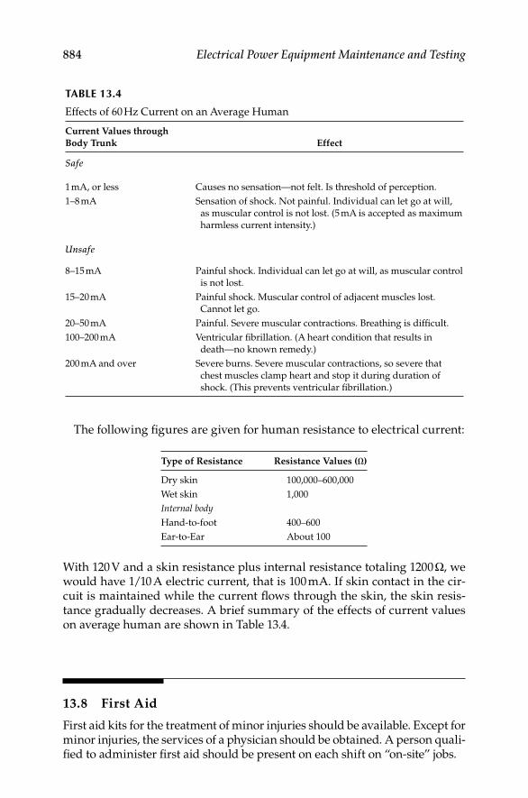
884 Electrical Power Equipment Maintenance and Testing
The following fi gures are given for human resistance to electrical current:
TABLE 13.4
Effects of 60 Hz Current on an Average Human
Current Values through
Body Trunk Effect
Safe
1 mA, or less Causes no sensation—not felt. Is threshold of perception.
1–8 mA Sensation of shock. Not painful. Individual can let go at will,
as muscular control is not lost. (5 mA is accepted as maximum
harmless current intensity.)
Unsafe
8–15 mA Painful shock. Individual can let go at will, as muscular control
is not lost.
15–20 mA Painful shock. Muscular control of adjacent muscles lost.
Cannot let go.
20–50 mA Painful. Severe muscular contractions. Breathing is diffi cult.
100–200 mA Ventricular fi brillation. (A heart condition that results in
death—no known remedy.)
200 mA and over Severe burns. Severe muscular contractions, so severe that
chest muscles clamp heart and stop it during duration of
shock. (This prevents ventricular fi brillation.)
Type of Resistance Resistance Values (Ω)
Dry skin 100,000–600,000
Wet skin 1,000
Internal bodyHand-to-foot 400–600
Ear-to-Ear About 100
With 120 V and a skin resistance plus internal resistance totaling 1200 Ω, we would have 1/10 A electric current, that is 100 mA. If skin contact in the cir-cuit is maintained while the current fl ows through the skin, the skin resis-tance gradually decreases. A brief summary of the effects of current values on average human are shown in Table 13.4.
13.8 First Aid
First aid kits for the treatment of minor injuries should be available. Except for minor injuries, the services of a physician should be obtained. A person quali-fi ed to administer fi rst aid should be present on each shift on “on-site” jobs.
DK4058_C013.indd 884DK4058_C013.indd 884 11/8/2008 12:24:20 PM11/8/2008 12:24:20 PM
Electrical Safety, Arc-Flash Hazard, Switching Practices, and Precautions 885
Prior to starting “on-site” jobs, telephone communications should be available and tested to summon medical assistance if required. Each “on-site” job should have the telephone number of the closest hospital and medical personnel available.
13.8.1 Shock
Shock occurs when there is a severe injury to any part of the body from any cause. Every injured person is potentially a patient of shock and should be regarded and treated as such, whether symptoms of shock are present or not.
Proper treatment of shock is as follows:
Keep the patient warm and comfortable, but not hot. In many cases, the only fi rst aid measure necessary and possible is to wrap the patient underneath as well as on top to prevent loss of body heat.
Keep the patient’s body horizontal or, if possible, position him or her so that the feet are 12–18 in. higher than the head. In any case, always keep the patient’s head low. The single exception to this positioning is the case of a patient who obviously has an injury to the chest, and who has diffi culty in breathing. This patient should be kept horizontal with head slightly raised to make breathing easier.
Do not let the patient sit up, except as indicated in chest injury or where there is a nose bleed. If there is a head injury and perhaps a fracture of the skull, keep the patient level and do not elevate his feet.
If the patient is conscious, you may give him or her hot tea, coffee, or broth in small quantities since the warmth is valuable in com-bating shock.
Proper transportation practice is never more imperative than in the case of a person who may develop shock. It is the most important single measure in the prevention and treatment of shock. Use an ambulance, if possible. If other means must be used, follow the above points as closely as possible.
13.8.2 Resuscitation
Seconds count. Begin artifi cial respiration as soon as possible. In • electric shock cases, do not rush and become a casualty yourself. Safely remove victim from electrical contacts before starting artifi cial respiration. Do not move victim unless necessary to remove him or her from danger or to place him or her in the proper position for artifi cial respiration.
Attempt to stop any hazardous fl ow of blood.•
Clear victim’s mouth of false teeth or any foreign objects or fl uids with • your fi ngers or a cloth wrapped around your fi nger. Watch victim closely to see that mucus or stomach contents do not clog air passages.
DK4058_C013.indd 885DK4058_C013.indd 885 11/8/2008 12:24:20 PM11/8/2008 12:24:20 PM

886 Electrical Power Equipment Maintenance and Testing
If help is available, have the following taken care of while applying • artifi cial respiration:
Call a doctor and ambulance.
Loosen victim’s clothing about neck, chest, and waist.
Keep victim warm during and after resuscitation. Use ammonia inhalants.
Do not give liquids while victim is unconscious.
Continue uninterrupted rescue breathing until victim is breathing • with out help or until pronounced dead.
The change of operators, when necessary, shall be done as smoothly • as possible without breaking the rhythm. If necessary to move victim, continue resuscitation without interruption.
Watch victim carefully after he revives. Do not permit him to exert • himself.
13.8.3 Resuscitation—Mouth-to-Mouth (Nose) Method
Place victim on his back. Place his head slightly downhill, if possible. A folded coat, blanket, or similar object under the victim’s shoulders will help maintain proper position. Tilt the head back so chin points straight upward.
Grasp the victim’s jaw and raise it upward until the lower teeth are higher than the upper teeth; or place fi ngers on both sides of the jaw near the ear-lobes and pull upward. Maintain jaw position throughout resuscitation period to prevent tongue from blocking air passage.
Pinch victim’s nose shut with thumb and forefi nger, take a deep breath and place your mouth over victim’s mouth making airtight contact; or close victim’s mouth, take a deep breath and place your mouth over victim’s nose making airtight contact. If you hesitate at direct contact, place a porous cloth between you and victim.
Blow into the victim’s mouth (nose) until his chest rises. Remove your mouth to let him exhale, turning your head to hear out rush of air. The fi rst 8 to 10 breaths should be as rapid as the victim will respond; thereafter, the rate should be slowed to about 12 times a minute.
13.8.4 Important Points to Remember
If air cannot be blown in, check position of victim’s head and jaw and recheck mouth for obstructions; then try again more forcefully. If chest still does not rise, turn victim face down and strike his back sharply to dislodge obstruction. Then repeat rescue breathing procedure.
Sometimes air enters victim’s stomach, evidenced by swelling of stomach. Expel air by gently pressing down on stomach during exhalation period.
DK4058_C013.indd 886DK4058_C013.indd 886 11/8/2008 12:24:20 PM11/8/2008 12:24:20 PM

Electrical Safety, Arc-Flash Hazard, Switching Practices, and Precautions 887
13.8.5 Two-Victim Method of Resuscitation—Mouth-to Mouth (Nose)
In those rare instances where two men working together are in shock, both require resuscitation, and only one worker is available to rescue them, the following method may be used:
Place two victims on their backs, with their heads almost touching and their feet extended in a straight line away from each other.
Perform the mouth-to-mouth resuscitation method as described in Section 13.8.3. Apply alternately to each victim. The cycle of infl ation and exhalation does not change so it will be necessary for rescuer to work quickly in order to apply rescue breathing to both victims.
13.8.6 External Heart Compression
Perform heart compression only when indicated: After rescue breathing has been performed for about half a minute, if bluish or gray skin color remains and no pulse can be felt, or if pupils of the eyes are dilated, heart compression should be started. Heart compression is always accompanied by rescue breathing. If only one rescuer is present, interrupt compression about every 10 to 15 compression cycles and give victim three or four breaths.
Place victim on his back on a fi rm surface.•
Put hands on breastbone. Place heel of one hand on lower third of • breastbone with other hand on top of fi rst.
Press downward. Apply pressure until breastbone moves 1–1.5 to • 2 in.
Lift hands and permit chest to return to normal.•
Repeat compression 60 times per minute.•
Heart compression should not be performed in the following instances:
When victim has a pulse•
When his pupils do not remain widely dilated•
When his ribs are broken•
DK4058_C013.indd 887DK4058_C013.indd 887 11/8/2008 12:24:20 PM11/8/2008 12:24:20 PM

DK4058_C013.indd 888DK4058_C013.indd 888 11/8/2008 12:24:20 PM11/8/2008 12:24:20 PM

889
Appendix A Forms and Reports
A key factor in an effi cient maintenance and testing program is the prepara-tion and fi lling of all inspection and test data and records. This enables mathemafi cal trends to be established, and to a great extent future perfor-mance and maintenance measures can be prepared.
Forms permit the orderly recording of data and are a reminder to record all pertinent factors, for example temperature and relative humidity and so on. A variety of forms are available for recording of data. The test and inspection data has been traditionally recorded manually, but today with the computer based management programs much of data entry can be automated. Many of the test and inspection forms are available from the test equipment manufac-turers or utility companies, but if one wishes to prepare his own then they can be tailored to fi t requirements as needed. One method of fi lling is by apparatus with the original inspection and test, and all successive test for that apparatus would be fi led in chronological order. The important fact is that records should be maintanined (in whatever order or format that may be suitable) for com-parison, evaluation and trending. Following are sample test data forms that the reader may wish to adopt for recording test data if these forms are already not in the workplace.
1. Substation inspection report: It can be used daily or weekly to moni-tor pertinent operating conditions.
2. Power transformer test record: A summary of all tests performed at installation, scheduled maintenance, or special occasions (trouble or suspected trouble).
3. Bushing current transformer test record: Same as the transformer.
4. Power circuit breaker test record: Same as the transformer.
5. Insulation resistance—dielectric absorption test sheet: These forms are available from test equipment manufacturers such as Megger Incorporated and others. These form is very useful when conducting motor and generator insulation resistance and dielectirc absorption tests.
6. Contact resistance (microohm) tests: This form is used to record test data when conducting switchgear and breaker tests for detecting and assessing imperfect and/or conncetion having high resistance.
7. High Potential and Megohmmeter tests: This is useful when one or several circuit components are subjected to insulation resistance and go, no-go high potential tests. This form should be modifi ed to include equipment ambient temperature, relative humidity, and to state mea-sured insulation resistance values in Megohms.
DK4058_A001.indd 889DK4058_A001.indd 889 11/8/2008 12:43:47 PM11/8/2008 12:43:47 PM

890 Appendix A
8. Insulation megger and live line tests: This form is for switchyards where insulators are intalled in sections, and confi rms that each layer is doing its share in a series string.
9. DC-Hipot test graph paper: This form is useful in recording DC hi-pot test data for generators or other apparatus and as well as cables.
10. Transducer test sheet: A calibration record of transducers when used in instrumentation schemes in connection with supervisory control. This applilcation is increasing in various industries such as large pumping stations.
11. Instrument tests: A calibration form for switchyard instruments and other indicating and recording instruments. This form can be modifi ed by the user as required for polyphase connections and other multipliers.
12. Low voltage breaker test report (600 V or less): This form is used to record the data when low voltage breaker protective devices are calibrated and tested. This is very useful form for recording the protective devices data and test points for as found and as left conditions.
13. Fall of potential method: This form is used when conducting ground-ing electrode and ground grid resistance measurements. It allows the test technician to record data conveniently while conducting the test.
14. Protective relay test record: This form is similar to the low voltage breaker test report except that this form is used in relays used in the medium voltage switchgear.
15. Cable test record: This form is similar to the DC hi-pot test form except that it is three-dimensional, i.e., it allows the test technician to reord the data in megohms or microamps with respect to test voltage. It auto-matically converts megohms to microamps and vice versa.
Transformers
Rating
kW
kVar
(A) PH. amps
(B) PH. amps
(C) PH. amps
(A) PH. volts
(B) PH. volts
(C) PH. volts
Tap range
Tap position
Max. tap pos.
Tap operations
Gas gauze
Oil temp.
Max. oil temp.
Date: Substation:
Time: Inspector:
DK4058_A001.indd 890DK4058_A001.indd 890 11/8/2008 12:43:47 PM11/8/2008 12:43:47 PM
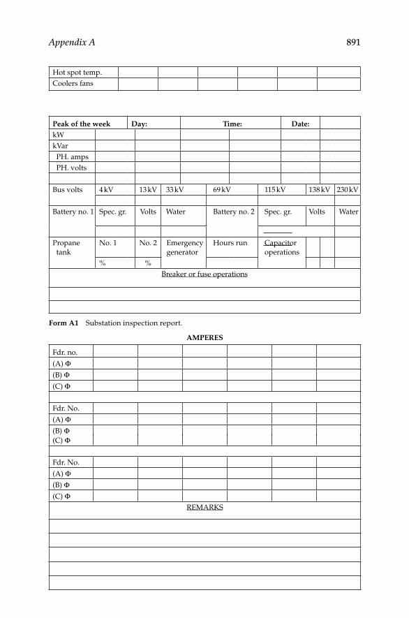
Appendix A 891
Peak of the week Day: Time: Date:
kW
kVar
PH. amps
PH. volts
Bus volts 4 kV 13 kV 33 kV 69 kV 115 kV 138 kV 230 kV
Battery no. 1 Spec. gr. Volts Water Battery no. 2 Spec. gr. Volts Water
Propane
tank
No. 1 No. 2 Emergency
generator
Hours run Capacitor
operations
% %
Breaker or fuse operations
Form A1 Substation inspection report.
AMPERES
Fdr. no.
(A) Φ(B) Φ(C) Φ
Fdr. No.
(A) Φ(B) Φ(C) Φ
Fdr. No.
(A) Φ(B) Φ(C) Φ
REMARKS
Hot spot temp.
Coolers fans
DK4058_A001.indd 891DK4058_A001.indd 891 11/8/2008 12:43:47 PM11/8/2008 12:43:47 PM

892 Appendix A
DK4058_A001.indd 892DK4058_A001.indd 892 11/8/2008 12:43:48 PM11/8/2008 12:43:48 PM
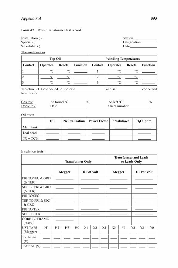
Appendix A 893
Form A2 Power transformer test record.
Installation ( ) Station
Special ( ) Designation
Scheduled ( ) Date
Thermal devices:
Top Oil Winding Temperatures
Contact Operates Resets Function Contact Operates Resets Function
1 °C °C 1 °C °C
2 °C °C 2 °C °C
3 °C °C 3 °C °C
Ten-ohm RTD connected to indicate and is connected
to indicator.
Gas test: As found °C % As left °C %
Doble test: Date Sheet number
Oil tests:
IFT Neutralization Power Factor Breakdown H2O (ppm)
Main tank
Dial head
TC − OCB
Insulation tests:
Transformer Only
Transformer and Leads
or Leads Only
Megger Hi-Pot Volt Megger Hi-Pot Volt
PRI TO SEC & GRD
(& TER)
___________ ___________ ___________ ___________
SEC TO PRI & GRD
(& TER)
___________ ___________ ___________ ___________
PRI TO SEC ___________ ___________ ___________ ___________
TER TO PRI & SEC
& GRD
___________ ___________ ___________ ___________
PRI TO TER ___________ ___________ ___________ ___________
SEC TO TER ___________ ___________ ___________ ___________
CORE TO FRAME
(500 V)
___________
UST TAPS
(Megger)
H1 H2 H3 H0 X1 X2 X3 X0 Y1 Y2 Y3 Y0
To Flange
(V)
____ ____ ____ ____ ____ ____ ____ ____ ____ ____ ____ ____
To Cond. (V) ____ ____ ____ ____ ____ ____ ____ ____ ____ ____ ____ ____
DK4058_A001.indd 893DK4058_A001.indd 893 11/8/2008 12:43:48 PM11/8/2008 12:43:48 PM
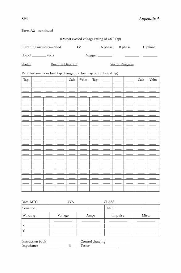
894 Appendix A
Form A2 continued
(Do not exceed voltage rating of UST Tap)
Lightning arresters—rated kV A phase B phase C phase
Hi-pot volts Megger
Sketch Bushing Diagram Vector Diagram
Ratio tests—under load tap changer (no load tap on full winding)
Tap ____ ____ ____ Calc Volts Tap ____ ____ ____ Calc Volts
____ ____ ____ ____ ____ ____ ____ ____ ____ ____ ____ ____
____ ____ ____ ____ ____ ____ ____ ____ ____ ____ ____ ____
____ ____ ____ ____ ____ ____ ____ ____ ____ ____ ____ ____
____ ____ ____ ____ ____ ____ ____ ____ ____ ____ ____ ____
____ ____ ____ ____ ____ ____ ____ ____ ____ ____ ____ ____
____ ____ ____ ____ ____ ____ ____ ____ ____ ____ ____ ____
____ ____ ____ ____ ____ ____ ____ ____ ____ ____ ____ ____
____ ____ ____ ____ ____ ____ ____ ____ ____ ____ ____ ____
____ ____ ____ ____ ____ ____ ____ ____ ____ ____ ____ ____
____ ____ ____ ____ ____ ____ ____ ____ ____ ____ ____ ____
____ ____ ____ ____ ____ ____ ____ ____ ____ ____ ____ ____
____ ____ ____ ____ ____ ____ ____ ____ ____ ____ ____ ____
____ ____ ____ ____ ____ ____ ____ ____ ____ ____ ____ ____
____ ____ ____ ____ ____ ____ ____ ____ ____ ____ ____ ____
____ ____ ____ ____ ____ ____ ____ ____ ____ ____ ____ ____
____ ____ ____ ____ ____ ____ ____ ____ ____ ____ ____ ____
____ ____ ____ ____ ____ ____ ____ ____ ____ ____ ____ ____
____ ____ ____ ____ ____ ____ ____ ____ ____ ____ ____ ____
____ ____ ____ ____ ____ ____ ____ ____ ____ ____ ____ ____
____ ____ ____ ____ ____ ____ ____ ____ ____ ____ ____ ____
____ ____ ____ ____ ____ ____ ____ ____ ____ ____ ____ ____
Data: MFG kVA CLASS
Serial no. NO.
Winding Voltage Amps Impulse Misc.
E ___________ ___________ ___________ ___________
X ___________ ___________ ___________ ___________
Y ___________ ___________ ___________ ___________
Instruction book ____________________ Control drawing _______________
Impedance __________________%__ Tester _________________
DK4058_A001.indd 894DK4058_A001.indd 894 11/8/2008 12:43:48 PM11/8/2008 12:43:48 PM

Appendix A 895
Tester
Form A2 continued
Primary current _______________ amperes
Designation __________ __________ __________ __________ __________
__________ Calc.
Actual
__________ __________ __________ __________
__________ Calc.
Actual
__________ __________ __________ __________ __________
__________ Calc.
Actual
__________ __________ __________ __________ __________
__________ Calc.
Actual
__________ __________ __________ __________ __________
__________ Calc.
Actual
__________ __________ __________ __________ __________
__________ Calc.
Actual
__________ __________ __________ __________ __________
__________ Calc.
Actual
__________ __________ __________ __________ __________
__________ Calc.
Actual
__________ __________ __________ __________ __________
__________ Calc.
Actual
__________ __________ __________ __________ __________
__________ Calc.
Actual
__________ __________ __________ __________ __________
__________ Calc.
Actual
__________ __________ __________ __________ __________
__________ Calc.
Actual
__________ __________ __________ __________ __________
__________ Calc.
Actual
__________ __________ __________ __________ __________
__________ Calc.
Actual
__________ __________ __________ __________ __________
__________ Calc.
Actual
__________ __________ __________ __________ __________
DK4058_A001.indd 895DK4058_A001.indd 895 11/8/2008 12:43:48 PM11/8/2008 12:43:48 PM

896 Appendix A
Form A3 Bushing current transformer test record.
Installation ( ) Station
Special ( ) Designation
Date
Data:
Designation Bushing Max. ratio Conn. ratio Mfg. Type Use
______________ _________ _________ _________ _________ _________ _________
______________ _________ _________ _________ _________ _________ _________
______________ _________ _________ _________ _________ _________ _________
______________ _________ _________ _________ _________ _________ _________
______________ _________ _________ _________ _________ _________ _________
______________ _________ _________ _________ _________ _________ _________
______________ _________ _________ _________ _________ _________ _________
______________ _________ _________ _________ _________ _________ _________
______________ _________ _________ _________ _________ _________ _________
______________ _________ _________ _________ _________ _________ _________
______________ _________ _________ _________ _________ _________ _________
______________ _________ _________ _________ _________ _________ _________
Bushings installed on:
Misc. Notes:
DK4058_A001.indd 896DK4058_A001.indd 896 11/8/2008 12:43:48 PM11/8/2008 12:43:48 PM

Appendix A 897
Form A4 Power circuit breaker test record.
Installation ( ) Station
Special ( ) Designation
Scheduled ( ) Date
Contact resistance (μΩ) Tank No. 1 No. 2 No. 3
Pressure switch: type:
Contacts Operates Resets
Total breaker
operations to
No. 1 psi psi Compressor motor
start
No. 2 psi psi Alarm contact
operation
No. 3 psi psi Breaker lockout
Travel Analyzer Tank No. 1 Tank No. 2 Tank No. 3 Mfg. Rec.
Breaker contact opening
time (cycles)
Lift rod travel (ft./s)
“a” Switch opening time
(cycles)
Total lift road travel (in.)
Breaker trip free time
(cycles)
Doble test: Date Sheet number
Oil Tests IFT Neutralization Power Factor Breakdown
Tank No. 1
Tank No. 2
Tank No. 3
Rectox Tests Normal Operating Conditions
% Age R Sta. Ser. V AC volts DC volts AC amps DC amps
AF
AL
CB min. close volts AF AL Closing relay min. close volts
AF AL
Cubicle heaters: Number Thermostat set Feed
Protection
DK4058_A001.indd 897DK4058_A001.indd 897 11/8/2008 12:43:48 PM11/8/2008 12:43:48 PM

898 Appendix A
Operating mech.
Top view
(indicate bus and line) Top view.
Stud side view.
(indicate bus and line)
Mfg. Volts Amps
Int. cap. Type
Serial NO.
Close volts Amps Cycles
Open volts Amps Cycles
Comp. motor volts Amps Cycles
Tester
Form A4 continued
Insulation tests:
PCB Only PCB and Leads or Leads Only
Closed breaker Megger Hi-Pot Volt Megger Hi-Pot Volt
A to ground
B to ground
C to ground
A to B
A to C
B to C
Open breaker Megger
1 to grd. 4 to grd. 1 to 2 3 to 4
2 to grd. 5 to grd. 1 to 3 3 to 5
3 to grd. 6 to grd. 2 to 4 5 to 6
Omit on three tank breakers
Open breaker Hi-Pot, each pole kV, other poles and tank grounded.
UST Taps:
(Megger) Pole No. 1 Pole No. 2 Pole No. 3 Pole No. 4 Pole No. 5 Pole No. 6
To fl ange
To conductor
(Do not exceed voltage rating of UST tap)
Data:
Pole 5Pole
Rear-GETop-others
Pole
Pole 6 Phase
Phase
Phase
Operation awch. Phase
Pole 4
Pole 2
Pole 3
Pole 1
1 3 5
2 4 6
0 00Tank
Tank
Tank
0
0 0
0 0
3
2
1
0
0 0 0
DK4058_A001.indd 898DK4058_A001.indd 898 11/8/2008 12:43:49 PM11/8/2008 12:43:49 PM

Appendix A 899
Form A5 Insulation resistance—dielectric absorption test sheet.
Rotating equipment Test no.
Company DATE
Location TIME
Equipment Rating Voltage
Type Mfg. Serial
Recent operating history
Winding condition as to clearnesses and repair
Armature insulation age Class Field insulation age Class
Describe end turn corona shielding
List associated equipment included in test
Line cable length: Conductor size: Insulation material: Insulation thickness:
AC armature phases
connectedDelta � Star � Neutral cable
Test data—megohms
Part Tested Test Mode
Hours
Days
After
Shutdown
Grounding
time
Dry bulb temp. °F
Test voltage Wet bulb temp. °F
To line To line To line To line Dew point °F
Part Tested Test Mode
Hours
Days
After
Shutdown
Test
connections
To earth To earth To earth To earth Relative
humidity
%
To guard To guard To guard To guard Absolute
humidity
GR/#
1/4 MIN Equipment
temp.
°F (°C)
DK4058_A001.indd 899DK4058_A001.indd 899 11/8/2008 12:43:49 PM11/8/2008 12:43:49 PM

900 Appendix A
1/2 MIN How obtained
3/4 MIN
1
2 Megohm
meter inst. –
3 Serial no.
4 Range
5 Voltage
6
7
8
9
10
10/1 MIN
megohms
Remarks
Tested by
Form A5 continued
DK4058_A001.indd 900DK4058_A001.indd 900 11/8/2008 12:43:49 PM11/8/2008 12:43:49 PM
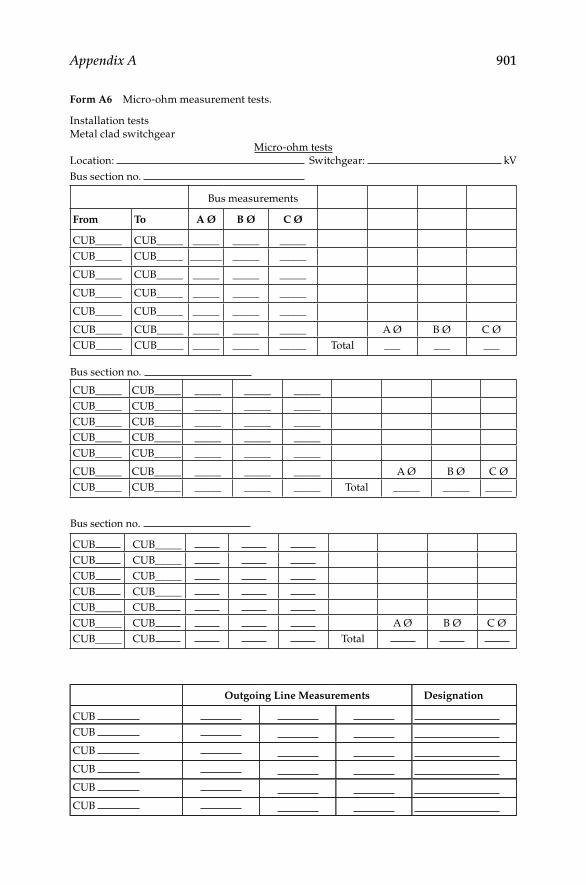
Appendix A 901
Form A6 Micro-ohm measurement tests.
Installation tests
Metal clad switchgear
Micro-ohm tests
Location: Switchgear: kV
Bus section no.
Bus measurements
From To A Ø B Ø C Ø
CUB_____ CUB_____ _____ _____ _____
CUB_____ CUB_____ ______ _____ _____
CUB_____ CUB_____ _____ _____ _____
CUB_____ CUB_____ _____ _____ _____
CUB_____ CUB_____ _____ _____ _____
CUB_____ CUB_____ _____ _____ _____ A Ø B Ø C Ø
CUB_____ CUB_____ _____ _____ _____ Total ___ ___ ___
Bus section no.
CUB_____ CUB_____ _____ _____ _____
CUB_____ CUB_____ _____ _____ _____
CUB_____ CUB_____ _____ _____ _____
CUB_____ CUB_____ _____ _____ _____
CUB_____ CUB_____ _____ _____ _____
CUB_____ CUB_____ _____ _____ _____ A Ø B Ø C Ø
CUB_____ CUB_____ _____ _____ _____ Total _____ _____ _____
Bus section no.
CUB CUB_____
CUB CUB_____
CUB CUB_____
CUB CUB_____
CUB_____ CUB
CUB_____ CUB A Ø B Ø C Ø
CUB_____ CUB Total
Outgoing Line Measurements Designation
CUB
CUB
CUB
CUB
CUB
CUB
DK4058_A001.indd 901DK4058_A001.indd 901 11/8/2008 12:43:49 PM11/8/2008 12:43:49 PM

902 Appendix A
CUB
CUB
CUB
CUB
CUB
CUB
CUB No. ___trans sec
CUB No. ___trans sec
CUB No. ___trans sec
Form A6 continued
DK4058_A001.indd 902DK4058_A001.indd 902 11/8/2008 12:43:49 PM11/8/2008 12:43:49 PM
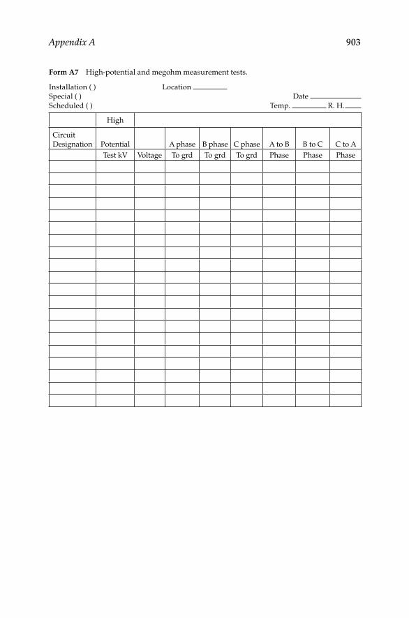
Appendix A 903
Form A7 High-potential and megohm measurement tests.
Installation ( ) Location
Special ( ) Date
Scheduled ( ) Temp. R. H.
High
Circuit
Designation Potential A phase B phase C phase A to B B to C C to A
Test kV Voltage To grd To grd To grd Phase Phase Phase
DK4058_A001.indd 903DK4058_A001.indd 903 11/8/2008 12:43:49 PM11/8/2008 12:43:49 PM

904 Appendix A
Form A8 Insulator megohm measurement and live line tests.
AΦ BΦ CΦ
TO
PT
OP
DK4058_A001.indd 904DK4058_A001.indd 904 11/8/2008 12:43:50 PM11/8/2008 12:43:50 PM

Appendix A 905
Form A9 DC Hi-Pot test graph paper.JO
B LO
CATI
ON
Microamps
DC
test
vol
tage
kV
CA
BLE
MFP
CA
BLE
RATI
NG
HU
MID
ITY
TEM
PERA
TURE
LEA
KA
GE
CU
RREN
T A
T FU
LL T
EST
DIS
CH
ARG
E TI
ME
VOLT
AG
E IN
CREM
ENTS
INSU
LATI
ON
TYPE
VO
LTA
GE
AFT
ER 1
MIN
. DIS
CH
ARG
EM
IN. D
ISC
HA
RGE
TYPE
OF
TEST
KV
OPE
RATO
R
WIT
NES
S
Test
Tech
.
KV
KV
STA
BILI
ZATI
ON
CON
DU
CTO
RSI
ZE
DA
TE
DO
WN
TO
MIN
UTE
S
(I V
S. T
IME)
MIN
UTE
S
VO
LTA
GE
AFT
ER
PHA
SEA B C
�A
�A
�A
SEC
.SE
C.
SEC
.
KV
Forms and ReportsTI
ME
DK4058_A001.indd 905DK4058_A001.indd 905 11/8/2008 12:43:50 PM11/8/2008 12:43:50 PM

906 Appendix A
Form A10 Transducer test sheet.
Page of
Transducer data Location Design”
Tester
Watts Vars Volts Amps Remarks
Date Circuit %Error Mfr. %Error Mfr. %Error Mfr. %Error Mfr. Remarks
DK4058_A001.indd 906DK4058_A001.indd 906 11/8/2008 12:43:50 PM11/8/2008 12:43:50 PM

Appendix A 907
Form A11 Instrument test.
Circuit no.
Date of test Station no.
Instrument under test:
Location
Serial no. Type Amp. Cap. Volts
Scale C. T. Ratio P. T. Ratio Freq.
Cap. C. T. Used Amps. Ratio Make Type
Cap. P. T. Used Volts-Amps. Ratio Make Type
As found test data
Standard
Meter Under
Test %Error Standard
Meter Under
Test %Error
As left
Standard
Meter Under
Test %Error Standard
Meter Under
Test %Error
Remarks:
Tester Assistant
DK4058_A001.indd 907DK4058_A001.indd 907 11/8/2008 12:43:50 PM11/8/2008 12:43:50 PM
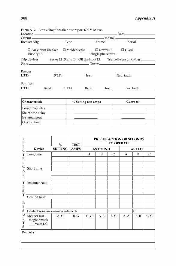
908 Appendix A
Form A12 Low voltage breaker test report 600 V or less.
Location Date
Circuit Job no.
Breaker Mfg. Type Frame Serial
� Air circuit breaker � Molded/case � Drawout � Fixed
Fuse type Single phase prot.
Trip devices Series � Static � Oil dash pot � Trip coil/sensor Rating
Style Curve
Ranges
L.T.D. S.T.D. Inst. Grd. fault
Settings
L.T.D. Band S.T.D. Band Inst. Grd fault.
Characteristic % Setting test amps Curve (s)
Long time delay
Short time delay
Instantaneous
Ground fault
E
L
E
C
T
R
I
C
A
L
T
E
S
T
R
E
S
U
L
T
S
Device
%
SETTING
TEST
AMPS
PICK UP ACTION OR SECONDS
TO OPERATE
AS FOUND AS LEFT
Long time A B C A B C
Short time
Instantaneous
Ground fault
Contact resistance—micro-ohms: A B C
Megger test
meghohms @
____volts DC
A–G B–G C–G A–B B–C A–A B–B C–C
Remarks:
DK4058_A001.indd 908DK4058_A001.indd 908 11/8/2008 12:43:50 PM11/8/2008 12:43:50 PM

Appendix A 909F
orm
A1
3
Fa
ll o
f p
ote
nti
al
plo
t.
Inst
rum
en
t m
fg.
N
am
e o
f o
per
ato
r:
Mo
del
Lo
cati
on
: D
ate:
Ser
ial
# _
__
__
__
__
__
__
__
_ G
rou
nd
sy
stem
ty
pe:
Sin
gle
ro
d �
M
ult
iple
ro
ds �
Lo
ng
est
dim
en
sio
n
ft.
Dep
th
ft.
Dis
tan
ce o
f au
xil
iary
cu
rren
t el
ect
rod
e Z
: ft
.
Vo
ltag
e
Ele
ctro
de
Dis
tan
ce
fro
m
Gro
un
d
Un
der
Test
Resi
stan
ce
Test
Co
nd
itio
ns
Tem
p:
So
il:
Mo
ist �
D
ry �
So
il t
yp
e
Lo
am
�
S
an
d &
Gra
vel
�
S
hale
�
Cla
y �
Lim
esto
ne �
San
dst
on
e �
Gra
nit
e �
Sla
te �
Oth
er
Fee
tO
hm
s
50
100
45
90
40
80
35
70
DK4058_A001.indd 909DK4058_A001.indd 909 11/8/2008 12:43:50 PM11/8/2008 12:43:50 PM
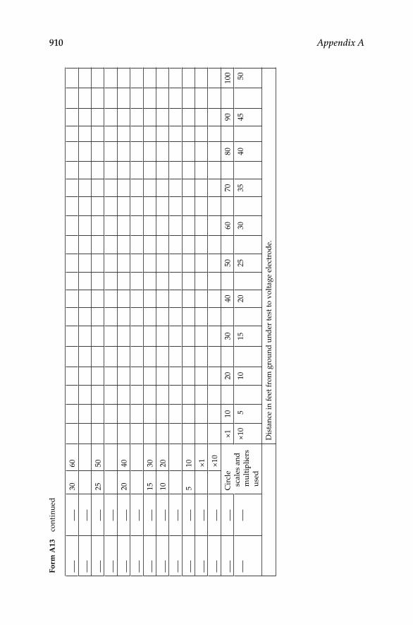
910 Appendix A
30
60
25
50
20
40
15
30
10
20
510
×1
×10
Cir
cle
scale
s an
d
mu
ltip
lier
s
use
d
×1
10
20
30
40
50
60
70
80
90
100
×10
510
15
20
25
30
35
40
45
50
Dis
tan
ce i
n f
eet
fro
m g
rou
nd
un
der
tes
t to
vo
ltag
e el
ectr
od
e.
Fo
rm A
13
con
tin
ued
DK4058_A001.indd 910DK4058_A001.indd 910 11/8/2008 12:43:50 PM11/8/2008 12:43:50 PM
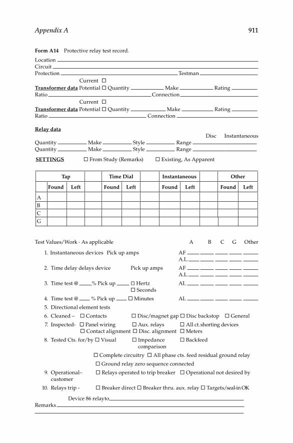
Appendix A 911
Form A14 Protective relay test record.
Location
Circuit
Protection Testman
Current �Transformer data Potential � Quantity Make Rating
Ratio Connection
Current �Transformer data Potential � Quantity Make Rating
Ratio Connection
Relay data
Disc Instantaneous
Quantity Make Style Range
Quantity Make Style Range
SETTINGS � From Study (Remarks) � Existing, As Apparent
Tap Time Dial Instantaneous Other
Found Left Found Left Found Left Found Left
A
B
C
G
Test Values/Work ◊ As applicable A B C G Other
1. Instantaneous devices Pick up amps AF
A.L.
2. Time delay delays device Pick up amps AF
A.L.
3. Time test @ % Pick up � Hertz AL
� Seconds
4. Time test @ % Pick up � Minutes AL
5. Directional element tests
6. Cleaned – � Contacts � Disc/magnet gap � Disc backstop � General
7. Inspected- � Panel wiring � Aux. relays � All ct. shorting devices
� Contact alignment � Disc. alignment � Meters
8. Tested Cts. for/by � Visual � Impedance � Backfeed
comparison
� Complete circuitry � All phase cts. feed residual ground relay
� Ground relay zero sequence connected
9. Operational– � Relays operated to trip breaker � Operational not desired by
customer
10. Relays trip - � Breaker direct � Breaker thru. aux. relay � Targets/seal-in OK
Device 86 relayto
Remarks
DK4058_A001.indd 911DK4058_A001.indd 911 11/8/2008 12:43:50 PM11/8/2008 12:43:50 PM

912 Appendix A
Form A15 Cable test record.
1xx4 5 6 7 8 9 10 15 100
1000900800700600
500
400
350
300
200
150
1009080
70
60
40
35
30
25
20
15
1098765432.521.51.00.90.80.70.60.50.4
5.04.03.02.01.0.50.25
Remarks: absorption testMin.
Kv
Install
Term.LengthKV ratingTypeSizeManuf.Cable dataCal. dateTest betS/N ofCircuitTester
DateCircuitForms and Reports
Location Job no.Microamperes
Type of test KV
ProofMaint.
TestLeakagecurrent
microamps (μA)
A∅ B∅ C∅
A∅ B∅ C∅
9080706050403025KilovoltsRemarks
20
1xx
100
200
300
400
500
600
700
800
9001000
1500
Meg
ohm
s
1000
2000
3000
4000
5000
6000
7000
8000
900010000
Insulation resistance at
Phase no. 1Phase no. 2Phase no. 3
V.D.C.(in megohms)
DK4058_A001.indd 912DK4058_A001.indd 912 11/8/2008 12:43:50 PM11/8/2008 12:43:50 PM

913
Appendix B ANSI/IEEE Standard Device Function Numbers
In North America protective relays are generally referred to by standard device numbers. Letters are sometimes added to specify the application.
1. Master element2. Time-delay starting or closing relay3. Checking or interlocking relay4. Master contractor5. Shopping device6. Starting circuit breaker7. Anode circuit breaker8. Control power disconnecting device9. Reversing device
10. Unit sequence switch11. Reserved for future application12. Overspeed device13. Synchronous-speed device14. Underspeed device15. Speed- or frequency-matching device16. Reserved for future application17. Shunting or discharge switch18. Accelerating or decelerating device19. Starting-to-running transition contactor20. Electrically operated valve space (solenoid valve)21. Distance relay22. Equalizer circuit breaker23. Temperature-control device24. Reserved for future application25. Synchronizing- or synchronous-check device26. Apparatus thermal device27. Undervoltage relay28. Flame detector29. Isolating contactor30. Annunciator relay31. Separate excitation device32. Directional power relay33. Position switch34. Master sequence device35. Brush-operating or slip-ring short-circuiting device36. Polarity or polarizing voltage device37. Undercurrent or underpower relay
DK4058_A002.indd 913DK4058_A002.indd 913 11/8/2008 12:44:07 PM11/8/2008 12:44:07 PM

914 Appendix B
38. Bearing protective device39. Mechanical condition monitor40. Loss of fi eld relay41. Field circuit breaker42. Running circuit breaker43. Manual transfer or selector device44. Unit sequence starting relay45. Atmospheric condition monitor46. Reverse-phase or phase-balance current relay47. Phase-sequence voltage relay48. Incomplete sequence relay49. Machine or transformer thermal relay50. Instantaneous overcurrent or rate-of-rise relay51. AC time overcurrent relay52. AC circuit breaker53. Exciter on DC generator relay54. High-speed DC circuit breaker55. Power factor relay56. Field application relay57. Short-circuiting or grounding device58. Rectifi cation failure relay59. Overvoltage relay60. Voltage- or current-balance relay (use 60 °C when 60 V is also present)61. Machine split phase current balance62. Time-delay stopping, or opening, relay63. Liquid or gas pressure or vacuum relay64. Ground protective or detector relay65. Governor66. Notching or jogging device or starts per hour67. AC directional overcurrent relay68. Blocking relay69. Permissive control device70. Rheostat71. Liquid- or gas-level relay or switch72. DC circuit breaker73. Load-resistor contractor74. Alarm relay75. Position-changing mechanism76. DC overcurrent relay77. Pulse transmitter78. Phase angle measuring or out-of-step protective relay79. AC reclosing relay80. Liquid or gas fl ow relay81. Frequency relay82. DC reclosing relay83. Automatic selective control or transfer relay
DK4058_A002.indd 914DK4058_A002.indd 914 11/8/2008 12:44:07 PM11/8/2008 12:44:07 PM

Appendix B 915
84. Operating mechanism85. Carrier or pilot-wire receiver relay86. Locking-out relay87. Differential protective relay88. Auxiliary motor or motor generator89. Line switch90. Regulating device91. Voltage directional relay92. Voltage and power directional relay93. Field-changing contactor94. Tripping or trip-free relay95. Used only for specifi c applications on individual installation where none
of the assigned numbered functions from 1 to 94 are suitable96. Auto loading relay
Note: Suffi x letters are used with device function numbers for various purposes; for instance,
suffi x N is generally used if the device is connected in the secondary neutral of current
transformers, and suffi xes X, Y, and Z are used to denote separate auxiliary devices.
Where more than one device is used for similar functions, a numerical suffi x is used to
differentiate (e.g., 52–1, 52–5).
B = Bus, F = fi eld, G = ground or generator, N = neutral, and T = transformer.
DK4058_A002.indd 915DK4058_A002.indd 915 11/8/2008 12:44:07 PM11/8/2008 12:44:07 PM

DK4058_A002.indd 916DK4058_A002.indd 916 11/8/2008 12:44:07 PM11/8/2008 12:44:07 PM

917
Bibliography
Chapter 1
Andreas, J. C., Energy-Effi cient Electric Motors: Selection and Application, Marcel Dekker, Inc., New York, 1992.
Bartley, W. H., Analysis of Transformer Failures: Part 2—Causes, Prevention and Maxi-mum Service Life, International Association of Engineering Insurers 36th Annual Conference, Stockholm, Sweden, 2003.
de Siqueira, I. P., Reliability-centered maintenance of oil immersed transformers: A work group approach from several companies, Doble Client Conference, Boston, MA, 2008.
Edison Electric Institute, Report on equipment availability for 10 year period, 1965–74, EEI Publication No. 75-50, November 1975 (Prime Mover Generation Equipment).
Edison Electric Institute, Report on excitation system troubles, 1975, EEI Publication No. 76-78, December 1976 (later data have also been published).
Edison Electric Institute, Report on generator troubles, 1975, EEI Publication No. 76082, December 1976 (later data have also been published).
Edison Electric Institute, Report on metalclad switchgear troubles, 1975, EEI Publica-tion No. 76-82, December 1976 (later data have also been published).
Edison Electric Institute, Report on motor troubles, 1975, EEI Publication No. 76-79, December 1976.
Edison Electric Institute, Report on power circuit troubles, 1975, EEI Publication No. 76-81, December 1976.
Edison Electric Institute, Report on power transformer troubles, 1975, EEI Publica-tion No. 76-80, December 1976.
Hillmer, T. and Brandes, H., New generation of a class 180 (H) electrical insulation system for high voltage machines, Doble Client Conference, Boston, MA, 2008.
IEEE Committee Report, Report on reliability survey of industrial plants: Parts I, II, and III, IEEE Transaction on Industry Applications, Vol. IA-10, No. 2, July/August 1974, pp. 213–252; Parts IV, V and VI, Vol. IA-10, No. 4, July/August 1974, pp. 456–476.
IEEE Committee Report, Report on reliability survey of industrial plants: Parts I–VI, IEEE Transactions on Industry Applications, March/April 1974, pp. 213–252; July/August 1974, pp. 456–476; September/October 1974, p. 681 (see Annex A and Annex B).
IEEE Committee Report, Report of switchgear bus reliability survey of industrial plants and commercial buildings, IEEE Transactions on Industry Applications, March/April 1979, pp. 141–147 (see Annex E).
IEEE Committee Report, Report of generator reliability survey of industrial plants and commercial buildings, IEEE-ICPS Technical Conference Record, CH1543-8-1A, May 1980, pp. 40–44.
IEEE Committee Report, Report of transformer reliability survey—Industrial plants and commercial buildings, IEEE Transactions on Industry Applications, 1983, pp. 858–866 (see Annex G).
DK4058_C014.indd 917DK4058_C014.indd 917 11/8/2008 12:25:11 PM11/8/2008 12:25:11 PM

918 Bibliography
IEEE Std 500-1984 (Reaff 1991), IEEE Guide to the Collection and Presentation of Electrical, Electronic, Sensing Component, and Mechanical Equipment Reliability Data for Nuclear Power Generating Stations 2, 3, IEEE Std 493-2007, Chapter 10.
IEEE Std 120-1989, IEEE Master Test Guide for Electrical Measurements in Power Circuits.
IEEE Std 902-1998, IEEE Guide for Maintenance, Operation, and Safety of Industrial and Commercial Power Systems.
IEEE Std 1-2000, IEEE Recommended Practice-General Principles for Temperature Limits in the Rating of Electrical Equipment and for the Evaluation of Electrical Insulation.
IEEE Std 493-2007, IEEE Recommended Practice for the Design of Reliable Industrial and Commercial Power Systems.
Mayoux, C., On the degradation of industrial materials withstanding electrical stress, IEEE Conference on Electrical Insulation and Dielectric Phenomena 2000, Victoria, BC.
McWilliams, D. W., Patton, A. D., and Heising, C. R., Reliability of electrical equip-ment in industrial plants—Comparison of results from 1959 survey and 1971 survey, IEEE-ICPS Technical Conference Record, 74CH0855-71A, Denver, CO, June 2–6, 1974, pp. 105–112.
Megger Inc., “A Stitch in Time…” The Complete Guide to Electrical Testing, 21-P8b-1992, Megger Inc., Valley Forge, PA.
Moubray, J., ATA MSG-3, Operator/manufacturer scheduled maintenance develop-ment, Reliability-Centered Maintenance, Industrial Press, Inc., New York, 2003.
Neitzel, D. K., Circuit Breaker Maintenance, Medium-Voltage Course Textbook, Chapter 1, AVO Training Institute, Inc., Dallas, TX, revision 2006, p. 1-10.
Neitzel, D. K., Circuit Breaker Maintenance, Medium-Voltage Course Textbook, Chapter 4, AVO Training Institute, Inc., Dallas, TX, revision 2006, p. 4-18.
Neitzel, D., Establishing an electrical safety program, NETA Conference Papers, 2006.Neitzel, D. K., Protective Relay Maintenance, Basic Course Textbook, Module 3, AVO
Training Institute, Inc., Dallas, TX, revision 2006, p. 5-24.Neitzel, D. K., Circuit Breaker Maintenance, Low-Voltage Course Textbook, Module 2,
AVO Training Institute, Inc., Dallas, TX, revision 2007, p. 34.Neitzel, D. K., Principle Components of a Molded-Case Circuit Breaker, AVO Training
Institute, Inc., Dallas, TX, revision 2007, p. 14.Neitzel, D. K., Various Electrical Safety Course Textbooks, NEC 110.16 Required Label,
AVO Training Institute, Inc., Dallas, TX, revision 2007.Neitzel, D. K., Various Electrical Safety Course Textbooks, Recommended Label for
Arc-Flash Hazard, AVO Training Institute, Inc., Dallas, TX, revision 2007.A Guide to the Reliability-Centered Maintenance (RCM) Standard, (SAE JA1012), Society of
Automotive Engineers (SAE), January 2002.NUREG/CR-6819, Common-Cause Failure Event Insights-Circuit Breakers, Vol. 4, Idaho
National Engineering and Environmental Laboratory, Idaho Falls, ID, May 2003.O’Donnell, P., Report of large motor reliability survey of industrial plants and
commercial installations, IEEE Transactions on Industry Applications, Parts 1 and 2, July/August 1985, pp. 853–872; Part 3, January/February 1987, pp. 153–158 (see Annex H).
O’Donnell, P., Survey of lower voltage breakers as found during maintenance, IEEE Industrial & Commercial Power Systems Technical Conference, May 6–9, 1996, New Orleans, LA.
DK4058_C014.indd 918DK4058_C014.indd 918 11/8/2008 12:25:11 PM11/8/2008 12:25:11 PM

Bibliography 919
Patton, A. D., Determination and analysis of data for reliability studies, IEEE Transac-tions on Power Apparatus and Systems, Vol. PAS-87, January 1968, pp. 84–100.
PowerDB Inc., Instructional Manual for PowerDB Software, PowerDB Inc., College Station, TX, 2008.
ReliaSoft Corporation, Basic steps of applying reliability centered maintenance (RCM)—Part II, Reliability HotWire, ReliaSoft Corporation, Issue 73, 2007.
Smith, A. and Glenn R., RCM—Gateway to World Class Maintenance, Elsevier, Burlington, MA, 2004.
St. Germain, E., and Pride, A., NASA Reliability Maintenance Guide for Facilities and Collateral Equipment, 1996.
UL 1446-2007, Standard for Systems of Insulating Materials.
Chapter 2
Bishop, T., Insulation resistance testing: How many megohms does it take to start a motor? NETA World, Spring 2008.
El-Hawary, M. E. (Series Editor), Electrical Insulation for Rotating Machines, Design, Evaluation Aging Testing and Repair, IEEE Press Series on Power Engineering, John Wiley & Sons, Inc., Hoboken, NJ, 2004.
Gregorec, J., The basics of insulation testing, NETA World, Fall 2006.IEEE Std 62-1995, IEEE Guide for Diagnostic Field Testing of Electric Power
Apparatus, Part 1: Oil Filled Power Transformers, Regulators, and Reactors.IEEE Std 4-1995, IEEE Standard Techniques for High-voltage Testing.IEEE Std 902-1998 (Yellow Book), IEEE Guide for Maintenance, Operation, and Safety
of Industrial and Commercial Power Systems.IEEE Std 400-2001, Guide for Field Testing and Evaluation of the Insulation of
Shielded Power Cable Systems.IEEE Std 400-2001, IEEE Guide for Field Testing and Evaluation of the Insulation of
Shielded Power Cable Systems.IEEE Std 4a-2001, Amendment to IEEE Standard Techniques for High-Voltage Testing.IEEE Std 95-2002, IEEE Recommended Practice for Insulation Testing of AC Electric
Machinery (2300 V and above) with High Direct Voltage.IEEE Std 522-2004, IEEE Guide for Testing Turn Insulation of Form-Wound Stator
Coils for Alternating-Current Electric Machines.IEEE Std 62.2-2004, IEEE Guide for Diagnostic Field Testing of Electric Power
Apparatus.IEEE Std 112-2004, IEEE Standard Test Procedure for Polyphase Induction Motors
and Generators.IEEE Std 1-2005, IEEE Recommended Practice—General Principles for Temperature
Limits in the Rating of Electrical Equipment and for the Evaluation of Electrical Insulation.
IEEE Std 400.1-2007, IEEE Guide for Field Testing of Laminated Dielectric, Shielded Power Cable Systems Rated 5 kV and above with High Direct Current Voltage.
Jowett, J., Insulation testing as an electrical maintenance tool, NETA World, Summer 2004.
Megger Inc., “A Stitch in Time…” The Complete Guide to Electrical Testing, 21-P8b-1992, Megger Inc., Valley Forge, PA.
DK4058_C014.indd 919DK4058_C014.indd 919 11/8/2008 12:25:11 PM11/8/2008 12:25:11 PM

920 Bibliography
Megger Inc., A Guide to Diagnostic Insulation Testing above 1 kV, MEG-562/3M/5.2007, Megger Inc., Valley Forge, PA.
Megger Inc., Instructional Manual for S1-552 5 kV Digital Insulation Resistance Tester, S1-552_UG_en_V03 0806, Megger Inc., Dover, U.K.
NETA Maintenance Testing Specifi cations for Electrical Power Distribution Equip-ment and Systems (NETA MTS-2005), International Electrical Testing Associa-tion, Portage, MI, Table 100-1, 2005.
Reynolds, A. O., The Lowdown on High-Voltage DC Testing, 22-P1-1988, Biddle Instru-ments, Blue Bell, PA, 1988.
Westinghouse Electric Corporation, Westinghouse Electrical Maintenance Hints, West-inghouse Electric Corporation Printing Division, Trafford, PA, 1984.
Chapter 3
Cotter, J. and Kennedy, M., Factory verses Field Testing of C2 for HSP Bushings, Doble Client Conference, Boston, MA, 2008.
Doble Engineering Co., Power-Factor Test Data Reference Book, Doble Engineering Co., Watertown, MA, 1985.
Gregorec, J., The basics of insulation testing, NETA World, Fall 2006.Hill, K., Basic power factor testing, NETA Conference Papers, 2004.IEEE Std 4-1995, IEEE Standard Techniques for High-Voltage Testing (revision of
IEEE Std 4-1 978).IEEE Std 62-1995, IEEE Guide for Diagnostic Field Testing of Electric Power Appara-
tus, Part 1: Oil Filled Power Transformers, Regulators, and Reactors.IEEE Std 286-2000, IEEE Recommended Practice for Measurement of Power Factor
Tip-Up of Electric Machinery Stator Coil Insulation.IEEE Std 576-2000, IEEE Recommended Practice for Installation, Termination, and
Testing of Insulation.IEEE Std 400-2001, IEEE Guide for Field Testing and Evaluation of the Insulation of
Shielded Power Cable Systems.IEEE Std 4a-2001, Amendment to IEEE Standard Techniques for High-Voltage Testing.IEEE Std 522-2004, IEEE Guide for Testing Turn Insulation of Form-Wound Stator
Coils for Alternating-Current Electric Machines.IEEE Std 62.2-2004, IEEE Guide for Diagnostic Field Testing of Electric Power Apparatus.IEEE Std 400.2-2004, IEEE Guide for Field Testing of Shielded Power Cable Systems
Using Very Low Frequency (VLF).IEEE Std 400.3-2006, IEEE Guide for Partial Discharge Testing of Shielded Power
Cable Systems in a Field Environment.Jesing, J., C1 and C2 testing sensitivity on a current transformer, CLP Power India
GPEC Paguthan CCPP, Doble Client Conference, Boston, MA, 2008.Megger Inc., Instructional Manual for Delta-3000 10 kV Automated Insulation Test Set,
AVTM673001, Megger Inc., Valley Forge, PA.Megger Inc., Instructional Manual for Capacitance and Dissipation Factor Bridge Catalog
No. 810130, AVTM810130, Megger Inc., Valley Forge, PA, 2002.Melo, M. C. and Brazil, F., Analysis and comparison of failure modes of OIP and RIP
bushings, Doble Client Conference, Boston, MA, 2008.Rowan, S., Non-invasive on-line diagnostics for electrical systems, Mining Technology
Magazine, July 1988.
DK4058_C014.indd 920DK4058_C014.indd 920 11/8/2008 12:25:11 PM11/8/2008 12:25:11 PM
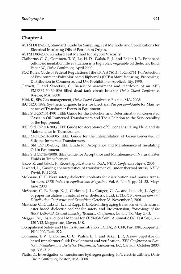
Bibliography 921
Chapter 4
ASTM D117-2002, Standard Guide for Sampling, Test Methods, and Specifi cations for Electrical Insulating Oils of Petroleum Origin.
ASTM D88-2007, Standard Test Method for Saybolt Viscosity.Claiborne, C. C., Oommen, T. V., Le, H. D., Walsh, E. J., and Baker, J. P., Enhanced
cellulosic insulation life evaluation in a high oleic vegetable oil dielectric fl uid, Paper 3C, Doble Conference, April 2002.
FCC Rules, Code of Federal Regulations Title 40 Part 761.1 (40CFR761.1), Protection of Environment-Polychlorinated Biphenyls (PCBs) Manufacturing, Processing, Distribution in Commerce, and Use Prohibitions-Applicability, 1995.
Garnett, J. and Sweetser, C., In-service assessment and teardown of an ABB PME362-50-30 SF6 fi lled dead tank circuit breaker, Doble Client Conference, Boston, MA, 2008.
Hibi, K., SF6 Gas management, Doble Client Conference, Boston, MA, 2008.IEC 61203:1992, Synthetic Organic Esters for Electrical Purposes—Guide for Mainte-
nance of Transformer Esters in Equipment.IEEE Std C57.104-1991, IEEE Guide for the Detection and Determination of Generated
Gases in Oil-Immersed Transformers and Their Relation to the Serviceability of the Equipment.
IEEE Std C57.111-2003, IEEE Guide for Acceptance of Silicone Insulating Fluid and its Maintenance in Transformers.
IEEE Std C57.146-2005, IEEE Guide for the Interpretation of Gases Generated in Silicone-Immersed Transformers.
IEEE Std C57.106-2006, IEEE Guide for Acceptance and Maintenance of Insulating Oil in Equipment.
IEEE Std C57.147-2008, IEEE Guide for Acceptance and Maintenance of Natural Ester Fluids in Transformers.
Jakob, K. and Jakob, F., Recent applications of DGA, NETA Conference Papers, 2006.Lewand, L., Gassing characteristics of transformer oil under thermal stress, NETA
World, Fall 2005.McShane, C. P., New safety dielectric coolants for distribution and power trans-
formers, IEEE Industry Applications Magazine, Vol. 6, No. 3, pp. 24–32, May/June 2000.
McShane, C. P., Rapp, K. J., Corkran, J. L., Gauger, G. A., and Luksich, J., Aging of paper insulation in natural ester dielectric fl uid, IEEE/PES Transmission and Distribution Conference and Exposition, October 28–November 2, 2001.
McShane, C. P., Luksich, J., and Rapp, K. J., Retrofi lling aging transformer with natural ester based dielectric coolant for safety and life extension, Proceedings of the IEEE-IAS/PCA Cement Industry Technical Conference, Dallas, TX, May 2003.
Megger Inc., Instructional Manual for OTS60SX Semi Automatic Oil Test Set, 6172-120 V12, Megger Inc., Dover, U.K.
Occupational Safety and Health Administration (OSHA), 29 CFR, Part 1910, Subpart Z, 1910.1000, Table Z-2.
Oommen, T. V., Claiborne, C. C., Walsh, E. J., and Baker, J. P., A new vegetable oil based transformer fl uid: Development and verifi cation, IEEE Conference on Elec-trical Insulation and Dielectric Phenomena, Vancouver, BC, Canada, October 2000, pp. 308–312.
Platts, D., Investigation of transformer hydrogen gassing, PPL electric utilities, Doble Client Conference, Boston, MA, 2008.
DK4058_C014.indd 921DK4058_C014.indd 921 11/8/2008 12:25:12 PM11/8/2008 12:25:12 PM

922 Bibliography
U.S. Environmental Protection Agency, Environmental Technologies Verifi cation (ETV) Reports, EPA 600/R-02/042 and EPA 600/R-02/043, Offi ce of Research and Development, National Center for Environmental Research, Washington, DC.
U.S. Environmental Protection Agency, Environmental Technology Verifi cation, Joint Verifi cation Statement for Vegetable Oil-Based Insulation Dielectric Fluid, Statement VS-R-02-02, June 2002, and VSR-02-03, June 2002.
U.S. Environmental Protection Agency, Test Method OPPTS 835.3110, Offi ce of Prevention, Pesticides, and Toxic Substances Test Guidelines, Washington, DC, September 1995.
VDE 0370-1978, Insulating Oils in Service in Transformers and Switchgear.
Chapter 5
Babcock, R. O., Application Guide for Power Factor Testing of Bushings, Megger Inc., Dallas, TX, 2003.
Babcock, R. O., Application Guide for Power Factor Testing of Power and Distribution Transformers, Megger Inc., Dallas, TX, 2003.
Bartley, W., Analysis of transformer failures, International Associations of Engineering Insurers Association 36th Annual Conference, Stockholm, 2003.
Bartley, W., Investigating transformer failures, Weidmann-ACTI 5th Annual Technical Conference, Hartford Steam Boiler Inspection & Insurance Company, November 2006.
Britton, J. A., Frequency response analysis of power transformers: Practical aspects of FRA testing and interpretation, NETA 2005 Annual Technical Conference, New Orleans, LA.
Coffeen, L. (NEETRAC), Cantrelle, D. (George Power Co.), and Mongo, J. (Florida Power and Light), Online Monitor Tracks Transformer Health, Transmission and Distribution World, October 1, 2007.
Hamaker, C., A blueprint for transformer maintenance, Public Utilities Fortnightly, July 2006.
IEEE C57.125-1991, IEEE Guide for Failure Investigation, Documentation and Analysis for Power Transformers and Shunt Reactors.
IEEE C57.19.01-2000, IEEE Standard Performance Characteristics and Dimensions for Outdoor Apparatus Bushings.
IEEE C57.91-1995, IEEE Guide for Loading Mineral-Oil-Immersed Transformers.IEEE PC 57.119-2001, Recommended Practice for Performing Temperature Rise Tests
on Oil Immersed Power Transformers at Loads beyond Nameplate Ratings.IEEE Std 259-1999, IEEE Standard Test Procedure for Evaluation of Systems of Insula-
tion for Dry-Type Specialty and General-Purpose Transformers.IEEE Std C57.113-1991, IEEE Guide for Partial Discharge Measurement in Liquid-
Filled Power Transformers and Shunt Reactors.IEEE Std C57.12.00-2000, IEEE Standard General Requirements for Liquid-Immersed
Distribution, Power, and Regulating Transformers.IEEE Std C57.12.10-1997, Product Standard for Power Transformers.IEEE Std C57.12.90-1999, IEEE Standard Test Code for Liquid-Immersed Distribution,
Power, and Regulating Transformers.IEEE Std C57.93-2007, IEEE Guide for Installation and Maintenance of Liquid-
Immersed Power Transformers.
DK4058_C014.indd 922DK4058_C014.indd 922 11/8/2008 12:25:12 PM11/8/2008 12:25:12 PM

Bibliography 923
IEEE Std C57.98-1993 (Reaff 1999), IEEE Guide for Transformer Impulse Tests.James, R. and Bartley, W., Transformer asset management, Weidmann-ACTI 2nd
Annual Technical Conference, New Diagnostics for Better Asset Management, November 2003.
Kennedy, M., Field experiences with SFRA, DOBLE Client Conference, Boston, MA, 2008.
Mandeville, J., SFRA—AEP’s Prospective, Doble Client Conference, Boston, MA, 2008.Megger Inc., Instructional Manual for Capacitance and Dissipation Factor Bridge Catalog
No. 810130, AVTM810130, Megger Inc., Valley Forge, PA.Megger Inc., Instructional Manual for Delta-3000 10kV Automated Insulation Test Set,
AVTM673001, Megger Inc., Valley Forge, PA.Megger Inc., Instructional Manual for S1-552 5kV Digital Insulation Resistance Tester,
S1-552_UG_en_V03 0806, Megger Inc., Dover, U.K.Megger Inc., Instructional Manual for Transformer Ohmmeter Catalog No. 830280,
AVTM830280, Megger Inc., Valley Forge, PA.Megger Inc., Instructional Manual for TTR Hand Crank Transformer Turn Ratio Test Set,
AVTM 55-JD, Megger Inc., Valley Forge, PA.Megger Inc., Instructional Manual for TTR25 Handheld Transformer Turn Ratio Test Set,
AVTMTTR25, Megger Inc., Valley Forge, PA.Megger Inc., Instructional Manual for TTR310 Three-Phase Transformer Turn Ratio Test
Set, AVTMTTR310, Megger Inc., Valley Forge, PA.Meyers, S. D., Kelly, J. J., and Parrish, R. H., A Guide to Transformer Maintenance, Trans-
former Maintenance Institute, Akron, OH, 1981.NEMA standard publication number TR1-1993 (R2000), Transformers, Regulators, and
Reactors, NEMA, Rosslyn, VA.NETA Maintenance Testing Specifi cation for Electrical Power Distribution Equip-
ment and Systems (NETA MTS-2005), International Electrical Testing Associa-tion, 3050 Old Center Ave, Portage, MI, Table 100-5, 2005.
Prout, P. and Simonelli, R., Assessment of insulation dryness using dew point measure-ments of transformers below freezing, DOBLE Client Conference, Boston, MA, 2008.
Rojas, A., The role of test voltage and current levels in transformer condition assess-ment—Is there a better way? NETA Conference Papers, 2006.
Sánchez, S., Pérez, C., and Avalos, A., Frequency response analysis for fault detection in power transformers, Doble Client Conference, Boston, MA, 2008.
Stephens, R., Hill, K., and Stelmach, D., High voltage transformer tests uncover man-ufacturing defect not detected in the factory, DOBLE Client Conference, Boston, MA, 2008.
Theyeri, M., Risk management associated with power transformers, DOBLE Client Conference, Boston, MA, 2008.
Chapter 6
Abdolall, K., Halldorson, G. L., and Green, D., Condition assessment and fail-ure modes of solid dielectric cables in perspective, IEEE Transaction on Power Delivery, Vol. 17, No. 1, January 2002.
Ahmed, N. and Srinivas, N., Partial discharge measurements in distribution class extruded cables, IEEE T&D Conference, New Orleans, 1999, pp. 46–51.
DK4058_C014.indd 923DK4058_C014.indd 923 11/8/2008 12:25:12 PM11/8/2008 12:25:12 PM

924 Bibliography
Ahmed, N. and Srinivas, N., Online Versus Offl ine Partial Discharge Testing in Power Cables, DTE Energy Technologies Inc., 2001.
Babcock, R. O., Application Guide for Power Factor Testing of Cables and Potheads, 2003, Megger Inc., Dallas, TX.
Boone, W., Reliability improvement of cable circuits by condition-based maintenance, NETA Conference Papers, 2004.
Chan, J.C., Duffy, P., Hiivala, L.J., and Wasik, J. Partial discharge-Part VIII: PD Testing of solid dielectric cables, Electrical Insulation Magazine, September/ October 1991, pp. 744–760.
Eynon, R., Inspections of medium-voltage power cables, NETA Conference Papers, 2004.GE Wire and Cable Hand Book, Wire and Cable Products Department, Bridgeport,
CT, 1973.Gulski, E., Smith, J. J., Seitz, P. N., and Smit, J. C. PD Measurements on-site using
oscillating wave test system, Conference Record of the 1998 International Sympo-sium of Electrical Insulation, Virginia, June 7–10, 1998, pp. 420–423.
Hicks, S., On-line partial-discharge testing of medium-voltage cables, NETA Conference Papers, 2004.
IEEE Std 400-2001, IEEE Guide for Field Testing and Evaluation of the Insulation of Shielded Power Cable Systems.
IEEE Std 400.2-2004, IEEE Guide for Field Testing of Shielded Power Cable Systems Using Very Low Frequency (VLF).
IEEE Std 400.3-2006, IEEE Guide for Partial Discharge Testing of Shielded Power Cable Systems in a Field Environment.
IEEE Std 400.1-2007, IEEE Guide for Field Testing of Laminated Dielectric, Shielded Power Cable Systems Rated 5 kV and above with High Direct Current Voltage.
Lanz, B., Cable testing options compared, Application Note, 2004.Megger Inc., Instructional Manual for Portable Fault Locator PFL40A, AVTMPFL40A-EN,
Megger Inc., Valley Forge, PA.Megger Inc., Fault Finding Solutions, MEG-231/MIL/3M/11.2003, Megger Inc., Valley
Forge, PA.Moore, G. F. (Ed.), Electrical Cables Handbook/BICC Cables, 3rd edn., Blackwell Science,
Oxford; Malden, MA, 1997.Morshuis, P., Assessment of dielectric degradation of ultrawide band PD detec-
tion, IEEE Transaction on Dielectric and Electrical Insulation, Vol. 2, No. 5, 1995, pp. 774–760.
Ross, R., Composition, structure and growth of water trees in polythene, KEMA Scientifi c and Technical Reports (ISSN 0167–8590), KEMA, the Netherlands, Vol. 8, No. 4, 1990, pp. 209–271.
Ross, R. and Smit, J. J., Infl uence of ageing conditions on water tree growth processes, IEEE Transactions on Electrical Insulation, 1992, pp. 368–371.
Chapter 7
Anderson, B., Remote breaker racking, Doble Client Conference, Boston, MA, 2008.Babcock, R. O., Application Guide for Power Factor Testing of Circuit Breakers, Megger
Inc., Dallas, TX, 2003.Blohm, R., Battery installation and maintenance recommendations, NETA Annual
Technical Conference, San Antonio, TX, 2004.
DK4058_C014.indd 924DK4058_C014.indd 924 11/8/2008 12:25:12 PM11/8/2008 12:25:12 PM

Bibliography 925
Brown, J., Revise the Doble test procedure for SF6 dead tank and vacuum breakers, Doble Client Conference, Boston, MA, 2008.
Claesson, L. Stanisic, Z., Wernli, H., and Petterson, K., Safe circuit breaker timing with new technology, Cigre and IEEE International Conference on Condition Moni-toring and Diagnosis, Changwon, Korea, April 4, 2006.
Fernihough, W. J., Detection of SF6 circuit breaker problems using the Doble test set, Doble Client Conference, Boston, MA, 2008.
IEEE Std C37.85-1989, American National Standard for Switchgear—Alternating-Current High-Voltage Power Vacuum Interrupters-Safety Requirements for X-Radiation Limits.
IEEE Std 1291-1993, IEEE Guide for Partial Discharge Measurement in Power Switchgear.
IEEE Std C37.010-1999, IEEE Application Guide for AC High-Voltage Circuit Breakers Rated on a Symmetrical Current Basis.
IEEE Std C37.06-2000, American National Standard AC High-Voltage Circuit Breakers Rated on a Symmetrical Current Basis-Preferred Ratings and Related Required Capabilities.
IEEE Std C37.10.1-2000, Guide for the Selection of Monitoring for Circuit Breakers.IEEE Std 450-2002, IEEE Recommended Practice for Maintenance, Testing, and
Replacement of Vented Lead-Acid Batteries for Stationary Applications.IEEE Std C37.48-2005, IEEE Guide for Application, Operation, and Maintenance
of High-Voltage Fuses, Distribution Enclosed Single-Pole Air Switches, Fuse Disconnecting Switches, and Accessories.
IEEE Std 1188-2005, IEEE Recommended Practice for Maintenance, Testing, and Replacement of Valve-Regulated Lead-Acid (VRLA) Batteries for Stationary Applications.
IEEE Std 551-2006 (Violet Book), IEEE Recommended Practice for Calculating Short-Circuit Currents in Industrial and Commercial Power Systems.
IEEE Std C37.04-2006, IEEE Standard Rating Structure for AC High-Voltage Circuit Breakers.
Jensen, R., ABB Type 15-VHK-500 Vacuum breakers manufactured between 1989 and 1997, Doble Client Conference, Boston, MA, 2008.
Knights, M., Tracking down the greenhouse gas SF6 with infrared thermography, Doble Client Conference, Boston, MA, 2008.
Leoni, A. R. and Nelson, J. P., Some lessons learned from commissioning substation and medium voltage switchgear equipment, IEEE Paper No. PCIC-2000-XX.
Locarno, M., Southern states capacitor switcher problem found by Doble testing, Doble Client Conference, Boston, MA, 2008.
Mandeville, J., New battery technology, Doble Client Conference, Boston, MA, 2008.Megger Inc., Instructional Manual for BITE2 Battery Impedance Test Equipment,
AVTM246004, Megger Inc., Valley Forge, PA.Megger Inc., Instructional Manual for DLRO200 High Current Low Resistance Ohmmeter,
6172-763, Megger Inc., Dover, U.K.Megger Inc., Instructional Manual for S1-5010 Diagnostic Insulation Tester, 6172-283,
Megger Inc., Dover, U.K.Megger Inc., Instructional Manual for S1-552 5 kV Digital Insulation Resistance Tester,
S1-552_UG_en_V03 0806, Megger Inc., Dover, U.K.Megger Inc., Battery Testing Guide, MEG-290/MIL/2.5M/4.2004, Megger Inc., Dover, U.K.Megger Inc., A Guide to Low Resistance Testing: Understanding and Measuring Low Resis-
tance to Ensure Electrical System Performance, MEG-429_V04/MIL/2.5M/7.2005, Megger Inc., Dover, U.K.
DK4058_C014.indd 925DK4058_C014.indd 925 11/8/2008 12:25:12 PM11/8/2008 12:25:12 PM

926 Bibliography
NUREG/CR-6819, Common-Cause Failure Event Insights-Circuit Breakers, Vol. 4, ID 83415, Idaho National Engineering and Environmental Laboratory, Idaho Falls, May 2003.
Patterson, C., Field application of partial discharge testing for medium-voltage switchgear, NETA Conference Papers, 2004.
Programma Instruments, Instructional Manual for TM1800 Circuit Breaker Analyzer System, CG0757EE, Programma Instruments, Taby, Sweden.
Programma Instruments, Instructional Manual for Torkel 820/840/860 Battery Load Units, BS2395EE, Programma Instruments, Taby, Sweden.
Programma Instruments, Instructional Manual for Vidar Vacuum Tester, BR0150AE, Programma Instruments, Taby, Sweden.
Programma Instruments, Instructional Manual for EGIL Breaker Analyzer, BM0087JE, Programma Instruments, Taby, Sweden.
Rogers, D. and Smith, M., Oil circuit breaker (WE 2300-GW-20000) failure due to high moisture content, Doble Client Conference, Boston, MA, 2008.
Salinas, A. Southern California Edison, Vacuum bottle monitoring, Doble Client Con-ference, Boston, MA, 2008.
Smeaton, R. W. and Ubert, W. H., Switchgear and Control Handbook, 3rd edn., McGraw Hill Book Company, New York.
Tressler, R., Practical aspects of maintaining and testing stationary batteries, NETA Conference Papers, 2004.
True, T., Switching 138 kV breakers with capacitors using gang operated switches causes arcing, Doble Client Conference, Boston, MA, 2008.
Chapter 8
ABB Inc., Installation/Maintenance Instructions for Low Voltage Air-Magnetic Power Circuit Breakers, K-Line 225A through 2000A, Stationary and Draw-Out Frames, Manually and Electrically Operated Mechanisms, ABB Inc., Florence, SC, IB 6.1.12.1-1D, Issue “D” 7-15-06.
ANSI C37.16-2000, Low-Voltage Power Circuit Breakers and AC Power Cir-cuit Protectors Preferred Ratings, Related Requirements, and Application Recommendations.
ANSI/IEEE C37.13-1995, Standard for Low-Voltage AC Power Circuit Breakers Used in Enclosures.
ANSI/IEEE Std 242-1986, IEEE Recommended Practice for Protection and Coordina-tion of Industrial and Commercial Power Systems (Buff Book), New York.
ANSI/IEEE Std 242-2001, IEEE Recommended Practice for Protection and Coordination of Industrial and Commercial Power Systems.
Casler, C., Electrical inspections with the use of thermography, ultrasound, and ultraviolet technology, NETA Conference Papers, 2008.
IEEE Standards Collection, C37, Circuit Breakers, Switchgear, Substations, and Fuses, 7995 Edition, The Institute for Electrical and Electronics Engineers, Inc., New York.
IEEE Std 944-1986, IEEE Recommended Practice for the Application and Testing of Uninterruptible Power Supplies for Power Generating Stations.
IEEE Std 141-1993 (Redbook), IEEE Recommended Practice for Electric Power Distribution for Industrial Plants.
DK4058_C014.indd 926DK4058_C014.indd 926 11/8/2008 12:25:12 PM11/8/2008 12:25:12 PM

Bibliography 927
IEEE Std 242-2001 (Buff Book), IEEE Recommended Practice for Protection and Coordination of Industrial and Commercial Power Systems.
IEEE Std 1458-2005, IEEE Recommended Practice for the Selection, Field Testing, and Life Expectancy of Molded Case Circuit Breakers for Industrial.
IEEE Std 1015-2006 (Blue Book), IEEE Recommended Practice for Applying Low Voltage Circuit Breakers Used in Industrial and Commercial Power Systems.
Ignall, R., Power monitoring—How to perform a power survey, NETA Conference Papers, 2008.
Megger Inc., A Guide to Low Resistance Testing—Understanding and Measuring Low Resistance to Ensure Electrical System Performance, MEG-429_V04/MIL/2.5M/7.2005, Megger Inc., Dover, U.K.
Megger Inc., Instructional Manual for CB-832 Circuit Breaker and Overload Relay Test Set, 9841, Megger Inc., Dallas, TX.
Megger Inc., Instructional Manual for CB-845 Circuit Breaker Test Set, 9820, Megger Inc., Dallas, TX.
Megger Inc., Instructional Manual for DDA-3000 and DDA-6000 Universal Circuit Breaker Test Set, 17176, Megger Inc., Dallas, TX.
Megger Inc., Instructional Manual for High CCA-1600 Circuit Breaker Test Set, 50550, Megger Inc., Dallas, TX.
Megger Inc., Instructional Manual for High Current Test Set Model MS-2, 12510, Megger Inc., Dallas, TX.
Neitzel, D. K., Neeser, D., and Callanan, M., Preventative maintenance and reliability of low-voltage overcurrent protective devices, IEEE-PCIC Europe 2004 Confer-ence Documentation, 2004.
NEMA AB-1, Molded Case Circuit Breakers and Molded Case Switches.NEMA AB-1-2002, Molded Case Circuit Breakers and Molded Case Switches.NEMA AB-1, 2002, Molded-Case Circuit Breakers, Molded Case Switches, and
Circuit-Breaker Enclosures, Only Available from UL, See UL 489.NEMA AB-3, 2006, Molded Case Circuit Breakers and Their Application.NEMA AB-4, 2003, Guidelines for Inspection and Preventive Maintenance of Molded
Case Circuit Breakers Used in Commercial and Industrial Applications.NEMA C37.16, 2000, Low-Voltage Power Circuit Breakers and AC Power Circuit
Protectors—Preferred Ratings, Related Requirements, and Application Recommendations.
NEMA C37.17, 1997, Trip Devices for AC and General Purpose DC Low Voltage Power Circuit Breakers.
NEMA Standards Publication AB 4, National Electrical Manufacturers Association, Washington, DC.
NETA Maintenance Testing Specifi cations for Electrical Power Distribution Equip-ment and Systems (NETA MTS-2005), International Electrical Testing Associa-tion, 3050 Old Center Ave, Portage, MI, Table 100.18.
Schneider Electric USA, Introduction to Field Testing and Maintenance Guide, for Thermal-magnetic and Micrologic® Electronic-trip Molded Case Circuit Breakers, Schneider Electric USA, Palatine, IL, 1/2005 (600DB9901R1/05).
Sprague, M. J., Service-life evaluations of low-voltage power circuit breakers and molded-case circuit breakers (Frame Size amperes 800A–4000A).
UL 248-1 2000, UL Standard for Safety for Low-Voltage Fuses: Part 1: General Require-ments, 2nd edn.; Reprint with revisions through and including August 11,2005.
DK4058_C014.indd 927DK4058_C014.indd 927 11/8/2008 12:25:12 PM11/8/2008 12:25:12 PM

928 Bibliography
UL 248-8 and 10, 2000, UL Standard for Safety for Low-Voltage Fuses: Part 8 and 10: Class J & L Fuses, 2nd edn.; Reprint with revisions through and including August 11, 2005.
UL 489-2002, UL Standard for Safety Molded-Case Circuit Breakers, Molded-Case Switches, and Circuit-Breaker Enclosures, 10th edn.; Reprint with revisions through and including June 30, 2006.
UL 67, UL Standard for Safety for Panelboards, Underwriters Laboratories Inc., Northbrook, IL.
UL 248.1–248.16-2000, UL Standard for Safety for Low-Voltage Fuses, Part 1–Part 16.UL-489-1991, Standard for Safety Molded-Case Circuit Breakers, Molded-Case
Switches, and Circuit-Breaker Enclosures.UL-489-2002, Standard for Safety Molded-Case Circuit Breakers, Molded-Case
Switches, and Circuit-Breaker Enclosures.
Chapter 9
ANSI/IEEE C57.13.1-1981, Field Testing of Relaying Current Transformers.ANSI/IEEE C57.13-1993.06.01 (R2000), Standard Requirements for Instrument
Transformers.ANSI/IEEE Std C57.13.3-1983, IEEE Guide for Grounding of Instrument
Transformers.Beach, D., Klotz, S., and Barney, B., Practical Experience in Commissioning Distributed
Generation Installations, Basler Electrical Company, Highland, IL, 2002.Gosalia, J., Relay performance testing, NETA Annual Technical Conference, Denver,
CO, 2004.Guiliante, T., Makki, A. M., and Taffuri, J., New techniques for dynamic relay testing,
NETA Conference Papers, 2007.IEEE Special Publication # 96TP115-0, Relay performance testing, Power System
Relaying Committee, Report of Working Group 113.IEEE Std C37.103-2004, IEEE Guide for Differential and Polarizing Relay Circuit
Testing.IEEE Std C57.13.3-2005, IEEE Guide for Grounding of Instrument Transformer
Secondary Circuits and Cases.IEEE Std C37.90-2005, IEEE Standard for Relays and Relay Systems Associated with
Electric Power Apparatus.IEEE Std C57.13.1-2006, IEEE Guide for Field Testing of Relaying Current
Transformers.IEEE Std C37.110-2007, IEEE Guide for the Application of Current Transformers Used
for Protective Relaying Purposes.Jodice, J. A., Relay Performance Testing, IEEE Transactions on Power Delivery, Vol. 12,
No. 1, January 1997.Kumm, J. J., Webber, M. S., Schmeitzer, E. O. III, and Hou, D., Philosophies
for testing protective relays, 48th Annual Georgia Tech Protective Relaying Conference, Schweitzer Engineering Laboratories Incorporated, Atlanta, GA, May 1994.
Megger Inc., Instructional Manual for MCT-1600 Current Transformer Test Set, 750025, Megger Inc., Dallas, TX.
DK4058_C014.indd 928DK4058_C014.indd 928 11/8/2008 12:25:12 PM11/8/2008 12:25:12 PM

Bibliography 929
Megger Inc., Instructional Manual for MPRT Protective Relay Test System, 710000, Megger Inc., Dallas, TX.
Pieniazek, D. and Williamson, R., Application of relaying class current transformers, NETA Conference Papers, 2006.
Programma Instruments, Instructional Manual for Sverker 750/760 Relay Test Unit, ZP-CD01ER05A, Programma Instruments, Taby, Sweden.
Relay testing and maintenance, General Electric Company Power Management Technical Publication No. GET-3473B-2000.
Tienken, C., Gosalia, J., and Giuliante, A. T., End-to-end testing for routine mainte-nance, Annual Western Protective Relay Conference, October 21–23, 1997.
Werstiuk, C., Back to the basics—Current transformer testing: Parts 1 & II, NETA World, Fall and Winter 2004–2005.
White, J., Current transformers—a forgotten piece of the relay system, NETA World, Winter 2004–2005.
Young, M. and Horak, J., Commissioning of Numerical Relays, Basler Electrical Company, Highland, IL, 2001.
Zavadlov, C., Communicating with modern protective relays, NETA Conference Papers, 2007.
Zimmerman, K., Commissioning of protective relay systems, SEL Technical Papers, 2007.
Zocholl, S. E., Standard CT accuracy ratings in metal-clad switchgear, NETA Confer-ence Papers, 2006.
Zocholl, S. E., Analyzing and Applying Current Transformers, Schweitzer Engineering Laboratories, Inc., WA, 2004.
Chapter 10
Bethel, N. P., Fault Zone Analysis—Six Part Series on Identifying Motor Defects, PdMA Corporation, Tampa, FL, 2005.
Blokhintsev, I. and Patterson, C., Continuous partial discharge monitoring on motors, Doble Client Conference, Boston, MA, 2008.
Bruni, K. A., Guidelines for Successful Commutator and Brush Operation, Carbon Prod-ucts Operation Inc., East Stroudsburg, PA, pp. 1–7.
Brynjebo, E., Electrical testing and tabulation of high voltage motors, Doble Client Conference, Boston, MA, 2008.
Edwards, D. G., On-line Monitoring of Stator Winding Insulation in High Voltage Motors, Society of Petroleum Engineers, 1989, No. 19272.
General Electric Company, Power Consideration for Adjustable Drives, General Electric Company, Drive Dept., Erie, PA (GET-6468B-9/1988).
Gleichman, R., Failure modes and fi eld testing of medium voltage motor windings, IEEE Transactions on Industry Applications, Vol. 38, No. 5, September/October 2002.
IEEE Std 666-1991, Design Guide for Electric Power Service System for Generating Systems.
IEEE Std 115-1995, IEEE Guide: Test Procedures for Synchronous Machines.IEEE Std 43-2000, IEEE Recommended Practice for Testing Insulation Resistance of
Rotating Machinery.
DK4058_C014.indd 929DK4058_C014.indd 929 11/8/2008 12:25:12 PM11/8/2008 12:25:12 PM

930 Bibliography
IEEE Std 43-2000, IEEE Recommended Practice for Testing Insulation Resistance of Rotating Machinery.
IEEE Std 1434-2000, IEEE Trial-Use Guide to the Measurement of Partial Discharges in Rotating Machinery.
IEEE Std 841-2001, IEEE Standard for the Petroleum and Chemical Industry—Severe Duty Totally Enclosed Fan-Cooled (TEFC) Squirrel Cage Induction Motors—Up to and Including 370 kW (500 hp).
IEEE Std 112-2004, IEEE Standard Test Procedure for Polyphase Induction Motors and Generators.
IEEE Std 67-2005, IEEE Guide for Operation and Maintenance of Turbine Generator.IEEE Std 415-2006, IEEE Guide for Induction Machinery Maintenance Testing and
Failure Analysis.IEEE Std 434-2006, IEEE Guide for Functional Evaluation of Insulation Systems for
AC Electric Machines Rated 2300 V and above.IEEE Std 1415-2006, IEEE Guide to Induction Machinery Maintenance Testing and
Failure Analysis.Maughan, C., Inspection, test and operating issues with collector rings, Doble Client
Conference, Boston, MA, 2008.Megger Inc., Instructional Manual for Delta-3000 10 kV Automated Insulation Test Set,
AVTM673001, Megger Inc., Valley Forge, PA.Megger Inc., Instructional Manual for S1-1052 5 kV Digital Insulation Resistance Tester,
S1-1052_UG_en_V03 0806, Megger Inc., Dover, U.K.Megger Inc., A Guide to Diagnostic Insulation Testing above 1 kV, MEG-562/3M/5.2007,
Megger Inc., Valley Forge, PA.Michalec, J., Thermal imaging of carbon brushes as a maintenance tool, Doble Client
Conference, Boston, MA, 2008.NEMA MG-1, Motors and Generators—Includes Revision 1, 2007.O’Donnell, P. (Coordinating Author), IEEE Committee Report, Report of large motor
reliability survey of industrial and commercial installations, Parts 1 and 2, IEEE Transaction on Industry Applications, Vol. IA-21, No. 4, July/August 1985, pp. 853–872.
O’Donnell, P. (Coordinating Author), IEEE Committee Report, Report of large motor reliability survey of industrial and commercial installations, Parts 3, IEEE Transaction on Industry Applications, Vol. IA, No. 1, January/February 1987, pp. 153–158.
Pong, L., Hill, K., Simard, H., and Ryman, V., Condition assessment of RM fi eld poles using M4000 test set, Doble Client Conference, Boston, MA, 2008.
Stone, G. C., Partial discharge measurements to asses rotating machine insulation condition: A survey, 1996, IEEE International Symposium on Electrical Insulation, Montreal, Canada, June 1996.
Tesla, A. and Tetreault, A., End winding vibration in large rotating machines, Doble Client Conference, Boston, MA, 2008.
Thomas, T. M., Integrating static and dynamic electric motor testing into a predictive maintenance program, NETA Conference Papers, 2006.
Timperley, J., High Voltage Equipment Condition Assessment with EMI Diagnostics, Doble Client Conference, Boston, MA, 2008.
Toliyat, H. A. and Kliman, G. B., Handbook of Electric Motors, Marcel Dekker Inc., New York, 2004.
DK4058_C014.indd 930DK4058_C014.indd 930 11/8/2008 12:25:12 PM11/8/2008 12:25:12 PM

Bibliography 931
Chapter 11
C62.92.2-1989, IEEE Guide for the Application of Neutral Grounding in Electrical Utility Systems, Part II: Grounding of Synchronous Generator Systems.
C62.92.4-1991, IEEE Guide for the Application of Neutral Grounding in Electrical Utility Systems, Part IV: Distribution.
C62.92.5-1992, IEEE Guide for the Application of Neutral Grounding in Electrical Utility Systems, Part V: Transmission Systems and Sub-Transmission Systems.
C62.92.3-1993, IEEE Guide for the Neutral Grounding in Electrical Utility Systems, Part III: Generator Auxiliary System.
C62.92.1-2000, IEEE Guide for the Application of Neutral Grounding in Electrical Utility Systems, Part 1: Introduction.
Clem, O., Used in company catalog, datasheet, and brochure, Megger/Programma, Valley Forge, PA, 2008.
Cunnie, E., Testing the bonding resistance in a grounding electrode system, NETA Conference Papers, 2006.
Havens, A., High resistance grounding or what happens when a phase-to-ground fault occurs? NETA Conference Papers, 2005.
IEEE Std 81-1983, IEEE Guide for Measuring Earth Resistivity, Ground Impedance, and Earth Surface Potentials of a Ground System.
IEEE Std 665-1995, IEEE Guide for Generating Station Grounding.IEEE Std 80-2000, IEEE Guide for Safety in AC Substation Grounding.IEEE Std 1050-2004, IEEE Guide for Instrumentation and Control Equipment Ground-
ing in Generating Stations.IEEE Std 1100-2005 (Emerald Book), IEEE Std 1100-2005, IEEE Recommended Practice
for Powering and Grounding Electronic Equipment.IEEE Std 142-2007 (Green Book), IEEE Recommended Practice for Grounding of
Industrial and Commercial Power Systems.Jowett, J., Slope method, NETA World, Summer 2002.Jowett, J., Measuring ground resistance—the fall of potential method, NETA World,
Spring 2002.Jowett, J., The role of testing in the practice of good grounding, NETA Conference
Papers, 2004.Jowett, J., Ground testing in complex, diffi cult environments, NETA Conference Papers,
2007.Megger Inc., Instructional Manual for DET2/2 Digital Earth Tester, 6171-428 V10, Megger
Inc., Dover, U.K.Megger Inc., Instructional Manual for GTS-300 Ground Grid Test Set, 4464400600,
Megger Inc., Dallas, TX.Megger Inc., Getting Down to Earth A Practical Guide to Earth Resistance Testing, MEG-
456/MIL/5M/11.2005, Megger Inc., Valley Forge, PA.Selkirk, D., Ground-fault detection, charging current and neutral-grounding resistor
selection, NETA Conference Papers, 2008.Tajali, R., System grounding for mission-critical power systems, NETA World, Winter,
2004–2005.Vlachos, G., Understanding ground resistance testing, NETA Conference Papers, 2006.
DK4058_C014.indd 931DK4058_C014.indd 931 11/8/2008 12:25:12 PM11/8/2008 12:25:12 PM

932 Bibliography
Chapter 12
ANSI/IEEE C57.110, 1986, Recommended Practice for Establishing Transformer Capacity When Supplying Non-Sinusoidal Load Currents.
Dranetz Technologies, Inc., Power Line Harmonics Problems—Causes and Cures, 1994.Dranetz Technologies, Inc., The Dranetz Field Handbook for Power Quality Analysis,
Dranetz Technologies, Inc., Edison, NJ, 1991.EC&M Practical Guide to Quality Power for Sensitive Electronic Equipment, Second Edi-
tion, DeDad, John and Waggoner, Ray, Intertec Publishing, Overland Park, KS, 1997.
EPRI, Wiring and Grounding for Power Quality, Electric Power Research Institute, Palo Alto, CA, 1995.
EPRI, Electrotek Concepts, Inc., Power Quality Workbook for Utility and Industrial Appli-cations, TR-105500, Research Project 2935-30, Final Report, October 1995.
Fluke Corporation, Applying Power Quality Measurements to Predictive Maintenance, 2005.
Fluke Corporation, Basic Power Quality Methodology and Common Culprits, 2004.Fluke Corporation, Common Power Quality Factors Affecting Transformers, 2004.Fluke Corporation, Electrical Noise and Transients, 2004.Fluke Corporation, How Adjustable Speed Drives Affect Power Distribution, 2004.Fluke Corporation, Performing Power Quality Studies and Troubleshooting Loads, 2007.Fluke Corporation, Power Quality Clamp Meter, 2007.Fluke Corporation, Power Quality Measurements at Receptacle Branch Circuits, 2004.Fluke Corporation, Power Quality Troubleshooting with Hand Held Tools, 2004.Fluke Corporation, Reducing Downtime by Troubleshooting Power Quality Disturbances,
2006.Fluke Corporation, Troubleshooting Power Harmonics—Basic Troubleshooting Using
Multimeters and Current Clamps, 2004.Grady, W. M. and Gilleskie, R. J., Harmonics and how they relate to power factor,
Proceedings of EPRI Power Quality Issues and Opportunities Conference, San Diego, CA, November 1993.
Heydt, G. T., Electric Power Quality, Stars in a Circle Publication, Indianapolis, IN.IEEE Std 519-1992, IEEE Recommended Practices and Requirements for Harmonic
Control in Electric Power systems, Table 10.3, Table 11.1.IEEE Std 1100-1992 (Emerald Book), IEEE Recommended Practice for Powering and
Grounding Sensitive Electronic Equipment.IEEE Std C57.110-1998, IEEE Recommended Practice for Establishing Transformer
Capability When Supplying Nonsinusoidal Load Currents.IEEE Tutorial Course, Power System Harmonics, IEEE Power Engineering Education
Committee and the IEEE Transmission and Distribution Committee General Systems Subcommittee of the IEEE Power Engineering Society, 84, EHO221-2-PWR.
Ignall, R., Power quality monitoring—Seeing what’s on the wires, NETA Conference Papers, 2007.
Mack Grady, W., Understanding Power System Harmonics, IEEE Power Engineering Review, Vol. 21, No. 11, November 2001.
Megger Inc., Instructional Manual for PA-9 Plus Portable Power Quality Analyzer, AVTMP9P, Megger Inc., Valley Forge, PA, 2007.
NIST, FIPS Publication 94-Guidance on Electrical Power for ADP Installations, NIST, Gaithersburg, MD, 1994.
DK4058_C014.indd 932DK4058_C014.indd 932 11/8/2008 12:25:12 PM11/8/2008 12:25:12 PM

Bibliography 933
Ontario Hydro, Power Quality Reference Guide, Ontario Hydro, Toronto, Ontario, Canada.
Pacifi c Gas and Electric Company, Power System Harmonics, 1993.Rusch, R. J., K-rated transformers, Industry INFO, June 1998.The power of a waveform: Expanded troubleshooting options with the Fluke 345,
2006.Wagner, J. P., Switch Mode Power Conversion in Data Processing Equipment, 1997.
Chapter 13
ANSI C2-2007, National Electrical Safety Code (NESC), 2009.ANSI Z244.1-1982 (Reaff 1993), Safety Requirements for the Lock Out/Tag Out of
Energy Sources.ANSI Z535.4-1998, Product Safety Signs and Labels.ANSI/NFPA 70B-2006, Recommended Practice for Electrical Equipment
Maintenance.ASTM D120-95, Standard Specifi cation for Rubber Insulating Gloves.Guide to Industrial Electric Power Distribution. Compiled by the editors of Electrifi ed
Industry, B. J. Martin Co., Chicago.Hartman, P., Electric arc fl ash protective clothing, NETA Conference Papers, 2004.IEEE Std 1584, IEEE Guide for Performing Arc-Flash Hazard Calculations.IEEE Std 141-1993 (Red Book), IEEE Recommended Practice for Electric Power
Distribution for Industrial Plants.Inshaw, C. and Toepfer, F., Arc fl ash compliance practical application of NFPA-70 and
IEEE 1584 standards, 73rd Annual International Doble Client Conference, Boston, MA, 2006.
Lee, R. H., The other electrical hazards—Electric arc blast burns. IEEE TP IPSD 81-55.
Neitzel, D. K., CPE, Protective Devices Maintenance as it Applies to the Arc/Flash Hazard, AVO Training Institute, Dallas, TX, 2004.
Neitzel, D. K., Proper protective device maintenance and testing—The difference between life and death, NETA Conference Papers, 2004.
NFPA 70E-2004, Standard for Electrical Safety Requirements for Employee Workplaces.
NFPA 70E, Standard for Electrical Safety in the Workplace, 2004.NFPA 70E, Standard for Electrical Safety in the Workplace, 2004, Table 130.2(C), Table
130.7(C)(11).NFPA 70-2008, National Electrical Code (NEC).Occupational Safety and Health Administration (OSHA) 29 CFR Part 1910 Subpart S
and I, 1910.131, 1910-132-.139, 1910.147, 1910-302-.308, 1910.331-.335, 1910.361-.398 and Appendix A.
DK4058_C014.indd 933DK4058_C014.indd 933 11/8/2008 12:25:12 PM11/8/2008 12:25:12 PM

DK4058_C014.indd 934DK4058_C014.indd 934 11/8/2008 12:25:12 PM11/8/2008 12:25:12 PM
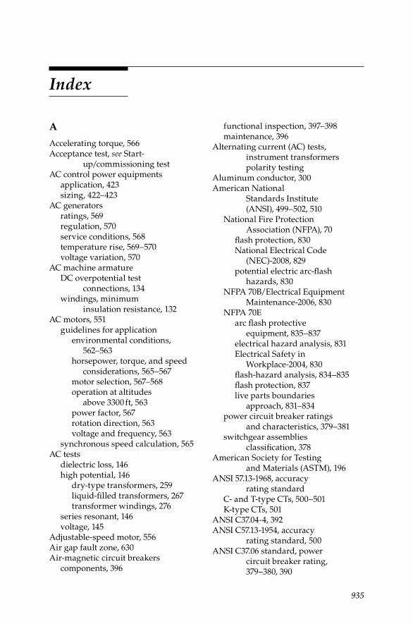
935
Index
A
Accelerating torque, 566Acceptance test, see Start-
up/commissioning testAC control power equipments
application, 423sizing, 422–423
AC generatorsratings, 569regulation, 570service conditions, 568temperature rise, 569–570voltage variation, 570
AC machine armatureDC overpotential test
connections, 134windings, minimum
insulation resistance, 132AC motors, 551
guidelines for applicationenvironmental conditions,
562–563horsepower, torque, and speed
considerations, 565–567motor selection, 567–568operation at altitudes
above 3300 ft, 563power factor, 567rotation direction, 563voltage and frequency, 563
synchronous speed calculation, 565AC tests
dielectric loss, 146high potential, 146
dry-type transformers, 259liquid-fi lled transformers, 267transformer windings, 276
series resonant, 146voltage, 145
Adjustable-speed motor, 556Air gap fault zone, 630Air-magnetic circuit breakers
components, 396
functional inspection, 397–398maintenance, 396
Alternating current (AC) tests, instrument transformers polarity testing
Aluminum conductor, 300American National
Standards Institute (ANSI), 499–502, 510
National Fire Protection Association (NFPA), 70
fl ash protection, 830National Electrical Code
(NEC)-2008, 829potential electric arc-fl ash
hazards, 830NFPA 70B/Electrical Equipment
Maintenance-2006, 830NFPA 70E
arc fl ash protective equipment, 835–837
electrical hazard analysis, 831Electrical Safety in
Workplace-2004, 830fl ash-hazard analysis, 834–835fl ash protection, 837live parts boundaries
approach, 831–834power circuit breaker ratings
and characteristics, 379–381switchgear assemblies
classifi cation, 378American Society for Testing
and Materials (ASTM), 196ANSI 57.13-1968, accuracy
rating standardC- and T-type CTs, 500–501K-type CTs, 501
ANSI C37.04-4, 392ANSI C57.13-1954, accuracy
rating standard, 500ANSI C37.06 standard, power
circuit breaker rating, 379–380, 390
DK4058_C015.indd 935DK4058_C015.indd 935 11/8/2008 12:38:21 PM11/8/2008 12:38:21 PM

936 Index
ANSI/IEEE standard device function numbers, 913–915
Antifriction bearings, 598Arc-fl ash hazard analysis
failure statistics, 91–92personal protective
equipment (PPE), 91protective devices
electrical equipment, 85electric power system, 89EPM program, 82low voltage power circuits, 86maintenance and testing, 81–82medium voltage power
circuits, 86–87molded-case circuit
breakers, 83–84operating mechanism, 88relays, 87–91
regulatory requirementsevaluation report, 843NFPA 70, 70E, and OSHA
requirements, 841PPE category, 840software programs, IEEE-
1584-2002 methodology, 842Arc-furnace transformers, 239Armature, 581–582Askarel insulating fl uid
contamination and reconditioning, 229
inspection and sampling, 228liquids, 230–231testing procedure, 228–229vapors, 230
Asymmetrical current wave, circuit breaker, 384–385
Autotransformerinsulation circuit, 162PF tests, 163
B
Battery, switchgear applicationsacid spillage, 428–429equalizing charge
frequency, 425volts per cell (VPC) values, 424
inspections, 423–424
loose connections and corrosion, 429
maintenance, 429tests
acceptance and performance, 425
battery impedance, 427battery service / load, 426connection resistance, 427
water addition, 427Battery impedance
tester (BITE), 428Brush rigging, 580Building management
systems (BMSs), 11Buna, thermosetting
compound, 304Bushing capacitors
capacitance, 182PF test connections, 182–183
Bus insulators, 183Bus transfer protection system
fast bus trip scheme, 536protection logic processor, 537
Butyl, thermosetting compound, 304
C
Cablebending, 324characteristics
geometric factor, 311geometric mean distance,
310–311geometric mean
radius, 309–310properties, 309
construction and classifi cationcable types, 301, 331conductor arrangement, 301conductor types, 300–301fi nishes and jackets, 306–307insulations, 302–305low and medium-voltage
cables, 307–308shielding and semiconducting
tape, 305electrical constants
insulation resistance, 313–314
DK4058_C015.indd 936DK4058_C015.indd 936 11/8/2008 12:38:21 PM11/8/2008 12:38:21 PM

Index 937
positive-and negative-sequence reactance and resistance, 312
shunt capacitance reactance, 313
zero-sequence resistance and reactance, 312–313
extruded/solid dielectric, 331failures and analysis
chemical action, 329electrical puncture, 327external fi re and HV surges, 329fi re and lightning surges, 327heating, 326–327inherent causes, 327–328local galvanic action, 329mechanical, 326, 329moisture, 326noninherent causes, 328–329overheating, 329sheath corrosion, 326
fault locating methodsapplication guide, 367–375terminal techniques, 356–361tracer techniques, 362–367
fi eld testingdegradation and diagnostic
tests, 330–334methods, 335–352safety practices and
grounding, 334–335installation
bending data, 323indoor, 323outdoor, 322pulling tensions, 323–325
laminated, 331maintenance, 325monitoring and aging assessment
BIS prognostic/diagnostic technique, 354–356
cable indentor, 352–353ECAD system, 352OSW testing, 353–354
ratingscontinuous current-carrying, 314emergency current-carrying, 315short-circuit, 316voltage, 316
selection and applicationconstruction, 318installation, 317operation, insulation
levels, 318–319shielding, 320–321size, 319–320
tension limitations, 325testing methods
AC hi-pot, 336–337AC resonance, 346–348GCA, 350hi-pot withstand type, 348–350insulation resistance and DC
hi-pot, 335–336PD, 341–346, 350–352PF and DF, 337–338VLF, 338–341
types, 301Cable testing
DC overpotentialconnections, 123as go, no-go type, 121leakage current vs. time, 121procedures, 122, 124setup for, 117–118step-voltage, 118–120test voltage values, 117
insulation resistance measurementcable test connections, 115instrument, 113megohmmeter, 114minimum IR values, 116
power factor, 180at 20°C, 190shielded and sheathed cables, 181unshielded and unsheathed
cables, 181–182Capacitance charging current, 98–99Capacitive current
changes, 148formula, 147
Capacitor AC to DC high-voltage fi eld tests, 138
Capacitor banks, harmonicscauses, 753distribution line type, 753–754PF correction type, 754problem criteria, 755–756
DK4058_C015.indd 937DK4058_C015.indd 937 11/8/2008 12:38:21 PM11/8/2008 12:38:21 PM

938 Index
Cellouse winding insulation, 196Circuit breakers
air-magnetic, 396–398closing angle, 383, 386–387contact resistance measurement, 127DC hi-pot testing, 126–127insulation mediums, 171insulation resistance test
bushings, 126connections, 125procedure, 125–126
oil, 398–399PF tests
medium-voltage circuit breakers, 172–173
OCBs, 173–176power, 393–396time–travel analysis, 31vacuum, 399–400
Clamp-on ground resistance measurement
central offi ce locations, 710in-fi eld type
distribution grounded equivalent circuit, 705instrument, 706pad-mounted transformer,
707–709pole-mounted transformer,
705–707service entrance or meter, 707system circuit, 704
operation principle, 704–705transmission towers, 709–710
Common mode (CM) noise, 724–725Commutation, 582–587Compensated series motor, 553Compound-wound motor, 553Condition-based maintenance
(CBM) strategy, 3Conductors
aluminium, 300arrangements, 301copper, 299types, 300–301
Confi ned-spaces entering proceduredangerous air contaminants, 864emergency conditions, 868–869equipment, 867–868hazardous condition detection, 865
safety monitors, 868testing, 865–866ventilation, 866–867
Constant-horsepower motors, 568Constant-speed motor, 556Constant-torque motors, 568Copper conductor, 299Coupling capacitors, 191Crest factor (CF), 606CTER-91, CT test sets model, 528Cup testing, see Dielectric
breakdown voltage testingCurrent demodulation, 629–630Current distortion, 636Current transformers (CTs)
construction types, 498–499continuity checks and associated
wiring, 530excitation test circuit, 506grounding, 508–509metering accuracy
standard, 499–500polarity check, 528ratio check, 528relaying accuracy standard, 499
ANSI standards and, 500ratio correction error, 501
remanence, 507–508standard burdens, 499
Current waveforms, 637
D
DAR, See Dielectric absorption ratioDC control power equipments
batterieschargers, 422types, 421–422
sizingIEEE standard, 420–421loads, classifi cation, 420
DC dielectric test set, 103DC generators
application criteriaoverload capability, 572overspeed, 572ratings, 572service conditions, 571temperature rise, 572
DK4058_C015.indd 938DK4058_C015.indd 938 11/8/2008 12:38:21 PM11/8/2008 12:38:21 PM
Index 939
voltage excitation, 572types, 554
DC hi-pot testcables and accessories
connections, 123as go, no-go overpotential, 121leakage current vs. time, 121procedures, 122, 124setup for, 117–118step-voltage, 118–120test voltage values, 117
conversion factors, 118maintenance test values, 405–406precautions, 143–144procedures and connection, 406–407transformers
cautions and considerations, 112–113
procedure, 111–112routine maintenance, 113
DC machine armature, 132DC motors
application criteriaoperation above/below
base speed, 571overload capability, 571rectifi ed AC, 570–571service conditions, 570
types, 553DC voltage testing
advantages and disadvantages, 101–102
electrical switchgear (see Electrical switchgear testing)
insulation systemcapacitance charging
current, 98–99dielectric absorption current, 99partial discharge current, 99–100surface leakage current, 99volumetric leakage current, 100
methods (see High-potential voltage testing; Insulation resistance testing)
precautions, 143–144transformers (see Transformers,
DC testing of)DC voltage tip-up test, 105; see also
Step-voltage testDC winding resistance testing, 285–286
Defi nite-purpose motor, 550Delta-3000 test set, 150–151DF test equipments, 149DGA. see Dissolved gas analysisDielectric absorption current, 99Dielectric absorption (DA) tests,
106, 110, 620, 650Dielectric absorption ratio, 105, 143Dielectric breakdown voltage
testing, 224ASTM D-877, 198–199ASTM D-1816, 200electrodes types, 197referee and routine, 199
Dielectric rating, machines and generators, 560–561
Dielectricscharged particles, 101polarization, 101voltage, 100
Dielectric theorycapacitor, 36–37characteristics
AC dielectric loss, 34–35capacitance, 35–36PF and DF, 35
DC vs. AC voltage test, 37–39electrical circuits, 32–34insulation breakdown modes, 39–40magnetic resistance, 33
Digital relayscontact input/output circuitry, 532monitoring functions, 533relay failures detection, 532–533self-tests, 531–532
Dipole polarization, 101Direct-acting trip
electromagnetic force, 435series trip, electromechanical
and dashpot trip device, 434short-circuit current fl ow, 435
Disconnect switches, 441–442Disk electrodes, see Dielectric
breakdown voltage testingDissipation factor testing, 145
dry-type transformers, 259liquid-fi lled transformer, 267
Dissolved gas analysis (DGA), 204diagnostic capability, 296monitoring systems, 292–293
DK4058_C015.indd 939DK4058_C015.indd 939 11/8/2008 12:38:21 PM11/8/2008 12:38:21 PM

940 Index
online tools, 294–296transformer testing, 207–208
Distribution transformersapplications, 238PF test results, 185–186three phase and three single-
phase shell type, 239Doble PF test set
general operation instructions, 153–154
MEU test set, 153PF/DF calculating formulas, 153
Dry-type transformersacceptance test, 258–260drying out methods
combination method, 262–263external heat, 261–262internal heat, 262
inspection, 257–258installation, 255–257maintenance
cleaning process, 260testing, 261
self-cooled and forced air-cooled, 236
storage, 263Dual-voltage motors, 557Dynamic capacitance
measurement (DCM), HV breakers, 413–415
E
EGIL breaker analyzer, 412Electrical constants
insulation resistance, 313–314positive-and negative-sequence
reactance, 312positive-and negative-sequence
resistance, 312shunt capacitance reactance, 313zero-sequence resistance and
reactance, 312–313Electrical distribution system, 637Electrical disturbance types, PQ
problemselectrical noise, 723–725electromagnetic phenomena and
characteristics, 725frequency variation, 720–721
harmonics, 721–723impulse transient, 719interruptions, 720oscillatory transient, 719–720overvoltages, 717parallel resonance condition, 717switching transient, 720transients, 718undervoltage, 717–718voltage dip, 718voltage disturbances, 717voltage imbalance, 723
Electrical equipment inspectionIR thermography
delta-T temperature rating systems, 488–490
standards-based temperature rating system, 490–493
thermographic fi ndings, examples, 494–495
thermographic scanner typenitrogen cooled photon
detector, 488thermal, evaporation
and argon cooled photon detectors, 487
thermographic survey, 493Electrical fi re emergencies
cutting wire, 878–879direct contact, energized object,
875–876electric equipment,
electric company representative, 881–882
energized and dangerous wireground, 877object, 877–878vehicle, 878
energized object vicinitycovered wires and telephone
cables, 877electrical emergency work, 876
faulty energized object vicinity, 876hose streams, energized facilities,
880hose streams, underground fault
de-energization, 882–883indoor and outdoor alert, 880–881procedures and equipment,
energized facilities, 879
DK4058_C015.indd 940DK4058_C015.indd 940 11/8/2008 12:38:21 PM11/8/2008 12:38:21 PM
Index 941
Electrical power equipment maintenance and testing
arc-fl ash hazard analysisfailure statistics, 91–92NFPA 70E and OSHA, 92–93protective devices, 81–91protective trip devices, 93–96
condition-based maintenance (CBM), 3
dielectric theorycapacitor, 36–37characteristics, 34–36DC vs. AC voltages, 37–39electrical circuits, 32–34insulation breakdown
modes, 39–40magnetic resistance, 33
EPM planning programactivities, 25–28maintenance management
considerations, 18–20power distribution
system, 21power system equipment, 23–24technical requirements, 20–25
insulating materials, degradation and failure modes
cables and connectors, 69–71components and levels, 47–48electrical buses, 65–68electrical stresses, 49environmental factors and hot
spots, 48–49fl exible laminates and
fi lms, 41–46glass polyester products, 41mechanical stress, 48relays, 64–65rigid laminates sheet, rod
and tube, 40–41rotating machines, 71–80switchgear and circuit
breakers, 56–64temperature ratings, 46–47thermal aging, 49–50transformers, 50–56
key factors, 12maintenance strategies
RCM program, 5RTF, 2–3
mean time between failures (MTBF), 1
PM interval optimization, 14–15reliability-centered
maintenance (RCM)airborne ultrasonic and
lubrication oil analysis, 8analysis, 11condition monitoring
techniques, 8–9implementation, 10–11infrared thermography, 7–8maintenance strategies, 5methods, 3–4mix and reactive, 5–6plant databases, 11–12PM, condition and
vibration monitoring, 7proactive maintenance, 9RCFA and FMEA, 10specifi cation, 9–10target systems and
components, 4run-to-failure (RTF), 2–3systematic failure analysis approach
engineering support, 16–17EPM program features, 17–18postmaintenance testing, 16
systematic trending, 15testing program and EPM, 12–13time-based maintenance (TBM), 3types
acceptance, 28circuit breaker time–travel
analysis, 31fault gas analysis, 31–32grounding electrode system, 31infrared inspection, 32insulating liquids, 30protective device, 30–31routine maintenance, 28–29solid insulation, 29–30special maintenance, 29
Electrical power system groundingdefi nitions, 665–666ground resistance
electrode depth, 687electrode size, 682–684ground grid integrity
measurements, 710–713
DK4058_C015.indd 941DK4058_C015.indd 941 11/8/2008 12:38:21 PM11/8/2008 12:38:21 PM

942 Index
grounding rod (electrode), 680–682
measurements, 689–710soil resistivity, 684–687values, 687–689
methodsreactance and resistance
grounded systems, 669–672resonant grounded
systems, 672–673solidly grounded systems,
668–669ungrounded systems,
666–668, 673–675selection criteria
ground-fault neutralizers, 679–680
high-resistance grounding, 679low-and medium-voltage
systems, 677low-resistance grounding,
678–679reactance grounding, 679solidly grounded system, 677–678systems factors, 676
Electrical precautionsair break fl ashover protection
fault current fl ow, 874ground mats, 874–875
air break switchesgang operated disconnect, 873transmission line parallel
breakage, 874interrupter switches and closing
disconnects, 873loads and currents
lines, cables and equipment energization, 869
switch disconnection, 870motor-controlled disconnects
and air breaks, 875opening disconnects, “inching”
method, 871selector and circuit breakers
disconnects, 872switch sticks
insulated tools, 870storage, 871
Electrical preventive maintenance (EPM)
activitiesanalysis, 25–26computerized management
system, 26–28maintenance and testing data, 26testing and electrical repairs, 25
maintenance management considerations
programming steps, 18–19responsibilities and inspection, 19scheduling, 19–20work orders and record
keeping, 20optimization decisions, 12power system equipment, 23–24technical function, 24technical requirements
critical equipment, 23–24electrical fl ow, 22factors, 24instruction and procedures,
24–25plant equipment, 20–23power distribution system, 21system diagrams, 23
testing program, 12–13Electrical safety precautions
electrical circuits/equipment testingcapacitor service, 851electrical voltage detectors
operation, 850electrostatic coupling and vacuum
circuit breaker high-potential testing, 851
electrical fi re emergenciescutting wire, 878–879direct contact, energized
object, 875–876electric equipment, electric
company representative, 881–882
energized and dangerous wire, 877–878
energized object vicinity, 876–877faulty energized object
vicinity, 876hose streams, energized
facilities, 880hose streams, underground fault
de-energization, 882–883
DK4058_C015.indd 942DK4058_C015.indd 942 11/8/2008 12:38:21 PM11/8/2008 12:38:21 PM

Index 943
indoor and outdoor alerts, 880–881
procedures and equipment, energized facilities, 879
grounds-personnel protectionAmerican wire gauge (AWG)
conductor, 857switchgear ground and test
(G&T) device, 858industry standards and regulatory
requirementsANSI C2/National Electrical
Safety Code-2007, 828–829ANSI/NFPA 70, National
Electrical Code (NEC)-2008, 829–830
ANSI/NFPA 70B standard/Electrical Euipment Maintenance-2006, 830
ANSI/NFPA 70E standard/Electrical Safety in Workplace-2004, 830–837
OSHA, 837–839lock-out/tagging
danger and out of order tags, 848out of service and
caution tags, 849low-voltage tester
AC/DC measurement, 854air leakage testing, 854–855tic tracer, audio voltage
detector, 855medium and HV detectors
direct contact type, 856–857proximity type, 855–856
“on-site” electrical safetyenergized circuits and
equipment, 845work direction and safety
coordination, 844practices and precautions
electrical circuits/equipment testing, 850–851
grounds-personnel protection, 857–858
lock-out/tagging, 848–849low-voltage tester, 854–855medium and HV detectors,
855–857“on-site” safety kit, 844–846
protective apparel-operating electrical equipment, 849–850
rubber gloves, electrical work-use and care, 851–854
work area control, 846–848protective apparel-operating
electrical equipment, 849–850rubber gloves, electrical
work-use and careair leakage testing, 854HV rubber gloves, 852low-voltage and leather
protector, 853on-site electrical work, 852visual inspection, 853
work area controlred stripe tape, 847solid red tape barrier, 846
Electrical shock effects, 883–884Electrical switchgear testing
circuit breaker contact resistance measurement, 407
circuit breaker time–travel analysis, 407
closing and opening time, 408–409
closing operation, 411contact bounce, 409opening and closing
synchronization, 409total opening and closing
speed, 410trip-free operation, 411trip operation, 410trip-reclose operation, 411–412
DC and AC hi-pot, 405–407DC voltage
hi-pot testing, 126insulation resistance test,
124–125deteriorating factors, 403HV breakers, dynamic capacitance
measurement, 413–415insulation resistance
measurement, 403connection, 404procedure, 404
power factor, 407Electrical switching,
practices and precautions
DK4058_C015.indd 943DK4058_C015.indd 943 11/8/2008 12:38:21 PM11/8/2008 12:38:21 PM

944 Index
confi ned spaces-procedure, 864–869
electrical, 869–875on-site circuit breaker maintenance
safety checklists, 859–864Electric Power Research Institute
(EPRI), 352Electromagnetic induction, 551Electromagnetic (radio frequency)
energy, 655Electromechanical protective relays
calibration and checklist, 524inspection and tests
advance preparation, 521after completion, 523–524daily preparation, 522
instrument transformers calibration
continuity check and backfeed test, 530
grounding CT and VT circuits, 529
open-secondary circuits, 529polarity check, 527ratio check–CTs, 527
test points and test circuits, 524–527types, 511
Electronic characterization and diagnostic (ECAD®) System, 352
Electronic fi lters, see Noise fi ltersElectronic megohmmeter, 102–103Electronic-trip units, see Static-
trip unitsEnd-turn insulation, 178Energy management systems (EMS), 11Environmental Protection Agency
(EPA), 228, 236Envirotemp® (FR3)
fl uid maintenance tests, 224storage and handling, 223–224
Ethylene propylene rubber (EPR), elastomer compound, 303
Event reporting, 540–544current and rms current values
derivation, 545distribution recloser, manual close,
547phasor rms current values
derivation, 546
sampling, 544Extra-high-voltage (EHV) circuits, 513
F
Failure mechanisms, electric machineexciter and rotor winding
insulations, 577stator-winding insulation,
576–577Failure modes, electrical power
equipmentcables and connectors
impregnated paper insulation, 69mechanical, thermal and metallic
shield, 71polymeric insulation materials,
69–71electrical buses
aging characteristics, 65stressors and effects, 68
relaysoperating temperatures, 64–65stressors and effects, 66–67
rotating machinesAC machine, 74aging stressors and machines,
79–80electrical connections, 75–76environment, 78inherent component, 71manufacturing processes, 74–75mechanical forces, 77–78stressors and cables, 72–73thermal stresses, 76–77
switchgear assemblyarc-quenching medium, 57circuit breakers, 58–59components, 60principal categories, 60–61, 64stressors and effects, 62–63thermosetting compounds, 56
transformersdistribution and causes, 52magnetic iron core, 50–51oil-fi lled cables, 51power and cooling system, 53stressors and effects, 54–55thermal, mechanical and
electrical system, 56
DK4058_C015.indd 944DK4058_C015.indd 944 11/8/2008 12:38:21 PM11/8/2008 12:38:21 PM
Index 945
Failure modes and effects analysis (FMEA), 6
Fall-of-potential measurement methodauxiliary electrode spacing, 696–697auxiliary electrodes position,
693–694effective resistance areas, 694instrument, 69362% method
effective nonoverlapping resistance areas, 696
effective overlapping resistance areas, 695
principle, 694–695multiple electrode system
excessive auxiliary rod resistance, 699
excessive noise, 698principle, 697–698screens as auxiliary
electrodes, 700stray voltages testing, 698tar or concrete mat, 700
principle, 692problems and errors, 692
Fault location methods, cableacoustic signal pickup, 365application guide, 367buried secondary cable, 375capacitance bridge
measurement method, 358charging current method, 358data analysis, 369defi nition, 356electromagnetic pickup, 365impulse current pickup, 365localizing technique
arc-refl ection method, 372–373bridge method, 370–371divide and conquer method,
369–370electromagnetic impulse
detection technique, 374–375surge pulse method, 373TDR method, 371–372voltage gradient method, 375
locate or pinpoint, 375murry loop bridge method, 357terminal techniques
bridge methods, 357–359
radar method, 359–360resonance method, 360
tracer techniquesarc-refl ection method, 365–366audio frequency (tone tracing)
method, 363earth gradient method, 366–367impulse (thumper) method,
363–365tracing current method, 362–363
types, 357Field windings, 579–580, 587–588Field-winding test procedures,
128–129Finishes, cables
metallic, 306–307non-metallic, 307
First aid, electrical safetyexternal heart compression, 887minor injuries treatment, 884resuscitation method
artifi cial respiration, 885mouth-to-mouth (nose)
method, 886–887shock, 885
Forced air-cooled dry-type transformers, 236
Forms and reportsbushing current transformer, 896cable test record, 912DC hi-pot test graph paper, 905high-potential and megohm
measurement, 903–904instrument test, 907low voltage breaker test report
600 V or less, 908micro-ohm measurement, 901–902potential plot fall, 909–910power circuit breaker, 897–900power transformer, 893–895protective relay, 911substation inspection, 891–892transducer test sheet, 906
Four-point measurement method, 701–702
Franklin Research Center, 352Frequency response analysis (FRA)
testingliquid-type transformers, 267online testing, 298
DK4058_C015.indd 945DK4058_C015.indd 945 11/8/2008 12:38:21 PM11/8/2008 12:38:21 PM

946 Index
sweep frequency response testing, 283–285
Fuller’s earth fi lter press system, 214Fuses
low-voltage fusesanti-single phase protection
feature, 441current and noncurrent
limiting fuses, 440single-phase interrupters, 441
medium-voltage fuses, 439
G
General condition assessment (GCA) test, 350
General DC industrial motor, 551General-purpose generator, 550Generator, insulation systems
DC overpotential test, 133insulation resistance test
fi eld-winding, 128–129individual stator winding,
130–133overall stator, 129–130overall system, 130
leakage current vs. time, 134–135step-voltage, 133–134
Geometric mean distance (GMD), 310–311
Geometric mean radius (GMR), 309–310
Gervin test, 201Girth cracking, 578Grounded-specimen test mode, 154Grounded system, 666Ground-fault neutralizers, 665, 679–680Ground resistance
vs. electrode depth, 682–684vs. electrode size, 682–683, 687ground grid integrity measurements,
710–713grounding rod (electrode)
components, 680–681earth resistance, 682
measurementsclamp-on type, 704–710fall-of-potential method, 692–700four-point method, 701–702ratio method, 700–701
three-point method, 690–692touch potential method, 702–704two-point method, 689–690
soil resistivityof different soils, 684vs. electrode depth, 687moisture effects, 685nomograph, 687salt content, 686in stony clay soil, 685temperature effects, 685
valuesNEC code, 687nomograph, 688substations for various
installations, 688GST-G mode, see Guard-specimen
test modeGST mode, see Grounded-specimen
test modeGuard-specimen test mode, 155–156
H
Harmonic distortions (HDs), 610, 636, 727
Harmonics, power system equipment and loads
conceptscurrent distortion factor
(CDF), 744–745insulation stress, 747load disruption, 747–748thermal stress, 745–747total harmonic current
distortion (THD), 744–745effects
capacitor banks, 753–756electronic equipment, 758lighting devices, 759metering devices, 758protective relays, 757rotating machines, 751–753switchgear, 756–757transformers, 748–751
voltage distortion categories, 744Harmonic voltage, effects on motor’s
performance, 610Harmonic voltage factor (HVF), 607High-capacitance current load, 660
DK4058_C015.indd 946DK4058_C015.indd 946 11/8/2008 12:38:22 PM11/8/2008 12:38:22 PM

Index 947
High-potential voltage testingDC hi-pot test, transformers
cautions and considerations, 112–113
procedure for, 111–112for routine maintenance, 113
dielectric absorption test, 106maintenance tests, 106step-voltage test, 105
Hot-collar test, 167–168Human machine interface (HMI), 514Hypalon, elastomer compound, 304
I
IEEE Guide for Induction Machinery Maintenance Testing and Failure Analysis, 643
IEEE standard 43-2000, 131–132IEEE std 400-2001, 330IEEE Trial-Use Guide to the Measurement
of Partial Discharges in Rotating Machinery, 656
Impedance, 383Individual stator winding test
connection diagram for, 131procedures, 130
Induced potential testing, 281–282Induction machinery,
comparison of maintenance tests for, 644–649
Induction motor, 550high and low frequency of, 564high and low voltage on, 564selection of, 567–568types of, 551, 588
Industrial DC generator, 550Industry standards
ANSI C2/National Electrical Safety Code-2007, 828–829
ANSI/National Fire Protection Association (NFPA) 70, National Electrical Code (NEC)-2008, 829–830
ANSI/NFPA 70B standard/Electrical Euipment Maintenance-2006, 830
ANSI/NFPA 70E standard/Electrical Safety in Workplace-2004, 830–837
Occupational Safety and Health Administration (OSHA) standards, 837–839
Infrared inspection and insulating liquid testing, 30, 32
Instantaneous units, electromechanical relays, 511
Institute of Electrical and Electronic Engineers (IEEE) Standard, 205–206
Instrument transformers, 497burden measurements, 507CT grounding, 508–509CT remanence, 507–508functions, 498general purpose, 509maintenance and testing, 509polarity of
AC tests for, 504–505DC tests for, 503marking, 503
ratio testing, 504excitation curves, 506–507excitation test, 505–506voltage and current method
test, 505revenue metering, 509winding and lead resistance
measurements, 507Insulated Cable Engineering
Association (ICEA), 316Insulated gate bipolar transistor
(IGBT) technology, 639Insulating fl uids, less fl ammable, 209
acceptance values, 210diagnostic tests, 226–227maintenance
askarel, 227–231RTemp transformers, 217–218silicone, 218–220wecosol, 223–224
performance tests, 224quality tests, 225–226safety and care procedures, 227
Insulating gases, SF6 maintanance, 231conducting particles, 231–232gaseous contamination and arc
products, 233moisture and oil contamination, 232
Insulating liquid dielectric testing, 266
DK4058_C015.indd 947DK4058_C015.indd 947 11/8/2008 12:38:22 PM11/8/2008 12:38:22 PM

948 Index
Insulating liquid sampling procedures, 210
gas-in-oil analysis, 212transformers and drums or
shipping containers, 211Insulating materials, electrical
power equipmentdegradation
components and levels, 47–48electrical stresses, 49mechanical stress, 48temperature hot spots, 48–49thermal aging, 49–50
failure modescables and connectors, 69–71electrical buses, 65–68relays, 64–65rotating machines, 71–80switchgear and circuit
breakers, 56–64transformers, 50–56
fl exible laminates and fi lms, 41–42acrylics, ceramics and beryllium
oxide, 44cotton, paper and asbestos, 42glass fi bers, 43mica sheets, micarta and synthetic
resins, 45polyvinylcloride (PVC), 44rubber and siliconelfi berglass, 46synthetic textiles and fi lms, 43–44varnish, 45–46
glass polyester products, 41rigid laminates sheet, rod and tube,
40–41temperature ratings, 46–47
Insulating oilcombustible gas analysis
dissolved gas analysis (DGA) and total fault gas analysis (TCGA), 204
faults and key gases, 208–209interpretation, 204–206total combustible gas (TCG), 203transformer testing, 206–208
deteriorationmoisture, 194–195moisture absorption, 196nitrogen absorption, 196oxygen effect, 194
in transformers, 195hydrocarbon oil, 193reconditioning
cartridge fi lters, 215–216centrifuges, 215, 217coalescers, 217fi lter presses, 214–215fi lter press operation, 215natural precipitation, 213–214vacuum dehydrator, 216–217
testing, 196acidity, 200–201dielectric breakdown voltage,
197–200interfacial tension (IFT)
and color, 201power factor, 201–202specifi c gravity and water
content, 202Insulation breakdown voltage
rating, 642Insulation resistance, 110
of conductor of multiconductor cable, 116
effects of contamination on, 618effects of temperature on, 618–619for electrical apparatus, 143fi eld acceptance limit of, 117measurements of, 616–617tester, 604testing
PI test, 105short-time readings, 103step-voltage readings, 105time–resistance readings, 103–105
Insulation resistance measurementof cables and accessories
cable test connections for, 115instrument for, 113minimum IR values, 116using megohmmeter, 114
factors affecting, 139physical factors affecting, 140of transformers
test connections for, 107–108test procedures, 107variables affecting, 106
Insulationsasbestos, 303extruded/solid dielectric cable, 331
DK4058_C015.indd 948DK4058_C015.indd 948 11/8/2008 12:38:22 PM11/8/2008 12:38:22 PM

Index 949
laminated cable, 331MI cables, 304–305paper, 302–303rubber and rubber-like compounds
(polymeric insulation), 303–304tefl on, 305varnished cambric, 303
Insulation shield system, 305Insulation system, of machines, 127Integral-horsepower motor, 550Interfacial tension (IFT) test, 201Inverter duty motors, 642IR, see Insulation resistance
K
Karl Fisher method, see Water content test
L
Laminated shielded cables, fi eld test voltages for, 119
Large-apparatus induction motors, 552LC fi lters, see Tuned inductor and
capacitor (LC) fi ltersLeakage current, 616
defi nition, 120vs. time, 121, 134–135vs. voltage, 119–120, 133–134
Leakage fl ux, 570Leakage impedance, 244–245Lenz’s law, 242Lightning arresters
insulating quality of, 188maintenance procedures for,
136–137PF tests of, 171test connections, 136
Linear loads, PQ problemscategories
arcing devices, 728electrostatic discharges (ESDs),
728power electronic devices, 727saturatable devices, 727
impedance characteristics, 730PF characteristics, 735–739power disturbances sources, 727
Line fi lters, see Noise fi lters
Liquid-fi lled transformersacceptance test, 265–267construction process, 236cooling methods, 236–237DC hi-pot test voltage on, 113diagnostic guide, 273–275drying-out methods
heat alone, 271–272heat followed by vacuum, 272–273
inspection, 264installation, 263–264insulation systems, 112maintenance, 267–271storage, 272
Load cycle, 561Load reactors, 643Load-time rating, of machines
and generators, 561–562Lock-rotor torque, 566Low-voltage breakers service life
continuous current rating, 444–445endurance requirements
electrical operations, 449MCCB, 450overload switching, 448
maximum voltage rating/nominal voltage class, 444
rated short-circuit currentNEMA AB-1-2002 and UL
489-2002 standards, 445power factor, 446
short circuit current rating/panelboards, MCC and switchgear assembly, 447
Low-voltage circuit breakersfused power circuit breakers, 434low-voltage equipment selection
and applicationcontinuous current rating,
444–445endurance requirements, 448–450maximum voltage rating/nominal
voltage class, 444panelboards, MCC, and
switchgear assembly, 447short-circuit current rating,
445–447low-voltatge fuses
anti-single phase protection feature, 441
DK4058_C015.indd 949DK4058_C015.indd 949 11/8/2008 12:38:22 PM11/8/2008 12:38:22 PM
950 Index
current and noncurrent limiting fuses, 440
single-phase interrupters, 441MCCB and insulated-case
circuit breakers, 433overcurrent protective devices
direct-acting trip, 434–435monitoring and protection
packages, 439static and electronic-trip
units, 435–439power circuit breakers
electrical maintenance factors, 458–459
mechanical maintenance factors, 456–458
spring-operated, stored-energy mechanisms, 433
tripping action, 434Low-voltage fuses
anti-single phase protection feature, 441
current and noncurrent limiting fuses, 440
single-phase interrupters, 441Low-voltage protective device testing
ground fault sensing and relaying equipment testing
fi elding training preparation, 475fi eld testing, 475–477
molded-case breaker tripsprotective trip testing, 471–472verifi cation testing, 472–474
overcurrent trip unitselectromechanical trips, 466–468solid-state trip units, 468–470
overload relays, 474Low-voltage switches, 441–442Low-voltage switchgear
indoor and outdoor switchgear, 431maintenance and care
air disconnect switches, 464corona, 453–454energized and de-
energized equipment, 451heat, 452insulators, 465MCCB, 460–463moisture, 452–453physical damage, 451–452
power fuses, 464–465tracking, 453
original equipment manufacturer (OEM), 432
three-phase AC system, 431Lubrication, of machines, 596
M
Machine insulation system, 178, 573Machine windings, cleaning and
varnishing of, 593–596Magnetic fl ux, 630Magnetomotive forces, 551MCCB
low-voltage circuit breakers, 433mechanical and electrical factors
circuit breakers, 461insulation resistance
measurement, 462mechanical operation and
connection test, 461–462UL listed components repair/
replacement, 460–461MCT-1600, CT test set model,
528–529Medium-voltage circuit breakers, 172
PF tests procedure for, 173problems in, 188–189
Medium-voltage switchgearconstruction features
metal-clad, 378, 382metal-enclosed interrupter, 382station-type cubicle, 382–383
control power requirementsAC and DC, 415AC tripping methods, 418capacitor trip, 416–418circuit breaker closing methods,
418–419circuit breakers, tripping
methods, 416–417DC battery trip, 416
power circuit breakers, 393–396short-circuit and power circuit
breaker ratingsAC and DC effective values, 384AC component currents, 386asymmetrical current wave,
385–386
DK4058_C015.indd 950DK4058_C015.indd 950 11/8/2008 12:38:22 PM11/8/2008 12:38:22 PM
Index 951
available short circuit/fi rst half-cycle current, 387–388
average and instantaneous value, 384
closing angle, 386–387current-limiting fuses, 388DC component, 385decay, 386fault at zero, asymmetrical
current wave, 387let-through current, 389operating time, 383random closing, 387total current, 385X/R ratio, 389–390
voltage and insulation ratings, 378Megavolt-amperes (MVA), 390–391Megger DF test equipment
Delta-3000 test set, 151formulas for calculating PF or DF,
151–152general instructions for
operation of, 152–153simplifi ed circuit diagram of, 150
Megger DLRO 200, microohmmeter, 407–408
Megger S1-5010, insulation resistance measurement test, 403–404
Megger Vidar instrumentDC, 394, 401vacuum bottle integrity, 399
Megohm value, insulation resistance measurement test, 403
Metal rolling mill motor, 551Mineral insulated (MI) cables, 304–305Mitigation devices and methods,
harmonic solutionspreventive measures, 820–821remedial measures
circuit detuning, 821delta–delta and delta–wye
transformers, 823isolation transformers, 823line reactors, 823passive harmonic fi lters, 821–823
Mobile cartridge-type fi lter, model BA-2FC2-20, 216
Model CB-100, 150Molded-case breaker trips
low-voltage protective device, 470
primary current injection method, 471
protective trip testingINST (magnetic) test, 472overload (thermal element)
test, 471verifi cation testing
INST trip tolerance, 473UL standard 489 and
NEMA AB-1, 472Motor control centers (MCCs), 27Motor current signature
analysis (MCSA), 9Motors, insulation systems
DC overpotential test, 133insulation resistance test of
fi eld-winding test procedures, 128–129
individual stator winding test, 130–133
overall stator test, 129–130overall system test, 130
leakage current vs. time test, 134–135step-voltage test, 133–134
Motors and generatorsapplications of, 559–560
electrical integrity, 560–562mechanical integrity, 562
insulation systems for, 572–576maintenance of
balancing, 602–603belts, gears, and pinions, 603–604brushes, 600–602failure mechanisms, 576–577general inspection, 577–580induction motor, 588–592lubrication, bearings, and oil
seals, 596–600machine windings, 593–596recommendations for, 580–588synchronous motors and
generators, 592–593NEMA classifi cation of, 549–559other insulation test methods
series resonant testing, 662–663very low frequency testing,
660–662predictive maintenance guide
on, 604–605air gap, 630
DK4058_C015.indd 951DK4058_C015.indd 951 11/8/2008 12:38:22 PM11/8/2008 12:38:22 PM

952 Index
insulation condition, 615–621power circuit, 611–615power quality, 605–611rotor condition, 625–630stator condition, 621–625
rotating machines/rotating apparatus, 549
terminal markings for, 556testing of, 643–649
conductor insulation tests, 657dissipation factor tan δ
test, 653–654high-potential test, 650–652insulation resistance and
dielectric absorption tests, 650
motor and generator component tests, 657
partial discharge test, 654–656PF test, 652–653slot discharge test, 657voltage surge comparison test,
658–660torque–speed curve, 565vibration analysis for, 663–664
Multispeed motor, 556, 568
N
National Electrical Code (NEC), 15, 193, 302
National Electrical Manufacturers Association (NEMA) standards, 229, 239, 252, 377, 393
classifi cation of motors and generators, 549
application, 550–551electrical type, 551–553physical protection and methods
of cooling, 554–555size, 550variability of speed, 555–556terminal marking of machines,
556–559MG1-2006 standards for motors
and generators, 549power circuit breakers, standard
voltages and operating ranges, 416
National Electric Energy Testing, Research and Application Center (NEETRAC), 298
National Fire Protection Association (NFPA) 14, 70
fl ash protection, 830National Electrical Code
(NEC)-2008, 829potential electric arc-fl ash
hazards, 830NEMA standard CP1-2000, 139Neoprene, elastomer compound, 304Network transformers, 239NFPA, see National Fire Protection
AssociationNFPA 70E
arc fl ash protective equipment, 835–837
electrical hazard analysis, 831Electrical Safety in
Workplace-2004, 830fl ash-hazard analysis, 834–835fl ash protection, 837live parts boundaries
approach, 831–834Noise fi lters, 808Noncondenser-type bushings, 167–168Nondestructive testing, 146Nonlinear loads, PQ problems
categoriesarcing devices, 728electrostatic discharges
(ESDs), 728power electronic devices, 727saturatable devices, 727
PF characteristics, 736power disturbances sources, 727types
current source inverter (CSI) drives, 734–735
fl uorescent lighting, 732–733switch-mode power supplies
(SMPS), 735variable frequency drives
(VFDs), 733VSI drives, 733
V–I characteristicsharmonic generating
characteristics, 742harmonics sensitivity, 743
DK4058_C015.indd 952DK4058_C015.indd 952 11/8/2008 12:38:22 PM11/8/2008 12:38:22 PM

Index 953
HD terminology, 731–732noise sensitivity, 743phase sequence of harmonics,
739–742power factor (PF) characteristics,
735–739types, 732–735voltage fl icker sensitivity, 743
Normal mode noise, 724–725
O
Occupational safety and health administration (OSHA), 14
Oil circuit breakers, 398–399components of, 173insulation test on, 173–174PF tests procedure for, 174–175
interrupter assembly, 176problems in, 189
TLI test, 175–176Oil-fi lled power, PF test results of, 185Oil seals, installation of, 599–600On-Line Monitoring Corporation,
297–298Online monitoring systems,
transformersbushings and lightning
arrestors, 296–298DGA testing, 292–296diagnostics, 296
On-site circuit breaker maintenance safety checklists
low voltage checklistequipment/breakers
examination, 859–860precautions racking, 861preparation, 859
medium-voltage checklistequipment breakers
examination, 862–863precautions racking, 863–864preparation, 861–862
Oscillating wave (OSW) Testingapparatus, 354description, 353procedure, 354
Overall stator winding testprocedures, 129test connection for, 130
Overall system testprocedure, 130test connection for, 131
Overcurrent protective devicesdirect-acting trip
electromagnetic force, 435series trip, electromechanical
and dashpot trip device, 434short-circuit current fl ow, 435
monitoring and protection packages, 439
static and electronic-trip unitscurrent measurement, 436current sensor, 438current transformer sensor, 435digital communication
network, 437fl ux-shift device control, 438harmonic current generation, 436microprocessor trip element, 437Micro-VersaTrip plus, 438semiconductor-integrated
circuits usage, 435signal monitoring, 436
Overcurrent trip unitselectromechanical trips
mechanical checking, 466overcurrent test, 466–468
solid-state trip unitsprimary current injection
test, 468–469secondary current injection
test, 469–470Overhead cable conductors, 300Overload duty, 562
P
Paper-insulated lead-covered (PILC) cable, 301
Partial discharge current, 99–100Partial discharges (PD) testing
characteristics, 341data analysis and documentation,
344–346diagnostics tests, 351magnitude calibration, 343multiterminal testing, 342off-line PD diagnostics, 351–352on-and off-line detection system, 342
DK4058_C015.indd 953DK4058_C015.indd 953 11/8/2008 12:38:22 PM11/8/2008 12:38:22 PM

954 Index
online PD diagnostics, 351sensitivity assessment, 343voltage stress, 343–344
Part-winding-start motor, 550PD inception voltage (PDIV), 333PE, see PolyethylenePeak value/crest, 384Percent full-load amperes (% FLA), 613Personal protective equipment (PPE), 91PF correction capacitors, see Power-
factor correction capacitorsPF Live Plus, online monitoring system,
297–298PF testing
basic test connectionsgrounded-specimen test mode,
154guard-specimen test mode,
154–155ungrounded specimen test mode,
155of cables
precautions for, 180shielded and sheathed cables, 181unshielded and unsheathed
cables, 181–182of circuit breakers, 171
medium-voltage circuit breakers, 172–173
OCBs, 173–176and DF tests, 146equipments
manufacturers of, 149Megger DF test equipmenttest circuit modes of, 154–155
factors infl uencinghumidity and surface leakage
current, 149temperature, 148
of lightning arrestors, 171–172on machine winding insulation
test connections for, 179using PF tip-up test, 178, 180
principles ofcapacitive current, 147resistive current and dielectric
losses, 148safety cautions with, 155
apparatus insulation, 156HV test cable, 157
safety switches, 157of SF6 breaker, 177of transformer bushing, 164
hot-collar test, 167–168test connections, 166–167
of transformer oils and fl uids, 170–171
of transformersautotransformer, 163conditions for, 158PTs, 163–164three-winding transformers,
161–163two-winding transformers,
158–161PF tip-up test, machine winding
insulation, 178Phase-to-ground insulation, 178Phase-to-phase insulation, 656Phase-to-phase voltages, 607Polarity testing, in TTR testing, 281Polarization current, 616Polarization index (PI), 620Polarization recovery voltage test
composites, 286measuring instrument, 287–288polarization spectra, 290–291power transformers, 288–289
Polyethylene (PE), thermoplastic compound, 304
Polyphase motors, 551–552, 557–559Polyvinyl chloride (PVC), thermoplastic
compound, 304Potential transformers (PTs), 163Power cable conductors, 300Power circuit breakers
electrical maintenance factorsinsulation resistance, AC
dielectric and low-frequency tests, 459
primary circuit resistance check, 458–459
mechanical maintenance factorsarc chute and interphase, 458contact erosion, 457contact pressure and alignment,
456–457current-carrying components
lubrication, 458operating mechanism, 456
DK4058_C015.indd 954DK4058_C015.indd 954 11/8/2008 12:38:22 PM11/8/2008 12:38:22 PM

Index 955
selection and applicationinstallation, 394limits, 393maintenance, 395–396receiving, handling, and storage,
393–394steps, 392
Power factor (PF), 390, 564, 567Power-factor correction capacitors
capacitance of, 190–191design, 182tests
checking before placing in service, 137
factors affecting, 137NEMA standard CP1-2000, 139serviceability, 137–139
Power line conditionersenhanced isolation transformer, 813ferroresonant type, 813–814magnetic synthesizers, 814motor generator (M-G) transform,
814–815tap switching, 814types, 812–813
Power quality (PQ)concept and fundamentals
comprehensive defi nition, 716–717electrical disturbances types,
717–725defi nition, 715harmonics
capacitor banks, 753–756current distortion factor (CDF),
744–745electronic equipment, 758insulation stress, 747lighting devices, 759load disruption, 747–748metering devices, 758protective relays, 757rotating machines, 751–753switchgear, 756–757thermal stress, 745–747total harmonic current distortion
(THD), 744–745transformers, 748–751voltage distortion categories, 744
linear loads, 729load current waveforms, 730
nonlinear loads, V–I characteristicsharmonic generating
characteristics, 742harmonics sensitivity, 743HD terminology, 731–732noise sensitivity, 743PF characteristics, 735–739phase sequence of harmonics,
739–742types, 732–735voltage fl icker sensitivity, 743
solutions and power treatment devices
HDs, 817–823problem categories, 807voltage disturbance and noise,
807–817wiring and grounding, 823–825
sourcesexternal, 726grounding design and
installation, 728internal, 726lightning strikes, 726–727linear and nonlinear loads,
727–728load switching and surges, 727power system faults, 726wiring design and installation,
728–729types, 715
Power supply system, 607Power transformer
applications, 240graphical representation of, 244polarization recovery voltage test,
288–289Power treatment devices
harmonic distortion (HD)industry standards, 818mitigation devices and methods,
820–823negative aspects, 817system harmonics evaluation,
818–820problem categories, 807voltage disturbance and noise
isolation transformers, 812noise fi lters, 808power line conditioners, 812–815
DK4058_C015.indd 955DK4058_C015.indd 955 11/8/2008 12:38:22 PM11/8/2008 12:38:22 PM

956 Index
TVS suppressors (TVSS), 808–809UPS, 815–817voltage regulators, 809–812
wiring and grounding, 823–825Preventive maintenance
program, 2, 127Programma TM-1800, circuit
breaker analyzer, 413Protective device testing, 30–31Protective relays, power systems
application and principlesback up relaying, 516current/voltage/balance
relays, 517–518differential relaying, 518–519directional relays, 517distance relaying, 518overcurrent relays, 516–517over–under voltage relays,
516–517pilot wire relaying, 519primary relaying, 515
classifi cation of, 510construction and types
electromechanical and induction relays/fi rst-generation relays, 511
microprocessor relays/fourth-generation relays, 513–514
solid-sate relays/third-generation relays, 513
static relays/second-generation relays, 512–513
tests typesacceptance, 519–520commissioning and start-
up tests, 520maintenance tests, 520troubleshooting, 520–521
Pulse height analyzer, 656Pulse width modulated (PWM)
switching, 561PVC, see Polyvinyl chloridePWM inverters, 638
R
Radio frequency current transformer, 656
Radio noise meter, 656Random closing, circuits, 387Rated short-circuit current
NEMA AB-1-2002 and UL 489-2002 standards, 445
power factor, 446RC snubber networks, 642–643Reactance grounded system, 665Recovery voltage meter (RVM)
5462, 287–289Rectifi er transformers, 240Reliability-centered maintenance (RCM)
airborne ultrasonic and lubrication oil analysis, 8
analysis, 11condition monitoring
techniques, 8–9implementation, 10–11infrared thermography, 7–8maintenance strategies, 5methods, 3–4mix and reactive, 5–6plant databases, 11–12PM, condition and vibration
monitoring, 7proactive maintenance, 9RCFA and FMEA, 10specifi cation, 9–10target systems and components, 4
Resistance grounded system, 665Resistance temperature
detector (RTD), 569Resonant grounded system, 665; see also
Ground-fault neutralizersReversing hot mill motor, 551Ripple currents, 571Ripple effect, 570Root cause failure analysis (RCFA), 6Root-mean-square (rms)
effective value, 384Rotating apparatus, energy-
conversion device, 549Rotating machinery, PF testing
contamination detection, 1902500 V PF test set and
10 kV PF test set, 177Rotor infl uence check (RIC), 626–627Round cell battery, 421Routine inspection sheet (RIS), 522
DK4058_C015.indd 956DK4058_C015.indd 956 11/8/2008 12:38:22 PM11/8/2008 12:38:22 PM

Index 957
Rule of thumb, 139Run-to-failure (RTF), 2–3
S
Schering bridge, 653SEL 421, high-speed line
protection relay, 514–515Self-cooled dry-type transformers, 236Series-wound motor, 551, 553Service-factor duty, 561SF6 breaker, PF test procedures
capacitances, 177problems in, 189–190
Shielding and semiconducting tape, 305
Short-time duty, 561Shunt-wound motor, 553Silicone insulating fl uid
fi ltering, 219–220receiving and handling, 218–219safety precautions, 220storage and periodic inspection, 219
Silicone rubber, thermosetting compound, 304
Single-phase transformersadditive polarity, 247insulation resistance
of windings, 110subtractive polarity, 246–247test connections for insulation
resistance of, 108Single-phase windings, 659Single-voltage motors, 557Sleeve bearings, 596–598Slip, calculation of, 565Small (fractional) machine, 550Soil resistivity measurements, see
Four-point measurement method
Solid insulation testing, 29–30Solidly grounded system, 666Special-purpose motor, 550Specifi c insulation resistance, 120Spill prevention, control, and
countermeasure (SPCC), 227Squirrel-cage induction motors, 551Squirrel-cage induction rotor, 627Start-up/commissioning test, 28
Static and digital relayscommissioning methods and
practices, 534bus protection scheme, 536–537communications means, 535line protection system, 536transformer differential scheme,
538–539test methods, 534Static relays, testing and
commissioning of, 531Static-trip units
current measurement, 436current sensor, 438current transformer sensor, 435digital communication network, 437fl ux-shift device control, 438harmonic current generation, 436microprocessor trip element, 437Micro-VersaTrip plus, 438semiconductor-integrated circuits
usage, 435signal monitoring, 436
Stator insulation system, 654Step-voltage test, 105
of cables, 119–120of motors and generators, 133–134of transformer, 111
Strand shielding (semiconducting tape), 305
Surface leakage current, 99Surge arrestors, insulating quality of,
188Surge capacitors
design, 182main capacitance of, 190
Surge impedance, 642Sweep frequency response analysis
(SFRA) testing, 283–285Swirl effect, 628Switchgear bus and enclosure, 400
electrical distress areas, 402maintenance procedures, 401–402
Switchgear maintenanceair disconnect switches, 464corona, 453–454energized and de-energized
equipment, 451heat, 452
DK4058_C015.indd 957DK4058_C015.indd 957 11/8/2008 12:38:22 PM11/8/2008 12:38:22 PM
958 Index
insulators, 465MCCB, 460–463moisture, 452–453physical damage
mechanical stress, 451thermal cycling and strains, 452
power fuses, 464–465tracking, 453
Symmetrical current wave, 384–385Synchronous generators,
temperature rise for, 569Synchronous motor, 551, 568System neutral grounded system, 666
T
TDMS 2000 L DGA monitoring system, 293–294
Temperature coeffi cient, 618Temperature correction factors,
102, 104Temperature vs. insulation resistance
curve, 619Terminal markings
for AC motors and generators, 556of machines, 556–557
Terminal voltage, 608–610Testing and test methods, electrical
power equipmentcircuit breaker time–travel
analysis, 31fault gas analysis, 31–32grounding electrode system, 31infrared inspection, 32insulating liquids, 30protective device, 30–31routine maintenance, 28–29solid insulation, 29–30special maintenance, 29start-up/commissioning type, 28
Testing methods, cableAC hi-pot testing, 336–337AC resonance testing
defi nition, 346variable frequency, 347–348
GCA testing, 350hi-pot withstand testing
DC hi-pot test, 34960 Hz hi-pot test and AC
resonant test, 349
VLF hi-pot test, 349–350insulation resistance and DC hi-pot
testing, 335–336PD testing
characteristics, 341data analysis and documentation,
344–346diagnostics tests, 351magnitude calibration, 343multiterminal testing, 342off-line PD diagnostics, 351–352on-and off-line detection system,
342online PD diagnostics, 351sensitivity assessment, 343voltage stress, 343–344
PF and DF testing, 337–338VLF testing
advantages and disadvantages, 341
cosine-rectangular waveform, 340
diagnostic testing, 338–339sinusoidal waveform, 340
Test Procedures for Synchronous Machines, 569
T-frame motors, voltage variation effects, 609
Thermal stress, harmonicscopper losses, 745–746dielectric losses, 747iron losses, 746–747
Three-phase machine insulation, 178Three-phase short circuit, 389Three-phase transformers
confi gurations, 248–249polarity of, 247terminal marking, 249–250
Three-winding transformersDC testing of, 108insulation circuit of, 161PF tests on, 162test connections for insulation
resistance of, 109Time-based maintenance (TBM)
strategy, 3Time-delay units, electromechanical
relays, 511–512Time-domain refl ectometer (TDR)
method, 371–372
DK4058_C015.indd 958DK4058_C015.indd 958 11/8/2008 12:38:22 PM11/8/2008 12:38:22 PM

Index 959
Torkel programmable load unit battery load tester, 426
Torquecharacteristics of various motors, 567for motors, 565produced by electric motor, 565
Total fault gas analysis (TCGA), 204, 206
Total harmonic distortion (THD), 606Touch potential measurement method,
ground resistancestep potential, 703touch potential, 702values, 704vs. fall-of-potential
measurements, 703Transformer bushing
classifi cation of, 164PF tests on
core insulation and tap insulation, 164–167
insulation of bushing without tap, 165, 167
noncondenser-type bushings, 167–168
problems in, 185, 187Transformer core ground testing, 286Transformer correction factor
(TCF), 500, 502Transformer differential protection
schemeprimary injection test, 539testing levels, 538
Transformer excitation current test, 168–170, 185
Transformer insulating fl uids, PF test of, 170–171, 187
Transformersapplications
distribution transformer, 238–239network and arc-furnace
transformers, 239rectifi er and power
transformers, 240characteristics
basic impulse insulation level (BIL), 253
cooling properties, 251–252kVA and voltage ratings, 251short-circuit conditions, 252
sound and impedance levels, 252–253
componentsiron core, 242primary winding, 241secondary winding, 241–242
connection and circuit diagram, 240construction techniques
core construction, 238tank construction, 237
copper and core losses, 242defi nition, 235fundamental concepts
equivalent and vector diagram of, 243
leakage impedance, 244–245percentage equivalent circuit,
245–246voltage vs. current, 244
insulating mediumdry-type transformers, 236liquid-fi lled transformers, 236–237
online monitoring systemsbushings and lightning arrestors,
296–298DGA testing, 292–296diagnostics, 296
preventive maintenancedry-type transformers, 255–263installation, acceptance, and
maintenance, 253–255liquid-type transformers, 263–275
single-phase transformersadditive polarity, 247subtractive polarity, 246–247
testingAC hi-pot test, 276alternative TTR test, 279–280DC winding resistance, 285–286FRA testing, 282–285induced potential test, 281–282polarity, 281polarization recovery voltage
test, 286–291transformer core ground test, 286TTR capacitor, 280–281TTR test, 277–279
three-phase transformersconfi gurations, 248–249polarity, 247
DK4058_C015.indd 959DK4058_C015.indd 959 11/8/2008 12:38:22 PM11/8/2008 12:38:22 PM

960 Index
terminal marking, 249–250Transformers, DC testing of
DC hi-pot testcautions and considerations in,
112–113procedure for, 111–112for routine maintenance, 113
dielectric absorption test, 110insulation resistance measurement
test connections for, 107–108test procedures, 107variables affecting, 106
Transformers, harmonicseffects, 748K-factor
data sources, 751dry-type, 750normalized method, 749–750UL method, 749–750
overheating, 751Transformers, PF testing
prerequisite conditions for, 158problems in, 185of three-winding transformer, 162two-winding transformers
HV and LV bushing, 159test connection arrangements
for, 160–161Transformer turns ratio (TTR) testing
dry-type transformer, 259liquid-fi lled transformer, 266–267
Triangular wave, current-limiting fuse, 389
TTR capacitor testing, 280–281Tuned inductor and capacitor (LC)
fi lters, 642Two-winding transformers
insulation system, 158–159PF tests on
HV and LV bushing, 159test connection arrangements
for, 160–161
U
Underwriters laboratory (UL) method, 748–750
Ungrounded specimen test mode, 155Ungrounded system
BÍ fault to ground, 667
defi nition, 666grounded neutral systems, 668grounding
impedance type, 675wye-zigzag grounding
transformer, 674normal condition, 667
Uninterruptible power supplybattery system, 480
electrochemical pretesting, 484–486
mechanical inspection, 481–482precharge electrical inspection,
482–484confi guration, 815rotary UPS (RUPS) system, 816static UPS (SUPS) system, 815–816testing
background, 477–478combined test, 480preinstallation checks and
tests, 478–480U.S. Federal Aviation Administration
(FAA), 354U.S. Nuclear Regulatory
Commission (NRC), 355UST mode, see Ungrounded
specimen test modeUtility-type cable, 301
V
Vacuum breaker, 396, 400Vacuum circuit breaker
checks, 399vacuum bottles and disconnect
fi ngers, 400Vacuum dehydrator, model BA-D-H-
1800, 216Valve-regulated lead–acid
(VRLA), 421Variable current inverters (VCI), 638Variable frequency drives (VFDs),
604–605, 635application guide for, 641–643classifi cations of, 638
Variable speed drive (VSD), 635Variable voltage inverters (VVI),
638–639Varying-speed motor, 556
DK4058_C015.indd 960DK4058_C015.indd 960 11/8/2008 12:38:22 PM11/8/2008 12:38:22 PM

Index 961
VDE electrode, see Dielectric breakdown voltage test
Very low-frequency (VLF) testingadvantages and disadvantages, 341cosine-rectangular waveform, 340diagnostic testing, 338–339sinusoidal waveform, 340
Viscosity, insulating fl uids, 224VLF test, 146Voltage/potential transformers
(VTs), 500accuracy classes, 502ANSI standard burdens for, 502ratings of, 502
Voltage regulatorsbuck–boost regulators type, 810–811constant type, 811constant voltage transformers
(CVTs), 811–812line type, 809–810tap changer type, 810
Voltage source inverter (VSI), 639Voltage waveform, 639Volumetric leakage current, 100
W
Water content test, 202Water treeing, 331–332
Wecosol insulating fl uid, 220drying, reprocessing, 222receiving and handling, 221sampling, 221–222
Wiring and grounding, power qualitycontinuity of conduit/enclosure
grounds, 824dedicated feeders and direct path
routing, 825equipment grounding conductor
impedance, 824–825grounding electrode resistance, 825isolated ground (IG) and conduit
ground systems, 825load phase and neutral currents, 824measurements, 823–824neutral conductor impedance, 825N–G bonds, 824separately derived system
(SDS), 825Wound-rotor motors, 551
X
XLPE, thermosetting compound, 304
Z
Zero sequence harmonics, 637
DK4058_C015.indd 961DK4058_C015.indd 961 11/8/2008 12:38:22 PM11/8/2008 12:38:22 PM

DK4058_C015.indd 962DK4058_C015.indd 962 11/8/2008 12:38:22 PM11/8/2008 12:38:22 PM