Specifications for Control of Vibrations During Blasting and ...
116
this document downloaded from vulcanhammer.net Since 1997, your complete on- line resource for information geotecnical engineering and deep foundations: The Wave Equation Page for Piling The historical site for Vulcan Iron Works Inc. Online books on all aspects of soil mechanics, founda- tions and marine construc- tion Free general engineering and geotechnical software And much more... All of the information, data and computer software (“information”) presented on this web site is for general information only. While every effort will be made to insure its accuracy, this information should not be used or relied on for any specific applica- tion without independent, competent professional examination and verification of its accuracy, suitability and applicability by a licensed profes- sional. Anyone making use of this information does so at his or her own risk and assumes any and all liability resulting from such use. The entire risk as to quality or usability of the information contained within is with the reader. In no event will this web page or webmaster be held liable, nor does this web page or its webmaster provide insurance against liability, for any damages including lost profits, lost savings or any other incidental or consequential damages arising from the use or inability to use the information contained within. This site is not an official site of Prentice-Hall, Pile Buck, the Univer- sity of Tennessee at Chattanooga, Vulcan Foundation Equipment or Vulcan Iron Works Inc. (Tennessee Corporation). All references to sources of software, equipment, parts, service or repairs do not constitute an endorsement Terms and Conditions of Use: Visit our companion site http://www.vulcanhammer.org
-
Upload
khangminh22 -
Category
Documents
-
view
0 -
download
0
Transcript of Specifications for Control of Vibrations During Blasting and ...

this document downloaded from
vulcanhammer.netSince 1997, your complete on-line resource for information geotecnical engineering and deep foundations:The Wave Equation Page for Piling
The historical site for Vulcan Iron Works Inc.
Online books on all aspects of soil mechanics, founda-tions and marine construc-tion
Free general engineering and geotechnical software
And much more...
All of the information, data and computer software (“information”) presented on this web site is for
general information only. While every effort will be made to insure its accuracy, this information should
not be used or relied on for any specific applica-tion without independent, competent professional
examination and verification of its accuracy, suitability and applicability by a licensed profes-
sional. Anyone making use of this information does so at his or her own risk and assumes
any and all liability resulting from such use. The entire risk as to quality or usability
of the information contained within is with the reader. In no event will
this web page or webmaster be held liable, nor does this web page or its webmaster provide insurance
against liability, for any damages including lost profits, lost savings or
any other incidental or consequential damages arising from the use or
inability to use the information contained within.
This site is not an official site of Prentice-Hall, Pile Buck, the Univer-
sity of Tennessee at Chattanooga, Vulcan Foundation Equipment or
Vulcan Iron Works Inc. (Tennessee Corporation). All references to
sources of software, equipment, parts, service or repairs do not
constitute an endorsement
Terms and Conditions of Use:
Visit our companion site
http://www.vulcanhammer.org
NORTHWESTERN UNIVERSITY
SPECIFICATIONS
FOR CONTROL OF VIBRATIONS
DURING BLASTING AND PILE DRIVING
THESIS
SUBMITTED TO THE DEPARTMENT OF CIVIL ENGINEERING
IN PARTIAL FULFILLMENT OF THE REQUIREMENTS
for the Degree
MASTER OF SCIENCE
Field of Civil Engineering
by
Pierre SANTONI
Evanston, Illinois
December, 1993
ABSTRACT
Controlling environmental effects of civil engineering operations hasalways been of concern to all parties involved in the construction process. Sincecontrol is exercised through the responsibilities outlined in contractspecifications, these details are important. This work specifically addresses
specifications that incorporate recent developments in the control of externalconstruction vibration effects. These technical vibration specifications are
intended to establish controls for the protection of nearby structures from
ground vibrations, permanent ground deformation, emission of projectiles, and
low frequency air overpressures. Annoyance of neighbors from noise andvibration intrusion also must be taken into account.
An attempt is made in this thesis to present suitable specifications for alltypes of blasting encountered today in civil engineering projects: productionrounds, controlled, close-in and demolition blasting, as well as blast
densification of sands. Special chapters deal with vibrations and soildisplacement caused by pile driving, and with air overpressures created by bothblasting and piling engineering.
The following conclusions are advanced, among others, concerning the
geotechnical, the procedural, and the management aspects of vibration controlspecifications. It is necessary to take vibration considerations into account inthe design of the project. This can be accomplished by making preconstruction
surveys, by incorporating frequency considerations, and by setting realistic
particle velocity limits. The specification should ask the contractor to meet
given requirements, but should leave the choice of the method to his ingenuity.
Specialists of the operations carried out on the site should be hired by the
contractor, and test programs should always be performed before the start of
full scale activities. Monitoring of vibration effects, such as peak particlevelocity and air overpressures, requires special schemes, especially for piledriving, where two threshold values of particle velocity should be introduced.
The engineer should not be considered only as the control authority, but also asa skilled person whose advise on specific problems can be valuable.

ACKNOWLEDGMENTS
The author deeply thanks
- his advisor Professor Charles H. Dowding for his valuable contribution to this
work, his enthusiasm, and his interest in the progress of his students,-
- the teaching staff of the Civil Engineering Department, and especially R.J. Finno
and R.J. Krizek,
- MM. Eyrolles, Vallee, and Fargier, from the 'Ecole Speciale des Travaux
Publics' in Paris, for allowing him to live his 'American dream',
- the 'Programme Lavoisier1 of the French 'Ministaire des Affaires Etrangeres', for
his funding,
- all the individuals who helped in the collection of the articles and texts used as
bibliography for this work,
- his parents, his sister, and his whole family, who never failed to support him
throughout the years, and especially this one,
- his two fellows Franck and Mikel, whose presence and friendship helped to
spend this year in the most enjoyable way,
- all his friends on the French side of the Atlantic Ocean, and especially Chrystel,
dite 'Tigresse', Catherine, Rodolphe, Matthieu, Stephane, and Nicolas, because, in
spite of the distance, they were always here when he needed them (even in the
middle of the night, n'est-ce-pas, Rodolphe?),
- all his friends on the American side of the Atlantic, and especially Melissa (and
her family), Gael, Sara, Lynette, Gerd, Joe, Joel, and of course Smita, for helping
him to recover from his 'work hangovers'.
Evanston, Illinois, USA,
August 1993.
TABLE OF CONTENTS
Page
Abstract
Acknowledgements
Table of Contents .
List of Figures
List of Tables
List of Symbols
i
ii
iii
xii
xiv
xv
Introduction
Chapter 1: Blasting and Vibrations
Sources . . . . . . . . . .
Customizing a n d U s e o f these Specifications . . . .
Format . .
Performance Specification . . . . . .
Customizing a n d U s e . . . . .
Preconstruction Survey
Susceptibility Ratings
Microvibrations and Sensitive Equipment
and / or Operations
Surrounding Rock / Soil Densification and Backbreak
2
2
2
3
3
111
1. Production Blasting: General Blasting Provisions
1.1. Explosives . . . . .
1.2. Blasting Procedures . . . .
Controlled Perimeter Blasting Techniques
Blasting Mats / Flyrock Control
1.3. Blasting Specialists . . . .
1.4. Blasting Plan . . . . .
General
Shot by Shot
1.5. Test Blast Program . . . .
Definition / Responsible Party
Monitoring
Analysis of Results
1.6. Blast Warning Procedures .
General
Special
Radio Transmitters
1.7. Public Awareness . . . .
1.8. Production Blasting . . . .
Blasting Technique
Muck Removal
Size of Excavated Material
1.9. Noise / Overpressure
5
5
6
7
8
1 1
13
13
14
2 . Controls . . . .
2 .1 . Permanent Displacement
Line and Grade Survey of Remaining Rock
15
15
IV
Existing Building Cracks
Reporting
2.2. Condit ion Survey . . . . . . . . 1 6
2.3. Particle Velocity Controls . . . . . . 1 7
Definitions
Controls
Maximum Peak Particle Velocity
Constant with Frequency
Maximum Peak Particle Velocity
Varying with Frequency
2.4. Optional Additional Clause . . . . . . 2 1
2.5. Curing of Concrete: treated separately . . . . 2 2
2.6. Application of the Particle Velocity Control . . . . 2 2
3 . Monitoring o f Progress . . . . . . . . 2 3
3.1. Recorded Data . . . . . . . . 2 3
Peak Particle Velocity
Shot Record Report
3.2. Instrumentation . . . . . . . . 2 4
Different Types and Characterist ics
Blast Monitors
Transducer Attachment
Number and Location
Blast Monitors
3.3. Archiving . . . . . . . . . 2 6
4 . Cracking Deformation . . . . . . . . 2 6
4.1. Types o f Cracking . . . . . . . 2 7
4.2. Control Limits . . . . . . . 2 7
Chapter 2: Pile Driving and Vibrations . . . . . . 2 8
Preconstruction Survey . . . . . . . . . 2 8
1 . General Provisions . . . . . . . . . 2 8
1.1. Pile Driving Equipment . . . . . . . 2 8
1.2. Driving Plan . . . . . . . . 2 9
1.3. Test Pile Program . . . . . . . . 3 0
Definition / Responsible Party
Monitoring
Analyses
1.4. A i r / Overpressure . . . . . . . . 3 2
2 . Controls . . . . . . . . . . . 3 2
2.1. Cracking . . . . . . . . . 3 2
Condition Survey
2.2. Permanent Deformation of Soil . . . . . . 3 3
Line and Grade Survey
Lateral Deformation of Retaining Structure
Condition of Soil after Piling
2.3. Particle Velocity Controls . . . . 3 4
3 . Monitoring . . . . . . . . . . 3 4
VI
3.1. Threshold Values of Particle Velocities
for Monitoring Purposes . . . . . . 3 5
3.2. Monitoring Schemes and Record Keeping . . . . 3 5
Chapter 3 : A i r Overpressure . . . . . . . 3 7
1. Preliminary Concerns and Definitions . . . . . . 3 7
2. Noise Level Criteria for Impact Evaluat ion . . . . 3 7
3 . General Provisions f o r Noise Control . . . . . 3 9
4 . A i r Blasts Controls . . . . . . . 4 0
4.1. General . . . . . . . . 4 0
4.2. Air Overpressure Control Limits . . . . . 4 1
4.3. Blasting Noise . . . . . . . . 4 2
5 . Pile Driving Controls . . . . . . . . 4 3
5.1 & 5.2. General / Air Overpressure Controls . . . . 4 3
5.3. Pile Driving Noise . . . . . . . . 4 3
6. Monitoring of Construction Site Air Overpressures . . . . 4 4
6.1. Instrument Scaling and Range . . . . . . 4 4
6.2. Analysis o f Data . . . . . . . . 4 5
VII
Chapter 4 : Controlled Blasting . . . . . . . 4 6
Sources . . . . . . . . . . . 4 6
1 . General Provisions . . . . . . . . . 4 6
2 . Description . . . . . . . . . . 4 7
*
3 . Different Methods . . . . . . . . . 4 7
3.1. Line Drilling . . . . . . 4 8
3.2. Cushion Blasting . . . . . . . . 4 9
3.3. Presplitting . . . . . . . . . 51
3.4. Smooth Wall Blasting . . . . . . . 5 3
4 . Test Face Program . . . . . . . . . 5 3
5. Control 55
6 . Application o f Control . . . . . . . . 5 6
Protrusions
Backbreak
7 . Muck Removal . . . . . . . . . . 5 8
/•
8. Size of Excavated Material 59
Vll l
Chapter 5 : Close-in Blasting . . . . . 6 0
1 . General Provisions . . . . . . . . . 6 0
2 . Description . . . . . . . . . . 6 0
3 . Blasting Technique . . . . . . . . . 6 0
4 . Controls . . . . . . . . . . 6 1
4.1. Surveys. . . . . . . . . . 6 1
4.2. Ground Motions . . . . . . . . 6 2
4.3. Ground Deformations . . . . . . . 6 2
General
Special Rock Joints Requirements
4.4. Application o f Control . . . . . . . 6 4
5 . Curing Mass a n d I n Situ Concrete . . . . . . . 6 4
Chapter 6: Blast Dens i f i cat ion of Sands . . . . . 6 6
1 . General Provisions . . . . . . . . . 6 6
1.1. Specialists . . . . . . . . . 6 6
Blasting Specialist
Geotechnical Engineer
1.2. Blasting Plan . . . . 6 7
General
1.3. Test Blast Program . . . . . . . . 6 8
ix
1.4. Public Awareness . . . . . . . . 6 9
2 . Controls . . . . . . . . . . . 6 9
2.1. Pre-Blasting Conditions of Soil . . . . . . 6 9
2.2. Air Overpressures and Ground Motions . . . . 7 0
2.3. Post-Blasting Conditions . . . . . . . 7 0
Settlements
Densification
3 . Ground Motions Monitoring . . . . . . . 7 1
3.1. Optional Monitoring of Dynamic Pore Pressures . . . 7 1
Chapter 7 : Demoli t ion Blast ing . . . . . . . 7 2
1 . General Provisions . . . . . . . . 7 2
1.1. Explosives . . . . . . . . 7 2
1.2. Specialists . . . . . 7 2
Demolit ion Blasting Specialist
Structural Engineer
1 . 3 Demolition Plan . . . . . . . . 7 3
2. Demolition Blasting Technique . . . . . . . 7 4
3 . Preblast Procedures . . . . . . . . . 7 5
3.1. Projectiles . . . . . . . . . 7 5
3.2. Dust . 7 6
3.3. Surveys . . . . . . . . . 7 6
3.4. Blast Warning Procedures . . . . . . . 7 7
3.5. Evacuation Plan . . . . . . . . 7 8
4. Monitoring and Control of Event . . . . . . . 7 8
5 . Postblast Procedures . . . . . . . . . 7 8
Conclusions and Recommendations . . . . . . 7 9
Appendices . . . . . . . . . . 8 1
XI
LIST OF FIGURES
Page
Figure 3.1 Provisional Criteria Relating NPL
to Community Noise Acceptability . . . . . 3 9
Figure 3 . 2 Effect o f Weighting Scales . . . . . . 4 5
Figure 4.1 Typical Hole Pattern for Line Drilling . . . . 4 9
Figure 4.2 Typical Layout for Cushion Blasting . . . . 5 0
Figure 4.3 Presplit Blasting in Limestone . . . . . 5 1
Figure 4.4 Typical Layout for Presplit Holes . . . 52
Figure 4.5 Test Blast Both With and Without Presplitting . . . 5 5
Figure 4.6 Backbreak Due to Excessive Burden . . . . 5 7
Figure 4.7 Backbreak Due to Excessive Stiffness . . . . 5 8
Figure C.I Blasting Level Chart . . . . . . . C - 2
xu
Figure C.2 Safe Levels of Blasting Vibration for Houses using a Combination
of Velocity and Frequency . . . . . . C-3
Figure C.3 Graphic Representation of the Values in Table C.2. . . C-4
Figure C.4 Limiting Values of Peak Particle Velocity vs. Frequency . . C-5
Figure C.5 Limiting Curves of Particle Velocity vs. Frequency . . C-6
Xl l l
LIST OF TABLES
Page
Table 1.1 Frequency Based Peak Particle Velocity Control . . . 2 1
Table 3.1 Maximum Allowable Air Overpressures . . . . 4 2
Table 4.1 Guidelines for Drill Holes Spacing and Loading for Various Drill HolesDiameters for Cushion Blasting. . . . . . 5 0
Table 4.2 Typical Loads and Spacing for Presplitting . . . . 5 2
Table 5.1 Peak Particle Velocity Control Limit for Curing Concrete . . 65
Table C.I Maximum Vibration Levels for Preventing Damage: IntermittentExcitation on Transportation Construction or Maintenance . C-l
Table C.2 References Values for the Peak Particle Velocity for the Assessmentof the Effect of Vibrations C-4
Table C.3 Structural Types for Swiss Standard . . . . . C-5
xiv
LIST OF SYMBOLS
V = vibration peak particle velocity, in ips (mm/s),
I = intercept, vibration particle velocity when (R/\/VV)=l,
R = distance from the blast, in ft (m),
W = charge weight per delay, in Ibs (kg),
n = attenuation slope,
i = 2 or 3, respectively for square or cubic root scaling,
f = frequency, in Hz,
5 = displacement, in inches (mm),
g = acceleration of the gravity,
D = distance from the pile driving activity, in m,
I = intercept, vibration particle velocity when D = 1m,
j = seismic component,
LNP = noise pollution level, in dB,
Leq = mean intensity of the noise over a specific time period, in dB,
a = standard deviation of instantaneous noise pollution level
xv
INTRODUCTION
Controlling environmental effects of civil engineering operations hasalways been of concern to all parties involved in the construction process. Sincecontrol is exercised through the responsibilities outlined in contract specifications,these details are important. This work specifically addresses specifications thatincorporate recent developments in the control of external construction vibrationeffects. These technical vibration specifications are intended to establish controlsfor the protection of nearby structures from ground vibrations, permanent grounddeformation, emission of projectiles, and low frequency air overpressures.Annoyance of neighbors from noise and vibration intrusion also must be taken intoaccount.
Excavation of rock by production or controlled blasting methods is themain cause of ground vibrations. Moreover, today's use of explosives as anengineering tool challenges contractors to blast in immediate proximity to existingstructures, to explosively demolish entire buildings, and to blast densify loosesands. Specifications must therefore be updated to follow these special needs.
Pile driving operations produce ground motions and soil movement.Nevertheless, the concern is more focused on controlling the permanentdisplacement of the soil than limiting the ground motions. It appears that pilingvibration specifications are rare, if not non-existent; the general practice being torefer to blasting specifications without any modification or comment.
Both piling and blasting engineering induce air overpressures. The natureof the control depends on the frequency of the excitation, and distinction must bemade in the text of the specification.
The following specifications are intended to establish controls for groundvibrations and soil / rock permanent displacement caused by all types of blastingoperations: production rounds, controlled, close-in and demolition blasting, aswell as blast densification of sands. An attempt is made to present a pilingvibration specification, and a special chapter deals with air overpressures.
These specifications are written to stress equally geotechnical, procedural,and management aspects of the problem, including measures to be taken beforethe writing of the specification. Segments can be extracted for use as specialproject provisions, to supplement other more general specifications, or to aid inupdating existing texts. A special effort has been made to provide commentsuseful for the contractor to ascertain the nature of the procedures required,therefore allowing for an accurate bidding of the project. Finally, the intent of thetext as a performance specification promotes any contribution the contractor maymake to the job from his past experience and ingenuity.
CHAPTER 1
BLASTING AND VIBRATIONS
SOURCES
The following list comports the existing specifications used in the writing of the
specification part of this text. The complete details of these references, as well as the
literature used for the comments, feature in appendix A.
(1) Federal Highway Administration (FHWA), Controlled Blasting
Specification, 1985,
(2) Wiss, Janney, Elstner, Associates, Inc. (WJE), Blast Vibration Protection
Guidelines for various projects, 1987 to 1991,
(3) Hendron and Oriard, Specifications for Controlled Blasting in Civil
Engineering Projects. 1972,
(4) Stone and Webster Engineering Corporation, Technical Specifications for
different projects, 1974, 1975,
(5) US Army Corps of Engineers, Typical CE Blasting Specifications. 1972
(6) Dowding, Blast Vibration Controls for Lyceum Theater. 1986,
(7) US Department of the Interior, Office of Surface Mining Reclamation and
Enforcement Regulations. 1987.
CUSTOMIZING AND USE OF THESE SPECIFICATIONS
Format
The text consists of two parts written both in bold and normal fonts. The bold
parts represent the specification itself, while the normal, and indented, parts are
comments on the specification paragraph immediately above.
Performance Specification
As far as possible, these specifications emphasize the performance necessary to
fulfill the given requirements, rather than the method used to meet them. This makes it a
performance specification, rather than a methods specification.
Customizing and Use
Different methods are generally given in comments, and it is necessary for the
person in charge of the project to customize this text, to fit as best the specific
characteristics of each project. This "tailoring" operation requires full cooperation
between the Owner, the Engineer / Designer, and ultimately the Contractor. An
important part of this customizing phase is the preconstruction survey, described below.
Preconstruction Survey
A preconstruction survey of all buildings within a radius of 400 ft (120 m) of the
future blasting activities, or out to a distance at which vibration of 0.1 ips (2 mm/s)
occurs should be undertaken by the Engineer prior to the start of any activity on the site,
including the test blast program. The objective of this survey is to determine the
buildings' susceptibility to disruption from blast vibrations. Disruption includes impact on
sensitive equipment and operation, as well as cosmetic cracking, and effect on the
surrounding geologic materials. The results of this study will be made available to the
Contractor.
Susceptibility Ratings of Structures
The Engineer should classify the buildings inspected under the requirements of
this specification into different categories, as a function of a building's susceptibility to
cracking during blasting vibrations. Each building inspected should be placed into one of
these categories.
Usually, and as developed by Wiss, Janney, Elstner, Associates, Inc. (WJE, 1990),
three different categories are considered: "low susceptibility", "moderate susceptibility",
and "high susceptibility" to cracking. "Cracking" is the threshold of cosmetic cracking, as
defined below.
A building identified as having "high susceptibility" has already experienced a
significant amount of degradation to its primary structural and / or non structural
systems. Blasting vibrations may result in further degradation of these elements, possibly
resulting in injuries to personnel in the vicinity of the building. Buildings with loose or
unstable elements, such as loose bricks or structurally cracked terra cotta cornices, are
considered to fall into this category. Buildings with significant quantities of fragile,
potentially unstable contents, which may be damaged during blasting, are also included in
this category.
A building identified as having a "moderate susceptibility" has not yet experienced
significant degradation to its primary structure, or its non structural systems, which
would lead to further building degradation due to blasting; however some building
deterioration has occurred prior to blasting. Buildings identified as having bricks that
may possibly be loose, as determined by visual inspection, are considered to fall into this
category. Buildings with small to moderate quantities of fragile, potentially unstable
contents, which may be damaged during blasting, are also included in this category.
A building identified as having a "low susceptibility" is not expected to experience
cosmetic cracking when subjected to blasting.
Microvibrations and Sensitive Equipment and / or Operations
An important part of the preconstruction survey should deal with the possible
nearby presence of sensitive equipment and / or operations, such as hospitals,
computerized industries or banks, industrial machinery,... It is necessary to take theses
information into account for the establishment of the controls.
Surrounding Rock / Soil Densification and Backbreak
One of the objectives of the preconstruction survey is to check for static stability
of the geologic material surrounding the site. Densification of loose material, slope
movement, and / or backbreak of existing slopes can occur during blasting operations,
and this possibility must be considered when establishing control limits of ground
vibrations.
PRODUCTION BLASTING: GENERAL BLASTING PROVISIONS TSection 1) (4)
This specification is intended to establish controls for use of explosives in the
interest of life, health, and safety of employees and the public, as wel'l as theprotection of nearby structures, property, and rock that is to remain in place. All of
the Contractor's responsibilities apply equally to any Subcontractor involved inblasting activities. Blasting shall be allowed only during a specific period of timeevery day, as determined by the Engineer on site, according to locally applicable
codes and necessary operational restrictions.
Explosives (Section 1.1) (2, 4)
Transportation, handling, storage, and use of explosives shall be subject to
all state and local ordinances concerning this matter, as well as to appropriate
federal safety guides. The Contractor shall maintain an inventory record of storage
and withdrawal of all explosives. This record shall be available to the contracting
officer, and he shall be promptly notified of any loss or theft of explosives. The
Contractor shall provide such reasonable and adequate protective facilities as arenecessary to prevent loss or theft of explosives. Overnight storage of explosives and
detonators outside of the magazines will not be permitted. Caps or others exploders
(4) Refers to list on page 1
or fuses shall in no case be stored, transported, or kept in the same place in whichdynamite or other explosives are stored, transported or kept.
The object of this paragraph is to make clear that the Contractor is entirely
responsible for the use of explosives on the construction site. The appropriate
federal safety guides (in the United States) for reference in this section are
usually the Subpart U -Blasting and the Use of Explosives- of the Department
of Labor "Safety and Health Regulations for Construction", and the
regulations of the Department of Treasury contained in 26 CFR 181,
Commerce in Explosives.
Blasting Procedures (Section 1.2)
Controlled Perimeter Blasting Techniques (1, 2, 4)
Where blasting is used for excavation, the best modern practice of controlledblasting method shall be employed. Acceptable controlled perimeter techniques
include the so-called smooth wall, cushion, pre splitting or line drilling blasting.
Controlled blasting refers to the controlled use of explosives and blasting
accessories, in carefully spaced and aligned drill holes, to produce a uniform free
surface, or shear plane, in the rock along the specified backslope.
Since this is a performance specification, as opposed to a method specification,
the choice of the blasting technique is left entirely to the Contractor. Moreover,
details of controlled blasting will be treated in a special chapter.
Blasting Mats / Flyrock Control (1, 2, 4)
Before the firing of any blast, the rock to be blasted shall be covered with
blasting mats, as approved by the Engineer. Mats shall be placed for every blastover the entire loaded area and shall restrict all fly rock from leaving the site. If
blasted rock is permitted to escape the blasting mats, all blast-related activities,
including drilling operations, shall be stopped by the Engineer. The Contractor
shall prepare a report describing why rock was allowed to be ejected, and how suchevents will be prevented in the future. This report shall be submitted to theEngineer. In order to proceed with any further blast-related activity, writtenpermission shall be obtained from the Engineer. These provisions do not relieve theContractor from all responsibility for the safety of his own personnel, the safety of
the general public, as well as damage to structures.
The paragraph notifies that the Contractor will be held liable for all claims
resulting from personal injury and damage to property or equipment due to
excessive flying rock. Blasting mats are usually made of steel-wire rope, or
rubber tires, or a combination of both.
Blasting Specialists (Section 1.3) (2, 4)
The Contractor shall engage a blasting specialist as required to establish
satisfactory blasting techniques. The specialist shall have had considerableexperience in the use of explosives . His qualifications shall be subject to the
approval of the Engineer (with the concurrence of the Geotechnical Engineer, if
any). As a minimum, he must be a licensed blaster in the state where blastingoperations take place. He shall be responsible for the design of all blasting
operations, and his services shall be continued as long as the Engineer deems them
to be necessary.
In some cases, and where the size of the project is of enough importance, the
Contractor shall assign to the blasting operations, and maintain on a full time
basis during the time that blasting is in progress, a supervisor of mature
experience specialized in the use of explosives. His qualifications shall be
subject to the same approval as for the blasting specialist. This requirement is
necessary to ensure that an appropriately trained person designs and continues
the work.

Blasting Plan CSection 1.4) (1, 2, 3, 4, 5, 7)
General
No less than three weeks prior to commencing the test blast program, or atthe preconstruction conference (whichever is earliest), or at any time theContractor proposes to change the drilling and blasting methods, the Contractorshall submit a blasting plan to the Engineer for review. The blasting plan shallcontain the full details of the drilling and blasting patterns and controls theContractor proposes to use for both the production and controlled blasting. Theblasting plan shall contain the following min imum information:
- station limits of proposed shots,- plan and section view of proposed drill pattern including free face,
burden, blast hole spacing, blast hole diameters, blast hole angles,lift height, and sub drill depth,
- loading diagrams for each blast showing type and amount of explosives,primers, initiators, and location and depth of stemming,
- form for reporting the vibration results for each blast,- initiation sequence of blast holes, including delay times and delay system,- identification of explosives suppliers and blasting specialists,- manufacturers data sheets for all explosives, primers, and initiators to be
employed,- procedures to inform and protect the public and adjacent property,- plan for de-initiation in case of misfire.
The blasting plan submittal is for quality control and record keeping purposes.Review of the blast plan by the Engineer does not relieve the Contractor fromhis responsibility for the accuracy and adequacy of the plan when implementedin the field.
Shot bv Shot
The Contractor shall submit records identified in the blasting plan for eachindividual shot, on forms approved / supplied by the Engineer. The shot recordreports must be transmitted to the Engineer by the Contractor, within 24 hours ofthe shot, in the case when the vibration level exceeds 80% of the control limit. Thisrequirement will be developed in section 2.6 of this specification.
When the contract requires the Contractor to retain a blasting consultant toassist with the blast design, all blasting plan submittals must be approved by theblasting consultant. The approval of the detailed plans by the Engineer does in noway relieve the Contractor of his responsibility and liability for injury to persons,or damage to property, or other responsibilities under this contract. TheContractor may also make his own measurements, to ensure that the blasting iswithin safe limits. Nevertheless, these measurements are not justif ication for usingcharges per delay greater than those calculated by the Engineer.
A blank Shot Record Report can be found in Appendix B.
Test Blast Program fSection 1.4) (1, 2, 4)
Definition / Responsible Party
The Contractor shall provide any necessary cooperation with the Engineerfor conducting a test blast program. While the Engineer will take the lead role inthis program, the Contractor shall concur in the intent , design and process of thetesting. This program shall be performed prior to the start of any constructionblasting, including presplitting. It shall be performed to show how the vibrationsdecrease with increasing distances from the blast, and increase with increasingamounts of explosives. This program is intended to provide subsequent guidancefor a correct blast design, conducted for this particular project, and not to defineany envelope or relationship to be used as a control.
Velocity control limits will not be raised on the basis of data obtained from the
test blast program. If, during the test blast program or during the course of
construction, it becomes evident that the limits established are too high for safe
blasting, more restrictive limits may be established.
The program should be designed to include a range in the blast parameters. The
first blast should be conservatively designed to produce air pressures and
ground vibrations well below the controls established for the project. Charge
weight per delay and the number of holes should then be increased until near-
production rounds are detonated (Linehan and Dowding, 1986). Ordinarily, the
tests include three to seven blasts, and should be completed in one to three
days. The Contractor will be held responsible for any consequences resulting
from this program in terms of damage to structures and/or to persons, on the
same basis as for any other blasting activity conducted on the site.
Monitoring
At least six blast monitors shall be used. Their number, type, and location
shall be approved by the Engineer. They shall be aligned in two linear arrays,
perpendicular to one another. For each linear instrument array, a wide range of
instrument distances shall be used. The far position shall be at least a hundred
times farther from the blast than the closest. Properly spaced instrument positions
should be established in log distance increments, rather than additive distanceincrements, to reach out three logarithmic units.
Analysis of Results
A statistical analysis of the test data will be performed by the Engineer. Theresults of this analysis shall be given to the Contractor within three weeks of thecompletion of the test blast program. This information is for general guidance
information only, and does not relieve the Contractor from designing future blasts
that meet the ground vibration controls.
10
Statistical analyses for evaluating test blast data are based on methods that
have been accepted for the last several years. The maxima of three-component
peak particle velocities, measured at varying distances from the blast with
various charge sizes, are employed to develop an attenuation relationship. The
resulting attenuation relationship, based on the accepted practice of square or
cubic root scaling and a power equation, takes the following form (Linehan and
Dowding, 1986):
v =
where:
V = vibration peak particle velocity, in ips (mm/s)
I = intercept, vibration particle velocity when (R/V\V)=1
R = distance from the blast, in ft (m)
W = charge weight per delay, in Ibs (kg)
n = attenuation slope
i = 2 or 3, respectively for square or cubic root scaling.
This attenuation relationship should be established such that 95% of the
measurements will fall below its bound. There are other methods of allowing
for variations in blast amplitude at a particular site. The important point is that
the attenuation relationship should be conservative to allow for variations in
geology and blast parameters.
Blast Warning Procedures (Section 1.6) (2, 4)
General
The Contractor, at his own expense, shall erect proper, durable signs of
adequate size stating that blasting operations are being carried out in the area.
Such signs shall be posted at points clearly visible to all traffic approaching the
area. A system of reliable, audible warnings shall be established by the Contractor,*
11
subject to the Engineer's approval, to ensure proper warning to all personnel in thearea of an impending detonation.
Special
The Contractor shall be cognizant of the possible need to schedule blastingduring periods when delicate operations are not being performed (i.e. surgery innearby hospitals). In the event that operation staff states that blasting cannot beperformed at certain times because of negative effects, the Contractor shallreschedule his blasting at no additional charge. Those times shall be determined bythe Contractor, and included in the blasting plan (section 1.5).
Radio Transmitters
Radio transmitters shall not be permitted in the immediate area of blastingoperations, unless properly locked and sealed. The Contractor shall be responsiblefor the effect due to any stray currents and the radio communication system withinthe area of the site, in the case when construction occurs in an area of industrialactivities. The Contractor will be furnished with the necessary data pertaining toradio systems and any other available data upon receipt of a written request.Mutually agreeable administrative procedures must be developed between theContractor, the Engineer, and the supervision of the industrial activities to controlthe use of any equipment (including mobile transmitters and radios), that emitselectromagnetic radiation, within the construction area during blasting operations.
In some cases where there is particular concern about extraneous electricity,the employment of electric blasting, including use of electric detonators,delays, electric blasting caps, and electric firing of any type may be expresslyforbidden. The above requirement is appropriately illustrated by a bumpersticker saying "HAM RADIO ZONE, NO BLASTING ALLOWED"! Thissticker refers to the usual sign, which says "Blasting Zone, No RadiosAllowed".
12
Public Awareness (Section 1.7) (2, 4)
The Contractor is required to have both letter and personal contact withresidents, institutional operators, and business establishments that are within theconstruction area, or near enough to it for ground vibrations from blastingoperations to be objectionable. This contact shall be made prior to the beginning ofany blasting, or other vibration-related activity. The Contractor is required tofurnish the Engineer a list of those contacted prior to the blasting operations, andinclude on that list all pertinent information as approved by the Engineer.
The area concerned in this paragraph is generally defined by a distance of 400ft (120m) of the nearest blasting activity, in an urban area (WJE, 1987). Theaction described in this section can also be coordinated with the performing ofthe condition survey.
Production Blasting (Section 1.8) (1, 2, 4, 5)
Blasting Technique
Production blasting, as covered herein, refers to the main fragmentationblasting, resulting from appropriately spaced production holes, drilled throughoutthe main excavation area, adjacent to any backslopes shaped by controlled blasting.
For production blasting, the Contractor shall space drill holes and schedulethe delays of caps such that shots break to an open face, except as approved by theEngineer. Unless otherwise approved by the Engineer, the depth of blast holes andthe amount of explosive per hole shall be progressively reduced as the excavationapproaches the final grade, and / or design lines to preserve the rock immediatelybeneath and adjacent to the foundation for structures in the best possiblecondition.
13
The object of this section is to give guidelines for production blasting
technique, while leaving enough room for the Contractor to come up with his
own method. The open face makes it easier to remove the blasted material from
the area.
Muck Removal
The Contractor shall take all necessary measures to ensure that all muck
created by production blasting activities is removed from in front of the face in a
timely fashion. This operation shall take place immediately after each shot, in order
to allow the Engineer to observe the face, and determine if the control is met.
This section is necessary to ensure that the Contractor will not leave large
quantities of muck accumulate in front of the final face. Such a process would
prevent the Engineer from assessing the quality of the rock face.
Size of Excavated Material
The excavated rock produced by production blasting activities shall be
restricted in its size (i.e. volume and / or dimensions), as determined by theEngineer. All excavated material that will not meet these requirements shall be
crushed to the limited size, at the Contractor's expense.
Noise / Overpressure (Section 1.9)
This section will be treated in chapter 3.
14
CONTROLS rSection 2)
Permanent Displacement (Section 2.1) (2, 4, 7)
Line and Grade Survey of Remaining Rock
The line (location) and grade (elevation) survey will be performed by a
surveyor licensed by the State in which the construction occurs. It will establishcontrol and grade-lines to detect movements along the exterior faces of buildings.
This survey will be conducted on all buildings within a 75-feet (22m) radius of theconstruction site, and all historic buildings or structures. Reports shall be deliveredmonthly to both the Engineer and Contractor.
All control lines and grades shall be referenced to existing bench marks,
which shall be established far enough from the construction site to be preserved forall surveys. Tilting of the nearest walls of structures will be established bymeasurement with a portable tilt meter, made by a specialist.
Buildings included in this survey are those which could experience permanent
deformation because of their proximity to the excavation. The amount of
expected deformation therefore needs to be quantified.
Reference points are generally taken at a distance greater than 750 ft (225 m)
from the site, so that they are well beyond the reach of blasting vibrations. The
precision required can vary, but in general surveys should be accurate to 0.06
in. (1.5 mm)(WJE, 1987).
15
Existing Building Cracks
Permanent deformation of buildings will be monitored with crack monitoringgages. Their sensitivity shall be to the nearest (specify here). The type of gages shallbe determined by the type of potential distress (plaster cracks, movement,...).
(specify number here) crack monitoring gages will placed on strategicstructures, within a radius of 75 ft (22 in) from the nearest blasting activities, andon buildings or structures of particular concern, such as historical monuments,within a radius of 400 ft (120 m) from the blasting activities.
Reporting
Surveys and gage readings are generally obtained monthly. A report must beissued to the Contractor and Engineer monthly which summarizes the surveyand crack opening data.
Condition Survey (Section 2.2) (2, 4, 7)
A condition survey shall be taken for all buildings within 400 ft (120 m) ofthe construction activity, and all historic buildings or structures, with the exceptionthat engineered buildings will not be surveyed. This survey shall document theexisting exterior and interior conditions of these buildings.
This survey shall include a documentation of interior sub-grade and above-grade accessible walls, ceilings, floors, roof, and visible exterior as viewed from thegrade level. It will detail, by video tape or photographs, the existing structural,cosmetic, plumbing, and electrical condition, and shall include all walls, and not belimited to areas in buildings showing existing damage. Notes and sketches may bemade, to highlight or enhance the photographic documentat ion.
16
The condition report shall present engineering notes and photographs orvideo records. The report shall also summarize the condition of each building anddefine areas of concern. Reports of the condition surveys shall be made available to
the Contractor for his review prior to the start of any construction or demolitionactivity.
A pre-blasting (condition) survey, to be of real value, has to be conducted with
care, ensuring that no observable defects are omitted. A poor inspection in
which defects are omitted will be of little value to an operator. In many cases,
home owners are unaware of all the defects present in their homes, but they
will inspect their homes more closely upon being startled, and will notice pre-
existing defects for the first time. Such cases lead to complaints, litigation, and
sometimes to court orders to halt construction operations. The presence of this
survey in the contract considerably reduces the chances of such complaints,
and, if they do occur, provides information vital for the assessment of the
cracking and settlement of post construction claims. A blank Field Inspection
Report can be found in appendix B (Dowding, 1985).
Particle Velocity Controls (Section 2.3) ( 1 , 2 , 4 , 5 , 6 , 7 )
Definitions
The peak particle velocity is the maximum rate of change with respect to
time of the particle displacement, measured on the ground. The velocity amplitudes
are given in units of inches per second (ips), or millimeters per second (mm/s) zeroto peak amplitude.
The frequency of vibration is the number of oscillations which occur in one
second. The frequency units given are in Hertz, where 1 Hz equals 1 cycle persecond.
17
The dominant frequency is usually defined as the frequency at the maximumparticle velocity, which will be calculated from the seismograph strip chart for thehalf cycle which has as its center point the maximum velocity.
The scaled distance is equal to the distance from the blast, measured in a
horizontal plane, divided by the square, or cube, root of the maximum chargeweight per delay. Common units are respectively ft (in) and Ibs (kg).
The potential for cosmetic cracking has been found to correlate most closely
with the maximum, or peak, particle velocity of a particle in the ground, as
opposed to its displacement or acceleration (Dowding, 1985). Particle velocity
should not be confused with propagation velocity. The two velocities are best
distinguished by considering the motion of a bobbing cork during a passing
wave. The particle velocity is the speed with which the cork moves up and
down, while the propagation velocity is the speed with which the wave passes
the cork.
Scaling of distance is necessary to predict peak particle velocity when both the
energy of the blast (proportional to the charge weight per delay), and the
distance from the blast vary. The two most popular approaches are square and
cube root scaling. Square root scaling is traditionally accepted, but the choice
of scaling is left open in this specification.
Frequency considerations are important, because low and high frequency
excitations do not have the same effect on structures. The acceptable amount
of velocity can vary with frequency, as explained in the following.
Controls
Blasting shall be controlled by limiting ground particle velocity. Peak
particle velocity shall be the measure of the level of vibration, and it should bemeasured with the instrumentation and methods described in section 3.2 of this
specification. Peak particle velocity shall satisfy one of the following controls:
18
maximum peak particle velocity independant of frequency (option 1),
maximum peak particle velocity that varies with frequency (option 2).
The choice of the control method to be used is the responsibility of the
Engineer. The first criterion is distance related, with no consideration of
frequency, and requires that each shot be monitored, with a recording
seismograph. The second one requires the monitoring, recording, and analysis
techniques that provide complete frequency information, since the limitations
imposed are frequency related.
Maximum Peak Particle Velocity Independant of Frequency (option 1)
The peak particle velocity shall be less than a given limit, at the nearest
structure. The type of structure and distance between this structure and the nearesthole will condition the allowable value, as described in the table below (fill in table).
Particle velocity shall be recorded in three mutually perpendicular axes. Themaximum allowable peak particle velocity shall be that of any of the three axes.
Numerous variations of this control exist, each specifying different levels of
acceptability. The definition of these levels is the responsibility of the Engineer.
To reach acceptable levels of limitation, each structure should be examined as a
particular case. The main advantage of this option is its simplicity, as it does
not require that frequency be determined. However, expected dominant
frequency should be estimated or determined before the control limit is chosen.
The simplest approach is to adopt one control limit for the entire site with
specific exceptions or restrictions.
Maximum Peak Particle Velocity Varying with Frequency ("option 2)
Frequency based limits for the peak particle velocity shall be imposed as
defined in the table below for distances less than 25 m (85 ft). At all other
19
distances, the maximum particle velocity shall be 25 nim/s (1 ips) (or some other
control limit as appropriate).
For this option, a seismographic record, including both particle velocitytime-history and dominant vibration frequency, shall be provided by theContractor for each blast. The method for the analysis of the predominantfrequency contained in the vibrator time histories shall be approved by theEngineer during the submittal of the blast plan.
Numerous frequency based limiting curves of peak particle velocity exist, and
are presented in appendix C. They have been derived by organizations, such as
the United States Bureau of Mines, National code writing bodies, such as the
German DIN, as well as private engineering firms. The choice of the approach
is the responsibility of the Engineer.
Rather than employing curves, it has been found that tables of limiting particle
velocity by frequency increments are easier for communication. This example
was employed by the Minnesota Department of Transportation (MNDOT) for
blasting in downtown Duluth (WJE, 1987).
Variation of the particle velocity versus frequency is usually presented with
four-axis tripartite paper. The maximum allowable peak particle velocity varies
along specified displacement and velocity bounds. In other words, the
maximum transient displacement of the ground during blasting is limited. The
graph of the particle velocity follows the oblique axis on which the
displacement is constant, equal to this limit (Dowding, 1985). In the following
example, the maximum displacement allowed during blasting is 0.005 in. (0.13
mm) for frequencies greater than 40 Hz.
The equation used to compute the velocities in the following table is:
where:
20
V is the peak particle velocity,
f is the frequency,
5 is the displacement.
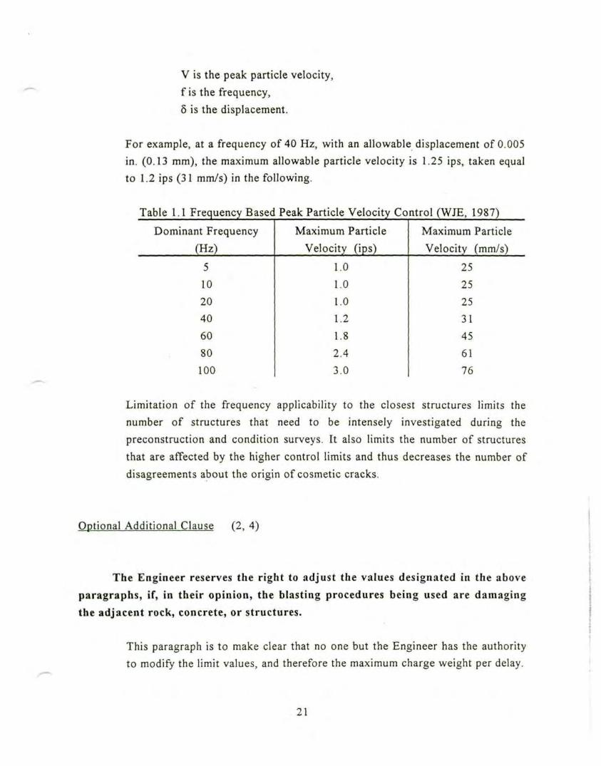
For example, at a frequency of 40 Hz, with an allowable displacement of 0.005
in. (0.13 mm), the maximum allowable particle velocity is 1.25 ips, taken equal
to 1.2 ips (31 mm/s) in the following.
Table 1.1 Frequency Based Peak Particle Velocity Control (WJE, 1987)
Dominant Frequency
(Hz)
5
10
20
40
60
80
100
Maximum Particle
Velocity (ips)
1.0
1.0
1.0
1.2
1.8
2.4
3.0
Maximum Particle
Velocity (mm/s)
25
25
25
31
45
61
76
Limitation of the frequency applicability to the closest structures limits the
number of structures that need to be intensely investigated during the
preconstruction and condition surveys. It also limits the number of structures
that are affected by the higher control limits and thus decreases the number of
disagreements about the origin of cosmetic cracks.
Optional Additional Clause (2, 4)
The Engineer reserves the right to adjust the values designated in the above
paragraphs, if, in their opinion, the blasting procedures being used are damaging
the adjacent rock, concrete, or structures.
This paragraph is to make clear that no one but the Engineer has the authority
to modify the limit values, and therefore the maximum charge weight per delay.
21
Curing Concrete (Section 2.5)
Some specifications contain a section specific to blasting within 24 hours after
pouring concrete on the site. This section will be treated in the chapter
concerning close-in blasting. A cross check should be made with the structural
specifications to ensure that the control limits are consistant.
Application of the Particle Velocity Control (Section 2.6) (2)
If the Contractor exceeds 80 % of the ground vibration control limit for anysingle axis of any blast, he shall cease all blasting activities and submit anadditional written report to the Engineer. This report shall give the blast parameterdata, and include any necessary proposed corrective action for the next shot toensure that the specified limit will not exceeded. The next shot shall not be loadeduntil the Engineer acknowledges, in writing, that a design change is beingattempted.
If the Contractor exceeds 100 % of the ground vibration control limit for any
single axis of any blast, he shall cease all blasting-related activities, including
drilling operations, and submit an additional written report to the Engineer. Thisreport shall give the blast parameter data, and include any necessary proposedcorrective action for the next shot to ensure that the specified l imit will not beexceeded. Drilling activities shall not resume until the Engineer acknowledges, inwriting, that a design change is being attempted.
These controls ensure that the Engineer can regulate blasting activity.
Imposition of a control limit, without some activities to accompany its
exceedance may lead both parties to assume an outcome, which may not be
agreeable to the other. In no case should the Engineer approve the design
change, but rather acknowledge that the Contractor is modifying the blast
design. It is always the Contractor's responsibility to meet the specified control
limits.
22
MONITORING OF PROGRESS CSECTION 3)
Recorded Data (Section 3.1) (1 ,2 ,3 ,4 ,5 ,7 )
Peak Particle Velocity
All three components (longitudinal, transverse, vertical) of particle velocity
will be measured on the ground at the location of the nearest and other strategicstructures identified below, at the location of fresh concrete (if necessary), and / or
at any other location as the Engineer deems necessary for any particular blast.(include list of structures) This measurement shall be made on the ground adjacent
to these structures as blasting progresses.
The three components of particle velocity are normally defined as follows:
(OSMRE, 1987)
- longitudinal (sometimes called radial); measured in a direct line
horizontally towards the blast from the point of interest or
measurement,
- transverse: measured horizontally at 90 degrees to the longitudinal plane,
- vertical: measured vertically at 90 degrees of both preceding planes.
Shot Record Report
The Contractor shall maintain a blast log and, when blasting is in progress,
shall submit daily reports to the Engineer regarding blasting. These shot recordreports shall follow the form accepted in the blasting plan (section 1.5).
23
Instrumentation ( Section 3.2) (2, 4, 7)
The Contractor shall provide the instrumentation agreed to in the blastingplan to monitor the blast vibrations and permanent deformation of the strategic
structures. On-site measurements will be made by the Engineer. The Engineer willprovide any other additional instrumentation not defined herein.
Despite this language, three different options may be considered:
- Contractor provides the instrumentation and makes the measurements,
- Contractor provides the instrumentation and Engineer makes the
measurements (as written),
- Engineer provides the instrumentation and make the measurements.
The option selected here corresponds to that applied most generally in highway
construction in the United States. If the Contractor is required to provide the
instrumentation, its cost will appear in the commercial bid, and therefore, the
Federal Government will pay the majority of the amount. If not, the Engineer
(or the State, in the case of highway construction) will have to pay for the
totality.
Different Types and Characteristics
Blast Monitors
Particle Velocity shall be monitored by Type I and Type II blast monitors.
These types are defined as below:
- Type I is the waveform recorder. It provides a particle velocity waveform or
time-history of the recorded event, sometimes in conjunction with peak eventinformation. This type of recorder must be used in option 2,
24
- Type II is known as a continuous peak particle velocity recorder. Itprovides no waveform, and therefore no frequency information. Both Type Iand II can be employed for monitoring in option 1.
Acceptable monitors include (precise manufacturer and model number).
Characteristics of these recorders are (frequency range for ground motion and air
overpressure, digitalization rate, method of calculating dominant frequency,
telecommunication capability).
Transducer Attachment
When the measurement surface consists of rock, asphalt, or concrete, thetransducers shall be bolted to the measurement surface, or bounded with eitherdouble-side tape, epoxy, quick setting cement. For significant accelerations (greaterthan l.Og), only cement or bolts shall be used. AH transducers mounted on verticalsurfaces shall be bolted in place.
For accelerations above 1 g when the measurement surface consists of soil thetransducer shall be buried and held in place with compacted soil. For repeatedmonitoring at the same location, a permanent soil bolt anchor system shall beconstructed. An acceptable design consists of a thin (50 to 75 mm) concretepedestal, buried 300 mm, and welded into the surounding soil mass by compactingsoil around and above. A small diameter hole for the transducer should then beexcavated to reach the bolt seat.
Usually, the horizontal radial and transverse directions are aligned with the
principal axes of the structures of concern (Linehan and Dowding, 1986). The
advantage of this option is that potential blast effects on the structure can be
more directly related to the measured motions.
Number and Location
25
Blast Monitors
The number of instruments required by the project is (specify here).However, there shall be, as a minimum, 2 monitors of Type I, and 1 monitor ofType II. Only one monitor of Type I will be used on site, while the other one will bekept as a backup, or used off-site for specific demands, such as importantcomplaints.
Archiving CSection 3.3) (2, 4, 5, 7)
The Contractor will provide the Engineer with all data necessary for recordkeeping purposes. These data shall be kept by both parties, for at least three years,and shall include, as a minimum, the following information:
- all monthly surveys conducted for vibration control purposes, including thepre-construction survey,
- the original blasting plan, as well as any adjustments made to it during thecourse of the construction activities,
- all monitored data, relative to each and every shot. Those shot recordreports shall contain all information, as required and approved in theblasting plan, including all information concerning the type andcharacteristics of the monitoring instruments used on the site, theirlocation and orientation,
- all shot loading data for each and every shot, correlated with the monitoreddata,
- all weather conditions, occurring during the blasting activities, includingthose which may cause possible adverse blasting effects,
- all details concerning the blasting mats, or any other protection used.
Those archiving requirements are necessary in case of litigation. In this event,these data are certain to be called into evidence, and as evidence they should beabsolutely unassailable.
CRACKING DEFORMATION (Section 4)
26
Types of Cracking (Section 4.1) (2)
The Engineer will distinguish different types of cracking in structures. Thetwo categories considered will be:
- cosmetic cracking,
- structural cracking.
These categories are usually defined as follows (Edwards and Northwood,
1960, Northwood et al., 1963, and Dowding, 1985):
Cosmetic cracking includes:
- threshold damage: opening of old cracks, and formation of new plaster
cracks; dislodging of loose objects (e.g. loose bricks in chimneys),
- architectural or minor damage: superficial, not affecting the strength of
the structures (e.g. broken windows, loosened or fallen plaster), hairline
cracks in masonry.
Structural cracking, also referred to as major cracking, results in serious
weakening of the building (e.g. large cracks or shifting, of foundations or
bearing walls, major settlement resulting in distortion or weakening of the
structure, walls out of plumb).
Control Limits (Section 4.2) (2, 4, 5, 7)
The Engineer will select the most appropriate cracking criterion for the site,
to control blasting operations. This criterion will be used, in conjunction with the
expected peak particle velocities from blast vibrations, to develop safe vibrationcontrol limits, as described in section 2.3.
Different types of cracking appear at different peak particle velocities. Thus,
different cracking controls have been developed to control vibrations, in order
to prevent certain types of cracking. Appendix C contains several frequency
based criteria.
27
CHAPTER 2
PILE DRIVING AND VIBRATIONS
PRJECONSTRUCTION SURVEY
A preconstruction survey shall be undertaken prior to the start of any
activity on the site, including the test pile program. This survey shall be completed
according to the requirements presented in the "Blasting and Vibrations" part of
these specifications, and should address susceptibility ratings of structures,
microvibrations and sensitive equipment / operations, and surrounding soil
densification.
GENERAL PROVISIONS (Section 1)
Except as otherwise specified in the following , the Contractor shallcomply with all sections of the "Blasting and Vibrations" part of thesespecifications.
Pile Driving Equipment (Section 1.1)
Two types of pile drivers can be used: impact or vibratory hammers.
The Contractor shall be aware of the fact that ground vibrations induced by
these machines are of different nature, and therefore he shall take the utmostcare in the selection of his equipment and driving method.
In the case of an impact hammer, the pile is driven by separate blows
from a hammer, which is raised by a rope, compressed gas or air, and
falls back by gravity (single-acting) or is accelerated downwards
(double-acting). The driving energy is transmitted to the pile through a
28

hammer cushion, and, at every blow, the inertia of the pile and the
resistance of the soil must be overcome. Ground vibrations caused by an
impact hammer are essentially of transient nature, and attenuation with
increasing distance occurs generally within a few cycles.
A vibratory hammer consists of a static mass, which is connected to an
oscillating mass by steel or plastic springs. The oscillating part is rigidly
attached to the head of the pile, and the pulsating force, which acts
along the entire pile, causes it to continuously move upwards and
downwards. Ground vibrations caused by vibratory hammers are
essentially of steady-state nature, and can propagate relatively far from
the source, and even amplify when resonance is reached, i.e. the
frequency of the vibration of the machine equals the natural frequency of
the soil layer in which the pile is driven. Resonance effects usually
occurs while starting up and switching off the vibrator (Massarch,
1992).
Driving plan (Section 1.2)
No less than three weeks prior to commencing the test pile program, or
at the preconstruction conference (whichever is earliest), or at any time the
Contractor proposes to change the driving method, the Contractor shall
submit a driving plan to the Engineer for review. The driving plan shall
contain (1) all information required under the general piling specifications,
and (2) all information relative to vibrations and vibration controls, as
described in the following.
The driving plan is for quality control and record keeping purposes.
Review of the driving plan by the Engineer does not relieve the
Contractor from his responsibility for the accuracy and adequacy of the
plan when implemented in the field.
29
Test Pile Program (Section 1.3)
Definition / Responsible Party
The Contractor shall provide any necessary cooperation with theEngineer for conducting a test pile program. While the Engineer will take thelead role in this program, the Contractor shall concur in the intent, designand process of the testing. This program shall be performed prior to the start
of any piling activities. It shall be performed to show how the vibrations
decrease with increasing distances from the pile, and vary with the type of
pile used. This program is intended to verify prior design assumptions, andnot to define any envelope or relationship to be used as a control.
Velocity control limits will not be raised on the basis of data obtained
from the test pile program. If, during the test pile program or during the
course of construction, it becomes evident that the limits established are
too high for safe piling activities, more restrictive limits may be
established.
The Contractor will be held responsible for any consequences resulting
from this program in terms of damage to structures and / or to persons,
on the same basis as for any other piling activity conducted on the site.
This testing is most economically accomplished if conducted with other
pile test programs, such as the load-deflection testing. The program
should be designed to include a range in the pile parameters. The
Contractor should try different pile configurations (if possible) as well
as hammer / pile combinations, to determine the best way to minimize
construction vibrations.
30
Monitoring
The number, type, and location of the seismographs used to monitorthe test pile program shall be determined by the Engineer.
Monitoring of the test pile program can be done using the provisions
described in section 1.5 of the "Blasting and Vibrations" part of these
specifications for the test blast program, with the necessary
modifications to piling activities.
Analyses
Statistical analyses of the test data will be performed by the Engineer.The results of these analyses will be transmitted to the Contractor within
three weeks after the completion of the test pile program. The three analysesto be performed are:
- a seismic analysis,
- a frequency analysis,
- a response spectrum analysis.
The seismic analysis establishes the rate at which the vibration intensity
decreases from the source. The vibration intensity can then be predicted
for any other distances within the bounds of the testing parameters.
Propagation laws can take the following form: (WJE, 1984)
V = Ij (D)-nj
where:
V = vibration particle velocity, in mm/s,
D = distance from the pile driving activity, in m,
I = intercept, vibration particle velocity when D = 1m,
n = propagation slope,
j = seismic component.
31

The propagation slope, n, quantifies the rate at which the seismic vibration
intensity decreases with increasing distances. The intercept, I, is a function
of the type of pile, the type of hammer, and the geology of the site. This
attenuation relationship should be established so that 95% of themeasurements fall below its bound.
The frequency analysis is performed to determine the ranges of frequency
associated with each pile, and / or hammer.
The response spectrum analysis is conducted based on time history records
of ground motions, and assuming the motion was applied to the base of a
structure having a variety of natural frequencies. The spectra are usuallyshown in tripartite coordinates.
Air Overpressure (Section 1.4)
This section will be treated separately in the "Air Overpressure" chapter of
these specifications.
CONTROLS ^Section 2)
Cracking (Section 2.1)
Crack monitoring gages shall be placed (fill in number and location),
and a condition survey shall be taken. These dispositions shall follow therequirements exposed respectively in sections 2.1 and 2.2 of the "Blastingand Vibrations" part of these specifications. The purpose is to report thecracking situation in the buildings surrounding the site, both prior to andduring piling operations.
32
Permanent Deformation of Soil (Section 2.2)
Line and Grade Survey
A line and grade survey, establishing control and grade lines to detect
movements along the exterior faces of nearby buildings, will be performed, in
accordance with the requirements exposed in section 2.2 of the "Blasting andVibrations" part of these specifications.
Lateral Deformation of Retaining Structure
In addition to the above requirements, control lines and benchmarksshall be established for any eventual temporary lateral support system, in
order to monitor the deformation of this system during the progress of pilingactivities. Surveys shall be obtained monthly.
The presence of lateral support systems between the piling area and the
surrounding structures allows for a direct control of the soil
deformations, produced by the excavation and / or vibrations of loose
sands and silts. A maximum allowable displacement can be introduced
here. Cracking criteria for adjacent structures are based upon a fixed and
stable subsurface.
Condition of Soil After Pil ing
Monitoring of permanent displacement of the soil is required during
the dismantling of the temporary support system.
33
During dismantling operations, release of stresses in the ground will
induce permanent deformation of the soil. This displacement is directly
related to the one that the surrounding buildings will endure, and is
therefore important to control.
Particle Velocity Controls (Section 2.3)
Particle velocity controls shall comply with the requirements exposedin section 2.3 of the "Blasting and Vibrations" part of these specifications.
Controls limits used in this section, for both impact and vibratory pile
hammers, are typically the ones used for blasting activities. However,
blast vibrations, which typically have larger energies, longer attenuation
distances, and fewer repetition, are not necessarily representative of pile
driving vibrations. But, since no special limits have ever been raised for
pile driving, it is necessary to make reference to blasting specifications.
MONITORING (Section 3)
The requirements under this section are the same as those exposed in
section 3 of the "Blasting and Vibrations" part of these specifications, with
the following modifications:
- "piling" shall replace "blasting" in the wording,
- "vibration monitors" shall be used instead of "blast monitors",
These machines are the same, and can be rented or leased from the
company who perform blast vibration monitoring.
34
- monitoring schemes and specific record keeping requirementsconcerning ground motions shall be performed according to thefollowing.
Threshold Values of Particle Velocities for Monitoring Purposes (Section 3.1)
Two threshold values of peak particle velocity shall be considered formonitoring purposes:
- the control value, specified in section 2.3 above,
- the "significant event" value, equal to half the control value, belowwhich no record of either peak or wave form is retained.
Monitoring Schemes and Record Keeping (Section 3.2)
Time histories of all pile driving events producing peak particle
velocities greater than the control value, measured at the location of adjacent
structures, shall be obtained.
Peak values of all pile driving events producing peak particle velocities
greater than the "significant event" value, but less than the control value,measured at the location of adjacent structures, shall be obtained.
The five largest motions of pile driving events producing peak particle
velocities less than the "significant event" value, measured at the location of
adjacent structures, shall be recorded, regardless of their intensity. Theserecords shall be kept for any period between two significant events.
As opposed to blasting, pile driving involves a great number of events.
However, only a small portion of the activity will produce significant
particle velocities. But, since all events should be accounted for in some
fashion, the formulation of two threshold values of peak particle
velocities is meant to allow for the necessary selection between
"insignificant" and "significant" events. The monitoring schemes
35
described above can be achieved easily by programming self-triggering
vibration (or blast) monitors.
Time histories for pile driving activities exceeding the control value are
required to allow for the determination of dominant frequencies. For
particle velocities less than the control value, only peaks are of interest,
to show that the control is not exceeded. While it is useless to keep
record of insignificant events, it is still necessary to be able to show that
the recording equipment was functioning. Therefore, the five highest
motions under the second (i.e. the lowest) threshold value should be
kept to demonstrate functionality.
36
CHAPTER 3
AIR OVERPRESSURE
PRELIMINARY CONCERNS AND DEFINITIONS (Section 1)
Air overpressure, as covered herein, is defined as airborne pressurewaves, resulting from detonation of explosives (also called air blast) and to alesser extent concussion mechanisms, such as impact pile driving. Noise is thehigh frequency audible portion of the air overpressure.
The Contractor shall be fully aware of the two different kinds of airpressure waves, and of their possible adverse effects:
- low frequency waves, such as those generated by air blasts. They arevirtually inaudible, but have a cracking potential because theyinduce vibration in structures,
- high frequency waves, referred to as noise. They generate noisepollution, which produces community annoyance.
This specification does not establish acceptable noise levels and doesnot relieve the Contractor from obeying all OSHA and community noisestandards.
NOISE LEVEL CRITERIA FOR IMPACT EVALUATION TSection 2)
The Engineer should use a noise level criterion for impact evaluation.This criterion should give an appreciation of the noise level, as a function ofthe percentage of time that this given level is exceeded.
37
This criterion allows for considerations of duration. Indeed, the effect ofa continuous event, repeated, say, more than 100 times a day, such as
the impact of a pile driver, will not be the same than the one of apunctual event, occurring less than 5 times a day, such as a blast.
For instance, the US Department of Housing and Urban Development
(HUD) provides the criteria presented in Figure 3.1, based upon thedefinition of the 'noise pollution level1, or NPL, given below:
Ljsjp = Leq + 2.56 a
where:
is the noise pollution level (NPL),
Leq is the mean intensity of the noise over a specific timeperiod,
a is the standard deviation of the instantaneous levelconsidered as a statistical time series over thespecified time period.
Integration of the noise level over time is accomplished assuming that
the event is continuous (pile driving). However, there is little
experimental evidence to support this procedure.
Four different levels of acceptability of noise emission can be defined asshown in Figure 3.1:
- clearly acceptable: indoors and outdoors pleasant,- normally acceptable: outdoors reasonably pleasant, and indoors
acceptable even for sleeping,- normally unacceptable: costly construction required to make
indoors acceptable, and barriers required to make outdoorsacceptable,
- clearly unacceptable: prohibitive costs to make indoors and
outdoors acceptable.
38

100
99.5
99
98
95
90
§ 70
S 50
: "
10
6
1.
0.
020.
\\
\
\
\
\
\
\
\\ Normally \
\
\
\ Normally \\ atceolaole \
\
\\
Clearly•ccecub
v\a\.
>^e \;
\
\
\
Clearlyunacceptable
y\\\
Vv«~ v
\%,\
•
^&
V^
" V
%Ny%
\"^
\
Pll
\ ̂
\
\\
1 \ ! \ ! *
50A-wtighled level, in
Figure 3.1 Provisional Criteria Relating NPL to Community Noise
Acceptability (from Hersh, 1974)
GENERAL PROVISIONS FOR NOISE CONTROL (Section 3)
The Contractor shall take the necessary time and effort to understand
and conform to the existing noise ordinances adopted in the community
where the construction site is located.
The Contractor shall be informed of the noise radiation characteristics
of his equipment (such as impact pile drivers). This shall imply periodicmeasurements, despite the equipment manufacturer's noise specifications.
Equipment noise often increases with use, especially if improperly
maintained. Furthermore, the resulting sound levels may rise in confined
spaces, or where the air waves (creating the sound) are channeled by
structures.
39
The Contractor shall include noise as a factor in planning hisoperations. If the predicted noise emission is to be excessive for a particularperiod, the Contractor shall discuss this problem with the local residents and
officials, to reach some type of agreement, before the commencement of the
work.
With careful planning, it is possible to maintain a highly efficient work
output with a minimal noise output. It is necessary to identify, in
chronological order, the various tasks with their associated equipment.
This information, along with accurate sound level measurements of the
equipment, allow a prediction of the noise which will be emanated from
the construction site at any specific time, and this prediction can be
checked against local noise regulations.
The Contractor shall use all of the above information to work with
local officials and equipment manufacturers, in order to formulate rationalnoise reductions which can be implemented within a reasonable time frame.
AIR BLASTS CONTROLS (Section 4)
General (Section 4.1)
The Contractor shall design his blast rounds in order to minimize air
blast overpressures. A well designed blasting round that breaks and moves
rock efficiently seldom produces excessive air blast overpressures. If
detonating cord is used, it shall be covered with sand to minimize air blasts.
Postponement of blasting operations shall be considered when a heavy low-level cloud cover exists. Blasting operations shall take into account winddirection and possibility of focusing.
40
The five primary causes of air blast overpressures, that are under the
control of the blaster, are: (Rosenthal and Morlock, OSMRE, 1987)
- the Air Pressure Pulse, caused directly by the rock displacement at
the free surface or mounding at the borehole collar,
- the Rock Pressure Pulse, caused by vibrating ground,
- the Gas Release Pulse, caused by gas escaping from the detonation
through fissures in the fractured rock,
- the Stemming Release Pulse, caused by gas escaping from blown-
out stemming,
- presence of uncovered detonating cord.
In addition, some other factors, normally outside the control of the
blaster, such as nature and shape of the terrain and / or weather
conditions, can increase adverse air blast effects. It is the responsibility
of the Contractor to use his best knowledge of blasting effects in order
to prevent, or inhibit the propagation of excessive air overpressures.
Air Overpressure Control Limits (Section 4.2)
Air blast overpressures shall not exceed the limits listed in the tablebelow, measured at the location of any public building, residence, school,church, or community or institutional building. If necessary to preventdamage, the Engineer will specify lower maximum allowable air blasts levelsthan those given in this section for use in the vicinity of specific structures.
The following values of maximum air blast overpressures are proposed
by the USBM, in the Report RI 8485 (1980).
41
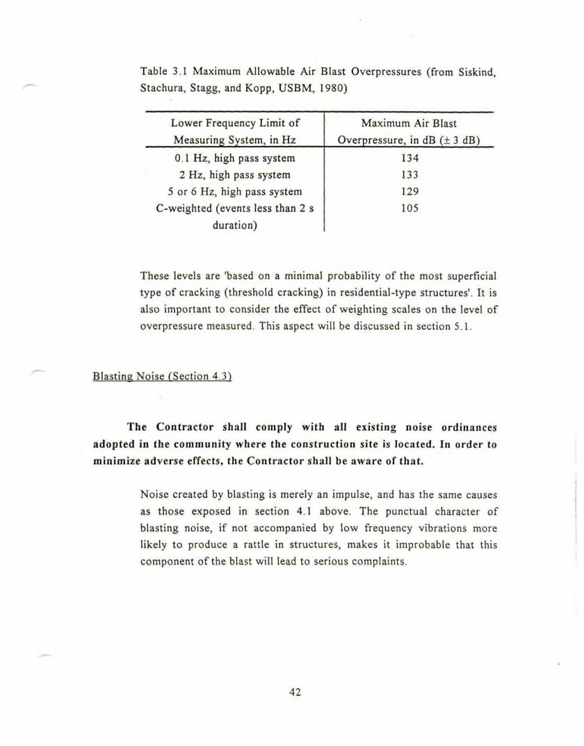
Table 3.1 Maximum Allowable Air Blast Overpressures (from Siskind,
Stachura, Stagg, and Kopp, USBM, 1980)
Lower Frequency Limit of
Measuring System, in Hz
0.1 Hz, high pass system
2 Hz, high pass system
5 or 6 Hz, high pass system
C-weighted (events less than 2 s
duration)
Maximum Air Blast
Overpressure, in dB (± 3 dB)
134
133
129
105
These levels are 'based on a minimal probability of the most superficial
type of cracking (threshold cracking) in residential-type structures'. It is
also important to consider the effect of weighting scales on the level of
overpressure measured. This aspect will be discussed in section 5.1.
Blasting Noise (Section 4.3)
The Contractor shall comply with all existing noise ordinances
adopted in the community where the construction site is located. In order to
minimize adverse effects, the Contractor shall be aware of that.
Noise created by blasting is merely an impulse, and has the same causes
as those exposed in section 4.1 above. The punctual character of
blasting noise, if not accompanied by low frequency vibrations more
likely to produce a rattle in structures, makes it improbable that this
component of the blast will lead to serious complaints.
42
PILE DRIVING CONTROLS fSection 5)
General / Air Overpressure Control Limits (Sections 5.1 & 5.2)
Pile driving operations shall be subj'ected to the same generalprovisions and air overpressure control limits as the one established for
blasting, and described above.
However, it is not expected that pile driving will produce the low
frequency air overpressures associated with blasting.
Pile Driving Noise (Section 5.2)
The Contractor shall comply with all existing noise ordinancesadopted in the community where the construction site is located. TheContractor shall be fully aware of the necessity to take noise-reductionmeasures, including modifications of the pile driver (such as enclosure of the
hammer, modification of the muffler, ...) in the event that the Engineer and /
or municipal officials determine noise levels to exceed OSHA and / or local
community standards..
Pile driving is considered to be a continuous event. The impact of the
hammer on the pile is reproduced thousands of times a day; thereby
inducing high annoyance even at relatively low noise levels. Noise
control measures can be applied to pile driving in a cost-effective
manner, to reduce the objectionable off-site noise by about 10 dB
(Kessler, 1985).
43
MONITORING OF CONSTRUCTION SITE AIR OVERPRESSURES fSection 61
Instrument Scaling and Range (^Section 6.1)
Linear scaling of instruments shall be used as default. In cases where
no low-frequency overpressure (likely to crack structures) is expected, and
only noise community annoyance is of concern, A or C weighted instrumentscan be used, if approved by the Engineer.
The instruments' scale employed for control shall be (specify here).
The A weighted scale is known to represent the manner in which the ear
interprets the loudness of a given event throughout the frequency range
of human sensitivity. It has therefore been used to interpret the effects
of human annoyance.
The C weighted scale is also adequate for studying hearing response,
but, as the A weighted scale, it will not record the information necessary
for correlation with structural response.
The linear scale records accurately the air overpressures in both the
structurally critical range, usually between 5 to 20 Hz, and the range
critical for human hearing. This system is therefore the most reliable in
critical monitoring situations. (Hersh, 1974, and Dowding, 1985)
Figure 3.2 represents the difference between the actual loudness of a
given event and its weighted value, as a function of the frequency.
44

100
m -102 -20o1 -30= -40E -50< -60
-701 10 100 1000 10,000
Frequency (Hz)
Figure 3.2 Effect of Weighting Scales (from Dowding, 1985)
Analysis of Data (Section 6.2)
Air overpressures shall be recorded as time histories. For certain
events that do not require extreme attention, the Engineer may allow theContractor, as an exceptional measure, to use peak recording instrumentsonly.
45
CHAPTER 4
CONTROLLED BLASTING
SOURCES
The following list comports the existing specifications used in the writing
of the specification part of this text. The complete details of these references, as
well as the literature used for the comments, are featured in appendix A.
(1) Federal Highway Administration (FHWA), Controlled Blasting
Specification. 1985,
(2) Wiss, Janney, Elstner, Associates Inc.(WJE), Blast Vibration Protection
Guidelines for various projects, 1987 to 1991,
(3) Hendron and Oriard, Specifications for Controlled Blast ing in Civil
Engineering Projects. 1972,
(4) Stone and Webster Engineering Corporation, Technical Specifications
for different projects, 1974, 1975,
(5) US Army Corps of Engineers, Typical CE Blasting Specifications. 1972
GENERAL PROVISIONS TSection 1) (1, 2)
AH controlled blasting techniques described below shall be performed
in accordance with the requirements specified in the 'Blasting and
Vibrations' part of these specifications.
Unless otherwise permitted by the Engineer, the Contractor shall
completely remove all overburden soil, and loose or decomposed rock, along
the top of the excavation, for a specified distance, to be determined by the
Engineer, of the production hole drilling limits, or to the end of the cut,before drilling the controlled blasting holes. Potentially dangerous material
located beyond the excavation limits shall also be removed.
46
DESCRIPTION (Section 2) (1, 2)
Controlled blasting refers to the controlled use of explosives andblasting accessories in carefully spaced and aligned drill holes, to produce afree surface, or shear plane, in the rock along the specified backslope.Controlled blasting techniques covered by this specification include linedrilling, cushion (or trim), presplitting, and smooth-wall blasting techniques.
Blast damage to the final rock face may cause (1) backbreak and over
excavation, as well as (2) instability and rockfall hazards. For these
reasons, among others, controlled blasting is an indispensable routine in
excavation for structures and elsewhere. Controlled blasting techniques
minimize overbreakage, and permit steeper slope design, because of
increased mechanical stability and resistance to weathering. They also
reduce deeper fracturing and weakening of the finished excavation. The
techniques described can be used to excavate rock to accurate lines
around vertical and horizontal corners, even when contiguous to
adjacent structures.
Sometimes, slope dimension criteria is specified to establish when
controlled blasting should be used, such as "when blasting toexcavation slopes 1/2:1 or steeper, and more than 10 ft high".
Inclusion of specific slope and/or depth criteria in the specification, if
desired, is left open.
DIFFERENT METHODS (Section 3) (3)
The remaining face is a function of:
- the diameter, depth, and spacing of the perimeter holes,- an approximate range of the charge per foot of hole,- the type of stemming material,- the tolerances in the alignment of the perimeter holes,
47
rock type,joint type and orientation.
Formation of a fracture plane in the rock is influenced by borehole
spacing, with the closer spacing forming a more prominent fracture.
Because of the high cost of drilling, the optimum spacing is the largest
at which radial cracks will join, and form a continuous undamaged
surface. This distance is a function of (1) the rock type and joint
patterns, as well as (2) the hole loading and shot initiation
characteristics.
Because of this complex interation, the Contractor should choose the
method using the 'test face1 approach, described below, in section 4. The
characteristics given for each method should not be chosen by the
Engineer, but are included as guides for the blaster's plan.
Line Drilling (Section 3.1) (1, 3, 4, 5)
Line drilling is a method that, under proper geologic conditions, canbe used to produce a cosmetically appealing final wall. It consists of drilling
a single row of very closely spaced holes along the perimeter of theexcavation, not loading the holes, having a suitable burden / spacing ratio, areduced explosive charge in the lines of holes nearest to the line-drilled holes,and a limit on the distance between the line-drilled holes and the nearest lineof primary blast holes. The drilled holes form a surface of weakness to which
the primary blast can break. They also reflect some of the shock waves,protecting the rock mass behind the final grade.
The spacing of the holes is generally two to four times the hole
diameter, while the primary blasting is usually conducted to within two
to three rows of the line-drilled row to decrease the burden (Hendron
and Oriard, 1972). A typical arrangement is shown in figure 4.1.
48
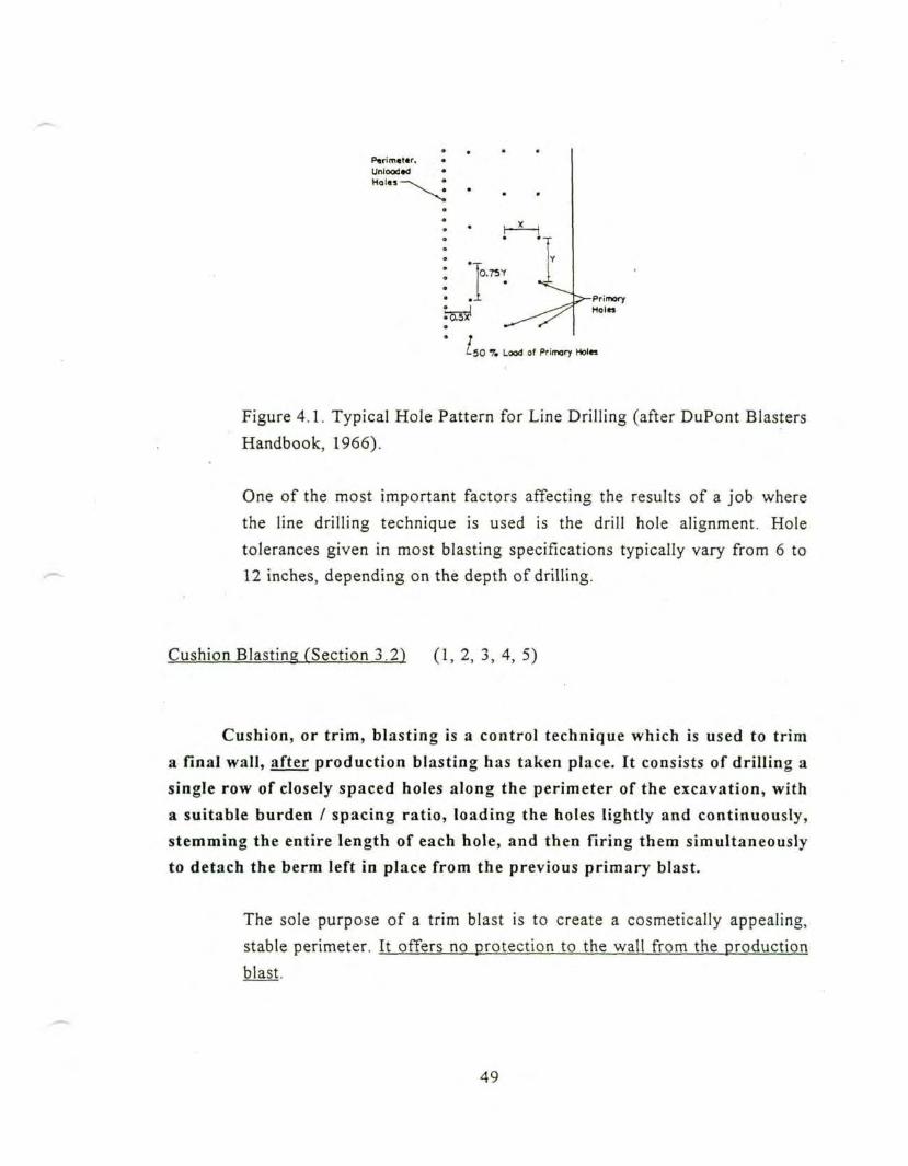
I3.7SY'
^-50 7. Lood of Prinxiry Hol«s
Figure 4.1. Typical Hole Pattern for Line Drilling (after DuPont Blasters
Handbook, 1966).
One of the most important factors affecting the results of a job where
the line drilling technique is used is the drill hole alignment. Hole
tolerances given in most blasting specifications typically vary from 6 to
12 inches, depending on the depth of drilling.
Cushion Blasting fSection 3.2) (1, 2, 3, 4, 5)
Cushion, or trim, blasting is a control technique which is used to trima final wall, after production blasting has taken place. It consists of drill ing asingle row of closely spaced holes along the perimeter of the excavation, witha suitable burden / spacing ratio, loading the holes lightly and continuously,stemming the entire length of each hole, and then firing them simultaneouslyto detach the berm left in place from the previous primary blast.
The sole purpose of a trim blast is to create a cosmetically appealing,
stable perimeter. It offers no protection to the wall from the production
blast.
49
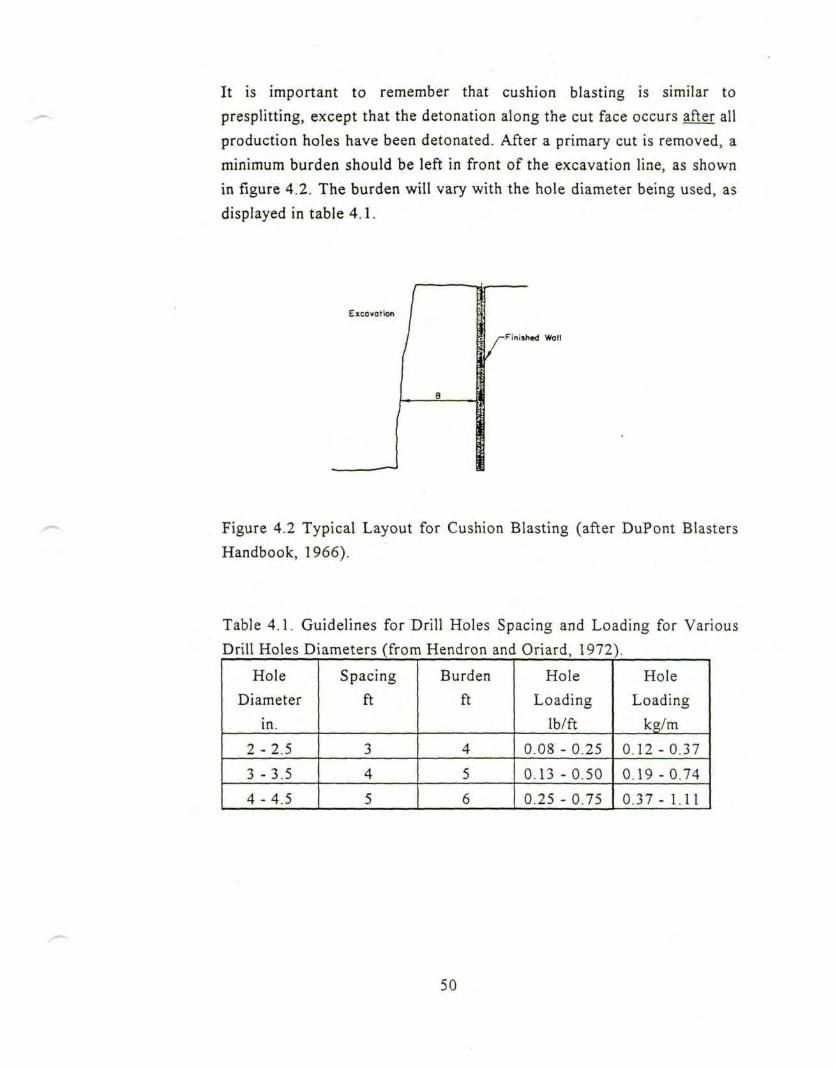
It is important to remember that cushion blasting is similar to
presplitting, except that the detonation along the cut face occurs after all
production holes have been detonated. After a primary cut is removed, a
minimum burden should be left in front of the excavation line, as shownin figure 4.2. The burden will vary with the hole diameter being used, as
displayed in table 4.1.
Excavation
Finished Wall
Figure 4.2 Typical Layout for Cushion Blasting (after DuPont Blasters
Handbook, 1966).
Table 4.1. Guidelines for Drill Holes Spacing and Loading for Various
Drill Holes Diameters (from Hendron and Oriard, 1972).
HoleDiameter
in.
2 - 2 . 5
3 -3.5
4 - 4 . 5
Spacing
ft
3
4
5
Burdenft
4
5
6
HoleLoading
Ib/ft
0.08 -0 .25
0.13 - 0.50
0.25 - 0.75
HoleLoading
kg/m
0.12 - 0.37
0.19 - 0.74
0.37 - 1.11
50
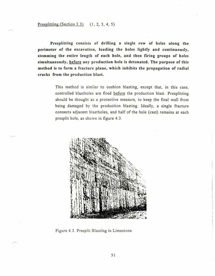
Presplitting (Section 3.31 ( 1 , 2 , 3 , 4 , 5 )
Presplitting consists of drilling a single row of holes along the
perimeter of the excavation, loading the holes lightly and continuously,stemming the entire length of each hole, and then firing groups of holes
simultaneously, before any production hole is detonated. The purpose of this
method is to form a fracture plane, which inhibits the propagation of radial
cracks from the production blast.
This method is similar to cushion blasting, except that, in this case,
controlled blastholes are fired before the production blast. Presplitting
should be thought as a protective measure, to keep the final wall from
being damaged by the production blasting. Ideally, a single fracture
connects adjacent blastholes, and half of the hole (cast) remains at each
presplit hole, as shown in figure 4.3.
Figure 4.3. Presplit Blasting in Limestone.
51
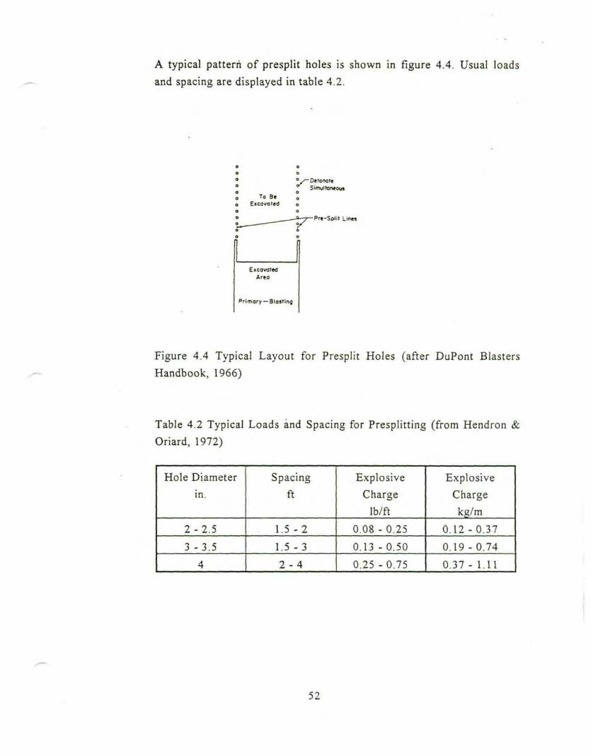
A typical pattern of presplit holes is shown in figure 4.4. Usual loadsand spacing are displayed in table 4.2.
To BeExcavated
ExcavatedArea
Primary — Slasting
-DetonoteSimultaneous
-Pre-Split Lines
Figure 4.4 Typical Layout for Presplit Holes (after DuPont BlastersHandbook, 1966)
Table 4.2 Typical Loads and Spacing for Presplitting (from Hendron &
Oriard, 1972)
Hole Diameterin.
2 - 2 . 5
3 -3 .5
4
Spacing
ft
1.5 -2
1.5 -3
2 - 4
ExplosiveCharge
Ib/ft
0.08 -0.25
0.13 - 0.50
0.25 -0.75
ExplosiveChargekg/m
0.12-0.37
0.19 - 0.74
0.37 - 1.11
52
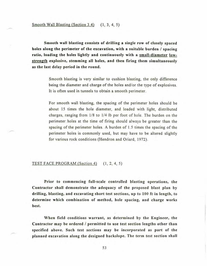
Smooth Wall Blasting (Section 3.4) (1, 3, 4, 5)
Smooth wall blasting consists of drilling a single row of closely spacedholes along the perimeter of the excavation, with a suitable burden / spacingratio, loading the holes lightly and continuously with a small-diameter low-strength explosive, stemming all holes, and then firing them simultaneouslyas the last delay period in the round.
Smooth blasting is very similar to cushion blasting, the only differencebeing the diameter and charge of the holes and/or the type of explosives.It is often used in tunnels to obtain a smooth perimeter.
For smooth wall blasting, the spacing of the perimeter holes should be
about 15 times the hole diameter, and loaded with light, distributed
charges, ranging from 1/8 to 1/4 Ib per foot of hole. The burden on the
perimeter, holes at the time of firing should always be greater than thespacing of the perimeter holes. A burden of 1.5 times the spacing of the
perimeter holes is commonly used, but may have to be altered slightlyfor various rock conditions (Hendron and Oriard, 1972).
TEST FACE PROGRAM fSection 4) (1 ,2 ,4 ,5 )
Prior to commencing full-scale controlled blasting operations, theContractor shall demonstrate the adequacy of the proposed blast plan bydrilling, blasting, and excavating short test sections, up to 100 ft in length, todetermine which combination of method, hole spacing, and charge worksbest.
When field conditions warrant, as determined by the Engineer, theContractor may be ordered / permitted to use test section lengths other thanspecified above. Such test sections may be incorporated as part of the
-planned excavation along the designed backslope. The term test section shall
53 I
mean drilling, loading, shooting, and exposure of the complete face toviewing.
The contractor shall begin the tests with the controlled blastholesspaced at a given distance, usually 30 ft apart, as determined by theEngineer, then adjust, if needed, until the Engineer approves the spacing tobe used for full-scaled blasting operations. The requirements for blastingoperations, covered elsewhere in this specification, shall also apply to theblasting carried out in conjunction with the test shots.
The Contractor will not be allowed to drill ahead of the test shot area,until the test section has been excavated and the results examined by theEngineer. An ideal presplit face will have a relatively smooth fractureconnecting adjacent drill holes, the half cast of each hole will be clearlyevident, and specification for face tolerances will be met. If the results of thetest shots, in the opinion of the Engineer, are unsatisfactory, then,notwithstanding the Engineer' prior review of such methods, the Contractorshall adopt such revised methods as are necessary to achieve the requiredresults. Unsatisfactory results include an excessive amount of fragmentationor overbreak beyond the perimeter line, absence of satisfactory evidences ofcasts, out-of-tolerance face, excessive fly-rock, or violation of otherrequirements within these specifications.
If, at any time during the progress of the work, the methods of drillingand blasting do not produce a uniform slope and shear face, within thetolerance specified, the Contractor will be required to drill, blast, andexcavate in short sections, not exceeding 100 ft in length, until a technique isarrived at, that will produce the required results. Extra cost resulting fromthis requirement shall be borne by the Contractor.
The test face program is particularly important in areas where no recentexperience with blasting and rock response is known. The importance ofproper wall control, and the effects of blasting, both with and withoutcontrolled techniques, are shown in figure 4.5. It is also an importantcontrol mechanism, when the Contactor does not adequately control his
54
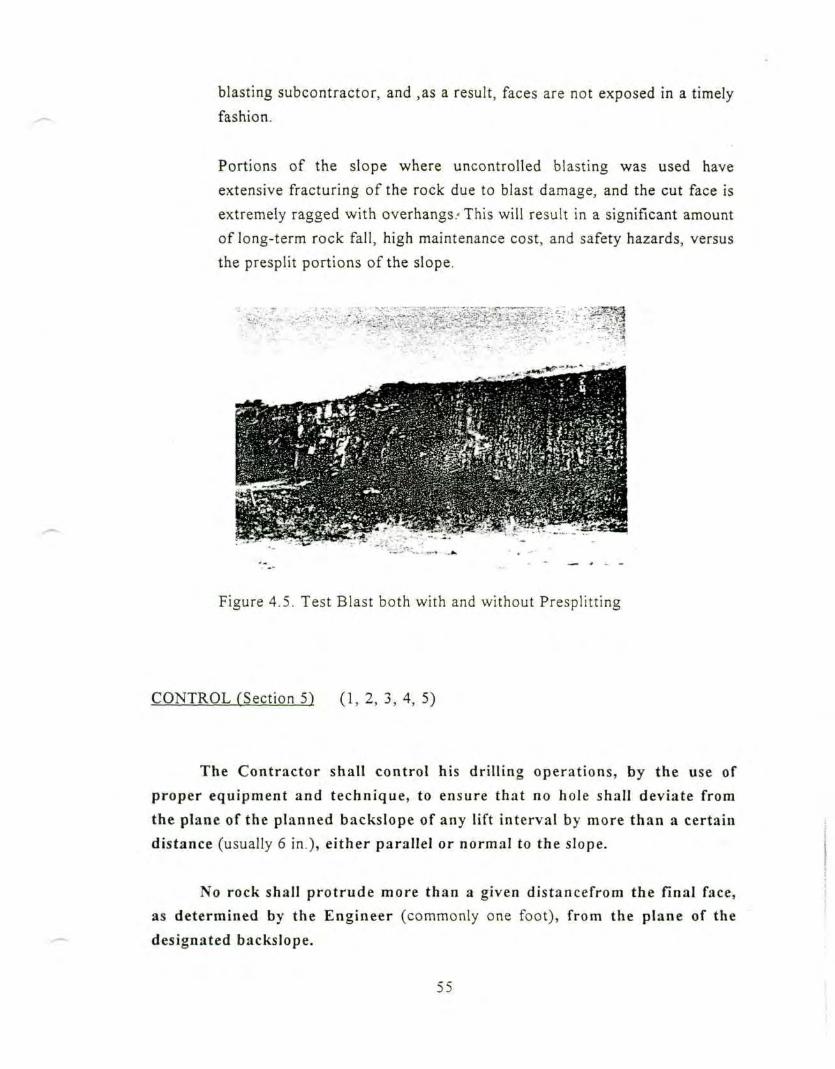
blasting subcontractor, and ,as a result, faces are not exposed in a timelyfashion.
Portions of the slope where uncontrolled blasting was used haveextensive fracturing of the rock due to blast damage, and the cut face isextremely ragged with overhangs/ This will result in a significant amount
of long-term rock fall, high maintenance cost, and safety hazards, versus
the presplit portions of the slope.
• •< „ • • • - - ' ' :T. --•- . — ••<p"T'T'--:
. : - - • ' • • • • - .,:•;. .;;.^ - - . . .* ' "
Figure 4.5. Test Blast both with and without Presplitting
CONTROL rSection 5) (1, 2, 3, 4, 5)
The Contractor shall control his drilling operations, by the use ofproper equipment and technique, to ensure that no hole shall deviate fromthe plane of the planned backslope of any lift interval by more than a certaindistance (usually 6 in.), either parallel or normal to the slope.
No rock shall protrude more than a given distancefrom the final face,as determined by the Engineer (commonly one foot), from the plane of thedesignated backslope.
55
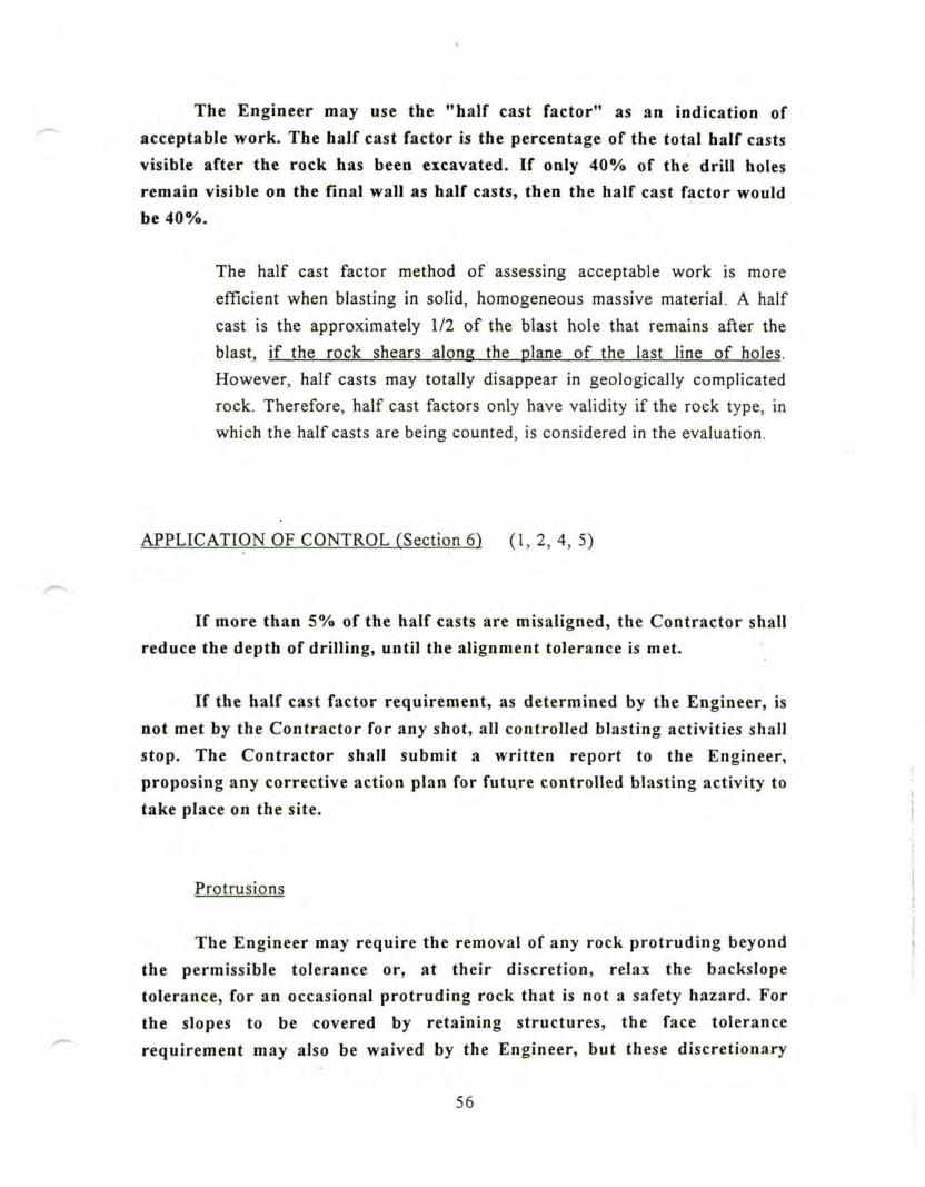
The Engineer may use the "half cast factor" as an indication ofacceptable work. The half cast factor is the percentage of the total half castsvisible after the rock has been excavated. If only 40% of the drill holesremain visible on the final wall as half casts, then the half cast factor wouldbe 40%.
The half cast factor method of assessing acceptable work is more
efficient when blasting in solid, homogeneous massive material. A half
cast is the approximately 1/2 of the blast hole that remains after the
blast, if the rock shears along the plane of the last line of holes.
However, half casts may totally disappear in geologically complicated
rock. Therefore, half cast factors only have validity if the rock type, in
which the half casts are being counted, is considered in the evaluation.
APPLICATION OF CONTROL (Section 6) (1, 2, 4, 5)
If more than 5% of the half casts are misaligned, the Contractor shallreduce the depth of drilling, until the alignment tolerance is met.
If the half cast factor requirement, as determined by the Engineer, isnot met by the Contractor for any shot, all controlled blasting activities shallstop. The Contractor shall submit a written report to the Engineer,proposing any corrective action plan for futu.re controlled blasting activity totake place on the site.
Protrusions
The Engineer may require the removal of any rock protruding beyondthe permissible tolerance or, at their discretion, relax the backslopetolerance, for an occasional protruding rock that is not a safety hazard. Forthe slopes to be covered by retaining structures, the face tolerancerequirement may also be waived by the Engineer, but these discretionary
56
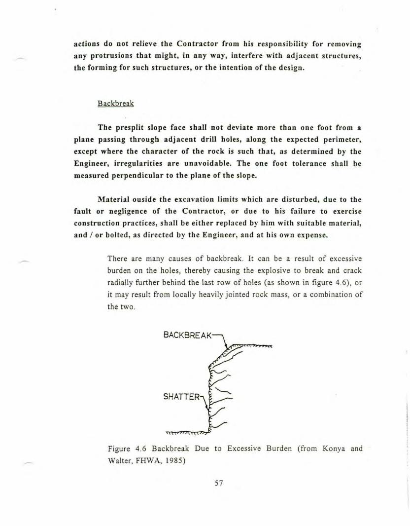
actions do not relieve the Contractor from his responsibility for removingany protrusions that might, in any way, interfere with adjacent structures,the forming for such structures, or the intention of the design.
Backbreak
The presplit slope face shall not deviate more than one foot from aplane passing through adjacent drill holes, along the expected perimeter,except where the character of the rock is such that, as determined by the
Engineer, irregularities are unavoidable. The one foot tolerance shall bemeasured perpendicular to the plane of the slope.
Material ouside the excavation limits which are disturbed, due to thefault or negligence of the Contractor, or due to his failure to exerciseconstruction practices, shall be either replaced by him with suitable material,and / or bolted, as directed by the Engineer, and at his own expense.
There are many causes of backbreak. It can be a result of excessive
burden on the holes, thereby causing the explosive to break and crack
radially further behind the last row of holes (as shown in figure 4.6), or
it may result from locally heavily jointed rock mass, or a combination of
the two.
BACKBREAK
SHATTER-^ I
Figure 4.6 Backbreak Due to Excessive Burden (from Konya and
Walter, FHWA, 1985)
57
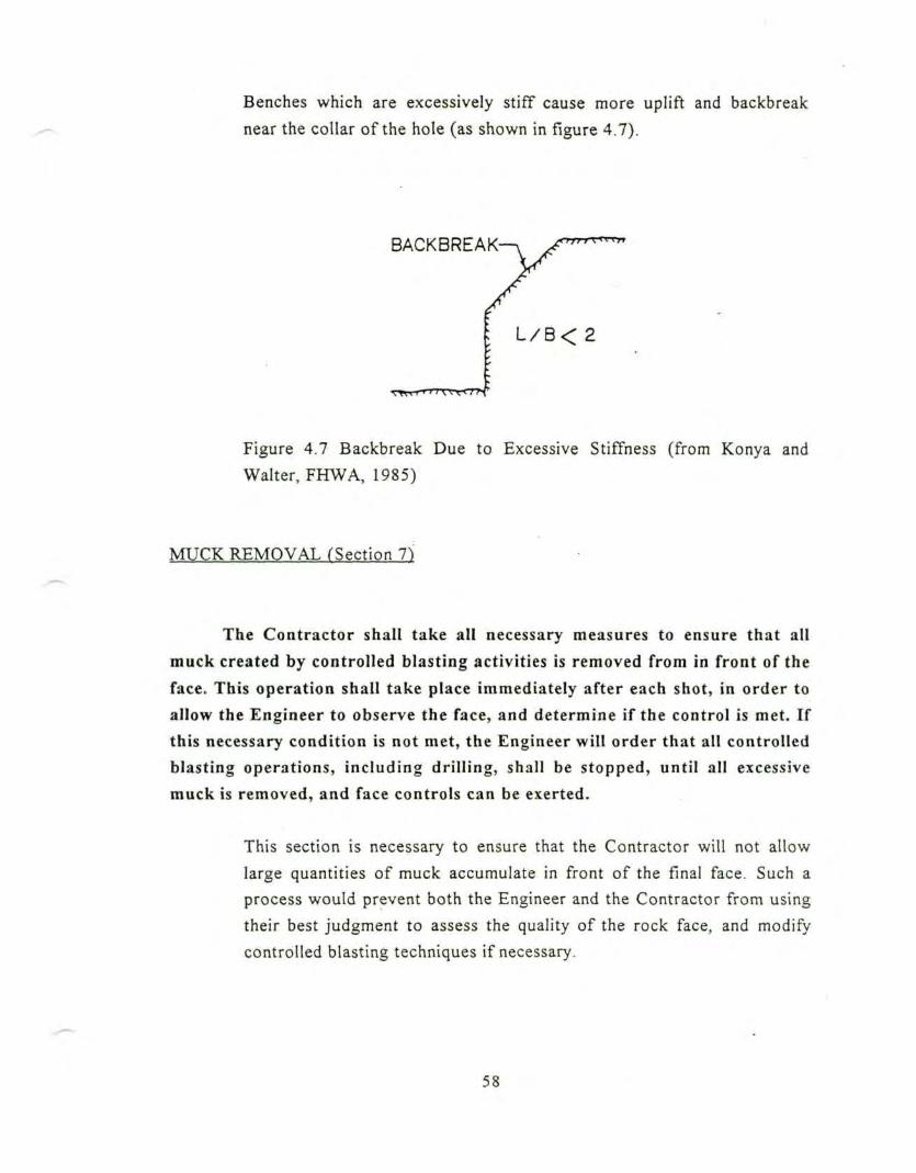
Benches which are excessively stiff cause more uplift and backbreak
near the collar of the hole (as shown in figure 4.7).
BACKBREAK
L/B< 2
Figure 4.7 Backbreak Due to Excessive Stiffness (from Konya andWalter, FHWA, 1985)
MUCK REMOVAL fSection 7)
The Contractor shall take all necessary measures to ensure that all
muck created by controlled blasting activities is removed from in front of the
face. This operation shall take place immediately after each shot, in order to
allow the Engineer to observe the face, and determine if the control is met. Ifthis necessary condition is not met, the Engineer will order that all controlledblasting operations, inc luding drilling, shall be stopped, until all excessive
muck is removed, and face controls can be exerted.
This section is necessary to ensure that the Contractor will not allow
large quantities of muck accumulate in front of the final face. Such aprocess would prevent both the Engineer and the Contractor from usingtheir best judgment to assess the quality of the rock face, and modifycontrolled blasting techniques if necessary.
58
SIZE OF EXCAVATED MATERIAL (Section 8)
The excavated rock produced by controlled blasting activities shall berestricted in its size (i.e. volume and / or dimensions), as determined by the
Engineer. AH excavated material that will not meet these requirements shall
be crushed to the limited size, at the Contractor's expense.
If there is a need for size restrictions (either large or small) for final
disposal or use, this issue must be explicitely established in this
specification.
59
CHAPTER 5
CLOSE-IN BLASTING
GENERAL PROVISIONS rSection
Except as otherwise specified herein, all close-in blasting activitiesshall be performed in accordance with the requirements specified in the"Blasting and Vibrations" and "Controlled Blasting" parts of thesespecifications.
DESCRIPTION (Section 2)
Close-in blasting refers to drilling and rock excavation activitieswithin a distance to existing structures that is equal to the final excavationdepth. Close-in blasting activities involve the use of controlled blastingtechniques, as described in the "Controlled Blasting" addendum of thesespecifications.
If not carefully controlled, the release of delayed gas pressures and high
particle velocities can have undesirable side effects. Blasting activities
falling into this category are generally those carried out at less than 20
m from existing facilities.
BLASTING TECHNIQUE (Section 3)
When blasting near adjacent structures, production blasting shall
start as far as possible from the existing facilities so that blast vibrations andbedrock geology can be evaluated as blasting approaches the structures.
60
Controlled perimeter blasting techniques, as described in the
"Controlled Blasting" addendum of these specifications, shall be utilizedalong the excavation perimeter, to assist in obtaining a stable, undisturbedrock face. Smaller blast rounds may be desirable, as blasting approaches theadjacent structures, to minimize explosive charge weights and mitigateimpacts in the event normally sized charges do not produce expected results.
An important side effect of close-in blasting is potential permanent
ground deformations, resulting from cratering and backbreak near the
blast source, and from block movement caused by delayed gas pressure
that may be transmitted through open joints and seams in the rock. In
addition, there is still concern for the relatively large elastic ground
motions (McKown, 1991).
CONTROLS fSection 4)
Surveys (Section 4.1)
A line and grade and a condition survey shall be performed on theadjacent structures. These surveys shall comply with all requirementsexposed in Section 2.1 of the "Blasting and Vibrations" part of these
specifications.
Close-in blasting is the most likely type to be associated with permanent
displacement. The line and grade surveys are needed to distinguish
excavation induced displacements from suspected vibration induced
movements. It should be remembered that vibration controls were
established with the assumption that there would be no permanent
displacement of the structure.
61
Ground Motions (Section 4.2)
All frequency based provisions concerning control of ground motions,as presented in the "Blasting and Vibrations" part of these specifications,shall apply here. Blasting within 30 m of the following structures shall becontrolled by the respective following limits, provided no other structure iscloser, (include list of "sensitive" structures here)
Greater peak particle velocities may be allowable, in this case, since this
type of blasting most often results in very high vibration frequencies,
and little to no amplification by the adjacent structure (McKown and
McClure, 1988). The control structure may not be a house with plaster
walls, but may be a reinforced concrete or steel frame commercial
building, or another engineered structure, that is much more resistant to
damage than a residential structure. Application of usual criteria may be
too conservative, thereby increasing the costs and resulting in longer
construction times.
Ground Deformations (Section 4.3)
General
The Contractor shall take all necessary measures to prevent, or tolimit, as far as possible, the permanent deformation of the rock immediatelyadjacent and beneath the structures, along the perimeter of the excavation.
Permanent ground deformations are promoted by the following factors
that should be of particular concern for the Contractor: (McKown,
1991)
62
- high blast confinement, resulting of a too large burden, low angles
of breakage, absence of a free face, or other situations that
tend to restrict the fragmentation of the blasted rock,
- lack of rock mass confinement, for exterior corners in particular,
- open joints and seams, which provide unusual avenues for the
escape of explosive gasses,
- concentrated loading, resulting in overbreak and rock block
movement outside the limits of excavation,
- low powder factor (weight of explosive per unit volume), which
results in inadequate fracture and rock movement, and
ultimately leads to greater energy released through ground
vibrations.
Sometimes, a limit to ground heave or settlement is imposed
(generally 1 inch, measured at the ground surface immediately
adjacent to structures).
Special Rock Joint Requirements
Drillers shall keep detailed, written records of penetration rates, loss
of fluids, etc. , that identify the depths of the seams and fracture zones thatare encountered.
This provision is optional and should normally be part of the Contractor's
method of producing a quality result. If specified, then the definition and
collection methods must be included.
To allow for the study of the exposed vertical rock face after each
round, so that open joints that could cause gas venting can be identified, aswell as to reduce confinement, all excavated rock shall be removed from theblast area after each round (as specified in Section 7 of the "ControlledBlasting" addendum of these specifications).
63
If open, continuous joints are found at locations and orientations thatcould result in rock block movement adjacent to or below the structures,grouted rock dowels shall be installed, to reinforce the rock between the blastarea and the structures. In addition, the Contractor shall take precautions toavoid placing explosives in areas where gas venting could occur.
To prevent explosive gasses from opening joints, damaging rock, and
moving rock blocks outside the excavation limits, the Contractor can use
steel bars grouted into nearly vertical drill holes, located just outside the
excavation limits, to reinforce the rock while, at the same time, filling
with grout any open joints.
Application of Control (Section 4.4)
If specified vibration limits at the existing adjacent structures areexceeded, and / or if the half cast factor requirement is not met, and if theEngineer feels that continued blasting would threaten the integrity of
adjacent structures, the Contractor shall be required to stop his blastingactivities in the area of concern. The Contractor shall then be required to use
non explosive techniques of rock fragmentation, near the existing structures,at no additional cost to the Owner.
Examples of non explosive fragmentation methods would be a hoe ram
(hydraulic impact hammer), expansive cement, or ripping with a
bulldozer or a large backhoe.
CURING MASS AND IN-SITU CONCRETE (Section 5)
When necessary to blast in areas where concrete is curing, speciallimits of allowable peak particle velocities, as determined by the Engineer,shall be applied. If the Contractor wishes to utilize higher vibration limits,and can show, by independent testing or consultant data, that higher limits
64
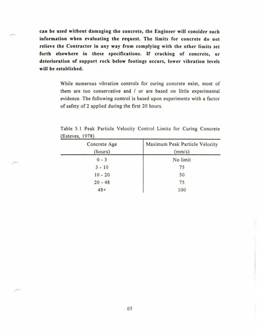
can be used without damaging the concrete, the Engineer will consider suchinformation when evaluating the request. The limits for concrete do not
relieve the Contractor in any way from complying with the other limits set
forth elsewhere in these specifications. If cracking of concrete, ordeterioration of support rock below footings occurs, lower vibration levelswill be established.
While numerous vibration controls for curing concrete exist, most of
them are too conservative and / or are based on little experimental
evidence. The following control is based upon experiments with a factor
of safety of 2 applied during the first 20 hours.
Table 5.1 Peak Particle Velocity Control Limits for Curing Concrete
(Esteves, 1978)
Concrete Age
(hours)
0 - 3
3 - 10
10-20
20-48
48+
Maximum Peak Particle Velocity
(mm/s)
No limit
75
50
75
100
65
CHAPTER 6
BLAST DENSIFICATION OF SANDS
GENERAL PROVISIONS (Section 1)
Except as otherwise specified in the following, the Contractor shallcomply with all sections of the "Blasting and Vibrations" part of thesespecifications.
Specialists (Section 1.1)
Blasting Specialist
Same as in the general provisions, except that in addition the blastingspecialist shall have previous experience in detonating explosives below thewater table.
Detonating explosives below the water table can produce adverse effects
if not conducted properly. The shock waves generated in the water by
the explosion of the first delay(s) can sympathetically detonate
remaining delayed charges if the proper explosives and techniques are
not employed.
Geotechnical Engineer
The Contractor shall engage a geotechnical engineer for advise on the
soil conditions, as well as on the resulting densification and ground
vibrations. His qualifications shall be approved as part of the review of the
66
blasting plan. The geotechnical engineer shall work in full cooperation withthe blasting specialist to assist him in the design of the densification process.
The presence of a geotechnical engineer on site is necessary to ensurethat the soil properties are correctly accounted for in the blast design.
Blasting Plan (Section 1.2)
General
No less than three weeks prior to commencing the test blast program,or at the preconstruction conference (whichever is earliest), or at any timethe Contractor proposes to change the drilling and blasting methods, theContractor shall submit a blasting plan to the Engineer for review. Theblasting plan shall contain the full details of the drilling and blastingpatterns and controls the Contractor proposes to use for densificationblasting. The blasting plan shall contain the following min imum information:
- station of proposed shots,- number of coverages for a given number of charges per unit area
(e.g. single coverage at a tight spacing, or multiple overlappingcoverages at a wider spacing)
- plan and section view of proposed hole pattern, including spacing,diameter, and depth,
- loading diagrams for each hole, showing type and amount ofexplosives, type of casing, primers, initiators, and location,depth and type of stemming between separately delayedcharges,
- init iation sequence of blast holes, inc luding delay times and delaysystem,
- form for reporting vibration results for each blast,- identification of explosive suppliers, blasting specialist, and
geotechnical engineer,
67
• manufacturers data sheets for all explosives, primers and initiators,- procedures to inform the public and protect adjacent properties,-plan for de-initiation in case of misfire.
The blasting plan submittal is for quality control and record keeping
purposes. Review of the blast plan by the Engineer does not relieve the
Contractor from his responsibility for the accuracy and adequacy of the
plan when implemented in the field.
Test Blast Program (Section 1.3)
In addition to the general requirements, this program is intended to:
- determine the optimum blasting parameters,
- obtain ground vibration data,- verify the increased soil density,- correlate density improvement with ground surface and deep
settlements.
The test blast program is also useful to reassure the project owner and
developer that this unconventional method (compared to more common
alternatives) will indeed achieve the intended purpose without undue
environmental effects. The sheer number of variables, combined with the
scarcity of experience with this particular method, make it prudent to
perform a test program to achieve a design that will minimize the
possible adverse effects.
68
Public Awareness (Section 1.4)
Because blast densification of sands produces low frequency vibrations,
effects can be felt far away from the source; it is necessary to take extra
measures to develop public awareness.
CONTROLS (Section 2)
Pre-Blasting Conditions of Soil (Section 2.Q
Prior to the commencement of any activity on the site, the Contractorshall conduct in-situ tests in order to determine the initial soil conditions.The results of these tests shall show the penetration resistance and / ordensity of the soil.
These tests shall consist of (specify here:
- type,- method,
- location,
- frequency)
Such in-situ tests can be Cone Penetration Test (CPT), Standard
Penetration Test (SPT), or any other method that the Engineer will deem
necessary for the particular site. The type of density characteristic varies
with the test method. For the CPT, it is the tip pressure, usually in psi;
for the SPT, it is the blowcount (La Fosse and Gelormino, 1991, and
Hryciw and Dowding, 1986).
69
Air Overpressures and Ground Motions (Section 2.2)
In addition to the preceding requirements, air overpressures andground motions will be recorded on the form of time histories during blasts.
Post-Blasting Conditions (Section 2.3)
Settlements
Ground settlements shall be determined by surveying settlementplatforms placed just below the ground surface, and deeper settlementpoints. The depths and locations of those measurements are (specify here).
Settlement control points shall be placed so that they extend out to adistance where less than 1 mm of settlement is expected. The exact spacingand location of the control points are (specify here).
During the densification process, settlements are inevitable as they are
the objective of the process. In addition, the amount of ground
settlement must be controlled because it is of importance not only in the
design of the facilities to be constructed on the site, but also to the
existing and adjacent structures.
Shallow platforms are generally placed at approximately two feet below
the surface, while the position of the deeper points is a direct function of
the soil conditions, as well as the amount of densification required.
Densification
The degree of densification achieved by blasting shall be measured by
the Contractor with the same method of in-situ testing, and at the same
70
locations, as during the pre-blasting survey. The length of time between thetwo measurements shall be determined to account for the increase in
penetration that ultimately is produced by blasting. The success of the
densification operations shall be measured by comparison between the pre-blasting and post-blasting tests results.
Although this specification is intended for the control of vibrations, the
degree of densification sought can be added explicitly in the text, as well
as a control criterion for the result, such as a given minimum percentage
of increase in penetration resistance.
GROUND MOTIONS MONITORING (Section 3)
Optional Monitoring of Dynamic Pore Pressures (Section 3.1)
The Engineer will record time histories of dynamic pore pressurescreated by deep blasting. The characteristics of this monitoring (depth,location, instrumentation, ...) will be determined by the Engineer, and the
instrumentation shall be furnished by the Contractor.
Deep blasting induces significant dynamic pore pressures. Some
projects, where this parameter is of particular concern, may require the
monitoring of these pore pressures.
71
CHAPTER 7
DEMOLITION BLASTING
GENERAL PROVISIONS (Section 1)
Explosives (Section 1.1)
Transportation, handling, storage, and use of explosives shall besubject to the requirements stated in Section 1.1 of the "Blasting andVibrations" part of these specifications.
Specialists CSection 1.2)
Demolition Blasting Specialist
The Contractor shall engage a blasting specialist as required toestablish satisfactory demolition. The specialist shall have considerableexperience in the use of explosives in general, and in demolition blasting inparticular. His qualifications shall be subject to the approval of all partiesinvolved in the demolition process. He shall be responsible for the design ofall blasting operations, and his services shall be continued as long as theEngineer deems them to be necessary. When more than one person isinvolved in the conception of the blasting, the qualifications of all membersof the blasting team shall be equally submitted to the above requirements.
The skill in demolition is, even today, very largely based on practicalexperience and empiricism. Therefore, these requirements are necessary
72
to ensure that an appropriately trained person (or group of persons)
designs and supervises the work.
Structural Engineer
The Contractor shall engage a structural engineer to advise on the
stability of the building (or structure) to be demolished and of neighboring
buildings (or structures). His qualifications shall be subject to the approval
of all parties involved in the demolition process. The structural engineer shallwork in full cooperation with the demolition blasting specialist, to assist him
in the design of the demolition sequence.
The cooperation of a structural engineer is necessary to determine which
parts of the building can be severed to bring the factor of safety down to
1.00001 before the final blast. His experience will also be of great use in
assisting the demolition blasting specialist to select the location of the
charges.
Demolition Plan (Section 1.3)
No less than three weeks prior to commencing any operations on thesite, the Contractor shall submit a demolition plan to the parties involved for
review. The demolition plan shall contain the full details of the demolition
sequence, and the following minimum information:
- description of the members to be pre-cut, and in which order to
severe them, so that the unloaded factor of safety is reduced to
1.00001,- location of proposed charges,- plan view and section view of proposed drill patterns, including blast
hole spacing, blast hole diameter, blast hole angles,
73
- loading diagrams for each hole, showing type and amount ofexplosives, primers, initiators,
- initiation sequence of blast holes, including delay time and delaysystem,
- specific plan to control air blast, dust, and debris thrown from theimpact,
- specific plan for evacuation of adjacent structures before final blast,if necessary,
- identification of explosive suppliers, demolition blasting spec ia l i se s )and structural engineer(s),
- manufacturers data sheets for all explosives, primers, initiators, anddelay system to be used,
- forms for reporting the vibration results and air blast overpressure,- all safety codes and procedures to inform and protect the workers,
public and adjacent property,- plan for de-initiation in case of misfire.
The demolition plan submittal is for quality control and record keepingpurposes. Review of the demolition plan does not relieve the Contractorfrom his responsibility for the accuracy and adequacy of the plan whenimplemented in the field.
DEMOLITION BLASTING TECHNIQUE TSection 2)
The best modern practice of demolition blasting shall be employed.Acceptable demolition techniques are the ones that limit ground motionsinduced by blasting and collapse of the structure, air blast overpressure, aswell as expulsion of debris and dust from the site.
The Contractor and his consultants shall design the loads and theinitiation sequence to control:
- the direction of collapse,- the disintegration of mass concrete,
74
- the emission of projectiles and dust,
- the ground motions and air blast overpressure,- the impact of the falling structure on the ground.
Determination of a general method of demolition blasting is simply
impossible, since each building or structure has its own characteristics to
be taken into account. Therefore, this specification is intended as a
performance specification. It is the responsibility of the Contractor to
meet the requirements of this text, by using the method that he will
deem necessary.
Proximity of adjacent structures usually requires the building to collapse
in a given direction. Such directionality can be ensured by a correct
explosive sequence. Explosive demolition usually produces four
environmental effects: (1) ground motions, (2) air blast, (3) projectiles,
and (4) dust. It is therefore important to control these four elements. Air
blast can be significant, unless specifically controlled. Moreover, ground
motions are produced by two separate sources: ground coupling of the
explosion, and impact of the falling structure. Previous work (Dowding,
1993) has shown that the second is the more important in terms of
induced vibrations. Designing the demolition so that the building will tilt
on one side, and then "progressively" fall, is therefore recommended.
PREBLAST PROCEDURES (Section 3)
Projectiles (Section 3.1)
Before the demolition blasting of the building, the Contractor shallerect barriers, to prevent expulsion of any but dust sized particles. The
Contractor will be held liable for the damage caused to any property, and /
or person, by projectiles that were permitted to escape the barriers.
75
In addition to the erection of barriers, the Contractor shall take allnecessary measures to protect, on the buildings immediately adjacent to thestructure to be demolished, the windows facing the location of blasting. Thisprotection can take the form of screens or mats designed to prevent breakageof these windows.
As observed, parking of trailer trucks around structures has been
employed as barrier protection at some demolition sites. It is the
responsibility of the Contractor to develop efficient means to limit
ejection of projectiles. Since he is liable for any damage, he will very
likely pay attention to this aspect.
Building demolition is a punctual event. Therefore, no corrective
measure can be taken after the blast, and all necessary prevention must
be carefully thought out and planned before the blast. Another aspect of
this punctuality is that the assessment of damage is possible immediately
after the explosion and the collapse of the building.
Dust (Section 3.2)
The collapse of a structure is accompanied with the emission of finegrained soil sized particles and dust, that no barrier or mat can prevent frombeing emitted. The Contractor shall remove all dust, created and emitted byhis demolition blasting activities, in a radius of (specify here) from the
structure. Dust shall be removed from any place where it can causeannoyance, whether it is in the adjacent streets, public places, or privateproperties, within a period of two weeks after the demolition has occurred.
Surveys (Section 3.3)
76
Condition and line and grade surveys shall be performed incompliance with the requirements exposed in sections 2.1 and 2.2 of the"Blasting and Vibrations" part of these specifications.
It might be necessary to correct the requirements concerning the radiuswithin which all buildings will be surveyed. In an urban area, 400 ft, asspecified before, include a significant number of structures, and all ofthem cannot be surveyed.
Blast Warning Procedures (Section 3.4)
The Contractor shall comply with all the requirements exposed insection 1.6 of the "Blasting and Vibrations" part of these specificationsconcerning erection of warning signs, radio transmitters, and publicawareness.
In addition, a system of reliable, audible warnings shall be establishedby the Contractor, subject to approval, to ensure proper warning to allpersonnel in the area of detonation. It is important that visitors are madeaware of this warning procedures. The code shall contain three signals:
1) a warning signal before blasting. A suitable time for the warningsignal is that it is sufficient for people to reach a place of safetybefore the blast is fired,
2) a firing signal,3) an all-clear signal.
The Contractor is responsible for developing a system to ensure thatno personnel remain inside the bui ld ing dur ing the blast init iat ion process.
77
Evacuation Plan (Section 3.5
The Contractor shall have both letter and personal contacts withresidents, institutional operators, and business establishments that areadjacent to the demolition site, in order to establish an evacuation plan ofthe concerned buildings.
MONITORING AND CONTROL OF EVENT (Section 4)
The ground vibrations and air blast overpressures shall be subject tothe same provisions concerning control methods, monitoring processes, andinstrumentation, as those exposed in the "Blasting and Vibrations" and"Noise and Overpressure" parts of these specifications, respectively.
POSTBLAST PROCEDURES (Section 5)
The Contractor shall establish a construction bond, to cover the risksof unpredicted damages to adjacent bui ldings or structures.
Postblast surveys of the buildings and / or structures surrounding thedemolition site will be made in the event that owners or residents make aspecific blast-related damage claim. These surveys will be conducted by anindependent specialist consultant, whose qualif icat ions shall be submitted toapproval of the involved parties. The postblast survey, then, will be based onthe particular damage claim, and will serve simply to confirm or deny thevalidity of the damage claim. The complaint damage itself shall be inspected,documented, and photographed if necessary, in order to make comparisonreference to the original preblast survey. A report shall be issued, stating ifthe claim is confirmed or denied, and transmitted to the Contractor.
78
CONCLUSIONSAND
RECOMMENDATIONS
In this thesis, technical specifications, focused on the control of ground
vibrations induced by blasting and pile driving, and of air overpressures, have
been developed to incorporate frequency based approaches. In addition, special
chapters have been developed for situations such as controlled blasting, close-in
blasting, demolition blasting, and blast densification of sands. After the review of
existing texts, collection of numerous articles, and synthesis of these
specifications, the following conclusions can be advanced, concerning respectively
the geotechnical, the procedural, and the management aspects of vibration control
specifications.
Too many ground vibration controls are over conservative. Respecting
these unnecessarily stringent limits requires time, money and energy, that could be
employed more profitably. Use of realistic controls for the particular site should
be one of the principal objectives of both the Contractor and the Engineer.
Frequency considerations are important, because both structural and human
responses are a function of the excitation frequency. This aspect is also critical in
the choice of the instrumentation for monitoring purposes.
A clear distinction should be made between air overpressures in general,
and noise, which is the high frequency audible portion of the air overpressure.
Noise is harmless to structures, but produces community annoyance and should
therefore be controlled.
Control of permanent displacement of the soil and / or rock is more critical
for some operations, such as pile driving and close-in blasting, than limiting
ground motions. Special design and control measures should be taken in critical
cases.
79
Specifications should be written to measure outcomes rather than methods.
This performance approach leaves room for the Contractor to meet the
requirements with his own method(s) and creativity.
Vibration considerations should be taken into account early in the design of
the project. Making a preconstruction survey, to identify critical structures and
processes is an example of an appropriate measure to be taken prior to the writing
of the specifications.
It is necessary for the Contractor to work in collaboration with specialists
of the operations carried out on the site. These persons, whether they are
geotechnical, structural, or blasting specialists, must be qualified to assist the
design and / or to be consulted on specific problems.
Test programs should always be carried out before starting full-scale
operations. This measure allows for any eventual correction in the methods used,
in the event that the tests do not produce the expected effects.
The choice of the type of instrumentation to be used for the monitoring of
the ground motions is a function of the expected velocities, and / or the conditions
of the site. Nevertheless, monitors providing time histories of the event should be
preferred.
Two threshold values of peak particle velocity should be introduced for
monitoring purposes during piling activities. It is then possible to carry out an
exhaustive, but not data intensive, monitoring program.
The above specifications are intended to be customized to fit the
characteristics of each project. The text will not be appropriate if this necessary
tailoring operation is not carried out.
The role of the Engineer should not be limited to the control authority. He
should be available for advise on specific problems, but the final results should
remain the responsibility of the Contractor.
80

APPENDICES
81

APPENDIX A
APPENDIX A
BIBLIOGRAPHY AND REFERENCES
American Association for State Highway and Transportation Officials, 1979,
"Standard Recommended Practice for Evaluation of Transportation Related
Earthborne Vibrations", Specifications for Materials, AASHTO
Designation R8-81, pp. 1064-1071.
Berger, P.R., 1983, "Blast Recording Report", P.R. Berger Assoc., Warrendale,
Pennsylvania.
Berta, G., 1990, Explosives: An Engineering Tool. Italesplosivi, Milano, Italy,
483 pp.
Chellis, R.D., 1961, Pile Foundations. Second Edition, McGraw-Hill Book
Company, New York, 704 pp.
Clough, G.W., and Chameau, J.L., 1980, "Effects of Vibratory Sheetpile Driving:
A Case Study", Minimizing Detrimental Construction Vibrations. American
Society of Civil Engineers, Preprint 80-175, pp. 27-61.
Department of Transport, 1991, "Specifications for Highway Works", Transport
Research Laboratory, HMSO, Crowthorne, Berkshire, England, pp. 7-8.
Department of Transport, 1991, "Notes for Guidance on the Specifications for
Highway Works", Transport Research Laboratory, HMSO, Crowthorne,
Berkshire, England, p. 4.
Dowding, C.H., 1985, Blast Vibration Monitoring and Control. Prentice Hall, Inc,
Englewood Cliffs, New Jersey, 297 pp.
Dowding, C.H., 1987, "Blast Vibration Controls for Lyceum Theater", Prepared
for the City of New York, New York, 5 pp.
A-l
Dowding, C.H., 1992, "Suggested Method for Vibration Monitoring",
International Journal of Rock Mechanics and Mining Sciences. Vol. 29,
No. 2, March 1992, pp. 143-146.
Dowding, C.H., 1993, "Environmental Effects of Explosive Demolition of
Structures", Internal Report, Northwestern University, Evanston, Illinois,
35pp.
Du Pont, 1966, Blasters Handbook. E.I. Du Pont de Nemours and Company, Inc.,
Wilmington, Delaware, 494 pp.
Erschiitterungen im Bauwesen, Einwirkungen auf baulishe Anlagen, Deutsche
Norm, DIN 4150, Teil 1982, Part 3.
Esteves, J.M., 1978, "Control of Vibration Caused by Blasting", Laboratorio de
Engenharia Civil, Memoria 409, Ministerio da Habitacao e Obras Publicas,
Lisbon, Portugal, p. 11.
Fleming, W.G.K., Weltman, A.J., Randolph, M.F., and Elson, W.K., 1985, Piling
Engineering. Halsted Press, a Division of John Wiley & Sons, Inc., New
York City, N.Y., pp. 260-264.
Foch, J.D., and Burke, R.E., 1985, "Sound Levels from Oil and Gas Exploration
Activities - Flathead National Forest, Glacier National Park, Helena
National Forest", United States Environmental Protection Agency, Region
VIII, Denver, Colorado, 220 pp.
Heckman, W.S., and Hagerty, D.J., 1978, "Vibrations Associated with Pile
Driving", Journal of the Construction Division, American Society of Civil
Engineers, December, Vol. 104, No. C04, pp. 385-394.
Hemphill, G.B., 1981, Blasting Operations. McGraw-Hill Book Company, New
York, 258 pp.
Hendron, A.J., and Oriard, L.L., 1972, "Specifications for Controlled Blasting in
Civil Engineering Projects", Proceedings of the First North American Rapid
A-2

Excavation and Tunneling Conference. Society of Mining Engineers,
Chicago, Illinois, June 5-7, Volume 2, pp. 1585-1609.
Hersh, A.S., (undated), "Review of Construction Noise Legislation", Draft
Monogram, Hersh Acoustical Engineering, Chatsworth, California.
Hersh, A.S., 1974, "Construction Noise - Its Origin and Effects", Journal of the
Construction Division. American Society of Civil Engineers, Vol. 100., No.
CO3, September, pp. 433-448.
Holloway, D.M., et al, 1980, "Field Study of Pile Driving Effects on Noearby
Structures", Minimizing Detrimental Construction Vibrations. American
Society of Civil Engineers, Preprint 80-175, pp. 63-100.
Hryciw, R.D., and Dowding, C.H., 1986, "Dynamic Pore Pressure and Ground
Motion Instrumentation of Blast Densification of Sands", Proceedings of
the First International Symposium on Environmental Geotechnology. pp.
620-629.
Kessler, F.M., 1985, "Cost Assessment of Construction Noise Control", Noise and
Vibration Measurement: Prediction and Mitigation. Proceedings of the
Symposium on Environmental Engineering, American Society of Civil
Engineers, Denver, Colorado, May 1-2, pp. 33-47.
Konya, C.J., and Walter, E.J., 1985, Rock Blasting. U.S. Department of
Transportation, Federal Highway Administration, Seminar on Blasting and
Overbreak Control, May, 355 pp.
Lafosse, U., and Gelormino, T.A., 1991, "Soil Improvement by Deep Blasting - A
Case Study". Proceedings of the 17^ Annual Symposium on Explosives
and Blasting Technique. International Society of Explosive Engineers,
February 3-7, Vol. 1, pp. 205-213.
Lee, V.M., Abrams, J.H., and Parish, W.C.P., 1983, "Development of
Specifications for Construction Noise and Vibration Control", Internal
A-3
Report, Parsons Brinckerhoff Quade & Douglas, Inc., New York City,
New York, 11 pp.
Linehan, P.W., and Dowding, C.H., 1986, "Components of Successful Test Blast
Programs", Technical Paper presented at the 12tn Annual Conference on
Explosives and Blasting Techniques Society of Explosive Engineers,
Atlanta, Georgia, February 9-14, 9 pp.
Massarch, K.R., 1983, "Vibration Problems in Soft Soils", Proceedings of the
Symposium on Recent Developments in Laboratory and Field Tests and
Analyses of Geotechnical Problems, Asian Institute of Technology,
Bangkok, A.A. Balkema, December, pp. 539-549.
Massarch, K.R., 1992, "Static and Dynamic Soil Displacements Caused by Pile
Driving", Keynotee Lecture at the Fourth International Conference on the
Application of Stress-Wave Theory to Piles, The Hague, The Netherlands,
September 21-24, 10 pp.
McKown A.F., 1991, "Close-In Construction Blasting: Impact & Mitigation
Measures", Civil Engineering Practice, Journal of the Boston Society of
Civil Engineers, Section / American Society of Civil Engineers, Volume 6,
Number 2, Fall, pp. 73-92.
McKown, A.F., and McClure, R.A., 1988, "Close Proximity Trench Blasting Case
History", Proceedings of the Fourteenth Conference on Explosives and
Blasting Technique. Society of Explosives Engineers, Anaheim, California,
24pp.
Monfourny, J., 1990, "Campagne de Tirs Experimentaux a Proximite de 1'Unite
Phebus, Centre d'Etudes Nucleaires de Cadarache", Centre Experimental de
Recherches et d'Etudes du Batiment et des Travaux Publics, Rapport No.
D/4162.0.002, 16pp.
New, B.M., 1986, "Ground Vibrations Caused by Civil Engineering Works",
Department of Transport, Transport and Road Research Laboratory,
Research Report 53, Crowthorne, Berkshire, England, 20 pp.
A-4
New, B.M., 1992, "Construction Induced Vibration in Urban Environments",
Presented to the American Society of Civil Engineers Annual Convention,
Section 2R, Excavation and Support for the Urban Infrastructure, Design
and Construction Considerations, New York, September, 28 pp.
New York City Fire Department, 1989, "Guidelines for Blasting Contractors",
New York, 25 pp.
Olofsson, S.O., 1991, Applied Explosives Technology for Construction and
Mining. Applex, Aria, Sweden, 303 pp.
Oriard, L.L., 1990, "Censored", Report to (Censored), Lewis L. Oriard Inc.,
Huntington Beach, California, 45 pp.
Oriard, L.L., 1992, "Blasting Criteria for Existing Pipelines", Report to
(Censored), Lewis L. Oriard, Inc., Huntington Beach, California, 24 pp.
Oriard, L.L., (undated), "Problems with Common Analytical Models for Blast
Effects", Notes prepared for Course at National University of Mexico,
Personal Communication.
Oriard, L.L., and CoulsonJ.H., 1980, "TVA Blast Vibration Criteria for Mass
Concrete", Minimizing Detrimental Construction Vibrations. American
Society of Civil Engineers, Preprint 80-175, pp. 101-123.
Rosenthal, M.F., and Morlock, G.L., 1987, Blasting Guidance Manual. United
States Department of the Interior, Office of Surface Mining Reclamation
and Enforcement, 201 pp.
Siskind, D.E., Stachura, V.J., Stagg, M.S., and Kopp, J.W., 1980, Structural
Response and Damage Produced by Airblast from Surface Mining. United
States Bureau of Mines, Report of Investigations RI 8485, 111 pp.
Siskind, D.E., Stagg, M.S., Kopp, J.W., and Dowding, C.H., 1980, Structure
Response and Damage Produced by Ground Vibrations from Surface Mine
A-5
Blasting. United States Bureau of Mines, Repot of Investigations RI 8507,90 pp.
Stone and Webster Engineering Corporation, 1974, "Master Specification for
Piles and Pile Driving", Spec. No. 00000-G003J, Boston, Massachusetts,
33pp.
Stone and Webster Engineering Corporation, 1974, "Technical Specifications",
Prepared for Niagara Mohawk Power Corporation, Boston, Massachusetts,
140 pp.
Stone and Webster Engineering Corporation, 1975, "Master Specification for
Rock Tunneling", Spec. No. m-508-50-13e, Boston, Massachusetts, 26 pp.
Stone and Webster Engineering Corporation, 1975, "Technical Specifications for
Green County Project", Internal Publication, Boston, Massachusetts, 12
PP-
Stone and Webster Engineering Corporation, 1975, "Specification for General
Excavation", Nile Point Nuclear Station, Spec. No. 12177-G002L, Boston,
Massachusetts, 44 pp.
Studer, J. and Suesstrunk, A., 1978, "Swiss Standard for Vibrational Damage to
Buildings", Proceedings of the Tenth International Conference on Soil
Mechanics and Foundation Engineering. American Society of Civil
Engineers, 1978, pp. 307-312.
U.S. Army Corps of Engineers, 1972, Systematic Dril l ing and Blasting for Surface
Excavations. Engineer Manual EM 1110-2-3800, Washington, D.C., 80 pp.
United States Department of the Interior, 1974, "Specifications: Tunelling and
Grouting, Yellowtail Dam, Pick-Sloan Missouri Basin Program", Bureau of
Reclamations, Denver, Colorado, pp. 30-31.
Vuolio, R., 1990, "Blast Vibration: Threshold Values and Vibration Control",
Ph.D. Thesis, Acta Polytechnica Scandinavica, Helsinki, Sweden, 146 pp.
A-6
Wiss, J.F., 1980, "Construction Vibrations: State of the Art", Minimizing
Detrimental Construction Vibrations. American Society of Civil Engineers,
Preprint 80-175, pp. 1-26.
Wiss, Janney, Elstner Associates, Inc., 1984, "Vibration Monitoring During the I-
10 West Papago / Inner Loop Advance Test Pile Program", Prepared for
Howard, Needles, Tammen & Bergendoff, Report WJE No. 830535,
Northbrook, Illinois, 70 pp.
Wiss, Janney, Elstner Associates, Inc., 1987, "Technical Specifications for the I-
35 Construction in St. Paul, Minnesota", Specifications WJE S.P. 6280-231
and 6280-247, Northbrook, Illinois, pp. 88-105.
Wiss, Janney, Elstner Associates, Inc., 1988, "Test Blast Program for the 1-35
Construction in St. Paul, Minnesota", Prepared for the Minnesota
Department of Transportation, Report WJE No. 870600, Northbrook,
Illinois, 20 pp.
Wiss, Janney, Elstner Associates, Inc., 1990, "Condition Report and
Recommended Blast Vibration Protection Guidelines for Structures
Located Near 1-394 Parking Structures", Minneapolis, Minnesota, Prepared
for the Minnesota Department of Transportation, Report WJE No. 900173,
Northbrook, Illinois, 140 pp.
Wiss, Janney, Elstner Associates, Inc., 1991, "Condition Report and
Recommended Construction Vibration Protection Guidelines for Buildings
Located Near 1-394 TAD Construction in Minneapolis", Minnesota,
Prepared for the Minnesota Department of Transportation, Report WJE
No. 902097 and 910005, Northbrook, Illinois, 65 pp.
Wood, W.C., and Theissen, J.R., 1982, "Variations in Adjacent Structures Due to
Pile Driving", Proceedings of the 1982 Geopile Conference. Associated
Pile and Fitting Corporation, pp. 83-108.
A-7

APPENDIX B
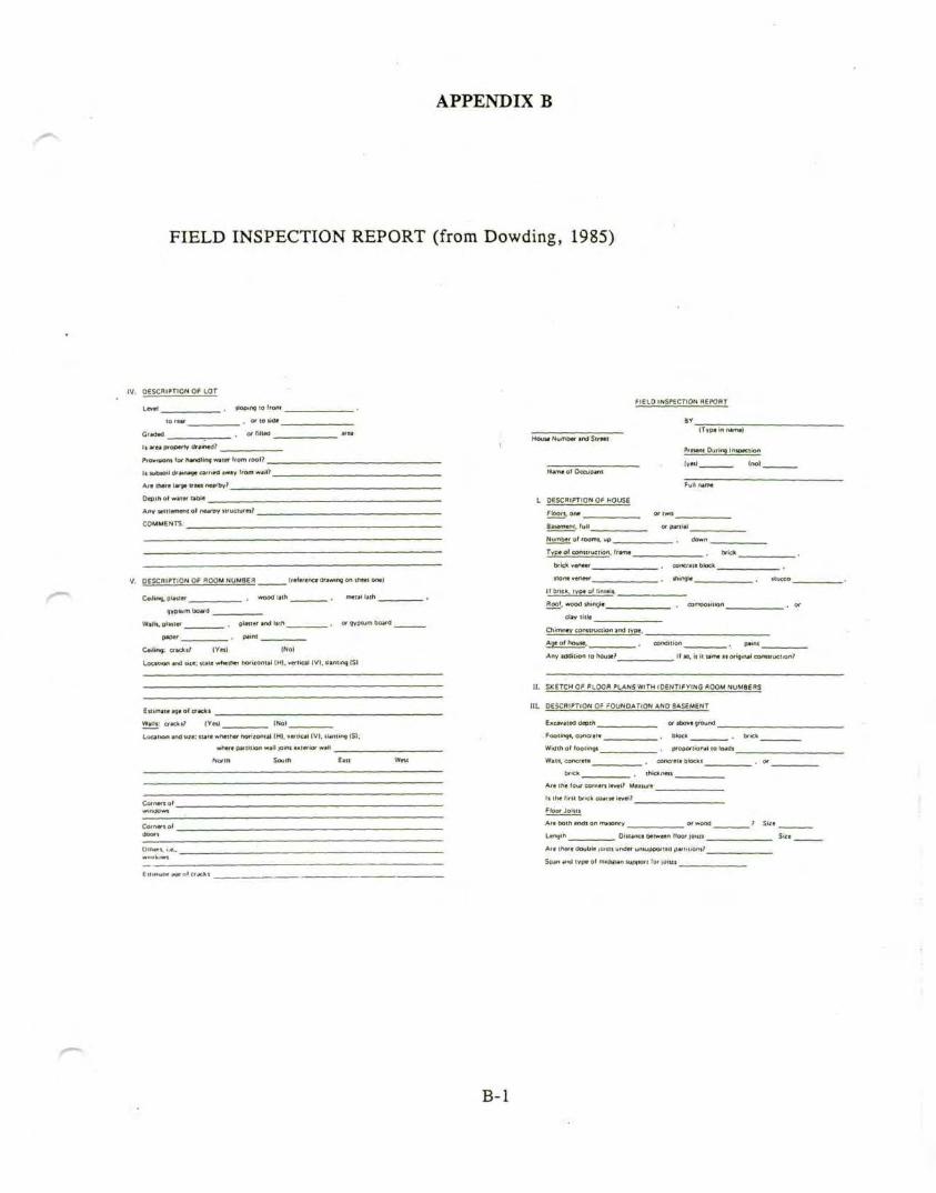
APPENDIX B
FIELD INSPECTION REPORT (from Dowding, 1985)
(V. DESCRIPTION OrM-OT
Level to ''one
, or to ude
It area property d
fm i f»x Handling waiw from root?
11 subsoil iJ( jui*4< earned away from will? _
Are th**e large trees neirby?
Depth ol water table
Any tetiiemem o( nearov structures? _
COMMENTS:
V. DESCRIPTION OF ROOM NUMBER (reference drawing on sheet one)
Ceiling, plaster , wood lath . metal lath
gypsum bo<wd _
W»Hi, plajwr
paper
planer and lain
. ciacki/ (Yei) (No)
Local ion and u/«: irate whether horizontal (H), vertical IV), slanting (5)
Eilimaitaqeof cracki
Wain cracks? [Yet) (No)
o and we: »uie whether hofiiontal (H). vertical (V|. Hannng (S);
where pa/tmon wall jomi anterior wall
North South East
FIELD INSPECTION flEPOBT
Number and Street
Namtof Occupant
L DESCRIPTION Of= HOUSE
(Type in aarnei
Preunt Dufinq Intgecii'
Number of room*, up
Type of construction, (ram*
brick veneer
none vene«r
concrsieOtoc.il
IIJjricK, type of_lin_ijli,
f. wood triingle_
clay title
Chimney construction and type.
Aot of house.
Any addition 10 house? II », it it tame ai original constructionr
II. SK_ETCH_0_F_Ft_gO_g PLANg^WTHjOErJTl^YING ROOM NUMBERS
IIL DESCRIPTION OF FOUNDATION AND BASEMENT
Excavated depth _
Footing*, concrete
Width o' (00(1091
Walls, concrete
brick
or above ground
block
, proportional to loads
concrete blocki
Are the (our corners level? Measure _
li the first brick coarse level?
Ftoor Joisis
Are both endi on masonry
Length Distance between floor joist* _
Are (here Uoutite |Oni( under unsupported partitions?
Span and type of rnxjspan support for joists
B-l
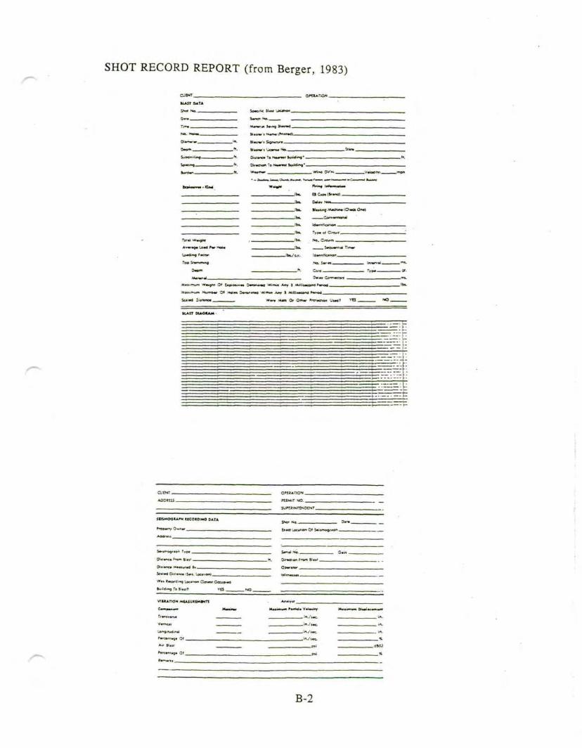
SHOT RECORD REPORT (from Berger, 1983)
-. 5 .,.">.--
SI t itm-j M«dww -.-• -a Onwt
JBSMOGIA^M RICOtOIHO DATA
SOimnc. rS*.i.
Jwawiin^ Lae*H
_ *f. Qir*aion from 3l*i
VIUAHON MCA5UREMV4T1
B-2

APPENDIX C
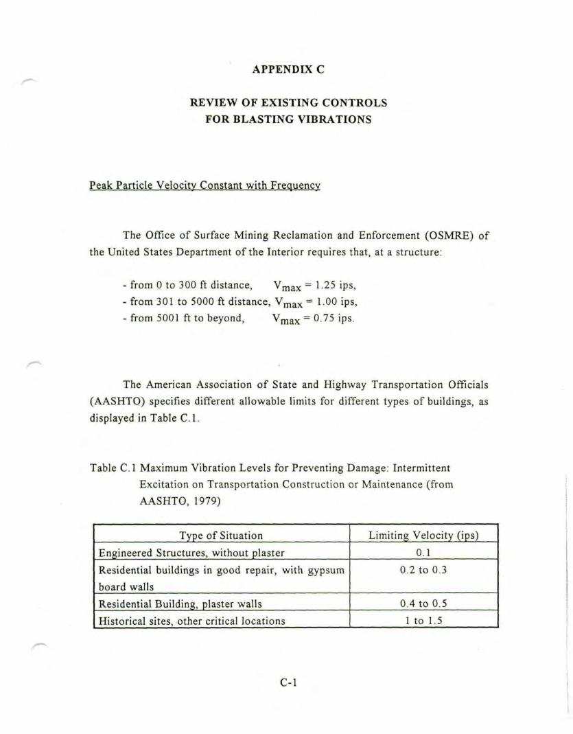
APPENDIX C
REVIEW OF EXISTING CONTROLS
FOR BLASTING VIBRATIONS
Peak Particle Velocity Constant with Frequency
The Office of Surface Mining Reclamation and Enforcement (OSMRE) of
the United States Department of the Interior requires that, at a structure:
- from 0 to 300 ft distance, Vmax = 1.25 ips,
- from 301 to 5000 ft distance, Vmax =1.00 ips,
- from 5001 ft to beyond, Vmax = 0.75 ips.
The American Association of State and Highway Transportation Officials
(AASHTO) specifies different allowable limits for different types of buildings, as
displayed in Table C.I.
Table C.I Maximum Vibration Levels for Preventing Damage: Intermittent
Excitation on Transportation Construction or Maintenance (from
AASHTO, 1979)
Type of Situation
Engineered Structures, without plaster
Residential buildings in good repair, with gypsum
board walls
Residential Building, plaster walls
Historical sites, other critical locations
Limiting Velocity (ips)
0.1
0.2 to 0.3
0.4 to 0.5
1 to 1.5
C-l
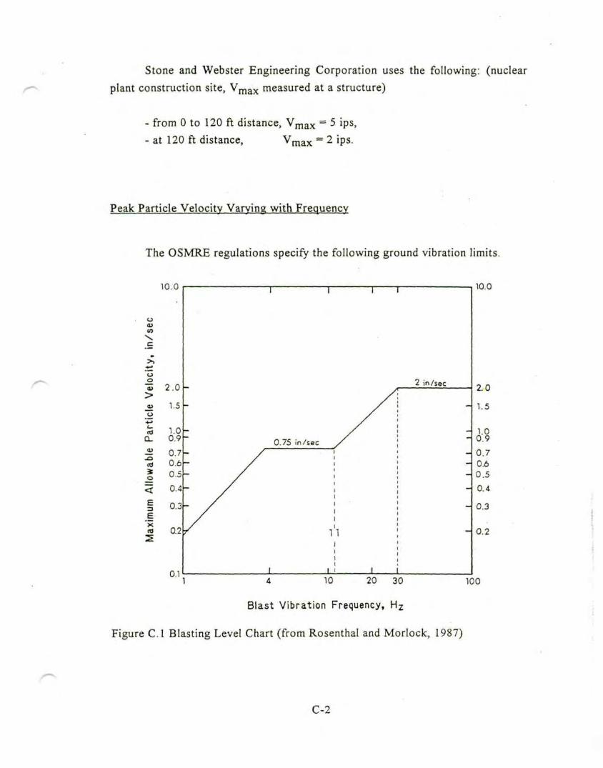
Stone and Webster Engineering Corporation uses the following: (nuclear
plant construction site, Vmax measured at a structure)
- from 0 to 120 ft distance, Vmax = 5 ips,- at 120 ft distance, max = 2 ips.
Peak Particle Velocity Varying with Frequency
The OSMRE regulations specify the following ground vibration limits.
10.0
o<u
.£9
>>
*->"oo"S 2.0
<u 1.5
15 1.00. 0.9
-£ 0.7"S 0.6
I °'5
5 0.4
E3
_E"x
0.3
0.2
0.1
T
0.75 in/sec
2 in/sec
10.0
2.0
1.5
1.00.9
0.70.60.5
0.4
0.3
0.2
4 10 20 30 100
Blast Vibration Frequency, Hz
Figure C.I Blasting Level Chart (from Rosenthal and Morlock, 1987)
C-2
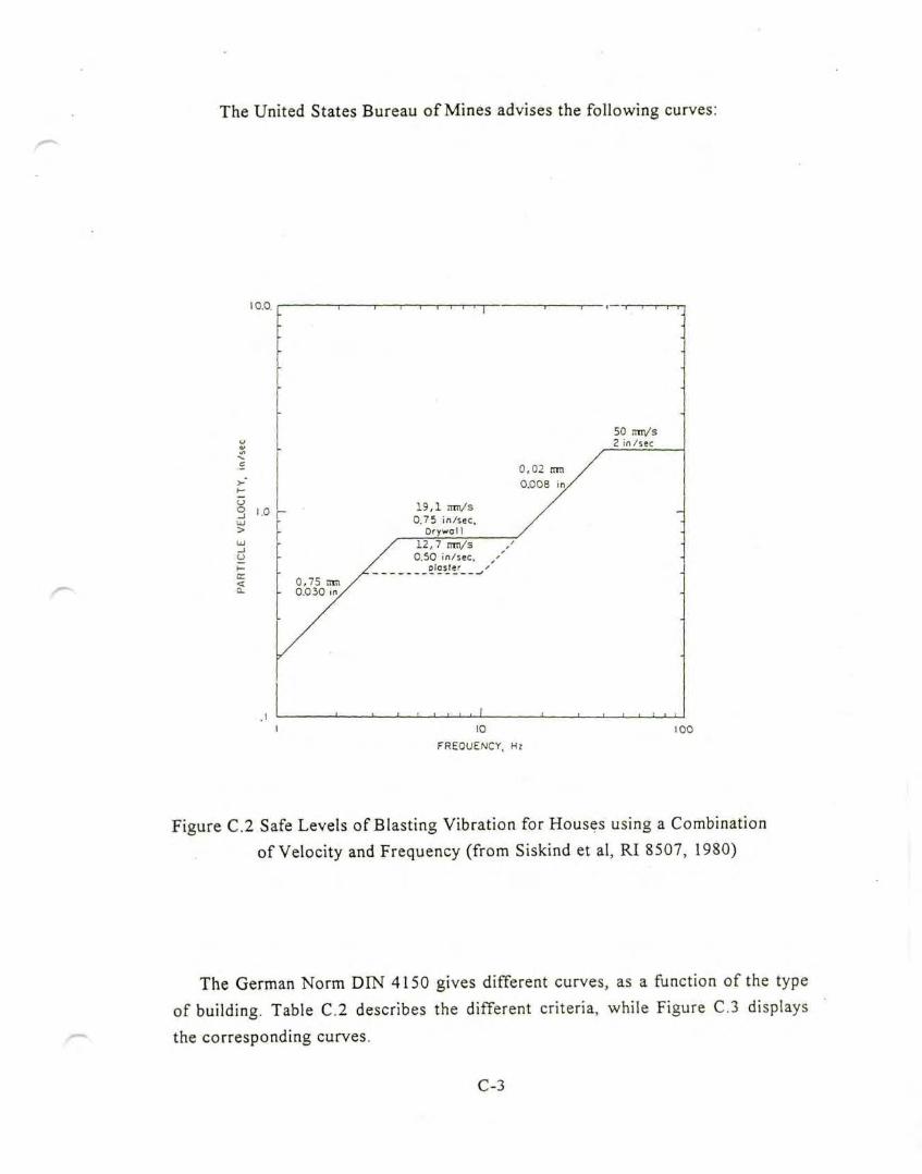
The United States Bureau of Mines advises the following curves:
10.0.
yo
es
19,1 nm/s0.75 in/sec
Orywo 1 1
100
FREQUENCY, Hz
Figure C.2 Safe Levels of Blasting Vibration for Houses using a Combinationof Velocity and Frequency (from Siskind et al, RI 8507, 1980)
~
The German Norm DIN 4150 gives different curves, as a function of the type
of building. Table C.2 describes the different criteria, while Figure C.3 displays
the corresponding curves.
C-3
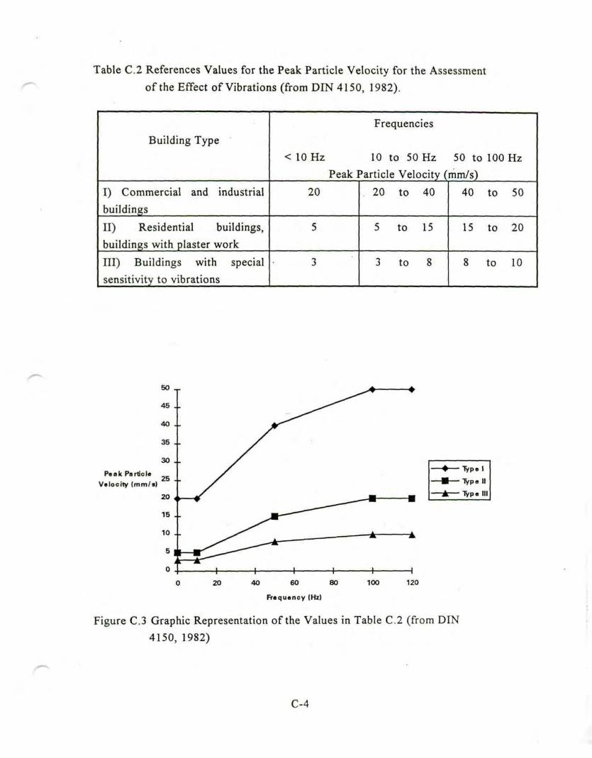
^Table C.2 References Values for the Peak Particle Velocity for the Assessment
of the Effect of Vibrations (from DIN 4150, 1982).
Building Type
I) Commercial and industrial
buildings
II) Residential buildings,
buildings with plaster work
III) Buildings with special
sensitivity to vibrations
Frequencies
<10Hz 10 to 50 Hz 50 to 100 Hz
Peak Particle Velocity (mm/s)
20
5
3
20 to 40
5 to 15
3 to 8
40 to 50
15 to 20
8 to 10
^
Peak ParticleVelocity (mm/s)
40 60 80
Frequency (Hi)
100 120
Figure C.3 Graphic Representation of the Values in Table C.2 (from DIN
4150, 1982)
C-4
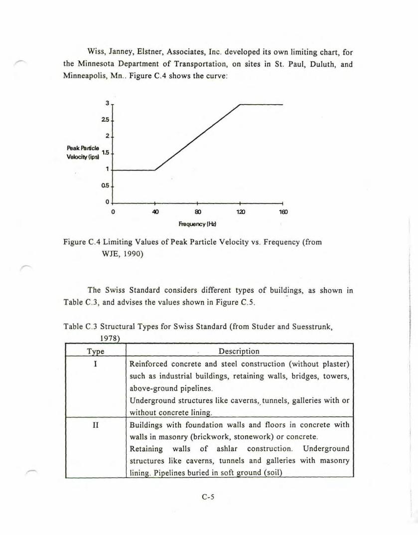
Wiss, Janney, Elstner, Associates, Inc. developed its own limiting chart, for
the Minnesota Department of Transportation, on sites in St. Paul, Duluth, andMinneapolis, Mn.. Figure C.4 shows the curve:
Peak Particle
Velocity (ipsj
Figure C.4 Limiting Values of Peak Particle Velocity vs. Frequency (fromWJE, 1990)
The Swiss Standard considers different types of buildings, as shown in
Table C.3, and advises the values shown in Figure C.5.
Table C.3 Structural Types for Swiss Standard (from Studer and Suesstrunk,1978}
Type
I
II
Description
Reinforced concrete and steel construction (without plaster)
such as industrial buildings, retaining walls, bridges, towers,
above-ground pipelines.
Underground structures like caverns, tunnels, galleries with or
without concrete lining.
Buildings with foundation walls and floors in concrete withwalls in masonry (brickwork, stonework) or concrete.
Retaining walls of ashlar construction. Undergroundstructures like caverns, tunnels and galleries with masonry
lining. Pipelines buried in soft ground (soil)
C-5
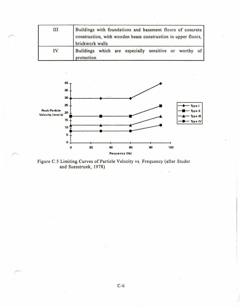
Ill
IV
Buildings with foundations and basement floors of concrete
construction, with wooden beam construction in upper floors,
brickwork walls
Buildings which are especially sensitive or worthy of
protection
40 _
36 ..
30
25 ..Peak Particle
Velocity (mm./s)20
15
10
5
0
^
-f-20 40 60
Frequency (Hz)
80 100
Figure C.5 Limiting Curves of Particle Velocity vs. Frequency (after Studerand Suesstrunk, 1978)
C-6