Frequency Locking of an Optical Cavity using LQG Integral Control
Upload
independentCategory
view
0download
0
INTERNATIONAL JOURNAL FOR NUMERICAL METHODS IN ENGINEERING, VOL. 35, 503-519 (1992)
A SHEAR LOCKING FREE ISOPARAMETRIC THREE- NODE TRIANGULAR FINITE ELEMENT FOR
MODERATELY-THICK AND THIN PLATES
HUMAYUN R. H. KABIR'
Engineering Mechanics Research Corporation, 1607 East Big Beaver Road, Troy, Michigan 48083, U.S .A.
SUMMARY A shear locking free isoparametric three-node triangular plate bending element, KEYA, is developed. Reissner/Mindlin theory that incorporates transverse shear deformation is assumed in the plate formula- tions. Numerical results include patch tests, convergence of transverse displacement and stress resultants, and variations of them for various parametric effects on cantilever, simply supported and clamped plates.
INTRODUCTION
Low order three-node triangular plate bending elements, based on Reissner/Mindlin theory, also known as First Order Shear Deformation Theory (FSDT), are most desired by finite element users for their simplicity in modelling (e.g. using auto mesh generation code) irregular shapes along with other types of finite element, and managing efficiently pre- and post-processor data bases. But these benefits are not attainable without paying proper dues in terms of such difficulties as obtaining reliable and efficient elements capable of performing well in thick and thin plate situations by achieving a shear locking free environment. As a result extensive research on FSDT- based three-node triangular elements has continued.
The aforementioned difficulties not only arise in three-node shear-flexible triangular elements, but also they are found in such finite elements as, for example, six-node triangular elements, four- or eight-node quadrilateral elements, etc. Attempts have been made to circumvent such difficult- ies by introducing:
(i) reduced or selective integration techniques;' (ii) an explicit set of shape functions for covariant components of transverse shear strains
(iii) hybrid stress model^;^ (iv) the Discrete Shear Triangle (DST);4 and (v) a shear correction term.5
Use of reduced or selective integration techniques provides reasonably acceptable results for higher order isoparametric elements, e.g. eight-node quadrilateral and six-node triangular elements. However, the same is not true for three-node isoparametric triangular elements as
(non-physical) in natural co-ordinates;2
*Senior Research Engineer
0029-598 1/92/160503-17$13.50 0 1992 by John Wiley & Sons, Ltd.
504 H. R. H. K A B l R
reported by Batoz et uL6 They have clearly shown the poor performance of three-node isopara- metric triangular elements in thin plate situations, a result of shear locking.
Bathe and Dvorkin2 have developed an efficient four-node quadrilateral element by introdu- cing an independent set of shape functions for the covariant components of transverse shear strains, and shown its better performance in both thick and thin plate situations. This concept, however, is yet to be directly applied to the case of three-node triangular elements.
Saleeb and Chang' have developed an efficient quadrilateral element based on the Hellinger/- Reissner mixed variational principle, where displacement and stress fields are assumed independ- ently. However, they have reported the inherent difficulties involved in the selection of stress fields. Lee and Pian' and Malkus and Hughes' have reported that, in some specific situations, for the case of three-node triangular elements, the stiffness matrix derived from the selective integration formulation is equivalent to the one obtained using the HellingerlReissner type mixed formulation. A recent addition of a mixed formulation to three-node triangular elements is due to Papadopolus and Taylor,' where transverse displacement and rotations are assumed to vary cubically and quadratically, respectively. The element stability and performance are checked following the method provided by Zeinkiewicz and Lefebvre" developed in the context of various quadrilateral and triangular elements based on the mixed formulation.
Another line of research on three-node elements is based on DST,4 which includes transverse shear deformation in the plate formulations. It is an improvement over the Discrete Kirchhoff Triangle (DKT), where transverse shear deformation is set to zero in the plate formulations in a discrete manner. DST becomes DKT in a thin plate situation. In the case of DST, transverse displacement and rotations are expressed in terms of cubic and quadratic polynomials, respect- ively. As a result, covariant components of rotations are not compatible along the edges of the element^.^
Although six-node triangular elements behave fairly well in thick to thin range situations using reduced integration techniques, Verwood and Kok' have recently further improved the element by introducing a shear correction term.
Following displacement-based formulations, Lynn and Dhillon' have presented three-node triangular plate bending elements that include the effects of shear deformations. The transverse displacement and rotations are assumed to vary quadratically and linearly, respectively. The authors have claimed that the element is suitable for moderately thick plates, and provided numerical results for a span-to-thickness ratio of 10. Hughes and Tay1orl3 have formulated a triangular element assuming the polynomial of the transverse displacement to be one order higher than that of the rotations, an approach similar to a bilinear quadrilateral element.I4 Their elements have given satisfactory results for cross-diagonal mesh configurations. To the best of the author's knowledge, a shear locking free robust isoparametric three-node FSDT-based triangular plate element is yet to be reported in the literature.
Therefore, the prime objective of the present investigation is to develop a shear locking free isoparametric three-node FSDT-based triangular plate bending element (KEYA). The second objective is to present such numerical results as (i) patch tests; (ii) convergence test of a cantilever plate, simply supported plate and clamped plate; (iii) variation of transverse displacement and stress-resultants for various parametric effects; and (iv) comparison of them with the available exact and finite element solutions.
FINITE ELEMENT FORMULATION
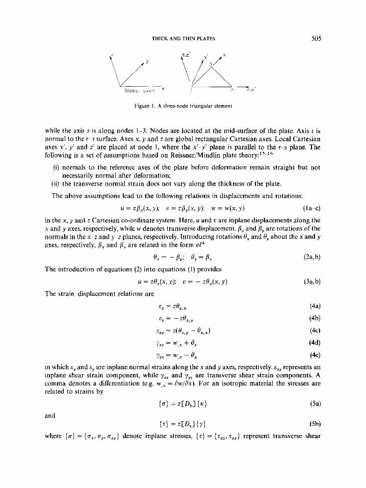
Figure 1 shows a three-node triangular element with a natural co-ordinate system ( I , s, t ) placed at mid-surface (the reference surface) of the plate thickness at node 1. Axis r is along nodes 1-2,
THICK AND THIN PLATES 505
Figure 1. A three-node triangular element
while the axis s is along nodes 1-3. Nodes are located at the mid-surface of the plate. Axis t is normal to the r-s surface. Axes x, y and z are global rectangular Cartesian axes. Local Cartesian axes x’, y’ and z’ are placed at node 1, where the x’-y’ plane is parallel to the r-s plane. The following is a set of assumptions based on Reissner/Mindlin plate theory:l5- l6
(i) normals to the reference axes of the plate before deformation remain straight but not
(ii) the transverse normal strain does not vary along the thickness of the plate.
The above assumptions lead to the following relations in displacements and rotations:
necessarily normal after deformation;
u = ZP,(X, y); u = Z B Y k Y); w = w(x, Y) t 1 a+) in the x, y and z Cartesian co-ordinate system. Here, u and u are inplane displacements along the x and y axes, respectively, while w denotes transverse displacement. p, and By are rotations of the normals in the x-z and y-z planes, respectively. Introducing rotations 8, and 8, about the x and y axes, respectively, p, and f ly are related in the form of4
e x = - p y ’ 8, = B, (2a, b)
= zey(x, y); u = - zex(x, y) (3a,b)
The introduction of equations (2) into equations (1) provides
The straindisplacement relations are
in which E, and ey are inplane normal strains along the x and y axes, respectively. E , ~ represents an inplane shear strain component, while y,, and yyz are transverse shear strain components. A comma denotes a differentiation (e.g. w,, = aw/ax). For an isotropic material the stresses are related to strains by
(01 = z C 4 l {.I (54
where {o} = {ox, oy, oxy} denote inplane stresses, {z} = {zXz, zXy} represent transverse shear

506
stresses and
H. R. H. KABlR
D s = - [ ' k E '1 2(1 + v) 0 1
E and v are Young's modulus and Poisson's ratio, respectively. k is a shear correction factor, and usually is taken as 5/6 for homogeneous isotropic plates. For the three-node isoparametric triangular element, the interpolation functions for element nodal co-ordinates, displacement and rotations are17
where N , = l - r - s
N , = r
N 3 = s
With these interpolation functions, transverse shear strains ( yxz and yyz) contain the rotation terms-a first order polynomial-and the derivative of displacement terms-a zeroth order polynomial. The mismatch of the order of polynomials in rotation and displacement terms in the transverse shear strain formulations is supposed to be responsible for shear locking. A correction term, Aw, first utilized by Verwood and Kok' in the context of six-node triangular elements, is introduced to eliminate the effect of inhomogeneous terms in transverse shear strains. Therefore, the corrected shear strain y:= is assumed to be
Y % = Y x z + AYXZ or
= By + w , ~ + A W , ~ (9) The term Aw can easily be evaluated from equation (9) considering the following:
Y Z , r = 0
Y,*,r = V n , r + Aw,rr = 0
( 1 0 4
(lob)
(104
where Aw is assumed in the form of
AW = u l d 2 + a2f2 + a 3 x ' y f + u4xf + a5y' +
THICK AND THIN PLATES 507
with respect to the local co-ordinates. The constant coefficients, ai ( i = 1, . . . ,6), of equation (1Oc) can be obtained by satisfying equation (lob) and vanishing Aw at nodes.
The strain energy of an element may be written as
U" = u; + us (1 1)
where
u; = - 1 lu Z2{K)T[DbI {.Idu
U E = i j u {Y * T D } c ,I{Y*>dU
The total potential energy can be written as
II" = - Z2{K)T[Db] fK)dU + - r*[D,] {r:)d~ - W (13) : I : I where W is the potential energy due to applied loads. Minimization of II" with respect to nodal variables { u } = ( wi, O i , Of)' supplies the following equation:
C K l e W = {f)' where [K] ' is a stiffness matrix, and ( J } " is a load vector. The stiffness matrix can be written as
in which
and
( 16b)
[Bb] and [B,] are defined as { K ) = [Bb] ( u ) and { y * ) = [B,] {u ) , respectively.
NUMERICAL RESULTS AND DISCUSSIONS
Two integration schemes are selected: (i) 1-point centroidal quadrature, and (ii) 3-point Gaus- sian quadrature. A single element with 1-point centroidal quadrature has one spurious (non-rigid body) zero energy mode, while with full integration it has none. To verify the accuracy and efficiency of the element, the following numerical results are presented. The numerical results are presented for both the integration schemes.
Patch test
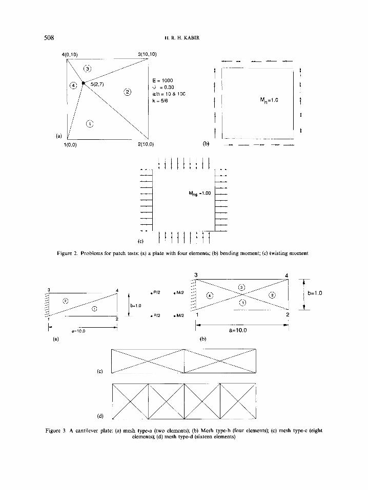
A group of four elements as shown in Figure 2 is considered for patch tests. Geometric and material properties are taken as those of Batoz and Lardeur? and are shown in Figure 2(a). The patch tests are performed for constant moments (Figure 2(b)) and constant twists (Figure 2(c)). Table I reports results of the patch subjected to constant moments ( M , = 1.0). Results agree
H. R. H. KABIR 508
41
E = 1000 4 = 0.30 a h = 10& 100 k = 516 M, =I .O
t
E M,, =I .OO
Figure 2. Problems for patch tests: (a) a plate with four elements; (b) bending moment; (c) twisting moment
Figure 3. A cantilever plate: (a) mesh type-a (two elements); (b) Mesh type-b (four elements); (c) mesh type-c (eight elements); (d) mesh type-d (sixteen elements)

THICK AND THIN PLATES 509
Table I. Patch test results for constant moments
alh = 10 alh = 100
Element no. M , M y M, , M , M y M x y
1 1.00 1~00 0.00 1.00 1.00 0.00 2 1.00 1.00 0.00 1.00 1Qo 0.00 3 1.00 1.00 0.00 1.00 1.00 0.00 4 1.00 1.00 0.00 1.00 1.00 0.00
Table 11. Patch test results for constant twists
alh = 10 a/h= 100
Element no. M , MY MXY MX MY MX"
Table 111. Maximum transverse displacements of a cantilever plate for various alh ratios (mesh type-a)
Present element Dvorkin and Bathe KEYA Ref. 18
Concentrated loads alh w (at nodes 2 and 4) w (at nodes 2 and 4)
5 0.75 0.75 100 0.75 0.75
Moments 5 1 .00 100 1 .00
1 .oo 1 .oo
E = 2 5 0 0 0 v=O; k = 5 / 6
faithfully with the exact solutions. Similar situations are also noticed for constant twists, M,, = 1.0 (Table 11).
Cantilever plates
A cantilever plate of span a and width b is shown in Figure 3. Two loading conditions are considered: (i) concentrated loads, and (ii) concentrated moments. The example is taken from Dvorkin and Bathe'* who previously have used it for four-node quadrilateral elements. Table I11 shows normalized (with respect to the exact solution) maximum transverse displacements for aspect ratios a/h = 5 and 100 with v = 0, and shear correction factor, k = 5/6. Results of the

510 H. R. H. KABIR
-
050 -
-
0.25 -
-
present isoparametric triangular element are in good agreement with those of Dvorkin and Bathe's quadrilateral elements. Figures 4 and 5 show the convergence of normalized (with respect to exact analysis) transverse displacement for two a/h ratios.
Simply supported plates
A plate with different sizes of mesh is considered for the analysis of a simply supported plate with SSl type of boundary conditions (according to the classification of Hoff and Rehfield,"
W
1 .oo 1'25 1 0.75 4 0.50 1
,- p e f 141 8
L Present element cantilever plate E = 25000 4 = 0.0 k = 516 & = 5
/
0.25 1 1
I I I I I I I I I I N 4 8 12 16 20
Figure 4. Convergence of normalized transverse displacement (at centre) with respect to mesh size for a cantilever plate with a/h = 10
W
0.75 1'0° 1 r Ref141
P a
Present element cantilever plate E = 25000 d = 0.0 k = 516 a/h = 100
I I I I I I I I I 4 8 12 16
lN 20
Figure 5. Convergence of normalized transverse displacement (at centre) with respect to mesh size for a cantilever plate with alh = 100

THICK A N D THIN PLATES 51 1
pal4
N=l (4 elements) N=2 (16 elements)
Figure 6. A quarter of a rectangular plane
W*
0.07
Exact solutioh r e f [201
0.05
Sinply supported p la te (sS1 boundary condltlon)
0.01 a/h=5 a=b
0.0 I I I I I I I I I I 1 2 3 4 5 6 7 8 9 10
N
Figure 7. Convergence of normalized transverse displacement (at centre) with respect to mesh size for a simply supported plate (SSl) with a/h = 5
W* 0.08
0.07 1 0.05 0'06 rl
,-Exact solution, r e f 1201 - - 0.04 -
Sinply supported p la te (SSI boundary condition)
0.01 a/h=lOO
0.0 1 2 3 4 5 6 7 8 9 10
N
Figure 8. Convergence of normalized transverse displacement (at centre) with respect to mesh size for a simply supported plate (SS1) with a/h = 100
512 H. R. H. KABlR
0.05 -
0.04 -
0.03 -
0.02 -
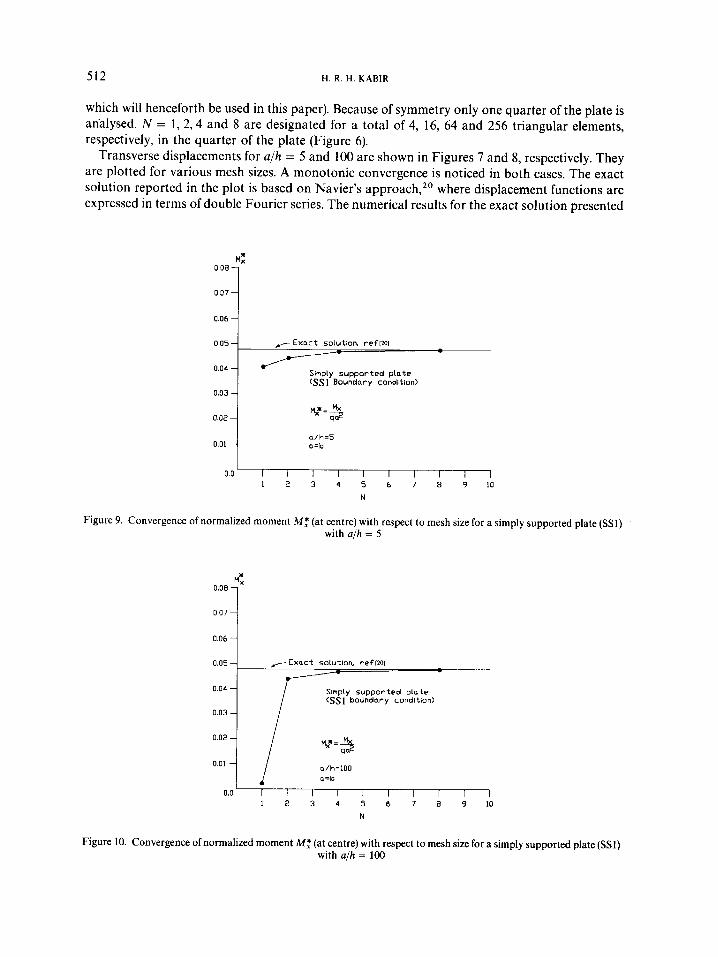
which will henceforth be used in this paper). Because of symmetry only one quarter of the plate is an8lysed. N = 1 , 2 , 4 and 8 are designated for a total of 4, 16, 64 and 256 triangular elements, respectively, in the quarter of the plate (Figure 6).
Transverse displacements for a/h = 5 and 100 are shown in Figures 7 and 8, respectively. They are plotted for various mesh sizes. A monotonic convergence is noticed in both cases. The exact solution reported in the plot is based on Navier's approach,20 where displacement functions are expressed in terms of double Fourier series. The numerical results for the exact solution presented
f l Exact solution, ref[ml - Sinply supported plate (SSI Boundary condition)
0.06
O.O1 i a/h=5 a=b
I 0.0 I I I I 1 I I I I 1
1 2 3 4 5 6 7 8 9 10 N
Figure 9. Convergence of normalized moment M : (at centre) with respect to mesh size for a simply supported plate (SS1) with aih = 5
0.06 O , O 7 I
0.05 - ,-- Exact solution, r e f 1201
0.04 - Sinply supported plnte <SS1 boundnry condition)
0.0 I l l I I I I I l l 1 2 3 4 5 6 7 8 9 10
N
Figure 10. Convergence of normalized moment M: (at centre) with respect to mesh size for a simply supported plate (SSI) with alh = 100

THICK AND THIN PLATES 513
Table IV. Maximum normalized transverse displace- ments for a square simply supported plate subjected to
central concentrated load for various alh ratios
Present element' Batoz et al., Ref. 6 alh KEYA (SRI) ~ ~ ~
10 13.37 13.24 48 1 1.59 7.81
1000 11.45 0.008 10000 11.45 0.0008
Exact 11.60 (based on the thin plate theory)
w * = lo3 WD/(qa4); k = 5 / 6 ; ' N = 8
D = E h 3 / l 2( 1 - v 2 ); E = 10 000; v = 03;
Table V. Comparison of maximum normalized trans- verse displacements for a square simply supported plate
subjected to a uniform loading
alh
Present element+ KEYA Ref. 4 Ref. 21 Ref. 22 Ref. 23 Exact Ref. 20 Number of terms m = n = 1 9
5
0.0533
0.053 1 0.0522 0.0524 0.0522 0.0535
10 100
0.0463 0.0441
0.0463 0.044 1 0.0462 0.0440 0.0462 0.0434 0.0463 0.0444 0.0466 0.0443
w*=wEh3/qa3; w* for thin plate=0.0444, ' N = 8
Table VI. Comparison of maximum normalized bending moments (M: ) for a square simply supported plate sub-
jected to a uniform loading
alh 5 10 100
Present element' 0.0476 0.0476 0.0476 KEYA Ref. 4 0.0475 0.0476 0.0479 Ref. 21 0.0480 0.0481 0.0482 Ref. 24 0.0479 0.0479 0.0479 Exact Ref. 20 0.0478 0.0478 0.0478 Number of terms m = n = 19
M: = M,/qaz; ' N =8
514 H. R. H. KABIR
1,75-
1.50 -
1.25
1.00 -
0,75-
0,50-
0,25-
0.0
are for the terms rn = n = 19 of the solution functions. A similar trend is also observed for the case of central moments, M, (Figures 9 and 10).
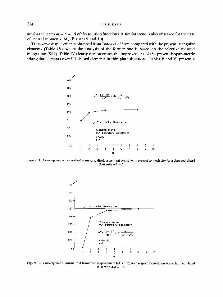
Transverse displacements obtained from Batoz et d6 are compared with the present triangular elements (Table IV), where the analysis of the former one is based on the selective reduced integration (SRI). Table IV clearly demonstrates the improvement of the present isoparametric triangular elements over SRI-based elements in thin plate situations. Tables V and VI present a
,--Thin p la te theo ry [xi - Clamped Plate (C4 boundary condltion)
a/h=lOO
T I I I 1 I I I I I
W*
3.0{
1.5
Clamped p la te (C4 boundary condltlon)
a/h=5 a=b
I 0.0 I I I I I I I I I I
1 2 3 4 5 6 7 8 9 10
N
Figure 11. Convergence of normalized transverse displacement (at centre) with respect to mesh size for a clamped plated (C4) with a/h = 5
w *
* ' 0 ° 1

THICK AND THIN PLATES 515
comparison of maximum transverse displacements and bending moments, respectively, for various a/h ratios with available results.
Clamped plates
For a clamped plate, convergences of transverse displacements and central moments with respect to various mesh sizes are shown in Figures 11 to 14. They also show a monotonic convergence for both transverse displacements and moments in thick and thin plate situations.
M:
Oo40 1 0.035
0.030
0025 -
0020 -
Ctonped P lo te 0.015 (C4 boundary condition)
0 005
0°10 I a/h=5 a=b
I 0.0 1 7 1 l l I l I l
1 2 3 4 5 6 7 8 9 10
N
Figure 13. Convergence of normalized moment Mf (at centre) with respect to mesh size for a clamped plate (C4) with a/h = 5
M1: 0 040
0035 1 O o 3 0 1
/Thin p la te t h e o r y 1261 0.025
Clamped P lo te 0.015 (C4 boundary condition)

516 H. R. H. KABIR
A comparison of maximum transverse displacements and central bending moments with the available finite element and thin-plate-based results is reported in Tables VII and VIII, respect- ively, for various a/h ratios. The influence of the a/h ratio is more dominant for the case of the damped plate than the simply supported one. Results of the present elements also agree with the other finite element results.
Regular and cross-diagonal meshing
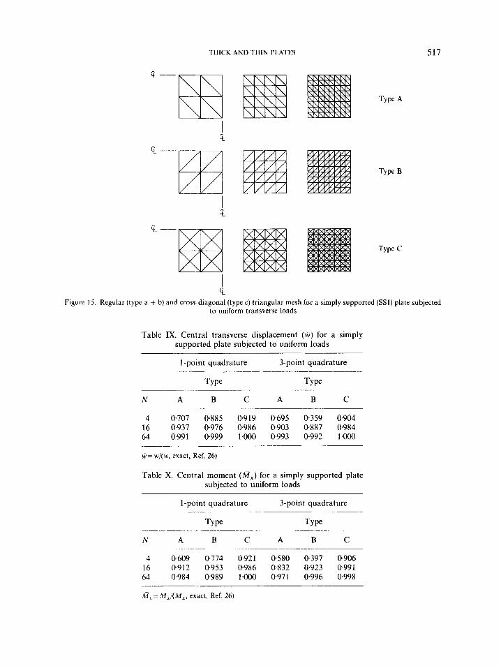
A set of regular (type A and B, Figures 15(a) and 15(b)) and cross-diagonal (type C, Figure 15(c)) triangular meshes is selected for a quarter of an SS1-type simply supported plate subjected to a uniform load. The span-to-thickness ratio is assumed to be 50. Tables IX and X present central transverse displacement and moment, respectively, for mesh types A, B and C, using 1-point and 3-point quadratures. For all types of meshing, both the quadratures provide very satisfactory results, indicating robustness against all types of triangular meshing.
Influence of distortion
results of the plate modelled with the distorted and regular triangular elements. Figure 16 shows a model of a quarter of a plate with some distorted elements. Table XI presents
Table VII. Comparison of maximum normalized trans- verse displacements ( w * ) for a square clamped plate
subjected to a uniform loading
alh 5 10 100
Present element' 2.162 1.492 1.248 KEYA Ref. 4 2.1 12 1.480 1.265 Ref. 21 2.054 1.470 1.250 Ref. 22 2.160 1.520 1.280 Ref. 25 2.134 1.495 -
w * = w D x 10CO/qa4; D = E h 3 / { 1 2 ( l - v 2 } ; w* for thin plate =1.260; t N = 8
Table VIII. Comparison of maximum normalized bending moments (Mf) for a clamped plate subjected to
a uniform loading
alh 5 10 100
Present element' 0.0233 0.0230 0.0227 KEYA Ref. 4 0.023 1 0.0230 0.0230 Ref. 21 0.0243 0.0240 0.0237 Ref. 25 0-026 1 0.0244 -
M : = M J q a * ; M , at centre for a thin plate=0.0231; ' N = 8
THICK AND THIN PLATES 517
c ‘c
c Y
Figure 15. Regular (type a + b) and cross-diagonal (type c) triangular mesh for a simply supported (SSl) plate subjected to uniform transverse loads
Table IX. Central transverse displacement ( W ) for a simply supported plate subjected to uniform loads
1-point quadrature 3-point quadrature .. ._ .
Type Type
N A B C A B C ~
4 0.707 0.885 0.919 0.695 0.359 0.904 16 0.937 0.976 0.986 0.903 0.887 0.984 64 0.991 0999 1QOO 0.993 0.992 1.OOO
W = w/(w, exact, Ref. 26)
Table X. Central moment (A,) for a simply supported plate subjected to uniform loads
1-point quadrature
Type ~ ~ -
~~ - ~ . _ _
N A B C ~~ ~ . _ ~ ~
4 0-609 0 774 0.921 16 0.912 0.953 0.986 44 0984 0.989 1.000
3-point quadrature ~
Type
A B C
0.580 0-397 0.906 0.832 0.923 0.991 0.971 0.996 0.998
~~~ ~ -. __ _ _ -~
~- -
sf,: M , / ( M , , exact, Ref. 26)

518 H. R. H. KABIR
distorted I,* I
Figure 16. A quarter of a rectangular plate with some distorted elements
Table XI. Central moments (M:) and transverse displacements (w*) for a simply supported plate for various a/h ratios with a
few distorted elements in the model'
a/h ry*(w* for no distortion) M:(M: for no distortion)
5 0.05 1 1 (0.05 3 3 ) 0.0476 (0.0476) 100 OW4 1 (0.0441) 0.0476 (0.0476)
w* = wEh3/qa4; M : = M J q a ; ' N = 8
CONCLUSIONS
A shear locking free isoparametric three-node plate bending triangular element (KEYA) based on the Reissner/Mindlin formulation is developed. A shear correction term is introduced to nullify the mismatch of polynomials arising into the components of transverse shear strains, due to transverse displacement and rotations. Numerical results of the element, KEYA, have shown excellent performance in both thick and thin plate situations for all types of triangular meshing. The element, KEYA, has also been extended for laminated plates, and the results will be published in another paper. The introduction of this element into a general shell situation is presently under study.
ACKNOWLEDGEMENTS
The author wishes to thank reviewers for their suggestions on an earlier version of the manuscript. The author also wishes to thank Mrs A. Helou for her typing the manuscript, and Mrs S. Deb for her assistance in drawing the figures.

THICK AND THIN PLATES 519
REFERENCES
1. 0. C. Zienkiewicz, R. L. Taylor and J. M. Too, ‘Reduced integration technique in general analysis of plates and shells’,
2. K. J. Bathe and E. N. Dvorkin, ‘Short communication--a four node plate bending element based on Mindlin/Reissner
3. T. H. H. Pian and D. K. C. Wang, ‘Hybrid plate elements based on balanced stresses and displacements’, Finite
4. J. L. Batoz and P. Lardeur, ‘A discrete shear triangular nine d.0.f. element for the analysis of thick to very thin plates’,
5. M. H. Verwood and A. W. M. Kok, ‘A shear locking free six-node Mindlin plate bending element’, Comp. Struct., 36,
6. J. L. Batoz, K. J. Bathe and L. W. Ho, ‘A study of three-node triangular plate bending elements’, Int. j . numer. methods
7. A. F. Saleeb and T. Y. Chang, ‘An efficient quadrilateral element for plate bending analysis, Int. j . numer. methods eng.,
8 . S. W. Lee and T. Pian, ‘Improvement of plate and shell finite elements by mixed formulation’, A I A A J . , 16, 29-34 (1978).
9. D. S. Malkus and T. J. Hughes, ‘Mixed finite element methods-reduced and selective integration techniques: a unification concept’, Comp. Methods Appl. Mech. Eng., 15, 63-81 (1978).
10. P. Papadopoulos and R. L. Taylor, ‘A triangular element based on Reissner-Mindlin plate theory’, Int. j . numer methods eng., 30, 1029-1049 (1990).
11. 0. C. Zienkiewicz and D. Lefebvre, ‘Three-field mixed approximation and the plate bending problem’, Commun. appl. numer methods, 3, 301-309 (1987).
12. P. P. Lynn and B. S. Dhillon, ‘Triangular thick plate bending elements’, Proc. 1st International SMiRT Conference, Berlin, 1971 M6/5.
13. T. J. R. Hughes and R. L. Taylor, ‘The linear triangular bending element’, The Mathematics ofFinite Elements and Applications I V (edited by J. R. Whiteman), London, 1981, pp. 127-142.
14. T. J. R. Hughes and T. E. Tezduyar, ‘Finite elements based upon Mindlin plate theory with particular reference to the four-node bilinear isoparametric element’, in T. J. R. Hughes (ed.), New Concepts in Finite Element Analysis, ASME, New York, 1981.
Int. j . numer. methods eng., 3, 275-290 (1971).
plate theory and mixed interpolation’, Int. j . numer methods eng., 21, 367-383 (1985).
Element Methodsfor Plate and Shell Structures, Vol. I , Pineridge Press, Swansea, U.K., 1986.
lnt . j . numer methods eny., 28, 533-560 (1989).
547-555 (1990).
eng., 15, 1771-1812 (1980).
24, 1123-1155 (1987).
15. E. Reissner, ‘On the theory of bending of elastic plates’, J . Math. Phys., 23, 184-191 (1944). 16. R. D. Mindlin, ‘Influence of rotatory inertia and shear on flexural motion of isotropic elastic plates’, J . Appl. Mech.
17. K. J. Bathe, Finite Element Procedures in Engineering Analysis, Prentice-Hall, Englewood Cliffs, N.J., 1982. 18. E. N. Dvorkin and K. J . Bathe, ‘A continuum mechanics based four node shell element for general non-linear analysis’,
19. J. N. Hoff and L. W. Rehfield, ‘Buckling of axially cylindrical shells at stresses smaller than the classical critical value’,
20. J. N. Reddy, Energy and Variational Methods in Applied Mechanics, Wiley, New York, 1984. 21. G. R. Bhashyam and R. H. Gallagher, ‘A triangular shear flexible finite element for moderately thick laminated
22. T. Kant, D. R. J. Owen and 0. C. Zienkiewicz, ‘A refined higher order Co-plate bending element’, Comp. Struct., 15,
23. V. L. Salerno and Goldberg, ‘Effect of shear deformation on the bending of rectangular plates’, J . Appl. Mech. ASME,
24. T. Kant, ‘Numerical analysis of thick plates’, Comp. Methods Appl. Mech. Eng., 31, 1-18 (1982). 25. S. Srinivas and A. K. Rao, ‘Flexure of thick rectangular plates’, J . Appl. Mech. ASME, 40, 298-299 (1973). 26. S. Timoshenko and S . W. Krieger, Theory o fp la t e s and Shells, McGraw-Hill, New York 1959.
ASME, 18, 31-38 (1951).
Eny. Comp., I, 77-88 (1984).
J . Appl. Mech. ASME, 32, 542- (1965).
composite plates’, Comp. Methods Appl. Mech. Eng., 40, 309-326 (1983).
177-183 (1982).
27, 54-58 (1960).
Copyright © 2022 FDOKUMEN