Review Article: Build Up of Patches Caused by Rhizoctonia Solani
Upload
independentCategory
view
0download
0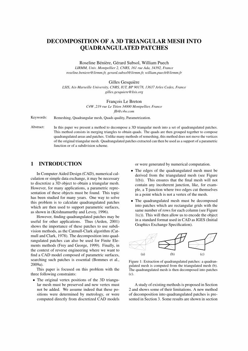
DECOMPOSITION OF A 3D TRIANGULAR MESH INTOQUADRANGULATED PATCHES
Roseline Beniere, Gerard Subsol, William PuechLIRMM, Univ. Montpellier 2, CNRS, 161 rue Ada, 34392, France
[email protected], [email protected], [email protected]
Gilles GesquiereLSIS, Aix-Marseille University, CNRS, IUT, BP 90178, 13637 Arles Cedex, France
Francois Le BretonC4W ,219 rue Le Titien 34000 Montpellier, France
Keywords: Remeshing, Quadrangular mesh, Quads quality, Parametrization.
Abstract: In this paper we present a method to decompose a 3D triangular mesh into a set of quadrangulated patches.This method consists in merging triangles to obtain quads. The quads are then grouped together to composequadrangulated areas and patches. Unlike many methods of remeshing, this method does not move the verticesof the original triangular mesh. Quadrangulated patches extracted can then be used as a support of a parametricfunction or of a subdivision scheme.
1 INTRODUCTION
In Computer Aided Design (CAD), numerical cal-culation or simple data exchange, it may be necessaryto discretize a 3D object to obtain a triangular mesh.However, for many applications, a parametric repre-sentation of these objects must be found. This topichas been studied for many years. One way to solvethis problem is to calculate quadrangulated patcheswhich are then used to support parametric surfaces,as shown in (Krishnamurthy and Levoy, 1996).
However, finding quadrangulated patches may beuseful for other applications. Thus (Arden, 2001)shows the importance of these patches to use subdi-vision methods, as the Catmull-Clark algorithm (Cat-mull and Clark, 1978). The decomposition into quad-rangulated patches can also be used for Finite Ele-ments methods (Frey and George, 1999). Finally, inthe context of reverse engineering where we want tofind a CAD model composed of parametric surfaces,searching such patches is essential (Bommes et al.,2009a).
This paper is focused on this problem with thethree following constraints:• The original vertex positions of the 3D triangu-
lar mesh must be preserved and new vertex mustnot be added. We assume indeed that these po-sitions were determined by metrology, or werecomputed directly from discretized CAD models
or were generated by numerical computation.
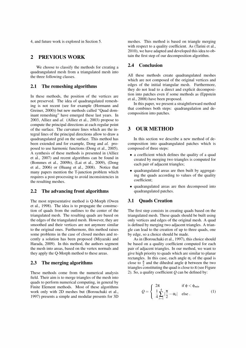
• The edges of the quadrangulated mesh must bederived from the triangulated mesh (see Figure1(b)). This ensures that the final mesh will notcontain any incoherent junction, like, for exam-ple, a T-junction where two edges cut themselvesin a point which is not a vertex of the mesh.
• The quadrangulated mesh must be decomposedinto patches which are rectangular grids with thesame number of rows for each column (see Figure1(c)). This will then allow us to encode the objectin a standard format used in CAD as IGES (InitialGraphics Exchange Specification).
(a) (b) (c)
Figure 1: Extraction of quadrangulated patches: a quadran-gulated mesh is computed from the triangulated mesh (b).The quadrangulated mesh is then decomposed into patches(c).
A study of existing methods is proposed in Section2 and shows some of their limitations. A new methodof decomposition into quadrangulated patches is pre-sented in Section 3. Some results are shown in section
4, and future work is explored in Section 5.
2 PREVIOUS WORK
We choose to classify the methods for creating aquadrangulated mesh from a triangulated mesh intothe three following classes.
2.1 The remeshing algorithms
In these methods, the position of the vertices arenot preserved. The idea of quadrangulated remesh-ing is not recent (see for example (Hormann andGreiner, 2000)) but new methods called “Quad dom-inant remeshing” have emerged these last years. In2003, Alliez and al. (Alliez et al., 2003) propose tocompute the principal directions at each regular pointof the surface. The curvature lines which are the in-tegral lines of the principal directions allow to draw aquadrangulated grid on the surface. This method hasbeen extended and for example, Dong and al. pro-posed to use harmonic functions (Dong et al., 2005).A synthesis of these methods is presented in (Alliezet al., 2007) and recent algorithms can be found in(Bommes et al., 2009b), (Lai et al., 2009), (Donget al., 2006) or (Huang et al., 2008). Notice thatmany papers mention the T-junction problem whichrequires a post-processing to avoid inconsistencies inthe resulting meshes.
2.2 The advancing front algorithms
The most representative method is Q-Morph (Owenet al., 1998). The idea is to propagate the construc-tion of quads from the outlines to the center of thetriangulated mesh. The resulting quads are based onthe edges of the triangulated mesh. However, they aresmoothed and their vertices are not anymore similarto the original ones. Furthermore, this method raisessome problems in the case of closed meshes and re-cently a solution has been proposed (Miyazaki andHarada, 2009). In this method, the authors segmentthe mesh into areas, based on the vertex normals andthey apply the Q-Morph method to these areas.
2.3 The merging algorithms
These methods come from the numerical analysisfield. Their aim is to merge triangles of the mesh intoquads to perform numerical computing, in general byFinite Element methods. Most of these algorithmswork only with 2D meshes but (Borouchaki et al.,1997) presents a simple and modular presents for 3D
meshes. This method is based on triangle mergingwith respect to a quality coefficient. As (Tarini et al.,2010), we have adapted and developed this idea to ob-tain the first step of our decomposition algorithm.
2.4 Conclusion
All these methods create quadrangulated mesheswhich are not composed of the original vertices andedges of the initial triangular mesh. Furthermore,they do not lead to a direct and explicit decomposi-tion into patches even if some methods as (Eppsteinet al., 2008) have been proposed.
In this paper, we present a straightforward methodthat combines both steps: quadrangulation and de-composition into patches.
3 OUR METHOD
In this section we describe a new method of de-composition into quadrangulated patches which iscomposed of three steps:
• a coefficient which defines the quality of a quadcreated by merging two triangles is computed foreach pair of adjacent triangles;
• quadrangulated areas are then built by aggregat-ing the quads according to values of the qualitycoefficient;
• quadrangulated areas are then decomposed intoquadrangulated patches.
3.1 Quads Creation
The first step consists in creating quads based on thetriangulated mesh. These quads should be built usingonly vertices and edges of the original mesh. A quadis defined by merging two adjacent triangles. A trian-gle can lead to the creation of up to three quads, oneby edge, so a choice should be made.
As in (Borouchaki et al., 1997), this choice shouldbe based on a quality coefficient computed for eachpair of adjacent triangles. In our method, we want togive high priority to quads which are similar to planarrectangles. In this case, each angle αi of the quad isclose to π
2 and the dihedral angle φ between the twotriangles constituting the quad is close to π (see Figure2). So, a quality coefficient Q can be defined by:
Q =
2π if φ < φmin
14
4
∑i=1|π2−αi| else . (1)

Thus, this coefficient equals to the average differ-ence between each angle and π
2 . Thus a quad which issimilar to a rectangle will have a coefficient close to0.
φ
α3α4
α2α1
(a)
φ
(b)
Figure 2: (a) The quality coefficient Q is computed with theαi (in red) which are the angles at the quad vertices and thedihedral angle φ (in blue). (b) A large dihedral angle and αifar from π
2 implies a “bad” quality.
Moreover, if the dihedral angle is smaller than atolerance φmin, the quad will be flagged as “incorrect”as in Figure 2(b). Similarly, the quads which have aquality coefficient greater than the tolerance Qmax arenot used to build quadrangulated areas.
3.2 Extraction of QuadrangulatedAreas
The aim of this step is to extract quadrangulated areasusing the quality coefficient presented in the previoussection.
In the first step, to initialize the process, the quadwith the best quality coefficient is chosen. The quad-rangulated area is propagated iteratively by adding ateach step the quad having the best quality coefficientamong the neighborhood of the area in construction.
To find this quad, all potential quads containing anadjacent triangle with an edge of the area outline areexamined. For example, in Figure 3(b), the hatchedtriangles are examined to find the next quad of thequadrangulated area.
Initialization FinalizationStep n
(a) (b) (c)
Figure 3: Iterative extraction of a quadrangulated area: ini-tialization with the quad having the best quality coefficient(a); at each step a quad is added (b); the process stops whenthere is no quad to be added anymore (c)
The propagation is stopped when there is noneighboring triangles anymore, or if the triangle isisolated, or if the neighboring triangles can only cre-ate quads with a quality coefficient larger than Qmax.
When an area is finalized, a new area is initialized,with the quad having the best quality coefficient in thepart of the triangulated mesh not used yet.
Thus from a triangulated mesh, one or more quad-rangulated areas are obtained. For example, only onequadrangulated area has been extracted from the meshin Figure 4. However, all triangles are not used, theleft triangles correspond to isolated triangles or tri-angles which can only lead to quads with a qualitycoefficient larger than Qmax.
Figure 4: Extraction of a quadrangulated area from a trian-gulated mesh. The left triangles do not enable to create aquad having a good quality.
3.3 Decomposition intoQuadrangulated Patches
After the quadrangulated area process, a decomposi-tion into sub-areas which are called “rectilinear poly-gons” begins. For this purpose, a unique position isassigned to each quad. This position consists in a linenumber and a column number which will allow to de-fine the rectilinear polygons.
The quad having the best quality coefficient ischosen in the quadrangulated area. It is labeled withthe position (0, 0). Positions are then propagated toits four neighbors, as in the Figure 5.
(1,1)
(0,1)
(1,0)
(0,1)(0,0) (0,0)
(1,0)
Initialization Step 1 Step n
(a) (b) (c)
(0,-1)
(-1,0)
(0,-1)
(1,-1)
(-1,1)
(0,0)
(-1,-1)(-1,0)
Figure 5: Propagation of the position from the first quad toits neighbors.
When a position is assigned to each quad, a recti-linear polygon is defined using the positions to storethe quads at a correct place in a regular grid.
Creating the rectilinear polygon by assigning a po-sition to each quad in relation to the position of its

neighbors can lead to ambiguities. Thus, the first cho-sen quad in Figure 6 is quad 1, the positions of quads2, 3, 4, 5 and 7 are easily deduced afterward. Theproblem is with the quad 6 which would have boththe position (1, 2) as a neighbor “down” of the quad5 and the position (0, 2) as a neighbor “up” of thequad 7. Furthermore, these two positions are alreadyassigned. There will be another problem with quad11 which has two different positions assigned, one asthe “right” neighbor of quad 8 and one as the “right”neighbor of quad 9.
Such ambiguities occur when the vertices of thequadrangulated area are not of valence 4. In the ex-ample of Figure 6, a valence 3 vertex and a valence 5vertex raise the position attribution problems.
8
9
11
12
10
31 5
2
(1,0)
47
(0,2)
(1,1) (1,2)
6
(??,2)
(0,1)(0,0) Valence 3
Valence 5
Figure 6: Decomposition into “rectilinear polygons” withambiguity positions with the quads 6 and 11.
To avoid this, some tests were added to check iftwo quads have not the same position or if two po-sitions are not assigned to the same quad. If any ofthese cases occur, the rectilinear polygon is decom-posed into two polygons. Thus the quadrangulatedmesh of Figure 6 is decomposed into three rectilinearpolygons as in Figure 7.
Rectilinear polygons containing only one quad arenot kept, like the rectilinear polygon with the singlequad 11 in Figure 7. Its two triangles remain then inthe triangulated mesh.
47 10
(0,0) (0,1) (0,2)(0,3)
12
(0,4)
31 5
6 9(0,0)
(0,1) (0,2)
(1,3)
(0,3)
8
(1,2)
11
(0,0)
2
Figure 7: Decomposing the quadrangulated area into 3 rec-tilinear polygons.
The last step enables to decompose the rectilin-ear polygons into patches, which are rectangular gridshaving the same number of lines for each column.
An iterative method is used to perform this. Ini-tially, the patch with the greatest number of quads iscomputed. The quads of the patch are removed from
the rectilinear polygon. A new patch with the great-est number of quads can be then searched in the newrectilinear polygon. The process is stopped when noquad is left in the rectilinear polygon.
To find the patch with the greatest number ofquads in the rectilinear polygon, each quad of the rec-tilinear polygon is examined. For a quad, all patcheshaving this quad at “left upper corner” are computed.Such a computation of patches is based on browsingalong only two directions(→ and ↓), because the twoother directions were already examined by browsingfrom the previous quads. The longest line (→) fromthe quad is computed. Then, the number of lines hav-ing the same length existing down (↓) is determined.In Figure 8, from the quad q, the longest possible lineincludes five quads, and lines of five quads are pos-sible only on both lines. Finally, the patch with thegreatest number of quads among all patches computedfor each quad is selected.
q
Figure 8: Patch construction in a rectilinear polygon fromquad q.
Nevertheless, this method does not guarantee thatthe number of patches is minimal at the end of theprocess. Thus in Figure 9, extracting initially thepatch with the greatest number of quads (hatchedin blue), the rectilinear polygon is decomposed intothree patches whereas only two would be necessaryto cover the whole it.
Figure 9: Case where our method does not give an optimalcovering: we obtain three patches while two would be suf-ficient.
However we decide to keep this simple approacheven if some methods exist to optimize the number ofpatches dissecting the rectilinear polygon as for ex-ample in (Soltan and Gorpinevich, 1993).
Finally, the three steps lead to three quadrangu-lated patches, shown in Figure 10. Notice that a partof the triangulated mesh is not used. This is due toisolated triangles, quads of which Q > Qmax, or quads

Quadrangle with
Triangle isolated
Patch extracted 1Patch extracted 2Patch extracted 3
Quadrangle isolated
bad quality
Figure 10: Decomposition into quadrangulated patchesfrom a triangulated mesh.
isolated during the creation of the rectilinear poly-gons.
4 EXPERIMENTAL RESULTS
Our method has been implemented in the soft-ware 3D Shop of the C4W1. This software gives ef-ficient development tools for 3D modeling and visu-alization2.
Figures 11 (Bunny), 12 (Face), 13 (Fandisk), 14(Smurf 3), 15 (CubeCylinders) and 16 (Torus) showsome results obtained on triangulated meshes comingfrom various sources as CAD for CubeCylinders andTorus, infography for Face and Smurf or 3D digitiza-tion for Bunny and Fandisk. Each result is constitutedof the extracted quadrangulated patches (in blue) andof remaining triangles (in green). Table 1 gives foreach mesh, the number of triangles, the number of ex-tracted patches and the covering percentage that cor-responds to the percentage of original triangles cov-ered by quadrangulated patches.
On Bunny, Face and Fandisk, the quadrangulatedpatches cover a large part of the mesh. That enables toobtain a reduction factor between the triangle numberand the patch number which reaches 30. Effectivecoding in CAD format based on the face concept (likeIGES) can be envisaged.
Nevertheless, some patches have a small size andto cover 80% of the 5,590 triangles of the mesh Face,335 patches are used. The decomposition of someareas into small patches comes from a few triangles
1C4W is a company which develops innovativeCAD solutions and support this Ph.D. Thesis work(http://www.c4w.com)
2www.c4w.com/3d-cad-software.html3http://www.3dvalley.com/3d-models/characters
or quads which are isolated and lead to decompose alarge potential patch into several smaller ones.
To avoid this and to create larger patches, we ex-perimented different values for the parameters Qmaxand φmin because these thresholds may limit the prop-agation process during the construction of quadran-gulated areas. The values Qmax and φmin were em-pirically fixed to respectively π
2 and 5π
6 , for all testsexcept on the mesh Smurf.
For the mesh Smurf in Figure 14, the value Qmaxis fixed successively to π
2 , π and 2π. The thresholdφmin has been modified in the last case to 2π: in thiscase, all potential quads have been then considered.Figure 14, with the mesh Smurf, which have 64,320triangles, shows the patches evolution. Some areaslike the eyes, the hands or the shoulder contain manytriangles which are not used. The number of unusedtriangles decreases when the thresholds are modified.The number of patches decreases too and the cover-ing percentage increases. These new results arisesbecause the patch shapes can change dramatically byadding only one new quad as in Figure 14.
However, it is necessary to take care of the quad-rangulated patches which can then contain somequads with low quality. This may engender problemsto some applications, for example in numerical calcu-lation. Moreover even when we set both thresholdsto 2π, there are always left triangles. Indeed, thereare triangles isolated in the quadrangulated areas con-struction and quads isolated in the rectilinear poly-gons construction. On the quadrangulated areas con-taining many vertices which are not valence 4, thesequads can very be numerous and may lead to lots ofsmall rectilinear polygons.
Finally, we have tested our method on 3D simpleobjects, like the union of a cube and two cylinders(figure 15). The result of the decomposition fromthe mesh CubeCylinders, is satisfying because morethan 95% of the mesh is covered with only 21 patcheswhich corresponds to a reduction factor of more than130. However in the case of a simply torus like Figure16, our method finds one patch which covers 100%of the object. The method is really adapted to CADmeshes composed by simple primitives. In fact ourmethod has good result on the CAD mesh becausethe discretization of the mesh has often a first step ofquadrangulation which was then triangulated.
5 CONCLUSION ANDPERSPECTIVES
In this paper, we have presented a method en-abling to decompose 3D triangulated meshes into
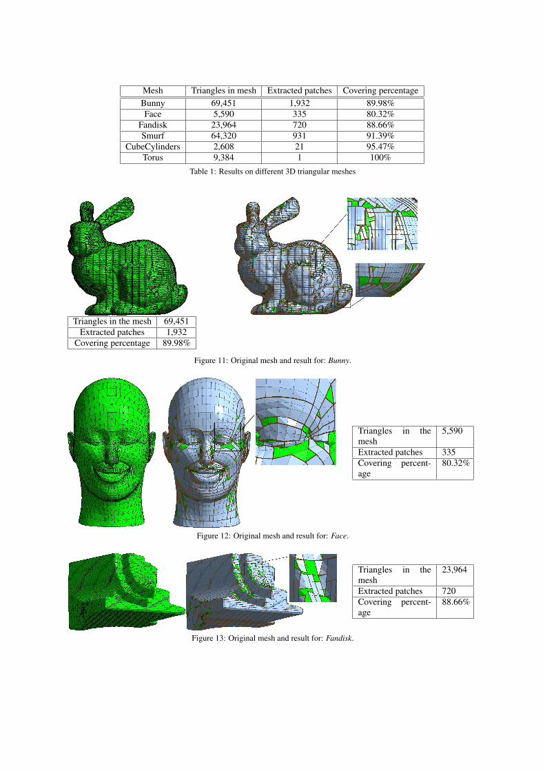
Mesh Triangles in mesh Extracted patches Covering percentageBunny 69,451 1,932 89.98%Face 5,590 335 80.32%
Fandisk 23,964 720 88.66%Smurf 64,320 931 91.39%
CubeCylinders 2,608 21 95.47%Torus 9,384 1 100%
Table 1: Results on different 3D triangular meshes
Triangles in the mesh 69,451Extracted patches 1,932
Covering percentage 89.98%
Figure 11: Original mesh and result for: Bunny.
Triangles in themesh
5,590
Extracted patches 335Covering percent-age
80.32%
Figure 12: Original mesh and result for: Face.
Triangles in themesh
23,964
Extracted patches 720Covering percent-age
88.66%
Figure 13: Original mesh and result for: Fandisk.
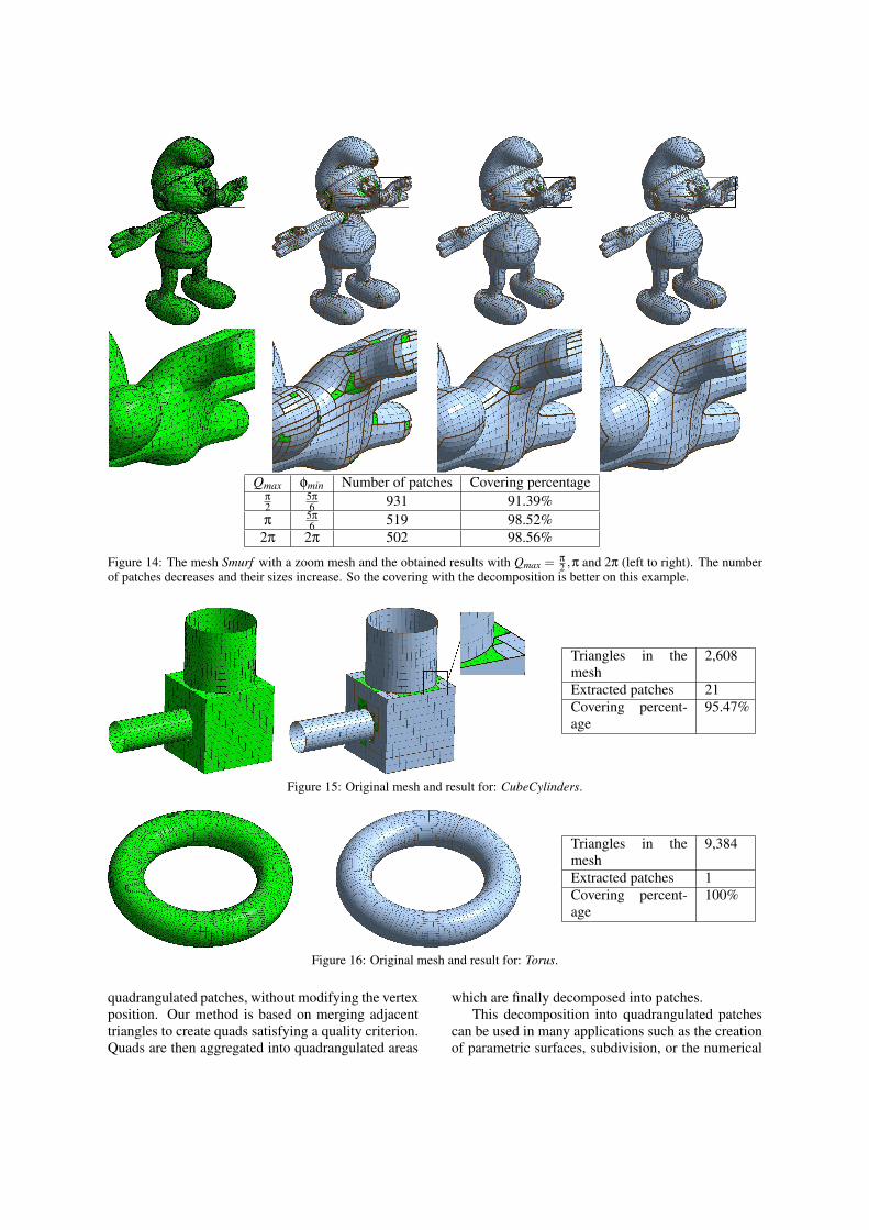
Qmax φmin Number of patches Covering percentageπ
25π
6 931 91.39%π
5π
6 519 98.52%2π 2π 502 98.56%
Figure 14: The mesh Smurf with a zoom mesh and the obtained results with Qmax = π
2 ,π and 2π (left to right). The numberof patches decreases and their sizes increase. So the covering with the decomposition is better on this example.
Triangles in themesh
2,608
Extracted patches 21Covering percent-age
95.47%
Figure 15: Original mesh and result for: CubeCylinders.
Triangles in themesh
9,384
Extracted patches 1Covering percent-age
100%
Figure 16: Original mesh and result for: Torus.
quadrangulated patches, without modifying the vertexposition. Our method is based on merging adjacenttriangles to create quads satisfying a quality criterion.Quads are then aggregated into quadrangulated areas
which are finally decomposed into patches.This decomposition into quadrangulated patches
can be used in many applications such as the creationof parametric surfaces, subdivision, or the numerical

calculation.Comparison with other existing methods, quad-
rangulation and decomposition ones, should be made.The proposed method can be improved in each
of its three steps. First, defining other quality coef-ficients could improve the extraction of quadrangu-lated areas. According to computed parameters on thecomplete mesh, averages of angles computed for allthe vertices seems to be a good way. The constraintscan also be adjusted according to its local “shape”, byrelaxing for example the constraints of the dihedralangle in the most curved part of the object.
Other propagation algorithm for the creation ofquadrangulated areas, can be proposed or the researchof rectilinear polygons can be optimized. The objec-tive of these two modifications would be to decreasethe number of isolated triangles.
Another possible improvement would be to avoidthe step of extracting rectilinear polygons, and to de-compose directly quadrangulated areas into patches.This would enable to optimize globally the processand to decrease the number of patches constituted bya single quad which do not belong to the final decom-position.
A last step of patch merging could be added andit would enable to group two patches in only one, in-tegrating if it is necessary adjacent isolated quads. Ifit does not improve the percentage of covering, it willdecrease the number of patches of the decomposition.
Finally, some feature lines could be used, asthe “ridge lines” to define potential boundaries forpatches. The decomposition would be then optimizedusing this knowledge as it is done in several remesh-ing algorithms.
ACKNOWLEDGEMENTS
The authors want to thank the C4W company and theAssociation Nationale de la Recherche et de la Tech-nologie (ANRT) for their financial support.
REFERENCES
Alliez, P., Cohen-Steiner, D., Devillers, O., Lvy, B., andDesbrun, M. (2003). Anisotropic polygonal remesh-ing. ACM Transactions on Graphics, SIGGRAPH2003 Conference Proceedings, 22(3):485–493.
Alliez, P., Ucelli, G., Gotsman, C., and Attene, M.(2007). Recent advances in remeshing of surfaces.In Shape Analysis and Structuring, pages 53–82.Springer Berlin Heidelberg.
Arden, G. (2001). Approximation Properties of SubdivisionSurfaces. PhD thesis, University of Washington.
Bommes, D., Vossemer, T., and Kobbelt, L. (2009a). Quad-rangular parametrization for reverse engineering. Lec-ture Notes in Computer Science (to appear).
Bommes, D., Zimmer, H., and Kobbelt, L. (2009b).Mixed-integer quadrangulation. ACM Trans. Graph.,28(3):1–10.
Borouchaki, H., Frey, P. J., and George, P. L. (1997). Mail-lage de surfaces parametriques. Partie III: Elementsquadrangulaires. 325(1):551–556.
Catmull, E. and Clark, J. (1978). Recursively generatedB-spline surfaces on arbitrary topological meshes.Computer-Aided Design, 10(6):350–355.
Dong, S., Bremer, P.-T., Garland, M., Pascucci, V., andHart, J. C. (2006). Spectral surface quadrangulation.ACM Trans. Graph., 25(3):1057–1066.
Dong, S., Kircher, S., and Garland, M. (2005). Har-monic functions for quadrilateral remeshing of arbi-trary manifolds. Computer Aided Geometry Design,Special Issue on Geometry Processing, 22(5):392–423.
Eppstein, D., Goodrich, M. T., Kim, E., and Tamstorf, R.(2008). Motorcycle graphs : Canonical mesh parti-tioning. Comput. Graph. Forum, 27(5):1477–1486.
Frey, P. J. and George, P. L. (1999). Maillage : Applicationsaux elements finis.
Hormann, K. and Greiner, G. (2000). Quadrilateral remesh-ing. In Girod, B., Greiner, G., Niemann, H., and Sei-del, H.-P., editors, Proceedings of Vision, Modeling,and Visualization 2000, pages 153–162, Saarbrucken,Germany.
Huang, J., Zhang, M., Ma, J., Liu, X., Kobbelt, L., and Bao,H. (2008). Spectral quadrangulation with orientationand alignment control. ACM Trans. Graph., 27(5):1–9.
Krishnamurthy, V. and Levoy, M. (1996). Fitting smoothsurfaces to dense polygon meshes. In Proceedings ofSIGGRAPH 96, pages 313–324.
Lai, Y.-K., Kobbelt, L., and Hu, S.-M. (2009). Featurealigned quad dominant remeshing using iterative lo-cal updates. Computer-Aided Design (to appear).
Miyazaki, R. and Harada, K. (2009). Transformation ofa closed 3D triangular mesh to a quadrilateral meshbased on feature edges. IJCSNS International Journalof Computer Science and Network Security, 9(5).
Owen, S. J., Staten, M. L., Canann, S. A., and Saigal, S.(1998). Advancing front quadrilateral meshing usingtriangle transformations. 7th International MeshingRoundtable, pages 409–428.
Soltan, V. and Gorpinevich, A. (1993). Minimum dissec-tion of a rectilinear polygon with arbitrary holes intorectangles. Discrete and Computational Geometry,9(1):57–59.
Tarini, M., Pietroni, N., Cignoni, P., Panozzo, D., andPuppo, E. (2010). Practical quad mesh simplification.Computer Graphics Forum, 29(2):To appear.
Copyright © 2022 FDOKUMEN