Durkin’s Propagation Model Based on Triangular Irregular Network Terrain
9
Durkin’s Propagation Model Based on Triangular Irregular Network Terrain Marija Vuckovik, Dimitar Trajanov and Sonja Filiposka University Ss Cyril and Methodius, Faculty of Electrical Engineering and Information Technology, Karpos 2 bb, Skopje, Macedonia, {marija.vuckovic,mite,filipos}@feit.ukim.edu.mk Abstract. Propagation models that are commonly used in assessing the performances of ad hoc networks, take into account the mechanisms of reflection, diffraction and scattering on the ground. However, it must not be forgotten that the communication between devices is usually carried out in irregular terrain, so it's necessary to use the terrain profile in order to determine the signal coverage. In this paper we layout the extension of the Durkin’s propagation model using Triangular Irregular Network (TIN) based terrain. The verification of the proposed propagation model is done by comparing the results with the ones obtained with a SRTM map used in the Radio Mobile software. Keywords: TIN Terrain, Durkin’s propagation model, wireless networks 1 Introduction The dynamics of life imposes the need for mobile communication, while the technical development allows permanent connection between people in different environments. In the last decade in order to achieve a greater degree of freedom and maximized use of the capabilities of wireless networks there is increased interest in ad hoc networks research [1]. The main characteristic of the ad hoc networks is that they can be established anywhere, which means that they do not rely on any infrastructure. The wireless mobile nodes which are part of the network are the main creators of communication in the network, because of their capability of self-organization, which leads to a decentralized network [2]. The network is called ad hoc because each node transmits data to another node, and the decision for forwarding is made dynamically depending on the connectivity of the network. In order to establish communication, ad hoc networks allow for multihop transmission of data between nodes outside of their direct radio range. This kind of communication is controlled by a special ad hoc routing protocol that is concerned with discovery, maintenance and proper use of the multihop paths [3]. The main problem when determining the performance of networks is that usually the irregularities of the terrain that exist in real environments are left out. This leads to poor performance evaluation of the networks. Most of the simulators provide modeling and evaluation of performance of the networks on a two-dimensional terrain on which the network is set, not taking into account the elevation of the terrain which
Transcript of Durkin’s Propagation Model Based on Triangular Irregular Network Terrain
Durkin’s Propagation Model Based on Triangular Irregular Network Terrain
Marija Vuckovik, Dimitar Trajanov and Sonja Filiposka
University Ss Cyril and Methodius, Faculty of Electrical Engineering and Information Technology, Karpos 2 bb, Skopje, Macedonia,
{marija.vuckovic,mite,filipos}@feit.ukim.edu.mk
Abstract. Propagation models that are commonly used in assessing the performances of ad hoc networks, take into account the mechanisms of reflection, diffraction and scattering on the ground. However, it must not be forgotten that the communication between devices is usually carried out in irregular terrain, so it's necessary to use the terrain profile in order to determine the signal coverage. In this paper we layout the extension of the Durkin’s propagation model using Triangular Irregular Network (TIN) based terrain. The verification of the proposed propagation model is done by comparing the results with the ones obtained with a SRTM map used in the Radio Mobile software.
Keywords: TIN Terrain, Durkin’s propagation model, wireless networks
1 Introduction
The dynamics of life imposes the need for mobile communication, while the technical development allows permanent connection between people in different environments. In the last decade in order to achieve a greater degree of freedom and maximized use of the capabilities of wireless networks there is increased interest in ad hoc networks research [1]. The main characteristic of the ad hoc networks is that they can be established anywhere, which means that they do not rely on any infrastructure. The wireless mobile nodes which are part of the network are the main creators of communication in the network, because of their capability of self-organization, which leads to a decentralized network [2]. The network is called ad hoc because each node transmits data to another node, and the decision for forwarding is made dynamically depending on the connectivity of the network. In order to establish communication, ad hoc networks allow for multihop transmission of data between nodes outside of their direct radio range. This kind of communication is controlled by a special ad hoc routing protocol that is concerned with discovery, maintenance and proper use of the multihop paths [3].
The main problem when determining the performance of networks is that usually the irregularities of the terrain that exist in real environments are left out. This leads to poor performance evaluation of the networks. Most of the simulators provide modeling and evaluation of performance of the networks on a two-dimensional terrain on which the network is set, not taking into account the elevation of the terrain which
2 Marija Vuckovik, Dimitar Trajanov and Sonja Filiposka
has a major role in enabling communication between nodes in the network. Hence, there is obvious need for using three-dimensional terrain modeled in space in order to provide realistic and accurate measurement of networks performance.
In order to make our performance observations more realistic, we decided to use a propagation model that incorporates the nature of propagation over irregular terrain and losses caused by obstacles in the radio path. In our previous work, we made an implementation of the Durkin’s model as an extension for the NS-2 simulator [4], thus allowing us to conduct more realistic simulation scenarios and analyze the way the terrain profile affects the ad hoc network performances. This implementation was based on a Digital Elevation Model (DEM) terrain which is a type of representation for irregular terrain included in the original Durkin’s model [12].
The DEM files store elevation information (integer values) for a number of positions on Earth's surface at regular spatial intervals (divided by geographic latitude or longitude) [5][6]. However, this model includes a huge number of data that need to be stored in one file. However, the Triangulated Irregular Network (TIN) file can be used as replacement for the DEM file. It also stores digital data structures which are used in terrain files for the representation of surfaces. TIN is a vector-based representation of the surface, which is obtained by improperly allocated points and lines in three-dimensional system (x, y, z), organized into a network of triangles that do not overlap [7]. This model is derived from the elevation data stored in raster-based models, such as DEM. In this paper, we present the implementation of the Durkin’s model based on terrain data that is read from a TIN file. The model implementation is made so that it takes advantage of the way the data is stored in the TIN model eliminating the need to asses every point along the line of sight.
2 TIN Terrain
The model of a network of irregular triangles represents an alternative to the regular raster DEM files used in a range of geographic information systems [7] [8]. This model is developed in the early 70s of the last century as a simple way to create an area of irregular points in space. However, its commercial use began in the 80s of last century.
The network of irregular triangles (Triangular Irregular Network - TIN) is a digital data structure used in geographic information systems for representation of surfaces. The advantage of the TIN model compared to the DEM alternative is in the mapping and analysis of the TIN model points that are randomly distributed with an algorithm that determines which points are the most necessary to obtain more accurate possible representation of the ground. Therefore, the input data is flexible and the number of points that should be saved is less than the raster DEM.
The TIN model is composed of a triangular network of points which are called concentrators with three-dimensional coordinates, connected with links to form a mosaic of triangles. In areas with small variation of the height of the surface the points are widely installed, while in areas where we find more intense variation of the height of the surface the density of points is greater.
Durkin’s Propagation Model Based on Triangular Irregular Network Terrain 3
2.1 Creation of TIN Terrain
TIN is created from point-concentrators, which are actually points with heights collected from various sources. Usually TIN is created from digitized contours, raster with z values, collections of data structures or other operations on the TIN. The triangulation to obtain triangles known as surfaces is performed on these entry points, called nodes and lines known as edges. Each area is part of the plane in three-dimensional space and there is no intersection between the defined areas. In this paper, the TIN terrain file is obtained using a DEM data file.
We use the LandSerf software [9] in order to generate the TIN terrain data. LandSerf is a software that enables visualization and analysis of spatial data. It was firstly designed to be used with surfaces and elevation models, but now it works with many types of terrain data. Currently supports raster DEM, vector TIN and contours.
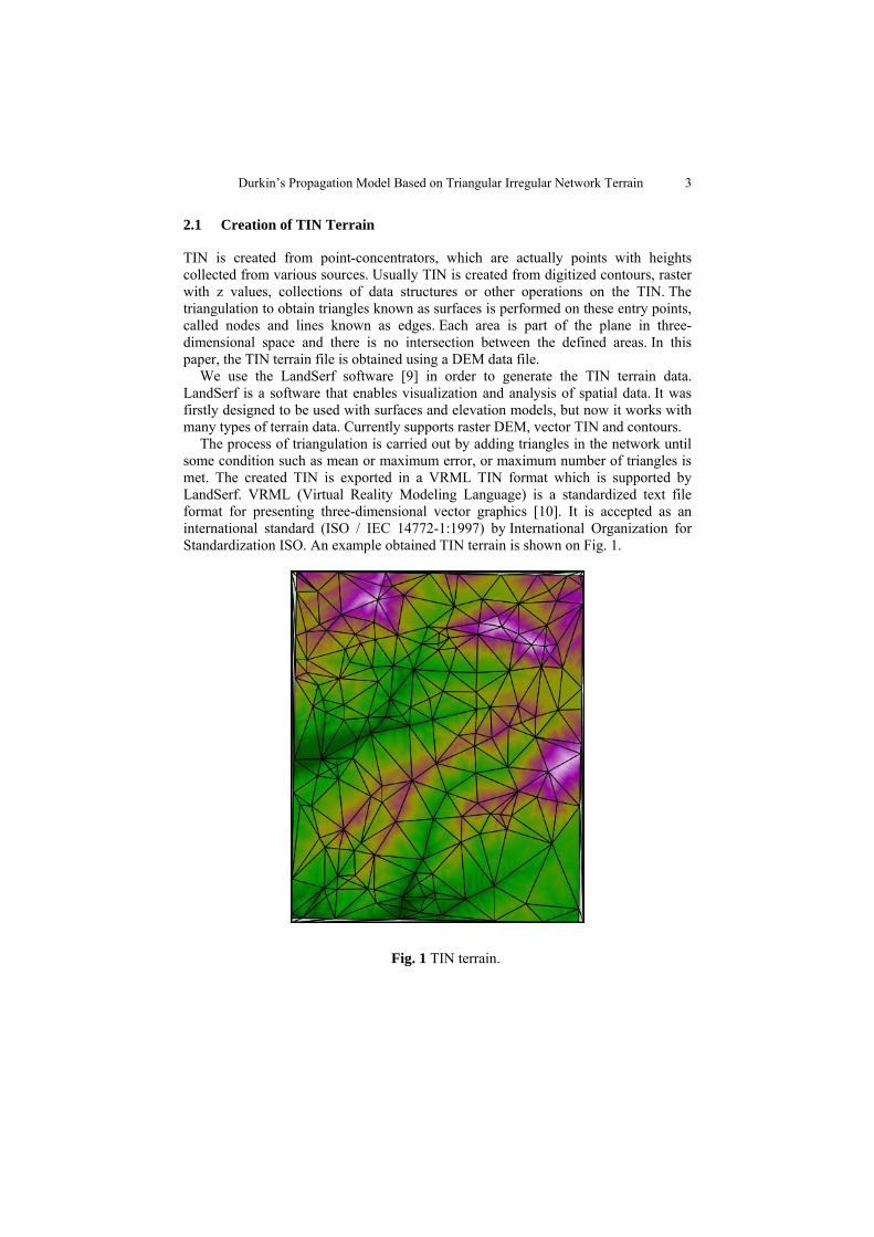
The process of triangulation is carried out by adding triangles in the network until some condition such as mean or maximum error, or maximum number of triangles is met. The created TIN is exported in a VRML TIN format which is supported by LandSerf. VRML (Virtual Reality Modeling Language) is a standardized text file format for presenting three-dimensional vector graphics [10]. It is accepted as an international standard (ISO / IEC 14772-1:1997) by International Organization for Standardization ISO. An example obtained TIN terrain is shown on Fig. 1.
Fig. 1 TIN terrain.
4 Marija Vuckovik, Dimitar Trajanov and Sonja Filiposka
3 Durkin’s model
The main goal of the Durkin’s model is to predict the median transmission loss using the path geometry of the terrain profile [11]. The original execution of the path loss estimation consists of two parts. The first part consists of loading a topographic DEM file which is turned into a topographical database and reconstruction of the ground profile information along the path between the transmitter and the receiver (T-R). The second part of the algorithm calculates the expected path loss along that path.
The first step of the algorithm is to decide whether a line-of-sight (LOS) path exists between T-R. This can be done by computing the difference between the height of the line joining T-R antennas and the height of the ground profile in 3D space. If any difference is found to be positive, it is concluded that a LOS path does not exists, otherwise, a LOS path exists. Assuming the path has a clear LOS, the next step is to see whether first Fresnel zone clearance is achieved. If the Fresnel zone of the radio path is unobstructed, then the resulting loss mechanism is approximately that of free space. But, if there is any kind of obstruction, then the Fresnel- Kirchoff diffraction parameter v must be calculated as in [11].
1 2
1 2
2( )d dv h
d dλ+
= (1)
where h is the relative height of the obstruction, d1 and d2 are distanced from the obstacle to the transmitter and the receiver, respectively, and λ is the radio signal wavelength. In practice, graphical or numerical solutions are relied upon to compute the diffraction gain.
If the terrain profile failed the first Fresnel zone test then there are two possibilities: Non-LOS and LOS, but with inadequate first Fresnel zone clearance.
For both of these cases, the program calculates the free space loss and the received power using the plane earth propagation equation known as two ray ground model. The algorithm then selects the smaller value as the appropriate received power for the terrain profile. If the profile is LOS with inadequate first Fresnel zone clearance there is additional diffraction loss that is added (in dB) to the appropriate received power according to the approximate solution given by Lee as in [11].
After implementing the original Durkin’s model we decided to make a new implementation of the Durkin’s model which will be based on the original properties and calculations, but it will work with a TIN based terrain.
3.1 Durkin’s model for TIN terrain
The algorithm for Durkin’s model for TIN terrain was created based on knowledge of geometry and solid geometry and uses only simple geometric calculations corresponding to three-dimensional space. Instead of checking every point along and around the LOS, we now work with the LOS and the triangle planes defined in the TIN file. In order to avoid the complexity of the calculations within the algorithm instead of trying to calculate the intersection between the Fresnel ellipsoid and a
Durkin’s Propagation Model Based on Triangular Irregular Network Terrain 5
triangle from the terrain, the test for checking the clearance of the Fresnel zones is based solely on the calculation of the radius of the first Fresnel zone at a given point in the ellipsoid.
This algorithm consists of several steps: • Check whether there is a point of intersection of LOS with a given triangle • If there is an intersection then find the maximum normal distance from the point
of intersection to each side of the triangle • If there is no intersection then calculate the shortest distance from the normal line
of the transmitter and receiver to each side of the triangle • Calculate the diffraction parameter v.
First, the algorithm checks if there is an intersection between the line of the transmitter and receiver with a given triangle. If there is a point of intersection, that means that there is no line of sight, and the next step of the algorithm is calculation of the diffraction parameter v. In order to calculate the diffraction parameter for the knife-edge diffraction, it is necessary to determine the maximum distance from the point of intersection to the sides of a triangle and the radius of the first Fresnel zone at the point of intersection. If there is no point of intersection, then there is a LOS between T-R. But that does not imply that there is a clear first Fresnel zone. At this stage the minimum distance between the line which connects the transmitter and receiver, and each side of the triangle should be calculated in order to find the worst case of penetration into the zone. Then the radius of the first Fresnel zone at the point of the segment from the transmitter to the receiver that is closest to the side of a triangle is calculated. If the difference between distance and radius of first Fresnel zone is negative, it means that there is an obstacle in the first Fresnel zone and the obtained difference is used for the calculation of the diffraction parameter v. If this is not the case, then we have a clear first Fresnel zone.
The calculation of the power of the received signal is carried out according to standard procedure described in Durkin's model.
4 Model verification
Radio Mobile is a free and powerful tool for drawing RF patterns and predicting the performance of radio systems [13]. By using freely available data it can create gray, X-Ray and virtual maps painted in the colors of the rainbow. In this paper, we use it as a tool for verification of our implementation of the Durkin’s model based on the TIN file format by performing a comparison of the results obtained from our model and the results obtained with Radio Mobile for the same real terrain. Radio Mobile uses SRTM map for examination. SRTM (Shuttle Radar Topography Mission) produces the fullest, elevation digital model of Earth with the highest resolution.
We used the 802.11b network with 2,4 GHz. We observed a single polar coverage, where the transmitter was positioned in one point, and all other nodes were distributed over the terrain. We used two real terrain areas derived from SRTM map which are shown on Fig. 2. The transmitter was being placed at various locations. The TIN terrains that comply to the area bordered with SRTM map were generated with LandSerf software, from the appropriate DEM terrains set as a base.
6 Marija Vuckovik, Dimitar Trajanov and Sonja Filiposka
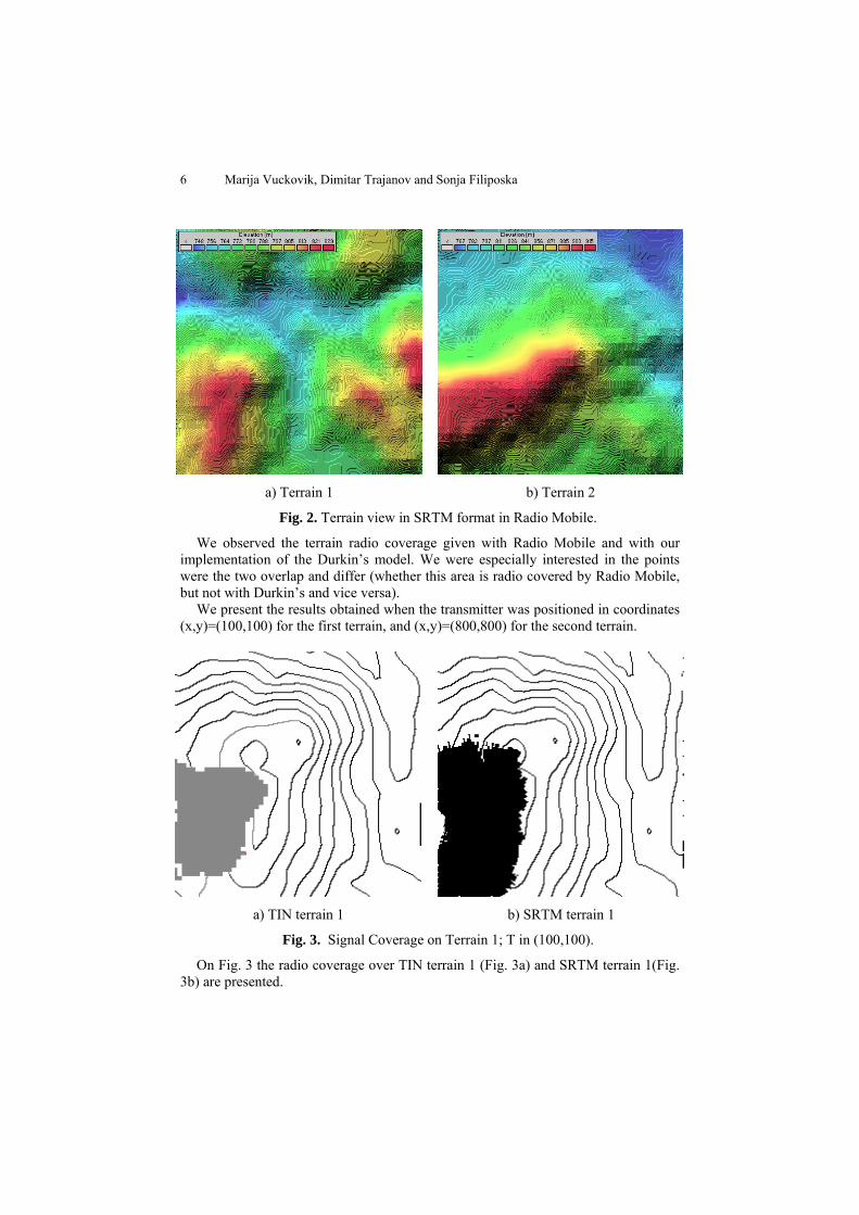
a) Terrain 1 b) Terrain 2
Fig. 2. Terrain view in SRTM format in Radio Mobile.
We observed the terrain radio coverage given with Radio Mobile and with our implementation of the Durkin’s model. We were especially interested in the points were the two overlap and differ (whether this area is radio covered by Radio Mobile, but not with Durkin’s and vice versa).
We present the results obtained when the transmitter was positioned in coordinates (x,y)=(100,100) for the first terrain, and (x,y)=(800,800) for the second terrain.
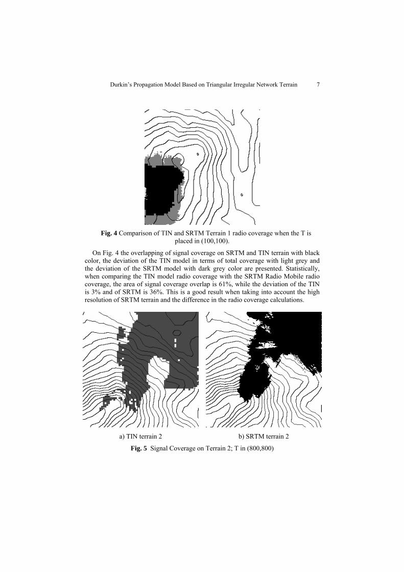
a) TIN terrain 1 b) SRTM terrain 1
Fig. 3. Signal Coverage on Terrain 1; T in (100,100).
On Fig. 3 the radio coverage over TIN terrain 1 (Fig. 3a) and SRTM terrain 1(Fig. 3b) are presented.
Durkin’s Propagation Model Based on Triangular Irregular Network Terrain 7
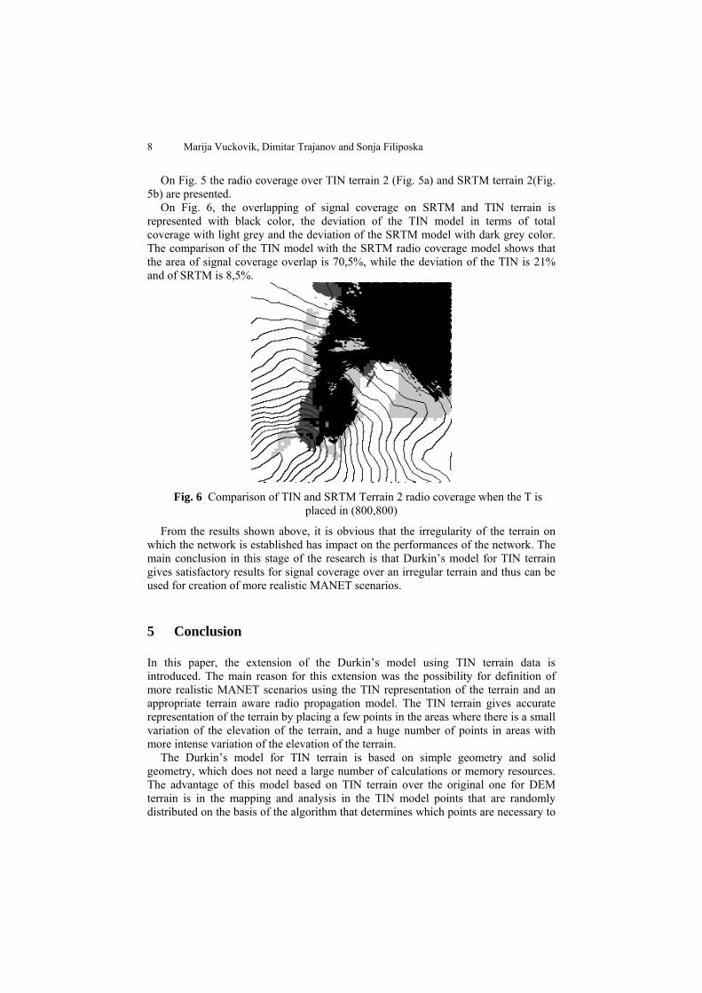
Fig. 4 Comparison of TIN and SRTM Terrain 1 radio coverage when the T is
placed in (100,100).
On Fig. 4 the overlapping of signal coverage on SRTM and TIN terrain with black color, the deviation of the TIN model in terms of total coverage with light grey and the deviation of the SRTM model with dark grey color are presented. Statistically, when comparing the TIN model radio coverage with the SRTM Radio Mobile radio coverage, the area of signal coverage overlap is 61%, while the deviation of the TIN is 3% and of SRTM is 36%. This is a good result when taking into account the high resolution of SRTM terrain and the difference in the radio coverage calculations.
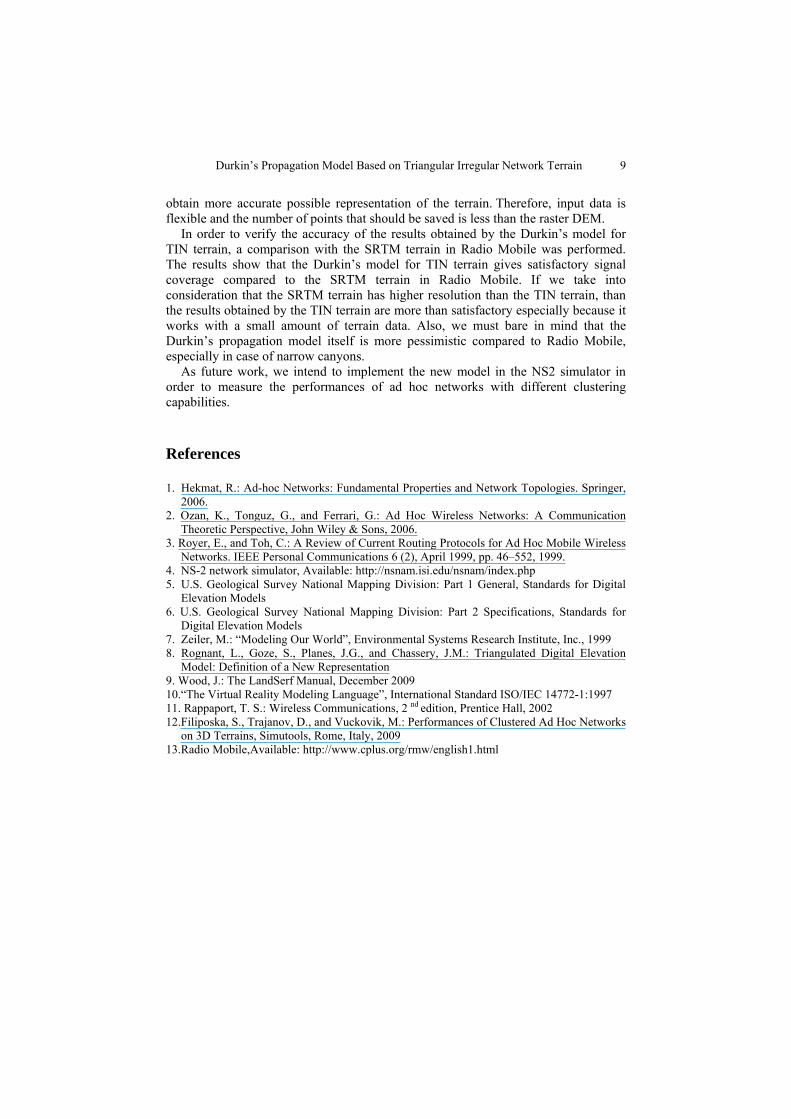
a) TIN terrain 2 b) SRTM terrain 2 Fig. 5 Signal Coverage on Terrain 2; T in (800,800)
8 Marija Vuckovik, Dimitar Trajanov and Sonja Filiposka
On Fig. 5 the radio coverage over TIN terrain 2 (Fig. 5a) and SRTM terrain 2(Fig. 5b) are presented.
On Fig. 6, the overlapping of signal coverage on SRTM and TIN terrain is represented with black color, the deviation of the TIN model in terms of total coverage with light grey and the deviation of the SRTM model with dark grey color. The comparison of the TIN model with the SRTM radio coverage model shows that the area of signal coverage overlap is 70,5%, while the deviation of the TIN is 21% and of SRTM is 8,5%.
Fig. 6 Comparison of TIN and SRTM Terrain 2 radio coverage when the T is
placed in (800,800)
From the results shown above, it is obvious that the irregularity of the terrain on which the network is established has impact on the performances of the network. The main conclusion in this stage of the research is that Durkin’s model for TIN terrain gives satisfactory results for signal coverage over an irregular terrain and thus can be used for creation of more realistic MANET scenarios.
5 Conclusion
In this paper, the extension of the Durkin’s model using TIN terrain data is introduced. The main reason for this extension was the possibility for definition of more realistic MANET scenarios using the TIN representation of the terrain and an appropriate terrain aware radio propagation model. The TIN terrain gives accurate representation of the terrain by placing a few points in the areas where there is a small variation of the elevation of the terrain, and a huge number of points in areas with more intense variation of the elevation of the terrain.
The Durkin’s model for TIN terrain is based on simple geometry and solid geometry, which does not need a large number of calculations or memory resources. The advantage of this model based on TIN terrain over the original one for DEM terrain is in the mapping and analysis in the TIN model points that are randomly distributed on the basis of the algorithm that determines which points are necessary to
Durkin’s Propagation Model Based on Triangular Irregular Network Terrain 9
obtain more accurate possible representation of the terrain. Therefore, input data is flexible and the number of points that should be saved is less than the raster DEM.
In order to verify the accuracy of the results obtained by the Durkin’s model for TIN terrain, a comparison with the SRTM terrain in Radio Mobile was performed. The results show that the Durkin’s model for TIN terrain gives satisfactory signal coverage compared to the SRTM terrain in Radio Mobile. If we take into consideration that the SRTM terrain has higher resolution than the TIN terrain, than the results obtained by the TIN terrain are more than satisfactory especially because it works with a small amount of terrain data. Also, we must bare in mind that the Durkin’s propagation model itself is more pessimistic compared to Radio Mobile, especially in case of narrow canyons.
As future work, we intend to implement the new model in the NS2 simulator in order to measure the performances of ad hoc networks with different clustering capabilities.
References
1. Hekmat, R.: Ad-hoc Networks: Fundamental Properties and Network Topologies. Springer, 2006.
2. Ozan, K., Tonguz, G., and Ferrari, G.: Ad Hoc Wireless Networks: A Communication Theoretic Perspective, John Wiley & Sons, 2006.
3. Royer, E., and Toh, C.: A Review of Current Routing Protocols for Ad Hoc Mobile Wireless Networks. IEEE Personal Communications 6 (2), April 1999, pp. 46–552, 1999.
4. NS-2 network simulator, Available: http://nsnam.isi.edu/nsnam/index.php 5. U.S. Geological Survey National Mapping Division: Part 1 General, Standards for Digital
Elevation Models 6. U.S. Geological Survey National Mapping Division: Part 2 Specifications, Standards for
Digital Elevation Models 7. Zeiler, M.: “Modeling Our World”, Environmental Systems Research Institute, Inc., 1999 8. Rognant, L., Goze, S., Planes, J.G., and Chassery, J.M.: Triangulated Digital Elevation
Model: Definition of a New Representation 9. Wood, J.: The LandSerf Manual, December 2009 10.“The Virtual Reality Modeling Language”, International Standard ISO/IEC 14772-1:1997 11. Rappaport, T. S.: Wireless Communications, 2 nd edition, Prentice Hall, 2002 12.Filiposka, S., Trajanov, D., and Vuckovik, M.: Performances of Clustered Ad Hoc Networks
on 3D Terrains, Simutools, Rome, Italy, 2009 13.Radio Mobile,Available: http://www.cplus.org/rmw/english1.html