
STUDY, DESIGN AND OPTIMIZATION OF TRIANGULAR FINS
8
IJIRST –International Journal for Innovative Research in Science & Technology| Volume 1 | Issue 12 | May 2015 ISSN (online): 2349-6010 All rights reserved by www.ijirst.org 47 Study, Design and Optimization of Triangular Fins Abel Jacob Gokul Chandrashekhara Department of Mechanical Engineering Department of Mechanical Engineering Saintgits College of Engineering, Kottayam, India Saintgits College of Engineering, Kottayam, India Jerin George Jubin George Department of Mechanical Engineering Department of Mechanical Engineering Saintgits College of Engineering, Kottayam, India Saintgits College of Engineering, Kottayam, India Abstract Extended surfaces commonly known as fins, offer an economical and trouble free solutions in many situations demanding natural convection heat transfer. Heat sinks in the form of fin arrays horizontal and vertical surfaces used in variety of engineering applications, studies of heat transfer and fluid flow associated with such arrays are of considerable engineering significance. The main controlling variable generally available to designer is geometry of fin arrays. Considering the above fact natural convection heat transfer from triangular fin arrays have been investigated experimentally and theoretically. Fin optimization is useful to go through the exercise of optimizing a fin in order to achieve the high rate of heat transfer per volume of fin material. The result of this optimization provides general guidelines relative to the dimensionless characteristics of a well- designed fin. Keywords: effectiveness, computational fluid dynamics _______________________________________________________________________________________________________ I. INTRODUCTION Fins are extended surfaces often used to enhance the rate of heat transfer from the engine surface. Fins are generally used on the surface which has very low heat transfer coefficient. Straight fins are one of the most common choices for enhancing better heat transfer from the flat surfaces. The rate of heat flow per unit surface area is directly proportional to the added heat conducting surface. The major heat transfer takes place in two modes i. e. by conduction or by convection. Heat transfer through fin to the surface of the fin takes place through conduction whereas from surface of the fin to the surroundings takes place by convection. Further heat transfer may be by natural convection or by forced convection. Due to the high demand for lightweight, compact, and economical fins, the optimization of the fin size is of great importance. The removal of excessive heat from system components is essential to avoid the damaging effects of burning or overheating. Therefore, the enhancement of heat transfer is an important subject in thermal engineering. The study of convective heat transfer originates from human’s desire to understand and predict the amount of energy which is observed through any f luid flow as an energy transferring mediums. The science of convection is an interdisciplinary field which connects two earlier sciences, Heat Transfer and Fluid Mechanics. The rectangular fin is widely used, probably, due to simplicity of its design and it’s less difficult in manufacturing proces s. However, it is well-known fact that the rate of heat transfer from a fin base diminishes along its length. The optimum profile has been determined which may be circular or parabolic depending upon the consideration of with or without the idealization of length of arc. On the other hand, a triangular fin is attractive, since, for an equal heat transfer, it requires much less volume (fin material) than a rectangular profile. Nevertheless, since heat transfer rate per unit volume for a parabolic profile is only slightly greater than that for the triangular profile, its use can scarcely be justified in view of its larger manufacturing costs. II. RESEARCH METHODOLOGY Model is a Representation of an object, a system, or an idea in some form other than that of the entity itself. Modeling is the process of producing a model; a model is a representation of the construction and working of some system of interest. A model is similar to but simpler than the system it represents. One purpose of a model is to enable the analyst to predict the effect of changes to the system. On the one hand, a model should be a close approximation to the real system and incorporate most of its salient features. On the other hand, it should not be so complex that it is impossible to understand and experiment with it.
-
Upload
ramjimmakwana -
Category
Documents
-
view
5 -
download
0
Transcript of STUDY, DESIGN AND OPTIMIZATION OF TRIANGULAR FINS
IJIRST –International Journal for Innovative Research in Science & Technology| Volume 1 | Issue 12 | May 2015 ISSN (online): 2349-6010
All rights reserved by www.ijirst.org 47
Study, Design and Optimization of Triangular
Fins
Abel Jacob Gokul Chandrashekhara
Department of Mechanical Engineering Department of Mechanical Engineering
Saintgits College of Engineering, Kottayam, India Saintgits College of Engineering, Kottayam, India
Jerin George Jubin George
Department of Mechanical Engineering Department of Mechanical Engineering
Saintgits College of Engineering, Kottayam, India Saintgits College of Engineering, Kottayam, India
Abstract
Extended surfaces commonly known as fins, offer an economical and trouble free solutions in many situations demanding
natural convection heat transfer. Heat sinks in the form of fin arrays horizontal and vertical surfaces used in variety of
engineering applications, studies of heat transfer and fluid flow associated with such arrays are of considerable engineering
significance. The main controlling variable generally available to designer is geometry of fin arrays. Considering the above fact
natural convection heat transfer from triangular fin arrays have been investigated experimentally and theoretically. Fin
optimization is useful to go through the exercise of optimizing a fin in order to achieve the high rate of heat transfer per volume
of fin material. The result of this optimization provides general guidelines relative to the dimensionless characteristics of a well-
designed fin.
Keywords: effectiveness, computational fluid dynamics
_______________________________________________________________________________________________________
I. INTRODUCTION
Fins are extended surfaces often used to enhance the rate of heat transfer from the engine surface. Fins are generally used on the
surface which has very low heat transfer coefficient. Straight fins are one of the most common choices for enhancing better heat
transfer from the flat surfaces. The rate of heat flow per unit surface area is directly proportional to the added heat conducting
surface. The major heat transfer takes place in two modes i. e. by conduction or by convection. Heat transfer through fin to the
surface of the fin takes place through conduction whereas from surface of the fin to the surroundings takes place by convection.
Further heat transfer may be by natural convection or by forced convection.
Due to the high demand for lightweight, compact, and economical fins, the optimization of the fin size is of great importance.
The removal of excessive heat from system components is essential to avoid the damaging effects of burning or overheating.
Therefore, the enhancement of heat transfer is an important subject in thermal engineering. The study of convective heat transfer
originates from human’s desire to understand and predict the amount of energy which is observed through any fluid flow as an
energy transferring mediums. The science of convection is an interdisciplinary field which connects two earlier sciences, Heat
Transfer and Fluid Mechanics.
The rectangular fin is widely used, probably, due to simplicity of its design and it’s less difficult in manufacturing process.
However, it is well-known fact that the rate of heat transfer from a fin base diminishes along its length. The optimum profile has
been determined which may be circular or parabolic depending upon the consideration of with or without the idealization of
length of arc. On the other hand, a triangular fin is attractive, since, for an equal heat transfer, it requires much less volume (fin
material) than a rectangular profile. Nevertheless, since heat transfer rate per unit volume for a parabolic profile is only slightly
greater than that for the triangular profile, its use can scarcely be justified in view of its larger manufacturing costs.
II. RESEARCH METHODOLOGY
Model is a Representation of an object, a system, or an idea in some form other than that of the entity itself. Modeling is the
process of producing a model; a model is a representation of the construction and working of some system of interest. A model is
similar to but simpler than the system it represents. One purpose of a model is to enable the analyst to predict the effect of
changes to the system. On the one hand, a model should be a close approximation to the real system and incorporate most of its
salient features. On the other hand, it should not be so complex that it is impossible to understand and experiment with it.

Study, Design and Optimization of Triangular Fins (IJIRST/ Volume 1 / Issue 12 / 008)
All rights reserved by www.ijirst.org 48
Fig. 1: Isometric View of Single Fin
Figure 1 shows the isometric view of a Single Fin. A good model is a judicious tradeoff between realism and simplicity.
Simulation practitioners recommend increasing the complexity of a model iteratively. An important issue in modeling is model
validity.
Model validation techniques include simulating the model under known input conditions and comparing model output with
system output. Generally, a model intended for a simulation study is a mathematical model developed with the help of
simulation software.
Fig. 2: Array of Fins Showing the Pitch Selected
Meshing: A.
Fig. 3: Mesh of Array with l/d ratio = 1
The figure 3 shows the updated mesh obtained for the array of triangular fins with l/d ratio = 1. In order to increase the accuracy
of the convergence graph, the relevance centre was chosen of fine type instead of coarse type. The total number of nodes and
elements are shown in Table 1 below.
Fig. 4: Mesh of Array with l/d ratio = 1.5
The figure 4 shows the updated mesh obtained for the array of triangular fins with l/d ratio = 1.5. In order to increase the
accuracy of the convergence graph, the relevance centre was chosen of fine type instead of coarse type. The total number of
nodes and elements are shown in Table 7.1 below.
Study, Design and Optimization of Triangular Fins (IJIRST/ Volume 1 / Issue 12 / 008)
All rights reserved by www.ijirst.org 49
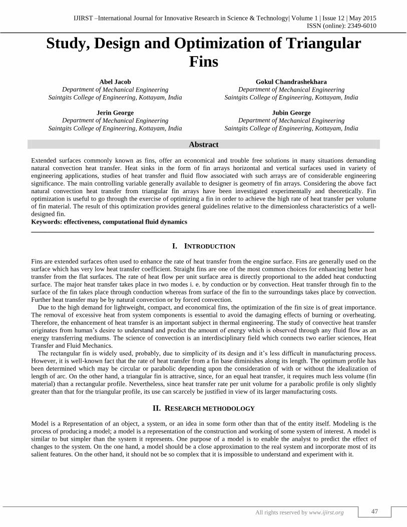
Fig. 5: Mesh of Array with l/d ratio = 2
The figure 5 shows the updated mesh obtained for the array of triangular fins with l/d ratio = 2. In order to increase the
accuracy of the convergence graph, the relevance centre was chosen of fine type instead of coarse type. The total number of
nodes and elements are shown in Table 1 below. L/D Ratio Number of Nodes Number of Elements
1 35151 179456
1.5 35992 183262
2 36403 184240
III. RESULT AND DISCUSSIONS
After the generation of mesh and assigning of load and constraints next step is to run the simulation for the model. This proceeds
for the analyzing the steady-state heat transfer process and finally obtain the required result contour of temperature.
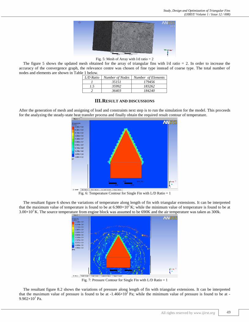
Fig. 6: Temperature Contour for Single Fin with L/D Ratio = 1
The resultant figure 6 shows the variations of temperature along length of fin with triangular extensions. It can be interpreted
that the maximum value of temperature is found to be at 6.980×10²
K; while the minimum value of temperature is found to be at
3.00×10² K. The source temperature from engine block was assumed to be 690K and the air temperature was taken as 300k.
Fig. 7: Pressure Contour for Single Fin with L/D Ratio = 1
The resultant figure 8.2 shows the variations of pressure along length of fin with triangular extensions. It can be interpreted
that the maximum value of pressure is found to be at -1.466×101
Pa; while the minimum value of pressure is found to be at -
9.902×101 Pa.

Study, Design and Optimization of Triangular Fins (IJIRST/ Volume 1 / Issue 12 / 008)
All rights reserved by www.ijirst.org 50
Fig. 8: Temperature Contour for Single Fin with L/D Ratio = 1.5
The resultant figure 8 shows the variations of pressure along length of fin with triangular extensions. It can be interpreted that
the maximum value of pressure is found to be at -1.466×101
Pa; while the minimum value of pressure is found to be at -
9.902×101 Pa.
Fig. 9: Pressure Contour for Single Fin with L/D Ratio = 1.5
The resultant figure 9 shows the variations of pressure along length of fin with triangular extensions. It can be interpreted that
the maximum value of pressure is found to be at -1.466×101
Pa; while the minimum value of pressure is found to be at -
9.902×101 Pa.
Now we take single fin of L/D ratio = 2 (i.e. ratio of length of fin to width of fin is 1.5). We analyze the pressure and
temperature contour formation of the fin when the source temperature is set as 690k and atmospheric pressure is taken as 1×
Pa. Then we find the heat transfer rate from the fin.
Fig. 10: Temperature Contour for Single Fin with L/D Ratio = 2

Study, Design and Optimization of Triangular Fins (IJIRST/ Volume 1 / Issue 12 / 008)
All rights reserved by www.ijirst.org 51
The resultant figure 10 shows the variations of pressure along length of fin with triangular extensions. It can be interpreted that
the maximum value of pressure is found to be at -1.466×101
Pa; while the minimum value of pressure is found to be at -
9.902×101 Pa.
Fig. 11: Pressure Contour for Single Fin with L/D Ratio = 2
The resultant figure 11 shows the variations of pressure along length of fin with triangular extensions. It can be interpreted that
the maximum value of pressure is found to be at -1.466×101
Pa; while the minimum value of pressure is found to be at -
9.902×101 Pa.
Fig. 12: Temperature Contour for an Array of Fins with Pitch 50and L/D Ratio = 1.5
The resultant figure 12 shows the variations of pressure along length of array of fins with triangular extensions. It can be
interpreted that the maximum value of pressure is found to be at -1.466×101
Pa and the minimum pressure is found to be at -
9.902×101 Pa.
Now we analyze the heat transfer rate of an array of fins with pitch 50mm (i.e., distance between two corresponding points on
adjacent fins is 50mm) and L/d ratio = 1.5 (i.e. ratio of length of fin to width of fin is 1.5). We analyze the pressure and
temperature contour formation of these fins when the source temperature is set as 690k and atmospheric pressure is taken as
1× Pa.
Fig. 13: Pressure Contour for an Array of Fins with Pitch 50 and L/D Ratio = 1.5
Study, Design and Optimization of Triangular Fins (IJIRST/ Volume 1 / Issue 12 / 008)
All rights reserved by www.ijirst.org 52
The resultant figure 13 shows the variations of pressure along length of array of fins with triangular extensions. It can be
interpreted that the maximum value of pressure is found to be at -1.466×101
Pa and the minimum pressure is found to be at -
9.902×101 Pa.
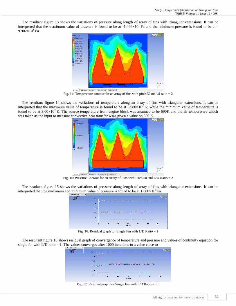
Fig. 14: Temperature contour for an array of fins with pitch 50and l/d ratio = 2
The resultant figure 14 shows the variations of temperature along an array of fins with triangular extensions. It can be
interpreted that the maximum value of temperature is found to be at 6.980×10²
K; while the minimum value of temperature is
found to be at 3.00×10²
K. The source temperature from engine block was assumed to be 690K and the air temperature which
was taken as the input to measure convective heat transfer wsas given a value on 300 K.
Fig. 15: Pressure Contour for an Array of Fins with Pitch 50 and L/D Ratio = 2
The resultant figure 15 shows the variations of pressure along length of array of fins with triangular extensions. It can be
interpreted that the maximum and minimum value of pressure is found to be at 1.000×10⁵ Pa.
Fig. 16: Residual graph for Single Fin with L/D Ratio = 1
The resultant figure 16 shows residual graph of convergence of temperature and pressure and values of continuity equation for
single fin with L/D ratio = 1. The values converges after 1000 iterations to a value close to
Fig. 17: Residual graph for Single Fin with L/D Ratio = 1.5

Study, Design and Optimization of Triangular Fins (IJIRST/ Volume 1 / Issue 12 / 008)
All rights reserved by www.ijirst.org 53
The resultant figure 8.12 shows residual graph of convergence of temperature and pressure and values of continuity equation
for single fin with L/D ratio = 1.5. The values converges after 1000 iterations to a value close to
Fig. 18: Residual graph for Single Fin with L/D Ratio = 2
The resultant figure 18 shows residual graph of convergence of temperature and pressure and values of continuity equation for
single fin with L/D ratio = 2. The values converges after 1000 iterations to a value close to
Fig. 19: Temperature contour for an array of rectangular fins with pitch 50and l/d ratio = 2
The resultant figure 19 shows the variations of temperature along an array of fins with rectangular extensions. It can be
interpreted that the maximum value of temperature is found to be at 6.980×10²
K; while the minimum value of temperature is
found to be at 2.98×10²
K. The source temperature from engine block was assumed to be 690K and the air temperature which
was taken as the input to measure convective heat transfer was given a value on 300 K.
Fig. 20: Pressure contour for an array of rectangular fins with pitch 50and l/d ratio = 2
The resultant figure 20 shows the variations of pressure along length of fin with rectangular extensions. . It can be interpreted
that the maximum value of pressure is found to be at 3.837×10⁻²
Pa; while the minimum value of pressure is found to be at -
1.365×100 Pa
IV. CONCLUSIONS
From the result it is clear that as the l/d ratio increases, the heat transfer also increases up to a certain limit. It is clear that as the
pitch of the fins increases the heat transfer to a maximum value and then decreases. In comparison to the conventional fin
(rectangular), rate of heat transfer of proposed fin is increased by 28.7%.Triangular fins provide about 5 % to 13% more

Study, Design and Optimization of Triangular Fins (IJIRST/ Volume 1 / Issue 12 / 008)
All rights reserved by www.ijirst.org 54
enhancement of heat transfer as compared to conventional fins. Heat transfer through fin with triangular extensions higher than
that of fin with other types of extensions. The effectiveness of fin with triangular extensions is greater than other extensions.
ACKNOWLEDGMENT
The authors would like to acknowledge the support of Mechanical Engineering Department of Saintgits College of Engineering
for conducting the present investigation.
REFERENCES
[1] Tri Lam Ngo et al, Heat transfer and pressure drop correlations of micro channel heat exchangers with S-shaped and zigzag fins for carbon dioxide
cycles. [2] GiulioLorenzini et al, Constructed design of T–Y assembly of fins for an optimized heat removal.
[3] GiulioLorenzini et al,Numerical analysis on heat removal from Y -shaped fins: Efficiency and volume occupied for a new approach to performance
optimization.