behaviour and design of thin-walled angle columns: geometrical
Upload
independentCategory
view
0download
0
TECHNICAL ARTICLE—PEER-REVIEWED
Simulation and Experimental Work on a Thin-Walled StructureUnder Crushing
L. S. Lee • Aidy Ali • A. B. Sanuddin •
Reza Afshar
Submitted: 15 September 2009 / in revised form: 19 January 2010
� ASM International 2010
Abstract This study investigates a thin-walled cylindri-
cal structure subjected to impact loading. Both simulations
and experiments were performed to predict the deformation
mode and its deformation rate. In the simulation, a three-
dimensional finite element model of a soft drink can was
developed and post-processed using ANSYS and
LS-DYNA commercial packages, respectively. The
experimental work was carried out by dropping a flat
weight from a certain height to crush the specimen, using a
drink can to represent the thin-walled structure. A high-
speed camera was employed to capture the entire process
of the crush. The simulation and experiment showed strong
agreement.
Keywords Thin-walled structure � Crush � FEM �ANSYS � LS-DYNA
Introduction
A thin-walled cylinder can be defined as a cylinder with a
ratio of outer diameter to thickness of at least 1:20. Many
containment tanks, such as natural gas vehicle (NGV) tanks
and domestic gas tanks, can be classified as thin-walled,
although their shells seem very thick. In engineering
applications, a wide range of thin-walled cylinder shells to
sustain axial compressive loads are employed, particularly
in relation to buckling due to their ease in plastic defor-
mation [1]. The studies of the deformation mode can be
very helpful in designing such devices for safe operation.
To improve the absorbed energy by crushing, many
structural elements with various shapes as well as uniform
cross-sections have been investigated, such as tapered
tubes (frusta), double skin tubes, grooved tubes, tubes
stiffened by stringers and rings [2]. Ezra and Fay classified
energy-absorbing devices into three groups; each one relies
either on material deformation, extrusion or friction [3].
This project emphasizes the material deformation.
The crushing of thin-walled cylinders can normally be
evaluated in many ways ranging from quasi-static testing
[4–8], dynamic testing [4, 6, 8] and impact testing [5, 9].
For this project, an emphasis is given to impact testing in
evaluating the deformation mode of thin-walled cylinders.
In previous studies conducted by other researchers, many
factors that affect the crushworthiness of thin-walled cyl-
inders have been investigated. Examples of the factors are
the ratio of radius to thickness [10], height to thickness,
initial imperfection due to preliminary defects during
manufacturing and to handling problems [11] and liquid- or
sand-filled cylinders [12]. However, in this work, other
factors such as loading directions and the amount of liquid
contained in the cylinder are explored.
In the simulation work, the finite element method (FEM)
was used as a tool to analyze both small- and large-scale
deflection under loading or applied displacement. The
simulation is crucially required in order to reduce the
astronomical number of calculations that are needed to
analyze a large structure. It is evident that the finite element
analysis (FEA) is a way to deal with structures that are
more complex than can be described by analytical solutions
using classical theories [13, 14]. Therefore, the objectives
of this work are (1) to develop an impact model of a soft
drink can and (2) to study the crush behavior of modeled
soft drink can under impact loading.
L. S. Lee � A. Ali (&) � A. B. Sanuddin � R. Afshar
Department of Mechanical and Manufacturing Engineering,
Universiti Putra Malaysia, 43400
Serdang, Selangor, Malaysia
e-mail: [email protected]
123
J Fail. Anal. and Preven.
DOI 10.1007/s11668-010-9330-2

Methodology
In this work, the main studies were carried out by applying
an impact load on thin-walled cylinder specimens and
analyzed through experiments and simulation. The simu-
lation of the models was developed using ANSYS and
analyzed with LS-DYNA. The steps taken in methodology
are shown in Fig. 1.
Material Selection
The specimen used in this study was a standard soft drink
can with material properties listed in Table 1 and 2.
The materials are 3004-H19 for the body and 5182-H19 for
the top lid. The detailed specimen geometry and its
dimensions are shown in Fig. 2.
Simulation Work
The finite element (FE) software program ANSYS was
used for pre-processing and processing, while LS-DYNA
was used for post-processing the drink can model.
Experimental Work
Simulation Work
Preparing the specimens
Experiment design
Experiment procedure
Measure specimen dimension
Simulation procedure
Simulating result
Comparing the experiment and simulation result
Discussion and conclusion
Load holder design and fabrication
Fig. 1 The methodology flow chart
Table 1 Mechanical properties of 3004-H19
Density, q1 2720 kg/m3
Ultimate tensile strength, rUTS,1 295 MPa
Yield strength, ry,1 285 MPa
Modulus of elasticity, E1 69 GPa
Elongation at break 2.00%
Poison ratio, m1 0.35
Table 2 Mechanical properties of 5182-H19
Density, q2 2650 kg/m3
Ultimate tensile strength, rUTS,2 420 MPa
Yield strength, ry,2 395 MPa
Modulus of elasticity, E2 69.6 GPa
Elongation at break 4.00%
Poison ratio, m2 0.33
Fig. 2 Geometry of specimen in mm
J Fail. Anal. and Preven.
123

Geometry Modeling
The simulation work using ANSYS began with modeling
the specimen, load and support; the geometry for these
models is shown in Fig. 2–4, respectively. The specimen
was created by extruding the lines after defining appro-
priate key points using by axis from the ANSYS guide user
interface. However, for the support and the load, it was
created by constructing the volume from the boxes option.
Figure 5 shows the FEM model drawn by ANSYS for the
load, specimen and support.
Mesh Generation
In this section, quadrilateral meshing elements were uti-
lized for specimen area mesh, while hexahedral meshing
elements were used in the volume mesh for the load and
support to avoid degenerate shell and solid element shapes.
There were 15,837 elements created in total; 117 elements
made up the load and support and the other 15,720 ele-
ments were the specimen. The specimen was the only
structure that underwent large strain deformation; hence, a
large number of elements was required in order to obtain a
precise and reliable result. Figure 6 shows the meshed
FEM model developed by ANSYS.
Boundary Conditions
The constraint was applied to the load in the X and Y
directions, while the support was constraint in all degrees
of freedom (DOF). Since this is an explicit analysis, con-
tact conditions are unpredictable. In this work, automatic
surface to surface contact was chosen and the program
automatically adjusted for the changes during the
simulation.
Experimental Procedures
The results obtained from experiment are the data on the
specimen deformation shape and the strain of the specimen
Fig. 3 Geometry of load in mm
Fig. 4 Geometry of support in mm
Fig. 5 FEM model developed by ANSYS
Fig. 6 Meshed FEM model developed by ANSYS
J Fail. Anal. and Preven.
123

at a certain time after collision. These data can be extracted
from the movie captured by using the camera software that
was installed on the computer. In experimental work, the
specimen was loaded under a drop weight impact loading
machine, as shown in Fig. 7. Then, a mass of 7.5 kg was
left to drop freely from a height of 7 feet above the
specimen. A load holder was designed in order to allow the
load to free fall when released at a certain height, as
depicted in Fig. 8. The load holder ensured that the load
was released at the exact height in every test made. A high-
speed camera with a capability to capture the picture at up
to 3000 frames per second was used in the experiment,
which means the pictures were taken approximately every
0.00033 s, thus allowing a better comparison with the
simulation results.
Results and Discussion
The results from the finite element model were compared
with the experiment. The comparison was made in terms of
the deformation mode and deformation rate of both results.
In addition, the energy absorbed by the specimen was also
observed from the FEM analysis, which used a thin-walled
structure in contact with high-velocity impact loading.
Deformation Mode
The deformation mode is related to how the specimen is
crushed. A small variation in time between the experiment
and simulation might occur because of the differences in
the time step between the experiment and the simulation. In
comparison, buckling waves were first created before the
crush, as shown in Fig. 9. In the experiment, the first
buckling waves were created at the time 0.0003333 s;
however, the obvious waves were created in simulation
falls around 0.00165 s. Another comparison, as in Fig. 10
and 11, shows different results, where in the simulation the
Load holder
Specimen
Load
Adjusting handle
High speed camera
Support
Fig. 7 Impact machine with high camera set up
Fig. 8 Load holder
J Fail. Anal. and Preven.
123

specimen collapsed first and continued at the base and the
lid. However, the specimen starts and continues to collapse
at the body in the experiment. The sole reason for the
difference is due to the assumption made in the modeling
of the specimen, where the thickness throughout the FEM
model is constant. In fact, the thickness is thicker at the
base and lid.
Figures 12–14 show the deformed specimen for both the
experiment and simulation at a certain time after crushing
by the drop load. These figures indicated that the
Buckling Waves
(a) (b)
Fig. 9 Buckling waves created
on the surface of the specimen
for (a) experiment and
(b) simulation
Does not Collapse Collapsed
Fig. 10 Condition of the
specimen in the experiment at
0.000667 s and in the
simulation at 0.000775 s
J Fail. Anal. and Preven.
123

simulation and experiment behave differently. One of the
known reasons for the discrepancy between the simulation
and experiment is the coefficients keyed into the simulation
option, namely, the static friction coefficient, dynamic
friction coefficient, exponential decay coefficient, coeffi-
cient for viscous friction and viscous damping coefficient.
Those coefficients were not able to be determined properly
because they can only be obtained by research and
experiment. Moreover, in the experiment, the air is con-
tained inside the specimen under atmospheric pressure.
When the drop load hits the specimen, the air inside the
specimen is compressed, thus leading to higher pressure.
Therefore, it provides strength to counteract the impact
force.
In another case, the simulation was similar to the
experiment in terms of the pattern of buckling waves
Does Not Collapse Collapsed
Fig. 11 Condition of the
specimen in the experiment at
0.001333 s and in the
simulation at 0.0015 s
Fig. 12 Condition of the
specimen for both the
experiment and simulation at
0.003 s
J Fail. Anal. and Preven.
123
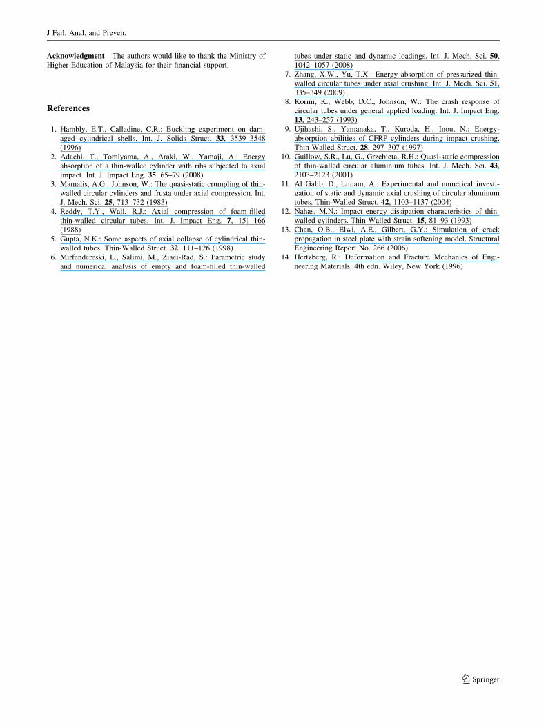
produced but at different times. The similarities occurred at
0.000667 s for the experiment and 0.00225 s for the sim-
ulation. The similarities of the wave are shown by the color
circle drawn in Fig. 15.
Deformation Rate
Figure 16 shows the graph of the Y-displacement versus
time for both the experiment and simulation. In the graph,
the two results are close at the start but continuously sep-
arate as the time increases. This divergence pattern may be
due to the air that is contained inside the specimen in the
experiment but not in the simulation. As the air is further
compressed, the higher pressure counteracts the force
exerted on it. Hence, less deformation is produced in the
experiment compared to the simulation.
Energy Absorption
The thin-walled cylinder structure plays an important role in
energy absorption, especially in the automotive industry.
The energy absorbed can reduce the amount of force
Fig. 13 Condition of the
specimen for both the
experiment and simulation at
0.009 s
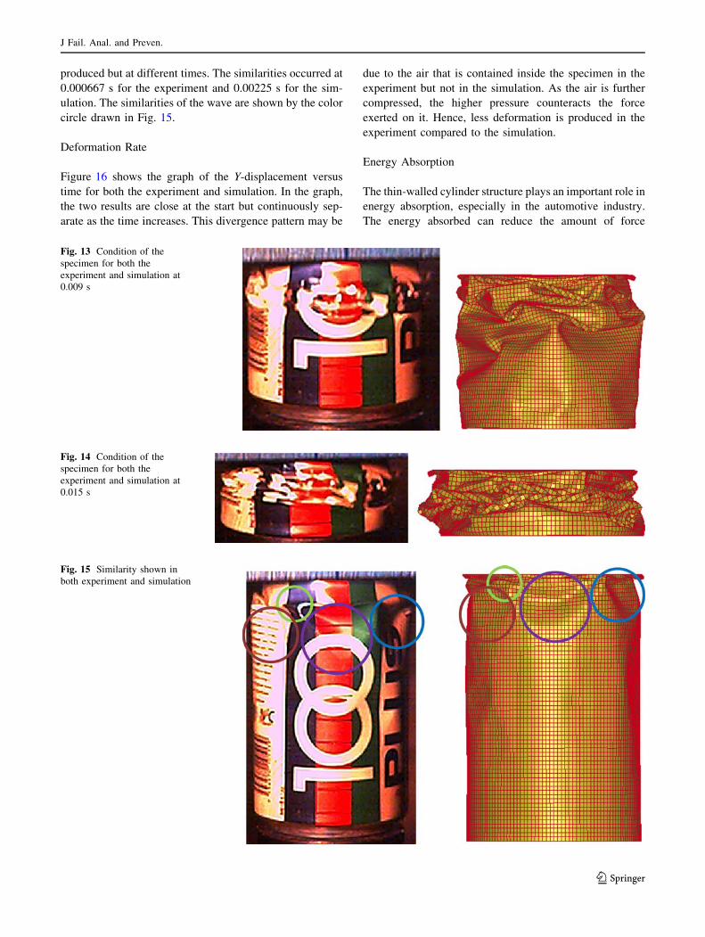
Fig. 14 Condition of the
specimen for both the
experiment and simulation at
0.015 s
Fig. 15 Similarity shown in
both experiment and simulation
J Fail. Anal. and Preven.
123

transmitted to the whole system during a crush. Figure 17
shows the amount of energy in the drop load during free fall.
From the graph, there is a total of 157.93 J of energy at the
release of the drop load, which is maintained just before it
hits the specimen. The first slanting line is due to small
buckling waves created on the slanted surface at the speci-
men, which further reduce the velocity of the load. The large
slanting line, which is created at time 0.00165 s, is due to the
obvious buckling waves created on the surface of the
specimen. The horizontal line after that is due to the defor-
mation of the specimen body. This pattern is further move on
alternately between buckling waves forming and deforma-
tion occurred. Hence, it can be said that the buckling waves
created have a greater effect on reducing the load velocity,
which directly reflects the higher kinetic energy being
absorbed. The total energy absorbed was 23.3 J.
Conclusions
A three-dimensional finite element analysis was used to
examine the crushing under high-velocity impact loading
of a drink can, and comparisons were made with experi-
mental results. These comparisons include the deformation
mode and the deformation rate. The simulation and
experiment did not yield the same result, but the results are
similar. Hence, a FEM used to predict the crushing of a
thin-walled structure was successfully developed. There-
fore, the present simulation work can be used to predict the
crushing of thin-walled structures of other materials, load
and geometry. Several improvements could be made to
improve the accuracy of the simulation. In the future, the
experimental method should use several cameras posi-
tioned at different angles to obtain a clearer overview, thus
making the comparisons easier. In the simulation, the
thickness of the FEM model should vary according to the
experimental specimen, which is thicker at the base and lid.
Coefficients in contact analysis should be obtained to yield
a higher accuracy in simulation, and finally, the air pressure
should be incorporated in the simulation.
Fig. 17 Graph of kinetic
energy versus time for the drop
load
Fig. 16 Y-displacement versus time for both experiment and
simulation
J Fail. Anal. and Preven.
123
Acknowledgment The authors would like to thank the Ministry of
Higher Education of Malaysia for their financial support.
References
1. Hambly, E.T., Calladine, C.R.: Buckling experiment on dam-
aged cylindrical shells. Int. J. Solids Struct. 33, 3539–3548
(1996)
2. Adachi, T., Tomiyama, A., Araki, W., Yamaji, A.: Energy
absorption of a thin-walled cylinder with ribs subjected to axial
impact. Int. J. Impact Eng. 35, 65–79 (2008)
3. Mamalis, A.G., Johnson, W.: The quasi-static crumpling of thin-
walled circular cylinders and frusta under axial compression. Int.
J. Mech. Sci. 25, 713–732 (1983)
4. Reddy, T.Y., Wall, R.J.: Axial compression of foam-filled
thin-walled circular tubes. Int. J. Impact Eng. 7, 151–166
(1988)
5. Gupta, N.K.: Some aspects of axial collapse of cylindrical thin-
walled tubes. Thin-Walled Struct. 32, 111–126 (1998)
6. Mirfendereski, L., Salimi, M., Ziaei-Rad, S.: Parametric study
and numerical analysis of empty and foam-filled thin-walled
tubes under static and dynamic loadings. Int. J. Mech. Sci. 50,
1042–1057 (2008)
7. Zhang, X.W., Yu, T.X.: Energy absorption of pressurized thin-
walled circular tubes under axial crushing. Int. J. Mech. Sci. 51,
335–349 (2009)
8. Kormi, K., Webb, D.C., Johnson, W.: The crash response of
circular tubes under general applied loading. Int. J. Impact Eng.
13, 243–257 (1993)
9. Ujihashi, S., Yamanaka, T., Kuroda, H., Inou, N.: Energy-
absorption abilities of CFRP cylinders during impact crushing.
Thin-Walled Struct. 28, 297–307 (1997)
10. Guillow, S.R., Lu, G., Grzebieta, R.H.: Quasi-static compression
of thin-walled circular aluminium tubes. Int. J. Mech. Sci. 43,
2103–2123 (2001)
11. Al Galib, D., Limam, A.: Experimental and numerical investi-
gation of static and dynamic axial crushing of circular aluminum
tubes. Thin-Walled Struct. 42, 1103–1137 (2004)
12. Nahas, M.N.: Impact energy dissipation characteristics of thin-
walled cylinders. Thin-Walled Struct. 15, 81–93 (1993)
13. Chan, O.B., Elwi, A.E., Gilbert, G.Y.: Simulation of crack
propagation in steel plate with strain softening model. Structural
Engineering Report No. 266 (2006)
14. Hertzberg, R.: Deformation and Fracture Mechanics of Engi-
neering Materials, 4th edn. Wiley, New York (1996)
J Fail. Anal. and Preven.
123
Copyright © 2022 FDOKUMEN