Deformable Boundary Detection of Stents in Angiographic Images
Upload
independentCategory
view
5download
0
Journal of Sound and <ibration (2000) 237(1), 101}118doi:10.1006/jsvi.2000.3055, available online at http://www.idealibrary.com on
OUT-OF-PLANE VIBRATIONS OF SHEAR DEFORMABLECONTINUOUS HORIZONTALLY CURVED
THIN-WALLED BEAMS
MARCELO T. PIOVAN AND VIDCTOR H. CORTIDNEZ
Mechanical Systems Analysis Group, ;niversidad ¹ecnologica Nacional. F.R.B.B., 11 de abril,461 -8000 BahıHa Blanca, Argentina
AND
RAUL E. ROSSI
Department of Engineering, ;niversidad Nacional del Sur Avenida Alem, 1253-8000 BahıHa Blanca,Argentina
(Received 25 January 1999, and in ,nal form 28 March 2000)
This paper presents numerical study about the in#uence of the shear #exibility, due toeither bending and warping, on the out-of-plane free vibration of continuous horizontallycurved thin-walled beams with both open and closed sections. This study was made bymeans of a recently developed "nite element formulation for shear deformable curvedthin-walled beams. The model is brie#y reviewed and is used to obtain natural frequencies ofcontinuous I-beams and box beams. A parametric study was performed in order to elucidatethe in#uence of shear deformability, on the dynamic behavior of continuous thin-walledcurved beams, for di!erent slenderness ratios, cross-sectional characteristics and boundaryconditions.
( 2000 Academic Press
1. INTRODUCTION
Many designers of engineering structures such as piping systems, highway bridges andmachine elements take advantage of the high strength-to-weight ratio of thin-walled beams.Hence, extensive research on the dynamic behavior of these members has been made.Chidamparam and Leissa [1] classi"ed most of the recent available papers concerning thedynamics of curved beams, some of them dealing with thin-walled beams. In the 1960sVlasov [2] presented a dynamic theory of curved thin-walled beams, which was usedsuccessfully in several applications. Snyder and Wilson [3] used Vlasov's theory to studythe dynamics of continuous curved thin-walled beams. They solved the equations by meansof a closed-form solution, in order to provide numerical information for these structuralmembers, which may be considered as a "rst approach in the design of highway, rail, rapidtransit and guideway structures. Other researchers employed Vlasov's theory and usednumerical approaches (like di!erential quadrature method) to "nd natural frequencies ofthin-walled curved beams with open sections [4].
However, Vlasov's theory does not consider shear deformability which should haveremarkable importance when vibrations associated with higher modes have to bedetermined. A few papers deal with vibrations of shear deformable curved thin-walled
0022-460X/00/410101#18 $35.00/0 ( 2000 Academic Press
RAVINDRA BG VVC JSV 19992811 DATE 2}6}2000....................DISC USED NO !

102 M. T. PIOVAN E¹ A¸.
beams. Kawakami et al. [5] studied the in-plane and out-of-plane vibrations of curvedthin-walled considering shear e!ects associated to the lateral motion although neglectingthe warping shear deformability. On the other hand, Fu and Hsu [6] analyzed statics ofthin-walled beams taking into account warping shear e!ect, but not the bending shear#exibility. According to the author's knowledge there are only a few studies dealing withvibrations of curved thin-walled beams that consider the shear e!ect in a full form [7}9].On the other hand, Piovan et al. [10] developed a theory which includes shear e!ects for thecase of bisymmetrical H-sectional shape subjected to initial stresses. While the out-of-planevibration analysis of curved thin-walled beams over multiple supports have been performedby many authors [3, 1}13], analysis including shear #exibility is, according to the authors'knowledge, non-existent.
The main objective of this paper is to elucidate the role of the shear #exibility, due to bothbending and warping, on the out-of-plane free vibration behavior of continuoushorizontally curved thin-walled beams with several end supports.
To accomplish this purpose a "nite element formulation, recently developed by theauthors [8, 10], for the dynamic analysis of shear #exible thin-walled curved beams isemployed.
The present "nite element solution is applied to uniform thin-walled curved beams withthree spans of equal lengths. H-cross-sectional shape and rectangular closed sections areconsidered. The "rst six free-vibration frequencies and the corresponding mode shapes arecalculated over a range of geometrical parameters such as horizontal radius of curvatureand angular openings. A convergence study is also performed on the "nite elementemployed in order to enhance its quality.
From the numerical study, conclusions are obtained with respect to the in#uence of theshear deformability for di!erent slenderness ratios and cross-sectional characteristics.
2. MATHEMATICAL MODEL
The out-of-plane vibration for horizontally curved beams shown in Figure 1 isconsidered. As it may be seen, R denotes the radius of curvature at the centroid, ¸ is thelength of the beam between outer supports, e
Ais the thickness of the walls, b and h are the
width and height of the section, and a is the angle between outer supports. Also, it may beseen in Figure 1 that a right-hand co-ordinate system is used. Axes y and z are principalcentroidal axes of the beam cross-section and x is tangent to the curved axis of this member.The assumptions of the model follow concepts of Cortinez et al. [8] and Cortinez and Rossi
Figure 1. Analyzed beams: (a) H cross-section, (b) closed cross-section.
JSV=20003055=VVC!Ravi

CURVED THIN-WALLED BEAMS 103
[14] and they are as follows. The original cross-section of the beam is preserved; the stresstensor is considered as a composition of a Saint Venant pure torsion state and a membranalstate. The variation of curvature through the thickness is neglected for shear deformations.Then the displacement "eld can be written in the form [8]
ux"!yh
z(x, t)#u(h (x, t)#h
z(x, t)/R),
uy"v
c(x, t)!z/(x, t), u
z"y/(x, t), (1)
where vcis the vertical displacement of the centroid, / is the torsional rotation, h
zis the
#exural rotation around the centroidal axis z, h is a measure of the warping along the beam,u is the warping function given by expressions (2) and (3) for the H-cross-section andrectangular closed section respectively [2, 15]:
u"D!Ps
0
r ds with D"
1
m Pm
0
ds Ps
0
r ds, u"Q (r!t) ds, (2, 3)
where r is the distance from the shear center to the tangent at a point in the middle line ofthe wall, m is the length of the cross-sectional thin wall and t is the shear strain due to SaintVenant torsion normalized with respect to d//dx according to Krenk and Gunneskov [15].It has to be noted that expressions (1) reduce to Vlasov's displacement "eld used by Yangand Kuo [16] if the internal restraints h
z"Lv
c/Lx and h"L//Lx are predetermined.
Therefore, the present model contains Vlasov's theory as a special case. When the restraintsmentioned above are not imposed the shearing strain components are not zero in themiddle line of the walls, as indicated by CortmHnez and Rossi [8]. Thus the model allows sheardeformability. The derivation of present model may be followed in a detailed form inreferences [8, 10].
The di!erential equations, which govern the out-of plane free vibration of the curvedbeam are [8]
!
LQy
Lx#oA
L2vc
Lt2"0, (4)
LMz
Lx!Q
y!
1
R
LB
Lx#
¹sv
R#oCIz
L2hz
Lt2#
Cw
R
L2hLt2D"0, (5)
!
LB
Lx!¹
w#o CCw
L2hLt2
#
Cw
R
L2hz
Lt2 D"0, !
L (¹w#¹
sv)
Lx#
Mz
R#oI
0
L2/Lt2
"0, (6, 7)
where Qy, M
z, B, ¹
wand ¹
svdenote shear force, bending moment, bimoment,
#exural-torsional moment and Saint Venant torsion moment respectively. Thesegeneralized stresses are expressed in terms of the generalized displacement (1) as
Qy"GK
yALv
cLx
!hzB, M
z"!EI
zALh
zLx
!
/
RB, (8a, b)
B"ECw
LLxAh#
hz
RB, ¹w"GK
wAL/Lx
!hB, (8c, d)
¹sv"GJA
L/
Lx#
hz
RB , (8e)
JSV=20003055=Ravi=VVC

104 M. T. PIOVAN E¹ A¸.
where A is the cross-sectional area, Iz
and Iy
are moments of inertia with respect to axesx and y, respectively, C
wis the warping constant, J is the torsion constant, I
0is the polar
moment of inertia and Kyand K
ware shear rigidity factors deduced by Cortinez and Rossi
[14, 17].The boundary conditions at a simple support are zero vertical de#ection (v
c"0),
zero torsional rotation (/"0), zero #exural moment (Mz"0) and zero bimoment
(B"0), although taking into account equations (8b,c) they can be expressed in condensedform in equation (9). For a clamped support the boundary conditions are shown inexpression (10):
vc"/"
Lhz
Lx"
LhLx
"0, vc"/"h
z"h"0. (9, 10)
A "nite element based on the present model was developed in references [8, 10]. Thiselement may be considered a generalization for curved beams of an earlier "nite developedfor straight beams by Cortinez and Rossi [14]. The vector that contains the nodalunknowns is denoted by q and it is
q"Mvc1
, hz1
, /1, h
1, v
c2, h
z2, /
2, h
2NT. (11)
For the out-of-plane vibration displacement "eld may be interpolated as indicated byequations (12a}d), where coe$cients b
iand d
iare indeterminate functions depending on
time:
vc"b
0#b
1xJ #b
2xJ 2#b
3xJ 3, h
z"b
1#
b1b3
2#2b
2xJ #3b
3xJ 2, (12a, b)
/"d0#d
1xJ #d
2xJ 2#d
3xJ 3, h"d
1#
b3d3
2#2d
2xJ #3d
3xJ 2, (12c, d)
with
xI "x
le
, b1"
12EIz
GKyl2e
, b3"
12ECW
GKwl2e
, (13)
where leis the element length. The element interpolated with the displacement "eld (12a}d)
is shear locking free and it could be reduced, as a limiting case, to a Vlasov element [8, 10].This is possible when a large shear rigidity (say K
w, K
yP1020) is imposed in the sti!ness
matrix, and on the other hand, when #exure and warping rotary inertias are neglected (sayC
W"I
z"0) in the mass matrix. Also, this curved element reduces to the straight beam
"nite element of CortmHnez and Rossi [14] when RPR.Carrying out the conventional steps of the "nite element method for free-vibration
problems, one arrives at the expression
[K!X2M]Q*"0, (14)
where K is the global matrix, M is the global mass matrix, Q* is the displacement vectorindependent of time, X"2nf is the circular frequency of vibration and f is the frequency(measured in Hz).
JSV=20003055=VVC!Ravi

Figure 2. Diagram of the continuous beam studied, with the boundary conditions (BCi) considered l
a, l
b, l
c, a
a,
ab, a
care lengths and subtended angles of each span. a is the subtended angle between outer supports.
TABLE 1
Properties of the sections used in the numerical studies
Property Open H-section Closed-section
Cross-sectional area: A (m2) 2)40E!02 2)40E!02Inertia moment: I
z(m4) 7)47E!04 5)33E!04
Polar moment: I0
(m4) 9)61E!04 7)20E!04Warping constant: C
w(m6) 8)55E!06 3)53E!07
Torsion constant: J (m4) 3)20E!06 4)26E!04Flexural shear rigidity factor: K
y(m2) 7)03E!03 1)46E!02
Torsion shear rigidity factor: Kw
(m4) 5)54E!04 5)33E!05Longitudinal modulus of elasticity: E (N/m2) 2)10E#11 2)10E#11Transversal modulus of elasticity: G (N/m2) 8)07E#10 8)07E#10Mass density: o (kg/m3) 7830 7830
CURVED THIN-WALLED BEAMS 105
3. GEOMETRICAL MODELS
A general diagram of the continuous beam studied here is shown in Figure 2. It consists ofthree circular spans of length l
a, l
b, l
c(thus, ¸"l
a#l
b#l
c), with four supports, where the
inner ones are simply supported and the outer ones may be simply supported or clamped.For this general outline, two particular cases of outer boundary conditions were selected:simply supported at both ends (SS}SS) and clamped at both ends (C}C). The spans haveequal length (l
a"l
b"l
c). The dimensions for the open section H were b"h"0)40 m,
whereas for the boxed rectangular section b"h/2"0)20 m. For both sections the samewall thickness e
A"0)02 m were employed. The material properties for both sections as well
as sectional features are listed in Table 1.
4. NUMERICAL RESULTS
4.1. CONVERGENCE CHECK
In order to check the element performance, a set of comparative tests was performed withanalytical results, as well as convergence studies. In Table 2, a convergence check of the "rstsix frequencies (measured in Hz) is given for the outer boundary conditions SS}SS with
JSV=20003055=Ravi=VVC

TABLE 2
Convergence checks of the ,rst six frequencies (Hz). Results with shear -exibility are depicted in column (a). Results without shear -exibility incolumn (b)
Column a a"453 R"2 m Column b a"453 R"2 m
Elements ElementsAnalytical Analytical
f 21 45 81 [9] f 21 45 81 [9]
1 1567)79 1559)17 1557)53 1557)17 1 2391)58 2391)60 2390)79 2395)492 1576)27 1568)34 1566)65 * 2 3058)87 3058)84 3057)80 *
3 1585)68 1577)13 1575)50 * 3 3639)47 3639)47 3639)57 3633)014 1768)83 1761)14 1760)01 1759)21 4 4396)88 4396)57 4395)12 *
5 1846)58 1838)54 1837)02 * 5 4539)27 4539)17 4539)31 *
6 2041)15 2030)72 2028)73 * 6 6309)17 6308)54 6308)68 *
a"903 R"4 m a"903 R"4 m
f 21 45 81 [9] f 21 45 81 [9]
1 138)61 137)57 137)31 137)24 1 145)07 145)08 145)03 145)062 192)31 191)32 191)12 * 2 219)01 219)02 218)93 *
3 287)57 286)24 286)09 * 3 337)31 337)29 337)15 *
4 309)81 308)91 308)69 308)58 4 378)54 378)56 378)53 378)455 327)85 326)80 326)54 * 5 445)43 445)45 445)43 *
6 367)24 365)76 365)47 * 6 605)57 605)56 605)56 *
a"1203 R"8 m a"1203 R"8 m
f 21 45 81 [9] f 21 45 81 [9]
1 12)99 12)38 12)25 12)18 1 12)26 12)26 12)26 12)262 29)55 29)13 29)04 * 2 30)36 30)35 30)35 *
3 53)32 52)81 52)70 * 3 55)58 55)56 55)56 *
4 87)35 85)81 85)47 85)31 4 88)14 88)06 88)06 88)065 101)68 101)29 101)20 * 5 105)14 105)14 105)15 *
6 105)83 104)47 104)18 * 6 110)53 110)43 110)42 *
106M
.T.P
IOV
AN
E¹
A¸
.
JSV=
20003055=
VV
C!
Ravi

Figure 3. Modes of the analytical results taken from reference [9]: (a) third frequency of a single-span beam,(b) sixth frequency of a single span beam.
TABLE 3
Comparisons with non-dimensional frequencies: I, reference [3]; II, present model
a (deg) Parameters Model p1
p2
p3
p4
p5
p6
45 C"0)05 I 0)975 1)265 1)861 3)987 4)548 5)584m"0)005 II 0)976 1)265 1)862 3)988 4)548 5)584D"0)001 Dp
i(II)!p
i(I)D/p
i(I)(%) 0)10 0)00 0)05 0)03 0)00 0)00
C"2 I 0)992 1)275 1)866 3)993 4)552 5)587m"0)005 II 0)992 1)275 1)866 3)993 4)552 5)587D"0)01 Dp
i(II)!p
i(I)D/p
i(I)(%) 0)00 0)00 0)00 0)00 0)00 0)00
90 C"0)05 I 0)844 1)166 1)798 3)901 4)477 5)529m"0)005 II 0)845 1)167 1)798 3)903 4)479 5)531D"0)001 Dp
i(II)!p
i(I)D/p
i(I)(%) 0)11 0)09 0)00 0)05 0)04 0)03
C"2 I 0)967 1)254 1)850 3)968 4)530 5)567m"0)005 II 0)967 1)254 1)850 3)968 4)530 5)568D"0)01 Dp
i(II)!p
i(I)D/p
i(I)(%) 0)00 0)00 0)00 0)00 0)00 0)02
180 C"0)05 I 0)523 0)899 1)568 3)377 4)030 5)157m"0)005 II 0)523 0)899 1)569 3)381 4)034 5)160D"0)001 Dp
i(II)!p
i(I)D/p
i(I)(%) 0)00 0)00 0)06 0)12 0)10 0)06
C"2 I 0)866 1)171 1)785 3)866 4)438 5)486m"0)005 II 0)866 1)171 1)785 3)866 4)438 5)486D"0)01 Dp
i(II)!p
i(I)D/p
i(I)(%) 0)00 0)00 0)00 0)00 0)00 0)00
CURVED THIN-WALLED BEAMS 107
several values of angular spacing a. Comparisons were carried out with analytical resultsobtained with the methodology used in reference [9] (for a single span curved H-beam withthe same outer angular spacing a). The Column &a' shows results allowing shear #exibilitywhereas Column &b' shows results without shear #exibility, but allowing rotary inertia. As itmay be appreciated, convergence is good enough even with 21 element, i.e., seven elementsover each span. In Table 2 the frequencies, which were compared with the analytical method[9], have the sinusoidal modes shown in Figures 3(a) and 3(b) respectively. These two modesare referred to the vertical displacement v
cand they correspond, respectively, to the third
and sixth modes of the single span curved H-beam studied in reference [9].
4.2. COMPARISON WITH VLASOV MODELS
In Table 3 comparisons with the non-dimensional frequencies (actually pi"
XJ(oAl4a)/(n4EI
z)) of reference [3] are presented. Results are given for outer angular
JSV=20003055=Ravi=VVC
108 M. T. PIOVAN E¹ A¸.
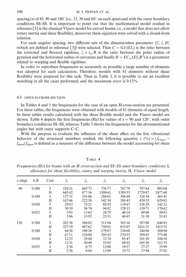
spacing (a) of 45, 90 and 1803 (i.e., 15, 30 and 603 on each span) and with the outer boundaryconditions SS}SS. It is important to point out that the mathematical model studied inreference [3] is the classical Vlasov model for curved beams, i.e., a model that does not allowrotary inertia and shear #exibility, moreover these equation were solved with a closed-formsolution.
For each angular spacing, two di!erent sets of the dimensionless parameter MC, m, DN(which are de"ned in reference [3]) were selected. Then C"GJ/(EI
z) is the ratio between
the torsional and #exural rigidities, m"rp/R is the ratio between the polar radius of
gyration and the horizontal radius of curvature and "nally D"ECw/(EI
zR2) is a parameter
related to warping and #exible rigidities.In order to reproduce frequencies as accurately as possible a large number of elements
was adopted for each calculation. Therefore, models with 81 elements without shear#exibility were prepared for this task. Then in Table 3, it is possible to see an excellentmatching in all the cases performed, and the maximum error is 0)12%.
4.3. OPEN H-CROSS SECTION
In Tables 4 and 5 the frequencies for the case of an open H-cross-section are presented.For these tables, the frequencies were obtained with models of 81 elements of equal length.In these tables results calculated with the shear #exible model and the Vlasov model areshown. Table 4 depicts the "rst frequencies (Hz) for values of a"90 and 1203, with outerboundary conditions SS}SS, whereas Table 5 shows the frequencies for the aforementionedangles but with outer supports C}C.
With the purpose to evaluate the in#uence of the shear e!ect on the free vibrationalbehavior of the structural members studied, the following quantity e (%)"D f
Vlasov!
fshear
D/fshear
is de"ned as a measure of the di!erence between the model accounting for shear
TABLE 4
Frequencies (Hz) for beams with an H cross-section and SS}SS outer boundary conditions: I,allowance for shear -exibility, rotary and warping inertia, II, <lasov model
a (deg) h/R Case f1
f2
f3
f4
f5
f6
90 0)200 I 519)21 603)73 738)77 767)79 797)64 903)04II 645)42 877)16 1309)61 1389)33 1729)87 2477)68
0)100 I 137)31 191)06 286)01 308)69 326)54 365)41II 147)66 222)58 342)34 388)43 459)35 629)81
0)050 I 29)83 53)21 88)83 119)67 126)29 142)21II 30)39 56)74 94)82 128)15 139)71 170)62
0)025 I 5)95 13)62 24)79 40)14 49)86 50)93II 5)96 13)92 25)51 40)85 51)39 51)85
120 0)200 I 282)38 366)02 511)04 565)16 587)06 648)81II 327)19 487)62 750)91 853)07 1021)21 1415)31
0)100 I 64)26 109)26 179)67 234)68 244)86 268)04II 67)11 124)00 205)43 270)53 299)45 375)48
0)050 I 12)25 29)04 52)70 85)47 101)20 104)18II 12)31 30)49 55)85 88)92 105)36 111)35
0)025 I 2)36 6)75 12)88 19)57 27)27 35)99II 2)36 6)84 13)09 19)72 27)94 37)02
JSV=20003055=VVC!Ravi

TABLE 5
Frequencies (Hz) for beams with an H cross-section and C}C outer boundary conditions: I,allowance for shear -exibility, rotary and warping inertia, II, <lasov model
a (deg) h/R Case f1
f2
f3
f4
f5
f6
90 0)200 I 603)73 738)77 797)64 799)96 903)04 990)23II 877)15 1309)61 1593)28 1729)87 2477)68 2989)80
0)100 I 191)06 286)01 326)54 338)48 365)41 388)73II 222)58 342)34 417)40 459)35 629)81 753)42
0)050 I 53)21 88)83 111)07 126)29 142)21 152)21II 56)74 94)82 118)72 139)71 170)62 196)68
0)025 I 13)62 24)79 33)75 49)86 52)12 55)33II 13)92 25)51 35)14 51)39 53)37 57)54
120 0)200 I 366)02 511)04 575)74 587)06 648)81 704)21II 487)62 750)91 918)30 1021)21 1415)31 1696)38
0)100 I 109)26 179)67 221)16 224)86 268)04 282)74II 124)00 205)43 256)15 299)45 375)48 437)59
0)050 I 29)04 52)70 70)70 103)57 104)18 110)65II 30)49 55)85 76)31 109)25 111)35 120)28
0)025 I 6)75 12)88 19)54 27)27 35)99 42)44II 6)84 13)09 20)19 27)94 37)02 43)92
Figure 4. Curves of error versus relation h/R for the cases of Tables 4 and 5: (a) Case 903 of Table 4, (b) Case 903of Table 5, (c) Case 1203 of Table 4, (d) Case 1203 of Table 5; e%: percent di!erence; h/R: height}radius ratio.(}r }, First frequency; }j }, second frequency; }m }, third frequency; }h }, fourth frequency; }e }, "fthfrequency; }s }, sixth frequency.)
CURVED THIN-WALLED BEAMS 109
#exibility and the Vlasov's model. The curves of e versus h/R for each frequency number ofTable 4 and 5 are presented in Figure 4. As it could be clearly seen in Figure 4, for a givenH-cross-section, the di!erences between frequencies calculated by Vlasov's model and themodel including shear #exibility rise uniformly with the ratio h/R. These curves show how
JSV=20003055=Ravi=VVC

110 M. T. PIOVAN E¹ A¸.
signi"cant is the shear e!ect on the dynamics of thin-walled open beams. For example, the"rst frequency of a deep beam, corresponding to h/R"0)200 and a"903 with clampedends, has a di!erence of e"45% (Figure 4(b)), but the sixth frequency of the same case hasa di!erence of e"202%. However, in the case of slender beams, say h/R"0)025 and lower,these di!erences are small (less than 3%) for all the frequencies considered.
4.4. CLOSED CROSS-SECTION
In Tables 6 and 7 the frequencies for the case of closed-rectangular cross-section arepresented. These tables exhibit the same pattern as the previous ones, except for the boxsection described in Table 1. Thus, Table 6 shows the frequencies (Hz) for the values of a of90 and 1803, with SS}SS outer boundary conditions, whereas Table 7 shows the frequenciesfor the angles mentioned above but with C}C outer supports.
In Figure 5, it is possible to see curves of e versus h/R for the six frequencies of Table 6 and7. Di!erences between Vlasov and present models are noticeable. For example, the thirdfrequency in Figure 6(a) has e"34% at h/R"0)100, but the sixth frequency in Figure 5(b)has e"99% at h/R"0)200. However, observing Figure 5 and comparing it with Figure 4,one may see a very di!erent in#uence of the shear e!ect on the dynamics of curved beamswith rectangular closed sections. Some frequencies have a uniform increase of e with h/Rand some other have di!erent behavior. In fact, for a given frequency number, e mayincrease with h/R in the whole range, like for example f
1, f
2and f
3in Figure 5(c), however for
other frequencies e could decrease after certain values of h/R, like f3
in Figure 5(b) or f4, f
5and f
6in Figures 5(c) and 5(d). The explanation of this behavior is related to the qualitative
and quantitative variation, with h/R, of the mode characteristics for a given frequencynumber. A coupled #exural-torsional mode of the frequency could change to a dominanttorsional mode (where, for a closed section the warping is negligible) depending on the
TABLE 6
Frequencies (Hz) for beams with closed cross-section and SS}SS outer boundary conditions: I,allowance for shear -exibility, rotary and warping inertia, II, <lasov model
a (deg) h/R Case f1
f2
f3
f4
f5
f6
90 0)200 I 733)84 811)89 976)16 1236)26 1242)53 1255)64II 922)78 1114)88 1279)17 1387)89 1540)18 2080)14
0)100 I 229)76 279)52 374)17 617)05 619)16 623)44II 253)09 331)75 488)50 627)65 635)56 657)12
0)050 I 62)34 79)95 114)87 242)36 267)35 308)35II 64)10 84)22 125)61 270)05 307)87 309)24
0)025 I 15)95 20)83 30)75 65)75 74)37 89)97II 16)07 21)12 31)50 67)78 77)53 95)49
180 0)200 I 189)33 248)38 355)14 682)41 684)19 688)04II 202)75 287)21 447)04 716)90 725)01 746)58
0)100 I 51)13 70)91 108)24 229)83 256)37 302)00II 52)16 74)18 117)18 253)09 292)42 347)44
0)050 I 13)07 18)46 28)90 62)35 71)33 87)30II 13)13 18)68 29)53 64)09 74)17 92)37
0)025 I 3)28 4)66 7)36 15)95 18)41 22)82II 3)29 4)68 7)40 16)07 18)59 23)16
JSV=20003055=VVC!Ravi

TABLE 7
Frequencies (Hz) for beams with closed cross-section and C}C outer boundary conditions: I,allowance for shear -exibility, rotary and warping inertia, II, <lasov model
a (deg) h/R Case f1
f2
f3
f4
f5
f6
90 0)200 I 811)89 976)16 1067)47 1242)53 1255)64 1262)95II 1113)85 1277)49 1325)59 1540)18 2080)14 2498)71
0)100 I 279)52 374)17 425)21 619)16 623)44 625)63II 331)75 488)50 576)98 635)56 657)12 687)22
0)050 I 79)95 114)87 136)24 267)35 309)01 310)41II 84)22 125)61 153)32 307)87 310)86 315)34
0)025 I 20)83 30)75 37)23 74)37 89)97 99)36II 21)12 31)50 38)47 77)53 95)49 106)89
180 0)200 I 248)38 355)14 412)82 684)19 688)04 690)78II 287)21 447)04 545)01 724)43 745)98 773)03
0)100 I 70)91 108)24 131)24 256)37 302)00 326)86II 74)18 117)18 146)16 292)42 348)32 352)53
0)050 I 18)46 28)90 35)76 71)33 87)30 96)95II 18)68 29)53 36)86 74)17 92)37 103)98
0)025 I 4)66 7)36 9)16 18)41 22)82 25)59II 4)68 7)40 9)23 18)59 23)16 26)07
Figure 5. Curves of error versus relation h/R for the cases of Tables 6 and 7: (a) Case 903 of Table 6, (b) Case 903of Table 7, (c) Case 1803 of Table 6, (d) Case 1803 of Table 7; e%: percent di!erence; h/R: height}radius ratio.(}r }, First frequency; }j }, second frequency; }m }, third frequency; }h }, fourth frequency; }e }, "fthfrequency; }s }, sixth frequency.)
CURVED THIN-WALLED BEAMS 111
values of h/R for a particular frequency number and geometrical features. Actually, inFigures 5(c) and (5d) it is possible to appreciate a very di!erent behavior beyondh/R"0)100 in frequencies f
4, f
5and f
6. These frequencies have basically a coupled
#exural-torsional motion, but for h/R"0)200, the motion changes to a predominanttorsional mode.
JSV=20003055=Ravi=VVC

Figure 6. Mode shapes of the "rst frequency ( f1) for the beam with closed section, a"903 and SS}SS outer
boundary conditions K: measure of motion characteristics; vc: vertical displacement, /: torsion angle.
112 M. T. PIOVAN E¹ A¸.
Unlike what occurs in the thin-walled open sections, thin-walled closed sections do notmanifest a quite considerable di!erence between Vlasov and present models, when themotion is predominantly torsional. In order to explain the behavior of e in Figures5(a)}5(d), the non-dimensional parameter K"Dh/2 /
max/v
cmaxD is de"ned as a measure of the
motion characteristics for a given frequency. That is, values of K quite greater than onereveal dominant torsional modes, values of K closer to zero correspond to dominant#exural modes, values of K belonging to the interval (0)1, 1)0) may be accepted as coupled#exural-torsional modes.
Figures 6}11 depict a sequence of mode shapes at some frequencies showing theaforementioned qualitative and quantitative variation. Thus, Figures 6}8 show the modeshapes of variables v
c, / and the corresponding parameter K for frequencies f
1, f
2and f
3,
respectively, calculated with both models, the case of a"903 with SS}SS outer boundaryconditions, for h/R"0)05 and 0)20. Then in Figures 6}8, it is possible to appreciate that, for
JSV=20003055=VVC!Ravi

Figure 7. Mode shapes of the second frequency ( f2) for the beam with closed section, a"903 and SS}SS outer
boundary conditions K: measure of motion characteristics; vc: vertical displacement, /: torsion angle.
CURVED THIN-WALLED BEAMS 113
a given frequency and a value of h/R, the mode shape of each variable is not di!erent, and itis the same for both models. Just for instance, the mode shape of v
cin the present model is
the same at h/R"0)05 and 0)20, it occurs also in the Vlasov model. However, quantitativedi!erences appear in the Vlasov model for f
3(Figure 8). This mode is #exural-torsional at
h/R"0)05 (i.e., K"0)320) and it changes to a torsional-dominant mode at h/R"0)20 (i.e.,K"5)250). With little di!erences, the same response could be observe in Figure 5(b), i.e., forthe same angular opening but with C}C outer boundary conditions.
Figures 9}11 show the mode shapes of variables vc, /, and the corresponding parameter
K for frequencies f4, f
5and f
6, respectively, calculated with Vlasov and present models, but
for a"1803, cases h/R"0)10 and 0)20 (Table 6). The mode shapes at these threefrequencies change abruptly from a coupled #exural-torsional mode at h/R"0)10 (i.e.,K(1) in both models to a dominant torsional mode at h/R"0)20, except in the case of f
6(Figure 11) where the Vlasov model already has a dominant mode at h/R"0)10 (i.e., K"8).
JSV=20003055=Ravi=VVC

Figure 8. Mode shapes of the third frequency ( f3) for the beam with closed section, a"903 and SS}SS outer
boundary conditions K: measure of motion characteristics; vc: vertical displacement, /: torsion angle.
114 M. T. PIOVAN E¹ A¸.
Also, in this "gure it is possible to see a change in the mode shape when one moves fromh/R"0)10 to 0)20 for a given frequency number.
5. CONCLUSIONS
A "nite element analysis of the out-of-plane vibrations of continuous thin-walled curvedbeams was performed. Special emphasis was given to the in#uence of the shear #exibility,due to bending and warping, over the dynamics of the member. The convergence analysisand the comparisons with exact results show the very good performance of the elementemployed.
It may be concluded from the present analysis that the shear e!ect is quite noticeable forfrequencies associated with high modes or even with low modes in the case of deep beams.
JSV=20003055=VVC!Ravi

Figure 9. Mode shapes of the fourth frequency ( f4) for the beam with closed section, a"1803 and SS}SS outer
boundary conditions K: measure of motion characteristics; vc: vertical displacement, /: torsion angle.
CURVED THIN-WALLED BEAMS 115
Moreover, the shear e!ect showed di!erent in#uences depending on the cross-sectiontype, i.e., if the section is open or closed. The relative di!erence (e) between frequenciesobtained with Vlasov and present models, for the case of the H-open section, decreasesuniformly with h/R (Figure 4). However, for the closed section, e decreases uniformly withh/R only for certain frequencies but for other frequencies the variation of e with h/R isconnected with qualitative and quantitative changes in its dominant mode (which aredistinguished by the introduced parameter K) especially when a #exural}torsional coupledmode changed to a torsional-dominant mode (Figures 9}11).
From the present study it should be concluded that the shear e!ect should be taken intoaccount in the dynamic analysis of these types of structures at least when deep beams orhigh modes are considered.
JSV=20003055=Ravi=VVC

Figure 10. Mode shapes of the "fth frequency ( f5) for the beam with closed section, a"1803 and SS}SS outer
boundary conditions K: measure of motion characteristics; vc: vertical displacement, /: torsion angle.
116 M. T. PIOVAN E¹ A¸.
ACKNOWLEDGMENT
The authors highly appreciate the support of Secretaria de Ciencia y TecnologmHa ofUniversidad TecnoloH gica Nacional and SecretarmHa de ciencia y Tecnologia of UniversidadNacional del Sur. The authors also thank the support of CONICET.
REFERENCES
1. P. CHIDAMPARAN and A. W. LEISSA 1993 Applied Mechanics Reviews 46, 467}483. Vibrations ofplanar curved beams, rings and arches.
2. V. Z. VLASOV 1961 ¹hin=alled Elastic Beams. Washington, DC: 23National Science Foundation.3. J. M. SNYDER and J. F. WILSON 1992 Journal of Sound and<ibration 157, 345}355. Free vibrations
of continuous horizontally curved beams.4. K. KANG, C. W. BERT and A. G. STRIZ 1996 Journal of Structural Engineering 122, 657}662.
Vibration analysis of horizontally curved beams with warping using DQM.
JSV=20003055=VVC!Ravi

Figure 11. Mode shapes of the sixth frequency ( f6) for the beam with closed section, a"1803 and SS}SS outer
boundary conditions K: measure of motion characteristics; vc: vertical displacement, /: torsion angle.
CURVED THIN-WALLED BEAMS 117
5. M. KAWAKAMI, T. SAKIYAMA et al. 1995 Journal of Sound and <ibration 187, 381}401. In-planeand out-of-plane vibrations of curved beams with variable sections.
6. C. C. FU and Y. T. HSU 1995 Computers and Structures 54, 147}159. The development of animproved curvilinear thin-walled Vlasov element.
7. A. S. GENDY and A. F. SALEEB 1994 Journal of Sound and <ibration 174, 261}274. Vibrationanalysis of coupled extensional/#exural/torsional modes in curved beams with arbitrary thinwalled sections.
8. V. H. CORTIDNEZ, M. T. PIOVAN and R. E. ROSSI 1999 Structural Engineering and Mechanics, 8,257}272. Out of plane vibrations of thin walled curved beams considering shear #exibility.
9. V. H. CORTIDNEZ, M. T. PIOVAN and R. H. GUTIERREZ 1999 Proceedings of VI Pan AmericanCongress of Applied Mechanics, Rio de Janeiro, Brazil. Analytical solution for out of planevibrations of shear deformable thin walled curved beams with pinned ends.
10. M. T. PIOVAN, V. H. CORTIDNEZ and R. E. ROSSI 1998 Computational Mechanics (E. On8 ate andS. R. Idelsohn, editors). Barcelona, Spain: CIMNE. Vibrations of curved I beams with allowancefor shear deformability.
11. C. P. HEINS and M. A. SABIN 1979 Journal of the Structural Division ASCE 105, 2591}2600.Natural frequency of curved box girder bridges.
JSV=20003055=Ravi=VVC

118 M. T. PIOVAN E¹ A¸.
12. J. F. WILSON, Y. WANG and I. THREFALL 1999 Journal of Sound and <ibration 222, 563}576.Responses of near-optimal continuous horizontal curved beams to transit loads.
13. C. H. KOU, S. E. BENZLEY, J. Y. HUANG and D. A. FIRMAGE 1992 Journal of StructuralEngineering 118, 2890}2910. Free vibration analysis of curved thin walled grinder bridges.
14. V. H. CORTIDNEZ and R. E. ROSSI 1998 Revista Internacional de MeH todos NumeH ricos para CaH lculoy DisenJ o en IngenierıHa 14, 293}316. DinaH mica de vigas de seccioH n abierta de pared delgadadeformables por corte sujetas a un estado inicial de tensiones.
15. S. KRENK and O. GUNNESKOV 1981 International Journal for Numerical Methods in Engineering17, 1407}1426. Statics of thin-walled pretwisted beams.
16. Y. B. YANG and S. R. KUO 1987 Journal of Structural Engineering 113, 1185}1202. E!ect ofcurvature on stability of curved beams.
17. V. H. CORTIDNEZ and R. E. ROSSI 1998 Computational Mechanics (E. On8 ate and S. R. Idelsohn,editors). Barcelona, Spain: CIMNE. Vibrations of pretwisted thin-walled beams with allowancefor shear deformability.
JSV=20003055=VVC!Ravi
Copyright © 2022 FDOKUMEN