Chavel-Curved-Girders.pdf - Oregon.gov
34
6/23/2021 1 Photo: 2020 Prize Bridge National Winner – Manning Crevice (Idaho) – Photo Credit: Ken Saindon Primary Principles for Horizontally Curved Steel I-girder Bridges Brandon Chavel, PhD, PE June 23, 2021 Director of Market Development, National Steel Bridge Alliance Presentation Outline • Structural Behavior • Analysis Considerations • Girder Design • Cross-frame Design • Fit Condition • Summary 1 2
-
Upload
khangminh22 -
Category
Documents
-
view
1 -
download
0
Transcript of Chavel-Curved-Girders.pdf - Oregon.gov
6/23/2021
1
Photo: 2020 Prize Bridge National Winner – Manning Crevice (Idaho) – Photo Credit: Ken Saindon
Primary Principles for Horizontally Curved Steel I-girder Bridges
Brandon Chavel, PhD, PE June 23, 2021
Director of Market Development, National Steel Bridge Alliance
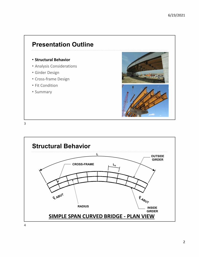
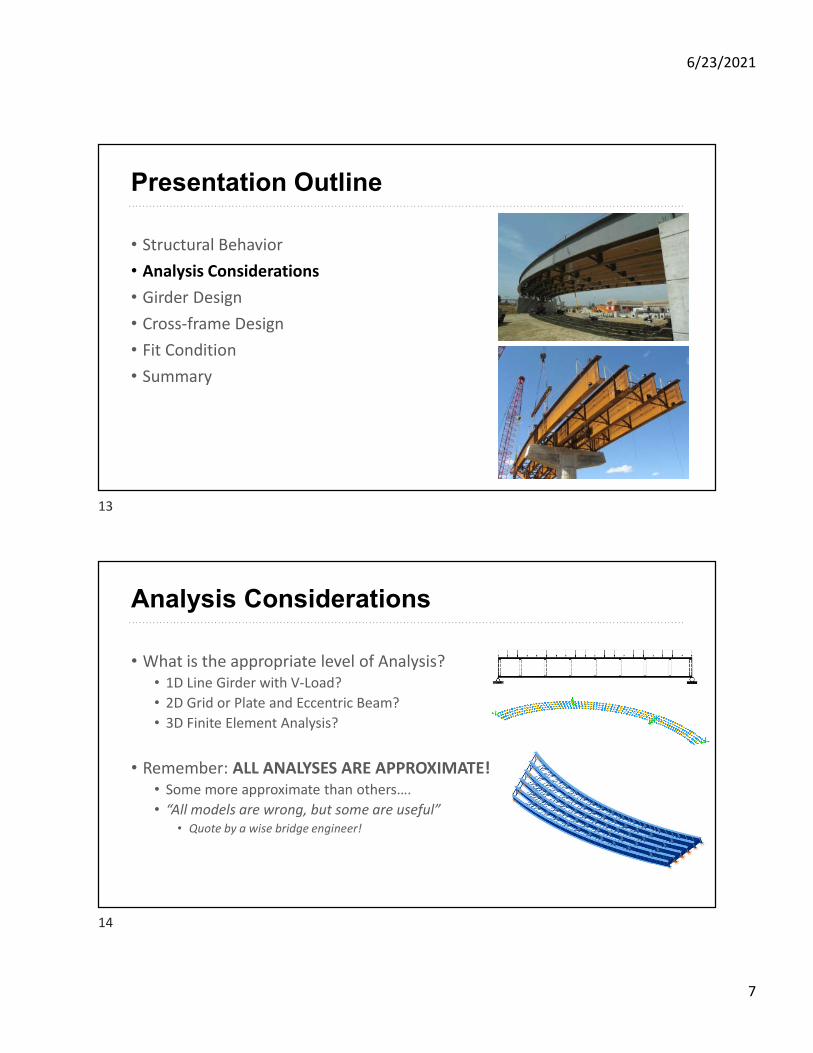
Presentation Outline
• Structural Behavior
• Analysis Considerations
• Girder Design
• Cross-frame Design
• Fit Condition
• Summary
1
2
6/23/2021
2
Presentation Outline
• Structural Behavior
• Analysis Considerations
• Girder Design
• Cross-frame Design
• Fit Condition
• Summary
Structural BehaviorL
OUTSIDEGIRDER
INSIDEGIRDER
CROSS-FRAME
RADIUS
SIMPLE SPAN CURVED BRIDGE - PLAN VIEW
Lb
3
4
6/23/2021
3
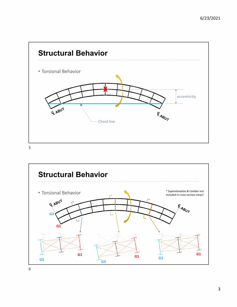
Structural Behavior
• Torsional Behavior
Chord line
eccentricity
X
Structural Behavior
• Torsional Behavior
G1
G3
G1 G1G1
G3G3
G3
* Superelevation & Camber not included in cross-section views!
5
6

6/23/2021
4
Structural Behavior
• Load Shifting
G1 G5
Structural Behavior
• Design Forces that need to be considered:• Major-axis bending moments
• Flange lateral bending moments from warping torsion
• Minor-axis bending moments from lateral loads (wind)
• Girder vertical web shear
• Cross-frame member forces
7
8
6/23/2021
5
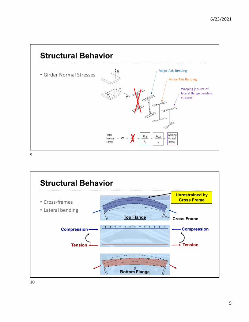
Structural Behavior
• Girder Normal StressesMajor-Axis Bending
Minor-Axis Bending
Warping (source of lateral flange bending stresses)
• Cross-frames
• Lateral bending
Structural Behavior
Unrestrained by Cross Frame
Top Flange Cross Frame
CompressionCompression
TensionTension
Bottom Flange
9
10
6/23/2021
6
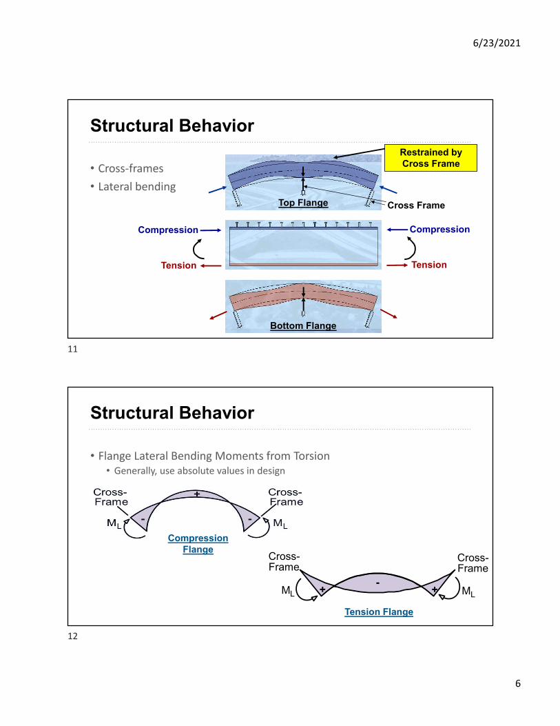
• Cross-frames
• Lateral bending
Structural Behavior
Restrained by Cross Frame
Top Flange Cross Frame
CompressionCompression
TensionTension
Bottom Flange
Structural Behavior
• Flange Lateral Bending Moments from Torsion• Generally, use absolute values in design
+ +-
Cross-Frame
Cross-Frame
MLML
Compression Flange
Tension Flange
11
12
6/23/2021
7
Presentation Outline
• Structural Behavior
• Analysis Considerations
• Girder Design
• Cross-frame Design
• Fit Condition
• Summary
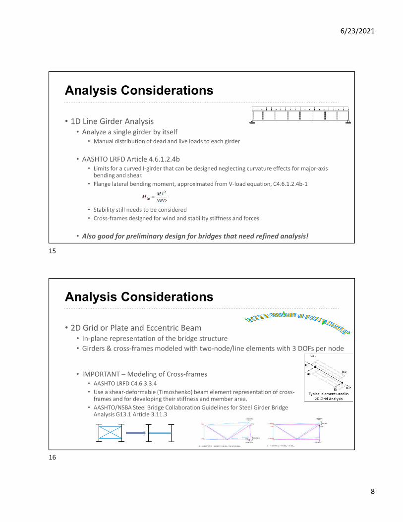
Analysis Considerations
• What is the appropriate level of Analysis?• 1D Line Girder with V-Load?
• 2D Grid or Plate and Eccentric Beam?
• 3D Finite Element Analysis?
• Remember: ALL ANALYSES ARE APPROXIMATE!• Some more approximate than others….
• “All models are wrong, but some are useful”• Quote by a wise bridge engineer!
13
14
6/23/2021
8
Analysis Considerations
• 1D Line Girder Analysis• Analyze a single girder by itself
• Manual distribution of dead and live loads to each girder
• AASHTO LRFD Article 4.6.1.2.4b• Limits for a curved I-girder that can be designed neglecting curvature effects for major-axis
bending and shear.
• Flange lateral bending moment, approximated from V-load equation, C4.6.1.2.4b-1
• Stability still needs to be considered
• Cross-frames designed for wind and stability stiffness and forces
• Also good for preliminary design for bridges that need refined analysis!
Analysis Considerations
• 2D Grid or Plate and Eccentric Beam• In-plane representation of the bridge structure
• Girders & cross-frames modeled with two-node/line elements with 3 DOFs per node
• IMPORTANT – Modeling of Cross-frames• AASHTO LRFD C4.6.3.3.4
• Use a shear-deformable (Timoshenko) beam element representation of cross-frames and for developing their stiffness and member area.
• AASHTO/NSBA Steel Bridge Collaboration Guidelines for Steel Girder Bridge Analysis G13.1 Article 3.11.3
15
16
6/23/2021
9
Analysis Considerations
• 2D Grid or Plate and Eccentric Beam• Only considers St. Venant Torsional Stiffness, GJ/Lb.
• Can underestimate torsional stiffness
• IMPORTANT – Torsional Stiffness & Warping Rigidity• AASHTO LRFD C4.6.3.3.2
• NCHRP Report 725 and AASHTO/NSBA Steel Bridge Collaboration Guidelines for Steel Girder Bridge Analysis G13.1-2019 provide approximate method
• Equivalent Torsional Stiffness, Jeq:
• G13.1-2019: Section 3.12
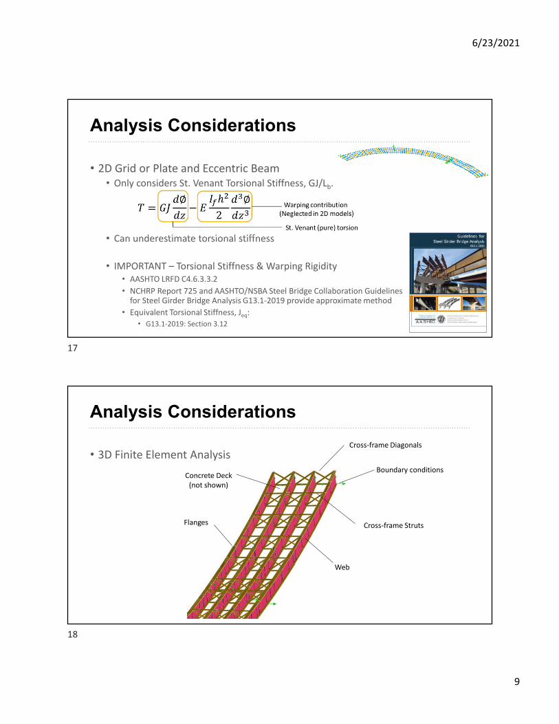
Analysis Considerations
• 3D Finite Element Analysis
Concrete Deck (not shown)
Flanges Cross-frame Struts
Web
Cross-frame Diagonals
Boundary conditions
17
18
6/23/2021
10
Analysis Guidance
• Where to get Guidance?
• Guidelines for Steel Girder Bridge Analysis (G13.1-2019)• Provides the most comprehensive presentation and discussion regarding analysis
techniques associated with steel girder bridges.
• Discussion about line girder (1D), 2D, and 3D analysis methods, while also helping engineers determine the appropriate level of analysis based on a bridge’s geometric aspects.
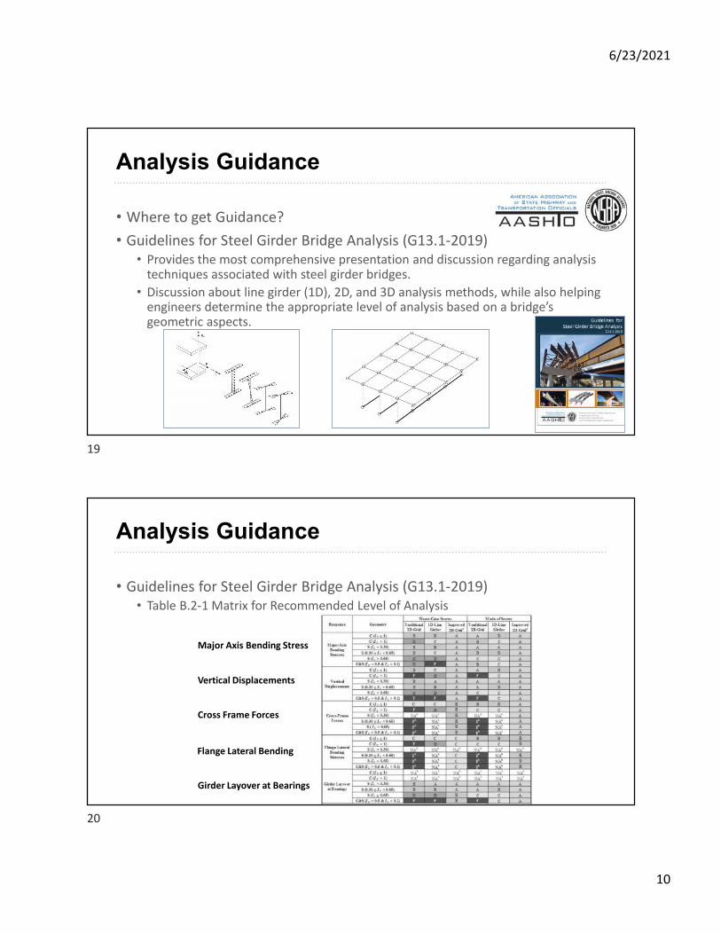
Analysis Guidance
• Guidelines for Steel Girder Bridge Analysis (G13.1-2019)• Table B.2-1 Matrix for Recommended Level of Analysis
Major Axis Bending Stress
Vertical Displacements
Cross Frame Forces
Flange Lateral Bending
Girder Layover at Bearings
19
20
6/23/2021
11
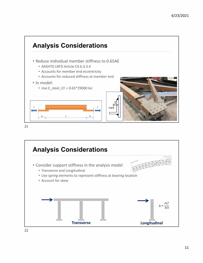
Analysis Considerations
• Reduce individual member stiffness to 0.65AE• AASHTO LRFD Article C4.6.3.3.4
• Accounts for member end eccentricity
• Accounts for reduced stiffness at member end
• In model:• Use E_steel_CF = 0.65*29000 ksi
Analysis Considerations
• Consider support stiffness in the analysis model• Transverse and Longitudinal
• Use spring elements to represent stiffness at bearing location
• Account for skew
Transverse Longitudinal
∆ =���
3��
21
22
6/23/2021
12
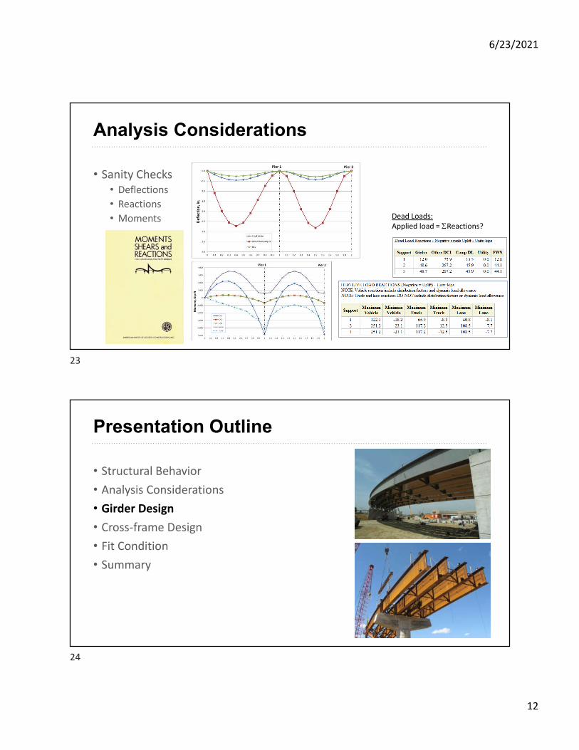
Dead Loads:Applied load = SReactions?
Analysis Considerations
• Sanity Checks• Deflections
• Reactions
• Moments
Presentation Outline
• Structural Behavior
• Analysis Considerations
• Girder Design
• Cross-frame Design
• Fit Condition
• Summary
23
24
6/23/2021
13
Girder Design
• Topics for consideration today:• Design of each girder
• Girder flange sizing for fabrication
• Flange lateral bending stresses
• Girder camber
• Girder shear & transverse stiffeners
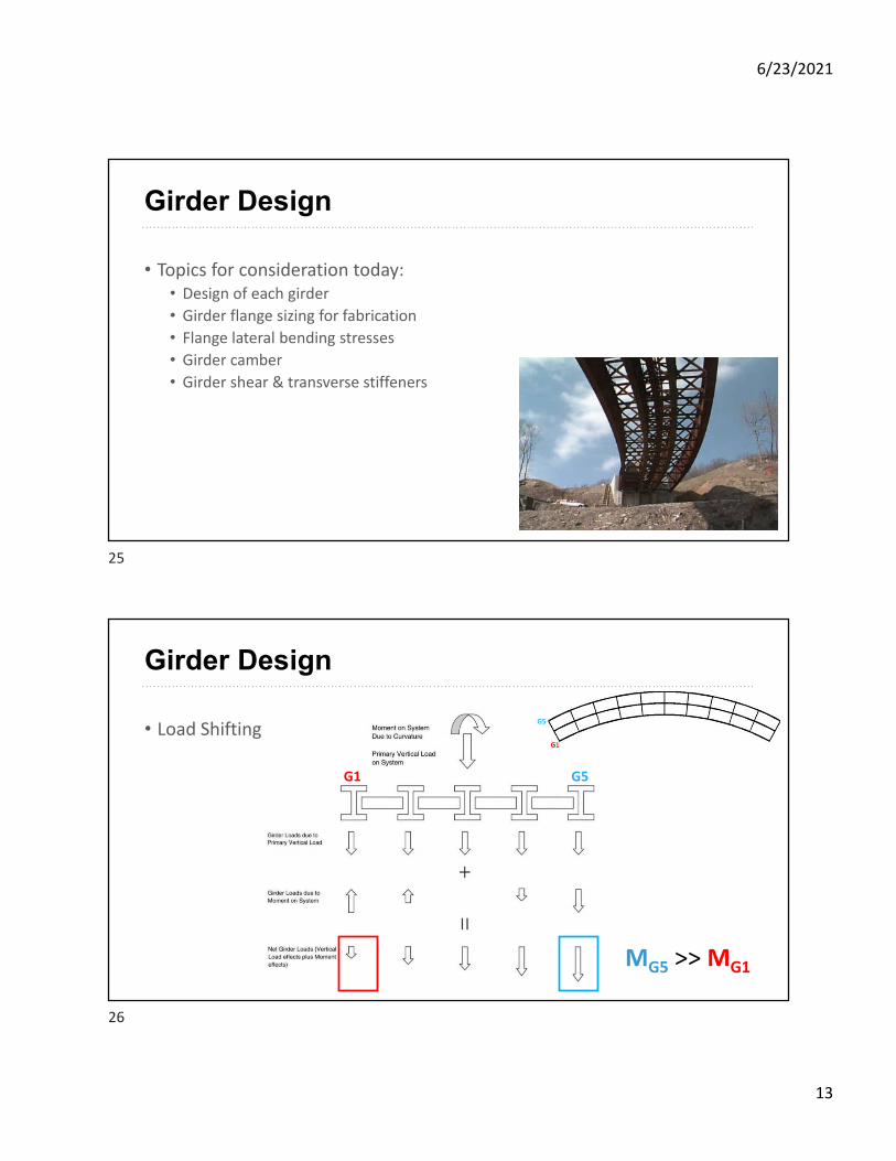
Girder Design
• Load Shifting
G1 G5
MG5 >> MG1
25
26
6/23/2021
14
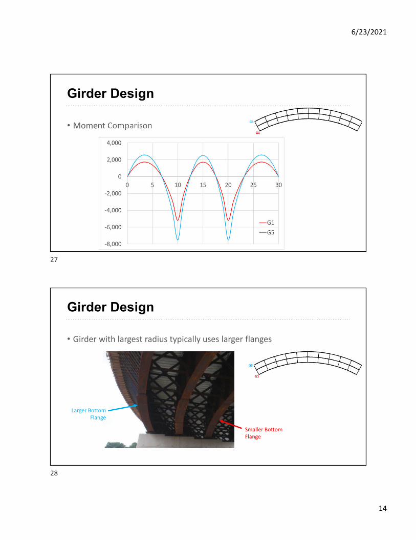
Girder Design
• Moment Comparison
Girder Design
• Girder with largest radius typically uses larger flanges
Larger Bottom Flange
Smaller Bottom Flange
27
28
6/23/2021
15
Girder Design
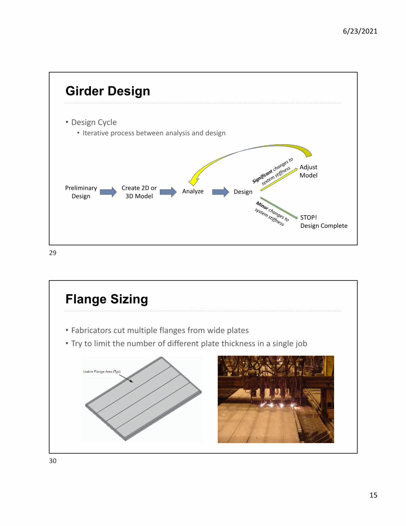
• Design Cycle• Iterative process between analysis and design
Preliminary Design
Create 2D or 3D Model
Analyze
Adjust Model
Design
STOP!Design Complete
Flange Sizing
• Fabricators cut multiple flanges from wide plates
• Try to limit the number of different plate thickness in a single job
29
30
6/23/2021
16
Flange Sizing
• Example• Try to use same flange thicknesses over all girders
• change the width over the adjacent field pieces
CL PierCL Pier
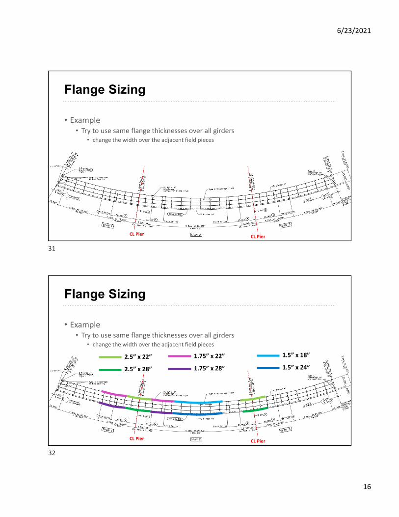
Flange Sizing
• Example• Try to use same flange thicknesses over all girders
• change the width over the adjacent field pieces
CL PierCL Pier
2.5” x 22”
2.5” x 28”
1.5” x 18”
1.5” x 24”
1.75” x 22”
1.75” x 28”
31
32
6/23/2021
17
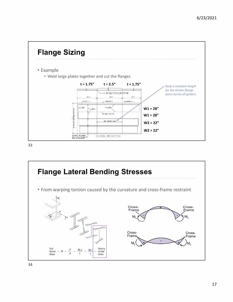
Flange Sizing
• Example• Weld large plates together and cut the flanges
t = 2.5” t = 1.75”t = 1.75”
W1 = 28”
W2 = 22”
W2 = 22”
W1 = 28”
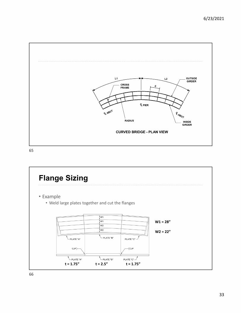
Keep a constant length for the thicker flange piece across all girders.
Flange Lateral Bending Stresses
• From warping torsion caused by the curvature and cross-frame restraint
33
34
6/23/2021
18
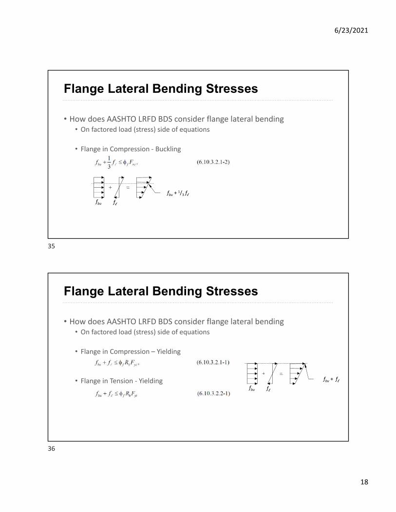
Flange Lateral Bending Stresses
• How does AASHTO LRFD BDS consider flange lateral bending• On factored load (stress) side of equations
• Flange in Compression - Buckling
fbu fl
fbu + 1/3 fl
Flange Lateral Bending Stresses
• How does AASHTO LRFD BDS consider flange lateral bending• On factored load (stress) side of equations
• Flange in Compression – Yielding
• Flange in Tension - Yieldingfbu fl
fbu + fl
35
36
6/23/2021
19
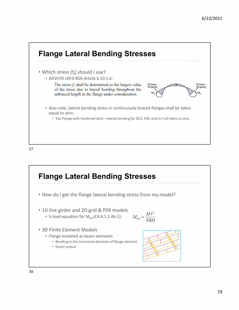
Flange Lateral Bending Stresses
• Which stress (fl) should I use?• AASHTO LRFD BDS Article 6.10.1.6:
• Also note, lateral bending stress in continuously braced flanges shall be taken equal to zero.• Top Flange with hardened deck – lateral bending for DC2, DW, and LL+I all taken as zero.
Flange Lateral Bending Stresses
• How do I get the flange lateral bending stress from my model?
• 1D line girder and 2D grid & PEB models• V-load equation for Mlat (C4.6.1.2.4b-1):
• 3D Finite Element Models• Flange modeled as beam elements
• Bending in the transverse direction of flange element
• Direct output
37
38
6/23/2021
20
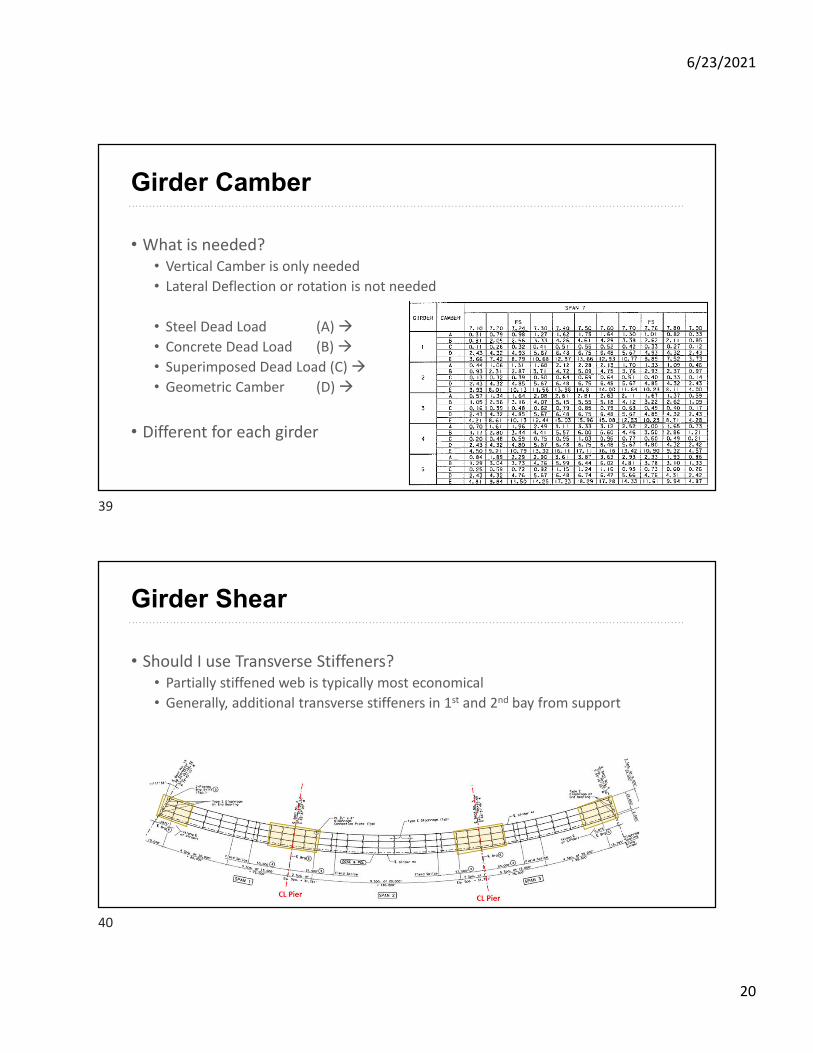
Girder Camber
• What is needed?• Vertical Camber is only needed
• Lateral Deflection or rotation is not needed
• Steel Dead Load (A)
• Concrete Dead Load (B)
• Superimposed Dead Load (C)
• Geometric Camber (D)
• Different for each girder
Girder Shear
• Should I use Transverse Stiffeners?• Partially stiffened web is typically most economical
• Generally, additional transverse stiffeners in 1st and 2nd bay from support
39
40
6/23/2021
21
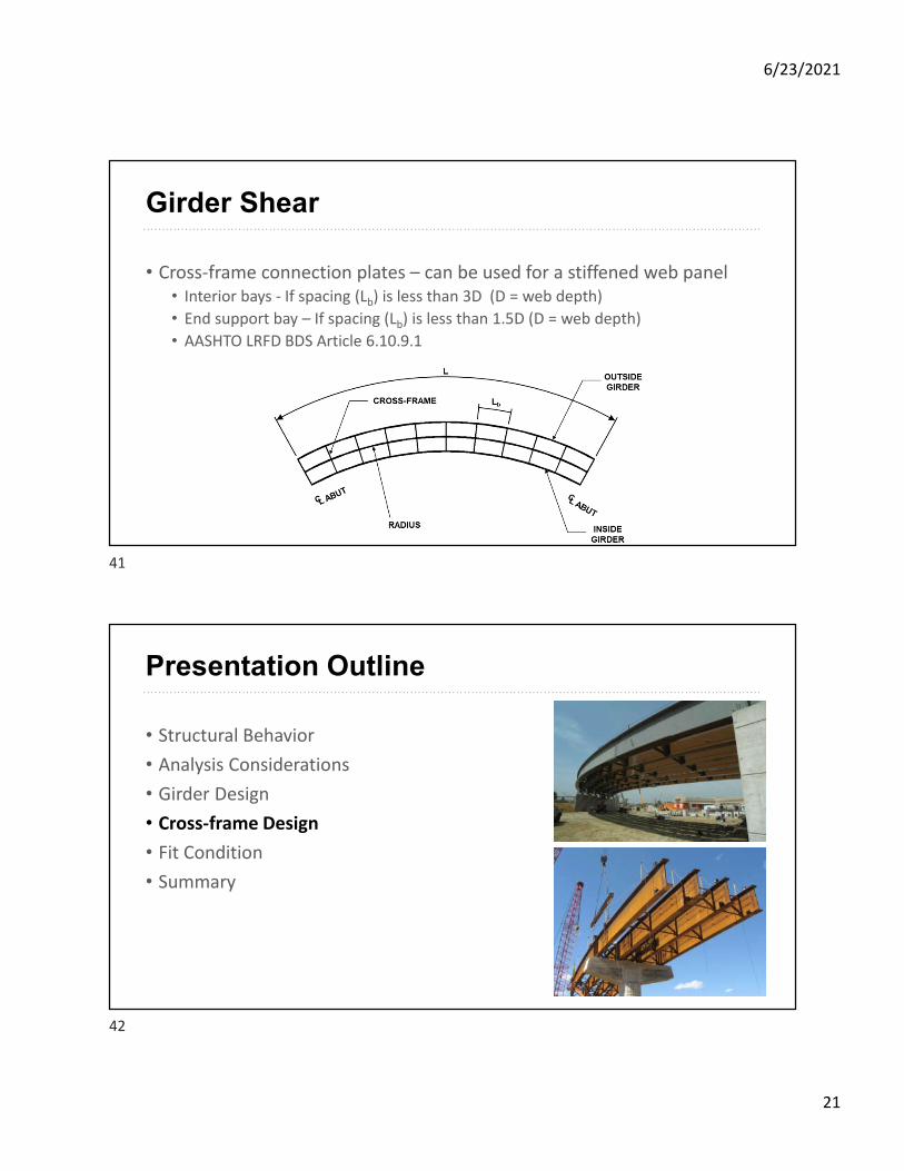
Girder Shear
• Cross-frame connection plates – can be used for a stiffened web panel• Interior bays - If spacing (Lb) is less than 3D (D = web depth)
• End support bay – If spacing (Lb) is less than 1.5D (D = web depth)
• AASHTO LRFD BDS Article 6.10.9.1
Presentation Outline
• Structural Behavior
• Analysis Considerations
• Girder Design
• Cross-frame Design
• Fit Condition
• Summary
41
42
6/23/2021
22
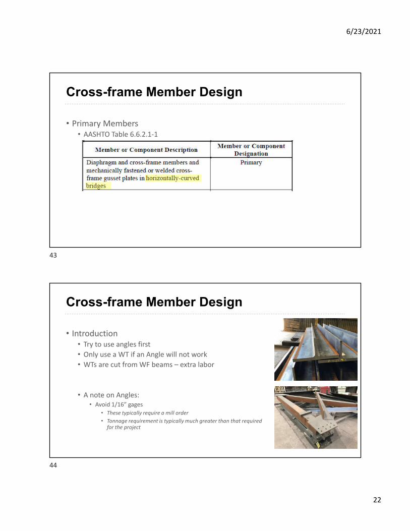
Cross-frame Member Design
• Primary Members• AASHTO Table 6.6.2.1-1
Cross-frame Member Design
• Introduction• Try to use angles first
• Only use a WT if an Angle will not work
• WTs are cut from WF beams – extra labor
• A note on Angles:• Avoid 1/16” gages
• These typically require a mill order
• Tonnage requirement is typically much greater than that required for the project
43
44
6/23/2021
23
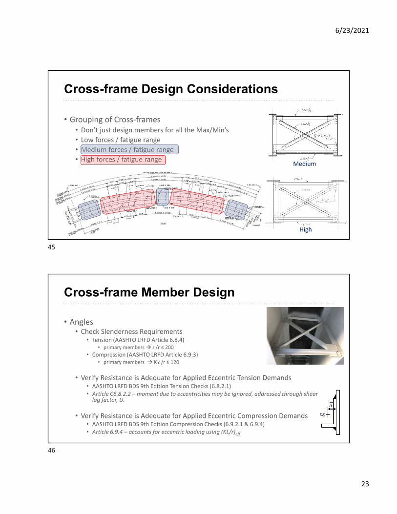
Cross-frame Design Considerations
• Grouping of Cross-frames• Don’t just design members for all the Max/Min’s
• Low forces / fatigue range
• Medium forces / fatigue range
• High forces / fatigue rangeMedium
High
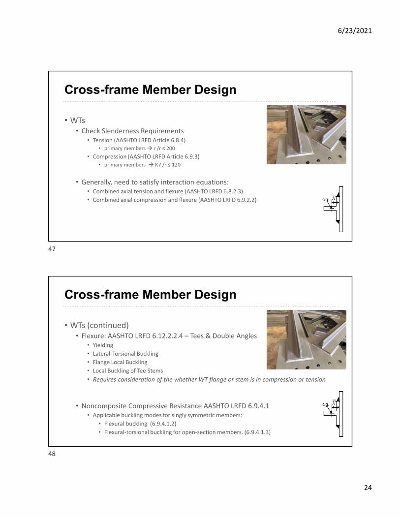
Cross-frame Member Design
• Angles• Check Slenderness Requirements
• Tension (AASHTO LRFD Article 6.8.4)• primary members l /r ≤ 200
• Compression (AASHTO LRFD Article 6.9.3)• primary members K l /r ≤ 120
• Verify Resistance is Adequate for Applied Eccentric Tension Demands• AASHTO LRFD BDS 9th Edition Tension Checks (6.8.2.1)• Article C6.8.2.2 – moment due to eccentricities may be ignored, addressed through shear
lag factor, U.
• Verify Resistance is Adequate for Applied Eccentric Compression Demands• AASHTO LRFD BDS 9th Edition Compression Checks (6.9.2.1 & 6.9.4) • Article 6.9.4 – accounts for eccentric loading using (KL/r)eff
45
46
6/23/2021
24
Cross-frame Member Design
• WTs• Check Slenderness Requirements
• Tension (AASHTO LRFD Article 6.8.4)• primary members l /r ≤ 200
• Compression (AASHTO LRFD Article 6.9.3)• primary members K l /r ≤ 120
• Generally, need to satisfy interaction equations:• Combined axial tension and flexure (AASHTO LRFD 6.8.2.3)
• Combined axial compression and flexure (AASHTO LRFD 6.9.2.2)
Cross-frame Member Design
• WTs (continued)• Flexure: AASHTO LRFD 6.12.2.2.4 – Tees & Double Angles
• Yielding
• Lateral-Torsional Buckling
• Flange Local Buckling
• Local Buckling of Tee Stems
• Requires consideration of the whether WT flange or stem is in compression or tension
• Noncomposite Compressive Resistance AASHTO LRFD 6.9.4.1• Applicable buckling modes for singly symmetric members:
• Flexural buckling (6.9.4.1.2)
• Flexural-torsional buckling for open-section members. (6.9.4.1.3)
47
48
6/23/2021
25
Presentation Outline
• Structural Behavior
• Analysis Considerations
• Girder Design
• Cross-frame Design
• Fit Condition
• Summary
Fit Condition
49
50
6/23/2021
26
Fit Condition
• Fit Condition – deflected girder geometry associated with a targeted dead load condition for which the cross-frames are detailed to connect to the girders.• A fit decision must always be made so the Fabricator/Detailer can complete the
shop drawings & successfully fabricate the bridge components – allows Erector/Contractor to assemble the steel & achieve the desired geometry in the field.
• The fit decision also affects design decisions regarding rotation demands on the bearings, and internal force effects for which the cross-frames and girders must be designed.
• The fit condition should ideally be selected by the Engineer.
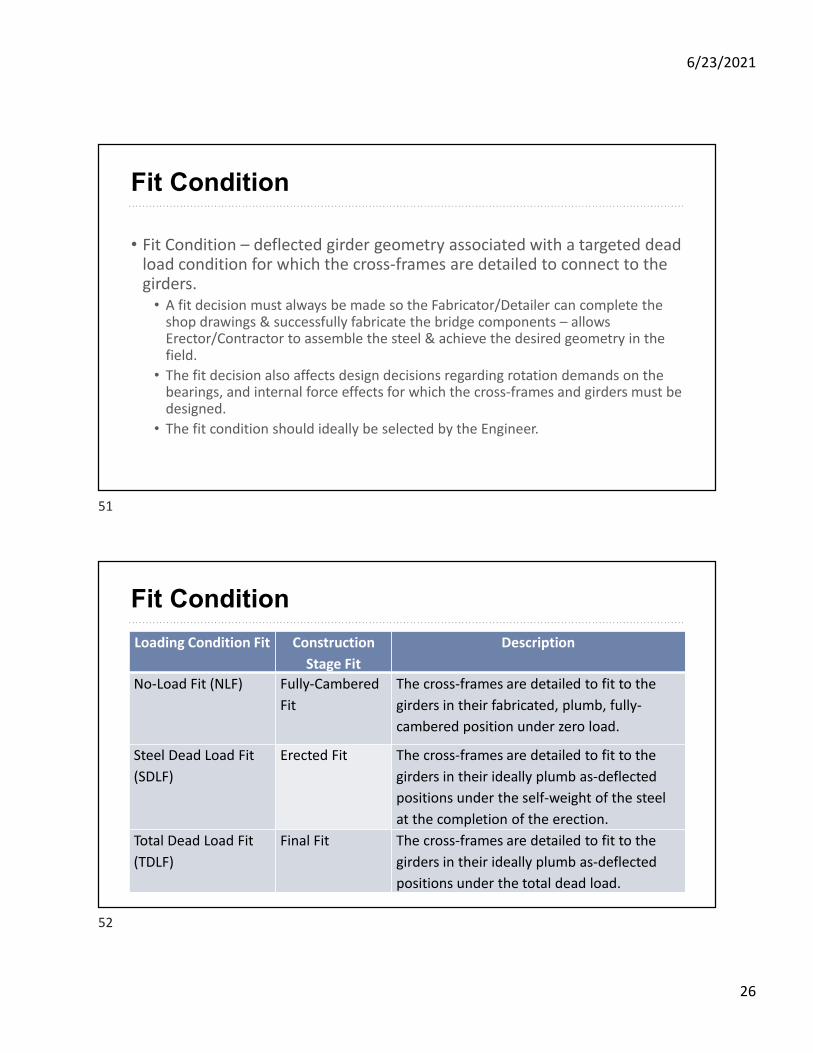
Fit Condition
Loading Condition Fit Construction
Stage Fit
Description
No-Load Fit (NLF) Fully-Cambered
Fit
The cross-frames are detailed to fit to the
girders in their fabricated, plumb, fully-
cambered position under zero load.
Steel Dead Load Fit
(SDLF)
Erected Fit The cross-frames are detailed to fit to the
girders in their ideally plumb as-deflected
positions under the self-weight of the steel
at the completion of the erection.
Total Dead Load Fit
(TDLF)
Final Fit The cross-frames are detailed to fit to the
girders in their ideally plumb as-deflected
positions under the total dead load.
51
52
6/23/2021
27
Fit Condition
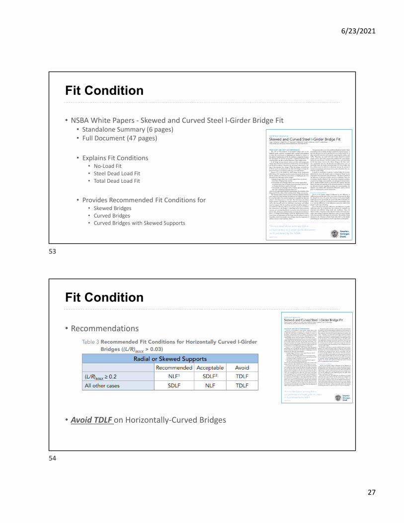
• NSBA White Papers - Skewed and Curved Steel I-Girder Bridge Fit• Standalone Summary (6 pages)• Full Document (47 pages)
• Explains Fit Conditions• No-Load Fit
• Steel Dead Load Fit
• Total Dead Load Fit
• Provides Recommended Fit Conditions for• Skewed Bridges
• Curved Bridges• Curved Bridges with Skewed Supports
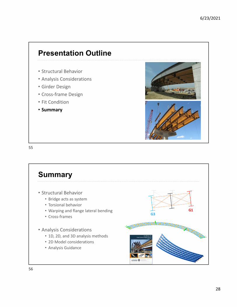
Fit Condition
• Recommendations
• Avoid TDLF on Horizontally-Curved Bridges
53
54
6/23/2021
28
Presentation Outline
• Structural Behavior
• Analysis Considerations
• Girder Design
• Cross-frame Design
• Fit Condition
• Summary
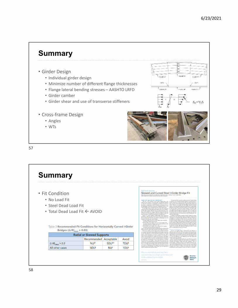
Summary
• Structural Behavior• Bridge acts as system
• Torsional behavior
• Warping and flange lateral bending
• Cross-frames
• Analysis Considerations• 1D, 2D, and 3D analysis methods
• 2D Model considerations
• Analysis Guidance
55
56
6/23/2021
29
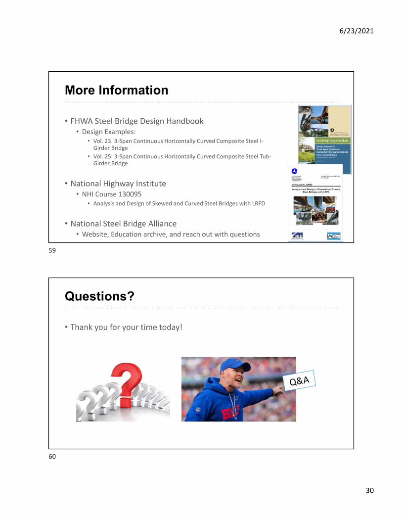
Summary
• Girder Design• Individual girder design
• Minimize number of different flange thicknesses
• Flange lateral bending stresses – AASHTO LRFD
• Girder camber
• Girder shear and use of transverse stiffeners
• Cross-frame Design• Angles
• WTs
Summary
• Fit Condition• No Load Fit
• Steel Dead Load Fit
• Total Dead Load Fit AVOID
57
58
6/23/2021
30
More Information
• FHWA Steel Bridge Design Handbook• Design Examples:
• Vol. 23: 3-Span Continuous Horizontally Curved Composite Steel I-Girder Bridge
• Vol. 25: 3-Span Continuous Horizontally Curved Composite Steel Tub-Girder Bridge
• National Highway Institute• NHI Course 130095
• Analysis and Design of Skewed and Curved Steel Bridges with LRFD
• National Steel Bridge Alliance• Website, Education archive, and reach out with questions
Questions?
• Thank you for your time today!
59
60
6/23/2021
31
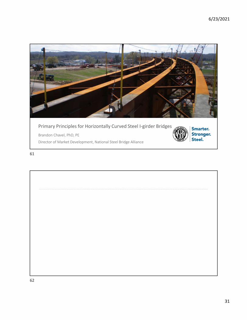
Photo: 2020 Prize Bridge National Winner – Manning Crevice (Idaho) – Photo Credit: Ken Saindon
Primary Principles for Horizontally Curved Steel I-girder Bridges
Brandon Chavel, PhD, PE
Director of Market Development, National Steel Bridge Alliance
61
62
6/23/2021
32
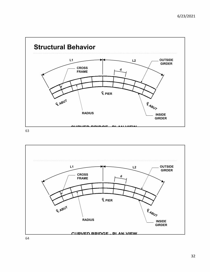
Structural Behavior
L1 L2 OUTSIDEGIRDER
L PIERC
INSIDEGIRDER
CROSSFRAME
RADIUS
CURVED BRIDGE - PLAN VIEW
d
L1 L2 OUTSIDEGIRDER
L PIERC
INSIDEGIRDER
CROSSFRAME
RADIUS
CURVED BRIDGE - PLAN VIEW
d
63
64
6/23/2021
33
Flange Sizing
• Example• Weld large plates together and cut the flanges
t = 2.5” t = 1.75”t = 1.75”
W1 = 28”
W2 = 22”
65
66

6/23/2021
34
67