Development of simplified thin-walled beam models for crashworthiness analyses
13
This article was downloaded by:[Liu, Yucheng] On: 3 January 2008 Access Details: [subscription number 789155483] Publisher: Taylor & Francis Informa Ltd Registered in England and Wales Registered Number: 1072954 Registered office: Mortimer House, 37-41 Mortimer Street, London W1T 3JH, UK International Journal of Crashworthiness Publication details, including instructions for authors and subscription information: http://www.informaworld.com/smpp/title~content=t778188386 Development of simplified thin-walled beam models for crashworthiness analyses Y. Liu a ; M. L. Day a a Department of Mechanical Engineering, University of Louisville, Louisville, KY, USA Online Publication Date: 01 January 2007 To cite this Article: Liu, Y. and Day, M. L. (2007) 'Development of simplified thin-walled beam models for crashworthiness analyses', International Journal of Crashworthiness, 12:6, 597 - 608 To link to this article: DOI: 10.1080/13588260701497888 URL: http://dx.doi.org/10.1080/13588260701497888 PLEASE SCROLL DOWN FOR ARTICLE Full terms and conditions of use: http://www.informaworld.com/terms-and-conditions-of-access.pdf This article maybe used for research, teaching and private study purposes. Any substantial or systematic reproduction, re-distribution, re-selling, loan or sub-licensing, systematic supply or distribution in any form to anyone is expressly forbidden. The publisher does not give any warranty express or implied or make any representation that the contents will be complete or accurate or up to date. The accuracy of any instructions, formulae and drug doses should be independently verified with primary sources. The publisher shall not be liable for any loss, actions, claims, proceedings, demand or costs or damages whatsoever or howsoever caused arising directly or indirectly in connection with or arising out of the use of this material.
Transcript of Development of simplified thin-walled beam models for crashworthiness analyses

This article was downloaded by:[Liu, Yucheng]On: 3 January 2008Access Details: [subscription number 789155483]Publisher: Taylor & FrancisInforma Ltd Registered in England and Wales Registered Number: 1072954Registered office: Mortimer House, 37-41 Mortimer Street, London W1T 3JH, UK
International Journal ofCrashworthinessPublication details, including instructions for authors and subscription information:http://www.informaworld.com/smpp/title~content=t778188386
Development of simplified thin-walled beam models forcrashworthiness analysesY. Liu a; M. L. Day aa Department of Mechanical Engineering, University of Louisville, Louisville, KY,USA
Online Publication Date: 01 January 2007To cite this Article: Liu, Y. and Day, M. L. (2007) 'Development of simplifiedthin-walled beam models for crashworthiness analyses', International Journal ofCrashworthiness, 12:6, 597 - 608To link to this article: DOI: 10.1080/13588260701497888
URL: http://dx.doi.org/10.1080/13588260701497888
PLEASE SCROLL DOWN FOR ARTICLE
Full terms and conditions of use: http://www.informaworld.com/terms-and-conditions-of-access.pdf
This article maybe used for research, teaching and private study purposes. Any substantial or systematic reproduction,re-distribution, re-selling, loan or sub-licensing, systematic supply or distribution in any form to anyone is expresslyforbidden.
The publisher does not give any warranty express or implied or make any representation that the contents will becomplete or accurate or up to date. The accuracy of any instructions, formulae and drug doses should beindependently verified with primary sources. The publisher shall not be liable for any loss, actions, claims, proceedings,demand or costs or damages whatsoever or howsoever caused arising directly or indirectly in connection with orarising out of the use of this material.

Dow
nloa
ded
By:
[Liu
, Yuc
heng
] At:
14:2
7 3
Janu
ary
2008
Development of simplified thin-walled beammodels for crashworthiness analyses
doi:10.1080/13588260701497888
Y Liu and M L DayDepartment of Mechanical Engineering, University of Louisville, Louisville, KY 40292, USA
Abstract: In this paper, simplified finite element models for thin-walled beams with hexagon andcircular cross sections are created and validated through crashworthiness analyses. To create thesimplified models, the published collapse theories of thin-walled hexagon and circular beams underaxial compression are reviewed and applied to simulate their axial buckling behavior. Meanwhile, theirmoment – bending relationship is predicted by derived analytical equations, which are then appliedto the simplified models to simulate the bending behavior. After the simplified models are generated,the same crashworthiness analyses are performed on both simplified and detailed models to verify thedeveloped simplified models as well as the applied existing and derived collapse theories. From theresults, good agreements are achieved between the detailed and simplified models, and the derivedcollapse theories for thin-walled hexagon and circular beams are therefore validated.
Key words: Simplified model, crashworthiness, thin-walled beam, bending resistance, hexagonal,circular.
NOTATION
C Edge length of hexagonal cross-sectionEext Total external energyEint Total internal energyH Half length of plastic folding waveM(θ ) Bending momentM0 Fully plastic moment per unit length of section
wallP Instantaneous crushing forcePm Mean crushing forcer Small rolling radiust Wall thicknessα Folding angleδ Axial shorteningθ Rotation angleσ0 Energy equivalent flow stressσu Ultimate stressR Mean radius of circular beam
Corresponding Author:Y. LiuDepartment of Mechanical EngineeringUniversity of LouisvilleLouisville, KY 40292, USATel: (502) 852-6334; Fax: (502) 852-6053Email: albert liu [email protected]
INTRODUCTION
Finite element (FE) model has been extensively used forcrashworthiness analysis. Nowadays, most of the FE mod-els are modeled using shell elements, which is called adetailed model. The using of shell elements can promisea high fidelity to the real model’s physical geometry anddesign features and is therefore very useful for the productdesign and evaluation at a detailed level. However, the de-tailed model requires more modeling effort and may resultin an overcomplicated FE model for certain elaborate de-signed structures and therefore consume more computertime and resources during analyses. As a matter of fact, inearly design process, before the design features requiredfor a detailed model are established, users always want touse a simplified model that only requires a smaller model-ing effort and allows evaluation of more design alternatives.Meanwhile, the application of the simplified FE models forcomputer analyses can save more computer time and otherresources.
To acquire a qualified simplified FE model, elementswith simpler formulations have to be applied to replacethe shell elements. As is well known, beam element withproper cross-sectional information can be a good substitu-tion for the shell element. However, to correctly simulatethe structure’s buckling behavior, a new element has to bedeveloped and applied for the simplified model in addi-tion to the beam element. The authors of this paper havebeen working on developing nonlinear spring elements to
Copyright C© 2007 Taylor & Francis 597 IJCrash 2007 Vol. 12 No. 6 pp. 597–608

Dow
nloa
ded
By:
[Liu
, Yuc
heng
] At:
14:2
7 3
Janu
ary
2008
Y Liu and M L Day
simulate the buckling behavior of thin-walled structures[1, 2]. In their works, collapse theories that have been de-veloped by Wierzbicki and Abramowics [3, 4] and Kecman[5] are applied to determine the nonlinear spring’s charac-teristics for thin-walled box section beam. The authors alsoderived collapse theories for the thin-walled channel sec-tion beam and applied it for generating its simplified model[1, 2]. Besides the box section and channel section, prac-tical thin-walled structures may have more cross sectiontypes, such as hexagonal section and circular section. Theaxial crushing of thin-walled hexagonal and circular sectionbeam was studied by Wierzbicki, Abramowics, and Jones[6, 7], while the moment-bending relationships to describetheir bending behavior are still absent. This paper con-tinues to derive the bending resistances of the thin-walledhexagonal and circular section beams based on their physi-cal collapse mechanisms. The derived bending resistancesthen are applied for developing simplified models for suchbeams and verified through running crashworthiness anal-yses on these developed simplified models.
As mentioned above, this paper has two major objec-tives. The first objective is to derive the moment-bendingrelationships of the thin-walled hexagonal and circularbeams to correctly predict their bending behavior dur-ing the crash. The second one is, due to the superiorityof the simplified model in computer simulation, to ap-ply the bending equations developed here and the exist-ing axial buckling equations [6, 7] to create the simplifiedmodels for the thin-walled beams with hexagonal and cir-cular sections. To verify the developed simplified models,for each of the hexagonal and circular section beams, adetailed straight thin-walled beam model and a detailedthin-walled curved model are created, which only containshell elements. All the detailed and simplified models areused for crashworthiness analyses, and the results are thencompared to show the correlation between the detailedmodels and the simplified ones. In developing the simpli-fied models, the modeling techniques presented in [1, 2]are employed.
BACKGROUND
As mentioned before, this paper focuses on developing sim-plified models for straight and curved thin-walled beamsthat have hexagonal and circular cross sections. The mod-eling methods developed by Y-C Liu and M. Day [1, 2]are used for generating such models. Based on the pub-lished papers, beam elements are used in the simplifiedmodels to construct the body of the beam, and developednon-linear spring elements are used to model the plastichinges which can simulate the thin-walled beam’s crashbehaviors. For a straight beam, which is divided by severalbeam segments according to existing crash theories, thetranslational springs connecting these segments togetherare used to predict the beam’s buckling behavior underaxial compression. While for a curved beam it is the ro-tational springs that model its plastic hinges, which are
located at the intersections of the straight beam segmentsof the curved beam, that are used to simulate the beam’sbending behavior. The properties of both translational androtational spring elements are determined based on thecrash characteristics of the actual thin-walled beams.
The characteristics of axial crushing of the thin-walledbeams with hexagonal and circular cross sections were pub-lished in [6] and [7], and will be applied in this paper to de-velop the nonlinear translational spring elements. Also, themoment-rotation relationship of such beams is derived onthe basis of existing backgrounds and with the applicationof numerical derivation. The following sections thoroughlyillustrate all the existing and derived crash characteristics ofthe aforementioned thin-walled structures. Later, a seriesof simplified models are created according to the existingdetailed models, including the straight hexagonal sectionbeam model, the curved hexagonal section beam model,the straight circular section beam model, and the curvedcircular section beam model. Finally, all the developed sim-plified models are validated through the crashworthinessanalyses.
SIMPLIFIED MODELING OF STRAIGHTHEXAGONAL BEAM
In this part, a detailed model for a straight thin-walledbeam with hexagonal cross section is first created usingshell elements. A simplified model is then developed usingLiu and Day’s methods [1, 2], which is based on the de-tailed model and is composed only of beam and nonlinearspring elements. Both models are used for crashworthi-ness analysis to validate the developed simplified model,and a good correlation is achieved through the compari-son. Wierzbicki and Abramowicz’s theories [6] about thethin-walled column that is subjected to axial loading areapplied to determine the characteristics of the spring ele-ments. The classic collapse mechanism of the thin-walledcolumn is also referenced during the simplified modeling.
Detailed model
The detailed model for the thin-walled straight beam withhexagonal cross section is shown in Figure 1, which willsubsequently be used for crashworthiness analyses. Thedetailed model uses the full integration shell element: 4-node Belytschko-Tsay shell element with five integrationpoints through the thickness. Also, as shown in the figure,during the crash analysis, the beam model is fully con-strained at one end. An initial velocity 15m/s is appliedon the other end to make the model move along the Zdirection. Table 1 lists all the related conditions and infor-mation of the thin-walled straight beam. After the analysis,the dynamic results are documented and compared withthose from the simplified model, which will be presentedin the latter section of this paper.
598IJCrash 2007 Vol. 12 No. 6 Copyright C© 2007 Taylor & Francis

Dow
nloa
ded
By:
[Liu
, Yuc
heng
] At:
14:2
7 3
Janu
ary
2008
Development of simplified thin-walled beam models for crashworthiness analyses
Figure 1 The detailed model for thin-walled straight beamwith hexagonal section.
Table 1 Information about the thin-walledstraight beam
Material propertiesYoung’s modulus 2.07E5PaDensity 7830 kg/m3
Yield stress 250 MPaUltimate stress 448 MPaHardening modulus 630 MPaPoisson’s ratio 0.3
GeometriesTotal length 300 mmCross section Side length 30 mmWall thickness 1.5 mm
Crash conditionsAdded mass 450 kgInitial velocity 15 m/sCrash time 0.01 sec
Spring characteristics
The force-shortening characteristics of the spring ele-ments are determined from the collapse mechanisms ofthin-walled hexagonal columns, which were illustrated ina previous paper [6]. According to that paper, the mean
Figure 2 Length of half plastic folding wave, H.
crushing force Pm can be calculated as
Pm = 20.23σ0t1.6C 0.4 (1)
where σ0 is the material’s energy equivalent flow stress thatapproximately equals to: σ0 = 0.92σu , t is the thickness ofthe thin-walled beam, and C is the edge length of thehexagonal cross section. Also, the length of the plasticfolding wave generated during axial crushing 2H (as shownin Figure 2) can be obtained by minimizing the globalenergy balance equation for a corner element (Eq. (2)) withrespect to two free parameters H and the small bendingradius r .
Pm
M0= 1
0.73
{4.44
rt
+ πCH
+ 2.30Hr
}(2)
H = 0.973√
tC 2 (3)
r = 0.53√
t2C (4)
Compare this H with the one obtained from square sectionbeams and it can be seen that the buckling wavelength Hyielded from both the thin-walled square and hexagonalcolumns follows the same analytical form. Actually, sincethe H is calculated from the global energy balance equationfor one corner element, the thin-walled beams with anarbitrary number of corners should yield H with the sameform as Eq. (3).
Applying Eqs. (1) and (2) and substituting the materialproperties listed in Table 1, the calculated length of theplastic folding wave is 2H = 21.44 mm, and the meancrushing force is Pm = 34.7 KN. Thus, the spring elementfor the straight hexagonal column then can be determinedand its F – δ relationship is plotted in Figure 3. With thisproperty, the spring begins to deform when the crushingforce reaches 34.7KN. After its deformation reaches 21.44mm, the spring fails and stops deforming.
Simplified model
The simplified crash model (Figure 4) for such a beamis then created applying Liu and Day’s method [1]. Inthe developed simplified model, the Hughes-Liu beamelements are used for creating a pure beam-element model
599Copyright C© 2007 Taylor & Francis IJCrash 2007 Vol. 12 No. 6

Dow
nloa
ded
By:
[Liu
, Yuc
heng
] At:
14:2
7 3
Janu
ary
2008
Y Liu and M L Day
Table 2 Comparisons of crash results from detailed and simplifiedstraight hexagonal section beam models
Detailed model Simplified model Difference (%)
Global displacement (mm) 146 145.8 −0.14Peak crushing force (KN) 62 56 −9.7Absorbed energy (KJ) 4.63 4.37 −5.6Nodes/elements 1530/1530 70/70
Figure 3 F – δ curve of nonlinear spring element for straighthexagonal section beam.
and appropriate cross-sectional information is assigned.Afterwards, the entire beam is divided into several equalsegments of 21.44 mm, which is the length of one plas-tic fold, and the developed spring elements connect themtogether. During crashworthiness analysis, it is the springelements that simulate the simplified model’s axial buck-ling behavior. To ensure that the simplified model deformsonly along its length, suitable boundary conditions are ap-plied on corresponding nodes.
Results and comparisons
After the completion of the modeling, both simplifiedand detailed models undergo the same crash analyses, andthe results from both models are compared. Table 2 andFigure 5 display all the results from the comparisons.
Upon examination of the results, it is found that the sim-plified model can generate good results while using fewerand simpler elements. Table 2 shows that the errors of allthe important crash results are within 10%, therefore, themethod that applies the current collapse theory to generatesimplified thin-walled straight hexagonal beam model isvalidated.
SIMPLIFIED MODELING OF CURVED HEXAGONALBEAM
This section focuses on creating the simplified model forthin-walled curved hexagonal beams. Unlike the straightbeam, the thin-walled curved beams experience more
Figure 4 Simplified model for thin-walled straight beamwith hexagonal section.
bending and rotations during the crash than buckling ax-ially. The moment-rotation relationship of the hexagonalbeam is derived on the basis of its collapse mechanisms andthe derived bending resistance is then applied for devel-oping the nonlinear spring element that would be used forthe simplified model.
Detailed model
Figure 6 shows the detailed model of the thin-walledcurved beam with hexagonal cross section, which will beused for crash analysis. The curved beam model has thesame material properties and crash conditions as listed inTable 1, and Table 3 lists the model’s geometries. As shownin that figure, during the crash analysis, the beam model
600IJCrash 2007 Vol. 12 No. 6 Copyright C© 2007 Taylor & Francis

Dow
nloa
ded
By:
[Liu
, Yuc
heng
] At:
14:2
7 3
Janu
ary
2008
Development of simplified thin-walled beam models for crashworthiness analyses
Figure 5 Comparisons of crash results – straight thin-walled hexagonal beam, (a) deformed configurations, (b) displacements,(c) crushing forces, (d) absorbed energies.
Figure 6 The detailed model for thin-walled curved beam with hexagonal section.
Table 3 Geometries of thin-walledcurved beam with hexagonal crosssection
Geometries
Total length 1084 mmCross section Side length 50 mmWall thickness 1.5 mm
is fully constrained at its frontal end, and the initial veloc-ity is applied on the other end to make the model movealong X-direction. After the analysis, important computerresults are documented and compared to those from thesimplified model, which will be presented later.
Non-linear spring characteristics
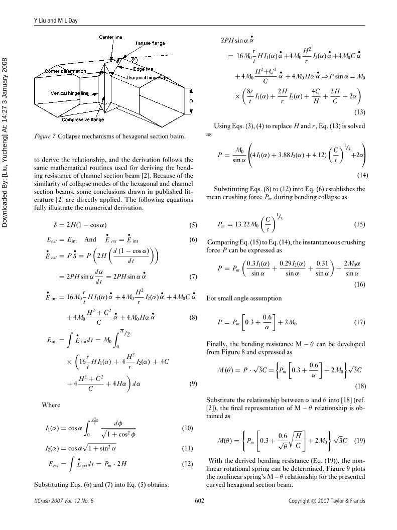
The moment-rotation characteristics of the non-linearrotational spring element can be derived based on thecollapse mechanisms of the hexagonal section beam(Figure 7). Global energy equilibrium method is applied
601Copyright C© 2007 Taylor & Francis IJCrash 2007 Vol. 12 No. 6
Dow
nloa
ded
By:
[Liu
, Yuc
heng
] At:
14:2
7 3
Janu
ary
2008
Y Liu and M L Day
Figure 7 Collapse mechanisms of hexagonal section beam.
to derive the relationship, and the derivation follows thesame mathematical routines used for deriving the bend-ing resistance of channel section beam [2]. Because of thesimilarity of collapse modes of the hexagonal and channelsection beams, some conclusions drawn in published lit-erature [2] are directly applied. The following equationsfully illustrate the numerical derivation.
δ = 2H(1 − cos α) (5)
Eext = Eint And•E ext = •
E int (6)
•E ext = P
•δ = P
(2H
(d (1 − cos α)
d t
))
= 2PH sin αdα
d t= 2PH sin α
•α (7)
•E int = 16M0
rt
H I1(α)•α + 4M0
H2
rI2(α)
•α + 4M0C
•α
+ 4M0H2 + C 2
C•α + 4M0 Hα
•α (8)
Eint =∫ •
E intd t = M0
∫ π/2
0
×(
16rt
H I1(α) + 4H2
rI2(α) + 4C
+ 4H2 + C 2
C+ 4Hα
)dα (9)
Where
I1(α) = cos α
∫ √2α2
0
dφ√1 + cos2 φ
(10)
I2(α) = cos α√
1 + sin2 α (11)
Eext =∫ •
Eextd t = Pm · 2H (12)
Substituting Eqs. (6) and (7) into Eq. (5) obtains:
2PH sin α•α
= 16M0rt
H I1(α)•α +4M0
H2
rI2(α)
•α +4M0C
•α
+ 4M0H2+C 2
C•α + 4M0 Hα
•α ⇒P sin α = M0
×(
8rt
I1(α) + 2Hr
I2(α) + 4CH
+ 2HC
+ 2α)
(13)
Using Eqs. (3), (4) to replace H and r , Eq. (13) is solvedas
P = M0
sin α
(4I1(α) + 3.88I2(α) + 4.12)
(Ct
)1/3+2α
(14)
Substituting Eqs. (8) to (12) into Eq. (6) establishes themean crushing force Pm during bending collapse as
Pm = 13.22M0
(Ct
)1/3(15)
Comparing Eq. (15) to Eq. (14), the instantaneous crushingforce P can be expressed as
P = Pm
(0.3I1(α)
sin α+ 0.29I2(α)
sin α+ 0.31
sin α
)+ 2M0α
sin α
(16)
For small angle assumption
P = Pm
[0.3 + 0.6
α
]+ 2M0 (17)
Finally, the bending resistance M – θ can be developedfrom Figure 8 and expressed as
M (θ ) = P ·√
3C ={
Pm
[0.3 + 0.6
α
]+ 2M0
}√3C
(18)
Substitute the relationship between α and θ into [18] (ref.[2]), the final representation of M – θ relationship is ob-tained as
M(θ ) ={
Pm
[0.3 + 0.6√
θ
√HC
]+ 2M0
} √3C (19)
With the derived bending resistance (Eq. (19)), the non-linear rotational spring can be determined. Figure 9 plotsthe nonlinear spring’s M – θ relationship for the presentedcurved hexagonal section beam.
602IJCrash 2007 Vol. 12 No. 6 Copyright C© 2007 Taylor & Francis

Dow
nloa
ded
By:
[Liu
, Yuc
heng
] At:
14:2
7 3
Janu
ary
2008
Development of simplified thin-walled beam models for crashworthiness analyses
Table 4 Comparisons of crash results from detailed and simplified curvedhexagonal section beam models
Detailed model Simplified model Difference (%)
Global displacement (mm) 147.3 146.8 −0.14Peak crushing force (KN) 19.2 21.5 12Absorbed energy (KJ) 14 13 −7.1Nodes/elements 3288/3292 55/55
Figure 8 Relationship between M(θ ) and P .
Figure 9 M(θ ) – θ curve of nonlinear spring element forcurved hexagonal section beam.
Simplified model
The simplified curved beam model (Figure 10) then canbe developed applying Liu and Day’s modeling method[1]. In the simplified model, the detailed curved hexago-nal beam model is represented by three straight segmentsand three plastic hinges. The straight beam segments aremodeled with Hughes – Liu beam elements, and the de-veloped nonlinear rotational spring elements are used formodeling the local plastic hinges. Such plastic hinges areused to simulate the model’s bending behavior during theanalyses. To define a nonlinear rotational spring elementin LS-DYNA, a created rotational angle-moment table isinput, which contains a series of moment values in termsof different rotational angle θ which are calculated basedon the derived Eq. (19) in Microsoft Excel.
In deciding the simplified model’s boundary conditions,the boundary conditions of the detailed model are refer-enced. In the simplified model, the impact-end node of thecurved beam is fully constrained by fixing all its six degrees
Figure 10 Simplified model for thin-walled curved beam with hexagonal section.
603Copyright C© 2007 Taylor & Francis IJCrash 2007 Vol. 12 No. 6

Dow
nloa
ded
By:
[Liu
, Yuc
heng
] At:
14:2
7 3
Janu
ary
2008
Y Liu and M L Day
Figure 11 Comparisons of crash results – curved thin-walled hexagonal beam, (a) deformed configurations, (b) displacements,(c) crushing forces, (d) absorbed energies.
Figure 12 The detailed model for thin-walled straight beamwith circular section.
of freedom, and only the translational degree of freedomalong its length is released for the rear-end node, where theinitial velocity is imposed. Additionally, since the curvedbeam is defined along a 2D plane, certain constraints haveto be applied in order to prevent the out-of-plane mo-tion. Meanwhile, the coincident nodes where the springelements were defined are bonded together to promise cor-rect connectivity.
Results and comparisons
The generated simplified model is then used for crash anal-yses, as well as the original detailed model. Figure 11 andTable 4 display and compare the analysis results. From acomparison of the results, it is shown that the developedsimplified curved hexagonal section model is qualified forreplacing the detailed model to be used for crash analyses.Also, it is preliminarily verified that the derived Eq. (19)can correctly predict the bending behavior of the hexago-nal section beam, even if it is derived by taking reasonableassumptions and approximations. Undoubtedly, it is appli-cable to determining the nonlinear spring elements, whichare used in simplified modeling.
604IJCrash 2007 Vol. 12 No. 6 Copyright C© 2007 Taylor & Francis

Dow
nloa
ded
By:
[Liu
, Yuc
heng
] At:
14:2
7 3
Janu
ary
2008
Development of simplified thin-walled beam models for crashworthiness analyses
Figure 13 Comparisons of crash results – straight thin-walled circular beam, (a) deformed configurations, (b) displacements,(c) crushing forces, (d) absorbed energies.
Table 5 Comparisons of crash results from detailed and simplified straight circularsection beam models
Detailed model Simplified model Difference (%)
Global displacement (mm) 146.2 145.4 −0.55Peak crushing force (KN) 75.6 79.2 4.8Absorbed energy (KJ) 4.64 4.56 −1.7Nodes/elements 1836/1836 70/70
Table 6 Comparisons of crash results from detailed and simplified curved circularsection beam models
Detailed model Simplified model Difference (%)
Global displacement (mm) 147 146.1 −0.61Peak crushing force (KN) 19 25.4 33.7Absorbed energy (KJ) 14.4 16.1 11.8Nodes/elements 3530/3532 55/55
SIMPLIFIED MODELING OF STRAIGHT CIRCULARBEAM
Similar to the thin-walled straight hexagonal beam,Figure 12 shows the detailed straight circular beam model.
The radius of the circular cross section R is 35 mm andother geometries, material of properties and crash condi-tions are the same as the straight hexagonal beam (Table1). According to previous literature [7], the mean crushingforce Pm and the half plastic folding wave length H are
605Copyright C© 2007 Taylor & Francis IJCrash 2007 Vol. 12 No. 6

Dow
nloa
ded
By:
[Liu
, Yuc
heng
] At:
14:2
7 3
Janu
ary
2008
Y Liu and M L Day
Figure 14 The detailed model for thin-walled curved beam with circular section.
estimated as
Pm/M0 = 25.23(2R/t)1/2 + 15.09 (20)
H = 1.84R(t/2R)1/2 (21)
With Eqs. (19) and (20), the spring element for thepresented circular beam model can be fully defined. Sub-stituting R, t, and M0 into the equations, Pm and H arecalculated as 43.5KN and 9.43 mm respectively. There-fore, the F – δ characteristic of the spring element can bedetermined, which is that same curve as plotted in Figure3, except the force is 43.5KN and the maximum defor-mation is 2H = 18.86 mm. The simplified beam modelthen can be created following the same routine introducedbefore, which has a similar configuration as the simpli-fied hexagonal model (Figure 4), where the length of eachbeam segment equals 18.86 mm and these segments areconnected by the developed springs. Hughes – Liu beamelements with circular cross section are used to build thesebeam segments.
Results and comparisons
Similarly, both the detailed and simplified models intro-duced in this section are used for crash analyses; Figure 13and Table 5 show the results from the comparisons. Fromthe comparison results, the same conclusion can be drawnthat the current axial collapse theories for circular tubes canbe applied to generate qualified simplified models that canbe used to replace the detailed models for crash analyses.
SIMPLIFIED MODELING OF CURVED CIRCULAR BEAM
Figure 14 shows the detailed curved circular beam model,which has the same geometries, material properties, andcrash conditions as the curved hexagonal beam (Table 3),except that the radius of its cross section is 50 mm. Thecollapse mode of such a beam model is plotted in Figure 15(ref. [8]). From that figure, it is shown that during itsbending, all the internal energy is dissipated along twoplastic hinge lines. The internal energy can be written as
•E int = 4M0 R
•θ (22)
Figure 15 Collapse mode of thin-walled circular sectionbeam.
Figure 16 M(θ ) – θ curve of nonlinear spring element forcurved circular section beam.
Following the same routine used for curved hexagonalbeam, the bending resistance of curved circular beam canbe numerically estimated. From Eqs. (6), (7), and (21), wecan have
2PH sin αα̇ = 4M0 Rθ̇ (23)
Also, the bending moment M for the curved circular beamis:
M = P · (2R) (24)
Combining Eqs. (22), (23), and (20), and also substitutingthe relationship between α and θ , the desired bendingresistance can be obtained and plotted (Figure 16).
M = 3.07M0 R1.5/(tθ )0.5 (25)
606IJCrash 2007 Vol. 12 No. 6 Copyright C© 2007 Taylor & Francis

Dow
nloa
ded
By:
[Liu
, Yuc
heng
] At:
14:2
7 3
Janu
ary
2008
Development of simplified thin-walled beam models for crashworthiness analyses
Figure 17 Comparisons of crash results – curved thin-walled circular beam, (a) deformed configurations, (b) displacements,(c) crushing forces, (d) absorbed energies.
The M(θ ) – θ curve plotted in Figure 16 then is employedto define a nonlinear rotational spring element. The sim-plified curved circular beam model can then be developed,which is similar to the developed simplified curved hexag-onal beam model (Figure 10). In this simplified model,the straight beam segments are modeled using Hughes –Liu beam elements with circular cross section, and thedeveloped nonlinear rotational spring elements are usedfor modeling the local plastic hinges. This derived circu-lar beam’s bending resistance (Eq. (25)) and the developedsimplified curved circular beam model are verified throughthe crashworthiness analysis.
Results and comparisons
After modeling, both simplified and detailed models areused for crash analysis, and the dynamic results yieldedfrom both models are compared to one another, to validatethe developed simplified model. Table 6 lists the results ofthe comparisons, and Figure 17 plots these results and thedeformed shapes as well.
As Table 6 shows, both models yield the same globaldisplacement, but the errors for the peak crushing forceand the absorbed energy are higher compared to other typesof models. A possible reason might be the rough collapsemode that is used here for deriving the bending resistanceof thin-walled circular section beams (Figure 16). In orderto acquire better simulation results, an improved bendingcollapse mode has to be applied instead of the one shownin Figure 16.
CONCLUSION AND RECOMMENDATION
This paper focuses on generating simplified finite elementmodels for general thin-walled structures based on the pub-lished and derived collapse theories, which can be used forcrashworthiness analyses. Two types of thin-walled struc-tures – the hexagonal cross section and the circular crosssection are covered in this project, and two types of col-lapse behavior – the axial collapse and the bending collapseare discussed and applied for the simplified modeling. Inthis paper, the published axial collapse theories for bothhexagonal and circular cross-sectional beams are directlyapplied for generating the simplified models. Meanwhile,
607Copyright C© 2007 Taylor & Francis IJCrash 2007 Vol. 12 No. 6

Dow
nloa
ded
By:
[Liu
, Yuc
heng
] At:
14:2
7 3
Janu
ary
2008
Y Liu and M L Day
the numerical relationships between the bending momentsand rotation angle are derived on the basis of the collapsemodes for both thin-walled structures. The developed sim-plified models and the derived bending resistances of thethin-walled beams are validated through running the crashanalyses and comparing the results. The results of the com-parisons verify that the generated simplified models couldsimulate the structures’ collapse behavior efficiently andproperly, as well as the original detailed models. Also, it isverified that the derived bending resistance for the hexag-onal section beam could correctly predict such a beam’sbending behavior, while a better collapse mode for thin-walled circular beam is required for acquiring a precisedescription of its bending characteristics.
Besides the fewer and simpler elements used in sim-plified models, it is found that with the simplified modelthe transition between the thin-walled hexagonal and cir-cular beam models can be easily implemented, by as-signing different cross-sectional information and differentspring characteristics. Even for other hexagonal or circularbeams with different cross-sectional information or mate-rial, there is no need to re-create a new model but to re-define the material properties, cross-sectional geometries,and spring characteristics. This is an important advantageof the simplified models and in the preliminary designphase it will allow designers to evaluate and compare moredesign alternatives.
Summarily, this paper reviews and derives the axial andbending collapse characteristics of two typical thin-walledstructures: hexagonal beam and circular beam. From thispaper, the relationships of crushing force-axial shortening,and bending moment-rotation angle, of these two struc-tures can be easily predicted based on their given geome-
tries and properties. Besides that, the developed simplifiedmodels based on the demonstrated collapse characteristicsare verified to be used for the crashworthiness analyses.The analyses results from the simplified models reach agood agreement to those from the detailed ones. Comparedto the detailed models, the developed simplified models areeasy to build and modify, and also take less time and com-puter resources during the analyses. These features makethem suitable for the early design process in product engi-neering.
REFERENCES
1. Y C Liu and M L Day, ‘Simplified modeling of thin-walled boxsection beam’, Int J Crashworthiness, 2006 11(3) 263–272.
2. Y C Liu and M L Day, ‘Bending collapse of thin-walled beamswith channel cross-section’, Int J Crashworthiness, 2006 11 (3)251–262.
3. T Wierzbicki and W Abramowicz, ‘On the crushingmechanisms of thin-walled structures’, J Appl Mech, 1983 50727–734.
4. W Abramowicz and T Wierzbicki, ‘Axial crushing ofmulticorner sheet metal columns’, J Appl Mech, 1989 53113–120.
5. W Abramowicz, ‘Simplified crushing analysis of thin-walledcolumns and beams’, Rozprawy Inzynierskie, Eng Trans, 1981 29(1) 5–26.
6. D Kecman, ‘Bending collapse of rectangular and square sectiontubes’, Int J Mech Sci, 1983 25 (9/10) 623–636.
7. W Abramowicz and N Jones, ‘Dynamic progressive buckling ofcircular and square tubes’, Int J Impact Eng, 1986 4 (4)243–270.
8. L Zheng and T Wierzbicki, ‘Quasi-static crushing of S-shapedaluminum front rail’, Int J Crashworthiness, 2004 9 (2) 155–173.
608IJCrash 2007 Vol. 12 No. 6 Copyright C© 2007 Taylor & Francis