Finding the limbs and cusps of generalized cylinders
16
International Journal of Computer Vision, 1, 195-210 (1987) © 1987 Kluwer Academic Publishers, Boston. Manufactured in The Netherlands Finding the Limbs and Cusps of Generalized Cylinders* JEAN PONCE AND DAVID CHELBERG Robotics Laboratory, Stanford University, Stanford, Calif. 94305 Abstract This paper addresses the problem of finding analytically the limbs and cusps of generalized cylinders. Orthographic projections of generalized cylinders whose axis is straight and whose axis is an arbitrary 3D curve are considered in turn. In both cases, the general equations of the limbs and cusps are given. They are solved for three classes of generalized cylinders: solids of revolution, straight homogeneous generalized cylinders whose scaling sweeping rule is a polynomial of degree less than or equal to 5 and generalized cylinders whose axis is an arbitrary 3D curve but the cross section is circular and constant. Examples of limbs and cusps found for each class are given. Applications and extensions to perspective projection and completely general straight generalized cylinders are discussed. 1 Introduction A generalized cylinder [1] is the solid obtained by sweeping a planar surface, its cross section, along a space curve, its axis, or spine. The axis is not necessarily straight, or even planar; the cross sec- tion is not necessarily circular or even constant; its deformation is governed by a sweeping rule. Generalized cylinders have been used exten- sively to represent three-dimensional objects in computer vision [3,7,8]. The problem of finding analytically the limbs and cusps of a generalized cylinder under arbi- trary viewing directions is addressed here. Limbs are points on the generalized cylinder surface where the normal )V to the surface is orthogonal to the viewing direction V. Cusps are limb points where the viewing d~ection V is aligned with the limb tangent vector T. The viewing direction can be constant (orthographic projection), or given by the line joining the focal point to the con- sidered point on the surface (perspective pro- jection). *This work was supported by the Air Force Office of Scien- tific Research under contract F33615-85-C-5106 and the Ad- vanced Research Agency under Knowledge Based Vision contract AIADS S1093-S-1. Limbs and cusps are important because they determine the "geometric" discontinuities in the images of smooth curved surfaces [2].1 If an ob- ject contains edges (orientation discontinuities) then these edges also produce intensity discon- tinuities, even when they are not actual limbs. The visibility of the edges' and limbs' projections changes only at cusp points and T-junctions (i.e., where two segments cross each other). It follows that the knowledge of the limbs, edges, cusps, and T-junctions of an object in a given view completely determines the visible image boundaries of the projection of this object in this view [4,13]. For a given object, the edges are independent of the viewing direction, and T- junctions can be found by computing the inter- sections of the contour segments. Limbs and cusps, on the other hand, depend on the surface geometry and the viewing direc- tion. They are not curves physically drawn on the surface. This makes the analysis of line drawings much more complex for curved objects [5] than for polyhedra. In particular, a vision system designed to deal with curved objects should be llmage discontinuities can also be caused by illumination and reflectance discontinuities.
Transcript of Finding the limbs and cusps of generalized cylinders

International Journal of Computer Vision, 1, 195-210 (1987) © 1987 Kluwer Academic Publishers, Boston. Manufactured in The Netherlands
Finding the Limbs and Cusps of Generalized Cylinders*
JEAN PONCE AND DAVID CHELBERG Robotics Laboratory, Stanford University, Stanford, Calif. 94305
Abstract
This paper addresses the problem of finding analytically the limbs and cusps of generalized cylinders. Orthographic projections of generalized cylinders whose axis is straight and whose axis is an arbitrary 3D curve are considered in turn. In both cases, the general equations of the limbs and cusps are given. They are solved for three classes of generalized cylinders: solids of revolution, straight homogeneous generalized cylinders whose scaling sweeping rule is a polynomial of degree less than or equal to 5 and generalized cylinders whose axis is an arbitrary 3D curve but the cross section is circular and constant. Examples of limbs and cusps found for each class are given. Applications and extensions to perspective projection and completely general straight generalized cylinders are discussed.
1 Introduction
A generalized cylinder [1] is the solid obtained by sweeping a planar surface, its cross section, along a space curve, its axis, or spine. The axis is not necessarily straight, or even planar; the cross sec- tion is not necessarily circular or even constant; its deformation is governed by a sweeping rule. Generalized cylinders have been used exten- sively to represent three-dimensional objects in computer vision [3,7,8].
The problem of finding analytically the limbs and cusps of a generalized cylinder under arbi- trary viewing directions is addressed here. Limbs are points on the generalized cylinder surface where the normal )V to the surface is orthogonal to the viewing direction V. Cusps are limb points where the viewing d~ection V is aligned with the limb tangent vector T. The viewing direction can be constant (orthographic projection), or given by the line joining the focal point to the con- sidered point on the surface (perspective pro- jection).
*This work was supported by the Air Force Office of Scien- tific Research under contract F33615-85-C-5106 and the Ad- vanced Research Agency under Knowledge Based Vision contract AIADS S1093-S-1.
Limbs and cusps are important because they determine the "geometric" discontinuities in the images of smooth curved surfaces [2]. 1 If an ob- ject contains edges (orientation discontinuities) then these edges also produce intensity discon- tinuities, even when they are not actual limbs. The visibility of the edges' and limbs' projections changes only at cusp points and T-junctions (i.e., where two segments cross each other).
It follows that the knowledge of the limbs, edges, cusps, and T-junctions of an object in a given view completely determines the visible image boundaries of the projection of this object in this view [4,13]. For a given object, the edges are independent of the viewing direction, and T- junctions can be found by computing the inter- sections of the contour segments.
Limbs and cusps, on the other hand, depend on the surface geometry and the viewing direc- tion. They are not curves physically drawn on the surface. This makes the analysis of line drawings much more complex for curved objects [5] than for polyhedra. In particular, a vision system designed to deal with curved objects should be
llmage discontinuities can also be caused by illumination and reflectance discontinuities.

196 Ponce and Chdbeng
able to reason about the limbs and cusps of these objects.
Typically, limbs and cusps can be used for three kinds of tasks: The first one is prediction, where one predicts observable characteristics of the image of an object, given some knowledge of the viewing direction [13]. We have used else- where [10] the results presented in this paper to predict view-independent properties of the con- tours of generalized cylinders.
When the viewing direction is precisely known, prediction reduces to a graphics problem, i.e., drawing the image of an object knowing its posi- tion and orientation. Along these lines, we have incorporated the results presented in this paper in a solid modeling system combining straight homogeneous generalized cylinders through set operations [9].
The third task is segmentation. In this case, by using invariant or quasi invariant properties of the limbs' projections, one can for example find ribbons in an image [3]. We have used the results presented here to find the axis of straight homo- geneous generalized cylinders in real images [10[.
These examples show the importance of the mathematical study of the geometric properties of the limbs and cusps of generalized cylinders. Work in this area was pioneered by Marr [6] and more recently by Shafer and Kanade [12]. We follow an approach very similar to theirs, extend- ing their results to find the limbs and cusps for a wide class of generalized cylinders.
In this paper, we consider generalized cylin- ders whose cross sections are in a plane orthog- onal to their axis and are defined in some polar coordinate system of this plane (figure 1). We are only concerned with orthographic projection. The general limb and cusp equations are ex- pressed for straight generalized cylinders (sec- tion 2) and generalized cylinders whose spine is an arbitrary 3D curve (section 5).
For limbs, this is done by deriving the expres- sion of the normal to the surface of the general- ized cylinder, and expressing the fact that the dot product between the normal and the viewing direction is 0. For cusps, this is done by deriving the expression of the tangent to the limb, and ex- pressing the fact that the vector product between the tangent and the viewing direction is 0.
sp i t l , " I f cross section
Fig. 1. A generalized cylinder is defined by a 3D curve, its spine (or axis), and planar cross sections orthogonal to the spine. The cross sections are defined in polar coordinates.
Solutions to the equations defining the limbs and cusps are given for three classes of general- ized cylinders: arbitrary solids of revolution (sec- tion 3), straight homogeneous generalized cylin- ders whose scaling sweeping rule is a polynomial of degree less than or equal to 5 (section 4), and generalized cylinders whose axis is an arbitrary 3D curve, and whose cross section is constant and circular (section 6).
For each class, examples of the limbs and cusps found for members of the class are given (figures 6, 8, 11, and 12). In section 7, we finally discuss and illustrate in more detail applications of these methods to prediction, graphics, and segmentation. Extensions to completely general straight generalized cylinders and perspective projection are briefly discussed in the conclusion (see [11] for more details).
Finding the Limbs and Cusps of Generalized Cylinders 197
2 The General Case of Straight Generalized Cylinders
In this section, we derive the general l imb and cusp equations for straight generalized cylinders. Although generalized cylinders are volumes, the limbs and cusps are defined in terms of their sur- face, so we use a parametric representation of these surfaces.
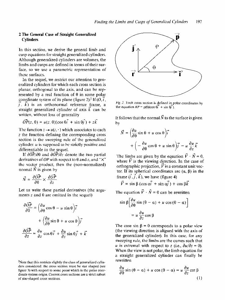
In the sequel, we restrict our attention to gen- eralized cylinders for which each cross section is planar, orthogonal to the axis, and can be rep- resented by a real function of 0 in some polar £oordinate system of its plane (figure 2). 2 If (O, i, j , k) is an orthonormal reference f rame, a straight generalized cylinder of axis k can be written, without loss of generality
O-~P(z, O) = u(z, 0)(cos 0 f + sin 0 f ) + z k
The function z --~ u(z,. ) which associates to each z the function defining the corresponding cross section is the sweeping rule of the generalized cylinder, u is supposed to be strictly positive and differentiable in thesequel .
If OOP/OO and OOP/Oz denote the two partial derivatives of OP with respect to 0 and z, and "'×" the vector product, then the (non-normalized) normal N is given by
_ OOP X OOP O0 Oz
Let us write these partial derivatives (the argu- ments z and 0 are omitted in the sequel)
+ (°;0s,n0+ co 0)j OOP _ Ou c o s O [ + Ou Oz Oz fiZZ sin o f + k*
2Note that this restricts slightly the class of generalized cylin- ders considered: the cross section must be star shaped (see figure 3) with respect to some point which is the polar coor- dinate system origin. Convex cross sections are a strict subset o f star-shaped cross sections.
Fig. 2. Each cross section is def ined i n p o l a r coordinates by the equation RP = p(0)(cos 0i + sin 0j ).
It follows that the normal N to the surface is given by
= s i n 0 + u c o s 0
+ - ~ c o s 0 + u s in0 - u ~
The limbs are given by the equation P • N = 0, where V is the viewing direction. In the case of orthographic projection, P is a constant unit vec- tor. If its spherical coordinates are (a, 13) in the
frame ( [ , f , k), we have (figure 4)
f = sin 13 (cos cJ" + sin a f ) + cos 13k
The equation P • IV = 0 can be rewritten
sin 13 ~ sin (0 - ct) + u cos (0 - a)
Ou = u c o s 13
The case sin 13 = 0 corresponds to a polar view (the viewing direction is aligned with the axis of the generalized cylinder). In this case, for any sweeping rule, the limbs are the curves such that u is extremal with respect to z (i.e., Ou/Oz = 0). When the view is not polar, the limb equation for a straight generalized cylinder can finally be rewritten
Ou O Uo0 sin (0 - ct) + u cos (0 - ct) = u Ozz cot [3
(1)

198 Ponce and Chelberg
Convex Star shaped around P
U
Two non star shaped regions.
Fig. 3. A region is star shaped with respect to a point P iff for each point on its boundary, the whole segment between P and the point is included inside the region. Convex regions are star shaped with respect to any point within them.
We now turn to cusps. They are points on the limbs where the tangent T is aligned with the viewing direction. We first compute the tangent to the limb. Suppose the limb equat ion is solved, and the limb can be parameter ized by say t, i.e., that 0 and z can be written as functions of t. A point on the l imb can then be written
O-P(t) = u [z(t),O(t)] [cos 0(t)~ + sin 0( t ) f ]
+ z(t) Let us define v(t) by o(t) = u [z(t), 0(t)]. F rom now on we drop the t argument. The (non-normal- ized) tangent T to the l imb is
_ d O e dt - (v' cos0 - v0' s i n 0 ) t
+ (o' sin 0 + v0' cos 0 ) f + z'k"
The cusp equation is T × V = O. It can be rewrit- ten as a set of three equations, expressing that the three coordinates of the cross product are 0.
(o0' cos 0 + v' sin 0) cos 13 - z ' sin ct sin 13 = 0 ( l . a )
(v0' sin 0 - v' cos 0) cos 13 + z ' cos ~ sin 13 = 0 0 .b)

Finding the Limbs and Cusps of General&ed Cylinders 199
---> By substituting the value of Ou/Oz given by equa- k tion (1) we get
v ' ( t ) = z '
Ou × [ff0 sin (0 - a) + u cos (0 - ct)]
+ 0 ' ~ ,
By substituting v in equation (1.e) we get
z sin 13 Ou . i - - u - - [ ~ sin ( 0 - ct)+ u cos ( 0 -
r OU + 0 cos 13 f f~=z cos (O - (~) sin13
Fig.4. A sphericalcoordina_te system.The vector ~ is given by V = sin 13 (cos ai + sin qi ) + cos [3k. (ct, [3) are the spheri- cal coordinates of 3.
- s i n [3Iv' sin (0 - (x) + uO' cos (0 - ct)] = 0 (1.c)
We have three equations defining points param- eterized by a single parameter t. We now show that in fact the third equat ion is a combinat ion of the two first equations, which are equivalent. First, the equations (1.a) and (1.b) are equiva- lent to
vO' cos [3 = - z ' sin (0 - ct) sin [3 (1.d)
which is
(1.a) c o s O + (1 .b ) s inO = (1.d)
and
o' cos 13 = z' cos (0 - (~) sin 13 (1.e)
which is
(1.a) sinO - (1.b) c o s O = (1.e)
In particular (1.d) and (1.e) imply (1.c). We now use the l imb equation to show that (1.d) and (1.e) are equivalent. The derivative of v is
Ou , Ou O' o ' ( t ) = U z +
By simplifying this equation, we get (1.d). This means that cusps are given by the limbs points which verify (1.d) or equivalently (1.e).
We now solve the limb and cusp equations for solids of revolution and straight homogeneous generalized cylinders for which the sweeping rule is a polynomial of degree less than or equal to 5.
3 Solids of Revolution
A solid of revolution is obtained by rotating a planar curve around a straight line. Here we re- strict our attention to the case where the generat- ing curve can be expressed as a strictly positive function r of z (figure 5).
In this case u(z, 0) is identical to r(z). Its partial derivative with respect to 0 is identically 0, and its derivative with respect to z is r'(z). Substituting in equation (1), and dividing by r, we finally get
cos (0 - a) = r'(z) cot [3
This implies in particular that if the view is close enough to a polar view, there is no limb (e.g., when one looks at a cone from above, only the circular edge is visible). When there is a limb on the other hand, this limb has an analytical ex- pression 0 =f(z) . See [12] for a slightly different approach, leading to the same result. Notice finally that the limbs of a solid of revolution are

200 Ponce and Chelberg
Fig. 5. A solid of revolution. This bottle-shaped solid is formed by rotating a sine function r(z) around the z-axis.
in general not planar (although, for example, the limbs of a cone are straight lines).
We now use equation (1.d) to get the cusps. In this case the parameter t is z itself, and v is identi- cal to r. z' = 1, and we get 0' by differentiating the limb equation.
- 0 ' sin (0 - ct) = r" cot 13
By substituting 0' and z' in (1.d), and replacing sin2(0 - ct) by (1 - / 2 cot 2 13) we finally get the cusp equation:
r '2 + rr" - tan 213 = 0
This is a one parameter equation in z. It is solved by looking for its zeros along the limb. Figure 6 shows different views of a solid of revolution, with its l imbs and cusps.
4 Straight Homogeneous Generalized Cylinders
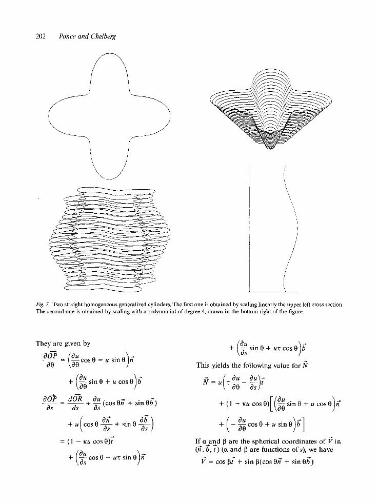
We now consider straight homogeneous general- ized cylinders (SHGC's, following the taxonomy of Shafer and Kanade [12]): they are generalized cylinders whose cross sections are scaled ver- sions of a reference curve (figure 7). In this case the function u(z, 0) can be decoupled into the product r(z)p(0), where p specifies the reference
cross section, and r the scaling function. The par- tial derivatives of u are Ou/O0 = r 9' and Ou/Oz
= / P . By substituting in equation (1), and dividing by rp 2 we get
p--. 1 p2 sin (0 - ct) + -p cos (0 - ~t) = r' cot 13
In particular this implies that if the scaling func- tion r is constant or linear, or if the view is equatorial (cos 13 -- 0), the limbs, if they exist, are planar curves (they are given by a constant left member of the equation, which is a function of 0 only, and can be found by looking for the zeros of a one parameter function). In the case of a polar view, the l imbs are the cross sections correspond- ing to extrema of the r function. Finally, in the remaining case, if the scaling function is a poly- nomial of degree between 2 and 5, the right mem- ber of the equation is a polynomial of degree be- tween 1 and 4, As there exist closed-form solu- tions for the roots of such polynomials, this gives an analytical expression for the l imbs of the form z = f(0). Arbitrary scaling functions can be ap- proximated in terms of low-order splines.
We now solve the cusp equation. Here, the parameter defining the limb is 0. We use again the equation (1.d) to find the cusps. 0' = 1, and o
Finding the Limbs and Cusps of Generalized Cylinders 201
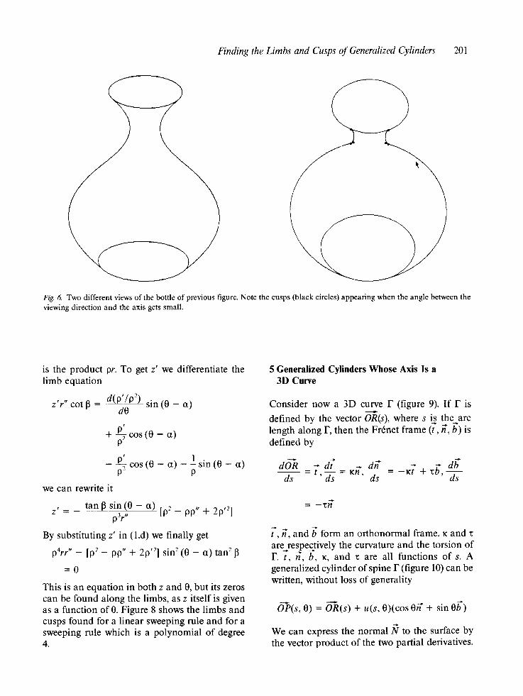
Fig. 6. Two different views of the bottle of previous figure. Note the cusps (black circles) appearing when the angle between the viewing direction and the axis gets small.
is the product pr. To get z' we differentiate the limb equation
z'r" cot [3 - d(P'/P2) sin (0 - a) dO
p' + c o s ( 0 - ct)
P' cos (0 - a) - l sin (0 - a) P- P
we can rewrite it
z' = - tan [3 sin (0 - (z) [p2 _ pp,, + 20,2] p 3 r "
By substituting z' in (1.d) we finally get
p4rr,, _ [p2 _ p9,, + 2p,2] sin 2 (0 - ~t) tan 2
= 0
This is an equation in both z and 0, but its zeros can be found along the limbs, as z itself is given as a function of 0. Figure 8 shows the limbs and cusps found for a linear sweeping rule and for a sweeping rule which is a polynomial of degree 4.
5 Generalized Cylinders Whose Axis Is a 3D Curve
Consider now a 3D curve F (figure 9). If F is
defined by the vector OR(s), where s is the arc length along F, then the Frrnet frame (f, if, b) is defined by
dO~R _ -[, d7 dh* - K ~ + zb, d b ds ds = rh*, d~- = ds
= - z f f
7, if, and b form an orthonormal frame. K and are respectively the curvature and the torsion of F.-~, h', b, K, and 1: are all functions of s. A generalized cylinder of spine F (figure 10) can be written, without loss of generality
O--P(s, O) = O--R(s) + u(s, 0)(cos Oh* + sin 0b')
We can express the normal N to the surface by the vector product of the two partial derivatives.
Ponce and Chelberg 202
i Fig. 7. Two straight homogeneous generalized cylinders. The first one is obtained by scaling linearly the upper left cross section The second one is obtained by scaling with a polynomial of degree 4, drawn in the bottom right of the figure.
They are given by
Ou - 0)h" O ~ - ( ~ c o s 0 us in
+ (O~00 sin 0 + u cos 0)b"
OOP dOR ~ss ds ~ - - ds + (cos 0h*+sin0g ' )
+ u cos0~j-s + s i n 0 ~ s - s
= (1 - ~:u cos 0)t"
+ (O~Us cos 0 - ul: sin 0)h'
• ( s o0 cos0) This yields the following value for
( Ou Ou ; = u z O0 Os]
+ (1 - Ku cos 0 ) [ ( ~ sin 0 + u cos O)h ~
(0u ) ] + - f f o c o s O + u s i n O
If a and 13 are the spherical coordinates of P in (h', b, ~') (ct and l] are functions of s), we have
f = cos 13t" + sin 13(cos Oh" + sin Ob)

Finding the Limbs and Cusps of Generalized Cylinderv 203
F
\ ~ ' , / ' / \ / // ,, ", ,, , *,, ', :/ /
/ /
/ /
/ / I / '\
"\, \
/ / /
/ I ,
~ J
\ !, \ '\
, '\ \, \~
, \ "\\L \\
\
/ / /
/ /
/ / /
'lj
i / ' "\
/ ' k
\ ~ ) / !
Fig. 8. The limbs and cusps for the two previous generalized cylinders.
And the limb equation can be rewritten
sin 13 (1 - Ku cos 0 ) [ ~ sin (0 - c t)
+ u cos (0 - ~ ) ]
(0u = - c o s l 3 u ~ O0
On
(2)
We now derive the cusp equation. As for the straight axis case, we suppose the limb equation has been solved, and that s and 0 can be written as functions of a parameter t. Again, we introduce the function o(t)= u Is(t), O(t)]. Its derivative is given by
O U O U , . .
v'(t) = Os s'(t) + fro 0 (t)

204 Ponce and Chelberg
Fig. 9. The Fr6net frame associated to a 3D curve_: 7 is the tangent to the curve, and it forms with the normal n and the binormal ff a moving orthonormal frame which is function of the arc length s along the curve.
Fig. 10. A generalized cylinder whose axis is an arbitrary 3D curve (in this case a helix).
The tangent T to the l imb can be written
f _ dOP dt
dOR = s'(t) ~ Is(t)]
+ [v ' ( t ) cos 0(t)
- v(t)O'(t) sin O(t)]~ls(t)]
+ V(t) COS O(t)s'(t) ~ s [s(/)l
+ [v ' ( t ) sin 0(t)
+ v(t)O'(t) cos O(t)lbls(t)]
+ v(t) sin O(t)s'(t) ~ [s(t)]
F r o m n o w on we d rop the a r g u m e n t t. Substitut- ing dOR/ds, dff/ds, a n d db/ds, a n d o' we get
= s'(1 - ~u(s, 0) cos 0 )7
+ {[o' OU (s, O) + s ' Ou ] ~ (s, O) cos 0
- (0' + rs')u(s, O) sin Oth"
+{[oou ,ou ] ~(s,O)+ Os(S'O) sinO
+ (0' + ~s')u(s, 0) cos 0}b"
For the sake o f concis ion , we d rop the a rgumen t s s a n d 0, the cusp equa t ion is then given by the three equa t ions
[(O' + r,s')u cosO + (O 'on s' sin0] X cos 13 - s ' (1 - Ku cosO) s i n a sin ~ = 0
(2 .a)
[(O' + r ,s ' )usinO-(O 'Ou s'
X cos 13 + s ' (1 - ~u cos O) cos a sin 13 = 0 (2 .b)

Finding the Limbs and Cusps of Generalized Cylinders 205
- s i n 13[(0' Ou s' Ou) + ~-s s i n ( 0 - c t )
+ (0' + ~s')u cos (0 - a ) ] = 0 (2.c)
The equations (2.a) and (2.b) are equivalent to
(0' + r~s ' )u cos 13
= - s ' ( l - Ku cos 0) sin (0 - ct) sin ]3 (2.d)
which is
(2.a) cos 0 + (2.b) sin 0
and
(o' OU s ' Ou) + c o s 13
= s ' ( l - Ku cos 0) cos (0 - ct) sin [3 (2.e)
which is
(2.a) sin 0 - (2.b) cos 0
Once again, (2.d) and (2.e) imply (2.c), so a limb point is a cusp point iff it verifies (2.d) or equiv- alently (2.e).
6 Circular Tubes
Consider now the special case where the cross section is circular and constant. We call such a generalized cylinder a circular tube. The func- tion u is then a constant P0, and its two partial derivatives are identically 0. I f we denote the radius of curvature of the spine by R(s) = 1/K(s), we get by substituting in equation (2)
( P0 cos O)p0 cos (0 - a(s)) = 0 sin13(s) 1 -
We can suppose without loss of generality that f~ > O. Also, for the generalized cylinder to be well defined, we must have R > P0 (otherwise the surface can self-intersect). So a point is a limb iff 13(s) = 0 (which means that when the viewing direction is aligned with the tangent to the curve, the whole corresponding cross section is a limb) or 0 = a(s) =4- n/2. In the latter case, the limb is
given by an analytic 3D curve parameterized by s.
We now look for cusps. We use equation (2.d). Here the parameter t is s itself, and v(t) = P0. By substituting in (2.d) we get
(0' + ~:)p0 cos 13
= - ( 1 - K90 cos 0) sin (0 - a) sin [3
But the limb equation implies that sin (0 - a) = e where e = T-l, so 0' = a', and cos 0 = - e sin a. Substituting in the previous equation we get
(ct' + ~)90 cos 13 = - e (1 + poke s i n a ) sin[3
or finally
P0el(ct' + ~:) cos 13 + • sin 13 sin ct] = - s i n 13
To simplify further this equation, we express the fact that the viewi~ng direction is a constant vec- tor, i.e., dV/ds = 0. We have
dV d? 13' sin 13t" ds - c o s l 3 d s s -
dh" + (sin 13 cos ct) d~-
+ (13' cos 13 cos a - a ' sin 13 sin a)f f
db" + (sin 13 sin a) d ~
+ (13' cos 13 sin ct + ct' sin 13 cos cob*
By substituting the values of dORMs, dff/ds, and
db/ds, we get the three equations
(a) - s in[3 (13' + ~ c o s a ) -- 0
(b) 13' cos 13 cos a - (a ' + ~) sin 13 sin a
= ~ K COS 13
(c) 13' cos 13 sin a + (ct' + 1:) sin 13 cos a = 0
(d) (b) cos ct + (c) sin ct: cos [3 (13'
+ ~ cos a) = 0
(e) (c) cos a - (b) sin ct: (v + a ' ) sin 13
= K sin ct cos 13
Finally (a), (b), and (c) are equivalent to (e) and
206 Ponce and Chelberg
13' = -K cos ct. We can now substitute ct' in the cusp equation, and we get
poCK sin a + sin 2 [3 = 0
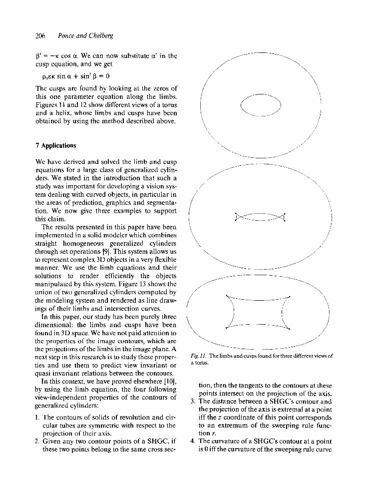
The cusps are found by looking at the zeros of this one parameter equation along the limbs. Figures 11 and 12 show different views of a torus and a helix, whose limbs and cusps have been obtained by using the method described above.
7 Applications
We have derived and solved the limb and cusp equations for a large class of generalized cylin- ders. We stated in the introduction that such a study was important for developing a vision sys- tem dealing with curved objects, in particular in the areas of prediction, graphics and segmenta- tion. We now give three examples to support this claim.
The results presented in this paper have been implemented in a solid modeler which combines straight homogeneous generalized cylinders through set operations [9]. This system allows us to represent complex 3D objects in a very flexible manner. We use the limb equations and their solutions to render efficiently the objects manipulated by this system. Figure 13 shows the union of two generalized cylinders computed by the modeling system and rendered as line draw- ings of their limbs and intersection curves.
In this paper, our study has been purely three dimensional: the limbs and cusps have been found in 3D space. We have not paid attention to the properties of the image contours, which are the projections of the limbs in the image plane. A next step in this research is to study these proper- ties and use them to predict view invariant or quasi invariant relations between the contours.
In this context, we have proved elsewhere [10], by using the limb equation, the four following view-independent properties of the contours of generalized cylinders:
1. The contours of solids of revolution and cir- cular tubes are symmetric with respect to the projection of their axis.
2. Given any two contour points of a SHGC, if these two points belong to the same cross sec-
/ \ , \ / \ / \
/ / /
~. / / /
/
\..
\
\
\,
/ /
/ J
/
/ \
\
J
Fig. I1. The limbs and cusps found for three different views of a toms.
tion, then the tangents to the contours at these points intersect on the projection of the axis.
3. The distance between a SHGC's contour and the projection of the axis is extremal at a point iff the z coordinate of this point corresponds to an extremum of the sweeping rule func- tion r.
4. The curvature of a SHGC's contour at a point is 0 iffthe curvature of the sweeping rule curve

Finding the Limbs and Cusps of Generalized Cylinders 207
/
/
\ .
j f
/ /
/ /
j j l j ~ \
/ "\
Fig. 12. The limbs and cusps found for three different views of a helix.
Fig. 13. The union of two generalized cylinders. The hidden line problem has been solved efficiently by displaying only the intersection curves, edges, and limbs, and using ray trac- ing at the cusps and T junctions only (see 191).
at this point is 0. The curvature is undefined at cusps.
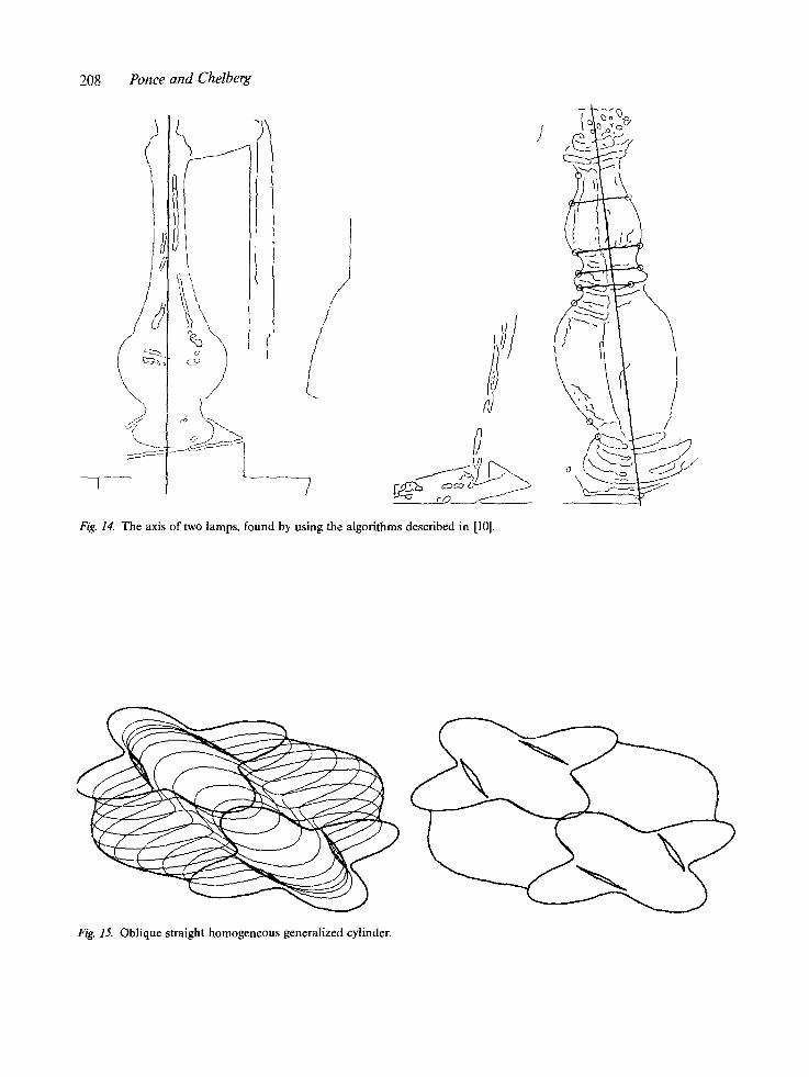
We have used these properties in two algo- rithms for finding the axis of straight homo- geneous generalized cylinders in images [10]. The first one uses property 2 and a Hough transform to find the axis by intersecting all the tangents to contours. This algorithm is com- putationally expensive. A more efficient algo- rithm uses property 4 to guide the Hough trans- form by matching zeros of curvature on the contours. We have successfully tested a pre- liminary implementation of these algorithms on some simple images (figure 14).
Conclusion
We have derived the limb and cusp equations for generalized cylinders with straight and curved spines. We have been able to solve these equa-
208 Ponce and Chelberg
\
q(
"~ ~_._cO_ f _
Fig. 14. The axis of two lamps, found by using the algorithms described in [10].
Fig. 15. Oblique straight homogeneous generalized cylinder.

Finding the Limbs and Cusps of Generalized Cylinders 209
Fig. 16. SHGC whose cross sections are not star shaped.
tions for a large class of generalized cylinders, We have shown how these results could be ap- plied in the areas of prediction, graphics, and segmentation.
In this paper, we have considered only a subset of generalized cylinders, and considered only the case of orthographic projection. It is possible to prove [11] that most of these restrictions can be relaxed. In fact, in the case of straight generalized cylinders, we can deal with non-star-shaped cross sections, oblique cross sections, and per- spective projection.
We can rewrite and solve the limb equation for these more general cases (see figures 15 and 16). Invariant properties can be extended the same way. For example, we have proved [10] that prop- erty 2 of section 7 is true even for oblique SHGC's, even for perspective projection.
Our future work will be dedicated to three main themes: extend the results presented here to an even broader class of generalized cylinders; develop more robust segmentation algorithms and develop analogous methods for range im- ages; and, finally, use these techniques for recog- nizing objects represented by part-whole graphs of joined primitives [2~.
Acknowledgments
We thank Tom Binford, Wally Mann, Glenn Healey, and Brad Chen for useful discussions and comments on earlier drafts of this paper.
References
1. T.O. Binford, "'Visual perception by computer," in PROC. IEEE CONF. Systems and Control, Miami, December 1971.
2. T.O. Binford, ~'lnferring surfaces from images," ARTIFI- CIAL INTELLIGENCE, vol. 17, pp. 205-244, 1981.
3. R.A. Brooks, "Symbolic reasoning among 3D models and 2D images," ARTIFICIAL INTELLIGENCE, vol. 17, pp. 285-348, 1981.
4. J.J. Koenderink and A.J. Van Doorn, "'The singularities of the visual mapping," BIOLOGICAL CYBERNETICS, vol. 24, pp. 51-59, 1976.
5. J. Malik, "'Labelling line drawings of curved objects," in PROC. IU WORKSHOP, Miami Beach, Fla., 1985, pp. 209-218.
6. D. Mart, "'Analysis of occluding contour," in PROC. ROY. SOC. (London) B-197, pp. 441-475, 1977.
7. D. Marr and K. Nishihara, '~Representation and recogni- tion of the spatial organization of three dimensional shapes," in PROC. ROY. SOC. (London), B-200, pp. 269- 294, 1977.

210 Ponce and Chelberg
8. R. Nevatia, Machine perception. Prentice-Hall: En- glewood Cliffs, NJ., 1982.
9. J. Ponce and D. Chelberg, "Localized intersections com- putation for solid modeling with straight homogeneous generalized cylinders," in PROC. FOURTH IEEE RO- BOTICS CONF., Raleigh, N.C., April 1987.
10. J. Ponce, D. Chelberg, and W. Mann, "Analytical proper- ties of generalized cylinders and their projections," in PROC. FIRST INT. CONF. ON COMPUTER VISION, London, U.K., June 1987.
11. J. Ponce and D. Chelberg, "Finding the limbs and cusps of generalized cylinders," to appear as a CS Technical Report, Stanford University, 1987.
12. S.A. Shafer and T. Kanade, "The theory of straight homogeneous generalized cylinders," Tech. Rep. CMU- CS083-105, Computer Science Department, Carnegie Mellon University, 1983.
13. R. Scott, "Graphics and prediction from models," in PROC. IU WORKSHOP, pp. 98-106, 1984.