smhhhhhhhh I EhhhhhhhhhhhhIl EhhhhhhhhhhhhE ... - DTIC
143
,AD-R127 461 SURVEY OF FOREIGN SYSTEMS FOR INCINERATION AND ENERGY 1/2 RECOVERY(U) SYSTECH CORP XENIA OH R FROUNFELKER ET AL. APR 83 NCEL-CR-83.825 N62583-82-MT-i59 UNCLASSIFIED F/G 13/2 N smhhhhhhhh I EhhhhhhhhhhhhIl EhhhhhhhhhhhhE EhhhhhhhhhhhhI mhhhhhhI-
-
Upload
khangminh22 -
Category
Documents
-
view
2 -
download
0
Transcript of smhhhhhhhh I EhhhhhhhhhhhhIl EhhhhhhhhhhhhE ... - DTIC

,AD-R127 461 SURVEY OF FOREIGN SYSTEMS FOR INCINERATION AND ENERGY 1/2RECOVERY(U) SYSTECH CORP XENIA OH R FROUNFELKER ET AL.APR 83 NCEL-CR-83.825 N62583-82-MT-i59
UNCLASSIFIED F/G 13/2 N
smhhhhhhhh IEhhhhhhhhhhhhIlEhhhhhhhhhhhhEEhhhhhhhhhhhhI
mhhhhhhI-

- "4 - -
.6, 12.'1i
11111L25' .4
IIIII 11-11 111114
MICROCOPY RESOLUTION TEST CHARTNATIONAL BUREAU OF STANDARDS-1963-A
.,'..... .. . . ""..-." " ." . " . "• . ,". "
.. . . . . ," - . ... " . . ." ". . . . .°

:'"C 1R 83.02 5
NAVAL CIVIL ENGINEERING LABORATORYPort Hueneme, California
Sponsored byCHIEF OF NAVAL MATERIALNAVAL FACILITIES ENGINEERING COMMAND
SURVEY OF FOREIGN SYSTEMS FOR INCINERATION ANDENERGY RECOVERY
April 1983
An Investigation Conducted bySYSTECH CORPORATION245 North Valley RoadXenia, Ohio
N62583-82-MT- 150
L Approved for public release; distribution unlimited
88 04 29 042

1966 .I a .r I Air
~~Y In~

77- 7 77 757.
Unclassi fiedSECURITY CLASSIFICATION OF T.I$ WAGE (in.. f)4N. F..I..~E )
READ INSTRUCTIONSREPORT DOCUMENTATION PAGE BEFORE COMPLETING FORMI REPORT NUMlfP ft GOVT ACCESSION iO. * RECIPIENT'S CATALOG NUMBER
CR 83.025 VdIx.//)9e4 TITLE IIt(d Subtl.) $ TYPE OF RePORIT ' PERIOp COVEREO
SURVEY OF FOREIGN SYSTEMS FOR Not final;INCINERATION AND ENERGY RECOVERY •,.moa..,2o 419.T4.i.4;
7 A" T O(*-,. 0 CONTRACT O GRANT NUMGER(.)
Richard Frounfelker N62583-82-MT-150Brian A. Hausfeld
SPERFORMING ORGANIZATION NAME AND ADDRESS 10 PROGRAM ELEMENT. PROJECT. TASKSYSTECH CORPORATION YOAREA, WO K UN %,,9
245 North Valley Road SO371-O-421A/BXpnia_. OH 451R6
1' CONTROLL9NC OFFICE NAME AND ADDRESS 12 REPORT DATE
Naval Civil Engineering Laboratory April 1983Port Hueneme, CA 93043 14 3 MU°ROFPAA
14 MONITORING AGENCY NAME & AODRESSI.f d.lg fro..I #- COnIIIl,..E1 OIlI *) IS. SECURITY CL ASS. (of thie eporf)
Chief of Naval Material, Washington, DCNaval Facilities Engineering Command UnclassifiedIeOE[Ct ASSI FiC ALTION ' OWINGN ADING
Alexandria, VA SC.,I,,,.,
IS OISTRINUTION STATIMENT (.1 'Ni. Repo,,)
Approved for public release; distribution unlimited
1? OISTRI@UTION STATEMENT (ot the Abstract "iI#,.- , , .eah 20. 40 different frowI or )
I0 SWPIPLEMENTARY NOTES
t KEY 0 . 05 (C-11-ne - 10v-* .e* 0 1 old* , 11 A I, i block ItInb()
Solid waste; resource recovery; incinerators
o AS RACT ICo.,o,... e,. . needo e1.. I r . b i.r,, Idecb Wo . )
*Solid waste heat recovery incinerator (HRI) facilities out-side the United States, which were capable of 24-hour a dayoperation, had operated for about a year, and had combustors ofbetween 0.75 and 3.0 ton/hr caDacity were identified to permitselection of best facilities for field visits. Of the 40 ven-dors identified, 21 responses were received. Eleven of the.. -
DO ,*As 1473 EO,IONO, 'NOV ,SOSOLETE UnclasifiadsECI TV CLASSIFICATION OF TN'1 PAGE I. Vete EI.f- d)
4'f

-..: . . . . . . . .
Unclassified,'*' . , e~~l[CCWMT 6&AIfCAT-0%W 01 '1-5 PAI .E n A o ~ e
vendors had facilities that fit the above criteria. FacilitesN of six vendors were selected for field visits
DD ,' 0,, 1473 LOIko oe uoecUnclass ifi edSICuRITY CLAS~riCAtION OF Y.41S PAQL (*%.A Per& E01,e,.E
. . ,.- -.

CONTENTS
Section Page
I Introduction . o * .. . . . . . . o .. . . .. * o IS umUary a e e * * .. . . . . . . . . .. . .. . 2
2 Facility Identification . . . . ... ... . . . . . .. 12
3 Technology Discussion .. . . . . . . . . . . . . . . . . 15
Overview .. . . . . . . .. . . . . . .. . . . . . 15
Unlocated technologies ............... 17
Applicable technologies .. . . . . . . . . .. .. . 18
Other technologies .. . . . . . . .. . . .. . 27
Bibliography .. . . . . . . . . . .. .. . . . . . . . . . . . . . 30Appendix
De BartoloseisBruun & Sorensen A@ess66iof ForCadoux NTIS GRA&IJosef Martin DTIc TAB 13Lurgi Wannounced 3Seghers Engineering JustificatioSigoure Freres S. A.Stein BVereinigte Kesselverk AG (VKW) Distribution/VolundVon Roll Availability Codes
Elboma Avail and/or K
Kvaener Brug A/S Dist specialNo rsk-Hyd roAlberti-FonsarWidner & ErnstR EI Industrieanlagen GMBHCornel Schiidt

- - -.- . .-. --- ..--. "
SECTION 1
I NTRODUCT ION
The U.S. Navy has taken a very active role in implesenting waste-to-
energy systems at their shore based facilities. The level of success of the
implemented facilities has been mixed. Because there are comprehensive plans
to adopt waste-to-energy programs at many of the other shore based facilities,
the Naval Civil Engineering Laboratory at Port Nueneme, California, is
actively working on obtaining information on various technologies to ensure
the success of future installations.
Currently the Navy is investigating two generic technologies: fuel
preparation (RDF) and mass burning. For fuel preparation, the Navy is
planning a comprehensive parmetric evaluation of various unit processing
operations. For the mass burning concept detailed evaluations of existing
facilities are planned. From these evaluations "success factors" are to be
identified and compiled and made available to the designers of future systems.
As a precursor to the on-site evaluation of the mass burning facilities
the Navy has coi issioned two surveys of existing technologies. The first
survey is limited to those technologies that have been Implemented within the
U.S. while the second survey Is directed to all other Implemented facilities
(foreign systems). This report presents the results of the Survey of Foreign
Systems.
To be considered for this study, the technology must burn mixed
municipal waste and meet the following three requirements: (1) the combustor
has a capacity of between 0.75 and 3.00 tons per hour (TPE), (2) the facility
1
i o . . . . _ ° -. ..... . .. . . . ., . .

is capable of 24-hr/day operation, and (3) the facility has operated at least
I year during the 7ist 5 years or is operating at this time. Vendors of
incineration systems in foreign countries were identified by SYSTECH and,
where possible, data concerning their equipment were obtained and analyzed.
This data included a description of the technology, types of waste processed,
a listing of facilities applicable to this study, and the names and addresses
of suppliers in the United States. Although planned, direct interaction with
facility operators was not achieved.
SUMMARY
Survey Overview
Through a review of in-house data and published literature and through
contact with embassieira total of 40 manufacturers of incinerators was
identified. (A bibliography of sources utilized and list of individuals
contacted is given at the end of this report.) To obtain information on their
technologies and Installations, an attempt was made to contact each
manufacturer. Where possible, the United States representative of each
technology was contacted; otherwise the phone calls and letters were directed
to the manufacturer at its home address. A copy of a typical letter is
enclosed in the Appendix.
Enclosed with the letter was a survey form requesting detailed
information to be supplied by the owner or operator on the facilities built by
the vendor for inclusion in this study. It was pointed out by the vendors
*. that responses to such forms would be very slow in returning or not returned
at all. A copy of the survey is enclosed in the Appendix. This form was also
translated into French and German as they are the languages most widely
utilized in western Europe. No responses were received from these surveys at
the time of this report preparation. A second letter was sent to the vendors
L.L.." that had not responded to the first inquiry, and supplemental domestic and
transatlantic phone calls were placed. The results of the survey are
presented in Table 1. The 40 identified vendors are presented, and their
K 2
. .

0 - 0
o0 00664
0 -
t6 V 0.0 Id r4 CIO
oV'4 414
cQ 00 0o 00 1 g4 1ow 1 00OS 0qW54 6 04
1-4 0 v-400
CJ 4 2 PJo u"I
Ff "
1411
bd 00
ILI 144.
0.
0.z
.4 1414 6
* -d
SOW
* 0 40'2d
v" 0
-P4 tU V 1 -
~P-

%-4 0 (A 0 0 jiJ4iU (A -jl u0
0 0O ai so -0- 0 410~W a ad 0 0) 60.W ..
6~ 4 U 0 40 cca .
S 0 C I-w-4 0j U 0C1V U C00 adW Cd "4 0 C:
.a)v 4 %~4 1 06 U) w,~ v 60 4La "4 "y4U 4 0 P4 to a..'
CLaAi ad 4) 0 0.U ~ w wo 0. 0 )U
a)0 0 v) 0 P4 0 .. 4 aa) $4 c0U &"4 V ~ 00 40
L.
00u"W
t0
CA4
04 0
'-44
000 to,
.1CC1
I-i 0 0% 0 0% 0
"4 P4
I.. C 4.4
U 4 ) 0 0j-PF 4 Uw V4 U) a
V- C 00 so U **41 i-I ow U) a) z
ALI go i e e e

Idi
0. 14 v Ia 0 V4 0
W. U.ow
q. 3 40
V4 tic~ 0.1 Ie v~I 0
0 aj 0~ ID 1
0 v-I 4 Ud$* WD Id4'.
14 0 I gO 0.5' .
pollID
s. 8 0, 4
4W
0oU
0. 4o00
a 5d0 cSd'
-4%-PC CA C W CA P

0
4)4
000: 0
w k0 00
4)
0, Z
00
0 c
4.41-41
t41I~i(A
s% 00
"0 4 P.%

.. . . . . ... i 7 7 J
responses or lack or responses, applicability to this study, and pertinent
comments are summarized. Of the 40 vendors identified, 21 responded to the
letter and phone calls and provided information. Three of the vendors made no
response to our contacts, and addresses could not be located for 16. Eleven
of the vendors had facilities that fit the criteria for study of this program.
The others dealt only with special waste or had built no facilities near the
size range required under the scope of this program.
The objective of the survey program was to obtain as much information as
possible on the facilities. However, since no responses were received from
specific facilities within this time period, a different approach was taken to
describe the facilities. This approach involved the vendor's recommendation
of facilities to be visited and a discussion of each technology in general,
rather than site specific details. The vendors reviewed the questionnaire and
recommended facilities that they knew would have the information requested
thereon and would allow (with the vendor's assistance) a 1-wk evaluation.
SYSTECH reviewed the technologies for similarities and differences.
Technology Survey
The technologies were reviewed for similarities as well as differences in
approaches as compared with each other as well as with those commonly utilized
in the United States for (1) receiving, storing, and handling the waste;
(2) combustion chamber configuration; (3) removal of the residue; and (4) heat
recovery. A summary of this review is presented in Table 2. This table
prioritizes the technologies for visiting sites based upon suitability to Navy
requirements, diversity in process operations, uniqueness in approach compared
with technologies in the United States, and number of installations.
Diversity in process operation was employed as a criteria so that if only a
few facilities are visited, the greatest diversity in approach can be
observed.
In reviewing the technologies, the configuration of the combustion
chambers, which includes the type of grate system, was found to be the most
7
. .. . . . .

qju 4 41 0)3 4) w 4. ) 41 5
~s 0 00(0 0 0 0
00> >. >.
0 "Aau4U4 0 01. v.4 OJ 0u15d4.1 -40 "J U.4 Ai C)w
s 0 w1. 04. c. . 41 cc 4b0L 0-. 00l .. ~-0- 00 00r-
w >) 04 c 41 o0 41 " 14 Cl00c
41 0 0- r4Ow0 d L, wJ 4 W~ ".-0 0
-Li to. t4 m -4 w .0 ac .> W r .0 w0"0 w 0.0 L2 cAi"W z t s 0 0 wM > 94. .o0 0 c J0 w 1J. a-1. 41 w11
0J ccEl 0 u L 0 01. ~ -4 0 c
4) IO 00 N0) t e 0 cu cc 0.. 04 C U
C r= (v m 00 -'4 00 -4> C' e04 4
-4 s > > 0C 0 >%C 0r4U mc )-01 03 -4 0 v. -i u 0 40)O 00
W. c. A4 C,-iCL4 .0 000m41A0 .1 .. W 4-i F- I-4 En 5 &J% *.d0 J 0 Na 4-
b. 0 - c 00 - Q ca 0r 40w4 z6 4 0 6W40-' " &) 1 -4 10 , $- 0 C v .0 . $a .0)0
c w- 0 0 mn 00Xo ... ca 4-)0 .48 -4 0) L0S 4 Ic 0ICL c 04- li .40 000 -4J0 9 r $
OL vCU cc 4.c t- .L 4J .0) 00 x.0 -H C r44) t
> -*10- 000i~ 00
U~ ~~~~~ 0 -4~0I- -4-45 U. c.4J0.1. 0 0 '0A at -I C5 0-P4 I. c.. %V. c a)co 0 c0 0C OJ .0 41 V 0 -4 00.- 00-o "4 14J000 04J0.0tiQ4 0 c o .I V C: "
c 4 Z "W 1.4 000 ->.. 4 .4 ~0. -40 - 0)Z% "40.0 40u.5 u " Ai . 4.)0 Z~ 41I~.
>0 u cou4 t ,wt0)c It . 0 s00
I. C-N 0- cj$ o. -4 0W" 6.
CC
d) r4 u v 0 ,4) u 0410to c 4 a 0-i 00000100" 0 00000n t
0 c 40 Lo0 # 0 T,- 0- :s" O1 .
r0c c CL4'0 I-CN .C CL C C C 00.
0c16a
0s
I' 0 o -0P s400

- - - - -4 - - -
$W r u 0 .-%0 0 o uC 0
$W 1 1c , a0~~ ~ co00V"
* 0 0~.0 0 *y.4 - 4.4
a 0 -to 0 a0
P4 -F " "
o ~~t to~~0 4C0 4. 001 AL-0
m0 4 CL 0 0$W to 41040
c 0 to 4
0 4.0 00 &1A9... 0 0 0WAi V
LA 44 4j to94 ) 0
0 6 *0 (A 0-V. 0). 001. w4)00 u 0 A w.4i c 10" a a1 4
00 000 4) W 0a 0 00w 0 04.1 4
- V-4a- CL0 C -40 v 4 0qc0 1.. 4&1 to uto -A.4 .6~ wiq IL0-P0u 0 u r.INa if to 0 0 9 0 4.9 00 0 4 -4-w4
0) $W 3a w~ a%.P. 6 0 w o. 0V 00 $01. 0 41 0 01041
00 @Iu w 0@ba 0o P- b-A a0 .044U.o.1"400 0 4 t
4.' 0 Q 000w. c "4 A0.. 66of46-I0wI 0 .00 .0 0 0 U .6 0 -4000
Id 0 *IaObi 4* r4~p4 0~ w I
0 0 P
0 0P3 11-4 0 ItO 14
4. ". 0 410
0 0 a a 00. 4 0~w V.4 "q "4 -4 o
r04. 001. r 0 06 4.844.n 0 00 00 0
0061.0 i-e 0.0
6k
V40 .10 $ V0 0 xIL 0 to0 04 A 0
60 4l0~4.0 4*0~ *.~.0 0.o.00.0X CD..0 0.0

significant difference between the technologies. The second largest
difference was the method of residue removal, and the third was the method of
energy recovery. The waste handling and air emissions control approaches were
all similar. Detailed discussion of each technology and cross sectional
drawings as provided by the vendors are presented in Section 3.
Facility Review
The vendors of each technology deemed applicable to this program
recommended one or more facilities to be visited and evaluated. In most
cases they also provided a local contact and address. They all recommended
that any visit to the facilities be coordinated through them to assure
compliance with local protocol. Table 3 presents the history of facilities
that could be visited and evaluated. Site contacts and any other information
gathered during the survey are presented in Section 3 within the textual
discussion of each technology.
r-)
10
• . . ...

TABLE 3. LISTING OF FACILITIES RECOMMENDED BY THE VENDORS OFFOREIGN TECHNOLOGIES FOR EVALUATION
Start up CapacityVendor Recommended site(s) date Energy recovery
I. Sigoure Freres Millas, France 1980 2 TPHRoanne, France 150 psg steam
2. Cadoux Contrexeville 1981 1 TPHParis, France France 200 psi steam
3. Rrunn & Sorensen Korsoer, Denmark 1972 2 TPHAarhus, Denmark hot water
4. Seghers Engineering La-Chaux-de-Fonds 1972 3 TPHBrussels, Belgiun Switzerland 680 psi steau/elec
Besancon, France 1971 1.8 & 3 TPH350 psi steam
5. Volund Thisted, Denmark 1978 3 TPHGlostrup, Denmark 100 psi steam
Videbaek, Denmark 1980 2 TPH
6. Von Roll Deauville, France 2.5 TPHSwitzerland steam
,J
,' I

7.1
SECTION 2
FACILITY IDENTIFICATION
One of the goals of this program was to obtain information on available
technologies through the direct survey of operating facilities. Therefore,
one of the first steps was to review published data and to contact other
personnel familiar with foreign systems. The two most comprehensive published
studies are the ones prepared by Battelle and Resource Planning Associates.
Additionally, a reference report by SRI International was reviewed.
In studying these reports it was found that very limited information wascontained about the majority of the installations. These reports did not
contain sufficient information to allow contact with the facilities directly.
In an attempt to overcome this limitation, we contacted the principal authors
to inquire about obtaining this information directly from their files.
Typically, they indicated that they did not have address information for most
facilities, especially those in the size range appropriate to our study. We
also attempted to obtain this information through other sources such as the
U.S. EPA, Environment Canada, and the ASME Solid Waste Processing Division.
Rather than continue with an approach that showed little promise of
- success, we decided to try to obtain this information from vendors. A review
of published information and other resources identified a total of 38
manufacturers/vendors of waste Incineration system. However, for more than
80 percent there were no addresses or contacts presented. The only
information provided was the firm name and the country of origin.
12

We were readily able to obtain the addresses of either the U.S.
representative or the home office of 12 firms through a combination of
in-house resources and published information. Contact with the foreign
* embassy for each country listed as having a firm engaged in waste incineration
provided addresses for 11 more firms. Through this process we were able
to identify and obtain addresses for two additional firms beyond the original
38. However, we were unable to obtain an address or contact for a total of
15 of the 40 firms.
We contacted the identified firms for information on specific facilities.
We submitted a form requesting the names and addresses of installations of
their systems to permit our direct contact with the operator and requested a
description of the facility. We also indicated that it would be acceptable
for them to transmit the form directly to these facilities.
A comprehensive nine page survey form was developed for completion by the
facility operator. The information requested can be broken down into four
general categories. The first requested general site information; name and
address of the owner, operator, designer, and vendor; and general information
on waste type, operating schedule, system capacity, and recovered products.
*The second category covered system design parameters such as waste handling,
combustion, ash handling, and energy recovery. The third category covered
plant economics, while the final category requested information on plant
." records and availability of testing. Whenever practical the questions
developed for this survey were placed in a form to permit a "multiple choice"
or yes/no answer. Also, the survey form was translated into both French and
German to facilitate response.
For the most part the vendors were cooperative and willing to supply
information. Additionally, information dissemination was facilitated when we
*i were corresponding with a U.S. office or licensee of a firm. Through this
.. approach we were able to obtain substantial information on the various
" technologies, but there was difficulty obtaining sufficient information to
U permit 4irect contact with operating facilities. Although there were
13

exceptions, many firms specifically refused to supply this information at
this time. However, they would supply the contact information and complete
the forms Immediately prior to a visit which could only be scheduled by the
vendor. It was only at the very end of the program that we identified the
addresses of the facilities, too late to submit Individual survey forms and
expect a response in time for inclusion in the report.
The information we were able to obtain is consistent with the goals of
the program and provides significant data on a number of technologies that may
be suitable for the Navy's shore based facilities.
14
41

SECTION 3
TECHNOLOGY DISCUSS ION
OVERVIEW
The survey identified 40 reported vendors or manufacturers of
incineration system in Europe. The addresses of 15 companies could not be
determined. These companies are listed by country in Table 4 and discussed
under Unlocated Technologies. Of the 24 companies that sent Information,
three firms did not respond. Of these, De Bartolomeis of Italy was documented
in other reports as having facilities meeting the requirements of this
program, so they are included. The other two, Renirie b.v., Netherlands, and
Destructor, Sweden, are listed as having constructed only large facilities and
were not included in the analysis. Of the 21 responding firms, Chamotte
Rijkaart Inc., etherlands, expressed no intirest in participating; CEC of
France was purchased by Seghers Engineering of Belgium, and their facilities
are listed under that name; and three of the listed vendors are selling
equipment manufactured by a U.S. company or another European firm. These
Include Reenan Environmental, United Kingdom; Bronswerk Utrecht, Netherlands;
and Kockum Landsverk (now out of business), Sweden (see Table 1).
Of the located technologies, ten meet the program requirements of
capacity, energy recovery, municipal waste, and continuous operation. They
are discussed in Applicable Technologies, and their data and brochures are
given in the Appendix. They are listed in Table 5.
The remaining seven technologies that responded to the inquiries are
viable incineration technologies but have not met all the program
I-. 15

TABLE 4. VOREIGN FIRMS WHERE ADDRESSES WERE NOT LOCATEDBY THE SURVEY PROGRAM
Name Country
Alherti-Fonsar
Almaco S.A. ItalyClaudius Peters GermanyCompagnie des Fours Prance
Esslingen Germany-oval-Werk A.G. LiechtensteinKeller Peukert Germany
Kohlenscheidungs-Gesellschaft (KSG) Germany
Kunstler Koch SwitzerlandLambian SHG GermanyO.Y. Tampella Finland
Steinmuller GermanyTrummer SwitzerlandVenien FranceWSI b.v. Netherlands
TABLE 5. FOREIGN TECHNOLOGIES APPLICABLE TO THESMALL SYSTEMS STUDY PROGRAM
Vendor Location
Do Bartolomeis ItalyBruun & Sorensen DenmarkCadoux France
Josef M4artin Germany
Lurgi GermanySeghers Engineering Belgium
Sigourt Freres FranceVereintgte Kesselwerk GermanyVolund Denmark
Von Roll Switzerland
.Vl
L 16

- -" -- . . - -•
requirements. Three of those technologies are making attempts to become
viable small municipal incineration systems. They have met one or more but
not all of the program requirements and warrant future consideration. The
firms are Elboma PVBA, Belgium; Kvaerner Brug A/S, Norway; and Norsk-Hydro,
Norway. Technical data and information are included in the Appendix on these
technologies. They are discussed in more detail in the text under Other
Technologies. The remaining four technologies, BKMI, Germany; Cornel
Schmidt, Germany; Stein, France; and Vyncke, Belgium, are not deemed
appropriate for this program. Their data are included in the Appendix, but
they are not discussed.
UNLOCATED TECHNOLOGIES
The literature was reviewed for data concerning the 15 companies whose
addresses could not be located. The SRI report listed seven of the companies
as manufacturers of incinerators. Their technology was described as being
wood/bark burners or industrial waste units, having no experience with HSW, or
else were not described. They are Almaco, Italy; Hoval-Werk A.G.,
Liechtenstein; O.Y. Tampella, A.B. Finland; Trummer, Switzerland; Compagnie
des Fours D'Incineration--S.A. Mueller, France; Lambian SHG, Germany; and
W.S.I. b.v., Netherlands. These firms were not listed in the Battelle or the
Resource Planning Associates reports. Aecause no information could be
obtained to conclude that these firms are in the small municipal systems
business, they were dropped from consideration.
Through other information and phone calls SYSTECH found that Keller
Peukert, Germany, has sold its grate technology to Deutche-Babcock, and VKW
is using it in their small units; and Steinmueller, Germany, has supplied Its
stoker to Widmer & Ernst for some units in Germany. The firms Alberti-
Fonsar, Italy; Kunstler Koch, Germany; and KSG, Germany, were listed in
several reports but no facilities less than 4 TPH were indicated. These firms
were dropped from consideration because no information could be obtained to
suggest their technology was applicable to this program.
17

No information could be obtained on the remaining three unlocated
technologies whose names were listed in the Battelle report. They are
Claudius Peters, Esslingen, and Venien. The Battelle report listed Claudius
Peters as having a 2.5-TPH unit in Germany and Esslingen as having a 170 TPD
unit in Norway. Rowever, we have received an unconfirmed report that these
two firms are no longer in the waste incineration business. No facility
listing was given for Venien.
APPLICARLE TECHNOLOGIES
The 11 technologies applicable to this study program were found to have
at least a total of 97 small incineration facilities burning municipal solid
waste. Capacities range from 1 to 3 TPH, but not all of the facilities have
energy recovery, particularly the 1 or 2 TPH units. Several of the 3-TPH
units produce high pressure steam and electricity. The following paragraphs
present a brief discussion on the technologies of these 11 firms.
De Bartolomeis. Italy
Current information on this technology has not been received. The
original request for information was sent to the wrong address (as supplied by
the Italian Embassy) but was correctly forwarded at a later date.
The technology is listed in the literature as being utilized at three
facilities. Rowever, none of the reports reviewed presented a discussion on
the technology of this firm. Therefore, unless additional information is
obtained to the contrary, this technology is not recommended.
Bruun & Sorensen. Denmark
The Rruun & Sorensen Environmental Engineering Company has two designs
for small municipal incineration system. The Type W grate system has been
used extensively in the last 10 years. It consists of inclined rocking grates
* grouped together in blocks. One set of blocks rotates through 60 degrees

clockwise while the next set rotates 60 degrees counter clockwise. Units from
* 1- to 5-TPH capacity have been built. The other hearth, Type SR. is a flat
grate system in two steps. With both units, the primary combustion chamber is
* followed by a cyclonic secondary chamber where additional air turbulence and
residence time allows complete combustion of the gases. Energy is generally
recovered in waste heat boilers. Most of the Bruun & Sorensen systems have
been built in Denmark and Sweden where the majority of the installations are
connected to district heating systems. truun & Sorensen also has larger
systems supplying high and low pressure steam.
This technology is recommended for a site visit because of the following
factors:
1. The vendor has considerable experience in the size range relevant
to the Navy'. requirement
2. None of their installations, regardless of size, are located in
the United States.
3. The rocking action of the grates and the tangential secondary
chamber can be considered a unique feature not found in other
recommended technologies.
4. A package fire-tube waste heat boiler is typically used to recover
energy. This is different from the other grate manufacturer.
5. The facility recommended removes the ash by means of a vibrating
pan conveyor rather than a drag chain.
As presented in the Appendix, we have received location and contact
• -information from the manufacturer on a facility to be visited.
19
--

Cadoux, France
The Cadoux technology employs a combustion chamber with a grate system
and several vaults or refractory baffles. The waste is fed into the
combustion chamber by a ram/hopper system much like the common U.S. systems.
*The grate is in three sections, two inclined and one horizontal. The first
dries the refuse, the second burns, and the third controls the discharge of
ash. The baffles cause the gases to change direction and reduce velocity to
allow the entrained particulate to drop. The vault or baffle located over the
*combustion chamber forces some of the hot gases over the new refuse on the
-first hearth. This facilitates drying and ignition. The gases then go into a
* :water-tube boiler that has a soot blowing system that utilizes compressed air
to remove the particulate.
Cadoux manufactures incinerators of this design in only two sizes, I and
1.0 TPH. Larger facilities are constructed by adding units. They list
19 facilities with the earliest having been built in 1976. This technology is
recommended ror a visit for because of the following factors:
1. The system is modular.
2. Rased upon the bid submitted at Pascagoula, Mississippi, the
technology appears cost competitive with U.S. modular systems,
at least on a capital cost basis.
3. The technology lias not been extensively discussed in the
literature.
4. ~None of their installations, regardless of size, are available
in the United States.
5. Fnergy recovery by use of a flash tank is unique.
6. Other aspects of the combustion chamber are not duplicated in
other technologies.
20

Josef Martin, Germany
The Martin technology has been utilized on many large incineration
facilities and a few small units. This system employs a patented, high alloy,
refractory metal, inclined grate system. The action of the grates is reverse
or upward to the inclined hearth. This action causes the refuse to roll down
the hearth. The refuse is fed into the unit by means of a preliminary grate
system at the bottom of the long feed chute. The refuse is carried from the
bottom of the chute into the furnace and dried on this grate before it drops
*onto the inclined grate. The secondary chamber is a waterwall boiler section.
The Martin technology is not recommended with a high priority for a site
visit for the following reasons:
1. Their primary market thrust has been with large systems.
Therefore, the literature has mentioned only three small
systems, and only one is applicable to the program.
2. Although much larger in capacity than of interest for this
*. program, Martin does have U.S. installations.
3. Much of the innovative aspect of the Martin design has been
previously reported.
4. The general facility layout is similar to other technologies.
'..- Lurgi, Germany
The Lurgi technology has one facility listed where municipal solid waste
is burned to dry sewage sludge. The Lurgi rotary, inclined kiln technology is
most often utilized for bulk waste and sludges. The waste is dropped through
a chute into the upper end of the refractory lined kiln. The residue drops
into a wet pit, and a drag chain removes the quenched ash. The combustion
*system is followed by a waste heat boiler.
21

Although technically viable, this system is not recommended with a high
priority for a site visit for the following reasons:
I. The literature only reports one system currently in operation.
It was built 13 years ago. We were unable to obtain any current
information on the operation or status of the facility.
2. The technology is not new, and similar units are available in
the United States which are being marketed for municipal solid
waste incineration.
3. The use of a continuous rotary kiln on municipal solid waste has
been reported.
Seghers Engineering, Belgium
The Seghers technology was purchased from Carbonisation Enterprise et
Ceramfque (CEC). They have built field erected units in the 2- to 12-TPH
capacity range, and several of the facilities have been in operation since the
1960's. The same technology is utilized for the small units as well as for
the large facilities. The waste is fed into the combustion chamber by a ram
at the bottom of the loading hopper. The single section of inclined grate has
two actions, rocking and lifting, to move and tumble the waste. The secondary
chamber is the tallest of all the technologies. This is to assure combustion
of all the gases and to provide refractory mass so as to moderate the
temperature of the flue gases. The refractory is cooled by drawing the
combustion air between the refractory and the chamber shell. A custom built
water-tubed boiler is utilized to recover the energy. Several 3-TPH units
have been built to generate high pressure steam for electricity production.
This technology is recommended for consideration for a site visit for
the following reasons:
1. The vendor has identified a total of seven facilities
applicable to the program.
22

1
2. The technology has not been extensively reported in the past.
3. There are no installations, regardless of size, located in
the United States.
4. In many regards a general arrangement similar to other systems
is employed.
5. Two unique aspects of the technology are the very high secondary
chamber and the two actions of the grate.
6. The capital costs and operations and maintenance costs are
expected to be typical of similar grate systems.
7. The boiler system is a unique package, designed by Seghers.
As oresented in the Appendix, the Belgian office has supplied address
and contact information on two installations. Additionally, the U.S.
licensee is actively marketing this technology.
Vereinigte Kesselwerk (VKW), Germany
The ViW technology is best known for its roller grate system. However,
in smaller units, 1 to 5 TPH, the Keller Peukert opposed motion cascade grate
system is used. This grate utilizes pivoting grates that lift and tumble the
refuse down the incline. The refuse is delivered into the furnace by a feed
ram at the bottom of the feed shaft. Variable speed of the ram ensures
continuous feeding of the refuse. The secondary chamber completes combustion
of the gases before they enter the waste heat, water-tube boiler. The ash is
discharged via a wet pit. The same pit extends beneath the grate system to
quench the siftings that fall through the grate. A drag chain removes the
residue.
23

Although technically viable, the VKW system is not given a high priority
for a site visit for the following reasons:
1. Although outside of the size range of this project, VKW does
have installations in the United States.
2. The primary market thrust of the firm is toward large systems.
3. Much of the innovative aspect of the VKW design has been
reported by others.
4. The general facility arrangement is similar to other technologies.
5. Although they do have two facilities applicable to this program,
the U.S. representative declined participation in the program.
Thus, additional difficulty is expected in obtaining access to
the installations.
6. Capital and operation and maintenance costs are expected to be
similar to other grate technologies.
7. No information unique from previously recommended technology
is expected from an evaluation.
Von Roll, Switzerland
The Von Roll technology utilizes an inclined step grate with a
reciprocating motion to agitate and convey the refuse. The secondary chamber
is a waterwalled section with part of the tubes covered with refractory plates
for protection. The ash drops into a wet pit and is removed by a drag chain.
The refuse is fed into the furnace by means of a ram at the bottom of the feed
chute.
24
Ii
-I-' "
---"-----'----,--" "--,-,--±-"

The Von Roll technology is recommended for a site visit for the
following reasons:
1. They employ a unique waterwall technology for energy recovery
with mechanical cleaning of the boiler tubes.
2. They have 11 identified facilities applicable to this program
which is more than the other "similar" technologies combined.
3. For study purposes, they can be considered representative of
the waterwall technology.
.7
4. Their combustion chamber configuration is similar to other
waterwall incineration systems.
5. They utilize a vet pit and drag chain versus the ejector blade
of the other recommended grate technologies.
The U.S. office of Von Roll has expressed interest In participation in
:' this program. However, as of this writing they have not supplied information
on a recommended site for visitation.
Volund. Denmark
Volund has been building small facilities since 1964. Numerous units
with 1- to 6-TPH capacities have been built. Small units utilize a 2-section
stepped grate while units larger than 6 TPH have a rotary kiln after the
grates to complete the combustion of all the carbon materials. The grates are
assembled in blocks. The bars within each block are individually removable.
An arch over the grate system serves two purposes: the first is to direct hot
gases over the incoming refuse for drying, and the second is to uniformly
distribute the temperature across the combustion bed. The gases pass into a
secondary chamber to complete combustion and drop out particulate before
4 entering a waste heat, fire-tubed boiler.
25.I

The Volund technology is recommended for a site visit for the following
reasons:
1. Although this technology has been subject to review by others,
little effort has been directed towards their smaller systems.
2. They have numerous applicable facilities that generate hot
water or steam.
3. They are the only manufacturer that employs an arch within the
combustion chamber.
4. The refuse is fed into the furnace by a grate rather than a
ram as in the other recommended facilities.
The U.S. office of Volund has expressed interest in participation in this
program. However, as of this writing they have not supplied information on a
recommended site for visitation.
*'. Sigoure Freres, France
The Sigoure system is a factory assembled, modular, vertical, rotary
hearth incinerator. The waste is fed through a double door and drop chute
system above the vertical primary chamber. The horizontal grate within the
chamber rotates 20 degrees with each load. After completing about 300 degrees
of rotation, the remaining ash is raked into a wet pit by a grate bar system.
, The primary chamber is a substoichiometrtc combustion chamber. The volatile
gases are burned in the vertical secondary chamber. The flue gases then pass
-.into a fire-tube boiler.
Sigoure Freres has 9 years of experience with units located only in
France. The units have been built in sizes ranging from 2 to 10 TPH. TheIU.S. licensee of Sigoure is negotiating to build two 75-TPD units in
Pascagoula, Mississippi. That contract is expected to be signed by January
26

1983. The local engineer for the City of Pascagoula has traveled to France
and visited three of the Sigoure facilities.
The Sigoure technology is recommended for a site visit for the following
reasons:
1. The use of a "stepped" revolving grate technology is different
from other technologies.
2. They have not been extensively reported by others.
3. Based upon the bid submitted at Pascagoula, Nissisgippi, they
can be considered cost competitive with U.S. systems.
4. No systems, regardless of size, are presently located in the
United States.
5. They utilize a packaged fire-tube boiler for energy recovery.
6. A rack and pinion drag chain is utilized to remove the ash from
the wet quench pit.
OTHER TECHNOLOGIES
These technologies were deemed to have some merit, but they could not
meet all the program requirements. The size and energy recovery were
appropriate, however operation on the type of waste and/or the continuous
operation requirements were not adequately proven.
Elboma PVBA. Belgium
The Elboma technology employs a reciprocating stepped grate to agitate
and convey the waste. Combustion is essentially completed in the furnace
chamber. However, a secondary chamber provides additional retention time for
27

gaseous products combustion. The furnace is usually followed by a fire-tubed
boiler with three passes. The units are fed manually through a double bomb-
bay door system. The ash drops into a wet pit, and a drag chain removes the
quenched material. Most of these units are burning industrial, hospital, and
apartment house waste. Only one municipal system was listed. Their capacity
is limited with the largest being 0.75 TPH. The units are modular, and some
factory assembly is utilized.
This technology is not recommended for review at this time. Contact with
the U.S. licensee should be actively maintained and the program on municipal
waste applications monitored.
*: Xvaerner Brug A/S. Norway
Kvaerner Brug is the parent company of Thune-Eureka which has been
* imarketing small municipal incineration systems in the Netherlands. Current
information was not obtained since the information sent to Thune-Eureka was
not forwarded to Kvaerner. Additional time is required to obtain their
response. Information provided to SYSTECH last year by Thune-Eureka indicates
". that up to three facilities have been built. They all recover energy in the
*. form of hot water. The units are claimed by the manufacturer to be cost
effective and inexpensive to operate.
The refuse is dumped directly into the primary combustion chamber. When
*. full, the chamber is closed and the refuse ignited. Controlled air
incineration in two chambers processes the refuse over a 16-hr period. An
R-hr burn down period then occurs, and the remaining ash is automatically
ejected from the chamber. The chamber is then recharged. Two units would
provide continuous energy output. The capacity of the units is stated as
4 being from 5 to 20 TPD per chamber. If current data can be obtained as to the
status of the three sites and if additional sites have been built, this
technology should be reconsidered for evaluation.
p.
o'..

Norsk-Hydro, Norway
This technology is a factory constructed modular incinerator. They have
some experience with municipal type waste from apartment complexes. The units
have two combustion chambers. The refuse, in small charges, is loaded into
the top and one end of the primary chamber. The ash is pulled through the
unit by an auger in the bottom of the primary chamber. The gases pass into
the secondary chamber to complete combustion. The units are built with a
capacity of 300 to 2000 lb/hr.
Experience with municipal type waste is limited, but the manufacturer is
attempting to expand this experience. The system does have a shipboard
version of the combustor. Their experience seems to be on homogeneous sized
waste or household bags of refuse. Problems are anticipated if they were to
process large boxes, branches, wires, and metal objects normally found in
municipal waste.
2
29

*o, .BIBLtOCRAPHY
1.Refuse Fired Energy Systems In Europe: An Evaluation of DesignPractices, Executive Summary, Volume 1 and Volume 2, U.S. EPASW771, November 1979 (Battelle Columbus Laboratories.)
* 2. Proceedings of the International Conference on Prepared Fuels andResource Recovery Technology, February 10-13, 1981, Nashville,Tennessee, U.S. DOE, April 1981.
3. European Waste to Energy systems, An Overview, Resource PlanningAssociation, June 1977.
4. European Developments in the Recovery of Energy and Materialsfrom Municipal Solid Waste, W. David Conn, California University,Los Angeles, May 1977.
5. Naval Facilities Energy Conversion Plants as Resource RecoverySystem Components, Arlie G. Capps, SRI International, CivilEngineering Laboratory, Port Hueneme, California, CR80.002,January 1980.
6. European Technology for Obtaining Energy from Solid waste,Edited by D. J. DeRenzo, Noyes Data Corporation, Park Ridge,New Jersey, 1978.
30

* . . . *.. ; :.. . , _. - : - . .. .. .. .... . .r -" - .. . . . . .
TELEPHONE AND/OR WRITTEN COMMUNICATIONS
Foreign System Technology ManufacturersGeneral and Vendors and U.S. Representatives
Battelle Columbus Labs RKMI (formerly Krauss-Maffei)505 King Avenue Industrieanlagen GMBHColumbus, OH 43201 Sapporobogen 6-8
Chris Stotler (614) 424-4721 D-8000 Hunchen 40. Philip Beltz (614) 424-4697 Federal Republic of Germany
Mr. Orion 089 12 40 1U.S. Air Force
" Foreign Technology Division Ford, Bacon and Davis Inc.Wright Patterson Air Force Base 375 Chipeta WayOhio 45433 Salt Lake City, UT 84108
Eugene P. Steinmetz (513) 257-2756 J. Edward Immergluck (801) 583-3773Kurt Kugler
U.S. Environmental Protection Agency401 M Street, SW Bronswerk UtrechtWashington, DC 20460 Bronserk Ketel-en Apparatenbouw B.V.
David Sussman (202) 382-4692 Tractieweg 40-41P.O. Box 2435
SRI International 3500 GK UtrechtMenlo Park The NetherlandsCalifornia q4025 J.C. Stoeltie 030-4492 11
Jerry Jones (415) 326-6200Bruun & Sorensen AS
Comtro Division B&S Environmental EngineeringSunbeam Equipment Corporation Aaboulevarden It180 Mercer Street DK 8000 Aarhus C
'M eadville, PA 16335 DenmarkFred Muller (814) 724-1456 Niels T. Holst 45 6 12 44 33
Mr. AndersenU.S. Department of CommerceCincinnati Bruun & Sorensen, USAOhio 3030 Bridge Avenue
Harry Weinstock (513) 684-2944 Suite 217Sausalito, CA 94965
Environment Canada Flemming Fischer (415) 332-5052Environmental Protection ServiceWaste Management Branch Cadoux-AthanorOttawa, Ontario KlA 1C8 7 Rue Galile'eCanada 75116 ParisChris Banwell (819) 997-4334 France
723-61-52
Anreg42 Rue D'Cambronne Cadoux Inc.7505 5349 Estate Office DriveParis, France Number 2
Memphis, TN 38119Compton Engineering Gerard Rateau-Holbach (901) 767-0676P.O. ox 686Pascagoula, MS 39567David Compton (601) 762-3970
31

TELEPHONE AND/OR WRITTEN COMMUNICATIONS (continued)
Chammotte Rykaart Industrteel BV Josef Martin Feverungsbau GMBHP.O. Box 2 Postf 40 12 294190 CA Geldermalsen 8 Munchen 40The Netherlands Federal Republic of Germany
M. VanEssen 3455-3441UOP Inc.
* Cornel Schmidt Environmental Systems GroupCS JABV 40 UOP PlazaPYROLYSETECHNIK VERTRIEBS GMBH Algonquin and Mount Prospect RoadsVonKetteler Strasse 1 Des Plains, IL 60016D5090 Leverkusen 1 Paul Walker (312) 391-2086Federal Republic of Germany
Mr. Rayer 02241 42071 Norsk HydroOslo
Elboma PVBA NorwayEngineering WorksFratersplein 10-li Stock EquipmentB-9000 Gent Energy SystemsBelgium 16776 Bernardo Center DriveEric Bolen 091-257745 San Diego, CA 92128
James Siltanen (714) 485-9864Industrial Boiler CompanyElboma Inc. Renirie BV221 Law Street Havenlaan IP.O. Drawer 2258 5433 NK CulijkThomasville, GA 31792 The Netherlands
Paul Goggins (912) 226-3024 F. Renirie 8850-12688Welch GogginsJulian Holland Seghers Engineering
Genevestraat 10, Box 14Heenan Environmental Systems B1140P.O. Box 14 Brussels, BelgiumShrub Hill Road Alain Sommers 02 242 1555Worchester WR4 9HAEngland Katy Seghers Incinco SystemsA.J. Harrison 0905 23461 3844 Walsh Street
St. Louis, MO 63116Lurgi Umwelt und Chemotechnik GMBH Art Beckman (314) 752-2400Bereich Awalu0-6000 Frankfurt am Main 2 Sigoure Freres SAFederal Republic of Germany Z.I. Riorges
06-11-1 5-71 42309 RoannneFrance
Lurgi Corporation Claude Maille 77 71 67 6366 Kinderkamack RoadRiver Edge, NJ 07661 Sigoure USA
John Vetter (201) 967-4914 1735 I StreetWashington, DC 20006
Paul Summerall (202) 331-1850
32
Ib

TELEPHONE AND/OR WRITTEN COMMUNICATIONS (continued)
Sigoure (continued) Von Roll (continued)
Town Services Wheelabrator Frye Inc.P.O. Box 9577 Liberty LaneJackson, MS 39206 Hampton, NH 03842Dave Shankas (601) 362-4110 Chris Ganotis (617) 777-4412
Stein Vyncbe PvbaNievwe Vaart 51
Trans Energy Systems D 900 GentSuite 101 Belgium14711 NE 29th PlaceBellevue, WA 98007 Steelcraft-Vyncke CorporationRonald J. Stryer (206) 881-8500 P.O. Box 12508
Memphis, TN 38112Thune Eureka Eric D. Johnson (901) 452-8094Kvaerner Brug A/SMollerct 12 Widmer & ErnstOslo 1 Zentralstrasse 74Norway 5430B. Fagerhaug 47 1 67 69 70 Wetteingen, Switzerland
Mr. Nigg 056 26 31 41ViolBrowning Ferris Industries Embassies ContactedP.O. Rox 3151Houston, TX 77001 Danish (312) 329-9644
Edmond A. Joran (713) 870-8100 Belgian (202) 333-6900Finnish (202) 363-2430
Volund French (202) 328-260011 Abildager Netherlands (202) 244-5300Glostrup 2600 Norweigan (202) 333-6000Denmark Swiss (202) 462-1811
01 95 22 00 British (202) 462-1340Italian (202) 328-5500
Volund, lISA West German (202) 298-4000900 Jorie Blvd.Oak Brook, IL 60521
Gurlar Kjaer (312) 655-1490
Von Roll Ltd.Environmental Engineering DivisionP.O. Box 8037Zurich, SwitzerlandA. Scharsach 01 44 12 41
Von Roll USA25 Commerce DriveCranford, NJ 07016
Rolf T. Baumgartner (201) 272-1555
33
"U : ' . . - - - - rM a J .,L ,a- m im 'a ,," ." ,m , -- ' r- "- -- I, - : m' -= - , ' . "

APPENDIX
I A-i

SYSTECH
,"CAfints- in en hnmen/I technoo
September 3, 1982 SYSTECH CORPORATIO245 North Valley R
Xenia, Ohio 4513/372-4071
Mr. Niels T. Holst 513/429-2
Brunn and Sorensen A/SThe Waste Treatment DepartmentAaboulevarden 228000Aarhus C. Denmark
Subject: U.S. Navy Survey
SYSTSCH Project 570
Dear Mr. Holst:
Based upon conversations with the Danish Embassy in Washington, D.C., USA,and a review of the report written by the staff of the Battelle ColumbusLaboratories, I am sending you this letter to request your assistance on aprogram we are conducting for the U.S. Navy. For your information, SYSTECHCorporation is a consulting engineering firm engaged primarily in providingtechnical assistance to public and private agencies in the proper managementof solid waste. We have been active in assisting coinnnities in implement .-gwaste-to-energy systems, primarily in the size range of less than 200 tonnesper day. We are currently working with the U.S. Navy to assist them inidentifying and collecting information on incineration systems that night besuitable for their shore based facilities. They have asked us to investigatefacilities which meet the following criteria:
1. Facilities in which individual incinerators are designed to burnbetween .75 and 3.0 tons/hr.
2. The incinerator should be capable of operating 24 hr/day.
3. The incinerator is designed to burn municipal types of waste andrecover energy.
4. The technology or design of the incinerator has not been installedin the United States in the size of .75 to 3.0 tons/hr.
A-3

Mr. Niels T. HolstSeptember 3, 1982Page 2
Based upon the report prepared by Battelle, we understand that Brunn andSorensen incinerators have been installed in the following cities:
1. Ebeltoft, Denmark One 1 MT/hr unit2. Frederikshaven, Denmark One 3 MT/hr unit
One 4 MT/hr unit3. Herning, Denmark Two 3 MT/hr units
One 4 MT/hr unit4. Hojetastrup, Denmark One 3 MT/hr unitS. Holstebro, Denmark One 3 MT/hr unit
One 4 MT/hr unit6. Kolding, Denmark Two 3 MT/hr units7. Korser, Denmark One 2 MT/hr unitR. Niidelfart, Denmark Two 2 MT/hr units9. Nyborg, Denmark One 3 MT/hr unit
One 4 MT/hr unit10. Ringsted, Denmark One 2 MT/hr unit11. Struer, Denmark One 2 MT/hr unit12. Taastrup, Denmark One 3 MT/hr unit13. Sadra, Sweden One 2 MT/hr unit
I would like your assistance in contacting the owners/operators of these andany other appropriate installations that have operating incinerators of theBrunn and Sorensen design. Enclosed with this letter is a survey form that wehave developed that shows the type of information we are requesting on thesefacilities. You would be of great assistance to as on this project if youwould either send a copy of this form to these facilities or send usinformation that would permit our contacting them directly. In either case,we would like you send us the proper name and address of each of thesefacilities to permit our follow up at a later date.
Upon receipt of the information from the various installations, we will submita report to the Navy. It is important to note that our contract requires onlythe submittal of the type of information requested in the questionnaire, andwe will not be performing any comparative assessment -f various technologies.Enclosed is a copy of the Statement of Work of our conuact with the Navy toprovide you with additional background information. Also, at a later date,the Navy, under a separate contract, may ask permission to visit severalincinerators and perform a week long evaluation at each.
A-4

Mr. Niels T. olst
September 3, 1982Page 3
In closing, thank you in advance for your assistance on this program. If youhave any questions or if I can be of any assistance, please call me at (513)
.- 372-8077. My deadline for preparing the report is November 1, 1982.
Sincerely,
SYSTECH CORPORATION
Brian A. Hausfeld, ManagerEngineering and Consulting Services
i' BAH/nr
Enclosures
g A-5

SYSTECH CORPORATION
WASTE-TO-ENERGY INCINERATOR DATA SHEET
FOR U.S. NAVY STUDY OF SYSTEMS OUTSIDE OF THE UNITED STATES
1. FACILITY IDENTIFICATION
(please mark appropriate boxes or fill, in the blank spaces)
1 .1 Location: City Country
1.2 Title of facility ..... ... . .
1.3 Facility owner: Name ... ....
Address City ,_ ,
Contact person
Title ,_Telephone
1.4 Facility operator: Name
Address City
Contact person
Title Telephone
1 .5 Facility designer: Architect
City Country
Engineer
City Country
Incinerator manufacturer
Address
City Country
Boiler manufacturer
Address .
City Country
2 6/014| A-7

2. PWCILITY OPERATION
2.1 Date of opening
Is it still operating? Yes No
If no, date of closing and
Reason for closing
2.2 Types of waste burned, source, and perc-entage of total by weight
Household: Yes No Source Percent
Commercial: Yes No Source Percent
Industrial: Yes No Source . _Percent ._.
Other: Yes No Source Percent
2.3 Total plant design capacity tonnes/hr tonnes/day
Design capacity for each
process line: No. I tonnes/hr tonnes/day
No. 2 tonnes/hr tonnes/day
No. 3 tonnes/hr tonnes/day
2.4 Actual operating capacity
for plant tonnes/hr tonnes/day
Actual operating capacity
for each process line: No. I tonnes/hr tonnes/day
No. 2 .... tonnes/hr tonnes/day
No. 3 . tonnes/hr tonnes/day
2.5 Operating schedule .. ... hours/day ... days/week
Receiving hours/day days/week
Processing hours/day days/week
Combustion hours/day days/week
2.6 Recovered products
Steam: tonnes/hr @ °C and ATM
Hot water: M3 /sec R °C and ATM
* Electricity: kWh
Materials: Fe tonnes/
Al tonnes/
Glass tonnes/
' Other tonnes/
2
26/02 A-8

3. FACILITY DESIGN
3.1 Cloncept of design for the incinerator
Type of incinerator:
Substoichiometric primary
chaaher and afterburner combustion
Rotary kiln
Watervall
Refractory lined
Other
Manufacturing: site aIsembled
factory assembled
Is a design schematic or descriptive brochure available?
Yes No Erclosed
3.2 Waste receiving:
Pit Tipping floor
Other .......
3.3 Is the waste burned as it is received or is it processed to improve
its quality, protect equipment, recover materials, or for other
reasons? Yes No
If yes: A. Why is it processed? .. . .
B. What preprocessing steps are employed and their sequence?
M anua l separation . .. .... .
Shredding
Screening
Air classificationOther
3.4 Method of conveying waste from receiving aree and into incinerator:
Crane Auger
Front end loader Hydraulic res
Mechanical conveyor Other
Pneumatic conveyor
2 6/03A-9

.--
3.5 Furnace data:
Type of grates:
Rotary Fixed bed with rams
Reciprocating Other
Traveling
1.6 Combustion air control
Primary chamber
Air source
Dampers: None Manual Automatic
Automatic and modulating
Air flow control point: Chamber temp. Refuse feed rate
Boiler temperature or pressure Stack pressure
Other
Overfire air
Air source
Dampers: None Manual Automatic
Automatic and modulating
Air flow control point: Chamber temp. Refuse feed rate
Boiler temperature or pressure Stack pressure
Other
Secondary chamber: Does not have a secondary chamber
Air source
Dampers: None Manual Automatic
Automatic and modulating
Air flow control point: Chamber temp. Refuse feed rate
Boiler temperature or pressure Stack pressure
Other
3.7 Auxiliary fuel use
Type used: Oil Gas Other
Used in primary chamber for: start up low temperature
continuously other
Used in secondary chamber for: start up low temperature
continuously other ,
4
26/04 A-10

• . . o - -
3.8 Heat recovery boiler
Radiant Water tube Fire tube
Superheat section Economizer
Row many passes do the gases make?
Type of soot blowing
None Air Steam Mechanical
3.9 Emission control equipment
What types of emission are controlled
6. Particulate SOx RCl Other
What type of emission control equipment is used?
None Cyclone Fabric filter ESP Scrubber
Other
3.10 Bottom ash removal system
How is the bottom ash removed?
In a batch every hours
Continuously
For continuous removal, how is it removed from the incinerator?
Grates Rau OtherIs it removed wet or dry? Wet Dry
How is the ash conveyed? Drag conveyor Belt conveyor
Pan conveyor Bucket conveyor Other
Is the ash conveyor combined vith other incinerators in the facility?
Yes No NIA
How is temporary storage of the ash at the facility accomplished?
Box Truck Storage pad Other _ _ _
3.11 Electrical power consumption
kWh used/ ( time period or tonnes processed)
r
2 6/052/0A-I
a . ........

Uq
*-i 4. PERSONNEL
4.1 Personnel
(Please list the number of workers at the facility by
classification and shift.)
Shift
Classification First Second Third Other Total
Operators
Maintenance
Administration
Clerical
Other
4.2 Maintenance
What has been found to the be primary maintenance items and their
frequency? The following is a guide to possible areas:
Preprocessing system Task Frequency
Shredder
Air classifier
Screens
Conveyor
Others
Incinerator system Task Frequency
Crane
Grates
Re fractory
Boiler tubes
Feed water pumps
Emission control
"4 equipment
Ash conveyor
Other
6
2 6/06
A-12
-oJ

Comments
For what systems are spare parts stocked, what are the major parts,
and what is their monitory value?
System Parts Value
4.3 System budget and coats
Capital costs
What were the original capital costs for the following categories
and what is their 1982 estimated cost?
Engineering Land Equipment
Original cost _______________________
Year purchased_________________ ________
1982 est. cost
7
2 6/07
A-13

, - - - - - - - -
Annual costs
What is the annual hudget or cost for operating the facility?
Item Cost
Debt service
Labor _
Maintenance & supplies
UtilitiesResidue disposal
~Other
Total
Annual revenues
What are the annual revenues for the facility?
Item Amoun t
Energy
Materials
Disposal fee
Other
Total
4.4 Other information
What other information about your facility can you supply?
What are the normal (daily, veekly, etc.) records that are kept about
the facility's operation?
q 8
26/08
A- 14
II

What is unique or innovative about the design of this system?
(for example, improvements in design over previous installations)
What design modifications have been made to the original system
design? ______________________________
Would you permit a teat team to visit your facility and perform a
detailed evaluation over a 1-week period?______________
9
26/09 A-I1S

SYSTEM DATA SHEET
Name: S. P. A. Pornie Impianti IndustrialiAddress: Ingg. De Bartolomeis
Via Settembrini, 7
20124 Milano, ItalyContact: Telephone: 02/2774 Telex: 311267 DBMI 1U.S. Office: None reported
U.S. Licensee: None reportedComment: This technology has facilities listed in the Battelle Labs
survey and the De Renzo overview. However, no contactcould be made with the vendor and mailing address could beobtained for the sites.
The wrong address was supplied for original vendor contact.However, the survey data sheet was forwarded to the correctaddress, but no response has been obtained.
A- 16

VENDOR De Bartoloseis
Unit PlantNo. of capacity capacity Start
Facility & location units TPH TPD date Energy recovery
Locarno, Switzerland 2 2.05 100 1969 Hot water
Monthey, Switzerland 2 3.75 180 1975 ElectricityCava Dei, Italy 2 1.6 1975 Steam
A-17

SYSTE4 DATA SHEET
Name: Bruun & Sorensen Environmental Engineering
Address: Aahoulevarden IIDK-8000 Aarmus
De nmarkContact: Niels T. Holst
U.S. Office: Bruun & Sorensen, USA3030 Bridge Avenue
Suite 217
Sausalito, CA 94965Contact: Mr. Flemming Fischer
(415) 332-5052U.S. Licensee: None reportedTechnologyDescription: Bruun & Sorensen has two types of incineration systems in
the size range applicable to Naval facilities. The Type Wsystem employs inclined grates and has a capacity ranging
from 1.0 to 121.5 TPH with five sizes less than 3 TPH. TheType SR system is a step grate system. Common to both ofthese designs is a refractory wall construction and acyclonic secondary or post combustion chamber. The Type Wdesign is a rocking grate inclined on a 28 degree angle with
alternating grates counter rotating with respect to the
adjacent.Rrochure: Attached Yes N/ARecommendedfacility: Korsoer, Denmark
Nordbrinken
DK-4220 KorsoerTelephone: +45-3-573536
Contact: Mr. Mogens SamerOdense, DenmarkVarmecentralen, J. B. WindslevsvejDK-5000 Odense
Contact: Mr. J. C. SchmidtTelephone: +45-9-133333, Extension 2901
Facilitylisting: Attached X N/A
Other: The Type SR has not been built recently (last 10 years).The Type W is the preferred option by the manufacturer. The
Korsoer facility was reviewed in 1975.
*| A-18

VENDOR Bruun & Sorensen
Unit PlantNo. of capacity capacity Start
Facility & location units TPH TPD date Energy recovery
Holatebro, Denmark 1 3.0 72 1970 Hot waterHerning, Plant No. 2, 1 3.0 72 1971 Hot waterDenmarkSlagelse, Denmark 1 3.0 72 1971 Hot waterKorsoer, Denmark 1 2.0 48 1972 Hot waterMiddlefart, Denmark 1 2.0 96 1972 Hot waterMiddelfart, Furnace No. 2, 1 2.0 96 1975 Hot waterDenmarkSkagen, Denmark 1 2.0 48 1978 Hot waterSolrbd, Denmark 1 2.0 48 1978 Hot waterAuesta, Sweden 2 2.0 144 1980 Hot waterMora, Sweden 1 3.0 72 1981 Hot waterRobro, Plant No. 2, 1 3.0 72 1981 Hot waterDenmark
Rerning, Denmark 1 3.0 72 1963 Hot waterBreding, Stockholm, 1 3.0 72 1964 Hot waterSweden
Frederikshaven, Denmark 1 3.0 72 1965 Hot waterFrederica, Denmark 2 2.3 110 1966 Hot waterStruer, Denmark 1 2.0 48 1967 Hot waterHije-Taastrup, Denmark 1 3.0 72 1967 Hot waterRingsted, Denmark 1 2.0 48 1969 Hot waterKolding, Denmark 1 3.0 144 1969 Hot waterNyborg, Denmark 1 3.0 72 1970 Hot waterSdnderborg 1 3.0 72 1970 Hot waterKolding, Furnz, Denmark 1 3.0 144 1972 Hot water
A-19

STANDARDPROGRAINIEB&S INCINERATOR SYSTEN\
-IM "'
A-1 20

ej9 i 4 w0f m I% i n itsII
A-2

SYSTEM DATA SHEET
Name: CadouxAddress: 7 Rue Calilee/Cadoux-Athador
75116 Paris
FranceTelephone: 723-61-52
U.S. Office: Cadoux Incorporated
5349 Estate Office Drive, No. 2Memphis, TN 38119
Telephone: (901) 767-0676Contact: Grard Rateau-Holbach
U.S. Licensee: None reportedTechnologyDescription: Cadoux supplies two incinerators of a nominal 1.0- and
1.6 TPH capacity. Both are a refractory lined, inclinedgrate system. the grates are of refractory steel and are
in four segments. Three are inclined at 22 1/2 degreesand oscillate while the fourth is horizontal and rotates90 degrees for ash/clinker removal. The waste is dried onthe first grate section by the counterflow of hot gases.The hot gases then enter a postcombustion chamber with a
3-second retention time to assure complete combustion and toallow the larger particulates to fall out.
Brochure: Attached Yes N/ARecommendedfacility: City of Contrexeville
City Hall 88-Contrexeville
FranceContact: M. Bidaud, Mayor of the City of Xertigny
Facilitylisting: Attached Yes N/A
L
.2
K
.A--22

VENDOR Cadoux
Unit PlantNo. of capacity capacity Start
Facility & location units TPH TPD date Energy recovery
Sity of Avesnes/Help 2 1.0 1981Country, FranceCity of Contrexeville, 1 1.0 1980 Steam, 200 psigFranceCity of Xertigny, France 1 1.0 1981Bauchy & Lagos, Nigeria 3 1.0 1982
2 1.6 1979Avize, Marne (51)Ste Menehould, Marne (51) 1.0 1976Cmateau-Chinon, Nivere (58) 1.0 1976Mezieres/Oise, Aimnes (02) 1.0 1976M Mane, Haute Garonne (31) 1.0 1977Isle Sur Serein, Yonne (89) 1.0 1977Lectoure, Germ (32) 1.0 1978Lezignan, Aude (11) 1.0 1979Corbigny, Nieure (58) 1.0 1979Mont Cuyon Charente 1.0 1979Maritime (17)Dol De Bretagne, Ille et 1.0 1979Villaine (35)Lerain, Vosges (88) 1.0 1979Saint-C're, Lot (46) 1.0 1979
Figeac, Lot (46) 1.0 1981Lezignan, Aude (11) 1.0 1979
A
g. A-23

CAD OTJXATHANOR INCINERATORSThe Simplest, Cheapest. Best Waste Disposal
with Energy Recovery
.. . .. . .. . .
r °j rT
4T
Simplest Cheapest Bestdesign operation system
The Cadoux Athanor is small. The Cadoux Athanor needs The Cadoux Athanors unique,
Designed for use alone or in power only to start the furnaces, clean-burning design easilymodular combination, our #900 With normal refuse, the units complies with rigid pollutionand #1400 units offer flexibility are capable of autocombustion. and environmental standards.
*in operation to meet any chang- One man can operate two Cadoux Athanor Energy Recov-ing waste disposal needs. units per shift and maintenance ery systems generate high qual-
Cadoux Athanors are self- requirements are minimal. ity steam to produce "Free"contained units requiring mini- powermum handling of refuse outside Worker safety has been care-the furnace itself. From truck to fully designed into the Cadoux
*ash, one operator can control A-24 system.77 the entire system.

Example of a2 furnace system
- I "NG Your choice of two energyrecovery systems:1) System with flash tank for
high pressure steam 200 to
2) System with thermic fluid forlow pressure steam used for
•,,.heating and cooling.
HIN.C I -UN.C 2
33 II
" lit'.--
ATHANORPIes 1 o fwat e hu nUcngn
at 200 pp .
:: ; , CONT It.
C A D O UJX ,ATHANOR i
PERFORMANCE.
11 hCado Athanw N 00 process-es 1 Ton of waste per hour and can gen-
enerate 1m Tn 3. Tons of wsteam. p o waste.. at 200)+ pounds of pressure. Up to 4
Modular units can be used to incinerate! from 24 up to 96 Tons per day. Q D ,,M,,
Trh*madom Athmor*#1400 process- ®.-es 1.6 Tons of waste per hour and can- - ,,generate more than 3.2 Tons of steam." - . ----Modular units can be used to range from38 Tons per day to more than 150 Tons.
For more information, write or call:
CADOUXIncorpo rted
5349 Estate Office Drive, #2A-25 Memphis, Tenneaee 38119
901/767-0576

PUTTING ON THE GROUND : by brush on the rail
Feeding from the long pulley
carriage 30 ft. by flexible garland cables
from long bridge-75 ft. : "
Electric security controlon bridge by stop and start
Rolling road IPN 200 x 98
total length 75 ft.
by 15' span
SECURITY COEFFICIENT arrow interior by 1/600
Paint Primary coat and finishing
PARTICULAR CHARACTERISTICS
- Lorraine pulley equipped with cable pressor or similar
- Portection of all motors by thermic replays
- Clamshell feed by roller fixed to the pulley
- Pulley box with supplementary contact for the clamshell
CHARACTERISTICS OF THE CLAMSHELL
Hydro - electric type with four shells with a capacity of
158 gallons each.
Open diameter 6.5 ft.
Motor power: 6HP at 1,500 rpm
The monorial beam and the grabbing clamshell are operated
by push button control located in the control cabin.
7- THE INCINERATION FURNACE AND ITS ACCESSORIES (DESCRIPTION
OF ONE FURNACE)
I - FEEDING
The feeding system is composed of one waste reception
hopper of 475 gallon capacity.
A pusher mounted on friction rollers and transferred
by a hydraulic motor, pushes the wastes to the furnace
interior. Inside the pusher are two sets of three forks
operated by a hydraulic jack which distribute the waste
inside the furnace.
*A-26

Ie - GRILLS
The furnace is equipped with six rows of inclined grills
at 22.5 degrees and with a fourth horizontal row of
grills.
The six inclined rows oscillate. This oscillation is
controlled by push buttons in the control cabin and
with the aid of two hydraulic jacks.
The fourth row or cinder removal row allows for evacu-
tion of the large slag towards a small wagon. This
oscillation is controlled manually up to 90 degrees.
All the grills are made of refractory steel.
Primary air is injected at grill level by three casings
with multiple air openings to aid combustion.
The usuable surface of the grills is 68 sq. ft. not
including the cinder removal grills.
II - COMBUSTION CHAMBER
The furnace is comprised of one combustion chamber
17 cu. yd. with vault and counter vault, this counter
vault makes the hot gases coming from combustion pass
over the newly introduced wastes and de-hydrates them
The furnace is surrounded by steel sheet metal .2 inches
thick with reinforcement profiles. The refractory
brick doors allow access to the grills and allow for
surveying the combustion process.
2 POST COMBUSTION CHAMBER
The post combustion chamber is completely lined with
bricks and refractory concrete and also serves as a
dust remover.
This chamber is madeup of compartments which make the
gases go in different directions brusquely; in the last
chamber the gases are held for a time. In this manner
the dust settles to the base of the compartments.
Traps regulated manually allow secondary air to gases.
4~ A-27

IV - CHIMNEY
The gases leaving the post combustion chamber are forced
toward the chimney which is 69 ft. high and made of
Corten steel and lined with refractory concerte.
V - INCINERATOR LINING
V-I COMBUSTION CHAMBER AND POST COMBUSTION CHAMBER
- Refractory brick coating 5.3 in. thick, interlocked
sides, 42/44% quality aluminum supercompressed 1IF
(high furnaces).
- Refractory coating 2.4 in thick, insulation in
ISOBLOCK 9 concrete, maintained against the casing
by steel anchorings 25/20.
- insulating coating in PYRAL panels, 1.6 in. thick.
The total thickness of the lining is 9.3 in.
V-2 DOOR LINTELS
Made of refractory concrete STRONG MIX 140 cast on steel
anchorings 25/20.
V-3 VAULT ABOVE THE FURNACE
Made of squares and wedges 9.06 in. thick, MU 42 HG
quality with AP8 brick insulation 2.4 in thick and
vermiculite concrete.
V-4 COUNTER VAULT
Made of squares 230 x 230 67/59, - S - 60 quality
(58% aluminum).
V-5 CHIMNEY
Lined with refractory concrete KAST-O-LITE insulation,
3.15 in. thickness for the entire height cast on steel
anchorings 25/20.
The total weight of the lining is around 40 tons.
VI - CINDER REMOVAL
The cinders are recovered in the inferior part of the
combustion chamber by continuous wet process.
4 A-28

The cinder remover is comprised of a tank full o water
where the cinders are extinguished, the extinguished
cinders are extracted by a chain of scrapers, DVHR
quality made of treated steel 350/400 Brinnel, thread
0.7" pitch 2.36" with rupture resistance of 30 tons.
This chain is operated by a moto-reductor group of CV
with coupler provided with fusible plus and reducing
gear in mesh in oil bath splash.
- Inside width 27.6 in or 2.3 ft.
- Unevenness 4.6 ft.
- Jetty level 5.74 ft.
- Speed 1.2 ft./mn
- otor-reducer power 2 HP
VII - MEASURING DEVICE - CONTROL AND REGULATION
Our furnaces are equipped with a tempe-sture regulator
hooked up to a thermo-electric couple in the combustion
chamber.
This regulator, placed near the operator, allows for
surveying the combustion and allows for the automatic
starting and stopping. A temperature register allows
for the continuous measuring of the furnace and post-
combustion temperatures.
ViIl - E2UIPMENT
Hydraulic power generator for the jacks and hydraulic motor.
Output 12 gal.
Pressure 100 atm.
Service pressure 90 atm.
Motor 12 HP at 1,500 rpm
Hydraulic rolled pusher motor 21 CU. IN. / prm
Rotation speed 14.5 rpm
2080 IN. LB couple under 50 atm.
PRIMA Y AIR VENTILATOR---------------
A steel air ientilator with support and ensemble comprising:
Output 2,615 yd./hr
Total pressure 12 in. WC at 68 F degrees C
Rotation speed 3,000 rpm
A-29

INSIDE THE COMBUSTION CHAMBER
t.
View of the grates and casings
* A-30

SYSTEM DATA SHEET
Name: Josef Martin Feuerungsban QBHAddress: Post Office Box 401229
8000 Munchen 40Federal Republic of Germany
U.S. Office: None reportedU.S. Licensee: UOP, Inc.
Environmental Systems Group40 UOP PlazaAlgonquin and Mt. Prospect RoadsDes Plaines, IL 60016
TechnologyDescription: Inclined grate and reverse action of rockers causes refuse
to roll up and over rather than down and over. The alloygrate lasts many years. A second grate system feeds thewaste from the feed hopper into the furnace.
Recommendedfacility: Zermott, Switzerland
Contact: UOPLimmattal, Switzerland
Contact: UOPFacilitylisting: Attached Yes N/A
A-31

6
VENDOR Jopsef Martin
Unit PlantNo. of capacity capacity Start
Facility & location units TPH TPD date Energy recovery
Zermott, Switzerland 1 1.R4 44 1964 None
LImmattal, Switzerland 2 2.54 121 1971 Steam
Kirchber, Switzerland 2 3.5 1976 Steam
A4
I
"| A-3 2

Fr
r-l Il

• odourless and meet the most stringent emission The vehicles dump the refuse into the storage pitstandards. without any previous sorting or shredding except
for bulky material. Overhead cranes transfer the* The well burnt-out combustion residue yields scrap refuse from the pit into the furnace feed hopper and
metal and is a valuable material for road construc- a ram-type feeder moves it onto the Martin Stoker.tion and similar civil works applications.
The MARTIN "Reverse-Acting" Stoker grate isEssential features of MARTIN plants: inclined downward from the feed end towards the
clinker discharge end and comprises alternatelyBest possible clinker burn-out (less than 5% carbon fixed and moving steps of grate bars. The activatedand less than 0.2% putrescible matter) steps move slowly counter to the downhill refuse
High operational availability movement, thus the fuel bed is constantly agitatedand again leveled out while glowing mass is pushed
Long periods of continuous operation between back from the main burning area towards the frontmaintenance shutdowns end of the grate. The different phases of combustion
i. e. drying, volatilization, ignition, and burn-out thusLow-wear, easy-to-maintain equipment take place at the same time.
Low operating personnel costThe MARTIN Stoker is subdivided lengthwise into
High energy recovery, through high efficiency and several compartments to which undergrate air is ad-low in-plant consumption mitted.
-- Minimum water consumptionThe grate bars consist of a wear and heat resisting
Gas and dust emissions in keeping with statutory high-chrome steel alloy. Undergrate air entering therequirements grate bars passes through the air slot (less than
Central control room for the whole plant 2 mm wide) between adjacent bars into the fuel bed.
No neighbourhood nuisance as all parts of equip- Above the main burning zone, the combustion gasesment are enclosed in buildings (about 9001000 oC) are turbulated by air jets.
Compact layout, which means low construction costand minimum land requirement The burned-out residue travels slowly down the
grate. After reaching the grate end, a slowly rotating- Pleasant architectural design and attractive plant clinker roll seizes the residue and dumps it into the
landscaping to harmonize with city skyline. MARTIN Ash Discharger where it is quenched.
-°4 .
View on graterunsof Martin Stoker
* Qin Munich-North Plant*A-34
j MARTIN Stoker grate

SYSTEM DATA SHEET
Name: Lurgi Umvelt und Chemotechnlk GMBHAddress: Bereich Awalu
Gervinusstrabe 17/19D-6000 Frankfurt am MainFederal Republic of GermanyTelephone: [06 111 1571
U.S. Office: Lurgi Corporation666 Kinderkamack RoadRiver Edge, NJ 07661Telephone: (201) 967-4914
Contact: Mr. John VetterU.S. Licensee: None reportedTechnologyDescription: Specialty technology. Fluidized bed and rotary kiln
technologies for industrial solid and liquid waste.Applicability for this program Is marginal.
I
*:q A-35

VENDOR Lurgi
Unit PlantNo. of capacity capacity Start
Facility & location units TPH TPD date Energy recovery
Bucach, Switzerland 2 2.25 108 1969 Sludge drying
1@
'7
A-36
L(

LURGI:an engineering group originating from theMetalluqische Gesellschaft AG (founded In 1807)and a subsidiary of the Metallgesellschaft AG Group.
Imgi Chm" uand 1ftemtecbmik GmbHDivisions: Inorganic Chemistry Ferrous MetallurgyNon-ferrous Metallurgy.
Inzgi Kohle und ""h GMDivisions: Coal Technology Gas Technology • Petro-leum Refining Petrochemistry • Fiber Technology.
Lwgi Umwdt und Ch mtochnik GmbHDivisions: Dust Collection and Emission ControlWaste Gas. Water, Air Thermal Processes Celluloseand Biotechnology • -Gotek- (Surface Coating)Workshops.
Organztiaon Abrad:Subsidiaries in Amsterdam, Bruxelles, Johannesburg,London, Madrid, Melbourne, Mexico D.F., Milano,New Delhi, New York, Paris, Rio de Janeiro, Stockholm,Toronto, Wien, Zarich;
Branch OMces in Tehran,Tokyo;
Representationsin Caracas, Kuwait, Manila, Moscow, Riyadh.
Agents in more than 40 countries.
Design, supply and construction of turnkey plants.Individual units or equipment based on Lurgiprocesses, licensed or standard processes, erectionand start-up of plants including proof of fulfilment ofguarantees, development and licensing of processesand equipment.Lurgi itself is not a manufacturer of machinery andequipment and selects the most appropriate suppliersin Germany and abroad for each individual project.
-3
-- 3

Applications
The Lurgi rotary kiln is suitable for theincineration of
Liquid Wastes:* thickened sludge from mechanical, biologicaland chemical waste water treatment plants,e waste oil, * emulsions, * toxic waste water,acids and alkaline solutions, * chlorinatedhydrocarbons, * still bottoms, e waste watercontaining organic substances and salts.
Pasty Wastes:(with solids content from 15 to 50 %)
e dewatered sewage sludge, oily sludge, sludgefrom neutralisation plants, abrasive slurries,* hydroxide and acid sludge, sludge fromhardening and galvanizing plants,. tankcleaning sludge, * colour and varnish residues,fats, resins, bitumen.
Solid Wastes:
* packing material, polymer wastes, wood,textiles, 9 metal and plastic barrels, * wastesfrom laboratories and production units,* municipal refuse, waste from canteens,- rubber and tyres, e contaminated soil. filtercakes, * hospital wastes.
Gaseous combustibles
" in exhaust air from production and storagerooms, e in vent gases from tanks and liquidhandling plants, * in vent gases from produc-tion units.
-" The Lurgi rotary kiln can, of course, also- ,Incinerate mixtures of solid, pasty and liquid
4AV. wastes. The products are
- ash and residue suitable for landfill, 9 fluegas meeting the respective emission standards,
... " a steam, hot water and electrical energy,
' r .,if required.
: A-38

Process and Design
The design of the Lurgi rotary kiln for wasteincineration is based upon numerous rotarykiln systems which have been developed byLurgi since the turn of the century, Le. for
* roasting of sulphide ores, magnetizing roastingof iron ores, the Waelz processes of the non-
. ferrous metallurgy, direct reduction of ironore and many other fields of application. Thekilns operate continuously with co-currentflow of solids and gas; control of the plant islargely automatic. In endothermic processes,the air is pre-heated by hot flue gases or by
steam from the waste heat boiler, whichresults in low consumption of supplementaryfuels (such as gas, fuel, oil, etc.). The heat ofthe flue gas is used to generate saturatedsteam, superheated steam or hot water.
The incineration temperature depends uponthe type of waste and its heat of combustion.Owing to the rotary motion of the kiln, thewaste is thoroughly mixed and completeincineration is achieved so that the legalstandards for ash and flue gas are always met.
The selection of equipment and the configura-tion of the complete plant depend upon thetype and ratio of waste to be incinerated,above all upon its mechanical, thermal andchemical properties. The rotary kiln, forexample, is complemented by special com-bustion chambers where high percentages of
4. liquid wastes are handled, and fluidized bedincinerators are installed additionally fordisposing of larger quantities of dewateredsludge. Such combined systems offer anadvantage in that sludge drying and sludgeincineration as well as the treatment of thedifferent flue gas streams are considerablysimpler and, thus, more economic. Flue gasescan be treated by means of vaxious dry or wetcleaning processes, including scrubber effluenttreatment as well as dewatering of the result-ing sludge.

SYSTEM DATA SHEET
Name: Seghers Engineering
Address: Venevestraat 10, Box 14B 1140
Brussels, BelgiumContact: Mr. Alain SommersU.S. Office: None reportedU.S. Licensee: Katy Seghers Incinco System
Division of Fulton Iron Works Co.
3844 Walsh Street
St. Louis, MO 63116
Contact: Mr. Arthur H. Beckman, P.E.TechnologyDescription: The Seghers incineration system used a field erected,
refractory lined, grate technology. Heat recovery is
accomplished through a waste heat boiler that reliesprimarily on convective heat transfer. The combustion of
the waste takes place on inclined (21 degrees) grates thatemploy a combined sliding and lifting action. The controlof the grates is by hydraulics, and the movement can bevaried to reflect both feed rate and Btu content.Combustion is excess air with control for both underfire andoverfire air. Ash is ejected by an extractor. There is nodrag chain. There is a large refractory lined chamber to
balance the heat load to the boiler. The refractory wallsare air cooled.
Brochure: Attached Yes N/A
Recommendedfacility: Cridor S. A.
30 Rue du Col1ege
La Chaux de FondsSwitzerland
Contact: Mr. Stoucky, ManagerSECIPRue Edouard Belin, 925000 Besancon, France
Contact: Mr. Alzepitarte, ManagerFacilitylisting: Attached Yes N/A
Other: The technology used by Seghers was purchased from
Carbonisation Enterprise et Ceramique (CEC) of France.
I
A-41
t""

VENDOR Seghers Engineering
Unit PlantNo. of capacity capacity Start
. Facility & location units TPH TPD date Energy recovery
Belforte, France 2 2 96 1937
Le Plessir Robinson, 1 1.5 36 1965
FranceBesancon, France 2 2.1 100 1971 Steam, 368 psig,
4820F
Lokeren, Belgium 2 1.8 100 1971 NoneLa Chaux de Fonds, 2 3 144 1972 Steam/electricity,Switzerland 680OF
Arcachon, France 2 3.6 173 1974 NoneBesancon, France 2 3 72 1974 Steam, 368 psig,
4820F
-4
I
A-4 2

* r ~ RA 12 3 General layout of a2. FEEDINdG Ko~en SEGHERS-CE.C.3. COO~INdG TOWER reuemcnrtonpat
4ELECTROSTATICPREC104TATOA R
R CEPBTION PAT 413 SLAG !VACUA TOM
1.CONVEYOR BELT kl.... 44-F-
678-1 12/1
________0______________12_____________
SEGHERS-C E C INGINERAT ON SYSTEM OFDOMESTIC__________REFUSE________BASIC_______LAYOUT _____
INCINERArION =elimination 2 hygienic eitmination of th The refuse is dumped directlysolid waste. refuse without any preliminary in a reception pit An overheaa
selection and without any roiling crane with special clawvrostcnoearusdfrhandling provides the continuous filling
Vaios ecniue ae se fr 3 the Solid residue islag is of the SEGHERS-C E C oventreating domestic refuse completely inert ar'c~ can be
*Incineration is however the most safely dumped The Combustion is performed*Common process in treating solid 4 flue gases are free of organic upon a mechanical grate with* f wastes for various reasons components due to incineration automatic addition of primary
at temperatures exceeding and secondary combustion air61 hign volumetric reduction 8000 C.
ratios Slag volume is iess than 5 the system enables a total A complete burn-out of 'he
100o of initial refuse volume purification of the flue gases refuse is guaranteed throughthe intensive mixing achievedupon the grate and thehomogeneous cistrinution of
combustion air The slags areevacuated at tne end of thegrate quenched in a watertrapand evacuated to a storagearea or to containers ah~er
___magnetic scrap oval
A-4
Refuse incineration plant - Kortrilk. Be1lum.

r
Inside view of the oven
The mechanical combustion grate An automatic hydraulic system the use o' nigh .uaitof the SEGHERS-C E C -system is actions the grate. The grate is materials arid the severeperfectly aCapted to the special inclined at 210 High quality quality controlrequirements of refuse burnout, refractory steel is used as grateIt consists of several identical material.elements. Each element consists The varicus motion sequences
of slid:n an liftting sectorsThe durability of the are set in the control room via
- two fixed sections SEGHERS-C.E C system' grate is a spec-al ,rocirammer In cdongguaranteed through its special so an type of reiLse. oomestic
- two sliding sections construction. or mixe-incUstral can beincineratec in curo-tions of
- two lifting sectons the efficient cooling of the optinnum c :ce duration andvarious grate elements by ourr-outthe combustion air.
- the lack of any relativemotion of adjacent Grate nintion and quantity of
graterods: ccmbustior air are regulatedThe sections are composed of - the cleaning of the upper separatelv per grate element.graterods, separated by a narrow part of the moving grate thus yielding a supplementarygap only thus recucing sifting of parts by a rake mechanism guarantee for COMPLETEashes to a minimum Each section of nodular graphite cast BIJRN-OUT in thecovers the whole width of the oven iron. SEGHERS-C E C system
Feeding the oven by means of -.a special claw.
-4
Detail of the combustion grate -
various elements. A _4I. - .. ____ _

* Scheme of the GRATE MECHANISM. 1. sliding section2. lifting section3. fixed section
' 1
3312494*
GRATE IN INITIAL POSITION SLIDING SECTION IN LIFTING SECTION IN
FOR WARD POSITION UPWARD POSITION
The flue gases leave the oven atapprox 10000 C If no heat recoveryis required. the flue gases are THE SEGHERS-C E C SYSTEMwater quencned to such a OVEN AND COMBUSTIONtemperature (approx 2500 C) that GRATE.efficient flue gas purification canbe performed Either electrostaticprecipitators 198 * yield minimum)or gas scrubbers are used In wetscruobing. a major reduction inharmfull gaseous components.such as chlorine and sulphuric The refuse is extracted from thecompounds. is achieved The flue feedig chute by the extractiongases are thereafter evacuatedfednchtbyhexraiothrough the stack grate which regulates the flow oft h sthe refuse Firstly. the refuse is
dried on a support of refractorybricks (high alumina content) by
4~ the radiation of the ceiling and thecountercurrent stream of the hot
The extended control equipment flue gases Thereafter, the driedano the total automation of the refuse is spread over theSEGHERS-C E C system combustiooi grate where
guarantee a safe exploitation combustion starts
Supply of the refuse to the incineration
plant.
Refuse reception in the reception pit.
aI
4 .. , . J..;mm$mm lml a ,-, m ~ ~~,, a ml .,

LA CHAUX DE FONDSa. Location: La Chaux de Fonds, Switzerland
b. Contracting Parties: C.E.C.c. Name of Plant Owrcr: Cridor S.A.
S-d. Name of Site Ownt r: Ville de La Chaux de Fondse. Name of Client's Person to Contact:
Mr. Stouky30 Rue Du CollegeLa Chaux de Fonds, SwitzerlandTelephone: (3g) 21.11.05
f. Operational Date of Plant: May, 1974g. Description of Process: Incineration of domestic refuse with
energy recovery
h. Redundancy of Process Equipment: 100%I. Disposal capability of plant (tonsiday): 144 TPD
1. Design capacity: 2 x 722. Highest recorded to date (one week base period): 144 TPD3. Average: 72 TPD (One oven stand-by)
j Operating Level of plant: 72 TPDk. Waste source (residential, commercial, industrial, other):
Residential - Commercial - Waste Oils
* 1. Percentage of the waste stream In the area being served which isprocessed by the system: 100%
m. Percentage of incoming waste stream ultimately placed in thelandfill: None-Inert slags 10% by vol., 20-25% by wt.
n. Recycled matt lals: Process used to recover product, quantity re-covered, percent efficiency of each operation, and price received:
None
o. Sale of energy, type and quantity of energy recovered, customerfor energy, length of contract, and price paid for energy.Waste heat boilers-39 ATM-360°C-680'FElectricity Production (6.087 Mwh in 1978) $195,445.65
istant Heating = (4156 G Cal.) $116,713.90" ected to public network
Operated bv city ut La L.IIiiUX UC 'lunus(Refuse Plant-Electricity and Distant Heating)
p. Required compliance with all pollution control laws:150 MB/Nm3in comipliance withSwiss air pollutionregulations
A-46

BESANCONa. Location: Besancon. Rue Edouard Belin. (25000) Franceb. Contracting Parties: City of Besanconc. Name of Plant Owner:. City of Besancond. Name of Site Owner: City of Besancon
- e. Name of Client's Person to Contact:Mr. R. SchwindtSenateur-MarieMairie de BesanconTelephone: (81) 81.80.12
f. Operational Date of Plant: 1971g. Description of Process: Incineration of domestic refuse with
energy recovery.h. Redundancy of Process Equipment: 2 x 2,1 TPH
1 x 3,0 TPH (1974)I. Disposal capability of plcnt (tons/day):
1. Design capacity: 172 TPD2. Highest recorded to date (one week base period): 185 TPD3. Average: 110 TPD
j Operating Level of plant: 172 TPDk. Waste source (residential, commercial, industrial, other):
Residential + Commercial Waste1. Percentage of the waste stream in the area being served which is
processed by the system: 100%m. Percentage of incoming waste stream ultimately placed in the
landfill: Fresh Waste = 0%, Slag = 25%
n. Recycled materials: Process used to recover product, quantity re-S- covered, percent efficiency of each operation, and price received:
V No recycling.
- o. Sale of energy, type and quantity of energy recovered, customerF for energy, length of contract, and price paid for energy:
Waste heat boilers-25 ATM-250*C-482°F. ..... ected to distant heating network of Besancon (Zup-L,-
Owned by City or besa.iiconNote: Refuse plant is operated by private firm (Cofreth) with along term contract.
p. Required compliance with all pollution control laws:(. ,. 150 Mg/Nm3
In compliance withFrench air pollutionregulations
A-47

SYSTEM DATA SHE'r
Name: Sigoure Freres S. A.Address: Z. 1. Riorges
42309 Roanne, FranceTelephone: 77-71-67-63 Telex: 380-400
Contact: Mr. Claude MailleU.S. Office: 1735 T N.W., Suite 501
Washington, DC 20006
Telephone: (202) 331-1850Contact: Mr. Paul SumerallU.S. Licensee: Town Services
P.O. Rox 9577
Jackson, MSTelephone: (601) 362-4110
Contact: Mr. Doug ShankasTechnologyDescription: 'orizontal rotary combustor with 20 degrees of rotation
every 10 minutes (adjustable). Modulated air to rotarychamber at ten locations. Secondary chamber. Fire-tubeboiler. Crane fed through chute on top of chamber. Water
seal. Rack and pinion chain for residue removal.Technology available for 9 years in France.
Brochure: Attached N/A XRecommended
facility: Miltas, France90 TPD, I unit150 psi steaml qqn
Facilitylisting: Attached N/A X
Other: Negotiation with Pascagoula, Mississippi, for full serviceof 150-TPD system. Engineer for Pascagoula has visited
plants in France and has operating and maintenance data.More data should be available after the contract isfinalized In Mississippi.
A-49

VENDOR Sigoure Freres S. A.
Unit PlantNo. of capacity capacity Start
Facility & location units TPH TPD date Energy recovery
Millas, France 1 2 50 1980 Steam
A-50

re'alisations d'usines
Ejemplos de plantas incineradoras* Pupitre do commandes centralishe Control cabinet with &// controls
v Pupitre central de mandos
e Chargemnent du four avec grappin* Loadir incinerator with a grab
*Carga del incinerador con cucharade mandibulas
A* Capacite 1 000 kg/h, implants. en ploins naturee Capacity 1 000 kg/h erected in the country,
*Capacidad 1000 kg,'h, situada en plena naturaleza
6 * Engertnenng assure per nos soins - conception 6conornique*Engineering realised by ourseAves - Economical design*Ingenieria propia diseno econ~mico
-t
A-

nomenciature
I Cherrnie
Karwin
2 Ehiyeets do vouteArch Elerent
Outside willElements
6M4- Soie o na ne
chargemfentHopper and Loadingdoor
chtckungstiur
6Evacuation descendresAsh extractionAschensuswurf
Hearth vomman dooris Machneanne der Sohie A52

differents types d'installationsvarious installationsTipos diversos de instalaciones
1 2
0 Chargemerit manuel e Chargemnent manuel depuisSManual loading un niveau*Carga manual * Manual loading from
a floor*Carga manual desde
plataforma elevada
kI 5 6
e Carernntmanuel avecouetr b *ui Chargement par skip incli
* Manual loading from a 9 Loading with inclined skipplatform at door level *Carga mecanizada con
*Carga manual desde muelle crao nlnd
A-S

SYSTE4 DATA SREET
Name: Stpfn
Ad dress: Not available
U.S. Office: None reported
U.S. Contact: TransEnergy Systems
Suite 10114711 N.E. 29th PlaceBellevue, WA 98007
Technology
Description: Three horizontal traveling grates in a stair steparrangement. Larger units have waterwalled combustionchambers. Crate is similar to the old CE drag chain system.Residue Is removed by an extractor which dumps the wasteinto a pit. No drag chain is used. Feed hopper dumpsdirectly on first grate. No feed ram is used.
"Brochure: Attached select pages N/A
Recommendedfacility: Rouen, Prance
2 x 1.2 TPD
Steam/electricity1970
Contact: TransEnergy SystemsNiort, France
3.3 TPH
No heat recovery1982
Facility
listing: Attached Yes N/AOther: A 500-TPD system is being designed for Salem, Oregon, by
TransEnergy.
A-55

VENDOR Stein
Un i t PlantNo. of capacity capacity Start
Facility & 1ocation units TPH TPD date Energy recovery
Niort, France 2 3.3 158 1972 None
Ales, France 2 2.2 105 1974 NoneSarcelles, France 2 1.0 48 1978 Steam/electricity
A-56

How Does a Waste-to-Energy Plant Work?
A cross-sectional sketch of the facility planned for Marion County with numbers keyed to
the description in the text following is shown below.
BELLEVUE il
SWASHINGTON57
5 -3N
WASTE TO ENERGY PLANT CROSS SECTION
Commercial refuse haulers and transfer trucks enter an enclosed receiving area( l ) anddeposit the refuse into a deep concrete pit. An overhead grappling hook(2 ) conveys the
refuse to a hopper(3 ) from which the refuse is fed into furnace/boiler units(4). Air for the
combustion process is drawn from the receiving area and holding pit. A negative air
pressure is created which draws odors into the furnace where the odors are burned along
with the refuse at temperatures up to 1800 0 F. Hot combustion air converts the water in
pipes in the boiler to steam(5). The cooled combustion gases are diverted through air
pollution control equipment(6) and then evacuated through a stack(7 ). The steam
produced in the boiler drives a turbine-generator which produces electricity for sale to
regional utilities. Ferrous metals are recovered from the ash(&) by means of magnetic
separators. Depending on available markets, this metal can then be sold for reuse.
A-57

WME WASTE TO ENERGY PLANTS
* AUBEUGE, FRANCE- (ENTRANCE VIEW)
MAUBEUGE, FRANCE .(VIEW FROM ROAD) ...
SARCELLES, FRANCE
A- 58

SYSTEM DATA SHEET
Name: T)eutsche Babcock Anlagen (DBA)
Address: Vereinigte Kesselwerke AG (VKW)Postfach 8240D-4000 Ddisseldorf 1
Telephone: (0211) 7 81 41 Telex: 0858 2729U.S. Office: None reportedU.S. Licensee: Browning-Ferris Industries
P.O. Box 3151Houston, TX 77001Telephone: (713) 870-8100
Contact: Mr. Edmond JoranTechnologyDescription: Roller grate for large systems. Opposed motion grate for
small systems, 1.5 to 5 TPH. Two chamber combustion, wasteheat boiler, water-tubed, three passes, drag chain for
residue removal.Brochure: Attached Yes N/A
Recommended
. facility: NoneOther: Several small facilities utilize the VKW grate system.
However, the U.S. licensee, BFI, stated that no marketeffort is being directed towards small systems in the UnitedStates since their costs are so much higher than U.S.technology. No assistance was provided by BFI in locating
sites. However, brochures and technical data were provided.
A-59

VENDOR Deutsche Babcock Anlagen (VKW)
Unit PlantNo. of capacity capacity Start
Facility & location units TPH TPD date Energy recovery
Willebrock, Belgium 2 2.3 110 1972 Air preheating
Cologne, Germany 1 3 72 1978 SteamWeis, Austria 1 3.4 1977 NoneVercelli, Italy 2 3 1977 NoneReggio Calabria, Italy 2 3 1972 NoneValdagno, Italy 2 1.6 1974 NoneMira, Italy 1 2.5 1975 NoneSan Vito, Italy 1 1.5 1976 NoneAachen, France 1 2 1977 Hot water
-.
* ~A-6 0

Vereinlgte Kesselwerke AGPosffach 8240D-4000 Dusseldorf 1~Werdener Stra~e 3
Telephone (02 11) 7 81 41
Telex 0858 2729
Deutsche Babcock Group
- *" -3. .. ":, ; Product lines Gas Purification
S".. ;Refuse and Waste Product Treatment Babcock-BSH AGMechanical Equipment for vorm. Bittner-Schilde-Haas AGTreatment Plants Postfach 4 + 6
Vereinigte Kesselwerke AG D-4150 Krefeld 11Postfach 8240 Telephone (0 21 51) 44 81D-4000 DOsseldorf 1 Telex 0853 824Telephone (02 11) 7 8141Telex 0858 2729Water Treatment Subsidiary companies
Waste Water Treatment Plefog
Vereinigte Kesselwerke AG Planungs- undPostfach 100347 ForschungsgeselischaftD-4200 Oberhausen 1 Dipl.-Ing. W. Kretzschmar
Telephone (02 08) 83 31 (Babcock) GmbH & Co KGTelex 0856 951 Lichtenfelser StraBe 53D-8650 KulmbachSludge Treatment 85 ubaVereinigte Kesselwerke AG WABAG
!.. erlnerStrae 2-33WasserreinigungsbauB n-1000 Berlin 27 Alfred Kretzschmar GmbH & Co KG
Postfach 2049Telephone (0 30) 4 30 11 (Borsig)Telex 0181 621 D-85 Kulmbach
- - Refuse and Waste Disposal Sludge TreatmentS" . . Complete plants for incineration of Plants for treatment of industrial
industrial and community refuse, and community waste water sludges: waste and sewage sludge. Plants for by thermal and chemical methods.
composting, waste recycling plants.Planning and design of complete Gas Cleaning
• disposal plants. Dust collection plants of any type
such as electrostatic precipitators,fabric filters, and cyclone dust
Water Treatment collectors. Gas cleaning andWaste Water Treatment washing plants, suction plants.Plants for treatment of potable water,swimming pool water, service water Sports Facilities and Recreationand boiler feed water. Complete Cntras, Schools,waste water treatment plants and Industrial Complexesclarification equipment for communi- Planning, design and constructionties and industry by mechanical and of complete indoor- and outdoorbiological methods, including plants swimming pools, sports facilitiesfor treatment of radioactive waste and recreation centres, schools aswaters from nuclear power stations, well as industrial complexes.

Foreword
A
The dangers to which our environment the waste water of communities
is exposed by the growing pollution and industry.of air, water and ground are entering Numerous plants are alreadymore and more into the awareness operating in the Federal Republicof the public. One of the most urgent of Germany, Holland. France,problems to be solved in the future England. Sweden. Czechoslowakiais to intercept, stop and control and Japan. Further plants are underthese dangers, construction or have been
K The activities of the commissioned for constructionGERMAN BABCOCK GROUP in other European countries,in the fields of including those of the Comecon.
* gas cleansing The DANO composting process which
* water treatment has undergone further development
* waste water purification by us has been successfully applied in
* refuse and waste treatment almost all the highly-industrialized
o waste water sludge treatment countries of the world.
wre -oated tetent The Vereinigte Kesselwerke AGwere coordinated dt the builds waste treatment plantsVEREINIGTE KESSELWERKE AG according to the following furnaceDOSSELDORF, in an systems:
-ENVIRONMENTAL roller grate of theCONTROL DIVISION. ,,Dusseldorf System"In this way it is ensured that the * opposed-motion cascade gratewhole experience and knowledge * rotary kilngained from the developments so far as well as the .DANO- comoostingmade and the operational results system._achieved in plants already constructeds
I"are evaluated andl made use of In addition to the treatment andmesodisposal of solid and liq,id waste of
centrally. The comprehensive all kinds, the problem of ircr.m-programme enables an objectiveselection of the applicale process venting the sewage sludge fromseeto f h plcbl.rcse communal and incdustrial waste waterand, consequently, optimum solution is one that needs to be solved in thetO the problems. future. We supply plants in which
r -. In the field of waste treatment we this sludge is treated mechanically,discriminate between the following chemically or ther-Rlly, and which ismajor processes and systems: burnt seperately , jointly with waste.
9 plants for the orderly depositing The decades of experience gainedof domestic. commercial and by the Vereinigte Kesselwerke AGindustrial refuse; in the fields of process, furnace and
Sp wpower station technology and in them plnts for waste utilization by construction of complete industrial
compostion according to the plants, ensure the optimum in designDANO process, with or without of all processing elements pertainingresidue comb~ustion; to an entire plant and. consequently, a
* plants for the incineration of high operational safety and utilization.
Stockholm refuse incineration plant domestic, commercial and This current publication illustrateswith roller grate of .OSIeldorf industrial refuse: the most important processes and A-62
System; 2 units with a refuse 9 plants for the combustion of systems of waste incineration andthroughput rate of 15 tons/hr each sludges obtained by -leansing composting.

Lontents
Large-Scale Incineration Plants forDomestic Refuse, Municipal Sewage Sludge andIndustrial Wastes
Roller Grate "DOsseldorf System"
I_ Page 4
Large-Scale Incineration Plants for* .. Domestic Refuse, Municipal Sewage Sludge and
Industrial Wastes
-Multi-Stage Travelling Grate
( Other Grate Systems
_ _ _ _ _Page 9
Small-Scale Incineration Plants forDomestic Refuse, Municipal Sewage Sludge,Industrial and Pathological Wastes
Opposed Motion Cascade Grate
Opposed Motion Turn-over Grate
"" *Page 10
.. Small-Scale Incineration Plants forDomestic Refuse, Industrial and Pathological Waste
Feeding, Tilting and Inclined Grate
A-6 3
Page 13
' " i - - - - -- - -l - -I -I l l i /

-D-R127 461 SURVEY OF FOREIN SYSTEMS FOR INCINERATION AND ENERGY 2/2RECOVERY(U) SYSTECH CORP XENIA OH R FROUNFELKER ET ALAPR 83 NCEL-CR-83.825 N62583-82-MT-i58
UNCLASSIFIED F/G 13/2 NL
mll!lglglgiEB!IEIEEEEEEEEEEEE-Ehh

4.!
I o*
4..
'11
MICROCOPY RESOLUTION TEST CHART
NATIONAL BUREAU OF STANDARDS- 1963-A
-7

., ,, .' _; ./.. -_ -.- - -. "-, .' ." -- -.- -- .-.-"."- . . ..- t." * ." "-. '- ., "." - . .- " - -: "-
Upposed-Motion Cascade (rate StoKer ot theKeller-Peukert System
The opposed-motion cascade grate and the robust construction of the distributed, and thoroughly raked.has been especially developed for the grate ensure a high degree of safety This raking action ensures a completecombustion of solid domestic, and utilization, waste bum-out in accordance withcommercial and industrial waste. legal requirements.This grate is suitable for throughput The waste is charged over the graterates of 1.5 to 5 tons/hr. inlet into the feed shaft at the end
wall. An infinitely variable feod pusher The combustion process is regulatedThe opposed-motion cascade grate at the bottom of the shaft ensures by an infinitely variable hydraulicconsists of a self-contained processing a continuous delivery. By the opposed- drive of the grate and by theunit which can be installed stress-free motion of the grate and intermediate introduction of the combustion airin the combustion chamber. The grate bars, the material to be burnt into several, individually separatedmaterialistic quality of its equipment is transported across the grate area, zones under the grate track.
Waste incineration plant withopposed-motion cascade stoker of* the Cologne University Hospital
Cross section of a refuse incineration plant with opposed-motion cascade grate
v m mClwing n wa4 m e ua A-6e
- O I gmwL air l u ge M Ii aiul s i tl r u
.............

Client and Location Number Through. Kind of Refuse Utilization of Heat Production Steam Conditions Year ofof Plant of Units out of Calorific Value of Steam at Boiler Outlet Commis-Refuse kJ kg t/hr Pressure/ aionlng
hr Temperature
C4311 Coiorate 2 2 x6 domestic refuse fully mechanical 2 x 18.5 26 bar 1977for Refuse Disposal and municipal opposed motion saturated steamson"r sewage sludges turn-over grateClIty a"d Land with boiler and sludge
dehydration as well assludge drying withcombined drying andpulverising
Tedtnfoall UnIverst 1 2 hospital refuse fully mechanical - hot water production 1977M~y of Aadwsn opposed motion 1800 C supply
turn-over grate temperaturewith heat recovery
1 0.3 pathological furnace forwaste pathological waste
with ceramic tub
* City of wows 1 3.4 domestic refuse fully mechanical 19T7lgAustria, opposed motion
turn-over gratewithout heat recovery
Refuse incineration p/ant at the Technical University in the City of Aachten.1 incineration unit designed for 2 tlhr refuse throughput capacity.
%N 0000

SYSTEM DATA SHEET
Name: VolundAddress: i Abildager
DK-2600 Glostrup
DenmarkU.S. Office: Volund USA
900 Jorie Blvd.Oak Brook, IL 60521
Telephone: (312) 655-1490Contact: Mr. Aunnar KjaerU.S. Licensee: Waste Management, Inc.
3003 Butterfield Rd.
Oak Brook, IL 60521TechnologyDescription: Forward pushing step grate. Hydraulically driven grate
mechanism. Special alloy case iron grates loose in a grateblock. The blocks move not the individual grates. Several
* steps for drying, igniting, and burning. Internal baffledirects gases two ways: over incoming waste for drying andinto secondary chamber. Turbulence, temperature, andadditional combustion air in secondary chamber. The bafflealso acts as a device to promote uniform Internal
temperatures. Ash removal from wet pit by drag chain.Packaged waste heat boiler for energy recovery.
Brochure: Attached Yes N/A .Recommended
facility: Thisted, Denmark
3 TPH, hot water
Videback, Denmark
2 TPD, hot waterFacility
listing: Attached Yes N/AOther: The U.S. versions of the Volund system employ the rotary
kiln after the grate system. The kiln is used on plants of6-TPH capacity and larger.
A-67
. . . .
o~ ~ . ... •o o • - .- . . . . . . . . . . . . . .*. % *. . .

VENDOR VoLund
Unit PlantNo. of capacity capacity Start
Facility & location units TPH TPD date Energy recovery
Dalum, renmark 1 2 48 1964 Hot waterHjoerring, Denmark 1 2.5 60 1965 Hot waterRoskilde I, Denmark 2 3.0 144 1966 Hot waterHaderslev, Denmark 1 3.0 72 1966 Hot waterioersholm, Denmark 2 3.0 144 1969 Hot waterThisted, Denmark 1 3.0 72 1978 Hot waterVideback, Denmark 1 2.0 48 1980 Hot waterGrenaa, Denmark 1 2.5 60 1980 Hot waterSundbyberg, Sweden 2 2.5 120 1954 Hot waterLinkoping, Sweden 2 2.5 120 1958 SteamUppsala, Sweden 2 2.5 120 1962 Hot waterBoras, Sweden 2 2.5 120 1965 Steam
A-68
.

Enironental~ Technology V InUmwelttechnikProtection de l'environnementTeXHINKa no oKpyma~ou4e4I cpe~e
i. .7 .
* 1.~~4 ThYiA PobMdi4ApMft~ Noated. Duwsk

71 7. 7. -
Beskrivelsm Beschreibung Description L'SectaForaadipm
Description Onomcwwe £m WA I w"" kc&I/kg Elthrostatsk
Nawberam CalWdk vahe Mu= Ehoctrostac
Neb do-m P. C. I. EPaE~m do (ernie. Fire mlewroauuKewusms Tumoamqi Own.emmd aggelms1 2500 *"an xT Meem~l rbaft '3POWyPOCUamqegM
Rim . ca/ ONtg 1978* Syer (jritt Sed.emm C imyaw
ROU K~ep~hAw.jbrS~~aem ~ GradinsCaeu h.Aedas wb
WTMKomosmw Nuinnewm sem a
KmPdamS 3 clh Kedk6 aw Eawbbleb Fpewu I vrmtCapumay Iek m6ew Pm. vandKapaiu, Ohm. EmUNIMMI Uded of hee Distric heatingICapadi " sk Ple. do dmbmp hot water
I~~p~insums 0ba. 90ems 6 arm he Fernhemmug3 r" 4~ 23 T h Warmiwase
I--vf Ii .4 1) )IeeMfl.. Chauffsp urbain I
TOWl kepeds 72:t/24 It Kebe..puar 120 *C EA Ligduiouo
* .- ropaman moss*. CapwAohemak To emewe dmos m
09 Teeeepmpm aMr*AWb 72 T,24,4 mrva
lowe~mee ro 0m afe me
POEMr au .winar
New Ceom s n gw a longe ~ nf NIMGNOMM dMRI I AbWW A-70
~-;i~=.§ ~ DK-2W0 OGostnP. Dourso_ Telupbom +452452200
TOW 3310 Vokod DK

Velund developed the first con-nuously operating plant for incine-ratdon of refuse in the late twenties.The operation of the first two plants=772 started in the early thirties.
During more than 40 years,through the depression of the thirdoas well as the prosporous sixtesthe plants managed the refuse a=i-flirioB equally well.
This bears witness of versatilityand reliabilty of ValuvA's plants
___________________________________=__-i which employ the lames ecnologyROY rdW CIU&Gft 19 and incorporate the current new
eperiems aheed from these plantsa swell as from the more than 150others which today ame in operationall over the world.
The Forward Puang VOLUNI)Soup Grat.The bean of the Volund incineratorplants is the robust, durable. andreliable forward pushing step graze.
The FaM arm Comsm of severalseL.s each sepvraed by grate tran-umns. Each Vat sewon is built upof lositmdinal sections.- the gratebeams - 130 to 300 mm wide. Every
So _Rb W secoad of these are stationary and
hydraulically driven. and both thestroke lemph and number of strokesper minute arn adjustable.
The forward strke of the grazemove=mis sowly liftin.and i
v~t.This mean that the refuse trans-b ~ ported on the grates is controllable
Sin rulationto the type of refuse.'~~~~I p Tegate movement produces
effective cutting up of the refusea"on the grate beam.
Due to the upward and down-__________________________________________ ward movement of the movable
~ ~ '~ ~graze beams a sideway rotatingS movement of the refuse layer will
k.-. ~ !take Place. This very movementprovides good contac between the
reueadth i rprdryig ad
-4 z; ring of any burning through in the~ refuse Jayar.
- , At the grate transitions ef fec.tiuve turning over of the refuse takes
,~place. and any crust formations on* the refuse layer will be broken, hus
M
A-71

. The Grate Blacops.Grate blocks manufacured of st.cially alloyed cast iron are mounted i
"*:. on the grate beams. Each block istilld up with loose grate bars. Thisway of building up of the onae layerfacilitues quick replacement of anyof the graze bars.
The combustion air is suppliedfrm undmati the grazes and iuamount is adjustl a each sraze
The verdcal i em of the zateS 'ban effects ca sve conta with the
combuion a, whereby effecve Gem Co MMascoolin of the graze bas and grateb- l bto ks place
in the zones of bu up asthe longest possible life of the graesthereby will be achieved.The Comh, stim Chnwmlle'..The combuo chamber serves toi:
* secure the corTect u raue condi-u~m in the combustion zons for t t
" obtaining the best possible burn updegree of the refuse and the thfslu es.
To secure effectve drying out ofthe refuse the coumer.flow P indpIwould be prefaable. Co__ __ arm n
To secure ood burn up of thesolid prts of the refuse the unifiowprindple would be preterable.
The cross flow principle is a com- Counter Flow Cross Flow Unflowpromise producing average burn up i..~ 1Tbw VOLUN Two-Way Flee Gm ; "System. loThe ideal solution is VLUND's
. two-way flue gas System. The gasflow can be adjusted Wa Vapour - Cold Flue Gs-- ,ot Flue Gas;or imo uni- and couerflow.The plants can be built for clanualor amonatic operation of the damper.:'.Flue GoFk
Cold Flue Gas, , -- -- Hot Flue Gas
Water vapour
Ve4uo's 2-way Flow Systlm
A-72 . . . .
- -.. -...-. ._.- - . ..

~ cer~..;will Lherefo..,~~~~ , - -aresult, at aow empm.- rure.On another pan of' the grate may
* ~ -~ ~be light refuse such as paper, plastic,~ ~ ~ .~< ... ~ nd paicing niateriais,which areeasiy combustible. and this createsVow G im. Ty"e F~Wa. high temperatures.
_______________________________________________ The brinck arch has the effect.4, that the heat radiation to the areas
,rnun,.... ~. ~with refuse of difficult combustionimonger adsupport the dmyn
out and combustion.* The heat emitted from the areaswith easily combustible refuse isabsorbed by the brick arch, with theeffem that the combustion is hamupe-red and the temperature is reducedin these areas.
The brick arch functions as atemperature stabilize.
For refuse with a high calorificvalue the brick arch can be shortened
$"on Vedi hutf LNIa FW or eventually dispensed with.
A-73

-- To achiev complete burn up of the__refuse three contons have to be saw ~ LA
*fufiued. Correct combustion Iempe.the, suffLoncobtonarad Bunde rie materials Book3 and Catalogues Vegetabe* te ecesay combustion time.- The Vw7ifl3 composition on the
-refuse necessitates combustionpeios rm ngtotre ad nWooden Pieces Screenings Sludge
Shalf hours. An incinerator piant-equipped solely with prates will not
fully meet the demands to varying ____
combustion periods, as the neces-UrYgrate area muste designed for _ _ _ _ _ _ _ _ _ _ _ _
the ajo pat oftherefse.Periodi-*C211y this MY IMPly poor burn up
of the clinkers. By utilzing Velund'spauntd afterburning grate areachieved considerable improvementsin the burm up degree.44
The Rotary Uin piauL UThe Volund rotary kfin plant iscapable of meeting all demands tovarying combustioif periods. The
'. pre-dzying. ignition. and burningup of the easily combustible refuse Z
.7 take Place on the grate section. The -
clinkers produced. and the refuse RotarU7 Inot Yet burnied up, proceed to an
* additional combustion section madeUP of a refrastory lined kilnrotating at an oblique angle. erectedrigh after the last combustion prate.The rotating movement produceseffective turn-over of the refuse,whereby the crus of clinkers israpped off, and new refuse isexposed. The constant supply ofcombustion air and the high tempe-rature ensure complete burning upof even the solid and heavy pant.__________
The rotary kiln is hydraulically _____________
* operated by a patented driving Roar MinuSwo* mechanism. The number of revolu- nij tto
Y os are variable for 0 to 12 r.p.h.
.V
Regaa 7 LAA

- U
U Udlizadiom of Clikers.... Thorough examnaton of t
kers from a Velund rotary kilnincIerator plant have proved thatthe clinkers are completely sterileand safe for the environment.
The exposure of the clinkers tothe mechanical affect of the rotarykiln also produces granulation.
After separation of all the scrap. iron. 80 - 90% of the clinkers are re-
- usable as foundation material andAR-. as filling material in the concrete
industry, replacing grvel.CRlaks Sepamnam A basic condition for re-use is
good burn up of the cfinkers.Velund's rotary kiln plants effect adegree of burn up of 95-98%.
Energ Recovery.Incineration develops heat. Of each
*tonne incinerated waste an be pro-1~ duced energy or heat corresponding1 1:"to 100 -220 kg oil. The V.,und
incinerator plants are especially wellsuited for heam utilization. Through
. the times V.lund has developed aprogramme of exhaust-gas boilers,
- which can be erected in any size ofR aw Fonmdzm SWbOW Ptodacaon Volund's incinerator plants.
Steam, super-heated water, orv-&m wwater may be ameans of
-. heating, according to local require.-- ment of heat or energy.
- The most ideal heat utilization
... . would be district heating for severalI users flats , . institutions, industries.*<- etc.I & sA By using the absorption principle
*4 the heat can be utilized in cooling-'% j7 ' systems, air conditioning plants, and
-...- ., •for iceproduction......- ~<~ < ~~ ... ....... -A- Other energy utilization would be
..... .,, ,,, . ,. . , ......-. electricity production, or sludgenM y Paa. aS Dlafg HIK* drying.
'-z '<--, -- 4
IF. :. [ i • : .,.. ...... :.. . :p . ,,::.:, .- .,: ,. ,.< - ,*... :, : .':.-...:....... ... '. ... ... ,.. .,.'., .. ...
'--A-A----To.
.. . ... : . . . . . . , .. . # .. / .,. . . . . .. , , ... . , . .. . < , : . . ' ' , : :: - I ) '.:/ // . , , .: - . : - . , : : ,. - ; . : '. . . ,• .: ,.. . . . . . . . ; . , : : .. . . ,.. . . . .. -... .-.. . . . . . ..
.. . 'b 's ) " ' . -. : ? . : : : : . ., . ..' " : " : : - ' : . ' .: .." : " ' ' ..... : :',:::: .. :rh -. ,- '''.: ? ::. : : 5 -.. "Y
" :.;, ;:°
": . ," >? " . % " '; :': :'" P: '." •," :'' " L '.t • . . .. :.:::.:: : , ;: .".5: ' .:. =; :.. 4:
. ....-.- .- -,s :, : t.y, :: ... . .. : "* -"."- ' :-

SYSTEM DATA SHEET
Name: Von Roll Limited, Environmental Engineering DivisionAddress: P.O. Box 760
CH-8037 Zurich, SwitzerlandTelephone: 01 44 12 41
Contact: Mr. A. Scharsach
U.S. Office: Von Roll Inc.Environmental Engineering Division
25 Commerce Drive
Cranford, NJ 07016Telephone: (201) 272-1557
Contact: Mr. Rolf T. Baumgartner
U.S. Licensee: Wheelabrator-Frye Inc.Liberty LaneHampton, NH 03842Telephone: (603) 926-5911
-. Contact: Mr. Chris G. GanotisTelephone: (617) 777-4412
TechnologyDescription: The Von Roll incineration system employs a refractory metal
step grate system along with the waterwall construction for
the heat recovery boiler. The inclined step grates use areciprocating motion to agitate the fuel bed and to convey
the refuse. Primary air is supplied under the grates viaslots in the grates while secondary air is above the bed ina manner to ensure complete combustion of CO. The most
common form of energy recovery is with a waterwall sectionin the combustion zone. Part of the boiler tubes in thiszone are protected by a refractory covering.
Brochure: Attached Yes N/ARecommendedfacility: None reported
Facilitylisting: Attached Yes N/A
-17
~A-77

VENDOR Von Roll
Unit PlantNo. of capacity capacity Start
Facility & location units TPH TPD date Energy recovery
BASF-Ludwigshafen II, 2 1.0 48 Ih4 Steam
GermanyContinental Hannover, 1 1.5 36 1964 Steam
GermanyChemische Werk, Buis, 1 2.3 55 1966 Steam
GermanyLandshut I, Germany 1 3.0 1971 Steam & electricity
Landshut TI, Germany I 3.0 1974 Steam & electricityOpel Risselshein, 1 1.8 42 1966 SteamGe rmany
Deauville, France 2 2.5 120 1974 Steam,Mieppe, France 2 3.0 144 1971 SteamChinon, France 1 2.8 67 1983 Steam
Schaffhausen, 2 3.0 144 1973 Steam
SwitzerlandMontcada, Spain 1 3.0 72 1975 Steam
v A- 78

Refuse Combustion
9
2
* Longitudinal section of a refuse combustion olant withi Von Roll two-pass boiler and flue gas scrubber
*The collecting vehicles (1) unload their is either used for in-plant purposes or means of ;.n induced draft fan.*contents into a refuse bunker (2). A sold. The exhaust steam from the tur- The combustion residues. i e. slag and*grab crane (3) drops the refuse into the bine is condensed in the air-cooled ash, drop down into a water-filled dlin-*feeding hopper (4), which leads to the condensers located above the turbo- ker through (10) and are discharged
grates (5) generator unit into the clinker pit by an endless scrar -- he gases produced by the combus- The flue gases exiting from the boiler er chain (11)*tion process are cooled in a superim- are cleaned. iirst in an electrostatic
po sed boiler (6). The steam raised in procipitator (7), then, in a wet scrubberthe boiler is expanded in a condensing (8). ar~d subsequently they are ex- A-79turbine, and the power thus generated hausted through the stack (9) by

The Von Roll Combustion System
Von Roirs combustion system is*the result of a continuous develop-
ment and adaptation of the system tothe present high standard of require-ments applying to refuse combustion
. Von Rolrs combustion system re-presents the optimum solution to con-trolling the multitude of problems con-
* nected with refuse firing, e.g.:- combustion automation- continuous operational availability- boiler corrosion- slag deposits in the combustion
chamber- grate riddlings- water consumption.Von Roirs combustion systemguarantees- high operational reliability yon Roil combustion system- exceptional economy
"- due to the optimum correlative tuning- . of all systein components.
Refuse Feeding Control* The most important requirement for
automatic furnace operation is a stea-dy refuse input load and a zero-4agreaction to every control order signal.10 7Von Roll uses a hydraulically poweredram-type feeding device. Each for-ward stroke feeds the same volume ofrefuse into the furnace. The forwardstroke speed is infinitely adjustable.
Grate SystemThe Von Roll grate is a modular systemdesign and so allows for universal ap-plication. Von Roll refuse feeding device
Confguration of Basic Module- transversely tied lateral grate blocks
resting on a carriage mounted onrollers
- movement of the grate elements bystandardized hydraulic cylindersmounted outside of the grate hop-per for easy access
- forced cooling of the grate blocks- high combustion air pressure drop
through the grate blocks, resultingin a uniform air distribution
- each grate block is individually re-placeable.
V osA-80,. 'van Roll combus grow svwn

The Von Roll Combustion System
Design-inherent properties bilit'y of all functions, the control of the
- minimum riddlings; pneumatic re- combustion progress is superimposed
moval is feasible on the load control.
- thorough raking effect with each This control procedure ensures the 4
grate motion lalso at pat-load). re- best possible stability of the combus-suiting in a zero-lag performance tion progress and of the amount of i /'
response to every control order heat generated in the combustionsignal process.l ,
- short grate zones giving any mea-Ash Dicag ____
sure of control over the retentiontime of the refuse on the grate. The amount and the properties of the
grate riddlings enable the use of aCombustion Automation simple pneumatic discharge system
The peraionof arefue cmbusionfor which the required air is taken fromThe operation of a refuse combustion the primary under-grate combustionplant as a refuse-burning power sta- air The riddlings are directly conveyedtion calls for an automation of the firing to the slag discharge chute.process that minimizes steam output The ash collected from the boiler andfluctuations The main problem to be from the electrostatic dust precipitatorsolved lies in the unorthodox proper- is removed in dry state by mechanicalties of the refuse as a fuel. and particu- means.larly in its fluctuating heat value.
Control Requirements SlI Dischargeconstant steam production concur- The residual slag and cinders are re-rent wth all other basic require- moved either by means of a scraperments such as chain, or a hydraulic-mechanical ex- I
ment suc aspeller. The water content of the wet- burnout quality of the residual slag slag is 15t 20%.- combustion gas burnout slag is 15 to 20%.- observance of all temperature li- In every application the slag removal Combustion air system- berac.o.lltmertreI-device operates without effluent
mits ess can corrode the boiler tubing
Control System Air System when gas burnout is incomplete and
Load Cotrol Besides its prinmy air systm every carbon monoxide (CO) remains pres-':" L~a CotrolBesden refse om bua sstn platei ent.
d modern refuse combustion plant is Von Roll has conducted extensiveLoad control is prmarily achieved provided with a seconday air sy tests in plants and in flow control labo-through the refuse feed volume. i e the tern. Its layout is decisive as to whe- ratores to determine the optimumspeed of the feeding device is adjust- ther or not the tube panel-cooled com- rorbesto desin thd onrired to the steam output. bustion chamber is protected against arran de r to ai
- Proces Control corrosion. The hydrochlonc acid (HCI) feed arrangements in order to achieve
To maintain constant performance sta- formed in the refuse combustion proc- corrosion risks.
II--
I -
ComOSW a)utometw" Steam Oroduction recordig

The Von Roll Combustion System
Bailer -low gas velocity through the tubeBoiler operation time I- onl-dut time banks.span between two consecutive clean- Owing to such measures, particularlying shut-downs) is a crucial factor also the efficient cleaning provisions inwhich largely determines the boiler refuse-fired boilers such as the rap-designconcept. Criticalarethecorrect ping device, the Von Roll two-passdecisions as to combustion gas tem- boiler ensures long operation periods.peratures. gas velocities, arrangement However. Von Roll not only providesof the various heat transfer surfaces. two-pass configurations. In casesflow patterns on the combustion gas where existing boiler houses or clients'and steam raising sides, boiler clean- requirements do not permit a two-ing provisions, and the measures pass boiler, a three-pass or even mul-against corrosion risks that are always tiple-pass boiler will be provided. Inprevalent in refuse combustion pro- such designs, as many fundamentalscesses oof the two-pass type as possible areThe Yn Roll two-pass boiler is spe- applied. e g. rapped suspended eva-cially dimensioned and designed to porators and mechanical shot-clean-meet these extreme requirements ig for the third pass.Corrosion risk is particularly acute withhigh steam temperatures in the super- Dust Removal and/orheater such as are required at the Flue Gas Scrubbingpresent time in the interest of high The installations for dust removal and/energy generating efficiency or further flue gas purification are
adapted case by case to the local de-Provisions against corrosion risk are: mands and regulations- evaporator location upstream of the Besides plants with mechanical or
superheater electrostatic dust removal equipment.- - - secondary superheater in parallel Von Roll has constructed many facili-
I "nRo flow with the gas stream ties including wet flue gas scrubbingoO - o- effective cleaning (rapping devices) and treatment systems which satisfy
Combustion Chamber - selection of appropriate construc- the most stringent requirements.%Deposit tion materials
The only effective measure against theformation of deposits depends on suc -ceeding either in keeping the flyashaway from the walls. or solidifying it bycooling. before the particles reach thewalls. Combustion chamber wall cool-fng achieved solely by constructing tas a boiler panel is inadequate withoutadditional provisions, although it willcontribute to lowering the tempera-ture in the chamber a a 1Therefore. Von Roll applies coolednon-perforated and perforated tiles onthe surfaces of potential deposit areas.
Von RON iWoM boier.

SYSTEM DATA SHEET
Name: Elboma PVBA, Engineering Works
Address: Fratersplein 10-IB-9000 GentB1 elgtum
Contact: Mr. Eric Roflen, Director, Export DivisionU.S. Office: None reported
U.S. Licensee: Industrial Boiler Company, Inc.221 Law StreetP.O. Drawer 2253Thomasville, GA 31792
Contact: Mr. Welch GogginsTechnologyDescription: Reciprocating, stepped grate in a two chambered combustor.
Small second chamber without secondary air injection. Fire-tubed boiler. Three passes. Manual charging systemconsisting of counterbalanced doors utilized on many units.Continuous ash removal through wet pit and drag chain.
Brochure: Attached Yes N/A
Recommendedfacility: None reported
Facilitylisting: Attached Yes N/A
Other: Experience mostly with industrial wood and paper waste.There are a few hospital units and only one municipal unit
listed. Units appear to be under 0.75 TPH.
A-83

VENDOR Elboma PVBA
Unit PlantNo. of capacity capacity Start
Facility & location units TPH TPD date Energy recovery
Zon + Zee VZW, Belgium 1 0.6 Hot water
A 8
o,-8

Tumkey Projects
... .. .... .
mil!
%*, Im.IIt .
....._.....
"+" t .. ... .... ......71 -
//
- -w f A
_ IndustliBaler Co,, Inc.Designers and Manufacturers of Energy Products for IndustryP.O. Drawer 2258/Thomosville, Georgia 31792
*" Telephone (912) 226-3024/Toll Free Number 1-800-841-1313/TWX No. 810-785-5848Cable Address: "BOILERS, THOMASVILLE, GA, U.S.A.'862.1 A-85
I ..

FREECAL FC-H HIGH PRESSUREBOILER WITH PRE-FURNACE nLOMA
WASTE INCINERATION WITH HEAT RECOVERYI!C of the United States and Elboma of Belgium the underground type with the pre-furnace below andhave combined their collective experience in the in front of the boiler, having the charging door atdesign of waste fired boilers and now offers the floor level.American made Freecal m line. The pre-furnace includes:
The FC series is of the three pass horizontal firetube A refractory combustion chamber designed fortype and is available as high pressure steam (FC-S) or burning the necessary quantities of dry or wethigh pressure hot water (FC-H). Almost any solid wastes.waste with a sufficiently high calorific value can be Refractory brickwork designed for quick and effi-used. These boilers are fitted with burn for in- cient drying of wet materials to facilitate combus-stantly switching to burn gas or oil. This makes com- tion.bhied combustion possible. A cooling screen protecting the refractory and
connected to the boiler.. The FC seris is manufactured as pe Insulating brickwork around the refractory cozn-
the requirements of Section I of the ASME Code, bustion chamber.stamped for and listed by the National Board of An chiner,
Pressure Vessel Inspectors. Quality materials, A filat grate for final combustion.modern construcion tecnique, ad advaced desig A charging door with balancing counter-weightsensure a quality boiler. Every unit is subjected to a - A refractory inner charging door.awis of quality control tests ad inpeton. A bottom door with adjustable air inlets.
h o. NThe outer shell is insulated with a thick Advataes. The Freecal FC high pressure boiler of-lake of hrgass coves with 22 auge boiler fers the advantages of:Sjacket. and pointed with epoy. long life due to robust construction
The use of a pre-furnma is recommend. flexibilvy of fuel supplyad wim it is nessary to burn lag quantities of dif- . high efficiency due to the multi-pass designfamat kinds of wow. The Mustrated version is of - energy conservation due to the burning of waste
P. O. DrMw 2258 / 7%oavill, GA 31792 USA 1(912) 226-3024 ELFCHP42
" - - ." • '" " . . . . " l l ll h l IM i m mm m um i no il W ,,ua.u , l.-.--n-oo k"t.

A________ I________________________
I

SYSTEM DATA SHEET
Name: Kvaerner Brug A/SAddress: Mollergt 12
Oslo 1, NorwayU.S. Office: None reportedU.S. Licensee: None reportedTechnologyDescription: Batch loading with automatic removal of ash. Two chamber
combustion. Modulated air. Substoichiometric in theprimary chamber. Fire-tube boiler, 16-hr burning, 8-hrburndown, automatic ejection by means of tipping floor.Primary chamber serves as storage pit as the trucks dumpdirectly into chamber. When full the charge door is closed,and the chamber is ignited. A second unit is provided if24-hr energy recovery is required.
" rochure: Attached Yes N/ARecommendedFacilitylisting: Attached Incomplete N/A
Other: Obtained technology recently from Thune-Eureka, anotherdivision of their company. Three facilities are mentioned,but there was not enough time to make contact. This systemwarrants further follow up to obtain more completei n forma t ion.
* A-89

VENDOR Kvaerner Brug A/S
Unit PlantNo. of capacity capacity Start
Facility & location units TPH TPD date Energy recovery
Norway 5 1980 Hot waterNorway 15 1981 N/ANorway 15 1981 N/A
A-90

GENERAL BACKGROUND
Thune-Eureka A/S, an engineering and mechanical productioncompany belonging to the Kvaerner Group of companies, hasfor several years been working in the field of environmentalprotection. More that 30 industrial and municipal sewagetreatment plants are operating with good results throughoutNorway.
The solid waste group is working within the field of compostingand materials recycling as well as incineration, specializingon smaller plants with high technology - but low cost.
The Rutan/Thune-Eureka incineration plant is a joint developmentbetween Rutan Fabrikker and Thune-Eureka A/S, which meetsthe following criteria:
- Low investment costs
- Low running costs
- High prosessability
- Energy recovery
- Emission regulations- Flexibility
TECHNICAL DESCRIPTION
The plant consists of the following main parts;
- The receiving chamber (A):
The waste is tipped directly from the collectionvehicle on to the hydraulically operated Charging plate (B)at the bottom of the receiving chamber after theRolling port (C) has been moved to its top position.The primary chamber door (D) is now closed.As soon as the waste is deposited on the plate, therolling port is closed to keep the waste out of sightand closed to the environment. The sealing surfacesaround the rolling port keep possible odor from escapingto the surroundings.3 The capacity of the receivingchamber is abt. 25 m . The waste is then fed by hydraulicallylifting the charging plate, and automatically opening theprimary chamber door into the
- Primary chamber (E), by gravity. The charging plate isthen lowered, and the door automatically closed.The incineration is now ready to take place.
A-91
4 * V . . .•* * .- . •- * .

The secondary burner (F) is now started to heat up
- the Seconday chamber (G) to 800°C before the waste islit by activating the Starting burner (H) at the bottomof the primary chamber. Primary and secondary air are nowautomatically fed into the system from the Blower unit (I)
.-- controlled by the automatic control system to ensure thecorrect amounts. Both burners are now out of operationand the waste burns by itself.Air is fed to the primary chamber trough 200 Nozzles (J)to get an even distribution over the whole surface ofthe waste heap.
The amount of air fed into the primary chamber is lessthan what is required for a complete combustion, and thus,the gases from this chamber, being in itself burnable,burn in the secondary chamber.
The gases, after having passed through the secondary chamber,enter into a simnple Syclone (K) where small dust particles
*-'- are removed, before going through the Boiler tubes (L) onits way out the chimney. In order to ensure a smallnegative pressure in the system at all times, and to control
*the incineration capacity, a Flue-gas blower (M) is installed.
The hot water boiler (N) is rated at 580 kW.
When the incineration is completed - and the slagg cooleddown - it is tipped,by hydraulically opening the Side plate (0)in the primary chamber, into a Container (P) for removal tolandfill site.
The incinerator is now ready for its next batch.
A-92

MAIN DATA* ( per incinerator
Maximum capacity 375 kgs/h
Maximum daily capacity 6 tons(the incinerator can be rechargedup to 6 tons during operation)
Required cooling time 8 hrs/day
Storage capacity 25 m 3 (enclosed)
3Air requirement abt. 2500 Nm /h
at abt. 1500 mm pressure
Oil requirement abt. 70 litres/cycle
Volume reduction 97 %
Operators required 1 on 8 hrs day(the plantonce started,
runs autonatically)
Installed power 25 kW
Rated power from boiler 580 kW(Available 16 hrs/dayat full capacity)
Flue-gas velocity attop chimney abt. 10 m/S
Dust in flue-gas max. 150 mg/Nm3
at 7 % 0
* All data referred to Norwegian Municipal waste with
a heat value of 2.300 kcal/kg ( 2,67 kWh/kg )
A-93

9 CO.
II
A-9

U,0
'-40
'-4'-4
I-I'U
4.).9-4
4.)
'U'-4
0.9-44-I'U$4a'
- ...
* V - ~.
I
A-95 9~' -4

SYSTEM DATA SHEET
Name: Norsk-RydroAddress: Oslo
NorwayU.S. Office: None reportedU.S. Licensee: Stock Equipment Co.
Energy Systems16776 Bernardo Center DriveSan Diego, CA 92128
Contact: Mr. James N. SiltanenTe chno logyDescription: The Norsk-Hydro system i a two stage modular incinerator
having a capacity of 300 to 2000 lb/hr at 4500 Btu/lb. Ashis removed by an auger in the bottom of the primary chamberhearth. Technical data available are Incomplete.
Brochure: Attached Yes N/ARecomendedfacility: Apartment Heating Plant
OsloNorway0.9 TPH, hot water, 1981
Contact: Mr. James Siltanen, Stock Equipment Co.Facilitylisting: Attached only one N/A
Other: Units in operation are less than 0.75 TPH except for theapartment unit above. Units appear to be designed for 16-hroperation with 8-hr burndovn while processing industrial orhospital waste.
-1
o
~A-97

V.NDOR Nor ak-Ryd ro
Unit PlantNo. of capacity capacity Start
Facility & location units TPH TPD date Energy recovery
Oslo, Norway 1 0.9 22 1981 Hot water
A-98

5TO I ~ ~ . ~4. -~:~i~ ~Enfergy,-Systems
MWuar Incineration,- 7S.yseSTOCK presents a state-of-the-art system for 'the In-_ Spicial FeatureS .,'.cineration of solid. siudge, and liquid wastes. The system . ~ Compact multi-hamber modular designsatisfies stringent environmental regulations. Operation. is -
*highly automated. Incineration -occws by partat prolysis -'-- .. .Unqu tub-~bjto -o -..in the primary chamber to~owed,,b -comnplete. thermal- jpteg5efedrste& . . .-
-.destruction inthe turbo-oxidstim secondary cotrlldmberrsyte-.-. Economics based on total yStern Inivestmnt witl IoWz--,-f #ea flue gs o atclt
oeaonand maintenanc* provides pabek ~ sa.r fysi epatr --
energy and waste disposal-cos aig. h nW~1j~ .
reliable with special features proven over several years.7,, z 4iC npe bmuwthstreahoperation. A'u~ztoat c astrefvar
~~~~1 - fg temperaure waste destruction'*Applications 7
LeHospitals, medical, and rose ,centelndia~zt incliuding hazardu
r iiSipboar andl off-shor
A-99

~00 0
-;r 00
F, U,
C4C
A-100fi
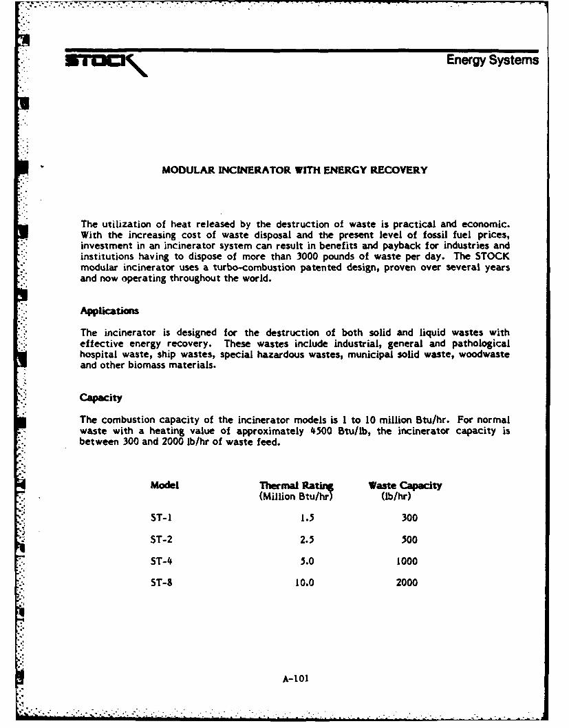
.. ~ c \Energy Systems
MODULAR INCINERATOR WITH ENERGY RECOVERY
The utilization of heat released by the destruction of waste is practical and economic.With the increasing cost of waste disposal and the present level of fossil fuel prices,investment in an incinerator system can result in benefits and payback for industries andinstitutions having to dispose of more than 3000 pounds of waste per day. The STOCKmodular incinerator uses a turbo-combustion patented design, proven over several yearsand now operating throughout the world.
Applicatiom
The incinerator is designed for the destruction of both solid and liquid wastes witheffective energy recovery. These wastes include industrial, general and pathologicalhospital waste, ship wastes, special hazardous wastes, municipal solid waste, woodwasteand other biomass materials.
Cac ity
The combustion capacity of the incinerator models is I to 10 million Btu/hr. For normalwaste with a heating value of approximately 4500 Btu/lb, the incinerator capacity isbetween 300 and 2000 lb/hr of waste feed.
Model Thermal Ratin Waste Capacity
(Million Btu/hr) (lb/hr)ST-I 1i 300
ST-2 2.5 500
.- ST-4 5.0 1000
ST-9 10.0 2000
A- 101. l A-OI.

SYSTEM DATA SHEET
Rame: A1herti-FonsarAddress: Not availableU.S. Office: None reportedU.S. Licensee: None reportedTechnologyDescription: Single action grate. One grate slides over a fixed grate.
Waste from feed hopper is Injected by a feed ram. Gasespass out the back of the combustion chamber rather than overthe top.
Brochure: Attached N/A XRecommendedfacility: None reported
Facilitylisting: Attached N/A X
Other: This vendor was listed in the De Renzo work but no mailingaddress could be obtained. Some facilities close to thedesired size range were listed.
A-103
*. . . . .- . . .

SYSTEM DATA SHEET
Name: Widmer & ErnstAddress: Zentralstrasse 74
5430
Wetteingen, SwitzerlandU.S. Office: None reported
U.S. Licensee: None reportedTechnologyDescription: Not available at this time.
Other: Information has not been obtained at this time but isexpected shortly. Review of the literature does not listany unit with less than 5-TPH capacity.
A-1 04

SYSTEM DATA SHEET
Name: BKI Industrieanlagen GMBHAddress: Sapporobogen 6-R
D-R000 Minchen 40
GermanyTelephone: 089/12 40
Contact: Hr. OrlinU.S. Office: Ford, Bacon & Davis Inc.
375 Chtpeta Way
Salt Lake City, UT 84108Telephone: (801) 583-3773
Contact: Mr. J. Edward ImmergluckU.S. Licensee: None reportedTechnologyDescription: Large rotary kiln and pyrolysis combustion. Destruction of
chemical and Industrial waste.Brochure: Attached Yes N/A
Recommendedfacility: None reported
Facilitylisting: Attached Yes N/A
Other: Formerly Krauss-Maffei and part of Deutsche-Babcock alongwith VKW. Technology limited to rotary kiln and pyrolysisin MSW. VKW takes all grate projects.
A-105

SYSTEM DATA SHEET
%lame: Cornel SchmidtAddress: Maschinen und Apparateban
Postfach 10 1270D-5090 Leverkusen 1
Federal Republic of GermanyU.S. Office: None reportedU.S. Licensee: None reported
TechnologyDescription: Pyrolysis plant for waste and paper incineration. Two
chamber substoichiometric incinerator. Batch feed and ashremoval. Packaged fire-tube boiler.
Brochure: Attached Yes N/A
Other: No municipal waste experience.
A-106

.Pyrolysis, substoichiometdc combustion
New anti-pollution waste disposalmethods!
The destruction of refuse Dy means of comoustion is the Numerous TUV (Test Code Assocation) test certificatesmost customary method of waste disposal and has confirm the advantages of this process. The cooling of
reached a high technical level In the past. the combustion waste gas can take place by the addition of fresh air or in awas not satisfactory in some cases due to changing com- waste heat boilerpositions of refuse, different calorific values high propor- In the case of a lacking heat requirement or of a malfunc-tions of plastics and increasing amounts of waste Efforts to ion in the water or steam circuits, the incinerator waste
nto the utization of an old technque namely the thermal gas is cooled with fresh air and conducted directly to theto -. fn ther zaimprovemnt ofd thnqe omstion p rocs ledbyasngtebolrfission with a deficiency of tree oxygen (also called dry stack. bypassing the boierdistillation) today covered by the general term pyrolysis The installation is fully automatic with the exception of the
intermittent combustion chamber chargingThe technique is very old and was already used in charcoalpiles as well as at the beginning of the twentieth century in Larger types of incinerators can be run in continuousthe distillation of wood for driving motor vehicles or gas operation by automating the ash removalengines Summary
In the fleid of thermal waste disposal. the designation - The combustion chamber (carbonization chamber) canpyrolysis has also been generally adopted for the "degasi- be charged with waste material for a maximum of 2fication'" "dry distillation" and "gasification" processes oe hr Staff reiement a thu ngib:. operating hours. Staff requirements are thus negligible
:. A complete combustion is obtained in the traditionalAncometen combsti iysuobtaingrenth aiioals - The waste can contain plastic materials up to a propor-faicitionPyrolyi of wate her sp n . ereat es (ar tion of 40% or even more if they have a suitable composi-factor 21 Pyrolysis. on the other hand, operates with a tn dotrahn h ea mt ie o h at
deficiency of air which means that only 16-25% of the air tion, without reaching the legal limits fixeo for the wastevolume normally required for a complete combustion of gas emission values. The proportion of waste materials
waste is supplied to the combustion chamber through containing chlorine is limited.nozzles This deficiency of free oxygen is called sub- - Lowest dust and pollutant emission values or grey scale
- stoichiometric combustion The combustible gas produced values of the waste gas plumein this way (mainly steam and hydrocarbons) is also calledpyrolysis gas The pyrolysis gas is lighted up by a burner in waOt bfsan afterOurning chamber and burned at a temperature of waste gas800-850 C by supplying the required air volume
CS-JABU Pyrolysis Installationsoperate according to the following system:
The incinerator is charged with the waste material manually-or automatically via a charging hopper The afterburning
chamber is then preheated to an operating temperature ofZ 8000 C by cutting in the light-oil or natural gas afterburnerand the carbonization process initiated by cutting in thelighting-up burner in the main combustion chamber for ashort period of time.
The combustible or pyrolysis gas set free is lighted up andSburnt in the afterouming cyclone together with the
required volume of airThe capacity stages of the afterburner are switched inaccordance with the calorific value of the pyrolysis gas orthe burner is switched offThe particularly significant thermocompensation of the
carbonization process and an absolutely uniformincinerator waste gas temperature with minimum con-
" sumption of additional fuel are obtained by regulating the.. carbonization chamber or afterburner chamber air volumes
with cutting in of the two additional burners if required
;I CORNEL. SCHMIDT CS-JABUPYROLYSETECHNIK VERTRIEBS-GMBH Zwelgburo Trolsdorfc-er'~e'S'-3.3e ' C - 5090 Le,erKusen 1 Landgrafenstra~e 37-39
Te'efY '2'4. 6-031 D-5210 Troisdorf-OberlarTetex e,eruSsen 85108'6 Telefon: (0 22 41) 4 20 71
A-107
' -' n i li i i ' l i "
l .--.- ,,, -2--.-, _

. ... .j.jf, jj ,- . .
.. 7/ 7 .771 :- . .
Pyrolysis installation with container Energy gain by means of heat exchangerscharging and waste heat boiler o at a olr
* The increasing costs of primary energiesand the German Energy Act (Energie-Sicherungsgesetz) make it a compulsoryrequirement to utilize the flue gas heatwhich has so far been wasted in therefuse incineration.
* The waste gas from our pyrolysis furnaceshas a degree of purity that allows a varietyof boilers or heat exchanger combinationsto be used without the risk of heatingsurfaces becoming contaminated.
* The heat recovery plant system can beadapted to your specific requirements.Possible heat exchanging media:- warm or hot water,- low-pressure or high-pressure steam,- thermal oil or hot air.
9 Waste heat boiler behind pyrolysis installation
A- 108
E..

-- a
M&- _'" $OMD.et ""M I-O C4 +"'
. . . .film
Functional CharacteristicsCharging: Ash removal:with container tilting mechanism by operating the ash slide valve, into an ash can placedFeeding: underneathFeed hlopper With pneumatically operated top hopper cover Waste gas cooling:and bottom hopper slide valve, from approx 8500 C to approx 220 to 28 0 C in the post-
Ignition: arranged smoke tube waste heat boilerof the fuel by means of a light-oil or natural gas auxiliary Bypass equipment:burner and beginning ot the carbonization process After In the case of a malfunction in the boiler safety chain (e g..ignition the burner is cut out. deficiency of water) or if the steam consumption is too low.
Combustion air feeding: the boiler is bypassed on the flue gas side and fresh air iswith the combustion air blower I rf, air volumes supplied to additionally supplied for waste gas cooling This process isthe carbonization chamber and to the afterburning chamber fully automatic.
are proportioned with combustion air dampers 1 and 2 Waste gas fan:Combstile r pyolyis as:This fan produces the required suction and conveys the
The pyrolysis gas set free in the carbonization chamber is waste gas to the stack.lighted up with the 2-stage Afterburner in a cyclone cell inthe afterburner chamber and burned with the introductionof the combustion air
Depending on the calorific value or the combustibility of thepyrolysis gas. the afterburner stages are switched or theafterburner is cut outNote It can be proven that the requirement of additionalfuel is at a minimum value due to the Switching of the twoburnersMeasuring and control equipment:The whole carbonization process and the combustion of thepyrolysis gas are regulated by the air damper control andthe circuitry of additional burners in such a way that auniform waste gas temperature of approx 850' C in theafterburning Chamber and a minimum consumption ofsupplementary fuel is guaranteedThe waste gas temperatures in the carbonization chamber.
U the afterbumning chamber and the waste gas temperaturebehind the waste heat boiler are indicated and recordedThe suction at the incinerator end is controlled.
A-109

2a 70
i2J 6:L 8 4)
I Incinerator1' 9 2 Front charging
2a Top charging3 Auxiliary firing4 Ash removal door5 Cleaning door6 Air blower7 Cotrol cabinet8 Inspection hole9 Waste heat boiler
10 Top flue gas outlettOa Rear or lateral flue gas outlet
Technical Data Standard Types Special TypesIncinerator type CES0 CE 100 CE 200 CE 300 C E 400 CE 500
W - width mm 1060 1350 1650 1900 2200 2450
L - length mm 2200 2400 2975 3600 3800 4175
H - height mm 1900 2000 2300 2550 2800 3000
Charging door - front mm 500/550 500/550 500/600
* Charging hopper - top mm 500/600 700/600 800/800 800/800 800/1000 1000/1000
Topping up quantity rn- 0.58 0.92 1.75 2.25 3.20 4.6
Combustion capacity kg/hat Hu- 2,5W kcal/kg waste 50 100 200 300 400 500
Weight approx. k9 4500 9000J 12000 15000 18000 23000
Chimney cross section 625 1225 2500 4000 5000 6500* approx. cm2
Approximate values; the required dimensions are calculated by us in accordance with the specific project.
A- I

Al. N;
47 ~
, 0
,I.A
IFI-,j
IL ~ I*