8/17/9 Annua: I - DTIC
29
REPORT DOCUMENTATION PAGE OW *A ono~res F- -6g loil ii w 1. AGENCY USE ONLY LeY', n&J 2. &er PORT OA RPoR TYPE AO S €o 8/17/9 Annua: I 5/l/93-4/30/94 4. TITLE ANO SUBTITLE S. PUNOING NUMBER Tbeoretical and Experimental Studies ONR Contract of a Novel Accelerating Structure SFRC Number . AUTHORMs N00014-9 1-J-19 41 R. M. Gilgenbach and Y. Y. Lau 7. PERFORMING ORGANIZATION NAME(S) AND AOOP.ESS(ES) I. PER•FORMING ORGANIZATION REPORT NUMBER Nuclear Engineering Department University of Michigan Ann Arbor, MI 48109-2104 '. SPONSORINGIMONITORING AGENCY NAME(S) AND AOOCESS(ES) 10. SPONSORING IMON0O0 AGENCY REPORT NUMBER Ballistic Missile Defense Organization Innovative Science and Technology/ Office of Naval Research 11. SUPPLEMENTARY NOTES 120. OSSTRIUTION IAVAILABUJY STATEMENT 12b. OISTRIUTMO COCK Approved for public release; distribution is unlimited. 13. ABSTRACT (Maximum 200 worc) Research during the past year has concentrated on a novel, two-beam accelerator (twobetron) which was conceived. This Idea was published In Physical Review Letters and a patent application was filed. Accomplishments include the following: 1) Theoretical analysis of the new technique for phase-focusing this new accelerator, 2) Theory of e-beam modulation, BBU and other issues, 3) Initial generation and transport of an annular electron beam, 4) Design and fabrication of model/ prototype accelerator cavities, and 5) Initial cold tests of accelerator cavities. 14. SUBJECT TERMS IS. NUIJMBER OF PAGES Electron beams, accelerators, beam-breakup- 29 instability 16. ERPU CODE I?. SCOTM CLASSWKATION 16. SECURITY oASSWoATM 19. SECURITY COASSWATWON 20. UMITATION OF ABSTRACT OF RPMOr OF THIS PAGE OF MSTRACTU UNCLASSIFIED UNCLASSIFED UNCLASSIFIED Unlimited "NSN 7540-01-26805500 Standard Form 296 (Rev 24-9) P•euqem OV AetU SW Ill-I
-
Upload
khangminh22 -
Category
Documents
-
view
1 -
download
0
Transcript of 8/17/9 Annua: I - DTIC

REPORT DOCUMENTATION PAGE OW *A ono~res
F- -6g loil ii w
1. AGENCY USE ONLY LeY', n&J 2. &er PORT OA RPoR TYPE AO S €o
8/17/9 Annua: I 5/l/93-4/30/944. TITLE ANO SUBTITLE S. PUNOING NUMBER
Tbeoretical and Experimental Studies ONR Contractof a Novel Accelerating Structure SFRC Number
. AUTHORMs N00014-9 1-J-19 41
R. M. Gilgenbach and Y. Y. Lau
7. PERFORMING ORGANIZATION NAME(S) AND AOOP.ESS(ES) I. PER•FORMING ORGANIZATIONREPORT NUMBER
Nuclear Engineering Department
University of MichiganAnn Arbor, MI 48109-2104
'. SPONSORINGIMONITORING AGENCY NAME(S) AND AOOCESS(ES) 10. SPONSORING IMON0O0AGENCY REPORT NUMBER
Ballistic Missile Defense OrganizationInnovative Science and Technology/Office of Naval Research
11. SUPPLEMENTARY NOTES
120. OSSTRIUTION IAVAILABUJY STATEMENT 12b. OISTRIUTMO COCK
Approved for public release;distribution is unlimited.
13. ABSTRACT (Maximum 200 worc)
Research during the past year has concentrated on a novel, two-beam accelerator(twobetron) which was conceived. This Idea was published In Physical Review Letters and apatent application was filed.Accomplishments include the following:1) Theoretical analysis of the new technique for phase-focusing this new accelerator,2) Theory of e-beam modulation, BBU and other issues,3) Initial generation and transport of an annular electron beam,4) Design and fabrication of model/ prototype accelerator cavities, and5) Initial cold tests of accelerator cavities.
14. SUBJECT TERMS IS. NUIJMBER OF PAGES
Electron beams, accelerators, beam-breakup- 29instability 16. ERPU CODE
I?. SCOTM CLASSWKATION 16. SECURITY oASSWoATM 19. SECURITY COASSWATWON 20. UMITATION OF ABSTRACTOF RPMOr OF THIS PAGE OF MSTRACTU
UNCLASSIFIED UNCLASSIFED UNCLASSIFIED Unlimited"NSN 7540-01-26805500 Standard Form 296 (Rev 24-9)
P•euqem OV AetU SW Ill-I

Table of Contents
Report Documentation Page ............................................................... 1
1.0 Summary of Research Progress ........................................................ 3
2.0 Experimental Design ................................................................................ 4
3.0 Experimental Results ............................................................................... 5
3.1 Initial Annular Electron Beam Generation and Transport ..... 5
3.2 Microwave Cavity Design and Fabrication ................................. 7
4.0 Theoretical Results .................................................................................. 8
4.1 Two Beam Accelerator ................................................................... 8
5.0 Patent Application Filed ........................................................................ 12
6.0 Honors and Awards .................................................................................... 12
7.0 Publications Sponsored by This Project ............................................ 12
8.0 Personnel Involved in Research ........................................................... 13
Appendices: Reprints of Refereed Joumal Publications and Patent
A) "Proposal for a Novel Two-Beam Accelerator" ................... A-1
B) "Beam breakup growth and reduction experiments ................ B-1in long-pulse electron beam transport" JAP
C) Beam breakup in an annular electron beam" ........................ C-1
Ae£egslon ]for
DTIC TAB
Unannouncoed 3
Justitication
Availability O6dell
2No Speal e•o
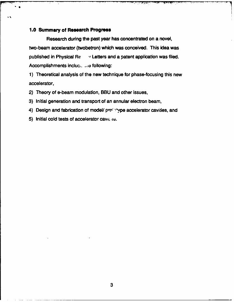
1.0 Summary of Research Progress
Research during the past year has concentrated on a novel,
two-beam accelerator (twobetron) which was conceived. This idea was
published in Physical Re •' Letters and a patent application was filed.
Accomplishments incluo(, .ie following:
1) Theoretical analysis of the new technique for phase-focusing this new
accelerator,
2) Theory of e-beam modulation, BBU and other issues,
3) Initial generation and transport of an annular electron beam,
4) Design and fabrication of model/ pr' & ype accelerator cavities, and
5) Initial cold tests of accelerator cavi i.
3
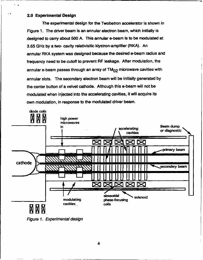
2.0 Experimental Design
The experimental design for the Twobetron accelerator is shown in
Figure 1. The driver beam is an annular electron beam, which initially is
designed to carry about 500 A. This annular e-beam is to be modulated at
3.65 GHz by a two- cavity relativisitic klystron-amplifier (RKA). An
annular RKA system was designed because the desired e-beam radius and
frequency need to be cutoff to prevent RF leakage. After modulation, the
annular e-beam passes through an array of TM0 2 microwave cavities with
annular slots. The secondary electron beam will be initially generated by
the center button of a velvet cathode. Although this e-beam will not be
modulated when injected into the accelerating cavities, it will acquire its
own modulation, in response to the modulated driver beam.
diode coils
high powermicrowavesin accelerating Beam dumpScavitis or diagnostic
cathode miIdi ::f': ifl '"
3 N~secondary beam
sinusoidal solenoidmodulating phase-focusingcavities, coils
Figure 1. Experimental design
4

3.0 Experimental Results
3.1 Annular e-bem Genermtion and Transport
Electron beam experiments during the first year of the Two-Beam
Accelerator project concentrated on the generation and transport of an
annular electron beam. The annular e-beam cathode is depicted in Figure
2; a ring of velvet emitter was placed on a shaped aluminum cathode. The
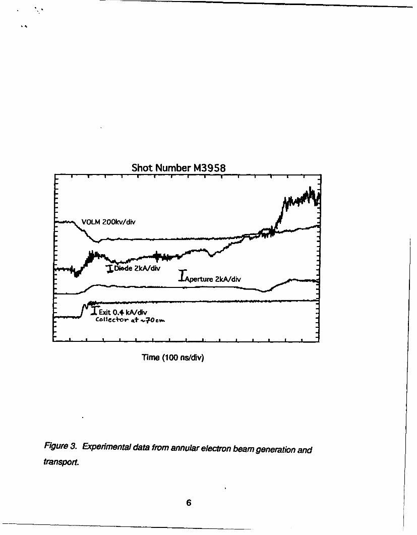
desired nonemitting region was coated with glyptal. Initial experimental
results are shown in Figure 3, showing about 1.5 ps of the electron beam
pulselength. On the waveform flattop sections (t.700ns), the diode
current is about 5.4 kA; apertured current extracted through the anode is
about 2.5 kA. Of the 2.5 kA extracted, about 1.3 kA was collected by a
graphite plate located - 70 cm down the 15.2 cm-diameter transport tube.
The magnetic field was about 3-4 kG in the transport tube. Since we only
need about 500 A through the annular accelerator-cavity slots, these
initial results are very promising.
cathode glyptalstalk
Figure 2. Annular e-beam cathode (initial trial).
5
Shot Number M3958
LM 200kv/div
"-Iid 2kkA/div- T•oerture 2kA/div
•E.dt O0.4 kAdi
Time (100 ns/div)
Figure 3. Expermental data from annular electron beam generation and
transport.
6
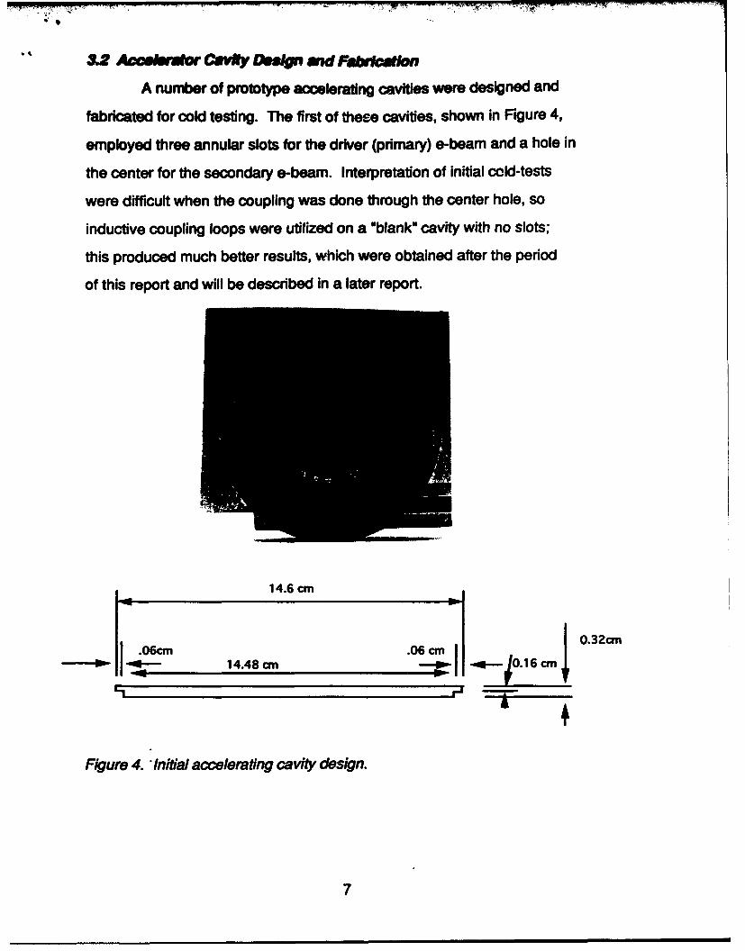
3. 2 ACeCe rMOS CVRty O. md Faka d tn
A number of prototype accelerating cavities were designed and
fabricated for cold testing. The first of these cavities, shown in Figure 4,
employed three annular slots for the driver (primary) e-beam and a hole in
the center for the secondary e-beam. Interpretation of initial cold-tests
were difficult when the coupling was done through the center hole, so
inductive coupling loops were utilized on a "blank" cavity with no slots;
this produced much better results, which were obtained after the period
of this report and will be described in a later report.
14.6 cm
.06cm .06c an03c
_M* 14.48 an
Figure 4. Initial accelerating cavity design.
7

4.0 Theoretical Results
4.1 Two Beam Accelerator
The concept of the novel two-beam accelerator has already been
documented in our papers (attached) and will not be repeated here. We
shall only address a few important issues that we have more recently
examined. They concern the scaling laws, wakefield effects, effects of
finite beam thickness, coupling among cavities, modification of rf
characteristic by the intense driver beam, and the integrity of the primary
beam modulation in the accelerating structure.
Scaling Laws
The average energy gain per cavity by the secondary beam in the
twobetron is
<Es>= (16.3 keV) X O X (IdldkA) X (A/a)
where 0 is the quality factor of the TM0 2 0 mode, Id is the rf current on
the driver beam, A is the amplitude of radius modulation, and a is the
mean radius of the annular driver beam. The transformer ratio, R, which
is the ratio of the energy gain in the secondary beam to the energy loss to
the primary beam, is
R. 0.803 (a/A)
The maximum amount of secondary beam current, Is, that can be
accelerated is limited to
Is < Id/2R
8
Given a driver beam current, we cannot make the acceleration
gradient (i.e., <Es>) excessively high by using a high 0 cavity. Too high a
value of Q would lead to formation of a virtual cathode in the primary
beam. Another practical limit on <Es> is set by rf breakdown in the
cavities.
In general, a transformer ratio R of the order of 10 seems
achievable. A two-stage twobetron, in which the accelerated beam of the
first stage is used as the driver beam in the second stage, will provide
voltage multiplication by a factor of 100, while the output current is
correspondingly much reduced.
Primary Beam Instabilties
The intense driver beam passing through a sequence of cavities
are highly vulnerable to beam breakup instabilities (BBU). However, we
have recently found that BBU in an annular beam may be far less serious
than a pencil beam. Specifically, in the absence of other stabilizing
mechanisms such as stagger tune and betatron frequency spread, the BBU
exponentiates only 1.8 e-folds ( in amplitude) for a 500 ns, 0.5 kA driver
beam in a 90 cm accelerator structure embedded in a 10 kG solenoidal
magnetic field.
We conjecture that the longitudinal (Robinson-like) instability
probably is not important for the twobetron, at least in the proposed
proof-of-principle experiment. Unlike a circular accelerator, the present
scheme is single-pass. Its acceleration length is quite short, its length is
only slightly over one wavelength in the radius modulation. Moreover, the
drive frequency may be adjusted to be on the "right side" of the structure
frequency to avoid the Robinson-like instability.
9
In a preliminary particle simulation, we find that the current
modulation is preserved on the primary beam, after it is made to
propagate through the accelerating structure, using the beam and
structure parameters that are being planned for the proof-of-principle
experiment.
RF Coupling Between Cavities
We have for simplicity assumed that the cavities are isolated
from one another electromagnetically when the beam is absent. There are
several ways to reduce the coupling among neighboring cavities. The
inductive coupling at the annular slots, through which the driver beam
passes, may be cancelled by the capacitive coupling at the center hole, and
if necessary, by introducing additional holes near the rf electric field
maximum (so as to increase the capacitive coupling) that is close to the
outer wall of the cavity. Alternatively, conducting wires may be inserted
radially across the annular gap to reduce the inductive coupling. Multiple
pencil beams may also be used as the driver. These pencil beams pass
through holes that are distributed annularly. In the event that the
neighboring cavities are not completely isolated electromagnetically, a
traveling wave formulation would be required; but the radius modulation
that is proposed in this paper still provides an external control to ensure
phase focusing.
The presence of intense space charge in the driver beam
complicates matter substantially as It is known to modify the rf
characteristics in an unpredictable manner. Such modifications include a
detune of the structure frequency and modification of the gap
transit-time factor, especially if a virtual cathode is at the verge of
being formed. Other modes may be excited. Indeed, mode competition is a
major area that requires considerable attention in the twobetron concept.
10
CONCLUDING REMARKS
In summary, the twobetron has the potential of converting many
existing pulse power systems into compact rf accelerators that are
suitable for industrial and medical applications. The driver beam is a
modulated electron beam of annular shape and low energy. The secondary
beam is an on-axis pencil beam. The secondary beam may reach an energy
up to 10 MeV in one to two meters. Transformer ratio on the order of ten
is considered feasible for each stage. Phase focusing and energy
tunability of t,,e accelerated beam may be provided by an external
magnetic field, which controls the radius of the primary beam.
Excitation of the ,ndesirable modes by the driver beam is perhaps
the single most important issue in the twobetron concept.
11

5.0 Patent Application Filed
A patent application was filed on"Two-Beam Particle Acceleration Method
and Apparatus" on February 18, 1994.
6.0 Honors and Awards
Y. Y. Lau received the Excellence in Research Award from the
University of Michigan Nuclear Engineering Department in January 1994.
Professor Lau was appointed Associate Editor of Physics of Plasmas,
effective January 1994.
7.0 Publications Sponsored by This Project
1) "Proposal for a Novel Two-Beam Accelerator", Ya. S. Derbenev, Y. Y. Lau,
and R. M. Gilgenbach, Physical Review Letters, Z2 3025 (1994)
2) Beam breakup in an annular beam", Y.Y. Lau and J. Luginsland, Journal of
Applied Physics 74 5877 (1993)
3) "Beam breakup growth and reduction experiments in long-pulse
electron beam transport", P. R. Menge, R. M. Gilgenbach, Y. Y. Lau, and R. A.
Bosch, Journal of Applied Physics, Z5 1258 (1994)
Conference Papers
1) Beam breakup in an annular beam", Y.Y. Lau, J. Luginsland, and R. M.
Gilgenbach, Presented at the 1993 Annual Meeting of the Division of
Plasma Physics of the APS, St. Louis, MO
2) Y. Y. Lau, Ya. S. Derbenev, and R. M. Gilgenbach, "Novel, Compact
Two-Beam Accelerator", Beams '94, San Diego, CA, June 20-24, 1994
(Published in Proceedings)
3) Advanced Accerator Workshop, Lake Geneva, Wl, June 12-17, 1994
12
8.0 Personnel Involved In This Research
1) R. M. Gilgenbach, Professor
2) Y. Y. Lau, Professor
3) Ya. S. Derbenev, Visiting Research Scientist
4) John Luginsland, Graduate Student (Theory)
5) Jonathan Hochman, Graduate Student (Experiment)
6) Mark Waiter, Graduate Student (Experiment)
13

VOLUME 72, NUMBER 19 PHYSICAL REVIEW LETTERS 9 MAY 1994
Proposal for a Novel Two-Beam Accelerator
Ya. S. Derbenev, Y. Y. Lau, and R. M. GilgenbachIntense Energy Beam Interaction Laboratory. Department of Nuclear Engineering.
Unit'rsity of Michigan. Ann Arbor. Michigan 48109-2104(Received I November 1993; revised manuscript received 16 February 1994)
A new configuration is proposed wherein a low-current beam is accelerated to high energies (tens ofamps, tens of MeV) by a driver beam of high current and low energy (a few kiloamps, < I MeV). Theannular driver beam excites the TMo2o cavity mode of an accelerating structure which transfers its rfpower to the on-axis secondary beam. Systematic variation of the driver beam radius provides the secon-dary beam with phase focusing and adjustable acceleration gradient. A proof-of-principle experiment issuggested.
PACS numbers: 41.75.-i. 29.17.+w
Compact electron and ion accelerators in the 10 MeV primary beam, and the resultant acceleration of therange have a wide range of applications, such as treat- secondary beam by this mode, we assume that the intensement of bulk materials, activation analysis, and medical space charge on the beam does not alter the rf charac-radiation sources. To achieve such an energy at moderate teristic of the cavities 14,11,12]. We also assume that thelevels of current (tens of amps) requires considerable individual pillbox cavities are electromagnetically isolatedpower, and a natural candidate for a driver is the pulse from each other when the beams are absent [13,141.power system [1,21. Intense annular electron beams (a Since the cavities are excited mainly by the rf current Idfew kiloamps, < I MeV) extracted from such a system carried by the primary beam, the TMo2o mode so excitedhave been modulated efficiently, and the current modula- always decelerates the primary beam electrons on thetions exhibit a high degree of amplitude and phase stabil- average (by conservation of energy). This is true whetherity [31. These modulated beams have been used to gen- the beam radius ro is larger or smaller than a, wherecrate ultrahigh power microwaves [4,51 and to accelerate a -2.405c/eo is the radius of the rf electric field null ofelectrons to high energies 16]. They will be used as the the TMO2o mode [Fig. 2(a)]. The value of the rf electricdriver in the two-beam accelerator to be proposed in this field at ro then gives the deceleration gradient. In termspaper. of the relativistic mass factor (yd), the energy loss by this
Various two-beam accelerators have been studied in driver beam as it traverses the nth cavity is given bythe past [6-101. There are significant differences in the dyd,present configuration, shown schematically in Fig. I. The - . _ AP (I)driver beam is an annular beam of radius ro, carrying an dn
ac current Id at frequency wa. It passes through an ac- in a continuum description. In Eq. (I),celerator structure, consisting of N cylindrical pillbox A -0.066((oL/c)Q(ld/I kA) (2)cavities. Each cavity has a radius b -5.52c/oJ so that (ois also the resonant frequency of the TMo2o mode of the is the dimensionless parameter that measures the strengthpillbox cavity (Fig. I). The secondary beam is an on-axis of the cavity excitation by the primary beam,pencil beam, carrying an ac current Is (1 <<ld), also atfrequency w. Since the rf electric fields of the TMo2o -Jo(wroc)- -. 249(ro-a)/a, (3)mode have opposite signs in the outer region and in the Q is the quality factor of the TMo20 mode, L is the cavityinner region, the mode retards the annular driver beam length, and Jo is the Bessel function of the first kind ofbut accelerates the on-axis secondary beam. As we shallsee, if the driver beam radius is modulated axially, phase driver beam (annular, modulated)/ ~Jo(w°r k)
focusing and tunability in the output energy of the secon-dary beam can be achieved. This is the crucial feature of -IT- I I--the present device, not shared by the prior works [6- 101. IF
Thus, without the use of rf plumbing, the presentscheme provides-the gradual conversion of the primary jxj Ibeam power to the secondary beam over many accelerat- "r_______ Thozo Mode
ing gaps. Since the current modulation on the primary J1111111beam has been shown to be insensitive to the variations inthe diode voltage and diode current [31, the effectiveness secondary beam (pencil, modulated)in the acceleration of the secondary beam is likewise in- FIG. I. Schematic drawing of the two-beam accelerator.sensitive to such variations. Also shown is the rf force profile, Jo(owr/c), associated with the
To calculate the excitation of the TMo2o mode by the axial electric field of the TMo20 cavity mode.
0031-9007/94/72(19)/3025(4)$06.00 3025C 1994 The American Physical Society
A- I

VOLumE 72 Nutmm It PHYSICAL REVIEW LETTERS 9 MAY 1994
2A i .4,_ a_ - . . . -- iO
DRIVER
m-i-r-rrrr"---m- rr-I. Iflllllor/ 111111 aa'IJ (a)
1.2 i
r.(A) > a> r.(5) '-2314ev
431 SECONDARY
25/Tian m II d 511 iV
FIG. 2. (a) Position of the primary beam radius ro (ro > a) 0 IS
for secondary beam acceleration when both beams enter thecavity at the same phase. (b) Position of the primary beam ra- FIG. 3. Evolution of the relativistic mass factors when thedius re (re < a) for secondary beam acceleration when both driver beam radius ro is a constant: (a) the driver beam, (b)beams enter the cavity at 180I phase apart. the secondary beam. Phase slippage prohibits continual ac-
celeration of the secondary beam.order zero. In writing the last expression of Eq. (3), wehave made the assumption that the annular beam is locat- The effect on the secondary beam by this phase slippageed in the vicinity of the rf electric field null (ro x= a). is illustrated in Fig. 3, which is obtained by numerically
If the secondary beam enters the cavity at the same solving the system of three equations [(M), (4), (5)] inphase as the primary beam, the former will be accelerat- three unknowns: yd, y,, and G, - Od. The initial condi-ed if ro > a, for in this case the rf fields experienced by tions for these three unknowns are taken to be 0, - od -0both beams have opposite polarity [Fig. 2(a)]. Since the and yd - y, -2.37, corresponding to an initial energy ofrf electric field has a radial dependence of Jo(wr/c), it is 700 keV for both beams. The other parameters areobvious that 1/161 is the "transformer ratio," which is the ai/2x-3.65 GHz, b -7.221 cm, L - I cm, a -3.146 cm,ratio of the energy gain by the secondary beam to the en- ro-3.322 cm, Q-100, and !d- 0 .5 kA. Since we haveergy loss by the primary beam, if both beams enter the taken L -I cm, the cavity number n is also the axial dis-cav'ity at the same phase. This dependence on the phase tance (z) in cm.is reflected in the following equation which describes the Figure 3(a) shows that y'd decreases from the initialchange in the relativistic mass factor (y,) of the secon- value of 2.37 to 1.24 at n -90; i.e., the primary beam'sdary beam as it traverses the nth cavity: energy steadily decreases from 700 to 125 keV after
propagating 90 cm. The secondary beam's energy [Fig.dy- -Acos(0, - Od), (4) 3(b)] increases initially, reaching a maximum value ofdn 2.3 MeV after 24 cm, and then decreases due to the
where 0, is the phase of the secondary beam bunch and phase slippage until n -56, and oscillates further down-Od is the phase of the primary beam bunch when they stream as the phase slippage continues.enter the nth cavity. Equation (4) is readily obtained The phase slippage may be corrected by adjusting thefrom Eq. (1) by noting the transformer ratio 1/8 and the primary beam's radius ro. Consider, for example, thephase difference mentioned above. Equations (3) and (4) worst case of phase slippage where the primary beam andindeed show that y, increases if ro > a and if Od - 0,. the secondary beam arrive at a cavity 180* out of phase.
The secondary beam cannot be accelerated indefinitely as shown in Fig. 2(b). If the primary beam's radius ro isbecause of the increase in the phase slippage between Od less than a, it generates an rf electric field which wouldand 0, downstream. This phase slippage occurs as the retard both beams during the time when the primaryprimary beam' is decelerated and the secondary beam is beam occupies the cavity. However, when the chargeaccelerated. Its rate of increase is governed by bunch of the primary beam resides in the cavity, there are
few particles in the secondary beam residing in the samed(G,-Gd) ~. .L.L I cavity because both beams arrive at the cavity 180° out
dn C 1 ,t Pd of phase. By the time the charge bFunch of the primarybeam is about to leave the cavity, the rf electric field is
ML [(I - I./,,2) - 1 (iI ) -1/2]. about to change sign, at which time the charge bunch ofc the secondary beam is about to enter the cavity, whose rf
(5) electric field then begins to accelerate the entering bunch
3026

VOLUME 72, NUMBER 19 PHYSICAL REVIEW LETTERS 9 MAY 1994
on the secondary beam. Thus, the phase slippage prob- DRIVERlem can be corrected by a simple cure: At the locations To havwhere the bunches of both beams enter the cavity with 23
the same phase, place r0 outside a. When the bunches of .t)both beams arrive at the cavity 180* out of phase, placero inside a. -9
Mathematically, it is easy to see from Eqs. (3) and (4) t. _.._...__...___,
that y, is a monotonically increasing function of n if r0 is 30 ntapered in such a way that (ro-a)cos(8,- 6d) -) 0.
The above idea of phase slippage correction has been 6 s_ D 4.2-, vtested for the example shown in Figs. 3(a) and 3(b).From that figure, the phase slippage occurs with a periodof the order of 75 cm. Thus, we correct the primarydo i 4 (b)beam radius ro according to
ro(cm) -3.146+ (3.322 - 3.146) cos(2xn/75). (6)
Including only this modification, and keeping all other nparameters the same, we obtain Fig. 4. In Fig. 4, we see FIG. 4. Evolution of the relativistic mas factors when thethat the primary beam's energy monotonically decreases driver beam radius ro is modulated to compensate phase'from 700 to 400 keV over 90 cm, whereas the secondary page: (a) the driver beam, (b) the secondary beam.beam's energy increases monotonically from 700 keV to amaximum of 4.2 MeV over the same distance, in sharp down limit. If we assume an acceleration efficiency ;contrast to Fig. 3(b). The loss of 300 keV in the primary 25%, a secondary beam of more than 10 A of currentbeam and the gain of 3.5 MeV in the secondary beam may be accelerated to 4 MeV in less than a meter in thisimplies an effective transformer ratio of about (3.5 proof-of-principle experiment.MeV)/(300 keV),-l 1.7. There are many issues which may affect the eventual
In Fig. 4, the zero slopes in y, and in yd occur at the usefulness of the two-beam accelerator concept outlinedaxial positions (n) at which the driver beam radius ro above. Chief among them is the modification of the rfcoincides with the field-null position a. The slight dip in characteristic that always accompanies an intense drivery, at n -90 only means that the primary beam's radius ro beam, which includes a detuning of the structure frequen-needs further adjustment there. If we write ro0 a cy and a modification of the gap transit-time factor+Acos(W), where A is the amplitude and V is the phase [4,11,12,17). Also of concern is the beam breakup insta-of the modulation in ro, the general phase focusing condi- bility (BBU) on the driver beam (10,13,14,171. However,tion reads dp/dn "d( - Gd)/dn. This condition is appl- we have recently found that BBU in an annular beamicable when the two beams have different velocities. In may be far less serious than a pencil beam [18, and BBUfact, one might argue that this technique of radius modu- can be controlled by many well-known techniques [19).lation provides both beams with self-focusing in phase, The degree of coupling among neighboring cavities, espe-similar to the self-focusing in synchrotrons [15]. cially in the presence of an intense beam, remains to be
The modulation in the annular beam radius may be studied (201. Although the driver beam's radius is a cru-readily achieved by a proper adjustment of the external cial factor, the effects of the beam's finite thickness aresolenoidal magnetic field which is often used for beam far less important, according to our preliminary studies.focusing and beam transport [3-6,141. Since the rate of We have also examined the effects of the transverse wakechange of energy depends on the annular beam radius ro [211 and of the longitudinal instabilities (221 and found[cf. Eqs. (I) and (3)], the output energy of the accelerat- that they are not serious, at least for the parameters useded beam may also be controlled by the same external in the above numerical example, assuming a solenoidalmagnetic field coils. field of 10 kG in the accelerating structure.
The above ideas may be tested in a proof-of-principle In summary, we propose a novel scheme which has theexperiment with parameters similar to those used to pro- potential of converting many existing pulse power systemsduce Fig. 4. The primary beam may be obtained, for cx- into compact rf accelerators that are suitable for industri-ample, from the Michigan Electron Long-Beam Ac- al and medical applications. The driver beam is a modu-celerator (MELBA) [161, which operates with diode pa- lated intense relativistic electron beam of annular shaperameters of 700 keV, current up to 10 kA, and flattop and low energy ( < I MeV). The secondary beam is anpulse length up to I ps. This primary beam may be on-axis pencil beam. The secondary beam may reach anmodulated using the proven techniques by Friedman et energy up to 10 MeV in I to 2 m. Phase focusing and en-al. [3,4,61. Note that the average acceleration gradient ergy tunability of the accelerated beam may be providedof 40 kV/cm and the peak acceleration gradient of about by an external magnetic field, which controls the radius80 kV/cm implied by Fig. 4 are well within the rf break- of the primary beam. While we have in this paper con-
A-3 3027
VOLwUE72. NUMBER 19 PHYSICAL REVIEW LETTERS 9 MAY 1994
centrated only on electron acceleration in the 10 MeV 117) P. Meags, Ph.D thesis, University of Michiga, Ann Ar-range, it is intriguing to speculate on the potential of us- bor 1993.ing this technique (a) to accelerate ions to tens of MeV, D[18 Y. Y. Lau and J. W. Luginsland, J. Appl. Phys. 74. 5877and (b) to accelerate electrons to ultrahigh energy using (1993). In the line above Eq. (7) of this paper, the factorsuperconducting cavities [cf. Eq. (2)1 and higher energy 11/(I kA)J should read 111(17 kA)].driver beams. (191 In the absence of other stabilizing mechanisms such asWe thank John W. Luginsland for assistance in the stagger tune and betatron frequency spread, we estimatethat a solenoidal magnetic field of 10 kG and a dipolepreparation of this manuscript. This work was supported mode Q of 100 would limit the worst BBU growth toby SDIO-BMD/IST/ONR. I.Be-fold (in amplitude) for a 500 ns, 0.5 kA beam in a
90 cm accelerator structure, as in the numerical example.(201 There are several ways to reduce the coupling among
neighboring cavities. The inductive coupling at the annu-(I] J. C. Martin (unpublished); see also the survey by J. A. lar hole, through which the driver beam passes, may be
Nation, Part. Accel. 10, I (1979). canceled by the capacitive coupling at the center hole.121 S. Humphries, Charged Particle Beams (Wiley, New and if necessary, by introducing additional holes near the
York, 1990); R. C. Davidson, Physics of Nonneutral rf electric field maximum (so as to increase the capacitivePlasmas (Addison-Wesley, Redwood City, CA. 1990); R. coupling) that is close to the outer wall of the cavity (Fig.B. Miller, Intense Charged Particle Beams (Plenum, New I). Alternatively, conducting wires may be inserted radi-York. 1982). ally across the annular gap to reduce the inductive cou-
(31 M. Friedman and V. Serlin, Phys. Rev. Lett. SS, 2860 pling. Multiple pencil beams may also be used as the(1985); M. Friedman et at., J. Appl. Phys. 64, 3353 driver. These pencil beams pass through holes that are(1988); J. Krall and Y. Y. Lau, Appl. Phys. Lett. 52, 431 distributed annularly. In the event that the neighboring(1988). cavities are not completely isolated electromagnetically, a
141 M. Friedman et al., Rev. Sci. Instrum. 61, 171 (1990); Y. traveling wave formulation would be required; but the ra-Y. Lau et al., IEEE Trans. Plasma Sci. 18, 553 (1990). dius modulation that is proposed in this paper still pro-
151 See, e.g., Proc. SPIE Int. Soc. Opt. Eng. 1407 (1991); vides an external control to ensure phase focusing.1629 (1992); 1372 (1993) (edited by H. E. Brandt). 1211 We estimate that a nominal value of solenoidal field
[61 M. Friedman et al., Phys. Rev. Lett. 63, 2468 (1989). B0-10 kG would render the effects of the transverse171 M. A. Allen et al., Phys. Rev. Lett. 63, 2472 (1989); A. wake field on the driver beam unimportant. Specifically,
M. Sessler and S. S. Yu, ibid. 58, 2439 (1987). under the condition fl1 >> wy,(l +pd), where ii is the(81 G. Voss and T. Weiland, DESY Report No. M82-10, nonrelativistic cyclotron frequency associated with Bo and
1982 (unpublished); DESY Report No. M82-079, 1982 the other symbols are the same as in Eq. (5), the electron(unpublished). motion is adiabatic along the composite (dc+rf) magnetic
[91 W. Gai et al., Phys. Rev. Lett. 61, 2765 (1988); H. field line. The maximum angular displacement, from theFigueroa et al., ibid. 60, 2144 (1988); J. B. Rosenzweig et mean, is estimated to be t-0.52(c/e)(E,/cBa)P1/al., Phys. Fluids B 2, 1376 (1990). (I -pd) where E. is the maximum accelerating electric
[101 A. M. Sessler et al., Part. Accel. 31, 1277 (1990); Nucl. field experienced by the secondary beam. The maximumInstrum. Methods Phys. Res., Sect. A 306. 592 (1991); radial displacement is 1, where )L -2xPdydc/nD. B. Hopkins et al., Nucl. Instrum. Methods Phys. Res. and A. is the axial wavelength associated with the modu-228, 15 (1984); D. H. Whittum et al., Phys. Rev. A 43, lation in the driver beam radius. For the parameters used294 (1991); also in "Advanced Accelerator Concepts," in the numerical example. t:S 0.2 cm, and I,4 0.0058edited by J. Wurtele, AlP Conf. Proc. No. 279 (AlP, cm. The spread in momentum, dp, in the driver beamNew York, to be published). may introduce a variation in its annular beam radius.
1II1 P. B. Wilson, in Physics of High Energy Particle Ac- dro. It is estimated that droa [2(0.AD.)A+0.083X.E,/celerators, edited by R. A. Carrigan et al., AlP Conf. cBoldplp, where A is the amplitude of the modulation inProc. No. 87 (AlP, New York, 1982), p. 452. the driver beam radius. Using the parameters in the nu-
(121 D. G. Colombant and Y. Y. Lau, Phys. Rev. Lett. 64, mcrical example, we find drg<0.0061 cm if dplp < I.2320 (1990). Thus. the effectiveness of radius modulation is not
1131 This is similar to the cumulative beam breakup instabili- affected by momentum spread.ty, suggested by W. K. H. Panofsky and M. Bander, Rev. (221 We conjecture that the longitudinal (Robinson-like) in-Sci. Instrum. 39, 206 (1968). stability probably is not important for the present scheme.
(141 See, e.g.,P. R. Menge, R. M. Gilgenbach, and Y. Y. Lau, at least in the proposed poof-of-principle experiment.Phys. Rev. Lett. 69, 2372 (1992); Y. Y. Lau, ibid. 63, Unlike a circular accelerator, the present scheme is single1141 (1989), and references therein, pass. Its acceleration length is quite short; its length is
[151 See, e.g., E. D. Courant, in Physics of High Energy Par- only slightly over one wavelength in the radius modula-ticle Accelerators (Ref. 1II1), p. 2. tion. Moreover, the drive frequecy may be adjusted to
(161 R. M. Gilgenbach et al., in Digest of Fifth IEEE Pulse be on the "right side" of the structure frequency to avoidPower Conference (IEEE, New York, 1985), p. 126. the Robinson-like instability.
A-4-3028
Beam breakup growth and reduction experiments in long-pulse electronbeam transport
P. R. Menge,* R. M. Gigenbach, Y. Y. Lau, and R. A. Boschb)Ndwke EAia ftwi~ DepammanL Intmws Eaeg7 Ewn Interactkv, Labowutoe. University of MichigaAnn Arbor. Michim 48109-2104
(Received 19 August 1993; accepted for publication 26 October 1993)
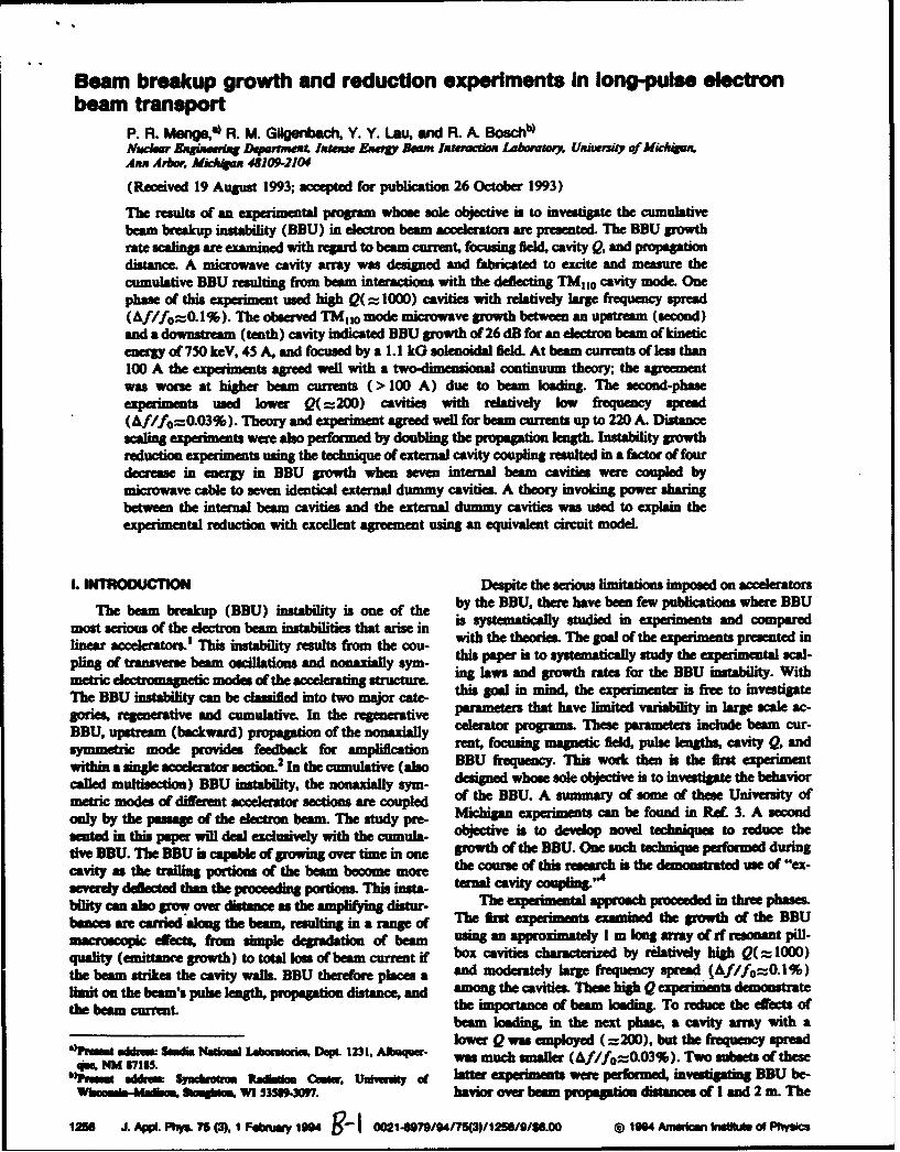
The results of an experimental program whose sole objective is to investigate the cumulativebeam breakup instability (BBU) in electron beam accelerators are presented. The BBU growthrate scalings are examined with regard to beam current, focusing field, cavity Q, and propagationdistance. A microwave cavity array was designed and fabricated to excite and measure thecumulative BBU resulting from beam inteactions with the deflecting TMuo cavity mode. Onephase of this experiment used high Q(= 1000) cavities with relatively large frequency spread(Af/fo=0.1%). The observed TM,,o mode microwave growth between an upstream (second)and a downstream (tenth) cavity indicated BBU growth of 26 dB for an electron beam of kineticenergy of 750 keV, 45 A, and focused by a 1.1 kG solenoidal field. At beam currents of less than100 A the experiments agreed well with a two-dimensional continuum theory; the agreementwas worse at higher beam currmnts (> 100 A) due to beam loading. The second-phasee i used lower Q(= 20 0 ) cavities with relatively low frequency spread(Af/f0=0.03%). Theory and experiment agreed well for beam currents up to 220 A. Distancescaling experiments were also performed by doubling the propagation length. Instability growthreduction experiments using the technique of external cavity coupling resulted in a factor of fourdecrease in energy in BBU growth when seven internal beam cavities wen coupled bymicrowave cable to seven identical external dummy cavities. A theory invoking power sharingbetween the internal beam cavities and the external dummy cavities was used to explain theexperimental reduction with excellent agreement using an equivalent circuit model.
L IR Despite the serious limitations imposed on accelerators
The beam breakup (BBU) instability is one of the by the BBU, there have been few publications where BBU
most serious of the electron beam instabilities that arise in is systematically studied in experiments and compared
linear accelerators.' This instability results from the cou- with the theories. The goal of the experiments presented in
pling of averse beam oscillations and nonaxiay Sym- this paper is to systematically study the experimental scal-
metric electrmagnetic modes of the accelerating structume ing laws and growth rates for the BBU instability. With
The BBU instability can be classified into two major cate- his go in mind, the experimenter is free to investigate
gories, regenerative and cumulative. In the regenerative parameters that have limited variability in large scale ac-
BBU, upstream (backward) propagation of the nonaxially celertor programs. These parameters include beam cur-
symmetric mode provides feedback for amplification rent. focusing magnetic W pulse lengths, cavity Q, and
within a single accelerator section.2 In the cumulative (also BBU frequency. This work then is the first experiment
called multisection) BBU instability, the nonaxially sym- deigned whose sole objective is to investigate the behavior
metric modes of different accelerator sections are coupmed of the BBU. A summary of some of these University of
only by the pampge of the electron beam. The study pre- Michigan experiments can be found in Ref 3. A secondanted in this paper lfl del eivelywith ta- objective is to develop novel techniques to reduce the
tive BBU. The BBU is capable of growing over time in one growth of the BBU. One such technique performed duringcavity as the trailing portions of the beam become more the course of this research is the demoustrated use of "ex-sever*l deflected than the proceeding portions. This insta- taa Cavity Cooapling"4bility can also grow over distance a the amplifying distur- The experimental approach proceeded in three phases.ban= an carried along the beaom, resulting in a range of The AM expeints examined the growth of the BBUmacroscopic effects, from sumple degradation of beam uin an approximately 1 m long array of rf resonant pill-quality (emittance growth) to total loss of beam current if box cavities characterized by relatively high Q(= 1000)the beam strikes the cavity walls. BBU theredore places a and moderately large frequency spre (Af/fo=0.1%)himit on the beam's pus length, propagation distane, an among the cavities. These high Q2 experiments demonstratethe beam current the importance of beam loading. To reduce the effects of
beam loading, in the next phase, a cavity array with alower Q was employed (=200), but the frequency spread
".rn d Sed. Na Labm D. 1231. ANq1- was much smaller (Af/fo=.O 3%). Two subets of these-. e NM 87165.
'CrZa Wddmu Syadwt=m Radlism CmiW. U•,an of h latterxeperiments were performed, investigating BBU be-Whaarn-Mýrn, Sieonas . W1 33589.3097. havior over beam propagation distances of 1 and 2 in. The
1256 J. Appi. Phys. 75 (3). 1 Fiburuy 1094 9-1 0021-ft"//4I75()/1256/0/SS.OO @ 1994 Anwican ma illfs of Physics
10o . 0 .7-lno /mwo~dStrong
102
103 SLACS Tdr-Mal liftert100 1 1 1 0I 2.1 Curent c•potgrat.
0•. Str•r I-Mer Colkdr Cabo Curen
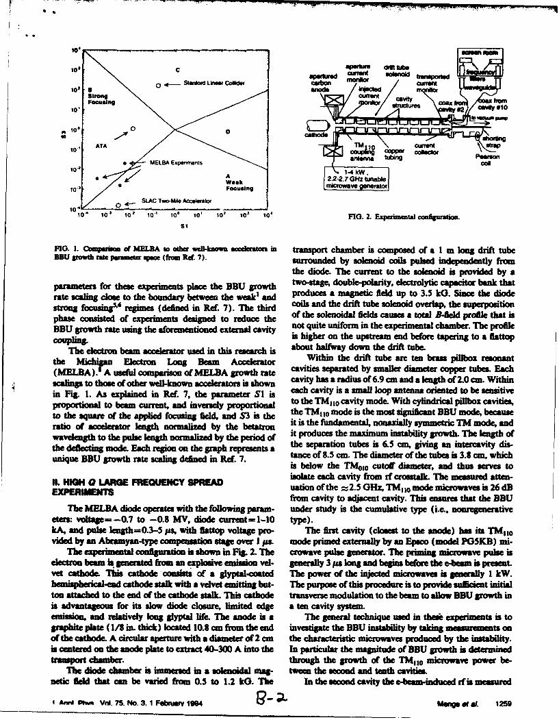
FIG 1 Cmpr~. MEIILBA top oHthe se-nw ceeaoa traspo tchmbe ascmpsdofa1 ogrrfttb
Sto • Wekmorwv tuxW
lo3 Focusig Iro
1- _ahd shortingde io
the dde The current o h s ii ro aparametesfor these es place the BBU g t t- po er colytic t bank
rat clin cis to ti i• nar t•etw w,. die proue a magneti fil upt 3.5 kG. Sinc th did
phs cnise of taesigne to reduce th of the soleoaa fields causes a total B-il prfl that asBBU growtha rate win the aioeeninc external not quit unfom in the expeienta chme. The proieis higer on e u a ed ore ta to a flattnp
Th3 eletro bemMXXn.i ~ , bothlway ow thedittue
the 1 Electron Long Beam Accelerator Within the drift tube are ten brass pillbox resnant(MELA).I A useful comparison of MELDA growth rate cavities separated by smaller diameter copper tubes. Each
scalings to those of other well-known accelerators is shown cavity lass a radius of 6.9cma and a length of 2.0 cm. Withinin Fgig. r. As explained in Ref. 7, thr u d each cavity isa smal loop antena oriented to be semitiveprportional to beam current, and inversely p to the TMio1 cavity mode. With cylindrical pilrbox cavities,
tote qae fth plidfouig fild andS3 the •TM,0 mod is the ms sinfiat BBU moe becuseratio of cerator length normalized by the betatron it is the fulamental, nonaxiallysymmetric TM mode, andwavescalingthlow to the pulselengtorm d b yw the per, oMid produces the maximum instability growth. The length of
sums tos Argms(eieinRf7)Ththr olad the drif tube soeni ovrlp the superpsitio
the eflctig mde. achregon n te grph eprsens a the separation tubes is 6.5 cm, giving an intercavity dis-
phae d c• onitde ofa epriment deine t oeSrp redue ~the ofteslniaailscue attlBfedpoieta
unique BBU growth rate scaling defined in Rexr. 7. tane of 8.5 cm. The diameter ofthe tubes is 3.8 cm, whichis below the aco0 cutoff diameter, sand thus serves toisolate each cavity from af crostalk. The meaued atten-
II. HI to 0 G R EdCY R uation of the a 2 .c e-oz, TMas d mode micraves is 26 dBEXPEIMENTra from cavity to adjacent cavity. This ensures that the BBU
the A diode operates with the following pad3 m- under study is the cumulative type (i.e., nonrgenerativeeteo voltaler--0.7 to --0.8 MV, diode current=h 1-i0 type).kAv and pulse llenh=0.3--5 s, with flattop volthge pro- The r t cav (cloes the anode) has its TMhof
heded by an Aroamyan-tyeg compepsation stage over I65 ode primed externally by an Ec (model P5KB) mi-The experimoet cngra tinM ifhown in Fg. 2. The coavee - neraom . The ptimigs misc rowa em isr beam is g t froU an Spove imis ve- gten 3 a long and begins before the easem i peatsen
vet cathode. This cathodeucsiss ot a 2yptal-oated T p f te i mves is I kW.hemispherical-and cathode stalk with a velvet emitting but- The purpose of this procedure is to provide sur cient initialton attached to the end of the cathode stalk. This cathode transveuse modulation to the beam to allow BDU growth inis advantageous for its slow diode closure, limited edge a ten cavity system.kmiso, and reatively long glyp3 t life. The anode is a The general technique lsed in thes a exeints is to
grapvite plate (1/8 in. thik) located 10.8 cm from the n invetigate the eBU insatly y y takng (mel rmts ono the catxhe. A rirecula ratu with a diamee o 2 cm the rac teristic microwaves produced by tho stav bilp .is centred on ltnanoe plaOte t exptract em-ss A int ve In parla the ande oeforeU growt i- dtpermned
t chamdbe- r, through the w rowth of the ine te m icrowave powee r be
Te diopede cahamber istl witmredi a v olvenoidatingbu- twen thpoe seond ands troenth cavitopvies. ul t t
netic e that can be varied fro s 0.5 to 1.2 kG. The In the second cavity the -beam-induced a fo s meauredis •dvan ts.for its slo 75. cl.3u, limite 1de te cv st..m 1

TABI.5LP F Ind I ar~bi~h bras hqmmcyq ed m4d.
caviy *SIakqN&. W0HO TUhM Q
12.5190 6602 2.5200 10903 2.5200 142D04 2.5201 low05 ism26 5306 2-5270 61007 2.5230 1160a 2.5240 9209 2.5248 610t0 ism25 1010 V
Avuap 2.523*0.1 1000*310
via the loop antennla. Thie microwaves are propagated out 100 nis/divof the experimental chamber through R/0A.405 U semi-rigid transmisuion cable to a vacum eidthrough, to FIG. 3. E~ree d~ata Wm fvom t"=ow urshOes. (a)DodkG/S Cable to an S bind Waveguide. The Wavegu de runs vokoaa (310 kydiv). GOsapis 750 kV (b) IeCta Mu (92 A/diy).to a Faraday cage where the signal is attenuated and fil- Mwin=o i 230 A.. (c) TiompaWiomwsa (40 A/div). lattap is 46 A.tered for frequency inforaion. Part: of the miowv C d) Daeftar Opaul of secod cavit if (100 MV/diy). signa aneamuateSignal is diverte inlto a flter that passe 2.523 GHz*R by 12 dL (a) Doomta sipu of samtb cavity Irf (100 mV/diy), migue
MHz. ThIs frequency, as noted above corsponds to th is b.1 32d.I cae 0 m/i.Sl1 aeiTM,,0 DDU frequency.
The rf power in the tenth (lsas) cavity is measured inthe Same way With its Own sad Ge cables and waveguides. correpodig to approximately 220 A. Ih cente tracIle growth Ge the BDDU instability is determined by the Wc represients the transported mcurnt. Thisi trac is thedeimbels Ge growth in 2.5 0Hz microwave power between spgal from the Pearson coil that surrounds the cablthe second and tenth cavities. which connects the collector plate to ground. The magni
Electron beam current is measured at several points in tudie Ge beam current on the flattop for this signal is 46 A.the transport experiment. Cathode stak curret in the di- The drift tube: solnoid produced a magnetic field Ge 1100ode is measured by a B4do loop in the MELBA Oil tank, 0 for this pariculair Shot. Thie fturth tra= (d) is the diodebehind the insulators. Extracteid curlrent is monitored by a crystal detector spgna of the microwaves picked up by theRagowski coil in the fAnme after the anode. Injected cur- loop antenna in the second cavty. This signal has passedrent is measured by a Rogowsld coil beforie the Amrs cavity through the frequency filter which passes freuencies atand exit curret is detected by a Rogowski coil after the 2.523 *0.0110GHz. Thie external attenuation added to thelas cavity. Ex-iting current is also measured by a carbon second-cavity microwaves is 12 dB. The lowrmot trace:platecurrent collector which is grounded by a strap which (e) is the microwave crystal deeco sgal as received bypassiest through a Pearson curret uamsformeir the loop antennas in the tenth (last) cavity; this signal has
The exac TMIO resonant elaracteristics Ge the ten. passed through a frequency filter similar to that used forcavities in the trasport array ate listed in Table 1. The the second-cavity diagnostcs. The external attenuationcavities are numbered in ordier e, beam encounter. As in- added for this signal is 32 dB. The external mIcrwvdicated the averag reaoaaic frequency is 2.523 0Hz priming source was tuned to the exact resonance ofethe firs*0.1%, and the averag Q is 1000*310. Comparison Ge cavity (see Table 1), 2.519 0Hz, and the power Ge thethe frequency spread (Af/fo-0l%) and averalge, rewo priming pulse wils approximately I kW-at liniewidth (1/Q=0.1%) reveals that they are approx- The experimental spaWa growth rafte for the 333 in-
iaeyequal, and. thus the frequency spread among the stability can be determinied fromn the data presented in Fig.cavities can be reEcrre to as large 3. The experimental growth rafte is ascetained through
FWgur 3 shows a typical data set of electron beam and examination ofethe rf signals [trace (d) and (e) firom Fig.rf signals from a high Q, large-frequency-apred BBU 3). These traces are diode crystal detector sigals whicht:ransport experiment. The uppermost signal trac (a) is give measurements of microwrave power bieced into thethe voltae appled to the diode by the MELBA Marx detectors Scrutiny ofethe microwaves from the soeod cay-generator. The voltae has a total length of about 700 na ity (signal (d) of Fig. 3) shows a deetrsignal of about 90and the duration ofethe flatop is about 400 ns. The votaep mV along the flattop of the MELBA voltage pulme A sig-magnithude: at the flattop is - 750 WY. The seod trac (b) nal magnitude of 80 mV corresponds to a power of9 mWis the signal firom the R~ogowsk coil that emndrees the en- for this particular detector. Before entering the detector,tranuce to the JIrs cavity. This sigal has a flattop amplitud the signal was purposely reduced by 12 dB in external
150 J. APPL Plqs. VOL. 75, No. S. I Februwy 19S4 G1- 3 1A 0 ofAt

afsmm mio aad do by anor 2.7 dD from mujie aad1 16 1-b ma ith s a vouW le and h ency &1-ter. Thm dh total power of the TMso microwaves on the soflattop PIcked upby th loop antenna in the second cavityis 270 mW. I
The TMU o mirowave signal in the tenth cavity has a 40omagnitude of about 160 mV on the flattop. Note that the* 0
overall shape of the tenth-cavity microwave power is srn- 30 Wliar to that of the seoned cavity. There is about 40 its of E
z ~00delay between the tenth and weoond cavity signals due to a mm20
longer waveguide used to transport the microwaves fromthe tenth cavity. This suggests that the magnitude of themicrowaves in the tenth cavity is a direct result of growth 10 , 40 0 0
from the saed-cavity microwaves. This detector's cahi- 1 (05)
bration at 160 mV gives a detector power of 35 mW. TheUS (,,kG)
added attenuation in this signal is 32 dB with an additionalreduction of 2.9 dB from resistive and insertion losses. FIG. 4. Gah of beaftu bremkup istability rowth VS the ratio of trana-Thus, the total power received by the antenna in the tenth pored curnt to - W a /id /. Por each point repreaming eper-
imearnedy masred rowth (cloed cirda), the correspoedin tbeoreti-cavity is 99 W. Therefore, the growth in TMo0 microwave cal prediction for growth vmag the saw beam parametera a also plottedpower between the second and tenth cavities as sampled by (open squarto). Te lhies an soida for the eye.
the loop antennas is 99 W/0.27 W=370, which is equiva-lent to 26 dB. The distance between the antennas is 68 cm,giving a spatial microwave growth rate of 38 dB/n. BBU growth for a 750 keV electron beam with
A theoretical prediction for the amount of BBU current=46 A, and a solenoidal focusing field of 1.1 kG.growth can be found using the continuum dispeion This is in reasonably good agreement with the expemen-relation"', for solenoidal focusinV" tal growth of 26 dB, considering the use of a continuous
2 r 2 model for the few cavity system and the neglect of beamloading and frequency detuning among the cavities.
where fl-=--kv and The preceding continuum model treats the transverseimpulsive forces from the accelerating cavities as a contin.
2012( uous force per unit length. This approximation limits the&-o2 +4+&~oVq * dispersion relations to the cases where instability scale
The variable k is the wave number of the instability. is lengths (i.e., e-folding length, and wavelength of the BBUdisturbance) are long compared to the cavity spacing.the frequency which undergoes BBU growth, ft is the dinge ansvers fore o the bameti
TMI, 0 angular resonant frequency, v is the electron beam Modeling the tmaverse force on the beam resulting from
velocity, Q is the cavity quality factor, w, is the relativistic pillbox cavities placed at discrete locations produces theangular betatron frequency, and e is the dimensionless - following dispeon relation:piing constant,7 where (Lfl L.) L . L,
I(1 0 - (2)
6=-0.422L 7k. The discrete cavity dispersion relation of Eq. (2) yields aprediction of 24 dB growth in the BBU, when the effect of
Here, I is the cavity length, L is the spacing of cavity frequency spread is taken into account, Le., the growth incentes, I is the e-beam current, and 0 and Y have their each cavity is computed locally using the individual pa-usual meanings. For the experimental pammeters of 1-2 rameters for each cavity (see Table I).cm, L=8.5 cm, transported current=46 A, and kinetic An unfortunate crumstance in this exprient is theenergy=750 keV, one finds e-= l.OX lO-. A solenoidal fact that in order to increase the amount of transportedfid of 1.1 kG yields w,= 7.85 Grad/s, the BBU frequency current, the applied magnetic field must also be increased.is the priming freguency, w=21X2.519 -Hz, and the av- Thereore, it i difficult to determine the saling of theerage TM 1o frequency is fo=2rX2.523 GHz. Insertion BBU growth versus current while holding the magnitudeof these values into Eq. (1) produces a theoretical spatial of the focusing field constant or vice versa. An attempt togrowth rate in the continuum model of porate the I vs B dependence into the growth rate
I. manalysis examines the BBU growth rate versus the ratio ofIm(k)--4.90 i-. current to magnetic field, I/B. Figure 4 plots the expen-
Thus, the e-folding length for the instability is 20.4 cm. mental and theoretical growth of the BBU vs I/B using theThis implies a rf amplitude growth over the 68 cm between two imensio.l continuum theory, Eq. (1).the second and the tenth cavities of exp{68.0/20.4) =28.0. In Fig. 4, it is evident that the BDU growth predictedAn amplitude growth of 28 tramlates to 29 dB pin. Thus, by continuum theory (open squares) agrees well with BBUthe two-dimeni continuum theory predicts 29 dB of growth in expenments with low IB. For large values of
I AW. Phys. vo. 75, No.3. 31 FSbnfY 194 Mn of e"L 1261
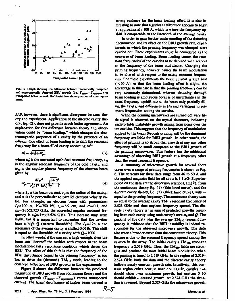
30 . strong evidence for the beam loading effect. It is also in-teaeging to Dote that significant difference appears to begin
A A at approximately 100 A, which is where the frequency up-2o shift is comparable to the linewidth of the average cavity.
A A In order to gain further understanding of the detuning=10 AA A phenomenon and its effect on the BBU growth rate, exper-
A AA A iments in which the priming frequency was changed were
11 10A A Aý carried out. These experiments could be considered as theA converse of beam loading. um loading causes the reso-
0nant frequencies of the cavities to be detuned with respectto the frequency of the beam modulation. Changing the
-10 .. priming frequency, however, causes the beam modulation0 20 40 60 80 100 120 140 160 180 200 to be altered with repect to the cavity resonant frequen-
transported current (A) cies For these experiments the beam current is kept low( < 50 A) so that the beam loading effect is slight An
FIG. s. OGph s the diffree be computed advantage in this case is that the priming frequency can beand expermmUtay obseved DBU growth (Lc, r,.,-r , ) vs very accurately determined, whereas detuning throughrsausported beam current. Hoarzotal lne shows positio of exact aree- beam loading is ambiguous because of uncertainties in thewent exact frequency upshift due to the beam only partially fill.
ing the cavity, and differences in Q's and variations in res-onant frequencies among the cavities.
1/B, however, there is sgnificant divergence between the- When the priming microwaves are turned off, very lit-ory and experiment. Application of the discrete cavity the- tle signal is observed on the crystal detectors, indicatingory, Eq. (2), does not provide much better agreement. An undetectable instability growth arising from noise over theexplanation for this difference between theory and obser- ten cavities. This suggests that the frequency of modulationvation could be "beam Woading," which changes the elec- applied to the beam through priting will be the dominanttromasnetic properties of a cavity by the presence of an frequency available for BBU growth. In other words, thee-beam. One effect of beam loading is to shift the resonant effect of prining is so strong that growth at any any otherfrequecy for a beam-fllled cavity according ton frequency will be small compared to the BBU growth of
A-- w pro(3) the priming microwaves. This feature has the additionaladvantage of observing BBU growth at a frequency other
where a• is the corrected upshifted remnant frequency, wo than the exact resonant frequency.is the angular resonant frequency of the cold cavity, and A summary of microwave growth for several shotsOpe Is the angular plasma frequency of the electron beam taken over a range of priming frequencies is shown in Fig.given by 6. The currents for these data range from 40 to 50 A and
S41.Abc2 I the applied magnetic field for all shots is 1.1 kG. Superim-r-1ir) (4) posed on the data are the dispersion relations, Ima(k), from
the continuum theory Eq. (1) (thin lined curve), and the
where Ib is the beam current, r, is the radius of the cavity, discrete cavity theory, Eq. (2) (thick lined curve), with wand a is the perpendicular to parallel electron velocity ra- equal to the priming frequency. The continuum theory usestio. For example, an electron beam with parameters: too equal to the average cavity TMI 1o resonant frequency ofIb=10 0 A, V=750 kV, r-=6.9 cm, and a=O.1, and 2.523 GHz and thus neglects frequency spread. The dis-o-=-2irX 2.523 GHz, the corrected angular resonant fre- crete cavity theory is the sum of predicted growths result-
quency is o---2rX-2.524 GHz. This increase may seem ing from each cavity using each cavity's own f and Q. Theslight, but it is important to remember that the cavities peaking of the data near the average TM11o resonant fre-have a high Q (narrow linewidth). For Ib-=128 A the quency is evidence that the BBU instability is indeed re-resonance of the average cavity is shifted 0.05%. This shift sponsible for the observed microwave growth. The datais equal to the linewidth of a cavity with Q= 1000. also trace a broader curve than the continuum theory. This
In other words, if the current is high enough, then the feature is due to the resonant frequency spread among thebeam can "detune" the cavities with respect to the beam cavities in the array. The initial cavity's TMo10 resonantmodulation-cavity resonance condition which drives the frequency is 2.519 GHz. Thus, the TM,,0 fields are stron-BBU. The effect of this shift is that the frequency of the gest and produce the most initial beam modulation whenBBU disturbance (equal to the priming frequency) is too the priming is tuned to 2.519 GHz. In the iegion of 2.519-low to drive the (detuned) TM,10 mode, leading to the 2.524 GHz, both the data and the discrete cavity theoryobserved reduction of BBU growth in the experiments, indicate nearly constant growth rate. Intuitively, this con-
Figu•e 5 shows the difference between the predicted stant region exists because near 2.519 GHz, cavities 1-4magnitude of BBU growth from continuum theory and the should show , esr maximum growth, but cavities 5-10obsred growth (I', r, .P ,w) versus transported should exhibit ucressed growth. At 2.524 0Hz the situa-current. The larger discrepancy at higher beam current is tion is reversed. Beyond 2.524 0Hz the microwave growth
1262 J. AWl. Phys.. Vol. 75. No. 3. 1 February 1994 8-5- Moe et a.
-1 --- TABLE IL Fee 1W low a~ bqmm II qMi. s moei
TMirmincavity maw
NO. (0Hz) 111,10
1 23M7 2302 21501M 290
103 2.30W0 215104 2.5M6 220
5 215M7 2806 2.5072 2307 2.5076 1608 2.5073 1959 2.5065 ISO
A10 2.5096 170
Average 2.5075*0.03% 215 *45
2460 2.490 2.500 2.510 2.520 2.530 2.540 2.5W0 2.560
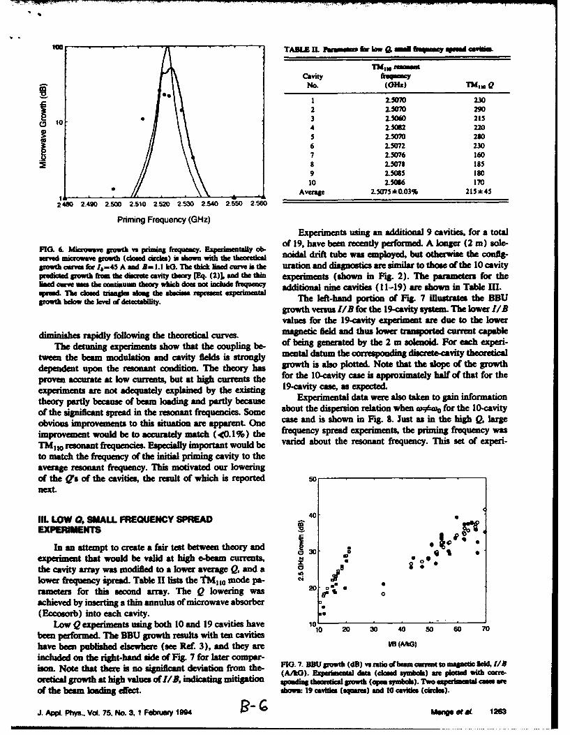
Priming Frequency (GHz)Experiments using an additional 9 cavities, for a total
FI 6. blcov grwt vs prmn frqec.Eprnnal of 19, have been recently performed. A longer (2 mn) sole-eVeCK microwave growth (closed circles) as shwnR wih the theretical oidal drift tube was emloyed, but otherwise the config-
growth curves for 4#=45 A sand A- 1.1 kG. ThU thick fimed curve is the uration and diagnostics are similar to thase of the 10 cavitypredicled growth from the discrete cavity theory (Eq. (2)), a101 the thin experiments (shown in Fig. 2). The parameters for thelined curve use the contaumne theory wh"c does not ush~ fiqe additional nine cavities ( 11-19) are shown in Table Ill.-ot bhelo tosed tlnaeve of deethe alasas ep The left-hand portion of Fig. 7 ilustrates the BDU
growh ~'. tygrowth versus I/B for the 19-cavity system. The lower 11B
values for the 19-cavity experiment are due to the lower
diminishes rapidly following the theoretical curves. magnetic field and thus lower transported current capableThe detuning experiments show that the coupling be- of being generated by the 2 mn solenoid. For each experi-
tween the beam modulation and cavity fields is strongly mental datum the corresponding discrete-cavity theoreticaldependent upon the resonant condition. The theory has growthlias also plotted. Note that the slope of the growthproven accurate at low currets, but at hig curet th for the 10-cavity case is approximately half of that for theexperiments are not adequately explained by the existing 19-cavity case, as expected.theory partly because of beam loading and partly because Experimenta data were also taken to gain informationof the significant spread in the resonant frequencies. Some about the dispersion relation when wo#) for the 10-cavityobvious improvemnents to this situatIon are apparent. One cas and is shown in Fig. 8. Just as in the high Q, largeimprovement would be to accurately match (-<0.1%) the frequency spread experiments, the priming frequency wasTMý,. 1 resonant frequencies. Especially important would be varied about the resonant frequency. This set of experi-to match the frequency of the initial priming cavity to theaverage resonant frequency. This motivated our loweringof the Qs of the cavities, the result of which is reported snext.
Ill LOW 0, SMALL FREQUENCY SPREAD 0
EXPERIMENTS V
In an attempt to create a faitr test between theory andexperiment that would be valid at high e-beamn currents, 0 0*. 0:
the cavity array was modified to a lower average Q, and a I
lower frequency *pea&. Table 11 lists the 'fM 110 mode pa-rameters for this second array. The Q lowering was SP Ub
achieved by inserting a thin annulus of microwave absorber(Eccosorb) into each cavity.
Low Q experiments using both 10 and 19 cavities have II ý- 30 40 S Jbeen perfomied. The BBU growth results with ten cavities 1 0 3 0 5 0 7
have been published elsewhere (see Ref 3), and they are US (MG)
included on the right-hand aide of lFag 7 for later compar- FG .BUSwh(B srto fba ura omgei ed /ison. Note that there Is no significant deviation from the- FIO.7. ExUperowethl (dD)atio (cosed yamos werret to* mantcwre-d/oretical growth at high values of 11B, indicating mitigation (A'oftth Ezarinaw dat lmd symbols). 7 -xp wimethl come-
of the beam loading efec. shown: 19 cavities (qas)and 10 cavite (circles).
J. Appi. Phys.. Vol. 75. No. 3. 1 Febniy 1904 PMangs of a 1263
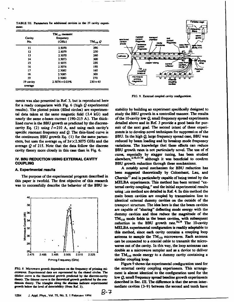
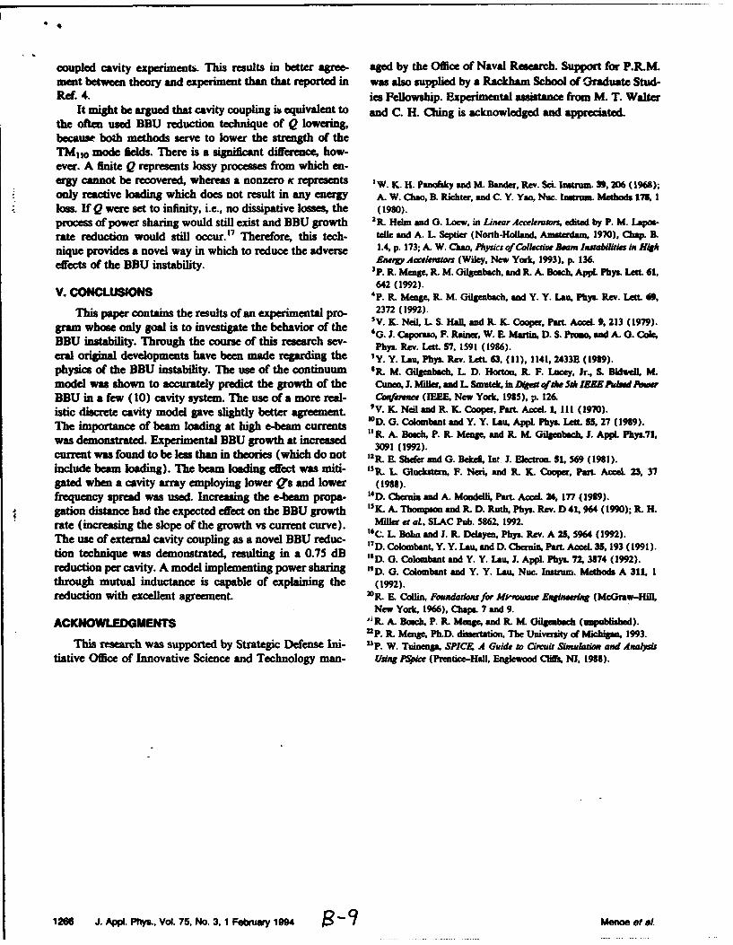
TABLE 11. Parameters for additional cavities in the 19 cavity experi-
TM110 r~mo~ant Z;
cavity frequency eue uil W~ ggidNo. (GHz) TWIG Q c I b - I' • A
I1 2.5070 290 W/ 0 /1012 2.5079 25013 2.50702614 2.5073 30015 2.5075 23016 2.5076 190
17 2.5082 160 Ca18 2.5085 300
19 2.5080 270 n T v19 cavity 2.5076-+0.03% 230*45 P,,
average
FIG. 9. External coupled cavity configuration.
ments was also presented in Ref. 3, but is reproduced herefor a ready comparison with Fig. 6 (high Q experimentalresults). The plotted points (filled circles) are experimen- stability by building an experiment specifically designed total data taken at the same magnetic field (3.4 kG) and study the BBU growth in a controlled manner. The resultsnearly the same e-beam current (190-215 A). The thick- of the 10-cavity low Q, small frequency spread experimentslined curve is the BBU growth as predicted by the discrete- detailed above and in Ref. 3 provide a good basis for pur-cavity Eq. (2) using 1=210 A, and using each cavity's suit of the next goal. The second intent of these experi-specific resonant frequency and Q. The thin-lined curve is ments is to develop novel techniques for suppression of thethe continuum BBU growth Eq. (1) for the same param- BBU. In the high Q, large frequency spread case, BBU waseters, but uses the average ft of 2vrX2.5075 GHz and the reduced by beam loading and by breakup mode frequencyaverage Q of 215. Note that the data follow the discrete variations. The knowledge that these effects can reducecavity theory more closely in this case than in Fig. 6. BBU growth rates is not particularly novel The use of rf
cures, especially by stagger tuning, has been studiedIV. BBU REDUCTION USING EXTERNAL CAVITY elsewhere,23.103-16 although it was beneficial to confirmCOUPUNG BBU growth reduction through these mechanisms.
A. Experimental resuits A notably novel mechanism for BBU reduction hasbeen suggested theoretically by Colombant, Lau, and
The purpose of the experimental program described in Chenin1 7 and is particularly capable of being tested by thethis paper is twofold. The first objective of this research MELBA experiments his method has been termed "ex-was to successfully describe the behavior of the BBU in- ternal cavity coupling." and the initial experimental results
using is method are detailed in Ref. 4. In this method the
40_ main beam cavities are coupled by transmission line toidentical external dummy cavities on the outside of the
38. transport structure. The idea here is that the beam cavitiesg are capable of "sharing" deflecting mode energy with the
a dummy cavities and thus reduce the magnitude of the34 11M 0 mode fields n the beam cavities, with subsequent
reduction in the BBU growth rates't9 The 10-cavity1 32MLA expeiena cofiuato is readily adaptable to
3this method, since each cavity contains a coupling loopantenna to sample the TM[ 0 microwaves. Each antenna
2 . can be connected to a coaxial cable to transmit the micro-waves out of the cavity. In this way, the loop antennas can
26 .double as a microwave sampler and as a device to deliver2.475 2.485 2.495 2.505 2.515 2.525 the TMIi 0 mode energy to a dummy cavity containing a
Priming Frequency (GHz) similar coupling loop.
Figure 9 shows the experimental configuration used forFIG. 8. Microwave growth dependence on the frequency of priming mi- the external cavity coupling experiments. This arange-crowaves. Experimentla data are represented by the closed circle. The meat is almost identical to the configuration used for thethicker curve is the theoretical growth predicted by the discrete-cavity low Q, small frequency spread baseline growth experimentstheory. The thin curve is the theoretical growth predicted by the con-tenam theory. The triangle along the abscis isa icate 12p 1 described in Sec. II. The differeace is that the seven inter-growth below the level of detectability (from Rt. 3). mediate cavities (3-9) between the second and tenth have
1264 J. Appi. Phys., Vol. 75, No. 3. 1 Febimm 1QA
340 0 0 10 .. 0 a32,~ lm 0d I abe=-. 6d...6
Smana amDummy
C\1 24 . . . , . . . d Cd2 4 6 8 101214 16182022 242628303234363840'
Shot #IR d
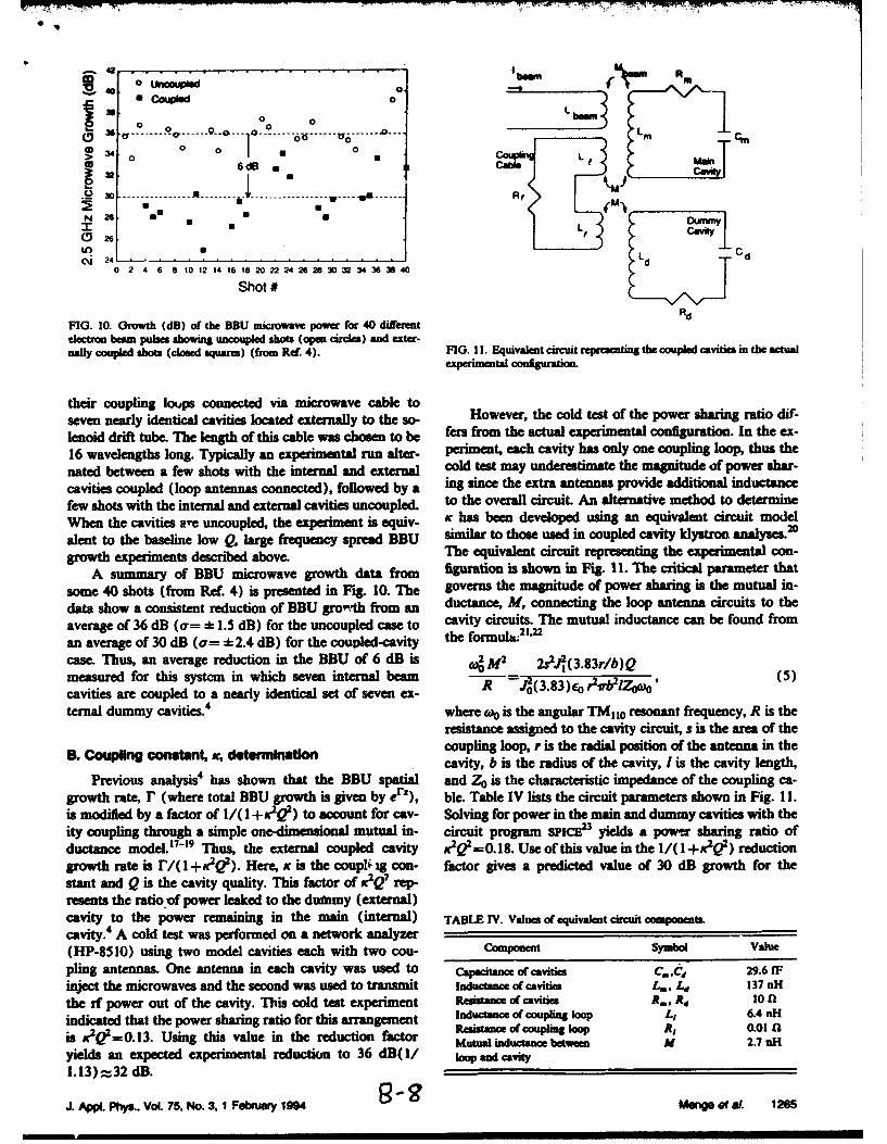
FIG. 10. Growth (dB) of the BBU micrwave power for 40 differentelectron hest pubes shouia uncoupled shots (open circles) and exter-naft coulpled shots (cloud squares) (from Ref. 4). FIG. 11I. Equivalent circuit represeting the couped cavities in the actual
experinbent cortftigdon
their coupling lo ups connected via m icrow ave cable to H w v r h od t s ft e p w r s a i g r t o d fseven nearly identical cavities located externally to the so- Hwvr h odts ftepwrsaigrtodflenoid drf tube. The length of this cable was chosen to be fers from the actual experimental configuration. In the ex-16 wavelengths long. Typically an experimental run alter- periment, each cavity has only one coupling loop. thus thehate between a few shots with the internal and external cold test may underestimate the magnitude of power shar-
cavities coupled (loop antennas connected), followed by a ing since the extra antenna provide additional inductancefew shots with the internal and external cavities uncoupled, to the overall circuit An alternative method to determineWhen the cavities are uncoupled, the experiment is equiv- Kc has been developed using an equivalent circuit model,,lent to the basline low 9, large frequency spread BBU s~imlar to those used in coupled cavity Idystron analyses.2°
grwth experiments described above. Ile equivalent circuit representing the experimental con-A summary of BBU microwave growth data from figurationi is shown in Fig. 11. The critical parameter that
some 40 shots (from Ref. 4) is presented in Fig. 10. The governs the magnitude of power sharing is the mutual in-data show a consistent reduction of BBU gro-th from an ductance, M, connecting the loop antenna circuits to theaverage of 36 dB (a7= :k-1.5 dB) for the uncoupled case to cavity circuits. The mutual inductance can be found froman average of 30 dCa (a= =-2.4 dB) for the couvpled-cavity the formula.21,2
case. Thus, an average reduction in the BBU of 6 dB is c4M2 2MCd(3.83r/b)Q
measured for this system in which seven internal beam R -(38)o2r/o0 (5)cavities are coupled to a nearly identical set of seven ex- R .(.3erv2Z .ternal dummy cavities.4 where 16 is the angular TMu0 resonant frequency, R is the
resistance assigned to the cavity circuit, s is the area of the
B. Cuplng cns~t, v doerniinaioncoupling loop, r is the radial position of the antenna in theB.ncavity, b is the radius of the cavity, I is the cavity length,
Previous analysisO has shown that the BBU spatial and Ze is the characteristic impedance of the coupling ca-growth amte, r (where total BBU growth is given by er-), ble. Table IV lists the circuit parameters shown in Fig. I I.is modified by a factor of s /( r +sK)(o ) to a4count for cav- Solvin v for power in the main and dummy cavities with theity oupling through a simple one-diienional mutual in- circuit program sPICE23 yields a powen sharing ratio of
ductace model."-'9 Thus, the external coupled cavity X.2 V=0.18. Use of this value in the 1/(I +K2QA) reductiongrowth rate is r/( l+ ). Here, K is the co1pli ng con- factor gives a predicted value of 30 dB growth for thestant and Q is the cavity quality. This fCtor Of K tc e reporesents the ratio.of power leaked to the dwamy (external)cavity eto the power Typiclya iex the main (internal) TABLEnTV. Valuea ofequivalat circeit componentgcavity. A cold test was performed on a network analyzer
(HP-8510) using two model cavities each with two cou- C3omonent Symbo Valuepeing antennas. One antenna in eachl cavitiws uc ed to th e ov cavities A.lCtni 29.6 d r
inject the microwaves and the second was used to transmit Inductnce of cavities Lm., L 137 nHthe nf power out of the cavity. i nis cold test experiment Reedhas e of uavitie s A., .A ci mlindicated t the bee low s largerfrequencythis arrangement Inducmiare of t oupling loop Li 6.4 nHigrowt exprimenths described i above Theeequivefactor Rntic i t of cn loop x, 0.0aon
Ais u of Using mhicrowavue e growthedatairo m fgrtMutual inductance between M 2.7 teHydelds an expected experimental reduction of 36 grot frm aan M coavity1. 13) = 32 dB.
J. Asel.Phys., Vol. 75, No. 3. 1rFebduc y 1994 te U Mof 6et W. 1265
mesuedfo tissyte i wic sve itena ~ R Illll • I 1 bIIII (5)l •l
coupled cavity experiment& This results in better agree- aged by the Office of Naval Research. Support for P.R.M.mert between theory and experiment than that reported in was also supplied by a Rackham School of Craduate Stud-Ref. 4. ies Fellowship. Experimental assistance from M. T. Walter
It might be argued that cavity coupling is equivalent to and C. H. Ching is acknowledged and appreciated.the often used BBU reduction technique of Q lowering,because both methods serve to lower the strength of theTMo10 mode fields. There is a significant difference, how-ever. A finite Q represents lossy processes from which en-ergy cannot be recovered, whereas a nonzero K represents W. K. H. pa and M. Itndr, Rev. Sci. Instrum. 39, 206 (1965);only reactive loading which does not result in any energy A. W. Chao, B. Richter. and C. Y. Yao, Nuc. Inotrum. Methods 175, I
loss. If Q were set to infinity, i.e., no dissipative losses, the (1980).process of power sharing would still exist and BBU growth 2 R. Helm and G. Loew, in Linear Accekator, edited by P. M. Lapos.
rate reduction would still occur.17 Therefore, this tech- telle and A. L Septier (North-Holland, Amsterdm 1970), Cap. B.
nique provides a novel way in which to reduce the adverse 1.4. p. 173; A. W. Chao, Physics ofColkecve Bosom Insabilities in H
effects of the inst tAyw erA tom (Wiley, New York, 1993), p. 136.eesfthe BBU instability. 3P. R. Menge, R. M. Gilgenbach. and R. A. Bosch, AppL Phy. Lemt 61,
642 (1992).V. CONCLUSION 4p. RL Menge. R. M. Gflgenbsch, and Y. Y. LaW. Phys. Rev. LetL 69,
This paper contains the results of an experimental pro- 2372 (1992).
gram whose only goal is to investigate the behavior of the 'V. IL Neil, L S. Hall, and R. K. Cooper, Part. Aoel. 9, 213 (1979).'G. J. Cqmapoa, F. Rainer, W. B. Manian, D. S. Promo, and A. 0. Cole,
BBU instability. Through the course of this research sev- 6 .C F. R, W9 (1986).Phys. Rev. Lett. S'7, 1591 (1996).
eral original developments have been made regarding the 'Y. Y. Lam, Phys. Rev. Lett. 63, (11), 1141, 2433E (1989).
physics of the BBU instability. The use of the continuum 8R'. M. Gilgenbach, L D. Horton, RK F. Lucey, Jr., S. Bidwell, M.model was shown to accurately predict the growth of the Qineo, 1. Miller, and L Smutek, tn D•Wot••t 5th 1E Pulsed Poer
BBU in a few (10) cavity system. The use of a more real- Comference (IEEE. New York, 1985). p. 126.istic discrete cavity model gave slightly better agreement. 'V. K. Neil and K. K. Cooper, Part. Accel. 1,111 (1970).
The importance of beam loading at high e-beam currents '0 D. G. Colombmnt and Y. Y. Lau, Appl. Phys. Len. $5, 27 (1989).Thsimponstrataned. ofxerimedngtal higrh -eat incuretse "R. A. Bosch, P. K_ Menge, and .I M. Gilgenbsch, J. Appl. Phys.71,was demonstrated. Experimental BBU growth at increased 3091 (1992).
current was found to be les than in theories (which do not 12R. L Shefer and G. Beke Int J. Electron. S, 569 (1981).
include beam loading). The beam loading effect was miti- 13R. L _luc (kaI, F. Nem, and R. IK Cooper, Pat Acel. 23, 37
gated when a cavity array employing lower Q's and lower (1988).frequency spread was used. Increasing the e-beam propa- I'D. Chernin and A. Mondelli, Put Accel. A4, 177 (1989).gation distance had the expected effect on the BBU growth 'K_ A- Thompson and RK D. Ruth, Phys. Rev. D 41,964 (1990); K H.
rate (increasing the slope of the growth vs current curve). Miller et aL, SLAC Pub. 5862, 1992.'6C. L Bohn and J. K Delayen, Phys. Rev. A 25, 5964 (1992).Ile use of external cavity coupling as a novel BBU reduc- 7 D. Colombant, Y. Y. Lau, and D. Chernin, Pat. Accel. 35,193 (1991).
tion technique was demonstrated, resulting in a 0.75 dB "D. G. Colouabant and Y. Y. Lau, 3. AppL Phys. 72 3874 (1992).reduction per cavity. A model implementing power sharing t9D. G. Colombt and Y. Y. Lau, Nuc. Instrum. Methods A 311, 1through mutual inductance is capable of explaining the (1992).
reduction with excellent agreement. R,. E Collin, Foundatios for Miaeowawe Engineering (McGraw-Hill,New York, 1966). Chaps. 7 and 9.
ACKNOWLEDGMENTS " R A. Bosch, P. R. Menge, and K. M. Gilgenbach (unpubliased)."2P. K Menge, Ph.D. dissertation, The Univenrty of Michig 1993.
This research was supported by Strategic Defense Ini- 2p. W. Tuinenga, SPICE A Guide to Circuit Simuladon and Analysistiative Office of Innovative Science and Technology man- Usang PSpice (Prentice-Hall, Englewood Clifs NJ. 1988).
126 J. AppI. Phys., Vol. 75. No.3,1 Febuary 1994 M'ae eta,.
Beam breakup Instability in an annular electron beamY. Y. Lau and John W. LuginaanIntene aew Ewwnm Inmeacton Lahowaoiy and Deparment of Nuclear Esiginering~Univrity of Michkan. Ann Arbor, Michgan 48109-2104
(Received 8 March 1993; accepted for publication 19 July 1993)
It is shown that an annular electron beam may carry six times as much current as a pencil beamfor the same beam breakup (BBU) growth. This finding suggests that the rf magnetic field of thebreakup mode is far more important than the if electric field in the excitation of BBU. Aproof-of-principle experiment is suggested, and the implications explored.
Annular electron beams have the capability of carrying Consider an infinitesimally thin annular beam of radiusa much higher current than a pencil beam. Besides the r0 inside a cylindrical pillbox of radius b. The beam carriesobvious fact that annular beams have a larger cross- a total current I and coasts at velocity vo with the corre-sectional area, their limiting currents are significantly sponding relativistic factors y and fi. The drift tube ishigher than those of a pencil beam when placed in a me- loaded with a slow wave structure, modeled by a series oftallic drift tube. For this and other reasons, annular beams cylindrical pillbox cavities, each of which supports thehave recently been chosen as the preferred geometry to nonaxisymmetric TM,, 0 mode.'s'3 6-" The interaction be-generate coherent, ultrahigh power microwaves.t• They tween this mode and the beam causes BBU to be excited.have also been used as the primary beam in several "two- In the limit r0 -. O, this is the basic model of BBU for abeam accelerator" configurations.3'4 These annular beams pencil beam. Since we are comparing the strength of BBU
either encounter a sequence of modulating gaps, or simply interaction for different values of ro, we pretend that mag-
glaze by a slow wave structure to generate a wake field in netic focusing is absent and that the quality factor Q of the
the case of two-beam accelerators.3 The beam radius, the deflecting mode is infinite.pill box radius, and the slow wave structure radius may all Let A, =q(t)(cos O)E(r) be the vector potential of
be of the same order of magnitude. The high current would the deflecting dipole mode in a cavity. For the fundamental
then lead to the beam breakup instability (BBU)54 and TM,, 0 mode, E(r)=JI(pr) represents the radial depen-
this concern motivates the present study. dence of the axial electric field with J, being the Bessel
BBU is usually analyzed for a pencil beam propagating function of order one and p= 3.832/b. The corresponding
along the center axis of a sequence of accelerating cavities, magnetic field is BI=VXAI. The action of this mode on
Many BBU calculations of practical interest assume that the beam is calculated as follows.
the accelerating unit is the familiar cylindrical pillbox cav- We divide the annular beam into N azimuthal seg-
ity and that the dominant deflecting mode is the TM, 0 ments (N large). The ith segment is located at r=ro,
mode.5"6'0 Extension to an annular beam is straightfor- 0=i=21ri/N, in the unperturbed state but is displaced
ward. Nevertheless, this calculation leads to several unex- radially by gi and azimuthally by 71i when the deflecting
pected results and provides some new insights into BBU, to mode is present. The linearized force law yields
be reported in this communication. -- (o-kvo)2gi=(e/mo)(Vo1c)qEv(ro)COSOi, (1)It is well known that BBU is excited by the combined
action of the if magnetic field (BI) and the if electric field -- _r(W-kV)2j= -_ (elm0 )(E,) of the deflecting modes:5 B, causes beam deflectionthrough the Lorentz force and E, causes mode amplifica- X (vo/c)q[E(ro)lroJsin 0j, (2)
tion through the work done on the mode by the beam where the right-hand sides represent the components of thecurrent J. Our calculation strongly suggests that B, is Lorentz force that causes beam deflection. In writing Eqs.much more critical than El in contributing to BBU (1) and (2), we have assumed a wave-like solutiongrowth. Thus, an annular beam strategically placed near exp(o~t--kz)] for the disturbances, with j 2=_ 1, and wethe minimum of the if magnetic field would suffer far less have used a prime to denote derivative with respect to thebeam breakup growth than a pencil beam.that is centered argument.on the cavity axis, where the magnetic field is large and the The instantaneous current J on the ith current fila-axial electric field is small. By the same argument, placing ment isthe annular beam very close to the wall of a metallic drifttube, at which the axial electric field is vanishingly small, Jl(rt)2=!86(r--r°--)6 O--O- (3)cannot eliminate BBU growth because of the substantialdeflecting magnetic field generated by the wall current. where 8 is the Dirac delta function. The work done by thisToward the end of this communication, we propose an current filament on the deflecting mode is proportional toexperiment which would unambiguously test the relativeimportance between the if magnetic field and the if axial Wi= f dVA, -J, (4)electric field, as discussed here.
5877 J. AppI. Phys. 74 (9), 1 November 1993-/10021-8979/93/74(9)/587'7/3/$6.00 1993 American Institute of Physics 5877

pected since E1 -. 0 near a metallic wall. As a result,1.0 JI-E,--.0 and, superficially, one could hardly expect any
transfer of power from the beam to drive the breakup
0.8 mode.9 The finite BBU strength as ro-.b is another strongindication that the deflecting magnetic field is far moreimportant than the axial rf electric field in driving BBU.
0.6 The importance of the rf magnetic field can be tested inan experiment in which a pencil beam is focused by a
0.4 solenoidal magnetic field and is made to pass through asequence of pillbox cavities, in which the first cavity is
0.2 primed with microwaves at the TM110 mode.'0 BBUgrowth is monitored at the last cavity, before the beam
o . ,• __________ ,exit. The above theory then predicts the unusual featureS.0 0.2 0.4 0.6 0.8 1.0 that BBU growth should be much less if the pencil beam is
"W ro/b placed off-axis, than if the pencil beam were on-axis. " TheBBU growth should be minimum if this pencil beam isplaced at a distance of about 0.56 of the pillbox radius,
FIG. 1. Comparison of the BBU coupling constant e between an annular where the if magnetic field is minimum.beam of radius r0 and an on-axis pencil beam (ro-0) with the same total We also repeated the calculations for the higher ordercurrent radial modes: TM,2, TM130, TM140, and TM1 So. Fixing
ro/b-=0.56, the ratio e/E0 equals 0.16, 0.012, 0.037, and0.013 for these four higher order modes, respectively.
where the volume integral is performed over the cavity. In Thus, the annular beam still suffers substantially lowerevaluating WV, we should retain only the if component of J, BBU growth, in the higher order deflecting modes, than anin Eq. (3), since only the if current performs work on the on-axis pencil beam of the same current.breakup mode. Upon substituting Eqs. (1)-(3) into Eq. In conclusion, the if magnetic field is found to be much(4), and summing over all i, we find the total work done more important than the if electric field in contributing to
SLle 0 [E,(ro) ]2+ [E(ro)/roJ2 BBU growth. A simple proof-of-principle experiment isW= Y Wi q )2 (s) proposed to test this new finding. Annular beams are far
-l mo c y(a--kvo)2 more stable than an on-axis pencil beam, as a result.apart from a multiplicative constant that is independent of We thank Professor Ronald Gilgenbach for his sup-the beam's equilibrium position r0. This energy transfer port and for many useful discussions. This work was sup-leads to growth of the BBU mode, which is described by ported in part by an SDIO/IST contract managed bythe BBU dispersion relation:8 ONR.
W ) (w,,- kv)=- 24 2 0,/o (6)where e is the coupling constant and wo is the breakup Iv. Serlin and M. Friedman, AppL Phys. Let. 62 2772 (1993); Y. Y.mode frequency. In writing the last form of Eq. (6), we Lau, M. Friedman, J. KraII, and V. Serlin, IEEE Tranm PS-iS, 553normalize e in terms of c the coupling constant for an (1990) and references therein; M. Friedman, Y. Y. Lau, J. Krall, and
V. Serlin, U. S. Patent 5,132,638 (issued July 21, 1992); J. Kral], M.on-axis, pencil beam (ro-0). For the TM110 mode, Friedman, Y. Y. Lau, and V. Serlin, IEEE Trans. EMC-34, 22 (1992).E=J,(pr) and fo=0.422(f/y,) (III kA). It is clear from 2C. Chen, P. Catr4a andG. B"ekef AppL Phys. Lett 62, 1579(1993);Eq. (5) that See also, "Intense Microwave and Particle Beams III," Proc. Soc. Photo
Opt. Instrum. Eng. SPIE 1629 (1992).22 G. Voss and T. Weiland, "The wakefield acceleration mechanism,"
0 2f1 (pro)12+ [ '0) 2 (7) Deutsches Electron-Synchrotron Internal Report DESY #M82-106 Pro JJ(1982); M82-079 (1982), Hamburg, Germany.4 M. Friedman, J. Krall, Y. Y. Lau, and V. Serlin, Phys. Rev. Lett 63,which ompares the BBU strength between an annular 2468 (1989).
beam and a pencil beam of the same current. Note that this sW. K. H. Panoftky and M. Bander, Rev. Sci. Instrum. 39,206 (1968);ratio reduces to unity in the limit ro-.0. Rt. H. Helm and 0. A. Loew, in Linear Acceleraton, edited by R_ P.
Equation (7' is.plotted in Fig. I as a function of ro/b. Lapostolle and A. L. Septier (North-Holland, Amsterdam, 1970), p.173.
It is seen from this figure that e/e, may be as small as 0.17 6V. K. Neil, L S. Hall, and R. K. Cooper, Part Accel. 1, 111 (1970); 9,when the annular beam is located at ro=0.56b. Note also 213 (1979).that this location coincides with the minimum of the if 7A. W. Chao, B. Richter, and C. Y. Yao, Nucl. Instrum. Methods 178,magnetic field of the deflecting mode. What this means is 1 (1980); K. A. Thompson and R. D. Ruth, Phys. Rev. D 41, 964
(1990); R. L. Gluckstern, F. Neri, and R. K. Cooper, Pirt. Accel. 23,that an annular beam placed at this location can carry as 37 (1988); C. L. Bohn and J. R. Delayen, Phys. Rev. A 45, 5964much as 1/0. 17 = 6 times the current as an on-axis pencil (1992); D. Chernin and A. Mondeli, Part. Accel. 24, 685 (1985); G.beam, and suffer the same BBU growth. Another point Decker and J. M. Wang, Phys, Rev. D 38,980 (1988); W. . Martin,worth noting is that BBU growth retains significant G.J. Caporaso, W. M. Fawley, D. Prosnitz, and A. G. Cole, Phys. Rev.
Lett. , 685 (1985); D. Colombant, Y. Y. Lau, and D. Chernin, Part.strength even if the annular beam is very close to the wall Accel. 35, 193 (1991).of the drift tube (cf. ro-.b in Fig. 1). This result is unex- 8Y. Y. Lau, Phys. Rev. Lett. 63, 1141 (1989).
5878 J. AppI. Phys., Vol. 74, No. 9, 1 November 1993 C- Y. Y. Lau and J. W. Luginsland 5878

7. -. WI 7- 7
-~ 'Mhumb dpow- nd is pppodmdiiu to i &tp ftw , md "DM1 pow& so a Pmd bý dM ig ia ou - beamdm K, butM& =@Im be ur wham 4w m*&A ftm (3) bwr Eq. obu by of Eq (4) bmM if 4q (S).. We pwgMi do doe(4) and p 1,u koe~nds by puf meal b arn nrm b 'raa by do A MWmq. ow8 (4).
"Mr. I Mug.. 3.. b Opgrnba* nd Y. Y. IAN% Phy. RAW. L~AIL 0 Aiehaqh do DUW si~ ofsw6 = anuEcamW bar depw~ an 06 ie2372 (IM9); P. IL. bMW 3.. K. CNIprbub and 3R. Daub. Appi. coupuig comamnc £biso no* I= d doe "A for v m orn-ankPhys. Lam 41, 642 (199). bowrn
5879 J. Appi. Phys.. Val. 74. No. 9. 1 Novwnber 1993 C 3Y. Y. Lou and I. W. LUglnsbnd 5879