Beneficial Use of Water Treatment Sludge in Geotechnical ...

UNIVERSITY OF NIGERIA, NSUKKA
FACULTY OF PHYSICAL SCIENCES
DEPARTMENT OF GEOLOGY
REPORT ON STUDENT INDUSTRIAL WORK EXPERIENCE
SCHEME (SIWES) TRAINING PROGRAMME
AT
KDF KONSULT LIMITED
SUBMITTED IN PARIAL FUFILMENT OF THE REQUIREMENT FOR THE STUDENT INDUSTRIAL WORK EXPERIENCE SCHEME
BY
NAME: BASSEY, DANIEL KUFRE
MATRIC NO: 2010/170012
PROGRAMME: GEOLOGY
FROM: MAY - OCTOBER 2014
SUPERVISOR:

TITLE PAGE
A SIWESS REPORT ON GEOTECHNICAL ASSESSMENT

DEDICATION
I dedicate this report first and foremost to Almighty God who has been there right from the
beginning to this very point. Special dedication also to my ever supportive parents, friends, and
colleagues for their relentless support and compassion towards me during the course of my six
months SIWES training.
To God be all the glory.

ACKNOWLEDGMENT
With a deep sense of appreciation, respect and gratitude, I want to say a big thank you to my
parents, brother, sisters, and other relatives and non-relative for their caring attitude and support
from the beginning of my pursuit for B.Sc. degree in Geology to this point. I also want to express
my appreciation to the MD, KDF KONSULT LIMITED, Mr. OLAOYE KAYODE, my immediate
supervisors, Mr. ADENIRAN EMMANUEL TOPE and Mr. OYENIYI ADESHOLA, and other
staff of KDF KONSULT LIMITED for their intellectual support during our work together. Not
forgetting my other IT colleagues. My sincere appreciation also goes to everyone that has been by
me all this while. A Big thanks to you all.
Bassey Daniel Kufre

TABLE OF CONTENTS
Title page …………………………………………………………………………………i
Dedication ………………………………………………………………………………...ii
Acknowledgement ………………………………………………………………………..iii
Table of content …………………………………………………………………………..iv
List of figures ……………………………………………………………………………..
List of plates ……………………………………………………………………………….
CHAPTER ONE: INTRODUCTION
1.1 Brief history of SIWES ……………………………………………………………….1
CHAPTER TWO:
2.1 Company profile ……………………………………………………………………..5
2.2 Brief history of the company ………………………………………………………...6
2.3 Department of the company …………………………………………………………6
2.4 Organogram of company ……………………………………………………………7
CHAPTER THREE
3.1 Activity 1 …………………………………………………………………………....8
3.1.1 Process and Result …………………………………………………………………9
3.1.2 Skill acquired ……………………………………………………………………...17
3.2 Activity 2 ……………………………………………………………………………17
3.2.1 Process and Result …………………………………………………………………18
3.2.2 Skill acquired ………………………………………………………………………31

CHAPTER FOUR
4.1 Summary …………………………………………………………………………..34
4.2 Main activities of the company ……..……………………………………………...34
4.3 Benefits and Challenges …………………………………………………………....35
4.4 Recommendation …………………………………………………………………...35
4.5 Lesson/skills acquired ….…………………………………………………………...36
CHAPTER FIVE: CONCLUSION …………………………………….………….....37

LIST OF FIGURES
FIGURE NUMBER PAGE
FIGURE 1: Organizational chart of KDF KONSULT LTD…………………………………...7
FIGURE 2: Dutch Cone Penetrometer (2.5 Ton Capacity)……………………………………10
FIGURE 3: Schematic of a Geotechnical Borehole……………………………………………17
FIGURE 4: Geotechnical Borehole Log (1)……………………………………………………21
FIGURE 5: Geotechnical Borehole Log (2)…………………………………………………....23
FIGURE 6: Site Layout………………………………………………………………………...33
LIST OF PLATES
PLATE NUMBER PAGE
PLATE 1: Sounding Rod (1M) and Cone…………………………………………………….10
PLATE 2a: Showing activity on site……………………………………………………….....11
PLATE 2b: Showing activity on site……………………………………………………….....11
CHAPTER ONE
INTRODUCTION
BRIEF HISTORY OF SIWES
SIWES was established by ITF in 1973 to solve the problem of lack of adequate practical skills
preparatory for employment in industries by Nigerian graduates of tertiary institutions.
The Scheme exposes students to industry based skills necessary for a smooth transition from the
classroom to the world of work. It affords students of tertiary institutions the opportunity of being
familiarized and exposed to the needed experience in handling machinery and equipment which
are usually not available in the educational institutions.
Participation in Industrial Training is a well-known educational strategy. Classroom studies are
integrated with learning through hands-on work experiences in a field related to the student’s
academic major and career goals. Successful internships foster an experiential learning process
that not only promotes career preparation but provides opportunities for learners to develop skills
necessary to become leaders in their chosen professions.
One of the primary goals of the SIWES is to help students integrate leadership development into
the experiential learning process. Students are expected to learn and develop basic non-profit
leadership skills through a mentoring relationship with innovative non-profit leaders.
By integrating leadership development activities into the Industrial Training experience, we hope
to encourage students to actively engage in non-profit management as a professional career
objective. However, the effectiveness of the SIWES experience will have varying outcomes based
upon the individual student, the work assignment, and the supervisor/mentor requirements. It is

vital that each internship position description includes specific, written learning objectives to
ensure leadership skill development is incorporated.
Participation in SIWES has become a necessary pre-condition for the award of Diploma and
Degree certificates in specific disciplines in most institutions of higher learning in the country, in
accordance with the education policy of government.
Operators - The ITF, the coordinating agencies (NUC, NCCE, NBTE), employers of labor and the
institutions.-
Funding - The Federal Government of Nigeria
Beneficiaries - Undergraduate students of the following: Agriculture, Engineering, Technology,
Environmental, Science, Education, Medical Science and Pure and Applied Sciences.
Duration - Four months for Polytechnics and Colleges of Education, and Six months for the
Universities.
The following are some of the objectives of SIWES:
1. SIWES will provide students the opportunity to test their interest in a particular career before
permanent commitments are made.
2. SIWES students will develop skills in the application of theory to practical work situations.
3. SIWES will provide students the opportunity to test their aptitude for a particular career before
permanent commitments are made.
4. SIWES students will develop skills and techniques directly applicable to their careers.
5. SIWES will aid students in adjusting from college to full-time employment.

6. SIWES will provide students the opportunity to develop attitudes conducive to effective
interpersonal relationships.
7. SIWES will increase a student's sense of responsibility.
8. SIWES students will be prepared to enter into full-time employment in their area of
specialization upon graduation.
9. SIWES students will acquire good work habits.
10. SIWES students will develop employment records/references that will enhance employment
opportunities.
11. SIWES will provide students the opportunity to understand informal organizational
interrelationships.
12. SIWES will reduce student dropouts.
13. SIWES Students will be able to outline at least five specific goals with several staff members
by comparing performance with job duties and develop a draft plan with staff to accomplish
performance needs, supervision plan and rewards.
14. SIWES Students will be able to develop a draft agency or project budget and will be able to
identify methods of obtaining revenue to support the budget.
15. SIWES Students will be able to provide tools to use in prioritizing tasks of an assigned project
and create with staff a tentative schedule for completion based on these tasks.
16. SIWES Students will be able to develop a model policy that gives current front-line leaders
the permission and expectation to work with other staff on conflict resolution and explain how this
works to current front line leaders.

17. SIWES Students will be able to describe different skills leaders can use to Foster commitment
and collaboration with both internal and external constituents.
The 6 months Students Industrial Work Experience Scheme (SIWES) which is a requirement for
the completion of my course of study, Geology, was undertaken at KDF KONSULT LIMITED
located at 3, Balogun Street, Ikeja, Lagos state. The company functions to provide a professional,
efficient and sustainable geotechnical assessment, survey, report, and training.

CHAPTER TWO
2.1 KDF KONSULT LIMITED COMPANY PROFILE
KDF KONSULT LIMITED is a geotechnical and engineering company which has its head office
at NO. 3, Balogun Street, Ikeja, Lagos State. The company has a professional experience in the
application of scientific principle to engineering problems. As professionals, the engineers,
geologists, surveyors in the company owe a duty to the public as well as to their clients who receive
the final product; a final product that retains the same professional characteristics that meets the
professional standard. The company has extended the scope of the services rendered because of
the presence of the Industrial Training students so that we may actually appreciate the importance
of site supervision and borehole management as IT students.
Kdf Konsult Limited is a leading service provider in Geotechnical, Mining, Dredging, Water and
Environmental Engineering, Servicing and Construction sector using the best resources available
to maximize is returns and create positive impact in the industry. The company presently has client
spanning different sectors. These include:
Construction
Oil and Gas
Telecommunications
Financial Institutions
Government Parastatals
Net worth Individuals and more
2.2 BRIEF HISTORY OF KDF KONSULT LIMITED
KDF Konsult Ltd was established in 2002 and actually started full operation in 2003. Our company
was deliberately fashioned out, to focus on Engineering services, General Procurements and
Project Support Services.
We have a team of competent registered professionals with broad and deep experience in business
engineering and safety/ environmental field.
We have records of breakthrough and we are waxing stronger in proving services with diligence
and excellent level of practice. Our human resources development, structures and background gave
us ample opportunity to deal professionally in various field of life jointly with our technical partner.
Our simple profile reflects the summary of our key staff, that of our technical partner, and our
achievements in practice as individuals when working with previous bigger organization and as a
group now working in KDF Konsult Ltd.
2.3 DEPARTMENT OF THE COMPANY
The various departments in KDF KONSULT LTD include:
Administrative department
Human resources
Finance
Geotechnical Engineering and Piling
Maintenance
Geological
Quality assurance
Civil Engineering

Environmental Consulting
Fibre Optics
2.4 THE ORGANIZATIONAL STRUCTURE OF KDF KONSULT LTD
FIGURE I: ORGANIZATIONAL CHART

CHAPTER THREE
3.0 ACTIVITIES AT KDF KONSULT LIMITED
3.1 ACTIVITY 1: SUBSOIL INVESTIGATION
INTRODUCTION
Subsoil investigation is essential before any construction work is done on any land.
The purpose of the subsoil investigation include the following:
Determination of the subsoil and surface/groundwater conditions of the designated
location.
Evaluation of the subsoil stratigraphic sequence geotechnical/engineering
properties of the soil and the subsequent effects on foundation design and
construction.
Analysis of the data/results of tests carried out on the soil samples obtained and
provide recommendations on the fit-for-purpose and economic type of foundation
for the proposed structure.
To disclose and make provisions for difficulties and anomalies that may arise
during construction due to ground and other local conditions.
3.1.1 PROCESS AND RESULT
INTRODUCTION
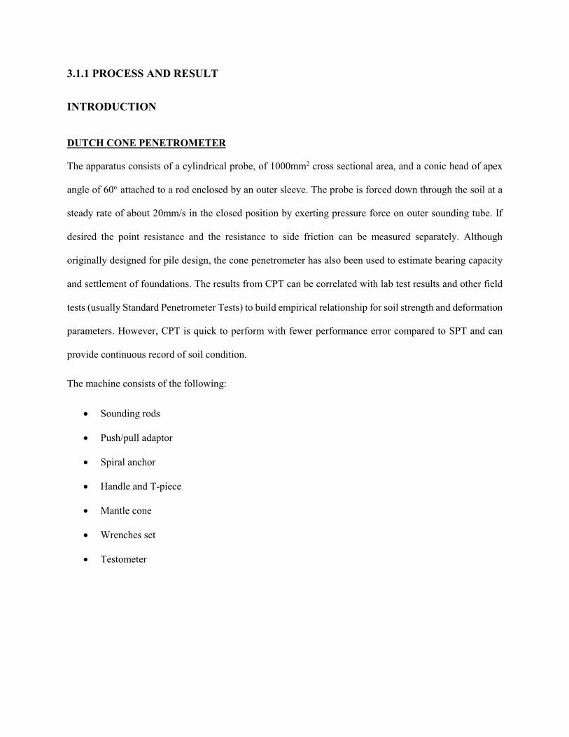
DUTCH CONE PENETROMETER
The apparatus consists of a cylindrical probe, of 1000mm2 cross sectional area, and a conic head of apex
angle of 60o attached to a rod enclosed by an outer sleeve. The probe is forced down through the soil at a
steady rate of about 20mm/s in the closed position by exerting pressure force on outer sounding tube. If
desired the point resistance and the resistance to side friction can be measured separately. Although
originally designed for pile design, the cone penetrometer has also been used to estimate bearing capacity
and settlement of foundations. The results from CPT can be correlated with lab test results and other field
tests (usually Standard Penetrometer Tests) to build empirical relationship for soil strength and deformation
parameters. However, CPT is quick to perform with fewer performance error compared to SPT and can
provide continuous record of soil condition.
The machine consists of the following:
Sounding rods
Push/pull adaptor
Spiral anchor
Handle and T-piece
Mantle cone
Wrenches set
Testometer

FIGURE 2: 2.5 Ton Penetrometer PLATE 1: Cone and Rod
Six static cone penetration tests were carried out using a 2.5 Ton capacity testing equipment (machine) on
each point. The test involves advancing the cone into the ground slowly at a constant rate and the resistant
to penetration measured at predetermined intervals of 0.20m depth. The tests were terminated at depths
where the machine anchor legs lifted.
These tests were taken from the existing ground level down to depths of -5.00m in Pen1, -3.50m in Pen 2,
-4.00m in Pen 3, -4.25m in Pen 4, -4.00m in Pen 5 and -3.50m in Pen 6.

PLATE 2a; showing work on site PLATE 2b; showing work on site
SUBSOIL CONDITION
The subsoil condition of the site, based on the DCP and Borehole/SP carried out reveals
predominantly cohesive soil as observed from the DCP Plot and Borehole log.
Details of the subsoil characteristics encountered during the Penetrometer tests and Borehole/SP
test:
Soil Profile
Depth (m) Description of Stratum
0.00 to –.0.75 Dark brown cohesionless soil.
0.75 to –2.00 Firm to stiff cohesive soil.
2.00 to –5.00 Stiff to very stiff cohesive soil.
GEOTECHNICAL PROPERTIES
Depth (m) Geotechnical Properties
0.00 to –.0.75 Moderate geotechnical properties, moderate shear strength and
moderate compressibility potential.

0.75 to –2.00 Moderate to good geotechnical properties, moderate to high shear
strength and low compressibility potential.
2.00 to –5.00 Good geotechnical properties, high shear strength and low
compressibility potential
GEOTECHNICAL ENGINEERING PARAMETERS
Depth (m) P1 P2 P3
0.00 – 0.75m 5 – 10 14 – 26 12 – 15
0.75 – 2.00m 13 – 17 38 – 56 20 – 38
2.00 – 5.00m 23 – 152 74 – 147 44 – 152
Depth (m) P4 P5 P6
0.00 – 0.75m 15 – 18 10 – 20 15 – 18
0.75 – 2.00m 19 – 41 25 – 42 18 – 62
2.00 – 5.00m 48 – 150 54 – 156 60 – 148

SITE LOCATION
Several subsoil investigations were carried out during my time with KDF KONSULT LIMITED.
Presented in this paper is a case study on a site located at Muritala Mohammed Airport Way (Int`l),
off Concord Way, Ikeja, Lagos State. The project site is an open piece of land within residential
and commercial environment. Structures around site show no sign of distress at the time of our
investigation.
GEOLOGY OF THE AREA
Geologically, the site falls within the formation called the coastal plain sands. This formation has
a recent deposit called the alluvial deposit on it. Sands, clays and lignite, sometimes mixtures of
these constitute the material that makes up this formation.
GROUNDWATER CONDITION
Groundwater was encountered at depth 0.25m to 1.60m during the subsoil investigation. This level is
subjected to variation due to season.

RESULT ANALYSIS AND INTERPRETATION
PENETROMETER 1
PENETROMETER 2

PENETROMETER 3
PENETROMETER 4

PENETROMETER 5
PENETROMETER 6
3.1.2 SKILS AND KNOWLEDGE ACQUIRED
I got familiarized with the soil testing apparatus, its parts, and mode of operation.
Ability to effectively carry out subsoil investigation given the necessary tools.
Mentality of working with others (team work) was greatly developed.
3.2 ACTIVITY 2; GEOTECHNICAL BOREHOLE DRILLING
INTRODUCTION
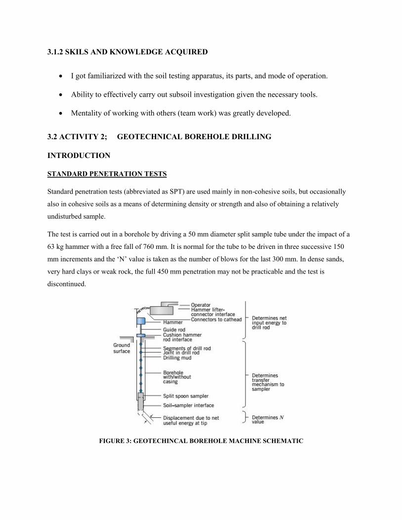
STANDARD PENETRATION TESTS
Standard penetration tests (abbreviated as SPT) are used mainly in non-cohesive soils, but occasionally
also in cohesive soils as a means of determining density or strength and also of obtaining a relatively
undisturbed sample.
The test is carried out in a borehole by driving a 50 mm diameter split sample tube under the impact of a
63 kg hammer with a free fall of 760 mm. It is normal for the tube to be driven in three successive 150
mm increments and the ‘N’ value is taken as the number of blows for the last 300 mm. In dense sands,
very hard clays or weak rock, the full 450 mm penetration may not be practicable and the test is
discontinued.
FIGURE 3: GEOTECHINCAL BOREHOLE MACHINE SCHEMATIC

The test results are reported in the following form:
• In the case where full penetration is obtained with successive blow counts for each 150 mm of say 4, 6
and 7 as 4, 6, 7 ~`N = 13
• In the case where the test is discontinued short of full penetration, say after 15 blows for the first 150
mm and 30 blows for the next 40 mm as 15, 30/40 mm.
The results of the tests can be related empirically to the engineering properties of the soil.
Occasionally, the test method is used to obtain samples in 50 mm diameter thin walled sample tubes in
clays. In such circumstances, the test results are shown on the bore logs in brackets.
SITE LOCATION
The site is located at Muritala Mohammed Airport Way (Int`l), off Concord Way, Ikeja, Lagos
State. The project site is an open piece of land within residential and commercial environment..
Structures around site show no sign of distress at the time of our investigation.
3.2.1: PROCESS AND RESULT
GEOLOGY OF THE AREA
Geologically, the site falls within the formation called the coastal plain sands. This formation has a recent
deposit called the alluvial deposit on it. Sands, clays and lignite, sometimes mixtures of these constitute the
material that makes up this formation.
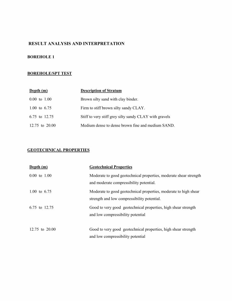
RESULT ANALYSIS AND INTERPRETATION
BOREHOLE 1
BOREHOLE/SPT TEST
Depth (m) Description of Stratum
0.00 to 1.00 Brown silty sand with clay binder.
1.00 to 6.75 Firm to stiff brown silty sandy CLAY.
6.75 to 12.75 Stiff to very stiff grey silty sandy CLAY with gravels
12.75 to 20.00 Medium dense to dense brown fine and medium SAND.
GEOTECHNICAL PROPERTIES
Depth (m)
Geotechnical Properties
0.00 to 1.00 Moderate to good geotechnical properties, moderate shear strength
and moderate compressibility potential.
1.00 to 6.75 Moderate to good geotechnical properties, moderate to high shear
strength and low compressibility potential.
6.75 to 12.75 Good to very good geotechnical properties, high shear strength
and low compressibility potential
12.75 to 20.00 Good to very good geotechnical properties, high shear strength
and low compressibility potential
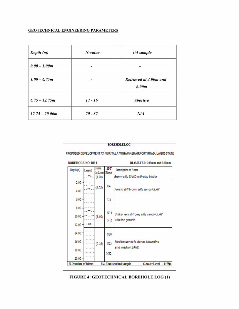
GEOTECHNICAL ENGINEERING PARAMETERS
FIGURE 4: GEOTECHNICAL BOREHOLE LOG (1)
Depth (m) N-value U4 sample
0.00 – 1.00m - -
1.00 – 6.75m - Retrieved at 3.00m and
6.00m
6.75 – 12.75m 14 - 16 Abortive
12.75 – 20.00m 20 - 32 N/A

BOREHOLE 2
BOREHOLE/SPT TEST
Depth (m) Description of Stratum
0.00 to 0.75 Dark brown silty sand with clay binder.
0.75 to 6.00 Firm to stiff grey silty sandy CLAY with gravels.
6.00 to 12.75 Medium dense to dense brown fine and medium SAND
12.75 to 16.50 Stiff brownish grey silty CLAY with sand at the bottom part.
16.50 to 20.00 Medium dense to dense brown fine and medium SAND
GEOTECHNICAL PROPERTIES
Depth (m)
Geotechnical Properties
0.00 to 0.75 Moderate geotechnical properties, moderate shear strength and
moderate compressibility potential.
0.75 to 6.00 Moderate to good geotechnical properties, moderate to high shear
strength and low compressibility potential.
6.00 to 12.75 Good geotechnical properties, high shear strength and low
compressibility potential
12.75 to 16.50 Good geotechnical properties, high shear strength and low
compressibility potential
16.50 to 20.00 Good to very good geotechnical properties, high shear strength
and low compressibility potential

GEOTECHNICAL ENGINEERING PARAMETERS
FIGURE 5: GEOTECHNICAL BOREHOLE LOG (2)
Depth (m) N-value U4 sample
0.00 – 0.75m - -
0.75 – 6.00m - Retrieved at 3.00m
6.00 – 12.75m 14 - 16 Abortive
12.75 – 16.50m 20 - 32 N/A
16.50 – 20.00m 20 - 32 N/A

LABORATORY ANALYSIS
PROPOSED DEVELOPMENT AT MURITALA MOHAMMED AIRPORT ROAD LAGOS.
Samples are normally taken from the field for laboratory analysis to characterize the physical and mechanical
properties if soil strata. These parameters are used to design foundations and to evaluate the application of soils as
construction materials.
Disturbed samples (such as from Standard Sampler) are usually used for visual inspection and for tests to
determine the physical properties such as grain size, grain shape, and plasticity.
Undisturbed samples (such as from Thin-Walled Sampler) are used for both physical and mechanical assessment.
Test results, especially mechanical, are strongly affected by sampling, handling, transportation, and sample
preparation disturbances.
Care must be taken to protect the intact condition of soil samples. Wax is often used to coat soil samples to
prevent moisture loss.
LABORATORY ANALYSIS TABLE
BH No
Sample No
Depth
(m)
Soil Type
Moisture content %
Specific gravity
Cu
Ø
1
5
3.00
C
28
2.06
175
13
2
5
3.00
C
29
2.11
190
12

BH 1 Sample: 5 Depth: 3.00m
Undrained Cohesion 175KN/m2
Angle of Friction (PHI) 13 deg
BH 2 Sample: 5 Depth: 3.00m
Undrained Cohesion 190KN/m2
Angle of Friction (PHI) 12 deg
0
200
400
0 50 100 150 200 250 300 350 400 450 500 550 600 650 700 750 800 850 900 950 1000Sh
ear
Str
ess,
KN
/m2
Total Normal Stress, KN/m2
0
200
400
0 50 100 150 200 250 300 350 400 450 500 550 600 650 700 750 800 850 900 950 1000Sh
ear
Str
ess,
KN
/m2
Total Normal Stress, KN/m2

4.1.1 Proposed Development
No structural detail of the proposed development was made available to us prior to the subsoil
Investigation, thus our recommendations are based on the DCP and Borehole/SPT carried out.
The geotechnical issues considered relevant to the proposed development include
Soil bearing pressure
Level of groundwater
Recommendation of a suitable foundation type
RECOMMENDATION
The foundation type to be chosen for a particular structure depends largely on the followings;
- Loads to be transmitted
- Receiving soil strata
- Factor of safety against shear failure of the supporting soil must be adequate.
- Settlement should neither cause any unacceptable damage nor interfere with the function
of the structure.
Foundations can be classified as shallow foundation or as deep foundation.
The choice between shallow foundation and deep foundation can be arrived at after careful
consideration of the following elements:
1. The magnitude of the transmitted loads from the stratum,
2. The soil nature,
3. The economic aspects of the elements of the foundation work,
4. Problems concerning foundation construction.

Allowable bearing pressure calculated between ground surface and -3.00m
Allowable bearing pressure calculated in accordance with theoretical soil mechanics principle for depths
are indicated below:
KPA VALUES:
Differential Depth (m) Allowable bearing Capacity (KN/m2)
0.00 – 1.00 132
1.00 – 2.00 186
2.00 – 3.00 390
METHOD OF CALCULATING ALLOWABLE BEARING PRESSURE IN COHESIVE SOIL IS
GIVEN BY:
Empirical Method for calculating in Cohesive Soil is given by:
qult = 5.14Cu + ϪD (Prandtl method of estimating allowable bearing pressure)
qa= qult/F.S (3) – For Shallow foundation
If the Clay is very Sandy
Correlation between qc and SPT (N – Values)
N = qC / 2
qa = 10N, or 5.0N (If Submerged)
Correlation between qc and Cu
Cu = qc / 20 (KN/m2)

METHOD OF CALCULATING ALLOWABLE BEARING PRESSURE IN COHESSIONLESS
SOIL IS GIVEN BY:
qa = 2.7qc .Rw2 (Meyerhof method) (for all width of foundation and limit settlement to 25mm)
If Reinforced Raft Foundation is to be adopted qa calculated above could be doubled.
Correlation between qc and SPT (N – Values) in Cohessionless Soil
N = qC / 4 = N
qa = 10N, or 5.0N (If Submerged)
FOUNDATION RECOMMENDATION
The selection of parameters for foundation design should take into account the extent, quality and
adequacy of the ground investigation, reliability of the geological and geotechnical analysis model, the
appropriateness of the test methods, the representativeness of soil parameters for the likely field
conditions, the method of analysis adopted for the design, and the likely effects of foundation
construction on material properties. In principle, sophisticated analyses, where justified, should only be
based on high quality test results. The reliability of the output is, of course, critically dependent on the
representativeness and accuracy of the input parameters.
'Best-estimate' parameters, which are those representative of the properties of the materials in the field,
should be selected for design. Engineering judgment is always required in the interpretation of test results
and in the choice of design parameters, having regard to previous experience and relevant case histories.
In adopting well-established correlations for a given geological material, it is important to understand
how the parameters involved in the database for the particular correlation have been evaluated. In
principle, the same procedure in determining the parameters should be followed to safeguard the validity
of the correlations.

Shallow foundation
Shallow Foundation (Stiffened Raft Slab) is considered adequate for the proposed development on the
project site.
Stiffened Raft Slab helps to minimize differential settlement.
Settlement
Settlement for this allowable bearing pressure stated above would not exceed 50mm.
Our analysis on settlement is based on the method stated below
S = 1.1Mv x 0.55qn x h
Where S = Total settlement
Mv = Volume of compressibility potential
qn = net foundation base pressure
h = depth of foundation
The table below shows the permissible settlement as per I.S Code.
Soil type
Permissible total settlement
Permissible differential settlement
For isolated
footings
For raft footings
For isolated
footings
For raft footings
Sandy
4.0cm
4.cm to 6.5cm
2.5cm
2.5cm
Clays
6.5cm
6.5 to 10.0cm
4.0cm
4.0cm
Factor of Safety
Factor of safety of 3 was adopted for the estimation of allowable bearing pressure.
Excavation
Adequate preparation should be put in place to excavate into brown silty sandy clay
Excavation could be achieved using conventional excavating equipment.
Excavation support would not be required
General Precaution for Shallow Foundation Construction
It is recommended that the following general guidelines that govern the construction of shallow
foundation should be observed when work starts on the site:
Over excavation beyond the depths stated should not be done.
Ingress of water into the excavated foundation trench should be prevented if the stated
bearing value at the founding depth is to be achieved. A layer of concrete blinding should
therefore be provided within a trench once it has been excavated.
Adequate cover to the concrete should be allowed for the reinforcement bars to protect
them from possible effect of corrosion.
The sides of foundation should be backfilled up to existing ground level as soon as they are
cast.

CONCLUSION
Shallow Foundation (Stiffened Raft Slab) is considered adequate for the proposed development on
the project site.
Stiffened Raft Slab helps to minimize differential settlement.
Despite an objective soil investigation and reporting, a poorly designed and/or constructed
foundation may lead to structural failure if all other environmental conditions remain constant.
3.2.2 SKILS AND KNOWLEDGE ACQUIRED
I got familiarized with the soil testing apparatus (SPT), its parts, and mode of operation.
Ability to effectively carry out subsoil investigation (SPT) given the necessary tools.
Mentality of working with others (team work) was greatly developed.
SUMMARY
Geotechnical reports are based on information gained from limited subsurface test boring and
sampling, supplemented by knowledge of local geology and experience.
Description and Classification Methods
In general, descriptions cover the following properties - strength or density, colour, structure, soil
or rock type and inclusions.
Soil types are described according to the predominating particle size, qualified by the grading of
other particles present (e.g. sandy clay) on the following bases:
Soil Classification Particle Size
Clay = less than 0.002 mm
Silt = 0.002 to 0.06 mm

Sand = 0.06 to 2.00 mm
Gravel = 2.00 to 60.00 mm
Cohesive soils are classified on the basis of strength either by laboratory testing or engineering
examination.
The strength terms are defined as follows.
Classification Undrained Shear Strength kPa
Very soft less than 12
Soft 12—25
Firm 25—50
Stiff 50—100
Very stiff 100—200
Hard Greater than 200
Non-cohesive soils are classified on the basis of relative density, generally from the results of
standard penetration tests (SPT) or Dutch cone Penetrometer tests (CPT) as below:
Relative Density SPT “N” Value (blows/300 mm)
CPT Cone Value (qc — MPa)
Very loose less than 5 less than 2
Loose 5—10 2—5
Medium dense 10—30 5—15
Dense 30—50 15—25
Very dense greater than 50 greater than 25
Rock types are classified by their geological names. Where relevant, further information
regarding rock classification is given.

Sampling
Sampling is carried out during drilling to allow engineering examination (and laboratory testing
where required) of the soil or rock. Disturbed samples taken during drilling provide information
on colour, type, inclusions and, depending upon the degree of disturbance, some information on
strength and structure.
Undisturbed samples are taken by pushing a thin walled sample tube into the soil and
withdrawing with a sample of the soil in a relatively undisturbed state. Such samples yield
information on structure and strength, and are necessary for laboratory determination of shear
strength and compressibility. Undisturbed sampling is generally effective only in cohesive soils.
FIGURE 6: SITE LAYOUT

CHAPTER FOUR
SUMMARY
The benefits of the (SIWES) Programme is that it helped me to be acquainted with major activities
carried out in the geological industry and to appreciate the practical view of my study , especially
as regards geotechnical operations.
4.1 Main Activities
I was assigned to the geotechnical (subsoil investigation) department were I was taught on the
essence and methodology of soil testing using Dutch Cone Penetrometer (2.5 TON and 10 TON).
Some of the tools and terms that I familiarised myself with include:
Drilling rig : the machine used to drill a wellbore,the rig includes mud tanks,mud pumps, derrick,
rotary table, drill string, power generator equipment and auxilary equipment in other words it is a
package of special equipment put together to enable us drill into the earth.
Dutch Cone Penetrometer : apparatus/machine used to carry out subsoil investigation.
Probe (Rod) : one meter long metal attached to the cone and forced into ground.
Anchor : CPT machine legs used for stability of machine during operation.
water table : A level beneath the Earth's surface, below which all pore spaces are filled with water
and above which the pore spaces are filled with air aquifer.

4.2 BENEFITS AND CHALLENGES
BENEFITS
The benefits of the SIWES programme is that it helped me to be acquainted with most major
activities carried out in the geoscience world and to appreciate the practical view of my syudy,
especially as regards geotechnical operations, and also helped me improve in the area of
socialization.
CHALLENGES
The problems I encountered are listed below:
I. Though I was among the few students that found a place to work, it took some weeks
before I took part in the executions of project.
II. Unfavourable weather conditions sometimes obstruct smooth execution of projects.
III. More projects came at the time of my departure that I could have benefitted from.
4.3 RECOMMENDATION
For subsequent trainees being taken up by the company, I strongly recommend a more stringent
supervision of their training program, especially by the industry based SIWES supervisor. This
will go a long way in ensuring that trainees do not lose focus and will constantly remind them that
their services to the company remain valuable.

Also I suggest ITF should liaise with some companies where they will take up students for
industrial training. This will help students who find it difficult to find attachments or who end up
in companies where they do nothing.
4.4 LESSONS/SKILLS ACQUIRED
After my internship with KDF KONSULT LIMITED :
• I can effectively carry out soil testing usina a Dutch Cone Penetrometer.
• I can process raw Qc values from site
• I can accurately give recommendation on foundation design.

CHAPTER FIVE
CONCLUSION
This Industrial Training has afforded me the basic practical and theoretical knowledge that I may
not have gotten from the lecture room. It also gave me the opportunity to have a feel of what life
after school is like.
After my internship with KDF KONSULT LIMITED :
• I can effectively carry out soil testing usina a Dutch Cone Penetrometer.
• I can process raw Qc values from site
• I can accurately give recommendation on foundation design.
Other benefits include:
Good working ethics as a result of the close working relationship I had with the geologists and
engineers. These ethics include being able to handle situation with little or no help, being able to
provide solutions to lingering problems, etc.
I have been able to use this training to explore various avenues available at my disposal career-
wise. It has given me the opportunity to have a look into the future and assess my readiness for
employment or entrepreneurship.
Copyright © 2022 FDOKUMEN