SIWES (IT) REPORT ON SUBSOIL INVESTIGATION (GEOTECHNICAL ASSESSMENT)

A
TECHNICAL REPORT
ON
INDUSTRIAL TRAINING(I.T)
WITH
NIGERIAN PETROLEUM DEVELOPMENT COMPANY (NPDC)(A SUBSIDIARY OF NIGERIAN NATIONAL PETROLEUM CORPORATION)
62/64 SAPELE ROAD BENIN CITY
BY OGBEIDE KENNEDY AGBONS
PETROLEUM ENGINEERING DEPARTMENT
DELTA STATE UNIVERSITY OLEH CAMPUS

DELTA STATE
18/11/2014
PAGE
Abstract………………………………………………………………2
Acknowledgement…………………………………………………..3
Introduction…………………………………………………………4
Chapter one
The company’s symposium ………… ………………………….5-10
Chapter two
Field Description………..……………………………………….11-18
Chapter three
OBAX Flow station description ……………………………………………19-21
Chapter four
Processing of Gas in IGHF……….22-23
Chapter five
Other operations carried out at NPDC’S flow station ……………24-29
Chapter six

Flow station process control systems at NPDC……………30-31
Conclusion………………………………………………………32
Recommendations …………………………………………….33
References………………………………………………………34
Nomenclature………………………………………………….35
Appendixes………… …………………………………………36
ABSTRACT
The introduction of students’ Industrial Work ExperienceScheme (SIWES) into the normal schools’ curriculum hasopened up an avenue for students to acquire a lot ofexperience, skills, information and knowledge during theperiod of attachment to the company/ industry in order tosupplement the theoretical background of their chosen courseof study and also to prepare them for the challenges thefuture holds. This report is centered on my six monthsindustrial training program with Nigerian PetroleumDevelopment Company for processing, with highlight on officeand field activities such as monitoring the plant process,operational calculation, chemical injection, well testingand control systems of NPDC e.t.c. The organizationstructure of the company is also included.

ACKNOWLEDGEMENT
I want to appreciate God Almighty for giving me the grace, opportunity and strength to complete my industrial training successfully. I also want to thank the management of NPDC most especially Gas Development Department (GDD), Abdullahi,A.H

(Manager, GDD), Jamari S (Deputy Manager, GDD), Mr. Musa M (supervisor), Mr. Olajide K (supervisor) and Omolara (SecretaryGDD ).I wish to thank the entire Gas Development Department (GDD) for their lovely support and accommodation giving to me
during my Industrial Training.

INTRODUCTIO
N
INTRODUCTION TO OREDO FLOWSTATION AND INTERGRATED GAS
HANDLING FACILITY
Oredo flow station and Integrated Gas Handling Facility (IGHF) islocated at suburb of Ologbo Town, Ikpoba Okha Local Government ofEdo State.
Oredo flow station was built initially to accommodate medium pressure producing wells. Over time, more wells were drilled and completed, which turned out to be high pressure wells which couldnot be accommodated by the available facilities.
Another Early Production Facility (EPF) was built to accommodate these strings. This facility is known as OBAX Flow station mainlycalled New EPF. NPDC (old) EPF has a production capacity of 6000BPD for oil, and 14MMSCFD of Gas daily.
OBAX EPF has a producing capacity of 10,000 BPD of oil and 70MMSCFD of gas. Presently, OBAX facility produces from ten (10) strings at about 1607 BPD and about 80MMSCFD of gas. The gas separated is sent to the gas handling facility to be processed and exported.
INTEGRATED GAS HANDLING FACILITY (IGHF) Integrated Gas Handling Facility (IGHF) is operated by Network oil and gas (NO&G), they handle the gas produced from old and newEPF. In an effort to reduce gas flaring and natural gas wastage, the facility was built to process the gas and make it available for consumers, for power generation, to fuel automobiles, machinery and so many others uses. Currently the facility only compresses the gas and transports it to Nigerian Gas Company (NGC) where it will be further processed. This is because the gashandling facility is not fully operational for other forms of

processing. 95% of the produced gas is handled by this gas facility.
FLOW STATION A flow station is an important facility in the oil and gas industry. In the oil and gas field development, sometimes many development wells can be drilled over the field area; these wellscontain fluid with varying properties, phase and features. It is important that these fluids be processed before they are delivered to the refineries or for export.
A flow station is a gathering centre where primary separation/processing of the reservoir fluid take place. These fluids are later transported to terminals for export or to the refinery, while the other products are either treated or flared or disposed.
A flow station is usually designed to run unmanned or automatically. It employs pneumatic instrumentation logic for control and shut down in a safe manner. At the flow station, flowlines run from the well-head to the manifold, then to the different separators for primary separation of the fluid into various phase.

Diagram is shown Above The reservoir fluid is most times a mixture of usually three phases of fluids’ namely ;
1. Gas2. Oil3. Water (sometimes with basic sediments)
It is important that these fluids be handled individually according to their phases. Thus, at the flow station, the primary separation of these mixtures takes place
Flow stations may have different configuration, depending on
the kind of reservoir, location, temperature and pressure
conditions in the geological area

PIPELINES
Pipelines: are used to transport petroleum, petroleum
products, liquid carbon dioxide, and other liquid and gases
over great distances. In spite of the cost of constructing
pipelines, they are a relatively economical means of
transport. A pipeline system consist of pipes, pump
stations, compressor stations, and other facilities to
support the safe, continuous movement of liquids and gases.
Pipelines carry petroleum from the source, the oil and gas
field, to the refineries, to and from gas processing plant,
and eventually to consumers. Pipes are most often buried in
the ground, but they are also laid under water and sometimes
erected above the ground.
Today, a network of gas and liquid
pipelines crisscrosses the United States. The first pipeline
on a continental scale was completed in the 1930s, but the
real boom in cross-country lines came during World War II
when the Big Inch and the little Big Inch were constructed
to provide fuel for wartime industry and the military. The
Big Inch began operating in 1943, was 24 inches in diameter,
and stretched 1,341 miles from Longview, Texas, to
Phoenixville, Pennsylvania, and Linden, New Jersey. This
made it the largest crude oil pipeline in the world. The
Little Inch, opened in 1944, was 20 inches in diameter and
1,475 miles long. It carried refined products from
Beaumont, Texas, to Linden, New Jersey.

PIPELINE NETWORKING
IndividualWell
Gathering orFlow Station
or Terminals Offshore Loading Platform

CHAPTER ONE
COMPANY’S SYMPOSIUM
1.1 The NIGERIAN NATIONAL PETROLEUM CORPORATION (NNPC)was formed on April 1st 1977, through the merging of NigeriaNational Oil Company {NNOC} and the ministry of petroleum offunction as the corporation may determine. Section 1, 5 (d)of decree number 33 of 1977 constitution empowers NNPC toestablish and maintain subsidiaries model. As part of thecommercialization program the NNPC has established thefollowing subsidiaries;
A) Nigerian Petroleum Development Company Limited (NPDC)charge with the exploration and production of crudeoil.
B) Integrated Data Services Limited (IDSL) charge with theresponsibility of geophysical data acquisition andancillary services to west African sub-region
C) Warri Refinery and Petrochemicals Company (WRPC)
D) Kaduna Refinery and Petrochemicals Company (KRPC)
E) Port Harcourt Refinery and Petrochemicals CompanyLimited (PHRC)
F) Pipeline and Product Marketing Company Limited (PPMC)
G) Eleme Petrochemicals Company Limited (EPCL) (DISSOLVED)
H) National Engineering and Technical Company Limited(NETCO)
I) Hyson/Calson (Nigeria) Limited

J) National Petroleum Investment Management Services(NAPIMS)
K) Research and Development Division (RDD) (NEW)
1.2 NIGERIAN PETROLEUM DEVELOPMENT COMPANY (NPDC)
NIGERIAN PETROLEUM DEVELOPMENT COMPANY (NPDC) is an oilproducing company under the umbrella of NNPC and it plays acrucial role in the exploration and production of crude oilin Nigeria. The company (NPDC) was established as one of theeleven strategic business units (SBU) of NNPC in June 1988at inceptions.
The company was assigned ten concessions comprising of OPL90 (offshore), OPL 450 (onshore), OPL 477 (onshore tar), OML64 (onshore), and OML 65 (swamp).
NPDC commence its operation in 1989 with only Abura field asthe only source of generating its revenue. On January 29th
1996 NPDC successfully started production from the secondfield Oredo which is situated in the Ologboo area of Edostate within the concession boundaries of OML 111. In theyear 2002 the third field Oziengbe south was established.
NPDC has its administrative office at 62/64 Sapele roadBenin City and operations office at 23 Etete road G.R.ABenin City, Edo state, where my department (PetroleumEngineering Department) is situated.
NPDC’s vision is emerging as a Nigeria’s Premier OilExploration and Production Company. The mission statement ofNPDC is to profitably operate a petroleum exploration andproduction business both nationally and internationallyusing indigenous manpower and correct technology.
THE KEY BUSINESS OBJECTIVES OF NPDC ARE:

A) To produce hydrocarbon (oil, gas and condensate) from NPDCassigned concession. To increase NPDC hydrocarbon reserves
B) To profitably market NPDC’s crude oil, gas and condensate.
C) To train and develop good quality work force to meet NPDC’sbusiness needs in all facets of the company’s operations.
D) To operate a safe and friendly environment consistent withstandards in the Nigeria oil industry.
NPDC ORGANOGRAM

Fig 1.0 A typical NPDC Organogram
ORGANISATION STRUCTURE OF THECOMPANYNPDC consist of various departments that are directlyinvolved in different aspect of exploration and productionof petroleum. The major objectives of the departments andthe sections are to monitor and direct all administration,engineering and practical activities of the company. Thesedepartments/sections are listed below with their functions.
EXPLORATION DEPARTMENT
The function of this department is to find out and locate the region in which crude oil reservoir can be found, through sampling of the rock or soil and carrying out all type of seismic activities or survey in order to pin point the exact location of the oil well and also to know quantityof crude oil in that deposit. They also provide adequate information on the exact point to drill, the type of rock, topography, size of well and other useful facts. The exploration department also has a work station unit, where all the analysis of the data obtained from the field during seismic surveys is logged on to the computer for interpretation and simulation.

DRILLING DEPARTMENT
The department deals with the technology surround withdrilling and casing of oil well into the likely oil bearingformation. Drilling forms the final test of explorationstage and first step of production stage. It is only bydrilling into the potential oil bearing rock structures thatthe presence or absence of oil can be finally determined.
TECHNICAL SERVICES DEPARTMENT
The technical services department is concerned with thefollowing:
A) Pipeline installation
B) Electrification
C) Road construction
D) Minor and major repairs on machines
E) Maintenance and servicing of equipments ,etc
There are three different sections in this department:-
Mechanical engineering section: this section supervises
pipeline installation, welding, generator servicing, and
general repairs on equipment.
Electrical engineering section: This section is concerned
with the electrification of buildings, circuit connections,
community electrification and so on.
Civil engineering section: This section makes plans and
constructs buildings. They are also concerned with the

construction of roads to the company’s flow stations and
their operational areas
PETROLEUM ENGINEERINGDEPARTMENT
This department is responsible for lining up pipelines for
crude flow, sequential checking of equipment, passing report
and radio messages, crude oil water content analysis (BS&W),
pressure surveys and lots more. Here the main control of the
flow station is handled. This department is divided into threedifferent sections namely Production operations, production
technology and reservoir engineering. Below is an Organogram
for PED:

Fig 1.1 PED Organogram
RESERVOIR ANALYSIS SECTION
This section run reservoir simulation model, estimateinitial oil in place, volume reserve, construct a reservoirsurveillance plan, monitor and improve reservoir
PEDPRODUCTION OPERATIONSPRODUCTION OPERATIONS WELL/SURFACE FACILITIES OPERATIONSFIELD OPERATIONSPRODUCTION TECHNOLOGY WELL INTERVENTIONWELL PERFORMANCE/ SURVEILLANCE PRODUCTION CHEMIST LAB RESERVOIR ENGINEERINGRESERVE ESTIMATION/ECONOMIC EVERLUATIONRESERVOIR CHARACTERISATION / STUDIESPVT ANALYSIS/ BHP SURVEY

performance, perform fluid sampling and analyze fluidproperties (PVT), predict reservoir performance, design,implement and analyze well tests (BHP).
PRODUCTION TECHNOLOGY SECTION
This section measures well and plant effluent, investigatesall chemicals used in drilling and production process,advises other functions on production chemical subject,applies new technology for profitability , improvement,monitor well performance and gives recommendation onrequired remedial measures, preparation of short, medium andlong production potentials for management information,maintenance of adequate records for NAPIMS, DPR and forstudies, or procurement of well test data, well reviewacquisition of well cost data ,provision of program for wellcompletion/work over jobs, forecast down hole equipmentrequirement and also they takes care of well completiondesign and engineering. They also carry out production test,by finding the percentage of various impurities and otherliquid contents associated with the crude oil produced.
Basically, this section is involved in well completion,
well surveillance and well intervention.
PRODUCTION OPERATIONS SECTION
The activities of this section can be grouped into1. Office activities like crude oil accounting, preparationof periodic reports on flows stations, preparation of spreadsheet for reconciliation of crude oil quantities pumped,liaising with other department to ensure that materials andservices needed in the stations are provided on time,definition of scope of work and tendering process, planning,organizing and supervision of DST/TCP and surface welltesting operation during the well completion phase e.t.c

2. Field activities that consist of the flow station andwell head operations. The flow station operations includesperiodic testing of the well in order to measure wellperformance and the monitor of cumulative production volume,monitoring of flow station equipments to detect problems,operation of flow station equipment to ensure optimal anduninterrupted production, injection of chemicals into crudeoil stream at manifold in order to achieve optimalseparation. The well head operation includes periodicpressure survey and crude oil sampling, injection ofchemicals at the well head in order to avoid flow lineblockage.
Fig:1.2 Flowstation facilities
INTEGRATED GAS HANDLING FACILITY (IGHF)
00000

The aim of an integrated gas handling facility is to produce a natural gas that is over 99% rich in methane and has its processing operation in five stages as listed below;
(a). Compression
(b). Dehydration
(c). Fractionation
(d). Refrigeration
(e). Metering
But the Integrated gas handling facility at Oredo flow station only carries out compression and metering on the natural gas it receives from the early production facilities.
QUALITY, HEALTH, SAFETY AND ENVIRONMENT DEPARTMENT (QHSE)
The activity of this department ranges from ensuring safety of the environment, personnel and facilities of forestallingany hazard that could pose a threat to human being and environment. The section also ensures pollution control and general impact assessment. It also ensures the quality control/improvement of the product.
The safety section, in addition to providing safety of the environment, personnel and facilities, provides personnel protective equipment, combats fire in the event of fire out break, maintenance of fire alarm system, servicing of fire extinguisher e.t.c.
The Environment section handles comprehensively studies onEnvironmental Impact Assessment (EIA) and it has beendetailed below

ENVIRONMENTAL IMPACT ASSESSMENT (EIA)
Environmental Impact Assessment (EIA) is an examination,
analysis and assessment of planned activities with a view to
ensuring environmentally sound and sustainable development.
It has been considered a statutory mechanism for evaluating
the possible ecological impacts of any project development.
An EIA should provide adequate details of the Physical,
Biological, Chemical and Socio-economic/cultural components
of the project area. Elements of the physical environment
include Geology, Topography, Soils, Biotic Sediment, Climate
& Meteorology, ambient water quality, hydrology, ambient air
quality, level of pollution in the project area.
The changes in the environment resulting from man’s action
are termed effects. These effects become impacts only when a
value judgement is applied to change. Thus an impact on the
environment implies that the quality of the environment has
changed. “Effects” and “impacts” can either be harmful or
beneficial to the environment depending on the scale of
change and the time scale in which judgement is made. The
need to take environmental considerations into account in
project planning & development and the realisation of the
need to fore cast has given rise to the activity known as
Environmental Impact Assessment (EIA). The activity is
concerned basically with identifying & assessing the
environmental consequences of development projects in an
attempt to ensure that the best alternatives are selected.

Baseline ecological data acquisition study is particularly
useful in providing environmental data that can be utilised
to assess the organisation of the ecosystem significant,
abiotic and biotic component; and the effects of
perturbation on the ecosystem as a result of man’s
activities.
Impact identification is carried out by superimposing the
proposed project as a whole, on the baseline data that has
been collected.
Data collection usually involves extensive field work andsampling exercise, as well as laboratory analyses.
CHAPTER TWO GENERAL DESCRIPTION OF A TYPICAL OIL FIELDWELLHEAD The wellhead is mounted at the surface of an oil or gas well; itis the component at the surface of an oil or gas well that provides the structural and pressure-containing interface for thedrilling and production equipment. The wellhead serves as an anchor point for the casing and tubing strings. It provides a means of pressure sealing and isolation between casings at surface when many casing strings are used. The wellhead provides

communication access to the annulus of the well during work over operations.
The wellhead serves as a base on which the Christmas tree sits onand provides a means of attaching a blowout preventer during drilling. The components of the wellhead includes : casing head, casing spool and hanger adapter, tubing head, tubing spool and hanger adapter, packoffs (isolation) seals, bowl protectors / wear bushings, test plugs, mudline suspension systems.
Offshore, where a wellhead is located on the production platform it is called a surface wellhead, and if located beneath the waterthen it is referred to as a subsea wellhead or mudline wellhead
Diagrams of a well head is shown below;

CHRISTMAS TREEThe Christmas tree is an assembly of valves, spools, pressure gauges, and chokes that are fitted to the well head of the completed well. It provides flow and pressure control of formation fluid through the wellhead. The Christmas tree also provides entrance for wireline in and out of the well in casesof workover. The Christmas tree allows flow from the well intothe surface flowlines down into the production facility (flowstation).
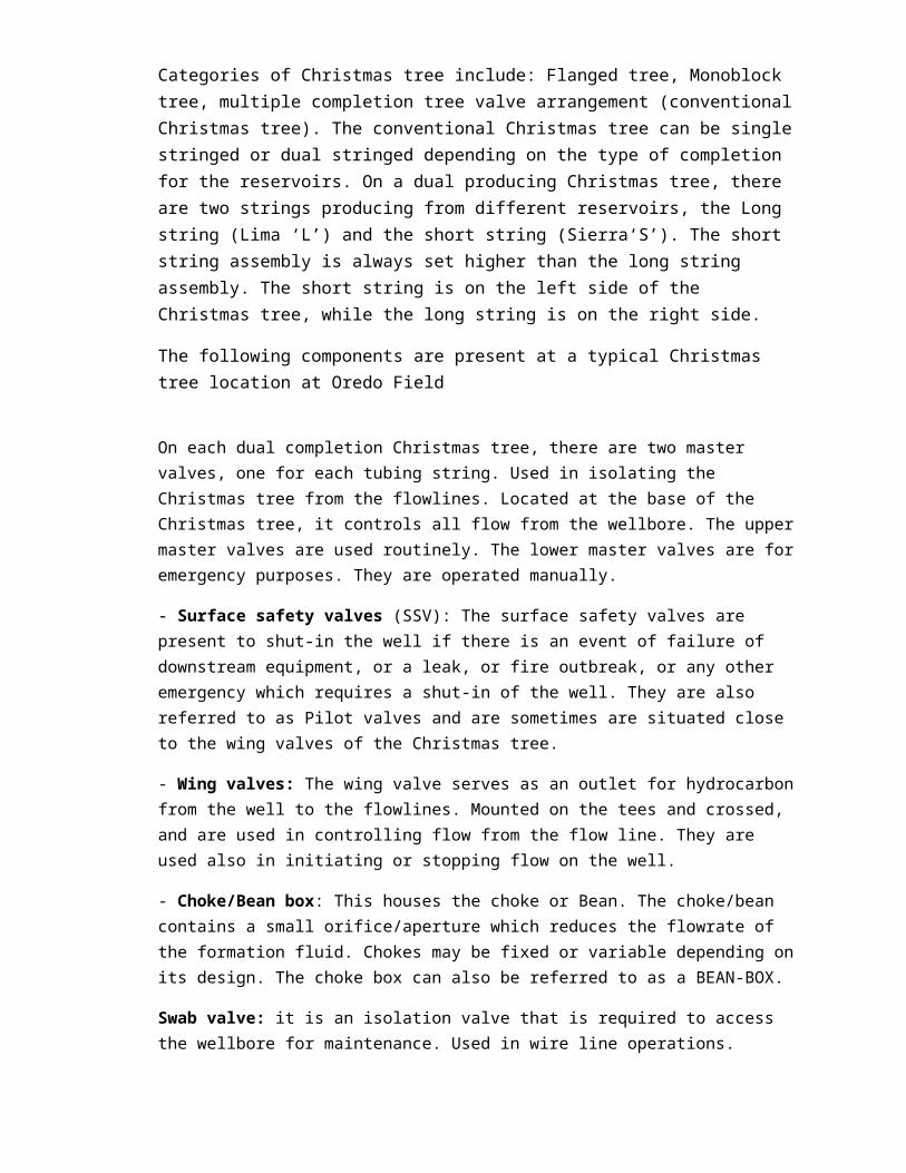
Categories of Christmas tree include: Flanged tree, Monoblock tree, multiple completion tree valve arrangement (conventionalChristmas tree). The conventional Christmas tree can be singlestringed or dual stringed depending on the type of completion for the reservoirs. On a dual producing Christmas tree, there are two strings producing from different reservoirs, the Long string (Lima ‘L’) and the short string (Sierra‘S’). The short string assembly is always set higher than the long string assembly. The short string is on the left side of the Christmas tree, while the long string is on the right side.
The following components are present at a typical Christmas tree location at Oredo Field
On each dual completion Christmas tree, there are two master valves, one for each tubing string. Used in isolating the Christmas tree from the flowlines. Located at the base of the Christmas tree, it controls all flow from the wellbore. The uppermaster valves are used routinely. The lower master valves are foremergency purposes. They are operated manually.
- Surface safety valves (SSV): The surface safety valves are present to shut-in the well if there is an event of failure of downstream equipment, or a leak, or fire outbreak, or any other emergency which requires a shut-in of the well. They are also referred to as Pilot valves and are sometimes are situated close to the wing valves of the Christmas tree.
- Wing valves: The wing valve serves as an outlet for hydrocarbonfrom the well to the flowlines. Mounted on the tees and crossed, and are used in controlling flow from the flow line. They are used also in initiating or stopping flow on the well.
- Choke/Bean box: This houses the choke or Bean. The choke/bean contains a small orifice/aperture which reduces the flowrate of the formation fluid. Chokes may be fixed or variable depending onits design. The choke box can also be referred to as a BEAN-BOX.
Swab valve: it is an isolation valve that is required to access the wellbore for maintenance. Used in wire line operations.

- Riser: They are upward protruding part of the Christmas tree. It traps a bit of the gas just flowing out of the well. The trapped gas now serves as fuel for the pneumatically surface controlled devices at the wellhead.
A SKETCH OF CHRISTMAS TREE SHOWN ABOVE
DIAGRAMS OF CHRISTMAS TREE
CHOKE
The choke controls the flow rate and pressure of the well.
Typical Well Head
Typical Well Head

SURFACE SAFETY VALVES (SSV)
Surface safety valves are used for monitoring pressure ofthe wells and flow line in case of line rupture at setpoint. Swab valves for wire line operations, e.g.installation of surface control subsurface safety valve(SCSSV), wax cutting e.t.c.
PNEUMATIC CONTROL UNIT
Pneumatic control unit: Also known as surface control panel, it controls the surface safety Valve (SSV) and Surface Controlled Subsurface Safety Valve (SCSSV). It is primarily pneumatically operated by the Gas supplied to the unit throughthe risers. Secondarily, the control unit can also be hydraulically operated. The hydraulics can be manually pumped

from the surface through the control lines to the subsurface safety valves to open the when they are in close position
DIAGRAMS IS SHOWN BELOW

CELLER PIT
This is a pit that surrounds the well head and the Christmastree, its function is to contain any spillage that may arisefrom producing well

Diagram above represent celler pit that is covered
FLOW STATIONA flow station is a gathering centre where primaryseparation takes place. At the flow station pipes are runfrom the wellhead to the manifold, then to differentseparators. NPDC presently has two flow stations namelyOredo and Oziengbe flow station. Oredo and oziengbe flowstations are designed to carry out two phase separationsthat is separating liquid phase (water and oil) from gasphase.
Gathering SystemThis consists primarily of pipes, valves, and fittings
necessary to connect the wellhead to the separation
equipment. The gathering system may contain one or more
lines with branches to each well, or it may consist of
separate lines from each well, which are connected to a
group header or test header system, as distance and
distribution dictates. Other accessories needed include.
(i) Gross-production meters
(ii) Automatic well test units with programmers and
computer readouts communicated to remote office
locations or production headquarters

(iii) Corrosion inhibitor and chemical injection
equipment
(iv) Automatic routing valves; and
(v) Production limiting devices. In some cases gas is
removed from the casing head into a field gathering
system. Orifice meters are installed at each well, or
one meter may be used to measure the entire gas
production.
A BRIEF DESCRIPTION OF FLOWSTATION FACILITIES
FLOW-LINES
These are steel pipes that convey crude oil from theproducing wells to the flow station.
ARRIVAL MANIFOLD

This is an inlet by which all crude oil flow-lines enters
the flow station, the essence of the manifold is for easy
switching of crude oil from the well head to different
separators. The arrival manifold has ESD (Emergency Shut
Down) valves attached to the headers for automatic shut down
,in case pressure for a given header is exceeded or below
it.
Fig 2.6a Arrival Manifold showing ESD valve
MANIFOLD
The individual well streams are brought into the main production facilities over a network of gathering flowlines and manifold systems.
A gathering point made up of a combination of valves and fittings where hydrocarbon converges and is diverted to the respective separator headers according to the flowline pressure. The manifold contains a variable choke valve which is used to control the flowrate and in turn control the pressure of the well stream going into the various headers. The valve that contains the variable choke is an angle valve. It is the official “entrance” for hydrocarbon from different wells into the production facility

Fig 2.6b Arrival manifold showing valves
PRODUCTION MANIFOLD

CHEMICAL INJECTION SYSTEM
Defoamers, demulsifiers, and dewaxers are injected into the fluidjust before it gets into the separators and just before the gas booth in order to break emulsifying bonds in the fluid in order to further aid separation of the component phases. These chemicals are injected intermittently with small diameter needle valves and pumps
The Emulsion formed can be either of the following
i) Primary emulsion, which can be oil-water emulsion or
water-oil emulsion.
ii) Secondary emulsion, which can be oil-water
emulsion or water-oil emulsion.
SEPARATORS

Separator is a vessel which separates fluids by means ofgravity settling into its constituent phases which could beoil, gases, and water. Generally, formation fluid from thewell is a 3-phase combination comprising gas, oil, and producewater. This fluid may also convey solid particles insuspension, such as sands, corrosive products, paraffin-based,and asphalt based components that have been precipitated out.Hydrocarbon must be separated into their various phases andimpurities removed before it can be shipped for commercialpurposes.
Separators are classified by their shape, operating pressure ranges, application and number of separation phases
Shape: By shape, separators are either vertical, spherical or horizontal
Operating pressures: Separators could be low pressure operated (15-225)psi, medium pressure operated (230-650)psi or high pressure operated(700-1500)psi.
Separation Phase: separators are either 2-phase (gas + liquid) or 3-phase (gas+ oil+ water)
Application: Test separator, production separator.
Separators are also made use of in other hydrocarbon processing facilities apart from the early production facility (EPF) such as; gas handling facility, refineries. In the Early Production facility, there are other more specific separators such as: fuel gas scrubber, knock out drum and degasser.

The main purpose of an early production facility is separationof hydrocarbon, hence the importance of these different separating vessels.
The Oredo Old EPF have horizontal medium pressure separator and test separator due to relatively lower gas to oil ratio from handled well strings.
TEST SEPARATOR
The primary essence of a separator is to separate gas, waterfrom the crude oil and at the same time reducing thepressure at which the crude oil is coming from the well.Test separator is similar in configuration as the otherseparators.

This separator has the major function of determining the “wellness” i.e. the producing potential of the well that flows ata particular time. It is equipped with various flow metering system necessary for measuring oil, gas, and water, for potentialtest, periodic production tests, etc. it can be used to determinethe nature of the well, gas oil ratio (GOR), surface pressure, surface temperature, amount of crude produced per day, amount of gas produced per day. Some of the meters present on this separator include the:
Flow analyzer: for measuring quantity of liquid produced and the flowrate into/out the separator
Diagram representing flow analyzer
Daniel orifice meter: which measures the amount of gas produced, by creating a pressure differential through the orifice plate, that is recorded on the Barton recorder with the use of Barton charts.
Recent technology In Oredo Field however, has replaced theflow analyzer and Daniel Orifice meter by Transmitters andcomputerized Flow meters.

Test separator typically consists of a vessel, an oil flow-measuring system with dual meters, a flow-measuring system for gas, several sampling points for each effluent phase, and two relief valves to protect the vessel against overpressure. Most separators are also equipped to measure water flow rate. To provide accurate measurements, the test separator is fitted with pneumatic regulators that maintain a constant pressure and a constant liquid level inside the vessel by control valves on the oil and gas outlets.
The test separator is fitted with a deflector plate, coalescing plates, a foam breaker, a vortex breaker, a weir plate, and a mist extractor. These components reduce the risk of carryover (liquid in gas line) and carry under/blowby (gas in liquid line) that would affect the flow rate measurement accuracy.
Fig 2.8a Internal Feature of a test Separator

Test Separator

TEST SEPERATOR UNIT
HIGH PRESSURE SEPARATOR (HP)
HP separator have the same working principle as test
separator, the only difference is that the HP is designed
for crude oil from high pressure well as pressure specified
in separation staged. The HP separator is designed to handle
the bulk of the incoming production from the high pressure
well(s) and remove gas from the liquid. Crude is fed intothis separator via the HP header on the arrival manifold.
MEDIUM PRESSURE SEPARATOR (MP)MP separator has the same working principle as the testseparator but the difference is that the MP is designed forcrude oil from medium pressure wells as pressure specifiedin separation staged. The well stream flows in the mpseparator through mp separator for further processing. Themp separator is designed to remove free water from the oiland remove gas from the liquid.
LOW PRESSURE SEPERATOR (LP)
LP separator has the same working principle as testseparator but the only difference is that, is it designed

for low pressure wells as pressure specified in separationstaged. It is also designed to remove free water from oilthat is coming from the MP separator prior to sending theoil to surge tank or crude storage tanks.
About 65% of the existing gas from the top far end of thetest separator, MP separator and HP separator is piped to HPflare knock out vessel, while 25% of the gas is piped tofuel gas scrubber. The gas from the LP separator is ventedto the LP flare knock out vessel.
GAS BOOTH (DEGASSER)Produced liquid from the separators is channeled to the degasser.Degassers carry out the same function as the low pressure separator. It extracts further traces of gas from the oil, beforeit is stored. Depending on the configuration and design of a degasser, it could either be a water degasser, or oil degasser.
The gas that is extracted from the water degasser is channeled tothe Low pressure flare knockout drums, and the oil is stored in the storage tanks.
Gas extracted from crude degasser is channeled to the gas handling facility while the water is channeled to the floatation cell for treatment before disposal.

FLARE KNOCK OUT TANK
These are tanks where produced gas is channeled. The tanks
dry the gas by allowing any liquid that is with the gas to
that point to settle in it, so as to allow the dried gas to
be sent to the flare knock out stack where it is being
flared. We have two flare knock out tanks, they are the LP
flare knock out tank and the HP flare knock out tank. Gas
from the test separator, HP and MP separators are channeled
to the HP flare knock out tank whereas the gas from the LP
separator is channeled to the LP flare knock out tank.
FLAREKNOCK OUT TANK;

This is an underground tank, produced gas is channel into it, dry it and send it tothe flare knock out stack where it is being flared.
FUEL GAS SCRUBBER
This process plant equipment traps gas from the gas headerand purify it by removing further traces of crude oil in it,with mixer or extractor, then send it to the fuel filter.The fuel gas scrubber is designed to remove oil dropletsfrom the incoming gas to be used as fuel. The accumulatedliquids are dumped to the closed drain sump tank. The gas isthen sent to the instrument gas filter separator, which isdesigned to remove aerosols from the gas prior to sendingthe gas to the end users, such as gas driven generator andcooking.

PUMPS:
In the transfer of crude from the flowstation for export or to
the refineries, pumps are used. These pumps include the booster
pump which is a centrifugal volume pump that pumps the crude out
of the tanks and the Export pumps which further pressurizes the
crude to pump it over a long distance (several thousand
kilometres). The export pump is usually a reciprocating pressure
pump. Booster Pumps: These pumps collects crude oil from the
crude oil storage tanks and boost the pressure on the export line
for the major export pump to pick up on an adequate line
pressure.
In a simplified sense, its describe below:
(a) Booster Pumps: These pumps collects crude oil from the crude oil storage
tanks and boost the pressure on the export line for the major export pump to
pick up on an adequate line pressure.
(b) Export Pumps: These pumps depend on the pressure built by the booster
pump to suck and discharge crude oil for export.
(c) Produced Water Transfer Pumps: These pumps suck water from the storage
tanks and send it into the skimmer

WATER DEGASSER
This is the equipment that receives produced water from theseparators and extracts further traces of gas and oil fromthe water. The produced water dumped by the HP, MP, LP andtest separators is piped to the water degasser. Each of thefour separators (HP,MP,Test,LP) and water degasser has atransparent type level gauge for monitoring oil/waterinterface inside the main section of the vessel before theweir plate .These separators are cylindrically in shape andare made of carbon steel materials, their thickness varieswith depth .The degasser is also designed to remove largeoil droplet from the water by feeding oil water through thethree sets of coalesce plate packs. The water dischargedfrom the water degasser is then sent to the floatation cellor corrugated plate interceptor (CPI) for final treatment.The accumulated oil is pumped to the closed drain sump tank.Any excess gas which breaks out from the water, while insidethe water degasser vessel is vented to the LP flare knockout tank, and the water is sent to the skimmer pit.

FLARE SCRUBBERS:
The HP Flare Scrubber and LP Flare Scrubber are designed to
scrub any Liquids from the gas stream that is being vented
prior to flaring.
CLOSED DRAIN
The Closed Drain Sump Tank and Associated Diaphragm Pumps
are designed to accumulate the liquid from the closed drain
header and then pump this liquid back to the LP separator
for reprocessing. This pump must be adjusted to discharge
oil from drain tank into LP separator and overcome the
pressure inside the LP separator. The drain tank basically
operates at atmospheric pressure and any pressure gases
which accumulate inside the vessel are vented to atmosphere
through a vent type flare arrestor. Pump exhaust gas is
piped into the drain tank so that flammable gases are not
present around the drain tank. The tank will be place in a
cement pit approximately 1 meter below grade to facilitate
liquids drain header draining into this vessel.

Fig 2.15 Closed Drain
CORRUGATED PLATE INTERCEPTOR (CPI)
Produced water is sent into this equipment and it purifies the
water before sending it to the produced water storage tank. There
are many pumps used and all have their different function to
perform. The principle is the same as the suck liquid and
discharges it into the produced water storage tank, LP Separator
for reprocessing. The pump must be adjusted to discharge oil from
drain tank into LP Separator and overcome the pressure inside the

LP Separator. The drain tank basically operates at atmospheric
pressure and any gases, which accumulate inside the vessel, are
vented to the atmosphere through a vent type flare arrestor.
PRODUCED WATER STORAGE TANK
This store and preserves purified water produced from theprocess and serves as a stand by for fire fighting unit incase there is an emergency.
Fig 2.17 Produced Water Tank

CRUDE OIL STORAGE TANK
After separation, crude is kept here until when it is to be exported. The capacity of the standard tank at NPDC’s flowstation is 20000 barrels.
These are vessels with high storage capacity where crude oilproduced is stored prior to pumping. The storage capacity ofthe tank in Oredo flow station is 20,000 barrels and the height of the tank is 24 feet. These tanks serve as a centerfor decantation of water after being allowed to settle for at least 12 hours or more. These tanks allow gas liberation while limiting pressure loses through evaporation. The tank has the following accessories;
A) Production or Inlet pipe: generally fixed at the bottomof the tank and internally extended with a perforated pipe rising in a cage. This device acts as a separator,which permits the liberation of gas towards top and helps to avoid the agitation of liquid hence promotes the draining.
B) Discharge or export pipe: this is also fixed at the body of the tank at a certain height, perforated and extended in the tank. It makes it possible to dischargecrude oil at the top.
C) Drainage pipe: this is used to collect drains at the bottom of the tank.
D) Overflow pipe:
E) Circulation pipe:
F) Man-hole: all storage tanks are equipped with one or
two man-hole to be used as an access into the tanks to
carry out repairs or cleaning. All tanks must also be

free of gas before any work is carried out in order to
avoid explosion due to gas and air. Therefore to degas
the tank, vapour may be injected and then an
explorimeter is used to verify if it has been degassed.
G) Level controllers: these are liquid level indicator that gives direct reading of liquid head.

STORAGE TANK
METERING UNIT
Crude being exported passes through the metering unit, to get real time and cumulative reading of crude being exported. The metering unit records in barrels of per day. The meter is clockedoff daily to get cumulative daily shipment.
LACT UNIT (lease automatic custody transfer): It is the unit
designed for the transfer of ownership of crude from the buyer
to the seller. It allows the operators to monitor and manage
the crude oil that is being exported or received. It employs
specialized meters to measure the natural gas or oil as it
flows through the pipeline, without impeding its movement.
This unit of transfer is very important since crude is sold on
the basis of API gravity and BS&W, it is necessary make
accurate measurements, hence the need for a viable transfer
unit.

WATER UNIT
Water unit consist of boreholes, reservoir, storage tank,
treatment plant water pump and over head tank.
Water is being pumped through the water pump from the
borehole to the reservoir, which is connected to the storage
tank that has a flow station cell, which control the water
flow from the storage tank. From the storage tank water is
being pumped into the treatment vessel (cylindrical) while
chemical (chlorine) is being ejected into the storage tank
before going into the treatment vessel with the aid of
chemical ejector connected to two chemical drums. After the
treatment of the water, it is being pumped through the water

pump to the overhead storage tank, which supplies water to
the entire flow station.
2.2.1.18 Gravity Settling Tanks
The simplest treating equipment for removing solids from
water is a gravity settling tank or vessel, which may be
designed in either a vertical or horizontal configuration.
In vertical settling tanks, the solid particles must fall
countercurrent to the upward flow of the water. A typical
vertical gravity settling vessel is shown below by Fig
2.20(Schematic of vertical gravity settling vessel).
The water enters the vessel and flows upward to the water
outlet. Solids fall countercurrent to the water and collect
in the bottom. As shown, large diameter vessels or tanks
should have spreaders and collectors to distribute the water
flow and minimize short-circuiting.
Fig 2.20 vertical gravity settling vessel
For small diameter gravity settling vessels, the collected
solids may be removed by periodically opening the sand drain

shown in Fig 2.20 (Schematic of vertical gravity settling vessel). The use
of a cone bottom rather than an elliptical head allows more
complete removal of solids through the drain. Typically, an
angle of 45 to 60 degrees from the horizontal is used for
the cone to overcome the angle of internal resistance of the
sand and allow natural flow of solids when the drain is
opened.
Any flash gases that evolve from the water leave the
settling vessel through the gas outlet at the top of the
vessel. The volume of flash gas must be kept to a minimum so
the gas does not adversely affect the removal of small
solids particles. If large amounts of gas are flashed, the
small gas bubbles can adhere to solids particles and carry
them to the water surface. The solids then may be carried
out the water outlet.
In horizontal settlers, the solids fall perpendicular to the
flow of the water, as shown in Fig 2.21 (Schematic of horizontal
gravity settling vessel).

Fig 2.21 Horizontal gravity settling vessel
The inlet is often introduced above the water section so
that flash gases may be separated from the water prior to
separating the solids from the water.
The collected solids must be periodically removed from the
vessel; thus, several drains may be placed along the length
of a horizontal vessel. Since the solids will have an angle
of repose of 45 to 60 degrees, the drains must be spaced at
very close intervals and operated frequently to prevent
plugging. The addition of sand jets in the vicinity of each
drain to fluidize the solids while the drains are in
operation is expensive, but sand jets proved successful in
keeping drains open. Alternatively, the vessel may have to
be shut down so that solids may be manually removed through
a man way. Although effective, this method can be extremely
expensive and time consuming.
Horizontal vessels are more efficient at solids separation
because the solid particles do not have to fall
countercurrent to the water flow. However, other

considerations, such as the difficulty of removing solids,
must be kept in mind when such a configuration is selected.
Horizontal vessels require more plan area to perform the
same separation as vertical vessels. Most small horizontal
vessels have less liquid surge capacity. For a given change
in liquid surface elevation, there is typically a larger
increase in liquid volume for a horizontal vessel than for a
vertical vessel sized for the same flow rate. However, the
geometry of most small horizontal vessels causes any high-
level shutdown device to be located close to the normal
operating level. In large diameter (greater than 1.8 m (6ft)
horizontal vessels and in vertical vessels, the shutdown
could be placed much higher, allowing the level controller
and dump valve more time to react to a surge.
It should be pointed out that vertical vessels have
some drawbacks that are not process related; these must be
considered in making a selection. For example, the relief
valve and some of the controls may be difficult to service
without special ladders and platforms. The vessel may have
to be removed from a skid for trucking due to height
restrictions.
The choice of a pressure vessel versus an atmospheric tank
for a solids-settler depends on the overall needs of the
system. Although pressure vessels are more expensive than
tanks, they should be considered when potential gas blow-by
through an upstream vessel dump system could create too much
backpressure in an atmospheric tank's vent system; or when
the water must be dumped to a higher elevation for further

treating and a pump would be needed if an atmospheric tank
were installed.
For gravity settling of solids, water retention time does
not directly affect the solids removal, and only settling
theory must be considered. Some small retention time is
required for evolved gases to flash out of solution and
reach equilibrium. This process usually requires less than
30 seconds; therefore, retention time criteria rarely govern
vessel size.
Gravity settling is useful for settling of large diameter m
microns). It is normally used where there is a high solid
(greater than 50 flow rate of large diameter solids) that
might otherwise quickly overload equipment designed to
separate smaller diameter solids from the liquid stream.
Through the individual tubing, the fluids are produced to
the surface via the Xmas tree and routed to the flow station
through the flow lines.
PIG LAUNCHING UNIT
This is the unit where pig/brush is launched into the exportline to enable it to clean the line of dirt and scales.

CUP PIG DISC PIG

SPHERE PIG FOAM PIG
FLARE KNOCK-OUT STACK
This is a point where all the gas after being filtered fromwater and oil in the flare knock-out tanks is flared.

MOTOR CONTROL CENTER (MCC):
There are two types of MCC, one for the flow station that
controls fire pump, main breaker, jockey pump, power &
lighting, circulation pump, and export pump (line) and
generator MCC that control the diesel generator and gas
generator as well.
FIRE PUMP (PANEL):
The fire pumps are use to quench fire in case of fire
outbreak.
MAIN BREAKER (PANEL):
The main breaker is being fed by the generator and givespower to the fire pump box, power & lighting, jockey pumpand booster pump.
JOCKEY PUMP (PANEL):
The jockey is a pressure stabilizer, it maintain static
pressure in the water lines (for fire fighting) during
operation when not in use.
CIRCULATION PUMP (PANEL):
It helps or controls the oil/water separation from the crude
oil.
BOOSTER PUMP (PANEL):
The booster pump panels control the booster pump (A & B).

SUBMERSIBLE PUMP (PANEL):
The submersible pump panel controls the water bore hole.
PROGRAMMABLE LOGICAL CONTROL (PLC):
The programmable logical control panels controls all the
system in the station electrically (D.C). The PLC controls
all the valves and it is designed to shut down valve for
safety reason. It also helps to control pressure from the
well, the PLC sense pressure from the SSV (sub safety valve)
in case of excess pressure. The PLC shut down the station
with the aid of pressure transmitters that send signal to
the PLC, which knock off the solenoid.
CRUDE OIL PROCESSING AT NPDC (OREDO) FLOW STATION
Each flow line from a producing well is connected via a
choke valve into the test manifold, MP manifold drain
installed on the manifold skid. Fluid enters the MP
separator via MP manifold for separation. The MP separator
is designed for both stage 1 and stage 2 production
criteria; it will perform a two phase gas/liquid separation

in stage 1 at 500 psi, and a three phase (gas/oil/liquid)
separation in stage 2 over the range 800-1500 psi. The
produced gas from the separators is metered and then routed
to the fuel gas system and to the flare header via a
pressure control valve. The gas outlet is fitted with a
demister pad to minimize liquid carry over to the fuel gas
and flare systems. The separated liquid is routed into the
degassing tank on level control. The normal MP separator is
50% full. A 30% surge volume is provided between the normal
and high liquid level to allow for potential flow line
slugging. On high pressure and high level, the MP separator
is shut down by closing the inlet valve. In stage 1 this
will result in eventual shutdown of the production system.
Also there is a test separator designed to test individual
well gas/oil/condensate and water flow rate in both stage 1
and 2 developments. The well stream fluid from a specific
well is routed to the test separator via the test manifold.
The separated oil and water streams are recombined after
metering and routing into degassing tank. The produced gas
is metered and routed to the flare header. On high
pressure and high level, the test separator is shut down by
closing the inlet valve. The fluid outlet control valves are
closed and the gas control valve opened to flare. In stage 1
this will result in eventual shutdown of the production
system also.

All fluid drained from the manifolds and flow lines isrouted via a drain manifold into closed drain header whichruns to the underground flare knock out tank.
The degassing tank is designed to perform a two phasegas/liquid separation at around atmospheric pressure priorto routing of the crude/water into the crude oil tank. Thefluid from MP and Test separators enters the degassing tankthrough a horizontal nozzle fitted with an inletdistribution. The small quantity of gas produced in thedegassing tank is metered and routed to the flare header.The separated liquid is routed to the crude oil tank via aseal leg to ensure that the liquid has sufficient residencetime for degassing purposes. The high level in the degassingtank shut down the production system by closing the upstreamshut down control valves. The level sounds an alarm at thecontrol room.
The crude oil tank has a capacity of 10,000 barrels and isdesigned for crude dewatering and for crude storage duringexport pipeline shutdown. The crude/water is routed into thetank via an inlet distributor located 6-10” from the bottomof the tank. The separated crude is routed to the crudeexport pumps via a floating suction arrangement. The crudeoil level is maintained by float type level switches in thetank, the stop and start levels of these switches can beadjusted if required. The separated water is routed to theproduced water transfer pumps on interface level control.The crude oil tank is surrounded by a temporary sand bunddesigned to contain any spilled oil in the event of tankrupture, flange, leakage etc.

Two triplex reciprocating type crude export pumps areprovided; one operating and one standby, to pump crude fromcrude oil tank to the export pipeline via the crude meteringpackage to Pan Ocean Oil Company for export. While theproduced water is pumped by the transfer pump set comprisingof centrifugal pumps from crude oil tank to an elevated firewater/produced water storage tank. Excess produced water isdiverted by a spillway to CPI oil-in-water clean up unit.clean water is now pumped by single stage centrifugal typeproduced water disposal pumps (one operating and one onstandby) though a totalizing meter and 3 inch pipeline to awater course for disposal.
All excess off gas is disposed of by burning at the flarestack. All the headers are continuously purged with fuel gasscrubber to prevent air ingress. The flare stack is equippedwith flame arrestor for flash back protection and a flamefailure alarm. The flare knock out is also provided with apump designed to return the liquid to the degassing tank.While the fuel gas system is designed to produce gas for usefor the power generation package, flare purge gas,instrument gas and flare ignition system.
All fluid draining from the pressurized equipment such asthe MP separator, manifold skid and crude export scraperlauncher are routed into a flare knock out tank locatedbelow grade.
CRUDE OIL PROCESSING TRAIN

STAGE
SHIPMENT:
Shipment of crude oil commences when the crude in the
storage tank has been built to a considerable level, some
water is still contained in the tank which is then allowed
to settle down after some hours; because water is denser
than oil. The water is first drained from the bottom with
the pump before shipment began. To start shipment, the
booster pump is switched ON before the export pump. The
pressure reading of the export pump is taken and recorded as
discharge/export line pressure (DELP). Shutting down the
export pump is the reverse of starting. Before shipment
begins, the panel in the control room is first acknowledged
and then reset. Sometimes shipment may be difficult when the
Clean upSand
Skim m ing Filtration Softening&
Deaeration
StabilizationD ehydrationD esalting
H 2SR em oval
Phase SeparationGatheringW ellhead
TreatingC ondensateR em ovalD ehydration
SulfurR em oval
W ater
Sand D isposal
Stabilization
Storage

pressure of the export pump is low .It might also be due to
low level in the storage tank. The pump may also cavitate
thereby vibrating ceaselessly and consequently shutting
down.
Gear oil and harmony oil are the two important lubricants
used in running the export pump and need be refilled when
their levels fall. Harmony oil is otherwise called
light/compressor oil. During shipment, the crude oil level
in the storage tank where export is taking place and the
reserve storage tank are taken and recorded continuous for
every two hours. There is a side glass attached to the
storage tank which shows the level of crude contained in it.
Shipment of crude can only be done with one export pump, one
booster pump and from one storage tank at a time. During
shipment, the level of crude oil in the reserved storage
tank is built up. When building up levels in a tank, the
produce line and the drain line of that storage tank are
opened while the over flow line and the export line are
closed. Most times there may be needed to divert production
from one tank to another. In this case, the production line
of the storage tank where diversion is directed to is first

opened before the opening of the production line and drain
line of the tank where diversion is coming from. After
shipment has been terminated, a daily production report is
written which shows the quantity of barrels shipped for that
particular day.
OBAX FLOWSTATION DESCRIPTION (MAINLY CALLED NEWEPF)
The oredo new EPF operated by OBAX petroleum, was constructed in order to handle increased production from the oredo field. OBAX EPF has a producing capacity of 10,000 BPD of oil, and 70MMSCFD of gas. Presently, Obax facility produces from 10 strings at about 1607 barrels per day of oil, and about 80 MMSCFD of gas. The gas separated is sent to the gas handling facility to be processed and exported.

Plan view of the new EPF
Operations and surface facilities in the new epf are almost the same with very slight configurationally differences. Some of the facilities are discussed below:
VERTICAL HIGH PRESSURE SEPARATOR
The EPF handles production with very high pressured wells with high gas to oil ratio ratio. Thus, a vertical separator is used here due to the high GOR. Vertical separators have good gas handling capacity.
Horizontal medium pressure separator: for further condensate stabilization of the crude from the HP separator is routed to the

MP separator. Good amount of gas has been taken care of in the HPseparator for the MP to further perform its separation
horizontal test and MP separator (on left and right side) of the Vertical HP separator
HEAT EXCHANGER
There is a minimum temperature requirement for fluids to enter into the thermal treater, this is not usually met by the medium pressure separator, and therefore, crude temperature must be boosted before entering into the treater. The heat exchanger is basically a medium of exchange for heat from liquids coming into and from the thermal treater respectively. In the heat exchanger,there is heat loss from liquids leaving the heater treater, and corresponding heat gain for liquids entering into the heater treater.
THERMAL TREATER/ HEATER TREATER

Replacing the chemical injection system is the thermal treater. The thermal treater serves to break the bonds between oil and water by heating the fluid to temperatures high enough to break the stubborn emulsifying bonds. It is heated to temperatures of about 110 degree Fahrenheit, which demulsifies it, and also serves to remove any remaining gas in the crude. The thermal treater level is controlled by a dump valve, as other separator levels. The temperature at which heating takes place is controlled by temperature sensors and indicators. High and low set points are put in place for ignition and temperature control in the thermal treater.
Horizontal thermal treater
FLOATATION CELL

This is a water treatment facility that extracts remaining oil droplets in the separated water before it is disposed off. The floatation cell skims off oil floating on the surface of the separated water.
Floatation cell
THE MECHANISM OF SEPARATION
A conventional separator works with the centrifugal/ gravity settling principle.
At the entrance of a separator is an inlet diverter also knownas a baffle plate. The incoming fluid hits this plate which causes a change in the momentum and thus primary separation of

gas from the liquid. The gas tends to bubble out of the liquidand travels upward through the mist extractor which captures liquid molecules in the gas. By gravity settling the liquid falls to the bottom of the separator to liquid collection section where the denser liquid (usually the
water) settles at the bottom while the relatively less dense liquid (crude oil) settles just above the dense fluid.
The centrifugal inlet device makes the incoming stream spin around. Depending on the flowrate of the mixture, the reaction force from the separator wall can generate a centripetal acceleration of up to 500 times the gravitational acceleration. This action forces the liquid droplets together, where they fall to the bottom of the separator into the settling section.
The settling section allows enough room for turbulence of the fluid stream to subside and the liquid droplets to fall to the bottom of the vessel due to gravity segregation. There is a largesection of sufficient height and length, to allow liquid dropletsto settle out of the gas stream with adequate room for slugs of liquid, while gas goes out through the gas outlet to the header. Also present is a mist extractor near the gas outlet to trap (coalesce) small particles of liquid which did not settle directly.
WEIRS are vertical baffles placed in the liquid accumulation section of the separator. In a 3 phase separator vessel, they separate the water accumulation from the oil accumulation part ofthe separator. The time taken for oil and water to separate usingthe differences in their densities while in the separator is referred to as RETENTION TIME.
It is necessary that there is sufficient room for separation for both liquid and gas, to prevent LIQUID CARRYOVER to the gas outlet, or GAS BLOWBY to the liquid outlet. Carryover is a term used in describing free liquid that has left the gas phase at thetop of the separator. It indicates high liquid level, or it may be as a result of faulty level controller, level control switch, or plugged liquid valves at the bottom of the separator.

The liquid level in a separator is controlled by level control valves, also known as dump valves. These valves are triggered to open or close by level controllers located outside the separator.The liquid level inside the separator is monitored by a floating bridle which signals the level controller to activate the controlvalve (dump valve). On the outside, the liquid level is monitoredthrough the side gauge glass.
Pressure and temperature of a separator are monitored by temperature and pressure gauges calibrated in Pounds per square inch (PSI) and degree Fahrenheit (°F) respectively. 30
CHAPTER FOUR
INTEGRATED GAS HANDLING FACILITY (IGHF)
Natural gas produced from hydrocarbon reservoirs is also as useful as the crude recovered from these reservoirs. But, it is being wasted by flaring this large quantity of gas as use and large market for the gases have not been established. Withfurther development, technologies; the need for the use of this gas has increased. Thus gas processing and making this natural gas available has become of importance
The integrated gas handling facility is responsible for gas processing. The facility is operated by NETWORK OIL AND GAS COMPANY.
CRUDE OIL BRIEF OVERVIEW OF GAS PROCESSING

Typically, processing natural gas and making it ready for use takes place in four stages depending on the compositional makeup of the gas
Here in the Oredo field, the stages the facility is being constructed to handle includes
1. Compression stage
2. Dehydration stage
3. Cryogenic stage (chilling/refrigeration)
4. Fractionation stage (NGL recovery)
In other gas processing facilities, a gas sweetening stage might be included if the gas to be processed contains acid gases like H2S and CO2. In the oredo gas field and in generally in Nigeria, the hydrocarbon has little or no presence of these acid gases (crude termed as SWEET CRUDE).
COMPRESSION STAGE
In the compression stage of gas processing, the gas is compressedby compressors in other to increase its pressure for transportation. This gas might be transported through pipelines under very high pressure. As liquids are pumped with high pressure for transport, gases are compressed to high pressures for transport.
From thermodynamics, the compression of gases increases its pressure likewise its temperature. Thus, intercoolers and aftercoolers are installed along the compression lines to reduce the temperature of the compressed gases.
Method of Gas compression in IGHF
Gas sent from separation unit, (let say from Oredo flow station) enter into gas manifold and the manifold empty into the header pipe. The gas from header moves into suction scrubber. The suction scrubber helps to separate any trace amount of liquid from the gas i.e as the name implies scrubber “separate”. After this stage, the gas enter suction bottle.

Immediately after the suction bottle, the gas moves direct to compression cylinder (the cylinder is made up of two cylinders tagged cylinder 1 and 3 in the first stage compression). Then thegas enter discharge bottle, after here, the gas moves to interstage cooler, since the gas that have passed through different unit would be very hot, this unit helps to cool the gas.
After this stage the gas moves from interstage cooler back to 2nd stage suction scrubber unit . The suction scrubber helps to separate any trace amount of liquid from the gas. After this stage, the gas enter suction bottle.
Immediately after the suction bottle, the gas moves direct to compression cylinder (the cylinder is made up of two cylinders tagged cylinder 2 and 4 in the second stage compression). Then the gas enter discharge bottle, after here, the gas moves into “After cooler”, since the gas that have passed through differentunit would be very hot, this unit helps to cool the gas.
At the IGHF gases are compressed to pressures of 900psi with final line temperatures of about 90°F.
Currently at the IGHF, the compression stage is the only functional stage. The other stages are not yet functional but most of the facilities and equipments are present on the field.
Further, liquid entrained in the gases are separated from the gasby Scrubbers positioned before the compressors. This gas is compressed and transported to Nigerian Gas Company for further processing.
DEHYDRATION STAGE
The dehydration is stage is meant to separate from water vapour present in the gas. It is essential that these water molecules are removed from the gas as it reduces heating value of the gas, might react with gas to form acidic compounds that may be corrosive. The water vapour could also react with the gas under

reduced temperatures to form slugs that will impede the free flowof the gas.
Dehydrating the gas involves using
1. Tryethylene (TEG) or Diethylene (DEG) contactor tower
2. Molecular sieves
3. Methanol injection ( rarely used)
Present at the oredo field flowstation are TEG contactor towerand two molecular sieves.
Using TEG involves random or tray packed tray columns through which there is an interaction of the gas with the TEG substance. This TEG has strong affinity for water molecules. As other hydrocarbon gases would pass through the TEG substance, water molecules would be retained in the TEG substance.
A regeneration station purifies the TEG off water molecules soit can be reused. This is done by re-boiling the rich Glycol (TEG with water molecule) to temperatures at which water molecules would evaporate leaving just the lean glycol ( without water molecule) to be reused in the contactor tower.
Molecular sieves are solid desiccants that act as adsorbents for water molecules. The hydrocarbon gas is passed over the solid surface (pellets) in the molecular sieves and the water moleculesare collected over the solid surface as this electronically polarpellet attracts water molecules only.
CRYOGENIC STAGE In this stage of gas processing propane refrigerant chillers are used to reduce the temperature of the gas stream to temperatures at which methane alone would remain in the gaseous stage while other fractions of the gas will turn to liquids. The methane is thus collected over the DEMETHANIZER tower.
FRACTIONAL RECOVERY Here the natural gas liquids (C2 to C4) are separated into their fractions using appropriate facilities of DE-ETHANIZER for

ethane, DEPROPANIXER for propane and DE-BUTANIZER for butane. Other heavier liquid fractions have been separated out using scrubbers and low temperature separators before the stream reaches this stage.
INTEGRATED GAS HANDLING FACILITY
CHAPTER FIVE OTHER OPERATIONS CARRIED OUT AT NPDC’S FLOW STATION
Other operation carried out at NPDC includes daily
production operations as below:
1. Daily oil production into Tanks A and B, a process
called TANK LEVEL BUILD UP (TLBU). When the level
reaches around 28 feet or there about, production is

then directed into either of the two tanks (A or B) and
the one with 28 feet is now drained of water. The drain
flow line is then opened while the production line is
closed. Draining water in Oredo flow station is
necessary due to the fact that the separation is in
two- phase that is it always separates the gas from the
fluid. A minimum of six hours is allowed for the oil to
settle in the storage tank (settling time) before
SHIPMENT occurs. However, both tanks A and B could be
built up simultaneously if the other streams were
producing.
2. ROUTINE BEAN INSPECTION
The bean (choke size) used by NPDC in their wells is
mostly 20-32’’ according to DPR regulation. However,
for well 4L in Oredo field 24/64’’ bean is used. The
bean here is a positive one that is a bean with a fixed
diameter. Due to sand and water production the choke
size can increase due to corrosion and may result to
various problems. For example:
I. Since water production is a function of flow,
increase in choke size will increase the well

out-flow and thereby seriously affecting
production by building up a head above the hole
pressure.
II. Also if the well is water driven, the reservoir
will be depleted of its natural energy and
thereby may leave a lot of crude in the reserve
un-produced as in the case of Abura well 2L with
almost 4MMbbls unrecovered due to reservoir
energy depletion.
DURING A BEAN INSPECTION AT OREDO WELL 4L ON THE MONTH OF
SEPTEMBER,2014
APPARATUS USED
a) Bean extractor
b) Large size hammer
c) A nut and bolt
d) Lubricating oil
e) Hand glove
During the bean inspection exercise the following procedure
was followed

1. Close the well from the well head (Christmas
tree).
2. Blow off trapped pressure by opening the valves
along the flow line
3. Close the flow line from the ball valve
4. Open up the bean box for inspection
RESULTS
The positive bean orifice which has a fixed diameter was
found to be eroded (increase in diameter) caused by the
high water production with the water cut of almost 30%
DAILY PRODUCTION CALCULATIONS
GROSS PRODUCTION: Subtracting the reading gotten from the
LACT unit before pumping of crude oil from that gotten after
pumping.
Gross production = CMR – OMR
Where CMR =close meter reading
OMR = Open meter reading.
The unit is BLPD (barrels of liquid per day). This is
because it still contains water.

NET PRODUCTION: This is gotten by multiplying the grossproduction by (1 – BS&W)
Where BS&W = basic sediment and water.
This is done to get the exact amount of crude oil withoutwater.
I.e. NET PRODUCTION = Gross prod. * (1 – BS&W)
The unit of this is BOPD (barrels of oil per day)
GAS RATE CALCULATION (Q):
Q = C * SQUARE ROOT (Hw * Pf) *24hrs
Where C = Orifice plate constant
Hw = Differential pressure
Pf = static pressure + 15 psi
GAS OIL RATIO (GOR):
Dividing gas rate, Q by the net production, does this
I .e GOR = Q / net prod.
3.1.5 OTHER OPERATIONS:
5.9 OTHER OPERATIONS:
Daily operations on the flow-station fall into two categories,
based on the timing:
a) Operations performed at two-hour interval include:
Recording of pressure and temperature readings of the HP
separator, Test Separator, MP Separator, LP Separator, Water
Degasser and Fuel Gas Scrubber.

Recording of the flow-rate of liquids or crude oil in the HP
Separator, Test Separator, MP Separator and LP Separator.
Recording of the pressure and level of crude oil in the
crude oil storage tank.
b) Operations performed at four-hours intervals are:
Recording of voltage (V), frequency (Hz), current (A),
temperature (F), oil pressure (psi), gas pressure (psi),
speed (RPM) and period (hrs).
c.) Assisting the supervisors to provide orientations for
the new I. T. students about certain operations been carried out in the field.
CHAPTER SIX FLOW STATION PROCESS
CONTROL SYSTEM AT NPDC
With surges in liquid production, liquid level in separator
increases. If liquids were allowed to accumulate to the
level of the gas outlet, oil could escape through the gas
outlet. If a minimum liquid level were not maintained, gas
could escape through the liquid or lower outlet. Therefore
liquid level control is provided to prevent the liquid level
from being either too high or too low and operates dump
valve in the oil outlet. As production increase, liquid
level rises and dump valve opens. The liquid level control
maintains a liquid seal, thus preventing gas from escaping
through the liquid outlet. Most of the level controls use a
float displacer to control the dump valve regulating liquid

level. The up/down motion of the float is transmitted to the
dump valve through a system of levers. When the float moves
down, the valve lever moves up for the valve to close. When
the liquid and float rise to the desired level, the valve
opens. The turnbuckle controls the liquid level maintained
in the separator. The above operation is mechanical. There
is another type of liquid level control, though the same
action but purely pneumatic in operation it entails a
sensing element in the form of a bourdon c-tube or bellows,
relay, nozzle and flapper. In this case an input signal to
the valve either to open or close depending on the level in
separator or tank.
Also the high level in degassing tank shutdown the
production system by closing the upstream shutdown control
valves. The low level sounds alarm at the control room. The
crude oil level is maintained by float type level switches
in the tank. The stop and start levels of these switches can
be adjusted if required.
The emergency shutdown (ESD) system comprises of a relay
logic control system contained within a cabinet in the
operators building (control room). This shut down level is
activated manually or automatically by instrument gas low
pressure. All production will cease immediately and the MP
separator flare valve opened. While a process shutdown will
be activated automatically if a major process failure
occurs. The main aims of the instrumentation and control and
Emergency shutdown (ESD) system design are to ensure the

safety of personal, continuity of production and the
protection of the plant and its associated facilities. In case of fire incidence, a firewater system C/W a chemical
foam trailer is supplied to protect the plant. The fire
system is operated manually. Three fire hydrants are
strategically placed around the Flow station for use in the
event of fire.
CONCLUSION
I had a tremendous experience working under NPDC. Within theduration of six month, I was able to visit the flowstations. I learnt a lot, which will help me for now and thefuture. I learnt about the operations going on at thevarious flow stations and how most of the separating plantsworks and also how to carry out daily production reading andcalculations.
I thank God for such an opportunity to get all theseexperience during my six months industrial training.
RECOMMENDATION
Based on my experience with NPDC, I there made the followingrecommendation:
1) Federal government should make amendments to theindustrial training of university students by reviewingand reworking the period and emoluments given to them.

2) Also the Industrial Training Fund (ITF) officialsshould be paying regular visit to industries/factorieswhere industrial trainees are, to access their level ofperformance and to ensure they were well placed in thearea patterned to their discipline.
3) Finally I wish to recommend this report to the entireIT students in the oil related disciplines.
REFERENCES
NNPC website
Process plant equipment procedure by NPDC
Flow station production operation manual by NPDC
NPDC library

NOMENCLATURE
BS&W = Basic sediment and water
BOPD = Barrels of oil per day
BLPD = Barrels of liquid per day
BHP = Bottom hole pressure
CPI = Corrugated plate interceptor
DST = Drilling stem testing
ESD = Emergency shut down
SSV = Surface safety valve

SSSSV = Subsurface safety valve
SCSSV = Surface control subsurface safety valve
SBU = Strategic business unit
THP = Tubing head pressure
FLP = Flow line pressure
GOR = Gas oil ratio
MCC = Motor control center
OML = Oil mining lease
PSI = Pounds per square inch
APPENDIXES
DAILY PRODUCTION CALCULATION
GROSS PRODUCTION: This is gotten by subtracting the readinggotten from the LACT unit before pumping of the crude oilfrom that gotten after pumping.
Gross production = CMR – OMR
Where CMR = close meter reading
OMR = open meter reading

The unit is BLPD (barrels of liquid per day). This isbecause is still contains water.
NET PRODUCTION: This is gotten by multiplying the grossproduction by (1-BS&W)
Where BS&W = basic sediment and water.
This is done to get the exact amount of crude oil withoutwater. That is, net production = gross multiplied by (1-BS&W). The unit off this is BOPD (barrels of oil per day)
GAS RATE CALCULATION (Q)
Q = C multiplied by square root of (Hw multiplied by Pf)multiplied by 24 hours.
Where C = orifice plate constant
Hw = differential pressure
Pf = static pressure + 15 psi
GAS OIL RATIO (GOR)
Dividing gas rate, Q by the net production, does this.
Attached is a daily production report of Oredo and OBAX flowstation and IGHF

Copyright © 2022 FDOKUMEN