CHAPTER ONE INTRODUCTION 1.1 History of SIWES The ...
29
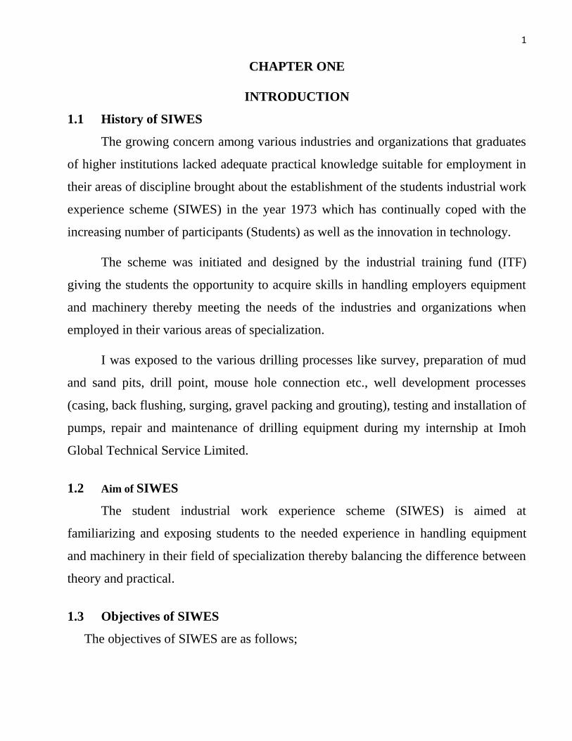
1 CHAPTER ONE INTRODUCTION 1.1 History of SIWES The growing concern among various industries and organizations that graduates of higher institutions lacked adequate practical knowledge suitable for employment in their areas of discipline brought about the establishment of the students industrial work experience scheme (SIWES) in the year 1973 which has continually coped with the increasing number of participants (Students) as well as the innovation in technology. The scheme was initiated and designed by the industrial training fund (ITF) giving the students the opportunity to acquire skills in handling employers equipment and machinery thereby meeting the needs of the industries and organizations when employed in their various areas of specialization. I was exposed to the various drilling processes like survey, preparation of mud and sand pits, drill point, mouse hole connection etc., well development processes (casing, back flushing, surging, gravel packing and grouting), testing and installation of pumps, repair and maintenance of drilling equipment during my internship at Imoh Global Technical Service Limited. 1.2 Aim of SIWES The student industrial work experience scheme (SIWES) is aimed at familiarizing and exposing students to the needed experience in handling equipment and machinery in their field of specialization thereby balancing the difference between theory and practical. 1.3 Objectives of SIWES The objectives of SIWES are as follows;
-
Upload
khangminh22 -
Category
Documents
-
view
3 -
download
0
Transcript of CHAPTER ONE INTRODUCTION 1.1 History of SIWES The ...
1
CHAPTER ONE
INTRODUCTION
1.1 History of SIWES
The growing concern among various industries and organizations that graduates
of higher institutions lacked adequate practical knowledge suitable for employment in
their areas of discipline brought about the establishment of the students industrial work
experience scheme (SIWES) in the year 1973 which has continually coped with the
increasing number of participants (Students) as well as the innovation in technology.
The scheme was initiated and designed by the industrial training fund (ITF)
giving the students the opportunity to acquire skills in handling employers equipment
and machinery thereby meeting the needs of the industries and organizations when
employed in their various areas of specialization.
I was exposed to the various drilling processes like survey, preparation of mud
and sand pits, drill point, mouse hole connection etc., well development processes
(casing, back flushing, surging, gravel packing and grouting), testing and installation of
pumps, repair and maintenance of drilling equipment during my internship at Imoh
Global Technical Service Limited.
1.2 Aim of SIWES
The student industrial work experience scheme (SIWES) is aimed at
familiarizing and exposing students to the needed experience in handling equipment
and machinery in their field of specialization thereby balancing the difference between
theory and practical.
1.3 Objectives of SIWES
The objectives of SIWES are as follows;

2
i. To bridge the gap of inequality between theory and practical giving the students
opportunity to apply their knowledge in real work situation especially under
stress and emergency.
ii. To expose students to most machinery and equipment not found within their
respective institutions and its effective work methods and techniques.
iii. To create a chance for students contacts for later job placement giving them a
view to the world of work.
iv. To prepare the minds of the students for future employment.
v. To enlist and strengthen employers involvement in the entire educational
process.
Table 1.1: Roles of the different organization involve in SIWES
ORGANIZATIONS ROLES
Federal Government
(Federal Ministry of
Commerce and
Industry)
i. Funds the programme, gives rules and regulations to
govern the scheme.
ii. To make it mandatory for all Ministries, companies and
Parastatals to offer places for the attachment of
students in accordance with the provisions of Decree
No. 47 of 1971 as amended in 1990.
Industrial Training
Fund (SIWES
DIVISION)
i. Management of the scheme as well as ensuring
smooth operation of the scheme.
ii. Disburse Supervisory and Students’ allowances.
iii. Organise biennial SIWES National Conference and
Annual SIWES Review Meeting.
iv. Vet and process students’ logbooks and ITF form 8.

3
Supervising/Regulato
ry Agencies
(NUC, NBTE)
i. Directing of institution which they regulate, to
establish, monitor and fund SIWES coordinating unit.
ii. Ensure the establishment and accreditation of SIWES
Units in institutions under their jurisdiction
Industry/Employers
(Government
Establishments)
i. To appoint an Industry-based Supervisor for students
on attachment.
ii. Employ students for SIWES and train them in their
specialized areas.
Tertiary Institutions
(Polytechnics,
Universities)
i. Supervise students at their places ofattachment and sign
their log-books.
ii. Organise orientation courses in collaboration with the
ITF for their students.
iii. Submit comprehensive reports on the scheme to ITF
through their Supervising Agencies on ITF Form 8A at
the end of every year’s programme.
Student Trainees
(Science and
Technology,
Engineering)
i. To avail themselves for the training in order to acquire
knowledge, as they are the direct beneficiaries of the
program.
ii. To be obedient to constituted authorities and adhere
strictly to all rules and regulations of the Organization
where the student is attached.
iii. To record all training activities and other assignments
in the log-book and complete ITF Form-8 to ensure
proper assessments.

4
Fig 1.1: Structure of SIWES organization
FEDERAL GOVERNMENT
(FEDERAL MINISTRY OF
COMMMERCE & INDUSTRY)
CHIEF
EXECUTIVE
FORUM
SUPERVISING
AGENCIES
(NUC, NCCE)
INDUSTRIAL
TRAINING FUND
(SIWES DIVISION)
ORGANISED PRIVATE
SECTOR (MAN, NECA,
NACCIMA)
TERTIARY INSTITUTIONS
(UNIVERSITIES,
POLYTECHNICS,
COLLEGES OF
EDUCATION)
ITF AREA OFFICES
(SIWES UNIT)
EMPLOYERS
(INDUSTRY/GOVERNMEN
T)
STUDENT TRAINEES
(SCIENCE & TECHNOLOGY,
ENGINEERING)

5
CHAPTER TWO
REVIEW OF IMOH GLOBAL TECHNICAL SERVICES LIMITED
2.1 Profile of the Company
Imoh Global Technical Services Limited (I.G.T.S.L) is a water servicing
company which deals with water drilling, repairs of submersible pumps, water
distribution, installation and completion. The director Mr. Imoh Okon with years of
experience in this field owns and runs the affairs of the company. It is situated at No
470 Oron road, Uyo, Akwa Ibom State.
2.2 Brief History of I.G.T.S.L.
The company was incorporated in 2007 with registration no. 689497. It is an
indigenous private enterprise whose prime objective is providing reliable and excellent
service in water production and distribution for domestic and industrial use. The
establishment is owned by Mr. Imoh Okon who is also the director and has about
twenty (20) personnel working in the various departments.
2.3 Services Rendered By I.G.T.S.L.
For the past thirteen (13) years, the company has been able to excel in the
following;
Provision of suitable/clean water for domestic and industrial consumption.
Maintenance and repair of borehole.
Installation of pumps and casing.
Development of borehole.
Erection of water tanks and plumbing.
Harnessing and solving electrical faults.

6
2.4 Equipment/Facilities Owned and Used By the Company
A 15KVA Lister Generator owned by the company
2 model mw100 drilling rig capable of drilling up to 350m usually hired by the
company
6 Water tanks owned by the company.
A VHP 700 atlas Copco Air Compressor of 12bar capacity owned by the
company
A 20 horse power submersible pump mainly for industrial use owned by the
company
7.5 & 5 horse power Granfos submersible pump with accessories for testing
owned by the company
2.5 Departments of the Organization
Administrative department: This department is concerned with running the
administration of the company. The department is headed by Mr. Imoh Okon,
the director of the company.
Operation department: They are concerned with water drilling operations as
well as the completion and installation of the borehole; the following persons are
involved;
Mr. Imoh Okon Head of Department
Mr. Anwanga-abasi Udofia Assistant
Mr. Jonathan Member
Mr. Nkese Ikpe Member
Mr. Nsisong Member
Mr. David Member
Mr. Oto-obong Member

7
Engineering Department: The members of this department are concerned with
the repair of the borehole and servicing of equipment.
Accounting Department: this department keeps record of the cash inflows and
outflows of the company as well as staff payment, headed by Miss Florence.
Fig 2.1: I.G.T.S.L. Organizational chart
2.6 Mission of the Company
The company’s mission is to create better opportunities for students to acquire
basic skills in their field and interested individuals; to cultivate a service culture that is
quality oriented in the provision of clean water for domestic and industrial uses thereby
attaining her goal as a global best.
Director
Secretary/Accountant
Operation manager
Safety Officer Drilling Unit Electrical Unit
8
CHAPTER 3
MATERIALS AND METHODS
3.1 Pre-Drilling Procedures
Before drilling takes place, various procedures are carried out. They include:
Site preparation
Drilling fluid/mud preparation
Preparation of drilling equipment
3.2 Site Preparation
During this process, the site for drilling is first located, the following few factors
were considered before preparing the site;
i. The site to be drilled must not be too rocky.
ii. It must not be close to any source of contamination.
3.3 Drilling Mud Preparation
3.3.1 Materials Used:
i. Bentonite
ii. Clean water
iii. Antisol
iv. Extender
3.3.2 Equipment Used:
i. Marsh Funnel
ii. PH Meter

9
3.3.3 Steps Involved In Preparing Drilling Mud
i. A measurable amount of Bentonite is added to a given amount of water and
mixed thoroughly while pumping water through a 3-way valve and recirculating
the water back through the pit.
ii. A sample of the mud is taken and a PH meter is used to measure the
concentration of the hydrogen ions of the mud.
iii. Using the above sample, the viscosity of the mud is also measured using a marsh
funnel, this helps to determine the ability of the drilling fluid to hold cuttings.
iv. The mixture is allowed for a certain period of time to ensure complete clay
hydration to avoid it swelling in the hole.
3.3.4 Importance of the Drilling Mud
i. Provide the hydrostatic pressure needed to subdue the formation pressure and
aids borehole stability.
ii. It seals the borehole wall and reduces fluid loss.
iii. It transports sands/rocks (cuttings) from the bottom of the borehole to the
settling pit (sand base).
iv. It cools and lubricates the drill bit, the drill pipe and the mud pump.
v. It allows cutting to drop out in the sand base to prevent recirculation.
3.3.5 Preparation of Drilling Equipment
i. Connect the drill bit to the drill pipe.
ii. The suction hose is then connected to the mud pump.
iii. One end of the Kelly hose or Delivery hose is connected to the swivel and the
other to the mud pump.
iv. The swivel along with the Kelly hose is then connected to the drill pipe using a
pipe wrench.
10
3.4 Drilling Methods
Primarily there are two (2) methods of drilling, they include:
1. Manual Method which include:
a. Chakachaka drilling
b. Tripod Stand
c. Rotary jetting
2. Mechanical Method which include:
a. Drilling Rig
In oil industry, heavy machineries are used such that man power is not required
but in this case, we are most concerned with the manual (man power). During drilling,
Different geological formations are encountered, requiring a four-man power to break
through the formations with the help of the clamp.
3.4.1 Advantages of Manual Drilling Method
i. The cost of hiring tools and equipment are very low, thus enabling the local
artisans carry out their work effectively.
ii. Easy access to drilling sites in the rural areas where drilling rigs cannot be
used.
iii. It is cost effective.
iv. It does not occupy space as in the case of drilling rig.
3.4.2 Disadvantages of Manual Drilling Method
1. It consumes much time and energy to get a task completed.
2. The efficiency of the work depends on the number of workers present due to its
quest for man power

11
3.4.3 Chakachaka Drilling Method
Chakachaka is used in sandy or soft formations, where no rocks will be
encountered and in cases where there is no space for the installation of the tripod stand.
In this method, the clamp is fastened to the drill pipe and the Kelly hose is
connected to one end of the swivel and the drill pipe is connected to the other end of
the swivel with the drillbit then connected to the other end of the drill pipe to be
tripped in, thus drilling resumes by a clockwise rotation of the clamp.
3.4.4 Tripod Stand Drilling Method
The equipment is made up of three stands as the name implies. The use of this
equipment to drill is called the tripod method. It is mostly used in hard/rocky
formations. But the chakachaka can be used in the case where there is no space for the
stands to be erected, though it requires more time and energy.
In tripod stand method, the Kelly hose is connected to one end of the swivel and
the drill pipe to the other end of the swivel, the swivel is then connected to the central
point of the stand by a hook which is connected to a winch. A rotating clamp is
fastened to the drill string and with its help; the component is rotated in a clockwise
direction to enhance effective penetration of the bit.
The komkom bit is used to drill, but when a hard formation is encountered, a
wrap bit (fork like in nature, not used to drill but to break hard rocks) is used.
3.4.5 The Rotary Jetting Method
Jetting is a process that involves the useof a pump to compel a flow of water
down a drill pipe and out of a narrow nozzle to make a jet of water, which helps to
soften the sediment.

12
The pipe is suspended from a tripod and rotated by hand to keep the borehole
straight. There is usually a return flow of the drilling fluid outside the drill pipe which
carries cuttings to the surface and down to the settling pit then back to the mud pit.
The major disadvantage of this method is that; It cannot be used in rocky
formations due to the weight of the cuttings, which cannot be carried by the drilling
fluid to the surface.
3.5 Water Drilling Process
3.5.1 Materials Used For Drilling
i. Bentonite
ii. Antisol
iii. Extender
3.5.2 Equipment Used For Drilling
i. Drill pipe
ii. Tripod stand
iii. Spade
iv. Winch
v. Pipe wrench
vi. Drill bit
vii. Clamp
viii. Kelly hose
ix. Suction hose
x. Swivel
Drilling process begins with the site preparation, equipment, drilling fluid
preparation, mud pit of about 3ft and settling (sand pit) pit of about 21/2ft are

13
excavated, and any of the drilling methods could be used depending on the nature of
the formation.
The drill bit is connected to the drill pipe and to the swivel using a pipe wrench, the
mud pump and the water tanks are kept near the mud pit, the Kelly and the suction
hose are then connected to the mud pump which when switched on circulates water
from the mud pit through the Kelly hose, swivel and drill pipe into the formation and
back to the mud pit, it is a continuous process till the drilling operation is completed.
The drill pipe is 10ft, so at the end of every drilled pipe the formation sample is
collected. During the first 60ft of drilling, clean water is used as drilling fluid without
any additive to minimize subsequent well development problems (like: reduction in
penetration rate) , the formations at this depth is made up of clay which yields when
mixed with water acting as bentonite. After this depth bentonite is added to increase
the viscosity of the mud to prevent the hole from collapsing since the formations below
are sandy.
The drilling mud needs to be adjusted during drilling, either by adding water or by
removing accumulated cuttings from the sand pit. As the drilling depth increases, the
formation samples become finer. Drilling operation is discontinued when crystalline
sand sample is obtained which indicates that a clean water table has been reached. Due
to the nature of formations, the drill depth differs in various terrains (locations).

14
Fig 3.1: The drilling process
3.6 Well Casing and Screen Installation
Borehole is cased to prevent the caving in of the hole. There are several forms of
screened metallic pipes used in the oil industries but in this case PVC pipes are used to
avoid contamination and by this, one of the casing pipes is slotted with the help of a
saw blade to create openings which is equivalent to the perforation of the production
casing in petroleum for oil drainage into the wellbore.
3.6.1 Equipment Used:
i. Saw blade
ii. Hammer

15
iii. Rope
3.6.2 Materials Used:
i. PVC screen pipe
ii. PVC casing pipes
iii. Toptic gum
Before casing is carried out, the total depth of the well (distance of borehole from
top to bottom) must be known and the required casing pipes and screen cleaned and put
in place for use.
A casing slump and a drive shoe are attached to the bottom of the well screen to
prevent mud and silt from entering into the casing, a slip clamp is attached to the upper
part of the screen to prevent it from slipping into the hole and then subsequent casings
are joined using gum and nail till the casing screen reaches the bottom, a rope is used
to slightly raise and suspend the casing into the well.
3.6.3 Functions of Well Casing and Screen Installation
i. The screen acts as a filter to prevent silt, sand and gravel from entering into the
water.
ii. The casing prevents the well from caving in.
iii. The casing prevents and protects the submersible pump from damage and also
enhances fishing process when need arises.
3.7 Gravel Packing Process
Gravel packing as the name implies, is carried out in order to prevent sand and
silt particles from entering into the well, the gravels are used to fill the annular space, it
acts as a filter.

16
3.7.1 Functions of Gravel Packing
i. It helps to increase the life of the well.
ii. It increases the porosity of the wellbore.
iii. It results in high yield of the well.
3.8 Well Development
This is the process of removing sand particles, clay and silt that were introduced
into the well while drilling to keep the well clean.
3.8.1 Materials Used:
i. Air
ii. Water
3.8.2 Equipment Used:
i. Pipe hose
ii. Air compressor
iii. Steel pipes
3.8.3 Benefits of Well Development
i. It helps to produce high quality water.
ii. Well development helps to increase the service life of the pump.
iii. It increases the rate of water flow from the aquifer into the well.
iv. It stabilizes the aquifer and prevents sand pumping.
v. It helps to breakdown and removes any drilling mud additives that may have
penetrated into the well.
3.8.4 Well Development Techniques
The various well development techniques used are as follows;

17
i. Over pumping
ii. Surging
iii. Bailing
iv. Air compression
v. Back flushing
Over pumping: The process of pumping a well for at least 3-4 times, the water is
discharged for a long period of time; it pumps the well sand free at a very high rate.
Pumping is not done continuously but by a process known as the “start-stop cycle
pumping”.
Surging: In this process, the surge block is pushed downwards in other to force water
at a high velocity and pressure out of the screen. As the surge block is pulled upwards,
the muddy water is pulled into the screen and pumped out as well.
Bailing: A bailer is a pipe with one way valve in the bottom. The bailer is lowered into
the well until it is filled with water and sediments. It is then pulled to the surface and
emptied. It takes a long period of time to be completed.
Air Compression: In this method, a compressor is used to inject air at a very high
pressure into the well to lift the water. As it reaches the top of the casing, the supply of
air is shut off thereby allowing aerated water column to fall.
Back Flushing: In this process, a water lifting device and a container in which water
can be stored and allowed to flow back easily into the well are used. Water is then
pumped to the surface until the container is full, and it is quickly dumped into the well,
this process is repeated continually until the well is clean.
3.9 Installation of the Well Head
After well development has been carried out, the well head is installed. Its main
functions include:

18
i. It provides a suspension point for the casing strings that runs from the bottom of
the wellbore to the surface.
ii. It helps to suspend the tubings (risers).
iii. It provides a means of attaching a well pump.
iv. It provides a means of linking the pipe to the storage tank.
Fig 3.2: Installation of wellhead
3.10 Installation of Risers and Pump
Risers and pump are the next things to install after well head installation. A
pump ranging from 1.5hp to 20hp can be used depending on the capacity, purpose or

19
demand of the owner. The electric pump is made up of the pump head, the pump motor
and the pump cable.
The riser pipes serves as a channel for the passage of water to the surface and
down to the storage tanks. During the installation process, a riser pipe is screwed to the
threaded part of the pump and a marine rope is knotted to the two holes on the pump
close to the threaded section. A cello tape is used to bind the cable and the marine rope
to the riser and the whole assembly is sent down into the well and the marine rope and
cable are tensioned to avoid the whole assembly from slipping into the borehole. With
the same procedures, subsequent risers are screwed one to another and sent down until
the installation depth is reached.
After the pump and risers installation, a process known as “pump testing” is
usually carried out. Pump testing involves the testing of the flow rate of the pump per
second.
3.11 Setting of the Storage Tank
A storage tank is use for the storage of the water, usually situated close to the
borehole, where a pipe is connected from the wellhead with the aid of either PVC or a
GI elbow and down to the storage tank which is sometimes on top of a platform, same
approach is applied in the oil industry, in tank farms for the storage of oil.

20
Fig 3.3: Installation of water storage tank
3.12 Slab and Fence
After installation, a concrete slab is usually made, and a fence is made around
the well head using concrete. When the slab solidifies, it is being placed on the fence in
a way that it will cover the well head assembly. The slab and fence are to prevent
surface water from getting into the borehole and its design is based on the owners taste.

21
CHAPTER FOUR
RESULTS AND DISCUSSION
During the program, we were coached on how to handle various equipment and
machinery and most times we were given opportunity to carryout different task in the
field, which helped boast our spirit of teamwork, competence and leadership. We were
shown various techniques and the need to satisfy our employers.
Below are few sites drilled during this program:
4.1 Drilling at Use Offot, Nwaniba
The total depth drilled was 180ft; a tripod stand was used to drill in this
formation because it was rocky. The type of bit used here was the komkom bit with the
size of 6in and a casing size of 4.5in was installed at a depth of 160ft.
The various formations encountered are as follows:
Table 4.1: Drilling data at EtimOkonUsangha, off Nwaniba
DEPTH(ft) FORMATION TYPE
10-30 Laterite
50-60 Laterite mixed with sand
80-80 Fine grain sand (brown)
100-100 Medium grain gravels
120-130 Clay
150-150 Clay sand
170-170 Fine grain gravels
180 Fine sand (pure white)

22
4.2 Drilling at Etinan LGA
The borehole here was drilled to a total depth (TVD) of 190ft before pure water
was found. The chakachaka method was used to drill this formation (because the
formation was not rocky). The diameter of the bit used was 6in with a casing size of
4in cased to the depth of 110ft.
The various formations that were encountered include:
Table 4.2: Drilling data at Ikot Aka, Etinan
DEPTH(FT) FORMATION TYPE
10-40 Laterite
50-90 Sharp sand
90-120 Fine sharp sand
120-140 Clay sand
150-190 Fine gravel sand
10-40ft 50-70ft 80-100ft
100-120ft 125-145ft
150-165ft 170-190ft
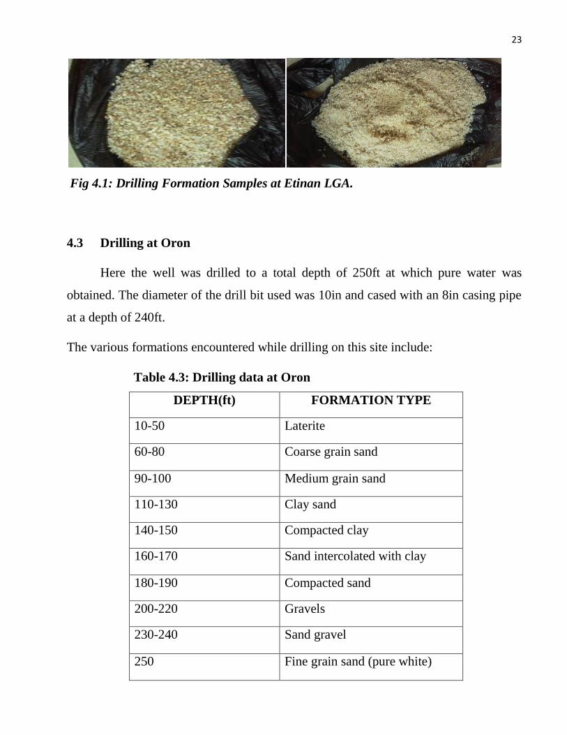
23
Fig 4.1: Drilling Formation Samples at Etinan LGA.
4.3 Drilling at Oron
Here the well was drilled to a total depth of 250ft at which pure water was
obtained. The diameter of the drill bit used was 10in and cased with an 8in casing pipe
at a depth of 240ft.
The various formations encountered while drilling on this site include:
Table 4.3: Drilling data at Oron
DEPTH(ft) FORMATION TYPE
10-50 Laterite
60-80 Coarse grain sand
90-100 Medium grain sand
110-130 Clay sand
140-150 Compacted clay
160-170 Sand intercolated with clay
180-190 Compacted sand
200-220 Gravels
230-240 Sand gravel
250 Fine grain sand (pure white)

24
4.4 Drilling at Ikot Ekpene Road
Here the well was drilled to a total depth of 180ft at which pure water was
obtained. The diameter of the drill bit used was 10in and cased with an 8in casing pipe
at a depth of 170ft.
The various formations encountered while drilling on this site include:
Table 4.4: Drilling data at Oron
DEPTH(FT) FORMATION TYPE
10-30 Laterite
40-80 Sharp sand
90-110 Fine sharp sand
120-150 Clay sand
160-180 Fine gravel sand
4.5 The Problems of Borehole Drilling, Causes and Solutions
1. Stuck Drill Pipe
In the case where there is short of drilling fluid in the mud pit when
drilling into a clay formation and the drill pipe is left in the formation for a day
or more before drilling fluid is supplied for the continuation of the drilling
process, it will result to stuck pipe and may extend the drilling time.
Though the stuck pipe can be freed by the addition of water and the
continuous shaking and pulling, which might require much energy as in the case
of Ikot Aka, Etinan local government area.

25
2. The Cost Of Drilling
Different areas have different cost of drilling depending on the nature of
the formations to be encountered or performance record from the nearby wells
used to determine the depth to be drilled. Rocky and clay formations with high
depth charges more than soft formation with less depth.
3. Shortage Of Water
It is one of the most important problems encountered while drilling in
remote areas where there is no good road for water supply and no source close to
the drilled site, in this case the drilling is always abandoned or takes longer time
for its completion.
4. Collapse Of The Borehole
The borehole can collapse during drilling if the right amount of antisol is
not added, this antisol helps to hold the walls of the formation when drilling and
prevent collapse, and the well can also collapse if not properly cased after
drilling.
5. Fluid Loss
When drilling, the drill fluid may be loss to the permeable walls of the
formation thereby preventing effective circulation.
6. Not Drilling To The Right Depth
When drilling for water, there are some formations that contain water
(not sufficient), but this is not usually the right depth. If the driller stops drilling
at this point, there is a possibility that after installation and completion, the water
will flow for few days and then stop.Thus, it is advisable to carry out survey on

26
the intended terrain to be drilled to know the depth at which clean water is
expected, thereby helping your budget for the drilling process.
Table 4.5: Differences between water and oil drilling
S/N WATER DRILLING OIL DRILLING
1. Water can be produced at a
shallow depth
Oil is buried deep into the earth crust
2. Artificial pump is used to bring
water to the surface
The well flows at a high pressure,
artificial pumps can only be used when
the pressure is not sufficient enough for
production
3. Tripod stands are used for
drilling
It involves the use of drilling rigs
4. The only drilling fluid use here
is the water base mud
Oil based mud, water based mud and air
based mud are the drilling fluids used
5. The mud man checks the sand
base and removes cuttings,
mixes mud and additives
Here, the mud engineer monitors the
mud system
6. Drilling is carried out only on
land
Drilling is carried out both on land and
water (onshore and offshore)
7. There is no possibility of
blowout
There is high possibility of blowout due
to high depth drilled

27
CHAPTER FOUR
CONCLUSION AND RECOMMENDATIONS
4.1 Conclusion
The water drilling process is quite similar to the drilling process for crude oil
production in petroleum engineering and the challenges encountered are slightly
different due to the operating system, materials, equipment, techniques and depth
drilled.
The industrial training program at Imoh Global Technical Services Limited
(I.G.T.S.L) has granted me the opportunity to learn the practical aspect of drilling as it
applies in my field which has improved my competence, team spirit, leadership skills
and ability to critically evaluate and handle work situations even under stress and
emergency. Now with the impacted ideas and techniques in areas such as; Repairs and
Maintenance, pre-drilling procedures, drilling process and well development processes,
I can confidently sail through work situations when called upon.
4.2 Recommendation
For subsequent trainees, I strongly recommend that;
i. Various educational bodies should participate in the supervision of students as
well as employers.
ii. Incentives benefits should be given to trainee no matter how small to boast their
focus and performance.
iii. The checking of log books on weekly bases so as to make the trainee more
focus.

28
iv. Funds should be released to improve the scheme as there is a growing number of
institutions, as well as the number of participants.
v. Trainees should be given opportunity to engage in field work and operate
machinery no matter how complicated it may be.
vi. Placement opportunities be created for students in the industries where they can
be exposed not only in one area of their field, and get to experience what is
really explored (not water instead of oil) to enhance effective competency after
graduation.

29
REFERENCES
Anderson, K. (1993). Ground Water Handbook, Dublin Ohio: National ground water
Association, pp. 401.
Driscoll, F. G. (1986). Ground water and wells, 2nd Edition, St. Paul: Johnson Division,
pp. 1089
Chilingarian, G. V. and Vorabutr, P. (1983). Drilling and Drilling fluid.
Imoh, E. O. (2007). Imoh Global Technical Services Company’s Bronchure.
Kate, Van Dyke (1998). Drilling Fluid, Mud pumps and conditioning equipment.
Miller, C. Drilling (2012). Drilling techniques.
Moffat, B. (1986) “Efficient Water Well”, Developing World Water, Hong Kong:
Grosvenor Press International, pp. 36-37.
Raymond, Rowley (1995). Drilling for water (2nd edition). Avebury, Cranfield
University.
Schreurs, R. (1987) “Well Development is Critical”, Developing World Water, Hong
Kong: Grosvenor Press International.
University Of Uyo Students SIWES Handbook.