The student industrial work experience scheme (SIWES) is the ...
73
1 | Page CHAPTER1 INTRODUCTION Thestudentindustrialworkexperiencescheme(SIWES)istheacceptedskilledtraining program formingpartoftheapprovedminimum academicstandardinthevariousdegree programofallNigerianuniversities.Itisgearedtowardsclosingtheexistinggapbetween theoryandpracticesofscience,agriculture,medicine,engineeringandtechnology, managementandotherprofessionaleducationalprogrammesinNigeriatertiaryinstitutions.It isaimedatexposingstudentstomachinesandequipment’s,professionalworks,methodsand waysofsafeguardofworkareas,workers,industriesandorganizations.Theminimum durationstipulatedforSIWESshouldbetwenty-four(24)weeksexceptforengineeringand technologyprogram wheretheminimum durationisforty(40)weeks,theschemeisa tripartiteprogrammeinvolvingthestudents,theuniversitiesandtheindustries(employersof labour)itisfoundedbythefederalgovernmentofNigeriaandjointlyco-ordinatedbythe industrialtrainingfund(ITF)andNigerianuniversitycommission(NUC). 1.1OBJECTIVESOFSTUDENTSINDUSTRIALWORK EXPERIENCESCHEME (SIWES). InaccordancewiththeSIWESprogramme,itismadespecificallythattheobjectivesof thestudentsindustrialworkexperienceincludes; 1.ToprovideavenueforthestudentinNigerianuniversitiestoacquireindustrialtraining skillsandexperienceintheircourseofstudy. 2.Topreparestudentsfortheworksituationtheyarelikelytoencounteraftergraduation. 3.Toexposestudentstoworkmethodsandtechniquesinhandlingequipmentthatmaynotbe availableintheuniversity. 4.Tomaketransitionfrom theuniversitytotheworldofworkandthisenhancesstudent contactforbetterjobplacement. 5.Toprovidestudentwithanopportunitytoapplythetheoreticalinrealworksituation, therebybridgingthegapbetweenuniversityworkandactualworkexperience. 6.Toenlistandstrengthenemployersinvolvementintheentryprocessofpreparinguniversity
-
Upload
khangminh22 -
Category
Documents
-
view
2 -
download
0
Transcript of The student industrial work experience scheme (SIWES) is the ...
1|Page
CHAPTER1
INTRODUCTION
Thestudentindustrialworkexperiencescheme(SIWES)istheacceptedskilledtraining
programformingpartoftheapprovedminimumacademicstandardinthevariousdegree
programofallNigerianuniversities.Itisgearedtowardsclosingtheexistinggapbetween
theoryandpracticesofscience,agriculture,medicine,engineeringandtechnology,
managementandotherprofessionaleducationalprogrammesinNigeriatertiaryinstitutions.It
isaimedatexposingstudentstomachinesandequipment’s,professionalworks,methodsand
waysofsafeguardofworkareas,workers,industriesandorganizations.Theminimum
durationstipulatedforSIWESshouldbetwenty-four(24)weeksexceptforengineeringand
technologyprogramwheretheminimumdurationisforty(40)weeks,theschemeisa
tripartiteprogrammeinvolvingthestudents,theuniversitiesandtheindustries(employersof
labour)itisfoundedbythefederalgovernmentofNigeriaandjointlyco-ordinatedbythe
industrialtrainingfund(ITF)andNigerianuniversitycommission(NUC).
1.1OBJECTIVESOFSTUDENTSINDUSTRIALWORK EXPERIENCESCHEME
(SIWES).
InaccordancewiththeSIWESprogramme,itismadespecificallythattheobjectivesof
thestudentsindustrialworkexperienceincludes;
1.ToprovideavenueforthestudentinNigerianuniversitiestoacquireindustrialtraining
skillsandexperienceintheircourseofstudy.
2.Topreparestudentsfortheworksituationtheyarelikelytoencounteraftergraduation.
3.Toexposestudentstoworkmethodsandtechniquesinhandlingequipmentthatmaynotbe
availableintheuniversity.
4.Tomaketransitionfromtheuniversitytotheworldofworkandthisenhancesstudent
contactforbetterjobplacement.
5.Toprovidestudentwithanopportunitytoapplythetheoreticalinrealworksituation,
therebybridgingthegapbetweenuniversityworkandactualworkexperience.
6.Toenlistandstrengthenemployersinvolvementintheentryprocessofpreparinguniversity
2|Page
graduatesforemploymentinindustries.
Thefollowingmandatesareonthepartofthestudentstoplay;
1.Toberegularandpunctualatrespectiveplacesofattachment.
2.Tocomplywiththeemployersrulesandregulations.
3.Tokeepproperrecordsoftrainingactivitiesandotherassignmentinthelogbook.
4.TosubmittoITFthroughtheiremployersformSPE-1.
5.TosubmittoITFthroughtheirinstitutiontheevaluationreportFORM-8dulycompletedby
thestudent,employerandtheinstitution.
1.2ROLEOFTHEEMPLOYERS
1.Toacceptthestudentandassignthemtorelevanceon-thejobtraining.
2.Toattachexperiencetothestudentsforeffectivetrainingandsupervision.
3.Tocontrolanddisciplinestudentsaspermanentstaff.
4.Topaystudentmonthlyasatwhendue.
5.Toprovidemedicalcaresforthestudentswithinthelimitsoftheemployersandconditions
ofserviceduringattachment.
6.TopermitrepresentationofITFandthatoftheinstitutebasedsupervisorstovisitthe
studentsonattachmentforassessment.
7.TogradestudentsasprovidedintheassessmentformandtheITFform-8attheendofthe
programmeandsubmitthesametotheinstitution.
1.3WARRIREFININGANDPETROCHEMICALCOMPANYLIMITED(WRPC).
WarriRefiningandPetrochemicalCompanyLimitedisoneofthesubsidiaryofthe
NigerainNationalPetroleumCorporation(NNPC)incorporatedinNovember1988asaresult
ofthemergeroftheWarriRefinaryandEkpanPetrochemicalPlantinthewakeofNNPC’s
commercializationexercise.Therefinerywascommissionedin1978withaninitialnameplate
capacityof100,000BPSDandthiswaslaterdebottleneckedin1987to125,000BPSD,and
thepetrochemicalplants,commissiondinmarch,1988aremadeupofa35,000MT/yearof
polypropyleneand18,000MT/yearofcarbonproductionfacilities.

3|Page
TherefineryisdesignedtoprocessEscravosLightCrude(chevron)andUQCCCrude(shell)
intofinishedpetroleumproductswhilethepetrochemicalplantsconvertstheotherwiselow
utilityrefiningby-productsnamelypropyleneanddecantedoiltoproducevalue-added
polypropyleneandcarbonblackproducts.
WPRC isselfrelianton powersupply and generatesitsutilitiesforprocess
requirement.WRPCalsomaintainatankfarmforstorageoffinishedproductsandcrudeoil
forinternalprocessing and exportto KRPC(kaduna refining and petrochemical
company).WRPCpowersupplyalsoextendstootherneighbouringNNPCsubsidiaries
namely,PPMCandNGC.
1.4WARRIREFININGANDPETROCHEMICALCOMPANYFACILITIES.
WRPC’sproductionprocessescanbeclassifiedintotwobroadcategoriesnamelythe
primaryandsecondaryprocesses.Theprimaryprocessesusedistillationprinciplestoseparate
crudeintointermediateandsomefinishedproductswhilethesecondaryprocessesuse
catalysttoconverttheintermediatestohigherqualityfinishedandvalueaddedpetrochemical
products
ThemarketableproductsfromWRPC’sfacilitiesare:
i.Liquefiedpetroleumgas(CookingGas)
ii.PremiumMotorSpirit(Petrol)
iii.Kerosene(Domestic/Aviation)
iv.AutomotiveGasOil(DieselOil)
v.FuelOil
vi.Polypropylenepellets(Nipolene)
vii.CarbonBlackPellets
Atmaximumdesigncapacityrefineryisconfiguredtoproducethepetroleumproductat
thefollowingrates.

4|Page
WRPCDesignProductSlate
ProductatMaximumDesignCapacity
DESIGNPARTICULARS METRICTON/DAY LITRES
FUELGAS 273.65 482,716.22
LPG 204.39 362,591.22
PMS 5,498.31 7,285,261.82
KERO 1,778.82 2,170,033.78
AGO 5,119.93 5,959,601.35
F.OIL 3,496.62 3,671,452.70FC
Table1.0
TheprimaryprocessesarecarriedoutattheAtmosphericDistillationUnit,theVacuum
DistillationUnitandthegasplant.ThesecondaryprocessesunitsaretheNaphtha
HydrotreatingUnit,ThecatalyticReformingUnit,KeroseneHydrotreatingUnit,theFluid
CatalyticUnit,theHFalkylationUnit,PolypropyleneandCarbonBlackPlants.Thefunctions
ofthevariousunitsaredescribedasfollows:
1.5CRUDEDISTILLATIONUNIT(CDU).
Crudeispumpedtotheunitdirectlyfromthestoragetank.Inordertoreducethecostof
operatingtheunit,thein-comingcrudeisdesaltedandpassedthroughseriesofheat
exchangerswhereitabsorbsheatfromthehotstreamsbeforeenteringthecrudeheater.The
crudeisheatedtothedesiretemperatureintheheaterbeforeenteringtheatmospheric
distillationcolumn.Someofthecrudeenteringtheflashzoneofthedistillationcolumn
flashesintovapour,whichrisesupthecolumnwhiletheremainingliquidresiduedrops
downwards.Thelightestproduct,which isgenerally naphtha,passesoverhead and is
condensedandsenttothestabilizersandsplitterforfurtherseparation.Theproductsthatare
heavierthanthenetoverheadsareobtainedbywithdrawingportionsoftheinternalreflux
streamsassidecuts.Threesidecutsorproductsarewithdrawnfromthecrudecolumnand
senttostorage.TheseareHouseholdKeresene(HHK),DieselOil(LightAtmosphericGasOil
i.eLAGO).pathofthehouseholdkeroseneissenttokerosenehydrotreatingunitwhileallthe
HAGOissenttoFCC(FluidCatalyticCracking)forfurtherprocessingtovacuumdistillation

5|Page
unitforfurtherseparation.
1.6VACUUMDISTILLATIONUNIT(VDU).
Inordertoincreasetherecoveryofgasoil,atmosphericresiduefromcrudedistillation
unitisfurtherprocessedinavacuumdistillationunit.TheproductofVDUarevacuumgas
oil,slopwax,andvacuum residue.Thevacuum gasoilaresenttoFCCunitforfurther
processing.Thedistillationofatmosphericresidueisconductedundervacuumpressureor
reducepressureinordertoavoidthermaldecompositionorcrackingathightemperature.
Thebasicprinciplesuponwhichvacuumunitoperateisthattheboilingpointofany
materialdropsasthepressureislowered.Atatmosphericpressure,reducedcrudecontaining
gasoilwithboilingpointsrangingfrom340degressCelsiusto560degressCelsiuswouldbe
subjectedtocrackingtemperaturelongbeforemeaningfulquantitiescouldbeflashedoff.By
distillingundervacuumorreducedpressure,thedesiredquantitiesofgasoilcanbeflashed
offandrecoveredbeforecrackingtemperatures.
1.7GASPLANTS.
TheoverheadfromthestabilizersinCDUisthefeedbacktothegasplants,Itis
predominantlyamixtureofbutaneandpropaneotherwiserefferedtoasmixedLPG.The
basicoperationinthisunitissimilarinprincipletothatoftheCDUasitisseparationof
mixturesbydistilllatonprocess.ThemixedLPGischargedintothede-ethanizerforthefor
theremovalofethaneandlighterends.Thwbottomisthenfedintothede-polarizerwhere
propaneandbutaneareseparated.ButaneissenttoHFAlkylationplantasfeedbackor
storagewhilepropaneissenttofuelsplantandcarbonblackfuelgassystems.
1.8NAPHTHAHYDROTREATINGUNIT
HeavyNaphthafromCDUconstitutesthefeedbacktoNHU.Themainpurposeof
NaphthaHydrotreatingunitistocleanuporeliminatecatalystpoisonssuchasorganic
Sulphur,nitrogenandoxygencompoundstothatitissuitableaschargedtocatalytic
reformingunit.
HeavyNaphthamixedwithhydrogenisheatedinafurnaceandchargedintoafixedbed
reactorcontainingcabalt-molybdenumcatalyt.Theposioncontainingcompouds undergo
reactioninthepresenceofhydrogenreleasingtheirpoisonouscomponentsasgases.

6|Page
1.9CATALYTICREFORMINGUNIT.
TheCRUandNHUarebothdesignedtoprocess2035.9MetricsTonsperstreamdayor
16,600BPSDofheavyNaphtha.Themainfunctionofthecatalyticreformingunitisto
upgradelowoctanenumberstraight-runheavyNaphthatohigher-octanemotorfuelblending
componentbycatalyticallypromotingspecificgroupsofchemicalreaction.Inthese
reaction,naphthenesandparaffinsareconvertedintoaromaticcompounds.Hydrogen,theby-
productfromthearomaticproducingreactionsisusedinsupportingoperationsinNHUas
wellasCRU.
Treatedheavynaphthamixedwithhydrogenisheatedinthefurnaceandcharged
throughfourcatalyticfixedbedreactorsarrangedinseries.Thehotreactoreffluentis
stabilizedbyseparatingitintoReformateLPGandFuelgas.Thereformateispumpedtothe
premiummotorspiritblendingpoolwhiletheLPGistransferredtothegasplantforfurther
processing.Reformateisahighqualitypremiummotorspiritblendingstock.
1.10KEROSENEHYDROTREATINGUNIT(KHU).
StraightrunkeroseneorhouseholdkeroseneobtainedfromCDUisthefeedstocktothis
unit.Thisunitconvertsstraightrunkerosenetoaviationturbinekerosene(JetFuel)by
improvingitscombustioncharacteristics.Fixedbedcatalyticreactorsareemployedinthe
presenceofhydrogenforremovalofimpuritiesandsmokepointimprovement.Thisgeneral
operatingprinciplesaresimilartothoseofNHUandCRU.Theinstalledcapacityofthisunit
is8,500bpsd.
1.11FLUIDCATALYTICUNIT(FCC).
Theunitisdesignedtoprocess26,000bpsdasoilfeedstockintohighvaluedproduct
likepremiummotorspiritandLPG.Thisisveryimportantunit,andcantrulybedescribedas
the“heartofrefiningoperation”.HeavyAtmosphericand,Vacuum Gasoilsaremixed
togetherandthenheatedbyatrainofheatexchangersandalsoinaheater(furnace)beforethe
oilisinjectedintoaflowingstreamofinjectedintoaflowingstreamofcatalystparticlesina
longpipereactorusuallyreferredtoasRiser.
Intheriser,theoilmeetshotregeneratedcatalystfromtheregenerator.Thehotcatalyst
7|Page
vaporizesthefeed,raisesittoreactiontemperatureofabout521degreeCelsiusandsupplies
thenecessaryheatforcrackingreactiontoproceed.Theflowofthemixtureofcrackedfeed
andcatalystcontinuesintothehorizontal“crossover”sectionandintotwoparallel“roughcut”
cyclonesforanabruptseparationofthehydrocarbonvaporandcatalyst.Thisistoensurethat
re-crackingofthepremiummotorspiritcomponenttolightercomponentsisavoided.
Thetotalhydrocarbonvapourandtreamflowsupwardsthroughthedisengagetowardsfour
singlesstagedcyclones.Thesecyclonesseparateallbutasmallquantityoftheentrained
catalystfromthevaporsandreturntothestripperandbackintotheRegeneratorwherethe
cokedepositisburntoffwiththeaidofair.Thevaporsthenpassoutofthecyclones,intothe
disengagedoverheadvaporlineandintotheMainFractionatingColumnwhereseparation
intocolumnoverheadvapors,HeavyNaphtha,LightcycleoilandDecantoiliseffected.The
columnoverheadvaporsandpartoftheHeavyNaphthastreamarefurthertreatedinthe
VaporRecoveryUnittoproduceFuelgas,propaneandButaneandpremiummotorspirit.
Thepremiummotorspiritproductisahighoctanevalueandassuchforblendinginthe
premiummotorspiritpool.ThedecantoilisusedasfeedstockforcarbonBlackplantbutcan
alsobeblendedintofueloil.The propylene-propaneislikewiseusedasfeedstockto
polypropyleneplant(PPplant)orforLPGblending.Theolefinicbutanealsoservesaspartof
thefeedstocktotheHFAlkylationunitandwithbutaneasdomesticcookinggas.
1.12WRPCMANAGEMENTSTRUCTURE.
Therefineryisstaffedwithhighlyprofessionalandskilledpersonnelwithconsiderable
experienceinrefiningoperations.AlthoughemploymentinNNPCisconductedatoperations
headquarters(NNPCTOWERS,centralbusinessdistrict,Abuja),thepeculiarneedsofeach
ofthesubsidiarycompaniesareusuallytakenintoconsiderationinthedevelopmentof
personnel.Belowistherefineryorganogram,depictingtheadministrativestructureofthe
company.Themanagingdirectoristhechiefexecutiveofficersofthecompany,heis
supportedbytwoexecutivedirectors,oneinchargeofoperationswhiletheotherservicesi.e.
inchargeofthedaytodayactivitiesofthecompany’skeyfunctions.Theoperationsdivision
ismadeupofproduction,maintenance,engineeringandtechnicalservices,production
programingandqualitycontrol,powerplantandutility,andthehealth,safetyand
environmentdepartmentswhiletheservicesdivisionisservedbytheFinancialandAccounts,
Administration,humanresources,publicAffairsandsecurityDepartments.
Inaddition,thereisamanagingdirector’sDivisionmadeupofMaterialsManagement,

8|Page
planningandBudgetmanagementandthecompanysecretariatandlegaladvisoryservices
department.
Alldepartmentaresupportedbysectionsandunitshead.Thetotalstaffstrengthisabout
2000.
Figure1.12OrganizationchartofWarriRefiningandPetrochemicalcompany.
1.13FUNCTIONSOFTHEMAJORPOSITIONSINWRPC
1.Managingdirector:Themanagingdirector’sroleistodesign,developandimplement
strategicplansforthecompanyinacost-effectiveandtime-efficientmanner.
2.Executivedirectorofoperation:Theexecutivedirectionofoperationisresponsibleforthe
day-to-dayoperationofthecompany,whichincludesmanagingcommitteesandstaffaswell
asdevelopingbusinessplanincollaborationwiththeboard.

9|Page
3.Executivedirectorofservices::Theexecutivedirectionofservicesisresponsibleforthe
day-to-dayservicesofthecompany
4.Managerofmaintenance:Themaintenancemanageroverseesthefacilitiesmaintenance
functionandassociateofthedepartment.
5.Managerofproduction:Theproduction managerisresponsibleforthetechnical
management,supervisionandcontrolofindustrialproductionprocesses.Theproduction
manageralsoensurethatmanufacturingprocessesrunreliablyandefficiently.
6.ManagerofEngineeringandTechnicalservices:TheETSD managersupervisesall
technicalstaffthatareresponsiblefordistrict-widedatanetworkandcomputerandnetwork
operation.Assignsandcoordinatesworkassignmentandresolutionofcriticaltechnicaland
proceduralproblems.
7.ManagerofHealth,SafetyandEnvironment:TheHSE managerisresponsiblefor
developingandimplementingorganizationalsafetyprograms.Healsoevaluatetheworkplace
environmentanddevelopssafetymanagementpoliciesthatidentifyanddefinethesafety
responsibilityofallemployees.
8.ManagerofProgrammingandQualitycontrol:ThePQCmanageristoensurethatthe
productsmeetqualityandefficientstandardsetbythecompanyandhealsoensurethat
manufacturingproductionlinesrunsmoothlyandgenerateaconsistentlysuitableoutputfor
theiremployers
9.ManagerofPublicAffairs:The managerofthepublicaffairsisresponsibleforthe
developmentand implementation ofthe company’s communication strategy and
objectives.Healsodevelopscommunicationplansandimplementsabroadrangeofpublic
relationactivities.
10.ManagerofAdministration:Themanagerofadministrationoverseesthesupportoperation
ofanorganization.Heensurethatthereiseffectiveinformationflowandthatresourcesare
employedefficientlythroughoutthecompany.
11.Manager of Human resources:The human resources manager has two basic
functions:overseeingdepartmentfunctionsandmanagingemployees.
12.ManagerofSecurity:Themanagerofsecurityandhisteamroleistoensuretheperimeter
ofthecompanyissecuredfrom anyexternalandinternalvisiblethreatthatmayarise.They
10|Page
alsoensurethatthelifesoftheworkersandthecompany’spropertyaresecured.
1.14MAINTENANCE
Maintenancecanbeseenascertainactivitiesoractionscarriedoutonworkingmachines,
equipment’s,facilitiesinordertomaintain,keepthemfunctioningorrestoretoserviceable
conditions.
1.15TYPESOFMAINTENANCESTRATEGY:
1.Preventivemaintenance:preventivemaintenanceispracticedinordertodelayorprevent
breakdown.
2.Correctivemaintenance: thisstrategyisemployedwhennomaintenanceactivitiesis
carriedoutuntilbreakdownoccurorisabouttooccur.Correctivemaintenanceisusually
donetorestoreafaultysystem.
1.16 SUMMARYOFINTERN’SROLE/RESPONSIBILITYANDWORKDONE
InthemaintenancedepartmentinWRPCwhereIwasscheduledto,Iwasinvolvedin
carryingoutcorrectiveandpreventivemaintenanceondifferentequipmentssuchas
Pumps(centrifugalpumpinparticular),Steam andGasTurbines,AirCoolers,Centrifugal
Compressor,Valves(PneumaticsandManuallyoperated).
SomeoftheworkIdidonpumpswere,rectificationofstiffnessoftheshaftsoftheelectric
motorandcentrifugalpump,fixingofcouplingspacers,mechanicalseals,packings,shaft
sleeves,impellers and bearings on the pump’s shaft,carrying shaftalignmenton
pumps.ThereafterImovedtoAircoolersunitwhereIparticipatedinthefixingandremoval
ofbladesonthecouplinghub,changingofthebearingsontheshaft,fixingandremovalof
loosedandworn-outbeltsonthewheeloftheAircooler.ThereafterImovedtoCompressor
andBlowerunitwhereIwasinvolvedinthereplacementoflubeoilfiltersincompressor’s
lubeoiltanks,fixingofbeltsinblowers,installationandgreasingofstackdamperpins.
ThereafterImovedtoPneumaticworkshopwhereIpersonallydidaseriesofcalibrationof
pressuregaugesusingthedeadweighttesterandfromtimetotimeIalsowentaroundthe
plantareainspectingthecontrolvalves(safetyvalve,reliefvalve)andthemanuallyoperated
valve.ThereafterImovedtoMachinetoolsunitwhereItookpartinperformingsome
operationslikeBoring,Turning,Threadcuttingonthelathemachine.ThereafterImovedto
PowerPlantandUtilityunitwhereIparticipatedinthealignmentandfixingofgovernorson

11|Page
steamturbines,fixingonmechanicalsealsoncentrifugalpumps,extractionandchangingof
bearingsofcentrifugalpumps,constructiononshelterondifferentrotatingequipments.
Finally Imoved to Planning unitin Area3 whereIwasinvolved in the
registering,recordinganddispatchingofworkrequestinthedifferentunitunderAREA3,I
alsoparticipatedintakingvibrationreadings(threetimesaweek)ontheGasturbines,stock
takingfromthewarehouseofthemaintenancedepartment.
CHAPTER2.
DETAILEDINTERN’SROLEANDDAILYACTIVITIES
Inthischapter,adetailedexplanationoftheworkdone,knowledgegainedorskill
obtainedonaweeklybasisthroughoutthetraining.
Mostofthepracticesdoneduringthistrainingarebrieflydescribedweekly.
Inthefirstweekwasthefinalsubmissionofdocumentstothecompanyandfinal
processingofmyadmissionandclearanceasanindustrialtrainingstudents,followedby
dispatchingandreceivingofdocumentsfromthevarioussectionofthecompany.
AtthebeginningoftheSecondweekIwasscheduledtotheAREA1OFFSITEUNIT
whereIwasinvolvedintheinstallationofmechanicalpackingofafirepump,removalofthe
couplingspacerofthefirepump(sothatrepairscanbecarriedoutontheelectric
motor),installationofamultistagecentrifugalpumptoitsdriver.
InthethirdweekIparticipatedintheoverhaulingofasinglestagecentrifugal
pump,carryingoutshaftalignmentofafirepump usingthedialindicatormethodand
decouplingof203centrifugalpumpfromtheplant.
Inthefourthweekdecouplingandassemblyofa15-P-02centrifugalpumpinstallinga
couplingspacer,alignmentofthe15-P-02centrifugalpumpwiththeelectricmotorwas
successfullycarriedout.
InthefifthweekIwasscheduledtoAREA1,PUMPANDTURBINESUNITwhereIwas
involvedinthecheckingandrectifyingoffaultson16-K-02ofaTurbineActuator,Iaslo

12|Page
participatedintheinstallationofanewsinglestagecentrifugalpumpintheplant,thereafterI
coupledthecouplingspacerofthenewpump.
ThesixthweeksawmydevelopmentinperformingshaftalignmentwithSKFalignment
tools,fixingofcouplingspacers.Iwasalsoexposedtoprocessonhowtochangeandreplace
inboardandoutboardbearingsofpumps.
Intheseventhweekwasallaboutrectificationofstiffnesson10-P-10B,15-P-06A,15-P-
07BCentrifugalpumpsthereafterIaslodevelopedmyskillsonhowtoperform shaft
alignmentandcouplingofspacers.InthesameweekIwasintroducedtoacomponentofa
pumpcalledtheshaftsleeves(whichptotectstheexposepartoftheshaftfromcorrosion),how
tofixitontheshaft.
IntheeightweekIwasscheduledtoAREA1AIRCOOLERUNIT.Thisweekhadtwo
holidaysneverthelessIwasinvolvedinoverhaulingof16-A-06Aircooler,fasteningof
missingnutsin10-AM-01EAircoolermotor,andalsoreplacingofthemissingbeltof10-
AM-08AAircooler.
Theninthweek wasallaboutreplacingmissingbeltsondifferentAircoolersand
installingbearingsontheshaftofanAircoolers,participatingaswellinthefixingofblades
tothecouplinghubofAircoolers.
InthetenthweekIwasinvolvedincoupling ofthewheelandfixingofV-beltsand
bladesondifferentsAircoolers.Ialsoparticipatedinthedecouplingofasodaoverheadcrane
electricmotorforrepairs.
IntheeleventhweekIwasscheduledtoAREA1COMPRESSORUNITwhereI
participatedinreplacementofLubeoilfilterinthelubeoiltankofacompressor
package,decouplingandcouplingofthegearboxofthestackdamperofaheater.
Thetwelfthweekwasallaboutreplacementoflubeoilfilterinacompressorturbineunit
andaninstallationoflubeoilclarifierofthecompressorunit.
Inthethirteenthweekprovisionofanewpinforstackdamperwheel,greasingand
exercisingofthestackdamperofanheaterandplentyofshaftalignmentwasdone.
InthefourteenthweekIwasscheduledtoPNEUMATICSWORKSHOPUNITwhereI
wasopportunetolearnhowpneumaticsvalvesworksandstepstoobservewhencalibrating
pressuregauges.Ialsoparticipatedinthedecoupling,assembly,testingandcalibrationofa
13|Page
pressuredifferentialgauge.
Inthefifteenthweekdismantlingoftheoutercasingandoutercomponentsofadead
weighttester,changingthehydraulicoilintheoiltankofthedeadweighttester,couplingof
thedismantledpartofthetestweighttesterandtestingthedeadweighttesterwasdone.
InthesixteenthweekImovedaccordingtomyscheduletoMACHINETOOLSUNIT
whereIparticipatedinboringofaninboardandoutboardbearinghousingonthelathe
machine,Ididaslsoturningoperation,threadcuttingandtaperingofHVstem.Lastlyinthis
weekIlearnthowtocutthreadonhexagonalbolts.
Intheseventeenthweekdrillingonthecircumferenceofandimpeller,cuttingofinternal
internalthreadusingtapandwrench,stockloadingandstocktakingweredone.
Drillingofholesonthesurfaceofanimpeller,drillingofholesonagarcoupling
hub,machiningofTeflongasketwasdoneintheeighteenthweekonalathemachine.
ThroughoutthenineteenthweekIwasinvolvedinthedecouplingofakickstarterofan
hilluxcar,changingtheBendixofthedecoupledkickstarter,fixingofenginesitterofthe
foundationoftheengine,fixingofa13toncapacityfolklift.
InthetwentiethweekIwasmadetoundergoaHealthSafetyandEnvironmentprogram
thatlastedforthreedays,neverthelessinthatsameweekIalsocoupledaspacerofa
centrifugalpump.
Thetwenty-firstweekwasonewhichIrememberclearlythatweworkedonasteam
turbineforaweek.Idecoupledtheoutercasingoftheturbine,removedalsothelabyrinth
sealsandspacersfromtheturbineshafts,Ididparticipatedintheextractionofthebearings
fromthetwoendsoftheshaft(boththejournalbearingandtheballbearing.).
Inthetwenty-secondweekIparticipatedinthefixingofamechanicalsealonacentrifugal
pump,extractionandfixingofthebearingsoftheabovecentrifugalpumps,shaftalignmentof
acentrifugalpumpdrivenbyasteamturbine(109-PT-01C),fixingofcouplingspacerson101
-P-15Aand101-P-15Bcentrifugalpump.
Inthetwenty-thirdweekIwasinvolvedinfollowingactivities;fixingofthemechanical
governorof109-PT-01Csteamturbine,replacingthecasing,shaftsleevesandshaftof101-P-
12centrifugalpump,constructiononshelteronalubhydroxylpump,shaftalignmentof101-P
-18AandBcentrifugalpump.
14|Page
Atthebeginningofthetwenty-fourthweekIwasscheduletoPLANNINGUNITAT
AREA3whereIjoinedintheregistering,recordinganddispatchingofworkrequestinthe
differentunitunderAREA3,Ialsoparticipatedintakingvibrationreadingsondifferent
rotatingequipments,stocktakingfromthewarehouseofthemaintenancedepartment.
CHAPTER3
PUMPS
Apumpisamechanicaldeviceusedtoincreasethepressure,flowrateofthefluidit
handles.Pumpsareusedtotransferfluidsfromlowpressurezonestohighpresurezonesby
meansofamechanicalaction.Generallypumpsareusedtoraisethepressure and
velocity(flowrates)offluids
Pumpsoperatebysomemechanism(typicallyreciprocatingorrotary),andconsume
energytoperformmechanicalworkbymovingthefluid.Pumpsoperateviamanyenergy
sources,inWarrirefiningandpetrochemicalcompany(WRPC)pumpsaremostlydrivingby
electricmotors.
3.1TYPESOFPUMPS
Pumpsmaybeclassifiedonthebasisoftheapplicationtheyserve,theliquidsthey
handle,andthierorientationinspace.
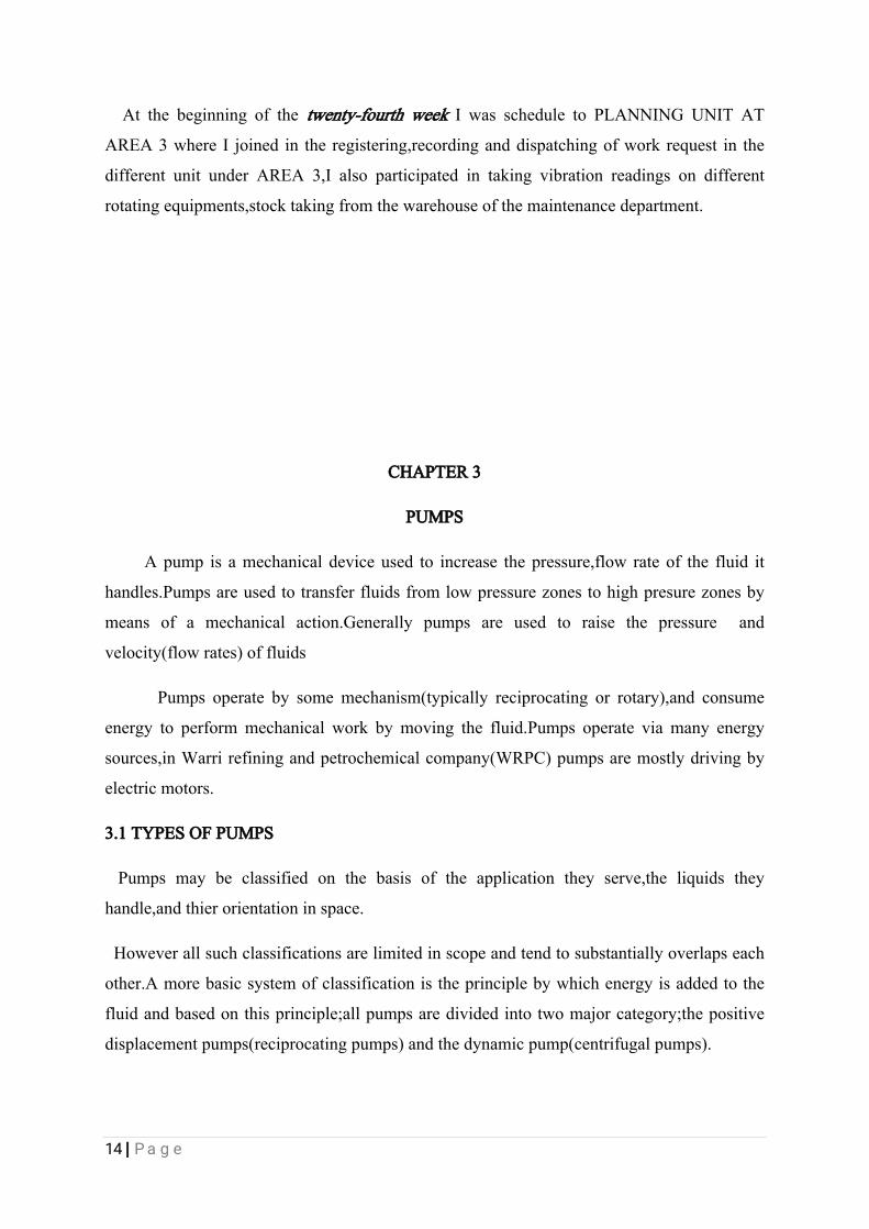
Howeverallsuchclassificationsarelimitedinscopeandtendtosubstantiallyoverlapseach
other.Amorebasicsystemofclassificationistheprinciplebywhichenergyisaddedtothe
fluidandbasedonthisprinciple;allpumpsaredividedintotwomajorcategory;thepositive
displacementpumps(reciprocatingpumps)andthedynamicpump(centrifugalpumps).
15|Page
Figure3.1classificationofpumps.
InWarrirefiningandpetrochemicalcompany(WRPC)themostcommonlyusedpumps
arethecentrifugalpumps.
3.2CENTRIFUGALPUMPS
Centrifugalpumpsisarotodynamicpumpthatusesarotatingimpellertoincreasesthe
pressureandflowrateofafluid.itsworkingprincipleissimple.
Attheheartofthesystemliestheimpeller.ithasaseriesofcurvedvanesfittedinto
shroudplates.Theimpellerisalwaysimmersedinwater,whentheimpellerismadetorotate,it
makesthefluidsurroundingitalsotorotateandthisimpartscentrifugalforcestothe
water(assumingthefluidtobewater)particles,andthewaterparticlestendstomoveradially
outwardsinalldirections.Infig.3.2athisprocessisillustrated.

16|Page
fig.3.2aTherotatingimpellerimpartsacentrifugalforcetothewaterparticlesandthe
watermovesradiallyout.
Sincetherotationalmechanicalenergyistransferredtothefluid,atthedischargedsideof
theimpeller,boththepressureandthekineticenergyofthewaterrises.Atthesuction
side,waterisgettingdisplaced,soanegativepressurewillbeinducedintheeyeofthe
impeller.suchlowpressurehelpstosuckfreshwaterintostreamintothesystemagain,and
thisprocesscontinues.
Fig.3.2bnegativepressurecreatedbydisplacementofwaterfromeyeoftheimpellerhelpsto
suckfreshsteamofwaterfromareservoir.
Fromforegoingdiscussionitisclearthat,thenegativepressureattheeyeoftheimpeller
helpstomaintaintheflowinthesystem.ifnowaterispresentinitially,thenegativepressure

17|Page
developedbytherotatingairattheimpellereyewillbenegligiblysmalltosuckfreshstream
ofwater.Asaresulttheimpellerwillrotatewithoutsuckinganddischarginganywater
content.sothepumpshouldbeinitiallyfilledwithwaterbeforestartingit.thisprocessis
knownaspriming.
Theimpellerisfittedinsideacasing.Asaresultthewaterthatmovesoutwillbecollected
insideit(casing),andwillmoveinthesamedirectionofrotationoftheimpellertothe
dischargenozzle.thisisshowninthefig3.11c
Figure.3.2c.Waterwhichleavestheimpellergetscollectedinsidethecasing,flowdirectionis
alsomarked
MostofthecentrifugalpumpsinWarrirefiningandpetrochemicalcompany(WRPC)are
runbyelectricmotors.BelowaresomeofthediagramscentrifugaltypepumpsinWarri
refiningandpetrochemicalcompany(WRPC)
18|Page
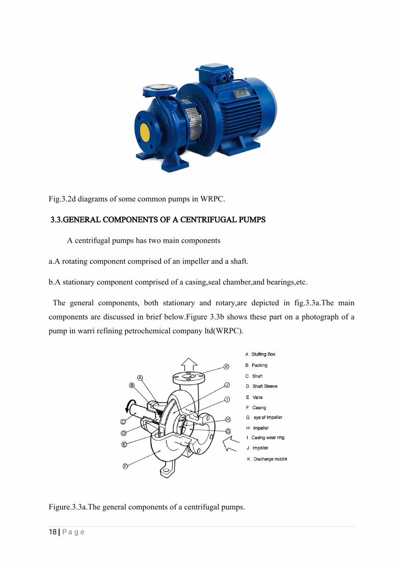
Fig.3.2ddiagramsofsomecommonpumpsinWRPC.
3.3.GENERALCOMPONENTSOFACENTRIFUGALPUMPS
Acentrifugalpumpshastwomaincomponents
a.Arotatingcomponentcomprisedofanimpellerandashaft.
b.Astationarycomponentcomprisedofacasing,sealchamber,andbearings,etc.
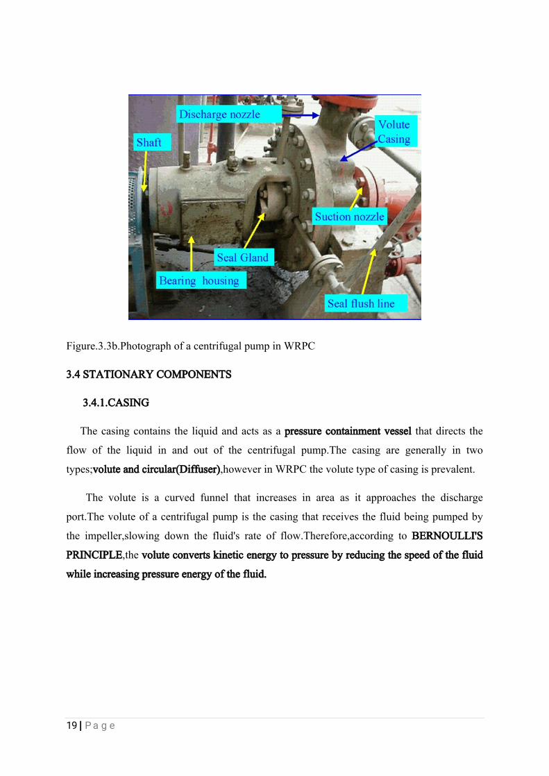
Thegeneralcomponents,bothstationaryandrotary,aredepictedinfig.3.3a.Themain
componentsarediscussedinbriefbelow.Figure3.3bshowsthesepartonaphotographofa
pumpinwarrirefiningpetrochemicalcompanyltd(WRPC).
Figure.3.3a.Thegeneralcomponentsofacentrifugalpumps.
19|Page
Figure.3.3b.PhotographofacentrifugalpumpinWRPC
3.4STATIONARYCOMPONENTS
3.4.1.CASING
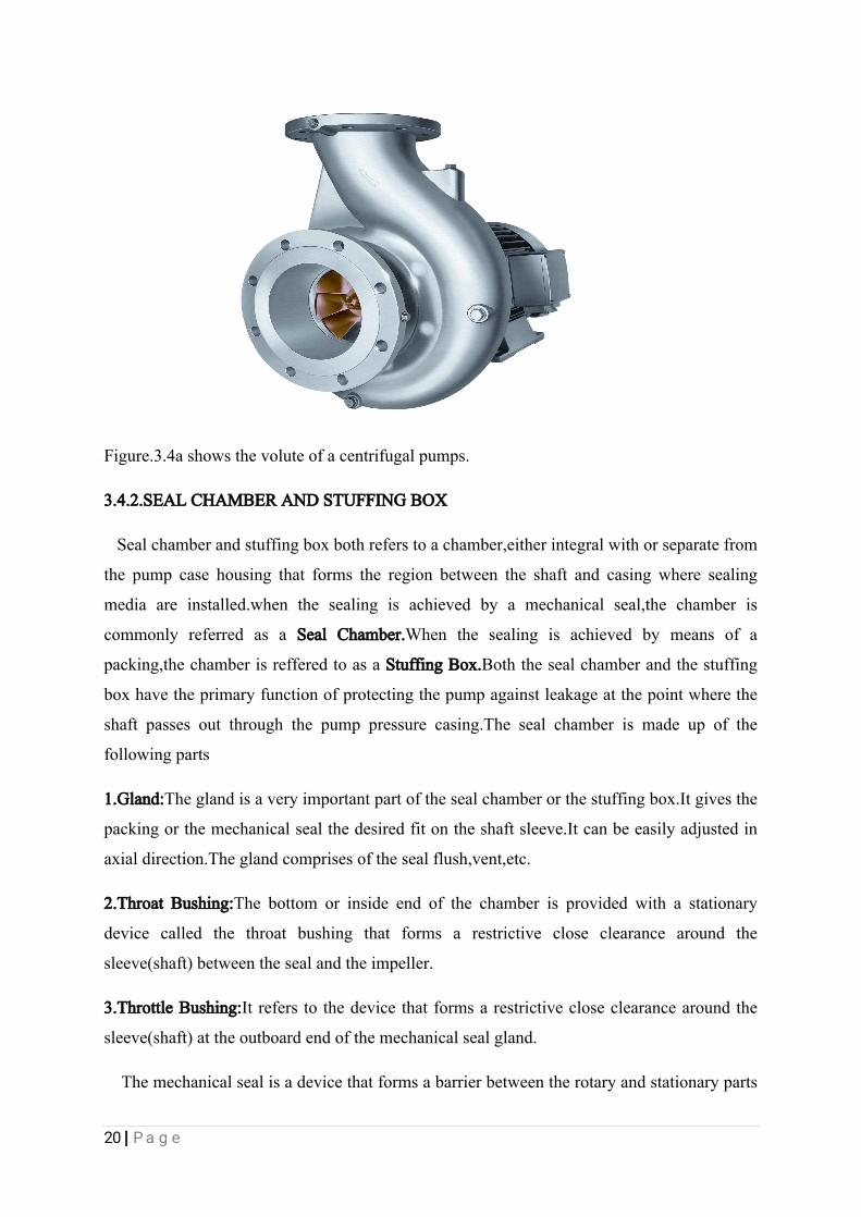
Thecasingcontainstheliquidandactsasapressurecontainmentvesselthatdirectsthe
flowoftheliquidinandoutofthecentrifugalpump.Thecasingaregenerallyintwo
types;voluteandcircular(Diffuser),howeverinWRPCthevolutetypeofcasingisprevalent.
Thevoluteisacurvedfunnelthatincreasesinareaasitapproachesthedischarge
port.Thevoluteofacentrifugalpumpisthecasingthatreceivesthefluidbeingpumpedby
theimpeller,slowingdownthefluid'srateofflow.Therefore,accordingtoBERNOULLI'S
PRINCIPLE,thevoluteconvertskineticenergytopressurebyreducingthespeedofthefluid
whileincreasingpressureenergyofthefluid.
20|Page
Figure.3.4ashowsthevoluteofacentrifugalpumps.
3.4.2.SEALCHAMBERANDSTUFFINGBOX
Sealchamberandstuffingboxbothreferstoachamber,eitherintegralwithorseparatefrom
thepumpcasehousingthatformstheregionbetweentheshaftandcasingwheresealing
mediaareinstalled.whenthesealingisachievedbyamechanicalseal,thechamberis
commonlyreferredasaSealChamber.Whenthesealingisachievedbymeansofa
packing,thechamberisrefferedtoasaStuffingBox.Boththesealchamberandthestuffing
boxhavetheprimaryfunctionofprotectingthepumpagainstleakageatthepointwherethe
shaftpassesoutthroughthepumppressurecasing.Thesealchamberismadeupofthe
followingparts
1.Gland:Theglandisaveryimportantpartofthesealchamberorthestuffingbox.Itgivesthe
packingorthemechanicalsealthedesiredfitontheshaftsleeve.Itcanbeeasilyadjustedin
axialdirection.Theglandcomprisesofthesealflush,vent,etc.
2.ThroatBushing:Thebottomorinsideendofthechamberisprovidedwithastationary
devicecalledthethroatbushingthatformsarestrictivecloseclearancearoundthe
sleeve(shaft)betweenthesealandtheimpeller.
3.ThrottleBushing:Itreferstothedevicethatformsarestrictivecloseclearancearoundthe
sleeve(shaft)attheoutboardendofthemechanicalsealgland.
Themechanicalsealisadevicethatformsabarrierbetweentherotaryandstationaryparts

21|Page
inthepumpandtopreventleakageofthefluid.
4.MechanicalSeal:Mechanicalsealhasbeendesigntoblockleakageatthreepoints.
i.Betweentherotatingandstationaryfaceoftheseal.
ii.Betweenthestationaryelementandthesealcamberhousingofthepump.
iiiBetweentherotaryelementandthesleeveofthepump.
Themechanicalsealhascomponentwhichincludes;sleeves,rotatingface,stationary
face,sleevesgasket,sealcage,sealpackingandcarbonrings.
Figure3.4bshowingthecomponentsofamechanicalseal.
3.4.3.BEARINGHOUSING:
Thebearinghousingenclosesthebearingsmountedontheshaft.Thebearingsisone
ofthepumpaccessoriesthataidsthepurerotationoftheshaftwithoutfriction,abearingisa
machineelementthatconstrainsrelativemotionbetweentherotatingparttothedesired
motion.Thedesignofabearingmayprovidelinearmovementofthemovingpartorforfree
rotationaroundafixedaxis.Theyaremainlytwotypesofbearingsmostlyusedina
centrifugalpumptheyare;thrustandballbearing.Thrustbearingsrestrictaxialmovementof
theshaftwhiletheballrestrictsradialmovementoftheshaft.

22|Page
Figure3.4cshowingtheexternalandinternalsurfacesofaballbearing.
3.5.ROTATINGCOMPONENTS:
3.5.1.IMPELLER:
Animpellerisarotatingcomponentsofacentrifugalpump,usuallymadeof
steel,iron,bronzeandbrass,whichtransfersenergyfromthemotorthatdrivesthepumptothe
fluidbeingpumpedbyacceleratingthefluidoutwardsfrom thecenterofrotation.The
velocityachievedbytheimpellertransferintopressurewhentheoutwardmovementofthe
fluidisconfinedbythepumpcasing(inthevolute).Impellersareusuallyshortcylinderswith
anopeninlet(calledtheeye)toacceptincomingfluid,vanestopushthefluidradially,anda
splined,key,orthreadedboretoacceptadriveshaft.Impellersareoftenclassifiedinmany
waystheseare,
Basedonmajordirectionoftheflowinreferencetotheaxisofrotation
1.Radialflowimpeller
2.Axialflowimpeller
3..mixedflowimpeller
Basedonsuctiontype
1.Singlesuction
2.Doublesuction
Basedonmechanicalconstruction

23|Page
1.closedimpeller
2.openimpeller
3.semi-openorvortextypeimpeller
InWRPCtheimpellerwewereintroducedtowastheonebasedonconstructioni.eclosed
impellersandopenimpellers.Thefigurebelowshowsthedifferenttypesofimpellersbased
onmechanicalconstruction
closedimpeller semi-openimpeller openimpeller.
Figure3.5.1.kindofimpellersusedincentrifugalpumps.
3.5.2.PUMPSHAFT:
Thepurposeofacentrifugalpumpshaftistotransmitthetorqueswhenstartingand
duringoperationwhilesupportingtheimpellerandotherrotatingparts.itmustdothisjob
withadeflectionlessthantheminimum clearancebetweentherotatingandstationary
components.
3.5.3.SHAFTSLEEVE:
Pumpshaftareusuallyprotectedfromerosion,corrosion,andatthesealchamber,leakage
joints,internalbearingsbysleeves.Theshaftsleeveactsasashieldfortheshaftassemblyin
pumps.Ashaftsleeveisahollowmetalcube,cylindricalinshape,whichismountedovera

24|Page
shaftandshaftassemblytoprotectitinacorrosiveenvironment.
Thebasicfunctionofashaftsleeveistoprotecttheshaftfrompackingwearatthe
stuffingbox,andalsoprotecttherunningsurfaceoftheshaftsealorthesurfacesincontact
fromdamageorabrasivewear.Thehardnessofthematerialusedtoconstructtheshaftmust
besufficient;otherwiseitmaycauseashaftsleevetofail.
Thethermalexpansionofmustbeconsideredwhendesigningashaftsleeve.Inideal
conditions,theshaftcoefficientofthermalexpansionshouldbeequaltothatoftheshaft
sleeve.
Figure3.5.3showingdifferentstypesofshaftsleeves.
3.6.PUMPANDMOTORSHAFTALIGNMENT:
Shaftalignment,oftencalledcouplingalignmentisaprocesstomaketwoormore
rotatingshaftsco-linear,orinthesamestraightline,bothverticallyandhorizontally.
Whenadriverliketheelectricmotoriscoupledtothepump,itisessentialthattheshafts
ofthemotorandthepumpmustbealigned,anymisalignmentbetweenthetwoshafts
increasesthestressontheshaftsandwillalsocertainlyresultinexcessivewearand
prematurebreakdownoftheequipment,bearingsandmechanicalsealscanalsobedamaged.
Theimplicationofapumpexhibitingrotaryunbalanceincludes;
1.Excessiverunningnoise.
2.Vibrationandexcessiveloadsonthebearingscausingprematurefailureofthebearing.
25|Page
3.Rapidwearonthecouplingsandeventuallyprematurefailure.
4.Prematurepackingofsealfailure.
5.Wearsandrubbingbetweenclosetolerancesrotaryandstationaryelementinthepump
leadstotheirfailure.
6.Prematuredriverbearingfailure.
3.7TYPESOFMISALIGNMENT:
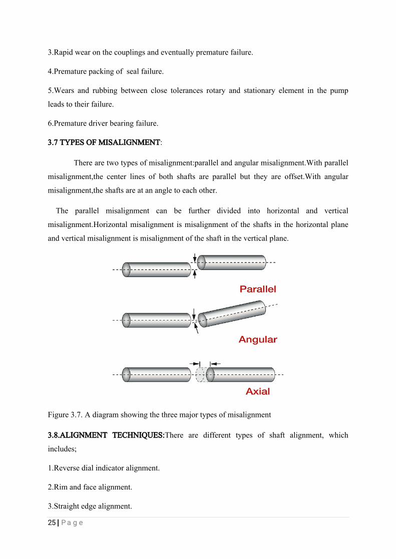
Therearetwotypesofmisalignment:parallelandangularmisalignment.Withparallel
misalignment,thecenterlinesofbothshaftsareparallelbuttheyareoffset.Withangular
misalignment,theshaftsareatanangletoeachother.
The parallelmisalignmentcan be furtherdivided into horizontaland vertical
misalignment.Horizontalmisalignmentismisalignmentoftheshaftsinthehorizontalplane
andverticalmisalignmentismisalignmentoftheshaftintheverticalplane.
Figure3.7.Adiagramshowingthethreemajortypesofmisalignment
3.8.ALIGNMENTTECHNIQUES:Therearedifferenttypesofshaftalignment,which
includes;
1.Reversedialindicatoralignment.
2.Rimandfacealignment.
3.Straightedgealignment.

26|Page
4.Laseralignment.
OnlythelaserandreversedialindicatoralignmentareusedinWRPC.
3.8.1.REVERSEDDIALINDICATORALIGNMENT:Thismethodusestwodialindicators
oneonthepumpandtheotheronthemotorshaft.Sometimesthetwoindicatorsaremounted
inthecouplings,astheshaftisbeenrotatedtheindicatordeflectsshowingtheadjustment
required.Whentheindicatorsareatthe9’oclockand3’oclockposition,itreadsthe
horizontalmisalignmentandwhentheindicatorsareatthe12’oclockand6’oclockposition
itreadstheverticalmisalignment.
Figure3.8.1Adiagramdepictingthepositionofthedialindicatorsontheshafts.
Thefigureaboveshowsthedialindicatorsmountedontheshaftsofthepumpsandmotors
3.8.2..LASERALIGNMENT:Alaseralignmentsystemusesatransmitter(onethatemitsa
laser)andreceiver.Thetransmitterofthelaserisinstalledonthepumpshaft,Duringoperation
thelaseremitalowintensitybeam,thebeamisdetectedbyadevicecallthereceivera
detectorwhichismountedonthemotorshaft.Astheshaftarerotatedduringthe
alignment,thebeamwillhitthecircularfaceofthereceiveratdifferentpoint,thelocationof
beamonthereceiverisrelatedtothemisalignmentbetweenthetwoshafts.Thereceiveris
connectedtoadisplaycomputer,thecomputerusestheinformationreceivesfromthereceiver
tocalculatehowmuchmisalignmentexistandhowtocorrectthemisalignment.Shimsare
insertedtocorrectthegapindicatedbythealignmenttester.Ifthetwocoupledshaftare
perfectlyalignedthentheyaresaidtobeco-linearwhichmeansthatasinglestraightlinewill
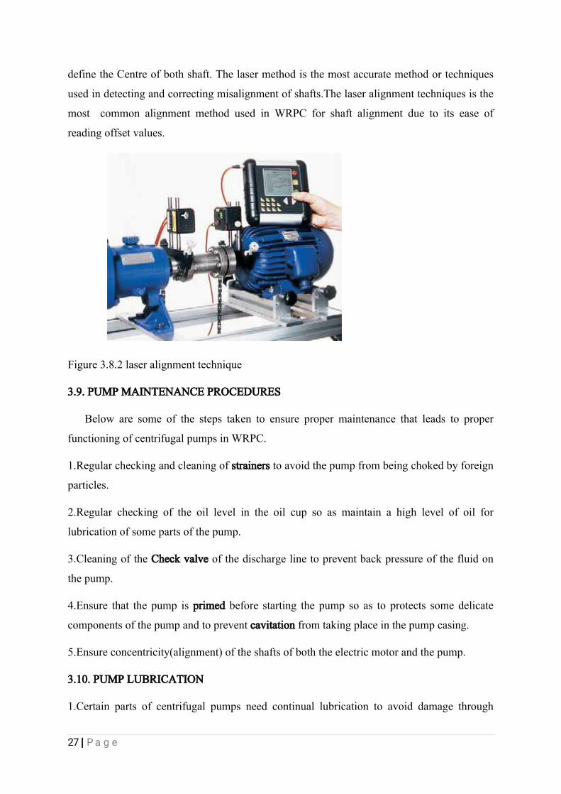
27|Page
definetheCentreofbothshaft.Thelasermethodisthemostaccuratemethodortechniques
usedindetectingandcorrectingmisalignmentofshafts.Thelaseralignmenttechniquesisthe
mostcommonalignmentmethodusedinWRPCforshaftalignmentduetoitseaseof
readingoffsetvalues.
Figure3.8.2laseralignmenttechnique
3.9.PUMPMAINTENANCEPROCEDURES
Belowaresomeofthestepstakentoensurepropermaintenancethatleadstoproper
functioningofcentrifugalpumpsinWRPC.
1.Regularcheckingandcleaningofstrainerstoavoidthepumpfrombeingchokedbyforeign
particles.
2.Regularcheckingoftheoillevelintheoilcupsoasmaintainahighlevelofoilfor
lubricationofsomepartsofthepump.
3.CleaningoftheCheckvalveofthedischargelinetopreventbackpressureofthefluidon
thepump.
4.Ensurethatthepumpisprimedbeforestartingthepumpsoastoprotectssomedelicate
componentsofthepumpandtopreventcavitationfromtakingplaceinthepumpcasing.
5.Ensureconcentricity(alignment)oftheshaftsofboththeelectricmotorandthepump.
3.10.PUMPLUBRICATION
1.Certainpartsofcentrifugalpumpsneedcontinuallubricationtoavoiddamagethrough
28|Page
overheatingandwear.Thewearringsarelubricatedduringnormaloperationbythefluidthat
isbeingpumped.Ifthepumprunsdry,seriousproblemswilloccur,suchasthewearrings
canseizeup
2.Pumpstuffingboxesmustbecontinuallylubricated.Normallythefluidfromthepump
lubricatesthem.Thefluidisallowedtoleakslightlythroughthepackingrings.Ifcorrosiveor
hazardousliquidsarebeingpumped,thenthepackingmustbelubricatedexternally.Thisis
donethroughthelanternring,whichissupplied,withoilfromoutsidethepump
3.Greasecupsinsteadofoillubricatesomestuffingboxes.Thepumpshaftmustrotatefreely,
withaslittlefrictionaspossible
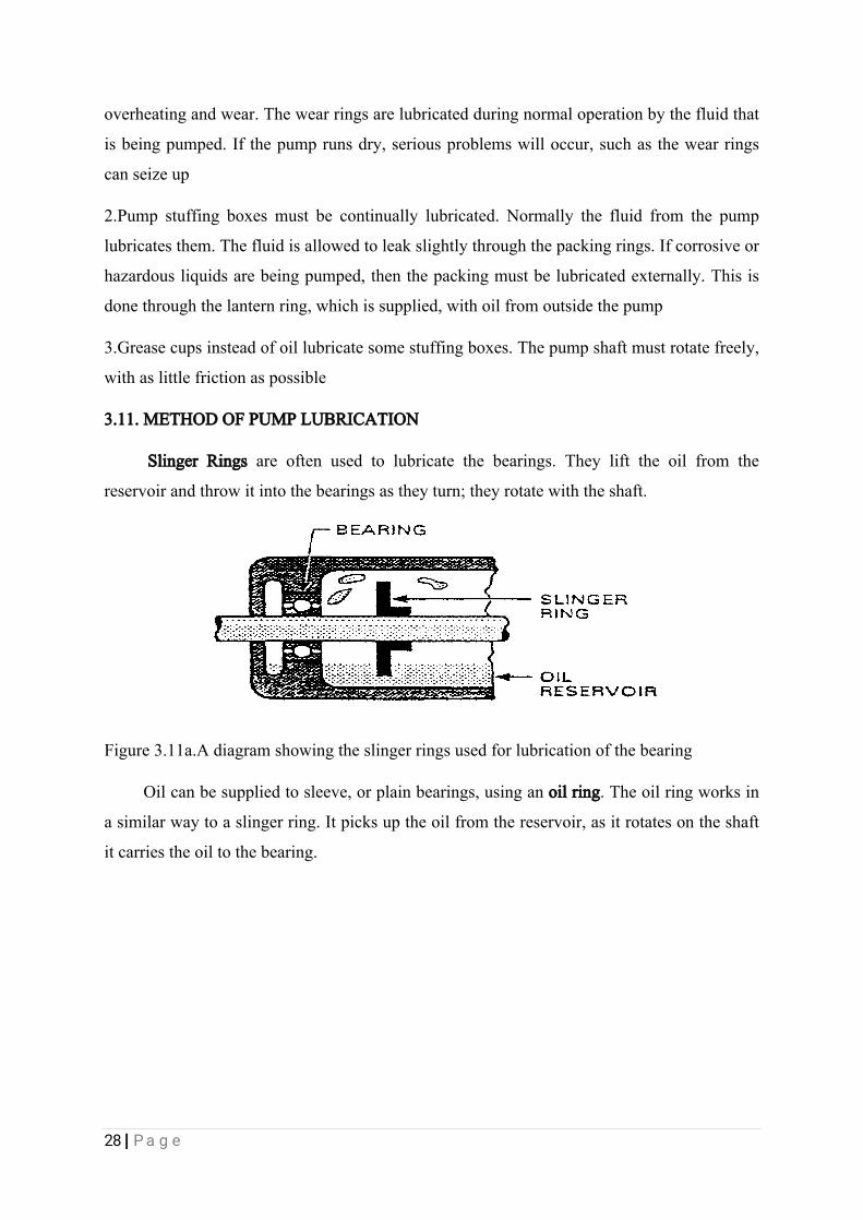
3.11.METHODOFPUMPLUBRICATION
SlingerRingsareoftenusedtolubricatethebearings.Theylifttheoilfromthe
reservoirandthrowitintothebearingsastheyturn;theyrotatewiththeshaft.
Figure3.11a.Adiagramshowingtheslingerringsusedforlubricationofthebearing
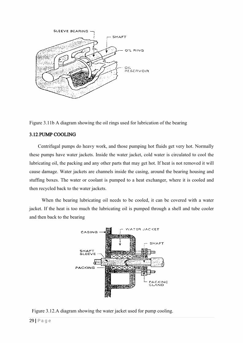
Oilcanbesuppliedtosleeve,orplainbearings,usinganoilring.Theoilringworksin
asimilarwaytoaslingerring.Itpicksuptheoilfromthereservoir,asitrotatesontheshaft
itcarriestheoiltothebearing.
29|Page
Figure3.11bAdiagramshowingtheoilringsusedforlubricationofthebearing
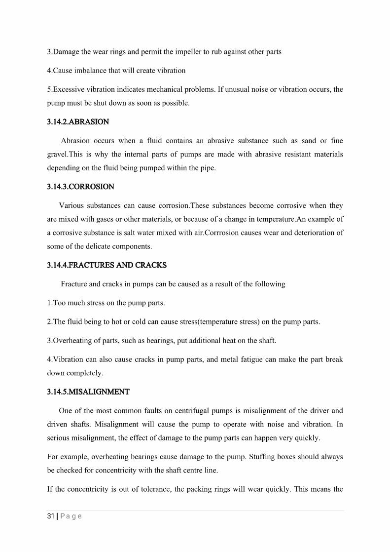
3.12.PUMPCOOLING
Centrifugalpumpsdoheavywork,andthosepumpinghotfluidsgetveryhot.Normally
thesepumpshavewaterjackets.Insidethewaterjacket,coldwateriscirculatedtocoolthe
lubricatingoil,thepackingandanyotherpartsthatmaygethot.Ifheatisnotremoveditwill
causedamage.Waterjacketsarechannelsinsidethecasing,aroundthebearinghousingand
stuffingboxes.Thewaterorcoolantispumpedtoaheatexchanger,whereitiscooledand
thenrecycledbacktothewaterjackets.
Whenthebearinglubricatingoilneedstobecooled,itcanbecoveredwithawater
jacket.Iftheheatistoomuchthelubricatingoilispumpedthroughashellandtubecooler
andthenbacktothebearing
Figure3.12.Adiagramshowingthewaterjacketusedforpumpcooling.

30|Page
3.13.CAVITATIONINCENTRIFUGALPUMP
Theformationofvapourbubbleswithinaliquidatlow-pressureregionsthatoccurin
placeswheretheliquidhasbeenacceleratedtohighvelocities,asintheoperationof
centrifugalpumps,waterturbines,andmarinepropellers.
Cavitationisundesirablebecauseitproducesextensiveerosionoftherotatingimpeller,
additionalnoisefromtheresultantknockingandvibrations,andasignificantreductionof
efficiencybecauseitdistortstheflowpattern.
Thecavitiesformwhenthepressureoftheliquidhasbeenreducedtoitsvapourpressure;
theyexpandasthepressureisfurtherreducedalongwiththeflowandsuddenlycollapse
whentheyreachregionsofhigherpressure.Thesuddengrowthandcollapseofthesevapour
cavitiescausetheextremepressuresthatpitthemetalsurfacesexposedtothecavitating
liquid.
3.14.COMMONCENTRIFUGALPUMPSPROBLEMSINWRPC
Therearemanycommonproblemsthatoccurincentrifugalpumpoperation.Othersare
foundduringroutineorplannedmaintenanceorthroughbadassemblyworkafterwards.
FiveCommononesare:
1.Alignmentandvibration
2.Abrasion
3.Corrosion
4.Fracturesandcracks
5.Misalignment
3.14.1.ALIGNMENTANDVIBRATION
Acentrifugalpumpandprimemoverarejoinedtogetherbycouplings.Whentheyare
joinedtogethertheymustbealignedcorrectly.Ifthepumpishandlinghotfluids,thenthe
pumpshouldbeheatedtonearoperatingtemperaturebeforecheckingalignment.Improper
alignmentofthepumpandprimemovercan:
1.Putastrainontheshaft,causingtheshaftandthecouplingtowearorbreak
2.Causethebearingsandsealstowearoutquickly
31|Page
3.Damagethewearringsandpermittheimpellertorubagainstotherparts
4.Causeimbalancethatwillcreatevibration
5.Excessivevibrationindicatesmechanicalproblems.Ifunusualnoiseorvibrationoccurs,the
pumpmustbeshutdownassoonaspossible.
3.14.2.ABRASION
Abrasionoccurswhenafluidcontainsanabrasivesubstancesuchassandorfine
gravel.Thisiswhytheinternalpartsofpumpsaremadewithabrasiveresistantmaterials
dependingonthefluidbeingpumpedwithinthepipe.
3.14.3.CORROSION
Varioussubstancescancausecorrosion.Thesesubstancesbecomecorrosivewhenthey
aremixedwithgasesorothermaterials,orbecauseofachangeintemperature.Anexampleof
acorrosivesubstanceissaltwatermixedwithair.Corrrosioncauseswearanddeteriorationof
someofthedelicatecomponents.
3.14.4.FRACTURESANDCRACKS
Fractureandcracksinpumpscanbecausedasaresultofthefollowing
1.Toomuchstressonthepumpparts.
2.Thefluidbeingtohotorcoldcancausestress(temperaturestress)onthepumpparts.
3.Overheatingofparts,suchasbearings,putadditionalheatontheshaft.
4.Vibrationcanalsocausecracksinpumpparts,andmetalfatiguecanmakethepartbreak
downcompletely.
3.14.5.MISALIGNMENT
Oneofthemostcommonfaultsoncentrifugalpumpsismisalignmentofthedriverand
drivenshafts.Misalignmentwillcausethepumptooperatewithnoiseandvibration.In
seriousmisalignment,theeffectofdamagetothepumppartscanhappenveryquickly.
Forexample,overheatingbearingscausedamagetothepump.Stuffingboxesshouldalways
becheckedforconcentricitywiththeshaftcentreline.
Iftheconcentricityisoutoftolerance,thepackingringswillwearquickly.Thismeansthe
32|Page
pumpwillhavenoeffectivesealingdevice.
Thiscausesotherproblemssuchasfluidleakingfromthepumporairgettingintothepump.
Ifamechanicalsealisusedasthesealingdevice,thesealfaceswillbedamagedifthe
stuffingboxisnotconcentric.
3.15.REMOVALOFPUMPFORINSPECTIONANDMAINTENANCE
Thefollowingaresomestepsinvolvedinremovingafittedpumpformaintenance;
1.Isolatepumpelectricalcircuitbreakeronmainswitchboardandattachawarningnotice.
(DoNotOperate-MenatWork).
2.Switchoffandlockpumpssupplyatitslocalsupplypanel.Attachawarningnoticeto
pumplocalsupplypanel.
3.Closesuctionanddischargevalves.
4.Openpumpsuctionanddischargepipedrainvalvestobilgeandwhenproductceasesto
flow;crackopenthepipes/pumpflangejointscarefullytoensurethatpumphasdrainedoff
andissafeforopening.
5.Useacenter-punchtomatch/markcouplingandcasing,thenremovesthecouplingbolts
6.Disconnect,fixi/dtagandremovemotorsupplycables;tapingoverbareendswith
insulatingtape.
8.Disconnectallexternalfittingsfrompumpcasinge.g.coolingpipe,pressuregauge,oil
reservoirsandaircock.
9.Removeboltingfromtopcoverandremovecover.Scrapeoffoldgasketandcheckmating
surfaces,andrenewgasketonassembly.(Lightsmearofgreaseongasket/faces).
10.Thepumpshaftwithimpellercanbeliftedoutofcasing.
11.Dismantletheimpeller,andremovethewearring.
12.Removetheglandpackingforinspection
3.16. COMPRESSORS

33|Page
Acompressorisamechanicaldevicelikeapumpthatisusedtoincreasethe
velocityandkineticenergyofafluidandthenconvertsthekineticofthefluidtopressure
energy.Thecompressorsdiffersfrom apumpinthatcompressorsareusuallyusedfor
increasingthepressure,velocityandkineticenergyofgasesspecifically(accordingtothe
assumptiononthemoleculartheoryofmatterthatliquidsarenearlyincompressible.).while
pumps areusuallyusedforincreasingthepressure,velocityandkineticofliquids
specifically.Therearetwomaintypesofcompressorsthesearethedynamiccompressorsand
positivedisplacementcompressors.Themostcommontypeof positivedisplacement
compressoristhereciprocatingcompressorandthemostcommontypeofdynamic
compressorsisthecentrifugalcompressors.
ThecentrifugalcompressorsIworkedonatWRPCarenormallypurchasedasacompressor
package,thatistherearemadeupofacompressorandseveralothercomponents.Atypical
compressorpackageatWRPC(AREA1,COMPESSORUNIT.)ismadeupofacompressor,a
driverorapowersource,gearboxandcouplingswhichareusedtoconnectsthese
componentstogether,andalsoasealoilsystemandalubeoilsystemwhichcaneasilybe
identifiedbythemeansofsmallerpippingssurroundingthecompressorpackage,sometimesa
gascoolingsystemisalsopartoftheoverallpackage.
Thecompressoristhemosteasyandidentifiablepartofthecompressorpackagebecause
ofislargecasing.Thecasingiswheretheinternalpartofthecompressorarehousedandis
alsowherethegasiscompressed.Insidethecasingaretwospecialgaspassagesthatformsthe
stationarypartsofthecompressor,thesearetheinletguideandthediffuserordischarged
volute.Therotatingpartofthecompressorsiscalledtherotorassembly.Therotorassembly
consistofashaftwithoneormoreimpellersmountedontheshaft,astherotorassembly
rotateeachimpellerdeliversenergytothegascomingfrom thesuctionline.Therotor
assemblyshaftissupportedbybearingswhichpreventstheaxialandradialmovementofthe
shaft.
3.17.CENTRIFUGALCOMPRESSORS:
CentrifugalcompressorworksonBernoulli’sprinciple,accordingtowhich,thetotal
mechanicalenergyofaflowingfluid,comprisingtheenergyassociatedwithfluidpressure,the
gravitationalpotentialenergyofelevation,andthekineticenergyothefluidmotion,remains
constant.So,ifthepotentialenergyiskeptconstant,thendecreaseinkineticenergywillresult
inacorrespondingincreaseifpressureandviceversa.

34|Page
Inacentrifugalcompressoradditionalkineticenergyisimpartedtothefluidwiththehelp
ofarotatingcomponentcalledtheimpeller.Herefluid(gas)enterstheprimarysuctioneyeof
theimpeller,whichconsistofradialvanescastinit.Astheimpellerstartsrotating,theblades
ontheimpellerpushesthegasoutwards.Inthistravel,thevelocityoftheimpellerisimparted
tothegasandhence,itskineticenergyincreases.Nextthegasfromthepheripheryofthe
impellerisguidedthroughapassagecalleddiffuser,wherethevelocity,hencekineticenergy
isdecreased.Thisresultinincreaseofpressureenergyofthefluid.Sobasicallyitworksonthe
principle of conversation of kinetic energy into pressure energy.
Figure3.17.showingtheoperationofacentrifugalcompressor
3.18.MAJORCOMPONENTSOFACOMPRESSOR
3.18.1.CASING
Thecasingorhousingisthepressurecontainingcomponentsofthecompressor.Thecase
housesthestationaryinternalcomponentsandthecompressorrotor.Bearingsareattachedto
thecasetoprovidebothradialandaxialsupportoftherotor.Thecasealsocontainsnozzles
withinletanddischargeflangeconnectionstointroduceflowintoandextractflowfromthe
compressor.Theflangeconnectionmustbeproperlysizedtolimitthegasvelocityas
necessary.Thecaseismanufacturedinoneofthetwobasictypes,thesearethehorizontally
splitcaseandtheverticallysplitcase
1.HORINZONTALLY(AXIALLY)SPLITCASE.
Ahorinzontallysplitcaseissplitparalleltotheaxisoftherotor.Theupperhalfofthecase
isboltedanddoweledtothelowerhalf.Accesstotheinternalcomponentsforinspectionand
35|Page
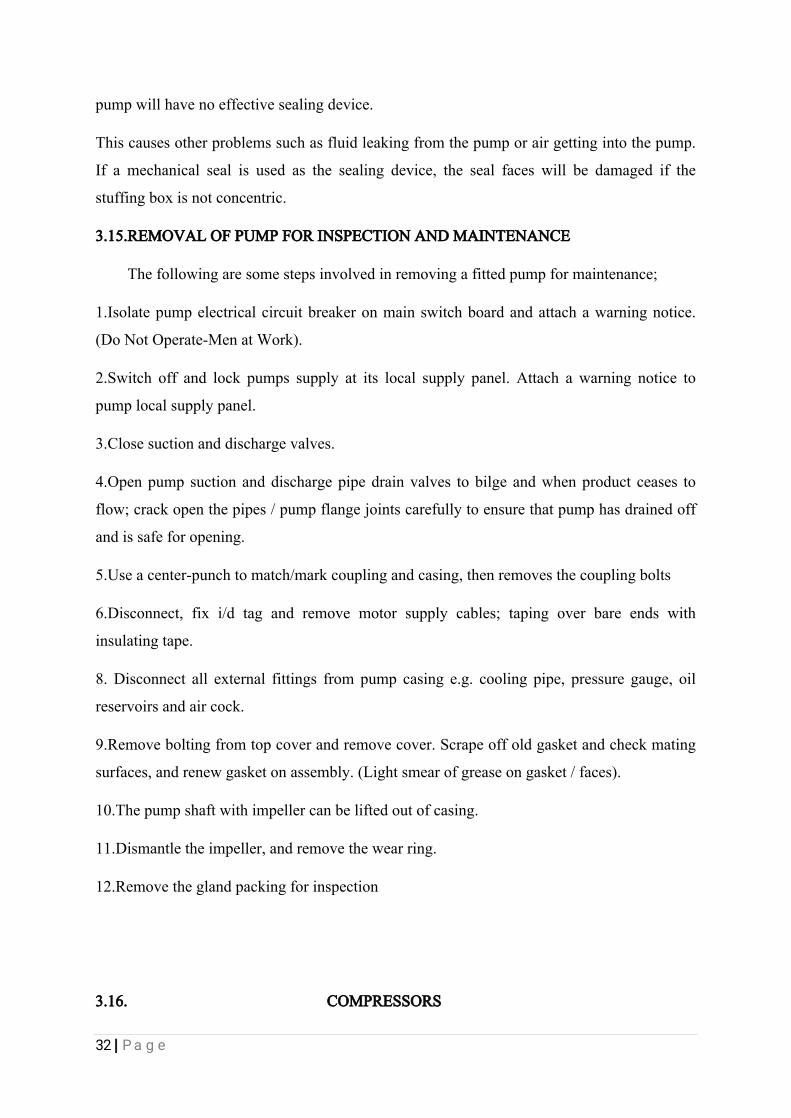
maintenanceisfacilitatedwiththiscasedesign.Thehorizontallysplitdesignisinherently
pressure-limitedtopreventgasleakageatthecasejoint.
Themainadvantageofhorizontallysplitcaseisthatitcanbeopenedup,sothattheinternal
partscanbeseen,withoutdisturbingittoomuch.
Figure.3.18ashowingthehorizontallysplitcasing
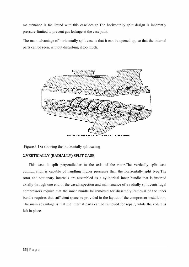
2.VERTICALLY(RADIALLY)SPLITCASE.
Thiscaseissplitperpendiculartotheaxisoftherotor.Theverticallysplitcase
configurationiscapableofhandlinghigherpressuresthanthehorizontallysplittype.The
rotorandstationaryinternalsareassembledasacylindricalinnerbundlethatisinserted
axiallythroughoneendofthecase.Inspectionandmaintenanceofaradiallysplitcentrifugal
compressorsrequirethattheinnerbundleberemovedfordissambly.Removaloftheinner
bundlerequiresthatsufficientspacebeprovidedinthelayoutofthecompressorinstallation.
Themainadvantageisthattheinternalpartscanberemovedforrepair,whilethevoluteis
leftinplace.
36|Page
Figure.3.18bshowingtheverticallysplitcasing
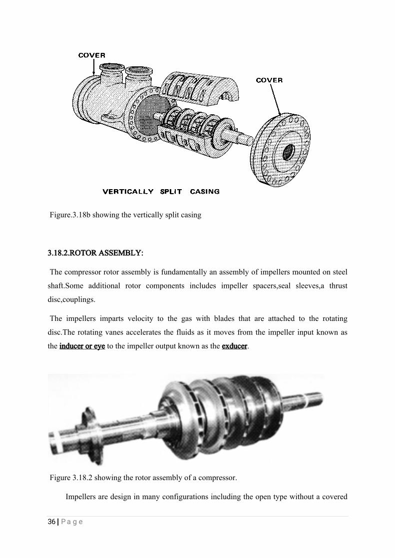
3.18.2.ROTORASSEMBLY:
Thecompressorrotorassemblyisfundamentallyanassemblyofimpellersmountedonsteel
shaft.Someadditionalrotorcomponentsincludesimpellerspacers,sealsleeves,athrust
disc,couplings.
Theimpellersimpartsvelocitytothegaswithbladesthatareattachedtotherotating
disc.Therotatingvanesacceleratesthefluidsasitmovesfromtheimpellerinputknownas
theinduceroreyetotheimpelleroutputknownastheexducer.
Figure3.18.2showingtherotorassemblyofacompressor.
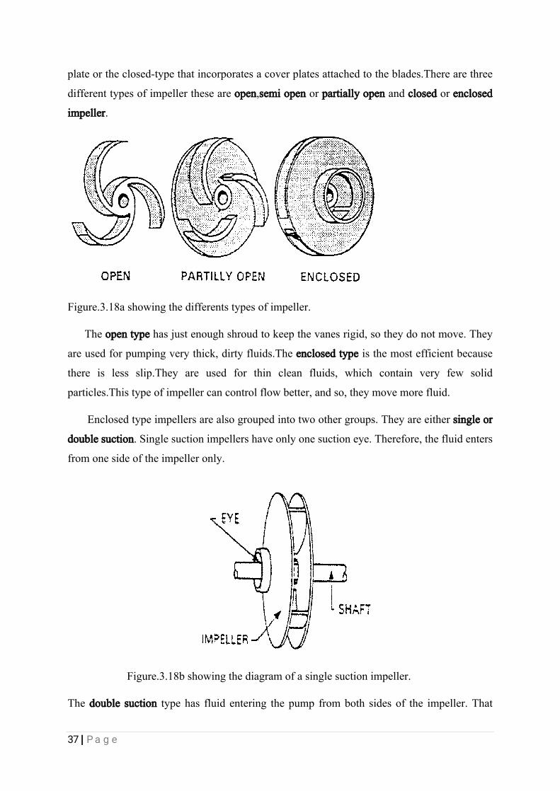
Impellersaredesigninmanyconfigurationsincludingtheopentypewithoutacovered
37|Page
plateortheclosed-typethatincorporatesacoverplatesattachedtotheblades.Therearethree
differenttypesofimpellertheseareopen,semiopenorpartiallyopenandclosedorenclosed
impeller.
Figure.3.18ashowingthedifferentstypesofimpeller.
Theopentypehasjustenoughshroudtokeepthevanesrigid,sotheydonotmove.They
areusedforpumpingverythick,dirtyfluids.Theenclosedtypeisthemostefficientbecause
thereislessslip.Theyareusedforthincleanfluids,whichcontainveryfew solid
particles.Thistypeofimpellercancontrolflowbetter,andso,theymovemorefluid.
Enclosedtypeimpellersarealsogroupedintotwoothergroups.Theyareeithersingleor
doublesuction.Singlesuctionimpellershaveonlyonesuctioneye.Therefore,thefluidenters
fromonesideoftheimpelleronly.
Figure.3.18bshowingthediagramofasinglesuctionimpeller.
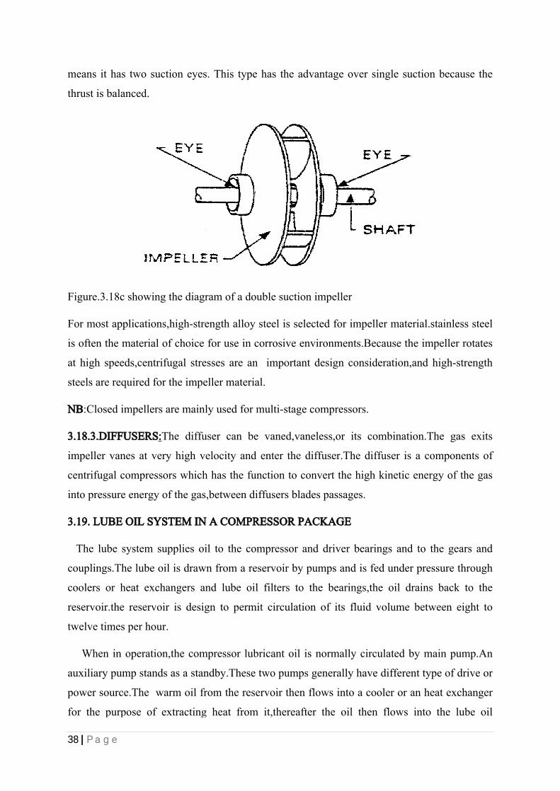
Thedoublesuctiontypehasfluidenteringthepumpfrombothsidesoftheimpeller.That
38|Page
meansithastwosuctioneyes.Thistypehastheadvantageoversinglesuctionbecausethe
thrustisbalanced.
Figure.3.18cshowingthediagramofadoublesuctionimpeller
Formostapplications,high-strengthalloysteelisselectedforimpellermaterial.stainlesssteel
isoftenthematerialofchoiceforuseincorrosiveenvironments.Becausetheimpellerrotates
athighspeeds,centrifugalstressesareanimportantdesignconsideration,andhigh-strength
steelsarerequiredfortheimpellermaterial.
NB:Closedimpellersaremainlyusedformulti-stagecompressors.
3.18.3.DIFFUSERS:Thediffusercanbevaned,vaneless,oritscombination.Thegasexits
impellervanesatveryhighvelocityandenterthediffuser.Thediffuserisacomponentsof
centrifugalcompressorswhichhasthefunctiontoconvertthehighkineticenergyofthegas
intopressureenergyofthegas,betweendiffusersbladespassages.
3.19.LUBEOILSYSTEMINACOMPRESSORPACKAGE
Thelubesystemsuppliesoiltothecompressoranddriverbearingsandtothegearsand
couplings.Thelubeoilisdrawnfromareservoirbypumpsandisfedunderpressurethrough
coolersorheatexchangersandlubeoilfilterstothebearings,theoildrainsbacktothe
reservoir.thereservoirisdesigntopermitcirculationofitsfluidvolumebetweeneightto
twelvetimesperhour.
Wheninoperation,thecompressorlubricantoilisnormallycirculatedbymainpump.An
auxiliarypumpstandsasastandby.Thesetwopumpsgenerallyhavedifferenttypeofdriveor
powersource.Thewarmoilfromthereservoirthenflowsintoacooleroranheatexchanger
forthepurposeofextractingheatfromit,thereaftertheoilthenflowsintothelubeoil
39|Page
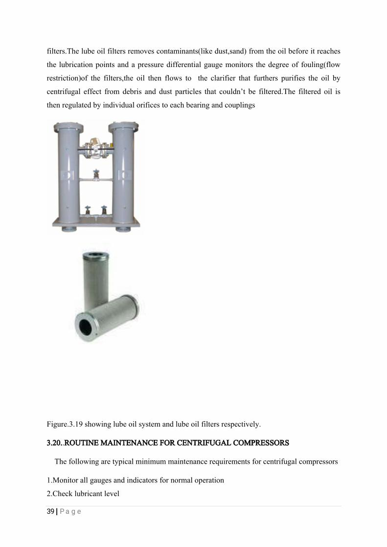
filters.Thelubeoilfiltersremovescontaminants(likedust,sand)fromtheoilbeforeitreaches
thelubricationpointsandapressuredifferentialgaugemonitorsthedegreeoffouling(flow
restriction)ofthefilters,theoilthenflowsto theclarifierthatfurtherspurifiestheoilby
centrifugaleffectfromdebrisanddustparticlesthatcouldn’tbefiltered.Thefilteredoilis
thenregulatedbyindividualorificestoeachbearingandcouplings
Figure.3.19showinglubeoilsystemandlubeoilfiltersrespectively.
3.20..ROUTINEMAINTENANCEFORCENTRIFUGALCOMPRESSORS
Thefollowingaretypicalminimummaintenancerequirementsforcentrifugalcompressors
1.Monitorallgaugesandindicatorsfornormaloperation
2.Checklubricantlevel
40|Page
3.Checkforlubricantleaks
4.Checkforunusualnoiseorvibration
5.Drainwaterfromlubricantreservoir
6.Checksafetyvalveoperation
7.Serviceairfilterasneeded
8.Checkoperationofallcontrols
9.Checkoperationoflubricantreturnsystem
10.Gooverunitandcheckallboltsfortightness
11.Changeairfilter
3.21. BLOWERS.
Industrialblowersaremachineswhoseprimaryfunctionistotransportalargevolumeof
airwithoutnecessitybeinglaidhavingahighincreaseofthepressureoftheair.Therearetwo
majorcompressors.Thisblowersismadeupofimpellersmountedonashaftthatisconnected
toatypesofblowers;centrifugalandpositivedisplacementblowers.
3.22.CENTRIFUGALBLOWERS
Thecentrifugalblowersworksinsimilarmannertothecentrifugalpumpsand
driver(electricmotor)supportedbybearingsateachendoftheshaft.
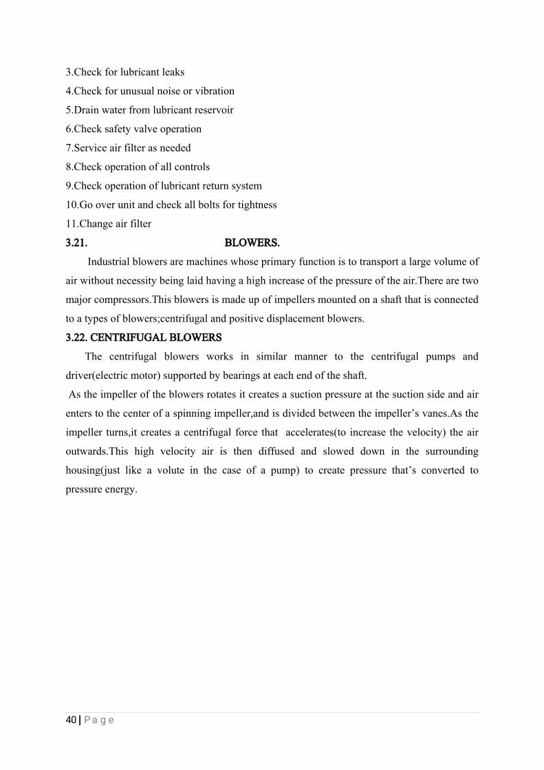
Astheimpelleroftheblowersrotatesitcreatesasuctionpressureatthesuctionsideandair
enterstothecenterofaspinningimpeller,andisdividedbetweentheimpeller’svanes.Asthe
impellerturns,itcreatesacentrifugalforcethataccelerates(toincreasethevelocity)theair
outwards.Thishighvelocityairisthendiffusedandsloweddowninthesurrounding
housing(justlikeavoluteinthecaseofapump)tocreatepressurethat’sconvertedto
pressureenergy.
41|Page
Figure.3.22showingthediagramofacentrifugalblower.
InWRPCcentrifugalblowersarecommonlyusecomparedtothepositivedisplacement
blower.
3.23.APPLICATIONOFBLOWERSINWRPC
1.Conveyingcombustionairforburnersandindustrialwaterheater
2.Conveyingcombustionairforheaters
3.Transportingsteamproducefrompowerplantunittoallindustrialprocessrequirement.
4.Coolingelectricalandmechanicalequipmentorpartsfromoverheating.
5.Pressurizingcabinetandrooms.
6.Generalventilationofroomsorfactories
7.Blow-offsystemstoremovemoisturefrompartspriortopaintingandcoating.
BelowaresomeofthestepsrequiredformaintainingcentrifugalblowersinWRPCto
preventitfromlongperiodofrepairsanddowntimes
i.Thebeltdrivemustbevisuallyinspectedafter24hoursofoperation.Afterwardsitshouldbe
checkedeverythreemonths.Thebeltshouldalsobeprotectedagainstdrippingoilandother
chemicals.Permanentexposuretothisfluidcausesearlywearofbelts.
ii.Apartfromtheregularvisualinspection(atleastonceayear)theimpellermustbecleaned
wheneveritisdirty.Thecleaningintervaldependsonthefluidconveyed.
iii.Whencleaningthebearinghousing,completelyremoveoldgrease,possiblycleanthe
bearingandfillwithnewgrease.

42|Page
3.24.AIRCOOLERS.
IndustrialaircoolersWRPCplaysvitalroleincoolingtransportedliquidproductsbefore
therearestoredinstoragetanks.Usuallytheproductsproducefromsomeareas(unit)inthe
companyareataveryhightemperatureatsuchifstoredwithoutcoolingitmaycause
explosioninthestoragetanks.
Aircoolersaredevicesthatextractsheatfrom aflowinghotsubstancesandthen
cools(reducesthetemperature)itbythehelpsofrotatingblades.
3.25.COMPONENTSOFANAIRCOOLER.
Themajorcomponentsofanaircoolerare
1Aircoolerunit
2.ElectricMotor
3.V-belts
4.AluminiumFins
5.blades
6.Wheel.
Theelectricmotorprovidesthetorqueneededtodrivetheaircoolerunit.Av-beltsisuseto
transferthetorquegeneratedbytheelectricmotorbyconnectingthev-beltsfromtheshaftof
theelectricmotortothewheeloftheaircoolerunit.Thewheeloftheaircoolerismountedon
theaircoolershaft.Soasthewheelrotatesitalsocausestheshaftoftheaircoolertorotates
therebymakingthebladeswhicharecoupledtotheshaftoftheaircoolerto
rotates.Aluminiumfinsbeing ahighconductivematerialthanthepipeusuallymadeof
carbonmaterialsfinsarewoundedroundthepipesthatcarriesthehotfluidsoastoextract
theheatfromtheliquidthroughconvectionthereafter.Thebladesoftheaircoolerthenblows
theextractedheatawayfromthesurroundingoftheaircooler.

43|Page
Figure3.25showingthediagramofanindustrialaircooler
3.26.MAINTENANCEPROCEDURESFORAIRCOOLERS.
BelowaresomeofthestepsrequiredformaintainingAircoolersinWRPCto
preventitfromlongperiodofrepairsanddowntimes.
i.Changingofbeltswhentherearewornoutforthismaycauselowtorquetransmission,also
slackedbeltshouldbereplacedwithneweronesformaximumtransmissionofpower.
ii.Lubricatingthebearinghousingwithgreaseoranysuitablelubricanttoreducefriction
betweentherotatingshaftandtheinternalsurfaceofthebearing.
iii.Drainingofhotlubricantorgreasefromthebearinghousing.
iv.Checkforvibration
v.Checklubricantlevel.
3.27.VALVES
Valvesaremechanicaldevicesthatregulatestheflowoffluidsbyopening,closing,or
partiallyobstructingvariouspassageways.
Valvesarequitediverseandmaybeclassifiedintoanumberoftypes.Valvescanbe
categorizedintothefollowingbasictypes.
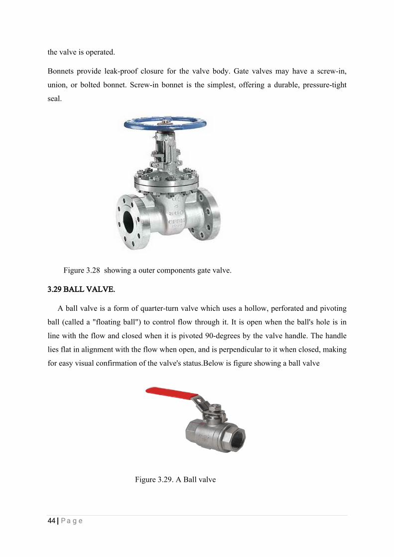
3.28GATEVALVE
Agatevalve,alsoknownasasluicevalve,isavalvethatopensbyliftingaroundor
rectangulargate/wedgeoutofthepathofthefluid.Thedistinctfeatureofagatevalveisthe
sealingsurfacesbetweenthegateandseatsareplanar,sogatevalvesareoftenusedwhena
straight-lineflowoffluidandminimumrestrictionisdesired.Gatevalvesarecharacterized
ashavingeitherarisingstem.Risingstemsprovideavisualindicationofvalveposition
becausethestemisattachedtothegatesuchthatthegateandstemriseandlowertogetheras
44|Page
thevalveisoperated.
Bonnetsprovideleak-proofclosureforthevalvebody.Gatevalvesmayhaveascrew-in,
union,orboltedbonnet.Screw-inbonnetisthesimplest,offeringadurable,pressure-tight
seal.
Figure3.28showingaoutercomponentsgatevalve.
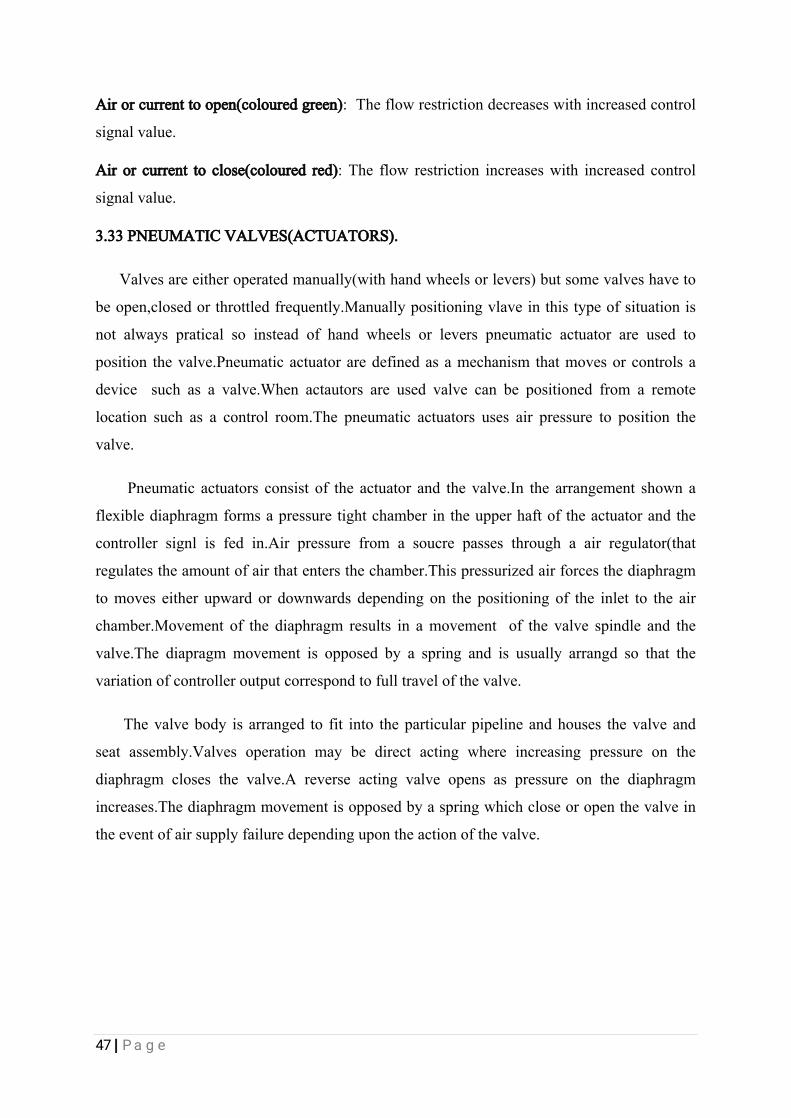
3.29BALLVALVE.
Aballvalveisaformofquarter-turnvalvewhichusesahollow,perforatedandpivoting
ball(calleda"floatingball")tocontrolflowthroughit.Itisopenwhentheball'sholeisin
linewiththeflowandclosedwhenitispivoted90-degreesbythevalvehandle.Thehandle
liesflatinalignmentwiththeflowwhenopen,andisperpendiculartoitwhenclosed,making
foreasyvisualconfirmationofthevalve'sstatus.Belowisfigureshowingaballvalve
Figure3.29.ABallvalve

45|Page
3.30BUTTERFLYVALVE
Abutterflyvalveisavalvewhichcanbeusedforisolatingorregulatingflow.The
closingmechanismtakestheformofadisk.Operationissimilartothatofaballvalve,which
allowsforquickshutoff.Butterflyvalvesaregenerallyfavoredbecausetheyarelowerin
costtoothervalvedesignsaswellasbeinglighterinweight,meaninglesssupportisrequired.
Thediscispositionedinthecenterofthepipe,passingthroughthediscisarodconnectedto
anactuatorontheoutsideofthevalve.Rotatingtheactuatorturnsthedisceitherparallelor
perpendiculartotheflow.Unlikeaballvalve,thediscisalwayspresentwithintheflow
thereforeapressuredropisalwaysinducedintheflow,regardlessofvalveposition.
3.31CHECKVALVE
Thistypeofvalveonlyallowsflowsofliquidinonedirection,itisemployedtopreventthe
backflowofproductpassingthroughit,itmakesuseofasleevethatisautomatically
controlledbytheflow,toopenthevalve,iftheproducttendstoflowbackthesleevecloses
theinletofthevalve
Figure3.31showingthecheckvalve.
3.32CONTROLVALVES
Acontrolvalveisavalveusedtocontrolfluidflowbyvaryingthesizeoftheflow
passageasdirectedbyasignalfromacontroller.Thisenablesthedirectcontrolofflowrate
andtheconsequentialcontrolofprocessquantitiessuchaspressure,temperature,andliquid
level. Inautomaticcontrolterminologyacontrolvalveistermeda"finalcontrolelement

46|Page
Figure3.32showingdiagramsofcontrolvalves
Theopeningorclosingofautomaticcontrolvalvesisusuallydonebyelectrical,hydraulic
orpneumaticactuators.Normallywithamodulatingvalve,whichcanbesettoanyposition
betweenfullyopenandfullyclosed,valvepositionersareusedtoensurethevalveattainsthe
desireddegreeofopening.
Air-actuated(pneumatic)valvesarecommonlyusedbecauseoftheirsimplicity,asthey
onlyrequireacompressedairsupply,whereaselectrically-operatedvalvesrequireadditional
cablingandswitchgear,andhydraulically-actuatedvalvesrequiredhighpressuresupplyand
returnlinesforthehydraulicfluid.
ThepneumaticcontrolsignalsinWRPCaretraditionallybasedonapressurerangeof3-
15psi(0.2-1.0bar)
Anautomaticcontrolvalveconsistsofthreemainpartsinwhicheachpartexistinseveral
typesanddesigns:
Valveactuator:whichmovesthevalve'smodulatingelement,suchasballorbutterfly.
Valvepositioner:Whichensuresthevalvehasreachedthedesireddegreeofopening.This
overcomestheproblemsoffrictionandwear.
Valvebody:istheareawhichthemodulatingelement,aplug,globe,ballorbutterfly,is
contained.
Takingtheexampleofanair-operatedvalveinWRPC,therearetwocontrolactions
possible:
47|Page
Airorcurrenttoopen(colouredgreen):Theflowrestrictiondecreaseswithincreasedcontrol
signalvalue.
Airorcurrenttoclose(colouredred):Theflowrestrictionincreaseswithincreasedcontrol
signalvalue.
3.33PNEUMATICVALVES(ACTUATORS).
Valvesareeitheroperatedmanually(withhandwheelsorlevers)butsomevalveshaveto
beopen,closedorthrottledfrequently.Manuallypositioningvlaveinthistypeofsituationis
notalwayspraticalsoinsteadofhandwheelsorleverspneumaticactuatorareusedto
positionthevalve.Pneumaticactuatoraredefinedasamechanismthatmovesorcontrolsa
device suchasavalve.Whenactautorsareusedvalvecanbepositionedfromaremote
locationsuchasacontrolroom.Thepneumaticactuatorsusesairpressuretopositionthe
valve.
Pneumaticactuatorsconsistoftheactuatorandthevalve.Inthearrangementshowna
flexiblediaphragmformsapressuretightchamberintheupperhaftoftheactuatorandthe
controllersignlisfedin.Airpressurefromasoucrepassesthroughaairregulator(that
regulatestheamountofairthatentersthechamber.Thispressurizedairforcesthediaphragm
tomoveseitherupwardordownwardsdependingonthepositioningoftheinlettotheair
chamber.Movementofthediaphragmresultsinamovementofthevalvespindleandthe
valve.Thediapragmmovementisopposedbyaspringandisusuallyarrangdsothatthe
variationofcontrolleroutputcorrespondtofulltravelofthevalve.
Thevalvebodyisarrangedtofitintotheparticularpipelineandhousesthevalveand
seatassembly.Valvesoperationmaybedirectactingwhereincreasingpressureonthe
diaphragmclosesthevalve.Areverseactingvalveopensaspressureonthediaphragm
increases.Thediaphragmmovementisopposedbyaspringwhichcloseoropenthevalvein
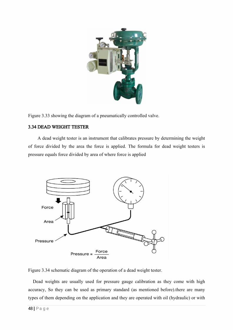
theeventofairsupplyfailuredependingupontheactionofthevalve.
48|Page
Figure3.33showingthediagramofapneumaticallycontrolledvalve.
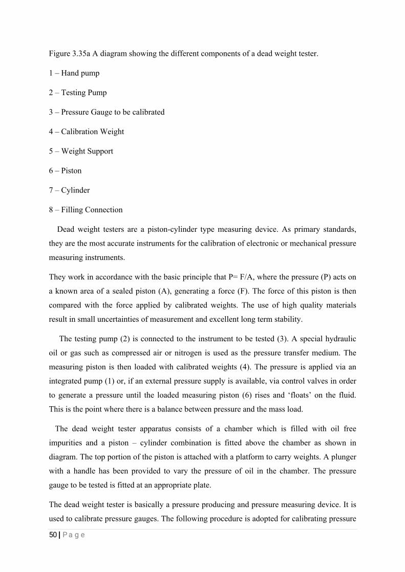
3.34DEADWEIGHTTESTER
Adeadweighttesterisaninstrumentthatcalibratespressurebydeterminingtheweight
offorcedividedbytheareatheforceisapplied.Theformulafordeadweighttestersis
pressureequalsforcedividedbyareaofwhereforceisapplied
Figure3.34schematicdiagramoftheoperationofadeadweighttester.
Deadweightsareusuallyusedforpressuregaugecalibrationastheycomewithhigh
accuracy,Sotheycanbeusedasprimarystandard(asmentionedbefore).therearemany
typesofthemdependingontheapplicationandtheyareoperatedwithoil(hydraulic)orwith

49|Page
air(pneumatic).
Deadweighttestersarethebasicprimarystandardforaccuratemeasurementofpressure.
Theyareusedtomeasurethepressureexertedbygasorliquidandcanalsogenerateatest
pressureforthecalibrationofnumerouspressureinstruments.Indeadweighttester,weput
theweightontheweightstandofthedeadweighttester,theweightaddediscalledthe
referenceweightwhichistobecalibratedandfurtherweappliedpressurebyamovingpiston
,whenappliedpressureandreferenceweight(Pressure)isequalatthisconditionreference
weightwillbezero(Dead).thereforeitiscalleddeadweightester.
Adeadweighttester(DWT)isacalibrationstandardwhichusesapistoncylinderon
whichaloadisplacedtomakeanequilibriumwithanappliedpressureunderneaththepiston.
TheformulatodesignaDWTisbasedbasicallyisexpressedasfollows:
p=F/A[Pa]
where:
p:referencepressure
F:forceappliedonpiston
A:effectivearea
3.35WORKINGOFADEADWEIGHTTESTER
Figure3.35.ADiagramshowingthecomponentsofaDeadWeighttester
50|Page
Figure3.35aAdiagramshowingthedifferentcomponentsofadeadweighttester.
1–Handpump
2–TestingPump
3–PressureGaugetobecalibrated
4–CalibrationWeight
5–WeightSupport
6–Piston
7–Cylinder
8–FillingConnection
Deadweighttestersareapiston-cylindertypemeasuringdevice.Asprimarystandards,
theyarethemostaccurateinstrumentsforthecalibrationofelectronicormechanicalpressure
measuringinstruments.
TheyworkinaccordancewiththebasicprinciplethatP=F/A,wherethepressure(P)actson
aknownareaofasealedpiston(A),generatingaforce(F).Theforceofthispistonisthen
comparedwiththeforceappliedbycalibratedweights.Theuseofhighqualitymaterials
resultinsmalluncertaintiesofmeasurementandexcellentlongtermstability.
Thetestingpump(2)isconnectedtotheinstrumenttobetested(3).Aspecialhydraulic
oilorgassuchascompressedairornitrogenisusedasthepressuretransfermedium.The
measuringpistonisthenloadedwithcalibratedweights(4).Thepressureisappliedviaan
integratedpump(1)or,ifanexternalpressuresupplyisavailable,viacontrolvalvesinorder
togenerateapressureuntiltheloadedmeasuringpiston(6)risesand‘floats’onthefluid.
Thisisthepointwherethereisabalancebetweenpressureandthemassload.
Thedeadweighttesterapparatusconsistsofachamberwhichisfilledwithoilfree
impuritiesandapiston–cylindercombinationisfittedabovethechamberasshownin
diagram.Thetopportionofthepistonisattachedwithaplatformtocarryweights.Aplunger
withahandlehasbeenprovidedtovarythepressureofoilinthechamber.Thepressure
gaugetobetestedisfittedatanappropriateplate.
Thedeadweighttesterisbasicallyapressureproducingandpressuremeasuringdevice.Itis
usedtocalibratepressuregauges.Thefollowingprocedureisadoptedforcalibratingpressure
51|Page
gauges.Calibrationofpressuregaugemeansintroducinganaccuratelyknownsampleof
pressuretothegaugeundertestandthenobservingtheresponseofthegauge.Inorderto
createthisaccuratelyknownpressure,thefollowingstepsarefollowed.Thevalveofthe
apparatusisclosed.
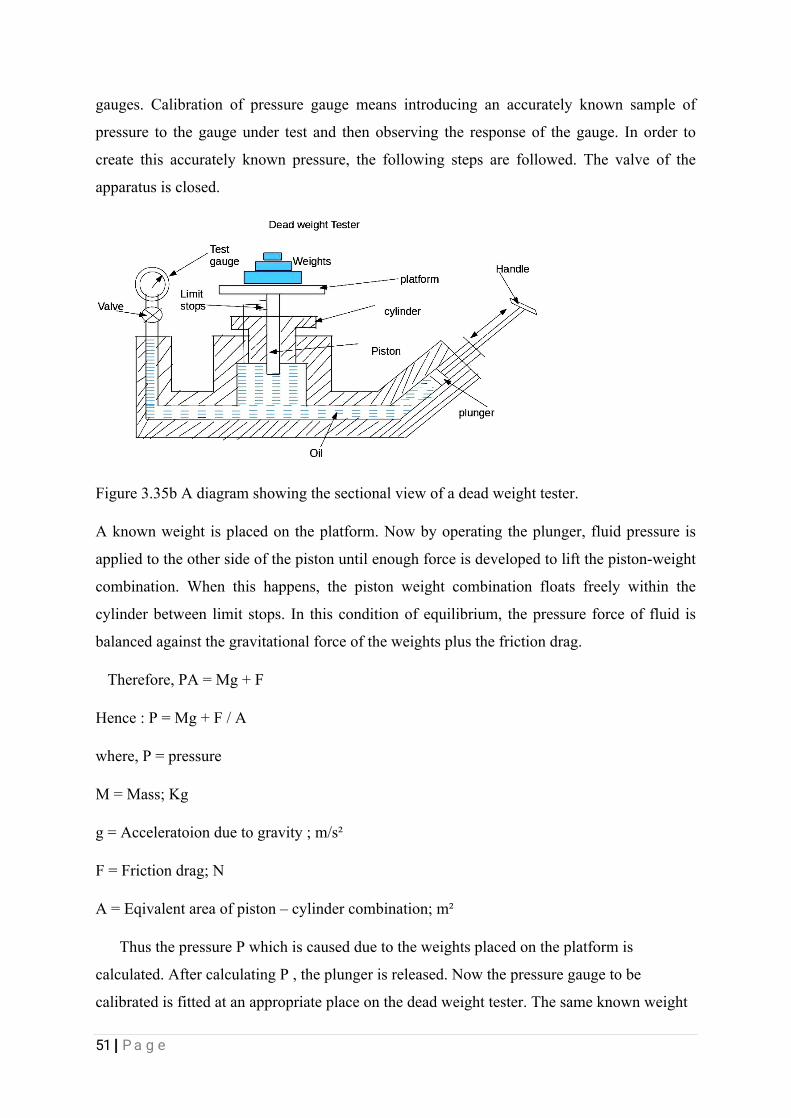
Figure3.35bAdiagramshowingthesectionalviewofadeadweighttester.
Aknownweightisplacedontheplatform.Nowbyoperatingtheplunger,fluidpressureis
appliedtotheothersideofthepistonuntilenoughforceisdevelopedtoliftthepiston-weight
combination.Whenthishappens,thepistonweightcombinationfloatsfreelywithinthe
cylinderbetweenlimitstops.Inthisconditionofequilibrium,thepressureforceoffluidis
balancedagainstthegravitationalforceoftheweightsplusthefrictiondrag.
Therefore,PA=Mg+F
Hence:P=Mg+F/A
where,P=pressure
M=Mass;Kg
g=Acceleratoionduetogravity;m/s²
F=Frictiondrag;N
A=Eqivalentareaofpiston–cylindercombination;m²
ThusthepressurePwhichiscausedduetotheweightsplacedontheplatformis
calculated.AftercalculatingP,theplungerisreleased.Nowthepressuregaugetobe
calibratedisfittedatanappropriateplaceonthedeadweighttester.Thesameknownweight

52|Page
whichwasusedtocalucatedPisplacedontheplatform.Duetotheweight,thepistonmoves
downwardsandexertsapressurePonthefluid.Nowthevalveintheapparatusisopenedso
thatthefluidpressurePistransmittedtothegauge,whichmakesthegaugeindicatea
pressurevalue.Thispressurevalueshownbythegaugeshouldbeequaltotheknowninput
pressureP.IfthegaugeindicatessomeothervalueotherthanPthegaugeisadjustedsothat
itreadsavalueequaltoP.Thusthegaugeiscalibrated.
Figure3.35cAdiagramshowingofaDeadweighttester
Applications:
Itisusedtocalibratedallkindsofpressuregaugessuchasindustrialpressuregauges,
pressuretransmittersetc.
Advantages:
itissimpleinconstructionandeasytouse.Itcanbeusedtocalibratedawiderangeof
pressuremeasuringdevices.Fluidpressurecanbeeasilyvariedbyaddingweightsorby
changingthepistoncylindercombination.
Limitations:theaccuracyofthedeadweighttesterisaffectedduetothefrictionbetweenthe
pistonandcylinder,andduetotheuncertaintyofthevalueofgravitationalconstant‘g’.

53|Page
3.36MACHINETOOLS
Amachinetoolisamachineforshapingormachiningmetalorotherrigidmaterials,
usuallybycutting,boring,grinding,shearing,orotherformsofdeformation.Allmachine
toolshavesomemeansofconstrainingtheworkpieceandprovideaguidedmovementofthe
partsofthemachine.Thustherelativemovementbetweentheworkpieceandthecuttingtool
(whichiscalledthetoolpath)iscontrolledorconstrainedbythemachinetoatleastsome
extent,ratherthanbeingentirely"offhand"or"freehand".
Anymachinetoolgenerallyhasthecapabilityof;
1.Holdingandsupportingtheworkpieceeitherbyamachinevice,clampsordividingheads.
2.Holdingandsupportingtheworkpiece.
Impactingasuitablemovement(rotatingorsomemeansofconstrainingtheworkpiece
andprovideaguidedmovementofthepartsofthemachine.Thustherelativemovement
betweentheworkpieceandthecuttingtool(whichiscalledthetoolpath)iscontrolledor
constrainedbythemachinetoatleastsomeextent,ratherthanbeingentirely"offhand"or
"freehand".
Anymachinetoolgenerallyhasthecapabilityof;
1.Holdingandsupportingtheworkpieceeitherbyamachinevice,clampsordividingheads.
2.Holdingandsupportingtheworkpiece.
3.Impactingasuitablemovement(rotatingorreciprocating)tothecuttingtoolorthework.
4.Feedingthecuttingortheworksothatthedesiredcuttingactionandaccuracywillbe
achieved.
Varioustechniquescanbeusedtoremoveunwantedmetalduringtheprocessof
fabricatingorshapingparts,namelysingleedgecuttingtools;multipleedgecuttingtools,
electricaldischargemachiningandgrinding(abrasivecutting).
3.37TYPESOFMACHINEINMACHINETOOLSWORKSHOPATWRPC
3.38THELATHEMACHINE
Alatheisanaccurateversatilemachineinwhichmanyoperationscanbecarriedouton,
suchasshapingandmachiningofvariousworkpieces.
54|Page
Inmanufacturing,itisimportanttoproduceworkpiecesaccordingtospecifications.Thisis
wherethelathemachinecomesinhandy.Alathemachineisusedforthemachiningand
workingofhardmaterials.Conventionally,themainfunctionofthelatheistoremove
materialfromaworkpiecethroughtheuseofcuttingtools.Thelatheshapesamaterialby
holdingandrotatingthematerialasacuttingtoolisadvancedintoit
Themajorpathofalathemachinesare;
1.Thebed–thebedisaheavy,ruggedcasting,madetosupporttheworkingpartofthelathe.
Oneitstopsectionaremachinewaysthatguideandalignthemajorpartofthelathe.
2.Theheadstock–theheadstockislocatedatthelefthandsideofthebed,ontheheadstock
istheheadstockspindle,andgearbox.Itisusedtohold,supportandrotatethework
3.Thecarriage–itislocatedontopofthebed,itconsistofthreemajorpartthecrossslide,
saddleandapron.Itisusedtomovethecuttingtoolalongthelathe
4.Thetailstock–itislocatedattherightendofthelathe.Thisconsistingoftheupperand
lowertailstockcasting,itcanbeadjustedfortaperorparallelturningsbytwoscrewssetto
thebase.Thetailstockcanbelockedinanypositionalongthebedofthelathebythetail
stockclamp.
5.Thelathehasthreejawchuckordependedchuckandthefourjawchuckorindependent
chuck.
Therearethreegeneraltypesoflathemachineswhichareenginelathes,turretlathes,
andspecialpurposelathes.Eachoftheselatheshasspecificapplicationsanddistinctive
characteristics.
DuringthecourseofmyindustrialtraininginWRPCIcameacrosstheenginelate,Its
maincomponentsincludethebed,headstock,andtailstock.Theenginelathescanbeadjusted
tovariablespeedsfortheaccommodationofawidescopeofwork.Thegoodthingabout
enginelathesisthatitcanbeusedinvariousmaterials,asidefrommetal.Thelatheperforms
severaloperationswhichincludes;
55|Page
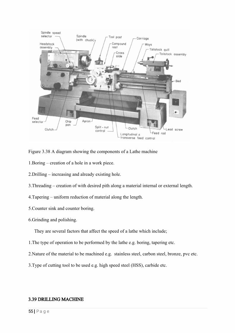
Figure3.38AdiagramshowingthecomponentsofaLathemachine
1.Boring–creationofaholeinaworkpiece.
2.Drilling–increasingandalreadyexistinghole.
3.Threading–creationofwithdesiredpithalongamaterialinternalorexternallength.
4.Tapering–uniformreductionofmaterialalongthelength.
5.Countersinkandcounterboring.
6.Grindingandpolishing.
Theyareseveralfactorsthataffectthespeedofalathewhichinclude;
1.Thetypeofoperationtobeperformedbythelathee.g.boring,taperingetc.
2.Natureofthematerialtobemachinede.g.stainlesssteel,carbonsteel,bronze,pvcetc.
3.Typeofcuttingtooltobeusede.g.highspeedsteel(HSS),carbideetc.
3.39DRILLINGMACHINE
56|Page
Drillingmachinecomesinmanyshapesandsizes,fromsmallhand-heldpowerdrillsto
benchmountedandfinallyfloor-mountedmodels.Theycanperformoperationsotherthan
drilling,suchascountersinking,counterboring,reaming,andtappinglargeorsmallholes.d
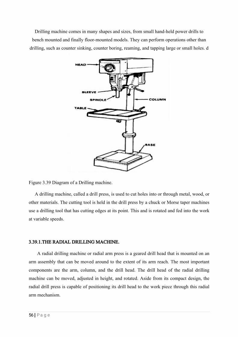
Figure3.39DiagramofaDrillingmachine.
Adrillingmachine,calledadrillpress,isusedtocutholesintoorthroughmetal,wood,or
othermaterials.ThecuttingtoolisheldinthedrillpressbyachuckorMorsetapermachines
useadrillingtoolthathascuttingedgesatitspoint.Thisandisrotatedandfedintothework
atvariablespeeds.
3.39.1.THERADIALDRILLINGMACHINE.
Aradialdrillingmachineorradialarmpressisageareddrillheadthatismountedonan
armassemblythatcanbemovedaroundtotheextentofitsarmreach.Themostimportant
componentsarethearm,column,andthedrillhead.Thedrillheadoftheradialdrilling
machinecanbemoved,adjustedinheight,androtated.Asidefromitscompactdesign,the
radialdrillpressiscapableofpositioningitsdrillheadtotheworkpiecethroughthisradial
armmechanism.
57|Page
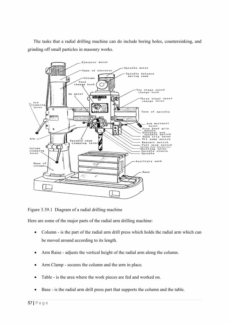
Thetasksthataradialdrillingmachinecandoincludeboringholes,countersinking,and
grindingoffsmallparticlesinmasonryworks.
Figure3.39.1Diagramofaradialdrillingmachine
Herearesomeofthemajorpartsoftheradialarmdrillingmachine:
Column-isthepartoftheradialarmdrillpresswhichholdstheradialarmwhichcan
bemovedaroundaccordingtoitslength.
ArmRaise-adjuststheverticalheightoftheradialarmalongthecolumn.
ArmClamp-securesthecolumnandthearminplace.
Table-istheareawheretheworkpiecesarefedandworkedon.
Base-istheradialarmdrillpresspartthatsupportsthecolumnandthetable.
58|Page
Spindle-istherotatedpartofthedrillpresswhichholdsthedrillchuckusedin
holdingthecuttingtool.
DrillHead-isthepartofthedrillpressthatpenetratesthroughthematerialorwork
pieceanddrillthroughthespecificholesize.
RadialArm-holdsandsupportsthedrillheadassemblyandcanbemovedaroundon
theextentofitslength.
3.40MAINTENANCEPROCEDURESFORMACHINETOOLS
Lubricationisimportantbecauseoftheheatandfrictiongeneratedbythemovingparts.
themanufacturer’smanualshouldbefollowedforproperlubricationmethods.
i.Cleaneachmachineafteruse,cleanT-slots,grooves,anddirtfrombeltsandpulleys.
ii.Removechipstoavoiddamagetomovingparts.
iii.Wipeallspindlesandsleevesfreeofgrittoavoiddamagingtheprecisionfit.
iv.Putalightcoatofoilonallunpaintedsurfacestopreventrust.
v.Operateallmachineswithcaretoavoidoverworkingtheelectricmotor.
vi.Operationsunderadverseconditionsrequirespecialcare.Ifmachinesareoperatedunder
extremelydustyconditions.
viiOperateattheslowestspeedstoavoidrapidabrasivewearonthemovingpartsand
lubricatethemachinesmoreoften.
viii.Underextremecoldconditions,startthemachinesataslowspeedandallowthepartsand
lubricantstowarmupbeforeincreasingthespeeds.
Metalbecomesverybrittleinextremecold.sodonotstrikethemachineswithhardtools.
Extremeheatmaycausethemotortooverheat.souseintermittent.oronandoff,operations
tokeepthemotorrunningcool.
3.41TURBINES
Aturbineisarotarymechanicaldevicethatextractsenergyfromafluidflowandconverts
itintousefulwork.Aturbineisaturbo-machinewithatleastonemovingpartcalledarotor
assembly,whichisashaftordrumwithbladesattached.Movingfluidactsonthebladesso

59|Page
thattheymoveandimpartrotationalenergytotherotor.InWRPCIworkedfrequentlyon
thesteamturbineandonceonaGasturbine.
3.42STEAMTURBINES
Thesteamturbinesisessentiallyaflowmachineinwhichheatenergyinthesteamis
transferredintokineticenergyanditskineticenergyisutilizedtorotatetherotorwhilethe
steamflowsthroughtheturbine.Duringtheflowofsteamthroughthenozzle,theheatenergy
isconvertedintokineticenergy,Thesteamwithhighvelocityenterstheturbinebladesand
suffersachangeindirectionofmotionwhichgivesrisetochangeofmomentum and
thereforetoaforce.Thisconstitutethedrivingforceoftheturbine.Thisforceactingonthe
bladesinthecircumferencialdirectionsetsuptherotationofthewheelorrotor.Asthewheel
rotateseachoneofthebladesfixedontherimofthejetofsteamwhichcausesthewheelto
rotatecontinuously.
Figure3.42showingtheinternalpartsofsteamturbine.
Themainpartsofasteamturbinesare:
i.Rotor.
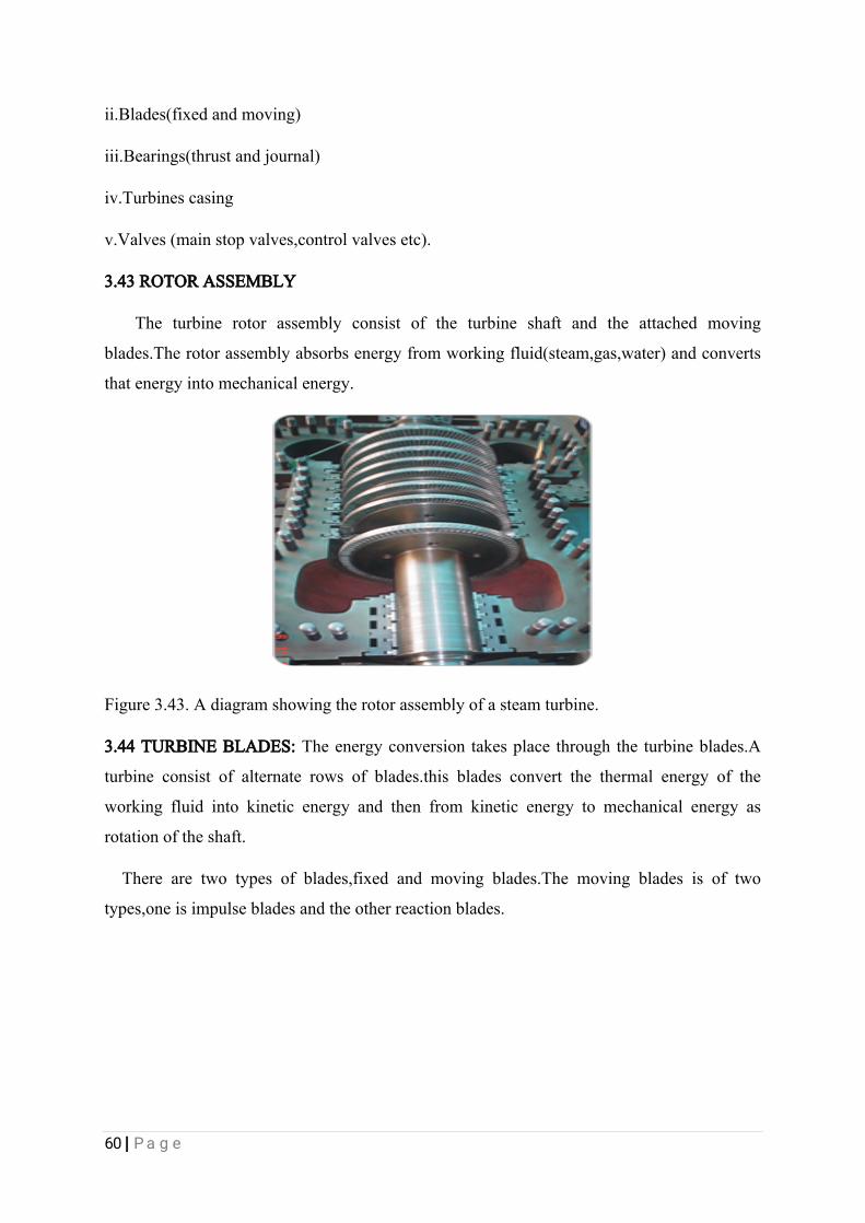
60|Page
ii.Blades(fixedandmoving)
iii.Bearings(thrustandjournal)
iv.Turbinescasing
v.Valves(mainstopvalves,controlvalvesetc).
3.43ROTORASSEMBLY
Theturbinerotorassemblyconsistoftheturbineshaftandtheattachedmoving
blades.Therotorassemblyabsorbsenergyfromworkingfluid(steam,gas,water)andconverts
thatenergyintomechanicalenergy.
Figure3.43.Adiagramshowingtherotorassemblyofasteamturbine.
3.44TURBINEBLADES:Theenergyconversiontakesplacethroughtheturbineblades.A
turbineconsistofalternaterowsofblades.thisbladesconvertthethermalenergyofthe
workingfluidintokineticenergyandthenfromkineticenergytomechanicalenergyas
rotationoftheshaft.
Therearetwotypesofblades,fixedandmovingblades.Themovingbladesisoftwo
types,oneisimpulsebladesandtheotherreactionblades.

61|Page
Figure3.44Adiagramshowingthebladesofaturbine
3.45FIXEDBLADES
Afixedbladeassemblyisveryimportantforturbineblading.itisalsoknownasdiaphragm
blades.Theshapeofthebladeisthekeytotheenergyconversionprocess.Sincethefixed
bladeshaveaconversingnozzleshape,itisalsocallednozzle.Whensteamispassedoverthe
fixedblades,theyincreasethevelocityofthesteamasanoperationofanozzle.Theseblades
convertsthethermalenergyofthesteamintokineticenergybycausingthesteamtospendup
andgainvelocity.
3.46MOVINGBLADES
Movingbladescanbeshapedineitheroftwoways:reactionshapedorimpulse
shaped.Theshapeofthebladesdeterminehowtheenergyisactuallyconverted.Eithertypeof
movingbladesorcombinationcanbeattachedtotheshaftoftherotoronthedisccalled
wheel.Alongtheouterrimofthebladesisametalband,calledshroudingwhichtiesthe
bladestogether.Themovingbladesconvertsthekineticenergyofthesteam intothe
mechanicalenergyasarotorrotation.
3.47BEARINGSINSTEAMTURBINES:
Twotypesofbearingsareusedtosupportandlocatetherotorsofsteamturbines:
Journalbearingsareusedtosupporttheweightoftheturbinerotors.Ajournalbearing
consistsoftwohalf-cylindersthatenclosetheshaftandareinternallylinedwithBabbitt,a
metalalloyusuallyconsistingoftin,copperandantimony.

62|Page
Figure3.47Adiagramofajournalbearing
Thrustbearingsisaparticulartypeofrotarybearing.Likeotherbearingstheypermitrotation
betweenparts,buttheyaredesignedtosupportpredominatelyaxialload.
Figure3.47Adiagramofthrustbearing
High-pressureoilisinjectedintothebearingstoprovidelubrication.Theoiliscarefully
filteredinthelubeoilsystemtoremovesolidparticles.Speciallydesignedcentrifugeslike
clarifierremoveanywaterfromtheoil.
63|Page
3.48TURBINECASING
Steamturbinesconsistessentiallyofacasingtowhichstationarybladesarefixedonthe
insideandarotorcarryingmovingbladesontheperiphery.Therotorisfittedinsidethe
casingwiththerowsofmovingbladespenetratingbetweentherowsoffixedblades.
Thussteamflowingthroughtheturbinepassesalternatelythroughfixedandmovingblades
withthefixedbladesdirectingthesteamattherightangleforentryintothemovingblades.
Bothcasingsandrotorsmustbeconstructedtominimizedamagingthermalstressesandthe
movingbladesmustbefittedtotherotorsecurelytowithstandthehighcentrifugalforces.
Wheretheshaftoftherotorpassesthroughtheendsofthecasing,asealisrequiredto
preventsteamleakage.Alsowithinthecasing,sealsarerequiredtopreventsteamfrom
leakingaroundthebladesratherthanpassingthroughthem.
Figure3.48Adiagramshowingthecasingofasteamturbines
3.49VALVESINSTEAMTURBINES
Steamfromtheboilerisroutedtotheturbinethroughasteamlinethatcontainsthemain
stopvalveandthecontrolvalve.
3.49.1.MAINSTOPVALVES
Itissuchavalvethroughwhichsteampassestotheturbineblades.Bycontrollingthis
valvesteamflowcanbecontrolled.Eachmainstopvalveconsitofavalvedisk,avalvestem
andahydraulicactuator.Thehydraulicactuatorcontainsapistonand compression

64|Page
spring.Sincethevalvediskandstemareconnectedtothepiston,movementofthepiston
causesmovementofthevalvedisc.Duringnormalturbineoperation,hydraulicoilisdirected
intooroutofthehydraulicactuator.Directingoilintotheactuatoropensthevalveand
compressthespring.Aslongastheamountofoilintheactuatorallowsisheldconatant,the
valvewillremaininthesameposition.Bleedingoilfromtheactuatorallowsthespringto
pushonthepiston,closingthevalve.Trippingtheturbinecauseshydraulicoiltobebled
quicklyfrombeneaththepiston,allowingthespringtoquicklyshutthevalve
3.49.2CONTROLVALVES
Whenthemainstopvalvearefullyopened,theflowofsteamintothehighpressureturbineis
usuallyregulatedbyfourormorecontrolvalves.Thecontrolvalvesregulatetheturbinespeed
oritspoweroutput.Steamfromthemainstopvalveflowstothecontrolvalvethrougha
steamlinebelowthecontrolvalves.Eachcontrolvalvefeedsonlyonesectionofthenozzle
block.
Thecontrolvalveareoperatedbyhydraulicactuactors.Thecontrolvalvesregulatesteam
flowintotheturbinebyopeningandclosinginsequence.Aseachvalveisopened,moresteam
isadmittedtothetrurbine.Duringnormaloperation,thecontrolvalveareautomatically
positionedtocompensateforchangesinload.Forexample,ifloadincreases,thecontrolvalve
areopenedmorewhichincreasestheflowofsteamintotheturbine.Ifloaddecreases,the
controlvalveareclosedmorewhichdecreasestheflowofsteamintotheturbine.Atfull
condition,allthecontrolvalvearecompletelyopened.
3.50TURBINEGOVERNINGSYSTEM
3.51MECHANICALGOVERNOR:Thepurposeofamechanicalgovernoristomaintainthe
speedoftheturbineatdesiredvalue.Themainpartsofmechanicalgovernorare
i.Flyweights
ii.Bracket
iii.Spring

65|Page
Figure3.51Adiagramshowinggovernorofasteamturbine
Whentheturbineshaftsrotates,thegovernorflyweightsrespondtothecentrifugalforces
created by the rotations.Asthe turbine speed increases,the centrifugalto move
outwards,overcomingthetensionofthespring.
Theforceofthespringtendstopulltheflyweightstowardsthecenterofthegovernor.When
turbinespeeddecreases,thecentrifugalforcealsodecreases,allowingthespringtopullthe
flyweightsinwards.
Whenthespeedoftheturbineincreases,theflyweightsmoveoutward,whichcausesthe
pilotvalvestemtomoveupward.Themovementofthestemanddiscunblockstheportofthe
controllineandallowsoiltoflowfromtheactuator,throughthepilotvalve,tothedrain.The
resultingdecreaseinthepressurebeneaththepistonallowstheactuatorspringto
expand,forcingthepistontowards.Thisactiondecreasestheopeningofthecontrolvalveand
Lesssteamisadmittedtotheturbineandtheturbinespeeddecreases.
Whenturbinespeeddecreasestheflyweightsmovesinwardandtheconnectingrod
movesdownwards.Astherodmovesdownwards,thepilotvalvealsomovesdownwards.Then
thepilotvalveblocksthedrainlineandopensthelubeoilsupplyline,asaresultoilfromthe
supplylineflowsthroughthepilotvalveandthenintothecontroloillinetotheactuator.Now
thepressureofthelubeoilcausethepsitontomoveupwards.Thustheopeningofthecontrol
valveincreaseandmaresteamisadmittedtotheturbine.Hencetheturbinespeedincreases
graduallyuntilitreachesadesirespeed.

66|Page
3.52SHAFTSEALSINSTEAMTURBINES
Largesteamandgasturbinesapplicationscommonlyemploylabyrinthsealsforreducingthe
leakageofsteam
3.52.1LABYRINTHSEALS
Alabyrinthsealisatypeofmechanicalsealthatprovidesatortuouspathtohelp
preventleakage.Anexampleofsuchasealissometimesfoundwithinanaxle'sbearingto
helppreventtheleakageoftheoillubricatingthebearing.
Alabyrinthsealmaybecomposedofmanygroovesthatpresstightlyinsideanotheraxle,
orinsideahole,sothatthefluidhastopassthroughalonganddifficultpathtoescape.
Sometimesscrewthreadsexistontheouterandinnerportion.Theseinterlock,toproducethe
longcharacteristicpathwhichslowsleakage.Forlabyrinthsealsonarotatingshaft,avery
smallclearancemustexistbetweenthetipsofthelabyrinththreadsandtherunning
surface.The"teeth"ofthelabyrinthsealmaybeontherotatingshaft.
Labyrinthsealsonrotatingshaftsprovidenon-contactsealingactionbycontrollingthe
passageoffluidthroughavarietyofchambersbycentrifugalmotion,aswellasbythe
formationofcontrolledfluidvortices.Athigherspeeds,centrifugalmotionforcesthefluid
towardstheoutsideandthereforeawayfrom anypassages.Similarly,ifthelabyrinth
chambersarecorrectlydesigned,anyfluidthathasescapedthemainchamberbecomes
entrappedinalabyrinthchamber,whereitisforcedintoavortex-likemotion.Thisactsto
preventitsescape,andalsoactstorepelanyotherfluid.Becausetheselabyrinthsealsarenon
-contact,theydonotwearout.
Manygasturbineengines,havinghighrotationalspeeds,uselabyrinthsealsduetotheirlack
offrictionandlonglife.
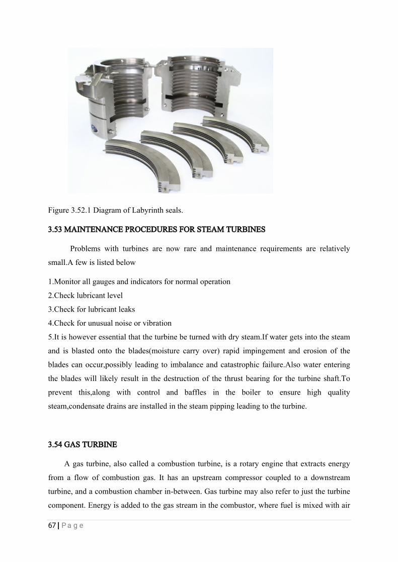
67|Page
Figure3.52.1DiagramofLabyrinthseals.
3.53MAINTENANCEPROCEDURESFORSTEAMTURBINES
Problemswithturbinesarenowrareandmaintenancerequirementsarerelatively
small.Afewislistedbelow
1.Monitorallgaugesandindicatorsfornormaloperation
2.Checklubricantlevel
3.Checkforlubricantleaks
4.Checkforunusualnoiseorvibration
5.Itishoweveressentialthattheturbinebeturnedwithdrysteam.Ifwatergetsintothesteam
andisblastedontotheblades(moisturecarryover)rapidimpingementanderosionofthe
bladescanoccur,possiblyleadingtoimbalanceandcatastrophicfailure.Alsowaterentering
thebladeswilllikelyresultinthedestructionofthethrustbearingfortheturbineshaft.To
preventthis,along with controland bafflesin theboilerto ensurehigh quality
steam,condensatedrainsareinstalledinthesteampippingleadingtotheturbine.
3.54GASTURBINE
Agasturbine,alsocalledacombustionturbine,isarotaryenginethatextractsenergy
fromaflowofcombustiongas.Ithasanupstreamcompressorcoupledtoadownstream
turbine,andacombustionchamberin-between.Gasturbinemayalsorefertojusttheturbine
component.Energyisaddedtothegasstreaminthecombustor,wherefuelismixedwithair
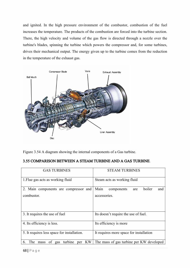
68|Page
andignited.Inthehighpressureenvironmentofthecombustor,combustionofthefuel
increasesthetemperature.Theproductsofthecombustionareforcedintotheturbinesection.
There,thehighvelocityandvolumeofthegasflowisdirectedthroughanozzleoverthe
turbine'sblades,spinningtheturbinewhichpowersthecompressorand,forsometurbines,
drivestheirmechanicaloutput.Theenergygivenuptotheturbinecomesfromthereduction
inthetemperatureoftheexhaustgas.
Figure3.54AdiagramshowingtheinternalcomponentsofaGasturbine.
3.55COMPARISONBETWEENASTEAMTURBINEANDAGASTURBINE.
GASTURBINES STEAMTURBINES
1.Fluegasactsasworkingfluid Steamactsasworkingfluid
2.Maincomponentsarecompressorand
combustor.
Main components are boiler and
accessories.
3.Itrequirestheuseoffuel Itsdoesn’trequiretheuseoffuel.
4.Itsefficiencyisless. Itsefficiencyismore
5.Itrequireslessspaceforinstallation. Itrequiresmorespaceforinstallation
6.ThemassofgasturbineperKW ThemassofgasturbineperKWdeveloped

69|Page
developedisless. ismore.
7.Itdoesnotdependuponwatersupply. Itdependsuponwatersupply.
Table3.55Showingthedifferencesbetweengasturbineandsteamturbines
3.56SOME OF THE PROBLEMS IENCOUNTER DURING MY INDUSTRIAL
TRAININGATTACHMENTANDHOWITWASSOLVED
1.THEIMPELLEROF203-P-210CENTRIFUGALPUMPS:Afterreceivinganewlybought
impellerfromtheplanningdepartment,wetriedfixinginintotheshaftbutithappensthatthe
internaldiameteroftheimpellerwassmallerthanthediameteroftheshaft.Sowehadto
machinedtheinternaldiameteroftheimpellertotherequireddiameterwhereitcanfitinto
theshaftwithsomeallowableclearance.
2.THEBEARINGSOF101-P-18A:Whentryingtochangethebearingsof101-P-18A
centrifugalpumpwithanewoneweencounteredadifficultybecausethebearingdesignation
hascleanedofffrom thebearingsurfacesmakinghardforustoknowtheparticular
bearing(insizeandthickness)tousefortheshaft.SowehadtoturnourattentiontotheSKF
CATALOGUEMANUALforbearingswhichshowsushow wecangetthebearing
designation from measuring the externaland internaldiameterbearingsand the
thickness,afterwetookthemeasurementofthosethreeparameterswetraceditontheSKF
CATALOGUEMANUALandthengotthebearingdesignation.
3.SHAFTALIGNMENTOF15-P-06ACENTRIFUGALPUMPS:Whiletryingtocarryout
shaftalignmenton15-P-06Acentrifugalpumpweobservedthatthevaluesinthedisplayunit
sensorwastolerable(accepted)butitwasintolerablefortheverticalmisalignment.Sowetried
tocorrecttheverticalmisalignmentbyadjustingthepump,butthemorewetriedthemorethe
verticalandhoizontalmisalignmentvaluesincreases.Finallyweresolvedtoaddingshimson
thefootoftheelectricmotorwhichgaveusanacceptablemisalignmentvalues.
4.THESHAFTSLEEVESOF101-P-18B:Anewshaftsleevewastobefixedontheshaftof
the101-P-18Bcentrifugalpump,butithappenedthatthediameteroftheshaftsleevewasa
bitsmallerthantheshaftdiameter,seeingthattheshaftsleevewascostlierthantheshaftwe
hadtoproduceanothershaftthatcansuitsthediameteroftheshaftsleeve.

70|Page
CHAPTER4
CONCLUSION,LIMITATIONANDRECOMMENDATION
CONCLUSION
Studentindustrialworkexperiencescheme(SIWES)isacrucialandpractically
educativeprogrammeforallengineeringstudents,whichorientatethem practicallyand
broadentheirknowledgeintheirrespectiveengineeringdepartmentalsoexposethemhowto
handlechallengesahead.Havingasixmonthindustrialtraininghasenlightenedmeonhow
relevanttheMechanicalEngineeringskillsareinthedailytransverseinanengineeringfield
particularlyasregardstocruderefiningactivitiesandpetrochemicals.Myperiodofindustrial
trainingwasaperiodofintenselearningboththeoreticallyandpractically.Thankstothe
team ofsupervisors,managersandtheoperatorswhomadesurethatthetrainingwas
successful.Abilitytofeelasenseofresponsibilityinallspheresofengineeringhasmademe
readyforthechallengesthatwillfaceamechanicalengineeringgraduate.Withoutanydoubt
theimportanceoftheindustrialtrainingprogrammecannotbeoveremphasizedsinceitsbasic
aimshasbeenachievedwhichincludethefollowing;
1.Exposingstudentstomachinesandequipments.
2.Bridgingtheexistingbetweentheoryandpracticeofengineering.
3.Professionalworkmethods/approachandwayofsafeguardingthepersonnelandwork
areas.
Also,itwasmadeknownthatconfidenceisverycrucialinthedailyproceedingsofan
Engineeranditisparamountwhenitcomestoundertakingtarget.Itwasbroughttomy
understandingthatnomatterthepressuremountedbytimeorserviceability,oneshouldnot
compromisesafetyforeitherspeed,monetarygainorfavourasthecasemaybe.Withthese
andothervaluesIgainedduringtheseweeks,Icansaywithgreatconfidencethatthepurpose
ofSIWEShasbeenaccomplished.Alsosafetymeasuretoheedtoinaprocessindustrywas
alsoacquired.Myinitiativesandintelligencewasalsotestedbymyindustrial-based
supervisorswherebyaskingmeseveralquestionsandcarryingoutsomeworkactivitiesinthe
71|Page
plantunderduesupervisionandsafety.
4.1LIMITATIONINTHEUSEOFTHEEQUIPMENTSANDPROCEDURESFOR
CARRYINGOUTJOBINWRPC
ThelimitationIobservedatWRPCabouttheuseoftheirequipmentsandtheprocedurefor
carryingoutjobswere;
1.Someoftheequipmentsareoperatedonbreakdownmaintenancemodethat’stheoperators
waitsuntiltheequipmentsfailsandrepairsit.Suchapolicyisnotsuitableforarefinery
becauseitwillsignificantlyaffecttheoperationandproductionofproductsintherefinery.It
canalsocauseatotalfailureofthemachinebeyondrepairasmaintenanceisonlycarriedout
whenthematerilasfails.andiftheequipmentsfailsbeyondrepairsitleavesthecompanywith
nochoicebuttoincuranewmachineandthatmaycostthecompanyaswell.
2.TheageoftheequipmentsinWRPCaffectstheefficiencyoftheequipmentsandthe
processofproductionsingeneral
3.Workrequestthatarestatedforemergencypurposewasnotreallycarriedouton
emergencybasisandthisreducesorslowsdowntheproductionrateofproductsinWRPC.
4.Workpermitwasonlycollectedbystaffandnotsupportstaff
4.2RECOMMENDATIONS
1.Preventive,periodicandpredictivemaintenanceshouldbecarriedoutonalltheworking
equipments.Preventivemaintenanceentailscleaning,inspecting,oiling,re-tightheningofthe
partsofthemachines.
2.Newlydesignedequipmentsshouldbepurchasedtoensurethatoptimumproductiontakes
place.
3.Workrequestinstructionshouldbeobeyedatalltimes,forthiswillreducethedowntimesof
thecompany’soperation.

72|Page

73|Page