
Alamouti Scheme Presentation
19
A Simple Transmit Diversity Scheme for Wireless Communication Author: Siavash M. Alamouti Sujeet Patole Dec 16, 2013
Transcript of Alamouti Scheme Presentation
A Simple Transmit Diversity Scheme for Wireless
Communication
Author: Siavash M. Alamouti
Sujeet Patole
Dec 16, 2013

The Wireless Channel
TX
↵0
e j✓0
↵1e j✓
1
↵N e j✓
N
RX
Figure 1 : Wireless channel
• Multipath: EM waves propagate through di↵erent path before reachingreceiver.• Gains in each path are independent of each other.
• Receiver collects the superposition of multi paths ! CLT
E↵ective Complex Gain = ↵e j✓=NX
n=1
↵n
cos ✓n
+ jNX
n=1
↵n
sin ✓n
⇠ CN (0,�2)
↵ ⇠ Rayleigh, ✓ ⇠ U[�⇡,⇡] (1)
• LOS!Rician Fading

Multipath Fading
• For a Gaussian channel with no fading, using BPSK modulation with
SNR �, Pe
is Q(p2�). Note that (Q(x) 1
2
e�x
2
2 )
• Performance Degradation in the presence of Multipath Fading
s
h = ↵e j✓ n
r = hs + n
Figure 2 : Multipath channel
r = hs + n = ↵e j✓s + n (2)
• SNR at the receiver � = |h|2Eb
N
0
is RV with exponential distribution.
P̄e
=
ZQ(
p2�)f (�)d� ⇡ 1
4�̄(3)
• BER improvement costs power: to improve BER from 10�3 to 10�2, 1-2dB higher SNR is required in AWGN case while 10dB higher SNR isrequired in multi-path case.

Multipath Fading Mitigation
Using Diversity Schemes
•Transmitter Power Control! Predistort signal! Dynamic
Range, Radiated Power limitations, CSI at the transmitter
requires receiver feedback!Throughput considerations.
•Time Diversity: Same signal at di↵erent times separated by at
least coherence time ! Length of the codeword to average
out slow fading ! Delays
•Frequency Diversity: Same signal over frequencies separated
by at least coherence BW ! BW consumption
•Space Diversity: Same signal sent over two di↵erent
uncorrelated paths received using Multiple antennas !Techniques and implementation Issues

Maximal Receiver Ratio Combining (MRRC)
• At two receiving antenna under flat fading (h0
= ↵0
e j✓0 , h1
= ↵1
e j✓1)received signal is given by:
r0
= h0
s0
+ n0
, r1
= h1
s0
+ n1
(4)
Detector
h⇤1n
1
n0
h0
= ↵0
e j✓0
h1
= ↵1
e j✓1
h⇤0
r1
s̃0
r0s
0
ML
• At the receiver optimum performance is obtained using ML detection.Assuming CSI at the RX, ML detection corresponds to:
R = [r0
r1
]T maxs
i
P
✓R
H, si
◆(5)
• For Gaussian distributed noise n1
and n2
, eq. [5] corresponds to: signal si
over sk
i↵:d2(r
0
, h0
si
) + d2(r1
, h1
si
) d2(r0
, h0
sk
) + d2(r1
, h1
sk
) 8i 6= k (6)
• This performance can achieved using MRC. (SNR is maximized isobtained using optimum weights.)
s̃0
= h⇤0
r0
+ h⇤1
r1
(7)
s̃0
= (↵2
0
+ ↵2
1
)s0
+ h⇤0
n0
+ h⇤1
n1
(8)

MRRC
• SNR at the combiner output is:
SNR⌃
=(↵2
0
+ ↵2
1
)Es
N0
= sum of individual SNR (9)
• For an independent fading on each path distribution of SNR is improved.SNR
⌃
= SNR0
+ SNR1
) PSNR
⌃
(SNR)= PSNR0
(SNR) ⇤ PSNR1
(SNR)
P̄e
=
ZPe
(SNR⌃
)PSNR
⌃
(SNR) d(SNR) (10)
• Diversity order of number of receiving antennas is obtained.• With CSI at RX, ML detection can be used.
d2(s̃0
, (↵2
0
+ ↵2
1
)si
) d2(s̃0
, (↵2
0
+ ↵2
1
)sk
) 8i 6= k (11)• Multiple antenna at the Receiver ! Space in User terminals, size, cost

Various Space Diversity Schemes
Modulator
Encoder
Channel
S to P
D
g(t)
g(t)
Modulator
Figure 3 : Delay diversity
• Using Multiple antennas at the transmitter! Economical• Simulcasting: Delay diversity scheme [Wittneben, 1991]
[Wittneben, 1993][Seshadri, 1993][Winters, 1994]• Same signal is delayed and transmitted through multiple antennas.
Repetition code is used. Receiver uses MLSE with the knowledge ofchannel.

Various Space Diversity Schemes
g(t)
Encoder
Channel
S to P
g(t)
Modulator
Modulator
d2
d1
Figure 4 : Space time trellis coding
• Repetition code and delay element is replaced by trellis coding[Tarokh, 1998].
• Space time trellis coding and FEC gives space as well as coding diversitygain.
• Additional processing ! Complexity increases as a function of bits/s/Hzand Diversity order
• Simple processing schemes is required.

The New Transmit Diversity Scheme
• Assuming that fading is constant over two consecutive symbols,h0
(t) = h0
(t + T ) = h0
= ↵0
e j✓0 , h1
(t) = h1
(t + T ) = h1
= ↵1
e j✓1
n1
h0
= ↵0
e j✓0
s0
r0
r1
Detector
ML
Combiner
s⇤0
h0
h1
s̃1
s̃0
-s⇤1
s1
h1
= ↵1
e j✓1
n0
Figure 5 : New transmit diversity scheme
Time Antenna 0 Antenna 1
t s0
s1
t+T -s⇤1
s0
⇤
Table 1 : Encoding sequence at the transmitter
• Received signal over two consecutive interval is:r0
= r(t) = h0
s0
+ h1
s1
+ n0
r1
= r(t + T ) = �h0
s⇤1
+ h1s⇤0
+ n1

The New Transmit Diversity Scheme
⇣r0
r⇤1
⌘=
⇣h0
h1
h⇤1
�h⇤0
⌘⇣s0
s1
⌘+
⇣n0
n⇤1
⌘
• The combiner builds following signals which are sent to ML detector
s̃0
= h⇤0
r0
+ h1
r⇤1
s̃1
= h⇤1
r0
� h0
r⇤1
(12)
• Simplifying,s̃0
= (↵2
0
+ ↵2
1
)s0
+ h⇤0
n0
+ h1
n⇤1
s̃1
= (↵2
0
+ ↵2
1
)s1
� h0
n⇤1
+ h⇤1
n0
(13)
• Comparing equation [13] with MRRC combiner output [8].• SNR of each symbol at the combiner output is sum of individual SNRs.• Hence, same diversity order as two branch MRRC can be obtained using
two transmitter antennas.

Two Branch Transmit Diversity with Two Receivers
n3
s0
r1
s⇤0
-s⇤1
s1
h1
= ↵1
e j✓1
n0
n1
h0
= ↵0
e j✓0
Combiner
h0
Detector
ML
h2
= ↵2
e j✓2
h3
= ↵3
e j✓3
r0
r2
r3
h1
h2
h3
s̃0
s̃1
n2
Figure 6 : New transmit diversity scheme
Time Antenna 0 Antenna 1
t h0
, r0
h2
, r2
t+T h1
, r1
h3
, r3
Table 2 : Channel coe�cients and receive signal definitions

Two Branch Transmit Diversity with Two Receivers and
Extension to M receivers.
• Received signals over two consecutive interval are:
r0
= h0
s0
+ h1
s1
+ n0
r1
= �h0
s1
⇤+h1s⇤0
+ n1
r2
= h2
s0
+ h3
s1
+ n2
r3
= �h2
s1
⇤+h3s⇤0
+ n3
(14)
0
@r0
r⇤1
r0
r⇤1
1
A =
0
@h0
h1
h⇤1
�h⇤0
h2
h3
h⇤3
�h⇤2
1
A⇣s0
s1
⌘+
0
@n0
n⇤1
n2
n⇤3
1
A
• Combiner produces:
s̃0
= h⇤0
r0
+ h1
r⇤1
+ h⇤2
r2
+ h3
r⇤3
s̃1
= h⇤1
r0
� h0
r⇤1
+ h⇤3
r2
� h2
r⇤3
(15)
• Simplifying,s̃0
= (↵2
0
+ ↵2
1
+ ↵2
2
+ ↵2
3
)s0
+ h⇤0
n0
+ h1
n⇤1
+ h⇤2
n2
+ h3
n⇤3
s̃1
= (↵2
0
+ ↵2
1
+ ↵2
2
++↵2
3
)s1
� h0
n⇤1
+ h⇤1
n0
� h2
n⇤3
+ h⇤3
n2
(16)• s̃
0
, s̃1
are fed to ML detector.• Eq. [16] shows diversity order equivalent to 4-branch MRRC.

Simulation Results
• Combined signal from two antennas is addition of combined signal fromsingle antenna case.
• Thus, two receiver antenna case can be extended to M receivingantennas.• Using two transmitter antennas and M receiver antennas give 2 timesMRRC diversity gain. Total diversity gain obtained is 2M.
• Uncoded coherent BPSK is used for the simulations. Total transmittedpower from two antennas is same as single antenna transmitted power inMRRC.• 3dB penalty in power as compared to MRRC.
Figure 7 : Simulation Results
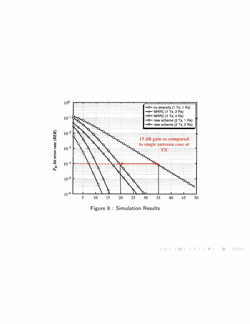
Figure 8 : Simulation Results

Implementation Issues
Power Requirements: RF power handling limitation
For same total radiated power at the transmitter, 3dB penalty in errorperformance is seen. Half power transmitted from each antenna.Cheaper,smaller, more e�cient and less intermodulation distortion power amplifiers arepossible. Same performance is obtained when there is no TX power limit.
Sensitivity to Channel Estimation Error
Perfect CSI at the receiver is assumed. Pilot symbols used for estimation[Sampei , 1989][Cavers, 1991]. Quantization and interpolation errors. Pilotinsertion frequency should be greater than twice doppler shift (Throughput).
• One TX!Many RX• Many RX!One RX! M more pilots are required
Two orthogonal symbols are needed at the transmitter (Number of pilots aretwo times MRRC).
Decoding Delay
Two symbols decoding delay. Can be reduce to one symbol by using twodi↵erent frequencies (within the coherence BW) and transmitting at the sametime sending copies of same signal.

Implementation Issues
Antenna Configuations
Diversity requires to uncorrelated signal paths. Receive diversity requirements:10� at base station Rx and 3� at UT. Reciprocal channel. Same requirementsfor transmit diversity.
Soft failure
Failure of the transmitting antenna implies lost diversity gain. Same as MRRC.
Impact of interference
Half the interference power and double the number of interferes same powerand interference distribution within the system. If possible interferencecancellation may be used.

Conclusions
•The new transmit scheme with two TX and one RX antenna
provide same diversity order as one TX and two RX MRRC
scheme.
•With two TX and M RX antenna 2M diversity order is
obtained.
•Less computational complexity, no feedback from receiver.
•3 dB SNR loss.
•Twice number of pilot symbols.

References
Wittneben, A (1991)
Basestation modulation diversity for digital simulcast
IEEE Vehicular Technology Conf. , 848-853.
Wittneben, A (1993)
Basestation modulation diversity for digital simulcast
IEEE International Conf. on Communications , 1630-1634.
N. Seshadri and J. H. Winters(1993)
Two signaling schemes for improving the error performance offrequency-division-duplex (FDD) transmission systems using transmitterantenna diversity
IEEE Vehicular Technology Conf. , 508-511
J. H. Winters(1994)
The diversity gain of transmit diversity in wireless systems with Rayleighfading
ICC/SUPERCOMM , 1121-1125

References
V. Tarokh, N. Seshadri and A. R. Calderbank (1998)
Space-time codes for high data rate wireless communication
IEEE Trans. Inform. Theory , 1121-1125
J. K. Cavers (1991)
An analysis of pilot symbol assisted modulation for Rayleigh fadingchannels
IEEE Trans. Veh. Technol , Vol.40 686-693
S. Sampei and T. Sunaga(1989)
Rayleigh fading compensation method for 16 QAM in digital land mobileradio channels
IIEEE Trans. Veh. Technol , 640646
V. Tarokh, A. Naguib, N. Seshadri and A. R. Calderbank (1998)
pace- time codes for wireless communication: Combined array processingand space time coding
IEEE Trans. Inform. Theory