
Networking Siwes report
34
A TECHNICAL REPORT OF STUDENT INDUSTRIALWORK EXPERIENCESCHEME (SIWES) HELD AT NETWORK OPERATING CENTER (NOC), OPPOSITE BLOCK 10, UNIVERSITY OF ILORIN, ILORIN KWARA STATE, NIGERIA. WRITTEN BY: MOHAMMED SALIHU MANKO (MATRIC NO: U11/FAN/CSC/046) SUBMITTED TO: DEPARTMENT OF MATHEMATICS AND COMPUTER SCIENCE, FACULTY OF NATURAL SCIENCES, IBRAHIM BADAMASI BABAGIDA UNIVERSITY, LAPAI, NIGER STATE.
-
Upload
ibbuniversity -
Category
Documents
-
view
1 -
download
0
Transcript of Networking Siwes report
A
TECHNICAL REPORT
OF
STUDENT INDUSTRIALWORK EXPERIENCESCHEME (SIWES)
HELD AT
NETWORK OPERATING CENTER (NOC), OPPOSITE BLOCK 10,
UNIVERSITY OF ILORIN, ILORIN KWARA STATE, NIGERIA.
WRITTEN BY:
MOHAMMED SALIHU MANKO
(MATRIC NO: U11/FAN/CSC/046)
SUBMITTED TO:
DEPARTMENT OF MATHEMATICS AND COMPUTER SCIENCE,
FACULTY OF NATURAL SCIENCES,
IBRAHIM BADAMASI BABAGIDA UNIVERSITY, LAPAI,
NIGER STATE.

IN PARTIAL FULFILMENT FOR THE AWARD OF BACHALOR OF
SCIENCE (B.SC COMPUTER SCIENCE)
FROM 14TH JULY TO 24TH DECEMBER, 2014.
DECLARATION
I, Mohammed Salihu M. with matriculation number
U11/FAN/CSC/046 hereby declare that I undergo six
full months of Industrial Training Programme at
Network Operations Center (NOC) University of Ilorin,
Ilorin, Kwara State and that this report is written
by me to the best of the practical knowledge I gained
during the course of the training programme.
---------------------------------------- ------
----------------------------------
Student Name/Matric Number
Sign.
DEDICATION
I dedicate this report to Allah (SWT) who gave me the
grace and strength to finish my SIWES program
successfully and also for providing all the necessary
resources.

ACKNOWLEDGEMENT
I am grateful to GOD Almighty, who granted me thegrace, strength and knowledge to go through my periodof Industrial attachment successfully. My sincereappreciation and heartfelt gratitude goes to mysupervisor MR. USMAN M. GANA who had to leave all the

way from Lapai to Ilorin to come not only tosupervise me but also to check if the organization isgood for my SIWES. My appreciation also goes to allmy departmental lecturers who have been of help allthrough.
To my wonderful family; My dad; Alhaji Mohammed J.Abubakar, My mum; Mrs. Fatimah Mohammed, My stepmums; Mrs. Aishat Mohammed, Mrs. Memunat Mohammed, Mybrothers; Mohammed Mohammed, Mohammed Haruna B, Mysisters; Mrs. Fatima “Woman Leader”, Mrs. AishaMohammed, and my only kid sister; Ruqayat Mohammed,and to my son; Abdullahi A. Sadiq, words cannotquantify the depth of my gratitude. Thank you foryour love, support, prayers and encouragementthroughout this process. My special appreciation alsogoes to those who are not mentioned here, but havesupported, encouraged and prayed for me. May GODalmighty reward you and grant you all your heartdesires.
I also want to thank my friends; Adam N. Mohammed,Ibrahim J. Deko, Aminu Mohammed, Hassan E. Mohammed,Mohammed T. Ibrahim, Mohammed Jikuchi, Musa Mustapha,Adeyinka Hezekiah, Esther Silas, Mary Jiya, for theirlove, encouragement and contribution.
My gratitude goes to my loved ones; Zainab Alhassan,Blessing Sabo, Hauwa Ibrahim, Fatimah Yahaya, Rahmat,who have always being by my side.
Lastly, I say a big thanks to NOC manager andcoordinator; Engr Husseini Akande, NOC HOD; EngrLawal Adebayo, my industrial base supervisor; sister
Eletta Adeola O, other NOC staff; Mrs. AdeolaKhadeeja, Olaoye Adeleke, Rafin Muritala and to mycolleagues at NOC; Ahmed Mujidat K, Adeyemi KhadeejatT, Boluwatife Alabi Ruth, AbdulGaniyu Otuoze, Mary,Jibril Yahaya, you’ve been a pillar of support duringmy time at NOC. Thank you all and GOD bless.
TABLE OF CONTENT
DECLARATION
DEDICATION
ACKNOWLEDGEMENT
CHAPTER ONE
1:0 Introductions
1:1 Background
1:2 Objectives of SIWES
CHAPTER TWO
2:0 Description of the establishment of attachment.
2.1 Location and brief history of establishment
2.2 Objectives of establishment
2.3 Organisational structure
2.4 Departments/units in the establishment and their
functions
CHAPTER THREE
Work Experience
3.0 Networking
3.1 Network Topology
3.2 Transmission Media
3.3 Network Equipment
3.4 IP Addressing
3.5 Troubleshooting skills
CHAPTER FOUR
5:0 Summary, conclusions and recommendation
5.1 Summary of attachment activities
5.2 Suggestions for improvement of the scheme

CHAPTER ONE
1.0 INTRODUCTION
1.1 BACKGROUND
The Industrial Training fund established by decree 43
was introduced in 1971, vis-à-vis the birth of the
Students Industrial Work Experience Scheme (SIWES)
the same year by the Federal Government of Nigeria
(FGN).
It is an integral part of the requirements for the
award of Certificates, Diplomas and Degrees in
institutions of higher learning, e.g, Colleges of
Education, Polytechnics, Universities, etc.
Student Industrial Work Experience Scheme (SIWES)
exposes students to industry based skills necessary
for a smooth transition from the classroom to work
environments. It accords students of tertiary
institutions the opportunity of being familiarised
and exposed to the needed experience in handling
machinery and equipment which are more often than
not, found in such an educational institutions.
My six months Industrial Training was observed at
Network Operations Centre, University of Ilorin,
Ilorin, Kwara State, Nigeria .
1.2 OBJECTIVES OF SIWES
To .provide students with relevant practical
experience.
To satisfy accreditation requirements set by the
Nigerian Universities Commission (NUC)

To familiarize students with typical environments
in which they are likely to function professionally
after graduation.
To provide student an opportunity to see the real
world of their discipline and consequently bridge
the gap between the University work and actual
practice.
To change the orientation of students towards
labour market when seeking for job.
To help students access area of interest and
suitability for their chosen profession.
To enhance students contact for future employment
To provide access to equipment and other facilities
that would not normally be available in the
University workshop
To enlist and enhance industry involvement in
university education.
Summarily the objective of the Student Industrial
Work Experience Scheme.
To solve, the problem of inadequate practical
skills, preparatory for employment in industries by
Nigerian graduates of tertiary institution.
To promote and encourage the acquisition of skills
in industry and commerce, with a view of generating

a pool of indigenous trained manpower sufficient to
meet the needs of the economy.
CHAPTER TWO
2.0 DESCRIPTION OF THE ESTABLISHMENT OF ATTACHMENT
2.1 LOCATION AND BRIEF HISTORY OF ESTABLISHMENT
The network operating centre (NOC) is located at the
university of Ilorin main campus opposite the
department of Electrical Engineering (block 10).

It was earlier located at Block 10; formerly called
the VSAT office, with just three members of staff.
The present day Network Operating Centre evolved from
the defunct VSAT office which was being managed by a
contractor before the university administrators
constituted a board that was responsible for the
management and maintenance of the internet
infrastructure and improvement in network services
both on and off the university campuses. The board
was named UNILORIN VSAT BOARD sometimes in 2006,
while its technical office was situated in Block 10
down. Since then, the board has been responsible for
internet connectivity and support in all units of the
university. The then chairman of the board was Prof.
Fakeye and the secretary was Dr. Mrs O.V Mejabi who
later became the chairman of the board after Prof.
Fakeye had stepped down as the chairman. The
technical manager then, now (NOC Manager) is Engr.
Akande O. Hussein.
In the year 2008, a befitting Network Operating
Centre was conceived by the administration of Prof.
IS-HAQ O. OLOYEDE, after a while foundation laying
ceremony was conducted and works started in earnest.
Upon completion of the NOC building in 2010, VSAT
office in block 10 ceased to exist. Meanwhile, the
defunct VSAT office in block 10 remained till date
NOC annex.
In 2012 the NOC received an intervention from the
World Bank, Nigeria office, Abuja this has helped the
unit to invest so much on gigabit technology
recourses and run it services on the core fibre
optics network.
Finally the Network Operating Centre (NOC) is the
unit responsible for the provision of network
services (intranet and internet), carry out
installations and renders support services on
activities she renders in all its campuses.
2.2 OBJECTIVES OF ESTABLISHMENT
The following are the objectives of the
establishment:
To provide quality internet service to both members
of staff and students of the institution.
To make research easy for members of staff and
students.
To ensure adequate interaction between lecturers
and students through online teaching and forums.
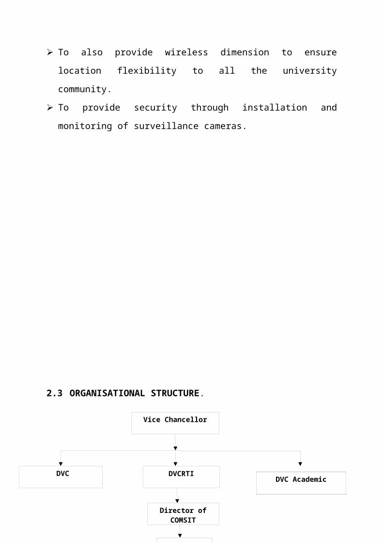
Vice Chancellor
DVC DVCRTI
Director of COMSIT
NOC Manager
To also provide wireless dimension to ensure
location flexibility to all the university
community.
To provide security through installation and
monitoring of surveillance cameras.
2.3 ORGANISATIONAL STRUCTURE.
DVC Academic

Network Engineers
System Analyst
NOC Manager
Higher Technical Officer
Data Entry Staff
Industrial Training Students
Technical Officer
Riggers
SUPERVISOR
2.4 UNITS IN THE ESTABLISHMENT AND THEIR FUNCTIONS
Following units exist in NOC:
Network administration department
This department is saddled with the responsibility of
designing the entire network; provide network service
to clients of data, voice and video. Staff in this
unit includes network engineers and system analysts.
Technical department
The technical department carries out all forms of
technical activities which include amongst other
things; uninterrupted power supply to the unit,
mounting of radios on mast and site inspection of
where installations can be carried out. Staff in this
unit includes technical officers, riggers and
students on IT.
Help desk
This section is charged with the duty of receiving
clients and their complaints. It also does data entry
activities, monitors the network performance and
bandwidth utilization (using the PRTG software).
Those working in this area include data entry staff
and students on IT.
The surveillance department
This department has the prerogative of carrying out
strict surveillance of the university community using
intelligent devices e.g. CCTV, mounted in strategic
places in and around the university community. This
is to engender security and protection of life and
properties of the general public within the
university community confinement. Those who work in
this unit are surveillance staff and Security staff.
CHAPTER THREE
WORK EXPERIENCE
3.0 NETWORKING
Network are component involve in connecting computer
and application across small and large distance.
Each computer on the network has access to the files
and peripheral device (such as printers or modems) on
all the other computers on the network.
3.1 NETWORK TOPOLOGY
Common topology found in networking includes mesh
topology star topology, bus topology, ring topology,
and others.

Network topology refers to the layout of the
transmission medium and devices on a network.
Topologies use either a point to point or multipoint
connection scheme.
A connection scheme indicates how many devices are
connected to a transmission media segment or an
individual cable.
An example of point-to-point connection scheme is a
modem/ printer connected to computer, direct cable
connection between two computers.
An example of a multi point connection scheme is a
star or bus topology network.
Star Topology
This is a local area network topology where all the
nodes are connected individually to a central
connecting device called a hub or switch. Signals
travel from the nodes to the hub which then sends
signals to other nodes on the network. A star
topology network is scale able –i.e. it can be design
and redesign easily.

Bus Topology
A LAN topology where each node is connected to a
single main bus cable, is transmits data to all the
nodes on the network. The bus is actually a series of
cable segments running from one node to the other.
Break or faulty piece of cable anywhere on the
segment prevents all the computers on the segment
from being able to communicate.
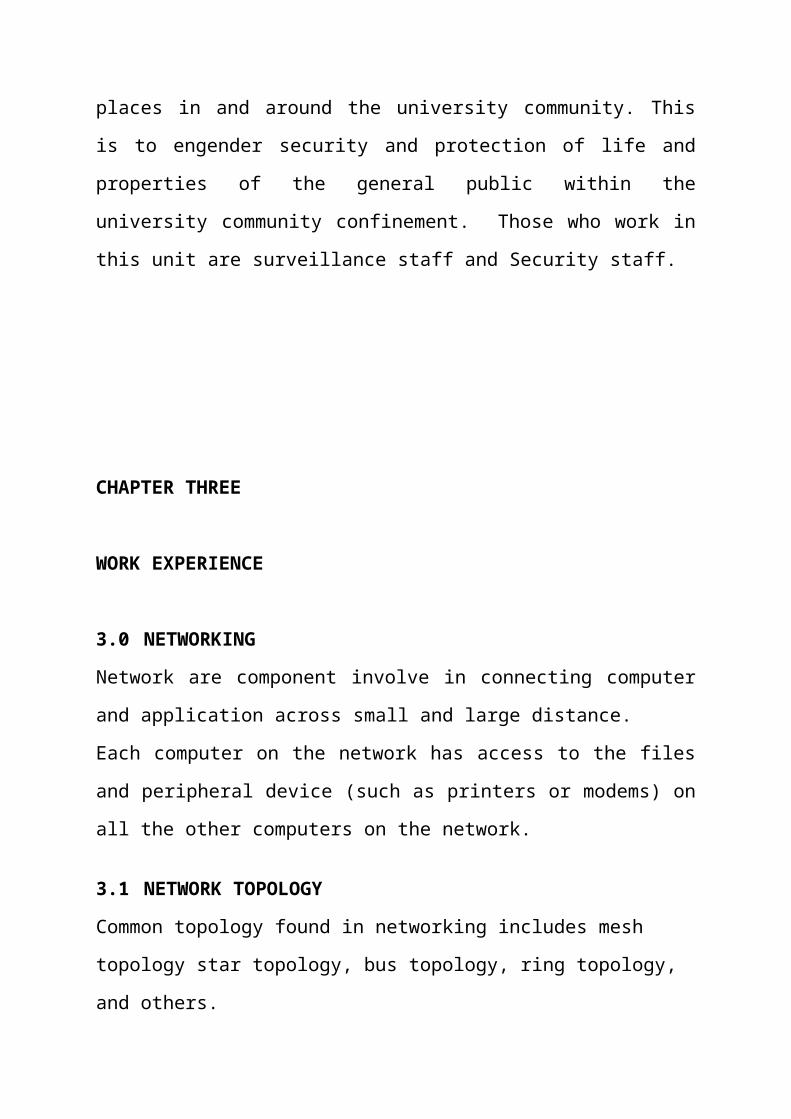
Mesh Topology
This is a network topology where every node on the
network has a separate wire connecting it to every
other node on the network. It provides each device
with a point-to-point connection to every other
device in the network. This type of network has a
high fault tolerance because failure of one node does
not affect data transmission between other nodes.
At NOC the topology adopted is the mesh topology.
3.2 TRANSMISSION MEDIA
• Wired media
• Wireless media
Wired Media

These are media which require the use of wires, lines
and cables to transmit communication signals. During
my industrial training at NOC, I encountered majorly
three different types of wired network media namely:
Coaxial cable
A coaxial cable is an alternative for protecting
data from noise. Coaxial cables do not produce
external electric and magnetic fields and are not
affected by them. This makes them ideally suited,
although more expensive, for transmitting signals.
Twisted pair cable
In a twisted pair there are eight copper wire that
are coated with different colours; the colours are
mix/orange, orange, mix/blue, blue, mix/green, green,
mix/brown and brown.

These colours are very important when terminating
cables. The two most common ways of terminating
Ethernet cables are:
(i)Straight-through method
(ii)cross-over method
In straight-through method, in any way you put in
your cable, the colour adopted at both ends must be
the same.
In a cross-over method all you need to do is to
terminate one end with a straight rule method and the
other end would be that pin ‘1’ goes to pin ‘3’ and
vice-versa, the pin ‘2’ then goes to pin ‘6’ and also
vice-versa.
I got to know that a cross-over cable is used to
connect two similar devices like a PC to a PC while a
straight through cable is used to connect different
devices e.g. a PC to a router.
Fibre optic cable
At NOC the backbone upon which the network is built
is fibre optic.
It is made of glass fibres instead of wire; it
consists of a centre glass core surrounded by several
layers of protective material. The outer insulating
jacket is made of Teflon or PVC. The fibre optic
cables transmit light rather than electronic signals,
thereby eliminating the problem of electrical
interference.

Optical fibres come in two types:
• Single-mode fibres
• Multi-mode fibres
Single-mode fibres have small cores while
Multi-mode fibres have larger cores. Used for short-
distance communication links.
Wireless Media

To fully explore the wireless added dimension,
Communication system designers have sought to use
wireless media to reduce infrastructure cost and
complexity, when compared to wired communication
systems. There is no need to construct miles of
telephone line poles or cable trenches.
During my stay at NOC I was able to interact with
the following devices:
3.3 NETWORK EQUIPMENT
Some network equipment:
Ethernet Radio
Is a device that sends and receive packets from one
network to the other.
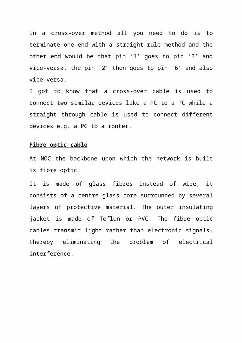
Router
A router is a device that forwards data
packets between computer networks, creating an
overlay internetwork. A router is connected to
two or more data lines from different networks.
When a data packet comes in one of the lines, the
router reads the address information in the
packet to determine its ultimate destination.
Then, using information in its routing
table or routing policy, it directs the packet to
the next network on its journey.
Switch
A network switch is a computer networking device that
connects network segments or network devices. It
serves mainly for extension.
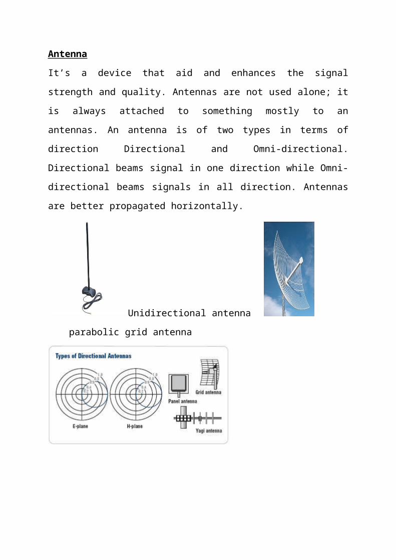
Antenna
It’s a device that aid and enhances the signal
strength and quality. Antennas are not used alone; it
is always attached to something mostly to an
antennas. An antenna is of two types in terms of
direction Directional and Omni-directional.
Directional beams signal in one direction while Omni-
directional beams signals in all direction. Antennas
are better propagated horizontally.
Unidirectional antenna
parabolic grid antenna
Twisted pair Cable
Twisted pair is the ordinary copper wire that
connects home and many business computers to the
telephone company. To reduce crosstalk or
electromagnetic induction between pairs of wires, two
insulated copper wires are twisted around each other.
Each connection on twisted pair requires both wires.
Since some telephone sets or desktop locations
require multiple connections, twisted pair is
sometimes installed in two or more pairs, all within
a single cable.
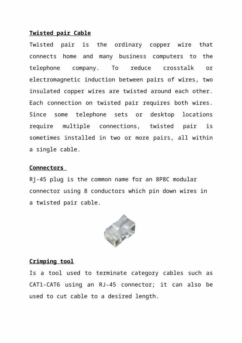
Connectors
Rj-45 plug is the common name for an 8P8C modular
connector using 8 conductors which pin down wires in
a twisted pair cable.
Crimping tool
Is a tool used to terminate category cables such as
CAT1-CAT6 using an RJ-45 connector; it can also be
used to cut cable to a desired length.
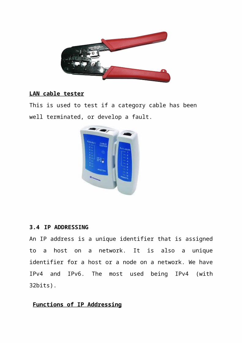
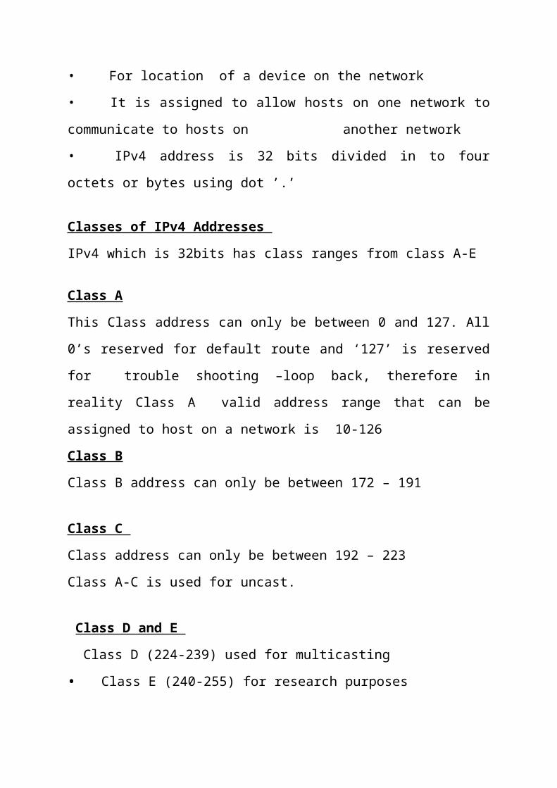
LAN cable tester
This is used to test if a category cable has been
well terminated, or develop a fault.
3.4 IP ADDRESSING
An IP address is a unique identifier that is assigned
to a host on a network. It is also a unique
identifier for a host or a node on a network. We have
IPv4 and IPv6. The most used being IPv4 (with
32bits).
Functions of IP Addressing
• For location of a device on the network
• It is assigned to allow hosts on one network to
communicate to hosts on another network
• IPv4 address is 32 bits divided in to four
octets or bytes using dot ’.’
Classes of IPv4 Addresses
IPv4 which is 32bits has class ranges from class A-E
Class A
This Class address can only be between 0 and 127. All
0’s reserved for default route and ‘127’ is reserved
for trouble shooting –loop back, therefore in
reality Class A valid address range that can be
assigned to host on a network is 10-126
Class B
Class B address can only be between 172 – 191
Class C
Class address can only be between 192 – 223
Class A-C is used for uncast.
Class D and E
Class D (224-239) used for multicasting
• Class E (240-255) for research purposes
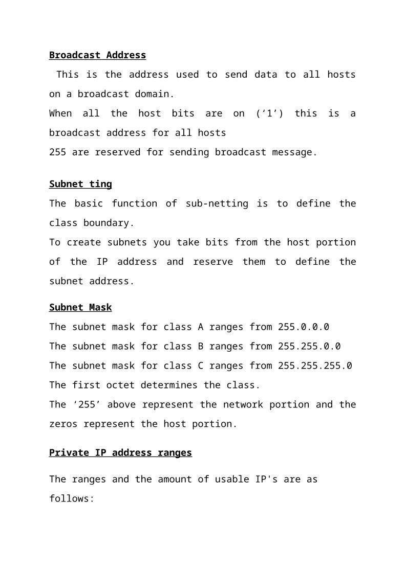
Broadcast Address
This is the address used to send data to all hosts
on a broadcast domain.
When all the host bits are on (‘1’) this is a
broadcast address for all hosts
255 are reserved for sending broadcast message.
Subnet ting
The basic function of sub-netting is to define the
class boundary.
To create subnets you take bits from the host portion
of the IP address and reserve them to define the
subnet address.
Subnet Mask
The subnet mask for class A ranges from 255.0.0.0
The subnet mask for class B ranges from 255.255.0.0
The subnet mask for class C ranges from 255.255.255.0
The first octet determines the class.
The ‘255’ above represent the network portion and the
zeros represent the host portion.
Private IP address ranges
The ranges and the amount of usable IP's are as
follows:

10.0.0.0 - 10.255.255.255
Addresses: 16,777,216
172.16.0.0 - 172.31.255.255
Addresses: 1, 048, 5
3.5 TROUBLESHOOTING SKILLS
Troubleshooting is the process of finding problems
and solving them.
Should a client unable to browse or unable to make
calls via the IP phone, the check begins with the
cable being used if client is connected via LAN
cable, this is done using the LAN-cable tester, check
the face plates to know if it is working, check the
patched panel and switches on the distribution rack
where they are kept. Ping the systems Ethernet port,
ping the server etc.
CHAPTER FOUR
5.0 SUMMARY OF ATTACHMENT ACTIVITIES
The gains of this exercise are immense; that it was
worth the while is grossly an understatement. Being
accorded another opportunity in life to be exposed to
the rudiments of work places outside the class room
teaching is an experience of a life time.
Furthermore, the exposure to practical tools,
software and hardware had engendered better
understanding of lessons thought in the class room
and charted a course for career development in
networking.
5.1 RECOMMENDATIONS & SUGGESTION FOR IMPROVEMENT OF
THE SCHEME
I put forward the following suggestions and
recommendations for future improvement of the scheme;
Organizing workshops, seminars and symposium for
students in various faculties in other to keep the
student abreast of new technologies and
innovations.
Posting of students for SIWES should be done by the
scheme to ensure conformity with course of study.
A mass enlightenment campaign should be carried
out, to enable industries and establishments know
the importance of SIWES to the future of the
student and the society at large.
The scheme should also try to enforce the act
guiding the establishment of the scheme, to serve
as deterrent to those establishments who reject
student for IT.
School Curriculum should be organized in such a way
that the SIWES exercise be carried out at a stretch
of six months and not the intermittent arrangement
of three months twice.
4.3 CONCLUSION
The Student Industrial Work Experience Scheme (SIWES)
plays a significant role in human resource
development, it helps students develop new skills and
enlightens them of what the present society holds for
them after graduation and helps them adapt
accordingly.