comtia networking
108
-
Upload
crutech-edu -
Category
Documents
-
view
0 -
download
0
Transcript of comtia networking
Author: Johan Hiemstra
This study guide pertains to the exam objectivesfor CompTIA’s N10-003 Network+
Visit www.techexams.net for more TechNotesand practice exams
Discuss these TechNotes online in our forums
CompTIA Network+ (N10-003)
TechExams.Net is not sponsored by, endorsed by or affiliated with CompTIA.All trademarks are trademarks of their respective owners.
Copyright 2002-2007 © TechExams.Net
N10-003 TechNotes Version:FV001
All images and text are copyright protected,violations of these rights will be prosecuted to the full extend of the law.
TechExams.netTechNotes
N10-003 CompTIA Network+ TechNotes TechExams.net
Author: Johan Hiemstra Copyright 2003-2007 TechExams.net
1
About the Network+ TechNotes This study guide is major update of the TechNotes I wrote for the previous version of CompTIA’s Network+ exam, and covers the essentials of all the technologies mentioned in the N10-003 Network+ exam objectives published by CompTIA. For any exam, I recommend you use at least 2 sources, for example two text books, or a book and a CBT – these TechNotes can be used as that second source. When you get stuck and can’t seem to find the answer, visit our forums. Besides me, there are many friendly people out there willing to help a hard working student or professional. I hope you will find this guide useful and that it will contribute to your knowledge and help you pass the exam! Johan Hiemstra - [email protected] About CompTIA’s Network+ Certification
CompTIA Network+ certification is an excellent introduction to a career as an IT professional. Regardless of whether you plan to go into networking, system administration, or information security, a good foundation in network technologies will be essential. There are no prerequisites for the Network+ exam. Exam code: N10-003 Format: Conventional multiple choice Number of questions: 85 Passing score: 554 (scale 100-900) - Go to www.comptia.org for more information including a FAQ, the latest exam objectives, and official sample questions. - Go to www.vue.com or www.2test.com to schedule your test online. After Network+
There are many different certification you could pursue after you completed Network+, but the following three directions seem to be most popular:
• Other CompTIA certifications (A+, Security+, Server+, Linux+, etc) • Microsoft certifications (A+ and Network+ combined can substitute the
‘elective’ requirement for MCSA and MCSE) • Cisco Certified Network Administrator (for those who want to go further in
networking and in particular manage/implement Cisco networks). Disclaimer
TechExams.net is not affiliated with CompTIA or any other company mentioned in the TechNotes. TechExams.net, nor the author, can be held responsible for any damage that occurred by an action based on the contents of this study guide. All other trademarks are trademarks of their respective owners.

N10-003 CompTIA Network+ TechNotes TechExams.net
Author: Johan Hiemstra Copyright 2003-2007 TechExams.net
2
Table of Contents
About the Network+ TechNotes ................................................................... 1 About CompTIA’s Network+ Certification........................................................ 1 After Network+ .......................................................................................... 1 Disclaimer ................................................................................................. 1
Table of Contents ......................................................................................... 2 Networking Basics........................................................................................ 7
Client/Server vs Peer-to-Peer ....................................................................... 7 LAN/WAN .................................................................................................. 7 Private vs Public Networks ........................................................................... 7 Media........................................................................................................ 7 Protocols ................................................................................................... 8 Addressing................................................................................................. 8
Media and Topologies................................................................................... 9 Network Topologies....................................................................................10 Network Technologies ................................................................................10
802.2 (LLC) .......................................................................................... 10 802.3 (Ethernet) ................................................................................... 11
802.3 Ethernet Standards ...........................................................................11 10Base2 and 10Base5............................................................................ 11 10BaseT (802.3i)................................................................................... 12 100BaseTX (Fast Ethernet, 802.3u).......................................................... 13 10BaseFL (802.3j) ................................................................................. 13 100BaseFX (802.3u) .............................................................................. 15 Gigabit Ethernet .................................................................................... 15 1000BaseT (802.3ab) ............................................................................ 15 1000BaseX (802.3z) .............................................................................. 15 10Gigabit Ethernet (802.3ae).................................................................. 16
Ring Network Technologies .........................................................................17 802.5 (Token Ring)................................................................................ 17 FDDI ................................................................................................... 18
IEEE1394 (FireWire)...................................................................................18 Tools .......................................................................................................19
Network Components................................................................................. 20 Collision Domain........................................................................................21 Broadcast Domain .....................................................................................21 Hubs........................................................................................................21 Bridges ....................................................................................................22 Switches ..................................................................................................22 Routers ....................................................................................................24 Gateways .................................................................................................24 CSU/DSU..................................................................................................25
N10-003 CompTIA Network+ TechNotes TechExams.net
Author: Johan Hiemstra Copyright 2003-2007 TechExams.net
3
NICs ........................................................................................................25 Modems ...................................................................................................26 Transceivers (Media Converters) ..................................................................26
7-Layer OSI Model...................................................................................... 27 OSI MODEL...............................................................................................28 Application (Layer 7)..................................................................................29 Presentation (Layer 6)................................................................................29 Session (Layer 5) ......................................................................................29 Transport (Layer 4)....................................................................................29 Network (Layer 3) .....................................................................................30 Data Link (Layer 2)....................................................................................30
- LLC sublayer....................................................................................... 30 - MAC sublayer ..................................................................................... 30
Physical (Layer 1) ......................................................................................31 TCP/IP Suite .............................................................................................. 32
IP............................................................................................................33 IP Addressing........................................................................................ 33 Private vs. Public addresses .................................................................... 34 Subnet Masks ....................................................................................... 34 Default Gateways .................................................................................. 35 IPv6 .................................................................................................... 36
OTHER TCP/IP PROTOCOLS.........................................................................36 Sockets................................................................................................ 36 TCP ..................................................................................................... 36 UDP..................................................................................................... 37 ARP/RARP ............................................................................................ 37 ICMP ................................................................................................... 37 IGMP ................................................................................................... 37 FTP ..................................................................................................... 38 SFTP.................................................................................................... 38 SCP ..................................................................................................... 38 TFTP.................................................................................................... 38 SMTP................................................................................................... 38 POP3/IMAP4 ......................................................................................... 38 HTTP ................................................................................................... 39 HTTPS ................................................................................................. 39 NNTP ................................................................................................... 39 TELNET ................................................................................................ 39 SSH..................................................................................................... 39 NTP ..................................................................................................... 39 RIP...................................................................................................... 40 LDAP ................................................................................................... 40 LPR ..................................................................................................... 40
TCP/IP Utilities .......................................................................................... 41 TRACERT / TRACEROUTE ............................................................................41 PING........................................................................................................42 ARP .........................................................................................................43

N10-003 CompTIA Network+ TechNotes TechExams.net
Author: Johan Hiemstra Copyright 2003-2007 TechExams.net
4
NETSTAT ..................................................................................................43 NBTSTAT..................................................................................................44 IPCONFIG.................................................................................................45 IFCONFIG.................................................................................................46 WINIPCFG ................................................................................................46 NSLOOKUP / DIG.......................................................................................47
Network Services ....................................................................................... 49 DHCP/bootp..............................................................................................49 Name Resolution .......................................................................................50
DNS .................................................................................................... 50 WINS................................................................................................... 51
SNMP.......................................................................................................52 Network Attached Storage (NAS) .................................................................53
WAN Technologies ..................................................................................... 54 Circuit switching vs. Packet switching ...........................................................54 ISDN .......................................................................................................54 T1/E1/J1 & T3/E3/J3 ..................................................................................55 SONET/OCx ..............................................................................................55 X.25 ........................................................................................................56 ATM.........................................................................................................56 Frame Relay .............................................................................................56
Remote Access and Security Protocols ....................................................... 58 Remote Access Services (RAS) ....................................................................58 Point-To-Point Protocol (PPP).......................................................................58 Point-to-Point Protocol over Ethernet (PPPoE) ................................................59 Remote Desktop Protocol (RDP)...................................................................59 Virtual Private Networks (VPN) ....................................................................60 Point to Point Tunneling Protocol (PPTP)........................................................61 Layer Two Tunneling Protocol (L2TP) ............................................................61 Internet Protocol Security (IPSec) ................................................................61 Secure Sockets Layer (SSL) ........................................................................62 802.1x .....................................................................................................62
Authentication Protocols ............................................................................ 63 CHAP .......................................................................................................63 MS-CHAP..................................................................................................63 EAP (Extensible Authentication Protocol) .......................................................64 RADIUS (Remote Authentication Dial-In User Service) ....................................64 Kerberos ..................................................................................................64
Internet Access and Connections ............................................................... 66 Routed vs. Translated.................................................................................66 Network Address Translation (NAT) ..............................................................67 Firewalls...................................................................................................67

N10-003 CompTIA Network+ TechNotes TechExams.net
Author: Johan Hiemstra Copyright 2003-2007 TechExams.net
5
Proxy.......................................................................................................69 ICS..........................................................................................................70 Extranet/Intranet.......................................................................................71 Internet Access .........................................................................................71
POTS / PSTN......................................................................................... 71 xDSL (Digital Subscriber Line) ................................................................. 72 Broadband Cable (Cable modem)............................................................. 72 Satellite ............................................................................................... 73 Wireless ............................................................................................... 73
Wireless Networking .................................................................................. 74 IEEE 802.11 Standards...............................................................................76
802.11b ............................................................................................... 76 802.11a ............................................................................................... 77 802.11g ............................................................................................... 77 802.11 Network Operation...................................................................... 77 Ad Hoc and Infrastructure Mode .............................................................. 78
Wireless Access Point (WAP)........................................................................78 Antennas..................................................................................................81
Omni-directional.................................................................................... 81 Semi-Directional.................................................................................... 82 Highly-Directional .................................................................................. 83
Environmental Factors and Interference ........................................................84 Wireless Network Security...........................................................................84
WEP (Wired Equivalent Privacy)............................................................... 84 WPA (Wi-Fi Protected Access).................................................................. 85
InfraRed...................................................................................................85 Bluetooth .................................................................................................86
Antivirus Software ..................................................................................... 87 Viruses and Malware ..................................................................................87 Antivirus Software .....................................................................................87
OS Specific Networking .............................................................................. 88 Microsoft Windows Networking ....................................................................89
NETBEUI .............................................................................................. 89 SMB/CIFS............................................................................................. 90
UNIX/LINUX Networking .............................................................................91 NFS..................................................................................................... 92 SAMBA................................................................................................. 92 LPD/LPR............................................................................................... 92
MAC OS X Networking ................................................................................93 AppleTalk Addressing ............................................................................. 95
Netware Networking...................................................................................97 IPX Addressing...................................................................................... 99
Fault Tolerance and Disaster Recovery..................................................... 100 Fault Tolerance........................................................................................100
UPS....................................................................................................100 Link Redundancy ..................................................................................100 Mirrored Servers ..................................................................................101

N10-003 CompTIA Network+ TechNotes TechExams.net
Author: Johan Hiemstra Copyright 2003-2007 TechExams.net
6
RAID ..................................................................................................101 Disaster Recovery....................................................................................102
Data Backups.......................................................................................102 Hot and Cold Spares .............................................................................103 Alternate Sites .....................................................................................103
Network Support and Troubleshooting..................................................... 104 Well-known Ports..................................................................................... 106 Notes........................................................................................................ 107

N10-003 CompTIA Network+ TechNotes TechExams.net
Author: Johan Hiemstra Copyright 2003-2007 TechExams.net
7
Networking Basics Networking refers to connecting two or more devices to allow communication between them with the purpose of sharing information and resources. Examples of these devices are computers, printers, routers, hubs, modems, and PDAs. The information and resources being shared can be anything from MS Office documents and e-mail to printers and fax devices. Internetworking refers to connecting multiple networks with the purpose of creating one large network. The Internet is the most common example of an internetwork. Client/Server vs Peer-to-Peer
Most of today's networks use the client/server model. In this model at least one computer acts as a server. Servers hold resources that are accessed over the network by clients. Examples of resources are shared files, e-mail messages and even applications. Another common server is the print server that allows access to network printers. In a peer-to-peer network model, every computer can act as a client and a server at the same time. An example is a network with ten Windows XP Professional computers in a workgroup using file and print sharing. LAN/WAN
The terms LAN and WAN mainly refer to the physical area of the network. LAN is short for Local Area Network and is typically a high-speed network within a building. WAN is short for Wide Area Network, and refers to relatively low-speed networks that span a large area, for example a network that spans several cities or the entire globe even. The Internet can be considered the largest WAN, but actually consists of many different WANs, which, in turn, interconnect LANs. The connection between LANs in an internetwork is also referred to as a WAN connection, although a network diagram of a WAN typically includes the LANs in it. Private vs Public Networks
Two other terms used to categorize networks are private networks and public networks. A private network is typically within the premises of a corporation and can be accessed only by users working for, or related to, that corporation. A public network Internet can be accessed by multiple individuals and/or corporations, the best example of a public network is again, the Internet. Media
The physical connection used to transport electrical signals (bits, 1s & 0s) between the network devices is called the media. Examples of network media are copper cabling, fiber optic cabling and infra-red. The most common types of media are outlined later in this chapter.

N10-003 CompTIA Network+ TechNotes TechExams.net
Author: Johan Hiemstra Copyright 2003-2007 TechExams.net
8
Protocols
To be able to communicate with each other, network devices need a common language. The language network devices use is called a protocol. There are many different types of protocols available, and most of them are actually a suite of several protocols, each with a different function. For example, one protocol enables data transfer between hosts and another can be used to retrieve email from a mail server. Today's most common protocol suite is TCP/IP. Addressing
If you want to contact somebody by snail-mail, you need some sort of address. In a telephone network, you need to enter a telephone number to reach your intended communication partner. Similar, devices in a network need an address. There are two types of addresses, the first type is configured in software by a network administrator and uses protocols to define the addressing scheme and format. This type is known as network or layer 3 addressing. The other type of address that devices in a network use, is most commonly referred to as MAC address; this address is burned into the chip of the physical network interface.

N10-003 CompTIA Network+ TechNotes TechExams.net
Author: Johan Hiemstra Copyright 2003-2007 TechExams.net
9
Media and Topologies Current related exam objectives for the Network+ exam. 1.1 Recognize the following logical or physical network topologies given a schematic diagram or description: - Star/Hierarchical, Bus, Mesh, Ring 1.2 Specify the main features of 802.2 (LLC), 802.3 (Ethernet), 802.5 (token ring), 802.11 (wireless) and FDDI networking technologies, including: - Speed, Topology, Media - Access Method (CSMA / CA (Carrier Sense Multiple Access/Collision Avoidance) and CSMA / CD (Carrier Sense Multiple Access / Collision Detection)) 1.3 Specify the characteristics (For example: speed, length, topology, cable type, etc.) of the following 802.3 (Ethernet) standards: - 10BASE-T and 10BASE-FL - 100BASE-TX and 100BASE-FX - 1000BASE-TX, 1000BASE-CX, 1000BASE-SX and 1000BASE-LX - 10GBASE-SR, 10GBASE-LR and 10GBASE-ER 1.4 Recognize the following media connectors and/or describe their uses: - RJ-11 (Registered Jack) - RJ-45 (Registered Jack) - ST (Straight Tip) - SC (Standard Connector) - F-Type - IEEE1394 (FireWire) - LC (Local Connector) - MTRJ (Mechanical Transfer Registered Jack) 1.5 Recognize the following media types and describe their uses: - Category 3, 5, 5e, and 6 - UTP (Unshielded Twisted Pair) - STP (Shielded Twisted Pair) - Coaxial cable - SMF (Single Mode Fiber) optic cable - MMF (Multimode Fiber) optic cable 3.3 Identify the appropriate tool for a given wiring task (For example: wire crimper, media tester / certifier, punch down tool or tone generator). 4.8 Given a network troubleshooting scenario involving an infrastructure (For example: wired or wireless) problem, identify the cause of a stated problem (For example: bad media, interference, network hardware or environment). 4.7 Given a troubleshooting scenario involving a network with a particular physical topology (For example: bus, star, mesh or ring) and including a network diagram, identify the network area affected and the cause of the stated failure.

N10-003 CompTIA Network+ TechNotes TechExams.net
Author: Johan Hiemstra Copyright 2003-2007 TechExams.net
10
Network Topologies
A logical topology depicts the route the signal takes on the network. A physical topology depicts how the cabling physically connects network devices. The four diagrams below represent the four topologies:
Bus - Devices in a bus topology are connected to a central cable. In this type of network, both cable ends must be terminated. A defective cable segment, and changes and additions can affect the entire network.
Star - Devices in a star topology are connected through a central hub. In this type of network, new nodes can be easily added making it easy to expand. Multiple connected star networks can form a large star or hierarchical topology. The central hub, which physically can be a hub, switch, or router, forms a single-point-of-failure. Another disadvantage is the increased amount of required cabling.
Ring - In a ring topology, every node is logically connected to two other nodes, forming a ring. Traffic flows through the entire ring until it reaches its destination.
Mesh - In a full mesh, every device in the network is connected to every other device. In reality, a partial mesh is commonly used in backbone environments to provide fault-tolerant connections between critical servers and network devices.
Network Technologies
802.2 (LLC)
The IEEE 802.2 standard specifies the Logical Link Control (LLC) layer, which is the upper sub-layer of the Data Link layer (Layer 2) in the OSI model. LLC masks the underlying physical network technologies by hiding their differences, hence providing a single interface to the Network layer. The interface acts as an intermediate between the different network protocols (IPX, TCP/IP, etc.) and the different network types (Ethernet, Token Ring, etc.).

N10-003 CompTIA Network+ TechNotes TechExams.net
Author: Johan Hiemstra Copyright 2003-2007 TechExams.net
11
802.3 (Ethernet) Ethernet is a LAN standard developed by DIX (Digital, Intel and Xerox) in the 1970s. In 1980, version 1 of the IEEE 802.3 standard was released. Two years later version 2 of the IEEE 802.3 standard was introduced, which in turn is the basis for today's Ethernet networks. It specifies an implementation of the physical layer and the MAC sub-layer of the data link layer. The older 10Base2 and 10Base5, and the modern Fast Ethernet, Gigabit Ethernet, and 10Gigabit Ethernet extensions and variations are all based on the original IEEE 802.3 standard. The access method – how the wire is accessed and signals are places on it – for Ethernet networks is Carrier Sense Multiple Access/Collision Detection (CSMA/CD). In a CSMA/CD network, a stations listen to check if the network is busy transmitting data before starting its own data transmission. If the network is free, the station transmits data. When two stations listen and both determine the network is not busy and start sending the data simultaneously, a collision occurs. When the collision is detected, both stations will retransmit the data after a random wait time created by a backoff algorithm. An Ethernet network is a broadcast system; this means that when a station transmits data, every other station receives the data. The frames contain a destination address in the frame header and only the station with that address will pick up the frame and pass it on to upper-layer protocols to be processed. 802.3 Ethernet Standards
10Base2 and 10Base5 CompTIA removed 10Base2 and 10Base5 from the exam objectives with the Network+ 2005 update, but you may still find these technologies being part of networks in some organizations. 10Base2 is commonly referred to as Thinnet, and 10Base5 is known as Thicknet, both offering data transfer rates up to 10Mb/s. These names refer to the diameter of the coaxial cable employed by these network technologies. This rigid type of cabling is shielded and provides fairly good protection against electromagnetic interference (EMI) and eavesdropping. Both outer cable ends are terminated using a 50-Ohm terminator. 10Base2 uses a bus topology as depicted in the following diagram:
The maximum length of a 10Base2 segment is 185 meters, which can be extended by using repeaters. The maximum number of nodes that can be attached, using BNC T-connectors as shown below, is 30 stations per segment.
British Naval Connector (BNC)

N10-003 CompTIA Network+ TechNotes TechExams.net
Author: Johan Hiemstra Copyright 2003-2007 TechExams.net
12
10Base5 also employs a bus topology, as depicted in the following diagram, but uses a different method to attach network nodes to the central cable in the bus.
Stations are attached using a MAU (Medium Attachment Unit), a transceiver that is attached to the central cable using vampire taps that pierce the cable. A cable with AUI connectors is used to connect the transceiver to the network interface on for example a computer, hub or repeater.
AUI connectors MAU transceiver
The maximum length of a 10Base5 segment is 500 meters, which also can be extended by using repeaters. The maximum length of the cable between a MAU and the AUI connector on pc is 50 meter. The maximum number of nodes that can be attached per segment is 100.
10BaseT (802.3i) The 10BaseT Ethernet specification specifies Ethernet over Cat 3, 4 and 5 UTP cabling and provides a maximum data transfer rate of 10 Mb/s. This specification is commonly referred to as Ethernet, just plain Ethernet. Devices on the network are connected through a central hub or switch in a star/hierarchical topology.
The maximum cable length of 10BaseT segment is 100 meters. The maximum number of attachments per cable segment is 2, i.e. a hub and a client. 10BaseT employs Cat 3, 4 and 5 Unshielded Twisted Pair (UTP) cabling with RJ-45 connectors as depicted below. Older network devices with AUI interfaces can use a transceiver to employ UTP cabling.

N10-003 CompTIA Network+ TechNotes TechExams.net
Author: Johan Hiemstra Copyright 2003-2007 TechExams.net
13
RJ-45 connectors A wire crimper, depicted in the image below, is used to attach the RJ-45 connector to the cable.
Another tool commonly used to attach UTP cabling to a jacket, in a patch closet for example, is the punch down tool, shown in the following image:
100BaseTX (Fast Ethernet, 802.3u) 100BaseTX, Fast Ethernet, is similar to 10BaseT but requires Category 5 UTP or Category 1 STP (Shielded Twisted Pair) cabling. It uses only four of the eight wires in the cable, just as 10BaseT does. The maximum cable segment distance is still 100 meters, but the maximum data transfer rate is 100 Mb/s.
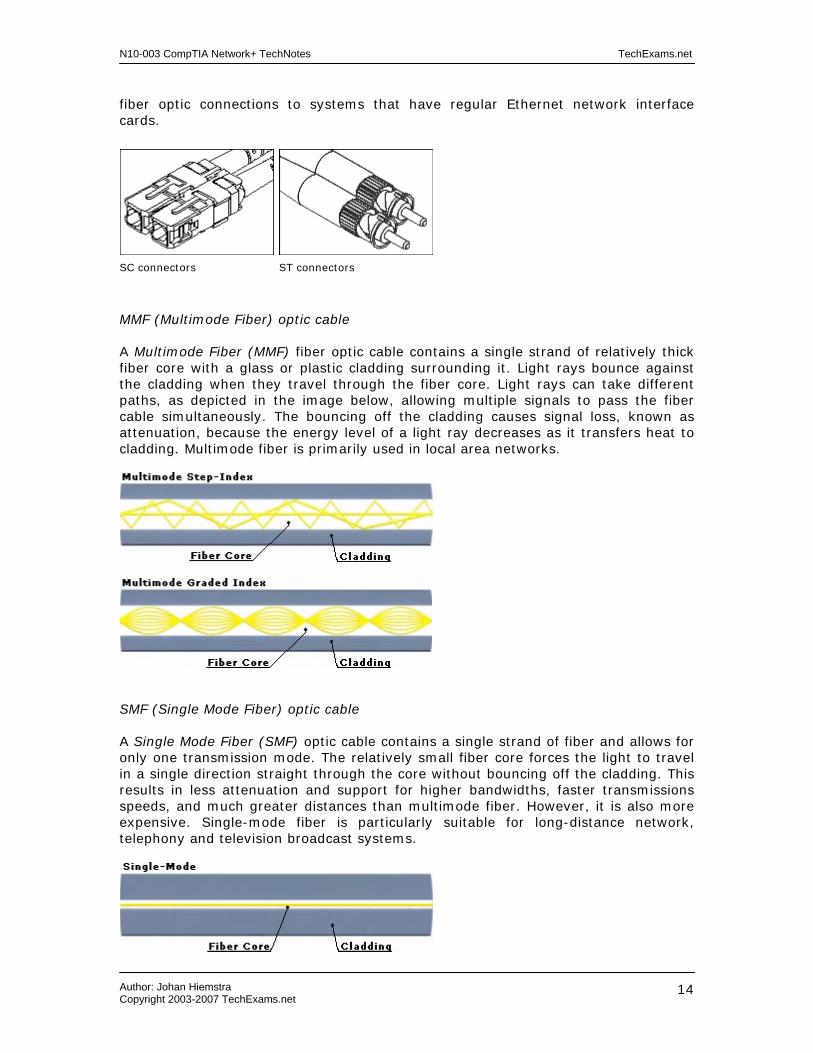
10BaseFL (802.3j) 10BaseFL is the successor of the FOIRL (Fiber Optic Inter-Repeater Link) specification, and defines Ethernet over fiber optic cabling. FOIRL allowed a point-to-point link between two repeaters up to 1000 meters apart. When fiber optic cabling started to ‘reach’ desktops and other end-devices, new standards where developed, starting with the 10BaseF set including 10BaseFL, 10BaseFB, and 10BaseFP. 10BaseFL is the most common of the three, and is the only one of importance for the CompTIA Network+ exam. 10BaseFL is similar to 10BaseT but designed to operate over two strands of multimode fiber cabling and provides a maximum data transfer rate of 10 Mb/s. One strand is used for sending, the other is used for collision detection and receiving. It is designed to be able to work with existing FOIRL hardware, allowing a smooth migration to 10BaseFL. The maximum cable segment length is 2000 meters for a 10BaseFL multimode fiber link. 10BaseFL uses primarily ST or SC connectors as depicted below. Media converters can be used to provide
N10-003 CompTIA Network+ TechNotes TechExams.net
Author: Johan Hiemstra Copyright 2003-2007 TechExams.net
14
fiber optic connections to systems that have regular Ethernet network interface cards.
SC connectors ST connectors
MMF (Multimode Fiber) optic cable A Multimode Fiber (MMF) fiber optic cable contains a single strand of relatively thick fiber core with a glass or plastic cladding surrounding it. Light rays bounce against the cladding when they travel through the fiber core. Light rays can take different paths, as depicted in the image below, allowing multiple signals to pass the fiber cable simultaneously. The bouncing off the cladding causes signal loss, known as attenuation, because the energy level of a light ray decreases as it transfers heat to cladding. Multimode fiber is primarily used in local area networks.
SMF (Single Mode Fiber) optic cable A Single Mode Fiber (SMF) optic cable contains a single strand of fiber and allows for only one transmission mode. The relatively small fiber core forces the light to travel in a single direction straight through the core without bouncing off the cladding. This results in less attenuation and support for higher bandwidths, faster transmissions speeds, and much greater distances than multimode fiber. However, it is also more expensive. Single-mode fiber is particularly suitable for long-distance network, telephony and television broadcast systems.

N10-003 CompTIA Network+ TechNotes TechExams.net
Author: Johan Hiemstra Copyright 2003-2007 TechExams.net
15
100BaseFX (802.3u) 100BaseFX is the fiber optic equivalent of 100BaseTX. As 10BaseFL, it specifies operation over two strands of multimode fiber cabling. The maximum length of a 100BaseFX link is 400 meters in half-duplex mode and 2000 meters in full-duplex mode. There are non-standard 100BaseFX–based solutions available that allow distances up to 75 km for single-mode fiber optic cabling. 100BaseFX specifies ST, SC, and MIC connectors, but MT-RJ connectors are also used in 100BaseFX-based product:
SC to ST cable MIC connector MT-RJ connector
The Mechanical Transfer Registered Jack (MTRJ) is part of a family of Small Form Factor (SFF) adapters that are compact in size compared to the more popular SC and ST adapter types. This increases fiber density per rack unit in data closets.
Gigabit Ethernet The two 802.3 standards that specify Gigabit Ethernet systems are described below. A major difference with previous Ethernet specifications, is that it uses a different encoding type named 8B/10B with simple NRZ (Non Return to Zero), which results in 10 bits being send per byte (instead of 8). By running pulses of 1250 MHz, the maximum data transfer rate is 1 Gb/s even with the 20% overhead.
1000BaseT (802.3ab)
Specifies Gigabit Ethernet over Cat 5e UTP cabling and provides data transfer rates of 1000 Mb/s. It utilizes all four pairs of cable wires for transmission. The maximum cable segment length is 100 meters. 1000BaseTX specifies Gigabit Ethernet over Cat 6 UTP cabling, but is not part of the IEEE 802.3ab standard.
1000BaseX (802.3z) The IEEE 802.3z Gigabit Ethernet standard includes two Physical Layer specifications for fiber optic media, 1000BaseSX and 1000BaseLX, and one for shielded copper media, 1000BaseCX. 1000BaseLX uses multimode fiber with a maximum length of 550 meters or single-mode fiber with a maximum length of 5 km.

N10-003 CompTIA Network+ TechNotes TechExams.net
Author: Johan Hiemstra Copyright 2003-2007 TechExams.net
16
1000BaseSX uses multimode fiber with a cable length up to 500 meters IEEE standard specifies SC connectors. Both 1000BaseLX and 1000BaseSX use SC connectors or the newer LC (Local Connector) connectors. The LC connectors are half the size as their predecessors and reduce the loss of light entering or leaving the cable. LC connectors are available in single-mode and multimode versions.
LC Connector
1000BaseCX specifies Gigabit Ethernet over a special 150-Ohm shielded coaxial cable, also known as twinax, with DB-9 connectors. It is specifically designed for short cable runs such as server-to-server connections and specifies a maximum cable length of 25 meters.
10Gigabit Ethernet (802.3ae) The IEEE 802.3ae standard specifies 10Gigabit Ethernet, also referred to as 10GbE, over multimode and single-mode fiber optics. In addition to additional bandwidth, 10GbE increases the maximum fiber optic cable lengths up to 40 kilometers. Just as Gigabit Ethernet is based on the original Ethernet standard, 10 Gigabit Ethernet continues still uses the same frame format and size. However, since it is a full-duplex and employs only fiber optic cabling, it does not need CSMA/CD access method protocol. The most common 10GbE specifications that are relevant for the CompTIA Network+ exam are 10GBaseSR, 10GBaseLR, and 10GBaseER. These specifications use a much more efficient encoding type named 64B/66B, which results in data transfer rates of 10.3 Gb/s. All three of the following use SC or LC connectors. 10GBaseSR operates over multimode fiber up to 300 meters. 10GBaseLR operates over single-mode fiber up to 10 km. 10GBaseER operates over single-mode fiber up to 40 km.

N10-003 CompTIA Network+ TechNotes TechExams.net
Author: Johan Hiemstra Copyright 2003-2007 TechExams.net
17
Ring Network Technologies
802.5 (Token Ring)
Token Ring was originally developed by IBM in the 1970s. Later the IEEE 802.5 specification was developed based on IBM's Token Ring. Despite of what the exam objective implies, Token Ring and the IEEE 802.5 specification are not exactly the same, but the differences are minor. For example, the IEEE 802.5 specification does not specify a physical topology and media, while Token Ring does. The term Token Ring usually refers to either specification. In a Token Ring network, a token is passed around the network from station to station. When a station does not need to transmit data it passes the token to the next station in the logical ring. A station that receives the token and needs to transmit data, seizes the token and sends a data frame. The receiving station marks the data frame as read and passes it forward along the ring to the source station. During this entire process, no other station can transmit data, which rules out collisions on the wire. The source station releases the token (passing it to the next station in line) when it received the data frame and verified it was read. While the logical topology is a ring, the physical topology is star/hierarchical as illustrated in the diagram below. Stations connect to Multi-Station Access Units (similar to a hub) using UTP cabling, which in turn are connected in a physical ring. If one station in the ring fails, it generally doesn't mean the ring is broken. Instead, the MSAU will bypass the individual port and exclude it from the ring.
Token Ring specifications: - Data transfer rate is 4 or 16 Mb/s - Maximum attachments per segment is 250 - Uses Twisted Pair cabling (Cat 3 for 4 MB/s, Cat 5 for 16 Mb/s) - Access method is token passing - Logical topology ring, physical topology is star - Connector type is RJ-45 The original IBM Token Ring specification uses IBM Class 1 STP cabling with IBM proprietary connectors. This connector is called the IBM-type Data Connector (IDC) or Universal Data Connector (UDC), and is neither male nor female.
N10-003 CompTIA Network+ TechNotes TechExams.net
Author: Johan Hiemstra Copyright 2003-2007 TechExams.net
18
FDDI
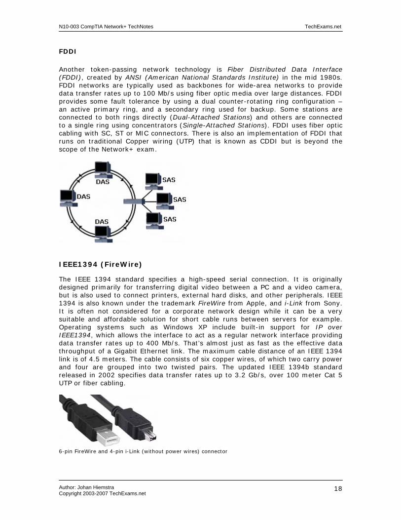
Another token-passing network technology is Fiber Distributed Data Interface (FDDI), created by ANSI (American National Standards Institute) in the mid 1980s. FDDI networks are typically used as backbones for wide-area networks to provide data transfer rates up to 100 Mb/s using fiber optic media over large distances. FDDI provides some fault tolerance by using a dual counter-rotating ring configuration – an active primary ring, and a secondary ring used for backup. Some stations are connected to both rings directly (Dual-Attached Stations) and others are connected to a single ring using concentrators (Single-Attached Stations). FDDI uses fiber optic cabling with SC, ST or MIC connectors. There is also an implementation of FDDI that runs on traditional Copper wiring (UTP) that is known as CDDI but is beyond the scope of the Network+ exam.
IEEE1394 (FireWire)
The IEEE 1394 standard specifies a high-speed serial connection. It is originally designed primarily for transferring digital video between a PC and a video camera, but is also used to connect printers, external hard disks, and other peripherals. IEEE 1394 is also known under the trademark FireWire from Apple, and i-Link from Sony. It is often not considered for a corporate network design while it can be a very suitable and affordable solution for short cable runs between servers for example. Operating systems such as Windows XP include built-in support for IP over IEEE1394, which allows the interface to act as a regular network interface providing data transfer rates up to 400 Mb/s. That’s almost just as fast as the effective data throughput of a Gigabit Ethernet link. The maximum cable distance of an IEEE 1394 link is of 4.5 meters. The cable consists of six copper wires, of which two carry power and four are grouped into two twisted pairs. The updated IEEE 1394b standard released in 2002 specifies data transfer rates up to 3.2 Gb/s, over 100 meter Cat 5 UTP or fiber cabling.
6-pin FireWire and 4-pin i-Link (without power wires) connector

N10-003 CompTIA Network+ TechNotes TechExams.net
Author: Johan Hiemstra Copyright 2003-2007 TechExams.net
19
Tools
Media tester/certifier There are several types of cable testers, of which some only monitor the electrical signal and others are capable of recognizing errors such as collisions, traffic congestion, error frames, and protocol errors even. A certifier typically measures frequencies to determine the maximum MHz for a cable.
Tone generator This device is used to find outer ends of a cable. Place the tone generator on one end of the cable you want to find the other end of, and use a tracer (or probe) on the other end, or usually, what you think is the other end.
Optical tester This device can be used to find a break or kink in fiber optic cabling.
Time Domain Reflectometer This device sends pulses through a cable to detect a break or other inconsistencies.
Loopback adapter As a physical device, a loopback adapter is a kind of terminator you can connect directly to a NIC, allowing you to configure it with an IP address and simulate as if a network were attached, hence test the NIC’s functionality.
Digital Volt meter A very common electrical measurement tool that can be used to track down breaks in the cable and shortage with other cabling or metal.
Protocol Analyzers (Sniffers)
Typically a tool implemented in software, which analyzes data packets to determine network problems related to software, clients/servers, network addressing and much more.

N10-003 CompTIA Network+ TechNotes TechExams.net
Author: Johan Hiemstra Copyright 2003-2007 TechExams.net
20
Network Components Current related exam objectives for the Network+ exam. 1.6 Identify the purposes, features and functions of the following network components: - Hubs - Switches - Bridges - Routers - Gateways - CSU / DSU (Channel Service Unit / Data Service Unit) - NICs (Network Interface Card) - ISDN (Integrated Services Digital Network) adapters - Modems - Transceivers (media converters) 2.1 Identify a MAC (Media Access Control) address and its parts. 2.4 Identify the OSI layers at which the following network components operate: - Hubs - Switches - Bridges - Routers - Network Interface Cards 3.8 Identify the main characteristics of VLANs (Virtual Local Area Networks). 4.3 Given a network scenario, interpret visual indicators (For example: link LEDs (Light Emitting Diode) and collision LEDs (Light Emitting Diode)) to determine the nature of a stated problem.

N10-003 CompTIA Network+ TechNotes TechExams.net
Author: Johan Hiemstra Copyright 2003-2007 TechExams.net
21
Collision Domain
As you may have read in our Media and Topologies TechNotes, collisions occur on Ethernet networks when multiple nodes on the 'network' put a signal on the wire at exactly the same time and collide with each other. In today's large-fast-growing-bandwidth-eating network environments, this can quickly become a serious problem. When more collisions occur, stations will have to wait longer before they can transmit data, decreasing performance for all nodes in the same collision domain. Networks can be separated in to multiple collisions domains by using the appropriate device. Where exactly the boundaries of a collision domain lie, will be made clear using a network diagram for each of the relevant network components below. Broadcast Domain
All devices in the same broadcast domain will receive broadcast frames originating from any other device within the domain. Broadcast frames are frames explicitly directed to all nodes in the same network. Broadcast domains are typically bounded by routers because routers do not forward broadcast frames. Broadcast domains are essentially layer 2 segments, which can be extended or separated by using the appropriate network devices as discussed below. Hubs
Hubs, also known as concentrators or multiport repeaters, are used in star/hierarchical networks to connect multiple stations. A hub takes the incoming signal from one port and forwards it to all other ports. There are two main types of hubs: passive and active. A passive hub simply splits the signal and forwards it. An active hub takes the incoming frames, amplifies the signal, and forwards it. Some hubs can be managed allowing individual port configuration and traffic monitoring, these are know as intelligent- or managed hubs. Hubs operate on the Physical layer of the OSI model and they are protocol transparent. That means they are not aware of the upper-layer protocols such as IP, IPX, nor MAC addressing. Hence they do not control broadcast or collision domains, but they extend them as illustrated below:
The following is a picture of a Fast Ethernet hub.

N10-003 CompTIA Network+ TechNotes TechExams.net
Author: Johan Hiemstra Copyright 2003-2007 TechExams.net
22
Bridges
Bridges are more intelligent than hubs; they operate on the Data Link layer of the OSI model. They are used to increase network performance by segmenting networks in separate collision domains. Bridges are also protocol transparent, meaning they are not aware of the upper-layer protocols. A bridge maintains a table with MAC addresses of all attached nodes, and on which segment they are located. It takes an incoming frame, reads the destination MAC address and consults the table to decide what should be done with the frame. If the location of the destination MAC address is listed in the table, the frame is forwarded to the corresponding port. The frame will be discarded if the destination port is the same as the port from which the frame arrived. If the location is not known yet, the frame will be flooded through all outgoing ports/segments. This is also true for broadcast frames. As illustrated below, bridges control collision domains, they do not control broadcast domains:
Switches
Switches were developed to improve network performance even more. Switches are very similar to bridges as they also maintain a table with MAC addresses per port to make forwarding decisions, operate at the Data Link layer (layer 2) of the OSI model, and are protocol transparent. Some of the main differences between switches and bridges are:
• Switches have more ports than bridges. Switches are meant to replace hubs and improve network performance by creating a separate collision domain per port.
• Bridges switch in software whereas switches switch in hardware (integrated circuits).
• Switches offer more variance in speed; an individual port can be assigned 10 Mb/s, 100 Mb/s, 1 Gb/s or even more.
As illustrated below, switches control collision domains, they do not control broadcast domains by default:

N10-003 CompTIA Network+ TechNotes TechExams.net
Author: Johan Hiemstra Copyright 2003-2007 TechExams.net
23
However, switches can control broadcast domains when Virtual Local Area Networks (VLANs) are configured. Most modern switches support VLANs, which are logical groups of network devices in which the members can be located on different physical segments. Virtual Local Area Networks (VLANs) offer the following main benefits: - Scalability – members of a VLAN can be miles apart and still act as a single LAN. - Manageability – members can be easily relocated to a different VLAN without having to change the physical connection. - Security – traffic to and from VLANs can be filtered or simply not implemented. A VLAN can be based on Port IDs, MAC addresses, protocols or applications even. For example, port 1 to 12 on a switch could be assigned to VLAN 1, and port 13 to 24 to VLAN 2, resulting in two different broadcast domains. An example of a large network with VLANs is an office building with a switch on each of the three floors and a main switch connecting them all together. An administrator would be able to maintain a list of MAC addresses, assign stations from different floors to a single VLAN, and for example create a VLAN (hence separate broadcast domain) for each department in the company. Switches can share their MAC address table information with other switches so the path to a destination can be quickly found. The following diagram represents a switch configured with two VLANs. As in the previous diagram, each port forms a collision domain, and as you can see in this diagram, the network is separated in two broadcast domains using VLANs. If the network protocol used in this network would be TCP/IP, the VLANs would each have its own (sub-)network address, for example VLAN 1 could be assigned the class C 192.168.110.x and VLAN 2 192.168.220.x. A router would have to be attached to the switch to allow actual communication between the VLANs configured on one or multiple switches.
N10-003 CompTIA Network+ TechNotes TechExams.net
Author: Johan Hiemstra Copyright 2003-2007 TechExams.net
24
Routers
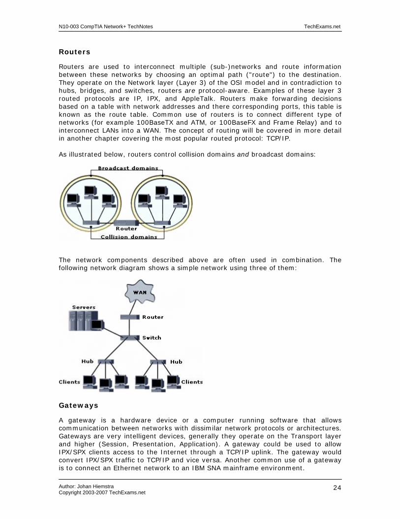
Routers are used to interconnect multiple (sub-)networks and route information between these networks by choosing an optimal path ("route") to the destination. They operate on the Network layer (Layer 3) of the OSI model and in contradiction to hubs, bridges, and switches, routers are protocol-aware. Examples of these layer 3 routed protocols are IP, IPX, and AppleTalk. Routers make forwarding decisions based on a table with network addresses and there corresponding ports, this table is known as the route table. Common use of routers is to connect different type of networks (for example 100BaseTX and ATM, or 100BaseFX and Frame Relay) and to interconnect LANs into a WAN. The concept of routing will be covered in more detail in another chapter covering the most popular routed protocol: TCP/IP. As illustrated below, routers control collision domains and broadcast domains:
The network components described above are often used in combination. The following network diagram shows a simple network using three of them:
Gateways
A gateway is a hardware device or a computer running software that allows communication between networks with dissimilar network protocols or architectures. Gateways are very intelligent devices, generally they operate on the Transport layer and higher (Session, Presentation, Application). A gateway could be used to allow IPX/SPX clients access to the Internet through a TCP/IP uplink. The gateway would convert IPX/SPX traffic to TCP/IP and vice versa. Another common use of a gateway is to connect an Ethernet network to an IBM SNA mainframe environment.
N10-003 CompTIA Network+ TechNotes TechExams.net
Author: Johan Hiemstra Copyright 2003-2007 TechExams.net
25
CSU/DSU
A CSU/DSU (Channel Service Unit/Data Service Unit) is a hardware device about the size of an external modem, which converts digital data frames from the communication technology used on a local area network (LAN) into frames appropriate to a wide-area network (WAN) and vice versa. A CSU/DSU is primarily used on both ends of a T-1 or T-3 connection. A T1 or T3 is a fast digital leased line, often used for high-speed internet connections (will be covered in more detail in our WAN Technologies TechNotes). NICs
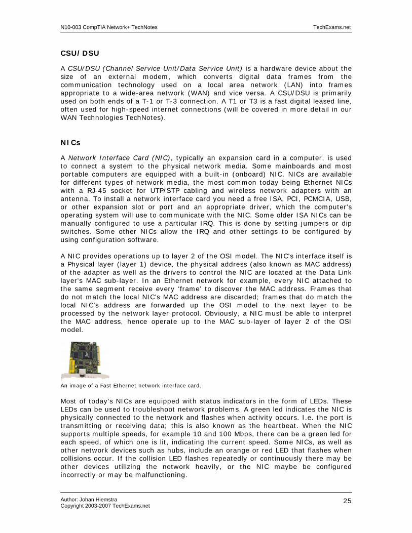
A Network Interface Card (NIC), typically an expansion card in a computer, is used to connect a system to the physical network media. Some mainboards and most portable computers are equipped with a built-in (onboard) NIC. NICs are available for different types of network media, the most common today being Ethernet NICs with a RJ-45 socket for UTP/STP cabling and wireless network adapters with an antenna. To install a network interface card you need a free ISA, PCI, PCMCIA, USB, or other expansion slot or port and an appropriate driver, which the computer's operating system will use to communicate with the NIC. Some older ISA NICs can be manually configured to use a particular IRQ. This is done by setting jumpers or dip switches. Some other NICs allow the IRQ and other settings to be configured by using configuration software. A NIC provides operations up to layer 2 of the OSI model. The NIC's interface itself is a Physical layer (layer 1) device, the physical address (also known as MAC address) of the adapter as well as the drivers to control the NIC are located at the Data Link layer's MAC sub-layer. In an Ethernet network for example, every NIC attached to the same segment receive every ‘frame’ to discover the MAC address. Frames that do not match the local NIC’s MAC address are discarded; frames that do match the local NIC’s address are forwarded up the OSI model to the next layer to be processed by the network layer protocol. Obviously, a NIC must be able to interpret the MAC address, hence operate up to the MAC sub-layer of layer 2 of the OSI model.
An image of a Fast Ethernet network interface card. Most of today's NICs are equipped with status indicators in the form of LEDs. These LEDs can be used to troubleshoot network problems. A green led indicates the NIC is physically connected to the network and flashes when activity occurs. I.e. the port is transmitting or receiving data; this is also known as the heartbeat. When the NIC supports multiple speeds, for example 10 and 100 Mbps, there can be a green led for each speed, of which one is lit, indicating the current speed. Some NICs, as well as other network devices such as hubs, include an orange or red LED that flashes when collisions occur. If the collision LED flashes repeatedly or continuously there may be other devices utilizing the network heavily, or the NIC maybe be configured incorrectly or may be malfunctioning.

N10-003 CompTIA Network+ TechNotes TechExams.net
Author: Johan Hiemstra Copyright 2003-2007 TechExams.net
26
As described earlier, network interfaces are physically configured with an address known as the MAC address (MAC is short for Media Access Layer), layer 2 address, Burned In Address (BIA), or physical address. The following is an example of a MAC address: 00-10-E3-42-A8-BC. The first six hexadecimal digits specify the vendor/manufacturer of the NIC; the other six define the host. MAC addresses are supposedly unique across the planet. Modems
Modems are used for low-speed long-distance connections over telephone lines. They convert parallel digital data into serial analog data and vice versa. This allows digital devices such as computers to communicate over an analog medium. There are two main types of modems: - Internal expansion cards (e.g. ISA, PCI) or 'On-board' (integrated in mainboard) - External modems that connect to the serial RS-232 or USB port and often have their own power supply. A telephone line is connected to the modem using a RJ-11 connector displayed below:
Transceivers (Media Converters)
Replacing the network interface when a different media type is being implemented can be expensive or even impossible if it is integrated into the network device. For example, when 10BaseT twisted-pair Ethernet started to replace 10Base2 and 10Base5 coaxial Ethernet, most of the network equipment in use, such as routers, didn’t have a RJ-45 socket but an 10Base5 AUI port. Transceivers, also referred to as media converters, were developed to overcome this problem and allow for a more affordable transition to newer network technologies. The following picture shows an Ethernet transceiver with an AUI Ethernet port on one side and an RJ-45 socket on the other.
More advanced media converters are available to connect copper media connection to fiber optic media, for example, transceivers that convert 10BaseT to 10BaseFL or 100BaseT to 100BaseFX. And those that allow fiber optic media to connect to a IEEE 1394 interface and hence drastically increase the maximum distance.

N10-003 CompTIA Network+ TechNotes TechExams.net
Author: Johan Hiemstra Copyright 2003-2007 TechExams.net
27
7-Layer OSI Model Current related exam objectives for the Network+ exam. 2.2 Identify the seven layers of the OSI model and their functions. 2.4 Identify the OSI layers at which the following network components operate: - Hubs - Switches - Bridges - Routers - NICs (Network Interface Card) - WAPs (Wireless Access Point)

N10-003 CompTIA Network+ TechNotes TechExams.net
Author: Johan Hiemstra Copyright 2003-2007 TechExams.net
28
OSI MODEL
The OSI (Open System Interconnection) model is developed by ISO in 1984 to provide a reference model for the complex aspects related to network communication. It divides the different functions and services provided by network technology in 7 layers. This facilitates modular engineering, simplifies teaching and learning network technologies, helps to isolate problems, and allows vendors to focus on just the layer(s) in which their hardware or software is implemented and enables them to create products that are compatible, standardized, and interoperable.
The diagram below shows the 7 layers of the OSI Model. To remember them in the correct order, a common mnemonic is often used: All People Seem To Need Data Processing.
Host A Host B
The Application, Presentation and Session layers are known as the Upper Layers and are implemented in software. The Transport and Network layer are mainly concerned with protocols for delivery and routing of packets and are implemented in software as well. The Data Link is implemented in hard- and software and the Physical layer is implemented in hardware only, hence its name. These lower two layers define LAN and WAN specifications. A more detailed description of each layer follows below, but here's what basically happens when data passes from Host A to Host B:
1. the Application, Presentation and Session layer take user input and converts it into data,
2. the Transport layer adds a segment header converting the data into segments,
3. the Network layer adds a network header and converts the segments into packets / datagrams,
4. the Data Link layer adds a frame header converting the packets/datagrams into frames,
5. the MAC sublayer converts the frames into a bits, which the Physical layer can put on the wire.
The steps are known as the 5 steps of data encapsulation. When the bits stream arrives at the destination, the Physical layer takes it of the wire and converts it into frames, each layer will remove their corresponding header while the data flows up the OSI model until it is converted back to data and presented to the user. This is also known as decapsulation.

N10-003 CompTIA Network+ TechNotes TechExams.net
Author: Johan Hiemstra Copyright 2003-2007 TechExams.net
29
Application (Layer 7) The Application layer provides network services directly to the user's application such as a web browser or email client. This layer is said to be "closest to the user". Examples of protocols that operate on this layer are TELNET, HTTP, FTP, TFTP, SMTP, and NTP. Presentation (Layer 6)
The Presentation layer 'represents' the data in a particular format to the Application layer. It defines encryption, compression, conversion and other coding functions. Examples of specifications defined at this layer are GIF, JPEG, MPEG, MIME, and ASCII. Session (Layer 5)
The Session layer establishes, maintains, and terminates end-to-end connections (sessions) between two applications on two network nodes. It controls the dialogue between the source and destination node, which node can send when and for how long. It also provides error reporting for the Application, Presentation and Session layer. Examples of protocols/API's that operate on this layer are RPC and NETBIOS. Transport (Layer 4)
The Transport layer converts the data received from the upper layers into segments and prepares them for transport. The Transport layer is responsible for end-to-end (source-to-destination) delivery of entire messages. It allows data to be transferred reliably and uses sequencing to guarantee that it will be delivered in the same order that it was sent. It also provides services such as error checking and flow control (in software). Examples of protocols that operate on this layer are TCP, UDP, NETBEUI, and SPX. The above Transport layer protocols are either connectionless or connection-oriented: Connection-oriented means that a connection (a virtual link) must be established before any actual data can be exchanged. This guarantees that data will arrive, and in the same order as it was sent. It guarantees delivery by sending acknowledgements back to the source when messages are received. TCP is an example of a connection-oriented transport protocol. A common example of connection-oriented communication is a telephone call. You call, the 'destination' picks up the phone and acknowledges, and you start talking (sending data). When a message or a piece of it doesn't arrive, you say: "What!?" and the sender will repeat what he said (retransmit the data). Connectionless is the opposite of connection-oriented; the sender does not establish a connection before it sends data, it just sends it without guaranteeing delivery. UDP is an example of a connectionless transport protocol.
N10-003 CompTIA Network+ TechNotes TechExams.net
Author: Johan Hiemstra Copyright 2003-2007 TechExams.net
30
Network (Layer 3)
The Network layer converts the segments from the Transport layer into packets (or datagrams) and is responsible for path determination, routing, and the delivery of packets across internetworks. The network layer treats these packets independently, without recognizing any relationship between those individual packets. It relies on higher layers for reliable delivery and sequencing. The Network layer is also responsible for logical addressing (also known as network addressing or Layer 3 addressing) for example IP addressing. Examples of protocols defined at this layer are IP, IPX, ICMP, RIP, OSPF, and BGP. Examples of devices that operate on this layer are layer-3 switches and routers. The latter includes WAPs with built-in routing capabilities (wireless access routers). Data Link (Layer 2) The Data Links provides transparent network services to the Network layer so the Network layer can be ignorant about the underlying physical network topology. It is responsible for reassembling bits, taken of the wire by the Physical layer, to frames, and makes sure they are in the correct order and requests retransmission of frames in case an error occurs. It provides error checking by adding a CRC to the frame, and flow control. Examples of devices that operate on this layer are switches, bridges, WAPs, and NICs. IEEE 802 Data Link sub layers Around the same time the OSI model was developed, the IEEE developed the 802-standards such as 802.5 Token Ring and 802.11 for wireless networks. Both organizations exchanged information during the development, which resulted in two compatible standards. The IEEE 802 standards define physical network components such as cabling and network interfaces, and correspond to the Data Link and/or Physical layer of the OSI model. The IEEE refined the standards and divided the Data Link layer into two sublayers: the LLC and the MAC sublayer. - LLC sublayer LLC is short for Logical Link Control. The LLC layer is the upper sublayer of the Data Link layer and is defined in the IEEE 802.2 standard. LLC masks the underlying physical network technologies by hiding their differences to provide a single interface to the Network layer. The LLC sublayer uses Source Service Access Points (SSAPs) and Destination Service Access Points (DSAPs) to help the lower layers communicate with the Network layer protocols, acting as an intermediate between the different network protocols (IPX, TCP/IP, etc.) and the different network technologies (Ethernet, Token Ring, etc.). Additionally, this layer is responsible for sequencing and acknowledgements of individual frames. - MAC sublayer The Media Access Control layer takes care of physical addressing and allows upper layers access to the physical media, handles frame addressing, error checking. This layer controls and communicates directly with the physical network media through the network interface card. It converts the frames into bits to pass them on to the

N10-003 CompTIA Network+ TechNotes TechExams.net
Author: Johan Hiemstra Copyright 2003-2007 TechExams.net
31
Physical layer, that puts them on the wire (and vice versa). IEEE LAN standards such as 802.3, 802.4, 802.5, and 802.11 define standards for the MAC sublayer as well as the Physical layer. Physical (Layer 1)
This layer communicates directly with the physical media. It is responsible for activating, maintaining and deactivating the physical link. It handles a raw bits stream and places it on the wire to be picked up by the Physical layer at the receiving node. It defines electrical and optical signaling, voltage levels, data transmission rates, as well as mechanical specifications such as cable lengths and connectors, the amount of pins and their functions. Examples of devices that operate on this layer are hubs/concentrators, repeaters, NICs, WAPs, and LAN and WAN interfaces such as RS-232, OC-3, and BRI.

N10-003 CompTIA Network+ TechNotes TechExams.net
Author: Johan Hiemstra Copyright 2003-2007 TechExams.net
32
TCP/IP Suite Current related exam objectives for the Network+ exam. 2.4 Differentiate between the following network protocols in terms of routing, addressing schemes, interoperability and naming conventions: - TCP / IP (Transmission Control Protocol / Internet Protocol) 2.5 Identify the components and structure of IP (Internet Protocol) addresses (IPv4, IPv6) and the required setting for connections across the Internet. 2.6 Identify classful IP (Internet Protocol) ranges and their subnet masks (For example: Class A, B and C). 2.7 Identify the purpose of subnetting. 2.8 Identify the differences between private and public network addressing schemes. 2.9 Identify and differentiate between the following IP (Internet Protocol) addressing methods: - Static - Dynamic - Self-assigned (APIPA (Automatic Private Internet Protocol Addressing)) 2.10 Define the purpose, function and use of the following protocols used in the TCP / IP (Transmission Control Protocol / Internet Protocol) suite: - TCP (Transmission Control Protocol) - UDP (User Datagram Protocol) - FTP (File Transfer Protocol) - SFTP (Secure File Transfer Protocol) - TFTP (Trivial File Transfer Protocol) - SMTP (Simple Mail Transfer Protocol) HTTP (Hypertext Transfer Protocol) - HTTPS (Hypertext Transfer Protocol Secure) - POP3 / IMAP4 (Post Office Protocol version 3 / Internet Message Access Protocol version 4) - Telnet - SSH (Secure Shell) - ICMP (Internet Control Message Protocol) - ARP/RARP (Address Resolution Protocol/Reverse Address Resolution Protocol) - NTP (Network Time Protocol) - NNTP (Network News Transport Protocol) - SCP (Secure Copy Protocol) - LDAP (Lightweight Directory Access Protocol) - IGMP (Internet Group Multicast Protocol) - LPR (Line Printer Remote)

N10-003 CompTIA Network+ TechNotes TechExams.net
Author: Johan Hiemstra Copyright 2003-2007 TechExams.net
33
2.11 Define the function of TCP / UDP (Transmission Control Protocol / User Datagram Protocol) ports. 2.12 Identify the well-known ports associated with the following commonly used services and protocols: - 20 FTP (File Transfer Protocol) - 21 FTP (File Transfer Protocol) - 22 SSH (Secure Shell) - 23 Telnet - 25 SMTP (Simple Mail Transfer Protocol) - 53 DNS (Domain Name Service) - 69 TFTP (Trivial File Transfer Protocol) - 80 HTTP (Hypertext Transfer Protocol) - 110 POP3 (Post Office Protocol version 3) - 119 NNTP (Network News Transport Protocol) - 123 NTP (Network Time Protocol) - 143 IMAP4 (Internet Message Access Protocol version 4) - 443 HTTPS (Hypertext Transfer Protocol Secure)
TCP/IP is today's most widely adapted standard internet technology and is the protocol in the Internet. It is a routable protocol that supports connections between heterogeneous network systems. In other words, it allows communication between UNIX, Windows, Netware, and Mac OS computers spread over multiple interconnected networks. TCP/IP is actually a suite composed of many different protocols, each with its own purpose. The two main protocols are in its name: the Transmission Control Protocol and the Internet Protocol. Both are outlined in this chapter, as well as several other protocols from the TCP/IP suite. IP
The Internet Protocol (IP) is a Network layer protocol that provides connectionless delivery of packets across internetworks. The primary functions of IP are to facilitate routing and implement Network layer addressing. IP employs TCP or UDP for the actually data transport, these two protocols are discussed later in these TechNotes.
IP Addressing
IP addressing is assigning a 32-bit logical numeric address to a network device. Every IP address on the network must be unique. IP addresses are assigned manually (i.e. by an administrator) or automatically (i.e. dynamically by DHCP or APIPA). These addressing methods will be covered more extensively in the Network Services TechNotes. An IP address is represented in a dotted decimal format, for example: 159.101.6.8 As you can see, the address is divided in 4 parts, which are called octets. Each octet in an IP address represents 8 bits. The IP address mentioned above can also be displayed in dotted binary format: 10011111.01100101.00000110.00001000
N10-003 CompTIA Network+ TechNotes TechExams.net
Author: Johan Hiemstra Copyright 2003-2007 TechExams.net
34
Converting the decimal address to a binary format (and vice versa) is a fairly easy process. The highest decimal number you can represent with 8 bits is 255. This is the case when all bits in an octet are set to 1. 1 1 1 1 1 1 1 1 128 + 64 + 32 + 16 + 8 + 4 + 2 + 1 (2^7 2^6 2^5 2^4 2^3 2^2 2^1 2^0)
= 255
The following are examples of binary values and their decimal counterparts: Binary Decimal 00000010 2 00000011 3 10000000 128 10000001 129 11111010 250 The currently available addressing space in IP version 4 is divided in 5 classes: Classes First Octet Class A 1 126 Class B 128 191 Class C 192 223 Class D 224 239 Class E 240 254
Private vs. Public addresses
IANA reserved four address ranges to be used in private networks only. This prevents address conflict between addresses on private corporate or home networks and the Internet: - 10.0.0.0 through 10.255.255.255 from the Class A range - 172.16.0.0 through 172.31.255.255 from the Class B range - 192.168.0.0 through 192.168.255.255 from the Class C range - 169.254.0.1 through 169.254.255.254 (reserved for Automatic Private IP Addressing) The range 127.0.0.0 to 127.255.255.255 is reserved for IP loopback addresses, which are mainly intended for testing purposes and for checking if the TCP/IP stack has correctly loaded. To function properly in a TCP/IP internetwork, a network device needs an IP address, a subnet mask, and a default gateway. The latter two are discussed below.
Subnet Masks In order for a protocol to be routable, its network address must use two parts: a host and a network portion. The host portion uniquely identifies the host address in the local network (subnet), and the network portion identifies the network in the
N10-003 CompTIA Network+ TechNotes TechExams.net
Author: Johan Hiemstra Copyright 2003-2007 TechExams.net
35
internetwork. IP employs subnet masks to determine which part is the host portion and which is the network portion. For two network devices to communicate with each other without a router, they need to be in the same (sub-)network, hence use the same subnet mask. The following table lists the default subnet masks for the classes from which IP addresses can be used for static or dynamic IP address assignment. Default subnet masks: Class A 255.0.0.0 Class B 255.255.0.0 Class C 255.255.255.0 For example, in a Class B IP address 172.16.12.234, with the default Class B 16 bits subnet mask 255.255.0.0, the network portion is 172.16 and the host part is 12.234. In binary language, this means that the portion of the subnet mask where the bits are 1 defines the network portion. A TCP/IP client performs this calculation to determine whether a remote host is located on the same local subnet or on a remote network. If the network portion of the remote host’s IP address differs from the client’s IP address network portion, it means they are located on different (sub-) networks, and the client will need to send traffic through a router (i.e. a default gateway, which is discussed in the next section). Instead of using the default subnet masks, additional bits in the mask can be set to 1. This means ‘stealing’ bits from the host portion, which in turn means more bits to create different sub-networks, but each with less available host addresses. This process is known as subnetting. The main reason to divide a Class A, B, or C network into smaller subnets is to use the available address space more efficiently. For example, your company is assigned a Class B network, which allows for 65534 different host addresses. It would be a waste of addresses to use the entire range for a single network with 200 nodes. Instead, the class B address can be subnetted by using Class C subnet mask, or a classless subnet mask. Classless means that the mask is not a Class A, B, or C mask, and the boundary between the network and the host portion of an address does not lie exactly between octets. For example, a Class C network 192.168.1.0 can be divided into two subnets by using the subnet mask 255.255.255.128. The first subnet would use the range 192.168.1.0 – 192.168.1.127 and the second subnet would use 192.168.1.128 – 192.168.1.255. Calculating the correct subnet masks for specific scenarios is not something you will be tested on for the Network+ exam but it is important to understand what subnetting is.
Default Gateways The purpose of a default gateway is easily defined ("All data not meant for the local subnet is sent to this router"), but it is best explained by using an example of IP packets traveling along an internetwork. For example, in the network diagram below, the default gateway for Host B is the router interface 192.168.1.254 and for Host E the default gateway is the router’s other interface 192.168.5.230. If Host B wants to contact Host E, it will notice the network portion of the Host E’s IP address differs from its own address. This means it is not on the same IP (sub-)network and it needs to send packets to a router that can forward them to the destination network.

N10-003 CompTIA Network+ TechNotes TechExams.net
Author: Johan Hiemstra Copyright 2003-2007 TechExams.net
36
So again: if a default gateway is set and a computer wants to send a packet to a host on another (sub-)network it is sent to the default gateway.
IPv6 All of the information above refers to IP version 4, which is currently the most used version. A new version, IPv6, is developed to allow for more and larger networks with more hosts. This is needed because we might run out of IPv4 addresses within a matter of years. IPv6 uses a 128-bit address format allowing a theoretical 128^2 unique addresses (=340282366920938463463374607431768211456 forgive me if I made a typo ;) ). An IPv6 address is written in a maximum of 8 groups of 16 bits each written as four hex digits separated by colons, for example: FEDC:BA12:ABCD:3210:FEDC:BA98:7654:1234 Although most newer operating systems and network devices support IPv6, it may take years before the world will start a massive migration from version 4 to 6. And it will take many years more of coexistence before IP version 4 is replaced entirely. OTHER TCP/IP PROTOCOLS
Sockets
Before we go over the main TCP/IP protocols, let us first go over an essential feature of TCP/IP: sockets. A socket is the combination of an IP address and a port number. Different applications and services use different port numbers allowing multiple applications to share the same connection. For example connect to an SMTP mail server on port 25 to send email, and at the same time connect to a web server on port 80 to browse website. These application and services uses TCP and/or UDP for the actual data transport.
TCP
The Transmission Control Protocol (TCP) is a Transport layer protocol that provides reliable, connection-oriented, full-duplex transport. Connection-oriented means that a connection is established before two communication partners on a network can actually exchange data. A common explanation of connection-oriented communication is a telephone call: you make the call, the 'destination' picks up the phone, acknowledges, and you start talking (sending data). TCP guarantees delivery by sending acknowledgements back to the source when messages are received. If individual messages are not acknowledged, the source will retransmit them.

N10-003 CompTIA Network+ TechNotes TechExams.net
Author: Johan Hiemstra Copyright 2003-2007 TechExams.net
37
UDP
The User Datagram Protocol (UDP) is a connectionless Transport layer protocol that provides best-effort delivery. Unlike TCP, there is no guarantee that UDP datagrams ever reach their intended destination. Therefore, UDP is said to be unreliable. It is like sending a postcard; you just send it out and hope it will reach its destination.
ARP/RARP Before two stations in a network are able to communicate with each other, they must know each other’s physical (MAC) addresses. The Address Resolution Protocol (ARP) is used to discover a remote MAC address (layer 2) based on the IP address (layer 3). An ARP request is broadcasted on the local network and only the station with the IP address listed in the broadcast responds with an ARP reply containing its IP and MAC address. This requires the participating network devices to know their own MAC address and IP address. The station that requested the MAC address will store it in its local ARP cache. The Reverse Address Resolution Protocol (RARP) performs the opposite translation, it discovers an IP address based on a MAC address. A RARP client doesn’t send broadcasts, but contacts a RARP server that contains a list with MAC address to IP address mappings. The list can be manually configured on a router and can be the dynamic ARP cache. RARP is typically used by new stations that do not know their own IP address. ARP and RARP are both Data Link layer protocols. ICMP The Internet Control Message Protocol (ICMP) is a Network layer protocol used for exchanging control information and messages. One of the most common examples of an application that uses ICMP is the ping utility. Ping is a utility that allows you to determine whether a particular TCP/IP host is reachable. It sends out an echo request to an IP address and if the destination is alive and reachable it will respond with an echo reply. If not there is no route available to the destination, the last router on the path sends a Destination Unreachable message back to the source station. Echo request and echo reply are two of a set of message types ICMP employs to provide and request feedback.
IGMP The Internet Group Management Protocol (IGMP) is a Network layer protocol that is used for registering and sharing multicast group membership information. Multicast traffic is directed to a group of IP clients identified by a single IP address. This can reduce the total amount of bandwidth required for streaming data, such as video, over large internetworks. Multicast clients can dynamically join and leave the group using the IGMP protocol at their local router, which in turn can use IGMP to notify other routers of its registered multicast groups. Multicast groups use addresses from the Class D IP range (224.0.0.0 to 239.255.255.255).

N10-003 CompTIA Network+ TechNotes TechExams.net
Author: Johan Hiemstra Copyright 2003-2007 TechExams.net
38
FTP
The File Transfer Protocol (FTP) is an Application layer protocol that provides connection-oriented file transfer between a client and a server. I was originally used to transfer files between UNIX systems, and is now the most popular file transfer protocol on the Internet. FTP use TCP port 21 for control and TCP port 20 for data transport.
SFTP
The Secure File Transfer Protocol (S/FTP or SFTP) allows you to implement the same functionality as regular FTP, but much more secure. SFTP is essentially FTP over SSH (Secure Shell), hence provide the same level of security as SSH. This includes mutual authentication based on digital certificates, and establishing a tunnel between the client and the server through which data is transmitted in an encrypted form. Another mentionable advantage is that SFTP operates over the same port as SSH (port 22) and does not require port 20 and 21 to be open as with regular FTP.
SCP Another alternative to FTP that is included in *nix systems is the Secure Copy Protocol (SCP). SCP is the secure counterpart of the Remote Copy Protocol (RCP), and provides secure file transfer using SSH. Like rcp, scp is also a command-line utility on Unix-like systems.
TFTP The Trivial File Transfer Protocol (TFTP) is an Application layer protocol that provides connectionless file transfer functions. TFTP is a simple and small protocol, which makes it suitable for transferring small amounts of data. It is primarily used for updating devices such as routers and switches. Another common use is transferring the data required to boot a diskless system over the network. TFTP uses UDP port 69.
SMTP The Simple Mail Transfer Protocol (SMTP) is an Application layer protocol used for sending email to and between mail servers. SMTP uses TCP port 25.
POP3/IMAP4
While SMTP is used to send email, both the Post Office Protocol and the IMAP are use used to retrieve e-mail. The main difference between the latter two Application layer protocols is that POP3 can be used to access the "Inbox" folder only, and the more complex IMAP4 can be used to access every server-based messaging folder (sent items, deleted items etc). Hence, IMAP4 eliminates the need for a local repository. POP3 clients connect to TCP port 110, IMAP4 clients connect to TCP port 143.

N10-003 CompTIA Network+ TechNotes TechExams.net
Author: Johan Hiemstra Copyright 2003-2007 TechExams.net
39
HTTP
The HyperText Transfer Protocol (HTTP) is an Application layer protocol originally designed for transferring World Wide Web documents and is extended to transfer other type of files as well. Its most common use is transferring web pages between a web browser and a web server. HTTP uses TCP Port 80 by default.
HTTPS
HTTPS is used in exactly the same way as the HTTP protocol. The differences are that HTTPS uses a default port number, 443, and that HTTPS uses SSL (Secure Socket Layer) to send data in an encrypted form and to authenticate the server. For example, when you buy something online using a credit card, the URL should start with https:// instead of http://. At the bottom right of your browser, you should notice a small padlock. Both indicate that a secure HTTP connection over SSL has been established with a web server.
NNTP The Network News Transport Protocol (NNTP) is an Application layer protocol that allows news clients to connect to a Usenet news server that hosts newsgroups. Newsgroups are similar to online discussion forums but use a client such as Microsoft Outlook Express. NNTP uses TCP port 119.
TELNET Telnet is a terminal emulation protocol that allows remote access to a system. The most common use of the telnet protocol is the utility with the same name as the protocol: telnet. Telnet operates on the Application layer of the OSI model and uses TCP port 23.
SSH Telnet is considered insecure mainly because it sends username and password information in clear text. Therefore, Telnet should be replaced with SSH (Secure SHell). SSH can be used to provide similar functionality as Telnet, but is much more secure. It employs encryption through certificates and authenticates the server to the client (vice versa is also possible). When possible, SSH version 2 should be used instead of version 1 because version 2 provides much better encryption. SSH operates on port 22.
NTP The Network Time Protocol (NTP) is an Application layer protocol used to provide accurate time synchronization in LANs and WANs by synchronizing the time of a computer to a reference time source, such as an NTP server, a radio or satellite receiver. NTP is capable of synchronizing distributed clocks to the millisecond. NTP uses UDP port 123.
N10-003 CompTIA Network+ TechNotes TechExams.net
Author: Johan Hiemstra Copyright 2003-2007 TechExams.net
40
RIP
The Routing Information Protocol (RIP) is used for exchanging routing information between routers. Each router builds a routing table that contains entries of possible routes in the network and their attributes. When a link to a network goes down, the route to that network, and perhaps other upstream networks that are connected to it, become invalid. To inform routers in an internetwork about this change in the network, a routing protocol is used. RIP is typically used in smaller environments. An example of a more scalable routing protocol is Open Shortest Path First (OSPF).
LDAP The Lightweight Directory Access Protocol (LDAP) provides access to directory services such as centralized address books and Microsoft’s Active Directory. It allows clients to search a directory for information and objects such as contacts, certificates, and shared network resources. LDAP uses TCP and UDP port 389.
LPR The Line Printer Remote (LPR) protocol allows clients to connect to and use print services of a server running the Line Printer Daemon (LPD) service. This server is typically a UNIX server, but LPR/LPD is available for other operating systems as well. Additionally, network printers attached directly to the TCP/IP network support the LPR protocol.

N10-003 CompTIA Network+ TechNotes TechExams.net
Author: Johan Hiemstra Copyright 2003-2007 TechExams.net
41
TCP/IP Utilities Current related exam objectives for the Network+ exam. 4.1 Given a troubleshooting scenario, select the appropriate network utility from the following: - tracert / traceroute - ping - arp - netstat - nbtstat - ipconfig / ifconfig - winipcfg - nslookup / dig 4.2 Given output from a network diagnostic utility (For example: those utilities listed in objective 4.1), identify the utility and interpret the output. TRACERT / TRACEROUTE
Tracert is a Windows command-line utility that uses ICMP Echo packets and their TTL (Time To Live) value to determine the route and hopcount to a destination. In the following network for example, when a connection between host A and B fails, you can use tracert to find out where the packet stopped.
The following image shows the output of running tracert 192.168.5.110 on host A.
The target can be either a name or an IP address. By default, tracert will try to resolve the IP address of every hop (router) along the path to a hostname. To prevent this, and possibly speed up the tracing process, you can use the –d option as displayed in the following image:

N10-003 CompTIA Network+ TechNotes TechExams.net
Author: Johan Hiemstra Copyright 2003-2007 TechExams.net
42
The Unix/Linux counterpart of tracert is traceroute, which basically provides the same functionality as tracert does for Windows systems. However, traceroute offer several additional command-line options to give you more control, such as specifying the gateway or source IP address. Traceroute uses UDP packets by default instead of ICMP packets.
PING
The ping utility is a diagnostic tool that you can use to test TCP/IP configurations and connections. It is useful to determine whether a particular TCP/IP host can be reached and is available. The syntax for the ping command is:
ping target
target can be either a name (hostname or NetBIOS name) or an IP address. The following image shows the output of running the command ping www.techexams.net
Some common situations where PING can be useful:
- To verify that TCP/IP is installed, initialized, and bound to your network interface, ping the loopback address (ping 127.0.0.1).
- To verify that the default gateway is available and the computer can communicate with a remote host through a router, ping a host on a remote network.
- To verify that DNS host name resolution is available, ping an existing host name of a computer you know is online and available.
- To verify that WINS name resolution is available, ping an existing NETBIOS name, of a computer you know is online and available.

N10-003 CompTIA Network+ TechNotes TechExams.net
Author: Johan Hiemstra Copyright 2003-2007 TechExams.net
43
ARP
As described in the TCP/IP Suite chapter, the Address Resolution Protocol (ARP) is used for resolving layer 3 IP addresses to layer 2 MAC addresses. The corresponding utility arp can be used to manually resolve an IP address to a MAC addresses and to modify or display the current ARP cache table. Below is an example output of using arp with the -a switch to display the IP address to MAC mappings currently in the ARP cache: arp –a
This command is issued on Host A (as shown in the network diagram in the tracert section above). The first entry is dynamic, as it has been discovered using ARP broadcasts. The second is an example of a static entry entered using arp with the -s switch. In this case the IP address 192.168.2.10 was mapped to the MAC address 00-90-69-42-c6-09 by using the following command:
arp -s 192.168.2.10 00-90-69-42-c6-09 Any entry can be deleted by issuing the command arp -d ip_address. By using an * as the ip_address parameter you can delete all entries.
NETSTAT
Netstat displays TCP/IP protocol statistics and information about TCP and UDP connections to and from the local computer. Netstat -a displays the current connections and listening ports:
Netstat can also be used to display Ethernet statistics such as the number of bytes sent and received, as well as any dropped network packets, by using the -e switch:

N10-003 CompTIA Network+ TechNotes TechExams.net
Author: Johan Hiemstra Copyright 2003-2007 TechExams.net
44
netstat –e
netstat -r produces the same output as the route print command, in other words: displays the contents of the routing table.
NBTSTAT
Nbtstat is used for troubleshooting NetBIOS name resolution problems. It displays protocol statistics and current TCP/IP connections that are using (NBT) NetBIOS over TCP/IP as well as the NetBIOS name table and cache.
To display the NetBIOS name table of the local computer use nbtstat with the -n switch. The status of Registered indicates that the name is registered either by broadcast or with a WINS server. If two hosts on the local network would use the same NetBIOS name, the status would be Conflict.
nbtstat –n
To display the NetBIOS name table of a remote computer use one of the following:
nbtstat -a remotename or nbtstat -A IPaddress
Use nbtstat –c to display the contents of the local computer NetBIOS name cache.
Use nbtstat -r to display to verify NETBIOS names are correctly resolved by WINS:

N10-003 CompTIA Network+ TechNotes TechExams.net
Author: Johan Hiemstra Copyright 2003-2007 TechExams.net
45
IPCONFIG
Ipconfig can be used on Windows NT, 2000/2003 and XP to display TCP/IP configuration information, renew and release DHCP assigned address configuration, and register in dynamic DNS or flush the local DNS cache. When the ipconfig command is issued without any options the output will be similar to the one below:
ipconfig /all displays full configuration information, for example:
Use ipconfig /release release the IP address configuration. Use ipconfig /renew Renew the IP address configuration.

N10-003 CompTIA Network+ TechNotes TechExams.net
Author: Johan Hiemstra Copyright 2003-2007 TechExams.net
46
ipconfig /flushdns clears the local DNS cache. This is useful when the IP address for a previously resolved host name changed and you want the client to request the IP address fresh from the DNS server rather than the local cache.
IFCONFIG
Ifconfig is a UNIX/Linux command-line utility used to configure and manage network interfaces. Used without any parameters, ifconfig displays the status of all active network adapters:
ifconfig –a displays the status of all adapters including those that are down. Ifconfig is the most common command for checking basic information such as the IP address or whether an interface is enabled. The ifconfig command can also be used to configure an interface. The following example shows how to set an IP address and subnet mask for interface eth0: ifconfig eth0 10.0.0.3 netmask 255.0.0.0 Settings configured in this manner are only kept until the machine is rebooted. To make network settings permanent the changes must be made to the appropriate configuration file in the /etc/sysconfig/network-scripts directory. Ifconfig can be used with either the up or down parameter to start or stop an interface. The following example disables the first Ethernet interface: ifconfig eth0 down WINIPCFG
Winipcfg allows you to display the TCP/IP configuration information and renew and release DHCP assigned address configuration on Windows 9x and ME computers. The screenshot below shows the configuration of an Ethernet adapter with a manually assigned IP address configuration.
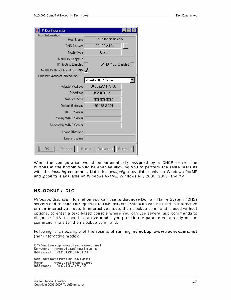
N10-003 CompTIA Network+ TechNotes TechExams.net
Author: Johan Hiemstra Copyright 2003-2007 TechExams.net
47
When the configuration would be automatically assigned by a DHCP server, the buttons at the bottom would be enabled allowing you to perform the same tasks as with the ipconfig command. Note that winipcfg is available only on Windows 9x/ME and ipconfig is available on Windows 9x/ME, Windows NT, 2000, 2003, and XP.
NSLOOKUP / DIG
Nslookup displays information you can use to diagnose Domain Name System (DNS) servers and to send DNS queries to DNS servers. Nslookup can be used in interactive or non-interactive mode. In interactive mode, the nslookup command is used without options, to enter a text based console where you can use several sub commands to diagnose DNS. In non-interactive mode, you provide the parameters directly on the command-line after the nslookup command.
Following is an example of the results of running nslookup www.techexams.net (non-interactive mode):

N10-003 CompTIA Network+ TechNotes TechExams.net
Author: Johan Hiemstra Copyright 2003-2007 TechExams.net
48
You can use a different DNS server by adding the hostname or IP address of another DNS server, for example:
nslookup www.techexams.net ns2.tedomain.net
Dig is a more advanced utility for diagnosing DNS issues. Originally a UNIX/Linux tool but can be downloaded for Windows as well. It provides numerous options that allow you to control the manual host name lookups and responses. The following screenshot shows the output of running dig www.techexams.net

N10-003 CompTIA Network+ TechNotes TechExams.net
Author: Johan Hiemstra Copyright 2003-2007 TechExams.net
49
Network Services Current related exam objectives for the Network+ exam. 2.13 Identify the purpose of network services and protocols, for example: - DNS (Domain Name Service) - WINS (Windows Internet Name Service) - SNMP (Simple Network Management Protocol) 4.6 Given a scenario, determine the impact of modifying, adding or removing network services for network resources and users. For example: - DHCP (Dynamic Host Configuration Protocol) - DNS (Domain Name Service) - WINS (Windows Internet Name Service) DHCP/bootp The Dynamic Host Configuration Protocol (DHCP) is a service used in TCP/IP networks to assign automatic IP addressing configuration to network nodes. DHCP consist of a server part and a client part. The server part is a service typically running on a Windows/Unix server but also on routers and wireless access points for example. The client part is installed on clients, servers, and other devices, and requests an IP address configuration from a DHCP server. DHCP significantly simplifies administration and ensures every host will use a unique IP address as is required in an IP network. When a DHCP client boots for the first time, it uses the bootp protocol to request a DHCP server to issue an IP address. This is called the lease process and goes as follows: 1. The client sends out a DHCPDiscover broadcast message to request IP addressing information from a DHCP server. 2. One or more DHCP servers respond with a DHCPOffer, containing an IP address and other IP addressing info such as subnet mask and default gateway. The first DHCPoffer received by the client is will be accepted, others will be ignored. 3. The client responds with a DHCPRequest, a broadcast message containing the IP addressing information again to make sure it is still available and can be used. 4. If the address is still available, the DHCP server responds with a DHCPAck (Acknowledge) and the optional configuration, such as DNS and WINS servers. Once the client receives the acknowledgement, it will start using the new IP addressing configuration. Or, the DHCP server responds with a DHCPNak (Negative Acknowledge) when the IP address is no longer available, which forces the client to start the lease process all over again. The IP addresses issued by the DHCP server are valid for a configurable amount of time, called the lease period. When 50% of the lease period has expired, the client will try to renew the lease for the same IP address. If this fails, the client will try again at 87.5% of the lease period. When a DHCP client is not able to locate a DHCP server, during the initial configuration or during the lease renewal attempt, the client will be configured with an IP address of 0.0.0.0. In case the client uses Automatic Private IP Addressing (APIPA), it will configure itself with an IP address from the network 169.254.0.0 and subnet mask 255.255.0.0.

N10-003 CompTIA Network+ TechNotes TechExams.net
Author: Johan Hiemstra Copyright 2003-2007 TechExams.net
50
DHCP servers listen to incoming messages at UDP port 67, and clients listen at UDP port 68. Routers typically do not forward UDP broadcasts, hence every subnet requires its own DHCP server. To overcome this limitation, a router can be configured to forward UDP port 67 and 68 broadcasts, or a DHCP relay agent can be installed in subnets without DHCP servers. The DHCP relay agent can be either a client or a server that picks up DHCP broadcasts and forwards them to a DHCP server in another subnet. That DHCP server responds to the DHCP relay agent, which in turn forwards the information to the DHCP client that sent the original broadcast. In other words, the DHCP relay agent acts as an intermediate between a DHCP client in one subnet and a DHCP server in another subnet. In addition to the IP address and the subnet mask, other IP addressing information is also typically issued by a DHCP server. These parameters include: - Default gateway address - DNS server addresses - WINS server addresses Besides for DHCP messages, the Bootp protocol is also used for bootstrapping. Bootstrapping allows a diskless client to boot from the network by loading the operating system from a central server. Name Resolution
Compared to TCP/IP networks, most telephone systems are rather dumb. In general, when you want to call someone, you have to dial an x-digit number. In TCP/IP networks you can contact an intended communication partner by using a name instead of having to know a numeric address for every computer you want to contact. For this to work, there has to be some naming system that can resolve names to IP addresses. The two main services taking care of this are DNS and WINS.
DNS
Today's most common naming system in corporate IP networks and ‘the’ naming system on the Internet is the Domain Naming System (DNS). The primary function of DNS is to resolve host names to IP addresses, and vice versa. A DNS server maintains a hierarchical directory, or a portion of it, in a database with zone for each domain. Records are created in a zone to map host names of individual network resources to their IP addresses. Following are some common example of resource records:
A This is the hostb part in the FQDN below this table and maps a host name to an IP address.
CNAME This is an alias for an A record, for example the www part in www.tedomain.net could actually be an alias for host11.tedomain.net. And mail.tedomain.net and ftp.tedomain.net could be the same host as well.
MX This name maps to the IP address of an SMTP server to which email for this domain should be send. For example: mail.tedomain.net.
PTR A pointer record is the opposite of an A record. It maps an IP address to a

N10-003 CompTIA Network+ TechNotes TechExams.net
Author: Johan Hiemstra Copyright 2003-2007 TechExams.net
51
hostname instead of vice versa. This allows DNS clients to resolve an IP address to host name.
A host name is actually a part of a 'larger' name, called a Fully Qualified Domain Name (FQDN). Following is an example of an FQDN: hostb.tedomain.net This name consists of three parts read from right to left: net is the top-level domain tedomain is the second-level domain hostb is the host name. There is actually another level on top of the top-level domain, which is called the root and is sometimes actually represented in an FQDN, right from the top-level domain, as a dot. For example: hostb.tedomain.net. When a client wants to communicate with another host in the network by using a host name, it connects to UDP port 53 on the DNS server and requests the IP address of the target host. If the zone for the domain of the hostname is located on the DNS server, it will reply with the IP address. If the zone is located on another DNS server, on the Internet for example, the DNS server can forward the request and act as an intermediate between the client requesting the IP address and the DNS server hosting the database with the actual record. The HOSTS file is the local static equivalent and predecessor of DNS. It is a text file that contains IP address to host name mappings. It originated on UNIX but can be found on Windows OS clients and servers as well. Following is example content of a HOSTS file: 102.54.94.97 server1.tedomain.net # source server 38.25.63.10 server2.tedomain.com # x client host 127.0.0.1 localhost On Windows NT-based systems such as Windows XP and 2000, the HOSTS file is located in the C:\WINDOWS\system32\drivers\etc folder. On Windows 9x the file can be found in the C:\WINDOWS\ folder.
WINS The Windows Internet Naming System (WINS) was the primary naming system in Microsoft networks. Since the introduction of Windows 2000, DNS took over the role of WINS, but the latter is still available in Windows products to maintain compatibility with older systems. WINS maps NETBIOS names to IP addresses, and was used heavily in Windows NT 4 networks. Read the NETBEUI/NETBIOS TechNotes for more information about NETBIOS names and the difference with host names. When a station without access to a WINS server uses a NETBIOS name to contact another station, the station will send a broadcast to discover the name of its

N10-003 CompTIA Network+ TechNotes TechExams.net
Author: Johan Hiemstra Copyright 2003-2007 TechExams.net
52
intended communication partner. When that station receives the broadcast message, it will respond with its IP address so an IP connection can be established. To reduce the amount of broadcasts on the network, clients can be configured to consult a WINS server for NETBIOS to IP address mappings. All WINS clients register their name at the WINS server at startup to populate the WINS database on the WINS server. When they need to resolve a NETBIOS name to an IP address, they contact the WINS server using a direct unicast connection instead of generating broadcasts. Besides the difference that WINS is used for NETBIOS names to IP address name resolution and DNS for host name to IP address name resolution, another main difference between DNS and WINS used to be that the WINS database is dynamic and DNS was static. WINS clients register and update their own records, although you can also add static entries to a WINS database. Most of the DNS servers on the Internet are still static, but modern implementation of DNS, such as those in Windows 2000 and 2003 can also be dynamic. The LMHOSTS file is the local, static equivalent and predecessor of WINS. It is a text file that contains IP address to NetBIOS name mappings. It originated on Lan Manager (Microsoft's operating system before Windows) but used to be commonly configured on Windows OS clients and servers as well. Following is a sample entry of a LMHOSTS file: 102.54.94.97 teserver1 #PRE #DOM:tedomain On Windows NT-based systems such as Windows XP and 2000, the file is located in the C:\WINDOWS\system32\drivers\etc folder. On Windows 9x, the file can be found in the C:\WINDOWS\ folder. Note that the file is called lmhosts.sam by default, you will need to create a new file or rename the sample file (thus remove the .sam extension) before you can use it. SNMP
The Simple Network Management Protocol (SNMP) is an application layer protocol that is primarily used to monitor, and gather information about, network systems and devices. An SNMP agent is installed on a managed device to send SNMP information to a central Network Management System (NMS). On the NMS, the information is stored in a Management Information Base (MIB), which can be used to produce graphs, reports, baselines and other useful overviews of the network. The following are 3 of the basic commands supported by SNMP: Read A read command can be sent to an agent to request information about a
managed device. Trap Trap messages are sent from the agent to an NMS when a certain event
occurs. E.g. when a service stops or a network interface goes down. Write Besides passively monitoring and gathering information, SNMP can also be
used to 'manage' a network by configuring managed devices using a Write command.
SNMP agents listen and respond to UDP port 161, trap messages are send to UDP port 162. When an agent is not able to communicate with an NMS in another
N10-003 CompTIA Network+ TechNotes TechExams.net
Author: Johan Hiemstra Copyright 2003-2007 TechExams.net
53
network, verify that these ports are not blocked on an intermediate router or firewall. Besides operating over UDP and IP, SNMP can also be used in IPX and AppleTalk networks. Network Attached Storage (NAS)
(Note: Although NAS is no longer listed in the Network+ exam objectives, it’s covered here because some related protocols are still listed. These remote file access protocols will be covered in more detail in another section in these TechNotes regarding operating specific networking.) Network Attached Storage (NAS) in its simplest form is a file server that runs on a dedicated device directly connected to the network. Usually a box containing several hard disks combined in a RAID set, it is directly attached to the network through connections ranging from 10Mbps to 1Gbps and faster. Many NAS devices are based on Linux or UNIX derivatives and are usually easily installed, configured, and managed using a web browser. NAS can communicate with the network using TCP/IP, IPX/SPX, NetBEUI, or AppleTalk even. The primary advantage of this wide variety of supported protocols is that Windows, UNIX/Linux, Mac OS, and Novell clients can all use the same storage and access and share the same data. These operating systems each support one or more remote file access protocols to access data on a NAS device. Windows systems access files using either Server Messenger Block (SMB) or Common Internet File System (CIFS). Unix/Linux systems use the Network File System (NFS). Novell systems use the Netware Core Protocol (NCP). And Apple systems use AppleShare or the Apple Filing Protocol (AFP). Additionally, most NAS devices also support file access through HTTP and FTP. Do not confuse NAS with Storage Area Network (SAN). SAN is not a just a device, but refers to a complete network configuration where servers use central storage connected through fiber optic cabling or SCSI. Instead of being an autonomous device, the file system is dictated by the operating system running on the servers. SAN is commonly used in combination with clusters.

N10-003 CompTIA Network+ TechNotes TechExams.net
Author: Johan Hiemstra Copyright 2003-2007 TechExams.net
54
WAN Technologies Current related exam objectives for the Network+ exam. 2.14 Identify the basic characteristics (For example: speed, capacity, and media) of the following WAN (Wide Area Networks) technologies: - Packet switching - Circuit switching - ISDN (Integrated Services Digital Network) - T1 (T Carrier level 1) / E1 / J1 - T3 (T Carrier level 3) / E3 / J3 - OCx (Optical Carrier) - X.25 Circuit switching vs. Packet switching
Circuit switching and packet switching are both communication methods for large networks. The most common example of a circuit switching network is the telephone system: the sender and the receiver establish a dedicated physical path for the entire duration of the call. All of the transmitted information follows the same route and the circuit is available only to the nodes that established it. PSTN (Public Switched Telephone Network), covered in the Internet Connections TechNotes, and ISDN, covered below, both use the circuit switching technology. In packet switching networks, data is segmented into packets that each take a route independently based on the addressing information their header. In theory, the route can be different for each packet, but also one and the same. The packet is sent from hop to hop whereby each hop (e.g. a router) determines the best next part of the route. Other nodes can send packets, seemingly simultaneously, over the same dynamic route. Most large WANs are largely made up of packet switching networks, the Internet being the most common example. ISDN
Integrated Services Digital Network (ISDN) is a circuit-switching network used for voice, data, and video transfer over plain copper telephone lines. ISDN is a bit similar to the normal telephone system but it is faster, more reliable, and requires less time to setup a call. Digital ISDN phones digital faxes are usually provided by the telco. An ISDN modem can be used to convert the signals of non-ISDN equipment to ISDN signals. An ISDN modem can be external or internal and is usually connected to the wall outlet by using an UTP cable with an 8-pin RJ-45 connector on the modem side, and a 6-pin RJ-11 connector on wall jack side. Some ISDN modems use or allow in addition an RJ-45 to RJ45 or RJ-11 to RJ-11 connection. An ISDN modem can also be integrated in a router to provide a shared WAN or Internet connection for multiple users in a network. An ISDN connection consists of several different types of digital channel. The 64 Kb B-channel used for transferring data, and the D-channel used for transmitting control information are the most common type of channels in use. Most home users or

N10-003 CompTIA Network+ TechNotes TechExams.net
Author: Johan Hiemstra Copyright 2003-2007 TechExams.net
55
smaller organizations with an ISDN connection usually have an ISDN BRI (Basic-Rate Interface) connection. Two B-channels + one D-channel make up ISDN BRI. Some remote access servers support a feature called multilink allowing the two B-channels to be combined in a single virtual link of 128 Kbps. In reality, often 1 B-channel is used for data (an Internet connection for example) and 1 B-channel is used for voice (connected to a digital telephone for example). ISDN PRI (Primary-Rate Interface) is more often used by medium to large sized organizations and is made up of 23 B-channels and 1 D-channel. The European version of PRI supports 30 B-channels. A common implementation of these two types of ISDN is a remote access solution with ISDN PRI at the corporate network supporting 23 dial-in connections for employees with ISDN BRI at home. T1/E1/J1 & T3/E3/J3
A T1 connection is a digital leased line made up of 24 channels (called DS0, 1 DS0 is 64K) that providing transfer rates up to 1.544 Mbps, and is often used to connect corporate networks and ISPs to the Internet. The European version E1 is made up of 30 channels providing rates up to 2.048 Mbps. The Japanese version is made up of 24 channels just like a T1. They all use the DS1 signaling standard and that's why a T1 connections is sometimes also referred to as a DS1 line. A T3 is an even faster digital leased line providing rates up to 44.736 Mbps (672 channels), and is used for high-speed Internet backbones and large organizations. The European version E3 provides rates up to 34.368 Mbit/s (512 channels) The Japanese version J3 provides rates up to 34.064 Mbps (480 channels). T3, E3, and J3 use the DS3 signaling standard. A CSU/DSU (Channel Service Unit/Data Service Unit) is a modem-like device that converts digital data frames from the communications technology used on a LAN into frames appropriate to a WAN and vice versa. This device sits on both ends of the T1/T3 connection, sometimes as an integrated device in a router. SONET/OCx Sonet (Synchronous Optical NETwork) is a hierarchy of standardized digital data rates for optical transmission interfaces proposed by Bellcore. The data rates in these fiber optic networks are divided in OC-levels. The following table lists the speeds for all OC levels: OC-1 = 51.85 Mbps OC-3 = 155.52 Mbps OC-9 = 466.56 Mbps OC-12 = 622.08 Mbps OC-18 = 933.12 Mbps OC-24 = 1.244 Gbps OC-36 = 1.866 Gbps OC-48 = 2.488 Gbps OC-192 = 9.952 Gbps OC-768 = 40 Gbps OC-3072 = 160 Gbps

N10-003 CompTIA Network+ TechNotes TechExams.net
Author: Johan Hiemstra Copyright 2003-2007 TechExams.net
56
Obviously, you only need to remember the speed of OC-1, for example: OC-192 is simply 192 times the speed of OC-1. X.25
X.25 is a classic packet-switching standard from ITU-T that operates at the Physical, Data Link, and Network layers of the OSI model. It uses PSTN and ISDN connections to allow large scale WANs. X.25 was mainly used in older environments with remote terminals connected through a simple PSTN modem connection. Because the older telephone lines were prone to error and interference, X.25 is mainly concerned with error-correction to allow a more reliable connection. The main part of an X.25 network usually belongs to a public carrier, and subscribers connected to it usually pay for the bandwidth they use. The following two WAN technologies are no longer on the Network+ exam but are still part of these TechNotes because they cover current network technologies that are actually newer than X.25. ATM ATM is short for Asynchronous Transfer Mode, an advanced packet-switching-like network that is commonly used for high-speed backbones in large network environments such as the Internet, for voice, data and video transfer. Data is transmitted in small 53-byte fixed length cells, and that is why ATM is referred to as a cell-switching network. Partly because of the fixed length cell approach, ATM is able to reach data rates up to 622 Mbps. Also, an ATM switch uses integrated hardware circuits that switch cells between incoming and outgoing ports which significantly increase data throughput compared to software based switching. Every cell with the same source and destination address travels over the same route if possible. ATM supports several innovative features such as Bandwidth on demand and QoS (Quality of Service). The latter allows data to be prioritized based on the content. For example, real-time video transfer could have a higher priority than file transfer, to allow the user to watch the video without interruptions. ATM uses its own reference model, which corresponds roughly to both the OSI Data Link and the Physical Layer. ATM supports different types of physical media including, OC-3, OC-12, TE/E3, UTP and FDDI. Frame Relay
Frame Relay, one of today's most common examples of a packet-switching network, is a high-performance WAN protocol that operates at the physical and data link layers of the OSI model. An advantage of using Frame Relay is that the physical network medium and the available bandwidth are dynamically shared between the connected end nodes. Common use of Frame Relay is to interconnect LANs in a WAN and provide centralized shared Internet connectivity to remote offices. Frame Relay can be very cost-effective because generally you often only pay for the bandwidth

N10-003 CompTIA Network+ TechNotes TechExams.net
Author: Johan Hiemstra Copyright 2003-2007 TechExams.net
57
usage. A Frame Relay network is represented as a cloud like in the following network diagram:
The cloud typically represents the carrier’s network, which can be a public network owned by the phone company or a private Frame Relay network. Multiple parties, such as different companies, can share the same Frame Relay network. To ensure there is bandwidth available, the carrier and the customer agree on a Committed Information Rate (CIR). This is where you pay for; if more bandwidth is available you'll be able to use it but the CIR is the minimum guaranteed bandwidth available. Common line speeds in the US are fractional T1 to T1 (1.544 Mbps). Frame Relay supports a wide variety of physical media including ISDN and T1. The boxes in the diagram above represent the routers (which can also be terminals, PCs, bridges etc.) are located on the premises of a customer. The connections between two locations are called Virtual Circuits; there are two types of VCs in frame relay: - Permanent Virtual Circuits: manually configured permanent connection. - Switched Virtual Circuits: dynamic connection, created when needed.
N10-003 CompTIA Network+ TechNotes TechExams.net
Author: Johan Hiemstra Copyright 2003-2007 TechExams.net
58
Remote Access and Security Protocols Current related exam objectives for the Network+ exam. 2.16 Define the function of the following remote access protocols and services: - RAS (Remote Access Service) - PPP (Point-to-Point Protocol) - SLIP (Serial Line Internet Protocol) - PPPoE (Point-to-Point Protocol over Ethernet) - PPTP (Point-to-Point Tunneling Protocol) - VPN (Virtual Private Network) - RDP (Remote Desktop Protocol) 2.17 Identify the following security protocols and describe their purpose and function: - IPSec (Internet Protocol Security) - L2TP (Layer 2 Tunneling Protocol) - SSL (Secure Sockets Layer) - 802.1x Remote Access Services (RAS)
Almost every company offers some type of remote access to accommodate employees working from home, business partners, or external technical support. Remote access became very popular partly due to the Remote Access Service (RAS) on Microsoft's Windows NT. It allows remote clients to dial-in and connect and logon to network as if they were sitting in the office and locally connected. Nowadays the acronym RAS is used to define many types of remote dial-in solutions. Point-To-Point Protocol (PPP)
PPP is today's most widely used RAS protocol and is supported by virtually every network system because it is part of the TCP/IP suite. In addition to point-to-point dial-up connections over POTS and ISDN, PPP is also used for router-to-router connections in WANs. PPP operates at the Data Link layer of the OSI model and consists of two types of control protocols:
• Link Control Protocol (LCP) - establishes, configures, maintains, and terminates the point-to-point connection.
• Network Control Protocol (NCP) – Provides and interface for various upper-
layer Network protocols such as IP, IPX, AppleTalk, and NetBEUI, and is used to encapsulate the upper-layer protocols' data and transfers it over the link created by the LCP. Multiple protocols, such as IP and IPX, can use the link simultaneously.

N10-003 CompTIA Network+ TechNotes TechExams.net
Author: Johan Hiemstra Copyright 2003-2007 TechExams.net
59
PPP supports several authentication protocols including MS-CHAP, EAP, the older Password Authentication Protocol (PAP), and the Challenge Handshake Authentication Protocol (CHAP). After the remote client is authenticated, the PPP connection is rather insecure because the transmitted data is not encrypted. Several other protocols are available to encrypt the transmitted data and to secure the authentication process. Examples of such protocols are PPTP and IPSec, which are discussed later on in this chapter. A very useful extension to PPP is Multilink PPP, which allows multiple physical connections to be combined in one logical connection. A typical example of this is bundling the 2 B-channels in an ISDN BRI connection. PPP is the successor of the Serial Line Internet Protocol (SLIP), an older dial-up protocol, used primarily in UNIX environments and still supported by some ISPs. Major differences with PPP are that SLIP lacks authentication, compression, and multilink capabilities. Point-to-Point Protocol over Ethernet (PPPoE)
As its name indicates, PPP over Ethernet (PPPoE) allows encapsulation of PPP packets in Ethernet frames. PPP is designed for point-to-point connections rather than a shared broadcast medium like Ethernet. But when DSL, cable and other broadband connections became available, which that could provide access to multiple hosts on a shared Ethernet network, ISPs wanted to maintain the same functionality provided by PPP to manage, and charge for, individual client connections. PPPoE basically provides the functionality of PPP, such as LCP, NCP, and its authentication methods, but for Ethernet. It allows multiple Ethernet hosts to establish a unique PPP session with the provider through a bridging device such as a cable modem. Remote Desktop Protocol (RDP)
The Remote Desktop Protocol (RDP) is used by remote control software such as Microsoft’s Remote Desktop to transfer mouse/keyboard input and screen output over a TCP/IP connection. For example, an administrator can manage a server remotely, without having to walk to the server room, and work with the server as if she was sitting in front of it. Desktop support staff can solve client problems without going to the user’s office. This is obviously very convenient for both IT staff and users as it can save both a lot of time and effort. RDP is also used for Microsoft’s Terminal Services, which allow clients to run applications on a remote server. This allows a computer with a minimal configuration to run applications that would normally not run on the computer due to hardware limitations. This concept is known as thin client and allows multiple users to use different applications simultaneously, in their own private workspace on the terminal server. In addition to keyboard input, mouse input, and screen output, clients can use their local disks and printers from applications running on the remote server. RDP was introduced in Windows, but RDP servers and clients are now also available for Linux and other operating systems. RDP uses port 3389.

N10-003 CompTIA Network+ TechNotes TechExams.net
Author: Johan Hiemstra Copyright 2003-2007 TechExams.net
60
Virtual Private Networks (VPN)
A Virtual Private Network (VPN) is a private connection over a public network such as the Internet. VPNs can save a company a lot of money because they can use their Internet connection, instead of expensive long-distance point-to-point connections such as dial-up, ISDN, and leased lines, to allow remote networks and remote employees to connect to the corporate network. The first main type of VPN is a connection between two networks and is known as a site-to-site or LAN-to-LAN VPN. It is typically used for connecting branch offices of a single organization or for creating an extranet for business partners. When the VPN is established, a private virtual point-to-point connection, called a tunnel, is created over the Internet between two routers or firewalls. The clients and servers in the networks on both sides of the VPN connection are unaware of the VPN. The following network diagram shows a simple example of a site-to-site VPN. The green line depicts the virtual connection.
The second main type of VPN, called remote access VPN, is especially useful for remote and mobile users who need to access the corporate network. Whether they are in a hotel, at a business partner’s office, or on a business trip to the other side of the planet, all they need is an Internet connection and a VPN client. The VPN client software is installed on the client operating system and establishes a tunnel to the corporate network after a connection with a local ISP is established. This type of VPN is referred to as remote access VPN and is depicted in the following network diagram. The remote access connection from the client to the Internet can be anything from a dial-up to a cable connection as long as it supports PPP. The router in the following network diagram can be a firewall or a VPN hardware appliance.
Tunneling refers to encapsulating a packet into another packet. There are at least three types of protocols involved in a tunnel. The first is the carrier protocol, for example IP on the public Internet. The second is the tunneling protocol, for example PPTP, L2TP, and IPSec. The third is the encapsulated protocol, such as IP, IPX, NetBEUI and AppleTalk. The following three sections cover the tunneling protocols.
N10-003 CompTIA Network+ TechNotes TechExams.net
Author: Johan Hiemstra Copyright 2003-2007 TechExams.net
61
Point to Point Tunneling Protocol (PPTP)
The Point to Point Tunneling Protocol (PPTP) is a tunneling protocol created primarily by Microsoft. It is an extension of PPP and encapsulates PPP packets to transfer them through a tunnel over a public IP network. The encapsulated protocol can be IP as well, but also IPX, AppleTalk, and other protocols supported by PPP. PPTP relies on the authentication protocols in PPP, such as MS-CHAP, and relies on a protocol called Microsoft Point-to-Point Encryption (MPPE) to provide data encryption. PPTP itself does not provide any actual security because it does not encrypt the encapsulated packets, it merely tunnels (encapsulates) them. PPTP operates at the Data-Link layer of the OSI-model and uses TCP port 1723. Layer Two Tunneling Protocol (L2TP)
The Layer 2 Tunneling Protocol (L2TP) is an IETF standard developed to replace PPTP. It is the result of combining the technology of Microsoft’s PPTP with Cisco's Layer 2 Forwarding (L2F) tunneling protocol. In addition to IP networks, L2TP supports tunneling through various other types of point-to-point networks including Frame Relay, X.25, and ATM. The encapsulated protocol can be IP, but also IPX, AppleTalk, and other protocols supported by PPP (even though they are transmitted as IP packets). Just as with PPTP, L2TP does not actually encrypt data, nor does it authenticate individual messages. To overcome these shortcomings, L2TP is often used in conjunction with IPSec. This combination provides an additional layer of authentication and encryption because the L2TP packets are encapsulated in IPSec packets at the Network layer. L2TP operates at the Data-Link layer of the OSI-model and uses UDP port 1701. Internet Protocol Security (IPSec)
IPSec is a popular and complete encryption framework for IP networks that provides end-to-end security at the Network layer by employing a variety of protocols and encryption techniques. IPSec is often used in conjunction with tunneling protocols such as L2TP to offer a higher level of security in VPNs. Besides VPNs, IPSec is also used in LAN environments for client/server connections, router-to-router connections in WANs, and for secure RAS connections. A primary advantage of IPSec is that it is transparent to the user and can be easily implemented because most modern operating systems and network devices support it natively. IPSec can run in two different modes: Transport mode or Tunnel mode. In transport mode, only the payload of an IP packet is protected. In tunnel mode, the payload and the header are protected. If the original header is encrypted, a new header with the basic IP address information is added to the encrypted packet, so routers and network devices can still read the information they need in order to transport the packet. IPSec and its protocols use port 50, 51, and 500.

N10-003 CompTIA Network+ TechNotes TechExams.net
Author: Johan Hiemstra Copyright 2003-2007 TechExams.net
62
Secure Sockets Layer (SSL)
Secure Sockets Layer (SSL) is a protocol developed by Netscape to allow for secure HTTP communication. Now at version 3.0, SSL has come a long way since its introduction. It is still used primarily in combination with HTTP but it can be used for other application layer Internet protocols as well. It provides a secure session between a client and a server, server to client authentication, and optionally, an SSL server can require the client to authenticate itself. The server is typically a web server as the most common use of SSL is HTTPS (Hypertext Transfer Protocol over Secure Sockets Layer), which is discussed later on in this chapter. As with many protocols, SSL employs several sub-protocols to perform tasks such as key exchange, negotiating encryption schemes, and performing the actual data encryption. These protocols operate between the Application and Transport layer of the OSI model. One of the primary protocols is the SSL handshake protocol, which is in charge of establishing a secure connection. A main difference between SSL and IPsec is that the latter can be used to protect any IP connection and SSL can only be used if the application supports it, such as a web browser and web server software. SSL uses either TCP or UDP port 443. 802.1x
The IEEE 802.1x protocol provides authenticated access to wired Ethernet networks and wireless 802.11 networks. It allows for port-based access control at the Data Link layer (layer 2) for clients connected to switches and wireless access points. When an 802.1x client connects to a physical port on a switch, or associates with a wireless access point, it needs to authenticate itself before it can use other protocols and access network services. The following diagram depicts the three components of a typical 802.1x setup. The supplicant in the diagram is the client requesting access to the network. The authenticator is the switch or WAP to which the supplicant connects, and is responsible for exchanging authentication information between the supplicant and the authentication server. The authentication server is usually a RADIUS server.
In large networks with multiple switches and access points, all authentication requests can be sent to a single RADIUS server providing centralized user administration. The RADIUS server can be used in conjunction with Windows Active Directory, and other major network operating systems. In wireless networks, 802.1x is particularly useful for providing dynamic key management for WEP keys. Although WEP itself does not offer strong security, using 802.1x to issue unique dynamic keys and to change them frequently during a session can dramatically increase security.

N10-003 CompTIA Network+ TechNotes TechExams.net
Author: Johan Hiemstra Copyright 2003-2007 TechExams.net
63
Authentication Protocols Current related exam objectives for the Network+ exam. 2.18 Identify authentication protocols (For example: CHAP (Challenge Handshake Authentication Protocol), MS-CHAP (Microsoft Challenge Handshake Authentication Protocol), PAP (Password Authentication Protocol), RADIUS (Remote Authentication Dial-In User Service), Kerberos and EAP (Extensible Authentication Protocol)). Authentication refers to verifying the identity of a user or computer. When a user logs on to the network, whether on a LAN or thru a remote access connection, she will need to provide a username and password, a smartcard, certificate, or other means of proving that she is who she claims she is. Several authentication protocols are developed to allow a secure exchange of authentication information over network connections and are described in the following paragraphs. CHAP
The Challenge Handshake Authentication Protocol (CHAP) is an authentication protocol that is primarily used for remote access PPP connections. CHAP is the successor of the Plain Authentication Protocol (PAP), which transmits the username and password in clear text over the network media. CHAP uses a more secure method; when a client logs on, the server sends a challenge request to the client, the client replies with a challenge response that is a hashed (one-way encrypted) value based on the username/password-combination and a random number. The server performs the same encryption and if the resulting value matches the response from the client, the client is authenticated. The actual password is not transmitted across the network. MS-CHAP
MS-CHAP is the Microsoft version of CHAP and provides the technology from CHAP combined with Microsoft authentication and encryption. MS-CHAP is available on Microsoft Windows 95, NT, 2000 and later versions. Windows 2003 includes MS-CHAP v2, which provides stronger security for the handshake process and mutual authentication. The latter means the client authenticates itself to the server, and the server authenticates itself to the client. While CHAP requires the password to be stored in plain text on the authentication server, an MS-CHAP password can be the user’s Windows password stored on a domain controller. This allows centralized management of the username and password and offers a ‘single sign-on’ to connect to the remote access server and access resources in the remote network.

N10-003 CompTIA Network+ TechNotes TechExams.net
Author: Johan Hiemstra Copyright 2003-2007 TechExams.net
64
EAP (Extensible Authentication Protocol)
The Extensible Authentication Protocol (EAP) was created as an extension to PPP to provide an interface for different authentication methods. Nowadays EAP is also commonly used with the 802.1x Data Link layer authentication protocol. Instead of choosing PAP, CHAP, or MS-CHAP for example, the client and server agree to use EAP as the authentication protocol. The actual authentication method used by EAP varies a lot, and new methods can be developed and implemented without focusing on the underlying remote access technology. RADIUS (Remote Authentication Dial-In User Service)
The Remote Authentication Dial-In User Service (RADIUS) provides authentication to clients that connect to a remote access server by using a SLIP or PPP dialup connection and an authentication protocol such as PAP, CHAP, or EAP. It allows a Network Access Server (NAS), which can be a remote access server, router, or wireless access point for example, to delegate the task of authenticating clients to a centralized RADIUS server. When a user dials in to a remote access server, the remote access server acts as a RADIUS client and forwards the access request to the RADIUS server. The RADIUS server is usually a service running on a Windows or UNIX server and uses its local user database or contacts another server, such as a Windows domain controller or LDAP directory, to authenticate the client’s logon information. If the remote client is successfully authenticated, the RADIUS server replies to the RADIUS client (the NAS), which in turn accepts the connection of the remote client.
In addition to centralized authentication, user and permissions management, RADIUS provides accounting, which refers to tracking when and what network resources are accessed by a particular client. The accounting information is exchanged between the NAS and the RADIUS server using the RADIUS protocol. Port 1812 is used for the RADIUS authentication protocol and 1813 for the RADIUS accounting protocol. Kerberos
Kerberos is a very popular and advanced authentication protocol developed by MIT. Version 4 still runs in many networks, but V5 is considered to be standard Kerberos. It is the default authentication protocol in Windows 2000/2003 environments. In a Kerberos environment, a centralized authorization server called the Key Distribution Center (KDC) issues a ticket to a client when it successfully logs on to the network. This ticket is used to grant the client (system or user) access to network resources
N10-003 CompTIA Network+ TechNotes TechExams.net
Author: Johan Hiemstra Copyright 2003-2007 TechExams.net
65
such as shares, printers, intranet applications, databases; anything that support Kerberos. The main advantage is that Kerberos provides single sign-on functionality for users in large heterogeneous network environments. Once users are authenticated by the KDC, a Windows 2003 domain controller for example, they will automatically be authorized when they try to access another network resource, without having to enter a username and password again and again. Kerberos is partly so secure because it uses encrypted timestamps in authentication messages that are sent over the network. This prevents a malicious individual from capturing the messages and resending it to log on gaining unauthorized access. To make sure the client, server, and network resources all share the exact same time and date, the Network Time Protocol (NTP) must be configured to automatically synchronize the time throughout the network. Kerberos uses TCP and UDP port 88.

N10-003 CompTIA Network+ TechNotes TechExams.net
Author: Johan Hiemstra Copyright 2003-2007 TechExams.net
66
Internet Access and Connections Current related exam objectives for the Network+ exam. 1.6 Identify the purposes, features and functions of the following network components: - Firewalls 2.13 Identify the purpose of network services and protocols (For example: NAT (Network Address Translation), ICS (Internet Connection Sharing)) 2.15 Identify the basic characteristics of the following internet access technologies: - xDSL (Digital Subscriber Line) - Broadband Cable (Cable modem) - POTS / PSTN (Plain Old Telephone Service / Public Switched Telephone Network) - Satellite - Wireless 3.5 Identify the purpose, benefits and characteristics of using a firewall. 3.6 Identify the purpose, benefits and characteristics of using a proxy service. 3.7 Given a connectivity scenario, determine the impact on network functionality of a particular security implementation (For example: port blocking / filtering, authentication and encryption). 3.9 Identify the main characteristics and purpose of extranets and intranets. Routed vs. Translated
Before we discuss the services and devices that are used to connect LANs and WANs to the Internet, we will first have a look at why we need such services. As you know, corporate LANs and WANs use private address ranges, and the Internet uses public address ranges. This means that every IP address on the Internet is unique, but the addresses used in corporate networks are repeatedly used. For example, the private class A network 10.0.0.0 can be used at both company A and company B, while both their networks need to be connected to the Internet. In this context, there are two main types of connections: routed and translated. In a routed network, every IP address must be unique. If in the above example, both company A and B would have a routed connection to the Internet, their internal addresses would be advertised on the web, resulting in conflicting duplicate IP addresses. To avoid this, companies could register public addresses and use them for their internal hosts. However, this would be very expensive, and there are simply not enough available public IP addresses to make every corporate LAN/WAN part of the same WAN (the Internet). The solution to this is a translated connection which can be accomplished by using Network Address Translation (NAT).

N10-003 CompTIA Network+ TechNotes TechExams.net
Author: Johan Hiemstra Copyright 2003-2007 TechExams.net
67
Network Address Translation (NAT)
Network Address Translation (NAT) is used to translate public IP addresses to private and vice versa and is typically configured on access routers and firewalls that connect home and office networks to the Internet. These networks use IP addresses from the private address ranges and therefore cannot have a routed connection to the Internet. NAT translates network addresses, thus it operates at the Network layer (Layer 3) of the OSI model. A common type of NAT is dynamic NAT, in which case the router maintains a list of internal addresses and a list of external addresses that are dynamically mapped to each other. When a client from an internal network communicates with a web server on the Internet, the NAT router will change the source IP address in the header of the IP packet. The source address is changed from internal client’s IP address to the public IP address of the router’s external interface. For the web server, the packets will appear to be coming from the NAT router, hence that is were it sends the replies with the requested data. The NAT router will in turn forward the replies to the client that initially made the request. With static NAT, the router is configured with an address table. This table contains static entries that maps public address to local addresses. Static NAT entries are typically used when a web or mail server resides on the internal LAN. The clients and servers on each side of the router are not aware of the translating process and do not require any additional software. A NAT router is typically also a DCHP server and DNS Proxy for its internal clients. Besides using NAT on routers connected to the Internet, NAT is also used in corporate WANs when multiple LANs use the same IP subnet. NAT offers some security as well, because only a single public IP addresses needs to be visible to external hosts while the internal network addressing schema can remain hidden. Instead of using a list of internal and external addresses, a single external address can be used by changing the source port, which is essentially part of the complete address known as socket (the combination of an IP address and a port number). This is also known as Port Address Translation (PAT). Firewalls
A firewall is a hardware device or software application on a computer that protects private networks from unauthorized external intruders. A firewall filters both inbound and outbound traffic by checking if it meets certain criteria. The most common firewall operates at the Network layer and is known as a packet filter. The criteria for blocking or forwarding packets are typically source and destination addresses, and the TCP/UDP port numbers. For example, you can configure a packet filter, also known as access control list, on a router that connects to the Internet to allow port 25 for inbound and outbound SMTP traffic but deny port 110 to block POP3 traffic. Because packet filtering firewalls inspect only the header of packets it has little impact on network performance. Most operating systems and routers include a packet filter options and are therefore inexpensive to implement.

N10-003 CompTIA Network+ TechNotes TechExams.net
Author: Johan Hiemstra Copyright 2003-2007 TechExams.net
68
The following network diagram shows a simple firewall setup. All outbound and inbound traffic must be authorized by the firewall before it can pass. The firewall can be a dedicated hardware device with two network interfaces, or a computer with two NICs running firewall software. The latter is also known as a multi-homed firewall.
The higher in the OSI model a firewall operates the more advanced criteria it can use. Application layer firewalls are able to inspect traffic all the way up to layer 7 of the OSI model. This means they do not only inspect the header of a packet, but also the data payload, allowing you to set criteria for applications without allowing or denying them entirely. Another type of firewall is the circuit-level firewall, which operates at the Transport layer of the OSI model. This firewall checks if the TCP and UDP messages used to establish a connection meet certain criteria. Once a connection is established (i.e. the TCP handshake completed successfully), traffic can pass the firewall without further checking. A newer and more advanced type of firewall, stateful firewalls, can use more advanced criteria than simple packet filter firewalls, and they are aware of the state of connections. For example, if an internal client initiates a HTTP connection to a web server on the Internet, and the firewall blocks inbound HTTP traffic, it will still allow the HTTP reply to the client as the firewall will ‘know’ it is part of an established session. The next network diagram shows a firewall configuration with a demilitarized zone (DMZ). The hosts in the DMZ are typically web servers, e-mail servers, and the alike, and are accessible for both internal and external users. This allows users on the Internet to access the servers without accessing the organization’s internal network. Although the servers in the DMZ can be accessed only through the firewall, security is less strict, and they are connected to the Internet, and therefore should be locked down and hardened.
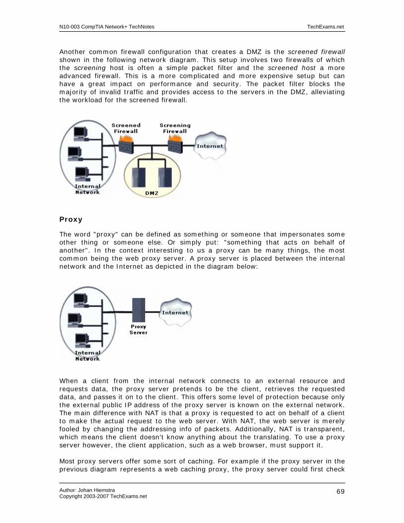
N10-003 CompTIA Network+ TechNotes TechExams.net
Author: Johan Hiemstra Copyright 2003-2007 TechExams.net
69
Another common firewall configuration that creates a DMZ is the screened firewall shown in the following network diagram. This setup involves two firewalls of which the screening host is often a simple packet filter and the screened host a more advanced firewall. This is a more complicated and more expensive setup but can have a great impact on performance and security. The packet filter blocks the majority of invalid traffic and provides access to the servers in the DMZ, alleviating the workload for the screened firewall.
Proxy
The word "proxy" can be defined as something or someone that impersonates some other thing or someone else. Or simply put: "something that acts on behalf of another". In the context interesting to us a proxy can be many things, the most common being the web proxy server. A proxy server is placed between the internal network and the Internet as depicted in the diagram below:
When a client from the internal network connects to an external resource and requests data, the proxy server pretends to be the client, retrieves the requested data, and passes it on to the client. This offers some level of protection because only the external public IP address of the proxy server is known on the external network. The main difference with NAT is that a proxy is requested to act on behalf of a client to make the actual request to the web server. With NAT, the web server is merely fooled by changing the addressing info of packets. Additionally, NAT is transparent, which means the client doesn't know anything about the translating. To use a proxy server however, the client application, such as a web browser, must support it. Most proxy servers offer some sort of caching. For example if the proxy server in the previous diagram represents a web caching proxy, the proxy server could first check

N10-003 CompTIA Network+ TechNotes TechExams.net
Author: Johan Hiemstra Copyright 2003-2007 TechExams.net
70
if the data an internal client requests, is previously requested by another. If that is the case, the proxy server would retrieve the data from its own hard disk instead of using the external connection. This can reduce traffic on expensive and relatively slow internet connections. Following are the most common type of proxies:
• HTTP Proxy - besides providing an anonymous appearance on the web and acting as an intermediate for clients, it also caches web content requested by clients.
• DNS Proxy - caches DNS lookups initiated by clients. When an internal client needs to know the IP address for a domain name, i.e. www.techexams.net, it will send the request to the DNS Proxy (i.e. a NAT router), which will forward it to DNS server on the Internet or retrieve the info from its cache if it the address has been requested previously.
• WINS Proxy - works similar as a DNS Proxy except it forwards NETBIOS name lookups to a WINS server in a different subnet and is used only in Microsoft networks.
• SOCKS Proxy, SOCKS is a protocol that works with TCP/IP (hence also with HTTP, FTP, POP3, SMTP, NNTP, etc.), and provides secure and transparent communication between a client and a proxy server.
A HTTP Proxy is often used in combination with a SOCKS proxy. The HTTP Proxy handles requests for web pages, and the SOCK proxy all other TCP/IP traffic, such as SMTP, POP3, and Telnet for example. Many companies today use proxy servers and virtually every ISP provides one to its subscribers. There are also many public proxy servers available. These are intended for anonymous surfing rather then for improving speed through caching. ICS
Internet Connection Sharing (ICS) allows multiple computers to share single Internet connection and is included in several Windows versions. ICS is especially suitable for small home and small office networks. For example, in a small company with five employees who need regular access to the Internet, ICS would allow you to configure one client with a dialup, cable or DSL connection, enable ICS, and share the connection between all five employees. The computer with the shared internet connection must have at least two network interfaces: the shared public interface that is connected to the internet, and a private interface that is connected to the internal network. The computer with ICS enabled performs NAT, and acts as a DHCP server and DNS proxy for the other internal clients. This is at the same time a disadvantage of ICS there may already be a DHCP server in the LAN. Only IP addresses from the private IP Class C network 192.168.0.0 can be assigned to hosts in the internal network when using ICS. In Windows, ICS can be enabled on the Advanced tab of the Properties of the interface that connects to the Internet.

N10-003 CompTIA Network+ TechNotes TechExams.net
Author: Johan Hiemstra Copyright 2003-2007 TechExams.net
71
Extranet/Intranet
The technology of interconnecting web clients and servers, HTTP, and HTML, is also suitable for use in networks with a less public nature than the Internet. The first use is an Intranet, which is a small private piece of ‘Internet’ that is accessible only to users within the organization. It is a very suitable medium to keep employees up to date with information about both the organization and its systems. Typical examples of information you can find on an Intranet are employee directories, emergency evacuation procedures, internal job vacancies, employee of the month articles, and other more, and less, useful information. Additionally, the Intranet can be used to keep employees informed about security related information, such as virus alerts, incident response policies, and acceptable use policies. In its most basic form, an Intranet is a web server running a website or web application and is accessible only to users with a web browser in the company’s LAN or WAN. The more advanced implementations of an Intranet often use separate servers for backend operations, such as database servers. Protecting the servers that make up the Intranet is no different from protecting the rest of the internal network; they should not be accessible to anyone outside the company. Authentication of Intranet users should preferably occur automatically by using a single sign-on system. This means that the same user credentials used to access the file servers, email, and shared printers, should be used to authenticate the user. A typical example of this is a Microsoft Windows domain with IIS as the web server. An Extranet is similar to an Intranet, but is accessible by two or more parties. When two companies/partners need to communicate and collaborate a lot, they may benefit from connecting their networks together. Instead of creating a direct connection, which would be objectionable from a security perspective, they create a network that is accessible from both companies’ networks. Firewalls at the entrance points ensure the extranet serves as a buffer between the two companies, and prevent direct access between their networks while allowing them to collaborate and share information in a secure manner. The companies can create this network themselves, but can also introduce a third party to host and manage the extranet. Internet Access
POTS / PSTN POTS (Plain Old Telephone Service) and PSTN (Public Switched Telephone Network) refer to the standard telephone network. It is a circuit-switching network designed for analog transmission of ‘voice’ over copper wires. By using a modem, a computer can use the telephone line for transferring digital information. This dial-up connection has long been the most widely used method to connect to the Internet but has been replaced by faster methods such as DSL and cable Internet when those became available. A dial-up modem connection offers relatively slow transfer rates up to 56Kbps, in reality even less. Apart from the low transfer rates, there are several other disadvantages to using dial-up connections. Dial-up connections are established when needed, usually on demand. In other words, a dial-up connection is not permanent. It can take up to several minutes for a modem to establish a connection with a remote modem. Customers are charged per minute or second for dial-up connections, so unless it is used sporadically, it is usually less expensive to lease a permanent connection. Although dial-up Internet connections are still
N10-003 CompTIA Network+ TechNotes TechExams.net
Author: Johan Hiemstra Copyright 2003-2007 TechExams.net
72
common, amongst mobile users with notebooks for example, they are mostly being replaced with high-speed broadband and wireless connections.
xDSL (Digital Subscriber Line) DSL uses the standard copper telephone wires, often already installed in offices and homes, to provide a high-speed digital Internet connection. There are different types of DSL, of which Asynchronous Digital Subscriber Line (ADSL) is the most widely installed. ADSL allows the telephone wires to be used for the analog POTS system and digital data transfer simultaneously. The download speed for ADSL connections is much faster than the upload speed, which corresponds to the needs of most of the typical Internet users. Another type of DSL is Symmetric DSL (SDSL), which cannot share the physical medium with standard telephone communication and has a download speed equal to the upload speed. DSL connections are not available everywhere because of the distance limitations and incompatible POTS systems. The actually transfer speed varies a lot per type of DSL connection, and depends a lot on the distance of the connection between the user and the provider's Central Office (CO). The CO is the location at which customers’ lines from a particular area are terminated and connected to a DSL Access Multiplexer (DSLAM). The DSLAMs are in turn connected to the telco/ISP’s backbone to provide access to the Internet and other telephone services. This is usually a high-speed ATM connection. The maximum distance of an ADSL connection to the CO is 18,000 feet (5,460 meters. This is the limit for most other types of DSL as well. The download speeds generally range from 1.544 Mbps to 8.448 Mbps depending on the distance to the CO. The upload speed usually ranges from 64 and 640 Kbps. The ISP that offers the DSL service usually provides a DSL transceiver, commonly referred to as a DSL modem. This small box usually allows an Ethernet UTP or an USB connection directly to a PC, or to a hub, router, or switch to provide Internet access to an entire network. The DSL transceiver can also be integrated in a router or switch. In addition to providing Internet access to homes and offices, DSL can also be suitable for VPN connections between offices or for home workers remotely accessing the corporate network.
Broadband Cable (Cable modem) The cable that has become so popular for receiving TV broadcasts turns out to be very suitable for an Internet connection as well. TV channels only take up 6 MHz each, which usually leaves several hundred MHz available. This additional space on cable allows for a permanent high-speed Internet connection. Information from the Internet travels through the cable as a single TV channel of 6 MHz. Upstream information requires just 2 MHz. Theoretically this can allows for download speeds of 5 Mbps, but in reality it usually ranges from 384Kbps to 1.5Mbps. The transmissions speeds do not depend on the distance of the connection, but since the medium is shared with other customers, they can vary a lot depending on how many users are connected in your area. Just as with DSL, cable Internet requires a special transceiver at the customer’s premises. This cable modem translates the analog signal to digital information and vice versa. Together with the Cable Modem Termination System (CMTS) on the
N10-003 CompTIA Network+ TechNotes TechExams.net
Author: Johan Hiemstra Copyright 2003-2007 TechExams.net
73
provider’s end, they allow to use the cable to receive and send information on frequencies not used by TV channels. Just like the DSLAM for DSL connections, the CMTS interconnects the customers’ cable connections to a single high-capacity Internet connection. The incoming 75 ohm coaxial cable connect with an F-Type connector to the cable modem, which in turn provides one or more LAN interfaces, usually Ethernet or USB, which connect directly to a client, or a device such as a hub, switch, or wireless access router, to allow additional internal clients or entire networks to use the same connection. The cable modem is also equipped with connections for TV and radio for example.
Satellite Using satellites for Internet access may seem a bit futuristic, but in rural areas where DSL and cable Internet services are not available, using satellite Internet access can be a very good alternative to standard dial-up connections. The download speeds is typically around 500Kbps and the upload speed around 50Kbps, but this can vary per provider. Satellite Internet requires a dish of about the same size as those used for satellite TV reception. The customer’s dish communicates with the satellite, which in turn communicates with a large dish at the provider. IP multicasting, compression, and acceleration technology is implemented throughout the entire circuit to squeeze the most out of the connection.
Wireless
Wireless Internet access is particularly useful for mobile users. With handheld devices becoming more advanced and increasingly popular, most of the major mobile telcos started offering wireless internet access in several ways. This is includes deploying WiFi hotspots in populated areas and locations such as airports and hotels. Organizations can use the same method to offer wireless access to the corporate network for mobile employees and indirectly provide them access to the Internet. Technologies such as GPRS and UMTS allow smartphones and other handhelds with Internet capabilities to access the Internet using the existing cell phone network.

N10-003 CompTIA Network+ TechNotes TechExams.net
Author: Johan Hiemstra Copyright 2003-2007 TechExams.net
74
Wireless Networking Current related exam objectives for the Network+ exam. 1.2 Specify the main features of 802.11 (wireless) networking technologies, including: - Speed - Access Method (CSMA / CA (Carrier Sense Multiple Access/Collision Avoidance)) - Topology - Media 1.4 Recognize the following media connectors and/or describe their uses: - F-Type 1.6 Identify the purposes, features and functions of the following network components: - WAPs (Wireless Access Points) 1.7 Specify the general characteristics (For example: carrier speed, frequency, transmission type and topology) of the following wireless technologies: - 802.11 (Frequency hopping spread spectrum) - 802.11x (Direct sequence spread spectrum) - Infrared - Bluetooth 1.8 Identify factors that affect the range and speed of wireless service (For example: interference, antenna type and environmental factors). 2.3 Identify the OSI (Open Systems Interconnect) layers at which the following network components operate: - WAPs (Wireless Access Point) 2.17 Identify the following security protocols and describe their purpose and function: - WEP (Wired Equivalent Privacy) - WPA (Wi-Fi Protected Access) Although wireless networking has been around a lot longer than most people assume, it is only since the past 5 years that the cost of wireless networking equipment has dropped dramatically and therefore became widely available to large enterprises, small companies and even home users. Nowadays, you can hardly walk through a populated area without absorbing someone’s wireless signal. Airports and hotels offer wireless Internet access to travelers, companies offer wireless access to mobile users within the organization, and wireless Internet access on cell phones is almost becoming a standard feature. Despite the negative reputation of wireless networking in regards to security, it is still increasing in popularity. For the Network+ exam, you need to know about several of the wireless networking technologies available today. This includes the popular IEEE 802.11 standards,

N10-003 CompTIA Network+ TechNotes TechExams.net
Author: Johan Hiemstra Copyright 2003-2007 TechExams.net
75
Infrared, Bluetooth, and related devices and concepts. Each of these technologies has its own best suitable purposes, advantages and disadvantages. Before we look at those, let us have a look at the best suitable purposes for wireless networking in general. Connectivity for mobile users and offices The percentage of mobile users in organizations is growing rapidly. Mobile users often spend most of their time outside the office, and when they are in the office, they often share workspace and do not have their own office or cubicle. If you have 50 mobile users, you may only need 5 workspaces because most of them will be in the field. This makes wireless connectivity an ideal solution for mobile users. Outside the office, they can use a public hotpot to connect with their laptop to corporate network, or use a technology such as GPRS to access their email by using a smartphone or PDA. Building-to-building connectivity Putting cables in the ground to connect two buildings is often a very expensive solution for building-to-building connectivity, even if the buildings are near each other. A wireless connection is can be very suitable in such situations as it is relatively cheap and easy to implement. Last mile data delivery Wireless connections can be a very suitable replacement for wired connections in areas where it may be difficult or expensive to extend the cable network to every location. A typical example of last mile data delivery using wireless communication are satellite Internet connections in rural areas. Instead of using expensive cables for DSL connections to cover long distances to houses in low-populated areas, a central location is connected by cable and wireless connectivity is provided from that central location to the Internet subscribers in the area. New advances in wireless technology, such as 802.11n and 802.16 (outside scope for Network+) are making it a competitive “last mile” technology in densely populated areas too. Public environments Wireless networking is very suitable for public environments such as airports and beaches. In many cities around the world, you can sit outside on a terrace, drink a coffee, and connect to a public hotspot to browse the web or check your email. A hotspot is public wireless access point that allows users to access the Internet using a laptop or other mobile device. Hotspots are free or require some sort of subscription or ticket. Wireless networking is a great addition to the available ingredients for small to large networks, but it is not meant to replace every cable on the planet. There are many situations in which wireless networking is usually not suitable; following are some examples: Backbone connections in a datacenter - Due to the limited of data transfer rates, wireless LAN technologies are not suitable for backbones. 802.11g allows up to 54Mbps for example, and the effective rate is even lower. The data transfer rates for a backbone that connects servers and other networking devices in a datacenter, typical range from 100 Mbps to 10Gigabit Ethernet.

N10-003 CompTIA Network+ TechNotes TechExams.net
Author: Johan Hiemstra Copyright 2003-2007 TechExams.net
76
Factory floors Although it may seem appealing to reduce the number of cables on a factory floor, the machinery in factories often produces a level of electromagnetic interference (EMI), which can drastically reduce the data throughput in a wireless network. Wireless networks can operate at different frequencies (2.4 and 5 GHz), and use noise-resistant transmission patterns (FHSS), but even this may not be enough to overcome the affects of very electronically noisy environments. Highly secure environments Wireless networking is a relatively insecure network technology and is therefore less suitable for highly secure environments. You do not need physical access to access the physical layer of a wireless network. A malicious individual can tap into a wireless network relatively easier than into a wired network. In case of the latter, he or she would need access to a cable, hub, or switch for example, to tap into a wired network. Wireless network traffic however, is all around us, and can be grabbed from the ‘air’ by anyone with the right tools. In most cases, they would still need to decrypt the traffic, but that often turns out to be easier than physically accessing a wired network. IEEE 802.11 Standards
The IEEE 802.11 standard defines the MAC layer (sublayer of Data Link layer) and Physical layer specifications for Wireless LANs with data rates of 1 and 2 Mbps. It was first completed in 1997 but went through several changes until it was finalized in 1999. The MAC layer specifications are concerned with how the network devices access the medium, in this case, the air. 802.11 uses the 2.4 GHz frequency band. The Physical layer specifications in 802.11 define standards for three different radio technologies: Direct Sequence Spread Spectrum (DSSS), Frequency Hopping Spread Spectrum (FHSS), and InfraRed (IR). In 2001, the IEEE approved two new amendments for the original 802.11 standard, but with additions to the Physical layer specifications: the 802.11a and 802.11b standards. The term 802.11x is sometimes used to refer to the entire group of 802.11 WLAN standards, of which some are still under development. It includes the standards outlined above, as well as several others addressing the need for speed, region specific regulations, and security. Do not confuse 802.11x with 802.1x, the layer 2 port-based authentication protocol that provides authenticated access to 802.11 wireless networks and wired Ethernet networks. 802.11b The first wireless networking products that became widely available are based on the extended IEEE 802.11b standard. Because of the availability and affordability of 802.11b equipment, it has become popular especially in small and home networks. According to the standard, 802.11b provides data rates of 5.5 and 11Mbps, and is backwards compatible with the 1 and 2 Mbps data rates of 802.11. An organization called Wi-Fi Alliance, formerly known as the Wireless Ethernet Compatibility Alliance (WECA), is concerned with the compatibility of 802.11b equipment from different manufacturers. When products based upon the 802.11b standard pass the compatibility tests performed by the Wi-Fi Alliance, they are awarded the WiFi (Wireless Fidelity) logo. 802.11b operates on the 2.4 GHz frequency band just like 802.11.

N10-003 CompTIA Network+ TechNotes TechExams.net
Author: Johan Hiemstra Copyright 2003-2007 TechExams.net
77
802.11a It took several years before a wide range of products based upon the 802.11a standard became available. When they finally did around 2002, more companies became interested in wireless networking. The primary reason for this is that the 802.11a standard increases the maximum data throughput to 54 Mbps. However, 802.11a is not backward compatible with 802.11 and 802.11b because it uses the 5 GHz frequency band instead of 2.4 GHz, and a different modulation scheme (OFDM instead of QPSK). 802.11g The 802.11g standard also allows data transfer rates up to 54 Mbps, but is backward-compatible with both 802.11 and 802.11b, supporting both their data rates (1, 2, 5.5, and 11 Mbps) and modulation scheme (QPSK). 802.11g also supports the modulation scheme used by 802.11a (OFDM), but is not compatible with 802.11a because 802.11g uses the 2.4 GHz frequency band. While both standards define 54 Mbps as the maximum throughput, in reality it is closer to 50% of that.
802.11 Network Operation 802.11 can be considered the wireless equivalent of 802.3 wired Ethernet, but there are some major differences. The first one is obviously the media, which carries the network traffic. For wired Ethernet networks, the medium is the cable, a copper or fiber cable for example, and the network traffic is a collection of electrical signals or light pulses. For a wireless network, the media is the air, and the network traffic is a radio wave on a particular frequency in the Radio Frequency (RF) spectrum. Not just the media, but also the access method of an Ethernet network and an 802.11 wireless network is different. Ethernet networks use the Carrier Sense Multiple Access/Collision Detection (CSMA/CD) access method. This means a station listens to check if the cable is currently accessed before starting its own data transmission. When two stations both determine the media is available and start sending the data simultaneously, a collision occurs, meaning the electrical signals on the cable collide with each other. When the collision is detected, both stations will retransmit the data after a different and random amount of time determined by a backoff algorithm. In a wireless 802.11 network, the access method is Carrier Sense Multiple Access with Collision Avoidance (CSMA/CA). This means that if a wireless station determines the network is busy, it will also back off for a random amount of time, but because collisions between wireless signals cannot be detected, acknowledgments are used to inform stations of the availability of the media. If an acknowledgment is not received for a packet, the sender will assume that a collision occurred and the packet was lost. CSMA/CA in wireless networks does not operate exactly the same as CSMA/CA in some wired networks such as LocalTalk, in which broadcasts are used to notify other stations the network is busy and thereby avoiding collisions.
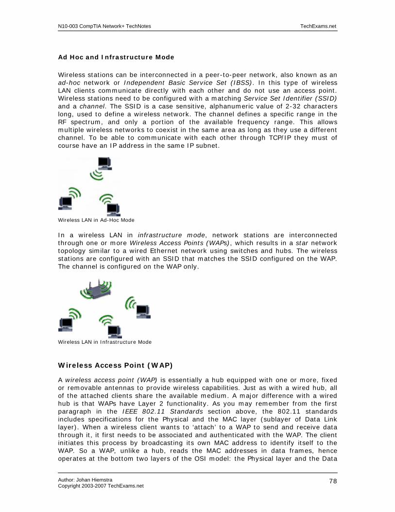
N10-003 CompTIA Network+ TechNotes TechExams.net
Author: Johan Hiemstra Copyright 2003-2007 TechExams.net
78
Ad Hoc and Infrastructure Mode Wireless stations can be interconnected in a peer-to-peer network, also known as an ad-hoc network or Independent Basic Service Set (IBSS). In this type of wireless LAN clients communicate directly with each other and do not use an access point. Wireless stations need to be configured with a matching Service Set Identifier (SSID) and a channel. The SSID is a case sensitive, alphanumeric value of 2-32 characters long, used to define a wireless network. The channel defines a specific range in the RF spectrum, and only a portion of the available frequency range. This allows multiple wireless networks to coexist in the same area as long as they use a different channel. To be able to communicate with each other through TCP/IP they must of course have an IP address in the same IP subnet.
Wireless LAN in Ad-Hoc Mode In a wireless LAN in infrastructure mode, network stations are interconnected through one or more Wireless Access Points (WAPs), which results in a star network topology similar to a wired Ethernet network using switches and hubs. The wireless stations are configured with an SSID that matches the SSID configured on the WAP. The channel is configured on the WAP only.
Wireless LAN in Infrastructure Mode Wireless Access Point (WAP)
A wireless access point (WAP) is essentially a hub equipped with one or more, fixed or removable antennas to provide wireless capabilities. Just as with a wired hub, all of the attached clients share the available medium. A major difference with a wired hub is that WAPs have Layer 2 functionality. As you may remember from the first paragraph in the IEEE 802.11 Standards section above, the 802.11 standards includes specifications for the Physical and the MAC layer (sublayer of Data Link layer). When a wireless client wants to ‘attach’ to a WAP to send and receive data through it, it first needs to be associated and authenticated with the WAP. The client initiates this process by broadcasting its own MAC address to identify itself to the WAP. So a WAP, unlike a hub, reads the MAC addresses in data frames, hence operates at the bottom two layers of the OSI model: the Physical layer and the Data

N10-003 CompTIA Network+ TechNotes TechExams.net
Author: Johan Hiemstra Copyright 2003-2007 TechExams.net
79
Link layer. We will cover this process in more detail in the Wireless Network Security section below.
Wireless Access Point (WAP)
Besides interconnecting wireless network stations, a WAP is typically used to integrate wired and wireless stations into a single network. Actually, most WAPs offer additionally functionality, such as bridging/switching and routing (Layer 3 / Network Layer) even. Many consumer WAPs have several built-in wired switch ports as USB and UTP interfaces, but the enterprise WAPs used in commercial applications do not. Instead, it usually provides a single bridge port to connect the WAP to a wired network, allowing it to function as a gateway bridge for wireless clients. Remember that a switch is just a multiport bridge, so if you interconnect LAN segments with a switch, you are effectively bridging. For example, a WAP can function as a bridge between a wired Ethernet 802.3 and a wireless 802.11b network. As depicted in the image below, the stations on the wired and the wireless network become part of the same LAN, and use an IP address from the same IP subnet. In other words, they become part of the same broadcast domain. However, the stations on the wireless segment are all in the same collision domain, while every wired connection on the WAP (and each connection behind the switch) is its own collision domain.
WAP functioning as bridge between wired and wireless segment
Almost every wireless network connects to a wired network at some point. In a SOHO network, the wired network is often the Internet connection. The following

N10-003 CompTIA Network+ TechNotes TechExams.net
Author: Johan Hiemstra Copyright 2003-2007 TechExams.net
80
diagram shows a typical example in which the WAP functions as a router, also referred to as a wireless access router.
WAP functioning as router
The wireless access router appears as the only client to the ISP, and usually performs NAT for the connected wireless clients instead of actually created a routed connection. A DHCP server, running on the WAP, assigns the clients an IP address from a private address range. A WAP functioning as a router, operates also on the Network layer of the OSI model an separates broadcasts and collision domains just like a router between two wired networks would. Another use of a wireless access point is to extend network connection by functioning as a repeater. Remember that a repeater amplifies the signal to allow a connection to span a larger distance. The following diagram depicts a simple network with a wireless access point repeating the signal to allow it to cross the distance. The preferred method would be to use a more power antenna.
WAP functioning as repeater
Read the Internet Connections TechNotes for more information about routed and translated connections, and read the Network Components TechNotes for more information about bridges, switched, routers, and broadcast and collision domains.

N10-003 CompTIA Network+ TechNotes TechExams.net
Author: Johan Hiemstra Copyright 2003-2007 TechExams.net
81
Modern WAPs often support multiple 802.11 standards, often referred to as ‘modes’. For example, B-only Mode (802.11b), G-only Mode (802.11g), and B/G (mixed) Mode. The latter allows for a mixed environment, which sounds convenient but should only be used temporarily, e.g. when migrating from 802.11b to 802.11g, but preferably be avoided entirely. Allowing both 802.11b and 802.11g clients to connect to the same access point has significant negative impact on the performance. In B-only mode, the AP only uses DSSS allowing up to 11 Mbps of bandwidth (in reality about 5.5 Mbps of data throughput). In G-only mode, the AP only uses OFDM, and only 802.11g clients can connect to the AP, allowing up to 54 Mbps of bandwidth (in reality about 20 Mbps of data throughput). In mixed mode, the AP uses both DSSS and ODFM, supporting both 802.11b and 802.11g, but reducing the total realistic data throughput from 20 Mbps to 8 Mbps or less, when both 802.11b and 802.11g clients are connected. Antennas
Although most WAPs and wireless network cards have integrated antennas, many of them allow an external antenna to be connected. The main advantage is that a different, more powerful antenna can be connected to increase the maximum range. The latter is important to provide proper connectivity to clients or other wireless devices. The further a client is located from a WAP, the weaker the signal it receives will be. If a client is entirely out of range, the signal will be too weak, preventing the client from connecting. Another advantage of using an external antenna is that it can be placed outdoors while connected to a WAP indoors. The cable running from the WAP or WLAN NIC to the antenna is often a proprietary cable, also referred to as a pigtail. The connectors for these pigtails differ per brand. High-end antennas typically use a coaxial cable with an F-type connector. The quality and length of the cable have a significant influence on the signal power. Following are the three main types of antennas, omni, semi, and highly-directional, and Each type has its own characteristics and suitable purposes and are discussed below.
Omni-directional This is the most common type of antenna on WAPs and wireless network cards, usually referred to as a dipole antenna or just dipole (similar to a magnet having two poles). The ‘rabbit ears’ on older TVs is a classic example of a dipole antenna. The following image depicts a simple dipole antenna; the donut-shaped wireframe show how the signal propagates.
Omni antenna – Side view Omni antenna – Top view

N10-003 CompTIA Network+ TechNotes TechExams.net
Author: Johan Hiemstra Copyright 2003-2007 TechExams.net
82
Omni-directional antennas are particularly suitable for point-to-multipoint connections and are often used in conjunction to create a large wireless network with to a cell topology as depicted below. At the center of these cells is an omni antenna of which the signal coverage overlaps slightly with adjacent cells to provide full coverage. The cell topology with omni antennas is used both indoors and outdoors. The most know outdoor example is of course the cell phone network using GSM or UMTS for example.
Cells in a wireless network
Semi-Directional
The Yagi and the Patch antenna are two common types of semi-directional antennas. They each use a similar method to force the signal to propagate into a certain direction. The Yagi antenna is typically used for point-to-point and point-to-multipoint connections outdoors. The element with the black protective cover on the Yagi antenna below is the one connected to the cable. The element left from it reflects the signal while the elements on the right help propagate the signal in the right direction.
Directional Yagi Antenna
A directional patch antenna contains a back panel and a ‘patch’ as depicted in the image below on the right. The back panel performs the same function as the reflective element in the Yagi antenna, it reflects the signal originating from the patch and forces it to propagate into a certain direction. Patch antennas are typically used for point-to-multipoint connections outdoors and point-to-point connections indoors.

N10-003 CompTIA Network+ TechNotes TechExams.net
Author: Johan Hiemstra Copyright 2003-2007 TechExams.net
83
Directional Patch Antenna
Highly-Directional Highly-directional antennas are most suitable for outdoor long distance point-to-point connections. The parabolic dish and the parabolic grid are the most common examples of highly-directional antennas. The main difference between them is the structure of the antenna, which enables the parabolic grid to withstand strong winds.
Parabolic Dish Antenna
Parabolic Grid Antenna
The following image depicts the RF beam of a highly-directly antenna. The dish or grid bundles the signal and forces the signal to propagate in a specific direction. An important requirement for point-to-point connections using highly-directional antennas is a clear line of sight. If a building or other large obstacle blocks the visibility between two highly-directional antennas, the narrow beam will neither be able to avoid the obstacle.
Highly-directional antenna
Besides point-to-point connections, directional antennas are often used in combination with omni antennas to create point-to multipoint connections. For example, the main building on a campus could have an omni antenna on the roof and several smaller buildings each use a directional antenna to connect to the main building.

N10-003 CompTIA Network+ TechNotes TechExams.net
Author: Johan Hiemstra Copyright 2003-2007 TechExams.net
84
Environmental Factors and Interference
Radio Frequency Interference (RFI) is one of the major challenges for wireless networks. RFI refers to interference of other devices that operate on the same radio frequency, which can cause delays, hence reduced data throughput and even loss of data and connectivity. Common sources of RFI in 802.11b and 802.11g networks are cordless phones, microwave ovens, neighboring wireless LANs, and Bluetooth devices, which like the former, operate in the 2.4-GHz band. One of the major factors on the signal quality in wireless networks is the environment. Walls, plants, windows, office equipment and human beings are examples of obstacles in indoor wireless networks that can have a negative impact. Outdoors, trees, mountains, lakes, buildings and other structures absorb or reflect the signal causing undesired results. The primary cause of signal power in a wireless network is path loss, which refers to the signal power decreasing by distance. This is commonly compared to a flashlight: as the distance increases, the beam gets wider shining less light on its target. The same thing happens with an RF wave, and it is also known as dispersion. Eventually the signal will be to low for the receiving antenna to separate data from noise. Wireless Network Security
WEP (Wired Equivalent Privacy) The Wired Equivalent Privacy (WEP) protocol is part of the 802.11 standard and is developed as an effort to provide privacy in wireless networks similar to privacy in wired networks. Intercepting traffic (eavesdropping) on a wireless network is very easy compared to wired networks, so it is essential that data frames are encrypted. When a station powers up, and attempts to establish a wireless connection, it will first be associated with an access point. When the station is associated, it will attempt to authenticate itself to the access point. The original IEEE 802.11 standards provide the following two types of authentication:
• Open System Authentication -The client broadcasts its MAC address to identify itself, an AP replies with an authentication verification frame. Although its name implies differently, no actual authentication occurs when Open System Authentication is used.
• Shared Key Authentication - The client will be authenticated only if it is configured with a preshared key. This means that the same key must be configured on both the client station and the AP. The AP sends a challenge text to the client requesting authentication, which is encrypted using WEP and the shared key at the client, and then send back to the AP where it is decrypted again to see if it matches the original challenge. If it matches, the client will be able to start transmitting and receiving data and participate in the network.
The WEP key used for authentication can also be used to encrypt the wireless traffic. Although this produces a significant amount of overhead on low-speed wireless networks such as 802.11b, it should be enabled if no other, better, security method

N10-003 CompTIA Network+ TechNotes TechExams.net
Author: Johan Hiemstra Copyright 2003-2007 TechExams.net
85
is used instead of WEP. WEP offers rather weak security that can be relatively easily cracked using widely available tools that can be found free on the Internet. It uses a weak implementation of the RC4 cipher, which uses key lengths of 64 and 128-bits. The key includes a 24-bit Initialization Vector (IV), which is sent in clear text format, so actually they secret portion of the WEP keys are 40 and 104-bits. In 2004 the 802.11 standard was updated by the IEEE 802.11i workgroup in an effort to increase security in wireless networks. This resulted in WPA and WPA2, which should be used instead of WEP whenever available.
WPA (Wi-Fi Protected Access) Wi-Fi Protected Access (WPA) is a standard released by the Wi-Fi Alliance to provide more advanced security for 802.11 wireless networks, including stronger encryption and authentication methods. It includes the Temporal Key Integrity Protocol (TKIP), which offers dynamic key distribution. RC4 is still used for the actual data encryption, but they key used to encrypt the data is changed periodically. This makes it harder to crack than WEP. WPA also supports authentication through the IEEE 802.1x port-based authentication protocol. While WPA and TKIP were designed as a more secure replacement for WEP, partly because RC4 was still used several flaws were quickly discovered. The Wi-Fi Alliance released WPA2 in 2004, which adds support for the Advanced Encryption Standard (AES) to allow for much stronger encryption. The best approach to secure wireless networks is to implement multiple layers of security. A secure wireless network employs security technologies such as IPSec, 802.1x authentication, and strong encryption protocols. A costly but secure option is using Virtual Private Networks (VPN), and basically treat the wireless network as if it were a public network like the Internet. InfraRed
The Infrared Data Association (IrDA) creates standards for short-distance infrared communication. It defines data transmission rates from 9600 bps with primary speed/cost steps of 115 Kbps, a maximum of 4 Mbps for Fast IrDA and a maximum of 16 Mbps for Very Fast IrDA. Infrared is commonly used to exchange data between mobile devices and other devices such as printers. The primary limitation of infrared communication is that it requires a clear line-of-sight. IR waves are easily absorbed and reflected by obstacles, which is the main reason why network communication using infrared light is not very popular.
N10-003 CompTIA Network+ TechNotes TechExams.net
Author: Johan Hiemstra Copyright 2003-2007 TechExams.net
86
Bluetooth
Bluetooth is a wireless networking technology that is very common in Personal Area Networks (PANs). A PAN covers the area directly surrounding the user, and typically includes handheld devices such as PDAs and smartphones. Wireless connectivity allows users to synchronize files, email, and connect to printers and other network devices. Bluetooth is also popular for providing connectivity between non-network devices, such as connecting hands-free sets to phones or controllers to videogame systems. The specified maximum data transfer rate is 1 Mbps, but in reality it is much lower. Bluetooth with Enhanced Data Rate offers transfer rates up to 3 Mbps, but again the effective rates are much lower. Bluetooth operates in the unlicensed ISM band at 2.4GHz and uses the FHSS (Frequency Hopping Spread Spectrum). It avoids interference from other signals by hopping to a new frequency after transmitting or receiving a packet. Compared to other systems in the same frequency band, the Bluetooth radio hops faster and uses shorter packets. Bluetooth's hop rate of 1,600 hops per second over 79 channels means the chance of other signals interfering is very low, but the hopping also limits the maximum transfer rates. The main reason why Bluetooth uses FHSS instead of DSSS is that FHSS is much simpler, requiring less powerful chips, using less power. The latter is obviously very important for handheld devices that run on batteries.

N10-003 CompTIA Network+ TechNotes TechExams.net
Author: Johan Hiemstra Copyright 2003-2007 TechExams.net
87
Antivirus Software Current related exam objectives for the Network+ exam. 3.10 Identify the purpose, benefits and characteristics of using antivirus software. Viruses and Malware
Malware is a piece of software that can damage or alter data and programs on a system without permission and notice of the user. The goal of malware varies from gaining unauthorized access to simply disabling a system. Malware is typically delivered through email, but also IRC channels and websites are common sources of malicious code. The most common type of malicious code is a virus. It can infect systems by attaching itself to files and programs. Just like its biological counterpart, it needs a host to infect and survive. A virus is usually a program that needs to be executed by a user before it can do any damage. For example, a virus attached to an email message is usually only harmful when a user opens (executes) the attachment. The result of a virus infection varies a lot depending on the type of virus. This includes deleted files, corrupted Windows registry, missing boot sector or master boot record, and other more or less harmless events. Viruses are also used to create a backdoor for other malicious code such as key loggers and Trojans. Antivirus Software
Decent anti-virus software should be used both pro-active and re-active to prevent damage by viruses. Since viruses are spread primarily through email, it is important to establish the first line of defense at the corporate email server. That will help prevent viruses from reaching the clients, the place where they are most likely executed and distributed. Corporate antivirus software suites can provide protection against viruses and other malware on clients and servers. An antivirus solution is not complete unless it is implemented in all systems in a network. Modern client-side anti-virus software can also actively scan data as it is received through a network connection, in addition to scanning and cleaning viruses on disk after detection hence, after infection. There are many anti-virus products available, which usually provide the best results if they are used in combination with a competitive product. Anti-virus products use virus definitions, also known as signatures, to identify viruses. It is imperative that these virus definitions/signatures are up to date. Most antivirus programs allow scheduled automatic updates over the Internet. Besides updating the virus definitions, the detection software itself is frequently improved and needs to be up to date at all time as well.
N10-003 CompTIA Network+ TechNotes TechExams.net
Author: Johan Hiemstra Copyright 2003-2007 TechExams.net
88
OS Specific Networking Current related exam objectives for the Network+ exam. 2.4 Differentiate between the following network protocols in terms of routing, addressing schemes, interoperability and naming conventions: - IPX / SPX (Internetwork Packet Exchange / Sequence Packet Exchange) - NetBEUI (Network Basic Input / Output System Extended User Interface) - AppleTalk / AppleTalk over IP (Internet Protocol) 2.13 Identify the purpose of network services and protocols (For example: NFS (Network File System), SMB (Server Message Block), AFP (Apple File Protocol), LPD (Line Printer Daemon) and Samba), and Zeroconf (Zero configuration). 3.1 Identify the basic capabilities (For example: client support, interoperability, authentication, file and print services, application support and security) of the following server operating systems to access network resources: - UNIX/Linux/Mac OS X Server - Netware - Windows - AppleShare IP 3.2 Identify the basic capabilities needed for client workstations to connect to and use network resources (For example: media, network protocols and peer and server services). 3.4 Given a remote connectivity scenario comprised of a protocol, an authentication scheme, and physical connectivity, configure the connection. Includes connection to the following servers: - UNIX / Linux / MAC OS X Server - Netware - Windows - AppleShare IP 4.5 Given a troubleshooting scenario between a client and the following server environments, identify the cause of a stated problem: - UNIX / Linux / Mac OS X Server - Netware - Windows - AppleShare IP

N10-003 CompTIA Network+ TechNotes TechExams.net
Author: Johan Hiemstra Copyright 2003-2007 TechExams.net
89
Microsoft Windows Networking
Microsoft is a leading vendor for both client and server operating systems, named Windows, in corporate and home networks. Windows supports many standardized protocols and network services but also includes many Microsoft proprietary technologies. Most Windows computers today use the TCP/IP suite as the primary means of communication in networks. Microsoft’s own implementation of those standard technologies can be very different from other operating systems. A good example is Dynamic DNS, even though others now also support it. Another good example of a proprietary network technology in Windows networks is WINS, which is an older naming service similar to DNS. You can read more about WINS in the Network Services chapter. A Microsoft network typically consists of one or more servers and a bunch of clients, which are joined together in a workgroup or an Active Directory domain. In case of a workgroup, each computer regardless of whether it is a server or client maintains its own local user account database. If you want a certain user to be able to access different computers in the workgroup, you need to recreate the user account on all those computers. In Active Directory domains however, users accounts, groups, etc, are stored on one or more centralized servers referred to as Domain Controllers. The Domain Controllers perform the authentication of users and computers logging on in the domain. When you add a member server (a server that is not a domain controller) or a client, an administrator must join it to the domain before it share or access resources throughout the domain. Users logging on to the domain can be assigned permissions to resources by configured ACL (access control lists). An ACL is attached to every resource (e.g. file, printer) and lists the users and groups that are assigned or denied certain permissions. Before you can communicate with other systems in the network however, you need to configure the network protocol, which on any recent Windows version with a network interface is TCP/IP and installed automatically. By default, it is configured to obtain IP addressing information automatically, i.e. through DHCP or APIPA. If your network does not have a DHCP server, you should configure the IP addresses manually instead. Most Windows systems support additional network protocols such as IPX and AppleTalk, which you may need to configure when your Windows systems need to communicate with older MAC or Netware systems that don’t support TCP/IP. Following are two other protocols/services that are listed in the Network+ exam objectives or related to them. NETBEUI NetBIOS Extended User Interface (NetBEUI) is a non-routable Transport layer protocol created by Microsoft. Novell and Microsoft wanted to use the Session layer part of the NetBIOS protocol with other transport protocols such as TCP and SPX and decided to split up NetBIOS into NetBEUI and NETBIOS. NetBEUI may still be used in some exceptional legacy networks but in general has been replaced by TCP/IP.

N10-003 CompTIA Network+ TechNotes TechExams.net
Author: Johan Hiemstra Copyright 2003-2007 TechExams.net
90
The reason NetBEUI is non-routable is its flat addressing scheme. NETBEUI uses NetBIOS names, sometimes referred to as friendly names, to identify computers on the network, and do not contain a network portion. NetBIOS names are 16 characters in length and cannot contain any of the following characters: \ / : * ? " < > |, but most version of Windows don't allow many other characters, such as @ and {} neither. The first 15 characters represent a unique name identifying a resource. The 16th character is a suffix identifying the type of resource or group of resources. For example, the redirector, server, or messenger services can be installed on one computer resulting in three times the same name but with different suffixes. If you set a name of 8 characters, it is padded with spaces up to 15 characters long to allow the '16th' character. NETBEUI is a broadcast protocol, meaning a computer running NETBEUI discovers the MAC address from an intended communication partner by sending out a broadcast with the remote NETBIOS name. The owner of the MAC address listed in the broadcast message then replies with is MAC address. The main advantage of NETBEUI is that it is small (on disk and in memory) and requires little configuration.
SMB/CIFS The Server Message Block (SMB) protocol is an older file and printer sharing protocol used in OS/2, Windows 95 and Windows NT networks. The Common Internet File System (CIFS) is Microsoft’s attempt to create an open and enhanced version of SMB. CIFS offers better security, is supported also by UNIX and other operating systems, and is optimized for file transfer across the Internet and other IP networks. In addition to access to Windows and other file servers, CIFS is commonly used to access Network Attached Storage (NAS), which is covered in more detail in the Network Services chapter.

N10-003 CompTIA Network+ TechNotes TechExams.net
Author: Johan Hiemstra Copyright 2003-2007 TechExams.net
91
UNIX/LINUX Networking
UNIX is a multi-tasking, multi-user, server and client operating system. It is text-based, meaning it does not have a graphical user interface. In a typical old fashion UNIX network, dumb terminals are connected to a centralized server running UNIX, which is like connecting several monitors and keyboards to the same computer. In modern network environments, UNIX systems often coexist with other operating systems and then clients use a terminal emulator (e.g. as a TELNET client), or other specialized as well as standard client software (e.g. a web browser) to access the server. Every user executes programs and stores files on the same system, allowing them to share resources in real-time. Even though UNIX is often looked at as an old-timer, it is still a popular OS for critical and reliable services. There are many different UNIX variants (Linux, Solaris, SunOS, HP-UX, Digital UNIX, SCO Open Server, DG-UX, UNIXWARE, AIX, BSDI, NetBSD, NEXTSTEP, A/UX, to name a ‘few’), which run on various types of hardware, from regular PCs to large mainframes. UNIX is an operating system "developed by programmers for programmers", making it rather complex to manage. Nevertheless, because it is powerful and stable, UNIX and its variants are used in many different types of environments such as hospitals, telecommunication systems, academia and many corporate networks. TCP/IP is the native protocol for UNIX networks. The HOSTS file, DNS and many other TCP/IP protocols and utilities now common on other operating systems originated on UNIX. Even the location of the HOSTS file on Windows NT/2000/XP systems is the same as on UNIX systems (the etc directory). Some other relevant from origin UNIX services and protocols are described below the Linux section. LINUX Linux is an open source operating system that is somewhat similar to UNIX. Open source means that its source code is publicly available, allowing everyone to create extensions, utilities, GUIs, software, etc. Partly because of this, there are many different distributions of Linux, of which many are free. Linux is very popular for web hosting; many of the web servers on the Internet today run a Linux or a Linux-like OS. Besides acting as a HTTP, FTP or mail server, Linux is also often used for firewalls and caching proxy servers. One of the advantages of Linux over Windows for example is that Linux can be stripped down to run on older and/or slower hardware. Besides using Linux as a server, Linux has become more popular as a client OS as well. A variety of GUIs are available to make it all a bit more user-friendly, as Linux is originally a text-based only OS like UNIX. Security in Linux is also very similar to security in UNIX. Users and groups can be configured and assigned Read, Write, and/or Execute permissions for files and folders. The owners/creators of files can assign these permissions for their own files and folders, the user ‘root’ (equivalent to Administrator on Windows systems) The National Security Agency (NSA) developed a more advanced security system for Linux, called Security-Enhanced Linux (SELinux), which implements mandatory access controls that allow an administrator to define a wide range of security policies. These policies allow applications, services, and data to be made available based on their context regardless of user and group permissions.

N10-003 CompTIA Network+ TechNotes TechExams.net
Author: Johan Hiemstra Copyright 2003-2007 TechExams.net
92
Because TCP/IP is the standard protocol in Linux and UNIX systems, connecting it to a network, regardless of other operating systems in the network, usually requires only a basic IP address configuration (IP address, subnet mask, default gateway, and DNS servers). For a more advanced integration in Microsoft networks you can use other services such as the ones below. Some of the following services and protocols have already been mentioned in the Network Services chapter in regards to different operating systems accessing and sharing the same Network Attached Storage (NAS). These services and protocols can also be used to allow Microsoft, Linux, Mac OS X and other operating systems to coexist in a network and share additional services such as printer sharing, name resolution, and authentication.
NFS Network File System (NFS) is a remote file access service that allows a UNIX machine to mount a directory (share) on a remote computer and treat it as part of the local file system. The main drawback of NFS is that it is not a very secure technology. Besides UNIX and Linux systems, NFS is also supported by other operating systems including MAC OS, Windows, and Netware. The latter each have there own similar services and protocols to provide seemingly local access to remote files. Examples of similar technologies covered in other section of these TechNotes are SMB/CIFS, Apple Filing Protocol (AFP), and Netware Core Protocol (NCP).
SAMBA SAMBA is a collection of services and protocols that allows UNIX, Linux and Max OS computers to participate in Microsoft networks. Its initial purpose was to provide UNIX file and print services to Microsoft clients, by making shared folders and shared printers appear as they were located on a Microsoft Windows server. SAMBA essentially allowed UNIX to understand the SMB and NETBIOS protocol. Nowadays, SAMBA goes beyond providing file and print services and allows UNIX and the formerly mentioned operating systems to fully participate in a Microsoft Windows domain. This includes logging on to the domain and participating in Active Directory services by using a modified version of Kerberos and LDAP and name resolution through WINS and Dynamic DNS. Above all, SAMBA is available as a free download from www.samba.org.
LPD/LPR UNIX provides advanced printer sharing services through the Line Printer Daemon (LPD) service. With LPD/LPR you can print from a UNIX, MAC, or Windows workstation to a print server. The Line Printer Remote (LPR) protocol allows clients to connect to printers shared on a server running the Line Printer Daemon (LPD) service. This server is typically a UNIX server, but LPR/LPD is available in other operating systems running TCP/IP. Additionally, every network printer attached directly to a TCP/IP network supports client through the LPR protocol.
N10-003 CompTIA Network+ TechNotes TechExams.net
Author: Johan Hiemstra Copyright 2003-2007 TechExams.net
93
MAC OS X Networking
Mac OS X is Apple’s current operating system for Macintosh computers. It is a UNIX-like system, which in contrary to its early predecessors is able to communicate with other systems such as Netware, UNIX, Linux, and Windows servers, through TCP/IP. Macintosh computers are particularly popular in the graphical and publishing industry, but also in other industries you are more than likely to find a couple of Macs attached to the network. AppleShare IP is Apple’s former server software and includes a print, mail and web server. AppleShare can serve Mac AppleTalk, IP, and Windows clients through TCP/IP, AFP, SMB/CIFS, and other protocols and services. AppleShare has been replaced with Mac OS X Server, which is a UNIX/BSD based system and supports communication with UNIX, Linux, Mac, and Windows clients, and servers, through the former mentioned protocols, including those mentioned in the UNIX/Linux Networking TechNotes. Mac OS X uses an access permission system based on a UNIX. Every file and folder on a hard disk has an associated set of permissions that determines who can read, write, and/or execute. Apple not only conformed to the Internet Protocol (IP), but also introduced several other features in Mac OS, such Open Directory and Bonjour, which makes setting up a network a simple job even for users. Open Directory is Apple’s answer to Microsoft’s Active Directory and Novell’s eDirectory. It is an Open LDAP-based directory and supports Kerberos authentication. In addition to allowing better integration and management of Mac OS X and Mac OS X Server systems, it also supports Linux and Windows systems and can be connected to the former mentioned directories. Bonjour, formerly named Rendezvous, essentially allows you to create a plug-and-play network, also known as zero-configuration networking. Different type of network devices, such as Windows and Mac computers, network printers, and mobile devices such as PDAs, can automatically interoperate in a network without requiring the user to configure anything. Network devices can assign themselves an IP address from the 169.254.x.x range using called link-local addressing (Microsoft Windows systems use the same range for APIPA) when a DHCP server is not available. Bonjour uses a special type of DNS called Multicast DNS–Service Discovery (mDNS-SD) to implement a naming system that doesn’t require a dedicated DNS server in the network. Instead, network devices broadcast their name, which is then stored locally on the other network devices in the network, like a hosts file, but dynamic. Services such as file and printer shares are also automatically discovered. Bonjour is available as a free download for Windows computers. AppleTalk AppleTalk was developed by Apple in the early 1980s to allow file and printer sharing and mail functionality between Macintosh computers. Like TCP/IP, AppleTalk is not just a single protocol, but a suite of multiple protocols and services for different purposes. It is built-in in every Macintosh computer, requires virtually no user interaction, and is therefore very easy to administer in small network environments. Although most modern Macintosh computers are now configured solely with TCP/IP, AppleTalk can still be found in corporate networks and is still listed in the exam

N10-003 CompTIA Network+ TechNotes TechExams.net
Author: Johan Hiemstra Copyright 2003-2007 TechExams.net
94
objectives of the N10-003 Network+ exams. As any other network protocol, AppleTalk is best explained in correlation to the 7-layer OSI model. AppleTalk includes media specifications at the Physical and Data Link layers that allow AppleTalk to run over network types with different media-access technologies. EtherTalk allows AppleTalk to run over Ethernet, TokenTalk allows AppleTalk to run over Token Ring, FDDITalk allows AppleTalk to run over FDDI, and LocalTalk is Apple's own media-access technology. LocalTalk uses the CSMA/CA access-method, UTP or STP cabling, and has a maximum data transfer rate of 230 Kbps. There may be some small networks left in which it is used for simple file and printer sharing. Later versions of AppleShare include AppleTalk over IP, which allows AppleTalk traffic to be encapsulated in IP packets, creating a tunnel through which AppleTalk clients and servers can communicate and advertise services. The image below shows a connector used in LocalTalk networks to connect network nodes. At one side, it connects to a computer or printer using a mini-din or DB-9 serial connector. The other side connects to a phone cable, which in turn, connects to another LocalTalk connector or a terminator. This type of media is known a PhoneNet, and is similar to building a 10Base2 bus network topology.
At the Network layer, AppleTalk defines two main protocols:
Datagram Delivery Protocol (DDP)
A connectionless datagram protocol that provides best-effort delivery and layer 3 addressing. It is very similar to the function of IP.
AppleTalk Address Resolution Protocol (AARP)
Maps (Network) layer 3 addresses to (Data Link) layer 2 MAC addresses. This is Apple’s version of the ARP protocol used in TCP/IP.
At the Transport layer, a big difference with the TCP/IP suite becomes noticeable. In TCP/IP, the routing protocols are defined at the Network layer, while AppleTalk defines them at the Transport layer:
Routing Table Maintenance Protocol (RTMP)
Allows AppleTalk routers to exchange information and build their routing tables. RTMP routers broadcast their routing table to neighboring routers every 10 seconds causing a lot of overhead. RTMP is the equivalent of the Routing Information Protocol (RIP) used in TCP/IP networks.
AppleTalk Update-based Routing Protocol (AURP)
Allows AppleTalk networks to be connected over a TCP/IP WAN link. AURP wraps AppleTalk datagrams into UDP datagrams allowing them to be tunneled over IP connections.

N10-003 CompTIA Network+ TechNotes TechExams.net
Author: Johan Hiemstra Copyright 2003-2007 TechExams.net
95
AppleTalk Echo Protocol (AEP)
Used to verify whether remote hosts are reachable. This is similar to ICMPs Echo messages used by the PING utility in TCP/IP networks.
AppleTalk Transaction Protocol (ATP)
This is the transport protocol in AppleTalk and provides reliable delivery service for transactions. ATP handles acknowledgements, flow control and sequencing.
Network Binding Protocol (NBP)
Maps AppleTalk names to AppleTalk network layer addresses. This protocol is largely responsible for the large overhead on AppleTalk networks because of the broadcast method it uses. NBP is somewhat similar to DNS and WINS in TCP/IP.
At the Session layer, AppleTalk defines the Printer Access Protocol (PAP), which manages the virtual connection between client and printers and print servers. The AppleTalk Data Stream Protocol (ADSP) and the AppleTalk Session Protocol (ASP) to establish and manage session with remote hosts. And the Zone Information Protocol (ZIP), which manages the relationship between network numbers and zone names and allows applications to use zones. At the Presentation and Application layer, the AppleTalk Filing Protocol (AFP) is defined. AFP allows a workstation on an AppleTalk network to access files on an AFP file server, such as an AppleShare file server, or NAS device. When the user opens a session with an AppleShare file server over the network, it appears as if the files were located on a local disk drive.
AppleTalk Addressing
The following network diagram shows an example of a simple AppleTalk network using EtherTalk:
An AppleTalk network consists of three main components:
Nodes Uniquely identified hosts on the network. Examples are Macintosh workstations, printers, Windows PCs, and routers.
Networks Multiple network numbers can be assigned to a single segment, known as an extended cable range.
Zones Similar to the concept of VLANs, they are used to control broadcast traffic by dividing internetworks into logical

N10-003 CompTIA Network+ TechNotes TechExams.net
Author: Johan Hiemstra Copyright 2003-2007 TechExams.net
96
groups. When a client request resources such as shares and printers, only those in the same zone of the client, will appear by default.
An AppleTalk address is 24 bits in length and as with all routable protocols, has a network and a host portion. The first 16 bits denote the network portion of the address, and is automatically learned from another AppleTalk computer or a router. The remaining 8 bits denote the node portion. When a client is added to the network, it will make up the node portion itself and broadcast messages to see if the number is already in use. If the number is in use, the client will generate a new number and start over again until an unused node number is found. The 16 bits network portion allows for 65000 networks and the 8 bits node portion allows for 254 hosts (0 can't be used, 255 is the broadcast address). AppleTalk phase 2 allows multiple network numbers to be assigned to a single segment, known as an extended cable range, and eliminates the limit of 254 nodes per network. The complete AppleTalk network address of node 37 in the above diagram is 58.37. Sometimes the address includes a socket number, for example 58.37.254 or 58.37/254. An AppleTalk socket is similar to the concept of ports in TCP/IP. Using the Network Binding Protocol's services, AppleTalk objects can be named. AppleTalk names consist of an object, type and zone field, where each of these three parts are limited to 32 characters in length. An example of a printer name could be Finance1:LaserWriter@Executive, where Finance1 is the name configured for the object, LaserWriter the object type, and Executive the zone name.
N10-003 CompTIA Network+ TechNotes TechExams.net
Author: Johan Hiemstra Copyright 2003-2007 TechExams.net
97
Netware Networking
Novell developed Netware in the early 1980s, based on the Xerox Network System, as a network operation system to provide file and printer sharing and mail functionality using client-server architecture. Netware servers used to be very popular, and can still be found in many corporate networks today. After having focused solely on the server market for ages, Novell now also offers a client operating system called SuSe, which, similar to Apple’s move to UNIX, is just another Linux flavor. A once very popular version of Netware is version 3.12, which later became ‘millennium proof’ as version 3.2. NetWare operating systems prior to NetWare 4 relied on the bindery. The NetWare bindery kept server-specific user and group information in a flat file, which every network server maintained independent of the bindery on other servers; hence, there was no relationship between objects. The bindery relied heavily on the Service Advertising Protocol to advertise its resources to clients. In Netware version 4, Novell introduced the Netware Directory Services (NDS), which allows network resources to be grouped together and organized in a hierarchical way, so they can be easily located and administered. NDS uses the same concept as Microsoft's Active Directory. Before version 4, Netware clients needed to be configured with a preferred server to handle the logon authentication request, Netware clients version 4.x and up need to be configured with a Tree and Context. Netware servers support Netware Loadable Modules (NLMs), which are software modules that can be added to provide additional functionality. GroupWise is a popular groupware server and client that provides email and other groupware services, similar to a combination of MS Exchange Server and Outlook. The required services and protocols for allowing other operating systems to communicate with Novell Netware servers depend heavily on the Netware version. NWLINK is Microsoft's implementation of IPX/SPX that allows Windows clients to communicate with older Netware servers that run IPX/SPX. For Netware 5 and up, you can simply use TCP/IP. Netware Protocol Suite Although current versions of Novell Netware use TCP/IP, before Netware version 5 IPX was the protocol in Netware networks. The Netware protocol suite consists of several protocols for different functions, the most important being IPX and SPX. IPX is similar to the Internet Protocol from the TCP/IP suite, it is a connectionless Layer 3 (Network layer) protocol used to transfer datagrams between hosts and networks. SPX is the Transport protocol used to provide reliable transport for IPX datagrams, similar as TCP does for IP. IPX/SPX networks support a maximum of approximately 300 hosts per segment. Next, we will further outline the Netware protocols in correlation to the 7-layer OSI model. Netware protocols and services are defined at the 5 upper layers, but Novell created their own version of an Ethernet frame format for the Data Link layer (Layer 2) as well. Besides Ethernet, IPX/SPX can run over a variety of network technologies such as Token Ring, FDDI and PPP WAN connections.
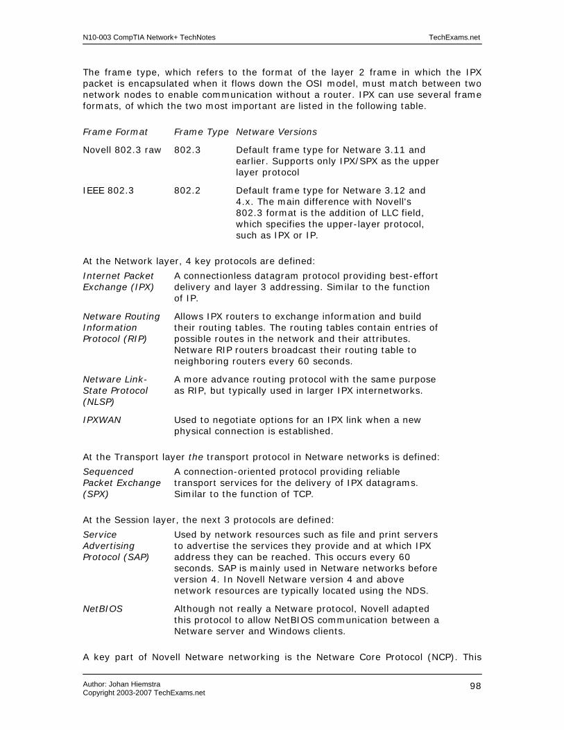
N10-003 CompTIA Network+ TechNotes TechExams.net
Author: Johan Hiemstra Copyright 2003-2007 TechExams.net
98
The frame type, which refers to the format of the layer 2 frame in which the IPX packet is encapsulated when it flows down the OSI model, must match between two network nodes to enable communication without a router. IPX can use several frame formats, of which the two most important are listed in the following table.
Frame Format Frame Type Netware Versions
Novell 802.3 raw 802.3 Default frame type for Netware 3.11 and earlier. Supports only IPX/SPX as the upper layer protocol
IEEE 802.3 802.2 Default frame type for Netware 3.12 and 4.x. The main difference with Novell's 802.3 format is the addition of LLC field, which specifies the upper-layer protocol, such as IPX or IP.
At the Network layer, 4 key protocols are defined:
Internet Packet Exchange (IPX)
A connectionless datagram protocol providing best-effort delivery and layer 3 addressing. Similar to the function of IP.
Netware Routing Information Protocol (RIP)
Allows IPX routers to exchange information and build their routing tables. The routing tables contain entries of possible routes in the network and their attributes. Netware RIP routers broadcast their routing table to neighboring routers every 60 seconds.
Netware Link-State Protocol (NLSP)
A more advance routing protocol with the same purpose as RIP, but typically used in larger IPX internetworks.
IPXWAN Used to negotiate options for an IPX link when a new physical connection is established.
At the Transport layer the transport protocol in Netware networks is defined:
Sequenced Packet Exchange (SPX)
A connection-oriented protocol providing reliable transport services for the delivery of IPX datagrams. Similar to the function of TCP.
At the Session layer, the next 3 protocols are defined:
Service Advertising Protocol (SAP)
Used by network resources such as file and print servers to advertise the services they provide and at which IPX address they can be reached. This occurs every 60 seconds. SAP is mainly used in Netware networks before version 4. In Novell Netware version 4 and above network resources are typically located using the NDS.
NetBIOS Although not really a Netware protocol, Novell adapted this protocol to allow NetBIOS communication between a Netware server and Windows clients.
A key part of Novell Netware networking is the Netware Core Protocol (NCP). This

N10-003 CompTIA Network+ TechNotes TechExams.net
Author: Johan Hiemstra Copyright 2003-2007 TechExams.net
99
protocol operates on the upper three layers of the OSI-model, and provides services to client redirectors such as the Netware Shell. Services include file and printer access, security and name services. Some of the most important Application layer services are the Message-Handling Services (MHS), a simple electronic messaging system, and NDS, Novell's directory services. IPX Addressing A complete IPX network address is 80 bits in length and is represented in a hexadecimal format. As with all routable protocols it needs a network and a host portion, the network portion is 32 bits in length and is manually configured. The host portion is 48 bits in length and is derived from the MAC address of the host's network interface. Examples of full IPX internetwork addresses are: - 0CC001D8.0050.BF61.6C71 - 0000ABBA.0060.9736.954B - 00000046.0060.E92A.C2A4 Data send to an address of which the network portion is 0 (zero), is meant for the local network. Hence, this number cannot be used when configuring network addresses. The IPX broadcast address is FFFFFFFFFFFF. To identify an unique connection when multiple processes are communicating over IPX addresses can also include a socket, which is a 16-bit number appended at the end of the IPX address, for example: 0CC001D8.0050.BF61.6C71.322 Each Netware host that provides server services, including as a Netware server, a NWLINK client sharing resources, or those that act as a router, needs an internal network number. This logical IPX address is not present on the physical network, and issued on only local to the server.
N10-003 CompTIA Network+ TechNotes TechExams.net
Author: Johan Hiemstra Copyright 2003-2007 TechExams.net
100
Fault Tolerance and Disaster Recovery Current related exam objectives for the Network+ exam. 3.11 Identify the purpose and characteristics of fault tolerance: - Power - Link redundancy - Storage - Services 3.12 Identify the purpose and characteristics of disaster recovery: - Backup / restore - Offsite storage - Hot and cold spares - Hot, warm and cold sites Fault Tolerance
Fault tolerance refers to software or hardware options that allow a system to continue operating in case a particular component fails. The main purpose of fault tolerance is to guarantee the availability of information systems to users. Following are some of the most common fault tolerant configurations.
UPS A UPS (Uninterruptible Power Supply) is a hardware device installed between a power outlet and a system. Example systems include servers, monitors, routers, and other network devices. When the main power fails, the UPS takes over and functions as a battery. This allows the system to stay running ‘uninterrupted’ so the system can be taken down properly after warning users and closing sessions. Or, make an effort to restore the main power before the UPS itself runs out of power. There are two main different types of UPSs. The first is the standby UPS, which is active only when the main power fails. When that happens, the UPS switches to its battery pack to provide power to the connected devices. During this switching of the power source, the power may be interrupted even if it is for the slightest amount of time. The second type is the online UPS, also referred to as a true UPS, and always provides power from its battery pack. The latter is continuously recharged from the main power source, and continues to provide power during short or longer power outages.
Link Redundancy A faulty network interface card or cable can prevent an entire server from being able to provide its services to users. To prevent a NIC and cable from being a single-point of failure for the entire server or network device, an extra NIC can be installed and connected. If one interface fails, the other can automatically continue to operate. Multiple NICs can be combined to provide load-balancing in addition to fault tolerance. This means that the load of network traffic can be dynamically and equally divided over the two connections. For increased bandwidth the two links can also be
N10-003 CompTIA Network+ TechNotes TechExams.net
Author: Johan Hiemstra Copyright 2003-2007 TechExams.net
101
combined to act as one, and still provide fault tolerance by continue to operate if one link fails. Link redundancy also refers to implementing multiple WAN connections between branch office or to the Internet for example.
Mirrored Servers A more advanced solution is to mirror complete servers, also known as clustering. A cluster contains two or more nodes (servers). If one node fails, another node will take over its duties. This process is known as fail-over. In modern configuration the nodes connect to a shared storage device using fiber optic cabling. The obvious advantage of using clusters is that the availability of services such as file and print sharing, databases, and shared Internet connections are protected. Even though the services can be mirrored on multiple servers, they will still appear as a single server to users.
RAID RAID (Redundant Array of Inexpensive (or Independent) Disks) allows multiple hard disks to be combined in a set to expand the maximum amount of storage and/or provide fault tolerance in case of a disk failure. RAID is primarily used on servers in corporate environments but using RAID on workstations is not uncommon anymore. Following are the three most common types of RAID, which are relevant for the Network+ exam. RAID 1 refers to Disk Mirroring/Duplexing. This configuration requires two, in some cases identical, hard disks. When data is written to a RAID 1 set, it is written to the primary and the mirrored disk. This may slow down write performance, but increases read performance since data can be read form both disks at the same time. It is called duplexing when each disk has its own hard disk controller, providing an extra level of redundancy. When a disk fails, the other disk can continue to operate. This process occurs entirely automatically on the better RAID systems. RAID 5, also known as a stripe set with parity, is more advanced and requires at least three hard disks. When data is written to the RAID 5 set, it is distributed over all disks and parity information about data blocks on one disk are stored on the other disks. In case of a disk failure, the parity information can be used to reconstruct the data that was on the missing disk. Because data is spread out over several disks, RAID 5 offers better read performance than single or mirrored disks. However, because every write requires the parity calculation, write performance can be slower, especially when RAID 5 is implemented in software. If two disks in a RAID 5 set fail, you will need to replace the disks and restore the information from backup. Fault tolerance RAID configurations implemented in hardware usually offer hot-swappable drives. This means you can pull out and replace a drive while the system is running and it will perform the reconstruction of the data automatically. Another type is RAID 0, also known as a stripe set. It requires at least two hard disks, and does not offer fault tolerance. It is merely a method of combining hard disks to allow for larger storage volumes. When a file is written to a RAID 0 stripe set with two disks, the first block is written to the first disk, the second block to the second disk, and the third data block is written on the first disk, and so on. If one of the hard disks in the stripe set fails, the entire stripe set is lost and needs to be rebuild and restored from backup.

N10-003 CompTIA Network+ TechNotes TechExams.net
Author: Johan Hiemstra Copyright 2003-2007 TechExams.net
102
Disaster Recovery
When you implemented fault tolerance, it doesn't mean you ‘implemented’ disaster recovery. Planning for disaster recovery is an essential task, no matter the level of fault-tolerance. The goal of disaster recovery planning is to recover from a disaster as quickly as possible and keep the impact on day-to-day operations to a minimum.
Data Backups Backing up data to tape regularly is the most common method to prepare for disaster recovery. Following are some important practices to consider when developing a tape backup strategy:
• Use a carefully planned tape rotation scheme - You should avoid data on tapes from being overwritten too frequently. Problems with data may have occurred long before they are discovered and restoring a recent backup of the data may include those same problems. On the other hand, using a new tape for every single day is often too costly. A common rotation scheme is Grandfather-Father-Son. For example, a "Son" tape is used for a daily incremental backup on Monday through Thursday. These 4 tapes are reused weekly. A "Father" tape is used for a full backup on Friday, and a different Father tape exists for every Friday in a month. These 5 tapes are reused monthly. A "Grandfather" tape is used to perform a full backup on the last business day of each month in a quarter. These 3 tapes are reused quarterly. This method ensures there is always a backup archive of at least 3 months.
• Store tapes at an off-site location - Imagine a large office complex with several buildings. A company that has offices in two buildings can easily exchange back ups at the end of a workday. If one building goes up in flames, the backup tapes will be safely stored in the other building. Having employees storing backup tapes at home is not a reliable alternative.
• Store tapes in a locked fire safe - This actually doesn't always mean they will be safe from any fire, the heat can get so intense the tapes will melt anyway, but it is the least you can do.
• Test backups frequently - A complete and reliable backup system can be a lifesaver for any organization, so it is imperative to make sure the backups actual can be restored. It is also important to test the backup procedure to be prepared and have a guide for when you do need to restore a complete server for example.
To understand the various common backup types, you need to know about the archive file attribute. If a file has this attribute turned on, it indicates to the backup software that the file changed since the time the archive attribute was turned off. An archive attribute is turned off by performing certain types of backup, or manually by using the 'attrib' command line utility or the change the file properties in Windows Explorer for example. The table below lists the most common backup types:
Normal/Full Backs up every selected file, regardless of the archive attribute setting, and clears the archive attribute.
Copy Backs up every selected file, regardless of the archive attribute setting. Does not clear the archive attribute.

N10-003 CompTIA Network+ TechNotes TechExams.net
Author: Johan Hiemstra Copyright 2003-2007 TechExams.net
103
Daily Backs up every selected file that has changed that day, regardless of the archive attribute setting. Does not clear the archive attribute.
Incremental Backs up only those files created or changed since the last normal or incremental backup, and clears the archive attribute. This method is used in combination with a periodic full backup. For example, use a Normal/Full backup on Mondays and an incremental backup on the remaining days of the week. In case of a restore, you will need the last normal backup as well as all incremental backups since the last normal backup.
Differential Backs up only those files created or changed since the last normal or incremental backup, and does not clear the archive attribute. This method is also used in combination with a periodic full backup. For example, use a Normal/Full backup on Mondays and a differential backup on the remaining days of the week. In case of a restore, you will need the last normal backup and the last differential backup.
Hot and Cold Spares
Hot spare devices are fully configured spare devices that are identical to production devices and can be used to quickly replace a system in case of a disaster. Examples include routers, switches and complete servers. Hot-spare systems are also referred to as standby systems. A cold spare is a device identical or similar to a device that is operational in the network, but is not configured and does not contain any data. For example, in case of a disruptive event with a production server, it is replaced with a cold spare server. This server then needs to be configured, and data backups need to be restored before it can serve client again.
Alternate Sites A more rigorous solution to ensure business continuity is an alternate site. These come in various shapes and sizes from fully equipped data centers to empty buildings, and are often divided into three categories, hot, warm, and cold sites.
• Hot site – A remote facility with power, heating, ventilation, network equipment, local and remote network connections, fully configured servers and clients, and anything else that is needed to continue the primary business operations as soon as possible after a disaster occurred. Data from the original site must be replicated to the hot site very frequently. This usually requires a high speed connection between the original and the hot site.
• Warm site – A remote facility with power, heating, ventilation, and ‘some’ network equipment and business critical systems. This site can usually be made operational by restoring backups and configuring client, servers, and network devices.
• Cold site – A remote facility with power, heating, and ventilation. A cold site usually doesn’t contain any hardware, and is basically just an empty space. To make a cold site operational, new equipment must be installed and configured, and data needs to be restored from backup.

N10-003 CompTIA Network+ TechNotes TechExams.net
Author: Johan Hiemstra Copyright 2003-2007 TechExams.net
104
Network Support and Troubleshooting Current related exam objectives for the Network+ exam. 4.9 Given a network problem scenario, select an appropriate course of action based on a logical troubleshooting strategy. This strategy can include the following steps:
1. Identify the symptoms and potential causes 2. Identify the affected area 3. Establish what has changed 4. Select the most probable cause 5. Implement an action plan and solution including potential effects 6. Test the result 7. Identify the results and effects of the solution 8. Document the solution and process
Knowing the facts and details covered in the rest of our Network+ TechNotes will enable you to solve most of the scenario questions related to the exam objectives of Domain 4.0 Network Support. The rest comes down to knowing the steps listed above and described below. You don't need to go thru all of the steps for every problem you will encounter and the order of the steps can differ slightly. Also, every step or subset of steps can be repeated multiple times. For example, you probably won't document a solution if it the solution was "disable caps lock". In many real world scenarios you also want to recognize the potential effects of the solution before you implement it. And if you implemented a solution and tested the results, the results might be negative and force you to go back and repeat previous steps. If you carefully read a network problem scenario question in the Network+ exam, one or more of the first 3 steps will usually be provided (after all, we don’t have access to the system(s) that need troubleshooting so they need to provide you with some clear hints). For example: "A user calls you and says she can't logon to the network since her workstation has been moved to another office building." This includes pretty much all the information you need to complete step 1, 2, and 3. The following step would be to select the most probable cause and then to implement a solution. The remaining part of the question could be: "Select the most probable cause: a. Incorrect TCP/IP settings b. Defective NIC c. Defective patch cable d. Incorrect password". In this case you'll have to select the most probable cause by combining your technical knowledge with plain logic. There is no reason to assume that answer b, c, or d is correct. Although they could all be the cause of the problem, they are less easy to relate to the move. More probable is that the other office building requires different TCP/IP settings. Instead, the remaining part of the question could also be: "What would you do to solve the problem? a. Replace the workstation's NIC b. Reinstall the client's OS c. Reconfigure the client's IPX settings d. Replace the patch cable" This means they will assume you know the probable cause already and they skip right ahead to implementing a solution. The cause is mostly obvious and the best solution can be

N10-003 CompTIA Network+ TechNotes TechExams.net
Author: Johan Hiemstra Copyright 2003-2007 TechExams.net
105
determined again by using your technical knowledge combined with plain logic. There is no reason to assume that answer a, or d is correct, and answer b is obviously incorrect. You should pick answer c because you assume the 2 buildings are connected with routers, meaning the IPX network number will be different in the other office. Some scenario questions might include network diagrams on which you should apply the first 4 steps. Keep in mind that symptoms may be ‘indirect’ caused by the real cause of the problem. For example, a MAC OS X system not being able to access the Internet may very well be a problem with a Cisco router or Microsoft firewall. As with any exam: Read carefully! Another possibility is that you'll be asked to choose the next step. For example, in the first scenario above, the remaining part of the question could be: "What is the next step you should take? a. Test the result b. Implement a solution c. Recognize the potential effects of the solution d. Select the most probable cause". The correct answer would of course be d. The chance that you might encounter a question like this, and the fact that it will make you more efficient in solving such problems, is reason enough to memorize these steps.

N10-003 CompTIA Network+ TechNotes TechExams.net
Author: Johan Hiemstra Copyright 2003-2007 TechExams.net
106
Well-known Ports
20 File Transfer Protocol (FTP) for data transport
21 File Transfer Protocol (FTP)
22 Secure Shell (SSH) protocol
23 TELNET
25 Simple Mail Transfer Protocol (SMTP)
53 Domain Naming Service (DNS)
69 Trivial File Transfer Protocol (TFTP)
80 Hyper Text Transfer Protocol (HTTP)
110 Post Office Protocol (POP3)
119 Network News Transfer Protocol (NNTP)
123 Network Time Protocol (NTP)
137 NetBIOS Name Service
143 Internet Message Access Protocol (IMAP)
161 Simple Network Management Protocol (SNMP)
389 Lightweight Directory Access Protocol (LDAP)
443 SSL/HTTPS
1512 Windows Internet Naming Service (WINS)
1701 Layer 2 Tunneling Protocol (L2TP)
1723 Point-to-Point Tunneling Protocol (PPTP)
Following the URL below for a complete list: http://www.iana.org/assignments/port-numbers

N10-003 CompTIA Network+ TechNotes TechExams.net
Author: Johan Hiemstra Copyright 2003-2007 TechExams.net
107
Notes