Multimedia Networking
53
Multimedia Networking Protocols for Real-Time Interactive Applications
-
Upload
khangminh22 -
Category
Documents
-
view
1 -
download
0
Transcript of Multimedia Networking

Multimedia Networking
Protocols for Real-Time Interactive Applications

Protocols for Real Time Interactive Applications
• Real Time Protocol• Real Time Control Protocol• Session Initiation Protocol• H.323

Protocols for Real Time Interactive ApplicationsReal-Time Protocol (RTP)
• RTP is companion protocol of RTCP• Complementary to SIP and H.323• It runs on top of UDP• Specifies packet structure for packets carrying audio,
video data• RFC 3550• RTP runs in end systems only
– (not by intermediate routers)
• Interoperability: – If two VoIP applications run RTP, – they may be able to work together
Protocols for Real Time Interactive ApplicationsReal-Time Protocol (RTP)
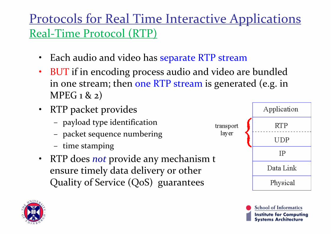
• Each audio and video has separate RTP stream• BUT if in encoding process audio and video are bundled
in one stream; then one RTP stream is generated (e.g. in MPEG 1 & 2)
• RTP packet provides – payload type identification– packet sequence numbering– time stamping
• RTP does not provide any mechanism to ensure timely data delivery or other Quality of Service (QoS) guarantees
Protocols for Real Time Interactive Applications(RTP Example)
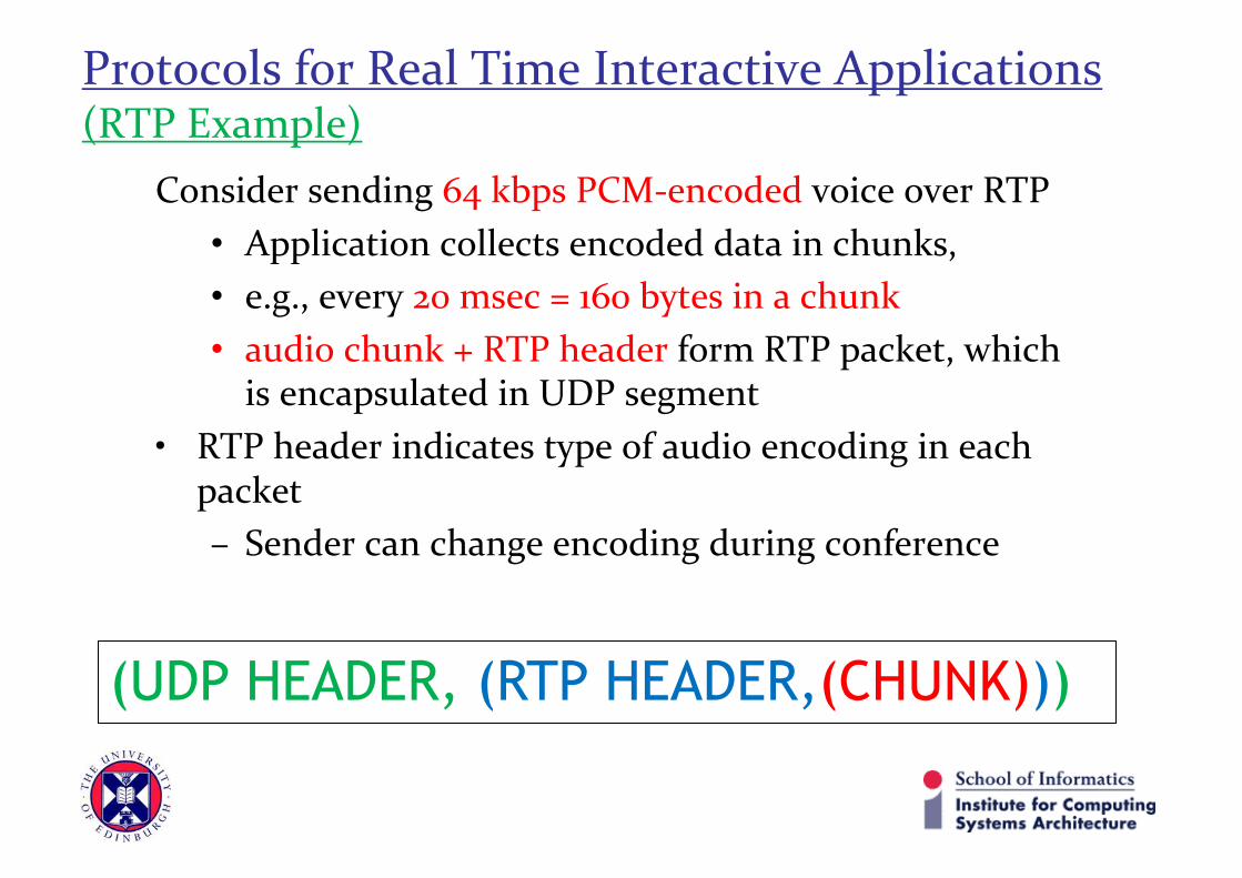
Consider sending 64 kbps PCM-encoded voice over RTP• Application collects encoded data in chunks, • e.g., every 20 msec = 160 bytes in a chunk• audio chunk + RTP header form RTP packet, which
is encapsulated in UDP segment • RTP header indicates type of audio encoding in each
packet– Sender can change encoding during conference
(UDP HEADER, (RTP HEADER,(CHUNK)))

Protocols for Real Time Interactive Applications(RTP Header Format)
• Payload type (7 bits): indicates type of encoding currently being used – Payload type 0: PCM mu-law, 64 kbps– Payload type 3: GSM, 13 kbps– Payload type 7: LPC, 2.4 kbps– Payload type 26: Motion JPEG– Payload type 31: H.261– Payload type 33: MPEG2 video
• If sender changes encoding during call, sender informs receiver via payload type field
• Sequence number (16 bits): increment by one for each RTP packet sent– detect packet loss, restore packet sequence
Payload type
Sequence number
type
Timestamp SynchronizationSource ID
Miscellaneous fields

Protocols for Real Time Interactive Applications(RTP Header Format)
• Timestamp field (32 bits long): sampling instant of first byte in this RTP data packet– for audio, timestamp clock increments by one for each sampling
period (e.g., each 125 µsecs for 8 KHz sampling clock) – if application generates chunks of 160 encoded samples,
timestamp increases by 160 for each RTP packet when source is active. Timestamp clock continues to increase at constant rate even when source is inactive.
– For removing jitter and for synchronous playout at receiver.
• Synchronization Source or SSRC field (32 bits long):identifies source of RTP stream. Each stream in RTP session has distinct SSRC.
Payload type
Sequence number
type
Timestamp SynchronizationSource ID
Miscellaneous fields

Protocols for Real Time Interactive Applications(RTCP: Real-Time Control Protocol)
• RTCP works in conjunction with RTP– Each participant in RTP session periodically
sends RTCP control packets to all other participants
• For an RTP session– There is typically a single multi-cast
address– All RTP and RTCP packets belonging to
same session uses same multicast address– RTP and RTCP are distinguished by port
number, RTCP port#= RTP port#+1

Protocols for Real Time Interactive Applications(RTCP: Real-Time Control Protocol)
• RTCP packets– Do not encapsulate chunks of video/audio– Reports statistics periodically
• Each RTCP packet contains sender and/or receiver reports useful to applications– Number of packets sent– Number of packets lost– Inter-arrival jitter
• Feedback used to control performance– Sender may modify its transmissions based on feedback

Protocols for Real Time Interactive Applications(RTCP Packet Types: Sender Report)
• For each RTP stream that a sender is transmitting, the sender createsand transmits RTCP sender report.
• A sender report includes information about the RTP stream including:• SSRC of the RTP stream: Identification number of the RTP stream.• Timestamp and wall clock time: of the most recently generated RTP
packet in the stream.• Number of packets: sent in the RTP stream.• Number of Bytes: sent in the RTP stream.• Sender report enables receiver to synchronizes different media streams
within an RTP session
Sender Report(SSRC, Timestamp, Wall-clock time, # of sent packets, # of sent bytes)

Protocols for Real Time Interactive Applications(RTCP Packet Types: Source Descriptors)
• For each RTP stream that a sender is transmitting, the sender alsocreates transmit source description packet.
• These packets contain information about source:• SSRC of the associated RTP stream• E-mail address of the sender.• Sender’s name.• The application that generates the RTP stream• These packets provide a mapping between the source identifier (that is
SSRC) and the user/host name.• The source report, receiver report and source descriptor can be
concatenated into a single packet. The resulting packet is thenencapsulated into a UDP segment.

Protocols for Real Time Interactive Applications(RTCP Packet Types: Receiver Report)
• Receiver generates a report for each RTP stream that it receives.• It aggregates its reception reports into a single RTCP packet and sends
it into multicast tree that connects all the session’s participants.• Important information in the reception report are:• SSRC of the RTP stream: For which the reception report is generated.• Fraction of Packets Lost within RTP stream: If a sender receives
reception reports indicating that the receivers are receiving only asmall fraction of the sender’s transmitted packets, it can switch to alower encoding rate; with aim to improve the reception rate.
• Last sequence number: of the RTP packet received.• Inter-arrival jitter: which is a smoothed estimate of the variation in the
inter-arrival time between successive packets in the RTP stream.
Receiver Report(SSRC, Fraction of lost Packets, Last seq. number, Inter-arrival jitter)

Protocols for Real Time Interactive Applications(RTCP Bandwidth Scaling)
• RTCP has scaling problem:– An RTP session consists of one
sender and a large number of receivers
– If each of the receiver periodically generates RTCP packets, then the aggregate transmission rate of RTCP packets can greatly exceed the rate of the RTP packets sent by the sender
– As RTP sent traffic in multi-cast tree does not change as the number of receivers increases, whereas the amount of the RTCP traffic grows linearly with the number of the receivers.

Protocols for Real Time Interactive Applications(RTCP Bandwidth Scaling)
RTCP attempts to limit its traffic to 5% of session bandwidth
Example: one sender, sending video at 2 Mbps
• RTCP attempts to limit RTCP traffic to 100 Kbps
• RTCP gives 75% of rate to receivers; remaining 25% to sender
• 75 kbps is equally shared among receivers: – with R receivers, each
receiver gets to send RTCP traffic at 75/R kbps.
• Sender gets to send RTCP traffic at 25 kbps.
• Participant determines RTCP packet transmission period by calculating avg RTCP packet size (across entire session) and dividing by allocated rate
Protocols for Real Time Interactive Applications(SIP: Session Initiation Protocol, RFC 3261)
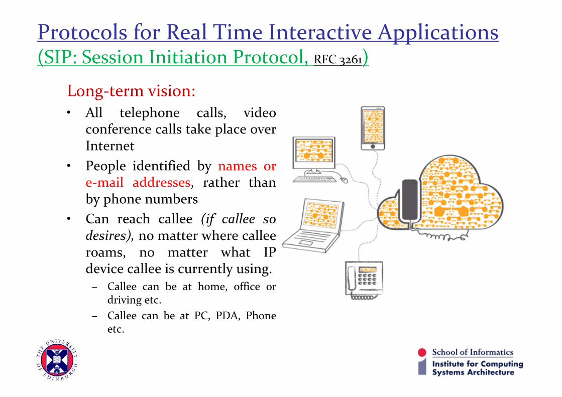
Long-term vision:• All telephone calls, video
conference calls take place overInternet
• People identified by names ore-mail addresses, rather thanby phone numbers
• Can reach callee (if callee sodesires), no matter where calleeroams, no matter what IPdevice callee is currently using.
– Callee can be at home, office ordriving etc.
– Callee can be at PC, PDA, Phoneetc.

Protocols for Real Time Interactive ApplicationsSIP Example: Setting up call to a known IP address
• Alice’s SIP invite message indicates her port number, IP address,encoding she prefers to receive (PCM µlaw)
• Bob’s 200 OK message indicates his port number, IP address,preferred encoding (GSM)
• SIP messages can be sent over TCP or UDP; here sent overRTP/UDP
• Default SIP port number is 5060• If Bob could not use PCM µlaw encoding, it will simply send 600
Not Acceptable message along with encoding schemes that it canuse, Alice will then send a new INVITE with new ending scheme.
• Bob can reject the call by sending “busy”, “gone”, “paymentrequired” and “forbidden” messages.

Protocols for Real Time Interactive ApplicationsSIP Example: Setting up call to a known IP address

Protocols for Real Time Interactive ApplicationsSIP Addresses
• SIP addresses resembles e-mail addresses• Example: [email protected]• When Alice’s SIP device sends an INVITE message, the message
would include his e-mail like address.• The SIP infrastructure then routes the message t the IP device that
Bob is currently using.• Other possible forms can be:
– Bob’s legacy phone number– Bob’s first/middle/last name (assuming it is unique)
• SIP addresses can be included in web-pages (for visitors to call onit), just like e-mail address of people (making mailto URL)

Protocols for Real Time Interactive ApplicationsSIP Messages
• SIP INVITE message from Alice to Bob, with Alice notknowing IP address of the SIP device Bob is currently using.

Protocols for Real Time Interactive ApplicationsSIP Name Translation and User Location
• Caller wants to call callee:– But only has callee’s name or e-mail address.– Need to get IP address of callee’s current host:– User moves around– DHCP protocol– User has different IP devices (PC, smartphone, car device)
• SIP Proxy helps in mapping a callee’s name to IP address• Result can be based on:
– Time of day (work, home)– Caller (don’t want boss to call you at home)– Status of callee (calls sent to voicemail when callee is already talking to
someone)

Protocols for Real Time Interactive ApplicationsSIP Name Translation and User Location
REGISTER sip:domain.com SIP/2.0
Via: SIP/2.0/UDP 193.64.210.89
From: sip:[email protected]
To: sip:[email protected]
Expires: 3600
• SIP registrar: Every SIP user has an associated server called registrar. Whenever a user launches a SIP application on a device, the application sends SIP register message to the registrar informing registrar of its current IP address.
• When device is changes, a new SIP Register message is sent.• If device and IP address is same then a refresh message is
sent to registrar, stating that IP address is still valid (every 3600 sec).
SIP REGISTER message:

Protocols for Real Time Interactive ApplicationsSIP Name Translation and User Location
• SIP Proxy:– Alice sends invite message to her proxy server
Ø contains address sip:[email protected]Ø proxy responsible for routing SIP messages to callee, possibly through multiple
proxies– Bob sends response back through same set of SIP proxies– Proxy returns Bob’s SIP response message to Alice – Contains Bob’s IP address

Protocols for Real Time Interactive ApplicationsSIP Example: [email protected] calls [email protected]
1
1. Jim sends INVITEmessage to UMass SIP proxy.
2. UMass proxy forwards requestto Poly registrar server
2 3. Poly server returns redirect response,indicating that it should try [email protected]
3
5. eurecom registrar forwards INVITE to 197.87.54.21, which is running keith’s SIP client
5
44. Umass proxy forwards requestto Eurecom registrar server
86
76-8. SIP response returned to Jim
99. Data flows between clients
UMass SIP proxy
Poly SIPregistrar
Eurecom SIPregistrar
197.87.54.21128.119.40.186
Protocols for Real Time Interactive ApplicationsH.323 [ITU-T]
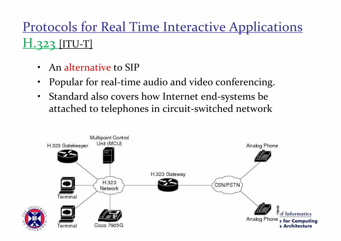
• An alternative to SIP• Popular for real-time audio and video conferencing.• Standard also covers how Internet end-systems be
attached to telephones in circuit-switched network

Protocols for Real Time Interactive ApplicationsH.323 [ITU-T]
• Terminals (what people see/hear)– Communication devices– Multimedia PCs, any stand-alone device, a simple telephone– Must support audio (video) communication
• Gateways (control and ‘routing’ )– Speaks H.323 protocols on Internet side and PSTN protocols on telephone side– Data format translation– Audio/video codec translation– Call setup, termination from both sides of the network
Protocols for Real Time Interactive ApplicationsH.323 [ITU-T]
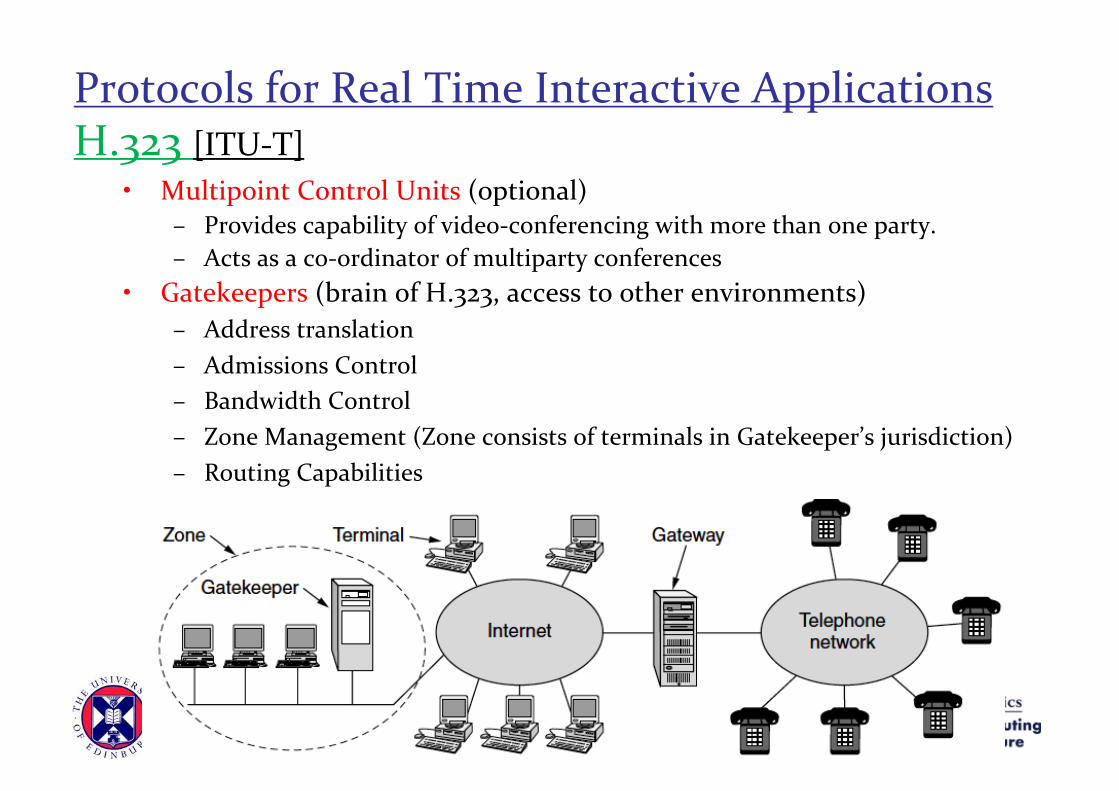
• Multipoint Control Units (optional)– Provides capability of video-conferencing with more than one party.– Acts as a co-ordinator of multiparty conferences
• Gatekeepers (brain of H.323, access to other environments)– Address translation– Admissions Control– Bandwidth Control– Zone Management (Zone consists of terminals in Gatekeeper’s jurisdiction)– Routing Capabilities

Protocols for Real Time Interactive ApplicationsH.323
• An umbrella specification that includes following specifications:
• How end-points negotiate common audio/video encodings
• How audio and video chunks are encapsulated and sent over the network.
• How endpoints communicate with their respective gatekeepers
• How internet phones communicate with PSTN phones via a gateway
Protocols for Real Time Interactive ApplicationsH.323
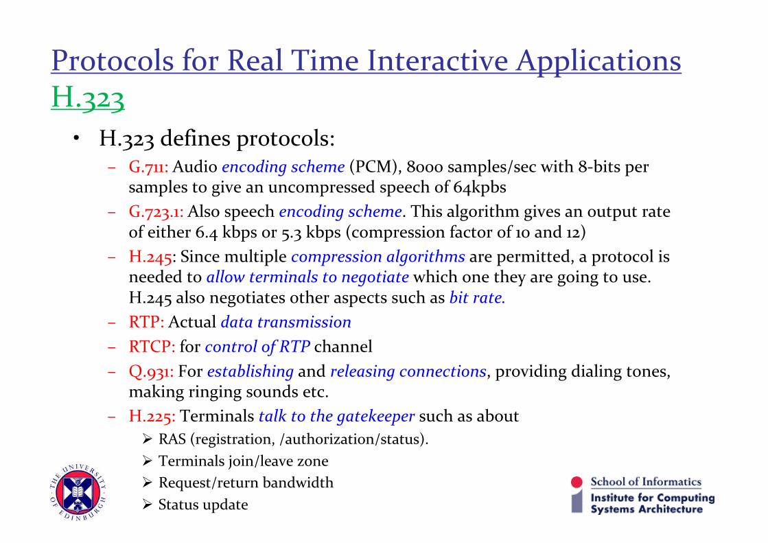
• H.323 defines protocols:– G.711: Audio encoding scheme (PCM), 8000 samples/sec with 8-bits per
samples to give an uncompressed speech of 64kpbs– G.723.1: Also speech encoding scheme. This algorithm gives an output rate
of either 6.4 kbps or 5.3 kbps (compression factor of 10 and 12)– H.245: Since multiple compression algorithms are permitted, a protocol is
needed to allow terminals to negotiate which one they are going to use. H.245 also negotiates other aspects such as bit rate.
– RTP: Actual data transmission– RTCP: for control of RTP channel– Q.931: For establishing and releasing connections, providing dialing tones,
making ringing sounds etc.– H.225: Terminals talk to the gatekeeper such as about
Ø RAS (registration, /authorization/status). Ø Terminals join/leave zoneØ Request/return bandwidthØ Status update

29
Protocols for Real Time Interactive ApplicationsH.323 stack

30
Protocols for Real Time Interactive ApplicationsH.323 stack
• How Protocol stack is used• Consider a PC on a LAN calling a remote telephone• PC has to discover the gatekeeper, so broadcasts a UDP gatekeeper discovery
message to port 1718.• When gatekeeper responds, PC learns its IP address• Now PC registers with gatekeeper by sending it an RAS message in UDP
packet• After gatekeeper accepts, the PC sends the gatekeeper an RAS admission
message requesting bandwidth• After bandwidth is granted; call may setup. PC now establishes a TCP
connection to the gatekeeper to begin the call setup. It sends a Q.9331 SETUP message over the connection by specifying number of telephone being called.
• The gatekeeper responds with Q.931 CALL PROCEEDING message to ACK correct receipt of the request. And forwards the SETUP message to the gateway.
31
Protocols for Real Time Interactive ApplicationsH.323 stack
• How Protocol stack is used• Gateway which is half computer half telephone, then makes an ordinary
telephone call to the desired number.• The end office to which the telephone is attached rings the called telephone and
also sends back a Q.931 ALERT message to tell the calling PC that ringing has begun.
• When person at the other end picks the telephone, the end office sends back Q.931 CONNECT message to the PC.
• Once connection is established, the gatekeeper is no longer in the loop; but gateway is; subsequent packets go directly to the gateways. The H.245 protocol is now used to negotiate the parameters of the call.
• H.245 uses control channel; each side announces its capabilities (i.e. whether it can handle video or conference calls, which codecs it supports etc).
• Once each side knows what other can handle; two unidirectional data channels are setup and a codec and the other parameters are assigned to each one.

32
Protocols for Real Time Interactive ApplicationsH.323 stack
• How Protocol stack is used• Data flow is done by RTP• RTCP manages RTP and acts a role of congestion control. If video is present
RTCP handles synchronization of audio and video.• When either party hangs up; Q.931 call signaling channel is used to tear down the
connection• When call terminates; the calling PC contacts the gatekeeper again with a RAS
message to release the bandwidth.

H.323 [ITU-T]• Complete, vertically integrated suite of
protocols for multimedia conferencing: signaling, registration, admission control, transport, codecs
• Comes from the ITU (telephony)
SIP: [IETF]• Embraces simplicity• Single component. Works with RTP,
but does not mandate it. Can be combined with other protocols, services
• Borrows much of its concepts from HTTP
Protocols for Real Time Interactive ApplicationsH.323 vs SIP

Network Support for Multimedia
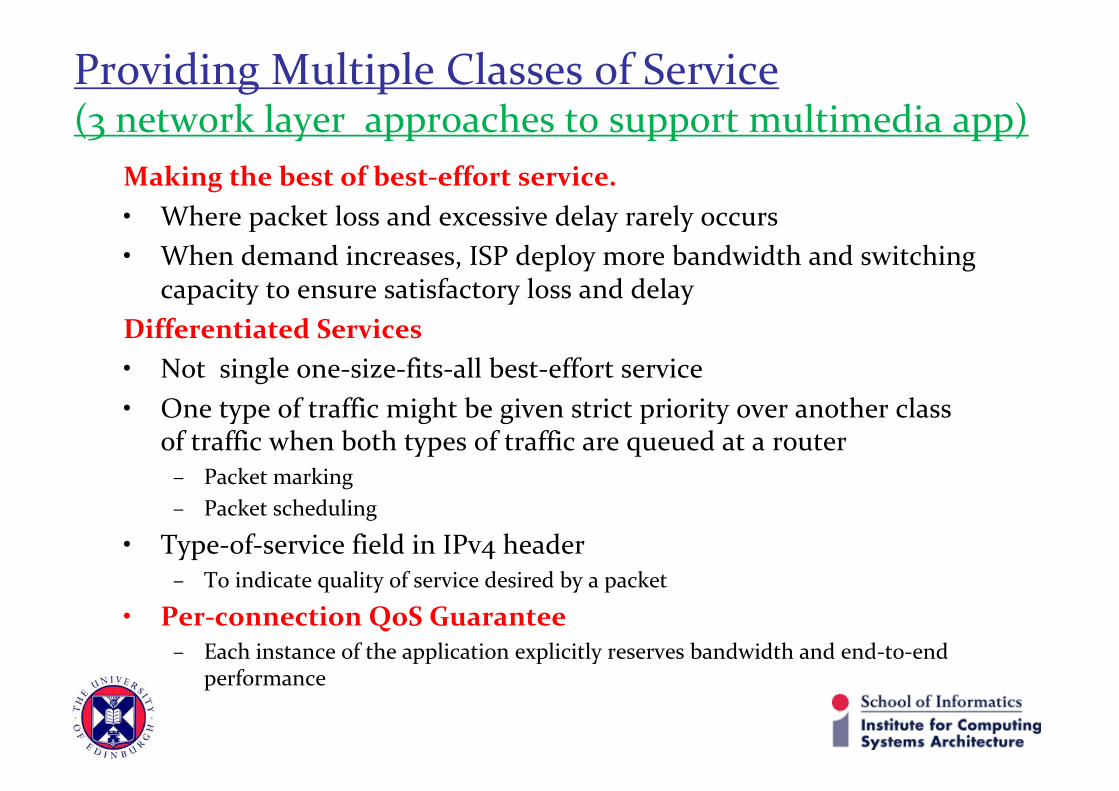
Making the best of best-effort service.• Where packet loss and excessive delay rarely occurs• When demand increases, ISP deploy more bandwidth and switching
capacity to ensure satisfactory loss and delayDifferentiated Services• Not single one-size-fits-all best-effort service• One type of traffic might be given strict priority over another class
of traffic when both types of traffic are queued at a router– Packet marking– Packet scheduling
• Type-of-service field in IPv4 header– To indicate quality of service desired by a packet
• Per-connection QoS Guarantee– Each instance of the application explicitly reserves bandwidth and end-to-end
performance
Providing Multiple Classes of Service (3 network layer approaches to support multimedia app)

Providing Multiple Classes of Service (3 network layer approaches to support multimedia app)

Providing Multiple Classes of Service (Dimensioning Best-Effort Networks)Multimedia communication needs.• Low end-to-end delay/jitter and lossProblem occurs • When congestion occursSimple solution• Throw money at the problem and avoid network contention• This could be achieved with no changes to the Internet best-effort
architecture.Problem with this solution• Not practical according to ISP business standpoint• How much capacity to provide at network links in a given topology
to achieve a given level of performance (bandwidth provisioning).• How to design a network topology to achieve a given level of end-to-
end (network dimensioning)

Providing Multiple Classes of Service (Dimensioning Best-Effort Networks)• Following issues must be addressed to predict
– application-level performance between two network end points, – and provision enough capacity to meet an performance
requirements.• Models of traffic demand between network end points. Models may
need to be specified – Call level (for example, users “arriving” to the network) – Packet level (packets being generated by ongoing applications). – Note that workload may change over time.
• Well-defined performance requirements.– E.g. to support delay-sensitive traffic (a threshold value)
• Models to predict end-to-end performance for a given workload model, and techniques to find a minimal cost bandwidth allocation that will result in all user requirements being met.

Providing Multiple Classes of Service (Providing Multiple Classes of Service)Simplest enhancement to the one-size-fits-all best-effort service is • To divide traffic into classes• Provide different levels of service to these different classes of traffic.
– For example, an ISP might well want to provide a higher class of service to delay-sensitive Voice-over-IP or teleconferencing traffic (and charge more for this service!) than to elastic traffic such as email or HTTP.
– An ISP may provide a higher quality of service to customers willing to pay more for this improved service. A number of ISPs have adopted such tiered levels of service—with platinum-service subscribers receiving better performance than gold- or silver-service subscribers
Economy class < business class < first class passengers

• Suppose two application packet flows originate on Host H1 and H2 on one LAN
• The packets are destined for Hosts H3 and H4 on another LAN
• The routers on the two LANs areconnected with a 1.5Mbps link
• Speed of the LANs are significantly higher than 1.5Mbps
• Both packet loss and delay will occur if the combined sending rate of H1 and H2 exceeds 1.5Mbps
• Suppose one communication is from 1Mbps audio application and other from HTTP web browsing
Providing Multiple Classes of Service(Motivating Scenarios)

• In best-effort Internet– FIFO order– Burst of packets from Web-browsing
may delay/ loss audio packets• Multiple classes
– Since web-browsing is elastic application, problem can be solved by giving priority to audio stream
– An audio packet in the router buffer will always be transmitted before web traffic packet
– A dedicated 1.5Mbps link for audio traffic
– Web traffic will flow only when no audio traffic
– Each type of traffic will be marked for router to distinguish each
Providing Multiple Classes of Service(Motivating Scenarios)

• Multiple classes– In current scenario audio traffic
1Mbps,– So, web traffic can still have the
remaining 0.5 Mbps– BUT what if audio application
starts transmission at 1.5Mbps– The web traffic will starve– Similarly many audio traffics
sharing a link will starve FTP traffic if the priority is given to audio traffic.
• Degree of isolation– So that one class of traffic can be
protected from the other class.
Providing Multiple Classes of Service(Motivating Scenarios)

Degree of isolation.- Traffic Policing- It makes sure that certain criteria
(like <=1Mbps rate) is followed by a traffic class
- In case the traffic class exceeds the threshold packet be delayed or discarded at routers.
- The traffic policing and marking is both implemented at network edge
Providing Multiple Classes of Service(Motivating Scenarios)
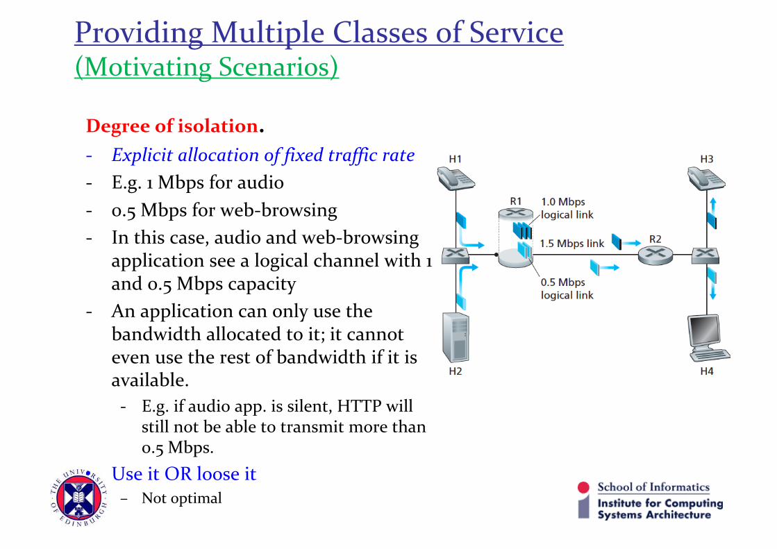
Degree of isolation.- Explicit allocation of fixed traffic rate- E.g. 1 Mbps for audio- 0.5 Mbps for web-browsing- In this case, audio and web-browsing
application see a logical channel with 1 and 0.5 Mbps capacity
- An application can only use the bandwidth allocated to it; it cannot even use the rest of bandwidth if it is available.- E.g. if audio app. is silent, HTTP will
still not be able to transmit more than 0.5 Mbps.
• Use it OR loose it– Not optimal
Providing Multiple Classes of Service(Motivating Scenarios)

Scheduling Mechanisms.- First in-first out (FIFO)• Packets arriving at the link output queue wait for transmission if the link
is currently busy transmitting another packet. • If there is not sufficient buffering space to hold the arriving packet, the
queue’s packet-discarding policy then determines– whether the packet will be dropped (lost) or – whether other packets will be removed from the queue.
Providing Multiple Classes of Service(Motivating Scenarios)

Scheduling Mechanisms.- Priority Queuing• Packets are divided into classes and marked accordingly (i.e. TOS field in
IPv4).• Each class has its own queue• Packets will be transmitted from the highest priority class that has a
nonempty queue (that is, has packets waiting for transmission). • The choice among packets in the same priority class is typically done in a
FIFO manner.
Providing Multiple Classes of Service(Motivating Scenarios)
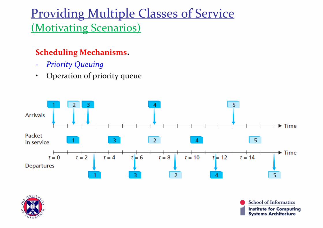
Scheduling Mechanisms.- Priority Queuing• Operation of priority queue
Providing Multiple Classes of Service(Motivating Scenarios)

Scheduling Mechanisms.- Round Robin • Packets are sorted into classes just like priority queue• Rather than a strict selection based on priority; Round robin process is
used:– A class 1 packet followed by a class 2 packet is transmitted
• A work-conserving round robin discipline:– that looks for a packet of a given class but finds none will immediately
check the next class in the round robin sequence.
Providing Multiple Classes of Service(Motivating Scenarios)

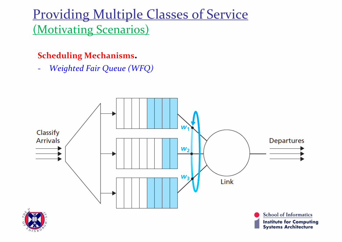
Scheduling Mechanisms.- Weighted Fair Queue (WFQ)• A generalized abstraction of Round Robin queue• Arriving packets are classified and queued in appropriate waiting area
– a WFQ scheduler will serve classes in a circular manner
• Here each class receives a differential amount of service in any interval of time. Specifically, each class, i, is assigned a weight, wi .
• During any interval of time during which there are class i packets to send, class i will then be guaranteed to receive a fraction of service equal to wi/(Σwj ), where the sum in the denominator is taken over all classes that also have packets queued for transmission.
• Thus, for a link with transmission rate R, class i will always achieve a• throughput of at least R · wi /(Σwj ).
Providing Multiple Classes of Service(Motivating Scenarios)
Scheduling Mechanisms.- Weighted Fair Queue (WFQ)
Providing Multiple Classes of Service(Motivating Scenarios)

Providing Multiple Classes of Service(Traffic Policing)
Goal: limit traffic to not exceed declared parameters
Three commonly used parameters: • (long term) average rate: how many packets can be sent
per unit time (in the long run)• crucial question: what is the interval length?
• 100 packets per sec or 6000 packets per min have same average!
• peak rate: e.g., 6000 packets per min (ppm) average and 1500 pps peak rate
• (max.) burst size: max number of packets sent consecutively (with no intervening idle)

Providing Multiple Classes of Service(Leaky Bucket Mechanism)
Token bucket: limits input to specified average rate and burst size
• Bucket can hold b tokens• Tokens generated at rate r tokens/sec unless bucket full• Over an interval of length t, the number of packets
admitted ≤ r t + b
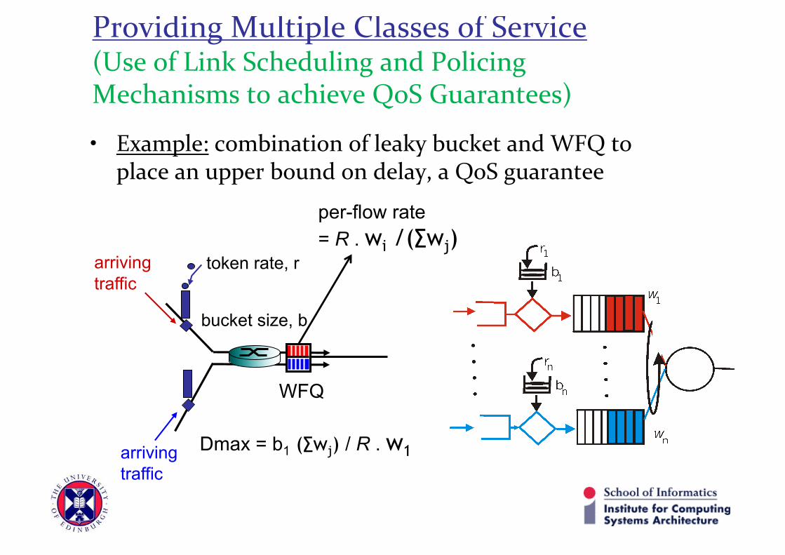
Providing Multiple Classes of Service(Use of Link Scheduling and Policing Mechanisms to achieve QoS Guarantees)
• Example: combination of leaky bucket and WFQ to place an upper bound on delay, a QoS guarantee
WFQ
token rate, r
bucket size, b
per-flow rate = R . wi /(∑wj)
Dmax = b1 (∑wj) / R . w1
arrivingtraffic
arrivingtraffic