Geotechnical-Report-G155-18-Final.pdf - San Jacinto River ...
92
GEOTECHNICAL INVESTIGATION SAN JACINTO RIVER AUTHORITY HIGHLANDS SOUTH CANAL SIPHON 29 IMPROVEMENTS - WO#2 HARRIS COUNTY, TEXAS Reported to: Texas Water Engineering, PLLC Sugar Land, Texas by Aviles Engineering Corporation 5790 Windfern Houston, Texas 77041 713-895-7645 REPORT NO. G155-18 March 2019
-
Upload
khangminh22 -
Category
Documents
-
view
0 -
download
0
Transcript of Geotechnical-Report-G155-18-Final.pdf - San Jacinto River ...
GEOTECHNICAL INVESTIGATION
SAN JACINTO RIVER AUTHORITY HIGHLANDS SOUTH CANAL
SIPHON 29 IMPROVEMENTS - WO#2 HARRIS COUNTY, TEXAS
Reported to: Texas Water Engineering, PLLC
Sugar Land, Texas
by
Aviles Engineering Corporation 5790 Windfern
Houston, Texas 77041 713-895-7645
REPORT NO. G155-18
March 2019
5790 Windfern Road
Houston, Texas 77041
Tel: (713)-895-7645
Fax: (713)-895-7943 March 11, 2019 Ms. Victoria A. Foss, P.E.
Texas Water Engineering, PLLC
19901 Southwest Freeway, Suite 134
Sugar Land, TX 77479
Reference: Geotechnical Investigation
San Jacinto River Authority - Highlands South Canal
Siphon 29 Improvements - Work Order No. 2
Harris County, Texas
AEC Report No. G155-18
Dear Ms. Foss,
Aviles Engineering Corporation (AEC) is pleased to present this report of the results of our geotechnical
investigation for the above referenced project. Notice to Proceed for the project was provided by the San
Jacinto River Authority (SJRA) on September 4, 2018. The project terms and conditions were in
accordance with the Professional Services Agreement between Texas Water Engineering (TWE) and AEC,
dated February 1, 2018 and Work Order 2, dated September 4, 2018. The project scope was based on AEC
proposal G2018-07-08, dated July 19, 2018.
AEC appreciates the opportunity to be of service to you. Please call us if you have any questions or
comments concerning this report or when we can be of further assistance.
Respectfully submitted,
Aviles Engineering Corporation (TBPE Firm Registration No. F-42)
Wilber L. Wang, P.E. 03/11/2019 Mohammad Bhuiyan, E.I.T.
Senior Engineer Staff Engineer
Reports Submitted: 1 Texas Water Engineering, PLLC (electronic)
1 File (electronic)
Z:\ENGINEERING\REPORTS\2018\G155-18 SJRA SIPHON 29 IMPROVEMENTS - TEXAS WATER ENGINEERING, PLLC
(MOHAMMAD)\G155-18 FINAL.DOCX
TABLE OF CONTENTS EXECUTIVE SUMMARY ............................................................................................................................. i 1.0 INTRODUCTION ............................................................................................................................. 1
1.1 General ........................................................................................................................................... 1 1.2 Purpose and Scope ........................................................................................................................ 1
2.0 SUBSURFACE EXPLORATION ................................................................................................... 2 3.0 LABORATORY TESTING PROGRAM ....................................................................................... 3 4.0 SITE CONDITIONS ......................................................................................................................... 4
4.1 Subsurface Conditions .................................................................................................................. 5 4.2 Hazardous Materials .................................................................................................................... 6 4.3 Subsurface Variations .................................................................................................................. 6
5.0 GEOTECHNICAL ENGINEERING RECOMMENDATIONS .................................................. 7 5.1 Demolition and Removal of Siphon Pipes and Headwalls......................................................... 7 5.2 Installation of Siphon Pipes by Open-Cut Method .................................................................... 8
5.2.1 Geotechnical Parameters for Siphon Pipes ............................................................................ 8 5.2.2 Loadings on Pipes .................................................................................................................. 8 5.2.3 Trench Stability .................................................................................................................... 10 5.2.4 Bedding and Backfill ........................................................................................................... 13
5.3 Installation of Siphon Pipes by Tunnel or Trenchless Methods ............................................. 13 5.3.1 Tunnel Access Shafts ........................................................................................................... 14 5.3.2 Tunnel/Trenchless Face Stability during Construction ........................................................ 17
5.3.2.1 General ................................................................................................................................................................ 19 5.3.2.2 Anticipated Ground Behavior ............................................................................................................................. 20 5.3.2.3 Influence of Tunneling/Boring on Existing Structures ........................................................................................ 22
5.3.3 Measures to Reduce Distress from Tunneling/Boring ......................................................... 22 5.3.4 Monitoring Existing Structures ............................................................................................ 23
5.4 Siphon Inlet/Outlet Structures .................................................................................................. 24 5.4.1 Allowable Bearing Capacity ................................................................................................ 24 5.4.2 Lateral Earth Pressures ......................................................................................................... 24 5.4.3 Hydrostatic Uplift ................................................................................................................ 26 5.4.4 Drainage System .................................................................................................................. 26 5.4.5 Siphon Inlet/Outlet Construction ......................................................................................... 27
5.5 Select Fill ...................................................................................................................................... 28 5.6 SJRA Canal at Siphon 29 ........................................................................................................... 29
5.6.1 Slope Stability Analysis ....................................................................................................... 29 5.6.2 Design Soil Parameters and Profiles .................................................................................... 30 5.6.3 Conditions Analyzed for Slope Stability .............................................................................. 30 5.6.4 Slope Stability for East Bank of Upstream Section at Station 0+81.49 ............................... 31
5.7 Rip Rap ........................................................................................................................................ 32 6.0 CONSTRUCTION CONSIDERATIONS ..................................................................................... 34
6.1 Site Preparation .......................................................................................................................... 34 6.2 Groundwater Control ................................................................................................................. 34 6.3 Construction Monitoring ........................................................................................................... 36 6.4 Monitoring of Existing Structures ............................................................................................. 36
7.0 LIMITATIONS ............................................................................................................................... 36
APPENDICES APPENDIX A Plate A-1 Vicinity Map Plate A-2 Boring Location Plan Plates A-3 to A-5 Boring Logs Plate A-6 Key to Symbols Plate A-7 Classification of Soils for Engineering Purposes Plate A-8 Terms Used on Boring Logs Plate A-9 ASTM & TXDOT Designation for Soil Laboratory Tests Plates A-10 to A-11 Sieve Analysis Results Plate A-12 Crumb Test Results Plate A-13 Crumb Test Results from AEC Report G116-13, dated October 18, 2013. Plate A-14 Mohr Coulomb Diagrams (from CU Tests) Plate A-15 Consolidation Test Result APPENDIX B Plates B-1 and B-2 Site Photographs near Siphon 29 APPENDIX C Plate C-1 Recommended Geotechnical Design Parameters for Underground Utilities Plate C-2 Recommended Geotechnical Design Parameters for Head/Wing Walls Plate C-3 Coefficients of Active and Passive Earth Pressures for Sloped Backfill Plate C-4 Load Coefficients for Pipe Loading Plate C-5 Live Loads on Pipe Crossing Under Roadway Plate C-6 Tunnel/Bore Settlement Calculations for One Pass Method Plate C-7 Tunnel/Bore Settlement Calculations for Two Pass Method Plate C-8 Soil Parameters for Siphon Mat Foundation Settlement Analysis APPENDIX D Plate D-1 Critical Heights of Cut Slopes in Nonfissured Clays Plate D-2 Maximum Allowable Slopes Plate D-3 A Combination of Bracing and Open Cuts Plate D-4 Lateral Pressure Diagrams for Open Cuts in Cohesive Soil-Long Term Conditions Plate D-5 Lateral Pressure Diagrams for Open Cuts in Cohesive Soil-Short Term Conditions Plate D-6 Lateral Pressure Diagrams for Open Cuts in Sand Plate D-7 Bottom Stability for Braced Excavation in Clay Plate D-8 Tunnel Behavior and TBM Selection Plate D-9 Relation between the Width of Surface Depression and Depth of Cavity for
Tunnels Plate D-10 Methods of Controlling Ground Water in Tunnel and Grouting Material Selection Plate D-11 Buoyant Uplift Resistance for Buried Structures APPENDIX E Plates E-1 and E-2 Plan and Profile, and Canal Cross Section Exhibits prepared by TWE, dated
January 24, 2019 Plate E-3 Design Soil Parameters for Slope Stability Analyses Plates E-4 to E-9 Slope Stability Analysis for East Bank of Upstream Cross Section at Station
0+81.49, based on Boring B-46
i
EXECUTIVE SUMMARY
The report submitted herein presents the results of Aviles Engineering Corporation’s (AEC) geotechnical investigation for the San Jacinto River Authority’s (SJRA) proposed improvements of Highlands Division Siphon 29 on the Highlands South Canal, at Ellis School Road in Harris County, Texas (Houston Key Map 460 X). The project improvements include: (i) demolition and removal or abandonment in place of existing siphon pipes and headwall structures; (ii) installation and construction of new siphon pipes and headwall structures; and (iii) slope stability analysis for the existing canal bank.
1. Subsurface Soil Conditions: Based on AEC’s borings, the subsurface soil conditions in the vicinity of Siphon 29 generally consist of approximately 18 feet of firm to hard fat clay (including fill) at the ground surface, underlain by approximately 17 to 20 feet of soft to very stiff lean clay which was encountered at depths of 18 to 38 feet. Approximately 4 to 7 feet of silty sand (SM) was encountered at depths of 24 to 28 feet and 31 to 38 feet in Boring B-1, respectively. Approximately 4 feet of sandy silt (ML) was encountered at depths of 36 to 40 feet in Boring B-2. Approximately 1 to 5 feet of silty sand (SM) was encountered at depths of 23 to 24 and 35 to 40 feet in G116-13 Boring B-46.
2. Subsurface Soil Properties: The subsurface cohesive soils encountered in the borings (including Boring B-46 of AEC report G116-13) have slight to very high plasticity, with liquid limits (LL) ranging from 28 to 81, and plasticity indices (PI) ranging from 10 to 59. The cohesive soils encountered are classified as “CL” and “CH” type soils and granular soils were classified as “SM” and “ML” type soils in accordance with ASTM D 2487.
3. Groundwater Conditions: Groundwater was initially encountered in Borings B-1, B-2, and G116-13 Boring B-46 at a depth of 18 to 23 feet below grade during drilling, and subsequently rose to a depth between 7.6 and 12.6 feet approximately 15 minutes after the initial encounter. Groundwater was measured at 6.2 to 6.5 feet below grade approximately 1 to 3 days after drilling was completed. Based on the groundwater level observed, the groundwater in the borings is likely to be pressurized. A summary of groundwater depths encountered in the borings is presented on Table 5 in Section 4.1 of this report.
4. Soil Dispersion Characteristics: AEC performed a total of 4 crumb tests from Borings B-1 and B-
2, and also considered the crumb test results from G116-13 Boring B-46 to evaluate the dispersive characteristics of clay soils along the canal. The results indicate that the tested soil samples in the channel zone for Boring B-1 and B-2 are classified as non-dispersive, while the samples tested from G116-13 Boring B-46 are non-dispersive to dispersive.
5. Recommendations for the design and installation of siphon pipes by open cut or tunnel/trenchless
methods are presented in Sections 5.2 and 5.3 of this report, respectively. Recommendations for design and installation of siphon inlet/outlet structures are presented in Section 5.4 of this report.
6. AEC performed slope stability analyses on a selected cross section of the canal to determine if the
canal slopes will be stable. The slope stability analyses consider three different conditions: the short-term condition, long-term condition and rapid drawdown condition. AEC performed the stability analyses in general accordance with the December 2010 Harris County Flood Control District (HCFCD) Geotechnical Guidelines. Based on our analyses, the safety factor’s (SF) for the
ii
analyzed canal cross section meet HCFCD’S minimum requirements under short term, long term, and rapid-drawdown conditions.
This Executive Summary is intended as a summary of the investigation and should not be used without the full text of this report.
1
GEOTECHNICAL INVESTIGATION
SAN JACINTO RIVER AUTHORITY HIGHLANDS SOUTH CANAL
SIPHON 29 IMPROVEMENTS - WO#2 HARRIS COUNTY, TEXAS
1.0 INTRODUCTION
1.1 General
The report submitted herein presents the results of Aviles Engineering Corporation’s (AEC) geotechnical
investigation for the San Jacinto River Authority’s (SJRA) proposed improvements of Highlands Division
Siphon 29 on the Highlands South Canal, at Ellis School Road in Harris County, Texas (Houston Key Map
460 X). A vicinity map is presented on Plate A-1, in Appendix A. The project improvements include: (i)
demolition and removal or abandonment in place of existing siphon pipes and headwall structures; and (ii)
installation and construction of new siphon pipes and headwall structures; and (iii) slope stability analysis
for the existing canal bank.
1.2 Purpose and Scope
The purpose of this geotechnical investigation is to evaluate the subsurface soil conditions at the site and
develop geotechnical engineering recommendations for design and construction of the siphon pipes and
siphon inlets/outlets, including demolition and removal or abandonment in place of existing siphon pipes
and headwall structures. The scope of this geotechnical investigation is summarized below:
1. Drilling and sampling 2 geotechnical borings to 40 feet below existing grade; 2. Soil laboratory testing on selected soil samples; 3. Recommendations for demolition and removal or abandonment in place of existing siphon pipes and
headwall structures; 4. Engineering analyses and recommendations for the installation of siphon pipes by open cut method,
including loadings on pipes, bedding, lateral earth pressure parameters, trench stability, and backfill requirements;
5. Engineering analyses and recommendations for the installation of siphon pipes by trenchless method, including bore/auger launching and receiving shafts, reaction walls, and bore face stability;
6. Engineering analyses and recommendations for siphon inlets/outlets, including allowable bearing capacity and lateral earth pressure parameters for headwalls and wingwalls;
7. Engineering analyses and recommendations for the existing canal slope, including slope stability analysis on a selected cross section;
2
8. Construction recommendations for the siphon pipes and inlets/outlets.
2.0 SUBSURFACE EXPLORATION
As directed by SJRA, AEC drilled a total of two borings to 40 feet below existing grade at the site. The total
drilling footage is 80 feet. G116-13 Boring B-46 was drilled to 40 feet below existing grade in June 2013
for AEC report G116-13, and is also included in this report for reference. The boring locations are shown
on the Boring Location Plan on Plate A-2, in Appendix A. After completion of drilling, the boring
locations were surveyed by GeoSolutions, LLC. Boring survey data in State Plane Grid Coordinates (Texas
South Central Zone) is presented on Table 1 and on the boring logs.
Table 1. Summary of Borings Coordinates and Elevations
Boring No.
Boring Depth (ft)
Northing (Grid, ft)
Easting (Grid, ft)
Boring Surface Elevation (ft)
B-1 40 13,859,924.29 3,227,693.675 31.769
B-2 40 13,859,804.27 3,227,773.863 31.842
The field drilling was performed with a truck-mounted drilling rig. The borings were generally advanced
initially using dry auger method, and then using wet rotary method once groundwater was encountered, or
the borings began to cave in. Undisturbed samples of cohesive soils were obtained from the borings by
pushing 3-inch diameter thin-wall, seamless steel Shelby tube samplers in general accordance with ASTM
D 1587. Granular soils were sampled with a 2-inch split-barrel sampler in accordance with ASTM D 1586.
Standard Penetration Test resistance (N) values were recorded for the granular soils as “Blows per Foot”
and are shown on the boring logs. Strength of the cohesive soils was estimated in the field using a hand
penetrometer. The undisturbed samples of cohesive soils were extruded mechanically from the core barrels
in the field and wrapped in aluminum foil; all samples were sealed in plastic bags to reduce moisture loss
and disturbance. The samples were then placed in core boxes and transported to the AEC laboratory for
testing and further study. Groundwater readings were taken during drilling, after completion of drilling,
and 3 days after completion of drilling. After the final groundwater readings were obtained, the borings
were backfilled with bentonite chips.
3
3.0 LABORATORY TESTING PROGRAM
Soil laboratory testing was performed by AEC personnel. Samples from the borings were examined and
classified in the laboratory by a technician under the supervision of a geotechnical engineer. Laboratory
tests were performed on selected soil samples in order to evaluate the engineering properties of the
foundation soils in accordance with applicable ASTM Standards. Atterberg limits, moisture contents,
percent passing a No. 200 sieve, sieve analysis, and dry unit weight tests were performed on selected
samples to establish the index properties and confirm field classification of the subsurface soils. For
completeness, AEC also included the sieve and hydrometer analysis from AEC report G116-13 Boring B-
46 in this report. Strength properties of cohesive soils were determined by means of torvane (TV),
unconfined compression (UC), undrained-unconsolidated (UU), and consolidated-undrained (CU) triaxial
tests performed on undisturbed samples. The test results are presented on the boring logs. Details of the
soils encountered in the borings are presented on Plates A-3 through A-5, in Appendix A. A key to the
boring logs, classification of soils for engineering purposes, terms used on boring logs, and reference
ASTM Standards for laboratory testing are presented on Plates A-6 through A-9, in Appendix A. Sieve
analysis results are presented on Plates A-10 and A-11, in Appendix A.
Crumb Tests: To evaluate the dispersive characteristics of clayey soils along the canal, four crumb tests
were performed on selected soil samples in accordance with ASTM D 6572, Method A. The results of the
crumb tests are summarized on Table 2 and are presented on Plate A-12, in Appendix A. AEC also
considered the crumb test results performed on soil samples from G116-13 Boring B-46 and included them
in Table 2 and as well as on Plate A-13, in Appendix A.
Table 2. Summary of Crumb Test Results
Sample ID and Description Dispersive
Grade Dispersive
Classification
B-1, 4’-6’, Fat Clay (CH) 1 Non-dispersive
B-1, 12’-14’, Fat Clay (CH) 1 Non-dispersive
B-2, 2’-4’, Fat Clay (CH) 1 Non-dispersive
B-2, 10’-12’, Fat Clay (CH) 1 Non-dispersive
G116-13 Boring B-46, 4’-6’, Fat Clay (CH)
1 Non-dispersive
G116-13 Boring B-46, 23’-25’, Lean Clay (CL)
3 Dispersive
4
Consolidated-Undrained Triaxial Tests: One CU triaxial shear test was performed in accordance with
ASTM D 4767 to determine shear strength parameters of the soil. The CU test Mohr Coulomb Diagrams
are included on Plate A-14, in Appendix A. The shear strength parameters obtained from the CU triaxial
tests are summarized below in Table 3.
Table 3. Summary of Shear Strength Parameters from CU Triaxial Tests
Sample ID and Description Effective Stress Total Stress
c′ (psf) φ′ (deg) ccu (psf) φcu
(deg)
B-2, 8’-10’, Fat Clay (CH) 210 17.2 230 13.1
Notes: (1) c' = effective cohesion, φ' =effective friction angle, obtained from CU tests with pore pressure measurements; (2) ccu = cohesion in total stress, φcu = friction angle in total stress, obtained from CU tests.
Consolidation Tests: A one-dimensional consolidation test was performed on a selected soil sample in order
to evaluate the general compressibility characteristics of clay soils at the site. The results of the
consolidation test are presented on Plate A-15. The initial void ratio, compression index, recompression
index, preconsolidation pressure, and estimated overconsolidation ratio (OCR) for the consolidation test are
summarized in Table 4.
Table 4. Summary of Consolidation Test Results
Sample ID and Description e0 Cc Cr pc (tsf) OCR
B-1, 14’-16’, Fat Clay (CH) 0.8371 0.2239 0.0301 4.4 7.0
Note: (1) e0 = initial void ratio; (2) Cc = compression ratio; (3) Cr = recompression ratio, which is derived from the recompression curve within the stress range from 2 to
8 ksf; (4) pc = preconsolidation pressure; and (5) OCR = overconsolidation ratio.
4.0 SITE CONDITIONS
The current siphon structure is located beneath Ellis School Road, which is a two lane (one lane in each
direction) asphalt roadway with grass-lined roadside ditches. The existing siphon consists of dual 42-inch
diameter concrete siphon pipes (based on as-built drawings dated 1978) and an additional 60-inch diameter
concrete bypass siphon pipe (based on as-built drawings dated 1997). In 1998 the dual 42-inch pipes were
slip-lined with 36-inch HOBAS Relining Pipes. Concrete headwalls for the existing siphon pipes are
located on either side of Ellis School Road at the canal intersection. Based on AEC’s site visits, horizontal
5
movement of the headwalls and wing walls were observed at various locations. Loss of soils behind the
wing walls, slope failures near the siphon structures, and cracks in the head walls and wing walls were also
observed from various locations at Siphon 29. Selected photos in the vicinity of Siphon 29 are presented on
Plates B-1 and B-2, in Appendix B.
4.1 Subsurface Conditions
Details of the soils encountered during drilling are presented in the boring logs. Soil strata encountered in
our borings are summarized below.
Boring Depth (ft) Description of Stratum B-1 0 - 4 Fill: very stiff, Fat Clay (CH), with shell 4 - 18 Firm to very stiff, Fat Clay (CH), with slickensides 18 - 24 Stiff, Sandy Lean Clay (CL), with silty clay pockets 24 - 28 Silty Sand (SM), with fat clay seams, wet 28 - 31 Stiff, Sandy Lean Clay (CL), with calcareous nodules 31 - 38 Loose, Silty Sand (SM), with clayey sand pockets, wet 38 - 40 Stiff, Fat Clay (CH), with ferrous stains B-2 0 - 18 Firm to hard, Fat Clay (CH), with slickensides 18 - 22 Very stiff, Lean Clay (CL), with silty clay and fat clay pockets 22 - 36 Soft to stiff, Sandy Lean Clay (CL), with abundant silty clay pockets, wet 36 - 40 Sandy Silt (ML), with silty clay seams, wet G116-13 0- 4 Fill: very stiff, Fat Clay with Sand (CH), with calcareous nodules and roots B-46 4 - 18 Firm to very stiff, Fat Clay (CH), with slickensides and ferrous stains 18 - 23 Stiff, Lean Clay (CL), with silt partings 23 - 24 Silt (ML), wet 24 - 28 Stiff, Fat Clay (CH), with sand pockets 28 - 35 Soft to stiff, Lean Clay with Sand (CL), with abundant silt partings 35 - 40 Medium dense, Silty Sand (SM), with clayey sand pockets, wet
Subsurface Soil Properties: The subsurface cohesive soils encountered in the borings (including G116-13
Boring B-46) have slight to very high plasticity (see Plate A-7, in Appendix A), with liquid limits (LL)
ranging from 28 to 81, and plasticity indices (PI) ranging from 10 to 59. The cohesive soils encountered are
classified as “CL” and “CH” type soils and granular soils were classified as “SM” and “ML” type soils in
accordance with ASTM D 2487. High plasticity clays can undergo significant volume changes due to
seasonal changes in moisture contents. “CH” soils undergo significant volume changes due to seasonal
changes in soil moisture contents. “CL” type soils with lower LL (less than 40) and PI (less than 20)
generally do not undergo significant volume changes with changes in moisture content. However, “CL”
6
soils with LL approaching 50 and PI greater than 20 essentially behave as “CH” soils and could undergo
significant volume changes.
Groundwater: Groundwater levels encountered in the borings are presented in Table 5. AEC has also
included the groundwater readings from G116-13 Boring B-46 in Table 5 for reference.
Table 5. Groundwater Depths below Existing Ground Surface
Boring No.
Date Drilled Boring
Depth (ft) Groundwater Depth (ft)
B-1 9/7/18 40 18 (Drilling) 7.6 (15 min.) 6.3 (9/10/18)
B-2 9/7/18 40 20 (Drilling)
12.6 (15 min.) 6.5 (9/10/18)
G116-13 B-46
6/4/13 40 23.4 (Drilling) 7.8 (15 min.) 6.2 (6/5/13)
The information in this report summarizes conditions found on the dates the borings were drilled. It should
be noted that our groundwater observations are short-term; groundwater depths and subsurface soil moisture
contents will vary with environmental variations such as frequency and magnitude of rainfall and the time
of year when construction is in progress.
4.2 Hazardous Materials
No signs of visual staining or odors were encountered during field drilling or during processing of the soil
samples in the laboratory.
4.3 Subsurface Variations
It should be emphasized that: (i) at any given time, groundwater depths can vary from location to location,
and (ii) at any given location, groundwater depths can change with time. Groundwater depths will vary
with seasonal rainfall and other climatic/environmental events. Subsurface conditions may vary away from
and in between the boring locations.
7
Clay soils in the Greater Houston area typically have secondary features such as slickensides, calcareous
and ferrous nodules, and contain sand/silt seams/lenses/layers/pockets. It should be noted that the
information in the boring logs is based on 3-inch diameter soil samples. Soil samples were obtained from
the borings continuously at intervals of 2 feet from the ground surface to a depth of 20 feet, then at intervals
of 5 feet thereafter to the boring termination depths. A detailed description of the soil secondary features
may not have been obtained due to the small sample size and sampling interval between the samples.
Therefore, while a boring log shows some soil secondary features, it should not be assumed that the features
are absent where not indicated on the boring logs.
5.0 GEOTECHNICAL ENGINEERING RECOMMENDATIONS
The project improvements include: (i) demolition and removal or abandonment in place of existing siphon
pipes and headwall structures; and (ii) installation and construction of new siphon pipes and headwall
structures.
Based on information provided by Texas Water Engineering (TWE), AEC understands that: (i) two 72-inch
siphon pipes are proposed with an approximate flowline elevation of 19 feet above Mean Sea Level (MSL)
and (ii) the existing siphon pipes will either be removed or abandoned in place, depending on which method
will be used to construct the new siphon pipes. Based on the drawing provided by TWE, the foundation slab
of the siphon inlet/outlet headwalls will bear at an elevation of 16.5 feet above MSL.
5.1 Demolition and Removal of Siphon Pipes and Headwalls
Based on the information provided by TWE, AEC understands that the existing 42 inch siphon pipes will be
either removed or grouted in place depending on how the new siphon pipes are installed. If the new pipes
are installed by open-cut method, then the existing siphon pipes will be removed. If the new pipes will be
installed by tunnel or trenchless method, then the existing siphon pipes will be abandoned in place. AEC
assumes that whichever method is used to install the new siphon pipes, all three (both 42 inch diameter and
60 inch diameter) of the existing siphon pipes will all be either removed or abandoned together.
Demolition and Backfill: Assuming the new siphon pipes will be installed by open cut, then demolition of
the existing siphon pipes, headwalls, wingwalls, and their foundations should be performed in accordance
with Section 02 41 13.13 of the latest edition of the SJRA Construction Specifications. The contractor
8
should take care to ensure that the surrounding soils are not excessively disturbed while removing the
existing siphon pipes, headwalls, wingwalls, and footings. Backfilling of the removed siphon pipes,
headwalls, wingwalls, and footings should be performed in accordance with Section 31 21 33 of the latest
edition of the SJRA Construction Specifications.
Abandon in Place: If the new siphon pipes will be installed by tunnel or trenchless methods, then the
existing structures and siphon pipes will be abandoned in place. AEC recommends that the existing siphon
pipes and any other to be abandoned structure cavities be properly backfilled with flowable fill. Flowable
fill should be in accordance with Item 401 of the Texas Department of Transportation (TxDOT) Standard
Construction Recommendations for the Construction and Maintenance of Highways, Streets, and Bridges,
or equivalent SJRA Construction Specification.
5.2 Installation of Siphon Pipes by Open-Cut Method
According to TWE, AEC understands that the new siphon pipes will likely be installed by open cut method.
Siphon pipes installed by open-cut methods should be designed and installed in accordance with Section 31
21 33 of the latest edition of the SJRA Construction Specifications.
5.2.1 Geotechnical Parameters for Siphon Pipes
Recommended geotechnical parameters for the subsurface soils at the site to be used for design of siphon
pipes are presented on Plate C-1, in Appendix C. The design values are based on the results of field and
laboratory test data on individual boring logs as well as our experience. It should be noted that because of
the variable nature of soil stratigraphy, soil types and properties along the alignment or at locations away
from a particular boring may vary substantially.
5.2.2 Loadings on Pipes
Underground utilities support the weight of the soil and water above the crown, as well as roadway traffic
and any structures that exist above the utilities.
Earth Loads: For underground utilities to be installed using open cut methods, the vertical soil load We can
be calculated as the larger of the two values from Equations (1) and (3):

9
We = Cd Bd2 ............ Equation (1)
Cd = [1- e -2K’(H/Bd)]/(2K’) ............ Equation (2)
We = BcH ............ Equation (3)
where: We = trench fill load, in pounds per linear foot (lb/ft);
Cd = trench load coefficient, see Plate C-4, in Appendix C; = effective unit weight of soil over the conduit, in pounds per cubic foot (pcf); Bd = trench width at top of the conduit < 1.5 Bc (ft); Bc = outside diameter of the conduit (ft); H = variable height of fill (ft);
when the height of fill above the top of the conduit Hc >2 Bd, H = Hh (height of fill above the middle of the conduit). When Hc < 2 Bd, H varies over the height of the conduit; and
K’ = 0.1650 maximum for sand and gravel, 0.1500 maximum for saturated top soil, 0.1300 maximum for ordinary clay, 0.1100 maximum for saturated clay.
When underground conduits are located below groundwater, the total vertical dead loads should include the
weight of the projected volume of water above the conduits.
Traffic Loads: The vertical stress on top of an underground conduit, pL (psf), resulting from traffic loads
(from a HS-20 truck) can be obtained from Plate C-5, in Appendix C. The live load on top of the
underground conduit can be calculated from Equation (4):
WL = pL Bc ............ Equation (4)
where: WL = live load on the top of the conduit (lb/ft); pL = vertical stress (on the top of the conduit) resulting from traffic loads (psf); Bc = outside diameter of the conduit, (ft);
Lateral Loads: The lateral soil pressure pl can be calculated from Equation (5); hydrostatic pressure should
be added, if applicable.
pl = 0.5 (Hh + ps) ............ Equation (5)
where: Hh = height of fill above the center of the conduit (ft); = effective unit weight of soil over the conduit (pcf); ps = vertical pressure on conduit resulting from traffic and/or construction equipment (psf).
10
5.2.3 Trench Stability
Cohesive soils in the Houston area contain many secondary features which affect trench stability, including
sand seams and slickensides. Slickensides are shiny weak failure planes which are commonly present in fat
clays; such clays often fail along these weak planes when they are not laterally supported, such as in an
open excavation. The Contractor should not assume that slickensides and sand seams/layers/pockets are
absent where not indicated on the logs.
The Contractor should be responsible for designing, constructing and maintaining safe excavations. The
excavations should not cause any distress to existing structures.
Trenches 20 feet and Deeper: The Occupational Safety and Health Administration (OSHA) requires that
shoring or bracing for trenches 20 feet and deeper be specifically designed by a licensed professional
engineer.
Trenches Less than 20 Feet Deep: Trench excavations that are less than 20 feet deep may be shored, sheeted
and braced, or laid back to a stable slope for the safety of workers, the general public, and adjacent
structures, except for excavations which are less than 5 feet deep and verified by a competent person to
have no cave-in potential. The excavation and trenching should be in accordance with OSHA Safety and
Health Regulations, 29 CFR, Part 1926. Recommended OSHA soil types for trench design for existing
soils can be found on Plate C-1, in Appendix C. Fill soils are considered OSHA Class ‘C’; submerged
cohesive soils should also be considered OSHA Class ‘C’, unless they are dewatered first.
Critical Height is defined as the height a slope will stand unsupported for a short time; in cohesive soils, it is
used to estimate the maximum depth of open-cuts at given side slopes. Critical Height may be calculated
based on the soil cohesion. Values for various slopes and cohesion are shown on Plate D-1, in Appendix D.
Cautions listed below should be exercised in use of Critical Height applications:
1. No more than 50 percent of the Critical Height computed should be used for vertical slopes.
Unsupported vertical slopes are not recommended where granular soils or soils that will slough when not laterally supported are encountered within the excavation depth.
2. If the soil at the surface is dry to the point where tension cracks occur, any water in the crack will
increase the lateral pressure considerably. In addition, if tension cracks occur, no cohesion should be assumed for the soils within the depth of the crack. The depth of the first waler should not
11
exceed the depth of the potential tension crack. Struts should be installed before lateral displacement occurs.
3. Shoring should be provided for excavations where limited space precludes adequate side slopes,
e.g., where granular soils will not stand on stable slopes and/or for deep open cuts. 4. All excavation, trenching and shoring should be designed and constructed by qualified
professionals in accordance with OSHA requirements.
The maximum (steepest) allowable slopes for OSHA Soil Types for excavations less than 20 feet are
presented on Plate D-2, in Appendix D.
If limited space is available for the required open trench side slopes, the space required for the slope can be
reduced by using a combination of bracing and open cut as illustrated on Plate D-3, in Appendix D.
Guidelines for bracing and calculating bracing stress are presented below.
Computation of Bracing Pressures: The following method can be used for calculating earth pressure against
bracing for open cuts. Lateral pressure resulting from construction equipment, traffic loads, or other
surcharge should be taken into account by adding the equivalent uniformly distributed surcharge to the
design lateral pressure. Hydrostatic pressure, if any, should also be considered. The active earth pressure at
depth z can be determined by Equation (6). The design soil parameters for trench bracing design are
presented on Plate C-1 in Appendix C.
............ Equation (6) where: pa = active earth pressure (psf); qs = uniform surcharge pressure (psf); ’ = wet unit weight and buoyant unit weight of soil (pcf); h1 = depth from ground surface to groundwater table (ft); h2 = z-h1, depth from groundwater table to the point under consideration (ft); z = depth below ground surface for the point under consideration (ft); Ka = coefficient of active earth pressure; c = cohesion of clayey soils (psf); c can be omitted conservatively; w = unit weight of water, 62.4 pcf.
Pressure distribution for the practical design of struts in open cuts for clays and sands are illustrated on
Plates D-4 through D-6, in Appendix D.
Bottom Stability: In open-cuts, it is necessary to consider the possibility of the bottom failing by heaving,
due to the removal of the weight of excavated soil. Heaving typically occurs in soft plastic clays when the
221 2)'( hKcKhhqp waasa

12
excavation depth is sufficiently deep enough to cause the surrounding soil to displace vertically due to
bearing capacity failure of the soil beneath the excavation bottom, with a corresponding upward movement
of the soils in the bottom of the excavation. In fat and lean clays, heave normally does not occur unless the
ratio of Critical Height to Depth of Cut approaches one. In very sandy and silty lean clays and granular
soils, heave can occur if an artificially large head of water is created due to installation of impervious
sheeting while bracing the cut. This can be mitigated if groundwater is lowered below the excavation by
dewatering the area. Guidelines for evaluating bottom stability in clay soils are presented on Plate D-7, in
Appendix D.
According to the drawing provide by TWE, the flow line of the new siphon pipes will be at a depth of
approximately 12.8 to 13.1 feet below grade (i.e. at an approximate elevation of 19 feet above MSL).
Based on the borings and the proposed siphon invert depths, AEC anticipates that the open cut trench
excavations will primarily encounter firm to hard fat clay (CH) throughout the trench and pipe bedding
zone. Based on Table 5 in Section 4.1 of this report, open cut excavations are likely to encounter
groundwater within the trench or pipe bedding zone (i.e. at a depth below approximately 6 feet).
Groundwater control during trench excavation operations may be required; groundwater control
recommendations are presented in Section 6.2 of this report.
If the excavation extends below groundwater and the soils at or near the bottom of the excavation are
mainly sands or silts, the bottom can fail by blow-out (boiling) when a sufficient hydraulic head exists. The
potential for boiling or in-flow of granular soils increases where the groundwater is pressurized. To reduce
the potential for boiling of excavations terminating in granular soils below pressurized groundwater, the
groundwater table should be lowered at least 3 feet below the bottom of the excavation to maintain a stable
surface. Dewatering should be performed in accordance with Section 01 57 23.02 of the latest edition of
the SJRA Construction Specifications.
Calcareous nodules, silt/sand seams, and fat clays with slickensides were encountered in our borings. These
secondary structures may become sources of localized instability when they are exposed during excavation,
especially when they become saturated. Such soils have a tendency to slough or cave in when not laterally
confined, such as in trench excavations. The Contractor should be aware of the potential for cave-in of the
soils. Low plasticity soils (silts and clayey silts) will lose strength and may behave like granular soils when
saturated.
13
Stockpile and Equipment Surcharge: To avoid surcharging the excavation walls, stockpile of excavated
materials immediately adjacent to the excavation face should be prohibited. We recommend stockpiled
materials be placed at least 6 feet away from the edge of an excavation face, and no higher than 3 feet.
Construction equipment working near the trench may also induce excessive surcharge loads; AEC
recommends appropriate shoring or shield system be provided considering these impacts in addition to the
lateral earth and hydrostatic pressures.
5.2.4 Bedding and Backfill
Trench excavation, pipe embedment material, and backfill for the proposed siphon pipes should be in
general accordance with Section 31 21 33 of the latest edition of the SJRA Construction Specifications.
5.3 Installation of Siphon Pipes by Tunnel or Trenchless Methods
According to TWE, AEC understands that the intent is to install the siphon pipes by open cut method.
However, considering that open cut installation would likely require Ellis School Road to be closed during
construction, open cut installation may not be possible if the roadway cannot be closed. If open cut
installation cannot be performed then the siphon pipes would need to be installed by either tunnel method or
trenchless method.
The Contractor is responsible for designing, constructing, implementing, and monitoring safe tunneling
excavation and protecting existing structures in the vicinity from adverse effects resulting from
construction, and retaining professionals who are qualified and experienced to perform the tasks and who
are capable of modifying the system, as required. The following discussion provides general guidelines to
the Contractor for reference purposes.
Tunnel Method: With tunneling methods, the excavation face is advanced using either a boring shield (with
hand mining, or mechanized means such as backacter or cutting boom), microtunnel boring machine
(MTBM), or mechanized tunnel boring machine (TBM). In cases with soft or unstable ground, then a
slurry TBM or earth pressure balance machine (EPBM) will be used instead. The boring shield or machine
is typically placed in front of the carrier pipe (in a one pass method) or in front of a primary liner (in a two
pass method). Tunneling methods should be performed in accordance with Section 33 05 23.19 of the latest
edition of the SJRA Standard Specifications.
14
Trenchless Method: With trenchless method, the excavation face is advanced using either dry auger/bore
method (either above groundwater, or with lowering the groundwater table), or slurry auger/bore method
(below groundwater or within saturated sands/silts). The tip of the auger is in line with the front of the
carrier pipe (in a one pass method) or primary liner (in a two pass method). Trenchless methods should be
performed in accordance with Section 33 05 23.23 of the latest edition of the SJRA Standard Specifications.
Excavation Walls: For this report, the term “Excavation walls” can refer to the soils surrounding the pipes
whether trenchless or tunnel methods are used. Excavation walls can be constructed using either: (i) a one
pass method, where the siphon carrier pipe is pushed through the ground by jacking it into the soil and the
carrier pipe directly supports the excavation walls; or (ii) a two pass method, which includes first installing
a primary liner (which supports the excavation walls and has a larger diameter than the carrier pipe), and
then installing the siphon carrier pipe within the primary liner. For two pass methods, primary liner options
include: (i) steel casing; (ii) rib and lagging; (iii) steel liner plate; or (iv) segmented concrete. Two pass
method construction should be in accordance with Section 31 71 00.01 of the latest edition of the SJRA
Construction Specifications.
Loadings on Pipes: Recommendations for computation of loadings on pipes from HS-20 trucks are
presented in Section 5.2.1 of this report.
5.3.1 Tunnel Access Shafts
For the purposes of this investigation, AEC considers bore launching and receiving pits (if trenchless
methods are used) to be essentially the same as a tunnel access shaft (if tunneling method is used). Based
on the information provided by SJRA, the flow line elevation of the proposed siphon pipes will be at an
elevation of 19 feet above MSL. Based on our experience with other projects involving tunneling, AEC
assumes that the bottom of the tunnel access shafts will be approximately 3 feet lower than the siphon pipe
invert depth, i.e. at an elevation of 16 feet above MSL. AEC should be notified if the access shaft bottom
will be more or less than 3 feet below the siphon pipe invert depth so that our recommendations can be
updated if necessary. Tunnel access shafts should be constructed in accordance with Section 31 75 00 of
the latest edition of the SJRA Construction Specifications. The approximate tunnel invert depths and
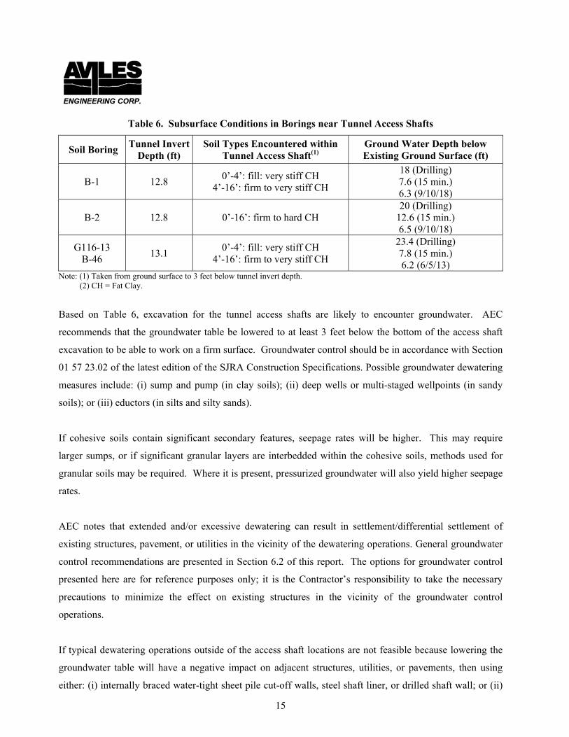
possible subsurface conditions at the tunnel access shafts are summarized in Table 6 below.
15
Table 6. Subsurface Conditions in Borings near Tunnel Access Shafts
Soil Boring Tunnel Invert
Depth (ft) Soil Types Encountered within
Tunnel Access Shaft(1) Ground Water Depth below Existing Ground Surface (ft)
B-1 12.8 0’-4’: fill: very stiff CH
4’-16’: firm to very stiff CH
18 (Drilling) 7.6 (15 min.) 6.3 (9/10/18)
B-2 12.8 0’-16’: firm to hard CH 20 (Drilling)
12.6 (15 min.) 6.5 (9/10/18)
G116-13 B-46
13.1 0’-4’: fill: very stiff CH
4’-16’: firm to very stiff CH
23.4 (Drilling) 7.8 (15 min.) 6.2 (6/5/13)
Note: (1) Taken from ground surface to 3 feet below tunnel invert depth. (2) CH = Fat Clay.
Based on Table 6, excavation for the tunnel access shafts are likely to encounter groundwater. AEC
recommends that the groundwater table be lowered to at least 3 feet below the bottom of the access shaft
excavation to be able to work on a firm surface. Groundwater control should be in accordance with Section
01 57 23.02 of the latest edition of the SJRA Construction Specifications. Possible groundwater dewatering
measures include: (i) sump and pump (in clay soils); (ii) deep wells or multi-staged wellpoints (in sandy
soils); or (iii) eductors (in silts and silty sands).
If cohesive soils contain significant secondary features, seepage rates will be higher. This may require
larger sumps, or if significant granular layers are interbedded within the cohesive soils, methods used for
granular soils may be required. Where it is present, pressurized groundwater will also yield higher seepage
rates.
AEC notes that extended and/or excessive dewatering can result in settlement/differential settlement of
existing structures, pavement, or utilities in the vicinity of the dewatering operations. General groundwater
control recommendations are presented in Section 6.2 of this report. The options for groundwater control
presented here are for reference purposes only; it is the Contractor’s responsibility to take the necessary
precautions to minimize the effect on existing structures in the vicinity of the groundwater control
operations.
If typical dewatering operations outside of the access shaft locations are not feasible because lowering the
groundwater table will have a negative impact on adjacent structures, utilities, or pavements, then using
either: (i) internally braced water-tight sheet pile cut-off walls, steel shaft liner, or drilled shaft wall; or (ii)
16
jet grouting of sandy soils in the immediate surrounding area can be considered. It is AEC’s opinion that
using either water-tight: internally-braced sheet piles, steel shaft liner, or drilled shaft wall (with grout
between the shafts) would be an effective option for tunnel access shaft shoring; in addition, these methods
also reduce and/or eliminate the need for groundwater control outside of the access shaft excavations.
Sheet Piling: Design soil parameters for sheet pile design are presented on Plate C-1, in Appendix C. AEC
recommends that the sheet pile design consider both short-term and long-term parameters; whichever is
critical should be used for design. The determination of the pressures exerted on the sheet piles by the
retained soils shall consider active earth pressure, hydrostatic pressure, and uniform surcharge (including
construction equipment, soil stockpiles, and traffic load, whichever surcharge is more critical).
Sheet pile design should be based on the following considerations:
(1) Consider the ground water elevation to be at the top of the ground surface on the retained side (i.e. outside of the access shaft).
(2) Consider the ground water elevation to be at least 3 feet below the bottom of the access shaft excavation, whether or not the groundwater level is actually lowered to 3 feet below the bottom of the excavation during construction. This should result in a more conservative design for sheet piling length, due to an increase of the hydrostatic pressure head differential.
(3) Neglect cohesion for active pressure determination, based on Equation (6) in Section 5.3.2 of this report;
(4) The design retained height should extend from the ground surface to the bottom of the access shaft excavation.
(5) A 300 psf uniform surcharge pressure from construction equipment or soil stockpiles should be considered at the top of the sheet piles; loose soil stockpiles during access shaft construction should be limited to 3 foot high or less.
(6) Use a Factor of Safety of 2.0 for passive earth pressure in front of (i.e. the shaft side) the sheet piles.
Design, construction, and monitoring of sheet piles should be performed by qualified personnel who are
experienced in this operation. Sheet piles should be driven in pairs, and proper construction controls
provided to maintain alignment along the wall and prevent outward leaning of the sheet piles. Construction
of sheet piles should be in accordance with Section 31 62 17 of the latest edition of the SJRA Construction
Specifications.
Stockpile and Equipment Surcharge: To avoid surcharging the access shaft excavation walls, stockpile of
excavated materials immediately adjacent to the excavation face should be prohibited. We recommend
stockpiled materials be placed at least 6 feet away from the edge of an excavation face, and no higher than 3

17
feet. Construction equipment working near the access shaft excavations may also induce excessive
surcharge loads; AEC recommends appropriate shoring or shield system be provided considering these
impacts in addition to the lateral earth and hydrostatic pressures.
Bottom Stability: Recommendations for evaluating tunnel access shaft bottom stability are presented in
Section 5.3.2 of this report.
Reaction Walls: Reaction walls (especially if a one pass method is used) will be part of the tunnel shaft
walls; they will be rigid structures and support tunneling/trenchless operations by mobilizing passive
pressures of the soils behind the walls. The passive earth pressure can be calculated using Equation (7); we
recommend that a factor of safety of 2.0 be used for passive earth pressure. The design soil parameters that
can be used for reaction wall design are presented on Plate C-1 in Appendix C.
pp = zKp + 2c(Kp)
½ ............ Equation (7) where, pp = passive earth pressure (psf); = wet unit weight of soil (pcf); z = depth below ground surface for the point under consideration (ft); Kp = coefficient of passive earth pressure; c = cohesion of clayey soils (psf).
Due to subsurface variations, soils with different strengths and characteristics will likely be encountered at a
given location. The soil resulting in the lowest passive pressure should be used for design of the walls. The
soil conditions should be checked by geotechnical personnel to confirm the recommended soil parameters.
5.3.2 Tunnel/Trenchless Face Stability during Construction
A general description of tunnel and trenchless methods are presented in Section 5.3 of this report. In
general, tunneling methods include using either a boring shield or TBM to advance the excavation face,
while trenchless methods include using an auger (either dry or with slurry) to advance the excavation face.
For tunneling method, AEC notes that the MTBM, SFM, and EPBM are all able to counteract hydrostatic
pressures from groundwater. In a similar vein, for trenchless methods, a slurry auger/bore will also be able
to counteract hydrostatic pressures from groundwater. All of these methods reduce or eliminate the need
for groundwater control during tunneling/trenchless methods. Conversely, for tunneling method, an open
face or partial boring shield or a mechanized close face TBM cannot counteract hydrostatic pressures.
18
Similarly for trenchless methods, a dry auger/bore will also be unable to counteract hydrostatic pressures.
If these methods are used, the groundwater table either needs to be lowered during construction, or
saturated sands/silts need to be grouted prior to tunneling/trenchless operations.
Trenchless Method: Based on AEC’s discussions with TWE (and considering the siphon carrier pipe will be
72 inches in diameter), AEC understands that the most likely method to construct the siphon pipe will be a
bore and jack method. A one pass method will be used to jack the siphon carrier pipe directly into the
ground (supporting the excavation wall) while a bore/auger (i.e. trenchless method) will be used to advance
the excavation face. For this method, AEC prefers that the trenchless method use a slurry auger/bore to
advance the excavation, since groundwater is likely to be encountered within the auger/bore zone during
construction. However, selection of auger/bore method (whether dry auger or slurry auger) will be up to the
trenchless Contractor. AEC notes that bore and jack is also frequently performed as a two pass method,
where a steel casing is first jacked into the ground, the soil within the casing is bored out, and then the
carrier pipe is installed. However, according to TWE, AEC understands that the two pass method is less
likely to be used.
Tunneling Method: If a tunneling method will be used, AEC also assumes that a one pass method is likely
(because of the relatively short siphon pipe length, and based on our discussions with TWE), where the
tunnel boring shield/TBM and carrier pipe are jacked directly into the ground. However, AEC notes that
two pass systems (with primary liner) are also commonly used in these applications. For tunneling method
(based on the AEC’s borings and considering the siphon carrier pipe will be 72 inches in diameter), feasible
tunneling methods include tunnel boring shield, close faced mechanized TBM, or MTBM. However, due to
the likely presence of groundwater within the tunneling zone, AEC prefers using a MTBM (with a slurry
face) because dewatering operations are not typically required during construction. However, if a boring
shield or close-faced mechanized TBM are used, dewatering operations along the tunnel alignment are
likely to be required. Selection of tunneling method (whether boring shield, mechanized TBM, or MTBM)
will ultimately be up to the tunneling Contractor.
Tunneling using a Boring Shield: AEC has the following precautions if tunneling using a boring shield is
used, especially when granular soils (such as sands or silts, saturated or not) are present either within or
immediately above or below the tunnel zone. These precautions include: (i) slower process compared to
excavation with a mechanized TBM, which will in turn lengthen the period of dewatering, causing
consolidation of the soils above the tunnel, will cause additional disturbance and increased settlement of the
19
ground surface/roadway above; (ii) less control over the volume of soil removed compared to a mechanized
TBM or MTBM, which can increase the volume of excavated soil approximately 1 to 2 percent, resulting in
more ground surface settlement. Using mechanized processes (such as a backacter or cutting boom) may be
faster than digging by hand, which may help to mitigate the amount of surface settlement. Workman safety
against possible tunnel face collapse (especially if flowing soils are encountered), including protection
against potential buildup of toxic/noxious gases (if any) will be the sole responsibility of the Contractor.
5.3.2.1 General
The stability of a tunnel or bore face is governed primarily by ground water and subsurface soil conditions,
type of method used (either tunnel or trenchless), and workmanship. Based on the subsurface conditions
encountered in our borings and the proposed invert depths (see Table 7 in Section 5.3.2.2 of this report), we
anticipate that firm to very stiff fat clay (CH) will generally be encountered within the tunnel/auger zone
along the siphon pipe alignment. Secondary features such as sand or silt clay seams/pockets/layers were
also encountered within the cohesive soils, and could be significant at some locations. In addition, the type
and property of subsurface soils are subject to change between borings, and may be different at locations
away from the borings.
When granular soils are encountered during construction an unsupported tunnel/bore face (in case of
tunneling by boring shield or dry bore/auger by trenchless method) can become unstable. Granular soils
below ground water will tend to flow into the excavation hole; granular soils above the ground water level
will generally not stand unsupported but will tend to ravel until a stable slope is formed at the face with a
slope equal to the angle of repose of the material in a loose state. Thus, granular soils are generally
considered unstable in an unsupported excavation face; uncontrolled flowing soil can result in large loss of
ground. A MTBM with a slurry face should be able to support the tunnel face if saturated granular soils are
encountered, even under groundwater. Similarly, a slurry auger/bore can also support the excavation face if
saturated granular soils are encountered, even under groundwater. Similarly, a close-faced TBM should
also be able to support the tunnel face within granular soils, although the groundwater level within the
granular soil layers will need to be lowered first.
20
5.3.2.2 Anticipated Ground Behavior
Where granular or soft cohesive soils are encountered, provisions should be made to stabilize the tunnel or
bore excavations. AEC notes that granular soils (not necessarily indicated on the boring logs) may be
encountered between boring locations; subsurface conditions between boring locations should be verified
against the boring logs and AEC notified if different soil conditions are encountered during construction so
that additional recommendations can be provided as necessary.
The estimated ground surface settlements caused by volume loss from tunneling method using boring
shield, mechanized close face TBM, or MTBM, as well as trenchless method using dry auger/bore or slurry
auger/bore are presented in Table 7. The settlement estimates presented in Table 7 include both one pass
and two path methods. For two pass method, AEC assumes that a 78 inch diameter steel casing (considering
72 inch diameter siphon pipes) will be used, although other primary liner options can also be considered.
If tunneling method using a boring shield or trenchless method using a dry auger are used, a Stability
Factor, Nt = (Pz - Pa)/Cu may be used to evaluate the stability of an unsupported tunnel/bore face in cohesive
soils, where Pz is the overburden pressure to the tunnel/bore centerline; Pa is the equivalent uniform interior
pressure applied to the face; and Cu is the soil undrained shear strength. For tunneling operations, no
interior pressure is applied. Generally, Nt values of 4 or less are desirable as it represents a practical limit
below which tunneling/augering may be accomplished without significant difficulty. Higher Nt values
usually lead to large deformations of the soil around the tunnel/bore and problems associated with increased
subsidence. It should be noted that the exposure time of the face is most important; with time, creep of the
soil will occur, resulting in a reduction of shear strength. The Nt values will therefore increase when
construction is slow. Estimated Nt values are presented on Table 7.
Note that the cohesive soils have secondary structures such as fissures, sand seams, and sand lenses which
can cause the bore face to become unstable. Where granular or soft cohesive soils, if any, are encountered,
the Contractor should make provisions for casing to stabilize the tunnel.
The settlement amounts estimated in Table 7 also assume the Contractor practices good workmanship
during construction. AEC notes that if the Contractor practices poor workmanship during construction, the
amount of settlement could be significantly larger than the amounts estimated in Table 7.
Secondary soil features present within the clay soils (which will be encountered within almost all
21
tunnel/bore zones) such as sand/silt seams, and slickensides can result local instabilities at the tunnel face.
Table 7. Anticipated Soil Types and Estimated Settlements along Tunnel/Bore Alignments
Soil Boring
Approx. Tunnel/Bore Invert Depth
(ft)
Anticipated Soil Types in Tunnel/Bore
Zone(2)
One Pass Method Two Pass Method
Note/Suggestion Stability Factor
Nt
Smax(1)
(in)
Stability Factor
Nt
Smax(1)
(in)
B-1 12.8
(elevation 19’ above MSL)
4’-16’: Firm to very stiff Fat Clay (CH)
1.5
MTBM or Mechanized TBM: 0.11
Boring Shield or
Auger/Bore: 0.45
1.4
MTBM or Mechanized TBM: 0.12
Boring Shield or
Auger/Bore: 0.49
Potential swelling ground due to high plasticity fat clay. Pressurized groundwater. Dewatering not required if MTBM or slurry bore/auger is used. Otherwise, dewatering operations will be necessary if boring shield, mechanized TBM, or dry auger/bore is used.
B-2 and G116-13 B-46
12.8/13.1 (elevation 19’ above MSL)
4’-16’: Firm to very stiff Fat Clay (CH)
1.2
MTBM or Mechanized TBM: 0.10
Boring Shield or
Auger/Bore: 0.41
1.2
MTBM or Mechanized TBM: 0.11
Boring Shield or
Auger/Bore: 0.45
Potential swelling ground due to high plasticity fat clay. Pressurized groundwater. Dewatering not required if MTBM or slurry bore/auger is used. Otherwise, dewatering operations will be necessary if boring shield, mechanized TBM, or dry auger/bore is used.
Note: (1) Smax = Estimated settlement along the tunnel/bore alignment due to volume loss only; not including consolidation settlement, collapse of voids, or lowering of groundwater table.
(2) Tunnel zone takes as one half waterline diameter above tunnel/bore crown to one half waterline diameter below tunnel invert.
AEC notes that the estimated settlements presented in Table 7 do not include settlement from dewatering
operations (if a boring shield, mechanized TBM, or dry auger/bore is used), consolidation settlement, or
settlement from collapse of voids within the soil around the tunnel/bore. As a result, the actual settlement at
the tunnel/bore locations during construction could be more than estimated in Table 7. In addition, if
dewatering operations are used in the vicinity of the tunnel/bore (if a boring shield, mechanized TBM, or
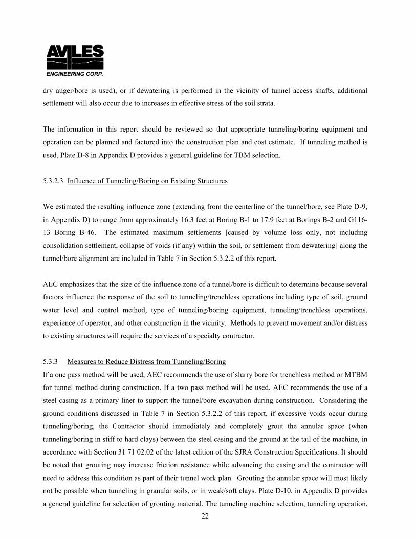
22
dry auger/bore is used), or if dewatering is performed in the vicinity of tunnel access shafts, additional
settlement will also occur due to increases in effective stress of the soil strata.
The information in this report should be reviewed so that appropriate tunneling/boring equipment and
operation can be planned and factored into the construction plan and cost estimate. If tunneling method is
used, Plate D-8 in Appendix D provides a general guideline for TBM selection.
5.3.2.3 Influence of Tunneling/Boring on Existing Structures
We estimated the resulting influence zone (extending from the centerline of the tunnel/bore, see Plate D-9,
in Appendix D) to range from approximately 16.3 feet at Boring B-1 to 17.9 feet at Borings B-2 and G116-
13 Boring B-46. The estimated maximum settlements [caused by volume loss only, not including
consolidation settlement, collapse of voids (if any) within the soil, or settlement from dewatering] along the
tunnel/bore alignment are included in Table 7 in Section 5.3.2.2 of this report.
AEC emphasizes that the size of the influence zone of a tunnel/bore is difficult to determine because several
factors influence the response of the soil to tunneling/trenchless operations including type of soil, ground
water level and control method, type of tunneling/boring equipment, tunneling/trenchless operations,
experience of operator, and other construction in the vicinity. Methods to prevent movement and/or distress
to existing structures will require the services of a specialty contractor.
5.3.3 Measures to Reduce Distress from Tunneling/Boring
If a one pass method will be used, AEC recommends the use of slurry bore for trenchless method or MTBM
for tunnel method during construction. If a two pass method will be used, AEC recommends the use of a
steel casing as a primary liner to support the tunnel/bore excavation during construction. Considering the
ground conditions discussed in Table 7 in Section 5.3.2.2 of this report, if excessive voids occur during
tunneling/boring, the Contractor should immediately and completely grout the annular space (when
tunneling/boring in stiff to hard clays) between the steel casing and the ground at the tail of the machine, in
accordance with Section 31 71 02.02 of the latest edition of the SJRA Construction Specifications. It should
be noted that grouting may increase friction resistance while advancing the casing and the contractor will
need to address this condition as part of their tunnel work plan. Grouting the annular space will most likely
not be possible when tunneling in granular soils, or in weak/soft clays. Plate D-10, in Appendix D provides
a general guideline for selection of grouting material. The tunneling machine selection, tunneling operation,
23
and grouting (as necessary) will be the full responsibility of the Contractor.
To reduce the potential for the tunneling/boring to influence existing foundations or structures, we
recommend that the outer edge of the influence zone of the tunnel/bore be a minimum of 5 feet from the
outer edge of the bearing (stress) zone of existing foundations. The bearing (stress) zone is defined by a
line drawn downward from the outer edge of an existing foundation and inclined at an angle of 45 degrees
to the vertical.
We recommend that the following situations be evaluated on a case by case basis, where:
• tunneling/boring cannot be located farther than the minimum distance recommended above; • tunneling/boring cannot be located outside the stress zone of the foundations for existing structures; • unstable soils are encountered near existing structures; • heavily loaded or critical structures are located close to the influence zone of the tunnels/bores;
As an option, existing structure foundations should be protected by adequate shoring or strengthened by
underpinning or other techniques, provided that tunneling/boring cannot be located outside the stress zone
of the existing foundations.
Disturbance and loss of ground from the tunneling/trenchless operation may create surface soil disturbance
and subsidence which in turn may cause distress to existing structures (including underground utilities and
pavements) located in the zone of soil disturbance. Any open-cut excavation in the proposed
tunneling/boring areas should be adequately shored.
5.3.4 Monitoring Existing Structures
The Contractor should be responsible for monitoring existing structures nearby and taking necessary action
to mitigate impact to adjacent structures. Existing structures located close to the proposed construction
excavations should be surveyed prior to construction and pre-existing conditions of such structures and their
vicinity be adequately recorded. This can be accomplished by conducting a pre-construction survey, taking
photographs and/or video, and documenting existing elevations, cracks, settlements, and other existing
distress in the structures. The monitoring should include establishment of elevation monitor stations, crack
gauges, and inclinometers, as required. The monitoring should be performed before, periodically during,
and after construction. The data should be reviewed by qualified engineers in a timely manner to evaluate
24
the impact on existing structures and develop plans to mitigate the impact, should it be necessary.
5.4 Siphon Inlet/Outlet Structures
Based on the drawing provided by TWE, the dual 72 inch diameter siphon pipes will have a flowline invert
elevation of 19 feet above MSL. The inlet/outlet structure headwalls will be supported on a mat foundation
that will bear at an elevation of 16.5 feet above MSL.
Design of the siphon structure headwalls and wingwalls should consider the allowable bearing capacity of
the foundation soils, sliding, and overturning stability. We recommend using a factor of safety (FS) of 2 for
passive earth pressure, a FS of 1.5 for sliding, and a FS of 2 for overturning stability of the walls.
5.4.1 Allowable Bearing Capacity
Based on the drawing provided by TWE, the proposed inlet/outlet structures will be supported on a mat
foundation that bears at an elevation of approximately 16.5 feet above MSL. Based on Borings B-1, B-2,
and G116-13 Boring B-46, an inlet/outlet structure footing bearing at an elevation of approximately 16.5
feet above MSL can be designed for an allowable net bearing capacity of 1,400 pounds per square foot (psf)
for sustained loads and 2,100 psf for total loads. These allowable bearing pressures include a minimum FS
of 3 for sustained loads and 2 for total loads, whichever is more critical should be used for design.
Modulus of Subgrade Reaction: The modulus of subgrade reaction (k) is frequently used in the structural
analysis of mat foundations. Based on the soil conditions encountered, we recommend using k = 25 pounds
per cubic inch (pci) for a mat foundation founded at an elevation of 16.5 feet above MSL.
Foundation Settlement: AEC understands that TWE will perform settlement analysis of the inlet/outlet
structure mat foundations. Design soil parameters for mat foundation settlement analyses are presented on
Plate C-8, in Appendix C.
5.4.2 Lateral Earth Pressures
The inlet/outlet structure headwalls and wingwalls will be subjected to lateral earth pressures. The
magnitudes of the lateral earth pressures will depend on the type and density of the backfill, surcharge on
25
the backfill, and hydrostatic pressure. If the backfill is over-compacted or if highly plastic clays are placed
behind the walls, the lateral earth pressure could exceed the vertical pressure from the weight of the
backfill. Lateral pressure resulting from construction equipment, and traffic, or other surcharge on the top
of the walls should be taken into account by adding the equivalent uniformly distributed surcharge to the
design lateral pressure. We recommend that at least 250 psf surcharge be considered for design of the
walls. Hydrostatic pressure should also be included, unless adequate drainage is provided behind the walls
(see Section 5.4.4 of this report).
The wall design should be based on whether or not the top of the walls will be allowed to move. If the
walls will be allowed to move, then the wall design should be based on active earth pressure parameters. If
the walls will not be allowed to move (i.e. considered fully restrained), then the wall design should be based
on at-rest earth pressure parameters. Selection of which earth pressure condition to use (either active or at-
rest) should be determined by the wall designer. Wall design should consider short-term and long-term
conditions; whichever case is critical should be used for the design. Active earth pressure can be determined
in accordance with Equation (6) in Section 5.2.3 of this report. The at-rest earth pressure at depth z can be
determined by Equation (8). Design soil parameters that can be used for wall design are presented on Plate
C-2, in Appendix C.
p0 = (qs+γ h1+γ’ h2) K0 + γwh2 ............ Equation (8)
where, p0 = at-rest earth pressure, psf. qs = uniform surcharge pressure, psf. γ, γ’ = wet and buoyant unit weights of soil, pcf. h1 = depth from ground surface to ground water table, feet. h2 = z-h1, depth from ground water table to point under consideration, feet. z = depth below ground surface, feet. K0 = coefficient of at-rest earth pressure. γw = unit weight of water, 62.4 pcf.
The short-term and long-term lateral earth pressure design soil parameters presented on Plate C-2, in
Appendix C should be used for head/wing walls design. The values of soil cohesion, c, and c’, can
conservatively be omitted for lateral earth pressure design. AEC notes that the coefficients of active, at-rest,
and passive earth pressure provided in Plate C-2, in Appendix C are for level backfill behind the head/wing
walls. Coefficients of active and passive earth pressure for sloped backfill can be determined using Plate C-
3, in Appendix C.
26
Sliding Resistance: The resistance of a structure wall footing against sliding due to lateral loads is a
combination of soil friction resistance, soil adhesion resistance (on the footing), plus passive pressure
resistance in front of the wall (if any). Sliding resistance can be determined using Equation (9). Passive
pressure resistance can conservatively be omitted from design. Otherwise, if passive earth pressure
resistance is considered in the design, a FS of 2 should be applied to the passive pressure component.
Passive earth pressure resistance can be determined using Equation (7) in Section 5.3.1 of this report.
Design soil parameters for sliding resistance are presented on Plate C-2, in Appendix C.
Fr V x tan () + Bf x C + Pp ............ Equation (9) where: Fr = Sum of horizontal resisting forces V = Sum of vertical forces = 2/3 = angle of internal friction Bf = width of footing (ft) C = soil adhesion (psf) Pp = passive pressure resistance [see equation (7) in Section 5.3.1 of this report].
5.4.3 Hydrostatic Uplift
For hydrostatic uplift, AEC recommends the structure design consider a most conservative case of when the
siphon pipes are empty, but the design water level is at the top of wall or 100-year flood elevation,
whichever is more critical. If the dead weight of the structure (including the backfill on top of the pipe) and
the frictional resistance between the wall and backfill are inadequate to resist uplift forces, the width of the
wall footing and the wall thickness can be increased to provide additional uplift resistance. The buoyant
unit weight of concrete can be taken as 90 pcf. The minimum recommended factors of safety against uplift
should be 1.1 for concrete weight, 1.5 for soil weight and 3.0 for soil friction. Structure uplift design should
consider short-term and long-term conditions, whichever is critical. Design soil parameters are presented on
Plate C-2, in Appendix C. Recommended design criteria for uplift resistance are shown on Plate D-11, in
Appendix D.
5.4.4 Drainage System
If possible, AEC recommends a 1-foot wide, vertical “bank sand chimney” drainage system or equivalent
prefabricated drainage element be placed behind the head/wing walls. Bank sand can be composed of SP,
SW, SP-SM, SW-SM, and some SM type soils in accordance with the USCS classification system, with less
27
than 15 percent passing the No. 200 sieve, and amount of clay not exceeding 2 percent by weight. The
entirety of the bank sand chimney should be wrapped in a geotextile filter fabric. In addition, a 12 to 24
inch thick select fill clay cap should be placed on top of the drainage chimney to prevent the infiltration of
surface runoff into the drainage chimney. The select fill clay cap should be in accordance with Section 5.5
of this report. The drainage system should drain water through weepholes in the wall face, or into a
perforated drainage pipe (also wrapped with a geotextile filter fabric) that connects to a sump or a storm
sewer. If weepholes are used, we recommend at least 3-inch diameter weepholes installed at a spacing of
10 feet on center or less, both horizontally and vertically. The drainage system should be regularly
maintained and repaired as necessary so that hydrostatic pressures do not develop behind the wall. If the
drainage system is not used, then the wall designer should consider hydrostatic pressure in the wall design,
as discussed in Section 5.4.2 of this report.
5.4.5 Siphon Inlet/Outlet Construction
Based on Borings B-1, B-2, and G116-13 Boring B-46, the top 15.5 (i.e. at an elevation of approximately
16.5 feet above MSL) feet of the subsurface soil conditions at the siphon inlet/outlet structures consist of
firm to hard fat clay. Evaluation of foundation excavation, bottom stability, and shoring/bracing (if needed)
should be performed in general accordance with the excavation stability guidelines presented in Section
5.2.2 of this report.
Based on the groundwater encountered in Borings B-1, B-2, and G116-13 Boring B-46, groundwater
control may be required during siphon inlet/outlet construction. Dewatering guidelines are presented in
Section 6.2 of this report.
AEC anticipates that the inlet/outlet structures will be installed by open cut method. Siphon inlet/outlet
construction should be performed in general accordance with Section 31 23 16.16 of the latest edition of the
SJRA Construction Specifications. After excavation, any soft or compressible materials and ponded water
should be removed from the bottom of the excavation prior to placement of concrete; such materials should
be replaced with compacted select fill. Select fill should be in accordance with Section 5.5 of this report.
Excavation Extents: For backfill purposes (see below), AEC recommends that the structure excavation
extend an additional 2 feet horizontally past the edge of the mat foundation and slope upward at a minimum

28
H:V = 1:1 inclination to the ground surface. The excavation should also be benched as necessary; AEC
recommends that the bench height not exceed 4 feet, and the bench width be at least 8 feet.
Backfill: AEC recommends compacted select fill be used as backfill behind the head/wing walls. Select fill
criteria are presented in Section 5.5 of this report. Based on Borings B-1, B-2, and G116-13 Boring B-46,
the top 18 feet of soils at the site are high plasticity fat clay. Due to its high expansive potential, AEC does
not recommend excavated onsite soils to be reused as wall backfill, since the expansive clay can impart
additional loading on the walls. Furthermore, the magnitude of swell pressures on the walls will be difficult
to predict, and would depend on PI, moisture content, degree of compaction at the time of fill placement, as
well as change in moisture content within the backfill throughout the life of the structure. Regardless, AEC
does not recommend the onsite in-situ material be re-used as wall backfill.
5.5 Select Fill
“Select” Fill: It is AEC’s experience that “select” fill material imported from sand and clay pits in the
Greater Houston area is generally non-homogenous (i.e. composed of a mixture of sands, silts, and clays,
instead of a homogenous sandy clay material) and of poor quality, and either contains too much sand or has
large clay clods with high expansive potential. Use of this non-homogenous soil can result in poor long
term performance of structures and pavements placed on top of the fill.
Select fill (whether imported from offsite or is already onsite) should consist of uniform, non-active
inorganic lean clays with a PI between 10 and 20 percent, and more than 50 percent passing a No. 200
sieve. Material intended for use as select fill shall not have clay clods with PI greater than 20, clay clods
greater than 2 inches in diameter, or contain sands/silts with PI less than 10. Sand and clay mixtures/blends
are unacceptable for use as select fill. Sand/silt with clay clods is unacceptable for use as select fill.
Mixing sand into clay or mixing clay into sand/silt is also unacceptable for use as select fill. Prior to
construction, the Contractor should determine if he or she can obtain qualified select fill meeting the
above select fill criteria. The testing lab shall reject any material intended for use as select fill that
does not meet the PI, sieve, and clay clod requirements above, without exceptions.
Lifts and Compaction: All material intended for use as select fill should be tested prior to use to confirm
that it meets select fill criteria. The fill should be placed in loose lifts not exceeding 8 inches in thickness.
Backfill within 3 feet of the siphon, headwalls, wingwalls, or other adjacent structures should be placed in

29
loose lifts no more than 4-inches thick and compacted using hand tampers, or small self-propelled
compactors.
Select fill should be compacted to a minimum of 95 percent of the ASTM D 698 (Standard Proctor)
maximum dry unit weight at a moisture content ranging between optimum and 3 percent above optimum.
Testing: If select fill will be used, at least one Atterberg Limits and one percent passing a No. 200 sieve
test shall be performed for each 5,000 square feet (sf) of placed fill, per lift (with a minimum of one
set of tests per lift), to determine whether it meets select fill requirements. Prior to placement of
pavement or concrete, the moisture contents of the top 2 lifts of compacted select fill shall be re-tested (if
there is an extended period of time between fill placement and concrete placement) to determine if the in-
place moisture content of the lifts have been maintained at the required moisture requirements.
5.6 SJRA Canal at Siphon 29
Plan and profile and cross section drawings along the SJRA canal immediately upstream and downstream
of Siphon 29 were prepared by TWE and provided to AEC. The provided cross section locations are
presented on Plate E-1 and the cross sections themselves are presented on Plate E-2, in Appendix E. Based
on the drawings provided by TWE, the canal depth varies approximately from 7.0 to 7.4 feet and the
existing canal interior slopes have an inclination varying from H:V = 2.3:1 to 2.9:1. According to TWE, the
100 year water surface elevation (WSE) is at an approximate elevation of 28 feet above MSL and the
ordinary WSE is between 29 to 30 feet above MSL.
5.6.1 Slope Stability Analysis
AEC performed slope stability analysis on the interior east bank of the upstream cross section at Station
0+81.49 (see Plate E-2, in Appendix E), based on the soil conditions encountered in G116-13 Boring B-46.
AEC performed the analysis based on three different conditions: short-term condition, long-term condition,
and rapid drawdown condition. AEC performed the stability analyses in general accordance with the
requirements of the December 2010 HCFCD Geotechnical Guidelines.
30
5.6.2 Design Soil Parameters and Profiles
Soil parameters used in the analyses include moist unit weights, UU shear strengths, effective stress shear
strength (developed using total stress parameters and pore water pressure), and total stress shear strength.
AEC selected the interior east bank at Station 0+81.49 along the canal at Siphon 29 as the ‘most-critical’
cross section to perform slope stability analyses, since it has the steepest interior slope amongst the
provided cross sections. Design soil parameters for the slope stability analysis are presented on Plate E-3,
in Appendix E.
Clay Desiccation Zone: In general, very high plasticity fat clay soils were encountered in the borings along
the canal. Exposing these fat clays to the atmosphere and cycles of wetting-drying from seasonal moisture
changes will result in desiccation, cracking, and progressive movement of these clays, and a reduction in
their shear strengths. We considered the desiccation zone for fat clay from the top of levee or levee slope
surface to the assumed seepage line in the existing levee. For fat clay within the desiccation zone, we used
effective residual shear strengths of c'r = 65 psf and 'r = 21 degrees to evaluate slope stability for long-term
and rapid drawdown conditions. We also reduced the c' and ccu of clay soils (with a PI greater than 20)
within the non-desiccated zone based on our experience with similar levee projects in the Houston area
based on a combination of methods by G. Mesri (1999) and S. Wright (2005) for both the long-term
condition and rapid drawdown condition.
5.6.3 Conditions Analyzed for Slope Stability
We used the Simplified Bishop Method of Slices option in the GeoStudio 2018 computer program
(SLOPE/W) to analyze slope stability for 2-dimensional limiting equilibrium. The program has the
capability to compute pore water pressures based on a defined piezometric surface.
Groundwater Level: For the analyses, we considered different groundwater conditions for short term, long
term, and rapid drawdown conditions. For the short term and long term conditions, we considered the water
level within the canal to be at the ordinary WSE, and the groundwater outside to the canal to be equal to the
seepage line where the groundwater has saturated the levee soil below the defined piezometric surface. For
the rapid drawdown condition, we considered the water level within the canal to be at the ordinary WSE (30
feet above MSL), and the water level outside the canal to be at the ground surface. The rapid drawdown
31
condition considers that the groundwater level rapidly changes from the ground surface/ordinary WSE to
the bottom of the canal, such as a condition where the canal is drained for maintenance purposes.
Required Safety Factor: HCFCD requires a minimum Safety Factor (SF) of 1.3 for short-term conditions,
1.5 for long-term conditions, and 1.25 for rapid drawdown conditions. Stability analyses for the channel
slopes were conducted for the short-term (end-of-construction), long-term, and rapid drawdown conditions.
A brief description of these conditions is presented below:
1. Short Term (i.e. End-of-Construction Condition) - This condition models rapid construction loading taking place, so that there is no time for the induced excess pore water pressure to dissipate or for consolidation to occur during the loading period. Unconsolidated-undrained shear strength parameters were used for this analysis.
2. Long-Term Condition - This condition models long-term steady seepage through
embankments and the long-term stability of slopes in clays. Consolidated-drained effective stress shear strength parameters (obtained from CU triaxial tests with pore water pressure measurements) were used for this analysis.
3. Rapid Drawdown Condition - The majority of slope failures in the Harris County/Houston area occur under rapid drawdown conditions. This condition models when the slope becomes fully saturated and consolidated and is at equilibrium with the existing stress system, then encounters rapid drawdown and simultaneously allows no drainage to occur. Consolidated-undrained total stress shear strength with pore pressures parameters modeling rapid drawdown conditions were used for this analysis.
AEC considered global slide (GS) and local slide (LS) conditions in the slope stability analysis. GS
condition can be defined as a global slope failure where the failure circle passes through and/or below the
slope toe, which can cause a catastrophic failure of the levee. For the LS condition, the slope failure occurs
locally on the slope with a limited volume of slope movement. However, a LS condition can cause
progressive slope movement and eventually become a global slide.
5.6.4 Slope Stability for East Bank of Upstream Section at Station 0+81.49
We performed slope stability analyses on the interior east bank of the upstream section at Station 0+81.49
based on the soil conditions encountered in G116-13 Boring B-46. The analyses were performed on the
existing canal slopes. Design soil parameters used for the slope stability analyses are presented on Plate E-
3, in Appendix E. A 300 psf construction surcharge was added to the top of bank for the short term
condition.

32
The results of the slope stability analyses of the interior east bank of the canal levee at Station 0+81.49
under short-term, long-term, and rapid drawdown conditions are presented on Plates E-4 through E-9, in
Appendix E. The SF of the canal levee slopes under short term, long term, and rapid drawdown conditions
are in Table 8.
Table 8. Slope Stability Analysis Results for East Bank of Canal at Station 0+81.49
Slope Condition
Calculated Safety Factor (SF)
Short-Term Long-Term Rapid Drawdown
Existing Slope, Canal Side
6.05 (GS, Plate E-4) 24.6 (LS, Plate E-5)
2.27 (GS, Plate E-6) 2.88 (LS, Plate E-7)
1.30 (GS, Plate E-8) 1.79 (LS, Plate E-9)
Notes: (1) G.S. = global slide; (2) L.S. = local slide.
Based on the summary in Table 8, the calculated SF’s of the existing canal levee interior slope meets
HCFCD requirements under short term, long term, and rapid-drawdown conditions.
Exterior Levee Slope: According to the drawings provided by TWE, maximum height of the exterior slope
on both sides of the existing levee is approximately 2.13 feet with a steepest slope inclination of H:V =
3.2:1. Based on the soils encountered in our borings, slope height and inclination, and our experience, the
exterior levee slope should be stable. For reference, HCFCD does not typically require slope stability
analyses for levees with a height of less than 3 feet.
5.7 Rip Rap
Slope failures due to local slides were observed on both of the banks of the canal near the siphon structures
and displacement of the existing riprap was also seen southwest of Siphon 29 (see Plate B-1, in Appendix
B). Distress of the canal levees include local slides, sloughing and undermining caused by scouring, and
desiccation cracks in the soils on the top of the levee, which can result in progressive slope movement in the
future and which might have an adverse impact on the headwalls/wingwalls. To protect the levee slopes, a
minimum 24 inch thick layer of stone rip rap can be used in accordance with Section 31 37 00 of the latest
edition of the SJRA Construction Specifications. An extra volume of rip rap should be included at the slope
toes (ideally the rip rap toe should be trenched to below the depth of potential for rip rap degradation and
contraction scour) to mitigate the potential for undermining of the rip rap toe due to wave action or flow at
the siphon inlet/outlet areas. All stone rip rap should be underlain by a geotextile filter fabric that is suitable
33
for mechanically separating the riprap and underlying soils. AEC also recommends that rip rap be provided
around the inlet/outlet structure headwalls and wingwalls to mitigate scouring effects, especially where
granular soils are present.
Synthetic Filter Fabric: We recommend that non-woven geotextile fabric be used and placed between the
riprap and the underlying soils to prevent soil movement into or through the riprap. AEC recommends
adding a chart to the construction drawings that provides the requirements for non-woven general filter
fabric properties to be placed under all riprap. The contractor should submit proposed filter fabric design
calculations and specifications for approval by the Construction Manager before installing the fabric under
the riprap.
The design of geotextile filter fabric should address: (1) retention criterion - the geotextile must retain the
soil; (2) permeability criterion - the geotextile opening size must allow water to pass through the geotextile;
(3) clogging resistance criterion - over the life of the structure; and (4) survivability criterion - the geotextile
must survive the installation process. The geotextile filter fabric should be in accordance with the
requirements of Section 31 38 25 of the latest edition of the SJRA Construction Specifications. Additional
filter fabric requirements are presented on Table 9 below.
Table 9. Filter Fabric Requirements
Physical Properties Test Method Type 2 Requirements
Fabric Weight, on an ambient temperature air-dried tension-free sample
-- 12 oz/yd2, minimum
Porosity -- 30%, minimum
Permittivity, 1/sec ASTM D 4491 KFabric > 10Ksoil
Tensile Strength, N ASTM D 4632 890 N (200 lbs), minimum
Apparent Opening size ASTM D 4751 80-120
Elongation at yield, % ASTM D 4632 20-100
Trapezoidal Tear, N ASTM D 4533 490 N (110 lbs), minimum
The geotextile filter fabric should be overlapped on the edges by at least 2 feet, and the anchor pins be
spaced every 3 feet along the overlap. The upper and lower ends of the cloth should be buried a minimum
of 12 inches below ground. Precautions should be taken to not damage the cloth by dropping the riprap. If
damage occurs, the riprap should be removed, and the sheet repaired by adding another layer of filter fabric
34
with a minimum overlap of 12 inches around the damaged area. Where large stones are to be placed, a 4-
inch layer of fine sand or gravel is recommended to protect the filter cloth.
Riprap: The gradation and installation of riprap should be in accordance with Section 31 37 00 of the latest
edition of the SJRA Construction Specifications. Placement of the riprap should follow immediately after
placement of the filter. Riprap should be placed so that it forms a dense, well-graded mass of stone (or
concrete) with minimum voids. Place riprap to its full thickness in one operation.
Riprap Maintenance: AEC recommends the riprap be inspected periodically for scour or dislodged stones.
Missing or dislodged riprap should be replaced as soon as possible. Damaged filter fabric should also be
patched and repaired.
6.0 CONSTRUCTION CONSIDERATIONS
6.1 Site Preparation
To mitigate site problems that may develop following prolonged periods of rainfall, it is essential to have
adequate drainage to maintain a relatively dry and firm surface prior to starting any work at the site.
Adequate drainage should be maintained throughout the construction period. Methods for controlling
surface runoff and ponding include proper site grading, berm construction around exposed areas, and
installation of sump pits with pumps.
6.2 Groundwater Control
The need for groundwater control will depend on the depth of excavation relative to the groundwater depth
at the time of construction. In the event that there is heavy rain prior to or during construction, the
groundwater table may be higher than indicated in this report; higher seepage is also likely and may require
a more extensive groundwater control program. In addition, groundwater may be pressurized in certain
areas of the alignment, requiring further evaluation and consideration of the excess hydrostatic pressures.
The Contractor should be responsible for selecting, designing, constructing, maintaining, and monitoring a
groundwater control system and adapt his operations to ensure the stability of the excavations.
Groundwater information presented in Section 4.1 and elsewhere in this report, along with consideration for

35
potential environmental and site variation between the time of our field exploration and construction, should
be incorporated in evaluating groundwater depths. The following recommendations are intended to guide
the Contractor during design and construction of the dewatering system.
In cohesive soils seepage rates are lower than in granular soils and groundwater is usually collected in
sumps and either pumped out or channeled by gravity flow to storm sewers. If cohesive soils contain
significant secondary features, seepage rates will be higher. This may require larger sumps and drainage
channels, or if significant granular layers are interbedded within the cohesive soils, methods used for
granular soils may be required. Where it is present, pressurized groundwater will also yield higher seepage
rates.
Groundwater for excavations within saturated sands can be controlled by the installation of wellpoints. The
practical maximum dewatering depth for well points is about 15 feet. When groundwater control is
required below 15 feet, multiple staged wellpoints or eductors (for silts or silty sands) have generally
proved successful. AEC recommends that the groundwater table be lowered to at least 3 feet below the
excavation bottom to be able to work on a firm surface when water-bearing granular soils are encountered.
Groundwater control should be in accordance with Section 01 57 23.02 of the latest edition of the SJRA
Construction Specifications. Another groundwater control option is to use water-tight sheet pile cutoff walls
to seal off water bearing sand/silt layers (see Section 5.3.1 of this report).
Extended and/or excessive dewatering can result in settlement of existing structures in the vicinity; the
Contractor should take the necessary precautions to minimize the effect on existing structures in the vicinity
of the dewatering operation. We recommend that the Contractor verify the groundwater depths and seepage
rates prior to and during construction and retain the services of a dewatering expert (if necessary) to assist
him in identifying, implementing, and monitoring the most suitable and cost-effective method of controlling
groundwater.
For open cut construction in cohesive soils, the possibility of bottom heave must be considered due to the
removal of the weight of excavated soil. In lean and fat clays, heave normally does not occur unless the
ratio of Critical Height to Depth of Cut approaches one. In silty clays, heave does not typically occur unless
an artificially large head of water is created through the use of impervious sheeting in bracing the cut.
Guidelines for evaluating bottom stability are presented in Section 5.2.2 of this report.
36
6.3 Construction Monitoring
If applicable, excavation, bedding, and backfilling of underground utilities should be monitored by qualified
geotechnical professionals to check for compliance with project documents and changed conditions, when
encountered. AEC should be allowed to review the design and construction plans and specifications prior
to release to check that the geotechnical recommendations and design criteria presented herein are properly
interpreted.
6.4 Monitoring of Existing Structures
Existing structures in the vicinity of the project area should be closely monitored prior to, during, and for a
period after excavation. Several factors (including soil type and stratification, construction methods,
weather conditions, other construction in the vicinity, construction personnel experience, and supervision)
may impact ground movement in the vicinity of the alignment. We therefore recommend that the
Contractor be required to survey and adequately document the condition of existing structures in the
vicinity of the proposed alignment.
7.0 LIMITATIONS
The information contained in this report summarizes conditions found on the dates the borings were drilled.
The attached boring logs are true representations of the soils encountered at the specific boring locations on
the dates of drilling. Reasonable variations from the subsurface information presented in this report should
be anticipated. If conditions encountered during construction are significantly different from those
presented in this report; AEC should be notified immediately.
This investigation was performed using the standard level of care and diligence normally practiced by
recognized geotechnical engineering firms in this area, presently performing similar services under similar
circumstances. This report is intended to be used in its entirety. The report has been prepared exclusively
for the project and location described in this report. If pertinent project details change or otherwise differ
from those described herein, AEC should be notified immediately and retained to evaluate the effect of the
changes on the recommendations presented in this report, and revise the recommendations if necessary.
The recommendations presented in this report should not be used for other structures located along these
alignments or similar structures located elsewhere, without additional evaluation and/or investigation.
APPENDIX A Plate A-1 Vicinity Map Plate A-2 Boring Location Plan Plates A-3 to A-5 Boring Logs Plate A-6 Key to Symbols Plate A-7 Classification of Soils for Engineering Purposes Plate A-8 Terms Used on Boring Logs Plate A-9 ASTM & TXDOT Designation for Soil Laboratory Tests Plates A-10 to A-11 Sieve Analysis Results Plate A-12 Crumb Test Results Plate A-13 Crumb Test Results from AEC Report G116-13, dated October 18, 2013. Plate A-14 Mohr Coulomb Diagrams (from CU Tests) Plate A-15 Consolidation Test Result
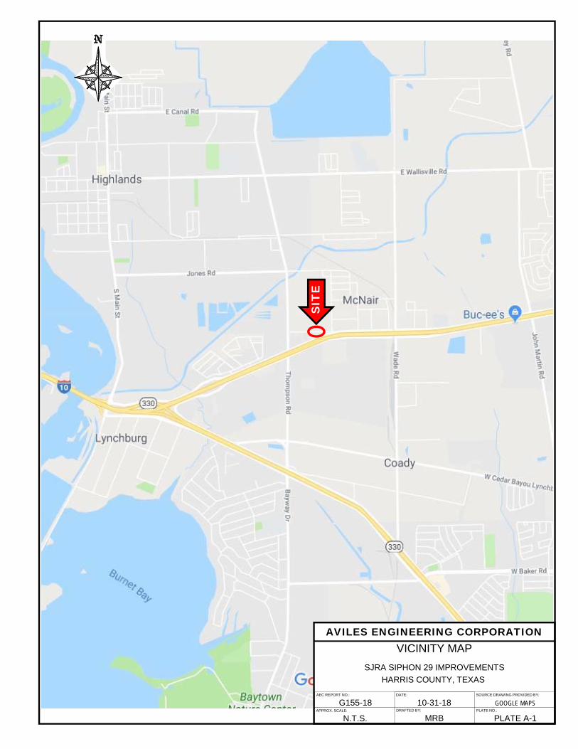
AEC REPORT NO.:
G155-18
AVILES ENGINEERING CORPORATION
APPROX. SCALE:
N.T.S.
DATE:
DRAFTED BY:
SOURCE DRAWING PROVIDED BY:
GOOGLE MAPSPLATE NO.:
PLATE A-1
VICINITY MAP
10-31-18
MRB
SJRA SIPHON 29 IMPROVEMENTS
HARRIS COUNTY, TEXAS
SIT
E
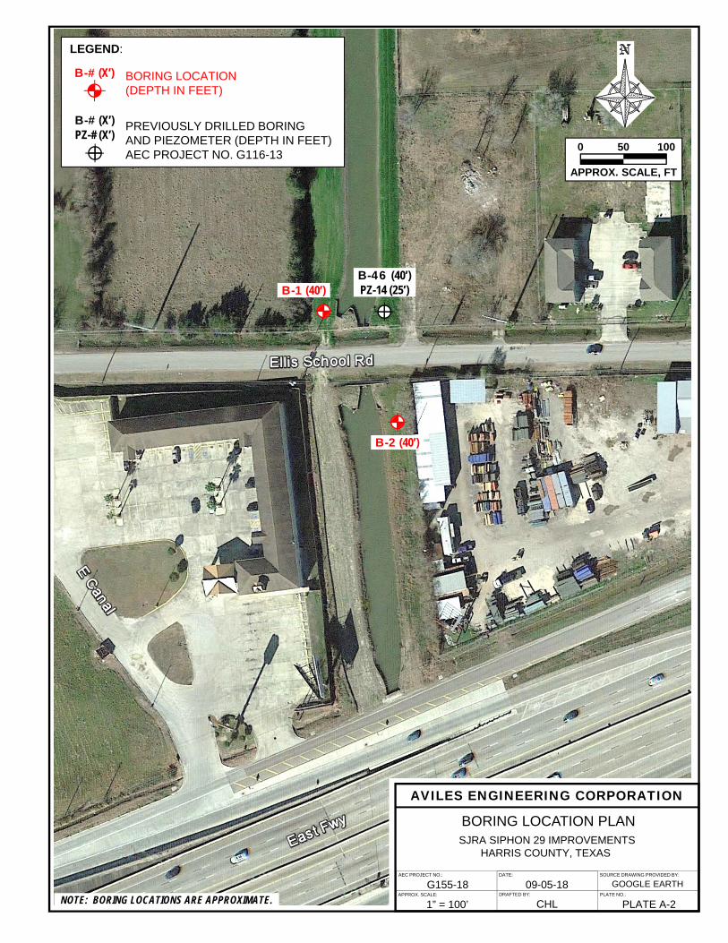
AEC PROJECT NO.:
G155-18
AVILES ENGINEERING CORPORATION
APPROX. SCALE:
1” = 100’
DATE:
DRAFTED BY:
SOURCE DRAWING PROVIDED BY:
GOOGLE EARTHPLATE NO.:
PLATE A-2
BORING LOCATION PLAN
09-05-18
CHL
SJRA SIPHON 29 IMPROVEMENTSHARRIS COUNTY, TEXAS
LEGEND:
BORING LOCATION (DEPTH IN FEET)
PREVIOUSLY DRILLED BORING AND PIEZOMETER (DEPTH IN FEET) AEC PROJECT NO. G116-13
B-# (X’)
APPROX. SCALE, FT
0 50 100
B-2 (40’)
B-46 (40’)PZ-14 (25’)
B-# (X’)PZ-# (X’)
B-1 (40’)
NOTE: BORING LOCATIONS ARE APPROXIMATE.
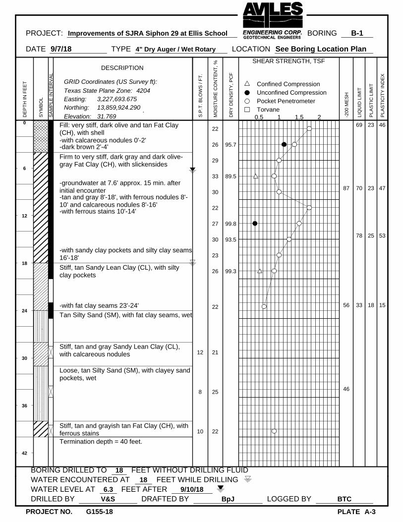
0
6
12
18
24
30
36
42
Fill: very stiff, dark olive and tan Fat Clay(CH), with shell-with calcareous nodules 0'-2'-dark brown 2'-4'
Firm to very stiff, dark gray and dark olive-gray Fat Clay (CH), with slickensides
-groundwater at 7.6' approx. 15 min. afterinitial encounter-tan and gray 8'-18', with ferrous nodules 8'-10' and calcareous nodules 8'-16'-with ferrous stains 10'-14'
-with sandy clay pockets and silty clay seams16'-18'
Stiff, tan Sandy Lean Clay (CL), with siltyclay pockets
-with fat clay seams 23'-24'
Tan Silty Sand (SM), with fat clay seams, wet
Stiff, tan and gray Sandy Lean Clay (CL),with calcareous nodules
Loose, tan Silty Sand (SM), with clayey sandpockets, wet
Stiff, tan and grayish tan Fat Clay (CH), withferrous stainsTermination depth = 40 feet.
12
8
10
22
26
29
33
30
22
27
30
23
26
22
21
25
22
95.7
89.5
99.8
93.5
99.3
87
56
46
69
70
78
33
23
23
25
18
46
47
53
15
PROJECT: Improvements of SJRA Siphon 29 at Ellis School BORING B-1
DATE 9/7/18 TYPE 4" Dry Auger / Wet Rotary LOCATION See Boring Location Plan
BORING DRILLED TO 18 FEET WITHOUT DRILLING FLUIDWATER ENCOUNTERED AT 18 FEET WHILE DRILLINGWATER LEVEL AT 6.3 FEET AFTER 9/10/18DRILLED BY V&S DRAFTED BY BpJ LOGGED BY BTC
PLATE A-3
DE
PT
H IN
FE
ET
SY
MB
OL
SA
MP
LE IN
TE
RV
AL
DESCRIPTION
.
S.P
.T. B
LOW
S /
FT
.
MO
IST
UR
E C
ON
TE
NT
, %
DR
Y D
EN
SIT
Y, P
CF
SHEAR STRENGTH, TSF
0.5 1 1.5 2TorvanePocket PenetrometerUnconfined CompressionConfined Compression
-20
0 M
ES
H
LIQ
UID
LIM
IT
PLA
ST
IC L
IMIT
PLA
ST
ICIT
Y IN
DE
X
PROJECT NO. G155-18
Elevation: 31.769
Northing: 13,859,924.290Easting: 3,227,693.675
GRID Coordinates (US Survey ft):
Texas State Plane Zone: 4204

0
6
12
18
24
30
36
42
Firm to hard, dark brown Fat Clay (CH), withslickensides-with roots 0'-2'-dark olive-gray and black 2'-4'-dark gray 4'-8'
-with ferrous nodules 6'-10'
-grayish tan 8'-10', with calcareous nodules8'-12'-tan and gray 10'-18', with ferrous stains 10'-16'-groundwater at 12.6' approx. 15 min. afterinitial encounter-with calcareous nodules 14'-16'
-with silty clay seams 16'-18'
Very stiff, tan and gray Lean Clay (CL), withsilty clay and fat clay pockets
Soft to stiff, tan Sandy Lean Clay (CL), withabundant silty clay pockets, wet-with silty clayey sand seams 23'-25'
-tan and gray, with silty sand pockets 28'-30'
-with fat clay seams 33'-35'
Tannish gray and gray Sandy Silt (ML), withsilty clay seams, wet
Termination depth = 40 feet.
5
7
25
26
29
30
30
27
30
29
24
23
24
30
25
23
93.3
92.7
96.3
102.3
98
57
52
72
75
75
28
24
23
28
18
48
52
47
10
PROJECT: Improvements of SJRA Siphon 29 at Ellis School BORING B-2
DATE 9/7/18 TYPE 4" Dry Auger / Wet Rotary LOCATION See Boring Location Plan
BORING DRILLED TO 20 FEET WITHOUT DRILLING FLUIDWATER ENCOUNTERED AT 20 FEET WHILE DRILLINGWATER LEVEL AT 6.5 FEET AFTER 9/10/18DRILLED BY V&S DRAFTED BY BpJ LOGGED BY BTC
PLATE A-4
DE
PT
H IN
FE
ET
SY
MB
OL
SA
MP
LE IN
TE
RV
AL
DESCRIPTION
.
S.P
.T. B
LOW
S /
FT
.
MO
IST
UR
E C
ON
TE
NT
, %
DR
Y D
EN
SIT
Y, P
CF
SHEAR STRENGTH, TSF
0.5 1 1.5 2TorvanePocket PenetrometerUnconfined CompressionConfined Compression
-20
0 M
ES
H
LIQ
UID
LIM
IT
PLA
ST
IC L
IMIT
PLA
ST
ICIT
Y IN
DE
X
PROJECT NO. G155-18
Elevation: 31.842
Northing: 13,859,804.270Easting: 3,227,773.863
GRID Coordinates (US Survey ft):
Texas State Plane Zone: 4204
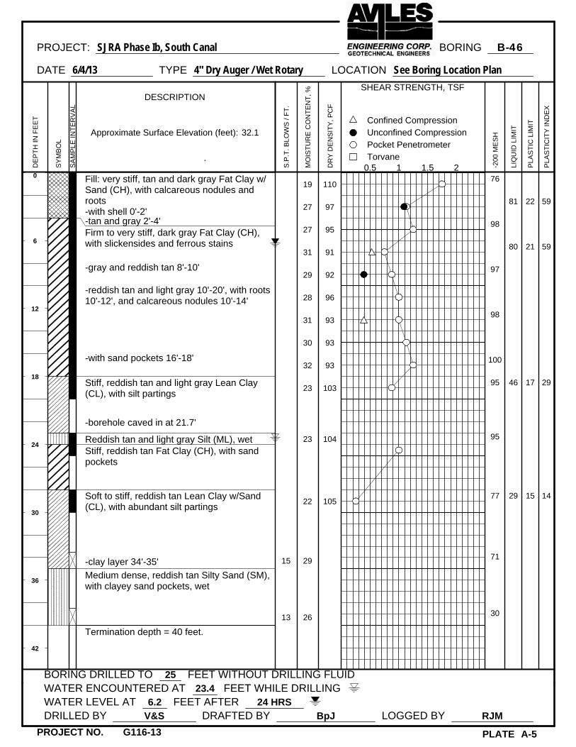
0
6
12
18
24
30
36
42
Fill: very stiff, tan and dark gray Fat Clay w/Sand (CH), with calcareous nodules androots-with shell 0'-2'-tan and gray 2'-4'Firm to very stiff, dark gray Fat Clay (CH),with slickensides and ferrous stains
-gray and reddish tan 8'-10'
-reddish tan and light gray 10'-20', with roots10'-12', and calcareous nodules 10'-14'
-with sand pockets 16'-18'
Stiff, reddish tan and light gray Lean Clay(CL), with silt partings
-borehole caved in at 21.7'
Reddish tan and light gray Silt (ML), wetStiff, reddish tan Fat Clay (CH), with sandpockets
Soft to stiff, reddish tan Lean Clay w/Sand(CL), with abundant silt partings
-clay layer 34'-35'
Medium dense, reddish tan Silty Sand (SM),with clayey sand pockets, wet
Termination depth = 40 feet.
15
13
19
27
27
31
29
28
31
30
32
23
23
22
29
26
110
97
95
91
92
96
93
93
93
103
104
105
76
98
97
98
100
95
95
77
71
30
81
80
46
29
22
21
17
15
59
59
29
14
PROJECT: SJRA Phase Ib, South Canal BORING B-46
DATE 6/4/13 TYPE 4" Dry Auger / Wet Rotary LOCATION See Boring Location Plan
BORING DRILLED TO 25 FEET WITHOUT DRILLING FLUIDWATER ENCOUNTERED AT 23.4 FEET WHILE DRILLINGWATER LEVEL AT 6.2 FEET AFTER 24 HRSDRILLED BY V&S DRAFTED BY BpJ LOGGED BY RJM
PLATE A-5
DE
PT
H IN
FE
ET
SY
MB
OL
SA
MP
LE IN
TE
RV
AL
DESCRIPTION
.
S.P
.T. B
LOW
S /
FT
.
MO
IST
UR
E C
ON
TE
NT
, %
DR
Y D
EN
SIT
Y, P
CF
SHEAR STRENGTH, TSF
0.5 1 1.5 2TorvanePocket PenetrometerUnconfined CompressionConfined Compression
-20
0 M
ES
H
LIQ
UID
LIM
IT
PLA
ST
IC L
IMIT
PLA
ST
ICIT
Y IN
DE
X
PROJECT NO. G116-13
Approximate Surface Elevation (feet): 32.1
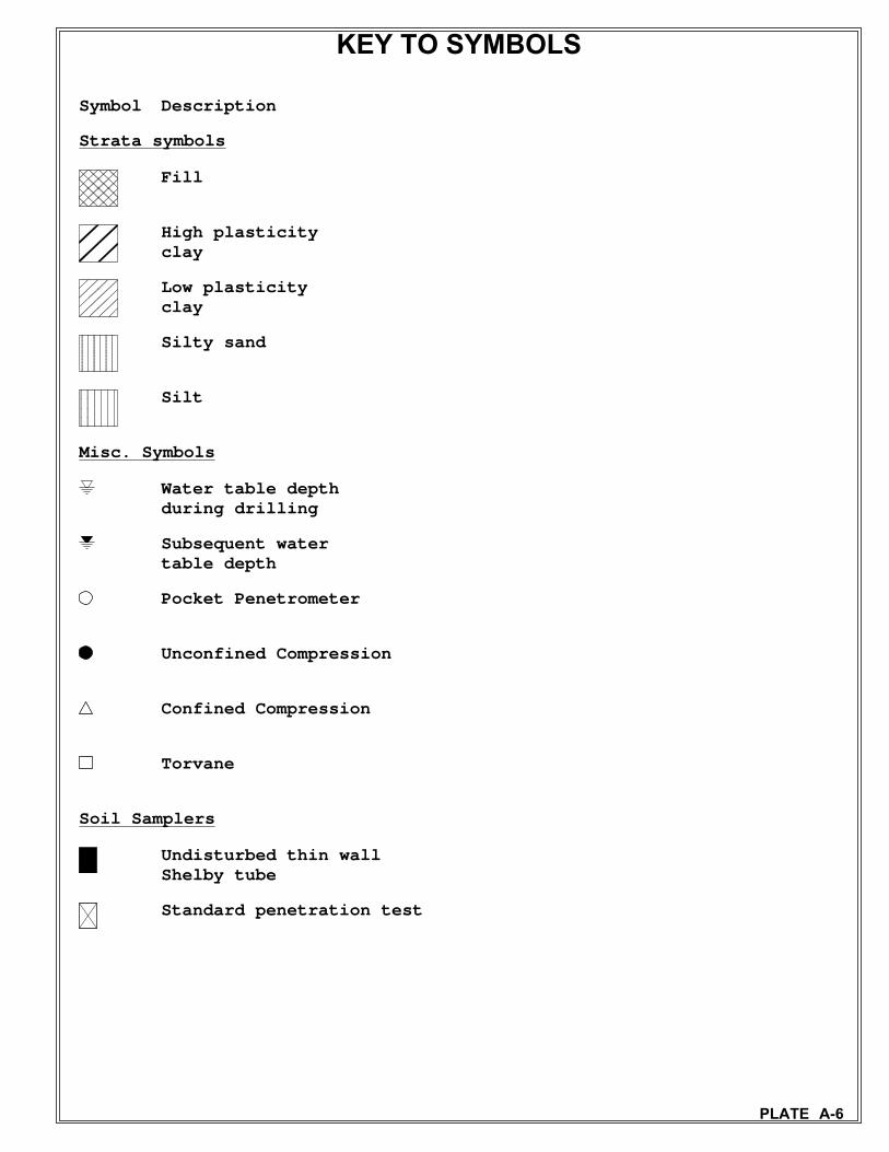
Symbol Description
Strata symbols
Fill
High plasticityclay
Low plasticityclay
Silty sand
Silt
Misc. Symbols
Water table depthduring drilling
Subsequent watertable depth
Pocket Penetrometer
Unconfined Compression
Confined Compression
Torvane
Soil Samplers
Undisturbed thin wallShelby tube
Standard penetration test
KEY TO SYMBOLS
PLATE A-6

PLATE A-7
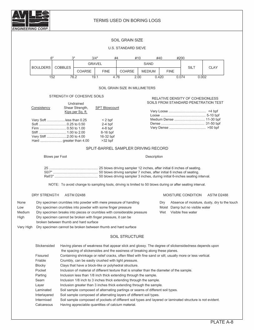
PLATE A-8
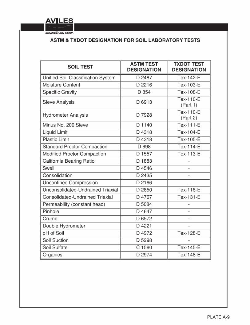
ASTM & TXDOT DESIGNATION FOR SOIL LABORATORY TESTS
SOIL TEST ASTM TEST DESIGNATION
TXDOT TEST DESIGNATION
Unified Soil Classification System D 2487 Tex-142-E
Moisture Content D 2216 Tex-103-E
Specific Gravity D 854 Tex-108-E
Sieve Analysis D 6913 Tex-110-E
(Part 1)
Hydrometer Analysis D 7928 Tex-110-E
(Part 2)
Minus No. 200 Sieve D 1140 Tex-111-E
Liquid Limit D 4318 Tex-104-E
Plastic Limit D 4318 Tex-105-E
Standard Proctor Compaction D 698 Tex-114-E
Modified Proctor Compaction D 1557 Tex-113-E
California Bearing Ratio D 1883 -
Swell D 4546 -
Consolidation D 2435 -
Unconfined Compression D 2166 -
Unconsolidated-Undrained Triaxial D 2850 Tex-118-E
Consolidated-Undrained Triaxial D 4767 Tex-131-E
Permeability (constant head) D 5084 -
Pinhole D 4647 -
Crumb D 6572 -
Double Hydrometer D 4221 -
pH of Soil D 4972 Tex-128-E
Soil Suction D 5298 -
Soil Sulfate C 1580 Tex-145-E
Organics D 2974 Tex-148-E
PLATE A-9
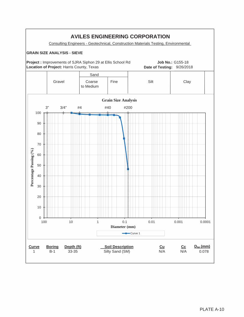
GRAIN SIZE ANALYSIS - SIEVE
Project : Improvements of SJRA Siphon 29 at Ellis School Rd Job No.: G155-18Location of Project: Harris County, Texas 9/26/2018
Sand
Gravel Coarse Fine Clay to Medium
Curve Boring Depth (ft) Cu Cc D50 (mm)1 B-1 33-35 N/A N/A 0.078Silty Sand (SM)
Date of Testing:
Soil Description
AVILES ENGINEERING CORPORATIONConsulting Engineers - Geotechnical, Construction Materials Testing, Environmental
Silt
3" #43/4" #40 #200
0
10
20
30
40
50
60
70
80
90
100
0.00010.0010.010.1110100
Perc
enta
ge P
assi
ng (%
)
Diameter (mm)
Grain Size Analysis
Curve 1
PLATE A-10
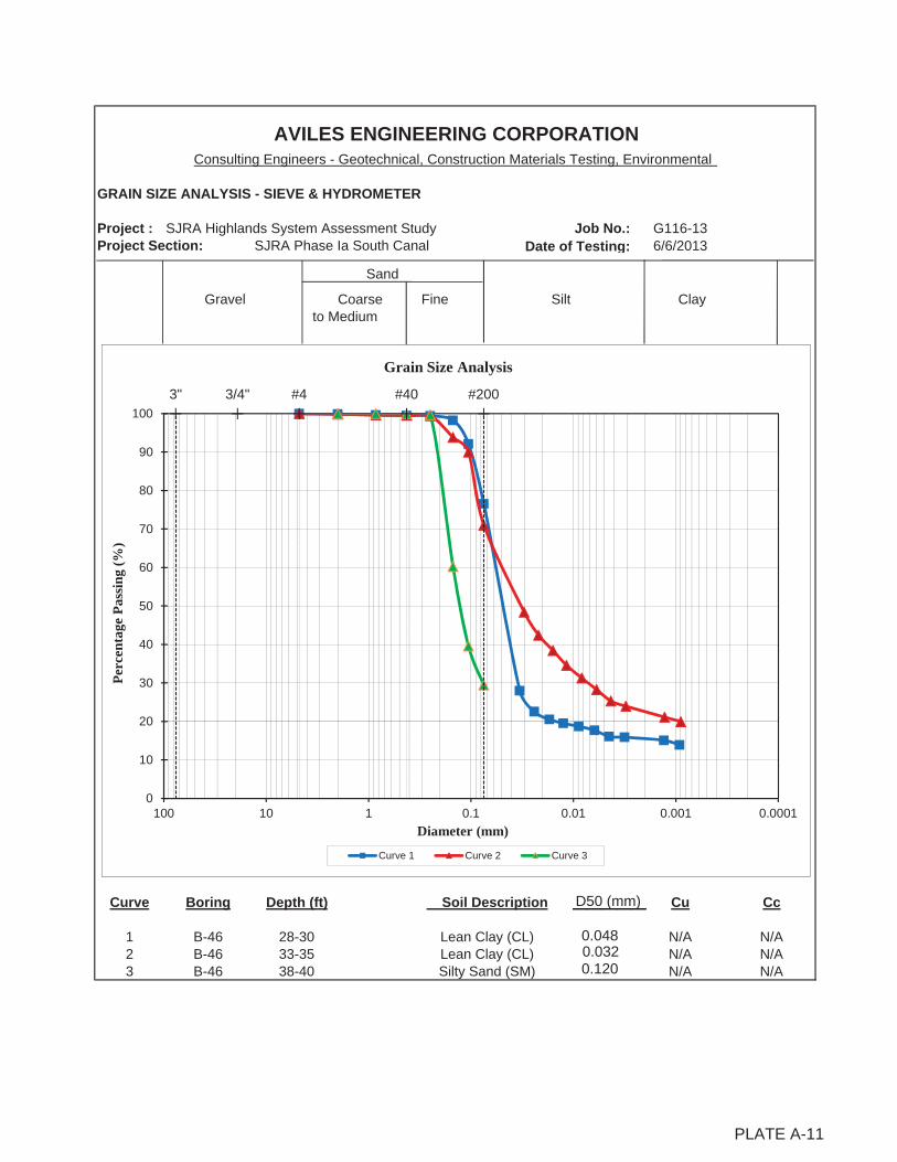
GRAIN SIZE ANALYSIS - SIEVE & HYDROMETER
Project : SJRA Highlands System Assessment Study Job No.: G116-13Project Section: SJRA Phase Ia South Canal Date of Testing: 6/6/2013
Sand
Gravel Coarse Fine Silt Clay to Medium
Curve Boring Depth (ft) Cu Cc
1 B-46 28-30 N/A N/A2 B-46 33-35 N/A N/A3 B-46 38-40 N/A N/A
PLATE A-13
AVILES ENGINEERING CORPORATIONConsulting Engineers - Geotechnical, Construction Materials Testing, Environmental
Soil Description
Lean Clay (CL)Lean Clay (CL)Silty Sand (SM)
3" #43/4" #40 #200
0
10
20
30
40
50
60
70
80
90
100
0.00010.0010.010.1110100
Perc
enta
ge P
assi
ng (%
)
Diameter (mm)
Grain Size Analysis
Curve 1 Curve 2 Curve 3
PLATE A-11
D50 (mm)_____0.048 0.0320.120
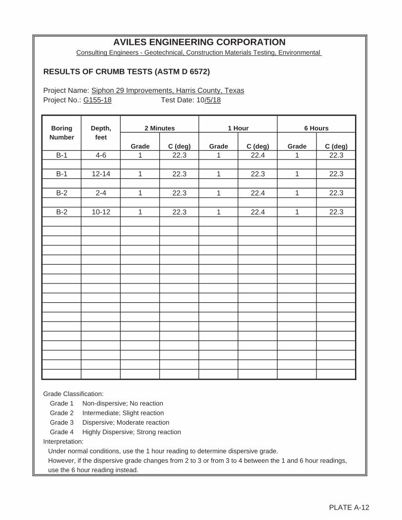
RESULTS OF CRUMB TESTS (ASTM D 6572)
Project Name: Siphon 29 Improvements, Harris County, TexasProject No.: G155-18 Test Date: 10/5/18
Boring Depth,Number feet
B-1 4-6 1 22.3 1 22.4 1 22.3
B-1 12-14 1 22.3 1 22.3 1 22.3
B-2 2-4 1 22.3 1 22.4 1 22.3
B-2 10-12 1 22.3 1 22.4 1 22.3
Grade Classification:
Grade 1 Non-dispersive; No reaction
Grade 2 Intermediate; Slight reaction
Grade 3 Dispersive; Moderate reaction
Grade 4 Highly Dispersive; Strong reaction
Interpretation:
Under normal conditions, use the 1 hour reading to determine dispersive grade.
However, if the dispersive grade changes from 2 to 3 or from 3 to 4 between the 1 and 6 hour readings,
use the 6 hour reading instead.
AVILES ENGINEERING CORPORATIONConsulting Engineers - Geotechnical, Construction Materials Testing, Environmental
6 Hours2 Minutes 1 Hour
C (deg)Grade C (deg) Grade C (deg) Grade
PLATE A-12

RESULTS OF CRUMB TESTS (ASTM D 6572)
Project Name: Highlands System Assessment Study - SJRA Phase Ib South CanalProject No.: G116-13 Test Date: 6/17/2013
Boring Depth,Number feet Crumbles? @15 @30
(Y/N) Minor Moderate Immediate minutes minutesB-46 4-6 Y • 1 1
B-46 23-25 Y • 2 3
B-54 2-4 Y • 1 1
Results interpretation:
1 No sign of cloudy water caused by colloidal suspension
2 Bare hint of colloidal cloud formation at surface or soil crumb
3 Easily recognized colloidal cloud covering at least 1/4 to 1/2 of the bottom of the glass container
4 Strong reaction with colloidal cloud covering most of the bottom of the glass container
Plate A 19
AVILES ENGINEERING CORPORATIONConsulting Engineers - Geotechnical, Construction Materials Testing, Environmental
If soil crumbles, rate of crumblingCrumbling Characteristics
Crumb Test Classification
PLATE A-13
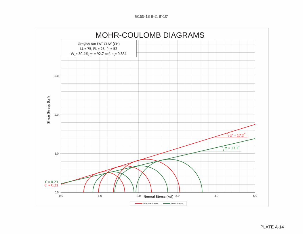
G155-18 B-2, 8'-10'
0.0
1.0
2.0
3.0
0.0 1.0 2.0 3.0 4.0 5.0
Shea
r Str
ess
(ksf
)
Normal Stress (ksf)
MOHR-COULOMB DIAGRAMS
Effective Stress Total Stress
C' = 0.21C = 0.23
' = 17.2
= 13.1
Grayish tan FAT CLAY (CH)LL = 75, PL = 23, PI = 52
W = 30.4%, d = 92.7 pcf, e = 0.851
PLATE A-14
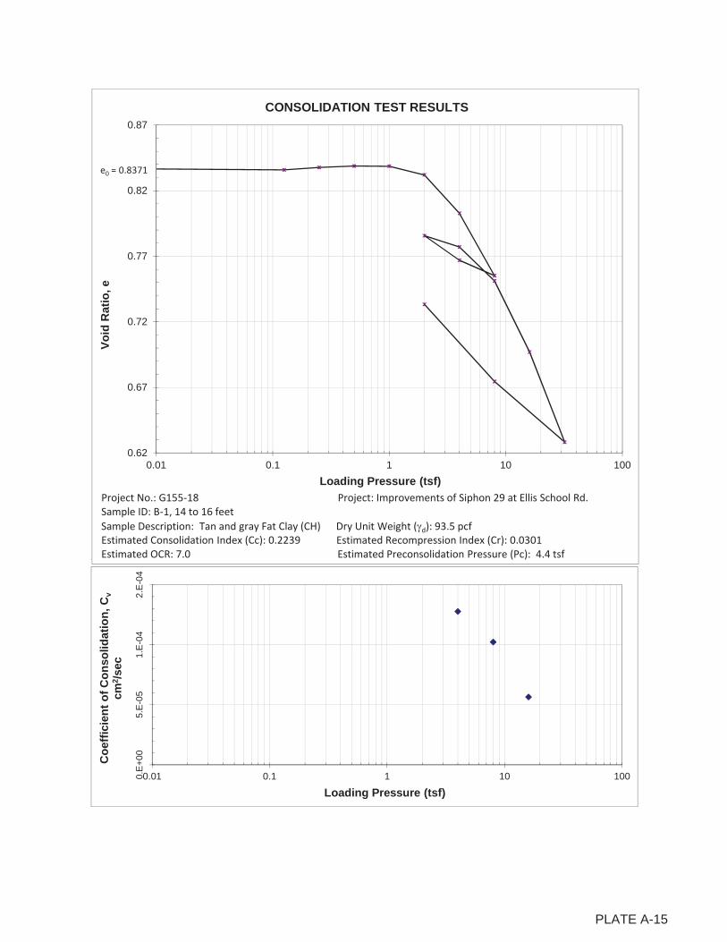
0.E
+0
05
.E-0
51
.E-0
42
.E-0
4
0.01 0.1 1 10 100
Coe
ffici
ent o
f Con
solid
atio
n, C
vcm
2 /sec
Loading Pressure (tsf)
0.62
0.67
0.72
0.77
0.82
0.87
0.01 0.1 1 10 100
Void
Rat
io, e
Loading Pressure (tsf)
CONSOLIDATION TEST RESULTS
Project No.: G155 18 Project: Improvements of Siphon 29 at Ellis School Rd.Sample ID: B 1, 14 to 16 feetSample Description: Tan and gray Fat Clay (CH) Dry Unit Weight ( d): 93.5 pcfEstimated Consolidation Index (Cc): 0.2239 Estimated Recompression Index (Cr): 0.0301Estimated OCR: 7.0 Estimated Preconsolidation Pressure (Pc): 4.4 tsf
e0 = 0.8371
PLATE A-15
APPENDIX B
Plates B-1 and B-2 Site Photographs near Siphon 29
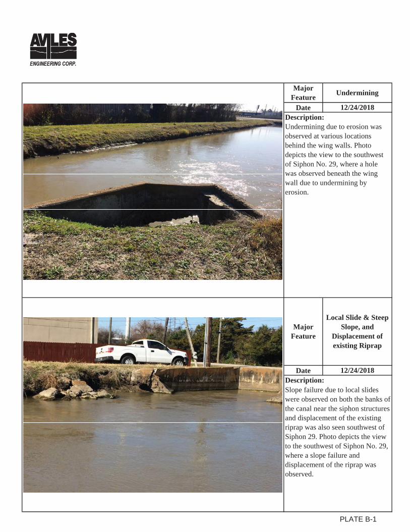
Date
Date
Description:Undermining due to erosion was observed at various locations behind the wing walls. Photo depicts the view to the southwest of Siphon No. 29, where a hole was observed beneath the wing wall due to undermining by erosion.
MajorFeature
Local Slide & Steep Slope, and
Displacement of existing Riprap
Description:12/24/2018
12/24/2018
Slope failure due to local slides were observed on both the banks of the canal near the siphon structures and displacement of the existing riprap was also seen southwest of Siphon 29. Photo depicts the view to the southwest of Siphon No. 29, where a slope failure and displacement of the riprap was observed.
MajorFeature Undermining
PLATE B-1

Date
Date
Description:Cracks on all the wing walls were observed. Photo depicts the view to the northeast of Siphon No. 29, where a severe crack on the wing wall was observed.
Crack and Movement of the
Head Walls
12/24/2018
12/24/2018
MajorFeature
Crack on Wing Walls
MajorFeature
Description:Cracks and movement of both the head walls were observed. Photo depicts a view to the north of Ellis School Road at Siphon No. 29, where number of cracks on the head wall and its movement were observed.
PLATE B-2
APPENDIX C Plate C-1 Recommended Geotechnical Design Parameters for Underground Utilities Plate C-2 Recommended Geotechnical Design Parameters for Head/Wing Walls Plate C-3 Coefficients of Active and Passive Earth Pressures for Sloped Backfill Plate C-4 Load Coefficients for Pipe Loading Plate C-5 Live Loads on Pipe Crossing Under Roadway Plate C-6 Tunnel/Bore Settlement Calculations for One Pass Method Plate C-7 Tunnel/Bore Settlement Calculations for Two Pass Method Plate C-8 Soil Parameters for Siphon Mat Foundation Settlement Analysis
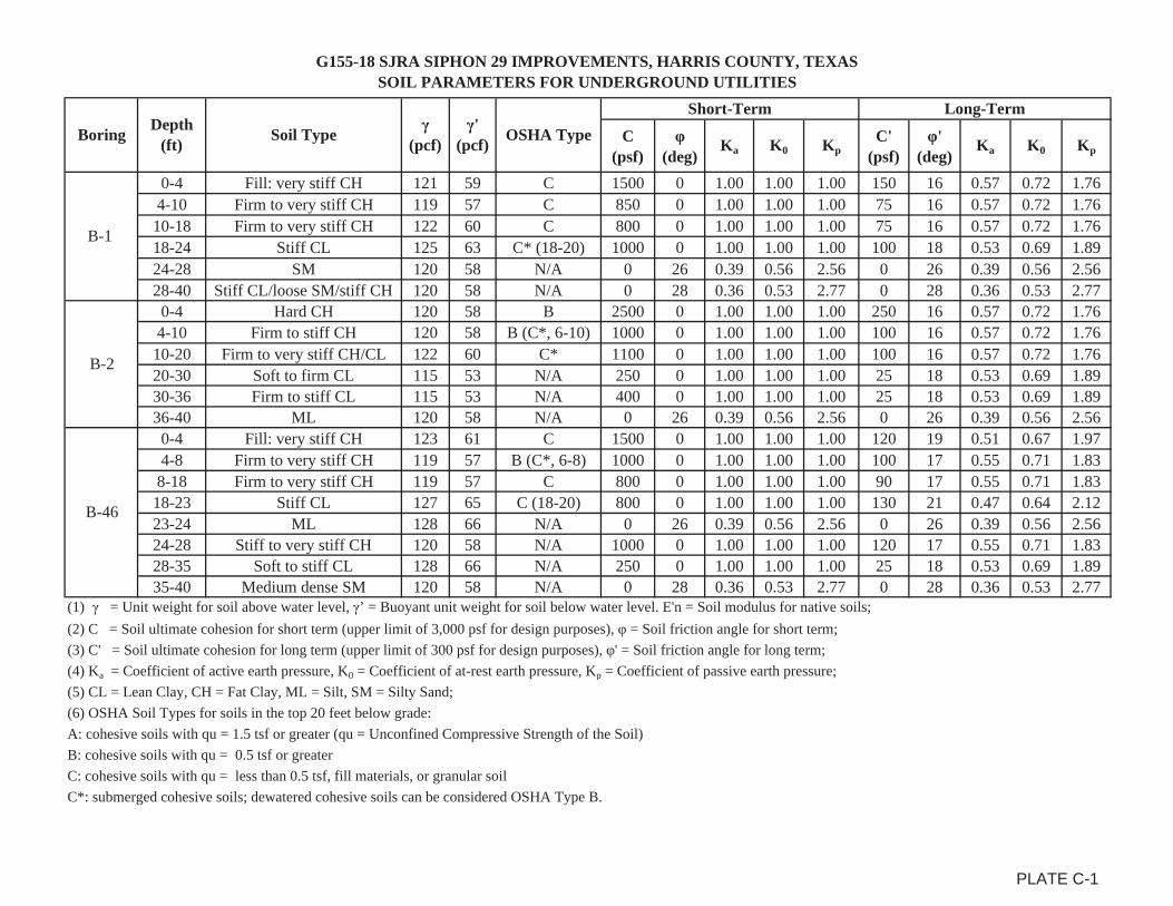
G155-18 SJRA SIPHON 29 IMPROVEMENTS, HARRIS COUNTY, TEXASSOIL PARAMETERS FOR UNDERGROUND UTILITIES
C (psf)
(deg)
Ka K0 KpC'
(psf)'
(deg)Ka K0 Kp
0-4 Fill: very stiff CH 121 59 C 1500 0 1.00 1.00 1.00 150 16 0.57 0.72 1.764-10 Firm to very stiff CH 119 57 C 850 0 1.00 1.00 1.00 75 16 0.57 0.72 1.76
10-18 Firm to very stiff CH 122 60 C 800 0 1.00 1.00 1.00 75 16 0.57 0.72 1.7618-24 Stiff CL 125 63 C* (18-20) 1000 0 1.00 1.00 1.00 100 18 0.53 0.69 1.8924-28 SM 120 58 N/A 0 26 0.39 0.56 2.56 0 26 0.39 0.56 2.5628-40 Stiff CL/loose SM/stiff CH 120 58 N/A 0 28 0.36 0.53 2.77 0 28 0.36 0.53 2.770-4 Hard CH 120 58 B 2500 0 1.00 1.00 1.00 250 16 0.57 0.72 1.76
4-10 Firm to stiff CH 120 58 B (C*, 6-10) 1000 0 1.00 1.00 1.00 100 16 0.57 0.72 1.7610-20 Firm to very stiff CH/CL 122 60 C* 1100 0 1.00 1.00 1.00 100 16 0.57 0.72 1.7620-30 Soft to firm CL 115 53 N/A 250 0 1.00 1.00 1.00 25 18 0.53 0.69 1.8930-36 Firm to stiff CL 115 53 N/A 400 0 1.00 1.00 1.00 25 18 0.53 0.69 1.8936-40 ML 120 58 N/A 0 26 0.39 0.56 2.56 0 26 0.39 0.56 2.560-4 Fill: very stiff CH 123 61 C 1500 0 1.00 1.00 1.00 120 19 0.51 0.67 1.974-8 Firm to very stiff CH 119 57 B (C*, 6-8) 1000 0 1.00 1.00 1.00 100 17 0.55 0.71 1.83
8-18 Firm to very stiff CH 119 57 C 800 0 1.00 1.00 1.00 90 17 0.55 0.71 1.8318-23 Stiff CL 127 65 C (18-20) 800 0 1.00 1.00 1.00 130 21 0.47 0.64 2.1223-24 ML 128 66 N/A 0 26 0.39 0.56 2.56 0 26 0.39 0.56 2.5624-28 Stiff to very stiff CH 120 58 N/A 1000 0 1.00 1.00 1.00 120 17 0.55 0.71 1.8328-35 Soft to stiff CL 128 66 N/A 250 0 1.00 1.00 1.00 25 18 0.53 0.69 1.8935-40 Medium dense SM 120 58 N/A 0 28 0.36 0.53 2.77 0 28 0.36 0.53 2.77
(1) = Unit weight for soil above water level, ’ = Buoyant unit weight for soil below water level. E'n = Soil modulus for native soils;(2) C = Soil ultimate cohesion for short term (upper limit of 3,000 psf for design purposes), = Soil friction angle for short term;(3) C' = Soil ultimate cohesion for long term (upper limit of 300 psf for design purposes), ' = Soil friction angle for long term;(4) Ka = Coefficient of active earth pressure, K0 = Coefficient of at-rest earth pressure, Kp = Coefficient of passive earth pressure;(5) CL = Lean Clay, CH = Fat Clay, ML = Silt, SM = Silty Sand;(6) OSHA Soil Types for soils in the top 20 feet below grade:A: cohesive soils with qu = 1.5 tsf or greater (qu = Unconfined Compressive Strength of the Soil)B: cohesive soils with qu = 0.5 tsf or greaterC: cohesive soils with qu = less than 0.5 tsf, fill materials, or granular soilC*: submerged cohesive soils; dewatered cohesive soils can be considered OSHA Type B.
Long-TermBoring Depth
(ft) Soil Type (pcf)
' (pcf) OSHA Type
Short-Term
B-2
B-1
B-46
PLATE C-1
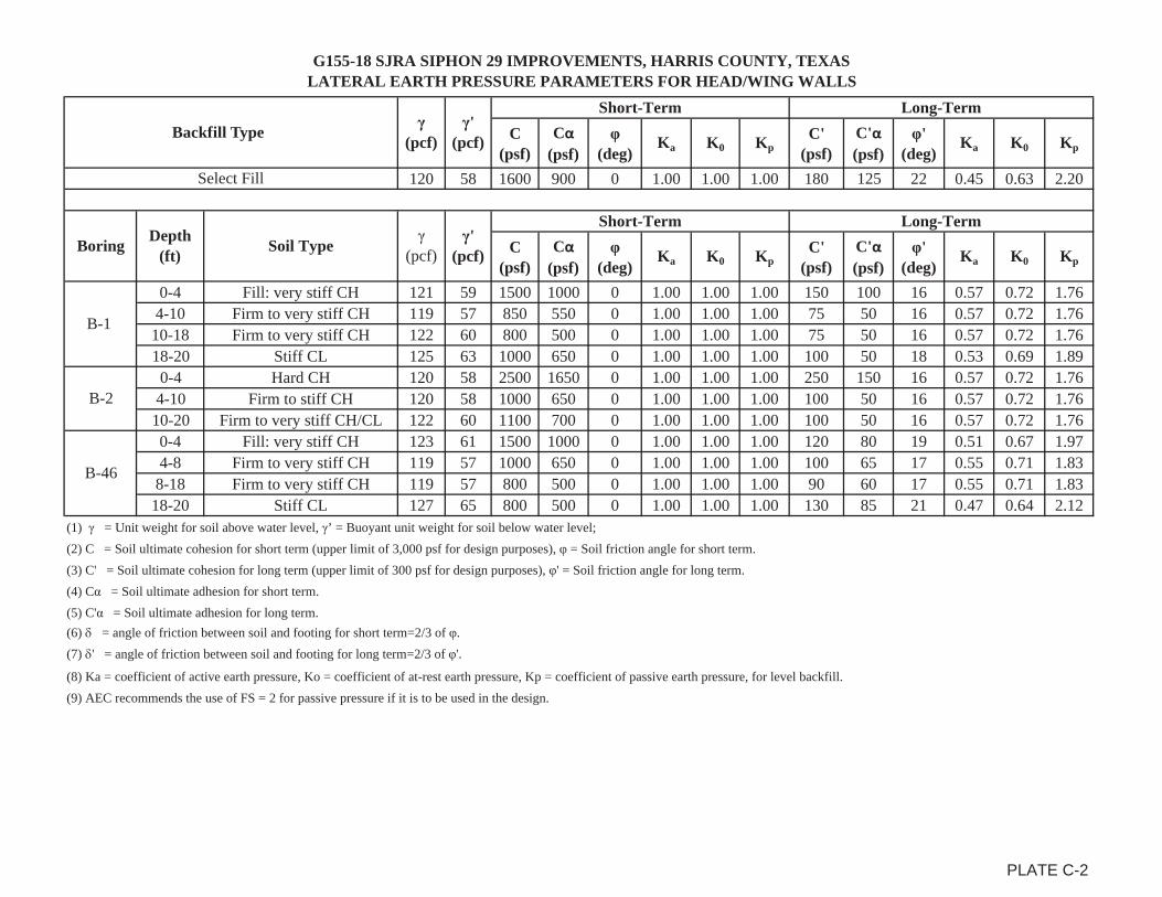
G155-18 SJRA SIPHON 29 IMPROVEMENTS, HARRIS COUNTY, TEXASLATERAL EARTH PRESSURE PARAMETERS FOR HEAD/WING WALLS
C (psf)
C(psf)
(deg)
Ka K0 KpC'
(psf)C'(psf)
' (deg)
Ka K0 Kp
120 58 1600 900 0 1.00 1.00 1.00 180 125 22 0.45 0.63 2.20
C (psf)
C(psf)
(deg)
Ka K0 KpC'
(psf)C'(psf)
' (deg)
Ka K0 Kp
0-4 Fill: very stiff CH 121 59 1500 1000 0 1.00 1.00 1.00 150 100 16 0.57 0.72 1.764-10 Firm to very stiff CH 119 57 850 550 0 1.00 1.00 1.00 75 50 16 0.57 0.72 1.76
10-18 Firm to very stiff CH 122 60 800 500 0 1.00 1.00 1.00 75 50 16 0.57 0.72 1.7618-20 Stiff CL 125 63 1000 650 0 1.00 1.00 1.00 100 50 18 0.53 0.69 1.890-4 Hard CH 120 58 2500 1650 0 1.00 1.00 1.00 250 150 16 0.57 0.72 1.76
4-10 Firm to stiff CH 120 58 1000 650 0 1.00 1.00 1.00 100 50 16 0.57 0.72 1.7610-20 Firm to very stiff CH/CL 122 60 1100 700 0 1.00 1.00 1.00 100 50 16 0.57 0.72 1.760-4 Fill: very stiff CH 123 61 1500 1000 0 1.00 1.00 1.00 120 80 19 0.51 0.67 1.974-8 Firm to very stiff CH 119 57 1000 650 0 1.00 1.00 1.00 100 65 17 0.55 0.71 1.83
8-18 Firm to very stiff CH 119 57 800 500 0 1.00 1.00 1.00 90 60 17 0.55 0.71 1.8318-20 Stiff CL 127 65 800 500 0 1.00 1.00 1.00 130 85 21 0.47 0.64 2.12
(1) = Unit weight for soil above water level, ’ = Buoyant unit weight for soil below water level;(2) C = Soil ultimate cohesion for short term (upper limit of 3,000 psf for design purposes), = Soil friction angle for short term.(3) C' = Soil ultimate cohesion for long term (upper limit of 300 psf for design purposes), ' = Soil friction angle for long term.(4) C = Soil ultimate adhesion for short term.(5) C' = Soil ultimate adhesion for long term.(6) = angle of friction between soil and footing for short term=2/3 of .(7) ' = angle of friction between soil and footing for long term=2/3 of '.
(8) Ka = coefficient of active earth pressure, Ko = coefficient of at-rest earth pressure, Kp = coefficient of passive earth pressure, for level backfill.(9) AEC recommends the use of FS = 2 for passive pressure if it is to be used in the design.
B-2
B-1
B-46
Select Fill
Short-Term Long-Term
Boring Depth (ft) Soil Type
(pcf)'
(pcf)
Short-Term Long-Term
Backfill Type (pcf)
' (pcf)
PLATE C-2
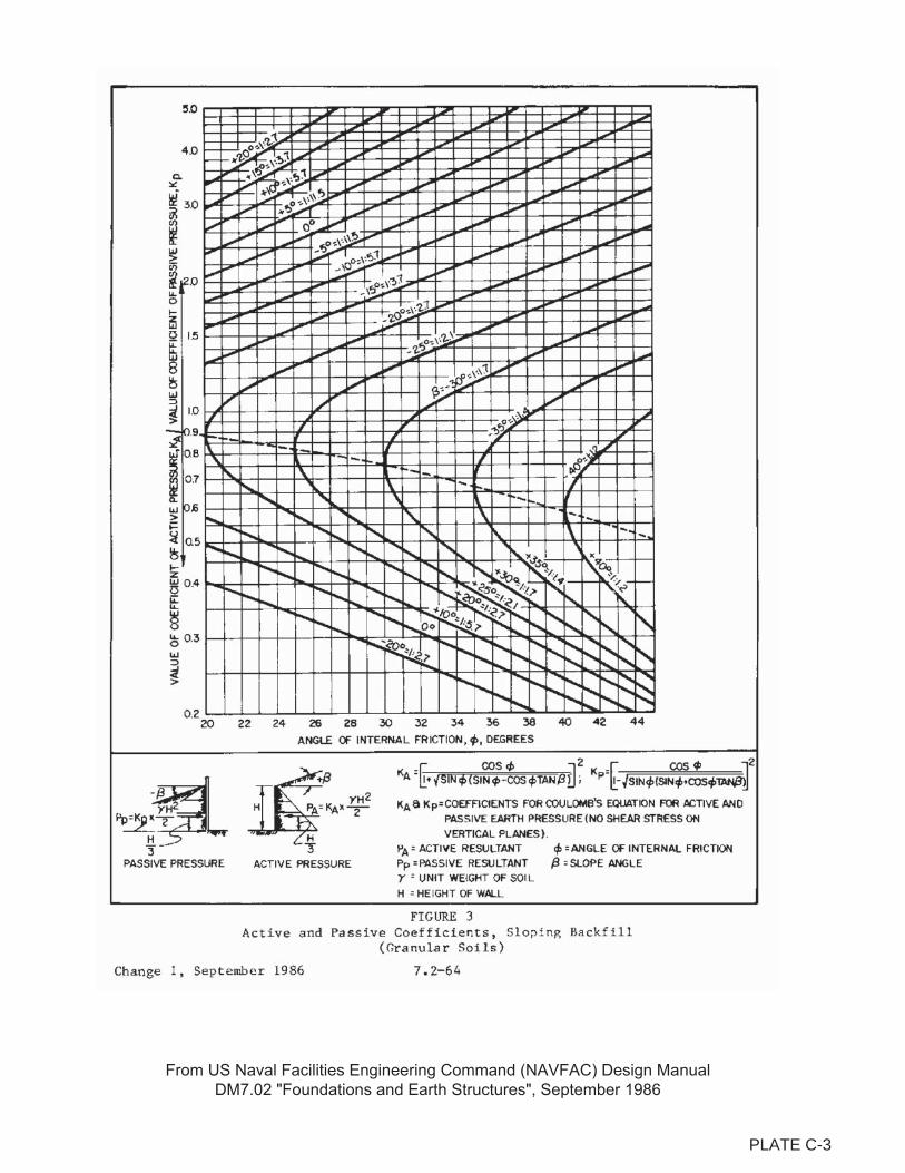
PLATE C-3

PLATE C-2
Reference: US Army Corps of Engineers Engineering Manual, EM 1110-2-2902, Oct. 31, 1997, Figure 2-5.
PLATE C-4
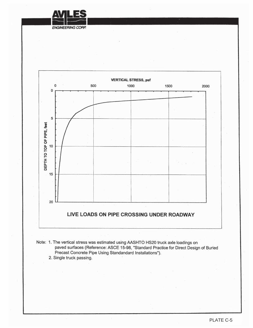
PLATE C-3PLATE C-5

TUNNEL SETTLEMENT CALCULATION FOR ONE PASS METHODProject Name: Siphon 29 Improvements Date: 12/28/2018
Client: Texas Water Engineering Project #: G155-18
Locations: Harris County, Texas
Tunnel Center Line
Tunnel Diameter, D = 6 ft, Tunnel Volume/ft, V = π(R)2
= 28.27 ft3/ft
Tunnel Radius, R = D/2 = 3 ft, Max Settlement, Smax = VLπR2/(2.5i), ft
Z0 = Depth of Tunnel Centerline, ft Cu = Undrained Shear Strength of Soil, psf
�z = Overburden Pressure to Tunnel Centerline, psf Nt = �z/Cu, Stability Factor
Tunnel Invert
Depth, Z (ft)
Tunnel Zone
Soil Type
Z0 = Z-R, (ft) 9.7 10.3
Unit Weight of
Soil (pcf) 120.3 120.5
�z (psf) 1167 1241
Cu (psf) 800 1000
Nt 1.5 1.2
VL (%) 0.5 1.0 1.5 2.0 0.5 1.0 1.5 2.00
Volume Loss =
VL*V (ft3/ft) 0.141 0.283 0.424 0.565 0.141 0.283 0.424 0.565
Z0/(2R) 1.62 1.72
i/R 2.0 2.2
i (ft) 6.0 6.6
Smax (ft) 0.0094 0.0188 0.0283 0.0377 0.0086 0.0171 0.0257 0.0343
Smax (in) 0.113 0.226 0.339 0.452 0.103 0.206 0.308 0.411
0.5 Trough
Width, 2.5i (ft) 15.0 16.5
Note
Estimated settlement for using micro-tunnel boring machine (MTBM)/mechanized close face Tunnel Boring Machine (TBM)
Estimated Settlement for Boring Shield or Auger/Bore.
VL and i/R from: J. Bickel, T. Kuesel, and E. King, 'Tunnel Engineering Handbook', 2nd Edition, 1996, Tables 6-8 and Figure 6-19, respectively.
B-1 B-2/B-46
12.7 13.3
Firm to very stiff Fat Clay (CH) Firm to very stiff Fat Clay (CH)
Potential swelling ground due to high plasticity fat
clay. Pressurized groundwater. Dewatering not
required if MTBM or slurry bore/auger is used.
Otherwise, dewatering operations will be necessary
if boring shield, mechanized TBM, or dry auger/bore
is used.
Potential swelling ground due to high plasticity fat
clay. Pressurized groundwater. Dewatering not
required if MTBM or slurry bore/auger is used.
Otherwise, dewatering operations will be necessary
if boring shield, mechanized TBM, or dry auger/bore
is used.
PLATE C-6
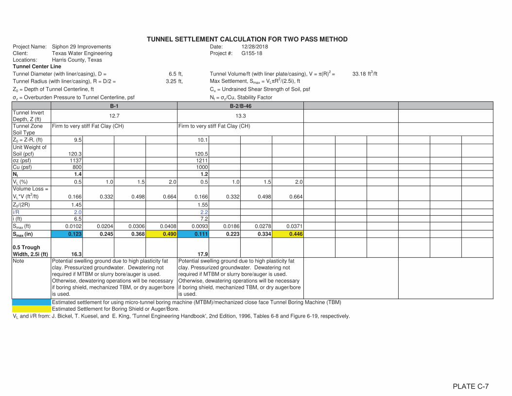
TUNNEL SETTLEMENT CALCULATION FOR TWO PASS METHODProject Name: Siphon 29 Improvements Date: 12/28/2018
Client: Texas Water Engineering Project #: G155-18
Locations: Harris County, Texas
Tunnel Center Line
Tunnel Diameter (with liner/casing), D = 6.5 ft, Tunnel Volume/ft (with liner plate/casing), V = π(R)2
= 33.18 ft3/ft
Tunnel Radius (with liner/casing), R = D/2 = 3.25 ft, Max Settlement, Smax = VLπR2/(2.5i), ft
Z0 = Depth of Tunnel Centerline, ft Cu = Undrained Shear Strength of Soil, psf
�z = Overburden Pressure to Tunnel Centerline, psf Nt = �z/Cu, Stability Factor
Tunnel Invert
Depth, Z (ft)
Tunnel Zone
Soil Type
Z0 = Z-R, (ft) 9.5 10.1
Unit Weight of
Soil (pcf) 120.3 120.5
�z (psf) 1137 1211
Cu (psf) 800 1000
Nt 1.4 1.2
VL (%) 0.5 1.0 1.5 2.0 0.5 1.0 1.5 2.0
Volume Loss =
VL*V (ft3/ft) 0.166 0.332 0.498 0.664 0.166 0.332 0.498 0.664
Z0/(2R) 1.45 1.55
i/R 2.0 2.2
i (ft) 6.5 7.2
Smax (ft) 0.0102 0.0204 0.0306 0.0408 0.0093 0.0186 0.0278 0.0371
Smax (in) 0.123 0.245 0.368 0.490 0.111 0.223 0.334 0.446
0.5 Trough
Width, 2.5i (ft) 16.3 17.9
Note
Estimated settlement for using micro-tunnel boring machine (MTBM)/mechanized close face Tunnel Boring Machine (TBM)
Estimated Settlement for Boring Shield or Auger/Bore.
VL and i/R from: J. Bickel, T. Kuesel, and E. King, 'Tunnel Engineering Handbook', 2nd Edition, 1996, Tables 6-8 and Figure 6-19, respectively.
Firm to very stiff Fat Clay (CH) Firm to very stiff Fat Clay (CH)
Potential swelling ground due to high plasticity fat
clay. Pressurized groundwater. Dewatering not
required if MTBM or slurry bore/auger is used.
Otherwise, dewatering operations will be necessary
if boring shield, mechanized TBM, or dry auger/bore
is used.
Potential swelling ground due to high plasticity fat
clay. Pressurized groundwater. Dewatering not
required if MTBM or slurry bore/auger is used.
Otherwise, dewatering operations will be necessary
if boring shield, mechanized TBM, or dry auger/bore
is used.
12.7 13.3
B-1 B-2/B-46
PLATE C-7
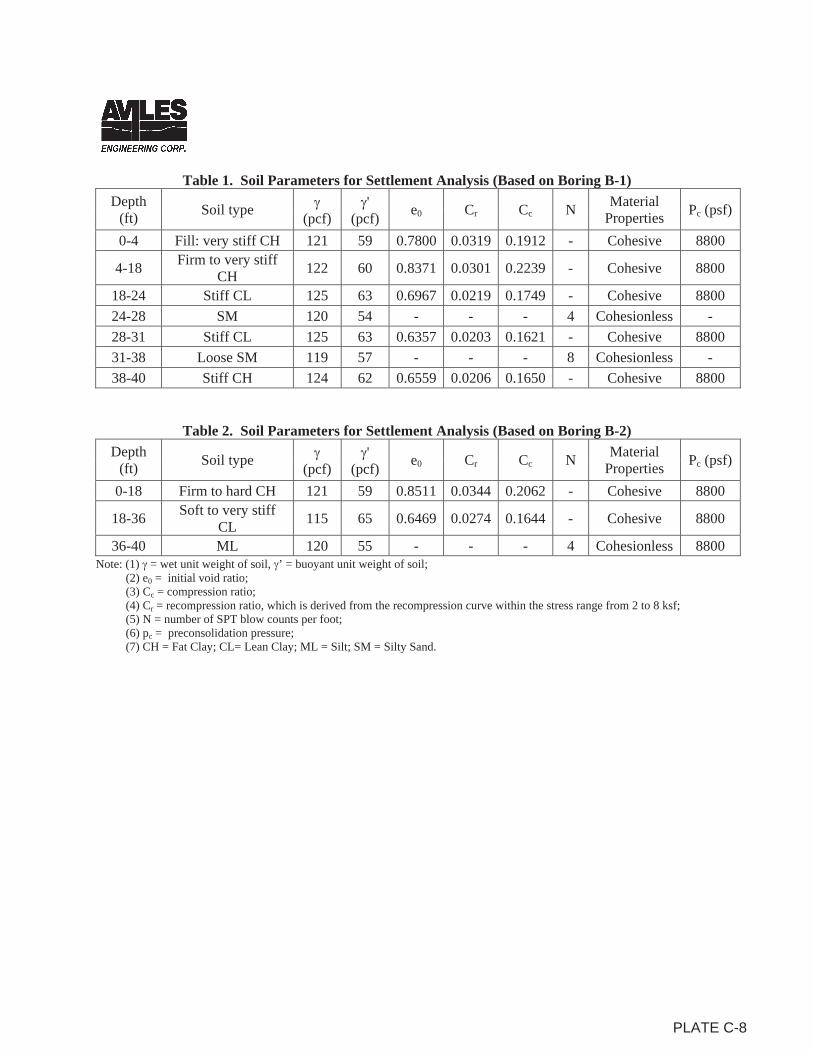
Table 1. Soil Parameters for Settlement Analysis (Based on Boring B-1)Depth
(ft) Soil type (pcf)'
(pcf) e0 Cr Cc N MaterialProperties Pc (psf)
0-4 Fill: very stiff CH 121 59 0.7800 0.0319 0.1912 - Cohesive 8800
4-18 Firm to very stiff CH 122 60 0.8371 0.0301 0.2239 - Cohesive 8800
18-24 Stiff CL 125 63 0.6967 0.0219 0.1749 - Cohesive 8800 24-28 SM 120 54 - - - 4 Cohesionless - 28-31 Stiff CL 125 63 0.6357 0.0203 0.1621 - Cohesive 8800 31-38 Loose SM 119 57 - - - 8 Cohesionless - 38-40 Stiff CH 124 62 0.6559 0.0206 0.1650 - Cohesive 8800
Table 2. Soil Parameters for Settlement Analysis (Based on Boring B-2)Depth
(ft) Soil type (pcf)'
(pcf) e0 Cr Cc N MaterialProperties Pc (psf)
0-18 Firm to hard CH 121 59 0.8511 0.0344 0.2062 - Cohesive 8800
18-36 Soft to very stiff CL 115 65 0.6469 0.0274 0.1644 - Cohesive 8800
36-40 ML 120 55 - - - 4 Cohesionless 8800 Note: (1) = wet unit weight of soil, ’ = buoyant unit weight of soil;
(2) e0 = initial void ratio; (3) Cc = compression ratio; (4) Cr = recompression ratio, which is derived from the recompression curve within the stress range from 2 to 8 ksf; (5) N = number of SPT blow counts per foot; (6) pc = preconsolidation pressure; (7) CH = Fat Clay; CL= Lean Clay; ML = Silt; SM = Silty Sand.
PLATE C-8
APPENDIX D Plate D-1 Critical Heights of Cut Slopes in Nonfissured Clays Plate D-2 Maximum Allowable Slopes Plate D-3 A Combination of Bracing and Open Cuts Plate D-4 Lateral Pressure Diagrams for Open Cuts in Cohesive Soil-Long Term Conditions Plate D-5 Lateral Pressure Diagrams for Open Cuts in Cohesive Soil-Short Term Conditions Plate D-6 Lateral Pressure Diagrams for Open Cuts in Sand Plate D-7 Bottom Stability for Braced Excavation in Clay Plate D-8 Tunnel Behavior and TBM Selection Plate D-9 Relation between the Width of Surface Depression and Depth of Cavity for
Tunnels Plate D-10 Methods of Controlling Ground Water in Tunnel and Grouting Material Selection Plate D-11 Buoyant Uplift Resistance for Buried Structures
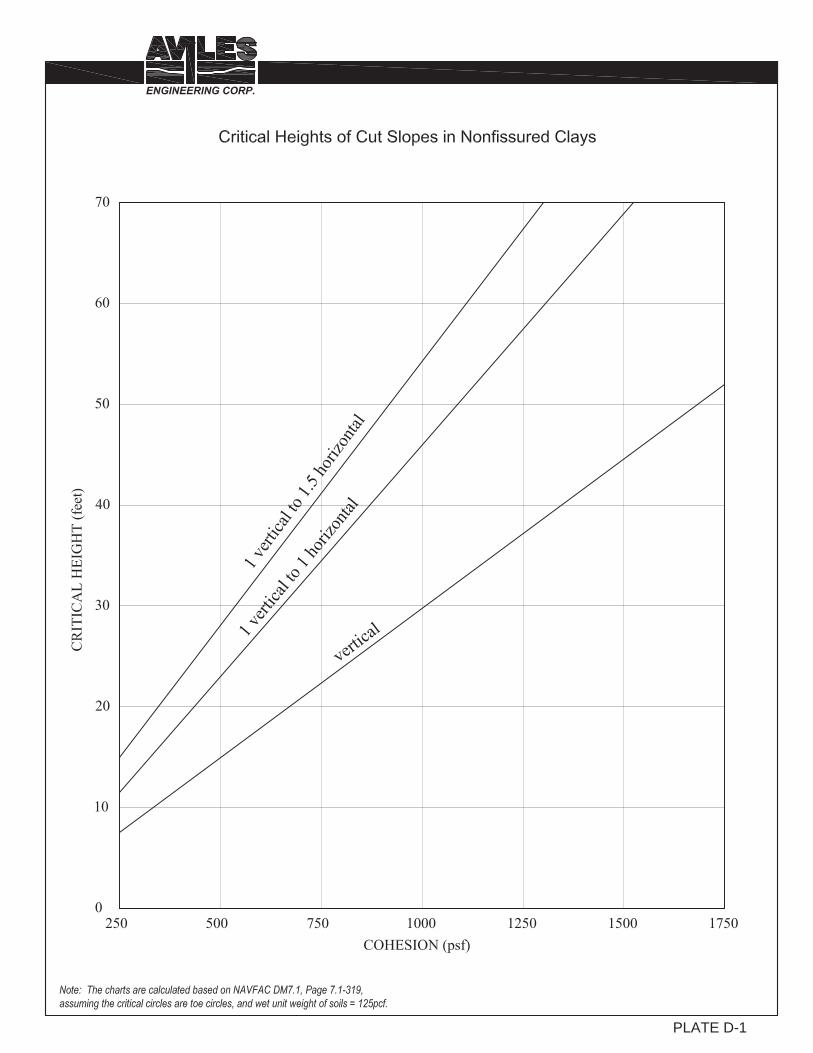
PLATE D-1
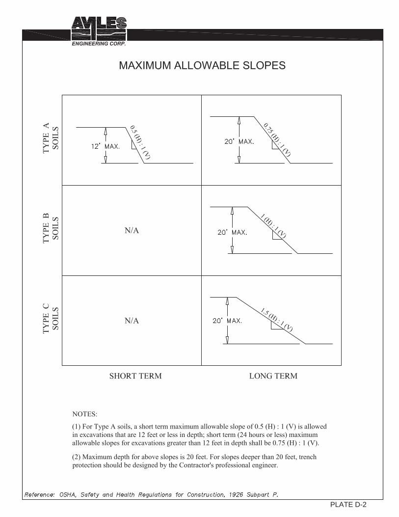
PLATE D-2
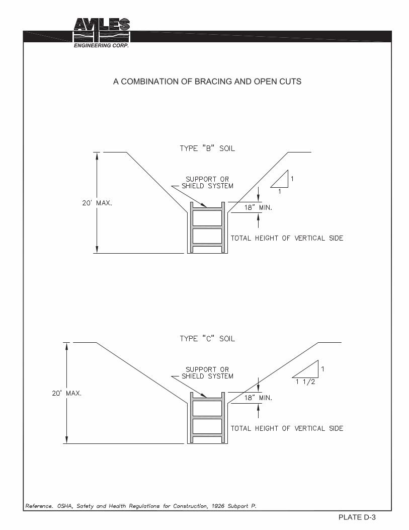
PLATE D-3
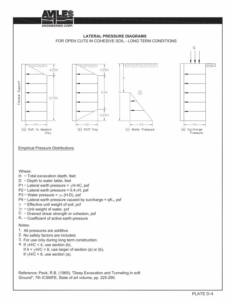
PLATE D-4

PLATE D-5
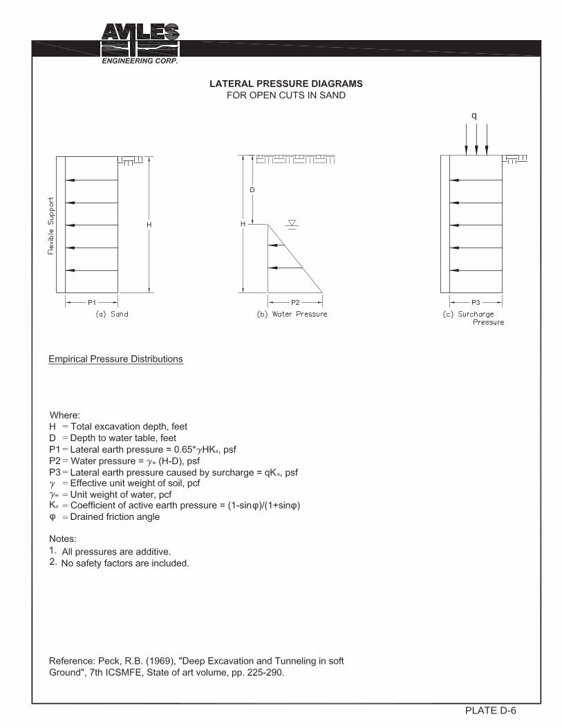
PLATE D-6

PLATE D-7
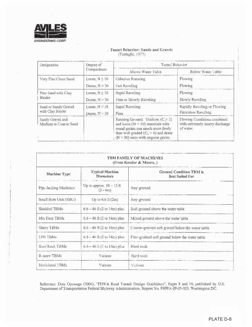
PLATE D-8
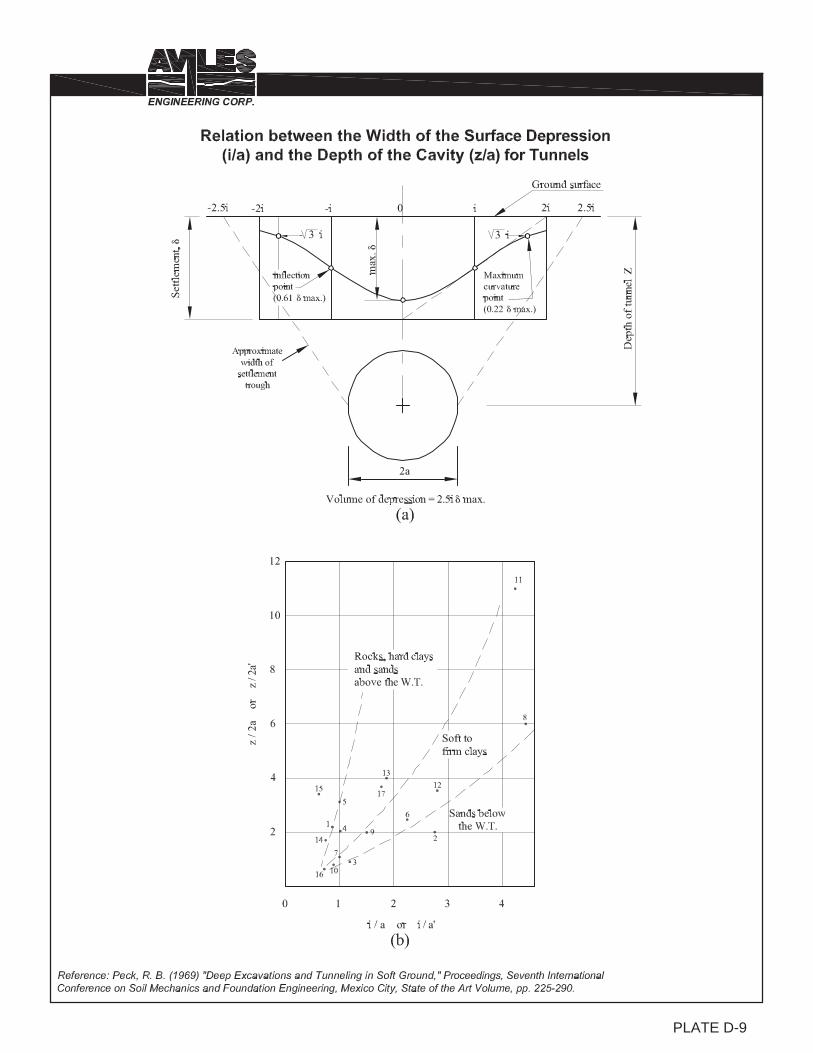
� � � � � � � �PLATE D-9
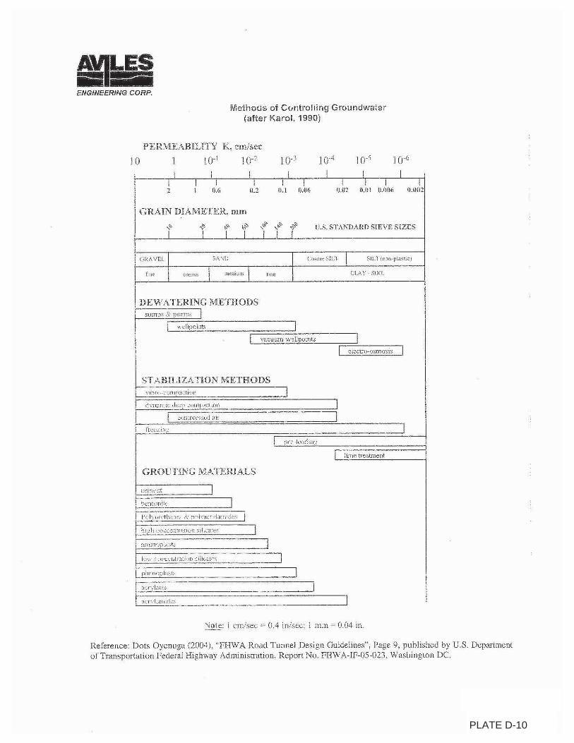
PLATE D-10
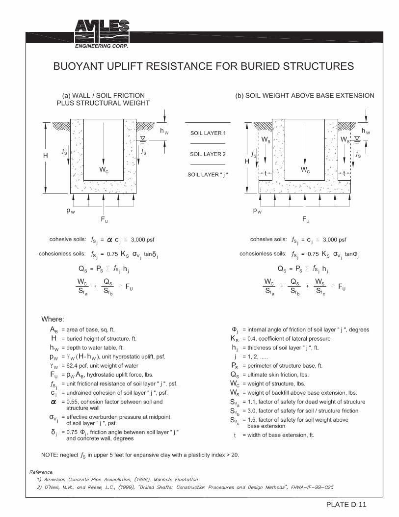
1PLATE D-11

APPENDIX E
Plates E-1 and E-2 Plan and Profile, and Canal Cross Section Exhibits prepared by TWE, dated January 24, 2019
Plate E-3 Design Soil Parameters for Slope Stability Analyses Plates E-4 to E-9 Slope Stability Analysis for East Bank of Upstream Cross Section at Station
0+81.49, based on Boring B-46
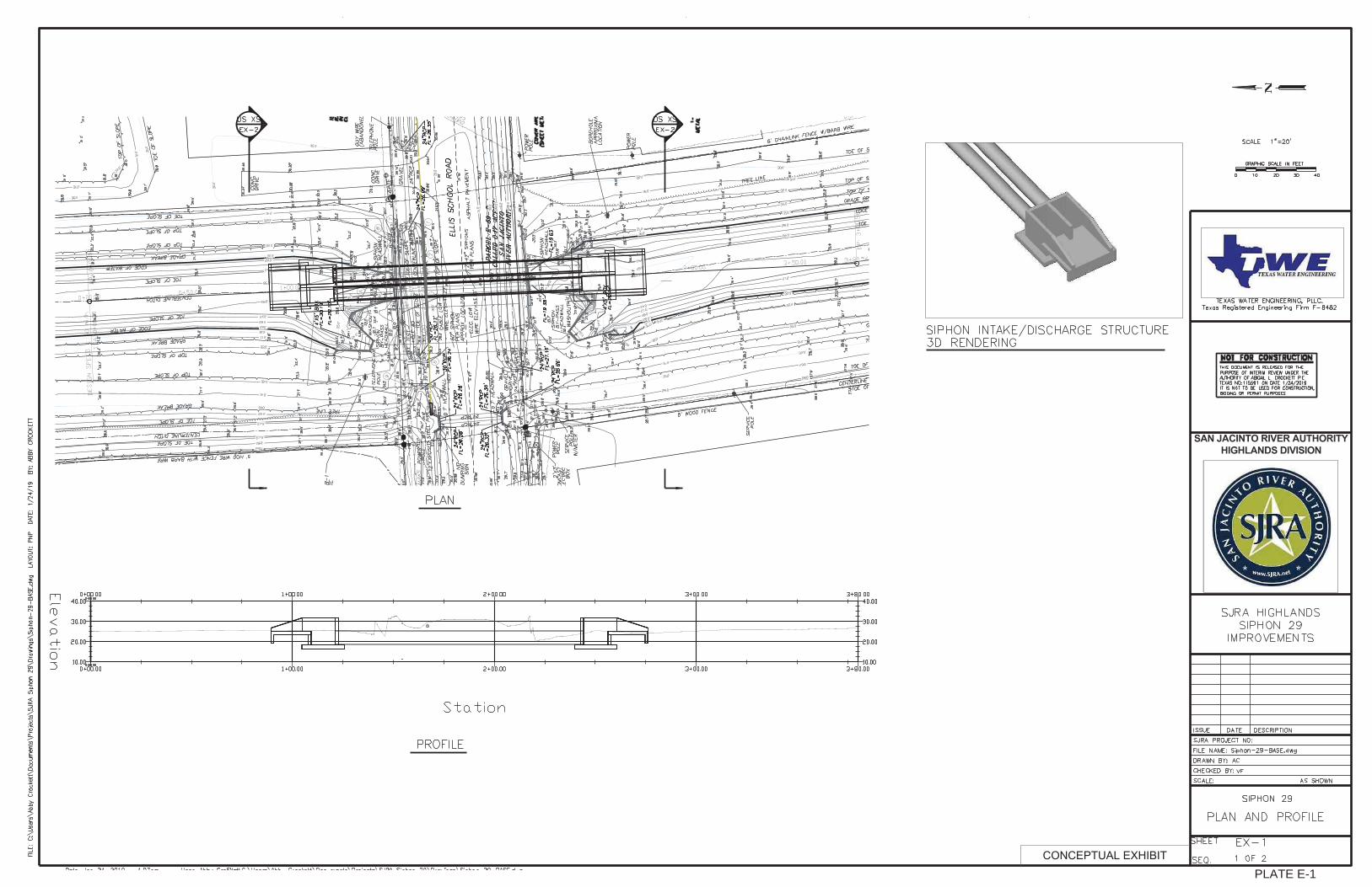
PLATE E-1

PLATE E-2
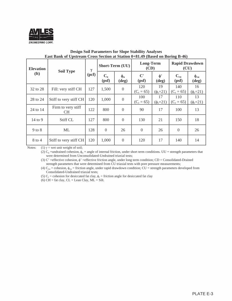
Design Soil Parameters for Slope Stability Analyses East Bank of Upstream Cross Section at Station 0+81.49 (Based on Boring B-46)
Elevation(ft) Soil Type
(pcf)
Short-Term (UU) Long-Term(CD)
Rapid Drawdown (CU)
Cu(psf)
u(deg)
C'(psf)
'(deg)
Ccu(psf)
cu(deg)
32 to 28 Fill: very stiff CH 127 1,500 0 120 (Cr = 65)
19 ( r=21)
140 (Cr = 65)
16 ( r=21)
28 to 24 Stiff to very stiff CH 120 1,000 0 100 (Cr = 65)
17 ( r=21)
110 (Cr = 65)
13 ( r=21)
24 to 14 Firm to very stiff CH 122 800 0 90 17 100 13
14 to 9 Stiff CL 127 800 0 130 21 150 18
9 to 8 ML 128 0 26 0 26 0 26
8 to 4 Stiff to very stiff CH 120 1,000 0 120 17 140 14
Notes: (1) = wet unit weight of soil; (2) Cu =undrained cohesion, u = angle of internal friction, under short term conditions. UU = strength parameters that
were determined from Unconsolidated-Undrained triaxial tests; (3) C’ =effective cohesion, ’ =effective friction angle, under long term condition; CD = Consolidated-Drained
strength parameters that were determined from CU triaxial tests with pore pressure measurements; (4) Ccu = cohesion, cu = friction angle, under rapid drawdown condition; CU = strength parameters developed from
Consolidated-Undrained triaxial tests; (5) Cr = cohesion for desiccated fat clay, r = friction angle for desiccated fat clay (6) CH = fat clay, CL = Lean Clay, ML = Silt.
PLATE E-3

6.047
Distance (ft)
0 10 20 30 40 50 60 70 80 90 100
Ele
vatio
n (f
t)
4
9
14
19
24
29
34
39
Stiff CL, r = 127 pcf, Cu = 800 psf, Phiu = 0 deg
G155-18 HIGHLANDS SOUTH CANAL SIPHON 29 IMPROVEMENTS - WO#2SLOPE STABILITY ANALYSIS FOR EAST BANK OF UPSTREAM CROSS SECTION AT STATION 0+81.49 SHORT TERM (GLOBAL SLIDE) CONDITION, BASED ON BORING B-46
ML, r = 128 pcf, C' = 0 psf, Phi' = 26 deg
12.3
Firm to very stiff CH, r = 122 pcf, Cu = 800 psf, Phicu = 0 deg
Stiff to very stiff CH, r = 120 pcf, Cu = 1,000 psf, Phiu = 0 deg
(1) Fill: very stiff CH, r = 127 pcf, Cu = 1,500 psf, Phiu = 0 deg
Stiff to very stiff CH, r = 120 pcf, Cu = 1,000 psf, Phiu = 0 deg
(1)Ordinary WSE = 30 feet
300 psf Construction Surcharge
13.2
PLATE E-4
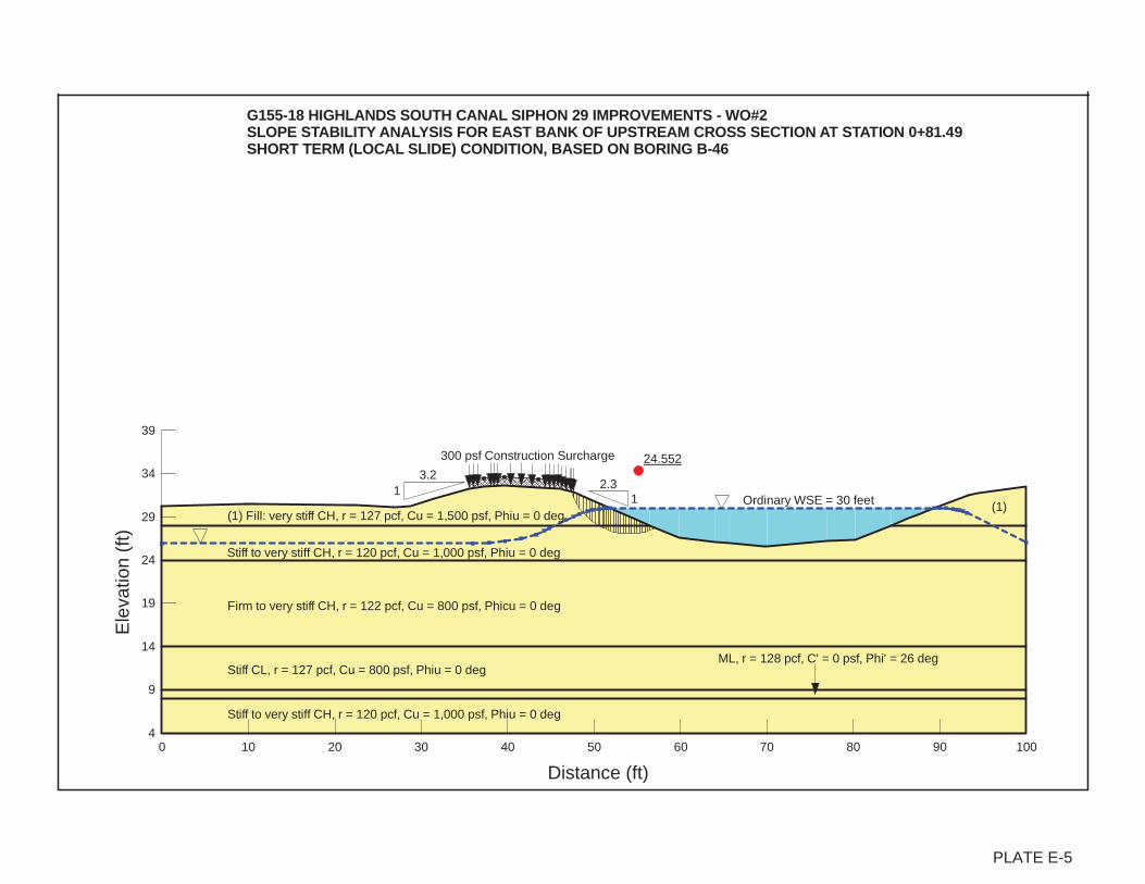
24.552
Distance (ft)
0 10 20 30 40 50 60 70 80 90 100
Ele
vatio
n (f
t)
4
9
14
19
24
29
34
39
Stiff CL, r = 127 pcf, Cu = 800 psf, Phiu = 0 deg
G155-18 HIGHLANDS SOUTH CANAL SIPHON 29 IMPROVEMENTS - WO#2SLOPE STABILITY ANALYSIS FOR EAST BANK OF UPSTREAM CROSS SECTION AT STATION 0+81.49 SHORT TERM (LOCAL SLIDE) CONDITION, BASED ON BORING B-46
ML, r = 128 pcf, C' = 0 psf, Phi' = 26 deg
12.3
Firm to very stiff CH, r = 122 pcf, Cu = 800 psf, Phicu = 0 deg
Stiff to very stiff CH, r = 120 pcf, Cu = 1,000 psf, Phiu = 0 deg
(1) Fill: very stiff CH, r = 127 pcf, Cu = 1,500 psf, Phiu = 0 deg
Stiff to very stiff CH, r = 120 pcf, Cu = 1,000 psf, Phiu = 0 deg
(1)Ordinary WSE = 30 feet
300 psf Construction Surcharge
3.21
PLATE E-5
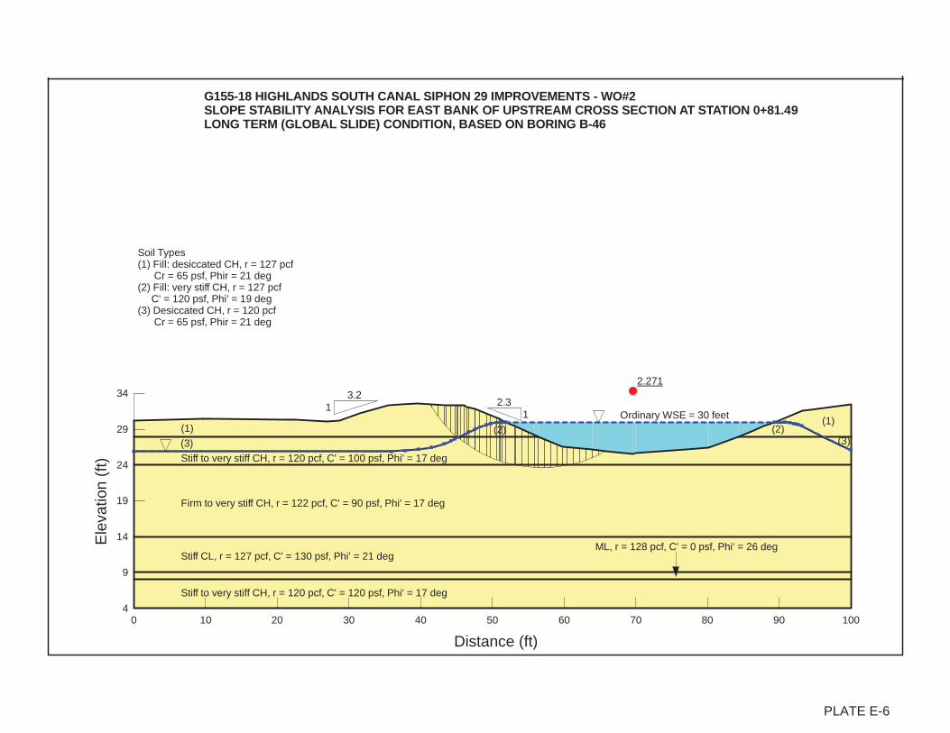
2.271
Distance (ft)
0 10 20 30 40 50 60 70 80 90 100
Ele
vatio
n (f
t)
4
9
14
19
24
29
34
Stiff CL, r = 127 pcf, C' = 130 psf, Phi' = 21 deg
G155-18 HIGHLANDS SOUTH CANAL SIPHON 29 IMPROVEMENTS - WO#2SLOPE STABILITY ANALYSIS FOR EAST BANK OF UPSTREAM CROSS SECTION AT STATION 0+81.49 LONG TERM (GLOBAL SLIDE) CONDITION, BASED ON BORING B-46
ML, r = 128 pcf, C' = 0 psf, Phi' = 26 deg
12.3
Firm to very stiff CH, r = 122 pcf, C' = 90 psf, Phi' = 17 deg
(3)
(1)
Stiff to very stiff CH, r = 120 pcf, C' = 120 psf, Phi' = 17 deg
(1)
(3)
Stiff to very stiff CH, r = 120 pcf, C' = 100 psf, Phi' = 17 deg
Soil Types(1) Fill: desiccated CH, r = 127 pcf Cr = 65 psf, Phir = 21 deg(2) Fill: very stiff CH, r = 127 pcf C' = 120 psf, Phi' = 19 deg(3) Desiccated CH, r = 120 pcf Cr = 65 psf, Phir = 21 deg
(2) (2)Ordinary WSE = 30 feet
3.21
PLATE E-6
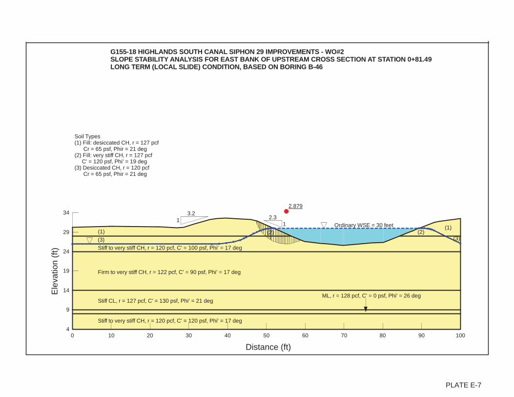
2.879
Distance (ft)
0 10 20 30 40 50 60 70 80 90 100
Ele
vatio
n (f
t)
4
9
14
19
24
29
34
Stiff CL, r = 127 pcf, C' = 130 psf, Phi' = 21 deg
G155-18 HIGHLANDS SOUTH CANAL SIPHON 29 IMPROVEMENTS - WO#2SLOPE STABILITY ANALYSIS FOR EAST BANK OF UPSTREAM CROSS SECTION AT STATION 0+81.49 LONG TERM (LOCAL SLIDE) CONDITION, BASED ON BORING B-46
ML, r = 128 pcf, C' = 0 psf, Phi' = 26 deg
12.3
Firm to very stiff CH, r = 122 pcf, C' = 90 psf, Phi' = 17 deg
(3)
(1)
Stiff to very stiff CH, r = 120 pcf, C' = 120 psf, Phi' = 17 deg
(1)
(3)
Stiff to very stiff CH, r = 120 pcf, C' = 100 psf, Phi' = 17 deg
Soil Types(1) Fill: desiccated CH, r = 127 pcf Cr = 65 psf, Phir = 21 deg(2) Fill: very stiff CH, r = 127 pcf C' = 120 psf, Phi' = 19 deg(3) Desiccated CH, r = 120 pcf Cr = 65 psf, Phir = 21 deg
(2) (2)Ordinary WSE = 30 feet
3.21
PLATE E-7
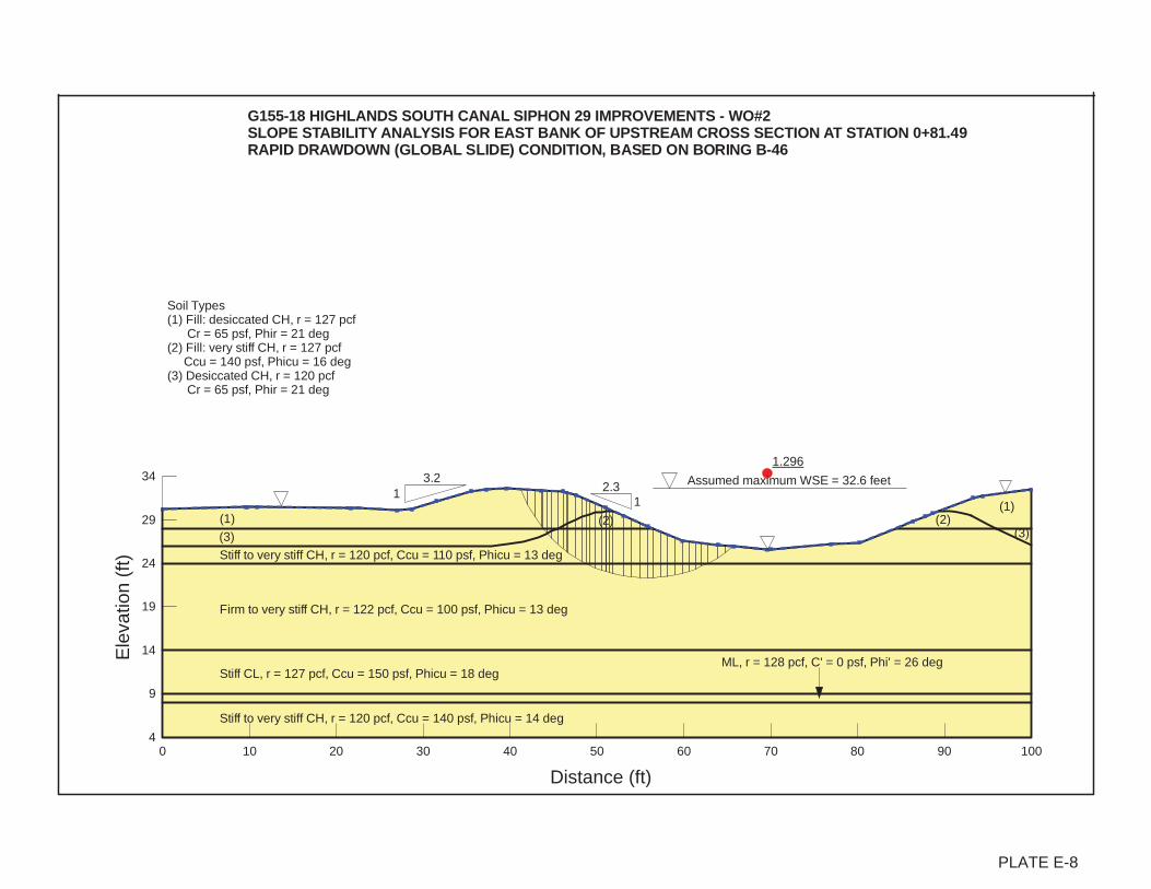
1.296
Distance (ft)
0 10 20 30 40 50 60 70 80 90 100
Ele
vatio
n (f
t)
4
9
14
19
24
29
34
Stiff CL, r = 127 pcf, Ccu = 150 psf, Phicu = 18 deg
G155-18 HIGHLANDS SOUTH CANAL SIPHON 29 IMPROVEMENTS - WO#2SLOPE STABILITY ANALYSIS FOR EAST BANK OF UPSTREAM CROSS SECTION AT STATION 0+81.49 RAPID DRAWDOWN (GLOBAL SLIDE) CONDITION, BASED ON BORING B-46
ML, r = 128 pcf, C' = 0 psf, Phi' = 26 deg
12.3
Firm to very stiff CH, r = 122 pcf, Ccu = 100 psf, Phicu = 13 deg
(3)
(1)
Stiff to very stiff CH, r = 120 pcf, Ccu = 140 psf, Phicu = 14 deg
(1)
(3)
Stiff to very stiff CH, r = 120 pcf, Ccu = 110 psf, Phicu = 13 deg
Soil Types(1) Fill: desiccated CH, r = 127 pcf Cr = 65 psf, Phir = 21 deg(2) Fill: very stiff CH, r = 127 pcf Ccu = 140 psf, Phicu = 16 deg(3) Desiccated CH, r = 120 pcf Cr = 65 psf, Phir = 21 deg
(2) (2)
Assumed maximum WSE = 32.6 feet3.21
PLATE E-8

1.785
Distance (ft)
0 10 20 30 40 50 60 70 80 90 100
Ele
vatio
n (f
t)
4
9
14
19
24
29
34
Stiff CL, r = 127 pcf, Ccu = 150 psf, Phicu = 18 deg
G155-18 HIGHLANDS SOUTH CANAL SIPHON 29 IMPROVEMENTS - WO#2SLOPE STABILITY ANALYSIS FOR EAST BANK OF UPSTREAM CROSS SECTION AT STATION 0+81.49 RAPID DRAWDOWN (LOCAL SLIDE) CONDITION, BASED ON BORING B-46
ML, r = 128 pcf, C' = 0 psf, Phi' = 26 deg
12.3
Firm to very stiff CH, r = 122 pcf, Ccu = 100 psf, Phicu = 13 deg
(3)
(1)
Stiff to very stiff CH, r = 120 pcf, Ccu = 140 psf, Phicu = 14 deg
(1)
(3)
Stiff to very stiff CH, r = 120 pcf, Ccu = 110 psf, Phicu = 13 deg
Soil Types(1) Fill: desiccated CH, r = 127 pcf Cr = 65 psf, Phir = 21 deg(2) Fill: very stiff CH, r = 127 pcf Ccu = 140 psf, Phicu = 16 deg(3) Desiccated CH, r = 120 pcf Cr = 65 psf, Phir = 21 deg
(2) (2)
Assumed maximum WSE = 32.6 feet3.21
PLATE E-9