Geotechnical Investigation for Balila - Omadara Road in South Kordufan State
Upload
khangminh22Category
view
0download
0
AAPPPPEENNDDIIXX DD GGEEOOTTEECCHHNNIICCAALL IINNVVEESSTTIIGGAATTIIOONN

Geotechnical Engineering Engineering Geology
Storm Water Management Construction Observation & Testing Services
1600 Willow Pass Court • Concord, CA 94520 • Tel 925.688.1001
Serving Northern and Central California, Sacramento, and Central Valley Regions www.sfandb.com
104-126.rpt
March 4, 2016 Mr. John Compaglia KB Home 5000 Executive Parkway, Suite 125 San Ramon, CA 94583 Re: Geotechnical Investigation
Telles Property, Hayward, CA SFB Project No.: 104-126
Mr. Compaglia: As requested, Stevens, Ferrone & Bailey Engineering Company, Inc. has performed a geotechnical investigation for the proposed Telles Property residential development project in Hayward, California. The accompanying report presents the results of our field investigation, laboratory tests, and engineering analysis. The geotechnical conditions are discussed, and recommendations for the geotechnical engineering aspects of the project are presented. Conclusions and recommendations contained herein are based upon applicable standards of our profession at the time this report has been prepared. Should you have any questions or require additional information, please do not hesitate to contact me. Sincerely, Stevens, Ferrone & Bailey Engineering Company, Inc. Ken Ferrone President TC/JB/KCF:tc\encl. Copies: Addressee (1 by email)

Geotechnical Engineering Engineering Geology
Storm Water Management Construction Observation & Testing Services
1600 Willow Pass Court • Concord, CA 94520 • Tel 925.688.1001
Serving Northern and Central California, Sacramento, and Central Valley Regions www.sfandb.com
104-126.rpt
March 4, 2016
GEOTECHNICAL INVESTIGATION TELLES PROPERTY RESIDENTIAL DEVELOPMENT
HAYWARD, CALIFORNIA SFB PROJECT NO. 104-126
Prepared For:
KB Home 5000 Executive Parkway, Suite 125
San Ramon, CA 94583
Prepared By:
Stevens, Ferrone & Bailey Engineering Company, Inc.
Taiming Chen, P.E., G.E. Kenneth C. Ferrone, P.E., G.E., C.E.G. Civil/Geotechnical Engineer Civil/Geotechnical Engineer
Certified Engineering Geologist

Stevens, Ferrone & Bailey Engineering Company, Inc. i Telles Property, 104-126.rpt March 4, 2016
TABLE OF CONTENTS
1.0 INTRODUCTION..............................................................................................................1
2.0 SCOPE OF WORK............................................................................................................2
3.0 SITE INVESTIGATION ...................................................................................................3
3.1 Surface ....................................................................................................................3 3.2 Subsurface ..............................................................................................................4 3.3 Groundwater ..........................................................................................................4 3.4 Hydrologic Soil Group ...........................................................................................4 3.5 Geology and Seismicity ..........................................................................................5 3.6 Liquefaction ............................................................................................................6
4.0 CONCLUSIONS AND RECOMMENDATIONS ...........................................................7
4.1 Earthwork ...............................................................................................................8 4.1.1 Clearing and Site Preparation ..................................................................8 4.1.2 Existing Fill and Soil Re-Compaction ......................................................9 4.1.3 Subgrade Preparation .............................................................................10 4.1.4 Fill Material ..............................................................................................10 4.1.5 Compaction ...............................................................................................10 4.1.6 Utility Trench Backfill .............................................................................11 4.1.7 Exterior Flatwork ....................................................................................11 4.1.8 Construction During Wet Weather Conditions ....................................12 4.1.9 Surface Drainage, Irrigation, and Landscaping ...................................12 4.1.10 Storm Water Runoff Structures .............................................................13 4.1.11 Future Maintenance.................................................................................15 4.1.12 Additional Recommendations .................................................................15
4.2 Foundation Support .............................................................................................15 4.2.1 Post-Tensioned Slabs ...............................................................................15 4.2.2 Retaining Walls and Soundwalls ............................................................17 4.2.3 Seismic Design Criteria ...........................................................................20
4.3 Pavements .............................................................................................................20
5.0 CONDITIONS AND LIMITATIONS............................................................................22

Stevens, Ferrone & Bailey Engineering Company, Inc. ii Telles Property, 104-126.rpt March 4, 2016
TABLE OF CONTENTS
(Continued) FIGURES 1 Site Plan APPENDICES A Field Investigation A-1
Figure A-1, Key to Exploratory Boring Logs Exploratory Boring Logs (SFB-1 and SFB-2)
B Laboratory Investigation B-1 C Logs of Previous Field Explorations and Results of Previous Lab Testing D ASFE Guidelines

Stevens, Ferrone & Bailey Engineering Co., Inc. Page 1 of 23 Telles Property, 104-126.rpt March 4, 2016
1.0 INTRODUCTION
This report presents the results of our geotechnical investigation for the proposed residential development at the Telles Property located at the northwestern corner of Mission Blvd and Sorenson Road in Hayward in Hayward, California as shown on the Site Plan, Figure 1. The purpose of our investigation was to evaluate the geotechnical conditions at the site and provide recommendations regarding the geotechnical engineering aspects of the project. Based on the information indicated on the Site Plan, as well as information provided by KB Home, it is our understanding that the project will consist of developing approximately 2.7 acres of land for seven townhome buildings that consist of 35 residential units. Nominal grading is anticipated. Associated underground utilities and roadways will be constructed. The existing structures and facilities at the site will be demolished prior to new construction. A remainder parcel will be located at the south end of the site for a possible future apartment development. The conclusions and recommendations provided in this report are based upon the information presented above; Stevens, Ferrone & Bailey Engineering Company, Inc. (SFB) should be consulted if any changes to the project occur to assess if the changes affect the validity of this report.

Stevens, Ferrone & Bailey Engineering Co., Inc. Page 2 of 23 Telles Property, 104-126.rpt March 4, 2016
2.0 SCOPE OF WORK
This investigation included the following scope of work:
Reviewing published and unpublished geotechnical and geological literature relevant to the site;
Reviewing a previous geotechnical investigation report prepared by Alan Kropp & Associates (AKA) and dated March 27, 2006 for the site, including the results of eight previous exploratory borings to depths of about 11-1/2 to 20-1/2 feet;
Performing reconnaissance of the site and surrounding area; Performing a subsurface exploration program, including drilling two supplemental
exploratory borings to a maximum depth of about 31-1/2 feet; Performing laboratory testing of samples retrieved from the borings; Performing engineering analysis of the field and laboratory data; and Preparing this report.
The data obtained and the analyses performed were for the purpose of providing geotechnical design and construction criteria for site earthwork, underground utilities, drainage, building foundations, retaining walls and soundwalls, and pavements. Toxicity potential assessment of onsite materials or groundwater (including mold) and flooding evaluations were beyond our scope of work.

Stevens, Ferrone & Bailey Engineering Co., Inc. Page 3 of 23 Telles Property, 104-126.rpt March 4, 2016
3.0 SITE INVESTIGATION
Reconnaissance of the site and surrounding area was performed on February 16 and 24, 2016. Subsurface exploration was performed using a truck-mounted drill rig equipped with 4-inch diameter, continuous flight, solid stem augers. Two supplemental exploratory borings were drilled on February 24, 2016 by SFB to a maximum depth of about 31-1/2 feet. Previously, eight exploratory borings were performed at the site by AKA on December 29, 2005. It is also our understanding that four monitoring wells were previously installed by Aqua Science Engineers (ASE) within an area at the south end of the site. Based on our field measurements, the bottoms of the well casings extended to depths of about 59 to 63 feet. The actual construction and condition of these wells are unknown. The approximate locations of SFB’s borings and the previous borings and monitoring wells by others are shown on the Site Plan, Figure 1. Logs of SFB’s borings and details regarding SFB’s field investigation are included in Appendix A. The results of SFB’s laboratory tests are discussed in Appendix B. Logs of the previous borings and results of previous laboratory testing on onsite soils by others are provided in Appendix C for reference. It should be noted that changes in the surface and subsurface conditions can occur over time as a result of either natural processes or human activity and may affect the validity of the conclusions and recommendations in this report.
3.1 Surface
At the time of our investigation and as shown on Figure 1, the site was bounded by Mission Blvd on the northeast, Sorenson Road on the southeast, existing residential developments on the southwest, and existing commercial developments on northwest. The site is a parallelogram in shape, sloped very slightly downward toward the south, and has a plan area of about 2.7 acres with maximum dimensions of about 470 feet by 175 feet. The site was occupied by a large strip mall building at the northern three-quarters of the site and two small retail shop buildings at the southern one-quarter of the site. The surrounding areas were covered with asphalt concrete as parking and driveway. Landscape strips and planters were also located throughout the site. It is our understanding that, according to a previous geotechnical investigation report by AKA, two underground storage tanks (UST) were reportedly removed from the area at the south end of the site. The approximate locations of the previous UST removals (from the previous groundwater elevation contour map dated 6/30/99 by ASE) are shown on Figure 1. The details of the previous UST removal and excavation backfill are unknown. The backfill of the UST’s may extend to depths of about 11 feet below existing ground surface.

Stevens, Ferrone & Bailey Engineering Co., Inc. Page 4 of 23 Telles Property, 104-126.rpt March 4, 2016
3.2 Subsurface
The near-surface soil materials encountered in our borings and previous borings by others at the site (below existing pavements) generally consisted of stiff to hard clays that extended to the maximum depth explored of about 31-1/2 feet. Our Borings SFB-1 and SFB-2 also encountered clayey fills at surface that extended, respectively, to depths of about 7 and 3 feet. In addition, Boring B-8 by others also reported clayey and sandy UST backfills that extended to a depth of about 11 feet. The fills and UST backfills may be heterogeneous, and potentially weak and compressible; it is not known whether they were placed and compacted in accordance with acceptable engineering standards. According to the results of laboratory testing, the near-surface more clayey soils have medium to high plasticity and moderate to high expansion potential. Detailed descriptions of the materials encountered in our exploratory borings are presented on the boring logs in Appendix A. Our attached boring logs and related information depict location specific subsurface conditions encountered during our field investigation. The approximate locations of our borings were determined using pacing or landmark references and should be considered accurate only to the degree implied by the method used.
3.3 Groundwater
No groundwater was encountered in the borings by SFB and others to the maximum depth explored of about 31-1/2 feet. Our borings were backfilled with lean cement grout in accordance with Alameda County Public Work Agency requirements prior to leaving the site. Groundwater tables were measured by SFB in the onsite monitoring wells at depths of about 52 to 55 feet. According to the previous groundwater elevation contour map dated 6/30/99 by ASE, groundwater levels were observed in the monitoring wells at a depth of about 50 feet. Historically, groundwater in the vicinity of the site has been measured at depths of about 35 to 40 feet1. It should be noted that our borings might not have been left open for a sufficient period of time to establish equilibrium groundwater conditions. In addition, fluctuations in the groundwater level could occur due to change in seasons, variations in rainfall, and other factors.
3.4 Hydrologic Soil Group
The surface soils of the site have been mapped as Rincon clay loam (0 to 2 percent slopes) and were assigned to Hydrologic Soil Groups C by USDA Natural Resources Conservation Service (NRCS); the soils have been categorized as having moderately low to moderately high transmission rates (approximately 0.06 to 0.2 inches per hour). The Group C soil is defined as 1State of California, 2006, Seismic Hazard Zone Report for the Hayward 7.5-Minute Quadrangle, Alameda County, California, CGS Seismic Hazard Zone Report 091.

Stevens, Ferrone & Bailey Engineering Co., Inc. Page 5 of 23 Telles Property, 104-126.rpt March 4, 2016
having a slow infiltration rate when thoroughly wet and may consist chiefly of soils having a layer that impedes the downward movement of water or soils of moderately fine texture or fine texture.
3.5 Geology and Seismicity
According to Helley and Graymer (1997)2, the site (below pavement sections and surficial fills if any) is underlain by Pleistocene alluvial fan and fluvial deposits that have been generally described as brown dense gravely and clayey sand or clayey gravel that fines upward to sandy clay. The project site is located in the San Francisco Bay Area that is considered one of the most seismically active regions in the United States. Significant earthquakes have occurred in the San Francisco Bay Area and are believed to be associated with crustal movements along a system of sub-parallel fault zones that generally trend in a northwesterly direction. According to the Earthquake Zones of Required Investigation Map of the Hayward Quadrangle (2012), the site is not located in an earthquake fault zone as designated by the State of California3. Earthquake intensities will vary throughout the San Francisco Bay Area, depending upon numerous factors including the magnitude of earthquake, the distance of the site from the causative fault, and the type of materials underlying the site. The U.S. Geological Survey (2008) indicated that there is a 63 percent chance of at least one magnitude 6.7 or greater earthquake striking the San Francisco Bay region between 2008 and 20374. Therefore, the site will probably be subjected to at least one moderate to severe earthquake that will cause strong ground shaking. According to the Probabilistic Seismic Hazard Analysis (NSHMP PSHA) interactive deaggregation model developed by U.S. Geological Survey (2008), the site has a 10% probability of exceeding a peak ground acceleration of about 0.68g in 50 years (design basis ground motion based on stiff soil site condition; mean return time of 475 years). The actual ground surface acceleration might vary depending upon the local seismic characteristics of the underlying bedrock and the overlying unconsolidated soils.
2Helley & Graymer, 1997, Quaternary Geology of Alameda County, and Parts of Contra Costa, Santa Clara, San Mateo, San Francisco, Stanislaus, and San Joaquin Counties, California: A Digital Database, USGS Open File Report 97-97. 3California Geologic Survey, 2012, Earthquake Zones of Required Investigation, Hayward Quadrangle. 4Field, Edward H., Milner, Kevin R., and the 2007 Working Group on California Earthquake Probabilities, 2008, Forecasting California's earthquakes; what can we expect in the next 30 years?: U.S. Geological Survey, Fact Sheet 2008-3027, 4 p.

Stevens, Ferrone & Bailey Engineering Co., Inc. Page 6 of 23 Telles Property, 104-126.rpt March 4, 2016
3.6 Liquefaction
Soil liquefaction is a phenomenon primarily associated with saturated, cohesionless, soil layers located close to the ground surface. These soils lose strength during cyclic loading, such as imposed by earthquakes. During the loss of strength, the soil acquires mobility sufficient to permit both horizontal and vertical movements. Soils that are most susceptible to liquefaction are clean, loose, uniformly graded, saturated, fine-grained sands that lie close to the ground surface. According to ABAG and the U.S. Geological Survey, the site is located in an area that has been characterized as having moderate liquefaction susceptibility5,6. According to the Seismic Hazard Zones Map of the Hayward Quadrangle, the site is not located in a liquefaction seismic hazard zone as designated by the State of California7. Based on our review of available information and the results of field exploration, it is our opinion that the potential for ground surface damage at the site resulting from liquefaction is low due to the lack of liquefiable soils and relatively deep groundwater (having a reported historical high of about 35 to 40 feet deep and being measured at about 50 feet deep in the onsite monitoring wells by SFB at the time of our field exploration and also by others in 1999) at the site.
5Witter, Knudsen, Sowers, Wentworth, Koehler, and Randolph, 2006, Maps of Quaternary Deposits and Liquefaction Susceptibility in the Central San Francisco Bay Region, California”, USGS Open File Report 2006-1037. 6Knudsen, Sowers, Witter, Wentworth, and Helly, 2000, “Preliminary Maps of Quaternary Deposits and Liquefaction Susceptibility, Nine-County San Francisco Bay Region, California”, USGS Open File Report 00-444. 7State of California, Seismic Hazard Zones, Hayward Quadrangle, Official Map, Released: July 2, 2003.

Stevens, Ferrone & Bailey Engineering Co., Inc. Page 7 of 23 Telles Property, 104-126.rpt March 4, 2016
4.0 CONCLUSIONS AND RECOMMENDATIONS
It is our opinion that the site is suitable for the proposed project from a geotechnical engineering standpoint. The conclusions and recommendations presented in this report should be incorporated in the design and construction of the project to reduce soil or foundation related issues. The following are the primary geotechnical considerations for development of the site. EXISTING FILL MATERIALS: As described previously, our Borings SFB-1 and SFB-2 encountered clayey fills at the surface that extended, respectively, to depths of about 7 and 3 feet. In addition, Boring B-8 by others also reported clayey and sandy UST backfills that extended to a depth of about 11 feet. The fills and UST backfills may be heterogeneous, and potentially weak and compressible; it is not known whether they were placed and compacted in accordance with acceptable engineering standards. In addition, the removal of the existing structures and improvements at the site will likely result in loosening of the surface soils in the upper 2 to 3 feet. In order to reduce the potential for damaging differential settlement of overlying improvements (such as new fills, building foundations, driveways, exterior flatwork, and pavements), we recommend that these weak fills and soils be completely removed and re-compacted. We estimate the process can consist of over-excavating two feet, scarifying and re-compacting the bottom 12 inches in-place, and replacing the excavation with compacted fill materials. Deeper removal will be required, however, within the previous UST removal areas and in the area of Boring SFB-1; the actual depth and lateral extent of fills should be determined at the time of clearing using a backhoe or excavator. There would be no need to over-excavate fills and soils within areas that do not support improvements, such as within planned open spaces. The over-excavations should extend to depths where competent soil is encountered. The over-excavation and re-compaction should also extend at least 5 feet beyond building footprints and at least 3 feet beyond exterior flatwork (including driveways) and pavement wherever possible. Where the over-excavation limits abut adjacent property, SFB should be consulted to determine the actual vertical and lateral extent of over-excavation so that adjacent property is not adversely impacted. Over-excavations should be performed so that no more than 5 feet of differential fill thickness exists below the proposed building foundations. The removed fill and soil materials can be used as new fill provided it is placed and compacted in accordance with the recommendations presented in this report. The extent of the removal and re-compaction will vary across the site and should be determined in the field by SFB at the time of the earthwork operations.

Stevens, Ferrone & Bailey Engineering Co., Inc. Page 8 of 23 Telles Property, 104-126.rpt March 4, 2016
EXPANSION POTENTIAL: The more clayey, moderately to highly expansive surface soil materials will be subjected to volume changes during seasonal fluctuations in moisture content. To reduce the potential for post-construction distress to the proposed structures resulting from swelling and shrinkage of these materials, we recommend that the proposed residences be supported on a post-tensioned slab foundation system that is designed to reduce the impact of the expansive soils. It should be noted that special design considerations will be required for exterior slabs. CORROSION POTENTIAL: Two onsite soil samples will be tested for pH (ASTM D4972), chlorides (ASTM D4327), sulfates (ASTM D4327), sulfides (ASTM D4658M), resistivity at 100% saturation (ASTM G57), and Redox potential (ASTM D1498) for use in evaluating the potential for corrosion on concrete and buried metal such as utilities and reinforcing steel. The results of these tests area included in Appendix B. We recommend these test results be forwarded to your underground contractors, pipeline designers, and foundation designers and contractors. ADDITIONAL RECOMMENDATIONS: Detailed drainage, earthwork, foundation, retaining wall and soundwall, and pavement recommendations for use in design and construction of the project are presented below. We recommend SFB review the design and specifications to verify that the recommendations presented in this report have been properly interpreted and implemented in the design, plans, and specifications. We also recommend SFB be retained to provide consulting services and to perform construction observation and testing services during the construction phase of the project to observe and test the implementation of our recommendations, and to provide supplemental or revised recommendations in the event conditions different than those described in this report are encountered. We are not responsible for misinterpretation of our recommendations.
4.1 Earthwork
4.1.1 Clearing and Site Preparation
The site should be cleared of all obstructions including any existing structures and their entire foundation systems, existing utilities and pipelines and their associated backfill, designated trees and their associated entire root systems, fencing, and debris. Holes resulting from the removal of underground obstructions extending below the proposed finish grade should be cleared and backfilled with fill materials as specified in Section 4.1.4, Fill Material, and compacted to the requirements in Section 4.1.5, Compaction. Tree roots may extend to depths of about 3 to 4 feet. Wells and septic systems, if they exist, should be abandoned in accordance with Alameda County standards.

Stevens, Ferrone & Bailey Engineering Co., Inc. Page 9 of 23 Telles Property, 104-126.rpt March 4, 2016
From a geotechnical standpoint, any existing trench backfill materials, clay or concrete pipes, pavements, and concrete that are removed can be used as new fill onsite provided debris is removed and it is broken up to meet the size requirement for fill material in Section 4.1.4, Fill Material. We recommend fill materials composed of broken up concrete or asphalt concrete not be located within 3 feet of the ground surface in yard areas. Consideration should be given to placing these materials below pavements, directly under building footprints, or in deeper excavations. We recommend backfilling operations for any excavations be performed under the observation and testing of SFB.
4.1.2 Existing Fill and Soil Re-Compaction
As described previously, our Borings SFB-1 and SFB-2 encountered clayey fills at surface that extended, respectively, to depths of about 7 and 3 feet. In addition, Boring B-8 by others also reported clayey and sandy UST backfills that extended to a depth of about 11 feet. The fills and UST backfills may be heterogeneous, and potentially weak and compressible; it is not known whether they were placed and compacted in accordance with acceptable engineering standards. In addition, the removal of the existing structures and improvements at the site will likely result in loosening of the surface soils in the upper 2 to 3 feet. Where these weak fills and soils will not be removed during grading and where proposed improvements including new fills, building foundations, driveways, exterior flatwork, and pavements will be constructed, we recommend these weak fills and soils be completely removed and re-compacted. We estimate the process can consist of over-excavating two feet, scarifying and re-compacting the bottom 12 inches in-place, and replacing the excavation with compacted fill materials. Deeper removal will be required within the previous UST removal areas and in the area of Boring SFB-1; the actual depth and lateral extent of fills should be determined at the time of clearing using a backhoe or excavator. There would be no need to over-excavate the soils within areas that do not support improvements, such as within planned open spaces. The over-excavation should extend to depths where competent soil is encountered. The over-excavation and re-compaction should also extend at least 5 feet beyond building footprints and at least 3 feet beyond exterior flatwork (including driveways) and pavement wherever possible. Where the over-excavation limits abut adjacent property, SFB should be consulted to determine the actual vertical and lateral extent of over-excavation so that adjacent property is not adversely impacted. Over-excavations should be performed so that no more than 5 feet of differential fill thickness exists below the proposed building foundations. The extent of the removal and re-compaction will vary across the site and should be determined in the field by SFB at the time of the earthwork operations.

Stevens, Ferrone & Bailey Engineering Co., Inc. Page 10 of 23 Telles Property, 104-126.rpt March 4, 2016
Removed fill and soil materials may be used as new fill onsite provided it satisfies the recommendations provided in Section 4.1.4, Fill Material. Compaction should be performed in accordance with the recommendations in Section 4.1.5, Compaction.
4.1.3 Subgrade Preparation
After the completion of clearing, site preparation, and weak fill and soil re-compaction, soil exposed in areas to receive improvements (such as structural fill, building foundations, driveways, exterior flatwork, and pavements) should be scarified to a depth of about 12 inches, moisture conditioned to approximately 3 to 5 percent over optimum water content, and compacted to the requirements for structural fill. If building pads or pavement subgrade are allowed to remain exposed to sun, wind, or rain for an extended period of time, or are disturbed by borrowing animals or vehicles, the exposed subgrade or pavement subgrade may need to be reconditioned (moisture conditioned and/or scarified and recompacted) prior to foundation or pavement construction. SFB should be consulted on the need for subgrade reconditioning when the subgrade is left exposed for extended periods of time.
4.1.4 Fill Material
From a geotechnical and mechanical standpoint, onsite soils having an organic content of less than 3 percent by volume can be used as fill. Fill should not contain rocks or lumps larger than 6 inches in greatest dimension with not more than 15 percent larger than 2.5 inches. If required, imported fill should have a plasticity index of 20 or less and have a significant amount of cohesive fines. In addition to the mechanical properties specifications, all imported fill material should have a resistivity (100% saturated) no less than the resistivity for the onsite soils, a pH of between approximately 6.0 and 8.5, a total water soluble chloride concentration less than 300 ppm, and a total water soluble sulfate concentration less than 500 ppm. We recommend import samples be submitted for corrosion and geotechnical testing at least two weeks prior to being brought onsite.
4.1.5 Compaction
Within the upper 5 feet of the finished ground surface, we recommend structural fill be compacted between 88 and 92 percent relative compaction, and structural fill below a depth of 5 feet be compacted to at least 90 percent relative compaction, as determined by ASTM D1557 (latest edition). We recommend the new fill be moisture conditioned approximately 3 to 5 percent over optimum water content. The upper 6 inches of subgrade soils beneath pavements should be compacted to at least 95 percent relative compaction. Fill material should be spread and compacted in lifts not exceeding approximately 8 to 12 inches in uncompacted thickness.

Stevens, Ferrone & Bailey Engineering Co., Inc. Page 11 of 23 Telles Property, 104-126.rpt March 4, 2016
4.1.6 Utility Trench Backfill
Pipeline trenches should be backfilled with fill placed in lifts of approximately 8 inches in uncompacted thickness. Thicker lifts can be used provided the method of compaction is approved by SFB and the required minimum degree of compaction is achieved. Backfill should be placed by mechanical means only. Jetting is not permitted. Onsite trench backfill should be compacted to at least 90 percent relative compaction. Imported sand trench backfill should be compacted to at least 95 percent relative compaction and sufficient water is added during backfilling operations to prevent the soil from "bulking" during compaction. The upper 3 feet of trench backfill in foundation, slab, and pavement areas should be entirely compacted to at least 95 percent relative compaction. To reduce piping and settlement of overlying improvements, we recommend rock bedding and rock backfill (if used) be completely surrounded by a filter fabric such as Mirafi 140N (or equivalent); alternatively, filter fabric would not be necessary if Caltrans Class 2 permeable material is used in lieu of rock bedding and rock backfill. Sand or gravel backfilled trench laterals that extend toward driveways, exterior slabs-on-grade, or under the building foundations, and are located below irrigated landscaped areas such as lawns or planting strips, should be plugged with onsite clays, low strength concrete, or sand/cement slurry. The plug for the trench lateral should be located below the edge of pavement or slabs, and under the perimeter of the foundation. The plug should be at least 24 inches thick, extend the entire width of the trench, and extend from the bottom of the trench to the top of the sand or gravel backfill.
4.1.7 Exterior Flatwork
We recommend that exterior slabs (including patios, sidewalks, and driveways) be placed directly on the properly compacted fills. We do not recommend using aggregate base, gravel, or crushed rock below these improvements. If imported granular materials are placed below these elements, subsurface water can seep through the granular materials and cause the underlying soils to saturate or pipe. Prior to placing concrete, subgrade soils should be moisture conditioned to increase their moisture content to approximately 3 to 5 percent above laboratory optimum moisture (ASTM D-1557). The more expansive clayey soils at the site could be subjected to volume changes during fluctuations in moisture content. As a result of these volume changes, some vertical movement of exterior slabs (such as driveways, sidewalks, patios, exterior flatwork, etc.) should be anticipated. This movement could result in damage to the exterior slabs and might require periodic maintenance or replacement. Adequate clearance should be provided between the

Stevens, Ferrone & Bailey Engineering Co., Inc. Page 12 of 23 Telles Property, 104-126.rpt March 4, 2016
exterior slabs and building elements that overhang these slabs, such as window sills or doors that open outward. Consideration should be given to reinforcing exterior slabs with steel bars in lieu of wire mesh. To reduce potential crack formation, the installation of #4 bars spaced at approximately 18 inches on center in both directions should be considered. Score joints and expansion joints should be used to control cracking and allow for expansion and contraction of the concrete slabs. We recommend appropriate flexible, relatively impermeable fillers be used at all cold/expansion joints. The installation of dowels at all expansion and cold joints will reduce differential slab movements; if used, the dowels should be at least 30 inches long and should be spaced at a maximum lateral spacing of 18 inches. Although exterior slabs that are adequately reinforced will still crack, trip hazards requiring replacement of the slabs will be reduced if the slabs are properly reinforced.
4.1.8 Construction During Wet Weather Conditions
If construction proceeds during or shortly after wet weather conditions, the moisture content of the onsite soils could be significantly above optimum. Consequently, subgrade preparation, placement and/or reworking of onsite soil or fills as structural fill might not be possible. Alternative wet weather construction recommendations can be provided by our representative in the field at the time of construction, if appropriate. All the drainage measures recommended in this report should be implemented and maintained during and after construction, especially during wet weather conditions.
4.1.9 Surface Drainage, Irrigation, and Landscaping
Ponding of surface water must not be allowed on pavements, adjacent to foundations, at the top or bottom of slopes, and at the top or adjacent to retaining walls. Ponding of water should also not be allowed on the ground surface adjacent to or near exterior slabs, including driveways, walkways, and patios. Surface water should not be allowed to flow over the top of slopes, down slope faces, or over retaining walls. We recommend positive surface gradients of at least 2 percent be provided adjacent to foundations to direct surface water away from the foundations and toward suitable discharge facilities. Roof downspouts and landscaping drainage inlets should be connected to solid pipes that discharge the collected water into appropriate water collection facilities. We recommend the surface drainage be designed in accordance with the latest edition of the California Building Code. In order to reduce differential foundation movements, landscaping (where used) should be placed uniformly adjacent to the foundation and exterior slabs. We recommend trees be no closer to the

Stevens, Ferrone & Bailey Engineering Co., Inc. Page 13 of 23 Telles Property, 104-126.rpt March 4, 2016
structure or exterior slabs than half the mature height of the tree; in no case should tree roots be allowed to extend near or below the foundations or exterior slabs. Drainage inlets should be provided within enclosed planter areas and the collected water should be discharged onto pavement, into drainage swales, or into storm water collection systems. In order to reduce the potential for heaving, consideration should be given to lining planting areas and collecting the accumulated surface water in subdrain pipes that discharge to appropriate collection facilities. The drainage should be designed and constructed so that the moisture content of the soils surrounding the foundations do not become elevated and no ponding of water occurs. The inlets should be kept free of debris and be lower in elevation than the adjacent ground surface. We recommend regular maintenance of the drainage systems be performed, including maintenance prior to rainstorms. The inspection should include checking drainage patterns to make sure they are performing properly, making sure drainage systems and inlets are functional and not clogged, and checking that erosion control measures are adequate for anticipated storm events. Immediate repairs should be performed if any of these measures appears to be inadequate. Irrigation should be performed in a uniform, systematic manner as equally as possible on all sides of the foundations and exterior slabs to maintain moist soil conditions. Over-watering must be avoided. To reduce moisture changes in the natural soils and fills in landscaped areas, we recommend that drought resistant plants and low flow watering systems be used. All irrigation systems should be regularly inspected for leakage.
4.1.10 Storm Water Runoff Structures
To satisfy local and state permit requirements, most new development projects must control pollutant sources and reduce, detain, retain, and treat specified amounts of storm water runoff. The types of improvements that are designed to accomplish these goals are known as Post-Construction Requirements (PCR’s) and/or Low Impact Development (LID’s). The intent of these types of improvements is to conserve and incorporate on-site natural features, together with constructed hydrologic controls, to more closely mimic pre-development hydrology and watershed processes.

Stevens, Ferrone & Bailey Engineering Co., Inc. Page 14 of 23 Telles Property, 104-126.rpt March 4, 2016
To aid in the Civil Engineering design and analyses of appropriate treatment facilities, we recommend the onsite soils be categorized as Hydrologic Soil Group C8. Onsite groundwater levels were observed in the previous monitoring wells at depths of about 50 feet. We recommend PCR/LID improvements that are designed to detain or retain water such as bio-swales, porous pavement structures, and water detention basins, be lined with a relatively impermeable membrane in order to reduce water seepage and the potential for damage to other infrastructure improvements (such as pavements, foundations, and walkways). We recommend a relatively impermeable membrane such as STEGO Wrap 15-mil or equivalent be installed below and along the sides of these facilities that direct the collected water into subdrain pipes. The membrane should be lapped and sealed in accordance with the manufacture’s specifications, including taping joints where pipes penetrate the membrane. The soil filter materials within basins and swales will consolidate over time causing long-term ground surface settlement. Additional filling within the basins and swales over time may be needed to maintain design surface elevations. The soil filter materials and associated compaction requirements should be specified by the Civil Engineer and shown in detail on the grading and improvement plans. Sidewalls of earthen swales and basins steeper than 2:1 (horizontal to vertical) will experience downward and lateral movements that can cause significant ground surface movements. The magnitude and rate of movement depends upon the swale and basin backfill material type and compaction. To reduce the potential for damaging movements, we recommend 2:1 sidewall slopes be used or the slopes be appropriately restrained. SFB should be consulted to evaluate the need for sidewall restraint when swales or basins are planned. Where swales and basins are located adjacent to improvements (such as foundations, pavements, curbs, driveways, and sidewalks), the improvements will be susceptible to settlement and lateral movements. To reduce the potential for vertical and lateral movement of the improvements, we recommend either the improvements be setback beyond a 1:1 (horizontal to vertical) plane projected upward from the bottom of the swale/basin or lateral restraint (such as deepened curbs or walls) be provided that is designed to resist the soil’s lateral pressures. In order to resist the lateral pressures, the lateral restraint will need to extend below the bottom of the swale/basin and should be engineered. Where foundations are located near swales or basins, we recommend the foundations be extended below the projected 1:1 plane projected upward from the bottom of the swale or basin.
8U.S. Department of Agriculture, Natural Resources Conservation Service, National Engineering Handbook Part 630, Chapter 7, Hydrologic Soil Groups, updated January 2009.

Stevens, Ferrone & Bailey Engineering Co., Inc. Page 15 of 23 Telles Property, 104-126.rpt March 4, 2016
4.1.11 Future Maintenance
In order to reduce water-created issues, we recommend regular maintenance of the site and each lot be performed, including maintenance prior to rainstorms. Maintenance should include the recompaction of loosened soils, collapsing and infilling holes with compacted soils or low strength sand/cement grout, removal and control of digging animals, modifying storm water drainage patterns to allow for sheet flow into drainage inlets or ditches rather than concentrated flow or ponding, removal of debris within drainage ditches and inlets, and immediately repairing any erosion or soil flow. The inspection should include checking drainage patterns, making sure drainage systems are functional and not clogged, and erosion control measures are adequate for anticipated storm events. Immediate repair should be performed if any of these measures appears to be inadequate. Temporary and permanent erosion and sediment control measures should be installed over any exposed soils immediately after repairs are made. Differential movement of exterior slabs can occur over time as a result of numerous factors. We recommend homeowners and the HOA perform inspections and maintenance of the slabs, including infilling significant cracks, providing fillers at slab offsets, and replacing slabs if severely damaged.
4.1.12 Additional Recommendations
We recommend the drainage, irrigation, landscaping, and maintenance recommendations provided in this report be forwarded to your designers and contractors, and we recommend they be included in disclosure statements given to homeowners and their maintenance associations.
4.2 Foundation Support
4.2.1 Post-Tensioned Slabs
The proposed residential buildings can be supported on a post-tensioned slab foundation that is designed for the expansion potential of the onsite soils. The slab foundation should bear entirely on properly prepared, compacted structural fill. In no case should a slab foundation bear upon fills with differential expansion characteristics. Recommendations for building pad preparation are described previously in Sections 4.1.3, Subgrade Preparation. Prior to the concrete pour, we recommend the moisture content of the subgrade materials be approximately 3 to 5 percent above laboratory optimum moisture. If the building pads are left exposed for an extended period of time prior to constructing foundations, we recommend SFB be contacted for recommendations to re-condition the pads in order provide adequate building support.

Stevens, Ferrone & Bailey Engineering Co., Inc. Page 16 of 23 Telles Property, 104-126.rpt March 4, 2016
The post-tensioned slab thickness should be determined by the Structural Engineer, however we recommend the post-tensioned slabs be at least 10 inches thick. An allowable bearing pressure of 1,500 pounds per square foot can be used for localized point and line loads. Deflection of the slab foundations should not exceed the values recommended in the most recent PTI Manual. Lateral loads, such as derived from earthquakes and wind, can be resisted by friction between the post-tensioned slab foundation bottom and the supporting subgrade. A friction coefficient of 0.25 is considered applicable. At least 10 feet of cover should be provided between the outer face of slabs and un-retained slope faces, as measured laterally between slope faces and the slabs. Where less than 10 feet of cover exists, deepening of the edge of slabs may be necessary in order to achieve 10 feet of cover for buildings located near tops of slopes. Where slabs are located adjacent to utility trenches, the slab bearing surface should bear below an imaginary 1 horizontal to 1 vertical plane extending upward from the bottom edge of the adjacent utility trench. Alternatively, the slab reinforcing could be increased to span the area defined above assuming no soil support is provided. A vapor retarder must be placed between the subgrade soils and the bottom of the slabs-on-grade. We recommend the vapor retarder consist of a single layer of Stego Wrap Vapor Barrier 15 mil or equivalent provided the equivalent satisfies the following criteria: a permeance as tested before and after mandatory conditioning of less than 0.01 Perms and strength of Class A as determined by ASTM E 1745 (latest edition), and a thickness of at least 15 mils. Installation of the vapor retarder should conform to the latest edition of ASTM E 1643 (latest edition) and the manufacturers requirements, including all joints should be lapped at least 6 inches and sealed with Stego Tape or equal in accordance with the manufacturer’s specifications. Protrusions where pipes or conduit penetrate the membranes should be sealed with either one or a combination of Stego Tape, Stego Mastic, Stego Pipe Boots, or a product of equal quality as determined by the manufacturer’s instructions and ASTM E 1643. Care must be taken to protect the membrane from tears and punctures during construction. We do not recommend placing sand or gravel over the membrane. Concrete slabs retain moisture and often take many months to dry; construction water added during the concrete pour further increases the curing time. If the slabs are not allowed to completely cure prior to constructing the super-structure, the concrete slabs will expel water vapor and the vapor will be trapped under impermeable flooring. The concrete mix design for the slabs should have a maximum water/cement ratio of 0.45; the actual water/cement ratio may need to be reduced if the concentration of soluble sulfates or chlorides in the supporting subgrade is detrimental to the concrete. The results of sulfate and chloride testing of onsite soil samples are included under separate cover for reference. We recommend you consult with your concrete slab designers and concrete contractors regarding methods to reduce the potential for differential concrete curing.

Stevens, Ferrone & Bailey Engineering Co., Inc. Page 17 of 23 Telles Property, 104-126.rpt March 4, 2016
An experienced Structural Engineer should design the post-tensioned slabs to resist the differential soil movement. The preliminary soil design parameters presented below were generated using the procedures presented in the 3rd edition of the PTI design manual9, PTI standard requirements10, and a PTI preferred computer program, VOLFLO (Version 1.5 Build 120704), was employed to simulate the wetting and drying scenarios of the soils beneath the post-tensioned slabs. The values provided below are based upon the post-tensioned slab foundations being entirely surrounded by uniform, properly drained, moderately irrigated landscaping; if differing conditions will exist that will cause differential soil moisture adjacent or below the slabs, or if portions of the foundations will be located adjacent to relatively dry or wet soils, then we should be consulted and modifications to the values below would need to be modified in writing. Please refer to Section 4.1.9, Surface Drainage, Irrigation, and Landscaping, for additional recommendations. We recommend the slab-subgrade friction values provided in the most recent PTI Manual be used in order to determine the friction that might be expected to exist during tendon stressing.
SWELLING MODE
Center Lift Edge Lift
Edge Moisture Variation Distance (em) 9.0 feet 5.0 feet
Differential Soil Movement (ym) 0.5 inch 1.3 inch We recommend SFB review the foundation drawings and specifications prior to submittal to verify that the recommendations provided in this report have been used and properly interpreted in the design of the slabs.
4.2.2 Retaining Walls and Soundwalls
If segmental block walls with geogrid will be used at the site, SFB should be contacted to provide block wall and geogrid designs and specifications. Where walls retain soil, they must be designed to resist both lateral earth pressures and any additional lateral loads caused by surcharging such as building and roadway loads. The
9Post-Tensioning Institute, 2008, Design of Post-Tensioned Slabs-On-Ground (PTI DC10.1-08), Third Edition. 10Post-Tensioning Institute, 2012, Standard Requirements for Design and Analysis of Shallow Post-Tensioned Concrete Foundations on Expansive Soils (PTI DC10.5-12).

Stevens, Ferrone & Bailey Engineering Co., Inc. Page 18 of 23 Telles Property, 104-126.rpt March 4, 2016
recommendations provided below are for retaining walls that are located at least 1.5H feet away from a building, where H is the height of the retaining portion of the walls. Where concrete or masonry walls are used to retain soil, we recommend unrestrained walls (walls free to deflect and disconnected from other structures) be designed to resist an equivalent fluid pressure of 50 pounds per cubic foot. This assumes a level backfill. Restrained walls (walls restrained from deflection) should be designed to resist an equivalent fluid pressure of 50 pounds per cubic foot plus a uniform pressure of 10H pounds per square foot, where H is the height of the wall in feet. Walls with inclined backfill should be designed for an additional equivalent fluid pressure of 1 pound per cubic foot for every 1 degree of slope inclination. Walls subjected to surcharge loads should be designed for an additional uniform lateral pressure equal to one-third and one-half the anticipated surcharge load for unrestrained and restrained walls, respectively. These lateral pressures depend upon the moisture content of the retained soils to be constant over time; if the moisture content of the retained soils will fluctuate or increase compared to the moisture content at time of construction, then SFB should be consulted and provide written modifications to this design criteria. For retaining walls that need to resist earthquake induced lateral loads from nearby foundations, walls that are to be designed to resist earthquake loads, and any retaining walls that are higher than 6 feet, we recommend the walls also be designed to resist a triangular pressure distribution equal to an equivalent fluid pressure of 65 pounds per cubic foot based on the ground acceleration from a design basis earthquake. This seismic induced earth pressure is in addition to the pressures noted above. Due to the transient nature of the seismic loading, a factor of safety of at least 1.1 can be used in the design of the walls when they resist seismic lateral loads. Some movement of the walls may occur during moderate to strong earthquake shaking and may result in distress as is typical for all structures subjected to earthquake shaking. The recommended lateral pressures assume walls are fully-back drained to prevent the build-up of hydrostatic pressures. This can be accomplished by using ½ to ¾ inch crushed, uniformly graded gravel entirely wrapped in filter fabric such as Mirafi 140N or equal (an overlap of at least 12 inches should be provided at all fabric joints). The gravel and fabric should be at least 8 inches wide and extend from the base of the wall to within 12 inches of the finished grade at the top (Caltrans Class 2 permeable material (Section 68) may be used in lieu of gravel and filter fabric). A 4-inch diameter, perforated pipe should be installed at the base and centered within the gravel. The perforated pipe should be connected to a solid collector pipe that transmits the water directly to a storm drain, drainage inlet, or onto pavement. If weep holes are used in the wall, the perforated pipe within the gravel is not necessary provided the weep holes are kept free of animals and debris, are located no higher than approximately 6 inches from the lowest adjacent grade, and are able to function properly. As an alternative to using gravel, drainage panels (such as AWD SITEDRAIN Sheet 94 for walls or equal) may be used behind the walls in conjunction with perforated pipe (connected to solid collector pipe), weep holes, or strip drains

Stevens, Ferrone & Bailey Engineering Co., Inc. Page 19 of 23 Telles Property, 104-126.rpt March 4, 2016
(such as SITEDRAIN Strip 6000 or equal). If used, the drainage panels can be spaced on-center at approximately 2 times the panel width. If heavy compaction equipment is used behind the walls, the walls should be appropriately designed to withstand loads exerted by the heavy equipment and/or temporarily braced. Fill placed behind walls should conform to the recommendations provided in Section 4.1.4, Fill Material, and Section 4.1.5, Compaction. Retaining walls and soundwalls can be supported on drilled, cast-in-place, straight shaft friction piers that develop their load carrying capacity in the materials underlying the site. The piers should have a minimum diameter of 12 inches and a center-to-center spacing of at least three times the shaft diameter. We recommend that piers be at least 6 feet long. The pier reinforcing should be based on structural requirements but in no case should less than two #4 bars for the entire length of the pier be used. The actual design depth of the piers should be determined using an allowable skin friction of 500 pounds per square foot (psf) for dead plus live loads, with a one-third increase for all loads including wind or seismic. Seventy percent of the skin friction value can be used to resist uplift. Lateral load resistance can be developed in passive resistance for pier foundations. A passive resistance equal to an equivalent fluid weighing 350 pounds per cubic foot acting against twice the projected diameter of pier shafts can be used. The upper two feet of pier embedment should be neglected in the vertical and passive resistance design as measured from finished grade. The portion of the pier shaft located within 10 feet (as measured laterally) of the nearest slope face should also be ignored in the design. We recommend the pier foundations be located outside of (or beyond) a 1:1 (horizontal to vertical) plane projected upward from the base of any wall or utility trench, or the portion of a pier located within this zone should be ignored in the design of the pier. The bottoms of the pier excavations should be relatively dry and free of all loose cuttings or slough prior to placing reinforcing steel and concrete. Any accumulated water in pier excavations should be removed prior to placing concrete. We recommend that the excavation of all piers be performed under the direct observation of SFB to confirm that the pier foundations are founded in suitable materials and constructed in accordance with the recommendations presented herein. Preliminarily, we recommend concrete pours of pier excavations be performed within 24 hours of excavation and prior to any rainstorms. Where caving or high groundwater conditions exist, additional measures such as using casing, tremie methods, and pouring concrete immediately after excavating may be necessary. SFB should be consulted on the need for additional measures for pier construction as needed during construction.

Stevens, Ferrone & Bailey Engineering Co., Inc. Page 20 of 23 Telles Property, 104-126.rpt March 4, 2016
4.2.3 Seismic Design Criteria
The following parameters were calculated using the U.S. Seismic Design Map program11, and were based on the site being located at approximate latitude 37.647°N and longitude 122.064°W. For seismic design using the 2013 California Building Code (CBC), we recommend the following tabulated seismic design values be used.
4.3 Pavements
Based on the results of laboratory testing of onsite materials, we recommend that an R-value of 5 be used in preliminary asphalt concrete pavement design. We recommend additional R-value tests be performed once the pavement subgrade is established to confirm the R-value used in the design. Pavement subgrade composed of sandy and gravelly fills will result in higher R-values and thinner pavement sections. We developed the following alternative preliminary pavement sections using Topic 608 of the State of California Department of Transportation Highway Design Manual, the recommended R-value, and typical traffic indices for residential developments. The project’s Civil Engineer or appropriate public agency should determine actual traffic indices. The pavement thicknesses shown below are SFB’s recommended minimum values; governing agencies may require pavement thicknesses greater than those shown.
11USGS Website, http://earthquake.usgs.gov/hazards/designmaps/usdesign.php, last updated 6/23/14.
2013 CBC SEISMIC PARAMETERS
Seismic Parameter Design Value CBC Reference Site Class D Section 1613.3.2
SS 2.42 Figure 1613.3.1(1)
S1 1.01 Figure 1613.3.1(2)
Fa 1.0 Table 1613.3.3(1)
Fv 1.5 Table 1613.3.3(2)
Stevens, Ferrone & Bailey Engineering Co., Inc. Page 21 of 23 Telles Property, 104-126.rpt March 4, 2016
PRELIMINARY PAVEMENT DESIGN ALTERNATIVES SUBGRADE R-VALUE = 5
Location
Pavement Components Total Thickness (inches) Asphalt Concrete
(inches) Class 2 Aggregate
Base (inches) T.I. = 4.5 (auto & light
truck parking) 3.0 9.0 12.0
T.I. = 5.0 (access ways/courts) 3.0 11.0 14.0
T.I. = 6.0 (primary roadways) 3.0 14.0 17.0
If the pavements are planned to be placed prior to or during construction, the traffic indices and pavement sections may not be adequate for support of what is typically more frequent and heavier construction traffic. If the pavement sections will be used for construction access by heavy trucks or construction equipment (especially fork lifts with support footings), SFB should be consulted to provide recommendations for alternative pavement sections capable of supporting the heavier use and heavier loads. If requested, SFB can provide recommendations for a phased placement of the asphalt concrete to reduce the potential for mechanical scars caused by construction traffic in the finished grade. Preliminary pavement sections should be revised, if necessary, when actual traffic indices are known and pavement subgrade elevations are determined. Pavement baserock and asphalt concrete should be compacted to at least 95 percent relative compaction. The asphalt concrete compacted unit weight should be determined using Caltrans Test Method 308-A or ASTM Test Method D1188. Asphalt concrete should also satisfy the S-value requirements by Caltrans. We recommend regular maintenance of the asphalt concrete be performed at approximately five year intervals. Maintenance may include sand slurry sealing, crack filling, and chip seals as necessary. If regular maintenance is not performed, the asphalt concrete layer could experience premature degradation requiring more extensive repairs.

Stevens, Ferrone & Bailey Engineering Co., Inc. Page 22 of 23 Telles Property, 104-126.rpt March 4, 2016
5.0 CONDITIONS AND LIMITATIONS
SFB is not responsible for the validity or accuracy of information, analyses, test results, or designs provided to SFB by others or prepared by others. The analysis, designs, opinions, and recommendations submitted in this report are based in part upon the data obtained from our field work and upon information provided by others. Site exploration and testing characterizes subsurface conditions only at the locations where the explorations or tests are performed; actual subsurface conditions between explorations or tests may be different than those described in this report. Variations of subsurface conditions from those analyzed or characterized in this report are not uncommon and may become evident during construction. In addition, changes in the condition of the site can occur over time as a result of either natural processes (such as earthquakes, flooding, or changes in ground water levels) or human activity (such as construction adjacent to the site, dumping of fill, or excavating). If changes to the site’s surface or subsurface conditions occur since the performance of the field work described in this report, or if differing subsurface conditions are encountered, we should be contacted immediately to evaluate the differing conditions to assess if the opinions, conclusions, and recommendations provided in this report are still applicable or should be amended. We recommend SFB be retained to provide geotechnical services during design, reviews, earthwork operations, paving operations, and foundation installation to confirm and observe compliance with the design concepts, specifications and recommendations presented in this report. Our presence will also allow us to modify design if unanticipated subsurface conditions are encountered or if changes to the scope of the project, as defined in this report, are made. This report is a design document that has been prepared in accordance with generally accepted geological and geotechnical engineering practices for the exclusive use of KB Home and their consultants for specific application to the proposed Telles Property residential development project in Hayward, California, and is intended to represent our design recommendations to KB Home for specific application to the Telles Property project. The conclusions and recommendations contained in this report are solely professional opinions. It is the responsibility of KB Home to transmit the information and recommendations of this report to those designing and constructing the project. We will not be responsible for the misinterpretation of the information provided in this report. We recommend SFB be retained to review geological and geotechnical aspects of the construction calculations, specifications, and plans; we should also be retained to participate in prebid and preconstruction conferences to clarify the opinions, conclusions, and recommendations contained in this report. It should be understood that advancements in the practice of geotechnical engineering and engineering geology, or discovery of differing surface or subsurface conditions, may affect the

Stevens, Ferrone & Bailey Engineering Co., Inc. Page 23 of 23 Telles Property, 104-126.rpt March 4, 2016
validity of this report and are not uncommon. SFB strives to perform its services in a proper and professional manner with reasonable care and competence but we are not infallible. Geological engineering and geotechnical engineering are disciplines that are far less exact than other engineering disciplines; therefore we should be consulted if it is not completely understood what the limitations to using this report are. In the event that there are any changes in the nature, design or location of the project, as described in this report, or if any future additions are planned, the conclusions and recommendations contained in this report shall not be considered valid unless we are contacted in writing, the project changes are reviewed by us, and the conclusions and recommendations presented in this report are modified or verified in writing. The opinions, conclusions, and recommendations contained in this report are based upon the description of the project as presented in the introduction section of this report. This report does not necessarily represent all of the information that has been communicated by us to KB Home and their consultants during the course of this engagement and our rendering of professional services to KB Home. Reliance on this report by parties other than those described above must be at their own risk unless we are first consulted as to the parties’ intended use of this report and only after we obtain the written consent of KB Home to divulge information that may have been communicated to KB Home. We cannot accept consequences for use of segregated portions of this report. Please refer to Appendix D for additional guidelines regarding use of this report.

FIGURE


APPENDIX A Field Investigation

Stevens, Ferrone & Bailey Engineering Co., Inc. A-1 Telles Property, 104-126.rpt March 4, 2016
APPENDIX A Field Investigation
Our field investigation for the proposed Telles Property residential development project in Hayward, California, consisted of surface reconnaissance and a subsurface exploration program. Geotechnical reconnaissance of the site and surrounding area was performed on February 16 and 24, 2016. Subsurface exploration was performed using a truck-mounted drill rig equipped with 4-inch diameter, continuous flight solid stem augers. Two exploratory borings were drilled on February 24, 2016 to a maximum depth of about 31-1/2 feet. Our representative continuously logged the soils encountered in the borings in the field. The soils are described in general accordance with the Unified Soil Classification System (ASTM D2487). The logs of the borings as well as a key for the classification of the soil (Figure A-1) are included as part of this appendix. Representative samples were obtained from our exploratory boring at selected depths appropriate to the investigation. Relatively undisturbed samples were obtained using a 3-inch O.D. split barrel sampler with liners, and disturbed samples were obtained using the 2-inch O.D. split spoon sampler. All samples were transmitted to our offices for evaluation and appropriate testing. Both sampler types are indicated in the “Sampler” column of the boring logs as designated in Figure A-1. The elevations discussed in this report and shown on the logs in this appendix were obtained from the base map shown on Figure 1; datum unknown. Resistance blow counts were obtained in our boring with the samplers by dropping a 140-pound safety hammer through a 30-inch free fall. The sampler was driven 18 inches and the number of blows were recorded for each 6 inches of penetration. The blows per foot recorded on the boring logs represent the accumulated number of converted blows that were required to drive the last 12 inches, or the number of inches indicated where hard resistance was encountered. The blow counts recorded on the boring logs have been converted to equivalent SPT field blowcounts, but have not been corrected for overburden, silt content, or other factors. The attached boring logs and related information show our interpretation of the subsurface conditions at the dates and locations indicated, and it is not warranted that they are representative of subsurface conditions at other locations and times.

A-1
1600 Willow Pass CourtConcord, CA 94520Tel: 925-688-1001Fax: 925-688-1005
Pitcher Barrel
Ground Water level initially encountered
Ground Water level at end of drilling
PI = Plasticity IndexLL = Liquid LimitR = R-Value
GRAIN SIZES
Hard
And
UNIFIED SOIL CLASSIFICATION SYSTEM
0 - 2
CONSISTENCYRELATIVE DENSITY
Very Dense
0 - 4
LL < 50
ltr
ClaysLL > 50
Description
Highly Organic
OL
MH
Over 32
Loose
Silts and ClaysSands and Gravels Blows/Foot* Strength (tsf)**
Silts
GC
Shelby Tube
*Number of Blows for a 140-pound hammer falling 30 inches, driving a 2-inch O.D. (1-3/8" I.D.) split spoon sampler.**Unconfined compressive strength.
FIGURE NO.
SP
0 - 1/4
30 - 50
4 - 10
10 - 30
Coarse
3/4"
Soils
CH
SW
Modified California sampler(3" OD Split Barrel)
HQ Core
Standard Penetration sampler(2" OD Split Barrel)
SYMBOLS & NOTES
KEY TO EXPLORATORY BORING LOGS
Clayey sands, and-clay mixtures
CLEAR SQUARE SIEVE OPENINGS
Siltsand
Clays
Sand
Fine Medium
Major Divisions
SandAnd
SandySoils
200
Grained
Poorly-graded gravels or gravelsand mixture, little or no fines
Silty gravels, gravel-sand-siltmixtures
Clayey gravels, gravel-sand-claymixtures
Well-graded sands or gravellysands, little or no fines
Gravelly
Medium Dense
3"
Inorganic clays of low to mediumplasticity, gravelly clays, sandyclays, silty clays, lean clays
Organic silts and organic silt-claysof low plasticity
Inorganic silts, micaceous ordiatomaceous fine or silty soils,elastic silts
Organic clays of medium to highplasticity
Blows/Foot*
ML
CL
Fine
Inorganic clays of high plasticity,fat clays
Soils
Soils
12"U.S. STANDARD SERIES SIEVE
Clays
SiltsAnd
16 - 32
Soils
ltr
1/4 - 1/2
Inorganic silts and very fine sands,rock flour, silty or clayey finesands or clayey silts with slightplasticity
Very SoftSoftFirmStiff
Very Stiff
1/2 - 11 - 2
2 - 44 - 8
SM
Over 50
GW
GP
GM
Description
OH
PT
Major Divisions grfgrf
Gravel
Dense
Coarse
Poorly-graded sands or gravellysands, little or no fines
Silty sands, sand-silt mixtures
40 10 4
2 - 4Over 4
Peat and other highly organic soils
Gravel
SC
Very Loose
Well-graded gravels or gravel sandmixtures, little or no fines
CoarseCobbles Boulders
8 - 16
tracesomewith
-y
<5%5-15%
16-30%31-49%
Constituent Percentage
SaturatedWet
MoistDampDry
Increasing VisualMoisture Content
California Sampler(2.5" OD Split Barrel)
PROJECT NO. DATE
KE
Y 2
54-5
1.G
PJ
ST
EV
EN
S F
ER
RO
NE
BA
ILE
Y.G
DT
1/
25/1
6
TELLES PROPERTY Hayward, California
104-126 March 2016

Asphalt Concrete (AC) 3" thick.Aggregrate Base (AB) 5" thick.FILL: CLAY (CL), mottled brown, silty, withsand(fine- to coarse-grained), some gravel(fineto coarse, subangular to subrounded), dry.FILL: CLAY (CL), mottled brown, silty, with tosandy(fine- to coarse-grained), dry.
Some gravel(fine to coarse, angular tosubrounded).CLAY (CL), brown, silty, with sand, fine- tomedium-grained,(trace coarse-grained), dry todamp.
Some sand(fine- to coarse-grained).
CLAY (CL), brown, with to silty, sandy(fine- tomedium-grained), damp.
Thin sand lense(fine- to coarse-grained), withgravels(fine, subangular to subrounded) at 25.5'to 26'.
With sand(fine- to medium-grained, somecoarse-grained), some gravel(fine, subangularto subrounded).Bottom of Boring = 31.5 feetNotes: Stratification is approximate, variationsmust be expected. Blowcounts converted toSPT N-values. See Report for additional details.
7.8
9.8
11
13
105
110
23
40
58
30/6"
42
39
15
29
very stiff
hard
hard
hard
stiff
very stiff
At 2':Liquid Limit = 41Plasticity Index = 23Fine Gravel = 5%Coarse Sand = 7%Medium Sand = 14%Fine Sand = 15%Silt = 25%Clay = 34%
BORING DIAMETER 4-inch
DESCRIPTION AND CLASSIFICATION
EXPLORATORY BORING LOG
DE
PT
H(F
EE
T)
DESCRIPTION AND REMARKS
BORING NO.
SFB-1
DRILL RIG Mobile B-24 CFA LOGGED BY RAC
DATE DRILLED 02/24/16
SURFACE ELEVATION 85.5 feet
DEPTH TO GROUND WATER Not Encountered
PROJECT NO. DATE
March 2016104-126
TELLES PROPERTYHayward, California
1600 Willow Pass CourtConcord, CA 94520Tel: 925-688-1001Fax: 925-688-1005
EX
PLO
RA
TO
RY
BO
RIN
G L
OG
104
-12
6.G
PJ
ST
EV
EN
S F
ER
RO
NE
BA
ILE
Y.G
DT
3/
4/1
6
UN
C.
CO
MP
.(K
SF
)
SA
MP
LER
WA
TE
RC
ON
TE
NT
(%
)
DR
Y D
EN
SIT
Y(P
CF
)
SP
TN
-VA
LUE
ELE
VA
TIO
N
85
80
75
70
65
60
55
0
5
10
15
20
25
30
CONSIST SOILTYPE
OTHER
TESTS

Asphalt Concrete (AC) 3" thick.Aggregrate Base (AB) 5" thick.FILL: CLAY (CL), mottled brown, silty,sandy(fine- to coarse-grained), somegravel(fine, angular to subrounded), dry.CLAY (CL), mottled gray brown, silty, withsand(fine- to coarse-grained), some gravel(fine,angular to subrounded), dry to damp.
Change color to brown.
Sandy(fine- to coarse-grained), somegravel(fine, subangular to subrounded), dry todamp.
CLAY (CL), brown, silty, some to with sand(fine-to medium-grained), damp.
Bottom of Boring = 16.5 feetNotes: Stratification is approximate, variationsmust be expected. Blowcounts converted toSPT N-values. See Report for additional details.
2.0
8.6
12
16
97
111
15
20
32
34
14
stiff
very stiff
hard
hard
stiff
BORING DIAMETER 4-inch
DESCRIPTION AND CLASSIFICATION
EXPLORATORY BORING LOG
DE
PT
H(F
EE
T)
DESCRIPTION AND REMARKS
BORING NO.
SFB-2
DRILL RIG Mobile B-24 CFA LOGGED BY RAC
DATE DRILLED 02/24/16
SURFACE ELEVATION 98.5 feet
DEPTH TO GROUND WATER Not Encountered
PROJECT NO. DATE
March 2016104-126
TELLES PROPERTYHayward, California
1600 Willow Pass CourtConcord, CA 94520Tel: 925-688-1001Fax: 925-688-1005
EX
PLO
RA
TO
RY
BO
RIN
G L
OG
104
-12
6.G
PJ
ST
EV
EN
S F
ER
RO
NE
BA
ILE
Y.G
DT
3/
4/1
6
UN
C.
CO
MP
.(K
SF
)
SA
MP
LER
WA
TE
RC
ON
TE
NT
(%
)
DR
Y D
EN
SIT
Y(P
CF
)
SP
TN
-VA
LUE
ELE
VA
TIO
N
95
90
85
80
75
70
65
0
5
10
15
20
25
30
CONSIST SOILTYPE
OTHER
TESTS

APPENDIX B Laboratory Investigation

Stevens, Ferrone & Bailey Engineering Company, Inc. B-1 Telles Property, 104-126.rpt March 4, 2016
APPENDIX B Laboratory Investigation
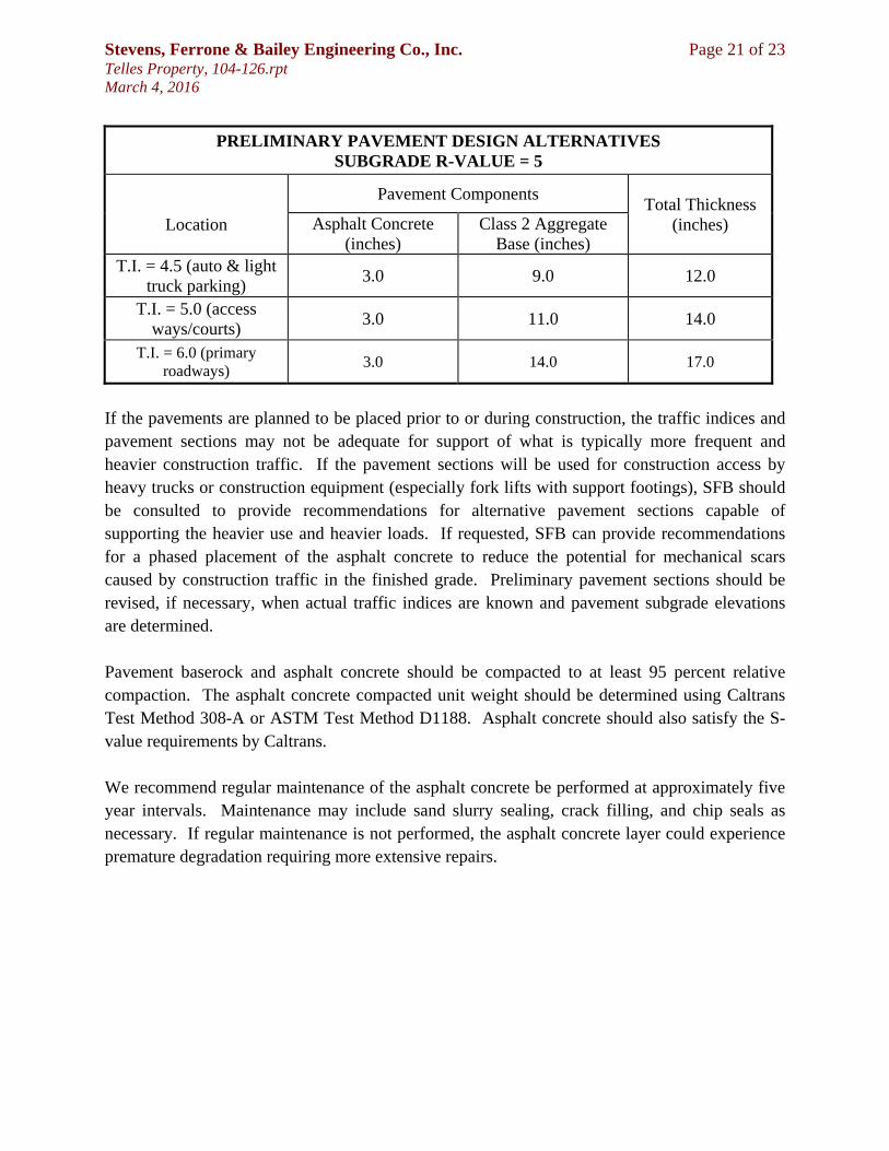
Our laboratory testing program for the proposed Telles Property residential development project in Hayward, California was directed toward a quantitative and qualitative evaluation of the physical and mechanical properties of the soils underlying the site. The natural water contents was determined on four samples of the subsurface soils. The water contents are recorded on the boring logs at the appropriate sample depths. Dry density determination was performed on four samples of the subsurface soils to evaluate their physical properties. The results of the tests are shown on the boring logs at the appropriate sample depths. Atterberg Limit determinations were performed on one sample of the subsurface soils to determine the range of water content over which these materials exhibit plasticity. These values are used to classify the soil in accordance with the Unified Soil Classification System and to indicate the soil's compressibility and expansion potentials. The results of the tests are presented on the boring log at the appropriate sample depth and are also attached to this appendix. Gradation and hydrometer tests were performed on one sample of the subsurface soils. These tests were performed to assist in the classification of the soils and to determine their grain size distribution. The results of the tests are presented on the boring log at the appropriate sample depth and are also attached to this appendix. Unconfined compression test was performed on four relatively undisturbed samples of the subsurface soils to evaluate the undrained shear strengths of these materials. Failure was taken as the peak normal stress. The results of the tests are presented on the boring logs at the appropriate sample depths and are also attached to this appendix. Two onsite soil samples were tested for pH (ASTM D4972), chlorides (ASTM D4327), sulfates (ASTM D4327), sulfides (ASTM D4658M), resistivity at 100% saturation (ASTM G57), and Redox potential (ASTM D1498) for use in evaluating the potential for corrosion on concrete and buried metal such as utilities and reinforcing steel. The results of these tests are included in this appendix. We recommend these test results be forwarded to your underground contractors, pipeline designers, and foundation designers and contractors.
Hydrometer Analysis – ASTM D422
Composite Sieve Data Standard Sieve Size
Percent Passing
3” 1.5” 3/4” 100.0 3/8” 99.2 #4 95.5
#10 87.9 #16 82.6 #30 76.6 #50 71.3
#100 66.1 #200 59.2
Particle Diameter (mm)
Percent Soil in Suspension
0.0311 51.6 0.0203 45.9 0.0120 41.6 0.0086 38.7 0.0062 35.9 0.0031 30.1 0.0013 24.4
Project Number: 104-126 Project Name: Telles Property
Sample Number: B-1 Description: Dark brown sandy silty CLAY (CL)
Depth: 2 Test Date: 02-29-16 Tested By: R
3" 2" 1"3/4"1/2" 1/4" 4 810 16 20 30 40 50 100 200 3250
10
20
30
40
50
60
70
80
90
1000
10
20
30
40
50
60
70
80
90
100
0.0010.010.1110100
US Standard Sieve Size
Per
cent
Ret
aine
d
Per
cent
Pas
sing
Particle Size (mm)
Gravel Sand Silt
Course Fine Course Medium Fine
Clay

Atterberg Limits Test – ASTM D4318
Project Number: 104-126 Project Name: Telles Property
Boring/Sample Number: B-1 Depth: 2 Date: 02-26-16
Description of Sample: Dark brown sandy silty CLAY (CL) Tested By: R
Data Summary Liquid Limit 41
Plastic Limit 18
Plasticity Index 23
Natural Water Content 11.1
Liquidity Index -0.30
% Passing #200 59.2
0
10
20
30
40
50
60
0 10 20 30 40 50 60 70 80 90 100
Pla
stic
ity I
ndex
(%
)
Liquid Limit (%)
Plasticity Chart
MH or OH
CL-ML
CL or OL
ML or OL
15 20 25 30 35 40 45 5039
40
41
42
43
10
Wat
er C
onte
nt (
%)
Number of Blows
Liquid Limit
Plastic Limit Data
Trial 1 2 Ave Water Content (%) 17.9 17.9 18

UNCONFINED COMPRESSIVE STRENGTH – D2166
0
1000
2000
3000
4000
5000
6000
7000
8000
9000
0.0 1.0 2.0 3.0 4.0 5.0
Unc
onf
ine
d S
tre
ngth
(lb
/ft2
)
Strain (%)
Max Unconfined Compressive Strength
Elapsed Time 3.5 min Vertical Dial 0.175 in Strain 3.5 % Area 0.03310 ft2 Axial Load 257.6 lbs
Compressive Strength 7,782 psf
Soil Specimen Initial Measurements
Diameter 2.42 in Initial Area 4.60 in2
Initial Length 5 in Volume 0.01331 ft3
Water Content 11.1 Wet Density 116.9 pcf Dry Density 105.2 pcf
Project Number: 104-126 Boring #: B-1 Depth: 2
Project Name: Telles Property Date: 2/25/2016
Description: Dark brown sandy silty CLAY (CL) Tested By: R

UNCONFINED COMPRESSIVE STRENGTH – D2166
0
2000
4000
6000
8000
10000
12000
0.0 2.0 4.0 6.0 8.0
Unc
onf
ine
d S
tre
ngth
(lb
/ft2
)
Strain (%)
Max Unconfined Compressive Strength
Elapsed Time 6 min Vertical Dial 0.3 in Strain 6.0 % Area 0.03398 ft2 Axial Load 332.6 lbs
Compressive Strength 9,787 psf
Soil Specimen Initial Measurements
Diameter 2.42 in Initial Area 4.60 in2
Initial Length 5 in Volume 0.01331 ft3
Water Content 12.8 Wet Density 124.3 pcf Dry Density 110.2 pcf
Project Number: 104-126 Boring #: B-1 Depth: 6
Project Name: Telles Property Date: 2/25/2016
Description: Dark brown silty CLAY with sand and gravel (CL) Tested By: R

UNCONFINED COMPRESSIVE STRENGTH – D2166
0
500
1000
1500
2000
2500
0.0 1.0 2.0 3.0 4.0 5.0
Unc
onf
ine
d S
tre
ngth
(lb
/ft2
)
Strain (%)
Max Unconfined Compressive Strength
Elapsed Time 3.5 min Vertical Dial 0.175 in Strain 3.6 % Area 0.03313 ft2 Axial Load 65.9 lbs
Compressive Strength 1,989 psf
Soil Specimen Initial Measurements
Diameter 2.42 in Initial Area 4.60 in2
Initial Length 4.9 in Volume 0.01304 ft3
Water Content 11.8 Wet Density 108.7 pcf Dry Density 97.3 pcf
Project Number: 104-126 Boring #: B-2 Depth: 2
Project Name: Telles Property Date: 2/25/2016
Description: Dark brown sandy silty CLAY (CL/ML) Tested By: R

UNCONFINED COMPRESSIVE STRENGTH – D2166
0
1000
2000
3000
4000
5000
6000
7000
8000
9000
10000
0.0 2.0 4.0 6.0 8.0
Unc
onf
ine
d S
tre
ngth
(lb
/ft2
)
Strain (%)
Max Unconfined Compressive Strength
Elapsed Time 6.5 min Vertical Dial 0.325 in Strain 6.5 % Area 0.03417 ft2 Axial Load 294.3 lbs
Compressive Strength 8,614 psf
Soil Specimen Initial Measurements
Diameter 2.42 in Initial Area 4.60 in2
Initial Length 5 in Volume 0.01331 ft3
Water Content 16.4 Wet Density 129.3 pcf Dry Density 111.1 pcf
Project Number: 104-126 Boring #: B-2 Depth: 6
Project Name: Telles Property Date: 2/25/2016
Description: Dark brown silty CLAY some sand (CL) Tested By: R


APPENDIX C Logs of Previous Field Explorations & Results of Previous Lab Testing


APPENDIX D ASFE Guidelines


Copyright © 2022 FDOKUMEN