Pile Foundations - GEOTECHNICAL FIELD TEST ...
73
PILE FOUNDATIONS
-
Upload
khangminh22 -
Category
Documents
-
view
0 -
download
0
Transcript of Pile Foundations - GEOTECHNICAL FIELD TEST ...

PILE FOUNDATIONS


Friction Piles End-bearing Piles

Types of pilesDifferent types of piles are used in construction work, depending on:
o the type of load to be carried, o the subsoil conditions,o the location of the water table.
Piles can be divided into the following categories: o steel piles o concrete piles, o wooden (timber) piles,o composite piles.
Piles can be divided into three major categories, depending on their lengths and the mechanisms of load transfer to the soil: ,o point bearing piles, o friction piles, o compaction piles

Types of pilesBased on the nature of their placement, piles may be divided into two categories: o displacement piles o nondisplacement piles
Driven piles are displacement piles because they move some soil laterally; hence there is a tendency for densification of soil surrounding them. Concrete piles and closed-ended pile piles are high-displacement piles. However, steel H-piles displace less soil laterally during driving, and so they are low displacement piles. In contrast, bored piles are nondisplacement piles because their placement causes very little change in the state of stress in the soil.

Friction PilesWhen no layer of rock or rocklike material is present at a reasonable depth at a site, point bearing piles become very long and uneconomical. For this type o subsoil condition, piles are driven through the softer material to specified depths (figure 8. 6c).
The ultimate load of these piles may be expressed by equation below. However, if the value of 𝑄𝑄𝑝𝑝 is relatively small,
These piles are called friction piles because most of the resistance is derived from skin friction. However, the term friction pile, although used often in the literature, is a misnomer: in clayey soils, the resistance to applied load is also caused by adhesion. The length of friction of piles depends on the shear strength of the soil, the applied load and the pile size. To determine the necessary lengths of these piles, an engineer needs a good understanding of soil-pile interaction, good judgment, and experience.

ESTIMATING PILE CAPACITYPoint Bearing Capacity, 𝑸𝑸p
Frictional Resistance, 𝑸𝑸s

There are several methods for estimating 𝑄𝑄𝑝𝑝 and 𝑄𝑄𝑠𝑠.
It needs to be reemphasized that, in the field, for full mobilization of the point resistance (𝑄𝑄𝑝𝑝), the pile tip must go through a displacement of 10 to 25% of the pile width (or diameter).

MEYERHOF’S METHODS – Qp -- SANDSand:
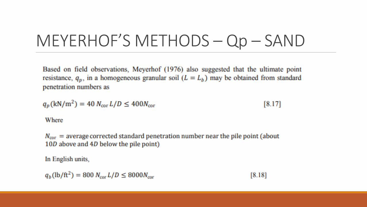
MEYERHOF’S METHODS – Qp – SAND

MEYERHOF’S METHODS – Qp – CLAYClay (𝝓𝝓 = 𝟎𝟎 condition)

VESIC’S METHOD-𝑸𝑸p
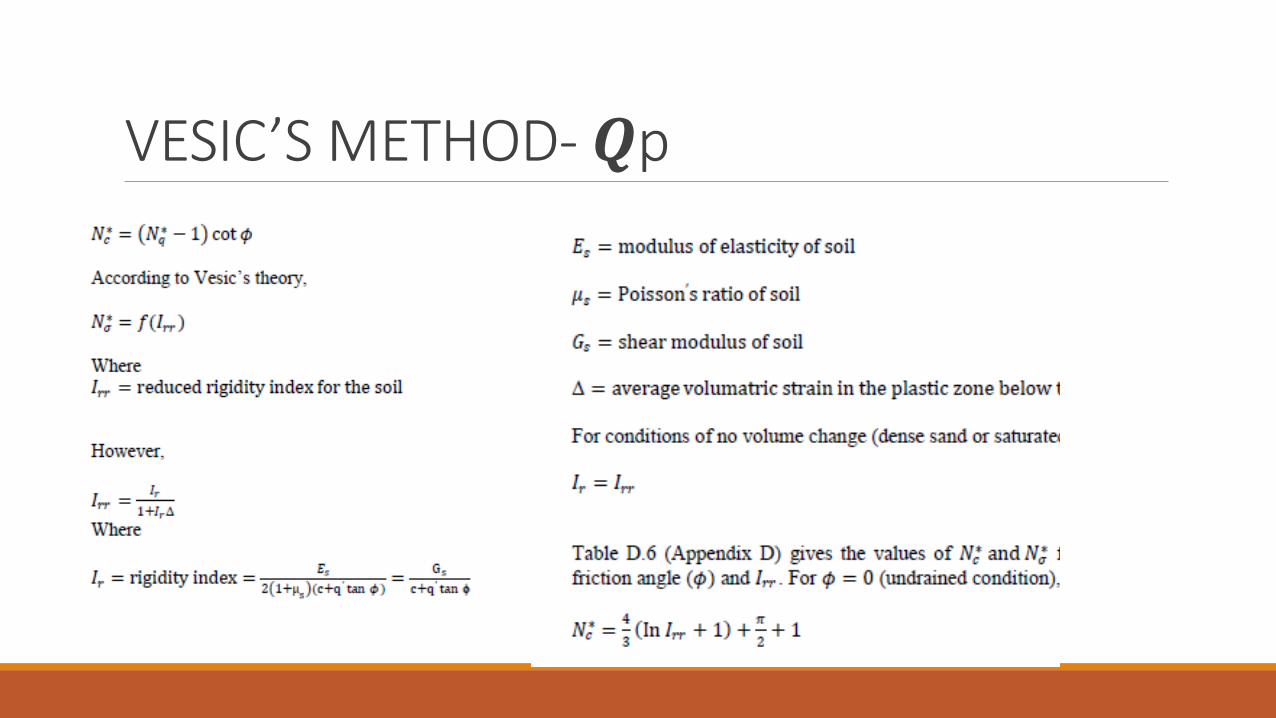
VESIC’S METHOD-𝑸𝑸p

VESIC’S METHOD-𝑸𝑸p

FRICTIONAL RESISTANCE (𝑸𝑸𝒔𝒔) IN SAND
The unit frictional resistance, f, is hard to estimate. In making an estimation of f, several important factors must be kept in mind. They are as follows:
1) The nature of pile installation. For driven piles in sand, the vibration caused during pile driving helps densify the soil around the pile.
Compaction of sand near driven piles (after Meyerhof, 1961)

FRICTIONAL RESISTANCE (𝑸𝑸𝒔𝒔) IN SAND
Unit frictional resistances for piles in sand
2) It has been observed that the nature of variation of f in the field is approximately as shown in figure. The unit skin friction increases with depth more or less linearly to a depth of L’ and remains constant thereafter. The magnitude of the critical depth L’ may be 15 to 20 pile diameters. A conservative estimate would be L’ ≅ 15D
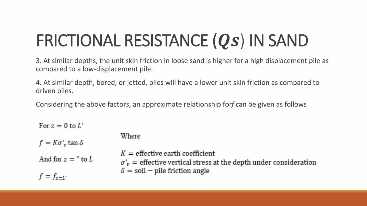
FRICTIONAL RESISTANCE (𝑸𝑸𝒔𝒔) IN SAND 3. At similar depths, the unit skin friction in loose sand is higher for a high displacement pile as compared to a low-displacement pile.
4. At similar depth, bored, or jetted, piles will have a lower unit skin friction as compared to driven piles.
Considering the above factors, an approximate relationship for f can be given as follows

FRICTIONAL RESISTANCE (𝑸𝑸𝒔𝒔) IN SAND
The values of 𝛿𝛿 from various investigations appear to be in the range of 0.5𝜙𝜙 to 0.8𝜙𝜙.

FRICTIONAL RESISTANCE (𝑸𝑸𝒔𝒔) IN SAND For high displacement driven piles,
Bhusan (1982) recommended
Meyerhof (1976) also indicated that the average unit frictional resistance, 𝑓𝑓𝑎𝑎v,
for high-displacement
for low-displacement
Where Ncor=average corrected value of standard penetration resistance

FRICTIONAL RESISTANCE IN CLAY -- 𝜆𝜆Method

FRICTIONAL RESISTANCE IN CLAY -- 𝜆𝜆Method

FRICTIONAL RESISTANCE IN CLAY -- αMethod

FRICTIONAL RESISTANCE IN CLAY -- βMethod
OCR= overconsolidation ratio

POINT BEARING CAPACITY OF PILES RESTING ON ROCK
The unconfined compression strength of rock can be determined by laboratory tests on rock specimens collected during field investigation. However, extreme caution should be used in obtaining the proper vale of 𝑞𝑞𝑢𝑢 because laboratory specimens usually are small in diameter. As the diameter of the specimen increases, the unconfined compression strength decreases, this is referred to as the scale effect. For specimens larger than about 3 ft(1 m) in diameter, the value of 𝑞𝑞𝑢𝑢 remains approximately constant. There appears to be a fourfold to fivefold reduction of the magnitude of 𝑞𝑞𝑢𝑢 in this process.
The scale effect in rock is primarily caused by randomly distributed large and small fractures and also by progressive ruptures along the slip lines. Hence, it is recommended that
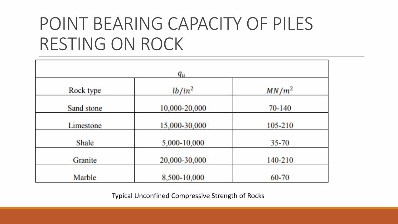
POINT BEARING CAPACITY OF PILES RESTING ON ROCK
Typical Unconfined Compressive Strength of Rocks

POINT BEARING CAPACITY OF PILES RESTING ON ROCK
Typical Values of Angle of Friction, 𝝓𝝓𝝓𝝓, of Rocks

POINT BEARING CAPACITY OF PILES RESTING ON ROCKA factor of safety of at least 3 should be used to determine the allowable point bearing capacity of piles. Thus :

SETTLEMENT OF PILES
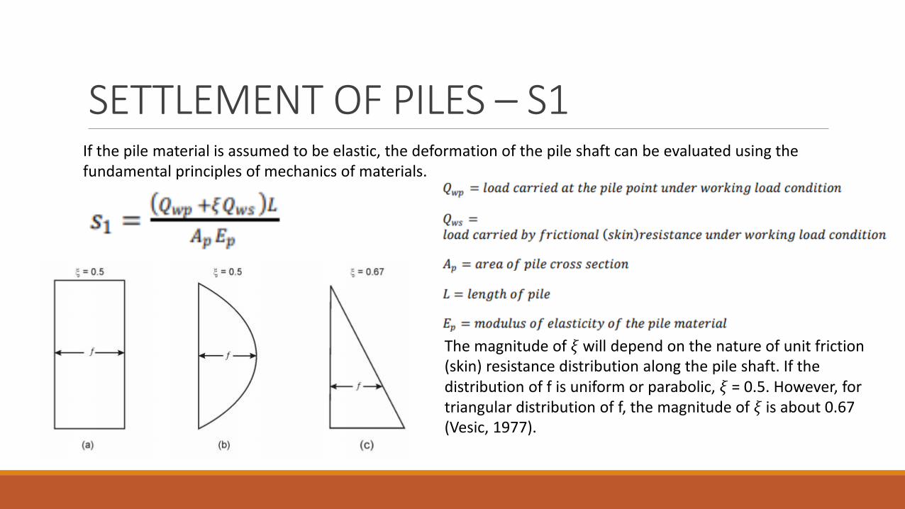
SETTLEMENT OF PILES – S1If the pile material is assumed to be elastic, the deformation of the pile shaft can be evaluated using the fundamental principles of mechanics of materials.
The magnitude of 𝜉𝜉 will depend on the nature of unit friction (skin) resistance distribution along the pile shaft. If the distribution of f is uniform or parabolic, 𝜉𝜉 = 0.5. However, for triangular distribution of f, the magnitude of 𝜉𝜉 is about 0.67 (Vesic, 1977).

SETTLEMENT OF PILES – S2The settlement of a pile caused by the load carried at the pile point may be expressed in a form similar to that given for shallow foundations:
Vesic (1977) also proposed a semi-empirical method to obtain the magnitude of the settlement, 𝑠𝑠2:

SETTLEMENT OF PILES – S3The settlement of a pile caused by the load carried by the pile shaft is given by a relation:
Note that the term 𝑄𝑄𝑤𝑤s/𝑝𝑝L is the average value of along the pile shaft.
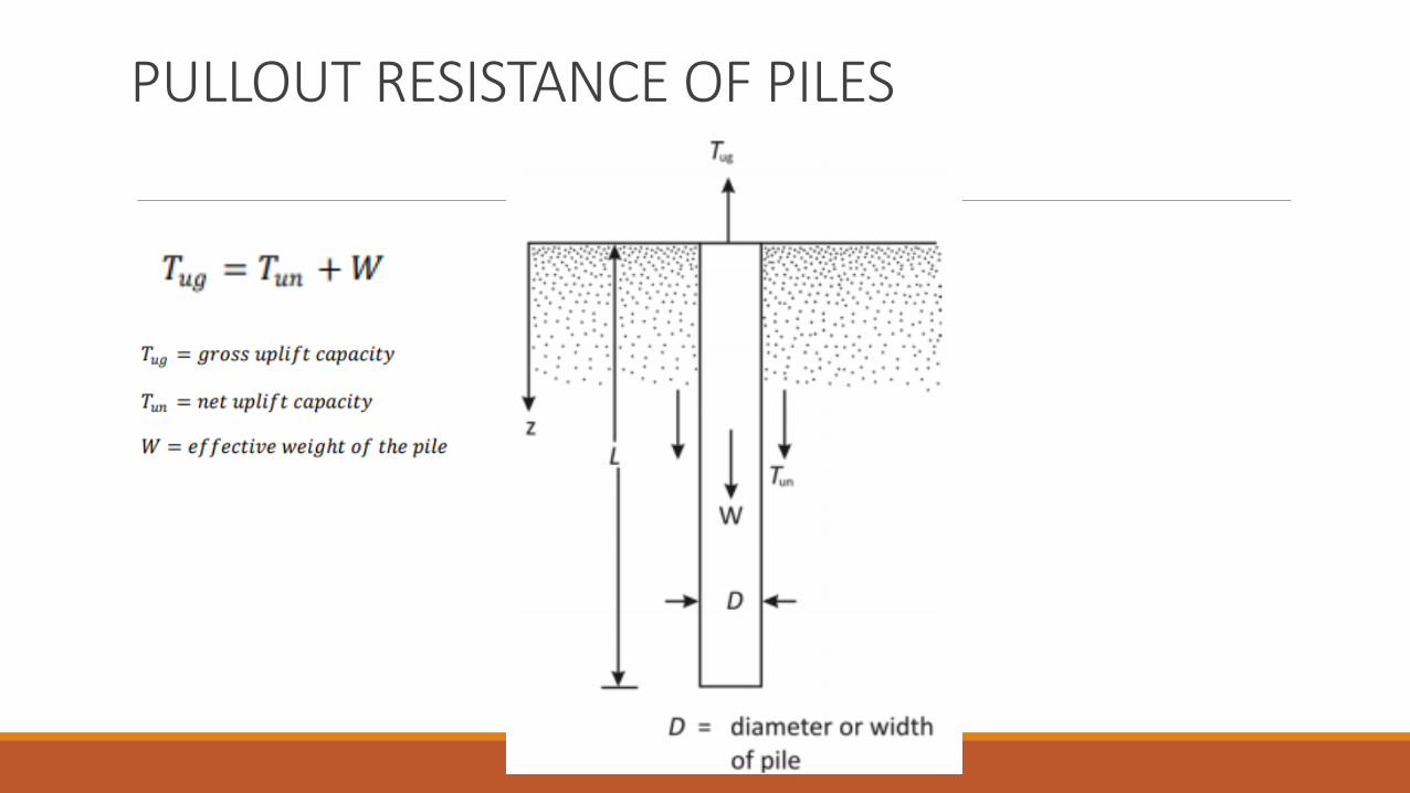
PULLOUT RESISTANCE OF PILES
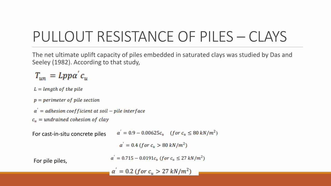
PULLOUT RESISTANCE OF PILES – CLAYSThe net ultimate uplift capacity of piles embedded in saturated clays was studied by Das and Seeley (1982). According to that study,
For cast-in-situ concrete piles
For pile piles,
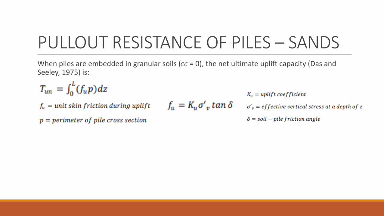
PULLOUT RESISTANCE OF PILES – SANDSWhen piles are embedded in granular soils (𝑐𝑐𝑐𝑐 = 0), the net ultimate uplift capacity (Das and Seeley, 1975) is:
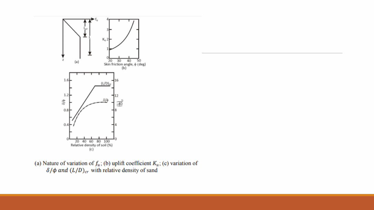

For calculating the net ultimate uplift capacity of piles, the following procedure is suggested:
1) Determine the relative density of the soil and, using figure c, obtain the value of 𝐿𝐿𝑐𝑐r
2) If the length of the pile, L, is less than or equal to 𝐿𝐿cr.
3) For L>Lcr
For dry soils:
A factor of safety of 2-3 is recommended

LATERALLY LOADED PILES
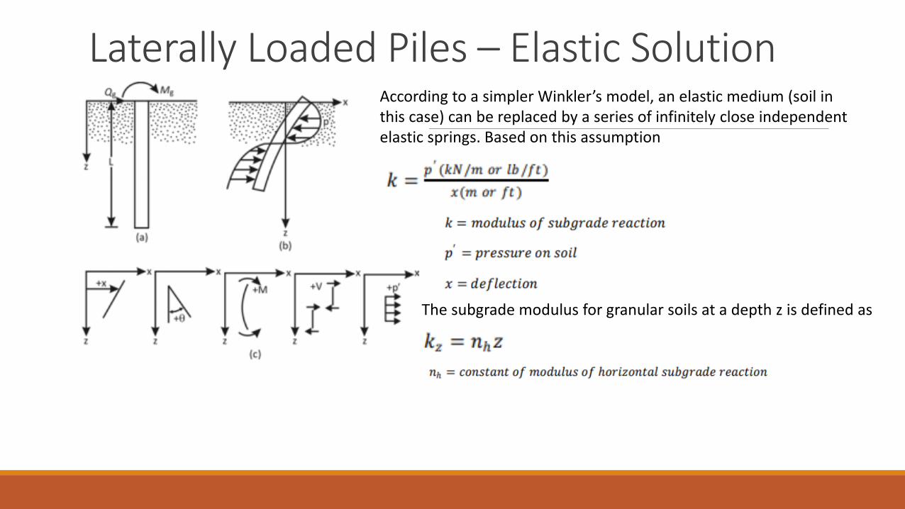
Laterally Loaded Piles – Elastic SolutionAccording to a simpler Winkler’s model, an elastic medium (soil in this case) can be replaced by a series of infinitely close independent elastic springs. Based on this assumption
The subgrade modulus for granular soils at a depth z is defined as

Laterally Loaded Piles – Elastic Solution – SAND
When 𝐿𝐿 ≥ 5𝑇𝑇, the piles is considered to be a long pile. For 𝐿𝐿 ≤ 2𝑇𝑇, the pile is considered to be a rigid pile.
When 𝐿𝐿/𝑇𝑇 is greater than about 5, the coefficients do no change, which is true of long piles only.
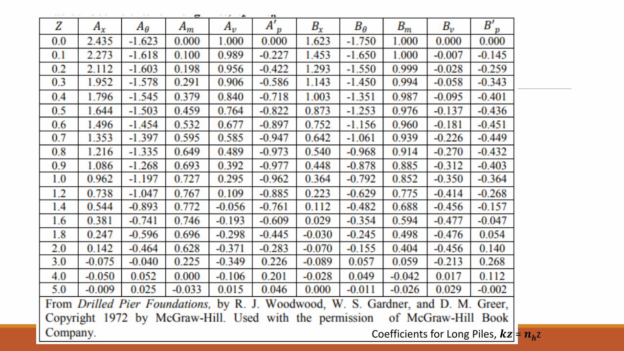
Coefficients for Long Piles, 𝒌𝒌𝒛𝒛 = 𝒏𝒏𝒉𝒉z

Representative Values of 𝒏𝒏h

Laterally Loaded Piles – Elastic Solution – CLAY

For sands, the coefficient of subgrade reaction was showed a linear variation with depth. However, in cohesive soils, the subgrade reaction may be assumed to be approximately constant with depth. Vesic (1961) proposed the following equation to estimate the value of 𝑘𝑘:
Laterally Loaded Piles – Elastic Solution – CLAY

Ultimate Load Analysis-Brom’s Method – Short PilesBroms (1965) developed a simplified solution for laterally loaded piles based on the assumptions of (a) shear failure in soil, which is the case for short piles, and (b) bending of the pile governed by plastic yield resistance of the pile section, which is applicable for long piles. Brom’s solution for calculating the ultimate load resistance, 𝑄𝑄𝑢𝑢(𝑔𝑔), for short piles is given in figure 8.41a. A similar solution for piles embedded in cohesive soil is shown in figure 8.41b.

Ultimate Load Analysis-Brom’s Method – Long Piles
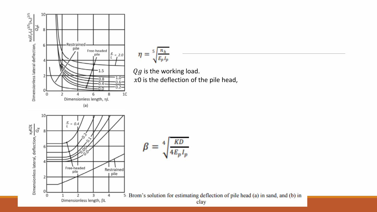
𝑄𝑄𝑔𝑔 is the working load.𝑥𝑥0 is the deflection of the pile head,
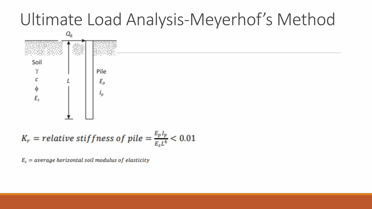
Ultimate Load Analysis-Meyerhof’s Method

Piles in Sand -Meyerhof’s MethodFor short (rigid) piles in sand, the ultimate load resistance can be given as
The maximum moment, 𝑀𝑀max , in the pile due to the lateral load, 𝑄𝑄𝑢𝑢(𝑔𝑔), is

Piles in Sand -Meyerhof’s Method

The ultimate lateral load, 𝑄𝑄𝑢𝑢(𝑔𝑔), applied at the ground surface for short (rigid) pile embedded in clay can be given as
Piles in Clay-Meyerhof’s Method – Short Pile
The maximum bending moment in the pile due to 𝑄𝑄𝑢𝑢(𝑔𝑔) is

For long (flexible) piles, use by substituting the effective length (𝐿𝐿𝑒𝑒 ) in place of L.
The maximum moment in a flexible pile due to a working lateral load 𝑄𝑄𝑔𝑔 applied at the ground surface is
Piles in Clay-Meyerhof’s Method – Long Pile

NEGATIVE SKIN FRICTION – NSF

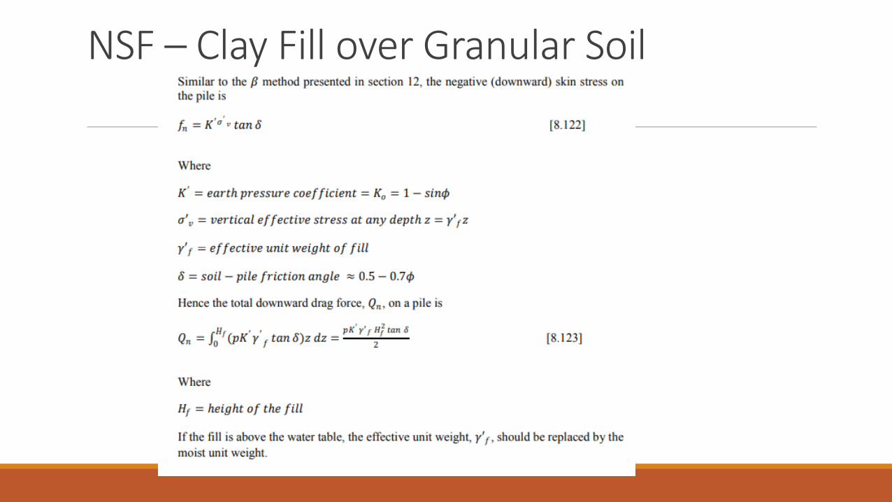
NSF – Clay Fill over Granular Soil

NSF – Granular Soil Fill over Clay
If the soil and the fill are above the water table, the effective unit weights should be replaced by moist unit weights.
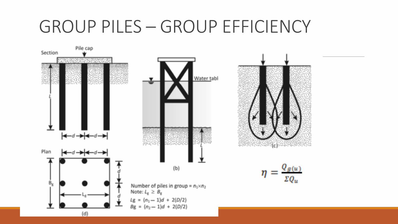
GROUP PILES – GROUP EFFICIENCY
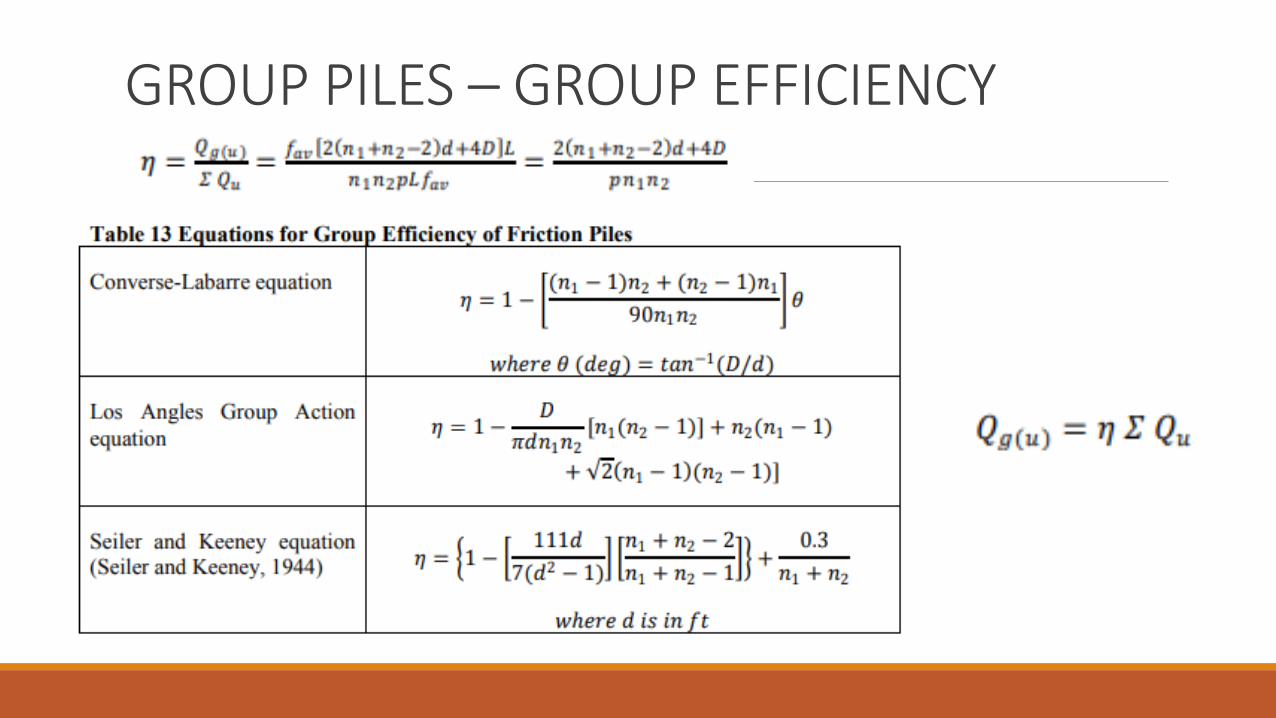
GROUP PILES – GROUP EFFICIENCY
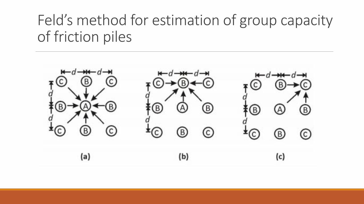
Feld’s method for estimation of group capacity of friction piles

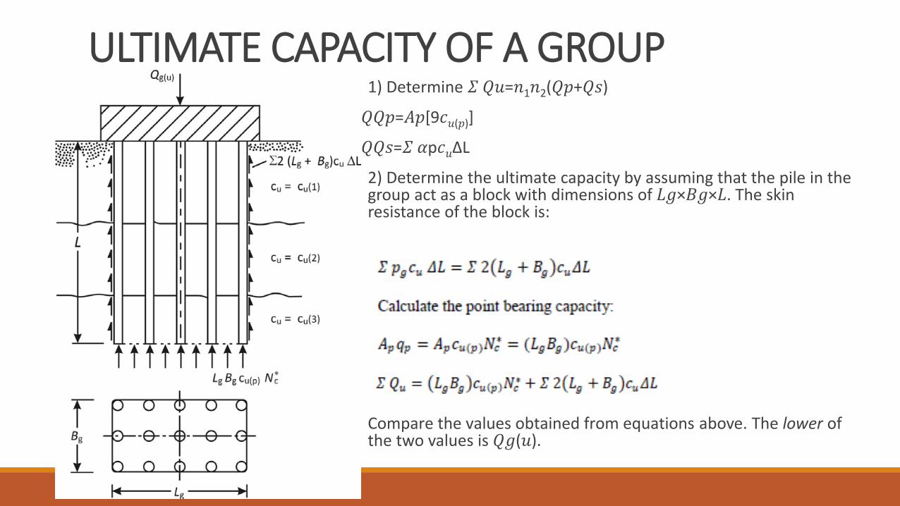
ULTIMATE CAPACITY OF A GROUP 1) Determine 𝛴𝛴 𝑄𝑄𝑢𝑢=𝑛𝑛1𝑛𝑛2(𝑄𝑄𝑝𝑝+𝑄𝑄𝑠𝑠)
𝑄𝑄𝑄𝑄 𝑝𝑝=𝐴𝐴𝑝𝑝[9𝑐𝑐𝑢𝑢(𝑝𝑝)]
𝑄𝑄𝑄𝑄 𝑠𝑠=𝛴𝛴 𝛼𝛼p𝑐𝑐𝑢𝑢ΔL
2) Determine the ultimate capacity by assuming that the pile in the group act as a block with dimensions of 𝐿𝐿𝑔𝑔×𝐵𝐵𝑔𝑔×𝐿𝐿. The skin resistance of the block is:
Compare the values obtained from equations above. The lower ofthe two values is 𝑄𝑄𝑔𝑔(𝑢𝑢).


PILES IN ROCK For point bearing piles resting on rock, most building codes specify that 𝑄𝑄𝑔𝑔(𝑢𝑢)=𝛴𝛴 𝑄𝑄𝑢𝑢, provided that the minimum center-to-center spacing of piles is 𝐷𝐷+300 𝑚𝑚𝑚𝑚. For H-piles and piles with square cross section, the magnitude of D is equal to the diagonals dimensions if the pile cross section.

Example The section of a 3×4 group pile in layered saturated clay is shown in figure. The piles are square in cross section (14 𝑖𝑖n.×14 𝑖𝑖n.). The center-to-center spacing, d, of the piles n 35 in. Determinethe allowable load-bearing capacity of the pile group. Use FS=4.


CONSOLIDATION SETTLEMENT OF GROUP PILES The consolidation settlement of a group pile in clay can be
approximately estimated by using the 2:1 stress distribution method. The procedure of calculation involves the following steps:


ELASTIC SETTLEMENT OF GROUP PILES In general, the settlement of a pile group under similar working load per pile increases with the width of the group (𝐵𝐵𝑔𝑔) and the center-to-center spacing of piles (d). This fact is demonstrated in figure below obtained from the experimental results of Meyerhof (1961) for pile groups in sand. In this figure , 𝑠𝑠𝑔𝑔(𝑒𝑒) is the settlement of the pile group and s is the settlement of isolated piles under similar working load.

ELASTIC SETTLEMENT OF GROUP PILES Several investigations relating to the settlement of group piles with widely varying results have been reported in the literature. The simplest relation for the settlement of group piles was given by Vesic (1969) as
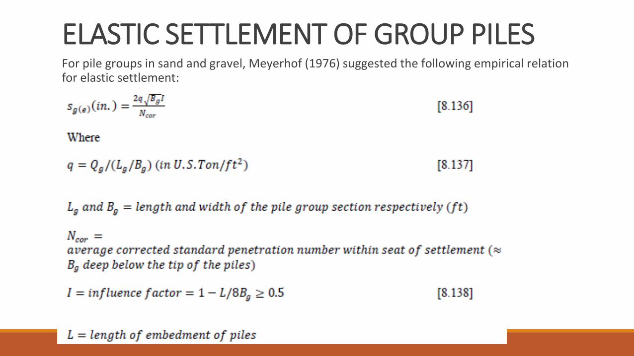
ELASTIC SETTLEMENT OF GROUP PILES For pile groups in sand and gravel, Meyerhof (1976) suggested the following empirical relation for elastic settlement:

ELASTIC SETTLEMENT OF GROUP PILES Similarly, the pile group settlement is related to the cone penetration resistance as:
In equation (139), all symbols are in consistent units.

UPLIFT CAPACITY OF GROUP PILES Under certain circumstances, group piles may be used for construction of foundations subjected to uplifting load. The group efficiency under uplift may be expressed as