Geotechnical Investigation for Tawila Dam in North Darfur
49
ن الرحيم ه الرحم بسمUniversity of Khartoum Faculty of Engineering Civil Engineering Department P. O. Box 321, P. Code 11111, Khartoum, Sudan Tel. 0249-11- 771577 E-mail: [email protected] عة الخرطوم جام كلية الهندسةدسة المدنية قسم الهن ص ب321 خرطوم– سودان تلفون:771577 G G G E E E O O O T T T E E E C C C H H H N N NI I I C C C A A A L L L I I I N N N V V V E E E S S S T T T I I I G G G A A A T T T I I I O O O N N N F F F O O O R R R T T T A A A W W WI I I L L L A A A D D D A A A M M M I I I N N N N N N O O O R R R T T T H H H D D D A A A R R R F F F U U U R R R S S S T T T A A A T T T E E E B B B Y Y Y D D D R R R . . . M M MA A A G G G D D D I I I Z Z Z U U U M M MR R R A A A W W W I I I M M M A A A R R R C C C H H H 2 2 2 0 0 0 1 1 1 5 5 5
Transcript of Geotechnical Investigation for Tawila Dam in North Darfur

بسم ه الرحمن الرحيم
University of Khartoum Faculty of Engineering Civil Engineering Department P. O. Box 321, P. Code 11111, Khartoum, Sudan
Tel. 0249-11-771577 E-mail: [email protected]
771577تلفون: سودان –خرطوم 321ص ب قسم الهندسة المدنية الهندسة كلية جامعة الخرطوم
GGGEEEOOOTTTEEECCCHHHNNNIIICCCAAALLL IIINNNVVVEEESSSTTTIIIGGGAAATTTIIIOOONNN
FFFOOORRR
TTTAAAWWWIIILLLAAA DDDAAAMMM IIINNN NNNOOORRRTTTHHH DDDAAARRRFFFUUURRR SSSTTTAAATTTEEE
BBBYYY
DDDRRR... MMMAAAGGGDDDIII ZZZUUUMMMRRRAAAWWWIII
MMMAAARRRCCCHHH 222000111555
Geotechnical Investigation for By Dr. Magdi Zumrawi
Tawila Dam in North Darfur State University of Khartoum
1
بسم اه الرمن الرحيمبسم اه الرمن الرحيم
TTaabbllee ooff CCoonntteennttss
1 INTRODUCTION .......................................................................................... 2
1.1 General ..................................................................................................... 2
1.2 Study Objectives ...................................................................................... 2
1.3 Project Description ................................................................................... 3
2 FIELD INVESTIGATION ............................................................................ 5
2.1 Current Situation ...................................................................................... 5
2.2 Sampling .................................................................................................. 9
3 LABORATORY TESTING ........................................................................10
3.1 Atterberg limits ......................................................................................10
3.2 Grain Size Analysis ................................................................................10
3.3 Compaction Test ....................................................................................11
3.4 Permeability Test ...................................................................................11
3.5 Shear Strength Tests ...............................................................................11
4 RESULTS AND ANALYSIS ......................................................................12
4.1 Tests Results ...........................................................................................12
4.2 Soil Profile .............................................................................................15
4.3 Soil Bearing Capacity ............................................................................15
4.4 Stability of Spillway Section..................................................................16
4.5 Causes of the Dam Failure .....................................................................20
5 RECOMMENDATIONS .............................................................................21
5.1 Embankment Design Considerations .....................................................21
5.2 Seepage Control .....................................................................................23
5.3 Spillway Foundation ..............................................................................24
6 APPENDEX (A) ...........................................................................................25
7 APPENDEX (B)............................................................................................31
Geotechnical Investigation for By Dr. Magdi Zumrawi
Tawila Dam in North Darfur State University of Khartoum
2
11.. IInnttrroodduuccttiioonn
1.1. GGeenneerraall
This is a detailed geotechnical investigation report that presents
the results of the field and laboratory investigations that carried out
for the damaged dam of Tawila in North Darfur State. After the dam
failure in July 2014, UNOPS has requested road and soil section,
university of Khartoum to undertake a technical review of the Tawila
Dam Rehabilitation Design Report. The dam was constructed in 1954
and by the early 1970s it was fully silted. It was subjected to
overtopping and a second spillway was installed to cater for presumed
increased runoff in the upper catchment. It was at this section that a
breach occurred. The dam has since not stored water and a new river
bed alignment has occurred.
The is investigation is carried out to provide an extensive
diagnosis study to point out the main structural and geotechnical
weaknesses of Tawila Dam. Clear recommendations are provided to
design a proper rehabilitation of the dam.
1.2. SSttuuddyy OObbjjeeccttiivveess
The following are detailed objectives of the study:
1) Determine the physical and mechanical properties of the
foundation soils and the embankment material at the dam site,
2) Establish a proper diagnosis of the current dam, after the
collapsing of the secondary spillway based on an extensive visual

Geotechnical Investigation for By Dr. Magdi Zumrawi
Tawila Dam in North Darfur State University of Khartoum
3
inspection and the data set used to site and size the original dam,
the diagnosis had to emphasize the spillway section, embankment
and foundations structural stability.
3) To investigate the source of failures occurred in the dam
embankment and spillway section.
4) To enable an adequate and appropriate design for the new
rehabilitation work.
The investigation consisted of site reconnaissance, field
investigation and collection of soil samples. The laboratory testing
was conducted to provide the physical and mechanical properties of
the dam embankment and spillway foundation soils.
1.3. PPrroojjeecctt DDeessccrriippttiioonn
Tawila Dam is located about 70 km west of North Darfur capital
El Fasher town; it was constructed in 1954 by the State Water
Corporation. The dam is an earthen embankment (1.8 km long) across
the wadi, with two spillway structures (primary and supplementary).
The project area is located in the El ku basin of the North Darfur. The
river is one of the main flow contributors to wadi El ku. The project
area as shown in Figure 1 lies approximately between 269204 E,
1493145 N and 268047 E and 1494352 N.

Geotechnical Investigation for By Dr. Magdi Zumrawi
Tawila Dam in North Darfur State University of Khartoum
4
Figure 1: The site location of Tawila Dam in North Darfur State
This dam is one of the interventions of Drought Risk Reduction
Project in North Darfur State. The project is to contribute in
increasing the products of rain-fed agriculture schemes through
reduction of water storage period and use of complementary
irrigation. As per the State Water Corporation sources, the design
capacity of the reservoir is 300,000 m3, however it has lost storage
volume due to silt accumulation. The primary objectives of Tawila
dam were:
Provide surface water storage for the surrounding farmers for their
living and agriculture.
Infiltration for ground water recharge.
Protection of the town from natural flood.
The dam suffered from water erosion and damages occurred in
Tawila Dam

Geotechnical Investigation for By Dr. Magdi Zumrawi
Tawila Dam in North Darfur State University of Khartoum
5
the dam body. It is required to investigate the prevailing situation and
to make proper design for rehabilitation of the dam.
22.. FFiieelldd IInnvveessttiiggaattiioonn
The field investigation was comprised of a site visit to the dam
location at Twaila and collecting soil samples. The investigation
started with the site reconnaissance in order to collect information
data about the dam construction and how the failure occurred from the
local and the contractor to assess in investigating the source and
reasons of failures. The field work included also collection of soil
samples from the embankment and the spillways foundation soils.
2.1. CCuurrrreenntt SSiittuuaattiioonn
The author together with a hydrology expert and the contractor
had conducted a visual inspection of the dam in order to detect any
obvious structural defects in the spillways and the dam embankment.
It was observed that the secondary spillway structure and the adjacent
embankment of the dam have collapsed due to excessive seepage that
caused voids creation underneath the structure. The new constructed
section of the secondary spillway has severed failure due to shear
stress and washed away during rainy season. The reservoir is no more
holding water. As per the information for the locals, the dam failure
has occurred same year where the nearby secondary spillway was
constructed and this has suspected of seepage underneath the
embankment close to the spillway as shown in Fig. 2.

Geotechnical Investigation for By Dr. Magdi Zumrawi
Tawila Dam in North Darfur State University of Khartoum
6
Figure 2: The total collapsed of the secondary spillway with severed
cracks due to shear forces
The partial breaching/weakening of embankment section is also
observed at the far north part of the embankment which could lead to
total collapse. This embankment weakening was happening mainly
due to scouring effect of the incoming waddy which flows adjacent to
the embankment section parallel to the dam axis. This scouring has
caused the embankment slope to get steeper and has increased the
waddy depth which has increased the embankment height which can
lead to failure. During rainy season, this steeper section was falling in
to the waddy when it get saturated and washed downstream which
further weakens the embankment section (see Figure 3).

Geotechnical Investigation for By Dr. Magdi Zumrawi
Tawila Dam in North Darfur State University of Khartoum
7
Figure 3: Weak and steep slope of the embankment due to scouring.
In general, the embankment has changed it original section
dimension and shape throughout the entire length where the crest of
the embankment is narrowed and the side slopes are flattened some
sections and steeped at others.
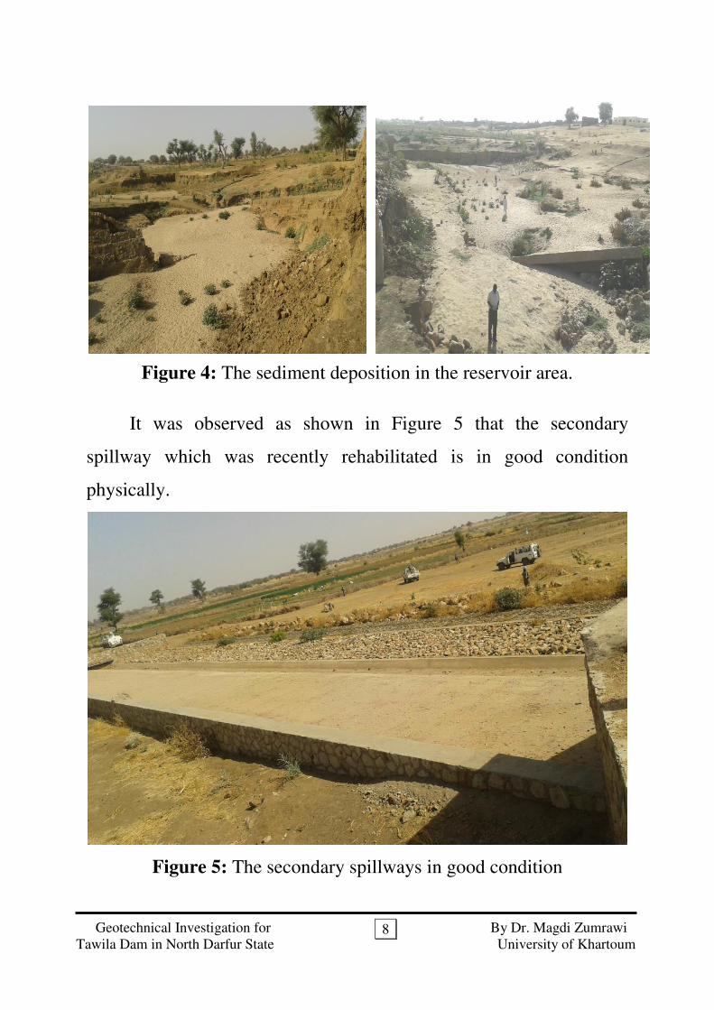
In addition to breaching and weakening of the embankment, the
other concern observed in Tawila dam is sediment deposition in the
reservoir area. The sediment deposition has reduced the storage
capacity of the reservoir by significant volume. This is mainly due to
huge sediment load form the catchment is caused by degradation and
less vegetation cover. There is no any sediment releasing sluice gate
provision to release flush floods carrying high sediment load are
experienced in other dams in Darfur. The sediment deposition lead to
reduction in reservoir capacity as well as reduction in aquifer
recharging to augments the ground water (see figure 4).
Geotechnical Investigation for By Dr. Magdi Zumrawi
Tawila Dam in North Darfur State University of Khartoum
8
Figure 4: The sediment deposition in the reservoir area.
It was observed as shown in Figure 5 that the secondary
spillway which was recently rehabilitated is in good condition
physically.
Figure 5: The secondary spillways in good condition
Geotechnical Investigation for By Dr. Magdi Zumrawi
Tawila Dam in North Darfur State University of Khartoum
9
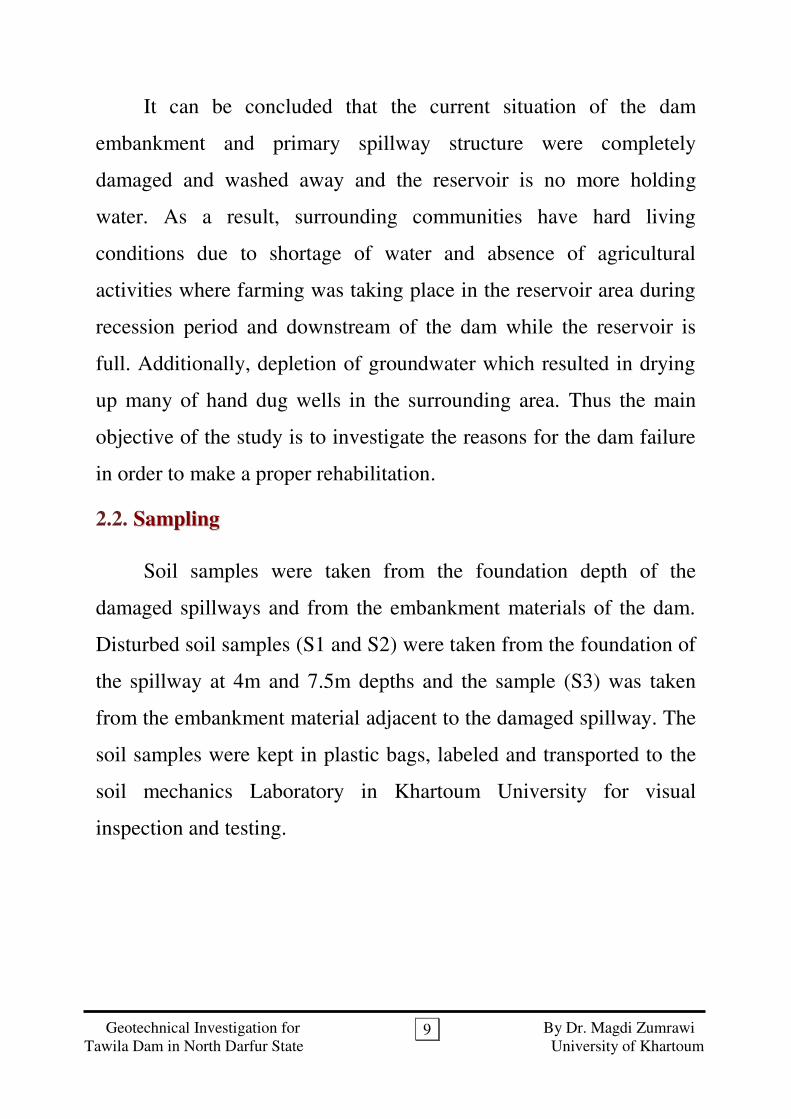
It can be concluded that the current situation of the dam
embankment and primary spillway structure were completely
damaged and washed away and the reservoir is no more holding
water. As a result, surrounding communities have hard living
conditions due to shortage of water and absence of agricultural
activities where farming was taking place in the reservoir area during
recession period and downstream of the dam while the reservoir is
full. Additionally, depletion of groundwater which resulted in drying
up many of hand dug wells in the surrounding area. Thus the main
objective of the study is to investigate the reasons for the dam failure
in order to make a proper rehabilitation.
2.2. SSaammpplliinngg
Soil samples were taken from the foundation depth of the
damaged spillways and from the embankment materials of the dam.
Disturbed soil samples (S1 and S2) were taken from the foundation of
the spillway at 4m and 7.5m depths and the sample (S3) was taken
from the embankment material adjacent to the damaged spillway. The
soil samples were kept in plastic bags, labeled and transported to the
soil mechanics Laboratory in Khartoum University for visual
inspection and testing.
Geotechnical Investigation for By Dr. Magdi Zumrawi
Tawila Dam in North Darfur State University of Khartoum
10
33.. LLaabboorraattoorryy TTeessttiinngg
The Laboratory testing program was conducted to evaluate the
physical and mechanical properties of the soils encountered during the
site exploration. The testing procedures followed were in general
conformance with those recommended in the British Standard BS
1377 (1990) and the soils were classified according to the Unified
System for Classifying Soils (USCS). The laboratory tests performed
included the following:-
Atterberg Limits
Grain size distribution
Compaction test
Permeability test
Shear strength test
33..11.. AAtttteerrbbeerrgg LLiimmiittss
The tests performed were the liquid limit, LL and the plastic
limit, PL tests. These tests were carried out on fine soils passing sieve
no. 40. The soil samples tested, about three samples and the data
analysis are given in Appendix (A).
33..22.. GGrraaiinn SSiizzee DDiissttrriibbuuttiioonn
The wet sieve analysis tests were carried out on soil samples
taken from the site of the damaged spillway section. The tests
performed are three and the data analysis is given in the tables of
Appendix (A).
Geotechnical Investigation for By Dr. Magdi Zumrawi
Tawila Dam in North Darfur State University of Khartoum
11
33..33.. CCoommppaaccttiioonn TTeesstt
This test was carried out using disturbed soil sample taken from
the embankment material. The test was carried out to determine the
maximum dry density and optimum moisture content for the soil
sample tested. Representative sample was taken from the
embankment soil adjacent to the damaged spillway was subjected to
standard compaction test. The test data analysis is given in Appendix
(A).
33..44.. PPeerrmmeeaabbiilliittyy TTeesstt
The “Falling Head” and "Constant Head" method were used to
measure the soil permeability. The permeability test was carried out
on the three soil samples. The sample taken from the embankment
material was compacted at optimum water content and maximum dry
density of the standard compaction test. The tests results are given
below in Table 2.
33..55.. SShheeaarr SSttrreennggtthh TTeessttss
The triaxial compression test was conducted on the clayey soil
samples taken from the embankment at the damaged spillway
location. While the sandy soils taken from the foundation depths of
the damaged spillway were subjected to shear box test. The tests were
carried out to determine the cohesion "C" and angle of internal
friction "ф" of the soils. The tests results are given in Table 2.

Geotechnical Investigation for By Dr. Magdi Zumrawi
Tawila Dam in North Darfur State University of Khartoum
12
44.. RReessuullttss aanndd AAnnaallyyssiiss
4.1. TTeessttss RReessuullttss
The tests results of the soils samples (S1 and S2) taken from the
foundation of the spillway at depths 4m and 7.5m respectively and
also the sample (S3) from embankment material are summarized in
Tables 1&2.
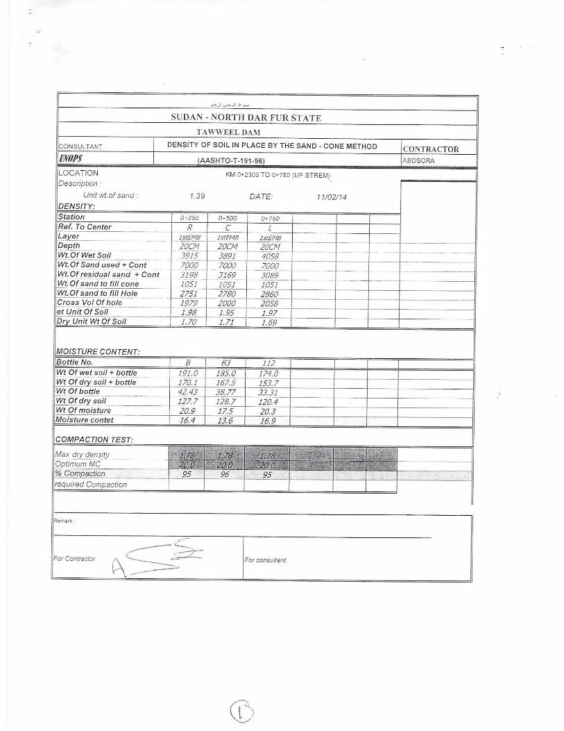
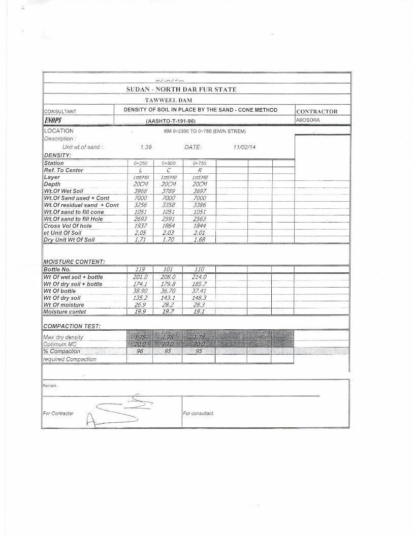
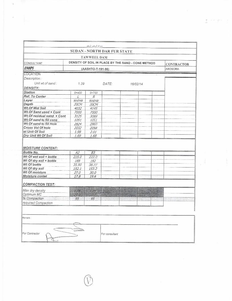
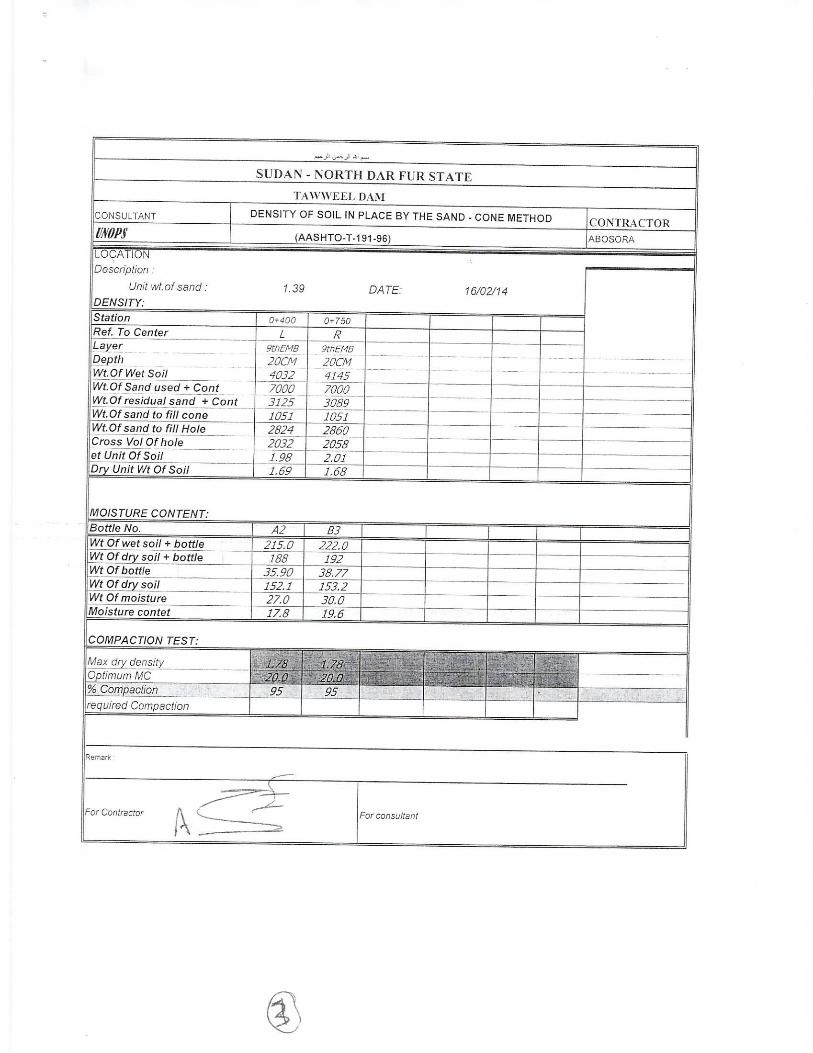
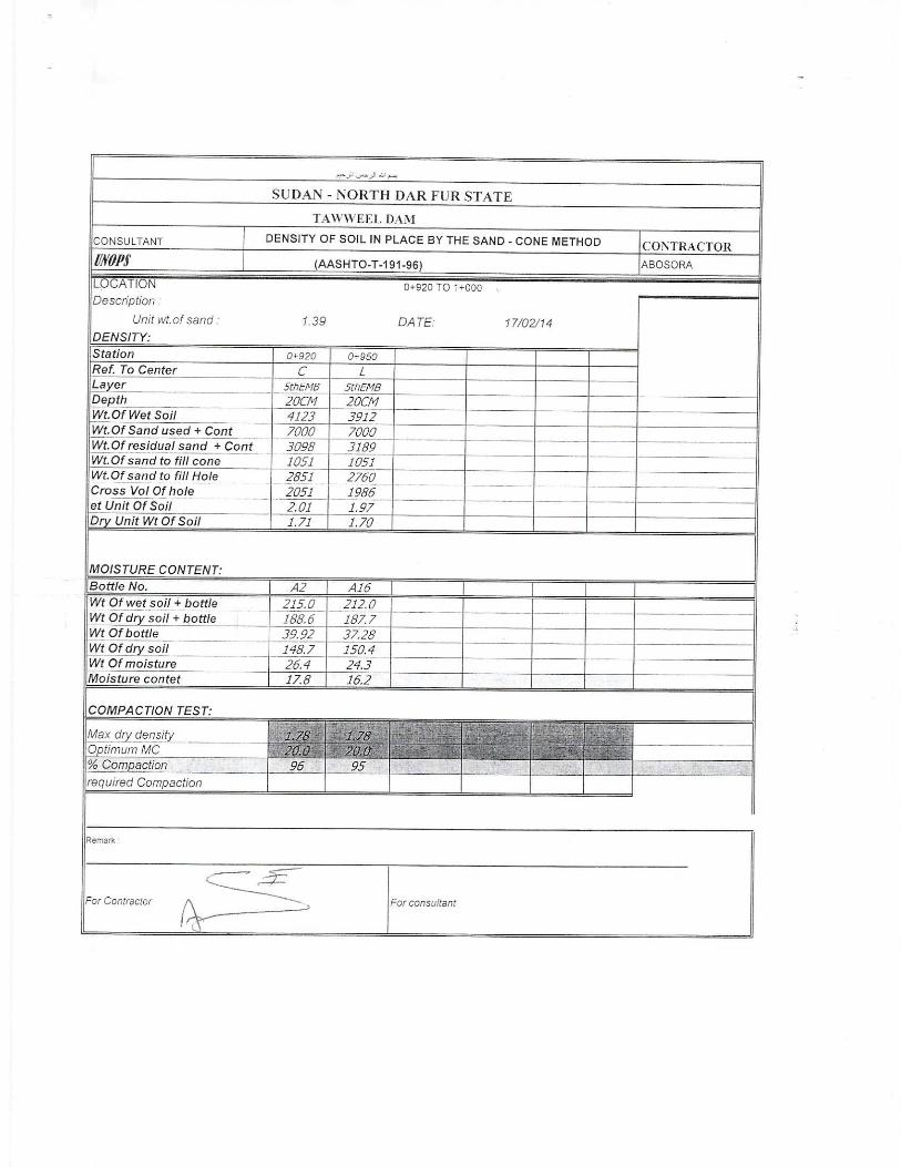
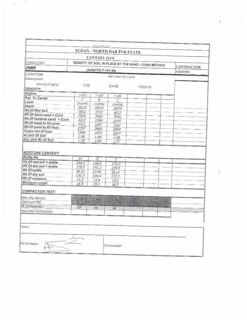
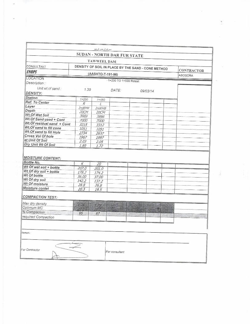
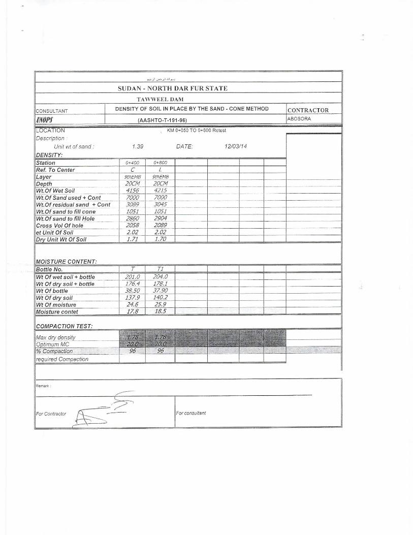
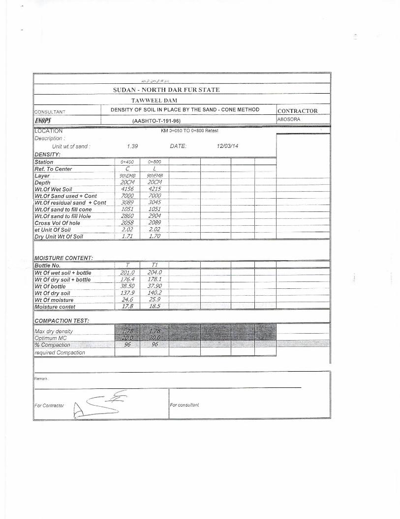
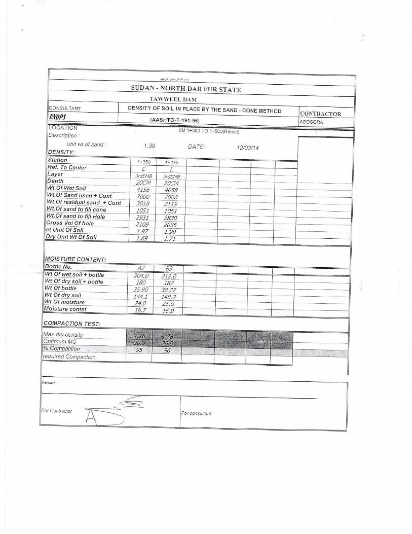
It is important to note that the contractor was requested to
submit any tests results for the quality control during dam
construction. He submitted only some field density tests for the
compaction of the embankment layers (Appendix (B)).
Table 1: Classification Tests Results for the Dam Site.
Test Measured
Property
Spillway Structure (S1 & S2) Embankment
(S3) Depth 4m Depth 7.5m
Sieve
Analysis
Gravel 0 5 0
Sand 94 93 1
Clay 6 2 99
Atterberg's
Limits
LL
NP NP
57
PL 27
PI 27
Classification USCS SP SW CH
Geotechnical Investigation for By Dr. Magdi Zumrawi
Tawila Dam in North Darfur State University of Khartoum
13
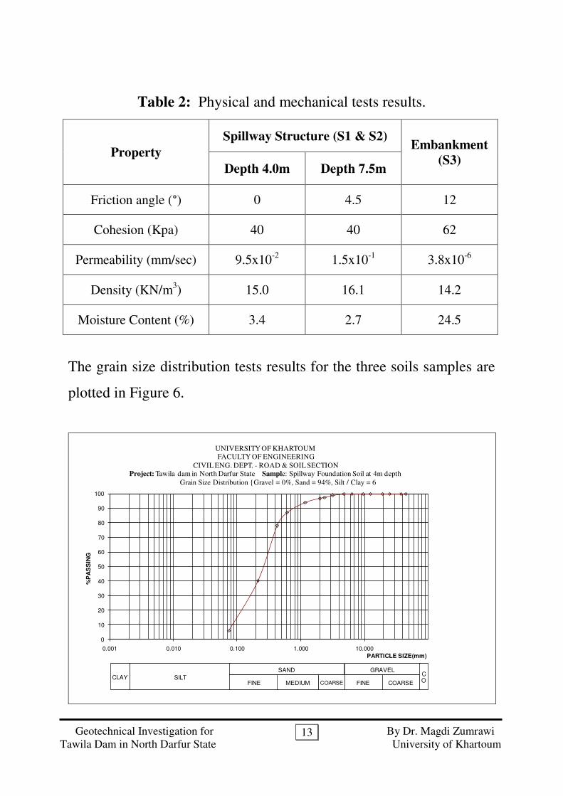
Table 2: Physical and mechanical tests results.
Property
Spillway Structure (S1 & S2) Embankment
(S3) Depth 4.0m Depth 7.5m
Friction angle (°) 0 4.5 12
Cohesion (Kpa) 40 40 62
Permeability (mm/sec) 9.5x10⁻²
1.5x10⁻¹
3.8x10⁻⁶
Density (KN/m3) 15.0 16.1 14.2
Moisture Content (%) 3.4 2.7 24.5
The grain size distribution tests results for the three soils samples are
plotted in Figure 6.
0
10
20
30
40
50
60
70
80
90
100
0.001 0.010 0.100 1.000 10.000
%P
AS
SIN
G
PARTICLE SIZE(mm)
UNIVERSITY OF KHARTOUM FACULTY OF ENGINEERING
CIVIL ENG. DEPT. - ROAD & SOIL SECTIONProject: Tawila dam in North Darfur State Sample: Spillway Foundation Soil at 4m depth
Grain Size Distribution {Gravel = 0%, Sand = 94%, Silt / Clay = 6
SILTFINE MEDIUM COARSE
SAND
FINE COARSE
GRAVELCO
CLAY

Geotechnical Investigation for By Dr. Magdi Zumrawi
Tawila Dam in North Darfur State University of Khartoum
14
0
10
20
30
40
50
60
70
80
90
100
0.001 0.010 0.100 1.000 10.000
%P
AS
SIN
G
PARTICLE SIZE(mm)
UNIVERSITY OF KHARTOUM FACULTY OF ENGINEERING
CIVIL ENG. DEPT. - ROAD & SOIL SECTIONProject: Tawila dam in North Darfur State Sample: Spillway Foundation Soil at 7.5m depth
Grain Size Distribution {Gravel = 5%, Sand = 93%, Silt / Clay =
SILTFINE MEDIUM COARSE
SAND
FINE COARSE
GRAVELCO
CLAY
0
10
20
30
40
50
60
70
80
90
100
0.001 0.010 0.100 1.000 10.000
%P
AS
SIN
G
PARTICLE SIZE(mm)
UNIVERSITY OF KHARTOUM FACULTY OF ENGINEERING
CIVIL ENG. DEPT. - ROAD & SOIL SECTIONProject: Tawila dam in North Darfur State Sample: Embankment Material
Grain Size Distribution {Gravel = 0%, Sand = 1%, Silt / Clay = 99%}
SILTFINE MEDIUM COARSE
SAND
FINE COARSE
GRAVELCO
CLAY
Figure 6: Grain size distribution for the three soils samples.

Geotechnical Investigation for By Dr. Magdi Zumrawi
Tawila Dam in North Darfur State University of Khartoum
15
4.2. SSooiill PPrrooffiillee
The subsoil profile for the dam is determined based on the
visual inspection at the site and the tests results of the samples as
shown on plots of Figure 6. The profile generally reflected similar soil
stratifications with slight variations. The soil profile at the location of
the spillway structure consists of a thick layer of sand. At the top of
the layer of 4 m thick is fine Sand was encountered. This is followed
by fine to medium Sand was encountered at 7.5 m. Generally the
subsoil in the dam site is sand of non plasticity. This soil was
encountered mostly mixed with silt. The permeability of this soil is
high leading to water seepage under the spillway.
The whole dam section is made of homogeneous embankment
material. Investigation was conducted to assess the type of material
and its properties used on embankment construction. The construction
material for the embankment construction is clay soil of high
plasticity and very low permeability.
4.3. SSooiill BBeeaarriinngg CCaappaacciittyy
The bearing capacity of the spillway foundation soil at depth
7.5m can be determined using Terzaghi bearing capacity equation:
qu = CNc Sc + q Nq + 0.5 γ B N γ S γ
The foundation of the spillway structure was placed at 7.5m
depth on fine to medium sand. The average foundation soil properties
can be obtained from the tests results as given in Table 2:
Average bulk density (γ) = 16.1 KN/m3
Geotechnical Investigation for By Dr. Magdi Zumrawi
Tawila Dam in North Darfur State University of Khartoum
16
Soil cohesion (C) = 4.5 KN/ m2
Angle of internal friction (ф) = 40◦
Foundation depth = 7.5m
Foundation width = 3m
The bearing capacity coeff. : Nc = 34.9, Nq = 20.5, N γ= 18.8
Vertical surcharge pressure q = 16.1* 7.5 = 120.8 KN/ m2
Foundation shape coeff. Sc = 1.3, S γ = 0.80
By substituting the above properties in Terzaghi’s equation, the
ultimate bearing capacity qu = 3285 KN/m2. By using factor of safety
equal 5, the allowable bearing capacity qa= 657 KN/ m2.
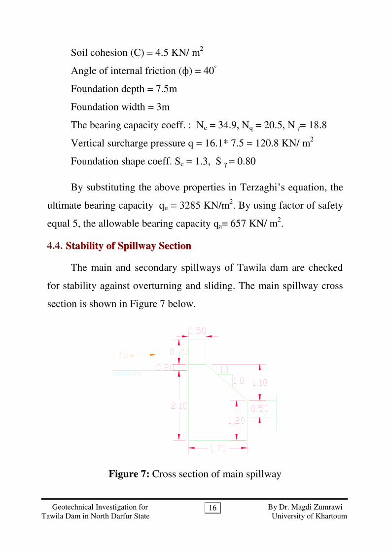
4.4. SSttaabbiilliittyy ooff SSppiillllwwaayy SSeeccttiioonn
The main and secondary spillways of Tawila dam are checked
for stability against overturning and sliding. The main spillway cross
section is shown in Figure 7 below.
Figure 7: Cross section of main spillway

Geotechnical Investigation for By Dr. Magdi Zumrawi
Tawila Dam in North Darfur State University of Khartoum
17
The weight of materials
Concrete Masonry Sand ( sand ) Sand (sat ) Clay (C)
2250 Kg/m3
2640 Kg/m3 19.6KN/m
3 16.0KN/m
3 40KN/m
2
Centroid of spillway section 321
332211 ***
AAA
rArArAr
Area of spillway section
264.32.1*)5.021.1(21.1*2
2.09.0*5.05.0*)2.09.0(5.0*75.0 mAtotal
mr 00.164.3
05.2*2
5.021.167.0*21.1*
3
255.0*
2
5.021.138.0*)
2
5.021.1(
Normal condition
Vertical forces forceUpliftWF masonryV
KNFV
09.5605.3*71.1*81.9*2
19.25*64.3
Horizontal forces SDSUHForceessureForceessureF // PrPr
Resultant force KNFFF HVtesul 85.6455.3209.56 2222
tanRe
Net Moment ckWcountercloclockWo MMM
KN
hhhhF SDsatSDmasonrySUWSUsatH
55.325.0*16*2
15.0*9.25*
2
195.0*81.9*
2
11.2*16*
2
1
*2
1*
2
1*
2
1*
2
1
2222
2
/
2
/
2
/
2
/

Geotechnical Investigation for By Dr. Magdi Zumrawi
Tawila Dam in North Darfur State University of Khartoum
18
KNm
M CClockW
45.106
3
7.0*7.0*6.19*
2
15.0*5.0*9.25*7.0
3
1*5.00.1*9.25*64.3 22
KNm
M ClockW
09.68
2
1*95.0*95.0*81.9*
2
1
2
1*1.2*1.2*16*
2
15.*71.1*05.3*71.1*81.9*
2
1 22
KNmMMM ckWcountercloclockWo 36.3809.6845.106
mFR
MxFRxM net
net 59.085.64
36.38*
The centroid of the resultant force passes through one third of
the bottom thickness of the spillway which insures that the dam
section is safe.
Forces acting on a subsurface dam
Moment resisting over turning=
KNmM r 46.106.
Moment causing overturning= rupliftrPFM SUo **/
KNmM o 09.68
Factor of safety against overturning
!56.109.68
45.106ReSafe
momentgOverturnin
MomentsistingFSO
SDSsandDSUSsandUmasonrymasonryr rWrWrWM //// ***

Geotechnical Investigation for By Dr. Magdi Zumrawi
Tawila Dam in North Darfur State University of Khartoum
19
Factor of safety found against overturning is much bigger than
the minimum value of factor of safety required. This however ensures
that the height of the structure can be extended (rise up) to increase
the spillway height of the dam. The increased pressure force will be
resisted by the spillway section.
Factor of Safety against Sliding
Sum of sliding forces = upstream pressure force - downstream
pressure force
KN
hhhh SDsatSDmasonrySUWSUsat
55.325.0*16*2
15.0*9.25*
2
195.0*81.9*
2
11.2*16*
2
1
*2
1*
2
1*
2
1*
2
1
2222
2
/
2
/
2
/
2
/
Sum of forces resisting sliding = cohesion of rock material* area
of contact
= KNAC foundation 41.6871.1*40*
Factor of safety against Sliding
!10.255.32
41.68ReSafe
ForceShearing
forcessistingFS S
The same is applied for secondary spillway and found safe.
Geotechnical Investigation for By Dr. Magdi Zumrawi
Tawila Dam in North Darfur State University of Khartoum
20
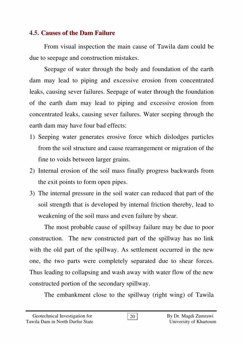
4.5. CCaauusseess ooff tthhee DDaamm FFaaiilluurree
From visual inspection the main cause of Tawila dam could be
due to seepage and construction mistakes.
Seepage of water through the body and foundation of the earth
dam may lead to piping and excessive erosion from concentrated
leaks, causing sever failures. Seepage of water through the foundation
of the earth dam may lead to piping and excessive erosion from
concentrated leaks, causing sever failures. Water seeping through the
earth dam may have four bad effects:
1) Seeping water generates erosive force which dislodges particles
from the soil structure and cause rearrangement or migration of the
fine to voids between larger grains.
2) Internal erosion of the soil mass finally progress backwards from
the exit points to form open pipes.
3) The internal pressure in the soil water can reduced that part of the
soil strength that is developed by internal friction thereby, lead to
weakening of the soil mass and even failure by shear.
The most probable cause of spillway failure may be due to poor
construction. The new constructed part of the spillway has no link
with the old part of the spillway. As settlement occurred in the new
one, the two parts were completely separated due to shear forces.
Thus leading to collapsing and wash away with water flow of the new
constructed portion of the secondary spillway.
The embankment close to the spillway (right wing) of Tawila
Geotechnical Investigation for By Dr. Magdi Zumrawi
Tawila Dam in North Darfur State University of Khartoum
21
dam got saturated due to excessive seepage. It might have been
eroded, producing small slumps/slides presenting relatively steep
faces which once again became saturated by seepage from the
reservoir and slumped again, forming slightly higher and unstable
faces. This raveling process kept on going until the remaining portion
of the embankment became too thin to withstand the water pressure,
thus leading to the collapse of embankment and right wing-wall.
55.. RReeccoommmmeennddaattiioonnss
Based on the investigation results, it is clear that the failure of
the spillway structure and the adjacent embankment of the dam is
mainly due to seepage and improper design and construction.
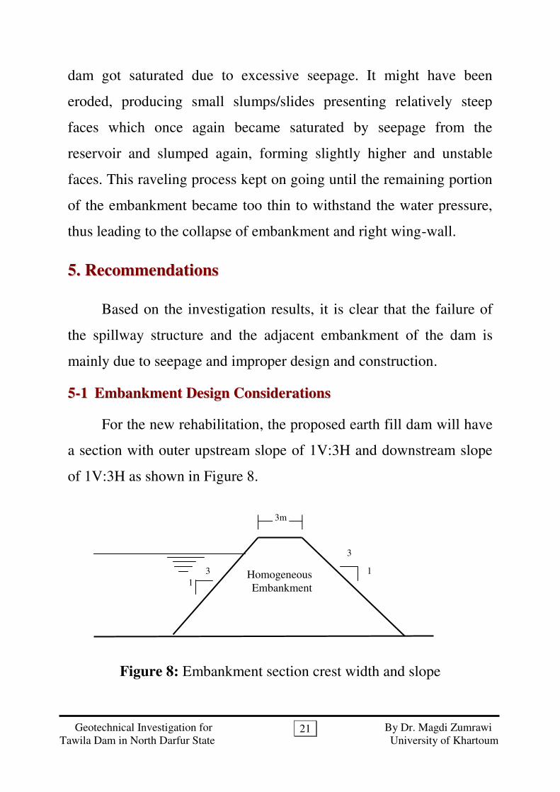
55--11 EEmmbbaannkkmmeenntt DDeessiiggnn CCoonnssiiddeerraattiioonnss
For the new rehabilitation, the proposed earth fill dam will have
a section with outer upstream slope of 1V:3H and downstream slope
of 1V:3H as shown in Figure 8.
Figure 8: Embankment section crest width and slope
1
3 Homogeneous
Embankment
1
3
3m

Geotechnical Investigation for By Dr. Magdi Zumrawi
Tawila Dam in North Darfur State University of Khartoum
22
An impervious blanket immediately upstream of a dam can be
used to seal the reservoir bottom and sides and thereby reduce
seepage quantities and pressures beneath a dam (Figure 9). If the dam
contains a permeable shell, the impervious blanket must be extended
up the embankment slope to effectively control the seepage problem.
Figure 9: Upstream impervious blanket
In order to control the escaping of fine particles, a rock toe drain
will be provide which consists of filter and rock. The purpose of the
filter and drain is to provide a way for seepage to exit the dam without
causing excessive erosion of the dam material.
The two basic dimensions for this dam are the height (H) and
the crest width (B). The height chosen will depend on the depth of
water at full supply level (D) and the freeboard required. Crest width
will depend on the height.
Upstream impervious blanket
Homogeneous
Embankment

Geotechnical Investigation for By Dr. Magdi Zumrawi
Tawila Dam in North Darfur State University of Khartoum
23
Figure 10: Cross-Section of Homogenous Dam with Toe Drain
Hand-placed riprap is recommended to protect the slopes of the
dam embankment against destructive wave action in the upstream and
from weathering effects for downstream slopes.
55--22 SSeeeeppaaggee CCoonnttrrooll
To avoid and prevent any seepage of water below the spillway
structure that may occur, some technical solutions and precautions
should be considered in design and construction of foundation.
Because of water percolates through the foundation soil of the
spillway, use vertical moisture barriers to a depth not less than 10m
at three different locations below the concrete slab.
Because water percolates through earth dam; when however it
stagnates in the downstream portion of the dam and over saturates
it; the slips of the material of this portion may occur, resulting in
failure of dam. The taking out of this water from the downstream
portion so that there may be no slips, it is necessary since the
material in the downstream portion of dam has no good natural
drainage properties. Drainage may be in the form of toe drain.
D
H
D+2m
H/3
Geotechnical Investigation for By Dr. Magdi Zumrawi
Tawila Dam in North Darfur State University of Khartoum
24
55--33 SSppiillllwwaayy FFoouunnddaattiioonn
The choice of foundation type for any site depends on many
factors such as the superstructure imposed load, subsoil profile,
placement condition and the foundation soil bearing capacity.
Generally the spillway structure of the dam will imposed
significant surcharge pressure on the foundation soil. The spillway is
structurally required to be stable and the foundation settlement should
be within the permissible limit.
Taking these factors into account with the foundation soil
bearing capacity, 657 KPa, raft foundation can support the spillway
structure. But the foundation soil of the spillway structure of sand soil
that has high permeability will increase water seepage and erosion at
upstream and downstream aprons. Therefore the best foundation
option is pile foundation of end bearing support.
Vertical moisture barriers are also suggested to reduce variation
of moisture content in the foundation soil and prevent any seepage of
water through this sandy soil. These barriers are to be erected to a
depth not less than 10m at three different locations, below the edges
and center of the concrete slab (i.e. at upstream, downstream and
center of the dam). The purpose of these moisture barriers is to reduce
or prevent water flow in the zone of sand soil below the dam.

Geotechnical Investigation for By Dr. Magdi Zumrawi
Tawila Dam in North Darfur State University of Khartoum
25
AAppppeennddiixx ((AA))
Laboratory Tests
Data Analysis

Geotechnical Investigation for By Dr. Magdi Zumrawi
Tawila Dam in North Darfur State University of Khartoum
26
Project:
Sample Description:
100
(mm) Wt. (g) (%)
44.500 0.0 0.0 100
37.500 0.0 0.0 100
25.000 0.0 0.0 100
19.000 0.0 0.0 100
12.500 0.0 0.0 100
9.500 0.0 0.0 100
6.350 0.0 0.0 100
4.760 0.0 0.0 100
3.180 1.2 1.2 99
2.360 1.4 1.4 97
2.000 0.8 0.8 97
1.180 2.8 2.8 94
0.600 6.9 6.9 87
0.425 8.7 8.7 78
0.211 38.1 38.1 40
0.075 34.2 34.2 6
Gravel 0% D10 0.085 mm
Sand 94% D30 0.170 mm
Silt & Clay 6% D60 0.310 mm
USCS SP Cu 4
AASHTO A-1-a Cc 1.1
B.S seive
Tawila Dam in North Darfur
Sandy Soil (S1)
Retained %age Passing
م ه الرحمن الرحيم س بUNIVERSITY OF KHARTOUM
Faculty of Engineering - Civil Eng. Dept.
Sieve Analysis for Granular Materials
Sample Total Weight (g)
Based on BS 1377

Geotechnical Investigation for By Dr. Magdi Zumrawi
Tawila Dam in North Darfur State University of Khartoum
27
Project:
Sample Description:
100
(mm) Wt. (g) (%)
44.500 0.0 0.0 100
37.500 0.0 0.0 100
25.000 0.0 0.0 100
19.000 0.0 0.0 100
12.500 0.0 0.0 100
9.500 1.5 1.5 99
6.350 2.0 2.0 97
4.760 1.6 1.6 95
3.180 0.4 0.4 95
2.360 5.2 5.2 89
2.000 1.8 1.8 88
1.180 8.1 8.1 79
0.600 21.8 21.8 58
0.425 15.6 15.6 42
0.211 27.3 27.3 15
0.075 12.6 12.6 2
Gravel 5% D10 0.17 mm
Sand 93% D30 0.32 mm
Silt & Clay 2% D60 0.65 mm
USCS SW Cu 4
AASHTO A-1-a Cc 0.9
م ه الرحمن الرحيم س بUNIVERSITY OF KHARTOUM
Faculty of Engineering - Civil Eng. Dept.
Sieve Analysis for Granular Materials
Sample Total Weight (g)
Based on BS 1377
B.S seive
Tawila Dam in North Darfur
Sandy Soil (S2)
Retained %age Passing
Geotechnical Investigation for By Dr. Magdi Zumrawi
Tawila Dam in North Darfur State University of Khartoum
28
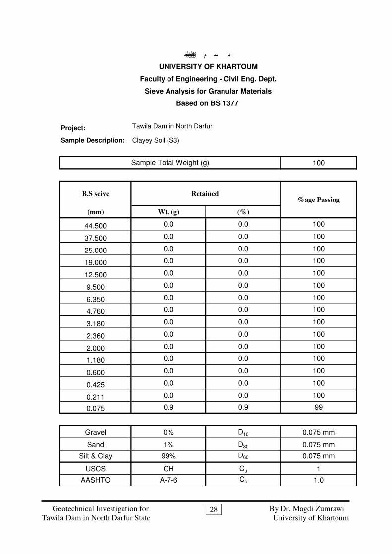
Project:
Sample Description:
100
(mm) Wt. (g) (%)
44.500 0.0 0.0 100
37.500 0.0 0.0 100
25.000 0.0 0.0 100
19.000 0.0 0.0 100
12.500 0.0 0.0 100
9.500 0.0 0.0 100
6.350 0.0 0.0 100
4.760 0.0 0.0 100
3.180 0.0 0.0 100
2.360 0.0 0.0 100
2.000 0.0 0.0 100
1.180 0.0 0.0 100
0.600 0.0 0.0 100
0.425 0.0 0.0 100
0.211 0.0 0.0 100
0.075 0.9 0.9 99
Gravel 0% D10 0.075 mm
Sand 1% D30 0.075 mm
Silt & Clay 99% D60 0.075 mm
USCS CH Cu 1
AASHTO A-7-6 Cc 1.0
م ه الرحمن الرحيم س بUNIVERSITY OF KHARTOUM
Faculty of Engineering - Civil Eng. Dept.
Sieve Analysis for Granular Materials
Sample Total Weight (g)
Based on BS 1377
B.S seive
Tawila Dam in North Darfur
Clayey Soil (S3)
Retained %age Passing
Geotechnical Investigation for By Dr. Magdi Zumrawi
Tawila Dam in North Darfur State University of Khartoum
29
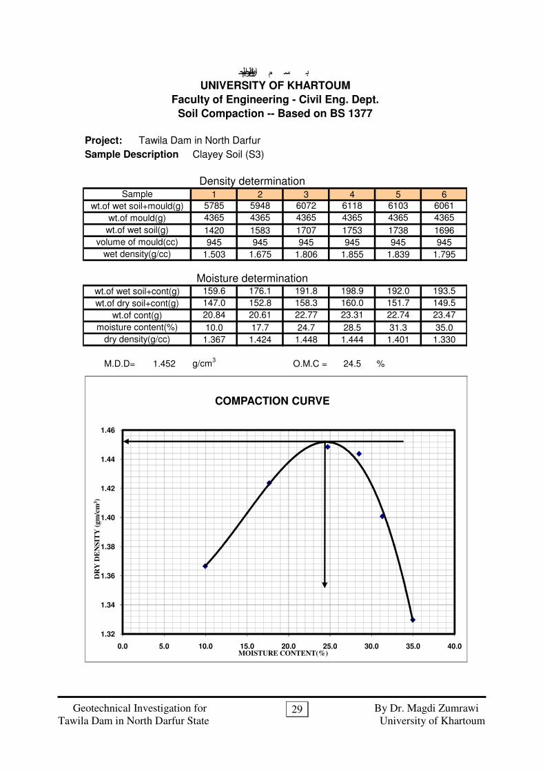
Project: Tawila Dam in North Darfur
Sample Description
1 2 3 4 5 6
5785 5948 6072 6118 6103 6061
4365 4365 4365 4365 4365 4365
1420 1583 1707 1753 1738 1696
945 945 945 945 945 945
1.503 1.675 1.806 1.855 1.839 1.795
159.6 176.1 191.8 198.9 192.0 193.5
147.0 152.8 158.3 160.0 151.7 149.5
20.84 20.61 22.77 23.31 22.74 23.47
10.0 17.7 24.7 28.5 31.3 35.0
1.367 1.424 1.448 1.444 1.401 1.330
M.D.D= 1.452 g/cm3
O.M.C = 24.5 %
Faculty of Engineering - Civil Eng. Dept.
Soil Compaction -- Based on BS 1377
wt.of wet soil+cont(g)
Sample
wet density(g/cc)
Clayey Soil (S3)
م ه الرحمن الرحيم س بUNIVERSITY OF KHARTOUM
dry density(g/cc)
Moisture determination
Density determination
wt.of wet soil+mould(g)
wt.of dry soil+cont(g)
wt.of cont(g)
moisture content(%)
wt.of mould(g)
wt.of wet soil(g)
volume of mould(cc)
1.32
1.34
1.36
1.38
1.40
1.42
1.44
1.46
0.0 5.0 10.0 15.0 20.0 25.0 30.0 35.0 40.0
DR
Y D
EN
SIT
Y (
gm
/cm
3)
MOISTURE CONTENT(%)
COMPACTION CURVE
Geotechnical Investigation for By Dr. Magdi Zumrawi
Tawila Dam in North Darfur State University of Khartoum
30
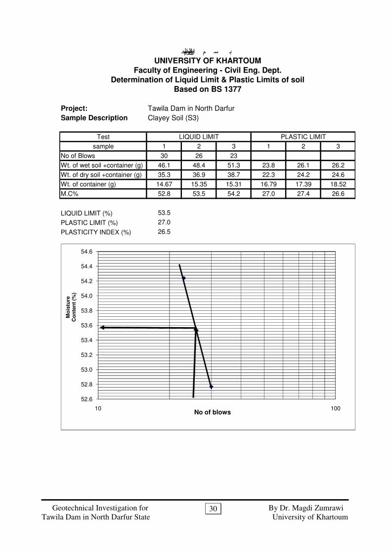
Project: Tawila Dam in North Darfur
Sample Description
Test
sample 1 2 3 1 2 3
No of Blows 30 26 23
Wt. of wet soil +container (g) 46.1 48.4 51.3 23.8 26.1 26.2
Wt. of dry soil +container (g) 35.3 36.9 38.7 22.3 24.2 24.6
Wt. of container (g) 14.67 15.35 15.31 16.79 17.39 18.52
M.C% 52.8 53.5 54.2 27.0 27.4 26.6
LIQUID LIMIT (%) 53.5
PLASTIC LIMIT (%) 27.0
PLASTICITY INDEX (%) 26.5
Determination of Liquid Limit & Plastic Limits of soil
م ه الرحمن الرحيم س بUNIVERSITY OF KHARTOUM
Faculty of Engineering - Civil Eng. Dept.
LIQUID LIMIT PLASTIC LIMIT
Based on BS 1377
Clayey Soil (S3)
52.6
52.8
53.0
53.2
53.4
53.6
53.8
54.0
54.2
54.4
54.6
10 100No of blows
Mo
istu
re
Co
nte
nt
(%)
Geotechnical Investigation for By Dr. Magdi Zumrawi
Tawila Dam in North Darfur State University of Khartoum
31
AAppppeennddiixx ((BB))
Field density Tests Results
During Construction
(Contractor Documents)