Geotechnical Investigation – Proposed Commercial ...
57
© 2016 Pinchin Ltd. Geotechnical Investigation – Proposed Commercial Development 571 Lacolle Way Ottawa, Ontario Prepared for: Morley Hoppner Limited 1818 Bradley Side Road Ottawa, ON K0A 1L0 Attention: Brian Morley Vice President October 14, 2016 Pinchin File: 117840.001
-
Upload
khangminh22 -
Category
Documents
-
view
2 -
download
0
Transcript of Geotechnical Investigation – Proposed Commercial ...

© 2016 Pinchin Ltd.
Geotechnical Investigation – Proposed Commercial Development 571 Lacolle Way Ottawa, Ontario
Prepared for:
Morley Hoppner Limited 1818 Bradley Side Road Ottawa, ON K0A 1L0
Attention: Brian Morley Vice President October 14, 2016
Pinchin File: 117840.001

Geotechnical Investigation – Proposed Commercial Development October 14, 2016 571 Lacolle Way, Ottawa, Ontario Pinchin File: 117840.001 Morley Hoppner Limited
© 2016 Pinchin Ltd. Page i
Issued to: Contact: Issued on: Pinchin file: Issuing Office: Primary Contact:
Morley Hoppner Limited Brian Morley October 14, 2016 117840.001 555 Legget Drive, Suite 1001, Tower A, Kanata, ON K2K 2X3 Wesley Tabaczuk, Project Manager
Author: Wesley Tabaczuk, P. Eng. Project Manager 1-613-592-3387 Ext. 1829 [email protected]
Reviewer: Scott Mather, P. Eng. Manager National Capital Region 1-613-592-3387 Ext. 1802 [email protected]

Geotechnical Investigation – Proposed Commercial Development October 14, 2016 571 Lacolle Way, Ottawa, Ontario Pinchin File: 117840.001 Morley Hoppner Limited
© 2016 Pinchin Ltd. Page ii
TABLE OF CONTENTS
1.0 INTRODUCTION .............................................................................................................................. 1 2.0 SITE DESCRIPTION AND GEOLOGICAL SETTING ..................................................................... 2
3.0 GEOTECHNICAL FIELD INVESTIGATION AND METHODOLOGY .............................................. 2
4.0 FIELD LOGGING AND SUBSURFACE CONDITIONS ................................................................... 3
4.1 Borehole Soil Stratigraphy & Groundwater Conditions ........................................................ 3
5.0 GEOTECHNICAL DESIGN RECOMMENDATIONS ....................................................................... 4
5.1 Foundation Recommendations ............................................................................................. 4 5.1.1 Natural Soil Subgrade Preparation ........................................................................ 6 5.1.2 Biaxial Geogrid Installation .................................................................................... 7 5.1.3 Vertical Transition of Strip Footings ....................................................................... 8 5.1.4 Individual Spread Footings .................................................................................... 8 5.1.5 Estimated Settlement ............................................................................................. 8 5.1.6 Building Drainage ................................................................................................... 8 5.1.7 Shallow Foundation Frost Protection & Foundation Backfill .................................. 9 5.1.8 Concrete Floor Slab-on-Grade ............................................................................. 10
6.0 ASPHALTIC CONCRETE PAVEMENT STRUCTURE DESIGN FOR PARKING LOT ................. 11
6.1 Discussion .......................................................................................................................... 11 6.2 Pavement Structure ............................................................................................................ 12 6.3 Pavement Structure Subgrade Preparation and Granular Up Fill ...................................... 13 6.4 Horizontal Transition Treatment ......................................................................................... 14 6.5 Drainage ............................................................................................................................. 14
7.0 SITE SERVICES ............................................................................................................................ 15
7.1 Pipe Bedding and Cover Materials for Flexible and Rigid Pipes ........................................ 15 7.2 Trench Backfill .................................................................................................................... 15 7.3 Frost Protection .................................................................................................................. 17
8.0 INSTALLATION OF ENGINEERED FILL ...................................................................................... 17
9.0 SITE CLASSIFICATION FOR SEISMIC SITE RESPONSE & SOIL BEHAVIOUR ....................... 18
10.0 SITE SUPERVISION & QUALITY CONTROL ............................................................................... 19
10.1 Open Cut Excavations ........................................................................................................ 19 10.2 Anticipated Groundwater Management .............................................................................. 20
11.0 DISCLAIMER ................................................................................................................................. 21
Geotechnical Investigation – Proposed Commercial Development October 14, 2016 571 Lacolle Way, Ottawa, Ontario Pinchin File: 117840.001 Morley Hoppner Limited
© 2016 Pinchin Ltd. Page iii
FIGURES
FIGURE 1 General Site Location Plan
FIGURE 2 Borehole Location Plan
APPENDICES
APPENDIX I Abbreviations, Terminology and Principle Symbols used in Report and Borehole Logs
APPENDIX II Pinchin’s Borehole Logs
APPENDIX III Analytical Laboratory Testing Reports for Soil Samples APPENDIX IV Report Limitations and Guidelines for Use

Geotechnical Investigation – Proposed Commercial Development October 14, 2016 571 Lacolle Way, Ottawa, Ontario Pinchin File: 117840.001 Morley Hoppner Limited
© 2016 Pinchin Ltd. Page 1 of 22
1.0 INTRODUCTION
Pinchin Ltd. (Pinchin) was retained by Morley Hoppner Limited (Client) to conduct a Geotechnical
Investigation and provide subsequent geotechnical design recommendations for the proposed
commercial development to be located at 571 Lacolle Way Ottawa, Ontario (Site). The Site location is
shown on Figure 1.
Based on a drawing provided by the Client entitled “Site Plan Study” dated May 9, 2016, Project No. 16-
034, the proposed development is to consist of an approximate 1,420 square metre (m2) addition to the
west portion of the existing commercial building located on-Site. The proposed addition will reportedly
consist of a single-storey, slab-on-grade (i.e. no basement level) building. The development will also
include an asphalt surfaced parking area complete with 44 parking spaces.
Pinchin’s comments and recommendations are based on the results of the Geotechnical Investigation
and understanding of the project scope.
The purpose of the Geotechnical Investigation was to delineate the subsurface conditions and soil
engineering characteristics by advancing a total of four sampled boreholes and one Dynamic Cone
Penetration Test (DCPT) within the vicinity of the proposed building footprint. The information gathered
from the Geotechnical Investigation will allow Pinchin to provide geotechnical design recommendations
for the proposed development.
Based on a desk top review and the results of the Geotechnical Investigation, the following geotechnical
data and engineering design recommendations are provided herein:
• A review of relevant area geology and Site background information;
• A detailed description of the soil and groundwater conditions, including borehole logs;
• Foundation design recommendations including soil bearing pressures at Serviceability
Limit States (SLS) design;
• Foundation subgrade preparation;
• Potential foundation settlements;
• Foundation frost protection and engineered fill specifications and installation;
• Interior concrete floor slab-on-grade;
• Building drainage and foundation backfill;
• Asphaltic concrete pavement structure design for parking lot area;
• Site service trench design;
• Seismic Site classification for seismic Site response;

Geotechnical Investigation – Proposed Commercial Development October 14, 2016 571 Lacolle Way, Ottawa, Ontario Pinchin File: 117840.001 Morley Hoppner Limited
© 2016 Pinchin Ltd. Page 2 of 22
• Open cut excavations; and
• Anticipated groundwater management.
Abbreviations terminology and principle symbols commonly used throughout the report, borehole logs
and appendices are enclosed in Appendix I.
2.0 SITE DESCRIPTION AND GEOLOGICAL SETTING
The Site is located on the northeast corner of the intersection of Lacolle Way and Taylor Creek
Boulevard, approximately 150 m north of St. Joseph Boulevard in Ottawa, Ontario. Currently the Site is
occupied by a single storey commercial retail building, asphalt and gravel surfaced parking areas and
areas of soft landscaping (i.e. grassed areas with trees).
Data obtained from the Ontario Geological Survey Maps, as published by the Ontario Ministry of Natural
Resources, indicates that the Site is located on a fine-textured glaciomarine deposit consisting of massive
to well laminated silt and clay, with minor sand and gravel. The underlying bedrock at this Site is of the
Shadow Lake Formation consisting of limestone, dolostone, shale, arkose and sandstone (Ontario
Geological Survey Map 2419, published 1979).
3.0 GEOTECHNICAL FIELD INVESTIGATION AND METHODOLOGY
Pinchin completed a field investigation at the Site on September 2, 2016 by advancing a total of four
sampled boreholes throughout the Site. The boreholes were advanced to sampled depths ranging from
approximately 5.9 to 6.7 metres below existing grade (mbg). Below the sampled depth in borehole BH1
(6.7 m), a Dynamic Cone Penetration Test (DCPT) was advanced to a depth of approximately 17.1 mbg
to further assess the consistency of the soils. The approximate spatial locations of the boreholes
advanced at the Site are shown on Figure 2.
The boreholes were advanced with the use of a track mounted mobile drill rig, owned and operated by
Strata Drilling Group, which was equipped with 200 millimetre (mm) diameter continuous flight hollow
stem augers and standard soil sampling equipment. Soil samples were collected at 0.76 m intervals in the
upper 3.0 m, then 1.52 m intervals thereafter using a 51 mm outside diameter (OD) split spoon barrel in
conjunction with Standard Penetration Tests (SPT) “N” values (ASTM D1586). The SPT “N” values were
used to estimate the consistency of the cohesive soils.
The DCPT was performed with a 60 degree apex cone attached to “A” size drill rods. The numbers of
blows were recorded for each 300 mm of soil penetration advanced by a 63.5 kilogram (kg) weight free
falling a distance of 0.76 m. It is noted that the DCPT values per 300 mm are not fully representative of
the consistency of the soil due to rod friction masking the actual tip resistance. As such, the DCPT values
should only be interpreted with the guidance of a geotechnical consultant.

Geotechnical Investigation – Proposed Commercial Development October 14, 2016 571 Lacolle Way, Ottawa, Ontario Pinchin File: 117840.001 Morley Hoppner Limited
© 2016 Pinchin Ltd. Page 3 of 22
The soil sampling operation was completed under the full time supervision of experienced Pinchin
personnel. Pinchin logged the drilling operations and identified the soil samples as they were retrieved.
The recovered soil samples were sealed into plastic bags and carefully transported to an independent
and accredited materials testing laboratory for detailed analysis and testing. All soil samples were
classified according to visual and index properties by the project engineer. Upon completion of the drilling
program, the boreholes were backfilled with auger cuttings and sealed with bentonite pellets.
A local temporary benchmark was established on the top nut of the fire hydrant located adjacent to the
southwest corner of the Site. The temporary benchmark was assigned a local elevation of 100.00 m. The
approximate spatial locations and local elevations of the boreholes advanced at the Site are shown on
Figure 2.
4.0 FIELD LOGGING AND SUBSURFACE CONDITIONS
Field logging of the soil and groundwater conditions was performed to collect geotechnical engineering
design information. Details of the soil and groundwater conditions encountered within the boreholes are
included in Appendix II, Borehole Logs. The borehole logs include textural descriptions of the subsoil in
accordance with a modified Unified Soil Classification System (USCS) and indicate the soil boundaries
inferred from non-continuous sampling and observations made during the borehole advancement. These
boundaries reflect approximate transition zones for the purpose of geotechnical design and should not be
interpreted as exact planes of geological change. The modified USCS classification is explained in
further detail in Appendix I.
Select soil samples collected from the boreholes were submitted to a materials testing laboratory to
determine the natural moisture content, grain size distribution, and Atterberg Limits of the soils. A copy of
the laboratory analytical reports is included in Appendix IV. In addition, the collected samples were
compared against previous geotechnical information from the area, for consistency and calibration of
results.
It is noted that due to the limitations of retrieving soil samples with a 51 mm diameter split spoon barrel,
the grain size distribution results may not be representative of the in-situ soil matrix and reflect the larger
particles observed by the field personnel. These observations are reflected on the borehole logs.
4.1 Borehole Soil Stratigraphy & Groundwater Conditions
In general, the soil stratigraphy encountered within the boreholes consisted of approximately 300 mm of
topsoil and grass overlying silty clay to the maximum borehole termination depth of approximately 6.7
mbg.

Geotechnical Investigation – Proposed Commercial Development October 14, 2016 571 Lacolle Way, Ottawa, Ontario Pinchin File: 117840.001 Morley Hoppner Limited
© 2016 Pinchin Ltd. Page 4 of 22
The silty clay material was encountered in all boreholes underlying the topsoil and grass. The moisture
content of the silty clay material was noted to increase with depth (i.e. dry to wet) and the colour was
noted to be greyish brown. Undrained shear strengths of the silty clay material ranged from 6 to 77
kilopascals (kPa) indicating a very soft to stiff consistency. It is noted that the shear strength of the soil
generally decreases with depth and is primarily a function of the natural groundwater elevation. Grain size
distribution analysis indicates that the silty clay material contains 20 to 22% silt and 78 to 80% clay sized
particles. Atterberg Limit testing indicates that the silty clay material is of high plasticity. The water content
of the silty clay material tested ranged from 34.1 to 54.8%. The sensitivity of the silty clay material ranges
between approximately 0.94 and 6.53.
Groundwater was encountered at depths ranging from approximately 2.3 to 3.0 mbg within the boreholes.
Seasonal variations in the water table should be expected, with higher levels occurring during wet
weather conditions in the spring and fall and lower levels occurring during dry weather conditions.
A detailed description of the subsurface stratigraphy encountered during borehole advancement is
documented in the borehole logs located in Appendix II.
5.0 GEOTECHNICAL DESIGN RECOMMENDATIONS
5.1 Foundation Recommendations
The recommendations presented in the following sections of this report are based on the information
available regarding the proposed construction, the results obtained from the investigation, and Pinchin’s
experience with similar projects. Since the investigation only represents a portion of the subsurface
conditions, it is possible that conditions may be encountered during construction that are substantially
different than those encountered during the investigation. If these situations are encountered,
adjustments to the design may be necessary. A qualified geotechnical engineer should be on Site during
the foundation preparation to ensure the subsurface conditions are the same/similar to what was
observed during the investigation.
It is typical construction practice to provide foundation frost protection with soil cover. For the Ottawa
area, foundations should be provided with a minimum of 1.8 m of soil cover frost protection above the
underside of the foundation for heated buildings.
The Geotechnical Investigation indicates that the natural subgrade soils at this Site become weaker with
depth. As such, to mitigate the pressure on the underlying weaker soils (i.e. silty clay) it is recommended
to install the foundations as high as practically possible and provide a combination of soil cover and rigid
polystyrene insulation for frost protection.

Geotechnical Investigation – Proposed Commercial Development October 14, 2016 571 Lacolle Way, Ottawa, Ontario Pinchin File: 117840.001 Morley Hoppner Limited
© 2016 Pinchin Ltd. Page 5 of 22
Based on the results of the Geotechnical Investigation, Pinchin has reviewed several different shallow
foundation sizes and subgrade improvement options for the soil conditions encountered within the
boreholes. The final foundation design will be based on the loading requirements. Prior to finalizing the
foundation design it should be reviewed by Pinchin to ensure it satisfies the design assumptions. Given
the poor soil conditions with depth, the following preliminary shallow strip and spread footing design
options are provided for the support of the proposed development:
• Maximum 1 m wide shallow strip footing founded on the natural silty clay located
approximately 1.0 mbg, with a maximum applied allowable bearing pressure of 50 kPa at
Serviceability Limit States (SLS); and
• Maximum 1.5 x 1.5 m spread footing founded on the natural silty clay located
approximately 1.0 mbg, with a maximum applied allowable bearing pressure of 75 kPa at
SLS.
Alternatively, a slightly higher bearing pressure could be obtained by improving the subgrade as follows:
• Excavate all organic material to the undisturbed non-organic natural silty clay located
approximately 2.5 mbg, install a non-woven geotextile (Terrafix 270R or equivalent) and a
biaxial geo-grid (Terrafix TBX2000 or equivalent);
• Install 1.5 m of Granular A (OPSS 1010), which is to be divided into two 750 mm layers,
separated by a biaxial geo-grid (Terrafix TBX2000 or equivalent); and
• The reinforced engineered fill pad is to extend a minimum horizontal distance of 1.2 m
beyond the outside face of the foundations and slope down at 1H:1V to ensure loads are
properly transferred to the underlying natural subgrade soil as well as to accommodate
the installation of the geogrid.
For foundations installed on a reinforced engineered fill pad as outlined above the following strip and
spread footing design options are provided:
• Maximum 1 m wide shallow strip footing founded on a reinforced engineered fill pad
consisting of 1.5 m of Granular A Ontario Provincial Standards and Specifications (OPSS
1010) overlying the natural silty clay located approximately 2.5 mbg, with a maximum
applied allowable bearing pressure of 75 kPa at Serviceability Limit States (SLS); and
• Maximum 1.5 x 1.5 m spread footing founded on a reinforced engineered fill pad
consisting of 1.5 m of Granular A (OPSS 1010) overlying the natural silty clay located
approximately 2.5 mbg, with a maximum applied allowable bearing pressure of 125 kPa
at SLS.
All foundation walls should consist of steel reinforced poured concrete.
Geotechnical Investigation – Proposed Commercial Development October 14, 2016 571 Lacolle Way, Ottawa, Ontario Pinchin File: 117840.001 Morley Hoppner Limited
© 2016 Pinchin Ltd. Page 6 of 22
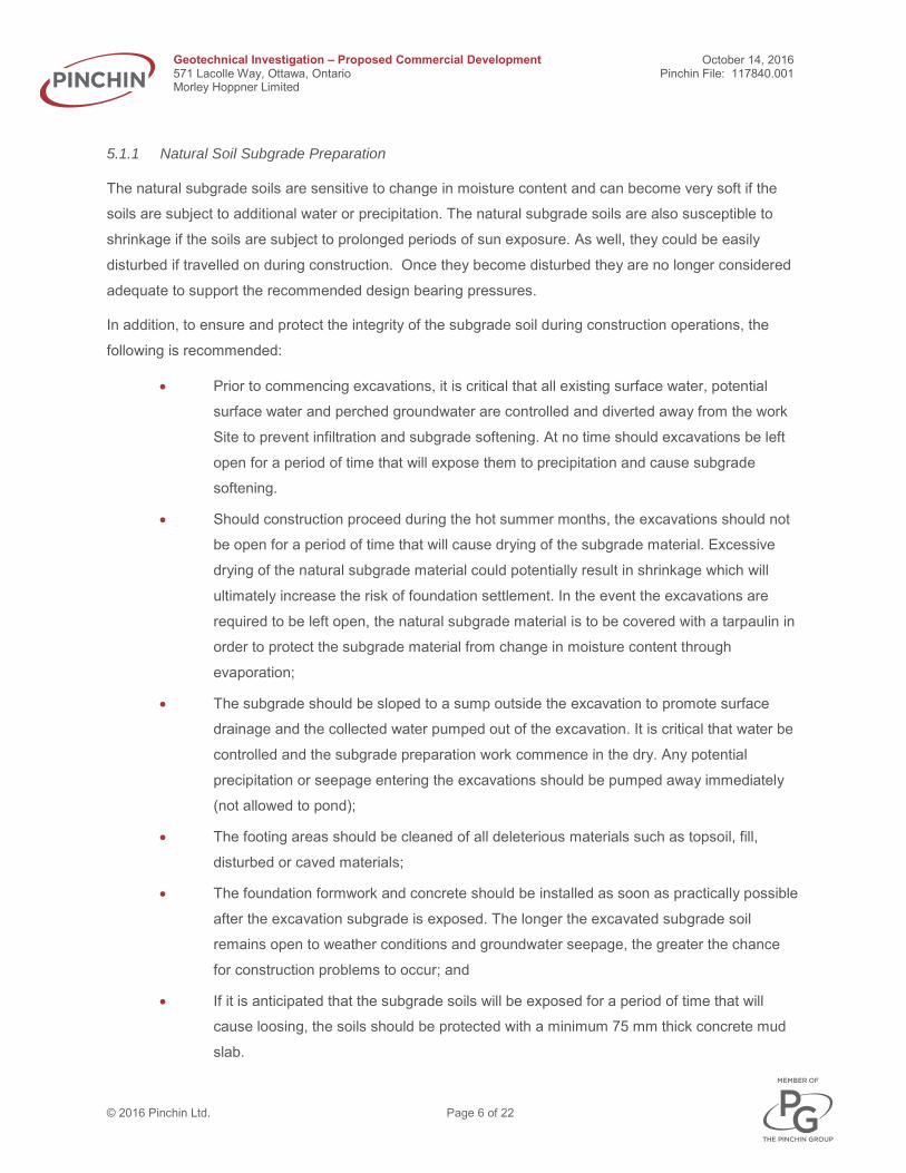
5.1.1 Natural Soil Subgrade Preparation
The natural subgrade soils are sensitive to change in moisture content and can become very soft if the
soils are subject to additional water or precipitation. The natural subgrade soils are also susceptible to
shrinkage if the soils are subject to prolonged periods of sun exposure. As well, they could be easily
disturbed if travelled on during construction. Once they become disturbed they are no longer considered
adequate to support the recommended design bearing pressures.
In addition, to ensure and protect the integrity of the subgrade soil during construction operations, the
following is recommended:
• Prior to commencing excavations, it is critical that all existing surface water, potential
surface water and perched groundwater are controlled and diverted away from the work
Site to prevent infiltration and subgrade softening. At no time should excavations be left
open for a period of time that will expose them to precipitation and cause subgrade
softening.
• Should construction proceed during the hot summer months, the excavations should not
be open for a period of time that will cause drying of the subgrade material. Excessive
drying of the natural subgrade material could potentially result in shrinkage which will
ultimately increase the risk of foundation settlement. In the event the excavations are
required to be left open, the natural subgrade material is to be covered with a tarpaulin in
order to protect the subgrade material from change in moisture content through
evaporation;
• The subgrade should be sloped to a sump outside the excavation to promote surface
drainage and the collected water pumped out of the excavation. It is critical that water be
controlled and the subgrade preparation work commence in the dry. Any potential
precipitation or seepage entering the excavations should be pumped away immediately
(not allowed to pond);
• The footing areas should be cleaned of all deleterious materials such as topsoil, fill,
disturbed or caved materials;
• The foundation formwork and concrete should be installed as soon as practically possible
after the excavation subgrade is exposed. The longer the excavated subgrade soil
remains open to weather conditions and groundwater seepage, the greater the chance
for construction problems to occur; and
• If it is anticipated that the subgrade soils will be exposed for a period of time that will
cause loosing, the soils should be protected with a minimum 75 mm thick concrete mud
slab.

Geotechnical Investigation – Proposed Commercial Development October 14, 2016 571 Lacolle Way, Ottawa, Ontario Pinchin File: 117840.001 Morley Hoppner Limited
© 2016 Pinchin Ltd. Page 7 of 22
If groundwater or perched groundwater is infiltrating the excavation, an approximate 150 mm granular
pad consisting of 19 mm clear stone gravel (OPSS 1004) wrapped in a non-woven geotextile (Terrafix
270R or equivalent) should be considered to maintain the integrity of the original subgrade soils. The
clear stone should contain a minimum of 50% crushed particles. The clear stone will help distribute foot
pressures and protect the integrity of the subgrade soils during the construction of the concrete formwork.
Water collected within the stone should be controlled through sumps and filtered pumps.
Prior to installing the formwork for the foundations, the subgrade soils are to be inspected and approved
by a qualified geotechnical engineering consultant to ensure that the material conforms with the soil type
and consistency observed during the subsurface investigation work preparation, and to verify design
assumptions and recommendations. This is especially critical with respect to the verification of the
recommended soil bearing pressures.
If the soils are not consistent with the observations made from within the boreholes, Pinchin can provide
appropriate recommendations at that time.
If construction proceeds during freezing weather conditions, adequate temporary frost protection for the
footing bases and concrete must be provided and maintained above freezing at all times.
5.1.2 Biaxial Geogrid Installation
The following provides a brief outline of key installation procedures that need to be performed during the
installation of the biaxial geogrid. These procedures, as well as the manufactures specifications are to be
followed:
• For strip footings, the geogrid is to be oriented such that the roll length runs parallel to the
footing direction;
• For square footings, the geogrid shall be oriented such that the roll direction runs
perpendicular to the roll direction of the previous layer of geogrid;
• The geogrid is to extend out a minimum of 1.2 m from the outside edge of the footing in
all directions;
• The geogrid is to have a minimum overlap of 600 mm. To prevent separation during
construction it may be held together with plastic ties, wire ties, staples, etc.;
• The geogrid must be laid down so there are no kinks, ripples or waves and is to be
secured in place with either staples, pins, sand bags or piles of granular backfill;
• Granular fill material is to be placed so that it minimizes movement and the above
aforementioned; and
Geotechnical Investigation – Proposed Commercial Development October 14, 2016 571 Lacolle Way, Ottawa, Ontario Pinchin File: 117840.001 Morley Hoppner Limited
© 2016 Pinchin Ltd. Page 8 of 22
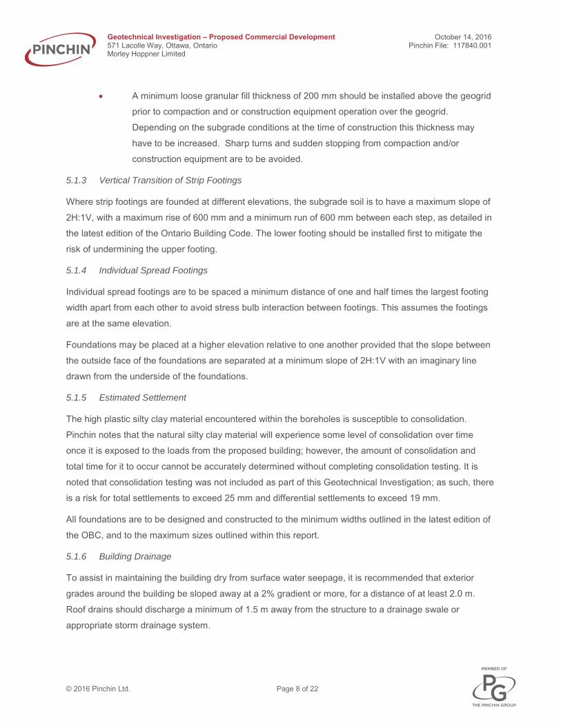
• A minimum loose granular fill thickness of 200 mm should be installed above the geogrid
prior to compaction and or construction equipment operation over the geogrid.
Depending on the subgrade conditions at the time of construction this thickness may
have to be increased. Sharp turns and sudden stopping from compaction and/or
construction equipment are to be avoided.
5.1.3 Vertical Transition of Strip Footings
Where strip footings are founded at different elevations, the subgrade soil is to have a maximum slope of
2H:1V, with a maximum rise of 600 mm and a minimum run of 600 mm between each step, as detailed in
the latest edition of the Ontario Building Code. The lower footing should be installed first to mitigate the
risk of undermining the upper footing.
5.1.4 Individual Spread Footings
Individual spread footings are to be spaced a minimum distance of one and half times the largest footing
width apart from each other to avoid stress bulb interaction between footings. This assumes the footings
are at the same elevation.
Foundations may be placed at a higher elevation relative to one another provided that the slope between
the outside face of the foundations are separated at a minimum slope of 2H:1V with an imaginary line
drawn from the underside of the foundations.
5.1.5 Estimated Settlement
The high plastic silty clay material encountered within the boreholes is susceptible to consolidation.
Pinchin notes that the natural silty clay material will experience some level of consolidation over time
once it is exposed to the loads from the proposed building; however, the amount of consolidation and
total time for it to occur cannot be accurately determined without completing consolidation testing. It is
noted that consolidation testing was not included as part of this Geotechnical Investigation; as such, there
is a risk for total settlements to exceed 25 mm and differential settlements to exceed 19 mm.
All foundations are to be designed and constructed to the minimum widths outlined in the latest edition of
the OBC, and to the maximum sizes outlined within this report.
5.1.6 Building Drainage
To assist in maintaining the building dry from surface water seepage, it is recommended that exterior
grades around the building be sloped away at a 2% gradient or more, for a distance of at least 2.0 m.
Roof drains should discharge a minimum of 1.5 m away from the structure to a drainage swale or
appropriate storm drainage system.

Geotechnical Investigation – Proposed Commercial Development October 14, 2016 571 Lacolle Way, Ottawa, Ontario Pinchin File: 117840.001 Morley Hoppner Limited
© 2016 Pinchin Ltd. Page 9 of 22
Exterior perimeter foundations drains are not required, where the finished floor elevation is established a
minimum of 150 mm above the exterior final grades or that the exterior gradient is properly sloped to
divert surface water away from the building.
Where interior finished floor elevations do not satisfy the above requirements, it is recommended that
exterior perimeter foundation drains be installed where subsurface walls are exposed to the interior. The
foundation drains should consist of a minimum 150 mm diameter fabric wrapped perforated drainage tile
surrounded by 19 mm diameter clear stone (OPSS 1004) with a minimum cover of 150 mm on top and
sides and 50 mm below the drainage tile. Since the natural soil contains a significant amount of clay sized
particles, the clear stone gravel should be wrapped in a non-woven geotextile (Terrafix 270R or
equivalent). The water collected from the weeping tile should be directed away from the building to
appropriate drainage areas; either through gravity flow or interior sump pump systems. All subsurface
walls should be water proofed.
The in-situ natural soils encountered within the boreholes are not considered a free draining material and
as such, may not be reused as foundation backfill.
5.1.7 Shallow Foundation Frost Protection & Foundation Backfill
In the Ottawa area, exterior perimeter foundations for heated buildings require a minimum of 1.8 m of soil
cover above the underside of the footing to provide soil cover for frost protection. Isolated unheated
foundations (i.e., pier pads) should be provided with a minimum of 2.1 m of soil cover for frost protection.
As previously mentioned, Pinchin recommends to install the foundations as high as practically possible;
as such, the footings will require a combination of soil cover and rigid polystyrene insulation to provide
frost protection.
To provide a combination of soil cover and rigid polystyrene insulation frost protection for the building
foundations, Pinchin recommends the following:
• The insulation should have a minimum thermal resistance value of R-20. If Dow
Styrofoam is used this would require a total of 100 mm of insulation;
• The insulation should buttress the foundation wall and extend out a minimum horizontal
distance of 1.8 m beyond the outside face of the footing;
• The insulation should be installed vertically on the perimeter of the foundation wall, from
approximately 100 mm below the proposed finished grade to the top of the horizontal
insulation;
• A minimum of 600 mm of soil cover is to be provided above the insulation at all times;
and

Geotechnical Investigation – Proposed Commercial Development October 14, 2016 571 Lacolle Way, Ottawa, Ontario Pinchin File: 117840.001 Morley Hoppner Limited
© 2016 Pinchin Ltd. Page 10 of 22
• The insulation placed beyond the foundation is to have a positive slope away from the
building foundation.
These insulation recommendations assume the interior of the building is maintained at 18 degrees
Celsius or higher.
The insulation is to be installed as outlined above as well as in accordance with the manufactures
requirements. The insulation recommendations are Site specific and are not to be used for any other
structures except for the Site in which it was intended for. Where there is less than 760 mm of soil cover
above the insulation and heavy vehicular traffic is present, a Dow HI (High Load) product should be
considered.
To minimize potential frost movements from soil frost adhesion, the perimeter foundation backfill should
consist of a free draining granular material, such as a Granular “B” Type I or Type II Ontario Provincial
Standards and Specifications (OPSS 1010) extending a minimum lateral distance of 600 mm beyond the
foundation. The maximum aggregate size should not exceed 200 mm in diameter. It is critical that
particles greater than 200 mm in diameter are not in contact with the foundation or insulation to prevent
point loading and overstressing. The backfill material used against the foundation must be placed so that
the allowable lateral capacity is achieved. Ideally, during backfilling operations, all backfill material should
be placed on each side of the foundation in equal lifts, not exceeding 300 mm. Additionally, it is
recommended that exterior grades around the foundation be sloped away at a 2% gradient or more, for a
distance of at least 2 m so that surface water is diverted away from the foundation to further mitigate soil
frost adhesion.
All granular material is to be placed in maximum 300 mm thick lifts compacted to a minimum of 98%
SPMDD within 2% optimum moisture content. It is recommended that inspection and testing be carried
out during construction to confirm backfill quality, thickness and to ensure compaction requirements are
achieved.
The natural soils are not considered suitable as foundation backfill material.
5.1.8 Concrete Floor Slab-on-Grade
Based on the in-situ soil conditions, it is recommended to establish the concrete floor slab-on-grade on a
minimum 300 mm thick layer of Granular “A” (OPSS 1010). Any required up fill below the Granular “A”
should consist of Granular “B” Type I or Type II (OPSS 1010).

Geotechnical Investigation – Proposed Commercial Development October 14, 2016 571 Lacolle Way, Ottawa, Ontario Pinchin File: 117840.001 Morley Hoppner Limited
© 2016 Pinchin Ltd. Page 11 of 22
Prior to the installation of the engineered fill material, all organics and deleterious materials should be
removed to the underlying organic free in-situ soils. Provided organics are not encountered during
excavations for the footings then the undisturbed natural soil may be left in place.
The natural silty clay material is to be proof roll compacted to a minimum of 98% Standard Proctor
Maximum Dry Density (SPMDD) with the use of a minimum 10 tonne vibratory steel drum roller. Pinchin
notes that there may be areas that the steel drum roller will not be able to access; as such, a minimum
450 Kg vibratory plate compactor may be used in these areas in order to achieve the recommended
compaction. Any soft areas encountered during proof rolling are to be removed and replaced with a
Granular “B” Type I (OPSS 1010) compacted to 98% SPMDD.
Once the subgrade soils are exposed they are to be inspected and approved by a qualified geotechnical
engineering consultant to ensure that the material conforms with the soil type and consistency observed
during the subsurface investigation work.
6.0 ASPHALTIC CONCRETE PAVEMENT STRUCTURE DESIGN FOR PARKING LOT
6.1 Discussion
It is assumed that the parking lot area will be used by normal vehicular traffic as well as moderately heavy
trucks. Prior to the installation of the recommended pavement structure, all organics and deleterious
materials should be removed to the underlying organic free in-situ soils.
The subgrade material is to be proof roll compacted to a minimum of 98% SPMDD with the use of a
minimum 10 tonne vibratory steel drum roller. Any loose/soft areas encountered during proof rolling are to
be removed and replaced with a Granular “B” Type I (OPSS 1010) compacted to 98% SPMDD. Pinchin
notes that there may be areas that the steel drum roller will not be able to access; as such, a minimum
450 Kg vibratory plate compactor may be used in these areas in order to achieve the recommended
compaction.
Pinchin has not been provided with the proposed final grades for the parking lot and access roadways. As
such, provided the pavement structure overlies the in-situ silty clay material, the following pavement
structure is recommended.

Geotechnical Investigation – Proposed Commercial Development October 14, 2016 571 Lacolle Way, Ottawa, Ontario Pinchin File: 117840.001 Morley Hoppner Limited
© 2016 Pinchin Ltd. Page 12 of 22
6.2 Pavement Structure
The following table presents the minimum specifications for a flexible asphaltic concrete pavement
structure constructed on the in-situ silty clay material:
Pavement Layer Compaction Requirements Light Duty Traffic Heavy Duty Traffic
Surface Course Asphaltic Concrete HL-8 (OPSS 1150)
92 to 96.5% MRD as per OPSS 310 50 mm 50 mm
Base Course Asphaltic Concrete HL-8 (OPSS 1150)
92 to 96.5% MRD as per OPSS 310 N/A 50 mm
Base Course: Granular “A” (OPSS
1010)
100% Standard Proctor Maximum Dry Density
(ASTM-D698) 150 mm 150 mm
Subbase Course: Granular “B” Type I
(OPSS 1010)
100% Standard Proctor Maximum Dry Density
(ASTM D698) ii300 mm 450 mm
Non-woven geotextile (Terrafix 270R or equivalent)
Notes:
i) The compacted thickness of the asphalt layer should be at least 3 times the nominal
maximum aggregate size to achieve adequate compaction, smoothness and durability;
ii) A Granular “B” Type II (OPSS 1010) product is preferred since it is not as sensitive to
changes in water content and maintains its frictional capacity during traffic loading. It is also
preferred to be installed during times of the year when excessive precipitation is expected;
iii) The recommended pavement structure may have to be adjusted according to the city of
Ottawa standards. If construction takes place during times of substantial precipitation and the
subgrade soils become wet and disturbed, then the granular thickness may have to be
increased to compensate for the weaker subgrade soils. Further, the granular fill material
may have to be temporarily increased to allow heavy construction equipment access the Site,
such as tri-axel dump trucks to avoid the sandy clayey silt subgrade from “pumping” up into
the granulars.

Geotechnical Investigation – Proposed Commercial Development October 14, 2016 571 Lacolle Way, Ottawa, Ontario Pinchin File: 117840.001 Morley Hoppner Limited
© 2016 Pinchin Ltd. Page 13 of 22
The Superpave asphaltic concrete mixes should be designed for Traffic Level A or B. Performance grade
PG 58-34 asphaltic concrete should be specified for either Superpave or Marshall mixes.
The recommended pavement structure design requires routine maintenance, such as, crack sealing,
pothole repairs, and etcetera to maintain the longevity of the structure. As well as a possible asphaltic
concrete overlay in about 12 to 15 years.
6.3 Pavement Structure Subgrade Preparation and Granular Up Fill
The proper placement of base and subbase fill materials becomes very important in addressing the
proper load distribution to provide a durable pavement structure.
The natural subgrade soils are sensitive to change in moisture content and can become very soft if the
soils are subject to additional water or precipitation. The natural subgrade soils are also susceptible to
shrinkage if the soils are subject to prolonged periods of sun exposure. Furthermore, they could be easily
disturbed if travelled on during construction. As such, where this material will be exposed, it is
recommended that the engineered fill be placed immediately upon excavation to protect the integrity of
the soil.
The first layer of granular fill should be placed at a minimum thickness of 300 mm (loose) prior to
compaction to mitigate disturbance of the underlying original subgrade soils.
Should the subgrade soils become disturbed during construction or pockets of unstable or unsuitable
areas be encountered, Pinchin can provide recommendations at that time, which may include but not be
limited to the following:
• Compaction of the subgrade soil;
• Removal of subgrade material and subsequent replacement with engineered fill; and
• Placement of geogrid.
A geotechnical engineer should be on-Site to review the subgrade material and to ensure fill
specifications and compaction requirements are achieved. Once the subgrade is approved, it can then be
backfilled with the recommended pavement structure materials.
Where fill material is required to increase the grade to the underside of the pavement structure it should
consist of a Granular “B” Type I (OPSS 1010). The granular up fill material is to be placed in maximum
300 mm thick lifts compacted to 95% SPMDD within 4% of the optimum moisture content.
All stockpiled material should be protected from deleterious materials, additional moisture and be kept
from freezing.

Geotechnical Investigation – Proposed Commercial Development October 14, 2016 571 Lacolle Way, Ottawa, Ontario Pinchin File: 117840.001 Morley Hoppner Limited
© 2016 Pinchin Ltd. Page 14 of 22
Where buried services intercept the parking and roadway areas the backfill material between the
underside of the pavement structure and service cover material should consist of the excavated natural
soils to the underside of the granular subbase. The material should be compacted in maximum 300 mm
thick lifts to 95% SPMDD within 4% optimum moisture content. This is recommended to provide soil
compatibility and help minimize potential abrupt differential frost heave between the local soils and
another type of backfill material.
Post compaction settlement of fine grained soils can be expected, even when placed to compaction
specifications. As such, fill material should be installed as far in advance as possible before finishing the
parking lot and access roadways for best grade integrity.
6.4 Horizontal Transition Treatment
Where the subgrade material types differ below the underside of the pavement structure, the transition
between the materials should be sloped as per frost heave taper OPSD 205.60.
6.5 Drainage
Control of surface water is a critical factor in achieving good pavement structure life. The pavement
thickness designs are based on a drained pavement subgrade via sub-drains or ditches.
Any potential sub-drains should consist of 150 mm diameter fabric wrapped perforated drainage tile
surrounded by 19 mm diameter clear stone (OPSS 1004) with a minimum cover of 150 mm on top and
sides and 50 mm below the drainage tile. Since the original soil contains a significant amount of silt sized
particles, the clear stone gravel should be wrapped in a non-woven geotextile (Terrafix 270R or
equivalent). Any potential ditching should have inverts of at least 500 mm below the underside of the
subbase.
The surface of the roadways should be free of depressions and be sloped at a minimum grade of 1% in
order to drain to appropriate drainage areas. Subgrade soils should slope a minimum of 3% toward
stormwater collection points. Positive slopes are very important for the proper performance of the
drainage system. The granular base and subbase materials should extend horizontally to any potential
ditches or swales.
In addition, routine maintenance of the drainage systems will assist with the longevity of the pavement
structure. Ditches, culverts, sewers and catch basins should be regularly cleared of debris and
vegetation.

Geotechnical Investigation – Proposed Commercial Development October 14, 2016 571 Lacolle Way, Ottawa, Ontario Pinchin File: 117840.001 Morley Hoppner Limited
© 2016 Pinchin Ltd. Page 15 of 22
7.0 SITE SERVICES
7.1 Pipe Bedding and Cover Materials for Flexible and Rigid Pipes
Service pipes require an adequate base to ensure proper pipe connection and positive flow is maintained
post construction. As such, pipe bedding should be placed to be of uniform thickness and compactness.
The pipe bedding and cover material should conform to OPSD 802.010 and 802.013 specifications for
flexible pipes and to OPSD 802.031 to 802.033 with Class “B” bedding for rigid pipes. The pipe bedding
material should consist of a minimum thickness of 150 mm Granular “A” (OPSS 1010) below the pipe and
extend up the sides to the spring line. However, the bedding thickness may have to be increased
depending on the pipe diameter or if wet or weak subgrade conditions are encountered. The pipe cover
material from the spring line should consist of a Granular “B” Type I (OPSS 1010) with a minimum particle
diameter size of 26.5 mm and should extend to a minimum of 300 mm above the top of the pipe. All
granular fill material is to be placed in maximum 200 mm thick loose lifts compacted to a minimum of 98%
SPMDD.
The bedding material, pipe and cover material should be installed as soon as practically possible after the
excavation subgrade is exposed. The longer the excavated subgrade soil remains open to weather
conditions and groundwater seepage, the greater the chance for construction problems to occur.
A Granular “B” Type II material may be required where it is difficult to stabilize the subgrade due to
groundwater or the material is higher than the optimum moisture content. Alternatively, if constant
groundwater infiltration becomes an issue, than an approximate 150 mm granular pad consisting of 19
mm clear stone gravel (OPSS 1004) wrapped in a non-woven geotextile (Terrafix 270R or equivalent)
should be considered to maintain the integrity of the natural subgrade soils. The clear stone should
contain a minimum of 50% crushed particles. Water collected within the stone should be controlled
through sumps and filtered pumps.
7.2 Trench Backfill
Above the pipe cover material, the trench can be backfilled by re-using the excavated natural soils
matching the materials exposed on the sides of the trenches. The soils should be placed to the underside
of the granular subbase of the pavement structure, and be compacted in maximum 300 mm thick lifts to
95% SPMDD within plus 2% to minus 4% optimum moisture content. This is recommended to provide soil
compatibility and help minimize potential abrupt differential frost heave between surrounding natural
materials similar in composition. The natural material must be free of organics or other deleterious
material. If it contains deleterious material or it is not utilized, then it should be removed and properly
disposed of.

Geotechnical Investigation – Proposed Commercial Development October 14, 2016 571 Lacolle Way, Ottawa, Ontario Pinchin File: 117840.001 Morley Hoppner Limited
© 2016 Pinchin Ltd. Page 16 of 22
All stockpiled material should be protected from deleterious materials, additional moisture and be kept
from freezing.
Quality control will be the utmost importance when selecting the material. The selection of the material
should be done as early in the contract as possible to allow sufficient time for gradation and proctor
testing on representative samples to ensure it meets the projects specifications.
Where the natural soils will be exposed, adequate compaction may prove difficult if the material becomes
wet (i.e., above the optimum moisture content). Depending on the moisture content of the natural
materials at the time of construction, they may either require moisture to be added or stockpiled and left
to dry to achieve moisture content within plus 2% to minus 4% of optimum. This will be the case for soils
excavated below the groundwater table. The natural soils at this site are subject to moisture content
increase during wet weather. As such, stockpiles should be compacted at the surface and/or be covered
with tarpaulins to help minimize moisture absorption during wet weather. Alternatively, an imported drier
material of similar gradation as the soils (i.e., silty sand/sandy silt) may be mixed to decrease the overall
moisture content and bring it to within plus 2% to minus 4% of optimum. Depending on weather
conditions at the time of construction, an imported material may be required regardless to achieve
adequate compaction. If the imported material is not the same/similar to the soil observed on the side
walls of the excavation then a horizontal transition between the materials should be sloped as per frost
heave taper OPSD 205.60. Any natural material is to be placed in maximum 300 mm thick lifts compacted
to 95% SPMDD within plus 2% to minus 4% optimum moisture content. Imported material should consist
of a Granular “A”, Granular “B” Type I, or Select Subgrade Material (OPSS 1010). Heavy construction
equipment and truck traffic should not cross any pipe until at least 1 m of compacted soil is placed above
the top of the pipe.
Post compaction settlement of finer grained soils can be expected, even when placed to compaction
specifications. As such, fill materials should be installed as far in advance as possible before finishing the
roadway in order to mitigate post compaction settlements.

Geotechnical Investigation – Proposed Commercial Development October 14, 2016 571 Lacolle Way, Ottawa, Ontario Pinchin File: 117840.001 Morley Hoppner Limited
© 2016 Pinchin Ltd. Page 17 of 22
7.3 Frost Protection
The frost penetration depth in Ottawa, Ontario for these types of soil conditions is estimated to extend to
approximately 2.1 mbg in open roadways cleared of snow. As such, it is recommended to place water
services at a minimum depth of 300 mm below this elevation with the top of the pipe located at 2.4 mbg or
lower as dictated by municipal service requirements. If a minimum of 2.4 m of soil cover cannot be
provided, then the pipe should be insulated with a rigid polystyrene insulation (DOW Styrofoam HI40, or
equivalent) or a pre-insulated pipe be utilized.
The insulation design configuration may either consist of placing horizontal insulation to a specified
design distance beyond the outside edge of the pipe or an inverted “U” surrounding the top and sides of
the pipe. Any method chosen requires suitable design and installation in accordance with the
manufactures recommendations. To accommodate the placement of horizontal insulation a wider
excavation trench may be required.
8.0 INSTALLATION OF ENGINEERED FILL
It is recommended that engineered fill be constructed as controlled, well-compacted fill. All engineered fill
material is to conform to Ontario Provincial Standards and Specifications (OPSS 1010). Any existing in-
situ soils with high organic content are suitable for reuse as fill in landscaping areas only. It is
recommended that only engineered fill be used within the building footprint and within 1 m of the building
footprint.
Prior to construction commencing, laboratory testing should be performed on the engineered fill to be
used to determine the appropriate moisture-density relationship of the material.

Geotechnical Investigation – Proposed Commercial Development October 14, 2016 571 Lacolle Way, Ottawa, Ontario Pinchin File: 117840.001 Morley Hoppner Limited
© 2016 Pinchin Ltd. Page 18 of 22
Pinchin recommends that engineered fill be compacted in accordance with the criteria stated in the
following table. A qualified geotechnical engineering technician should be on site to observe fill placement
operations and perform field density tests at random locations throughout each lift, including trench
backfilling, to indicate the specified compaction is being achieved.
Type of Engineered Fill
Maximum Loose Lift Thickness (mm)
Compaction Requirements
Moisture Content (Percent of Optimum)
Granular “A”
(OPSS 1010) 200 100% SPMDD Plus 2 to minus 4
Granular “B” Type I or Type II
(OPSS 1010) 200 98 to 100% SPMDD Plus 2 to minus 4
19 mm Clear Stone Gravel (OPSS 1010) 150 N/A N/A
Notes:
i) Granular “B” Type II is to be proof rolled compacted to a dense state, and verified by a
geotechnical engineering consultant during installation;
ii) The 19 mm clear stone gravel is to be tamped to rearrange the particles;
iii) The first lift of engineered fill is to be installed with a minimum thickness of 300 mm to mitigate
disturbance of the original subgrade soils; and
iv) The foundation backfill is to be compacted to 100% SPMDD where placed below any settlement
sensitive structures, such as sidewalks, parking lots etc.
9.0 SITE CLASSIFICATION FOR SEISMIC SITE RESPONSE & SOIL BEHAVIOUR
The following information has been provided to assist the building designer from a geotechnical
perspective only. These geotechnical seismic design parameters should be reviewed in detail by the
structural engineer and be incorporated into the design as required.
The seismic site classification has been based on the latest edition of the OBC. The parameters for
determination of Site Classification for Seismic Site Response are set out in Table 4.1.8.4.A of the OBC.
The site classification is based on the average shear wave velocity in the top 30 m of the site stratigraphy.
If the average shear wave velocity is not known, the site class can be estimated from energy corrected
Standard Penetration Resistance (N60) and/or the average undrained shear strength of the soil in the top
30 m.

Geotechnical Investigation – Proposed Commercial Development October 14, 2016 571 Lacolle Way, Ottawa, Ontario Pinchin File: 117840.001 Morley Hoppner Limited
© 2016 Pinchin Ltd. Page 19 of 22
There have been no shear wave velocity measurements at this Site; as such, the undrained shear
strengths and SPT values have been used to classify the soil.
The boreholes advanced at this site extended to between approximately 5.9 and 17.1 mbg and were
terminated in very soft clay. The SPT “N” values within the soil ranged from 0 to 10 blows per 300 mm,
while the undrained shear strengths of the soil ranged from approximately 6 to 77 kilopascals (kPa). The
soils below this depth are anticipated to be at least as competent. As such, based on Table 4.1.8.4.A of
the OBC, this Site has been classified as Class E. A Site Class E has an average shear wave velocity
(Vs) of less than 180 m/s. There is a potential that the Site Class may be higher; however, shear wave
velocity measurements would be required for the determination of a higher Site Classification, as per the
OBC.
10.0 SITE SUPERVISION & QUALITY CONTROL
It is recommended that all geotechnical aspects of the project be reviewed and confirmed under the
appropriate geotechnical supervision, to routinely check such items. This includes but is not limited to
inspection and confirmation of the undisturbed natural subgrade material prior to subgrade preparation,
pouring any foundations or footings, backfilling, or engineered fill installation to ensure that the actual
conditions are not markedly different than what was observed at the test hole locations and geotechnical
components are constructed as per our recommendations. Compaction quality control of engineered fill
material is recommended as standard practice, as well as sampling and testing of aggregates and
concrete, to ensure it meets the physical characteristics for compliance during installation and satisfies all
specifications presented within this report.
10.1 Open Cut Excavations
It is anticipated that excavations for the building foundation systems and site services will extend to
depths ranging from approximately 1.0 to 3.0 mbg. At the time of our investigation groundwater was
encountered between approximately 2.3 and 3.0 mbg within the majority of the boreholes.
Based on the subsurface information obtained from within the borehole, it is anticipated that the
excavated material will predominately consist of silty clay.
Where workers must enter trench excavations deeper than 1.2 m, the trench excavations should be
suitably sloped and/or braced in accordance with the Occupational Health and Safety Act (OHSA),
Ontario Regulation 213/91, Construction Projects, July 1, 2011, Part III - Excavations, Section 226.
Alternatively, the excavation walls may be supported by either closed shoring, bracing, or trench boxes
complying with sections 235 to 239 and 241 under O. Reg. 231/91, s. 234(1).

Geotechnical Investigation – Proposed Commercial Development October 14, 2016 571 Lacolle Way, Ottawa, Ontario Pinchin File: 117840.001 Morley Hoppner Limited
© 2016 Pinchin Ltd. Page 20 of 22
Based on the OHSA, the in-situ soil may be classified as Type 3 soil above the groundwater table and
Type 4 soil below the groundwater table. Temporary excavation side slopes in Type 3 soil should remain
stable at a slope of 1H:1V; however, temporary excavation side slopes in Type 4 soil should be braced or
shored. The in-situ soil can be excavated using conventional earthmoving equipment.
The natural subgrade soil is conducive to installing conventional shored steel sheet piles to support the
excavation walls and control groundwater. The use of trench boxes can most likely be used for temporary
support of vertical side walls. The appropriate trench should be designed/confirmed for use in this soil
deposit.
In addition to compliance with the OHSA, the excavation procedures must also be in compliance to any
potential other regulatory authorities, such as federal and municipal safety standards.
10.2 Anticipated Groundwater Management
Groundwater was encountered between approximately 2.3 and 3.0 mbg within the boreholes advanced at
the Site. As such, groundwater is expected to be encountered during excavations. If construction
commences during wet periods (typically spring or fall), there is a potential that the groundwater elevation
could be higher.
Prior to commencing excavations, it is critical that all existing surface water and potential surface water is
controlled and diverted away from the Site to prevent infiltration and subgrade softening. At no time
should excavations be left open for a period of time that will expose them to precipitation and cause
subgrade softening.
All collected water is to discharge a sufficient distance away from the excavation to prevent re-entry.
Sediment control measures, such as a silt fence should be installed at the discharge point of the
dewatering system. The utmost care should be taken to avoid any potential impacts on the environment.
It is the responsibility of the contractor to propose a suitable dewatering system based on the
groundwater elevation at the time of construction. The method used should not adversely impact any
nearby structures. The contractor should submit their proposal to the prime consultant for review and
approval prior to construction. A Permit to Take Water may be required from the Ministry of the
Environment and Climate Change. It is the responsibility of the contractor to make this application as
required.
Seasonal variations in the groundwater table should be expected, with higher levels occurring during wet
weather conditions in the spring and fall and lower levels occurring during dry weather conditions. As
such, depending on the groundwater at the time of the excavation works, a more involved dewatering
system may be required.

Geotechnical Investigation – Proposed Commercial Development October 14, 2016 571 Lacolle Way, Ottawa, Ontario Pinchin File: 117840.001 Morley Hoppner Limited
© 2016 Pinchin Ltd. Page 21 of 22
Any potential precipitation or seepage entering the excavations should be pumped away immediately (not
allowed to pond).
11.0 DISCLAIMER
This Geotechnical Investigation was performed for the exclusive use of Morley Hoppner Limited (Client) in
order to evaluate the subsurface conditions at 571 Lacolle Way Ottawa, Ontario.
Within the limitations of scope, schedule and budget, our services have been executed in accordance
with generally accepted practises in the field of geotechnical engineering for the Site. Classification and
identification of soils, and geologic units have been based upon commonly accepted methods employed
in professional geotechnical practice. No warranty or other conditions, expressed or implied, should be
understood. Conclusions derived are specific to the immediate area of study and cannot be extrapolated
extensively away from sample locations.
Performance of this Geotechnical Investigation to the standards established by Pinchin is intended to
reduce, but not eliminate, uncertainty regarding the subgrade soils at the Site, and recognizes reasonable
limits on time and cost.
Regardless how exhaustive a Geotechnical Investigation is performed, the investigation cannot identify all
the subsurface conditions. Therefore, no warranty is expressed or implied that the entire Site is
representative of the subsurface information obtained at the specific locations of our investigation. If
during construction, subsurface conditions differ from then what was encountered within our test location
and the additional subsurface information provided to us, Pinchin should be contacted to review our
recommendations.
This report does not alleviate the contractor, owner, or any other parties of their respective
responsibilities.
This report has been prepared for the exclusive use of the Client and their authorized agents. Any use
which a third party makes of this report, or any reliance on or decisions to be made based on it, are the
responsibility of the third parties. If additional parties require reliance on this report, written authorization
from Pinchin will be required. Pinchin disclaims responsibility of consequential financial effects on
transactions or property values, or requirements for follow-up actions and costs. No other warranties are
implied or expressed. Furthermore, this report should not be construed as legal advice.
The liability of Pinchin or our officers, directors, shareholders or staff will be limited to the lesser of the
fees paid or actual damages incurred by the Client. Pinchin will not be responsible for any consequential
or indirect damages. Pinchin will only be liable for damages resulting from the negligence of Pinchin.
Pinchin will not be liable for any losses or damage if the Client has failed, within a period of two years
following the date upon which the claim is discovered (Claim Period), to commence legal proceedings

Geotechnical Investigation – Proposed Commercial Development October 14, 2016 571 Lacolle Way, Ottawa, Ontario Pinchin File: 117840.001 Morley Hoppner Limited
© 2016 Pinchin Ltd. Page 22 of 22
against Pinchin to recover such losses or damage unless the laws of the jurisdiction which governs the
Claim Period which is applicable to such claim provides that the applicable Claim Period is greater than
two years and cannot be abridged by the contract between the Client and Pinchin, in which case the
Claim Period shall be deemed to be extended by the shortest additional period which results in this
provision being legally enforceable.
Pinchin makes no other representations whatsoever, including those concerning the legal significance of
its findings, or as to other legal matters touched on in this report, including, but not limited to, ownership
of any property, or the application of any law to the facts set forth herein. With respect to regulatory
compliance issues, regulatory statutes are subject to interpretation and these interpretations may change
over time. Please refer to Appendix IV, Report Limitations and Guidelines for Use, which pertains to this
report.

FIGURES

NOTE:Images obtained from © OpenStreetMap contributors


APPENDIX I Abbreviations, Terminology and Principle Symbols used in Report and
Borehole Logs

ABBREVIATIONS, TERMINOLOGY & PRINCIPAL SYMBOLS USED
Sampling Method
AS Auger Sample w Washed Sample SS Split Spoon Sample HQ Rock Core (63.5 mm diam.) ST Thin Walled Shelby Tube NQ Rock Core (47.5 mm diam.) BS Block Sample BQ Rock Core (36.5 mm diam.)
In-Situ Soil Testing
Standard Penetration Test (SPT), “N” value is the number of blows required to drive a 51 mm outside
diameter spilt barrel sampler into the soil a distance of 300 mm with a 63.5 kg weight free falling a
distance of 760 mm after an initial penetration of 150 mm has been achieved. The SPT, “N” value is a
qualitative term used to interpret the compactness condition of cohesionless soils and is used only as a
very approximation to estimate the consistency and undrained shear strength of cohesive soils.
Dynamic Cone Penetration Test (DCPT) is the number of blows required to drive a cone with a 60
degree apex attached to “A” size drill rods continuously into the soil for each 300 mm penetration with a
63.5 kg weight free falling a distance of 760 mm.
Cone Penetration Test (CPT) is an electronic cone point with a 10 cm2 base area with a 60 degree apex
pushed through the soil at a penetration rate of 2 cm/s.
Field Vane Test (FVT) consists of a vane blade, a set of rods and torque measuring apparatus used to
determine the undrained shear strength of cohesive soils.
Soil Descriptions
The soil descriptions and classifications are based on an expanded Unified Soil Classification System
(USCS). The USCS classifies soils on the basis of engineering properties. The system divides soils into
three major categories; coarse grained, fine grained and highly organic soils. The soil is then subdivided
based on either gradation or plasticity characteristics. The classification excludes particles larger than 75
mm. To aid in quantifying material amounts by weight within the respective grain size fractions the
following terms have been included to expand the USCS:

Soil Classification Terminology Proportion
Clay < 0.002 mm
Silt 0.002 to 0.06 mm “trace”, trace sand, etc. 1 to 10%
Sand 0.075 to 4.75 mm “some”, some sand, etc. 10 to 20%
Gravel 4.75 to 75 mm Adjective, sandy, gravelly, etc. 20 to 35%
Cobbles 75 to 200 mm And, and gravel, and silt, etc. >35%
Boulders >200 mm Noun, Sand, Gravel, Silt, etc. >35% and main fraction
Notes:
• Soil properties, such as strength, gradation, plasticity, structure, etcetera, dictate
the soils engineering behaviour over grain size fractions; and
• With the exception of soil samples tested for grain size distribution or plasticity, all soil
samples have been classified based on visual and tactile observations. The accuracy of
visual and tactile observation is not sufficient to differentiate between changes in soil
classification or precise grain size and is therefore an approximate description.
The following table outlines the qualitative terms used to describe the compactness condition of
cohesionless soil:
Cohesionless Soil
Compactness Condition SPT N-Index (blows per 300 mm)
Very Loose 0 to 4
Loose 4 to 10
Compact 10 to 30
Dense 30 to 50
Very Dense > 50

The following table outlines the qualitative terms used to describe the consistency of cohesive soils
related to undrained shear strength and SPT, N-Index:
Cohesive Soil
Consistency Undrained Shear Strength (kPa) SPT N-Index (blows per 300 mm)
Very Soft <12 <2
Soft 12 to 25 2 to 4
Firm 25 to 50 4 to 8
Stiff 50 to 100 8 to 15
Very Stiff 100 to 200 15 to 30
Hard >200 >30
Note: Utilizing the SPT, N-Index value to correlate the consistency and undrained shear strength of
cohesive soils is only very approximate and needs to be used with caution.
Soil & Rock Physical Properties
General
W Natural water content or moisture content within soil sample
γ Unit weight
γ’ Effective unit weight
γd Dry unit weight
γsat Saturated unit weight
ρ Density
ρs Density of solid particles
ρw Density of Water
ρd Dry density
ρsat Saturated density e Void ratio
n Porosity
Sr Degree of saturation
E50 Strain at 50% maximum stress (cohesive soil)

Consistency
WL Liquid limit
WP Plastic Limit
IP Plasticity Index
WS Shrinkage Limit
IL Liquidity Index
IC Consistency Index
emax Void ratio in loosest state
emin Void ratio in densest state
ID Density Index (formerly relative density)
Shear Strength
Cu, Su Undrained shear strength parameter (total stress)
C’d Drained shear strength parameter (effective stress)
r Remolded shear strength
τp Peak residual shear strength
τr Residual shear strength
ø’ Angle of interface friction, coefficient of friction = tan ø’
Consolidation (One Dimensional) Cc Compression index (normally consolidated range)
Cr Recompression index (over consolidated range)
Cs Swelling index
mv Coefficient of volume change
cv Coefficient of consolidation
Tv Time factor (vertical direction)
U Degree of consolidation
σ'o Overburden pressure
σ’p Preconsolidation pressure (most probable)
OCR Overconsolidation ratio

Permeability
The following table outlines the terms used to describe the degree of permeability of soil and common soil
types associated with the permeability rates:
Permeability (k cm/s) Degree of Permeability Common Associated Soil Type
> 10-1 Very High Clean gravel
10-1 to 10-3 High Clean sand, Clean sand and gravel
10-3 to 10-5 Medium Fine sand to silty sand
10-5 to 10-7 Low Silt and clayey silt (low plasticity)
>10-7 Practically Impermeable Silty clay (medium to high plasticity)
Rock Coring
Rock Quality Designation (RQD) is an indirect measure of the number of fractures within a rock mass,
Deere et al. (1967). It is the sum of sound pieces of rock core equal to or greater than 100 mm recovered
from the core run, divided by the total length of the core run, expressed as a percentage. If the core
section is broken due to mechanical or handling, the pieces are fitted together and if 100 mm or greater
included in the total sum.
RQD is calculated as follows:
RQD (%) = Σ Length of core pieces > 100 mm x 100
Total length of core run The following is the Classification of Rock with Respect to RQD Value:
RQD Classification RQD Value (%)
Very poor quality <25
Poor quality 25 to 50
Fair quality 50 to 75
Good quality 75 to 90
Excellent quality 90 to 100

APPENDIX II Pinchin’s Borehole Logs

Borehole Log:
Project:
Client:
Project No.: Logged By:
Entered By:
Reviewed By:
Location:
Drill Method:
Drill Date:
Datum:
Sheet: 1 of 2
Ground Elevation:
This data relates to the boring and shouldn't be interpreted as being indicative of the whole site
Drilled By:
Pinchin Ltd.555 Legget Drive, Suite 1001, Tower A
Kanata, Ontario,K2K 2X3
Depth
(m
)
0
1
2
3
4
5
6
7
8
9
10
Str
ata
Plo
t Description
Ele
vation
Sam
ple
Num
ber
Sam
ple
Type
Blo
ws /
0.3
m
Recovery
(%
)
Dynamic PenetrationResistance
Blows / 0.3m10 20 30 40 50 60 70 80 90
Undrained Shear Strength (Cu, kPa)
10 20 30 40 50 60 70 80 90
Water Content (%)
10 20 30 40
Remarks
Grain SizeGr Sa Si Cl M
onitoring W
ell
SUBSURFACE PROFILE SAMPLE
BH1
Geotechnical Investigation
Morley Hoppner Limited
117840.001 W. Tabaczuk
M. Garside
W. Tabaczuk
571 Lacolle Way, Ottawa, Ontario
Ground Surface
Topsoil and grass ~300mmSilty clay, dry to wet, greyish brown, very soft to stiff
99.5
92.8
SS1
SS2
SS3
SS4
SS5
SS6
SS7
SS
SS
SS
SS
SS
SS
SS
10
6
0 6
WH
WH
WH
WH
0
0
0
0
0
1
0
1
0
0
1
1
1
65
80
NA 100
100
100
100
100
NA
NA
NA
NA
NA
NA
NA
NA
NA
NA
6
6
6
1
0
0
0
0
0
1
0
1
0
0
58
9
6
54.8Cu=58kPar=12kPas=4.88
WL=62%WP=24%Groundwater was encountered at approximately 3.0m depthCu=9kPar=2kPas=5.05
Cu=6kPar=6kPas=0.94
Direct Push/Split Spoon
September 2, 2016
Local
99.54m
BH1 NEW
Strata Drilling Group
22 78
22 78
Start of Dynamic Cone Penetration Test (DCPT)

Borehole Log:
Project:
Client:
Project No.: Logged By:
Entered By:
Reviewed By:
Location:
Drill Method:
Drill Date:
Datum:
Sheet: 2 of 2
Ground Elevation:
This data relates to the boring and shouldn't be interpreted as being indicative of the whole site
Drilled By:
Pinchin Ltd.555 Legget Drive, Suite 1001, Tower A
Kanata, Ontario,K2K 2X3
Depth
(m
)
11
12
13
14
15
16
17
18
19
20
21
Str
ata
Plo
t Description
Ele
vation
Sam
ple
Num
ber
Sam
ple
Type
Blo
ws /
0.3
m
Recovery
(%
)
Dynamic PenetrationResistance
Blows / 0.3m10 20 30 40 50 60 70 80 90
Undrained Shear Strength (Cu, kPa)
10 20 30 40 50 60 70 80 90
Water Content (%)
10 20 30 40
Remarks
Grain SizeGr Sa Si Cl M
onitoring W
ell
SUBSURFACE PROFILE SAMPLE
BH1
Geotechnical Investigation
Morley Hoppner Limited
117840.001 W. Tabaczuk
M. Garside
W. Tabaczuk
571 Lacolle Way, Ottawa, Ontario
End of Borehole
82.4
1
0
0
1
1
1
0
1
0
1
2
1
2
2
2
2
2
3
3
3
2
3
3
NA
NA
NA
NA
NA
NA
NA
NA
NA
NA
NA
NA
NA
NA
NA
NA
NA
NA
NA
NA
1
1
0
1
1
0
1
2
1
2
2
2
2
2
3
3
2
3
3
3
Direct Push/Split Spoon
September 2, 2016
Local
99.54m
BH1 NEW
Strata Drilling Group
(DCPT Terminated)

Borehole Log:
Project:
Client:
Project No.: Logged By:
Entered By:
Reviewed By:
Location:
Drill Method:
Drill Date:
Datum:
Sheet: 1 of 1
Ground Elevation:
This data relates to the boring and shouldn't be interpreted as being indicative of the whole site
Drilled By:
Pinchin Ltd.555 Legget Drive, Suite 1001, Tower A
Kanata, Ontario,K2K 2X3
Depth
(m
)
0
1
2
3
4
5
6
7
Str
ata
Plo
t Description
Ele
vation
Sam
ple
Num
ber
Sam
ple
Type
Blo
ws /
0.3
m
Recovery
(%
)
Dynamic PenetrationResistance
Blows / 0.3m10 20 30 40 50 60 70 80 90
Undrained Shear Strength (Cu, kPa)
10 20 30 40 50 60 70 80 90
Water Content (%)
10 20 30 40
Remarks
Grain SizeGr Sa Si Cl M
onitoring W
ell
SUBSURFACE PROFILE SAMPLE
BH2
Geotechnical Investigation
Morley Hoppner Limited
117840.001 W. Tabaczuk
R. MacLeod
W. Tabaczuk
571 Lacolle Way, Ottawa, Ontario
Ground Surface
Topsoil and grass ~300mmSilty clay, dry to wet, greyish brown, very soft to stiff
End of Borehole
99.1
93.2
SS1
SS2
SS3
SS4
SS5
SS6
SS7
SS
SS
SS
SS
SS
SS
SS
10
6
6
WH
WH
WH
WH
65
80
100
100
100
100
100
10
6
6 58
17
9
Cu=58kPar=13kPas=4.36Groundwater was encountered at approximately 2.3m depth
Cu=17kPar=6kPas=2.80
Cu=9kPar=7.5kPas=1.19
Direct Push/Split Spoon
September 2, 2016
Local
99.07m
BH2
Strata Drilling Group

Borehole Log:
Project:
Client:
Project No.: Logged By:
Entered By:
Reviewed By:
Location:
Drill Method:
Drill Date:
Datum:
Sheet: 1 of 1
Ground Elevation:
This data relates to the boring and shouldn't be interpreted as being indicative of the whole site
Drilled By:
Pinchin Ltd.555 Legget Drive, Suite 1001, Tower A
Kanata, Ontario,K2K 2X3
Depth
(m
)
0
1
2
3
4
5
6
7
Str
ata
Plo
t Description
Ele
vation
Sam
ple
Num
ber
Sam
ple
Type
Blo
ws /
0.3
m
Recovery
(%
)
Dynamic PenetrationResistance
Blows / 0.3m10 20 30 40 50 60 70 80 90
Undrained Shear Strength (Cu, kPa)
10 20 30 40 50 60 70 80 90
Water Content (%)
10 20 30 40
Remarks
Grain SizeGr Sa Si Cl M
onitoring W
ell
SUBSURFACE PROFILE SAMPLE
BH3
Geotechnical Investigation
Morley Hoppner Limited
117840.001 W. Tabaczuk
R. MacLeod
W. Tabaczuk
571 Lacolle Way, Ottawa, Ontario
Ground Surface
Topsoil and grass ~300mmSilty clay, dry to wet, greyish brown, very soft to stiff
End of Borehole
98.9
92.2
SS1
SS2
SS3
SS4
SS5
SS6
SS7
SS
SS
SS
SS
SS
SS
SS
9
8
2
WH
WH
WH
WH
85
95
100
100
100
100
100
9
8
2
77
20
34.1
Cu=77kPar=11.5kPas=6.5
WL=63% 22 78WP=23%
20 80Cu=20kPar=4.5kPas=4.29
Groundwater was encountered at approximately 2.3m depth
Direct Push/Split Spoon
September 2, 2016
Local
98.94m
BH3
Strata Drilling Group

Borehole Log:
Project:
Client:
Project No.: Logged By:
Entered By:
Reviewed By:
Location:
Drill Method:
Drill Date:
Datum:
Sheet: 1 of 1
Ground Elevation:
This data relates to the boring and shouldn't be interpreted as being indicative of the whole site
Drilled By:
Pinchin Ltd.555 Legget Drive, Suite 1001, Tower A
Kanata, Ontario,K2K 2X3
Depth
(m
)
0
1
2
3
4
5
6
7
Str
ata
Plo
t Description
Ele
vation
Sam
ple
Num
ber
Sam
ple
Type
Blo
ws /
0.3
m
Recovery
(%
)
Dynamic PenetrationResistance
Blows / 0.3m10 20 30 40 50 60 70 80 90
Undrained Shear Strength (Cu, kPa)
10 20 30 40 50 60 70 80 90
Water Content (%)
10 20 30 40
Remarks
Grain SizeGr Sa Si Cl M
onitoring W
ell
SUBSURFACE PROFILE SAMPLE
BH4
Geotechnical Investigation
Morley Hoppner Limited
117840.001 W. Tabaczuk
R. MacLeod
W. Tabaczuk
571 Lacolle Way, Ottawa, Ontario
Ground Surface
Topsoil and grass ~300mmSilty clay, dry to wet, greyish brown, very soft to stiff
End of Borehole
99.6
92.9
SS1
SS2
SS3
SS4
SS5
SS6
SS7
SS
SS
SS
SS
SS
SS
SS
9
8
9
2
1
WH
WH
80
80
80
100
100
100
100
9
8
9
2
1
Groundwater was encountered at approximately 2.3m depth
21 79
Direct Push/Split Spoon
September 2, 2016
Local
99.59m
BH4
Strata Drilling Group

APPENDIX III Analytical Laboratory Testing Reports for Soil Samples

Checked By: H.Smith
Client:
Project:
Project No.: Figure
Pinchin Ltd.
Geotech Testing
60106.016
SYMBOL SOURCESAMPLE DEPTH
Material Description AASHTONO. (m.)
SOIL DATA
PE
RC
EN
T F
INE
R
0
10
20
30
40
50
60
70
80
90
100
PE
RC
EN
T C
OA
RS
ER
100
90
80
70
60
50
40
30
20
10
0
GRAIN SIZE - mm.
0.0010.010.1110100
% +3"Coarse
% Gravel
Fine Coarse Medium
% Sand
Fine Silt
% Fines
Clay
0.0 0.0 0.0 0.0 0.0 0.0 21.6 78.4
0.0 0.0 0.0 0.0 0.0 0.2 21.9 77.9
0.0 0.0 0.0 0.0 0.0 0.2 18.5 81.3
0.0 0.0 0.0 0.0 0.0 0.1 20.9 79.0
80
56
40
28
20
14
10
5 2.5
1.2
5
0.6
3
0.3
15
0.1
6
0.0
75
Particle Size Distribution Report
117840.001 BH1 2.29-2.90 Silty Clay A-7-6(44)
117840.001 BH3 0.76-1.37 Silty Clay A-7-6(46)
117840.001 BH3 1.52-2.13 Clay some Silt
117840.001 BH4 3.05-3.66 Silty Clay

AME Materials Engineering
GRAIN SIZE DISTRIBUTION TEST DATA 09/23/2016
Client: Pinchin Ltd.Project: Geotech TestingProject Number: 60106.016Location: 117840.001Depth: 2.29-2.90 Sample Number: BH1Material Description: Silty ClayAASHTO: A-7-6(44)Checked by: H.Smith
Sieve Test Data
DrySample
and Tare(grams)
Tare(grams)
CumulativePan
Tare Weight(grams)
SieveOpening
Size
CumulativeWeight
Retained(grams)
PercentFiner
PercentRetained
320.23 0.00 0.00 2.0 mm 0.00 100.0 0.0
51.81 0.00 0.00 .850 mm 0.00 100.0 0.0
.425 mm 0.00 100.0 0.0
.250 mm 0.00 100.0 0.0
.106 mm 0.00 100.0 0.0
.075 mm 0.01 100.0 0.0
Hydrometer Test Data
Hydrometer test uses material passing #10Percent passing #10 based upon complete sample = 100.0Weight of hydrometer sample =51.81Automatic temperature correction Composite correction (fluid density and meniscus height) at 20 deg. C = -5.5Meniscus correction only = -1.0Specific gravity of solids = 2.750Hydrometer type = 152H Hydrometer effective depth equation: L = 15.75980 - .179 x Rm
ElapsedTime (min.)
Temp.(deg. C.)
ActualReading
CorrectedReading K Rm
Eff.Depth
Diameter(mm.)
PercentFiner
PercentRetained
1.00 20.2 58.0 52.5 0.0132 57.0 5.6 0.0312 99.1 0.9
2.00 20.2 57.5 52.0 0.0132 56.5 5.6 0.0222 98.2 1.8
5.00 20.2 56.5 51.0 0.0132 55.5 5.8 0.0143 96.3 3.7
15.00 20.1 55.5 50.0 0.0132 54.5 6.0 0.0084 94.4 5.6
30.00 20.1 54.0 48.5 0.0132 53.0 6.3 0.0061 91.6 8.4
60.00 20.2 52.0 46.5 0.0132 51.0 6.6 0.0044 87.8 12.2
250.00 20.3 48.0 42.5 0.0132 47.0 7.3 0.0023 80.3 19.7
1440.00 20.5 40.0 34.6 0.0132 39.0 8.8 0.0010 65.3 34.7

AME Materials Engineering
Fractional Components
Cobbles
0.0
Gravel
Coarse
0.0
Fine
0.0
Total
0.0
Sand
Coarse
0.0
Medium
0.0
Fine
0.0
Total
0.0
Fines
Silt
21.6
Clay
78.4
Total
100.0
D5 D10 D15 D20 D30 D40 D50 D60 D80
0.0022
D85
0.0034
D90
0.0053
D95
0.0094
FinenessModulus
0.00
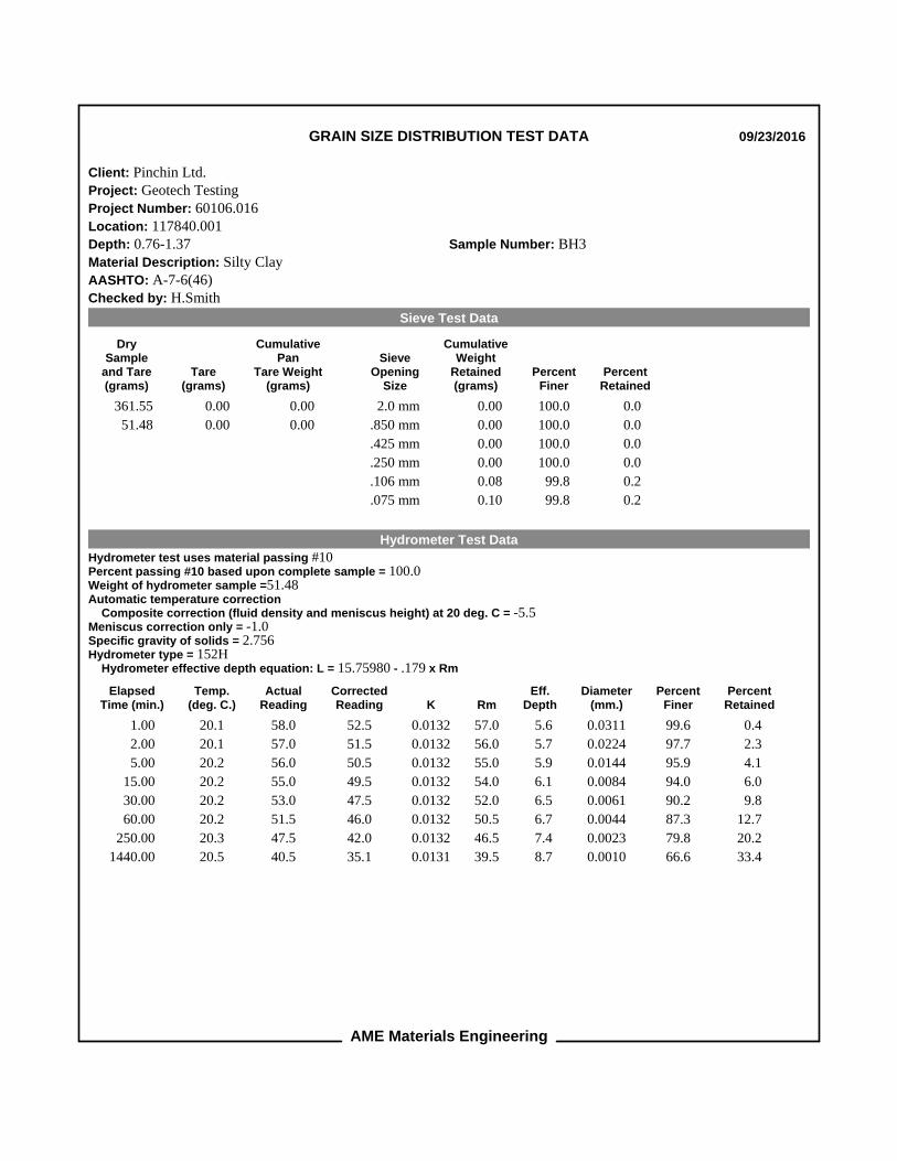
AME Materials Engineering
GRAIN SIZE DISTRIBUTION TEST DATA 09/23/2016
Client: Pinchin Ltd.Project: Geotech TestingProject Number: 60106.016Location: 117840.001Depth: 0.76-1.37 Sample Number: BH3Material Description: Silty ClayAASHTO: A-7-6(46)Checked by: H.Smith
Sieve Test Data
DrySample
and Tare(grams)
Tare(grams)
CumulativePan
Tare Weight(grams)
SieveOpening
Size
CumulativeWeight
Retained(grams)
PercentFiner
PercentRetained
361.55 0.00 0.00 2.0 mm 0.00 100.0 0.0
51.48 0.00 0.00 .850 mm 0.00 100.0 0.0
.425 mm 0.00 100.0 0.0
.250 mm 0.00 100.0 0.0
.106 mm 0.08 99.8 0.2
.075 mm 0.10 99.8 0.2
Hydrometer Test Data
Hydrometer test uses material passing #10Percent passing #10 based upon complete sample = 100.0Weight of hydrometer sample =51.48Automatic temperature correction Composite correction (fluid density and meniscus height) at 20 deg. C = -5.5Meniscus correction only = -1.0Specific gravity of solids = 2.756Hydrometer type = 152H Hydrometer effective depth equation: L = 15.75980 - .179 x Rm
ElapsedTime (min.)
Temp.(deg. C.)
ActualReading
CorrectedReading K Rm
Eff.Depth
Diameter(mm.)
PercentFiner
PercentRetained
1.00 20.1 58.0 52.5 0.0132 57.0 5.6 0.0311 99.6 0.4
2.00 20.1 57.0 51.5 0.0132 56.0 5.7 0.0224 97.7 2.3
5.00 20.2 56.0 50.5 0.0132 55.0 5.9 0.0144 95.9 4.1
15.00 20.2 55.0 49.5 0.0132 54.0 6.1 0.0084 94.0 6.0
30.00 20.2 53.0 47.5 0.0132 52.0 6.5 0.0061 90.2 9.8
60.00 20.2 51.5 46.0 0.0132 50.5 6.7 0.0044 87.3 12.7
250.00 20.3 47.5 42.0 0.0132 46.5 7.4 0.0023 79.8 20.2
1440.00 20.5 40.5 35.1 0.0131 39.5 8.7 0.0010 66.6 33.4

AME Materials Engineering
Fractional Components
Cobbles
0.0
Gravel
Coarse
0.0
Fine
0.0
Total
0.0
Sand
Coarse
0.0
Medium
0.0
Fine
0.2
Total
0.2
Fines
Silt
21.9
Clay
77.9
Total
99.8
D5 D10 D15 D20 D30 D40 D50 D60 D80
0.0023
D85
0.0035
D90
0.0060
D95
0.0098
FinenessModulus
0.00

AME Materials Engineering
GRAIN SIZE DISTRIBUTION TEST DATA 09/23/2016
Client: Pinchin Ltd.Project: Geotech TestingProject Number: 60106.016Location: 117840.001Depth: 1.52-2.13 Sample Number: BH3Material Description: Clay some SiltChecked by: H.Smith
Sieve Test Data
DrySample
and Tare(grams)
Tare(grams)
CumulativePan
Tare Weight(grams)
SieveOpening
Size
CumulativeWeight
Retained(grams)
PercentFiner
PercentRetained
341.96 0.00 0.00 2.0 mm 0.00 100.0 0.0
51.98 0.00 0.00 .850 mm 0.00 100.0 0.0
.425 mm 0.00 100.0 0.0
.250 mm 0.00 100.0 0.0
.106 mm 0.09 99.8 0.2
.075 mm 0.10 99.8 0.2
Hydrometer Test Data
Hydrometer test uses material passing #10Percent passing #10 based upon complete sample = 100.0Weight of hydrometer sample =51.98Automatic temperature correction Composite correction (fluid density and meniscus height) at 20 deg. C = -5.5Meniscus correction only = -1.0Specific gravity of solids = 2.761Hydrometer type = 152H Hydrometer effective depth equation: L = 15.75980 - .179 x Rm
ElapsedTime (min.)
Temp.(deg. C.)
ActualReading
CorrectedReading K Rm
Eff.Depth
Diameter(mm.)
PercentFiner
PercentRetained
1.00 20.1 58.5 53.0 0.0132 57.5 5.5 0.0308 99.5 0.5
2.00 20.1 58.0 52.5 0.0132 57.0 5.6 0.0220 98.6 1.4
5.00 20.1 57.5 52.0 0.0132 56.5 5.6 0.0140 97.6 2.4
15.00 20.1 56.5 51.0 0.0132 55.5 5.8 0.0082 95.7 4.3
30.00 20.2 55.0 49.5 0.0132 54.0 6.1 0.0059 93.0 7.0
60.00 20.2 53.0 47.5 0.0132 52.0 6.5 0.0043 89.2 10.8
250.00 20.3 49.5 44.0 0.0132 48.5 7.1 0.0022 82.7 17.3
1440.00 20.5 42.0 36.6 0.0131 41.0 8.4 0.0010 68.7 31.3

AME Materials Engineering
Fractional Components
Cobbles
0.0
Gravel
Coarse
0.0
Fine
0.0
Total
0.0
Sand
Coarse
0.0
Medium
0.0
Fine
0.2
Total
0.2
Fines
Silt
18.5
Clay
81.3
Total
99.8
D5 D10 D15 D20 D30 D40 D50 D60 D80
0.0018
D85
0.0027
D90
0.0046
D95
0.0074
FinenessModulus
0.00

AME Materials Engineering
GRAIN SIZE DISTRIBUTION TEST DATA 09/23/2016
Client: Pinchin Ltd.Project: Geotech TestingProject Number: 60106.016Location: 117840.001Depth: 3.05-3.66 Sample Number: BH4Material Description: Silty ClayChecked by: H.Smith
Sieve Test Data
DrySample
and Tare(grams)
Tare(grams)
CumulativePan
Tare Weight(grams)
SieveOpening
Size
CumulativeWeight
Retained(grams)
PercentFiner
PercentRetained
304.27 0.00 0.00 2.0 mm 0.00 100.0 0.0
51.47 0.00 0.00 .850 mm 0.00 100.0 0.0
.425 mm 0.00 100.0 0.0
.250 mm 0.00 100.0 0.0
.106 mm 0.01 100.0 0.0
.075 mm 0.06 99.9 0.1
Hydrometer Test Data
Hydrometer test uses material passing #10Percent passing #10 based upon complete sample = 100.0Weight of hydrometer sample =51.47Automatic temperature correction Composite correction (fluid density and meniscus height) at 20 deg. C = -5.5Meniscus correction only = -1.0Specific gravity of solids = 2.748Hydrometer type = 152H Hydrometer effective depth equation: L = 15.75980 - .179 x Rm
ElapsedTime (min.)
Temp.(deg. C.)
ActualReading
CorrectedReading K Rm
Eff.Depth
Diameter(mm.)
PercentFiner
PercentRetained
1.00 20.1 58.0 52.5 0.0132 57.0 5.6 0.0312 99.8 0.2
2.00 20.1 57.5 52.0 0.0132 56.5 5.6 0.0222 98.9 1.1
5.00 20.1 57.0 51.5 0.0132 56.0 5.7 0.0142 97.9 2.1
15.00 20.2 55.5 50.0 0.0132 54.5 6.0 0.0084 95.1 4.9
30.00 20.2 54.0 48.5 0.0132 53.0 6.3 0.0060 92.2 7.8
60.00 20.2 52.0 46.5 0.0132 51.0 6.6 0.0044 88.4 11.6
250.00 20.3 48.0 42.5 0.0132 47.0 7.3 0.0023 80.9 19.1
1440.00 20.5 40.0 34.6 0.0132 39.0 8.8 0.0010 65.7 34.3

AME Materials Engineering
Fractional Components
Cobbles
0.0
Gravel
Coarse
0.0
Fine
0.0
Total
0.0
Sand
Coarse
0.0
Medium
0.0
Fine
0.1
Total
0.1
Fines
Silt
20.9
Clay
79.0
Total
99.9
D5 D10 D15 D20 D30 D40 D50 D60 D80
0.0021
D85
0.0032
D90
0.0050
D95
0.0083
FinenessModulus
0.00

Checked By: H.Smith
Silty Clay 62 24 38 100.0 100.0 CH
Silty Clay 63 23 40 100.0 99.8 CH
60106.016 Pinchin Ltd.
MATERIAL DESCRIPTION LL PL PI %<#40 %<#200 USCS
Project No. Client: Remarks:
Project:
Figure
Source of Sample: 117840.001 Depth: 2.29-2.90 Sample Number: BH1
Source of Sample: 117840.001 Depth: 0.76-1.37 Sample Number: BH3
PL
AS
TIC
ITY
IN
DE
X
0
10
20
30
40
50
60
LIQUID LIMIT0 10 20 30 40 50 60 70 80 90 100 110
CL-ML
CL or O
L
CH or O
H
ML or OL MH or OH
Dashed line indicates the approximateupper limit boundary for natural soils
4
7
LIQUID AND PLASTIC LIMITS TEST REPORT
Geotech Testing
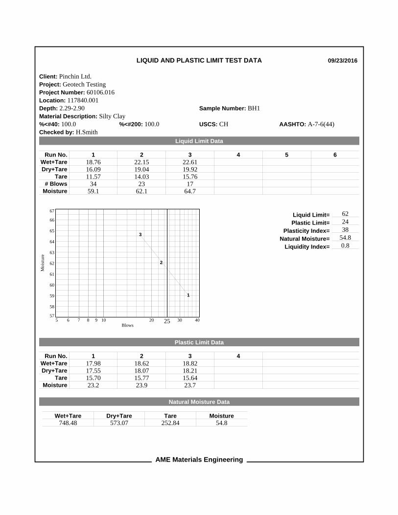
AME Materials Engineering
LIQUID AND PLASTIC LIMIT TEST DATA 09/23/2016
Client: Pinchin Ltd.Project: Geotech TestingProject Number: 60106.016Location: 117840.001Depth: 2.29-2.90 Sample Number: BH1Material Description: Silty Clay%<#40: 100.0 %<#200: 100.0 USCS: CH AASHTO: A-7-6(44)Checked by: H.Smith
Liquid Limit Data
1
18.7616.0911.57
3459.1
2
22.1519.0414.03
2362.1
3
22.6119.9215.76
1764.7
4 5 6Run No.Wet+TareDry+Tare
Tare# Blows
Moisture
Mo
istu
re
57
58
59
60
61
62
63
64
65
66
67
Blows5 6 7 8 9 10 20 25 30 40
1
2
3
Liquid Limit= 62
Plastic Limit= 24
Plasticity Index= 38
Natural Moisture= 54.8
Liquidity Index= 0.8
Plastic Limit Data
1
17.9817.5515.7023.2
2
18.6218.0715.7723.9
3
18.8218.2115.6423.7
4Run No.Wet+TareDry+Tare
TareMoisture
Natural Moisture Data
Wet+Tare748.48
Dry+Tare573.07
Tare252.84
Moisture54.8

AME Materials Engineering
LIQUID AND PLASTIC LIMIT TEST DATA 09/23/2016
Client: Pinchin Ltd.Project: Geotech TestingProject Number: 60106.016Location: 117840.001Depth: 0.76-1.37 Sample Number: BH3Material Description: Silty Clay%<#40: 100.0 %<#200: 99.8 USCS: CH AASHTO: A-7-6(46)Checked by: H.Smith
Liquid Limit Data
1
29.5526.4721.41
3360.9
2
23.4020.3915.61
2663.0
3
23.8920.5715.70
1568.2
4 5 6Run No.Wet+TareDry+Tare
Tare# Blows
Moisture
Mo
istu
re
60
61
62
63
64
65
66
67
68
69
70
Blows5 6 7 8 9 10 20 25 30 40
1
2
3
Liquid Limit= 63
Plastic Limit= 23
Plasticity Index= 40
Natural Moisture= 34.1
Liquidity Index= 0.3
Plastic Limit Data
1
18.9418.3415.7423.1
2
18.3617.8615.7323.5
3
18.0917.6415.7023.2
4Run No.Wet+TareDry+Tare
TareMoisture
Natural Moisture Data
Wet+Tare738.35
Dry+Tare615.02
Tare253.47
Moisture34.1

APPENDIX IV Report Limitations and Guidelines for Use

REPORT LIMITATIONS & GUIDELINES FOR USE
This information has been provided to help manage risks with respect to the use of this report.
GEOTECHNICAL SERVICES ARE PERFORMED FOR SPECIFIC PURPOSES, PERSONS AND PROJECTS
This report was prepared for the exclusive use of the Client and their authorized agents, subject to the
conditions and limitations contained within the duly authorized work plan. Any use which a third party
makes of this report, or any reliance on or decisions to be made based on it, are the responsibility of the
third parties. If additional parties require reliance on this report, written authorization from Pinchin will be
required. Pinchin disclaims responsibility of consequential financial effects on transactions or property
values, or requirements for follow-up actions and costs. No other warranties are implied or expressed.
Furthermore, this report should not be construed as legal advice.
SUBSURFACE CONDITIONS CAN CHANGE
This geotechnical report is based on the existing conditions at the time the study was performed, and
Pinchin’s opinion of soil conditions are strictly based on soil samples collected at specific test hole
locations. The findings and conclusions of Pinchin’s reports may be affected by the passage of time, by
manmade events such as construction on or adjacent to the Site, or by natural events such as floods,
earthquakes, slope instability or groundwater fluctuations.
LIMITATIONS TO PROFESSIONAL OPINIONS
Interpretations of subsurface conditions are based on field observations from test holes that were spaced
to capture a ‘representative’ snap shot of subsurface conditions. Site exploration identifies subsurface
conditions only at points of sampling. Pinchin reviews field and laboratory data and then applies
professional judgment to formulate an opinion of subsurface conditions throughout the Site. Actual
subsurface conditions may differ, between sampling locations, from those indicated in this report.
LIMITATIONS OF RECOMMENDATIONS
Subsurface soil conditions should be verified by a qualified geotechnical engineer during construction.
Pinchin should be notified if any discrepancies to this report or unusual conditions are found during
construction.
Sufficient monitoring, testing and consultation should be provided by Pinchin during construction and/or
excavation activities, to confirm that the conditions encountered are consistent with those indicated by the
test hole investigation, and to provide recommendations for design changes should the conditions
revealed during the work differ from those anticipated. In addition, monitoring, testing and consultation
by Pinchin should be completed to evaluate whether or not earthwork activities are completed in

accordance with our recommendations. Retaining Pinchin for construction observation for this project is
the most effective method of managing the risks associated with unanticipated conditions. However,
please be advised that any construction/excavation observations by Pinchin is over and above the
mandate of this geotechnical evaluation and therefore, additional fees would apply.
MISINTERPRETATION OF GEOTECHNICAL ENGINEERING REPORT
Misinterpretation of this report by other design team members can result in costly problems. You could
lower that risk by having Pinchin confer with appropriate members of the design team after submitting the
report. Also retain Pinchin to review pertinent elements of the design team's plans and specifications.
Contractors can also misinterpret a geotechnical engineering or geologic report. Reduce that risk by
having Pinchin participate in pre-bid and preconstruction conferences, and by providing construction
observation. Please be advised that retaining Pinchin to participation in any ‘other’ activities associated
with this project is over and above the mandate of this geotechnical investigation and therefore, additional
fees would apply.
CONTRACTORS RESPONSIBILITY FOR SITE SAFETY
This geotechnical report is not intended to direct the contractor's procedures, methods, schedule or
management of the work Site. The contractor is solely responsible for job Site safety and for managing
construction operations to minimize risks to on-Site personnel and to adjacent properties. It is ultimately
the contractor’s responsibility that the Ontario Occupational Health and Safety Act is adhered to, and Site
conditions satisfy all ‘other’ acts, regulations and/or legislation that may be mandated by federal,
provincial and/or municipal authorities.
SUBSURFACE SOIL AND/OR GROUNDWATER CONTAMINATION
This report is geotechnical in nature and was not performed in accordance with any environmental
guidelines. As such, any environmental comments are very preliminary in nature and based solely on field
observations. Accordingly, the scope of services do not include any interpretations, recommendations,
findings, or conclusions regarding the, assessment, prevention or abatement of contaminants, and no
conclusions or inferences should be drawn regarding contamination, as they may relate to this project.
The term "contamination" includes, but is not limited to, molds, fungi, spores, bacteria, viruses, PCBs,
petroleum hydrocarbons, inorganics, pesticides/insecticides, volatile organic compounds, polycyclic
aromatic hydrocarbons and/or any of their by-products.
Pinchin will not be responsible for any consequential or indirect damages. Pinchin will only be held liable
for damages resulting from the negligence of Pinchin. Pinchin will not be liable for any losses or damage
if the Client has failed, within a period of two years following the date upon which the claim is discovered
within the meaning of the Limitations Act, 2002 (Ontario), to commence legal proceedings against Pinchin
to recover such losses or damage.