CDOT-DIM Geotechnical Review Guidelines - City of Chicago
20
Chicago Department of Transportation (CDOT) – Division of Infrastructure Management (DIM) Geotechnical Review Guidelines June 2022
-
Upload
khangminh22 -
Category
Documents
-
view
1 -
download
0
Transcript of CDOT-DIM Geotechnical Review Guidelines - City of Chicago
Chicago Department of Transportation(CDOT) – Division of Infrastructure
Management (DIM) Geotechnical ReviewGuidelines
June 2022

CDOT-DIM Geotechnical Review Guidelines (June 2022) Page 2 of 20
CDOT-DIM Geotechnical Review Guidelines
Private and public projects which have excavations and/or penetrations equal to or greater than12 feet below existing grade will require, prior to starting any work, geotechnical and Office ofUnderground Coordination/Existing Facility Protection (OUC/EFP) reviews and approvals fromChicago Department of Transportation’s (CDOT) Division of Infrastructure Management (DIM).In addition, any excavation deeper than 4 feet that extends beyond the property lines and into thepublic way will require OUC review and approval. The following is a partial list of items thatwill require both geotechnical and OUC reviews:
A. Deep foundation members such as caissons, drilled shafts, H-piles, pipe piles, auger-castpiles, micropiles, helical piers, timber piles, dynamic compaction, etc.
B. Underpinning elements such as micropiles, hydraulically pushed piers, helical piers andany other form of underpinning.
C. Earth retention systems (ERS) that include, but not limited to, steel sheet piling, soldierpiles and lagging, slurry walls, secant walls, ground improvements for ERS, rings andlagging, timber sheeting, timber boards and lagging, trench boxes and/or any otherequivalent shoring systems.
D. Backfilling and/or restoration of utility vaults, vaulted sidewalks, vaulted alleys, and/orany other vaulted areas in the public way (these are special cases whereby any depthapplies).
For all building projects requiring building permits, contact the Department of Buildings (DOB)to start the building permit process which may include OUC/EFP review, geotechnical review,ERS review, etc. In these cases, OUC/EFP process is the responsibility of the DOB.
For projects requiring geotechnical reviews such as vaults (regardless of proposed work depth),bridges, roadway structures, utilities, tunneling, jack and bore (regardless of proposed workdepth), directional drilling, dynamic compaction, etc. contact Adam Ali ([email protected] or 312-742-3130) to start the geotechnical and OUC/EFP reviewprocess. The geotechnical review shall proceed concurrently with the OUC/EFP process. Thestart of the OUC/EFP process shall be coordinated with Adam Ali of CDOT. Both thegeotechnical and OUC/EFP reviews and approvals are required prior to issuance of permit byCDOT.
The project manager shall contact Adam Ali of CDOT to schedule an intake meeting to start thepermit review process of the proposed project along with the OUC/EFP submittal. It is theresponsibility of the project manager to submit complete required calculations and drawings forgeotechnical review. The submitted documents shall be 100% complete, signed and sealed (withseal expiration date), and ready for construction.
In addition to the geotechnical and OUC/EFP reviews, CDOT will advise the project managerwhich other permits and approvals will be required such as harbor permits, bridge permits, grantof privilege approvals for installation in the city’s right-of-ways (public ways), freight and trolleytunnel permits, vacations, dedications, easements, etc.

CDOT-DIM Geotechnical Review Guidelines (June 2022) Page 3 of 20
It is required that the project manager provide a complete set of drawings and reports asindicated in the CDOT-DIM Geotechnical Review Guidelines for the initial intake. Drawingsmust include all scope of work including, but not limited to, all excavation area limits, allstructural elements, penetrations, limits of the proposed ERS on plan views and sectionsindicating all geometry of the ERS, length and layout of tie-backs and/or anchorpiles (if any),adjacent utilities, etc. The project manager should submit a complete set of calculations,procedures, drawings, and reports for geotechnical review to CDOT. The submittal shall include,but not limited to, ERS designs, installation procedures (i.e. tie-backs, trench boxes, caissons,jack and bore, piles, directional drilling, etc.), bearing capacity and settlement calculations fromthe Engineer of Record, testing procedures (if applicable), geotechnical report, etc.
Damage monitoring of the City’s right-of-way (ROW) during construction by licensed surveyorsmay be required for the protection of adjacent facilities, utilities, and infrastructures. Prior topermit authorization, CDOT will provide damage monitoring criteria requirements (after thecompletion and approvals of the geotechnical and OUC/EFP reviews). Prior to the start of anywork, call DIGGER at 811, two days (minimum) to locate/mark all existing facilities andutilities.

CDOT-DIM Geotechnical Review Guidelines (June 2022) Page 4 of 20
1.0 GEOTECHNICAL INVESTIGATION AND RECOMMENDATION REPORTA. Provide finalized geotechnical report with scope of investigation (borings, tests, soils
strata descriptions, design, and procedures recommendations, etc.) Include allrecommended foundations, ERS, excavations, backfilling, dewatering, installationprocedures, etc. Report must be signed and sealed (with seal expiration date) by theGeotechnical Engineer of Record (Professional Engineer (PE)).
B. Provide adequate soil borings covering the entire area of installations. A minimum of onenew soil boring at the project site is required. Larger areas of work will require aminimum of one soil boring every two city blocks or as directed otherwise.
C. Soil borings must be drilled below the bottom of the proposed element installations(caissons, piles, ERS, etc.) and excavations to support design requirements. Whencaissons are proposed on top and/or into bedrock, it is required to obtain core borings tosufficient depths below the proposed bottom of caissons.
D. Soil boring logs shall include top elevation of existing ground surface, ground waterlevels, standard penetration test (N) values, unconfined compressive strength and/or shearstrength values, natural water content values, soil/rock core classifications with eachstrata layer identified, etc.
E. In-situ testing is recommended for the design of ERS, bearing capacity of deepfoundations, and settlement/lateral movements. Testing may include, but is not limited to,pressuremeter, vane shear, cone penetrometer, and other testing required by theGeotechnical Engineer of Record.
2.0 DRAWINGSA. Each drawing must be 100% complete and ready for CDOT review.B. Each drawing must be signed and sealed (with seal expiration date) by an Illinois PE
and/or Illinois Structural Engineer (SE) where appropriate.C. Drawings must clearly show all excavation/penetrations (with dimensions) being
performed at any stage of the construction sequence or process.D. Each drawing shall indicate the latest submittal date(s) and revision number(s).E. Each drawing must indicate the Deep Excavation EFP (DEEFP) number in the lower
right-hand corner of the drawing.F. The OUC Plan Set must have its own exclusive sheet numbering sequence (CDOT
Permit Sheet No.). This sheet numbering must be, DE-1, DE-2, DE-3, etc. (in consecutivesequence). An index of sheets (to include sheet numbering, title, revision letter, andrevision date) must be shown on the cover sheet or the index sheet(s). In the case whereowners/engineers have their own sheet numbering, it is acceptable to show the CDOTPermit Sheet No. in the lower right-hand corner, in parenthesis, in each sheet/drawing.Also, the index of sheets table must show the original sheet numbering with theequivalent DE sheet numbering as “CDOT Permit Sheet No.” The index of sheets tablemust match, verbatim, the information on the individual sheets. Below is an exampletable to be shown in the OUC Plan Set:

CDOT-DIM Geotechnical Review Guidelines (June 2022) Page 5 of 20
Index of SheetsDrawing/Sheet
No.CDOT Permit
Sheet No.Sheet Title Revision
LetterRevision
DateRevision
DescriptionOUC Review
G. Each drawing is considered a standalone sheet. Therefore, all callouts and notes mustreference in detail all reference sheets/drawings (i.e. Refer to Sheet X for details/cross-section/etc., Refer to Sheet Y for general plan and elevation., etc.). The submittal packagemust have every single sheet/drawing adequately reference all sheets within the permitpackage.
H. Show only the portion of the project being requested for a permit. All other areas not partof the permit request must be crossed/shaded out and indicated as “Not for permit underthis contract.” This must be done for every single drawing submitted.
I. For projects that have areas of work under separate permits, indicate the EFP and/orDEEFP number) of the area previously submitted to OUC and/or Deep Ex. If submissionis pending, then indicate “To be submitted for separate OUC review.”
J. A valid information retrieval (IR) must be shown. Expired IR will not be accepted. Allproposed work (i.e., excavations, foundations, ERS, etc.) must be dimensioned from theright of way lines (transverse and longitudinal dimensions).
K. All drawings must be of consistent size (preferably printed/displayed as 11” x 17”).L. The general set up for the OUC plan set is: Cover Page, Sheet Index, OUC Key Plan
Sheet, followed by all drawings associated with the OUC Key Plan Sheet (i.e. site plans,civil plans, civil details, excavations, foundations, ERS, etc.).
2.1 Cover SheetA. Provide the project name and address.B. Provide the design company full contact information (name, address, telephone number,
etc.).C. Provide the location/vicinity map with the area of work clouded or circled including
north arrow.D. Provide the scale used for drawings.E. Provide the scope of work description.F. Indicate legends for symbols for existing and proposed utilities.G. Provide 811 (Digger) information.H. Provide the project DEEFP number.I. Provide an index table listing all drawing/sheet numbers, drawing sheet title, revision
date, and revision number.J. Provide a brief and concise scope of work description that is being requested for permit.
Scope of work must indicate/identify all areas requiring permit review, means andmethods (i.e. open cuts, foundations, ERS, trench boxes, etc.), and all areas where thereare any excavations/penetrations into the ground. The following example is a scope ofwork for the cover sheet:
Scope of Work Requested for Deep Ex and OUC Permit:

CDOT-DIM Geotechnical Review Guidelines (June 2022) Page 6 of 20
Trench box installation for 36" sewer pipe.Open cut excavation for XYZ at locations ABC.H-pile installation for ABC.Etc.
2.2 Plat of SurveyA. Must provide plat of survey prepared, signed and sealed by a licensed surveyor, and dated
within the last six months in the Central Business District (CBD) and within one yearoutside the CBD (CBD bounded by North Avenue (north limit), Halsted Street (westlimit), Cermak Road (south limit), and Lake Michigan (east limit)).
B. Show existing streets, alleys, sidewalks, existing adjacent buildings, etc.C. Indicate all vacated and easement corridors.D. If existing utilities (gas, water, sewer, electric, telephone, telecom lines, freight and
trolley tunnels, abandoned water tunnels, etc.) were obtained through the OUC IR by thesurveyor, then all existing utility information shall be shown on the plat of survey.However, if OUC IR was not performed by the surveyor and existing utilities are notplotted on the plat of survey then it is required by CDOT that all indicated required utilityinformation must be obtained through OUC IR process by the Civil Engineer and shall beplotted on the civil existing conditions drawing.
E. OUC IR online link:https://www.chicago.gov/city/en/depts/cdot/supp_info/ouc--informationretrievalprocess.html
2.3 OUC Key Plan SheetA. OUC Key Plan shall comprise of the proposed site plan indicating all proposed
improvements. All areas of work requiring proposed excavations and/or deep foundations(i.e. ERS, open cuts, caissons, piles, etc.) shall be circled and each circled area mustindicate reference drawing number/s (utilizing the DE sheet numbering convention)where complete detailed plan views and sectional details of each proposed circled area ofwork (including existing utilities information) are included.
B. It is recommended to have the OUC Key Plan Sheet in one sheet. However, due to thedensity, scope, and limits of a project, several sheets may be required. It is best to useengineering judgment on the quantity of sheets and scale of the OUC Key Plan Sheet tobest depict the permitting request.
C. All information shown on the OUC Key Plan sheet is what will be utilized by CDOT forpermit review. Therefore, all permitting requests/items (shallow and deep work) must beclearly indicated.
2.4 Civil Plan and DetailsA. Provide a site plan indicating new and/or existing sidewalks, alleys, streets, proposed
grades, etc.B. Provide a demolition plan indicating all areas to be removed (sidewalks, alleys, streets,
utility lines, utility structures, etc.).

CDOT-DIM Geotechnical Review Guidelines (June 2022) Page 7 of 20
C. Provide the existing condition plan indicating existing grade streets, sidewalks, alleys,utility lines, utility structures, etc. (refer to Section 2.2.D).
D. Provide the proposed utility plan indicating all proposed utility lines and utilitystructures. All new utility lines and structures shall have dimensions from street ROWlines (longitudinally and transversely at proposed work limits).
E. Provide elevations and section detail drawing(s) indicating all proposed utility profilesand utility section details.
2.5 Structural PlansA. Provide a foundation plan indicating proposed foundations (caissons, grade beams, piles,
cap footings, etc.).B. Provide foundation details showing typical section details for caissons, piles, footings,
etc.
2.6 ERS/Excavation DrawingsA. Provide locations with dimensions of ERS/excavation limits. All proposed
ERS/excavation shall also be dimensioned from street ROW lines. Include all existingutilities, existing adjacent buildings, encroachments into the public way, etc.
B. Provide typical section details showing existing grade lines and elevations, top and tipelevation of proposed ERS, top and bottom of all sloped excavations. Section detailsmust indicate ROW/property lines, existing utility lines/utility structure, adjacentbuildings, any encroachments in the public way, etc.
C. Provide elevation section views (laterally and longitudinally) showing all utilities andunderground structures with lateral dimensions and depth dimensions. At a minimum,show all utilities and underground structures from the ERS face to within a lateraldistance equivalent to the maximum depth of the ERS.
2.7 Maintenance of Traffic (MOT) PlansA. Provide a plan view indicating streets, sidewalks, alleys (including utility poles), existing
CTA structures, CTA bus stops, fences, barricades, canopies with dimensions from ROWlines, etc. Also, indicate portions of streets, sidewalks, and alleys to be closed and anydetours with dimensions from ROW lines.
B. For additional requirements and typical details refer to CDOT regulations forconstruction and repair in the public way.
2.8 Trench BoxesA. Trench boxes required for installation with excavations less than 12 feet and not requiring
a direct OUC submittal must also be submitted for geotechnical review and approvalprior to permit issuance by CDOT.
B. Provide detailed step-by-step installation sequence/procedure that includes all dimensionsof the open trench (length, width, and depth) for trench box placement.
C. Installation sequence/procedure shall indicate immediate backfilling of the over-excavated areas/voids between the excavated trench sides and trench box with specified

CDOT-DIM Geotechnical Review Guidelines (June 2022) Page 8 of 20
fine grain soil after the trench box placement and before proceeding with excavation tospecified grades, utility line/structure installations, backfilling sequence, etc.
D. All excavation within the trench box shall be backfilled to street pavement subgrade leveland/or to the existing grade level prior to removal of the trench box and/or slidingforward of the trench box for the next segment of installation.
E. Proprietary product cut sheets shall be provided for all ERS elements verifying theassumed design parameters.
2.9 DewateringA. Dewatering calculations and dewatering drawings must be provided from the dewatering
contractor (signed and sealed with seal expiration date from a PE).B. Design calculations for discharge volume, well point spacings, well point diameter and
required length of the well points must be provided by the dewatering contractor.Submittal document shall include dewatering drawing with well points location plan andtypical well point details showing existing grade, ground water level, diameter of hole,diameter of well point, length of the well point, etc.
C. Dewatering by sump and pump method is only possible if steel sheeting and/or any otherimpervious systems such as slurry walls, secant walls, etc. are used and driven/installedto at least 2 feet into silty clay. For soldier pile and lagging ERS in granular soils withgroundwater, dewatering by sophisticated methods (well points, etc.) to at least 2 feetbelow the bottom of excavation level will be required.
2.10 Jack & BoreA. All open areas around pipe openings must be properly designed to avoid any inflow of
soils and groundwater into the pits. ERS elements around pipes must be designed anddetailed in the drawings as well.
B. To minimize damage to the infrastructures over the jacked and bored pipe, it is requiredthat the size of the auger head shall not be larger than ½ inch of the diameter of thecasing. Bentonite slurry should be used to facilitate pipe jacking. If for any reason theauger head diameter will need to be larger than ½ inch, then cement grout shall be used tofill the gap around the jacked pipe.
C. It is required that the proposed ERS shall be designed for the anticipated jacking forceapplied during jacking. Thrust pad design calculations shall be provided. All thrust detailsmust be included in the ERS drawings.
2.11 Directional DrillingA. Drawing(s) shall include existing conditions; sending and receiving pits; proposed
directional driving pipe alignment with all dimensions provided from ROW lines; typicalsections through pits and at quarter, half, and three-quarter points along the alignmentindicating existing ground surface elevation, depth and sizes of the pipe(s), existingutilities, etc.
B. To minimize damage to the overlying infrastructure, it is required that the size of thedrilling auger head and/or oversize drilled hole shall not be larger than ½ inch of thediameter of the carrier pipe(s). Bentonite slurry shall be used to facilitate drilling and pipe

CDOT-DIM Geotechnical Review Guidelines (June 2022) Page 9 of 20
installations. If the drilling auger head and/or oversize drilled hole is larger than ½ inchof the diameter of the carrier pipe, cement grout shall be used to fill the gap around theinstalled pipe(s).
2.12 Installation ProceduresA. Contractor’s means and methods, installation procedures, etc. must be provided on the
drawings. Any note on the drawing(s) indicating that the designer and/or engineer ofrecord will not be responsible for the contractor’s means and methods, installationprocedures, etc. is not acceptable to CDOT.
B. All work in the field shall be performed in conformance with the approved drawings byCDOT. Any changes required in the field from the permitted/approved drawings willrequire resubmittal of revised design calculations, procedures, and revised drawings of allrequired changes to CDOT for review and approval prior to performing anyrevisions/changes in the field.
3.0 FOUNDATION DESIGN CALCULATIONS AND INSTALLATION PROCEDURESThe project manager shall submit design calculations required by CDOT. Calculations shallindicate the latest submittal date(s) and revision number(s). Hand and/or Mathcad calculationsare required. If Mathcad calculations are provided then each line of calculations should include asymbolic formula, followed by the numerical formula with all numerical parameter valuesindicated, and then the numerical result. Computer outputs are not accepted. A general listing ofrequired calculations is provided below for reference. Additional calculations may be required onan individual project/site specific basis. Also, the requirements specific to soil testing andanalysis, as well as, foundation load testing and design parameters, may be found in the ChicagoBuilding Code (Chapter 18 – Soils and Foundations).
A. Foundation Design Calculations and Construction Proceduresa. Bearing Capacity: calculations for all types of foundations used [shallow (footing,
mats, etc.), deep foundations (caisson, piles, etc.), and/or combination]b. Settlement: total and differential settlementsc. Installation procedures
B. Underpinning of Existing Buildinga. Underpinning pier (pile) static capacityb. Analysis to determine if adjacent existing footing/wall are capable of withstanding
anticipated pressure/stress (documentation of structural review by others)c. Underpinning installation procedure
C. Adjacent Structure Analysis and Protectiona. Adjacent existing footing/wall sub-grade bearing capacity/stability analysis for
reduced factor of safety (FOS) due to removal of soil surcharge above and/orbelow existing footing subgrade levels
b. Stability Analysiso Allowable bearing capacity (a minimum FOS of 3.0 is required)o Sliding (a minimum FOS of 2.0 is required)o Overturning (a minimum FOS of 1.5 is required)
CDOT-DIM Geotechnical Review Guidelines (June 2022) Page 10 of 20
D. Load Testsa. Load tests shall be in conformance with the 2019 Chicago Building Code Section
1810.3.3.1.2.b. When a compression load test is performed on piles, it may be performed on a
production pile; however, the production pile cannot be used as a reaction pile forthe load test.
c. When a tension load test is performed, it must be performed on a sacrificial pile.
4.0 EARTH RETENTION CALCULATIONS AND INSTALLATION PROCEDURES4.1 Common ItemsThe following items are to be included with all ERS submittals. All ERS drawings andcalculations must be signed and sealed (with seal expiration date) by an Illinois SE.A. Hand calculations and/or Mathcad calculations are required. Computer outputs from
design software with no hand calculations or explanations are not accepted.B. Boring logs, field/lab test data and final geotechnical report (project site specific).C. List all design assumptions used in the calculations, as they are introduced in
sequence of computations.D. Provide copies of relevant pages of references used in the calculations. These include all
graphs, charts, or tables used in the analysis or design.E. Provide copies of catalogue sheets, cut sheets, and/or tables of material properties, used
in the structural calculations.F. All submittals must include a sketch with listing of soil layers, soil parameters, and
design water level assumed in the calculations. Specific borings which were used inestablishing the design soil profiles should be identified by boring numbers as indicatedon the boring logs. Note that because soil conditions vary from soil boring to soil boringover the project site, a composite and/or most critical design soil profile shall be used.
G. Calculations should include cross-sections of the ERS indicating elevations for:a. Top and toe of the wallb. Existing surrounding ground surfacec. Bottom of the excavationd. Existing adjacent foundations within the zone of influencee. Cut slopes and set-backsf. Ground water level elevations
H. All formulas must be listed as they are being used in the various parts of the calculations.I. Include all calculation steps that are a normal part of an actual hand solution whether or
not a computer-assisted analysis/design was used. Computer output that is written byhand does not classify as “hand calculations” and will not be accepted. Also, do notsubmit previously submitted calculations from a similar project as part of or a substitutefor the new project calculations.
J. Construction and/or building surcharge should be actual loading conditions planned bythe contractor (crane loading included) or a minimum traffic surcharge of 240 psf.
a. The building and crane surcharge shall be calculated from the bottom of theloaded foundation and applied to the tip of the ERS.

CDOT-DIM Geotechnical Review Guidelines (June 2022) Page 11 of 20
b. The traffic surcharge shall be applied from existing grade to the bottom of theERS.
K. ERS drawings must include plan views and cross-sections which are consistent with thefinal designs. Sufficient cross-sections must be provided indicating top of grade, cutbackslopes, excavation contour lines, adjacent buildings, sidewalks, alleys, roadways, and alllateral utilities within the zone of influence (within 2.0 times the excavation depth fromgrade). Dimensions from the ERS to all utilities must be shown.
L. Groundwater control plan section details and dewatering calculations prepared by anIllinois PE must be submitted for review in all cases where wells/wellpoints and/or othertype of dewatering methods are necessary to maintain a water-free, stable excavation.
M. ERS must include sequence of work (i.e. pre-holing for verifying existing foundation(s),pre-trenching for the removal of existing obstruction(s), backfilling with suitable materialto grade, and ERS installation). Include detailed step-by-step sequence for excavation andinstallation of bracings, backfilling, and removal of bracings all conforming with thestaged design calculations.
N. Provide separate calculations for active, passive and surcharge pressures at: grade,ground water level, excavation level, the upper and lower interface of each soil stratalayer and to at least the tip of the proposed ERS.
O. Provide separate active, passive, hydrostatic, surcharge, and net pressure diagrams(indicating all numerical values). The pressure diagrams should be used for the design ofwaler loads, ERS sizing, and for the required length of the ERS. Pressure diagrams withnumerical values shall be plotted to reasonable size for illustration. The pressurediagrams shall be split into triangular and rectangular units. Identify units by letters ornumbers for use in calculations.
P. In cases where a theoretical negative or small positive active earth pressures are predictedthrough clay strata, a minimum active earth pressure of 0.25γz should be used where “γz” is the total overburden pressure at depth z.
Q. Active pressure in clay is determined using equations: γH - 2c or 0.25γH, where γH is the total earth pressure at depth H. The higher value from the equations shall be used fordesign of the ERS.
R. For the design of soldier piles and lagging walls, no passive pressure shall be consideredfrom existing ground surface grade in front of the wall to a depth of 1.0 x D (diameter ofshaft or width of pile flange) in granular soils and 1.5 x D in cohesive soils.
S. All new proposed dockwall/riverwall sheeting shall be designed considering dredge lineelevations in the Chicago River established by the U.S. Army Corps of Engineers.
T. All permanent retaining walls and dock walls shall be designed for both the short term(undrained) condition and long term (drained) condition. For the design of short-termcondition only the shear strength (C) value shall be considered in clay layers and for thedesign of long-term condition, only the angle of internal friction (ɸ) value shall be usedin clay layers.
U. The ERS shall be designed for the maximum flexural moment. No moment reduction dueto flexibility of the wall shall be applied.

CDOT-DIM Geotechnical Review Guidelines (June 2022) Page 12 of 20
V. The ERS lagging shall be designed for the maximum lateral pressure along the ERS fromgrade to the excavation level.
4.2 Earth Retention System (ERS) Items – GeneralThe ERS submittal must include calculations for the design of all vertical wall componentsand for all bracing components. For example, depending on the system selected, this mayinclude design for:A. Sheet piles, soldier piles and lagging (timber, steel plate, etc.), timber sheeting, secant
piles, slurry walls, etc.B. Walers, struts, rakers, kicker blocks, anchors, connections, and temporary earth berms.C. Utility supports for existing infrastructure. All utility support design calculations and
utility support drawings shall be submitted to all affected OUC members, whose utilitieswill require protection, for their review, approval, and coordination prior to performingany work.
D. Use of proprietary systems (i.e. trench boxes or slide rail shoring) requires that an IllinoisSE confirm that the systems components are satisfactory for site-specific conditions withsupporting calculations. Manufacturers or suppliers cut sheets must be submitted, listingserial numbers of frames or boxes proposed for use on the project. These cut sheets mustbe signed and sealed (with seal expiration date) from an Illinois SE.
E. ERS in the City's ROW shall be cut off 4 feet below grade and left in place.F. ERS not within City's ROW may be removed if all affected adjacent utility owners
approve the removal. Required approval documentation must be provided in the Deep ExReview Package submittal.
4.3 Items Specific to Cantilever Wall Analysis/DesignIn addition to Section 4.1 and Section 4.2, the following must be included:A. Provide a stepwise calculation of lateral pressure distribution. Provide calculations for
pressures at every soil strata change of state (e.g. stratum boundaries excavation depth,ground water level, adjacent foundation load as it varies with depth, etc.).
B. Plot lateral pressures (with numerical values indicated) on diagram to reasonable size forillustration. Split diagram into reasonable triangular and rectangular units. Identify unitsby letter or number for use in calculations. Account for all components of load (soil,water, and surcharge).
C. Provide moment calculations based on pressure diagram(s), solving for wall embedmentdepth required for rotational equilibrium (FOS = 1.0) about the toe. Find zero shear andmaximum moment to size the ERS. Provide calculations for the anticipated deflection ofthe proposed ERS and adjacent ground surface settlement.
D. Provide additional embedment length to establish safety factor or margin of safety vs.rotational failure about the toe. Any of the generally recognized methods of determiningdesign embedment depth may be used. A minimum FOS of 1.5 is required in all caseswhen the ERS is utilized as a temporary structure. A minimum FOS 0f 2.0 is requiredwhen the proposed ERS is used as a permanent structure.
E. Provide analysis of structural wall deflection and ground deformation required tomobilize passive resistance. The support assumption for structural deflection should be

CDOT-DIM Geotechnical Review Guidelines (June 2022) Page 13 of 20
consistent with Figure 6-1 of the U.S. Army Corps of Engineers EM 1110-2504 “Designof Sheet Piles Walls.”
F. A check of base stability should be made using generally accepted methods. A minimumallowable FOS of 1.5 is required.
4.4 Items Specific to Single Level Braced or Anchored WallsIn addition to Section 4.1 thru Section 4.3, the following must be included:A. Provide calculations for earth pressure at brace or anchor level.B. Provide calculations for the ERS wall depth of embedment for rotational equilibrium
about the brace/anchor level for a FOS of 1.0. Provide calculations for waler load, pointof zero shear, and maximum moment for sizing ERS. Provide additional calculations forthe required length of the ERS wall for a minimum FOS of 1.5. A minimum FOS of 1.5is required in all cases when the ERS is utilized as a temporary structure. A greater FOSmay be required when the proposed ERS is used as a permanent structure.
C. Provide calculations for the design of bracings (walers, struts, connections, etc.). Providecalculations for the size of the ERS wall considering maximum moments.
D. Provide calculations for the anticipated deflection of the proposed ERS and adjacent groundsurface settlement. The assumption for structural deflection should be consistent with Figure6-2 of U.S. Army Corps of Engineers EM 1110-2504 “Design of Sheet Piles Walls.”
4.5 Items Specific to Walls with Two or more Levels of BracingIn addition to Section 4.1 and Section 4.2, the following must be included:A. Provide analysis for cantilever and single brace stages (see Sections 4.3 and 4.4) and final
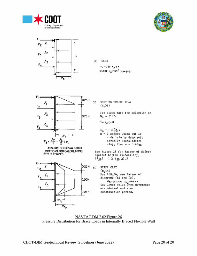
depth of excavation stages.B. Use generally recognized apparent earth pressure envelopes for determining multi-tier
strut loads, do not reduce strut or anchor loads to account for temporary conditions. NavalFacilities Engineering Command (NAVFAC) Design Manual 7.02 Figure 26 can be usedfor the design of shoring and waler/strut loads for excavation to the bottom of the shoringsystem. When excavation is in soft clays, Figure 26 “Case (b)” may be used. Whenexcavation is in stiff clays, Figure 26 “Case (c)” may be used.
C. Provide base stability analysis for partial and full depth of cut, as needed, to final criticalcorrelation. A minimum FOS of 1.5 is required.
D. An estimate of adjacent ground movement should be made (Clough’s Method or industryaccepted alternate methods) accounting for stiffness of proposed wall (FOS for basalheave, number of bracing levels, depth of excavation, etc.).
E. When analyzing overall stability, do not include friction between the wall and retainedsoil as contributing to stability of the system.
F. Provide design for all bracing component (walers, struts, rakers, connections, etc.)
4.6 BracingIn addition to Sections 4.1, 4.2, 4.4, and 4.5 and any other appropriate bracing analysis, thefollowing must be included:

CDOT-DIM Geotechnical Review Guidelines (June 2022) Page 14 of 20
A. Ground anchor (tieback, H-pile, etc.) design shall include both the unbonded and bondedlengths calculations with related sketches, testing procedures (proof, performance, andcreep), and production anchor installation procedure.
B. Provide design of all bracing components (walers, struts, rakers, connections, etc.).C. Provide structural design of stiffeners, connections, support brackets, etc. Check compact
and non-compact sections.
4.7 Global Stability AnalysisThe overall global stability of the proposed ERS shall be verified independently whenrequired. The global stability analysis and calculations must be provided by the GeotechnicalEngineer of Record.
The analysis should include computer generated analysis input and output data sheetsconsidering numerous slip circle failure planes. Indicate FOS on each slip circle failureplane. Provide a diagram and design calculations for the slip circle failure plane with thelowest FOS. The slip circle failure plane diagram must be drawn to an enlarged scale forCDOT to be able to verify the slip circle slice dimensions, slice angles, slice overturning andresisting moment, overall factor of safety of the proposed excavation design slopes, etc.Indicate each soil strata layer, soil strata layer design parameters, numbered slices, gradeelevation, as well as top and tip elevations of the ERS (when used). Additional calculationsof driving and resisting moments through individual slip circle failure plane slice(s) shall beprovided.
5.0 DEFLECTION CRITERIAAll the following deflection requirements shall be met for ERS in the City of Chicago unlessspecified otherwise:
A. The maximum deflection of a permanent ERS shall be 1% H (H denotes the retainedheight) but not greater than 1 inch.
B. The maximum deflection of a temporary ERS shall be 1.5% H (H denotes the retainedheight) but not greater than 2 inches.
C. When the excavation (temporary or permanent) is within 1:1 (Vertical (V):Horizontal(H)) of an adjacent structure (i.e. bridge/building shallow foundation) the deflection ofthe ERS shall be limited to ¼ inch.
D. When the excavation (temporary or permanent) is within 1:1.5 (V:H) of an adjacentstructure (i.e. bridge/building shallow foundation) the deflection of the ERS shall belimited to ½ inch.
E. When the excavation (temporary or permanent) is within 1:2 (V:H) of an adjacentstructure (i.e. bridge/building shallow foundation) the deflection of the ERS shall belimited to 1 inch.
F. For ERS (temporary or permanent) that is within 1:1.5 (V:H) of adjacent water, sewer,and/or gas utilities, ERS deflections exceeding 0.25 inches will require a written approvalfor the submitted ERS design and deflections from the water, sewer, and/or gas utilityowner(s).

CDOT-DIM Geotechnical Review Guidelines (June 2022) Page 15 of 20
6.0 OPEN CUT EXCAVATIONAll open cut excavations up to 4 feet in depth shall be sloped at 1:1 (H:V) or shored and allexcavations greater than 4 feet in depth shall be sloped at a minimum of 1.5:1 (H:V) or shored.Refer to Section 2.12 for additional requirements.
7.0 EXISTING VAULTSExisting standalone vaults with no access into the vault from any private property or buildingwill require CDOT geotechnical review when the scope of work involves backfilling and/or roofreplacement of the vaulted sidewalks, vaulted alleys, and/or any other vaulted areas in the publicway. For existing vaults in the public way with access into the vault from adjacent privateproperty or adjacent building will require a DOB permit/review.
7.1 Backfilling of Existing Vaults and RestorationContractor and/or engineer shall provide detailed step-by-step procedures and sequence forbackfilling and restoration to CDOT for review and approval. The procedures and sequencemay involve, but not limited to design and installation of shoring within the vault walls, vaultroof removal, backfilling of vault space by flowable fill and/or any other approved backfillmaterials by CDOT, restorations, etc.
For backfilling of an existing vault in the public way, which is adjacent and accessible fromthe building (on private property), refer to the CDOT Standard Detail A-3-3. For designcalculations for shoring system requirements, refer to Section 4.0.
7.2 Existing Vault Roof ReplacementContractor and/or engineer shall provide detailed step-by-step procedures and sequence forrestoration/replacement to CDOT for review and approval. The procedures and sequencemay involve, but not limited to, design and installation of a shoring system within theexisting vault walls; removal, replacement, and restoration of the vault roof; and any installedshoring removal. Design calculations for the shoring system will be required, refer to Section4.0.
8.0 DEEP EX PERMIT PROCESSDeep Ex permit process utilizes the program, ProjectDox, to track, monitor, and document thepermit process. ProjectDox is also utilized for document management, uploads, and retrievalspertaining to the project being reviewed for permitting. Prior to a ProjectDox account creation,contact Adam Ali for an intake request.
During the permit review process, the applicant project manager will act as the CDOT point ofcontact and project manager responsible for the permit. It is the applicant project manager’sresponsibility to ensure all instructions, guidelines, and documents are followed in complianceand coordinated with the permit team. All documents submitted must be QA/QC by the applicantteam prior to submitting to CDOT. All uploads into ProjectDox are to be in PDF format.

CDOT-DIM Geotechnical Review Guidelines (June 2022) Page 16 of 20
OUC review will expire six months from the “OUC Due Date” (determined by the OUC once theOUC application is received) within the area bounded by North Avenue, Halsted Street, CermakRoad, and Lake Michigan. Outside these mentioned limits, the OUC review will expire one yearfrom the “OUC Due Date.” An OUC expiration results in a complete resubmittal of the projectand restart of the permit process.
CDOT is not responsible for construction timelines and applicant team management. The permitprocess, applicant team management, and construction schedule are the responsibility of theapplicant team.
9.0 COT-DIM DEEP EX PERMIT FEE SYSTEMThe Chicago Department of Transportation (CDOT), Division of Infrastructure Management(DIM), has a Deep Excavation Review and Permit Fee System as per Municipal Code ofChicago (MCC) § 2-120-300(e). This fee system will include a non-expedited Office ofUnderground Coordination (OUC) review and a CDOT Deep Excavation review.
The CDOT Deep Excavation Review and Permit Fees are non-negotiable and will be as follows: $1,500.00 Deep Excavation Permit Application Fee
o This fee includes the initial permit drawings review, submittal for OUCreview, and one review cycle of a “Deep Ex Review Package” by DeepExcavation.
o This fee is subject to project submission limits based on density and scope ofpermitting decided and agreed upon by CDOT-DIM Deep Excavation.
$1,500.00 Deep Excavation Damage Monitoring and Inspections Fee
The mentioned fees are independent and do not include any other fees that may be required suchas, but not limited to, public-way opening fees, public-way closure fees, expedited review fees,etc.
The Deep Excavation Damage Monitoring and Inspections Fee is required on a per permit basisdetermined by, and at the discretion of CDOT-DIM Deep Excavation.
City of Chicago departments, State Agencies, and Federal Agencies will not be subject tothe Deep Excavation Review and Permit Fee System. All other permit applicants requiring aDeep Excavation review and permit will be required to pay the fees mentioned herein, noexceptions will be granted.

CDOT-DIM Geotechnical Review Guidelines (June 2022) Page 17 of 20
REFERENCE FIGURES
Theoretical Relationship Between Maximum Lateral Wall Movement, FOS Against BasalHeave, and System Stiffness*
Comparison of Field Data and Theoretical Trends for Anticipated Movements*
*Published research documents by Clough and other researchers.

CDOT-DIM Geotechnical Review Guidelines (June 2022) Page 18 of 20
U.S. Army Corps of Engineers EM 1110-2504 Figure 6-1Pressures and Supports for Structural Design of Cantilever Walls.
U.S. Army Corps of Engineers EM 1110-2504 Figure 6-2Pressures and Supports for Structural Design of Anchored Walls.

CDOT-DIM Geotechnical Review Guidelines (June 2022) Page 19 of 20
CDOT Standard Detail A-3-3Elimination of Vaulted Sidewalk Adjacent to Building at Property Line
CDOT-DIM Geotechnical Review Guidelines (June 2022) Page 20 of 20
NAVFAC DM 7.02 Figure 26Pressure Distribution for Brace Loads in Internally Braced Flexible Wall