Surface modifications of cellulose nanocrystals for biobased ...

This content has been downloaded from IOPscience. Please scroll down to see the full text.
Download details:
IP Address: 14.139.219.242
This content was downloaded on 31/01/2014 at 06:40
Please note that terms and conditions apply.
Significant improvement in dopant emission and lifetime in water soluble Cu:ZnSe/ZnS
nanocrystals
View the table of contents for this issue, or go to the journal homepage for more
2014 Mater. Res. Express 1 015014
(http://iopscience.iop.org/2053-1591/1/1/015014)
Home Search Collections Journals About Contact us My IOPscience
Significant improvement in dopant emission andlifetime in water soluble Cu:ZnSe/ZnS nanocrystals
K Saikia1, P Deb1, B Mondal2 and E Kalita31Department of Physics, Tezpur University (Central University), Tezpur-784028, India2Department of Central Scientific Services, Indian Association for the Cultivation of Science,Jadavpur, Kolkata 700032, India3Department of Molecular Biology and Biotechnology, Tezpur University (Central University),Tezpur-784028, IndiaE-mail: [email protected]
Received 8 November 2013, revised 12 December 2013Accepted for publication 12 December 2013Published 30 January 2014
Materials Research Express 1 (2014) 015014
doi:10.1088/2053-1591/1/1/015014
AbstractWe report here the enhanced dopant emission in Cu:ZnSe/ZnS core–shellnanocrystals (NCs) through an aqueous route in ambient conditions. A three-foldquantum enhancement in luminescence has been achieved by developing a ZnSinert shell as compared to the pristine doped NCs. The internal doping of Cuafter shell growth, signifying localization of Cu2+ t2 energy states in the deepband gap, has shown a significant improvement in dopant excited state lifetime.The long lifetime related to Cu dopant emission is the longest lifetime everreported for copper doped zinc based NCs developed through an aqueous route.The good colloidal as well as the luminescence stability of these highly efficientdoped NCs mean they have great potential for use in biomedical imagingapplications.
S Online supplementary data available from stacks.iop.org/MRX/1/015014/mmedia
Keywords: nanocrystals, colloids, photoluminescence, dopant emission, lifetime
1. Introduction
Luminescent semiconductor nanocrystals (NCs) have become one of the most attractiveresearch areas because of their tremendous potential applications in biomedical labeling,photovoltaics, and light-emitting diodes (LEDs) etc [1–6]. The quantum confinement effect andlarge surface-to-volume ratio in these NCs are two key factors resulting in unique optical andelectrical properties accompanied by broad absorption, narrow emission, long fluorescencelifetime, size tunable emission etc [7–9].
Materials Research Express 1 (2014) 0150142053-1591/14/015014+11$33.00 © 2014 IOP Publishing Ltd
In the last decade, Cd-based NCs, particularly CdSe NCs have been the workhorses of thenano emitter owing to their absorption and emission spectrum spanning mostly the visiblerange, as well as high emission yield [10]. However, the applicability of these NCs has beenharshly limited due to the leakage of the heavy metal cores leading to devastating harm to theenvironment, especially tissue [11, 12]. Researchers have tried to address this issue by usinginert shells, polymer coats, biocompatible coats etc over such NCs systems, with variousdegrees of success. But, the prospect of introducing a heavy metal based probe in biologicalsystems still prohibits their extensive use for biomedical applications. Doped semiconductorNCs, replacing heavy metal like Cd in their chalcogenide, with Zn as the absorption zone, andincorporating the transition elements (Mn or Cu) as the emissive centers, have been realized asthe possible alternative with inherent biocompatibility and tunable emission characteristics [13].However, the low quantum yield (QY) of these Zn based doped NCs due to the intrinsicinstability of the dopant elements in the host crystals, somehow raises questions about theirefficiency [14]. Moreover, the dopant induced capping ligand degradation is reported forlowering the colloidal and luminescence instability of these NCs [15, 16]. In this report, wehave reported doubly protected Cu:ZnSe/ZnS core-shell NCs to achieve an internally doped,stable and highly luminescent probe. A similar crystal structure and nearly identical latticeconstant of ZnS with ZnSe leads to the uniform enveloping of the Cu doped ZnSe NCs,resulting in efficient transfer of photo-excited electrons to the Cu ‘d’ levels without causingundesirable surface activated non-radiative relaxation phenomena. To the best of ourknowledge, we have reported for the first time the longest Cu dopant excited state lifetimealong with significant photoluminescence (PL) and stability enhancement for the water solubleCu doped ZnSe/ZnS system. The tactic for the significant enhancement of lifetime and PL andthe understanding of its underlying mechanism is the novel highlight of our study. Moreover,we have studied the growth dynamics of the ZnS shell in terms of PL evolution, which gives aninsight into the formation of the core–shell nanostructure in aqueous solution.
2. Materials
Zinc acetate (Zn(OAc)2.2H2O, 98%), Copper acetate (Cu(OAc)2H2O, 98%), sodiumborohydride (NaBH4, 99%), Sodium hydroxide (NaOH) and Sodium Sulfide (Na2S, 99%)were procured from Merck. Selenium powder (∼100 mesh, 99.999%), 3-mercaptopropionicacid (MPA, 99%), and hydrazine hydrate (N2H4.2H2O) were procured from Aldrich. Allchemicals were used without any purification and experiments were carried out in aqueousmedia and Milli-Q water was used throughout.
3. Synthesis of Cu:ZnSe and Cu:ZnSe/ZnS NCs
The synthesis was carried out through a simple aqueous route in an ambient atmosphere in twosteps. Here, Cu:ZnSe NCs were synthesized by modifying an aqueous synthesis route [17]. Atthe outset, we prepared the Zn precursor solution, where 3-mercaptopropionic acid (MPA) anda measured amount of hydrazine hydrate (N2H4.2H2O) were added. The pH of the solution wasadjusted to 11.50 adding NaOH solution. The Cu dopant precursor was added along with the Znprecursor solution and NaHSe solution was added subsequently with molar ratio Zn:Se:MPA:Cu = 1:0.02:3.3:0.025. Sodium hydroselenide (NaHSe) was prepared by reacting 0.5 mM
Mater. Res. Express 1 (2014) 015014 K Saikia et al
2

selenium and 1 mM sodium borohydride (NaBH4). The solution was refluxed at 100 °C fordifferent time intervals and cooled to room temperature. In the subsequent step, again Znprecursor solution (Zn: MPA=0.08:0.8) was added to the core solution and the pH adjusted to12.00. The sulfur source Na2S was added and the solution was refluxed again for the shellformation at 80 °C for different time intervals.
4. Characterizations details
The as-prepared NCs were diluted prior to UV-visible and PL studies. The absorption spectra ofentire samples were examined in a Shimadzu-2450 UV–Vis spectrophotometer. The PLcharacteristics of doped core and doped core–shell NCs were investigated using a Perkin ElmerLS 55 Fluorescence spectrometer with excitation wavelength 320 nm. The PL quantum yieldsof the NCs were estimated at room temperature using anthracene in ethanol (QY=27%,emission range: 360–480 nm) as the reference sample [18]. The crystalline phase of the dopedcore and doped core–shell NCs were studied with Rigaku Miniflex x-ray diffractometer (XRD)equipped with intense CuKα radiation (λ = 0.154 nm). The scan speed was 1° per minute andthe scanning range was 10–80°. The compositional study of the doped NCs with different shellgrowth intervals were studied with a Perkin Elmer ICP instrument. The particle sizes andmicrostructures of the doped core–shell NCs were obtained from the JEOL JEM-2100 HRTEMoperating at 200 kV. The surface characterization of the NCs was studied with Nicolet Fouriertransform infrared spectroscopy (FTIR). Electron paramagnetic resonance spectra (EPR) of thesamples were recorded at the X-band (9.12 GHz) with an ESR spectrometer (model no. JES-FA200, JEOL). The PL decay study of doped core and core–shell NCs was performed at roomtemperature using time-correlated single-photon counting (TCSPC), for which a NanoLED(laser diode or light-emitting diode)-440L (Pd, 200ps) excitation source was used to excite thesamples placed in a sample holder (Model- Fluora Cube 01-NL). The emitted signals werecollected with the detector (Model- MCP PMT Hamamatsu R3809) and counted with theFluoro Hub Single Photon Counting Controller.
5. Results and discussion
5.1. Microstructure of Cu:ZnSe/ZnS NCs
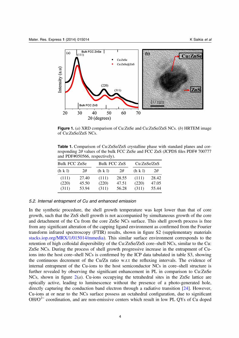
The XRD diffraction patterns in figure 1(a) reveal the face-centered cubic (FCC) structure for bothof the core and core–shell NCs [19]. But, the diffraction peaks of Cu:ZnSe/ZnS NCs are found atintermediate values of bulk FCC ZnSe and FCC ZnS. Table 1 shows the 2θ values for all planes ofboth the bulk FCC phases and Cu:ZnSe/ZnS NCs. The observed shifting of the diffraction maximaof Cu:ZnSe/ZnS NCs towards the bulk FCC ZnS phase is the evidence for deposition of ZnSaround Cu:ZnSe NCs [20–22]. From the XRD analysis, it is also confirmed that the incorporation ofCu and the deposition of ZnS to the core Cu:ZnSe NCs is not associated with any crystalline phasetransformation. The further analysis of the XRD patterns by the single line analysis method [23]demonstrates significant increase in lattice strain in the Cu:ZnSe/ZnS NCs, with negligible variationin the crystalline size. The growth of the ZnS matrix around the surface of Cu:ZnSe NCs is furthervisualized from the HRTEM in figure 1(b). The observed average particle size of Cu:ZnSe/ZnSNCs from the HRTEM is around 25 nm with quasi spherical shape shown in figure S1(supplementary materials stacks.iop.org/MRX/1/015014/mmedia).
Mater. Res. Express 1 (2014) 015014 K Saikia et al
3
5.2. Internal entrapment of Cu and enhanced emission
In the synthetic procedure, the shell growth temperature was kept lower than that of coregrowth, such that the ZnS shell growth is not accompanied by simultaneous growth of the coreand detachment of the Cu from the core ZnSe NCs surface. This shell growth process is freefrom any significant alteration of the capping ligand environment as confirmed from the Fouriertransform infrared spectroscopy (FTIR) results, shown in figure S2 (supplementary materialsstacks.iop.org/MRX/1/015014/mmedia). This similar surface environment corresponds to theretention of high colloidal dispersibility of the Cu:ZnSe/ZnS core–shell NCs, similar to the Cu:ZnSe NCs. During the process of shell growth progressive increase in the entrapment of Cu-ions into the host core–shell NCs is confirmed by the ICP data tabulated in table S3, showingthe continuous decrement of the Cu/Zn ratio w.r.t the refluxing intervals. The evidence ofinternal entrapment of the Cu-ions to the host semiconductor NCs in core–shell structure isfurther revealed by observing the significant enhancement in PL in comparison to Cu:ZnSeNCs, shown in figure 2(a). Cu-ions occupying the tetrahedral sites in the ZnSe lattice areoptically active, leading to luminescence without the presence of a photo-generated hole,directly capturing the conduction band electron through a radiative transition [24]. However,Cu-ions at or near to the NCs surface possess an octahedral configuration, due to significantOH/O2− coordination, and are non-emissive centers which result in low PL QYs of Cu doped
Mater. Res. Express 1 (2014) 015014 K Saikia et al
4
Figure 1. (a) XRD comparison of Cu:ZnSe and Cu:ZnSe/ZnS NCs. (b) HRTEM imageof Cu:ZnSe/ZnS NCs.
Table 1. Comparison of Cu:ZnSe/ZnS crystalline phase with standard planes and cor-responding 2θ values of the bulk FCC ZnSe and FCC ZnS (JCPDS files PDF# 700777and PDF#050566, respectively).
Bulk FCC ZnSe Bulk FCC ZnS Cu:ZnSe/ZnS
(h k l) 2θ (h k l) 2θ (h k l) 2θ
(111) 27.40 (111) 28.55 (111) 28.42(220) 45.50 (220) 47.51 (220) 47.05(311) 53.94 (311) 56.28 (311) 55.44

ZnSe NCs. In our system, Cu:ZnSe/ZnS NCs, the ZnS shell outside the Cu:ZnSe NCs hasprobably turned the non-emissive surface adsorbed Cu sites to emissive sites by restricting theCu ions further away from the NCs surface, also passivating the other surface defects asexplained in the schematic diagram, see figure 2(b). Therefore, Cu-ions are incorporated intothe host NC lattice aided by the ZnS shell. The 3-fold enhancement observed in the PL for theCu:ZnSe/ZnS in comparison to the Cu:ZnSe NCs indicates this phenomenon of Cu centerspassivation for behaving as emissive sites. Consequently, the QY of the Cu:ZnSe/ZnS NCs(15.5%) is much higher than that obtained for Cu:ZnSe NCs (6.6%). The fluorescentmicrographs shown in figure S4 also corroborate the evidence of this enhancement.
The UV-visible spectra in figure 2(a) show the slight red-shifting of the absorptionmaxima for the Cu:ZnSe/ZnS NCs from Cu:ZnSe NCs, which is a typical observation for core–shell systems.
5.3. Oxidation state of Cu-ions
During the development of Cu:ZnSe and Cu:ZnSe/ZnS NCs, a high reducing environment wasmaintained by adding hydrazine hydrate (N2H4.2H2O) to avoid the oxidation of the seleniumprecursor (NaHSe−). However, it has also been reported that hydrazine hydrate reduces theCu2+ to form Cu NPs in the presence of mercapto-ligands [25]. Therefore, in our method therewas the possibility for the nucleation and growth of Cu NPs and ZnSe NCs separately instead ofdoping. But, the probability of formation of Cu NPs is ruled out by the XRD and UV-visibleanalysis, as neither of the results show the presence of any Cu NPs. The Cu should be either inCu2+ or Cu1+ states in the host NCs. The EPR measurements show the characteristics of Cu2+
ions in both the samples. Figure 3 shows the EPR spectra of Cu:ZnSe and Cu:ZnSe/ZnS NCs,where both the samples exhibit a broad resonance signal at g∼ 2.049, characteristics of Cu2+
ions [26]. This broad nature of the EPR signal is due to the Jahn Teller distortion in the crystalfield of the host NCs on the subsitutional incorporation of Cu2+ ions. Similarly, the commonresonance signal at g∼ 1.989 can be attributed to the singly ionized selenium vacancy centers inthe NCs [27]. The appearance of the additional narrow resonance signal at g∼ 1.945 in the Cu:ZnSe NCs may be due to shallow donor like defects in a Cu rich region by imperfect oriented
Mater. Res. Express 1 (2014) 015014 K Saikia et al
5
Figure 2. (a) UV-visible absorption and PL spectra of Cu:ZnSe NCs and Cu:ZnSe/ZnSNCs, (b) schematic of ZnS surface passivation of Cu:ZnSe NCs.

attachment [28]. This justification is supported by the absence of this peak in the Cu:ZnSe/ZnSNCs, as the deposition of the ZnS shell matrix over Cu:ZnSe NCs removes these shallowdonors by encapsulating the imperfect oriented attachment of Cu atoms.
5.4. Study of charge carrier dynamics
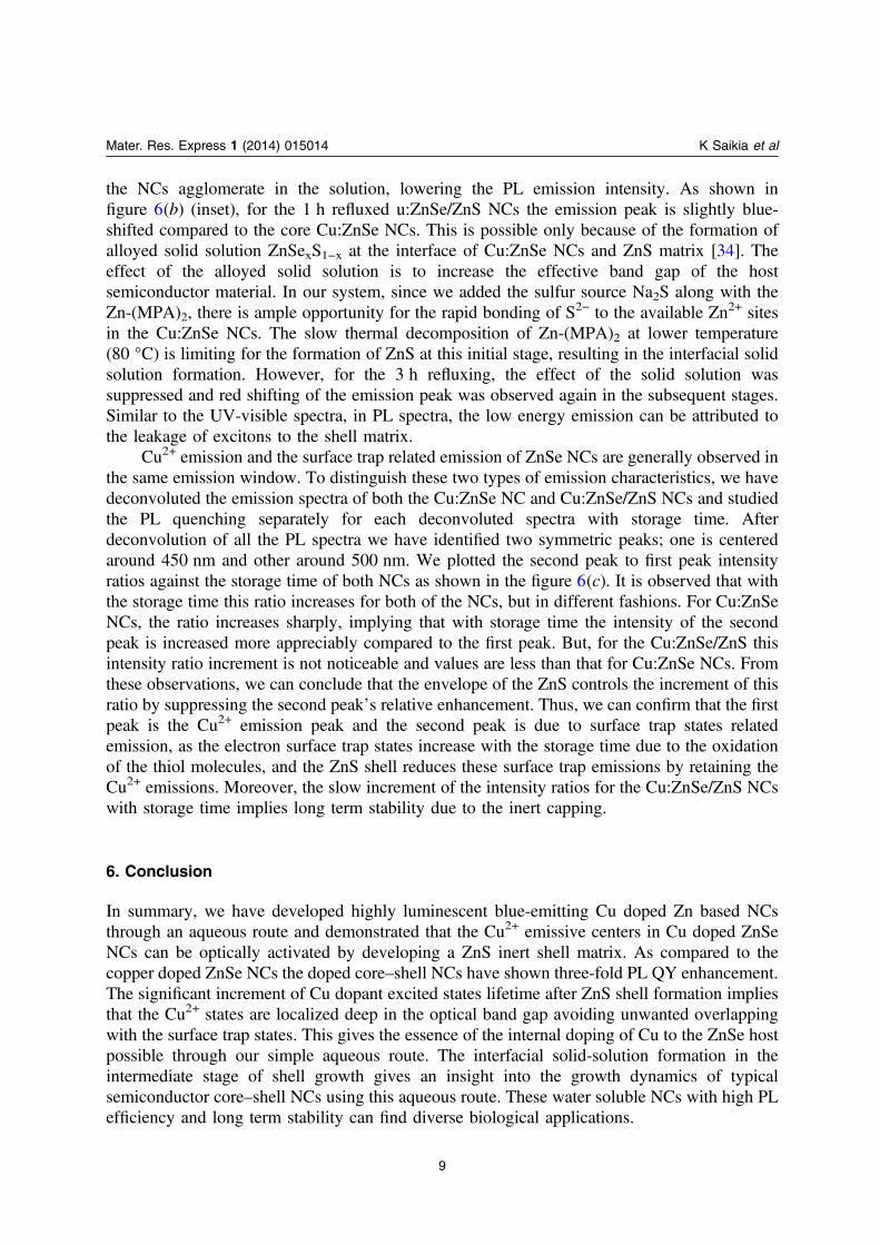
The PL lifetimes of different decay processes were investigated using time-correlated single-photon counting technique (TCSPC). The decay traces are shown in figure 4. Both the dopedcore and doped core–shell NCs were photoexcited with the wavelength 340 nm and theemissions were collected at 460 nm, in order the study different charge carrier dynamics. Boththe decay traces were best fitted with tri-exponetial decay equation (1), yielding a long-livedcomponent along with two comparatively short decay components, as shown in table 2
Mater. Res. Express 1 (2014) 015014 K Saikia et al
6
Figure 3. EPR spectra of Cu:ZnSe and Cu:ZnSe/ZnS NCs.
Figure 4. TCSPC traces of Cu doped core and Cu doped core shell NCs.
α τ α τ α τ= + − + − + −( ) ( ) ( )I y exp t/ exp t/ exp t/ . (1)o 1 1 2 2 2 2
In this equation, yo is accounting for the baseline correction, α1, α2, α3 are pre-exponentialfactors and τ1, τ2, τ3 are time constants of each decay component.
The observed long-lived decay components (τ3) in both decay traces are identified asexcited state lifetimes related to Cu emissive channels [14]. This long-lived component isclearly distinguishable from that of the deep trap states, which is of the order of fewnanoseconds [29]. The other two decay components τ1 and τ2 are undoubtedly related to theshallow trap states and deep trap states, respectively [14]. It is interesting to notice long-livedcomponent related to Cu emission is increased significantly (by 159%) for the core–shell NCs,which implies the effective doping of Cu to the host NCs. Cu2+ adsorbed to the host surfaceforms t2 energy states with pre-existing holes nearby the valance band which overlap easily withsurface traps sates yielding shorter Cu emission lifetime. But, in the Cu doped ZnSe/ZnS core–shell NCs aided ZnS layers passivate the surface adsorbed Cu2+ sites resulting in Cu relatedstates in the deep band gap. These localized Cu states in the deep band gap are less prone tooverlap with other surface sites and give longer excited state lifetime, which is the characteristicof stable internal doping. It is worth mentioning that with the increase of dopant emissionlifetime the PL QY is also enhanced significantly. The shallow tarp states are originated fromthe lattice imperfection due to Cu adsorption on the surface and other surface impurities, whiledeep trap states are hole trap states originated from Se2− dangling bonds or Zn2+ vacancies[30, 31]. For the core–shell NCs the deep trap state lifetime is increased which may be due tothe decrease in density of the trap states as Zn2+ vacancies are reduced by the ZnS shell growth.The shallow trap states lifetime is also increased a little after ZnS shell formation, signifying thereduction of shallow trap sates density.
5.5. Growth dynamics of Cu:ZnSe and Cu:ZnSe/ZnS NCs
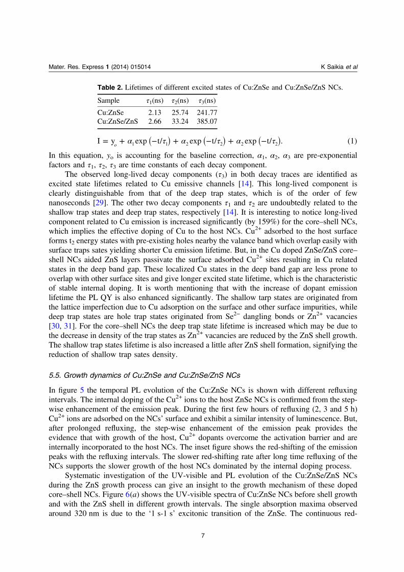
In figure 5 the temporal PL evolution of the Cu:ZnSe NCs is shown with different refluxingintervals. The internal doping of the Cu2+ ions to the host ZnSe NCs is confirmed from the step-wise enhancement of the emission peak. During the first few hours of refluxing (2, 3 and 5 h)Cu2+ ions are adsorbed on the NCs’ surface and exhibit a similar intensity of luminescence. But,after prolonged refluxing, the step-wise enhancement of the emission peak provides theevidence that with growth of the host, Cu2+ dopants overcome the activation barrier and areinternally incorporated to the host NCs. The inset figure shows the red-shifting of the emissionpeaks with the refluxing intervals. The slower red-shifting rate after long time refluxing of theNCs supports the slower growth of the host NCs dominated by the internal doping process.
Systematic investigation of the UV-visible and PL evolution of the Cu:ZnSe/ZnS NCsduring the ZnS growth process can give an insight to the growth mechanism of these dopedcore–shell NCs. Figure 6(a) shows the UV-visible spectra of Cu:ZnSe NCs before shell growthand with the ZnS shell in different growth intervals. The single absorption maxima observedaround 320 nm is due to the ‘1 s-1 s’ excitonic transition of the ZnSe. The continuous red-
Mater. Res. Express 1 (2014) 015014 K Saikia et al
7
Table 2. Lifetimes of different excited states of Cu:ZnSe and Cu:ZnSe/ZnS NCs.
Sample τ1(ns) τ2(ns) τ3(ns)
Cu:ZnSe 2.13 25.74 241.77Cu:ZnSe/ZnS 2.66 33.24 385.07
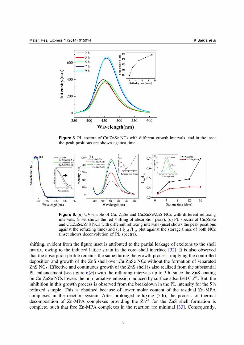
shifting, evident from the figure inset is attributed to the partial leakage of excitons to the shellmatrix, owing to the induced lattice strain in the core–shell interface [32]. It is also observedthat the absorption profile remains the same during the growth process, implying the controlleddeposition and growth of the ZnS shell over Cu:ZnSe NCs without the formation of separatedZnS NCs. Effective and continuous growth of the ZnS shell is also realized from the substantialPL enhancement (see figure 6(b)) with the refluxing intervals up to 3 h, since the ZnS coatingon Cu:ZnSe NCs lowers the non-radiative emission induced by surface adsorbed Cu2+. But, theinhibition in this growth process is observed from the breakdown in the PL intensity for the 5 hrefluxed sample. This is obtained because of lower molar content of the residual Zn-MPAcomplexes in the reaction system. After prolonged refluxing (5 h), the process of thermaldecomposition of Zn-MPA complexes providing the Zn2+ for the ZnS shell formation iscomplete, such that free Zn-MPA complexes in the reaction are minimal [33]. Consequently,
Mater. Res. Express 1 (2014) 015014 K Saikia et al
8
Figure 5. PL spectra of Cu:ZnSe NCs with different growth intervals, and in the insetthe peak positions are shown against time.
Figure 6. (a) UV-visible of Cu: ZnSe and Cu:ZnSe/ZnS NCs with different refluxingintervals, (inset shows the red shifting of absorption peak), (b) PL spectra of Cu:ZnSeand Cu:ZnSe/ZnS NCs with different refluxing intervals (inset shows the peak positionsagainst the refluxing time) and (c) I2nd /I1st plot against the storage times of both NCs(inset shows deconvolution of PL spectra).
the NCs agglomerate in the solution, lowering the PL emission intensity. As shown infigure 6(b) (inset), for the 1 h refluxed u:ZnSe/ZnS NCs the emission peak is slightly blue-shifted compared to the core Cu:ZnSe NCs. This is possible only because of the formation ofalloyed solid solution ZnSexS1−x at the interface of Cu:ZnSe NCs and ZnS matrix [34]. Theeffect of the alloyed solid solution is to increase the effective band gap of the hostsemiconductor material. In our system, since we added the sulfur source Na2S along with theZn-(MPA)2, there is ample opportunity for the rapid bonding of S2− to the available Zn2+ sitesin the Cu:ZnSe NCs. The slow thermal decomposition of Zn-(MPA)2 at lower temperature(80 °C) is limiting for the formation of ZnS at this initial stage, resulting in the interfacial solidsolution formation. However, for the 3 h refluxing, the effect of the solid solution wassuppressed and red shifting of the emission peak was observed again in the subsequent stages.Similar to the UV-visible spectra, in PL spectra, the low energy emission can be attributed tothe leakage of excitons to the shell matrix.
Cu2+ emission and the surface trap related emission of ZnSe NCs are generally observed inthe same emission window. To distinguish these two types of emission characteristics, we havedeconvoluted the emission spectra of both the Cu:ZnSe NC and Cu:ZnSe/ZnS NCs and studiedthe PL quenching separately for each deconvoluted spectra with storage time. Afterdeconvolution of all the PL spectra we have identified two symmetric peaks; one is centeredaround 450 nm and other around 500 nm. We plotted the second peak to first peak intensityratios against the storage time of both NCs as shown in the figure 6(c). It is observed that withthe storage time this ratio increases for both of the NCs, but in different fashions. For Cu:ZnSeNCs, the ratio increases sharply, implying that with storage time the intensity of the secondpeak is increased more appreciably compared to the first peak. But, for the Cu:ZnSe/ZnS thisintensity ratio increment is not noticeable and values are less than that for Cu:ZnSe NCs. Fromthese observations, we can conclude that the envelope of the ZnS controls the increment of thisratio by suppressing the second peak’s relative enhancement. Thus, we can confirm that the firstpeak is the Cu2+ emission peak and the second peak is due to surface trap states relatedemission, as the electron surface trap states increase with the storage time due to the oxidationof the thiol molecules, and the ZnS shell reduces these surface trap emissions by retaining theCu2+ emissions. Moreover, the slow increment of the intensity ratios for the Cu:ZnSe/ZnS NCswith storage time implies long term stability due to the inert capping.
6. Conclusion
In summary, we have developed highly luminescent blue-emitting Cu doped Zn based NCsthrough an aqueous route and demonstrated that the Cu2+ emissive centers in Cu doped ZnSeNCs can be optically activated by developing a ZnS inert shell matrix. As compared to thecopper doped ZnSe NCs the doped core–shell NCs have shown three-fold PL QY enhancement.The significant increment of Cu dopant excited states lifetime after ZnS shell formation impliesthat the Cu2+ states are localized deep in the optical band gap avoiding unwanted overlappingwith the surface trap states. This gives the essence of the internal doping of Cu to the ZnSe hostpossible through our simple aqueous route. The interfacial solid-solution formation in theintermediate stage of shell growth gives an insight into the growth dynamics of typicalsemiconductor core–shell NCs using this aqueous route. These water soluble NCs with high PLefficiency and long term stability can find diverse biological applications.
Mater. Res. Express 1 (2014) 015014 K Saikia et al
9
Acknowledgment
The authors would like to thank the Department of Biotechnology (DBT), Government of India,(BT/PR10874/NNT/28/136/2008) for financial support.
References
[1] Pradhan N, Battaglia M, Liu Y and Peng X 2007 Nano Lett. 7 312[2] Zeng R and Shen R 2013 Chem. Phys. Lett. 559 50[3] Colvin V L, Schlamp M C and Alivisatos A 1994 Nature 370 354[4] Nozik A 2001 Annu. Rev. Phys. Chem. 52 193[5] Michalet X, Pinaud F F, Bentolila L A, Tsay J M, Doose S, Li J J, Sundaresan G, Wu A M, Gambhir S S and
Weiss S 2005 Science 307 538[6] Gur I, Fromer A, Geier M L and Alivisatos A 2005 Science 310 462[7] Darugar Q, Qian W and El-Sayed M A 2006 Appl. Phys. Lett. 88 261108[8] Romero M J, Van de Lagemaat J, Mora-Sero I, Rumbles G and Al-Jassim M M 2006 Nano Lett. 6 2833[9] Yong K T, Roy I, Pudavar H E, Bergey E J, Tramp K M, Swihart M T and Prasad P N 2008 Adv. Mater. 20
1412[10] Aboulaich A, Geszke M, Balan L, Ghanbaja J, Medjahdi G and Schneider R 2010 Inorg. Chem. 49 10940[11] Jianga L W, Zhoua J, Yang X Z, Peng X N, Jiang H, Zhuo D Q, Chen L D and Yua X F 2011 Chem. Phys.
Lett. 510 135[12] Saikia K, Deb P and Kalita E 2013 Curr. Appl. Phys. 13 925[13] Thakar R, Chen Y and Snee P T 2007 Nano Lett. 7 3429[14] Gul S, Cooper J K, Corrado C, Vollbrecht B, Bridges F, Guo J and Zhang J Z 2011 J. Phys. Chem. C 115
20864[15] Han J, Zhang H, Tang Y, Liu Y, Yao X and Yang B 2009 J. Phys. Chem. C 113 7503[16] Xu S, Wang C, Wang Z, Zhang H, Yang J, Xu Q, Shao H, Li R, Lei W and Cui Y 2011 Nanotechnology 22
275605[17] Xue G, Chao W, Lu N and Xingguang S 2011 J. Lumin. 131 1300[18] Faton D F 1988 Pure Appl. Chem. 60 1107[19] Zheng Y G, Yang Z C and Ying J Y 2007 Adv. Mater 19 1475[20] Hines M A and Guyot-Sionnest P 1996 J. Phys. Chem. 100 468[21] Dabbousi B O, Rodriguez-Viejo J, Mikulec F V, Heine J R, Mattoussi H, Ober R, Jensen K F and
Bawendi M G 1997 J. Phys. Chem. B 101 9463[22] Gu Z, Zou L, Fang Z, Zhu W and Zhong X 2008 Nanotechnology 19 135604[23] Jha D K, Deb P, Kalita E, Shameem M and Patel A B 2012 Phys. Scr. 85 035802[24] Brovelli S, Galland C, Viswanatha R and Klimov V I 2012 Nano Lett. 12 4372[25] Saikova S, Vorobev S, Nikolaeva R and Mikhlin Y 2010 Russ. J. Gen. Chem. 80 1122[26] Jagannatha Reddya A, Kokilab M K, Nagabhushanac H, Chakradhard R P S, Shivakumarae C, Raof J L and
Nagabhushanag B M 2011 J. Alloys Comp. 509 5349[27] Setzler S D, Moldovan M, Yu Z, Myers T H and Giles N C 1997 Appl. Phys. Lett. 70 2274[28] Kumar P and Singh K 2011 J. Nanopart. Res. 13 1613[29] Jana S, Srivastava B B, Acharya S, Santra P K, Jana N R, Sarma D D and Pradhan N 2010 ChemComn. 46
2853[30] Pokrant S and Whaley K 1999 Eur. Phys. J. D 6 255[31] Underwood D F, Kippeny T and Rosenthal S J 2001 J. Phys. Chem. B 105 436[32] Reiss P, Protiere M and Li L 2009 Small 5 154[33] Wu P, Fang Z, Zhong X and Yang Y 2011 J. Colloids and Surfaces A: Physicochem. Eng. Aspects 375 109
Mater. Res. Express 1 (2014) 015014 K Saikia et al
10
[34] Estevez-Hernandez O, Gonzalez J, Guzman J, Santiago-Jacinto P, Rendon L, Montes E and Reguera E 2012Sci. Adv. Mater. 4 771
Mater. Res. Express 1 (2014) 015014 K Saikia et al
11
Copyright © 2022 FDOKUMEN