
Reducing Visual Impacts of Renewable Energy Facilities
342
i Best Management Practices for Reducing Visual Impacts of Renewable Energy Facilities on BLM-Administered Lands First Edition - 2013 BLM
-
Upload
khangminh22 -
Category
Documents
-
view
1 -
download
0
Transcript of Reducing Visual Impacts of Renewable Energy Facilities
i
Best Management Practices for Reducing Visual Impacts of Renewable Energy Facilities on BLM-Administered Lands
First Edition - 2013
BLM

Renewable Energy Visual BMPs
iv
Prepared By:
United States Department of the Interior Bureau of Land Management Wyoming State Office
Suggested Citation United States Department of the Interior. 2013. Best Management Practices for Reducing Visual Impacts of Renewable Energy Facilities on BLM-Administered
Lands. Bureau of Land Management. Cheyenne, Wyoming. 342 pp, April.
First Edition 2013
v
Contributors Tom Lahti of BLM (retired) originally conceived the idea for the Renewable Energy Visual BMP publication and obtained funding for its development. Sherry Roché (National Landscape Conservation System and Visual Resource Program Lead, BLM Wyoming State Office) was the BLM project manager for development of the BMP publication.
Robert Sullivan (Environmental Scientist, Argonne National Laboratory), Ron Kolpa (Principal Environmental Systems Engineer, Argonne National Laboratory), and John McCarty (Chief Landscape Architect, BLM Washington Office) were the principal authors. The following individuals reviewed all or portions of the BMP publication and provided comments.
BLM Reviewers
Beverly Gorny, Public Affairs Specialist, BLM Wyoming State Office Ken Henke, State Natural Resource Specialist, BLM Wyoming State Office Jim Perry, Senior Natural Resource Specialist, BLM Washington Office Adrienne Pilmanis, Plant Conservation Lead/Science Coordinator, BLM Wyoming State Office Karla Rogers, Landscape Architect/VRM Specialist, BLM National Operations Center David Scott, Safety Officer, BLM Wyoming State Office Mike Valle, Renewable Energy Coordinator, BLM Wyoming State Office Bob Wick, Wilderness and Wild and Scenic Rivers Program Lead, BLM California State Office
Other Reviewers
Laine Anderson, Plant Supervisor, Pacificorp Energy Kevin Boesch, Stormwater and Air Quality Permitting Specialist, Logan Simpson Design, Inc. Ken Borngrebe, Manager of Siting and Permitting, First Solar, Inc. Jeremy Call, Senior Landscape Architect and Environmental Planner, Logan Simpson Design, Inc. Terry DeWan, Principal, Terrence J. DeWan and Associates Craig Johnson, Senior Landscape Architect and Environmental Planner, Logan Simpson Design, Inc. Louise Kling, Environmental Planning Lead, URS Corporation Randy Manion, Renewable Resource Program Manager, Western Area Power Administration Jim May, Environmental Scientist, Argonne National Laboratory Mark Meyer, Renewable Energy Visual Resource Specialist, National Park Service Chad Moore, Night Skies Team Leader, National Park Service Guy Nelson, Executive Director, Utility Geothermal Working Group Merlyn Paulson, Professor, Department of Landscape Architecture, Colorado State University Kate Schwarzler, Landscape Architect/Principal, Otak, Inc.
The authors and BLM wish to thank the reviewers for their many thoughtful and helpful comments.
Lindsey Utter (Argonne National Laboratory) contributed sketch graphics. Pamela Richmond, Carolyn Steele, and Vicki Skonicki of Argonne National Laboratory were responsible for graphic design, production, editing, and word processing. Several organizations and individuals contributed photographs and illustrations; their contributions are acknowledged in the figure captions.
Renewable Energy Visual BMPs
vi
Table of Contents 1 Introduction _________________________________________________________________________ 1 1.1 Purpose and Need ___________________________________________________________________________ 1 1.2 How to Use the Renewable Energy Visual BMP Publication _____________________________________________ 4
2 Visual Resources _____________________________________________________________________ 7 2.1 An Overview of the BLM Visual Resource Management (VRM) System ____________________________________ 7
2.1.1 Visual Resource Inventory __________________________________________________________________ 7 2.1.2 The RMP and Visual Resource Management Classes ____________________________________________ 10 2.1.3 Visual Contrast Rating ____________________________________________________________________ 12
2.2 Visual Contrast and Visibility Factors _____________________________________________________________ 14 2.2.1 Visual Contrast _________________________________________________________________________ 15 2.2.2 Visibility Factors ________________________________________________________________________ 19
3 Wind _________________________________________________________________________________ 35 3.1 Consider Topography When Siting Wind Turbines __________________________________________________ 44 3.2 Cluster or Group Turbines to Break up Overly Long Lines of Turbines ____________________________________ 46 3.3 Create Visual Order and Unity among Turbine Clusters _______________________________________________ 48 3.4 Site Wind Turbines to Minimize Shadow Flicker ____________________________________________________ 49 3.5 Relocate Turbines to Avoid Visual Impacts _________________________________________________________ 50 3.6 Use Audio Visual Warning System (AVWS) Technology to Reduce Night Sky Impacts _________________________ 52 3.7 Create Visual Uniformity in Shape, Color, and Size __________________________________________________ 54 3.8 Use Fewer, Larger Turbines ____________________________________________________________________ 55 3.9 Use Non-reflective Coatings on Wind Turbines and Other Facility Components ____________________________ 56 3.10 Prohibit Commercial Messages and Symbols on Wind Turbines _______________________________________ 57 3.11 Keep Wind Turbines in Good Repair ____________________________________________________________ 58 3.12 Clean Nacelles and Towers ___________________________________________________________________ 59
4 Solar _________________________________________________________________________________ 61 4.1 Develop a Glint and Glare Assessment, Mitigation, and Monitoring Plan _________________________________ 80 4.2 Use Dry-Cooling Technology for CSP Facilities ______________________________________________________ 82 4.3 Site and Operate Solar Collectors to Avoid Offsite Glare ______________________________________________ 83 4.4 Screen Solar Collectors to Avoid Off-site Glare _____________________________________________________ 85 4.5 Use Color-Treated Solar Collectors and Support Structures ____________________________________________ 87 4.6 Maintain Color-Treated Surfaces of Solar Collectors _________________________________________________ 89

Table of Contents
vii
4.7 Avoid Complete Removal of Vegetation beneath Solar Collector Array ____________________________________ 90 4.8 Prohibit Commercial Messages and Symbols on Solar Power Towers and Solar Collector Arrays ________________ 92
5 Geothermal _________________________________________________________________________ 93 5.1 Use Dry-Cooling Technology ___________________________________________________________________ 100 5.2 Screen Pipelines from Roads and Other Sensitive Viewpoints _________________________________________ 102 5.3 Paint or Coat Aboveground Pipelines ____________________________________________________________ 104 5.4 Minimize Drill Rig and Well Test Facility Lighting ___________________________________________________ 106
6 Common Elements ________________________________________________________________ 107
6.1 Mitigation Planning 6.1.1 Ensure that Qualified Individuals Conduct and Review Impact Analyses and Mitigation ____________________ 114 6.1.2 Use Appropriate Methods and Data for Visual Impact Assessment and Mitigation Planning and Design _______ 116 6.1.3 Incorporate Stakeholder Input into the Siting and Design and Mitigation Planning Processes _______________ 118 6.1.4 Consult the Applicable Visual Resource Inventory (VRI) and Visual Resource Management (VRM)
Class Designations ________________________________________________________________________ 120 6.1.5 Conduct a Thorough Assessment of Existing and Potentially Affected Visual Resources _____________________ 123 6.1.6 Develop Spatially Accurate and Realistic Photo Simulations of Project Facilities __________________________ 127 6.1.7 Develop a Visual Resource Impact Monitoring and Mitigation Compliance Plan __________________________ 131 6.1.8 Develop a Decommissioning and Site Reclamation Plan ____________________________________________ 133 6.1.9 Hold a Preconstruction Meeting to Coordinate the Mitigation Strategy _________________________________ 134 6.1.10 Discuss Visual Mitigation Objectives with Equipment Operators _____________________________________ 136 6.1.11 Use Offsite Mitigation _____________________________________________________________________ 138
6.2 Siting and Design 6.2.1 Site Facilities and ROWs outside Sensitive Viewsheds, or as Far as Possible from Sensitive Viewing Locations ___ 141 6.2.2 Site ROW Crossings to Minimize Impacts on Linear KOPs ___________________________________________ 145 6.2.3 Site Projects Away from Visually Prominent Landscape Features ______________________________________ 147 6.2.4 Site Facilities to Avoid Night-Sky Impacts on Sensitive Locations ______________________________________ 149 6.2.5 Site Facilities in Previously Developed or Disturbed Landscapes ______________________________________ 150 6.2.6 Site Facilities and Components in Existing Clearings _______________________________________________ 151 6.2.7 Site and Design Facilities to Repeat the Form, Line, Color, and Texture of the Existing Landscape ____________ 152 6.2.8 Site Facilities in Areas Suitable for Reclamation __________________________________________________ 155 6.2.9 Minimize the Number of Facility Structures _____________________________________________________ 156 6.2.10 Collocate Linear Features in Existing ROWs or Corridors ___________________________________________ 157 6.2.11 Avoid Siting Linear Features in the Centers of Valley Bottoms and on Ridgetops _________________________ 158 6.2.12 Avoid Skylining __________________________________________________________________________ 160 6.2.13 Site Linear Facilities along Natural Lines within the Landscape ______________________________________ 161
Renewable Energy Visual BMPs
viii
6.2.14 Avoid Siting Roads on Side Slopes ___________________________________________________________ 163 6.2.15 Site Facility Components to Minimize Cut and Fill________________________________________________ 164 6.2.16 Avoid Siting Staging and Laydown Areas in Visually Sensitive Areas __________________________________ 166 6.2.17 Bury Underground Utilities along Roads _______________________________________________________ 167
6.3 Structure Design and Material Selection 6.3.1 Use Low-Profile Structures and Tanks _________________________________________________________ 170 6.3.2 Custom Design Structures in Key Areas _________________________________________________________ 172 6.3.3 Consider Use of Alternative Components] ______________________________________________________ 173 6.3.4 Use Natural-Looking Constructed Landform, Vegetative, or Architectural Screening _______________________ 174 6.3.5 Minimize Use of Signs and Make Signs Visually Unobtrusive ________________________________________ 176 6.3.6 Avoid Unnecessary Use of Gravel/Paved Surfaces ________________________________________________ 177 6.3.7 Use Rounded Road Cut Slopes _______________________________________________________________ 178 6.3.8 Use Monopole and Lattice Electric Transmission Towers Appropriately ________________________________ 179
6.4 Materials Surface Treatments 6.4.1 Require a Site Study for Color and Texture Selection ______________________________________________ 183 6.4.2 Select Materials and Surface Treatments to Repeat the Form, Line, Color, and Texture of
Surrounding Landscape ____________________________________________________________________ 185 6.4.3 Consider Seasonal Changes and Seasons of Heaviest Use in Choosing Material Colors and Textures _________ 187 6.4.4 Color Treat Structures to Reduce Contrasts with Existing Landscape ___________________________________ 189 6.4.5 Use Non-reflective Materials, Coatings, and/or Paint ______________________________________________ 191 6.4.6 Select Surface Treatment Colors from the BLM Standard Environmental Colors Chart _____________________ 193 6.4.7 Test Color Selections ______________________________________________________________________ 195 6.4.8 Color Treat Grouped Structures Using the Same Color _____________________________________________ 197 6.4.9 Color Treat Exposed Rock Faces ______________________________________________________________ 200 6.4.10 Color Treat Transmission Towers to Reduce Contrasts with Existing Landscape _________________________ 201 6.4.11 Use Camouflage and/or Disguise Strategies for Close KOPs in Highly Sensitive Viewsheds ________________ 205 6.4.12 Maintain Painted, Stained, or Coated Surfaces Properly __________________________________________ 206
6.5 Lighting 6.5.1 Prepare a Lighting Plan ____________________________________________________________________ 208 6.5.2 Use Audiovisual Warning System (AVWS) Technology for Hazard Lighting on Structures Taller than 200 ft ______ 210 6.5.3 Use Full Cutoff Luminaires __________________________________________________________________ 211 6.5.4 Direct Lights Properly to Eliminate Light Spill and Trespass _________________________________________ 213 6.5.5 Use Amber instead of Bluish-White Lighting _____________________________________________________ 214 6.5.6 Minimize Lighting Usage during Construction and Operations _______________________________________ 215 6.5.7 Use Vehicle-Mounted Lights or Portable Light Towers for Nighttime Maintenance Activities ________________ 218
Table of Contents
ix
6.6 Avoiding Unnecessary Disturbance 6.6.1 Minimize Project Footprint and Associated Disturbance ____________________________________________ 220 6.6.2 Avoid Unnecessary Road Improvements ________________________________________________________ 221 6.6.3 Use Penalty Clauses to Protect High-Value Landscape Features ______________________________________ 222 6.6.4 Confine Construction Activities and Facilities to Pre-Defined Areas ____________________________________ 223 6.6.5 Provide Construction Personnel with Avoidance Area Maps _________________________________________ 224 6.6.6 Do Not Apply Paints or Permanent Discoloring Agents to Rocks or Vegetation ____________________________ 225 6.6.7 Require Overland Driving Where Re-contouring Is Not Required _____________________________________ 226 6.6.8 Use Air Transport to Erect Transmission Towers __________________________________________________ 227
6.7 Soils, Erosion, and Dust Management 6.7.1 Implement Dust and Wind Erosion Control Measures _____________________________________________ 230 6.7.2 Implement Erosion and Sediment Control Measures ______________________________________________ 232 6.7.3 Implement Temporary and/or Permanent Soil Stabilization Measures _________________________________ 235 6.7.4 Strip, Stockpile, and Stabilize Topsoil for Re-spreading _____________________________________________ 237 6.7.5 Segregate Topsoil and Reapply to Disturbed Areas ________________________________________________ 239
6.8 Vegetation Management 6.8.1 Prepare a Reclamation Plan _________________________________________________________________ 242 6.8.2 Design Vegetative Openings to Mimic Natural Openings ____________________________________________ 244 6.8.3 Use Partial ROW Clearing and Feather Edges of Transmission ROWs __________________________________ 248 6.8.4 Preserve Existing Vegetation _________________________________________________________________ 251 6.8.5 Use Retaining Walls, Berms, Fences, and Markings to Protect Trees and Other Scenic Features ______________ 253 6.8.6 Avoid Slash Piles in Sensitive Viewing Areas; Chip Slash for Mulch to Hide Fresh Soil ______________________ 255 6.8.7 Mulch Cleared Areas, Furrow Slopes, and Use Planting Holes _______________________________________ 257 6.8.8 Use Pitting and Vertical Mulching to Facilitate Revegetation and Discourage Vehicle Traffic _________________ 260 6.8.9 Revegetate Using Salvaged Native Plants and Approved, Weed-free Seed Mixes _________________________ 262 6.8.10 Transplant Vegetation from Cleared Areas _____________________________________________________ 263 6.8.11 Monitor and Maintain Revegetated Areas until Vegetation Is Self-Sustaining ___________________________ 264
6.9 Reclamation 6.9.1 Review Predevelopment Visual Conditions after Construction________________________________________ 266 6.9.2 Begin Site Reclamation during Construction and Operations, Immediately after Disturbances _______________ 268 6.9.3 Recontour Disturbed Areas to Approximate Natural Slopes _________________________________________ 270 6.9.4 Scarify/Roughen Cut Slopes and Recontoured Areas ______________________________________________ 272 6.9.5 Salvage and Replace Rocks, Brush, and Woody Debris _____________________________________________ 274 6.9.6 Sculpt and Shape Bedrock Landforms _________________________________________________________ 275 6.9.7 Remove Two-Track Roads ___________________________________________________________________ 279 6.9.8 Close and Remediate Unused Access Roads _____________________________________________________ 281

Renewable Energy Visual BMPs
x
6.9.9 Remove Above-Ground and Near-Ground Structures _____________________________________________ 283 6.9.10 Remove or Bury Gravel and Other Surface Treatments ____________________________________________ 284
6.10 Good Housekeeping 6.10.1 Develop “Housekeeping” Procedures _________________________________________________________ 286 6.10.2 Maintain a Clean Worksite _________________________________________________________________ 287 6.10.3 Prohibit Onsite Burning ___________________________________________________________________ 289 6.10.4 Use Exit Tire Washes and Vehicle Tracking Pads to Reduce the Tracking of Sediment onto Roads ___________ 290 6.10.5 Remove or Avoid Slash Piles ________________________________________________________________ 292 6.10.6 Clean Off-Road Equipment _________________________________________________________________ 294 6.10.7 Remove Stakes and Flagging _______________________________________________________________ 295 6.10.8 Use Fabric-Covered Fences to Conceal Material Storage Yards and Laydown Yards ______________________ 296 6.10.9 Actively Maintain Operating Facilities _________________________________________________________ 298
BMP Source Documents ____________________________________________________________________________________________ 299
For Further Reading ________________________________________________________________________________________________ 303
Acronym List ________________________________________________________________________________________________________ 305
Glossary _____________________________________________________________________________________________________________ 307
Chapter 1: Introduction
1
1.1 Purpose and Need The Energy Policy Act of 2005 (EPACT) established
several key goals for achieving a move from non-
renewable energy sources to clean energy sources. It
contains provisions to encourage or facilitate the use
and development of utility-scale renewable energy
resources for electricity production. Investment in
these programs will assist in getting new technologies
to market, provide a clean baseload of power, accelerate
the clean energy economy, create and revitalize local
economies, and help advance long-term energy
independence (DOE 2010). The U.S. Department of the
Interior (DOI) has issued permits for more than
10,000 megawatts (MW) of renewable energy on public
lands and in offshore waters as of the end of 2012 (DOI
2012).
The DOI’s Bureau of Land Management (BLM) has a key
role in implementing EPACT, because the BLM
manages more than 245 million surface acres and
700 million subsurface acres of mineral estate for
multiple uses, including energy development. Over 20.6
million acres of public land have wind potential in 11
western states, and 22 million acres of public land
within six states have solar potential. In addition, the
BLM has delegated authority for leasing 249 million
acres of public lands with geothermal potential,
including over 100 million acres of National Forest
lands (BLM 2010).
The BLM faces increasing interest in the use of BLM-
administered public lands for utility-scale renewable
energy development. As renewable energy projects are
proposed throughout the western United States, the
Renewable Energy Visual BMPs
2
BLM evaluates and processes the applications for
rights-of-way (ROWs) and use of public land for these
projects. The BLM must ensure that these developments
meet all applicable environmental laws and regulations,
including the National Environmental Policy Act of 1969
(NEPA) and the Federal Land Policy and Management
Act of 1976 (FLPMA).
The BLM’s responsibility to manage the scenic
resources of the public lands is established by FLPMA
and NEPA as follows:
FLPMA requires that “the public lands be
managed in a manner that will protect the
quality of scientific, scenic, historical,
ecological, environmental, air and atmospheric,
water resource, and archeological values” and
stipulates that “The Secretary shall prepare and
maintain on a continuing basis an inventory of
all public lands and their resource and other
values (including, but not limited to, outdoor
recreation and scenic values…).” The act
prohibits unnecessary or undue degradation of
public lands, and makes protecting a range of
environmental values, including scenic values,
an explicit criterion that must be applied
throughout the BLM’s land management
activities.
A stated goal of NEPA is to “assure for all
Americans safe, healthful, productive, and
aesthetically and culturally pleasing
surroundings.” NEPA requires the development
of procedures to ensure that environmental
values are given appropriate consideration in
decision-making processes in which a federal
agency is involved (Ross 1979).
To comply with these Acts, the BLM requires that visual
design considerations be incorporated into all surface-
disturbing activities, including construction, operation,
and decommissioning of renewable energy facilities.
Design considerations are evaluated through
assessments of visual resources, which include all
natural and cultural features of the environment that
have the potential to be seen (Grinde and Kopf 1986).
It is the BLM’s mission to sustain the health, diversity,
and productivity of public lands for the use and
enjoyment of present and future generations. These
practices are supported by the establishment of district
and field office resource management plans (RMPs).
RMPs are comprehensive management documents that
determine how the BLM will manage the public lands
within the boundaries of a particular field office or
district. Decisions made within the RMP provide
direction for the actions of the agency. RMPs are
developed with the consideration and involvement of
the public.
As part of the RMP, management objectives are
established for visual resources on all lands included in
the RMP. Management decisions in the RMP must
consider the value of visual resources, along with other
important resources and agency objectives.
Management decisions regarding visual resources are
framed as Visual Resource Management Classes (VRM)
I through IV, with VRM Class I having the greatest
degree of protection and VRM Class IV having the least.
The use of best management practices (BMPs) to avoid
or reduce the visual impacts of development is a key
component in the BLM’s fulfillment of its scenic
resource management requirements while meeting its
goals to facilitate renewable energy development on
Chapter 1: Introduction
3
BLM-administered lands. The BLM and the U.S. Forest
Service previously developed standards and guidelines
for oil and gas development (DOI and USDA 2007) that
include measures to reduce the visual impacts of these
types of facilities, and the BLM has developed specific
guidance for reducing the visual impacts of oil and gas
development (BLM 2006). Now, in response to the
increasing use of BLM-administered lands for large-
scale renewable energy projects, the BLM presents Best
Management Practices for Reducing Visual Impacts of
Renewable Energy Facilities on BLM-Administered Lands
(hereafter referred to as the “BMP publication”). The
BMP publication presents 122 BMPs to avoid or reduce
potential visual impacts associated with the siting,
design, construction, operation, and decommissioning
of utility-scale renewable energy generation facilities,
including wind, solar, and geothermal facilities.
The BMP publication includes BMPs for avoiding and
reducing visual impacts associated with the energy
generation components of a facility, such as wind
turbines or solar energy collectors, and includes many
BMPs for reducing visual impacts associated with
ancillary components, such as electric transmission,
roads, and structures. However, visual impact
mitigation is only partly partly addressed by
considering what is built; mitigation must also address
where a facility is built, and how it is built, operated, and
decommissioned. Planning phase activities, such as
facility siting and design, and selection of structural
materials and coatings, are critical to effective visual
impact mitigation, as are “on-the-ground” activities,
such as recontouring and revegetating disturbed areas.
Consequently, a large part of this BMP publication is
devoted to BMPs for key activities that typically have a
major effect on the visual impacts associated with
facility development, including project siting and
design, mitigation planning, structure design and
materials selection, materials surface treatments,
lighting practices, and soils and vegetation
management.
The BMP publication provides BLM staff, industry, and
other stakeholders with proven, effective, and vetted
BMPs to address a wide range of potential visual
impacts from renewable energy facilities throughout
the project lifecycle. The BMP publication is intended
for use by the BLM’s visual resource management staff,
and other staff including, but not limited to,
recreational planners, landscape architects, project
managers, realty specialists, and cultural resource
specialists. The BMP publication can be used to provide
guidance for specific projects or as a general
information source for strategies to mitigate impacts
on visual resources on BLM-administered lands. The
BMPs were compiled from a variety of sources,
including guidance documents developed by various
federal and state agencies; existing environmental
analyses, including programmatic and project-specific
environmental impact statements and assessments;
professional practice literature; consultations with
landscape architects, engineers, and renewable energy
professionals; and field observations of existing
renewable energy facilities and facilities under
construction.
The BMPs presented are proven measures designed to
provide for safe and efficient operations while
minimizing undesirable impacts on visual resources. As
noted in the BMP descriptions, many visual BMPs also
benefit other valued resources, such as wildlife habitat,
biodiversity, and water quality. The best outcomes are
Renewable Energy Visual BMPs
4
achieved when BMPs are considered and implemented
as early as possible; the proactive incorporation of visual
BMPs into project planning and development typically
results in a more efficient review process, greater
stakeholder acceptance of proposed projects, and in
many cases, reduced remediation costs. Their effective
use helps the BLM manage and preserve scenic
resources on public lands for the enjoyment of present
and future generations.
1.2 How to Use the Renewable Energy Visual BMP Publication This BMP publication is divided into two main parts.
The first part (Chapters 1 and 2) provides an
introduction to the BMP publication and to key visual
resource concepts within the context of utility-scale
energy development on BLM lands. It includes an
abbreviated discussion of the BLM visual resource
management (VRM) system, a description of
terminology associated with visual resources, a
discussion of viewsheds, and an explanation of factors
that affect the overall visibility of large-scale facilities.
The second part (Chapters 3–6) presents information
about the visual characteristics of renewable energy
facilities and BMPs for avoiding or reducing visual
impacts from the facilities. Chapters 3–5 present the
visual characteristics and BMPs for wind energy
facilities, solar energy facilities, and geothermal
facilities respectively. Chapter 6 presents BMPs for
“common elements,” which include ancillary facilities
common to utility-scale energy facilities as well as the
design, construction, operation, and decommissioning
activities common to large-scale energy development
projects.
The common element BMPs presented in Chapter 6 for
ancillary facilities include BMPs for electric
transmission systems, roads and other surfaces,
structures, and signs. The common element BMPs for
design, construction, operation, and decommissioning
activities include the following:
Visual impact analysis and mitigation
planning;
Facility siting and design;
Structure design and materials selection;
Materials surface treatments;
Lighting design and operation;
Avoiding unnecessary disturbance;
Soil management and erosion control;
Vegetation management;
Interim and long-term reclamation; and
“Good housekeeping” practices.
These activities provide the framework for organizing
the common element BMPs. Chapter 6 is divided into 10
subsections, each of which presents BMPs specific to
the activities listed above.
A relatively large number of elements and activities are
common to most large-scale facilities, and there are a
variety of methods for mitigating impacts associated
with these elements. As a result, there are almost
100 common-element BMPs in the BMP publication. It
should be a valuable source of BMPs to address visual
impacts for almost any large-scale energy development
that occurs on BLM-administered lands.
Each discussion of a BMP generally includes the
following information:
The BMP title;
Chapter 1: Introduction
5
Project phase(s) during which the BMP is
implemented;
Description of the BMP;
Notes—supplementary information about the
BMP (e.g., the benefits of implementing the
BMP, details about the mechanism by which the
BMP actually reduces visual contrasts, or
technical details about implementation);
Limitations, where applicable, including
important restrictions, caveats, or
considerations that should be taken into
account when considering implementation of
the BMP; and
Photos or diagrams that show examples of poor
practices that worsen visual contrasts, the
results of successful application of the BMP,
and/or “how to” images that show the BMP
being implemented in a real situation.
Other useful features include tables at the beginning of
each BMP topic listing the BMP titles and indicating the
appropriate project phases for each BMP; a list of
recommended additional reading materials; a glossary
of technical terms used; and an acronym list.
Readers are cautioned that the BMP publication is not
prescriptive in nature, as not every BMP in the BMP
publication is appropriate for every project. Some BMPs
simply do not apply in all landscapes (e.g., color treating
exposed rock faces might not be applicable for a wind
farm sited in flat grasslands). In some cases, site
conditions might preclude the application of particular
BMPs or render the BMPs ineffective; for example,
transplanting native vegetation may not be a viable
option where suitable stock for transplanting does not
exist. There may also be conflicts between visual BMPs
and concerns for safety or other valued resources; for
example, additional lighting may be needed for safety
reasons, or building a screening landform might
interfere with water drainage. There may be technical
reasons why a particular BMP cannot be implemented;
for example, applying paint or a coating to a piece of
equipment may interfere with its functionality. And
finally, there may be cost-benefit concerns that might
make some visual BMPs impractical or inadvisable in a
given situation; changing a transmission line route may
result in lower visual impacts, but if an alternative route
adds length to the transmission line, makes getting
approval difficult, or results in significant project
delays, it could be prohibitively expensive and might
only be justifiable if the proposed route would result in
major impacts on a highly sensitive landscape.
Similarly, moving or eliminating a large number of
wind turbines because of visual or other potential
impacts could seriously affect the financial viability of a
proposed project, and should only be undertaken after
ensuring that the nature and severity of the potential
impacts justifies implementing the BMP, and of course
after exploring other means to reduce the impacts to an
acceptable level.
Fortunately, there are many highly effective visual
BMPs that are not particularly expensive or difficult to
implement, particularly if incorporated early in the
development process; these include successful
revegetation, recontouring to match existing terrain
characteristics, or painting facility components to blend
with the landscape background. Except in special
circumstances, such practices should always be
implemented where possible. Other visual BMPs also
have benefits to other resources (e.g., successful
revegetation could have beneficial effects on wildlife
Renewable Energy Visual BMPs
6
habitat, water quality, and air quality) that more than
justify the costs.
Choosing appropriate visual BMPs for a particular
renewable energy project is not as simple as copying the
list of BMPs from the BMP publication and requiring a
developer to implement them all. Careful consideration
must be given to the nature of the project and the site,
and to how site- and project-specific conditions may
affect the technical feasibility of BMPs under
consideration. Potential effects on other important
resources, the project’s operations, and the project’s
viability that may result from implementing the BMPs
must also be considered. Early and frequent
consultation with the developer, other resource
specialists, and potentially affected stakeholders will
help ensure that visual BMPs are applied where they are
needed, where they are effective, where the costs of
implementing them are appropriately weighed against
the benefits, and where they do not adversely affect
safety or other important environmental resources.
References BLM (Bureau of Land Management), 2006, Visual
Resource Management: Best Management Practices for Fluid
Minerals, U.S. Department of the Interior.
BLM, 2010, Renewable Energy and the BLM, BLM Fact
Sheet. Available at
http://www.blm.gov/pgdata/etc/medialib/blm/wo/MIN
ERALS__REALTY__AND_RESOURCE_PROTECTION_/
energy/renewable_references.Par.95879.File.dat/2010%2
0Renewable%20Energy%20headed.pdf. Accessed Sept.
1, 2011.
DOE (U.S. Department of Energy), 2010, Geothermal
Technologies Program, DOE/GO-102010-3045. Energy
Efficiency and Renewable Energy. Available at
http://www1.eere.energy.gov/office_eere/pdfs/geother
mal_fs.pdf. Accessed Sept. 2, 2011.
DOI (U.S. Department of the Interior), 2012, Salazar
Authorizes Landmark Wyoming Wind Project Site, Reaches
President’s Goal of Authorizing 10,000 Megawatts of
Renewable Energy, press release. Available at
http://www.doi.gov/news/pressreleases/Salazar-
Authorizes-Landmark-Wyoming-Wind-Project-Site-
Reaches-Presidents-Goal-of-Authorizing-10000-
Megawatts-of-Renewable-Energy.cfm. Accessed
Dec. 27, 2012.
DOI (U.S. Department of the Interior) and USDA (U.S.
Department of Agriculture), 2007, Surface Operating
Standards and Guidelines for Oil and Gas Exploration and
Development, BLM/ST-06/021+3071/REV 07.
Grinde, K., and A. Kopf, 1986, “Illustrated Glossary,”
pp. 308–333 in Foundations for Visual Project Analysis.
Smardon et al. (editors), John Wiley and Sons, New
York, NY. Available at
http://www.esf.edu/es/via/Vis_Found/FOUNDATIONS
%20FOR%20VISUAL%20PROJECT%20ANALYSIS%20-
%20INDEX.PDF. Accessed Sept. 13, 2011.
Ross, R.W., 1979, The Bureau of Land Management and
Visual Resource Management – An Overview. Presented at
the National Conference on Applied Techniques for
Analysis and Management of the Visual Resource,
Incline Village, NV, Apr. 23–25, 1979. Available at
http://www.fs.fed.us/psw/publications/documents/psw
_gtr035/psw_gtr035_15_ross.pdf. Accessed Sept. 26,
2011.
Chapter 2: Visual Resources
7
2.1 An Overview of the BLM Visual Resource Management (VRM) System The BLM’s VRM system provides a framework for
managing visual resources on BLM- administered
lands. Included in this system is a mechanism for
identifying visual resource values on BLM-administered
lands, minimizing the impacts of surface-disturbing
activities on visual resources, and maintaining the
scenic value of tracts of land for the future. The VRM
system involves the following:
Inventorying scenic values of BLM-
administered lands through the Visual
Resource Inventory (VRI) process;
Assigning VRM classes that establish VRM
objectives for these BLM-administered lands;
Evaluating proposed activities to determine
their impact on VRI values and whether or not
they conform to the established management
objectives through the Visual Contrast Rating
process; and
Updating the VRI to reflect the changed
conditions.
These processes are summarized below.
2.1.1 Visual Resource Inventory
The BLM’s VRI is a systematic process for:
Assessing and rating the inherent scenic quality
of a particular tract of land, through the Scenic
Quality Rating process;

Renewable Energy Visual BMPs
8
Measuring the public concern for the scenic
quality of the tract, through the Sensitivity Level
Analysis; and
Classifying the distance from which the
landscape is most commonly viewed, through
delineation of distance zones.
Based on the outcome of the VRI, BLM-administered
lands are assigned to one of four VRI classes. VRI
Class I lands have the greatest relative visual values, and
VRI Class IV lands have the lowest relative visual
values.The Scenic Quality Rating process, the
Sensitivity Level Analysis, and the Distance Zone
delineation process are discussed in more detail below.
2.1.1.1 Scenic Quality Rating
Within the VRI process, public lands are evaluated with
regard to their scenic quality, defined as the visual
appeal of a particular tract of land (BLM 1986a). Scenic
quality is determined systematically by (1) dividing the
landscape into Scenic Quality Rating Units (SQRUs)
based on conspicuous changes in physiography or land
use, and (2) ranking scenic quality within each SQRU
based on the assessment of seven key factors: landform,
vegetation, water, color, adjacent scenery, scarcity, and
cultural modifications. The ratings are made in the field
by trained observers who evaluate the landscape view
from inventory observation points, which are either
important viewpoints or points with views that are
representative of the SQRU. Based on the outcome of
this assessment, lands within each SQRU are assigned a
scenic value rating of A (high scenic value), B (moderate
scenic value), or C (low scenic value). Generally, those
areas with the most variety and most harmonious
composition have the highest scenic value ratings, while
areas with less variety and greater levels of disturbance
from human activities have the lowest scenic value
ratings.
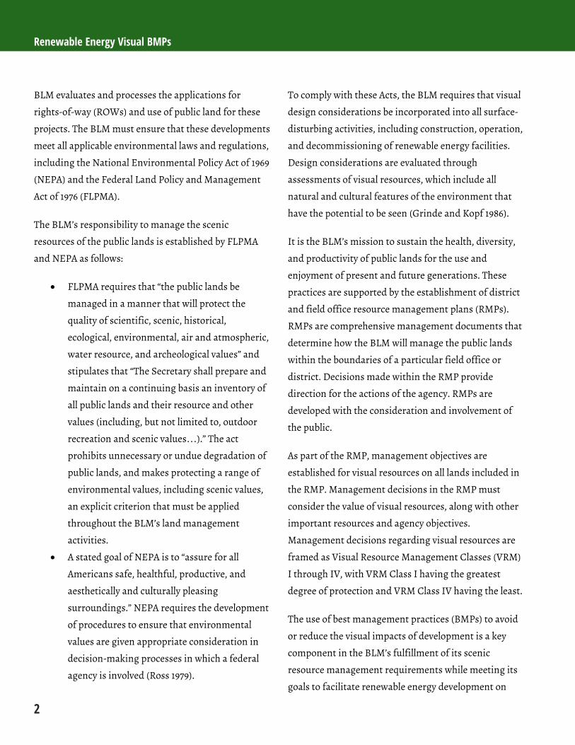
This colorful and varied BLM landscape has very high scenic quality. (Credit: BLM.)
2.1.1.2 Sensitivity Level Analysis
Visual sensitivity is defined as a measure of public
concern for scenic quality (BLM 1986a). Sensitivity is
determined by evaluating the types and numbers of
potential viewers of a specified area (this area is
referred to as a Sensitivity Level Rating Unit or SLRU),
the level of public interest in the SLRU, adjacent land
uses, and the presence of special areas. The Sensitivity
Level Analysis (SLA) is completed in two steps:
(1) delineation of SLRUs, and (2) rating visual sensitivity
within each SLRU. SLRUs represent geographic areas
where public sensitivity to change of the visual
resources is shared among constituents.
Determining the level of sensitivity requires familiarity
with the tracts of lands being evaluated, and with the
people who use them. Sensitivity is generally
determined by BLM staff most familiar with the users of
the areas, and can be supplemented by direct input
from other agencies, interest groups/stakeholders, and
the general public.
Sensitivity levels are described as high, medium, or low
within the VRI process. Scenic byways, wilderness
Chapter 2: Visual Resources
9
areas, and lands adjacent to national parks are
examples of lands that often have high sensitivity.
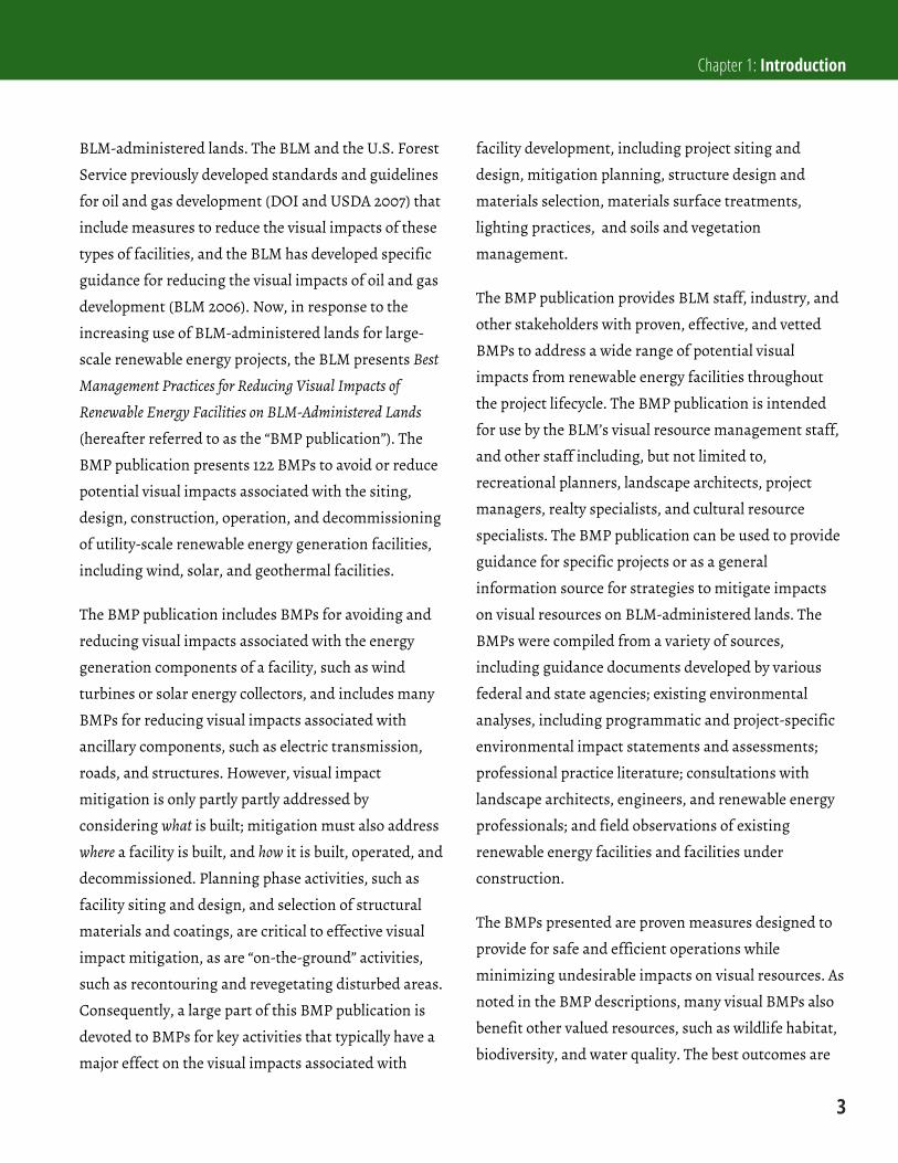
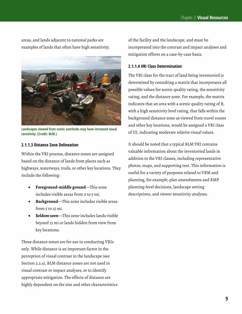
Landscapes viewed from scenic overlooks may have increased visual sensitivity. (Credit: BLM.)
2.1.1.3 Distance Zone Delineation
Within the VRI process, distance zones are assigned
based on the distance of lands from places such as
highways, waterways, trails, or other key locations. They
include the following:
Foreground-middle ground—This zone
includes visible areas from 0 to 5 mi.
Background—This zone includes visible areas
from 5 to 15 mi.
Seldom seen—This zone includes lands visible
beyond 15 mi or lands hidden from view from
key locations.
These distance zones are for use in conducting VRIs
only. While distance is an important factor in the
perception of visual contrast in the landscape (see
Section 2.2.4), BLM distance zones are not used in
visual contrast or impact analyses, or to identify
appropriate mitigation. The effects of distance are
highly dependent on the size and other characteristics
of the facility and the landscape, and must be
incorporated into the contrast and impact analyses and
mitigation efforts on a case-by-case basis.
2.1.1.4 VRI Class Determination
The VRI class for the tract of land being inventoried is
determined by consulting a matrix that incorporates all
possible values for scenic quality rating, the sensitivity
rating, and the distance zone. For example, the matrix
indicates that an area with a scenic quality rating of B,
with a high sensitivity level rating, that falls within the
background distance zone as viewed from travel routes
and other key locations, would be assigned a VRI class
of III, indicating moderate relative visual values.
It should be noted that a typical BLM VRI contains
valuable information about the inventoried lands in
addition to the VRI classes, including representative
photos, maps, and supporting text. This information is
useful for a variety of purposes related to VRM and
planning, for example, plan amendments and RMP
planning-level decisions, landscape setting
descriptions, and viewer sensitivity analyses.
Renewable Energy Visual BMPs
10
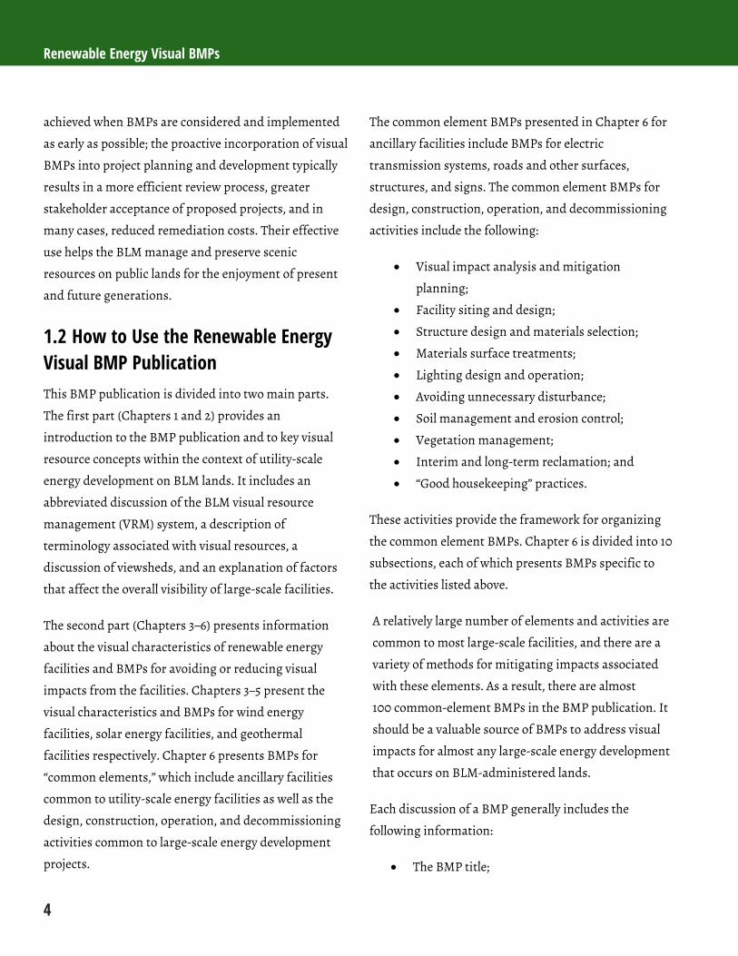
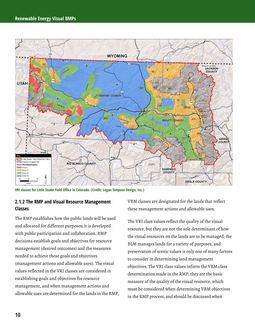
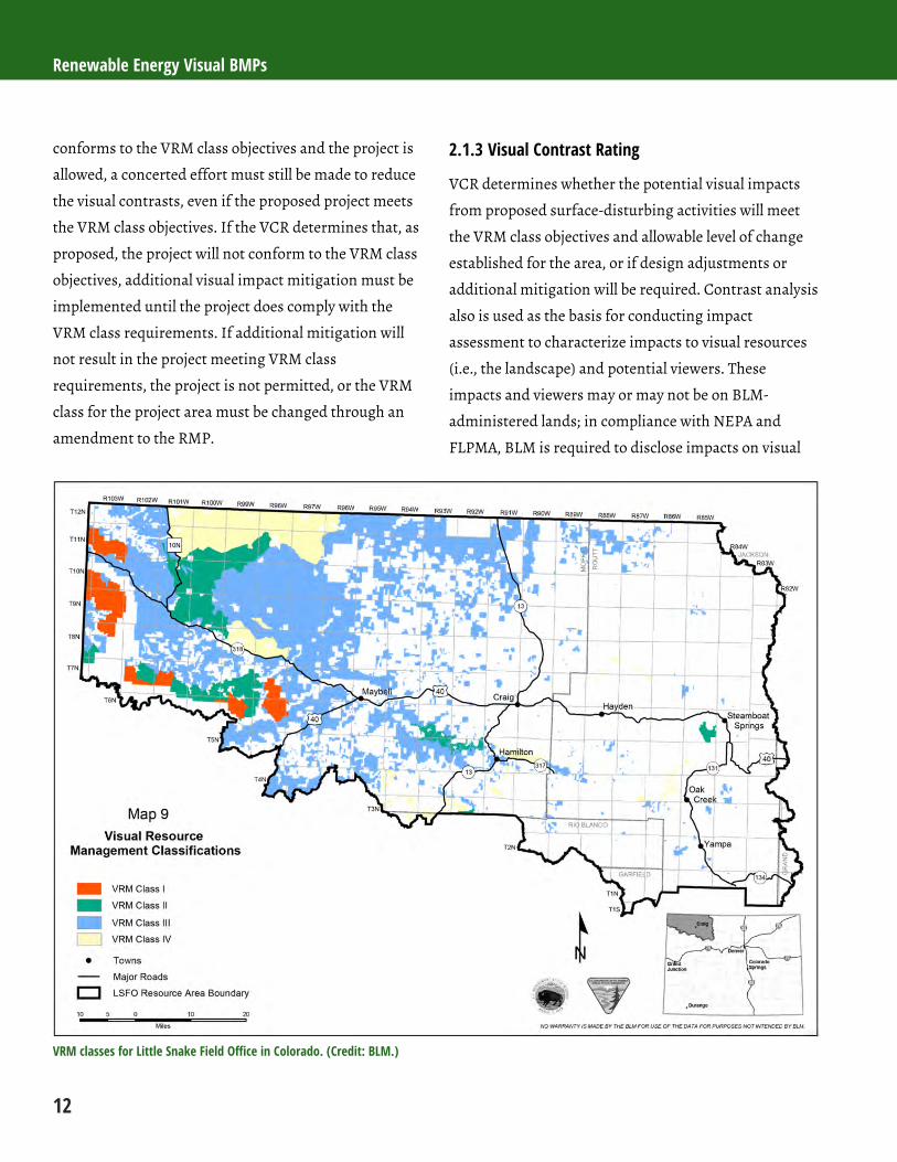
VRI classes for Little Snake Field Office in Colorado. (Credit: Logan Simpson Design, Inc.)
2.1.2 The RMP and Visual Resource Management Classes
The RMP establishes how the public lands will be used
and allocated for different purposes; it is developed
with public participation and collaboration. RMP
decisions establish goals and objectives for resource
management (desired outcomes) and the measures
needed to achieve these goals and objectives
(management actions and allowable uses). The visual
values reflected in the VRI classes are considered in
establishing goals and objectives for resource
management, and when management actions and
allowable uses are determined for the lands in the RMP,
VRM classes are designated for the lands that reflect
these management actions and allowable uses.
The VRI class values reflect the quality of the visual
resource, but they are not the sole determinant of how
the visual resources on the lands are to be managed; the
BLM manages lands for a variety of purposes, and
preservation of scenic values is only one of many factors
to consider in determining land management
objectives. The VRI class values inform the VRM class
determination made in the RMP; they are the basic
measure of the quality of the visual resource, which
must be considered when determining VRM objectives
in the RMP process, and should be discussed when

Chapter 2: Visual Resources
11
describing the visual impacts of a proposed surface-
disturbing action.
VRI classes are not intended to automatically become
VRM class designations. Management classes are
determined through careful analyses of other resource
values, and other potential land uses and demands. The
VRM class determination is based on a full assessment
that evaluates the VRI in concert with needed resource
uses and desirable future outcomes. The VRM class
designations may be different than the VRI classes
assigned in the inventory and should reflect a balance
between protection of visual values and meeting
America’s energy and other land use or commodity
needs.
The VRM classes set VRM objectives for lands in each
class, as well as the level of visual change in the
landscape character that is allowed as a result of
proposed management activities. The objectives and
allowed levels of change for each of the four VRM
classes are as follows:
Class I Objective: To preserve the existing
character of the landscape. Allowed Level of
Change: This class provides for natural
ecological changes; however, it does not
preclude very limited management activity. The
level of change to the characteristic landscape
should be very low and must not attract
attention.
Class II Objective: To retain the existing
character of the landscape. Allowed Level of
Change: The level of change to the
characteristic landscape should be low.
Management activities may be seen, but should
not attract the attention of the casual observer.
Any changes must repeat the basic elements of
form, line, color, and texture found in the
predominant natural features of the
characteristic landscape.
Class III Objective: To partially retain the
existing character of the landscape. Allowed
Level of Change: The level of change to the
characteristic landscape should be moderate.
Management activities may attract attention,
but should not dominate the view of the casual
observer. Changes should repeat the basic
elements found in the predominant natural
features of the characteristic landscape.
Class IV Objective: To provide for management
activities which require major modification of
the existing character of the landscape. Allowed
Level of Change: The level of change to the
characteristic landscape can be high.
Management activities may dominate the view
and may be the major focus of viewer attention.
However, the impact of these activities should
be minimized through careful siting, minimal
disturbance, and repeating the basic elements
of form, line, color, and texture within the
existing setting.
Once the VRM class is determined for a tract of BLM-
administered land in the RMP, BLM policy requires that
proposed management activities, such as constructing
and operating a utility-scale renewable energy facility
on that tract, must meet the requirements of the VRM
class. Disclosure of impacts to the visual values of the
project area and conformance with the VRM class
requirements is determined through the Visual
Contrast Rating (VCR) process (see below) during NEPA
analysis. If the VCR process determines that the project
Renewable Energy Visual BMPs
12
conforms to the VRM class objectives and the project is
allowed, a concerted effort must still be made to reduce
the visual contrasts, even if the proposed project meets
the VRM class objectives. If the VCR determines that, as
proposed, the project will not conform to the VRM class
objectives, additional visual impact mitigation must be
implemented until the project does comply with the
VRM class requirements. If additional mitigation will
not result in the project meeting VRM class
requirements, the project is not permitted, or the VRM
class for the project area must be changed through an
amendment to the RMP.
2.1.3 Visual Contrast Rating
VCR determines whether the potential visual impacts
from proposed surface-disturbing activities will meet
the VRM class objectives and allowable level of change
established for the area, or if design adjustments or
additional mitigation will be required. Contrast analysis
also is used as the basis for conducting impact
assessment to characterize impacts to visual resources
(i.e., the landscape) and potential viewers. These
impacts and viewers may or may not be on BLM-
administered lands; in compliance with NEPA and
FLPMA, BLM is required to disclose impacts on visual
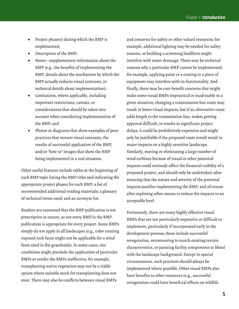
VRM classes for Little Snake Field Office in Colorado. (Credit: BLM.)
Chapter 2: Visual Resources
13
resources regardless of whether the affected lands are
public or private, or are managed by BLM, and
regardless of whether potential viewers are located on
BLM-administered or other lands. Contrast analysis is
also used to identify opportunities for avoidance or
mitigation of impacts.
The VCR involves a systematic comparison of the
landscape’s visual characteristics before and after the
project is implemented, as seen from key observation
points (KOPs), using the basic design elements of form,
line, color, and texture. The BLM defines KOPs as “the
most critical viewpoints,” such as points or a series of
points on a travel route, or at a use area or a potential
use area (BLM 1986b).
The following steps are included within the BLM
contrast rating process:
(1) Obtain a project description—The level of detail
required for this step varies by individual
project. This information usually can be
obtained from a project developer or
proponent. Typically, a preliminary Plan of
Development (POD) is submitted with the ROW
application. However, details such as exact
layout of facilities, roads, and transmission
lines are not identified, and therefore meeting
with the project proponent is warranted.
Assesing the impacts of renewable energy
facilities is strongly dependant on the location
of the components of the project. Details about
the main components and ancillary facilities are
therefore necessary to identify and characterize
contrast and associated impacts.
(2) Describe the VRM objectives—For each field
office or region, the RMP includes the VRM
objectives for lands included in the RMP,
usually in a GIS-generated map with polygons
labeled with the applicable VRM classes. From
this is drawn the existing VRM objective for the
parcel or parcels in which the proposed project
would be located.
(3) Select KOPs—Viewpoints are selected from
which to evaluate the visual contrast that would
be created if the proposed project were built.
KOPs should represent either a typical view
from a sensitive viewing location or the range
of impacts associated with the project. These
locations are usually located on commonly
travelled routes from which the project would
be visible, or other likely observation points.
KOPs typically are selected through a
consultation process with the BLM, and, in
some cases, interested stakeholders and the
public.
(4) Prepare visual impact simulations—Visual
simulations are spatially accurate and realistic
visualizations (typically computer-generated
photomontages) of the project and surrounding
landscape that are used to depict the overall
appearance of a proposed project. Simulations
depict views of the project from selected KOPs.
Simulations help the BLM and other
stakeholders visualize and respond to
development proposals. They are also used to
evaluate the effectiveness of mitigation
measures and BMPs to address visual impact
issues.
(5) Complete the contrast rating form—The BLM
provides a worksheet (Form 8400-4) with which
to conduct and record visual contrast ratings
for views from the KOPs selected for the VCR.

Renewable Energy Visual BMPs
14
The worksheet guides the evaluation and allows
for multiple observers to evaluate a potential
project. Contrast ratings are made by
comparing the basic elements of form, line,
color, and texture of the existing landscape with
the proposed development, using the
simulation to guide the assessment of expected
future conditions. Factors to be considered
when assessing visual contrast from the
proposed facility include distance, angle of
observation, length of time the project is in
view, relative size or scale, season of use,
lighting conditions, recovery time, spatial
relationships, atmospheric conditions, and
motion. These factors are considered in greater
detail in Section 2.2.
The results of the VCR for each KOP include a
determination of the level of visual contrast associated
with the project for each of the four design elements.
One of four levels of contrast (i.e., none, weak,
moderate, and strong) is assigned for each of the design
elements. The contrast assessment is used as the basis
for determining whether or not the proposed project
complies with the VRM objectives and allowable levels
of change assigned to the area in the RMP. If it is
determined that the project will not conform to the
VRM class requirements, the VCR also specifies
mitigation that will be required to meet the VRM class
requirements, if compliance could be achieved through
mitigation. Regardless of compliance with VRM class
objectives, the VCR is used to identify appropriate
impact avoidance and mitigation measures that should
be implemented.
Additional information on the VRM system can be
found in the following BLM documents:
BLM Handbook 8400, Visual Resource
Management;
BLM Manual H-8410-1, Visual Resource Inventory;
BLM Handbook H-8431-1, Visual Resource
Contrast Rating;
Information Bulletin No. 98-135;
Instruction Memorandum No. 98-164; and
Instruction Memorandum 2009-167.
Additional information on the RMP process can be
found in the BLM Land Use Planning Handbook
H-1601-1.
2.2 Visual Contrast and Visibility Factors At a very basic level, visual impacts can be defined as
changes to the scenic attributes of the landscape
brought about by the introduction of visual contrasts,
and the associated changes in the human visual
experience of the landscape. Visual impacts on the
visual experience of the landscape can be positive or
negative. If viewers feel that the visual contrasts
generated by a change to the visible elements of the
landscape improve its visual qualities, the impact is
positive. If viewers feel that the contrasts detract from
the scenic quality of a landscape rather than improve it,
the impacts are negative.
The concepts of visual contrast and visual impact are
central to understanding how renewable energy
facilities and other types of developments affect visual
resources on BLM-administered lands.
Visual contrast is a change in what is seen by the
observer. For example, if wind turbines are
Chapter 2: Visual Resources
15
introduced to a natural-appearing landscape,
the tall shapes of the towers, and their white
color, long vertical lines, smooth textures, blade
motion, and blinking lights at night are all
visual contrasts that can be seen by people and
can change the scenic quality of the landscape.
Visual impact includes both the change to the
visual qualities of the landscape resulting from
the introduction of visual contrasts, and the
resulting change to the human visual
experience of the landscape. Continuing with
the wind energy example above, the
introduction of contrasts from wind turbines
may change the VRI scenic quality rating of an
undisturbed and highly scenic area from an A to
a B; this change in scenic quality constitutes a
part of the visual impact from the project. The
presence of the wind facility may also change
the visual experience of persons who view the
project area; this constitutes another dimension
of the visual impact of the facility. Some viewers
may think that the addition of wind turbines
improves the view, perhaps because it adds
visual interest to an otherwise static view. For
these people, the visual impact of the wind
turbines is positive. Other viewers may feel that
the wind turbines add visual clutter or block the
view of mountains they enjoy looking at. For
these viewers, the visual impact of the wind
turbines is negative.
Broadly speaking, visual impact assessment includes:
(1) determination of the extent and nature of the
visual contrasts caused by a project;
(2) prediction of the effects of the contrasts on the
landscape’s visual qualities;
(3) prediction of viewers’ emotional responses to
the observed contrasts, as seen by likely viewers
from likely viewpoints; and
(4) identification of measures to avoid or reduce
the visual contrasts associated with the
proposed project.
2.2.1 Visual Contrast
The BLM’s VCR process focuses on the systematic
assessment of visual contrast. While the VRI process
recognizes that cultural modifications (manmade
elements visible in the landscape) may sometimes
positively affect scenic quality, the VCR process
identifies the sources and levels of visual contrast from
a proposed project. The BLM’s visual impact mitigation
approach seeks to reduce the visible contrasts from the
project or to avoid the contrasts altogether; this may be
accomplished, for example, by moving the entire project
or its visible elements, or by screening the project from
view. Because of this, a good understanding of the
sources of visual contrast and the factors that affect the
perception of visual contrast in the landscape is
important not only to visual impact assessment, but
also to the identification of appropriate visual impact
mitigation.
In the VRM system, contrast is described as the
differences in the four basic design elements of form,
line, color, and texture between the proposed project
and the surrounding landscape. Additional information
about these elements is presented in BLM VRM Manual
Handbook H-8431-1 (BLM 1986b); however, they are
summarized as follows:
Renewable Energy Visual BMPs
16
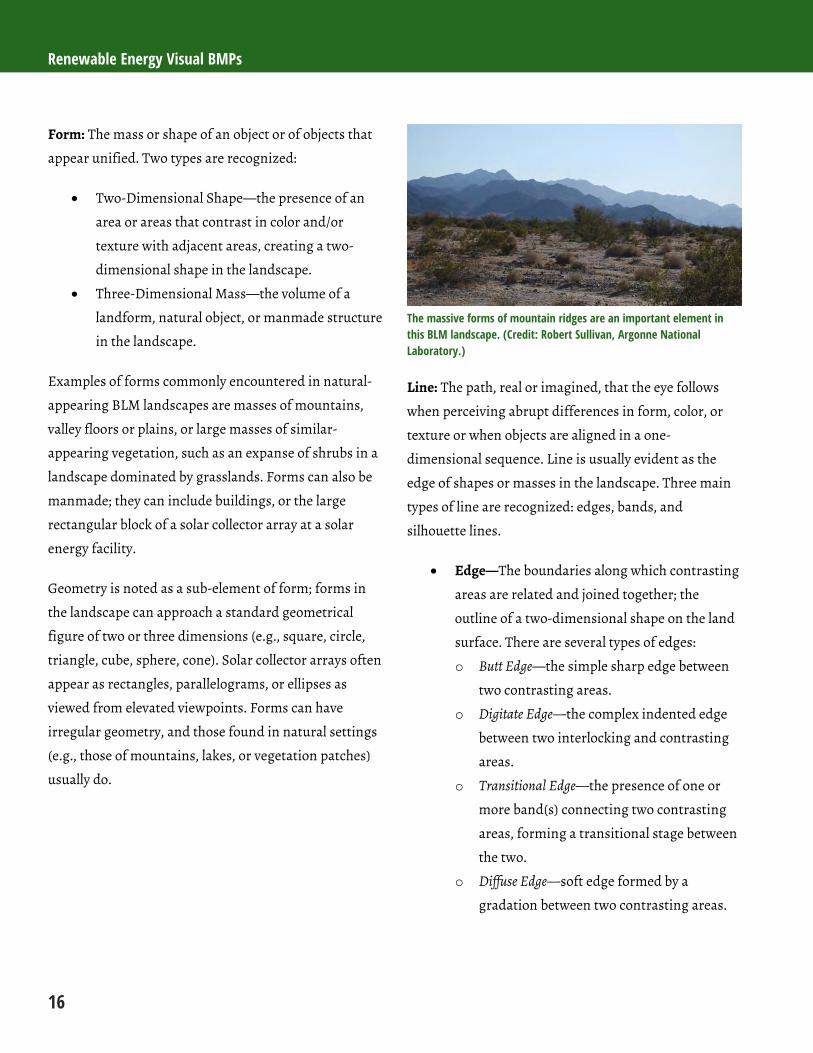
Form: The mass or shape of an object or of objects that
appear unified. Two types are recognized:
Two-Dimensional Shape—the presence of an
area or areas that contrast in color and/or
texture with adjacent areas, creating a two-
dimensional shape in the landscape.
Three-Dimensional Mass—the volume of a
landform, natural object, or manmade structure
in the landscape.
Examples of forms commonly encountered in natural-
appearing BLM landscapes are masses of mountains,
valley floors or plains, or large masses of similar-
appearing vegetation, such as an expanse of shrubs in a
landscape dominated by grasslands. Forms can also be
manmade; they can include buildings, or the large
rectangular block of a solar collector array at a solar
energy facility.
Geometry is noted as a sub-element of form; forms in
the landscape can approach a standard geometrical
figure of two or three dimensions (e.g., square, circle,
triangle, cube, sphere, cone). Solar collector arrays often
appear as rectangles, parallelograms, or ellipses as
viewed from elevated viewpoints. Forms can have
irregular geometry, and those found in natural settings
(e.g., those of mountains, lakes, or vegetation patches)
usually do.
The massive forms of mountain ridges are an important element in this BLM landscape. (Credit: Robert Sullivan, Argonne National Laboratory.)
Line: The path, real or imagined, that the eye follows
when perceiving abrupt differences in form, color, or
texture or when objects are aligned in a one-
dimensional sequence. Line is usually evident as the
edge of shapes or masses in the landscape. Three main
types of line are recognized: edges, bands, and
silhouette lines.
Edge—The boundaries along which contrasting
areas are related and joined together; the
outline of a two-dimensional shape on the land
surface. There are several types of edges:
o Butt Edge—the simple sharp edge between
two contrasting areas.
o Digitate Edge—the complex indented edge
between two interlocking and contrasting
areas.
o Transitional Edge—the presence of one or
more band(s) connecting two contrasting
areas, forming a transitional stage between
the two.
o Diffuse Edge—soft edge formed by a
gradation between two contrasting areas.
Chapter 2: Visual Resources
17
Band—contrasting linear form with two
roughly parallel edges dividing an area in two.
Silhouette-line—the outline of a mass seen
against a backdrop. The skyline is the
silhouette-line of the land against the sky.
Boldness, complexity, and orientation are sub-elements
of the line feature. Boldness refers to the visual strength
of the line; complexity refers to the degree of simplicity
or intricacy of a line; and orientation refers to the
overall relationship of the line to the (horizontal) axis of
the landscape or to compass bearings.
Examples of lines commonly encountered in natural-
appearing BLM landscapes are the horizon line; lines of
stratified layers of topography (e.g., successive ridges);
the lines of mountains or ridges against the sky; strata
in rock formations; streams; and the edges of
vegetation masses. Like forms, lines in the landscape
can be manmade, and manmade lines in BLM
landscapes are quite common; they include fences,
transmission towers and conductors, wind turbine
towers, the edges of solar arrays, and the pipelines of
geothermal plants.
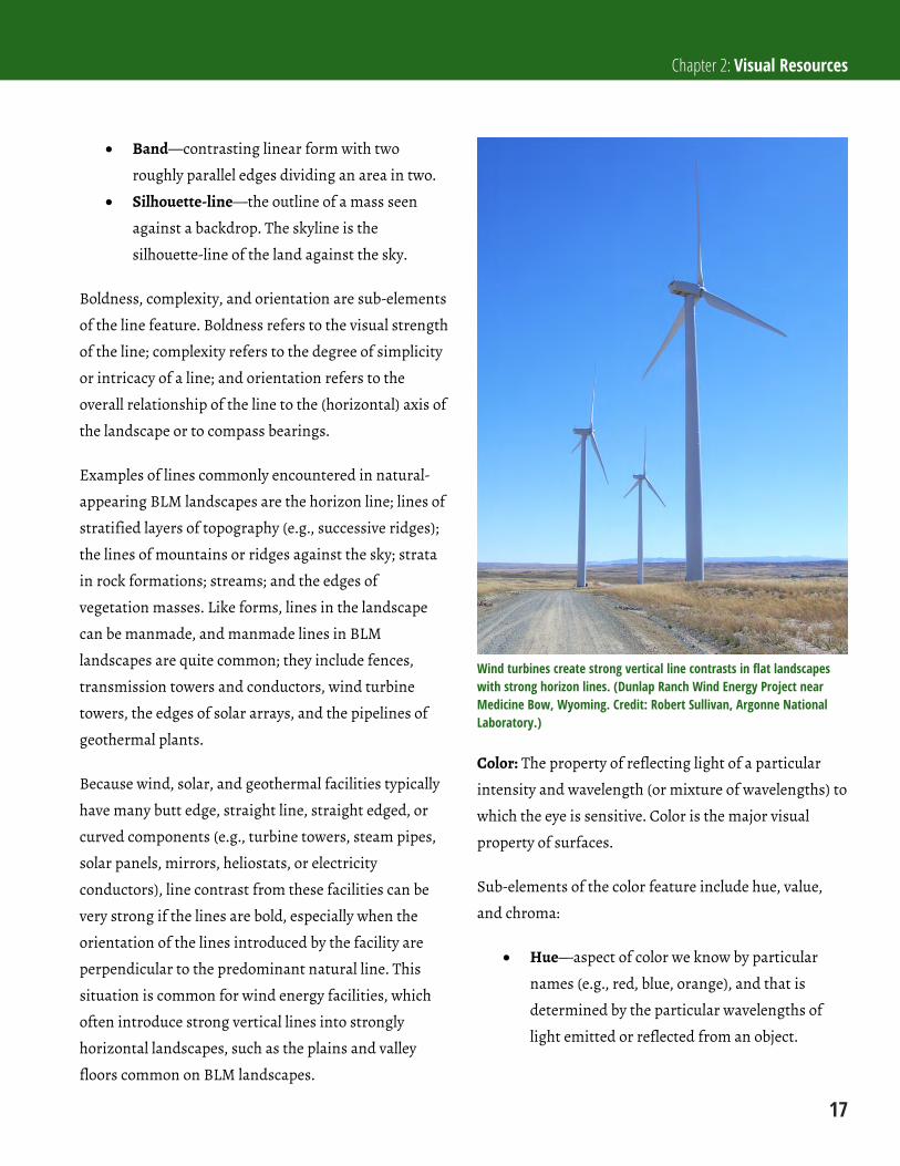
Because wind, solar, and geothermal facilities typically
have many butt edge, straight line, straight edged, or
curved components (e.g., turbine towers, steam pipes,
solar panels, mirrors, heliostats, or electricity
conductors), line contrast from these facilities can be
very strong if the lines are bold, especially when the
orientation of the lines introduced by the facility are
perpendicular to the predominant natural line. This
situation is common for wind energy facilities, which
often introduce strong vertical lines into strongly
horizontal landscapes, such as the plains and valley
floors common on BLM landscapes.
Wind turbines create strong vertical line contrasts in flat landscapes with strong horizon lines. (Dunlap Ranch Wind Energy Project near Medicine Bow, Wyoming. Credit: Robert Sullivan, Argonne National Laboratory.)
Color: The property of reflecting light of a particular
intensity and wavelength (or mixture of wavelengths) to
which the eye is sensitive. Color is the major visual
property of surfaces.
Sub-elements of the color feature include hue, value,
and chroma:
Hue—aspect of color we know by particular
names (e.g., red, blue, orange), and that is
determined by the particular wavelengths of
light emitted or reflected from an object.

Renewable Energy Visual BMPs
18
Value—lightness or darkness of the color,
which is caused by the intensity of light being
reflected, and ranges from black to white.
Chroma—degree of color saturation or
brilliance, determined by the mixture of light
rays emitted or reflected from an object. It is
the degree of grayness in a color, ranging from
pure (high chroma) to dull (low chroma).
Colors common to many BLM landscapes, particularly
in the desert southwest and intermountain west, are the
colors of vegetation, rock, and soil, which tend toward
muted (low chroma) greens, browns, and grays. Soil
color varies widely, but soils are often light tan, red, or
gray, and in desert or rocky areas with scant vegetation
soil can be an important contributor to landscape color.
Brighter colors, such as the colors of flowers, are
present but tend to be ephemeral. Water is generally
rare, but may be locally plentiful. The color of water
ranges from brown to green to blue, but it can be white
when water is cascading. Blue skies are common
overhead, but skies are generally very pale blue to light
gray at or near the horizon, except at sunrise and
sunset. Night skies away from cities tend to be dark, in
some places exceptionally dark. Manmade elements, of
course, can be any color, but in many BLM landscapes,
manmade elements are relatively uncommon and tend
to be widely spaced. They are often constructed of wood
or metal, with galvanized metal surfaces common, and
they can sometimes be highly reflective.
Depending on the technology, solar facilities use
thousands, or even hundreds of thousands, of mirrored
surfaces that in some instances are sources of glinting
(a brief flash of light) or glare (light bright enough to
cause annoyance or discomfort). When glinting and
glare are absent, the mirrors or heliostats may reflect
the sky, clouds, or, at certain angles, even the ground or
surrounding vegetation. Modern wind turbines are
always white, which often contrasts strongly with the
surrounding natural colors. Geothermal facilities can be
any color, but if their sometimes-extensive pipeline
networks are not painted or coated to match the
backdrop, their surfaces may be highly reflective.
Reflections of the blue sky in this solar parabolic trough facility’s mirrors causes strong color contrast with the surrounding vegetation. (Nevada Solar One near Boulder City, Nevada. Credit: Robert Sullivan, Argonne National Laboratory.)

Chapter 2: Visual Resources
19
Texture: The aggregation of small forms or color
mixtures into a continuous surface pattern; the
aggregated parts are small enough that they do not
appear as discrete objects in the visible landscape. Two
types of texture are recognized:
Color Mixture (mottling)—intrinsic surface
color contrasts of very small scale, which may be
due to hue, chroma, or value, alone or in
combination.
Light and Shade—the color contrast,
particularly in value, created by differences in
lighting on a varied surface or repeated forms.
It consists of the repetition of a lit side, a
shaded side, and the shadow cast.
Sub-elements of texture include grain, regularity, and
internal contrast. Grain refers to the relative
dimensions of the surface variations, ranging from
large (coarse texture, e.g., coniferous forest) to small
(fine texture, e.g., grassland). Regularity refers to the
degree of uniform recurrence and symmetrical
arrangement of the surface variation. Internal contrast
refers to the degree of contrast in colors or values
creating the texture. Perception of texture is highly
dependent on distance; a texture that appears coarse at
short distances may appear as a fine texture at longer
distances and will appear to be smooth at even longer
distances.
Naturally occurring textures include those of
vegetation, soils, and rocks. Vegetation and soil textures
are often predominantly color mixtures, but light and
shade textures are often important components of the
coarser textures of rocky areas and mountains. The
individual structures of renewable energy facilities
often have monotone, smooth surfaces that lack texture
even at very close viewing distances; however, light and
shade textures may be important contrast sources from
longer distances. They may be seen as the interplay of
shadows and lit surfaces from complex piping and
other elements of a power block at a thermal plant, or
from thousands of visually overlapping sunlit solar
collectors and the shadows they cast on the ground.
The power block, collector array, and buildings of this solar parabolic trough facility introduce a variety of non-natural textures to this landscape. (Nevada Solar One near Boulder City, Nevada. Credit: Robert Sullivan, Argonne National Laboratory.)
2.2.2 Visibility Factors
In many BLM landscapes, utility-scale wind, solar, and
geothermal energy facilities may create strong visual
contrasts with scenic settings. This is particularly true
for wind and solar facilities, because these projects
cover very large areas, and the structures involved can
be very tall and/or highly reflective. All three
technologies involve structures with distinctly
manmade geometry that may contrast strongly with
natural-appearing backgrounds when lighting
conditions and viewing angles are suitable, and viewers
are within a certain distance of the facility. However, at
other times, even when viewed from the same location,
the facilities may be invisible; they may be visible but
hard to distinguish from the background; or they may
be plainly visible but appear substantially different than
they have appeared at other times. The visibility of an
Renewable Energy Visual BMPs
20
object in a landscape setting, and its apparent visual
characteristics for any given view, are the result of a
complex interplay between the observer, the observed
object, and various factors that affect visual perception,
referred to as visibility factors. After introducing the
concept of the viewshed, the area of the landscape seen
from a particular location, the remainder of this chapter
is devoted to describing visibility factors and how they
affect the visibility and apparent visual contrast
associated with objects in the landscape, including
renewable energy facilities.
2.2.2.1 Viewsheds
A viewshed is the typical unit of study for a visual
impact assessment. A viewshed is the total landscape
that can be seen from a particular location, which could
be a point, such as a scenic overlook; a line, such a travel
route; or an area, such as a lake. Most visual impact
assessments begin with a viewshed analysis, a spatial
analysis conducted using various computer software
programs such as a geographic information system
(GIS). These programs analyze the land surface around
the point, line, or area of interest to determine which
part of the landscape would be visible from that
location, and which part of the landscape would be
screened from view, based on elevation data and data
on screening elements such as vegetation or structures,
if available. The user sets the maximum distance from
the viewshed origin (the viewpoint from which visibility
is being determined), as well as other controls
(discussed below). The output of the viewshed analysis
is usually a viewshed map, a map that indicates which
areas around the viewpoint are visible and which are
not. More specialized viewshed analyses are sometimes
conducted; these may include composite viewsheds that
indicate visibility of areas from multiple KOPs, or
viewsheds that indicate the height of an object at a
given location that could be concealed from view of a
KOP.
2.2.2.2 Viewshed Limiting Factors
Several factors determine the spatial extent of the
viewshed from a given viewpoint, within the maximum
distance of analysis set by the user; these factors are
here referred to as viewshed limiting factors, because they
define the spatial limits of the viewshed. They include
the following:
Topography: Obviously, terrain such as a ridge
or hill may block the view from a particular
location; in hilly or mountainous areas,
topography has a major effect on the shape and
size of the viewshed. The elevation data used in
the viewshed analysis provide information used
in the analysis to determine topographic
screening.
Vegetation: Vegetation, typically trees, may
screen views fully or partially, especially close to
the viewpoint. In many but not all BLM
landscapes, vegetation tall enough to screen
views is sparse or absent; however, where it is
present and of sufficient density to block views,
it can affect the size and shape of the viewshed.
Specialized elevation data may be required to
account for vegetation height in a viewshed
analysis, unless a standard vegetation height
can be calculated and incorporated into the
viewshed analysis. In areas with deciduous
vegetation, seasonal leaf drop may affect the
extent of screening. Views may be screened less
effectively when leaves are shed.
Chapter 2: Visual Resources
21
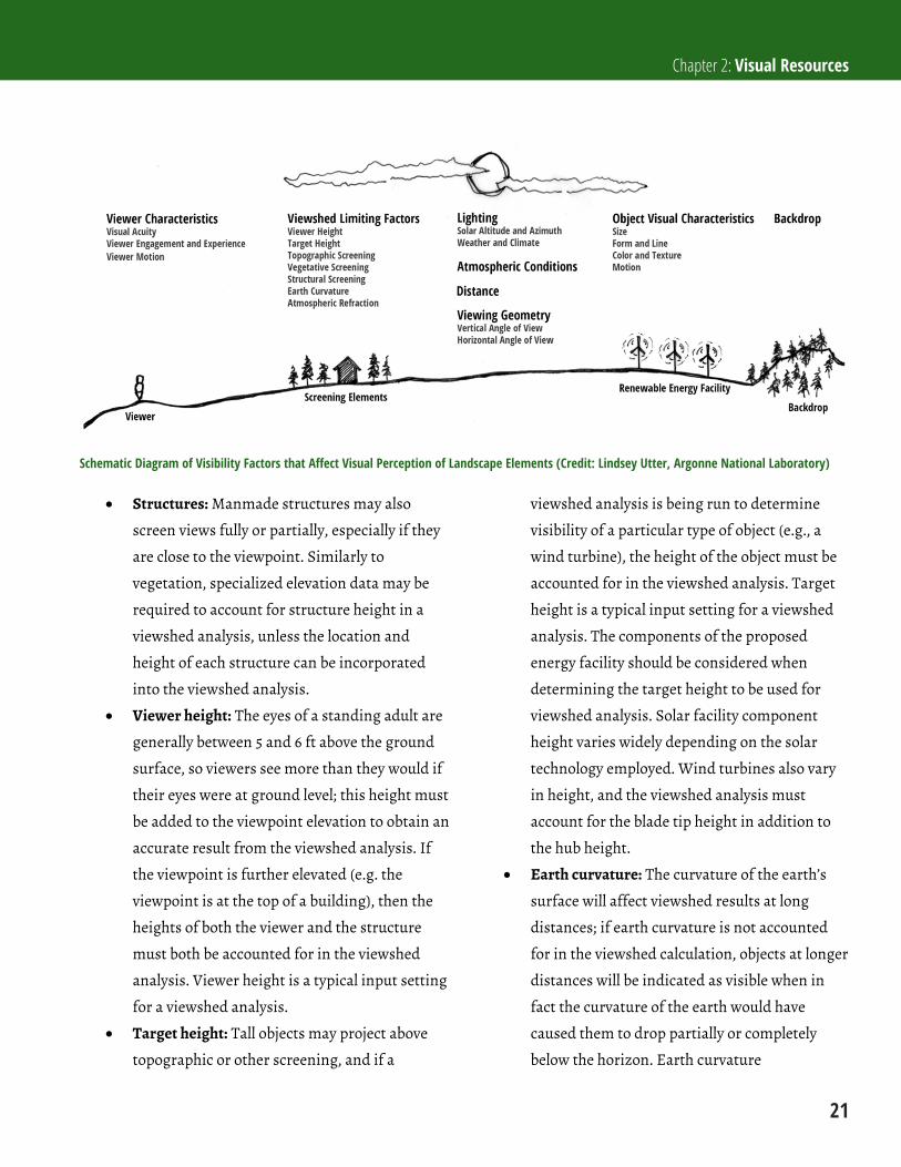
Schematic Diagram of Visibility Factors that Affect Visual Perception of Landscape Elements (Credit: Lindsey Utter, Argonne National Laboratory)
Structures: Manmade structures may also
screen views fully or partially, especially if they
are close to the viewpoint. Similarly to
vegetation, specialized elevation data may be
required to account for structure height in a
viewshed analysis, unless the location and
height of each structure can be incorporated
into the viewshed analysis.
Viewer height: The eyes of a standing adult are
generally between 5 and 6 ft above the ground
surface, so viewers see more than they would if
their eyes were at ground level; this height must
be added to the viewpoint elevation to obtain an
accurate result from the viewshed analysis. If
the viewpoint is further elevated (e.g. the
viewpoint is at the top of a building), then the
heights of both the viewer and the structure
must both be accounted for in the viewshed
analysis. Viewer height is a typical input setting
for a viewshed analysis.
Target height: Tall objects may project above
topographic or other screening, and if a
viewshed analysis is being run to determine
visibility of a particular type of object (e.g., a
wind turbine), the height of the object must be
accounted for in the viewshed analysis. Target
height is a typical input setting for a viewshed
analysis. The components of the proposed
energy facility should be considered when
determining the target height to be used for
viewshed analysis. Solar facility component
height varies widely depending on the solar
technology employed. Wind turbines also vary
in height, and the viewshed analysis must
account for the blade tip height in addition to
the hub height.
Earth curvature: The curvature of the earth’s
surface will affect viewshed results at long
distances; if earth curvature is not accounted
for in the viewshed calculation, objects at longer
distances will be indicated as visible when in
fact the curvature of the earth would have
caused them to drop partially or completely
below the horizon. Earth curvature
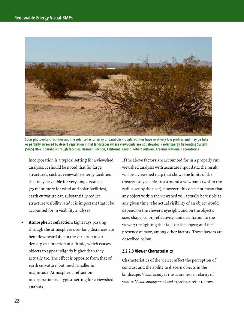
Renewable Energy Visual BMPs
22
Solar photovoltaic facilities and the solar collector array of parabolic trough facilities have relatively low profiles and may be fully or partially screened by desert vegetation in flat landscapes where viewpoints are not elevated. (Solar Energy Generating System [SEGS] III–VII parabolic trough facilities, Kramer Junction, California. Credit: Robert Sullivan, Argonne National Laboratory.)
incorporation is a typical setting for a viewshed
analysis. It should be noted that for large
structures, such as renewable energy facilities
that may be visible for very long distances
(25 mi or more for wind and solar facilities),
earth curvature can substantially reduce
structure visibility, and it is important that it be
accounted for in visibility analyses.
Atmospheric refraction: Light rays passing
through the atmosphere over long distances are
bent downward due to the variation in air
density as a function of altitude, which causes
objects to appear slightly higher than they
actually are. The effect is opposite from that of
earth curvature, but much smaller in
magnitude. Atmospheric refraction
incorporation is a typical setting for a viewshed
analysis.
If the above factors are accounted for in a properly run
viewshed analysis with accurate input data, the result
will be a viewshed map that shows the limits of the
theoretically visible area around a viewpoint (within the
radius set by the user); however, this does not mean that
any object within the viewshed will actually be visible at
any given time. The actual visibility of an object would
depend on the viewer’s eyesight, and on the object’s
size, shape, color, reflectivity, and orientation to the
viewer; the lighting that falls on the object; and the
presence of haze, among other factors. These factors are
described below.
2.2.2.3 Viewer Characteristics
Characteristics of the viewer affect the perception of
contrast and the ability to discern objects in the
landscape. Visual acuity is the acuteness or clarity of
vision. Visual engagement and experience refer to how

Chapter 2: Visual Resources
23
closely the viewer is looking at the landscape, whether
they are looking for a particular object or type of object,
and their familiarity with the type of object. Viewer
motion may change the aspect of the viewed facility, but
it can also limit the duration of views.
Visual acuity: Visual acuity is the ability to
discern visual details and is a physical
limitation of the human vision system. It is
dependent on the sharpness of the retinal focus
within the eye, the sensitivity of the nervous
elements, and the interpretative faculty of the
brain. It varies between individuals and
decreases with age, but generally can be
corrected with eyeglasses, contact lenses, or
surgery, or by other means.
Viewer engagement and experience: Human
vision has many similarities to a camera, but
unlike a camera, the human vision system is not
a passive recorder of the scene in front of the
lens. Seeing is an active process that involves
scanning the landscape to pick out recognizable
objects from the background, to look for
patterns, and in general, to organize and make
sense of the jumble of forms, lines, colors, and
textures presented to the eye. While much of
this activity happens without conscious effort
by the viewer, viewers who are consciously and
actively focusing on the landscape will normally
be better able to discern particular objects,
particularly if they know what they are looking
for, and especially if they have previous visual
experience with the object, such that they have a
mental “template” to help them predict the
forms, lines, colors, and textures they should be
looking for as they scan the view. Viewers who
are not focusing on the view, not actively
scanning the scene in front of them, and not
trying to identify a known type of object may be
less likely to see a given facility unless it is so
large or eye-catching as to be hard to miss.
Viewer motion: If the viewer is moving through
the landscape, the visual experience differs
from that of a static viewer in important ways.
If the viewer is moving directly toward or away
from the facility, the general aspect of the
facility will not change, but its apparent size
will, and the level of contrast it creates will
change similarly. If the viewer is moving
perpendicular to the line of sight to the facility
(i.e., the facility is moving across the field of
view), visual parallax will make the facility seem
to move across its visual backdrop. If the
backdrop is not uniform, and if the viewer is
sufficiently close to the facility, the contrast
from the facility may change dynamically as the
color and texture of the backdrop change. The
portions of the facility in view may change as
well. Viewer motion will also tend to decrease
the duration of views of the facility, particularly
if the motion is perpendicular to the line of
sight to the facility rather than toward the
facility. Decreased view duration will decrease
the likelihood that the facility is noticed and
decrease the overall perception of contrast.
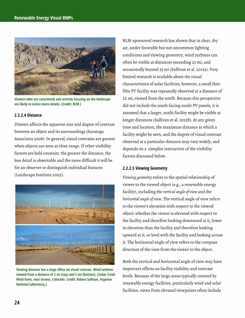
Renewable Energy Visual BMPs
24
Viewers who are consciously and actively focusing on the landscape are likely to notice more details. (Credit: BLM.)
2.2.2.4 Distance
Distance affects the apparent size and degree of contrast
between an object and its surroundings (Saratoga
Associates 2008). In general, visual contrasts are greater
when objects are seen at close range. If other visibility
factors are held constant, the greater the distance, the
less detail is observable and the more difficult it will be
for an observer to distinguish individual features
(Landscape Institute 2002).
Viewing distance has a large effect on visual contrast. Wind turbines viewed from a distance of 2 mi (top) and 5 mi (bottom). (Cedar Creek Wind Farm, near Grover, Colorado. Credit: Robert Sullivan, Argonne National Laboratory.)
BLM-sponsored research has shown that in clear, dry
air, under favorable but not uncommon lighting
conditions and viewing geometry, wind turbines can
often be visible at distances exceeding 25 mi, and
occasionally beyond 35 mi (Sullivan et al. 2012a). Very
limited research is available about the visual
characteristics of solar facilities; however, a small thin-
film PV facility was repeatedly observed at a distance of
22 mi, viewed from the north. Because this perspective
did not include the south-facing sunlit PV panels, it is
assumed that a larger, sunlit facility might be visible at
longer distances (Sullivan et al. 2012b). At any given
time and location, the maximum distance at which a
facility might be seen, and the degree of visual contrast
observed at a particular distance may vary widely, and
depends on a complex interaction of the visibility
factors discussed below.
2.2.2.5 Viewing Geometry
Viewing geometry refers to the spatial relationship of
viewer to the viewed object (e.g., a renewable energy
facility), including the vertical angle of view and the
horizontal angle of view. The vertical angle of view refers
to the viewer’s elevation with respect to the viewed
object: whether the viewer is elevated with respect to
the facility and therefore looking downward at it, lower
in elevation than the facility and therefore looking
upward at it, or level with the facility and looking across
it. The horizontal angle of view refers to the compass
direction of the view from the viewer to the object.
Both the vertical and horizontal angle of view may have
important effects on facility visibility and contrast
levels. Because of the large areas typically covered by
renewable energy facilities, particularly wind and solar
facilities, views from elevated viewpoints often include

Chapter 2: Visual Resources
25
the top surfaces of the structures in the facility, causing
it to occupy more of the field of view, and making the
full areal extent and the regular geometry of the facility
more apparent. For solar facilities, elevated views tend
to show more of the often highly reflective solar arrays,
which can greatly increase visual contrast, especially if
glare or glinting occurs.
The horizontal angle of view determines which side of
the facility is in view, and the angle of surfaces with
respect to the viewer (for example, whether wind
turbine blade motion is seen face-on, where it can be
quite noticeable, or seen from the side, where it may be
nearly invisible). The horizontal angle of view also
interacts with the solar azimuth (see Section 2.2.2.7
below) to determine whether the object is frontlit (the
side facing the viewer is fully illuminated by light
coming from behind the viewer), backlit (the side facing
the viewer is fully shaded because the object is between
the viewer and the light source), or sidelit (the side
facing the viewer is partly illuminated and partly
shaded because the light is falling more or less
perpendicular to the line of sight between the viewer
and the object).
Movement of the viewer during the act of viewing a
facility, as when viewing from an automobile on the
highway or while walking down a trail, causes the
viewing geometry to change, which can have dramatic
effects on visibility and visual contrast. As rapidly
changing viewing geometry changes the orientation of
the line of sight to reflective surfaces, bright flashes of
light, abrupt changes in apparent color, and abrupt
changes in the patterns of light and shadows may
result. For moving viewers, the visual experience of
wind facilities and especially solar facilities tends to be
very dynamic, with major changes in the appearance of
the facilities sometimes occurring over short periods of
time or with small changes in viewer position.
Views of the Silver State North solar PV facility, near Primm, Nevada from ground level (top photo) and from an elevated viewpoint (bottom photo). Views from elevated viewpoints often include the top surfaces of the structures in the facility, causing it to occupy more of the field of view, and making the full areal extent and the regular geometry of the facility more apparent. Credit: Robert Sullivan, Argonne National Laboratory.)
2.2.2.6 Background/Backdrop
Objects that stand out against the visual background
typically command a viewer’s attention. The ability to
see or detect an object is heavily influenced by the
contrast between the object and its background or
backdrop (Sprawls 1995). As contrast between an object
and its background is reduced, the ability to distinguish

Renewable Energy Visual BMPs
26
the object from the background diminishes. When the
contrast becomes too small, the object will no longer be
visible as separate from its background.
The backdrop against which the structures of a
renewable energy facility are viewed affects their
visibility. The degree to which visibility is affected
depends on the color and textures of the structures and
the backdrop, and the lighting falling on both (see
Section 2.2.2.4). Light-colored or sunlit structures
viewed against backdrops of dark vegetation or rock
will show strong contrasts that can greatly extend their
visibility, while dark or shaded structures against the
same backdrop may nearly disappear. Conversely, dark
or shaded structures against light backdrops such as
white or light gray clouds, pale blue skies, snow-covered
slopes, or expanses of dried grasses may cause strong
contrasts, while light-colored or sunlit structures may
be difficult to discern against these backdrops.
Because of their height, the visual backdrop of wind
turbines may have a particularly large effect on their
visibility. The strong vertical, stark white lines of sunlit
turbines against dark mountain ridges or dark clouds
may be especially conspicuous, while backlit turbines,
geothermal facilities, and especially low-height solar
facilities (e.g., PV facilities), may be substantially less
visible. It should be noted that sunlit water vapor
plumes at facilities that use thermal power technology
may stand out strongly against dark backdrops.
The texture or visual complexity of an object’s backdrop
may also affect the visibility of the object. While, in
general, it is harder to distinguish objects against
visually complex backgrounds, the flat, textureless
surfaces of some manmade facilities can contrast
strongly with visually complex, highly textured natural
backgrounds, although texture effects tend to become
less important at long distances.
2.2.2.7 Lighting
Objects are visible when light bounces (i.e., reflects) off
their surfaces and is redirected into an observer’s eye
(Hyslop 2009). The intensity and distribution of lighting
has a profound effect on the apparent color of objects
and their backgrounds. The angle of sunlight falling on
an object may result in shadows that greatly increase its
apparent contrast with the background. Sunlight can
cause glare from solar mirrors and glinting from wind
turbine blades, and can cause dramatic increases or
decreases in facility visibility as it interacts with clouds.
Lighting’s effects on visibility are complex and interact
with other visibility factors, such as atmospheric
conditions, and the surface characteristics of
structures. A number of variables affect the strength,
quality, and distribution of lighting and determine its
effects on the visibility of renewable energy facilities;
these are discussed below.
Solar altitude and azimuth—The solar altitude
is the angle of the sun above the horizon. Solar
altitude affects the overall visibility of a
renewable energy facility by altering the
amount and position of light on an object, and
in some instances by casting shadows onto the
object and the ground that can substantially
increase or decrease visual contrast. At higher
sun angles,

Chapter 2: Visual Resources
27
The complex interaction of viewing geometry, lighting, and visual backdrop may have large effects on facility visibility and contrast levels. Viewing distance ranges from 6 mi for top photo to 10 mi for bottom photo. (Dunlap Ranch Wind Energy Project near Medicine Bow, Wyoming. Credit: Robert Sullivan, Argonne National Laboratory.)
Renewable Energy Visual BMPs
28
light may be cast more on the tops of structures,
which can increase the brightness and contrast
of the facility as seen from elevated viewpoints.
At higher sun angles, shadows are diminished,
and the landscape can take on a more washed-
out appearance, with lower levels of contrast for
more distant objects. Of course, the horizontal
angle of sunlight (the solar azimuth) also alters
the amount and position of light on an object,
interacting with the viewing geometry to
determine whether structures in the landscape
are frontlit, backlit, or sidelit. Whether an object
is frontlit, backlit, or sidelit can greatly increase
or diminish its visibility, depending, in part, on
the visual backdrop against which it is viewed.
In general, backlighting from the sun will
silhouette objects, making their contours
prominent, but concealing surface detail.
Frontlighting reveals surface detail, texture,
and color differences and causes objects to
contrast more strongly with darker backdrops.
As discussed below, solar altitude and azimuth
vary both during the course of the day and
seasonally, sometimes causing facilities to vary
dramatically in appearance and contrast at
different times of day and at different times of
year.
Time of day—As the sun rises in the east, passes
through the meridian at noon, and sets in the
west, it will cause facilities to the east or west of
viewers to switch from being backlit to frontlit
or vice versa during the course of the day. Both
conditions may result in high contrast with the
visual backdrop, either because the backlit
objects are silhouetted against the brightly
sunlit background or frontlit objects are viewed
against the darker sky (or a ground backdrop)
opposite the sun. Objects will typically be sidelit
from the south during the middle parts of the
day, but the high-angle sunlight strikes
vertically oriented objects (e.g., wind turbines)
obliquely and with diminished shadows, so
contrast is somewhat lower.
Facilities south or north of viewers may be
sidelit at the beginning and end of the day,
depending upon the season (see below). For
viewers north of a facility, the facility will likely
be backlit in the middle part of the day, but
because the sun will be at a relatively high angle
the contrast will generally be less than if it were
directly behind the object. For viewers south of
a facility, it will generally be frontlit in the
middle of the day, but again, because the sun
will be at a relatively high angle, the contrast
will often be less than if the sun were more
directly behind the viewer.
In addition, renewable energy facilities are
lighted in the evening, although the nature and
amount of lighting varies widely. This lighting
will increase the visibility of the facilities during
the evening hours. For instance, wind turbines
and solar power towers would be lighted at
night for air navigation safety, typically with
red, slowly flashing lights. These lights can be
visible for very long distances, and although
they are not extremely bright, they can be
conspicuous in dark night skies, particularly as
a result of the flashing.
Seasonal variation— In the northern hemisphere
during the fall and winter, the sun is in the

Chapter 2: Visual Resources
29
southern sky the entire day; in the spring and
summer, the sun rises and sets in the northern
sky but is in the southern sky most of the day. At
the beginning of spring and fall, the sun rises
and sets near due east and due west. It is only in
spring and summer, in the early morning and
late afternoon, that the sun is located in the
northern sky for a significant portion of the
day. This means that throughout the year,
except for the early mornings and late
afternoons in spring and summer, a facility will
appear completely or mostly frontlit to viewers
south of the facility. It will be fully illuminated,
with little shadowing evident. If the backdrop is
light, contrast may be low. If the backdrop is
dark, contrast may be high. Viewers north of a
facility will almost always see the facility
components completely or mostly backlit
(shaded), and in winter, with the sun low in the
southern sky, components with a sky backdrop
may be silhouetted and show strong contrasts.
If the backdrop is dark, the components may be
difficult to discern. Viewers to the east or west
of a facility will tend to see the facility more
sidelit in winter than in summer.
There are other seasonal aspects to lighting that
are important: the sun is at a lower angle in the
winter months, and is consequently weaker,
which reduces the overall contrast levels
somewhat. Of course, day length is much
shorter in winter than in summer, so night sky
contrasts are a much greater percentage of the
overall visual contrast generated by the facility
on a daily basis. In some locations, there are
seasonal variations in weather that change the
average percentage of cloud cover and
humidity, both of which will affect perceived
visual contrast. Finally, in some regions, the
change of season may be accompanied by large
changes to the color of visual backdrops for
facilities, caused by greening of vegetation in
the spring, the drying of vegetation as summer
progresses, changes in leaf color and leaf drop
in the autumn, and snowfall in winter.
Weather and Climate—Local weather can
greatly affect the visibility and appearance of
facilities, primarily by changing the amount
and quality of sunlight falling on the facility. A
cloud passing in front of the sun changes the
light on both the facility and the backdrop, and
often causes a sudden drop in contrast that may
make distant facilities difficult to see. When the
sun “pops out” from behind a cloud, there may a
rapid increase in contrast and consequently
visibility. Thus in some circumstances, weather
adds a dynamic quality to the viewing
experience. Light diffused through clouds and
fog also can decrease contrast substantially
(San Diego County 2003).
Weather-induced lighting changes can have
dramatic effects on the contrast levels
associated with wind turbines, and especially
for solar facilities that utilize mirrors or
heliostats. White wind turbines may appear to
be starkly white in bright sunlight, but a
medium or even a dark gray when shaded.
When sunlit and shaded turbines are side by
side, the contrast between them can be striking.
Because solar mirrors and heliostats typically
reflect the sky above them, they will assume the
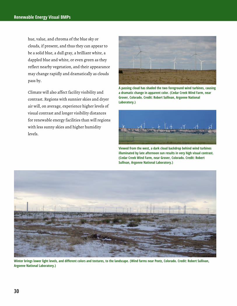
Renewable Energy Visual BMPs
30
hue, value, and chroma of the blue sky or
clouds, if present, and thus they can appear to
be a solid blue, a dull gray, a brilliant white, a
dappled blue and white, or even green as they
reflect nearby vegetation, and their appearance
may change rapidly and dramatically as clouds
pass by.
Climate will also affect facility visibility and
contrast. Regions with sunnier skies and dryer
air will, on average, experience higher levels of
visual contrast and longer visibility distances
for renewable energy facilities than will regions
with less sunny skies and higher humidity
levels.
A passing cloud has shaded the two foreground wind turbines, causing a dramatic change in apparent color. (Cedar Creek Wind Farm, near Grover, Colorado. Credit: Robert Sullivan, Argonne National Laboratory.)
Viewed from the west, a dark cloud backdrop behind wind turbines illuminated by late afternoon sun results in very high visual contrast. (Cedar Creek Wind Farm, near Grover, Colorado. Credit: Robert Sullivan, Argonne National Laboratory.)
Winter brings lower light levels, and different colors and textures, to the landscape. (Wind farms near Peetz, Colorado. Credit: Robert Sullivan, Argonne National Laboratory.)

Chapter 2: Visual Resources
31
2.2.2.8 Atmospheric Conditions
Water vapor (humidity) and particulate matter (dust,
air pollution, and other particles) within the air affect
visibility in multiple ways. Particulate matter scatters
and absorbs light coming from an object, which
diminishes contrast and subdues colors. The nature and
degree of these effects depends on particle type and
density, distance between the viewer and viewed object,
and lighting conditions, among other things.
Atmospheric conditions may affect an object’s visibility
through alterations of sharpness, brightness, and color,
and can have a substantial effect on project visibility,
especially at longer distances. On humid days with high
levels of dust or pollutants, distant facilities may not be
visible at all, or may be much harder to see, with
substantially lower contrast and indistinct structure
edges.
Atmospheric haze may substantially reduce visual contrast of facilities. (Ivanpah SEGS solar power towers, under construction, Ivanpah Valley, California. Credit: Robert Sullivan, Argonne National Laboratory.)
2.2.2.9 Object Visual Characteristics
The inherent visual characteristics of the viewed object
(e.g., a renewable energy facility) will obviously affect its
visibility and the level of visual contrast it creates. The
facility and structure size; the scale relative to other
objects in view; the form, line, surface colors, and
textures of the facility components; and any visible
motion of the facility components will all affect the
facility’s apparent visual contrast.
Size: Other things being equal, larger facilities
with larger structures will obviously show
increased visual contrasts relative to smaller
facilities. Depending on the distance and the
amount of the facility in view, a large wind
facility can cover a significant portion of the
horizontal field of view, even at long distances.
Solar facilities, while generally smaller in size,
are still quite large objects relative to what
humans normally encounter, and can occupy a
substantial portion of the field of view at
distances of several miles. Wind turbines and
power towers are likely to be much taller than
most other objects in BLM landscapes and may
seem out of scale with nearby objects in some
situations, which may tend to focus visual
attention on them.
Form and Line (Geometry): As noted in Section
2.2.1, because wind, solar, and geothermal
facilities typically have many rectilinear or
regularly curved components, they may
contrast strongly with the forms and lines of
predominantly natural landscapes.
Surface Color and Texture: The color and
surface texture of facility components can make
them stand out or blend in with the visual
backdrop. Darker colors tend to “recede” from
the viewer, and lighter colors to “advance,” so
that lighter colors may appear to be closer to the
viewer than darker background elements, and
may stand out against the background. Wind
turbines effectively must be painted white for
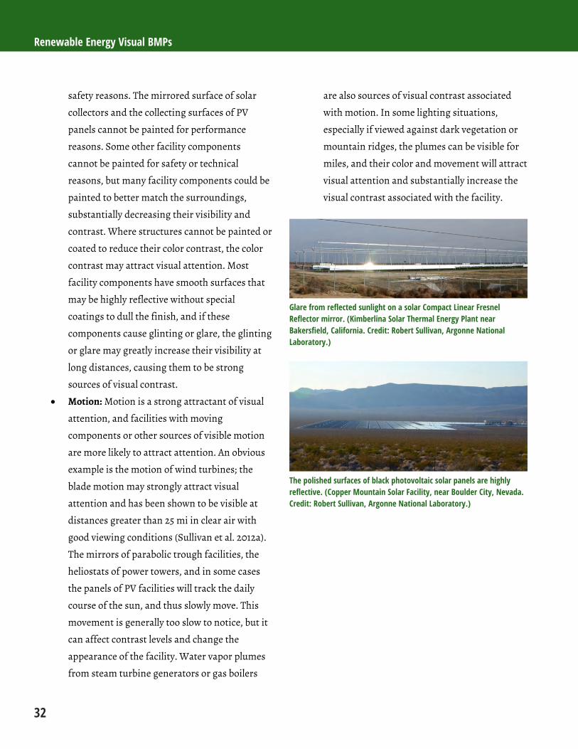
Renewable Energy Visual BMPs
32
safety reasons. The mirrored surface of solar
collectors and the collecting surfaces of PV
panels cannot be painted for performance
reasons. Some other facility components
cannot be painted for safety or technical
reasons, but many facility components could be
painted to better match the surroundings,
substantially decreasing their visibility and
contrast. Where structures cannot be painted or
coated to reduce their color contrast, the color
contrast may attract visual attention. Most
facility components have smooth surfaces that
may be highly reflective without special
coatings to dull the finish, and if these
components cause glinting or glare, the glinting
or glare may greatly increase their visibility at
long distances, causing them to be strong
sources of visual contrast.
Motion: Motion is a strong attractant of visual
attention, and facilities with moving
components or other sources of visible motion
are more likely to attract attention. An obvious
example is the motion of wind turbines; the
blade motion may strongly attract visual
attention and has been shown to be visible at
distances greater than 25 mi in clear air with
good viewing conditions (Sullivan et al. 2012a).
The mirrors of parabolic trough facilities, the
heliostats of power towers, and in some cases
the panels of PV facilities will track the daily
course of the sun, and thus slowly move. This
movement is generally too slow to notice, but it
can affect contrast levels and change the
appearance of the facility. Water vapor plumes
from steam turbine generators or gas boilers
are also sources of visual contrast associated
with motion. In some lighting situations,
especially if viewed against dark vegetation or
mountain ridges, the plumes can be visible for
miles, and their color and movement will attract
visual attention and substantially increase the
visual contrast associated with the facility.
Glare from reflected sunlight on a solar Compact Linear Fresnel Reflector mirror. (Kimberlina Solar Thermal Energy Plant near Bakersfield, California. Credit: Robert Sullivan, Argonne National Laboratory.)
The polished surfaces of black photovoltaic solar panels are highly reflective. (Copper Mountain Solar Facility, near Boulder City, Nevada. Credit: Robert Sullivan, Argonne National Laboratory.)

Chapter 2: Visual Resources
33
Sunlit white wind turbines may contrast strongly with blue skies and may be visible for long distances in open landscapes. (Wind energy project near Medicine Bow, Wyoming. Credit: Robert Sullivan, Argonne National Laboratory.)
References BLM (Bureau of Land Management), 1986a, Visual
Resource Inventory, BLM Manual Handbook 8410-1,
Release 8-28, U.S. Department of the Interior,
Washington, DC, Jan.
BLM, 1986b, Visual Resource Contrast Rating, BLM Manual
Handbook 8431-1, Release 8-30, U.S. Department of the
Interior, Washington, DC, Jan.
Hyslop, N.P., 2009, “Impaired Visibility: the Air
Pollution People See,” Atmospheric Environment 43: 182–
195. Available at
http://air.snu.ac.kr/journals/Hyslop_AE(2009).pdf.
Accessed Nov. 7, 2011.
Landscape Institute, 2002, Guidelines for Landscape and
Visual Impact Assessment, 2nd edition. Spon Press, Taylor
and Francis Group, New York, NY.
San Diego County, 2003, “Chapter 4.13 – Aesthetics,” in
Gregory Canyon Landfill, final EIR. State Clearinghouse
No. 1995061007. Available at
http://www.sdcounty.ca.gov/deh/waste/chd_gc_eir.htm
l#Decision Documents. Accessed June 6, 2011.
Saratoga Associates, 2008, New Grange Wind Farm Visual
Resource Assessment. Prepared for New Grange Wind
Farm, LLC, Feb. 2008. Available at
http://www.horizonwindfarms.com/northeast-
region/documents/under-
dev/arkwright/deis/Appendices/New%20Grange%20DE
IS_Feb08_AppF_Visual%20Resource%20Assmt.pdf.
Accessed June 3, 2011.
Sprawls, P., 1995, “Image Characteristics and Quality.”
In The Physical Principles of Medical Imaging, 2nd Edition.
Available at
http://www.sprawls.org/ppmi2/IMGCHAR/#Backgroun
d_Brightness.
Sullivan, R., et al., 2012a, Wind Turbine Visibility and
Visual Impact Threshold Distances in Western Landscapes.
Proceedings, National Association of Environmental
Professionals, 37th Annual Conference, May 21–24, 2012,
Portland, OR.
Sullivan, R., et al., 2012b, Visual Impacts of Utility-scale
Solar Energy Facilities on Southwestern Desert Landscapes,
National Association of Environmental Professionals,
37th Annual Conference, May 21–24, 2012, Portland, OR.


Chapter 1: Introduction
35
Introduction The following sections provide a discussion of the
general stages of utility-scale wind farm development,
as well as a summary of visual contrast sources and
effects by project phase.
Facility Life Cycle
In general, the development of a wind farm consists
of six stages, including planning/preliminary siting,
site evaluation, design/engineering, construction,
operations, and decommissioning. The following
discussion includes only the phases that involve
onsite activities that would lead to significant visual
contrasts: site evaluation, construction, operations,
and decommissioning and reclamation.
Site Evaluation Phase
Before a wind farm can be planned and built, the
wind regime at a potential site must be characterized
precisely. Meteorological monitoring towers, which
vary in height, are installed to transmit data on
weather conditions and wind speed, direction, and
shear on a continuous basis to a remote monitoring
facility. The data is used as the basis for a
“micrositing” strategy that places turbines on the site
in locations where maximum power production is
possible throughout the year.
Construction Phase
Throughout wind energy project construction, the
entire project area would be temporarily affected by
site preparation activities such as clearing;

Renewable Energy Visual BMPs
36
construction of access and onsite roads; preparation
and use of material and equipment laydown areas;
installation of turbine foundations; erection of
turbines; construction of the electrical substation,
central control facility, and ancillary facilities; and
installation of power and signal cables (typically
buried or vaulted). Concrete ingredients (sand,
aggregate) may also need to be extracted and hauled
to the site.
Operations Phase
No land-disturbing activities or associated impacts
would normally occur during the operations phase.
Routine operations include wind-driven operations of
the turbines to produce power, and regular
monitoring and maintenance activities to ensure safe
and consistent operation. Most monitoring would be
done remotely, but maintenance crews would be
present on regular shifts. In areas with significant
snowfall, roads might be snowplowed in the winter.
Decommissioning and Reclamation Phase
Decommissioning of a wind energy project would
include removal of turbines, buildings, concrete pads,
and foundations, as well as the excavation and
removal of buried components. Underground
components would be removed (generally to a depth
of at least 3 ft) to ensure an unobstructed root zone
for revegetation. More deeply buried components
might be abandoned in place. Following removal of
site components, site reclamation and revegetation
would mitigate some impacts, such as soil erosion,
habitat fragmentation, and visual impacts.
Visual Contrast Sources and Effects Summary by Project Phase
Site Evaluation Phase
Typical site evaluation activities include the
placement of one or more meteorological towers in or
near the proposed wind energy facility to collect one
or more years of meteorological data. Meteorological
towers are instrumented towers that vary in height
and appearance, but generally approximate the hub
height of the proposed wind turbine generators.
Multiple meteorological towers would be
interconnected with data collection and integration
equipment, usually contained in an enclosure
centrally located between the towers. Meteorological
towers are typically metal (galvanized or painted),
lattice-type structures; however, composite materials
are also used sometimes, as are smooth-skinned
materials. Meteorological towers may be guyed or
self-supporting; on guyed meteorological towers, guy
wires could be visible depending on distance, and
depending on the presence of bird diverters.
Aviation warning lights would be required for
meteorological towers more than 200 ft (60.9 m) tall;
normally these would be red flashing lights
(FAA 2007).
Vehicles and workers would be seen during tower
construction, and vehicles and workers might
occasionally be seen at the tower for maintenance
activities, but these activities would be rare.
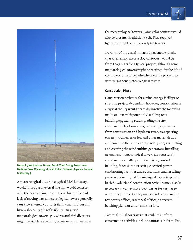
Chapter 3: Wind
37
Meterological tower at Dunlap Ranch Wind Energy Project near Medicine Bow, Wyoming. (Credit: Robert Sullivan, Argonne National Laboratory.)
A meteorological tower in a typical BLM landscape
would introduce a vertical line that would contrast
with the horizon line. Due to their thin profile and
lack of moving parts, meteorological towers generally
cause lower visual contrasts than wind turbines and
have a shorter radius of visibility. On guyed
meteorological towers, guy wires and bird diverters
might be visible, depending on viewer distance from
the meteorological towers. Some color contrast would
also be present, in addition to the FAA-required
lighting at night on sufficiently tall towers.
Duration of the visual impacts associated with site
characterization meteorological towers would be
from 1 to 3 years for a typical project, although some
meteorological towers might be retained for the life of
the project, or replaced elsewhere on the project site
with permanent meteorological towers.
Construction Phase
Construction activities for a wind energy facility are
site- and project-dependent; however, construction of
a typical facility would normally involve the following
major actions with potential visual impacts:
building/upgrading roads; grading the site;
constructing laydown areas; removing vegetation
from construction and laydown areas; transporting
towers, turbines, nacelles, and other materials and
equipment to the wind energy facility site; assembling
and erecting the wind turbine generators; installing
permanent meteorological towers (as necessary);
constructing ancillary structures (e.g., control
building, fences); constructing electrical power
conditioning facilities and substations; and installing
power-conducting cables and signal cables (typically
buried). Additional construction activities may also be
necessary at very remote locations or for very large
wind energy projects; they may include constructing
temporary offices, sanitary facilities, a concrete
batching plant, or a transmission line.
Potential visual contrasts that could result from
construction activities include contrasts in form, line,

Renewable Energy Visual BMPs
38
color, and texture resulting from vegetation clearing
and grading (with associated debris); road
building/upgrading; construction and use of staging
and laydown areas; wind turbine generator, electric
transmission, and support facility construction;
vehicular, equipment, and worker presence and
activity; dust; and emissions.
Unloading a wind turbine blade. (Milford Wind Corridor project, near Milford, Utah. Credit: BLM.)
Partially erected turbine, with nacelle and hub visible at right center. (Near Peetz, Colorado. Credit: Robert Sullivan, Argonne National Laboratory.)
Construction visual contrasts would vary in frequency
and duration throughout the course of construction;
there may be periods of intense activity followed by
periods with less activity, and associated visual
impacts would to some degree vary in accordance
with construction activity levels. Construction
schedules are project dependent. While many projects
might be completed within 1 year, larger projects may
take longer and could involve phased development,
with construction-related visual impacts therefore
lasting longer.
Operations Phase
Visual impacts associated with wind facility
operations include the presence of wind turbines,
control buildings, and other ancillary structures;
movement of the rotor blades; shadow flicker and
blade glinting; turbine marker lights and other
lighting on control buildings and other ancillary
structures; roads; vehicles; and workers conducting
maintenance activities.
Wind Turbines
The major visible components of a wind turbine
include the following:
Tower: Wind turbine towers typically consist of large,
tubular steel pieces that support the nacelle and rotor
hub. Heights vary, but as an example, a modern
3.0-MW tower may be nearly 400 ft tall, with a trend
toward increasing height.
Nacelle: An enclosure atop the tower that houses the
controller, gearbox, generator, and shafts. It typically
is equipped with an anemometer and wind vane,
which may be visible at short distances.
Rotor: The rotor consists of the blades and the hub.
Hub: The junction of the blades and the rotor
shaft, covered with a protective nose cone.
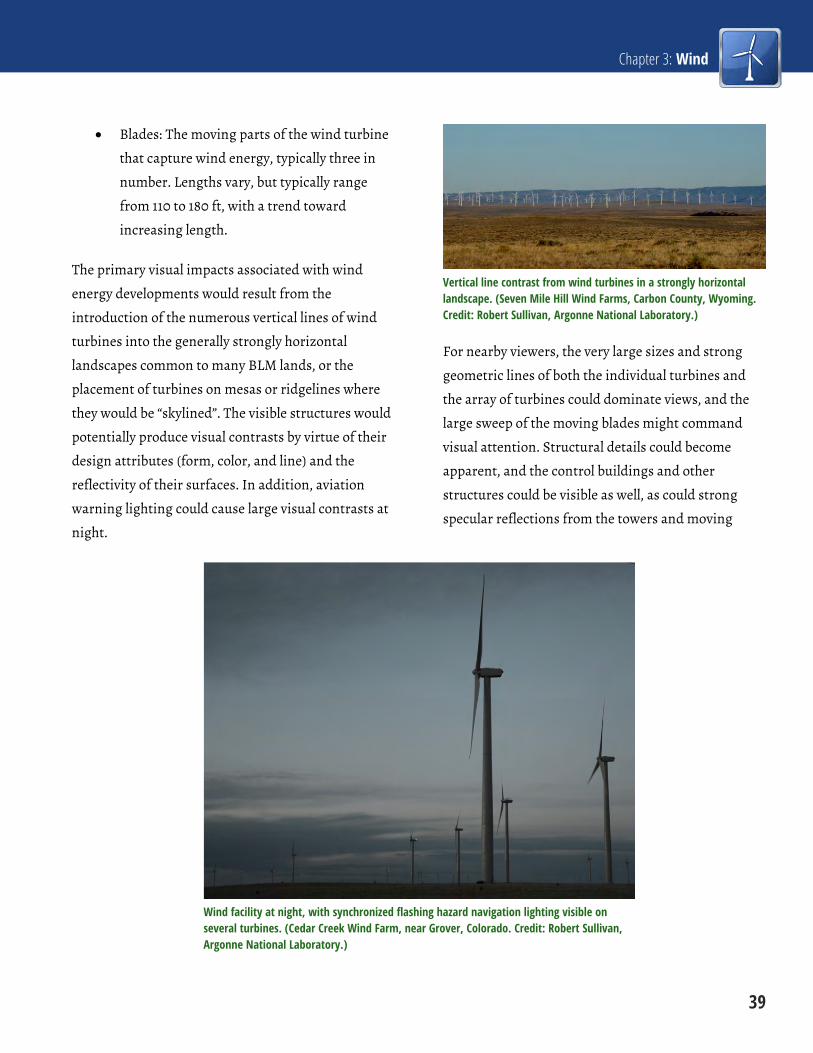
Chapter 3: Wind
39
Blades: The moving parts of the wind turbine
that capture wind energy, typically three in
number. Lengths vary, but typically range
from 110 to 180 ft, with a trend toward
increasing length.
The primary visual impacts associated with wind
energy developments would result from the
introduction of the numerous vertical lines of wind
turbines into the generally strongly horizontal
landscapes common to many BLM lands, or the
placement of turbines on mesas or ridgelines where
they would be “skylined”. The visible structures would
potentially produce visual contrasts by virtue of their
design attributes (form, color, and line) and the
reflectivity of their surfaces. In addition, aviation
warning lighting could cause large visual contrasts at
night.
Vertical line contrast from wind turbines in a strongly horizontal landscape. (Seven Mile Hill Wind Farms, Carbon County, Wyoming. Credit: Robert Sullivan, Argonne National Laboratory.)
For nearby viewers, the very large sizes and strong
geometric lines of both the individual turbines and
the array of turbines could dominate views, and the
large sweep of the moving blades might command
visual attention. Structural details could become
apparent, and the control buildings and other
structures could be visible as well, as could strong
specular reflections from the towers and moving
Wind facility at night, with synchronized flashing hazard navigation lighting visible on several turbines. (Cedar Creek Wind Farm, near Grover, Colorado. Credit: Robert Sullivan, Argonne National Laboratory.)
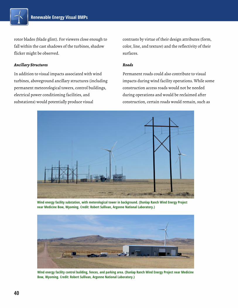
Renewable Energy Visual BMPs
40
rotor blades (blade glint). For viewers close enough to
fall within the cast shadows of the turbines, shadow
flicker might be observed.
Ancillary Structures
In addition to visual impacts associated with wind
turbines, aboveground ancillary structures (including
permanent meteorological towers, control buildings,
electrical power conditioning facilities, and
substations) would potentially produce visual
contrasts by virtue of their design attributes (form,
color, line, and texture) and the reflectivity of their
surfaces.
Roads
Permanent roads could also contribute to visual
impacts during wind facility operations. While some
construction access roads would not be needed
during operations and would be reclaimed after
construction, certain roads would remain, such as
Wind energy facility substation, with meterological tower in background. (Dunlap Ranch Wind Energy Project near Medicine Bow, Wyoming. Credit: Robert Sullivan, Argonne National Laboratory.)
Wind energy facility control building, fences, and parking area. (Dunlap Ranch Wind Energy Project near Medicine Bow, Wyoming. Credit: Robert Sullivan, Argonne National Laboratory.)
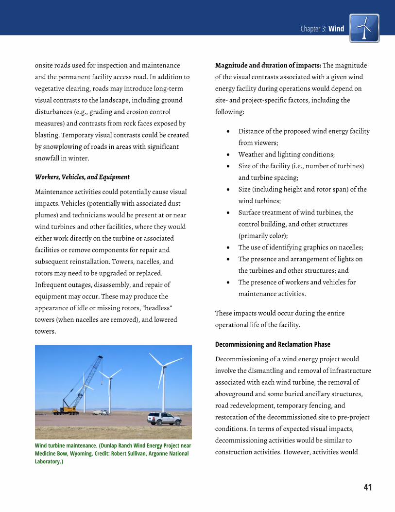
Chapter 3: Wind
41
onsite roads used for inspection and maintenance
and the permanent facility access road. In addition to
vegetative clearing, roads may introduce long-term
visual contrasts to the landscape, including ground
disturbances (e.g., grading and erosion control
measures) and contrasts from rock faces exposed by
blasting. Temporary visual contrasts could be created
by snowplowing of roads in areas with significant
snowfall in winter.
Workers, Vehicles, and Equipment
Maintenance activities could potentially cause visual
impacts. Vehicles (potentially with associated dust
plumes) and technicians would be present at or near
wind turbines and other facilities, where they would
either work directly on the turbine or associated
facilities or remove components for repair and
subsequent reinstallation. Towers, nacelles, and
rotors may need to be upgraded or replaced.
Infrequent outages, disassembly, and repair of
equipment may occur. These may produce the
appearance of idle or missing rotors, “headless”
towers (when nacelles are removed), and lowered
towers.
Wind turbine maintenance. (Dunlap Ranch Wind Energy Project near Medicine Bow, Wyoming. Credit: Robert Sullivan, Argonne National Laboratory.)
Magnitude and duration of impacts: The magnitude
of the visual contrasts associated with a given wind
energy facility during operations would depend on
site- and project-specific factors, including the
following:
Distance of the proposed wind energy facility
from viewers;
Weather and lighting conditions;
Size of the facility (i.e., number of turbines)
and turbine spacing;
Size (including height and rotor span) of the
wind turbines;
Surface treatment of wind turbines, the
control building, and other structures
(primarily color);
The use of identifying graphics on nacelles;
The presence and arrangement of lights on
the turbines and other structures; and
The presence of workers and vehicles for
maintenance activities.
These impacts would occur during the entire
operational life of the facility.
Decommissioning and Reclamation Phase
Decommissioning of a wind energy project would
involve the dismantling and removal of infrastructure
associated with each wind turbine, the removal of
aboveground and some buried ancillary structures,
road redevelopment, temporary fencing, and
restoration of the decommissioned site to pre-project
conditions. In terms of expected visual impacts,
decommissioning activities would be similar to
construction activities. However, activities would

Renewable Energy Visual BMPs
42
generally proceed in reverse order from construction
and would proceed more quickly than during
construction; thus, the associated impacts would last
for a shorter time.
Restoration activities would include recontouring,
grading, scarifying, seeding and planting, and
stabilizing disturbed surfaces. Newly disturbed soils
would create a visual contrast that could persist for
several seasons before revegetation would begin to
disguise past activity. Restoration of vegetation to
pre-project conditions may take much longer.
Invasive species may colonize recently reclaimed
areas. These species may be introduced naturally or in
seeds, plants, or soils introduced for intermediate
restoration, or by vehicles. Non-native plants that are
not locally adapted would likely produce contrasts of
color, form, texture, and line.
Similarly to construction, the various
decommissioning activities described above require
work crews, vehicles, and equipment that would add
to visual impacts during decommissioning.
References FAA (Federal Aviation Administration), 2007,
Obstruction Marking and Lighting, Advisory Circular AC
70/7460-1K, Feb. Available at
http://rgl.faa.gov/Regulatory_and_Guidance_Library/
rgAdvisoryCircular.nsf/0/b993dcdfc37fcdc4862572510
05c4e21/$FILE. Accessed Sept. 24, 2012.
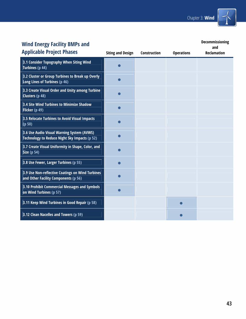
Chapter 3: Wind
43
Wind Energy Facility BMPs and Applicable Project Phases Siting and Design Construction Operations
Decommissioning and
Reclamation
3.1 Consider Topography When Siting Wind Turbines (p 44)
3.2 Cluster or Group Turbines to Break up Overly Long Lines of Turbines (p 46)
3.3 Create Visual Order and Unity among Turbine Clusters (p 48)
3.4 Site Wind Turbines to Minimize Shadow Flicker (p 49)
3.5 Relocate Turbines to Avoid Visual Impacts (p 50)
3.6 Use Audio Visual Warning System (AVWS) Technology to Reduce Night Sky Impacts (p 52)
3.7 Create Visual Uniformity in Shape, Color, and Size (p 54)
3.8 Use Fewer, Larger Turbines (p 55)
3.9 Use Non-reflective Coatings on Wind Turbines and Other Facility Components (p 56)
3.10 Prohibit Commercial Messages and Symbols on Wind Turbines (p 57)
3.11 Keep Wind Turbines in Good Repair (p 58)
3.12 Clean Nacelles and Towers (p 59)

Renewable Energy Visual BMPs
44 3.1 Consider Topography When Siting Wind Turbines
3.1 Consider Topography When Siting Wind Turbines Project Phase: Siting and Design
During the facility design process, wind turbine siting should be sensitive to, and respond to, the
surrounding landscape in a visually pleasing way. Avoid major modifications to natural landforms, roads,
water bodies, structures, or other characteristic parts of the landscape.
Non-linear turbine configurations are better suited to rolling terrain. (Spanish Fork Wind Farm, Utah. Credit: NREL.)
Linear turbine configuration in flat agricultural landscape. (Big Horn Wind Farm near Bickleton, Washington. Credit: NREL.)
Notes For example, in rolling landscapes, a less rectilinear and rigid configuration of wind turbines that follows
local topography may be appropriate. In flatter, agricultural landscapes with rectilinear patterns of roads
and fields, a more geometric or linear wind turbine configuration may be preferred. Where possible, the
nacelles should be kept at a constant height relative to the ground. Consideration should be given to the
appearance of the project at night, when the aircraft warning lights will create a strong horizontal line
above the ground. Computer modeling can be an effective tool to study the relationship between the
turbines and topography.
Limitations Wind farm efficiency (and therefore profitability) depends, in part, on precise turbine siting, based on local
topography, the local wind regime, and other technical factors. Micro-siting may reflect concerns for small-
scale components of the landscape, both cultural and environmental. Therefore, developers may be

Chapter 3: Wind
3.1 Consider Topography When Siting Wind Turbines 45
reluctant to site turbines in response to potential visual impacts, except where visual values are considered
a critical concern.
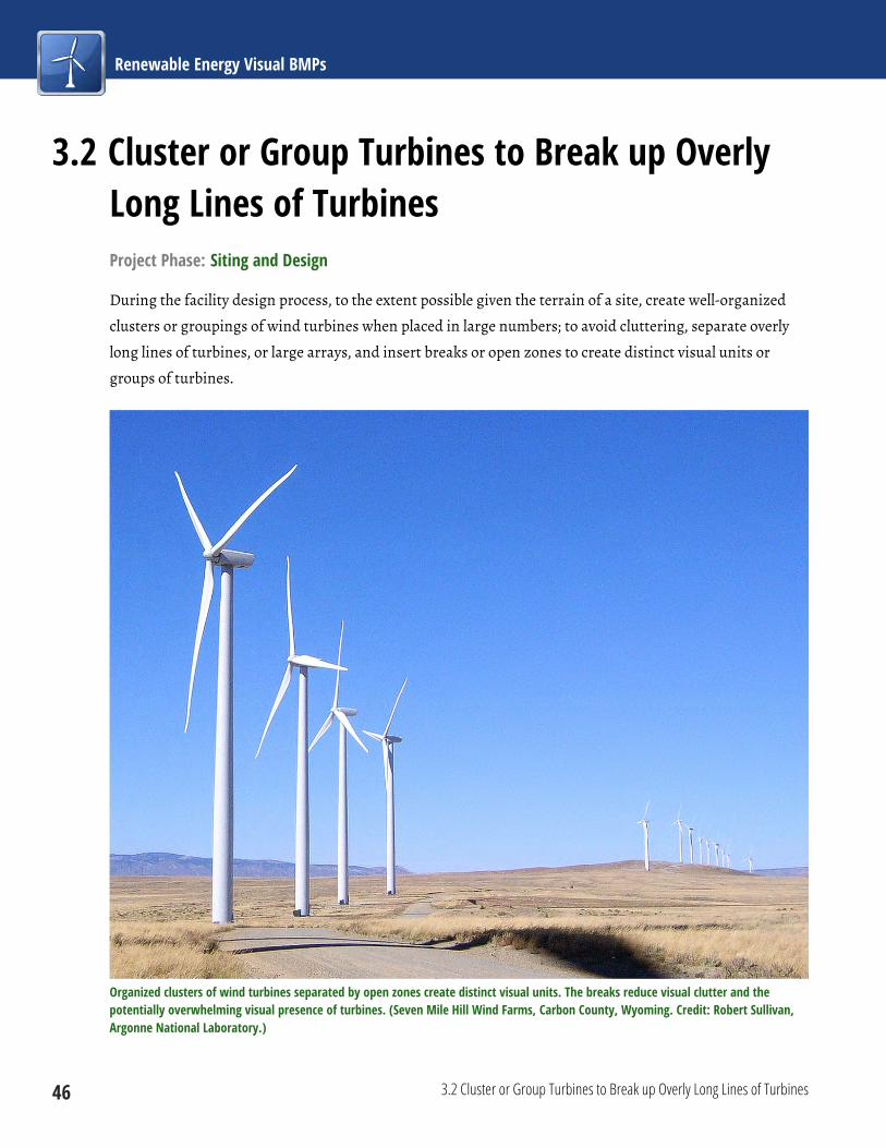
Renewable Energy Visual BMPs
46 3.2 Cluster or Group Turbines to Break up Overly Long Lines of Turbines
3.2 Cluster or Group Turbines to Break up Overly Long Lines of Turbines Project Phase: Siting and Design
During the facility design process, to the extent possible given the terrain of a site, create well-organized
clusters or groupings of wind turbines when placed in large numbers; to avoid cluttering, separate overly
long lines of turbines, or large arrays, and insert breaks or open zones to create distinct visual units or
groups of turbines.
Organized clusters of wind turbines separated by open zones create distinct visual units. The breaks reduce visual clutter and the potentially overwhelming visual presence of turbines. (Seven Mile Hill Wind Farms, Carbon County, Wyoming. Credit: Robert Sullivan, Argonne National Laboratory.)

Chapter 3: Wind
3.2 Cluster or Group Turbines to Break up Overly Long Lines of Turbines 47
Notes When siting large numbers of turbines, developers may be able to relieve visual clutter or a potentially
overwhelming visual presence of turbines by clustering turbines to create visual breaks.
Limitations Because engineering and other technical considerations are the primary drivers for decisions about wind
turbine locations, clustering may be impractical in some cases; in other cases, local topography may make
clustering ineffective for reducing visual impacts. In some situations, turbine clustering could increase the
lengths of the conductors needed to bring current to a central power control facility, which would involve
increased cost.

Renewable Energy Visual BMPs
48 3.3 Create Visual Order and Unity among Turbine Clusters
3.3 Create Visual Order and Unity among Turbine Clusters Project Phase: Siting and Design
The operator should create visual order and unity among clusters of turbines (visual units) to avoid visual
disruptions and perceived disorder, disarray, or clutter.
This array of turbines lacks visual order and unity, and appears cluttered. (Wind farm near Peetz, Colorado. Credit: Robert Sullivan, Argonne National Laboratory.)
Notes Large numbers of turbines in a visually disordered and apparently random array may appear to be visually
cluttered and have an overwhelming visual presence.
Limitations Wind farm efficiency (and therefore profitability) depends, in part, on precise siting of individual turbines
and turbine strings, based on local topography, the local wind regime, and other technical factors. As a
result, siting flexibility may be constrained, and developers may thus be reluctant to site turbines in
response to potential visual impacts, except where visual values are considered a critical concern. In
addition, perceived order in the turbine array is partially dependent on viewer location and viewing angle
with respect to the turbine array. Furthermore, where multiple, visually overlapping wind facilities are
visible from one observation point, some level of perceived disorder or clutter is almost inevitable.
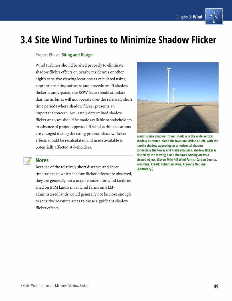
Chapter 3: Wind
3.4 Site Wind Turbines to Minimize Shadow Flicker 49
3.4 Site Wind Turbines to Minimize Shadow Flicker Project Phase: Siting and Design
Wind turbines should be sited properly to eliminate
shadow flicker effects on nearby residences or other
highly sensitive viewing locations as calculated using
appropriate siting software and procedures. If shadow
flicker is anticipated, the ROW lease should stipulate
that the turbines will not operate over the relatively short
time periods where shadow flicker presents an
important concern. Accurately determined shadow
flicker analyses should be made available to stakeholders
in advance of project approval. If wind turbine locations
are changed during the siting process, shadow flicker
effects should be recalculated and made available to
potentially affected stakeholders.
Notes Because of the relatively short distance and short
timeframes in which shadow flicker effects are observed,
they are generally not a major concern for wind facilities
sited on BLM lands; most wind farms on BLM-
administered lands would generally not be close enough
to sensitive resource areas to cause significant shadow
flicker effects.
Wind turbine shadow. Tower shadow is the wide vertical shadow at center, blade shadows are visible at left, with the nacelle shadow appearing as a horizontal shadow connecting the tower and blade shadows. Shadow flicker is caused by the moving blade shadows passing across a viewed object. (Seven Mile Hill Wind Farms, Carbon County, Wyoming. Credit: Robert Sullivan, Argonne National Laboratory.)
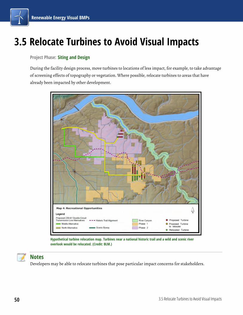
Renewable Energy Visual BMPs
50 3.5 Relocate Turbines to Avoid Visual Impacts
3.5 Relocate Turbines to Avoid Visual Impacts Project Phase: Siting and Design
During the facility design process, move turbines to locations of less impact, for example, to take advantage
of screening effects of topography or vegetation. Where possible, relocate turbines to areas that have
already been impacted by other development.
Hypothetical turbine relocation map. Turbines near a national historic trail and a wild and scenic river overlook would be relocated. (Credit: BLM.)
Notes Developers may be able to relocate turbines that pose particular impact concerns for stakeholders.

Chapter 3: Wind
3.5 Relocate Turbines to Avoid Visual Impacts 51
Limitations Wind farm efficiency (and therefore profitability) depends, in part, on precise siting of the turbines.
Therefore, developers may be reluctant to relocate turbines in response to potential visual impacts, except
where visual values are considered a critical concern. Furthermore, landscapes suitable for wind energy
development on BLM-administered lands typically lack sufficient topographic relief or vegetation tall
enough to screen wind turbines effectively.
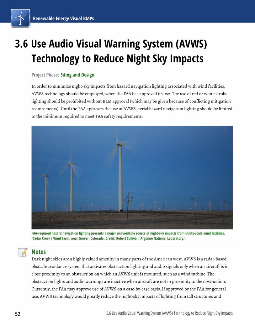
Renewable Energy Visual BMPs
52 3.6 Use Audio Visual Warning System (AVWS) Technology to Reduce Night Sky Impacts
3.6 Use Audio Visual Warning System (AVWS) Technology to Reduce Night Sky Impacts Project Phase: Siting and Design
In order to minimize night-sky impacts from hazard navigation lighting associated with wind facilities,
AVWS technology should be employed, when the FAA has approved its use. The use of red or white strobe
lighting should be prohibited without BLM approval (which may be given because of conflicting mitigation
requirements). Until the FAA approves the use of AVWS, aerial hazard navigation lighting should be limited
to the minimum required to meet FAA safety requirements.
FAA-required hazard navigation lighting presents a major unavoidable source of night-sky impacts from utility-scale wind facilities. (Cedar Creek I Wind Farm, near Grover, Colorado. Credit: Robert Sullivan, Argonne National Laboratory.)
Notes Dark night skies are a highly valued amenity in many parts of the American west. AVWS is a radar-based
obstacle avoidance system that activates obstruction lighting and audio signals only when an aircraft is in
close proximity to an obstruction on which an AVWS unit is mounted, such as a wind turbine. The
obstruction lights and audio warnings are inactive when aircraft are not in proximity to the obstruction.
Currently, the FAA may approve use of AVWS on a case-by-case basis. If approved by the FAA for general
use, AVWS technology would greatly reduce the night-sky impacts of lighting from tall structures and

Chapter 3: Wind
3.6 Use Audio Visual Warning System (AVWS) Technology to Reduce Night Sky Impacts 53
would also reduce avian mortality. Visual resource impact analysts and developers are encouraged to
remain current on the status of FAA approval.
Limitations As of the publication date, the use of AVWS technology for any structures other than communication
towers is under FAA evaluation. In the interim, projects proposing the use of AVWS technology are
reviewed on a case-by-case basis until the FAA makes a final determination on suitability. FAA approval of
the technology for utility-scale wind projects is anticipated in the near future; however, its use might not be
appropriate for all locations (e.g., near airports).

Renewable Energy Visual BMPs
54 3.7 Create Visual Uniformity in Shape, Color, and Size
3.7 Create Visual Uniformity in Shape, Color, and Size Project Phase: Siting and Design
If multiple turbine types are to be used in a single facility, developers should be encouraged to create visual
uniformity in the shape and size of blades, nacelles, and towers. Where multiple types are used in a project,
similar turbine designs should be grouped together and separated from dissimilar models to lessen the
perceived contrasts in height or appearance.
Multiple wind turbine models in close proximity add to the visual clutter in this view. (Tehachapi Pass Wind Farm, Kern County, California. Credit: David Hicks, NREL.)
Notes Multi-phase wind energy developments may occasionally utilize more than one turbine type. Developers
should be encouraged to use turbine designs that are as similar as possible in their visual characteristics,
because a uniform appearance is generally more pleasing.
Limitations Developers would normally be expected to use a single turbine type for a given project; however, because
engineering and other technical, cost, and supply considerations drive decisions about wind turbine
selection, developers may not always be able to use similar turbines.

Chapter 3: Wind
3.8 Use Fewer, Larger Turbines 55
3.8 Use Fewer, Larger Turbines Project Phase: Siting and Design
Downsize the facility by eliminating certain turbines to reduce
visual impacts. Use fewer, larger turbines to achieve desired
power output in preference to using a greater number of smaller
turbines.
Notes In some instances, a few larger turbines may result in a better
visual outcome than a greater number of smaller turbines.
Developers may be able to eliminate turbines that pose particular
impact concerns for stakeholders (e.g., turbines prominently
visible from a historic trail or residential area).
Limitations Because engineering and other technical, cost, and supply
considerations drive decisions about wind turbine selection, it
may be impractical for developers to use fewer turbines in some
cases, based solely on potential visual impacts. Increasing
turbine height may increase shadow flicker effects (see BMP 3.4)
and could accentuate scale differences between the turbines and
elements in the surrounding landscape.
In some instances, a few larger turbines may result in a better visual outcome than a greater number of smaller turbines. (Credit: Lindsey Utter, Argonne National Laboratory.)

Renewable Energy Visual BMPs
56 3.9 Use Non-reflective Coatings on Wind Turbines and Other Facility Components
3.9 Use Non-reflective Coatings on Wind Turbines and Other Facility Components Project Phase: Siting and Design
Where feasible, non-reflective paints and coatings should be
used on wind turbines, visible ancillary structures, and other
equipment to reduce reflection and glare. Turbines, visible
ancillary structures, and other equipment should be painted
before or immediately after installation. Uncoated galvanized
metallic surfaces should be avoided because they may create a
stronger visual contrast.
Notes BLM-sponsored research has shown that wind turbines may be
visible for very long distances, and reflections from untreated
surfaces can increase visibility and cause blade glinting (brief
flashes of reflected light) as the observer moves, or as wind
turbine blades move. Using non-reflective paints and coatings
reduces glinting and decreases the visual impact of the turbines
in the landscape. Certain wind facility ancillary components
may be treated with non-reflective coatings or colors selected to
blend in with their immediate surroundings, for example,
security fencing, substation components, and operations and
maintenance buildings.
Limitations Non-reflective paints and coatings may not be available for some
pre-manufactured facility components. Wind turbines are not
painted after erection, and the use of radar-absorbing materials on turbines (where applied) may preclude
the use of non-reflective coatings. It may be difficult for the wind farm developer to control the appearance
of equipment on substations owned by third parties.
Blade glinting near hub of turbine at left. These bright flashes from sunlight falling on the reflective surface of the blade have been observed at distances exceeding 15 mi, and can increase turbine visibility considerably. (Cedar Creek 1 Wind Farm, near Grover, Colorado. Credit: Robert Sullivan, Argonne National Laboratory.)
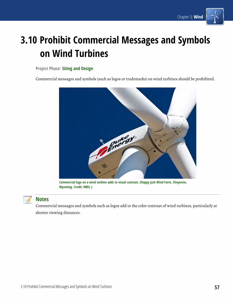
Chapter 3: Wind
3.10 Prohibit Commercial Messages and Symbols on Wind Turbines 57
3.10 Prohibit Commercial Messages and Symbols on Wind Turbines
Project Phase: Siting and Design
Commercial messages and symbols (such as logos or trademarks) on wind turbines should be prohibited.
Commercial logo on a wind turbine adds to visual contrast. (Happy Jack Wind Farm, Cheyenne, Wyoming. Credit: NREL.)
Notes Commercial messages and symbols such as logos add to the color contrast of wind turbines, particularly at
shorter viewing distances.
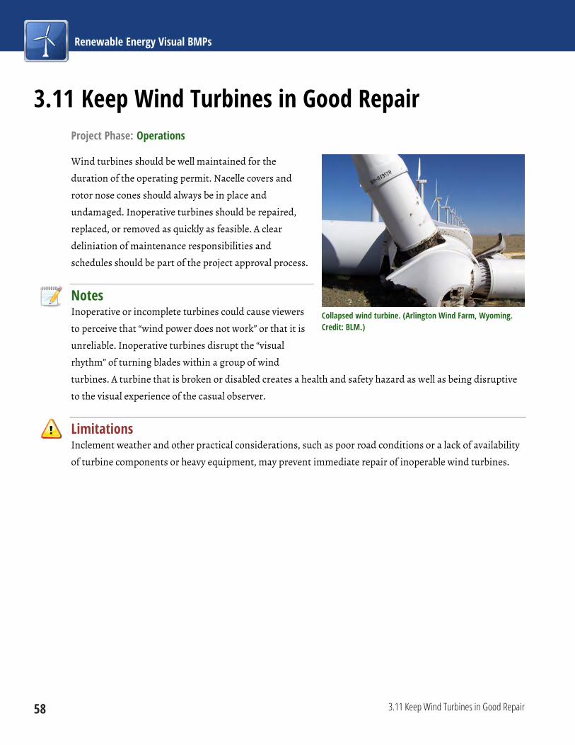
Renewable Energy Visual BMPs
58 3.11 Keep Wind Turbines in Good Repair
3.11 Keep Wind Turbines in Good Repair Project Phase: Operations
Wind turbines should be well maintained for the
duration of the operating permit. Nacelle covers and
rotor nose cones should always be in place and
undamaged. Inoperative turbines should be repaired,
replaced, or removed as quickly as feasible. A clear
deliniation of maintenance responsibilities and
schedules should be part of the project approval process.
Notes Inoperative or incomplete turbines could cause viewers
to perceive that “wind power does not work” or that it is
unreliable. Inoperative turbines disrupt the “visual
rhythm” of turning blades within a group of wind
turbines. A turbine that is broken or disabled creates a health and safety hazard as well as being disruptive
to the visual experience of the casual observer.
Limitations Inclement weather and other practical considerations, such as poor road conditions or a lack of availability
of turbine components or heavy equipment, may prevent immediate repair of inoperable wind turbines.
Collapsed wind turbine. (Arlington Wind Farm, Wyoming. Credit: BLM.)

Chapter 3: Wind
3.12 Clean Nacelles and Towers 59
3.12 Clean Nacelles and Towers Project Phase: Operations
Nacelles and towers should be cleaned to remove any spilled or
leaking fluids and the dirt and dust that would accumulate on
them.
Notes Cleaning nacelles and towers improves their appearance and
reduces the potential for negative public perception of the wind
energy facility and the operating company.
Cleaning leaking fluid from a wind turbine. (Credit: TGM Wind Services)


61
Introduction The following sections provide a discussion of the
general stages of utility-scale solar facility
development, a summary of visual contrast sources
and effects by project phase, and summaries of
technology-specific visual impacts.
Facility Life Cycle
In general, the development of a solar facility consists
of six stages, including planning/preliminary siting,
site evaluation, design/engineering, construction,
operation, and decommissioning. The following
discussion includes only the phases that involve
onsite activities that would lead to significant visual
contrasts: site evaluation, construction, operations,
and decommissioning and reclamation.
Site Evaluation Phase
During the site evaluation phase, a geotechnical
survey would evaluate general surface conditions,
subsurface conditions, seismicity, and other
geological information required to develop
recommendations for the design and construction of
project components (e.g., type of foundations
required to support the solar collectors). The
geotechnical survey would require soil borings.
Onsite monitoring/sampling wells and associated
impoundments for well drilling fluids and cuttings
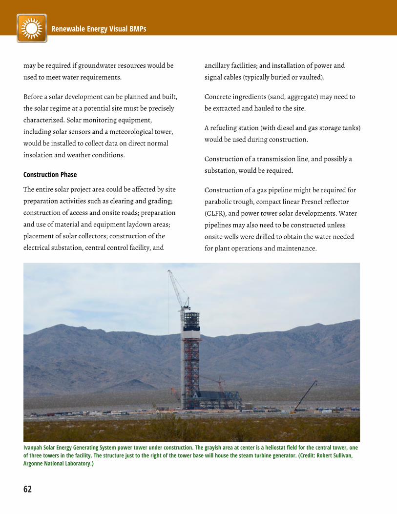
Renewable Energy Visual BMPs
62
may be required if groundwater resources would be
used to meet water requirements.
Before a solar development can be planned and built,
the solar regime at a potential site must be precisely
characterized. Solar monitoring equipment,
including solar sensors and a meteorological tower,
would be installed to collect data on direct normal
insolation and weather conditions.
Construction Phase
The entire solar project area could be affected by site
preparation activities such as clearing and grading;
construction of access and onsite roads; preparation
and use of material and equipment laydown areas;
placement of solar collectors; construction of the
electrical substation, central control facility, and
ancillary facilities; and installation of power and
signal cables (typically buried or vaulted).
Concrete ingredients (sand, aggregate) may need to
be extracted and hauled to the site.
A refueling station (with diesel and gas storage tanks)
would be used during construction.
Construction of a transmission line, and possibly a
substation, would be required.
Construction of a gas pipeline might be required for
parabolic trough, compact linear Fresnel reflector
(CLFR), and power tower solar developments. Water
pipelines may also need to be constructed unless
onsite wells were drilled to obtain the water needed
for plant operations and maintenance.
Ivanpah Solar Energy Generating System power tower under construction. The grayish area at center is a heliostat field for the central tower, one of three towers in the facility. The structure just to the right of the tower base will house the steam turbine generator. (Credit: Robert Sullivan, Argonne National Laboratory.)
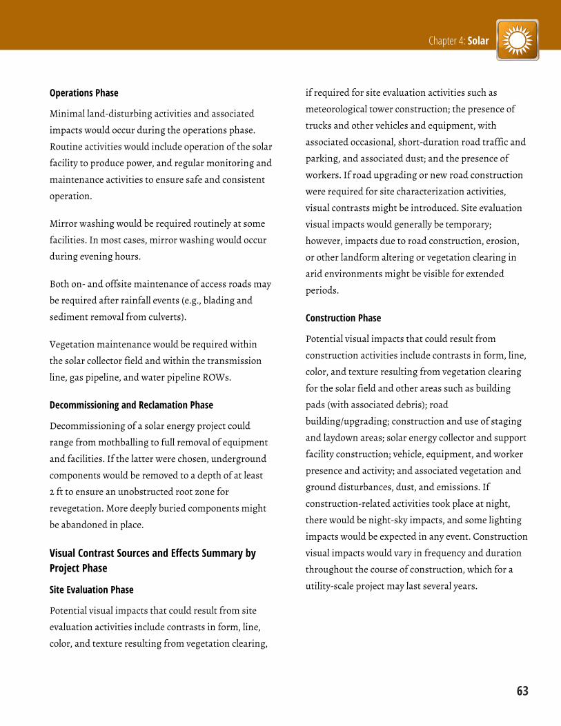
Chapter 4: Solar
63
Operations Phase
Minimal land-disturbing activities and associated
impacts would occur during the operations phase.
Routine activities would include operation of the solar
facility to produce power, and regular monitoring and
maintenance activities to ensure safe and consistent
operation.
Mirror washing would be required routinely at some
facilities. In most cases, mirror washing would occur
during evening hours.
Both on- and offsite maintenance of access roads may
be required after rainfall events (e.g., blading and
sediment removal from culverts).
Vegetation maintenance would be required within
the solar collector field and within the transmission
line, gas pipeline, and water pipeline ROWs.
Decommissioning and Reclamation Phase
Decommissioning of a solar energy project could
range from mothballing to full removal of equipment
and facilities. If the latter were chosen, underground
components would be removed to a depth of at least
2 ft to ensure an unobstructed root zone for
revegetation. More deeply buried components might
be abandoned in place.
Visual Contrast Sources and Effects Summary by Project Phase
Site Evaluation Phase
Potential visual impacts that could result from site
evaluation activities include contrasts in form, line,
color, and texture resulting from vegetation clearing,
if required for site evaluation activities such as
meteorological tower construction; the presence of
trucks and other vehicles and equipment, with
associated occasional, short-duration road traffic and
parking, and associated dust; and the presence of
workers. If road upgrading or new road construction
were required for site characterization activities,
visual contrasts might be introduced. Site evaluation
visual impacts would generally be temporary;
however, impacts due to road construction, erosion,
or other landform altering or vegetation clearing in
arid environments might be visible for extended
periods.
Construction Phase
Potential visual impacts that could result from
construction activities include contrasts in form, line,
color, and texture resulting from vegetation clearing
for the solar field and other areas such as building
pads (with associated debris); road
building/upgrading; construction and use of staging
and laydown areas; solar energy collector and support
facility construction; vehicle, equipment, and worker
presence and activity; and associated vegetation and
ground disturbances, dust, and emissions. If
construction-related activities took place at night,
there would be night-sky impacts, and some lighting
impacts would be expected in any event. Construction
visual impacts would vary in frequency and duration
throughout the course of construction, which for a
utility-scale project may last several years.

Renewable Energy Visual BMPs
64
Antelope Valley Solar Ranch thin-film PV facility under construction. Fixed (non-tracking) mounts for the PV panels have been installed, and await the panels. Note complete clearing of vegetation and leveling of ground underneath the collectors. (Credit: Robert Sullivan, Argonne National Laboratory.)
Operations Phase
Visual impacts associated with solar facility
operations include the presence of the cleared solar
field, the presence of the solar collector array and
supporting infrastructure, control buildings, and
other ancillary buildings and structures; glare,
glinting, and other reflections from the solar array
and ancillary facilities; lighting on ancillary buildings
and structures; roads; vehicles; and workers
conducting maintenance activities, which if
conducted at night would require lighting.
The operation and maintenance of solar energy
projects and associated electricity transmission lines,
roads, and ROWs would potentially have substantial
long-term visual effects. Some impacts are common
to all utility-scale solar energy projects, regardless of
solar technology employed; however, the solar energy
collectors and associated structures differ in terms of
visual impacts. Power tower projects generally have
larger visual impacts than the other technologies
because of the relatively tall and brightly illuminated
receiver towers. Photovoltaic (PV) projects generally
have lower visual impacts than the other technologies
because of the low profile of the collector arrays and
the lower reflectivity of the PV panels compared to the
highly reflective mirrors used by the other
technologies. However, all utility-scale solar facilities
could create strong visual contrasts for nearby
viewers. The following discussion includes impacts
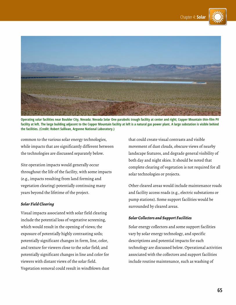
Chapter 4: Solar
65
Operating solar facilities near Boulder City, Nevada: Nevada Solar One parabolic trough facility at center and right; Copper Mountain thin-film PV facility at left. The large building adjacent to the Copper Mountain facility at left is a natural gas power plant. A large substation is visible behind the facilities. (Credit: Robert Sullivan, Argonne National Laboratory.)
common to the various solar energy technologies,
while impacts that are significantly different between
the technologies are discussed separately below.
Site operation impacts would generally occur
throughout the life of the facility, with some impacts
(e.g., impacts resulting from land forming and
vegetation clearing) potentially continuing many
years beyond the lifetime of the project.
Solar Field Clearing
Visual impacts associated with solar field clearing
include the potential loss of vegetative screening,
which would result in the opening of views; the
exposure of potentially highly contrasting soils;
potentially significant changes in form, line, color,
and texture for viewers close to the solar field; and
potentially significant changes in line and color for
viewers with distant views of the solar field.
Vegetation removal could result in windblown dust
that could create visual contrasts and visible
movement of dust clouds, obscure views of nearby
landscape features, and degrade general visibility of
both day and night skies. It should be noted that
complete clearing of vegetation is not required for all
solar technologies or projects.
Other cleared areas would include maintenance roads
and facility access roads (e.g., electric substations or
pump stations). Some support facilities would be
surrounded by cleared areas.
Solar Collectors and Support Facilities
Solar energy collectors and some support facilities
vary by solar energy technology, and specific
descriptions and potential impacts for each
technology are discussed below. Operational activities
associated with the collectors and support facilities
include routine maintenance, such as washing of

Renewable Energy Visual BMPs
66
solar collector surfaces, road and building
maintenance, and repairs.
Buildings common to solar energy projects may
include a control/administrative building, a
warehouse/shop building, a security building or
gatehouse, and a fire-water pump building. These
structures would normally be constructed of sheet
metal, concrete, or cinderblocks and would be
expected to range from approximately 20 to 40 ft in
height.
Utility-scale solar energy facilities may also include
various tanks for water and other chemicals
(e.g., gasoline or diesel fuel, potable water). Solar
energy projects would normally be fenced around the
outside perimeter and might include additional
fencing around certain support facilities.
These built structures would introduce complex,
rectilinear geometric forms and lines and artificial-
looking textures and colors into the landscape, and
would likely contrast markedly with natural-
appearing landscapes. Most buildings and some tanks
would be of sufficient height to protrude above the
collector arrays as viewed from outside the facility
and would likely contrast with the collector arrays in
terms of form, line, and color.
In addition to the collector/reflector arrays, solar
facilities would normally include other components
that may have reflective surfaces, such as array
support structures, steam turbine generator
components (for parabolic trough, CLFR, and power
tower facilities), piping, fencing, and transmission
towers and lines. Under certain viewing conditions,
Ancillary structures at a parabolic trough facility, including substation, administration building, equipment shed, and HTF tank. Steam turbine generator and cooling tower visible behind substation. Solar collector array visible at far right. (Nevada Solar One near Boulder City, Nevada. Credit: Robert Sullivan, Argonne National Laboratory.)
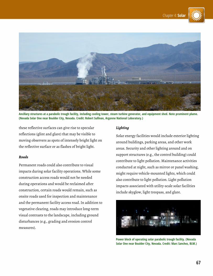
Chapter 4: Solar
67
Ancillary structures at a parabolic trough facility, including cooling tower, steam turbine generator, and equipment shed. Note prominent plume. (Nevada Solar One near Boulder City, Nevada. Credit: Robert Sullivan, Argonne National Laboratory.)
these reflective surfaces can give rise to specular
reflections (glint and glare) that may be visible to
moving observers as spots of intensely bright light on
the reflective surface or as flashes of bright light.
Roads
Permanent roads could also contribute to visual
impacts during solar facility operations. While some
construction access roads would not be needed
during operations and would be reclaimed after
construction, certain roads would remain, such as
onsite roads used for inspection and maintenance
and the permanent facility access road. In addition to
vegetative clearing, roads may introduce long-term
visual contrasts to the landscape, including ground
disturbances (e.g., grading and erosion control
measures).
Lighting
Solar energy facilities would include exterior lighting
around buildings, parking areas, and other work
areas. Security and other lighting around and on
support structures (e.g., the control building) could
contribute to light pollution. Maintenance activities
conducted at night, such as mirror or panel washing,
might require vehicle-mounted lights, which could
also contribute to light pollution. Light pollution
impacts associated with utility-scale solar facilities
include skyglow, light trespass, and glare.
Power block of operating solar parabolic trough facility. (Nevada Solar One near Boulder City, Nevada. Credit: Marc Sanchez, BLM.)
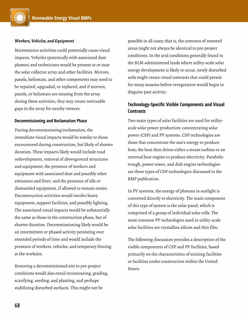
Renewable Energy Visual BMPs
68
Workers, Vehicles, and Equipment
Maintenance activities could potentially cause visual
impacts. Vehicles (potentially with associated dust
plumes) and technicians would be present at or near
the solar collector array and other facilities. Mirrors,
panels, heliostats, and other components may need to
be repaired, upgraded, or replaced, and if mirrors,
panels, or heliostats are missing from the array
during these activities, they may create noticeable
gaps in the array for nearby viewers.
Decommissioning and Reclamation Phase
During decommissioning/reclamation, the
immediate visual impacts would be similar to those
encountered during construction, but likely of shorter
duration. These impacts likely would include road
redevelopment, removal of aboveground structures
and equipment, the presence of workers and
equipment with associated dust and possibly other
emissions and litter, and the presence of idle or
dismantled equipment, if allowed to remain onsite.
Deconstruction activities would involve heavy
equipment, support facilities, and possibly lighting.
The associated visual impacts would be substantially
the same as those in the construction phase, but of
shorter duration. Decommissioning likely would be
an intermittent or phased activity persisting over
extended periods of time and would include the
presence of workers, vehicles, and temporary fencing
at the worksite.
Restoring a decommissioned site to pre-project
conditions would also entail recontouring, grading,
scarifying, seeding, and planting, and perhaps
stabilizing disturbed surfaces. This might not be
possible in all cases; that is, the contours of restored
areas might not always be identical to pre-project
conditions. In the arid conditions generally found in
the BLM-administered lands where utility-scale solar
energy development is likely to occur, newly disturbed
soils might create visual contrasts that could persist
for many seasons before revegetation would begin to
disguise past activity.
Technology-Specific Visible Components and Visual Contrasts
Two main types of solar facilities are used for utility-
scale solar power production: concentrating solar
power (CSP) and PV systems. CSP technologies are
those that concentrate the sun’s energy to produce
heat; the heat then drives either a steam turbine or an
external heat engine to produce electricity. Parabolic
trough, power tower, and dish engine technologies
are three types of CSP technologies discussed in the
BMP publication.
In PV systems, the energy of photons in sunlight is
converted directly to electricity. The main component
of this type of system is the solar panel, which is
comprised of a group of individual solar cells. The
most common PV technologies used in utility-scale
solar facilities are crystalline silicon and thin film.
The following discussion provides a description of the
visible components of CSP and PV facilities, based
primarily on the characteristics of existing facilities
or facilities under construction within the United
States.
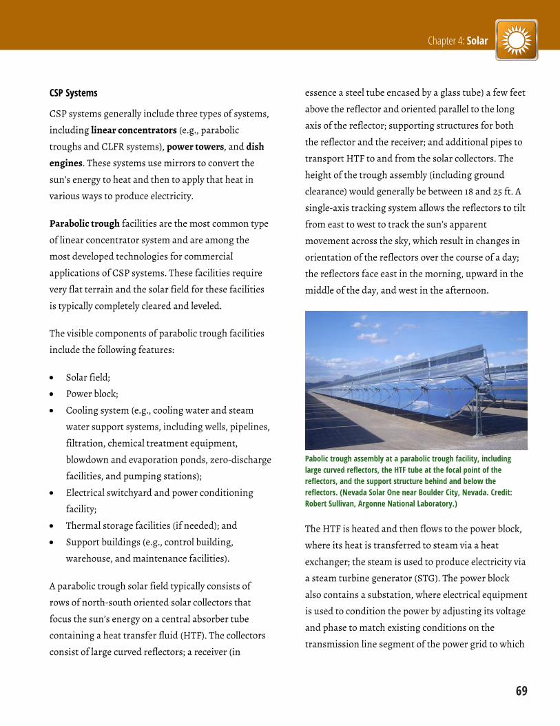
Chapter 4: Solar
69
CSP Systems
CSP systems generally include three types of systems,
including linear concentrators (e.g., parabolic
troughs and CLFR systems), power towers, and dish
engines. These systems use mirrors to convert the
sun’s energy to heat and then to apply that heat in
various ways to produce electricity.
Parabolic trough facilities are the most common type
of linear concentrator system and are among the
most developed technologies for commercial
applications of CSP systems. These facilities require
very flat terrain and the solar field for these facilities
is typically completely cleared and leveled.
The visible components of parabolic trough facilities
include the following features:
Solar field;
Power block;
Cooling system (e.g., cooling water and steam
water support systems, including wells, pipelines,
filtration, chemical treatment equipment,
blowdown and evaporation ponds, zero-discharge
facilities, and pumping stations);
Electrical switchyard and power conditioning
facility;
Thermal storage facilities (if needed); and
Support buildings (e.g., control building,
warehouse, and maintenance facilities).
A parabolic trough solar field typically consists of
rows of north-south oriented solar collectors that
focus the sun’s energy on a central absorber tube
containing a heat transfer fluid (HTF). The collectors
consist of large curved reflectors; a receiver (in
essence a steel tube encased by a glass tube) a few feet
above the reflector and oriented parallel to the long
axis of the reflector; supporting structures for both
the reflector and the receiver; and additional pipes to
transport HTF to and from the solar collectors. The
height of the trough assembly (including ground
clearance) would generally be between 18 and 25 ft. A
single-axis tracking system allows the reflectors to tilt
from east to west to track the sun’s apparent
movement across the sky, which result in changes in
orientation of the reflectors over the course of a day;
the reflectors face east in the morning, upward in the
middle of the day, and west in the afternoon.
Pabolic trough assembly at a parabolic trough facility, including large curved reflectors, the HTF tube at the focal point of the reflectors, and the support structure behind and below the reflectors. (Nevada Solar One near Boulder City, Nevada. Credit: Robert Sullivan, Argonne National Laboratory.)
The HTF is heated and then flows to the power block,
where its heat is transferred to steam via a heat
exchanger; the steam is used to produce electricity via
a steam turbine generator (STG). The power block
also contains a substation, where electrical equipment
is used to condition the power by adjusting its voltage
and phase to match existing conditions on the
transmission line segment of the power grid to which
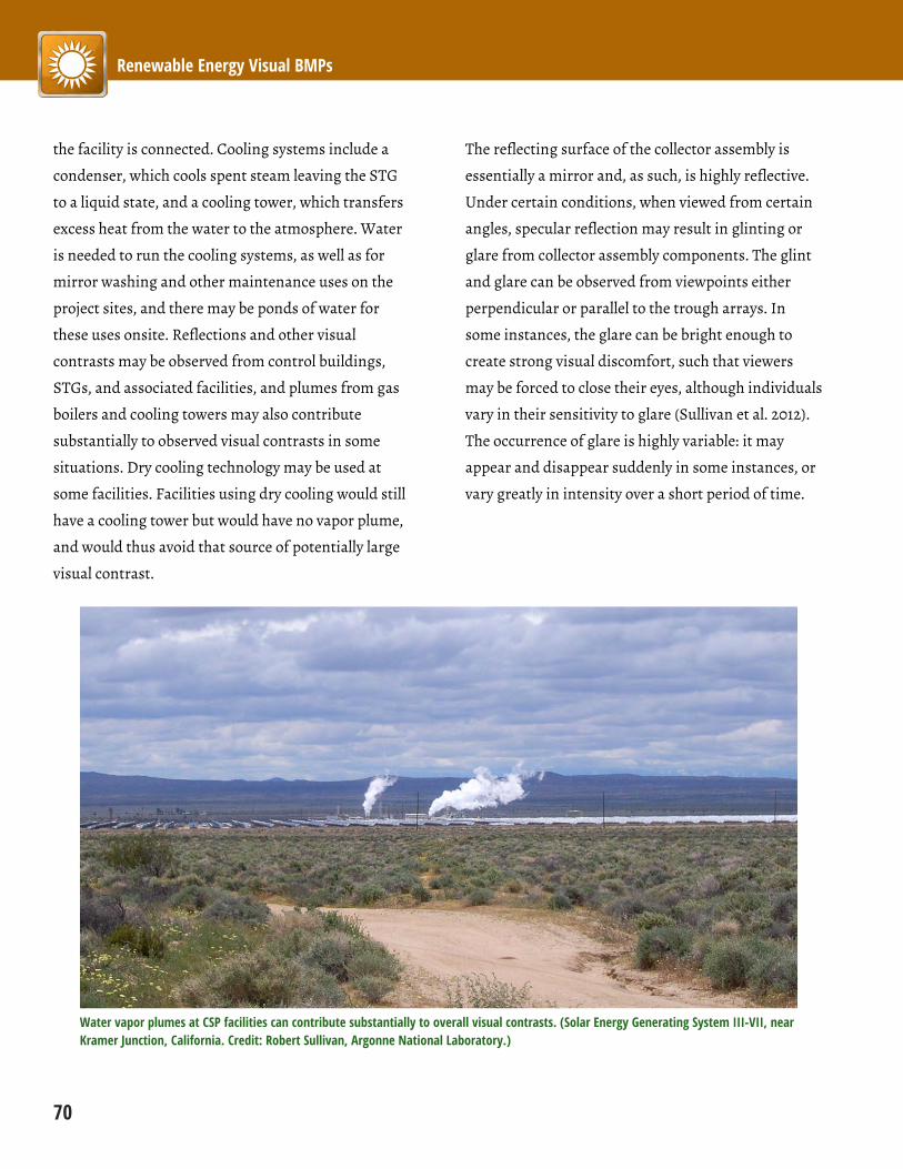
Renewable Energy Visual BMPs
70
the facility is connected. Cooling systems include a
condenser, which cools spent steam leaving the STG
to a liquid state, and a cooling tower, which transfers
excess heat from the water to the atmosphere. Water
is needed to run the cooling systems, as well as for
mirror washing and other maintenance uses on the
project sites, and there may be ponds of water for
these uses onsite. Reflections and other visual
contrasts may be observed from control buildings,
STGs, and associated facilities, and plumes from gas
boilers and cooling towers may also contribute
substantially to observed visual contrasts in some
situations. Dry cooling technology may be used at
some facilities. Facilities using dry cooling would still
have a cooling tower but would have no vapor plume,
and would thus avoid that source of potentially large
visual contrast.
The reflecting surface of the collector assembly is
essentially a mirror and, as such, is highly reflective.
Under certain conditions, when viewed from certain
angles, specular reflection may result in glinting or
glare from collector assembly components. The glint
and glare can be observed from viewpoints either
perpendicular or parallel to the trough arrays. In
some instances, the glare can be bright enough to
create strong visual discomfort, such that viewers
may be forced to close their eyes, although individuals
vary in their sensitivity to glare (Sullivan et al. 2012).
The occurrence of glare is highly variable: it may
appear and disappear suddenly in some instances, or
vary greatly in intensity over a short period of time.
Water vapor plumes at CSP facilities can contribute substantially to overall visual contrasts. (Solar Energy Generating System III-VII, near Kramer Junction, California. Credit: Robert Sullivan, Argonne National Laboratory.)
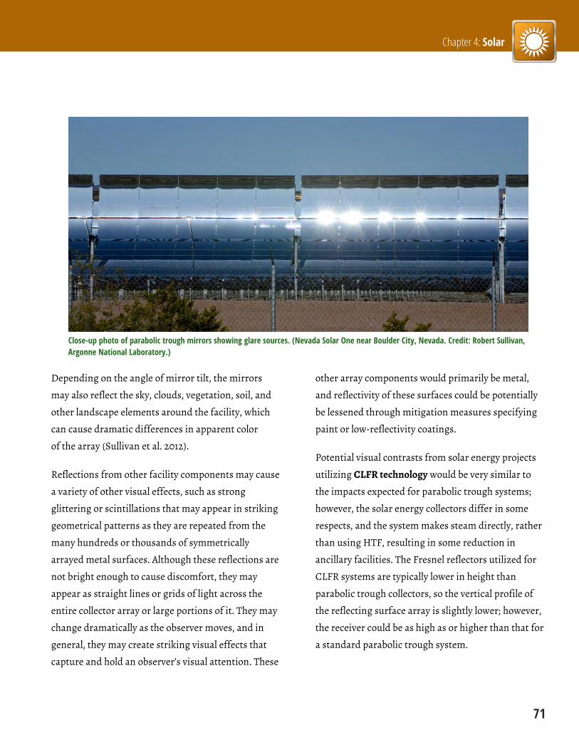
Chapter 4: Solar
71
Close-up photo of parabolic trough mirrors showing glare sources. (Nevada Solar One near Boulder City, Nevada. Credit: Robert Sullivan, Argonne National Laboratory.)
Depending on the angle of mirror tilt, the mirrors
may also reflect the sky, clouds, vegetation, soil, and
other landscape elements around the facility, which
can cause dramatic differences in apparent color
of the array (Sullivan et al. 2012).
Reflections from other facility components may cause
a variety of other visual effects, such as strong
glittering or scintillations that may appear in striking
geometrical patterns as they are repeated from the
many hundreds or thousands of symmetrically
arrayed metal surfaces. Although these reflections are
not bright enough to cause discomfort, they may
appear as straight lines or grids of light across the
entire collector array or large portions of it. They may
change dramatically as the observer moves, and in
general, they may create striking visual effects that
capture and hold an observer’s visual attention. These
other array components would primarily be metal,
and reflectivity of these surfaces could be potentially
be lessened through mitigation measures specifying
paint or low-reflectivity coatings.
Potential visual contrasts from solar energy projects
utilizing CLFR technology would be very similar to
the impacts expected for parabolic trough systems;
however, the solar energy collectors differ in some
respects, and the system makes steam directly, rather
than using HTF, resulting in some reduction in
ancillary facilities. The Fresnel reflectors utilized for
CLFR systems are typically lower in height than
parabolic trough collectors, so the vertical profile of
the reflecting surface array is slightly lower; however,
the receiver could be as high as or higher than that for
a standard parabolic trough system.

Renewable Energy Visual BMPs
72
Effects of sun angle and lighting on parabolic trough facility color. The solar collector array can appear black, glittering silver-white, green, gray, or blue, as the mirrors reflect objects around them. (Nevada Solar One near Boulder City, Nevada. Credit: Robert Sullivan, Argonne National Laboratory.)
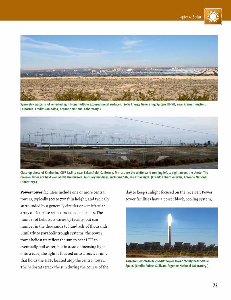
Chapter 4: Solar
73
Symmetric patterns of reflected light from multiple exposed metal surfaces. (Solar Energy Generating System III–VII, near Kramer Junction, California. Credit: Ron Kolpa, Argonne National Laboratory.)
Close-up photo of Kimberlina CLFR facility near Bakersfield, California. Mirrors are the white band running left to right across the photo. The receiver tubes are held well above the mirrors. Ancillary buildings, including STG, are at far right. (Credit: Robert Sullivan, Argonne National Laboratory.)
Power tower facilities include one or more central
towers, typically 300 to 700 ft in height, and typically
surrounded by a generally circular or semicircular
array of flat-plate reflectors called heliostats. The
number of heliostats varies by facility, but can
number in the thousands to hundreds of thousands.
Similarly to parabolic trough systems, the power
tower heliostats reflect the sun to heat HTF to
eventually boil water, but instead of focusing light
onto a tube, the light is focused onto a receiver unit
that holds the HTF, located atop the central tower.
The heliostats track the sun during the course of the
day to keep sunlight focused on the receiver. Power
tower facilities have a power block, cooling system,
Torresol Gemmasolar 20-MW power tower facility near Seville, Spain. (Credit: Robert Sullivan, Argonne National Laboratory.)
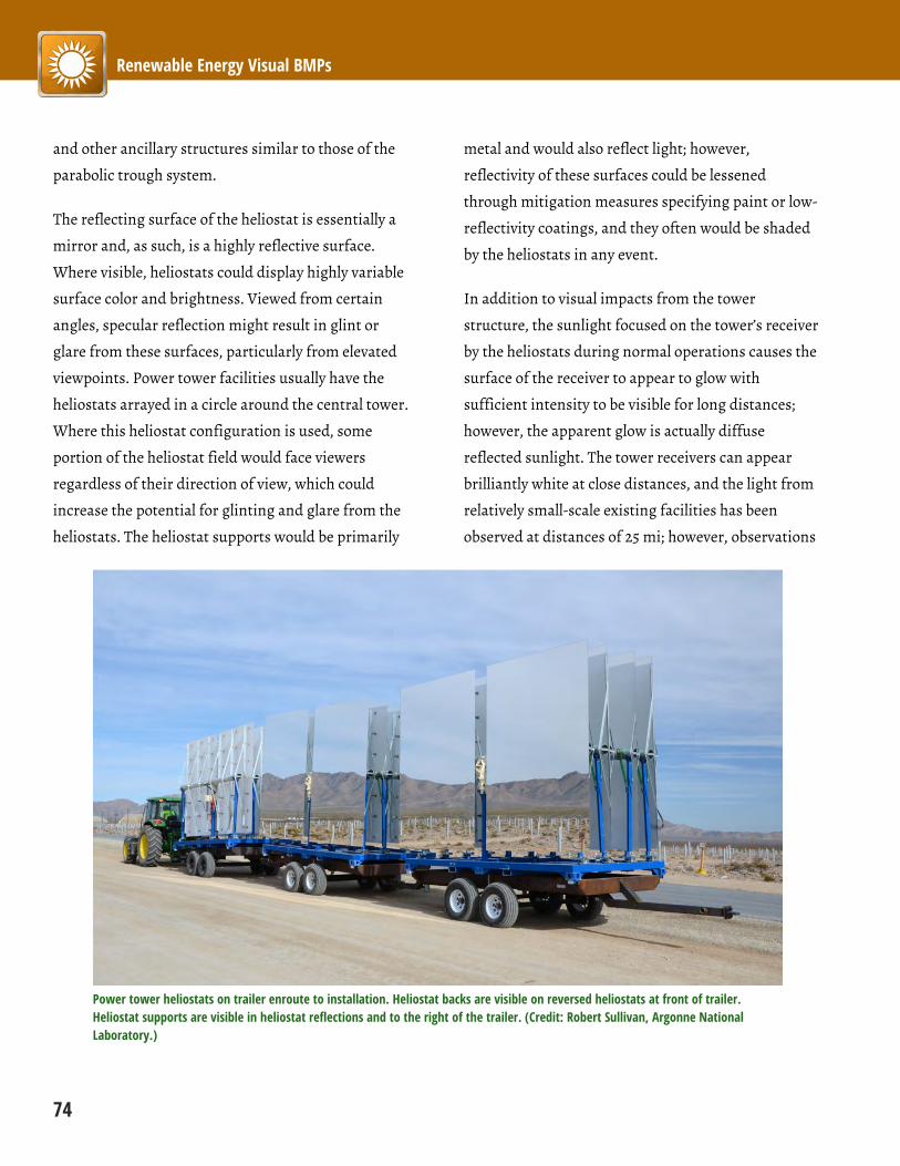
Renewable Energy Visual BMPs
74
and other ancillary structures similar to those of the
parabolic trough system.
The reflecting surface of the heliostat is essentially a
mirror and, as such, is a highly reflective surface.
Where visible, heliostats could display highly variable
surface color and brightness. Viewed from certain
angles, specular reflection might result in glint or
glare from these surfaces, particularly from elevated
viewpoints. Power tower facilities usually have the
heliostats arrayed in a circle around the central tower.
Where this heliostat configuration is used, some
portion of the heliostat field would face viewers
regardless of their direction of view, which could
increase the potential for glinting and glare from the
heliostats. The heliostat supports would be primarily
metal and would also reflect light; however,
reflectivity of these surfaces could be lessened
through mitigation measures specifying paint or low-
reflectivity coatings, and they often would be shaded
by the heliostats in any event.
In addition to visual impacts from the tower
structure, the sunlight focused on the tower’s receiver
by the heliostats during normal operations causes the
surface of the receiver to appear to glow with
sufficient intensity to be visible for long distances;
however, the apparent glow is actually diffuse
reflected sunlight. The tower receivers can appear
brilliantly white at close distances, and the light from
relatively small-scale existing facilities has been
observed at distances of 25 mi; however, observations
Power tower heliostats on trailer enroute to installation. Heliostat backs are visible on reversed heliostats at front of trailer. Heliostat supports are visible in heliostat reflections and to the right of the trailer. (Credit: Robert Sullivan, Argonne National Laboratory.)

Chapter 4: Solar
75
to date have not shown the receiver light to be as
intense as the glare observed from parabolic trough
facilities (Sullivan et al. 2012).
In addition to heliostat reflections and glare from the
receiver, at certain times of the day and from certain
angles, the reflection of sunlight on ambient dust
particles in the air could sometimes result in the
appearance of light streaming diagonally downward
and/or upward from the tower in a luminous,
transparent, tent-like form.
Glare and reflections from airborne dust particles at Torresol Gemmasolar 20-MW power tower facility near Seville, Spain. (Credit: Robert Sullivan, Argonne National Laboratory.)
Because of the height of the central towers, FAA-
compliant aircraft warning lights would be required
for power tower receivers (or other structures) 200 ft
tall or higher, and may be required in some
circumstances for lower height structures (FAA 2007).
These lights typically flash white during the day and
at twilight and red at night; or alternatively, red or
white strobe lights flash during the day and/or at
night. In theory, for power towers, daylight lighting
might be avoided by painting the tower orange and
white according to FAA guidelines; this practice could
result in large increases in visual contrast for the
tower during the day, but is unlikely.
Dish systems generate electricity through the action
of an external engine, rather than steam. These
systems usually consist of a parabolic concentrator, a
receiver, an external heat engine, and a generator.
Sunlight is concentrated onto the receiver, which
transfers the heat to a gas contained in a sealed
external heat engine. As the gas is heated, the
pressure increase drives a piston, thereby powering a
generator and producing electricity.
Hundreds or thousands of individual dish engines
can be grouped together to form a larger facility. Solar
dish engine units superficially resemble backyard
satellite dishes but are much larger. The solar dish
units are about 40 ft tall. The large surfaces of the
dishes may reflect the sky and clouds, potentially
creating strong color contrasts with the surrounding
landscape, particularly for elevated viewers. Because
the dishes are mirrors, they are capable of causing
glinting and glare.
Maricopa solar dish facility, Phoenix, Arizona. (Credit: U.S. Department of Energy.)
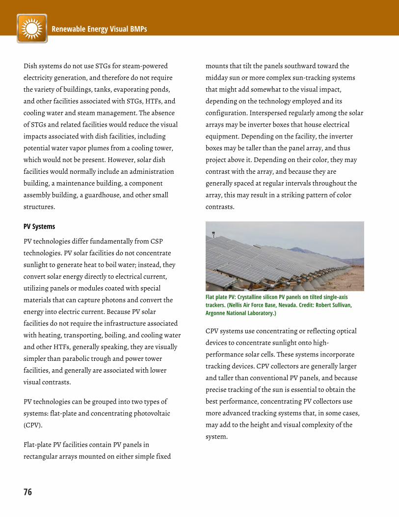
Renewable Energy Visual BMPs
76
Dish systems do not use STGs for steam-powered
electricity generation, and therefore do not require
the variety of buildings, tanks, evaporating ponds,
and other facilities associated with STGs, HTFs, and
cooling water and steam management. The absence
of STGs and related facilities would reduce the visual
impacts associated with dish facilities, including
potential water vapor plumes from a cooling tower,
which would not be present. However, solar dish
facilities would normally include an administration
building, a maintenance building, a component
assembly building, a guardhouse, and other small
structures.
PV Systems
PV technologies differ fundamentally from CSP
technologies. PV solar facilities do not concentrate
sunlight to generate heat to boil water; instead, they
convert solar energy directly to electrical current,
utilizing panels or modules coated with special
materials that can capture photons and convert the
energy into electric current. Because PV solar
facilities do not require the infrastructure associated
with heating, transporting, boiling, and cooling water
and other HTFs, generally speaking, they are visually
simpler than parabolic trough and power tower
facilities, and generally are associated with lower
visual contrasts.
PV technologies can be grouped into two types of
systems: flat-plate and concentrating photovoltaic
(CPV).
Flat-plate PV facilities contain PV panels in
rectangular arrays mounted on either simple fixed
mounts that tilt the panels southward toward the
midday sun or more complex sun-tracking systems
that might add somewhat to the visual impact,
depending on the technology employed and its
configuration. Interspersed regularly among the solar
arrays may be inverter boxes that house electrical
equipment. Depending on the facility, the inverter
boxes may be taller than the panel array, and thus
project above it. Depending on their color, they may
contrast with the array, and because they are
generally spaced at regular intervals throughout the
array, this may result in a striking pattern of color
contrasts.
Flat plate PV: Crystalline silicon PV panels on tilted single-axis trackers. (Nellis Air Force Base, Nevada. Credit: Robert Sullivan, Argonne National Laboratory.)
CPV systems use concentrating or reflecting optical
devices to concentrate sunlight onto high-
performance solar cells. These systems incorporate
tracking devices. CPV collectors are generally larger
and taller than conventional PV panels, and because
precise tracking of the sun is essential to obtain the
best performance, concentrating PV collectors use
more advanced tracking systems that, in some cases,
may add to the height and visual complexity of the
system.

Chapter 4: Solar
77
A utility-scale PV facility may include one or more of
the following: an administration building, a
maintenance building, a component assembly
building, a guardhouse, and other small structures. In
some cases, especially for smaller facilities,
administration and other buildings may be at offsite
locations.
Flat plate PV: Thin-film PV panels on fixed (non-tracking) mounts. (Silver State North Solar Project near Primm, Nevada. Credit: Robert Sullivan, Argonne National Laboratory.)
In general, the low profile of the solar collectors of PV
facilities would reduce their visibility (relative to the
other solar technologies) when viewed from low
viewing angles, especially from longer distances, and
they have less associated infrastructure than CSP
facilities, which further lowers their vertical profiles.
When viewed from elevated positions, more of the
facility would be visible, and the regular geometry of
the panel arrays would be more apparent, sometimes
resulting in substantially larger visual contrasts.
CPV units on dual-axis trackers. (Clark Generating Station, Las Vegas, Nevada. Credit: Robert Sullivan, Argonne National Laboratory.)
Unlike the solar reflectors for CSP technologies, PV
panel surfaces are not designed to reflect light and,
being significantly less reflective than the mirrored
surfaces of the solar collectors for the other
technologies, they have reduced potential for glint
and glare; however, the panels and other components
do reflect light that may result in glinting, glare, and
other visual effects that would also vary depending on
panel orientation, sun angle, viewing angle, viewer
distance, and other visibility factors. In a manner
somewhat similar to parabolic trough facilities, PV
facilities may vary substantially in their appearance,
depending on viewer location and other visibility
factors. Sullivan et al. (2012) observed the apparent
color of the panels at two different facilities to vary
rapidly from black to blue to silvery white, depending
on viewer location, as a vehicle was driven past the
facilities.
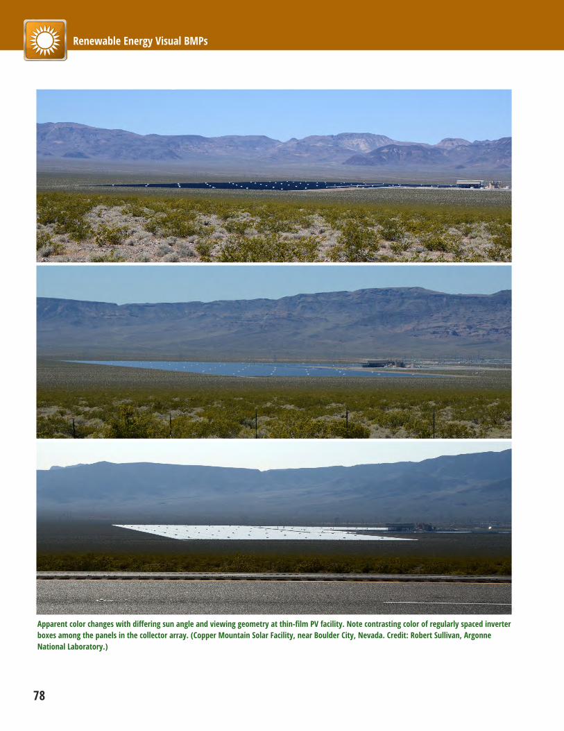
Renewable Energy Visual BMPs
78
Apparent color changes with differing sun angle and viewing geometry at thin-film PV facility. Note contrasting color of regularly spaced inverter boxes among the panels in the collector array. (Copper Mountain Solar Facility, near Boulder City, Nevada. Credit: Robert Sullivan, Argonne National Laboratory.)
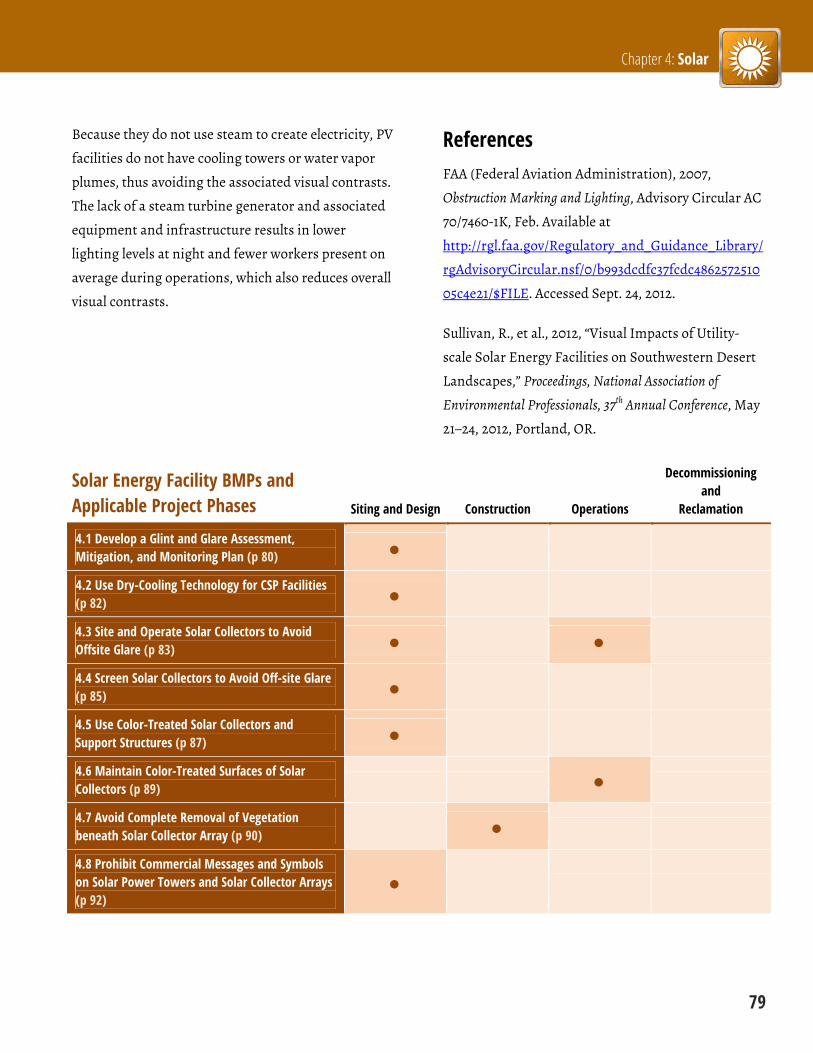
Chapter 4: Solar
79
Because they do not use steam to create electricity, PV
facilities do not have cooling towers or water vapor
plumes, thus avoiding the associated visual contrasts.
The lack of a steam turbine generator and associated
equipment and infrastructure results in lower
lighting levels at night and fewer workers present on
average during operations, which also reduces overall
visual contrasts.
References FAA (Federal Aviation Administration), 2007,
Obstruction Marking and Lighting, Advisory Circular AC
70/7460-1K, Feb. Available at
http://rgl.faa.gov/Regulatory_and_Guidance_Library/
rgAdvisoryCircular.nsf/0/b993dcdfc37fcdc4862572510
05c4e21/$FILE. Accessed Sept. 24, 2012.
Sullivan, R., et al., 2012, “Visual Impacts of Utility-
scale Solar Energy Facilities on Southwestern Desert
Landscapes,” Proceedings, National Association of
Environmental Professionals, 37th Annual Conference, May
21–24, 2012, Portland, OR.
Solar Energy Facility BMPs and Applicable Project Phases Siting and Design Construction Operations
Decommissioning and
Reclamation
4.1 Develop a Glint and Glare Assessment, Mitigation, and Monitoring Plan (p 80)
4.2 Use Dry-Cooling Technology for CSP Facilities (p 82)
4.3 Site and Operate Solar Collectors to Avoid Offsite Glare (p 83)
4.4 Screen Solar Collectors to Avoid Off-site Glare (p 85)
4.5 Use Color-Treated Solar Collectors and Support Structures (p 87)
4.6 Maintain Color-Treated Surfaces of Solar Collectors (p 89)
4.7 Avoid Complete Removal of Vegetation beneath Solar Collector Array (p 90)
4.8 Prohibit Commercial Messages and Symbols on Solar Power Towers and Solar Collector Arrays (p 92)

Renewable Energy Visual BMPs
80 4.1 Develop a Glint and Glare Assessment, Mitigation, and Monitoring Plan
4.1 Develop a Glint and Glare Assessment, Mitigation, and Monitoring Plan Project Phase: Siting and Design
Regardless of the solar technology proposed, a glint and glare assessment, mitigation, and monitoring plan
should be prepared that accurately assesses and quantifies potential glint and glare effects and determines
the potential health, safety, and visual impacts associated with glint and glare. The assessment should be
conducted by qualified individuals using appropriate software and procedures. The assessment results
should be made available to the BLM in advance of project approval.
Figure from glint/glare assessment for solar dish facility. (Credit: California Energy Commission.)

Chapter 4: Solar
4.1 Develop a Glint and Glare Assessment, Mitigation, and Monitoring Plan 81
Notes Research sponsored by the BLM and others has shown that utility-scale solar facilities are capable of
causing offsite glare that may cause annoyance, discomfort, or in certain circumstances, ocular damage. A
glare assessment, mitigation, and monitoring plan should be used to assist site design and operations
planning to avoid and reduce significant offsite glare impacts. The glare assessment, mitigation, and
monitoring plan may be incorporated as part of other visual assessment and mitigation planning for the
project. The FAA may also require this type of assessment if impacts on aircraft pilots or airports are
anticipated.
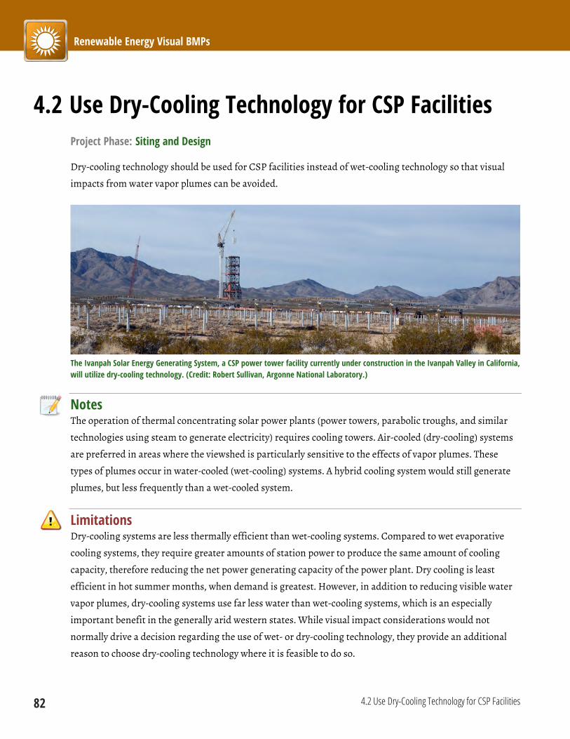
Renewable Energy Visual BMPs
82 4.2 Use Dry-Cooling Technology for CSP Facilities
4.2 Use Dry-Cooling Technology for CSP Facilities Project Phase: Siting and Design
Dry-cooling technology should be used for CSP facilities instead of wet-cooling technology so that visual
impacts from water vapor plumes can be avoided.
The Ivanpah Solar Energy Generating System, a CSP power tower facility currently under construction in the Ivanpah Valley in California, will utilize dry-cooling technology. (Credit: Robert Sullivan, Argonne National Laboratory.)
Notes The operation of thermal concentrating solar power plants (power towers, parabolic troughs, and similar
technologies using steam to generate electricity) requires cooling towers. Air-cooled (dry-cooling) systems
are preferred in areas where the viewshed is particularly sensitive to the effects of vapor plumes. These
types of plumes occur in water-cooled (wet-cooling) systems. A hybrid cooling system would still generate
plumes, but less frequently than a wet-cooled system.
Limitations Dry-cooling systems are less thermally efficient than wet-cooling systems. Compared to wet evaporative
cooling systems, they require greater amounts of station power to produce the same amount of cooling
capacity, therefore reducing the net power generating capacity of the power plant. Dry cooling is least
efficient in hot summer months, when demand is greatest. However, in addition to reducing visible water
vapor plumes, dry-cooling systems use far less water than wet-cooling systems, which is an especially
important benefit in the generally arid western states. While visual impact considerations would not
normally drive a decision regarding the use of wet- or dry-cooling technology, they provide an additional
reason to choose dry-cooling technology where it is feasible to do so.
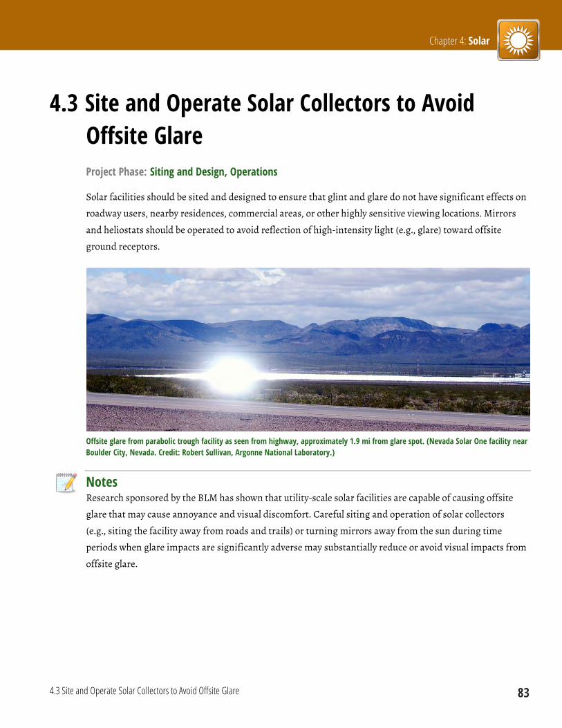
Chapter 4: Solar
4.3 Site and Operate Solar Collectors to Avoid Offsite Glare 83
4.3 Site and Operate Solar Collectors to Avoid Offsite Glare Project Phase: Siting and Design, Operations
Solar facilities should be sited and designed to ensure that glint and glare do not have significant effects on
roadway users, nearby residences, commercial areas, or other highly sensitive viewing locations. Mirrors
and heliostats should be operated to avoid reflection of high-intensity light (e.g., glare) toward offsite
ground receptors.
Offsite glare from parabolic trough facility as seen from highway, approximately 1.9 mi from glare spot. (Nevada Solar One facility near Boulder City, Nevada. Credit: Robert Sullivan, Argonne National Laboratory.)
Notes Research sponsored by the BLM has shown that utility-scale solar facilities are capable of causing offsite
glare that may cause annoyance and visual discomfort. Careful siting and operation of solar collectors
(e.g., siting the facility away from roads and trails) or turning mirrors away from the sun during time
periods when glare impacts are significantly adverse may substantially reduce or avoid visual impacts from
offsite glare.

Renewable Energy Visual BMPs
84 4.3 Site and Operate Solar Collectors to Avoid Offsite Glare
Left: Siting a facility with potential to cause glare close to a roadway may result in glare close to the driver’s line of sight at short viewing distances.
Right: Siting a facility with potential to cause glare farther from the roadway keeps glare sources farther away from the driver’s line of sight at short viewing distances. (Credit: Lindsey Utter, Argonne National Laboratory.)
Limitations Some glare from collector arrays is unavoidable. Glare
occurrence and intensity is highly technology- and site-specific
and varies widely depending on viewer location and various
environmental factors. It may be difficult or impossible to avoid
at least some offsite glare to ground receptors. However, glare
occurrence can be mathematically modeled and is predictable. A
glare assessment, mitigation, and monitoring plan (see
BMP 4.1) should be used to assist site design and operations
planning to reduce and avoid offsite glare impacts. Although
turning mirrors can reduce or eliminate glare, this can
adversely impact the power generation of the solar facility and
could affect the viability of the project.
Offsite glare from 20-MW power tower facility. (Torresol Gemasolar facility near Seville, Spain. Credit: Robert Sullivan, Argonne National Laboratory.)
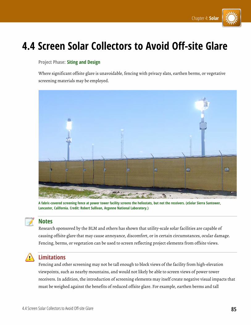
Chapter 4: Solar
4.4 Screen Solar Collectors to Avoid Off-site Glare 85
4.4 Screen Solar Collectors to Avoid Off-site Glare Project Phase: Siting and Design
Where significant offsite glare is unavoidable, fencing with privacy slats, earthen berms, or vegetative
screening materials may be employed.
A fabric-covered screening fence at power tower facility screens the heliostats, but not the receivers. (eSolar Sierra Suntower, Lancaster, California. Credit: Robert Sullivan, Argonne National Laboratory.)
Notes Research sponsored by the BLM and others has shown that utility-scale solar facilities are capable of
causing offsite glare that may cause annoyance, discomfort, or in certain circumstances, ocular damage.
Fencing, berms, or vegetation can be used to screen reflecting project elements from offsite views.
Limitations Fencing and other screening may not be tall enough to block views of the facility from high-elevation
viewpoints, such as nearby mountains, and would not likely be able to screen views of power tower
receivers. In addition, the introduction of screening elements may itself create negative visual impacts that
must be weighed against the benefits of reduced offsite glare. For example, earthen berms and tall

Renewable Energy Visual BMPs
86 4.4 Screen Solar Collectors to Avoid Off-site Glare
screening vegetation may not blend in well with a flat desert landscape containing only low shrubs and
grasses. The introduction of screening elements may also cause undesirable shading of the solar collectors.
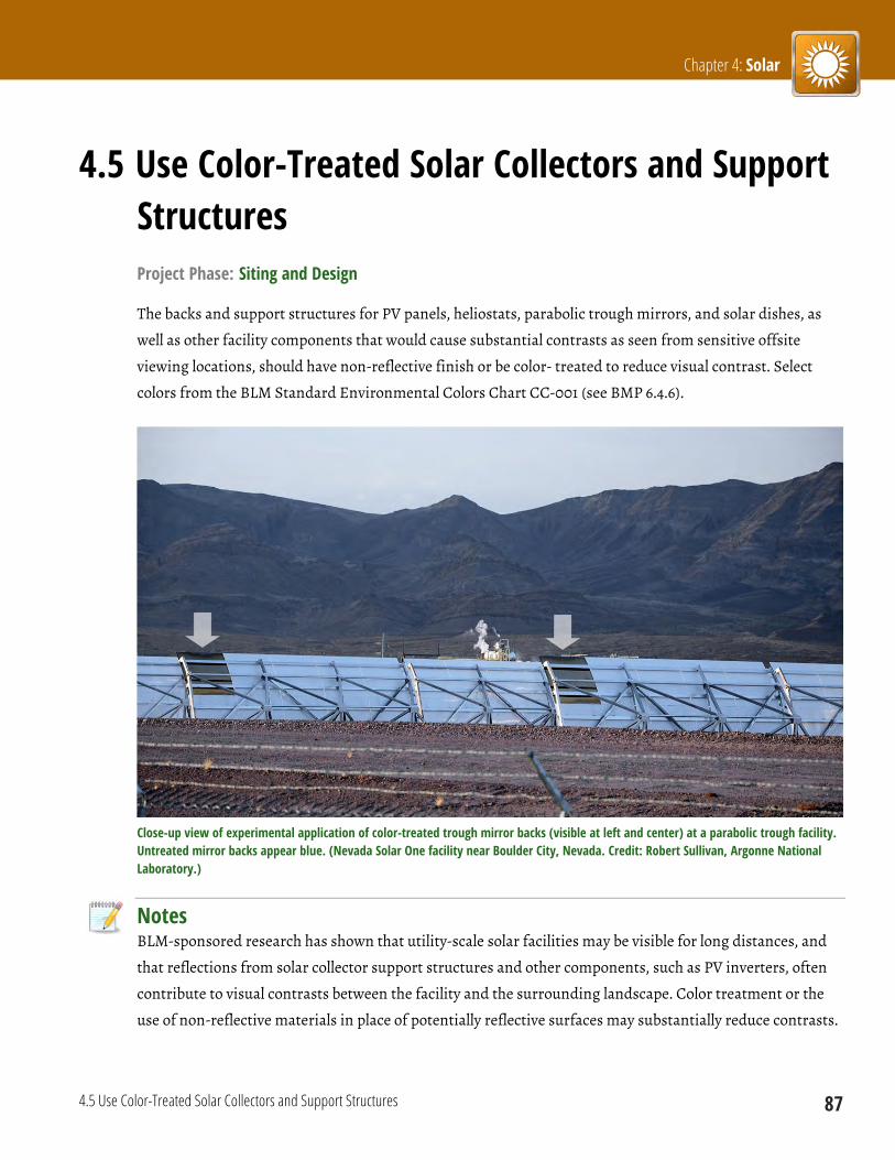
Chapter 4: Solar
4.5 Use Color-Treated Solar Collectors and Support Structures 87
4.5 Use Color-Treated Solar Collectors and Support Structures Project Phase: Siting and Design
The backs and support structures for PV panels, heliostats, parabolic trough mirrors, and solar dishes, as
well as other facility components that would cause substantial contrasts as seen from sensitive offsite
viewing locations, should have non-reflective finish or be color- treated to reduce visual contrast. Select
colors from the BLM Standard Environmental Colors Chart CC-001 (see BMP 6.4.6).
Close-up view of experimental application of color-treated trough mirror backs (visible at left and center) at a parabolic trough facility. Untreated mirror backs appear blue. (Nevada Solar One facility near Boulder City, Nevada. Credit: Robert Sullivan, Argonne National Laboratory.)
Notes BLM-sponsored research has shown that utility-scale solar facilities may be visible for long distances, and
that reflections from solar collector support structures and other components, such as PV inverters, often
contribute to visual contrasts between the facility and the surrounding landscape. Color treatment or the
use of non-reflective materials in place of potentially reflective surfaces may substantially reduce contrasts.
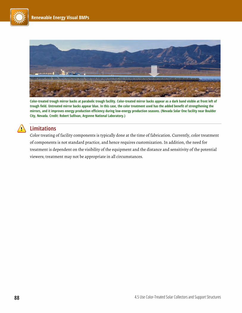
Renewable Energy Visual BMPs
88 4.5 Use Color-Treated Solar Collectors and Support Structures
Color-treated trough mirror backs at parabolic trough facility. Color-treated mirror backs appear as a dark band visible at front left of trough field. Untreated mirror backs appear blue. In this case, the color treatment used has the added benefit of strengthening the mirrors, and it improves energy production efficiency during low-energy production seasons. (Nevada Solar One facility near Boulder City, Nevada. Credit: Robert Sullivan, Argonne National Laboratory.)
Limitations Color treating of facility components is typically done at the time of fabrication. Currently, color treatment
of components is not standard practice, and hence requires customization. In addition, the need for
treatment is dependent on the visibility of the equipment and the distance and sensitivity of the potential
viewers; treatment may not be appropriate in all circumstances.

Chapter 4: Solar
4.6 Maintain Color-Treated Surfaces of Solar Collectors 89
4.6 Maintain Color-Treated Surfaces of Solar Collectors Project Phase: Operations
Color-treated surfaces of mirror, dish, and heliostat backs should be kept in good repair.
Notes Depending on the component and treatment method, treatments could be subject to fading or flaking, and
may require re-treatment to maintain proper coloration.
Limitations Re-treatment may be difficult or impossible for some in-place components, or could require disassembly
and offsite transport, which could be prohibitively expensive.
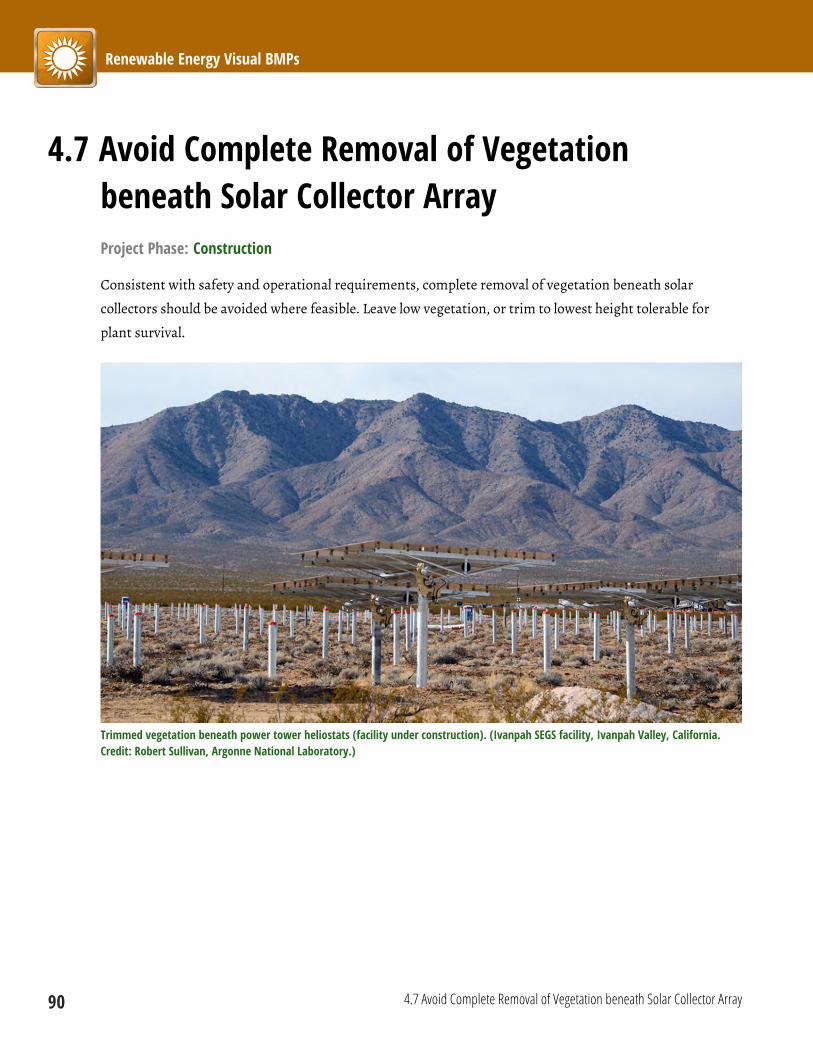
Renewable Energy Visual BMPs
90 4.7 Avoid Complete Removal of Vegetation beneath Solar Collector Array
4.7 Avoid Complete Removal of Vegetation beneath Solar Collector Array Project Phase: Construction
Consistent with safety and operational requirements, complete removal of vegetation beneath solar
collectors should be avoided where feasible. Leave low vegetation, or trim to lowest height tolerable for
plant survival.
Trimmed vegetation beneath power tower heliostats (facility under construction). (Ivanpah SEGS facility, Ivanpah Valley, California. Credit: Robert Sullivan, Argonne National Laboratory.)
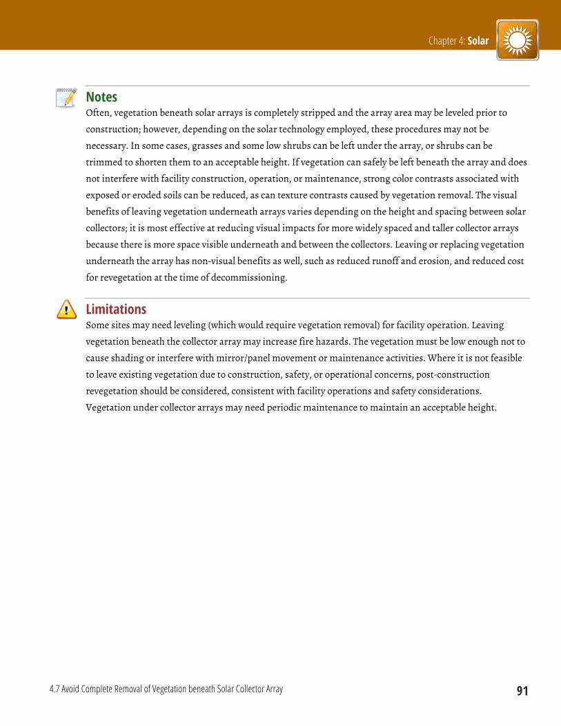
Chapter 4: Solar
4.7 Avoid Complete Removal of Vegetation beneath Solar Collector Array 91
Notes Often, vegetation beneath solar arrays is completely stripped and the array area may be leveled prior to
construction; however, depending on the solar technology employed, these procedures may not be
necessary. In some cases, grasses and some low shrubs can be left under the array, or shrubs can be
trimmed to shorten them to an acceptable height. If vegetation can safely be left beneath the array and does
not interfere with facility construction, operation, or maintenance, strong color contrasts associated with
exposed or eroded soils can be reduced, as can texture contrasts caused by vegetation removal. The visual
benefits of leaving vegetation underneath arrays varies depending on the height and spacing between solar
collectors; it is most effective at reducing visual impacts for more widely spaced and taller collector arrays
because there is more space visible underneath and between the collectors. Leaving or replacing vegetation
underneath the array has non-visual benefits as well, such as reduced runoff and erosion, and reduced cost
for revegetation at the time of decommissioning.
Limitations Some sites may need leveling (which would require vegetation removal) for facility operation. Leaving
vegetation beneath the collector array may increase fire hazards. The vegetation must be low enough not to
cause shading or interfere with mirror/panel movement or maintenance activities. Where it is not feasible
to leave existing vegetation due to construction, safety, or operational concerns, post-construction
revegetation should be considered, consistent with facility operations and safety considerations.
Vegetation under collector arrays may need periodic maintenance to maintain an acceptable height.
Renewable Energy Visual BMPs
92 4.8 Prohibit Commercial Messages and Symbols on Solar Power Towers and Solar Collector Arrays
4.8 Prohibit Commercial Messages and Symbols on Solar Power Towers and Solar Collector Arrays Project Phase: Siting and Design
Commercial messages and symbols (such as logos or
trademarks) on solar power towers and solar collector
arrays should be prohibited.
Notes Commercial messages and symbols such as logos add to
the color contrast of power towers and collector arrays,
particularly at shorter viewing distances.
Commercial logo on a solar power tower adds to visual contrast. (Torresol Gemmasolar power tower facility near Seville, Spain. Credit: Robert Sullivan, Argonne National Laboratory.)

Chapter 1: Introduction
93
Introduction The following provides a discussion of the general
stages of utility-scale geothermal facility
development, and a summary of visual contrast
sources and effects by project phase.
Facility Life Cycle
In general, the development of a geothermal facility
consists of six stages, including planning, site
evaluation, design/engineering, construction,
operations, and decommissioning. The following
discussion includes only the phases that involve
onsite activities that would lead to significant visual
contrasts: site evaluation, construction, operations,
and decommissioning and reclamation.
Site Evaluation Phase
Before geothermal resources can be developed,
various offsite exploratory activities must take place
to characterize the development potential of a
geothermal reservoir. Once data and surveys have
been compiled and analyzed, more invasive activities
such as geophysical testing, drilling temperature
gradient wells (above the reservoir), drilling holes for
explosive charges for seismic exploration, and core
drilling take place.
Specific activities affecting the project site include
clearing of vegetation and building of roads to
increase access to the project site; detonating small
charges below the ground surface to create seismic
pulses for the seismic surveys; burying cables and

Renewable Energy Visual BMPs
94
sensors as part of the seismic surveys; drilling of wells
(typically with truck-mounted rigs); and earth-
moving activities to prepare the drilling site. During
the exploration and drilling phase, fluids produced
during drilling (e.g., drilling mud and groundwater)
would be collected by sump or tanker truck and
transported to licensed offsite locations for disposal.
Geothermal drilling rig. (Credit: Idaho Department of Water Resources.)
If a site is confirmed as a viable prospect for
geothermal development, exploration wells are drilled
to test the reservoir. Activities include flow testing of
wells, producing geothermal fluids for chemical
evaluation, and injecting fluids into a geothermal
reservoir. Sumps or pits to hold excess geothermal
fluids would also be constructed. Water would be left
to evaporate, but remaining sludge would be removed
and transported to licensed offsite locations for
disposal. Some infrastructure construction may also
be required. If a reservoir and geothermal well were
determined to be sufficient for development, a
wellhead with valves and control equipment would be
installed on top of the well casing.
Construction Phase
After the exploration and drilling phase, the project
site is prepared for production. The construction
phase involves the construction of the geothermal
field(s), infrastructure, power plants, and
transmission lines. Activities in this phase of
development would include the following:
Clearing, grading, and constructing access roads;
Clearing, grading, and constructing electrical
generation facilities;
Building facility structures;
Drilling and developing well fields;
Installing pipeline systems; and
Installing meters, substations, and transmission
lines.
The construction phase of the development process
would result in the greatest area of land disturbance
at the geothermal energy project site, although some
of the disturbed land would be reclaimed once
construction activities end.
Operations Phase
The operations and maintenance phase involves the
operation and maintenance of the geothermal
field(s)—including drilling additional production and
reinjection wells—and the generation of electricity.
The types of operations and maintenance activities
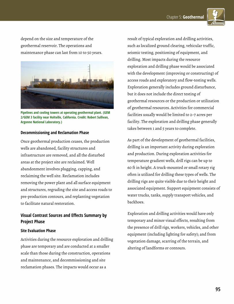
Chapter 5: Geothermal
95
depend on the size and temperature of the
geothermal reservoir. The operations and
maintenance phase can last from 10 to 50 years.
Pipelines and cooling towers at operating geothermal plant. (GEM 2/GEM 3 facility near Holtville, California. Credit: Robert Sullivan, Argonne National Laboratory.)
Decommissioning and Reclamation Phase
Once geothermal production ceases, the production
wells are abandoned, facility structures and
infrastructure are removed, and all the disturbed
areas at the project site are reclaimed. Well
abandonment involves plugging, capping, and
reclaiming the well site. Reclamation includes
removing the power plant and all surface equipment
and structures, regrading the site and access roads to
pre-production contours, and replanting vegetation
to facilitate natural restoration.
Visual Contrast Sources and Effects Summary by Project Phase
Site Evaluation Phase
Activities during the resource exploration and drilling
phase are temporary and are conducted at a smaller
scale than those during the construction, operations
and maintenance, and decommissioning and site
reclamation phases. The impacts would occur as a
result of typical exploration and drilling activities,
such as localized ground clearing, vehicular traffic,
seismic testing, positioning of equipment, and
drilling. Most impacts during the resource
exploration and drilling phase would be associated
with the development (improving or constructing) of
access roads and exploratory and flow-testing wells.
Exploration generally includes ground disturbance,
but it does not include the direct testing of
geothermal resources or the production or utilization
of geothermal resources. Activities for commercial
facilities usually would be limited to 2–7 acres per
facility. The exploration and drilling phase generally
takes between 1 and 5 years to complete.
As part of the development of geothermal facilities,
drilling is an important activity during exploration
and production. During exploration activities for
temperature gradient wells, drill rigs can be up to
60 ft in height. A truck-mounted or small rotary rig
often is utilized for drilling these types of wells. The
drilling rigs are quite visible due to their height and
associated equipment. Support equipment consists of
water trucks, tanks, supply transport vehicles, and
backhoes.
Exploration and drilling activities would have only
temporary and minor visual effects, resulting from
the presence of drill rigs, workers, vehicles, and other
equipment (including lighting for safety); and from
vegetation damage, scarring of the terrain, and
altering of landforms or contours.

Renewable Energy Visual BMPs
96
Geothermal drilling rig at night. (Long Valley Exploratory Well near Mammoth Lakes, California. Credit: Sandia National Laboratories.)
Construction Phase
Activities that may cause environmental impacts
during construction include site preparation (e.g.,
clearing and grading); facility construction (e.g.,
geothermal power plant, pipelines, transmission
lines); and vehicular and pedestrian traffic. Impacts
would be more extensive than those that would occur
in the exploration and drilling phase. The
construction phase would require from 50 to 350
acres, depending on the geometry of the geothermal
systems and the anticipated size of the power
development. Some of this disturbed land would be
reclaimed once construction activities end.
Construction of a large geothermal development
would normally require about 2 to 4 years. A pipeline
or transmission line could take several months or
more to construct, depending primarily on its length.
Construction activities would have temporary visual
effects resulting from the presence of drill rigs,
workers, vehicles, and other equipment (including
lighting for safety); and from vegetation damage,
scarring of the terrain, and altering of landforms or
contours.
Operations Phase
The operations and maintenance phase involves the
operation and maintenance of the geothermal field(s)
and the generation of electricity. Typical activities
during the operations and maintenance phase
include operation and maintenance of production
and injection wells and pipeline systems, operation
and maintenance of the power plant, waste
management, and maintenance and replacement of
facility components.
During utilization, the well field would be developed;
roads would be built and/or improved; well field
equipment, including piping, would be installed;
transmission lines would be built; and well work-
overs, repairs, and maintenance would occur.
Three types of geothermal power plant systems are
commonly used to generate electricity indirectly; the
technology selected is dependent on the temperature,
depth, and quality of the water and steam in the area:
Flash steam—this type of plant uses hot water
that is above 360 degrees Fahrenheit (182 degrees
Celsius). The high pressure underground keeps
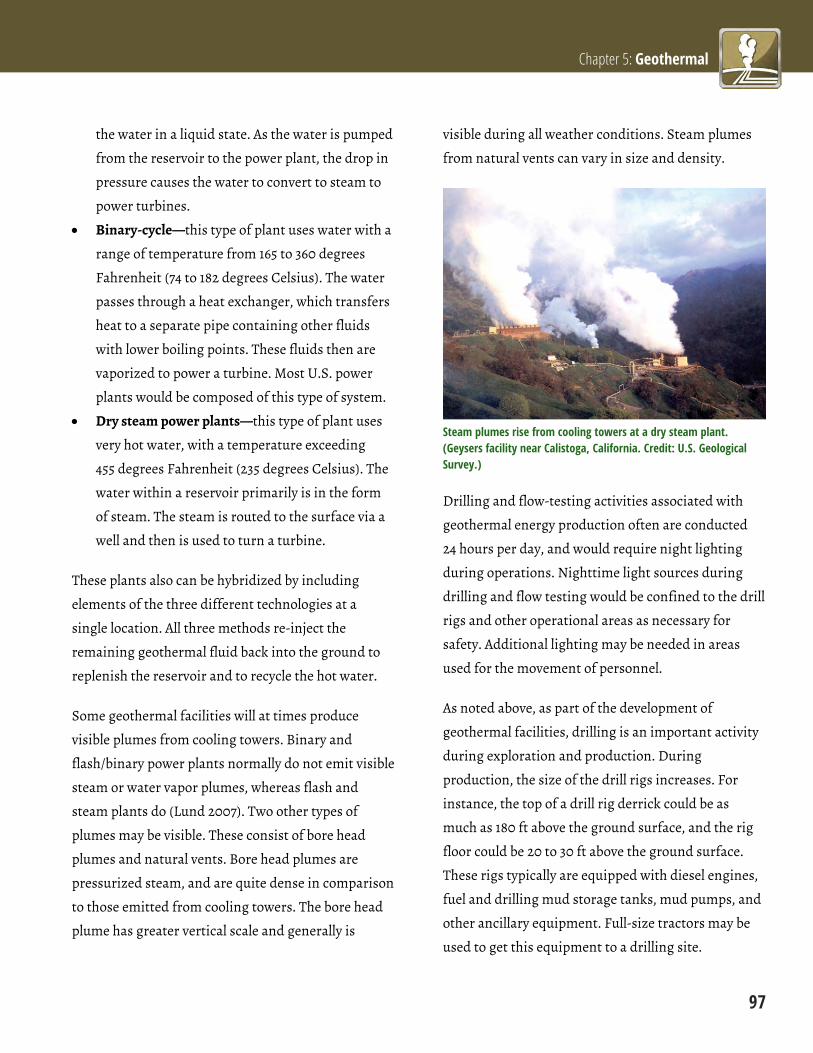
Chapter 5: Geothermal
97
the water in a liquid state. As the water is pumped
from the reservoir to the power plant, the drop in
pressure causes the water to convert to steam to
power turbines.
Binary-cycle—this type of plant uses water with a
range of temperature from 165 to 360 degrees
Fahrenheit (74 to 182 degrees Celsius). The water
passes through a heat exchanger, which transfers
heat to a separate pipe containing other fluids
with lower boiling points. These fluids then are
vaporized to power a turbine. Most U.S. power
plants would be composed of this type of system.
Dry steam power plants—this type of plant uses
very hot water, with a temperature exceeding
455 degrees Fahrenheit (235 degrees Celsius). The
water within a reservoir primarily is in the form
of steam. The steam is routed to the surface via a
well and then is used to turn a turbine.
These plants also can be hybridized by including
elements of the three different technologies at a
single location. All three methods re-inject the
remaining geothermal fluid back into the ground to
replenish the reservoir and to recycle the hot water.
Some geothermal facilities will at times produce
visible plumes from cooling towers. Binary and
flash/binary power plants normally do not emit visible
steam or water vapor plumes, whereas flash and
steam plants do (Lund 2007). Two other types of
plumes may be visible. These consist of bore head
plumes and natural vents. Bore head plumes are
pressurized steam, and are quite dense in comparison
to those emitted from cooling towers. The bore head
plume has greater vertical scale and generally is
visible during all weather conditions. Steam plumes
from natural vents can vary in size and density.
Steam plumes rise from cooling towers at a dry steam plant. (Geysers facility near Calistoga, California. Credit: U.S. Geological Survey.)
Drilling and flow-testing activities associated with
geothermal energy production often are conducted
24 hours per day, and would require night lighting
during operations. Nighttime light sources during
drilling and flow testing would be confined to the drill
rigs and other operational areas as necessary for
safety. Additional lighting may be needed in areas
used for the movement of personnel.
As noted above, as part of the development of
geothermal facilities, drilling is an important activity
during exploration and production. During
production, the size of the drill rigs increases. For
instance, the top of a drill rig derrick could be as
much as 180 ft above the ground surface, and the rig
floor could be 20 to 30 ft above the ground surface.
These rigs typically are equipped with diesel engines,
fuel and drilling mud storage tanks, mud pumps, and
other ancillary equipment. Full-size tractors may be
used to get this equipment to a drilling site.
Renewable Energy Visual BMPs
98
In addition, a pipeline system would be needed to
connect each of the production wells and injection
wells to the power plant. Pipelines are usually 24 to
36 in. in diameter and typically are constructed on
supports above the ground surface. The pipelines may
have a few feet of clearance underneath them. Every
100 to 200 ft or so, the pipeline may have an
expansion loop, or U-shaped bends, to allow for
expansion due to heating and cooling. Pipelines
transporting hot fluids to the plant are wrapped in
insulation, but injection pipelines generally are not.
Geothermal facilities generally have one or more
cooling towers used for cooling systems. Cooling
towers prevent turbines from overheating and help to
prolong facility life. The height of these towers can
vary, although typically they are around 50 ft tall or
less. Plumes from cooling towers at facilities using
wet cooling systems also may increase the overall
visibility of the individual structures, as previously
discussed.
Decommissioning and Reclamation Phase
After well production ceases, wells would be plugged
and capped, and the well site would be reclaimed.
Aboveground components and gravel from well pads
and access roads (if not maintained for other uses),
and from other ancillary facility sites, would be
removed. Other activities would include recontouring
the site and access roads, and revegetation. Following
decommissioning, the site would be restored to
approximate its original condition, or to some
standard that results in stable environmental
conditions.
Impacts would be similar to those addressed for the
construction phase. Decommissioning activities
would have only temporary and minor visual effects,
resulting from the presence of workers, vehicles, and
construction equipment (including lighting for
safety); and from vegetation damage, dust
generation, scarring of the terrain, and altering of
landforms as structures are dismantled and removed.
References Lund, J., 2007, Characteristics, Development, and
Utilization of Geothermal Resources, GHC Bulletin, June
2007. Available at http://geoheat.oit.edu/pdf/
tp126.pdf. Accessed Sept. 24, 2012.

Chapter 5: Geothermal
99
Geothermal Energy Facility BMPs and Applicable Project Phases Siting and Design Construction Operations
Decommissioning and
Reclamation
5.1 Use Dry-Cooling Technology (p 100)
5.2 Screen Pipelines from Roads and Other Sensitive Viewpoints (p 102)
5.3 Paint or Coat Aboveground Pipelines (p 104)
5.4 Minimize Drill Rig and Well Test Facility Lighting (p 106)
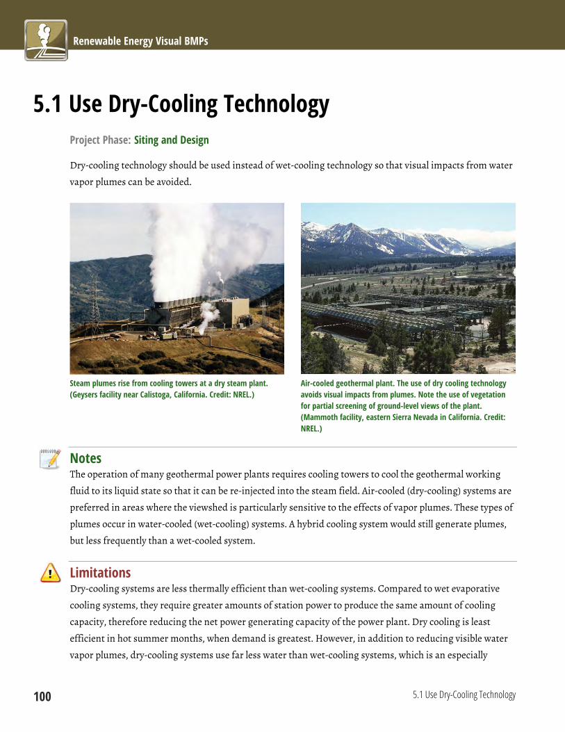
Renewable Energy Visual BMPs
100 5.1 Use Dry-Cooling Technology
5.1 Use Dry-Cooling Technology Project Phase: Siting and Design
Dry-cooling technology should be used instead of wet-cooling technology so that visual impacts from water
vapor plumes can be avoided.
Steam plumes rise from cooling towers at a dry steam plant. (Geysers facility near Calistoga, California. Credit: NREL.)
Air-cooled geothermal plant. The use of dry cooling technology avoids visual impacts from plumes. Note the use of vegetation for partial screening of ground-level views of the plant. (Mammoth facility, eastern Sierra Nevada in California. Credit: NREL.)
Notes The operation of many geothermal power plants requires cooling towers to cool the geothermal working
fluid to its liquid state so that it can be re-injected into the steam field. Air-cooled (dry-cooling) systems are
preferred in areas where the viewshed is particularly sensitive to the effects of vapor plumes. These types of
plumes occur in water-cooled (wet-cooling) systems. A hybrid cooling system would still generate plumes,
but less frequently than a wet-cooled system.
Limitations Dry-cooling systems are less thermally efficient than wet-cooling systems. Compared to wet evaporative
cooling systems, they require greater amounts of station power to produce the same amount of cooling
capacity, therefore reducing the net power generating capacity of the power plant. Dry cooling is least
efficient in hot summer months, when demand is greatest. However, in addition to reducing visible water
vapor plumes, dry-cooling systems use far less water than wet-cooling systems, which is an especially

Chapter 5: Geothermal
5.1 Use Dry-Cooling Technology 101
important benefit in the generally arid western states. While visual impact considerations would not
normally drive a decision regarding the use of wet- or dry-cooling technology, they provide an additional
reason to choose dry-cooling technology where it is feasible to do so.
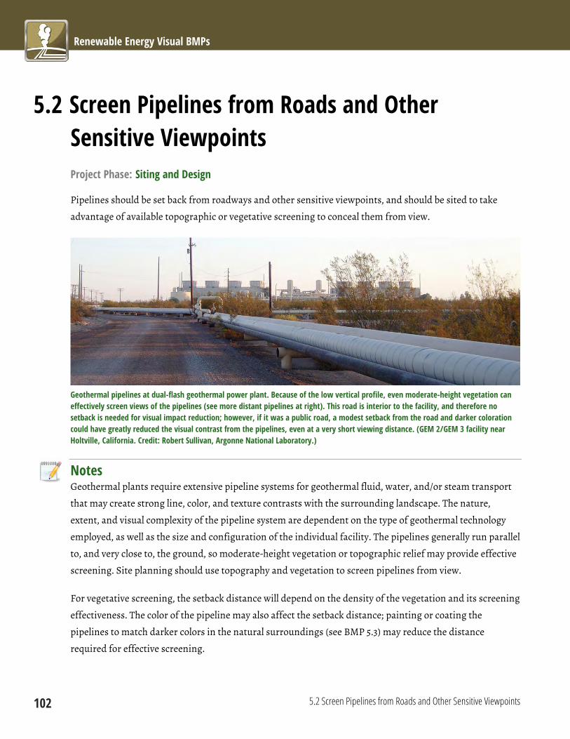
Renewable Energy Visual BMPs
102 5.2 Screen Pipelines from Roads and Other Sensitive Viewpoints
5.2 Screen Pipelines from Roads and Other Sensitive Viewpoints Project Phase: Siting and Design
Pipelines should be set back from roadways and other sensitive viewpoints, and should be sited to take
advantage of available topographic or vegetative screening to conceal them from view.
Geothermal pipelines at dual-flash geothermal power plant. Because of the low vertical profile, even moderate-height vegetation can effectively screen views of the pipelines (see more distant pipelines at right). This road is interior to the facility, and therefore no setback is needed for visual impact reduction; however, if it was a public road, a modest setback from the road and darker coloration could have greatly reduced the visual contrast from the pipelines, even at a very short viewing distance. (GEM 2/GEM 3 facility near Holtville, California. Credit: Robert Sullivan, Argonne National Laboratory.)
Notes Geothermal plants require extensive pipeline systems for geothermal fluid, water, and/or steam transport
that may create strong line, color, and texture contrasts with the surrounding landscape. The nature,
extent, and visual complexity of the pipeline system are dependent on the type of geothermal technology
employed, as well as the size and configuration of the individual facility. The pipelines generally run parallel
to, and very close to, the ground, so moderate-height vegetation or topographic relief may provide effective
screening. Site planning should use topography and vegetation to screen pipelines from view.
For vegetative screening, the setback distance will depend on the density of the vegetation and its screening
effectiveness. The color of the pipeline may also affect the setback distance; painting or coating the
pipelines to match darker colors in the natural surroundings (see BMP 5.3) may reduce the distance
required for effective screening.

Chapter 5: Geothermal
5.2 Screen Pipelines from Roads and Other Sensitive Viewpoints 103
Limitations Although geothermal pipeline systems generally have relatively low profiles, fencing and other screening
may not be tall enough to block views of the pipelines from high-elevation viewpoints, such as nearby
mountains. In addition, if artificial screening elements are constructed (e.g., fences or berms) the
introduction of these screening elements may create negative visual impacts that must be weighed against
the benefits of reduced contrast from the screening of pipelines. In addition, if additional bends in the re-
injection lines are needed, this could add to pumping costs; any increase in the length of the pipeline will
add to the cost as well.

Renewable Energy Visual BMPs
104 5.3 Paint or Coat Aboveground Pipelines
5.3 Paint or Coat Aboveground Pipelines Project Phase: Siting and Design
Aboveground pipelines should be painted or coated to match colors in the natural surroundings. Select
colors from the BLM Standard Environmental Colors Chart CC-001 (see BMP 6.4.6).
Uncoated geothermal pipelines contrast strongly with their surroundings. (Geysers facility near Calistoga, California. Credit: David Parsons, NREL.)
Notes Geothermal plants generally require extensive pipeline systems for geothermal fluid, water, and/or steam
that may create strong color contrasts with the surrounding landscape if untreated. Aboveground pipelines
should generally be painted or coated to match darker colors in the natural surroundings; however,
appropriate color selection is dependent on a careful analysis of site- and project-specific factors.

Chapter 5: Geothermal
5.3 Paint or Coat Aboveground Pipelines 105
Limitations Paint/coatings will require periodic retreatments to maintain
effectiveness in reducing color contrast. In some facilities, pipes
may be color-coded to identify pipeline contents or relative
temperature (hot or cold), for both safety and environmental
protection reasons. Dark coatings on pipes could exacerbate
thermal expansion problems for pipes exposed to desert sun.
However, if selective emissivity coatings are used, they can
reduce insolation (thus reducing thermal expansion and
contraction problems) and black body radiation (thus keeping
more heat in pipelines).
Geothermal pipelines coated to match surroundings at dual-flash geothermal power plant. Note that better results would have been obtained by using a darker color shade on the pipe coating. (GEM 2/GEM 3 facility near Holtville, California. Credit: Robert Sullivan, Argonne National Laboratory.)
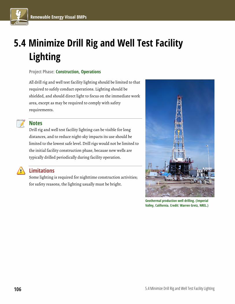
Renewable Energy Visual BMPs
106 5.4 Minimize Drill Rig and Well Test Facility Lighting
5.4 Minimize Drill Rig and Well Test Facility Lighting Project Phase: Construction, Operations
All drill rig and well test facility lighting should be limited to that
required to safely conduct operations. Lighting should be
shielded, and should direct light to focus on the immediate work
area, except as may be required to comply with safety
requirements.
Notes Drill rig and well test facility lighting can be visible for long
distances, and to reduce night-sky impacts its use should be
limited to the lowest safe level. Drill rigs would not be limited to
the initial facility construction phase, because new wells are
typically drilled periodically during facility operation.
Limitations Some lighting is required for nighttime construction activities;
for safety reasons, the lighting usually must be bright.
Geothermal production well drilling. (Imperial Valley, California. Credit: Warren Gretz, NREL.)
Chapter 6: Common Elements
107
Introduction Despite using very different approaches and
technologies for generating electricity, wind, solar,
geothermal, and other types of energy generation
facilities have numerous facility elements in common,
including electric transmission infrastructure, roads,
buildings, tanks, and other structures. Development
of the facilities involves common processes as well,
including both planning activities, such as facility
siting and design, and “on the ground” activities, such
as vegetation clearance and recontouring.
To avoid repetition, the BMP publication presents
BMPs that relate to these common facility elements
and processes separately, as “Common Element”
BMPs. Within this grouping, the BMPs have been
divided into ten topic areas, based on common
themes, such as BMPs for facility siting and design,
vegetation management, and lighting. Although they
may deal with different physical or planning
elements, the BMPs within each topic area share a
common principle or purpose. The ten topic areas are
introduced briefly below.
6.1 Mitigation Planning
These 11 BMPs address planning issues concerning
visual impact analysis and mitigation, including
making sure the right qualified parties conduct the
work using appropriate methods, and that necessary
planning documents are in place. They include the
following:

Renewable Energy Visual BMPs
108
6.1.1 Ensure that Qualified Individuals Conduct and
Review Impact Analyses and Mitigation Plans;
6.1.2 Use Appropriate Methods and Data for Visual
Impact Assessment and Mitigation Planning and
Design;
6.1.3 Incorporate Stakeholder Input into the Siting
and Design and Mitigation Planning Processes;
6.1.4 Conduct a Thorough Assessment of Existing and
Potentially Affected Visual Resources;
6.1.5 Consult the Applicable VRI and VRM Class
Designations;
6.1.6 Develop Spatially Accurate and Realistic Photo
Simulations of Project Facilities;
6.1.7 Develop a Decommissioning and Site
Reclamation Plan;
6.1.8 Develop a Visual Resource Impact Monitoring
and Mitigation Compliance Plan;
6.1.9 Hold a Preconstruction Meeting to Coordinate
the Mitigation Strategy;
6.1.10 Discuss Visual Mitigation Objectives with
Equipment Operators; and
6.1.11 Use Offsite Mitigation.
6.2 Siting and Design
These 17 BMPs help ensure that facilities and their
components are sited to avoid or reduce impacts on
visually sensitive areas. They include the following:
6.2.1 Site Facilities and ROWs outside Sensitive
Viewsheds, or as Far as Possible from Sensitive
Viewing Locations;
6.2.2 Site ROW Crossings to Minimize Impacts on
Linear KOPs;
6.2.3 Site Projects Away from Visually Prominent
Landscape Features;
6.2.4 Site Facilities to Avoid Night-Sky Impacts on
Sensitive Locations;
6.2.5 Site Facilities in Previously Developed or
Disturbed Landscapes;
6.2.6 Site and Design Facilities to Repeat the Form,
Line, Color, and Texture of the Existing Landscape;
6.2.7 Site Facilities in Areas Suitable for Reclamation;
6.2.8 Minimize the Number of Facility Structures;
6.2.9 Collocate Linear Features in Existing ROWs or
Corridors;
6.2.10 Avoid Siting Linear Features in the Centers of
Valley Bottoms and on Ridgetops;
6.2.11 Avoid Skylining;
6.2.12 Site Linear Facilities along Natural Lines within
the Landscape;
6.2.13 Avoid Siting Roads on Side Slopes;
6.2.14 Site Facility Components to Minimize Cut and
Fill;

Chapter 6: Common Elements
109
6.2.15 Avoid Siting Staging and Laydown Areas in
Visually Sensitive Areas;
6.2.16 Site Facilities and Components in Existing
Clearings; and
6.2.17 Bury Underground Utilities along Roads.
6.3 Structure Design and Materials Selection
These eight BMPs address the selection and design of
structures, landforms, and other materials to blend
with the existing landscape setting. They include the
following:
6.3.1 Use Low-Profile Structures and Tanks;
6.3.2 Custom Design Structures in Key Areas;
6.3.3 Consider Use of Alternative Components;
6.3.4 Use Natural-Looking Constructed Landform,
Vegetative, or Architectural Screening;
6.3.5 Minimize Use of Signs and Make Signs Visually
Unobtrusive;
6.3.6 Avoid Unnecessary Use of Gravel/Paved
Surfaces;
6.3.7 Use Rounded Road Cut Slopes; and
6.3.8 Use Monopole and Lattice Electric Transmission
Towers Appropriately.
6.4 Materials Surface Treatment
These 12 BMPs address the selection of appropriate
colors and surface treatments for structures to reduce
color contrast with the surrounding natural
environment. They include the following:
6.4.1 Require a Site Study for Color and Texture
Selection;
6.4.2 Select Materials and Surface Treatments to
Repeat the Form, Line, Color, and Texture of
Surrounding Landscape;
6.4.3 Consider Seasonal Changes and Seasons of
Heaviest use in Choosing Materials Colors and
Textures;
6.4.4 Color Treat Structures to Reduce Contrasts with
Existing Landscape;
6.4.5 Use Non-reflective Materials, Coatings, and/or
Paint;
6.4.6 Select Surface Treatment Colors from the BLM
Standard Environmental Colors Chart;
6.4.7 Test Color Selections;
6.4.8 Color Treat Grouped Structures Using the Same
Color;
6.4.9 Color Treat Exposed Rock Faces;
6.4.10 Color Treat Transmission Towers to Reduce
Contrasts with Existing Landscape;
6.4.11 Use Camouflage and/or Disguise Strategies for
Close KOPs in Highly Sensitive Viewsheds; and
6.4.12 Maintain Painted, Stained, or Coated Surfaces
Properly.

Renewable Energy Visual BMPs
110
6.5 Lighting
These seven BMPs help ensure that projects minimize
night-sky impacts through proper lighting design and
usage. They include the following:
6.5.1 Prepare a Lighting Plan;
6.5.2 Use Audio Visual Warning System Technology
for Hazard Lighting on Structures Taller than 200 ft;
6.5.3 Use Full Cutoff Luminaires;
6.5.4 Direct Lights Properly to Eliminate Light Spill
and Trespass;
6.5.5 Use Amber Instead of Bluish-White Lighting;
6.5.6 Minimize Lighting Usage during Construction
and Operations; and
6.5.7 Use Vehicle-Mounted Lights or Portable Light
Towers for Nighttime Maintenance Activities.
6.6 Avoiding Disturbance
These eight BMPs help to avoid or minimize land and
other types of disturbance. They include the
following:
6.6.1 Minimize Project Footprint and Associated
Disturbance;
6.6.2 Avoid Unnecessary Road Improvements;
6.6.3 Use Penalty Clauses to Protect High-Value
Landscape Features;
6.6.4 Confine Construction Activities and Facilities to
Pre-Defined Areas;
6.6.5 Provide Construction Personnel with Avoidance
Area Maps;
6.6.6 Do Not Apply Paints or Permanent Discoloring
Agents to Rocks or Vegetation to Mark Survey Limits
6.6.7 Require Overland Driving Where Recontouring
Is Not Required; and
6.6.8 Use Air Transport to Erect Transmission
Towers.
6.7 Soils and Erosion Management
These five BMPs help to avoid or reduce visual
impacts from wind and water erosion through dust
control, erosion and sediment control, and topsoil
management. They include the following:
6.7.1 Implement Dust and Wind Erosion Control
Measures;
6.7.2 Implement Erosion and Sediment Control
Measures;
6.7.3 Implement Temporary and/or Permanent Soil
Stabilization Measures;
6.7.4 Strip, Stockpile, and Stabilize Topsoil for Re-
spreading; and
6.7.5 Segregate Topsoil and Reapply to Disturbed
Areas.
6.8 Vegetation Management
These eleven BMPs concern vegetation protection,
vegetation clearing techniques, and measures to
Chapter 6: Common Elements
111
promote successful revegetation. They include the
following:
6.8.1 Prepare a Reclamation Plan;
6.8.2 Preserve Existing Vegetation;
6.8.3 Use Retaining Walls, Berms, Fences, and
Markings to Protect Trees and Other Scenic Features;
6.8.4 Design Vegetative Openings to Mimic Natural
Openings;
6.8.5 Use Partial ROW Clearing and Feather Edges of
Transmission ROWs;
6.8.6 Avoid Slash Piles in Sensitive Viewing Areas;
Chip Slash for Mulch to Hide Fresh Soil;
6.8.7 Mulch Cleared Areas, Furrow Slopes, and Use
Planting Holes;
6.8.8 Use Pitting and Vertical Mulching to Facilitate
Revegetation and Discourage Vehicle Traffic;
6.8.9 Revegetate Using Salvaged Native Plants and
Approved, Weed-free Seed Mixes;
6.8.10 Transplant Vegetation from Cleared Areas; and
6.8.11 Monitor and Maintain Revegetated Areas until
Vegetation Is Self-Sustaining.
6.9 Reclamation
These nine BMPs promote successful interim and
long-term reclamation through good recontouring
practices, site preparation to promote revegetation,
and removal of structures and surface treatments.
They include the following:
6.9.1 Review Predevelopment Visual Conditions after
Construction;
6.9.2 Begin Site Reclamation during Construction
and Operations, Immediately after Disturbances;
6.9.3 Recontour Disturbed Areas to Approximate
Natural Slopes;
6.9.4 Scarify/Roughen Cut Slopes and Recontoured
Areas;
6.9.5 Salvage and Replace Rocks, Brush, and Woody
Debris;
6.9.6 Sculpt and Shape Bedrock Landforms;
6.9.7 Close and Remediate Unused Access Roads;
6.9.8 Remove Aboveground and Near-Ground
Structures; and
6.9.9 Remove or Bury Gravel and Other Surface
Treatments.
6.10 “Good Housekeeping”
These nine BMPs address measures to keep the site
clean and orderly during construction, operations,
and decommissioning. They include the following:
6.10.1 Develop “Housekeeping” Procedures;
6.10.2 Maintain a Clean Worksite;
6.10.3 Prohibit Onsite Burning;

Renewable Energy Visual BMPs
112
6.10.4 Use Exit Tire Washes and Vehicle Tracking
Pads to Reduce the Tracking of Sediment onto Roads;
6.10.5 Remove or Avoid Slash Piles;
6.10.6 Clean Off-Road Equipment;
6.10.7 Remove Stakes and Flagging;
6.10.8 Use Fabric-Covered Fences to Conceal Material
Storage Yards and Laydown Yards; and
6.10.9 Actively Maintain Operating Facilities.

Chapter 6: Common Elements 6.1 Mitigation Planning
113
6.1 Mitigation Planning These BMPs address planning issues concerning visual impact analysis and mitigation, including making sure that
qualified parties conduct the work using appropriate methods, and that necessary planning documents are in place.
6.1 Mitigation Planning Siting and Design Construction Operations
Decommissioning and
Reclamation
6.1.1 Ensure that Qualified Individuals Conduct and Review Impact Analyses and Mitigation Plans (p 114)
6.1.2 Use Appropriate Methods and Data for Visual Impact Assessment and Mitigation Planning and Design (p 116)
6.1.3 Incorporate Stakeholder Input into the Siting and Design and Mitigation Planning Processes (p 118)
6.1.4 Consult the Applicable Visual Resource Inventory (VRI) and Visual Resource Management (VRM) Class Designations (p 120)
6.1.5 Conduct a Thorough Assessment of Existing and Potentially Affected Visual Resources (p 123)
6.1.6 Develop Spatially Accurate and Realistic Photo Simulations of Project Facilities (p 127)
6.1.7 Develop a Visual Resource Impact Monitoring and Mitigation Compliance Plan (p 131)
6.1.8 Develop a Decommissioning and Site Reclamation Plan (p 133)
6.1.9 Hold a Preconstruction Meeting to Coordinate the Mitigation Strategy (p 134)
6.1.10 Discuss Visual Mitigation Objectives with Equipment Operators (p 136)
6.1.11 Use Offsite Mitigation (p 138)
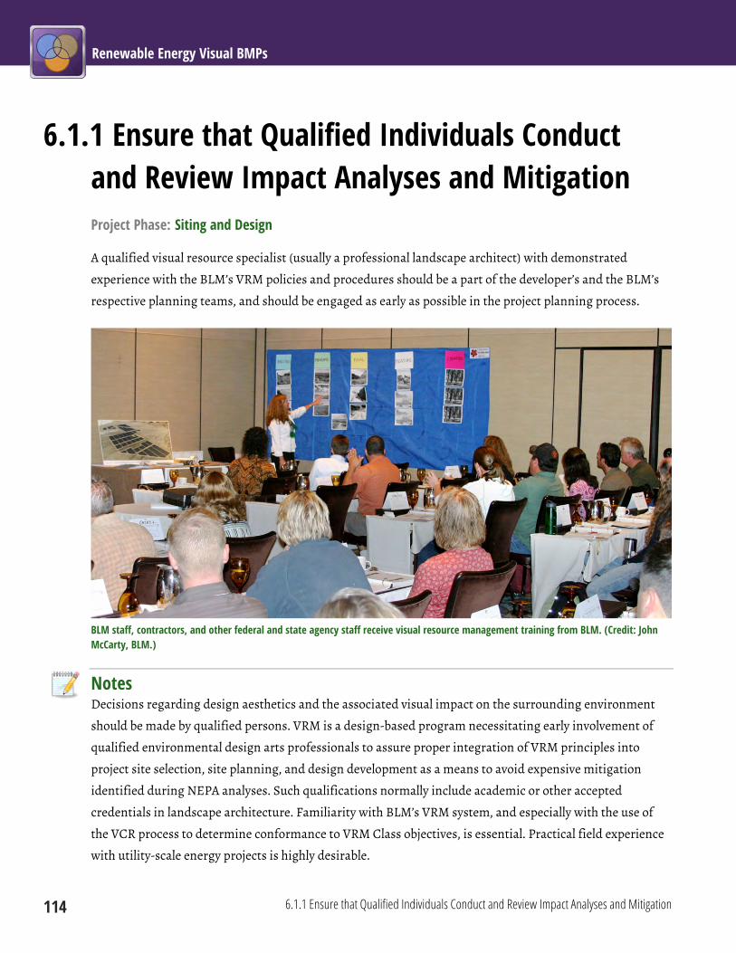
Renewable Energy Visual BMPs
114 6.1.1 Ensure that Qualified Individuals Conduct and Review Impact Analyses and Mitigation
6.1.1 Ensure that Qualified Individuals Conduct and Review Impact Analyses and Mitigation Project Phase: Siting and Design
A qualified visual resource specialist (usually a professional landscape architect) with demonstrated
experience with the BLM’s VRM policies and procedures should be a part of the developer’s and the BLM’s
respective planning teams, and should be engaged as early as possible in the project planning process.
BLM staff, contractors, and other federal and state agency staff receive visual resource management training from BLM. (Credit: John McCarty, BLM.)
Notes Decisions regarding design aesthetics and the associated visual impact on the surrounding environment
should be made by qualified persons. VRM is a design-based program necessitating early involvement of
qualified environmental design arts professionals to assure proper integration of VRM principles into
project site selection, site planning, and design development as a means to avoid expensive mitigation
identified during NEPA analyses. Such qualifications normally include academic or other accepted
credentials in landscape architecture. Familiarity with BLM’s VRM system, and especially with the use of
the VCR process to determine conformance to VRM Class objectives, is essential. Practical field experience
with utility-scale energy projects is highly desirable.

Chapter 6: Common Elements 6.1 Mitigation Planning
6.1.1 Ensure that Qualified Individuals Conduct and Review Impact Analyses and Mitigation 115
The visual resource specialist’s responsibilities include identifying and addressing visual resource issues as
a part of the early planning and design phase of the projects; working directly with the proponent’s
engineer to explore potential design options; evaluating and preparing additional mitigation measures
when preparing NEPA documents; and monitoring compliance with VRM conditions of approval when
under construction, during operation, and at decommissioning.
The large size and generally strong visual contrasts generated by renewable energy facilities and associated
transmission makes visual impact mitigation for these projects challenging. Proper siting of facilities and
facility components is the most effective way to mitigate potential visual impacts; engaging a visual
resource specialist early in the project planning process helps to avoid costly corrective mitigation that
could have been avoided though better siting and design decisions.
Limitations Project proponents typically will not have visual resource expertise on staff, and the same may be true for
contractors hired to conduct visual impact analyses. BLM project staff may need to consult with state VRM
leads and other VRM specialists within BLM.
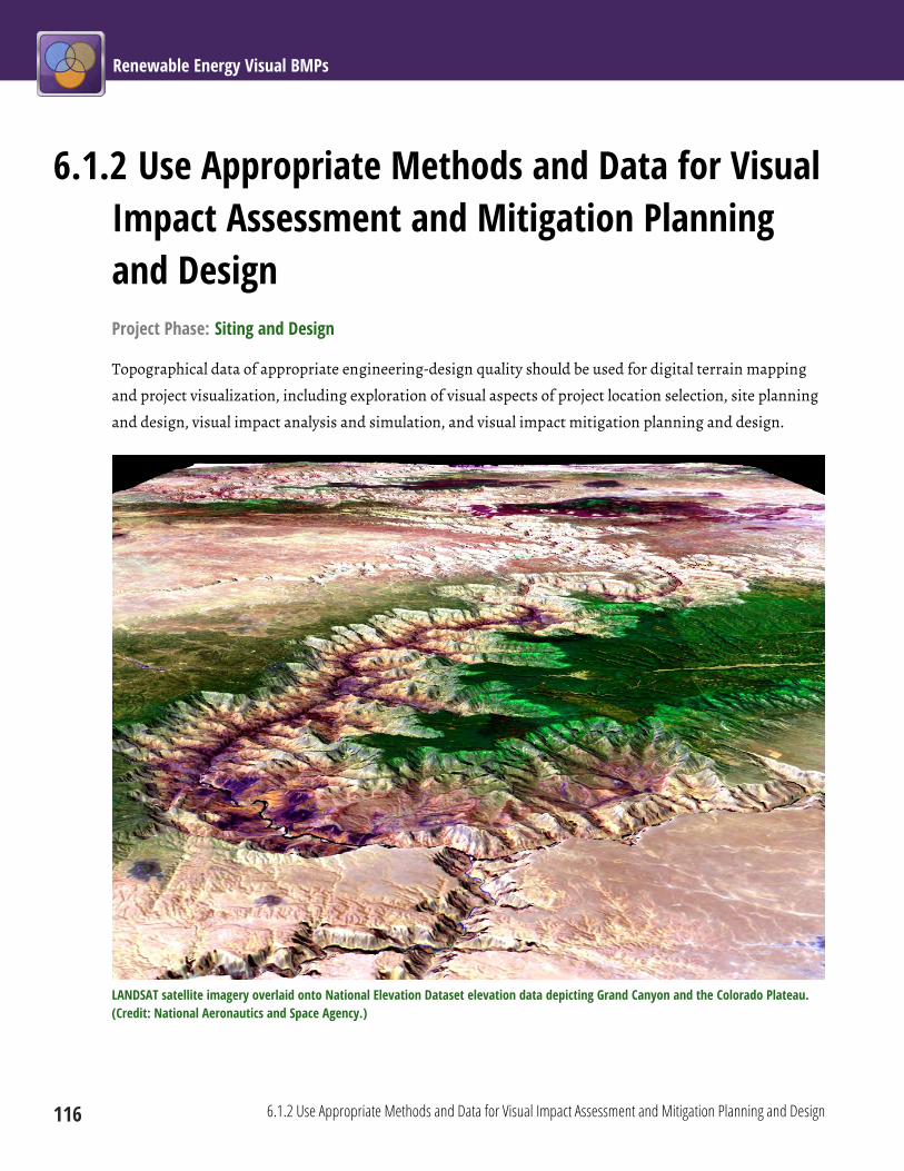
Renewable Energy Visual BMPs
116 6.1.2 Use Appropriate Methods and Data for Visual Impact Assessment and Mitigation Planning and Design
6.1.2 Use Appropriate Methods and Data for Visual Impact Assessment and Mitigation Planning and Design Project Phase: Siting and Design
Topographical data of appropriate engineering-design quality should be used for digital terrain mapping
and project visualization, including exploration of visual aspects of project location selection, site planning
and design, visual impact analysis and simulation, and visual impact mitigation planning and design.
LANDSAT satellite imagery overlaid onto National Elevation Dataset elevation data depicting Grand Canyon and the Colorado Plateau. (Credit: National Aeronautics and Space Agency.)
Chapter 6: Common Elements 6.1 Mitigation Planning
6.1.2 Use Appropriate Methods and Data for Visual Impact Assessment and Mitigation Planning and Design 117
Notes Visual impact analysis and mitigation planning and design should be performed through field assessments,
and through the use of global positioning system (GPS) technology, photo documentation, computer-aided
design and development software, GIS software, and three-dimensional modeling and rendering software.
These tools should be used to analyze visibility, select KOPs, depict site conditions, and create visual
simulations that reflect potential visual impacts and mitigation measures, including iterative visualization
of both project design evolution and mitigation outcomes. The digital terrain data should be at a horizontal
and vertical resolution suitable for site design and accurate placement of proposed developments at a
landscape and project viewshed scale. Visualization tools should be used early in project planning to inform
project siting, design, and mitigation planning and to support the visual impact assessment.
Limitations In some remote areas, terrain data of sufficiently high resolution may be difficult or very expensive to
obtain. Some visualization techniques require advanced computing skills and software/hardware.
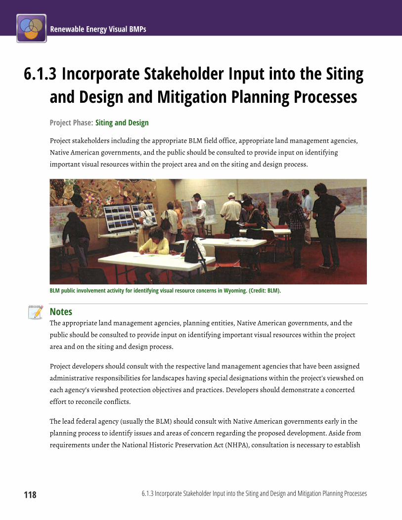
Renewable Energy Visual BMPs
118 6.1.3 Incorporate Stakeholder Input into the Siting and Design and Mitigation Planning Processes
6.1.3 Incorporate Stakeholder Input into the Siting and Design and Mitigation Planning Processes Project Phase: Siting and Design
Project stakeholders including the appropriate BLM field office, appropriate land management agencies,
Native American governments, and the public should be consulted to provide input on identifying
important visual resources within the project area and on the siting and design process.
BLM public involvement activity for identifying visual resource concerns in Wyoming. (Credit: BLM).
Notes The appropriate land management agencies, planning entities, Native American governments, and the
public should be consulted to provide input on identifying important visual resources within the project
area and on the siting and design process.
Project developers should consult with the respective land management agencies that have been assigned
administrative responsibilities for landscapes having special designations within the project's viewshed on
each agency’s viewshed protection objectives and practices. Developers should demonstrate a concerted
effort to reconcile conflicts.
The lead federal agency (usually the BLM) should consult with Native American governments early in the
planning process to identify issues and areas of concern regarding the proposed development. Aside from
requirements under the National Historic Preservation Act (NHPA), consultation is necessary to establish

Chapter 6: Common Elements 6.1 Mitigation Planning
6.1.3 Incorporate Stakeholder Input into the Siting and Design and Mitigation Planning Processes 119
whether the project is likely to disturb traditional cultural properties, affect access rights to particular
locations, disrupt traditional cultural practices, and/or visually impact areas important to the tribe(s).
In addition to traditional meetings, possible approaches for stakeholder involvement include conducting
public forums for disseminating information, offering organized tours of operating renewable energy
development projects, using computer simulation and visualization techniques in public presentations,
and conducting surveys regarding public perceptions and attitudes about specific types of renewable
energy developments. Beyond traditional meetings, these efforts often help stakeholders better understand
the potential visual impacts of the project, and in some cases this may result in decreased stakeholder
opposition.
Limitations Potentially affected stakeholders may be difficult to identify or to engage in the earliest stages of project
planning. The input of participating stakeholders may not be complete and may not be representative of all
viewpoints. Some stakeholders may be entirely opposed to the project on the basis of visual impacts that are
not mitigated effectively; if the project is built, they may feel that their input was not appropriately
considered in the planning and siting process. It may also be challenging to reconcile opposing views
among project stakeholders.

Renewable Energy Visual BMPs
120 6.1.4 Consult the Applicable Visual Resource Inventory (VRI) and Visual Resource Management (VRM) Class Designations
6.1.4 Consult the Applicable Visual Resource Inventory (VRI) and Visual Resource Management (VRM) Class Designations Project Phase: Siting and Design
Project developers should consult the relevant VRI class values and VRM class designations of proposed and
alternative project locations and surrounding viewsheds for information regarding visual quality, public
sensitivities, visibility, visual management objectives, and potential VRM conformance issues.
Notes The applicable VRI provides important baseline information about the project area’s visual resource values
and should be used to identify visual resource attributes that may be affected by project development.
Visual quality, public sensitivity, and visibility (distance zones) data from the VRI should be used in siting,
design, and mitigation planning. The VRI narrative provides useful information about the locations,
numbers, types, and sensitivities of viewers in the project area and can be used to inform the selection of
KOPs. In order to meet the requirements of NEPA to disclose potential impacts on the resource, anticipated
changes in VRI values must be analyzed.
The VRM class designations for the proposed project location and surrounding viewshed include VRM
objectives that reflect land management decisions (presented in the RMP) made in consideration of
multiple land use objectives. VRM class designations are not measures of scenic quality or other visual
resource values, and thus are fundamentally different than VRI classes. The impact analysis must discuss
the project’s conformance to the applicable VRM class designation. It is the developer’s responsibility to
conduct an early investigation of the respective project’s compatibility with the VRM class objectives and
the potential that these objectives can be met by applying effective siting, design, and mitigation strategies.
Project developers should document and demonstrate how the visual management objectives were factored
into the various phases of project planning and decision rationale.
Limitations Inexperienced analysts sometimes confuse VRM and VRI data, and BLM staff may need to provide
oversight to ensure that the VRI information is considered and presented correctly. In some field offices,
VRI data may be outdated or difficult to obtain in an easily usable format (e.g., GIS data), although the BLM
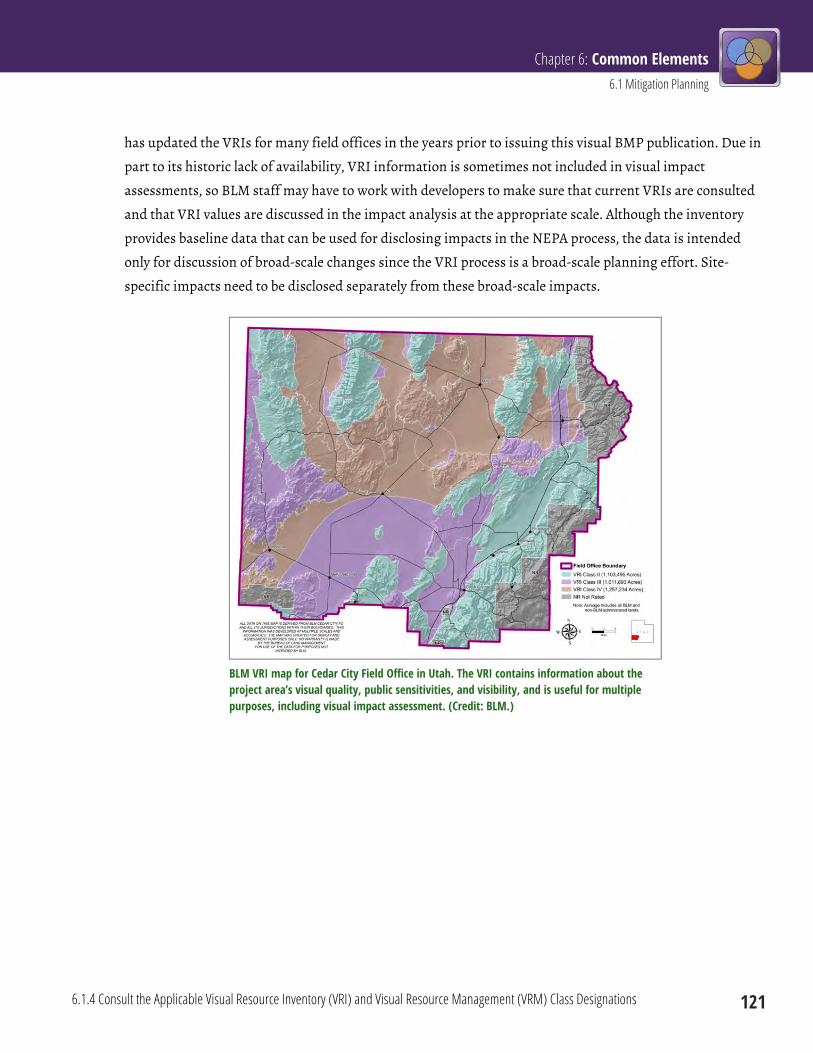
Chapter 6: Common Elements 6.1 Mitigation Planning
6.1.4 Consult the Applicable Visual Resource Inventory (VRI) and Visual Resource Management (VRM) Class Designations 121
has updated the VRIs for many field offices in the years prior to issuing this visual BMP publication. Due in
part to its historic lack of availability, VRI information is sometimes not included in visual impact
assessments, so BLM staff may have to work with developers to make sure that current VRIs are consulted
and that VRI values are discussed in the impact analysis at the appropriate scale. Although the inventory
provides baseline data that can be used for disclosing impacts in the NEPA process, the data is intended
only for discussion of broad-scale changes since the VRI process is a broad-scale planning effort. Site-
specific impacts need to be disclosed separately from these broad-scale impacts.
BLM VRI map for Cedar City Field Office in Utah. The VRI contains information about the project area’s visual quality, public sensitivities, and visibility, and is useful for multiple purposes, including visual impact assessment. (Credit: BLM.)
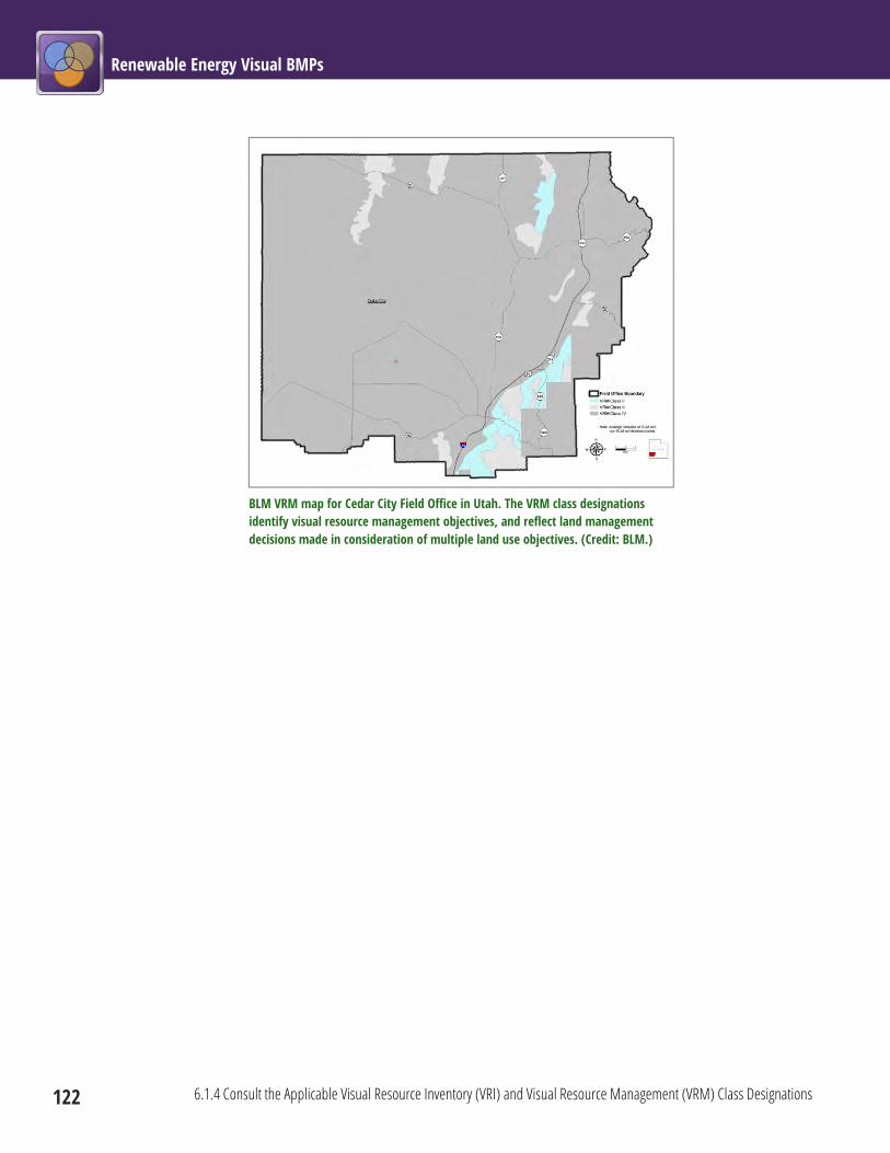
Renewable Energy Visual BMPs
122 6.1.4 Consult the Applicable Visual Resource Inventory (VRI) and Visual Resource Management (VRM) Class Designations
BLM VRM map for Cedar City Field Office in Utah. The VRM class designations identify visual resource management objectives, and reflect land management decisions made in consideration of multiple land use objectives. (Credit: BLM.)

Chapter 6: Common Elements 6.1 Mitigation Planning
6.1.5 Conduct a Thorough Assessment of Existing and Potentially Affected Visual Resources 123
6.1.5 Conduct a Thorough Assessment of Existing and Potentially Affected Visual Resources Project Phase: Siting and Design
The visual impact analysis should identify and map landscape characteristics, key observation points
(KOPs) and key viewsheds, prominent scenic and cultural landmarks, and other visually sensitive areas
near the project location. The analysis should include a review of the land-use planning-level VRI to assess
and analyze potential impacts on the relative visual resource values and the applicable RMP, and to identify
the VRM objectives for potential conformance conflicts (see BMP 6.1.4).
Notes KOPs should be selected by first determining the extent of the viewshed using GIS-based viewshed
modeling tools. The viewshed modeling should illustrate the areas from which the proposed facilities may
theoretically be seen. The distance from the project selected for the viewshed analysis should be sufficient
to include all areas likely to be subject to non-negligible visual contrasts from the proposed project. The
viewshed analysis should incorporate offsets for both viewer and target (project) heights. Viewer height
offset should be 5.5 ft. The target height offset should be equivalent to the tallest facilities to be incorporated
in the impact analysis. Because of the long visibility distances for utility-scale renewable energy facilities,
the viewshed analysis should incorporate earth curvature.
From within the visible areas, KOPs should then be selected at places where people would be expected: for
example, at scenic overlooks, roads, trails, campgrounds, recreationally active river corridors, historical
sites and trails, and residential areas. For the purpose of conducting a visual contrast rating evaluation, the
number of KOPs should be reduced to those that serve as the best representations for determining
conformance to the respective VRM class objectives. The BLM should approve KOP selections, and the BLM
should reserve the right to require additional KOPs to further determine the extent of visual impacts and
conformance to VRM class objectives.
The assessment of visual resources should be part of the project’s early pre-planning phases, and may need
to be re-assessed during the life of the project as the project design progresses, or if KOPs change, for
example, in response to residential area or road construction, development of scenic attractions, or
changing recreation patterns.

Renewable Energy Visual BMPs
124 6.1.5 Conduct a Thorough Assessment of Existing and Potentially Affected Visual Resources
Limitations There is no required or accepted radius of visual impact analysis for utility-scale renewable energy facilities.
An appropriate value may need to be determined on a site- and project-specific basis; however, because of
the large size and generally high visibility of renewable energy facilities (particularly wind and solar
facilities), distances of 25 mi or more may be appropriate in the open landscapes typical of BLM-managed
lands.
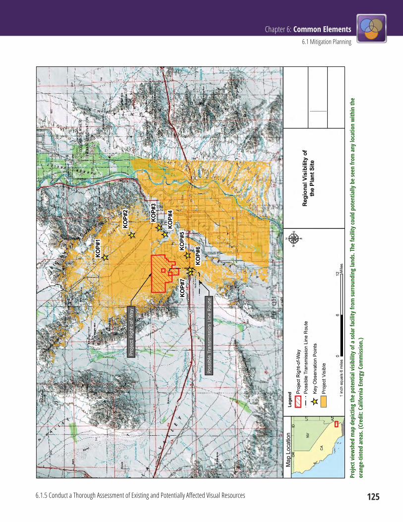
Chapter 6: Common Elements 6.1 Mitigation Planning
6.1.5 Conduct a Thorough Assessment of Existing and Potentially Affected Visual Resources 125
Proj
ect v
iew
shed
map
dep
ictin
g th
e po
tent
ial v
isibi
lity
of a
sola
r fac
ility
from
surro
undi
ng la
nds.
The
facil
ity co
uld
pote
ntia
lly b
e se
en fr
om a
ny lo
catio
n w
ithin
the
oran
ge-ti
nted
are
as. (
Cred
it: C
alifo
rnia
Ener
gy C
omm
issio
n.)
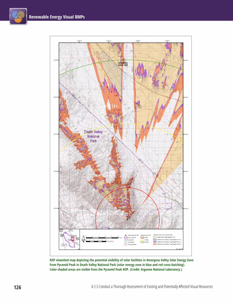
Renewable Energy Visual BMPs
126 6.1.5 Conduct a Thorough Assessment of Existing and Potentially Affected Visual Resources
KOP viewshed map depicting the potential visibility of solar facilities in Amargosa Valley Solar Energy Zone from Pyramid Peak in Death Valley National Park (solar energy zone in blue and red cross-hatching). Color-shaded areas are visible from the Pyramid Peak KOP. (Credit: Argonne National Laboratory.)

Chapter 6: Common Elements 6.1 Mitigation Planning
6.1.6 Develop Spatially Accurate and Realistic Photo Simulations of Project Facilities 127
6.1.6 Develop Spatially Accurate and Realistic Photo Simulations of Project Facilities Project Phase: Siting and Design
Spatially accurate and realistic photo simulations of project facilities in the proposed location must be
prepared and evaluated in accordance with BLM Handbook H-8431-1 and other agency directives, as part of
the siting process. They should show views from KOPs including sensitive visual resource areas and highly
sensitive viewing locations such as specially designated areas, scenic highways, and residences. The BLM
and other stakeholders should be involved in selecting KOPs for simulations. The BLM should approve KOP
selections for use in preparing simulations, and should reserve the right to require additional simulations
to further determine the extent of visual impacts and conformance to VRM class objectives.
Notes Visual impact simulations are a critical component of the visual impact analysis and mitigation planning
and design process. BLM VRM policy strongly recommends that visual impact simulations be prepared for
potentially high-impact projects, which would normally include utility-scale wind, solar, and geothermal
facilities, as well as transmission projects. Simulations should be prepared as described in BLM Handbook
H-8431-1, Visual Resource Contrast Rating, in order to evaluate visual contrasts of the energy projects to
determine if the proposed project is in conformance with the VRM Management Class objectives that apply
to the project area.
Simulations should be based on accurate project design specifications and on accurate spatial information
(particularly elevation data) and must account for screening vegetation and structures. Simulations should
be spatially accurate; they should show all of the project elements that would be visible, at the correct size
and location, and in the correct visual perspective. They should be realistic (i.e., they should look like the
facility would actually look when built, as seen from the relevant KOP), and they should be colored and
shaded realistically, with cast shadows that are depicted accurately and realistically. Any known errors in
accuracy or realism should be clearly stated so that viewer expectations are appropriate.
Simulations should portray a range of viewing conditions and anticipated impacts associated with lighting
conditions and sun angles. Simulations also should show enough of the surrounding landscape to show the
project in the appropriate spatial context. They should be reproduced at a size large enough to be
comfortably viewed from the appropriate specified distance to accurately depict the apparent size of the
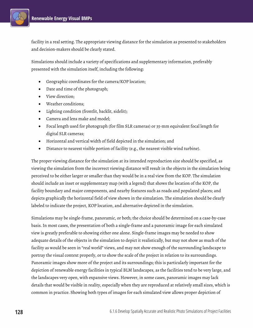
Renewable Energy Visual BMPs
128 6.1.6 Develop Spatially Accurate and Realistic Photo Simulations of Project Facilities
facility in a real setting. The appropriate viewing distance for the simulation as presented to stakeholders
and decision-makers should be clearly stated.
Simulations should include a variety of specifications and supplementary information, preferably
presented with the simulation itself, including the following:
Geographic coordinates for the camera/KOP location;
Date and time of the photograph;
View direction;
Weather conditions;
Lighting condition (frontlit, backlit, sidelit);
Camera and lens make and model;
Focal length used for photograph (for film SLR cameras) or 35-mm equivalent focal length for
digital SLR cameras;
Horizontal and vertical width of field depicted in the simulation; and
Distance to nearest visible portion of facility (e.g., the nearest visible wind turbine).
The proper viewing distance for the simulation at its intended reproduction size should be specified, as
viewing the simulation from the incorrect viewing distance will result in the objects in the simulation being
perceived to be either larger or smaller than they would be in a real view from the KOP. The simulation
should include an inset or supplementary map (with a legend) that shows the location of the KOP, the
facility boundary and major components, and nearby features such as roads and populated places; and
depicts graphically the horizontal field of view shown in the simulation. The simulation should be clearly
labeled to indicate the project, KOP location, and alternative depicted in the simulation.
Simulations may be single-frame, panoramic, or both; the choice should be determined on a case-by-case
basis. In most cases, the presentation of both a single-frame and a panoramic image for each simulated
view is greatly preferable to showing either one alone. Single-frame images may be needed to show
adequate details of the objects in the simulation to depict it realistically, but may not show as much of the
facility as would be seen in “real world” views, and may not show enough of the surrounding landscape to
portray the visual context properly, or to show the scale of the project in relation to its surroundings.
Panoramic images show more of the project and its surroundings; this is particularly important for the
depiction of renewable energy facilities in typical BLM landscapes, as the facilities tend to be very large, and
the landscapes very open, with expansive views. However, in some cases, panoramic images may lack
details that would be visible in reality, especially when they are reproduced at relatively small sizes, which is
common in practice. Showing both types of images for each simulated view allows proper depiction of
Chapter 6: Common Elements 6.1 Mitigation Planning
6.1.6 Develop Spatially Accurate and Realistic Photo Simulations of Project Facilities 129
facility details while showing the facility in the proper visual context and better depicting its scale in
relationship to its surroundings.
In some cases, the use of animations may be appropriate. The visual chracteristics of renewable energy
facilities are such that the viewing experience is dynamic; the appearance of wind and solar facilities in
particular may change dramatically in the course of a day. Animations are particularly effective at showing
wind turbine blade motion, changes in position and reflectivity of solar collectors/reflectors over the course
of a day, and changes in lighting conditions as the sun rises and sets or clouds pass in front of the sun.
Animations can also depict changes in the viewed landscape and visual contrasts as the viewer moves, for
example, while hiking a trail, floating a river, or driving a scenic byway.
Limitations The development of spatially accurate and realistic simulations is a complex technical process that requires
a high degree of skill, appropriate technology, accurate data, and rigorous methods. If improperly prepared,
simulations may be misleading, but the errors may not be apparent to casual observers. For a variety of
technical reasons, even when properly prepared, simulations are limited in their ability to realistically
portray the full range of the visual experience of utility-scale renewable energy facilities, particularly wind
and solar facilities. In addition, if the project design changes after the preparation of the simulations (a
relatively common occurrence), the simulations may not depict the actual project that is eventually built.
Because animations are more expensive to produce than still-image simulations, their use is generally
restricted to situations of high visual sensitivity.

Renewable Energy Visual BMPs
130 6.1.6 Develop Spatially Accurate and Realistic Photo Simulations of Project Facilities
Phot
omon
tage
sim
ulat
ion
of w
ind
ener
gy fa
cility
on
BLM
-adm
inist
ered
land
in A
rizon
a. N
ote
the
exte
nsiv
e su
pple
men
tary
info
rmat
ion
prov
ided
with
the
simul
atio
n, in
cludi
ng p
anor
amic
phot
ogra
ph to
show
land
scap
e co
ntex
t, in
set m
ap o
f win
d fa
cility
and
sim
ulat
ion
KOP,
des
crip
tion
of li
ghtin
g co
nditi
ons,
phot
ogra
phy
deta
ils, a
nd co
rrec
t sim
ulat
ion
view
ing
dist
ance
. (Cr
edit:
BLM
.)
Chapter 6: Common Elements 6.1 Mitigation Planning
6.1.7 Develop a Visual Resource Impact Monitoring and Mitigation Compliance Plan 131
6.1.7 Develop a Visual Resource Impact Monitoring and Mitigation Compliance Plan Project Phase: Siting and Design
A visual resource impact monitoring and mitigation compliance plan should be developed and
implemented. The plan should include provisions for monitoring the effectiveness of the visual impact
mitigation strategy and determining compliance with the project’s visual impact mitigation requirements.
Notes The visual resource impact monitoring and mitigation compliance plan should ensure that required visual
impact mitigations are implemented and are effective. Visual design objectives within the plans should be
measurable and monitored during construction, operations, and decommissioning. The plan should
include monitoring and compliance elements that establish the monitoring requirements and thresholds
for acceptable performance, and measures for corrective actions. The visual contrast rating procedures
should also be included for field-based compliance assessment during operations and after
decommissioning.
Limitations Currently, the BLM lacks protocols or guidelines for visual impact and mitigation conformance monitoring,
and it is not required of developers.
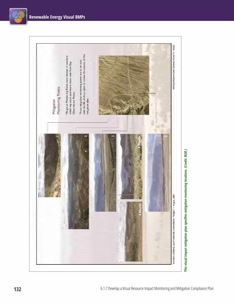
Renewable Energy Visual BMPs
132 6.1.7 Develop a Visual Resource Impact Monitoring and Mitigation Compliance Plan
This
visu
al im
pact
miti
gatio
n pl
an sp
ecifi
es m
itiga
tion
mon
itorin
g lo
catio
ns. (
Cred
it: B
LM.)

Chapter 6: Common Elements 6.1 Mitigation Planning
6.1.8 Develop a Decommissioning and Site Reclamation Plan 133
6.1.8 Develop a Decommissioning and Site Reclamation Plan Project Phase: Siting and Design
A decommissioning and site reclamation plan should be developed and implemented in order to ensure
that the area’s pre-development scenic quality and integrity are restored and that the project area is visually
integrated into the surrounding landscape setting. Important plan elements should include requirements
that most aboveground and near-ground structures be removed, that the project site be re-graded, and that
native vegetation be re-established to be consistent with the surrounding landscape.
Notes The plan should be in place prior to construction because decommissioning decisions can influence all
phases of the facility’s life cycle. Reclamation of the construction areas, including roads and rights-of-way
(ROWs), should begin immediately after construction to reduce the likelihood of visual contrasts associated
with erosion and invasive plant infestation and to reduce the visibility of temporarily disturbed areas as
quickly as possible. Topsoil from all decommissioning activities should be salvaged and reapplied during
final reclamation. See BMPs 6.9.1–6.9.9 for specific recommended best practices for site reclamation. The
decommissioning and site reclamation plan should be developed in coordination with the visual impact
monitoring and mitigation compliance plan (see BMP 6.1.7).
Limitations The ultimate success of the decommissioning and site reclamation plan depends in part on diligence on the
part of the project proponent and effective monitoring by the BLM.

Renewable Energy Visual BMPs
134 6.1.9 Hold a Preconstruction Meeting to Coordinate the Mitigation Strategy
6.1.9 Hold a Preconstruction Meeting to Coordinate the Mitigation Strategy Project Phase: Siting and Design
BLM landscape architects or other designated visual resource specialists should participate in the project
pre-construction meeting to coordinate the VRM mitigation strategy and confirm the compliance-checking
schedule and procedures. Final design and construction documents should be reviewed for completeness
with regard to the visual mitigation elements, assuring that requirements and commitments are
adequately addressed. The construction documents should include, but not be limited to, grading,
drainage, revegetation, vegetation clearing, and feathering plans, and they should demonstrate how VRM
objectives will be met, monitored, and measured for conformance.
BLM landscape architects or other designated visual resource specialists should participate in the project pre-construction meeting. (Credit: BLM.)
Notes VRM consultations should take place early in the project planning phase, in accordance with BLM VRM
manuals and handbooks, to help determine the proposed project’s potential conformance to the applicable
RMP’s VRM class designation and other potential constraints. Early consultation between the project

Chapter 6: Common Elements 6.1 Mitigation Planning
6.1.9 Hold a Preconstruction Meeting to Coordinate the Mitigation Strategy 135
proponent and BLM VRM specialists results in better mitigation and fewer potentially costly “surprises” for
both the developer and the BLM.
Limitations Design details for all project elements may not yet exist at a given point in time, and are subject to change.
Additional meetings may be necessary, especially if the project plans change significantly after the initial
preconstruction meeting.

Renewable Energy Visual BMPs
136 6.1.10 Discuss Visual Mitigation Objectives with Equipment Operators
6.1.10 Discuss Visual Mitigation Objectives with Equipment Operators Project Phase: Construction
Visual impact mitigation objectives and activities should be discussed with equipment operators before
construction activities begin.
Making sure that equipment operators understand good practices to avoid unnecessary damage to visual resources can have significant benefits in improved mitigation results. (Credit: BLM.)
Notes Because equipment operators are the persons actually making the alterations to the landscape associated
with project development, making sure that they understand good practices to avoid unnecessary damage
to visual resources can have significant benefits in improved mitigation results. Furthermore, experienced
equipment operators may have good suggestions for improving techniques for specific mitigation

Chapter 6: Common Elements 6.1 Mitigation Planning
6.1.10 Discuss Visual Mitigation Objectives with Equipment Operators 137
procedures that must be tailored to the environment of a specific site. At the most basic level, making
equipment operators aware of the importance of visual resource values may make them less likely to litter
or to engage in other actions that cause unnecessary visual impacts.
Providing equipment operators with example photographs or with diagrams of desired results (e.g., a
properly feathered ROW edge) can be very helpful in achieving better outcomes.
Limitations A large renewable energy project, particularly a large solar facility, may involve hundreds or thousands of
workers over a period of several years, with workers involved with a particular project for very specific tasks
over a relatively short period of time. Under these circumstances, effective communication with equipment
operators may be difficult.
Renewable Energy Visual BMPs
138 6.1.11 Use Offsite Mitigation
6.1.11 Use Offsite Mitigation Project Phase: Siting and Design
In addition to mitigation measures that directly reduce the impacts of the renewable energy facility under
consideration and its associated facilities, offsite mitigation of visual impacts may be an option in some
situations. Offsite mitigation should be considered in situations where nonconforming proposed actions
that will result in unavoidable visual impacts may lead to changing the VRM class objectives through an
RMP amendment. Unavoidable visual impacts may then be mitigated by correction or remediation of
impacts of approximately equal magnitude for a nonconforming existing condition resulting from a
different proposed action located within the same viewshed, and within the same or a more protective VRM
class.
In situations where offsite mitigation opportunities are absent within the same viewshed, different
viewsheds that need mitigation of visual impacts that could affect highly sensitive visual resources (for
example, along National Scenic and Historic Trails, Wild and Scenic River corridors, Scenic or Backcountry
Byways) may be considered.
Notes Offsite mitigation serves as a means to offset a loss of visual landscape integrity. For example, offsite
mitigation could include reclaiming unnecessary roads, removing abandoned buildings, reclaiming
abandoned mine sites, putting utility lines underground, rehabilitating and revegetating existing erosion
or disturbed areas, or establishing scenic conservation easements.
Limitations Appropriate offsite mitigation will be determined on a project-specific basis in consultation with the BLM.
The BLM’s policy is to mitigate impacts to an acceptable level onsite whenever possible through avoidance,
minimization, remediation, or reduction of impacts over time. Offsite mitigation may be used only when
the BLM can demonstrate that the proposed mitigation is reasonably necessary to accomplish an
authorized BLM purpose. When proposed offsite mitigation is geographically distant from the project area,
particularly when it occurs on non-Federal land, the connection to resources for which the BLM is
responsible should be clear. BLM policy guidance on offsite mitigation procedures is contained in BLM IM
2008-204, Offsite Mitigation.
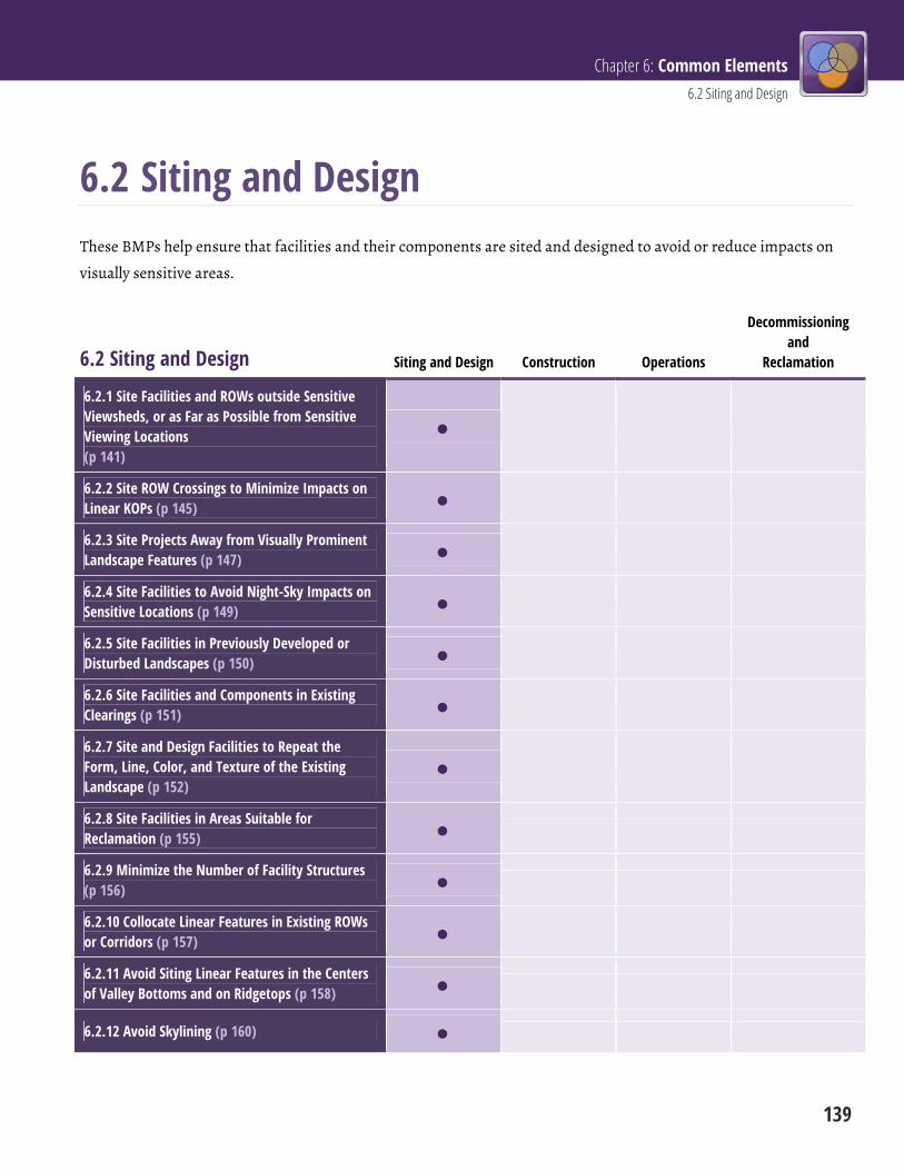
Chapter 6: Common Elements 6.2 Siting and Design
139
6.2 Siting and Design These BMPs help ensure that facilities and their components are sited and designed to avoid or reduce impacts on
visually sensitive areas.
6.2 Siting and Design Siting and Design Construction Operations
Decommissioning and
Reclamation
6.2.1 Site Facilities and ROWs outside Sensitive Viewsheds, or as Far as Possible from Sensitive Viewing Locations (p 141)
6.2.2 Site ROW Crossings to Minimize Impacts on Linear KOPs (p 145)
6.2.3 Site Projects Away from Visually Prominent Landscape Features (p 147)
6.2.4 Site Facilities to Avoid Night-Sky Impacts on Sensitive Locations (p 149)
6.2.5 Site Facilities in Previously Developed or Disturbed Landscapes (p 150)
6.2.6 Site Facilities and Components in Existing Clearings (p 151)
6.2.7 Site and Design Facilities to Repeat the Form, Line, Color, and Texture of the Existing Landscape (p 152)
6.2.8 Site Facilities in Areas Suitable for Reclamation (p 155)
6.2.9 Minimize the Number of Facility Structures (p 156)
6.2.10 Collocate Linear Features in Existing ROWs or Corridors (p 157)
6.2.11 Avoid Siting Linear Features in the Centers of Valley Bottoms and on Ridgetops (p 158)
6.2.12 Avoid Skylining (p 160)
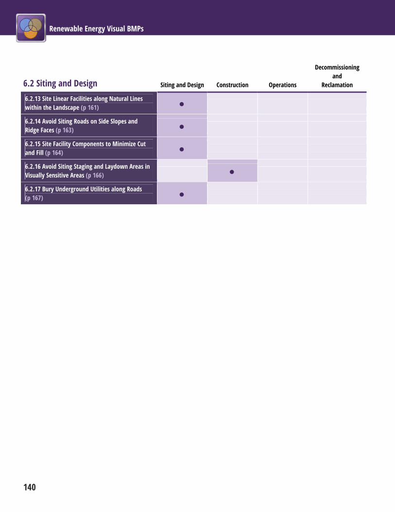
Renewable Energy Visual BMPs
140
6.2 Siting and Design Siting and Design Construction Operations
Decommissioning and
Reclamation
6.2.13 Site Linear Facilities along Natural Lines within the Landscape (p 161)
6.2.14 Avoid Siting Roads on Side Slopes and Ridge Faces (p 163)
6.2.15 Site Facility Components to Minimize Cut and Fill (p 164)
6.2.16 Avoid Siting Staging and Laydown Areas in Visually Sensitive Areas (p 166)
6.2.17 Bury Underground Utilities along Roads (p 167)
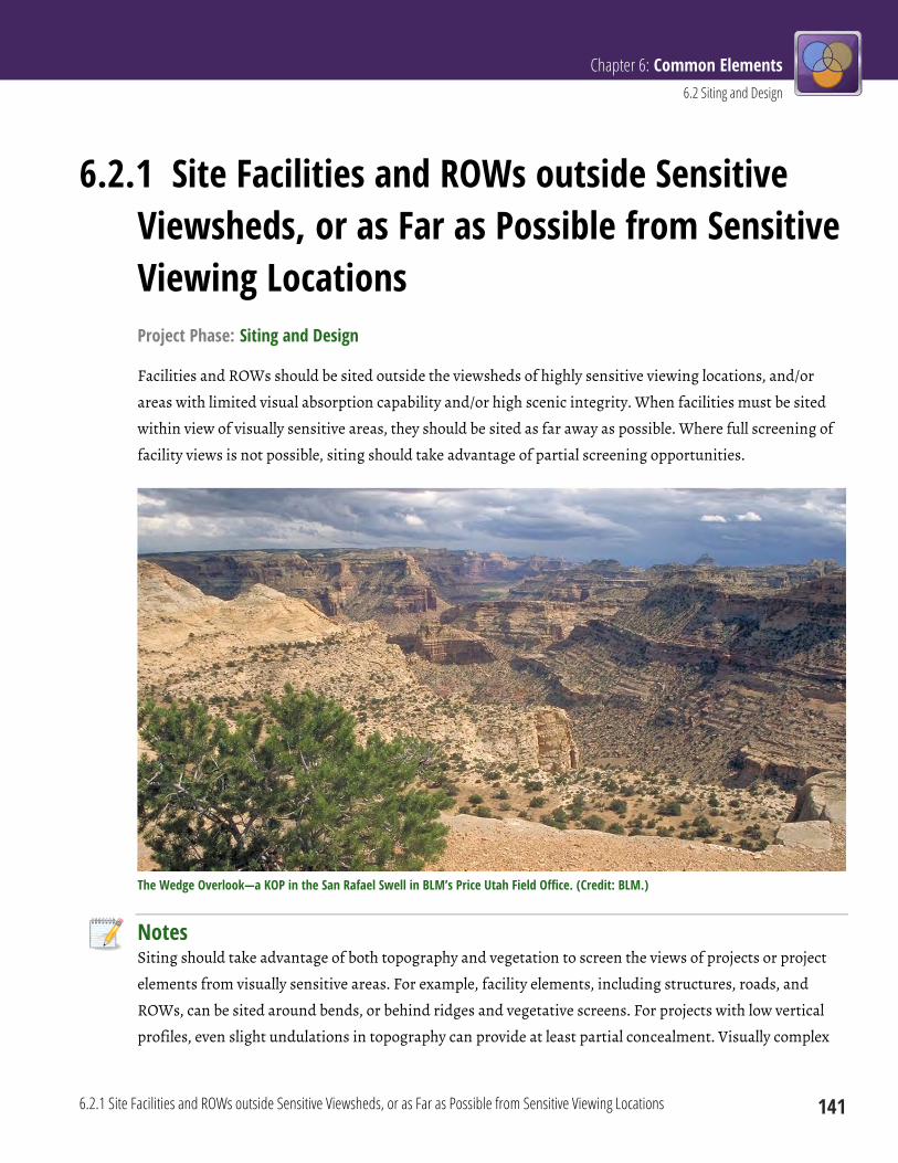
Chapter 6: Common Elements 6.2 Siting and Design
6.2.1 Site Facilities and ROWs outside Sensitive Viewsheds, or as Far as Possible from Sensitive Viewing Locations 141
6.2.1 Site Facilities and ROWs outside Sensitive Viewsheds, or as Far as Possible from Sensitive Viewing Locations Project Phase: Siting and Design
Facilities and ROWs should be sited outside the viewsheds of highly sensitive viewing locations, and/or
areas with limited visual absorption capability and/or high scenic integrity. When facilities must be sited
within view of visually sensitive areas, they should be sited as far away as possible. Where full screening of
facility views is not possible, siting should take advantage of partial screening opportunities.
The Wedge Overlook—a KOP in the San Rafael Swell in BLM’s Price Utah Field Office. (Credit: BLM.)
Notes Siting should take advantage of both topography and vegetation to screen the views of projects or project
elements from visually sensitive areas. For example, facility elements, including structures, roads, and
ROWs, can be sited around bends, or behind ridges and vegetative screens. For projects with low vertical
profiles, even slight undulations in topography can provide at least partial concealment. Visually complex

Renewable Energy Visual BMPs
142 6.2.1 Site Facilities and ROWs outside Sensitive Viewsheds, or as Far as Possible from Sensitive Viewing Locations
landscape backdrops often provide opportunity for visual concealment. ROW location, size, and boundary
determinations should consider terrain characteristics and opportunities for full or partial project
concealment by recessing the project into the landscape terrain. Where the entire facility cannot be
screened, partial screening is generally preferred, in order to reduce the apparent size and visual
dominance of the visible elements.
Special consideration should be given when siting facilities within view of National Historic Trails and
Sites (including sites eligible for Listing on the National Register of Historic Places), and tribal cultural
resources, especially if the visual setting is important to the historic or cultural context and integrity of the
area. A detailed visual analysis should be conducted, and stipulations, such as restrictions on surface
disturbance, may be warranted. Population centers and highly sensitive scenic resources, including, but not
limited to, units of the National Park Service, National Monuments, National Scenic Highways, and Wild
and Scenic Rivers, should also be given special consideration, and every attempt should be made to avoid
visual impacts on these areas, including consideration of alternative siting locations.
When facilities must be sited within view of visually sensitive areas, they should be sited as far away as
possible, as visual impacts generally diminish as viewing distance increases. Where they occur, landscapes
with low scenic integrity and/or high visual absorption capability are generally preferred as siting locations.
Limitations Some BLM landscapes have low relief and lack vegetation tall enough to screen the taller elements of
renewable energy facilities, particularly wind turbines, solar power tower receivers, plumes from boilers or
cooling towers, and transmission lines and towers. The very large size of most renewable energy facilities
may make complete screening of facility views difficult or impossible, especially for views from relatively
close viewpoints.

Chapter 6: Common Elements 6.2 Siting and Design
6.2.1 Site Facilities and ROWs outside Sensitive Viewsheds, or as Far as Possible from Sensitive Viewing Locations 143
Adva
nced
vie
wsh
ed a
naly
sis m
ap fo
r the
road
net
wor
k in
the
BLM
’s Kr
emm
ling
Field
Offi
ce in
Col
orad
o. R
oads
are
line
ar K
OPs;
the
colo
red
area
s on
the
map
indi
cate
the
leng
th o
f roa
d fro
m w
hich
a g
iven
poi
nt in
the
land
scap
e is
visib
le, w
ith re
d-tin
ted
area
s bei
ng th
e m
ost v
isibl
e, a
nd b
lue
area
s the
leas
t visi
ble
(gra
y ar
eas a
re n
ot v
isibl
e fro
m th
e ro
ads)
. Fro
m a
visu
al im
pact
stan
dpoi
nt, t
he re
d-tin
ted
area
s wou
ld g
ener
ally
be
less
opt
imal
facil
ity si
ting
loca
tions
. (Cr
edit:
BLM
.)
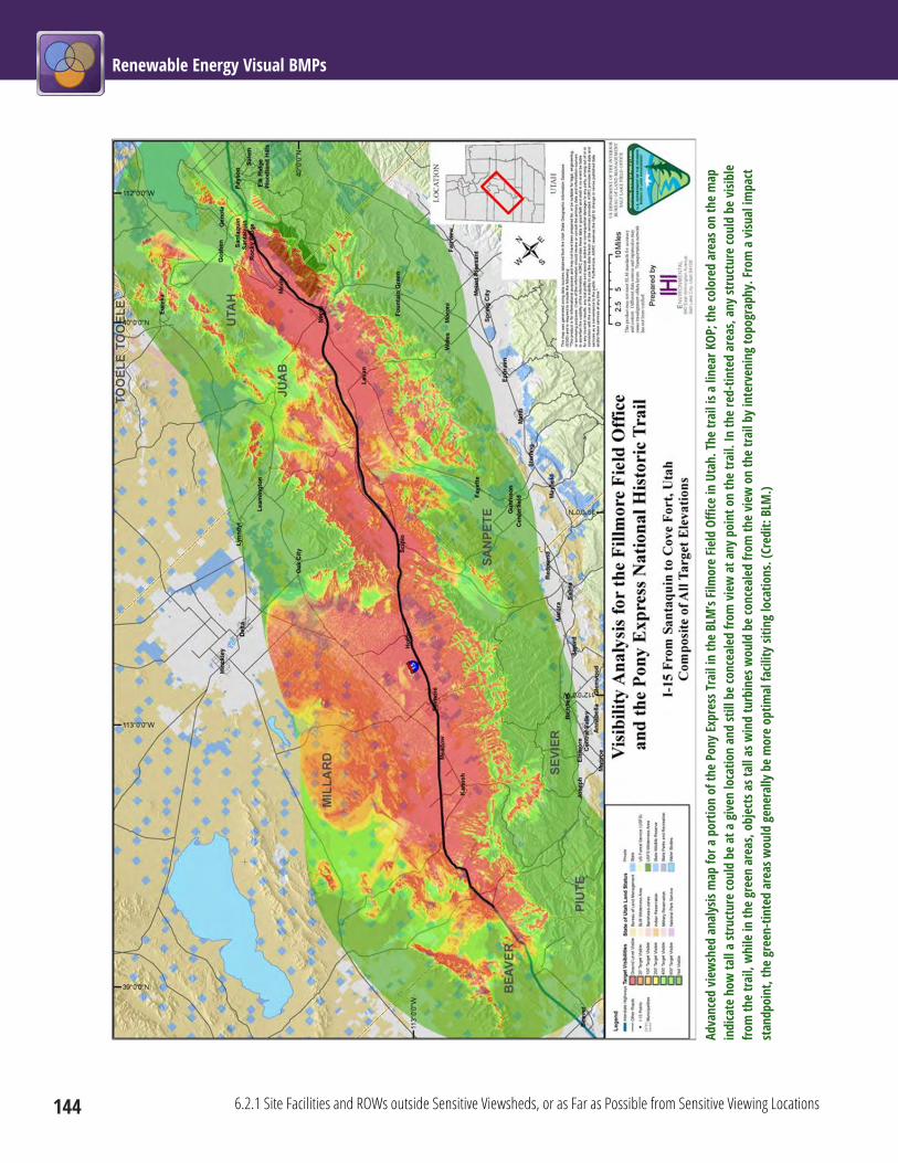
Renewable Energy Visual BMPs
144 6.2.1 Site Facilities and ROWs outside Sensitive Viewsheds, or as Far as Possible from Sensitive Viewing Locations
Adva
nced
vie
wsh
ed a
naly
sis m
ap fo
r a p
ortio
n of
the
Pony
Expr
ess T
rail
in th
e BL
M’s
Film
ore
Field
Offi
ce in
Uta
h. T
he tr
ail i
s a li
near
KOP
; the
colo
red
area
s on
the
map
in
dica
te h
ow ta
ll a
stru
ctur
e co
uld
be a
t a g
iven
loca
tion
and
still
be
conc
eale
d fro
m v
iew
at a
ny p
oint
on
the
trail.
In th
e re
d-tin
ted
area
s, an
y st
ruct
ure
coul
d be
visi
ble
from
the
trail,
whi
le in
the
gree
n ar
eas,
obje
cts a
s tal
l as w
ind
turb
ines
wou
ld b
e co
ncea
led
from
the
view
on
the
trail
by in
terv
enin
g to
pogr
aphy
. Fro
m a
visu
al im
pact
st
andp
oint
, the
gre
en-ti
nted
are
as w
ould
gen
eral
ly b
e m
ore
optim
al fa
cility
sitin
g lo
catio
ns. (
Cred
it: B
LM.)

Chapter 6: Common Elements 6.2 Siting and Design
6.2.2 Site ROW Crossings to Minimize Impacts on Linear KOPs 145
6.2.2 Site ROW Crossings to Minimize Impacts on Linear KOPs Project Phase: Siting and Design
Locations for right-of- way (ROW) crossings of roads,
waterways, and other linear KOPs should be chosen
to avoid the most visually sensitive points or
segments along the linear KOP. Site crossings should
be chosen to minimize duration of view for observers
traveling on the linear KOP. ROWs should cross
linear features at right angles whenever possible.
Notes Crossings of ROWs (and associated facilities) with
waterways, roads, trails and other features may
attract visual attention because of strong visual
contrasts in form, line, color, and texture, especially
where they involve extensive vegetation clearing.
They may become undesirable visual focal points in
the landscape. ROW crossings of roads, waterways,
and other linear features should be concealed or
located as far as possible from the most visually
sensitive points or segments on a linear KOP.
Where ROWs cross linear features (e.g., trails, roads, and rivers) at oblique angles, viewers traveling along
the linear features may be subject to relatively long-duration views of facilities in the ROW, at relatively
short distances. ROWs should cross linear features at right angles whenever possible to minimize the
viewing area and duration. Avoid crossings in the middle of long, straight segments and at road
intersections.
Road, trail, and waterway crossings often offer extended views down ROWs. Structures, roads, and other
project elements should be set as far back as possible from road, trail, and waterway crossings, and
vegetation should be used to screen views from crossings. Vegetative screening should mimic natural
Crossing sensitive linear features at a right angle minimizes the visibility of facilities on the ROW for viewers traveling along the linear feature. (Credit: Lindsey Utter, Argonne National Laboratory.)

Renewable Energy Visual BMPs
146 6.2.2 Site ROW Crossings to Minimize Impacts on Linear KOPs
vegetative patterns (using native plants) and be made to blend with the natural form, line, color, and
texture.
Limitations Many technical, environmental, and economic factors must be considered in locating ROW crossings; these
other considerations may outweigh potential visual impacts in the siting decision. Technical requirements
may determine where structures are located along ROWs, and may dictate that structures or other project
elements are sited near crossings. In these instances, vegetative screening may help to reduce negative
visual contrasts, although adding new vegetation may itself cause undesirable visual contrasts.

Chapter 6: Common Elements 6.2 Siting and Design
6.2.3 Site Projects Away from Visually Prominent Landscape Features 147
6.2.3 Site Projects Away from Visually Prominent Landscape Features Project Phase: Siting and Design
Avoid siting facilities near visually prominent landscape features that naturally draw an observer’s
attention. Do not site facilities so that they are visually aligned with prominent landscape features, as seen
from KOPs.
Siting this windfarm directly in front of a prominent mountain ridge (as seen from this KOP) draws visual attention to the wind turbines. (Dunlap Ranch Wind Energy Project, Carbon County, Wyoming. Credit: Robert Sullivan, Argonne National Laboratory.)
Notes Because the eye is naturally drawn to prominent landscape features (e.g., knobs and waterfalls), facilities
and their components should be sited away from these features. Similarly, facilities should be sited so that
they are away from the direct line of sight from a KOP to a prominent landscape feature. In some instances,
landscape features to avoid could be manmade (e.g., bridges or dams).
Limitations Siting facilities near or in line with prominent landscape features may be unavoidable in some
circumstances, such as when there are multiple KOPs or multiple prominent landscape features, or when
the only feasible location for a facility is near a landmark.
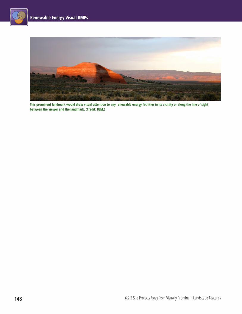
Renewable Energy Visual BMPs
148 6.2.3 Site Projects Away from Visually Prominent Landscape Features
This prominent landmark would draw visual attention to any renewable energy facilities in its vicinity or along the line of sight between the viewer and the landmark. (Credit: BLM.)
Chapter 6: Common Elements 6.2 Siting and Design
6.2.4 Site Facilities to Avoid Night-Sky Impacts on Sensitive Locations 149
6.2.4 Site Facilities to Avoid Night-Sky Impacts on Sensitive Locations Project Phase: Siting and Design
Renewable energy facility siting should take into account the impacts of facility lighting on the night sky,
and should avoid siting in areas where potential viewers are most sensitive to night-sky impacts.
Notes Facility siting should consider the potential for night-sky impacts, because starry night skies free from glare
and skyglow are a highly valued resource in many parts of the western United States, and night-sky tourism
is an important economic activity in some areas. In addition, nocturnal wildlife can be adversely affected by
outdoor lights. Research has shown that wind turbine lights may be visible for very long distances (more
than 35 mi), and indirect lighting impacts such as skyglow (the scattering of light in the sky) may reduce
night-sky quality at locations very distant from the light sources. Review of local Comprehensive Plans and
stakeholder consultation are excellent ways to determine the importance of night skies to local residents,
tourists, and other parties. See BMPs 6.5.1 through 6.5.7 for practices to reduce lighting impacts from
renewable energy facilities.
Limitations Economic considerations may sometimes preclude avoiding areas sensitive to night-sky impacts; however,
there are many cost-effective ways to reduce the use of lighting at facilities and to use lighting equipment
and practices that minimize night-sky impacts.
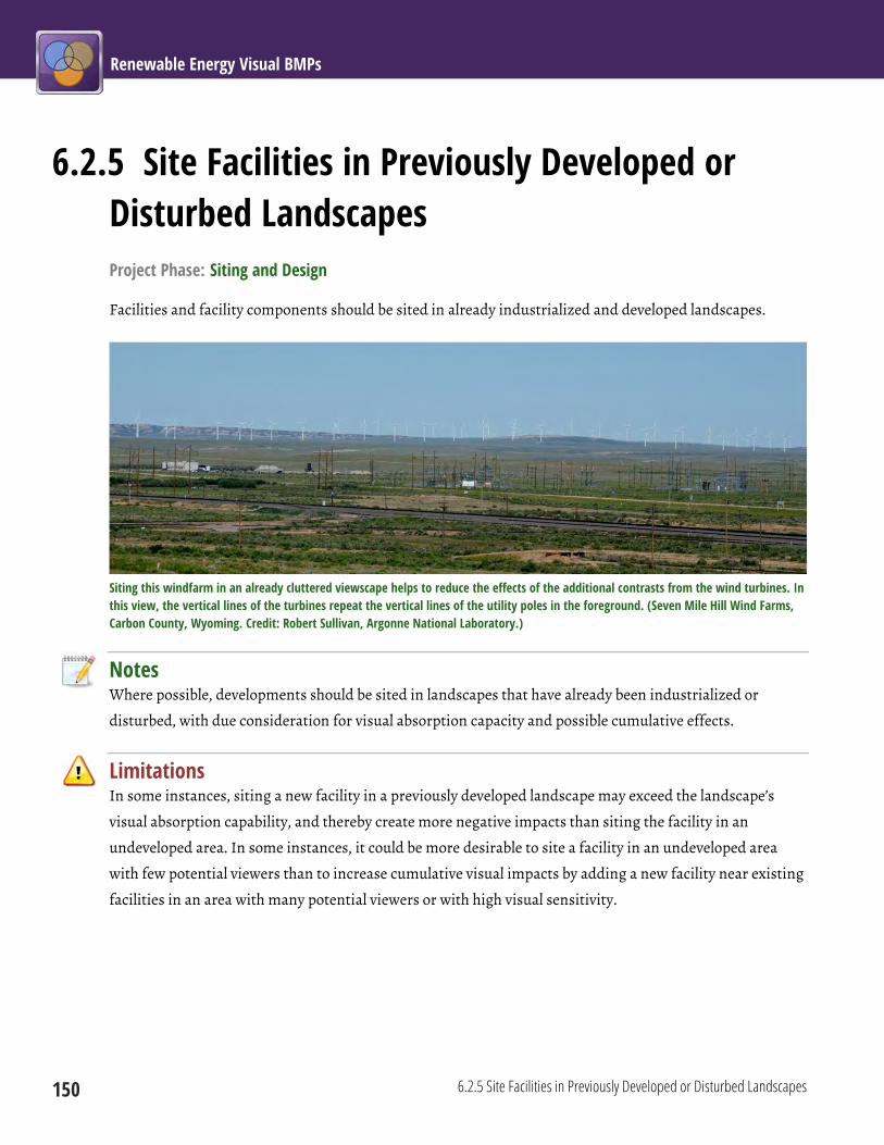
Renewable Energy Visual BMPs
150 6.2.5 Site Facilities in Previously Developed or Disturbed Landscapes
6.2.5 Site Facilities in Previously Developed or Disturbed Landscapes Project Phase: Siting and Design
Facilities and facility components should be sited in already industrialized and developed landscapes.
Siting this windfarm in an already cluttered viewscape helps to reduce the effects of the additional contrasts from the wind turbines. In this view, the vertical lines of the turbines repeat the vertical lines of the utility poles in the foreground. (Seven Mile Hill Wind Farms, Carbon County, Wyoming. Credit: Robert Sullivan, Argonne National Laboratory.)
Notes Where possible, developments should be sited in landscapes that have already been industrialized or
disturbed, with due consideration for visual absorption capacity and possible cumulative effects.
Limitations In some instances, siting a new facility in a previously developed landscape may exceed the landscape’s
visual absorption capability, and thereby create more negative impacts than siting the facility in an
undeveloped area. In some instances, it could be more desirable to site a facility in an undeveloped area
with few potential viewers than to increase cumulative visual impacts by adding a new facility near existing
facilities in an area with many potential viewers or with high visual sensitivity.

Chapter 6: Common Elements 6.2 Siting and Design
6.2.6 Site Facilities and Components in Existing Clearings 151
6.2.6 Site Facilities and Components in Existing Clearings Project Phase: Siting and Design
In forested areas or shrublands, site facilities and their
components in existing clearings.
Notes Because visual impacts are usually lessened when
vegetation and ground disturbances are minimized,
where possible in forested areas or shrublands, siting
should take advantage of existing clearings to reduce
vegetation clearing and ground disturbance.
Limitations There may be other environmental or technical reasons
to avoid siting facilities in a particular clearing.
Clearings for two facilities are shown in this photograph. The one on the lower left is at the edge of an existing clearing. The clearing to the upper right is located in densely vegetated area. Both clearings create strong color contrasts, but the upper clearing creates stronger line and texture contrasts. (Credit: BLM.)

Renewable Energy Visual BMPs
152 6.2.7 Site and Design Facilities to Repeat the Form, Line, Color, and Texture of the Existing Landscape
6.2.7 Site and Design Facilities to Repeat the Form, Line, Color, and Texture of the Existing Landscape Project Phase: Siting and Design
A careful study of the project site should be performed to identify appropriate colors and textures for
materials; the siting and design of facilities, structures, roads, and other project elements should match and
repeat the form, line, color, and texture of the existing landscape in accordance and compliance with the
visual resource management (VRM) class objectives.
Despite the elevated viewpoint, at a viewing distance of almost 7 mi the low, flat, and visually simple forms, lines, color, and texture of the Solar Energy Generating Systems III-VII parabolic trough facilities blend in well with the broad flat expanse of the valley in which they are located. Note, however, how lines from ROW clearing focus views on the facilities. (Credit: Robert Sullivan, Argonne National Laboratory.)
Notes Careful siting of facilities and facility components, along with good choices of materials and
paints/coatings can, in some instances, substantially reduce the apparent visual contrast associated with
renewable energy facilities through repetition of the form, line, color, and texture that occur in the natural
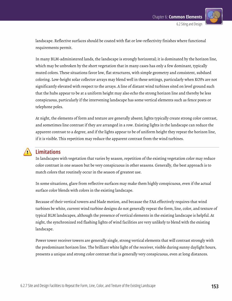
Chapter 6: Common Elements 6.2 Siting and Design
6.2.7 Site and Design Facilities to Repeat the Form, Line, Color, and Texture of the Existing Landscape 153
landscape. Reflective surfaces should be coated with flat or low-reflectivity finishes where functional
requirements permit.
In many BLM-administered lands, the landscape is strongly horizontal; it is dominated by the horizon line,
which may be unbroken by the short vegetation that in many cases has only a few dominant, typically
muted colors. These situations favor low, flat structures, with simple geometry and consistent, subdued
coloring. Low-height solar collector arrays may blend well in these settings, particularly when KOPs are not
significantly elevated with respect to the arrays. A line of distant wind turbines sited on level ground such
that the hubs appear to be at a uniform height may also echo the strong horizon line and thereby be less
conspicuous, particularly if the intervening landscape has some vertical elements such as fence posts or
telephone poles.
At night, the elements of form and texture are generally absent; lights typically create strong color contrast,
and sometimes line contrast if they are arranged in a row. Existing lights in the landscape can reduce the
apparent contrast to a degree, and if the lights appear to be of uniform height they repeat the horizon line,
if it is visible. This repetition may reduce the apparent contrast from the wind turbines.
Limitations In landscapes with vegetation that varies by season, repetition of the existing vegetation color may reduce
color contrast in one season but be very conspicuous in other seasons. Generally, the best approach is to
match colors that routinely occur in the season of greatest use.
In some situations, glare from reflective surfaces may make them highly conspicuous, even if the actual
surface color blends with colors in the existing landscape.
Because of their vertical towers and blade motion, and because the FAA effectively requires that wind
turbines be white, current wind turbine designs do not generally repeat the form, line, color, and texture of
typical BLM landscapes, although the presence of vertical elements in the existing landscape is helpful. At
night, the synchronized red flashing lights of wind facilities are very unlikely to blend with the existing
landscape.
Power tower receiver towers are generally single, strong vertical elements that will contrast strongly with
the predominant horizon line. The brilliant white light of the receiver, visible during sunny daylight hours,
presents a unique and strong color contrast that is generally very conspicuous, even at long distances.
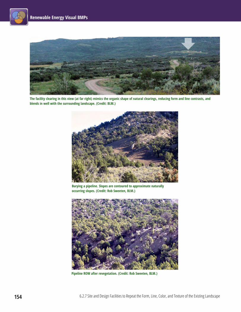
Renewable Energy Visual BMPs
154 6.2.7 Site and Design Facilities to Repeat the Form, Line, Color, and Texture of the Existing Landscape
The facility clearing in this view (at far right) mimics the organic shape of natural clearings, reducing form and line contrasts, and blends in well with the surrounding landscape. (Credit: BLM.)
Burying a pipeline. Slopes are contoured to approximate naturally occurring slopes. (Credit: Rob Sweeten, BLM.)
Pipeline ROW after revegetation. (Credit: Rob Sweeten, BLM.)
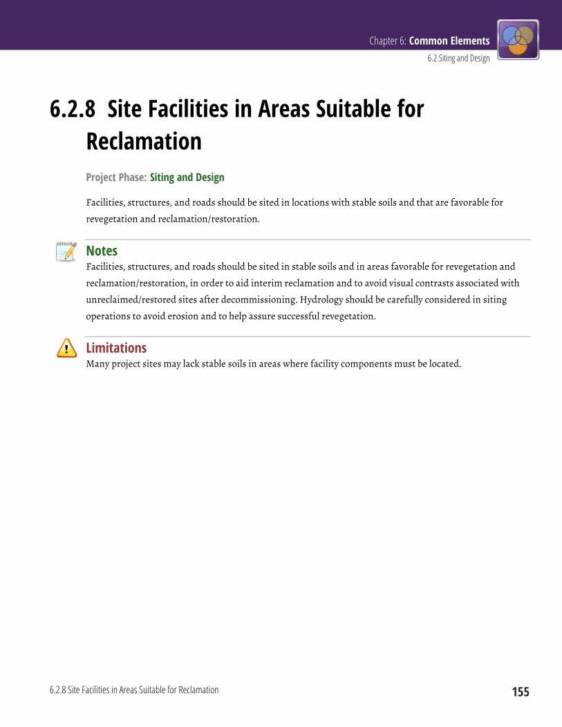
Chapter 6: Common Elements 6.2 Siting and Design
6.2.8 Site Facilities in Areas Suitable for Reclamation 155
6.2.8 Site Facilities in Areas Suitable for Reclamation Project Phase: Siting and Design
Facilities, structures, and roads should be sited in locations with stable soils and that are favorable for
revegetation and reclamation/restoration.
Notes Facilities, structures, and roads should be sited in stable soils and in areas favorable for revegetation and
reclamation/restoration, in order to aid interim reclamation and to avoid visual contrasts associated with
unreclaimed/restored sites after decommissioning. Hydrology should be carefully considered in siting
operations to avoid erosion and to help assure successful revegetation.
Limitations Many project sites may lack stable soils in areas where facility components must be located.
Renewable Energy Visual BMPs
156 6.2.9 Minimize the Number of Facility Structures
6.2.9 Minimize the Number of Facility Structures Project Phase: Siting and Design
Design facilities to use the minimum number of structures.
Notes Through site design, the number of permanent structures required should be minimized. Activities should
be combined and carried out in one structure, or structures should be collocated to share pads, fences,
access roads, and lighting. When the facility is not far from developed areas, some activities (e.g., storage of
spare parts) could also take place at offsite locations. Where multiple structures are required, they should
be clustered to the extent possible in order to decrease “sprawl;” reduce the visual footprint of associated
infrastructure (e.g., roads and potentially fences and lighting); and to take advantage of the screening
opportunities that closely spaced structures may provide.
The number of temporary structures (e.g., water tanks) should also be minimized; in some cases, these
structures may be onsite for long periods of time.
Limitations Safety and technical considerations will require separation of some project components.

Chapter 6: Common Elements 6.2 Siting and Design
6.2.10 Collocate Linear Features in Existing ROWs or Corridors 157
6.2.10 Collocate Linear Features in Existing ROWs or Corridors Project Phase: Siting and Design
Collocate linear features adjacent to existing ROWs or in designated utility corridors, rather than utilizing
new ROWs.
Collocation of transmission lines generally reduces overall visual impacts. (Credit: BLM.)
Notes To the extent possible, transmission lines, roads, and other extensive structures associated with renewable
energy should be collocated within a corridor to utilize existing/shared ROWs, access and maintenance
roads, and other infrastructure in order to reduce visual impacts associated with new construction.
Collocation of linear features, such as transmission lines and pipelines, usually results in reduced visual
contrast because of reduced vegetation clearing and road development. Where there are multiple ROWs,
they should be located on the same side of the road, preserving open views of landscapes on the opposing
side.
Limitations Regulatory authorities may prohibit or restrict collocation of facilities within existing ROWs for safety or
other reasons. Existing corridors may lack sufficient space for new facilities, or routing requirements may
preclude using existing ROWs. There are potential technical interferences between certain utilities. Issues
of liability and ROW access would also need to be addressed.

Renewable Energy Visual BMPs
158 6.2.11 Avoid Siting Linear Features in the Centers of Valley Bottoms and on Ridgetops
6.2.11 Avoid Siting Linear Features in the Centers of Valley Bottoms and on Ridgetops Project Phase: Siting and Design
Site transmission lines and other linear features to avoid valley bottoms and ridgetops.
This ROW bisects several ridges, creating prominent strong lines for the eye to follow. (Credit: BLM.)
Notes The eye follows strong natural lines in the landscape, and these lines and associated landforms can “focus”
views on particular landscape features. For this reason, linear facilities associated with renewable energy
projects, such as transmission line ROWs, should be sited to avoid running across the centers of valley
bottoms, and to avoid ridgetop bisection (i.e., routing the ROWs perpendicular to and over ridgelines).
Limitations Technical issues, land ownership patterns, cost, and various environmental factors generally dictate where
ROWs are located. For example, in rugged canyons, valley bottoms may provide the only buildable land and
be the only feasible, cost-effective route, especially if facilities are collocated in an existing ROW or
corridor.
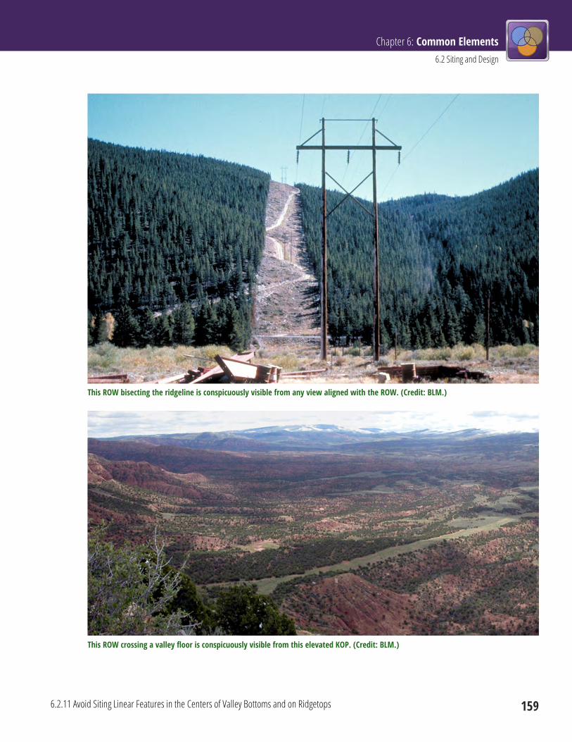
Chapter 6: Common Elements 6.2 Siting and Design
6.2.11 Avoid Siting Linear Features in the Centers of Valley Bottoms and on Ridgetops 159
This ROW bisecting the ridgeline is conspicuously visible from any view aligned with the ROW. (Credit: BLM.)
This ROW crossing a valley floor is conspicuously visible from this elevated KOP. (Credit: BLM.)
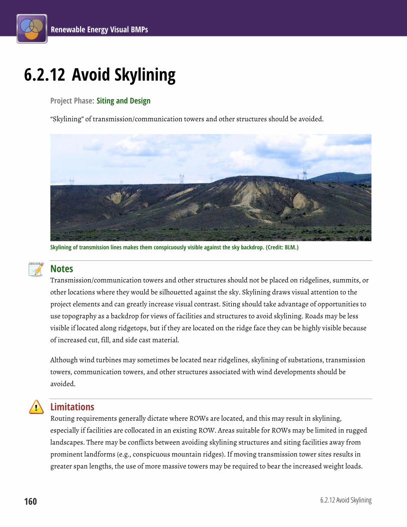
Renewable Energy Visual BMPs
160 6.2.12 Avoid Skylining
6.2.12 Avoid Skylining Project Phase: Siting and Design
“Skylining” of transmission/communication towers and other structures should be avoided.
Skylining of transmission lines makes them conspicuously visible against the sky backdrop. (Credit: BLM.)
Notes Transmission/communication towers and other structures should not be placed on ridgelines, summits, or
other locations where they would be silhouetted against the sky. Skylining draws visual attention to the
project elements and can greatly increase visual contrast. Siting should take advantage of opportunities to
use topography as a backdrop for views of facilities and structures to avoid skylining. Roads may be less
visible if located along ridgetops, but if they are located on the ridge face they can be highly visible because
of increased cut, fill, and side cast material.
Although wind turbines may sometimes be located near ridgelines, skylining of substations, transmission
towers, communication towers, and other structures associated with wind developments should be
avoided.
Limitations Routing requirements generally dictate where ROWs are located, and this may result in skylining,
especially if facilities are collocated in an existing ROW. Areas suitable for ROWs may be limited in rugged
landscapes. There may be conflicts between avoiding skylining structures and siting facilities away from
prominent landforms (e.g., conspicuous mountain ridges). If moving transmission tower sites results in
greater span lengths, the use of more massive towers may be required to bear the increased weight loads.
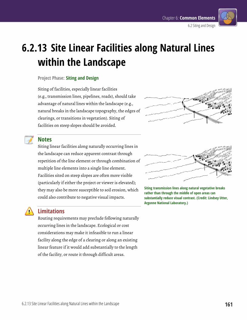
Chapter 6: Common Elements 6.2 Siting and Design
6.2.13 Site Linear Facilities along Natural Lines within the Landscape 161
6.2.13 Site Linear Facilities along Natural Lines within the Landscape Project Phase: Siting and Design
Siting of facilities, especially linear facilities
(e.g., transmission lines, pipelines, roads), should take
advantage of natural lines within the landscape (e.g.,
natural breaks in the landscape topography, the edges of
clearings, or transitions in vegetation). Siting of
facilities on steep slopes should be avoided.
Notes Siting linear facilities along naturally occurring lines in
the landscape can reduce apparent contrast through
repetition of the line element or through combination of
multiple line elements into a single line element.
Facilities sited on steep slopes are often more visible
(particularly if either the project or viewer is elevated);
they may also be more susceptible to soil erosion, which
could also contribute to negative visual impacts.
Limitations Routing requirements may preclude following naturally
occurring lines in the landscape. Ecological or cost
considerations may make it infeasible to run a linear
facility along the edge of a clearing or along an existing
linear feature if it would add substantially to the length
of the facility, or route it through difficult areas.
Siting transmission lines along natural vegetative breaks rather than through the middle of open areas can substantially reduce visual contrast. (Credit: Lindsey Utter, Argonne National Laboratory.)
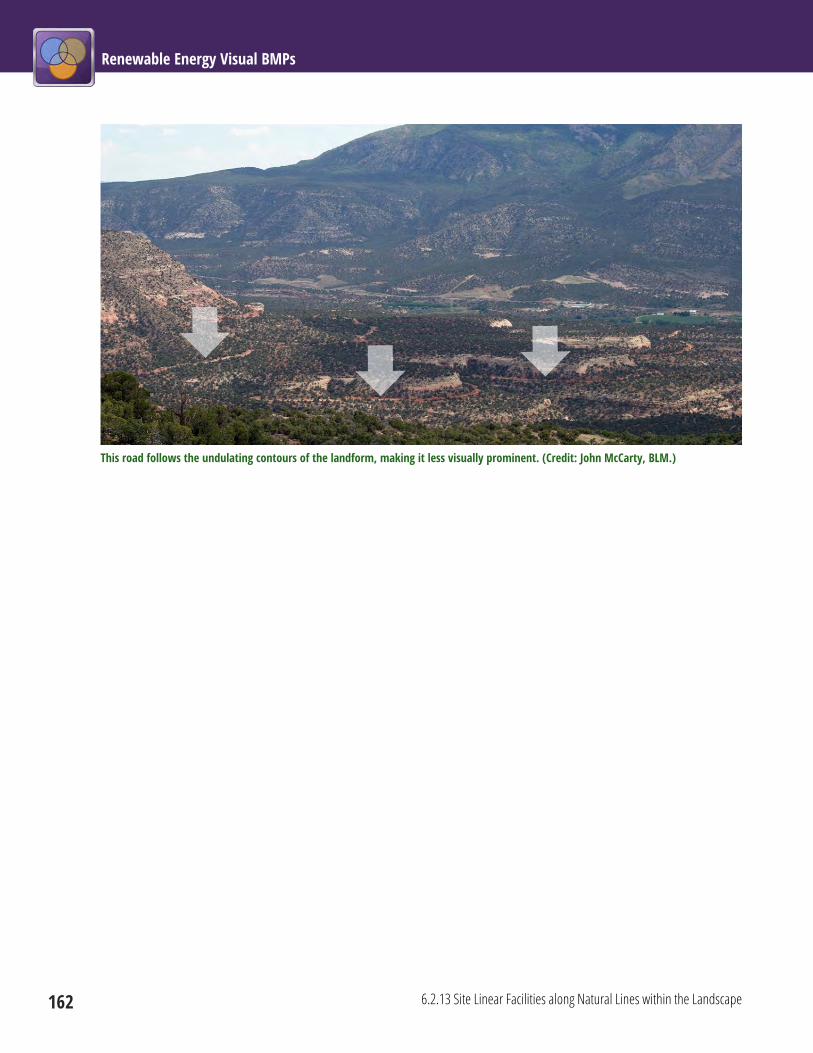
Renewable Energy Visual BMPs
162 6.2.13 Site Linear Facilities along Natural Lines within the Landscape
This road follows the undulating contours of the landform, making it less visually prominent. (Credit: John McCarty, BLM.)

Chapter 6: Common Elements 6.2 Siting and Design
6.2.14 Avoid Siting Roads on Side Slopes and Ridge Faces 163
6.2.14 Avoid Siting Roads on Side Slopes and Ridge Faces Project Phase: Siting and Design
Avoid siting roads on steep side slopes and ridge faces. Site roads along ridgetops.
Siting this road on a side slope resulted in a large amount of fill that creates strong visual contrasts. (Credit: BLM.)
Notes Siting of roads should avoid steep side slopes and ridge faces. Placing roads on steep side slopes and ridge
faces can make them highly visible due to increased cut and fill, and especially side cast material. Where
possible, site roads along ridgetops rather than side slopes and ridge faces. Siting roads along ridgetops
helps to minimize cut and fill and avoids contrast created by side cast material. Truck excess fill offsite
rather than side casting. If siting roads on steep slopes and ridge faces is unavoidable, use retaining walls to
minimize excessive cut and fill, and create cuts and fills that match existing lines, forms, colors, and
textures of the surrounding landscape as closely as possible. Minimize switchbacks by following the natural
contours.
Limitations Routing or other requirements may dictate that roads be sited on side slopes and ridge faces.

Renewable Energy Visual BMPs
164 6.2.15 Site Facility Components to Minimize Cut and Fill
6.2.15 Site Facility Components to Minimize Cut and Fill Project Phase: Siting and Design
Structures and roads should be designed and located to minimize cut and fill. Use retaining walls and
bridges to reduce cut and fill.
Building this road on a steep side slope resulted in excessive and highly visible cut and fill. (Credit: BLM)
Notes Minimizing cut and fill reduces vegetation and soil disturbance, which reduces associated visual contrasts;
it also reduces the potential for erosion and dust that have negative visual impacts. Minimizing cut and fill
also has substantial ecological benefits, and generally reduces cost. Retaining walls and bridges should be
used to reduce cut and fill. Cuts and fills should match existing lines, forms, colors, and textures of the
surrounding landscape as closely as possible.
Limitations Site characteristics and project requirements may limit opportunities to minimize cut and fill. Retaining
walls and bridges have their own potential visual impacts that must be considered.

Chapter 6: Common Elements 6.2 Siting and Design
6.2.15 Site Facility Components to Minimize Cut and Fill 165
This road follows natural contours, reducing the need for cut and fill. (Credit: BLM)
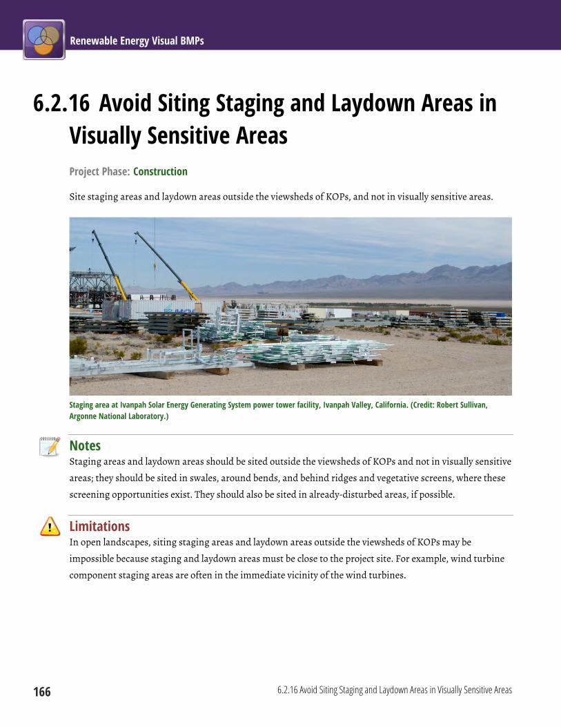
Renewable Energy Visual BMPs
166 6.2.16 Avoid Siting Staging and Laydown Areas in Visually Sensitive Areas
6.2.16 Avoid Siting Staging and Laydown Areas in Visually Sensitive Areas Project Phase: Construction
Site staging areas and laydown areas outside the viewsheds of KOPs, and not in visually sensitive areas.
Staging area at Ivanpah Solar Energy Generating System power tower facility, Ivanpah Valley, California. (Credit: Robert Sullivan, Argonne National Laboratory.)
Notes Staging areas and laydown areas should be sited outside the viewsheds of KOPs and not in visually sensitive
areas; they should be sited in swales, around bends, and behind ridges and vegetative screens, where these
screening opportunities exist. They should also be sited in already-disturbed areas, if possible.
Limitations In open landscapes, siting staging areas and laydown areas outside the viewsheds of KOPs may be
impossible because staging and laydown areas must be close to the project site. For example, wind turbine
component staging areas are often in the immediate vicinity of the wind turbines.
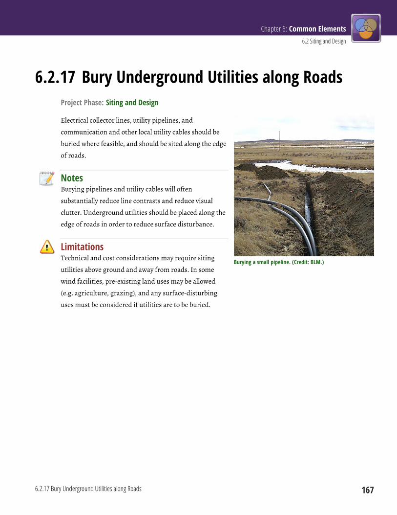
Chapter 6: Common Elements 6.2 Siting and Design
6.2.17 Bury Underground Utilities along Roads 167
6.2.17 Bury Underground Utilities along Roads Project Phase: Siting and Design
Electrical collector lines, utility pipelines, and
communication and other local utility cables should be
buried where feasible, and should be sited along the edge
of roads.
Notes Burying pipelines and utility cables will often
substantially reduce line contrasts and reduce visual
clutter. Underground utilities should be placed along the
edge of roads in order to reduce surface disturbance.
Limitations Technical and cost considerations may require siting
utilities above ground and away from roads. In some
wind facilities, pre-existing land uses may be allowed
(e.g. agriculture, grazing), and any surface-disturbing
uses must be considered if utilities are to be buried.
Burying a small pipeline. (Credit: BLM.)


Chapter 6: Common Elements 6.3 Structure Design and Material Selection
169
6.3 Structure Design and Material Selection These BMPs address the selection and design of structures, landforms, and other materials to blend with the
existing landscape setting.
6.3 Structure Design and Material Selection Siting and Design Construction Operations
Decommissioning and
Reclamation
6.3.1 Use Low-Profile Structures and Tanks (p 170)
6.3.2 Custom Design Structures in Key Areas (p 172)
6.3.3 Consider Use of Alternative Components (p 173)
6.3.4 Use Natural-Looking Constructed Landform, Vegetative, or Architectural Screening (p 174)
6.3.5 Minimize Use of Signs and Make Signs Visually Unobtrusive (p 176)
6.3.6 Avoid Unnecessary Use of Gravel/Paved Surfaces (p 177)
6.3.7 Use Rounded Road Cut Slopes (p 178)
6.3.8 Use Monopole and Lattice Electric Transmission Towers Appropriately (p 179)
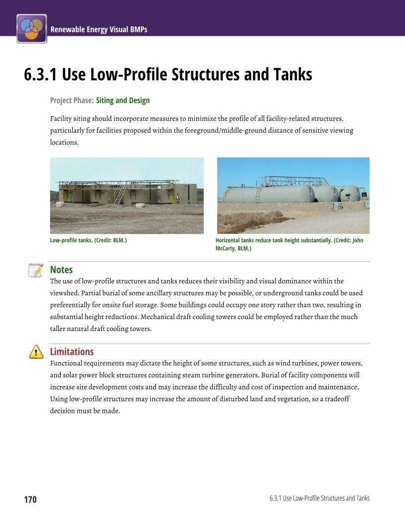
Renewable Energy Visual BMPs
170 6.3.1 Use Low-Profile Structures and Tanks
6.3.1 Use Low-Profile Structures and Tanks Project Phase: Siting and Design
Facility siting should incorporate measures to minimize the profile of all facility-related structures,
particularly for facilities proposed within the foreground/middle-ground distance of sensitive viewing
locations.
Low-profile tanks. (Credit: BLM.) Horizontal tanks reduce tank height substantially. (Credit: John McCarty, BLM.)
Notes The use of low-profile structures and tanks reduces their visibility and visual dominance within the
viewshed. Partial burial of some ancillary structures may be possible, or underground tanks could be used
preferentially for onsite fuel storage. Some buildings could occupy one story rather than two, resulting in
substantial height reductions. Mechanical draft cooling towers could be employed rather than the much
taller natural draft cooling towers.
Limitations Functional requirements may dictate the height of some structures, such as wind turbines, power towers,
and solar power block structures containing steam turbine generators. Burial of facility components will
increase site development costs and may increase the difficulty and cost of inspection and maintenance.
Using low-profile structures may increase the amount of disturbed land and vegetation, so a tradeoff
decision must be made.
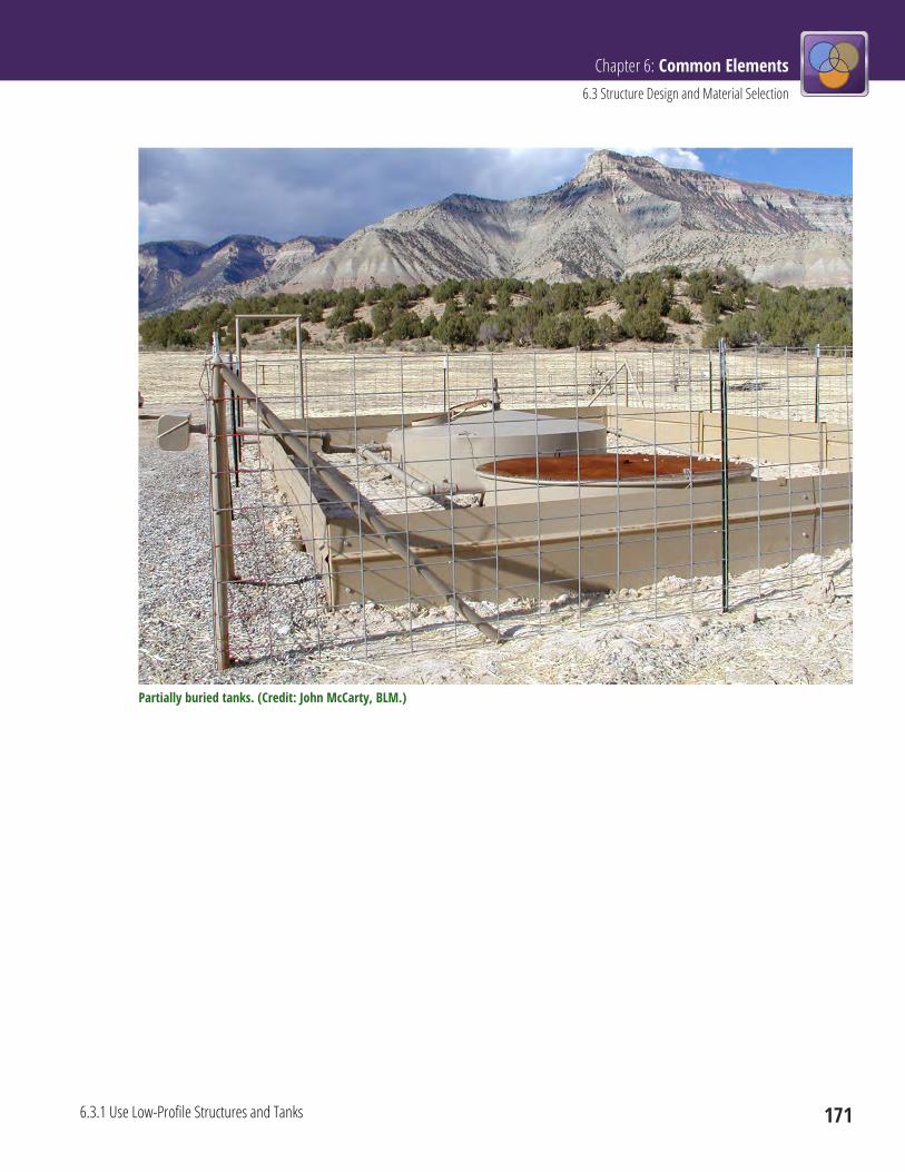
Chapter 6: Common Elements 6.3 Structure Design and Material Selection
6.3.1 Use Low-Profile Structures and Tanks 171
Partially buried tanks. (Credit: John McCarty, BLM.)
Renewable Energy Visual BMPs
172 6.3.2 Custom Design Structures in Key Areas
6.3.2 Custom Design Structures in Key Areas Project Phase: Siting and Design
Custom-designed structures should be used in key areas when such designs would soften the visual impact
and blend more effectively with the surroundings.
Notes Massing and scale of structures should be considered, as should the architectural character appropriate to
the region where a facility is to be located. Architectural considerations should include integration of
vertical and horizontal relief variation to create shadow lines that diminish the overall visual scale and
dominance of facilities.
Limitations The ability of a structure to blend in with the surrounding landscape or to reflect architectural character
appropriate to the region may be constrained by functional requirements of the structure.

Chapter 6: Common Elements 6.3 Structure Design and Material Selection
6.3.3 Consider Use of Alternative Components] 173
6.3.3 Consider Use of Alternative Components] Project Phase: Siting and Design
Alternate technologies that would serve the same function and simultaneously reduce visual impact should
be explored by project designers.
Notes Where visual impacts are an important concern, project designers should explore opportunities to
substitute facility components that are similar in functionality, but less likely to cause negative visual
impacts than the components that would normally be employed.
Limitations Functional limitations or available technology may limit opportunities for using alternative components.
Functional components of facilities are not typically selected based on visual impact considerations. Some
alternative technologies might involve increased cost or decreased efficiency (e.g., mechanical draft versus
natural draft cooling towers), and a tradeoff decision would be required.
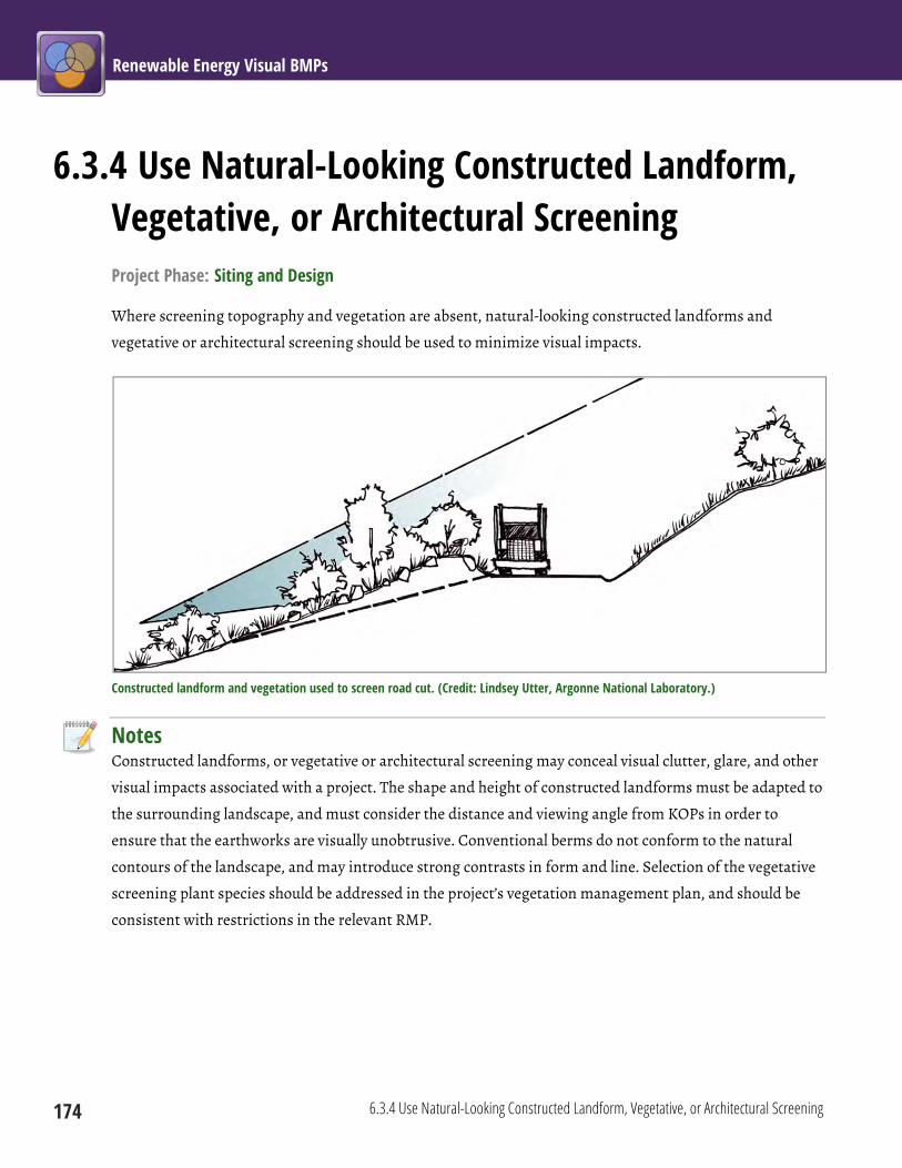
Renewable Energy Visual BMPs
174 6.3.4 Use Natural-Looking Constructed Landform, Vegetative, or Architectural Screening
6.3.4 Use Natural-Looking Constructed Landform, Vegetative, or Architectural Screening Project Phase: Siting and Design
Where screening topography and vegetation are absent, natural-looking constructed landforms and
vegetative or architectural screening should be used to minimize visual impacts.
Constructed landform and vegetation used to screen road cut. (Credit: Lindsey Utter, Argonne National Laboratory.)
Notes Constructed landforms, or vegetative or architectural screening may conceal visual clutter, glare, and other
visual impacts associated with a project. The shape and height of constructed landforms must be adapted to
the surrounding landscape, and must consider the distance and viewing angle from KOPs in order to
ensure that the earthworks are visually unobtrusive. Conventional berms do not conform to the natural
contours of the landscape, and may introduce strong contrasts in form and line. Selection of the vegetative
screening plant species should be addressed in the project’s vegetation management plan, and should be
consistent with restrictions in the relevant RMP.

Chapter 6: Common Elements 6.3 Structure Design and Material Selection
6.3.4 Use Natural-Looking Constructed Landform, Vegetative, or Architectural Screening 175
Limitations Depending on the landscape setting, constructing natural-appearing landforms may involve additional
surface disturbance. Vegetative or architectural screening may not fit well with the surrounding landscape,
potentially creating negative visual contrasts. Screening may be insufficient to screen taller project
elements, or could potentially screen solar collectors or disrupt wind flow at wind facilities. Vegetative
screening could increase fire risk by introducing an additional fuel source.

Renewable Energy Visual BMPs
176 6.3.5 Minimize Use of Signs and Make Signs Visually Unobtrusive
6.3.5 Minimize Use of Signs and Make Signs Visually Unobtrusive Project Phase: Siting and Design
The use of permanent signs and project construction signs should be minimized. Beyond those required for
basic facility and company identification for safety, navigation, and delivery purposes, commercial symbols
or signs and associated lighting on buildings and other structures should be minimized.
All commercial symbols and signs and associated lighting should be designed to minimize offsite visibility.
Necessary signs should be made of non-glare materials and utilize unobtrusive colors. The reverse sides of
signs and mounts should be painted or coated using the most suitable color selected from the BLM
Standard Environmental Color Chart CC-001 (see BMP 6.4.6) to reduce contrasts with the existing
landscape.
Notes Unnecessary signs, especially poorly designed commercial signs, may introduce strong color contrasts and
seem out of place in more natural-appearing landscapes. Signs should be architecturally pleasing, and
designed and placed to contribute to the visual quality of the facility entrance. The fronts and the backs of
signs, as well as the mounts, are potential sources of glinting and glare when sunlit.
Limitations Placement and design of any signs required by safety regulations must conform to regulatory
requirements.

Chapter 6: Common Elements 6.3 Structure Design and Material Selection
6.3.6 Avoid Unnecessary Use of Gravel/Paved Surfaces 177
6.3.6 Avoid Unnecessary Use of Gravel/Paved Surfaces Project Phase: Siting and Design
Installation of gravel and pavement should be avoided to reduce color and texture contrasts with the
existing landscape.
Notes Avoiding unnecessary use of gravel or paved surfaces reduces visual contrast, reduces decommissioning
effort and cost, and may provide other ecological benefits, such as better drainage, and preservation of
vegetation and animal habitat. It should be noted that in some settings, certain gravels may blend well with
the colors and textures of the surrounding natural landscape.
Limitations Anticipated traffic and loads may require gravel or paved surfaces and roads, especially during construction
and decommissioning.
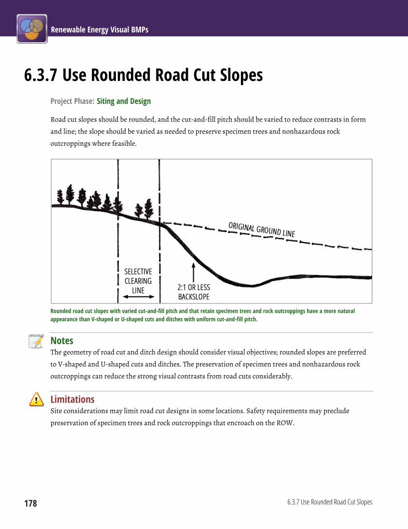
Renewable Energy Visual BMPs
178 6.3.7 Use Rounded Road Cut Slopes
6.3.7 Use Rounded Road Cut Slopes Project Phase: Siting and Design
Road cut slopes should be rounded, and the cut-and-fill pitch should be varied to reduce contrasts in form
and line; the slope should be varied as needed to preserve specimen trees and nonhazardous rock
outcroppings where feasible.
Rounded road cut slopes with varied cut-and-fill pitch and that retain specimen trees and rock outcroppings have a more natural appearance than V-shaped or U-shaped cuts and ditches with uniform cut-and-fill pitch.
Notes The geometry of road cut and ditch design should consider visual objectives; rounded slopes are preferred
to V-shaped and U-shaped cuts and ditches. The preservation of specimen trees and nonhazardous rock
outcroppings can reduce the strong visual contrasts from road cuts considerably.
Limitations Site considerations may limit road cut designs in some locations. Safety requirements may preclude
preservation of specimen trees and rock outcroppings that encroach on the ROW.
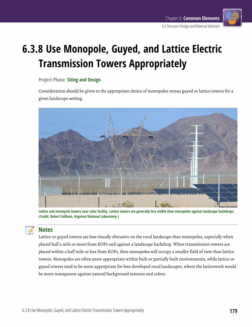
Chapter 6: Common Elements 6.3 Structure Design and Material Selection
6.3.8 Use Monopole, Guyed, and Lattice Electric Transmission Towers Appropriately 179
6.3.8 Use Monopole, Guyed, and Lattice Electric Transmission Towers Appropriately Project Phase: Siting and Design
Consideration should be given to the appropriate choice of monopoles versus guyed or lattice towers for a
given landscape setting.
Lattice and monopole towers near solar facility. Lattice towers are generally less visible than monopoles against landscape backdrops. (Credit: Robert Sullivan, Argonne National Laboratory.)
Notes Lattice or guyed towers are less visually obtrusive on the rural landscape than monopoles, especially when
placed half a mile or more from KOPs and against a landscape backdrop. When transmission towers are
placed within a half mile or less from KOPs, then monopoles will occupy a smaller field of view than lattice
towers. Monopoles are often more appropriate within built or partially built environments, while lattice or
guyed towers tend to be more appropriate for less-developed rural landscapes, where the latticework would
be more transparent against natural background textures and colors.

Renewable Energy Visual BMPs
180 6.3.8 Use Monopole, Guyed, and Lattice Electric Transmission Towers Appropriately
Where transmission facilities are to be collocated in ROWs or corridors, and the existing ROW or corridor
has either lattice towers only, guyed towers only, or monopoles only, the same tower type should be selected
for new transmission facilities within the ROW/corridor.
Limitations A variety of important technical considerations affect the decision to use monopole or lattice transmission
towers. These usually outweigh visual considerations.
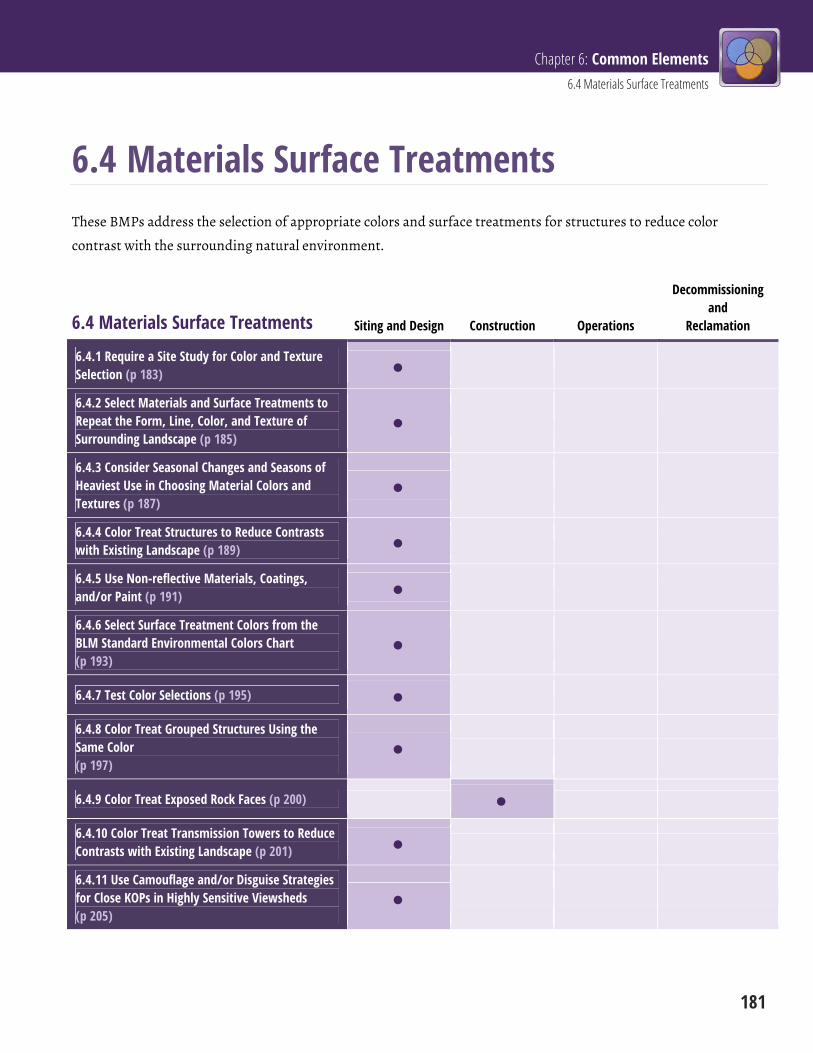
Chapter 6: Common Elements 6.4 Materials Surface Treatments
181
6.4 Materials Surface Treatments These BMPs address the selection of appropriate colors and surface treatments for structures to reduce color
contrast with the surrounding natural environment.
6.4 Materials Surface Treatments Siting and Design Construction Operations
Decommissioning and
Reclamation
6.4.1 Require a Site Study for Color and Texture Selection (p 183)
6.4.2 Select Materials and Surface Treatments to Repeat the Form, Line, Color, and Texture of Surrounding Landscape (p 185)
6.4.3 Consider Seasonal Changes and Seasons of Heaviest Use in Choosing Material Colors and Textures (p 187)
6.4.4 Color Treat Structures to Reduce Contrasts with Existing Landscape (p 189)
6.4.5 Use Non-reflective Materials, Coatings, and/or Paint (p 191)
6.4.6 Select Surface Treatment Colors from the BLM Standard Environmental Colors Chart (p 193)
6.4.7 Test Color Selections (p 195)
6.4.8 Color Treat Grouped Structures Using the Same Color (p 197)
6.4.9 Color Treat Exposed Rock Faces (p 200)
6.4.10 Color Treat Transmission Towers to Reduce Contrasts with Existing Landscape (p 201)
6.4.11 Use Camouflage and/or Disguise Strategies for Close KOPs in Highly Sensitive Viewsheds (p 205)

Renewable Energy Visual BMPs
182
6.4 Materials Surface Treatments Siting and Design Construction Operations
Decommissioning and
Reclamation
6.4.12 Maintain Painted, Stained, or Coated Surfaces Properly (p 206)

Chapter 6: Common Elements 6.4 Materials Surface Treatments
6.4.1 Require a Site Study for Color and Texture Selection 183
6.4.1 Require a Site Study for Color and Texture Selection Project Phase: Siting and Design
A careful study of the site should be performed to
identify appropriate colors and textures for facility
structures. The choice of colors should be based on the
appearance at typical viewing distances and consider the
entire landscape around the proposed development.
Notes Visual contrast of project elements can be substantially
reduced in many cases by choosing appropriate colors
for any structures that can be painted, stained, or
otherwise coated to reduce their visibility, and that have
surface textures compatible with the surrounding
landscape. Color choices should be made only after
carefully considering the existing colors and textures in
the broader landscape around the project, as seen from
typical viewing distances, and preferably from project
KOPs. Because even within a region the predominant landscape colors may vary widely from site to site, the
choice of appropriate colors and textures for facility structures should be based on an onsite assessment of
the proposed project site, rather than on assumptions about appropriate colors and textures for the region
as a whole.
Limitations Some structures may have functional requirements that preclude painting, staining, or coating (such as
solar collectors); safety considerations that dictate high-contrast colors (such as white wind turbines); or
other relevant environmental considerations (e.g., electric transmission conductor visibility to birds; see
BMP 6.4.10). Other structures have paint color schemes dictated by state or local laws.
A BLM landscape with a wide variety of colors and textures. (Credit: BLM.)

Renewable Energy Visual BMPs
184 6.4.1 Require a Site Study for Color and Texture Selection
A typical BLM landscape with relatively little variety of form, line, color, and texture. (Credit: BLM.)
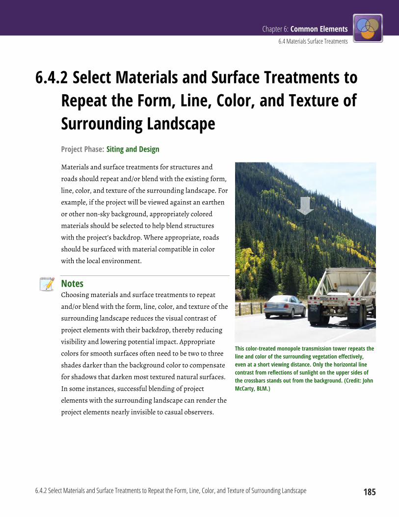
Chapter 6: Common Elements 6.4 Materials Surface Treatments
6.4.2 Select Materials and Surface Treatments to Repeat the Form, Line, Color, and Texture of Surrounding Landscape 185
6.4.2 Select Materials and Surface Treatments to Repeat the Form, Line, Color, and Texture of Surrounding Landscape Project Phase: Siting and Design
Materials and surface treatments for structures and
roads should repeat and/or blend with the existing form,
line, color, and texture of the surrounding landscape. For
example, if the project will be viewed against an earthen
or other non-sky background, appropriately colored
materials should be selected to help blend structures
with the project’s backdrop. Where appropriate, roads
should be surfaced with material compatible in color
with the local environment.
Notes Choosing materials and surface treatments to repeat
and/or blend with the form, line, color, and texture of the
surrounding landscape reduces the visual contrast of
project elements with their backdrop, thereby reducing
visibility and lowering potential impact. Appropriate
colors for smooth surfaces often need to be two to three
shades darker than the background color to compensate
for shadows that darken most textured natural surfaces.
In some instances, successful blending of project
elements with the surrounding landscape can render the
project elements nearly invisible to casual observers.
This color-treated monopole transmission tower repeats the line and color of the surrounding vegetation effectively, even at a short viewing distance. Only the horizontal line contrast from reflections of sunlight on the upper sides of the crossbars stands out from the background. (Credit: John McCarty, BLM.)

Renewable Energy Visual BMPs
186 6.4.2 Select Materials and Surface Treatments to Repeat the Form, Line, Color, and Texture of Surrounding Landscape
Limitations Some structures may have functional requirements that preclude painting, staining, or coating; safety
considerations that dictate high-contrast colors; or other relevant environmental considerations. Other
structures have paint color schemes dictated by state or local laws.
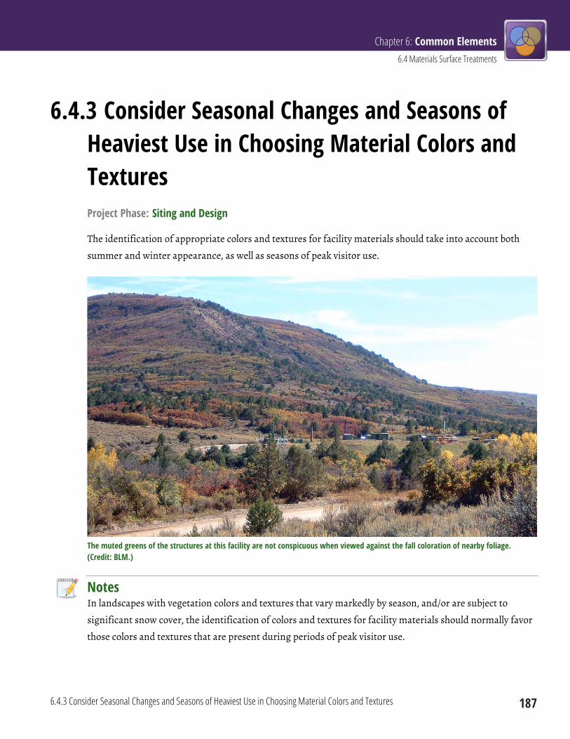
Chapter 6: Common Elements 6.4 Materials Surface Treatments
6.4.3 Consider Seasonal Changes and Seasons of Heaviest Use in Choosing Material Colors and Textures 187
6.4.3 Consider Seasonal Changes and Seasons of Heaviest Use in Choosing Material Colors and Textures Project Phase: Siting and Design
The identification of appropriate colors and textures for facility materials should take into account both
summer and winter appearance, as well as seasons of peak visitor use.
The muted greens of the structures at this facility are not conspicuous when viewed against the fall coloration of nearby foliage. (Credit: BLM.)
Notes In landscapes with vegetation colors and textures that vary markedly by season, and/or are subject to
significant snow cover, the identification of colors and textures for facility materials should normally favor
those colors and textures that are present during periods of peak visitor use.

Renewable Energy Visual BMPs
188 6.4.3 Consider Seasonal Changes and Seasons of Heaviest Use in Choosing Material Colors and Textures
Limitations The colors and textures of materials may be limited by technical or other (e.g., safety) considerations.
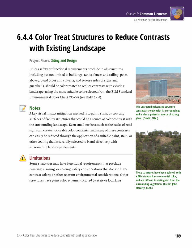
Chapter 6: Common Elements 6.4 Materials Surface Treatments
6.4.4 Color Treat Structures to Reduce Contrasts with Existing Landscape 189
6.4.4 Color Treat Structures to Reduce Contrasts with Existing Landscape Project Phase: Siting and Design
Unless safety or functional requirements preclude it, all structures,
including but not limited to buildings, tanks, fences and railing, poles,
aboveground pipes and culverts, and reverse sides of signs and
guardrails, should be color treated to reduce contrasts with existing
landscape, using the most suitable color selected from the BLM Standard
Environmental Color Chart CC-001 (see BMP 6.4.6).
Notes A key visual impact mitigation method is to paint, stain, or coat any
surfaces of facility structures that could be a source of color contrast with
the surrounding landscape. Even small surfaces such as the backs of road
signs can create noticeable color contrasts, and many of these contrasts
can easily be reduced through the application of a suitable paint, stain, or
other coating that is carefully selected to blend effectively with
surrounding landscape elements.
Limitations Some structures may have functional requirements that preclude
painting, staining, or coating; safety considerations that dictate high-
contrast colors; or other relevant environmental considerations. Other
structures have paint color schemes dictated by state or local laws.
This untreated galvanized structure contrasts strongly with its surroundings and is also a potential source of strong glare. (Credit: BLM.)
These structures have been painted with a BLM standard environmental color, and are difficult to distinguish from the surrounding vegetation. (Credit: John McCarty, BLM.)
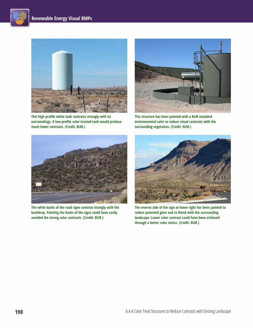
Renewable Energy Visual BMPs
190 6.4.4 Color Treat Structures to Reduce Contrasts with Existing Landscape
This high-profile white tank contrasts strongly with its surroundings. A low-profile color-treated tank would produce much lower contrasts. (Credit: BLM.)
This structure has been painted with a BLM standard environmental color to reduce visual contrasts with the surrounding vegetation. (Credit: BLM.)
The white backs of the road signs contrast strongly with the backdrop. Painting the backs of the signs could have easily avoided the strong color contrasts. (Credit: BLM.)
The reverse side of the sign at lower right has been painted to reduce potential glare and to blend with the surrounding landscape. Lower color contrast could have been achieved through a better color choice. (Credit: BLM.)
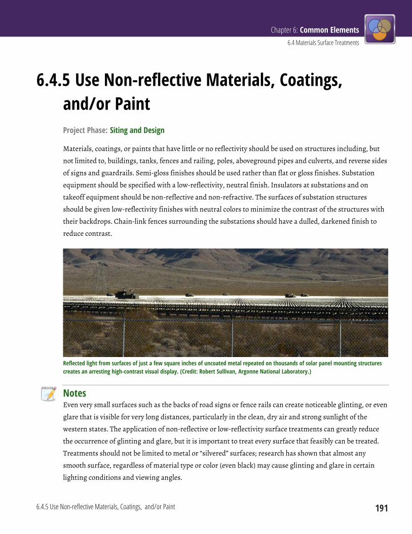
Chapter 6: Common Elements 6.4 Materials Surface Treatments
6.4.5 Use Non-reflective Materials, Coatings, and/or Paint 191
6.4.5 Use Non-reflective Materials, Coatings, and/or Paint Project Phase: Siting and Design
Materials, coatings, or paints that have little or no reflectivity should be used on structures including, but
not limited to, buildings, tanks, fences and railing, poles, aboveground pipes and culverts, and reverse sides
of signs and guardrails. Semi-gloss finishes should be used rather than flat or gloss finishes. Substation
equipment should be specified with a low-reflectivity, neutral finish. Insulators at substations and on
takeoff equipment should be non-reflective and non-refractive. The surfaces of substation structures
should be given low-reflectivity finishes with neutral colors to minimize the contrast of the structures with
their backdrops. Chain-link fences surrounding the substations should have a dulled, darkened finish to
reduce contrast.
Reflected light from surfaces of just a few square inches of uncoated metal repeated on thousands of solar panel mounting structures creates an arresting high-contrast visual display. (Credit: Robert Sullivan, Argonne National Laboratory.)
Notes Even very small surfaces such as the backs of road signs or fence rails can create noticeable glinting, or even
glare that is visible for very long distances, particularly in the clean, dry air and strong sunlight of the
western states. The application of non-reflective or low-reflectivity surface treatments can greatly reduce
the occurrence of glinting and glare, but it is important to treat every surface that feasibly can be treated.
Treatments should not be limited to metal or “silvered” surfaces; research has shown that almost any
smooth surface, regardless of material type or color (even black) may cause glinting and glare in certain
lighting conditions and viewing angles.
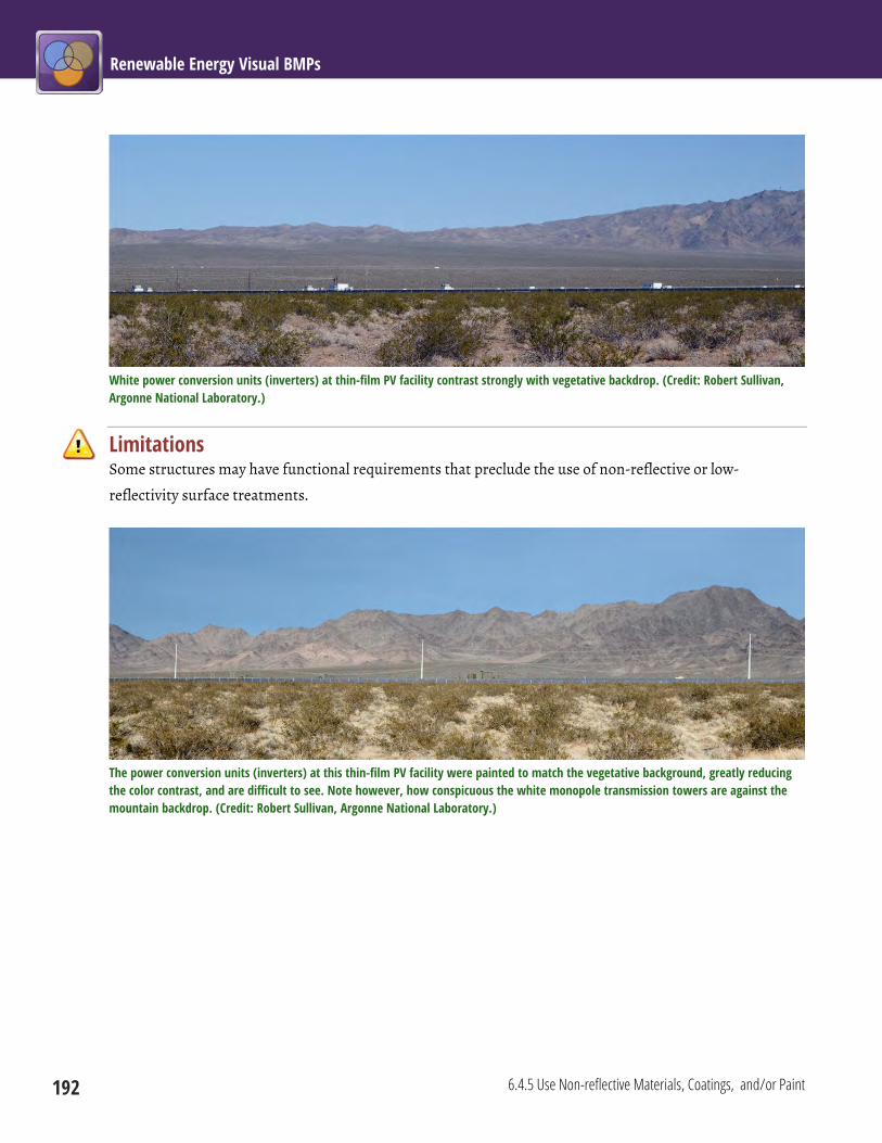
Renewable Energy Visual BMPs
192 6.4.5 Use Non-reflective Materials, Coatings, and/or Paint
White power conversion units (inverters) at thin-film PV facility contrast strongly with vegetative backdrop. (Credit: Robert Sullivan, Argonne National Laboratory.)
Limitations Some structures may have functional requirements that preclude the use of non-reflective or low-
reflectivity surface treatments.
The power conversion units (inverters) at this thin-film PV facility were painted to match the vegetative background, greatly reducing the color contrast, and are difficult to see. Note however, how conspicuous the white monopole transmission towers are against the mountain backdrop. (Credit: Robert Sullivan, Argonne National Laboratory.)
Chapter 6: Common Elements 6.4 Materials Surface Treatments
6.4.6 Select Surface Treatment Colors from the BLM Standard Environmental Colors Chart 193
6.4.6 Select Surface Treatment Colors from the BLM Standard Environmental Colors Chart Project Phase: Siting and Design
Colors for paints, stains, coatings, and other surface color treatments to be used on structures should be
selected from the BLM Standard Environmental Colors Chart.
Notes The BLM Standard Environmental Colors Chart CC-001 provides nine standard color choices for use in
selecting the most appropriate color(s) for facilities located on lands managed by the BLM. The nine colors
on the chart are those that were found to be the most effective in reducing color contrast within the various
landscape settings that make up the BLM-administered lands. The instructions on the CC-001 Color Chart
should be followed carefully. As a rule of thumb, selected colors should be darker than the background
colors to account for natural shadows, normal fading, and weathering. Lighter colors should be avoided.
Holding the color chart up to the background from a distance and squinting may help in identifying the
predominant background color. The chart also includes a description of various vegetated backgrounds and
colors that are typically best suited for use in those backgrounds.
Limitations Pre-fabricated materials may not be available in colors used on the BLM Standard Environmental Colors
Chart. Exact color matching of the manufactured paint, stain, or coating with the desired color may be
difficult. Safety considerations may require use of particular colors not found on the Standard
Environmental Colors Chart.
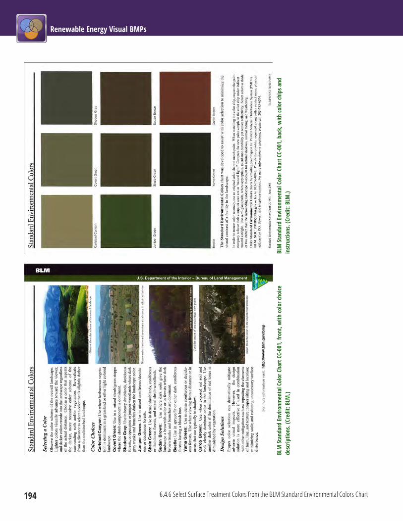
Renewable Energy Visual BMPs
194 6.4.6 Select Surface Treatment Colors from the BLM Standard Environmental Colors Chart
BLM
Stan
dard
Envi
ronm
enta
l Col
or C
hart
CC-0
01, b
ack,
with
colo
r chi
ps a
nd
inst
ruct
ions
. (Cr
edit:
BLM
.)
BL
M St
anda
rd En
viro
nmen
tal C
olor
Cha
rt CC
-001
, fro
nt, w
ith co
lor c
hoice
de
scrip
tions
. (Cr
edit:
BLM
.)
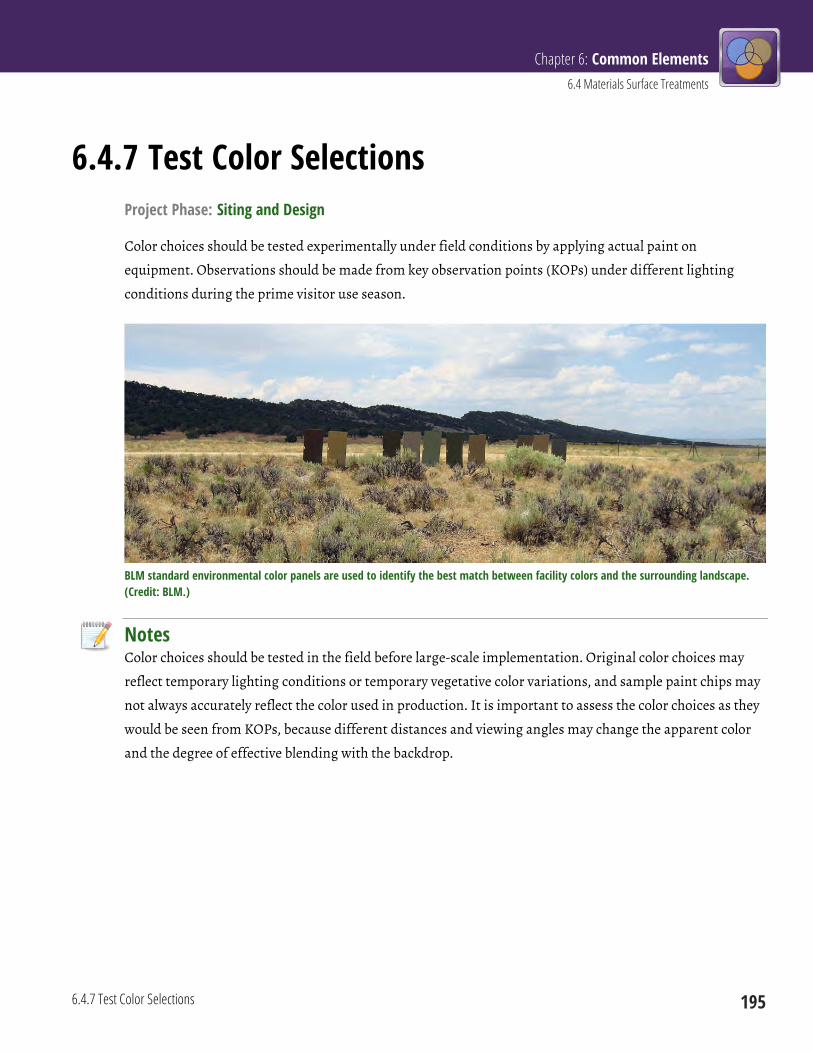
Chapter 6: Common Elements 6.4 Materials Surface Treatments
6.4.7 Test Color Selections 195
6.4.7 Test Color Selections Project Phase: Siting and Design
Color choices should be tested experimentally under field conditions by applying actual paint on
equipment. Observations should be made from key observation points (KOPs) under different lighting
conditions during the prime visitor use season.
BLM standard environmental color panels are used to identify the best match between facility colors and the surrounding landscape. (Credit: BLM.)
Notes Color choices should be tested in the field before large-scale implementation. Original color choices may
reflect temporary lighting conditions or temporary vegetative color variations, and sample paint chips may
not always accurately reflect the color used in production. It is important to assess the color choices as they
would be seen from KOPs, because different distances and viewing angles may change the apparent color
and the degree of effective blending with the backdrop.

Renewable Energy Visual BMPs
196 6.4.7 Test Color Selections
Tanks painted with two BLM standard environmental colors. The darker color is a better match for this landscape. (Credit: BLM.)
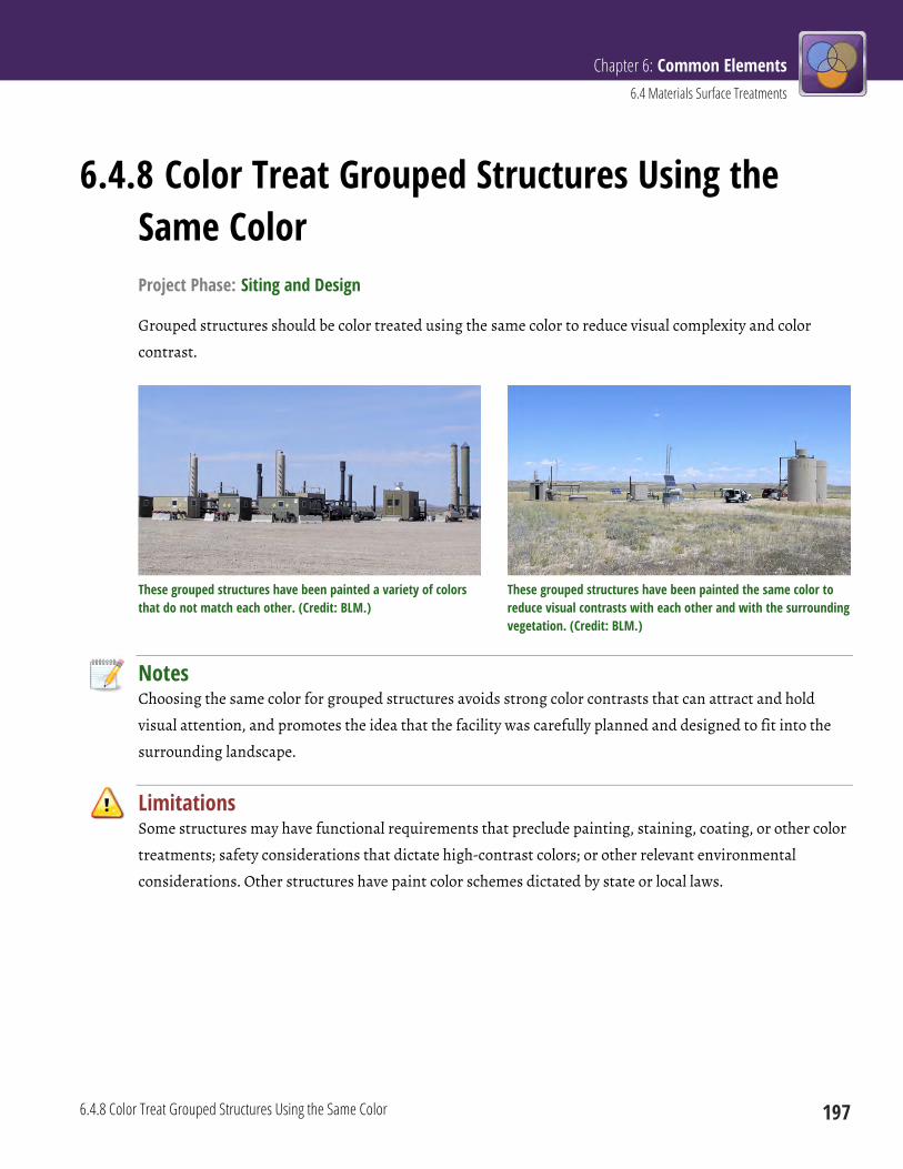
Chapter 6: Common Elements 6.4 Materials Surface Treatments
6.4.8 Color Treat Grouped Structures Using the Same Color 197
6.4.8 Color Treat Grouped Structures Using the Same Color Project Phase: Siting and Design
Grouped structures should be color treated using the same color to reduce visual complexity and color
contrast.
These grouped structures have been painted a variety of colors that do not match each other. (Credit: BLM.)
These grouped structures have been painted the same color to reduce visual contrasts with each other and with the surrounding vegetation. (Credit: BLM.)
Notes Choosing the same color for grouped structures avoids strong color contrasts that can attract and hold
visual attention, and promotes the idea that the facility was carefully planned and designed to fit into the
surrounding landscape.
Limitations Some structures may have functional requirements that preclude painting, staining, coating, or other color
treatments; safety considerations that dictate high-contrast colors; or other relevant environmental
considerations. Other structures have paint color schemes dictated by state or local laws.

Renewable Energy Visual BMPs
198 6.4.8 Color Treat Grouped Structures Using the Same Color
These structures have been painted the same color to reduce visual contrasts with each other and with the surrounding landscape. (Credit: BLM.)

Chapter 6: Common Elements 6.4 Materials Surface Treatments
6.4.8 Color Treat Grouped Structures Using the Same Color 199
Photograph of existing infrastructure at a geothermal plant, and a photosimulation showing the beneficial effects of painting facility components to reduce color contrasts with existing landscape (BMP 6.4.4), using the most suitable color selected from the BLM Standard Environmental Color Chart (BMP 6.4.6), and painting grouped structures the same color (BMP 6.4.8). The chosen color (Shadow Gray) is darker than the background color to compensate for shadows that darken most textured natural surfaces (BMP 6.4.2), and is a good match for both the creosote bush vegetation and the existing gray transmission towers. (Credit: Argonne National Laboratory).

Renewable Energy Visual BMPs
200 6.4.9 Color Treat Exposed Rock Faces
6.4.9 Color Treat Exposed Rock Faces Project Phase: Construction
The color contrast resulting from the exposure of unweathered rock on excavated rock faces should be
removed by color treating with an oxidizing color treatment.
Application of oxidizing color treatment on excavated rock face. (Credit: Craig Johnson, Logan Simpson Design, Inc.)
Notes Oxidizing color treatments can accelerate natural weathering processes to restore the natural appearance
of rock faces. Available chemicals include pH-neutral products that can be applied in a single application
without protective gear, and that do not harm vegetation or wildlife. Some color treaments can be applied
to a wide variety of materials, such as galvanized metal.
Limitations In areas with loose, scaling rock, untreated rock surfaces may become exposed after rock stain treatment,
thereby causing strong color contrasts.
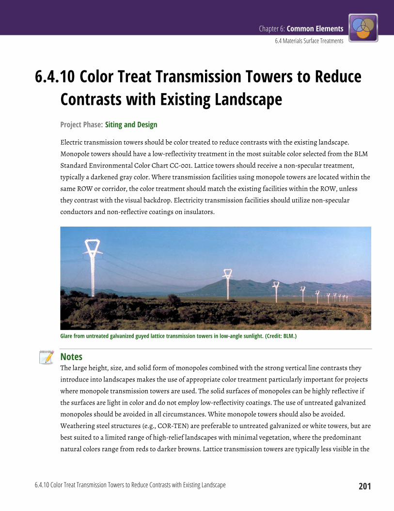
Chapter 6: Common Elements 6.4 Materials Surface Treatments
6.4.10 Color Treat Transmission Towers to Reduce Contrasts with Existing Landscape 201
6.4.10 Color Treat Transmission Towers to Reduce Contrasts with Existing Landscape Project Phase: Siting and Design
Electric transmission towers should be color treated to reduce contrasts with the existing landscape.
Monopole towers should have a low-reflectivity treatment in the most suitable color selected from the BLM
Standard Environmental Color Chart CC-001. Lattice towers should receive a non-specular treatment,
typically a darkened gray color. Where transmission facilities using monopole towers are located within the
same ROW or corridor, the color treatment should match the existing facilities within the ROW, unless
they contrast with the visual backdrop. Electricity transmission facilities should utilize non-specular
conductors and non-reflective coatings on insulators.
Glare from untreated galvanized guyed lattice transmission towers in low-angle sunlight. (Credit: BLM.)
Notes The large height, size, and solid form of monopoles combined with the strong vertical line contrasts they
introduce into landscapes makes the use of appropriate color treatment particularly important for projects
where monopole transmission towers are used. The solid surfaces of monopoles can be highly reflective if
the surfaces are light in color and do not employ low-reflectivity coatings. The use of untreated galvanized
monopoles should be avoided in all circumstances. White monopole towers should also be avoided.
Weathering steel structures (e.g., COR-TEN) are preferable to untreated galvanized or white towers, but are
best suited to a limited range of high-relief landscapes with minimal vegetation, where the predominant
natural colors range from reds to darker browns. Lattice transmission towers are typically less visible in the

Renewable Energy Visual BMPs
202 6.4.10 Color Treat Transmission Towers to Reduce Contrasts with Existing Landscape
landscape than monopoles, especially at longer distances, and in some instances can be rendered nearly
invisible by surface treatment that darkens their color and lowers their reflectivity.
Untreated galvanized monopole transmission towers (left) and lattice towers (right). Note monopole crossbar reflectivity even in distant background, and greater visual weight of monopoles beyond the immediate foreground. (Credit: Robert Sullivan, Argonne National Laboratory.)
Limitations In some sensitive locations, particularly in important bird migration pathways, flight paths, or
concentrated use areas (e.g., wetlands, aquatic habitats, or rookeries), coordination between resource
specialists should identify and resolve potential conflicts regarding conductor visibility, wildlife impacts,
and conformance to VRM objectives.
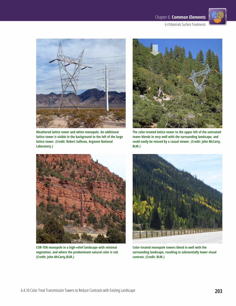
Chapter 6: Common Elements 6.4 Materials Surface Treatments
6.4.10 Color Treat Transmission Towers to Reduce Contrasts with Existing Landscape 203
Weathered lattice tower and white monopole. An additional lattice tower is visible in the background to the left of the large lattice tower. (Credit: Robert Sullivan, Argonne National Laboratory.)
The color-treated lattice tower to the upper left of the untreated tower blends in very well with the surrounding landscape, and could easily be missed by a casual viewer. (Credit: John McCarty, BLM.)
COR-TEN monopole in a high-relief landscape with minimal vegetation, and where the predominant natural color is red. (Credit: John McCarty,BLM.)
Color-treated monopole towers blend in well with the surrounding landscape, resulting in substantially lower visual contrast. (Credit: BLM.)
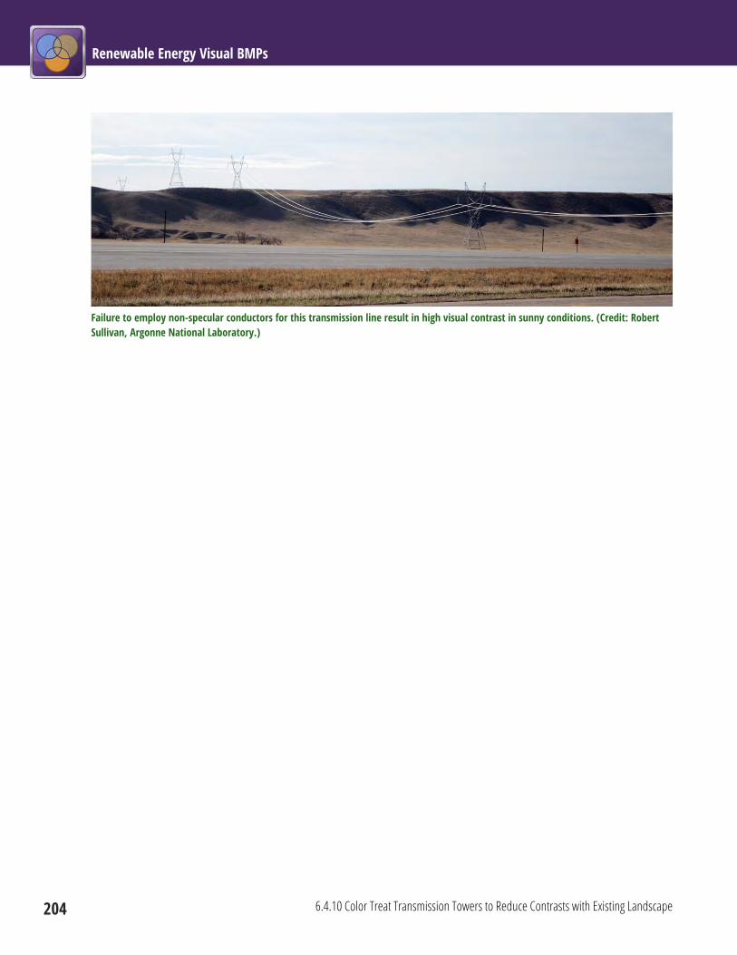
Renewable Energy Visual BMPs
204 6.4.10 Color Treat Transmission Towers to Reduce Contrasts with Existing Landscape
Failure to employ non-specular conductors for this transmission line result in high visual contrast in sunny conditions. (Credit: Robert Sullivan, Argonne National Laboratory.)

Chapter 6: Common Elements 6.4 Materials Surface Treatments
6.4.11 Use Camouflage and/or Disguise Strategies for Close KOPs in Highly Sensitive Viewsheds 205
6.4.11 Use Camouflage and/or Disguise Strategies for Close KOPs in Highly Sensitive Viewsheds Project Phase: Siting and Design
Color camouflage technology applications and/or
disguise strategies should be considered for structures
within sensitive viewsheds and with visibility distance
between 0.25 and 2 mi. BLM guidance on the use of color
to mitigate visual impacts should be consulted.
Notes In certain situations where project elements must be
sited within close proximity to highly sensitive
viewpoints, color camouflage technology applications
and/or disguise strategies can be used to reduce visibility
and visual contrast.
Limitations The BLM has tested camouflage technology applications
and disguise for certain structures. This research has
shown that camouflage technology applications and
disguise strategies are only effective in certain
circumstances, and are most effective at viewing
distances between 0.25 and 0.75 mi.
Color camouflage application on tank. (Credit: BLM.)

Renewable Energy Visual BMPs
206 6.4.12 Maintain Painted, Stained, or Coated Surfaces Properly
6.4.12 Maintain Painted, Stained, or Coated Surfaces Properly Project Phase: Operations
Painted, stained, or coated surfaces should be kept in good repair, and the surface treatment should be
reapplied when necessary, as the surface color fades or the coating flakes or otherwise deteriorates.
Notes The contrast reduction effectiveness of surface treatments depends of the condition of the surface
treatment. If the surface color fades too much, color contrast may increase. If the surface coating flakes, the
underlying structure’s surface may be exposed, potentially increasing contrast and causing glinting or
glare. Damaged surface coatings may also make the facility look unkempt or poorly maintained.
Limitations Some coatings may be difficult to apply in field settings.

Chapter 6: Common Elements 6.5 Lighting
207
6.5 Lighting These BMPs help ensure that projects minimize night-sky impacts through proper lighting design and usage.
6.5 Lighting Siting and Design Construction Operations
Decommissioning and
Reclamation
6.5.1 Prepare a Lighting Plan (p 208)
6.5.2 Use Audiovisual Warning System (AVWS) Technology for Hazard Lighting on Structures Taller than 200 ft (p 210)
6.5.3 Use Full Cutoff Luminaires (p 211)
6.5.4 Direct Lights Properly to Eliminate Light Spill and Trespass (p 213)
6.5.5 Use Amber instead of Bluish-White Lighting (p 214)
6.5.6 Minimize Lighting Usage during Construction and Operations (p 215)
6.5.7 Use Vehicle-Mounted Lights or Portable Light Towers for Nighttime Maintenance Activities (p 218)

Renewable Energy Visual BMPs
208 6.5.1 Prepare a Lighting Plan
6.5.1 Prepare a Lighting Plan Project Phase: Siting and Design
A lighting plan should be prepared documenting how lighting will be designed and installed to minimize
night-sky impacts and impacts on nocturnal wildlife during construction and operations. The lighting plan
should specify the following:
(1) Number of lights and lumen output of each—Minimum number of lights and the lowest luminosity
consistent with safe and secure operation of the facility;
(2) Alternatives to lighting—Retro-reflective or luminescent markers in lieu of permanent lighting
where feasible;
(3) Fixture design—Lights of the proper design, shielded to eliminate uplight, placed and directed to
eliminate light spill and trespass to offsite locations;
(4) Lamp color temperature—Lights of the proper color to minimize night-sky impacts;
(5) Standard operating procedures—Minimization of unnecessary lighting use through alternatives to
permanent lighting, such as restricting lighting usage to certain time periods;
(6) Any activities that may be restricted to avoid night-sky impacts; and
(7) A process for promptly addressing and mitigating complaints about potential lighting impacts.
Notes The dark night skies of many parts of the western United States are valued by residents and visitors to the
region and are a tourist amenity in some areas, particularly in the southwestern deserts. Poorly designed
outdoor lighting can impact areas tens of miles away. Not only is light pollution from facility and activity
lighting a negative visual impact, it also can be a concern for nocturnal wildlife. A quality lighting plan helps
ensure that unneeded lighting is avoided; lights are properly placed, shielded, and used; and there is a
process in place to resolve issues raised by local stakeholders concerning lighting.

Chapter 6: Common Elements 6.5 Lighting
6.5.1 Prepare a Lighting Plan 209
Limitations Safety and security must be considered in developing a lighting plan for facilities and access roads. The FAA
and other agencies may have regulations governing lighting practices that must be considered in designing
facility lighting.
Lighting management plan for a solar facility. (Credit: BLM.)

Renewable Energy Visual BMPs
210 6.5.2 Use Audiovisual Warning System (AVWS) Technology for Hazard Lighting on Structures Taller than 200 ft
6.5.2 Use Audiovisual Warning System (AVWS) Technology for Hazard Lighting on Structures Taller than 200 ft Project Phase: Siting and Design
If the FAA approves AVWS technology for general use, it should be used for structures exceeding 200 ft in
height. If the FAA denies a permit for use of this technology, the project developer should limit the amount
of lighting to the minimum required by the FAA, in order to minimize visibility beyond that required to
meet safety requirements.
Conventional hazard navigation lights atop wind turbines. (Credit: Terry DeWan, Terrence J. DeWan & Associates.)
Notes AVWS is a radar-based obstacle avoidance system that activates obstruction lighting and audio signals only
when an aircraft is in close proximity to an obstruction on which an AVWS unit is mounted, such as a wind
turbine. The obstruction lights and audio warnings are inactive when aircraft are not in proximity to the
obstruction. Currently, the FAA may approve use of AVWS on a case-by-case basis. If approved for general
use by the FAA, the use of AVWS technology would greatly reduce the night-sky impacts of lighting from tall
structures and would also reduce avian mortality.
Limitations As of the publication of the BMP publication, the use of AVWS technology for any structures other than
communication towers is under FAA evaluation. In the interim, projects proposing the use of AVWS
technology are reviewed on a case-by-case basis until the FAA makes a final suitability determination.
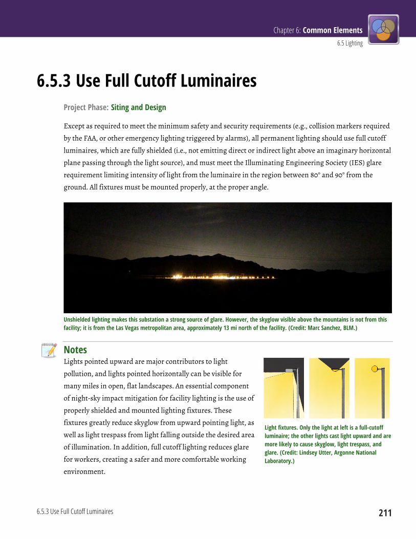
Chapter 6: Common Elements 6.5 Lighting
6.5.3 Use Full Cutoff Luminaires 211
6.5.3 Use Full Cutoff Luminaires Project Phase: Siting and Design
Except as required to meet the minimum safety and security requirements (e.g., collision markers required
by the FAA, or other emergency lighting triggered by alarms), all permanent lighting should use full cutoff
luminaires, which are fully shielded (i.e., not emitting direct or indirect light above an imaginary horizontal
plane passing through the light source), and must meet the Illuminating Engineering Society (IES) glare
requirement limiting intensity of light from the luminaire in the region between 80° and 90° from the
ground. All fixtures must be mounted properly, at the proper angle.
Unshielded lighting makes this substation a strong source of glare. However, the skyglow visible above the mountains is not from this facility; it is from the Las Vegas metropolitan area, approximately 13 mi north of the facility. (Credit: Marc Sanchez, BLM.)
Notes Lights pointed upward are major contributors to light
pollution, and lights pointed horizontally can be visible for
many miles in open, flat landscapes. An essential component
of night-sky impact mitigation for facility lighting is the use of
properly shielded and mounted lighting fixtures. These
fixtures greatly reduce skyglow from upward pointing light, as
well as light trespass from light falling outside the desired area
of illumination. In addition, full cutoff lighting reduces glare
for workers, creating a safer and more comfortable working
environment.
Light fixtures. Only the light at left is a full-cutoff luminaire; the other lights cast light upward and are more likely to cause skyglow, light trespass, and glare. (Credit: Lindsey Utter, Argonne National Laboratory.)

Renewable Energy Visual BMPs
212 6.5.3 Use Full Cutoff Luminaires
The terms “fully shielded luminaire” and “full cutoff luminaire” are often used interchangeably, but they are
not identical. All full cutoff luminaires are fully shielded, but not all fully shielded luminaires are full cutoff.
Full cutoff luminaires limit glare from the luminaire between 80° and 90° from the ground; a luminaire
could be fully shielded but not meet the glare limitation requirements between 80° and 90° that are
required to meet the IES full cutoff designation.
The IES recently adopted a new system for rating luminaires, the Backlight, Uplight, and Glare (BUG)
rating system. In the new IES BUG luminaire rating system (IES TM-15), luminaires are rated by the
amount of light they produce in different angular zones around the light source. In the BUG rating system,
lights at renewable energy facilities should have a U rating of 1 or below, and a G rating of 2 or below.
Limitations The FAA and other agencies may have regulations governing lighting practices that must be considered in
designing facility lighting. FAA consultation may be required and/or desirable in the early stages of both
wind and solar power tower facilities.

Chapter 6: Common Elements 6.5 Lighting
6.5.4 Direct Lights Properly to Eliminate Light Spill and Trespass 213
6.5.4 Direct Lights Properly to Eliminate Light Spill and Trespass Project Phase: Siting and Design, Construction
Construction and permanent lighting should be mounted and directed to focus light only on the intended
area, and to avoid light spill and offsite light trespass. Lights pointing upward or horizontally should be
avoided.
Nighttime shot of a building at a solar PV facility. The lights are shielded and are directing light downward and only to the immediate vicinity of the building; however, there may be more lights than the minimum needed. The building appears to be unoccupied; if so, motion sensors could be used to reduce lighting further. (Copper Mountain Solar Facility, near Boulder City, Nevada. Credit: Marc Sanchez, BLM.)
Notes Lights pointed upward are major contributors to light pollution, and lights pointed horizontally can be
visible for many miles in open, flat landscapes. Pointing lights only where needed helps to reduce light spill
into areas where it is not needed and light trespass that crosses property boundaries.
Limitations Safety or functional considerations may dictate lighting practices that result in some light spill or light
trespass.
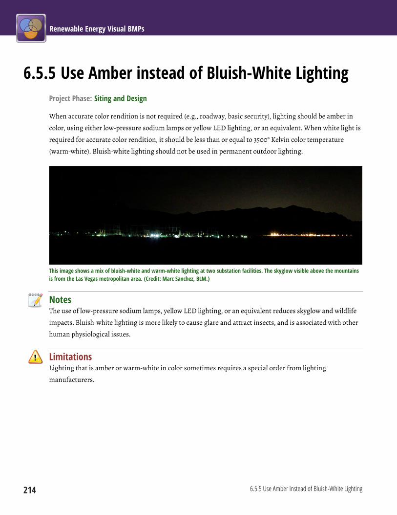
Renewable Energy Visual BMPs
214 6.5.5 Use Amber instead of Bluish-White Lighting
6.5.5 Use Amber instead of Bluish-White Lighting Project Phase: Siting and Design
When accurate color rendition is not required (e.g., roadway, basic security), lighting should be amber in
color, using either low-pressure sodium lamps or yellow LED lighting, or an equivalent. When white light is
required for accurate color rendition, it should be less than or equal to 3500° Kelvin color temperature
(warm-white). Bluish-white lighting should not be used in permanent outdoor lighting.
This image shows a mix of bluish-white and warm-white lighting at two substation facilities. The skyglow visible above the mountains is from the Las Vegas metropolitan area. (Credit: Marc Sanchez, BLM.)
Notes The use of low-pressure sodium lamps, yellow LED lighting, or an equivalent reduces skyglow and wildlife
impacts. Bluish-white lighting is more likely to cause glare and attract insects, and is associated with other
human physiological issues.
Limitations Lighting that is amber or warm-white in color sometimes requires a special order from lighting
manufacturers.

Chapter 6: Common Elements 6.5 Lighting
6.5.6 Minimize Lighting Usage during Construction and Operations 215
6.5.6 Minimize Lighting Usage during Construction and Operations Project Phase: Construction, Operations
Consistent with safety requirements, lighting use should be minimized during construction and
operations.
During construction, localized and portable lighting should be used where and when the work is occurring.
Lighting should be powered by generators and have switches to cut power when lighting is not required
during construction.
Lighting for facilities should not exceed the minimum number, intensity, and coverage required for safety
and basic security. All area lighting should be divided into separately controlled zones to focus lighting on
smaller areas where tasks are being performed and to avoid illuminating unused space. Area lighting
should be controlled by timers, sensors, or switches available to facility operators; dusk-to-dawn lighting
controlled by photocell alone should not be allowed except where required for safety. The facility operators
should identify those components/structures that do not require continuous lighting for safety reasons.
Area lights should only be switched on when there is a specific need (e.g., cleaning mirrors and panels at a
solar facility, pumping fuel, persons occupying an area, or alarm situation). When not needed, lights should
be switched off. Exceptions to switched-off lighting for safety purposes should be articulated in the lighting
plan (see BMP 6.5.1). Focused task lighting, portable light towers, or flashlights should be used instead of
area lighting, and retro-reflective or luminescent markers should be used in lieu of permanent lighting
where feasible.

Renewable Energy Visual BMPs
216 6.5.6 Minimize Lighting Usage during Construction and Operations
Nighttime shot of a geothermal power plant located near El Centro, California. Better lighting practices could substantially reduce light pollution from this facility. (Credit: Warren Gretz, NREL.)
Notes Dark night skies are a highly valued amenity in many parts of the American west. Many industrial facilities
have too much lighting, well beyond that needed for safety, security, and efficient conduct of work. Poorly
designed outdoor lighting can impact areas tens of miles away. In addition to causing light pollution,
excessive lighting can cause hazards for nocturnal wildlife, waste energy and money, and even create safety
and security hazards by causing excessive glare. Facilities should use the minimum lighting levels
consistent with safety and security requirements.
Nighttime shot of the power block and part of the cooling tower at a solar parabolic trough facility. Bright lights combined with many complex, highly reflective surfaces makes this facility lighting easily visible at distances greater than 10 mi (Nevada Solar One, near Boulder City, Nevada. Credit: Marc Sanchez, BLM.)
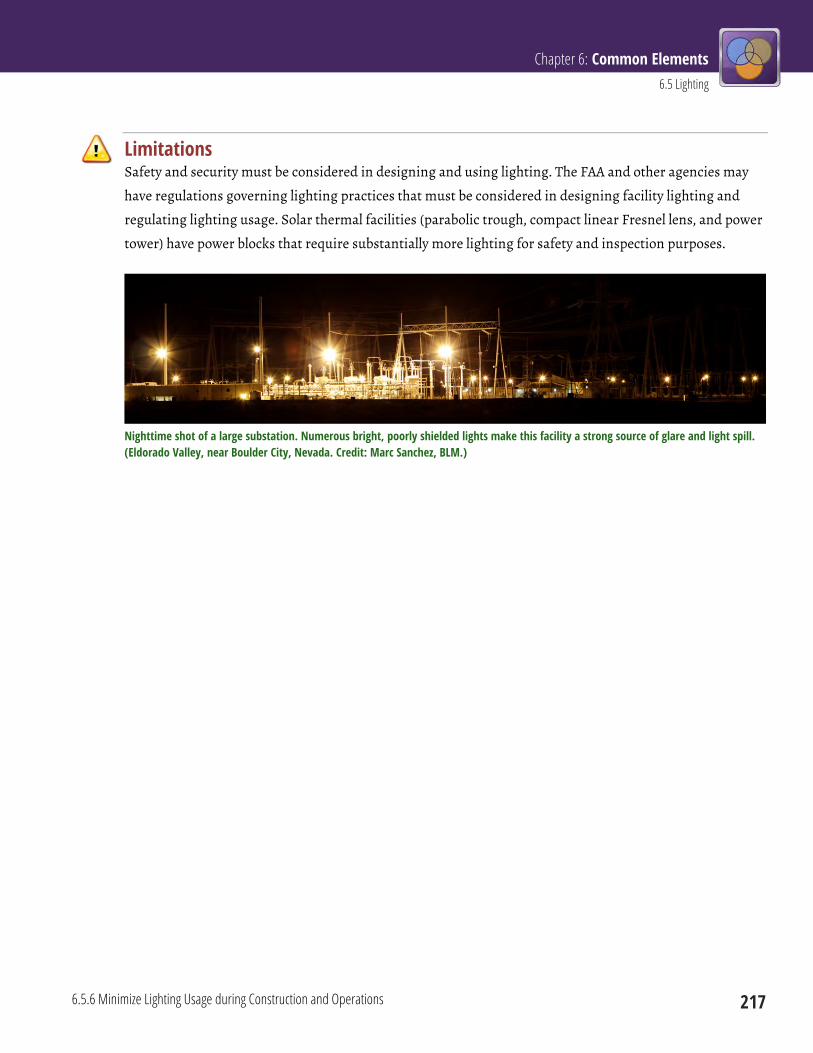
Chapter 6: Common Elements 6.5 Lighting
6.5.6 Minimize Lighting Usage during Construction and Operations 217
Limitations Safety and security must be considered in designing and using lighting. The FAA and other agencies may
have regulations governing lighting practices that must be considered in designing facility lighting and
regulating lighting usage. Solar thermal facilities (parabolic trough, compact linear Fresnel lens, and power
tower) have power blocks that require substantially more lighting for safety and inspection purposes.
Nighttime shot of a large substation. Numerous bright, poorly shielded lights make this facility a strong source of glare and light spill. (Eldorado Valley, near Boulder City, Nevada. Credit: Marc Sanchez, BLM.)
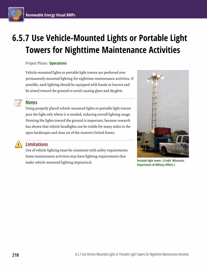
Renewable Energy Visual BMPs
218 6.5.7 Use Vehicle-Mounted Lights or Portable Light Towers for Nighttime Maintenance Activities
6.5.7 Use Vehicle-Mounted Lights or Portable Light Towers for Nighttime Maintenance Activities Project Phase: Operations
Vehicle-mounted lights or portable light towers are preferred over
permanently mounted lighting for nighttime maintenance activities. If
possible, such lighting should be equipped with hoods or louvers and
be aimed toward the ground to avoid causing glare and skyglow.
Notes Using properly placed vehicle-mounted lights or portable light towers
puts the light only where it is needed, reducing overall lighting usage.
Pointing the lights toward the ground is important, because research
has shown that vehicle headlights can be visible for many miles in the
open landscapes and clear air of the western United States.
Limitations Use of vehicle lighting must be consistent with safety requirements.
Some maintenance activities may have lighting requirements that
make vehicle-mounted lighting impractical.
Portable light tower. (Credit: Wisconsin Department of Military Affairs.)
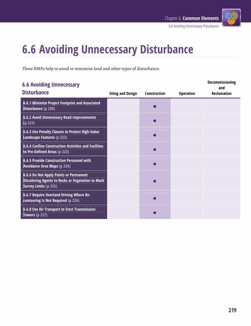
Chapter 6: Common Elements 6.6 Avoiding Unnecessary Disturbance
219
6.6 Avoiding Unnecessary Disturbance These BMPs help to avoid or minimize land and other types of disturbance.
6.6 Avoiding Unnecessary Disturbance Siting and Design Construction Operation
Decommissioning and
Reclamation
6.6.1 Minimize Project Footprint and Associated Disturbance (p 220)
6.6.2 Avoid Unnecessary Road Improvements (p 221)
6.6.3 Use Penalty Clauses to Protect High-Value Landscape Features (p 222)
6.6.4 Confine Construction Activities and Facilities to Pre-Defined Areas (p 223)
6.6.5 Provide Construction Personnel with Avoidance Area Maps (p 224)
6.6.6 Do Not Apply Paints or Permanent Discoloring Agents to Rocks or Vegetation to Mark Survey Limits (p 225)
6.6.7 Require Overland Driving Where Re-contouring Is Not Required (p 226)
6.6.8 Use Air Transport to Erect Transmission Towers (p 227)
Renewable Energy Visual BMPs
220 6.6.1 Minimize Project Footprint and Associated Disturbance
6.6.1 Minimize Project Footprint and Associated Disturbance Project Phase: Construction
Minimize the project footprint and associated disturbance during and after construction. The number,
size, and length of roads, temporary fences, laydown areas, and borrow areas should be minimized.
Existing rocks, vegetation, and drainage patterns should be preserved to the maximum extent possible. All
construction and maintenance activities should be conducted in a manner that will minimize disturbance
of vegetation, soils, drainage channels, and intermittent and perennial stream banks.
Notes Unnecessary site disturbance can be a major source of visual contrasts. As a general rule, the project
footprint and associated disturbance during and after construction should be minimized. Reducing the
project footprint and minimizing disturbance of vegetation, soils (particularly in areas with highly
contrasting subsoil color), drainage channels, and stream banks directly reduces the extent of visual
contrast and hence visual impacts, as well as having numerous other environmental benefits.
Limitations Site characteristics, and technical and environmental considerations, may limit the ability to reduce a
project’s footprint during construction.
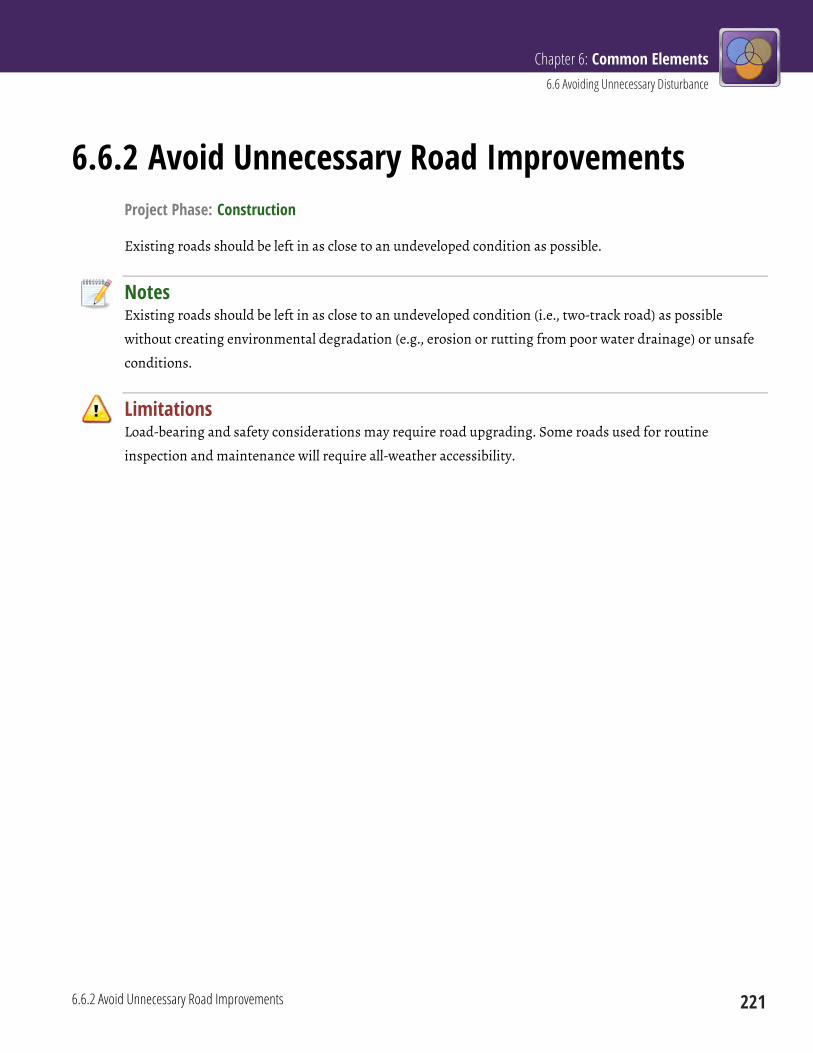
Chapter 6: Common Elements 6.6 Avoiding Unnecessary Disturbance
6.6.2 Avoid Unnecessary Road Improvements 221
6.6.2 Avoid Unnecessary Road Improvements Project Phase: Construction
Existing roads should be left in as close to an undeveloped condition as possible.
Notes Existing roads should be left in as close to an undeveloped condition (i.e., two-track road) as possible
without creating environmental degradation (e.g., erosion or rutting from poor water drainage) or unsafe
conditions.
Limitations Load-bearing and safety considerations may require road upgrading. Some roads used for routine
inspection and maintenance will require all-weather accessibility.
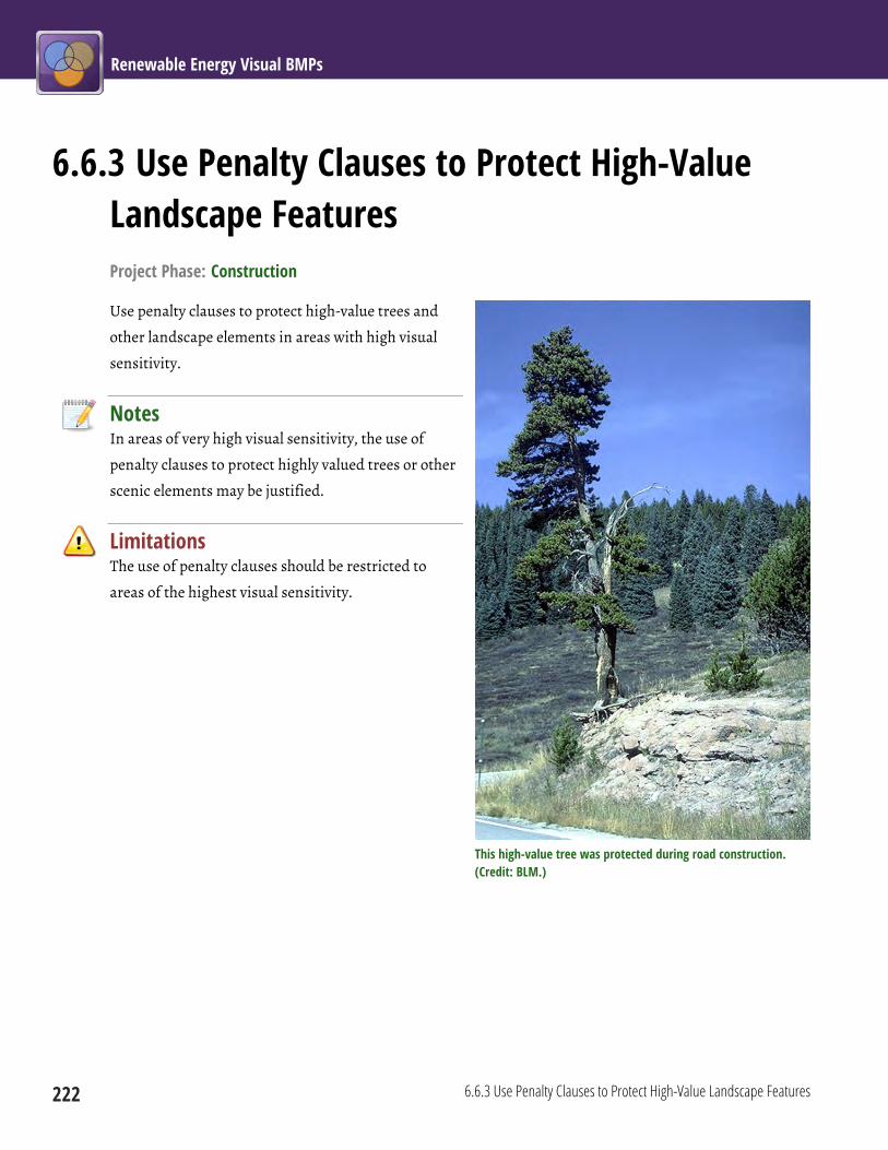
Renewable Energy Visual BMPs
222 6.6.3 Use Penalty Clauses to Protect High-Value Landscape Features
6.6.3 Use Penalty Clauses to Protect High-Value Landscape Features Project Phase: Construction
Use penalty clauses to protect high-value trees and
other landscape elements in areas with high visual
sensitivity.
Notes In areas of very high visual sensitivity, the use of
penalty clauses to protect highly valued trees or other
scenic elements may be justified.
Limitations The use of penalty clauses should be restricted to
areas of the highest visual sensitivity.
This high-value tree was protected during road construction. (Credit: BLM.)

Chapter 6: Common Elements 6.6 Avoiding Unnecessary Disturbance
6.6.4 Confine Construction Activities and Facilities to Pre-Defined Areas 223
6.6.4 Confine Construction Activities and Facilities to Pre-Defined Areas Project Phase: Construction
Personal vehicles, sanitary facilities, and work areas should be confined to clearly delineated construction
boundaries specified in the plan of development. For construction and prolonged operations and
maintenance projects, maintenance equipment, materials, and vehicles should be stored at the sites where
activities will occur, or at specified maintenance yards.
Limits of construction activities are clearly marked at this site. (Credit: John McCarty, BLM.)
Notes The limits of construction activity areas should be predetermined and demarcated, with activity restricted
to and confined within those limits. Confining equipment, vehicles, and activities to pre-defined areas will
result in less vegetation and ground disturbance, as well as reducing visual clutter.
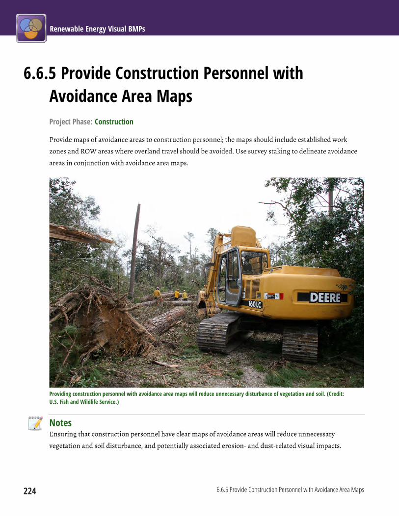
Renewable Energy Visual BMPs
224 6.6.5 Provide Construction Personnel with Avoidance Area Maps
6.6.5 Provide Construction Personnel with Avoidance Area Maps Project Phase: Construction
Provide maps of avoidance areas to construction personnel; the maps should include established work
zones and ROW areas where overland travel should be avoided. Use survey staking to delineate avoidance
areas in conjunction with avoidance area maps.
Providing construction personnel with avoidance area maps will reduce unnecessary disturbance of vegetation and soil. (Credit: U.S. Fish and Wildlife Service.)
Notes Ensuring that construction personnel have clear maps of avoidance areas will reduce unnecessary
vegetation and soil disturbance, and potentially associated erosion- and dust-related visual impacts.
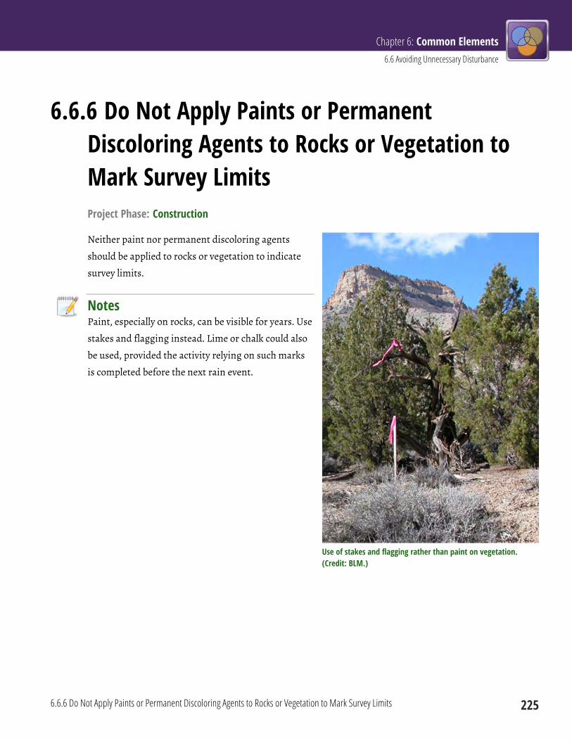
Chapter 6: Common Elements 6.6 Avoiding Unnecessary Disturbance
6.6.6 Do Not Apply Paints or Permanent Discoloring Agents to Rocks or Vegetation to Mark Survey Limits 225
6.6.6 Do Not Apply Paints or Permanent Discoloring Agents to Rocks or Vegetation to Mark Survey Limits Project Phase: Construction
Neither paint nor permanent discoloring agents
should be applied to rocks or vegetation to indicate
survey limits.
Notes Paint, especially on rocks, can be visible for years. Use
stakes and flagging instead. Lime or chalk could also
be used, provided the activity relying on such marks
is completed before the next rain event.
Use of stakes and flagging rather than paint on vegetation. (Credit: BLM.)
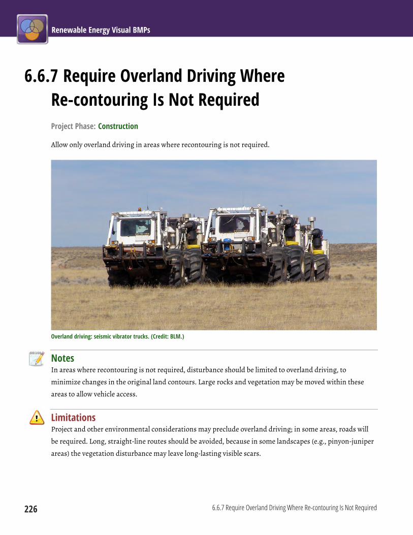
Renewable Energy Visual BMPs
226 6.6.7 Require Overland Driving Where Re-contouring Is Not Required
6.6.7 Require Overland Driving Where Re-contouring Is Not Required Project Phase: Construction
Allow only overland driving in areas where recontouring is not required.
Overland driving: seismic vibrator trucks. (Credit: BLM.)
Notes In areas where recontouring is not required, disturbance should be limited to overland driving, to
minimize changes in the original land contours. Large rocks and vegetation may be moved within these
areas to allow vehicle access.
Limitations Project and other environmental considerations may preclude overland driving; in some areas, roads will
be required. Long, straight-line routes should be avoided, because in some landscapes (e.g., pinyon-juniper
areas) the vegetation disturbance may leave long-lasting visible scars.
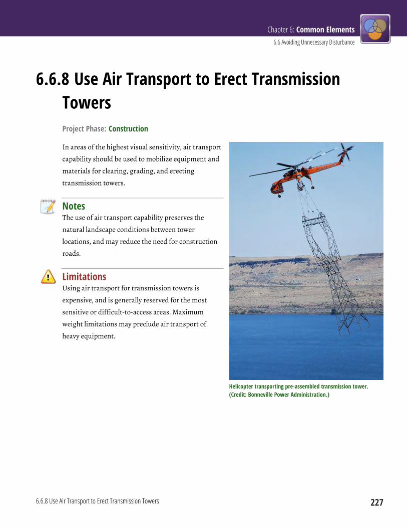
Chapter 6: Common Elements 6.6 Avoiding Unnecessary Disturbance
6.6.8 Use Air Transport to Erect Transmission Towers 227
6.6.8 Use Air Transport to Erect Transmission Towers Project Phase: Construction
In areas of the highest visual sensitivity, air transport
capability should be used to mobilize equipment and
materials for clearing, grading, and erecting
transmission towers.
Notes The use of air transport capability preserves the
natural landscape conditions between tower
locations, and may reduce the need for construction
roads.
Limitations Using air transport for transmission towers is
expensive, and is generally reserved for the most
sensitive or difficult-to-access areas. Maximum
weight limitations may preclude air transport of
heavy equipment.
Helicopter transporting pre-assembled transmission tower. (Credit: Bonneville Power Administration.)

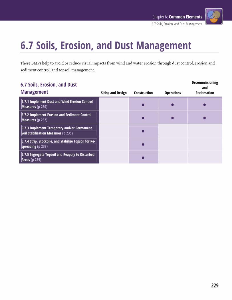
Chapter 6: Common Elements 6.7 Soils, Erosion, and Dust Management
229
6.7 Soils, Erosion, and Dust Management These BMPs help to avoid or reduce visual impacts from wind and water erosion through dust control, erosion and
sediment control, and topsoil management.
6.7 Soils, Erosion, and Dust Management Siting and Design Construction Operations
Decommissioning and
Reclamation
6.7.1 Implement Dust and Wind Erosion Control Measures (p 230)
6.7.2 Implement Erosion and Sediment Control Measures (p 232)
6.7.3 Implement Temporary and/or Permanent Soil Stabilization Measures (p 235)
6.7.4 Strip, Stockpile, and Stabilize Topsoil for Re-spreading (p 237)
6.7.5 Segregate Topsoil and Reapply to Disturbed Areas (p 239)
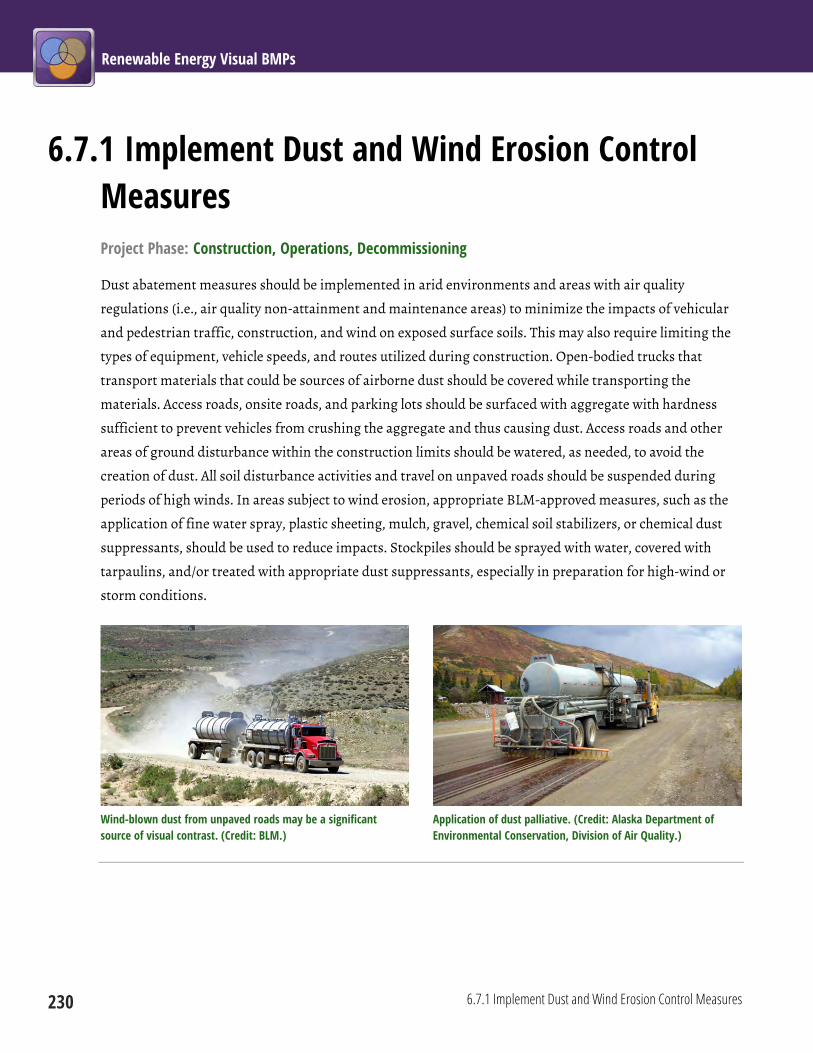
Renewable Energy Visual BMPs
230 6.7.1 Implement Dust and Wind Erosion Control Measures
6.7.1 Implement Dust and Wind Erosion Control Measures Project Phase: Construction, Operations, Decommissioning
Dust abatement measures should be implemented in arid environments and areas with air quality
regulations (i.e., air quality non-attainment and maintenance areas) to minimize the impacts of vehicular
and pedestrian traffic, construction, and wind on exposed surface soils. This may also require limiting the
types of equipment, vehicle speeds, and routes utilized during construction. Open-bodied trucks that
transport materials that could be sources of airborne dust should be covered while transporting the
materials. Access roads, onsite roads, and parking lots should be surfaced with aggregate with hardness
sufficient to prevent vehicles from crushing the aggregate and thus causing dust. Access roads and other
areas of ground disturbance within the construction limits should be watered, as needed, to avoid the
creation of dust. All soil disturbance activities and travel on unpaved roads should be suspended during
periods of high winds. In areas subject to wind erosion, appropriate BLM-approved measures, such as the
application of fine water spray, plastic sheeting, mulch, gravel, chemical soil stabilizers, or chemical dust
suppressants, should be used to reduce impacts. Stockpiles should be sprayed with water, covered with
tarpaulins, and/or treated with appropriate dust suppressants, especially in preparation for high-wind or
storm conditions.
Wind-blown dust from unpaved roads may be a significant source of visual contrast. (Credit: BLM.)
Application of dust palliative. (Credit: Alaska Department of Environmental Conservation, Division of Air Quality.)

Chapter 6: Common Elements 6.7 Soils, Erosion, and Dust Management
6.7.1 Implement Dust and Wind Erosion Control Measures 231
Notes Windblown dust can be highly visible, and is a particular problem in the arid southwestern states. Dust
abatement and wind erosion control measures reduce visual impacts, improve air quality, and provide
numerous other benefits.
Limitations There may be limitations to the amount of water that can be applied for dust abatement based on soil type.
Only BLM-approved products must be used, as certain chemical dust suppressants may not be allowed.
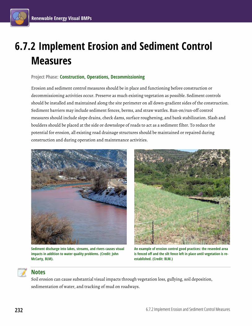
Renewable Energy Visual BMPs
232 6.7.2 Implement Erosion and Sediment Control Measures
6.7.2 Implement Erosion and Sediment Control Measures Project Phase: Construction, Operations, Decommissioning
Erosion and sediment control measures should be in place and functioning before construction or
decommissioning activities occur. Preserve as much existing vegetation as possible. Sediment controls
should be installed and maintained along the site perimeter on all down-gradient sides of the construction.
Sediment barriers may include sediment fences, berms, and straw wattles. Run-on/run-off control
measures should include slope drains, check dams, surface roughening, and bank stabilization. Slash and
boulders should be placed at the side or downslope of roads to act as a sediment filter. To reduce the
potential for erosion, all existing road drainage structures should be maintained or repaired during
construction and during operation and maintenance activities.
Sediment discharge into lakes, streams, and rivers causes visual impacts in addition to water quality problems. (Credit: John McCarty, BLM).
An example of erosion control good practices: the reseeded area is fenced off and the silt fence left in place until vegetation is re-established. (Credit: BLM.)
Notes Soil erosion can cause substantial visual impacts through vegetation loss, gullying, soil deposition,
sedimentation of water, and tracking of mud on roadways.

Chapter 6: Common Elements 6.7 Soils, Erosion, and Dust Management
6.7.2 Implement Erosion and Sediment Control Measures 233
Limitations EPA and/or states require permit coverage, including the creation of a Stormwater Pollution Prevention
Plan, prior to the disturbance of an acre or more. BLM may require certified weed-free straw to prevent
introduction of invasive or noxious species.
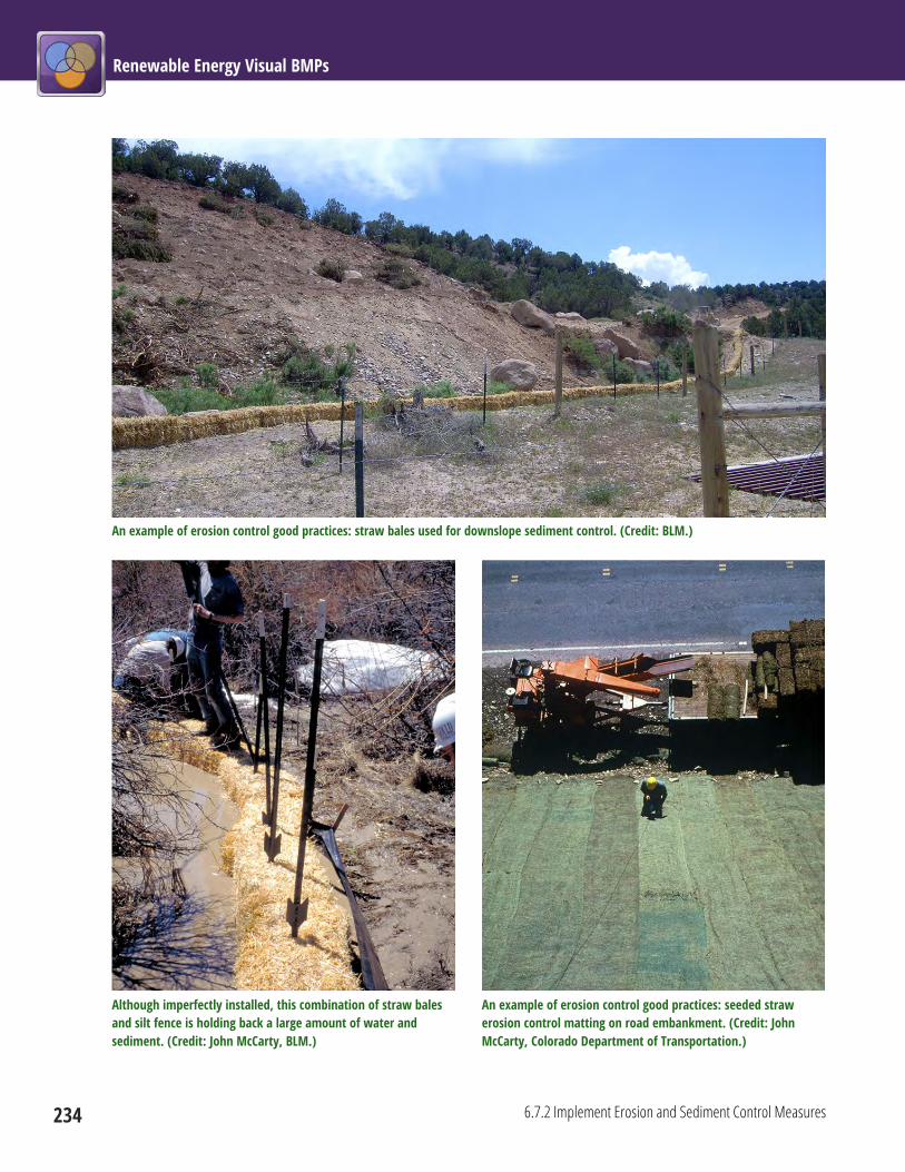
Renewable Energy Visual BMPs
234 6.7.2 Implement Erosion and Sediment Control Measures
An example of erosion control good practices: straw bales used for downslope sediment control. (Credit: BLM.)
Although imperfectly installed, this combination of straw bales and silt fence is holding back a large amount of water and sediment. (Credit: John McCarty, BLM.)
An example of erosion control good practices: seeded straw erosion control matting on road embankment. (Credit: John McCarty, Colorado Department of Transportation.)

Chapter 6: Common Elements 6.7 Soils, Erosion, and Dust Management
6.7.3 Implement Temporary and/or Permanent Soil Stabilization Measures 235
6.7.3 Implement Temporary and/or Permanent Soil Stabilization Measures Project Phase: Construction
Temporary and/or permanent soil stabilization measures should be applied immediately on all disturbed
areas as grading progresses and on all roadways. These measures should be utilized appropriately until
construction is complete, and all vegetation is established. Temporary slope stabilization measures may
include covering exposed soil with plastic sheeting, straw mulching, or other approved measures. To reduce
the potential for erosion, riprap, boulders, and vegetation can be used to stabilize slopes.
A stabilized and seeded slope. (Credit: BLM.)
Notes Loose soil must be protected from washing away in heavy rains to avoid soil deposition, sedimentation of
water, and tracking of mud on roadways. In some situations chemical solutions can be used to stabilize
soils.

Renewable Energy Visual BMPs
236 6.7.3 Implement Temporary and/or Permanent Soil Stabilization Measures
Limitations The transport of other materials to the site (e.g., riprap) and their use for soil stabilization itself causes
some environmental impacts; at some point, the soil stabilization benefits gained may be outweighed by
the impacts of implementing the procedures. A site-specific analysis of the potential benefits and costs
must be made. Potential effects of chemical soil stabilization solutions on native vegetation and other
sensitive environmental features in the immediate area may preclude the use of these soil stabilization
agents.
Slash used to stabilize slope below a road cut. (Credit: BLM.)

Chapter 6: Common Elements 6.7 Soils, Erosion, and Dust Management
6.7.4 Strip, Stockpile, and Stabilize Topsoil for Re-spreading 237
6.7.4 Strip, Stockpile, and Stabilize Topsoil for Re-spreading Project Phase: Construction
Strip, stockpile, and stabilize topsoil from a site before excavating earth for facility construction. Avoid
screening stockpiled topsoil. Stockpiled soil should be placed in a stable location and configuration. Soil
stockpiles should have temporary stabilization or covering at the end of each workday. Sediment fences
should be installed around stockpiles. Topsoil piles should not be left in sensitive viewing areas.
Stockpiled topsoil. In this case, composted sewage sludge (two darker piles in foreground) was mixed with soil from the topsoil stockpile behind and to the left of the mixed soil/compost piles. (Credit: John McCarty, Colorado Department of Transportation.)
Notes Topsoil is often better than subsoil for revegetation purposes, and should be saved for spreading on
disturbed areas. Depth of existing topsoil should be measured prior to stripping to assure complete salvage
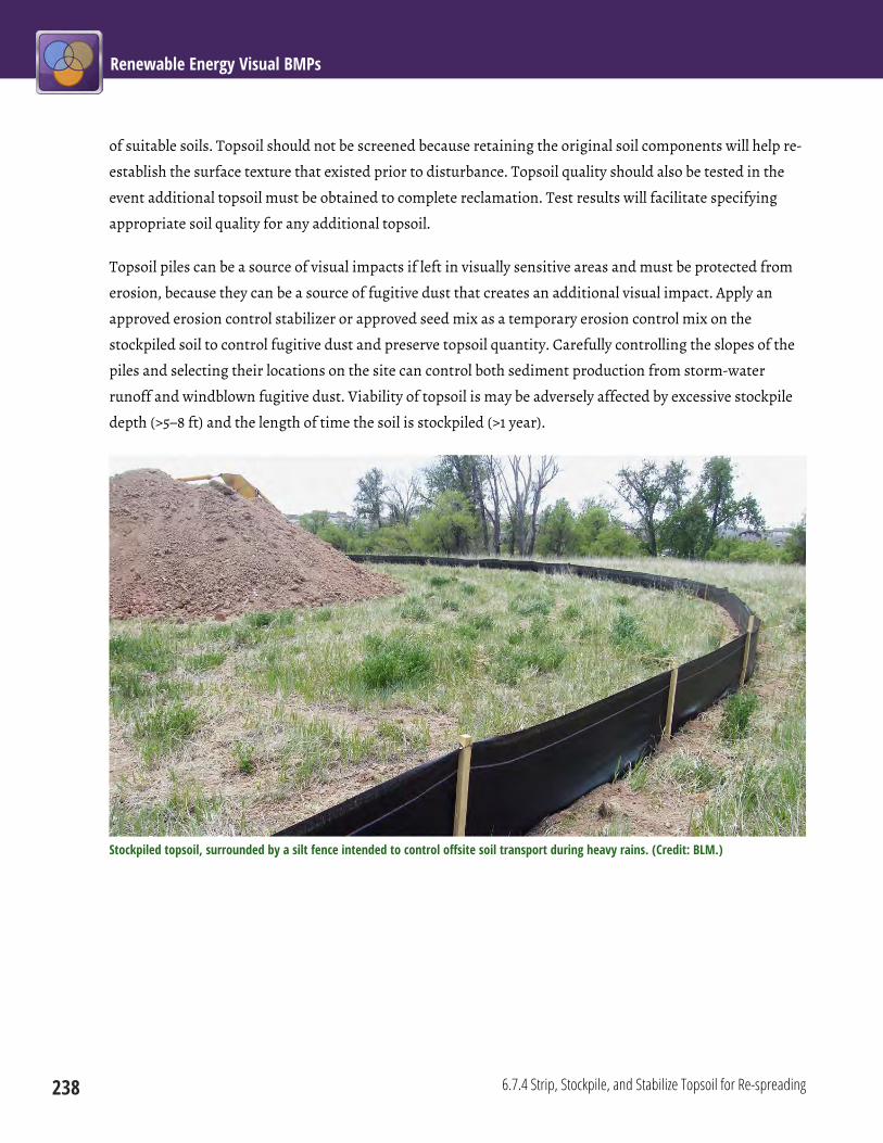
Renewable Energy Visual BMPs
238 6.7.4 Strip, Stockpile, and Stabilize Topsoil for Re-spreading
of suitable soils. Topsoil should not be screened because retaining the original soil components will help re-
establish the surface texture that existed prior to disturbance. Topsoil quality should also be tested in the
event additional topsoil must be obtained to complete reclamation. Test results will facilitate specifying
appropriate soil quality for any additional topsoil.
Topsoil piles can be a source of visual impacts if left in visually sensitive areas and must be protected from
erosion, because they can be a source of fugitive dust that creates an additional visual impact. Apply an
approved erosion control stabilizer or approved seed mix as a temporary erosion control mix on the
stockpiled soil to control fugitive dust and preserve topsoil quantity. Carefully controlling the slopes of the
piles and selecting their locations on the site can control both sediment production from storm-water
runoff and windblown fugitive dust. Viability of topsoil is may be adversely affected by excessive stockpile
depth (>5–8 ft) and the length of time the soil is stockpiled (>1 year).
Stockpiled topsoil, surrounded by a silt fence intended to control offsite soil transport during heavy rains. (Credit: BLM.)
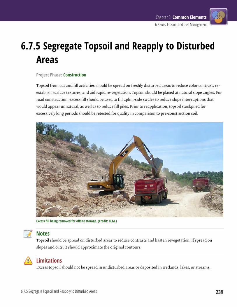
Chapter 6: Common Elements 6.7 Soils, Erosion, and Dust Management
6.7.5 Segregate Topsoil and Reapply to Disturbed Areas 239
6.7.5 Segregate Topsoil and Reapply to Disturbed Areas Project Phase: Construction
Topsoil from cut and fill activities should be spread on freshly disturbed areas to reduce color contrast, re-
establish surface textures, and aid rapid re-vegetation. Topsoil should be placed at natural slope angles. For
road construction, excess fill should be used to fill uphill-side swales to reduce slope interruptions that
would appear unnatural, as well as to reduce fill piles. Prior to reapplication, topsoil stockpiled for
excessively long periods should be retested for quality in comparison to pre-construction soil.
Excess fill being removed for offsite storage. (Credit: BLM.)
Notes Topsoil should be spread on disturbed areas to reduce contrasts and hasten revegetation; if spread on
slopes and cuts, it should approximate the original contours.
Limitations Excess topsoil should not be spread in undisturbed areas or deposited in wetlands, lakes, or streams.

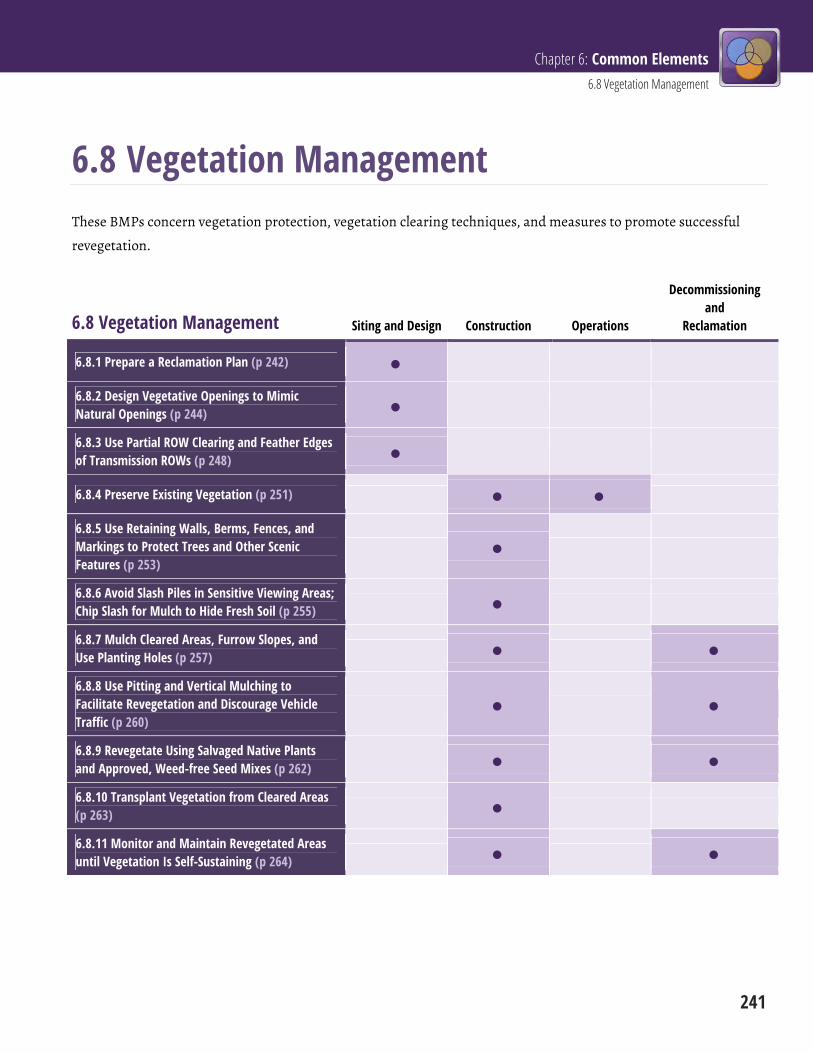
Chapter 6: Common Elements 6.8 Vegetation Management
241
6.8 Vegetation Management These BMPs concern vegetation protection, vegetation clearing techniques, and measures to promote successful
revegetation.
6.8 Vegetation Management Siting and Design Construction Operations
Decommissioning and
Reclamation
6.8.1 Prepare a Reclamation Plan (p 242)
6.8.2 Design Vegetative Openings to Mimic Natural Openings (p 244)
6.8.3 Use Partial ROW Clearing and Feather Edges of Transmission ROWs (p 248)
6.8.4 Preserve Existing Vegetation (p 251)
6.8.5 Use Retaining Walls, Berms, Fences, and Markings to Protect Trees and Other Scenic Features (p 253)
6.8.6 Avoid Slash Piles in Sensitive Viewing Areas; Chip Slash for Mulch to Hide Fresh Soil (p 255)
6.8.7 Mulch Cleared Areas, Furrow Slopes, and Use Planting Holes (p 257)
6.8.8 Use Pitting and Vertical Mulching to Facilitate Revegetation and Discourage Vehicle Traffic (p 260)
6.8.9 Revegetate Using Salvaged Native Plants and Approved, Weed-free Seed Mixes (p 262)
6.8.10 Transplant Vegetation from Cleared Areas (p 263)
6.8.11 Monitor and Maintain Revegetated Areas until Vegetation Is Self-Sustaining (p 264)

Renewable Energy Visual BMPs
242 6.8.1 Prepare a Reclamation Plan
6.8.1 Prepare a Reclamation Plan Project Phase: Siting and Design
A reclamation plan should be prepared in consultation with BLM when necessary. The plan should address
surface reconstruction and stabilization, topsoil management, soil preparation and seed mix(es), and
invasive plant management. The Authorized Officer should approve any changes to the plan, such as
changes to the seed mix(es).
Notes A well-designed and executed reclamation plan should re-establish the visual qualities of form, line, color,
and texture, while limiting vegetation loss and the spread and establishment of invasive plant species, as
well as helping to control soil erosion and windblown fugitive dust. Because adjacent, non-federal lands
could also be affected by the revegetation actions, consultation with state authorities such as the
department of natural resources or state soil conservation service may be helpful.
Limitations The reclamation plan must be consistent with fire safety requirements, and support safe facility operation.

Chapter 6: Common Elements 6.8 Vegetation Management
6.8.1 Prepare a Reclamation Plan 243
This visual mitigation plan includes instructions for using a seed mix that will balance recognized valued resources, including visual aesthetics, wildlife, soil, and water. (Credit: Otak, Inc.)
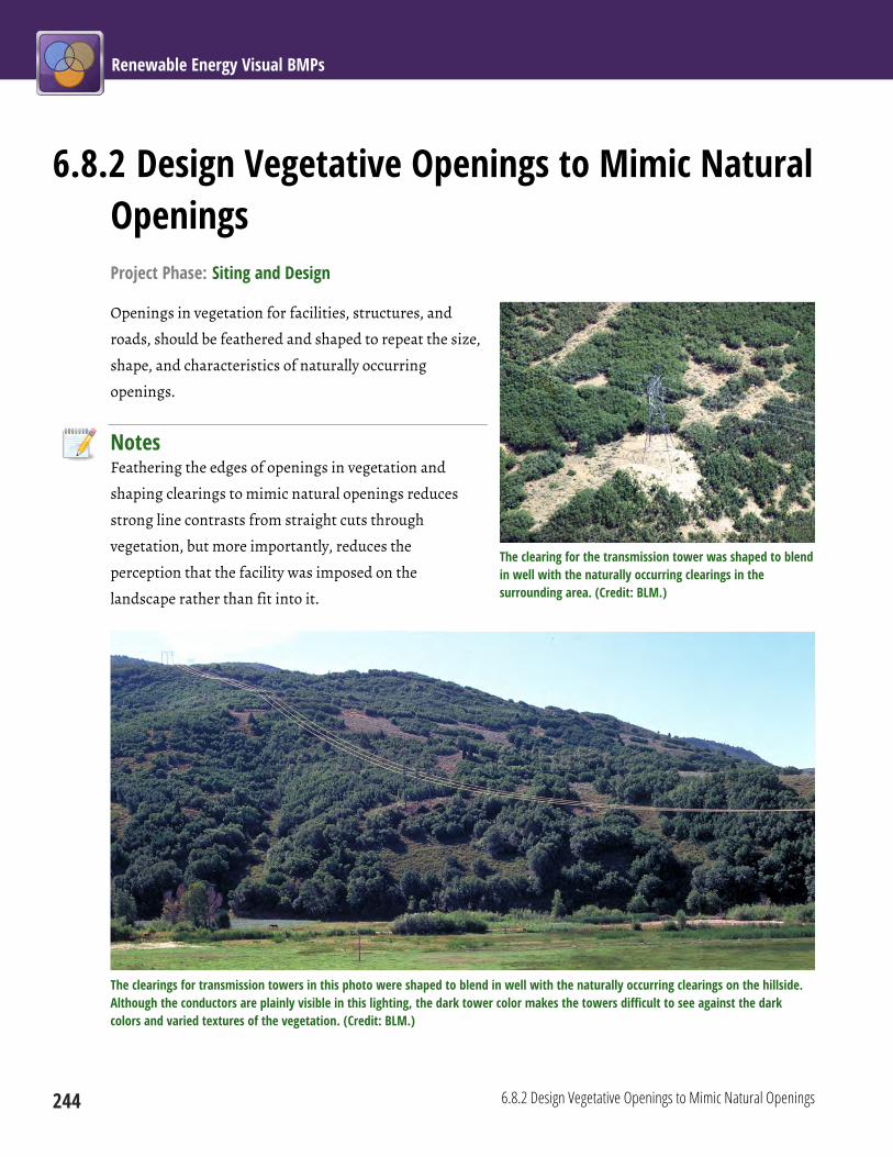
Renewable Energy Visual BMPs
244 6.8.2 Design Vegetative Openings to Mimic Natural Openings
6.8.2 Design Vegetative Openings to Mimic Natural Openings Project Phase: Siting and Design
Openings in vegetation for facilities, structures, and
roads, should be feathered and shaped to repeat the size,
shape, and characteristics of naturally occurring
openings.
Notes Feathering the edges of openings in vegetation and
shaping clearings to mimic natural openings reduces
strong line contrasts from straight cuts through
vegetation, but more importantly, reduces the
perception that the facility was imposed on the
landscape rather than fit into it.
The clearings for transmission towers in this photo were shaped to blend in well with the naturally occurring clearings on the hillside. Although the conductors are plainly visible in this lighting, the dark tower color makes the towers difficult to see against the dark colors and varied textures of the vegetation. (Credit: BLM.)
The clearing for the transmission tower was shaped to blend in well with the naturally occurring clearings in the surrounding area. (Credit: BLM.)

Chapter 6: Common Elements 6.8 Vegetation Management
6.8.2 Design Vegetative Openings to Mimic Natural Openings 245
Limitations In some circumstances, functional requirements or safety considerations may dictate specific vegetation
clearing practices, especially where space is limited. In some cases, feathering the edges of openings may
not be permitted.
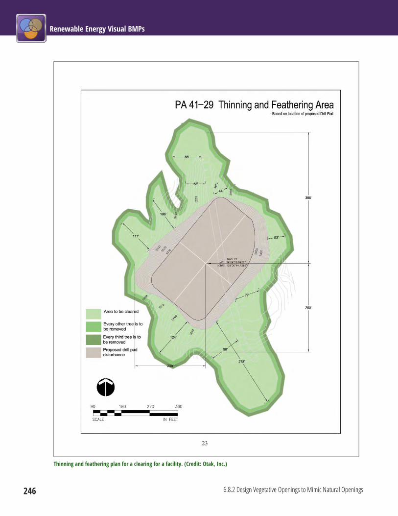
Renewable Energy Visual BMPs
246 6.8.2 Design Vegetative Openings to Mimic Natural Openings
Thinning and feathering plan for a clearing for a facility. (Credit: Otak, Inc.)
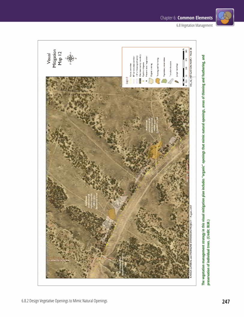
Chapter 6: Common Elements 6.8 Vegetation Management
6.8.2 Design Vegetative Openings to Mimic Natural Openings 247
The
vege
tatio
n m
anag
emen
t stra
tegy
in th
is vi
sual
miti
gatio
n pl
an in
clude
s “or
gani
c” o
peni
ngs t
hat m
imic
natu
ral o
peni
ngs,
area
s of t
hinn
ing
and
feat
herin
g, a
nd
pres
erva
tion
of in
divi
dual
tree
s. (C
redi
t: BL
M.)
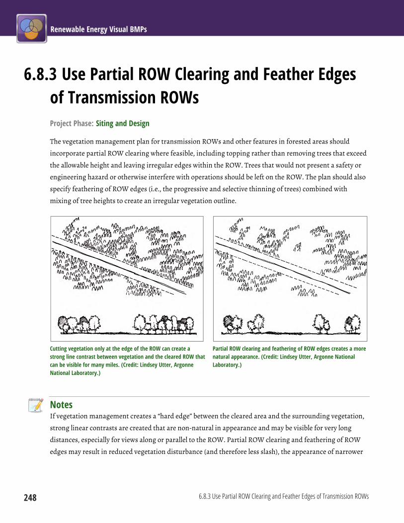
Renewable Energy Visual BMPs
248 6.8.3 Use Partial ROW Clearing and Feather Edges of Transmission ROWs
6.8.3 Use Partial ROW Clearing and Feather Edges of Transmission ROWs Project Phase: Siting and Design
The vegetation management plan for transmission ROWs and other features in forested areas should
incorporate partial ROW clearing where feasible, including topping rather than removing trees that exceed
the allowable height and leaving irregular edges within the ROW. Trees that would not present a safety or
engineering hazard or otherwise interfere with operations should be left on the ROW. The plan should also
specify feathering of ROW edges (i.e., the progressive and selective thinning of trees) combined with
mixing of tree heights to create an irregular vegetation outline.
Cutting vegetation only at the edge of the ROW can create a strong line contrast between vegetation and the cleared ROW that can be visible for many miles. (Credit: Lindsey Utter, Argonne National Laboratory.)
Partial ROW clearing and feathering of ROW edges creates a more natural appearance. (Credit: Lindsey Utter, Argonne National Laboratory.)
Notes If vegetation management creates a “hard edge” between the cleared area and the surrounding vegetation,
strong linear contrasts are created that are non-natural in appearance and may be visible for very long
distances, especially for views along or parallel to the ROW. Partial ROW clearing and feathering of ROW
edges may result in reduced vegetation disturbance (and therefore less slash), the appearance of narrower

Chapter 6: Common Elements 6.8 Vegetation Management
6.8.3 Use Partial ROW Clearing and Feather Edges of Transmission ROWs 249
ROWs, better screening, and a more natural-looking appearance. Feathering and clearing activities may
need to extend beyond the designated ROW.
Limitations The Federal Energy Regulatory Commission and North American Electric Reliability Council have strict
vegetation management standards for transmission ROWs, which are intended to ensure safe and reliable
electric transmission; vegetation management practices in transmission ROWs must adhere to these
standards.
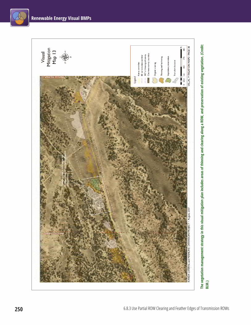
Renewable Energy Visual BMPs
250 6.8.3 Use Partial ROW Clearing and Feather Edges of Transmission ROWs
The
vege
tatio
n m
anag
emen
t stra
tegy
in th
is vi
sual
miti
gatio
n pl
an in
clude
s are
as o
f thi
nnin
g an
d cle
arin
g al
ong
a RO
W, a
nd p
rese
rvat
ion
of e
xist
ing
vege
tatio
n. (C
redi
t: BL
M.)
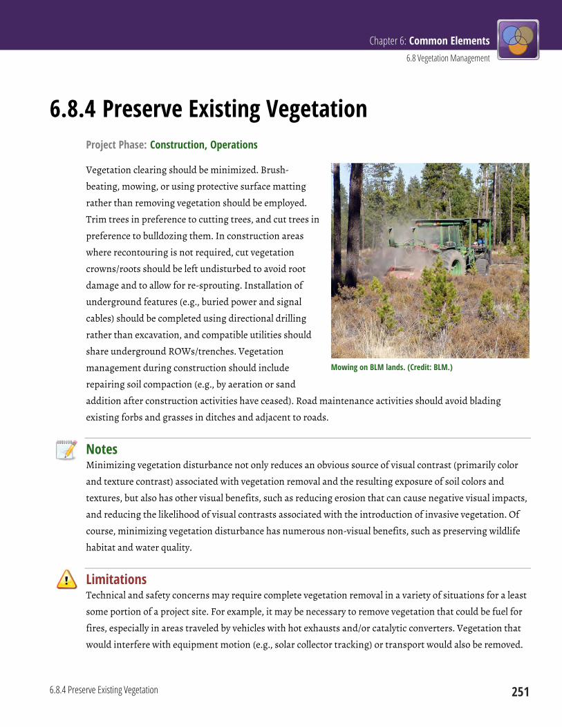
Chapter 6: Common Elements 6.8 Vegetation Management
6.8.4 Preserve Existing Vegetation 251
6.8.4 Preserve Existing Vegetation Project Phase: Construction, Operations
Vegetation clearing should be minimized. Brush-
beating, mowing, or using protective surface matting
rather than removing vegetation should be employed.
Trim trees in preference to cutting trees, and cut trees in
preference to bulldozing them. In construction areas
where recontouring is not required, cut vegetation
crowns/roots should be left undisturbed to avoid root
damage and to allow for re-sprouting. Installation of
underground features (e.g., buried power and signal
cables) should be completed using directional drilling
rather than excavation, and compatible utilities should
share underground ROWs/trenches. Vegetation
management during construction should include
repairing soil compaction (e.g., by aeration or sand
addition after construction activities have ceased). Road maintenance activities should avoid blading
existing forbs and grasses in ditches and adjacent to roads.
Notes Minimizing vegetation disturbance not only reduces an obvious source of visual contrast (primarily color
and texture contrast) associated with vegetation removal and the resulting exposure of soil colors and
textures, but also has other visual benefits, such as reducing erosion that can cause negative visual impacts,
and reducing the likelihood of visual contrasts associated with the introduction of invasive vegetation. Of
course, minimizing vegetation disturbance has numerous non-visual benefits, such as preserving wildlife
habitat and water quality.
Limitations Technical and safety concerns may require complete vegetation removal in a variety of situations for a least
some portion of a project site. For example, it may be necessary to remove vegetation that could be fuel for
fires, especially in areas traveled by vehicles with hot exhausts and/or catalytic converters. Vegetation that
would interfere with equipment motion (e.g., solar collector tracking) or transport would also be removed.
Mowing on BLM lands. (Credit: BLM.)

Renewable Energy Visual BMPs
252 6.8.4 Preserve Existing Vegetation
This BLM plan specifies preservation of existing vegetation. (Credit: BLM.)
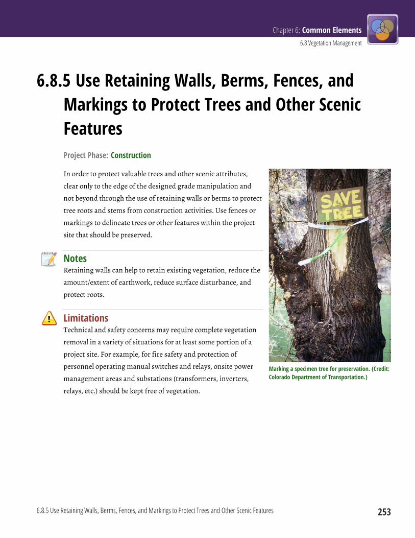
Chapter 6: Common Elements 6.8 Vegetation Management
6.8.5 Use Retaining Walls, Berms, Fences, and Markings to Protect Trees and Other Scenic Features 253
6.8.5 Use Retaining Walls, Berms, Fences, and Markings to Protect Trees and Other Scenic Features Project Phase: Construction
In order to protect valuable trees and other scenic attributes,
clear only to the edge of the designed grade manipulation and
not beyond through the use of retaining walls or berms to protect
tree roots and stems from construction activities. Use fences or
markings to delineate trees or other features within the project
site that should be preserved.
Notes Retaining walls can help to retain existing vegetation, reduce the
amount/extent of earthwork, reduce surface disturbance, and
protect roots.
Limitations Technical and safety concerns may require complete vegetation
removal in a variety of situations for at least some portion of a
project site. For example, for fire safety and protection of
personnel operating manual switches and relays, onsite power
management areas and substations (transformers, inverters,
relays, etc.) should be kept free of vegetation.
Marking a specimen tree for preservation. (Credit: Colorado Department of Transportation.)
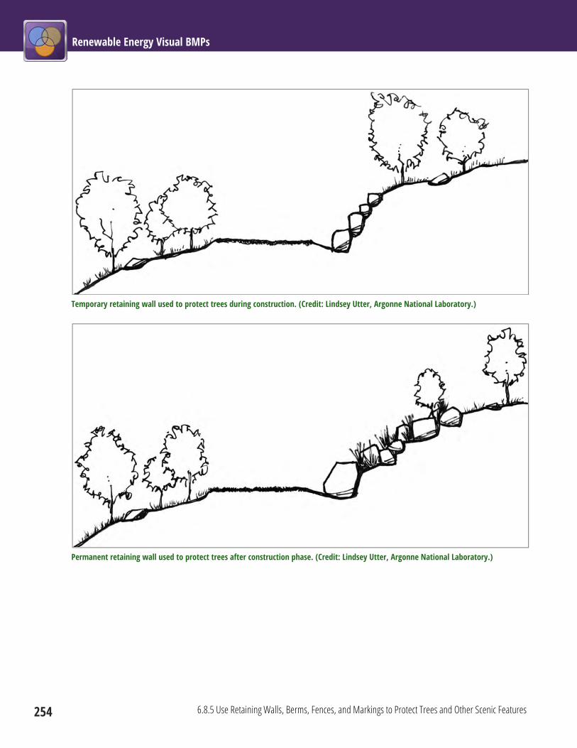
Renewable Energy Visual BMPs
254 6.8.5 Use Retaining Walls, Berms, Fences, and Markings to Protect Trees and Other Scenic Features
Temporary retaining wall used to protect trees during construction. (Credit: Lindsey Utter, Argonne National Laboratory.)
Permanent retaining wall used to protect trees after construction phase. (Credit: Lindsey Utter, Argonne National Laboratory.)

Chapter 6: Common Elements 6.8 Vegetation Management
6.8.6 Avoid Slash Piles in Sensitive Viewing Areas; Chip Slash for Mulch to Hide Fresh Soil 255
6.8.6 Avoid Slash Piles in Sensitive Viewing Areas; Chip Slash for Mulch to Hide Fresh Soil Project Phase: Construction
Slash piles should not be left in sensitive viewing areas. Slash from vegetation removal should be mulched
and spread to cover fresh soil disturbances (i.e., the preferred methodology) or should be buried.
Chipping slash to eliminate slash piles. (Credit: NPS.)
Notes Slash piles may be unsightly in and of themselves, but also give the project an “unfinished” look. Using slash
for mulch can immediately reduce color and texture contrast of exposed soils, and reduces erosion, aids in
moisture retention, and provides organic matter that aids revegetation, which ultimately reduces long-
term visual impacts. Other options for slash disposal include selling vegetation for fuel value or pulping.

Renewable Energy Visual BMPs
256 6.8.6 Avoid Slash Piles in Sensitive Viewing Areas; Chip Slash for Mulch to Hide Fresh Soil
Limitations Mulch should not be spread on undisturbed areas or wetlands. In some situations, there may be more
mulch from slash than the available cleared area can accommodate, in which case burial or offsite disposal
may be necessary.
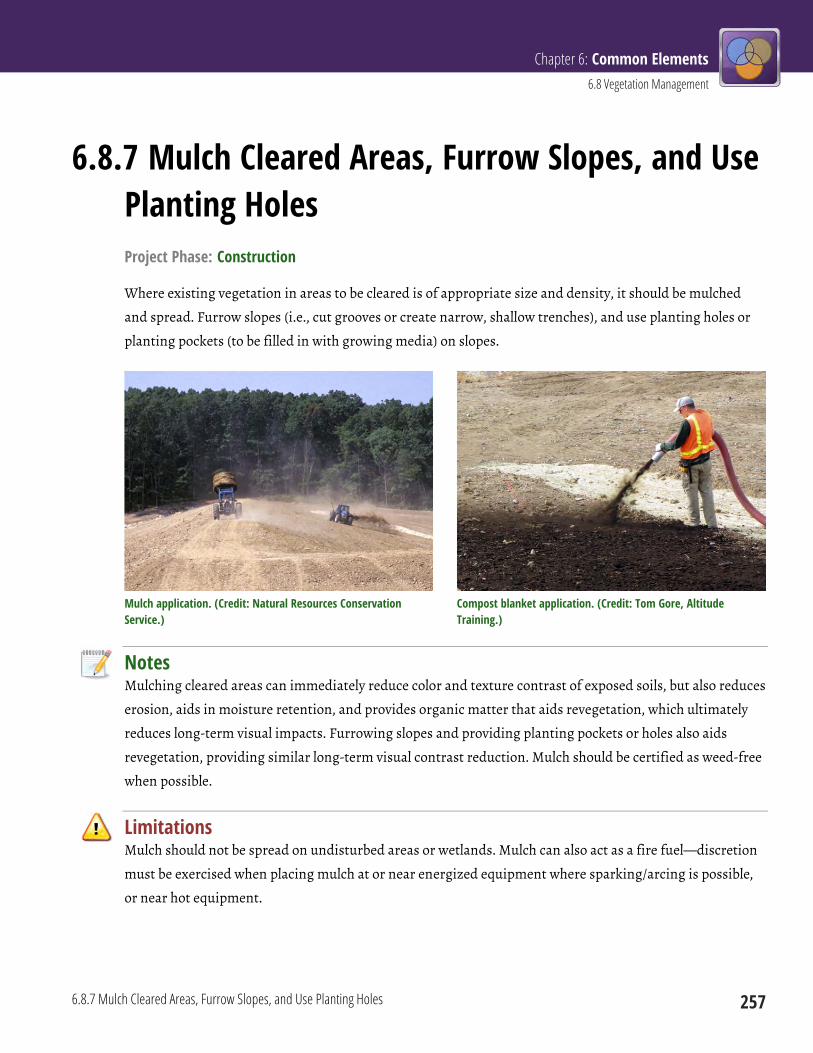
Chapter 6: Common Elements 6.8 Vegetation Management
6.8.7 Mulch Cleared Areas, Furrow Slopes, and Use Planting Holes 257
6.8.7 Mulch Cleared Areas, Furrow Slopes, and Use Planting Holes Project Phase: Construction
Where existing vegetation in areas to be cleared is of appropriate size and density, it should be mulched
and spread. Furrow slopes (i.e., cut grooves or create narrow, shallow trenches), and use planting holes or
planting pockets (to be filled in with growing media) on slopes.
Mulch application. (Credit: Natural Resources Conservation Service.)
Compost blanket application. (Credit: Tom Gore, Altitude Training.)
Notes Mulching cleared areas can immediately reduce color and texture contrast of exposed soils, but also reduces
erosion, aids in moisture retention, and provides organic matter that aids revegetation, which ultimately
reduces long-term visual impacts. Furrowing slopes and providing planting pockets or holes also aids
revegetation, providing similar long-term visual contrast reduction. Mulch should be certified as weed-free
when possible.
Limitations Mulch should not be spread on undisturbed areas or wetlands. Mulch can also act as a fire fuel—discretion
must be exercised when placing mulch at or near energized equipment where sparking/arcing is possible,
or near hot equipment.
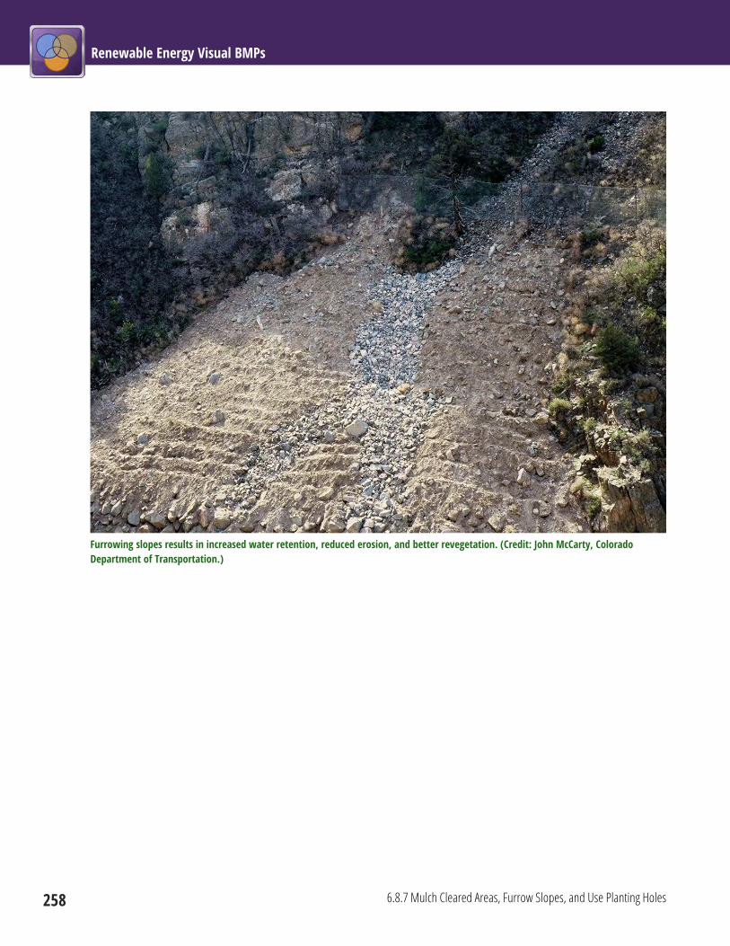
Renewable Energy Visual BMPs
258 6.8.7 Mulch Cleared Areas, Furrow Slopes, and Use Planting Holes
Furrowing slopes results in increased water retention, reduced erosion, and better revegetation. (Credit: John McCarty, Colorado Department of Transportation.)
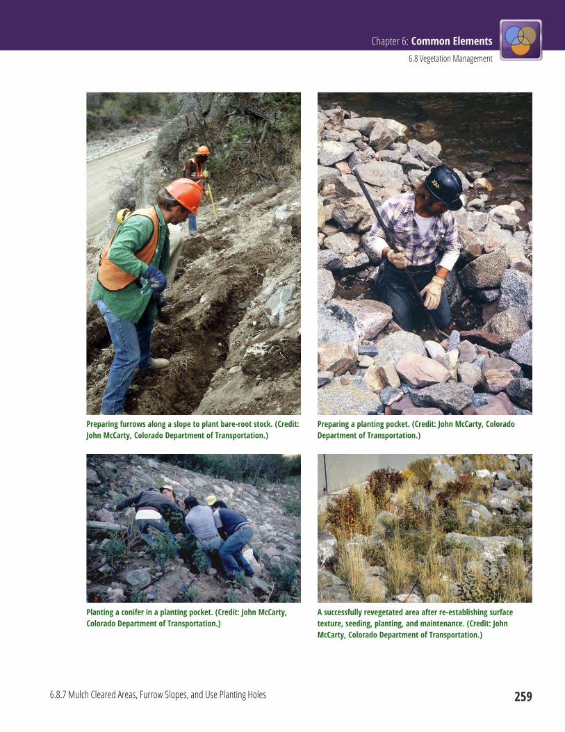
Chapter 6: Common Elements 6.8 Vegetation Management
6.8.7 Mulch Cleared Areas, Furrow Slopes, and Use Planting Holes 259
Preparing furrows along a slope to plant bare-root stock. (Credit: John McCarty, Colorado Department of Transportation.)
Preparing a planting pocket. (Credit: John McCarty, Colorado Department of Transportation.)
Planting a conifer in a planting pocket. (Credit: John McCarty, Colorado Department of Transportation.)
A successfully revegetated area after re-establishing surface texture, seeding, planting, and maintenance. (Credit: John McCarty, Colorado Department of Transportation.)
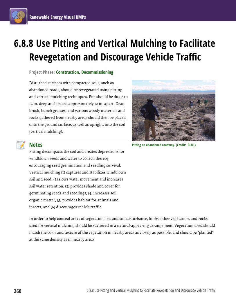
Renewable Energy Visual BMPs
260 6.8.8 Use Pitting and Vertical Mulching to Facilitate Revegetation and Discourage Vehicle Traffic
6.8.8 Use Pitting and Vertical Mulching to Facilitate Revegetation and Discourage Vehicle Traffic Project Phase: Construction, Decommissioning
Disturbed surfaces with compacted soils, such as
abandoned roads, should be revegetated using pitting
and vertical mulching techniques. Pits should be dug 6 to
12 in. deep and spaced approximately 12 in. apart. Dead
brush, bunch grasses, and various woody materials and
rocks gathered from nearby areas should then be placed
onto the ground surface, as well as upright, into the soil
(vertical mulching).
Notes Pitting decompacts the soil and creates depressions for
windblown seeds and water to collect, thereby
encouraging seed germination and seedling survival.
Vertical mulching (1) captures and stabilizes windblown
soil and seed; (2) slows water movement and increases
soil water retention; (3) provides shade and cover for
germinating seeds and seedlings; (4) increases soil
organic matter; (5) provides habitat for animals and
insects; and (6) discourages vehicle traffic.
In order to help conceal areas of vegetation loss and soil disturbance, limbs, other vegetation, and rocks
used for vertical mulching should be scattered in a natural-appearing arrangement. Vegetation used should
match the color and texture of the vegetation in nearby areas as closely as possible, and should be “planted”
at the same density as in nearby areas.
Pitting an abandoned roadway. (Credit: BLM.)
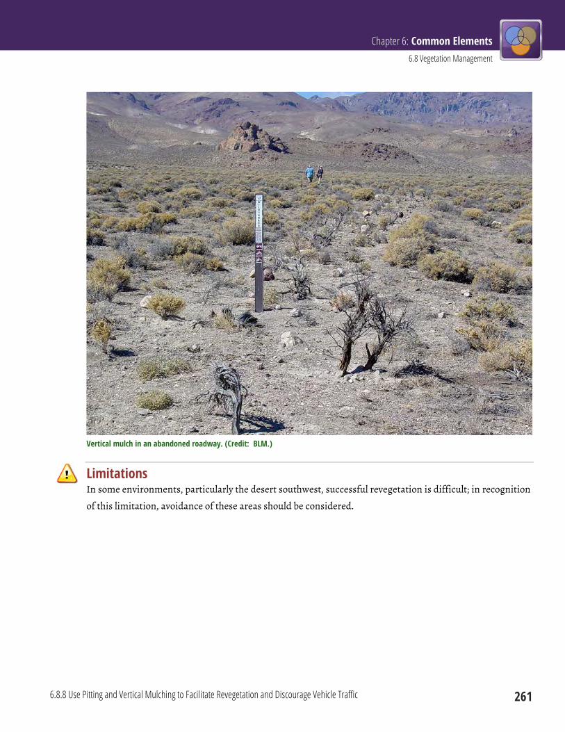
Chapter 6: Common Elements 6.8 Vegetation Management
6.8.8 Use Pitting and Vertical Mulching to Facilitate Revegetation and Discourage Vehicle Traffic 261
Vertical mulch in an abandoned roadway. (Credit: BLM.)
Limitations In some environments, particularly the desert southwest, successful revegetation is difficult; in recognition
of this limitation, avoidance of these areas should be considered.
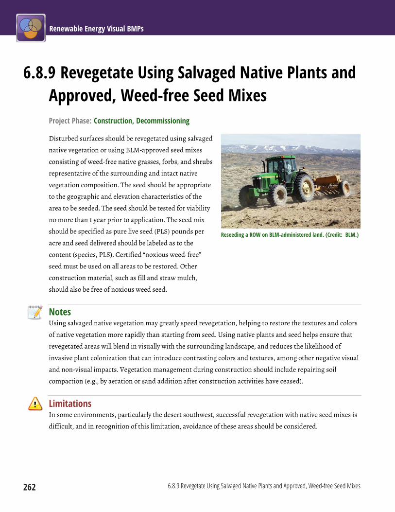
Renewable Energy Visual BMPs
262 6.8.9 Revegetate Using Salvaged Native Plants and Approved, Weed-free Seed Mixes
6.8.9 Revegetate Using Salvaged Native Plants and Approved, Weed-free Seed Mixes Project Phase: Construction, Decommissioning
Disturbed surfaces should be revegetated using salvaged
native vegetation or using BLM-approved seed mixes
consisting of weed-free native grasses, forbs, and shrubs
representative of the surrounding and intact native
vegetation composition. The seed should be appropriate
to the geographic and elevation characteristics of the
area to be seeded. The seed should be tested for viability
no more than 1 year prior to application. The seed mix
should be specified as pure live seed (PLS) pounds per
acre and seed delivered should be labeled as to the
content (species, PLS). Certified “noxious weed-free”
seed must be used on all areas to be restored. Other
construction material, such as fill and straw mulch,
should also be free of noxious weed seed.
Notes Using salvaged native vegetation may greatly speed revegetation, helping to restore the textures and colors
of native vegetation more rapidly than starting from seed. Using native plants and seed helps ensure that
revegetated areas will blend in visually with the surrounding landscape, and reduces the likelihood of
invasive plant colonization that can introduce contrasting colors and textures, among other negative visual
and non-visual impacts. Vegetation management during construction should include repairing soil
compaction (e.g., by aeration or sand addition after construction activities have ceased).
Limitations In some environments, particularly the desert southwest, successful revegetation with native seed mixes is
difficult, and in recognition of this limitation, avoidance of these areas should be considered.
Reseeding a ROW on BLM-administered land. (Credit: BLM.)
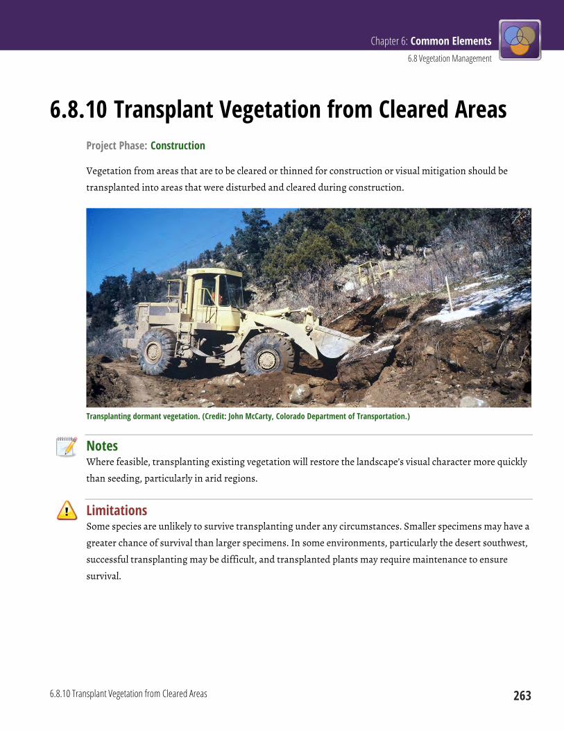
Chapter 6: Common Elements 6.8 Vegetation Management
6.8.10 Transplant Vegetation from Cleared Areas 263
6.8.10 Transplant Vegetation from Cleared Areas Project Phase: Construction
Vegetation from areas that are to be cleared or thinned for construction or visual mitigation should be
transplanted into areas that were disturbed and cleared during construction.
Transplanting dormant vegetation. (Credit: John McCarty, Colorado Department of Transportation.)
Notes Where feasible, transplanting existing vegetation will restore the landscape’s visual character more quickly
than seeding, particularly in arid regions.
Limitations Some species are unlikely to survive transplanting under any circumstances. Smaller specimens may have a
greater chance of survival than larger specimens. In some environments, particularly the desert southwest,
successful transplanting may be difficult, and transplanted plants may require maintenance to ensure
survival.
Renewable Energy Visual BMPs
264 6.8.11 Monitor and Maintain Revegetated Areas until Vegetation Is Self-Sustaining
6.8.11 Monitor and Maintain Revegetated Areas until Vegetation Is Self-Sustaining Project Phase: Construction, Decommissioning
The project developer should monitor and maintain revegetated surfaces. Corrective measures should be
conducted as needed until a self-sustaining stand of vegetation is re-established and visually adapted to the
undisturbed surrounding vegetation. No new disturbance should be created during operations without
completion of a VRM analysis and approval by the authorized officer.
Notes Poorly maintained revegetation efforts may lead to invasive plant colonization, erosion, and dust, all of
which have negative visual impacts and negative effects on wildlife, air and water quality, and other
resources.
Limitations In some environments, particularly the desert southwest, successful revegetation may be difficult, and may
take years. Maintaining revegetation efforts long after the other decommissioning procedures have
concluded will be difficult, and may need to be incorporated as a condition of the lease.
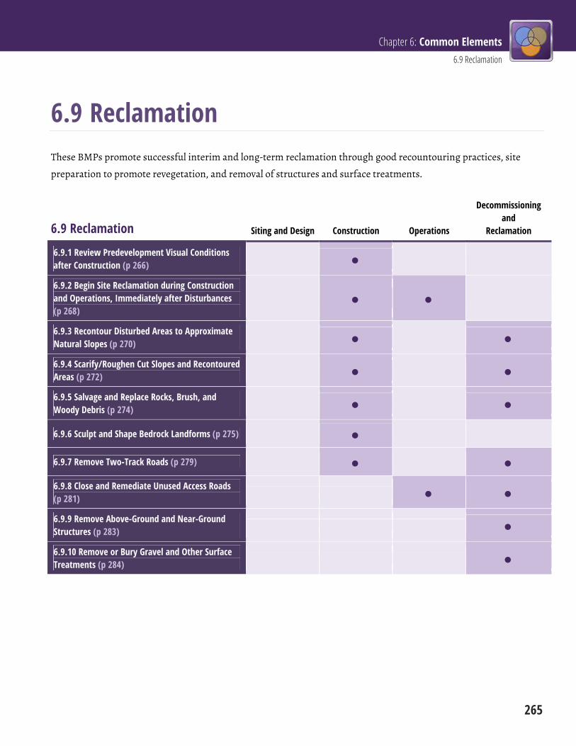
Chapter 6: Common Elements 6.9 Reclamation
265
6.9 Reclamation These BMPs promote successful interim and long-term reclamation through good recountouring practices, site
preparation to promote revegetation, and removal of structures and surface treatments.
6.9 Reclamation Siting and Design Construction Operations
Decommissioning and
Reclamation
6.9.1 Review Predevelopment Visual Conditions after Construction (p 266)
6.9.2 Begin Site Reclamation during Construction and Operations, Immediately after Disturbances (p 268)
6.9.3 Recontour Disturbed Areas to Approximate Natural Slopes (p 270)
6.9.4 Scarify/Roughen Cut Slopes and Recontoured Areas (p 272)
6.9.5 Salvage and Replace Rocks, Brush, and Woody Debris (p 274)
6.9.6 Sculpt and Shape Bedrock Landforms (p 275)
6.9.7 Remove Two-Track Roads (p 279)
6.9.8 Close and Remediate Unused Access Roads (p 281)
6.9.9 Remove Above-Ground and Near-Ground Structures (p 283)
6.9.10 Remove or Bury Gravel and Other Surface Treatments (p 284)
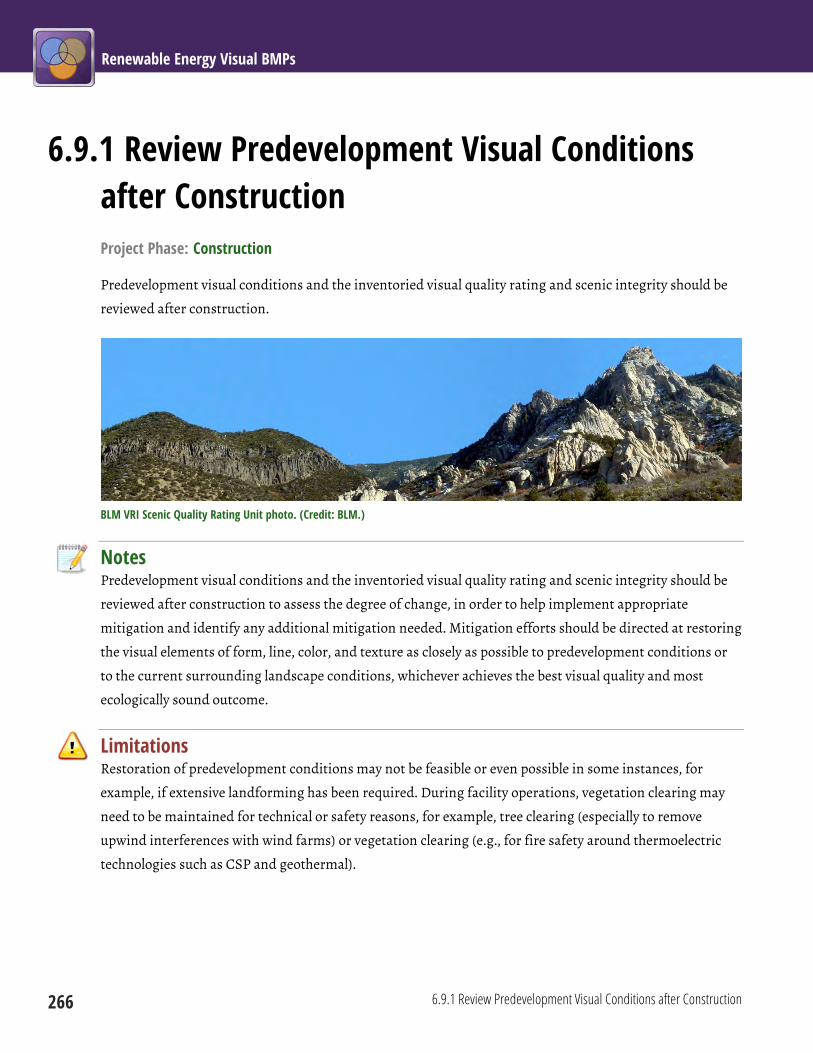
Renewable Energy Visual BMPs
266 6.9.1 Review Predevelopment Visual Conditions after Construction
6.9.1 Review Predevelopment Visual Conditions after Construction Project Phase: Construction
Predevelopment visual conditions and the inventoried visual quality rating and scenic integrity should be
reviewed after construction.
BLM VRI Scenic Quality Rating Unit photo. (Credit: BLM.)
Notes Predevelopment visual conditions and the inventoried visual quality rating and scenic integrity should be
reviewed after construction to assess the degree of change, in order to help implement appropriate
mitigation and identify any additional mitigation needed. Mitigation efforts should be directed at restoring
the visual elements of form, line, color, and texture as closely as possible to predevelopment conditions or
to the current surrounding landscape conditions, whichever achieves the best visual quality and most
ecologically sound outcome.
Limitations Restoration of predevelopment conditions may not be feasible or even possible in some instances, for
example, if extensive landforming has been required. During facility operations, vegetation clearing may
need to be maintained for technical or safety reasons, for example, tree clearing (especially to remove
upwind interferences with wind farms) or vegetation clearing (e.g., for fire safety around thermoelectric
technologies such as CSP and geothermal).
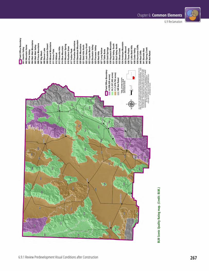
Chapter 6: Common Elements 6.9 Reclamation
6.9.1 Review Predevelopment Visual Conditions after Construction 267
BLM
Scen
ic Qu
ality
Rat
ing
map
. (Cr
edit:
BLM
.)

Renewable Energy Visual BMPs
268 6.9.2 Begin Site Reclamation during Construction and Operations, Immediately after Disturbances
6.9.2 Begin Site Reclamation during Construction and Operations, Immediately after Disturbances Project Phase: Construction, Operations
Begin site reclamation activities during construction and during operations, as soon as possible after
disturbances.
Had this pipeline installation been remediated immediately after construction, the visual impacts of erosion and weed infestation might have been avoided. (Credit: BLM.)
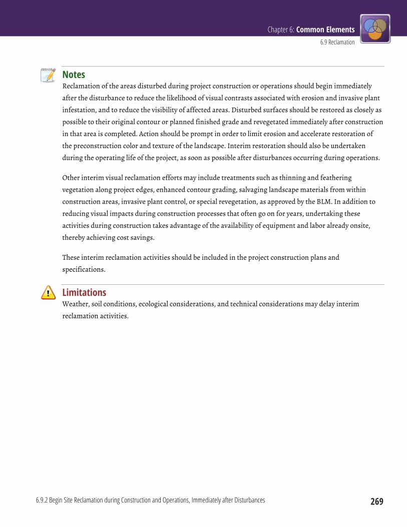
Chapter 6: Common Elements 6.9 Reclamation
6.9.2 Begin Site Reclamation during Construction and Operations, Immediately after Disturbances 269
Notes Reclamation of the areas disturbed during project construction or operations should begin immediately
after the disturbance to reduce the likelihood of visual contrasts associated with erosion and invasive plant
infestation, and to reduce the visibility of affected areas. Disturbed surfaces should be restored as closely as
possible to their original contour or planned finished grade and revegetated immediately after construction
in that area is completed. Action should be prompt in order to limit erosion and accelerate restoration of
the preconstruction color and texture of the landscape. Interim restoration should also be undertaken
during the operating life of the project, as soon as possible after disturbances occurring during operations.
Other interim visual reclamation efforts may include treatments such as thinning and feathering
vegetation along project edges, enhanced contour grading, salvaging landscape materials from within
construction areas, invasive plant control, or special revegetation, as approved by the BLM. In addition to
reducing visual impacts during construction processes that often go on for years, undertaking these
activities during construction takes advantage of the availability of equipment and labor already onsite,
thereby achieving cost savings.
These interim reclamation activities should be included in the project construction plans and
specifications.
Limitations Weather, soil conditions, ecological considerations, and technical considerations may delay interim
reclamation activities.

Renewable Energy Visual BMPs
270 6.9.3 Recontour Disturbed Areas to Approximate Natural Slopes
6.9.3 Recontour Disturbed Areas to Approximate Natural Slopes Project Phase: Construction, Decommissioning
Recontour soil borrow areas, cut and fill slopes,
berms, waterbars, and other disturbed areas to
approximate naturally occurring slopes.
Notes Contouring to approximate naturally occurring
slopes reduces form contrasts between disturbed
areas and the natural environment.
Limitations Naturally occurring contours and slopes may be
difficult to recreate in some circumstances; for
example, if substantial grade alterations are
necessary to install a permanent road with adequate
grades and shoulder slopes, or if rock outcrops were
removed.
Slope recontouring to approximate naturally occurring slopes during road reclamation. (Credit: BLM.)
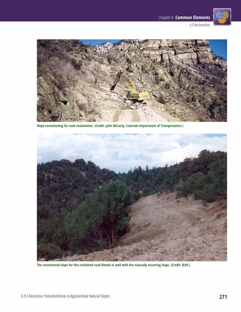
Chapter 6: Common Elements 6.9 Reclamation
6.9.3 Recontour Disturbed Areas to Approximate Natural Slopes 271
Slope recontouring for road reclamation. (Credit: John McCarty, Colorado Department of Transportation.)
The recontoured slope for this reclaimed road blends in well with the naturally occurring slope. (Credit: BLM.)
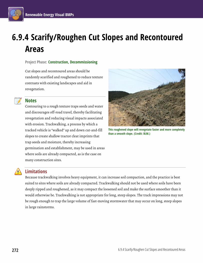
Renewable Energy Visual BMPs
272 6.9.4 Scarify/Roughen Cut Slopes and Recontoured Areas
6.9.4 Scarify/Roughen Cut Slopes and Recontoured Areas Project Phase: Construction, Decommissioning
Cut slopes and recontoured areas should be
randomly scarified and roughened to reduce texture
contrasts with existing landscapes and aid in
revegetation.
Notes Contouring to a rough texture traps seeds and water
and discourages off-road travel, thereby facilitating
revegetation and reducing visual impacts associated
with erosion. Trackwalking, a process by which a
tracked vehicle is “walked” up and down cut-and-fill
slopes to create shallow tractor cleat imprints that
trap seeds and moisture, thereby increasing
germination and establishment, may be used in areas
where soils are already compacted, as is the case on
many construction sites.
Limitations Because trackwalking involves heavy equipment, it can increase soil compaction, and the practice is best
suited to sites where soils are already compacted. Trackwalking should not be used where soils have been
deeply ripped and roughened, as it may compact the loosened soil and make the surface smoother than it
would otherwise be. Trackwalking is not appropriate for long, steep slopes. The track impressions may not
be rough enough to trap the large volume of fast-moving stormwater that may occur on long, steep slopes
in large rainstorms.
This roughened slope will revegetate faster and more completely than a smooth slope. (Credit: BLM.)
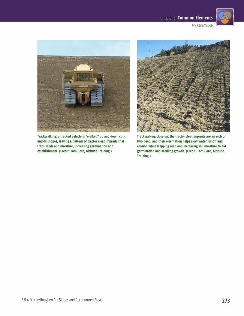
Chapter 6: Common Elements 6.9 Reclamation
6.9.4 Scarify/Roughen Cut Slopes and Recontoured Areas 273
Trackwalking: a tracked vehicle is “walked” up and down cut-and-fill slopes, leaving a pattern of tractor cleat imprints that traps seeds and moisture, increasing germination and establishment. (Credit: Tom Gore, Altitude Training.)
Trackwalking close up: the tractor cleat imprints are an inch or two deep, and their orientation helps slow water runoff and erosion while trapping seed and increasing soil moisture to aid germination and seedling growth. (Credit: Tom Gore, Altitude Training.)

Renewable Energy Visual BMPs
274 6.9.5 Salvage and Replace Rocks, Brush, and Woody Debris
6.9.5 Salvage and Replace Rocks, Brush, and Woody Debris Project Phase: Construction, Decommissioning
Rocks, brush, and woody debris should be salvaged and replaced to approximate pre-project visual
conditions.
The placement of salvaged woody debris in this reclaimed road helped to restore natural textures and colors to the reclaimed area. (Credit: John McCarty, BLM.)
Notes The replacement of rocks, brush, and woody debris
will help “soften” the color and texture contrasts
associated with project-related vegetation clearing
and site grading to re-establish the pre-disturbance
surface character. In addition, restoring brush and
woody debris reduces wind and water erosion, and
may improve water retention, aiding revegetation.
Limitations Ecological and safety concerns may preclude full
restoration of rocks, brush, and woody debris.
The placement of salvaged rocks on this slope helps to restore a more natural appearance to the reclaimed area, and holds soil in place for successful revegetation. (Credit: John McCarty, Colorado Department of Transportation.)
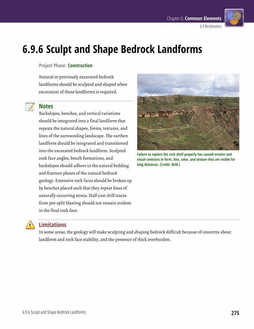
Chapter 6: Common Elements 6.9 Reclamation
6.9.6 Sculpt and Shape Bedrock Landforms 275
6.9.6 Sculpt and Shape Bedrock Landforms Project Phase: Construction
Natural or previously excavated bedrock
landforms should be sculpted and shaped when
excavation of these landforms is required.
Notes Backslopes, benches, and vertical variations
should be integrated into a final landform that
repeats the natural shapes, forms, textures, and
lines of the surrounding landscape. The earthen
landform should be integrated and transitioned
into the excavated bedrock landform. Sculpted
rock face angles, bench formations, and
backslopes should adhere to the natural bedding
and fracture planes of the natural bedrock
geology. Extensive rock faces should be broken up
by benches placed such that they repeat lines of
naturally occurring strata. Half-cast drill traces
from pre-split blasting should not remain evident
in the final rock face.
Limitations In some areas, the geology will make sculpting and shaping bedrock difficult because of concerns about
landform and rock face stability, and the presence of thick overburden.
Failure to replace the rock shelf properly has caused erosion and visual contrasts in form, line, color, and texture that are visible for long distances. (Credit: BLM.)
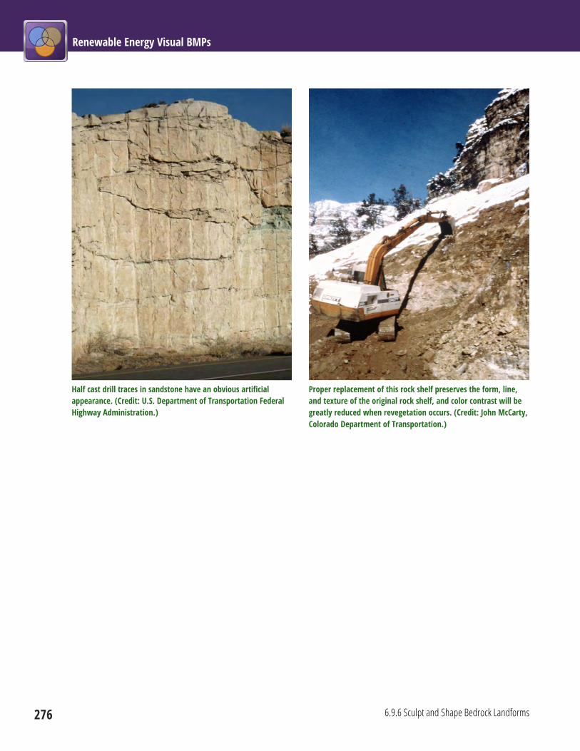
Renewable Energy Visual BMPs
276 6.9.6 Sculpt and Shape Bedrock Landforms
Half cast drill traces in sandstone have an obvious artificial appearance. (Credit: U.S. Department of Transportation Federal Highway Administration.)
Proper replacement of this rock shelf preserves the form, line, and texture of the original rock shelf, and color contrast will be greatly reduced when revegetation occurs. (Credit: John McCarty, Colorado Department of Transportation.)
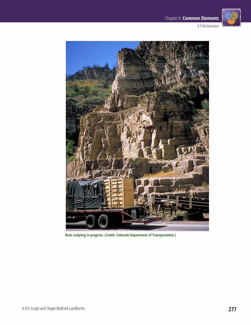
Chapter 6: Common Elements 6.9 Reclamation
6.9.6 Sculpt and Shape Bedrock Landforms 277
Rock sculpting in progress. (Credit: Colorado Department of Transportation.)
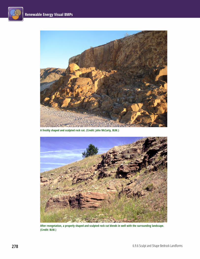
Renewable Energy Visual BMPs
278 6.9.6 Sculpt and Shape Bedrock Landforms
A freshly shaped and sculpted rock cut. (Credit: John McCarty, BLM.)
After revegetation, a properly shaped and sculpted rock cut blends in well with the surrounding landscape. (Credit: BLM.)
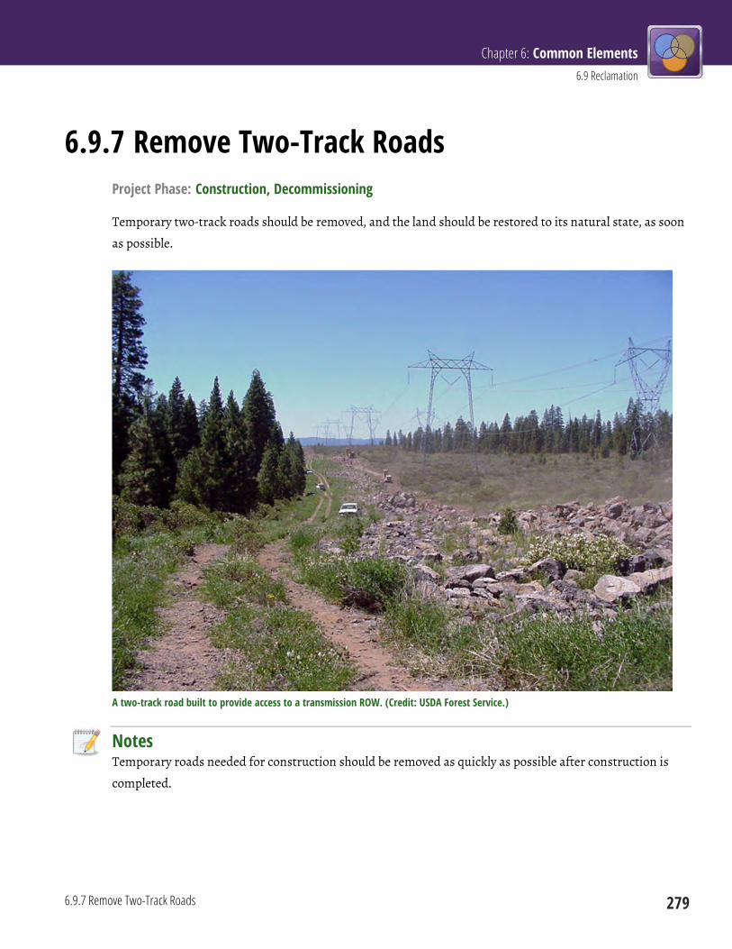
Chapter 6: Common Elements 6.9 Reclamation
6.9.7 Remove Two-Track Roads 279
6.9.7 Remove Two-Track Roads Project Phase: Construction, Decommissioning
Temporary two-track roads should be removed, and the land should be restored to its natural state, as soon
as possible.
A two-track road built to provide access to a transmission ROW. (Credit: USDA Forest Service.)
Notes Temporary roads needed for construction should be removed as quickly as possible after construction is
completed.

Renewable Energy Visual BMPs
280 6.9.7 Remove Two-Track Roads
Limitations Some construction roads may be needed for ROW maintenance. If the necessity for an all-weather access
road arises, the operator must consult with the surface management agency to determine whether all or a
portion of the road needs to be upgraded.
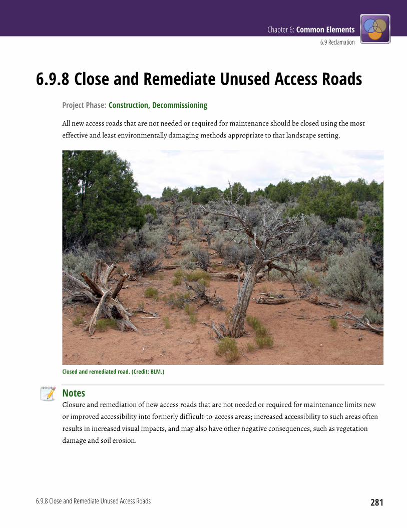
Chapter 6: Common Elements 6.9 Reclamation
6.9.8 Close and Remediate Unused Access Roads 281
6.9.8 Close and Remediate Unused Access Roads Project Phase: Construction, Decommissioning
All new access roads that are not needed or required for maintenance should be closed using the most
effective and least environmentally damaging methods appropriate to that landscape setting.
Closed and remediated road. (Credit: BLM.)
Notes Closure and remediation of new access roads that are not needed or required for maintenance limits new
or improved accessibility into formerly difficult-to-access areas; increased accessibility to such areas often
results in increased visual impacts, and may also have other negative consequences, such as vegetation
damage and soil erosion.
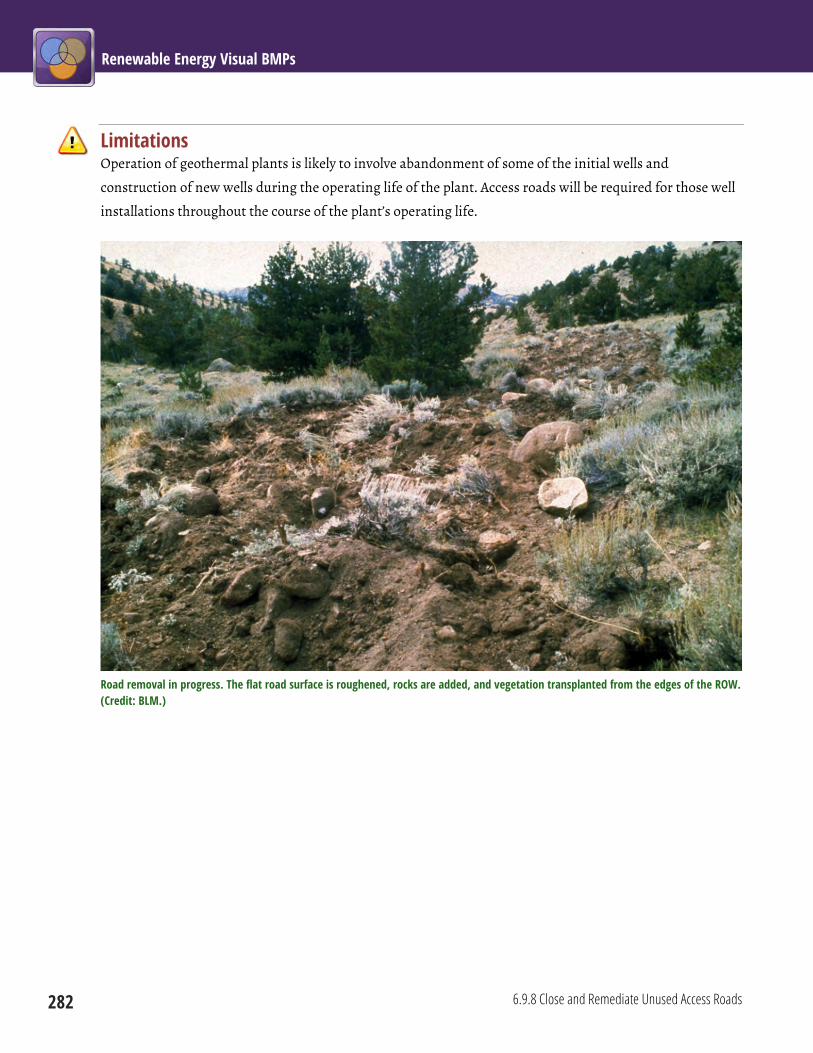
Renewable Energy Visual BMPs
282 6.9.8 Close and Remediate Unused Access Roads
Limitations Operation of geothermal plants is likely to involve abandonment of some of the initial wells and
construction of new wells during the operating life of the plant. Access roads will be required for those well
installations throughout the course of the plant’s operating life.
Road removal in progress. The flat road surface is roughened, rocks are added, and vegetation transplanted from the edges of the ROW. (Credit: BLM.)

Chapter 6: Common Elements 6.9 Reclamation
6.9.9 Remove Above-Ground and Near-Ground Structures 283
6.9.9 Remove Above-Ground and Near-Ground Structures Project Phase: Decommissioning
Most above-ground structures and near-ground
pipelines, conduits, and other connecting structures
should be removed upon completion of a project.
Notes Removal of above-ground structures avoids long-term
negative visual impacts.
Limitations Exceptions may be necessary for massive structures or
certain underground structures. The BLM has approved
abandonment in place (or required only partial removals
of buried objects to specified depths) for structures that
would not interfere with revegetation or future land uses
and that have adequate environmental remediation.
Consultation on removal/abandonment requirements
will be necessary.
Culvert removal during road decommissioning. (Credit: Washington State Recreation and Conservation Office.)
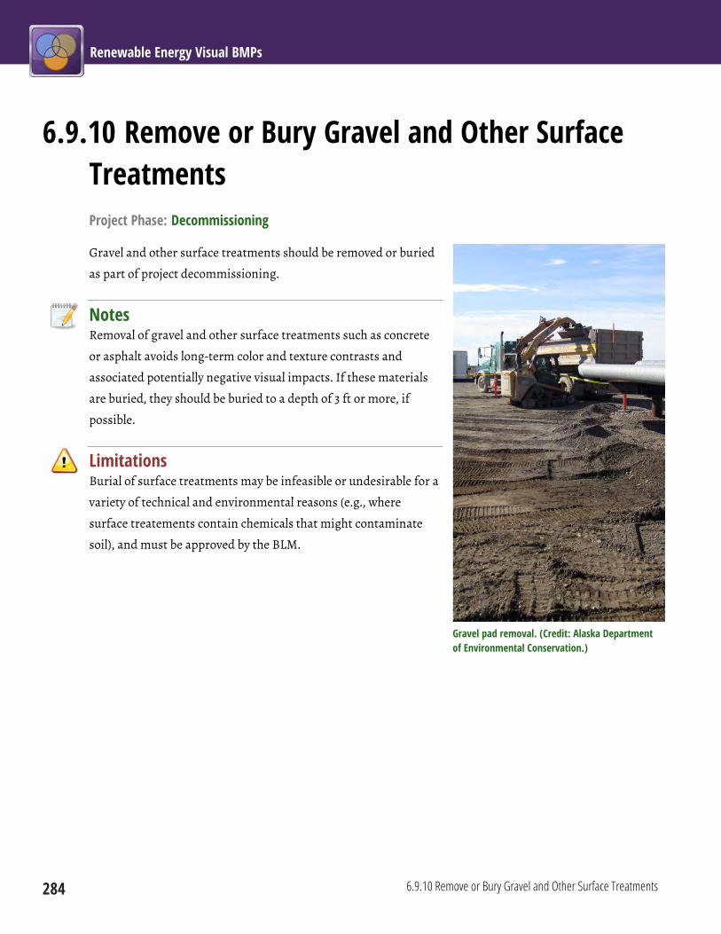
Renewable Energy Visual BMPs
284 6.9.10 Remove or Bury Gravel and Other Surface Treatments
6.9.10 Remove or Bury Gravel and Other Surface Treatments Project Phase: Decommissioning
Gravel and other surface treatments should be removed or buried
as part of project decommissioning.
Notes Removal of gravel and other surface treatments such as concrete
or asphalt avoids long-term color and texture contrasts and
associated potentially negative visual impacts. If these materials
are buried, they should be buried to a depth of 3 ft or more, if
possible.
Limitations Burial of surface treatments may be infeasible or undesirable for a
variety of technical and environmental reasons (e.g., where
surface treatements contain chemicals that might contaminate
soil), and must be approved by the BLM.
Gravel pad removal. (Credit: Alaska Department of Environmental Conservation.)

Chapter 6: Common Elements 6.10 Good Housekeeping
285
6.10 Good Housekeeping These BMPs address measures to keep the site clean and orderly during construction, operations, and
decommissioning.
6.10 Good Housekeeping Siting and Design Construction Operations
Decommissioning and
Reclamation
6.10.1 Develop “Housekeeping” Procedures (p 286)
6.10.2 Maintain a Clean Worksite (p 287)
6.10.3 Prohibit Onsite Burning (p 289)
6.10.4 Use Exit Tire Washes and Vehicle Tracking Pads to Reduce the Tracking of Sediment onto Roads (p 290)
6.10.5 Remove or Avoid Slash Piles (p 292)
6.10.6 Clean Off-Road Equipment (p 294)
6.10.7 Remove Stakes and Flagging (p 295)
6.10.8 Use Fabric-Covered Fences to Conceal Material Storage Yards and Laydown Yards (p 296)
6.10.9 Actively Maintain Operating Facilities (p 298)
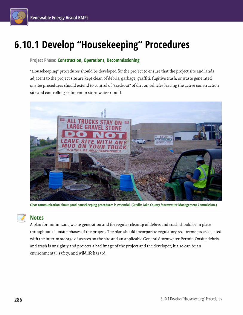
Renewable Energy Visual BMPs
286 6.10.1 Develop “Housekeeping” Procedures
6.10.1 Develop “Housekeeping” Procedures Project Phase: Construction, Operations, Decommissioning
“Housekeeping” procedures should be developed for the project to ensure that the project site and lands
adjacent to the project site are kept clean of debris, garbage, graffiti, fugitive trash, or waste generated
onsite; procedures should extend to control of “trackout” of dirt on vehicles leaving the active construction
site and controlling sediment in stormwater runoff.
Clear communication about good housekeeping procedures is essential. (Credit: Lake County Stormwater Management Commission.)
Notes A plan for minimizing waste generation and for regular cleanup of debris and trash should be in place
throughout all onsite phases of the project. The plan should incorporate regulatory requirements associated
with the interim storage of wastes on the site and an applicable General Stormwater Permit. Onsite debris
and trash is unsightly and projects a bad image of the project and the developer; it also can be an
environmental, safety, and wildlife hazard.

Chapter 6: Common Elements 6.10 Good Housekeeping
6.10.2 Maintain a Clean Worksite 287
6.10.2 Maintain a Clean Worksite Project Phase: Construction, Operations, Decommissioning
Facilities and offsite surrounding areas should be kept clean of debris, fugitive trash or litter, and graffiti.
Surplus, broken, and used materials and equipment of any size should not be allowed to accumulate. Scrap
heaps and materials dumps should be prohibited. Materials storage yards should be kept to a minimum.
Debris pile at an operating geothermal plant creates an eyesore. (Credit: BLM.)
Notes The worksite must be kept clean through a combination of regular cleanup, waste minimization, and
carefully planned onsite materials storage. The worksite should be routinely inspected to ensure that
material, debris, trash, and litter are not becoming a worksite issue.
Limitations Active construction sites involve considerable visual clutter, including temporary piles of debris.
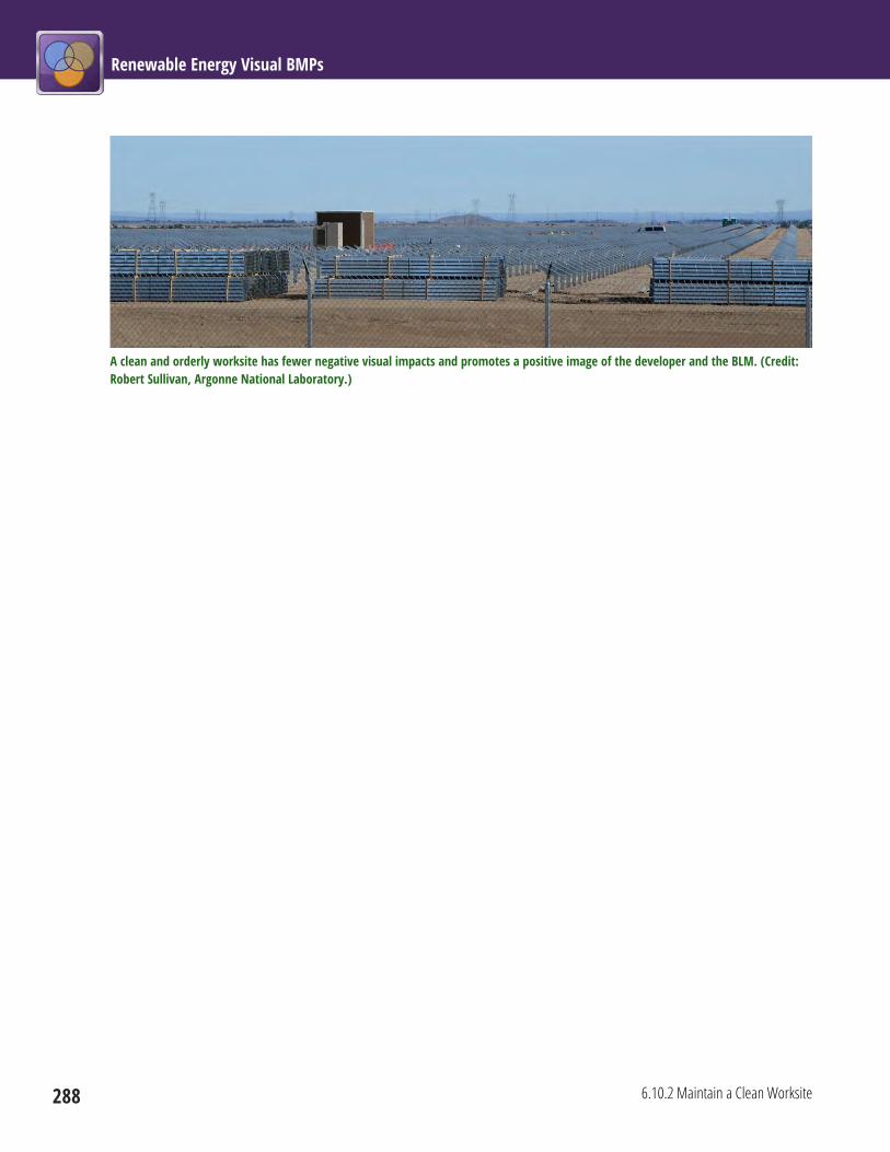
Renewable Energy Visual BMPs
288 6.10.2 Maintain a Clean Worksite
A clean and orderly worksite has fewer negative visual impacts and promotes a positive image of the developer and the BLM. (Credit: Robert Sullivan, Argonne National Laboratory.)

Chapter 6: Common Elements 6.10 Good Housekeeping
6.10.3 Prohibit Onsite Burning 289
6.10.3 Prohibit Onsite Burning Project Phase: Construction, Operations, Decommissioning
The burning of trash should be prohibited during
construction, operations, and decommissioning;
trash should be stored in containers and/or hauled
offsite.
Notes Burning trash onsite produces smoke that can be
visible for long distances; it is also a source of odors
and potentially toxic fumes, as well presenting a fire
hazard.
Limitations Depending on circumstances, burning of wood
debris may be the most environmentally preferred
option.
Onsite burning creates smoke plumes that can be visible for miles. (Credit: State of Washington Department of Ecology.)

Renewable Energy Visual BMPs
290 6.10.4 Use Exit Tire Washes and Vehicle Tracking Pads to Reduce the Tracking of Sediment onto Roads
6.10.4 Use Exit Tire Washes and Vehicle Tracking Pads to Reduce the Tracking of Sediment onto Roads Project Phase: Construction, Decommissioning
Construction sites should have entrances, exits,
and parking areas with exit tire washes and/or
vehicle tracking pads to reduce the tracking of
sediment onto roads; these areas should be kept
clean.
Notes Trackouts of mud and other debris onto a high-
speed highway represent a significant safety
hazard for vehicles traveling that highway, and
may also introduce sediment into nearby water
bodies. Safety and water quality protection are
the primary reasons exit tire washes and vehicle
tracking pads are installed at construction sites;
however, trackouts are unsightly, and tracked soil is also a potential transport mechanism for invasive
species. The use of exit tire washes and vehicle tracking pads will avoid or reduce the visual contrasts that
result from tracking of sediment onto roads; avoid or reduce the visual contrasts that may result from
invasive plants; and help preserve the visual quality of water bodies where sediment from trackouts could
degrade water clarity.
Limitations Tire washes may be unnecessary or undesirable in desert environments. Both tire washes and vehicle
tracking pads introduce their own visual contrasts, which could be substantial in some settings.
An exit tire wash removes dust, soil, mud, and other materials from trucks to minimize potential trackout of material onto roadways. (Credit: Tom Gore, Altitude Training.)

Chapter 6: Common Elements 6.10 Good Housekeeping
6.10.4 Use Exit Tire Washes and Vehicle Tracking Pads to Reduce the Tracking of Sediment onto Roads 291
A vehicle tracking pad is typically a stabilized pad of coarse aggregate over a geotextile base installed at construction site exits to roadways. When vehicles drive over the pad, the tires sink into the rock slightly and mud on the tires is removed. (Credit: Tom Gore, Altitude Training.)
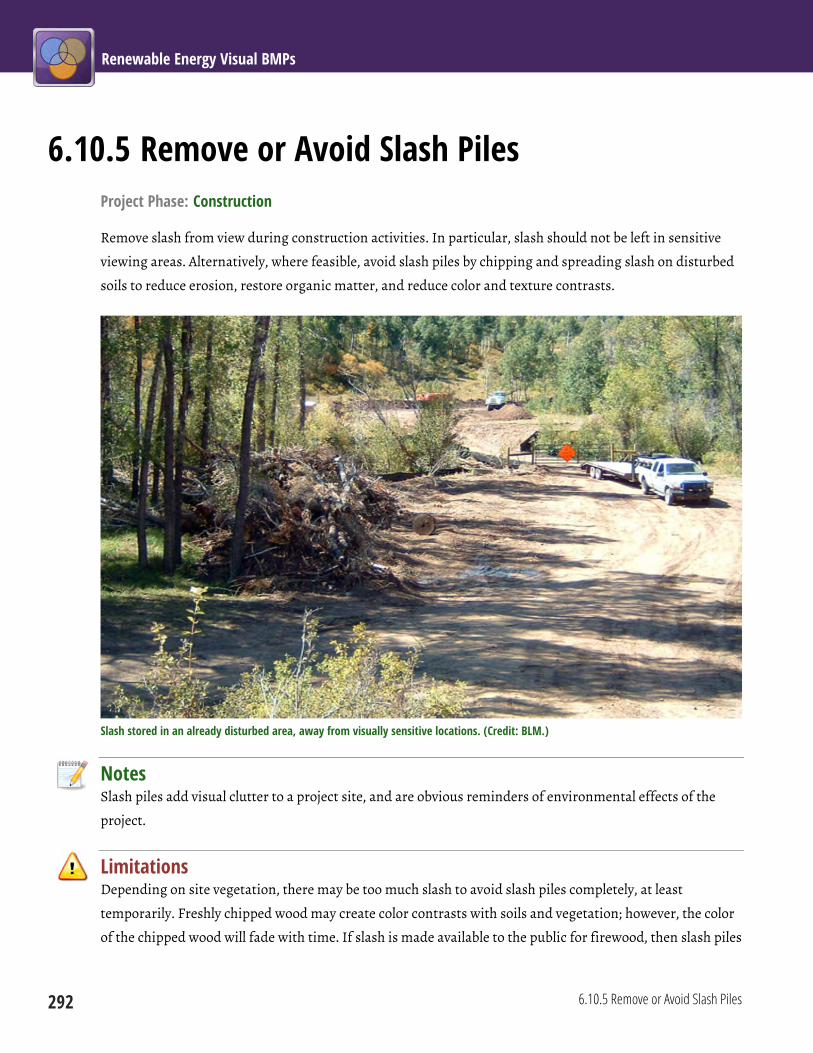
Renewable Energy Visual BMPs
292 6.10.5 Remove or Avoid Slash Piles
6.10.5 Remove or Avoid Slash Piles Project Phase: Construction
Remove slash from view during construction activities. In particular, slash should not be left in sensitive
viewing areas. Alternatively, where feasible, avoid slash piles by chipping and spreading slash on disturbed
soils to reduce erosion, restore organic matter, and reduce color and texture contrasts.
Slash stored in an already disturbed area, away from visually sensitive locations. (Credit: BLM.)
Notes Slash piles add visual clutter to a project site, and are obvious reminders of environmental effects of the
project.
Limitations Depending on site vegetation, there may be too much slash to avoid slash piles completely, at least
temporarily. Freshly chipped wood may create color contrasts with soils and vegetation; however, the color
of the chipped wood will fade with time. If slash is made available to the public for firewood, then slash piles

Chapter 6: Common Elements 6.10 Good Housekeeping
6.10.5 Remove or Avoid Slash Piles 293
may be located in accessible (and visible) areas. Fire safety control may preempt certain slash control
strategies. Chipped wood and slash can attract undesired insect infestations (e.g., bark beetles).
Renewable Energy Visual BMPs
294 6.10.6 Clean Off-Road Equipment
6.10.6 Clean Off-Road Equipment Project Phase: Construction, Operations, Decommissioning
The responsible party should clean all equipment that may operate off-road or disturb the ground before
beginning construction, operation and maintenance activities, or decommissioning. This process cleans
tracks and other parts of the equipment that could trap soil and dust.
Notes Cleaning off-road equipment reduces trackouts and dust that not only can cause visual impacts, but also
can present safety hazards, impact water quality, and spread invasive species.

Chapter 6: Common Elements 6.10 Good Housekeeping
6.10.7 Remove Stakes and Flagging 295
6.10.7 Remove Stakes and Flagging Project Phase: Construction, Decommissioning
All stakes and flagging should be removed from the construction area and disposed of in an approved
facility.
Notes Highly reflective flagging can be visible for long distances, and flagging and stakes can persist in certain
environments for years. They are easily removed, however, as part of “good housekeeping” procedures.
Limitations For temporary onsite haul roads, highly visible staking and flagging may be important to help drivers stay
on stable ground. Staking is also critical to site preparation when grade changes are required or sensitive
areas must be marked to avoid disturbance (e.g., sage-grouse nesting areas). Stakes and flags should be
removed once their purpose is met.

Renewable Energy Visual BMPs
296 6.10.8 Use Fabric-Covered Fences to Conceal Material Storage Yards and Laydown Yards
6.10.8 Use Fabric-Covered Fences to Conceal Material Storage Yards and Laydown Yards Project Phase: Construction
During construction, temporary chain-link fences surrounding the material storage yards and laydown
yards should be covered with fabric.
A fabric-covered temporary chain-link fence surrounding an equipment and materials storage yard provides effective screening for visual clutter behind the fence. (Credit: Robert Sullivan, Argonne National Laboratory.)
Notes Use of fabric coverings on construction fences will limit views into visually cluttered material storage yards
and laydown areas, resulting in a more unified and tidy appearance.

Chapter 6: Common Elements 6.10 Good Housekeeping
6.10.8 Use Fabric-Covered Fences to Conceal Material Storage Yards and Laydown Yards 297
Limitations In areas of high winds, fabric-covered fences may be blown over. Slits or holes in the fabric may be required
to allow wind to pass through. Fences are only effective for screening when observers are at the same or
lower elevation than the facility (i.e., fabric-covered fences will not be effective screens for views from
elevated KOPs).
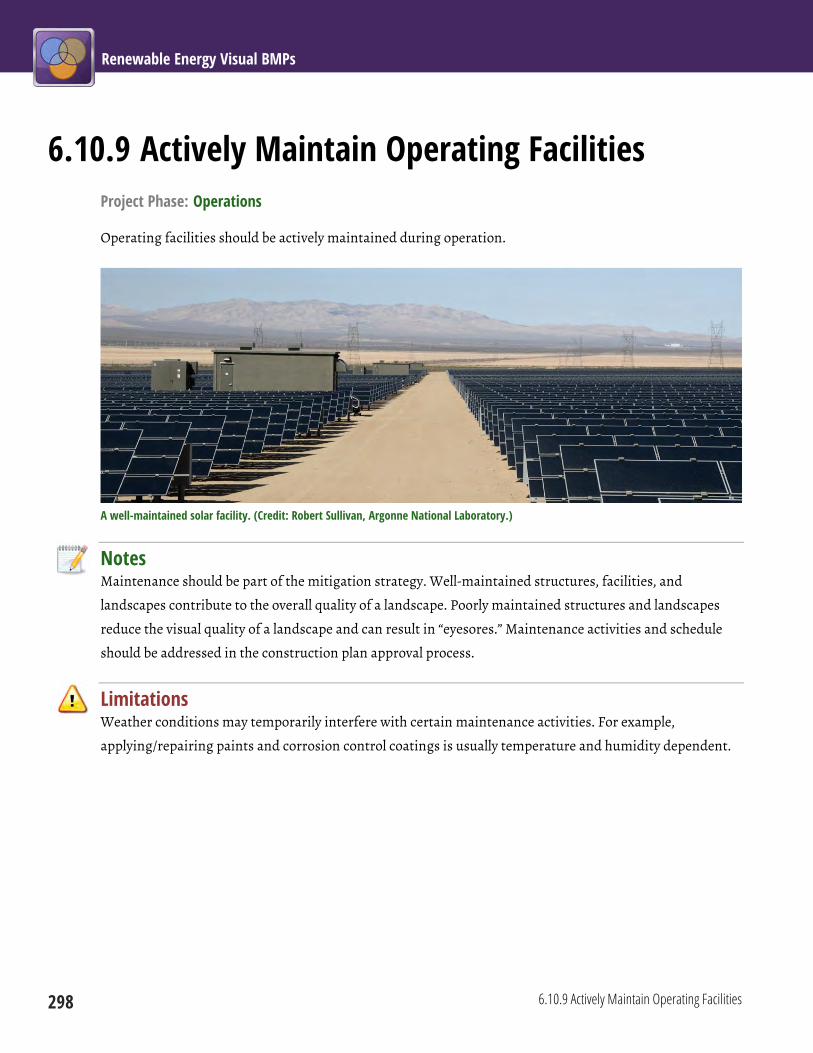
Renewable Energy Visual BMPs
298 6.10.9 Actively Maintain Operating Facilities
6.10.9 Actively Maintain Operating Facilities Project Phase: Operations
Operating facilities should be actively maintained during operation.
A well-maintained solar facility. (Credit: Robert Sullivan, Argonne National Laboratory.)
Notes Maintenance should be part of the mitigation strategy. Well-maintained structures, facilities, and
landscapes contribute to the overall quality of a landscape. Poorly maintained structures and landscapes
reduce the visual quality of a landscape and can result in “eyesores.” Maintenance activities and schedule
should be addressed in the construction plan approval process.
Limitations Weather conditions may temporarily interfere with certain maintenance activities. For example,
applying/repairing paints and corrosion control coatings is usually temperature and humidity dependent.

BMP Source Documents
299
BMP Source Documents Note to Reader: The following sources were consulted when compiling the BMPs in this publication. It is likely that
at the time of publication that some of these Web pages may no longer be available or their URL addresses may
have changed.
Arizona Public Service, 2001, Plan Of Development For The Saddle Mountain to Hyder 69kV Subtransmission Line Project,
submitted to Bureau of Land Management, Yuma Field Office, by Pinnacle West Capital Corporation, Nov. Available
at http://www.blm.gov/pgdata/etc/medialib/blm/wo/MINERALS__REALTY__AND_RESOURCE_PROTECTION_/
cost_recovery.Par.13846.File.dat/POD_69kv_Yuma.pdf. Accessed Sept. 19, 2012.
Bureau of Land Management, 2005, Wind Energy Final Programmatic Environmental Impact Statement (PEIS). Available
at http://windeis.anl.gov/documents/fpeis. Accessed Sept. 19, 2012.
Bureau of Land Management, 2006, Visual Resource Management for Fluid Minerals, Best Management Practices: Better
Ways for Achieving Better Results, Feb. Participant Notebook, Field Reference Guide.
Bureau of Land Management, 2006, Visual Resource Management National Training Center Coursebook. Course Number
8400-05, Santa Fe, NM, Sept. 25–29, 2006.
Bureau of Land Management, 2006, Visual Resource Management: Best Management Practices for Fluid Minerals. Available
at http://www.blm.gov/wo/st/en/prog/energy/oil_and_gas/best_management_practices/
technical_information.html. Accessed Sept. 19, 2012.
Bureau of Land Management, 2006, Final Environmental Impact Statement for the Atlantic Rim Natural Gas Field
Development Project, Carbon County, Wyoming. Available at http://www.blm.gov/wy/st/en/info/NEPA/documents/
rfo/atlantic_rim.html. Accessed Sept. 19, 2012.
Bureau of Land Management, 2008, BLM Wind Energy Development Policy Instruction Memorandum. Attachment 1. BLM
Wind Energy Program – Policies and Best Management Practices, IM 2009-043. Available at http://windeis.anl.gov/
documents/docs/IM2009-043_att1.pdf. Accessed Sept. 19, 2012.
Bureau of Land Management, 2008, Instruction Memorandum No. 2008-204, Washington DC., Sept. Available at
http://www.blm.gov/wo/st/en/info/regulations/
Instruction_Memos_and_Bulletins/national_instruction/20080/IM_2008-204.html. Accessed Sept. 19, 2012.
Renewable Energy Visual BMPs
300
Bureau of Land Management, 2011, Project Design Features and Best Management Practices for Record of Decision: North
Steens 230kV Transmission Line Project, Case File Number: OR-6589. Available at http://www.blm.gov/or/districts/
burns/plans/steen_trans/files/AttachmentA-TransmissionBMPsPDFs.pdf. Accessed Sept. 19, 2012.
Committee on Environmental Impacts of Wind Energy Projects, 2007, Environmental Impacts of Wind-Energy Projects,
National Research Council, National Academies Press, Washington DC.
Federal Highway Administration, 2007, Roadside Revegetation: An Integrated Approach to Establishing Native Plants,
FHWA-WFL/TD-07-005, Technology Deployment Program, Western Federal Lands Highway Division, Federal
Highway Administration, Vancouver, WA.
Forest Service, 1975, National Forest Landscape Management: Utilities, Agriculture Handbook 478, Volume 2, Chapter 2,
United States Government Printing Office, Washington DC.
Forest Service, 1977, National Forest Landscape Management: Roads, Agriculture Handbook 483, Volume 2, Chapter 4,
United States Department of Agriculture, United States Government Printing Office, Washington, D.C.
Forest Service, 2010, Final Environmental Impact Statement: Southern California Edison's Application for the Tehachapi
Renewable Transmission Project, United States Department of Agriculture. Available at ftp://ftp.cpuc.ca.gov/gopher-
data/environ/tehachapi_renewables/FinalEIS/TRTP%20Final%20EIS/FEIS_Index.htm. Accessed Sept. 19, 2012.
Gipe, P.B., 1998, “Design As If People Matter: Aesthetic Guidelines for the Wind Industry,” in Proceedings of the
International Workshop on Wind Energy and Landscape (WEL), C.F. Ratto and G. Solari (editors), Genoa, Italy, June
26−27, 1997, published by A.A. Balkema, Rotterdam, The Netherlands.
Gipe, P.B., 2002, “Design As If People Mattered: Aesthetic Guidelines for a Wind Power Future,” in Wind Power in
View: Energy Landscapes in a Crowded World, M.J. Pasqualetti et al. (editors), Academic Press, New York, NY.
International Finance Corporation (IFC) & World Bank Group, 2007, Environmental, Health, and Safety Guidelines for
Wind Energy, IFC. Available at http://www1.ifc.org/wps/wcm/connect/3af2a20048855acf8724d76a6515bb18/Final%2B-
%2BWind%2BEnergy.pdf?MOD=AJPERES&id=1323162509197. Accessed Sept. 19, 2012.
Minerals Management Service, 2007, Programmatic Environmental Impact Statement for Alternative Energy Development
and Production and Alternate Use of Facilities on the Outer Continental Shelf, Final Environmental Impact Statement. Available
at http://www.ocsenergy.anl.gov/documents/fpeis/index.cfm. Accessed Sept. 19, 2012.

BMP Source Documents
301
New York State Department of Environmental Conservation, 2000, “Assessing and Mitigating Visual Impacts,” in
The DEC Policy System, July 31. Available at http://www.dec.ny.gov/docs/permits_ej_operations_pdf/visual2000.pdf.
Accessed Sept. 19, 2012.
Office of Fossil Energy (FE), 2003, Tucson Electric Power Company (TEP) Sahuarita–Nogales Transmission Line Draft
Environmental Impact Statement (EIS), DOE/EIS-0336, United States Department of Energy. Available at
http://energy.gov/nepa/downloads/eis-0336-draft-environmental-impact-statement. Accessed Sept. 19, 2012.
Renewable Energy Action Team (California Energy Commission, California Department of Fish and Game, U.S.
Department of Interior Bureau of Land Management, and Fish and Wildlife Service), 2010, Best Management Practices
and Guidance Manual: Desert Renewable Energy Projects, REAT‐1000‐2010‐009, California Energy Commission, Siting,
Transmission and Environmental Protection Division. Available at http://www.energy.ca.gov/2010publications/
REAT-1000-2010-009/REAT-1000-2010-009.PDF. Accessed Sept. 19, 2012.
United States Department of Energy, 2008, Programmatic Environmental Impact Statement, Designations of Energy
Corridors on Federal Land in the 11 Western States, DOE/EIS-0386. Available at http://corridoreis.anl.gov/
documents/fpeis. Accessed Sept. 19, 2012.
United States Department of Energy and Bureau of Land Management, 2010, Draft Programmatic Environmental
Impact Statement for Solar Energy Development in Six Southwestern States. Available at http://solareis.anl.gov/
documents/dpeis/index.cfm. Accessed Sept. 19, 2012.
United States Department of Energy, Western Area Power Administration, and U.S. Fish and Wildlife Service, 2012,
Upper Great Plains Wind Energy Draft Programmatic Environmental Impact Statement. Available at
http://plainswindeis.anl.gov. Accessed Sept. 19, 2012.
United States Department of the Interior and United States Department of Agriculture, 2007, Surface Operating
Standards and Guidelines for Oil and Gas Exploration and Development, BLM/ST-06/021+3071/REV 07. Available at
http://www.blm.gov/wo/st/en/prog/energy/oil_and_gas/best_management_practices/gold_book.html. Accessed
Sept. 19, 2012.
Western Area Power Administration, 1999, Record of Decision and Floodplain Statement for the Interconnection of the
Southpoint Power Plant with the Western Area Power Administration’s Parker-Davis No. 1 and No. 2, 230-kilovolt Transmission
Lines, DOE/EIS-0308, United States Department of Energy. Available at http://govpulse.us/entries/1999/04/01/99-
8057/record-of-decision-and-floodplain-statement-for-the-interconnection-of-the-southpoint-power-plant-wi.
Accessed Sept. 19, 2012.

For Further Reading
303
For Further Reading The following sources contain additional information on best practices for reducing visual impacts and related
topics.
Benson, J.F., 2005, “Visualization of Windfarms,” in Visualization in Landscape and Environmental Planning: Technology
and Applications, I. Bishop and E. Lange (editors), New York: Taylor & Francis.
Bureau of Land Management, 1984, Visual Resource Management, BLM Manual Handbook 8400, Release 8-24, U.S.
Department of the Interior, Washington, DC.
Bureau of Land Management, 1985, Roads, BLM Manual 9113, Release 9-247, U.S. Department of the Interior,
Washington, DC, June.
Bureau of Land Management, 1986, Visual Resource Inventory, BLM Manual Handbook 8410-1, Release 8-28, U.S.
Department of the Interior, Washington, DC, Jan.
Bureau of Land Management, 1986, Visual Resource Contrast Rating, BLM Manual Handbook 8431-1, Release 8-30, U.S.
Department of the Interior, Washington, DC, Jan.
Bureau of Land Management, 2006, Visual Resource Management for Fluid Minerals, Best Management Practices: Better
Ways for Achieving Better Results, Feb. Participant Notebook, Field Reference Guide, U.S. Department of the Interior.
Bureau of Land Management, 2006, Visual Resource Management: Best Management Practices for Fluid Minerals, U.S.
Department of the Interior.
Bureau of Land Management, 2012, Visual Resource Management. Available at
http://www.blm.gov/wo/st/en/prog/Recreation/recreation_national/RMS.html. Accessed Feb. 27, 2013.
Bureau of Land Management, 2012, Best Management Practices. Available at
http://www.blm.gov/wo/st/en/prog/energy/oil_and_gas/best_management_practices.html. Accessed Feb. 27, 2013.
Federal Highway Administration, 2007, Roadside Revegetation: An Integrated Approach to Establishing Native Plants,
FHWA-WFL/TD-07-005, Technology Deployment Program, Western Federal Lands Highway Division, Vancouver,
WA.

Renewable Energy Visual BMPs
304
Forest Service, 1975, National Forest Landscape Management: Utilities, Agriculture Handbook 478, Vol. 2, U.S.
Department of Agriculture, U.S. Government Printing Office, Washington, DC.
Gipe, P.B., 2002, “Design As If People Mattered: Aesthetic Guidelines for a Wind Power Future,” in Wind Power in
View: Energy Landscapes in a Crowded World, M.J. Pasqualetti et al. (editors), Academic Press, New York, NY.
Scottish Natural Heritage (Agency) Staff, 2006, Visual Representation of Windfarms: Good Practice Guidance, Scottish
Natural Heritage, Perth, Scotland.
Sullivan, R.G., L. Kirchler, T. Lahti, S. Roché, and K. Beckman, 2012, “Wind turbine visibility and visual impact threshold distances in western landscapes,” National Association of Environmental Professionals 37th Annual Conference, Portland OR, May 21–24, 2012. Sullivan, R.G., L. Kirchler, C. McCoy, J. McCarty, K. Beckman, and P. Richmond, 2012, “Visual Impacts of Utility-scale Solar Energy Facilities on Southwestern Desert Landscapes,” National Association of Environmental Professionals 37th Annual Conference, Portland OR, May 21–24, 2012. U.S. Department of the Interior and U.S. Department of Agriculture, 2007, Surface Operating Standards and Guidelines
for Oil and Gas Exploration and Development, BLM/ST-06/021+3071/REV 07.

Acronym List
305
Acronym List AVWS Audio Visual Warning System
BLM Bureau of Land Management
BMP best management practice
BUG Backlight, Uplight, and Glare
CLFR compact linear Fresnel reflector
CPV concentrating photovoltaic
CSP concentrating solar power
DOI Department of the Interior
EPACT 2005 Energy Policy Act of 2005
FAA Federal Aviation Administration
FLPMA Federal Land Policy and Management Act of 1976
GIS geographic information systems
GPS global positioning system
HTF heat transfer fluid
IES Illuminating Engineering Society
KOP key observation point
LED light-emitting diode
MW megawatt(s)
NEPA National Environmental Policy Act of 1969
NHPA National Historic Preservation Act of 1966
NPS National Park Service
NREL National Renewable Energy Laboratory
Renewable Energy Visual BMPs
306
O&M operation and maintenance
PLS pure live seed
POD Plan of Development
PV photovoltaic
RMP resource management plan
ROW right-of-way
SEGS Solar Electric Generating System
SLRU sensitivity level rating unit
SQRU scenic quality rating unit
STG steam turbine generator
USFWS U.S. Fish and Wildlife Service
VCR visual contrast rating
VIA visual impact assessment
VRI visual resource inventory
VRM visual resource management
Glossary
307
Glossary Access road Gravel or dirt road (rarely paved) that provides overland access to transmission line and pipeline rights-of-way and facilities for construction, inspection, maintenance, and decommissioning.
Aeration The process by which atmospheric air enters the soil. The rate and amount of aeration depends on the size and continuity of the pore spaces within the soil and the degree of water logging.
Aggregate Mineral materials such as sand, gravel, crushed stone, or quarried rock used for construction purposes.
Air-cooled See Dry-cooling system.
Air quality Measure of the health-related and visual characteristics of the air to which the general public and the environment are exposed.
All-American Road A road recognized by the United States Department of Transportation under the National Scenic Byways Program as possessing two of six “intrinsic qualities,” including archeological, cultural, historic, natural, recreational, and/or scenic quality. See National Scenic Byway.
Ancillary structure Additional built feature (i.e., a substation).
Array The positioning and spatial arrangement of energy collection devices (wind turbines or solar energy collectors [mirrors, heliostats, or panels]) of an energy facility, or the energy collection devices themselves, referred to collectively.
Atmospheric refraction The deviation of light from a straight line as it passes through the atmosphere due to the variation in air density as a function of altitude.
Audio Visual Warning System (AVWS) A navigation hazard warning system that activates obstruction lighting and audio signals to alert aircraft pilots of potential collisions with tall obstacles, typically wind turbines or communications towers.

Renewable Energy Visual BMPs
308
Authorized Officer BLM employee responsible for exercising BLM’s enforcement authority to require compliance with the terms and conditions of a ROW grant (or grants).
Avian The scientific classification for all bird species.
Azimuth The horizontal angular distance from a reference direction, usually the northern point of the horizon, to the point where a vertical circle through a celestial body (e.g., the sun) intersects the horizon, usually measured clockwise.
Backdrop The landscape, seascape, or sky visible directly behind the visible elements of a facility, as seen from a particular viewpoint.
Backlit A lighting condition in which the side of an object facing the viewer is shaded, and sunlight or daylight is visible behind the object, causing it to appear in silhouette.
Backslope In road engineering, the slope above the roadway in a road cut. The backslope extends from the top of the cut at the existing grade to the bottom of the ditch or edge of the shoulder on the inside of the road.
Bedding plane A distinct surface of contact between two sedimentary rock layers.
Bedrock General term referring to the solid rock or ledge underlying other unconsolidated material (soil, loose gravel, etc.).
Bench A relatively level step, excavated into a slope on which fill is to be placed. Its purpose is to provide a firm, stable contact between the existing material and new fill that is to be placed on top of the bench.
Berm An artificially constructed continuous ridge or bank of earth, usually constructed and located to reduce erosion or screen an object from view.
Best Management Practice (BMP) A practice or combination of practices that are determined to provide the most effective, environmentally sound, and economically feasible means of managing an activity and mitigating its impacts.
Blackbody radiation The electromagnetic radiation that would be emitted from an ideal object (blackbody) capable of absorbing all radiant energy that falls upon it.
Glossary
309
Blade The aerodynamic structure on a wind turbine that catches the wind. Most utility-scale wind turbines have three blades.
Blade glint A brief bright and sometimes repetitious reflection of sunlight from the surface of rotating wind turbine blades. See Glint; Glare.
Borrow area A pit or excavation area used for obtaining earth materials (borrow) such as sand or gravel for use in construction.
Brush-beating Mowing of shrubs to reduce height.
Catalytic converter An antipollution device on an automotive exhaust system.
Check dam A small, temporary water control structure that is constructed across a swale or channel and used to slow the velocity of concentrated water flows to help reduce erosion.
Closed-loop cooling system Also known as a wet, closed-cycle cooling system, a system that circulates water between a steam condenser and a cooling tower to cool steam condensate at a thermoelectric power plant; the circulating water interacts with a counterflow (or crossflow) of ambient air at the cooling tower and is cooled through the principle of evaporation, at which point a small fraction of the water is evaporated. The evaporated amount is continually replaced to maintain the total volume of water in the system.
Clutter See Visual clutter.
Color The property of reflecting light of a particular intensity and wavelength (or mixture of wavelengths) to which the eye is sensitive. It is the major visual property of surfaces.
Compact Linear Fresnel Reflector (CLFR) A type of concentrated solar power (CSP) technology similar to a parabolic trough design but using flat parallel mirrors, in which the sun’s heat energy is reflected onto a receiver positioned above the mirrors and containing water; the water is converted to steam and delivered to a steam turbine-generator (STG) for production of electricity.

Renewable Energy Visual BMPs
310
Compost blanket A layer of loosely applied composted material placed on the soil in disturbed areas to reduce stormwater runoff and erosion. The material reduces runoff, and promotes stormwater infiltration and revegetation.
Concentrating Solar Power (CSP) A solar energy system that uses mirrors or lenses to concentrate sunlight, or solar thermal energy, onto a collector. The heat from the concentrated sunlight is used to generate electricity through steam generation or by mechanical means.
Conductor A substance or body that allows an electrical current to pass continuously along it. Electrical equipment receives power through electrical conductors.
Conservation easement Easement restricting a landowner to land uses that are compatible with long-term conservation and environmental values.
Constructed landform A manmade land feature that replicates the irregular shapes of natural slopes.
Construction staging area A designated area where vehicles, supplies, and construction equipment are positioned for access and use at a construction site; in some cases a location at or very near where facility components will be installed, used for component assembly.
Contour grading Changing the ground level to create curvilinear slopes rounded into existing terrain to produce a contoured and smooth transition from cut or fill faces to natural ground or abutting cut or fill surfaces.
Contrast Opposition or unlikeness of different forms, lines, colors, or textures in a landscape.
Cooling tower A structure in which heat used in electricity generation in thermal power plants (including certain types of solar and geothermal power plants) is removed from hot condensate.
Cultural resources Archaeological sites, structures, or features; traditional use areas; and Native American sacred sites or special use areas that provide evidence of the prehistory and history of a community.
Culvert A pipe or covered channel that directs surface water through a raised embankment or under a roadway, from one side to the other.
Glossary
311
Cumulative impacts The impacts assessed in an environmental impact statement that could potentially result from incremental impacts of the action when added to other past, present, and reasonably foreseeable future actions, regardless of what agency (federal or nonfederal), private industry, or individual undertakes such other actions. Cumulative impacts can result from individually minor but collectively significant actions taking place over a period of time.
Cut-and-fill The process of earth grading by excavating part of a higher area and using the excavated material for fill to raise the surface of an adjacent lower area.
Decommissioning All activities necessary to take a facility out of service and dispose of its components after its useful life.
Digital terrain mapping Representation of the earth’s surface for a geographic area stored in a digital file containing regularly spaced point locations with an elevation attribute.
Directional drilling The practice of drilling non-vertical wells, where the well bore is oriented laterally or at a slant from vertical; also called slant drilling.
Dish engine A CSP technology that produces electricity, typically in the range of 3 to 25 kW, by using a single parabolic mirror or, more typically, a parabolic array of mirrors to reflect sunlight to heat a working gas (typically hydrogen) in a closed container, causing it to expand and drive a reciprocating engine connected to an electric generator. The dish engine is unique among CSP systems because it uses mechanical energy rather than steam to produce electricity.
Distance Zones A set of pre-determined distances from a viewpoint. In the BLM’s visual resource management system, landscapes are subdivided into threee distanced zones based on relative visibility from travel routes or observation points. The three zones are foreground-middleground, background, and seldom seen. The foreground-middleground zone includes areas seen from highways, rivers, or other viewing locations that are less than 3–5 mi away. Seen areas beyond the foreground-middleground zone but usually less than 15 mi away are in the background zone. Areas not seen as foreground-middleground or background (i.e., hidden from view) are in the seldom-seen zone.
Disturbed land Land in which a discrete event or process has altered the land surface, the soil, and/or the vegetation.
Drilling (geothermal) Boring into the earth to access geothermal resources.
Renewable Energy Visual BMPs
312
Drill rig (geothermal) Machinery (typically oil and gas drilling equipment that has been modified to meet geothermal requirements) used to bore through the ground to locate geothermal resources (hot water or steam).
Dry cooling See Dry cooling system.
Dry cooling system Also known as dry closed-loop cooling; a technology for rejecting heat from the steam condensate of a thermoelectric plant. Cooling water circulates in a closed loop between a steam condenser, where it accepts heat from steam condensate, and a dry condenser located outdoors. Fans are used to establish a flow of ambient air across the surface of the dry condenser, allowing the heated cooling water inside the dry condenser to transfer heat to the ambient air before cycling back to the steam condenser.
Dual flash A configuration at a geothermal plant in which water leaving a separator is directed to another separator, where a lower pressure generates additional steam production.
Dust suppressant Products (water, salts, synthetic emulsions) that abate dust by changing the physical properties of the soil surface, typically used on construction sites and unpaved roads; also referred to as a “dust palliative.”
Effects Environmental consequences (the scientific and analytical basis for comparison of alternatives) that occur as a result of a proposed action. Effects may be direct (caused by the action and occurring at the same time and place), indirect (caused by the action but occurring later in time or farther removed in distance, but still reasonably foreseeable), or cumulative (incremental impacts of the action when added to other past, present, and reasonably foreseeable future actions).
Emissivity The relative power of a surface to emit heat by radiation.
Equipment and materials storage yard An area at a construction site where materials other than individual components needed for construction are kept, and where construction-related wastes are temporarily stored.
Erosion The wearing away of land surface by wind or water, intensified by land-clearing practices related to farming, residential or industrial development, road building, or logging.

Glossary
313
Facility An existing or planned location or site at which prime movers, electric generators, and/or equipment for converting mechanical, chemical, solar, thermal, and/or nuclear energy into electric energy are situated, or will be situated. A facility may contain more than one generator of either the same or different prime mover type.
Feathering A technique for reducing a strong line of visual contrast by creating a more natural look along a vegetative edge through the retention of a mix of existing trees and shrubs in different sizes.
Fill Manmade deposits of soil, rock, and/or waste material.
Flagging Tape, stakes, or other materials (but not including paints or coatings) used in surveying and construction to mark important locations.
Footprint The land or water area covered by a project. This includes direct physical coverage (i.e., the area on which the project physically stands) and direct effects (i.e., the disturbances that may directly emanate from the project, such as noise).
Forbs Herbaceous (non-woody), broad-leaved flowering plants; non-graminoid (grasses, sedges, and rushes) herbaceous plants.
Form The mass or shape of an object or objects that appears unified, such as a vegetative opening in a forest, a cliff formation, or a water tank.
Fracture plane A surface of fracture representing a more-or-less clean-cut break in the rock body.
Frontlit A lighting condition in which the side of an object facing the viewer is fully illuminated by light coming from behind the viewer.
Fugitive dust The dust released from any source other than a definable point source such as a stack, chimney, or vent. Sources include construction activities, storage piles, and roadways.
Galvanized (metallic surface) A metal surface (particularly iron or steel) coated with zinc.
Renewable Energy Visual BMPs
314
Generation (electricity) The process of producing electric energy by transforming other forms of energy; also, the amount of electric energy produced, expressed in watt-hours (Wh).
Geothermal Of or related to the Earth’s interior heat.
Geothermal energy Natural heat from within the Earth, captured for the production of electric power. This energy may be in the form of steam, hot water, or the thermal energy contained in rocks at great depths.
Geothermal fluid Hot, mineral-rich liquid or vapor that is the carrier medium that brings geothermal energy up through wells from the subsurface to the surface.
Geothermal pipeline system A network of pipe that connects the power plant with production and injection wells.
Geothermal plant A power plant in which the prime mover is a steam turbine. The turbine is driven either by steam produced from hot water or by natural steam that derives its energy from heat found in rocks or fluids at various depths beneath the surface of the earth. The energy is extracted by drilling and/or pumping.
Geothermal production Electricity produced from the heat energy of the earth. This energy may be in the form of steam, hot water, or the thermal energy contained in rocks at great depths.
Geothermal steam Steam drawn from deep within the earth.
Geysers, the A large geothermal steam field located north of San Francisco.
Glare The sensation produced by luminance within the visual field that is sufficiently greater than the luminance to which the eyes are adapted, which causes annoyance, discomfort, or loss in visual performance and visibility. See Glint.
Glint A momentary flash of light resulting from a spatially localized reflection of sunlight. See Glare.
Grading Mechanical process of moving earth to change the degree of rise or descent (slope) of the land in order to establish good drainage and otherwise suit the intent of a landscape design.
Glossary
315
Ground receptor Hikers, off-highway vehicle users, equestrians, and other visitors viewing the landscape from a normal human height above ground level, that can be impacted by renewable energy activities.
Grubbing Removal of stumps, roots, and vegetable matter from the ground surface after clearing and prior to excavation.
Hazard navigation lighting The illumination of an object for increased conspicuity to ensure the safety of air or water navigation, or the lighting equipment used to achieve this purpose.
Heat transfer fluid (HTF) Fluid that transfers heat generated at the solar collectors or in geothermal systems to a heat exchanger where steam is produced to run a steam generator.
Heliostat A power tower facility component consisting of a large, nearly flat mirror, usually on a tracker, pedestal, or other support structure, that allows it to continuously reflect the sun’s rays over the course of the day onto a central receiver at the top of a centrally positioned tower.
Historic Trails Routes of travel that commemorate historic (or prehistoric) trails of local, state, regional, or national significance.
Horizon line The apparent line in the landscape formed by the meeting of the visible land surface and the sky.
Horizontal angle of view The compass direction of the view from a viewer to a viewed object. The horizontal angle determines which side of the facility is in view, as well as the angle of the object’s vertical surfaces with respect to the viewer.
Hub The central portion of the rotor to which the blades of a wind turbine are attached.
Hybrid (wet-dry cooling) system A variation on a dry cooling system. In a hybrid system, small amounts of water are sprayed as a fine mist into the flow of ambient air being directed over the surface of a dry condenser. The water evaporates, cooling the air as it does so. Alternatively, water is deluged over the surface of the dry condenser where it evaporates after interacting with the overflowing ambient air stream, cooling that air. Wet/dry hybrid systems consume only minor amounts of water (compared to wet closed-loop cooling) but offer significantly better performance than dry cooling systems, especially in hot climates with low relative humidity.
Impact The effect, influence, alteration, or imprint caused by an action.
Renewable Energy Visual BMPs
316
Intermittent stream A stream that flows for a portion of the year but occasionally is dry or reduced to a pool stage when losses from evaporation or seepage exceed the available streamflow.
Invasive species Any species, including noxious and exotic species, that is an aggressive colonizer and can out-compete indigenous species.
Inventory Observation Point (IOP) In the BLM’s visual resource inventory process, a location from which a scenic quality rating is conducted. An IOP is either an important viewpoint or is representative of the scenic quality rating unit being evaluated for scenic quality.
Key observation point (KOP) A point at a use area or a potential use area, or a series of points or a segment on a travel route, where there may be views of a management activity. KOPs are typically used as viewpoints for assessing potential visual impacts resulting from a proposed management activity.
Landform Any recognizable physical form of the earth’s surface, having a characteristic shape. Landforms include major forms such as plains, plateaus, and mountains, and minor forms such as hills, valleys, slopes, and moraines. Taken together, the landforms make up the surface configuration of the earth.
Landmark A visually prominent physical feature of a landscape that attracts visual attention, such as a peak, knob, lake, or waterfall.
Landscape The expanse of visible scenery including landforms, waterforms, vegetation, and manmade elements such as roads and structures. Also the traits, patterns, and structure of a specific geographic area including its physical environment, its biological composition, and its anthropogenic or social patterns.
Land use A characterization of land in terms of its potential utility for various activities, or the activities carried out on a given piece of land.
Laydown area An area that has been cleared for the temporary storage of equipment and supplies for a construction activity; a location where individual components for use in construction are initially offloaded from their transport vehicle. To ensure accessibility and safe maneuverability for transport and offloading of vehicles, laydown areas are usually covered with rock and/or gravel.
Light-emitting diode (LED) lighting A solid-state lamp that uses light-emitting diodes as the source of light.

Glossary
317
Light fixture An electrical device used to create artificial light and/or illumination.
Light pollution Any adverse effect of manmade lighting, such as excessive illumination of night skies by artificial light. Light pollution is an undesirable consequence of outdoor lighting that includes such effects as skyglow, light trespass, and glare.
Light spill An undesirable condition in which light is cast where it is not wanted. Also referred to as light trespass.
Light trespass See Light spill.
Line The path, real or imagined, that the eye follows when perceiving abrupt differences in form, color, or texture. Within landscapes, lines may be found as ridges, skylines, the edges of structures, the edges of water bodies, changes in vegetative types, or individual trees and branches.
Low-pressure sodium lamp An energy-efficient form of outdoor lighting in which a lamp contains neon gas that lights at a relatively low temperature. As the temperature increases, sodium in the lamp begins to vaporize and creates a monochromatic yellow light.
Lumen A unit of illumination; the amount of illumination of a unit area of spherical surface, due to a light of a unit intensity placed at the center of the sphere.
Luminaire A complete lighting unit consisting of a lamp (or lamps) and the parts designed to distribute the light, to position and protect the lamp(s), and to connect the lamp(s) to the power supply. Also referred to as a light fixture. A full cutoff luminaire limits glare between 80° and 90° from the ground. A fully shielded luminaire emits no direct uplight, but does not limit glare between 80° and 90° from the ground.
Luminescent Emitting light not caused by heat.
Luminosity The brightness of a light source of a certain wavelength as it appears to the eye.
Mirror A reflecting surface of one of various physical shapes (parabolic, nearly flat, or flat) used to reflect and/or concentrate the sun’s energy to specific locations within solar energy facilities.
Renewable Energy Visual BMPs
318
Mitigation A method or process by which impacts from actions can be made less injurious to the environment through appropriate protective measures.
Mitigation measures Methods or actions that will reduce adverse impacts from facility development. Mitigation measures can include best management practices, stipulations in BLM ROW agreements, siting criteria, and technology controls.
Mulch Straw, shredded hardwood, or any other similar light, porous, organic substance that is spread to hinder weed growth and preserve moisture, or prevent erosion.
Nacelle The housing that protects the major components (e.g., generator and gear box) of a wind turbine.
National Historic Preservation Act (NHPA) A federal law providing that property resources with significant national historic value be placed on the National Register of Historic Places. It does not require permits; rather, it mandates consultation with the proper agencies whenever it is determined that a proposed action might impact a historic property.
National Historic Trails Trails determined to have national historical significance, designated by Congress under the National Trails System Act of 1968 and that following, as closely as possible, on federal land, the original trails or routes of travel.
National Monuments An area owned by the Federal Government and administered by the National Park Service, the BLM, the U.S. Fish and Wildlife Service, and/or U.S. Forest Service for the purpose of preserving and making available to the public a resource of archaeological, scientific, or aesthetic interest. National monuments are designated by the U.S. President, under the authority of the American Antiquities Act of 1906, or by Congress through legislation.
National Recreation Area An area designated by Congress to assure the conservation and protection of natural, scenic, historic, pastoral, fish, and wildlife values, and to provide for the enhancement of recreational values.
National Register of Historic Places (NRHP) A comprehensive list of districts, sites, buildings, structures, and objects that are significant in American history, architecture, archaeology, engineering, and culture. The NRHP is administered by the National Park Service, which is part of the Department of the Interior.
National Scenic Byway A road recognized by the United States Department of Transportation under the National Scenic Byways Program as possessing one of six “intrinsic qualities,” including archeological, cultural, historic, natural, recreational, and/or scenic quality. The National Scenic Byways Program was established by Congress in 1991 to preserve and protect the
Glossary
319
nation's scenic but often less-traveled roads and promote tourism and economic development. The program is administered by the Federal Highway Administration. See All-American Road.
Native American Of, or relating to, a tribe, people, or culture that is indigenous to the United States.
Night-sky impact An interference with enjoyment of dark night skies, or an effect on nocturnal wildlife resulting from light pollution.
Noxious weeds A plant species that has been designated by country, state, provincial, or national agricultural authority as injurious to agricultural and/or horticultural crops, natural habitats and/or ecosystems, and/or humans or livestock. Typically, noxious weeds grow aggressively, multiply quickly without natural controls, and adversely affect native habitats and native flora and fauna.
Ocular Of or pertaining to the eye.
Operator A person driving or controlling a piece of construction equipment.
Overburden Rock or soil overlying a mineral deposit, archaeological site, or other underground feature or resource.
Parabolic trough A type of CSP solar energy technology that uses parabola-shaped mirrors to concentrate sunlight on a receiver filled with a heat transfer fluid that subsequently transfers the heat it absorbs to water to produce steam to drive an STG to produce electricity. Parabolic trough systems typically mount the mirrors on a support that can track the sun’s apparent east-to-west movement across the sky over the course of the day to increase solar energy capture.
Penalty clause A statement in a contract that allows one party to charge extra money if the other party fails to follow the terms of the contract.
Perennial streams Streams that flow continuously, because they lie at or below the groundwater table that constantly replenishes them.
Photovoltaic (PV) Technology that utilizes semiconducting materials that convert sunlight directly into electricity.
Photovoltaic (PV) panel A device for generating electricity using PV energy conversion, consisting of a (typically) flat, rectangular glass-covered sheet of PV materials that may consist of multiple solar cells organized into interconnected modules in

Renewable Energy Visual BMPs
320
crystalline silicon PV panels or a sheet of PV materials in thin-film PV panels. Solar panels are typically mechanically fastened to a support structure, electrically interconnected, and designed to provide a field-installable unit.
Pipeline A line of pipe with pumping machinery and apparatus for conveying liquids, gases, or finely divided solids between distant points.
Plan of Development (POD) A document submitted to the BLM to obtain authorization to use federal lands for construction, operation, and maintenance of a renewable energy project. Includes engineering design information and mitigation measures.
Plant A facility that is the location of prime movers, electric generators, and auxiliary equipment for converting mechanical, chemical, solar, thermal, and/or nuclear energy into electric energy. A plant may contain more than one type of prime mover.
Plume A visible discharge of vapor and/or particulate matter from a given point of origin, for example, water vapor from a cooling tower.
Power block The power plant system at which electrical power is generated. It includes the steam heat exchanger where the steam is produced, the STG that produces electricity, and the electrical equipment contained in a substation.
Power plant A central generating facility that produces energy.
Power tower A type of CSP technology composed of many large, sun-tracking mirrors (heliostats) that focus sunlight on a receiver at the top of a centrally located tower. The sunlight heats up a heat transfer fluid in the receiver, which then is used to generate steam (or directly heats water to produce steam) that powers an STG to produce electricity. Power tower systems can also be equipped with molten salt in which the heat generated at the receiver can be stored for delayed production of electricity.
Power tower system See Power tower.
PV inverter A device that converts direct current from PV arrays into utility-grade alternating current.
Receiver A component of a solar energy facility that receives solar energy and converts it to useful energy forms, typically heat.

Glossary
321
Reclamation The restoration of land and water resources and the environment previously degraded by the adverse effects of an activity.
Recontouring Changing of the ground level in a disturbed area to create curvilinear slopes that are blended into existing terrain. Recontouring takes place after a disturbance that changes the existing land contours.
Reflective Capable of physically reflecting light or sound.
Reflectivity The fraction of radiant energy that is reflected from a surface.
Re-injection line Pipeline to return used geothermal fluids to the geothermal reservoir.
Renewable energy Energy derived from resources that are regenerative or that cannot be depleted. Renewable energy resources include wind, solar, biomass, geothermal, and moving water.
Resource Mangement Plan (RMP) A comprehensive land use plan for how BLM district or field offices will manage public land and federal minerals within district/field office boundaries for a period of 10–20 years. Decisions made in an RMP, once finalized, serve as the basis for every on-the-ground action the BLM field office(s) take(s), until it is time for the RMP to be revised again.
Retaining wall A containment system that is built to resist lateral pressure, especially a wall built to prevent the advance of a mass of earth.
Retinal irradiance Emission of rays of light to the retina of the eye.
Retro-reflective A descriptive term for surfaces that reflect light back toward the light source with a minimum scattering of light.
Revegetation The process of replanting on disturbed land. This may be a natural process produced by plant colonization and succession, or an artificial (manmade), accelerated process designed to replace vegetation that has been damaged, destroyed, or removed due to wildfire, mining, flood, development, or other causes.

Renewable Energy Visual BMPs
322
Right-of-way (ROW) Public land authorized to be used or occupied pursuant to a ROW grant. A ROW grant authorizes the use of a ROW over, upon, under, or through public lands for construction, operation, maintenance, and termination of a project.
Riprap A layer of large un-coursed stones or broken rock.
Rotor nose cone The exterior housing attached to the rotor hub after the blades have been installed in a wind turbine.
Scarify To loosen topsoil or break up the soil surface to improve conditions for seed germination or vegetation planting. Also refers to nicking or abrading the hard seed coat of some plant species to aid germination.
Scenic integrity The degree of “intactness” of a landscape, which is related to the existing amount of visual disturbance present. Landscapes with higher scenic integrity are generally regarded as more sensitive to visual disturbances.
Scenic quality A measure of the intrinsic beauty of landform, water form, or vegetation in the landscape, as well as any visible human additions or alterations to the landscape.
Scenic quality rating An assessment of scenic quality. In the BLM’s VRI process, public lands are given an A, B, or C rating based on the apparent scenic quality, which is determined using seven key factors: landform, vegetation, water, color, adjacent scenery, scarcity, and cultural modifications.
Scenic value The importance of a landscape based on human perception of the intrinsic beauty of landform, water form, and vegetation in the landscape, as well as any visible human additions or alterations to the landscape.
Screening A visual barrier consisting of earth, vegetation, structures, or other materials intended to block a particular view, or the actual blocking of a view through the use of a visual barrier.
Sedimentation The removal, transport, and deposition of sediment particles by wind or water.
Sediment fence A temporary barrier used in construction; consists of filter fabric stretched and attached to support posts to detain small amounts of silt or soil in runoff from disturbed areas. Also referred to as a silt fence.
Glossary
323
Seed mix A composition of plant seeds typically developed through specifications that describe material and physical requirements.
Sensitivity level (analysis) A measurement (e.g., high, medium, and low) of public concern for the maintenance of scenic quality. In the BLM’s VRI process, sensitivity is determined by evaluating the types and numbers of users that visit a specified area, the level of public interest in the area, adjacent land uses, and the presence of special areas.
Setback The distance of a structure or other feature from the property line or other feature.
Shadow flicker Refers to the flickering effect that occurs when a wind turbine casts shadows over structures and observers at times of day when the sun is directly behind the turbine rotor relative to the observer’s position.
Shrubland An area where shrubs are the dominant form of vegetation.
Sidelit A lighting condition in which the side of an object facing the viewer is partly illuminated and partly shaded because sunlight is falling more or less perpendicular to the line of sight between the viewer and the object.
Site planning The organizational stage in the design process that considers land use zoning, access, circulation, drainage, and other factors.
Sky glow Brightening of the night sky caused by outdoor lighting and natural atmospheric and celestial factors.
Skylining Siting of a structure on or near a ridgeline so that it is silhouetted against the sky.
Slash Any treetops, limbs, bark, abandoned forest products, windfalls, or other debris left on the land after timber or other forest products have been cut.
Soil stabilizer A chemical that alters the engineering property of a natural soil; used to stabilize slopes and prevent erosion.
Solar array See Solar collector array.
Renewable Energy Visual BMPs
324
Solar collector A component of a solar energy facility that receives solar energy and converts it to useful energy forms, typically heat or electricity. Major components include panels (for PV facilities) and mirrors or reflectors (for CSP facilities), additional features designed to further concentrate the incident sunlight (in some facilities), and a receiver or tube containing a heat transfer fluid.
Solar collector array That portion of the solar energy facility containing components that track and/or capture sunlight and convert it to other useful forms of energy, typically heat or electricity. Solar collector arrays are typically composed of panels (for PV facilities), parabolic mirrors or heliostats (for CSP facilities), receivers containing some form of heat transfer fluid, and support structures and controls that allow the panels (for certain types of PV facilities) or mirrors to track the sun over the course of the day to maximize solar energy capture. Together, all components of the solar array make up what is known as the solar field of a solar energy facility.
Solar dish A solar energy technology in which a parabolic mirror or a parabolic array of mirrors concentrates the rays of the sun to drive an external combustion engine (typically a Stirling engine).
Solar energy technology Technology associated with any engineered method for harnessing, storing, and using the sun’s energy.
Solar insolation A measure of radiant energy from the sun received on a given surface area in a given time.
Specially designated areas Land areas that have received recognition or designation because they possess unique or important resource values. Examples of BLM-administered specially designated areas include components of the BLM National Landscape Conservation System, areas of critical environmental concern, special recreation management areas, and areas with wilderness values. These areas may have been designated by Congress or by the BLM. Some specially designated areas are administered by the U.S. Forest Service, U.S. Fish and Wildlife Service, National Park Service, or states. While these areas would not generally be available for development of energy resources, they could be located near energy development areas and could be subjected to visual impacts associated with energy development on nearby lands.
Specular reflection Also known as direct reflection, regular reflection, or mirror reflection. The reflection of electromagnetic rays without scattering or diffusion. In specular reflection, the angle at which the wave is incident on the reflecting surface is equal to the angle at which it is reflected from that surface. See Glint; Glare.
Staging area A designated area where construction equipment is temporarily stored (usually only during the construction phase).
Glossary
325
Steam field Area where steam is drawn from deep within the earth for the purpose of providing geothermal energy.
Steam plumes Visible water vapor emissions caused by the evaporative cooling system in a geothermal or solar energy plant.
Stormwater permit A legal document from the state or Environmental Protection Agency (EPA) regional office submitted by the party in control of construction plans and specifications prior to any stormwater discharge from any construction activities.
Strata Single, distinct layers of sediment or sedimentary rock.
Straw wattle A long, tubular roll of weed-free straw wrapped in plastic netting used for erosion control.
Substation An electrical system used to switch generators, equipment, and circuits or lines in and out of a system. It is also used to change alternating-current voltages from one level to another. A substation consists of one or more transformers and associated switchgear.
Sun angle The angle of the sun above the horizon of the earth and its bearing (azimuth).
Swale A low place in a tract of land. A wide, shallow ditch, usually grassed or paved.
Target height The approximate height of an object of interest in the landscape that is added to the surface elevation in a viewshed analysis.
Terrain Topographic layout and features of a tract of land or ground.
Texture The visual manifestations of light and shadow created by the variations in the surface of an object or landscape.
Texture contrasts Visual contrasts between different objects or landscapes resulting from different visual manifestations of texture.
Thermal expansion Increase in volume of a material as its temperature is increased.
Renewable Energy Visual BMPs
326
Thermoelectric technology Energy technologies that generate electricity produced by heat from sources such as hot water or hot gases (e.g., steam).
Topographic relief The elevation of a land surface relative to the surrounding ground level.
Topography The shape of the earth’s surface; the relative position and elevations of natural and manmade features of an area.
Topping Removal or trimming of the upper canopy of a tree.
Tower The base structure that supports and elevates a wind turbine rotor and nacelle.
Trackout Material such as soil or rock that is transported via vehicle tires onto roadways or other paved surfaces.
Transmission (electric) The movement or transfer of electric energy over an interconnected group of lines and associated equipment between points of supply and points at which it is transformed for delivery to consumers or is delivered to other electric systems. Transmission is considered to end when the energy is transformed for distribution to the consumer. Also the interconnected group of lines and associated equipment that performs this transfer.
Transmission line A set of electrical current conductors, insulators, supporting structures, and associated equipment used to move large quantities of power at high voltage, usually over long distances (e.g., between a power plant and the communities that it serves).
Transmission tower A support structure for lines (conductors) that transmit high-voltage electricity from the transformer to the electric distribution system.
Tribe Term used to designate a federally recognized group of American Indians and their governing body. Tribes may be comprised of more than one band.
Turbine A machine for generating rotary mechanical power from the energy of a stream of fluid (such as wind, water, steam, or hot gas), in which a stream of fluid turns a bladed wheel, converting the kinetic energy of the fluid flow into mechanical energy available from the turbine shaft. Turbines are considered the most economical means of turning large electrical generators. See Wind turbine.
Glossary
327
Turbine array Any number of wind energy conversion devices that are connected together to provide electrical energy.
Utility (electric) A company that engages in the generation, transmission, and/or distribution of electricity.
Utility-scale Descriptive term for energy facilities that generate large amounts of electricity that is delivered to many users through transmission and distribution systems.
Vapor plume Air, super-saturated with water vapor and often containing solid, liquid, or gaseous contaminants, that is vented from industrial processes and is visible because it contains water droplets.
Vegetation Plant life or total plant cover in an area.
Vertical angle of view A viewer’s elevation with respect to a viewed object: whether the viewer is elevated with respect to the object, lower in elevation than the object, or level with the object.
Viewer height The approximate height of a standing adult’s eyes, by convention generally between 5 and 6 ft, that is added to the viewpoint elevation in a viewshed analysis.
Viewing geometry The spatial relationship of viewer to the viewed object (e.g., a renewable energy facility), including the vertical angle of view and the horizontal angle of view.
Viewpoint A point from which a landscape is viewed. Also a point from which a landscape view is analyzed and/or evaluated.
Viewshed The total landscape seen or potentially seen from a point, or from all or a logical part of a travel route, use area, or water body.
Viewshed limiting factors Variables that determine the nature and size of the viewshed from a given viewpoint, within the maximum distance of analysis set by the user, so called because they define the spatial limits of the viewshed. Viewshed limiting factors include the following: topography, vegetation, structures, viewer height, target height, earth curvature, and atmospheric refraction.
Renewable Energy Visual BMPs
328
Visibility factors Variables that determine and affect the visibility and apparent visual characteristics of an object in a landscape setting. Visibility factors include viewshed limiting factors that define the potentially visible area, viewer characteristics, distance, viewing geometry, background/backdrop, lighting, atmospheric conditions, and the object’s visual characteristics.
Visual absorption capability The physical capacity of a landscape to accept human alterations without loss of its inherent visual character or scenic quality.
Visual acuity The acuteness or clarity of vision.
Visual attention Noticing and focusing of vision on a particular object or landscape element.
Visual clutter The complex visual interplay of numerous disharmonious landscape characteristics and features resulting in a displeasing view.
Visual contrast Opposition or unlikeness of different forms, lines, colors, or textures in a landscape.
Visual Contrast Rating (VCR) An assessment of the visual contrast between a project and the surrounding landscape. In the BLM’s VCR process, the contrast is measured by comparing the project features with the major features in the existing landscape. The basic design elements of form, line, color, and texture are used to make this comparison and to describe the visual contrast created by the project.
Visual impact Any modification in land forms, water bodies, or vegetation, or any introduction of structures or other human-made visual elements, that negatively or positively affect the visual character or quality of a landscape through the introduction of visual contrasts in the basic elements of form, line, color, and texture.
Visual impact simulation A pictorial representation of a proposed project in its landscape setting, used to visualize the project before it is built, typically in order to determine its potential visual contrasts and associated visual impacts.
Visualization Development of an image (usually using computer hardware and software) that simulates the visual appearance of a proposed facility as it would appear after its construction, as it would be seen from a specified viewpoint.
Glossary
329
Visual mitigation Actions taken to avoid, eliminate, or reduce potential adverse impacts on scenic resources.
Visual order An arrangement of visual elements in a landscape.
Visual resource Any objects (manmade and natural, moving and stationary) and features such as landforms and water bodies that are visible on a landscape.
Visual resource inventory (VRI) A BLM process for inventorying scenic resources on BLM-administered lands that provides BLM managers with a means for determining relative visual values. A VRI consists of a scenic quality evaluation, sensitivity level analysis, and delineation of distance zones. Based on these three factors, BLM-administered lands are placed into one of four visual resource inventory classes.
Visual resource inventory (VRI) classes Classes that are assigned to public lands based on the results from the VRI. They do not establish management direction and should not be used as a basis for constraining or limiting surface disturbing activities. Inventory classes are informational in nature and provide the basis for considering visual values in the RMP process. There are four classes (I, II, III, and IV), with VRI Class I lands having the greatest relative visual values, and VRI Class IV lands having the lowest relative visual values.
Visual resource management (VRM) The planning, design, and implementation of management objectives for maintaining scenic values and visual quality.
Visual resource management (VRM) classes Scenic resource management objectives assigned to BLM-administered lands in the RMP process, which prescribe the amount of change allowed in the characteristic landscape. All actions proposed during the RMP process that would result in surface disturbances must consider the importance of the visual values and the impacts the project may have on these values. Management decisions in the RMP must reflect the value of visual resources. The value of the visual resource may be the driving force for some management decisions. There are four VRM classes (I, II, III, and IV).
Visual resource management class I Objective is to preserve the existing character of the landscape. The level of change to the characteristic landscape should be very low and must not attract attention.
Visual resource management class II Objective is to retain the existing character of the landscape. The level of change to the characteristic landscape should be low. Management activities may be seen but must not attract the attention of the casual observer. Any
Renewable Energy Visual BMPs
330
changes must repeat the basic elements of form, line, color, and texture found in the predominant natural landscape features.
Visual resource management class III Objective is to partially retain the existing character of the landscape. The level of change to the characteristic landscape should be moderate. Management activities may attract attention but should not dominate the view of the casual observer. Changes should repeat the basic elements of form, line, color, and texture found in the predominant natural landscape features.
Visual resource management class IV Objective is to provide for management activities that require major modification of the existing character of the landscape. The level of change to the characteristic landscape can be high.
Visual Resource Management System BLM’s system for minimizing the visual impacts of surface-disturbing activities and maintaining scenic values for the future. The inventory and planning actions taken to identify visual values and to establish objectives for managing those values; also the management actions taken to achieve the visual management objectives.
Visual sensitivity Public concern for the maintenance of scenic quality in a particular landscape setting.
Visual uniformity The quality or state of appearing to be similar in visual characteristics.
Visual value See Scenic value.
Waterbar A rock, earthen, or log barrier, or excavated channel, angled across a trail to divert the runoff water off of the trail.
Weed A plant considered undesirable, unattractive, or troublesome, usually introduced and growing without intentional cultivation.
Well test (geothermal) Drilling into the ground to analyze the potential energy yield and water temperature for geothermal energy production.
Wet cooling system See Closed-loop cooling system.
Wild and Scenic River A designation (under the Wild and Scenic Rivers Act of 1968) for certain rivers that are to be preserved for possessing outstandingly remarkable scenic, recreational, geologic, fish and wildlife, historic, cultural, or other similar values. A

Glossary
331
river or river section may be designated by Congress or the Secretary of the Interior. National Wild and Scenic rivers are managed by agencies of the federal or state governments.
Wind energy The kinetic energy of wind converted into mechanical energy by wind turbines (i.e., blades rotating from a hub) that drive generators to produce electricity for distribution. See Wind power.
Wind farm One or more wind turbines operating within a contiguous area for the purpose of generating electricity.
Wind power Power generated using a wind turbine to convert the mechanical power of the wind into electrical power. See Wind energy.
Wind turbine A term used for a device that converts wind energy into mechanical energy that is used to produce electricity.