RENEWABLE ENERGIES - Elettronica Veneta S.p.A.
108
CATALOGUE N. 28-A RENEWABLE ENERGIES
-
Upload
khangminh22 -
Category
Documents
-
view
0 -
download
0
Transcript of RENEWABLE ENERGIES - Elettronica Veneta S.p.A.

CATALOGUE N. 28-ARENEWABLE ENERGIES


INDEXRENEWABLE ENERGIESCATALOGUE N. 28-A
IND
EX
GENERAL INTRODUCTION 1
PRESENTATION 2
ST
SOLAR THERMAL ENERGY Mod. Page
FLAT PLATE COLLECTOR TRAINERTBSS/EV TBS/EV ST 3
COMPUTERIZED SOLAR CONCENTRATOR TRAINER SSC/EV ST 6
SOLAR THERMAL ENERGY TRAINERSTETP/EV STETCP/EV ST 9
SOLAR THERMAL KIT WITH FLAT PLATE COLLECTORSOL-K/EV SOL-KC/EV ST 12
SOLAR THERMAL KITSKT-.../EV SKT-...C/EV ST 15
DHW SOLAR THERMAL SYSTEM SIMULATOR SIM-BS/EV ST 17
SIMULATOR OF SOLAR THERMAL COMBISYSTEM FOR SPACE HEATING AND DOMESTIC WATER HEATING SIM-BSC/EV ST 18
PEPHOTOVOLTAIC ENERGY Mod. Page
PHOTOVOLTAIC PANEL TRAINERPM-E/EV PM/EV PE 3
OFF-GRID PHOTOVOLTAIC TRAINERPV-EOG/EVPV-OG/EV PE 6
ON-GRID PHOTOVOLTAIC TRAINERPV-EGRID/EV PV-GRID/EV PE 8
COMPUTERIZED SOLAR TRACKING SYSTEM S-TRACK/EV PE 10
PHOTOVOLTAIC ENERGY GENERATION KITPM-K/EV PM-K2/EV PE 13
SOLAR ENERGY MINI LABORATORY SMK/EV PE 14
PHOTOVOLTAIC SYSTEM SIMULATOR SIM-PM/EV PE 15
WIWIND ENERGY Mod. Page
WIND POWER GENERATOR TRAINERWG-C/EVWG/EV WI 3
AEROGENERATOR WITH WIND TUNNEL TRAINERWIND-TU/EVWIND-TU2/EV WI 6
OFF-GRID WIND POWER PLANT TRAINERWG-EOG/EVWG-OG/EV WI 9
ON-GRID WIND POWER PLANT TRAINERWG-EGRID/EVWG-GRID/EV WI 11
WIND ENERGY GENERATION KIT WG-K/EV WI 13
CUT-AWAY WIND POWER GENERATOR WG-SEC/EV WI 14
HEHYDROELECTRIC ENERGY Mod. Page
MINI HYDROELECTRIC POWER PLANT TRAINERWPP-E/EVWPP/EV HE 3
HYDROELECTRIC ENERGY GENERATION KIT WPP-K/EV HE 6

IND
EX
Note: The catalog is constantly updated. Please send any suggestion you have to [email protected]. We would also like to remindyou that, due to the continuous technological upgrades, the described products may be subjected to design and/or technical modifications.Nevertheless, we guarantee that the educational content of our equipment remains unchanged.
EMENVIRONMENTAL MONITORING Mod. Page
ENVIRONMENTAL MONITORING SYSTEM AWS/EV EM 3
WIRELESS ENVIRONMENTAL MONITORING SYSTEM AWWS/EV EM 5
CSCOMBINED SOLUTIONS Mod. Page
GRID-CONNECTED RENEWABLE ENERGY SYSTEM REMDI/EV CS 3
INTEGRATED PHOTOVOLTAIC-WIND POWER SYSTEMPMWG-E/EVPMWG/EV CS 6
OFF-GRID PHOTOVOLTAIC - WIND POWER PLANT TRAINERPVWG-EOG/EVPVWG-OG/EV CS 9
ON-GRID PHOTOVOLTAIC-WIND POWER PLANT TRAINERPVWG-EGR/EVPVWG-GR/EV CS 12
ON-GRID / OFF-GRID PHOTOVOLTAIC-WIND POWER PLANT TRAINERPVWG-E/EVPVWG/EV CS 14
INTEGRATED PHOTOVOLTAIC-WIND POWER KIT PMWG-K/EV CS 17
ASACCESSORIES AND INSTRUMENTS Mod. Page
SPOTLIGHT ACL220V AS 3
LAMPDCL12V DCL24V AS 3
DIRECT CURRENT MOTOR DCM/EV AS 3
ENERGY DISSIPATION KIT DW-EP/EV AS 3
ELECTRIC BATTERY CHARGER EBCH AS 3
METAL HYDRIDE STORAGE TANK H2-300 AS 3
HYDROGEN GENERATOR HG-1 AS 4
PEM ELECTROLYZER HG-480 AS 4
HEATING ELEMENTS MODULE RP/EV AS 4
HOT WATER PRODUCTION MODULE MC/EV AS 4
PORTABLE RHEOSTAT (1 x 20Ω) PRH-1 AS 5
PORTABLE RHEOSTAT (2 x 20Ω) PRH-2 AS 5
PORTABLE RHEOSTAT (3 x 35Ω) PRH-3 AS 5
BATTERY PACK SOLBA AS 5
SOLAR TRACKER SOLTR/EV AS 5
INDOOR LIGHTING DEVICESS-1/EVSS-2/EV AS 6
WIND POWER GENERATOR INDOOR OPERATION DEVICE
WG-I/EV WG-IM/EVWG-IE AS 6
SOLAR RADIATION METER SORM AS 7
CUP VANE AIR VELOCITY METER THAC AS 7
PORTABLE ANEMOMETER THAM AS 7
PORTABLE THERMOHYGROMETER THHY AS 7
PORTABLE THERMOMETER THRN AS 7
AC
CE
SS
OR
IES
INS
TRU
ME
NTS
FCFUEL CELL TECHNOLOGY Mod. Page
FUEL CELL TRAINERFCBE/EVFCBA/EV FC 3
FUEL CELL TESTING PANELFUEL-C.../EV FUEL-C...C/EV FC 6


GENERALINTRODUCTION
ELETTRONICA VENETA S.p.A. has been designing
and manufacturing educational equipment since 1963.
This equipment, covering the different fields of technology,
fulfils two important educational objectives:
• to facilitate the learning process of the student by
means of real systems which illustrate practically the
important aspects of the theory learned in the classroom.
• to simplify the work of the teacher enabling the
demonstration of the real, practical applications of the
theory learned.
Increasing the efficiency of the didactic process improves and
simplifies the integration of young students into the world of
employment and justifies the material and human investments
made in schools throughout the world.
ELETTRONICA VENETA S.p.A. operates on an
international level and takes into consideration the
training programs and cultures of each specific country.
In order to meet different requirements, we offer flexible
systems which ensure maximum compliance with the latest
technologies, technological advances and the professional
profile requirements of local industry.
The proposed laboratories and training equipment are suitable
for regular school education as well as ongoing post-diploma
training courses and professional re-qualification.
Our training equipment covers most of the technological
sectors included in the training programs of vocational
schools, technical institutes and universities, both national
and international.
ELETTRONICA VENETA S.p.A. headquarters is located in the
green fields of the Veneto region, not far from Venice, and
constitute a centre for equipment design and development
suited to the training needs of all professional and technical
profiles. The modern premises integrates R&D laboratories, a
production plant and a fully equipped teacher training centre.
The integration of these efficient training systems into local
school structures ensures high-quality, state-of-the-art training
programs which meet the diverse professional expectations
of the student and the technological requirements of
industry and research within their specific local contexts.
The ISO 9001 (Quality System Certification) obtained in
1998 and updated in application of the latest edition of the
International Standard, is further testament to the quality-
driven organisation of ELETTRONICA VENETA S.p.A. aimed at
providing top standard equipment, training and service.
1

The catalogue of renewable energies includes all educational
equipment for an easy study of the sources of renewable
energies (alternative to fossil fuels) applied to home and
industrial installations.
The apparatuses have been designed to train engineers so
that they can acquire skills on the most advanced applications
besides the basics of renewable energies.
Moreover the development of technology leads to a continuous
theoretical, experimental and practical refreshment of the
operators in this sector.
All that involves the need of having flexible and modular
training systems being able to adapt to diversified and varying
requirements.
ELETTRONICA VENETA S.p.A. has developed systems and
solutions for training and research answering this purpose
perfectly: in fact the apparatuses produced enable to analyze
all the topics concerning renewable energies from both the
theoretical and experimental points of view, starting from the
basic concepts to the most complex issues.
This catalogue is subdivided into seven product lines:
• Solar thermal energy• Photovoltaic energy• Wind energy• Hydroelectric energy• Fuel cell technology• Environmental monitoring• Combined solutions
Every line covers the topic under examination exhaustively;
for instance, as regards Solar Photovoltaic Energy, attention
can be focused onto the study of photovoltaic effect for
converting solar energy into electric current, or onto the
type of connection of the modules for assembling the most
suitable photovoltaic field.
This catalogue is completed with an eighth section concerning
accessories and instruments that includes the optional
equipment for the theoretical-practical activities of laboratory.
PRESENTATION
• SOLAR THERMAL ENERGY
• PHOTOVOLTAIC ENERGY
• WIND ENERGY
• HYDROELECTRIC ENERGY
• FUEL CELL TECHNOLOGY
• ENVIRONMENTAL MONITORING
• COMBINED SOLUTIONS
• ACCESSORIES AND INSTRUMENTS
2
The range of equipment produced by ELETTRONICA VENETA S.p.A. for the creation of RENEWABLE ENERGIES laboratories is divided into eight sections:


28A
-E-S
T
ST 2 ELETTRONICA VENETA S.P.A. - 31045 Motta di Livenza (TV) Italy - Via Postumia 16 - Tel. +39 0422 765 802 - Fax +39 0422 861 901 - E-mail: [email protected]
RE
NE
WA
BLE
EN
ER
GIE
S
ST
SOLAR THERMAL ENERGY
Mod. Pag.
FLAT PLATE COLLECTOR TRAINERTBSS/EV TBS/EV ST 3
COMPUTERIZED SOLAR CONCENTRATOR TRAINER SSC/EV ST 6
SOLAR THERMAL ENERGY TRAINERSTETP/EV STETCP/EV ST 9
SOLAR THERMAL KIT WITH FLAT PLATE COLLECTORSOL-K/EV SOL-KC/EV ST 12
SOLAR THERMAL KITSKT-.../EV SKT-...C/EV ST 15
DHW SOLARTHERMAL SYSTEM SIMULATOR SIM-BS/EV ST 17
SIMULATOR OF SOLAR THERMALCOMBISYSTEM FOR SPACE HEATINGAND DOMESTIC WATER HEATING SIM-BSC/EV ST 18

28A
-E-S
T
ST 3ELETTRONICA VENETA S.P.A. - 31045 Motta di Livenza (TV) Italy - Via Postumia 16 - Tel. +39 0422 765 802 - Fax +39 0422 861 901 - E-mail: [email protected]
RE
NE
WA
BLE
EN
ER
GIE
S
STFLAT PLATE COLLECTOR
TRAINERMod. TBSS/EVMod. TBS/EV (computerized version)
INTRODUCTION Energy saving and environmental pollution reduction are crucial
global issues. Using renewable energies as alternative sources
to fossil fuels can address both issues, with great benefits
especially in countries where traditional energy sources are
scarce.
Considering the above, this system enables experimental
investigation on the conversion of sunlight into thermal energy
for domestic hot water production by means of two flat plate
solar collectors. The equipment is manufactured using real
components available on the market.
-TB
SS
-TB
S-2
DESCRIPTIONThe system consists of:A) Flat plate solar collectors array mounted on castors
B) Water storage tank with circulation unit and instrumentation
C) PC data acquisition (TBS/EV only)
D) Portable Thermometer (TBS/EV only)
Relevant features:• The solar collectors array is equipped with shut-off valves
that control the operation of one collector or both
• The collectors array can be used outdoors and indoors. In
case of indoor use, the lighting device SS-1/EV is required
(optional item - refer to the end of this data sheet)
• The solar collectors array is mounted on castors; the frame
can be tilted to compare system performance under different
inclination and orientation
• The hot water stored in the tank is used as domestic hot
water
• In case of prolonged absence of sun, the equipment allows
to heat the water in the storage tank both electrically or
through hydraulic connection to an external heat source. In
this last case, the hot water production module MC/EV is
required (optional item - refer to the end of this data sheet)
A video demonstration is available on Elettronica Veneta YouTube channel
Scan
cod
e to
wat
ch
AB
C
D

28A
-E-S
T
ST 4 ELETTRONICA VENETA S.P.A. - 31045 Motta di Livenza (TV) Italy - Via Postumia 16 - Tel. +39 0422 765 802 - Fax +39 0422 861 901 - E-mail: [email protected]
RE
NE
WA
BLE
EN
ER
GIE
S
ST
• Water storage tank stratification measurements and energy
losses assessment (for TBSS/EV the portable thermometer
THRN is required - optional item - refer to the end of this
data sheet)
• Study of energy flows and related measurement devices
TECHNICAL SPECIFICATIONSFlat plate solar collectors array mounted on castors:• Steel frame with adjustable inclination
• Flat plate collectors - TBS/EV:
- 1 solar collector, surface area 2 m2, copper absorber plate,
rockwool insulation
- 1 high efficiency solar collector with thin specially flattened
and shaped copper pipes, surface area 1,8 m2, ceramic
fiber insulation
• Flat plate collectors - TBSS/EV:
- 2 solar collectors, surface area 2 m2 each, aluminium
absorber plate, rockwool insulation
• Automatic air venting valve
• Shut-off valves
Water storage tank with circulation unit and instrumentation• Tank for domestic hot water storage mounted on castors:
- capacity: 200 liters
- 2 coil heat exchangers
- dial thermometer, range: 0 ÷ 120°C
- wells for temperature measurements
- 1,5 kW built-in electrical resistance with immersion
thermostat for thermal power integration
- thermal insulation: polyurethane, thickness 6 cm
• Circulation unit including:
- variable speed pump, maximum head: 50 kPa, maximum
flow rate: 3,5 m3/h
- safety valve
- check valve
- gate valve
- automatic air venting valve
- fill/drain cock
- dial pressure gauge, range: 0 ÷ 6 bar
- dial flow and return thermometers, range: 0 ÷ 120°C
- mechanical water counter
• Water feeding line including:
- shut-off ball valve
- check valve
- safety valve
• Expansion vessel
• Domestic hot water line including mechanical water counter
• Line for connection to external domestic hot water
production module MC/EV (optional item - refer to the end
of this data sheet) with:
- mechanical water counter
- dial flow and return thermometers, range: 0 ÷ 120°C
- automatic air venting valve
• Comprehensive colored diagram of the system
• Thermomagnetic differential switch
• Digital controller (TBSS/EV only)
Operating principle:
When sun is shining the solar rays strike the flat plate collector
highly absorbent surface heating the water there contained.
After reaching a temperature slightly higher than that of the
water contained in the storage tank hydraulically connected to
the collectors, the circulation pump switches on and transfers
heat from the collectors to the tank.
In case of prolonged absence of sunshine, an electric heater
can meet the domestic hot water demands.
TRAINING PROGRAM• Physical principles whereby solar energy heats water
exploiting flat plate collectors
• Sizing of collector surface, storage tank, primary circuit
• Flat plate collector energy balance and efficiency
• Efficiency line
• Filling and maintenance operations
• Experimental assessment of flat plate collector instantaneous
efficiency and system efficiency (for TBSS/EV the solar
radiation meter SORM is required - optional item - refer to
the end of this data sheet)
• Plant parameters optimization
• Domestic hot water daily production assessment
PUMP
HOT WATER TANK
FLAT PLATE COLLECTORS
ELECTRIC HEATERINTEGRATION
DOMESTIC HOT WATER
TAP WATER
No sunshine
Sunshine
PUMP
HOT WATER TANK
FLAT PLATE COLLECTORS
HEATERINTEGRATION ELECTRIC
DOMESTIC HOT WATER
TAP WATER
-TB
SS
-TB
S-2

28A
-E-S
T
ST 5ELETTRONICA VENETA S.P.A. - 31045 Motta di Livenza (TV) Italy - Via Postumia 16 - Tel. +39 0422 765 802 - Fax +39 0422 861 901 - E-mail: [email protected]
RE
NE
WA
BLE
EN
ER
GIE
S
ST
• The software enables to:
- Visualize and modify the digital controller configuration
parameters
- Visualize the trend of the solar radiation incident on the
collectors, quantity of water drawn by the pump and all
process temperatures
- Save the exercises data for future analysis and for calculating
the instantaneous and average collectors efficiency
Power supply: 230 Vac 50 Hz single-phase - 1500 VA
(Other voltage and frequency on request)
DimensionsStorage tank: 70 x 70 x 150 cm
1 Solar collector: 100 x 200 x 10 cm
Solar collectors array: 230 x 150 x 150 cm
Net weight: 300 kg
Flexible pipes• 10 + 10 meter length 120°C black pipe for connection of the
collector array to the tank
• 6 meter length reinforced pipe for connection of water
feeding line and hot water line (if present)
TBS/EV only• Freely configurable digital controller for the management,
monitoring and control of systems with HVAC applications
• PC communication interface module with USB port
• Collector outlet temperature sensor
- Range: -30 ÷ +180°C
• Collector inlet temperature sensor
- Range: -30 ÷ +130°C
• Storage tank temperature sensor
- Range: -30 ÷ +130°C
• Environment temperature sensor
- Range: -35 ÷ +90°C
• Universal mechanical meter with pulse output for water
count
- Rated flow rate: 1,5 m3/h
• Solar radiation sensor
- Range: 0 ÷ 1000 W/m2
• Multi-channel portable thermometer with 2 thermocouple
probes, printer and transport case:
- Temperature range: -50 ÷ +350 °C
PC data acquisition (TBS/EV only)• The trainer is supplied with a specific software for monitoring
the system parameters.
• Parameters displayed:
- solar collectors inlet and outlet temperature,
- environment temperature
- storage tank temperature
- solar radiation incident on the collectors plane
- quantity of water drawn by the pump
-TB
SS
-TB
S-2
REQUIREDPERSONAL COMPUTER
- NOT INCLUDED -(TBS/EV only)
UTILITIES (PROVIDED BY THE CUSTOMER)• Water supply: min pressure 1 bar - max pressure 2,5 bar
SUPPLIED WITHTHEORETICAL-EXPERIMENTAL HANDBOOK
OPTIONAL (REF. ACCESS. AND INSTRUMENTS)
PORTABLE THERMOMETERMod. THRN (TBSS/EV only)For stratification measurements
SOLAR RADIATION METER Mod. SORM (TBSS/EV only)
To calculate the solar energy into electric energy conversion efficiency
INDOOR LIGHTING DEVICE Mod. SS-1/EVTo operate the solar collectors array indoor
HOT WATER PRODUCTION MODULE Mod. MC/EVFor heating the water in the storage tank with an external heat source, in case of prolonged absence of sun.
28A
-E-S
T
ST 6 ELETTRONICA VENETA S.P.A. - 31045 Motta di Livenza (TV) Italy - Via Postumia 16 - Tel. +39 0422 765 802 - Fax +39 0422 861 901 - E-mail: [email protected]
RE
NE
WA
BLE
EN
ER
GIE
S
ST COMPUTERIZED SOLAR
CONCENTRATOR TRAINERMod. SSC/EV
-SS
C-3
INTRODUCTIONEnergy saving and environmental pollution reduction are crucial
global issues. Using renewable energies as alternative sources
to fossil fuels can address both issues, with great benefits
especially in countries where traditional energy sources are
scarce.
Considering the above, this system enables experimental
investigation on the conversion of sunlight into thermal energy
by means of a parabolic trough solar collector. The equipment is
manufactured using real components available on the market.
DESCRIPTIONThe system consists of:A) Wheeled solar concentrator including:
A.1) Parabolic trough collector
A.2) Evacuated solar collector
A.3) Solar tracker
A.4) Photovoltaic panel
B) Water storage tank with circulation unit and instrumentation
C) Table top control panel
D) Portable thermometer
Relevant features:• The pump transferring heat from the absorber to the tank
can be powered by solar energy (photovoltaic panel) or by
the grid.
• The solar concentrator can be used outdoors and indoors.
In case of indoor use, the lighting device SS-1/EV is required
(optional item - refer to the end of this data sheet)
• The solar concentrator can automatically track the sun along
one or two axes, to allow the comparison of the performance
between a single-axis tracking installation and a biaxial
tracking installation.
A video demonstration is available on Elettronica Veneta YouTube channel
Scan
cod
e to
wat
ch
A
A.1 A.4
A.2
B
C
A.3
D

28A
-E-S
T
ST 7ELETTRONICA VENETA S.P.A. - 31045 Motta di Livenza (TV) Italy - Via Postumia 16 - Tel. +39 0422 765 802 - Fax +39 0422 861 901 - E-mail: [email protected]
RE
NE
WA
BLE
EN
ER
GIE
S
ST
TECHNICAL SPECIFICATIONS:Solar concentrator mounted on castors:• AISI 304 stainless steel framework
• Parabolic trough collector composed by high reflectance
layers deposited on a substrate of mirror finished brightened
and anodized high purity aluminium
- geometrical properties: chord 750 mm,
focal distance: 200 mm, depth: 1500 mm
- optical properties: Total Solar reflectance: 89,9%,
Total reflectance “Visible range”: >93%
• Evacuated solar collector
- black painted copper absorber
- borosilicate glass pipe
• Solar tracker
- Solar sensors assembly
- Actuators with DC motors
- Control panel for automatic/manual two axes tracking:
UP/DOWN and EAST-WEST
• Crystalline silicon cells Photovoltaic Panel, 60 W peak power,
for hydraulic pump feeding
Water storage tank with circulation unit and instrumentation• AISI 304 stainless steel storage tank
- capacity: 50 liters
- 2 coil heat exchangers
- 3 wells for temperature measurements
- thermal insulation
• Circulation unit including:
- 12 Vdc pump, maximum head: 38 kPa,
maximum flow rate: 1,5 m3/h
- safety valve
- 2 fill/drain cocks
- dial pressure gauge, range: 0 ÷ 10 bar
- balancing valve with built-in flow meter and indicator
with magnetic movement, range: 2 ÷ 7 liters/minute
- deaerator with air vent
- dial flow and return thermometers, range: 0 ÷ 160°C
- 2 shut-off valves with built-in check valve
- pre-formed shell insulation
• Water feeding line including:
- shut-off ball valve
- check valve
- safety valve
• Expansion vessel
• Domestic hot water line including mechanical water counter
• Fast connection fittings for connection to the external energy
dissipation kit DW-EP/EV (optional item - refer to the end of
this data sheet)
Table top control panel• Steel framework with a comprehensive colored diagram of
the system
• Thermomagnetic differential switch
• Freely configurable digital controller for the management,
monitoring and control of systems with HVAC applications
• PC communication interface module with USB port
Collector outlet temperature sensor• Range: -30 ÷ +180°C
• The hot water stored in the tank can be used as domestic
hot water or for space heating. In this last case the energy
dissipation kit DW-EP/EV is required (optional item - refer to
the end of this data sheet)
Operating principle:
The direct sun rays hit the highly reflective surface of the
parabolic trough collector and converge along a straight line
(formed by all the focuses of all the parables constituting the
cylinder orthogonal sections). The vacuum solar collector is
positioned in correspondence of this line. Absorbing energy,
the water contained in the collector heats. When it reaches
a temperature slightly higher than that of the water tank
connected to the collector, the circulation pump switches on
and transfers heat from the collectors to the tank.
TRAINING PROGRAM• Physical principles whereby solar energy heats water
exploiting a parabolic trough solar collector
• Parabolic trough solar collector energy balance and efficiency
• Efficiency line
• Filling and maintenance operations
• Experimental assessment of collector instantaneous
efficiency
• Experimental assessment of system efficiency
• Plant parameters optimization
• Domestic hot water daily production assessment
• Water storage tank stratification measurements and energy
losses assessment
• Study of energy flows and related measurement devices
-SS
C-3
PUMP
PVPANEL
DC
DOMESTICHOT WATER
TAP WATER
HOT WATER TANK
PARABOLIC TROUGH
COLLECTOR

28A
-E-S
T
ST 8 ELETTRONICA VENETA S.P.A. - 31045 Motta di Livenza (TV) Italy - Via Postumia 16 - Tel. +39 0422 765 802 - Fax +39 0422 861 901 - E-mail: [email protected]
RE
NE
WA
BLE
EN
ER
GIE
S
ST
• The software enables to:
- Visualize and modify the digital controller configuration
parameters
- Visualize the trend of the solar radiation incident on the
concentrator, quantity of water drawn by the pump and all
process temperatures
- Save the exercises data for future analysis and for calculating
the instantaneous and average collector efficiency
Power supply: 230 Vac 50 Hz single-phase - 230 VA
(Other voltage and frequency on request)DimensionsWheeled solar concentrator: 120 x 120 x 150 cm
Storage tank: 100 x 100 x 100 cm
Total net weight: 170 kg
Collector inlet temperature sensor• Range: -30 ÷ +130°C
Storage tank temperature sensor• Range: -30 ÷ +130°C
Environment temperature sensor• Range: -35 ÷ +90°C
Universal mechanical meter with pulse output for water count• Rated flow rate: 1,5 m3/h
Solar radiation sensor• Range: 0 ÷ 1000 W/m2
Multi-channel portable thermometer with 2 thermocouple
probes, printer and transport case:
• Temperature range: -50 ÷ +350 °C
Flexible pipes• 6 + 6 meter length 120°C black pipe for connection of the
collector to the tank
• 6 meter length reinforced pipe for connection of water
feeding line and hot water line (if present)
PC data acquisition• The trainer is supplied with a specific software for monitoring
the system parameters.
• Parameters displayed:
- solar collector inlet and outlet temperature,
- environment temperature
- storage tank temperature
- solar radiation incident on the concentrator plane
- quantity of water drawn by the pump
-SS
C-3
REQUIREDPERSONAL COMPUTER
- NOT INCLUDED -
UTILITIES (PROVIDED BY THE CUSTOMER)• Water supply: min pressure 1 bar - max pressure 4 bar
SUPPLIED WITHTHEORETICAL-EXPERIMENTAL HANDBOOK
OPTIONAL (REF. ACCESS. AND INSTRUMENTS)
ENERGY DISSIPATION KITMod. DW-EP/EVTo use the hot water for space heating

28A
-E-S
T
ST 9ELETTRONICA VENETA S.P.A. - 31045 Motta di Livenza (TV) Italy - Via Postumia 16 - Tel. +39 0422 765 802 - Fax +39 0422 861 901 - E-mail: [email protected]
RE
NE
WA
BLE
EN
ER
GIE
S
STSOLAR THERMAL ENERGY TRAINER
Mod. STETP/EVMod. STETCP/EV (computerized version)
INTRODUCTIONEnergy saving and environmental pollution reduction are crucial
global issues. Using renewable energies as alternative sources
to fossil fuels can address both issues, with great benefits
especially in countries where traditional energy sources are
scarce.
Considering the above, this system enables experimental
investigation on the conversion of solar radiation into thermal
energy by means of a flat plate solar collector. The equipment is
manufactured using real components available on the market.
-ST
ET
P-S
TE
TC
P-0
DESCRIPTIONThe system consists of three operating units:
A) Main module, consisting of a vertical frame mounted castors
including:
A.1) Front panel with a comprehensive diagram of the system
A.2) Components for the circulation and control of the liquid
in the primary and secondary circuits
A.3) Hot water tank (boiler)
B) Flat plate solar collector mounted on castors
C) Convector heater
Relevant features:
• The collector can be used outdoors and indoors. In case of
indoor use, the lighting device SS-1/EV is required (optional item - refer to the end of this data sheet)
• The solar collector is mounted on castors; the frame can
be tilted to compare system performance under different
inclination and orientation
• The hot water stored in the tank is used as domestic hot
water or to power the convector heater
A
B
C
A.1
A.3
A.2
A video demonstration is available on Elettronica Veneta YouTube channel
Scan
cod
e to
wat
ch

28A
-E-S
T
ST 10 ELETTRONICA VENETA S.P.A. - 31045 Motta di Livenza (TV) Italy - Via Postumia 16 - Tel. +39 0422 765 802 - Fax +39 0422 861 901 - E-mail: [email protected]
RE
NE
WA
BLE
EN
ER
GIE
S
ST
-ST
ET
P-S
TE
TC
P-0
Operating principle:
The solar rays strike the flat plate collector highly absorbent
surface heating the water there contained. After reaching a
temperature slightly higher than that of the water contained
in the storage tank hydraulically connected to the collector,
the circulation pump switches on and transfers heat from the
collector to the tank. The hot water stored in the tank can be
used for space heating using the convector or for sanitary use.
TRAINING PROGRAM• Physical principles whereby solar energy heats water
exploiting flat plate collectors
• Identification of all installed components
• Interpretation of technical parameters of all components
• Local control
• Convector heater, storage tank and pumps operation
• Sizing criteria for DHW facilities, air conditioning, etc.
• Assembly and maintenance criteria for facilities
• PC data acquisition and supervision (STETCP/EV only)
TECHNICAL SPECIFICATIONSMain moduleThe components are placed vertically on a base, facilitating
comfortable access to all components. The trainer design
allows the students to see its part from each side. It is mounted
on castors and includes:
• Front control panel placed in the top part
- system block diagram
- electronic control centre with LCD display for data
visualization
- USB interface port and specific software (developed with
LabView) to monitor the system parameters (STETCP/EV
only)
- situation lights
- thermomagnetic differential switch
• Electric water heater with solar circuit heat exchanger:
- magnesium anode
- capacity: 80 litres
- solar circuit heat exchanger surface: 0,15 m2
- power: 1,2 kW
- heating time (ΔT = 45 °C): h, min: 3,16
- max working temperature: 75 °C
- thermal dispersion at 65 °C: kWh/24h 1,51
- max working pressure: bar 8
• Solar circuit including:
- loading/unloading valve
- flow regulator
- air release valve
- safety valve
- manometer
- thermometer
- check valve
- expansion tank
- solar circuit pump
• DHW circuit including:
- water filling unit
- DHW pump for convector feeding
The hydraulic sockets for cold water inlet, hot sanitary water
outlet, connection to the solar panel, etc., are located at the
back of this module.
Real flat plate solar collector mounted on castors• Steel frame with adjustable inclination
• Connected to the main module through flexible pipes
• Flat plate collector:
- Dimension: 1004 x 2004 x 78 mm
- Aperture area: 1,83 m2
- Absorber area: 1,74 m2
- Volume of the fluid: 1 l
• Provided with manual air venting valve and shut-off valves
Convector heater• 3 speed fan
• Thermal power: max / med / min 1250 / 1100 / 850 W
• Air flow rate: max / med / min 227 / 189 / 136 m3/h
SensorsThe Trainer includes the following temperature sensors:
• Collector sensor hot side
• Collector sensor cold side
• Tank sensor hot side
• Tank sensor cold side
• DHW return sensor
• Cold water inlet sensor
Furthermore, a solar radiation sensor is included
FLAT PLATECOLLECTOR
HOT WATER TANK
DOMESTICHOT WATER
TAPWATER
PUMP
PUMP
CONVECTOR HEATER

28A
-E-S
T
ST 11ELETTRONICA VENETA S.P.A. - 31045 Motta di Livenza (TV) Italy - Via Postumia 16 - Tel. +39 0422 765 802 - Fax +39 0422 861 901 - E-mail: [email protected]
RE
NE
WA
BLE
EN
ER
GIE
S
ST
OPTIONAL (REF. ACCESS. AND INSTRUMENTS)
INDOOR LIGHTING DEVICE Mod. SS-1/EVTo operate the solar collector indoor
REQUIREDPERSONAL COMPUTER
- NOT INCLUDED -(STETCP/EV only)
UTILITIES (PROVIDED BY THE CUSTOMER)• Water supply: min pressure 1 bar - max pressure 2,5 bar
SUPPLIED WITHTHEORETICAL-EXPERIMENTAL HANDBOOK
PC data acquisition (STETCP/EV only)The trainer is supplied with a specific software for monitoring
the system parameters
• Displayed parameters:
- Collector cold/hot side temperature
- Tank cold/hot side temperature
- DHW return temperature
- Cold water inlet temperature
- Solar radiation
• The software enables to:
- Visualize the trend of all the process temperatures and the
solar radiation
- Save the exercises data for future analysis or project work
Power supply: 230 Vac 50 Hz single-phase - 1500 VA
(Other voltage and frequency on request)
DimensionsMain unit: 100 x 100 x 180 cm
Solar collector: 120 x 120 x 200 cm (assembly)
Convector: 66 x 22 x 48 cm
Total net weight: 200 kg
-ST
ET
P-S
TE
TC
P-0

28A
-E-S
T
ST 12 ELETTRONICA VENETA S.P.A. - 31045 Motta di Livenza (TV) Italy - Via Postumia 16 - Tel. +39 0422 765 802 - Fax +39 0422 861 901 - E-mail: [email protected]
RE
NE
WA
BLE
EN
ER
GIE
S
ST SOLAR THERMAL KIT
WITH FLAT PLATE COLLECTORMod. SOL-K/EVMod. SOL-KC/EV (computerized version)
INTRODUCTIONEnergy saving and environmental pollution reduction are crucial
global issues. Using renewable energies as alternative sources
to fossil fuels can address both issues, with great benefits
especially in countries where traditional energy sources are
scarce.
Considering the above, this system enables experimental
investigation on the conversion of sunlight into thermal energy
for domestic hot water production by means of a flat plate
solar collector. The equipment is manufactured using real
components available on the market.
A video demonstration is available on Elettronica Veneta YouTube channel
Scan
cod
e to
wat
ch
DESCRIPTIONThe system consists of:
A) Flat plate solar collector mounted on castors
B) Water storage tank with circulation unit and instrumentation
C) PC data acquisition (SOL-KC/EV only)
Relevant features:
• The collector can be used outdoors and indoors. In case of
indoor use, the lighting device SS-1/EV is required (optional item - refer to the end of this data sheet)
• The solar collector is mounted on castors and is equipped
with variable inclination structure. This allows to compare
system performance under different inclination and
orientation.
• The hot water stored in the tank is used as domestic hot
water.
-SO
LK-S
OLK
C-2
AB
C

28A
-E-S
T
ST 13ELETTRONICA VENETA S.P.A. - 31045 Motta di Livenza (TV) Italy - Via Postumia 16 - Tel. +39 0422 765 802 - Fax +39 0422 861 901 - E-mail: [email protected]
RE
NE
WA
BLE
EN
ER
GIE
S
ST
Operating principle:
The solar rays strike the flat plate collector highly absorbent
surface heating the water there contained. After reaching a
temperature slightly higher than that of the water contained
in the storage tank hydraulically connected to the collectors,
the circulation pump switches on and transfers heat from the
collector to the tank.
TRAINING PROGRAM• Physical principles whereby solar energy heats water
exploiting flat plate collectors
• Sizing of collector surface, storage tank, primary circuit
• Flat plate collectors energy balance and efficiency
• Efficiency line
• Filling and maintenance operations
• Experimental assessment of flat plate collector instantaneous
efficiency and system efficiency (for SOL-K/EV the solar
radiation meter SORM is required - optional item - refer to
the end of this data sheet)
• Plant parameters optimization
• Domestic hot water daily production assessment
• Water storage tank stratification measurements and energy
losses assessment (for SOL-K/EV the portable thermometer
THRN is required - optional item - refer to the end of this
data sheet)
• Study of energy flows and related measurement devices
TECHNICAL SPECIFICATIONSFlat plate solar collector mounted on castors:• Surface area 2 m2
• Steel frame with adjustable inclination
• Air venting valve
• Shut-off valves
Water storage tank with circulation unit and instrumentation• Wheeled tank for domestic hot water storage
- capacity: 150 liters
- coil heat exchanger
- dial thermometer, range: 0 ÷ 120°C
- wells for temperature measurements
- thermal insulation: polyurethane, thickness 6 cm
• Circulation unit including:
- variable speed pump
- safety valve
- check valve
- gate valve
- automatic air venting valve
- fill/drain cock
- dial pressure gauge, range: 0 ÷ 6 bar
- dial flow and return thermometers, range: 0 ÷ 120°C
- mechanical water counter
• Water feeding line including:
- shut-off ball valve
- check valve
- safety valve
• Expansion vessel
• Domestic hot water line including mechanical water counter
• Comprehensive colored diagram of the system
Control panel with:• Thermomagnetic differential switch
• Digital controller (SOL-K/EV only)
• Freely configurable digital controller for the management,
monitoring and control of systems with HVAC applications
(SOL-KC/EV only)
• PC communication interface module with USB port
(SOL-KC/EV only)
Flexible pipes• 10 + 10 meter length 120°C black pipe for connection of the
collector array to the tank
• 6 meter length reinforced pipe for connection of water
feeding line and hot water line (if present)
Complete sensors set including (SOL-KC/EV only):• Collector outlet temperature sensor; range: -30 ÷ +180°C
• Collector inlet temperature sensor; range: -30 ÷ +130°C
• Storage tank temperature sensor; range: -30 ÷ +130°C
• Environment temperature sensor; range: -35 ÷ +90°C
• Universal mechanical meter with pulse output for water
count; rated flow rate: 1,5 m3/h
• Solar radiation sensor; range: 0 ÷ 1000 W/m2
PC data acquisition (SOL-KC/EV only)• The trainer is supplied with a specific software for monitoring
the system parameters.
FLAT PLATE COLLECTOR
HOT WATER TANK
DOMESTIC HOT WATER
TAP WATERPUMP
-SO
LK-S
OLK
C-2

28A
-E-S
T
ST 14 ELETTRONICA VENETA S.P.A. - 31045 Motta di Livenza (TV) Italy - Via Postumia 16 - Tel. +39 0422 765 802 - Fax +39 0422 861 901 - E-mail: [email protected]
RE
NE
WA
BLE
EN
ER
GIE
S
ST
• Parameters displayed:
- solar collectors inlet and outlet temperature,
- environment temperature
- storage tank temperature
- solar radiation incident on the collectors plane
- quantity of water drawn by the pump
• The software enables to:
- Visualize and modify the digital controller configuration
parameters
- Visualize the trend of the solar radiation incident on the
collector, quantity of water drawn by the pump and all
process temperatures
- Save the exercises data for future analysis and for calculating
the instantaneous and average collector efficiency
Power supply: 230 Vac 50 Hz single-phase - 150 VA
(Other voltage and frequency on request)
Dimensions:Storage tank: 70 x 70 x 150 cm
Solar collector: 100 x 200 x 10 cm
Solar collector array: 120 x 120 x 200 cm
Total net weight: 200 kg
-SO
LK-S
OLK
C-2
REQUIREDPERSONAL COMPUTER
- NOT INCLUDED -(SOL-KC/EV only)
UTILITIES (PROVIDED BY THE CUSTOMER)• Water supply: min pressure 1 bar - max pressure 2,5 bar
SUPPLIED WITHTHEORETICAL-EXPERIMENTAL HANDBOOK
OPTIONAL (REF. ACCESS. AND INSTRUMENTS)
PORTABLE THERMOMETERMod. THRN (SOL-K/EV only)For stratification measurements
SOLAR RADIATION METERMod. SORM (SOL-K/EV only)
To calculate the solar energy into electric energy conversion efficiency
INDOOR LIGHTING DEVICE Mod. SS-1/EVTo operate the solar collector indoor

28A
-E-S
T
ST 15ELETTRONICA VENETA S.P.A. - 31045 Motta di Livenza (TV) Italy - Via Postumia 16 - Tel. +39 0422 765 802 - Fax +39 0422 861 901 - E-mail: [email protected]
RE
NE
WA
BLE
EN
ER
GIE
S
ST
INTRODUCTIONThe proposed system enables experimental investigation on
the conversion of solar energy into thermal energy for the
production of domestic hot water, by means of one or two solar
collectors of different type. The equipment is manufactured
using real components available on the market.
DESCRIPTIONThe system consists of:A) Different kinds of solar collector units mounted on castors:
A.1) 1 flat plate collector
A.2) 2 flat plate collectors
A.3) 1 evacuated (direct flow or heat pipe) collector
A.4) 2 evacuated (direct flow or heat pipe) collectors
B) Water storage tank with circulation unit and instrumentation
C) PC data acquisition (computerized versions only)
TRAINING PROGRAM• Physical principles by which solar energy heats water using
solar collectors
• Sizing of collector surface, storage tank, primary circuit
• Filling and maintenance operations
• Plant parameters optimization
-SK
T-1
SOLAR THERMAL KITMod. SKT-.../EVMod. SKT-...C/EV (computerized vers.)
TECHNICAL SPECIFICATIONSSolar collector unit mounted on castors:
• Steel frame with adjustable inclination
• Automatic air venting valve
• Shut-off valves
Model
Type and number of collectorsCompu- terized vers.
Flat plate
EvacuatedDirect flow Heat pipe
SKT-FP/EV 1
SKT-FPC/EV 1 YES
SKT-FP2/EV 2
SKT-FP2C/EV 2 YES
SKT-DF/EV 1
SKT-DFC/EV 1 YES
SKT-DF2/EV 2
SKT-DF2C/EV 2 YES
SKT-HP/EV 1
SKT-HPC/EV 1 YES
SKT-HP2/EV 2
SKT-HP2C/EV 2 YES
C
BA.1
A.2
A.3
A.4

28A
-E-S
T
ST 16 ELETTRONICA VENETA S.P.A. - 31045 Motta di Livenza (TV) Italy - Via Postumia 16 - Tel. +39 0422 765 802 - Fax +39 0422 861 901 - E-mail: [email protected]
RE
NE
WA
BLE
EN
ER
GIE
S
ST
Water storage tank with circulation unit and instrumentation• Domestic hot water storage tank mounted on castors
- capacity: 150 liters
- coil heat exchanger
- 1,5 kW built-in electrical resistance
• Circulation unit including:
- pump
- safety valve
- check valve
- air vent valve
- fill/drain cock
- dial pressure gauge
- dial flow and return thermometers
- flow meter
- expansion vessel
• Water feeding line including:
- shut-off ball valve
- check valve
- safety valve
• Domestic hot water line including mechanical water counter
• Comprehensive colored diagram picturing both the hydraulic
and electric circuit
• Digital controller (non-computerized vers. only)
• Data acquisition system via PC (computerized versions only)
Flexible pipes• 15 + 15 meter length 120°C black pipe for connection of the
collector array to the tank
• 6 meter length reinforced pipe for connection of water
feeding line and hot water line (if present)
PC data acquisition (computerized versions only)• The kit is supplied with a specific software for monitoring the
system parameters
• Parameters displayed:
- collector/s inlet and outlet temperatures
- storage tank water temperature
• The software enables to:
- Visualize the trend of all the process temperatures
- Save the exercises data for future analysis or project work
Power supply: 230 Vac 50 Hz single-phase - 1500 VA
(Other voltage and frequency on request)
Dimensions:Water storage tank: 70 x 70 x 150 cm
Flat plate collector: 100 x 200 x 10 cm
Evacuated solar collector: 71 x 200 x 10 cm
Net weight: 200 kg
-SK
T-1
REQUIREDPERSONAL COMPUTER
- NOT INCLUDED -(computerized versions only)
UTILITIES (PROVIDED BY THE CUSTOMER)• Water supply: min pressure 1 bar - max pressure 2,5 bar
SUPPLIED WITHTHEORETICAL-EXPERIMENTAL HANDBOOK
OPTIONAL (REF. ACCESS. AND INSTRUMENTS)
PORTABLE THERMOMETERMod. THRN (non-computerized vers. only)For stratification measurements
SOLAR RADIATION METERMod. SORM (non-computerized vers. only) To calculate the solar energy into electric energy conversion efficiency
INDOOR LIGHTING DEVICE Mod. SS-1/EVFor solar collector array indoor operation

28A
-E-S
T
ST 17ELETTRONICA VENETA S.P.A. - 31045 Motta di Livenza (TV) Italy - Via Postumia 16 - Tel. +39 0422 765 802 - Fax +39 0422 861 901 - E-mail: [email protected]
RE
NE
WA
BLE
EN
ER
GIE
S
STDHW SOLAR
THERMAL SYSTEM SIMULATORMod. SIM-BS/EV
INTRODUCTIONThe simulator, properly designed on educational purposes,
allows to study the operation of active solar thermal systems
for domestic water heating for individual users.
It must necessarily be connected to the PC (not included).
TRAINING PROGRAM• Instantaneous solar collector efficiency
• Flat plate collectors and evacuated tube collectors
• Stagnation conditions
• Controllers for solar thermal systems
• Freeze protection methods:
- Antifreeze based systems
- Drainback systems
• Coil or plate heat exchangers
• Single-tank and two-tank systems
• Fuel or electric power integration
• Anti-scald mixing valve
TECHNICAL SPECIFICATIONS• Coloured panel reproducing a typical solar thermal system
for domestic water heating
• Data acquisition and actuators control board
• PC connection via USB cable
• 9 potentiometers to simulate the following analog inputs:
- Inlet fluid parameter
- Solar collector outlet temperature
- Temperature at the tank bottom
- Controller setpoint
- Temperature at the tank top or at the second tank
- Tank setpoint
- User hot water temperature
- Anti-scald mixing valve setpoint
- Domestic water needs
• 3 bar-LEDs to simulate the following analog outputs:
- Solar collector efficiency
- Mixing valve opening
- Integration fuel boiler power modulation
• 4 switches to simulate the following digital inputs:
- System enabling
- Flat plate / evacuated tubes collector
- Power integration enabling
- Hot water faucet opening
• 4 LEDs to simulate the following digital outputs:
- Primary circuit pump status
- Power integration fuel boiler status
-SIM
BS
-1
REQUIREDPERSONAL COMPUTER
- NOT INCLUDED -
THEORETICAL-EXPERIMENTALHANDBOOK
SUPPLIED WITH
- Electric heater status
- 2nd “drainback” system pump status
• Application software developed in LabVIEW
Power supply: 230 Vac 50 Hz single-phase - 200 VA
(Other voltage and frequency on request)
Dimensions: 42 x 40 x 12 cm
Net weight: 6 kg

28A
-E-S
T
ST 18 ELETTRONICA VENETA S.P.A. - 31045 Motta di Livenza (TV) Italy - Via Postumia 16 - Tel. +39 0422 765 802 - Fax +39 0422 861 901 - E-mail: [email protected]
RE
NE
WA
BLE
EN
ER
GIE
S
ST SIMULATOR OF SOLAR THERMAL
COMBISYSTEM FOR SPACE HEATINGAND DOMESTIC WATER HEATING
Mod. SIM-BSC/EV
INTRODUCTIONThe simulator, properly designed on educational purposes,
allows to study the operation of active solar thermal systems
for both space heating and domestic water heating for
individual users.
It must necessarily be connected to the PC (not included).
TRAINING PROGRAM• Instantaneous solar collector efficiency
• Flat plate collectors and evacuated tube collectors
• Controllers for solar thermal systems
• Outdoor reset controller
• Freeze protection methods:
- Antifreeze based systems
- Drainback systems
• Coil or plate heat exchangers
• Single-tank and two-tank systems
• Mixing and diverting valves
TECHNICAL SPECIFICATIONS• Coloured panel reproducing a typical solar thermal
combisystem for space heating and domestic water heating
• Data acquisition and actuators control board
• PC connection via USB cable
• 9 potentiometers to simulate the following analog inputs:
- Solar collector outlet temperature
- Temperature at the tank bottom
- Solar controller setpoint
- Temperature at the tank top
- Domestic hot water tank setpoint
- Temperature at the 2nd tank bottom
- Temperature at the 2nd tank top
- Outdoor temperature
- Space heating supply water temperature
• 3 bar-LEDs to simulate the following analog outputs:
- Space heating water supply temperature based
on outdoor reset control
- Space heating mixing valve control signal
- Space heating pump speed
• 4 switches to simulate the following digital inputs:
- System enabling
- Room thermostat
- 2nd room thermostat
- Domestic hot water request
• 6 LEDs to simulate the following digital outputs:
- Solar circuit pump status
-SIM
BS
C-1
- Solar circuit diverting valve status
- DHW integration electric heater status
- Primary and secondary loop space heating pump state
- Primary loop diverting valve and burner state
- “drainback” system DHW primary loop pump status
• Application software developed in LabVIEW
Power supply: 230 Vac 50 Hz single-phase - 200 VA
(Other voltage and frequency on request)
Dimensions: 42 x 40 x 12 cm
Net weight: 6 kg
REQUIREDPERSONAL COMPUTER
- NOT INCLUDED -
THEORETICAL-EXPERIMENTALHANDBOOK
SUPPLIED WITH


28A
-E-P
E
PE 2 ELETTRONICA VENETA S.P.A. - 31045 Motta di Livenza (TV) Italy - Via Postumia 16 - Tel. +39 0422 765 802 - Fax +39 0422 861 901 - E-mail: [email protected]
RE
NE
WA
BLE
EN
ER
GIE
S
PE
PHOTOVOLTAIC ENERGY
Mod. Pag.
PHOTOVOLTAIC PANEL TRAINER PM-E/EV PM/EV PE 3
OFF-GRID PHOTOVOLTAIC TRAINER PV-EOG/EV PV-OG/EV PE 6
ON-GRID PHOTOVOLTAIC TRAINER PV-EGRID/EV PV-GRID/EV PE 8
COMPUTERIZED SOLAR TRACKING SYSTEM S-TRACK/EV PE 10
PHOTOVOLTAIC ENERGY GENERATION KITPM-K/EV PM-K2/EV PE 13
SOLAR ENERGY MINI LABORATORY SMK/EV PE 14
PHOTOVOLTAIC SYSTEM SIMULATOR SIM-PM/EV PE 15

28A
-E-P
E
PE 3ELETTRONICA VENETA S.P.A. - 31045 Motta di Livenza (TV) Italy - Via Postumia 16 - Tel. +39 0422 765 802 - Fax +39 0422 861 901 - E-mail: [email protected]
RE
NE
WA
BLE
EN
ER
GIE
S
PE
DESCRIPTIONSystem configuration: stand-alone (isolated from the grid)
The system consists of:A) Mobile silicon cell photovoltaic (PV) panel
B) Table top control panel including:
B.1) Charge controller
B.2) Sinewave inverter
B.3) Electric loads
B.4) Electric instrumentation for detecting the energy flows
in the different branches of the circuit
B.5) Data acquisition board with USB interface for PC
connection (PM/EV only)
C) Buffer battery
D) Solar radiation sensor (PM/EV only)
Relevant features:• The trainer can operate with or without the sun
• The PV panel can be used both outdoors and indoors. In
case of indoor use, the lighting device SS-1/EV is required
(optional item - refer to the end of this data sheet)
PHOTOVOLTAIC PANEL TRAINERMod. PM-E/EVMod. PM/EV (computerized vers.)
-PM
E-P
M-1
INTRODUCTIONEnergy saving and environmental pollution reduction are crucial
global issues. Using renewable energies as alternative sources
to fossil fuels can address both issues, with great benefits
especially in countries where traditional energy sources are
scarce.
Considering the above, this system enables experimental
investigation on the conversion of solar energy into
electricity exploiting the photovoltaic effect. The equipment is
manufactured using real components available on the market.
A video demonstration is available on Elettronica Veneta YouTube channel
Scan
cod
e to
wat
ch
A
B
C
B.1 B.2
B.4
D
B.5
FRONT
BACK
B.3

28A
-E-P
E
PE 4 ELETTRONICA VENETA S.P.A. - 31045 Motta di Livenza (TV) Italy - Via Postumia 16 - Tel. +39 0422 765 802 - Fax +39 0422 861 901 - E-mail: [email protected]
RE
NE
WA
BLE
EN
ER
GIE
S
PE
TECHNICAL SPECIFICATIONSMobile photovoltaic solar array:• Wheeled stainless steel frame
• Photovoltaic panel consisting of two modules, 120 W peak
power each
Table top control panel• Steel structure with:
- Front side: comprehensive colored diagram of the system
- back side: AC loading system consisting of 5 30 W
(equivalent) switchable lamps
• Charge controller:
- rated voltage: 12 Vdc
- max. power input from solar panel: 20 A
- max. switch off current at LOAD-output: 20 A
• Inverter:
- continuous output power: 600 W
- peak output power: 1200 W
- input voltage: 12 Vdc
- output voltage: 230 Vac - 50 Hz
- output waveform: modified sine wave
- stop for low battery charge
- protection against overload, short circuit, overtemperature
• Instrumentation:
- digital voltmeter for DC parameters
- digital ammeter for DC parameters
- multifunction instrument, microprocessor-based, for AC
parameters
• Socket for connection to the spotlight ACL220V (optional item - refer to the end of this data sheet)
• Ø 4 mm safety holes for connection to the portable rheostat
PRH-2 (optional item - refer to the end of this data sheet)
• Ø 4 mm safety holes for connection to the lamp DCL12V
(optional item - refer to the end of this data sheet)
Solar radiation sensor (PM/EV only) for measuring and
transmitting the global solar radiation incident on the PV panel
to the control panel.
• Transducer type: pyranometer
• Range: 0 ÷ 2000 W/m2
Buffer battery• Rated voltage: 12 Vcc
• Capacity: 100 Ah
PC data acquisition (PM/EV only)• The trainer includes a data acquisition board with USB
interface for connection to PC and voltage and current
converters.
• A specific software (developed with LabView) is supplied to
monitor the system parameters.
-PM
E-P
M-1
• The PV panel can be disconnected from the system to draw
the characteristic curve (one single module, two modules -
parallel connection, two modules - series connection). The
portable rheostat PRH-2 is required (optional item - refer to
the end of this data sheet)
• The PV panel can track the sun along two axes, to allow the
comparison of the performance between a fixed installation
(such as the one on the roof of a house) and an installation
with tracking device. In this case the solar tracker SOLTR/EV is
required (optional item - refer to the end of this data sheet)
Operating principle:
• In case there is no sunshine, all the energy consumed by the
user (loads) is taken from the battery.
• In case there is sunshine but no load is connected, all the
energy produced by the system charges the battery.
• In case there are both sunshine and loads, the energy
produced by the system partially charges the battery and
partially powers the loads.
• When the consumption is higher than the power available
from the sun, the power surplus is given by the battery.
TRAINING PROGRAM• Components of a stand-alone solar system for electricity
production
• Effect of solar radiation on the panel output voltage (*)
• Effect of applied load variation on the electric power
produced by the panel
• Effects of shading on a real solar installation (*)
• Photovoltaic panel energy conversion efficiency (*)
• Battery charging system management
• Operation and efficiency of a DC/AC inverter
• Connection to portable rheostat PRH-2 (optional item –
refer to the end of this data sheet) for photovoltaic panel
characteristic curve construction
(*) For PM-E/EV Solar radiation meter SORM (optional item –
refer to the end of this data sheet) required
No sunshine
Sunshine
CTRL INV
BATTERY
LOAD
CTRL INV
BATTERY
LOAD

28A
-E-P
E
PE 5ELETTRONICA VENETA S.P.A. - 31045 Motta di Livenza (TV) Italy - Via Postumia 16 - Tel. +39 0422 765 802 - Fax +39 0422 861 901 - E-mail: [email protected]
RE
NE
WA
BLE
EN
ER
GIE
S
PE
• Parameters displayed:
- All DC and AC parameters
- Global solar radiation incident on the PV panel
• The software enables to:
- Calculate solar energy conversion efficiency
- Visualize the trend of the solar radiation incident on the
PV panel and the energy flows to and from buffer battery,
inverter and PV panel
- Draw the PV panel characteristic curves output current vs
output voltage and output power vs output voltage to find
out the point of panel maximum performance
- Save the exercises data for future analysis or project work
Power supply: 230 Vac 50 Hz single-phase - 50 VA
(Other voltage and frequency on request)
Dimensions:Control panel: 92 x 46 x 72 cm
Mobile solar array: 120 x 120 x 200 cm
Tot weight: 180 kg
-PM
E-P
M-1
Connection of rheostat PRH-2 (optional item) to the control panel to draw the photovoltaic panel characteristic curve.
Detail of the Solar tracker SOLTR/EV (optional item) and its control box.
OPTIONAL (REF. ACCESS. AND INSTRUMENTS)
ELECTRIC BATTERY CHARGERMod. EBCHTo recharge the buffer battery after a prolonged period of inactivity of the system
PORTABLE RHEOSTAT MOd. PRH-2To draw the PV panel characteristic curve
SOLAR RADIATION METERMod. SORM (PM-E/EV only)
To calculate the solar energy into electric energy conversion efficiency
SOLAR TRACKER Mod. SOLTR/EVSteel framework and gearing system for orienting the panel on two degrees of freedom in space (up-down, east-west)
INDOOR LIGHTING DEVICE Mod. SS-1/EVTo operate the photovoltaic panel indoor
SPOTLIGHT Mod. ACL220VTo be used as 230 Vac electric load
LAMP Mod. DCL12VTo be used as 12 Vdc electric load
THEORETICAL-EXPERIMENTALHANDBOOK
SUPPLIED WITH
REQUIREDPERSONAL COMPUTER
- NOT INCLUDED -(PM/EV only)
28A
-E-P
E
PE 6 ELETTRONICA VENETA S.P.A. - 31045 Motta di Livenza (TV) Italy - Via Postumia 16 - Tel. +39 0422 765 802 - Fax +39 0422 861 901 - E-mail: [email protected]
RE
NE
WA
BLE
EN
ER
GIE
S
PE
Relevant features:• The PV panel can be used both outdoors and indoors. In
case of indoor use, the lighting device SS-2/EV is required
(optional item - refer to the end of this data sheet)
• The PV panel can be disconnected from the system to draw
the characteristic curve. The portable rheostat PRH-1 is
required (optional item - refer to the end of this data sheet)
OFF-GRID PHOTOVOLTAIC TRAINERMod. PV-EOG/EVMod. PV-OG/EV (computerized vers.)
-PV
EO
G-P
VO
G-0
INTRODUCTIONEnergy saving and environmental pollution reduction are crucial
global issues. Using renewable energies as alternative sources
to fossil fuels can address both issues, with great benefits
especially in countries where traditional energy sources are
scarce.
Considering the above, this system enables experimental
investigation on the conversion of solar energy into
electricity exploiting the photovoltaic effect. The equipment is
manufactured using real components available on the market.
DESCRIPTIONSystem configuration: stand-alone (isolated from the grid)
The system consists of:
A) Table top silicon cell photovoltaic panel
B) Table top control panel including:
B.1) Charge regulator
B.2) Electric load
B.3) Electric instrumentation for detecting the energy flows
in the different branches of the circuit
B.4) Data acquisition board with USB interface for PC
connection (PV-OG/EV only)
C) Buffer battery
PV-OG/EV only:
D) Solar radiation sensor
E) Temperature sensor
A
B
B.3
C
B.1
B.2
No sunshine
Sunshine
Operating principle:
CTRL
BATTERY
LOAD
CTRL
BATTERY
LOAD

28A
-E-P
E
PE 7ELETTRONICA VENETA S.P.A. - 31045 Motta di Livenza (TV) Italy - Via Postumia 16 - Tel. +39 0422 765 802 - Fax +39 0422 861 901 - E-mail: [email protected]
RE
NE
WA
BLE
EN
ER
GIE
S
PE
• The visualized parameters are:
- All DC parameters
- Global solar radiation incident on the PV panel
- PV panel temperature
• The software enables to:
- Calculate energy conversion efficiency
- Visualize the trend of the solar radiation incident on the
PV panel and its temperature and the energy flows to and
from PV panel, buffer battery and load
- Save the exercises data for future analysis or project work
Power supply: 230 Vac 50 Hz single-phase - 50 VA
(Other voltage and frequency on request)
Dimensions: Control panel 40 x 40 x 15 cm
Solar panel 80 x 50 x 88 cm
Tot weight: 50 kg
TRAINING PROGRAM• Components of a stand-alone solar system for electricity
production
• Effect of solar radiation on the panel output voltage (*)
• Effects of shading on a real solar installation (*)
• Photovoltaic panel energy conversion efficiency (*)
• Battery charging system management
• Connection to portable rheostat PRH-1 (optional item -
refer to the end of this data sheet) for photovoltaic panel
characteristic curve construction
(*) For PV-EOG/EV Solar radiation meter SORM (optional item
- refer to the end of this data sheet) required
TECHNICAL SPECIFICATIONSSilicon cell photovoltaic panel• Adjustable tilt table top aluminum frame
• 60 W photovoltaic panel
Table top control panel• Metal structure with complete color synoptic diagram
• Charge regulator:
- Rated voltage: 12 Vdc
- Max power input from solar panel: 6,5 A
- Max switch off current at load output: 6 A
• Electric load: 12 Vdc lamp
• Instrumentation:
- DC digital voltmeter
- DC digital ammeter
Buffer battery• Rated voltage: 12 Vdc
• Capacity: 12 Ah
Sensors (PV-OG/EV only)• Solar radiation sensor for measuring and transmitting the
global solar radiation incident on the PV panel to the control
panel. Range: 0 ÷ 2000 W/m2
• Temperature sensor for measuring and transmitting the PV
panel temperature to the control panel
PC data acquisition (PV-OG/EV only)• The trainer is supplied with data acquisition board with USB
interface for connection to PC
• A specific software (developed with LabView) is supplied to
monitor the system parameters
-PV
EO
G-P
VO
G-0
• In case there is no sunshine, all the energy consumed by the
user (loads) is taken from the battery
• In case there is sunshine but no load is connected, all the
energy produced by the system charges the battery
• In case there are both sunshine and loads, the energy
produced by the system partially charges the battery and
partially powers the loads
• When the consumption is higher than the power available
from the sun, the power surplus is given by the battery
OPTIONAL (REF. ACCESS. AND INSTRUMENTS)
PORTABLE RHEOSTAT Mod. PRH-1To draw the PV panel characteristic curve
INDOOR LIGHTING DEVICE Mod. SS-2/EVTo operate the photovoltaic panel indoor
SOLAR RADIATION METERMod. SORM (PV-EOG/EV only)
To calculate the solar energy into electric energy conversion efficiency
REQUIREDPERSONAL COMPUTER
- NOT INCLUDED -(PV-OG/EV only)
THEORETICAL-EXPERIMENTALHANDBOOK
SUPPLIED WITH

28A
-E-P
E
PE 8 ELETTRONICA VENETA S.P.A. - 31045 Motta di Livenza (TV) Italy - Via Postumia 16 - Tel. +39 0422 765 802 - Fax +39 0422 861 901 - E-mail: [email protected]
RE
NE
WA
BLE
EN
ER
GIE
S
PE
DESCRIPTIONSystem configuration: grid-connected
The system consists of:
A) Table top silicon cell photovoltaic (PV) panel
A.1) Solar radiation sensor (PV-GRID/EV only)
A.2) Temperature sensor (PV-GRID/EV only)
B) Table top control panel including:
B.1) Grid-Tie Inverter
B.2) Electric load (lamp)
B.3) Electric instrumentation for detecting the energy flows
in the different branches of the circuit
B.4) PC data acquisition system (PV-GRID/EV only)
Relevant features:• The PV panel can be used both outdoors and indoors. In
case of indoor use, the lighting device SS-2/EV is required
(optional item - refer to the end of this data sheet)
• The PV panel can be disconnected from the system to draw
the characteristic curve. The portable rheostat PRH-1 is
required (optional item - refer to the end of this data sheet)
ON-GRID PHOTOVOLTAIC TRAINERMod. PV-EGRID/EVMod. PV-GRID/EV (computerized vers.)
-PV
EGR
ID-P
VG
RID
-0
INTRODUCTIONEnergy saving and renewable energy exploitation are issues
of fundamental importance at global level. The use of a
photovoltaic panel allows to face these issues.
The proposed system, which uses real components available
on the market, allows the study and experimentation of the
operation of a photovoltaic panel.
A
B
B.1
B.3
A.2
A.1
B.2
B.4
A video demonstration is available on Elettronica Veneta YouTube channel
Scan
cod
e to
wat
ch

28A
-E-P
E
PE 9ELETTRONICA VENETA S.P.A. - 31045 Motta di Livenza (TV) Italy - Via Postumia 16 - Tel. +39 0422 765 802 - Fax +39 0422 861 901 - E-mail: [email protected]
RE
NE
WA
BLE
EN
ER
GIE
S
PE
Operating principle:
• If the user consumption is lower than the available energy from
the photovoltaic panel, the excess power is fed to the grid
• On the contrary, when consumption is higher than the
available energy, the additionally required energy is supplied
by the grid
TRAINING PROGRAM• Components of a grid connected solar system for electricity
production
• Effect of solar radiation on the panel output voltage (*)
• Effects of shading on a real solar installation (*)
• Photovoltaic panel energy conversion efficiency (*)
• Interconnection of solar energy to the public grid
• Operation and efficiency of a DC/AC inverter
• Connection to portable rheostat PRH-1 (optional item –
refer to the end of this data sheet) for photovoltaic panel
characteristic curve construction
(*) For PV-EGRID/EV Solar radiation meter SORM (optional item
– refer to the end of this data sheet) required
TECHNICAL SPECIFICATIONSSilicon cell photovoltaic panel• Adjustable tilt table top aluminum frame
• 60 W photovoltaic panel
Table top control panel• Metal structure with complete color synoptic diagram
• Grid tie power inverter:
- Rated AC Output Power: 450 W
- AC Output Voltage: 230 V
- AC Output Frequency: 50 Hz
- DC Input Voltage Range: 11 V ÷ 28 V
- Output Current Waveform: Pure Sine-wave
- MPPT Function
- Protection vs: Over Current, Over Temperature, Reverse
Polarity, Anti-Island
• Electric load: 230 V lamp
• Socket for connection to the spotlight ACL220V (optional item - refer to the end of this data sheet)
• Microprocessor-based instruments for DC/AC parameters
Sensors (PV-GRID/EV only)• Solar radiation sensor for measuring and transmitting the
global solar radiation incident on the PV panel to the control
panel. Range: 0 ÷ 2000 W/m2
• Temperature sensor for measuring and transmitting the PV
panel temperature to the control panel. Range: -50 ÷ +70 °C
PC data acquisition (PV-GRID/EV only)• All instruments and sensors, as described above, are
connected in Modbus network. This network is connected to
a PC via an adapter RS485/USB.
• A specific software (developed with LabView) is supplied to
monitor the system parameters
• Parameters displayed:
- All DC / AC parameters
- Photovoltaic panel incident solar radiation
- Photovoltaic panel temperature
• The software enables to:
- Calculate solar energy conversion efficiency
- Visualize the solar radiation incident on the panel surface
and its temperature and the energy flows to and from
photovoltaic panel, public grid and load
- Save the exercises data for future analysis or project work
Power supply: 230 Vac 50 Hz single-phase - 50 VA
(Other voltage and frequency on request)
Dimensions: Control panel: 65 x 40 x 10 cm
Solar panel: 80 x 50 x 88 cm
Tot weight: 35 kg
-PV
EGR
ID-P
VG
RID
-0
INV
LOAD
GRID
OPTIONAL (REF. ACCESS. AND INSTRUMENTS)
PORTABLE RHEOSTAT Mod. PRH-1To draw the PV panel characteristic curve
INDOOR LIGHTING DEVICE Mod. SS-2/EVTo operate the photovoltaic panel indoor
SOLAR RADIATION METERMod. SORM (PV-EGRID/EV only)
To calculate the solar energy into electric energy conversion efficiency
SPOTLIGHT Mod. ACL220VTo be used as 230 Vac electric load
REQUIREDPERSONAL COMPUTER
- NOT INCLUDED -(PV-GRID/EV only)
THEORETICAL-EXPERIMENTALHANDBOOK
SUPPLIED WITH

28A
-E-P
E
PE 10 ELETTRONICA VENETA S.P.A. - 31045 Motta di Livenza (TV) Italy - Via Postumia 16 - Tel. +39 0422 765 802 - Fax +39 0422 861 901 - E-mail: [email protected]
RE
NE
WA
BLE
EN
ER
GIE
S
PE
DESCRIPTIONSystem configuration: stand-alone (isolated from the grid)
The system consists of:
A) Table top silicon cell photovoltaic (PV) panel including:
A.1) Solar tracker
A.2) Solar radiation sensor
A.3) Temperature sensor
A.4) Direction sensor
A.5) Inclination sensor
B) Table top control panel including:
B.1) Charge controller
B.2) Electric load
B.3) Electric instrumentation for detecting the energy flows
in the different branches of the circuit
B.4) Data acquisition board with USB interface for PC
connection
C) Buffer battery
COMPUTERIZED SOLARTRACKING SYSTEMMod. S-TRACK/EV
-ST
RA
CK
-2
INTRODUCTIONEnergy saving is an issue of fundamental importance at
global level. The use of a solar tracking system applied to a
photovoltaic array allows to face this issue, with clear benefits,
if compared to a fixed installation.
In this context, the proposed system, which uses real
components available on the market, allows the study and
experimentation of the operation of a two-axis solar tracking
system applied to a silicon cell photovoltaic panel.
A
B
CB.1
B.3
A.2
B.2
A.1
A.3, A.5
B.4
A.4

28A
-E-P
E
PE 11ELETTRONICA VENETA S.P.A. - 31045 Motta di Livenza (TV) Italy - Via Postumia 16 - Tel. +39 0422 765 802 - Fax +39 0422 861 901 - E-mail: [email protected]
RE
NE
WA
BLE
EN
ER
GIE
S
PE
TRAINING PROGRAM• Components of a stand-alone solar system for electricity
production
• Operation of a one / two axis solar tracker
• Effect of panel inclination and orientation variation on the
electric power output
• Effect of solar radiation on the panel output voltage
• Effect of applied load variation on the electric power
produced by the panel
• Effects of shading on a real solar installation
• Photovoltaic panel energy conversion efficiency
• Battery charging system management
• Connection to portable rheostat PRH-1 (optional item –
refer to the end of this data sheet) for photovoltaic panel
characteristic curve construction
TECHNICAL SPECIFICATIONSSilicon cell photovoltaic (PV) panel• Table top stainless steel frame
• 60 W photovoltaic panel
• Solar tracker:
- Automatic/manual two axes tracking: RIGHT/LEFT and UP/
DOWN for maximum insolation
- Solar sensors assembly
- Actuators with DC motors
• Solar radiation sensor for measuring and transmitting the
global solar radiation incident on the PV panel to the control
panel
• Temperature sensor for measuring and transmitting the PV
panel temperature to the control panel
• Direction sensor for measuring and transmitting the angle
that the tracker rotates from its reference point (Geographical
South) to the control panel
• Inclination sensor for measuring and transmitting the angle
that the tracker rotates from its reference point (horizontal
plane) to the control panel
Table top control panel• Metal structure with complete color synoptic diagram
• Charge controller:
- rated voltage: 12 Vdc
- max. power input from solar panel: 6,5 A
- max. switch off current at LOAD-output: 6 A
• Electric load: 12 Vdc lamp
• Instrumentation:
- Digital voltmeter
- Digital ammeter
Buffer battery• Rated voltage: 12 Vdc
• Capacity: 12 Ah
Operating principle:
• With sunshine and loads, the energy produced by the system
partially charges the battery and partially powers the loads
• When the consumption is higher than the power available
from the sun, the power surplus is given by the battery
• With sunshine and no load connected, all the energy
produced by the system charges the battery
• In case there is no sunshine, all the energy consumed by the
user (loads) is taken from the battery
CTRL
BATTERY
LOAD
CTRL
BATTERY
LOAD
-ST
RA
CK
-2
No sunshine
Sunshine
Relevant features:• The PV panel can be used both outdoors and indoors. In
case of indoor use, the lighting device SS-2/EV is required
(optional item - refer to the end of this data sheet)
• The PV panel can be disconnected from the system to draw
the characteristic curve. The portable rheostat PRH-1 is
required (optional item - refer to the end of this data sheet)
• The PV panel can track the sun along one or two axes, to
allow the comparison of the performance between a fixed
installation (such as the one on the roof of a house) and an
installation with tracking device

28A
-E-P
E
PE 12 ELETTRONICA VENETA S.P.A. - 31045 Motta di Livenza (TV) Italy - Via Postumia 16 - Tel. +39 0422 765 802 - Fax +39 0422 861 901 - E-mail: [email protected]
RE
NE
WA
BLE
EN
ER
GIE
S
PE
PC data acquisition
• The unit is supplied with data acquisition board with USB
interface for connection to PC.
• The unit is supplied with a dedicated software package
(LabView environment) for monitoring the different
parameters of the system.
• The visualized parameters are:
- All DC parameters
- Global solar radiation incident on the PV panel
- PV panel temperature
- PV panel deviation angle on respect to the South
- PV panel inclination angle on respect to the horizontal plane
• The software allows to:
- Calculate solar energy conversion efficiency
- Visualize the trend of the solar radiation incident on the PV
panel and the energy flows to and from buffer battery and
PV panel
- Save the exercises data for future analysis or project work
Power supply: 230 Vac 50 Hz single-phase - 50 VA
(Other voltage and frequency on request)
Dimensions: Control panel: 40 x 40 x 12 cm
Solar panel: 70 x 70 x 100 cm
Tot weight: 35 kg
-ST
RA
CK
-2
OPTIONAL (REF. ACCESS. AND INSTRUMENTS)
PORTABLE RHEOSTAT Mod. PRH-1To draw the PV panel characteristic curve
INDOOR LIGHTING DEVICE Mod. SS-2/EVTo operate the photovoltaic panel indoor
THEORETICAL-EXPERIMENTALHANDBOOK
SUPPLIED WITH
REQUIRED
PERSONAL COMPUTER- NOT INCLUDED -

28A
-E-P
E
PE 13ELETTRONICA VENETA S.P.A. - 31045 Motta di Livenza (TV) Italy - Via Postumia 16 - Tel. +39 0422 765 802 - Fax +39 0422 861 901 - E-mail: [email protected]
RE
NE
WA
BLE
EN
ER
GIE
S
PE
PHOTOVOLTAIC ENERGY GENERATION KITMod. PM-K/EV (1 photovoltaic module)Mod. PM-K2/EV (2 photovoltaic modules)
INTRODUCTIONThis kit is the typical system configuration for exploiting solar
energy through silicon photovoltaic cells that allow the direct
transformation of solar energy into electrical power.
TRAINING PROGRAM• Components of a stand-alone solar system for electricity
production
• Photovoltaic panel energy conversion efficiency (*)
• Battery charging system management
• Connection to portable rheostat PRH-1 (optional item –
refer to the end of this data sheet) for photovoltaic panel
characteristic curve construction
(*) Solar radiation meter SORM (optional item – refer to the
end of this data sheet) required
TECHNICAL SPECIFICATIONS• Photovoltaic panel:
- 1 module 120 W peak power (PM-K/EV)
- 2 modules 120 W unitary peak power (PM-K2/EV)
- wheeled framework with adjustable inclination
• Charge controller for photovoltaic panels:
- rated voltage: 12 Vdc
- maximum current: 20 A
• Buffer battery:
- rated voltage: 12 Vdc
- capacity: 100 Ah
• Inverter:
- continuous output power: 600 W
- output peak power: 1200 W
- input voltage: 12 Vdc
- output voltage: 230 Vac - 50 Hz
- output waveform: modified sine wave
- stop for low battery charge
- protection against: overload, short circuit, overtemperature
• Clamp meter:
- voltage range (ac/dc): 0 ÷ 600 V
- current range (ac/dc): 0 ÷ 200 A
Overall dimensions and weightsmod. PM-K/EV: 67 x 120 x 155 cm, 62 kg
mod. PM-K2/EV: 135 x 120 x 155 cm, 75 kg
-PM
K-P
MK
2-1
OPTIONAL (REF. ACCESS. AND INSTRUMENTS)
PORTABLE RHEOSTATMod. PRH-1 (to be used with PM-K/EV)Mod. PRH-2 (to be used with PM-K2/EV)To draw the photovoltaic panel characteristic curve
SPOTLIGHT Mod. ACL220VTo be used as 230 Vac electric load
LAMP Mod. DCL12VTo be used as 12 Vdc electric load
ELECTRIC BATTERY CHARGERMod. EBCHTo recharge the buffer battery after a prolonged period of inactivity of the system
THEORETICAL-EXPERIMENTALHANDBOOK
SUPPLIED WITH
SOLAR RADIATION METER Mod. SORMTo calculate the solar energy into electric energy conversion efficiency
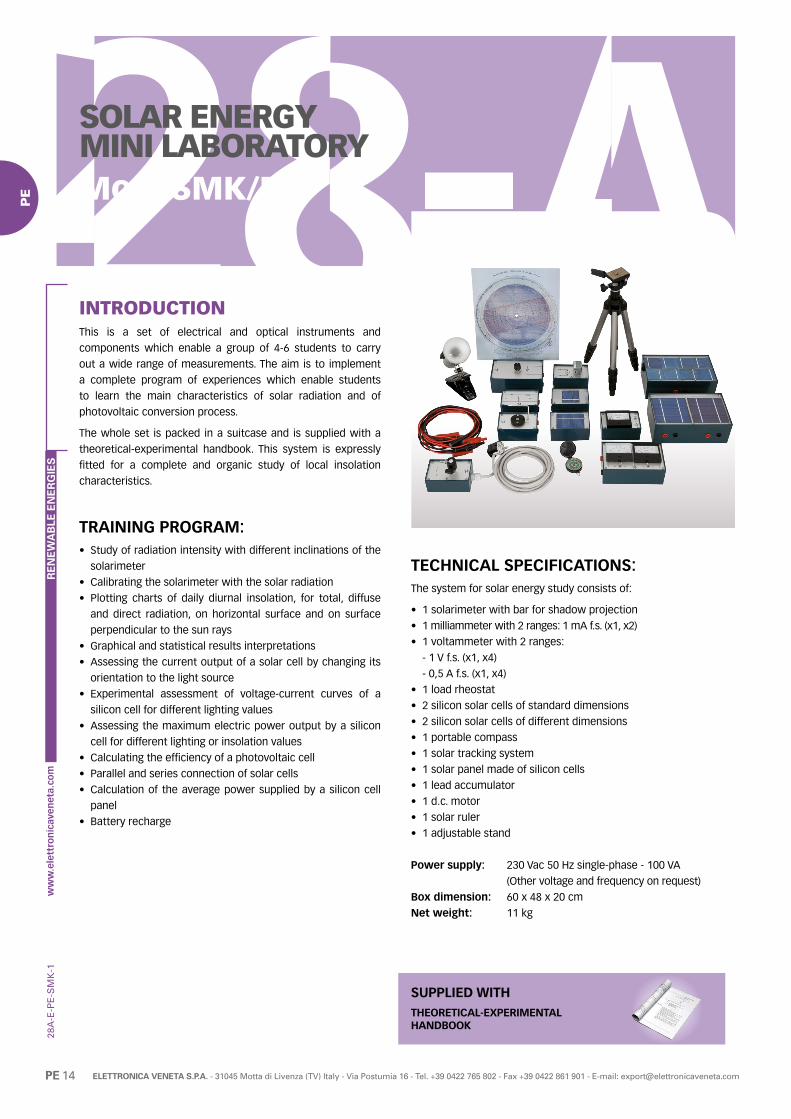
28A
-E-P
E
PE 14 ELETTRONICA VENETA S.P.A. - 31045 Motta di Livenza (TV) Italy - Via Postumia 16 - Tel. +39 0422 765 802 - Fax +39 0422 861 901 - E-mail: [email protected]
RE
NE
WA
BLE
EN
ER
GIE
S
PE
SOLAR ENERGY MINI LABORATORYMod. SMK/EV
INTRODUCTIONThis is a set of electrical and optical instruments and
components which enable a group of 4-6 students to carry
out a wide range of measurements. The aim is to implement
a complete program of experiences which enable students
to learn the main characteristics of solar radiation and of
photovoltaic conversion process.
The whole set is packed in a suitcase and is supplied with a
theoretical-experimental handbook. This system is expressly
fitted for a complete and organic study of local insolation
characteristics.
TRAINING PROGRAM:• Study of radiation intensity with different inclinations of the
solarimeter
• Calibrating the solarimeter with the solar radiation
• Plotting charts of daily diurnal insolation, for total, diffuse
and direct radiation, on horizontal surface and on surface
perpendicular to the sun rays
• Graphical and statistical results interpretations
• Assessing the current output of a solar cell by changing its
orientation to the light source
• Experimental assessment of voltage-current curves of a
silicon cell for different lighting values
• Assessing the maximum electric power output by a silicon
cell for different lighting or insolation values
• Calculating the efficiency of a photovoltaic cell
• Parallel and series connection of solar cells
• Calculation of the average power supplied by a silicon cell
panel
• Battery recharge
-SM
K-1
TECHNICAL SPECIFICATIONS:The system for solar energy study consists of:
• 1 solarimeter with bar for shadow projection
• 1 milliammeter with 2 ranges: 1 mA f.s. (x1, x2)
• 1 voltammeter with 2 ranges:
- 1 V f.s. (x1, x4)
- 0,5 A f.s. (x1, x4)
• 1 load rheostat
• 2 silicon solar cells of standard dimensions
• 2 silicon solar cells of different dimensions
• 1 portable compass
• 1 solar tracking system
• 1 solar panel made of silicon cells
• 1 lead accumulator
• 1 d.c. motor
• 1 solar ruler
• 1 adjustable stand
Power supply: 230 Vac 50 Hz single-phase - 100 VA
(Other voltage and frequency on request)
Box dimension: 60 x 48 x 20 cm
Net weight: 11 kg
THEORETICAL-EXPERIMENTALHANDBOOK
SUPPLIED WITH

28A
-E-P
E
PE 15ELETTRONICA VENETA S.P.A. - 31045 Motta di Livenza (TV) Italy - Via Postumia 16 - Tel. +39 0422 765 802 - Fax +39 0422 861 901 - E-mail: [email protected]
RE
NE
WA
BLE
EN
ER
GIE
S
PE
PHOTOVOLTAIC SYSTEM SIMULATORMod. SIM-PM/EV
INTRODUCTIONEducational simulator mod. SIM-PM/EV is designed to study
the operation of a stand-alone photovoltaic system (insulated
from the mains). Thanks to a photovoltaic panel, this type of
equipment collects and transforms the incident solar radiation,
so that it is available as electric energy to all users. The perfect
system operation is ensured by a battery charge controller and
by an inverter. The simulator enables to analyze the system
behavior depending on the battery charge level, the power
requested by users and the panel position; it also enables to
analyze the consequences of a disturbance on the system,
such as clouds or the breaking of a cell.
The simulator should necessarily be connected with a PC (not
included).
TRAINING PROGRAM:• Study of solar energy: photovoltaic effect
• Calculation of the average power developed by the sun on a
specific place
• Monocrystalline and polycrystalline silicon cells
• Energy balance of the panel, efficiency
• Devices for storing energy
• Batteries charge control
TECHNICAL SPECIFICATIONS:• Colour panel reproducing the photovoltaic system
• Board for data acquisition and control of output signals to
the actuators
• PC connection via USB cable
• 6 potentiometers to simulate the following analog inputs:
- solar radiation
- storage battery charge
- power requested by users
- panel inclination angle (referred to the horizontal surface)
- panel azimuth angle (referred to south direction)
- time of day
• 8 bar LEDs to simulate the following analog outputs:
- photovoltaic panel voltage
- panel output current
- battery voltage
- current supplied/absorbed by the battery
- current absorbed by the inverter
- solar power incident on the photovoltaic panel
-SIM
PM
-0
- power absorbed by users
- system efficiency
• 4 switches to simulate the following digital inputs:
- enabling system operation
- season (summer/winter)
- clouded sky
- breaking of a photovoltaic cell
• 3 LEDs to simulate the following digital outputs:
- alarm for low charge level of the storage battery
- alarm for inverter overload
- battery in charging or discharging phase
• Simulation program of photovoltaic system operation
Power supply: 230 Vac 50 Hz single-phase - 200 VA
(Other voltage and frequency on request)
Dimensions: 42 x 12 x 40 cm
Weight: 16 kg
THEORETICAL-EXPERIMENTALHANDBOOK
SUPPLIED WITH
REQUIRED
PERSONAL COMPUTER- NOT INCLUDED -

28A
-E-P
E
PE 16 ELETTRONICA VENETA S.P.A. - 31045 Motta di Livenza (TV) Italy - Via Postumia 16 - Tel. +39 0422 765 802 - Fax +39 0422 861 901 - E-mail: [email protected]
RE
NE
WA
BLE
EN
ER
GIE
S
PE


28A
-E-W
I
WI 2 ELETTRONICA VENETA S.P.A. - 31045 Motta di Livenza (TV) Italy - Via Postumia 16 - Tel. +39 0422 765 802 - Fax +39 0422 861 901 - E-mail: [email protected]
RE
NE
WA
BLE
EN
ER
GIE
S
WI
WIND ENERGY
Mod. Pag.
WIND POWER GENERATOR TRAINER WG-C/EVWG/EV WI 3
AEROGENERATOR WITH WIND TUNNEL TRAINER WIND-TU/EVWIND-TU2/EV WI 6
OFF-GRID WIND POWER PLANT TRAINER WG-EOG/EVWG-OG/EV WI 9
ON-GRID WIND POWER PLANT TRAINER WG-EGRID/EVWG-GRID/EV WI 11
WIND ENERGY GENERATION KIT WG-K/EV WI 13
CUT-AWAY WIND POWER GENERATOR WG-SEC/EV WI 14

28A
-E-W
I
WI 3ELETTRONICA VENETA S.P.A. - 31045 Motta di Livenza (TV) Italy - Via Postumia 16 - Tel. +39 0422 765 802 - Fax +39 0422 861 901 - E-mail: [email protected]
RE
NE
WA
BLE
EN
ER
GIE
S
WI
WIND POWER GENERATOR TRAINERMod. WG-C/EVMod. WG/EV (computerized version)
-WG
C-W
G-1
INTRODUCTIONEnergy saving and environmental pollution reduction are crucial
global issues. Using renewable energies as alternative sources
to fossil fuels can address both issues, with great benefits
especially in countries where traditional energy sources are
scarce.
Considering the above, this system enables experimental
investigation on the conversion of wind energy into electricity
by means of a wind power generator. The equipment is
manufactured using real components available on the market.
A video demonstration is available on Elettronica Veneta YouTube channel
Scan
cod
e to
wat
ch
DESCRIPTIONSystem configuration: stand-alone (isolated from the grid)
The system consists of:
A) Horizontal axis wind power generator including a
microprocessor-based controller
B) Table top control panel including:
B.1) Sinewave inverter
B.2) Electric loads
B.3) Electric instrumentation for detecting the energy flows
in the different branches of the circuit
B.4) Data acquisition board with USB interface for PC
connection (WG/EV only)
C) Buffer battery
D) Wind speed and direction sensor (WG/EV only)
Relevant features:
• The trainer can operate with or without the wind
• The wind generator can be used both outdoors and indoors.
In the last case, the indoor operation device WG-I/EV is
required (optional item - refer to the end of this data sheet)
• In case of outdoors operation, the wind generator follows the
wind direction being able to rotate around its vertical axis.
A
B
C
B.1
B.3
FRONT
BACK
B.2
D
B.4

28A
-E-W
I
WI 4 ELETTRONICA VENETA S.P.A. - 31045 Motta di Livenza (TV) Italy - Via Postumia 16 - Tel. +39 0422 765 802 - Fax +39 0422 861 901 - E-mail: [email protected]
RE
NE
WA
BLE
EN
ER
GIE
S
WI
Operating principle:
• In case there is no wind blowing, all the energy consumed by
the user (loads) is taken from the battery.
• In case there is wind blowing but no load is connected, all
the energy produced by the system charges the battery.
• In case there are both wind blowing and loads, the energy
produced by the system partially charges the battery and
partially powers the loads.
• When the consumption is higher than the power available
from the wind, the power surplus is given by the battery.
TRAINING PROGRAM• Components of a stand-alone wind power system for
electricity production
• Effect of the wind speed on the generator output voltage (*)
• Effect of applied load variation on the electric power
produced by the wind generator
• Wind generator energy conversion efficiency (*)
• Battery charging system management
• Operation and efficiency of a DC/AC inverter
• Connection to wind power generator indoor operation
device WG-I/EV (optional item - refer to the end of this data
sheet) for wind generator characteristic curve construction
(*) For WG-C/EV Cup vane air velocity meter THAC (optional item - refer to the end of this data sheet) required
TECHNICAL SPECIFICATIONSHorizontal axis wind power generator• Aluminium generator body
• 3 composite material blades (rotor diameter 1,17 m):
- Energy output: approx. 30 kWh/month at 5,8 m/s (13 mph)
average wind speed
- Startup Wind Speed: 3,6 m/s (8 mph)
- Survival wind speed: 49,2 m/s (110 mph)
• Permanent magnet brushless alternator
• Microprocessor-based controller:
- Output voltage: 12 Vdc
- Overspeed protection: electronic torque control
• Stainless steel supporting pole:
- Length 1,5 m
- Outer diameter: 48,1 mm
- Mounting kit
Table top control panel• Steel structure with:
- Front side: comprehensive colored diagram of the system
- back side: AC loading system consisting of 5 30 W
(equivalent) switchable lamps
• Inverter:
- continuous output power: 600 W
- peak output power: 1200 W
- input voltage: 12 Vdc
- output voltage: 230 Vac - 50 Hz
- output waveform: modified sine wave
- stop for low battery charge
- protection against overload, short circuit, overtemperature
• Instrumentation:
- digital voltmeter for DC parameters
- digital ammeter for DC parameters
- multifunction instrument, microprocessor-based,
for AC parameters
• Socket for connection to the spotlight ACL220V (optional item - refer to the end of this data sheet)
• Ø 4 mm safety holes for connection to the lamp DCL12V
(optional item - refer to the end of this data sheet)
Buffer battery• Rated voltage: 12 Vdc
• Capacity: 100 Ah
Wind speed and direction sensor (WG/EV only) for measuring
and transmitting wind speed and direction to the control panel.
• Wind speed transducer type: Hall effect sensor
• Wind direction transducer type: 20 Kohm potentiometer
• Wind speed range: 0 ÷ 40 m/s
• Wind direction range: 0 ÷ 360°
PC data acquisition (WG/EV only)• The unit includes a data acquisition board with USB interface
for connection to PC and voltage and current converters.
• A specific software (developed with LabView) is supplied to
monitor the system parameters.
• Parameters displayed:
- All DC and AC parameters
- Wind speed and direction
No wind is blowing
Wind is blowing
CTRL INV
BATTERY
LOAD
CTRL INV
BATTERY
LOAD
-WG
C-W
G-1

28A
-E-W
I
WI 5ELETTRONICA VENETA S.P.A. - 31045 Motta di Livenza (TV) Italy - Via Postumia 16 - Tel. +39 0422 765 802 - Fax +39 0422 861 901 - E-mail: [email protected]
RE
NE
WA
BLE
EN
ER
GIE
S
WI
• The software enables to:
- Calculate wind energy conversion efficiency
- Visualize the trend of the wind speed and the energy
flows to and from buffer battery, inverter and wind power
generator
- Draw the wind power generator characteristic curve output
power vs wind speed to find out the point of wind power
generator maximum performance
- Save the exercises data for future analysis or project work
Power supply: 230 Vac 50 Hz single-phase - 100 VA
(Other voltage and frequency on request)
Dimensions:Control panel: 92 x 46 x 72 cm
Wind generator rotor diameter: 117 cm
Net weight: 110 kg
-WG
C-W
G-1
The aerogenerator coupled to the optional indoor device WG-I/EV
REQUIREDPERSONAL COMPUTER
- NOT INCLUDED -(WG/EV only)
OPTIONAL (REF. ACCESS. AND INSTRUMENTS)
ELECTRIC BATTERY CHARGERMod. EBCHTo recharge the buffer battery after a prolonged period of inactivity of the system
CUP VANE AIR VELOCITY METERMod. THAC (WG-C/EV only)
For the calculation of the wind energy into electric energy conversion efficiency
WIND POWER GENERATOR INDOOR OPERATION DEVICE Mod. WG-I/EVTo operate the aerogenerator indoor
SPOTLIGHT Mod. ACL220VTo be used as 230 Vac electric load
LAMP Mod. DCL12VTo be used as 12 Vdc electric load
THEORETICAL-EXPERIMENTALHANDBOOK
SUPPLIED WITH
The aerogenerator installed outdoors at a school facility

28A
-E-W
I
WI 6 ELETTRONICA VENETA S.P.A. - 31045 Motta di Livenza (TV) Italy - Via Postumia 16 - Tel. +39 0422 765 802 - Fax +39 0422 861 901 - E-mail: [email protected]
RE
NE
WA
BLE
EN
ER
GIE
S
WI
-WIN
DT
U-W
IND
TU
2-0
INTRODUCTIONEnergy saving and environmental pollution reduction are crucial
global issues. Using renewable energies as alternative sources
to fossil fuels can address both issues, with great benefits
especially in countries where traditional energy sources are
scarce.
Considering the above, this system enables experimental
investigation on the conversion of wind energy into electricity by
means of a wind power generator. The equipment is manufactured
using real components available on the market and includes a
wind source (variable speed axial fan).
A video demonstration is available on Elettronica Veneta YouTube channel
Scan
cod
e to
wat
ch
DESCRIPTIONSystem configuration: stand-alone (isolated from the grid)
The system consists of:
A) Axial fan with frequency converter
B) Horizontal axis wind power generator including a
microprocessor-based controller
C) Sinewave inverter
D) Electric instrumentation for detecting the energy flow from
the aerogenerator
E) Buffer battery
F) Data acquisition board with USB interface for PC connection
(WIND-TU2/EV only)
G) Air speed sensor (WIND-TU2/EV) or portable anemometer
(WIND-TU/EV)
Relevant features:
• The wind speed is adjustable
• The aerogenerator orientation is adjustable depending
to the wind direction
AB
C
D
G
F
E
AEROGENERATOR WITH WIND TUNNEL TRAINERMod. WIND-TU/EVMod. WIND-TU2/EV (computerized version)

28A
-E-W
I
WI 7ELETTRONICA VENETA S.P.A. - 31045 Motta di Livenza (TV) Italy - Via Postumia 16 - Tel. +39 0422 765 802 - Fax +39 0422 861 901 - E-mail: [email protected]
RE
NE
WA
BLE
EN
ER
GIE
S
WI
• Socket for connection to the spotlight ACL220V (optional item - refer to the end of this data sheet)
Switch board• E.L.C.B. and T.M.C.B.
• Emergency pushbutton
• Instrumentation:
- analog voltmeter, range 0 ÷ 20 Vdc, for measuring
the aerogenerator voltage output
- analog ammeter, range 0 ÷ 20 A, for measuring
the aerogenerator dc current output
Buffer battery• Rated voltage: 12 Vdc
• Capacity: 27 Ah
Air speed sensor (WIND-TU2/EV) or portable anemometer (WIND-TU/EV) for measuring the air speed inside the tunnel
• Transducer type: thin film
• Range: 0 ÷ 15 m/s
PC data acquisition (WIND-TU2/EV only)• The trainer includes a data acquisition board with USB
interface for connection to PC and voltage and current
converters.
• A specific software (developed with LabView) is supplied to
monitor the system parameters.
• Parameters displayed:
- All DC and AC parameters powering the electric motor
- Wind speed and direction
Operating principle:
• In case no load is connected to the system, all the produced
energy charges the battery.
• In case some electric loads are connected to the system, the
produced energy partially charges the battery and partially
powers the loads.
• When the consumption is higher than the power available
from the wind, the power surplus is given by the battery.
TRAINING PROGRAM• Physical principles whereby wind power is transformed into
electrical power
• Study of brushless generators
• Understanding and use of the Country Statistics related to
the specific place where the wind generator is installed
• Calculation of average generated power
• Distinctive features
• Installation
• Energy balance and efficiency
• Battery charge control
• Study of energy flows and related measurement devices
TECHNICAL SPECIFICATIONSWheeled steel structure with:• A wind tunnel with two transparent observation windows to
prevent contact with the moving parts
• A comprehensive colored diagram of the system
Wind source consisting of:• Axial fan with three phase electric motor, rated power:
2,2 kW
• Frequency converter, applicable motor: 2,2 kW
Horizontal axis wind power generator:• Aluminium generator body, with internal parts partially
exposed
• 3 composite material blades (rotor diameter approx. 0,70 m)
- Startup wind speed: 3,6 m/s (8 mph)
- Survival wind speed: 49,2 m/s (110 mph)
• Permanent magnet brushless alternator
• Microprocessor-based controller
- Output voltage: 12 Vdc
- Overspeed protection: electronic torque control
• Aerogenerator axial orientation manual adjusting device
Inverter• Continuous output power: 600 W
• Peak output power: 1200 W
• Input voltage: 12 Vdc
• Output voltage: 230 Vac - 50 Hz
• Output waveform: modified sine wave
• Stop for low battery charge
• Protection against overload, short
circuit, overtemperature
-WIN
DT
U-W
IND
TU
2-0
CTRL INV
BATTERY
LOAD
VARIABLES
DIRECTION
SPEED

28A
-E-W
I
WI 8 ELETTRONICA VENETA S.P.A. - 31045 Motta di Livenza (TV) Italy - Via Postumia 16 - Tel. +39 0422 765 802 - Fax +39 0422 861 901 - E-mail: [email protected]
RE
NE
WA
BLE
EN
ER
GIE
S
WI
• The software enables to:
- Calculate wind energy conversion efficiency
- Visualize the trend of the energy flows to and from buffer
battery, inverter and wind power generator
- Draw the wind power generator characteristic curve output
power vs wind speed
- Draw the wind power generator characteristic curve
efficiency vs wind speed
- Save the exercises data for future analysis or project work
Power supply: 400 Vac 50 Hz three-phase - 2000 VA
(Other voltage and frequency on request)
Dimensions: 170 x 85 x 165 cm
Weight: 230 kg
-WIN
DT
U-W
IND
TU
2-0
Wind tunnel detail
THEORETICAL-EXPERIMENTALHANDBOOK
SUPPLIED WITH
OPTIONAL (REF. ACCESS. AND INSTRUMENTS)
ELECTRIC BATTERY CHARGERMod. EBCHTo recharge the buffer battery after a prolonged period of inactivity of the system
SPOTLIGHT Mod. ACL220VTo be used as 230 Vac electric load
REQUIREDPERSONAL COMPUTER
- NOT INCLUDED -(WIND-TU2/EV only)

28A
-E-W
I
WI 9ELETTRONICA VENETA S.P.A. - 31045 Motta di Livenza (TV) Italy - Via Postumia 16 - Tel. +39 0422 765 802 - Fax +39 0422 861 901 - E-mail: [email protected]
RE
NE
WA
BLE
EN
ER
GIE
S
WI
• In case there is no wind blowing, all the energy consumed by
the user (loads) is taken from the battery
• In case there is wind blowing but no load is connected, all
the energy produced by the system charges the battery
• In case there are both wind blowing and loads, the energy
produced by the system partially charges the battery and
partially powers the loads
• When the consumption is higher than the power available
from the wind, the power surplus is given by the battery
OFF-GRID WIND POWER PLANT TRAINERMod. WG-EOG/EVMod. WG-OG/EV (computerized vers.)
-WG
EOG
-WG
OG
-1
INTRODUCTIONEnergy saving and environmental pollution reduction are crucial
global issues. Using renewable energies as alternative sources
to fossil fuels can address both issues, with great benefits
especially in countries where traditional energy sources are
scarce.
Considering the above, this system enables experimental
investigation on the conversion of wind energy into electricity
by means of a wind power generator. The equipment is
manufactured using real components available on the market.
DESCRIPTIONSystem configuration: stand-alone (isolated from the grid)
The system consists of:A) Horizontal axis wind power generator
B) Table top control panel including:
B.1) Charge regulator
B.2) Electric load
B.3) Electric instrumentation for detecting the energy flows
in the different branches of the circuit
B.4) Data acquisition board with USB interface for PC
connection (WG-OG/EV only)
C) Buffer battery
D) Wind speed and direction sensor (WG-OG/EV only)
Relevant features:• To operate the wind generator the indoor operation device
WG-IE is required (refer to the end of this data sheet)
A
BB.3
CB.2
B.1
Operating principle:
CTRL
BATTERY
LOAD
CTRL
BATTERY
LOAD
No wind is blowing
Wind is blowing

28A
-E-W
I
WI 10 ELETTRONICA VENETA S.P.A. - 31045 Motta di Livenza (TV) Italy - Via Postumia 16 - Tel. +39 0422 765 802 - Fax +39 0422 861 901 - E-mail: [email protected]
RE
NE
WA
BLE
EN
ER
GIE
S
WI
• The software enables to:
- Calculate energy conversion efficiency
- Visualize the trend of the wind speed and direction and
the energy flows to and from wind generator, buffer battery
and load
- Save the exercises data for future analysis or project work
Power supply: 230 Vac 50 Hz single-phase - 50 VA
(Other voltage and frequency on request)
Dimensions: Control panel 40 x 40 x 15 cm
Wind gen. rotor diameter 51 cm
Tot weight: 50 kg
TRAINING PROGRAM• Components of a stand-alone wind power system for
electricity production
• Effect of the wind speed on the generator output voltage (*)
• Wind generator energy conversion efficiency (*)
• Battery charging system management
• Use of wind power generator indoor operation device
WG-IE (required - refer to the end of this data sheet) for wind
generator characteristic curve construction
(*) For WG-EOG/EV the cup vane air velocity meter THAC
(optional item - refer to the end of this data sheet) is required
TECHNICAL SPECIFICATIONSHorizontal axis wind power generator• 6 blades with outer ring (turbine diameter 510 mm):
- Cut in Wind Speed: 3 m/s
- Nominal power output: 49 W at 15 m/s
• Low friction 3 phase, brushless alternator
- Output nominal voltage: 12 Vdc
• Metal supporting frame with protecting grid
Table top control panel• Metal structure with complete color synoptic diagram
• Charge regulator:
- Pulse Width Modulation (PWM) regulation
- LED indicators for battery voltage levels and charging status
• Electric load: 12 Vdc lamp
• Instrumentation:
- Digital voltmeter
- Digital ammeter
Buffer battery• Rated voltage: 12 Vdc
• Capacity: 12 Ah
Sensors (WG-OG/EV only)• Wind speed and direction sensor for measuring and
transmitting wind speed and direction to the control panel.
- Wind speed range: 0 ÷ 40 m/s
- Wind direction range: 0 ÷ 360°
PC data acquisition (WG-OG/EV only)• The trainer is supplied with data acquisition board with USB
interface for connection to PC
• A specific software (developed with LabView) is supplied to
monitor the system parameters
• The visualized parameters are:
- All DC parameters
- Wind speed and direction
-WG
EOG
-WG
OG
-1 THEORETICAL-EXPERIMENTAL HANDBOOK
SUPPLIED WITH
REQUIRED
PERSONAL COMPUTER- NOT INCLUDED -(WG-OG/EV only)
WIND POWER GENERATOR INDOOR OPERATION DEVICE Mod. WG-IETo operate the aerogenerator
OPTIONAL (REF. ACCESS. AND INSTRUMENTS)
CUP VANE AIR VELOCITY METERMod. THAC (WG-EOG/EV only)
For the calculation of the wind energy into electric energy conversion efficiency

28A
-E-W
I
WI 11ELETTRONICA VENETA S.P.A. - 31045 Motta di Livenza (TV) Italy - Via Postumia 16 - Tel. +39 0422 765 802 - Fax +39 0422 861 901 - E-mail: [email protected]
RE
NE
WA
BLE
EN
ER
GIE
S
WI
DESCRIPTIONSystem configuration: grid-connected
The system consists of:A) Horizontal axis wind power generator
B) Table top control panel including:
B.1) Grid-Tie Inverter
B.2) Electric load
B.3) Electric instrumentation for detecting the energy flows
in the different branches of the circuit
B.4) PC data acquisition system (WG-GRID/EV only)
C) Wind speed sensor (WG-GRID/EV only)
D) Wind direction sensor (WG-GRID/EV only)
Relevant features:• To operate the wind generator the indoor operation device
WG-IE is required (refer to the end of this data sheet)
ON-GRID WIND POWER PLANT TRAINERMod. WG-EGRID/EVMod. WG-GRID/EV (computerized vers.)
-WG
EG
RID
-WG
GR
ID-0
INTRODUCTIONEnergy saving and environmental pollution reduction are
crucial global issues. Using wind power generators can address
both issues.
This system enables experimental investigation on the
operation of a wind power generator. The equipment is
manufactured using real components available on the market.
A
B
B.1
B.2B.3

28A
-E-W
I
WI 12 ELETTRONICA VENETA S.P.A. - 31045 Motta di Livenza (TV) Italy - Via Postumia 16 - Tel. +39 0422 765 802 - Fax +39 0422 861 901 - E-mail: [email protected]
RE
NE
WA
BLE
EN
ER
GIE
S
WI
Sensors (WG-GRID/EV only)• 1 wind speed and direction sensor for measuring and
transmitting the wind speed and direction to the control panel
- Speed range: 0 ÷ 40 m/s
- Direction range: 0 ÷ 360°
PC data acquisition (WG-GRID/EV only)• All instruments and sensors, as described above, are
connected in Modbus network. This network is connected to
a PC via an adapter RS485/USB
• A specific software (developed with LabView) is supplied to
monitor the system parameters
• Parameters displayed:
- All DC / AC parameters
- Wind speed and direction
• The software enables to:
- Calculate energy conversion efficiency
- Visualize the trend of the wind speed and direction and
the energy flows to and from wind power generator, grid
and load
- Save the exercises data for future analysis or project work
Power supply: 230 Vac 50 Hz single-phase - 50 VA
(Other voltage and frequency on request)
Dimensions: Control panel: 65 x 40 x 10 cm
Wind gen. rotor diameter: 51 cm
Tot weight: 35 kg
-WG
EG
RID
-WG
GR
ID-0
Operating principle:
• In case the user consumption is lower than the available energy
from the wind generator, the excess power is fed to the grid
• On the contrary, when consumption is higher than the
available energy, the additionally required energy is supplied
by the grid
TRAINING PROGRAM• Components of a grid connected wind power system for
electricity production
• Effect of the wind speed on the generator output voltage (*)
• Wind generator energy conversion efficiency (*)
• Interconnection of wind energy to the public grid
• Operation and efficiency of a DC/AC inverter
• Use of wind power generator indoor operation device
WG-IE (required - refer to the end of this data sheet) for wind
generator characteristic curve construction
(*) For WG-EGRID/EV the cup vane air velocity meter THAC
(optional item - refer to the end of this data sheet) is required
TECHNICAL SPECIFICATIONSHorizontal axis wind power generator• 6 blades with outer ring (turbine diameter 510 mm):
- Cut in Wind Speed: 3 m/s
- Nominal power output: 49 W at 15 m/s
• Low friction 3 phase, brushless alternator
- Output nominal voltage: 12 Vdc
• Metal supporting frame with protecting grid
Table top control panel• Metal structure with complete color synoptic diagram
• Grid tie power inverter:
- Rated AC Output Power: 450 W
- AC Output Voltage: 230 V
- AC Output Frequency: 50 Hz
- DC Input Voltage Range: 11 ÷ 28 V
- Output Current Waveform: Pure Sine-wave
- MPPT Function
- Protection vs: Over Current, Over Temperature, Reverse
Polarity, Anti-Island
• Electric load: 230 V lamp
• Socket for connection to the spotlight ACL220V (optional item - refer to the end of this data sheet)
• Microprocessor-based instruments for DC/AC parameters
INV
LOAD
GRID
OPTIONAL (REF. ACCESS. AND INSTRUMENTS)
CUP VANE AIR VELOCITY METERMod. THAC (WG-EGRID/EV only)
For the calculation of the wind energy into electric energy conversion efficiency
SPOTLIGHT Mod. ACL220VTo be used as 230 Vac electric load
THEORETICAL-EXPERIMENTAL HANDBOOK
SUPPLIED WITH
REQUIRED
PERSONAL COMPUTER- NOT INCLUDED -
(WG-GRID/EV only)
WIND POWER GENERATOR INDOOR OPERATION DEVICE Mod. WG-IETo operate the aerogenerator

28A
-E-W
I
WI 13ELETTRONICA VENETA S.P.A. - 31045 Motta di Livenza (TV) Italy - Via Postumia 16 - Tel. +39 0422 765 802 - Fax +39 0422 861 901 - E-mail: [email protected]
RE
NE
WA
BLE
EN
ER
GIE
S
WI
WIND ENERGYGENERATION KITMod. WG-K/EV
INTRODUCTIONThis equipment features the typical configuration of a horizontal
axis wind power generator, used to convert the wind kinetic
energy directly into electric energy.
TRAINING PROGRAM• Components of a stand-alone wind system for electricity production
• Wind generator energy conversion efficiency (*)
• Battery charging system management
• Connection to wind power generator indoor operation device
WG-IM/EV (optional item – refer to the end of this data
sheet) for wind generator characteristic curve construction
(*) Cup vane air velocity meter THAC (optional item – refer to
the end of this data sheet) required
TECHNICAL SPECIFICATIONSHorizontal axis wind power generator• Aluminium generator body
• 3 composite material blades (rotor diameter 1,17 m):
- Energy output: approx. 30 kWh/month at 5,8 m/s (13 mph)
average wind speed
- Startup Wind Speed: 3,6 m/s (8 mph)
- Survival wind speed: 49,2 m/s (110 mph)
• Permanent magnet brushless alternator
• Microprocessor-based controller:
- Output voltage: 12 Vdc
- Overspeed protection: electronic torque control
• Stainless steel supporting pole:
- Length 1,5 m
- Outer diameter: 48,1 mm
- Mounting kit
Buffer battery:• Rated voltage: 12 Vdc
• Capacity: 100 Ah
Inverter:• Continuous output power: 600 W
• Output peak power: 1200 W
• Input voltage: 12 Vdc
• Output voltage: 230 Vac - 50 Hz
• Output waveform: modified sine wave
• Stop for low battery charge
• Protection against: overload, short circuit, overtemperature
Clamp meter:• Voltage range (ac/dc): 0 to 600 V
• Current range (ac/dc): 0 to 200 A
-WG
K-3
DimensionsRotor diameter: 117 cm
Net weight: 70 kg
THEORETICAL-EXPERIMENTALHANDBOOK
SUPPLIED WITH
OPTIONAL (REF. ACCESS. AND INSTRUMENTS)
ELECTRIC BATTERY CHARGERMod. EBCHTo recharge the buffer battery after a prolonged period of inactivity of the system
CUP VANE AIR VELOCITY METER Mod. THACFor the calculation of the wind energy into electric energy conversion efficiency
WIND POWER GENERATOR INDOOR OPERATION DEVICE Mod. WG-IM/EVTo operate the aerogenerator indoor
SPOTLIGHT Mod. ACL220VTo be used as 230 Vac electric load
LAMP Mod. DCL12VTo be used as 12 Vdc electric load

28A
-E-W
I
WI 14 ELETTRONICA VENETA S.P.A. - 31045 Motta di Livenza (TV) Italy - Via Postumia 16 - Tel. +39 0422 765 802 - Fax +39 0422 861 901 - E-mail: [email protected]
RE
NE
WA
BLE
EN
ER
GIE
S
WI
CUT-AWAY WIND POWER GENERATORMod. WG-SEC/EV
INTRODUCTIONThe equipment enables a detailed study of a micro wind power
generator suitable for terrestrial or marine environment; it is a
real size sectioned and painted model which shows its internal
components and the operation principle.
The equipment includes:
• Support structure
• Lifting handles
• Sectioned horizontal axis wind power generator
TECHNICAL SPECIFICATIONS:
Horizontal axis wind power generator• Aluminium generator body
• 3 composite material blades, rotor diameter: 1,17 m
- Energy output: approx. 30 kWh/month at 5,8 m/s (13 mph)
average wind speed
- Startup Wind Speed: 3,6 m/s (8 mph)
- Survival wind speed: 49,2 m/s (110 mph)
• Permanent magnet brushless alternator
• Microprocessor-based controller:
- Output voltage: 12 Vdc
- Overspeed protection: electronic torque control
Dimensions: 80 x 40 x 60 cm
Net weight: 20 kg
-WG
SE
C-0


28A
-E-H
E
HE 2 ELETTRONICA VENETA S.P.A. - 31045 Motta di Livenza (TV) Italy - Via Postumia 16 - Tel. +39 0422 765 802 - Fax +39 0422 861 901 - E-mail: [email protected]
RE
NE
WA
BLE
EN
ER
GIE
S
HE
HYDROELECTRIC ENERGY
Mod. Pag.
MINI HYDROELECTRIC POWER PLANT TRAINERWPP-E/EVWPP/EV HE 3
HYDROELECTRIC ENERGY GENERATION KIT WPP-K/EV HE 6

28A
-E-H
E
HE 3ELETTRONICA VENETA S.P.A. - 31045 Motta di Livenza (TV) Italy - Via Postumia 16 - Tel. +39 0422 765 802 - Fax +39 0422 861 901 - E-mail: [email protected]
RE
NE
WA
BLE
EN
ER
GIE
S
HE
MINI HYDROELECTRIC POWER PLANT TRAINERMod. WPP-E/EVMod. WPP/EV (computerized version)
INTRODUCTIONEnergy saving and environmental pollution reduction are crucial
global issues. Using renewable energies as alternative sources
to fossil fuels can address both issues, with great benefits
especially in countries where traditional energy sources are
scarce.
Considering the above, this system enables experimental
investigation on the conversion of hydraulic energy into electricity
by means of a Pelton turbine. The system configuration is stand-
alone (isolated from the grid). The equipment is manufactured
using real components available on the market.
-WP
PE
-WP
P-1
DESCRIPTIONThe system consists of:
A) Mini hydroelectric power plant mounted on castors including:
A.1) Turbine-generator unit with water distributor
A.2) Variable speed centrifugal pump
A.3) Stainless steel water tank
A.4) Flow rate sensor (WPP/EV) or flow meter
(WPP-E/EV)
A.5) Pressure sensor (WPP/EV) and pressure gauge
B) Table top control panel including:
B.1) Controller with air dissipation system
B.2) Sinewave inverter
B.3) Electric loads
B.4) Electric instrumentation for detecting the energy flows
in different branches of the circuit
B.5) Data acquisition board with USB interface for PC
connection (WPP/EV only)
A video demonstration is available on Elettronica Veneta YouTube channel
Scan
cod
e to
wat
ch
A
B
B.2
B.4
A.1
A.3
A.2
B.5
FRONT
BACK
B.3
B
B.1A.5
A.4

28A
-E-H
E
HE 4 ELETTRONICA VENETA S.P.A. - 31045 Motta di Livenza (TV) Italy - Via Postumia 16 - Tel. +39 0422 765 802 - Fax +39 0422 861 901 - E-mail: [email protected]
RE
NE
WA
BLE
EN
ER
GIE
S
HE
Relevant features:• The turbine-generator unit is equipped with a 6-jet water
distribution system. In correspondence of each jet, a nozzle
or a cap can be installed, thus modifying the geometry
with which the water hits the turbine. Nozzles of different
diameter are available.
• 3 jets can be externally intercepted
• The turbine-generator unit can be disconnected from the
system, for drawing the external characteristic curve. In this
case the portable rheostat PRH-3 (optional item - refer to
the end of this data sheet) is required
Operating principle:
• If no load is connected to the system, all the produced
energy is dissipated in air or used to charge the battery pack
SOLBA (optional item - refer to the end of this data sheet)
• In case some loads are connected to the system, the produced
energy partially feeds the loads and partially charges the
battery pack (optional item) or is dissipated in air.
• When the consumption is higher than the power available
from the water, the power surplus is given by the battery
pack (optional item).
TRAINING PROGRAM• Components of a stand-alone hydraulic system for electricity
production
• Effect of water pressure variation on the electric power
produced by the generator
• Effect of applied load variation on the electric power
produced by the generator
• Hydraulic energy conversion efficiency
• Battery charging system management
• Operation and efficiency of a DC/AC inverter
• Connection to portable rheostat PRH-3 (optional item –
refer to the end of this data sheet) for generator external
characteristic curve construction
TECHNICAL SPECIFICATIONSMini hydroelectric power plant mounted on castors:• Turbine-generator unit:
- AISI 304 stainless steel Pelton turbine, d = 100 mm,
blade no. = 20
- 6-jet distributor
- 3 jets can be externally intercepted
- permanent magnets synchronous generator
- rated voltage: 25 Vac three phase
- frequency: 200 Hz
- nominal electric power output: 0,5 kW (height 30 m, flow
rate 3 l/s)
- generator speed: 3000 rpm
• AISI 304 stainless steel horizontal axis multistage monoblock
pump:
- power: 0,75 kW
- maximum flow rate: 10 m3/h
- maximum head: 43 m
- frequency converter for rpm adjustment
• AISI 304 stainless steel water tank, capacity: 250 liters
• AISI 304 stainless steel hydraulic circuit feeding the turbine-
generator unit with:
- ball valve and dial vacuum gauge, range: -1 ÷ 5 bar,
at pump suction
- dial pressure gauge, range: 0 ÷ 6 bar, and gate valve
at pump discharge
- ball valve at distributor-tank by-pass
Flow rate sensor (WPP-E/EV only) for measuring and
transmitting the water flow rate to the control panel
• Transducer type: rotating vane
• Range: 25 ÷ 250 liters/minute
Variable area flow meter (WPP-E/EV only)• Range: 1000 ÷ 12000 liters/hour
Pressure sensor (WPP-E/EV only) for measuring and
transmitting the water pressure to the control panel
• Transducer type: piezoresistive
• Range: 0 ÷ 16 bar
Table top control panel:• Steel structure with:
- front side: comprehensive colored diagram of the system
- back side: AC loading system consisting of 5 30 W (equivalent)
switchable lamps
• Controller
- Rectifier
- Air dissipation system
- Digital voltmeter for the DC parameters
- Digital ammeter for the DC parameters
• Inverter
- continuous output power: 600 W
- peak output power: 1200 W
- input voltage: 24 Vdc
- output voltage: 230 Vac - 50 Hz
- output waveform: modified sine wave
- stop for low battery charge
- protection against overload, short circuit, overtemperature
• Instrumentation
- multifunction instruments, microprocessor-based,
for AC parameters
• Socket for connection to the spotlight ACL220V (optional item - refer to the end of this data sheet)
• Ø 4 mm safety holes for connection to the portable rheostat
PRH-3 (optional item - refer to the end of this data sheet)
• Ø 4 mm safety holes for connection to the lamp DCL24V
(optional item - refer to the end of this data sheet)
-WP
PE
-WP
P-1
CTRL INV
OPTIONALBATTERY
LOAD
TURBINE-GENERATOR
UNIT

28A
-E-H
E
HE 5ELETTRONICA VENETA S.P.A. - 31045 Motta di Livenza (TV) Italy - Via Postumia 16 - Tel. +39 0422 765 802 - Fax +39 0422 861 901 - E-mail: [email protected]
RE
NE
WA
BLE
EN
ER
GIE
S
HE
PC data acquisition (WPP/EV only)• The trainer includes a data acquisition board with USB interface
for connection to PC and voltage and current converters.
• A specific software (developed with LabView) is supplied to
monitor the system parameters.
• Parameters displayed:
- All DC and AC parameters
- Water pressure and flow rate
• The software enables to:
- Calculate the hydraulic energy conversion efficiency
- Visualize the energy flows to and from turbine-generator
unit, battery pack (if present) and inverter
- Draw the characteristic curve efficiency / flow rate to find
out the point of maximum performance of the turbine-
generator unit
- Save the exercises data for future analysis or project work
Power supply: 230 Vac 50 Hz single-phase - 1000 VA
(Other voltage and frequency on request)
Dimensions: Control panel: 92 x 46 x 72 cm
Mini hydroelectric station: 100 x 80 x 130 cm
Weight: 170 kg
-WP
PE
-WP
P-1
Connection of rheostat mod. PRH-3 (optional item) to the control panel to draw the generator external characteristic curve.
Detail of Pelton turbine and distributors
THEORETICAL-EXPERIMENTALHANDBOOK
SUPPLIED WITH
REQUIREDPERSONAL COMPUTER
- NOT INCLUDED -(WPP/EV only)
OPTIONAL (REF. ACCESS. AND INSTRUMENTS)
PORTABLE RHEOSTAT Mod. PRH-3To draw the external characteristic curve of the generator
SPOTLIGHT Mod. ACL220VTo be used as 230 Vac electric load
LAMP Mod. DCL24VTo be used as 24 Vdc electric load
BATTERY PACK Mod. SOLBATo store the generated electricity

28A
-E-H
E
HE 6 ELETTRONICA VENETA S.P.A. - 31045 Motta di Livenza (TV) Italy - Via Postumia 16 - Tel. +39 0422 765 802 - Fax +39 0422 861 901 - E-mail: [email protected]
RE
NE
WA
BLE
EN
ER
GIE
S
HE
HYDROELECTRIC ENERGY GENERATION KITMod. WPP-K/EV
-WP
PK
-4
INTRODUCTIONThis equipment, expressly designed for educational purposes, is
an example of use of a Pelton hydraulic turbine for the production
of electric power in mini plants driven by small streams.
TRAINING PROGRAM• Study of hydroelectric power
• Power as function of water flow rate and difference in height
of the hydraulic pipe
• Head losses
• Electric power output
• Plant efficiency
TECHNICAL SPECIFICATIONSMini hydroelectric plant mounted on castors• Turbine-generator set:
- stainless steel Pelton turbine
- 6-jet distributor, 3 of which can be externally intercepted- permanent magnets synchronous generator- rated voltage: 25 Vac three phase- frequency: 200 Hz- nominal electric power output: 0,5 kW (height 30 m, flow
rate 3 l/s)- generator speed: 3000 rpm
- Ø 4 mm safety holes for connection to portable rheostat
PRH-3 (optional item – refer to the end of this data sheet)
• AISI 304 stainless steel horizontal axis multistage monoblock
pump:
- power: 0,75 kW
- maximum flow rate: 10 m3/h
- maximum head: 43 m
- frequency converter for rpm adjustment
• Water tank
• Flow meter, pressure gauge and gate valve on the pump
discharge line
Controller• Rectifier
• Air dissipation system
• Digital voltmeter for the DC parameters
• Digital ammeter for the DC parameters
• Ø 4 mm safety holes for connection to the generator, to the
lamp DCL24V (optional item - refer to the end of this data
sheet) and to the battery pack SOLBA (optional item - refer
to the end of this data sheet)
THEORETICAL-EXPERIMENTALHANDBOOK
SUPPLIED WITH
OPTIONAL (REF. ACCESS. AND INSTRUMENTS)
PORTABLE RHEOSTAT Mod. PRH-3To draw the external characteristic curve of the generator
BATTERY PACK Mod. SOLBATo store the generated electricity
LAMP Mod. DCL24VTo be used as 24 Vdc electric load
Clamp meter• Voltage range (ac/dc): 0 to 600 V
• Current range (ac/dc): 0 to 200 A
Power supply: 230 Vac 50 Hz single-phase - 1000 VA
(Other voltage and frequency on request)
Dimensions: 80 x 100 x 128 cm
Control panel dimensions: 80 x 40 x 60 cm
Net weight: 100 kg


28A
-E-F
C
FC 2 ELETTRONICA VENETA S.P.A. - 31045 Motta di Livenza (TV) Italy - Via Postumia 16 - Tel. +39 0422 765 802 - Fax +39 0422 861 901 - E-mail: [email protected]
RE
NE
WA
BLE
EN
ER
GIE
S
FC
FUEL CELLTECHNOLOGY
Mod. Pag.
FUEL CELL TRAINERFCBE/EVFCBA/EV FC 3
FUEL CELL TESTING PANELFUEL-C.../EV FUEL-C...C/EV FC 6

28A
-E-F
C
FC 3ELETTRONICA VENETA S.P.A. - 31045 Motta di Livenza (TV) Italy - Via Postumia 16 - Tel. +39 0422 765 802 - Fax +39 0422 861 901 - E-mail: [email protected]
RE
NE
WA
BLE
EN
ER
GIE
S
FCFUEL CELL TRAINERMod. FCBE/EVMod. FCBA/EV (computerized version)
INTRODUCTIONEnergy saving and environmental pollution reduction are
crucial global issues. Using Hydrogen as alternative source to
fossil fuels can address both issues, especially if it is produced
with the help of renewable energies.
Considering the above, this system enables experimental
investigation of the electrochemical energy conversion taking
place in a fuel cell stack fed by hydrogen and oxygen (present
in atmospheric air). The equipment is manufactured using real
components available on the market.
DESCRIPTIONThe system consists of:A) Fuel cell stack
B) Hydrogen feeding line
C) Switchable electric loads
D) Instrumentation
E) Transparent room for simulation of domestic heating (on
request for FCBE/EV)
F) Data acquisition system with USB interface for PC connection
(FCBA/EV only)
-FC
BE
-FC
BA
-2
Relevant features:• The fuel cell stack is PEM type and consists of 13 cells
connected in series.
• The room air feeding the stack carries the oxygen and cools
the stack at the same time.
• To operate, the fuel cell stack must be fed with hydrogen
supplied by the generator HG-1 (or the electrolyzer HG-480)
and the storage tank H2-300 (required - refer to the end of
this data sheet)
• The fuel cell stack can be connected to constant or variable
electric loads supplied with the equipment. It can also be
connected to the DC motor DCM/EV (optional item - refer
to the end of this data sheet)
• The stack cooling air can be conveyed to a reduced-size
transparent room to increase the temperature of the room
itself. This feature is available on request for FCBE/EV.
F
E C
D
A
B

28A
-E-F
C
FC 4 ELETTRONICA VENETA S.P.A. - 31045 Motta di Livenza (TV) Italy - Via Postumia 16 - Tel. +39 0422 765 802 - Fax +39 0422 861 901 - E-mail: [email protected]
RE
NE
WA
BLE
EN
ER
GIE
S
FC
Operating principle:
The hydrogen coming from the hydrogen generator or the
cylinder crosses the membranes of the fuel cell stack and
combines with the oxygen of the air forming water. This process
produces, on the one hand, electricity and, on the other hand,
heat. The electricity is used to power an electric load while the
heat is properly conveyed to heat a reduced-size room; as soon
as the room setpoint is reached, the room thermostat switches
the position of a damper which allows to release this heat (no
longer needed) into the atmosphere.
TRAINING PROGRAM• Electrochemical power conversion in a fuel cell
• Characteristics and application of fuel cells
• Measurement of the fuel cell stack output parameters in
different conditions of load
• Drawing the characteristic curves
• Fuel cell stack efficiency calculation
• Calculation of the heating power produces by the fuel cell
stack (for FCBE/EV, the thermohygrometer THHY and the
anemometer THAM are required - optional items - refer to
the end of this data sheet)
• Study of energy flows and related measurement devices
TECHNICAL SPECIFICATIONS• Table top steel structure with a comprehensive colored
diagram of the system
• Fuel cell stack including controller:
- fuel cell type: PEM
- cells number: 13
- rated power: 20 W
- performance: 7,8 V @ 2,6 A
- humidification: self-humidified
- cooling: air (plug-in fan)
- hydrogen flow rate at maximum power: 0,28 l/min
- stack efficiency at rated power: 40%
• Hydrogen feeding and discharge to the atmosphere lines with:
- pressure regulator
- dial pressure gauge, range: 0 ÷ 1 bar
- safety valve
- variable area flow meter, range: 50 ÷ 600 cm3/min (FCBE/EV
only)
- thermal mass flow meter, range: 20 ÷ 1000 ml/min (FCBA/EV
only) for measuring and transmitting to the data acquisition
board the flow rate of hydrogen feeding the fuel cell stack
- purge solenoid valve
• Air stream plexiglass conveyor at the stack outlet
• Plexiglass reduced-size room with door (on request for
FCBE/EV) including:
- room thermostat
- motorized damper
- air dissipator
• Electric instrumentation
- DC digital voltmeter for the stack output voltage
- DC digital ammeter for the stack output current
- digital thermometer with Pt100 probe for measuring the
temperature inside the reduced-size room (on request for
FCBE/EV)
• Switchable DC loads:
- toroidal rheostat with adjustment knob for drawing the
stack characteristic curves
- variable intensity lamp
- 3 fixed resistors with indicator LEDs for simulating loads
appliances
• Ø 4 mm safety holes for connection to the DC motor DCM/EV
(optional item - refer to the end of this data sheet)
Thermo-hygrometric sensors (FCBA/EV only) for measuring
and transmitting to the data acquisition board air temperature
and relative humidity at stack inlet and outlet, range: 0 ÷ 50°C
(temperature) and 0 ÷ 100% (relative humidity)
Air speed sensor (FCBA/EV only) for measuring and
transmitting to the data acquisition board the air speed at the
stack outlet, range: 0 ÷ 5 m/s
PC data acquisition (FCBA/EV only)• The trainer includes a data acquisition board with USB
interface for connection to PC.
• The trainer is supplied with a specific software for monitoring
the system parameters.
-FC
BE
-FC
BA
-2
OXYGEN (O2)HYDROGEN (H2)
CATHODEANODE
ELECTROLYTE
HEAT WATER (H2O)
LOAD
H+
e-e-

28A
-E-F
C
FC 5ELETTRONICA VENETA S.P.A. - 31045 Motta di Livenza (TV) Italy - Via Postumia 16 - Tel. +39 0422 765 802 - Fax +39 0422 861 901 - E-mail: [email protected]
RE
NE
WA
BLE
EN
ER
GIE
S
FC
• Parameters displayed:
- Voltage and current generated by the stack and powering
the loads
- Flow rate of hydrogen feeding the stack
- Temperature and relative humidity of air at stack inlet and
outlet
- Air speed at stack outlet
• The software enables to:
- Calculate the energy conversion efficiency
- Visualize the trend of power entering the stack (related
to the hydrogen flow rate), stack electric power output,
thermal power released by the stack
- Visualize the air enthalpy and hygrometric rate at stack inlet
and outlet
- Visualize the trend of air temperature and relative humidity
at stack inlet and outlet
- Draw the fuel cell stack characteristic curves output voltage
vs output current and efficiency vs output current to find
out the point of stack maximum performance
- Save the exercises data for future analysis or project work
Power supply: 230 Vac 50 Hz single-phase - 60 VA
(Other voltage and frequency on request)
Dimensions: 92 x 46 x 72 cm
Weight: 37 kg
-FC
BE
-FC
BA
-2
THEORETICAL-EXPERIMENTAL HANDBOOK
SUPPLIED WITH
OPTIONAL (REF. ACCESS. AND INSTRUMENTS)
PORTABLE ANEMOMETERMod. THAM (FCBE/EV only)To measure the air speed at fuel cell stack outlet
PORTABLE THERMOHYGROMETERMod. THHY (FCBE/EV only)To measure air temperature and relative humidity at fuel cell stack inlet and outlet
DIRECT CURRENT MOTOR Mod. DCM/EVDirect current variable-speed motor, for studying the application of fuel cells in the field of road transport
INDISPENSABLEPERSONAL COMPUTER
- NOT INCLUDED -(FCBA/EV only)
PEM ELECTROLYZERMod. HG-480 (NOT INCLUDED)
To feed the storage tank;capacity: 480 ml/min
METAL HYDRIDE STORAGE TANKMod. H2-300 (NOT INCLUDED)
To feed the fuel cell; capacity: 300 l
HYDROGEN GENERATORMod. HG-1 (NOT INCLUDED)
To feed the storage tank;capacity: 200 ml/min, or alternatively:

28A
-E-F
C
FC 6 ELETTRONICA VENETA S.P.A. - 31045 Motta di Livenza (TV) Italy - Via Postumia 16 - Tel. +39 0422 765 802 - Fax +39 0422 861 901 - E-mail: [email protected]
RE
NE
WA
BLE
EN
ER
GIE
S
FC FUEL CELL TESTING PANELMod. FUEL-C.../EVMod. FUEL-C...C/EV (computerized version)
INTRODUCTIONEnergy saving and environmental pollution reduction are
crucial global issues. Using Hydrogen as alternative source to
fossil fuels can address both issues, especially if it is produced
with the help of renewable energies.
Considering the above, this system enables experimental
investigation of the electrochemical energy conversion taking
place in a fuel cell stack fed by hydrogen and oxygen (present
in atmospheric air). The equipment is manufactured using real
components available on the market.
DESCRIPTIONThe system consists of:A) Fuel cell stack
B) Hydrogen feeding line
C) Variable electric load
D) Instrumentation
E) Data acquisition system with USB interface for PC connection
(computerized versions only)
F) Mini Electrolyzer with a set of metal hydride cartridges
(FUEL-CE/EV and FUEL-CEC/EV only)
Relevant features:• The fuel cell stack is PEM type and consists of cells connected
in series.
• The room air feeding the stack carries the oxygen and cools
the stack at the same time.
• To operate, the fuel cell stack must be fed with hydrogen
supplied by the generator HG-1 (or the electrolyzer HG-480)
and the storage tank H2-300 (required - refer to the end of
this data sheet). For models FUEL-CE/EV and FUEL-CEC/EV only,
a mini electrolyzer with its set of metal hydride cartridges is
already included.
A video demonstration is available on Elettronica Veneta YouTube channel
-FU
ELC
-3
Scan
cod
e to
wat
ch
E
C
AB
D
F
FUEL-CE/EV and FUEL-CEC/EV only

28A
-E-F
C
FC 7ELETTRONICA VENETA S.P.A. - 31045 Motta di Livenza (TV) Italy - Via Postumia 16 - Tel. +39 0422 765 802 - Fax +39 0422 861 901 - E-mail: [email protected]
RE
NE
WA
BLE
EN
ER
GIE
S
FC
Operating principle:
The hydrogen coming from the metal hydride cylinder crosses
the membranes of the fuel cell stack and combines with the
oxygen of the air forming water. This process produces, on
the one hand, electricity and, on the other hand, heat. The
electricity is used to power an electric load while the heat is
released to the environment.
TRAINING PROGRAM• Hydrogen storage in metal hydrides
• PEM fuel cells
• System startup
• Evaluation of the system operating parameters
• Calculation of the produced and consumed power
• Calculation of the efficiency of energy conversion
• Drawing the fuel cell stack characteristic curves
• Data acquisition and system supervision via PC (computerized
versions only)
TECHNICAL SPECIFICATIONS• Painted metallic framework with fore panel of insulating
material
• Comprehensive colored diagram of the system
• Stack of PEM fuel cells including air supplying and cooling
fan/s and purge solenoid valve:
• Hydrogen feeding line with:
- solenoid valve
- pressure regulator
- pressure gauge
- pressure transducer (computerized versions only) for
measuring and transmitting to the data acquisition system
the pressure of hydrogen feeding the fuel cell stack
- variable area flow meter (non-computerized versions only)
- thermal mass flow meter (computerized versions only) for
measuring and transmitting to the data acquisition system
the flow rate of hydrogen feeding the fuel cell stack
• DC multifunction analyzer for the fuel cell stack output
electric parameters
• DC electric load: toroidal rheostat with adjustable knob
• Set of three metal hydride cartridge for hydrogen storage
(FUEL-CE/EV and FUEL-CEC/EV only)
• Electrolyzer for cartridges refill (FUEL-CE/EV and FUEL-CEC/EV
only)
PC data acquisition (computerized versions only)• The panel includes a data acquisition system with USB
interface for connection to PC
• A specific software (developed with LabView) is supplied to
monitor the system parameters
• Parameters displayed:
- Voltage, current and power generated by the stack and
powering the load
- Flow rate of hydrogen feeding the stack
- Pressure of hydrogen feeding the stack
• The software enables to:
- Calculate the energy conversion efficiency
- Draw the fuel cell stack characteristic curves
- Save the exercises data for future analysis or project work
Power supply: 230 Vac 50 Hz single-phase
(Other voltage and frequency on request)
Dimensions: 65 x 40 x 10 cm
Net weight: 10 kg
Model Nominal power (W) Regulator Computerized
vers.
FUEL-CE/EV 12
FUEL-CEC/EV 12 YES
FUEL-CB/EV 20 YES
FUEL-CBC/EV 20 YES YES
FUEL-CD/EV 30 YES
FUEL-CDC/EV 30 YES YES
FUEL-CG/EV 60 YES
FUEL-CGC/EV 60 YES YES
FUEL-CF/EV 100 YES
FUEL-CFC/EV 100 YES YES-FU
ELC
-3
OXYGEN (O2)HYDROGEN (H2)
CATHODEANODE
ELECTROLYTE
HEAT WATER (H2O)
LOAD
H+
e-e-

28A
-E-F
C
FC 8 ELETTRONICA VENETA S.P.A. - 31045 Motta di Livenza (TV) Italy - Via Postumia 16 - Tel. +39 0422 765 802 - Fax +39 0422 861 901 - E-mail: [email protected]
RE
NE
WA
BLE
EN
ER
GIE
S
FC
-FU
ELC
-3
Example of feeding the fuel cell with hydrogen from the
storage tank, previously fed by a PEM Electrolyzer
FUEL CELL FEEDINGTo operate, the fuel cell stack must be fed with hydrogen
supplied by the generator HG-1 (or the electrolyzer HG-480) and
the storage tank H2-300.
A mini electrolyzer with its set of metal hydride cartridges is
included only with FUEL-CE/EV and FUEL-CEC/EV. In this specific
case HG-1 (or HG-480) and H2-300 are optional items and can
be used to increase the operating time of the system compared
to the supplied accessories.
THEORETICAL-EXPERIMENTAL HANDBOOK
SUPPLIED WITH
INDISPENSABLEPERSONAL COMPUTER
- NOT INCLUDED -(computerized versions only)
PEM ELECTROLYZERMod. HG-480 (NOT INCLUDED)
To feed the storage tank;capacity: 480 ml/min
METAL HYDRIDE STORAGE TANKMod. H2-300 (NOT INCLUDED)
To feed the fuel cell; capacity: 300 l(optional item for FUEL-CE and FUEL-CEC/EV)
HYDROGEN GENERATORMod. HG-1 (NOT INCLUDED)
To feed the storage tank;capacity: 200 ml/min, or alternatively:
(optional items for FUEL-CE and FUEL-CEC/EV)


28A
-E-E
M
EM 2 ELETTRONICA VENETA S.P.A. - 31045 Motta di Livenza (TV) Italy - Via Postumia 16 - Tel. +39 0422 765 802 - Fax +39 0422 861 901 - E-mail: [email protected]
RE
NE
WA
BLE
EN
ER
GIE
S
EM
ENVIRONMENTAL MONITORING
Mod. Pag.
ENVIRONMENTAL MONITORING SYSTEM AWS/EV EM 3
WIRELESS ENVIRONMENTAL MONITORING SYSTEM AWWS/EV EM 5

28A
-E-E
M
EM 3ELETTRONICA VENETA S.P.A. - 31045 Motta di Livenza (TV) Italy - Via Postumia 16 - Tel. +39 0422 765 802 - Fax +39 0422 861 901 - E-mail: [email protected]
RE
NE
WA
BLE
EN
ER
GIE
S
EM
ENVIRONMENTAL MONITORING SYSTEMMod. AWS/EV
-AW
S-2
INTRODUCTIONEnvironmental monitoring is strictly related to the study of the
performance of renewable energy plants, such as photovoltaic
and solar thermal systems and wind farms.
Considering the above, this system enables the monitoring of
a wide range of atmospheric parameters. The equipment is
manufactured using real components available on the market.
DESCRIPTIONThe system consists of:A) Cabinet for weather monitoring stations including:
A.1) electronic control unit
A.2) buffer battery
A.3) remote converter RS232-RS485
B) Weather sensors
C) Sensors supporting pole
D) Local converter RS232-RS485
E) Personal Computer
Operating principle:
The system can monitor the acquired data from a local PC
(converter RS232-RS485) or remotely (via modem). In the first
case the electronic control unit is connected directly to a RS232
port on a PC. In the second case 2 converters RS232-RS485 are
needed; the first one (remote) is connected to the electronic
control unit and the second (local) connected to the PC.
TRAINING PROGRAM• Weather-environmental control station: operation and
installation characteristics
• Sensors: operation and positioning characteristics
• Mechanical and electrical installation techniques
• Data transmission: software installation and station
preparation
Remote monitoring
WEATHERSENSORS
RS485 (remote)RS232 (direct)
PC
A
A.1
A.2
B
C
A.3

28A
-E-E
M
EM 4 ELETTRONICA VENETA S.P.A. - 31045 Motta di Livenza (TV) Italy - Via Postumia 16 - Tel. +39 0422 765 802 - Fax +39 0422 861 901 - E-mail: [email protected]
RE
NE
WA
BLE
EN
ER
GIE
S
EM
PC data acquisition• The system includes a Windows-based software, pre-
installed in the supplied PC, enabling:
- weather monitoring station configuration management
- instantaneous visualization of environmental parameters
transmitted by the sensors
- data download
- generation of tabular and graphical reports
Power supply: 230 Vac 50 Hz single-phase - 50 VA
(Other voltage and frequency on request)
Dimensions: 50 x 40 x 40 cm – h 600 cm
Weight: 80 kg
TECHNICAL SPECIFICATIONSInsulated cabinet suitable for weather monitoring stations• Equipped with power supply and protection
- degree of protection: IP65
- thermomagnetic switch
- buffer battery: 1.2 Ah
- brackets for pole mounting
• Electronic control unit for data acquisition and recording
- microprocessor-based control unit
- display for data visualization
- keyboard for local programming
- 12 analog inputs
- 4 optoinsulated digital inputs
- 8 open collector outputs (relays command)
- 2 configurable serial ports for data transmission and service
• Remote converter RS232-RS485 for data transmission
Weather sensors• Wind direction transducer
- Transducer type: Wind vane and potentiometric transducer
- Range: 0 ÷ 360°
• Wind speed transducer
- Transducer type: 3-cup Hall-effect magnetic transducer
- Range: 0,25 ÷ 50 m/s
• Barometric Transducer
- Transducer type: Semiconductor
- Range: 700 ÷ 1100 hPa
• Air Temperature & RH% Transducer
- Temperature:
- Sensor type: Platinum resistance Pt100 DIN 43760
- Range: -30 ÷ +60 °C
- Relative Humidity:
- Sensor: Temperature correct capacitive polymer
- Range: 0 ÷ 100 %
• Rain Transducer:
- Funnel area 500 cm²
- Transducer type: Tilting bucket on knife blade pivot
- Range: unlimited
• Global Solar Radiation Transducer:
- Transducer type: Thermopile
- Range: 0 ÷ 1300 W/m2
- Spectral response: 0,3 ÷ 3 μm
- Thermopile sensitivity: 1,5 mV/W/m2
• 5 12m cables for sensors with connectors
• Sensors supports
• Support for rain gauge, φ70 mm H = 1,8 m
Included Accessories• Galvanized steel pole, 6 meter high, self-supporting,
demountable into 4 pieces, rotatable for easy maintenance
• Galvanized steel pole for the rain gauge
• Local converter RS232-RS485 for data transmission
• Personal Computer
-AW
S-2
EXPERIMENTAL HANDBOOK
SUPPLIED WITH

28A
-E-E
M
EM 5ELETTRONICA VENETA S.P.A. - 31045 Motta di Livenza (TV) Italy - Via Postumia 16 - Tel. +39 0422 765 802 - Fax +39 0422 861 901 - E-mail: [email protected]
RE
NE
WA
BLE
EN
ER
GIE
S
EM
WIRELESS ENVIRONMENTAL MONITORING SYSTEMMod. AWWS/EV
INTRODUCTIONEnvironmental monitoring is strictly related to the study of the
performance of renewable energy plants, such as photovoltaic
and solar thermal systems and wind farms.
Considering the above, this system enables the wireless
monitoring of a wide range of atmospheric parameters. The
equipment is manufactured using real components available
on the market.
DESCRIPTIONWireless weather station, with radio range up to 300 m and
integrated sensor block, including supporting pole and mounting
tripod, enabling to investigate the techniques for installation
and control of the environmental monitoring systems.
The system consists of:A) Console
B) Complete set of weather sensors and accessories for correct
installation
C) Data logger with USB interface
D) Data acquisition and processing software
TRAINING PROGRAM:• Weather-environmental control station: operation and
installation characteristics
• Sensors: operation and positioning characteristics
• Mechanical and electrical installation techniques
• Data transmission: software installation, station preparation
TECHNICAL SPECIFICATIONS:Console• Graphical display
• Assembly base allowing both tabletop or wall use
• Power supply included
• Data transmission via radio every 2,5 seconds
• Instantaneous measure of the weather environmental
parameters mentioned above
• Visualization of:
- Heat index
- Minimum and maximum external/internal humidity, with
time and date
- Weather forecasts with graphical symbols
- Lunar phase and solar phase
-AW
WS
-3
- Minimum and maximum external temperature with time
and date
- Maximum wind speed with date and time
- Minimum and maximum values of external humidity, with
time and date
- Dew point
• Different settable alarms for all the functions
(up to 32 different alarms)
• More than 80 charts visible on the display with adjustable
range for any sensor
Environmental and weather sensors:• Pressure:
- range: 540 ÷ 1100 mbar
- resolution: 0,1 mbar
• Internal/external relative humidity:
- range: 0 ÷ 100%
- resolution: 1%
• External temperature:
- range: -40 ÷ +65 °C
- resolution: 0,1 °C
• Internal temperature:
- range: 0 ÷ 60 °C
- resolution: 0,1 °C
• Wind speed:
- range: 0 ÷ 89 m/s
- resolution: 0,5 m/s
A
B
CD

28A
-E-E
M
EM 6 ELETTRONICA VENETA S.P.A. - 31045 Motta di Livenza (TV) Italy - Via Postumia 16 - Tel. +39 0422 765 802 - Fax +39 0422 861 901 - E-mail: [email protected]
RE
NE
WA
BLE
EN
ER
GIE
S
EM
• Wind direction:
- range: 1 ÷ 360°
- resolution: 1°
• Rain:
- range: 0 ÷ 6553 mm
- resolution: 0,2 mm
• Solar radiation:
- range: 0 ÷ 1800 W/m2
- resolution: 1 W/m2
• Supporting pole (1,77 m) and mounting tripod
1 data logger with USB interface
PC data acquisition• The system includes a Windows-based data acquisition and
processing software enabling to:
- display the current conditions of the weather
- plot daily, weekly or yearly diagrams
- display different parameters at the same time and to
analyze their correlation
-AW
WS
-3
Dimensions:Console 240 x 150 x 38 mm
Data logger 30 x 35 x 15 mm
Tripod 762 x 838 x 1320 mm
EXPERIMENTAL HANDBOOK
SUPPLIED WITH
OPTIONAL
PERSONAL COMPUTER- NOT INCLUDED -


28A
-E-C
S
CS 2 ELETTRONICA VENETA S.P.A. - 31045 Motta di Livenza (TV) Italy - Via Postumia 16 - Tel. +39 0422 765 802 - Fax +39 0422 861 901 - E-mail: [email protected]
RE
NE
WA
BLE
EN
ER
GIE
S
CS
COMBINED SOLUTIONS
Mod. Pag.
GRID-CONNECTED RENEWABLE ENERGY SYSTEM REMDI/EV CS 3
INTEGRATED PHOTOVOLTAIC-WIND POWER SYSTEM PMWG-E/EVPMWG/EV CS 6
OFF-GRID PHOTOVOLTAIC - WIND POWER PLANT TRAINER
PVWG-EOG/EVPVWG-OG/EV CS 9
ON-GRID PHOTOVOLTAIC-WIND POWER PLANT TRAINER
PVWG-EGR/EVPVWG-GR/EV CS 12
ON-GRID / OFF-GRID PHOTOVOLTAIC-WIND POWER PLANT TRAINER
PVWG-E/EVPVWG/EV CS 14
INTEGRATED PHOTOVOLTAIC-WIND POWER KIT PMWG-K/EV CS 17

28A
-E-C
S
CS 3ELETTRONICA VENETA S.P.A. - 31045 Motta di Livenza (TV) Italy - Via Postumia 16 - Tel. +39 0422 765 802 - Fax +39 0422 861 901 - E-mail: [email protected]
RE
NE
WA
BLE
EN
ER
GIE
S
CS
-RE
MD
I-2
INTRODUCTIONNowadays the use of domestic electrical energy is changing
and this trend is evolving with time.
This change is related to the interconnection of renewable
energies (photovoltaic and wind energy, the most common in
domestic use) with the public grid, in a totally transparent way
for the end user.
This change carries the following consequences:
• Reduction of fossil fuels consumption at the electrical power
houses and the related pollution
• For countries with no fossil fuel resources, a reduction
in the national energy bill and the subsequent increased
independence from oil and gas producers
• For remote areas, increased energy independence and
selfsufficiency
• Reduction of Joule losses in electrical power transmission
lines
• And finally a consistent saving in the electrical costs for the
end user
Elettronica Veneta Spa, always in line with technical
advancements and trends, has designed this system for the
future generations of engineers that will face this change.
DESCRIPTIONThis advanced system combines the study of the most common
domestic renewable energies with their interconnection
devices and circuits to the public grid.
The system consists of:A) A wind turbine generator
B) A silicon cell photovoltaic panel
C) A wheeled panel including:
C.1) A hybrid charge controller
C.2) A sinewave inverter / battery charger
C.3) Electrical loads
C.4) Electric instrumentation for detecting the energy flows
in the different branches of the circuit
C.5) USB interface for PC connection
D) Buffer battery
E) Portable rheostat
GRID-CONNECTED RENEWABLE ENERGY SYSTEMMod. REMDI/EV
A
C C.2
C.4
C.1
C.3
C.5
E
D
BFRONT BACK

28A
-E-C
S
CS 4 ELETTRONICA VENETA S.P.A. - 31045 Motta di Livenza (TV) Italy - Via Postumia 16 - Tel. +39 0422 765 802 - Fax +39 0422 861 901 - E-mail: [email protected]
RE
NE
WA
BLE
EN
ER
GIE
S
CS
-RE
MD
I-2
Relevant features:
• The system can work connected (on-grid) or isolated from
the grid (stand-alone)
• The photovoltaic panel and the wind generator can be used
both outdoors and indoors. In case of indoor use, the wind
power generator indoor operation device WG-I/EV and the
lighting device SS-1/EV (optional items - refer to the end of
this data sheet) are required
• The photovoltaic panel can be disconnected from the
system, for constructing the characteristic curve (one single
module, two modules connected in parallel, two modules
connected in series)
• The photovoltaic panel can track the sun along two axes, to
allow the comparison of the performance between a fixed
installation (such as the one on the roof of a house) and an
installation with tracking device
• Experimental data can be saved for future analysis and
project work
Operating principle:
All the energy consumed by the user (loads) is taken from the
battery. Therefore all the system is intended to charge the
battery.
When consumption is higher than the available energy (from
the battery and the renewable energy sources), the additionally
required energy is supplied by the grid.
The system includes the measuring devices for detecting the
energy flows to and from the grid.
TRAINING PROGRAM• Components of a combined wind and solar system with
buffer battery and connected to the grid for electricity
production
• Effect of solar radiation on the panel output voltage
• Effect of applied load variation on the electric power
produced by the panel
• Effects of shading on a real solar installation
• Photovoltaic panel energy conversion efficiency
• Effect of the wind speed on the generator output voltage
• Effect of applied load variation on the electric power
produced by the wind generator
• Wind generator energy conversion efficiency
• Battery charging system management
• Interconnection of solar energy to the public grid
• Operation and efficiency of a DC/AC inverter
• Connection to portable rheostat for photovoltaic panel
characteristic curve construction
• Connection to wind power generator indoor operation
device WG-I/EV (optional item - refer to the end of this data
sheet) for wind generator characteristic curve construction
TECHNICAL SPECIFICATIONSWind power generator:• Three carbon fibre blades, rotor diameter: 1,15 m
- Rated wind speed: 14,5 m/s (52 km/h)- Start-up wind speed: 2,2 m/s (8 km/h)- Start-up charging: 2,5 m/s (9 km/h)
• Three phase permanent magnet generator:- Rated voltage: 12 VDC- Rated power output: 420 W- Charging indicator: LED-blue
• Stackable mast:- Material: polished stainless steel- Length of the tubes: 3 x 1 m- Total height: 2,8 m- External diameter: 48,1 mm- Mounting Kit
Mobile photovoltaic solar array:• Wheeled stainless steel frame
• Photovoltaic panel including two modules,
120 W peak power each
• Solar tracker:
- automatic/manual two axes tracking: RIGHT/LEFT
and UP/DOWN for maximum insolation
- solar sensors assembly
- actuators with DC motors
Mobile control panel:• Wheeled steel structure with:
- front side: comprehensive colored diagram of the system
- back side: AC loading system consisting of 5 30 W
(equivalent) switchable lamps
- shelf for the buffer battery (12 VDC, 260 Ah)
• Hybrid charge controller:
- Max. power input from wind generator: 600 W
- Max. current input from wind generator: 40 A
- Max. power input from solar panel: 550 Wp
- Max. current input of the solar panel: 40 A
- Max. total charge current: 80 A
- Max. switch off current at LOAD-output: 15 A
- LCD-display for visualizing all operating parameters
- 5 touch keys
- 2 signaling LEDs
- Thermally switched vent for the correct operating
temperature
- All types of lead batteries (Gel, AGM and acid) can be
charged
CTRL
INV
BATTERY LOAD
GRID

28A
-E-C
S
CS 5ELETTRONICA VENETA S.P.A. - 31045 Motta di Livenza (TV) Italy - Via Postumia 16 - Tel. +39 0422 765 802 - Fax +39 0422 861 901 - E-mail: [email protected]
RE
NE
WA
BLE
EN
ER
GIE
S
CS
-RE
MD
I-2
• Sinewave inverter / battery charger featuring adaptive
charge technology and high speed power transfer switch:
- Inverter:
- Input voltage range: 9,5-17 Vdc
- Output: voltage 230 Vac ±2%, frequency 50 Hz ±0,1%
- Continuous output power at 25°C: 800 VA
- Continuous output power at 25°C: 700 W
- Peak power: 1600 W
- Charger:
- Input 187 ÷ 265 Vac, 45 ÷ 55Hz, Power Factor: 1
- Charge current battery: 35 A
Instrumentation, including:
• 4 instruments, microprocessor-based, for DC parameters
• 2 instruments, microprocessor-based, for AC parameters
Sensors• 1 anemometer probe for measuring and transmitting wind
speed to control panel
• 1 temperature sensor for measuring and transmitting the
environment air temperature to control panel
• 1 pyranometer probe for measuring and transmitting
photovoltaic panel incident solar radiation to control panel
• 1 temperature sensor for measuring and transmitting
photovoltaic panel temperature to control panel
Portable Rheostat useful for tracing the photovoltaic panel
characteristic curve:
• Control slider
• Double winding each with 4 sections
• Ohmic value: 2 x 20 ohm
• Power: 1200 W
PC data acquisition• All instruments and sensors, as described above, are
connected in Modbus network. This network is connected to
a PC via an adapter RS485/USB.
• A specific software (developed with LabView) is supplied to
monitor the system parameters.
• Parameters displayed:
- All DC and AC parameters
- wind speed
- environment air temperature
- photovoltaic panel incident solar radiation
- photovoltaic panel temperature
• The software enables to:
- Calculate wind and solar energy conversion efficiency
- Visualize the energy flows to and from the public grid
- Save the exercises data for future analysis or project work
Power supply: 230 Vac 50 Hz single-phase
(Other voltage and frequency on request)
DimensionsControl panel: 112 x 60 x 160 cm
Wind turbine rotor diameter: 115 cm
Solar array: 120 x 120 x 200 cm
Total net weight: 330 kg
TRAINER VARIATIONS UPON REQUESTThe Trainer is also available in special versions without wind power generator or without photovoltaic panel.
REQUIRED
PERSONAL COMPUTER- NOT INCLUDED -
THEORETICAL-EXPERIMENTALHANDBOOK
SUPPLIED WITH
OPTIONAL (REF. ACCESS. AND INSTRUMENTS)
WIND POWER GENERATOR INDOOR OPERATION DEVICE Mod. WG-I/EVTo operate the aerogenerator indoor
INDOOR LIGHTING DEVICE Mod. SS-1/EVTo operate the photovoltaic panel indoor

28A
-E-C
S
CS 6 ELETTRONICA VENETA S.P.A. - 31045 Motta di Livenza (TV) Italy - Via Postumia 16 - Tel. +39 0422 765 802 - Fax +39 0422 861 901 - E-mail: [email protected]
RE
NE
WA
BLE
EN
ER
GIE
S
CS
INTEGRATED PHOTOVOLTAIC-WIND POWER SYSTEMMod. PMWG-E/EVMod. PMWG/EV (computerized vers.)
INTRODUCTIONEnergy saving and environmental pollution reduction are crucial
global issues. Using renewable energies as alternative sources
to fossil fuels can address both issues, with great benefits
especially in countries where traditional energy sources are
scarce.
Considering the above, this system enables experimental
investigation on the conversion of solar energy into electricity
exploiting the photovoltaic effect and the conversion of wind
energy into electricity by means of a wind power generator.
The system configuration is stand-alone (isolated from the
grid). The equipment is manufactured using real components
available on the market.
DESCRIPTIONThe system consists of:A) A mobile silicon cell photovoltaic panel
B) Horizontal axis wind power generator including a
microprocessor-based controller
C) Table top control panel including:
C.1) Charge controller
C.2) Sinewave inverter
C.3) Electric loads
C.4) Electric instrumentation for detecting the energy flows
in the different branches of the circuit
C.5) Data acquisition board with USB interface for PC
connection (PMWG/EV only)
D) Buffer battery
E) Solar radiation sensor (PMWG/EV only)
F) Wind speed and direction sensor (PMWG/EV only)
Relevant features:• The trainer can operate with or without sun and wind.
• The PV panel can be used both outdoors and indoors. In
case of indoor use, the lighting device SS-1/EV is required
(optional item - refer to the end of this data sheet)
• The PV panel can be disconnected from the system to draw
the characteristic curve (one single module, two modules -
parallel connection, two modules - series connection). The
portable rheostat PRH-2 is required (optional item - refer to
the end of this data sheet)
F
BACK
C.3
C
D
C.2
C.4
FRONT
C.5
AE
B
C.1
-PM
WG
E-P
MW
G-1

28A
-E-C
S
CS 7ELETTRONICA VENETA S.P.A. - 31045 Motta di Livenza (TV) Italy - Via Postumia 16 - Tel. +39 0422 765 802 - Fax +39 0422 861 901 - E-mail: [email protected]
RE
NE
WA
BLE
EN
ER
GIE
S
CS
• The PV panel can track the sun along two axes, to allow the
comparison of the performance between a fixed installation
(such as the one on the roof of a house) and an installation
with tracking device. In this case the solar tracker SOLTR/EV is
required (optional item - refer to the end of this data sheet)
• The wind generator can be used both outdoors and indoors.
In the last case, the indoor operation device WG-I/EV is
required (optional item - refer to the end of this data sheet
• In case of outdoors operation, the wind generator follows the
wind direction being able to rotate around its vertical axis.
Operating principle:
• In case there is no sunshine or wind blowing, all the energy
consumed by the user (loads) is taken from the battery.
• In case there is sunshine and/or wind blowing but no load is
connected, all the energy produced by the system charges
the battery.
• In case there are both sunshine/wind and loads, the energy
produced by the system partially charges the battery and
partially powers the loads.
• When the consumption is higher than the power available
from sun/wind, the power surplus is given by the battery.
TRAINING PROGRAM• Components of a combined stand-alone wind and solar
system for electricity production
• Effect of solar radiation on the panel output voltage (*)
• Effect of applied load variation on the electric power
produced by the panel
• Effects of shading on a real solar installation (*)
• Photovoltaic panel energy conversion efficiency (*)
• Effect of the wind speed on the generator output voltage (**)
• Effect of applied load variation on the electric power
produced by the wind generator
• Wind generator energy conversion efficiency (**)
• Battery charging system management
• Operation and efficiency of a DC/AC inverter
• Connection to portable rheostat PRH-2 (optional item -
refer to the end of this data sheet) for photovoltaic panel
characteristic curve construction
• Connection to wind power generator indoor operation
device WG-I/EV (optional item - refer to the end of this data
sheet) for wind generator characteristic curve construction
(*) For PMWG-E/EV Solar radiation meter SORM (optional item
- refer to the end of this data sheet) required
(**) For PMWG-E/EV Cup vane air velocity meter THAC (optional item - refer to the end of this data sheet) required
TECHNICAL SPECIFICATIONSPhotovoltaic solar array mounted on castors:• Stainless steel frame
• Photovoltaic panel including two modules, 120 W peak
power each
Horizontal axis wind power generator:• Aluminium generator body
• 3 composite material blades (rotor diameter 1,17 m):
- Energy output: approx. 30 kWh/month at 5,8 m/s (13 mph)
average wind speed
- Startup Wind Speed: 3,6 m/s (8 mph)
- Survival wind speed: 49,2 m/s (110 mph)
• Permanent magnet brushless alternator
• Microprocessor-based controller
- Output voltage: 12 Vdc
- Overspeed protection: electronic torque control
• Stainless steel supporting pole
- Length 1,5 m
- Outer diameter: 48,1 mm
- Mounting kit
Table top control panel• Steel structure with:
- Front side: comprehensive colored diagram of the system
- back side: AC loading system consisting of 5 30 W (equivalent)
switchable lamps
• Charge controller:
- rated voltage: 12 Vdc
- max. power input from solar panel: 20 A
- max. switch off current at LOAD-output: 20 A
• Inverter
- continuous output power: 600 W
- peak output power: 1200 W
- input voltage: 12 Vdc
- output voltage: 230 Vac - 50 Hz
- output waveform: modified sine wave
- stop for low battery charge
- protection against overload, short circuit, overtemperature
CTRL INV LOAD
BATTERY
CTRL INV LOAD
BATTERY
No sunshine, no wind is blowing
Sunshine, wind is blowing
-PM
WG
E-P
MW
G-1

28A
-E-C
S
CS 8 ELETTRONICA VENETA S.P.A. - 31045 Motta di Livenza (TV) Italy - Via Postumia 16 - Tel. +39 0422 765 802 - Fax +39 0422 861 901 - E-mail: [email protected]
RE
NE
WA
BLE
EN
ER
GIE
S
CS
• Instrumentation
- digital voltmeter for DC parameters
- digital ammeter for DC parameters
- multifunction instrument, microprocessor-based,
for AC parameters
• Ø 4 mm safety holes for connection to the portable rheostat
PRH-2 (optional item - refer to the end of this data sheet)
• Socket for connection to the spotlight ACL220V (optional item - refer to the end of this data sheet)
Buffer battery• rated voltage: 12 Vdc
• Capacity: 100 Ah
Solar radiation sensor (PMWG/EV only) for measuring and
transmitting the global solar radiation incident on the PV panel
to the control panel.
• Transducer type: pyranometer
• Range: 0 ÷ 2000 W/m2
Wind speed and direction sensor (PMWG/EV only) for
measuring and transmitting wind speed and direction to the
control panel.
• Wind speed transducer type: Hall effect sensor
• Wind direction transducer type: 20 Kohm potentiometer
• Wind speed range: 0 ÷ 40 m/s
• Wind direction range: 0 ÷ 360°
PC data acquisition (PMWG/EV only)• The trainer includes a data acquisition board with USB
interface for connection to PC and voltage and current
converters.
• A specific software (developed with LabView) is supplied to
monitor the system parameters.
• Parameters displayed:
- All DC and AC parameters
- Global solar radiation incident on the PV panel
- Wind speed and direction
• The software enables to:
- Calculate solar and wind energy conversion efficiency
- Visualize the trend of the solar radiation incident on the PV
panel, the wind speed and the energy flows to and from
buffer battery, inverter, PV panel and wind power generator
- Draw the PV panel characteristic curves output current vs
output voltage and output power vs output voltage to find
out the point of panel maximum performance
- Draw the wind power generator characteristic curve output
power vs wind speed to find out the point of wind power
generator maximum performance
- Save the exercises data for future analysis or project work
Power supply: 230 Vac 50 Hz single-phase - 1 kVA
(Other voltage and frequency on request)DimensionsControl panel: 92 x 46 x 72 cm
Solar array mobile: 120 x 120 x 200 cm
Wind turbine rotor diameter: 117 cm
Net weight: 240 kg
REQUIREDPERSONAL COMPUTER
- NOT INCLUDED -(PMWG/EV only)
THEORETICAL-EXPERIMENTAL HANDBOOK
SUPPLIED WITH
OPTIONAL (REF. ACCESS. AND INSTRUMENTS)
ELECTRIC BATTERY CHARGERMod. EBCHTo recharge the buffer battery after a prolonged period of inactivity of the system
PORTABLE RHEOSTAT Mod. PRH-2To draw the PV panel characteristic curve
SOLAR TRACKER Mod. SOLTR/EVSteel framework and gearing system for orienting the panel on two degrees of freedom in space (up-down, east-west)
INDOOR LIGHTING DEVICE Mod. SS-1/EVTo operate the photovoltaic panel indoor
SPOTLIGHT Mod. ACL220VTo be used as 230 Vac electric load
LAMP Mod. DCL12VTo be used as 12 Vdc electric load
WIND POWER GENERATOR INDOOR OPERATION DEVICE Mod. WG-I/EVTo operate the aerogenerator indoor
CUP VANE AIR VELOCITY METERMod. THAC (PMWG-E/EV only)
For the calculation of the wind energy into electric energy conversion efficiency
-PM
WG
E-P
MW
G-1
SOLAR RADIATION METER Mod. SORM (PMWG-E/EV only)
To calculate the solar energy into electric energy conversion efficiency

28A
-E-C
S
CS 9ELETTRONICA VENETA S.P.A. - 31045 Motta di Livenza (TV) Italy - Via Postumia 16 - Tel. +39 0422 765 802 - Fax +39 0422 861 901 - E-mail: [email protected]
RE
NE
WA
BLE
EN
ER
GIE
S
CS
DESCRIPTIONSystem configuration: stand-alone (isolated from the grid)
The system consists of:
A) Table top silicon cell photovoltaic panel
B) Horizontal axis wind power generator
C) Table top control panel including:
C.1) Charge regulator
C.2) Electric load
C.3) Electric instrumentation for detecting the energy flows
in the different branches of the circuit
C.4) Data acquisition board with USB interface for PC
connection (PVWG-OG/EV only)
D) Buffer battery
PVWG-OG/EV only:
E) Solar radiation sensor
F) Temperature sensor
G) Wind speed and direction sensor
Relevant features:• The PV panel can be used both outdoors and indoors. In
case of indoor use, the lighting device SS-2/EV is required
(optional item - refer to the end of this data sheet)
• The PV panel can be disconnected from the system to draw
the characteristic curve. The portable rheostat PRH-1 is
required (optional item - refer to the end of this data sheet)
• To operate the wind generator the indoor operation device
WG-IE is required (refer to the end of this data sheet)
OFF-GRIDPHOTOVOLTAIC - WIND POWER PLANT TRAINERMod. PVWG-EOG/EVMod. PVWG-OG/EV (computerized vers.)
-PV
WG
EOG
-PV
WG
OG
-0
INTRODUCTIONEnergy saving and environmental pollution reduction are crucial
global issues. Using renewable energies as alternative sources
to fossil fuels can address both issues, with great benefits
especially in countries where traditional energy sources are
scarce.
Considering the above, this system enables experimental
investigation on the conversion of solar energy into electricity
exploiting the photovoltaic effect and of wind energy into
electricity by means of a wind power generator. The equipment
is manufactured using real components available on the
market.
A
B
C.3C
D
C.2
C.1

28A
-E-C
S
CS 10 ELETTRONICA VENETA S.P.A. - 31045 Motta di Livenza (TV) Italy - Via Postumia 16 - Tel. +39 0422 765 802 - Fax +39 0422 861 901 - E-mail: [email protected]
RE
NE
WA
BLE
EN
ER
GIE
S
CS
TECHNICAL SPECIFICATIONSSilicon cell photovoltaic panel• Adjustable tilt table top aluminum frame
• 60 W photovoltaic panel
Horizontal axis wind power generator• 6 blades with outer ring (turbine diameter 510 mm):
- Cut in Wind Speed: 3 m/s
- Nominal power output: 49 W at 15 m/s
• Low friction 3 phase, brushless alternator
- Output nominal voltage: 12 Vdc
• Metal supporting frame with protecting grid
Table top control panel• Metal structure with complete color synoptic diagram
• Charge regulator:
- Pulse Width Modulation (PWM) regulation
- LED indicators for battery voltage levels and charging status
• Electric load: 12 Vdc lamp
• Instrumentation:
- DC digital voltmeter
- DC digital ammeter
Buffer battery• Rated voltage: 12 Vdc
• Capacity: 12 Ah
Sensors (PVWG-OG/EV only)• Solar radiation sensor for measuring and transmitting the
global solar radiation incident on the PV panel to the control
panel. Range: 0 ÷ 2000 W/m2
• Temperature sensor for measuring and transmitting the PV
panel temperature to the control panel
• Wind speed and direction sensor for measuring and
transmitting wind speed and direction to the control panel.
- Wind speed range: 0 ÷ 40 m/s
- Wind direction range: 0 ÷ 360°
PC data acquisition (PVWG-OG/EV only)• The trainer is supplied with data acquisition board with USB
interface for connection to PC.
• The trainer is supplied with a dedicated software package
(LabView environment) for monitoring the different
parameters of the system.
• The visualized parameters are:
- All DC parameters
- Global solar radiation incident on the PV panel
- PV panel temperature
- Wind speed and direction
TRAINING PROGRAM• Physical principles whereby solar power is transformed into
electrical power
• Physical principles whereby wind power is transformed into
electrical power
• Energy balance and efficiency; for PVWG-EOG/EV the solar
radiation meter SORM and the air velocity meter THAC are
required (optional items - refer to the end of this data sheet)
• Study of the Energy Flows and the related measurement
devices
-PV
WG
EOG
-PV
WG
OG
-0
• In case there is no sunshine or wind blowing, all the energy
consumed by the user (loads) is taken from the battery
• In case there is sunshine and/or wind blowing but no load is
connected, all the energy produced by the system charges
the battery
• In case there are both sunshine and/or wind blowing and
loads, the energy produced by the system partially charges
the battery and partially powers the loads
• When the consumption is higher than the power available
from the sun and the wind, the power surplus is given by
the battery
CTRL LOAD
BATTERY
CTRL LOAD
BATTERY
No sunshine, no wind is blowing
Sunshine, wind is blowingOperating principle:

28A
-E-C
S
CS 11ELETTRONICA VENETA S.P.A. - 31045 Motta di Livenza (TV) Italy - Via Postumia 16 - Tel. +39 0422 765 802 - Fax +39 0422 861 901 - E-mail: [email protected]
RE
NE
WA
BLE
EN
ER
GIE
S
CS
• The software enables to:
- Calculate energy conversion efficiency
- Visualize the trend of the solar radiation incident on the PV
panel and its temperature, wind speed and direction and
the energy flows to and from PV panel, wind generator,
buffer battery and load
- Save the exercises data for future analysis or project work
Power supply: 230 Vac 50 Hz single-phase - 50 VA
(Other voltage and frequency on request)
Dimensions:Control panel: 65 x 40 x 15 cm
Solar panel: 80 x 50 x 88 cm
Wind generator rotor diameter: 51 cm
Net weight: 50 kg
-PV
WG
EOG
-PV
WG
OG
-0
THEORETICAL-EXPERIMENTAL HANDBOOK
SUPPLIED WITH
REQUIRED
PERSONAL COMPUTER- NOT INCLUDED -
(PVWG-OG/EV only)
WIND POWER GENERATOR INDOOR OPERATION DEVICE Mod. WG-IETo operate the aerogenerator
OPTIONAL (REF. ACCESS. AND INSTRUMENTS)
PORTABLE RHEOSTAT Mod. PRH-1To draw the PV panel characteristic curve
INDOOR LIGHTING DEVICE Mod. SS-2/EVTo operate the photovoltaic panel indoor
SOLAR RADIATION METER Mod. SORM (PVWG-EOG/EV only)
To calculate the solar energy into electric energy conversion efficiency
CUP VANE AIR VELOCITY METERMod. THAC (PVWG-EOG/EV only)
For the calculation of the wind energy into electric energy conversion efficiency
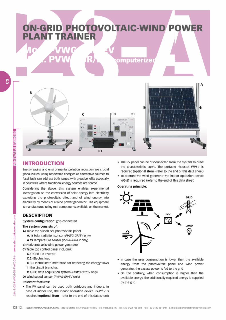
28A
-E-C
S
CS 12 ELETTRONICA VENETA S.P.A. - 31045 Motta di Livenza (TV) Italy - Via Postumia 16 - Tel. +39 0422 765 802 - Fax +39 0422 861 901 - E-mail: [email protected]
RE
NE
WA
BLE
EN
ER
GIE
S
CS
ON-GRID PHOTOVOLTAIC-WIND POWER PLANT TRAINERMod. PVWG-EGR/EVMod. PVWG-GR/EV (computerized vers.)
INTRODUCTIONEnergy saving and environmental pollution reduction are crucial
global issues. Using renewable energies as alternative sources to
fossil fuels can address both issues, with great benefits especially
in countries where traditional energy sources are scarce.
Considering the above, this system enables experimental
investigation on the conversion of solar energy into electricity
exploiting the photovoltaic effect and of wind energy into
electricity by means of a wind power generator. The equipment
is manufactured using real components available on the market.
DESCRIPTIONSystem configuration: grid-connected
The system consists of:A) Table top silicon cell photovoltaic panel
A.1) Solar radiation sensor (PVWG-GR/EV only)
A.2) Temperature sensor (PVWG-GR/EV only)
B) Horizontal axis wind power generator
C) Table top control panel including:
C.1) Grid-Tie Inverter
C.2) Electric load
C.3) Electric instrumentation for detecting the energy flows
in the circuit branches
C.4) PC data acquisition system (PVWG-GR/EV only)
D) Wind speed sensor (PVWG-GR/EV only)
Relevant features:• The PV panel can be used both outdoors and indoors. In
case of indoor use, the indoor operation device SS-2/EV is
required (optional item - refer to the end of this data sheet)
-PV
WG
EGR
-PV
WG
GR
-0
• The PV panel can be disconnected from the system to draw
the characteristic curve. The portable rheostat PRH-1 is
required (optional item - refer to the end of this data sheet)
• To operate the wind generator the indoor operation device
WG-IE is required (refer to the end of this data sheet)
Operating principle:
• In case the user consumption is lower than the available
energy from the photovoltaic panel and wind power
generator, the excess power is fed to the grid
• On the contrary, when consumption is higher than the
available energy, the additionally required energy is supplied
by the grid
B
A
C
C.1
C.3 C.2
INV
LOAD
GRID

28A
-E-C
S
CS 13ELETTRONICA VENETA S.P.A. - 31045 Motta di Livenza (TV) Italy - Via Postumia 16 - Tel. +39 0422 765 802 - Fax +39 0422 861 901 - E-mail: [email protected]
RE
NE
WA
BLE
EN
ER
GIE
S
CS
TRAINING PROGRAM• Components of a combined on-grid wind and solar system
for electricity production
• Effect of solar radiation on the panel output voltage (*)
• Effects of shading on a real solar installation (*)
• Photovoltaic panel energy conversion efficiency (*)
• Effect of the wind speed on the generator output voltage (**)
• Wind generator energy conversion efficiency (**)
• Interconnection of solar/wind energy to the public grid
• Operation and efficiency of a DC/AC inverter
• Connection to portable rheostat PRH-1 (optional item -
refer to the end of this data sheet) for photovoltaic panel
characteristic curve construction
• Connection to wind power generator indoor operation device
WG-IE (required - refer to the end of this data sheet) for wind
generator characteristic curve construction
(*) For PMWG-EGR/EV Solar radiation meter SORM (optional item - refer to the end of this data sheet) required
(**) For PMWG-EGR/EV Cup vane air velocity meter THAC
(optional item - refer to the end of this data sheet) required
TECHNICAL SPECIFICATIONSSilicon cell photovoltaic panel• Adjustable tilt table top aluminum frame
• 60 W photovoltaic panel
Horizontal axis wind power generator• 6 blades with outer ring (turbine diameter 510 mm):
- Cut in Wind Speed: 3 m/s
- Nominal power output: 49 W at 15 m/s
• Low friction 3 phase, brushless alternator
- Output nominal voltage: 12 Vdc
• Metal supporting frame with protecting grid
Table top control panel• Metal structure with complete colour synoptic diagram
• Grid tie power inverter:
- Rated AC Output Power: 450 W
- AC Output Voltage: 230 V
- AC Output Frequency: 50 Hz
- DC Input Voltage Range: 11 ÷ 28 V
- Output Current Waveform: Pure Sine-wave
- MPPT Function
- Protection vs: Over Current, Over Temperature, Reverse
Polarity, Anti-Island
• Electric load: 230 V lamp
• Socket for connection to the external AC load ACL220V
(optional item - refer to the end of this data sheet)
• Microprocessor-based instruments for DC/AC parameters
Sensors (PVWG-GR/EV only)• Solar radiation sensor for measuring and transmitting the global
solar radiation incident on the PV panel to the control panel
• Temperature sensor for measuring and transmitting the PV
panel temperature to the control pane
• Wind speed sensor for measuring and transmitting the wind
speed to the control panel
PC data acquisition (PVWG-GR/EV only)• All instruments and sensors, as described above, are
connected in Modbus network. This network is connected to
a PC via an adapter RS485/USB
• A specific software (developed with LabView) is supplied to
monitor the system parameters
• Parameters displayed:- All DC / AC parameters- Photovoltaic panel incident solar radiation- Photovoltaic panel temperature- Wind speed
• The software enables to:- Calculate solar energy conversion efficiency- Visualize the trend in time of the solar radiation incident on
the photovoltaic panel surface and its temperature and the wind speed and the energy flows to and from photovoltaic panel, wind power generator, public grid and load
- Save the exercises data for future analysis or project work
Power supply: 230 Vac 50 Hz single-phase - 50 VA (Other voltage and frequency on request)Dimensions Control panel: 80 x 40 x 10 cm Solar panel: 80 x 50 x 88 cm Wind gen. rotor diameter: 51 cmNet weight: 50 kg
-PV
WG
EGR
-PV
WG
GR
-0
THEORETICAL-EXPERIMENTAL HANDBOOK
SUPPLIED WITH
REQUIRED
PERSONAL COMPUTER- NOT INCLUDED -
(PVWG-GR/EV only)
WIND POWER GENERATOR INDOOR OPERATION DEVICE Mod. WG-IETo operate the aerogenerator
SPOTLIGHT Mod. ACL220VTo be used as 230 Vac electric load
CUP VANE AIR VELOCITY METERMod. THAC (PVWG-EGR/EV only)
For the calculation of the wind energy into electric energy conversion efficiency
OPTIONAL (REF. ACCESS. AND INSTRUMENTS)
PORTABLE RHEOSTAT Mod. PRH-1To draw the PV panel characteristic curve
INDOOR LIGHTING DEVICE Mod. SS-2/EVTo operate the photovoltaic panel indoor
SOLAR RADIATION METERMod. SORM (PVWG-EGR/EV only)
To calculate the solar energy into electric energy conversion efficiency

28A
-E-C
S
CS 14 ELETTRONICA VENETA S.P.A. - 31045 Motta di Livenza (TV) Italy - Via Postumia 16 - Tel. +39 0422 765 802 - Fax +39 0422 861 901 - E-mail: [email protected]
RE
NE
WA
BLE
EN
ER
GIE
S
CS
ON-GRID / OFF-GRIDPHOTOVOLTAIC-WIND POWER PLANT TRAINERMod. PVWG-E/EVMod. PVWG/EV (computerized vers.)
INTRODUCTIONEnergy saving and environmental pollution reduction are crucial
global issues. Using renewable energies as alternative sources
to fossil fuels can address both issues, with great benefits
especially in countries where traditional energy sources are
scarce.
Considering the above, this system enables experimental
investigation on the conversion of solar energy into electricity
exploiting the photovoltaic effect and of wind energy into
electricity by means of a wind power generator. The equipment
is manufactured using real components available on the
market.
-PV
WG
E-P
VW
G-0
DESCRIPTIONSystem configuration:• Stand-alone (isolated from the grid) or
• Grid-connected
The system consists of:A) Silicon cell photovoltaic panel
A.1) Solar radiation sensor (PVWG/EV only)
A.2) PV panel temperature sensor (PVWG/EV only)
B) Horizontal axis wind power generator
B.1) Wind speed sensor (PVWG/EV only)
C) Table top control panel for OFF-GRID operation including:
C.1) Charge regulator
C.2) DC electric load (lamp)
C.3) Electric instrumentation for detecting the energy flows
in the circuit branches
C.4) PC data acquisition system (PVWG/EV only)
D) Buffer battery
E) Table top control panel for ON-GRID operation including:
E.1) Grid-Tie Inverter
E.2) AC electric load
E.3) Electric instrumentation for detecting the energy flows
in the circuit branches
E.4) PC data acquisition system (PVWG/EV only)
B
C.3C
D
C.2
C.1
A
E
E.1
E.3 E.2
E.4
C.4

28A
-E-C
S
CS 15ELETTRONICA VENETA S.P.A. - 31045 Motta di Livenza (TV) Italy - Via Postumia 16 - Tel. +39 0422 765 802 - Fax +39 0422 861 901 - E-mail: [email protected]
RE
NE
WA
BLE
EN
ER
GIE
S
CS
OFF-GRID operation:
• In case there is no sunshine or wind blowing, all the energy
consumed by the user (load) is taken from the battery
• In case there is sunshine and/or wind blowing but no load is
connected, all the energy produced by the system charges
the battery
• In case there are both sunshine and/or wind blowing and
load, the energy produced by the system partially charges
the battery and partially powers the load
• When the consumption is higher than the power available from
the sun and the wind, the power surplus is given by the battery
ON-GRID operation:
• In case the user consumption is lower than the available energy
from sun and/or wind, the excess power is fed to the grid
• On the contrary, when consumption is higher than the
available energy, the additionally required energy is supplied
by the grid
Relevant features:• The PV panel can be used both outdoors and indoors. In
case of indoor use, the indoor operation device SS-2/EV is
required (optional item - refer to the end of this data sheet)
• The PV panel can be disconnected from the system to draw
the characteristic curve. The portable rheostat PRH-1 is
required (optional item - refer to the end of this data sheet)
• To operate the wind generator the indoor operation device
WG-IE is required (refer to the end of this data sheet)
TRAINING PROGRAM• Components of a combined no-grid / off-grid wind and solar
system for electricity production
• Effect of solar radiation on the panel output voltage (*)
• Effects of shading on a real solar installation (*)
• Photovoltaic panel energy conversion efficiency (*)
• Effect of the wind speed on the generator output voltage (**)
• Wind generator energy conversion efficiency (**)
• Battery charging system management
• Interconnection of solar/wind power energy to the public grid
• Operation and efficiency of a DC/AC inverter
• Connection to portable rheostat PRH-1 (optional item -
refer to the end of this data sheet) for photovoltaic panel
characteristic curve construction
• Connection to wind power generator indoor operation device
WG-IE (required - refer to the end of this data sheet) for wind
generator characteristic curve construction
(*) For PVWG-E/EV Solar radiation meter SORM (optional item
- refer to the end of this data sheet) required
(**) For PVWG-E/EV Cup vane air velocity meter THAC (optional item - refer to the end of this data sheet) required
TECHNICAL SPECIFICATIONSSilicon cell photovoltaic panel• Adjustable tilt table top aluminum frame
• 60 W photovoltaic panel
Horizontal axis wind power generator• 6 blades with outer ring (turbine diameter 510 mm):
- Cut in Wind Speed: 3 m/s
- Nominal power output: 49 W at 15 m/s
• Low friction 3 phase, brushless alternator
- Output nominal voltage: 12 Vdc
• Metal supporting frame with protecting grid
Table top control panel - OFF-GRID operation• Metal structure with complete color synoptic diagram
• Charge regulator:
- Pulse Width Modulation (PWM) regulation
- LED indicators for battery voltage levels and charging status
• Electric load: 12 Vdc lamp
• Instrumentation:
- DC digital voltmeter
- DC digital ammeter
Buffer battery• Rated voltage: 12 VDC
• Capacity: 12 Ah
CTRL LOAD
BATTERY
CTRL LOAD
BATTERY
INV
LOAD
GRID
-PV
WG
E-P
VW
G-0
No sunshine, no wind is blowing
Sunshine, wind is blowing

28A
-E-C
S
CS 16 ELETTRONICA VENETA S.P.A. - 31045 Motta di Livenza (TV) Italy - Via Postumia 16 - Tel. +39 0422 765 802 - Fax +39 0422 861 901 - E-mail: [email protected]
RE
NE
WA
BLE
EN
ER
GIE
S
CS
Table top control panel - ON-GRID operation• Metal structure with complete colour synoptic diagram
• Grid tie power inverter:
- Rated AC Output Power: 450 W
- AC Output Voltage: 230 V
- AC Output Frequency: 50 Hz
- DC Input Voltage Range: 11 ÷ 28 V
- Output Current Waveform: Pure Sine-wave
- MPPT Function
- Protection vs: Over Current, Over Temperature, Reverse
Polarity, Anti-Island
• Electric load: 230 V lamp
• Socket for connection to the external AC load ACL220V
(optional item - refer to the end of this data sheet)
• Microprocessor-based instruments for DC/AC parameters
Sensors (PVWG/EV only)• Solar radiation sensor for measuring and transmitting the
global solar radiation incident on the PV panel to the control
panel. Range: 0 ÷ 2000 W/m2
• Temperature sensor for measuring and transmitting the PV
panel temperature to the control panel
• Wind speed sensor for measuring and transmitting wind
speed to the control panel
PC data acquisition (PVWG/EV only)• All instruments and sensors, as described above, are
connected in Modbus network. This network is connected to
a PC via an adapter RS485/USB
• A specific software (developed with LabView) is supplied to
monitor the system parameters
• Displayed parameters:
- All DC / AC parameters
- Solar radiation incident on the photovoltaic panel
- Photovoltaic panel temperature
- Wind speed
• The software enables to:
- Calculate energy conversion efficiency
- Visualize the energy flows to and from the photovoltaic
generator, wind turbine, buffer battery or grid and load
- Save the exercises data for future analysis or project work
OPTIONAL (REF. ACCESS. AND INSTRUMENTS)
PORTABLE RHEOSTAT Mod. PRH-1To draw the PV panel characteristic curve
INDOOR LIGHTING DEVICE Mod. SS-2/EVTo operate the photovoltaic panel indoor
CUP VANE AIR VELOCITY METERMod. THAC (PVWG-E/EV only)
For the calculation of the wind energy into electric energy conversion efficiency
SOLAR RADIATION METERMod. SORM (PVWG-E/EV only)
To calculate the solar energy into electric energy conversion efficiency
SPOTLIGHT Mod. ACL220VTo be used as 230 Vac electric load
-PV
WG
E-P
VW
G-0
Power supply: 230 Vac 50 Hz single-phase - 50 VA
(Other voltage and frequency on request)
DimensionsControl panels: 80 x 40 x 15 cm
Solar panel: 70 x 70 x 5 cm
Wind generator rotor diameter: 51 cm
Net weight: 60 kg
THEORETICAL-EXPERIMENTAL HANDBOOK
SUPPLIED WITH
REQUIRED
PERSONAL COMPUTER- NOT INCLUDED -(PVWG/EV only)
WIND POWER GENERATOR INDOOR OPERATION DEVICE Mod. WG-IETo operate the aerogenerator

28A
-E-C
S
CS 17ELETTRONICA VENETA S.P.A. - 31045 Motta di Livenza (TV) Italy - Via Postumia 16 - Tel. +39 0422 765 802 - Fax +39 0422 861 901 - E-mail: [email protected]
RE
NE
WA
BLE
EN
ER
GIE
S
CS
INTEGRATED PHOTOVOLTAIC-WIND POWER KITMod. PMWG-K/EV
INTRODUCTIONThis kit represents the typical configuration of an integrated
system for the exploitation of renewable energies, with energy
production via horizontal axis wind power generator, used
to convert the wind kinetic energy directly into mechanical
energy, and via silicon photovoltaic cells enabling to transform
solar energy into electricity.
-PM
WG
K-2
TRAINING PROGRAM• Components of a combined wind and solar system for
electricity production
• Effect of solar radiation on the panel output voltage (*)
• Effects of shading on a real solar installation (*)
• Photovoltaic panel energy conversion efficiency (*)
• Effect of the wind speed on the generator output voltage (**)
• Wind generator energy conversion efficiency (**)
• Battery charging system management
• Operation and efficiency of a DC/AC inverter
• Connection to portable rheostat PRH-1 (optional item
- refer to the end of this data sheet) for photovoltaic panel
characteristic curve construction
• Connection to wind power generator indoor operation device
WG-IM/EV (optional item - refer to the end of this data sheet)
for wind generator characteristic curve construction
(*) Solar radiation meter SORM (optional item - refer to the end
of this data sheet) required
(**) Cup vane air velocity meter THAC (optional item - refer to
the end of this data sheet) required

28A
-E-C
S
CS 18 ELETTRONICA VENETA S.P.A. - 31045 Motta di Livenza (TV) Italy - Via Postumia 16 - Tel. +39 0422 765 802 - Fax +39 0422 861 901 - E-mail: [email protected]
RE
NE
WA
BLE
EN
ER
GIE
S
CS
TECHNICAL SPECIFICATIONSHorizontal axis wind power generator:• Aluminium generator body
• 3 composite material blades (rotor diameter 1,17 m):
- Energy output: approx. 30 kWh/month at 5,8 m/s (13 mph)
average wind speed
- Startup Wind Speed: 3,6 m/s (8 mph)
- Survival wind speed: 49,2 m/s (110 mph)
• Permanent magnet brushless alternator
• Microprocessor-based controller:
- Output voltage: 12 Vdc
- Overspeed protection: electronic torque control
• Stainless steel supporting pole:
- Length 1,5 m
- Outer diameter: 48,1 mm
- Mounting kit
Photovoltaic module:• 120 W Peak power with maximum radiation
• Adjustable inclination framework mounted on castors
Charge controller for photovoltaic panels:• Rated voltage: 12 Vdc
• Maximum current: 20 A
Buffer battery:• Rated voltage: 12 Vdc
• Capacity: 100 Ah
Clamp meter:• Voltage range (ac/dc): 0 to 600 V
• Current range (ac/dc): 0 to 200 A
Inverter:• Continuous output power: 600 W
• Output peak power: 1200 W
• Input voltage: 12 Vdc
• Output voltage: 230 Vac - 50 Hz
• Output waveform: modified sine wave
• Stop for low battery charge
• Protection against: overload, short circuit, overtemperature
DimensionsRotor diameter: 1,15 m
Photovoltaic module: 67 x 120 x 155 cm
Overall weight: 140 kg
-PM
WG
K-2
THEORETICAL-EXPERIMENTAL HANDBOOK
SUPPLIED WITH
OPTIONAL (REF. ACCESS. AND INSTRUMENTS)
ELECTRIC BATTERY CHARGERMod. EBCHTo recharge the buffer battery after a prolonged period of inactivity of the system
PORTABLE RHEOSTAT Mod. PRH-1To draw the photovoltaic panel characteristic curve
SOLAR RADIATION METER Mod. SORMTo calculate the solar energy into electric energy conversion efficiency
SPOTLIGHT Mod. ACL220VTo be used as 230 Vac electric load
LAMP Mod. DCL12VTo be used as 12 Vdc electric load
WIND POWER GENERATOR INDOOR OPERATION DEVICE Mod. WG-IM/EVTo operate the aerogenerator indoor
CUP VANE AIR VELOCITY METERMod. THACFor the calculation of the wind energy into electric energy conversion efficiency


28A
-E-A
I
AI 2 ELETTRONICA VENETA S.P.A. - 31045 Motta di Livenza (TV) Italy - Via Postumia 16 - Tel. +39 0422 765 802 - Fax +39 0422 861 901 - E-mail: [email protected]
ACCESSORIES AND INSTRUMENTS
INSTRUMENTS Mod. Page
SOLAR RADIATION METER SORM AI 7
CUP VANE AIR VELOCITY METER THAC AI 7
PORTABLE ANEMOMETER THAM AI 7
PORTABLE THERMOHYGROMETER THHY AI 7
PORTABLE THERMOMETER THRN AI 7
ACCESSORIES Mod. Page
SPOTLIGHT ACL220V AI 3
LAMPDCL12V DCL24V
AI 3
DIRECT CURRENT MOTOR DCM/EV AI 3
ENERGY DISSIPATION KIT DW-EP/EV AI 3
ELECTRIC BATTERY CHARGER EBCH AI 3
METAL HYDRIDE STORAGE TANK H2-300 AI 3
PEM ELECTROLYZER HG-480 AI 4
HYDROGEN GENERATOR HG-1 AI 4
HEATING ELEMENTS MODULE RP/EV AI 4
HOT WATER PRODUCTION MODULE MC/EV AI 4
PORTABLE RHEOSTAT (1 x 20Ω) PRH-1 AI 5
PORTABLE RHEOSTAT (2 x 20Ω) PRH-2 AI 5
PORTABLE RHEOSTAT (3 x 35Ω) PRH-3 AI 5
BATTERY PACK SOLBA AI 5
SOLAR TRACKER SOLTR/EV AI 5
INDOOR LIGHTING DEVICE SS-1/EV AI 6
INDOOR LIGHTING DEVICE SS-2/EV AI 6
WIND POWER GENERATOR INDOOR OPERATION DEVICE
WG-I/EV WG-IM/EV AI 6
WIND POWER GENERATOR INDOOR OPERATION DEVICE WG-IE AI 6
RE
NE
WA
BLE
EN
ER
GIE
S
AI

28A
-E-A
I
AI 3ELETTRONICA VENETA S.P.A. - 31045 Motta di Livenza (TV) Italy - Via Postumia 16 - Tel. +39 0422 765 802 - Fax +39 0422 861 901 - E-mail: [email protected]
-AC
CE
SS
-6
ACCESSORIES
ELECTRIC BATTERY CHARGERMod. EBCHDevice for battery charging 12V – 15A. Protection against:
• Overload
• Overtemperature
• Short circuit
ENERGY DISSIPATION KITMod. DW-EP/EVKit mounted on castors for dissipation in air of part of the
thermal power produced by renewable energy source,
including:
• Fan coil unit
• Pump
SPOTLIGHTMod. ACL220VTo be used as electric load, 150W - 230 Vac halogen projector.
LAMPMod. DCL12V (12 Vdc vers.)
Mod. DCL24V (24 Vdc vers.)
To be used as 12 or 24 Vdc electric load. 5W Lamp, 4 mm safety
holes.
DIRECT CURRENT MOTORMod. DCM/EVDirect current variable-speed motor, for studying the application
of fuel cells in the field of road transport.
METAL HYDRIDE STORAGE TANKMod. H2-300Hydrogen storage tank useful for fuel cells feeding.
• Capacity: 300 liters
• Maximum recharge pressure: 30 bar
AI
RE
NE
WA
BLE
EN
ER
GIE
S
AI

28A
-E-A
I
AI 4 ELETTRONICA VENETA S.P.A. - 31045 Motta di Livenza (TV) Italy - Via Postumia 16 - Tel. +39 0422 765 802 - Fax +39 0422 861 901 - E-mail: [email protected]
-AC
CE
SS
-6
PEM ELECTROLYZERMod. HG-480PEM Electrolyzer ideal for charging metal hydrides hydrogen
storage tanks.
Technical specifications:• Capacity: 480 ml/min
• Microprocessor based
• Graphic display
• Pressure adjustable from 0 to 16 bar
• Gas purity: 99,9999%
• Rated power: 224 W
• Power supply: 230V / 50Hz
• Dimensions: 41 x 44 x 18 cm
• Weight: 20 kg
RE
NE
WA
BLE
EN
ER
GIE
S
HOT WATER PRODUCTION MODULE Mod. MC/EVMobile installation suitable to produce domestic hot water
using a traditional heat source as addition to the one produced
by renewable energy sources in case of prolonged absence
of sun.
• Cast iron boiler
• 17 kW gasoil burner
• Protection and safety devices
For more information please refer to Cat. 27 - Thermotronics
HEATING ELEMENTS MODULE Mod. RP/EVMobile installation featuring different kinds of heating bodies.
It helps dissipate the heat produced by renewable energy
source. It includes:
• Radiators
• Floor heating
• Fan coil
For more information please refer to Cat. 27 - Thermotronics
HYDROGEN GENERATORMod. HG-1Generator for producing pure hydrogen by water electrolysis
for feeding a PEM fuel cell.
Technical specifications:• Capacity: 200 Nml/min• Purity: 99.9999%• Max output pressure: 8 bar• Touchscreen display• Drying filter• Solenoid valves for process control and safety• Water feeding through loading tank• Safety system against overpressure• Power supply: 230V / 50 Hz• Dimensions: 38 x 53 x 47 cm; weight: 30 kg
RE
NE
WA
BLE
EN
ER
GIE
S
AI

28A
-E-A
I
AI 5ELETTRONICA VENETA S.P.A. - 31045 Motta di Livenza (TV) Italy - Via Postumia 16 - Tel. +39 0422 765 802 - Fax +39 0422 861 901 - E-mail: [email protected]
-AC
CE
SS
-6
PORTABLE RHEOSTATMod. PRH-2Linear slider rheostat needed to draw the photovoltaic panel
characteristic curve.
• Double winding
• 4 sections per winding
• Ohm value: 2 x 20 Ω
• Power: 1200 W
PORTABLE RHEOSTATMod. PRH-1Linear slider rheostat needed to draw the photovoltaic panel
characteristic curve.
• Single winding
• 4 sections per winding
• Ohm value: 1 x 20 Ω
• Power: 600 W
BATTERY PACKMod. SOLBAThe pack includes two batteries, each having the following
characteristics:
• Nominal voltage: 12 Vdc
• Capacity: 100 Ah
SOLAR TRACKERMod. SOLTR/EVSun tracking device, provided with steel framework and gearing
system for orienting the panel on two degrees of freedom in
space: up-down, east-west.
AI
PORTABLE RHEOSTATMod. PRH-3Three-phase linear slider rheostat needed to draw the
generator external characteristic curve.
• Absorption: 6,5 A
• Ohm value: 3 x 35 Ω
• Power: 1500 W
RE
NE
WA
BLE
EN
ER
GIE
S
AI

28A
-E-A
I
AI 6 ELETTRONICA VENETA S.P.A. - 31045 Motta di Livenza (TV) Italy - Via Postumia 16 - Tel. +39 0422 765 802 - Fax +39 0422 861 901 - E-mail: [email protected]
-AC
CE
SS
-6
WIND POWER GENERATOR INDOOR OPERATION DEVICEMod. WG-I/EVMod. WG-IM/EV (mains powered version)
This device enables to operate a wind power generator indoors,
after removing its blades.
The variable speed asynchronous motor directly coupled to the
wind generator permits to simulate the wind action.
The rpm variation is controlled by a potentiometer or by a
PC (only for mod. WG-I/EV when used with a computerized
version).
The device is powered by the trainer (mod. WG-I/EV) or by the
mains (mod. WG-IM/EV).
INDOOR LIGHTING DEVICEMod. SS-1/EVDevice for the indoor operation of solar thermal and/or
photovoltaic equipment.
• Light source: six 1000 W spotlights.
• Stainless steel wheeled structure with telescopic fixing to
ensure the maximum stability of the system.
• Straight and inclined support rods, adjustable in height.
INDOOR LIGHTING DEVICEMod. SS-2/EVDevice for the indoor operation of photovoltaic equipment.
• Light source: two 1000 W spotlights
• Aluminium tilting support structure
WIND POWER GENERATOR INDOOR OPERATION DEVICEMod. WG-IEFor indoor use of a horizontal axis wind turbine.
• Paddle wheel dimensions 300 mm
• Mains voltage 230V / 50 Hz
• Revolutions per minute 2800 rpm
• Power 500 W
• Air flow 65 m3/min
• Degree of protection IP 54
• Weight 20 kg
• Noise 69 dB(A)
Wind generator(not included)
RE
NE
WA
BLE
EN
ER
GIE
S
AI
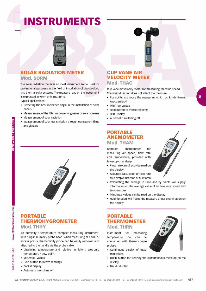
28A
-E-A
I
AI 7ELETTRONICA VENETA S.P.A. - 31045 Motta di Livenza (TV) Italy - Via Postumia 16 - Tel. +39 0422 765 802 - Fax +39 0422 861 901 - E-mail: [email protected]
INSTRUMENTS-S
TR
UM
-3
SOLAR RADIATION METERMod. SORMThe solar radiation meter is an ideal instrument to be used for
professional purposes in the field of installation of photovoltaic
and thermal solar systems. The measure read on the instrument
is expressed in W/m2 or in Btu/(ft2·h).
Typical applications:
• Detecting the best incidence angle in the installation of solar
panels
• Measurement of the filtering power of glasses or solar screens
• Measurement of solar radiation
• Measurement of solar transmission through transparent films
and glasses
PORTABLE ANEMOMETERMod. THAMCompact anemometer for
measuring air speed, flow rate
and temperature, provided with
telescopic handgrip.
• Flow rate can directly be read on
the display
• Accurate calculation of flow rate
by a simple insertion of duct area
• Calculating the average in time and by points will supply
information on the average value of air flow rate, speed and
temperature
• Min./max. values can be read on the display
• Hold function will freeze the measure under examination on
the display
CUP VANE AIR VELOCITY METERMod. THACCup vane air velocity meter for measuring the wind speed.
The wind direction does not affect the measure.
• Possibility to choose the measuring unit: m/s, km/h, ft/min,
knots, miles/h
• Min/max values
• Hold button to freeze readings
• LCD Display
• Automatic switching off
PORTABLE THERMOHYGROMETERMod. THHYAir humidity / temperature compact measuring instrument,
with plug-in humidity probe head. When measuring at hard-to-
access points, the humidity probe can be easily removed and
attached to the handle via the probe cable.
• Displaying temperature and relative humidity / wet-bulb
temperature / dew point
• Min./max. values
• Hold button to freeze readings
• Backlit display
• Automatic switching off
PORTABLE THERMOMETERMod. THRNInstrument for measuring
temperature that can be
connected with thermocouple
probes.
• Continuous display of max/
min values
• HOLD button for freezing the instantaneous measure on the
display
• Backlit display
RE
NE
WA
BLE
EN
ER
GIE
S
AI

28A
-E-A
I
AI 8 ELETTRONICA VENETA S.P.A. - 31045 Motta di Livenza (TV) Italy - Via Postumia 16 - Tel. +39 0422 765 802 - Fax +39 0422 861 901 - E-mail: [email protected]
-ST
RU
M-2
RE
NE
WA
BLE
EN
ER
GIE
S
AI

MODEL PRODUCT DESCRIPTION PAGE
ACL220V SPOTLIGHT AI 3
AWS/EV ENVIRONMENTAL MONITORING SYSTEM EM 3
AWWS/EV WIRELESS ENVIRONMENTAL MONITORING SYSTEM EM 5
DCL12VDCL24V LAMP AI 3
DCM/EV DIRECT CURRENT MOTOR AI 3
DW-EP/EV ENERGY DISSIPATION KIT AI 3
EBCH ELECTRIC BATTERY CHARGER AI 3
FCBE/EVFCBA/EV FUEL CELL TRAINER FC 3
FUEL-C.../EVFUEL-C...C/EV FUEL CELL TESTING PANEL FC 6
H2-300 METAL HYDRIDE STORAGE TANK AI 3
HG-1 HYDROGEN GENERATOR AI 4
HG-480 PEM ELECTROLYZER AI 4
MC/EV HOT WATER PRODUCTION MODULE AI 4
PM-E/EVPM/EV PHOTOVOLTAIC PANEL TRAINER PE 3
PM-K/EV PM-K2/EV PHOTOVOLTAIC ENERGY GENERATION KIT PE 13
PMWG-E/EVPMWG/EV INTEGRATED PHOTOVOLTAIC-WIND POWER SYSTEM CS 6
PMWG-K/EV INTEGRATED PHOTOVOLTAIC-WIND POWER KIT CS 17
PRH-1 PORTABLE RHEOSTAT (1 X 20Ω) AI 5
PRH-2 PORTABLE RHEOSTAT (2 X 20Ω) AI 5
PRH-3 PORTABLE RHEOSTAT (3 X 35Ω) AI 5
PV-EGRID/EV PV-GRID/EV ON-GRID PHOTOVOLTAIC TRAINER PE 8
PV-EOG/EVPV-OG/EV OFF-GRID PHOTOVOLTAIC TRAINER PE 6
PVWG-E/EVPVWG/EV ON-GRID / OFF-GRID PHOTOVOLTAIC-WIND POWER PLANT TRAINER CS 14
PVWG-EGR/EVPVWG-GR/EV ON-GRID PHOTOVOLTAIC-WIND POWER PLANT TRAINER CS 12
PVWG-EOG/EVPVWG-OG/EV OFF-GRID PHOTOVOLTAIC - WIND POWER PLANT TRAINER CS 9
REMDI/EV GRID-CONNECTED RENEWABLE ENERGY SYSTEM CS 3
RP/EV HEATING ELEMENTS MODULE AI 4
SIM-BS/EV DHW SOLAR THERMAL SYSTEM SIMULATOR ST 17
SIM-BSC/EV SIMULATOR OF SOLAR THERMAL COMBISYSTEM FOR SPACE HEATING AND DOMESTIC WATER HEATING ST 18
SIM-PM/EV PHOTOVOLTAIC SYSTEM SIMULATOR PE 15
SKT-.../EVSKT-...C/EV SOLAR THERMAL KIT ST 15
SMK/EV SOLAR ENERGY MINI LABORATORY PE 14
SOL-K/EVSOL-KC/EV SOLAR THERMAL KIT WITH FLAT PLATE COLLECTOR ST 12
ALP
HA
BE
TIC
AL
IND
EX
RENEWABLE ENERGIESCATALOGUE N. 28-A
PRODUCTS INDEXSORTED ALPHABETICALLY BY MODEL
ST SOLAR THERMAL ENERGY
PE PHOTOVOLTAIC ENERGY
WI WIND ENERGY
HE HYDROELECTRIC ENERGY
FC FUEL CELL TECHNOLOGY
EM ENVIRONMENTAL MONITORING
CS COMBINED SOLUTIONS
AI ACCESSORIES AND INSTRUMENTS

ALP
HA
BE
TIC
AL
IND
EX
SOLBA BATTERY PACK AI 5
SOLTR/EV SOLAR TRACKER AI 5
SORM SOLAR RADIATION METER AI 7
SS-1/EV INDOOR LIGHTING DEVICE (6 SPOTLIGHTS, 1000 W EACH) AI 6
SS-2/EV INDOOR LIGHTING DEVICE (2 SPOTLIGHTS, 1000 W EACH) AI 6
SSC/EV COMPUTERIZED SOLAR CONCENTRATOR TRAINER ST 6
STETP/EV STETCP/EV SOLAR THERMAL ENERGY TRAINER ST 9
S-TRACK/EV COMPUTERIZED SOLAR TRACKING SYSTEM PE 10
TBSS/EVTBS/EV FLAT PLATE COLLECTOR TRAINER ST 3
THAC CUP VANE AIR VELOCITY METER AI 7
THAM PORTABLE ANEMOMETER AI 7
THHY PORTABLE THERMOHYGROMETER AI 7
THRN PORTABLE THERMOMETER AI 7
WG-C/EVWG/EV WIND POWER GENERATOR TRAINER WI 3
WG-EGRID/EVWG-GRID/EV ON-GRID WIND POWER PLANT TRAINER WI 11
WG-EOG/EVWG-OG/EV OFF-GRID WIND POWER PLANT TRAINER WI 9
WG-I/EVWG-IM/EV WIND POWER GENERATOR INDOOR OPERATION DEVICE AI 6
WG-IE WIND POWER GENERATOR INDOOR OPERATION DEVICE(SUITABLE FOR TABLE-TOP AEROGENERATORS) AI 6
WG-K/EV WIND ENERGY GENERATION KIT WI 13
WG-SEC/EV CUT-AWAY WIND POWER GENERATOR WI 14
WIND-TU/EVWIND-TU2/EV AEROGENERATOR WITH WIND TUNNEL TRAINER WI 6
WPP-E/EVWPP/EV MINI HYDROELECTRIC POWER PLANT TRAINER HE 3
WPP-K/EV HYDROELECTRIC ENERGY GENERATION KIT HE 6

Elettronica Veneta S.p.A. forbids the duplication or the disclosure of the information contained in this catalogue without written authorization.

Elettronica Veneta S.p.A.Via Postumia, 1631045 Motta di Livenza (Treviso) ItalyTel. +39 0422 765 802 r.a. - Fax +39 0422 861 901E-mail: [email protected]
www.elettronicaveneta.com