Recent Developments and Future Challenges in Incremental ...
46
Metals 2022, 12, 124. https://doi.org/10.3390/met12010124 www.mdpi.com/journal/metals Review Recent Developments and Future Challenges in Incremental Sheet Forming of Aluminium and Aluminium Alloy Sheets Tomasz Trzepieciński 1, *, Sherwan Mohammed Najm 2,3 , Valentin Oleksik 4 , Delia Vasilca 4 , Imre Paniti 2,5 and Marcin Szpunar 6 1 Department of Manufacturing and Production Engineering, Faculty of Mechanical Engineering and Aeronautics, Rzeszow University of Technology, al. Powst. Warszawy 8, 35‐959 Rzeszów, Poland 2 Department of Manufacturing Science and Engineering, Budapest University of Technology and Economics, Műegyetemrkp 3, H‐1111 Budapest, Hungary; [email protected] (S.M.N.); [email protected] (I.P.) 3 Kirkuk Technical Institute, Northern Technical University, Kirkuk 41001, Iraq 4 Faculty of Engineering, Lucian Blaga University of Sibiu, 550024 Sibiu, Romania; [email protected] (V.O.); [email protected] (D.V.) 5 Centre of Excellence in Production Informatics and Control, Institute for Computer Science and Control (SZTAKI), Kende u. 13‐17, H‐1111 Budapest, Hungary 6 Doctoral School of Engineering and Technical Sciences, The Rzeszow University of Technology, al. Powst. Warszawy 12, 35‐959 Rzeszów, Poland; [email protected] * Correspondence: [email protected] Abstract: Due to a favourable strength‐to‐density ratio, aluminium and its alloys are increasingly used in the automotive, aviation and space industries for the fabrication of skins and other struc‐ tural elements. This article explores the opportunities for and limitations of using Single‐ and Two Point Incremental Sheet Forming techniques to form sheets from aluminium and its alloys. Incre‐ mental Sheet Forming (ISF) methods are designed to increase the efficiency of processing in low‐ and medium‐batch production because (i) it does not require the production of a matrix and (ii) the forming time is much higher than in conventional methods of sheet metal forming. The tool in the form of a rotating mandrel gradually sinks into the sheet, thus leading to an increase in the degree of deformation of the material. This article provides an overview of the published results of re‐ search on the influence of the parameters of the ISF process (feed rate, tool rotational speed, step size), tool path strategy, friction conditions and process temperature on the formability and surface quality of the workpieces. This study summarises the latest development trends in experimental research on, and computer simulation using, the finite element method of ISF processes conducted in cold forming conditions and at elevated temperature. Possible directions for further research are also identified. Keywords: aluminium; aluminium alloys; forming strategy; incremental sheet forming; process parameters; sheet metal; SPIF; TPIF 1. Introduction Aluminium is a metal of low density (2.6989 g/cm 3 at 20 °C), that is easy to form, with high electrical and thermal conductivity and high corrosion resistance. Annealed aluminium has the following properties: ultimate tensile stress, Rm = 70–120 MPa; yield stress, Re = 20–40 MPa; and elongation, A11.3 = 30–45%. Aluminium crystallises in a face‐centred cubic (A1) lattice, which makes it a metal susceptible to cold and hot form‐ ing. The strength properties of aluminium and aluminium alloys can be increased by cold working, which, however, reduces its plastic properties [1]. In the strengthened state with a 60–80% degree of cold work, the strength of aluminium increases to 140–230 MPa. Citation: Trzepieciński, T.; Najm, S.M.; Oleksik, V.; Vasilca, D.; Paniti, I.; Szpunar, M. Recent Developments and Future Challenges in Incremental Sheet Forming of Aluminium and Aluminium Alloy Sheets. Metals 2022, 12, 124. https://doi.org/ 10.3390/met12010124 Academic Editor: Marta Oliveira Received: 15 December 2021 Accepted: 7 January 2022 Published: 9 January 2022 Publisher’s Note: MDPI stays neutral with regard to jurisdictional claims in published maps and institutional affiliations. Copyright: © 2022 by the authors. Licensee MDPI, Basel, Switzerland. This article is an open access article distributed under the terms and conditions of the Creative Commons Attribution (CC BY) license (https://creativecommons.org/license s/by/4.0/).
-
Upload
khangminh22 -
Category
Documents
-
view
1 -
download
0
Transcript of Recent Developments and Future Challenges in Incremental ...
Metals 2022, 12, 124. https://doi.org/10.3390/met12010124 www.mdpi.com/journal/metals
Review
Recent Developments and Future Challenges in Incremental
Sheet Forming of Aluminium and Aluminium Alloy Sheets
Tomasz Trzepieciński 1,*, Sherwan Mohammed Najm 2,3, Valentin Oleksik 4, Delia Vasilca 4, Imre Paniti 2,5 and
Marcin Szpunar 6
1 Department of Manufacturing and Production Engineering,
Faculty of Mechanical Engineering and Aeronautics, Rzeszow University of Technology,
al. Powst. Warszawy 8, 35‐959 Rzeszów, Poland 2 Department of Manufacturing Science and Engineering, Budapest University of Technology and Economics,
Műegyetemrkp 3, H‐1111 Budapest, Hungary; [email protected] (S.M.N.);
[email protected] (I.P.) 3 Kirkuk Technical Institute, Northern Technical University, Kirkuk 41001, Iraq 4 Faculty of Engineering, Lucian Blaga University of Sibiu, 550024 Sibiu, Romania;
[email protected] (V.O.); [email protected] (D.V.) 5 Centre of Excellence in Production Informatics and Control,
Institute for Computer Science and Control (SZTAKI), Kende u. 13‐17, H‐1111 Budapest, Hungary 6 Doctoral School of Engineering and Technical Sciences, The Rzeszow University of Technology,
al. Powst. Warszawy 12, 35‐959 Rzeszów, Poland; [email protected]
* Correspondence: [email protected]
Abstract: Due to a favourable strength‐to‐density ratio, aluminium and its alloys are increasingly
used in the automotive, aviation and space industries for the fabrication of skins and other struc‐
tural elements. This article explores the opportunities for and limitations of using Single‐ and Two
Point Incremental Sheet Forming techniques to form sheets from aluminium and its alloys. Incre‐
mental Sheet Forming (ISF) methods are designed to increase the efficiency of processing in low‐
and medium‐batch production because (i) it does not require the production of a matrix and (ii) the
forming time is much higher than in conventional methods of sheet metal forming. The tool in the
form of a rotating mandrel gradually sinks into the sheet, thus leading to an increase in the degree
of deformation of the material. This article provides an overview of the published results of re‐
search on the influence of the parameters of the ISF process (feed rate, tool rotational speed, step
size), tool path strategy, friction conditions and process temperature on the formability and surface
quality of the workpieces. This study summarises the latest development trends in experimental
research on, and computer simulation using, the finite element method of ISF processes conducted
in cold forming conditions and at elevated temperature. Possible directions for further research are
also identified.
Keywords: aluminium; aluminium alloys; forming strategy; incremental sheet forming; process parameters; sheet metal; SPIF; TPIF
1. Introduction
Aluminium is a metal of low density (2.6989 g/cm3 at 20 °C), that is easy to form,
with high electrical and thermal conductivity and high corrosion resistance. Annealed
aluminium has the following properties: ultimate tensile stress, Rm = 70–120 MPa; yield
stress, Re = 20–40 MPa; and elongation, A11.3 = 30–45%. Aluminium crystallises in a
face‐centred cubic (A1) lattice, which makes it a metal susceptible to cold and hot form‐
ing. The strength properties of aluminium and aluminium alloys can be increased by
cold working, which, however, reduces its plastic properties [1]. In the strengthened state
with a 60–80% degree of cold work, the strength of aluminium increases to 140–230 MPa.
Citation: Trzepieciński, T.;
Najm, S.M.; Oleksik, V.; Vasilca, D.;
Paniti, I.; Szpunar, M. Recent
Developments and Future
Challenges in Incremental Sheet
Forming of Aluminium and
Aluminium Alloy Sheets. Metals
2022, 12, 124. https://doi.org/
10.3390/met12010124
Academic Editor: Marta Oliveira
Received: 15 December 2021
Accepted: 7 January 2022
Published: 9 January 2022
Publisher’s Note: MDPI stays
neutral with regard to jurisdictional
claims in published maps and
institutional affiliations.
Copyright: © 2022 by the authors.
Licensee MDPI, Basel, Switzerland.
This article is an open access article
distributed under the terms and
conditions of the Creative Commons
Attribution (CC BY) license
(https://creativecommons.org/license
s/by/4.0/).

Metals 2022, 12, 124 2 of 46
Aluminium has the ability to form a strongly adhering aluminium oxide layer on its
surface, which is resistant to weather conditions and protects the metal against oxidation
[2,3].
By adding alloying elements to aluminium, its strength properties can be increased
even by several times [4,5]. The alloys obtained in this way are characterised by low
weight and high impact strength. The greatest influence on increasing the hardness of
aluminium is exerted by molybdenum, magnesium, cobalt, manganese, tungsten, vana‐
dium, nickel, titanium, copper, iron, zinc and silicon [6,7]. Nickel and cobalt, as well as
magnesium and manganese, increase the strength properties, and titanium and chro‐
mium affect grain refinement [8–10]. Copper lowers the casting shrinkage. The content of
the main alloying elements in casting alloys reaches up to 30%, whilst in wrought alloys,
such content is up to about 10%. Wrought alloys usually contain up to 5% of alloying
elements and are used in the strengthened and heat‐treated state. Casting aluminium
alloys usually contain 5–25% of alloying elements. Under special conditions, casting al‐
uminium alloys can be processed using metal forming methods [11,12]. Some alloys can
be used in both the cast and wrought forms.
The ratio of the strength of aluminium alloys to their specific weight is greater than
for steel. Moreover, their toughness does not decrease as the temperature is lowered;
therefore, at low temperatures, they have a higher toughness than steel. However,
Al‐based alloys generally have a relatively low fatigue strength [13]. The fatigue life of
aluminium alloys can be improved by adding transition metal elements such as Ti, V and
Zr [14,15]. According to the EN 573‐3:2019‐12 [16] standard, aluminium alloys are classi‐
fied according to their chemical composition in eight series 1xxxx–8xxx [16,17] (Table 1).
Table 1. Classification and main properties of the aluminium alloys.
Series of
Al‐Based Alloy Main Alloying Elements Properties
1xxx lack (content of contami‐
nations <1%)
good formability in cold forming and at
elevated temperature, low strength, good
resistance to corrosion, high electrical and
heat conductivity
2xxx Cu low resistance to corrosion
3xxx Mn good formability but low strength, good
weldability and corrosion resistance
4xxx Si high strength and corrosion resistance
5xxx Mg good corrosion resistance in salt water,
good weldability and ability to anodising
6xxx Mg + Si high corrosion resistance, good formability
7xxx Zn + Mg
the highest strength from all Al‐based
alloys, low and medium resistance to cor‐
rosion
8xxx
various alloying elements,
the rest of aluminium
alloys
‐
The forming of materials by Sheet Metal Forming (SMF) is one of the most popular
methods of obtaining finished products. Conventional methods of deep drawing sheet
metal are carried out in cold, warm or hot forming conditions with the use of tools called
stamping dies [18,19]. During SMF, the sheet is deformed by exceeding the yield stress of
the material [20]. The disadvantage of conventional methods of sheet metal forming is the
need to manufacture special tools adapted to the shape of the element; therefore, the use

Metals 2022, 12, 124 3 of 46
of conventional SMF methods with the use of stamping dies is suitable for medium‐ and
large‐scale production [21,22].
In Incremental Sheet Forming (ISF), as the alternative to the SMF method, the tool in
the form of a rotating mandrel gradually sinks into the sheet, thus leading to an increase
in the degree of deformation of the material [2,23]. This variation of ISF is called Sin‐
gle‐Point Incremental Forming (SPIF). In Two‐Point Incremental Forming (TPIF), a
counter tool is used that moves on the opposite side of the sheet. The kinematics of these
varieties will be introduced to the readers in Chapter 3. The use of ISF methods is eco‐
nomically justified in unit (i.e., medical implants) and small‐lot production. One of the
main limitations of ISF is the long machining time resulting from the point contact be‐
tween the tool and the workpiece. The material is deformed locally along the given tra‐
jectory of the tool movement. Both in conventional SMF and ISF methods, the increase in
the strength of the drawpiece is related to the work hardening phenomenon of the sheet
material [24–26]. An important advantage of ISF is the greater deformation limit of the
material not causing sheet cracking than is the case with conventional SMF [27,28]. Sim‐
ilar to other sheet forming techniques, ISF also has some disadvantages related to the
properties of deformable materials, which include geometric accuracy and springback
[29].
In the last decade, an increase has been observed in works related to the incremental
forming of the following lightweight alloy sheets: titanium and titanium alloys [30,31],
aluminium alloys [32,33] and magnesium and its alloys [34]. These works are mainly re‐
lated to the use of these alloys in the aviation [32] and space [35] industries, where, in‐
creasing, the share of lightweight metals in the entire structure is part of the efforts to
reduce carbon dioxide emissions to the atmosphere. A brief overview of the
state‐of‐the‐art methods of incremental sheet forming for lightweight materials was pro‐
vided by Trzepieciński et al. [36]. Over the last decade, aluminium has remained the most
research‐oriented material due to its wide application and applications in major indus‐
tries due to its flexible properties [29]. On average, about 50% of the mass of materials
used in the construction of passenger airplanes is provided by aluminium alloys [37]. The
automotive industry is mainly interested in 5xxx and 6xxx series alloys. The 5xxx series
alloys have excellent strength to weight ratios, formability properties and they are fully
recyclable, the 6xxx series has the advantage of being versatile, heat treatable, highly
formable and very weldable. Therefore, 6xxx alloys currently account for at least 80% of
the volume currently supplied to automakers [38]. Aluminium alloys are used more and
more commonly in the construction industry, where, while maintaining the same
strength, it is possible to reduce the weight of the structure by about 50% in relation to
steel materials [39]. The increasing demands on the use of lightweight alloys in a variety
of applications have created a challenge in dealing with low formability materials at
room temperature [36,40,41]. This has led to the development of heat‐assisted ISF tech‐
niques that improve deformability in elevated temperature conditions [42,43]. These
methods include induction heating‐assisted ISF, laser‐assisted ISF, electrically assisted
ISF and combined electric‐ and stir‐friction‐assisted ISF [41,44,45].
Review papers found in the literature mainly concern a wide group of materials, but
their concern is only the influence of selected forming parameters on selected properties
of the drawpieces and ISF processing forces. Due to the difference in the mechanical
properties of different materials, the conclusions for a given group of alloys may not be
valid for other groups. In this paper, in the separate sections, the authors are focused on
the effects of specific forming parameters on the formability and geometrical features of
SPIFed and TPIFed aluminium and aluminium alloy drawpieces. This article provides an
overview of the published research results on the influence of the parameters of the SPIF
and TPIF processes on the formability and surface quality of the workpieces. Both cold
forming and processes conducted at elevated temperatures were considered. The article
summarises the latest development trends in experimental research, the analytical ap‐
proaches used and the numerical simulations of ISF processes carried out. The ad‐

Metals 2022, 12, 124 4 of 46
vantages of applying thermally assisted methods of ISF to increase the formability of
hard‐to‐deform aluminium alloys also forms one of the topics of this manuscript.
2. Methods of Review
The analysis of the literature in this article was carried out in accordance with Pre‐
ferred Reporting Items for Systematic Reviews and Meta‐Analyses (PRISMA) [46]. The
review of scientific articles, review articles, chapters in monographs, conference materials
and books indexed in the following major scientific bibliometric databases (Ingenta‐
Connect, Web of Science, ScienceDirect, Scopus, PubMed and EiCompendex) was limited
to the English language. The patent databases of Espacenet, PatentScope and Google
Patents were also explored. In fact, the scope of this review was limited to works written
in the 21st century. However, significant earlier papers were also considered. Articles by
the same authors with similar content were not taken into account. In the same way, du‐
plicate articles found in various databases and articles in conference proceedings, which
were published in scientific journals in an extended version, were rejected from the re‐
view. We searched for articles where the main content was related to the incremental
sheet forming of aluminium and its alloys. Next, the papers were divided according to
the planned contents of individual subsections (methods of incremental forming, process
formability of aluminium and aluminium alloys, accuracy in SPIF and TPIF, surface fin‐
ish in ISF and thermal‐assisted ISF).
3. Methods of Incremental Forming
3.1. Single‐ and Two‐Point Incremental Forming
ISF is a sheet metal forming technique, where a series of small incremental localised
plastic deformations are produced to form the final desired part [47,48]. ISF is one of the
moderate, innovative sheet‐forming technologies that does not use the traditional punch
and dies. In ISF, a simple tool moves and follows a previously specified path with a de‐
fined strategy to incrementally deform a clamped sheet to produce a new part [49,50].
The ISF apparatus and process patent US3342051A for incremental dieless forming goes
back to Leszak [51] in 1967; but the current conventional ISF is more similar to patent
US3316745A [52], and it is identical to DE1527973A1 [53] submitted by Berghan and
Murray. However, the relationship of the patents mentioned above to the emergence of
ISF was rejected by Emeens et al. [54], who did not think that they represent the start of
the current development of ISF. They state that the research published by Mason [55] is
the origin of the beginning of the development of ISF. Later in 1984, Mason and his
co‐author Appleton published an article related to sheet metal forming for small batches
using sacrificial tooling [56].
ISF technology can be divided into several types based on the number of contact
points between the tool and the sheet. The two main varieties of ISF are as follows:
Single Point ISF—only one contact point, in which one tool is used on one side of the
sheet.
Two Point ISF—two contact points from two tools, one on each side of the sheet.
The first patent mentioned above can be considered an SPIF, and TPIF was first
presented by Matsubara [57]. Different subtypes of TPIF have been developed, utilising
various support members; see the hierarchy graphic of the main methods of ISF in Figure
1.
Metals 2022, 12, 124 5 of 46
Figure 1. Main methods of incremental sheet forming.
In other categorisations, ISF can be classified into the following two main types:
positive and negative; this definition is based on the concavity of the components, which
can be concave up or concave down [58]. However, the one simple geometrical tool used
in SPIF moves to form the sheet incrementally to finally form the desired part (Figure 2a),
and this is identified as the most simplistic type of process within the ISF technologies
[59]. In TPIF, also known as two‐sided incremental sheet forming (TSIF), two contact
points should encounter the sheet surface during the forming process, i.e., one contact
point is the area between the forming tool and the sheet surface that is touched from the
upper side and there is also a support contact on the opposite side of the sheet. An aux‐
iliary tool, a counter tool, can be used as a support contact part in TPIS (Figure 2b); it can
also be a partial die (Figure 2c) or a full die (Figure 2d). In TPIF with a counter tool, two
independent tools are utilised to form the sheet, and a supplementary spindle is set on
the opposite side of the main forming spindle of the forming machine. The gap between
the two forming tools carried by the spindle holder, should be adjusted to the same sheet
thickness. The gap should be readjusted during the forming process according to the
thickness reduction following the sine law to ensure the forming tools are in contact with
the sheet surface. (Figure 2b). Related to the other two TPIF methods (Figure 2c,d), the
sheet clamping rig must have an auxiliary movement to follow the step‐down of the
forming tool. The movement transfers the two clamping plates (blank holder and backing
plate) as well as the sheet fixed between them, which slide down together guided on the
assembly bars. The ability to move the TPIF rig noted above results in a significantly
better geometric accuracy of the formed part, which enables one to control the sheet
thickness distribution. Compared to SPIF (Figure 2a), TPIF produces more precise com‐
ponents in terms of geometric accuracy. Among the methods discussed, TPIF with a
partial or full die is called positive incremental forming, and the other methods are called
negative incremental forming [36].

Metals 2022, 12, 124 6 of 46
Figure 2. (a) SPIF, (b) counter tool TPIF, (c) partial die TPIF, (d) full die TPIF: 1—forming tool,
2—blank holder, 3—backing plate, 4—workpiece, 5—rig frame, 6—counter tool, 7—partial die,
8—full die.
Compared to SPIF, TPIF shows better formability and geometric accuracy [60].
Multi‐stage TPIF is found to be effective in improving the thickness distribution of parts.
Li et al. [61] analysed different tool path strategies in the multi‐step TPIF of 5052 alu‐
minium alloy sheets. The following four strategies were considered: the variable angle
straight lines tool‐path strategy, stretch‐bend assist multi‐stage strategy, parallel arcs
tool‐path strategy and parallel linear tool‐path strategy. It was found that the thickness
distribution of a specimen formed with the variable angle straight lines tool‐path strategy
is more uneven than in the other strategies.

Metals 2022, 12, 124 7 of 46
3.2. Water Jet Incremental Forming
One of the problems of the SPIF and TPIF methods is the poor surface finish of the
final components. Iseki [62,63] proposed a forming method that uses a high‐pressure
water jet (WJ). In this way, the friction occurring at the interface between the metallic tool
and the workpiece is eliminated. The advantage of Water Jet Incremental Sheet Forming
(WJISF) is that there is no tool wear and no contamination of the treated surface by
grease. Moreover, as Jurisevic et al. [64] concluded, WJISF is preferable to conventional
SPIF in environmental impact, except for one unfavourable aspect in terms of forming
accuracy. The water pressure in WJISF is reduced to about one‐tenth of that in water jet
technology in order to prevent erosion of the workpiece. The plastic deformation of the
workpiece material is induced with a certain force of water jet. In WJISF, the nozzle di‐
ameter is higher than in WJ, the flow of water volume is about ten times higher compared
to the WJ cutting technique [64]. The relevant WJISF process parameters are shown in
Figure 3. The surface pressure at the interface between the water jet and the workpiece pS
and the force of the water jet FWJ are the most relevant WJISF parameters. The force FWJ
defines the maximum thickness of the blank that can be formed [64]. The water jet pres‐
sure plays an important role in the WJISF process. According to Lu et al. [65], if the
forming pressure produced by the water jet is too high, it may cause high levels of de‐
formation in a localised area, resulting in the wrinkling of formed parts.
Figure 3. Process parameters of WJISF (reprinted with permission from [64]; Copyright © 2022,
Springer‐Verlag London Limited).
During the sheet deformation process, the water comes out from the nozzle in a
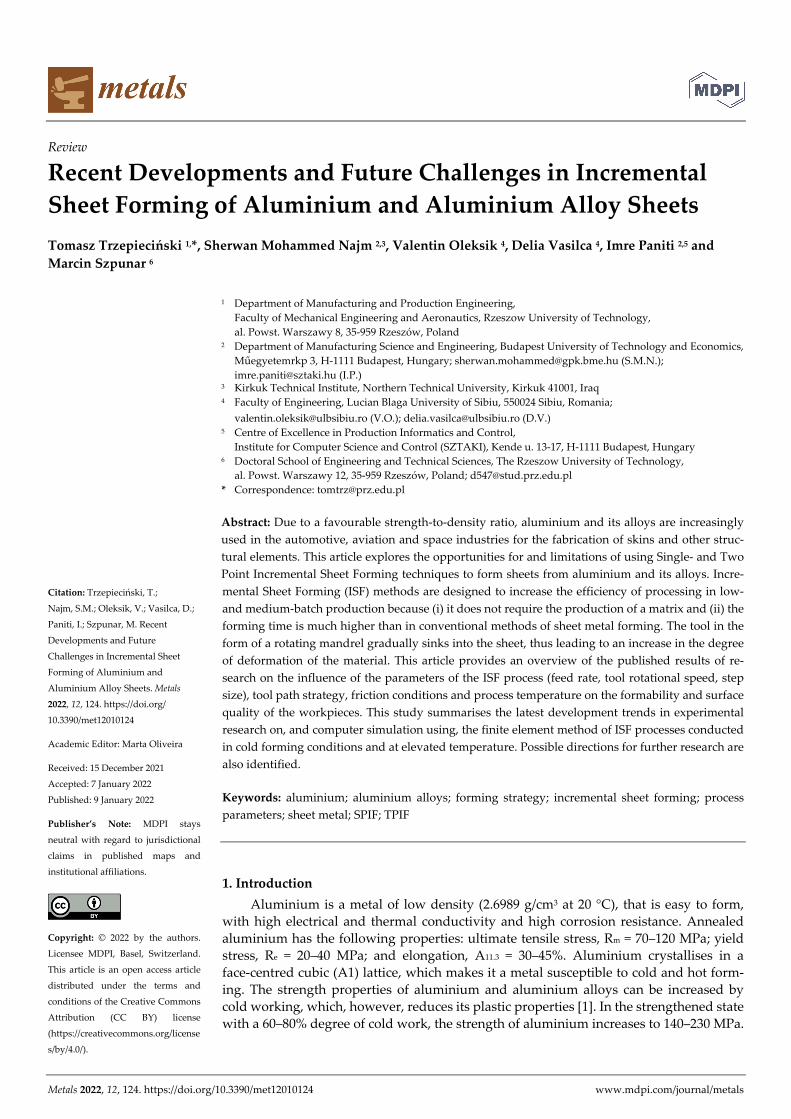
closed circuit. Figure 4 presents a comparison between ISF and WJISF. Considering that
WJISF is suited to unit and small‐lot production, where the highest priority is to ensure a
high‐quality surface finish, increasing the processing time and energy consumption do
not play a key role. The WJISF process is more flexible because, in principle, the process
parameters can be changed online during the forming process. WJISF can be performed
without lubrication, however. When the processing materials are susceptible to corro‐
sion, special additives are required in the water [64].
Metals 2022, 12, 124 8 of 46
Figure 4. Comparison between ISF and WJISF (reprinted with permission from [64]; Copyright ©
2022, Springer‐Verlag London Limited).
Zhang et al. [66] studied the high‐pressure oil jet incremental forming of
0.3‐millimetre‐thick aluminium sheets by simulating the effect of the geometry of the
conical nozzle on the dynamic pressure. They found that an oil pressure of 15 MPa was
suitable for forming the aluminium sheet material. Emmens [67] used a set of rotating,
columned water jets to expand and reshape beverage cans. He confirmed its high pro‐
duction efficiency for sheet metal parts with complex shapes when compared to the SPIF
processes.
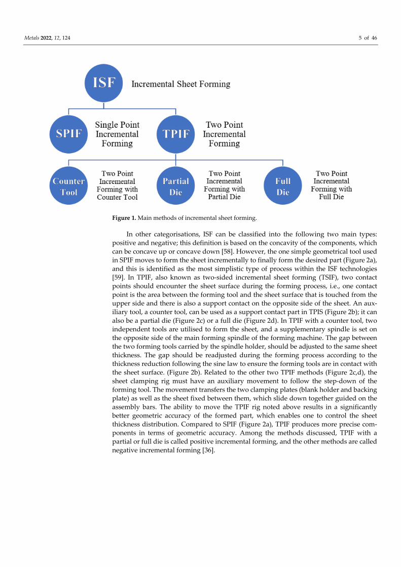
Jurisevic et al. [68] fabricated laminated tools with WJISF from aluminium sheets of
different thicknesses. The laminated tools (Figure 5) were relatively easy to produce and
did not significantly increase the total cost. Sajn et al. [69] carried out numerical simula‐
tions to obtain pressure and velocity distributions, taking into account turbulent fluid
flow through the nozzle and the WJ. They found that the area on the metal sheet affected
by the WJ pressure is significantly larger than the WJ cross section. The phenomenon of
an enlarged pressure area was successfully verified by experiment. Teymoori et al. [70]
used a coupled Eulerian–Lagrangian approach to simulate the WJISF forming process of
a conical part using the three‐dimensional Finite Element Method (FEM). The mechanics
of liquid/solid interaction in WJISF were studied by Kai et al. [71] using a finite ele‐
ment‐based numerical simulation. They modelled and simulated the water jet with a
Computational Fluid Dynamics (CFD) approach. It was found that most of the thinning
occurs in the former stage of WJISF and near the first path of the defined WJ trajectory.

Metals 2022, 12, 124 9 of 46
Figure 5. Laminated tools with various shapes and parts formed using different WJ trajectories
(reprinted with permission from [68]; copyright © 2022, Springer‐Verlag London Limited).
According to the device covered by patent CN102218706A [72], a water jet head may
be used for incremental sheet forming and cutting. The powerful impact force of the
water jet is used to carry out WJISF on the plate. The fine features of the plate can be
formed and cut by controlling the pressure of the water jet. In patent CN201110347675,
He et al. [73] developed a water jet apparatus that rotates during machining and oscil‐
lates within a set range so that a high‐pressure water column oscillates within the set
range and rotates axially around the axis of the water column to complete the forming
process.
3.3. Electromagnetic Incremental Forming
Electromagnetic incremental forming (EMIF) uses a Lorentz’s force occurring in a
pulse magnetic field generated by circuits conducting a high‐oscillation electric current
[74]. The electric current produces a transient magnetic field around the coil that induces
eddy currents in a metal workpiece. EMIF is a kind of powerful and high‐speed forming
technique where the deformation velocity can reach up to 300 m∙s−1 [75] and the strain
rate of the sheet metal is of the order of approximately 103∙s−1 [76–78]. To precisely control
the material behaviour in EMIF and obtain parts without defects, various techniques
were employed, such as applying two‐step forming [79], using tailored forming coils [80],
selecting optimized process parameters [81], predicting formability and failure [82] and
electromagnetic calibration [81,83]. EMIF is a powerful technique that can promote sig‐
nificant increases in the strain to failure in low ductility materials because of the strain
rate and inertial effect [84].
The process of electromagnetic incremental forming technology is described by Feng
et al. [84]. Firstly, the coil moved to the 0° position relative to the sheet, then the coil
discharged (Figure 6a). After the coil discharge, the sheet incurs local deformation under
the action of magnetic force. Then, the coil rotates along the sheet central axis, and the coil
discharges again to a locally undeformed region (Figure 6b–e).
Figure 6. Electromagnetic incremental sheet forming technology: (a) the initial position of the coil
and positions after rotation through (b) 90°, (c) 180°, (d) 270°, and (e) the region of plastic defor‐

Metals 2022, 12, 124 10 of 46
mation of workpiece (reprinted with permission from [84]; copyright © 2022 The Author(s). Pub‐
lished by Elsevier Ltd.).
Although the electromagnetic incremental sheet forming is a relatively new tech‐
nique, many scholars have investigated how to improve the formability of diffi‐
cult‐to‐form materials and reduce springback. EMIF was firstly proposed by Cui et al.
[85] to produce large‐size parts made of AA3003 aluminium alloy sheets. The effects of
the high‐speed impaction interaction between a concave die and a 5052 aluminium alloy
sheet, the coils moving trajectory and the discharge voltage on sheet formability were
studied by Feng et al. [84]. It was found that the conventional EMIF method cannot form
the bottom region flat part; it can only form the conical part. Imbert [86] demonstrated an
increased formability when an AA5754 aluminium alloy sheet was formed into a conical
die using EMIF. Long et al. [77] applied EMIF to manufacture a large‐size AA2524‐T3
aircraft skin with one‐dimensional curvature. The feasibility of Ethe MIF method in
forming specimen with a large size and one‐dimensional curvature was verified. Liu et
al. [87] investigated the effect of the shaping voltage on uniformity in EMIF based on dual
coil with the interval moving strategy. They proposed a strategy for EMIF by mul‐
ti‐passes in each layer. During EMIF based on a dual coil with an interval moving strat‐
egy by two forming layers, better forming uniformity of AA5052 aluminium alloy sheets
is found. Su et al. [88] investigated the deformation behaviours of a spherical
crown‐shaped thin‐walled AA2219‐O workpiece during a single layer forming of EMIF
by means of finite element‐based numerical modelling. It was found that the regions lo‐
cated outside the overlap region of coil positions deform insufficiently, leading to the
poor overall uniformity of the component. The forming uniformity can be improved by
properly reducing the first discharge voltage and increasing the last discharge voltage.
Guo et al. [89] found that the two consecutive discharge methods of a small voltage fol‐
lowed by a high voltage in a fixed position was helpful for improving the forming depth
and shape deviation to a die of the 2A12‐T4 aluminium alloy panel.
EMF has many advantages that make it an attractive alternative to conventional
SMF methods [90], such as the following:
there is no mechanical contact with the work piece,
no lubricants are needed,
the process can be fully controlled,
high technological flexibility,
parts formed by EMF exhibit good surface quality and high dimensional accuracy,
there is significant increase in workpiece ductility over conventional sheet metal
forming methods,
the formability limit is increased during electromagnetic forming due to high de‐
formation velocity,
the forming limit of the aluminium alloys can be improved by 10–14% [91] or even
2–3‐fold [92], compared to the quasi‐static loading conditions.
4. Process Formability of Aluminium and Aluminium Alloys
As is well known, aluminium and its alloys lend themselves to cold working opera‐
tions. The plasticity of aluminium varies directly with the degree of purity. Thus, the
higher the degree of purity is, the better the formability is. The plasticity of aluminium
alloys is different, and it depends on the nature and quantity of the alloying elements. Of
the alloying elements used in aluminium alloys, the magnesium content is of particular
importance. An increased magnesium content decreases the plasticity of alloys. Other
alloying elements that may be present in aluminium alloys are copper, iron, manganese
and silicon. Their presence also leads to an increased mechanical strength and a de‐
creased formability of aluminium alloys. The formability of aluminium and its alloys
with respect to the main metal forming processes (bending, deep drawing, etc.) has been

Metals 2022, 12, 124 11 of 46
studied in numerous scientific papers. This sub‐chapter aims to present the main studies
related to the formability in incremental forming.
In order to assess the formability, a deformation mechanism and stress state analysis
of the AA7075‐O aluminium alloy in SPIF was performed by Neto et al. [93]. This analy‐
sis was based on both a numerical simulation using the finite element method and ex‐
perimental investigations of the SPIF process for a frustum of the cone‐type part with a
wall angle of 45°. For the simulation, the hardening behaviour was implemented based
on Swift’s law and the Barlat criterion was chosen as the yield criterion. The major strain,
minor strain (both on the outer and inner surface) and thickness reduction were deter‐
mined. Following the analysis, it was found that the minor strain values are much lower
than those of the major strain and that the major strain distribution is almost identical to
the thickness reduction distribution. The authors of the paper also found that the defor‐
mation mode basically consists of a plane strain, as a result of the material predominantly
deforming in the meridional direction. The stress analysis led to the conclusion that there
is a negative mean stress in close proximity to the punch, leading to ductile fracture by
nucleation.
Shrivastava and Tandon [94] assessed the formability and deformation mechanism
of a face‐centred cubic aluminium AA 1050 H14 alloy in SPIF based on the microstructure
and texture analysis. The microstructure of the parts processed by SPIF was evaluated
using the Electron Back Scatter Diffraction method and X‐ray diffraction. The prelimi‐
nary research presented in the paper was related to the SPIF processing of frustum of
pyramid parts that were subsequently measured using Digital Image Correlation. By
measuring the inner and outer surfaces of the cone, the thickness reduction was obtained
for the processed parts. In parallel, the same geometry was obtained by numerical simu‐
lation using FEM, by means of the Altair software. In both experimental investigations
and numerical simulations, data analysis was performed at four different stages (unde‐
formed, early SPIF stage, intermediate SPIF stage and final SPIF stage). Subsequently, the
average grain size was determined for these stages, showing a decrease in the average
grain size from 42.40 to 11.05 μm on the frustum of the pyramid wall, in the area where
the maximum values of the major strain were observed. The orientation of the individual
grains was also studied, in order to analyse the grain rotation angle. The conclusion
drawn by the authors of the paper was that with the approach of the final stage, an in‐
crease in a large fraction of the high rotation angle and higher misorientation among the
grains is observed. Since bending is the main stress in the first stages, an ultrafine grain
structure is obtained. As the processing of the part progresses, the predominant stress is
stretching, and therefore a fine structure is obtained, but with elongated grains. Another
microstructural analysis was performed along the thickness direction. The appearance of
slip bands is observed in the final stages of SPIF, which leads to the appearance and ac‐
cumulation of dislocations. Another conclusion of the paper is that in the areas of the
material where there is a biaxial mode of deformation, higher values of the thickness
reduction are obtained, compared to the areas of the material in the plane strain condi‐
tion.
The forming behaviour of an Al‐Mg‐Si alloy (AA‐6061) was studied by Barnwall et
al. [95] from both experimental and theoretical (numerical simulation) perspectives,
showing a good correlation between the two approaches. The experimental investiga‐
tions focused on the determination of the mechanical characteristics in three directions
(rolling direction, transverse direction and diagonal direction), on the determination of
the major strain, minor strain and thickness reduction using Digital Image Correlation,
and then on the evaluation of the microstructural behaviour of the aluminium AA‐6061
alloy based on electron backscattering diffraction. The geometry used in SPIF to evaluate
the formability was a frustum of cone with a 45° wall angle and the punch trajectory was
a spiral. The geometry of the analysed parts was divided into the following three zones,
in order to assess the formability: a blank zone, a deformed zone situated on the wall of
the part and an undeformed zone situated on the bottom of the part. The main zone of
Metals 2022, 12, 124 12 of 46
interest was, of course, the deformed zone, where the authors observed that the maxi‐
mum values are obtained for both the major strain and the thickness reduction, which
has an almost identical distribution to that of the major strain. It was also found that the
direction of the major true strain is always perpendicular to the trajectory of the punch.
The authors also presented the variation during the SPIF process of the major and minor
strains for five radially arranged points, at equal distances, located in the deformed zone
and named this graph the strain path curve. Regarding the microstructural changes of the
AA‐6061 alloy during the SPIF process, it was observed that while, initially, the material
presented a higher volume fraction of cube and S textures, after the process, the de‐
formed zone presented a considerable increase in the volume fraction of brass. An in‐
crease in the resistance to deformation in the diagonal direction with respect to the roll‐
ing direction and the transverse direction could also be observed, as a result of a higher
Taylor in the diagonal direction.
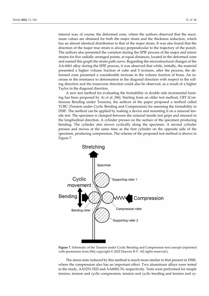
A new test method for evaluating the formability in double side incremental form‐
ing has been proposed by Ai et al. [96]. Starting from an older test method, CBT (Con‐
tinuous Bending under Tension), the authors of the paper proposed a method called
TCBC (Tension under Cyclic Bending and Compression) for assessing the formability in
DSIF. The method can be applied by making a device and mounting it on a uniaxial ten‐
sile test. The specimen is clamped between the uniaxial tensile test grips and stressed in
the longitudinal direction. A cylinder presses on the surface of the specimen producing
bending. The cylinder also moves cyclically along the specimen. A second cylinder
presses and moves at the same time as the first cylinder on the opposite side of the
specimen, producing compression. The scheme of the proposed test method is shown in
Figure 7.
Figure 7. Schematic of the Tension under Cyclic Bending and Compression test concept (reprinted
with permission from [96]; copyright © 2022 Elsevier B.V. All rights reserved.).
The stress state induced by this method is much more similar to that present in DSIF,
where the compression also has an important effect. Two aluminium alloys were tested
in the study, AA5251‐H22 and AA6082‐T6, respectively. Tests were performed for simple
tension, tension and cyclic compression, tension and cyclic bending and tension and cy‐

Metals 2022, 12, 124 13 of 46
clic bending and compression. An increase in elongation of almost seven times was
found for specimens stressed in tension and cyclic bending and compression, compared
to those stressed in simple tension. The major strain–minor strain diagrams were also
plotted. The DSIF process was then simulated using the finite element method and the
major strain–minor strain diagrams were plotted in this case also. It was found that the
proposed method can be used successfully for a more accurate evaluation of the forma‐
bility in DSIF.
The issue of reusing parts obtained by metal forming technologies (in most cases by
deep drawing) was studied by Ingarao et al. [97]. In order to reduce metal waste, scrap
parts can be reused if they are processed by SPIF. The authors of the paper analysed the
behaviour of parts initially processed by deep drawing and then subjected to the SPIF
process. An AA‐5754 H22 aluminium alloy with 0.5 mm thickness was chosen for the
study. The following two cases were analysed: one in which the SPIF geometry is located
at a distance from the deep‐drawn area, and another in which the SPIF geometry is close
to the deep‐drawn area. For the first case, a frustum of cone geometry (with small diam‐
eter) was obtained on a square‐box‐type part formed by deep‐drawing, while for the
second case, a frustum of pyramid geometry was obtained on a square‐shape‐type part
formed by deep‐drawing. In the second case, the dimensions of the two geometric shapes
are similar. For this situation, the following two wall angles were chosen to be processed
by SPIF: 45° and 60°. In the first case, the thinning of the material produced by the SPIF
process did not affect the geometry already achieved by deep drawing, due to the fact
that the two geometries practically do not interfere. In the second case, even if a signifi‐
cant increase in strain and thickness reduction was observed in the areas where the two
geometries are close together, no fractures occurred in the material.
The studies carried out to assess the formability in SPIF of aluminium and alumin‐
ium alloys did not only concern flat sheets with uniform thickness. Do et al. [98] pub‐
lished a paper that addresses the formability of 3D structured aluminium. In their paper,
they compared the forming behaviour of an Al3004‐P aluminium alloy presented in the
following two forms: a flat aluminium sheet and an embossed aluminium sheet. The
embossed model was achieved by means of two embossed rollers of conical shape, ob‐
taining a model with a pitch of 6.4 mm and a height of 0.7 mm. The first step consisted of
research carried out to determine the mechanical characteristics by means of the uniaxial
tensile test. For the embossed aluminium sheet, specimens were taken in the following
two directions: parallel to the embossed pattern and at 45° to the direction of the em‐
bossed pattern. For the embossed specimens taken in the parallel direction, an increase in
elongation was observed compared to the flat specimens, as well as an increase in the
hardening exponent. For the specimens taken at 45°, the results were similar to those of
the flat specimens. Using a CNC milling machine, parts were made by SPIF for a frustum
of pyramid geometry. An increase in the maximum wall angle to 62° was found in the
case of the embossed specimens, compared to 60° in the case of flat specimens when us‐
ing an inward path, and a maximum wall angle of 64° was found in embossed specimens
when using an outward path. The authors of the paper then plotted the FLC in SPIF for
the embossed aluminium Al3004‐P material, based on the major and minor strain.
Abd et al. [99] presented the possibility of using the SPIF process in the forming of
an Al/SUS bimetal sheet. To evaluate the formability of bimetallic sheets, they used an
Al1050 sheet with 1.5 mm thickness and SUS304 with 0.5 mm thickness. After the hot
rolling process, a thickness of 1 mm of the composite sheet was obtained, achieving a
thickness reduction of 50%. The parts were formed in two variants, with the aluminium
coming into contact with the punch (AL/SUS) and with the steel coming into contact with
the punch (SUS/AL). The geometry of the parts made was a frustum of a pyramid with a
variable angle, in order to determine the maximum wall angle at SPIF. The process pa‐
rameters were varied, namely, the punch diameter (from 10 to 20 mm) and the vertical
step (from 0.15 to 1 mm). It was found that regardless of the process parameters used, the
maximum value of the wall angle is obtained in the case where the punch comes into
Metals 2022, 12, 124 14 of 46
contact with the steel (SUS/AL). Using Digital Image Correlation (DIC), the major strain
and minor strain, as well as the FLD, were determined for these bimetallic materials. As
expected, the position of the FLD line in SPIF in the SUS/AL case is higher than in the
AL/SUS case. In addition, the negative slope of the line in the AL/SUS case is observed to
be greater in absolute value than in the SUS/AL case. All these conclusions lead to the
idea that, in terms of formability, it is preferable that the punch is in contact with the steel
in the case of these bimetallic materials. The authors also evaluated the influence of the
punch diameter and vertical step on the maximum wall angle in bimetallic materials and
concluded that at a small value of the vertical step (0.15 mm), increasing the punch di‐
ameter leads to a decrease in the maximum wall angle, while at a large value of the ver‐
tical step (1 mm), the effect is reversed, i.e., increasing the punch diameter leads to an
increase in the maximum wall angle.
4.1. Forming Limit Diagram
One of the first studies related to the aluminium formability (for 3003‐0 and 5754‐0
aluminium sheets) is that of Jeswiet et al. [100]. The study began by obtaining a linear
dependence relation between the wall angle and the initial thickness of the material for
the two mentioned aluminium alloys. The authors of this study were among the first to
draw the FLD for the incremental forming of aluminium alloys. To obtain the FLD, ex‐
perimental investigations were carried out up to the breakage of the material for several
types of geometries: the frustum of a cone shape, hyperbolic shape, hemispherical (dome)
shape, the frustum of a pyramid shape and a complex shape with five lobes. It was thus
found that for the frustum of cone‐shaped parts, the FLD is represented as a line with a
negative slope (of value −1) located in the first quadrant of the major and minor strain
(that of the positive biaxial strains). For the other types of geometries, the slope of the line
located in the same quadrant is also negative, but of a much larger value (between −30
and−40). The authors proposed constructing the FLD based on the two lines, thus cov‐
ering most types of part geometries obtained by SPIF.
Another paper, published by Mugendiran and Gnanavelbabu [101], performed a
comparison of the FLDs and thickness reduction distribution for two parts, a frustum of
the pyramid‐type part and a frustum of the cone‐type part. The material used in the pa‐
per was aluminium AA5052. For both parts of the geometries, FLDs were plotted as lines
with a negative slope, located in the quadrant with positive major and minor strains. The
authors observed that higher values of the major and minor strains are obtained in the
case of the frustum of cone‐type parts and, consequently, the FLD line for these parts is
found above the FLD line of the frustum of pyramid‐type parts. Another conclusion is
that the slope of the FLD line for the frustum of cone‐type parts is greater than that of the
frustum of pyramid‐type parts. Comparing these results with the ones obtained when
measuring the thickness reduction for the two types of geometries, it is found that the
frustum of cone‐type parts has a lower thickness reduction than the frustum of pyra‐
mid‐type parts. Both conclusions lead to the idea that the formability of parts with no
corners, made of smooth trajectories and without sudden changes of trajectory, is better.
Madeira et al. [102] proposed another study to assess the formability and determine
the FLD for SPIF. Aluminium AA1050‐H111 with a thickness of 1 mm was used for this
research. The authors used circle grid analysis to measure the major strain and minor
strain, and the tests were continued until the circumferential fracture occurred. The aim
of the research was to improve the understanding of the behaviour of aluminium in SPIF
by combining several tests: the double notched uniaxial tensile test, conventional forma‐
bility tests (Nakajima test, circular and elliptical bulge test and hemispherical dome test)
and a test on a frustum of a cone‐type part made by SPIF. The FLCs (forming limit
curves) were plotted on the basis of the conventional tests, while the FFLs (forming
fracture lines) were plotted on the basis of the double notched uniaxial tensile test. In
order to obtain the frustum of cone‐type parts by SPIF, different diameter punches (4, 6,
10, 15 and 25 mm) were used. By comparing the results obtained in SPIF with those of the

Metals 2022, 12, 124 15 of 46
FLC and FFL, the authors proved that the fracture in SPIF occurs by tension and the
fracture based on shear stresses (in‐plane or out‐of‐plane) cannot be questioned in SPIF.
Kumar and Maji [103] analysed the formability of aluminium alloys in SPIF, deter‐
mining the FLC based on the groove test and the deformation instability method. The
material used for the formability analysis was an AA5083 aluminium alloy, an alloy with
good thermal conductivity and corrosion resistance, accompanied by good strength. The
mechanical properties of the aluminium alloy were determined by conducting uniaxial
tensile tests on the rolling direction, transverse direction and at 45° to the rolling direc‐
tion. The FLCs for SPIF were then plotted and compared with the FLCs obtained in
conventional forming using the Marciniak–Kuczynski test. The authors concluded that
the formability in SPIF is improved by 60–80% compared to the conventional forming
processes. Parts with different wall angles were then made. The analysis continued with
the plotting of the FLCs in SPIF for different vertical steps, different speed rates and dif‐
ferent rotation speeds. It was concluded that increasing the vertical step leads to a de‐
creased formability, while increasing the feed rate and rotation speed leads to an in‐
creased formability of the AA5083 aluminium alloy. The FLC was also plotted for
heat‐assisted incremental forming, where the heating took place up to 300 °C. It was,
thus, observed that increasing the temperature significantly influences the maximum
wall angle, which can be increased by up to 3° in heat‐assisted incremental forming.
Several studies have recently focused on the application of SPIF to tailored welded
blanks. A recent paper conducted a comparative study on the FLD for welded blanks
made of AA6061 aluminium with a thickness of 2 mm and dimensions of 250 mm × 250
mm [104]. In fact, this study compared the FLD lines for different positions of the weld‐
ing line relative to the rolling direction. After selecting the optimal direction, the Re‐
sponse Surface Methodology (RSM) was used to identify which parameters are optimal
in terms of the friction stir welding process. The specimens were welded so that the
welding line was parallel to the rolling direction of both sheets, perpendicular to the
rolling direction of both sheets and forms an angle of 45° with the rolling direction of
both sheets. The frustum of cone was chosen as the geometry used to determine the FLD.
The results obtained led to the conclusion that the best results in terms of formability are
obtained when the welding line is positioned at an angle of 45° with the rolling direction
of both sheets. The authors correlated these results with the strain hardening exponent
values obtained for the same types of specimens, obtaining the highest value in the case
of those at an angle of 45° with the rolling direction of both sheets.
Another piece of research, also related to the evaluation of the formability of friction
stir welded blanks of aluminium alloys during SPIF, was published by Carlone et al.
[105]. The aim of this study was to determine the optimal friction stir welding parameters
so that the specimens produce the best results in terms of formability. The aluminium
alloy used for this research was 6082‐T6. Unlike other studies on the formability of fric‐
tion stir welded blanks of aluminium alloys, which focused either on producing the
frustum of cone‐ or the frustum of pyramid‐shaped parts with a constant wall angle, or
on evaluating the formability based on groove tests on different directions, this research
focused on producing the frustum of cone‐shaped parts with variable wall angles. Thus,
the authors were able to evaluate, based on the maximum frustum of the cone height, the
maximum wall angle at which the fracture occurs in SPIF. Five types of specimens with
different rotational speeds and feed rates were made by friction stir welding, and their
results were compared with a specimen made of base material and a specimen obtained
using the tungsten inert gas (TIG) welding process. A strong decrease in formability was
observed in the specimen obtained using TIG. It was also noted that the best results
(maximum frustum of cone height and maximum frustum of cone wall angle), even bet‐
ter than those of the base material specimen, were obtained for the specimen with a ro‐
tational speed of 1200 rpm and a feed rate of 70 mm/min. FLDs were also plotted for
these specimens and compared with those obtained in the conventional metal forming
processes.

Metals 2022, 12, 124 16 of 46
4.2. Effect of Process Parameters on Formability
One of the most important parameters considered for improving the formability in
SPIF is the forming strategy. Buffa et al. [106] used the finite element method (FEM) and
the Circular Grid Analysis (CGA) to highlight which multi‐step forming strategy leads to
better results in terms of increasing the formability for AA1050 sheets with 1 mm thick‐
ness. The investigations were performed both numerically, using the finite element
method, and experimentally, for square‐cup‐shaped parts with a 90° wall angle. The
forming process was continued until the breakage of the part. The following three types
of strategies were considered: a strategy by which a progressive increase in the wall angle
is achieved (strategy A), another strategy by which the part side is increased and thereby
leads to an increase in the wall angle (strategy B) and a last strategy using a
non‐horizontal path plane (strategy C). While strategies A and B are mono‐directional
strategies, strategy C is a multi‐directional strategy, whereby the part goes through dif‐
ferent stages until the final shape is reached. All these strategies are presented in Figure 8.
In the parts processed using the first two strategies, the fracture occurred in the corner
area of the part when the angle exceeded 70°. In the parts processed using strategy C (a
non‐horizontal path plane), no material breakage occurred. Using CGA, the authors also
plotted the minor strain–major strain diagrams for the processed parts. For strategy C,
these diagrams were also presented for the intermediate stages of the part up until the
final shape. Their analysis found that there is a substantial increase in formability when
using this type of strategy, mainly due to the redistribution of material over the thickness
of the part.
Figure 8. The three strategies used (a) A strategy, (b) B strategy and (c) C strategy (reprinted with
permission from [106]; copyright © 2022 The Society of Manufacturing Engineers. Published by
Elsevier Ltd. All rights reserved).
The effect of the punch geometry, punch diameter, side radius of the flat end of the
punch and a radius of an active surface of the punch on the formability of AA2024‐O
aluminium alloy sheets in SPIF was studied by Kumar et al. [107]. They chose the form‐
ing depth of the frustum of cone‐shaped parts as a formability indicator. Two punch
geometry shapes were chosen, a hemispherical one and a flat end one, as well as three
values for the punch diameter, three values for the radius of the active surface of the
punch and two values for the side radius of the flat end for each punch’s geometry. Parts
with three values of the wall angle, 60°, 65° and 70°, were also made and three values of

Metals 2022, 12, 124 17 of 46
the vertical step, 0.2, 0.5 and 0.8 mm, were used. The punch trajectory was a helical one.
The processed parts were scanned using a dual CCD camera. It was observed that de‐
creasing the punch diameter and radius lead to decreased formability and that the punch
with a hemispherical shape leads to increased formability. It was also found that de‐
creasing the wall angle and vertical step leads, as expected, to increased formability.
Baruah et al. [108] conducted a study that aimed to optimize the process parameters
for the SPIF forming of an AA5052‐H32 aluminium alloy with 1 mm thickness. The ob‐
jective of the optimization process was to simultaneously increase the formability and
improve the surface quality by reducing the roughness, and the following parameters
were considered: vertical step, feed rate, rotational speed and lubrication. These were
varied on three levels each, as follows: 0.2, 0.5 and 0.9 mm for the vertical step; 200, 500
and 800 mm/min for the feed rate; and 150, 400 and 800 rpm for the rotational speed and
dry, grease and oil for lubrication, respectively. The Grey relational analysis (GRA) was
used as the optimization method, while the test to evaluate the formability was the
groove test, performed in the rolling direction, transverse direction and diagonal direc‐
tion (45° to the rolling direction). The maximum depth of the parts before the fracture
occurred, as well as the roughness of the surface coming into contact with the punch,
were measured. Based on Taguchi’s orthogonal array, Grey relational analyses and
ANOVA, the following optimal values were obtained, which allow both the increase in
the formability of the AA5052‐H32 aluminium alloy during SPIF and the reduction in the
roughness: vertical step: 0.5 mm, feed rate: 200 mm/min, rotation speed: 150 rpm and
using a grease as lubrication.
Another paper that studies the formability of an aluminium friction stir welded
blank, this time during single point incremental forming versus two‐point incremental
forming, is a study conducted by Ebrahimzadeh et al. [109]. The material used in the
paper is aluminium 5083. The first research of the authors concerns the identification of
the influence of the friction stir welding process parameters (rotary speed, travel speed
and plunge depth) on the mechanical characteristics of the aluminium welded blanks
determined on the basis of the uniaxial tensile test. The parts were then processed by
SPIF and TPIF with two values of the wall angle, 63° and 73°, until the breakage occurred.
It was found that for both values of the wall angle, the maximum height obtained was
greater in the case of TPIF, the greatest difference occurring for the wall angle of 630.
Based on the Response Surface Methodology (RSM), an algorithm was developed to
choose the optimum values of the incremental forming process factors. The influencing
factors considered for both variants of incremental forming were the vertical step, rota‐
tional speed and feed rate, each of which had three levels of variation. Thus, the follow‐
ing values were chosen: 0.2, 0.4 and 0.6 mm for the vertical step; 0, 400 and 800 rpm for
the rotational speed; and 200, 400 and 600 mm/min for the feed rate. The thickness re‐
duction was measured to evaluate the formability, while the springback was measured to
evaluate the geometrical precision for all the possible cases resulting from the combina‐
tion of the previously mentioned parameters. It was, thus, concluded that increasing the
rotational speed leads to an increase in the thickness reduction and consequently to a
reduction in formability, that increasing the feed rate leads to a decrease in thickness
reduction and consequently to an increase in formability and that the vertical step has
very little influence on the thickness reduction and formability.
Vanhove et al. [110] presented a study on the formability of aluminium alloys pro‐
cessed by SPIF at a cryogenic temperature. They performed tests on two aluminium al‐
loys, AA5083‐H111 and AA1050‐H24, at the following three different temperatures: 293,
193 and 78 K. Preliminary investigations (uniaxial tensile tests) carried out at the same
temperatures led to an increase in the formability of the two alloys as the forming tem‐
perature decreased. In order to obtain the parts by SPIF, a cryogenic cooling clamping
system was built. The geometry of the parts made was a frustum of a cone. The parts
were obtained by dipping in LN2, both without lubrication and with graphite coating.
The SPIF process at low temperatures was not possible without graphite coating, the

Metals 2022, 12, 124 18 of 46
parts showing fractures regardless of the wall angle. The parts with graphite coating also
showed a decrease in formability with a decreasing temperature, obtaining a maximum
wall angle of 74° at 293 K, 72° at 193 K and 64° at 193 K. The authors indicated the change in the formability behaviour with respect to the uniaxial tensile test, the main cause of
this behaviour being the increased level of stress triaxiality in the parts formed at the
cryogenic temperature.
The influence of ultrasonic vibration on the formability of 1060 Aluminium material
was evaluated by Yang et al. [111]. The study was conducted using the Abaqus finite
element software on a frustum of cone geometry. The punch, in addition to the move‐
ment on the trajectory required for the part forming, was also imprinted with a sinusoi‐
dal (vibratory) movement with different amplitudes and different frequencies. Following
the analysis, the plastic strain along the x, y and z axes and the thickness reduction were
determined in order to estimate the moment when the breakage of the material occurs.
The authors started by studying the influence of ultrasonic vibrations on the maximum
wall angle in the parts processed by SPIF. The frequency was maintained at a constant
value of 24 KHz and the amplitudes were of 0, 2, 4, 6, 8 and 10 μm. The highest wall angle
value was obtained for a frequency of 6 μm. The respective frequency value (of 6 μm)
was then maintained at a constant, and the amplitude was varied from 10 to 25 KHz. It
was thus concluded that the highest formability is obtained at an amplitude of 25 KHz
and a frequency of 6 μm, for a 1060 aluminium sheet. The results obtained by numerical
simulation were then validated experimentally, and a punch clamping system, equipped
with an ultrasonic generator with a maximum power of 2 kW, was built.
5. Accuracy in SPIF and TPIF
ISF is a more suitable solution than the conventional sheet forming processes as far
as prototype manufacturing or small batch production processes are concerned. Many
process parameters affect the formed part’s quality and accuracy; however, improperly
selecting these parameters can cause a crack or fracture to appear during the process
before achieving the desired shapes. ISF still has disadvantages in terms of the geometric
accuracy of the components, in particular due to springback, path compensation and
pillow effects. To form sheet material incrementally with more accuracy, patent
US7984635B2 [112] by Callebaut and co‐inventors from the University of Leuven, Bel‐
gium, dating from 2011, locally applied dynamic heat to the contact zone by moving a
laser that moves synchronically in TPIF using a partial die. In patent US10010920B2 [113]
and similar patents CN102343386B [114], DE102011079734A1 [115] and RU2576792C2
[116], Ren and co‐workers [113] incrementally formed a part using TPIF in which two
forming tools move along multiple axes under the control of an electronic controller that
decreases the gap between the tool and the sheet, thus improving geometric accuracy. In
another patent, US8322176B2 [117], by Johnson and his co‐workers and an identical
Chinese patent, CN201744547U [118], the first forming tool moves in various directions
along the upper sheet surface to form a sheet and improve the surface quality and geo‐
metric accuracy. A second tool moves in multiple directions along the lower sheet sur‐
face. The first and second forming tools pass using first and second manipulators con‐
figured to move the forming tools according to the predetermined path strategies. In
patent EP2505279A1 [119], a device for two‐sided incremental sheet forming was in‐
vented to reduce the influence of the acting force on the lower forming tool and to stabi‐
lise and guide both forming tools to ensure accurately formed components. To prevent
ridges and ploughing in the formed sheet because of the incremental step, patent
US11072015B2 [120] by Roth et al., which is the same as patent US62311689 [121], pro‐
posed a tool and method to incrementally form a sheet by single point, double‐sided and
multi‐axis approaches. This patent proposes the generation of a high frequency between
the two steps, basically vibrating the forming tool in all directions, up and down, side to
side, inside and outside, or any combination of these, to provide a better surface, in‐
creased formability and greater geometrical accuracy.

Metals 2022, 12, 124 19 of 46
The accumulative double‐sided incremental forming (ADSIF) system in patent
US9168580B2 [122] and an identical patent in WIPO WO2013062827A1 [123] was in‐
vented by Cao and Malhotra. Patent US20210237140A1 [124] proposed double‐sided in‐
cremental tools for enhanced accuracy. The tool includes a sleeve with a hollow interior
space to position the contact element inside the hollow interior space of the sleeve. The
aforementioned patent is identical to EP3858511A1 [125] and CN113198919A [126]. The
geometric accuracy achieved with ADSIF is noteworthy when compared to SPIF and
DSIF. Continuous tool lines on both sides of the formed part indicate no contact loss
between the forming tools and the sheet surface. The innovative tools proposed in patent
US8021501B2 [127] by Kiridena et al. were used to assure dimensional accuracy and ac‐
cessibility in the incrementally formed part. They indicated that forming tool deflections
significantly affects the geometric accuracy as the shank length becomes longer and the
diameter becomes smaller, and the flat underside of the doughnut‐shaped tips improved
the geometric accuracy of the part. However, it stated that elastic deformation at the tool
tip will produce dimensional inaccuracies of the formed part, and the plastic defor‐
mations will permanently damage the forming tool if a flat tool with the smallest corner
radius is used because of a reduction in springback.
5.1. Springback Reduction
Inaccuracy in a component’s geometry discourages the use of ISF as an essential
industrial process and the use of this technology by manufacturing companies in place of
conventional methods. One of the main criteria that affect the accuracy of the compo‐
nents is springback. Two scenarios cause springback; the first is local springback because
the sheet placed behind the advancing forming tool has a tendency to return to its initial
position. The second is global springback in which springback occurs after the release of
the clamping on the sheet as the remaining residual stresses in the unconstrained mate‐
rial of the part formed using ISF are released [128]. Besides the above‐mentioned two
scenarios of springback, Gatea et al. [129] mentioned another type that occurs with the
displacement of the tool called a continuous local springback. Furthermore, they stated
that researchers gave particular consideration to the ISF process parameters on spring‐
back and accuracy because it is one of the main significant drawbacks of the process.
Therefore, Bambach et al. [130] stated that multistage incremental forming reduces local
elastic deformation and local springback (Figure 9) at the end stage of forming, which, in
general, increases the accuracy of the final product. Springback can be affected by the
following various factors: tool shape and size, rotation speed, feed rate, initial sheet
thickness, wall angle and residual stresses. To reduce springback, many researchers have
provided different solutions.
Figure 9. Scheme of local springback in SPIF (reprinted with permission from [130]; copyright ©
2022, German Academic Society for Production Engineering (WGP)).

Metals 2022, 12, 124 20 of 46
A method is proposed for mechanically deforming sheet material to decrease
springback in patent EP0055435A2 [131], published in 1982, and US4373371A [132], pub‐
lished in 1983 by Liu. The electrically assisted double‐sided incremental forming in‐
vented in patent US8741079B2 [133], as with WIPO WO2012030835A2 [134], by Roth and
Cao, can double‐side form a sheet incrementally and directly apply electricity to the
formed part. The current can be switched on before/after starting the forming process
and/or switched off before/after the ending of the forming process. The invention can
reduce the forming force, increase formability and reduce any springback. The first pa‐
tent, US8021501B2 [135], was submitted by Roth and granted in 2011. It proposes the
application of a direct electric current through the SPIF apparatus to reduce any spring‐
back. Patent US10500629B2 [136], dating from 2019, was also submitted by Roth and,
together with the identical WIPO patent WO2016/057688Al [137], provides a method for
reducing springback using electrically assisted manufacturing (EAM) on a 2024‐T3 alu‐
minium sheet that is 0.5 mm thick. The influence of using direct current on the reduction
in springback on 6061 aluminium sheets formed by SPIF has been described by patent
US9951397B2 [138]. This asserts that reduced springback can be obtained by increasing
the current density applied until the springback is eliminated at a current density of 120
A/mm2. Patent US6971256B2 [139] by Okada et al. provides a method and apparatus for
TPIF to reduce springback caused by supplying air heated by an electric heater blowing
on the aluminium alloy. A patent of Okada et al. [139] is the same as European Patent
EP1462189B1 [140] and the Japanese patent JP2004291067A [141]. The researchers in
[142,143] remarked that when forming AlMn1Mg1 aluminium, a tool with a flat tip
produced better components formed by SPIF with different process conditions than a
tool with a hemispherical tip in terms of formability, uniformity of thickness and the
pillow effect, and the best geometric accuracy was obtained. Wei et al. [144] drew many
conclusions from their experiment and simulation study of SPIF forming, such as that
springback has an insignificant impact on the forming accuracy of the final part, and that
there is a linear relationship between the wall angle and springback, i.e., a large wall an‐
gle of the formed part led to less springback. Sun et al. [145] studied the impact of ultra‐
sonic vibration on the springback and surface quality of the AA‐5052 aluminium alloy
formed by SPIF. They found that forming sheets incrementally with ultrasonic assistance
can reduce the springback effect. Rusu et al. [146] studied the behaviour of the following
various aluminium alloys: AA 2007, EN AW 5754 and EN AW 6060 that were formed
using SPIF, examining forming forces, thickness distribution and springback. The largest
springback effect was seen in the AA 2007 alloy, which was accompanied by the lowest
accuracy. Zhang et al. [147] investigated the effect of SPIF parameters on springback
during forming assisted by ultrasonic vibration (UV). They found that a larger tool size
led to greater springback, and that ultrasonic vibration reduced springback and im‐
proved geometric accuracy. Recently, artificial neural networks (ANN) have been em‐
ployed with or without controlled manufacturing to develop efficient predictive models
in many applications, including the metal forming process [148]. Various tool materials
and shapes were examined to analyse the parametric factors that affect the geometric
accuracy of AlMn1Mg1 components formed by SPIF. The results obtained were used to
predict the accuracy in two different ANN models via two output neurons (Figure 10a)
and one output neuron (Figure 10b) using a feed‐forward neural network with a back
propagation algorithm [149]. The SPIF process has been simulated by generating an
elastoplastic finite element model (FEM), and the results obtained are compared to the
experimental results of Han et al. [150]. The FEM results were adopted to predict
springback using the ANNs.

Metals 2022, 12, 124 21 of 46
(a)
(b)
Figure 10. The ANN structure for modelling the effect of process parameters on the surface
roughness of components: (a) two outputs, (b) one output (reprinted from [148]; copyright © 2022,
The Authors, this is an open access article distributed under the terms of the Creative Commons
CC BY license, which permits unrestricted use, distribution and reproduction in any medium,
provided the original work is properly cited).
5.2. Toolpath Compensation
Dimensional deviation due to springback occurs between the geometry obtained
and that desired at the end of the forming process and the release of the forming loads.
Furthermore, different reasons lead to faulty components being formed by ISF. One of
these is an inappropriate tool path. There are different tool path strategies used to form
sheet metal in an incremental fashion. The two main tool paths used are spiral or contour
paths. However, the forming tool moves peripherally along the programmed path in
both types of tool path strategy. Jeswiet et al. [151] preferred the spiral path to the con‐
tour path despite the fact that the generation of a spiral path is more challenging than that
of a contour one. Hirt et al. [152] assert that deviations in the geometry of components
may happen in the forming process even if the tool passes the selected path correctly and
elastic deformation emerges during the process due to the local forming force; accord‐
ingly, the plastic deformation partly escapes from the formed sheet. There are the fol‐
lowing two ways to control the geometric accuracy of components formed by ISF: tool
path correction and optimisation of the process parameters. The disadvantages of SPIF
components are the reduction in the geometric accuracy, especially the occurrence of the
significant springback of the sheet; however, these can be minimised by algorithms for
the correction of the tool path [36]. In various studies, the tool path in the ISF process has
been modified to compensate for the springback value. The compensation process was

Metals 2022, 12, 124 22 of 46
adopted to achieve a more precise component. Related to what has been noted, Ambro‐
gio et al. [153] studied the effect of incremental forming parameters on accuracy. They
suggested a compensation scheme because sheet springback during the incremental
forming process has an important influence on the forming accuracy. To this end, inte‐
gration between the numerical and experimental procedures is introduced on AA1050‐O.
Hirt et al. [154] said that one can successfully form the part as designed by precisely fol‐
lowing the tool path if all the deformations are totally pure plastic. Deviation can occur
due to elastic deformation, and one of their suggested forming strategies increased the
angle of the tool path from one stage to the next.
Feature‐based tool path methods have been generated and compared with the con‐
ventional ISF tool path in three case studies by Lu et al. [155]. The new feature‐based al‐
gorithm can obtain better geometric accuracy, particularly for non‐symmetrical compo‐
nents without a supporting die. SPIF and counter SPIF, as the first and second stages of
the incremental forming process, have been employed to decrease the springback of
formed components and other shaping errors. If the tool path is not along the critical
edge, tool marks may be left on the area where the tool path crosses the edge (Figure 11).
The tool path of the second stage was developed on the basis of the first stage, while the
first stage tool path was based on the part geometry.
Figure 11. Potential surface problem in non‐symmetrical part (reprinted with permission from
[155]; copyright © 2022, Elsevier B.V. Published by Elsevier B.V. All rights reserved).
Jung et al. [156] used SPIF and counter SPIF as the first and second stages of the in‐
cremental forming process, which had been employed to decrease the springback of
formed components and other shaping errors in the 5052 aluminium alloy. The tool path
of the second stage was developed based on the first stage, while the first stage tool path
was based on part geometry. Ren et al. [157] have generated a methodology suitable for
arbitrary shapes and different ISF processes to reduce component inaccuracy, particu‐
larly in springback. The methodology developed mainly consists of the following three
elements: finding the critical key that affects the complexity of the geometry, offline
simulation to predict springback and modifying the tool path in situ during the forming
process (Figure 12).

Metals 2022, 12, 124 23 of 46
Figure 12. An in situ springback compensation method (reprinted with permission from [157];
copyright © 2022, Published by Elsevier Ltd. on behalf of CIRP).
By measuring the deviation between the ideal part and the part as formed, an algo‐
rithm was developed by Fiorentino et al. [158] to correct component geometry iteratively
through the generation of a new, improved tool path. They eliminate the deviation to less
than 0.4 mm in incrementally formed Al components. Rauch et al. [159] proposed a new
method to generate and control Intelligent CAM (ICAM) tool paths. According to the
process data assessment, this new approach modifies the tool paths during manufactur‐
ing using ISF. Behera et al. [160] presented a compensated tool path strategy as an error
prediction to improve accuracy using multivariate adaptive regression splines (MARS).
Fu et al. [161] developed an iterative closed‐loop control algorithm in SPIF to correct the
tool paths based on Fast Fourier and wavelet transforms. The springback of formed parts
implemented by trial and corrected tool paths extracted from FEMs has been adopted in
the algorithms developed.
5.3. Pillow Effect
The pillow effect is a concave surface occurring in the centre of the bottom of com‐
ponents, which is an undeformed area [162]. The pillow effect (bulge) is a significant
manufacturing defect that negatively affects the geometric accuracy of parts formed us‐
ing SPIF. Many studies have tried to find a proper method to stop the pillow effect oc‐
curring in parts formed by SPIF. The first observations on the pillow effect were made by
Ambrogio et al. [163], who observed that besides the springback occurring after upload‐
ing, there was a sort of pillow effect (Figure 13) on the bottom base area. They noticed
that the pillow effect was significantly affected by the tip diameter and part depth and
there was an interaction between the factors mentioned and the wall angle.
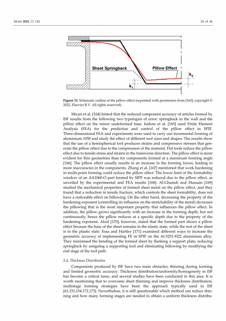
Metals 2022, 12, 124 24 of 46
Figure 13. Schematic outline of the pillow effect (reprinted with permission from [163]; copyright ©
2022, Elsevier B.V. All rights reserved).
Micari et al. [164] hinted that the reduced component accuracy of articles formed by
ISF results from the following two typologies of error: springback in the wall and the
pillow effect on the minor undeformed base. Isidore et al. [165] used Finite Element
Analysis (FEA) for the prediction and control of the pillow effect in SPIF.
Three‐dimensional FEA and experiments were used to carry out incremental forming of
aluminium 1050 and study the effect of different tool sizes and shapes. The results show
that the use of a hemispherical tool produces strains and compressive stresses that gen‐
erate the pillow effect due to the compression of the material. Flat tools reduce the pillow
effect due to tensile stress and strains in the transverse direction. The pillow effect is more
evident for thin geometries than for components formed at a maximum forming angle
[166]. The pillow effect usually results in an increase in the forming forces, leading to
more inaccuracies in the components. Zhang et al. [167] mentioned that work hardening
in multi‐point forming could reduce the pillow effect. The lower limit of the formability
window of an AA1060‐O part formed by SIPF was reduced due to the pillow effect, as
unveiled by the experimental and FEA results [168]. Al‐Ghamdi and Hussain [169]
studied the mechanical properties of formed sheet metal on the pillow effect, and they
found that a reduction in tensile fracture, which controls the sheet formability, does not
have a noticeable effect on billowing. On the other hand, decreasing the property of the
hardening exponent (controlling its influence on the stretchability of the metal) decreases
the pillowing that is the most important property that influences the pillow effect. In
addition, the pillow grows significantly with an increase in the forming depth, but not
continuously; hence the pillow reduces at a specific depth due to the property of the
hardening exponent. Afzal [170], however, stated that the formed part shows a pillow
effect because the base of the sheet remains in the elastic state, while the rest of the sheet
is in the plastic state. Essa and Hartley [171] examined different ways to increase the
geometric accuracy of implementing FE in SPIF on the Al‐5251‐H22 aluminium alloy.
They minimised the bending of the formed sheet by flanking a support plate, reducing
springback by assigning a supporting tool and eliminating billowing by modifying the
end stage of the tool path.
5.4. Thickness Distribution
Components produced by ISF have two main obstacles; thinning during forming
and limited geometric accuracy. Thickness distribution/uniformity/homogeneity in ISF
has become a critical issue, and several studies have been conducted in this area. It is
worth mentioning that to overcome sheet thinning and improve thickness distribution,
multistage forming strategies have been the approach typically used in ISF
[61,151,154,172,173]. Nevertheless, it is still questionable which method can reduce thin‐
ning and how many forming stages are needed to obtain a uniform thickness distribu‐

Metals 2022, 12, 124 25 of 46
tion. To this end, based on constant volume, Li et al. [174] suggested an equation to de‐
termine the appropriate number of forming stages required; moreover, they tested the
rule they suggested by producing a complex product. Furthermore, they note that a more
uniform distribution of sheet thickness in the double‐forming process mainly results
from an increase in the region undergoing total plastic deformation. Zhang et al. [167]
developed multi‐point forming to form the 2A12‐O aluminium alloy as a primary step
before starting the ISF process based on a thickness prediction model. A better thickness
distribution was obtained as a result of the new method. Ambrogio et al. [175] conducted
experimental and numerical research on pure aluminium, AA1050‐O, to investigate the
changes in the thickness distribution based on customised conditions imposed in SPIF.
The approach was that by weakening the sheet from different positions, they found that
the local deformation can be influenced by changing the strength of the sheet. Further‐
more, the imposed weakening was helpful in reducing sheet strength, which helps to thin
in an unweakened zone to produce a more uniform thickness distribution as the thinning
is usually in the mid‐zone in conventional SPIF. Utilising numerical models and experi‐
ments, Salem et al. [176] investigated the impact of the tool strain path on the formability
and local thinning of AA7075‐O sheets in SPIF. They revealed the following three dif‐
ferent zones on the formed part wall: bending, thinning and steady‐state, and they
claimed that most of the thinning occurs under the tool. Azaouzi and Lebaal [49] opti‐
mised the forming strategy using FEA together with the response surface method (RMS)
and sequential quadratic programming (SQP) algorithms. Their strategy improved the
sheet thickness distribution of aluminium alloy by 7%. Awankar et al. [177] hinted that
the thinning in the mid‐zone of the sheet is because the material is encountering uniaxial
stretching from both sides in this area. Zhu et al. [178] generated a new toolpath method
to form straight wall components from 1060 aluminium sheets by multistage forming to
eliminate the inhomogeneity in the thickness of the final product. In their method, the
toolpath is based on parallel planes adopting a stretching angle to minimise the distance
between the wall angle and the parallel planes. With insignificant warping at the bottom,
the formed part’s sidewall seems closer to the ideal shape by increasing the depth.
However, in the ideal case without any thinning or excessive thickness, the sine law (t = ti
sin ϴ) can be helpful in predicting the end thickness of the part wall after forming. Where
t is the final sheet thickness, ti is the initial sheet thickness and ϴ is the wall angle of the
formed part, and this has been used in many studies [179–182]. One can refer back to the
sine law when considering shear spinning, as noted by Avitzur and Yang [183]. The sine
law is a simple geometrical model for estimating sheet thickness in incremental sheet
forming, which is not adequate and may supply only a rough and average approxima‐
tion, and which, however, does not apply to all the regions along the final part wall be‐
cause, as shown by Young and Jeswiet [184], sheet thinning does not always follow the
sine law. Therefore, researchers proposed more practical and general ways to calculate
sheet thickness [185,186]. Yang et al. [187] analysed the effects of SPIF parameters on the
thinning ratio of a 1060 aluminium‐formed part, both numerically and experimentally.
Finally, a method was proposed to control the thinning rate by changing the forming
trajectory. This method was closer to the actual values than those calculated using the
sine law. However, the thinning rate increases with an increase in the tool tip diameter,
wall angle and initial thickness, but decreases with an increase in step size. On the other
hand, there was no mention of the influence of the feed rate on the thinning ratio. Cao et
al. [188] compared the thickness distributions of items formed by SPIF and the results
predicted for both the method developed, which tracked the nodal positions in each
step‐down, and the sine law. The authors assumed that the material point will move
along its normal position on the surface in every transit time. Therefore, for any given
point P on the final surface’s N+1th level, the point position on the previous surface of the
Nth level can be obtained by calculating the intersection point of the Ps and the profile
curve of the Nth level (Figure 14). The method developed was more accurate than the

Metals 2022, 12, 124 26 of 46
sine law in predicting the thickness distribution of AA5052 and AA1100 aluminium al‐
loys.
Figure 14. Schematic diagram of the pillow effect (reprinted with permission from [188]; copyright
© 2022, Springer‐Verlag London).
6. Surface Finish
6.1. Process Parameters
A significant problem occurring during the forming of aluminium and its alloys is
galling, which significantly affects the quality of manufactured products, as well as re‐
ducing the durability of the tools [189,190]. However, the tribological properties of alu‐
minium and its alloys, i.e., a high coefficient of friction, and the tendency to seize signif‐
icantly limit their incremental forming, in which there are high contact pressures
[191–193]. One of the ways to improve the surface quality of these sheets is to optimise
the processing strategy, including the values of the processing parameters.
Surface finish or surface roughness is a main drawback in ISF, which limits the ap‐
plication of this process. The appropriate combination and optimisation of ISF parame‐
ters is a challenge and a critical concern [194]. To obtain an acceptable surface texture, it is
important to control the process parameters (step size, tool rotation speed, forming angle,
feed rate) and lubrication conditions. Thus, many papers have been devoted to studying
the influences of these main factors on the final surface topography of the components
that are subject to ISF. Azpen et al. [194] investigated the influence of step size, tool size,
feed rate and tool rotation speed on the surface roughness of conical frustrums made
from z6061‐T6 aluminium alloy and formed using frictional stir incremental forming. The
results of Taguchi’s analysis have shown that tool diameter has a significant impact on
the resulting internal surface roughness with a percentage contribution of 93.86%. Du‐
rante et al. [195] investigated the influence of the tool rotational speed and direction on
the surface texture of the 7075‐T0 aluminium alloy. When forming pyramidal frustums,
roughness varies, but not considerably (Figure 15), depending on whether or not the tool
is set in rotation, while neither the direction of rotation nor the tool rotational speed in‐
fluence this parameter.
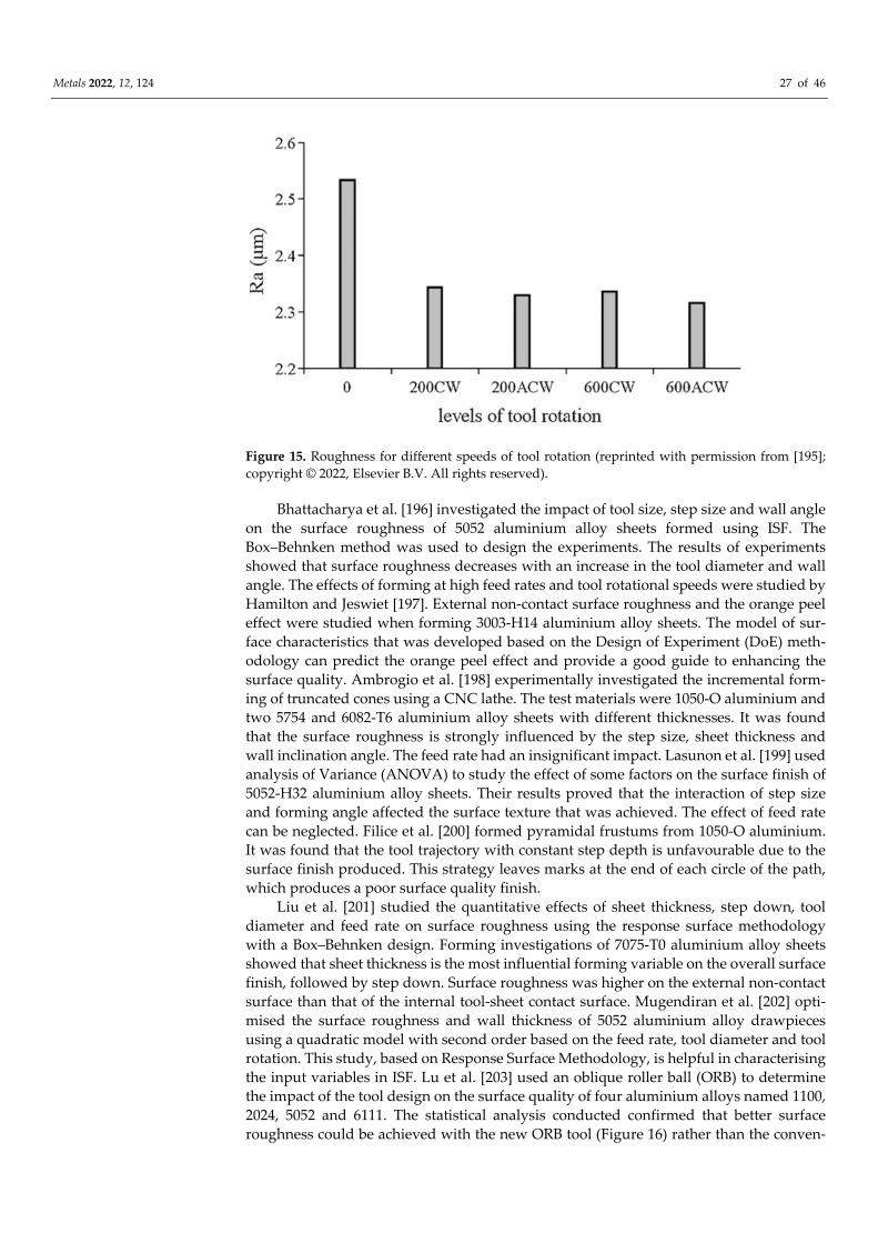
Metals 2022, 12, 124 27 of 46
Figure 15. Roughness for different speeds of tool rotation (reprinted with permission from [195];
copyright © 2022, Elsevier B.V. All rights reserved).
Bhattacharya et al. [196] investigated the impact of tool size, step size and wall angle
on the surface roughness of 5052 aluminium alloy sheets formed using ISF. The
Box–Behnken method was used to design the experiments. The results of experiments
showed that surface roughness decreases with an increase in the tool diameter and wall
angle. The effects of forming at high feed rates and tool rotational speeds were studied by
Hamilton and Jeswiet [197]. External non‐contact surface roughness and the orange peel
effect were studied when forming 3003‐H14 aluminium alloy sheets. The model of sur‐
face characteristics that was developed based on the Design of Experiment (DoE) meth‐
odology can predict the orange peel effect and provide a good guide to enhancing the
surface quality. Ambrogio et al. [198] experimentally investigated the incremental form‐
ing of truncated cones using a CNC lathe. The test materials were 1050‐O aluminium and
two 5754 and 6082‐T6 aluminium alloy sheets with different thicknesses. It was found
that the surface roughness is strongly influenced by the step size, sheet thickness and
wall inclination angle. The feed rate had an insignificant impact. Lasunon et al. [199] used
analysis of Variance (ANOVA) to study the effect of some factors on the surface finish of
5052‐H32 aluminium alloy sheets. Their results proved that the interaction of step size
and forming angle affected the surface texture that was achieved. The effect of feed rate
can be neglected. Filice et al. [200] formed pyramidal frustums from 1050‐O aluminium.
It was found that the tool trajectory with constant step depth is unfavourable due to the
surface finish produced. This strategy leaves marks at the end of each circle of the path,
which produces a poor surface quality finish.
Liu et al. [201] studied the quantitative effects of sheet thickness, step down, tool
diameter and feed rate on surface roughness using the response surface methodology
with a Box–Behnken design. Forming investigations of 7075‐T0 aluminium alloy sheets
showed that sheet thickness is the most influential forming variable on the overall surface
finish, followed by step down. Surface roughness was higher on the external non‐contact
surface than that of the internal tool‐sheet contact surface. Mugendiran et al. [202] opti‐
mised the surface roughness and wall thickness of 5052 aluminium alloy drawpieces
using a quadratic model with second order based on the feed rate, tool diameter and tool
rotation. This study, based on Response Surface Methodology, is helpful in characterising
the input variables in ISF. Lu et al. [203] used an oblique roller ball (ORB) to determine
the impact of the tool design on the surface quality of four aluminium alloys named 1100,
2024, 5052 and 6111. The statistical analysis conducted confirmed that better surface
roughness could be achieved with the new ORB tool (Figure 16) rather than the conven‐

Metals 2022, 12, 124 28 of 46
tional tool. The advantages of the roller‐based tool include better surface finish, higher
formability and lower forming load.
Figure 16. The ORB tool (reprinted from [203], this is an open access article distributed under the
terms of the Creative Commons CC‐BY license, which permits unrestricted use, distribution and
reproduction in any medium, provided the original work is properly cited).
Powers et al. [204] investigated the surface metrology in an SPIF of a 3003‐O alu‐
minium alloy. The effect of the sheet rolling mark direction on the surface topology in
SPIF was studied, taking into consideration the forming direction and feed rate. They
found that surface roughness Rz is greater with rolling marks perpendicular to the
forming direction. Najm and Paniti [148] predicted the effects of forming tool character‐
istics on the surface roughness of AlMn1Mg1 aluminium foil formed using SPIF. Support
Vector Regression (SVR) combined with artificial neural networks were used to predict
the effects of process parameters on surface roughness. The effects of SPIF parameters on
the surface roughness (Ra and Rz) of the formed sheet have been classified using Boosted
Decision Trees. The classification is based on the importance of the parameter that causes
the result of the surface roughness to fluctuate. The most important effect of the SPIF
parameters on the sheet surface roughness Ra is the tool material and tool surface
roughness Ra (Figure 17a). The ten‐point roughness of a tool surface Rz has the most
significant effect on the drawpiece surface roughness Rz (Figure 17b). The tool radius has
the least effect on both of the surface roughness parameters considered.
Singh et al. [205] studied the effects of seven parameters at different levels of surface
roughness of 2014 aluminium alloy components with three different thicknesses. They
concluded that the feed rate, step size and tool path have little effect on surface rough‐
ness. However, the sheet thickness has an extreme effect on surface roughness. Mulay et
al. [206] studied the effect of step size and feed rate on the surface roughness of 5754‐H22
aluminium alloy drawpieces. They observed that the most significant parameter is step
size, followed by feed rate. A slight increment in the step depth leads to a wavy surface
finish. Nama et al. [207] found that surface roughness can be decreased during the SPIF
of 1100 aluminium alloy sheets by increasing the feed rate, tool rotation speed and tool
tip diameter.

Metals 2022, 12, 124 29 of 46
(a)
(b)
Figure 17. Effect of SPIF parameters on (a) the arithmetical mean roughness of the drawpiece sur‐
face Ra and (b) the ten point roughness of a drawpiece surface Rz (reprinted from [148]), this is an
open access article distributed under the terms of the Creative Commons CC BY license, which
permits unrestricted use, distribution and reproduction in any medium, provided the original
work is properly cited.
6.2. Friction Conditions
High contact pressure, and consequently, the high levels of friction, in conventional
ISF processes conducted in cold forming conditions may result in a poor surface finish. In
friction‐assisted ISF processes conducted in elevated temperatures, the high level of fric‐
tion is a desirable phenomenon that allows the sheet to be heated to the required tem‐
perature. A detailed investigation of the friction effect is necessary for an improved sheet
surface quality. Besides friction, the surface finish may be affected by the kind of both
sheet and tool materials, lubrication conditions and processing parameters. Hagan and
Jeswiet [208] characterised the surface finish of 3003 aluminium alloy drawpieces under
different spindle speeds and depth increments. The results showed an exponential in‐
crease in the maximum peak‐to‐valley height as the increment size decreased. Hussain et
al. [209] concluded that in order to ensure the presence of lubricant at the interface of the
sheet and tool, a proper surface coating of the sheet‐blank is an essential pre‐requisite
before forming. Moreover, they found that the surface quality is directly related to type of
lubricant and lubrication method.

Metals 2022, 12, 124 30 of 46
Friction is a major factor in contributing to the through‐the‐thickness‐shear in the
incremental forming process. Bambach et al. [210] observed the
through‐the‐thickness‐shear in the FE‐based numerical simulation of 1050‐H14 alumin‐
ium pyramids. It was found that the through‐the‐thickness‐shear is dependent on both
the vertical pitch and tool diameter. Eyckens et al. [211] investigated the effect of friction
in the SPIF process when producing a large wall angle cone from an AA3103‐O alumin‐
ium alloy sheet. They found that the through‐the‐thickness‐shear was affected by the tool
rotational speed.
In any forming process, the use of lubricants is essential at the interface between the
workpiece and the tool. Lubricants improve heat distribution and give tools a longer life
by reducing friction and wear [212,213]. Lubricants differ in many characteristics, such as
consistency (i.e., fluid, paste, spray), density and viscosity. However, as concluded by
Azevedo et al. [214], there is not much discussion in the literature about the differences
between lubricants in relation to consumer choice. Suriyaprakan [215] found that AS‐40
grease yielded good results when used in SPIF and the multistage ISF of 1050 aluminium
alloy. Gulati et al. in [216] investigated the SPIF process for the 6063 aluminium alloy. The
influential process parameters for surface roughness were identified using analysis of
variance. They found that lubrication greatly affected the surface roughness compared to
a dry process; therefore, they used a coolant lubricant for forming. Nama et al. [217]
studied the ISF of 1100 aluminium sheets and found that the grease gave less surface
roughness when compared with coolant oil in all cases. Najm and Paniti [148] success‐
fully used machine oil when ISF forming AlMn1Mg0.5 sheets. Oraon and Sharma [217]
used artificial neural networks to predict the surface finish of a component produced by
the SPIF of the 3003‐O aluminium alloy. The density of the lubricant is considered as one
of the inputs. It was found that the average roughness parameter (Ra) is correlated with
the density of the lubricant. Patel et al. [218] applied grey relational analysis to reduce the
surface roughness of an SPIFed IS19000 aluminium sheet. They concluded that grease
lubricant plays a vital role in incremental forming at a low spindle speed, whereas lu‐
bricating oil is preferred at a high spindle speed. Azevedo et al. [214] have studied lu‐
brication considerations during the SPIF of steel or aluminium materials. Based on a lit‐
erature study and the conclusion that there is a lack of information on the role played by
the lubricant during the SPIF process, Azevedo et al. [214] tested the effect of several
lubricants on the surface finish obtained using SPIF technology on 1050‐T4 aluminium
alloy sheets. It was concluded that it was possible to find a clear relationship between the
viscosity of the lubricant used and the final roughness. Moreover, it was found that the
greater the hardness of the blank material is, the lower the viscosity of lubricant neces‐
sary is. AL‐M grease and SAE30 oil provided the best performance when forming 1050
aluminium alloy sheets.
The contact surface is small during SPIF and TPIF, and the forces during the forming
process are low; therefore, the amount of lubricant required is reduced as compared to
conventional SMF [129]. The ISF tool with lubrication does not leave scratches on the
sheet and it is possible to associate the heating of the sheet with the friction. Duflou et al.
[219] and Kim and Park [220] highlighted that the presence of lubricant is important
during the SPIF of aluminium and Al‐based alloys to avoid abrasive wear when the tool
is relatively hard in comparison with the workpiece material.
In the case of hot ISF, molybdenum disulphide (MoS2) is the most widely used lub‐
ricant. It is a solid inorganic compound used to reduce friction between the sheet and the
tool. Usually, a thin layer of MoS2 is brushed on the workpiece surface before forming
[40]. The high temperature in hot ISF reduces the viscosity of a liquid lubricant, thereby
adversely affecting its lubrication performance. At elevated temperatures, the use of
high‐performance lubricants allows one to overcome frictional effects [29]. Table 2 pre‐
sents the typical lubricants used in the incremental sheet forming of aluminium and al‐
uminium alloy sheets.

Metals 2022, 12, 124 31 of 46
Table 2. Lubricants used in ISF of selected aluminium and Al‐based alloys.
Lubricant Workpiece Material Conditions Reference
MoS2 AA2024‐T3 hot forming [40]
SAE 75W‐85 gear oil 2024‐T3
Alclad 7075‐T6 cold forming [32]
mineral oil 2219‐O and 2219‐T6 cold forming [29]
without lubrication 3003 cold forming [24]
without lubrication 1050 cold forming [220]
oil 7075‐T0 cold forming [195]
10w30 servo oil 5754 H22 cold forming [206]
machine oil AlMgSi0.5 cold forming [148]
Weicon AL‐M paste 1050 cold forming [214]
Moly Slip AS40 paste 1050 cold forming [214]
oil 1050‐O, 1050‐H24,
6082 hot forming [221]
mechanical oil 5052‐H32 hot forming [222]
Mineral oil (Total
Finarol B 5746) 1050 cold forming [214]
Moly Slip HSB paste 1050 cold forming [214]
SAE 30 oil 1050 cold forming [214]
Graphite powder +
mineral oil (1:4) 7075‐O hot forming [223]
SAE 0W‐4 6061‐T6 hot forming [194]
water–oil emulsion
cutting fluid 3003‐H14 cold forming [197]
graphite 33 5182 hot forming [224]
solid lubricant (stick
wax lubricant) 5052‐H32 cold forming [199]
MoS2 5083 hot forming [225]
MoS2 5055 hot forming [226]
without lubrication 1050 hot forming [227]
graphite 6061 hot forming [228]
solid graphite
powder and lithium
grease with scale 1:1
1050 H14 cold forming [193]
20W‐50 1050 H14 cold forming [193]
machine oil AlMn1Mg1 foil cold forming [142,143]
mineral oil 1050‐O cold forming [185]
coolant oil, Gp Grease
Calcium, Supergrees
EP2, Zinol grease
AA1100 cold forming [229]
7. Heat‐Assisted Incremental Forming
Over almost two decades, there has been an intense development of warm forming
processes as a response to limited ductility at room temperature. The elevated tempera‐
ture of aluminium and aluminium alloys activates additional slip lines, allowing dislo‐
cations to take place [230]. It has been proven in tensile tests that an elevated temperature
decreases the stress required for elongation [231]. The latest research focuses on the fol‐
lowing three types of heat‐assisted methods: electric hot incremental forming (EHIF),
friction‐stir‐assisted incremental forming (FSIF) and laser‐assisted incremental forming

Metals 2022, 12, 124 32 of 46
(LAIF). Although a source of heat is provided, in each method additional warmth is
generated by friction between the tool and workpiece and as a result of the plastic de‐
formation process.
7.1. Electrically Assisted ISF
There are a few variants of the electric heating arrangements: a heater located inside
the tool or close to the sheet blank, or a direct current (DC) heating at the tool‐workpiece
contact point where the Joule effect 𝑄 𝑅 𝐼² 𝑡 (Q—the amount of heat released,
I—electric current, R—electrical resistance of the conductor, t—current flow time) is used
to increase the temperature by applying a high density current. A DC power source can
be applied in two variants, connecting the anode to the forming tool and the cathode to
the sheet causing local heating at the contact zone [40] or both electrodes only to the sheet
as a part of a circuit, elevating the overall sheet temperature [226].
Hino et al. [225] were one of the first groups of researchers to arrange electric in‐
cremental forming in hard‐to‐form nonferrous metals. The authors positioned a 200 W
heater and thermocouple inside the forming tool to achieve an elevated sheet tempera‐
ture, mainly in the tool contact zone. That approach produced increased ductility, ex‐
tended the forming limit and also reduced springback. Moreover, the possible limit angle
of a cone formed from a 1‐millimetre‐thick EN AW 5083 sheet was increased from 50° to
75° by warming it up to 600 °C. Ambrogio et al. [40] applied a DC power source to a
forming tool through attaching a graphite anode and a cathode directly to the sheet and
locally warming up AA2024‐T3 (Figure 18a). The determination of process workability
windows and also the negative effects of electrical heating such as oxidation and reduced
surface quality have been presented in their research. The authors highlighted that an
increase in slope angle causes an increase in the energy delivered to the process.�Sy et al. [226] created a device with a global heating system for sheets by connecting
both DC electrodes to the blank alone. Four thermocouples were welded to the bottom
side of the formed sheet to control the circuit amperage in a closed loop. In a two‐level
factorial design, the authors noted that the elevated temperature allowed for the for‐
mation of an angle of up to 85° for AA5055, where the step size had the greatest impact
on the surface roughness obtained. Moreover, the springback effect was reduced while
the step size decreased. Li et al. [232] proved that the dimensional accuracy of Al1060
EHIF is improved in comparison to Single‐Stage Forming (SSF) and Double‐Stage
Forming (DSF) without a heat source. In a Box–Behnken design with response surface
methodology, the authors studied the influence of input parameters such as tool diame‐
ter, feed rate, step size and DC current on the maximum, average and error (deviation
between maximum and average) temperature, where the tool diameter seems to be the
most significant factor in the experimental range.
Heating leads to lower forces and better formability but decreases the geometric
accuracy caused by contraction; preheating the blank before forming allows deviations to
be reduced by about 5%, which was proven in a numerical simulation presented by
Pacheco and Silveira [233]. In further study [234], an investigation of the prediction of
heat distribution using FEM analysis has been proposed using different variables (vari‐
ants with/without convection and plastic strain) and shows a good agreement with the
analytical model developed by Bejan et al. [235]. Singh et al. [227] conducted an incre‐
mental forming experiment with the following three ranges: room temperature, elevated
both below and above the recrystallisation temperature of AA1050. Heaters located un‐
der a 1‐millimetre‐thick sheet warmed the whole sheet up. As a result, the forming tem‐
perature of 150°C (below recrystallisation) produced the finest surface quality as well as
the lowest reduction in drawpiece thickness. Vahdani et al. [228] applied the Taguchi
method with analysis of variance to AA6061 EHISF. A forming device was used together
with an AC transformer (Figure 18b) that was employed as the power supply with the
output current in the range of 300–1000 A. Both electrodes were connected directly to the
formed sheet. The tool diameter of Ø10 mm ended with a hemispherical radius of R = 5

Metals 2022, 12, 124 33 of 46
mm and an additional internal tool cooling system was applied. Temperature indicators
in the form of two thermocouples were located below the sheets. The amperage value
was determined to be a key forming factor for AA6061 with a contribution of 73.6%. Se‐
lecting the optimal combination of the following process parameters: graphite lubricant;
feed rate, 900 mm/min; step size, 0.2 mm; current, 300 A, achieved a 9.17‐millimetre
depth (9.14 mm was predicted by a model) before fracture, 1.12‐micrometre Ra rough‐
ness parameter and a maximum sheet temperature of 95 °C with a tool wear of 0.14 mm.
(a)
(b)
Figure 18. (a) Equipment for electrically assisted hot ISF (reprinted with permission from [40];
copyright © 2022, Elsevier Ltd. All rights reserved) and (b) the experimental equipment used in the
experiments: A—base structure, B—tool holder, C—workpiece, D—blank holder, E—forming tool,
F—Anode, G—cathode (reprinted with permission from [228]; copyright © 2022, Springer‐Verlag
London Ltd., part of Springer Nature).
In a study by Xiao et al. [231], ISF experiments were conducted with electric heaters
located under the 1‐millimetre‐thick AA7075‐T6 sheet and these were compared to FEM
analysis. A variable temperature range of 20–200 °C, step size of 0.3–0.7 mm with a con‐
stant hemispherical tool diameter of Ø10 mm and feed rate of 200 mm/min were taken
into consideration. The authors extended the forming limit angle from 50° to greater than
80° by warming up the blank from 20 to 200 °C in the Variable Wall Angle Cone Frustum
(VWACF) test. FEM analysis prepared in ABAQUS/Explicit with the Kim‐Tuan equation
and with the Hill 1948 yield feature predicted the location of a fracture with high accu‐
racy. Numerical and experimental investigations of SPIF assisted with cartridge heaters
to heat the AA6061 were presented in a study by Darzi et al. [236]. The authors investi‐
gated the homogeneous warming of blanks in the temperature range 25–400 °C. By in‐

Metals 2022, 12, 124 34 of 46
creasing the temperature to 400 °C, the height of a constant wall angle of 60° was in‐
creased from 7 to 44mm until breakage and the critical angle was increased up to 65°.
Further numerical simulations explained this effect by the reduced thinning caused by
lower equivalent plastic strain. Copper‐based anti‐seize grease seems to be the favoured
lubrication at 400 °C and the fracture depth was increased from 19.2 to 44 mm compared
to the use of MoS2 powder. If a higher temperature is used then there is better formability
and lower forces are needed, but there is also a tendency to grain growth, which pro‐
duces a drawpiece with decreased strength [237]. The vicinity of the fracture region fea‐
tures enhanced microhardness due to stretched and finer grains caused by stretching and
the work hardening effect [84].
Rahmani et al. [238] proposed a novel method for expanding a tube by hot incre‐
mental forming where a ceramic circular heater warms up the blank. A
1.5‐millimetre‐thick AA6063 aluminium tube was used as a blank material. Their work
focuses on the highest surface quality and formability by adjusting the temperature, the
linear velocity of the tool and the axial and radial feed in a full factorial Design of Ex‐
periment (DoE). ANOVA shows that temperature plays a key role in the bulge diameter
(54.96% contribution) and final tube length (58.80% contribution), whereas the axial feed
has a major impact on the surface roughness (57.23% contribution). The greatest expan‐
sion, 36.7%, was obtained at 300°C.
Roth and Cao [133] patented electrically assisted double‐sided incremental forming
and the processes associated with it. In patent US8741079B2, dated 3 June 2014, the au‐
thors claimed a patent for sheet metal processing by double‐sided incremental sheet
forming DSISF while an electrical DC passes through it. In a further patent, no.
WO2016/057688A1, Roth [137] claimed a method for springback reduction using electri‐
cally assisted manufacturing.
7.2. Friction‐Assisted ISF
The easiest, and also a low‐cost, way to generate local heat in the ISF process is pro‐
vided by tool spinning. The amount of warmth depends mainly on the RPM value in‐
duced by the friction between the tool and the workpiece. Durante et al. [195] investi‐
gated the effects of tool rotation on AA7075‐T0 forming. By measuring axial and radial
forces, the friction coefficient was determined between the sheet and hemispherical steel
punch. The authors achieved friction coefficients of μ = 0.19 at 0 RPM, μ = 0.11 at 200 and
400 RPM and μ = 0.06 at 600 and 800 RPM. Further tests were conducted considering the
clockwise and anticlockwise directions of the tool as well as selected tool rotation speeds
of 0, 200 and 600 RPM. The sheet temperature level was measured by an attached ther‐
mocouple. A reduction in the horizontal and vertical forces was observed while the tool
RPM increased and a minor improvement in surface roughness was caused by the rolling
effect as opposed to sliding (at 0 RPM). The greater tool RPM affected the rise in tem‐
perature of the sheet. Hamilton and Jeswiet [197] studied the influence of forming pa‐
rameters including high speeds of up to 2000 RPM and high feed rates of up to
8890mm/min on the orange peel effect on the outer side of a 0.81‐millimetre‐thick
AA3003‐H14 drawpiece. In a full factorial design (DoE), step size was the most signifi‐
cant factor affecting the orange peel effect as well as grain size after forming. Buffa et al.
[221] investigated local heating by the friction of AA1050‐O, AA1050‐H24 and
AA6082‐T6 sheets. The experiment resulted in a decrease in the average grain diameter
and also in microhardness, while tool rotation rose to more than 4000 RPM. By these
process parameters, the maximum wall angle was increased by an average of 10° as a
result of dynamic recrystallisation.
Tool texturing effects have been investigated by Xu et al. [222]. Special rectangular
oil pockets (Figure 19a) were created by a laser source on the hemispherical tip of the
punch. This modification reduced the coefficient of friction between the tool and the
sheet. However, as a consequence of the less heat generated, the formability decreased
(with the same process parameters) when compared to the tool without texturing. Otsu et

Metals 2022, 12, 124 35 of 46
al. [239] observed a slightly wider formability in an advancing direction (tool rotation
counter to feed direction) as well as a slightly improved drawpiece accuracy. Azpen et al.
[194] found that a greater tool diameter causes an improvement in the inner surface
roughness. The surface roughness parameter Ra on the inner surface (measured verti‐
cally and horizontally) was improved as the tool rotation increased; however, Gupta and
Jeswiet [240] proved that an increase in the relative velocity between the tool and the
workpiece has a marginal effect. Microhardness tests confirmed that at up to a 3000 RPM
tool rotation, the sheet hardness increases due to the work hardening effect; beyond this
limit there are decreases caused by the AA7075‐O recrystallisation process [223]. Kumar
et al. [107] observed an increase in formability, while the tool diameter or radius in‐
creased as well as the advantage of hemispherical tools over flat ends with a corner ra‐
dius.
Riaz et al. [29] focused on comparing two temper conditions of AA2219 O (fully
annealed) and T6 (solution heat treated and artificially aged). The authors applied the
same tool RPM to both, and more heat was generated during forming in the T6 condition.
This effect causes it to overheat and fracture at a depth of 25 mm, whereas the annealed
state avoided this problem. Wang et al. [241] determined the process window by or‐
thogonal analysis while forming AA2024‐T3 and AA5052‐H32 in terms of cutting and
defects. To avoid the fish scale effect (Figure 19b), the feed rate to tool RPM ratio should
be less than two. Zhan et al. [242] revealed the possibilities of the formation of micro‐
structure and macroscopic properties during FS‐ISF. AA2024 and AA6061 alloys were
taken into account in their experiment. A process window was determined allowing one
to customise the dislocation type, grain size and sub‐grains and solute precipitates as
well as better surface quality and elevated UTS and ductility by selecting the proper tool
RPM and step size. Only dynamic recrystallisation and the consequential low‐angle grain
boundaries appeared due to the elevated temperature resulting from tool–sheet friction.
Static recrystallisation is not possible because of the low residual temperature after pro‐
cessing [243].
(a) (b)
Figure 19. (a) Distribution of surface textures on the forming tool tip (reprinted with permission
from [222]; copyright © 2022, Elsevier Ltd. All rights reserved) and (b) surface fish scales (reprinted
with permission from [241]; copyright © 2022, Elsevier B.V. All rights reserved).
Li et al. [244] proposed a novel approach to the process with, in addition, synchro‐
nous bonding. DC05 with an AA5052 sheet was stacked and formed simultaneously.
Better formability and a lower bumping height on the stack centre were obtained for the
steel top/aluminium bottom sequence with a climbing direction of forming (the direction
of the feed rate was the same as the tool rotation at the contact zone) [245]. The process
has been extended to the double‐sided incremental forming variant [246]; the authors
carried out a model predicting the bonding quality and they also reduced profile devia‐
tion by 3.8 mm compared to single point forming [247].

Metals 2022, 12, 124 36 of 46
7.3. Laser‐Assisted ISF
Laser assistance is the most expensive way to generate heat in the process, but at the
same time, it is the most flexible, i.e., it allows the sheet to be warmed with an offset to the
tool or to provide precise control of the size of the heated zone. It generally requires an
additional independent CNC 3‐axis with a laser source located below the formed sheet.
Duflou et al. [224] investigated the laser‐assisted incremental forming of AA5182 where
the laser source was independently positioned on the opposite side of forming.
By setting a constant flow of coolant through the sheet, the temperature stabilised.
An offset between the laser beam and forming tool was set to 2.4 mm and the spot size to
9 mm at a power of 160 W. An improvement in accuracy as well as a reduction in the
force required and in the surface roughness Rz parameter was observed compared to
cold forming.
In further work [248], a laser source has been used in the annealing process after
cold SPIF as an alternative to LAISF and cold forming. It has been found that the laser
annealing process does not affect the accuracy of drawpiece geometry; however, it re‐
duces the work hardening effect. Lehtinen et al. [249] investigated an ISF experiment
with 0.5‐millimetre‐thick AW‐1050A and achieved a 61° wall angle with laser assistance
compared to 59° with cold forming. Moreover, an additional laser source made an insig‐
nificant difference to the wall angle precision. That may be caused by the good formabil‐
ity of AW‐1050A at room temperature and the low springback effect due to the low yield
point. Mohammadi et al. [250] studied the influence of the laser position offset on
AA5182‐O sheet formability. High temperature isotherms wholly covering the contact
zone are required to improve strain—a large laser beam without offset or large forward
advance between the forming tool and workpiece is required. The authors noticed an
enhanced formability because of the stress relief annealing effect. In further work [251],
different sheet temper conditions were analysed and compared to the T‐delivery state by
LAISF. Investigations were carried out on test material consisting of 0.4‐millimetre‐thick
AA2024 sheets in the following states: O‐annealed, treatment and quenching with
W‐solution and heat treating, quenching and cold working with T‐solution. A 41% im‐
provement in formability for O‐temper and 32% for W‐temper were obtained in a cold
forming process when compared to T‐temper. The LAISF process, at about 360°C, af‐
fected the formability of T‐state flows in a similar manner to O‐state cold ISF, causing the
maximum angle enhancement of 41% as well as, additionally, obtaining an accuracy
improvement. A hardness improvement was observed, caused by partial particle disso‐
lution during LAISF and consequent aging.
8. Conclusions
Incremental sheet forming is a promising technique for forming drawpieces with
complex shapes that can be formed by the movement of a simple tool along a pro‐
grammed path. The lack of a die makes this technique one of the most flexible in the
metal forming industry. Many articles have been published in the field of conventional
ISF and WJISF, the main purpose of which was to obtain components with a specific de‐
gree of deformation. At the same time, most of the authors studied the influence of sev‐
eral selected process parameters on the formability and surface finish of components.
Although this article focuses on the current state‐of‐the‐art in the scope of the ISF of al‐
uminium and Al‐based alloy sheets, most of the following conclusions also apply to the
processing of other materials:
The dieless nature of SPIF and TPIF greatly reduces the cost associated with making
the dies required in conventional SMF processes. Changes can be made to the
product design very quickly and easily, with minimal cost.
A limitation of the industrial application of SPIF technique is that the forming time is
much higher than in the conventional methods of sheet metal forming. After im‐

Metals 2022, 12, 124 37 of 46
plementing a multi‐point tool technique, it is possible to reduce the forming time
drastically.
The inner surfaces of the drawpieces are of low quality, which can be improved by
the optimisation of the process parameters, especially step size and tool path strat‐
egy. New types of tool designs, i.e., an oblique roller ball tool, were developed to
improve the surface finish of parts.
By increasing the rotational speed of the tool, it is possible to increase the formability
of the sheet material by friction‐stir‐assisted heating of the material.
The presence of lubricant is important in the ISF of aluminium and Al‐based alloys
to avoid wear in the abrasive form when the tool is relatively hard in comparison
with the workpiece material.
The dimensional accuracy of an ISFed component may be improved by using dif‐
ferent algorithms to optimise the tool path trajectory.
Some Al‐based alloys are included in the group of difficult‐to‐form materials. The
formability of these alloys may be improved with methods of hot ISF. These meth‐
ods include electrically assisted ISF, induction‐heating‐assisted ISF, laser‐assisted
ISF and combined electric‐ and friction‐stir‐assisted ISF.
The use of modern variants of SPIF (i.e., ultrasonic‐assisted ISF) permits a significant
reduction in the manufacturing costs when forming “difficult‐to‐form” materials.
Robotic ISF is more flexible than the CNC machine method, more cost‐effective for
large parts and easy to achieve when the right tools are used.
The effect of step size in SPIF and TPIF is not unequivocal; some researchers have
concluded that step size has a negative effect on formability; however, others have
shown that step size does not affect formability.
It is still hard to form parts with right angles or it cannot be achieved with one step.
Parts with a 90° wall angle can be obtained by adopting non‐linear strain paths by
multi‐stages, but to this end, the initial thickness of the sheet must be increased.
The geometric accuracy attributed to and residual stresses and springback effects is
one of the dominant limits for the further development of the ISF methods. There are
the following two ways to reduce springback: (i) the use of an algorithm to com‐
pensate the elastic strains of the material after unloading and modifying the tool
path strategy, and (ii) increasing the tool diameter and spindle speed and reducing
the vertical step size.
The surface roughness of the inner surface of an ISFed component may be improved
by (i) reducing the tool size and vertical step size, and (ii) using a rotating tool as
compared to a non‐rotating one.
There are no universal surface roughness parameters to describe the surface finish of
SPIFed components. A more comprehensive parametric study can be beneficial to
investigate the interdependence and interaction between forming parameters and
surface roughness parameters of inner and outer surfaces of drawpieces.
The parts produced by ISF have high surface roughness due to the waviness caused
by the forming tool. When ISF is performed with a dummy sheet at the top of the
main or target sheet, the surface roughness is minimized to some extent. In the SPIF
process using a dummy sheet, two sheets are deformed simultaneously.
Compared to traditional rigid tool incremental forming, water jet ISF has the fol‐
lowing several advantages: no metallic contact between the tool and workpiece, en‐
vironmental friendliness resulting from the absence of friction‐reducing lubricants
and a closed circuit for the working fluid and no tool wear during the forming pro‐
cess.
It is suggested that future research should be focused on optimising process pa‐
rameters for the use of SPIF methods to form various lightweight alloys used in the
aerospace industry, in which products are manufactured in relatively small series.
Finite element‐based simulations can be used to predict forming defects, clarify the
forming characteristics and improve the forming process. Accurate and efficient

Metals 2022, 12, 124 38 of 46
approaches for predicting the forming accuracy of drawpieces are awaited by the
industrial designers of SPIF.
There is little research on phenomenological or physical constitutive and damage
models to describe the material behaviour of aluminium and aluminium alloy
sheets. The effects of strain hardening and material anisotropy on the formability of
hard‐to‐deform materials require further research.
Author Contributions: Conceptualization, T.T.; methodology, T.T.; validation, T.T., S.M.N., V.O.,
D.V., I.P. and M.S.; formal analysis, T.T., S.M.N., V.O. and I.P.; investigation, T.T., S.M.N., V.O.,
D.V., I.P. and M.S.; resources, T.T., S.M.N., V.O., D.V. and M.S.; data curation, T.T., S.M.N., V.O.,
D.V., I.P. and M.S.; writing—original draft preparation, T.T., S.M.N., V.O., D.V., I.P. and M.S.;
writing—review and editing, T.T. All authors have read and agreed to the published version of the
manuscript.
Funding: This research received no external funding.
Institutional Review Board Statement: Not applicable.
Informed Consent Statement: Not applicable.
Data Availability Statement: The data presented in this study are available on request from the
corresponding author.
Acknowledgments: This work was supported through the TEHNE project based on the funding
scheme C1.2.PFE‐CDI.2021 of the Romanian Ministry of Research, Innovation and Digitization
aiming at supporting excellence in research.
Conflicts of Interest: The authors declare no conflict of interest.
References
1. Cheng, L.M.; Poole, W.J.; Embury, J.D.; Lloyd, D.J. The influence of precipitation on the work‐hardening behavior of the alu‐
minum alloys AA6111 and AA7030. Metall. Mater. Trans. 2003, 34, 2473–2481.
2. Ubertalli, G.; Matteis, P.; Ferraris, S.; Marcianò, C.; D’Aiuto, F.; Tedesco, M.M.; De Caro, D. High Strain Rate Behavior of Alu‐
minum Alloy for Sheet Metal Forming Processes. Metals 2020, 10, 242.
3. Schneider, R.; Heine, B.; Grant, R.J.; Zouaoui, Z. Aluminium Sheet Metal Forming at Low Temperatures. IOP Conf. Ser. Mater.
Sci. Eng. 2015, 74, 012014.
4. Huber, G.; Djurdjevic, M.B.; Manasijevic, S. Determination some thermo‐physical and metallurgical properties of aluminum
alloys using their known chemical composition. Int. J. Heat Mass Trans. 2019, 139, 548–553.
5. Taher, M.; Mao, F.; Berastegui, P.; Andersson, A.M.; Jansson, U. The influence of chemical and phase composition on me‐
chanical, tribological and electrical properties of Silver‐Aluminum alloys. Tribol. Int. 2018, 119, 680–687.
6. Dudareva, N.; Gallyamova, R. The Cnfluence of Chemical Composition of Aluminum Alloys on the Quality of Oxide Layers
Formed by Microarc Oxidation. Mater. Today Proc. 2019, 11, 89–94.
7. Vijayakumar, M.D.; Dhinakaran, V.; Sathish, T.; Muthu, G.; Bupathiram, P.M. Experimental study of chemical composition of
aluminium alloys. Mater. Today Proc. 2021, 37, 1790–1793.
8. Ravikumar, R.N.; Rajesh, G.H. The mechanical properties and microstructure behavior of aluminium alloys subjected to shock
waves. Mater. Today Proc. 2021, 46, 9132–9138.
9. Hattori, C.S.; Almeida, G.F.C.; Gonçalves, R.L.C.; Santos, R.G.; Souza, R.C.; da Silva, W.C.; Cunali, J.R.C.; Couto, A.A. Micro‐
structure and fatigue properties of extruded aluminum alloys 7046 and 7108 for automotive applications. J. Mater. Res. Technol.
2021, 14, 2970–2981.
10. Garric, V.; Colas, K.; Donnadieu, P.; Loyer‐Prost, M.; Leprêtre, F.; Cloute‐Cazalaa, V.; Kapusta, B. Impact of the microstructure
on the swelling of aluminum alloys: Characterization and modelling bases. J. Nuclear Mater. 2021, 557, 153273.
11. Puga, H. Casting and Forming of Advanced Aluminum Alloys. Metals 2020, 10, 494.
12. Dou, S.; Wang, X.; Xia, J.; Wilson, L. Analysis of Sheet Metal Forming (Warm Stamping Process): A Study of the Variable
Friction Coefficient on 6111 Aluminum Alloy. Metals 2020, 10, 1189.
13. Xiang, P.; Jia, L.J.; Shi, M.; Wu, M. Ultra‐low cycle fatigue life of aluminum alloy and its prediction using monotonic tension
test results. Eng. Fract. Mech. 2017, 186, 449–465.
14. Zhao, X.; Li, H.; Chen, T.; Cao, B.; Li, X. Mechanical Properties of Aluminum Alloys under Low‐Cycle Fatigue Loading. Mate‐
rials 2019, 12, 2064.
15. Shaha, S.K.; Czerwinski, F.; Kasprzak, W.; Friedman, J.; Chen, D.L. Improving High‐Temperature Tensile and Low‐Cycle
Fatigue Behavior of Al‐Si‐Cu‐Mg Alloys Through Micro‐additions of Ti, V, and Zr. Metall. Mater. Trans. A 2015, 46, 3063–3078.
16. EN 573‐3:2019‐12; Aluminum and Aluminum Alloys‐Chemical Composition and Types of Wrought Products‐Part 3: Chemical
Composition and Types of Articles. European Committee For Standardization: Brussels, Belgium, 2019.

Metals 2022, 12, 124 39 of 46
17. EN 1706:2020‐10; Aluminium and Aluminium Alloys. Castings. Chemical Composition and Mechanical Properties. European
Committee For Standardization: Brussels, Belgium, 2020.
18. Zheng, K.; Politis, D.J.; Wang, L.; Lin, J. A review on forming techniques for manufacturing lightweight complex—Shaped
aluminium panel components. Int. J. Light. Mater. Manuf. 2018, 1, 55–80.
19. Ismail, A.; Mohamed, M.S. Review on sheet metal forming process of aluminium alloys. In Proceedings of the 17th Interna‐
tional Conference on Applied Mechanics and Mechanical Engineering: Cairo, Egypt, 19–21 April, 2016; pp. 1–13.
20. Chen, J.; Lan, F.; Wang, J.; Wang, Y. Material Selection and Sheet Metal Forming Simulation of Aluminium Alloy Engine Hood
Panel. In Global Design to Gain a Competitive Edge; Yan, X.T., Ion, W.J., Eynard, B., Eds.; Springer: London, UK, 2008; pp. 529–538.
21. Yahaya, S.N.M.; Ng, C.H.; Lai, C.F.; Sharrifuddin, S.; Grote, K.H. Reviews on the Forming Process of Heat Treatable Alumin‐
ium Alloys. Int. J. Integr. Eng. 2018, 10, 74–79.
22. Jeswiet, J.; Geiger, M.; Engel, U.; Kleiner, M.; Schikorra, M.; Duflou, J.; Neugebauer, R.; Bariani, P.; Brushi, S. Metal forming
progress since 2000. CIRP J. Manuf. Sci. Technol. 2008, 1, 2–17.
23. Scholz, P.; Börner, R.; Kühn, R.; Müller, R. Dry Forming of Aluminium Sheet Metal: Influence of Different Types of Forming
Tool Microstructures on the Coefficient of Friction. Key Eng. Mater. 2015, 651–653, 516–521.
24. Jeswiet, J.; Hagan, E.; Szekeres, A. Forming parameters for incremental forming of aluminium alloy sheet metal. Proc. Inst.
Mech. Eng., Part B J. Eng. Manuf. 2002, 216, 1367–1371.
25. Meier, M.; Pfestorf, M.; Geiger, M.; Merklein, M. The use of dry film lubricants in aluminum sheet metal forming. Wear 2003,
255, 1455–1462.
26. Gronostajski, Z.; Pater, Z.; Madej, L.; Gontarz, A.; Lisiecki, L.; Łukaszek‐Sołek, A.; Ziółkiewicz, S. Recent development trends in
metal forming. Arch. Civ. Mech. Eng. 2019, 19, 898–941.
27. Quadrini, F.; Santo, L.; Squeo, E.A. Flexible forming of thin aluminum alloy sheets. Int. J. Modern. Manuf. Technol. 2010, 2, 79–84.
28. Jaremenko, C.; Ravikumar, N.; Affronti, E.; Merklein, M.; Maier, A. Determination of Forming Limits in Sheet Metal Forming
Using Deep Learning. Materials 2019, 12, 1051.
29. Riaz, A.A.; Ullah, N.; Hussain, G.; Alkahtani, M.; Khan, M.N.; Khan, S. Experimental Investigations on the Effects of Rotational
Speed on Temperature and Microstructure Variations in Incremental Forming of T6– Tempered and Annealed AA2219 Aer‐
ospace Alloy. Metals 2020, 10, 809.
30. Behera, A.K.; Gu, J.; Lauwers, B.; Duflou, J.R. Influence of material properties on accuracy response surfaces in single point
incremental forming. Key Eng. Mater. 2012, 504, 919–924.
31. Bautista‐Monsalve, F.; García‐Sevilla, F.; Miguel, V.; Naranjo, J.; Manjabacas, M.C. A Novel Machine‐Learning‐Based Proce‐
dure to Determine the Surface Finish Quality of Titanium Alloy Parts Obtained by Heat Assisted Single Point Incremental
Forming. Metals 2021, 11, 1287.
32. Trzepieciński, T.; Kubit, A.; Dzierwa, A.; Krasowski, B.; Jurczak, W. Surface Finish Analysis in Single Point Incremental Sheet
Forming of Rib‐Stiffened 2024‐T3 and 7075‐T6 Alclad Aluminium Alloy Panels. Materials 2021, 14, 1640.
33. Durante, M.; Formisano, A.; Langella, A. Observations on the influence of tool‐sheet contact conditions on an incremental
forming process. J. Mater. Eng. Perform. 2011, 20, 941–946.
34. Ambrogio, G.; Filice, L.; Manco, G.L. Warm incremental forming of magnesium alloy AZ31. CIRP Ann‐Manuf Technol. 2008, 57,
257–260.
35. Ramulu, P.J. Aluminum Alloys Behavior during Forming. In Aluminium Alloys and Composites; Cooke, K., Ed.; IntechOpen Ltd.:
London, UK, 2020; pp. 695–728.
36. Trzepieciński, T.; Oleksik, V.; Pepelnjak, T.; Najm, S.M.; Paniti, I.; Maji, K. Emerging Trends in Single Point Incremental Sheet
Forming of Lightweight Metals. Metals 2021, 11, 1188.
37. Sieniawski, J. Stopy aluminium stosowane w technice lotniczej. Mechanik 2009, 7, 649–654.
38. Djukanovic, G. Aluminium Alloys in the Automotive Industry: A Handy Guide. Available online:
https://aluminiuminsider.com/aluminium‐alloys‐automotive‐industry‐handy‐guide/ (accessed on 21 October 2021).
39. Kwiatkowski, L. Podatność na korozję i skuteczność aktualnych metod ochrony przed korozją stopów aluminium sto‐
sowanych w budownictwie. Inżynieria Powierzchni 2009, 4, 24–33.
40. Ambrogio, G.; Filice, L.; Gagliardi, F. Formability of lightweight alloys by hot incremental sheet forming. Mater. Des. 2012, 34,
501–508.
41. Bao, W.; Chu, X.; Lin, S.; Gao, J. Experimental investigation on formability and microstructure of AZ31B alloy in electro‐
pulse‐assisted incremental forming. Mater. Des. 2015, 87, 632–639.
42. Dou, S.; Xia, J. Analysis of Sheet Metal Forming (Stamping Process): A Study of the Variable Friction Coefficient on 5052 Alu‐
minum Alloy. Metals 2019, 9, 853.
43. Sun, L.; Cai, Z.; He, D.; Li, L. Aluminum Alloy Sheet‐Forming Limit Curve Prediction Based on Original Measured
Stress‐Strain Data and Its Application in Stretch‐Forming Process. Metals 2019, 9, 1129.
44. Xu, D.; Lu, B.; Cao, T.; Chen, J.; Long, H.; Cao, J. A comparative study on process potentials for frictional stir‐and electric
hot‐assisted incremental sheet forming. Procedia Eng. 2014, 81, 2324–2329.
45. Li, C.; Jiang, S.; Zhang, K. Pulse current‐assisted hot‐forming of light metal alloy. Int. J. Adv. Manuf. Technol. 2012, 63, 931–938.
46. Preferred Reporting Items for Systematic Reviews and Meta‐Analyses (PRISMA). Available online:
http://prisma‐statement.org/ (accessed on 10 October 2021).

Metals 2022, 12, 124 40 of 46
47. Kumar, Y.; Kumar, S. Incremental Sheet Forming (ISF). In Advances in Material Forming and Joining; Narayanan, R.G., Dixit, U.S.
Eds.; Springer: New Delhi, India, 2015; pp. 29–46.
48. Jackson, K.; Allwood, J. The mechanics of incremental sheet forming. J. Mater. Process. Technol. 2009, 209, 1158–1174.
49. Azaouzi, M.; Lebaal, N. Tool path optimization for single point incremental sheet forming using response surface method.
Simul. Model. Pract. Theory 2012, 24, 49–58.
50. Selvam, A.J.M.; Velu, R.; Dheerankumar, T. Study of the Influence of the Process Variables on Formability and Strain Distri‐
bution in Incremental Sheet Metal Working of AA 1050 Sheets. In Innovative Design and Development Practices in Aerospace and
Automotive Engineering; Bajpai, R., Chandrasekhar, U., Eds.; Springer: Singapore, 2014; pp. 493–505.
51. Leszak, E. Apparatus and Process for Incremental Dieless Forming. Patent No. US3342051A, 19 September 1967.
52. Berghan, W.G.; Murray, J.G.F. Method of Dielessly Forming Surfaces of Revolution. Patent No. US3316745A, 8 February 1965.
53. Berghan, W.G.; Murray, J.G.F. Process for the Production of Surfaces of Revolution. Patent No. DE1527973A1, 8 February 1965.
54. Emmens, W.C.; Sebastiani, G.; van den Boogaard, A.H. The technology of Incremental Sheet Forming—A brief review of the
history. J Mater. Process. Technol. 2010, 210, 981–997.
55. Mason, B. Sheet Metal Forming for Small Batches. Bachelor thesis, University of Nottingham: Nottingham, UK, 1978.
56. Appleton, E.; Mason, B. Sheet metal forming for small batches using sacrificial tooling. Prod. Eng. 1984, 63, 58.
57. Matsubara, S. Incremental Backward Bulge Forming of a Sheet Metal with a Hemispherical Head Tool—A Study of a Numer‐
ical Control Forming System II. J. Jpn. Soc. Technol. Plast. 1994, 35, 1311–1316.
58. Oleksik, V.; Trzepieciński, T.; Szpunar, M.; Chodoła, Ł.; Ficek, D.; Szczęsny, I. Single‐Point Incremental Forming of Titanium
and Titanium Alloy Sheets. Materials 2021, 14, 6372.
59. Trzepieciński, T.; Najm, S.M.; Sbayti, M.; Belhadjsalah, H.; Szpunar, M.; Lemu, H.G. New Advances and Future Possibilities in
Forming Technology of Hybrid Metal–Polymer Composites Used in Aerospace Applications. J. Compos. Sci. 2021, 5, 217.
60. Silva, M.B.; Martins, P.A.F. Two‐Point Incremental Forming with Partial Die: Theory and Experimentation. J. Mater. Eng. Per‐
form. 2013, 22, 1018–1027.
61. Li, X.; Han, K.; Li, D. Multi‐Stage Two Point Incremental Sheet Forming. J. Phys Conf. Ser. 2018, 1063, 012064.
62. Iseki, H. A simple deformation analysis for incremental bulging of sheet metal using high speed water jet. In Proceedings of the
6th International Conference on Technology of Plasticity, Nuremberg, Germany, 19–24 September 1999; pp. 1483–1490.
63. Iseki, H. Flexible and incremental bulging of sheet metal using high–speed water jet. JSME Int. J. Ser. C 2001, 44, 468–493.
64. Jurisevic, B.; Kuzman, K.; Junkar, M. Water jetting technology: An alternative in incremental sheet metal forming. Int. J. Adv.
Manuf. Technol. 2006, 31, 18–23.
65. Lu, B.; Bazeer, M.W.M.; Cao, J.F.; Ai, S.; Chen, J.; Ou, H.; Long, H. A study of incremental sheet forming by using water jet. Int.
J. Adv. Manuf. Technol. 2017, 91, 2291–2301.
66. Zhang, Q.; Zhang, T.T.; Lei, L.; Dai, M.Q. The high‐pressure liquid jet incremental forming for the aluminum sheet. Proc. Inst.
Mech. Eng. Part B J. Eng. Manuf. 2014, 229, 682–690.
67. Emmens, W.C. Water jet forming of steel beverage cans. Int. J. Mach. Tool. Manuf. 2006, 46, 1243–1247.
68. Jurisevic, B.; Sajn, V.; Kosel, F.; Junkar, M. Introduction of laminated supporting tools in water jet incremental sheet metal
forming. Int. J. Adv. Manuf. Technol. 2008, 37, 496–503.
69. Sajn, V.; Jurisevic, B.; Kosel, F. Water jet incremental sheet metal forming: Pressure distribution analysis. Int. J. Interact. Des.
Manuf. 2011, 5, 95–102.
70. Teymoori, F.; LohMousavi, M.; Etesam, A. Numerical analysis of fluid structure interaction in water jet incremental sheet
forming process using coupled Eulerian–Lagrangian approach. Int. J. Interact. Des. Manuf. 2016, 10, 203–210.
71. Kai, H.; Li, J.H.; Luo, Q.; Mao, H.; Du, R.X. A study on dieless incremental sheet metal forming using water jet technology. Adv.
Mater. Res. 2011, 189–193, 795–800.
72. Lu, B.; Cao, J.; Jun, C.; Bin, L.; Bin, L.; Jian, C.; Jun, C. High‐Pressure Water Jet Plate Incremental Forming and Cutting Device.
Patent No. CN102218706A, 24 March 2011.
73. He, K.; Li, J.; Mao, H.; Luo, Q.; Li, Q.; Kai, H.; Jiuhua, L.; He, M.; Qun, L.; Quanchang, L. High‐Pressure Water Jet Flexible
Incremental Forming Process and Device for Plates. Patent No. CN 201110347675, 4 November 2011.
74. Psyk, V.; Kurka, P.; Kimme, S.; Werner, M.; Landgrebe, D.; Ebert, A.; Schwarzendahl, M. Structuring by electromagnetic
forming and by forming with an elastomer punch as a tool for component optimisation regarding mechanical stiffness and
acoustic performance. Manuf. Rev. 2015, 2, 23.
75. Thibaudeau, E.; Kinsey, B.L. Analytical design and experimental validation of uniform pressure actuator for electromagnetic
forming and welding. J. Mater. Process. Technol. 2015, 215, 251–263.
76. Zhang, S.H.; Chen, S.F.; Ma, Y.; Song, H.W.; Cheng, M. Developments of new sheet metal forming technology and theory in
China. Acta Metall. Sin. 2015, 28, 1452–1470.
77. Long, A.; Wan, M.; Wang, W.; Wu, X.; Cui, X.; Ma, B. Forming methodology and mechanism of a novel sheet metal forming
technology‐electromagnetic superposed forming(EMSF). Int. J. Solids Struct. 2018, 151, 165–180.
78. Psyk, V.; Risch, D.; Kinsey, B.L.; Tekkaya, A.E.; Kleiner, M. Electromagnetic forming—A review. J. Mater. Process. Technol. 2011,
211, 787–829.
79. Kamal, M.; Shang, J.; Cheng, V.; Hatkevich, S.; Daehn, G.S. Agile manufacturing of a micro‐embossed case by a two‐step elec‐
tromagnetic forming process. J. Mater. Process. Technol. 2007, 190, 41–80.

Metals 2022, 12, 124 41 of 46
80. Li, J.; Qiu, W.; Huang, L.; Su, H.; Tao, H.; Li, P. Gradient electromagnetic forming (GEMF): A new forming approach for vari‐
able‐diameter tubes by use of sectional coil. Int. J. Mach. Tools Manuf. 2018, 135, 65–77.
81. Yu, H.; Chen, J.; Liu, W.; Yin, H.; Li, C. Electromagnetic forming of aluminum circular tubes into square tubes: Experiment and
numerical simulation. J. Manuf. Process. 2018, 31, 613–623.
82. Centeno, G.; Martínez‐Donaire, A.J.; Bagudanch, I.; Morales‐Palma, D.; Garcia‐Romeu, M.L.; Vallellano, C. Revisiting Forma‐
bility and Failure of AISI304 Sheets in SPIF: Experimental Approach and Numerical Validation. Metals 2017, 7, 531.
83. Cui, X.; Zhang, Z.; Yu, H.; Xiao, X.; Cheng, Y. Springback Calibration of a U‐Shaped Electromagnetic Impulse Forming Process.
Metals 2019, 9, 603.
84. Feng, F.; Li, J.; Huang, L.; Liu, X.; Ma, H.; Li, G. The research of electromagnetic incremental forming process of Aluminum
alloy sheet and the interaction between the die and the sheet. Procedia Eng. 2017, 207, 329–334.
85. Cui, X.H.; Mo, J.H.; Li, J.J.; Zhao, J.; Zhu, Y.; Huang, L.; Li, Z.W.; Zhong, K. Electromagnetic incremental forming (EMIF): A
novel aluminum alloy sheet and tube forming technology. J. Mater. Process. Technol. 2014, 214, 409–427.
86. Imbert, J.M.; Winkler, S.L.; Worswick, M.J.; Oliveira, D.A.; Golovashchenko, S. The effect of tool–sheet interaction on damage
evolution in electromagnetic forming of aluminum alloy sheet. J. Eng. Mater. Technol. 2005, 127, 145–153.
87. Liu, X.; Huang, L.; Li, J.; Su, H. An electromagnetic incremental forming (EMIF) strategy for large‐scale parts of aluminum
alloy based on dual coil. Int. J. Adv. Manuf. Technol. 2019, 104, 411–431.
88. Su, H.; Huang, L.; Li, J.; Ma, F.; Ma, H.; Huang, P.; Zhu, H.; Feng, F. Inhomogeneous deformation behaviors of oblique
hole‐flanging parts during electromagnetic forming. J. Manuf. Process. 2020, 52, 1–11.
89. Guo, K.; Lei, X.; Zhan, M.; Tan, J. Electromagnetic incremental forming of integral panel under different discharge conditions. J.
Manuf. Process. 2017, 28, 373–382.
90. Trzepieciński, T. Recent Developments and Trends in Sheet Metal Forming. Metals 2000, 10, 779.
91. Balanethiram, V.S.; Hu, X.; Altynova, M.; Daehn, G.S. Hyperplasticity: Enhanced formability at high rates. J. Mater. Process.
Technol. 1994, 45, 595–600.
92. Golovashchenko, S.F. Material formability and coil design in electromagnetic forming. J. Mater. Eng. Perform. 2007, 16, 314–320.
93. Neto, D.M.; Martins, J.M.P.; Oliveira, M.C.; Menezes, L.F.; Alves, J.L. Evaluation of strain and stress states in the single point
incremental forming process. Int. J. Adv. Manuf. Technol. 2016, 85, 521–534. https://doi.org/10.1007/s00170‐015‐7954‐9.
94. Shrivastava, P.; Tandon, P. Microstructure and texture based analysis of forming behavior and deformation mechanism of
AA1050 sheet during Single Point Incremental Forming. J. Mater. Process. Technol. 2019, 266, 292–310.
https://doi.org/10.1016/j.jmatprotec.2018.11.012.
95. Barnwal, V.K.; Chakrabarty, S.; Tewari, A.; Narasimhan, K.; Mishra, S.K. Forming behavior and microstructural evolution
during single point incremental forming process of AA‐6061 aluminum alloy sheet. Int. J. Adv. Manuf. Technol. 2018, 95,
921–935. https://doi.org/10.1007/s00170‐017‐1238‐5.
96. Ai, S.; Dai, R.; Long, H. Investigating formability enhancement in double side incremental forming by developing a new test
method of tension under cyclic bending and compression. J. Mater. Process. Technol. 2020, 27 116349.
https://doi.org/10.1016/j.jmatprotec.2019.116349.
97. Ingarao, G.; Zaheer, O.; Campanella, D.; Fratini, L. Re‐forming end‐of‐life components through single point incremental
forming. Manuf. Lett. 2020, 24, 132–135. https://doi.org/10.1016/j.mfglet.2020.05.001.
98. Do, V.C.; Nguyen, D.T.; Cho, J.H.; Kim, Y.S. Incremental forming of 3D structured aluminum sheet. Int. J. Precis. Eng. Manuf.
2016, 17, 217–223. https://doi.org/10.1007/s12541‐016‐0028‐6.
99. Abd Ali, R.; Chen, W.; Jin, K.; Bao, Y.; Hussein, A.W. Formability and failure analyses of Al/SUS bilayer sheet in single point
incremental forming. Int. J. Adv. Manuf. Technol. 2019, 105, 2785–2798. https://doi.org/10.1007/s00170‐019‐04470‐y.
100. Jeswiet, J.; Young, D. Forming limit diagrams for single‐point incremental forming of aluminium sheet. Proc. Inst. Mech. Eng.
Part B J. Eng. Manuf. 2005, 219, 359–364. https://doi.org/10.1243/095440505X32210.
101. Mugendiran, V.; Gnanavelbabu, A. Comparison of FLD and thickness distribution on AA5052 aluminium alloy formed parts
by incremental forming process. Procedia Eng. 2014, 97, 1983–1990. https://doi.org/10.1016/j.proeng.2014.12.353.
102. Madeira, T.; Silva, C.M.A.; Silva, M.B.; Martins, P.A.F. Failure in single point incremental forming. Int. J. Adv. Manuf. Technol.
2015, 80, 1471–1479. https://doi.org/10.1007/s00170‐014‐6381‐7.
103. Kumar, G.; Maji, K. Investigations into Enhanced Formability of AA5083 Aluminum Alloy Sheet in Single‐Point Incremental
Forming. J. Mater. Eng. Perform. 2021, 30, 1289–1305.
104. Alinaghian, I.; Ranjbar, H.; Beheshtizad, M.A. Forming Limit Investigation of AA6061 Friction Stir Welded Blank in a Single
Point Incremental Forming Process: RSM Approach. Trans. Indian Inst. Met. 2017, 70, 2303–2318.
https://doi.org/10.1007/s12666‐017‐1093‐y.
105. Carlone, P.; Thuillier, S.; Andrade‐Campos, A.; de Sousa, R.J.A.; Valente, R. Incremental forming of friction‐stir welded alu‐
minium blanks: An integrated approach. Int. J. Mater. Form. 2021, 14, 1121–1137. https://doi.org/10.1007/s12289‐021‐01628‐6.
106. Buffa, G.; Gucciardi, M.; Fratini, L.; Micari, F. Multi‐directional vs. mono‐directional multi‐step strategies for single point
incremental forming of non‐axisymmetric components. J. Manuf. Processes 2020, 55, 22–30.
https://doi.org/10.1016/j.jmapro.2020.03.055.
107. Kumar, A.; Gulati, V.; Kumar, P.; Singh, V.; Kumar, B.; Singh, H. Parametric Effects on Formability of AA2024‐O Aluminum
Alloy Sheets in Single Point Incremental Forming. J. Mater. Res. Technol. 2019, 8, 1461–1469.
Metals 2022, 12, 124 42 of 46
108. Baruah, A.; Pandivelan, C.; Jeevanantham, A.K. Optimization of AA5052 in incremental sheet forming using grey relational
analysis. Measurement 2017, 106, 95–100. https://doi.org/10.1016/j.measurement.2017.04.029.
109. Ebrahimzadeh, P.; Baseri, H.; Mirnia, M.J. Formability of aluminum 5083 friction stir welded blank in two‐point incremental
forming process. Proc. Inst. Mech. Eng. Part E J. Process Mech. Eng. 2018, 232, 267–280. https://doi.org/10.1177/0954408917692370.
110. Vanhove, H.; Mohammadi, A.; Duflou, J.R. Incremental forming of aluminium alloys in cryogenic environment. AIP Conf. Proc.
2016, 1769, 070020. https://doi.org/10.1063/1.4963473.
111. Yang, M.; Bai, L.; Li, Y.; Yuan, Q. Influences of Vibration Parameters on Formability of 1060 Aluminum Sheet Processed by
Ultrasonic Vibration‐Assisted Single Point Incremental Forming. Adv. Mater. Sci. Eng. 2019, 2019. 8405438
https://doi.org/10.1155/2019/8405438.
112. Callebaut, B.; Duflou, J.; Verbert, J. Asymmetric Incremental Sheet Forming System. Patent No. US7984635B2, 26 July 2011.
113. Ren, F.; Xia, Z.C. Method to Improve Geometrical Accuracy of an Incrementally Formed Workpiece. Patent No. US8783078B2,
22 July 2014.
114. Ren, F.; Xia, Z. The Method of Gradually Forming the Workpiece. Patent No. CN102343386A, 8 February 2012.
115. Ren, F.; Xia, Z.C. Verfahren Zum Verbessern Der Geometrischen Genauigkeit Eines Inkrementell Ausgebildeten Werkstücks.
Patent No. DE102011079734A1, 10 May 2012.
116. Ren, F.; Xia, Z.C. Method of Geometric Accuracy Increasing of Part Produced by Incremental Formation. Patent No.
RU2576792C2, 10 March 2016.
117. Johnson, C.F.; Kiridena, V.S.; Ren, F.; Cedric, Z. System and Method for Incrementally Forming a Workpiece. Patent No.
US8322176B2, 4 December 2012.
118. 83sa Johnson, C.F.; Vigeda, S.K.; Ren, F.; Xia, Z. System for Progressively Forming Workpieces. Patent No. CN201744547U, 16
February 2011.
119. Janos, S.; Paniti, I. Device for Two Sided Incremental Sheet Forming. Patent No. EP2505279A1, 3 October 2012.
120. Roth, J.T.; Grimm, T.J.; Craig, G. Incremental Forming Tools and Method. Patent No. US11072015B2, 27 July 2021.
121. Roth, J.T.; Grimm, T.J.; Craig, G. New Incremental Forming Tools and Method. Patent No. US62311689, 22 March 2017.
122. Cao, J.; Malhotra, R. System and Method for Accumulative Double Sided Incremental Forming. Patent No. US9168580B2, 27
October 2015.
123. Cao, J.; Malhotra, R. System and Method for Accumulative Double Sided Incremental Forming. Patent No. WO2013062827A1,
2 May 2013.
124. Konka, P.; Nallagundla, V.R.; Prakash, O.; Sahu, M. Tool for Enhanced Accuracy in Double‐Sided Incremental Forming. Patent
No. US20210237140A1, 5 August 2021.
125. Konka, P.; Nallagundla, V.R.; Prakash, O.; Sahu, M. A Tool for Improved Accuracy in Double-Sided Incremental Forming. Patent No.
EP3858511A1, 5 January 2021.
126. Konka, P.; Nallagundla, V.R.; Prakash, O.; Sahu, M. A Tool for Improved Accuracy in Double-Sided Incremental Forming. Patent No.
CN113198919A, 15 November 2020.
127. Kiridena, V.S.; Xia, Z.C.; Ren, F. High Stiffness and High Access Forming Tool for Incremental Sheet Forming. Patent No.
US8021501B2, 19 May 2016.
128. Edwards, W.L.; Grimm, T.J.; Ragai, I.; Roth, J.T. Optimum Process Parameters for Springback Reduction of Single Point In‐
crementally Formed Polycarbonate. Procedia Manuf. 2017, 10, 329–338.
129. Gatea, S.; Ou, H.; McCartney, G. Review on the influence of process parameters in incremental sheet forming. Int. J. Adv.
Manuf. Technol. 2016, 87, 479–499.
130. Bambach, M.; Taleb Araghi, B.; Hirt, G. Strategies to improve the geometric accuracy in asymmetric single point incremental
forming. Prod. Eng. 2009, 3, 145–156.
131. Liu, Y.C. Method of Reducing Springback in Mechanically Pressed Sheet Materials. Patent No. EP0055435A2A, 18 December
1981.
132. Liu, Y.C. Method of Reducing Springback in Mechanically Pressed Sheet Materials. Patent No. US4373371A, 15 February 1983.
133. Roth, J.; Cao, J. Electrical‐Assisted Double Side Incremental Forming and Processes Thereof. Patent No. US8741079B2, 3 June
2014.
134. Roth, J.; Cao, J. Electrical‐Assisted Double Side Incremental Forming and Processes Thereof. Patent No. WO2012030835A2, 8
March 2012.
135. Roth, J.T. Single Point Incremental Forming of Metallic Materials using Applied Direct Current. Patent No. US8021501B2, 20
September 2011.
136. Roth, J.T. Method for Reducing Springback Using Electrically‐Assisted Manufacturing. Patent No. US10500629B2, 10 Decem‐
ber 2019.
137. Roth, J.T. Method for Reducing Springback Using Electrically‐Assisted Manufacturing. Patent No. WO2016057688Al, 14 April
2016.
138. Roth, J.; Cao, J. Apparatus for Electrically Assisted Incremental Forming and Process Thereof. Patent No. US9951397B2, 25 June
2018.
139. Okada, N.; Ro, G.; Suzuki, Y. Method and Apparatus for Incremental Forming. Patent No. US6971256B2, 6 December 2005.
140. Okada, N.; Ro, G.; Suzuki, Y. Method and Apparatus for Incremental Forming. Patent No. EP1462189B1, 29 September 2004.
141. Okada, N.; Ro, G.; Suzuki, Y. Method and Apparatus for Incremental Forming. Patent No. JP2004291067A, 21 October 2004.

Metals 2022, 12, 124 43 of 46
142. Najm, S.M.; Paniti, I. Study on Effecting Parameters of Flat and Hemispherical end Tools in SPIF of Aluminium Foils. Teh.
Vjesn.‐Tech. Gaz. 2020, 27, 1844–1849.
143. Najm, S.M.; Paniti, I. Experimental Investigation on the Single Point Incremental Forming of AlMn1Mg1 Foils using Flat End
Tools. IOP Conf. Ser. Mater. Sci. Eng. 2018, 448, 012032.
144. Wei, H.; Zhou, L.; Heidarshenas, B.; Ashraf, I.K.; Han, C. Investigation on the influence of springback on precision of sym‐
metric‐cone‐like parts in sheet metal incremental forming process. Int. J. Light. Mater. Manuf. 2019, 2, 140–145.
145. Sun, Y.; Lu, Z.; Li, C.; Wang, R.; Zhai, W. Study on the Springback Effect and Surface Property for Ultrasonic‐Assisted Incre‐
mental Sheet Forming of Aluminum Alloy. Symmetry 2021, 13, 1217.
146. Rusu, G.P.; Bârsan, A.; Popp, M.O.; Maroșan, A. Comparison between aluminum alloys behavior in incremental sheet metal
forming process of frustum pyramid shaped parts. IOP Conf. Ser. Mater. Sci. Eng. 2021, 1009, 012054.
147. Zhang, L.; Wu, C.; Sedaghat, H. Ultrasonic vibration–assisted incremental sheet metal forming. Int. J. Adv. Manuf. Technol. 2021,
114, 3311–3323. https://doi.org/10.1007/s00170‐021‐07068‐5.
148. Najm, S.M.; Paniti, I. Predict the Effects of Forming Tool Characteristics on Surface Roughness of Aluminum Foil Components
Formed by SPIF Using ANN and SVR. Int. J. Precis. Eng. Manuf. 2021, 22, 13–26.
149. Najm, S.M.; Paniti, I. Artificial neural network for modeling and investigating the effects of forming tool characteristics on the
accuracy and formability of thin aluminum alloy blanks when using SPIF. Int. J. Adv. Manuf. Technol. 2021, 114, 2591–2615.
150. Han, F.; Mo, J.; Qi, H.; Long, R.; Cui, X.; Li, Z. Springback prediction for incremental sheet forming based on FEM‐PSONN
technology. Trans. Nonferrous Met. Soc. China 2013, 23, 1061–1071.
151. Jeswiet, J.; Micari, F.; Hirt, G.; Bramley, A.; Duflou, J.; Allwood, J. Asymmetric single point incremental forming of sheet metal.
CIRP Ann.–Manuf. Technol. 2005, 54, 88–114.
152. Hirt, G.; Kordtomeikel, R.; Bremen, T.; Laugwitz, M.; Bailly, D. On the Geometrical Accuracy in Incremental Sheet Forming. In
Forming the Future. The Minerals, Metals & Materials Series; Daehn, G., Cao, J., Kinsey, B., Tekkaya, E., Vivek, A., Yoshida, Y., Eds;
Springer: Cham, Switzerland; pp. 507–521.
153. Ambrogio, G.; Costantino, I.; de Napoli, L.; Filice, L.; Fratini, L.; Muzzupappa, M. Influence of some relevant process parame‐
ters on the dimensional accuracy in incremental forming: A numerical and experimental investigation. J. Mater. Process. Technol.
2004, 153, 501–507.
154. Hirt, G.; Ames, J.; Bambach, M.; Kopp, R.; Kopp, R. Forming strategies and Process Modelling for CNC Incremental Sheet
Forming. CIRP Ann. 2004, 53, 203–206.
155. Lu, B.; Chen, J.; Ou, H.; Cao, J. Feature‐based tool path generation approach for incremental sheet forming process. J. Mater.
Process. Technol. 2013, 213, 1221–1233.
156. Jung, K.S.; Yu, J.H.; Chung, W.J.; Lee, C.W. Tool Path Design of the Counter Single Point Incremental Forming Process to
Decrease Shape Error. Materials 2020, 13, 4719.
157. Ren, H.; Xie, J.; Liao, S.; Leem, D.; Ehmann, K.; Cao, J. In‐situ springback compensation in incremental sheet forming. CIRP
Ann. 2019, 68, 317–320.
158. Fiorentino, A.; Feriti, G.C.; Ceretti, E.; Giardini, C.; Bort, C.M.G.; Bosetti, P. Development of Tool Path Correction Algorithm in
Incremental Sheet Forming. Key Eng. Mater. 2014, 622, 382–389.
159. Rauch, M.; Hascoet, J.Y.; Hamann, J.C.; Plenel, Y. Tool path programming optimization for incremental sheet forming appli‐
cations. Comput. Aided Des. 2009, 41, 877–885.
160. Behera, A.K.; Verbert, J.; Lauwers, B.; Duflou, J.R. Tool path compensation strategies for single point incremental sheet forming
using multivariate adaptive regression splines. Comput. Des. 2013, 45, 575–590.
161. Fu, Z.; Mo, J.; Han, F.; Gong, P. Tool path correction algorithm for single‐point incremental forming of sheet metal. Int. J. Adv.
Manuf. Technol. 2013, 64, 1239–1248.
162. Nasulea. D.; Oancea, G. Achieving Accuracy Improvements for Single‐Point Incremental Forming Process Using a Circum‐
ferential Hammering Tool. Metals 2021, 11, 482.
163. Ambrogio, G.; Cozza, V.; Filice, L.; Micari, F. An analytical model for improving precision in single point incremental forming.
J. Mater. Process. Technol. 2007, 191, 92–95.
164. Micari, F.; Ambrogio, G.; Filice, L. Shape and dimensional accuracy in Single Point Incremental Forming: State of the art and
future trends. J. Mater. Process. Technol. 2007, 191, 390–395.
165. Isidore, B.B.L.; Hussain, G.; Shamchi, S.P.; Khan, W.A. Prediction and control of pillow defect in single point incremental
forming using numerical simulations. J. Mech. Sci. Technol. 2016, 30, 2151–2161.
166. Isidore, B.B.L. Controlling Pillow Defect in Single Point Incremental Forming Through Varying Tool Geometry. Master’s
Thesis, Eastern Mediterranean Universit, Gazimağusa, North Cyprus, June 2014.
167. Zhang, H.; Lu, B.; Chen, J.; Feng, S.; Li, Z.; Long, H. Thickness control in a new flexible hybrid incremental sheet forming
process. Proc. Inst. Mech. Eng. Part B J. Eng. Manuf. 2017, 231, 779–791.
168. Wei, H.; Hussain, G.; Shi, X.; Isidore, B.B.L.; Alkahtani, M.; Abidi, M.H. Formability of Materials with Small Tools in Incre‐
mental Forming. Chinese J. Mech. Eng. 2020, 33, 55.
169. Al‐Ghamdi, K.; Hussain, G. The pillowing tendency of materials in single‐point incremental forming: Experimental and finite
element analyses. Proc. Inst. Mech. Eng. Part B J. Eng. Manuf. 2015, 229, 744–753.
170. Afzal, M.J. Study on the Single Point Incremental Sheet Forming of AISI 321 Variable Wall Angle Geometry. Available online:
https://doi.org/10.21203/rs.3.rs‐836822/v1 (accessed on 31 October 2021).

Metals 2022, 12, 124 44 of 46
171. Essa, K.; Hartley, P. An assessment of various process strategies for improving precision in single point incremental forming.
Int. J. Mater. Form. 2011, 4, 401–412.
172. Li, J.; Yang, F.; Zhou, Z. Thickness distribution of multistage incremental forming with different forming stages and angle
intervals. J. Cent. South Univ. 2015, 22, 842–848.
173. Gonzalez, M.M.; Lutes, N.A.; Fischer, J.D.; Woodside, M.R.; Bristow, D.A.; Landers, R.G. Analysis of geometric accuracy and
thickness reduction in multistage incremental sheet forming using digital image correlation. Procedia Manuf. 2019, 34, 950–960.
174. Li, J.; Hu, J.; Pan, J.; Geng, P. Thickness distribution and design of a multistage process for sheet metal incremental forming. Int.
J. Adv. Manuf. Technol. 2012, 62, 981–988.
175. Ambrogio, G.; Gagliardi, F.; Serratore, G.; Ramundo, E.; Filice, L. SPIF of tailored sheets to optimize thickness distribution
along the shaped wall. Procedia Manuf. 2019, 29, 80–87.
176. Salem, E.; Shin, J.; Nath, M.; Banu, M.; Taub, A.I. Investigation of Thickness Variation in Single Point Incremental Forming.
Procedia Manuf. 2016, 5, 828–837.
177. Awankar, G.B.; Rathi, M.G.; Brahmagiri, A.S. Experimental Investigation of Thickness Distribution in Incremental Sheet
Forming for Aluminium. J. Mater. Sci. Mech. Eng. 2015, 2, 31–34.
178. Zhu, H.; Cheng, G.; Jung, D. Toolpath Planning and Generation for Multi‐Stage Incremental Forming Based on Stretching
Angle. Materials 2021, 14, 4818.
179. Li, J.; Li, C.; Zhou, T.T. Thickness distribution and mechanical property of sheet metal incremental forming based on numerical
simulation. Trans. Nonferr. Met. Soc. China 2012, 22, s54–s60.
180. Hrairi, M.; Echrif, S.B.M. Process Simulation and Quality Evaluation in Incremental Sheet Forming. IIUM Eng. J. 2011, 12,
185–196.
181. Hussain, G.; Gao, L. A novel method to test the thinning limits of sheet metals in negative incremental forming. Int. J. Mach.
Tools Manuf. 2007, 47, 419–435.
182. Li, X.; Han, K.; Xu, P.; Wang, H.; Li, D.; Li, Y.; Li, Q. Experimental and theoretical analysis of the thickness distribution in
multistage two point incremental sheet forming. Int. J. Adv. Manuf. Technol. 2020, 107, 191–203.
183. Avitzur, B.; Yang, C.T. Analysis of Power Spinning of Cones. J. Eng. Ind. 1960, 82, 231–244.
184. Young, D.; Jeswiet, J. Wall thickness variations in single‐point incremental forming. Proc. Inst. Mech. Eng. Part B J. Eng. Manuf.
2004, 218, 1453–1459.
185. Ambrogio, G.; Filice, L.; Gagliardi, F.; Micari, F. Sheet Thinning Prediction in Single Point Incremental Forming. Adv. Mater.
Res. 2005, 6, 479–486.
186. Bambach, M. A geometrical model of the kinematics of incremental sheet forming for the prediction of membrane strains and
sheet thickness. J. Mater. Process. Technol. 2010, 210, 1562–1573.
187. Yang, M.; Yao, Z.; Li, Y.; Li, P.; Cui, F.; Bai, L. Study on Thickness Thinning Ratio of the Forming Parts in Single Point Incre‐
mental Forming Process. Adv. Mater. Sci. Eng. 2018, 2018, 1–11.
188. Cao, T.; Liu, B.; Xu, D.; Zhang, H.; Chen, J.; Long, H.; Cao, J. An efficient method for thickness prediction in multi‐pass incre‐
mental sheet forming. Int. J. Adv. Manuf. Technol. 2015, 77, 469–483.
189. Dohda, K.; Yamamoto, M.; Hu, C.; Dubar, L.; Ehmann, K.F. Galling phenomena in metal forming. Friction 2021, 9, 665–685.
190. Pujante, J.; Pelcastre, L.; Vilaseca, M.; Casellas, D.; Prakash, B. Investigations into wear and galling mechanism of aluminium
alloy‐tool steel tribopair at different temperatures. Wear 2013, 308, 193–198.
191. Dabwan, A.; Ragab, A.E.; Saleh, M.A.; Anwar, S.; Ghalab, A.M.; Rehman, A.U. Study of the Effect of Process Parameters on
Surface Profile Accuracy in Single‐Point Incremental Sheet Forming of AA1050‐H14 Aluminum Alloy. Adv. Mater. Sci. Eng.
2020, 2020, 7265941.
192. Shamchi, S.P. Microstructures and Mechanical properties of AA‐5754 and AA‐6061 Aluminum alloys formed by Single Point
Incremental Forming Process. Master’s Thesis, Eastern Mediterranean University, Gazimağusa, Cyprus, 2014.
193. Viet, M.V.; Thinh, N.T.; Sy, L.V.; Antonov, S. Study on the formability by TPIF technology for aluminium sheet at room tem‐
perature. E3S Web Conf. 2020, 207, 05005.
194. Azpen, Q.; Beharudin, H.; Sulaiman, S.; Mustapha, F. Effect of process parameters on the surface roughness of aluminum alloy
AA 6061‐T6 sheets in frictional stir incremental forming. Adv. Prod. Eng. Manag. 2018, 13, 405–416.
195. Durante, M.; Formisano, A.; Langella, A.; Minutolo, F.M.C. The influence of tool rotation on an incremental forming process. J.
Mater. Process. Technol. 2009, 209, 4621–4626.
196. Bhattacharya, A.; Maneesh, K.; Venkata Reddy, N.; Cao, J. Formability and surface finish studies in single point incremental
forming. J. Manuf. Sci. Eng. 2011, 133, 061020.
197. Hamilton, K.; Jeswiet, J. Single point incremental forming at high feed rates and rotational speeds: Surface and structural
consequences. CIRP Annals 2010, 59, 311–314.
198. Ambrogio, G.; Filice, L.; Gagliardi, F. Improving industrial suitability of incremental sheet forming process. Int. J. Adv. Manuf.
Technol. 2012, 58, 941–947.
199. Lasunon, O.U. Surface roughness in incremental sheet metal forming of AA5052. Adv. Mater. Res. 2013, 753–755, 203–206.
200. Filice, L.; Fratini, L.; Micari, F. Analysis of material formability in incremental forming. CIRP Annals 2002, 51, 199–202.
201. Liu, Z.; Liu, S. Li, Y.; Meehan, P.A. Modeling and optimization of surface roughness in incremental sheet forming using a
multi‐objective function. Mater. Manuf. Process. 2014, 29, 808–818.

Metals 2022, 12, 124 45 of 46
202. Mugendiran, V.; Gnanavelbabu, A.; Ramadoss, R. Parameter optimization for surface roughness and wall thickness on AA5052
aluminium alloy by incremental forming using response surface methodology. Procedia Eng. 2014, 97, 1991–2000.
203. Lu, B.; Fang, Y.; Xu, D.K.; Chen, J.; Ou, H.; Moser, N.H.; Cao, J. Mechanism investigation of friction‐related effects in single
point incremental forming using a developed oblique roller‐ball tool. Int. J. Mach. Tools Manuf. 2014, 85, 14–29.
204. Powers, B.M.; Ham, M.; Wilkinson, M.G. Small data set analysis in surface metrology: An investigation using a single point
incremental forming case study. Scanning 2010, 32, 199–211.
205. Singh, S. A review on computer aided manufacturing factors affecting reduction of surface roughness and thickness. Int. Res. J.
Eng. Technol. 2017, 4, 1474–1478.
206. Mulay, A.; Ben, B.S.; Ismail, S.; Kocańda, A.; Jasiński, C. Performance evaluation of high‐speed incremental sheet forming
technology for AA5754 H22 aluminum and DC04 steel sheets. Arch. Civ. Mech. Eng. 2018, 18, 1275–1287.
207. Nama, S.A.; Namer, N.S.M.; Najm, S.M. The effect of using grease on the surface roughness of aluminum 1100 sheet during the
Single Point Incremental Forming Process. Trends Mach. Des. 2014, 1, 53–56.
208. Hagan, E.; Jeswiet, J. Analysis of surface roughness for parts formed by computer numerical controlled incremental forming.
Proc. Inst. MEch. Eng, Part B J. Eng. Manuf. 2004, 218, 1307–1312.
209. Hussain, G.; Gao, L.; Hayat, N.; Cui, Z.; Pang, Y.; Dar, N. Tool and lubrication for negative incremental forming of a commer‐
cially pure titanium sheet. J. Mater. Process. Technol. 2008, 203, 193–201.
210. Bambach, M.; Hirt, G.; Junk, S. Modelling and Experimental Evaluation of the Incremental CNC Sheet Metal Forming Process.
In Proceedings of the COMPLAS 7: 7th International Conference on Computational Plasticity, Barcelona, Spain, 7–10 April
2003; pp. 1–16.
211. Eyckens, P.; Duflou, J.; Bael, A.; Houtte, P. The significance of friction in the single point incremental forming process. Int. J.
Mater. Form. 2010, 3, 947–950.
212. Lee, B.H.; Keum, Y.K.; Wagoner, R.H. Modeling of the Friction Caused by Lubrication and Surface Roughness in Sheet Metal
Forming. J. Mater. Process. Technol. 2002, 130, 60–63.
213. Trzepieciński, T. Tribological Performance of Environmentally Friendly Bio‐Degradable Lubricants Based on a Combination of
Boric Acid and Bio‐Based Oils. Materials 2020, 13, 3892.
214. Azevedo, N.G.; Farias, J.S.; Bastos, R.P.; Teixeira, P.; Davim, J.P.; de Sousa, R.J.A. Lubrication aspects during single point in‐
cremental forming for steel and aluminum materials. Int. J. Precis. Eng. Manuf. 2015, 16, 589–595.
215. Suriyaprakan, P. Single Point Incremental Forming and MultiStage Incremental Forming on Aluminium Alloy 1050. Master’s
Thesis, University of Porto, Porto, Portugal, February 2013.
216. Gulati, V.; Aryal, A.; Katyal, P.; Goswami, A. Process parameters optimization in single point incremental forming. J. Inst. Eng.
(India) Ser. A 2016, 97, 185–193.
217. Oraon, M.; Sharma, V. Prediction of surface roughness in single point incremental forming of AA3003‐O alloy using artificial
neural network. Int. J. Mater. Eng. Innov. 2018, 9, 1–19.
218. Patel, J.R.; Samvatsar, K.S.; Prajapati, H.P.; Rangrej, S.S. Optimization of process parameters for reducing surface roughness
produced during single point incremental forming process. Int. J. Recent Technol. Mech. Electrical Eng. 2015, 2, 19–23.
219. Duflou, J.; Tunckol, Y.; Szekeres, A.; Vanherck, P. Experimental study on force measurements for single point incremental
forming. J. Mater. Process. Technol. 2007, 189, 65–72.
220. Kim, Y.H.; Park, J.J. Effect of process parameters on formability in incremental forming of sheet metal. J. Mater. Process. Technol.
2002, 130–131, 42–46.
221. Buffa, G.; Campanella, D.; Fratini, L. On the Improvement of Material Formability in SPIF Operation through Tool Stirring
Action. Int. J. Adv. Manuf. Technol. 2013, 66, 1343–1351.
222. Xu, D.; Wu, W.; Malhotra, R.; Chen, J.; Lu, B.; Cao, J. Mechanism Investigation for the Influence of Tool Rotation and Laser
Surface Texturing (LST) on Formability in Single Point Incremental Forming. Int. J. Mach. Tools Manuf. 2013, 73, 37–46.
223. Liu, Z. Friction Stir Incremental Forming of AA7075‐O Sheets: Investigation on Process Feasibility. Procedia Eng. 2017, 207,
783–788.
224. Duflou, J.R.; Callebaut, B.; Verbert, J.; De Baerdemaeker, H. Improved SPIF Performance through Dynamic Local Heating. Int.
J. Mach. Tools Manuf. 2008, 48, 543–549.
225. Hino, R.; Yoshida, F.; Nagaishi, N.; Naka, T. Incremental Sheet Forming with Local Heating for Lightweight Hard‐to‐Form
Material. Int. J. Mod. Phys. B 2008, 22, 6082–6087.
226. Sy, L.V.; Thanh Nam, N. Hot Incremental Forming of Magnesium and Aluminum Alloy Sheets by Using Direct Heating Sys‐
tem. Proc. Inst. Mech. Eng. Part B J. Eng. Manuf. 2013, 227, 1099–1110.
227. Singh, S.A.; Priyadarshi, S.; Tandon, P. Investigations on the Influence of Heat on AA1050 Sheet during Incremental Forming.
Lett. Mater. 2019, 9, 523–527.
228. Vahdani, M.; Mirnia, M.J.; Bakhshi‐Jooybari, M.; Gorji, H. Electric Hot Incremental Sheet Forming of Ti‐6Al‐4V Titanium,
AA6061 Aluminum, and DC01 Steel Sheets. Int. J. Adv. Manuf. Technol. 2019, 103, 1199–1209.
229. Najm, S.M.; Paniti, I.; Trzepieciński, T.; Nama, S.A.; Viharos, Z.J.; Jacso, A. Parametric Effects of Single Point Incremental
Forming on Hardness of AA1100 Aluminium Alloy Sheets. Materials 2021, 14, 7263.
230. Gupta, P.; Jeswiet, J. Observations on Heat Generated in Single Point Incremental Forming. Procedia Eng. 2017, 183, 161–167.
231. Xiao, X.; Kim, C.‐I.; Lv, X.‐D.; Hwang, T.‐S.; Kim, Y.‐S. Formability and Forming Force in Incremental Sheet Forming of
AA7075‐T6 at Different Temperatures. J. Mech. Sci. Technol. 2019, 33, 3795–3802.

Metals 2022, 12, 124 46 of 46
232. Li, Z.; Lu, S.; Zhang, T.; Zhang, C.; Mao, Z. 1060 Al Electric Hot Incremental Sheet Forming Process: Analysis of Dimensional
Accuracy and Temperature. Trans. Indian. Inst. Met. 2018, 71, 961–970.
233. Pacheco, P.A.P.; Silveira, M.E. Numerical Simulation of Electric Hot Incremental Sheet Forming of 1050 Aluminum with and
without Preheating. Int. J. Adv. Manuf. Technol. 2018, 94, 3097–3108.
234. Pacheco, P.A.P.; Silveira, M.E.; Silva, J.A. Heat Distribution in Electric Hot Incremental Sheet Forming. Int. J. Adv. Manuf.
Technol. 2019, 102, 991–998.
235. Bejan, A.; Kraus, A.D. Heat Transfer Handbook; John Wiley & Sons, Inc.: New York, NY, USA, 2003.
236. Darzi, S.; Mirnia, M.J.; Elyasi, M. Single‐Point Incremental Forming of AA6061 Aluminum Alloy at Elevated Temperatures. Int.
J. Adv. Manuf. Technol. 2021, 116, 1023–1039.
237. Zhang, P.; Li, J.; Chen, M. Effect of Different Temperatures on the Metallographic Structure and Tensile Property of 2024‐T4
Alloy in Integral Heating Single Point Incremental Forming. Microsc. Res. Techn. 2020, 83, 920–927.
238. Rahmani, F.; Seyedkashi, S.M.H.; Hashemi, S.J. Experimental Study on Warm Incremental Tube Forming of AA6063 Alumi‐
num Tubes. Int. J. Eng. 2020, 33, 1773–1779.
239. Otsu, M.; Katayama, Y.; Muranaka, T. Effect of Difference of Tool Rotation Direction on Forming Limit in Friction Stir Incre‐
mental Forming. Key Eng. Mater. 2014, 622–623, 390–397.
240. Gupta, P.; Jeswiet, J. Effect of Temperatures during Forming in Single Point Incremental Forming. Int. J. Adv. Manuf. Technol.
2018, 95, 3693–3706.
241. Wang, Z.; Cai, S.; Chen, J. Experimental Investigations on Friction Stir Assisted Single Point Incremental Forming of
Low‐Ductility Aluminum Alloy Sheet for Higher Formability with Reasonable Surface Quality. J. Mater. Process. Technol. 2020,
277, 116488.
242. Zhan, X.; Huang, W.; Li, D.; Chen, J. An Optimum Process Window to Preferable Microstructure Distribution and Improved
Macroscopic Property for Friction Stir–Assisted Incremental Aluminum Alloy Sheet Forming. Int. J. Adv. Manuf. Technol. 2021,
115, 1589–1603.
243. Zhan, X.; Liu, X.; Yang, M.; Li, M.; Li, X.; Chen, J. Dynamic Recrystallization and Solute Precipitation during Friction Stir As‐
sisted Incremental Forming of AA2024 Sheet. Mater. Charact. 2021, 174, 111046.
244. Li, M.; Wu, R.; Cai, S.; Chang, Z.; Wang, Z.; Chen, J. Experimental Investigation on Friction‐Stir‐Assisted Incremental Forming
with Synchronous Bonding of Aluminum Alloy and Steel Sheets. J. Mater. Eng. Perform. 2020, 29, 750–759.
245. Wu, R.; Li, M.; Liu, X.; Cai, S.; Chen, J. Characterization of Material Flow in Friction Stir‐Assisted Incremental Forming with
Synchronous Bonding of Dissimilar Sheet Metals. Int. J. Adv. Manuf. Technol. 2020, 109, 2523–2534.
246. Wu, R.; Li, M.; Liu, X.; Yang, Z.; Chen, J. Interfacial Quality Prediction Model for Al/Steel Sheets during Friction Stir Assisted
Double‐Sided Incremental Forming with Synchronous Bonding. Available online:
https://www.researchsquare.com/article/rs‐531361/v1 (accessed on 1 November 2021).
247. Wu, R.; Liu, X.; Li, M.; Chen, J. Investigations on Deformation Mechanism of Double‐Sided Incremental Sheet Forming with
Synchronous Thermomechanical Steel‐Aluminum Alloy Bonding. J. Mater. Process. Technol. 2021, 294, 117147.
248. Mohammadi, A.; Vanhove, H.; Bael, A.; Seefeldt, M.; Duflou, J. The Effect of Laser Radiation on the Residual Stress Levels of
Single Point Incrementally Formed (SPIF) Parts. Available online: https://core.ac.uk/download/pdf/34624438.pdf (accessed on
1 November 2021).
249. Lehtinen, P.; Väisänen, T.; Salmi, M. The Effect of Local Heating by Laser Irradiation for Aluminum, Deep Drawing Steel and
Copper Sheets in Incremental Sheet Forming. Phys. Procedia 2015, 78, 312–319.
250. Mohammadi, A.; Vanhove, H.; van Bael, A.; Weise, D.; Duflou, J.R. Formability Enhancement in Incremental Forming for an
Automotive Aluminium Alloy Using Laser Assisted Incremental Forming. Key Eng. Mater. 2015, 639, 195–202.
251. Mohammadi, A.; Qin, L.; Vanhove, H.; Seefeldt, M.; Van Bael, A.; Duflou, J.R. Single Point Incremental Forming of an Aged
AL‐Cu‐Mg Alloy: Influence of Pre‐Heat Treatment and Warm Forming. J. Mater. Eng. Perform. 2016, 25, 2478–2488.