Microbial World: Recent Developments in Health, Agriculture and ...
Upload
khangminh22Category
view
0download
0
agronomy
Review
Recent Developments in Understanding Biochar’sPhysical–Chemistry
Pellegrino Conte 1,* , Roberta Bertani 2 , Paolo Sgarbossa 2 , Paola Bambina 1, Hans-Peter Schmidt 3 ,Roberto Raga 4 , Giuseppe Lo Papa 1 , Delia Francesca Chillura Martino 5 and Paolo Lo Meo 5
�����������������
Citation: Conte, P.; Bertani, R.;
Sgarbossa, P.; Bambina, P.; Schmidt,
H.-P.; Raga, R.; Lo Papa, G.; Chillura
Martino, D.F.; Lo Meo, P. Recent
Developments in Understanding
Biochar’s Physical–Chemistry.
Agronomy 2021, 11, 615. https://
doi.org/10.3390/agronomy11040615
Academic Editor: Ornella Francioso
Received: 9 February 2021
Accepted: 18 March 2021
Published: 24 March 2021
Publisher’s Note: MDPI stays neutral
with regard to jurisdictional claims in
published maps and institutional affil-
iations.
Copyright: © 2021 by the authors.
Licensee MDPI, Basel, Switzerland.
This article is an open access article
distributed under the terms and
conditions of the Creative Commons
Attribution (CC BY) license (https://
creativecommons.org/licenses/by/
4.0/).
1 Department of Agricultural, Food and Forestry Science, University of Palermo, 90128 Palermo, Italy;[email protected] (P.B.); [email protected] (G.L.P.)
2 Department of Industrial Engineering, University of Padua, 35131 Padua, Italy;[email protected] (R.B.); [email protected] (P.S.)
3 Ithaka Institute for Carbon Strategies, Ancienne Eglise 9, 1974 Arbaz, Switzerland;[email protected]
4 Department of Civil, Environmental and Architectural Engineering, University of Padua, 35131 Padua, Italy;[email protected]
5 Department of Biological, Chemical and Pharmaceutical Sciences and Technologies, University of Palermo,90128 Palermo, Italy; [email protected] (D.F.C.M.); [email protected] (P.L.M.)
* Correspondence: [email protected]; Tel.: +39-091-23864673
Abstract: Biochar is a porous material obtained by biomass thermal degradation in oxygen-starvedconditions. It is nowadays applied in many fields. For instance, it is used to synthesize new materialsfor environmental remediation, catalysis, animal feeding, adsorbent for smells, etc. In the lastdecades, biochar has been applied also to soils due to its beneficial effects on soil structure, pH, soilorganic carbon content, and stability, and, therefore, soil fertility. In addition, this carbonaceousmaterial shows high chemical stability. Once applied to soil it maintains its nature for centuries.Consequently, it can be considered a sink to store atmospheric carbon dioxide in soils, therebymitigating the effects of global climatic changes. The literature contains plenty of papers dealing withbiochar’s environmental effects. However, a discrepancy exists between studies dealing with biocharapplications and those dealing with the physical-chemistry behind biochar behavior. On the onehand, the impression is that most of the papers where biochar is tested in soils are based on trial-and-error procedures. Sometimes these give positive results, sometimes not. Consequently, it appearsthat the scientific world is divided into two factions: either supporters or detractors. On the otherhand, studies dealing with biochar’s physical-chemistry do not appear helpful in settling the factions’problem. This review paper aims at collecting all the information on physical-chemistry of biocharand to use it to explain biochar’s role in different fields of application.
Keywords: charcoal; soil quality; pyrolysis; new materials; carbon sequestration; soil remediation
1. Introduction
Global climate change (GCC) is the most important challenge mankind is facingin the modern era. The whole scientific community agrees that the main cause of GCC aregreenhouse gases (e.g., carbon dioxide, methane, and various nitrous oxides) which haveatmospheric concentrations that depends not only on natural Earth emissions (e.g., biomassdecay and burning, oceans, volcanos, earthquakes) but also, and mainly, on anthropicactivities such as agriculture, deforestation, and burning of fossil fuels [1].
To account for the effects of global climate change on living systems, the term “envi-ronmental sustainability” has become keyword for scientists and politicians. It intendsto maintain environmental resources, thereby making them available for future gener-ations [2]. To this aim, one of the strategies applied to contrast GCC effects is to limitthe impact of anthropic activities on the environment, thus reducing the consumption
Agronomy 2021, 11, 615. https://doi.org/10.3390/agronomy11040615 https://www.mdpi.com/journal/agronomy

Agronomy 2021, 11, 615 2 of 41
of air, water, soils, and sediments [3]. A possible and viable alternative to fossil fuels is,for example, the use of bioenergy.
The term “bioenergy” refers to renewable and clean energy sources that derivefrom biomasses such as food residuals, agricultural crops, animals, and municipal solidwastes [4]. Biomasses can be transformed into bio-ethanol (the prefix “bio” is alwaysadded when a compound is obtained from biomasses; therefore, bio-ethanol is the verywell-known CH3CH2OH, which is produced by using biomasses), syngas (a mixture ofH2, CO, CxHy, N2, CO2, with a relative amount depending on the biomass used for itsproduction), and a solid residue (that is referred to as “biochar”, “char”, “charcoal”) whichcan be used also to obtain different forms of energy.
Nowadays, bio-ethanol is used in many countries as fuel for internal combustion en-gines [5], whereas syngas is burned either to obtain thermal energy [6] or to be transformedinto biofuels (i.e., bioethanol and biodiesel) for automotive uses [7].
Biochar/char/charcoal are highly porous fine-grained carbonaceous substances.While charcoal is mainly used for thermal energy [8], biochar is a useful material formany different applications such as soil amendment [9–19], soil decontamination [20],water treatment [21–24], food additive for animal feed [25], 3D printing [26], and electronicdevices [27].
1.1. What Is Biochar?
As we mentioned above, three terms—biochar, charcoal, and char—can be appliedto identify the solid black residue occurring from bioenergy production. Up to a fewyears ago, all of them were used synonymously in order to indicate the carbonaceousmaterial produced by thermal degradation in oxygen-starved conditions (also referred toas pyrolysis) of biomasses from plant and/or animal origin [28,29]. For thousands of years,it has been the basic material for cooking, space heating, and forging of metal tools [28,30].Moreover, the aforementioned material has also been used for centuries as soil amendment,animal bedding, medicine, and feed additive [28,30]. However, knowledge about its useshas been partly lost over time and has been only recently rediscovered [28,30]. Duringthe last decade, this material became a major topic for many research groups due to the factof its potential impact on slowing global warming and on its capacity to restore degradedsoils [16,31–37]. Figure 1 reports, as an example, that the number of scientific paperscontaining the word “biochar” increased from less than 50 at the end of the nineties andthe beginning of the 2000s to more than 3500 in 2020.
Agronomy 2021, 11, x FOR PEER REVIEW 2 of 42
soils, and sediments [3]. A possible and viable alternative to fossil fuels is, for example,
the use of bioenergy.
The term “bioenergy” refers to renewable and clean energy sources that derive from
biomasses such as food residuals, agricultural crops, animals, and municipal solid wastes
[4]. Biomasses can be transformed into bio-ethanol (the prefix “bio” is always added when
a compound is obtained from biomasses; therefore, bio-ethanol is the very well-known
CH3CH2OH, which is produced by using biomasses), syngas (a mixture of H2, CO, CxHy,
N2, CO2, with a relative amount depending on the biomass used for its production), and
a solid residue (that is referred to as “biochar”, “char”, “charcoal”) which can be used also
to obtain different forms of energy.
Nowadays, bio-ethanol is used in many countries as fuel for internal combustion en-
gines [5], whereas syngas is burned either to obtain thermal energy [6] or to be trans-
formed into biofuels (i.e., bioethanol and biodiesel) for automotive uses [7].
Biochar/char/charcoal are highly porous fine-grained carbonaceous substances.
While charcoal is mainly used for thermal energy [8], biochar is a useful material for many
different applications such as soil amendment [9–19], soil decontamination [20], water
treatment [21–24], food additive for animal feed [25], 3D printing [26], and electronic de-
vices [27].
1.1. What Is Biochar?
As we mentioned above, three terms—biochar, charcoal, and char—can be applied
to identify the solid black residue occurring from bioenergy production. Up to a few years
ago, all of them were used synonymously in order to indicate the carbonaceous material
produced by thermal degradation in oxygen-starved conditions (also referred to as pyrol-
ysis) of biomasses from plant and/or animal origin [28,29]. For thousands of years, it has
been the basic material for cooking, space heating, and forging of metal tools [28,30].
Moreover, the aforementioned material has also been used for centuries as soil amend-
ment, animal bedding, medicine, and feed additive [28,30]. However, knowledge about
its uses has been partly lost over time and has been only recently rediscovered [28,30].
During the last decade, this material became a major topic for many research groups due
to the fact of its potential impact on slowing global warming and on its capacity to restore
degraded soils [16,31–37]. Figure 1 reports, as an example, that the number of scientific
papers containing the word “biochar” increased from less than 50 at the end of the nineties
and the beginning of the 2000s to more than 3500 in 2020.
Figure 1. Graph showing the increasing number of papers published in the last two decades. The
source of the figures are “Web of Science”, where only the term, “biochar”, was used as a key-
word.
Figure 1. Graph showing the increasing number of papers published in the last two decades.The source of the figures are “Web of Science”, where only the term, “biochar”, was used as a keyword.

Agronomy 2021, 11, 615 3 of 41
To understand why biochar/charcoal/char is very helpful in reducing the effectsof global warming, one has to consider that carbonaceous plant metabolites producedby photosynthesis return back to CO2 when plant materials are allowed to decompose(Figure 2A). However, if plant residues are thermally degraded in oxygen-starved condi-tions, up to 60% of the original plant C can be transformed into biochar/charcoal/char(Figure 2B). Mineralization of this carbonaceous material back to CO2 is extremely slowwhen it is used to improve soil quality. For this reason, it provides a pathway for temporaryCO2 subtraction from the global C cycle and reduces the concentration of carbon dioxidein the atmosphere [34].
Agronomy 2021, 11, x FOR PEER REVIEW 3 of 42
To understand why biochar/charcoal/char is very helpful in reducing the effects of
global warming, one has to consider that carbonaceous plant metabolites produced by
photosynthesis return back to CO2 when plant materials are allowed to decompose (Fig-
ure 2A). However, if plant residues are thermally degraded in oxygen-starved conditions,
up to 60% of the original plant C can be transformed into biochar/charcoal/char (Figure
2B). Mineralization of this carbonaceous material back to CO2 is extremely slow when it
is used to improve soil quality. For this reason, it provides a pathway for temporary CO2
subtraction from the global C cycle and reduces the concentration of carbon dioxide in the
atmosphere [34].
Figure 2. Simplified carbon dioxide cycle. (A) CO2 is photosynthetically converted in carbonaceous
plant metabolites. Once the plant dies, the organic material returns back to CO2. (B) If the organic
matter from dead plants is pyrolyzed and then the produced carbonaceous material is applied to
soils, the rate of its conversion to CO2 is reduced, thereby allowing carbon sequestration in soils,
reducing the amount of atmospheric carbon dioxide.
The survey of Terra preta do indio in Brazil, historical Māori gardens in New Zea-
land, and some Anthrosols in Northern Europe [38–40] confirmed the contribution of the
aforementioned carbonaceous material in improving soil fertility. Soils of these regions
suffer from low fertility. Amazonian rain forest soils are usually thin, red, acidic, and in-
fertile; those in southern New Zealand do not support horticultural production, which is,
instead, possible in the warmer and more fertile volcanic areas placed in the northern part
of the country [41]; many areas of The Netherlands, Denmark, and Belgium are character-
ized by sandy soils showing a relatively high content of easily weathered minerals [38].
All those soils were made more fertile by addition—in ancient times—of organic material,
including biochar/charcoal/char, thereby suggesting that such a carbonaceous material
can be directly involved in the amelioration of the soil properties and the improvement of
crop production.
Regardless of what is reported in many textbooks about the lack of a scientific defi-
nition for biochar/charcoal/char [42], it must be pointed out that Lehmann et al. [9], Leh-
mann and Rondon [43], and Lehmann and Joseph [44] have defined the term “biochar” as
the carbonaceous material—obtained by biomass pyrolysis—which is deliberately ap-
plied to soils as an amendment. According to this, it appears clear that the terms “char-
coal” and “char” apply to the material which is not deliberately applied to soils. In partic-
ular, according to Knicker [45] charcoal can be intended as the carbonaceous material in-
corporated into soils as a consequence of forest fires, while from Bao et al. [46] and He et
al. [47], char can be considered as the carbonaceous material produced for the achievement
of new materials in industrial chemistry.
The biochar definition given by Lehmann’s group [9,43,44] appears weak for differ-
ent reasons. On the one hand, it does not fulfil the sustainability concept reported in
Brown et al. [2]. This definition implies that many plant biomass species can be used for
biochar production regardless of the time needed for their replacement. This means that,
Figure 2. Simplified carbon dioxide cycle. (A) CO2 is photosynthetically converted in carbonaceousplant metabolites. Once the plant dies, the organic material returns back to CO2. (B) If the organicmatter from dead plants is pyrolyzed and then the produced carbonaceous material is applied tosoils, the rate of its conversion to CO2 is reduced, thereby allowing carbon sequestration in soils,reducing the amount of atmospheric carbon dioxide.
The survey of Terra preta do indio in Brazil, historical Maori gardens in New Zealand,and some Anthrosols in Northern Europe [38–40] confirmed the contribution of the afore-mentioned carbonaceous material in improving soil fertility. Soils of these regions sufferfrom low fertility. Amazonian rain forest soils are usually thin, red, acidic, and infertile;those in southern New Zealand do not support horticultural production, which is, instead,possible in the warmer and more fertile volcanic areas placed in the northern part ofthe country [41]; many areas of The Netherlands, Denmark, and Belgium are character-ized by sandy soils showing a relatively high content of easily weathered minerals [38].All those soils were made more fertile by addition—in ancient times—of organic material,including biochar/charcoal/char, thereby suggesting that such a carbonaceous materialcan be directly involved in the amelioration of the soil properties and the improvement ofcrop production.
Regardless of what is reported in many textbooks about the lack of a scientific def-inition for biochar/charcoal/char [42], it must be pointed out that Lehmann et al. [9],Lehmann and Rondon [43], and Lehmann and Joseph [44] have defined the term “biochar”as the carbonaceous material—obtained by biomass pyrolysis—which is deliberately ap-plied to soils as an amendment. According to this, it appears clear that the terms “charcoal”and “char” apply to the material which is not deliberately applied to soils. In particular,according to Knicker [45] charcoal can be intended as the carbonaceous material incorpo-rated into soils as a consequence of forest fires, while from Bao et al. [46] and He et al. [47],char can be considered as the carbonaceous material produced for the achievement of newmaterials in industrial chemistry.
The biochar definition given by Lehmann’s group [9,43,44] appears weak for differentreasons. On the one hand, it does not fulfil the sustainability concept reported in Brownet al. [2]. This definition implies that many plant biomass species can be used for biocharproduction regardless of the time needed for their replacement. This means that, if not
Agronomy 2021, 11, 615 4 of 41
controlled by sustainability standards, their use for biochar production may pose seriousproblems for biodiversity protection, wildlife habitats, soil protection, and water produc-tion, thereby limiting the eco-sustainability of biochar applications. On the other hand,the definition by Lehmann and coworkers [9,43,44] is only oriented towards agronomicuses. In fact, it does not consider production methodologies, and it does not includethe very important greenhouse gas reduction property.
It is not possible to provide a single general definition for sustainability. It dependson the field where it is applied. As an example, sustainability is the ability to manage “aresource for maximum continuing production, consistent with the maintenance of a constantlyrenewable stock” when it deals with biological resources [2]. In agriculture, sustainabilityis “the ability of a system to maintain productivity in spite of a major disturbance” [2]. In theenergy field, the term is associated with the “transition from a global energy system based onconsuming depletable fossil fuels to a sustainable system based on non-depletable fuels” [2]. Whendealing with ecology, sustainability refers to the conservation of the micro- and macro-environments where flora and fauna can survive [2]. All these sustainability concepts mustbe fulfilled in order to produce a biochar which is environmentally sustainable. To this aim,the European Biochar Foundation [48] substantially changed the definition by Lehman andco-workers [48]:
“Biochar is a porous, carbonaceous material that is produced by pyrolysis of plantbiomasses and is applied in such a way that the contained carbon remains stored as a long-term C sink or replaces fossil carbon in industrial manufacturing. It is not made to beburnt for energy generation”.
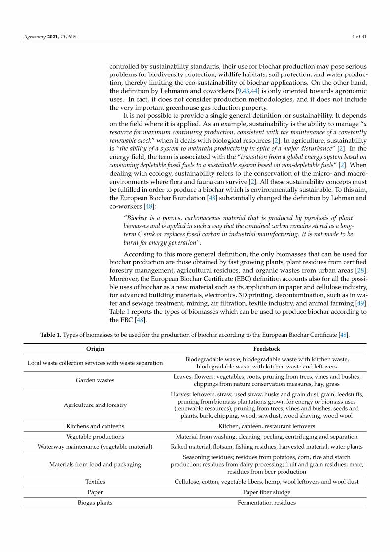
According to this more general definition, the only biomasses that can be used forbiochar production are those obtained by fast growing plants, plant residues from certifiedforestry management, agricultural residues, and organic wastes from urban areas [28].Moreover, the European Biochar Certificate (EBC) definition accounts also for all the possi-ble uses of biochar as a new material such as its application in paper and cellulose industry,for advanced building materials, electronics, 3D printing, decontamination, such as in wa-ter and sewage treatment, mining, air filtration, textile industry, and animal farming [49].Table 1 reports the types of biomasses which can be used to produce biochar according tothe EBC [48].
Table 1. Types of biomasses to be used for the production of biochar according to the European Biochar Certificate [48].
Origin Feedstock
Local waste collection services with waste separation Biodegradable waste, biodegradable waste with kitchen waste,biodegradable waste with kitchen waste and leftovers
Garden wastes Leaves, flowers, vegetables, roots, pruning from trees, vines and bushes,clippings from nature conservation measures, hay, grass
Agriculture and forestry
Harvest leftovers, straw, used straw, husks and grain dust, grain, feedstuffs,pruning from biomass plantations grown for energy or biomass uses
(renewable resources), pruning from trees, vines and bushes, seeds andplants, bark, chipping, wood, sawdust, wood shaving, wood wool
Kitchens and canteens Kitchen, canteen, restaurant leftovers
Vegetable productions Material from washing, cleaning, peeling, centrifuging and separation
Waterway maintenance (vegetable material) Raked material, flotsam, fishing residues, harvested material, water plants
Materials from food and packagingSeasoning residues; residues from potatoes, corn, rice and starch
production; residues from dairy processing; fruit and grain residues; marc;residues from beer production
Textiles Cellulose, cotton, vegetable fibers, hemp, wool leftovers and wool dust
Paper Paper fiber sludge
Biogas plants Fermentation residues
Agronomy 2021, 11, 615 5 of 41
1.2. Is Biochar Risky?
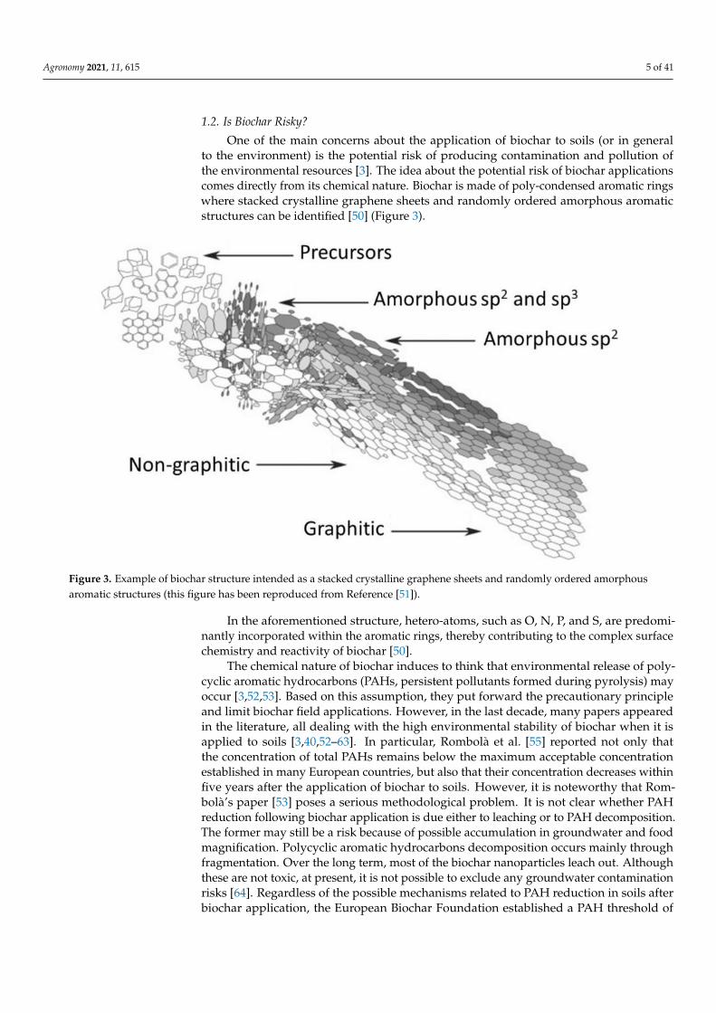
One of the main concerns about the application of biochar to soils (or in generalto the environment) is the potential risk of producing contamination and pollution ofthe environmental resources [3]. The idea about the potential risk of biochar applicationscomes directly from its chemical nature. Biochar is made of poly-condensed aromatic ringswhere stacked crystalline graphene sheets and randomly ordered amorphous aromaticstructures can be identified [50] (Figure 3).
Agronomy 2021, 11, x FOR PEER REVIEW 5 of 42
Materials from food and packaging
Seasoning residues; residues from potatoes, corn, rice and
starch production; residues from dairy processing; fruit
and grain residues; marc; residues from beer production
Textiles Cellulose, cotton, vegetable fibers, hemp, wool leftovers
and wool dust
Paper Paper fiber sludge
Biogas plants Fermentation residues
1.2. Is Biochar Risky?
One of the main concerns about the application of biochar to soils (or in general to
the environment) is the potential risk of producing contamination and pollution of the
environmental resources [3]. The idea about the potential risk of biochar applications
comes directly from its chemical nature. Biochar is made of poly-condensed aromatic
rings where stacked crystalline graphene sheets and randomly ordered amorphous aro-
matic structures can be identified [50] (Figure 3).
Figure 3. Example of biochar structure intended as a stacked crystalline graphene sheets and randomly ordered amor-
phous aromatic structures (this figure has been reproduced from Reference [51]).
In the aforementioned structure, hetero-atoms, such as O, N, P, and S, are predomi-
nantly incorporated within the aromatic rings, thereby contributing to the complex sur-
face chemistry and reactivity of biochar [50].
The chemical nature of biochar induces to think that environmental release of poly-
cyclic aromatic hydrocarbons (PAHs, persistent pollutants formed during pyrolysis) may
occur [3,52,53]. Based on this assumption, they put forward the precautionary principle
and limit biochar field applications. However, in the last decade, many papers appeared
in the literature, all dealing with the high environmental stability of biochar when it is
applied to soils [3,40,52–63]. In particular, Rombolà et al. [55] reported not only that the
concentration of total PAHs remains below the maximum acceptable concentration estab-
lished in many European countries, but also that their concentration decreases within five
years after the application of biochar to soils. However, it is noteworthy that Rombolà’s
Figure 3. Example of biochar structure intended as a stacked crystalline graphene sheets and randomly ordered amorphousaromatic structures (this figure has been reproduced from Reference [51]).
In the aforementioned structure, hetero-atoms, such as O, N, P, and S, are predomi-nantly incorporated within the aromatic rings, thereby contributing to the complex surfacechemistry and reactivity of biochar [50].
The chemical nature of biochar induces to think that environmental release of poly-cyclic aromatic hydrocarbons (PAHs, persistent pollutants formed during pyrolysis) mayoccur [3,52,53]. Based on this assumption, they put forward the precautionary principleand limit biochar field applications. However, in the last decade, many papers appearedin the literature, all dealing with the high environmental stability of biochar when it isapplied to soils [3,40,52–63]. In particular, Rombolà et al. [55] reported not only thatthe concentration of total PAHs remains below the maximum acceptable concentrationestablished in many European countries, but also that their concentration decreases withinfive years after the application of biochar to soils. However, it is noteworthy that Rom-bolà’s paper [53] poses a serious methodological problem. It is not clear whether PAHreduction following biochar application is due either to leaching or to PAH decomposition.The former may still be a risk because of possible accumulation in groundwater and foodmagnification. Polycyclic aromatic hydrocarbons decomposition occurs mainly throughfragmentation. Over the long term, most of the biochar nanoparticles leach out. Althoughthese are not toxic, at present, it is not possible to exclude any groundwater contaminationrisks [64]. Regardless of the possible mechanisms related to PAH reduction in soils afterbiochar application, the European Biochar Foundation established a PAH threshold of

Agronomy 2021, 11, 615 6 of 41
4 mg kg−1 [48], which is far below the background contamination. In addition, as reportedby Conte et al. [28]:
“Biochar shows a very good adsorption potential for hydrophobic materials [ . . . ]. For thisreason, the USEPA suggests charcoal as the best available technology for the treatment ofhydrophobic contamination. [ . . . ] the concern about possible dioxin content in biocharsis overstated. On the one hand, the amount of dioxins in biochars that have been analyzedto date was very low [ . . . ]. On the other hand, any dioxins present are strongly boundto biochar, thereby being unavailable for plant nutrition and to the food chain [ . . . ]”.
In other words, biochar adsorbs more environmental PAHs and other hydrophobicpollutants than it releases.
Table 2 reports the main characteristics to produce a biochar which follows the EBCguidelines. According to what has been reported above, the answer to the questionregarding biochar’s risk to health can only be that biochar is not risky provided thatit is produced and used according to the recommendations from the European BiocharFoundation [48].
Table 2. Technical parameters for biochars established by the European Biochar Certificate. The list is incomplete. It is,however, available in the link reported in Reference [48].
Parameter Value
H/C <0.7
O/C <0.4
Heavy metal content Pb < 150 g Mg−1; Cd < 1.5 g Mg−1; Cu < 100 g Mg−1; Ni < 50 g Mg−1;Hg < 1 g Mg−1; Zn < 400 g Mg−1; Cr < 90 g Mg−1
pH, bulk density, water, and ash content These are not fixed values. They must be measured and indicated
Polycyclic aromatichydrocarbons (PAH)
PAH content (sum of the EPA’s 16 priority pollutants) must be<6 mg kg−1 (<4 mg kg−1 for organic agriculture)
Polychlorinatedbiphenyls (PCB) <0.2 mg kg−1
1.3. Aim of This Work
Biochar research received a great deal of interest in the last decade and its role in manydifferent applications has been clarified. However, the understanding of biochar behaviorseems more empirical than relying on a well-structured theoretical framework. For thisreason, we intend to discuss the most recent literature to provide a general and criticaloverview of the newest findings on biochar’s physical chemistry, thereby highlighting allthe main information useful to disclose the molecular mechanisms of biochar functioning.Due to its multivalent characteristics, we will focus not only on the mechanisms of biocharapplied to soils, but also on its role in environmental remediation.
2. Making Biochar: A Brief Summary of the Main Production Methodologies
Notwithstanding that the focus of this review paper is not on biochar production,a brief summary of simple techniques used to obtain the aforementioned material is given.The idea is to provide an easy tool for inexperienced readers who want to approachbiochar science. The production methods listed here are not exhaustive of the wholerange of techniques used to obtain biochar; therefore, readers are recommended to consultthe publications in references [44,65,66] for wider and more detailed information.
The different techniques applied for biochar production provide materials with typicalcharacteristics, making them reliable for many specific uses [49]. As an example, when onlysmall amounts of biochar are needed for lab studies, the lab–muffle–furnace method can beapplied (Appendix A). This home-made, quick procedure to transform any kind of biomassis affected by the researcher’s awareness and by the impossibility of correctly controlling

Agronomy 2021, 11, 615 7 of 41
all the production parameters (e.g., atmosphere composition, quenching methodology).Therefore, a reliable approach to the lab–muffle–furnace method would be for the sameresearcher to undertake the production of biochar for the entire research group. This isthe only way to obtain a carbonaceous material with repeatable characteristics.
A valid alternative to obtain biochars with reproducible chemical–physical propertiesis the use of lab-pyrolizers (Appendix B). These are designed to adjust the pyrolyzing atmo-sphere and quenching procedures. Depending on the pyrolizer characteristics, the amountof biochar that is produced can be in the order of tens of grams, which is at least tentimes more than the amount obtained by the lab–muffle–furnace method. Being highlyreproducible, the advantages of the use of lab-pyrolizers rely on the fact that the obtainedbiochar can be used for the production of new materials such as electrodes [67], sorbent forspecific pollutants [68], or even for medicine [49].
The hydrothermal carbonization (Appendix C) is usually applied to retrieve biochars(which in this case are referred to as hydrochars) having very good fertilizing characteris-tics [69,70]. This is mainly due to the presence of residual polysaccharide and polypeptideunits that are not thermally decomposed by the mild temperature conditions used duringthe process [71].
When larger amounts of material are needed for agricultural purposes, the Kon-Tiki kiln can be a useful tool for biochar production (Appendix D). This method allowscontrol of the quenching procedure, whereas no control of the pyrolysis temperature isachieved. The biochar obtained by this home-made procedure appeared to be very effectivein increasing pumpkin production [72].
In Appendix E, the industrial thermochemical carbonization (also referred to as gasi-fication) is briefly summarized. The method is thought to produce syn-gas which canbe applied for energy production, while biochar is obtained as a low-cost by-product [6].The latter can be applied to achieve different aims such as agricultural purposes [16],environmental remediation, electrical energy storage, electrochemical sensors, and cataly-sis [73].
3. Biochar Physical–Chemical Properties3.1. The Effect of Feedstock Nature
The nature of the biomass used for biochar production appears to play a major rolein addressing its chemical–physical properties [28]. Different feedstocks show differ-ent composition in terms of cellulose, hemicellulose, lignin as well as inorganic compo-nents [21,74]. These differences result in a different biomass behavior during the thermaldegradation described in the previous paragraph [74,75]. In particular, hemicellulose isthe first to undergo decomposition at a temperature ranging between 200 and 260 ◦C,while cellulose breaks down at 240–350 ◦C and lignin at 280–500 ◦C [74]. The pyrolysismechanism of hemicelluloses starts with a depolymerization producing oligosaccharides.Therefore, xylan chain cleavage and molecular rearrangement produces a xylopyranose.The xylopyranose is further degraded to small molecular weight compounds such asfurfural and fragments containing two or three carbon atoms. As for the hemicellulose,also cellulose is first depolymerized into oligosaccharides. Then the glucosidic bonds ofthe oligosaccharides are broken to produce D-glucopyranose. The intramolecular rearrange-ment of D-glucopyranose produces levoglucosan. The latter further decomposes to formsmall molecular weight compounds. Pyrolysis of lignin generates phenolic compoundssuch as guaiacol-like, phenol-like, syringol-like, and catechol-like systems [74].
The relative abundances of the biomass components described above effect reactivityand yield, thereby affecting the ratios between the volatile products (e.g., bio-oil and gas)and the biochar [74–76]. For instance, biomasses with a low content of lignin, minerals,and nitrogen are used to produce bio-oil and fuel-gas. Conversely, feedstock containinglarger amounts of lignin are mainly applied to achieve biochar [8]. As a rule of thumb,the biochars produced from woods have low ash and high carbon contents, whereasthe thermal degradation of herbaceous biomasses, biosolids and manures result in biochars

Agronomy 2021, 11, 615 8 of 41
with low carbon content and larger amounts of ashes, nitrogen, phosphorus, potassium,and sulphur [44,77].
Besides their chemical nature, the biomasses used for biochar production affect alsoits porosity and, therefore, its adsorptive properties [44,78]. During the thermal degrada-tion, the loss of volatile organic compounds results in a volume reduction. Consequently,the arising mineral and carbon skeleton retain the rudimentary feedstock porosity andstructure. The residual cellular structures of botanical origin that are present and iden-tifiable in biochars contribute to the majority of the biochar macro-porosity [44]. This isconfirmed by microscopic investigations showing the presence of aligned honeycomb-likegroups of pores (Figure 4). The latter ones are due to the carbonaceous skeleton arisingfrom the biological capillary structure of the raw material. Finally, the large-sized poresserve as a feeder to lower-dimension pores [44].
Agronomy 2021, 11, x FOR PEER REVIEW 8 of 42
lose is first depolymerized into oligosaccharides. Then the glucosidic bonds of the oligo-
saccharides are broken to produce D-glucopyranose. The intramolecular rearrangement
of D-glucopyranose produces levoglucosan. The latter further decomposes to form small
molecular weight compounds. Pyrolysis of lignin generates phenolic compounds such as
guaiacol-like, phenol-like, syringol-like, and catechol-like systems [74].
The relative abundances of the biomass components described above effect reactivity
and yield, thereby affecting the ratios between the volatile products (e.g., bio-oil and gas)
and the biochar [74–76]. For instance, biomasses with a low content of lignin, minerals,
and nitrogen are used to produce bio-oil and fuel-gas. Conversely, feedstock containing
larger amounts of lignin are mainly applied to achieve biochar [8]. As a rule of thumb, the
biochars produced from woods have low ash and high carbon contents, whereas the ther-
mal degradation of herbaceous biomasses, biosolids and manures result in biochars with
low carbon content and larger amounts of ashes, nitrogen, phosphorus, potassium, and
sulphur [44,77].
Besides their chemical nature, the biomasses used for biochar production affect also
its porosity and, therefore, its adsorptive properties [44,78]. During the thermal degrada-
tion, the loss of volatile organic compounds results in a volume reduction. Consequently,
the arising mineral and carbon skeleton retain the rudimentary feedstock porosity and
structure. The residual cellular structures of botanical origin that are present and identifi-
able in biochars contribute to the majority of the biochar macro-porosity [44]. This is con-
firmed by microscopic investigations showing the presence of aligned honeycomb-like
groups of pores (Figure 4). The latter ones are due to the carbonaceous skeleton arising
from the biological capillary structure of the raw material. Finally, the large-sized pores
serve as a feeder to lower-dimension pores [44].
The number of inorganic components in the feedstock also plays an important role
in determining the physical structure of biochar. Depending on the applied processing
conditions (outlined below), ash fusion or sintering may dramatically change the physical
and structural composition of biochar.
Figure 4. Photo acquired by a scanning electron microscope (SEM) of a biochar from fir biomasscharred at 500 ◦C for a period of 30 min via the lab–muffle–furnace method (Appendix A).The honeycomb-like group of pores, due to the cellular structure of the feedstock, are clearly visible(unpublished results from the group of P.C.).
The number of inorganic components in the feedstock also plays an important rolein determining the physical structure of biochar. Depending on the applied processingconditions (outlined below), ash fusion or sintering may dramatically change the physicaland structural composition of biochar.
3.2. The Biomass Pretreatment
The chemical–physical biochar characteristics depend not only on the feedstock’snature but also on the pretreatments to which it was subjected. Pretreatments are usuallyapplied to facilitate thermal degradation. The hierarchical and recalcitrant nature ofbiomasses (due to the intricate structure where cellulose, hemicellulose, and lignin are

Agronomy 2021, 11, 615 9 of 41
rigidly associated through non-covalent bonds and covalent cross-linkages) prevent anyeasy disruption, thereby causing undesirable energy expenditure when biomass thermaldegradation is used for energy production (e.g., gasification). The advantages of biomasspretreatments are also related to the formation of solid by-products with specific propertiesenabling their use in wastewater treatments, air cleaning, soil remediation, and catalyticpurposes to facilitate energy production [8,76,79–83]. In particular, washing biomass priorto pyrolysis with either acidic or basic solutions may remove up to 70% of the initialminerals contained in the feedstock [79,84,85]. However, the use of dilute acid and hotwater results in a slight decomposition of hemicellulose. Conversely, the application ofdilute alkali disrupts lignin structure and solubilizes hemicellulose. As a consequence,the thermal degradation applied after the acid/base treatment achieves a higher yieldin liquids (tar) and gases at the expense of the solid residue [79,84,85]. The latter, whenobtained after biomass treatment with a 1:1 (v:v) HNO3/H2O2 solution, appears to haveenhanced adsorption capacity for cadmium from high concentration solutions as comparedto biochars obtained from non-pretreated biomasses [86]. This difference can be explainedassuming that the treatment favors biochar mesoporosity.
The three dimensional structure of the biomass can also be altered by the use of ionicliquids (ILs) [79]. These are poorly coordinated melted salts made by at least one largeorganic ion (possibly with a delocalized charge) with a relatively low reticular energy [87].When biomass is placed in an ionic liquid, the H-bond net is broken by the interactionswith the IL cation and anion moieties (Figure 5), thereby providing a material that canbe better used for energy purposes (i.e., high yield in biofuels rather than biochar) [79].However, when the biomass is first heated in concentrated sulphuric acid then treated withIL, a functionalized IL-biochar is obtained. The latter is successfully applied as a catalystin cellulose dissolution for biofuel production [88,89].
Agronomy 2021, 11, x FOR PEER REVIEW 9 of 42
Figure 4. Photo acquired by a scanning electron microscope (SEM) of a biochar from fir biomass
charred at 500 °C for a period of 30 min via the lab–muffle–furnace method (Appendix A). The
honeycomb-like group of pores, due to the cellular structure of the feedstock, are clearly visible
(unpublished results from the group of P.C.).
3.2. The Biomass Pretreatment
The chemical–physical biochar characteristics depend not only on the feedstock’s na-
ture but also on the pretreatments to which it was subjected. Pretreatments are usually
applied to facilitate thermal degradation. The hierarchical and recalcitrant nature of bio-
masses (due to the intricate structure where cellulose, hemicellulose, and lignin are rigidly
associated through non-covalent bonds and covalent cross-linkages) prevent any easy dis-
ruption, thereby causing undesirable energy expenditure when biomass thermal degra-
dation is used for energy production (e.g., gasification). The advantages of biomass pre-
treatments are also related to the formation of solid by-products with specific properties
enabling their use in wastewater treatments, air cleaning, soil remediation, and catalytic
purposes to facilitate energy production [8,76,79–83]. In particular, washing biomass prior
to pyrolysis with either acidic or basic solutions may remove up to 70% of the initial min-
erals contained in the feedstock [79,84,85]. However, the use of dilute acid and hot water
results in a slight decomposition of hemicellulose. Conversely, the application of dilute
alkali disrupts lignin structure and solubilizes hemicellulose. As a consequence, the ther-
mal degradation applied after the acid/base treatment achieves a higher yield in liquids
(tar) and gases at the expense of the solid residue [79,84,85]. The latter, when obtained
after biomass treatment with a 1:1 (v:v) HNO3/H2O2 solution, appears to have enhanced
adsorption capacity for cadmium from high concentration solutions as compared to bio-
chars obtained from non-pretreated biomasses [86]. This difference can be explained as-
suming that the treatment favors biochar mesoporosity.
The three dimensional structure of the biomass can also be altered by the use of ionic
liquids (ILs) [79]. These are poorly coordinated melted salts made by at least one large
organic ion (possibly with a delocalized charge) with a relatively low reticular energy [87].
When biomass is placed in an ionic liquid, the H-bond net is broken by the interactions
with the IL cation and anion moieties (Figure 5), thereby providing a material that can be
better used for energy purposes (i.e., high yield in biofuels rather than biochar) [79]. How-
ever, when the biomass is first heated in concentrated sulphuric acid then treated with IL,
a functionalized IL-biochar is obtained. The latter is successfully applied as a catalyst in
cellulose dissolution for biofuel production [88,89].
Figure 5. H-bond rupture mechanism by ionic liquids. IL stands for ionic liquid, C+ is the cation moiety, while A− isthe anion one [79].
Biochar characteristics can be modified also by treating biomasses with metals, e.g., Mg,Fe, Ca, and Al (usually as nitrogen-containing or chloride salts or by electrodeposition)prior to the thermal degradation [80]. The role of the metals is to enhance biochar adsorp-tion properties, thereby making it a good material for environmental remediation [80].Enhancement of the biochar’s adsorptive capacity following this treatment can be explainedby the Lewis acid-like behavior of the metals added to biomasses prior to the pyrolysis.
Other biomass pretreatments are: (i) the electrospinning of a cellulose acetate solutionwith subsequent deacetylation and pyrolysis in order to produce carbon fibers to be applied
Agronomy 2021, 11, 615 10 of 41
for the production of electrodes [90]; (ii) the low-temperature pre-carbonization combinedwith KOH chemical activation in order to retrieve tubular nanomaterials to be appliedfor the achievement of super-capacitors [91]; (iii) the addition of (NH4)2HPO4 before car-bonization in order to increase biochar porosity, cross-linking, and availability of nitrogenand phosphorous [91]. A complete review of biomass pretreatments for the achievement ofbiochars for the production of new materials is reported in Bi et al. [27].
3.3. The Influence of the Pyrolysis Conditions
The experimental conditions applied during the biomass thermal treatments (e.g., tem-perature and atmosphere) greatly affect biochar characteristics and properties. Therefore,biochar value in terms of its performance for its possible application (e.g., agriculture,soil carbon sequestration, catalyst) is strongly dependent on how pyrolysis is conducted.In the following sub-sections, the most important effects of pyrolysis conditions on biocharcharacteristics are reviewed.
3.3.1. Temperature Effect on the Amount of Carbon in Biochars
Pyrolysis temperature significantly influences the final biochar structural and physico-chemical properties. This is due to the release of volatiles and the formation and volatiliza-tion of intermediate melts [77,92–94]. Many studies indicate that the higher the temperature,the larger is the biochar carbon-content since loss of nitrogen, hydrogen, and oxygen arerecorded [77,92–95]. The biochars produced at low temperature (<350 ◦C) reveal a carboncontent below 60% (w/w), while as the temperature increases in the range 400–500 ◦C,the carbon-content increases to 60–80% (w/w). For temperatures as high as 500 ◦C, the car-bon content reaches values larger than 80% (w/w). However, the latter case is valid mostlyfor wood-derived biochar [44]. When animal residues (e.g., manure) are used, the carboncontent reveals an opposite trend [96,97]. This is explained by the effect of the large amountof ashes present in the biomasses from animal origin [97].
3.3.2. Temperature Effect on the Chemical Nature of Biochar Components
Besides the changes of carbon content in biochars, also the chemical nature of the biocharorganic components varies with temperature. With increasing temperatures, the amountof alkyl carbons decreases, and aromatic residues increases [44,98,99] (Figure 6). Fromapproximately 250–450 ◦C, the amount of alkyl and aromatic moieties increases, whileif the temperature reaches ≥500 ◦C, the resulting biochar is made by highly recalcitrantforms of organic matter, i.e., poly-condensed aromatic hydrocarbons (Figure 6). Therefore,the biochars produced at high temperatures (≥500 ◦C) are chemically more stable and moreresistant to microbial and abiotic degradations than those obtained at lower temperatures.
3.3.3. Temperature Effect on Biochar Ash Content
Temperature increase also results in a decreased amount of the final solid product,with a concomitant increase in the ash content due to the naturally occurring inorganiccomponents in all biomasses [92–94]. As an example, the biochar produced from chickenmanure revealed an ash content increasing from 40% to 60%, as the temperature rosefrom 300 ◦C to 600 ◦C [77]; the ash content in the biochar from apple tree branches varied6–9% as the temperature rose from 300 ◦C to 600 ◦C [93]; the biochar obtained from pinesawdust evidenced an increase of the ash content from 1% to 2% by increasing the pyrolysistemperature from 350 ◦C to 750 ◦C [94]; the ash content in a biochar obtained from peastraw increased from 15% to 24% as the temperature rose from 350 ◦C to 750 ◦C [94];the biochar from coconut flesh waste showed an ash content varying from 5% to 8% asthe temperature was changed from 350 ◦C to 600 ◦C [95]. These findings can be explainedby considering that the higher the temperature, the larger is the amount of volatile organiccompounds (VOCs) produced during the pyrolysis, thereby leading to an amount of solidbiochar smaller than that obtained at lower temperatures.

Agronomy 2021, 11, 615 11 of 41
Figure 6. Schematic representation of the chemical transformations occurring in biomasses as pyrolysis temperature increases.
3.3.4. Temperature Effect on Biochar Surface Properties
The progressively larger amount of volatile organic components released from the feed-stock with rising temperatures is responsible for the reduction of the surface functionalgroups which, in turn, cause the adsorption properties of biochars [39,100–103]. Accord-ing to Chun et al. [100], low-temperature biochars (that is, those obtained at 300–400 ◦C)revealed an amount of polar groups (e.g., –OH, –COOH, –C=O etc.) larger than those ob-tained at temperatures above 500 ◦C. Because of this, Uchimiya et al. [15,104] reported thatbiochars obtained at temperatures ≥500 ◦C revealed a lower capacity to trap heavy metals.Furthermore, the reduction of the adsorption capacity is due also to the biochar’s physicalstructure as the temperature increases [44,104–106]. In particular, the release of the volatileorganic components generates pore structures similar to those of the biomass cells (seeabove). Pore volume and average pore size (i.e., the porosity) increase as the temperaturerises up to approximately 500 ◦C. Above this temperature, pore coalescence and ash meltingoccur, thereby resulting in a reduction of the porosity [91,107,108]. Figure 7 schematicallysummarizes pore formation during biomass thermal degradation. The leftmost side ofthe figure represents the honeycomb-like cells in the biomass prior to the pyrolysis. As thetemperature increases to 500 ◦C, the volatilization of the organic components producesholes as schematized in the central part of Figure 7. Finally, above 500 ◦C, the high pressuregenerated by salt melting, together with the production of progressively larger amountsof VOCs, provokes disruption of cell walls and pore coalescence (at the rightmost side ofFigure 7), thereby allowing reduction of biochar surface area and capacity to retain organicand inorganic pollutants [107].

Agronomy 2021, 11, 615 12 of 41
Agronomy 2021, 11, x FOR PEER REVIEW 12 of 42
the high pressure generated by salt melting, together with the production of progressively
larger amounts of VOCs, provokes disruption of cell walls and pore coalescence (at the
rightmost side of Figure 7), thereby allowing reduction of biochar surface area and capac-
ity to retain organic and inorganic pollutants [107].
Figure 7. Schematic representation of pore formation during pyrolysis. The leftmost side of the figure shows the honey-
comb-like cells of the biomass prior of the thermal degradation. As the temperature increases pores are formed (central
part of the figure). Pore coalescence due to the release of volatile organic components and salt melting provokes hole
enlargement and reduction of the biochar surface area.
3.3.5. Effect of Pyrolysis Heating Rate and Holding Time
Three modes to perform pyrolysis can be recognized. As reported in Table 3, they
differ for the heating rate, that is the ramp applied to reach the pyrolysis temperature, and
the holding time, that is the time during which the heating temperature is maintained
[109,110].
Fast pyrolysis is carried out by applying very high heating rates (that is in the order
of hundreds of degrees Celsius per seconds, °C s−1) and a very short holding time (<2 s)
(Table 3). Under the aforementioned conditions, the heating rate is so rapid that the bio-
mass reaches the pyrolysis temperature before any thermal decomposition starts [111].
This mode is applied to obtain high yields of bio-oils that come from the condensation of
the volatile organic compounds generated by the biomass heating [112]. Bio oils—mainly
composed of 20–25% water, 20–25% water-insoluble-lignin, 25–30% organic acids, 5–12%
non-polar hydrocarbons, 5–10% sugars and 10–25% other oxygenated compounds [21]—
are used for the production of electrical energy. If the aim of fast pyrolysis is to produce a
maximum quantity of bio-oils compared to biochar and syngas, usually conditions need
to be accounted for: fine particle size of the biomass to be pyrolyzed (<1 mm), careful
control of the final temperature (around 450–550 °C), heating rate > 200 °C s−1, short hot
vapor residence time (around 2 s), and rapid cooling of the vapors [111–113]. When the
fast pyrolysis is conducted at a temperature ranging between 700 °C and 1000 °C, hydro-
gen gas is produced in addition to bio-oils [114].
Table 3. Different pyrolysis modes. They differ from each other for the heating rate, holding time, and the number of
different products obtained.
Pyrolysis Mode Heating Rate Holding Time Typical Holding
Temperature
Bio-Oil (%,
w w−1)
Biochar (%, w
w−1)
Gas (%, w
w−1)
Fast Very high <2 s <550 °C 70–80 10–15 10–15
Conventional Low 5 min up to few hours <600 °C 40–50 20–30 30–40
Slow Very low Days ≈400 °C 30 35 35
The conventional or mid pyrolysis is conducted by applying a heating rate of approx-
imately 20 °C s−1 and a pyrolysis temperature usually not above 600 °C held from a few
Figure 7. Schematic representation of pore formation during pyrolysis. The leftmost side of the figure shows the honeycomb-like cells of the biomass prior of the thermal degradation. As the temperature increases pores are formed (central part ofthe figure). Pore coalescence due to the release of volatile organic components and salt melting provokes hole enlargementand reduction of the biochar surface area.
3.3.5. Effect of Pyrolysis Heating Rate and Holding Time
Three modes to perform pyrolysis can be recognized. As reported in Table 3, theydiffer for the heating rate, that is the ramp applied to reach the pyrolysis temperature,and the holding time, that is the time during which the heating temperature is main-tained [109,110].
Table 3. Different pyrolysis modes. They differ from each other for the heating rate, holding time, and the number ofdifferent products obtained.
Pyrolysis Mode Heating Rate Holding Time Typical HoldingTemperature
Bio-Oil(%, w w−1)
Biochar(%, w w−1)
Gas(%, w w−1)
Fast Very high <2 s <550 ◦C 70–80 10–15 10–15Conventional Low 5 min up to few hours <600 ◦C 40–50 20–30 30–40
Slow Very low Days ≈400 ◦C 30 35 35
Fast pyrolysis is carried out by applying very high heating rates (that is in the orderof hundreds of degrees Celsius per seconds, ◦C s−1) and a very short holding time (<2 s)(Table 3). Under the aforementioned conditions, the heating rate is so rapid that the biomassreaches the pyrolysis temperature before any thermal decomposition starts [111]. This modeis applied to obtain high yields of bio-oils that come from the condensation of the volatileorganic compounds generated by the biomass heating [112]. Bio oils—mainly composedof 20–25% water, 20–25% water-insoluble-lignin, 25–30% organic acids, 5–12% non-polarhydrocarbons, 5–10% sugars and 10–25% other oxygenated compounds [21]—are usedfor the production of electrical energy. If the aim of fast pyrolysis is to produce a maxi-mum quantity of bio-oils compared to biochar and syngas, usually conditions need to beaccounted for: fine particle size of the biomass to be pyrolyzed (<1 mm), careful controlof the final temperature (around 450–550 ◦C), heating rate > 200 ◦C s−1, short hot vaporresidence time (around 2 s), and rapid cooling of the vapors [111–113]. When the fastpyrolysis is conducted at a temperature ranging between 700 ◦C and 1000 ◦C, hydrogengas is produced in addition to bio-oils [114].
The conventional or mid pyrolysis is conducted by applying a heating rate of approxi-mately 20 ◦C s−1 and a pyrolysis temperature usually not above 600 ◦C held from a fewminutes up to a few hours (Table 3) [21,112,115]. This mode is applied to obtain a betterbiochar yield compared to the fast pyrolysis.
The slow pyrolysis mode—the oldest one, used for thousands of years to producebiochar for agricultural purposes [21,44,112]—is conducted by applying very low heating

Agronomy 2021, 11, 615 13 of 41
rates, low to moderate temperatures (around 400 ◦C) and long reaction times (up to days)(Table 3). The long holding time ensures the conversion of condensable vapors into biocharand non-condensable gases. Unlike fast pyrolysis, the slow one does not necessarily needa fine feedstock particle size (smaller than 1 mm). In fact, raw materials that are notavailable as powders or fine particles are usually used [116]. Slow/conventional and fastpyrolysis generate different solid bio-carbon products, even when the same raw biomassmaterials are used. The most significant differences include the evolution of the specificsurface area resulting from the development of a porous structure during the pyrolysisprocess, and the average pore size and pore size distribution [27].
3.3.6. Effect of the Pyrolysis’ Atmosphere
Apart from temperature, heating, and holding times, also the atmosphere used duringthe thermal degradation influences the yield of the pyrolysis products and the biocharchemical–physical characteristics. As an example, Guizani et al. [117] reported that an at-mosphere of carbon dioxide applied during the pyrolysis was responsible for the lowerbiochar yield as compared to the pyrolysis conducted under an N2 atmosphere. This wasexplained by suggesting that carbon dioxide can hinder tar polymerization according toEquation (1) (tar polymerization is one of the secondary reactions contributing to biocharformation), can react with methane and hydrogen according to Equations (2) and (3) (thusaltering syngas composition), and may favor biochar degradation via the Boudouardreaction described in Equation (4) [117]:
CnHm + nCO2 → 2nCO +m2
H2 (1)
CO2 + CH4 → 2H2 + 2CO (2)
CO2 + H2 → H2O + CO (3)
CO2 + C→ 2CO (4)
Guizani et al. [117] also reported that the biochar produced in a CO2 atmospherehas larger surface area and lower H/C and O/C ratios than those produced in an N2atmosphere.
These characteristics have been related to the better adsorption properties for organicand inorganic contaminants as compared to the same materials obtained in an N2 atmo-sphere [118]. The ameliorated adsorption properties of the biochars obtained in a CO2atmosphere may also suggest a better nutrient exchange ability when they are applied tosoils as amendments. However, no studies have been found to confirm such an expectation.
The results from Guizani et al. [117] have been confirmed by Fan et al. [118], Valdés et al. [119],and Luo et al. [120], whereas only partially by Molenda [121]. In particular, the latterreported that “biocarbon obtained in an atmosphere of carbon dioxide is characterized by a higherproportion of oxygen compared to the product produced in a nitrogen atmosphere”. The differencesamong these studies lay in the different pyrolysis modes used to perform the CO2-driventhermal degradations. Fast pyrolysis was applied in Guizani et al. [117], Fan et al. [118],Valdés et al. [119], and Luo et al. [120], whereas slow pyrolysis followed by slow biocharcooling to room temperature was used in Molenda [121]. It is conceivable that the slowpyrolysis conditions may have avoided removal of the oxygenated functional groups(revealed by means of the infrared spectroscopy) laying on the surface of the biomassfeedstock.
An alternative to carbon dioxide and/or nitrogen atmosphere is the application ofan ammonia atmosphere. When NH3 is used to drive thermal degradation of biomasses,nitrogen-enriched biochars are obtained. They can be used either as plant fertilizers oruseful activated carbon in materials science (e.g., electronic, optic or transmission applica-tions) [122–124]. Ammonia leads to the formation of pyridinic-, pyrrolic-, quaternary-Nand pyridine-N-oxide groups.

Agronomy 2021, 11, 615 14 of 41
N-activated biochars can be also obtained via the application of an atmosphere madeby a mixture of carbon dioxide and ammonia. The results by Xiong et al. [125] andZhang et al. [126] showed that five different chemical pathways can conceivably occuron the biomass surface during the thermal degradation (Figure 8). In pathway 1, the alco-holic moieties can react with ammonia generating primary amines. The latter can combinewith carbon dioxide to provide N-alkyl ammonium salts and N-alkil carbamates. Pathway2 shows that, in the presence of ammonia, ether moieties are transformed to secondaryamines. The latter combine with carbon dioxide to produce N,N-dialkyl ammonium saltsand N,N-dialkyl carbamates. Primary and secondary amines (coming from Pathways 1and 2, respectively) can react with each other in the presence of carbon dioxide to produceN-alkyl ammonium salts and N,N-dialkyl carbamates (Pathway 3). The N-alkyl carbamatesfrom Pathway 1 may rearrange with water expulsion to produce isocianates (Pathway4). Finally, the N-alkyl carbamates from Pathway 1 and the N,N-dialkyl ammonium saltsfrom Pathway 2 can condense to form N-alkyl, N’,N’-dialkyl urea derivatives (Pathway 5).The simultaneous presence of all the aforementioned moieties obtained by the chemicaltransformations of the biomass surfaces appear to be responsible for the very high carbondioxide affinity of the produced biochars [125,126]. This may suggest that the CO2/NH3-obtained biochars can have different effects when applied to soils. On the one hand,they can work as nitrogen suppliers to plant nutrition. On the other hand, they can trapatmospheric CO2 in soils, thereby contributing to the mitigation of global climatic change.
Agronomy 2021, 11, x FOR PEER REVIEW 14 of 42
An alternative to carbon dioxide and/or nitrogen atmosphere is the application of an
ammonia atmosphere. When NH3 is used to drive thermal degradation of biomasses, ni-
trogen-enriched biochars are obtained. They can be used either as plant fertilizers or use-
ful activated carbon in materials science (e.g., electronic, optic or transmission applica-
tions) [122–124]. Ammonia leads to the formation of pyridinic-, pyrrolic-, quaternary-N
and pyridine-N-oxide groups.
N-activated biochars can be also obtained via the application of an atmosphere made
by a mixture of carbon dioxide and ammonia. The results by Xiong et al. [125] and Zhang
et al. [126] showed that five different chemical pathways can conceivably occur on the
biomass surface during the thermal degradation (Figure 8). In pathway 1, the alcoholic
moieties can react with ammonia generating primary amines. The latter can combine with
carbon dioxide to provide N-alkyl ammonium salts and N-alkil carbamates. Pathway 2
shows that, in the presence of ammonia, ether moieties are transformed to secondary
amines. The latter combine with carbon dioxide to produce N,N-dialkyl ammonium salts
and N,N-dialkyl carbamates. Primary and secondary amines (coming from Pathways 1
and 2, respectively) can react with each other in the presence of carbon dioxide to produce
N-alkyl ammonium salts and N,N-dialkyl carbamates (Pathway 3). The N-alkyl carba-
mates from Pathway 1 may rearrange with water expulsion to produce isocianates (Path-
way 4). Finally, the N-alkyl carbamates from Pathway 1 and the N,N-dialkyl ammonium
salts from Pathway 2 can condense to form N-alkyl, N’,N’-dialkyl urea derivatives (Path-
way 5). The simultaneous presence of all the aforementioned moieties obtained by the
chemical transformations of the biomass surfaces appear to be responsible for the very
high carbon dioxide affinity of the produced biochars [125,126]. This may suggest that the
CO2/NH3-obtained biochars can have different effects when applied to soils. On the one
hand, they can work as nitrogen suppliers to plant nutrition. On the other hand, they can
trap atmospheric CO2 in soils, thereby contributing to the mitigation of global climatic
change.
Figure 8. Chemical pathways involved in the changes of biomass surface chemistry during the pyrol-ysis in CO2/NH3 atmosphere. All the reactions described here do not account for the stoichiometry.The scheme has been re-elaborated from references [125,126].
Besides the effects on the biochar surface chemistry, the CO2/NH3 atmosphere alsoaffects pore formation and size [125,126]. Figure 9 shows that the atmosphere made solelyby carbon dioxide first improves pore volume and surface area as the temperature is raisedup to a value of around 700 ◦C. Above 800 ◦C, pore collapse occurs. Therefore, porevolume and surface area reduction are observed. As the thermal degradation is carried

Agronomy 2021, 11, 615 15 of 41
out in an ammonia atmosphere, pore clogging with reduction of porosity and surfacearea is observed up to a temperature of around 600 ◦C. As the temperature increases,the N-containing groups (generated by the reactions between ammonia and the wallsof the biomass pores) are degraded. At the same time, pore collapse occurs. Whenthe CO2/NH3 mixture is used as pyrolysis atmosphere, a synergic effect of both gasesis observed. While carbon dioxide allows pore volume and surface area improvement,ammonia reacts with the pore walls, thereby forming a kind of glue-like layer whichimproves the adsorption properties of the biochar as compared to the materials obtainedeither in pure CO2 or NH3 atmospheres. As the temperature is raised above the value ofaround 800 ◦C, pore collapse and degradation of N-containing groups occurs [125,126].
Agronomy 2021, 11, x FOR PEER REVIEW 15 of 42
Figure 8. Chemical pathways involved in the changes of biomass surface chemistry during the
pyrolysis in CO2/NH3 atmosphere. All the reactions described here do not account for the stoichi-
ometry. The scheme has been re-elaborated from references [125,126].
Besides the effects on the biochar surface chemistry, the CO2/NH3 atmosphere also
affects pore formation and size [125,126]. Figure 9 shows that the atmosphere made solely
by carbon dioxide first improves pore volume and surface area as the temperature is
raised up to a value of around 700 °C. Above 800 °C, pore collapse occurs. Therefore, pore
volume and surface area reduction are observed. As the thermal degradation is carried
out in an ammonia atmosphere, pore clogging with reduction of porosity and surface area
is observed up to a temperature of around 600 °C. As the temperature increases, the N-
containing groups (generated by the reactions between ammonia and the walls of the bi-
omass pores) are degraded. At the same time, pore collapse occurs. When the CO2/NH3
mixture is used as pyrolysis atmosphere, a synergic effect of both gases is observed. While
carbon dioxide allows pore volume and surface area improvement, ammonia reacts with
the pore walls, thereby forming a kind of glue-like layer which improves the adsorption
properties of the biochar as compared to the materials obtained either in pure CO2 or NH3
atmospheres. As the temperature is raised above the value of around 800 °C, pore collapse
and degradation of N-containing groups occurs [125,126].
Figure 9. Scheme of pore formation in CO2, NH3, and CO2/NH3 atmospheres. The grey color indi-
cates the formation of a “glue”-like layer made by N-containing groups. The scheme has been
elaborated from References [125,126].
The amount of oxygen-containing surface functional groups with the aim to produce
biochar having a high affinity for metal ions and, therefore, being possibly applied for
wastewater treatments, has been obtained by means of application of air steam under mild
temperature conditions (that is temperatures ~ 300 °C) [127]. The mild temperatures are
needed to prevent biomass burn-off while oxygen-functionalization occurs (Figure 10).
The advantage of this oxygen-rich carbonaceous material is related also to its high cationic
exchange capacity [127] which makes it potentially a useful soil fertilizer.
Figure 9. Scheme of pore formation in CO2, NH3, and CO2/NH3 atmospheres. The grey colorindicates the formation of a “glue”-like layer made by N-containing groups. The scheme has beenelaborated from References [125,126].
The amount of oxygen-containing surface functional groups with the aim to producebiochar having a high affinity for metal ions and, therefore, being possibly applied forwastewater treatments, has been obtained by means of application of air steam under mildtemperature conditions (that is temperatures ~ 300 ◦C) [127]. The mild temperatures areneeded to prevent biomass burn-off while oxygen-functionalization occurs (Figure 10).The advantage of this oxygen-rich carbonaceous material is related also to its high cationicexchange capacity [127] which makes it potentially a useful soil fertilizer.

Agronomy 2021, 11, 615 16 of 41
Agronomy 2021, 11, x FOR PEER REVIEW 16 of 42
3.3.7. Effect of Co-Pyrolysis
The term co-pyrolysis refers to a process where two or more different feedstock are
used to produce materials with a wide range of applications. As an example, co-pyrolysis
is applied to obtain sustainable bio-fuels, when biomasses are mixed with coal [128,129]
or some types of plastics [130–133]. The presence of the co-pyrolysis materials allows yield
efficiency in the production of bio-oils, thereby leading to the conclusion that co-pyrolysis
may satisfy two different types of needs. On one hand, it can provide liquid materials that
can be applied as biofuels, thus reducing the use of fossil fuels, and contributing to the
mitigation of the global climatic changes. On the other hand, it allows a better manage-
ment of plastic waste disposal. Plastic pollution is one of the main environmental prob-
lems humans are currently facing [134]. Although the biochar yield is lower than in the
absence of co-pyrolyzing materials, the solid carbonaceous products resulting from co-
pyrolysis appear more efficient in adsorbing organic and inorganic pollutants than the
biochar from non-co-pyrolyzed biomasses [130–133,135]. Moreover, Brebu et al. [136] also
found that the co-pyrolyzed biochar reveals higher calorific values compared to pyrolysis
of biomasses alone.
Figure 10. Oxygen-enriched biochar produced by the application of an air steam in mild tempera-
ture conditions.
3.4. Post-Pyrolysis Chemical and Physical Biochar Functionalization
The properties of biochar can be modulated after pyrolysis, thus providing new ma-
terials to be used in very different and often not even connected fields. As an example, He
et al. [137] and Liu et al. [138] report a persulfate post pyrolysis treatment of biochars
produced at different temperatures. Biochars activate either formation of radical sulfate
(∙ SO4−) or active oxygen (∙ OH−) which are the main agents responsible for the degradation
of the organic pollutants in biochar treated soils and water.
An innovative, costless, and highly efficient way to produce a biochar with surface
areas larger than 120%, compared with the typical surface areas in carbonaceous materials
from slow pyrolysis, is the hydrodynamic cavitation [139]. Cavitation is a physical phe-
nomenon occurring when a liquid surrounding a solid material is accelerated. Flow accel-
eration decreases liquid pressure on the surface of the solid system, thereby provoking
the formation of bubbles. Once the bubbles collapse, high-pressure waves are formed, and
new pores are generated on the surface of the biochar (Figure 11), leading to an improve-
ment of its surface area. The advantage of the hydrodynamic cavitation in designing new
Figure 10. Oxygen-enriched biochar produced by the application of an air steam in mild temperatureconditions.
3.3.7. Effect of Co-Pyrolysis
The term co-pyrolysis refers to a process where two or more different feedstock areused to produce materials with a wide range of applications. As an example, co-pyrolysisis applied to obtain sustainable bio-fuels, when biomasses are mixed with coal [128,129] orsome types of plastics [130–133]. The presence of the co-pyrolysis materials allows yieldefficiency in the production of bio-oils, thereby leading to the conclusion that co-pyrolysismay satisfy two different types of needs. On one hand, it can provide liquid materialsthat can be applied as biofuels, thus reducing the use of fossil fuels, and contributingto the mitigation of the global climatic changes. On the other hand, it allows a bettermanagement of plastic waste disposal. Plastic pollution is one of the main environmentalproblems humans are currently facing [134]. Although the biochar yield is lower thanin the absence of co-pyrolyzing materials, the solid carbonaceous products resulting fromco-pyrolysis appear more efficient in adsorbing organic and inorganic pollutants thanthe biochar from non-co-pyrolyzed biomasses [130–133,135]. Moreover, Brebu et al. [136]also found that the co-pyrolyzed biochar reveals higher calorific values compared topyrolysis of biomasses alone.
3.4. Post-Pyrolysis Chemical and Physical Biochar Functionalization
The properties of biochar can be modulated after pyrolysis, thus providing newmaterials to be used in very different and often not even connected fields. As an example,He et al. [137] and Liu et al. [138] report a persulfate post pyrolysis treatment of biocharsproduced at different temperatures. Biochars activate either formation of radical sulfate(·SO−4 ) or active oxygen (·OH−) which are the main agents responsible for the degradationof the organic pollutants in biochar treated soils and water.
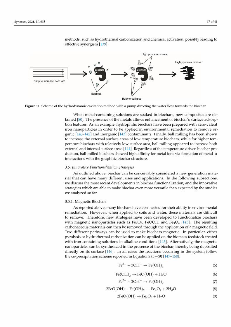
An innovative, costless, and highly efficient way to produce a biochar with surfaceareas larger than 120%, compared with the typical surface areas in carbonaceous mate-rials from slow pyrolysis, is the hydrodynamic cavitation [139]. Cavitation is a physicalphenomenon occurring when a liquid surrounding a solid material is accelerated. Flowacceleration decreases liquid pressure on the surface of the solid system, thereby pro-voking the formation of bubbles. Once the bubbles collapse, high-pressure waves areformed, and new pores are generated on the surface of the biochar (Figure 11), leadingto an improvement of its surface area. The advantage of the hydrodynamic cavitationin designing new types of biochars is its possible integration with other consolidated
Agronomy 2021, 11, 615 17 of 41
methods, such as hydrothermal carbonization and chemical activation, possibly leading toeffective synergism [139].
Agronomy 2021, 11, x FOR PEER REVIEW 17 of 42
types of biochars is its possible integration with other consolidated methods, such as hy-
drothermal carbonization and chemical activation, possibly leading to effective synergism
[139].
When metal-containing solutions are soaked in biochars, new composites are ob-
tained [80]. The presence of the metals allows enhancement of biochar’s surface adsorp-
tion features. As an example, hydrophilic biochars have been prepared with zero-valent
iron nanoparticles in order to be applied in environmental remediation to remove organic
[140–142] and inorganic [143] contaminants. Finally, ball milling has been shown to in-
crease the external surface areas of low temperature biochars, while for higher tempera-
ture biochars with relatively low surface area, ball milling appeared to increase both ex-
ternal and internal surface areas [144]. Regardless of the temperature-driven biochar pro-
duction, ball-milled biochars showed high affinity for metal ions via formation of metal–
π interactions with the graphitic biochar structure.
Figure 11. Scheme of the hydrodynamic cavitation method with a pump directing the water flow towards the biochar.
3.5. Innovative Functionalization Strategies
As outlined above, biochar can be conceivably considered a new generation material
that can have many different uses and applications. In the following subsections, we dis-
cuss the most recent developments in biochar functionalization, and the innovative strat-
egies which are able to make biochar even more versatile than expected by the studies we
analyzed so far.
3.5.1. Magnetic Biochars
As reported above, many biochars have been tested for their ability in environmental
remediation. However, when applied to soils and water, these materials are difficult to
remove. Therefore, new strategies have been developed to functionalize biochars with
magnetic nanoparticles such as Fe2O3, FeOOH, and Fe3O4 [145]. The resulting carbona-
ceous materials can then be removed through the application of a magnetic field. Two
different pathways can be used to make biochars magnetic. In particular, either pyrolysis
or hydrothermal carbonization can be applied on the biomass feedstock treated with iron-
containing solutions in alkaline conditions [145]. Alternatively, the magnetic nanoparti-
cles can be synthesized in the presence of the biochar, thereby being deposited directly on
its surface [146]. In all cases the reactions occurring in the system follow the co-precipita-
tion scheme reported in Equations (5)–(9) [147–150]:
Fe3+ + 3OH− → Fe(OH)3 (5)
Fe(OH)3 → FeO(OH) + H2O (6)
Fe2+ + 2OH− → Fe(OH)2 (7)
2FeO(OH) + Fe(OH)2 → Fe3O4 + 2H2O (8)
2FeO(OH) → Fe2O3 + H2O (9)
Figure 11. Scheme of the hydrodynamic cavitation method with a pump directing the water flow towards the biochar.
When metal-containing solutions are soaked in biochars, new composites are ob-tained [80]. The presence of the metals allows enhancement of biochar’s surface adsorp-tion features. As an example, hydrophilic biochars have been prepared with zero-valentiron nanoparticles in order to be applied in environmental remediation to remove or-ganic [140–142] and inorganic [143] contaminants. Finally, ball milling has been shownto increase the external surface areas of low temperature biochars, while for higher tem-perature biochars with relatively low surface area, ball milling appeared to increase bothexternal and internal surface areas [144]. Regardless of the temperature-driven biochar pro-duction, ball-milled biochars showed high affinity for metal ions via formation of metal–πinteractions with the graphitic biochar structure.
3.5. Innovative Functionalization Strategies
As outlined above, biochar can be conceivably considered a new generation mate-rial that can have many different uses and applications. In the following subsections,we discuss the most recent developments in biochar functionalization, and the innovativestrategies which are able to make biochar even more versatile than expected by the studieswe analyzed so far.
3.5.1. Magnetic Biochars
As reported above, many biochars have been tested for their ability in environmentalremediation. However, when applied to soils and water, these materials are difficultto remove. Therefore, new strategies have been developed to functionalize biocharswith magnetic nanoparticles such as Fe2O3, FeOOH, and Fe3O4 [145]. The resultingcarbonaceous materials can then be removed through the application of a magnetic field.Two different pathways can be used to make biochars magnetic. In particular, eitherpyrolysis or hydrothermal carbonization can be applied on the biomass feedstock treatedwith iron-containing solutions in alkaline conditions [145]. Alternatively, the magneticnanoparticles can be synthesized in the presence of the biochar, thereby being depositeddirectly on its surface [146]. In all cases the reactions occurring in the system followthe co-precipitation scheme reported in Equations (5)–(9) [147–150]:
Fe3+ + 3OH− → Fe(OH)3 (5)
Fe(OH)3 → FeO(OH) + H2O (6)
Fe2+ + 2OH− → Fe(OH)2 (7)
2FeO(OH) + Fe(OH)2 → Fe3O4 + 2H2O (8)
2FeO(OH)→ Fe2O3 + H2O (9)

Agronomy 2021, 11, 615 18 of 41
The conditions used to produce magnetic biochars can lead not only to materials easilyremovable from soils and water, but also with improved physicochemical properties (thatis surface area and porosity) that enable better sorption capacity for organic and inorganiccontaminants as compared to non-functionalized biochars [141,145,146].
3.5.2. The Plasticized Biochars
Among the different attempts to find novel uses for biochar or to improve its chemical–physical properties, plasticization appears to be the new frontier. Based on the syntheticprocedures to obtain nanocomposites made by the combination of epoxy resin and multi-walled carbon nanotubes [151], Giorcelli et al. [152] mixed biochar with a low viscosityepoxy resin and a hardener in order to obtain a composite that showed elasticity incrementfor biochar amounts <2% (w w−1). Conversely, as the amount of biochar increased over2%, the composite revealed higher ductility. This may suggest that biochar-based plasticscan be applied to the production of a wide number of products according to the particularproperty needed (elasticity or ductility). Composites with enhanced dynamic viscoelasticity,creep resistance, and stress relaxation were also obtained by melt mixing, then extrudinga rice husk biochar added with high-density polyethylene [153]. When the extrusion isperformed on the mixture made by biochar and polyethylene added with wood flour andother additives (such as Mg(OH)2 or Al(OH)3), the resulting plastic also shows interestingflame retardant characteristics [154].
3.5.3. The Co-Composted Biochar
Multiple nutrient deficiencies due to the fact of soil fertility depletion in many areasof the planet are emerging as the major constraint to the sustainability of agriculture ona global scale. Therefore, biochar has been considered a useful amendment to improvingsoil quality. Biochar can affect soil structure, thereby influencing water retention andnutrient availability [16], while it can be a source of several plant nutrients once it isfunctionalized as in the case, for example, of Kon-Tiki kiln quenching by cow urine [72].With the aim to produce new generation and more efficient fertilizers, biochar is alsoused as an additive to produce compost. The latter is an organic material obtained viaa procedure referred to as composting which, in turn, consists in the microbial breakdownof organic material into simpler components used to fertilize soils [155]. When compostingis done by mixing organic wastes with biochar, a co-composted material with very highcapacity to capture and release nitrate is obtained [17]. Moreover, enhancement of cationexchange capacity is observed [156], while a reduction of potentially harmful chemicals isachieved during composting [157]. The co-composted biochar allows the enhancement ofcrop production [17,156,158,159].
4. The Physical Chemistry of Biochar Functioning
As evidenced in the paragraphs above, biochar is a heterogeneous carbonaceous mate-rial which can have multiple uses. A very explicative review concerning biochar multipleapplications is given in Schmidt and Wilson [49]. However, the molecular mechanismsbehind the different biochar uses are not well clarified yet. In this paragraph a summary ofthe molecular mechanisms of biochar functioning is given.
4.1. The Thermodynamics of Biochar Adsorption/Desorption: A Novel Elaboration ofthe Freundlich Isotherm
Let us indicate as A, a generic compound solubilized in a liquid solvent. Whena porous system is present, the following equilibrium can be written:
Al � As (10)
In the chemical Equation (10), Al is the equilibrium liquid phase generic compound,while As is the same material adsorbed on the porous surface when the equilibrium is

Agronomy 2021, 11, 615 19 of 41
achieved. From a thermodynamic point of view, this equilibrium can be described bythe Freundlich equation in the form (11):
qs = KFCNw (11)
Here, qs, expressed in mol kg−1, represents the amount at equilibrium of the sorbed com-pound (in moles) per unit of biochar mass (in kg), Cw is the equilibrium molar concentrationof Al, KF, and N are the Freundlich constant and the linearity parameter, respectively.
Pignatello and co-workers [160–162] reported that Equation (11) poorly fits the adsorp-tion data, especially when aromatic organic pollutants are accounted for. This is becausebiochar surface chemistry and physics changes according to all the conditions previouslydescribed. In particular, the adsorption process is affected by:
- Cavity effects (cav): these refer to the structural organization of solvent molecules(e.g., water) at the solid–liquid interface, thereby accounting also for the transport ofthe solvated solute towards the point of the surface where it will be adsorbed [163,164];
- Dispersion forces (disp): These are better known as London dispersion forces. Theyare involved in the adsorption of a solute via induced dipole interactions;
- Dipole–dipole interactions (dip) due to the presence of permanent dipoles. Theyaccount for the solute–solvent, solute–solute, solvent–substrate, and solute–substrateinteractions;
- H-bonds (H-b): As for dip, these account for solvent–solute, solute–solute, substrate–solvent, and substrate–solute interactions;
- π−π interactions (π−π): As for dip and H-b, these are also involved in solute–solute,solute–solvent, substrate–solvent, and substrate–solute interactions.
For this reason, they re-elaborated the Freundlich isotherm by accounting for all those ef-fects and calculated the Gibbs free energy involved in the sorption process in Equation (10) as:
∆Gs−w,A = ∆Gcavs−w,A + ∆Gdisp
s−w,A + ∆Gdips−w,A + ∆GH−b
s−w,A + ∆Gπ−πs−w,A (12)
Here, the subscript s stands for “substrate” (i.e., the porous system such as biochar),while w stands for “water”. Since the latter has been recognized as the most relevantenvironmental solvent, from now on all the equations will refer to the adsorption processesfrom water systems.
The Gibbs free energy in (12) refers to the process of the removal of the solute A fromwater (let us indicate the solute–water interaction as [A·w]) and to its inclusion on the sub-strate surface (let us indicate the substrate–solute interaction with [A·s]) according toEquations (13) and (14). The latter two equations summed together give Equation (15),which is formally the same as Equation (10):
[A·w] � A + w (13)
s + A � [A·s] (14)
[A·w] � [A·s] (15)
Due to the non-ideality of the conditions, the excess free energy (Gex) must be ac-counted for [155]. Therefore, Equation (12) can be re-arranged as in (16):
∆Gs−w,A =[∆Gcav
s−w,A + ∆Gdisps−w,A −Gex,dip
w,A −Gex,H−bw,A −Gex,π−π
w,A
]+[Gex,dip
s,A + Gex,H−bs,A + Gex,π−π
s,A
](16)
The first term in brackets on the right side of Equation (16) represents the hydrophobiceffect involved in the removal of the solute from water and its transfer to the substrate sur-face. It can be indicated as ∆Ghydr
s−w,A. The other terms account for the direct intermolecular

Agronomy 2021, 11, 615 20 of 41
attractive forces, which are ultimately electrostatic in nature. It can be indicated as Gelects,A .
Therefore, Equation (16) can be re-written as:
∆Gs−w,A = ∆Ghydrs−w,A + Gelect
s,A (17)
Let us now indicate with s0 a generic solvent to put in contact with the aqueoussolution containing A. The Gibbs free energy for the partition equilibrium can be written asin (18):
∆Gs0−w,A = ∆Ghydrs0−w,A + Gelect
s0,A (18)
We can assume a linear correlation between ∆Ghydrs−w,A and ∆Ghydr
s0−w,A because the cavityand dispersion effects in both adsorption and partition depend on molecular size and onpolarizability. Hence:
∆Ghydrs−w,A = a∆Ghydr
s0−w,A + b (19)
where a and b are two solute concentration dependent empirical parameters. By combiningEquations (17)–(19), Equation (20) is obtained:
∆Gs−w,A = a∆Gs0−w,A +[Gelect
s,A − aGelects0,A
]+ b (20)
Keeping into account the direct correlation between the Gibbs free energy and the equi-librium constant, Equation (20) can be re-arranged as in (21):
lnKs−w,A = a× lnKs0−w,A − E + b1 (21)
where Ks−w,A is the equilibrium constant for the adsorption of the solute A on a substratesuch as biochar; Ks0−w,A is the partition constant of the solute A between water and
an organic solvent (e.g., it can be the octanol–water constant, Kow); E =
[Gelect
s,A −aGelects0,A
]RT is
the electrostatic contribution to the adsorption on the substrate; b1 = bRT .
Assuming that Ks−w,A =qsCw
, and re-arranging Equation (21), it is possible to write:
qs = CwKas0−w,ae(b1−E) (22)
Equation (22) simplifies to (23) when the adsorption of the generic A compound isaffected only by hydrophobic interactions with the substrate:
qs = CwKas0−w,Ae(b1) (23)
The Freundlich constant modified according to this model can be written as in (24):
K∗ = Kas0−w,ae(b1−E) (24)
The larger the K∗ value, the stronger the interaction between the generic compound Aand the biochar.
The modified Freundlich model reported above allows us to understand the differentcontributions (i.e., hydrophobic, and electrostatic) involved in the interactions betweena pollutant and a biochar. For this reason, it can be very helpful in addressing biocharproduction according to the chemical nature of the pollutant to be removed. However,for the sake of completeness, it must be noticed that this model was applied only tohydrophobic pollutants whose electrostatic contribution to the interaction with biocharwas negligible [160–162]. For this reason, more studies are needed to validate the strengthof this model.

Agronomy 2021, 11, 615 21 of 41
4.2. The Kinetics of Biochar Adsorption/Desorption
The reaction rate for the equilibrium described in Equation (10) is defined as the amountof adsorbate disappearing from the solution in the time unit as it is adsorbed on biochar [165].According to Tong et al. [166], Equation (25) must be accounted for the time dependence ofbiochar adsorption:
dQdt
= kx(Qe −Q)x (25)
Here, Q is the amount (in moles) of adsorbate per mass unit (in kg) of biochar; Qeis the amount of adsorbate in solution when the sorption equilibrium is achieved (it canbe expressed in moles per kilograms of solvent); x is the reaction order (it can have anyvalue ≥ 0); kx is referred to as kinetic constant. The latter is used as the experimentalparameter to establish the affinity between adsorbate and adsorbent. The larger the kxvalue, the higher the adsorbate-adsorbent affinity.
The order of reaction is experimentally established upon integration of Equation (25)and determines the dependence of the reaction rate on the concentration of the reactants.Assuming x = 1, 2, 3 after integration and rearrangement, Equation (25) can be re-writtenas in (26)–(28), respectively:
Qt = Qe
(1− e−k1t
)(26)
1Qt
= 1 +1
Q2e · k2
· 1t
(27)
1
(Qe −Qt)2 = − 1
Qe+ 2k3t (28)
Noticeably, for any x 6= 1 (i.e., the order of reaction can assume also non-integervalues), and the general solution of Equation (25) can be written as:
Qt = Qe −[Q(1−x)
e − (1− x)kxt] 1(1−x) (29)
In all the previous equations, Qt is the amount of adsorbate per mass unit of biocharat time t, while k1, k2, and k3 are the first-, second-, and third-order kinetic constants,respectively. Due to the complexity of the biochar adsorption phenomena (see below),these kinetics are also referred to as kinetics of pseudo-first, pseudo-second, and pseudo-third order, respectively [166–172].
Figure 12 reports the shape of Equations (26)–(28) which must be experimentally ac-counted for to establish if the adsorption follows one of the mentioned kinetic laws. Figure 12Ashows how the fitting of the experimental data points should appear if the pseudo-first orderkinetics applies. Conversely, Figure 12B,C report the linear correlation to be applied whenthe pseudo-second and pseudo-third order kinetics are valid.
Pseudo second-order kinetics appeared to best describe the adsorption uptake rate ofa dye on biochar surface from rice husk [173], of Pb(II) and Cd(II) on the surface of a mag-netic biochar obtained by functionalizing costless pine bark wastes with CoFe2O4 [174],and of Cu(II) and tetracycline on a Fe/Zn-doped sawdust biochar [175]. Interestingly,a study from Reguyal et al. [176] showed that the kinetics of biochar absorption is alsoaffected by adsorbate concentration. It was reported that the pseudo-second order kineticmodel best described the experimental data at low sulfamethoxazole concentrations (be-tween 1 and 5.1 mg L−1), while the pseudo-first order best applied to the kinetic data whensulfamethoxazole concentration was as high as 20.5 mg L−1 [176]. However, it must benoticed that in recent kinetic studies, the terms pseudo first- and pseudo second-ordershave been replaced by the term “partition coefficient” which better accounts for the biocharbehavior in removing pollutants from environmental compartments [177–180].

Agronomy 2021, 11, 615 22 of 41
Agronomy 2021, 11, x FOR PEER REVIEW 21 of 42
biochar [165]. According to Tong et al. [166], Equation (25) must be accounted for the time
dependence of biochar adsorption:
dQ
dt= kx(Qe − Q)x (25)
Here, Q is the amount (in moles) of adsorbate per mass unit (in kg) of biochar; Qe is
the amount of adsorbate in solution when the sorption equilibrium is achieved (it can be
expressed in moles per kilograms of solvent); x is the reaction order (it can have any value
≥ 0); kx is referred to as kinetic constant. The latter is used as the experimental parameter
to establish the affinity between adsorbate and adsorbent. The larger the kx value, the
higher the adsorbate-adsorbent affinity.
The order of reaction is experimentally established upon integration of Equation (25)
and determines the dependence of the reaction rate on the concentration of the reactants.
Assuming x = 1, 2, 3 after integration and rearrangement, Equation (25) can be re-written
as in (26)–(28), respectively:
Qt = Qe(1 − e−k1t) (26)
1
Qt= 1 +
1
Qe2 ∙ k2
∙ 1
t (27)
1
(Qe − Qt)2= −
1
Qe+ 2k3t (28)
Noticeably, for any x ≠ 1 (i.e., the order of reaction can assume also non-integer val-
ues), and the general solution of Equation (25) can be written as:
Qt = Qe − [Qe(1−x)
− (1 − x)kxt]1
(1−x) (29)
In all the previous equations, Qt is the amount of adsorbate per mass unit of biochar
at time t, while k1, k2, and k3 are the first-, second-, and third-order kinetic constants,
respectively. Due to the complexity of the biochar adsorption phenomena (see below),
these kinetics are also referred to as kinetics of pseudo-first, pseudo-second, and pseudo-
third order, respectively [166–172].
Figure 12 reports the shape of Equations (26)–(28) which must be experimentally ac-
counted for to establish if the adsorption follows one of the mentioned kinetic laws. Figure
12A shows how the fitting of the experimental data points should appear if the pseudo-
first order kinetics applies. Conversely, Figure 12B,C report the linear correlation to be
applied when the pseudo-second and pseudo-third order kinetics are valid.
Figure 12. Simulation curves for the pseudo−first order (A), pseudo−second order (B), and
pseudo−third order (C) absorption kinetics on biochar. The simulations have been performed by
using Origin Pro 7.5.
Figure 12. Simulation curves for the pseudo−first order (A), pseudo−second order (B),and pseudo−third order (C) absorption kinetics on biochar. The simulations have been performedby using Origin Pro 7.5.
The third-order kinetic model is rarely applied in biochar chemistry. However, Za-hedifar and Moosavi [181] reported that it was unsuitable to explain the Zn desorptionmechanisms from biochar-amended calcareous soils, while Tian et al. [182] showed thatthe third-order kinetics can be efficaciously used to describe the mechanisms of the CO2gasification of Miscanthus-derived-biochar at different processing conditions.
4.3. The Meaning of the Reaction Order and the Langmuir Isotherm from Kinetic Considerations
The reaction order is often related to the molecularity of a reaction. The term “molecu-larity” refers to the number of reactant molecules binding together to form, within the rate-limiting step of the reaction, an “activated complex” that affords the reaction products [165].Accordingly, a first-order reaction is a reaction for which only one molecule among the dif-ferent reactants is involved in the activated complex formation. However, when twomolecules are needed to form the collision complex, the reaction can be referred to assecond order. According to Laidler and Glasstone [165], reactions occurring on the surfaceof a solid-phase system, such as a catalyst, can be also considered as third-order reactions.In fact, the collision complex is made by all the reactants interacting with the surface ofthe catalyst. It must be recognized that the relationship between the order of a reaction andthe molecularity is only a simplification. However, this can help in developing a simplisticadsorption theory such as the one elaborated by Langmuir at the beginning of the 20thcentury [183–185].
Let us indicate with the letter B the biochar, with the letter A the system that can beadsorbed on biochar, and with B1 the A–B complex containing a molar amount of adsorbatewhich interacts with the biochar surface. We can write the equilibrium reported in (30):
B + A � B1 (30)
where the left-to-right reaction is the adsorption of A on B, thereby providing B1, whilethe right-to-left reaction is the desorption of A from the B surface. Let us also assume:
(I) a flat biochar surface;(II) each A molecule can interact with only one functional group on the biochar surface;(III) the A molecules can form only a monolayer on the biochar surface;(IV) the interactions of each A molecule are isotropic.
Based on these constraints, it is possible to consider the relationship (31) as descriptivefor the steady-state condition:
rd = ri (31)
where rd = kd[A][B] is the second-order adsorption rate containing the adsorption kineticrate constant (kd), the molar concentration of the adsorbate in solution as the equilibrium is

Agronomy 2021, 11, 615 23 of 41
achieved ([A]), and the molar concentration of the available adsorbing biochar sites at the equi-librium ([B]); while ri = ki[B1] is the first-order desorption rate containing the desorptionkinetic rate constant (ki) and the adsorbate surface molar concentration ([B1]).
Being the total amount of adsorbing biochar sites given by [B0] = [B] + [B1], the equi-librium constant for the Equation (29) given by ke = kd/ki and the fraction of biocharsites covered by the adsorbate given by ϑA = [B1]/[B0], it is straightforward to obtainEquation (32) which is the simplest form for the Langmuir adsorption isotherm.
ϑA =ke[A]
ke[A] + 1(32)
Figure 13A reports the simulations of the Langmuir Equation (32) by using differentke values. When ke is raised up to 1, the trend changes from the quasi-linear behaviorobserved for low ke values (i.e., ke = 0.025) to the L-shaped one. Equation (32) is unreliablein fitting S-shaped experimental data. This is certainly due to the limits of the approachbased on the ideal conditions (I) to (IV) indicated above. In fact, the ideal (I) to (IV)conditions are valid only for monodentate adsorbents in dilute solutions, while the biocharsurface must be completely flattened. The latter condition is never a real situation.
Agronomy 2021, 11, x FOR PEER REVIEW 23 of 42
the desorption kinetic rate constant (ki) and the adsorbate surface molar concentration
([B1]).
Being the total amount of adsorbing biochar sites given by [B0] = [B] + [B1], the
equilibrium constant for the Equation (29) given by ke = kd ki⁄ and the fraction of biochar
sites covered by the adsorbate given by ϑA = [B1] [B0]⁄ , it is straightforward to obtain
Equation (32) which is the simplest form for the Langmuir adsorption isotherm.
ϑA =ke[A]
ke[A] + 1 (32)
Figure 13A reports the simulations of the Langmuir Equation (32) by using different
ke values. When ke is raised up to 1, the trend changes from the quasi-linear behavior
observed for low ke values (i.e., ke = 0.025) to the L-shaped one. Equation (32) is unreli-
able in fitting S-shaped experimental data. This is certainly due to the limits of the ap-
proach based on the ideal conditions (I) to (IV) indicated above. In fact, the ideal (I) to (IV)
conditions are valid only for monodentate adsorbents in dilute solutions, while the bio-
char surface must be completely flattened. The latter condition is never a real situation.
Figure 13. (A) Langmuir isotherms obtained by simulation of Equation (32). The different curves have been acquired by
using the value of the equilibrium constant reported in the graph. (B). Langmuir isotherms obtained by simulation of
Equation (33). The different curves were obtained by fixing the ke value to 0.1 and by using the X values reported in
graph.
A modified Langmuir isotherm to account for non-ideal conditions is given in Equa-
tion (33) [186]:
ϑA =ke[A]X
ke[A]X + 1 (33)
where X is an empirical parameter related to the effects of the adsorbate concentration.
Equation (33) appears to be a good alternative to the model depicted in Equation (31)
when S-shaped trends are acquired (Figure 13B). A slightly modified version of Equation
(33) is referred to as the Sips equation [187,188], which can be written in the form (34):
qe =qmax(Ke[A])X
1 + (Ke[A])X (34)
Equation (34) has the advantage that the Ke values are always expressed as L mol−1,
irrespective of the value for X. Moreover, it reduces to the Freundlich equation for 1 ≫
(Ke[A])X. It is worth noting that Equation (34) has never been used in the evaluation of
biochar adsorption properties. Therefore, it is desirable that in the future its suitability for
the analysis of biochar characteristics is studied.
Figure 13. (A) Langmuir isotherms obtained by simulation of Equation (32). The different curves have been acquired byusing the value of the equilibrium constant reported in the graph. (B). Langmuir isotherms obtained by simulation ofEquation (33). The different curves were obtained by fixing the ke value to 0.1 and by using the X values reported in graph.
A modified Langmuir isotherm to account for non-ideal conditions is given in Equa-tion (33) [186]:
ϑA =ke[A]X
ke[A]X + 1(33)
where X is an empirical parameter related to the effects of the adsorbate concentration.Equation (33) appears to be a good alternative to the model depicted in Equation (31) whenS-shaped trends are acquired (Figure 13B). A slightly modified version of Equation (33) isreferred to as the Sips equation [187,188], which can be written in the form (34):
qe =qmax(Ke[A])X
1 + (Ke[A])X (34)
Equation (34) has the advantage that the Ke values are always expressed as L mol−1, irre-spective of the value for X. Moreover, it reduces to the Freundlich equation for 1� (Ke[A])X.It is worth noting that Equation (34) has never been used in the evaluation of biochar ad-

Agronomy 2021, 11, 615 24 of 41
sorption properties. Therefore, it is desirable that in the future its suitability for the analysisof biochar characteristics is studied.
Notwithstanding the aforementioned limitations, the Langmuir model reported in Equa-tion (31) showed a suitability to explain the competitive adsorption of different antibioticson bamboo-derived biochar, whereas Freundlich isotherm was more reliable in modellingabsorption of single antibiotics on the same biochar [189]. Similar results regarding the relia-bility of the Langmuir isotherm given in Equation (31) were obtained by Zhou et al. [175]who studied the adsorption mechanisms of Cu(II) on a Fe/Zn-doped-biochar.
As a general remark, special attention must be paid when one considers studiesconcerning the use of the Langmuir models. In most of the published papers, volumetricconcentrations of adsorbate are commonly used without any theoretical background.Conversely, the concentration units must be mol L−1. This comes from thermodynamicconsiderations [190]. In fact, Liu [190] showed that incorrect and unreasonable ∆G0 valuescan be calculated when non-molar units are applied. As a consequence, misunderstandingof the adsorption/desorption mechanisms can occur [190].
4.4. The Dynamics of Water and Nutrients in Biochar Pore System
In the previous paragraphs, the traditional thermodynamic and kinetic approacheshave been discussed to explain how experimental data can be handled to understandhow strongly an adsorbate is bound to biochar and which possible molecular mechanismscan be involved in the adsorbate–biochar interactions. However, a quite innovative dy-namic approach can be used to understand the nature of the adsorbate–biochar interfaceinteractions. This is based on the evaluation of fast field cycling (FFC) NMR relaxometryinvestigations [163,164].
Fast field cycling NMR relaxometry has been specifically designed for the measurementof the longitudinal relaxation times (T1) of NMR observable spin nuclei [163,164,191,192].T1 is a measure of the time needed for the recovery of the longitudinal component ofthe magnetization along the z-axis [193]. Its value is influenced by:
“fluctuating local magnetic or electrical fields generated by (i) nuclear dipoles, (ii) un-paired electrons, (iii) electric charges interacting with nuclear quadrupole moments for> 1/2 spin nuclei, (iv) anisotropy of the chemical shielding tensor, and (v) fluctuatingscalar coupling interactions and molecular rotations. It is recognized that molecularmotions are the primary factors affecting the aforementioned fluctuations. For this reason,the measurement of longitudinal relaxation time (or longitudinal relaxation rate, R1, thatis the inverse of T1) can be related to molecular dynamics. In particular, FFC NMR relax-ometry allows evaluating motion frequencies ranging from ≈105 to ≈108 Hz. These arethe typical motion frequencies for aqueous systems in natural porous media” [194].
It is widely recognized that the molecular dynamics investigated by the T1 value mea-surements of liquid systems, such as water, in biochar pores is affected by the interactionswith the porous boundaries [163,164,191–196]. Namely, the smaller the pore size, the moreconstrained water molecules are. Conversely, when pore sizes increase, water moleculesbecome more mobile. For this reason, according to pore size distribution, three differentwater types can be recognized: (i) strongly bound water in micropores; (ii) weakly boundwater in mesopores; (iii) bulk water in macropores [163].
Following variable temperature FFC NMR relaxometry experiments [22], it was shownthat water molecules can interact with pore boundaries by the inner-sphere mechanism,thereby suggesting that water molecules penetrate into biochar pores and adhere to the sur-face by formation of weak bonds such as non-conventional H-bonds (e.g., the OH–πbonding described in References [197,198]), Van der Waals interactions, and coordina-tion linkages (Figure 14). The latter are Lewis acid–base interactions occurring whenthe electron-rich oxygen in water approaches the metal ions situated on the biochar surface.

Agronomy 2021, 11, 615 25 of 41
Agronomy 2021, 11, x FOR PEER REVIEW 25 of 42
It is worth noting that the water molecules in biochar pores belong also to the hydra-
tion spheres of solutes which may work as plant nutrients (Figure 14) [199,200]. In other
words, some plant nutrients are captured in biochar thanks to water-mediated interac-
tions and can be released into the soil solution when it is used as soil amendment [17–19].
Given that the nature of the aforementioned interactions is transient, it is possible to
state that the movement of nutrients in the biochar pore system can occur via two different
mechanisms [201]. Firstly, water molecules diffuse horizontally on the biochar surface.
This allows nutrients to be dragged towards plant roots. Secondly, each water molecule
can “hop” from the biochar surface over a longer distance, while it is replaced by another
molecule. This allows nutrients to be leached towards deeper soil horizons, thereby re-
ducing fertility of the upper soil horizons. The time spent by water (and hence water-
solvated nutrients) either on the biochar surface (surface–time) or in the bulk (bulk–time)
can be measured by FFC NMR relaxometry [195]. The relationship between the surface–
and the bulk–times was used to define the biochar wettability [195], which is affected by
the chemistry of the biochar surface. The latter, in turn, depends on all the experimental
conditions reported above for the preparation.
Figure 14. Different possible bindings between water molecules and biochar. Water can interact with biochar’s surface by
OH–π bonding, Van der Waals interactions, and coordination linkages. The latter occur when the electron-rich oxygen in
water lays in the proximity of a metal ion (dark grey outgrowths). The blue spheres represent a solvated cation (e.g.,
ammonium).
Having clarified the molecular mechanisms involved in the water/nutrient dynamics
inside the biochar pore system, it is intuitive to understand why biochar application to
soils increases water retention [16,202–205], thereby ameliorating physiological plant re-
sponses to drought stresses [206], enhancing plant defense mechanisms [207], and increas-
ing soil microbial biodiversity [208,209]. For further information about the advantages and
disadvantages of biochar applications, see Das et al. [210].
4.5. The Mechanisms of Entrapment and Decomposition of Pollutants in Biochar
In Section 3.4., a post-pyrolysis biochar functionalization with persulfate was de-
scribed. It was pointed out that persulfate activates biochar surface via formation either
of radical sulfate (∙ SO4−) or hydroxyl radical (∙ OH−). When the persulfate-activated biochar
traps pollutants, a reaction such as that described in Figure 15 for the degradation of bi-
sphenol A, occurs [138]. Namely, this pollutant (also known as 2,2’-bis-(4-hydroxyphenil)-
propane) is firstly oxidized to 2-(4-hydroxyphenil)-2’-(3,4-dihydroxyphenil)-propane.
Then a homolytic split occurs, generating hydroxyphenyl and 2-(3,4-dihydroxyphenyl)-
Figure 14. Different possible bindings between water molecules and biochar. Water can interact with biochar’s surface byOH–π bonding, Van der Waals interactions, and coordination linkages. The latter occur when the electron-rich oxygenin water lays in the proximity of a metal ion (dark grey outgrowths). The blue spheres represent a solvated cation(e.g., ammonium).
It is worth noting that the water molecules in biochar pores belong also to the hydra-tion spheres of solutes which may work as plant nutrients (Figure 14) [199,200]. In otherwords, some plant nutrients are captured in biochar thanks to water-mediated interactionsand can be released into the soil solution when it is used as soil amendment [17–19].
Given that the nature of the aforementioned interactions is transient, it is possibleto state that the movement of nutrients in the biochar pore system can occur via twodifferent mechanisms [201]. Firstly, water molecules diffuse horizontally on the biocharsurface. This allows nutrients to be dragged towards plant roots. Secondly, each watermolecule can “hop” from the biochar surface over a longer distance, while it is replaced byanother molecule. This allows nutrients to be leached towards deeper soil horizons, therebyreducing fertility of the upper soil horizons. The time spent by water (and hence water-solvated nutrients) either on the biochar surface (surface–time) or in the bulk (bulk–time)can be measured by FFC NMR relaxometry [195]. The relationship between the surface–and the bulk–times was used to define the biochar wettability [195], which is affected bythe chemistry of the biochar surface. The latter, in turn, depends on all the experimentalconditions reported above for the preparation.
Having clarified the molecular mechanisms involved in the water/nutrient dynamicsinside the biochar pore system, it is intuitive to understand why biochar application to soilsincreases water retention [16,202–205], thereby ameliorating physiological plant responsesto drought stresses [206], enhancing plant defense mechanisms [207], and increasingsoil microbial biodiversity [208,209]. For further information about the advantages anddisadvantages of biochar applications, see Das et al. [210].
4.5. The Mechanisms of Entrapment and Decomposition of Pollutants in Biochar
In Section 3.4., a post-pyrolysis biochar functionalization with persulfate was de-scribed. It was pointed out that persulfate activates biochar surface via formation either ofradical sulfate (·SO−4 ) or hydroxyl radical (·OH−). When the persulfate-activated biochartraps pollutants, a reaction such as that described in Figure 15 for the degradation ofbisphenol A, occurs [138]. Namely, this pollutant (also known as 2,2′-bis-(4-hydroxyphenil)-propane) is firstly oxidized to 2-(4-hydroxyphenil)-2′-(3,4-dihydroxyphenil)-propane. Thena homolytic split occurs, generating hydroxyphenyl and 2-(3,4-dihydroxyphenyl)-propaneradicals. Both are subjected to a series of not well-defined oxidations which result in the for-mation of carbon dioxide and water [138].

Agronomy 2021, 11, 615 26 of 41
Agronomy 2021, 11, x FOR PEER REVIEW 26 of 42
propane radicals. Both are subjected to a series of not well-defined oxidations which result
in the formation of carbon dioxide and water [138].
When the biochar is obtained by co-pyrolysis with polyethylene terephthalate (Sec-
tion 3.3.7.), a material very efficient in removing/entrapping organic and inorganic pollu-
tants is obtained [135]. In particular, Oh and Seo [135] reported that this type of biochar is
able to reduce selenate (SeO4−) to selenite (SeO3
−) and then to selenide (Se2−) via metallic
selenium (Se) by redox reactions that can be schematized as follows:
2SeO4− + C → 2SeO3
− + CO2 (35)
4SeO3− + 5C + 4H+ → 4Se + 5CO2 + 2H2O (36)
2Se + C + 2H2O → 2Se2− + CO2 + 4H+ (37)
Figure 15. Example of degradation of a pollutant (bisphenol A) on the surface of a persulfate acti-
vated biochar. The reaction scheme has been re-elaborated with permission from Reference [138].
In reactions (35) to (37), C represents the biochar which is oxidized to carbon dioxide.
However, biochar oxidation can also be limited to a surface functionalization with for-
mation of oxidized groups, thereby making the carbonaceous material more hydrophilic.
While selenium-containing pollutants are immobilized by the alteration of their oxidation
Figure 15. Example of degradation of a pollutant (bisphenol A) on the surface of a persulfate activatedbiochar. The reaction scheme has been re-elaborated with permission from Reference [138].
When the biochar is obtained by co-pyrolysis with polyethylene terephthalate(Section 3.3.7), a material very efficient in removing/entrapping organic and inorganicpollutants is obtained [135]. In particular, Oh and Seo [135] reported that this type ofbiochar is able to reduce selenate (SeO−4 ) to selenite (SeO−3 ) and then to selenide (Se2−) viametallic selenium (Se) by redox reactions that can be schematized as follows:
2SeO−4 + C→ 2SeO−3 + CO2 (35)
4SeO−3 + 5C + 4H+ → 4Se + 5CO2 + 2H2O (36)
2Se + C + 2H2O→ 2Se2− + CO2 + 4H+ (37)
In reactions (35) to (37), C represents the biochar which is oxidized to carbon diox-ide. However, biochar oxidation can also be limited to a surface functionalization withformation of oxidized groups, thereby making the carbonaceous material more hydrophilic.While selenium-containing pollutants are immobilized by the alteration of their oxida-tion state, a pollutant such as chromate (CrO2−
4 ) is trapped via a mechanism involvingelectrostatic interactions [135]. Experimental results [135] suggest that the presence of

Agronomy 2021, 11, 615 27 of 41
polyethylene–terephthalate (Section 3.5.2.) as co-pyrolyzing material allows formation ofa biochar where the graphitic-like layer may reveal domains with low electron density.Hence, the electron-rich chromate anions can be hooked in the electronic “holes”, thusallowing formation of stable complexes which can be easily removed and disposed ofin landfills. Conversely, when heavy metals (Men+), such as Pb2+, are present in the envi-ronment, a Cπ−Men+ mechanism must be invoked. In this case, the electron-rich aromaticsystems of the graphitic-like biochar moieties (i.e., Cπ) can “hook” the electron-poor metalcations [135]. However, Paz-Ferreiro et al. [211] report that the mechanisms for heavy metalentrapment in biochar are also due to the presence of surface oxygenated/nitrogenatedfunctions, which can “hook” the metals via their lone-pair electrons. For this reason,the same authors state that biochar is suitable for soil phytoremediation projects becauseit allows reduction of heavy metals leachability and bioavailability. As already discussedin Section 3.3.6., biochar affinity for metal ions can be beneficial for water treatment. Surfacecomplexation was found to be the main mechanism in Pb2+ removal from contaminatedwater in lab-scale flow-through column tests [212], where biochar potential as an activecomponent in permeable reactive barriers for groundwater treatment was assessed.
Aromatic pollutants, such as 2,4-dichlorophenol (DCP) and triazines, may interactwith the biochar via weak Cπ − Cπ interactions [137,162], which were also describedin Conte et al. [213] to explain the increased retention of polycyclic aromatic hydrocarbonsin soils induced by treatment with humic substances. As nitro-groups are bound tothe benzene ring, such as in the case of the 2,4-dinitrotoluene, the biochar Cπ systemscan trap the aforementioned pollutant via interactions with the π systems of the nitro-groups [135]. Different mechanisms were accounted for to explain the immobilizationof polyfluorinated organic compounds on biochar surfaces [200]. In particular, a coolingagent used in scientific instruments commercially known as Galden®—IUPAC name isoxidized poly(1,1,2,3,3,3-hexafluoroprop-1-ene)—with formula CF3 − (OCF(CF3)CF2)n −(OCF2)m−OCF3 and an average molecular weight of 610 Da, can be adsorbed on biochar’ssurface by (i) charge transfer bond with biochar metal impurities; (ii) H-bonds with biocharsurface hydrophilic groups; (iii) Van der Waals interactions with the biochar C-skeleton;(iv) outer-sphere interactions where water molecules bridge the Galden® with the electron-poor biochar metal impurities. Biochar can also trap anionic pollutants such as fluoride(F−) in groundwater [214]. In this case, the presence of biochar surface cation impuritiesis considered responsible for F− electrostatic entrapment. However, the effect of theseimpurities reduces as pH increases. In fact, Zhou et al. [214] observed that the higherthe pH, the lower the amount of fluoride retained on the biochar surface. This can beexplained by the progressive deprotonation of the surface acidic functional groups whichallow negative charge to increase and electrostatic repulsions. In addition, when magneticbiochars are applied for groundwater remediation, the presence of paramagnetic systemsmodifies biochar z-potential, thus allowing enhancement of the capacity of magneticbiochar surfaces to attract fluoride ions [214].
5. Conclusions
This paper aimed for a critical evaluation of the main literature dealing with the phys-ical chemistry of biochar. As stated in the introduction, the number of studies on biocharapplications in many fields is increasing tremendously. While concordance about biocharpeculiarities exists in all the chemistry sectors where this system is seen as the base forthe synthesis of many different materials (e.g., filters, electrodes) [215], debate regardingbiochar’s usefulness in environmental applications is ongoing [28]. The latter is due tothe fact that in many studies, biochar is used prior to any detailed chemical and physicalevaluation of its properties and analysis of its environmental impact [216].
Summarizing the purpose of this paper in a very few words, it is a guide to answerthe key question on how I intend to use the biochar.

Agronomy 2021, 11, 615 28 of 41
We have reached an awareness about biochar complexity. This paper highlightsthat a great deal is known about the basis of biochar chemistry and physics, althoughthe answers that have been reported here represent the starting point for new questions.
Certainly, one should be aware that biochars made from different feedstocks can havevery different chemical properties, even if the same process is applied to produce them.However, not only feedstock choice but also biomass pre-functionalization, the correctproduction method, and biochar post-functionalization can be considered key points forbiochar uses. Accordingly, papers where any conclusion (either positive or negative)regarding biochar is achieved without any deep chemical–physical investigation are not ac-ceptable anymore. Moreover, the reading of the oldest papers where no physical–chemicalanalyses are reported should be contextualized and conclusions revisited by reproducingthe same data after performing the correct investigations to understand the “why and how”behind those conclusions.
Author Contributions: All the authors equally contributed to this paper. All authors have read andagreed to the published version of the manuscript.
Funding: This research received no external funding.
Institutional Review Board Statement: Not applicable.
Informed Consent Statement: Not applicable.
Data Availability Statement: Not applicable.
Conflicts of Interest: The authors declare no conflict of interest.
Appendix A. The Lab–Muffle–Furnace Method
When only a few grams of biochar are needed either for the purpose of chemical–physical characterization or in vitro experiments to test biochar effects on seed germina-tion and plant growth; a lab production can be achieved by using the system reportedin Figure A1 [77]. Namely, a small amount of an air-dried biomass is weighed in a Pyrexflask and placed into a muffle furnace with a cap not-hermetically closed on it. This can beobtained by placing an aluminum foil straw between the cap and the Pyrex flask opening.Muffle furnace temperature is then slowly raised until the desired value is reached. Tem-perature increase must be slow to avoid rapid gas release and sample blow-up. Initially,residual air is still present in the system. As the reaction starts, oxygen is consumed, the airflows away from the small aperture and cannot re-enter the flask due to the high operatingtemperature. Once this occurs, the thermal degradation proceeds under anoxic conditions.The limit of this method is not only the very low amount of biochar that can be obtained,but also the impossibility of controlling the quenching procedure. Moreover, the temper-ature is manually ramped, unless the lab muffle furnace is provided with an automatictemperature ramp controller.

Agronomy 2021, 11, 615 29 of 41Agronomy 2021, 11, x FOR PEER REVIEW 29 of 42
Figure A1. Lab–muffle–furnace biochar production. A few grams of air-dried biomass are placed
in a Pyrex flask. The temperature is slowly raised to the desired value. Initially, the oxygen-con-
taining air is still in the flask. Once the oxygen is consumed and the gas flows out from the con-
tainer, the pyrolysis starts.
Appendix B. The Lab Pyrolizer
The biochar obtained by lab–furnace method (Appendix A) cannot be used for the
production of new materials such as electrodes [67], sorbent for specific pollutants [68], or
medicine [49]. In these cases, reproducible chemical–physical properties must be achieved
by controlling all the pyrolysis conditions. Therefore, a different production approach
must be utilized [67,68,217].
Figure A2 shows a typical lab pyrolizer made from a computer-controlled muffle
furnace and a refractory tube where the biomass sample placed in a quartz container is
positioned. The refractory tube is connected to an inert gas bottle. The inert gas fulfills
two functions. Firstly, it removes the oxygen-containing air from the refractory tube,
thereby allowing a pyrolysis with a yield larger than that from the lab muffle furnace
methods (Appendix A). Secondly, the inert gas works as a carrier to remove the volatile
pyrolysis by-products which are expelled towards the fume cupboard. The computer con-
trol allows to program the temperature ramp, the pyrolysis temperature, and the pyroly-
sis duration. The advantage of the lab pyrolizer reported in Figure A2 is the possibility of
a scaling up for industrial purposes [217], while the limit can be the consumption of huge
amounts of expensive inert gases.
Figure A1. Lab–muffle–furnace biochar production. A few grams of air-dried biomass are placedin a Pyrex flask. The temperature is slowly raised to the desired value. Initially, the oxygen-containingair is still in the flask. Once the oxygen is consumed and the gas flows out from the container,the pyrolysis starts.
Appendix B. The Lab Pyrolizer
The biochar obtained by lab–furnace method (Appendix A) cannot be used for the pro-duction of new materials such as electrodes [67], sorbent for specific pollutants [68],or medicine [49]. In these cases, reproducible chemical–physical properties must beachieved by controlling all the pyrolysis conditions. Therefore, a different productionapproach must be utilized [67,68,217].
Figure A2 shows a typical lab pyrolizer made from a computer-controlled mufflefurnace and a refractory tube where the biomass sample placed in a quartz container ispositioned. The refractory tube is connected to an inert gas bottle. The inert gas fulfills twofunctions. Firstly, it removes the oxygen-containing air from the refractory tube, therebyallowing a pyrolysis with a yield larger than that from the lab muffle furnace methods(Appendix A). Secondly, the inert gas works as a carrier to remove the volatile pyrolysisby-products which are expelled towards the fume cupboard. The computer control allowsto program the temperature ramp, the pyrolysis temperature, and the pyrolysis duration.The advantage of the lab pyrolizer reported in Figure A2 is the possibility of a scaling upfor industrial purposes [217], while the limit can be the consumption of huge amounts ofexpensive inert gases.

Agronomy 2021, 11, 615 30 of 41Agronomy 2021, 11, x FOR PEER REVIEW 30 of 42
Figure A2. Lab pyrolizer. The muffle furnace is controlled by a computer which allows the programming and control of
the temperature ramp to reach the pyrolysis temperature. An inert gas removes the air from the systems, thus allowing
biomass thermal degradation with a larger yield than by the lab muffle furnace method. The reported scheme represents
the one available in one of the authors’ lab (PC).
Appendix C. The Hydrothermal Carbonization
Instead of the pyrolysis conducted as aforementioned, a newer way to produce bio-
char is the hydrothermal carbonization (HTC) (Figure A3). It is performed in a reactor
where the biomass, fully immersed in water, is heated at high pressure at a temperature
between 150 °C and 350 °C [218]. Under these conditions, water causes the hydrolysis and
cleavage of lignocellulose as well as the hydrolysis of all the organic systems present in
the biomass [218]. An advantage of HTC is the consumption of a lower amount of thermal
energy as compared to pyrolysis, while its limit is the impossibility to precisely control
the operating pressure. The latter “depends on the steam pressure of water and gas de-
velopment during feedstock decomposition” [218,219]. Usually, to distinguish between
the biochar obtained by pyrolysis and that produced by HTC, this second is referred to as
“hydrochar” [218].
Figure A2. Lab pyrolizer. The muffle furnace is controlled by a computer which allows the programming and control ofthe temperature ramp to reach the pyrolysis temperature. An inert gas removes the air from the systems, thus allowingbiomass thermal degradation with a larger yield than by the lab muffle furnace method. The reported scheme representsthe one available in one of the authors’ lab (PC).
Appendix C. The Hydrothermal Carbonization
Instead of the pyrolysis conducted as aforementioned, a newer way to produce biocharis the hydrothermal carbonization (HTC) (Figure A3). It is performed in a reactor wherethe biomass, fully immersed in water, is heated at high pressure at a temperature be-tween 150 ◦C and 350 ◦C [218]. Under these conditions, water causes the hydrolysis andcleavage of lignocellulose as well as the hydrolysis of all the organic systems presentin the biomass [218]. An advantage of HTC is the consumption of a lower amount ofthermal energy as compared to pyrolysis, while its limit is the impossibility to preciselycontrol the operating pressure. The latter “depends on the steam pressure of water and gasdevelopment during feedstock decomposition” [218,219]. Usually, to distinguish betweenthe biochar obtained by pyrolysis and that produced by HTC, this second is referred to as“hydrochar” [218].

Agronomy 2021, 11, 615 31 of 41Agronomy 2021, 11, x FOR PEER REVIEW 31 of 42
Figure A3. Schematic representation of a reactor for the hydrothermal carbonization of biomasses.
Appendix D
As stated in the present study, biochar is obtained by the thermal degradation of bi-
omasses in oxygen starved conditions. One of the most used and economic technologies
for biochar achievement is the Kon-Tiki kiln depicted in Figure A4A, while the reactions
occurring during biochar production are reported in Figure A4B [30,72].
The Kon Tiki kiln consists of a metallic cone where woody biomass, having the char-
acteristics reported in Table 1, is placed and rested on a metallic grid. The thermal energy
needed for the pyrolysis is provided by the flame produced by triggering biomass com-
bustion. Once the burning starts, a series of different thermal events occur (Figure A4B).
As the temperature rises to 100 °C, biomass moisture is volatilized. Simultaneously wood
combustion triggers, thereby producing carbon dioxide, ashes, and water vapor as well
as an increase of thermal energy. As the temperature rises, the oxygen around the wood
disperses and the production of oil vapors, pyrolysis gases (e.g., CO, H2, CH4), and biochar
is obtained in a zone where a temperature of around 400 °C is reached. Oil vapors disperse
and are degraded to hydrocarbons and tar in the zone of the flame where the temperature
rises to around 600 °C. The soot deriving from these processes is decomposed in the zone
where the temperature reaches around 1500 °C. Finally, the most distant part of the flame
contains all the degradation products at a temperature of around 400 °C.
To prevent an over production of ashes with a biochar low yield, the reactions occur-
ring in the Kon Tiki kiln can be quenched by using different methods. As an example, the
quench can be achieved with water solutions (such as tap water or urine) or by smothering
with a 5–10 cm thick layer of soil, sand, or manure [30,72].
Figure A3. Schematic representation of a reactor for the hydrothermal carbonization of biomasses.
Appendix D
As stated in the present study, biochar is obtained by the thermal degradation ofbiomasses in oxygen starved conditions. One of the most used and economic technologiesfor biochar achievement is the Kon-Tiki kiln depicted in Figure A4A, while the reactionsoccurring during biochar production are reported in Figure A4B [30,72].
The Kon Tiki kiln consists of a metallic cone where woody biomass, having the charac-teristics reported in Table 1, is placed and rested on a metallic grid. The thermal energyneeded for the pyrolysis is provided by the flame produced by triggering biomass com-bustion. Once the burning starts, a series of different thermal events occur (Figure A4B).As the temperature rises to 100 ◦C, biomass moisture is volatilized. Simultaneously woodcombustion triggers, thereby producing carbon dioxide, ashes, and water vapor as wellas an increase of thermal energy. As the temperature rises, the oxygen around the wooddisperses and the production of oil vapors, pyrolysis gases (e.g., CO, H2, CH4), and biocharis obtained in a zone where a temperature of around 400 ◦C is reached. Oil vapors disperseand are degraded to hydrocarbons and tar in the zone of the flame where the temperaturerises to around 600 ◦C. The soot deriving from these processes is decomposed in the zonewhere the temperature reaches around 1500 ◦C. Finally, the most distant part of the flamecontains all the degradation products at a temperature of around 400 ◦C.
To prevent an over production of ashes with a biochar low yield, the reactions oc-curring in the Kon Tiki kiln can be quenched by using different methods. As an example,the quench can be achieved with water solutions (such as tap water or urine) or by smoth-ering with a 5–10 cm thick layer of soil, sand, or manure [30,72].

Agronomy 2021, 11, 615 32 of 41Agronomy 2021, 11, x FOR PEER REVIEW 32 of 42
Figure A4. The Kon Tiki kiln is the metal funnel represented in (A). Here, the woody biomass is
placed and burned. During the burning, the reactions described in (B) occur, thereby leading to
the production of biochar. The image of the Kon Tiki kiln was modified from https://www.bio-
char-journal.org/en/ct/39 (accessed on 21 March 2021), while the image of the reactions was
adapted from http://www.allpowerlabs.com/gasification-explained (accessed on 21 March 2021).
Soil, sand, and manure are applied on the upper part of the kiln and act by reducing
the presence of the oxygen feeding the fire. This type of heating extinction is very slow
and may produce a biochar rich in condensates and pollutants such as PAHs. The final
carbonaceous product can certainly be good as fuel charcoal because condensates and
PAHs burn well. However, it cannot be applied for agricultural purposes due to the pos-
sibility of groundwater contamination [30].
When water or an aqueous solution is used, the quenching can be achieved in two
different ways. The liquid can be applied from the bottom. In this case a hot steam is gen-
erated when the solution gets in contact with the hot surface of the pyrolyzing material
and two effects are obtained: (i) an increase of the biochar surface area, thereby improving
its adsorption properties, (ii) the aqueous solution expels and reacts with the condensates
from the pores of the biochar, thus preventing their possible contaminating effect [30,72].
If the quenching is done from the top of the kiln, the effect of the hot steam is not as effi-
cient as previously described because the vapor phase cannot soak the whole system. As
a consequence, a reduced surface area with a diminished adsorption potential is obtained
[30,72]. The advantage of the Kon Tiki kiln is the huge amount of biochar that can be ob-
tained, thereby fulfilling the need for field applications. The limitation is the impossibility
of controlling all the pyrolysis conditions. This leads to biochars with chemical–physical
properties which may differ case by case. Therefore, a precise analytical characterization
is needed prior to any possible biochar field use.
Appendix E
Assuming that the conditions reported in Table 1 are fulfilled, the carbonaceous ma-
terial obtained as a by-product of industrial thermochemical processes (i.e., gasification)
can be also be referred to as “biochar” [99]. Gasification is used to produce a syngas which
is in turn applied for energy purposes. The process has been detailed in De Pasquale et al.
[99] and references therein. Briefly, the biomass is placed in a reactor where it is partially
oxidized by heating at temperatures as high as 1200 °C. The syngas produced by the bio-
Figure A4. The Kon Tiki kiln is the metal funnel represented in (A). Here, the woody biomass isplaced and burned. During the burning, the reactions described in (B) occur, thereby leading tothe production of biochar. The image of the Kon Tiki kiln was modified from https://www.biochar-journal.org/en/ct/39 (accessed on 21 March 2021), while the image of the reactions was adaptedfrom http://www.allpowerlabs.com/gasification-explained (accessed on 21 March 2021).
Soil, sand, and manure are applied on the upper part of the kiln and act by reducingthe presence of the oxygen feeding the fire. This type of heating extinction is very slowand may produce a biochar rich in condensates and pollutants such as PAHs. The finalcarbonaceous product can certainly be good as fuel charcoal because condensates and PAHsburn well. However, it cannot be applied for agricultural purposes due to the possibility ofgroundwater contamination [30].
When water or an aqueous solution is used, the quenching can be achieved in twodifferent ways. The liquid can be applied from the bottom. In this case a hot steamis generated when the solution gets in contact with the hot surface of the pyrolyzingmaterial and two effects are obtained: (i) an increase of the biochar surface area, therebyimproving its adsorption properties, (ii) the aqueous solution expels and reacts withthe condensates from the pores of the biochar, thus preventing their possible contaminatingeffect [30,72]. If the quenching is done from the top of the kiln, the effect of the hot steamis not as efficient as previously described because the vapor phase cannot soak the wholesystem. As a consequence, a reduced surface area with a diminished adsorption potentialis obtained [30,72]. The advantage of the Kon Tiki kiln is the huge amount of biocharthat can be obtained, thereby fulfilling the need for field applications. The limitation isthe impossibility of controlling all the pyrolysis conditions. This leads to biochars withchemical–physical properties which may differ case by case. Therefore, a precise analyticalcharacterization is needed prior to any possible biochar field use.
Appendix E
Assuming that the conditions reported in Table 1 are fulfilled, the carbonaceousmaterial obtained as a by-product of industrial thermochemical processes (i.e., gasification)can be also be referred to as “biochar” [99]. Gasification is used to produce a syngas whichis in turn applied for energy purposes. The process has been detailed in De Pasqualeet al. [99] and references therein. Briefly, the biomass is placed in a reactor where it ispartially oxidized by heating at temperatures as high as 1200 ◦C. The syngas produced by

Agronomy 2021, 11, 615 33 of 41
the biomass thermal degradation consists of a mixture of carbon monoxide, carbon dioxide,hydrogen, methane, and nitrogen. It can be used to power diesel-cycle endothermic enginesto produce both electricity and heat or as a ready-to-use fuel. The major reactions occurringduring gasification are [220]:
Drying:H2O(l) → H2O(g) (∆H = 40 MJ kmol−1
)Combustion
2C + O2 → 2CO(
∆H = −111 MJ kmol−1)
2CO + O2 → 2CO2
(∆H = −283 MJ kmol−1
)2H2 + O2 → 2H2O
(∆H = −242 MJ kmol−1
)Gasification
C + H2O→ CO + H2
(∆H = 131 MJ kmol−1
)C + CO2 → 2CO
(∆H = 172 MJ kmol−1
)C + 2H2 → CH4
(∆H = −75 MJ kmol−1
)CO + H2O→ CO2 + H2
(∆H = −41 MJ kmol−1
)CH4 + H2O→ CO2 + 3H2
(∆H = 206 MJ kmol−1
)The total amount of thermal energy from these processes is ∆H = −203 MJ kmol−1.
However, biomasses contain not only carbon, hydrogen, and water but also nitrogen(which is converted to NxOy, NH3, and N2), sulphur (converted to H2S), and chlorine(converted to HCl). The amount of nitrogenated, sulphurated, and chlorinated gases in syn-gas is negligible. Finally, the many inorganic components usually present in biomasses arecollected as ashes together with the biochar (Figure A5).
Agronomy 2021, 11, x FOR PEER REVIEW 33 of 42
mass thermal degradation consists of a mixture of carbon monoxide, carbon dioxide, hy-
drogen, methane, and nitrogen. It can be used to power diesel-cycle endothermic engines
to produce both electricity and heat or as a ready-to-use fuel. The major reactions occur-
ring during gasification are [220]:
Drying:
H2O(l) → H2O(g) (∆H = 40 MJ kmol−1)
Combustion
2C + O2 → 2CO (∆H = −111 MJ kmol−1)
2CO + O2 → 2CO2 (∆H = −283 MJ kmol−1)
2H2 + O2 → 2H2O (∆H = −242 MJ kmol−1)
Gasification
C + H2O → CO + H2 (∆H = 131 MJ kmol−1)
C + CO2 → 2CO (∆H = 172 MJ kmol−1)
C + 2H2 → CH4 (∆H = −75 MJ kmol−1)
CO + H2O → CO2 + H2 (∆H = −41 MJ kmol−1)
CH4 + H2O → CO2 + 3H2 (∆H = 206 MJ kmol−1)
The total amount of thermal energy from these processes is ΔH = −203 MJ kmol−1.
However, biomasses contain not only carbon, hydrogen, and water but also nitrogen
(which is converted to NxOy, NH3, and N2), sulphur (converted to H2S), and chlorine (con-
verted to HCl). The amount of nitrogenated, sulphurated, and chlorinated gases in syn-
gas is negligible. Finally, the many inorganic components usually present in biomasses
are collected as ashes together with the biochar (Figure A5).
Figure A5. The left side of the photo shows conifer wood residues. The right side shows the bio-
char obtained by the conifer biomass after industrial thermochemical carbonization (i.e., gasifica-
tion). The conifer biochar showed here was analyzed in de Pasquale et al. [99]. The amount of ash
resulted 80 ± 7 g kg−1.
References
1. Karl, T.R.; Trenberth, K.E. Modern Global Climate Change. Science 2003, 302, 1719–1723, doi:10.1126/science.1090228.
2. Brown, B.J.; Hanson, M.E.; Liverman, D.M.; Merideth, R.W. Global sustainability: Toward definition. Environ. Manag. 1987, 11,
713–719, doi:10.1007/BF01867238.
3. Qadeer, S.; Anjum, M.; Khalid, A.; Waqas, M.; Batool, A.; Mahmood, T. A Dialogue on Perspectives of Biochar Applications and
Its Environmental Risks. Water. Air. Soil Pollut. 2017, 228, 228–281, doi:10.1007/s11270-017-3428-z.
4. Zhang, L.; Charles, C.; Champagne, P. Overview of recent advances in thermo-chemical conversion of biomass. Energy Convers.
Manag. 2010, 51, 969–982, doi:10.1016/j.enconman.2009.11.038.
Figure A5. The left side of the photo shows conifer wood residues. The right side shows the biocharobtained by the conifer biomass after industrial thermochemical carbonization (i.e., gasification).The conifer biochar showed here was analyzed in de Pasquale et al. [99]. The amount of ash resulted80 ± 7 g kg−1.

Agronomy 2021, 11, 615 34 of 41
References1. Karl, T.R.; Trenberth, K.E. Modern Global Climate Change. Science 2003, 302, 1719–1723. [CrossRef]2. Brown, B.J.; Hanson, M.E.; Liverman, D.M.; Merideth, R.W. Global sustainability: Toward definition. Environ. Manag. 1987, 11,
713–719. [CrossRef]3. Qadeer, S.; Anjum, M.; Khalid, A.; Waqas, M.; Batool, A.; Mahmood, T. A Dialogue on Perspectives of Biochar Applications and
Its Environmental Risks. Water. Air. Soil Pollut. 2017, 228, 228–281. [CrossRef]4. Zhang, L.; Charles, C.; Champagne, P. Overview of recent advances in thermo-chemical conversion of biomass. Energy Convers. Manag.
2010, 51, 969–982. [CrossRef]5. Micic, V.; Jotanovic, M. Bioethanol as fuel for internal combustion engines. Zast. Mater. 2015, 56, 403–408. [CrossRef]6. Solarte-Toro, J.C.; Chacón-Pérez, Y.; Cardona-Alzate, C.A. Evaluation of biogas and syngas as energy vectors for heat and power
generation using lignocellulosic biomass as raw material. Electron. J. Biotechnol. 2018, 33, 52–62. [CrossRef]7. Mackaluso, J. The use of syngas derived from biomass and waste products to produce ethanol and hydrogen. Microbiol. Mol.
Genet. 445 Basic Biotechnol. eJ. 2007, 3, 98–103.8. Cha, J.S.; Park, S.H.; Jung, S.C.; Ryu, C.; Jeon, J.K.; Shin, M.C.; Park, Y.K. Production and utilization of biochar: A review. J. Ind.
Eng. Chem. 2016, 40, 1–15. [CrossRef]9. Lehmann, J.; Gaunt, J.; Rondon, M. Bio-char sequestration in terrestrial ecosystems—A review. Mitig. Adapt. Strateg. Glob. Chang.
2006, 11, 403–427. [CrossRef]10. Novak, J.M.; Busscher, W.J.; Laird, D.L.; Ahmedna, M.; Watts, D.W.; Niandou, M.A.S. Impact of biochar amendment on fertility of
a southeastern coastal plain soil. Soil Sci. 2009, 174, 105–112. [CrossRef]11. Dieguez-Alonso, A.; Anca-Couce, A.; Frišták, V.; Moreno-Jiménez, E.; Bacher, M.; Bucheli, T.D.; Cimò, G.; Conte, P.; Hagemann, N.;
Haller, A.; et al. Designing biochar properties through the blending of biomass feedstock with metals: Impact on oxyanionsadsorption behavior. Chemosphere 2019, 214, 743–753. [CrossRef] [PubMed]
12. Spokas, K.A.; Reicosky, D.C. Impacts of sixteeen different biochars on soil greenhouse gas production. Ann. Environ. Sci. 2009, 3, 179–193.13. Lenton, T.M. The potential for land-based biological CO2 removal to lower future atmospheric CO2 concentration. Carbon Manag.
2010, 1, 145–160. [CrossRef]14. Yuan, J.H.; Xu, R.K.; Wang, N.; Li, J.Y. Amendment of Acid Soils with Crop Residues and Biochars. Pedosphere 2011, 21, 302–308.
[CrossRef]15. Uchimiya, M.; Wartelle, L.H.; Klasson, K.T.; Fortier, C.A.; Lima, I.M. Influence of pyrolysis temperature on biochar property and
function as a heavy metal sorbent in soil. J. Agric. Food Chem. 2011, 59, 2501–2510. [CrossRef]16. Baiamonte, G.; De Pasquale, C.; Marsala, V.; Cimò, G.; Alonzo, G.; Crescimanno, G.; Conte, P. Structure alteration of a sandy-clay
soil by biochar amendments. J. Soils Sediments 2015, 15, 816–824. [CrossRef]17. Kammann, C.I.; Schmidt, H.-P.; Messerschmidt, N.; Linsel, S.; Steffens, D.; Müller, C.; Koyro, H.-W.; Conte, P.; Stephen, J. Plant
growth improvement mediated by nitrate capture in co-composted biochar. Sci. Rep. 2015, 5, 11080. [CrossRef]18. Hagemann, N.; Joseph, S.; Schmidt, H.P.; Kammann, C.I.; Harter, J.; Borch, T.; Young, R.B.; Varga, K.; Taherymoosavi, S.;
Elliott, K.W.; et al. Organic coating on biochar explains its nutrient retention and stimulation of soil fertility. Nat. Commun. 2017,8, 1089. [CrossRef]
19. Joseph, S.; Kammann, C.I.; Shepherd, J.G.; Conte, P.; Schmidt, H.-P.; Hagemann, N.; Rich, A.M.; Marjo, C.E.; Allen, J.;Munroe, P.; et al. Microstructural and associated chemical changes during the composting of a high temperature biochar:Mechanisms for nitrate, phosphate and other nutrient retention and release. Sci. Total Environ. 2018, 618, 1210–1223. [CrossRef]
20. Tang, J.; Zhu, W.; Kookana, R.; Katayama, A. Characteristics of biochar and its application in remediation of contaminated soil.J. Biosci. Bioeng. 2013, 116, 653–659. [CrossRef]
21. Mohan, D.; Pittman, C.U.; Steele, P.H. Pyrolysis of wood/biomass for bio-oil: A critical review. Energy Fuels 2006, 20, 848–889.[CrossRef]
22. Conte, P.; Marsala, V.; De Pasquale, C.; Bubici, S.; Valagussa, M.; Pozzi, A.; Alonzo, G. Nature of water-biochar interfaceinteractions. GCB Bioenergy 2013, 5. [CrossRef]
23. Caporale, A.G.; Pigna, M.; Sommella, A.; Conte, P. Effect of pruning-derived biochar on heavy metals removal and waterdynamics. Biol. Fertil. Soils 2014, 50. [CrossRef]
24. Ahmad, M.; Upamali, A.; Eun, J.; Zhang, M.; Bolan, N.; Mohan, D.; Vithanage, M.; Soo, S.; Sik, Y. Chemosphere Biocharas a sorbent for contaminant management in soil and water: A review. Chemosphere 2014, 99, 19–33. [CrossRef] [PubMed]
25. Schmidt, H.P.; Hagemann, N.; Draper, K.; Kammann, C. The use of biochar in animal feeding. PeerJ 2019, 7, e7373. [CrossRef]26. Idrees, M.; Jeelani, S.; Rangari, V. Three-Dimensional-Printed Sustainable Biochar-Recycled PET Composites. ACS Sustain.
Chem. Eng. 2018, 6, 13940–13948. [CrossRef]27. Bi, Z.; Kong, Q.; Cao, Y.; Sun, G.; Su, F.; Wei, X.; Li, X.; Ahmad, A.; Xie, L.; Chen, C.M. Biomass-derived porous carbon materials
with different dimensions for supercapacitor electrodes: A review. J. Mater. Chem. A 2019, 7, 16028–16045. [CrossRef]28. Conte, P.; Schmidt, H.-P.; Cimò, G. Research and Application of Biochar in Europe. In Agricultural and Environmental Applications
of Biochar: Advances and Barriers; Guo, M., He, Z., Uchimiya, S.M., Eds.; Soil Science Society of America, Inc.: Madison, WI, USA,2015; pp. 409–422. ISBN 9780891189640.
29. Gezahegn, S.; Sain, M.; Thomas, S. Variation in Feedstock Wood Chemistry Strongly Influences Biochar Liming Potential. Soil Syst.2019, 3, 26. [CrossRef]

Agronomy 2021, 11, 615 35 of 41
30. Schmidt, H.-P.; Taylor, P. Kon-Tiki Flame Curtain Pyrolysis for the Democratization of Biochar Production. Available online:http://www.biochar-journal.org/itjo/media/doc/1437139451142.pdf (accessed on 15 June 2020).
31. Ogawa, M.; Okimori, Y.; Takahashi, F. Carbon sequestration by carbonization of biomass and forestation: Three case studies.Mitig. Adapt. Strateg. Glob. Chang. 2006, 11, 429–444. [CrossRef]
32. Laird, D.A. The charcoal vision: A win-win-win scenario for simultaneously producing bioenergy, permanently sequesteringcarbon, while improving soil and water quality. Agron. J. 2008, 100, 178–181. [CrossRef]
33. Mathews, J.A. Carbon-negative biofuels. Energy Policy 2008, 36, 940–945. [CrossRef]34. Woolf, D.; Amonette, J.E.; Street-Perrott, F.A.; Lehmann, J.; Joseph, S. Sustainable biochar to mitigate global climate change.
Nat. Commun. 2010, 1, 56. [CrossRef] [PubMed]35. Nair, V.D.; Nair, P.K.R.; Dari, B.; Freitas, A.M.; Chatterjee, N.; Pinheiro, F.M. Biochar in the agroecosystem-climate-change-
sustainability Nexus. Front. Plant Sci. 2017, 8, 2051. [CrossRef]36. Mašek, O.; Buss, W.; Brownsort, P.; Rovere, M.; Tagliaferro, A.; Zhao, L.; Cao, X.; Xu, G. Potassium doping increases biochar
carbon sequestration potential by 45%, facilitating decoupling of carbon sequestration from soil improvement. Sci. Rep. 2019, 9,5514. [CrossRef] [PubMed]
37. Li, Y.; Jiang, S.; Wang, T.; Lin, Y.; Mao, H. Research on biochar via a comprehensive scientometric approach. RSC Adv. 2018, 8,28700–28709. [CrossRef]
38. Pape, J.C. Plaggen soils in the Netherlands. Geoderma 1970, 4, 229–255. [CrossRef]39. Glaser, B.; Lehmann, J.; Zech, W. Ameliorating physical and chemical properties of highly weathered soils in the tropics with
charcoal—A review. Biol. Fertil. Soils 2002, 35, 219–230. [CrossRef]40. Calvelo Pereira, R.; Kaal, J.; Camps Arbestain, M.; Pardo Lorenzo, R.; Aitkenhead, W.; Hedley, M.; Macías, F.; Hindmarsh, J.;
Maciá-Agulló, J.A. Contribution to characterisation of biochar to estimate the labile fraction of carbon. Org. Geochem. 2011, 42,1331–1342. [CrossRef]
41. Knight, C. Maori Gardening in Pre-European NZ. Available online: https://envirohistorynz.com/2010/06/07/maori-gardening-in-pre-european-nz/ (accessed on 15 June 2020).
42. Guo, M.; He, Z.; Uchimiya, S.M. Introduction to Biochar as an Agricultural and Environmental Amendment. In Agricultural andEnvironmental Applications of Biochar: Advances and Barriers; Guo, M., He, Z., Uchimiya, S.M., Eds.; Soil Science Society of America,Inc.: Madison, WI, USA, 2015; pp. 1–14. ISBN 9780891189640.
43. Lehmann, J.; Rondon, M. Bio-Char Soil Management on Highly Weathered Soils in the Humid Tropics. In Biological Approaches toSustainable Soil Systems; Ball, A.S., Fernandes, E., Herren, H., Husson, O., Laing, M., Palm, C., Pretty, J., Sanchez, P., Sanginga, N.,Thies, J., Eds.; CRC Press, Taylor & Francis Group: Boca Raton, FL, USA, 2006; pp. 517–529. ISBN 9781420017113.
44. Lehmann, J.; Jospeh, S. Biochar for Environmental Management: Science and Technology, 1st ed.; Lehmann, J., Joseph, S., Eds.;Earthscan: London, UK, 2009; ISBN 978-1-84407-658-1.
45. Knicker, H. How does fire affect the nature and stability of soil organic nitrogen and carbon? A review. Biogeochemistry 2007, 85,91–118. [CrossRef]
46. Bao, C.; Guo, Y.; Yuan, B.; Hu, Y.; Song, L. Functionalized graphene oxide for fire safety applications of polymers: A combinationof condensed phase flame retardant strategies. J. Mater. Chem. 2012, 22, 23057–23063. [CrossRef]
47. He, Z.; Uchimiya, S.M.; Guo, M. Production and Characterization of Biochar from Agricultural By-Products: Overview andUse of Cotton Biomass Residues. In Agricultural and Environmental Applications of Biochar: Advances and Barriers; Guo, M., He, Z.,Uchimiya, S.M., Eds.; Soil Science Society of America, Inc.: Madison, WI, USA, 2015; pp. 63–86. ISBN 9780891189640.
48. European Biochar Foundation Guidelines for a Sustainable Production of Biochar. Available online: https://www.european-biochar.org/biochar/media/doc/ebc-guidelines.pdf (accessed on 6 July 2020).
49. Schmidt, H.-P.; Wilson, K. The 55 Uses of Biochar. Available online: https://www.biochar-journal.org/en/ct/2 (accessed on 15 June 2020).50. Bourke, J.; Manley-Harris, M.; Fushimi, C.; Dowaki, K.; Nunoura, T.; Antal, M.J. Do all carbonized charcoals have the same chemical
structure? 2. A model of the chemical structure of carbonized charcoal. Ind. Eng. Chem. Res. 2007, 46, 5954–5967. [CrossRef]51. Schuepfer, D.B.; Badaczewski, F.; Guerra-Castro, J.M.; Hofmann, D.M.; Heiliger, C.; Smarsly, B.; Klar, P.J. Assessing the structural
properties of graphitic and non-graphitic carbons by Raman spectroscopy. Carbon N. Y. 2020, 161, 359–372. [CrossRef]52. de Resende, M.F.; Brasil, T.F.; Madari, B.E.; Pereira Netto, A.D.; Novotny, E.H. Polycyclic aromatic hydrocarbons in biochar
amended soils: Long-term experiments in Brazilian tropical areas. Chemosphere 2018, 200, 641–648. [CrossRef]53. Rombolà, A.G.; Fabbri, D.; Baronti, S.; Vaccari, F.P.; Genesio, L.; Miglietta, F. Changes in the pattern of polycyclic aromatic
hydrocarbons in soil treated with biochar from a multiyear field experiment. Chemosphere 2019, 219, 662–670. [CrossRef] [PubMed]54. Ameloot, N.; Graber, E.R.; Verheijen, F.G.A.; De Neve, S. Interactions between biochar stability and soil organisms: Review and
research needs. Eur. J. Soil Sci. 2013, 64, 379–390. [CrossRef]55. Farrell, M.; Kuhn, T.K.; Macdonald, L.M.; Maddern, T.M.; Murphy, D.V.; Hall, P.A.; Singh, B.P.; Baumann, K.; Krull, E.S.;
Baldock, J.A. Microbial utilisation of biochar-derived carbon. Sci. Total Environ. 2013, 465, 288–297. [CrossRef]56. Mukome, F.N.D.; Zhang, X.; Silva, L.C.R.; Six, J.; Parikh, S.J. Use of chemical and physical characteristics to investigate trends
in biochar feedstocks. J. Agric. Food Chem. 2013, 61, 2196–2204. [CrossRef] [PubMed]57. Maestrini, B.; Herrmann, A.M.; Nannipieri, P.; Schmidt, M.W.I.; Abiven, S. Ryegrass-derived pyrogenic organic matter changes
organic carbon and nitrogen mineralization in a temperate forest soil. Soil Biol. Biochem. 2014, 69, 291–301. [CrossRef]

Agronomy 2021, 11, 615 36 of 41
58. Bruun, E.W.; Müller-Stöver, D.; Ambus, P.; Hauggaard-Nielsen, H. Application of biochar to soil and N2O emissions: Potentialeffects of blending fast-pyrolysis biochar with anaerobically digested slurry. Eur. J. Soil Sci. 2011, 62, 581–589. [CrossRef]
59. Bruun, S.; Clauson-Kaas, S.; Bobul’ská, L.; Thomsen, I.K. Carbon dioxide emissions from biochar in soil: Role of clay, microorgan-isms and carbonates. Eur. J. Soil Sci. 2014, 65, 52–59. [CrossRef]
60. Cross, A.; Sohi, S.P. The priming potential of biochar products in relation to labile carbon contents and soil organic matter status.Soil Biol. Biochem. 2011, 43, 2127–2134. [CrossRef]
61. Jones, D.L.; Murphy, D.V.; Khalid, M.; Ahmad, W.; Edwards-Jones, G.; DeLuca, T.H. Short-term biochar-induced increase in soilCO2 release is both biotically and abiotically mediated. Soil Biol. Biochem. 2011, 43, 1723–1731. [CrossRef]
62. Luo, Y.; Durenkamp, M.; De Nobili, M.; Lin, Q.; Brookes, P.C. Short term soil priming effects and the mineralisation of biocharfollowing its incorporation to soils of different pH. Soil Biol. Biochem. 2011, 43, 2304–2314. [CrossRef]
63. Wilson, K.; Reed, D. IBI White Paper Implications and Risks of Potential Dioxin Presence in Biochar. Available online:https://www.biochar-international.org/wp-content/uploads/2018/04/IBI_White_Paper-Implications_of_Potential_Dioxin_in_Biochar.pdf (accessed on 15 June 2020).
64. Cullen, E.; O’Carroll, D.M.; Yanful, E.K.; Sleep, B. Simulation of the subsurface mobility of carbon nanoparticles at the field scale.Adv. Water Resour. 2010, 33, 361–371. [CrossRef]
65. Higman, C.; van der Burgt, M. Gasification, 2nd ed.; Gulf Professional Publishing: Burlington, MA, USA, 2008; ISBN 9780750685283.66. Panwar, N.L.; Pawar, A.; Salvi, B.L. Comprehensive review on production and utilization of biochar. SN Appl. Sci. 2019, 1, 168. [CrossRef]67. Schievano, A.; Berenguer, R.; Goglio, A.; Bocchi, S.; Marzorati, S.; Rago, L.; Louro, R.O.; Paquete, C.M.; Esteve-Núñez, A.
Electroactive Biochar for Large-Scale Environmental Applications of Microbial Electrochemistry. ACS Sustain. Chem. Eng. 2019, 7,18198–18212. [CrossRef]
68. Yang, X.; Zhang, S.; Ju, M.; Liu, L. Preparation and modification of biochar materials and their application in soil remediation.Appl. Sci. 2019, 9, 1365. [CrossRef]
69. Paneque, M.; Knicker, H.; Kern, J.; De la Rosa, J.M. Hydrothermal carbonization and pyrolysis of sewage sludge: Effects onLolium perenne Germination and Growth. Agronomy 2019, 9, 363. [CrossRef]
70. Eskandari, S.; Mohammadi, A.; Sandberg, M.; Eckstein, R.L.; Hedberg, K.; Granström, K. Hydrochar-amended substrates forproduction of containerized pine tree seedlings under different fertilization regimes. Agronomy 2019, 9, 350. [CrossRef]
71. Conte, P.; Hanke, U.M.; Marsala, V.; Cimoò, G.; Alonzo, G.; Glaser, B. Mechanisms of water interaction with pore systems ofhydrochar and pyrochar from poplar forestry waste. J. Agric. Food Chem. 2014, 62, 4917–4923. [CrossRef]
72. Schmidt, H.; Pandit, B.; Martinsen, V.; Cornelissen, G.; Conte, P.; Kammann, C. Fourfold Increase in Pumpkin Yield in Response toLow-Dosage Root Zone Application of Urine-Enhanced Biochar to a Fertile Tropical Soil. Agriculture 2015, 5, 723–741. [CrossRef]
73. Ngan, A.; Jia, C.Q.; Tong, S.-T. Production, Characterization and Alternative Applications of Biochar; Fang, Z., Smith, R., Jr., Tian, X.F.,Eds.; Production of Materials from Sustainable Biomass Resources. Biofuels and Biorefineries; Springer: Singapore, 2019;ISBN 9789811337680.
74. Liu, W.J.; Li, W.W.; Jiang, H.; Yu, H.Q. Fates of Chemical Elements in Biomass during Its Pyrolysis. Chem. Rev. 2017, 117,6367–6398. [CrossRef] [PubMed]
75. Basu, P. Biomass Gasification and Pyrolysis. Practical Design and Theory, 1st ed.; Academic Press: Burlington, MA, USA, 2010;ISBN 978012374988.
76. Nartey, O.D.; Zhao, B. Biochar preparation, characterization, and adsorptive capacity and its effect on bioavailability of contami-nants: An overview. Adv. Mater. Sci. Eng. 2014, 2014, 1–12. [CrossRef]
77. Cimò, G.; Kucerik, J.; Berns, A.E.; Schaumann, G.E.; Alonzo, G.; Conte, P. Effect of heating time and temperature on the chemicalcharacteristics of biochar from poultry manure. J. Agric. Food Chem. 2014, 62, 1912–1918. [CrossRef] [PubMed]
78. Keech, O.; Carcaillet, C.; Nilsson, M.C. Adsorption of allelopathic compounds by wood-derived charcoal: The role of woodporosity. Plant Soil 2005, 272, 291–300. [CrossRef]
79. Baruah, J.; Nath, B.K.; Sharma, R.; Kumar, S.; Deka, R.C.; Baruah, D.C.; Kalita, E. Recent trends in the pretreatment of lignocellu-losic biomass for value-added products. Front. Energy Res. 2018, 6, 141. [CrossRef]
80. Rodriguez-Narvaez, O.M.; Peralta-Hernandez, J.M.; Goonetilleke, A.; Bandala, E.R. Biochar-supported nanomaterials forenvironmental applications. J. Ind. Eng. Chem. 2019, 78, 21–33. [CrossRef]
81. Pereira, E.I.P.; Suddick, E.C.; Mansour, I.; Mukome, F.N.D.; Parikh, S.J.; Scow, K.; Six, J. Biochar alters nitrogen transformationsbut has minimal effects on nitrous oxide emissions in an organically managed lettuce mesocosm. Biol. Fertil. Soils 2015, 51,573–582. [CrossRef]
82. Xie, T.; Reddy, K.R.; Wang, C.; Yargicoglu, E.; Spokas, K. Characteristics and applications of biochar for environmental remediation:A review. Crit. Rev. Environ. Sci. Technol. 2015, 45, 939–969. [CrossRef]
83. Qian, K.; Kumar, A.; Zhang, H.; Bellmer, D.; Huhnke, R. Recent advances in utilization of biochar. Renew. Sustain. Energy Rev.2015, 42, 1055–1064. [CrossRef]
84. Das, O.; Sarmah, A.K. Mechanism of waste biomass pyrolysis: Effect of physical and chemical pre-treatments. Sci. Total Environ.2015, 537, 323–334. [CrossRef] [PubMed]
85. Mazerolle, D.; Rezaei, H.; Bronson, B.; Nguyen, L.; Preto, F. Sieving and acid washing as a pretreatment to fast pyrolysis of a highash hog fuel. Energy Fuels 2019, 33, 5352–5359. [CrossRef]

Agronomy 2021, 11, 615 37 of 41
86. Zhang, H.; Yue, X.; Li, F.; Xiao, R.; Zhang, Y.; Gu, D. Preparation of rice straw-derived biochar for ef fi cient cadmium removal bymodi fi cation of oxygen-containing functional groups. Sci. Total Environ. 2018, 631–632, 795–802. [CrossRef] [PubMed]
87. Johnson, K.E. What’s an Ionic Liquid? Available online: https://www.electrochem.org/dl/interface/spr/spr07/spr07_p38.pdf(accessed on 17 June 2020).
88. Zhang, C.; Fu, Z.; Liu, Y.C.; Dai, B.; Zou, Y.; Gong, X.; Wang, Y.; Deng, X.; Wu, H.; Xu, Q.; et al. Ionic liquid-functionalized biocharsulfonic acid as a biomimetic catalyst for hydrolysis of cellulose and bamboo under microwave irradiation. Green Chem. 2012, 14,1928–1934. [CrossRef]
89. Suganuma, S.; Nakajima, K.; Kitano, M.; Yamaguchi, D.; Kato, H.; Hayashi, S.; Hara, M. Hydrolysis of cellulose by amorphouscarbon bearing SO3H, COOH, and OH groups. J. Am. Chem. Soc. 2008, 130, 12787–12793. [CrossRef]
90. Cai, J.; Niu, H.; Wang, H.; Shao, H.; Fang, J.; He, J.; Xiong, H.; Ma, C.; Lin, T. High-performance supercapacitor electrode fromcellulose-derived, inter-bonded carbon nanofibers. J. Power Sources 2016, 324, 302–308. [CrossRef]
91. Cao, Y.; Xie, L.; Sun, G.; Su, F.; Kong, Q.Q.; Li, F.; Ma, W.; Shi, J.; Jiang, D.; Lu, C.; et al. Hollow carbon microtubes from kapokfiber: Structural evolution and energy storage performance. Sustain. Energy Fuels 2018, 2, 455–465. [CrossRef]
92. Shaaban, A.; Se, S.M.; Dimin, M.F.; Juoi, J.M.; Mohd Husin, M.H.; Mitan, N.M.M. Influence of heating temperature and holdingtime on biochars derived from rubber wood sawdust via slow pyrolysis. J. Anal. Appl. Pyrolysis 2014, 107, 31–39. [CrossRef]
93. Zhao, S.X.; Ta, N.; Wang, X.D. Effect of temperature on the structural and physicochemical properties of biochar with apple treebranches as feedstock material. Energies 2017, 10, 1293. [CrossRef]
94. Askeland, M.; Clarke, B.; Paz-Ferreiro, J. Comparative characterization of biochars produced at three selected pyrolysis tempera-tures from common woody and herbaceous waste streams. PeerJ 2019, 7, e6784. [CrossRef]
95. Mohamed Noor, N.; Shariff, A.; Abdullah, N.; Mohamad Aziz, N.S. Temperature effect on biochar properties from slow pyrolysisof coconut flesh waste. Malays. J. Fundam. Appl. Sci. 2019, 15, 153–158. [CrossRef]
96. Alén, R.; Kuoppala, E.; Oesch, P. Formation of the main degradation compound groups from wood and its components duringpyrolysis. J. Anal. Appl. Pyrolysis 1996, 36, 137–148. [CrossRef]
97. Gaskin, J.W.; Steiner, C.; Harris, K.; Das, K.C.; Bibens, B. Effect of Low-Temperature Pyrolysis Conditions on Biochar forAgricultural Use. Trans. Am. Soc. Agric. Biol. Eng. 2008, 51, 2061–2069.
98. Antal, M.J.; Grønli, M. The art, science, and technology of charcoal production. Ind. Eng. Chem. Res. 2003, 42, 1619–1640. [CrossRef]99. de Pasquale, C.; Marsala, V.; Berns, A.E.; Valagussa, M.; Pozzi, A.; Alonzo, G.; Conte, P. Fast field cycling NMR relaxometry
characterization of biochars obtained from an industrial thermochemical process. J. Soils Sediments 2012, 12, 1211–1221. [CrossRef]100. Chun, Y.; Sheng, G.; Chiou, G.T.; Xing, B. Compositions and sorptive properties of crop residue-derived chars. Environ. Sci. Technol.
2004, 38, 4649–4655. [CrossRef]101. Guo, Y.; Rockstraw, D.A. Physicochemical properties of carbons prepared from pecan shell by phosphoric acid activation.
Bioresour. Technol. 2007, 98, 1513–1521. [CrossRef]102. Song, W.; Guo, M. Quality variations of poultry litter biochar generated at different pyrolysis temperatures. J. Anal. Appl. Pyrolysis
2012, 94, 138–145. [CrossRef]103. Al-Wabel, M.I.; Al-Omran, A.; El-Naggar, A.H.; Nadeem, M.; Usman, A.R.A. Pyrolysis temperature induced changes in characteristics
and chemical composition of biochar produced from conocarpus wastes. Bioresour. Technol. 2013, 131, 374–379. [CrossRef]104. Uchimiya, M.; Lima, I.M.; Thomas Klasson, K.; Chang, S.; Wartelle, L.H.; Rodgers, J.E. Immobilization of heavy metal ions (CuII,
CdII, NiII, and PbII) by broiler litter-derived biochars in water and soil. J. Agric. Food Chem. 2010, 58, 5538–5544. [CrossRef]105. Raveendran, K.; Ganesh, A. Adsorption characteristics and pore-development of biomass-pyrolysis char. Fuel 1998, 77, 769–781. [CrossRef]106. Li, W.; Yang, K.; Peng, J.; Zhang, L.; Guo, S.; Xia, H. Effects of carbonization temperatures on characteristics of porosity in coconut
shell chars and activated carbons derived from carbonized coconut shell chars. Ind. Crops Prod. 2008, 28, 190–198. [CrossRef]107. Angin, D.; Sensöz, S. Effect of Pyrolysis Temperature on Chemical and Surface Properties of Biochar of Rapeseed (Brassica napus L.).
Int. J. Phytoremediat. 2014, 16, 684–693. [CrossRef] [PubMed]108. Langan, P.; Petridis, L.; O’Neill, H.M.; Pingali, S.V.; Foston, M.; Nishiyama, Y.; Schulz, R.; Lindner, B.; Leif Hanson, B.; Harton, S.; et al.
Common processes drive the thermochemical pretreatment of lignocellulosic biomass. Green Chem. 2014, 16, 63–68. [CrossRef]109. Bridgwater, A.V.; Meier, D.; Radlein, D. An overview of fast pyrolysis of biomass. Org. Geochem. 1999, 30, 1479–1493. [CrossRef]110. Onay, O. Influence of pyrolysis temperature and heating rate on the production of bio-oil and char from safflower seed by
pyrolysis, using a well-swept fixed-bed reactor. Fuel Process. Technol. 2007, 88, 523–531. [CrossRef]111. Pütün, A.E. Biomass to bio-oil via fast pyrolysis of cotton straw and stalk. Energy Sources 2002, 24, 275–285. [CrossRef]112. Yanik, J.; Kornmayer, C.; Saglam, M.; Yüksel, M. Fast pyrolysis of agricultural wastes: Characterization of pyrolysis products.
Fuel Process. Technol. 2007, 88, 942–947. [CrossRef]113. Uzun, B.B.; Pütün, A.E.; Pütün, E. Composition of products obtained via fast pyrolysis of olive-oil residue: Effect of pyrolysis
temperature. J. Anal. Appl. Pyrolysis 2007, 79, 147–153. [CrossRef]114. Czernik, S.; Bridgwater, A.V. Overview of applications of biomass fast pyrolysis oil. Energy Fuels 2004, 18, 590–598. [CrossRef]115. Jourabchi, S.A.; Gan, S.; Ng, H.K. Comparison of conventional and fast pyrolysis for the production of Jatropha curcas bio-oil.
Appl. Therm. Eng. 2016, 99, 160–168. [CrossRef]116. Maschio, G.; Koufopanos, C.; Lucchesi, A. Pyrolysis, a promising route for biomass utilization. Bioresour. Technol. 1992, 42,
219–231. [CrossRef]

Agronomy 2021, 11, 615 38 of 41
117. Guizani, C.; Escudero Sanz, F.J.; Salvador, S. Effects of CO2 on biomass fast pyrolysis: Reaction rate, gas yields and char reactiveproperties. Fuel 2014, 116, 310–320. [CrossRef]
118. Fan, B.G.; Jia, L.; Li, B.; Yao, Y.X.; Huo, R.P.; Zhao, R.; Qiao, X.L.; Jin, Y. Study on the Effects of the Pyrolysis Atmosphere on the ElementalMercury Adsorption Characteristics and Mechanism of Biomass Char. Energy Fuels 2018, 32, 6869–6878. [CrossRef]
119. Valdés, C.F.; Betancur, Y.; López, D.; Gómez, C.A.; Chejne, F. Effects of pyrolysis atmosphere on the porous structure and reactivityof chars from middle and high rank coals. Ing. Investig. 2017, 38, 31–45.
120. Luo, Y.; Ben, H.; Wu, Z.; Nie, K.; Han, G.; Jiang, W. Impact of CO2 on Pyrolysis Products of Bituminous Coal and PlatanusSawdust. Polymers 2019, 11, 1370. [CrossRef]
121. Molenda, J. the Influence of the Protective Pyrolysis Atmosphere of Vegetable Waste on Biocarbon Construction. J. Mach.Constr. Maint. 2018, 111, 99–104.
122. Xu, L.; Yao, Q.; Deng, J.; Han, Z.; Zhang, Y.; Fu, Y.; Huber, G.W.; Guo, Q. Renewable N-Heterocycles Production by ThermocatalyticConversion and Ammonization of Biomass over ZSM-5. ACS Sustain. Chem. Eng. 2015, 3, 2890–2899. [CrossRef]
123. Indayaningsih, N.; Destyorini, F.; Purawiardi, R.I.; Insiyanda, D.R.; Widodo, H. Production of activated carbon by using pyrolysisprocess in an ammonia atmosphere. J. Phys. Conf. Ser. 2017, 817, 012006. [CrossRef]
124. Chen, W.; Chen, Y.; Yang, H.; Li, K.; Chen, X.; Chen, H. Investigation on biomass nitrogen-enriched pyrolysis: Influence oftemperature. Bioresour. Technol. 2018, 249, 247–253. [CrossRef] [PubMed]
125. Xiong, Z.; Shihong, Z.; Haiping, Y.; Tao, S.; Yingquan, C.; Hanping, C. Influence of NH3/CO2 Modification on the Characteristicof Biochar and the CO2 Capture. Bioenergy Res. 2013, 6, 1147–1153. [CrossRef]
126. Zhang, X.; Zhang, S.; Yang, H.; Feng, Y.; Chen, Y.; Wang, X.; Chen, H. Nitrogen enriched biochar modified by high temperatureCO2-ammonia treatment: Characterization and adsorption of CO2. Chem. Eng. J. 2014, 257, 20–27. [CrossRef]
127. Bardestani, R.; Kaliaguine, S. Steam activation and mild air oxidation of vacuum pyrolysis biochar. Biomass Bioenergy 2018, 108,101–112. [CrossRef]
128. Abnisa, F.; Wan Daud, W.M.A. A review on co-pyrolysis of biomass: An optional technique to obtain a high-grade pyrolysis oil.Energy Convers. Manag. 2014, 87, 71–85. [CrossRef]
129. Thibanyane, N.; Agachi, P.; Danha, G. Effects of biomass/coal copyrolysis parameters on the product yield: A review. Proce-dia Manuf. 2019, 35, 477–487. [CrossRef]
130. Özsin, G.; Pütün, A.E. A comparative study on co-pyrolysis of lignocellulosic biomass with polyethylene terephthalate, polystyrene,and polyvinyl chloride: Synergistic effects and product characteristics. J. Clean. Prod. 2018, 205, 1127–1138. [CrossRef]
131. Shen, Z.; Hou, D.; Zhao, B.; Xu, W.; Ok, Y.S.; Bolan, N.S.; Alessi, D.S. Stability of heavy metals in soil washing residue with andwithout biochar addition under accelerated ageing. Sci. Total Environ. 2018, 619–620, 185–193. [CrossRef]
132. Xue, Y.; Bai, X. Synergistic enhancement of product quality through fast co-pyrolysis of acid pretreated biomass and waste plastic.Energy Convers. Manag. 2018, 164, 629–638. [CrossRef]
133. Uzoejinwa, B.B.; He, X.; Wang, S.; El-Fatah Abomohra, A.; Hu, Y.; Wang, Q. Co-pyrolysis of biomass and waste plasticsas a thermochemical conversion technology for high-grade biofuel production: Recent progress and future directions elsewhereworldwide. Energy Convers. Manag. 2018, 163, 468–492. [CrossRef]
134. Eriksen, M.; Lebreton, L.C.M.; Carson, H.S.; Thiel, M.; Moore, C.J.; Borerro, J.C.; Galgani, F.; Ryan, P.G.; Reisser, J. Plastic Pollutionin the World’s Oceans: More than 5 Trillion Plastic Pieces Weighing over 250,000 Tons Afloat at Sea. PLoS ONE 2014, 9, e111913. [CrossRef]
135. Oh, S.Y.; Seo, T.C. Upgrading biochar: Via co-pyrolyzation of agricultural biomass and polyethylene terephthalate wastes.RSC Adv. 2019, 9, 28284–28290. [CrossRef]
136. Brebu, M.; Ucar, S.; Vasile, C.; Yanik, J. Co-pyrolysis of pine cone with synthetic polymers. Fuel 2010, 89, 1911–1918. [CrossRef]137. He, J.; Xiao, Y.; Tang, J.; Chen, H.; Sun, H. Persulfate activation with sawdust biochar in aqueous solution by enhanced electron
donor-transfer effect. Sci. Total Environ. 2019, 690, 768–777. [CrossRef]138. Liu, J.; Jiang, S.; Chen, D.; Dai, G.; Wei, D.; Shu, Y. Activation of persulfate with biochar for degradation of bisphenol A in soil.
Chem. Eng. J. 2020, 381, 122637. [CrossRef]139. Albanese, L.; Baronti, S.; Liguori, F.; Meneguzzo, F.; Barbaro, P.; Vaccari, F.P. Hydrodynamic cavitation as an energy efficient
process to increase biochar surface area and porosity: A case study. J. Clean. Prod. 2019, 210, 159–169. [CrossRef]140. Dong, H.; Zhang, C.; Hou, K.; Cheng, Y.; Deng, J.; Jiang, Z.; Tang, L.; Zeng, G. Removal of trichloroethylene by biochar supported
nanoscale zero-valent iron in aqueous solution. Sep. Purif. Technol. 2017, 188, 188–196. [CrossRef]141. Lawrinenko, M.; Laird, D.A. Anion exchange capacity of biochar. Green Chem. 2015, 17, 4628–4636. [CrossRef]142. Mortazavian, S.; Jones-Lepp, T.; Bae, J.H.; Chun, D.; Bandala, E.R.; Moon, J. Heat-treated biochar impregnated with zero-valent
iron nanoparticles for organic contaminants removal from aqueous phase: Material characterizations and kinetic studies. J. Ind.Eng. Chem. 2019, 76, 197–214. [CrossRef]
143. Yang, F.; Zhang, S.; Sun, Y.; Cheng, K.; Li, J.; Tsang, D.C.W. Fabrication and characterization of hydrophilic corn stalk biochar-supported nanoscale zero-valent iron composites for efficient metal removal. Bioresour. Technol. 2018, 265, 490–497. [CrossRef]
144. Lyu, H.; Gao, B.; He, F.; Zimmerman, A.R.; Ding, C.; Huang, H.; Tang, J. Effects of ball milling on the physicochemical and sorptiveproperties of biochar: Experimental observations and governing mechanisms. Environ. Pollut. 2018, 233, 54–63. [CrossRef]
145. Tu, Y.; Peng, Z.; Xu, P.; Lin, H.; Wu, X.; Yang, L.; Huang, J. Characterization and Application of Magnetic Biochars from CornStalk by Pyrolysis and Hydrothermal Treatment. BioResources 2017, 12, 1077–1089. [CrossRef]
Agronomy 2021, 11, 615 39 of 41
146. Frolova, L.; Kharytonov, M. Synthesis of Magnetic Biochar for Efficient Removal of Cr(III) Cations from the Aqueous Medium.Adv. Mater. Sci. Eng. 2019, 2019, 1–7. [CrossRef]
147. Mahdavi, M.; Ahmad, M.B.; Haron, M.J.; Namvar, F.; Nadi, B.; Ab Rahman, M.Z.; Amin, J. Synthesis, surface modification andcharacterisation of biocompatible magnetic iron oxide nanoparticles for biomedical applications. Molecules 2013, 18, 7533–7548. [CrossRef]
148. Mascolo, M.C.; Pei, Y.; Ring, T.A. Room Temperature Co-Precipitation Synthesis of Magnetite Nanoparticles in a Large phWindow with Different Bases. Materials 2013, 6, 5549–5567. [CrossRef] [PubMed]
149. da Guarda Souza, M.O.; dos Santos, M.V.R.; Castro, L.M.F.; da Silva, C.P. Production and in situ transformation of hematite intomagnetite from the thermal decomposition of iron nitrate or goethite mixed with biomass. J. Therm. Anal. Calorim. 2020, 139,1731–1739. [CrossRef]
150. Rashid, H.; Mansoor, M.A.; Haider, B.; Nasir, R.; Abd Hamid, S.B.; Abdulrahman, A. Synthesis and characterization of magnetitenano particles with high selectivity using in-situ precipitation method. Sep. Sci. Technol. 2020, 55, 1207–1215. [CrossRef]
151. Giorcelli, M.; Savi, P.; Yasir, M.; Miscuglio, M.; Yahya, M.H.; Tagliaferro, A. Investigation of epoxy resin/multiwalled carbonnanotube nanocomposite behavior at low frequency. J. Mater. Res. 2014, 30, 101–107. [CrossRef]
152. Giorcelli, M.; Khan, A.; Pugno, N.M.; Rosso, C.; Tagliaferro, A. Biochar as a cheap and environmental friendly filler able toimprove polymer mechanical properties. Biomass Bioenergy 2019, 120, 219–223. [CrossRef]
153. Zhang, Q.; Cai, H.; Ren, X.; Kong, L.; Liu, J.; Jiang, X. The dynamic mechanical analysis of highly filled rice husk biochar/High-density polyethylene composites. Polymers 2017, 9, 628. [CrossRef] [PubMed]
154. Zhang, Q.; Cai, H.; Yang, K.; Yi, W. Effect of biochar on mechanical and flame retardant properties of wood—Plastic composites.Results Phys. 2017, 7, 2391–2395. [CrossRef]
155. Barrett, J.R. Compost: Your Trash, Nature’s Treasure! ChemMatters. 2017. Available online: https://www.acs.org/content/acs/en/education/resources/highschool/chemmatters/past-issues/2017-2018/october2017/composting-your-trash-natures-treasure.html (accessed on 21 March 2021).
156. Prost, K.; Borchard, N.; Siemens, J.; Kautz, T.; Séquaris, J.-M.; Möller, A.; Amelung, W. Biochar Affected by Composting withFarmyard Manure. J. Environ. Qual. 2013, 42, 164–172. [CrossRef]
157. Godlewska, P.; Schmidt, H.P.; Ok, Y.S.; Oleszczuk, P. Biochar for composting improvement and contaminants reduction. A review.Bioresour. Technol. 2017, 246, 193–202. [CrossRef]
158. Agegnehu, G.; Srivastava, A.K.; Bird, M.I. The role of biochar and biochar-compost in improving soil quality and crop performance:A review. Appl. Soil Ecol. 2017, 119, 156–170. [CrossRef]
159. Czekała, W.; Jezowska, A.; Chełkowski, D. The use of biochar for the production of organic fertilizers. J. Ecol. Eng. 2019, 20, 1–8. [CrossRef]160. Zhu, D.; Pignatello, J.J. Characterization of aromatic compound sorptive interactions with black carbon (charcoal) assisted by
graphite as a model. Environ. Sci. Technol. 2005, 39, 2033–2041. [CrossRef] [PubMed]161. Lattao, C.; Cao, X.; Mao, J.; Schmidt-Rohr, K.; Pignatello, J.J. Influence of molecular structure and adsorbent properties on sorption
of organic compounds to a temperature series of wood chars. Environ. Sci. Technol. 2014, 48, 4790–4798. [CrossRef] [PubMed]162. Xiao, F.; Pignatello, J.J. Interactions of triazine herbicides with biochar: Steric and electronic effects. Water Res. 2015, 80, 179–188.
[CrossRef] [PubMed]163. Conte, P.; Lo Meo, P. Nuclear Magnetic Resonance with Fast Field-Cycling Setup: A Valid Tool for Soil Quality Investigation.
Agronomy 2020, 10, 1040. [CrossRef]164. Conte, P. Environmental Applications of Fast Field-cycling NMR Relaxometry. In Field-cycling NMR Relaxometry: Instrumen-
tation, Model Theories and Applications; Kimmich, R., Ed.; The Royal Society of Chemistry: Croydon, UK, 2019; pp. 229–254.ISBN 9781788011549.
165. Laidler, K.J.; Glasstone, S. Rate, order and molecularity in chemical kinetics. J. Chem. Educ. 1948, 25, 383–387. [CrossRef]166. Tong, Y.; McNamara, P.J.; Mayer, B.K. Adsorption of organic micropollutants onto biochar: A review of relevant kinetics,
mechanisms and equilibrium. Environ. Sci. Water Res. Technol. 2019, 5, 821–838. [CrossRef]167. Yang, X.; Al-Duri, B. Kinetic modeling of liquid-phase adsorption of reactive dyes on activated carbon. J. Colloid Interface Sci.
2005, 287, 25–34. [CrossRef] [PubMed]168. Kołodynska, D.; Wnetrzak, R.; Leahy, J.J.; Hayes, M.H.B.; Kwapinski, W.; Hubicki, Z. Kinetic and adsorptive characterization of
biochar in metal ions removal. Chem. Eng. J. 2012, 197, 295–305. [CrossRef]169. Baghdadi, M. UT (University of Tehran) isotherm as a novel and useful adsorption isotherm for investigation of adsorptive
removal of pollutants. J. Environ. Chem. Eng. 2017, 5, 1906–1919. [CrossRef]170. Guarín, J.R.; Moreno-Pirajan, J.C.; Giraldo, L. Kinetic Study of the Bioadsorption of Methylene Blue on the Surface of the Biomass
Obtained from the Algae D. antarctica. J. Chem. 2018, 2018, 2124845. [CrossRef]171. Li, Q.; Tang, L.; Hu, J.; Jiang, M.; Shi, X.; Zhang, T.; Li, Y.; Pan, X. Removal of toxic metals from aqueous solution by biochars
derived from long-root Eichhornia crassipes. R. Soc. Open Sci. 2018, 5, 180966. [CrossRef] [PubMed]172. Tasar, S.; Özer, A. A thermodynamic and kinetic evaluation of the adsorption of pb(Ii) ions using peanut (arachis hypogaea)
shell-based biochar from aqueous media. Polish J. Environ. Stud. 2020, 29, 293–305. [CrossRef]173. Ganguly, P.; Sarkhel, R.; Das, P. Synthesis of pyrolyzed biochar and its application for dye removal: Batch, kinetic and isotherm
with linear and non-linear mathematical analysis. Surf. Interfaces 2020, 20, 100616. [CrossRef]174. Harikishore Kumar Reddy, D.; Lee, S.M. Magnetic biochar composite: Facile synthesis, characterization, and application for
heavy metal removal. Colloids Surfaces A Physicochem. Eng. Asp. 2014, 454, 96–103. [CrossRef]

Agronomy 2021, 11, 615 40 of 41
175. Zhou, Y.; Liu, X.; Xiang, Y.; Wang, P.; Zhang, J.; Zhang, F.; Wei, J.; Luo, L.; Lei, M.; Tang, L. Modification of biochar derived fromsawdust and its application in removal of tetracycline and copper from aqueous solution: Adsorption mechanism and modelling.Bioresour. Technol. 2017, 245, 266–273. [CrossRef]
176. Reguyal, F.; Sarmah, A.K.; Gao, W. Synthesis of magnetic biochar from pine sawdust via oxidative hydrolysis of FeCl2 forthe removal sulfamethoxazole from aqueous solution. J. Hazard. Mater. 2017, 321, 868–878. [CrossRef]
177. Kim, K.H.; Szulejko, J.E.; Raza, N.; Kumar, V.; Vikrant, K.; Tsang, D.C.W.; Bolan, N.S.; Ok, Y.S.; Khan, A. Identifying the best materials forthe removal of airborne toluene based on performance metrics—A critical review. J. Clean. Prod. 2019, 241, 118408. [CrossRef]
178. Vikrant, K.; Kim, K.H. Nanomaterials for the adsorptive treatment of Hg(II) ions from water. Chem. Eng. J. 2019, 358, 264–282. [CrossRef]179. Vikrant, K.; Kim, K.H.; Szulejko, J.E. The retrograde adsorption phenomenon at the onset of breakthrough and its quantitation:
An experimental case study for gaseous toluene on activated carbon surface. Environ. Res. 2019, 178, 108737. [CrossRef] [PubMed]180. Younis, S.A.; Motawea, E.A.; Moustafa, Y.M.; Lee, J.; Kim, K.H. A strategy for the efficient removal of chlorophenols in petro-
chemical wastewater by organophilic and aminated silica@alginate microbeads: Taguchi optimization and isotherm modelingbased on partition coefficient. J. Hazard. Mater. 2020, 397, 122792. [CrossRef] [PubMed]
181. Zahedifar, M.; Moosavi, A.A. Modeling desorption kinetics of the native and applied zinc in biochar-amended calcareous soils ofdifferent land uses. Environ. Earth Sci. 2017, 76, 567. [CrossRef]
182. Tian, H.; Hu, Q.; Wang, J.; Chen, D.; Yang, Y.; Bridgwater, A.V. Kinetics Study on the CO2 Gasification of Biochar Derived fromMiscanthus at Different Processing Conditions. Energy 2021, 217, 119341. [CrossRef]
183. Langmuir, I. The constitution and fundamental properties of solids and liquids. Part I. Solids. J. Am. Chem. Soc. 1916, 38,2221–2295. [CrossRef]
184. Langmuir, I. The Constitution and Fundamental Properties of Solids and Liquids. II. Liquids. J. Am. Chem. Soc. 1917, 39,1848–1906. [CrossRef]
185. Langmuir, I. The Adsorption of Gases on Plane Surfaces of Mica. J. Am. Chem. Soc. 1918, 40, 1361–1403. [CrossRef]186. Sohn, S.; Kim, D. Modification of Langmuir isotherm in solution systems—Definition and utilization of concentration dependent
factor. Chemosphere 2005, 58, 115–123. [CrossRef]187. Belhachemi, M.; Addoun, F. Comparative adsorption isotherms and modeling of methylene blue onto activated carbons.
Appl. Water Sci. 2011, 1, 111–117. [CrossRef]188. Tzabar, N.; ter Brake, H.J.M. Adsorption isotherms and Sips models of nitrogen, methane, ethane, and propane on commercial
activated carbons and polyvinylidene chloride. Adsorption 2016, 22, 901–914. [CrossRef]189. Ahmed, M.B.; Zhou, J.L.; Ngo, H.H.; Guo, W.; Johir, M.A.H.; Sornalingam, K. Single and competitive sorption properties and mechanism
of functionalized biochar for removing sulfonamide antibiotics from water. Chem. Eng. J. 2017, 311, 348–358. [CrossRef]190. Liu, Y. Some consideration on the Langmuir isotherm equation. Colloids Surf. A Physicochem. Eng. Asp. 2006, 274, 34–36. [CrossRef]191. Kimmich, R.; Anoardo, E. Field-cycling NMR relaxometry. Prog. Nucl. Magn. Reson. Spectrosc. 2004, 44, 257–320. [CrossRef]192. Conte, P.; Alonzo, G. Environmental NMR: Fast-field-cycling relaxometry. eMagRes 2013, 2, 389–398. [CrossRef]193. Steele, R.M.; Korb, J.P.; Ferrante, G.; Bubici, S. New applications and perspectives of fast field cycling NMR relaxometry.
Magn. Reson. Chem. 2016, 54, 502–509. [CrossRef]194. Conte, P.; Schmidt, H.-P. Soil-water interactions unveiled by fast field cycling NMR relaxometry. eMagRes 2017, 6, 453–464. [CrossRef]195. Bubici, S.; Korb, J.-P.; Kucerik, J.; Conte, P. Evaluation of the surface affinity of water in three biochars using fast field cycling
NMR relaxometry. Magn. Reson. Chem. 2016, 54, 365–370. [CrossRef] [PubMed]196. Lo Meo, P.; Mundo, F.; Terranova, S.; Conte, P.; Chillura Martino, D. Water Dynamics at the Solid-Liquid Interface to Unveil
the Textural Features of Synthetic Nanosponges. J. Phys. Chem. B 2020, 124, 1847–1857. [CrossRef]197. Kalra, K.; Gorle, S.; Cavallo, L.; Oliva, R.; Chawla, M. Occurrence and stability of lone pair-π and OH-π interactions between
water and nucleobases in functional RNAs. Nucleic Acids Res. 2020, 48, 5825–5838. [CrossRef] [PubMed]198. Jain, A.; Ramanathan, V.; Sankararamakrishnan, R. Lone pair · · · π interactions between water oxygens and aromatic residues: Quantum
chemical studies based on high-resolution protein structures and model compounds. Protein Sci. 2009, 18, 595–605. [CrossRef]199. Conte, P. Effects of ions on water structure: A low-field 1H T1 NMR relaxometry approach. Magn. Reson. Chem. 2015, 53, 711–718.
[CrossRef]200. Conte, P.; Laudicina, V.A. Mechanisms of organic coating on the surface of a poplar biochar. Curr. Org. Chem. 2017, 21, 559–565. [CrossRef]201. Conte, P.; Nestle, N. Water dynamics in different biochar fractions. Magn. Reson. Chem. 2015, 53, 726–734. [CrossRef]202. Lentz, R.D.; Ippolito, J.A.; Lehrsch, G.A. Biochar, Manure, and Sawdust Alter Long-Term Water Retention Dynamics in Degraded
Soil. Soil Sci. Soc. Am. J. 2019, 83, 1491–1501. [CrossRef]203. Hussain, R.; Ravi, K.; Garg, A. Influence of biochar on the soil water retention characteristics (SWRC): Potential application
in geotechnical engineering structures. Soil Tillage Res. 2020, 204, 104713. [CrossRef]204. Yi, S.; Chang, N.Y.; Imhoff, P.T. Predicting water retention of biochar-amended soil from independent measurements of biochar
and soil properties. Adv. Water Resour. 2020, 14, 103638. [CrossRef]205. Juriga, M.; Šimanský, V. Effect of biochar on soil structure—Review. Acta Fytotech. Zootech. 2018, 21, 11–19. [CrossRef]206. Rillig, M.C.; Wagner, M.; Salem, M.; Antunes, P.M.; George, C.; Ramke, H.G.; Titirici, M.M.; Antonietti, M. Material derived from
hydrothermal carbonization: Effects on plant growth and arbuscular mycorrhiza. Appl. Soil Ecol. 2010, 45, 238–242. [CrossRef]

Agronomy 2021, 11, 615 41 of 41
207. Jaiswal, A.K.; Alkan, N.; Elad, Y.; Sela, N.; Philosoph, A.M.; Graber, E.R.; Frenkel, O. Molecular insights into biochar-mediatedplant growth promotion and systemic resistance in tomato against Fusarium crown and root rot disease. Sci. Rep. 2020, 10, 13934.[CrossRef] [PubMed]
208. Nielsen, S.; Joseph, S.; Ye, J.; Chia, C.; Munroe, P.; van Zwieten, L.; Thomas, T. Crop-season and residual effects of sequentially ap-plied mineral enhanced biochar and N fertiliser on crop yield, soil chemistry and microbial communities. Agric. Ecosyst. Environ.2018, 255, 52–61. [CrossRef]
209. Blackwell, P.; Joseph, S.; Munroe, P.; Anawar, H.M.; Storer, P.; Gilkes, R.J.; Solaiman, Z.M. Influences of Biochar and Biochar-Mineral Complex on Mycorrhizal Colonisation and Nutrition of Wheat and Sorghum. Pedosphere 2015, 25, 686–695. [CrossRef]
210. Das, S.K.; Ghosh, G.K.; Avasthe, R. Valorizing biomass to engineered biochar and its impact on soil, plant, water, and microbialdynamics: A review. Biomass Convers. Biorefinery 2020. [CrossRef]
211. Paz-Ferreiro, J.; Lu, H.; Fu, S.; Méndez, A.; Gascó, G. Use of phytoremediation and biochar to remediate heavy metal pollutedsoils: A review. Solid Earth 2014, 5, 65–75. [CrossRef]
212. Hao, N.; Cao, J.; Ye, J.; Zhang, C.; Li, C.; Bate, B. Content and morphology of lead remediated by activated carbon and biochar:A spectral induced polarization study. J. Hazard. Mater. 2021, 411, 124605. [CrossRef]
213. Conte, P.; Zena, A.; Pilidis, G.; Piccolo, A. Increased retention of polycyclic aromatic hydrocarbons in soils induced by soiltreatment with humic substances. Environ. Pollut. 2001, 112, 27–31. [CrossRef]
214. Zhou, J.; Liu, Y.; Han, Y.; Jing, F.; Chen, J. Bone-derived biochar and magnetic biochar for effective removal of fluoridein groundwater: Effects of synthesis method and coexisting chromium. Water Environ. Res. 2019, 91, 588–597. [CrossRef]
215. Liu, W.J.; Jiang, H.; Yu, H.Q. Development of Biochar-Based Functional Materials: Toward a Sustainable Platform Carbon Material.Chem. Rev. 2015, 115, 12251–12285. [CrossRef] [PubMed]
216. Evans, M.R.; Jackson, B.E.; Popp, M.; Sadaka, S. Chemical properties of biochar materials manufactured from agriculturalproducts common to the southeast united states. Horttechnology 2017, 27, 16–23. [CrossRef]
217. Sun, H.; Hockaday, W.C.; Masiello, C.A.; Zygourakis, K. Multiple controls on the chemical and physical structure of biochars.Ind. Eng. Chem. Res. 2012, 51, 1587–1597. [CrossRef]
218. Zhang, S.; Zhu, X.; Zhou, S.; Shang, H.; Luo, J.; Tsang, D.C.W. Hydrothermal Carbonization for Hydrochar Production and ItsApplication. In Biochar from Biomass and Waste—Fundamentals and Applications; Sik Ok, Y., Tsang, D.C.W., Bolan, N., Novak, J.M.,Eds.; Elsevier: Amsterdam, The Netherlands, 2019; pp. 275–294. ISBN 9780128117293.
219. Wiedner, K.; Naisse, C.; Rumpel, C.; Pozzi, A.; Wieczorek, P.; Glaser, B. Chemical modification of biomass residues duringhydrothermal carbonization—What makes the difference, temperature or feedstock? Org. Geochem. 2013, 54, 91–100. [CrossRef]
220. NETL. Detailed Gasification Chemistry. Available online: https://www.netl.doe.gov/research/coal/energy-systems/gasification/gasifipedia/gasification-chemistry (accessed on 2 February 2021).
Copyright © 2022 FDOKUMEN