A data-driven model for maximization of methane production in a wastewater treatment plant
Upload
khangminh22Category
view
0download
0
CITY OF FARMINGTON
CONTRACT DOCUMENTS FOR
REBID WASTEWATER TREATMENT
PLANT IMPROVEMENTS
PHASE III
Project Number: 15-14
Contract Control Number: 16-112167 R
NMED Project Number: CWSRF 012
TECHNICAL SPECIFICATIONS
MAY 2016
ISSUED FOR BIDDING
PREPARED BY
HDR ENGINEERING, INC.
2155 LOUISIANA BLVD. N.E.
SUITE 9500
ALBUQUERQUE, NEW MEXICO
HDR PROJECT NO. 245971
VOLUME IIA

Engineer’s Certification I, Wade M. Chacon, certify that I am a licensed Professional Engineer in New Mexico (PE #17857) and that these contract documents were prepared by me or under my direction.
____________________________ Wade M. Chacon
City of Farmington, NM REBID WWTP Improvements Phase III
May 2016 Issued for Bidding
Table of Contents - 1
Table of Contents
VOLUME IIA
DIVISION 1 - GENERAL REQUIREMENTS
01 11 20 JOB CONDITIONS
01 22 00 MEASUREMENT AND PAYMENT
01 25 13 PRODUCT SUBSTITUTIONS
01 26 31 REQUEST FOR INFORMATION (RFI)
01 30 00 SPECIAL CONDITIONS
01 32 17 CONSTRUCTION PROGRESS SCHEDULE
01 33 00 SUBMITTALS
01 33 04 OPERATION AND MAINTENANCE MANUALS
01 35 05 ENVIRONMENTAL PROTECTION AND SPECIAL CONTROLS
01 42 13 STANDARD ABBREVIATIONS AND SYMBOLS
01 61 05 MAJOR EQUIPMENT SUPPLIERS
01 65 50 PRODUCT DELIVERY, STORAGE, AND HANDLING
01 73 20 OPENINGS AND PENETRATIONS IN CONSTRUCTION
01 73 29 DEMOLITION, CUTTING AND PATCHING
01 74 13 CLEANING
01 75 00 SYSTEM STARTUP
DIVISION 3 - CONCRETE
03 05 05 CONCRETE TESTING
03 09 00 CONCRETE
03 11 13 FORMWORK
03 21 00 REINFORCEMENT
03 31 30 CONCRETE, MATERIALS AND PROPORTIONING
03 31 31 CONCRETE MIXING, PLACING, JOINTING, AND CURING
03 31 32 CONCRETE FINISHING AND REPAIR OF SURFACE DEFECTS
DIVISION 4 - MASONRY
04 01 20 MASONRY CLEANING
04 05 13 MASONRY MORTAR AND GROUT
04 05 23 MASONRY ACCESSORIES
04 05 50 COLD AND HOT WEATHER MASONRY CONSTRUCTION
04 22 00 CONCRETE MASONRY
DIVISION 5 - METALS
05 12 00 STRUCTURAL STEEL
05 50 00 METAL FABRICATIONS
05 52 02 ALUMINIUM RAILINGS
DIVISION 6 - WOOD, PLASTICS, AND COMPOSITES
06 10 00 ROUGH CARPENTRY
06 82 00 FIBERGLASS REINFORCED PLASTIC FABRICATIONS
DIVISION 7 - THERMAL AND MOISTURE PROTECTION
07 14 00 FLUID APPLIED WATERPROOFING
City of Farmington, NM REBID WWTP Improvements Phase III
May 2016 Issued for Bidding
Table of Contents - 2
07 19 00 LIQUID WATER REPELLENT
07 21 00 BUILDING INSULATION
07 21 19 SPRAYED POLYURETHANE INSULATION
07 26 00 UNDER SLAB VAPOR RETARDER
07 54 25 FULLY ADHERED TPO ROOFING
07 61 13 METAL ROOFING
07 92 00 JOINT SEALANTS
DIVISION 8 - OPENINGS
08 11 00 HOLLOW METAL DOORS AND FRAMES
08 33 22 ALUMINUM ROLLING OVERHEAD DOORS
08 45 00 TRANSLUCENT PANEL SYSTEMS
08 70 00 FINISH HARDWARE
08 81 00 GLASS AND GLAZING
08 90 00 LOUVERS AND VENTS
DIVISION 9 - FINISHES
09 67 00 EPOXY FLOORING SYSTEM
09 91 00 PAINTING AND PROTECTIVE COATINGS
DIVISION 10 - SPECIALTIES
10 14 00 IDENTIFICATION DEVICES
10 14 23 SIGNAGE
10 28 13 TOILET AND BATH ACCESSORIES
10 44 33 FIRE EXTINGUISHERS
DIVISION 22 - PLUMBING
22 05 03 PIPE AND PIPE FITTINGS: PLUMBING SYSTEMS
22 20 00 PLUMBING FIXTURES AND EQUIPMENT
DIVISION 23 – HEATING, VENTILATING, AND AIR-CONDITIONING (HVAC)
23 05 93 HVAC SYSTEMS: BALANCING AND TESTING
23 09 23 INSTRUMENTATION AND CONTROL (DDC) FOR HVAC SYSTEMS
23 31 00 HVAC: DUCTWORK
23 34 00 HVAC: FANS
23 74 36 REFRIGERANT PIPING SYSTEM
23 80 00 HVAC: EQUIPMENT
City of Farmington, NM REBID WWTP Improvements Phase III
May 2016 Issued for Bidding
Table of Contents - 3
VOLUME IIB
DIVISION 26 - ELECTRICAL
26 05 00 ELECTRICAL: BASIC REQUIREMENTS
26 05 19 WIRE AND CABLE: 600 VOLT AND BELOW
26 05 26 GROUNDING AND BONDING
26 05 33 RACEWAYS AND BOXES
26 05 43 ELECTRICAL: EXTERIOR UNDERGROUND
26 05 74 SHORT CIRCUIT AND COORDINATION STUDY, AND ARC FLASH REPORT
26 08 13 ACCEPTANCE TESTING
26 09 13 ELECTRICAL METERING DEVICES
26 09 16 CONTROL EQUIPMENT ACCESSORIES
26 22 13 DRY TYPE TRANSFORMERS
26 24 16 PANELBOARDS
26 24 19 MOTOR CONTROL EQUIPMENT
26 27 26 WIRING DEVICES
26 28 00 OVERCURRENT AND SHORT CIRCUIT PROTECTIVE DEVICES
26 28 16 SAFETY SWITCHES
26 29 23 VARIABLE FREQUENCY DRIVES: LOW VOLTAGE
26 32 15 ENGINE GENERATOR: NATURAL GAS
26 36 00 TRANSFER SWITCHES
26 43 13 LOW VOLTAGE SURGE PROTECTION DEVICES (SPD)
26 50 00 INTERIOR AND EXTERIOR LIGHTING
DIVISION 28 – ELECTRONIC SAFETY AND SECURITY
28 31 00 FIRE ALARM SYSTEM
DIVISION 31 - EARTHWORK
31 10 00 SITE CLEARING
31 21 33 TRENCHING, BACKFILLING, AND COMPACTING FOR UTILITIES
31 23 00 EARTHWORK
DIVISION 32 - EXTERIOR IMPROVEMENTS
32 12 16 ASPHALTIC CONCRETE VEHICULAR PAVING
32 16 13 CONCRETE CURB AND GUTTER
32 16 23 CONCRETE SIDEWALK AND STEPS
32 31 13 CHAIN LINK FENCE AND GATES
32 91 05 TOPSOILING AND FINISHED GRADING
DIVISION 40 - PROCESS INTERCONNECTIONS
40 05 05 EQUIPMENT: BASIC REQUIREMENTS
40 05 13 PIPE AND PIPE FITTINGS: BASIC REQUIREMENTS
40 05 16 PIPE SUPPORT SYSTEMS
40 05 17 PIPE: COPPER
40 05 23 PIPE: STAINLESS STEEL
40 05 31 PIPE: PLASTIC
40 05 51 VALVES: BASIC REQUIREMENTS
40 05 64 BUTTERFLY VALVES
40 05 71 MISCELLANEOUS VALVES
40 12 00 COMPRESSED AIR SYSTEM
City of Farmington, NM REBID WWTP Improvements Phase III
May 2016 Issued for Bidding
Table of Contents - 4
40 20 16 PIPE: DUCTILE
40 41 13 HEAT TRACING CABLE
40 42 00 PIPE, DUCT AND EQUIPMENT INSULATION
40 50 10 PLUG VALVES
40 50 30 CHECK VALVES
40 60 05 WATER CONTROL GATES
40 90 00 INSTRUMENTATION FOR PROCESS CONTROL: BASIC REQUIREMENTS
40 90 05 CONTROL LOOP DESCRIPTIONS
40 91 10 PRIMARY METERS AND TRANSMITTERS
40 94 43 PROGRAMMABLE LOGIC CONTROLLER (PLC) CONTROL SYSTEM
40 97 00 CONTROL AUXILIARIES
40 98 00 CONTROL PANELS AND ENCLOSURES
40 99 00 SURGE PROTECTION DEVICES (SPD) FOR INSTRUMENTATION AND CONTROL
EQUIPMENT
DIVISION 41 - MATERIAL PROCESSING AND HANDLING EQUIPMENT
41 12 13 BELT COVEYORS
41 22 13 BRIDGE CRANES
41 22 23 HOISTS, TROLLEYS, MONORAILS
DIVISION 43 - PROCESS GAS AND LIQUID HANDLING, PURIFICATION, AND STORAGE EQUIPMENT
43 11 22 ROTARY POSITIVE DISPLACEMENT BLOWER
43 11 23 HIGH SPEED TURBO AERATION BLOWER
43 11 24 CENTRIFUGAL MULTI-STAGE BLOWERS
43 21 00 PUMPING EQUIPMENT: BASIC REQUIREMENTS
43 21 22 PUMPING EQUIPMENT: SUBMERSIBLE NON-CLOG
43 23 58 PUMPING EQUIPMENT: POSITIVE DISPLACEMENT (LOBE)
43 24 27 PUMPING EQUIPMENT: VERTICAL TURBINE (LINE SHAFT)
DIVISION 46 - WATER AND WASTEWATER EQUIPMENT
46 33 11 CHEMICAL FEED: LIQUID SYSTEMS
46 33 13 POLYMER BLENDING UNITS
46 41 01 MIXERS - HIGH SPEED
46 41 02 MIXERS - SLOW SPEED
46 43 23 SLUDGE COLLECTION: CIRCULAR SPIRAL COLLECTOR TYPE
46 51 00 AERATION EQUIPMENT: BASIC REQUIREMENTS
46 51 21 AERATION SYSTEM: COARSE BUBBLE TYPE
46 51 36 AERATION EQUIPMENT: FINE BUBBLE TYPE
46 66 56 OPEN CHANNEL ULTRAVIOLET (UV) DISINFECTION SYSTEM EQUIPMENT
46 71 33 ROTARY DRUM SLUDGE THICKENING SYSTEM
46 71 43 DISC THICKENING SYSTEM
46 76 27 SLUDGE DEWATERING SCREW PRESS
City of Farmington, NM REBID WWTP Improvements Phase III
May 2016 Issued for Bidding
Table of Contents - 5
REFERENCE DOCUMENTS The following documents are provided for information purposes only and may not be representative of
actual conditions. There shall be no change in cost due to inaccurate information provided on these
documents. Contractor shall be responsible to field verify all existing conditions and dimensions prior to
start of work.
• Existing Primary Clarifier A Shop Drawings
• Existing Primary Clarifier B Shop Drawings
• Existing Secondary Clarifier No. 1 Shop Drawings
• Existing Trickling Filter Drawing
• Existing Trickling Filter O&M Manual
City of Farmington, NM REBID WWTP Improvements Phase III May 2016 Issued for Bidding
JOB CONDITIONS 01 11 20 - 1
SECTION 01 11 20 1
JOB CONDITIONS 2
PART 1 - GENERAL 3
1.1 SUMMARY 4
A. Section Includes: 5
1. Job Conditions. 6
a. The work required described in these documents includes the following: 7
1) Mobilization 8
2) Site Work 9
3) Yard Piping 10
4) MRAS Basin No.1 11
5) MRAS Basin No.2 – Modifications 12
6) MRAS Basin No. 3 – Structure 13
7) Blower Building Modifications 14
8) Secondary Clarifier No.2 15
9) Secondary Clarifier No. 1–Modifications 16
10) Secondary Clarifier No. 3 – Structure 17
11) Solids Handling Facility 18
12) Disc Thickening System 19
13) Plant Drain Lift Station 20
14) Digested Sludge Pump Station 21
15) UV Disinfection Facility 22
16) DWAS Storage Tanks 23
17) Vactor Truck Dump Station 24
18) Primary Clarifier A – Recoating 25
19) Primary Clarifier B – Recoating and Effluent Launder 26
20) Electrical Improvements 27
21) SCADA System 28
22) Primary Digester No.2 – Insulate Cover 29
23) Primary Sludge Pumps 30
24) Grit Facility Handrails 31
25) Start-up/Demobilization 32
26) Additional Sidewalks 33
27) Over Excavation 34
28) Allowances 35
29) Additive/Deductive Alternates (if selected) 36
30) Other items as specified and/or shown on the Drawings. 37
B. Related Specification Sections include but are not necessarily limited to: 38
1. Division 00 - Bidding Requirements, Contract Forms, American Iron and Steel (AIS) 39
requirements, and Conditions of the Contract. 40
2. Division 01 - General Requirements. 41
3. Specification Sections in Division 02 through Division 46. 42
1.2 PROJECT CONDITIONS 43
A. Prior to installation of material, equipment and other work, verify with subcontractors, material 44
or equipment manufacturers, and installers that the substrate or surface to which those materials 45
attach is acceptable for installation of those materials or equipment. (Substrate is defined as 46
building surfaces to which materials or equipment is attached to i.e., floors, walls, ceilings, etc.). 47

City of Farmington, NM REBID WWTP Improvements Phase III May 2016 Issued for Bidding
JOB CONDITIONS 01 11 20 - 2
B. Correct unacceptable substrate until acceptable for installation of equipment or materials. 1
C. Maintaining Facility Operations: 2
1. Ensure construction activities do not interfere with Owner’s operation of facility. 3
2. Planned facility shut downs may be permitted at the Owners discretion and convenience. 4
Contractor shall coordinate with Owner all facility shut downs. 5
3. Contractor shall maintain site interior and exterior security fencing at all times. 6
D. Order of Construction 7
1. The following items shall be completed prior to draining liquid, removing sludge and grit 8
from any of the existing basins: 9
a. Plant Drain Lift Station 10
b. Vactor Truck Dump Station 11
2. After completion of the items stated above, the following items shall be completed: 12
a. MRAS Basin No.1 13
b. Secondary Clarifier No.2 14
c. MRAS Basin No. 2 Modifications (After MRAS Basin No. 1 is online and fully 15
operational in operation) 16
d. Pump / Blower Building Equipment 17
1) Constraint - Only one existing multi-stage blower may be taken out of service at a 18
time to rebuild. 19
e. Remove Trickling Filter and Construct Solids Handling Facility 20
f. Secondary Clarifier No. 1 Modifications (After Secondary Clarifier No. 2 is online and 21
fully operational) 22
g. Secondary Clarifier No. 3/MRAS Basin No. 3 (Work can run through other 23
Construction Constraints listed in item 3. below) 24
h. Existing Trickling Filter B and Final Clarifier A shall be in operations at all times. 25
3. Construction Constraints 26
a. The following cannot occur until MRAS Basin No. 1, MRAS Basin No. 2, Secondary 27
Clarifier No. 1 and Secondary Clarifier No. 2 are constructed and fully operational per 28
Specification Section 01 75 00. 29
1) Existing Trickling Filter B and Final Clarifier A shall be taken out of service 30
2) Only one Primary Clarifier can be taken offline at a time to be recoated 31
a) Primary Clarifier A – Recoating 32
b) Primary Clarifier B – Recoating and Effluent Launder 33
3) Temporary Convert Chlorine Disinfection to UV Disinfection Facility 34
b. Only one multistage blower may be taken offline at a time to be rebuilt. 35
c. Existing Belt Filter Press may not be taken offline until new Solids Handling Facility is 36
constructed and fully operational per Specification Section 01 75 00. 37
d. Digested sludge pump station cannot be taken offline until new Solids Handling 38
Facility is constructed and fully operational. 39
4. All other items not listed above can be constructed per the Contractor’s schedule 40
5. Ensure construction activities do not interfere with Owner's operation of facility. 41
a. Planned process shut-downs will be permitted on a case by case basis. Contractor shall 42
submit request to the Owner four weeks in advance of planned shut down detailing 43
specifics operation. Contractor shall be responsible for all costs including overtime; by-44
pass pumping; temporary facilities, etc. 45
6. Following the completion and startup of the entire project per Specification Section 01 75 46
00, Substantial Completion for the project will be given to the Contractor. 47
a. There will be no partial Substantial Completion given. 48
City of Farmington, NM REBID WWTP Improvements Phase III May 2016 Issued for Bidding
JOB CONDITIONS 01 11 20 - 3
E. This project includes an “American Iron and Steel (AIS)” requirement that is required by Clean 1
Water State Revolving Loan Fund (CWSRF) and Drinking Water State Revolving Loan Fund 2
(SWSRF) projects to use iron and steel products that are produced in the United States for 3
projects for the construction, alteration, maintenance, or repair of a public water system or 4
treatment works. All iron and steel shall meet the requirements as stated in Volume I under the 5
“Implementation of American Iron and Steel provisions of P.L. 113-76, Consolidated 6
Appropriations Act, 2014. 7
F. All equipment warranties shall be guaranteed for two (2) years after the date of Substantial 8
Completion for equipment listed in Specification Section 01 61 05, unless extended warranties 9
are noted otherwise. 10
a. Where manufacturer's standard warranties expire before expiration date required by 11
Contract Documents, obtain and pay for warranty extensions, as part of Contract Price. 12
PART 2 - PRODUCTS – (NOT APPLICABLE TO THIS SPECIFICATION SECTION) 13
PART 3 - EXECUTION – (NOT APPLICABLE TO THIS SPECIFICATION SECTION) 14
END OF SECTION 15

City of Farmington, NM REBID WWTP Improvements Phase III
May 2016 Issued for Bidding
MEASUREMENT AND PAYMENT
01 22 00 - 1
SECTION 01 22 00 1
MEASUREMENT AND PAYMENT 2
PART 1 - MEASUREMENT 3
1.1 GENERAL 4
A. Payment for materials furnished and work done under the contract will be made as hereinafter 5
stipulated, for actual amount of materials furnished and work performed under authorization of the 6
OWNER and in accordance with actual measurements. 7
B. BID ITEMS: 8
The following items, classifying the various kinds of work refer to the respective items listed in 9
the bid proposal and cover all items required to provide the owner with a complete project 10
considered to be incidental to the Base Bid. Any work elements not listed but are necessary for 11
a complete project are considered incidental even thought they are not specifically listed below. 12
All of the following items include construction staking; coordination; overtime; restoration; spare 13
parts; start-up; training; field offices, field office equipment; utilities; project overhead; construction 14
sign and all other materials, equipment and labor incidental thereto. 15
1.2 BASE BID ITEMS 16
C. BID ITEMS: 17
18
1. MOBILIZATION 19
a. Payment will be made for Mobilization at the stipulated Lump Sum price indicated in the 20
Bid Proposal. Bid shall include but not be limited to the following: bonds; insurance; 21
mobilization of forces; preconstruction conference; setting up trailers, staging areas; 22
permits; SWPPP; and all other materials, equipment and labor incidental thereto. This 23
amount will be amortized equally over a period of three (3) months. 24
25
2. SITE WORK: 26
a. Payment will be made for Site Work at the stipulated Lump Sum price indicated in the 27
Bid Proposal. Price Bid shall include but not be limited to the following: staking; 28
grading; excavation; clearing and grubbing, unclassified excavation, hauling and 29
disposal, backfill, import material, compaction; all demolition including the removal of 30
the trickling filter (media, mechanism, structure, piping) and the removal of the existing 31
RBC foundations; concrete; sidewalks; fencing; surface completions, asphalt, base 32
course, landscaping, gravel, restoration, dewatering; warranties, O&M manuals, training, 33
Record Drawings, cleaning and all other materials, equipment and labor incidental 34
thereto. 35
36
3. YARD PIPING 37
a. Payment will be made for Yard Piping at the stipulated Lump Sum price indicated in the 38
Bid Proposal. Price Bid shall include but not be limited to the following: staking; 39
clearing and grubbing, unclassified excavation, pipe bedding, import material, backfill, 40
compaction; and wasting material off site; surface completions; demolition; pipe; valves; 41
fittings, manifolds, pressure testing; disinfection; drain line from vactor truck dump 42
station (old RBC) to manhole southwest of JB No. 4, connections; pot holing, 43
appurtenances; by-pass piping and pumping; pot holing; concrete; dewatering; 44

City of Farmington, NM REBID WWTP Improvements Phase III
May 2016 Issued for Bidding
MEASUREMENT AND PAYMENT
01 22 00 - 2
warranties, O&M manuals, training, Record Drawings; spare parts, cleaning and all other 1
materials, equipment and labor incidental thereto. 2
3
4. MRAS BASIN NO. 1 4
a. Payment will be made for MRAS Basins No. 1 at the stipulated Lump Sum price 5
indicated in the Bid Proposal. Price Bid shall include but not be limited to the following: 6
staking; clearing and grubbing, unclassified excavation, backfill, import material, 7
compaction; and wasting material off site; demolition; new air headers; equipment; 8
membrane diffusers; piping in basin; course bubble diffusers; foam control system, 9
fittings, valves; manifolds, pipe (within structure & 5 feet outside of structure); pressure 10
testing; disinfection; connections; appurtenances; basin drain pumps & jib cranes, by-11
pass piping and pumping; mixers, slide gates; stairs, hand rails; grating; miscellaneous 12
metals; concrete, forming and reinforcement, concrete finishing, pressure relief valves, 13
dewatering, drain pump, guide bars and brackets, cable holders, instrumentation sensors, 14
flow meters, piping supports; control panels, lighting, protective coatings; electrical; 15
warranties, O&M manuals, system start-up training, Record Drawings; spare parts, 16
cleaning and all other materials, equipment and labor incidental thereto. 17
18
5. MRAS BASIN NO. 2 - MODIFICATIONS 19
a. Payment will be made for MRAS Basin No. 2 at the stipulated Lump Sum price 20
indicated in the Bid Proposal. Price Bid shall include but not be limited to the following: 21
demolition; equipment; dewatering, sludge and grit removal & cleaning of basin; 22
replacement of membranes diffusers in basin; relocating no. 2 air header and extending 23
drop legs with valves, air header supports, replacement of air header gaskets, air flow 24
meter, foam control system, fittings, valves; manifolds, pipe (within structure & 5 feet 25
outside of structure); pressure testing; connections; appurtenances; basin drain pumps & 26
jib cranes, by-pass piping and pumping; hand rails; grating; miscellaneous metals; cable 27
holders, instrumentation sensors, piping supports; control panels; protective coatings; 28
electrical; warranties, O&M manuals, training, system start-up Record Drawings; spare 29
parts, cleaning and all other materials, equipment and labor incidental thereto. 30
31
6. MRAS BASIN NO. 3 STRUCTURE 32
a. Payment will be made for MRAS Basin No. 3 at the stipulated Lump Sum price 33
indicated in the Bid Proposal. Bid shall include but not be limited to the following: 34
staking; clearing and grubbing, unclassified excavation, backfill, import material, 35
compaction; and wasting material off site; demolition; appurtenances; yard piping, 36
fittings, valves, pipe; by-pass piping and pumping; slide gates; stairs, hand rails; grating; 37
complete aeration header system including valves, flow meter, pipe supports, 6” drop 38
legs and 6” butterfly valves, install blind flange on drop legs, basin drain pump and jib 39
crane complete with piping and electrical, basin lighting, electrical conduits for all 40
equipment and instrumentation, miscellaneous metals, weirs, slide gates, concrete, 41
forming and reinforcement, concrete finishing, pressure relief valves, sidewalks; curb & 42
gutter; asphalt; dewatering; protective coatings; warranties, O&M manuals, training, 43
system start-up, Record Drawings; spare parts, cleaning and all other materials, 44
equipment and labor incidental thereto. 45
46
7. BLOWER BUILDING MODIFICATIONS 47
a. Payment will be made for the Blower Building Modifications at the stipulated Lump 48
Sum price indicated in the Bid Proposal. Bid shall include but not be limited to the 49
following: demolition; removal of equipment, installation of new equipment; pumps, 50
blowers, air compressor, reconditioning existing multi-stage blowers, conduit, pipe 51
(within structure & 5 feet outside of structure); pressure testing; disinfection; valves; 52

City of Farmington, NM REBID WWTP Improvements Phase III
May 2016 Issued for Bidding
MEASUREMENT AND PAYMENT
01 22 00 - 3
vents; patching bldg. walls (match existing), miscellaneous metals; concrete; supports; 1
painting, protective coatings, repaint floors, electrical, control panels, warranties, O&M 2
manuals, training, Record Drawings, system start-up, cleaning and all other materials, 3
equipment and labor incidental thereto. 4
5
8. SECONDARY CLARIFIER NO. 2 6
a. Payment will be made for Secondary Clarifier No. 2 at the stipulated Lump Sum price 7
indicated in the Bid Proposal. Bid shall include but not be limited to the following: 8
staking; clearing and grubbing, unclassified excavation, backfill, import material, 9
compaction; and wasting material off site; demolition; new clarifier mechanism; foam 10
control systems, weirs; pipe (within structure & 5 feet outside of structure); pressure 11
testing; disinfection; appurtenances; slide gates; hand rails; stairs on each side, grating; 12
launderer covers; miscellaneous metals; concrete, forming and reinforcement, concrete 13
finishing, pressure relief valves, lighting, sidewalks; dewatering; supports; control 14
panels, electrical; protective coatings; warranties, O&M manuals, training, Record 15
Drawings, system start-up, spare parts, cleaning and all other materials, equipment and 16
labor incidental thereto. 17
18
9. SECONDARY CLARIFIER NO. 1 – MODIFICATIONS 19
a. Payment will be made for Secondary Clarifier No. 1 at the stipulated Lump Sum price 20
indicated in the Bid Proposal. Bid shall include but not be limited to the following: 21
dewatering; cleaning; demolition; fittings, pipe (within structure & 5 feet outside of 22
structure); modifications to mechanism, connections; appurtenances; miscellaneous, 23
removal of existing safety rail, anchor bolts and concrete patching, metals; new foam 24
control system, sand blasting all painted surfaces, remove, sand blast, recoat and reinstall 25
scum beach, protective coatings; launder covers; electrical, handrails; warranties, O&M 26
manuals, training, system start-up, Record Drawings; spare parts, cleaning and all other 27
materials, equipment and labor incidental thereto. 28
29
10. SECONDARY CLARIFER NO. 3 STRUCTURE 30
a. Payment will be made for Secondary Clarifier No.3 Structure at the stipulated Lump 31
Sum price indicated in the Bid Proposal. Bid shall include but not be limited to the 32
following: staking; clearing and grubbing, unclassified excavation, backfill, import 33
material, compaction; and wasting material off site; demolition; appurtenances; 34
miscellaneous metals; concrete, forming and reinforcement, dewatering; over excavation 35
per the drawings; yard piping; fittings, pressure testing, connections, north set of stairs 36
and landing, south set of stairs and landing to connect to Clarifier No. 2 bridge, launderer 37
cover, V-notch weirs and scum baffles; dewatering; piping supports; protective coatings; 38
lighting, electrical conduits, warranties, O&M manuals, training, Record Drawings; spare 39
parts, cleaning and all other materials, equipment and labor incidental thereto. 40
41
11. SOLIDS HANDLING FACILITY 42
a. Payment will be made for the Solids Handling Facility at the stipulated Lump Sum price 43
indicated in the Bid Proposal. Price Bid shall include but not be limited to the following: 44
staking; clearing and grubbing, unclassified excavation, and dewatering; backfill, import 45
material, compaction; and wasting material off site; demolition; concrete, forming and 46
reinforcement; sidewalks; masonry; roofing system; doors; windows; roof down spouts, 47
drains splash blocks floor drains; HVAC systems; plumbing; equipment; dewatering 48
screw presses with two (2) totes of polymer; thickened sludge pumps; cranes; conveyor; 49
pumps; fittings; valves; manifolds, pipe (within structure & 5 feet outside of structure); 50
pressure testing; disinfection; connections; appurtenances; hand rails; grating; 51
miscellaneous metals; guide bars and brackets, new filtrate pumping station; chemical 52
City of Farmington, NM REBID WWTP Improvements Phase III
May 2016 Issued for Bidding
MEASUREMENT AND PAYMENT
01 22 00 - 4
feed systems and two (2) totes of Sodium Hypochlorite (NaOCl), restroom, 1
instrumentation sensors, supports; electrical, flow meters and vault, lighting, control 2
panels; protective coatings; warranties, O&M manuals, training, Record Drawings; 3
system start-up, spare parts, cleaning and all other materials, equipment and labor 4
incidental thereto. 5
6
12. DISC THICKENING SYSTEM 7
a. Payment will be made for the Solids Handling Facility at the stipulated Lump Sum price 8
indicated in the Bid Proposal. Price Bid shall include but not be limited to the following: 9
providing new disc thickening system including disc thickeners, drive motors, gear 10
reducers, support legs, flocculation reactor, polymer feed system with two (2) totes of 11
polymer, piping, valves, fittings, connections; electrical and controls; equipment; 12
appurtenances; O&M manuals, system start-up, Record Drawings, spare parts, cleaning 13
and all other materials, equipment and labor incidental thereto. 14
15
13. PLANT DRAIN LIFT STATION (old filtrate lift station & in-plant drain lift station) 16
a. Payment will be made for the Plant Drain Lift Station at the stipulated Lump Sum price 17
indicated in the Bid Proposal. Price Bid shall include but not be limited to the following: 18
dewatering; cleaning; staking; clearing and grubbing, unclassified excavation, backfill, 19
import material, compaction; and wasting material off site; demolition; foam control 20
system, pumps, fittings, pipe (within structure & 5 feet outside of structure); pressure 21
testing; disinfection; connections; equipment; appurtenances; by-pass piping and 22
pumping; covers; grating; miscellaneous metals; concrete; sidewalks; dewatering; guide 23
bars and brackets, cable holders, instrumentation sensors, supports; electrical, control 24
panels; surface preparation, protective coatings; warranties, O&M manuals, lighting, 25
removal of buried check valve, training, system start-up, Record Drawings; spare parts, 26
cleaning and all other materials, equipment and labor incidental thereto. 27
28
14. DIGESTED SLUDGE PUMP STATION 29
a. Payment will be made for Sludge Pump Station at the stipulated Lump Sum price 30
indicated in the Bid Proposal. Price Bid shall include but not be limited to the following: 31
dewatering; cleaning; staking; clearing and grubbing, unclassified excavation, backfill, 32
import material, backfill, compaction; and wasting material off site; demolition; pumps, 33
fittings, manifolds, pipe (within structure & 5 feet outside of structure); pressure testing; 34
disinfection; connections; equipment; appurtenances; by-pass piping and pumping; roof; 35
improvements to decant tank, telescoping valve; hand rails; grating; miscellaneous 36
metals; concrete; sidewalks; dewatering; guide bars and brackets, cable holders, 37
instrumentation sensors, supports; electrical, lighting, control panels; protective coatings; 38
warranties, O&M manuals, training, system start-up, Record Drawings; spare parts, 39
cleaning and all other materials, equipment and labor incidental thereto. 40
41
15. UV DISINFECTION FACILITY 42
a. Payment will be made for the UV Disinfection Facility at the stipulated Lump Sum price 43
indicated in the Bid Proposal. Price Bid shall include but not be limited to the following: 44
staking; clearing and grubbing, unclassified excavation, backfill, import material, 45
compaction; and wasting material off site; demolition; concrete, forming and 46
reinforcement; sidewalks; dewatering, UV equipment; washwater pumps; crane; fittings, 47
manifolds, pipe (within structure & 5 feet outside of structure); pressure testing; 48
temporary chlorine injection system, disinfection; connections; appurtenances; by-pass 49
piping and pumping; slide gates; hand rails; grating; miscellaneous metals; concrete; 50
dewatering; guide bars and brackets, instrumentation sensors, supports; electrical, control 51
panels; protective coatings; improvements to Splitter Box No. 5; warranties, O&M 52

City of Farmington, NM REBID WWTP Improvements Phase III
May 2016 Issued for Bidding
MEASUREMENT AND PAYMENT
01 22 00 - 5
manuals, training, system start-up, Record Drawings; spare parts, cleaning and all other 1
materials, equipment and labor incidental thereto. 2
3
16. DWAS STORAGE TANKS 4
a. Payment will be made for DWAS Storage Tanks at the stipulated Lump Sum price 5
indicated in the Bid Proposal. Price Bid shall include but not be limited to the following: 6
staking; clearing and grubbing; unclassified excavation, backfill, import material, 7
compaction; and wasting material off site; demolition; blowers; air header; course bubble 8
diffusers; fittings, manifolds, pipe (within structure & 5 feet outside of structure); 9
pressure testing; disinfection; DWAS pumps & jib cranes, connections; appurtenances; 10
slide gates; hand rails; grating; miscellaneous metals; valve vault, metal canopy, 11
concrete; concrete finishing, sidewalks; dewatering, pressure relief valves, guide bars 12
and brackets, cable holders, instrumentation sensors, supports; electrical, lighting, 13
control panels; protective coatings; warranties, O&M manuals, training, system start-up, 14
Record Drawings; spare parts, cleaning and all other materials, equipment and labor 15
incidental thereto. 16
17
17. VACTOR TRUCK DUMP STATION 18
a. Payment will be made for Vactor Dump Station at the stipulated Lump Sum price 19
indicated in the Bid Proposal. Price Bid shall include but not be limited to the following: 20
staking; clearing and grubbing, unclassified excavation, backfill, import material, 21
compaction; and wasting material off site; demolition; fittings, pipe (within structure & 5 22
feet outside of structure); connections; appurtenances; by-pass piping and pumping; 23
guardrails, grating; miscellaneous metals; concrete; sidewalks; dewatering; protective 24
coatings; lighting, warranties, O&M manuals, training, system start-up, Record 25
Drawings; spare parts, cleaning and all other materials, equipment and labor incidental 26
thereto. 27
28
18. PRIMARY CLARIFIER A - RECOATING 29
a. Payment will be made for Recoating Primary Clarifier A at the stipulated Lump Sum 30
price indicated in the Bid Proposal. Price Bid shall include but not be limited to the 31
following: dewatering; cleaning; new foam control system, sand blasting all painted 32
surfaces and recoating of clarifier mechanism and bridge, remove, sand blast, recoat and 33
reinstall scum beach, warranties, O&M manuals, training, system start-up, Record 34
Drawings; spare parts, cleaning and all other materials, equipment and labor incidental 35
thereto. 36
37
19. PRIMARY CLARIFIER B – RECOATING AND EFFLUENT LAUNDER 38
a. Payment will be made for Recoating and Effluent Launder for Primary Clarifier B at the 39
stipulated Lump Sum price indicated in the Bid Proposal. Price Bid shall include but not 40
be limited to the following: dewatering; cleaning; demolition; fittings, pipe (within 41
structure & 5 feet outside of structure); modifications to mechanism, connections; 42
appurtenances; miscellaneous metals; concrete; forms; rebar; new foam control system, 43
sand blasting all painted surfaces and recoating of clarifier mechanism and bridge; 44
remove, sand blast, recoat and reinstall scum beach, scum baffles and V-notch weirs, 45
warranties, O&M manuals, training, system start-up, Record Drawings; spare parts, 46
cleaning and all other materials, equipment and labor incidental thereto. 47
48
20. ELECTRICAL IMPROVEMENTS: 49
a. Payment will be made for Power, Instrumentation and Controls at the stipulated Lump 50
Sum price indicated in the Bid Proposal. Bid shall include but not be limited to the 51
following: staking; clearing and grubbing, unclassified excavation, backfill, import 52
City of Farmington, NM REBID WWTP Improvements Phase III
May 2016 Issued for Bidding
MEASUREMENT AND PAYMENT
01 22 00 - 6
material, compaction; motor control centers; variable frequency drives; sunshield; 1
colored duct banks with warning tape; conduit; wiring; heat tape / insulation ; equipment 2
installation; lighting; switches; pull boxes; handholes; instrumentation wiring; control 3
panels; installation of devices; power supply system, programing scada; testing, O&M 4
manuals; training; system start-up, appurtenances; Record Drawings; spare parts; 5
cleaning and all other materials, equipment and labor incidental thereto. 6
7
21. SCADA SYSTEM 8
a. Payment will be made for Scada System at the stipulated Lump Sum price indicated in 9
the Bid Proposal. Price Bid shall include but not be limited to the following: staking; 10
clearing and grubbing, unclassified excavation, backfill, import material, backfill, import 11
material, backfill, compaction; and wasting material off site; demolition; conduit; 12
appurtenances; potholing; concrete; computer; software; equipment; electrical; controls; 13
warranties, O&M manuals, training, system start-up, Record Drawings; spare parts, 14
cleaning and all other materials, equipment and labor incidental thereto. 15
16
22. PRIMARY DIGESTER NO.2 – INSULATE COVER 17
a. Payment will be made for the Insulating Digester Roof at the stipulated Lump Sum price 18
indicated in the Bid Proposal. Price Bid shall include but not be limited to the following: 19
installing sprayed foam insulation and roofing polyurethane of existing fiberglass 20
digester dome; warranties, O&M manuals, training, system start-up, Record Drawings; 21
spare parts, cleaning and all other materials, equipment and labor incidental thereto. 22
23
23. PRIMARY SLUDGE PUMPS 24
a. Payment will be made for Primary Sludge Pumps at the stipulated Lump Sum price 25
indicated in the Bid Proposal. Bid shall include but not be limited to the following: 26
removal of existing pumps and installation of new pumps, refitting of pipe, pipe, 27
gaskets, welding, painting, electrical, O&M manuals; training, system start-up, Record 28
Drawings; spare parts; cleaning and all other materials, equipment and labor incidental 29
thereto. 30
31
24. GRIT FACILITY HANDRAILS 32
a. Payment will be made for Grit Facility Handrails at the stipulated Lump Sum price 33
indicated in the Bid Proposal. Bid shall include but not be limited to the following: 34
removal and disposal of existing handrails; installation of new handrails, O&M manuals; 35
training; Record Drawings; spare parts; cleaning and all other materials, equipment and 36
labor incidental thereto. 37
38
25. DEMOBILIZATION: 39
a. Payment will be made for Demobilization at the stipulated Lump Sum price indicated in 40
the Bid Proposal. Payment will be made upon completion of final punch list issued at 41
time of substantial completion for the entire project. Price Bid shall include but not be 42
limited to the following: demobilization, final Record Drawings, cleaning and restoration 43
and all other materials, equipment and labor incidental thereto, final closeout documents 44
and submittal of all project warranties to Owner. 45
46
26. ADDITIONAL SIDEWALKS 47
a. Payment will be made for Additional Sidewalks (those not shown on plans) added by the 48
Owner at the stipulated Unit price indicated in the Bid Proposal. Price Bid shall include 49
but not be limited to the following: staking; clearing and grubbing, unclassified 50
excavation, backfill, import material, subgrade prep, compaction, fine grading, and 51

City of Farmington, NM REBID WWTP Improvements Phase III
May 2016 Issued for Bidding
MEASUREMENT AND PAYMENT
01 22 00 - 7
wasting material off site; demolition, concrete, forms, reinforcement, warranties, Record 1
Drawings, cleaning and all other materials, equipment and labor incidental thereto. 2
3
27. OVER EXCAVATION 4
a. Payment will be made for additional Over Excavation for unforeseen conditions which 5
are not called for by the Contract Documents at the stipulated Unit price indicated in the 6
Bid Proposal for additional quantities that are not shown on the drawings. All over 7
excavation show within the Contract Documents shall be included in the bid proposal 8
under the individual bid items. Price Bid shall include but not be limited to the 9
following: staking, clearing and grubbing, unclassified excavation, backfill, import 10
material, compaction, wasting material off site, dewatering, warranties, Record 11
Drawings, cleaning and all other materials, equipment and labor incidental thereto. 12
13
D. ALLOWANCES 14
The following items refer to the respective Allowance items listed in the bid proposal. 15
16
29. TESTING ALLOWANCE: 17
a. Payment will be made for actual costs for passing tests of soils and concrete. The 18
contractor will be reimbursed for actual costs based on submitted invoices. No 19
additional compensation will be allowed for delays or inconvenience caused by testing. 20
21
30. UTILITY RELOCATION ALLOWANCE: 22
a. This bid item is for use for only when the Owner request that an existing utility be 23
relocated. Payment will be made for actual negotiated cost for relocating unforeseen 24
utilities. 25
26
31. FIELD ENGINEER’S EQUIPMENT ALLOWANCE: 27
a. Payment will be made for actual costs for purchasing office/miscellaneous equipment for 28
Field Engineer’s construction trailer. Equipment purchased by this allowance shall be 29
retained by the Owner after project completion. The Contractor will be reimbursed for 30
actual costs based on submitted invoices. All contractors costs associated with the 31
purchase of this equipment is considered incidental to the contractors project site 32
overhead and no additional markups shall be included. 33
34
32. SAFETY EQUIPMENT ALLOWANCE: 35
a. Payment will be made for actual costs for purchasing safety/miscellaneous equipment. 36
Equipment purchased by this allowance shall be retained by the Owner after project 37
completion. The contractor will be reimbursed for actual costs based on submitted 38
invoices. All contractors costs associated with the purchase of this equipment is 39
considered incidental to the contractors project site overhead and no additional markups 40
shall be included. 41
42
E. DEDUCTIVE ALTERNATES 43
The following items refer to the respective Deductive items listed in the bid proposal. 44
45
33. ROTARY DRUM SLUDGE THICKENING SYSTEM 46
Price listed will be the difference in price from BID ITEM 10.0 DISC THICKENING 47
SYSTEM for installing a Rotary Drum Sludge Thickener at the stipulated Lump Sum price 48
indicated in the Bid Proposal in-lieu of Disc Thickeners, Bid shall include but not be 49
limited to the following: rotary drum thickeners; polymer feed system with two (2) totes of 50
polymer; equipment; drains, fittings, manifolds, pipe; connections; pressure testing; 51
City of Farmington, NM REBID WWTP Improvements Phase III
May 2016 Issued for Bidding
MEASUREMENT AND PAYMENT
01 22 00 - 8
appurtenances; hand rails; grating; miscellaneous metals; piping supports; protective 1
coatings; controls; electrical; warranties, O&M manuals, training, Record Drawings; spare 2
parts, cleaning and all other materials, equipment and labor incidental thereto. 3
F. ADDITIVE ALTERNATES 4
The following items refer to the respective Alternative items listed in the bid proposal. 5
6
34. SECOND CLARIFIER NO. 3 (EQUIPMENT) 7
a. Payment will be made for Secondary Clarifier No.3 at the stipulated Lump Sum price 8
indicated in the Bid Proposal. Bid shall include but not be limited to the following: 9
connections; appurtenances; clarifier mechanism with bridge, scum beach, controls, 10
electrical; warranties, O&M manuals, training, system start-up, Record Drawings; spare 11
parts, cleaning and all other materials, equipment and labor incidental thereto. 12
13
35. MRAS BASIN NO. 3 (EQUIPMENT) 14
a. Payment will be made for MRAS Basin No. 3 at the stipulated Lump Sum price 15
indicated in the Bid Proposal. Bid shall include but not be limited to the following: 16
equipment; complete aeration system from 6” butterfly valve on air header, membrane 17
diffusers and piping, course bubble diffusers and piping, foam control system, pressure 18
testing, connections, mixers including guide bars, brackets and cranes, cable holders, 19
instrumentation; sensors, control panels, electrical; warranties, O&M manuals, training, 20
system start-up, Record Drawings; spare parts, cleaning and all other materials, 21
equipment and labor incidental thereto. 22
23
END OF SECTION 24
City of Farmington, NM REBID WWTP Improvements Phase III May 2016 Issued for Bidding
PRODUCT SUBSTITUTIONS 01 25 13 - 1
SECTION 01 25 13 1
PRODUCT SUBSTITUTIONS 2
PART 1 - GENERAL 3
1.1 SUMMARY 4
A. Section Includes: 5
1. The procedure for requesting the approval of substitution of a product that is not equivalent 6
to a product which is specified by descriptive or performance criteria or defined by 7
reference to one or more of the following: 8
a. Name of manufacturer. 9
b. Name of vendor. 10
c. Trade name. 11
d. Catalog number. 12
2. Substitutions are not "or-equals." 13
3. This Specification Section does not address substitutions for major equipment. 14
a. See "INSTRUCTIONS TO BIDDERS." 15
B. Related Specification Sections include but are not necessarily limited to: 16
1. Division 00 - Bidding Requirements, Contract Forms, and Conditions of the Contract. 17
2. Division 01 - General Requirements. 18
C. Request for Substitution - General: 19
1. Base all bids on materials, equipment, and procedures specified. 20
2. Certain types of equipment and kinds of material are described in specifications by means of 21
references to names of manufacturers and vendors, trade names, or catalog numbers. 22
a. When this method of specifying is used, it is not intended to exclude from consideration 23
other products bearing other manufacturer's or vendor's names, trade names, or catalog 24
numbers, provided said products are "or-equals," as determined by Engineer. 25
3. Other types of equipment and kinds of material may be acceptable substitutions under the 26
following conditions: 27
a. Or-equals are unavailable due to strike, discontinued production of products meeting 28
specified requirements, or other factors beyond control of Contractor; or, 29
b. Contractor proposes a cost and/or time reduction incentive to the Owner. 30
1.2 QUALITY ASSURANCE 31
A. In making request for substitution or in using an approved product, Contractor represents 32
Contractor: 33
1. Has investigated proposed product, and has determined that it is adequate or superior in all 34
respects to that specified, and that it will perform function for which it is intended. 35
2. Will provide same guarantee for substitute item as for product specified. 36
3. Will coordinate installation of accepted substitution into Work, to include building 37
modifications if necessary, making such changes as may be required for Work to be 38
complete in all respects. 39
4. Waives all claims for additional costs related to substitution which subsequently arise. 40
1.3 DEFINITIONS 41
A. Product: Manufactured material or equipment. 42
1.4 PROCEDURE FOR REQUESTING SUBSTITUTION 43
A. Substitution shall be considered only: 44

City of Farmington, NM REBID WWTP Improvements Phase III May 2016 Issued for Bidding
PRODUCT SUBSTITUTIONS 01 25 13 - 2
1. After Award of Contract. 1
2. Under the conditions stated herein. 2
B. Written request through Contractor only. 3
C. Transmittal Mechanics: 4
1. Follow the transmittal mechanics prescribed for Shop Drawings in Specification Section 01 5
33 00. 6
a. Product substitution will be treated in a manner similar to "deviations," as described in 7
Specification Section 01 33 00. 8
b. List the letter describing the deviation and justifications on the transmittal form in the 9
space provided under the column with the heading DESCRIPTION. 10
1) Include in the transmittal letter, either directly or as a clearly marked attachment, 11
the items listed in Paragraph D below. 12
D. Transmittal Contents: 13
1. Product identification: 14
a. Manufacturer's name. 15
b. Telephone number and representative contact name. 16
c. Specification Section or Drawing reference of originally specified product, including 17
discrete name or tag number assigned to original product in the Contract Documents. 18
2. Manufacturer's literature clearly marked to show compliance of proposed product with 19
Contract Documents. 20
3. Itemized comparison of original and proposed product addressing product characteristics 21
including but not necessarily limited to: 22
a. Size. 23
b. Composition or materials of construction. 24
c. Weight. 25
d. Electrical or mechanical requirements. 26
4. Product experience: 27
a. Location of past projects utilizing product. 28
b. Name and telephone number of persons associated with referenced projects 29
knowledgeable concerning proposed product. 30
c. Available field data and reports associated with proposed product. 31
5. Data relating to changes in construction schedule. 32
6. Data relating to changes in cost. 33
7. Samples: 34
a. At request of Engineer. 35
b. Full size if requested by Engineer. 36
c. Held until substantial completion. 37
d. Engineer not responsible for loss or damage to samples. 38
1.5 APPROVAL OR REJECTION 39
A. Written approval or rejection of substitution given by the Engineer. 40
B. Engineer reserves the right to require proposed product to comply with color and pattern of 41
specified product if necessary to secure design intent. 42
C. In the event the substitution is approved, the resulting cost and/or time reduction will be 43
documented by Change Order in accordance with the General Conditions. 44
D. Substitution will be rejected if: 45
1. Submittal is not through the Contractor with his stamp of approval. 46
2. Request is not made in accordance with this Specification Section. 47
3. In the Engineer's opinion, acceptance will require substantial revision of the original design. 48
4. In the Engineer's opinion, substitution will not perform adequately the function consistent 49
with the design intent. 50

City of Farmington, NM REBID WWTP Improvements Phase III May 2016 Issued for Bidding
PRODUCT SUBSTITUTIONS 01 25 13 - 3
E. Contractor shall reimburse Owner for the cost of Engineer's evaluation whether or not 1
substitution is approved. 2
PART 2 - PRODUCTS - (NOT APPLICABLE TO THIS SPECIFICATION SECTION) 3
PART 3 - EXECUTION - (NOT APPLICABLE TO THIS SPECIFICATION SECTION) 4
END OF SECTION 5

City of Farmington, NM REBID WWTP Improvements Phase III May 2016 Issued for Bidding
REQUESTS FOR INFORMATION (RFI) 01 26 31 - 1
SECTION 01 26 31 1
REQUESTS FOR INFORMATION (RFI) 2
PART 1 - GENERAL 3
1.1 SUMMARY 4
A. This Specification Section specifies administrative and procedural requirements for handling and 5
processing Requests for Information (RFI). 6
B. RFI is intended for requesting clarifications and interpretations of Contract Documents due to 7
apparent inconsistencies, errors or omissions in Contract Documents, and due to unanticipated 8
existing conditions. 9
C. RFI is not intended for general communication, requesting substitutions, Contractor’s proposed 10
changes, resolution of nonconforming work, or coordination between contractors or for general 11
questions not related to Contract Documents. 12
D. RFI process is intended to be a cooperative effort between Engineer and Contractor to expedite 13
responses to RFIs and maintain progress of Work without utilizing other lengthy procedures. 14
E. Any other proposed method of processing RFIs other than indicated within this Specification 15
Section shall be evaluated by Engineer for potential impact on Engineer’s services. 16
1. If Engineer agrees to utilize another proposed method, Engineer will be reimbursed for any 17
special training, usage fees, extra time required to implement, maintain, utilize and 18
administer such a system. 19
1.2 RFI SUBMITTAL PROCEDURE 20
A. All RFIs shall be submitted on the form attached to this Specification Section, or on mutually 21
agreeable forms to be provided at the preconstruction meeting, and shall include all backup 22
information. 23
1. Backup information shall include, but not be limited to Contractor verified field 24
measurements, quantities, dimensions, installation requirements, materials, catalog number, 25
and any other information that will assist the Owner in reviewing the RFI. 26
B. Within ten (10) working days of receipt of RFI, Engineer will either return a response to the RFI 27
or notify Contractor when a response will be issued. 28
1.3 COMMENCEMENT OF RFI-RELATED WORK 29
A. No portion of the work requiring instruction from the Engineer shall begin until RFI has been 30
reviewed by the Engineer and returned to Contractor with instruction or with notation indicating 31
Engineer response is not necessary. 32
PART 2 - PRODUCTS - (NOT APPLICABLE TO THIS SPECIFICATION SECTION) 33
PART 3 - EXECUTION 34
3.1 REQUESTS FOR INFORMATION 35
A. Review of Contract Documents and Field Conditions: 36
1. Before starting each portion of Work, Contractor shall carefully study and compare various 37
Drawings, Specifications and other Contract Documents, coordination drawings, Shop 38
Drawings, prior correspondence or documentation relative to that portion of Work, as well 39
as information furnished by Owner. 40

City of Farmington, NM REBID WWTP Improvements Phase III May 2016 Issued for Bidding
REQUESTS FOR INFORMATION (RFI) 01 26 31 - 2
2. Contractor and Subcontractors shall evaluate and take field measurements of conditions 1
related to that portion of Work and shall observe any conditions at site affecting it. 2
3. These obligations are for purpose of facilitating coordination and construction by 3
Contractor. 4
4. Any errors, inconsistencies or omissions discovered in Contract Documents shall be 5
reported promptly to Engineer as a properly prepared and timely RFI. 6
B. Contractor’s and Subcontractor’s Responsibilities: 7
1. When interpretation, clarification or explanation of portion of Construction Documents is 8
needed by Contractor, Subcontractor, Vendor or Supplier, the request shall be processed 9
through Contractor. 10
a. Review request for completeness, quality, proper referencing to Drawing or 11
Specification Section and reason submitted. 12
b. If request is not acceptable, it shall be returned to submitter with comments regarding 13
reason for being returned. 14
c. Make every attempt to validate, resolve or respond to RFI by thoroughly researching 15
and reviewing Contract Documents and field conditions. 16
d. Respond to RFI accordingly if review of RFI discloses a response or is related to 17
coordination of construction or other issue not related to Contract Documents. 18
e. If unable to respond to request, it shall be restated in clear, concise, correct, complete 19
and easily understood manner, and rewritten if necessary, additional information 20
included if necessary, and only then submitted to Engineer for response. 21
2. Follow these procedures in developing an RFI: 22
a. List specific Contract Documents researched when seeking information being 23
requested. 24
b. Reference all applicable Contract Drawings by sheet number, section, detail, room 25
number, door number, etc., Specifications by section and paragraph number, and 26
reference any other relevant documents. 27
c. The field titled "Regarding" on attached RFI form must be clear for future reference in 28
reports or correspondence. 29
d. Clearly state request and provide Contract Document references and any additional 30
information needed so request can be fully understood, including sketches, photos or 31
other reference material. 32
e. Fully assess issues, suggest any reasonable solutions and include various factors, 33
including potential costs, schedule impacts, if any, and recommendations which will aid 34
in determining a solution or response. 35
1) If a reasonable solution can not be suggested, a statement to that effect should be 36
so stated. 37
f. Indicate reason request is being submitted. 38
g. Any critical RFI’s requiring a rapid response shall clearly indicate such with an 39
explanation as to why RFI is critical. 40
h. Priority for responses shall be indicated when multiple RFI’s are submitted within short 41
period of time. 42
3. Copies of responses to RFI’s shall be distributed to all parties affected. 43
4. A response to RFI shall not be considered a notice to proceed with a change that may revise 44
the Contract Sum or Contract Time, unless authorized by Owner in writing. 45
5. If response to RFI is determined incomplete, it shall be resubmitted with reason response is 46
unacceptable and any necessary additional information within five (5) days of time of 47
receipt of response to RFI. 48
C. RFI Submittal Numbering: 49
1. RFI’s shall be assigned unique numbers in sequential order (1, 2, 3, 4, etc.). 50
2. A resubmitted RFI or a previously answered RFI requiring revising or further clarification 51
shall be submitted using original RFI number proceeded by ".1" to indicate revision one of 52
RFI (i.e.: RFI No. 34.1 for revision 1 to RFI No. 34). 53

City of Farmington, NM REBID WWTP Improvements Phase III May 2016 Issued for Bidding
REQUESTS FOR INFORMATION (RFI) 01 26 31 - 3
3. Engineer may return RFI without response for following reasons: 1
a. Request is unclear or incomplete. 2
b. Detailed information not provided. 3
c. Is related to construction means, methods or techniques. 4
d. Is related to health or safety measures. 5
e. Is due to Contractor’s lack of adequate coordination. 6
f. Is for coordination between Subcontractors. 7
g. Is considered a "Substitution Request." 8
h. Is considered a "Contractor Proposed Change." 9
i. Is due to non-conformance. 10
j. Response is required by another party. 11
END OF SECTION 12
13
City of Farmington, NM REBID WWTP Improvements Phase III May 2016 Issued for Bidding
REQUESTS FOR INFORMATION (RFI) 01 26 31 - 4
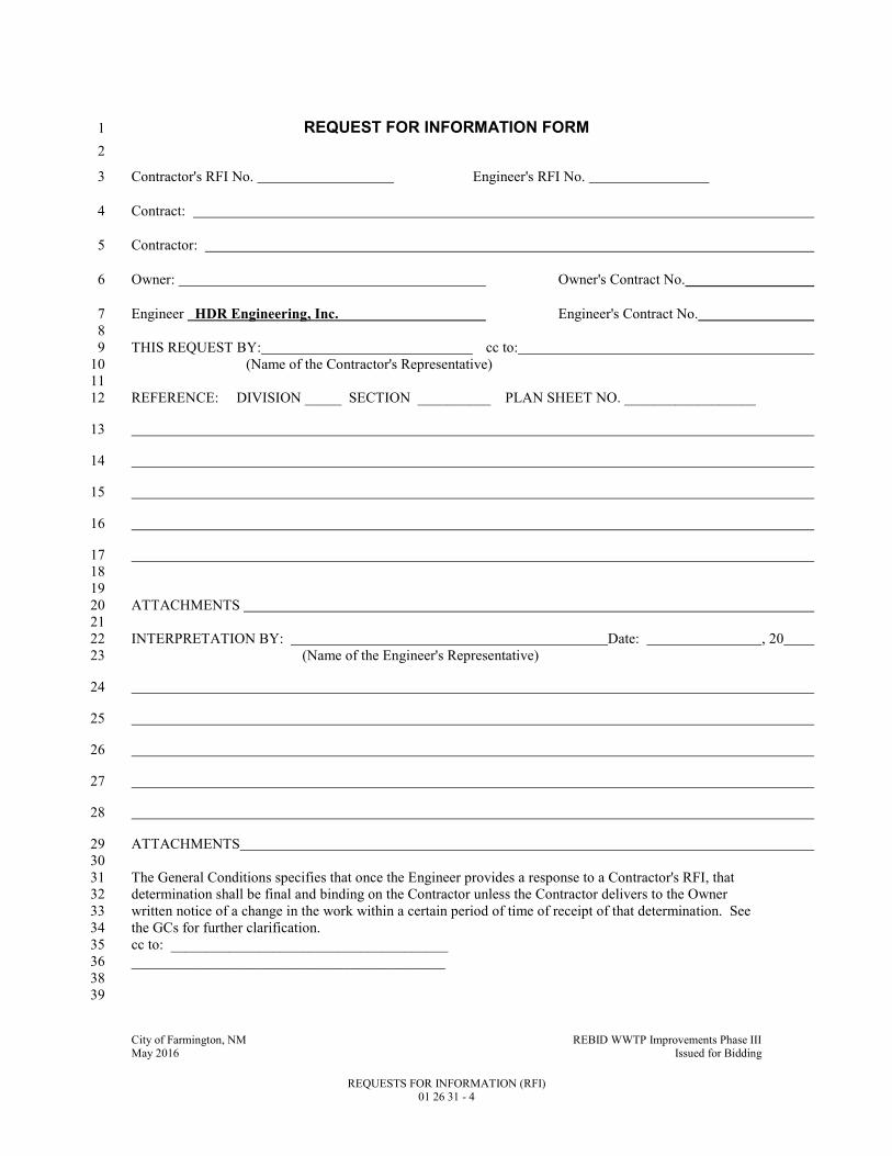
REQUEST FOR INFORMATION FORM 1
2
Contractor's RFI No. Engineer's RFI No. 3
Contract: 4
Contractor: 5
Owner: Owner's Contract No. 6
Engineer HDR Engineering, Inc. Engineer's Contract No. 7
8
THIS REQUEST BY: cc to: 9
(Name of the Contractor's Representative) 10
11
REFERENCE: DIVISION _____ SECTION __________ PLAN SHEET NO. __________________ 12
13
14
15
16
17
18
19
ATTACHMENTS 20
21
INTERPRETATION BY: Date: , 20 22
(Name of the Engineer's Representative) 23
24
25
26
27
28
ATTACHMENTS 29
30
The General Conditions specifies that once the Engineer provides a response to a Contractor's RFI, that 31
determination shall be final and binding on the Contractor unless the Contractor delivers to the Owner 32
written notice of a change in the work within a certain period of time of receipt of that determination. See 33
the GCs for further clarification. 34
cc to: ______________________________________ 35
___________________________________________ 36
38
39
City of Farmington, NM REBID WWTP Improvements Phase III May 2016 Issued for Bidding
SPECIAL CONDITIONS 01 30 00 - 1
SECTION 01 30 00 1
SPECIAL CONDITIONS 2
PART 1 - GENERAL 3
1.1 SUMMARY 4
A. Section Includes: 5 1. Administrative and procedural requirements for: 6
a. Preconstruction Conference. 7 b. Contractor's Superintendent's Field Office. 8 c. Drawings and Contract Documents for Contractor use. 9 d. Testing. 10 e. Schedule of Values. 11 f. Project meetings. 12 g. Special considerations related to adjacent properties and facilities. 13 h. Historical and archaeological finds. 14 i. Online Construction Management Software 15
B. Related Specification Sections include but are not necessarily limited to: 16 1. Division 00 - Bidding Requirements, Contract Forms, and Conditions of the Contract. 17 2. Division 01 - General Requirements. 18
1.2 PRECONSTRUCTION CONFERENCE 19
A. A preconstruction conference shall be held after award of Contract. 20 1. Engineer will notify the Contractor as to the date and time of the conference two (2) weeks 21
in advance of the proposed date. 22 2. Contractor's Project Manager and Project Superintendent and Contractor's Subcontractor 23
Representatives shall attend. 24
1.3 PROJECT SIGNS 25
A. Coordinate sign locations with Owner. 26
B. Signs not listed in this Specification Section permitted only upon approval of Owner. 27
1.4 FIELD OFFICES 28
A. OWNERS FIELD OFFICE. 29 1. Separate from Contractor's field office. 30 2. General Construction: 31
a. New or reconditioned mobile office trailer as manufactured by ATCO or equal. 32 1) Nominal 50 FT long and 16 FT wide. 33
b. Baked enamel aluminum siding. 34 c. Foil-backed fiberglass insulation throughout shall have a minimum R-value of 19. 35 d. Interior paneling. 36 e. Vinyl tile flooring. 37 f. 8 FT high acoustic tile ceiling. 38 g. Two private office areas, one at each end of trailer, one reception-conference room area, 39
and private washroom. 40 h. Windows: 41
1) Minimum two per room, excepting washroom, with one each on opposing walls. 42 2) Combination screen-storm windows. 43 3) Provide horizontal louver blinds on each window. 44
i. Two exterior doors (with cylinder deadbolt locks) with outer screens, exterior lights and 45 exterior stairs and railings. 46
City of Farmington, NM REBID WWTP Improvements Phase III May 2016 Issued for Bidding
SPECIAL CONDITIONS 01 30 00 - 2
j. Trailer shall be skirted around the entire perimeter. 1 k. Trailer shall be connected to public water and wastewater utility. 2
3. Electrical System: 3 a. All fixtures, outlets, and wiring of Underwriters Laboratory (UL) approved devices. 4 b. All circuits protected by circuit breakers; fuses are not acceptable. 5 c. Electrical system shall meet requirements of the latest National Electric Code. 6 d. System suitable for 220 V, single phase service. 7 e. Any transformers or other devices required to match this supply to the mobile office 8
shall be provided and connected. 9 f. Provide a circuit breaker for the incoming service. 10 g. Each interior room except the washroom shall have at least four 110 V duplex electrical 11
convenience outlets. 12 4. Security System: 13
a. The Contractor, at no cost to the Owner or Engineer, shall carry insurance that will 14 replace any property lost from the Engineer's Field Office as a result of theft, fire, or 15 vandalism. 16
5. Telephone Service: 17 a. Private telephone service and pay installation charges for three (3) telephone lines and a 18
minimum of three telephones; one telephone in each office, one telephone in conference 19 room. In addition, pay all local and long distance charges up to an average of $200 per 20 month over the duration of the Work. Telephone service shall include a minimum of 21 two (2) rotating telephone lines on one telephone number. A speaker-phone shall be 22 supplied for all phones. 23
b. Internet Service. Provide High Speed Internet Service Provider connection i.e. for E-24 Mail and to transfer files electronically. 25
6. Central Combination Electric Heating, Air-Conditioning System: 26 a. Fan-forced air. 27 b. Thermostatically controlled. 28 c. Individual room units are not acceptable. 29 d. Heat trace and insulate all piping. 30 e. System sized to maintain 75 DegF constant temperature in each room. 31
7. Lighting System: 32 a. Fluorescent type producing 100 foot-candles at desk top height. 33 b. Ample ceiling fixtures provided to ensure adequate lighting throughout. 34
8. Standard Washroom: 35 a. Flush toilet, sink, hot and cold running water. 36 b. Electric water heater. 37 c. Mirror. 38 d. Electric ceiling or wall vent. 39 e. Sound insulated partitions. 40 f. Toilet accessories. 41 g. All water lines shall be heat traced. 42
9. Furnishings: 43 a. One computer work station 29 x 30 x 60 IN per office. 44 b. One desk 36 x 72 IN long with locking lap drawer per office. 45 c. One plan table 39 x 72 x 36 IN wide, with one locking equipment drawer. 46 d. Two 30 x 72 IN folding tables. 47 e. One 48 x 60 IN liquid marking board with minimum four-color set of compatible 48
markers. 49 f. Five (5) four-drawer legal size locking filing cabinets. HON model or approved equal 50
filing cabinets shall be turned over to Owner at completion of project. 51 g. Two cushioned high back, intensive use, tilting, swivel executive arm chairs. HON 52
model or approved equal, shall be turned over to Owner at completion of project. 53

City of Farmington, NM REBID WWTP Improvements Phase III May 2016 Issued for Bidding
SPECIAL CONDITIONS 01 30 00 - 3
h. Six swivel, tilting, adjustable height, conference chairs. HON model or approved equal, 1 shall be turned over to Owner at completion of project. 2
i. Twelve folding chairs shall be turned over to Owner at completion of project. 3 j. One nominal 3 FT plan racks that hold a minimum of six 350 sheet sets of 36 x 24 IN 4
Drawings. 5 k. Two bookcases, composed of three shelves 36 IN long and 12 IN wide. The units shall 6
be a minimum of 5 FT high. 7 l. Two standard size waste paper baskets. 8 m. One Emerson Model, 3.1 CF refrigerator or equal. 9 n. One 10 LB ABC approved fire extinguisher. 10 o. One OSHA approved first aid kit. 11 p. One water cooler with chilled and hot drinking water; provide bottled water for the 12
duration of project. 13 q. One microwave oven. 14
10. Field Office Equipment: All field office equipment shall be retained by Owner upon 15 completion of project. 16 a. Provide one color printer, HP model 750 or equal, with three paper trays, letter, legal 17
and 11 x 17. 18 b. One three-hole punch, Master Products Series 25 or equal. 19 c. One stapler, Swingline 113 or equal. 20 d. Two (2) scotch tape dispensers. 21 e. Six wire in and out baskets. 22 f. One (1) Sony ICD PX333 Hand-held digital voice recorder. 23 g. One (1) Fellowes 18 Sheet Powershred cross-cut document shredder. 24 h. Provide use of Xerox copy machine in Contractor’s trailer. 25 i. Provide - One(1) lap top computer. Intel i7 5600U Processor (Dual Core, 2.6 I75600, 26
Operating system shall be Windows 10 Pro, 2.6 Ghz, 16 GB (2-8GB) 1600 MHz 27 DDR3L Memory, 500GB 7200RPM Hard drive minimum, 1 ea. - 24 inch monitor, Intel 28 Wireless Dual Band Card, Fingerprint Reader, Dell Universal Dock and Monitor Stand, 29 soundcard, Wireless Keyboard and Mouse, Speakers, DVR, Display port to HDMI 30 output, Dell carrying case, 3 year Dell Pro-Support, Microsoft Office Professional 2016 31 Dell Model Latitude Series 5000 15” LCD display or approved equal. Computer system 32 shall be turned over to Owner at completion of project. 33
j. Provide – One (1) lap top computer. Intel i76820 (Quad Core, 2.7 GHz, 3.60GHz 34 Turbo, Operating System shall be Windows 10 Pro 64 bit, 32GB DDR4-2133 MHz 35 SDRAM, 2DIMMS Memory, 1 TB 2.5 inch 7200rpm SATA Hard Drive, Two (2) each 36 Dell UltraSharp 27”monitors, Intel Wireless Dual Band Card, Fingerprint Reader, Dell 37 Docking Station,Video card-Nvidia QuadroM2000M, Wireless Keyboard and Mouse, 38 Speakers, DVR, Display port to HDMI output, Targus Drifter II Backpack, 3 year Dell 39 Pro-Support, Microsoft Office Professional 2016 and Microsoft Project Software, 40 Display 15.6” FHD, Anti-Glare LED - backlit, Dell Precision 7000 Series or approved 41 equal. Computer system shall be turned over to Owner at completion of project. 42 Provide - One (1) Microsoft Surface Pro 4 -16GB RAM - 256 GB/ Intel i7 with Type 43 cover (black), screen protector and case. System shall be turned over to Owner at 44 completion of project. 45
k. 60” color Sony HD Smart TV with video and audio capabilities to connect to lap top. 46 11. Pay for services of an administrative assistant, and provide for 12 hours per week during the 47
life of the Contract. This person shall be located in Contractor’s trailer, and shall be skilled 48 to perform the following tasks: 49 a. Label and catalog all project photos, etc. 50 b. Maintain filing system. 51 c. Attend meetings, record or take notes, and prepare minutes. 52 d. Other tasks as assigned. 53
12. Maintenance: 54

City of Farmington, NM REBID WWTP Improvements Phase III May 2016 Issued for Bidding
SPECIAL CONDITIONS 01 30 00 - 4
a. Contractor shall provide all maintenance and upkeep of trailer and equipment. 1 Equipment breakdowns shall be repaired promptly by Contractor. 2
13. Janitorial service. 3 a. Weekly: 4 b. Floor sweeping using dust suppressing compound. 5 c. Wet mopping with floor detergent. 6 d. Maintain one month supply of toilet paper, paper towels, Kleenex, and hand soap. 7 e. Inclement weather: Conduct weekly requirements on daily basis. 8 f. Monthly: Wash windows and clean window blinds. 9
14. Pay all utilities costs. 10 15. Maintain at least until final acceptance of the entire work by the Owner or until otherwise 11
suspended by the Engineer. 12 16. Remove field office from site upon final acceptance of the entire work by the Owner. 13 17. Maintain conditions of access road to site such that access is not hindered as the result of 14
construction related deterioration. 15
B. CONTRACTOR'S SUPERINTENDENT'S FIELD OFFICE 16 1. Establish at site of Project. 17 2. Equipment: Telephone, telecopy, mailing address, and sanitary facilities. 18 3. Assure attendance at this office during the normal working day. 19 4. At this office, maintain complete field file of Shop Drawings, posted Contract Drawings and 20
Specifications, and other files of field operations including provisions for maintaining "As 21 Recorded Drawings." 22
5. Remove field office from site upon final acceptance of the entire work by the Owner. 23
1.5 DRAWINGS AND CONTRACT DOCUMENTS FOR CONTRACTOR USE 24
A. Refer to General Conditions. 25
B. Electronic drawings and specifications will be provided to Contractor. Contractor shall be 26 responsible for reproduction of contract documents as needed. 27
C. Additional documents after "no-charge" documents will be furnished to Contractor at cost. 28
1.6 TESTING 29
A. Payment for Soil, Concrete and Other Testing: 30 1. Soils and concrete testing: 31
a. The Owner will pay for "Passing" soils and "Passing" concrete tests on the Project. 32 b. Costs of corrective action, costs of "Failing" soils and concrete tests, and cost of testing 33
associated with establishment of mix design are the sole responsibility of the Contractor. 34 2. Other testing: Required testing, testing procedures, reports, certificates, and costs associated 35
with all phases of securing required satisfactory test information which may be required by 36 individual Specification Sections or Drawings are the full responsibility of the Contractor. 37
1.7 SCHEDULE OF VALUES 38
A. Where a Contract is awarded on a lump sum basis, the Contractor shall file with the Engineer a 39 balanced price segregation of the lump sum bid into items similar to the various subdivisions of 40 the general and detailed specifications, the sum of which shall equal the lump sum bid. 41
1. The cost of various materials shall be furnished upon request of the Engineer, and such data 42 will then be used as a basis for making progress estimates. 43
2. Breakdown costs, itemized by Specification Section and trade, and distribute cost to 44 individual applicable units and structures. 45
3. Where structures, units, equipment or other components are identified by a specific series 46 or, identification number, utilize said designation throughout cost breakdown. 47
4. Provide detailed breakdown for individual yard piping or conduit runs and identify 48 approximate quantities involved to satisfaction of the Engineer. 49

City of Farmington, NM REBID WWTP Improvements Phase III May 2016 Issued for Bidding
SPECIAL CONDITIONS 01 30 00 - 5
5. Provide separate breakdown for change order items requested. 1 6. Provide an additional breakdown sheet, equivalent to the Stored Material Summary of 2
EJCDC document C620, showing the tabulation format for stored materials. 3 7. Submit this sheet each month with Contractor's pay request breakdown. 4 8. The detail and format of cost breakdown and stored materials tabulation sheet shall be fully 5
approved by Engineer. 6
B. A reasonable allocation of the Contract Price to the component parts of the Work will be approved 7 if component parts of the Work have values assigned to them that are well-balanced with respect 8 to relative values for similar work established by published estimating guides. 9
1. Unless otherwise agreed to at the Preconstruction Conference, Means Estimator Guide or 10 other similar nationally recognized estimating guide shall be used for resolving differences 11 between Engineer's and Contractor's opinions of allocation of values. 12
2. Consent of Surety: If Contractor and Engineer cannot mutually agree on a Schedule of 13 Values, Engineer will approve a Schedule of Values approved by the Surety providing the 14 Performance Bond. 15
C. Contractor's costs shall not govern the allocation of values when application of Contractor's costs 16 to a component part of the Work results in any other component part or combination of component 17 parts being under-valued in relation to conventional estimating guides. 18
D. Schedule of Values shall be agreed upon prior to first Application for Payment. 19
1.8 PROJECT MEETINGS 20
A. Construction Meetings: 21 1. The Engineer will conduct construction meetings involving: 22
a. Contractor's project manager. 23 b. Contractor's project superintendent. 24 c. Owner's designated representative(s). 25 d. Engineer's designated representative(s). 26 e. Contractor's subcontractors as appropriate to the Work in progress. 27 f. Owner's Construction Quality Control Consultant. 28
2. Meetings will be conducted weekly. Owner may change the frequency of meetings at his 29 discretion. 30
3. The Engineer will take meeting minutes and submit copies of meeting minutes to 31 participants and designated recipients identified at the Preconstruction Conference. 32 a. Corrections, additions or deletions to the minutes shall be noted and addressed at the 33
following meeting. 34 4. The Engineer will schedule meetings for most convenient time frame. 35 5. The Engineer will have available at each meeting full chronological files of all previous 36
meeting minutes. 37 6. The Contractor shall have available at each meeting up-to-date record drawings. 38
B. Pre-Installation Conferences: 39 1. Coordinate and schedule with Resident Project Representative and Engineer for each 40
material, product or system specified. 41 a. Conferences to be held prior to initiating installation, but not more than two (2) weeks 42
before scheduled initiation of installation. 43 b. Conferences may be combined if installation schedule of multiple components occurs 44
within the same two (2) week interval. 45 c. Review manufacturer’s recommendations and Contract Documents Specification 46
Sections. 47 2. Contractor's Superintendent and individual who will actually act as foreman of the 48
installation crew (installer), if other than the Superintendent, shall attend. 49

City of Farmington, NM REBID WWTP Improvements Phase III May 2016 Issued for Bidding
SPECIAL CONDITIONS 01 30 00 - 6
1.9 SPECIAL CONSIDERATIONS RELATED TO ADJACENT PROPERTIES AND 1 FACILITIES 2
A. Contractor shall be responsible for negotiations of any waivers or alternate arrangements required 3 to enable transportation of materials to the site. 4
B. Maintain conditions of access road to site such that access is not hindered as the result of 5 construction related deterioration. 6
1. Provide daily sweeping of hard-surface roadways to remove soils tracked onto roadway. 7
1.10 HISTORICAL AND ARCHAEOLOGICAL 8
A. If during the course of construction, evidence of deposits of historical or archeological interest is 9 found, the Contractor shall cease operations affecting the find and shall notify Owner. 10
1. No further disturbance of the deposits shall ensue until the Contractor has been notified by 11 Owner that Contractor may proceed. 12
2. Owner will issue a notice to proceed after appropriate authorities have surveyed the find and 13 made a determination to Owner. 14
3. Compensation to the Contractor, if any, for lost time or changes in construction resulting 15 from the find, shall be determined in accordance with changed or extra work provisions of 16 the Contract Documents. 17
4. The site has been previously investigated and has no known history of historical or 18 archaeological finds. 19
1.11 ADDITIONAL CONTRACTOR REQUIREMENTS 20
A. This project includes an “American Iron and Steel (AIS)” requirement that is required by Clean 21 Water State Revolving Loan Fund (CWSRF) and Drinking Water State Revolving Loan Fund 22 (SWSRF) projects to use iron and steel products that are produced in the United States for projects 23 for the construction, alteration, maintenance, or repair of a public water system or treatment 24 works. All iron and steel shall meet the requirements as stated in Volume I under the 25 “Implementation of American Iron and Steel provisions of P.L. 113-76, Consolidated 26 Appropriations Act, 2014. 27
B. See the Sample Certifications for AIS Compliance in Specification Section 01 33 00. 28 Documentation must be provided on company letterhead. 29
1.12 ONLINE CONSTRUCTION MANAGEMENT SOFTWARE 30
A. Contractor shall provide and maintain cloud-based online construction management software 31 application such as Procore to manage construction documents. Full access shall be provided at a 32 minimum to the Owner, Owner’s Operations, Engineer, and Funding Agency. At a minimum, the 33 software shall be capable of managing the following software: 34
1. Shop Drawing Submittals 35 2. RFI’s 36 3. Change Orders 37 4. Daily Reports 38 5. Photos 39 6. Punch List 40 7. Contract Documents 41
PART 2 - PRODUCTS - (NOT APPLICABLE TO THIS SPECIFICATION SECTION) 42
PART 3 - EXECUTION - (NOT APPLICABLE TO THIS SPECIFICATION SECTION) 43

City of Farmington, NM REBID WWTP Improvements Phase III May 2016 Issued for Bidding
CONSTRUCTION PROGRESS SCHEDULE 01 32 17 - 1
SECTION 01 32 17 1
CONSTRUCTION PROGRESS SCHEDULE 2
PART 1 - GENERAL 3
1.1 SUMMARY 4
A. Section Includes: 5
1. Specific requirements for the preparation, submittal, updating, status reporting and 6
management of the construction Progress Schedule. 7
B. Related Specification Sections include, but are not necessarily limited to: 8
1. Division 00 - Bidding Requirements, Contract Forms and Conditions of the Contract. 9
2. Division 01 - General Requirements. 10
1.2 QUALITY ASSURANCE 11
A. The person preparing and revising the construction Progress Schedule shall be experienced in 12
the preparation of schedules of similar complexity. 13
B. Within five (5) days from award of the Contract, Contractor shall submit to Engineer the name 14
of the person responsible for the preparation, maintenance, updating and revision of all 15
schedules. 16
1.3 DEFINITIONS 17
A. The following definitions shall apply to this Specification Section: 18
1. BASELINE SCHEDULE: The initial as-bid, detailed Progress Schedule prepared by the 19
Contractor to define its plan for constructing the Project as required by the Contract 20
Documents, and accepted by the Owner or Engineer as meeting the requirements of the 21
Contract Documents for specified constraints, sequences, milestones and completion dates. 22
2. RECORD SCHEDULE: The initially accepted Baseline Schedule, or subsequently 23
approved Revised Baseline Schedules, updated each month to reflect actual start and finish 24
dates of schedule activities and all time impact events whether caused by Contractor or 25
Owner or factors beyond the control of either party. 26
3. REVISED BASELINE SCHEDULE: The initially accepted Baseline Schedule revised to 27
reflect only approved changes. 28
4. WORKING SCHEDULE: A schedule developed from the Record Schedule to indicate the 29
Contractor’s plan for executing the Work, and providing for schedule recovery when 30
approved time extensions are not sufficient to provide for timely completion due to 31
Contractor inefficiencies beyond the control of the Owner or outside the risks accepted by 32
the Owner. 33
1.4 SUBMITTALS 34
A. Shop Drawings: 35
1. See Specification Section 01 33 00 for requirements for the mechanics and administration of 36
the submittal process. 37
2. Baseline Schedule: Submitted within 30 days after Effective Date of Agreement. 38
3. Monthly Record Schedules. 39
4. Revised Baseline Schedules. 40
5. Working Schedules. 41
6. Look-Ahead Schedules. 42
City of Farmington, NM REBID WWTP Improvements Phase III May 2016 Issued for Bidding
CONSTRUCTION PROGRESS SCHEDULE 01 32 17 - 2
1.5 GENERAL REQUIREMENTS 1
A. Construction operations will be scheduled to allow the Owner uninterrupted operation of 2
existing adjacent facilities. 3
1. Coordinate connections with existing work to ensure timely completion of interfaced items. 4
B. At no time shall Contractor or his employees modify operation of the existing facilities or start 5
construction modifications without approval of the Owner except in emergency to prevent or 6
minimize damage. 7
C. Within 10 days after award of Contract, submit for approval a bar/Gannt Chart or critical path 8
type schedule. 9
1. Account for schedule of Subcontracts. 10
2. Include proper sequence of construction, various crafts, purchasing time, Shop Drawing 11
approval, material delivery, equipment fabrication, startup, demonstration, and similar time 12
consuming factors. 13
3. Show on schedule as a minimum, earliest starting, earliest completion, latest starting, latest 14
finish, and free and total float for each task or item. 15
D. Evaluate schedule no less than monthly. 16
1. Update, correct, and rerun schedule and submit to Engineer in triplicate with pay application 17
to show rescheduling necessary to reflect true job conditions. 18
2. When shortening of various time intervals is necessary to correct for behind schedule 19
conditions, indicate actions to implement to accomplish work in shorter duration. 20
3. Information shall be submitted to Engineer in writing with revised schedule. 21
E. If Contractor does not take necessary action to accomplish work according to schedule, 22
Contractor may be ordered by Owner in writing to take necessary and timely action to improve 23
work progress. 24
1. Owner may require increased work forces, extra equipment, extra shifts or other action as 25
necessary. 26
2. Should Contractor refuse or neglect to take such action authorized, under provisions of this 27
Contract, Owner may take necessary actions including, but not necessarily limited to, 28
withholding of payment and termination of Contract. 29
F. Upon receipt of approved Baseline Schedule, within 10 days, submit to Engineer an estimated 30
payment schedule by each month of project duration. 31
1. Include a composite curve to show estimated value of work complete and stored materials 32
less specified retainage. 33
2. Establish key months when work will be 50, 80, 90, and 100 percent complete. 34
3. During the course of work, update with new composite curves at key months or whenever 35
variation is expected to be more than plus or minus 10 percent. 36
4. Retain original or previous composite curves as dashed curves on all updates. 37
G. Contractor shall prepare and submit Baseline and Record Schedules and updates and revisions to 38
them as specified herein. 39
1. The Baseline and Record Schedules shall be a calendar day-based and cost-loaded Critical 40
Path Method (CPM) network diagram with supporting data. 41
H. Disallowed Scheduling Software Features: 42
1. The following specific features are not allowed to be applied in the Baseline and Record 43
Schedules when using electronic Critical Path Method (CPM) software applications: 44
a. Resource leveling. 45
b. Activity or event constraints, other than those specified by the Contract Documents. 46
c. Leads and lags: 47
1) Create specific activities with specific durations in-lieu-of leads and lags. 48
2) Durations shall have positive values. 49
d. Default progress data: 50

City of Farmington, NM REBID WWTP Improvements Phase III May 2016 Issued for Bidding
CONSTRUCTION PROGRESS SCHEDULE 01 32 17 - 3
1) Start and finish dates shall not be automatically updated. 1
2) Update with actual start and finish dates documented from field reports. 2
3) Work activities shall be updated by actual Work progression, not cash flow driven. 3
4) Updating of activity percent complete and remaining duration shall be independent 4
functions, not one parameter calculated from the other. 5
5) Out-of-sequence progress shall be accounted for through retained logic, not a 6
default option of progress override. 7
e. Multiple calendars. 8
2. Any float suppression techniques or other software features that corrupts the pure 9
mathematical model calculating the critical path. 10
a. The following CPM schedule outputs will be rejected without further review: 11
1) Schedules indicating the start of the critical path at a date point or activity beyond 12
the date of Notice to Proceed, or schedules indicating a discontinuous critical path 13
from Notice to Proceed to Contract completion. 14
2) Schedules defining critical activities as those on a path or paths having some 15
minimum value of float. 16
3) Schedules with multiple critical paths. 17
4) Schedules indicating a completion date beyond the contractual completion date. 18
I. Float Time: 19
1. Neither the Owner nor the Contractor owns the float; the project owns the float. 20
2. As such, liability for delay of the project completion date rests with the party actually 21
causing delay to the project completion date. 22
J. By preparing and submitting the Baseline Schedule, the Contractor represents that it can and 23
intends to execute the Work and portions thereof within the specified times and constraints and 24
that its bid covers the costs associated with the execution of the Work in accordance with the 25
Construction Schedule. 26
K. Contractor shall provide an electronic copy on CD media for the Baseline Schedule and Record 27
Schedule and all monthly updates of both to accompany hard copies of the schedules and tabular 28
reports when using CPM scheduling software applications. 29
1.6 SUBMITTAL PACKAGES 30
A. Baseline Schedule: 31
1. Bar/Gannt Chart or CPM time-scaled network diagram: 32
a. Three (3) prints of each sheet. 33
b. Minimum sheet size: 11 IN x 17 IN. 34
2. Supporting data: 35
a. Three (3) sets of a list of project activities including the following: 36
1) Holidays that will be observed during construction. 37
2) Number of planned working days and shifts per week. 38
B. Monthly updates that include the following: 39
1. Narrative Schedule Report. 40
2. Revised Baseline Schedule as appropriate. 41
a. Update to reflect approved Change Orders occurring since the prior update 42
b. If no new approved Change Orders since prior update, provide a narrative report 43
indicating such, and acknowledging the pertinence of the previously approved Baseline 44
Schedule. 45
3. Updated Record Schedule. 46
4. Explanation of changes in logic, duration of activities. 47
5. The number of opaque reproductions which Contractor requires, plus three (3) copies which 48
will be distributed by the Engineer. 49
a. Do not submit fewer than three (3) copies. 50

City of Farmington, NM REBID WWTP Improvements Phase III May 2016 Issued for Bidding
CONSTRUCTION PROGRESS SCHEDULE 01 32 17 - 4
C. Look-Ahead Rolling Schedule: 1
1. A three-week rolling schedule shall be provided by the Contractor at each progress meeting. 2
a. The schedule shall provide an accurate representation of the work performed the 3
previous week and work planned for the current week and subsequent two (2) weeks. 4
2. The schedule shall be provided in a tabular format with bars representing work duration. 5
a. The schedule shall refer to activity ID numbers on the Baseline and Record Schedules. 6
b. Activities that are on the critical path and activities that are behind schedule shall be 7
noted by color, highlight, or underscore. 8
3. Derived from the Working Schedule, if applicable. 9
D. Narrative Schedule Report: 10
1. Schedule reports for Initial Baseline and Revised Baseline Schedules shall include the 11
following minimum data for each activity: 12
a. Preceding and succeeding activities. 13
b. Activity description and number. 14
c. Durations of activities: 15
1) Original durations. 16
2) Remaining durations. 17
d. Earliest start date (by calendar date). 18
e. Earliest finish date (by calendar date). 19
f. Actual start date (by calendar date). 20
g. Actual finish date (by calendar date). 21
h. Latest start date (by calendar date). 22
i. Latest finish date (by calendar date). 23
j. Float. 24
k. Percentage of activity completed. 25
l. Activity constraints specified by the Contract Documents. 26
m. Type of Tabulation (Initial or Updated). 27
n. Project Duration. 28
o. Project Contractual Completion Date. 29
p. The date of commencement of the Work as stated in the Notice to Proceed. 30
q. If an updated (revised) schedule, cite the new project completion date and project status 31
and date of revision. 32
2. Shall be organized in the following sequence with all applicable documents included: 33
a. Contractor's transmittal letter. 34
b. Work completed during the period. 35
c. Identification of unusual conditions or restrictions regarding labor, equipment or 36
material. 37
d. Description of the current critical path. 38
e. Changes to the critical path and scheduled completion date since the last schedule 39
submittal. 40
f. Description of problem areas. 41
g. Current and anticipated delays: 42
1) Cause of delay. 43
2) Impact of delay on other activities, milestones and completion dates. 44
3) Corrective action and schedule adjustments to correct the delay. 45
h. Pending items and status thereof: 46
1) Permits. 47
2) Change orders. 48
3) Time adjustments. 49
4) Non-compliance notices. 50
i. Reasons for an early or late scheduled completion date in comparison to the Contract 51
completion date. 52
City of Farmington, NM REBID WWTP Improvements Phase III May 2016 Issued for Bidding
CONSTRUCTION PROGRESS SCHEDULE 01 32 17 - 5
1.7 BASELINE SCHEDULE 1
A. Schedule shall include, but not be limited to, activities that show the following that are 2
applicable to the project: 3
1. Project characteristics, salient features, or interfaces, including those with outside entities, 4
that could affect time of completion. 5
2. Project start date, scheduled completion date and other milestones. 6
3. Work performed by Contractor, subcontractors and suppliers. 7
4. Submittal development, delivery, review and approval, including those from Contractor, 8
subcontractors and suppliers. 9
5. Procurement, delivery, installation and testing of materials, plants and equipment. 10
6. Testing and settlement periods. 11
7. Utility notification and relocation. 12
8. Finish work and final cleanup. 13
B. Early Completion Time: 14
1. Contractor may show early completion time on any schedule provided that the requirements 15
of the Contract are met. 16
2. Contractor may increase early completion time by improving production, reallocating 17
resources to be more efficient, performing sequential activities concurrently or by 18
completing activities earlier than planned. 19
C. Working durations shall be planned to incorporate the effects of normal weather impacts. 20
1.8 RECORD SCHEDULE 21
A. Develop Record Schedule based on approved Baseline and Revised Baseline Schedules. 22
1. All restrictions on use of constraints, leads and lags, resource leveling, etc., shall also apply 23
to Record Schedules. 24
B. The Record Schedule will be updated once per month for monitoring progress. 25
1.9 REVISIONS TO RECORD SCHEDULE 26
A. Contractor shall submit data for a revised Record Schedule within five (5) days of the 27
occurrence of any of the following: 28
1. When contractor-caused delay in completion of any activity or group of activities indicates 29
an overrun of the Contract Time or Control Dates by 30 working days or 10 percent of the 30
remaining duration, whichever is less. 31
2. When delays in submittals, deliveries, or work stoppages are encountered making necessary 32
the replanning or rescheduling of the Work. 33
3. When the schedule does not represent the actual progress of the Work. 34
4. When a change order significantly affects the Contract completion date. 35
B. The revised Record Schedule shall be the basis of a Working Schedule showing: 36
1. How Contractor intends to return to schedule. 37
2. How Contractor intends to avoid falling behind schedule on future activities. 38
C. Show changes on the network diagram and supporting data including: 39
1. New activities and their duration. 40
2. Modifications to existing activities. 41
D. Provide written narrative report as needed to define: 42
1. Problem areas, anticipated delays, and impact on the current schedule. 43
2. Corrective action recommended, and its effect. 44
3. Major changes in scope. 45
4. Revised projections of progress and completion. 46
City of Farmington, NM REBID WWTP Improvements Phase III May 2016 Issued for Bidding
CONSTRUCTION PROGRESS SCHEDULE 01 32 17 - 6
E. Except as provided in the following Subparagraphs 1 and 2, the cost of revisions to the Record 1
Schedule resulting from changes in the Work shall be included in the cost for the change in the 2
Work, and shall be based on the complexity of the revision or Change Order, man-hours 3
expended in analyzing the change, and the total cost of the change. 4
1. The cost of revision to the Construction Schedule not resulting from authorized changes in 5
the Work shall be the responsibility of the Contractor. 6
2. The cost of revision to the Construction Schedule for the Contractor's convenience shall be 7
the responsibility of the Contractor. 8
F. The revised network diagram and supporting data for the Record Schedule shall be submitted to 9
the Engineer upon completion of the revisions, but not later than the next progress meeting. 10
G. Revisions to the Record Schedule for the Contractor's convenience: 11
1. Must be approved by the Engineer before Contractor changes the sequence of Work. 12
1.10 TIME IMPACT ANALYSIS (TIA) 13
A. The accepted initial Baseline Schedule or subsequently accepted Revised Baseline Schedule 14
shall be used for TIA. 15
B. Contractor shall submit a written TIA to the Engineer with each request for adjustment of 16
Contract Time, or when Contractor or Engineer consider that an approved or anticipated change 17
may impact the critical path or contract progress. 18
1. The TIA must be attached to any change order prior to approval of any change to time or 19
cost. 20
C. The TIA shall illustrate the impacts of each change or delay on the current scheduled completion 21
date or internal milestone, as appropriate. 22
1. The analysis shall use the Baseline or Revised Baseline Schedule (accepted Baseline 23
Schedule) that has a data date closest to and prior to the event. 24
2. If the Engineer determines that the accepted Baseline Schedule used does not appropriately 25
represent the conditions prior to the event, the accepted Baseline Schedule shall be updated 26
to the day before the event being analyzed. 27
3. The TIA shall include an impact schedule developed from incorporating the event into the 28
accepted Baseline Schedule by adding or deleting activities, or by changing durations or 29
logic of existing activities as appropriate to the nature of the change event. 30
4. If the impact schedule shows that incorporating the event modifies the critical path and 31
scheduled completion date of the accepted Baseline Schedule, the difference between 32
scheduled completion dates of the two (2) schedules shall be equal to the adjustment of 33
contract time. 34
D. Contractor shall submit a TIA in duplicate within 15 working days of receiving a written request 35
for a TIA from the Engineer. 36
1. Contractor shall allow the Engineer two (2) weeks after receipt to approve or reject the 37
submitted TIA. 38
2. All approved TIA schedule changes shall be shown on the next update schedule. 39
E. In the event of a TIA rejection: 40
1. If a TIA submitted by the Contractor is rejected by the Engineer, the Contractor shall meet 41
with the Engineer to discuss and resolve issues related to the TIA. 42
2. If agreement is not reached, the Contractor will be allowed 15 days from the meeting with 43
the Engineer to give notice. 44
3. Contractor shall only show actual as-built work, not unapproved changes related to the TIA, 45
in subsequent update schedules. 46
4. If agreement is reached at a later date, approved TIA schedule changes shall be shown on 47
the next update schedule. 48
5. Engineer will withhold remaining payment on the schedule contract item if a TIA is 49
requested by Engineer and not submitted by Contractor within 15 working days. 50
City of Farmington, NM REBID WWTP Improvements Phase III May 2016 Issued for Bidding
CONSTRUCTION PROGRESS SCHEDULE 01 32 17 - 7
6. The schedule item payment will resume on the next estimate after the requested TIA is 1
submitted. 2
a. No other contract payment will be retained regarding TIA submittals. 3
F. Contractor shall also submit a narrative report with each updated analysis which shall include 4
but not be limited to, a description of current and anticipated problem areas, delaying factors and 5
their impact, and an explanation of corrective actions taken or proposed. 6
G. Delays to project completion due to adverse weather impacting the controlling activity will be 7
assigned by the Engineer in response to a request by the Contractor. 8
1. This request must be made on the same day as the delay to allow the Engineer an 9
opportunity to observe working conditions and evaluate the degree of delay the weather 10
impact poses. 11
2. Only normal work week days may be considered for weather impacts. 12
a. All such weather-impact days during the workweek will be noted but project extension 13
will only be granted for weather delays in excess of the typical number of working days 14
lost to inclement weather according to the table below. 15
PART 2 - PRODUCTS - (NOT APPLICABLE TO THIS SPECIFICATION SECTION) 16
PART 3 - EXECUTION - (NOT APPLICABLE TO THIS SPECIFICATION SECTION) 17
END OF SECTION 18
City of Farmington, NM REBID WWTP Improvements Phase III May 2016 Issued for Bidding
SUBMITTALS 01 33 00 - 1
SECTION 01 33 00 1
SUBMITTALS 2
PART 1 - GENERAL 3
1.1 SUMMARY 4
A. Section Includes: 5
1. Mechanics and administration of the submittal process for: 6
a. Shop Drawings. 7
b. Samples. 8
c. Informational submittals. 9
2. General content requirements for Shop Drawings. 10
B. Related Specification Sections include but are not necessarily limited to: 11
1. Division 00 - Bidding Requirements, Contract Forms, American Iron and Steel (AIS) 12
requirements, and Conditions of the Contract. 13
2. Division 01 - General Requirements. 14
3. Operations and Maintenance Manual submittal requirements are specified in Specification 15
Section 01 33 04. 16
4. Specification Sections in Division 01 through Division 46 identifying required submittals. 17
1.2 DEFINITIONS 18
A. Shop Drawings: 19
1. See General Conditions. 20
2. Product data and samples are Shop Drawing information. 21
3. Initial and Revised Construction Baseline Schedules. 22
4. Schedule of Values. 23
5. American Iron and Steel (AIS) certification of compliance for all iron and steel products for 24
this project. All iron and steel shall meet the requirements as stated in Volume I under the 25
“Implementation of American Iron and Steel provisions of P.L. 113-76, Consolidated 26
Appropriations Act, 2014. 27
B. Informational Submittals: 28
1. Submittals other than Shop Drawings and samples required by the Contract Documents that 29
do not require approval. 30
2. Representative types of informational submittal items include but are not limited to: 31
a. Construction Record Schedules (progress schedules). 32
b. HVAC test and balance reports. 33
c. Installed equipment and systems performance test reports. 34
d. Manufacturer's installation certification letters. 35
e. Instrumentation and control commissioning reports. 36
f. Warranties. 37
g. Service agreements. 38
h. Construction photographs. 39
i. Survey data. 40
j. Health and safety plans. 41
k. Work plans. 42
l. Delegated designs per performance specification requirements 43
3. For-Information-Only submittals upon which the Engineer is not expected to conduct 44
review or take responsive action may be so identified in the Contract Documents. 45
1.3 SUBMITTAL SCHEDULE 46
A. Schedule of Shop Drawings: 47
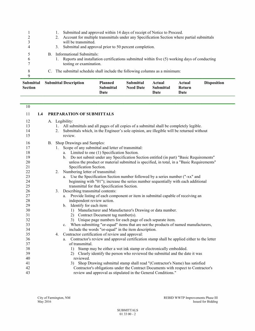
City of Farmington, NM REBID WWTP Improvements Phase III May 2016 Issued for Bidding
SUBMITTALS 01 33 00 - 2
1. Submitted and approved within 14 days of receipt of Notice to Proceed. 1
2. Account for multiple transmittals under any Specification Section where partial submittals 2
will be transmitted. 3
3. Submittal and approval prior to 50 percent completion. 4
B. Informational Submittals: 5
1. Reports and installation certifications submitted within five (5) working days of conducting 6
testing or examination. 7
C. The submittal schedule shall include the following columns as a minimum: 8
9
Submittal
Section
Submittal Description Planned
Submittal
Date
Submittal
Need Date
Actual
Submittal
Date
Actual
Return
Date
Disposition
10
1.4 PREPARATION OF SUBMITTALS 11
A. Legibility: 12
1. All submittals and all pages of all copies of a submittal shall be completely legible. 13
2. Submittals which, in the Engineer’s sole opinion, are illegible will be returned without 14
review. 15
B. Shop Drawings and Samples: 16
1. Scope of any submittal and letter of transmittal: 17
a. Limited to one (1) Specification Section. 18
b. Do not submit under any Specification Section entitled (in part) "Basic Requirements" 19
unless the product or material submitted is specified, in total, in a "Basic Requirements" 20
Specification Section. 21
2. Numbering letter of transmittal: 22
a. Use the Specification Section number followed by a series number ("-xx" and 23
beginning with "01"); increase the series number sequentially with each additional 24
transmittal for that Specification Section. 25
3. Describing transmittal contents: 26
a. Provide listing of each component or item in submittal capable of receiving an 27
independent review action. 28
b. Identify for each item: 29
1) Manufacturer and Manufacturer's Drawing or data number. 30
2) Contract Document tag number(s). 31
3) Unique page numbers for each page of each separate item. 32
c. When submitting "or-equal" items that are not the products of named manufacturers, 33
include the words "or-equal" in the item description. 34
4. Contractor certification of review and approval: 35
a. Contractor's review and approval certification stamp shall be applied either to the letter 36
of transmittal. 37
1) Stamp may be either a wet ink stamp or electronically embedded. 38
2) Clearly identify the person who reviewed the submittal and the date it was 39
reviewed. 40
3) Shop Drawing submittal stamp shall read "(Contractor's Name) has satisfied 41
Contractor's obligations under the Contract Documents with respect to Contractor's 42
review and approval as stipulated in the General Conditions." 43

City of Farmington, NM REBID WWTP Improvements Phase III May 2016 Issued for Bidding
SUBMITTALS 01 33 00 - 3
b. Submittals containing multiple independent items shall be prepared with each item 1
listed on the letter of transmittal or on an index sheet for all items listing the discrete 2
page numbers for each page of each item, which shall be stamped with the Contractor's 3
review and approval stamp. 4
1) Each independent item shall have a cover sheet with the transmittal number and 5
item number recorded. 6
a) Provide clear space of 3 IN SQ for Engineer stamping. 7
2) Individual pages or sheets of independent items shall be numbered in a manner that 8
permits the entire contents of a particular item to be readily recognized and associated 9
with Contractor's certification. 10
5. American Iron and Steel (AIS) certification of compliance for all iron and steel products for 11
this project. All iron and steel shall meet the requirements as stated in Volume I under the 12
“Implementation of American Iron and Steel provisions of P.L. 113-76, Consolidated 13
Appropriations Act, 2014. See the Sample Certifications for AIS Compliance at the end of 14
this section. Documentation must be provided on company letterhead. 15
6. Resubmittals: 16
a. Number with original Specification Section and series number with a suffix letter 17
starting with "A" on a (new) duplicate transmittal form. 18
b. Do not increase the scope of any prior transmittal. 19
c. Account for all components of prior transmittal. 20
1) If items in prior transmittal received "A" or "B" Action code, list them and indicate 21
"A" or "B" as appropriate. 22
a) Do not include submittal information for items listed with prior "A" or "B" 23
Action in resubmittal. 24
2) Indicate "Outstanding-To Be Resubmitted At a Later Date" for any prior "C" or 25
"D" Action item not included in resubmittal. 26
a) Obtain Engineer's approval to exclude items. 27
7. For 8-1/2 x 11 IN, 8-1/2 x 14 IN, and 11 x 17 IN size sheets, provide three (3) copies of 28
each submittal for Engineer plus the number required by the Contractor. 29
a. The number of copies required by the Contractor will be defined at the Preconstruction 30
Conference, but shall not exceed three (3). 31
b. All other size sheets: 32
1) Submit one (1) reproducible transparency or high resolution print and one (1) 33
additional print of each Drawing until approval is obtained. 34
2) Utilize mailing tube; do not fold. 35
3) The Engineer will mark and return the reproducible to the Contractor for 36
reproduction and distribution. 37
8. Contractor shall not use red color for marks on transmittals. 38
a. Duplicate all marks on all copies transmitted, and ensure marks are photocopy 39
reproducible. 40
b. Engineer will use red marks or enclose marks in a cloud. 41
9. Transmittal contents: 42
a. Coordinate and identify Shop Drawing contents so that all items can be easily verified 43
by the Engineer. 44
b. Provide submittal information or marks defining specific equipment or materials 45
utilized on the Project. 46
1) Generalized product information, not clearly defining specific equipment or 47
materials to be provided, will be rejected. 48
c. Identify equipment or material project application, tag number, Drawing detail 49
reference, weight, and other Project specific information. 50
d. Provide sufficient information together with technical cuts and technical data to allow 51
an evaluation to be made to determine that the item submitted is in compliance with the 52
Contract Documents. 53
e. Do not modify the manufacturer's documentation or data except as specified herein. 54
City of Farmington, NM REBID WWTP Improvements Phase III May 2016 Issued for Bidding
SUBMITTALS 01 33 00 - 4
f. Submit items such as equipment brochures, cuts of fixtures, product data sheets or 1
catalog sheets on 8-1/2 x 11 IN pages. 2
1) Indicate exact item or model and all options proposed. 3
g. When a Shop Drawing submittal is called for in any Specification Section, include as 4
appropriate, scaled details, sizes, dimensions, performance characteristics, capacities, 5
test data, anchoring details, installation instructions, storage and handling instructions, 6
color charts, layout Drawings, rough-in diagrams, wiring diagrams, controls, weights 7
and other pertinent data in addition to information specifically stipulated in the 8
Specification Section. 9
1) Arrange data and performance information in format similar to that provided in 10
Contract Documents. 11
2) Provide, at minimum, the detail specified in the Contract Documents. 12
h. If proposed equipment or materials deviate from the Contract Drawings or 13
Specifications in any way, clearly note the deviation and justify the said deviation in 14
detail in a separate letter immediately following transmittal sheet. 15
10. Samples: 16
a. Identification: 17
1) Identify sample as to transmittal number, manufacturer, item, use, type, project 18
designation, tag number, Specification Section or Drawing detail reference, color, 19
range, texture, finish and other pertinent data. 20
2) If identifying information cannot be marked directly on sample without defacing or 21
adversely altering samples, provide a durable tag with identifying information 22
securely attached to the sample. 23
b. Include application specific brochures, and installation instructions. 24
c. Provide Contractor's review and approval certification stamp or Contractor's Submittal 25
Certification form as indication of Contractor's checking and verification of dimensions 26
and coordination with interrelated work. 27
d. Resubmit revised samples of rejected items. 28
C. Informational Submittals: 29
1. Prepare in the format and detail specified in Specification requiring the informational 30
submittal. 31
1.5 TRANSMITTAL OF SUBMITTALS 32
A. Shop Drawings and Samples: 33
1. Transmit all submittals to: 34
35
HDR Engineering, Inc.
2155 Louisiana Blvd. NE Suite 9500
Albuquerque, NM 87110-5483
Attn: Wade Chacon, PE
36
2. Utilize two (2) copies of attached Exhibit A to transmit all Shop Drawings and samples. 37
3. All submittals must be from Contractor. 38
a. Submittals will not be received from or returned to subcontractors. 39
B. Informational Submittals: 40
1. Transmit under Contractor's standard letter of transmittal or letterhead. 41
2. Submit in triplicate or as specified in individual Specification Section. 42
3. Transmit to: 43
44
HDR Engineering, Inc.
2155 Louisiana Blvd. NE Suite 9500
Albuquerque, NM 87110-5483
Attn: Wade Chacon, PE

City of Farmington, NM REBID WWTP Improvements Phase III May 2016 Issued for Bidding
SUBMITTALS 01 33 00 - 5
1
4. Provide copy of letter of transmittal without attachments to Owner's Resident Project 2
Representative. 3
a. Exception for concrete, soils compaction and pressure test reports. 4
1) Transmit one (1) copy of test reports to Resident Project Engineer. 5
2) Transmit one (1) copy of test reports to location and individual indicated above for 6
other informational submittals. 7
C. Electronic Transmission of Submittals: 8
1. Transmittals may be made electronically. 9
a. Use commercial project collaboration application or by email. 10
b. Protocols and processes will be determined at the Pre-Construction Conference. 11
2. Scan all transmittals into Adobe Acrobat Portable Document Format (PDF), latest version, 12
with printing enabled. 13
a. Do not password protect or lock the PDF document. 14
b. Rotate sheets that are normally viewed in landscape mode so that when the PDF file is 15
opened the sheet is in the appropriate position for viewing. 16
3. Required signatures may be applied prior to scanning for transmittal. 17
1.6 ENGINEER'S REVIEW ACTION 18
A. Shop Drawings and Samples: 19
1. Items within transmittals will be reviewed for overall design intent and will receive one (1) 20
of the following actions: 21
a. A - FURNISH AS SUBMITTED. 22
b. B - FURNISH AS NOTED (BY ENGINEER). 23
c. C - REVISE AND RESUBMIT. 24
d. D - REJECTED. 25
e. E - ENGINEER'S REVIEW NOT REQUIRED. 26
2. Submittals received will be initially reviewed to ascertain inclusion of Contractor's approval 27
stamp. 28
a. Submittals not stamped by the Contractor or stamped with a stamp containing language 29
other than that specified herein will not be reviewed for technical content and will be 30
returned without any action. 31
3. In relying on the representation on the Contractor’s review and approval stamp, Owner and 32
Engineer reserve the right to review and process poorly organized and poorly described 33
submittals as follows: 34
a. Submittals transmitted with a description identifying a single item and found to contain 35
multiple independent items: 36
1) Review and approval will be limited to the single item described on the transmittal 37
letter. 38
2) Other items identified in the submittal will: 39
a) Not be logged as received by the Engineer. 40
b) Be removed from the submittal package and returned without review and 41
comment to the Contractor for coordination, description and stamping. 42
c) Be submitted by the Contractor as a new series number, not as a re-submittal 43
number. 44
b. Engineer, at Engineer’s discretion, may revise the transmittal letter item list and 45
descriptions, and conduct review. 46
1) Unless Contractor notifies Engineer in writing that the Engineer’s revision of the 47
transmittal letter item list and descriptions was in error, Contractor’s review and 48
approval stamp will be deemed to have applied to the entire contents of the submittal 49
package. 50
4. Submittals returned with Action "A" or "B" are considered ready for fabrication and 51
installation. 52
City of Farmington, NM REBID WWTP Improvements Phase III May 2016 Issued for Bidding
SUBMITTALS 01 33 00 - 6
a. If for any reason a submittal that has an "A" or "B" Action is resubmitted, it must be 1
accompanied by a letter defining the changes that have been made and the reason for the 2
resubmittal. 3
b. Destroy or conspicuously mark "SUPERSEDED" all documents having previously 4
received "A" or "B" Action that are superseded by a resubmittal. 5
5. Submittals with Action "A" or "B" combined with Action "C" (Revise and Resubmit) or 6
"D" (Rejected) will be individually analyzed giving consideration as follows: 7
a. The portion of the submittal given "C" or "D" will not be distributed (unless previously 8
agreed to otherwise at the Preconstruction Conference). 9
1) One (1) copy or the one (1) transparency of the "C" or "D" Drawings will be 10
marked up and returned to the Contractor. 11
a) Correct and resubmit items so marked. 12
b. Items marked "A" or "B" will be fully distributed. 13
c. If a portion of the items or system proposed are acceptable, however, the major part of 14
the individual Drawings or documents are incomplete or require revision, the entire 15
submittal may be given "C" or "D" Action. 16
1) This is at the sole discretion of the Engineer. 17
2) In this case, some Drawings may contain relatively few or no comments or the 18
statement, "Resubmit to maintain a complete package." 19
3) Distribution to the Owner and field will not be made (unless previously agreed to 20
otherwise). 21
6. Failure to include any specific information specified under the submittal paragraphs of the 22
Specifications will result in the submittal being returned to the Contractor with "C" or "D" 23
Action. 24
7. Calculations required in individual Specification Sections will be received for information 25
purposes only, as evidence calculations have been performed by individuals meeting 26
specified qualifications, and will be returned stamped "E. Engineer's Review Not Required" 27
to acknowledge receipt. 28
8. Contractor shall furnish required submittals with sufficient information and accuracy to 29
obtain required approval of an item with no more than two submittals. Engineer will record 30
Engineer’s time for reviewing a third or subsequent submittal of a Shop Drawings, sample, 31
or other item requiring approval, and Contractor shall be responsible for Engineer’s charges 32
to Owner for such time. Owner may impose a set-off against payments due to Contractor to 33
secure reimbursement for such charges. 34
9. Transmittals of submittals which the Engineer considers as "Not Required" submittal 35
information, which is supplemental to but not essential to prior submitted information, or 36
items of information in a transmittal which have been reviewed and received "A" or "B" 37
action in a prior submittal, will be returned with action "E. Engineer's Review Not 38
Required." 39
10. Samples may be retained for comparison purposes. 40
a. Remove samples when directed. 41
b. Include in bid all costs of furnishing and removing samples. 42
11. Approved samples submitted or constructed, constitute criteria for judging completed work. 43
a. Finished work or items not equal to samples will be rejected. 44
PART 2 - PRODUCTS - (NOT APPLICABLE TO THIS SPECIFICATION SECTION) 45
PART 3 - EXECUTION - (NOT APPLICABLE TO THIS SPECIFICATION SECTION) 46
END OF SECTION 47

City of Farmington, NM REBID WWTP Improvements Phase III May 2016 Issued for Bidding
SUBMITTALS
SUBMITTALS 01 33 00 - A1
EXHIBIT A Shop Drawing Transmittal No. ________-____
(Spec Section) (Series)Project Name: Date Received:
Project Owner: Checked By:
Contractor: HDR Engineering, Inc. Log Page:
Address: Address: HDR No.:
Spec Section:
Drawing/Detail No.:
Attn: Attn: 1st. Sub ReSub.
Date Transmitted: Previous Transmittal Date:
Item No.
No. Copies
Description Manufacturer Mfr/Vendor Dwg or Data No. Action Taken*
Remarks:
* The Action designated above is in accordance with the following legend:
A - Furnish as Submitted B - Furnish as Noted C - Revise and Submit 1. Not enough information for review. 2. No reproducibles submitted. 3. Copies illegible. 4. Not enough copies submitted. 5. Wrong sequence number. 6. Wrong resubmittal number. 7. Wrong spec. section. 8. Wrong form used. 9. See comments. D - Rejected
E - Engineer's review not required 1. Submittal not required. 2. Supplemental Information. Submittal retained for
informational purposes only. 3. Information reviewed and approved on prior submittal. 4. See comments. 5. Delegated Design - Submittal received as requested by
the Contract Documents. The Engineer did not review the engineering or technical content of the submittal.
Engineer's review and approval is limited to determine whether items covered by this submittal will, after installation or incorporation in the Work, conform in general to the information given in the Contract Documents and be compatible with the design concept of the completed Project as a functioning whole. Any deviation from plans or specifications not depicted in the submittal or included but not clearly noted by the Contractor may not have been reviewed. Review by the Engineer shall not serve to relieve the Contractor of the contractual responsibility for any error or deviation from contract requirements.
Comments:
By Date
Distribution: Contractor File Field Owner Other Copyright 1991-2013 HDR Engineering, Inc. - Revised November 2013

1
Sample Certifications for AIS compliance
The following information is provided as a sample letter of step certification for AIS
compliance. Documentation must be provided on company letterhead.
Date
Company Name
Company Address
City, State Zip
Subject: American Iron and Steel Step Certification for Project (XXXXXXXXXX)
I, (company representative), certify that the (melting, bending, coating, galvanizing, cutting, etc.)
process for (manufacturing or fabricating) the following products and/or materials shipped or
provided for the subject project is in full compliance with the American Iron and Steel
requirement as mandated in EPA’s State Revolving Fund Programs.
List Items, Products and/or Materials:
1. Xxxx
2. Xxxx
3. Xxxx
Such process took place at the following location:
If any of the above compliance statements change while providing material to this project we
will immediately notify the prime contractor and the engineer.
Signed by company representative: _______________________________________________________
Name and Title
City of Farmington, NM REBID WWTP Improvements Phase III May 2016 Issued for Bidding
OPERATION AND MAINTENANCE MANUALS 01 33 04 - 1
SECTION 01 33 04 1
OPERATION AND MAINTENANCE MANUALS 2
PART 1 - GENERAL 3
1.1 SUMMARY 4
A. Section Includes: 5
1. Administration of the submittal process for Operation and Maintenance Manuals. 6
2. Content requirements for Operation and Maintenance Manuals. 7
B. Related Specification Sections include but are not necessarily limited to: 8
1. Division 00 - Bidding Requirements, Contract Forms, and Conditions of the Contract. 9
2. Division 01 - General Requirements. 10
3. General submittal requirements are specified in Specification Section 01 33 00 - Submittals. 11
4. Sections in Division 01 through Division 46 identifying required Operation and 12
Maintenance Manual submittals. 13
1.2 DEFINITIONS 14
A. Equipment Operation and Maintenance Manuals: 15
1. Contain the technical information required for proper installation, operation and 16
maintenance of process, electrical and mechanical equipment and systems. 17
B. Building Materials and Finishes Operation and Maintenance Manuals: 18
1. Contain the information required for proper installation and maintenance of building 19
materials and finishes. 20
1.3 SUBMITTALS 21
A. List of all the Operation and Maintenance Manuals required by the Contract as identified in 22
Division 01 through Division 46. 23
B. Operation and Maintenance Manuals: 24
1. Draft and final electronic copies. 25
2. Final paper copies: Three (3). 26
1.4 SUBMITTAL SCHEDULE 27
A. List of Required Operation and Maintenance Manuals: 28
1. Submit list with Specification Section number and title within 90 days after Notice to 29
Proceed. 30
B. Draft Operation and Maintenance Manuals: 31
1. Submit approvable draft manuals in electronic format (PDF) within 30 days following 32
approval of the respective Shop Drawing. 33
a. Include placeholders or fly sheet pages where information is not final or is missing 34
from the draft manual. 35
2. All Draft Operation and Maintenance Manuals shall be received by no later than 50 percent 36
project completion. 37
C. Final Operation and Maintenance Manuals: 38
1. Final approval of Operation and Maintenance Manuals in electronic format (PDF) must be 39
obtained 45 days prior to equipment start-up. 40
2. Provide paper copies and CD-ROMs of approved final Operation and Maintenance Manuals 41
in electronic format (PDF), a minimum of 30 days prior to equipment start-up. 42
3. Issue addenda to Final Approved Operation and Maintenance Manual to include: 43

City of Farmington, NM REBID WWTP Improvements Phase III May 2016 Issued for Bidding
OPERATION AND MAINTENANCE MANUALS 01 33 04 - 2
a. Equipment data that requires collection after start-up, for example but not limited to 1
HVAC balancing reports, electrical switchgear, automatic transfer switch and circuit 2
breaker settings. 3
b. Equipment field testing data. 4
c. Equipment start-up reports. 5
1.5 PREPARATION OF SUBMITTALS 6
A. General: 7
1. All pages of the Operation and Maintenance Manual submittal shall be legible. 8
a. Submittals which, in the Engineer’s sole opinion, are illegible will be rejected without 9
review. 10
2. Identify each equipment item in a manner consistent with names and identification numbers 11
used in the Contract Documents, not the manufacturer’s catalog numbers. 12
3. Neatly type any data not furnished in printed form. 13
4. Operation and Maintenance Manuals are provided for Owner's use, to be reproduced and 14
distributed as training and reference materials within Owner's organization. 15
a. This requirement is: 16
1) Applicable to both paper copy and electronic files. 17
2) Applicable to materials containing copyright notice as well as those with no 18
copyright notice. 19
5. Notify supplier and/or manufacturer of the intended use of Operations and Maintenance 20
Manuals provided under the Contract. 21
B. Operation and Maintenance Manual Format and Delivery: 22
1. Draft electronic submittals: 23
a. Provide manual in Adobe Acrobat Portable Document Format (PDF), latest version. 24
b. Create one (1) PDF file for each equipment Operation and Maintenance Manual. 25
c. Do not password protect or lock the PDF document. 26
d. Drawings or other graphics must be converted to PDF file format from the original 27
drawing file format and made part of the PDF document. 28
e. Scanning of drawings is to be used only where actual file conversion is not possible and 29
drawings must be scanned at a resolution of 300 dpi or greater. 30
f. Rotate sheets that are normally viewed in landscape mode so that when the PDF file is 31
opened the sheet is in the appropriate position for viewing. 32
g. Create bookmarks in the bookmarks panel for the Operation and Maintenance Manual 33
cover, the Table of Contents and each major section of the Table of Contents. 34
h. Using Adobe Acrobat Standard or Adobe Acrobat Professional, set the PDF document 35
properties, initial view as follows: 36
1) Select File �Properties�Initial View. 37
2) Select the Navigation tab: Bookmarks Panel and Page. 38
3) Select the Page layout: Single Page. 39
4) Select the Magnification: Fit Page. 40
5) Select Open to page: 1. 41
6) Set the file to open to the cover page of the manual with bookmarks to the left, and 42
the first bookmark linked to the cover page. 43
i. Set the PDF file "Fast Web View" option to open the first several pages of the 44
document while the rest of the document continues to load. 45
1) To do this: 46
a) Select Edit�Preferences� Documents�Save Settings. 47
b) Check the Save As optimizes for Fast Web View box. 48
j. PDF file naming convention: 49
1) Use the Specification Section number, the manufacturer’s name and the equipment 50
description, separated by underscores. 51
2) Example: 11083_Sanitaire_Coarse_Bubble_Diffusers.pdf. 52

City of Farmington, NM REBID WWTP Improvements Phase III May 2016 Issued for Bidding
OPERATION AND MAINTENANCE MANUALS 01 33 04 - 3
3) Do not put spaces in the file name. 1
2. Final electronic submittals: 2
a. Submit four (4) copies in PDF file format on four (4) CD-ROM discs (one (1) copy per 3
CD-ROM), each secured in a jewel case. 4
b. CD-ROM Labeling: 5
1) Provide the following printed labeling on all CD-ROM discs: 6
a) Project name. 7
b) Specification Section. 8
c) Equipment names and summary of tag(s) covered. 9
d) Manufacturer name. 10
e) Date (month, year). 11
c. CD-ROM Jewel Case Holder: 12
1) Insert jewel cases containing labeled CD-ROM discs in three-ring binder holder 13
(C-Line Products, www.c-lineproducts.com stock number CLI-61968 or 14
equivalent) at the front of each final paper copy. 15
3. Final paper copy submittals: 16
a. Quantity: Provide four (4) copies. 17
b. Paper: 8.5 x 11 IN or 11 x 17 IN bright white, 20 pound paper with standard three-hole 18
punching. 19
c. 3-Ring Binder: 20
1) Provide D-ring binder with clear vinyl sleeves (i.e. view binder) on front and spine. 21
2) Insert binder title sheet with the following information under the front and spine 22
sleeves: 23
a) Project name. 24
b) Specification Section. 25
c) Equipment names and summary of tag(s) covered. 26
d) Manufacturer name. 27
e) Date (month, year). 28
3) Provide plastic sheet lifters prior to first page and following last page. 29
d. Drawings: 30
1) Provide all drawings at 11 x 17 IN size, triple folded and three-hole punched for 31
insertion into manual. 32
2) Where reduction is not practical to ensure readability, fold larger drawings 33
separately and place in three-hole punched vinyl envelopes inserted into the binder. 34
3) Identify vinyl envelopes with drawing numbers. 35
e. Use plastic coated dividers to tab each section of each manual in accordance with the 36
Table of Contents. 37
C. Equipment Operation and Maintenance Manual Content: 38
1. Provide a cover page as the first page of each manual with the following information: 39
a. Manufacturer(s) Name and Contact Information. 40
b. Vendor’s Name and Contact Information. 41
c. Date (month, year). 42
d. Project Owner and Project Name. 43
e. Specification Section. 44
f. Project Equipment Tag Numbers. 45
g. Model Numbers. 46
h. Engineer’s Name. 47
i. Contractor’s Name. 48
2. Provide a Table of Contents for each manual. 49
3. Provide Equipment Record sheets as follows: 50
a. Printed copies of the Equipment Record (Exhibits B1, B2 and B3), as the first tab 51
following the Table of Contents. 52
b. Exhibits B1-B3 are available as Fillable PDF Form documents from the Engineer. 53
City of Farmington, NM REBID WWTP Improvements Phase III May 2016 Issued for Bidding
OPERATION AND MAINTENANCE MANUALS 01 33 04 - 4
c. Each section of the Equipment Record must be completed in detail; simply referencing 1
the related equipment Operation and Maintenance Manual sections for nameplate, 2
maintenance, spare parts or lubricant information is not acceptable. 3
d. For equipment involving separate components (for example, a motor and gearbox), a 4
fully completed Equipment Record is required for each component. 5
e. Submittals that do not include the Equipment Record(s) will be rejected without further 6
content review. 7
4. Provide a printed copy of the Manufacturer’s Field Services report as required by 8
Specification Section 01 75 00 following the Equipment Record sheets. 9
5. Provide the following detailed information, as applicable: 10
a. Use equipment tag numbers from the Contract Documents to identify equipment and 11
system components. 12
b. Equipment function, normal and limiting operating characteristics. 13
c. Instructions for assembly, disassembly, installation, alignment, adjustment, and 14
inspection. 15
d. Operating instructions for start-up, normal operation, control, shutdown, and 16
emergency conditions. 17
e. Lubrication and maintenance instructions. 18
f. Troubleshooting guide. 19
g. Mark each sheet to clearly identify specific products and component parts and data 20
applicable to the installation for the Project; delete or cross out information that does 21
not specifically apply to the Project. 22
h. Parts lists: 23
1) A parts list and identification number of each component part of the equipment. 24
2) Exploded view or plan and section views of the equipment with a detailed parts 25
callout matching the parts list. 26
3) A list of recommended spare parts. 27
4) List of spare parts provided as specified in the associated Specification Section. 28
5) A list of any special storage precautions which may be required for all spare parts. 29
i. General arrangement, cross-section, and assembly drawings. 30
j. Electrical diagrams, including elementary diagrams, wiring diagrams, connection 31
diagrams, and interconnection diagrams. 32
k. Test data and performance curves. 33
l. As-constructed fabrication or layout drawings and wiring diagrams. 34
m. Copy of the equipment manufacturer’s warranty meeting the requirements of the 35
Contract. 36
n. Copy of any service contracts provided for the specific piece of equipment as part of 37
the Contract. 38
6. Additional information as required in the associated equipment or system Specification 39
Section. 40
D. Building Materials and Finishes Operation and Maintenance Manual Content: 41
1. Building products, applied materials and finishes: 42
a. Include product data, with catalog number, size, composition and color and texture 43
designations. 44
b. Provide information for ordering custom manufactured products. 45
2. Necessary precautions: 46
a. Include product MSDS for each approved product. 47
b. Include any precautionary application and storage guidelines. 48
3. Instructions for care and maintenance: 49
a. Include manufacturer's recommendations for cleaning agents and methods, precautions 50
against detrimental agents and methods and recommended schedule for cleaning and 51
maintenance. 52
4. Moisture protection and weather exposed products: 53

City of Farmington, NM REBID WWTP Improvements Phase III May 2016 Issued for Bidding
OPERATION AND MAINTENANCE MANUALS 01 33 04 - 5
a. Include product data listing, applicable reference standards, chemical composition, and 1
details of installation. 2
b. Provide recommendations for inspections, maintenance and repair. 3
5. Additional requirements as specified in individual product specifications. 4
1.6 TRANSMITTAL OF SUBMITTALS 5
A. Operation and Maintenance Manuals. 6
1. Transmit all submittals to: 7
a. The address specified in Specification Section 01 33 00 - SUBMITTALS. 8
9
2. Transmittal form: Use Operation and Maintenance Manual Transmittal, Exhibit A. 10
3. Transmittal numbering: 11
a. Number each submittal with the Specification Section number followed by a series 12
number beginning with "-01" and increasing sequentially with each additional 13
transmittal, followed by "-OM" (for example: 11061-01-OM). 14
4. Submit draft and final Operation and Maintenance Manual in electronic format (PDF) to 15
Engineer, until manual is approved. 16
B. Expedited Return Delivery: 17
1. Include prepaid express envelope or air bill in submittal transmittal package for any 18
submittals Contractor expects or requires express return mail. 19
2. Inclusion of prepaid express envelope or air bill does not obligate Engineer to conduct 20
expedited review of submittal. 21
1.7 ENGINEER'S REVIEW ACTION 22
A. Draft Electronic (PDF) Submittals: 23
1. Engineer will review and indicate one of the following review actions: 24
a. A - ACCEPTABLE 25
b. B - FURNISH AS NOTED 26
c. C - REVISE AND RESUBMIT 27
d. D - REJECTED 28
2. Submittals marked as Acceptable or Furnish As Noted will be retained; however, the 29
transmittal form will be returned with a request for the final paper and electronic documents 30
to be submitted. 31
3. Copies of submittals marked as Revise and Resubmit or Rejected will be returned with the 32
transmittal form marked to indicate deficient areas. 33
4. Resubmit until approved. 34
B. Final Paper Copy Submittals: 35
1. Engineer will review and indicate one (1) of the following review actions: 36
a. A - ACCEPTABLE 37
b. D - REJECTED 38
2. Submittals marked as Acceptable will be retained with the transmittal form returned as 39
noted. 40
3. Submittals marked as Rejected will be returned with the transmittal form marked to indicate 41
deficient areas. 42
4. Resubmit until approved. 43
PART 2 - PRODUCTS - (NOT APPLICABLE TO THIS SPECIFICATION SECTION) 44
PART 3 - EXECUTION - (NOT APPLICABLE TO THIS SPECIFICATION SECTION) 45
END OF SECTION 46
City of Farmington, NM WWTP Improvements Phase III - REBID May 2016 Issued for Bidding
OPERATION AND MAINTENANCE MANUALS EXHIBIT A1
EXHIBIT A Operation and Maintenance Manual Transmittal _________-_____ - OM
(Spec Section) (Series) .Project Name: Date Received:
Project Owner: Checked By:
Contractor: Owner: Log Page:
Address: Attn:
Address: Attn:
HDR No.:
1st. Sub. ReSub.
Date Transmitted: Previous Transmittal Date:
No. Copies
Description of Item Manufacturer Dwg. or Data No. Action Taken*
Remarks:
To: From:
HDR Engineering, Inc.
Date:
* The Action designated above is in accordance with the following legend: A - Acceptable
B - Furnish as Noted
C - Revise and Resubmit
D - Rejected
Comments:
By Date
Distribution: Contractor File Field Owner Other
Copyright 1991-2013 HDR Engineering, Inc.

City of Farmington, NM WWTP Improvements Phase III - REBID May 2016 Issued for Bidding
OPERATION AND MAINTENANCE MANUALS EXHIBIT B1
EXHIBIT B1 Equipment Record
Equipment Data and Spare Parts Summary
Project Name Specification Section:
Equipment Name Year Installed:
Project Equipment Tag No(s).
Equipment Manufacturer Project/ Order No.
Address Phone
Fax Web Site E-mail
Local Vendor/Service Center
Address Phone
Fax Web Site E-mail
MECHANICAL NAMEPLATE DATA
Equip. Serial No.
Make Model No.
ID No. Frame No. HP RPM Cap.
Size TDH Imp. Sz. CFM PSI
Other:
ELECTRICAL NAMEPLATE DATA
Equip. Serial No.
Make Model No.
ID No. Frame No. HP V. Amp. HZ PH RPM SF
Duty Code Ins. Cl. Type NEMA C Amb. Temp. Rise Rating
Other:
SPARE PARTS PROVIDED PER CONTRACT
Part No. Part Name Quantity
RECOMMENDED SPARE PARTS
Part No. Part Name Quantity
(Jun 1990; Revised Oct 2001, Revised Nov 2007) Copyright 1991 HDR Engineering, Inc.

City of Farmington, NM WWTP Improvements Phase III - REBID May 2016 Issued for Bidding
OPERATION AND MAINTENANCE MANUALS EXHIBIT B2
EXHIBIT B2 Equipment Record
Recommended Maintenance Summary Equipment Description Project Equip. Tag No(s).
RECOMMENDED BREAK-IN MAINTENANCE (FIRST OIL CHANGES, ETC.)
INITIAL COMPLETION * FOLLOWING START-UP
D W M Q S A RT Hours
RECOMMENDED PREVENTIVE MAINTENANCE
PM TASK INTERVAL *
D W M Q S A RT Hours
* D = Daily W = Weekly M = Monthly Q = Quarterly S = Semiannual A = Annual Hours = Run Time Interval
(Jun 1990; Revised Oct 2001, Revised Nov 2007) Copyright 1991 HDR Engineering, Inc.

City of Farmington, NM WWTP Improvements Phase III - REBID May 2016 Issued for Bidding
OPERATION AND MAINTENANCE MANUALS EXHIBIT B3
EXHIBIT B3 Equipment Record
Lubrication Summary
Equipment Description Project Equip. Tag No(s).
Lubricant Point
Lub
rica
nt
Typ
e
Manufacturer Product AGMA # SAE # ISO
1
2
3
4
5
Lubricant Point
Lub
rica
nt
Typ
e
Manufacturer Product AGMA # SAE # ISO
1
2
3
4
5
Lubricant Point
Lub
rica
nt
Typ
e
Manufacturer Product AGMA # SAE # ISO
1
2
3
4
5
Lubricant Point
Lub
rica
nt
Typ
e
Manufacturer Product AGMA # SAE # ISO
1
2
3
4
5
Lubricant Point
Lub
rica
nt
Typ
e
Manufacturer Product AGMA # SAE # ISO
1
2
3
4
5
Lubricant Point
Lub
rica
nt
Typ
e
Manufacturer Product AGMA # SAE # ISO
1
2
3
4
5
(Feb 1991; Revised Oct 2001, Revised Nov 2007) Copyright 1991 HDR Engineering, Inc.
City of Farmington, NM REBID WWTP Improvements Phase III May 2016 Issued for Bidding
ENVIRONMENTAL PROTECTION AND SPECIAL CONTROLS 01 35 05 - 1
SECTION 01 35 05 1
ENVIRONMENTAL PROTECTION AND SPECIAL CONTROLS 2
PART 1 - GENERAL 3
1.1 SUMMARY 4
A. Section Includes: 5
1. Minimizing the pollution of air, water, or land; control of noise, the disposal of solid waste 6
materials, and protection of deposits of historical or archaeological interest. 7
B. Related Specification Sections include but are not necessarily limited to: 8
1. Division 00 - Bidding Requirements, Contract Forms, and Conditions of the Contract. 9
2. Division 01 - General Requirements. 10
1.2 SUBMITTALS 11
A. Shop Drawings: 12
1. See Specification Section 01 33 00 for requirements for the mechanics and administration of 13
the submittal process. 14
2. Prior to the start of any construction activities submit: 15
a. A detailed proposal of all methods of control and preventive measures to be utilized for 16
environmental protection. 17
b. A drawing of the work area, haul routes, storage areas, access routes and current land 18
conditions including trees and vegetation. 19
c. A copy of the NPDES permit for storm water discharges from construction activities. 20
d. A copy of the approved pollution prevention plan. 21
PART 2 - PRODUCTS - (NOT APPLICABLE TO THIS SPECIFICATION SECTION) 22
PART 3 - EXECUTION 23
3.1 INSTALLATION 24
A. Employ and utilize environmental protection methods, obtain all necessary permits, and fully 25
observe all local, state, and federal regulations. 26
B. Land Protection: 27
1. Except for any work or storage area and access routes specifically assigned for the use of 28
the Contractor, the land areas outside the limits of construction shall be preserved in their 29
present condition. 30
a. Contractor shall confine his construction activities to areas defined for work within the 31
Contract Documents. 32
2. Manage and control all borrow areas, work or storage areas, access routes and embankments 33
to prevent sediment from entering nearby water or land adjacent to the work site. 34
3. Restore all disturbed areas including borrow and haul areas and establish permanent type of 35
locally adaptable vegetative cover. 36
4. Unless earthwork is immediately paved or surfaced, protect all side slopes and backslopes 37
immediately upon completion of final grading. 38
5. Plan and execute earthwork in a manner to minimize duration of exposure of unprotected 39
soils. 40
City of Farmington, NM REBID WWTP Improvements Phase III May 2016 Issued for Bidding
ENVIRONMENTAL PROTECTION AND SPECIAL CONTROLS 01 35 05 - 2
6. Except for areas designated by the Contract Documents to be cleared and grubbed, the 1
Contractor shall not deface, injure or destroy trees and vegetation, nor remove, cut, or 2
disturb them without approval of the Engineer. 3
a. Any damage caused by the Contractor's equipment or operations shall be restored as 4
nearly as possible to its original condition at the Contractor's expense. 5
C. Surface Water Protection: 6
1. Contractor shall be responsible to develop a SWPPP for Construction. Because proposed 7
construction disturbance is greater than 1 acre, Contractor will be required to develop a 8
Storm Water Pollution Prevention Plan (SWPPP) for the NPDES Construction General 9
Permit (CGP) prior to construction and submit an eNOI for permit coverage. The SWPPP 10
shall be written so that it covers both the City (as Owner) and the Contractor (as Operator). 11
City will review and approve the SWPPP prior to Contractor submitting eNOI for permit 12
coverage. SWPPP inspections will be conducted by a Qualified Inspector provided by the 13
Contractor, and the inspections will be conducted on behalf of both Owner and Operator. 14
Selection, installation and maintenance/repair of Best Management Practices (BMPs) are the 15
responsibility of the Contractor for the duration of the project. Upon completion of the 16
project, Contractor will be responsible for submitting a eNOT to terminate permit coverage 17
(as Operator). City will submit its own eNOT (as Owner). 18
2. Utilize, as necessary, erosion control methods to protect side and backslopes, minimize and 19
the discharge of sediment to the surface water leaving the construction site as soon as rough 20
grading is complete. 21
a. These controls shall be maintained until the site is ready for final grading and 22
landscaping or until they are no longer warranted and concurrence is received from the 23
Engineer. 24
b. Physically retard the rate and volume of run-on and runoff by: 25
1) Implementing structural practices such as diversion swales, terraces, straw bales, 26
silt fences, berms, storm drain inlet protection, rocked outlet protection, sediment 27
traps and temporary basins. 28
2) Implementing vegetative practices such as temporary seeding, permanent seeding, 29
mulching, sod stabilization, vegetative buffers, hydroseeding, anchored erosion 30
control blankets, sodding, vegetated swales or a combination of these methods. 31
3) Providing Construction sites with graveled or rocked access entrance and exit 32
drives and parking areas to reduce the tracking of sediment onto public or private 33
roads. 34
3. Discharges from the construction site shall not contain pollutants at concentrations that 35
produce objectionable films, colors, turbidity, deposits or noxious odors in the receiving 36
stream or waterway. 37
D. Solid Waste Disposal: 38
1. Collect solid waste on a daily basis. 39
2. Provide disposal of degradable solid waste to an approved solid waste disposal site. 40
3. Provide disposal of nondegradable solid waste to an approved solid waste disposal site or in 41
an alternate manner approved by Engineer and regulatory agencies. 42
4. No building materials wastes or unused building materials shall be buried, dumped, or 43
disposed of on the site. 44
E. Fuel and Chemical Handling: 45
1. Store and dispose of chemical wastes in a manner approved by regulatory agencies. 46
2. Take special measures to prevent chemicals, fuels, oils, greases, herbicides, and insecticides 47
from entering drainage ways. 48
3. Do not allow water used in onsite material processing, concrete curing, cleanup, and other 49
waste waters to enter a drainage way(s) or stream. 50
4. The Contractor shall provide containment around fueling and chemical storage areas to 51
ensure that spills in these areas do not reach waters of the state. 52

City of Farmington, NM REBID WWTP Improvements Phase III May 2016 Issued for Bidding
ENVIRONMENTAL PROTECTION AND SPECIAL CONTROLS 01 35 05 - 3
F. Control of Dust: 1
1. The control of dust shall mean that no construction activity shall take place without 2
applying all such reasonable measures as may be required to prevent particulate matter from 3
becoming airborne so that it remains visible beyond the limits of construction. 4
a. Reasonable measures may include paving, frequent road cleaning, planting vegetative 5
groundcover, application of water or application of chemical dust suppressants. 6
b. The use of chemical agents such as calcium chloride must be approved by the State of 7
New Mexico DOT. 8
2. Utilize methods and practices of construction to eliminate dust in full observance of agency 9
regulations. 10
3. The Engineer will determine the effectiveness of the dust control program and may request 11
the Contractor to provide additional measures, at no additional cost to Owner. 12
G. Burning: 13
1. Do not burn material on the site. 14
2. If the Contractor elects to dispose of waste materials by burning, make arrangements for an 15
off-site burning area and conform to all agency regulations. 16
H. Control of Noise: 17
1. Control noise by fitting equipment with appropriate mufflers. 18
I. Completion of Work: 19
1. Upon completion of work, leave area in a clean, natural looking condition. 20
2. Ensure all signs of temporary construction and activities incidental to construction of 21
required permanent work are removed. 22
J. Historical Protection: 23
1. If during the course of construction, evidence of deposits of historical or archaeological 24
interests is found, cease work affecting find and notify Engineer. 25
a. Do not disturb deposits until written notice from Engineer is given to proceed. 26
2. The Contractor will be compensated for lost time or changes in construction to avoid the 27
find based upon normal change order procedures. 28
K. Hazardous Materials 29
1. No studies for hazardous materials including asbestos or lead paint have been performed. 30
Contractor shall be responsible to review and determine the presence of hazardous materials 31
and surveys as required and include costs for disposal in the bid. There shall be no 32
additional costs to the Owner if these materials are determined to be present. 33
END OF SECTION 34
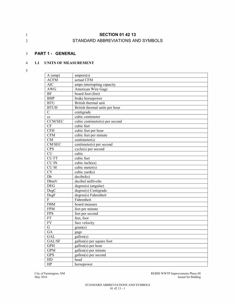
City of Farmington, NM REBID WWTP Improvements Phase III May 2016 Issued for Bidding
STANDARD ABBREVIATIONS AND SYMBOLS 01 42 13 - 1
SECTION 01 42 13 1
STANDARD ABBREVIATIONS AND SYMBOLS 2
PART 1 - GENERAL 3
1.1 UNITS OF MEASUREMENT 4
5
A (amp) ampere(s)
ACFM actual CFM
AIC amps interrupting capacity
AWG American Wire Gage
BF board foot (feet)
BHP brake horsepower
BTU British thermal unit
BTUH British thermal units per hour
C centigrade
cc cubic centimeter
CCM/SEC cubic centimeter(s) per second
CF cubic feet
CFH cubic feet per hour
CFM cubic feet per minute
CM centimeter(s)
CM/SEC centimeter(s) per second
CPS cycle(s) per second
CU cubic
CU FT cubic feet
CU IN cubic inch(es)
CU M cubic meter(s)
CY cubic yard(s)
Db decibel(s)
DbmV decibel millivolts
DEG degree(s) (angular)
DegC degree(s) Centigrade
DegF degree(s) Fahrenheit
F Fahrenheit
FBM board measure
FPM feet per minute
FPS feet per second
FT feet, foot
FV face velocity
G gram(s)
GA gage
GAL gallon(s)
GAL/SF gallon(s) per square foot
GPH gallon(s) per hour
GPM gallon(s) per minute
GPS gallon(s) per second
HD head
HP horsepower

City of Farmington, NM REBID WWTP Improvements Phase III May 2016 Issued for Bidding
STANDARD ABBREVIATIONS AND SYMBOLS 01 42 13 - 2
HR hour(s)
Hz hertz
IN inch(es)
IN Hg inches, mercury
IN-LB inch-pounds (force)
IN WG inches, water gage
IPS iron pipe size
K kip(s)
K value thermal conductivity (BTU/IN/HR/SF/DegF)
KG kilogram(s)
KHz kilohertz
Kpa kilopascal(s)
KSM kilogram(s) per square meter
KV kilovolt(s)
KVA kilovolt ampere(s)
KVAR kilovars
KW kilowatt(s)
KWH kilowatthours
L liter(s)
LB pound(s)
LBF-IN pound (force) inch
LF linear foot, linear feet
LIN linear, lineal
LM linear meter(s)
L/M liter(s)/meter
M meter
mA milliamps
MBTU thousand BTU
MBH thousand BTU/HR
MCFH thousand cubic feet per hour
MCM thousand circular mils
MFBM thousand feet board measure
MHz megahertz
mHz millihertz
MI mile(s)
MIN. min. minute(s), minimum
ml milliliter
MM, mm millimeter(s)
MO month(s)
MPH miles per hour
MVA megavoltamperes
OZ ounce(s)
QT quart
RH relative humidity
R value thermal resistance ((SF x DegF x HR)/BTU)
RMS root mean square
RPM revolutions per minute
S second
SCFM standard CFM
SF square foot, square feet
SM square meter(s)
SQ CM square centimeter(s)

City of Farmington, NM REBID WWTP Improvements Phase III May 2016 Issued for Bidding
STANDARD ABBREVIATIONS AND SYMBOLS 01 42 13 - 3
SQ IN square inch(es)
SQUARE square (roofing) = 100 SF of surface
SSU saybolt seconds universal
SYM symmetrical
U value thermal conductance (1 divided by total R value) (BTU/SF/DegF/HR)
uV microvolts
V volt(s)
Vac volt(s), AC
Vdc volt(s), DC
W watt(s)
YD yard(s)
YR year(s)
1.2 TERMINOLOGY 1
A astragal
@ at
AB anchor bolt
A/C air-condition, air-conditioner
AC air compressor, alternating current
ACLD air-cooled
ACOUS acoustical
ACSR aluminum conduit or steel reinforced
AD area drain, automatic damper
ADH adhesive
ADJ adjust, adjustable
ADMIN administration
A/E Architect/Engineer
AFF above finished floor
AFG above finished grade
AGGR aggregate
AHU air handling unit
AL aluminum
ALT alternate
AM amplitude modulation, ammeter
AMB ambient
AMP amplifier
ANOD anodized
ANN annunciator
ANT antenna
AP access panel
APC acoustical plaster ceiling
APPAR apparatus
APPX appendix
APX approximate
ART article
ASPH asphalt
ASST assistant
ASSY assembly
ATC acoustical tile ceiling
ATS automatic transfer switch
AUTO automatic
AUX auxiliary
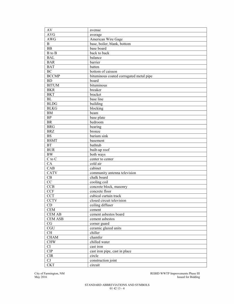
City of Farmington, NM REBID WWTP Improvements Phase III May 2016 Issued for Bidding
STANDARD ABBREVIATIONS AND SYMBOLS 01 42 13 - 4
AV avenue
AVG average
AWG American Wire Gage
B base, boiler, blank, bottom
BB base board
B to B back to back
BAL balance
BAR barrier
BAT batten
BC bottom of caisson
BCCMP bituminous coated corrugated metal pipe
BD board
BITUM bituminous
BKR breaker
BKT bracket
BL base line
BLDG building
BLKG blocking
BM beam
BP base plate
BR bedroom
BRG bearing
BRZ bronze
BS barium sink
BSMT basement
BT bathtub
BUR built-up roof
BW both ways
C to C center to center
CA cold air
CAB cabinet
CATV community antenna television
CB chalk board
CC cooling coil
CCB concrete block, masonry
CCF concrete floor
CCT cubical curtain track
CCTV closed circuit television
CD ceiling diffuser
CEM cement
CEM AB cement asbestos board
CEM ASB cement asbestos
CG corner guard
CGU ceramic glazed units
CH chiller
CHAM chamfer
CHW chilled water
CI cast iron
CIP cast iron pipe, cast in place
CIR circle
CJ construction joint
CKT circuit

City of Farmington, NM REBID WWTP Improvements Phase III May 2016 Issued for Bidding
STANDARD ABBREVIATIONS AND SYMBOLS 01 42 13 - 5
CL center line, clearance
CLG ceiling
CLJ control joint
CLKG calking
CLO closet
CM Construction Manager
CMP corrugated metal pipe
CMPR compressor
CMT ceramic mosaic tile
CND, C conduit
CO cleanout
COL column
COM common
COMP composite
COMPR compressible
CONC concrete
COND condition
CONN connection
CONST construction
CONT continuous
CONTR contractor
CU, COP copper
ORR corridor
CPT carpet
CR control room
CRIT critical
CRT cathode ray tube
CSMT casement
CSS clinical service sink
CT ceramic tile, cooling tower
CTB ceramic mosaic tile base
CTD coated
CTR center
CUH cabinet unit heater
CULV culvert
CURT curtain
CW cold water
d delta
DA deformed anchor
DBL double
DBT dry bulb temperature
DEM demolition, demolish
DEPT department
DET detail
DF drinking fountain
DIA, D diameter
DIAG diagonal
DIM dimension
DISP dispenser
DIST distribution
DL dead load
DN down

City of Farmington, NM REBID WWTP Improvements Phase III May 2016 Issued for Bidding
STANDARD ABBREVIATIONS AND SYMBOLS 01 42 13 - 6
DP dampproofing, double pole, data processing
DR drain, doctor’s register
DT dew point temperature
DWG drawing
DWR drawer
FA fire alarm
FCAN full capacity above nominal
FCBN full capacity below nominal
FD floor drain, fire damper
FDN foundation
FDV fire department valve
FE fire extinguisher
FEC fire extinguisher cabinet
FEM female
FF final filter
FH fire hose
FHC fire hose cabinet
FHV fire hose valve
FL floor, flush
FLA full load amps
FLEX flexible
FLG flooring
FLUOR fluorescent
FM frequency modulation radio
FT fin tube
FTG footing
FURN furnish
FUT future
FV field verify
FVC fire valve cabinet
FWC fabric wall covering
FXTR fixture
GA gage
GALV galvanize(d)
G.C. glazed coating
GEN generator
G.F. granular fill
GL glass
GR grade
GRD ground
GSB gypsum sheathing board
GWB gypsum wallboard
GYP gypsum
HB hose bib
HC handicapped
HDWD hardwood
HID high intensity discharge
H.M. hollow metal
HORIZ horizontal
HPS high pressure sodium
HR handrail
HTR heater

City of Farmington, NM REBID WWTP Improvements Phase III May 2016 Issued for Bidding
STANDARD ABBREVIATIONS AND SYMBOLS 01 42 13 - 7
HW hardware, hot water
HX heat exchanger
HZ hertz
IC intercom
ID inside diameter
IH intake head
IMC intermediate metal conduit
INSL insulation
ITB interior top bar
IVT intravenous track
JC Janitor's closet
KO knockout
LD linear diffuser
LE left end
LED light emitting diode
LIN linear, lineal
LL liveload
LR linear return
LRA locked rotor amps
LS life safety/support
LW lightweight
M meter
MACH machine
MAS masonry
MATL material
MATV master antenna television
MAX maximum
MB main breaker
MCB metal corner bead
MCC motor control center
MCP motor circuit protector
MECH mechanical
MED medicine
MERC mercury
MFD manufactured
MFG manufacturing
MFR manufacturer
MGA medical gas alarm
MH manhole, metal hallide
MIN minimum
MISC miscellaneous
MLDG molding
MLO main lugs only
MO masonry opening
MOD modification, modify
MS mop sink
MTD mounted
MTG mounting
MTL material
MULL mullion
MVA mega-voltamperes
MWP metal wall panel
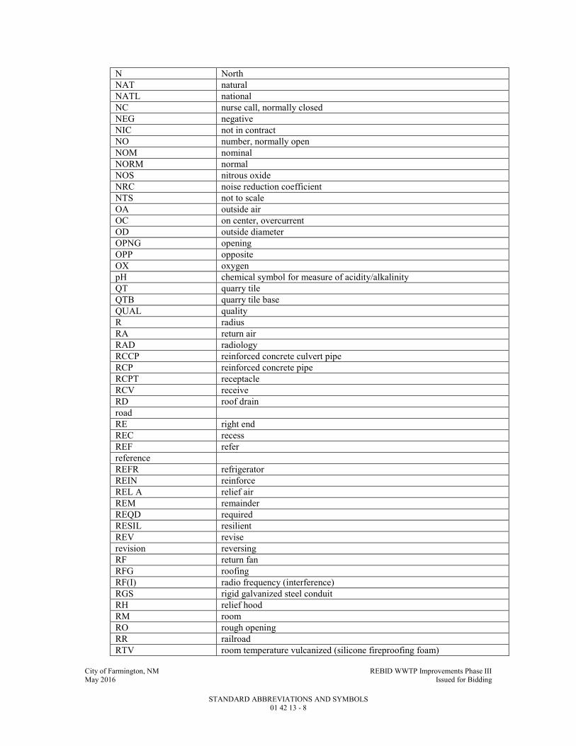
City of Farmington, NM REBID WWTP Improvements Phase III May 2016 Issued for Bidding
STANDARD ABBREVIATIONS AND SYMBOLS 01 42 13 - 8
N North
NAT natural
NATL national
NC nurse call, normally closed
NEG negative
NIC not in contract
NO number, normally open
NOM nominal
NORM normal
NOS nitrous oxide
NRC noise reduction coefficient
NTS not to scale
OA outside air
OC on center, overcurrent
OD outside diameter
OPNG opening
OPP opposite
OX oxygen
pH chemical symbol for measure of acidity/alkalinity
QT quarry tile
QTB quarry tile base
QUAL quality
R radius
RA return air
RAD radiology
RCCP reinforced concrete culvert pipe
RCP reinforced concrete pipe
RCPT receptacle
RCV receive
RD roof drain
road
RE right end
REC recess
REF refer
reference
REFR refrigerator
REIN reinforce
REL A relief air
REM remainder
REQD required
RESIL resilient
REV revise
revision reversing
RF return fan
RFG roofing
RF(I) radio frequency (interference)
RGS rigid galvanized steel conduit
RH relief hood
RM room
RO rough opening
RR railroad
RTV room temperature vulcanized (silicone fireproofing foam)
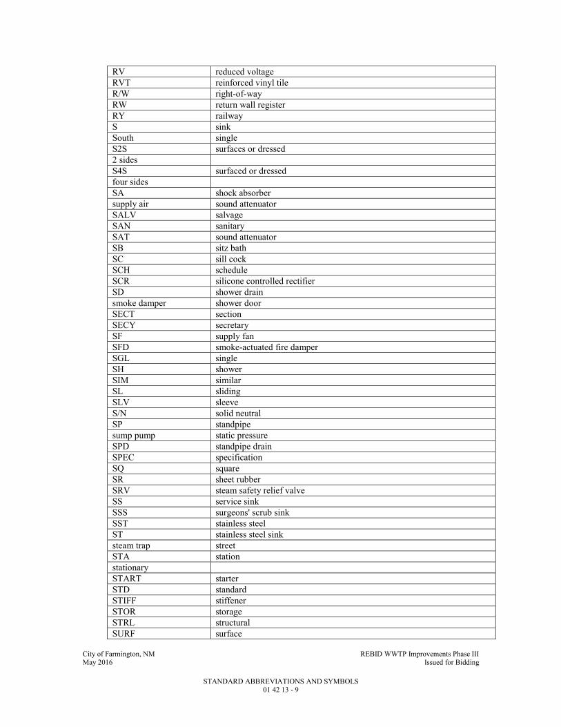
City of Farmington, NM REBID WWTP Improvements Phase III May 2016 Issued for Bidding
STANDARD ABBREVIATIONS AND SYMBOLS 01 42 13 - 9
RV reduced voltage
RVT reinforced vinyl tile
R/W right-of-way
RW return wall register
RY railway
S sink
South single
S2S surfaces or dressed
2 sides
S4S surfaced or dressed
four sides
SA shock absorber
supply air sound attenuator
SALV salvage
SAN sanitary
SAT sound attenuator
SB sitz bath
SC sill cock
SCH schedule
SCR silicone controlled rectifier
SD shower drain
smoke damper shower door
SECT section
SECY secretary
SF supply fan
SFD smoke-actuated fire damper
SGL single
SH shower
SIM similar
SL sliding
SLV sleeve
S/N solid neutral
SP standpipe
sump pump static pressure
SPD standpipe drain
SPEC specification
SQ square
SR sheet rubber
SRV steam safety relief valve
SS service sink
SSS surgeons' scrub sink
SST stainless steel
ST stainless steel sink
steam trap street
STA station
stationary
START starter
STD standard
STIFF stiffener
STOR storage
STRL structural
SURF surface

City of Farmington, NM REBID WWTP Improvements Phase III May 2016 Issued for Bidding
STANDARD ABBREVIATIONS AND SYMBOLS 01 42 13 - 10
SUSP suspend(ed)
SV sheet vinyl
SV(N.S.) sheet vinyl (nonslip)
SW supply wall diffuser
switch
SWBD switchboard
SYM symbol
symmetrical
SYS system
T toilet
throw top
T & G tongue and groove
TA tempered air
TB tackboard
TC top of curb
TEL telephone
TEMP temperature
temporary
TER terrazzo
TERM terminal
THRU through
TOC top of caisson
TOF top of footing
TOW top of wall
TP toilet partition
TRT treat
treatment treated
TS top of steel
TV television
TX transformer
TYP typical
UC undercut
UH unit heater
UHF ultra high frequency
UNEX unexcavated
UNFIN unfinished
UR urinal
US utility sink
UTIL utility
VAC vacuum
VAV variable air volume
VB vapor barrier
VCP vitrified clay pipe
VCPX vitrified clay pipe
extra strength
VD volume damper
VEH vehicle
VERT vertical
VEST vestibule
VF ventilation fan drop
VHF very high frequency
VM voltmeter

City of Farmington, NM REBID WWTP Improvements Phase III May 2016 Issued for Bidding
STANDARD ABBREVIATIONS AND SYMBOLS 01 42 13 - 11
VOL volume
VP vacuum pump
VS venturi station
VT vinyl tile
VTR vent thru roof
VWC vinyl wall covering
W West
wide flange wall mounted
W/ with
WA Wainscot
WBT wet bulb temperature
WC water closet
WD wood
WDW window
WF wide flange
WH water heater
WI wrought iron
WL wind load
WLD welded
WM wattmeter
W/O without
WP waterproof(ing)
weatherproof (electrical) working point
WS waterstop
WT weight
WWC wood wall covering
WWR welded wire reinforcement
XFMR transformer
XP explosion proof
YD yard
YR year
Y W wye
XLP cross linked polyethylene
ZA zone annunciator
1S single speed
2S two speed
1W one winding
2W two winding
1
1.3 ORGANIZATIONS AND STANDARDS 2
ANSI American National Standards Institute 3
ASHRAE American Society of Heating, Refrigeration and Air Conditioning Engineers, Inc. 4
ASME American Society of Mechanical Engineers 5
ASTM ASTM International 6
CS Commercial Standard (U.S.Department of Comm.) 7
FM FM Global 8
FS Federal Specification 9
IEEE Institute of Electrical and Electronic Engineers 10
IES Illuminating Engineering Society 11
IPCEA Insulated Power Cable Engineers Association 12
NBS National Bureau of Standards 13

City of Farmington, NM REBID WWTP Improvements Phase III May 2016 Issued for Bidding
STANDARD ABBREVIATIONS AND SYMBOLS 01 42 13 - 12
NEC National Electrical Code 1
NECA National Electrical Contractors Association 2
NECS National Electrical Code Standards 3
NEMA National Electrical Manufacturers Association 4
NFPA National Fire Protection Association 5
SMACNA Sheet Metal and Air Conditioning National Contractors Association, Inc. 6
UL Underwriters Laboratories, Inc. 7
END OF SECTION 8

City of Farmington, NM REBID WWTP Improvements Phase III May 2016 Issued for Bidding
MAJOR EQUIPMENT SUPPLIERS 01 61 05 - 1
SECTION 01 61 05 1
MAJOR EQUIPMENT SUPPLIERS 2
PART 1 - GENERAL 3
1.1 SUMMARY 4
A. Section Includes: 5
1. A listing of the equipment for the Project, which is considered to be major equipment. 6
2. A listing of the approved suppliers of said major equipment. 7
3. Certain instructions concerning the bidding of major equipment. 8
B. Related Specification Sections include but are not necessarily limited to: 9
1. Division 00 - Bidding Requirements, Contract Forms, and Conditions of the Contract. 10
2. Division 01 - General Requirements. 11
1.2 DEFINITIONS 12
A. Manufacturers or suppliers, as used in the context of "approved manufacturers or suppliers of 13
major equipment," shall mean the manufacturers or suppliers listed in the ACCEPTABLE 14
MANUFACTURERS OF MAJOR EQUIPMENT Article of this Specification Section. 15
1.3 INSTRUCTIONS FOR BIDDING MAJOR EQUIPMENT 16
A. Furnish, for base bid, equipment by any of the suppliers listed in the ACCEPTABLE 17
MANUFACTURERS OF MAJOR EQUIPMENT Article of this Specification Section, or as 18
added to the ACCEPTABLE MANUFACTURERS OF MAJOR EQUIPMENT Article of this 19
Specification Section by addendum. 20
B. Name only one (1) of said suppliers in the schedule of major equipment suppliers found in the 21
Proposal. 22
C. Proposal shall be considered irregular and subject to rejection if the Bidder: 23
1. Fails to list an approved supplier for each item. 24
2. Lists more than one approved supplier for each item. 25
D. If the Bidder fails to list an approved supplier, the Owner has the sole right to select one (1) of 26
the suppliers from the list of manufacturers in the ACCEPTABLE MANUFACTURERS OF 27
MAJOR EQUIPMENT Article of this Specification Section. 28
E. If the Bidder lists more than one (1) approved supplier, the Owner has the sole right to select one 29
(1) of the suppliers so listed. 30
F. Requests for prequalification of equipment to be listed in the ACCEPTABLE 31
MANUFACTURERS OF MAJOR EQUIPMENT Article of this Specification Section must 32
comply specifically with applicable provisions of the Contract Documents. 33
1. Refer to Specification Section 00 21 13. 34
G. The manufacturer shall warranty against any defects in material or workmanship of the complete 35
system for two (2) years for all major equipment listed. Warranty period will commence upon 36
issuance of substantial completion for the project. Manufacturer’s warranty shall be provided in 37
writing to Owner. 38
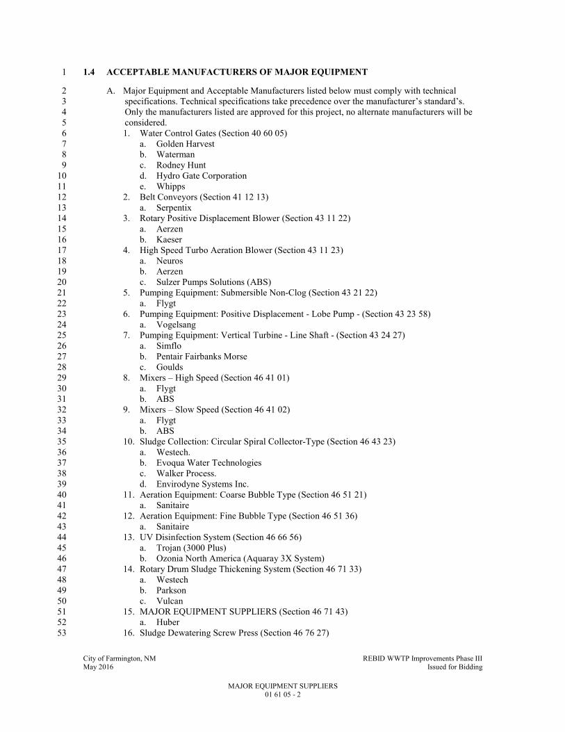
City of Farmington, NM REBID WWTP Improvements Phase III May 2016 Issued for Bidding
MAJOR EQUIPMENT SUPPLIERS 01 61 05 - 2
1.4 ACCEPTABLE MANUFACTURERS OF MAJOR EQUIPMENT 1
A. Major Equipment and Acceptable Manufacturers listed below must comply with technical 2
specifications. Technical specifications take precedence over the manufacturer’s standard’s. 3
Only the manufacturers listed are approved for this project, no alternate manufacturers will be 4
considered. 5
1. Water Control Gates (Section 40 60 05) 6
a. Golden Harvest 7
b. Waterman 8
c. Rodney Hunt 9
d. Hydro Gate Corporation 10
e. Whipps 11
2. Belt Conveyors (Section 41 12 13) 12
a. Serpentix 13
3. Rotary Positive Displacement Blower (Section 43 11 22) 14
a. Aerzen 15
b. Kaeser 16
4. High Speed Turbo Aeration Blower (Section 43 11 23) 17
a. Neuros 18
b. Aerzen 19
c. Sulzer Pumps Solutions (ABS) 20
5. Pumping Equipment: Submersible Non-Clog (Section 43 21 22) 21
a. Flygt 22
6. Pumping Equipment: Positive Displacement - Lobe Pump - (Section 43 23 58) 23
a. Vogelsang 24
7. Pumping Equipment: Vertical Turbine - Line Shaft - (Section 43 24 27) 25
a. Simflo 26
b. Pentair Fairbanks Morse 27
c. Goulds 28
8. Mixers – High Speed (Section 46 41 01) 29
a. Flygt 30
b. ABS 31
9. Mixers – Slow Speed (Section 46 41 02) 32
a. Flygt 33
b. ABS 34
10. Sludge Collection: Circular Spiral Collector-Type (Section 46 43 23) 35
a. Westech. 36
b. Evoqua Water Technologies 37
c. Walker Process. 38
d. Envirodyne Systems Inc. 39
11. Aeration Equipment: Coarse Bubble Type (Section 46 51 21) 40
a. Sanitaire 41
12. Aeration Equipment: Fine Bubble Type (Section 46 51 36) 42
a. Sanitaire 43
13. UV Disinfection System (Section 46 66 56) 44
a. Trojan (3000 Plus) 45
b. Ozonia North America (Aquaray 3X System) 46
14. Rotary Drum Sludge Thickening System (Section 46 71 33) 47
a. Westech 48
b. Parkson 49
c. Vulcan 50
15. MAJOR EQUIPMENT SUPPLIERS (Section 46 71 43) 51
a. Huber 52
16. Sludge Dewatering Screw Press (Section 46 76 27) 53
City of Farmington, NM REBID WWTP Improvements Phase III May 2016 Issued for Bidding
MAJOR EQUIPMENT SUPPLIERS 01 61 05 - 3
a. Huber 1
b. Andritz 2
17. Engine Generator: Natural Gas (Section 26 32 15) 3
a. See Specification Section 26 32 15. 4
END OF SECTION 5
City of Farmington, NM REBID WWTP Improvements Phase III May 2016 Issued for Bidding
PRODUCT DELIVERY, STORAGE, AND HANDLING 01 65 50 - 1
SECTION 01 65 50 1
PRODUCT DELIVERY, STORAGE, AND HANDLING 2
PART 1 - GENERAL 3
1.1 SUMMARY 4
A. Section Includes: 5
1. Scheduling of product delivery. 6
2. Packaging of products for delivery. 7
3. Protection of products against damage from: 8
a. Handling. 9
b. Exposure to elements or harsh environments. 10
B. Related Specification Sections include but are not necessarily limited to: 11
1. Division 00 - Bidding Requirements, Contract Forms, and Conditions of the Contract. 12
2. Division 01 - General Requirements. 13
C. Payment: 14
1. No payment will be made to Contractor for equipment or materials not properly stored and 15
insured or without approved Shop Drawings. 16
a. Previous payments for items will be deducted from subsequent progress estimate(s) if 17
proper storage procedures are not observed. 18
1.2 DELIVERY 19
A. Scheduling: Schedule delivery of products or equipment as required to allow timely installation 20
and to avoid prolonged storage. 21
B. Packaging: Deliver products or equipment in manufacturer's original unbroken cartons or other 22
containers designed and constructed to protect the contents from physical or environmental 23
damage. 24
C. Identification: Clearly and fully mark and identify as to manufacturer, item, and installation 25
location. 26
D. Protection and Handling: Provide manufacturer's instructions for storage and handling. 27
PART 2 - PRODUCTS - (NOT APPLICABLE TO THIS SPECIFICATION SECTION) 28
PART 3 - EXECUTION 29
3.1 PROTECTION, STORAGE AND HANDLING 30
A. Manufacturer's Instruction: 31
1. Protect all products or equipment in accordance with manufacturer's written directions. 32
a. Store products or equipment in location to avoid physical damage to items while in 33
storage. 34
b. Handle products or equipment in accordance with manufacturer's recommendations and 35
instructions. 36
2. Protect equipment from exposure to elements and keep thoroughly dry. 37
3. When space heaters are provided in equipment, connect and operate heaters during storage 38
until equipment is placed in service. 39

City of Farmington, NM REBID WWTP Improvements Phase III May 2016 Issued for Bidding
PRODUCT DELIVERY, STORAGE, AND HANDLING 01 65 50 - 2
3.2 FIELD QUALITY CONTROL 1
A. Inspect Deliveries: 2
1. Inspect all products or equipment delivered to the site prior to unloading. 3
a. Reject all products or equipment that are damaged, used, or in any other way 4
unsatisfactory for use on Project. 5
B. Monitor Storage Area: Monitor storage area to ensure suitable temperature and moisture 6
conditions are maintained as required by manufacturer or as appropriate for particular items. 7
END OF SECTION 8

City of Farmington, NM REBID WWTP Improvements Phase III May 2016 Issued for Bidding
OPENINGS AND PENETRATIONS IN CONSTRUCTION 01 73 20 - 1
SECTION 01 73 20 1
OPENINGS AND PENETRATIONS IN CONSTRUCTION 2
PART 1 - GENERAL 3
1.1 SUMMARY 4
A. Section Includes: 5
1. Methods of installing and sealing openings and penetrations in construction. 6
B. Related Specification Sections include but are not necessarily limited to: 7
1. Division 00 - Bidding Requirements, Contract Forms, and Conditions of the Contract. 8
2. Division 01 - General Requirements. 9
3. Section 05 50 00 - Miscellaneous Metals. 10
4. Section 07 92 00 - Joint Sealants. 11
5. Section 09 91 00 - Painting and Protective Coatings. 12
1.2 QUALITY ASSURANCE 13
A. Referenced Standards: 14
1. American Concrete Institute (ACI): 15
a. 318, Building Code Requirements for Structural Concrete. 16
2. ASTM International (ASTM): 17
a. A36, Standard Specification for Carbon Structural Steel. 18
b. A53, Standard Specification for Pipe, Steel, Black and Hot-Dipped, Zinc-Coated, 19
Welded and Seamless. 20
3. National Fire Protection Association (NFPA): 21
a. 70, National Electrical Code (NEC): 22
1) Article 501, Class 1 Locations. 23
b. 90A, Standard for Installation of Air Conditioning and Ventilating Systems. 24
4. Sheet Metal and Air Conditioning Contractors' National Association (SMACNA). 25
B. Assure all firestopping materials are in full compliance with Specification Section 07 84 00. 26
C. Obtain prior approval from Engineer when any opening larger than 100 SQ IN must be made in 27
existing or newly completed construction. 28
1.3 DEFINITIONS 29
A. Hazardous Areas: Areas shown in the Contract Documents as having Class I or Class II area 30
classifications. 31
B. Washdown Areas: Areas having floor drains or hose bibs. 32
1.4 SUBMITTALS 33
A. Shop Drawings: 34
1. See Specification Section 01 33 00 for requirements for the mechanics and administration of 35
the submittal process. 36
2. For each structure provide dimensioned or scaled (minimum 1/8 IN = 1 FT) plan view 37
drawings containing the following information: 38
a. Vertical and horizontal location of all required openings and penetrations. 39
b. Size of all openings and penetrations. 40
c. Opening type. 41
d. Seal type. 42
3. Manufacturer's installation instructions for standard manufactured products. 43

City of Farmington, NM REBID WWTP Improvements Phase III May 2016 Issued for Bidding
OPENINGS AND PENETRATIONS IN CONSTRUCTION 01 73 20 - 2
1.5 PROJECT CONDITIONS 1
A. For purposes of this Project, water table level is elevation unknown. 2
PART 2 - PRODUCTS 3
2.1 MATERIALS 4
A. Pipe Sleeves: Steel, ASTM A53, Schedule 40, black. 5
B. Pipe Sleeves Penetrating into Corrosive Areas: Stainless steel, 1/4 IN minimum thickness. 6
C. Backing Rod and Sealant: See Specification Section 07 92 00. 7
D. Modular Mechanical Seals: 8
1. Acceptable manufacturers: 9
a. Link-Seal. 10
2. 316 stainless steel bolts, nuts and washers. 11
E. Sheet Metal Sleeves: Steel, ASTM A36, 12 GA. 12
F. Commercial Wall Castings: 13
1. For unclassified areas both sides of penetration: 14
a. Ductile iron, class equal to connecting piping system. 15
2. For wet/corrosive areas either side of penetration: 16
a. Stainless steel, 304L. 17
PART 3 - EXECUTION 18
3.1 INSTALLATION AND APPLICATION 19
A. Perform HVAC penetrations in accordance with NFPA 90A. 20
B. Perform electrical penetrations in accordance with NFPA 70, Article 501. 21
C. Install sleeves and castings in accordance with ACI 318, Chapter #6. 22
D. Hot-dip galvanize in accordance with Specification Section 05 50 00 (or paint in accordance 23
with Specification Section 09 91 00) all steel sleeves installed. 24
E. When mechanical or electrical work cannot be installed as structure is being erected, provide and 25
arrange for building-in of boxes, sleeves, insets, fixtures or devices necessary to permit 26
installation later. 27
1. Lay out chases, holes or other openings which must be provided in masonry, concrete or 28
other work. 29
F. Where pipes, conduits or ducts pass through floors in washdown areas, install sleeves with top 30
3 IN above finish floors. 31
1. In non-washdown areas, install sleeves with ends flush with finished surfaces. 32
G. Size sleeves, blockouts and cutouts which will receive sealant seal such that free area to receive 33
sealant is minimized and seal integrity may be obtained. 34
H. For insulated piping and ducts, size sleeves, blockouts and cutouts large enough to accommodate 35
full thickness of insulation. 36
I. Do not cut into or core drill any beams, joists, or columns. 37
J. Do not install sleeves in beams, joists, or columns. 38

City of Farmington, NM REBID WWTP Improvements Phase III May 2016 Issued for Bidding
OPENINGS AND PENETRATIONS IN CONSTRUCTION 01 73 20 - 3
K. Do not install recesses in beams, joists, columns, or slabs. 1
L. Field Cutting and Coring: 2
1. Saw or core drill with non-impact type equipment. 3
2. Mark opening and drill small 3/4 IN or less holes through structure following opening 4
outline. 5
3. Sawcut opening outline on both surfaces. 6
a. Knock out within sawcuts using impact type equipment. 7
b. Do not chip or spall face of surface to remain intact. 8
c. Do not allow any overcut with saw kerf. 9
M. Precast-Prestressed Concrete Construction: 10
1. Do not cut openings nor core drill vertically or horizontally through stems of members. 11
2. Do not locate or install sleeves or recess sleeves vertically or horizontally through or in 12
stems of members. 13
3. Cast openings and sleeves into flanges of units. 14
4. Cast openings larger than 6 IN in diameter or 6 IN maximum dimension in units at time of 15
manufacture. 16
5. Cast openings smaller than 6 IN in diameter or 6 IN maximum dimensions in flanges of 17
units at time of manufacture or field cut. 18
N. Where alterations are necessary or where new and old work join, restore adjacent surfaces to 19
their condition existing prior to start of work. 20
O. Provide waterstop plate/anchor flange for piping, ducts, castings and sleeves cast-in-place in 21
concrete. 22
1. For fabricated units, weld plate to sleeve, pipe, or ductwork. 23
2. For commercial castings, cast water stop/anchor with wall pipe. 24
3. Plate is to be same thickness as sleeve, pipe, casting or ductwork. 25
4. For fabricated units, diameter of plate or flange to be 4 IN larger than outside diameter of 26
sleeve, pipe or ductwork. 27
5. For commercial castings, waterstop/anchor size to be manufacturer standard. 28
6. Provide continuous around entire circumference of sleeve, pipe, or ductwork. 29
P. Where area is blocked out to receive sheet metal sleeve at later date: 30
1. If blockout size is sufficient to allow placement, utilize dowels for interface of initially 31
placed concrete and sleeve encasement concrete which is placed later. 32
a. Size blockout based on sleeve size required plus 4 to 6 IN each side of sleeve for 33
concrete encasement. 34
b. Provide #4 dowels at 12 IN spacing along each side of blockout with minimum of 35
two (2) dowels required per side. 36
2. If blockout size is not sufficient to allow placement of dowels, provide keyway along all 37
sides of blockout. 38
a. Size blockout based on sleeve size required plus 2 to 4 IN each side of sleeve for 39
concrete encasement. 40
Q. For interior wall applications where backer rod and sealant are specified, provide backer rod and 41
sealant at each side of wall. 42
R. Refer to Drawings for location of fire-rated walls, floors, and ceilings. 43
1. Utilize firestopping materials and procedures in conjunction with scheduled opening type to 44
produce the required fire rating. 45
S. Use full depth expanding foam sealant for seal applications where single or multiple pipes, 46
conduits, etc., pass through a single sleeve. 47
T. Do not make duct or conduit penetrations below high water levels when entering or leaving 48
tankage, wet wells, or other water holding structures. 49
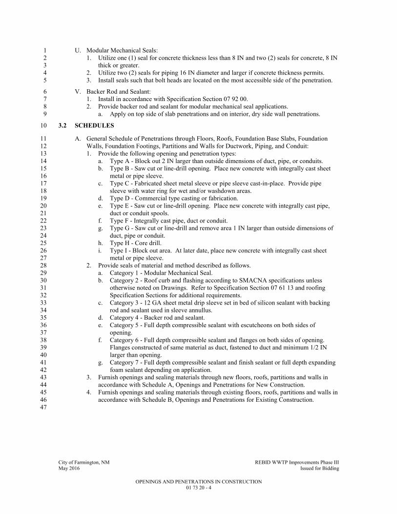
City of Farmington, NM REBID WWTP Improvements Phase III May 2016 Issued for Bidding
OPENINGS AND PENETRATIONS IN CONSTRUCTION 01 73 20 - 4
U. Modular Mechanical Seals: 1
1. Utilize one (1) seal for concrete thickness less than 8 IN and two (2) seals for concrete, 8 IN 2
thick or greater. 3
2. Utilize two (2) seals for piping 16 IN diameter and larger if concrete thickness permits. 4
3. Install seals such that bolt heads are located on the most accessible side of the penetration. 5
V. Backer Rod and Sealant: 6
1. Install in accordance with Specification Section 07 92 00. 7
2. Provide backer rod and sealant for modular mechanical seal applications. 8
a. Apply on top side of slab penetrations and on interior, dry side wall penetrations. 9
3.2 SCHEDULES 10
A. General Schedule of Penetrations through Floors, Roofs, Foundation Base Slabs, Foundation 11
Walls, Foundation Footings, Partitions and Walls for Ductwork, Piping, and Conduit: 12
1. Provide the following opening and penetration types: 13
a. Type A - Block out 2 IN larger than outside dimensions of duct, pipe, or conduits. 14
b. Type B - Saw cut or line-drill opening. Place new concrete with integrally cast sheet 15
metal or pipe sleeve. 16
c. Type C - Fabricated sheet metal sleeve or pipe sleeve cast-in-place. Provide pipe 17
sleeve with water ring for wet and/or washdown areas. 18
d. Type D - Commercial type casting or fabrication. 19
e. Type E - Saw cut or line-drill opening. Place new concrete with integrally cast pipe, 20
duct or conduit spools. 21
f. Type F - Integrally cast pipe, duct or conduit. 22
g. Type G - Saw cut or line-drill and remove area 1 IN larger than outside dimensions of 23
duct, pipe or conduit. 24
h. Type H - Core drill. 25
i. Type I - Block out area. At later date, place new concrete with integrally cast sheet 26
metal or pipe sleeve. 27
2. Provide seals of material and method described as follows. 28
a. Category 1 - Modular Mechanical Seal. 29
b. Category 2 - Roof curb and flashing according to SMACNA specifications unless 30
otherwise noted on Drawings. Refer to Specification Section 07 61 13 and roofing 31
Specification Sections for additional requirements. 32
c. Category 3 - 12 GA sheet metal drip sleeve set in bed of silicon sealant with backing 33
rod and sealant used in sleeve annullus. 34
d. Category 4 - Backer rod and sealant. 35
e. Category 5 - Full depth compressible sealant with escutcheons on both sides of 36
opening. 37
f. Category 6 - Full depth compressible sealant and flanges on both sides of opening. 38
Flanges constructed of same material as duct, fastened to duct and minimum 1/2 IN 39
larger than opening. 40
g. Category 7 - Full depth compressible sealant and finish sealant or full depth expanding 41
foam sealant depending on application. 42
3. Furnish openings and sealing materials through new floors, roofs, partitions and walls in 43
accordance with Schedule A, Openings and Penetrations for New Construction. 44
4. Furnish openings and sealing materials through existing floors, roofs, partitions and walls in 45
accordance with Schedule B, Openings and Penetrations for Existing Construction. 46
47
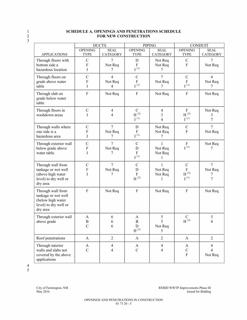
City of Farmington, NM REBID WWTP Improvements Phase III May 2016 Issued for Bidding
OPENINGS AND PENETRATIONS IN CONSTRUCTION 01 73 20 - 5
SCHEDULE A. OPENINGS AND PENETRATIONS SCHEDULE 1
FOR NEW CONSTRUCTION 2 3
DUCTS PIPING CONDUIT
APPLICATIONS
OPENING
TYPE
SEAL
CATEGORY
OPENING
TYPE
SEAL
CATEGORY
OPENING
TYPE
SEAL
CATEGORY
Through floors with
bottom side a
hazardous location
C
F
I
7
Not Req
7
D
F
I (1)
Not Req
Not Req
7
C
F
7
Not Req
Through floors on
grade above water
table
C
F
I
4
Not Req
4
C
F
I (1)
7
Not Req
7
C
F
I (1)
4
Not Req
7
Through slab on
grade below water
table
F Not Req F Not Req F Not Req
Through floors in
washdown areas
C
I
4
4
C
H (2)
I (1)
4
3
4
F
H (2)
I (1)
Not Req
3
7
Through walls where
one side is a
hazardous area
C
F
I
7
Not Req
7
D
F
I (1)
Not Req
Not Req
7
C
F
7
Not Req
Through exterior wall
below grade above
water table
C
F
I
7
Not Req
7
C
D
F
I (1)
1
Not Req
Not Req
1
F
I (1)
Not Req
7
Through wall from
tankage or wet well
(above high water
level) to dry well or
dry area
C
F
I
7
Not Req
7
C
D
F
H (2)
1
Not Req
Not Req
1
C
F
H (2)
I (1)
7
Not Req
7
7
Through wall from
tankage or wet well
(below high water
level) to dry well or
dry area
F Not Req F Not Req F Not Req
Through exterior wall
above grade
A
B
C
6
6
6
A
B
D
H (2)
5
5
Not Req
5
C
H (2)
5
4
Roof penetrations A 2 A 2 A 2
Through interior
walls and slabs not
covered by the above
applications
A
C
4
4
A
C
4
4
A
C
F
4
4
Not Req
4
5

City of Farmington, NM REBID WWTP Improvements Phase III May 2016 Issued for Bidding
OPENINGS AND PENETRATIONS IN CONSTRUCTION 01 73 20 - 6
SCHEDULE B. OPENINGS AND PENETRATIONS SCHEDULE 1
FOR EXISTING CONSTRUCTION 2 3
DUCTS PIPING CONDUIT
APPLICATIONS
OPENING
TYPE
SEAL
CATEGORY
OPENING
TYPE
SEAL
CATEGORY
OPENING
TYPE
SEAL
CATEGORY
Through floors with
bottom side a
hazardous location
B
E
7
Not Req
B (1)
E (3)
H (2)
7
Not Req
7
B (1)
E (3)
H (2)
7
Not Req
7
Through floors on
grade above water
table
B 7 B 7 B 7
Through slab on
grade below water
table
E Not Req E Not Req E Not Req
Through floors in
washdown areas
G 3 G
H (2)
3
3
G
H (2)
3
3
Through walls where
one side is a
hazardous area
B
E
7
Not Req
B (1)
B (3)_
E
H (2)
7
1
Not Req
7
B (1) (3)
E
H (2)
7
Not Req
7
Through exterior wall
below grade above
water table
B 7 B (1)
B (3)
H (2)
7
1
7
B (1) (3)
H (2)
7
7
Through wall from
tankage or wet well
(above high water
level) to dry well or
dry area
B
E
7
Not Req
B
E
H (2)
1
Not Req
1
B (1) (3)
E
H (2)
7
Not Req
7
Through wall from
tankage or wet well
(below high water
level) to dry well or
dry area
E Not Req E Not Req E Not Req
Through exterior wall
above grade
G 6 G (1) (3)
H (2)
5
5
G (1) (3)
H (2)
5
7
Roof penetrations G 2 G (1) (3)
H (2)
2 G 2
Through interior
walls and slabs not
covered by the above
applications
G 4 G (1) (3)
H (2)
4
4
G (1) (3)
H (2)
4
4
4 (1)
Multiple piping 3 IN and smaller or multiple conduits. 5 (2)
Single pipe 3 IN and smaller or single conduit. 6 (3)
Single pipe or conduit larger than 3 IN. 7

City of Farmington, NM REBID WWTP Improvements Phase III May 2016 Issued for Bidding
OPENINGS AND PENETRATIONS IN CONSTRUCTION 01 73 20 - 7
END OF SECTION 1

City of Farmington, NM REBID WWTP Improvements Phase III May 2016 Issued for Bidding
DEMOLITION, CUTTING AND PATCHING 01 73 29 - 1
SECTION 01 73 29 1
DEMOLITION, CUTTING AND PATCHING 2
PART 1 - GENERAL 3
1.1 SUMMARY 4
A. Section Includes: 5
1. Demolition, cutting and patching of existing construction where shown on Drawings, or as 6
required to accommodate new work shown or specified. 7
B. Related Specification Sections include but are not necessarily limited to: 8
1. Division 00 - Bidding Requirements, Contract Forms, and Conditions of the Contract. 9
2. Division 01 - General Requirements. 10
3. Section 03 31 32 - Concrete Finishing and Repair of Surface Defects. 11
4. Section 09 91 00 - Painting and Protective Coatings. 12
1.2 SUBMITTALS 13
A. Shop Drawings: 14
1. See Specification Section 01 33 00 for requirements for the mechanics and administration of 15
the submittal process. 16
2. Indicating manufacturer and type of: 17
a. Proposed nonshrink grout. 18
b. Epoxy bonding adhesive. 19
c. Proposed materials and methods to be used for matching and repairing existing 20
construction. 21
1.3 DELIVERY, STORAGE, AND HANDLING 22
A. General: 23
1. Salvage items, designated for Owner's salvage, as a functional unit. 24
2. Clean, list and tag for storage. 25
3. Protect from damage and deliver to location designated. 26
4. Salvage each item with auxiliary or associated equipment required for operation. 27
1.4 PROJECT CONDITIONS 28
A. Perform preliminary investigations as required to ascertain extent of work. 29
1.5 SEQUENCING AND SCHEDULING 30
A. Coordinate and reschedule work as required to preclude interference with other operations. 31
PART 2 - PRODUCTS 32
2.1 ACCEPTABLE MANUFACTURERS 33
A. Subject to compliance with the Contract Documents, the following products and manufacturers 34
are acceptable: 35
1. Nonshrink grout: 36
a. Supreme Grout by Gifford Hill. 37
b. Masterflow 713 Plus by BASF Building Systems. 38
c. Sika Grout 212 by Sika. 39
d. Five Star Grout by Five Star Products, Inc. 40

City of Farmington, NM REBID WWTP Improvements Phase III May 2016 Issued for Bidding
DEMOLITION, CUTTING AND PATCHING 01 73 29 - 2
2. Epoxy bonding adhesive: 1
a. Euco No.452 MV by Euclid Chemical Co. 2
b. Sikadur 32, Hi-Mod by Sika Corporation. 3
3. Epoxy patch: 4
a. Depth of patch: 5
1) Greater than 3/4 IN: Five Star MP Epoxy Patch. 6
2) Between 1/8 IN and 3/4 IN: Five Star Fluid Epoxy. 7
B. Submit request for substitution in accordance with Specification Section 01 25 13. 8
2.2 MATERIALS 9
A. Temporary Partitions: 10
1. Plywood: 1/2 IN minimum for interior or exterior use. 11
2. Paneling: 1/4 IN minimum for interior use. 12
B. Nonshrink Grout: 13
1. Nonmetallic, noncorrosive and nonstaining. 14
2. Premixed with only water to be added in accordance with manufacturer's instructions at 15
jobsite. 16
3. Grout to produce a positive but controlled expansion. 17
a. Mass expansion not to be created by gas liberation or by other means. 18
4. Minimum compressive strength at 28 days to be 6500 psi. 19
5. Coat exposed edges of grout with a cure/seal compound recommended by grout 20
manufacturer. 21
C. Epoxy Bonding Adhesive: 22
1. Two component, moisture insensitive adhesive manufactured for the purpose of bonding 23
fresh concrete to hardened concrete. 24
PART 3 - EXECUTION 25
3.1 PREPARATION 26
A. Provide temporary partitions as required in public areas. 27
1. Construct partitions of braced plywood in exterior areas. 28
2. Adequately braced paneling may be used in interior areas. 29
B. Provide covered passageways where necessary to ensure safe passage of persons in or near areas 30
of work. 31
C. Provide substantial barricades and safety lights as required. 32
D. Provide temporary dustproof partitions where indicated or necessary. 33
1. Prevent infiltration of dust into occupied areas. 34
E. Provide temporary weather protection as necessary. 35
3.2 INSTALLATION 36
A. Cutting and Removal: 37
1. Remove existing work indicated to be removed, or as necessary for installation of new 38
work. 39
2. Neatly cut and remove materials, and prepare all openings to receive new work. 40
3. Remove masonry or concrete in small sections. 41
B. Modification of Existing Concrete: 42
1. Where indicated, remove existing concrete and finish remaining surfaces as specified in 43
Specification Section 03 31 32. 44

City of Farmington, NM REBID WWTP Improvements Phase III May 2016 Issued for Bidding
DEMOLITION, CUTTING AND PATCHING 01 73 29 - 3
a. Protect remaining concrete from damage. 1
b. Make openings by sawing through the existing concrete. 2
c. Break out concrete after initial saw cuts in the event concrete thickness prevents cutting 3
through. 4
d. Make openings by drilling holes around perimeter of opening and then chipping out the 5
concrete where sawing is not possible. 6
1) Holes shall be sufficient in number to prevent damage to remaining concrete. 7
2. Oversize required openings in existing concrete 1 IN on all sides and build back to required 8
opening size by means of nonshrink grout epoxy bonded to the existing concrete. 9
3. Where oversized openings cannot be made, remove the concrete to the required opening 10
size and cut back exposed reinforcing 1 IN from face of concrete and fill resulting holes 11
with nonshrink grout. 12
C. Removal of Existing Anchor Bolts or Other Protruding Elements: 13
1. Remove all protruding elements. 14
2. Remove to a depth of 1/4 IN from finished surface. 15
3. Fill void with epoxy patch. 16
D. Matching and Patching: 17
1. Walls, ceilings, floors or partitions: 18
a. Repair abutting walls, ceilings, floors or partitions disturbed by removal. 19
b. Match and patch existing construction disturbed during installation of new work. 20
2. Methods and materials: 21
a. Similar in appearance, and equal in quality to adjacent areas for areas or surfaces being 22
repaired. 23
b. Subject to review of Owner. 24
3. Reinforcing steel that is cut and exposed: 25
a. Remove to a depth of 1/4 IN. 26
b. Fill void with epoxy patch. 27
E. Salvaged Items: 28
1. Thoroughly dry and clean all metal surfaces. 29
2. Prime all bare metal in accordance with Specification Section 09 91 00. 30
3. Clean and lubricate motors and other moving parts. 31
4. Brace motors attached to flexible mountings until reinstallation. 32
5. Dispose of items or materials not designated for Owner's salvage or reuse. 33
a. Promptly remove from site. 34
6. Do not store or sell Contractor salvaged items or materials on-site. 35
7. Carefully remove items to be salvaged and reused or to be delivered to Owner's storage. 36
a. Store and protect items indicated on Drawings or those which have been marked by 37
Owner to be salvaged or to be reused in Work. 38
b. Replace any item damaged through carelessness in removal, storage, or handling with 39
new items of same type. 40
c. Do not reuse materials or equipment not specifically indicated or specified to be reused. 41
8. Preparation of equipment for storage: 42
a. Identify each component with markings or tags to show its position in the assembly and 43
the assembly of which it belongs. 44
b. Place small parts of wooden boxes and clearly mark contents on the outside. 45
c. Remove oil from oil-lubricated bearings and gear boxes and replace with storage oil. 46
d. Grease grease-lubricated bearings. 47
e. Replace any breather plug with solid plug. 48
f. Megger test motor windings: Attach report of the test results to the unit and furnish one 49
(1) copy to the Engineer. 50
g. Attach unit to suitable crate bottom. 51
City of Farmington, NM REBID WWTP Improvements Phase III May 2016 Issued for Bidding
DEMOLITION, CUTTING AND PATCHING 01 73 29 - 4
h. Enclose unit in polyethylene film and seal all seams and the film to the base of the unit 1
with tape. 2
i. Construct crate of wooden slats around top and sides of unit. 3
j. Attach permanent instruction tag to outside of crate stating "This unit has been prepared 4
for storage--replace oil, vent plugs, and lubricant in accordance with manufacturer's 5
instructions before start-up." 6
F. Clean Up: Transport debris and legally dispose of off-site. 7
3.3 SALVAGED ITEMS 8
A. Items to be Salvaged to Owner: 9
1. The Owner has first rights to salvage any items identified for demolition. Prior to any 10
demolition activities. Coordinate with Owner to identify any items to be salvaged. 11
Contractor shall remove and place salvaged items in Owner’s designated area onsite. 12
B. Trickling Filter Rotary Distributor: 13
1. Disassemble trickling filter Rotary Distributor in accordance with manufacturer’s 14
instructions and salvage to Owner. Contractor shall place equipment per Owner’s direction 15
onsite. Completely dismantle each distributor arm and braces into four sections. Cover all 16
openings in distributor arms and center columns with plywood and place above ground on 17
wood timbers. Clearly label all parts with permanent tags according to manufacturer’s 18
labeling. Contractor shall coordinate with Owner prior to disassembling equipment. 19
END OF SECTION 20

City of Farmington, NM REBID WWTP Improvements Phase III May 2016 Issued for Bidding
CLEANING 01 74 13 - 1
SECTION 01 74 13 1
CLEANING 2
PART 1 - GENERAL 3
1.1 SUMMARY 4
A. Section Includes: 5
1. Intermediate and final cleaning of Work not including special cleaning of closed systems 6
specified elsewhere. 7
B. Related Specification Sections include but are not necessarily limited to: 8
1. Division 00 - Bidding Requirements, Contract Forms, and Conditions of the Contract. 9
2. Division 01 - General Requirements. 10
1.2 STORAGE AND HANDLING 11
A. Store cleaning products and cleaning wastes in containers specifically designed for those 12
materials. 13
1.3 SCHEDULING 14
A. Schedule cleaning operations so that dust and other contaminants disturbed by cleaning process 15
will not fall on newly painted surfaces. 16
PART 2 - PRODUCTS 17
2.1 MATERIALS 18
A. Cleaning Agents: 19
1. Compatible with surface being cleaned. 20
2. New and uncontaminated. 21
3. For Manufactured Surfaces: Material recommended by manufacturer. 22
PART 3 - EXECUTION 23
3.1 CLEANING - GENERAL 24
A. Prevent accumulation of wastes that create hazardous conditions. 25
B. Conduct cleaning and disposal operations to comply with laws and safety orders of governing 26
authorities. 27
C. Do not dispose of volatile wastes such as mineral spirits, oil, or paint thinner in storm or sanitary 28
drains or sewers. 29
D. Dispose of degradable debris at an approved solid waste disposal site. 30
E. Dispose of nondegradable debris at an approved solid waste disposal site or in an alternate 31
manner approved by Engineer and regulatory agencies. 32
F. Handle materials in a controlled manner with as few handlings as possible. 33
G. Do not drop or throw materials from heights greater than 4 FT or less than 4 FT if conditions 34
warrant greater care. 35

City of Farmington, NM REBID WWTP Improvements Phase III May 2016 Issued for Bidding
CLEANING 01 74 13 - 2
H. On completion of work, leave area in a clean, natural looking condition. 1
1. Remove all signs of temporary construction and activities incidental to construction of 2
required permanent Work. 3
I. Do not burn on-site. 4
3.2 INTERIOR CLEANING 5
A. Cleaning During Construction: 6
1. Keep work areas clean so as not to hinder health, safety or convenience of personnel in 7
existing facility operations. 8
2. At maximum weekly intervals, dispose of waste materials, debris, and rubbish. 9
3. Vacuum clean interior areas when ready to receive finish painting. 10
a. Continue vacuum cleaning on an as-needed basis, until substantial completion. 11
B. Final Cleaning: 12
1. Complete immediately prior to Demonstration Period. 13
2. Remove grease, mastic, adhesives, dust, dirt, stains, fingerprints, labels, and other foreign 14
materials from sight-exposed surfaces. 15
3. Wipe all lighting fixture reflectors, lenses, lamps and trims clean. 16
4. Wash and shine glazing and mirrors. 17
5. Polish glossy surfaces to a clear shine. 18
6. Ventilating systems: 19
a. Clean permanent filters and replace disposable filters if units were operated during 20
construction. 21
b. Clean ducts, blowers and coils if units were operated without filters during 22
construction. 23
7. Replace all burned out lamps. 24
8. Broom clean process area floors. 25
9. Mop office and control room floors. 26
3.3 EXTERIOR (SITE) CLEANING 27
A. Cleaning During Construction: 28
1. Construction debris: 29
a. Confine in strategically located container(s): 30
1) Cover to prevent blowing by wind. 31
2) Haul from site minimum once a week. 32
b. Remove from work area to container daily. 33
2. Vegetation: Keep weeds and other vegetation trimmed to 3 IN maximum height. 34
3. Soils, sand, and gravel deposited on paved areas and walks: 35
a. Remove as required to prevent muddy or dusty conditions. 36
b. Do not flush into storm sewer system. 37
B. Final Cleaning: 38
1. Remove trash and debris containers from site. 39
a. Re-seed areas disturbed by location of trash and debris containers. 40
2. Clean paved roadways. 41
3.4 FIELD QUALITY CONTROL 42
A. Immediately prior to Demonstration Period, conduct an inspection with Engineer to verify 43
condition of all work areas. 44
END OF SECTION 45

City of Farmington, NM REBID WWTP Improvements Phase III May 2016 Issued for Bidding
SYSTEM START-UP 01 75 00 - 1
SECTION 01 75 00 1
SYSTEM START-UP 2
PART 1 - GENERAL 3
1.1 SUMMARY 4
A. Section Includes: 5
1. Procedures and actions, required of the Contractor, which are necessary to achieve and 6
demonstrate Substantial Completion. 7
2. Requirements for Substantial Completion Submittals. 8
B. Related Sections include but are not necessarily limited to: 9
1. Division 00 - Bidding Requirements, Contract Forms, and Conditions of the Contract. 10
2. Division 01 - General Requirements. 11
3. Section 40 05 05 - Equipment: Basic Requirements. 12
4. Section 40 90 00 - Instrumentation for Process Control: Basic Requirements. 13
1.2 DEFINITIONS 14
A. Project Classified System (PCS): A defined part of the Project, consisting of an arrangement of 15
items, such as equipment, structures, components, piping, wiring, materials, or incidentals, so 16
related or connected to form an identifiable, unified, functional, operational, safe, and independent 17
system. 18
B. Pre-Demonstration Period: The period of time, of unspecified duration after initial construction 19
and installation activities during which Contractor, with assistance from manufacturer's 20
representatives, performs in the following sequence: 21
1. Finishing type construction work to ensure the each PCS has reached a state of Substantial 22
Completion. 23
2. Equipment start-up. 24
3. Personnel training. 25
C. Demonstration Period: A period of time, of specified duration, following the Pre-Demonstration 26
Period, during which the Contractor initiates process flow through the Project Classified System 27
and starts up and operates the Project Classified System , without exceeding specified downtime 28
limitations, to prove the functional integrity of the mechanical and electrical equipment and 29
components and the control interfaces of the respective equipment and components comprising the 30
Project Classified System as evidence of Substantial Completion. 31
D. Substantial Completion: See the General Conditions. 32
E. Warranties: Provide written warranties for projects and installations. 33
1.3 SUBMITTALS 34
A. See Specification Section 01 33 00 for requirements for the mechanics and administration of the 35
submittal process. 36
B. Submit in the chronological order listed below prior to the completion of the Pre-Demonstration 37
Period. 38
1. Master operation and maintenance training schedule: 39
a. Submit 30 days (minimum) prior to first training session for Owner's personnel. 40
b. Schedule to include: 41
1) Target date and time for Owner witnessing of each system initial start-up. 42
City of Farmington, NM REBID WWTP Improvements Phase III May 2016 Issued for Bidding
SYSTEM START-UP 01 75 00 - 2
2) Target date and time for Operation and Maintenance training for each system, both 1
field and classroom. 2
3) Target date for initiation of Demonstration Period. 3
c. Submit for review and approval by Owner. 4
d. Include holidays observed by Owner. 5
e. Attend a schedule planning and coordination meeting 60 calendar days prior to first 6
anticipated training session. 7
1) Provide a status report and schedule-to-complete for requirements prerequisite to 8
manufacturer's training. 9
2) Identify initial target dates for individual manufacturer's training sessions. 10
f. Owner reserves the right to insist on a minimum seven (7) days' notice of rescheduled 11
training session not conducted on master schedule target date for any reason. 12
g. Schedule to be resubmitted until approved. 13
2. Substantial Completion Submittal: 14
a. File Contractor's Notice of Substantial Completion and Request for Inspection. 15
b. Approved Operation and Maintenance manuals received by Engineer minimum one (1) 16
week prior to scheduled training. 17
c. Written request for Owner to witness each system pre-demonstration start-up. 18
1) Request to be received by Owner minimum 30 days before scheduled training of 19
Owner's personnel on that system. 20
d. Equipment installation and pre-demonstration start-up certifications. 21
e. Letter verifying completion of all pre-demonstration start-up activities including receipt 22
of all specified items from manufacturers or suppliers as final item prior to initiation of 23
Demonstration Period. 24
f. Provide all warranties prior to final acceptance. Submit warranties to OWNER in a 3-25
ring binder and electronically on PDF with a copy of transmittal form to ENGINEER. 26
1.4 SEQUENCING AND SCHEDULING 27
A. Phased Construction: 28
1. See Specification Section 01 11 20 – Paragraph 1.2.D 29
1.5 COST OF START-UP 30
A. Contractor to pay all costs associated with System start-up. 31
PART 2 - PRODUCTS - (NOT APPLICABLE TO THIS SPECIFICATION SECTION) 32
PART 3 - EXECUTION 33
3.1 GENERAL 34
A. Facility Start-up Divided into Two Periods: 35
1. Pre-Demonstration Period including: 36
a. Completion of construction work to bring Project to a state of Substantial Completion. 37
b. Start-up of Equipment. 38
c. Training of Personnel. 39
d. Completion of the filing of all required submittals. 40
e. Filing of Contractor's Notice of Substantial Completion and Request for Inspection. 41
2. Demonstration Period including: 42
a. Demonstration of functional integrity of facility or PCS. 43
City of Farmington, NM REBID WWTP Improvements Phase III May 2016 Issued for Bidding
SYSTEM START-UP 01 75 00 - 3
3.2 PRE-DEMONSTRATION PERIOD 1
A. Completion of Construction Work: 2
1. Complete the work to bring the PCS to a state of substantial completion. 3
B. Equipment Start-up: 4
1. Requirements for individual items of equipment are included in Division 02 through 5
Division 46 Specification Sections. 6
2. Prepare the equipment so it will operate properly and safely and be ready to demonstrate 7
functional integrity during the Demonstration Period. 8
3. Perform Equipment Start-up to extent possible without introducing product flow. 9
4. Introduce product flow to complete Equipment Start-up as required. 10
5. Procedures include but are not necessarily limited to the following: 11
a. Test or check and correct deficiencies of: 12
1) Power, control, and monitoring circuits for continuity prior to connection to power 13
source. 14
2) Voltage of all circuits. 15
3) Phase sequence. 16
4) Cleanliness of connecting piping systems. 17
5) Alignment of connected machinery. 18
6) Vacuum and pressure of all closed systems. 19
7) Lubrication. 20
8) Valve orientation and position status for manual operating mode. 21
9) Tankage for integrity using product flow. 22
10) Pumping equipment using product flow. 23
11) Instrumentation and control signal generation, transmission, reception, and 24
response. 25
a) See Specification Section 40 90 00. 26
12) Tagging and identification systems. 27
13) All equipment: Proper connections, alignment, calibration and adjustment. 28
b. Calibrate all safety equipment. 29
c. Manually rotate or move moving parts to assure freedom of movement. 30
d. "Bump" start electric motors to verify proper rotation. 31
e. Perform other tests, checks, and activities required to make the equipment ready for 32
Demonstration Period. 33
f. Documentation: 34
1) Prepare a log showing each equipment item subject to this paragraph and listing 35
what is to be accomplished during Equipment Start-up. 36
2) Provide a place for the Contractor to record date and person accomplishing 37
required work. 38
3) Submit completed document before requesting inspection for Substantial 39
Completion certification. 40
6. Obtain certifications, without restrictions or qualifications, and deliver to Engineer: 41
a. Manufacturer's equipment installation check letters (sometimes referred to as 42
Manufacturer’s Field Services report). 43
b. Instrumentation Supplier's Instrumentation Installation Certificate. 44
C. Personnel Training: 45
1. See individual equipment specification sections or Section 3.4 in this specification. 46
2. Conduct all personnel training after completion of Equipment Start-up for the equipment for 47
which training is being conducted. 48
a. Personnel training on individual equipment or systems will not be considered 49
completed unless: 50
1) All pretraining deliverables are received and approved before commencement of 51
training on the individual equipment or system. 52
City of Farmington, NM REBID WWTP Improvements Phase III May 2016 Issued for Bidding
SYSTEM START-UP 01 75 00 - 4
2) No system malfunctions occur during training. 1
3) All provisions of field and classroom training specifications are met. 2
b. Training not in compliance with the above will be performed again in its entirety by the 3
manufacturer at no additional cost to Owner. 4
3. Field and classroom training requirements: 5
a. Hold classroom training on-site. 6
b. Notify each manufacturer specified for on-site training that the Owner reserves the right 7
to video record any or all training sessions. 8
1) Organize each training session in a format compatible with video recording. 9
c. Training instructor qualification: Factory trained and familiar with giving both 10
classroom and "hands-on" instructions. 11
d. Training instructors: 12
1) Be at classes on time. 13
2) Session beginning and ending times to be coordinated with the Owner and 14
indicated on the master schedule. 15
3) Normal time lengths for class periods can vary, but brief rest breaks should be 16
scheduled and taken. 17
e. Organize training sessions into maintenance verses operation topics and identify on 18
schedule. 19
f. Plan for minimum class attendance of five (5) people at each session and provide 20
sufficient classroom materials, samples, and handouts for those in attendance. 21
g. Instructors to have a typed agenda and well prepared instructional material. 22
1) The use of visual aids, e.g., films, pictures, and slides is recommended for use 23
during the classroom training programs. 24
2) Deliver agendas to the Engineer a minimum of seven (7) days prior to the 25
classroom training. 26
3) Provide equipment required for presentation of films, slides, and other visual aids. 27
h. In the on-site training sessions, cover the information required in the Operation and 28
Maintenance Manuals submitted according to Specification Section 01 33 04 and the 29
following areas as applicable to PCS's. 30
1) Operation of equipment. 31
2) Lubrication of equipment. 32
3) Maintenance and repair of equipment. 33
4) Troubleshooting of equipment. 34
5) Preventive maintenance procedures. 35
6) Adjustments to equipment. 36
7) Inventory of spare parts. 37
8) Optimizing equipment performance. 38
9) Capabilities. 39
10) Operational safety. 40
11) Emergency situation response. 41
12) Takedown procedures (disassembly and assembly). 42
i. Address above Paragraphs 1), 2), 8), 9), 10), and 11) in the operation sessions. Address 43
above Paragraphs 3), 4), 5), 6), 7), and 12) in the maintenance sessions. 44
j. Maintain a log of classroom training provided including: Instructors, topics, dates, 45
time, and attendance. 46
D. Complete the filing of all required submittals: 47
1. Shop Drawings. 48
2. Operation and Maintenance Manuals. 49
3. Training material. 50
4. Warranties 51
E. Filing of Contractor's Notice of Substantial Completion and Request for Inspection of Project or 52
PCS: 53

City of Farmington, NM REBID WWTP Improvements Phase III May 2016 Issued for Bidding
SYSTEM START-UP 01 75 00 - 5
1. File the notice when the following have been completed: 1
a. Construction work (brought to state of Substantial Completion). 2
b. Equipment Start-up. 3
c. Personnel Training. 4
d. Submittal of required documents. 5
2. Engineer will review required submittals for completeness within 10 calendar days of 6
Contractor's notice. If complete, Engineer will complete inspection of the Work, within 10 7
calendar days of Contractor's notice. 8
3. Engineer will inform Contractor in writing of the status of the Work reviewed, within 14 9
calendar days of Contractor's notice. 10
a. Work determined not meeting state of Substantial Completion: 11
1) Contractor: Correct deficiencies noted or submit plan of action for correction 12
within 5 days of Engineer's determination. 13
2) Engineer: Reinspect work within 5 days of Contractor's notice of correction of 14
deficiencies. 15
3) Reinspection costs incurred by Engineer will be billed to Owner who will deduct 16
them from final payment due Contractor. 17
b. Work determined to be in state of tentative Substantial Completion: Engineer to 18
prepare tentative "Engineer's Certificate of Substantial Completion." 19
c. Engineer's Certificate of Substantial Completion: 20
1) Certificate tentatively issued subject to successful Demonstration of functional 21
integrity. 22
2) Issued for Project as a whole or for one or more PCS. 23
3) Issued subject to completion or correction of items cited in the certificate (punch 24
list). 25
4) Issued with responsibilities of Owner and Contractor cited. 26
5) Executed by Engineer. 27
6) Accepted by Owner. 28
7) Accepted by Contractor. 29
d. Upon successful completion of Demonstration Period, Engineer will endorse certificate 30
attesting to the successful demonstration, and citing the hour and date of ending the 31
successful Demonstration Period of functional integrity as the effective date of 32
Substantial Completion. 33
3.3 DEMONSTRATION PERIOD 34
A. General: 35
1. Demonstrate the functional integrity of the mechanical, electrical, and control interfaces of 36
the respective equipment and components comprising the PCS as evidence of Substantial 37
Completion. 38
2. Duration of Demonstration Period: 120 consecutive hours. 39
3. If, during the Demonstration Period, the aggregate amount of time used for repair, 40
alteration, or unscheduled adjustments to any equipment or systems that renders the affected 41
equipment or system inoperative exceed 10 percent of the Demonstration Period, the 42
demonstration of functional integrity will be deemed to have failed. 43
a. In the event of failure, a new Demonstration Period will recommence after correction of 44
the cause of failure. 45
b. The new Demonstration Period shall have the same requirements and duration as the 46
Demonstration Period previously conducted. 47
4. Conduct the demonstration of functional integrity under full operational conditions. 48
5. Owner will provide operational personnel to provide process decisions affecting plant 49
performance. 50
a. Owner's assistance will be available only for process decisions. 51
b. Contractor will perform all other functions including but not limited to equipment 52
operation and maintenance until successful completion of the Demonstration Period. 53

City of Farmington, NM REBID WWTP Improvements Phase III May 2016 Issued for Bidding
SYSTEM START-UP 01 75 00 - 6
6. Owner reserves the right to simulate operational variables, equipment failures, routine 1
maintenance scenarios, etc., to verify the functional integrity of automatic and manual 2
backup systems and alternate operating modes. 3
7. Time of beginning and ending any Demonstration Period shall be agreed upon by 4
Contractor, Owner, and Engineer in advance of initiating Demonstration Period. 5
8. Throughout the Demonstration Period, provide knowledgeable personnel to answer Owner's 6
questions, provide final field instruction on select systems and to respond to any system 7
problems or failures which may occur. 8
3.4 MANUFACTURER’S FIELD SERVICES INCLUDING TRAINING, O&M, AND 9
DEMONSTRATION SCHEDULES 10
A. Manufacture’s field services (training, O&M, and demonstration) shall be provided in the 11
individual equipment specification sections or listed as follows for Contractor supplied equipment: 12
13
Specification
Section
Type of Equipment or System
Training (Hours)
Durations for 1 group
40 60 05 Water Control Gates 8
40 90 00 Instrumentation and Process Control 40 at startup
Additional 40 within 6 months after project
completion to retrain operation staff. Systems
Integrator shall plan on holding at a minimum of three
(3) separate training trips for the total hours specified
for training at startup and training after project
completion. If more than three (3) trips are required
for startup, Systems Integrator shall conduct
additional trips as required at no additional cost to
Owner.
41 12 13 Belt Conveyors 16
43 11 22 Rotary Positive Displacement Blower 16
43 11 23 High Speed Turbo Aeration Blower 24
43 11 24 Centrifugal Multi-Stage Blowers 16
43 21 22 Pumping Equipment: Submersible Non-Clog 16
43 23 58 Pumping Equipment: Positive Displacement -
Lobe Pump
16
43 24 27 Pumping Equipment: Vertical Turbine - Line
Shaft
16
46 71 33 Rotary Drum Sludge Thickening System 16 at startup
Additional 8 within 6 months after project completion
to retrain operations staff and / or to review and
adjust equipment for performance.
46 71 43 Disc Thickening System 16 at startup
Additional 8 within 6 months after project completion
to retrain operations staff and / or to review and
adjust equipment for performance.
46 76 27 Sludge Dewatering Screw Press 16 at startup
Additional 8 within 6 months after project completion
to retrain operations staff and / or to review and
adjust equipment for performance.
46 41 01 Mixers – High Speed 8
46 41 02 Mixers – Slow Speed 8
46 43 23 Sludge Collection: Circular Spiral Collector-
Type
16
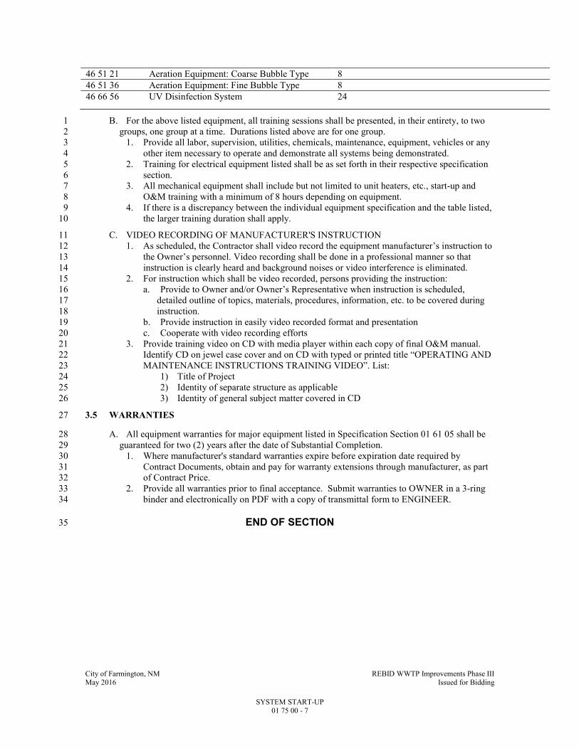
City of Farmington, NM REBID WWTP Improvements Phase III May 2016 Issued for Bidding
SYSTEM START-UP 01 75 00 - 7
46 51 21 Aeration Equipment: Coarse Bubble Type 8
46 51 36 Aeration Equipment: Fine Bubble Type 8
46 66 56 UV Disinfection System 24
B. For the above listed equipment, all training sessions shall be presented, in their entirety, to two 1
groups, one group at a time. Durations listed above are for one group. 2
1. Provide all labor, supervision, utilities, chemicals, maintenance, equipment, vehicles or any 3
other item necessary to operate and demonstrate all systems being demonstrated. 4
2. Training for electrical equipment listed shall be as set forth in their respective specification 5
section. 6
3. All mechanical equipment shall include but not limited to unit heaters, etc., start-up and 7
O&M training with a minimum of 8 hours depending on equipment. 8
4. If there is a discrepancy between the individual equipment specification and the table listed, 9
the larger training duration shall apply. 10
C. VIDEO RECORDING OF MANUFACTURER'S INSTRUCTION 11
1. As scheduled, the Contractor shall video record the equipment manufacturer’s instruction to 12
the Owner’s personnel. Video recording shall be done in a professional manner so that 13
instruction is clearly heard and background noises or video interference is eliminated. 14
2. For instruction which shall be video recorded, persons providing the instruction: 15
a. Provide to Owner and/or Owner’s Representative when instruction is scheduled, 16
detailed outline of topics, materials, procedures, information, etc. to be covered during 17
instruction. 18
b. Provide instruction in easily video recorded format and presentation 19
c. Cooperate with video recording efforts 20
3. Provide training video on CD with media player within each copy of final O&M manual. 21
Identify CD on jewel case cover and on CD with typed or printed title “OPERATING AND 22
MAINTENANCE INSTRUCTIONS TRAINING VIDEO”. List: 23
1) Title of Project 24
2) Identity of separate structure as applicable 25
3) Identity of general subject matter covered in CD 26
3.5 WARRANTIES 27
A. All equipment warranties for major equipment listed in Specification Section 01 61 05 shall be 28
guaranteed for two (2) years after the date of Substantial Completion. 29
1. Where manufacturer's standard warranties expire before expiration date required by 30
Contract Documents, obtain and pay for warranty extensions through manufacturer, as part 31
of Contract Price. 32
2. Provide all warranties prior to final acceptance. Submit warranties to OWNER in a 3-ring 33
binder and electronically on PDF with a copy of transmittal form to ENGINEER. 34
END OF SECTION 35

City of Farmington, NM REBID WWTP Improvements Phase III May 2016 Issued for Bidding
CONCRETE TESTING 03 05 05 - 1
SECTION 03 05 05 1
CONCRETE TESTING 2
PART 1 - GENERAL 3
1.1 SUMMARY 4
A. Section Includes: 5
1. Contractor requirements for testing of concrete and grout. 6
2. Definition of Owner provided testing. 7
3. Acceptance criteria for concrete. 8
B. Related Specification Sections include but are not necessarily limited to: 9
1. Division 00 - Bidding Requirements, Contract Forms, and Conditions of the Contract. 10
2. Division 01 - General Requirements. 11
3. Section 03 21 00 - Reinforcement. 12
4. Section 03 31 30 - Concrete, Materials and Proportioning. 13
1.2 RESPONSIBILITY AND PAYMENT 14
A. Contractor shall hire a qualified testing agency to perform the following testing and provide test 15
results to the Engineer. 16
1. Testing of materials and mixes proposed by the Contractor for compliance with the Contract 17
Documents and retesting in the event of changes. 18
2. Additional testing and inspection required because of changes in materials or proportions 19
requested by Contractor. 20
3. Contractor shall pay for services defined in Paragraphs 1.2B.1. and 1.2B.2. 21
4. Contractor shall reimburse Owner for testing services defined in Paragraphs 1.2A.2., 22
1.2A.3., 1.2A.4. and 1.2A.5. 23
5. See Specification Section 01 30 00. 24
B. Duties and Authorities of Testing Agency/Service Provider: 25
1. Any Testing Agency/Service Provider or agencies and their representatives retained by 26
Contractor or Owner for any reason are not authorized to revoke, alter, relax, enlarge, or 27
release any requirement of Contract Documents, nor to reject, approve or accept any portion 28
of the Work. 29
2. Testing Agency/Service Provider shall inform the Contractor and Engineer regarding 30
acceptability of or deficiencies in the work including materials furnished and work 31
performed by Contractor that fails to fulfill requirements of the Contract Documents. 32
3. Testing Agency to submit test reports and inspection reports to Engineer and Contractor 33
immediately after they are performed. 34
a. All test reports to include exact location in the work at which batch represented by a 35
test was deposited. 36
b. Reports of strength tests to include detailed information on storage and curing of 37
specimens prior to testing. 38
4. Owner retains the responsibility for ultimate rejection or approval of any portion of the 39
Work. 40
1.3 QUALITY ASSURANCE 41
A. Referenced Standards: 42
1. American Association of State Highway and Transportation Officials (AASHTO): 43
a. T260, Standard Method of Test for Sampling and Testing for Chloride Ion in Concrete 44
and Concrete Raw Materials. 45

City of Farmington, NM REBID WWTP Improvements Phase III May 2016 Issued for Bidding
CONCRETE TESTING 03 05 05 - 2
2. American Concrete Institute (ACI): 1
a. 318, Building Code Requirements for Structural Concrete. 2
3. ASTM International (ASTM): 3
a. C31, Standard Practice for Making and Curing Concrete Test Specimens in the Field. 4
b. C39, Standard Test Method for Compressive Strength of Cylindrical Concrete 5
Specimens. 6
c. C42, Standard Test Method for Obtaining and Testing Drilled Cores and Sawed Beams 7
of Concrete. 8
d. C138, Standard Test Method for Density (Unit Weight), Yield, and Air Content 9
(Gravimetric) of Concrete. 10
e. C143, Standard Test Method for Slump of Hydraulic-Cement Concrete. 11
f. C172, Standard Practice for Sampling Freshly Mixed Concrete. 12
g. C231, Standard Test Method for Air Content of Freshly Mixed Concrete by the 13
Pressure Method. 14
h. E329, Standard Specification for Agencies Engaged in Construction Inspection, 15
Testing, or Special Inspection. 16
4. National Bureau of Standards (NBS): 17
a. Cement and Concrete Reference Laboratory (CCRL). 18
B. Qualifications: 19
1. Contractor’s Testing Agency: 20
a. Meeting requirements of ASTM E329. 21
b. Provide evidence of recent inspection by CCRL of NBS, and correction of deficiencies 22
noted. 23
C. Use of Testing Agency and approval by Engineer of proposed concrete mix design shall in no 24
way relieve Contractor of responsibility to furnish materials and construction in full compliance 25
with Contract Documents. 26
1.4 DEFINITIONS 27
A. Testing Agency/Service Provider: An independent professional testing/inspection firm or 28
service hired by Contractor or by Owner to perform testing, inspection or analysis services as 29
directed, and as provided in the Contract Documents. 30
1.5 SUBMITTALS 31
A. Shop Drawings: 32
1. See Specification Section 01 33 00 for requirements for the mechanics and administration of 33
the submittal process. 34
2. Product technical data including: 35
a. Concrete materials and concrete mix designs proposed for use. 36
1) Include results of all testing performed to qualify materials and to establish mix 37
designs. 38
2) Place no concrete until approval of mix designs has been received in writing. 39
3) Submittal for each concrete mix design to include: 40
a) Sieve analysis and source of fine and coarse aggregates. 41
b) Test for aggregate organic impurities. 42
c) Proportioning of all materials. 43
d) Type of cement with mill certificate for the cement. 44
e) Brand, quantity and class of fly ash proposed for use along with other 45
submittal data as required for fly ash by Specification Section 03 31 30. 46
f) Slump. 47
g) Brand, type and quantity of air entrainment and any other proposed 48
admixtures. 49
h) Shrinkage test results. 50

City of Farmington, NM REBID WWTP Improvements Phase III May 2016 Issued for Bidding
CONCRETE TESTING 03 05 05 - 3
i) Total chloride ion content per cubic yard of concrete determined in accordance 1
with AASHTO T260. 2
j) 28-day compression test results and any other data required by Specification 3
Section 03 31 30 to establish concrete mix design. 4
3. Certifications: 5
a. Testing Agency qualifications. 6
PART 2 - PRODUCTS - (NOT APPLICABLE TO THIS SECTION) 7
PART 3 - EXECUTION 8
3.1 TESTING SERVICES TO BE PERFORMED 9
A. The following concrete testing will be performed: 10
1. Concrete strength testing: 11
a. Secure concrete samples in accordance with ASTM C172. 12
1) Obtain each sample from a different batch of concrete on a random basis, avoiding 13
selection of test batch other than by a number selected at random before 14
commencement of concrete placement. 15
b. For each strength test, mold and cure cylinders from each sample in accordance with 16
ASTM C31. 17
1) Record any deviations from requirements on test report. 18
2) Cylinder size: Per ASTM C31. 19
3) Quantity: 20
a) 6 IN DIA by 12 IN high: Four (4) cylinders. 21
b) 4 IN DIA by 8 IN high: Six (6) cylinders. 22
c. Field cure one (1) cylinder for the seven (7) day test. 23
1) Laboratory cure the remaining. 24
d. Test cylinders in accordance with ASTM C39. 25
1) 6 IN DIA cylinders: 26
a) Test two (2) cylinders at 28 days for strength test result and one (1) at seven 27
(7) days for information. 28
b) Hold remaining cylinder in reserve. 29
2) 4 IN DIA cylinders: 30
a) Test three (3) cylinders at 28 days for strength test result and one (1) at seven 31
(7) days for information. 32
b) Hold remaining cylinders in reserve. 33
e. Strength test result: 34
1) Average of strengths of two (2) 6 IN DIA cylinders or three (3) 4 IN DIA cylinders 35
from the same sample tested at 28 days. 36
2) If one (1) cylinder in a test manifests evidence of improper sampling, molding, 37
handling, curing, or testing, discard and test reserve cylinder; average strength of 38
remaining cylinders shall be considered strength test result. 39
3) Should all cylinders in a test show any of above defects, discard entire test. 40
f. Frequency of tests: 41
1) Concrete sand cement grout: One (1) strength test for each 4 HR period of grout 42
placement or fraction thereof. 43
2) Precast concrete, concrete topping, concrete fill and lean concrete: One (1) 44
strength test for each 10 CY of each type of concrete or fraction thereof placed. 45
3) All other concrete: 46
a) One (1) strength test to be taken not less than once a day, nor less than once 47
for each 50 CY or fraction thereof placed in any one (1) day. 48
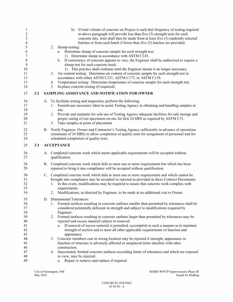
City of Farmington, NM REBID WWTP Improvements Phase III May 2016 Issued for Bidding
CONCRETE TESTING 03 05 05 - 4
b) If total volume of concrete on Project is such that frequency of testing required 1
in above paragraph will provide less than five (5) strength tests for each 2
concrete mix, tests shall then be made from at least five (5) randomly selected 3
batches or from each batch if fewer than five (5) batches are provided. 4
2. Slump testing: 5
a. Determine slump of concrete sample for each strength test. 6
1) Determine slump in accordance with ASTM C143. 7
b. If consistency of concrete appears to vary, the Engineer shall be authorized to require a 8
slump test for each concrete truck. 9
1) This practice shall continue until the Engineer deems it no longer necessary. 10
3. Air content testing: Determine air content of concrete sample for each strength test in 11
accordance with either ASTM C231, ASTM C173, or ASTM C138. 12
4. Temperature testing: Determine temperature of concrete sample for each strength test. 13
5. In-place concrete testing (if required). 14
3.2 SAMPLING ASSISTANCE AND NOTIFICATION FOR OWNER 15
A. To facilitate testing and inspection, perform the following: 16
1. Furnish any necessary labor to assist Testing Agency in obtaining and handling samples at 17
site. 18
2. Provide and maintain for sole use of Testing Agency adequate facilities for safe storage and 19
proper curing of test specimens on site for first 24 HRS as required by ASTM C31. 20
3. Take samples at point of placement. 21
B. Notify Engineer, Owner and Contractor’s Testing Agency sufficiently in advance of operations 22
(minimum of 24 HRS) to allow completion of quality tests for assignment of personnel and for 23
scheduled completion of quality tests. 24
3.3 ACCEPTANCE 25
A. Completed concrete work which meets applicable requirements will be accepted without 26
qualification. 27
B. Completed concrete work which fails to meet one or more requirements but which has been 28
repaired to bring it into compliance will be accepted without qualification. 29
C. Completed concrete work which fails to meet one or more requirements and which cannot be 30
brought into compliance may be accepted or rejected as provided in these Contract Documents. 31
1. In this event, modifications may be required to assure that concrete work complies with 32
requirements. 33
2. Modifications, as directed by Engineer, to be made at no additional cost to Owner. 34
D. Dimensional Tolerances: 35
1. Formed surfaces resulting in concrete outlines smaller than permitted by tolerances shall be 36
considered potentially deficient in strength and subject to modifications required by 37
Engineer. 38
2. Formed surfaces resulting in concrete outlines larger than permitted by tolerances may be 39
rejected and excess material subject to removal. 40
a. If removal of excess material is permitted, accomplish in such a manner as to maintain 41
strength of section and to meet all other applicable requirements of function and 42
appearance. 43
3. Concrete members cast in wrong location may be rejected if strength, appearance or 44
function of structure is adversely affected or misplaced items interfere with other 45
construction. 46
4. Inaccurately formed concrete surfaces exceeding limits of tolerances and which are exposed 47
to view, may be rejected. 48
a. Repair or remove and replace if required. 49
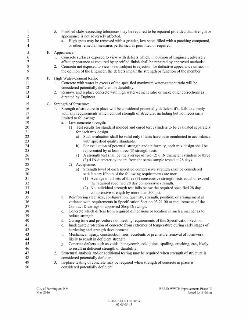
City of Farmington, NM REBID WWTP Improvements Phase III May 2016 Issued for Bidding
CONCRETE TESTING 03 05 05 - 5
5. Finished slabs exceeding tolerances may be required to be repaired provided that strength or 1
appearance is not adversely affected. 2
a. High spots may be removed with a grinder, low spots filled with a patching compound, 3
or other remedial measures performed as permitted or required. 4
E. Appearance: 5
1. Concrete surfaces exposed to view with defects which, in opinion of Engineer, adversely 6
affect appearance as required by specified finish shall be repaired by approved methods. 7
2. Concrete not exposed to view is not subject to rejection for defective appearance unless, in 8
the opinion of the Engineer, the defects impair the strength or function of the member. 9
F. High Water-Cement Ratio: 10
1. Concrete with water in excess of the specified maximum water-cement ratio will be 11
considered potentially deficient in durability. 12
2. Remove and replace concrete with high water-cement ratio or make other corrections as 13
directed by Engineer. 14
G. Strength of Structure: 15
1. Strength of structure in place will be considered potentially deficient if it fails to comply 16
with any requirements which control strength of structure, including but not necessarily 17
limited to following: 18
a. Low concrete strength: 19
1) Test results for standard molded and cured test cylinders to be evaluated separately 20
for each mix design. 21
a) Such evaluation shall be valid only if tests have been conducted in accordance 22
with specified quality standards. 23
b) For evaluation of potential strength and uniformity, each mix design shall be 24
represented by at least three (3) strength tests. 25
c) A strength test shall be the average of two (2) 6 IN diameter cylinders or three 26
(3) 4 IN diameter cylinders from the same sample tested at 28 days. 27
2) Acceptance: 28
a) Strength level of each specified compressive strength shall be considered 29
satisfactory if both of the following requirements are met: 30
(1) Average of all sets of three (3) consecutive strength tests equal or exceed 31
the required specified 28 day compressive strength. 32
(2) No individual strength test falls below the required specified 28 day 33
compressive strength by more than 500 psi. 34
b. Reinforcing steel size, configuration, quantity, strength, position, or arrangement at 35
variance with requirements in Specification Section 03 21 00 or requirements of the 36
Contract Drawings or approved Shop Drawings. 37
c. Concrete which differs from required dimensions or location in such a manner as to 38
reduce strength. 39
d. Curing time and procedure not meeting requirements of this Specification Section. 40
e. Inadequate protection of concrete from extremes of temperature during early stages of 41
hardening and strength development. 42
f. Mechanical injury, construction fires, accidents or premature removal of formwork 43
likely to result in deficient strength. 44
g. Concrete defects such as voids, honeycomb, cold joints, spalling, cracking, etc., likely 45
to result in deficient strength or durability. 46
2. Structural analysis and/or additional testing may be required when strength of structure is 47
considered potentially deficient. 48
3. In-place testing of concrete may be required when strength of concrete in place is 49
considered potentially deficient. 50

City of Farmington, NM REBID WWTP Improvements Phase III May 2016 Issued for Bidding
CONCRETE TESTING 03 05 05 - 6
a. Testing by impact hammer, sonoscope, or other nondestructive device may be 1
permitted by Engineer to determine relative strengths at various locations in the 2
structure or for selecting areas to be cored. 3
1) Such tests shall not be used as a basis for acceptance or rejection. 4
b. Core tests: 5
1) Where required, test cores will be obtained in accordance with ASTM C42. 6
a) If concrete in structure will be dry under service conditions, air dry cores 7
(temperature 60 to 80 DegF, relative humidity less than 60 percent) for seven 8
(7) days before test then test dry. 9
b) If concrete in structure will be wet or subjected to high moisture atmosphere 10
under service conditions, test cores after immersion in water for at least 40 11
HRS and test wet. 12
c) Testing wet or dry to be determined by Engineer. 13
2) Three (3) representative cores may be taken from each member or area of concrete 14
in place that is considered potentially deficient. 15
a) Location of cores shall be determined by Engineer so as least to impair 16
strength of structure. 17
b) If, before testing, one (1) or more of cores shows evidence of having been 18
damaged subsequent to or during removal from structure, damaged core shall 19
be replaced. 20
3) Concrete in area represented by a core test will be considered adequate if average 21
strength of three (3) cores is equal to at least 85 percent of specified strength and 22
no single core is less than 75 percent of specified strength. 23
4) Fill core holes with nonshrink grout and finish to match surrounding surface when 24
exposed in a finished area. 25
4. If core tests are inconclusive or impractical to obtain or if structural analysis does not 26
confirm safety of structure, load tests may be required and their results evaluated in 27
accordance with ACI 318, Chapter 20. 28
5. Correct or replace concrete work judged inadequate by structural analysis or by results of 29
core tests or load tests with additional construction, as directed by Engineer, at Contractor's 30
expense. 31
6. Contractor to pay all costs incurred in providing additional testing and/or structural analysis 32
required. 33
END OF SECTION 34

City of Farmington, NM REBID WWTP Improvements Phase III May 2016 Issued for Bidding
CONCRETE 03 09 00 - 1
SECTION 03 09 00 1
CONCRETE 2
PART 1 - GENERAL 3
1.1 SUMMARY 4
A. Section Includes: 5
1. Cast-in-place concrete and grout. 6
B. Related Specification Sections include but are not necessarily limited to: 7
1. Division 00 - Bidding Requirements, Contract Forms, and Conditions of the Contract. 8
2. Division 01 - General Requirements. 9
3. Division 03 - Concrete 10
1.2 QUALITY ASSURANCE 11
A. Referenced Standards: 12
1. American Concrete Institute (ACI): 13
a. 116R, Cement and Concrete Terminology. 14
b. 211.1, Standard Practice for Selecting Proportions for Normal, Heavyweight and Mass 15
Concrete. 16
c. 212.3R, Chemical Admixtures for Concrete. 17
d. 304R, Guide for Measuring, Mixing, Transporting, and Placing Concrete. 18
e. 304.2R, Placing Concrete by Pumping Methods. 19
f. 305R, Hot Weather Concreting. 20
g. 306R, Cold Weather Concreting. 21
h. 318, Building Code Requirements for Structural Concrete. 22
i. 347, Guide to Formwork for Concrete. 23
2. ASTM International (ASTM): 24
a. A82, Standard Specification for Steel Wire, Plain, for Concrete Reinforcement. 25
b. A185, Standard Specification for Steel Welded Wire Reinforcement, Plain, for 26
Concrete. 27
c. A615, Standard Specification for Deformed and Plain Carbon-Steel Bars for 28
Reinforcement. 29
d. A775, Standard Specification for Epoxy-Coated Steel Reinforcing Bars. 30
e. A1064, Standard Specification for Steel Wire and Welded Wire Replacement, Plain and 31
Deformed, for Concrete. 32
f. C31, Standard Practice for Making and Curing Concrete Test Specimens in the Field. 33
g. C33, Standard Specification for Concrete Aggregates. 34
h. C39, Standard Test Method for Compressive Strength of Cylindrical Concrete 35
Specimens. 36
i. C94/C94M, Standard Specification for Ready-Mixed Concrete. 37
j. C116, Standard Specification for Fiber-Reinforced Concrete and Shotcrete. 38
k. C138, Standard Method of Test for Density (Unit Weight), Yield, and Air Content 39
(Gravimetric) of Concrete. 40
l. C143, Standard Test Method for Slump of Hydraulic Cement Concrete. 41
m. C150, Standard Specification for Portland Cement. 42
n. C157, Standard Test Method for Length Change of Hardened Hydraulic-Cement, 43
Mortar, and Concrete. 44
o. C172, Standard Practice for Sampling Freshly Mixed Concrete. 45
p. C173, Standard Test Method for Air Content of Freshly Mixed Concrete by the 46
Volumetric Method. 47
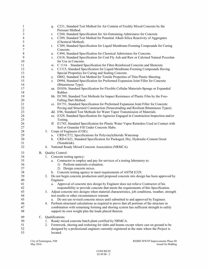
City of Farmington, NM REBID WWTP Improvements Phase III May 2016 Issued for Bidding
CONCRETE 03 09 00 - 2
q. C231, Standard Test Method for Air Content of Freshly Mixed Concrete by the 1
Pressure Method. 2
r. C260, Standard Specification for Air-Entraining Admixtures for Concrete. 3
s. C289, Standard Test Method for Potential Alkali-Silica Reactivity of Aggregates 4
(Chemical Method). 5
t. C309, Standard Specification for Liquid Membrane-Forming Compounds for Curing 6
Concrete. 7
u. C494, Standard Specification for Chemical Admixtures for Concrete. 8
v. C618, Standard Specification for Coal Fly Ash and Raw or Calcined Natural Pozzolan 9
for Use in Concrete. 10
w. C 1116 – Standard Specification for Fiber-Reinforced Concrete and Shotcrete 11
x. C1315, Standard Specification for Liquid Membrane-Forming Compounds Having 12
Special Properties for Curing and Sealing Concrete. 13
y. D882, Standard Test Method for Tensile Properties of Thin Plastic Sheeting. 14
z. D994, Standard Specification for Preformed Expansion Joint Filler for Concrete 15
(Bituminous Type). 16
aa. D1056, Standard Specification for Flexible Cellular Materials-Sponge or Expanded 17
Rubber. 18
bb. D1709, Standard Test Methods for Impact Resistance of Plastic Film by the Free-19
Falling Dart Method. 20
cc. D1751, Standard Specification for Preformed Expansion Joint Filler for Concrete 21
Paving and Structural Construction (Nonextruding and Resilient Bituminous Types). 22
dd. E96, Standard Test Methods for Water Vapor Transmission of Materials. 23
ee. E329, Standard Specification for Agencies Engaged in Construction Inspection and/or 24
Testing. 25
ff. E1745, Standard Specification for Plastic Water Vapor Retarders Used in Contact with 26
Soil or Granular Fill Under Concrete Slabs. 27
3. Corps of Engineers (COE): 28
a. CRD-C572, Specifications for Polyvinylchloride Waterstop. 29
b. CRD-C621, Standard Specification for Packaged, Dry, Hydraulic-Cement Grout 30
(Nonshrink). 31
4. National Ready Mixed Concrete Association (NRMCA). 32
B. Quality Control: 33
1. Concrete testing agency: 34
a. Contractor to employ and pay for services of a testing laboratory to: 35
1) Perform materials evaluation. 36
2) Design concrete mixes. 37
b. Concrete testing agency to meet requirements of ASTM E329. 38
2. Do not begin concrete production until proposed concrete mix design has been approved by 39
Engineer. 40
a. Approval of concrete mix design by Engineer does not relieve Contractor of his 41
responsibility to provide concrete that meets the requirements of this Specification. 42
3. Adjust concrete mix designs when material characteristics, job conditions, weather, strength 43
test results or other circumstances warrant. 44
a. Do not use revised concrete mixes until submitted to and approved by Engineer. 45
4. Perform structural calculations as required to prove that all portions of the structure in 46
combination with remaining forming and shoring system has sufficient strength to safely 47
support its own weight plus the loads placed thereon. 48
C. Qualifications: 49
1. Ready mixed concrete batch plant certified by NRMCA. 50
2. Formwork, shoring and reshoring for slabs and beams except where cast on ground to be 51
designed by a professional engineer currently registered in the state where the Project is 52
located. 53
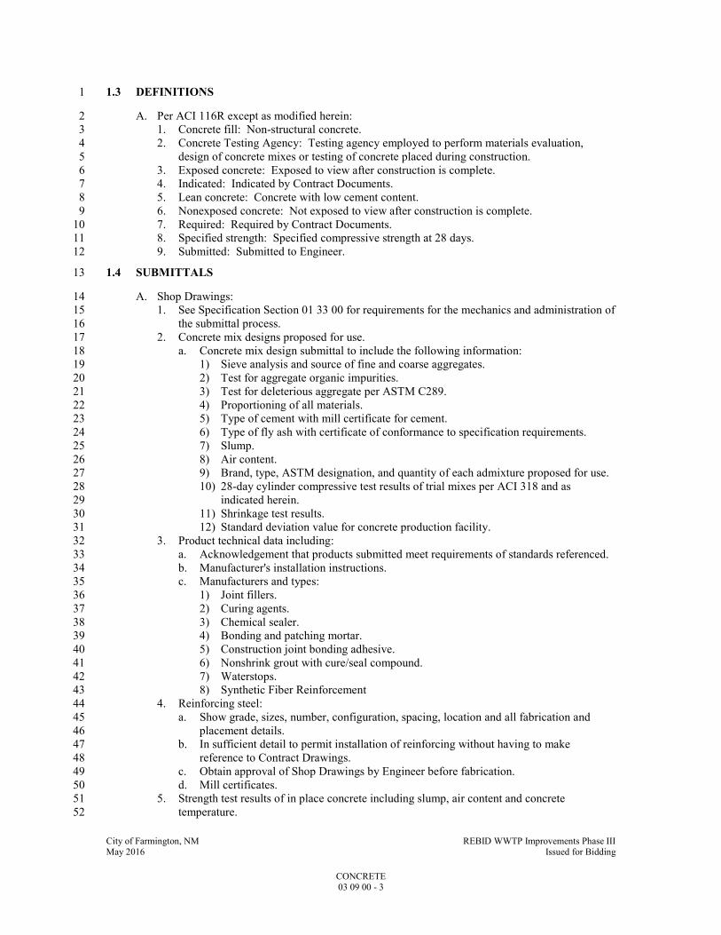
City of Farmington, NM REBID WWTP Improvements Phase III May 2016 Issued for Bidding
CONCRETE 03 09 00 - 3
1.3 DEFINITIONS 1
A. Per ACI 116R except as modified herein: 2
1. Concrete fill: Non-structural concrete. 3
2. Concrete Testing Agency: Testing agency employed to perform materials evaluation, 4
design of concrete mixes or testing of concrete placed during construction. 5
3. Exposed concrete: Exposed to view after construction is complete. 6
4. Indicated: Indicated by Contract Documents. 7
5. Lean concrete: Concrete with low cement content. 8
6. Nonexposed concrete: Not exposed to view after construction is complete. 9
7. Required: Required by Contract Documents. 10
8. Specified strength: Specified compressive strength at 28 days. 11
9. Submitted: Submitted to Engineer. 12
1.4 SUBMITTALS 13
A. Shop Drawings: 14
1. See Specification Section 01 33 00 for requirements for the mechanics and administration of 15
the submittal process. 16
2. Concrete mix designs proposed for use. 17
a. Concrete mix design submittal to include the following information: 18
1) Sieve analysis and source of fine and coarse aggregates. 19
2) Test for aggregate organic impurities. 20
3) Test for deleterious aggregate per ASTM C289. 21
4) Proportioning of all materials. 22
5) Type of cement with mill certificate for cement. 23
6) Type of fly ash with certificate of conformance to specification requirements. 24
7) Slump. 25
8) Air content. 26
9) Brand, type, ASTM designation, and quantity of each admixture proposed for use. 27
10) 28-day cylinder compressive test results of trial mixes per ACI 318 and as 28
indicated herein. 29
11) Shrinkage test results. 30
12) Standard deviation value for concrete production facility. 31
3. Product technical data including: 32
a. Acknowledgement that products submitted meet requirements of standards referenced. 33
b. Manufacturer's installation instructions. 34
c. Manufacturers and types: 35
1) Joint fillers. 36
2) Curing agents. 37
3) Chemical sealer. 38
4) Bonding and patching mortar. 39
5) Construction joint bonding adhesive. 40
6) Nonshrink grout with cure/seal compound. 41
7) Waterstops. 42
8) Synthetic Fiber Reinforcement 43
4. Reinforcing steel: 44
a. Show grade, sizes, number, configuration, spacing, location and all fabrication and 45
placement details. 46
b. In sufficient detail to permit installation of reinforcing without having to make 47
reference to Contract Drawings. 48
c. Obtain approval of Shop Drawings by Engineer before fabrication. 49
d. Mill certificates. 50
5. Strength test results of in place concrete including slump, air content and concrete 51
temperature. 52

City of Farmington, NM REBID WWTP Improvements Phase III May 2016 Issued for Bidding
CONCRETE 03 09 00 - 4
1.5 DELIVERY, STORAGE, AND HANDLING 1
A. Storage of Material: 2
1. Cement and fly ash: 3
a. Store in moistureproof, weathertight enclosures. 4
b. Do not use if caked or lumpy. 5
2. Aggregate: 6
a. Store to prevent segregation and contamination with other sizes or foreign materials. 7
b. Obtain samples for testing from aggregates at point of batching. 8
c. Do not use frozen or partially frozen aggregates. 9
d. Do not use bottom 6 IN of stockpiles in contact with ground. 10
e. Allow sand to drain until moisture content is uniform prior to use. 11
3. Admixtures: 12
a. Protect from contamination, evaporation, freezing, or damage. 13
b. Maintain within temperature range recommended by manufacturer. 14
c. Completely mix solutions and suspensions prior to use. 15
4. Reinforcing steel: Support and store all rebars above ground. 16
B. Delivery: 17
1. Concrete: 18
a. Prepare a delivery ticket for each load for ready-mixed concrete. 19
b. Truck operator shall hand ticket to Owner's Representative at the time of delivery. 20
c. Ticket to show: 21
1) Mix identification mark. 22
2) Quantity delivered. 23
3) Amount of each material in batch. 24
4) Outdoor temp in the shade. 25
5) Time at which cement was added. 26
6) Numerical sequence of the delivery. 27
7) Amount of water added. 28
2. Reinforcing steel: 29
a. Ship to jobsite with attached plastic or metal tags with permanent mark numbers. 30
b. Mark numbers to match Shop Drawing mark number. 31
3. Deliver synthetic fiber reinforcement in manufacturer’s original, unopened, undamaged 32
containers and packaging, with labels clearly identifying product name, unique 33
identification number, code approvals, directions for use, manufacturer, and weight of fibers 34
PART 2 - PRODUCTS 35
2.1 ACCEPTABLE MANUFACTURERS 36
A. Subject to compliance with the Contract Documents, the following products and manufacturers 37
are acceptable: 38
1. Nonshrink, nonmetallic grout: 39
a. Sika "SikaGrout 212." 40
b. Euclid Chemial "NS Grout." 41
c. BASF Admixtures, Inc. "Masterflow 713." 42
2. Epoxy grout: 43
a. BASF Admixtures, Inc. "Brutem MPG." 44
b. Euclid Chemical Company, "E3-G." 45
c. Fosroc, "Conbextra EPHF". 46
3. Expansion joint fillers: 47
a. Permaglaze Co. 48
b. Rubatex Corp. 49
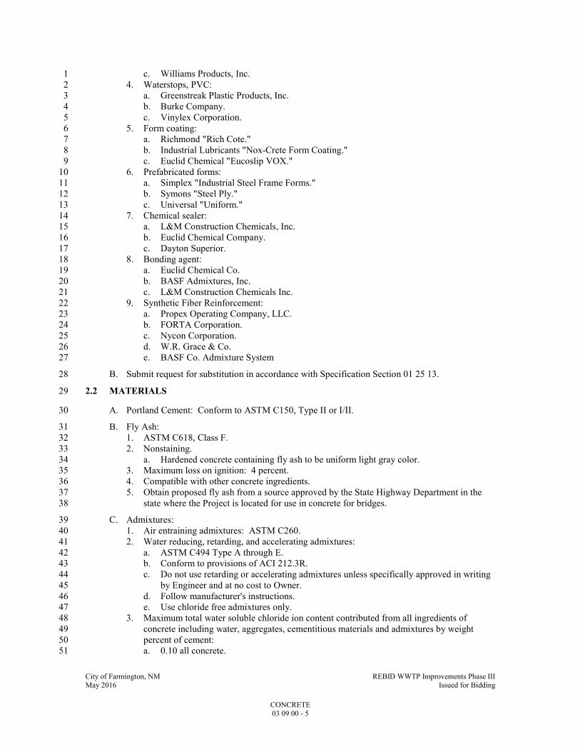
City of Farmington, NM REBID WWTP Improvements Phase III May 2016 Issued for Bidding
CONCRETE 03 09 00 - 5
c. Williams Products, Inc. 1
4. Waterstops, PVC: 2
a. Greenstreak Plastic Products, Inc. 3
b. Burke Company. 4
c. Vinylex Corporation. 5
5. Form coating: 6
a. Richmond "Rich Cote." 7
b. Industrial Lubricants "Nox-Crete Form Coating." 8
c. Euclid Chemical "Eucoslip VOX." 9
6. Prefabricated forms: 10
a. Simplex "Industrial Steel Frame Forms." 11
b. Symons "Steel Ply." 12
c. Universal "Uniform." 13
7. Chemical sealer: 14
a. L&M Construction Chemicals, Inc. 15
b. Euclid Chemical Company. 16
c. Dayton Superior. 17
8. Bonding agent: 18
a. Euclid Chemical Co. 19
b. BASF Admixtures, Inc. 20
c. L&M Construction Chemicals Inc. 21
9. Synthetic Fiber Reinforcement: 22
a. Propex Operating Company, LLC. 23
b. FORTA Corporation. 24
c. Nycon Corporation. 25
d. W.R. Grace & Co. 26
e. BASF Co. Admixture System 27
B. Submit request for substitution in accordance with Specification Section 01 25 13. 28
2.2 MATERIALS 29
A. Portland Cement: Conform to ASTM C150, Type II or I/II. 30
B. Fly Ash: 31
1. ASTM C618, Class F. 32
2. Nonstaining. 33
a. Hardened concrete containing fly ash to be uniform light gray color. 34
3. Maximum loss on ignition: 4 percent. 35
4. Compatible with other concrete ingredients. 36
5. Obtain proposed fly ash from a source approved by the State Highway Department in the 37
state where the Project is located for use in concrete for bridges. 38
C. Admixtures: 39
1. Air entraining admixtures: ASTM C260. 40
2. Water reducing, retarding, and accelerating admixtures: 41
a. ASTM C494 Type A through E. 42
b. Conform to provisions of ACI 212.3R. 43
c. Do not use retarding or accelerating admixtures unless specifically approved in writing 44
by Engineer and at no cost to Owner. 45
d. Follow manufacturer's instructions. 46
e. Use chloride free admixtures only. 47
3. Maximum total water soluble chloride ion content contributed from all ingredients of 48
concrete including water, aggregates, cementitious materials and admixtures by weight 49
percent of cement: 50
a. 0.10 all concrete. 51

City of Farmington, NM REBID WWTP Improvements Phase III May 2016 Issued for Bidding
CONCRETE 03 09 00 - 6
4. Do not use calcium chloride. 1
5. Pozzolanic admixtures: ASTM C618. 2
6. Provide admixtures of same type, manufacturer and quantity as used in establishing required 3
concrete proportions in the mix design. 4
D. Water: Potable, clean, free of oils, acids and organic matter. 5
E. Aggregates: 6
1. Normal weight concrete: ASTM C33, except as modified below. 7
2. Fine aggregate: 8
a. Clean natural sand. 9
b. No manufactured or artificial sand. 10
3. Coarse aggregate: 11
a. Crushed rock, natural gravel, or other inert granular material. 12
b. Maximum amount of clay or shale particles: 1 percent. 13
4. Gradation of coarse aggregate: 14
a. Lean concrete and concrete topping: Size #7. 15
b. All other concrete: Size #57 or #67. 16
F. Concrete Grout: 17
1. Nonshrink, nonmetallic grout: 18
a. Nonmetallic, noncorrosive, nonstaining, premixed with only water to be added. 19
b. Grout to produce a positive but controlled expansion. 20
c. Mass expansion not to be created by gas liberation. 21
d. Minimum compressive strength of nonshrink grout at 28 days: 6500 psi. 22
e. In accordance with COE CRD-C621. 23
2. Epoxy grout: 24
a. 3-component epoxy resin system. 25
1) Two liquid epoxy components. 26
2) One inert aggregate filler component. 27
b. Each component packaged separately for mixing at jobsite. 28
G. Reinforcing Steel: 29
1. Reinforcing bars: ASTM A615, Grade 60. 30
2. Welded wire reinforcement: 31
a. ASTM A185 or ASTM A1064. 32
b. Minimum yield strength: 60,000 psi. 33
3. Column spirals: ASTM A82 or ASTM A1064. 34
H. Synthetic Fiber Reinforcement 35
1. ASTM C 116, Type III: Fibrillated or monofilament polypropylene fiber engineered and 36
designed for use in concrete. 37
2. Fiber Length: ½ to 1 ½ inches. 38
3. Alkali, Acid and Salt Resistence: High. 39
4. Absorption: None. 40
5. Specific gravity: 0.91. 41
6. Melting Point: 320 degrees F. 42
I. Forms: 43
1. Prefabricated or job built. 44
2. Wood forms: 45
a. New 5/8 or 3/4 IN 5-ply structural plywood of concrete form grade. 46
b. Built-in-place or prefabricated type panel. 47
c. 4 x 8 FT sheets for built-in-place type except where smaller pieces will cover entire 48
area. 49
d. When approved, plywood may be reused. 50
3. Metal forms: 51

City of Farmington, NM REBID WWTP Improvements Phase III May 2016 Issued for Bidding
CONCRETE 03 09 00 - 7
a. Metal forms excluding aluminum may be used. 1
b. Forms to be tight to prevent leakage, free of rust and straight without dents to provide 2
members of uniform thickness. 3
4. Chamfer strips: Clear white pine, surface against concrete planed. 4
5. Form ties: 5
a. Removable end, permanently embedded body type with cones on outer ends not 6
requiring auxiliary spreaders. 7
b. Cone diameter: 3/4 IN minimum to 1 IN maximum. 8
c. Embedded portion 1-1/2 IN minimum back from concrete face. 9
d. If not provided with threaded ends, constructed for breaking off ends without damage to 10
concrete. 11
e. Provide ties with built-in waterstops at all walls that will be in contact with process 12
liquid during plant operation. 13
6. Form release: Nonstaining and shall not prevent bonding of future finishes to concrete 14
surface. 15
J. Waterstops: 16
1. Plastic: COE CRD-C572. 17
2. Serrated with center bulb. 18
3. Thickness: 3/8 IN. 19
4. Length (general use): 6 IN unless indicated otherwise. 20
5. Expansion joints: 21
a. Length: 9 IN. 22
b. Center bulb: 1 IN OD x 1/2 IN ID. 23
6. Provide hog rings or grommets spaced at maximum 12 IN OC along the length of the water 24
stop. 25
7. Provide factory made waterstop fabrications at all changes of direction, intersections and 26
transitions leaving only straight butt splices for the field. 27
K. Chairs, Runners, Bolsters, Spacers, and Hangers: 28
1. Stainless steel, epoxy coated, or plastic coated metal. 29
a. Plastic coated: Rebar support tips in contact with the forms only. 30
L. Chemical Floor Sealer: 31
1. Colorless low VOC water-based solution containing acrylic copolymers. 32
a. ASTM C1315, Class B, minimum 30 percent solids. 33
2. L&M Construction Chemicals Inc. Dress & Seal WB 30. 34
M. Vapor Retarder: 35
1. ASTM E1745, Class A, minimum 15 mil thickness. 36
2. Water vapor permeance: 0.03 maximum per ASTM E96. 37
3. Puncture resistance: ASTM D1709, Method B, 2200 grams. 38
4. Minimum tensile strength: 45 LBS/IN, ASTM D882. 39
5. Vapor retarder tape: As recommended by vapor retarder manufacturer. 40
N. Membrane Curing Compound: 41
1. ASTM C309, Type I-D. 42
2. Resin based, dissipates upon exposure to UV light. 43
3. Curing compound shall not prevent bonding of any future coverings, coatings or finishes. 44
4. Curing compounds used in water treatment plant construction to be nontoxic and taste and 45
odor free. 46
O. Bonding Agent: 47
1. High solids acrylic latex base liquid for interior or exterior application as a bonding agent to 48
improve adhesion and mechanical properties of concrete patching mortars. 49
2. Euclid Chemical Co. "Flex-Con." 50
3. BASF Admixtures, Inc. "Acryl-Set." 51
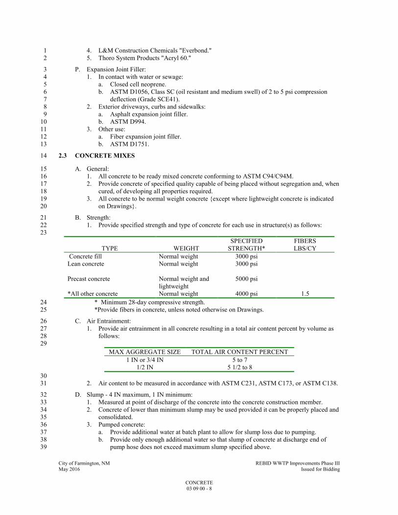
City of Farmington, NM REBID WWTP Improvements Phase III May 2016 Issued for Bidding
CONCRETE 03 09 00 - 8
4. L&M Construction Chemicals "Everbond." 1
5. Thoro System Products "Acryl 60." 2
P. Expansion Joint Filler: 3
1. In contact with water or sewage: 4
a. Closed cell neoprene. 5
b. ASTM D1056, Class SC (oil resistant and medium swell) of 2 to 5 psi compression 6
deflection (Grade SCE41). 7
2. Exterior driveways, curbs and sidewalks: 8
a. Asphalt expansion joint filler. 9
b. ASTM D994. 10
3. Other use: 11
a. Fiber expansion joint filler. 12
b. ASTM D1751. 13
2.3 CONCRETE MIXES 14
A. General: 15
1. All concrete to be ready mixed concrete conforming to ASTM C94/C94M. 16
2. Provide concrete of specified quality capable of being placed without segregation and, when 17
cured, of developing all properties required. 18
3. All concrete to be normal weight concrete {except where lightweight concrete is indicated 19
on Drawings}. 20
B. Strength: 21
1. Provide specified strength and type of concrete for each use in structure(s) as follows: 22
23
TYPE WEIGHT
SPECIFIED
STRENGTH*
FIBERS
LBS/CY
Concrete fill Normal weight 3000 psi
Lean concrete Normal weight 3000 psi
Precast concrete Normal weight and
lightweight
5000 psi
*All other concrete Normal weight 4000 psi 1.5
* Minimum 28-day compressive strength. 24
*Provide fibers in concrete, unless noted otherwise on Drawings. 25
C. Air Entrainment: 26
1. Provide air entrainment in all concrete resulting in a total air content percent by volume as 27
follows: 28
29
MAX AGGREGATE SIZE TOTAL AIR CONTENT PERCENT
1 IN or 3/4 IN 5 to 7
1/2 IN 5 1/2 to 8
30
2. Air content to be measured in accordance with ASTM C231, ASTM C173, or ASTM C138. 31
D. Slump - 4 IN maximum, 1 IN minimum: 32
1. Measured at point of discharge of the concrete into the concrete construction member. 33
2. Concrete of lower than minimum slump may be used provided it can be properly placed and 34
consolidated. 35
3. Pumped concrete: 36
a. Provide additional water at batch plant to allow for slump loss due to pumping. 37
b. Provide only enough additional water so that slump of concrete at discharge end of 38
pump hose does not exceed maximum slump specified above. 39

City of Farmington, NM REBID WWTP Improvements Phase III May 2016 Issued for Bidding
CONCRETE 03 09 00 - 9
4. Determine slump per ASTM C143. 1
E. Selection of Proportions: 2
1. General: 3
a. Proportion ingredients to: 4
1) Produce proper workability, durability, strength, and other required properties. 5
2) Prevent segregation and collection of excessive free water on surface. 6
2. Minimum cement contents and maximum water cement ratios for concrete to be as follows: 7
8
SPECIFIED
STRENGTH
MINIMUM CEMENT, LB/CY MAXIMUM WATER
CEMENT RATIO BY
WEIGHT
MAXIMUM AGGREGATE SIZE
1/2 IN 3/4 IN 1 IN
3000 --- 517 517 0.45
4000 580 580 580 0.45
5000 --- 686 665 0.40
9
3. Substitution of fly ash: Maximum of 25 percent by weight of cement at rate of 1 LB fly ash 10
for 1 LB of cement. 11
4. Sand cement grout: 12
a. Three parts sand. 13
b. One part Portland cement. 14
c. Entrained air: Six percent plus or minus one percent. 15
d. Sufficient water for required workability. 16
e. Minimum 28-day compressive strength: 3,000 psi. 17
5. Pan stair fill: 18
a. Coarse aggregate: 100 percent passing a 1/2 IN sieve. 19
b. Proportions: 20
1) 1 sack cement. 21
2) 150 LBS coarse aggregate. 22
3) 150 LBS fine aggregate (sand). 23
c. Adjust mix to obtain satisfactory finishing. 24
6. Normal weight concrete: 25
a. Proportion mixture to provide desired characteristics using one of methods described 26
below: 27
1) Method 1 (Trial Mix): 28
a) Per ACI 318, Chapter 5, except as modified herein. 29
b) Air content within range specified above. 30
c) Record and report temperature of trial mixes. 31
d) Proportion trial mixes per ACI 211.1. 32
2) Method 2 (Field Experience): 33
a) Per ACI 318, Chapter 5, except as modified herein: 34
b) Field test records must be acceptable to Engineer to use this method. 35
c) Test records shall represent materials, proportions and conditions similar to 36
those specified. 37
7. Required average strength to exceed the specified 28-day compressive strength by the 38
amount determined or calculated in accordance with the requirements of Paragraph 5.3 of 39
ACI 318 using the standard deviation of the proposed concrete production facility as 40
described in Paragraph 5.3.1 of ACI 318. 41
F. Allowable Shrinkage: 0.048 percent per ASTM C157. 42

City of Farmington, NM REBID WWTP Improvements Phase III May 2016 Issued for Bidding
CONCRETE 03 09 00 - 10
PART 3 - EXECUTION 1
3.1 FORMING AND PLACING CONCRETE 2
A. Formwork: 3
1. Contractor is responsible for design and erection of formwork. 4
2. Construct formwork so that concrete members and structures are of correct size, shape, 5
alignment, elevation and position. 6
a. Allowable tolerances: As recommended in ACI 347. 7
3. Provide slabs and beams of minimum indicated depth when sloping foundation base slabs or 8
elevated floor slabs to drains. 9
a. For slabs on grade, slope top of subgrade to provide floor slabs of minimum uniform 10
indicated depth. 11
b. Do not place floor drains through beams. 12
4. Openings: 13
a. Provide openings in formwork to accommodate work of other trades. 14
b. Accurately place and securely support items built into forms. 15
5. Chamfer strips: Place 3/4 IN chamfer strips in forms to produce 3/4 IN wide beveled edges 16
on permanently exposed corners of members. 17
6. Clean and adjust forms prior to concrete placement. 18
7. Tighten forms to prevent mortar leakage. 19
8. Coat form surfaces with form release agents prior to placing reinforcing bars in forms. 20
B. Reinforcement: 21
1. Position, support and secure reinforcement against displacement. 22
2. Locate and support with chairs, runners, bolsters, spacers and hangers, as required. 23
3. Set wire ties so ends do not touch forms and are directed into concrete, not toward exposed 24
concrete surfaces. 25
4. Lap splice lengths: ACI 318 Class B top bar tension splices unless indicated otherwise on 26
the Drawings. 27
5. Extend reinforcement to within 2 IN of concrete perimeter edges. 28
a. If perimeter edge is earth formed, extend reinforcement to within 3 IN of the edge. 29
6. Minimum concrete protective covering for reinforcement: As shown on Drawings. 30
7. Do not weld reinforcing bars. 31
8. Welded wire reinforcement: 32
a. Install welded wire reinforcement in maximum practical sizes. 33
b. Splice sides and ends with a splice lap length measured between outermost cross wires 34
of each fabric sheet not less than: 35
1) One spacing of cross wires plus 2 IN. 36
2) 1.5 x development length. 37
3) 6 IN. 38
c. Development length: ACI 318 basic development length for the specified fabric yield 39
strength. 40
C. Construction, Expansion, and Contraction Joints: 41
1. Provide at locations indicated. 42
2. Locate wall vertical construction joints at 30 FT maximum centers and wall horizontal 43
construction joints at 10 FT maximum centers. 44
3. Locate construction joints in floor slabs and foundation base slabs so that concrete 45
placements are approximately square and do not exceed 2500 SF. 46
4. Locate construction joints in columns and walls: 47
a. At the underside of beams, girders, haunches, drop panels, column capitals, and at floor 48
panels. 49
b. Haunches, drop panels, and column capitals are considered part of the supported floor 50
or roof and shall be placed monolithically therewith. 51
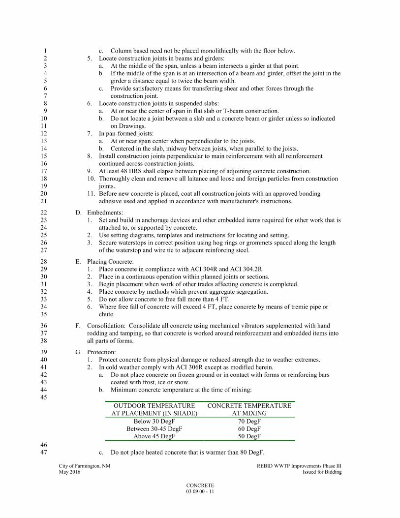
City of Farmington, NM REBID WWTP Improvements Phase III May 2016 Issued for Bidding
CONCRETE 03 09 00 - 11
c. Column based need not be placed monolithically with the floor below. 1
5. Locate construction joints in beams and girders: 2
a. At the middle of the span, unless a beam intersects a girder at that point. 3
b. If the middle of the span is at an intersection of a beam and girder, offset the joint in the 4
girder a distance equal to twice the beam width. 5
c. Provide satisfactory means for transferring shear and other forces through the 6
construction joint. 7
6. Locate construction joints in suspended slabs: 8
a. At or near the center of span in flat slab or T-beam construction. 9
b. Do not locate a joint between a slab and a concrete beam or girder unless so indicated 10
on Drawings. 11
7. In pan-formed joists: 12
a. At or near span center when perpendicular to the joists. 13
b. Centered in the slab, midway between joists, when parallel to the joists. 14
8. Install construction joints perpendicular to main reinforcement with all reinforcement 15
continued across construction joints. 16
9. At least 48 HRS shall elapse between placing of adjoining concrete construction. 17
10. Thoroughly clean and remove all laitance and loose and foreign particles from construction 18
joints. 19
11. Before new concrete is placed, coat all construction joints with an approved bonding 20
adhesive used and applied in accordance with manufacturer's instructions. 21
D. Embedments: 22
1. Set and build in anchorage devices and other embedded items required for other work that is 23
attached to, or supported by concrete. 24
2. Use setting diagrams, templates and instructions for locating and setting. 25
3. Secure waterstops in correct position using hog rings or grommets spaced along the length 26
of the waterstop and wire tie to adjacent reinforcing steel. 27
E. Placing Concrete: 28
1. Place concrete in compliance with ACI 304R and ACI 304.2R. 29
2. Place in a continuous operation within planned joints or sections. 30
3. Begin placement when work of other trades affecting concrete is completed. 31
4. Place concrete by methods which prevent aggregate segregation. 32
5. Do not allow concrete to free fall more than 4 FT. 33
6. Where free fall of concrete will exceed 4 FT, place concrete by means of tremie pipe or 34
chute. 35
F. Consolidation: Consolidate all concrete using mechanical vibrators supplemented with hand 36
rodding and tamping, so that concrete is worked around reinforcement and embedded items into 37
all parts of forms. 38
G. Protection: 39
1. Protect concrete from physical damage or reduced strength due to weather extremes. 40
2. In cold weather comply with ACI 306R except as modified herein. 41
a. Do not place concrete on frozen ground or in contact with forms or reinforcing bars 42
coated with frost, ice or snow. 43
b. Minimum concrete temperature at the time of mixing: 44
45
OUTDOOR TEMPERATURE
AT PLACEMENT (IN SHADE)
CONCRETE TEMPERATURE
AT MIXING
Below 30 DegF 70 DegF
Between 30-45 DegF 60 DegF
Above 45 DegF 50 DegF
46
c. Do not place heated concrete that is warmer than 80 DegF. 47
City of Farmington, NM REBID WWTP Improvements Phase III May 2016 Issued for Bidding
CONCRETE 03 09 00 - 12
d. If freezing temperatures are expected during curing, maintain the concrete temperature 1
at or above 50 DegF for 7 days or 70 DegF for 3 days. 2
e. Do not allow concrete to cool suddenly. 3
3. In hot weather comply with ACI 305R except as modified herein. 4
a. At air temperature of 90 DegF and above, keep concrete as cool as possible during 5
placement and curing. 6
b. Do not allow concrete temperature to exceed 90 DegF at placement. 7
c. Prevent plastic shrinkage cracking due to rapid evaporation of moisture. 8
d. Do not place concrete when the actual or anticipated evaporation rate equals or exceeds 9
0.2 LBS/SF/HR as determined from ACI 305R, Figure 2.1.5. 10
H. Curing: 11
1. Begin curing concrete as soon as free water has disappeared from exposed surfaces. 12
2. Cure concrete by use of moisture retaining cover, burlap kept continuously wet or by 13
membrane curing compound. 14
3. Provide protection as required to prevent damage to concrete and to prevent moisture loss 15
from concrete during curing period. 16
4. Provide curing for minimum of 7 days. 17
5. Form materials left in place may be considered as curing materials for surfaces in contact 18
with the form materials except in periods of hot weather. 19
6. In hot weather follow curing procedures outlined in ACI 305R. 20
7. In cold weather follow curing procedures outlined in ACI 306R. 21
8. If forms are removed before 7 days have elapsed, finish curing of formed surfaces by one of 22
above methods for the remainder of the curing period. 23
9. Curing vertical surfaces with a curing compound: 24
a. Cover vertical surfaces with a minimum of two coats of the curing compound. 25
b. Allow the preceding coat to completely dry prior to applying the next coat. 26
c. Apply the first coat of curing compound immediately after form removal. 27
d. Vertical surface at the time of receiving the first coat shall be damp with no free water 28
on the surface. 29
e. A vertical surface is defined as any surface steeper than 1 vertical to 4 horizontal. 30
I. Form Removal: 31
1. Remove forms after concrete has hardened sufficiently to resist damage from removal 32
operations or lack of support. 33
2. Where no reshoring is planned, leave forms and shoring used to support concrete until it has 34
reached its specified 28-day compressive strength. 35
3. Where reshoring is planned, supporting formwork may be removed when concrete has 36
sufficient strength to safely support its own weight and loads placed thereon. 37
a. While reshoring is underway, no superimposed loads shall be permitted on the new 38
construction. 39
b. Place reshores as soon as practicable after stripping operations are complete but in no 40
case later than the end of working day on which stripping occurs. 41
c. Tighten reshores to carry their required loads. 42
d. Leave reshores in place until concrete being supported has reached its specified 28-day 43
compressive strength. 44
3.2 CONCRETE FINISHES 45
A. Tolerances: 46
1. Class A: 1/8 IN in 10 FT. 47
2. Class B: 1/4 IN in 10 FT. 48
B. Surfaces Exposed to View: 49
1. Provide a smooth finish for exposed concrete surfaces and surfaces that are: 50
a. To be covered with a coating or covering material applied directly to concrete. 51

City of Farmington, NM REBID WWTP Improvements Phase III May 2016 Issued for Bidding
CONCRETE 03 09 00 - 13
b. Scheduled for grout cleaned finish. 1
2. Remove fins and projections, and patch voids, air pockets, and honeycomb areas with 2
cement grout. 3
3. Fill tie holes with nonshrink, nonmetallic grout. 4
C. Surfaces Not Exposed to View: 5
1. Patch voids, air pockets and honeycomb areas with cement grout. 6
2. Fill tie holes with nonshrink, nonmetallic grout. 7
D. Grout Cleaned Finish: 8
1. Mix one part Portland cement and 1-1/2 parts fine sand with sufficient bonding agent/water 9
mixture to produce a grout with the consistency of thick paint. 10
a. White Portland cement shall be substituted for gray Portland cement to produce a color 11
that matches color of surrounding concrete as determined by trial patch for areas not to 12
be painted. 13
2. Wet surface of concrete to prevent absorption of water by grout and uniformly apply grout 14
with brushes or spray gun. 15
3. Immediately scrub the surface with a cork float or stone to coat and fill air bubbles and 16
holes. 17
4. While grout is still plastic, remove all excess grout by working surface with rubber float, 18
sack or other approved means. 19
5. After the surface whitens from drying, rub vigorously with clean burlap. 20
6. Keep final finish damp for a minimum of 36 HRS after final rubbing. 21
E. Slab Float Finish: 22
1. After concrete has been placed, consolidated, struck off, and leveled, do no further work 23
until ready for floating. 24
2. Begin floating when water sheen has disappeared and surface has stiffened sufficiently to 25
permit operation. 26
3. During or after first floating, check planeness of entire surface with a 10 FT straightedge 27
applied at not less than two different angles. 28
4. Cut down all high spots and fill all low spots during this procedure to produce a surface 29
within Class B tolerance throughout. 30
5. Refloat slab immediately to a uniform sandy texture. 31
F. Troweled Finish: 32
1. Float finish surface. 33
2. Next power trowel, and finally hand trowel. 34
3. Produce a smooth surface which is relatively free of defects with first hand troweling. 35
4. Perform additional trowelings by hand after surface has hardened sufficiently. 36
5. Final trowel when a ringing sound is produced as trowel is moved over surface. 37
6. Thoroughly consolidate surface by hand troweling. 38
7. Leave finished surface essentially free of trowel marks, uniform in texture and appearance 39
and plane to a Class A tolerance. 40
8. On surfaces intended to support floor coverings remove any defects of sufficient magnitude 41
that would show through floor covering by grinding. 42
G. Broom Finish: Immediately after concrete has received a float finish as specified, give it a 43
transverse scored texture by drawing a broom across surface. 44
H. Apply chemical floor hardener to permanently exposed interior concrete floor slab surfaces 45
where indicated. 46
1. Apply in accordance with manufacturer's instructions. 47
3.3 GROUT 48
A. Preparation: 49
1. Nonshrinking, nonmetallic grout: 50
City of Farmington, NM REBID WWTP Improvements Phase III May 2016 Issued for Bidding
CONCRETE 03 09 00 - 14
a. Clean concrete surface to receive grout. 1
b. Saturate concrete with water for 24 HRS prior to grouting. 2
2. Rock anchors: 3
a. Clean rock anchors of all loose material. 4
b. Orient hook or bends in anchor bars to clear anchor bolts, reinforcements, and other 5
embedments to be installed later. 6
3. Epoxy grout: Apply only to clean, dry, {roughened,} sound surface. 7
B. Application: 8
1. Nonshrinking, nonmetallic grout: 9
a. Mix in a mechanical mixer. 10
b. Use no more water than necessary to produce flowable grout. 11
c. Place in accordance with manufacturer's instructions. 12
d. Completely fill all spaces and cavities below the bottom of baseplates. 13
e. Provide forms where baseplates and bedplates do not confine grout. 14
f. Where exposed to view, finish grout edges smooth. 15
g. Except where a slope is indicated on Drawings, finish edges flush at the baseplate, 16
bedplate, member, or piece of equipment. 17
h. Protect against rapid moisture loss by covering with wet rags or polyethylene sheets. 18
i. Wet cure grout for seven (7) days, minimum. 19
2. Rock anchors: 20
a. See Item 1 above. 21
b. If rodded: 22
1) Fill each hole so that it overflows when anchor bar is inserted. 23
2) Force anchor bars into place. 24
c. If pressure placed, set anchor bar before grouting. 25
d. Take special care to avoid any movement of anchors that have been placed. 26
3. Epoxy grout: 27
a. Mix and place in accordance with manufacturer's instructions. 28
b. Completely fill all cavities and spaces around dowels and anchors without voids. 29
c. Obtain manufacturer's field technical assistance as required to ensure proper placement. 30
3.4 FIELD QUALITY CONTROL 31
A. Owner will employ and pay for services of a concrete testing laboratory to perform testing of 32
concrete placed during construction. 33
1. Contractor to cooperate with Owner in obtaining and testing samples. 34
B. Tests During Construction: 35
1. Strength test - procedure: 36
a. Three cylinders, 6 IN DIA x 12 IN high, will be taken from each sample per 37
ASTM C172 and ASTM C31. 38
b. Cylinders will be tested per ASTM C39: 39
1) One (1) at seven (7) days. 40
2) Two (2) at 28 days. 41
2. Strength test - frequency: 42
a. Not less than one test each day concrete placed. 43
b. Not less than one test for each 50 CY or major fraction thereof placed in one day. 44
c. Not less than one test for each type of concrete poured. 45
d. Not less than one test for each concrete structure exceeding 2 CY volume. 46
3. Slump test: 47
a. Per ASTM C143. 48
b. Determined for each strength test sample. 49
c. Additional slump tests may be taken. 50
4. Air content: 51
a. Per ASTM C231, ASTM C173, and ASTM C138. 52

City of Farmington, NM REBID WWTP Improvements Phase III May 2016 Issued for Bidding
CONCRETE 03 09 00 - 15
b. Determined for each strength test sample. 1
5. Temperature: Determined for each strength test sample. 2
C. Evaluation of Tests: 3
1. Strength test results: 4
a. Average of 28-day strength of two cylinders from each sample. 5
1) If one cylinder manifests evidence of improper sampling, molding, handling, 6
curing or testing, strength of remaining cylinder will be test result. 7
2) If both cylinders show any of above defects, test will be discarded. 8
D. Acceptance of Concrete: 9
1. Strength level of each type of concrete shall be considered satisfactory if both of the 10
following requirements are met: 11
a. Average of all sets of three consecutive strength tests equals or exceeds the required 12
specified 28-day compressive strength. 13
b. No individual strength test falls below the required specified 28-day compressive 14
strength by more than 500 psi. 15
2. If tests fail to indicate satisfactory strength level, perform additional tests and/or corrective 16
measures as directed by Engineer. 17
a. Perform additional tests and/or corrective measures at no additional cost to Owner. 18
3.5 SCHEDULES 19
A. Form Types: 20
1. Surfaces exposed to view: 21
a. Prefabricated or job-built wood forms. 22
b. Laid out in a regular and uniform pattern with long dimensions vertical and joints 23
aligned. 24
c. Produce finished surfaces free from offsets, ridges, waves, and concave or convex 25
areas. 26
d. Construct forms sufficiently tight to prevent leakage of mortar. 27
2. Surfaces normally submerged or not normally exposed to view: Wood or steel forms 28
sufficiently tight to prevent leakage of mortar. 29
3. Other types of forms may be used: 30
a. For surfaces not restricted to plywood or lined forms. 31
b. As backing for form lining. 32
B. Grout: 33
1. Nonshrinking, nonmetallic grout: General use. 34
2. Epoxy grout: 35
a. Grouting of dowels and anchor bolts into existing concrete. 36
b. Other uses indicated on Drawings. 37
3. Sand cement grout: Keyways of precast members. 38
C. Concrete: 39
1. Precast concrete: Where indicated on Drawings. 40
2. Lean concrete: Where indicated on Drawings. 41
3. Concrete fill: Where indicated on Drawings. 42
4. Lightweight concrete: Where indicated on Drawings. 43
5. Normal weight concrete: All concrete. 44
6. Concrete pan fill: Stair and landings where indicated on Drawings. 45
7. General use concrete: All other locations. 46
D. Concrete Finishes: 47
1. Grout cleaned finish: Where indicated on Drawings. 48
2. Slab finishes: 49
a. Use following finishes as applicable, unless otherwise indicated: 50
City of Farmington, NM REBID WWTP Improvements Phase III May 2016 Issued for Bidding
CONCRETE 03 09 00 - 16
1) Floated finish: Surfaces intended to receive roofing, concrete topping, lean 1
concrete, concrete fill and waterproofing. 2
2) Troweled finish: Interior floor slabs, exposed roof slabs and base slabs of 3
structures, equipment bases, and column bases. 4
3) Broom finish: Sidewalks, docks, concrete stairs, and ramps. 5
6
END OF SECTION8

City of Farmington, NM REBID WWTP Improvements Phase III May 2016 Issued for Bidding
FORMWORK 03 11 13 - 1
SECTION 03 11 13 1
FORMWORK 2
PART 1 - GENERAL 3
1.1 SUMMARY 4
A. Section Includes: 5
1. Formwork requirements for concrete construction. 6
B. Related Specification Sections include but are not necessarily limited to: 7
1. Division 00 - Bidding Requirements, Contract Forms, and Conditions of the Contract. 8
2. Division 01 - General Requirements. 9
3. Section 03 31 31 - Concrete Mixing, Placing, Jointing, and Curing. 10
1.2 QUALITY ASSURANCE 11
A. Referenced Standards: 12
1. American Concrete Institute (ACI): 13
a. 116R, Cement and Concrete Terminology. 14
b. 347, Guide to Formwork for Concrete. 15
2. Building code: 16
a. International Code Council (ICC): 17
1) International Building Code and associated standards, 2009 Edition including all 18
amendments, referred to herein as Building Code. 19
B. Qualifications: 20
1. Formwork, shoring and reshoring to be designed by a professional structural engineer 21
currently registered in the state where the Project is located and having a minimum of 22
three (3) years experience in this type of design work. 23
a. Above qualifications apply to slabs and beams not cast on the ground, wall and column 24
pours over 15 FT high. 25
C. Miscellaneous: 26
1. Design and engineering of formwork, shoring and reshoring as well as its construction is the 27
responsibility of the Contractor. 28
2. Design requirements: 29
a. Design formwork for loads, lateral pressures and allowable stresses outlined in ACI 347 30
and for design considerations, wind loads, allowable stresses and other applicable 31
requirements of the controlling local Building Code. 32
1) Where conflicts occur between the above two (2) standards, the more stringent 33
requirements shall govern. 34
b. Design formwork to limit maximum deflection of form facing materials reflected in 35
concrete surfaces exposed to view to 1/240 of span between structural members. 36
3. For slabs and beams not cast on the ground, develop a procedure and schedule for removal 37
of shores {and installation of reshores} and for calculating the loads transferred to the 38
structure during this process. 39
a. Perform structural calculations as required to prove that all portions of the structure in 40
combination with remaining forming and shoring system has sufficient strength to 41
safely support its own weight plus the loads placed thereon. 42
b. When developing procedure, schedule and structural calculations, consider the 43
following at each stage of construction: 44
1) The structural system that exists. 45
2) Effects of all loads during construction. 46
City of Farmington, NM REBID WWTP Improvements Phase III May 2016 Issued for Bidding
FORMWORK 03 11 13 - 2
3) Strength of concrete. 1
4) The influence of deformations of the structure and shoring system on the 2
distribution of dead loads and construction loads. 3
5) The strength and spacing of shores or shoring systems used, as well as the method 4
of shoring, bracing, shore removal, and reshoring including the minimum time 5
intervals between the various operations. 6
6) Any other loading or condition that affects the safety or serviceability of the 7
structure during construction. 8
1.3 DEFINITIONS 9
A. Words and terms used in these Specifications are defined in ACI 116R. 10
1.4 SUBMITTALS 11
A. Shop Drawings: 12
1. See Specification Section 01 33 00 for the requirements for the mechanics and 13
administration of the submittal process. 14
2. Product technical data including: 15
a. Acknowledgement that products submitted meet requirements of standards referenced. 16
b. Manufacturer's installation instructions. 17
c. Manufacturer and type of proposed form materials. 18
d. Manufacturer and type of proposed form ties. 19
e. Manufacturer and type of proposed form coating material. 20
f. Manufacturer and type of void forms including compressive strength. 21
B. Samples: 22
1. A 12 IN SQ sample of each of the following form finishes: 23
PART 2 - PRODUCTS 24
2.1 ACCEPTABLE MANUFACTURERS 25
A. Subject to compliance with the Contract Documents, the following manufacturers are 26
acceptable: 27
1. Void forms: 28
a. SureVoid Products, Inc. 29
b. Deslauriers, Inc. 30
2. Stay-in-place forms: 31
a. Alabama Metal Industries Corporation. 32
B. Submit request for substitution in accordance with Specification Section 01 25 13. 33
2.2 MATERIALS 34
A. Forms for Surfaces Exposed to View: 35
1. Wood forms: 36
a. New 5/8 or 3/4 IN 5-ply structural plywood of concrete form grade. 37
b. Built-in-place or prefabricated type panel. 38
c. 4 x 8 FT sheets for built-in-place type except where smaller pieces will cover entire 39
area. 40
d. When approved, plywood may be reused. 41
2. Metal forms: 42
a. Metal forms excluding aluminum may be used. 43
b. Forms to be tight to prevent leakage, free of rust and straight without dents to provide 44
members of uniform thickness. 45

City of Farmington, NM REBID WWTP Improvements Phase III May 2016 Issued for Bidding
FORMWORK 03 11 13 - 3
B. Forms for Surfaces Not Exposed to View: 1
1. Wood or metal sufficiently tight to prevent leakage. 2
2. Do not use aluminum forms. 3
2.3 ACCESSORIES 4
A. Form Ties: 5
1. Commercially fabricated for use in form construction. 6
a. Do not use wire ties. 7
2. Constructed so that ends or end fasteners can be removed without causing spalling at 8
surfaces of the concrete. 9
3. 3/4 IN minimum to 1 IN maximum diameter cones on both ends. 10
4. Embedded portion of ties to be not less than 1-1/2 IN from face of concrete after ends have 11
been removed. 12
5. Provide ties with built-in waterstops in all walls that will be in contact with process liquid 13
during plant operation. 14
6. Through-wall ties that are designed to be entirely removed are not allowed in all walls that 15
will be in contact with process liquid during plant operation. 16
B. Void Forms: 17
1. Continuous void forms. 18
2. Specially designed and manufactured for the purpose of creating a void area directly under 19
concrete members which will allow a space for soil vertical upward movement. 20
3. Able to support the weight of concrete and construction loads to be placed thereon with no 21
decrease in required void form depth. 22
4. Constructed from double faced corrugated cardboard or fiberboard which is wax 23
impregnated and laminated with moisture-resistant adhesive. 24
5. Capable of resisting moisture with no loss of load carrying strength or change in depth or 25
configuration. 26
C. Stay-In-Place Forms: 27
1. Ribbed expanded metal leave-in-place concrete forms commercially fabricated to provide 28
an intentionally rougher surface. 29
2. Hot-dipped galvanized. 30
3. Alabama Metal Industries Corporation "Stay-Form." 31
PART 3 - EXECUTION 32
3.1 PREPARATION 33
A. Form Surface Treatment: 34
1. Before placing of either reinforcing steel or concrete, cover surfaces of forms with an 35
approved coating material that will effectively prevent absorption of moisture and prevent 36
bond with concrete, will not stain concrete or prevent bonding of future finishes. 37
a. A field applied form release agent or sealer of approved type or a factory applied 38
nonabsorptive liner may be used. 39
b. For water treatment plants provide form oil which will not be toxic after 30 days after 40
application. 41
2. Do not allow excess form coating material to stand in puddles in forms nor in contact with 42
hardened concrete against which fresh concrete is to be placed. 43
B. Provide temporary openings at base of column and wall forms and at other points where 44
necessary to facilitate cleaning and observation immediately before concrete is placed, and to 45
limit height of free fall of concrete to prevent aggregate segregation. 46
1. Temporary openings to limit height of free fall of concrete shall be spaced no more than 8 47
FT apart. 48
City of Farmington, NM REBID WWTP Improvements Phase III May 2016 Issued for Bidding
FORMWORK 03 11 13 - 4
C. Clean surfaces of forms, reinforcing steel and other embedded materials of any accumulated 1
mortar or grout from previous concreting and of all other foreign material before concrete is 2
placed. 3
3.2 ERECTION 4
A. Install products in accordance with manufacturer's instructions. 5
B. Tolerances: 6
1. Variation from plumb: 7
a. In lines and surfaces of columns, piers, walls, and in risers. 8
1) Maximum in any 10 FT of height: 1/4 IN. 9
2) Maximum for entire height: 1/2 IN. 10
b. For exposed corner columns, control-joint grooves, and other exposed to view lines: 11
1) Maximum in any 20 FT length: 1/4 IN. 12
2) Maximum for entire length: 1/2 IN. 13
2. Variation from level or from grades specified: 14
a. In slab soffits, ceilings, beam soffits and in arises, measured before removal of 15
supporting shores. 16
1) Maximum in any 10 FT of length: 1/4 IN. 17
2) Maximum in any bay or in any 20 FT length: 3/8 IN. 18
3) Maximum for entire length: 3/4 IN. 19
b. In exposed lintels, sills, parapets, horizontal grooves, and other exposed to view lines: 20
1) Maximum in any bay or in 20 FT length: 1/4 IN. 21
2) Maximum for entire length: 1/2 IN. 22
3. Variation of linear structure lines from established position in plan and related position of 23
columns, walls, and partitions: 24
a. Maximum in any bay: 1/2 IN. 25
b. Maximum in any 20 FT of length: 1/2 IN. 26
c. Maximum for entire length: 1 IN. 27
4. Variation in sizes and location of sleeves, floor openings, and wall openings: Maximum of 28
+1/2 IN. 29
5. Variation in horizontal plan location of beam, column and wall centerlines from required 30
location: Maximum of +1/2 IN. 31
6. Variation in cross sectional dimensions of columns and beams and in thickness of slabs and 32
walls: Maximum of -1/4 IN, +1/2 IN. 33
7. Footings and foundations: 34
a. Variations in concrete dimensions in plan: -1/2 IN, +2 IN. 35
b. Misplacement or eccentricity: 36
1) 2 percent of footing width in direction of misplacement but not more than 2 IN. 37
c. Thickness: 38
1) Decrease in specified thickness: 5 percent. 39
2) Increase in specified thickness: No limit except that which may interfere with 40
other construction. 41
8. Variation in steps: 42
a. In a flight of stairs: 43
1) Rise: +1/8 IN. 44
2) Tread: +1/4 IN. 45
b. In consecutive steps: 46
1) Rise: +1/16 IN. 47
2) Tread: +1/8 IN. 48
9. Establish and maintain in an undisturbed condition and until final completion and 49
acceptance of Project, sufficient control points and bench marks to be used for reference 50
purposes to check tolerances. 51

City of Farmington, NM REBID WWTP Improvements Phase III May 2016 Issued for Bidding
FORMWORK 03 11 13 - 5
10. Regardless of tolerances listed allow no portion of structure to extend beyond legal 1
boundary of Project. 2
11. To maintain specified tolerances, camber formwork to compensate for anticipated 3
deflections in formwork prior to hardening of concrete. 4
C. Make forms sufficiently tight to prevent loss of mortar from concrete. 5
D. Place 3/4 IN chamfer strips in exposed to view corners of forms to produce 3/4 IN wide beveled 6
edges. 7
E. At construction joints, overlap contact surface of form sheathing for flush surfaces exposed to 8
view over hardened concrete in previous placement by at least 1 IN. 9
1. Hold forms against hardened concrete to prevent offsets or loss of mortar at construction 10
joint and to maintain a true surface. 11
2. Where possible, locate juncture of built-in-place wood or metal forms at architectural lines, 12
control joints or at construction joints. 13
F. Where circular walls are to be formed and forms made up of straight sections are proposed for 14
use, provide straight lengths not exceeding 2 FT wide. 15
1. Brace and tie formwork to maintain correct position and shape of members. 16
G. Construct wood forms for wall openings to facilitate loosening, if necessary, to counteract 17
swelling. 18
H. Anchor formwork to shores or other supporting surfaces or members so that movement of any 19
part of formwork system is prevented during concrete placement. 20
I. Provide runways for moving equipment with struts or legs, supported directly on formwork or 21
structural member without resting on reinforcing steel. 22
J. Provide positive means of adjustment (wedges or jacks) of shores and struts and take up all 23
settlement during concrete placing operation. 24
1. Securely brace forms against lateral deflection. 25
2. Fasten wedges used for final adjustment of forms prior to concrete placement in position 26
after final check. 27
K. Void Forms: 28
1. After void forms are in place and before concrete is placed thereon, cover joints between 29
abutting form sections and cover ends of forms to prevent intrusion of soil, concrete or any 30
other materials. 31
2. Install void forms in accordance with manufacturer's instructions. 32
L. Stay-In-Place Forms: 33
1. Support stay-in-place forms as required to maintain the formwork in proper position. 34
2. Hold the edge of stay-in-place forms back a minimum of 2 IN from all smooth formed 35
concrete surfaces. 36
3. Stay-in-place forms may be used at the Contractor's option at: 37
a. Surfaces that will be backfilled with soil. 38
1) Maintain a minimum of 3 IN of concrete cover over all reinforcing. 39
b. Roughened construction joints. 40
c. Other locations approved by Engineer. 41
3.3 REMOVAL OF FORMS 42
A. No construction loads shall be supported on, nor any shoring removed from, any part of the 43
structure under construction except when that portion of the structure in combination with 44
remaining forming and shoring system has sufficient strength to safely support its weight and 45
loads places thereon. 46

City of Farmington, NM REBID WWTP Improvements Phase III May 2016 Issued for Bidding
FORMWORK 03 11 13 - 6
B. When required for concrete curing in hot weather, required for repair of surface defects or when 1
finishing is required at an early age, remove forms as soon as concrete has hardened sufficiently 2
to resist damage from removal operations or lack of support. 3
C. Remove top forms on sloping surfaces of concrete as soon as concrete has attained sufficient 4
stiffness to prevent sagging. 5
1. Perform any needed repairs or treatment required on such sloping surfaces at once, followed 6
by curing specified in Specification Section 03 31 31. 7
D. Loosen wood forms for wall openings as soon as this can be accomplished without damage to 8
concrete. 9
E. Formwork for columns, walls, sides of beams, and other parts not supporting weight of concrete 10
may be removed as soon as concrete has hardened sufficiently to resist damage from removal. 11
F. Where no reshoring is planned, leave forms and shoring used to support weight of concrete in 12
place until concrete has attained its specified 28 day compressive strength. 13
1. Where a reshoring procedure is planned, supporting formwork may be removed when 14
concrete has reached the concrete strength required by the formwork designer's structural 15
calculations. 16
G. When shores and other vertical supports are so arranged that non-load-carrying form facing 17
material may be removed without loosening or disturbing shores and supports, facing material 18
may be removed when concrete has sufficiently hardened to resist damage from removal. 19
3.4 RESHORING 20
A. No construction loads shall be supported on, nor any shoring removed from, any part of the 21
structure under construction except when that portion of the structure in combination with 22
remaining forming and shoring system has sufficient strength to safely support its weight and 23
loads placed thereon. 24
B. While reshoring is underway, no superimposed dead or live loads shall be permitted on the new 25
construction. 26
C. During reshoring do not subject concrete in structural members to combined dead and 27
construction loads in excess of loads that structural members can adequately support. 28
D. Place reshores as soon as practicable after stripping operations are complete but in no case later 29
than end of working day on which stripping occurs. 30
E. Tighten reshores to carry their required loads without overstressing. 31
F. Shoring, reshoring and supporting formwork may be removed when concrete has reached the 32
concrete strength required by the formwork designer's structural calculations. 33
G. For floors supporting shores under newly placed concrete leave original supporting shores in 34
place or reshore. 35
1. Reshoring system shall have a capacity sufficient to resist anticipated loads. 36
2. Locate reshores directly under a shore position above. 37
H. In multi-story buildings, extend reshoring over a sufficient number of stories to distribute weight 38
of newly placed concrete, forms, and construction live loads in such a manner that design 39
superimposed loads of floors supporting shores are not exceeded. 40
END OF SECTION 42

City of Farmington, NM REBID WWTP Improvements Phase III May 2016 Issued for Bidding
REINFORCEMENT 03 21 00 - 1
SECTION 03 21 00 1
REINFORCEMENT 2
(Including Synthetic Reinforcement) 3
PART 1 - GENERAL 4
1.1 SUMMARY 5
A. Section Includes: 6
1. Reinforcing bar requirements for concrete construction. 7
B. Related Specification Sections include but are not necessarily limited to: 8
1. Division 00 - Bidding Requirements, Contract Forms, and Conditions of the Contract. 9
2. Division 01 - General Requirements. 10
1.2 QUALITY ASSURANCE 11
A. Referenced Standards: 12
1. American Concrete Institute (ACI): 13
a. SP 66, ACI Detailing Manual. 14
b. 318, Building Code Requirements for Structural Concrete. 15
2. ASTM International (ASTM): 16
a. A615, Standard Specification for Deformed and Plain Carbon-Steel Bars for Concrete 17
Reinforcement. 18
b. A706, Standard Specification for Low-Alloy Steel Deformed and Plain Bars for 19
Concrete Reinforcement. 20
c. A775, Standard Specification for Epoxy-Coated Steel Reinforcing Bars. 21
d. A1064, Standard Specification for Steel Wire and Welded Wire Reinforcement, Plain 22
and Deformed, for Concrete. 23
3. American Welding Society (AWS): 24
a. D1.4, Structural Welding Code - Reinforcing Steel. 25
4. Concrete Reinforcing Steel Institute (CRSI): 26
a. Manual of Standard Practice. 27
B. Qualifications: 28
1. Welding operators, processes and procedures to be qualified in accordance with AWS D1.4. 29
2. Welding operators to have been qualified during the previous 12 months prior to 30
commencement of welding. 31
1.3 SUBMITTALS 32
A. Shop Drawings: 33
1. See Specification Section 01 33 00 for requirements for the mechanics and administration of 34
the submittal process. 35
2. Product technical data including: 36
a. Acknowledgement that products submitted meet requirements of standards referenced. 37
b. Manufacturer's installation instructions. 38
c. Mill certificates for all reinforcing. 39
d. Manufacturer and type of proprietary rebar mechanical splices. 40
e. Manufacturer and type of rebar adhesive anchor including installation instructions. 41
3. Qualifications of welding operators, welding processes and procedures. 42
4. Rebar number, sizes, spacing, dimensions, configurations, locations, mark numbers, lap 43
splice lengths and locations, concrete cover and rebar supports. 44
5. Sufficient rebar details to permit installation of reinforcing. 45
6. Rebar details in accordance with ACI SP 66. 46
City of Farmington, NM REBID WWTP Improvements Phase III May 2016 Issued for Bidding
REINFORCEMENT 03 21 00 - 2
7. Locations where proprietary rebar mechanical splices are required or proposed for use. 1
8. Shop Drawings shall be in sufficient detail to permit installation of reinforcing without 2
reference to Contract Drawings. 3
a. Shop Drawings shall not be prepared by reproducing the plans and details indicated on 4
the Contract Drawings but shall consist of completely redrawn plans and details as 5
necessary to indicate complete fabrication and installation of all reinforcing steel. 6
1.4 ADDITIONAL CONTRACTOR REQUIREMENTS 7
A. This project includes an “American Iron and Steel (AIS)” requirement that is required by Clean 8
Water State Revolving Loan Fund (CWSRF) and Drinking Water State Revolving Loan Fund 9
(SWSRF) projects to use iron and steel products that are produced in the United States for 10
projects for the construction, alteration, maintenance, or repair of a public water system or 11
treatment works. All iron and steel shall meet the requirements as stated in Volume I under the 12
“Implementation of American Iron and Steel provisions of P.L. 113-76, Consolidated 13
Appropriations Act, 2014. 14
B. See the Sample Certifications for AIS Compliance in Specification Section 01 33 00. 15
Documentation must be provided on company letterhead. 16
1.5 DELIVERY, STORAGE, AND HANDLING 17
A. Support and store all reinforcing above ground. 18
B. Ship to jobsite with attached plastic or metal tags with permanent mark numbers which match the 19
Shop Drawing mark numbers. 20
C. Handling of Epoxy-Coated Rebar: 21
1. Use padded or nonmetallic slings and padded straps to protect coated reinforcement from 22
damage. 23
2. Handle bundled bars to prevent sagging that could damage the coating. 24
3. Do not drop or drag rebars. 25
4. Store on wooden cribbing. 26
5. Coated rebars subject to rejection by Engineer if rebar coating has been damaged. 27
PART 2 - PRODUCTS 28
2.1 ACCEPTABLE MANUFACTURES 29
A. Subject to compliance with the Contract Documents, the following manufacturers are acceptable: 30
1. Rebar adhesive anchors: 31
a. HIT-HY150 System by HILTI FASTENING SYSTEMS, INC. 32
b. Epcon C6+ Adhesive Anchoring System by ITW Ramset/Red Head. 33
c. PE 1000+ by Powers Fastening, Inc. 34
2. Rebar mechanical splices: 35
a. Lenton Rebar Splicing by Erico, Inc. 36
b. Richmond dowel bar splicer system by Richmond Screw and Anchor Co., Inc. 37
c. Bar-Grip Systems by Barsplice Products, Inc. 38
3. Synthetic Fiber Reinforcement: 39
a. Propex Operating Company, LLC. 40
b. FORTA Corporation. 41
c. Nycon Corporation. 42
d. W.R. Grace & Co. 43
e. BASF Co. Admixture System 44
45
B. Submit request for substitution in accordance with Specification Section 01 25 13. 46

City of Farmington, NM REBID WWTP Improvements Phase III May 2016 Issued for Bidding
REINFORCEMENT 03 21 00 - 3
2.2 MATERIALS 1
A. Reinforcing Bars: ASTM A615, grade 60, deformed. 2
B. Reinforcing Bars to be Welded: ASTM A706. 3
C. Welded Wire Reinforcement: ASTM A185, ASTM A497 or ASTM A1064. 4
D. Smooth Dowel Bars: ASTM A615, grade 60 with metal end cap to allow longitudinal movement 5
equal to joint width plus 1 IN. 6
E. Proprietary Rebar Mechanical Splices: To develop in tension and compression a minimum of 125 7
percent of the yield strength of the rebars being spliced. 8
F. Welding Electrodes: 9
1. E90 meeting requirements of AWS D1.4. 10
G. Rebar Adhesive Anchors: 11
1. Manufactured for the specific purpose of embedding and developing 125 percent of the 12
yield strength of rebars in hardened concrete. 13
2.3 SYNTHETIC FIBER REINFORCEMENT 14
A. Synthetic Fiber Reinforcement: Fibrillated or monofilament polypropylene fibers Engineered and 15
designed for use in concrete. 16
1. Conformance: ASTM C 116, Type III. 17
2. Fiber Length: ½ inch to 1 ½ inch. 18
3. Alkali, Acid and Salt Resistance: High 19
4. Absorption: None. 20
5. Specific gravity: 0.91 21
6. Melting Point: 320 degrees F. 22
23
2.4 ACCESSORIES 24
A. Metal Chairs, Runners, Bolsters, Spacers, Hangers, and Other Rebar Supports: 25
1. Plastic-coated tips in contact with forms. 26
2. Plastic coating meeting requirements of CRSI Manual of Standard Practice. 27
B. Protective plastic caps at mechanical splices. 28
2.5 FABRICATION 29
A. Tolerances: 30
1. Sheared lengths: +1 IN. 31
2. Overall dimensions of stirrups, ties and spirals: +1/2 IN. 32
3. All other bends: +0 IN, -1/2 IN. 33
B. Minimum diameter of bends measured on the inside of the rebar to be as indicated in ACI 318 34
Paragraph 7.2. 35
C. Ship rebars to jobsite with attached plastic or metal tags. 36
1. Place on each tag the mark number of the rebar corresponding to the mark number indicated 37
on the Shop Drawing. 38
2. Mark numbers on tags to be so placed that the numbers cannot be removed. 39
3. For epoxy-coated rebars, use only plastic tags secured to rebars by nylon or plastic ties. 40
PART 3 - EXECUTION 41
3.1 INSTALLATION 42
A. Tolerances: 43
City of Farmington, NM REBID WWTP Improvements Phase III May 2016 Issued for Bidding
REINFORCEMENT 03 21 00 - 4
1. Rebar placement: 1
a. Clear distance to formed surfaces: +1/4 IN. 2
b. Minimum spacing between bars: -1/4 IN. 3
c. Top bars in slabs and beams: 4
1) Members 8 IN deep or less: +1/4 IN. 5
2) Members between 8 IN and 2 FT deep: -1/4 IN, +1/2 IN. 6
3) Members more than 2 FT deep: -1/4 IN, +1 IN. 7
d. Crosswise of members: Spaced evenly within +1 IN. 8
e. Lengthwise of members: +2 IN. 9
2. Minimum clear distances between rebars: 10
a. Beams, walls and slabs: Distance equal to rebar diameter or 1 IN, whichever is greater. 11
b. Columns: Distance equal to 1-1/2 times the rebar diameter or 1-1/2 IN, whichever is 12
greater. 13
c. Beam and slab rebars shall be threaded through the column vertical rebars without 14
displacing the column vertical rebars and still maintaining the clear distances required 15
for the beam and slab rebars. 16
B. Minimum concrete protective covering for reinforcement: As shown on Drawings. 17
C. Unless indicated otherwise on Drawings, provide splice lengths for reinforcing as follows: 18
1. For rebars: Class B splice meeting the requirements of ACI 318, Paragraph 12.15. 19
2. For welded wire reinforcement: 20
a. Splice lap length measured between outermost cross wires of each fabric sheet shall not 21
be less than one (1) spacing of cross wires plus 2 IN, nor less than 1.5 x development 22
length nor less than 6 IN. 23
b. Development length shall be as required for the yield strength of the welded wire 24
reinforcement in accordance with ACI 318, Paragraph 12.8. 25
3. Provide splices of reinforcing not specifically indicated or specified subject to approval of 26
Engineer. 27
a. Mechanical proprietary splice connectors may only be used when approved or indicated 28
on the Contract Drawings. 29
D. Welding: 30
1. Obtain approval by the Engineer prior to welding reinforcing. 31
2. Perform welding of rebars in accordance with requirements of AWS D1.4. 32
3. Have each welder place an approved identifying mark near each completed weld. 33
E. Placing Rebars: 34
1. Assure that reinforcement at time concrete is placed is free of mud, oil or other materials 35
that may affect or reduce bond. 36
2. Reinforcement with rust, mill scale or a combination of both will be accepted as being 37
satisfactory without cleaning or brushing provided dimensions and weights including 38
heights of deformations on a cleaned sample is not less than required by applicable ASTM 39
specification that governs for the rebar supplied. 40
3. Rebar support: 41
a. Uncoated rebar: 42
1) Support rebars and fasten together to prevent displacement by construction loads or 43
placing of concrete. 44
a) Locate and support reinforcement with bar supports to maintain minimum 45
concrete cover. 46
b) Set wire ties with ends directed into concrete, not toward exposed concrete 47
surfaces. 48
2) Rebar supported on ground: 49
a) Slab on grade and other members with only one mat of reinforcing: 50
(1) Provide metal bar supports with bottom plate. 51
(2) Do not use concrete blocks to support slab-on-grade reinforcing. 52
City of Farmington, NM REBID WWTP Improvements Phase III May 2016 Issued for Bidding
REINFORCEMENT 03 21 00 - 5
b) All other members: Provide supporting concrete blocks or metal bar supports 1
with bottom plate. 2
3) Rebar supported on formwork: 3
a) Concrete surfaces in contact with or over process liquid: 100 percent non-4
metallic, non-corrosive chairs. 5
b) All other formed surfaces: 6
(1) Provide plastic-coated metal chairs, runners, bolsters, spacers, hangers and 7
other rebar support. 8
(2) Only tips in contact with the forms need to be plastic coated. 9
b. Coated rebar: 10
1) Support coated rebars and fasten together to prevent displacement. 11
2) Use plastic or nylon ties to hold rebars rigidly in place. 12
3) Support rebars by use of plastic or plastic-coated chairs, runners, bolsters, spacers, 13
hangers and rebar supports as required. 14
4. Support rebars over cardboard void forms by means of concrete supports which will not 15
puncture or damage the void forms during construction nor impair the strength of the 16
concrete members in any way. 17
5. Where parallel horizontal reinforcement in beams is indicated to be placed in two or more 18
layers, rebars in the upper layers shall be placed directly above rebars in the bottom layer 19
with clear distance between layers to be 1 IN. 20
a. Place spacer rebars at 3 FT maximum centers to maintain the required 1 IN clear 21
distance between layers. 22
6. Extend reinforcement to within 2 IN of concrete perimeter edges. 23
a. If perimeter edge is formed by earth or stay-in-place forms, extend reinforcement to 24
within 3 IN of the edge. 25
7. To assure proper placement, furnish templates for all column vertical bars and dowels. 26
8. Do not bend reinforcement after embedding in hardened concrete unless approved by 27
Engineer. 28
a. Do not bend reinforcing by means of heat. 29
9. Do not tack weld reinforcing. 30
10. Embed rebars into hardened concrete utilizing adhesive anchor system specifically 31
manufactured for such installation: 32
a. Drill hole in concrete with diameter and depth as required to develop 125 percent of the 33
yield strength of the bar according to manufacturer's requirements. 34
b. Clean holes per manufacturer's recommendations. 35
c. Place adhesive in drilled hole. 36
d. Insert rebar into hole and adhesive in accordance with manufacturer's instructions. 37
3.2 FIELD QUALITY CONTROL 38
A. Reinforcement Congestion and Interferences: 39
1. Notify Engineer whenever the specified clearances between rebars cannot be met. 40
2. Do not place any concrete until the Engineer submits a solution to rebar congestion 41
problem. 42
3. Rebars may be moved as necessary to avoid interference with other reinforcing steel, 43
conduits, or embedded items. 44
4. If rebars are moved more than one bar diameter, obtain Engineer's approval of resulting 45
arrangement of rebars. 46
5. No cutting of rebars shall be done without written approval of Engineer. 47
B. Inspection of Epoxy-Coated Rebars: 48
1. Coated rebars will be inspected on the jobsite for handling defects, coating abrasion, coating 49
thickness and continuity of coating. 50
2. Engineer may defer final inspection of rebar coating integrity and repairs until the rebars 51
have been erected and all handling is completed. 52
City of Farmington, NM REBID WWTP Improvements Phase III May 2016 Issued for Bidding
REINFORCEMENT 03 21 00 - 6
3. Repair coated areas as directed by Engineer. 1
a. Do not place concrete until all repairs to coatings have been completed. 2
C. Patching of Epoxy-Coated Rebar: 3
1. Patching and repair to be performed in accordance with the instructions of patching material 4
manufacturer. 5
2. Patching material to provide a minimum film thickness of 5 mils over the bare area. 6
a. Thickness of area adjacent to patched area not to exceed 15 mils. 7
3. Areas to be patched to be clean and free of surface contaminants. 8
a. Treat areas in accordance with patching material manufacturer's instructions before 9
oxidation occurs. 10
4. Total surface area covered by patching material not to exceed 2 percent of total surface area 11
of the rebar. 12
5. Rebar welds and adjacent bare rebar areas to also be patched after welding is completed. 13
D. Employ a testing laboratory to perform and report following: 14
1. Review and approve Contractor proposed welding procedures and processes for 15
conformance with AWS D1.4. 16
2. Qualify welders in accord with AWS D1.4. 17
3. Test three (3) samples of each bar size and each type of weld in accord with AWS D1.4. 18
a. The tensile strength of each test shall be not less than 125 percent of the required yield 19
strength of the rebar tested. 20
4. Conduct nondestructive field tests (radiographic or magnetic particle) on not less than one 21
(1) random sample for each 10 welds. 22
a. In addition if any welds are found defective, test five (5) previous welds performed by 23
same welder. 24
5. Visually inspect each weld for presence of cracks, undercuts, inadequate size and other 25
visible defects. 26
END OF SECTION 27
City of Farmington, NM REBID WWTP Improvements Phase III May 2016 Issued for Bidding
CONCRETE, MATERIALS AND PROPORTIONING 03 31 30 - 1
SECTION 03 31 30 1
CONCRETE, MATERIALS AND PROPORTIONING 2
PART 1 - GENERAL 3
1.1 SUMMARY 4
A. Section Includes: 5
1. Concrete materials, strengths and proportioning for concrete work. 6
2. Grouting: 7
a. Base plates for columns and equipment. 8
b. Dowels and anchors into concrete. 9
c. Patching cavities in concrete. 10
d. As specified and indicated in the Contract Document. 11
B. Related Specification Sections include but are not necessarily limited to: 12
1. Division 00 - Bidding Requirements, Contract Forms, and Conditions of the Contract. 13
2. Division 01 - General Requirements. 14
3. Section 03 05 05 - Testing. 15
4. Section 03 41 33 - Precast and Prestressed Concrete. 16
1.2 QUALITY ASSURANCE 17
A. Referenced Standards: 18
1. American Concrete Institute (ACI): 19
a. 116R, Cement and Concrete Terminology. 20
b. 211.1, Standard Practice for Selecting Proportions for Normal, Heavyweight, and Mass 21
Concrete. 22
c. 212.3R, Chemical Admixtures for Concrete. 23
d. 318, Building Code Requirements for Structural Concrete. 24
e. 350, Code Requirements for Environmental Engineering Concrete Structures. 25
2. ASTM International (ASTM): 26
a. C33, Standard Specification for Concrete Aggregates. 27
b. C39, Standard Test Method for Compressive Strength of Cylindrical Concrete 28
Specimens. 29
c. C94/C94M, Standard Specification for Ready-Mixed Concrete. 30
d. C150, Standard Specification for Portland Cement. 31
e. C157, Standard Test Method for Length Change of Hardened Hydraulic-Cement, 32
Mortar, and Concrete. 33
f. C192, Standard Practice for Making and Curing Concrete Test Specimens in the 34
Laboratory. 35
g. C260, Standard Specification for Air-Entraining Admixtures for Concrete. 36
h. C494, Standard Specification for Chemical Admixtures for Concrete. 37
i. C618, Standard Specification for Coal Fly Ash and Raw or Calcined Natural Pozzolan 38
for Use in Concrete. 39
3. Corps of Engineers (COE): 40
a. CRD-C621, Standard Specification for Packaged, Dry, Hydraulic-Cement Grout 41
(NonShrink). 42
1.3 DEFINITIONS 43
A. Words and terms used in these Specifications are defined in ACI 116R. 44
City of Farmington, NM REBID WWTP Improvements Phase III May 2016 Issued for Bidding
CONCRETE, MATERIALS AND PROPORTIONING 03 31 30 - 2
1.4 SUBMITTALS 1
A. Shop Drawings: 2
1. See Specification Section 01 33 00 for requirements for the mechanics and administration of 3
the submittal process. 4
2. Product technical data including: 5
a. Acknowledgement that products submitted meet requirements of standards referenced. 6
b. Manufacturer's instructions. 7
c. Concrete mix designs as required by Specification Section 03 05 05. 8
d. Manufacturer and type of proposed admixtures. 9
e. Manufacturer and type of proposed nonshrink grout and grout cure/seal compound. 10
3. Certifications: 11
a. Certification of standard deviation value in psi for ready mix plant supplying the 12
concrete. 13
b. Certification that the fly ash meets the quality requirements stated in this Specification 14
Section, and fly ash supplier's certified test reports for each shipment of fly ash 15
delivered to concrete supplier. 16
c. Certification that the class of coarse aggregate meets the requirements of ASTM C33 17
for type and location of concrete construction. 18
d. Certification of aggregate gradation. 19
4. Test reports: Cement mill reports for all cement to be supplied. 20
1.5 DELIVERY, STORAGE AND HANDLING 21
A. Storage of Materials: 22
1. Store cement and pozzolan in weathertight buildings, bins, or silos which will exclude 23
moisture and contaminants. 24
2. Arrange aggregate stockpiles and use in a manner to avoid excessive segregation and to 25
prevent contamination with other materials or with other sizes of like aggregates. 26
3. Allow natural sand to drain until it has reached a relatively uniform moisture content before 27
use. 28
4. Store admixtures in such a manner as to avoid contamination, evaporation, or damage. 29
a. For those used in form of suspensions or non-stable solutions, provide agitating 30
equipment to assure thorough distribution of ingredients. 31
b. Protect liquid admixtures from freezing and temperature changes which would 32
adversely affect their characteristics and performance. 33
PART 2 - PRODUCTS 34
2.1 ACCEPTABLE MANUFACTURERS 35
A. Subject to compliance with the Contract Documents, the manufacturers listed in the applicable 36
Articles below are acceptable. 37
B. Submit request for substitution in accordance with Specification Section 01 25 13. 38
2.2 MATERIALS 39
A. Cement: 40
1. ASTM C150, Type II or I/II. 41
2. Cement type used shall correspond to that upon which selection of concrete proportions was 42
based in the mix design. 43
B. Fly Ash: 44
1. ASTM C618, Class F or Class C. 45
2. Non-staining. 46
City of Farmington, NM REBID WWTP Improvements Phase III May 2016 Issued for Bidding
CONCRETE, MATERIALS AND PROPORTIONING 03 31 30 - 3
3. Suited to provide hardened concrete of uniform light gray color. 1
4. Maximum loss on ignition: 4 percent. 2
5. Compatible with other concrete ingredients and having no deleterious effects on the 3
hardened concrete. 4
6. Produced by source approved by the State Highway Department in the state where the 5
Project is located for use in concrete for bridges. 6
7. Cement and fly ash type used shall correspond to that upon which selection of concrete 7
proportions was based in the mix design. 8
C. Admixtures: 9
1. Air entraining: ASTM C260. 10
2. Water reducing, retarding, and accelerating: Conform to ASTM C494, Types A through E, 11
and provisions of ACI 212.3R. 12
3. High range water reducers (superplasticizers): Conform to ASTM C494, Types F or G. 13
4. Admixtures to be chloride free. 14
a. Do not use calcium chloride. 15
5. Provide admixtures of same type, manufacturer and quantity as used in establishing required 16
concrete proportions in the mix design. 17
D. Water: 18
1. Potable. 19
2. Clean and free from deleterious substances. 20
3. Free of oils, acids and organic matter. 21
E. Aggregates for Normal Weight Concrete: 22
1. ASTM C33. 23
2. Fine and coarse aggregates to be regarded as separate ingredients. 24
3. Fine aggregates to be natural, not manufactured. 25
4. Coarse aggregate sieve analysis: 26
a. For lean concrete, concrete topping, and integral wearing course: ASTM C33, size 27
number 7 (maximum 1/2 IN). 28
b. For all other concrete: ASTM C33, size number 57 (maximum 1 IN) or size number 67 29
(maximum 3/4 IN). 30
5. Provide aggregates approved for bridge construction by the State Highway Department in 31
the State where the Project is located. 32
6. Pozzolan or other additives shall not be used to compensate for alkali reactivity of 33
aggregates. 34
F. Maximum total chloride ion content for concrete mix including all ingredients measured as a 35
weight percent of cement: 36
1. Prestressed concrete: 0.06. 37
2. All other concrete: 0.10. 38
G. Sand Cement Grout: 39
1. Approximately three (3) parts sand, one (1) part Portland cement, 6 +1 percent entrained air 40
and water to produce a slump which allows grout to completely fill required areas and 41
surround adjacent reinforcing. 42
a. Provide sand in accordance with requirements for fine aggregate for concrete. 43
2. Minimum 28 day compressive strength: 3000 psi. 44
H. Nonshrink Grout: 45
1. Nonshrink, nonmetallic, noncorrosive, and nonstaining. 46
2. Premixed with only water to be added in accordance with manufacturer's instructions at 47
jobsite. 48
3. Grout to produce a positive but controlled expansion. 49
a. Mass expansion shall not be created by gas liberation or by other means. 50
4. Minimum 28 day compressive strength: 6500 psi. 51
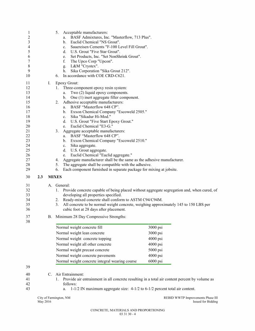
City of Farmington, NM REBID WWTP Improvements Phase III May 2016 Issued for Bidding
CONCRETE, MATERIALS AND PROPORTIONING 03 31 30 - 4
5. Acceptable manufacturers: 1
a. BASF Admixtures, Inc. "Masterflow, 713 Plus". 2
b. Euclid Chemical "NS Grout". 3
c. Sauereisen Cements "F-100 Level Fill Grout". 4
d. U.S. Grout "Five Star Grout". 5
e. Set Products, Inc. "Set NonShrink Grout". 6
f. The Upco Corp "Upcon". 7
g. L&M "Crystex". 8
h. Sika Corporation "Sika Grout 212". 9
6. In accordance with COE CRD-C621. 10
I. Epoxy Grout: 11
1. Three-component epoxy resin system: 12
a. Two (2) liquid epoxy components. 13
b. One (1) inert aggregate filler component. 14
2. Adhesive acceptable manufacturers: 15
a. BASF “Masterflow 648 CP”. 16
b. Exxon Chemical Company "Escoweld 2505." 17
c. Sika "Sikadur Hi-Mod." 18
d. U.S. Grout "Five Start Epoxy Grout." 19
e. Euclid Chemical "E3-G." 20
3. Aggregate acceptable manufacturers: 21
a. BASF “Masterflow 648 CP”. 22
b. Exxon Chemical Company "Escoweld 2510." 23
c. Sika aggregate. 24
d. U.S. Grout aggregate. 25
e. Euclid Chemical "Euclid aggregate." 26
4. Aggregate manufacturer shall be the same as the adhesive manufacturer. 27
5. The aggregate shall be compatible with the adhesive. 28
6. Each component furnished in separate package for mixing at jobsite. 29
2.3 MIXES 30
A. General: 31
1. Provide concrete capable of being placed without aggregate segregation and, when cured, of 32
developing all properties specified. 33
2. Ready-mixed concrete shall conform to ASTM C94/C94M. 34
3. All concrete to be normal weight concrete, weighing approximately 145 to 150 LBS per 35
cubic foot at 28 days after placement. 36
B. Minimum 28 Day Compressive Strengths: 37
38
Normal weight concrete fill 3000 psi
Normal weight lean concrete 3000 psi
Normal weight concrete topping 4000 psi
Normal weight all other concrete 4000 psi
Normal weight precast concrete 5000 psi
Normal weight concrete pavements 4000 psi
Normal weight concrete integral wearing course 6000 psi
39
C. Air Entrainment: 40
1. Provide air entrainment in all concrete resulting in a total air content percent by volume as 41
follows: 42
a. 1-1/2 IN maximum aggregate size: 4-1/2 to 6-1/2 percent total air content. 43

City of Farmington, NM REBID WWTP Improvements Phase III May 2016 Issued for Bidding
CONCRETE, MATERIALS AND PROPORTIONING 03 31 30 - 5
b. 1 IN maximum aggregate size: 5 to 7 percent total air content. 1
c. 3/4 IN maximum aggregate size: 5 to 7 percent total air content. 2
d. 1/2 IN maximum aggregate size: 5-1/2 to 8 percent total air content. 3
e. Interior slabs and mats with power trowel finish: Maximum 3 percent total air content. 4
D. Slump: 5
1. Walls and columns: 6
a. 8 IN maximum, 4 IN minimum measured at the point of discharge into the concrete 7
member. 8
b. Slump shall be obtained by use of mid-range or high-range water reducer in accordance 9
with ASTM C494. 10
2. All other members: 4 IN maximum, 1 IN minimum measured at point of discharge into the 11
concrete construction member. 12
3. Concrete of lower than minimum slump may be used provided it can be properly placed and 13
consolidated. 14
4. Provide additional water or water reducing admixture at ready mix plant for concrete that is 15
to be pumped to allow for slump loss due to pumping. 16
a. Provide only enough additional water so that slump of concrete at discharge end of 17
pump hose does not exceed maximum slump specified and the maximum specified 18
water-cement ration is not exceeded. 19
5. Slump may be adjusted in the field through the use of water reducers. 20
a. Coordinate dosage and mixing requirements with concrete supplier. 21
E. Proportioning: 22
1. General: 23
a. Proportion ingredients to produce a mixture which will work readily into corners and 24
angles of forms and around reinforcement by methods of placement and consolidation 25
employed without permitting materials to segregate or excessive free water to collect on 26
surface. 27
b. Proportion ingredients to produce proper placability, durability, strength and other 28
required properties. 29
2. Normal weight concrete minimum cement contents and maximum water cement ratios: 30
31
SPECIFIED
STRENGTH
(PSI)
MINIMUM
CEMENT
(LBS/CY)
MAXIMUM WATER
CEMENT RATIO BY
WEIGHT
3000 517* 0.45
4000 564* 0.45
4500 611* 0.42
5000 611* 0.45
6000 658* 0.45
32
* If fly ash is proposed for use, the weight of fly ash plus weight of Portland cement shall equal 33
these values. 34
35
3. Fly ash: 36
a. For cast-in-place concrete only, a maximum of 25 percent by weight of Portland cement 37
content per cubic yard may be replaced with fly ash at a rate of 1 LB fly ash for 1 LB 38
cement. 39
b. If fly ash is used, the water to fly ash plus cement ratio not to exceed the maximum 40
water cement ratio specified in this Specification Section. 41
c. Concrete containing fly ash shall not be used in the construction of the precast concrete 42
units specified in Specification Section 03 41 33. 43
4. Water reducing, retarding, and accelerating admixtures: 44
a. Use in accordance with manufacturer's instructions. 45

City of Farmington, NM REBID WWTP Improvements Phase III May 2016 Issued for Bidding
CONCRETE, MATERIALS AND PROPORTIONING 03 31 30 - 6
b. Do not use unless required by these specifications or approved for use by Engineer. 1
5. High range water reducers (superplasticizers): 2
a. Use in accordance with manufacturer's instructions. 3
b. Do not use unless required by these Specifications or approved for use by Engineer. 4
6. Concrete mix proportioning methods for normal weight concrete: 5
a. Method 1: 6
1) Used when combination of materials proposed is to be evaluated and proportions 7
selected to be on a basis of trial mixes. 8
2) Produce mixes having suitable proportions and consistencies based on ACI 211.1, 9
using at least three (3) different water cement ratios or cement contents which will 10
produce a range of compressive strengths encompassing the required average 11
strength. 12
3) Design trial mixes to produce a slump within 0.75 IN of maximum specified, and 13
for air entrained concrete, air content within 0.5 percent specified. 14
4) For each water cement ratio or cement content, make at least three (3) compression 15
test cylinders for specified test age, and cure in accordance with ASTM C192. 16
a) Test for strength at 28 days in accordance with ASTM C39. 17
5) From results of these tests, plot a curve showing relationship between water cement 18
ratio or cement content and compressive strength. 19
6) From this curve select water cement ratio or cement content to be used to produce 20
required average strength. 21
7) Use cement content and mixture proportions such that maximum water cement 22
ratio is not exceeded when slump is maximum specified. 23
8) Base field control on maintenance of proper cement content, slump, air content and 24
water cement ratio. 25
9) See paragraph hereafter for definition of required average strength. 26
b. Method 2: 27
1) In lieu of trial mixes, field test records for concrete made with similar ingredients 28
may be used. 29
2) Use of proposed concrete mix proportions based on field test records subject to 30
approval by Engineer based on information contained in field test records and 31
demonstrated ability to provide the required average strength. 32
3) Field test records to represent materials, proportions and conditions similar to those 33
specified. 34
a) Changes in the materials, proportions and conditions within the test records 35
shall have not been more restricted than those for the proposed concrete mix. 36
b) Field test records shall meet the requirements of ACI 318 Paragraph 5.3.1. 37
4) Required concrete proportions may be established by interpolation between the 38
strengths and proportions of two (2) or more test records each of which meets the 39
requirements of this Specification Section. 40
7. Required average strength to exceed the specified 28 day compressive strength by the 41
amount determined or calculated in accordance with Paragraph 5.3 of ACI 318 using the 42
standard deviation of the proposed concrete production facility as described in Paragraphs 43
5.3.1 and 2 of ACI 318. 44
F. Allowable Shrinkage: 0.048 percent per ASTM C157. 45
2.4 SOURCE QUALITY CONTROL 46
A. To assure stockpiles are not contaminated or materials are segregated, perform any test for 47
determining conformance to requirements for cleanness and grading on samples secured from 48
aggregates at point of batching. 49
B. Do not use frozen or partially frozen aggregates. 50
City of Farmington, NM REBID WWTP Improvements Phase III May 2016 Issued for Bidding
CONCRETE, MATERIALS AND PROPORTIONING 03 31 30 - 7
PART 3 - EXECUTION 1
3.1 FIELD QUALITY CONTROL 2
A. Perform concrete tests per Specification Section 03 05 05. 3
1. Perform a strength test on all concrete to which water or superplasicizer, above the amount 4
stated in the approved concrete mix design, has been added. 5
a. Perform sampling after water or superplasticizer has been added and additional mixing 6
has been performed. 7
B. Perform strength test on any concrete to which water has been added at the jobsite. 8
9
END OF SECTION 10
City of Farmington, NM REBID WWTP Improvements Phase III May 2016 Issued for Bidding
CONCRETE MIXING, PLACING, JOINTING, AND CURING 03 31 31 - 1
SECTION 03 31 31 1
CONCRETE MIXING, PLACING, JOINTING, AND CURING 2
PART 1 - GENERAL 3
1.1 SUMMARY 4
A. Section Includes: 5
1. Mixing, placing, jointing, and curing of concrete construction. 6
B. Related Specification Sections include but are not necessarily limited to: 7
1. Division 00 - Bidding Requirements, Contract Forms, and Conditions of the Contract. 8
2. Division 01 - General Requirements. 9
3. Section 03 05 05 - Testing. 10
4. Section 03 11 13 - Formwork. 11
5. Section 03 21 00 - Reinforcement. 12
6. Section 03 31 32 - Concrete Finishing and Repair of Surface Defects. 13
7. Section 07 26 00 - Under Slab Vapor Retarder. 14
8. Section 07 92 00 - Joint Sealants. 15
1.2 QUALITY ASSURANCE 16
A. Referenced Standards: 17
1. American Concrete Institute (ACI): 18
a. 116R, Cement and Concrete Terminology. 19
b. 304R, Guide for Measuring, Mixing, Transporting and Placing Concrete. 20
c. 304.2R, Placing Concrete by Pumping Methods. 21
d. 305R, Hot Weather Concreting. 22
e. 306R, Cold Weather Concreting. 23
f. 308R, Guide to Curing Concrete. 24
g. 309R, Guide for Consolidation of Concrete. 25
2. ASTM International (ASTM): 26
a. C94/C94M, Standard Specification for Ready-Mixed Concrete. 27
b. C156, Standard Test Method for Water Loss (from a Mortar Specimen) Through Liquid 28
Membrane-Forming Curing Compounds for Concrete. 29
c. C171, Standard Specification for Sheet Materials for Curing Concrete. 30
d. C309, Standard Specification for Liquid Membrane-Forming Compounds for Curing 31
Concrete. 32
e. D994, Standard Specification for Preformed Expansion Joint Filler for Concrete 33
(Bituminous Type). 34
f. D1056, Standard Specification for Flexible Cellular Materials-Sponge or Expanded 35
Rubber. 36
g. D1751, Standard Specification for Preformed Expansion Joint Filler for Concrete 37
Paving and Structural Construction (Nonextruding and Resilient Bituminous Types). 38
3. Corps of Engineers (COE): 39
a. CRD-C572, Specifications for Polyvinylchloride Waterstop. 40
4. National Ready Mixed Concrete Association (NRMCA): 41
a. Checklist for Certification of Ready Mixed Concrete Production Facilities. 42
5. NSF International (NSF). 43
B. Qualifications: 44
1. Ready Mixed Concrete Batch Plant: Certified by NRMCA. 45
City of Farmington, NM REBID WWTP Improvements Phase III May 2016 Issued for Bidding
CONCRETE MIXING, PLACING, JOINTING, AND CURING 03 31 31 - 2
1.3 DEFINITIONS 1
A. Words and terms used in this Specification Section are defined in ACI 116R. 2
1.4 SUBMITTALS 3
A. Shop Drawings: 4
1. See Specification Section 01 33 00 for requirements for the mechanics and administration of 5
the submittal process. 6
2. Product technical data including: 7
a. Acknowledgement that products submitted meet requirements of standards referenced. 8
b. Manufacturer's installation instructions. 9
1) Procedure for adding high-range water reducer at the jobsite. 10
c. Scaled (minimum 1/8 IN per foot) drawings showing proposed locations of 11
construction joints and joint keyway dimensions. 12
d. Manufacturers and types: 13
1) Joint fillers. 14
2) Curing agents. 15
3) Construction joint bonding adhesive. 16
4) Pressure relief valves. 17
5) Waterstops. 18
3. Certifications: 19
a. Ready mix concrete plant certification. 20
b. Waterstops: Products shipped meet or exceed the physical properties specified. 21
B. Informational Submittals: 22
1. See Specification Section 01 33 00 for requirements for the mechanics and administration of 23
the submittal process. 24
2. Copies of concrete delivery tickets. 25
1.5 DELIVERY, STORAGE, AND HANDLING 26
A. Delivery: 27
1. Concrete: 28
a. Prepare a delivery ticket for each load of ready mixed concrete. 29
b. Truck operator shall hand ticket to Contractor at the time of delivery. 30
c. Ticket to show: 31
1) Mix identification. 32
2) Quantity delivered. 33
3) Amount of material in each batch. 34
4) Outdoor temperature in the shade. 35
5) Time at which cement was added 36
6) Time of delivery. 37
7) Time of discharge. 38
8) Amount of water that may be added at the site without exceeding the specified 39
water-cement ratio. 40
9) Amount of water added at the site. 41
PART 2 - PRODUCTS 42
2.1 ACCEPTABLE MANUFACTURERS 43
A. Subject to compliance with the Contract Documents, the manufacturers listed in the applicable 44
Articles below are acceptable. 45
B. Submit request for substitution in accordance with Specification Section 01 25 13. 46
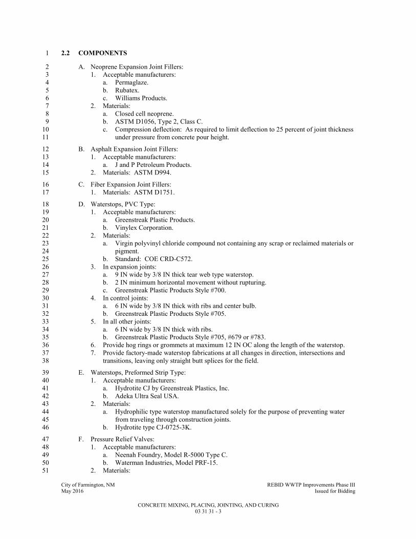
City of Farmington, NM REBID WWTP Improvements Phase III May 2016 Issued for Bidding
CONCRETE MIXING, PLACING, JOINTING, AND CURING 03 31 31 - 3
2.2 COMPONENTS 1
A. Neoprene Expansion Joint Fillers: 2
1. Acceptable manufacturers: 3
a. Permaglaze. 4
b. Rubatex. 5
c. Williams Products. 6
2. Materials: 7
a. Closed cell neoprene. 8
b. ASTM D1056, Type 2, Class C. 9
c. Compression deflection: As required to limit deflection to 25 percent of joint thickness 10
under pressure from concrete pour height. 11
B. Asphalt Expansion Joint Fillers: 12
1. Acceptable manufacturers: 13
a. J and P Petroleum Products. 14
2. Materials: ASTM D994. 15
C. Fiber Expansion Joint Fillers: 16
1. Materials: ASTM D1751. 17
D. Waterstops, PVC Type: 18
1. Acceptable manufacturers: 19
a. Greenstreak Plastic Products. 20
b. Vinylex Corporation. 21
2. Materials: 22
a. Virgin polyvinyl chloride compound not containing any scrap or reclaimed materials or 23
pigment. 24
b. Standard: COE CRD-C572. 25
3. In expansion joints: 26
a. 9 IN wide by 3/8 IN thick tear web type waterstop. 27
b. 2 IN minimum horizontal movement without rupturing. 28
c. Greenstreak Plastic Products Style #700. 29
4. In control joints: 30
a. 6 IN wide by 3/8 IN thick with ribs and center bulb. 31
b. Greenstreak Plastic Products Style #705. 32
5. In all other joints: 33
a. 6 IN wide by 3/8 IN thick with ribs. 34
b. Greenstreak Plastic Products Style #705, #679 or #783. 35
6. Provide hog rings or grommets at maximum 12 IN OC along the length of the waterstop. 36
7. Provide factory-made waterstop fabrications at all changes in direction, intersections and 37
transitions, leaving only straight butt splices for the field. 38
E. Waterstops, Preformed Strip Type: 39
1. Acceptable manufacturers: 40
a. Hydrotite CJ by Greenstreak Plastics, Inc. 41
b. Adeka Ultra Seal USA. 42
2. Materials: 43
a. Hydrophilic type waterstop manufactured solely for the purpose of preventing water 44
from traveling through construction joints. 45
b. Hydrotite type CJ-0725-3K. 46
F. Pressure Relief Valves: 47
1. Acceptable manufacturers: 48
a. Neenah Foundry, Model R-5000 Type C. 49
b. Waterman Industries, Model PRF-15. 50
2. Materials: 51

City of Farmington, NM REBID WWTP Improvements Phase III May 2016 Issued for Bidding
CONCRETE MIXING, PLACING, JOINTING, AND CURING 03 31 31 - 4
a. Cover: Bronze. 1
b. Body and strainer: Cast-iron. 2
c. Seal ring under cover: Neoprene. 3
3. Size: 4
a. Diameter: 4 IN. 5
b. Length: Sufficient length to penetrate the granular/ material at least 2 IN. 6
G. Screen for Pressure Relief Valve: 7
1. Material: Stainless steel, Type 304. 8
2. Wire gage: 16 GA minimum, 12 GA maximum. 9
3. Openings: 3/16 IN SQ. 10
4. Size: 12 by 12 IN. 11
H. Vapor Retarder: See Specification Section 07 26 00. 12
I. Sand cement grout, non-shrink grout and epoxy grout: See Specification Section 03 31 30. 13
PART 3 - EXECUTION 14
3.1 PREPARATION 15
A. General: 16
1. Complete formwork. 17
a. See Specification Section 03 11 13. 18
2. Remove earth, snow, ice, water, and other foreign materials from areas that will receive 19
concrete. 20
3. Secure reinforcement in place. 21
a. See Specification Section 03 21 00. 22
4. Position expansion joint material, anchors and other embedded items. 23
5. Obtain approval of reinforcement erection and placement prior to placing concrete. 24
6. Do not place concrete during rain, sleet, or snow, unless adequate protection is provided and 25
approval is obtained. 26
a. Plan size of crews with due regard for effects of concrete temperature and atmospheric 27
conditions on rate of hardening of concrete as required to obtain good surfaces and 28
avoid unplanned cold joints. 29
b. Do not allow rainwater to increase mixing water nor to damage surface finish. 30
7. Prepare all construction joints for proper bond per the Construction Joints - Bonding 31
Paragraph in PART 3 of this Specification Section. 32
8. Remove hardened concrete and foreign materials from inner surfaces of conveying 33
equipment and formwork. 34
9. Provide slabs and beams of minimum indicated required depth when sloping structural 35
foundation base slabs and elevated slabs to drains. 36
a. For floor slabs on grade, slope top of subgrade to provide slab of required uniform 37
thickness. 38
B. Preparation of Subgrade for Slabs On Ground: 39
1. Subgrade drained and of adequate and uniform load-bearing nature. 40
2. Obtain approval of subgrade compaction density prior to placing slabs on ground. 41
3. Maintain subgrade at a temperature above 32 DegF before concrete placing begins for a 42
sufficient amount of time to remove frost. 43
4. Moisten subgrade to eliminate absorption. 44
a. Keep subgrade moist at time of concreting. 45
b. Allow no free-standing water on subgrade or soft or muddy spots when concrete is 46
placed. 47
C. Edge Forms and Screeds: 48

City of Farmington, NM REBID WWTP Improvements Phase III May 2016 Issued for Bidding
CONCRETE MIXING, PLACING, JOINTING, AND CURING 03 31 31 - 5
1. Set accurately to produce designated elevations and contours of finished surface. 1
2. Sufficiently strong to support vibrating screeds or roller pipe screeds, if required. 2
3. Use strike off templates, or approved vibrating type screeds, to align concrete surfaces to 3
contours of screed strips. 4
3.2 CONCRETE MIXING 5
A. General: 6
1. Provide all concrete from a central plant conforming to Checklist for Certification of Ready 7
Mixed Concrete Production Facilities of the NRMCA. 8
2. Batch, mix, and transport in accordance with ASTM C94/C94M. 9
B. Control of Admixtures: 10
1. Charge admixtures into mixer as solutions. 11
a. Measure by means of an approved mechanical dispensing device. 12
b. Liquid considered a part of mixing water. 13
c. Admixtures that cannot be added in solution may be weighed or measured by volume if 14
so recommended by manufacturer. 15
2. Add separately, when two or more admixtures are used in concrete, to avoid possible 16
interaction that might interfere with efficiency of either admixture, or adversely affect 17
concrete. 18
3. Complete addition of retarding admixtures within one minute after addition of water to 19
cement has been completed, or prior to beginning of last three quarters of required mixing, 20
whichever occurs first. 21
C. Tempering and Control of Mixing Water: 22
1. Mix concrete only in quantities for immediate use. 23
2. Discard concrete which has set. 24
3. Discharge concrete from ready mix trucks within time limit and drum revolutions stated in 25
ASTM C94/C94M. 26
4. Addition of water at the jobsite: 27
a. See Specification Section 03 31 30 for specified water cement ratio and slump. 28
b. Do not exceed maximum specified water cement ratio or slump. 29
c. Incorporate water by additional mixing equal to at least half of total mixing required. 30
d. Perform strength test on any concrete to which water has been added at the jobsite. 31
1) See Specification Section 03 05 05. 32
3.3 PLACING OF CONCRETE 33
A. General: 34
1. Comply with ACI 304R and ACI 304.2R. 35
2. Deposit concrete: 36
a. Continuously to avoid cold joints. 37
b. In layers of 12 to 18 IN. 38
3. Locate construction joints at locations approved by Engineer. 39
a. Plan size of crews with due regard for effects of concrete temperature and atmosphere 40
conditions to avoid unplanned cold joints. 41
4. Place concrete at such a rate that concrete, which is being integrated with fresh concrete, is 42
still workable. 43
5. Do not deposit concrete which has partially hardened or has been contaminated by foreign 44
materials. 45
6. Spreaders: 46
a. Temporary: Remove as soon as concrete placing renders their function unnecessary. 47
b. Embedded: 48
1) Obtain approval of Engineer. 49
2) Materials: Concrete or metal. 50

City of Farmington, NM REBID WWTP Improvements Phase III May 2016 Issued for Bidding
CONCRETE MIXING, PLACING, JOINTING, AND CURING 03 31 31 - 6
3) Ends of metal spreaders coated with plastic coating 2 IN from each end. 1
7. Deposit concrete as nearly as practicable in its final position to avoid segregation. 2
a. Maximum free fall: 4 FT. 3
b. Free fall exceeding 4 FT: Place concrete by means of hopper, elephant trunk or tremie 4
pipe extending down to within 4 FT of surface placed upon. 5
8. Perform the following operations before bleeding water has an opportunity to collect on 6
surface: 7
a. Spread. 8
b. Consolidate. 9
c. Straightedge. 10
d. Darby or bull float. 11
B. Admixtures: 12
1. All admixtures to be introduced at the batch plant in accordance with manufacturer's 13
recommendations. 14
C. Cold Weather Concrete Placement: 15
1. Comply with ACI 306R. 16
2. Do not place concrete on substrates that are below 32 DegF or contain frozen material. 17
3. Maintain all materials, forms, reinforcement, subgrade and any other items which concrete 18
will come in contact with free of frost, ice or snow at time of concrete placement. 19
4. Temperature of concrete when discharged at site: 20
21
AIR
TEMPERATURE
DEGF
MINIMUM CONCRETE
TEMPERATURE, DEGF FOR
SECTIONS WITH LEAST
DIMENSION LESS THAN 12 IN
MINIMUM CONCRETE
TEMPERATURE, DEGF FOR
SECTIONS WITH LEAST
DIMENSION 12 IN OR GREATER
30 to 45 60 55
0 to 30 65 55
below 0 70 60
22
5. Heat subgrade, forms, and reinforcement so the temperature of the subgrade, forms, and 23
reinforcement will be between 45 and 70 DegF, when temperature of surrounding air is 40 24
DegF or below at time concrete is placed. 25
a. Remove all frost from subgrade, forms and reinforcement before concrete is placed. 26
6. Combine water with aggregate in mixer before cement is added, if water or aggregate is 27
heated above 90 DegF. 28
7. Do not mix cement with water or with mixtures of water and aggregate having a 29
temperature greater than 90 DegF. 30
8. Do not place slabs on ground if temperature is below 40 DegF or if temperature surrounding 31
the slab will be below 40 DegF before structure is enclosed and heated. 32
D. Hot Weather Concrete Placement: 33
1. Comply with ACI 305R. 34
2. Cool ingredients before mixing, or add flake ice or well crushed ice of a size that will melt 35
completely during mixing for all or part of mixing water if high temperature, low slump, 36
flash set, cold joints, or shrinkage cracks are encountered. 37
3. Temperature of concrete when placed: 38
a. Not to exceed 90 DegF. 39
b. Not so high as to cause: 40
1) Shrinkage cracks. 41
2) Difficulty in placement due to loss of slump. 42
3) Flash set. 43
4. Temperature of forms and reinforcing when placing concrete: 44
a. Not to exceed 90 DegF. 45

City of Farmington, NM REBID WWTP Improvements Phase III May 2016 Issued for Bidding
CONCRETE MIXING, PLACING, JOINTING, AND CURING 03 31 31 - 7
b. May be reduced by spraying with water to cool below 90 DegF. 1
1) Leave no standing water to contact concrete being placed. 2
E. Consolidating: 3
1. Consolidate in accordance with ACI 309R except as modified herein. 4
2. Consolidate by vibration so that concrete is thoroughly worked around reinforcement, 5
embedded items and into corners of forms. 6
a. Eliminate: 7
1) Air or stone pockets. 8
2) Honeycombing or pitting. 9
3) Planes of weakness. 10
3. Internal vibrators: 11
a. Minimum frequency of 8000 vibrations per minute. 12
b. Insert and withdraw at points approximately 18 IN apart. 13
1) Allow sufficient duration at each insertion to consolidate concrete but not sufficient 14
to cause segregation. 15
c. Use in: 16
1) Beams and girders of framed slabs. 17
2) Columns and walls. 18
d. Size of vibrators shall be in accordance with ACI 309R, Table 5.1.5. 19
4. Obtain consolidation of slabs with internal vibrators, vibrating screeds, roller pipe screeds, 20
or other approved means. 21
5. Do not use vibrators to transport concrete within forms. 22
6. Provide spare vibrators on jobsite during all concrete placing operations. 23
7. Bring a full surface of mortar against form by vibration supplemented if necessary by 24
spading to work coarse aggregate back from formed surface, where concrete is to have an 25
as-cast finish. 26
8. Use suitable form vibrators located just below top surface of concrete, where internal 27
vibrators cannot be used in areas of congested reinforcing. 28
9. Prevent construction equipment, construction operations, and personnel from introducing 29
vibrations into freshly placed concrete after the concrete has been placed and consolidated. 30
F. Handle concrete from mixer to place of final deposit by methods which will prevent segregation 31
or loss of ingredients and in a manner which will assure that required quality of concrete is 32
maintained. 33
1. Use truck mixers, agitators, and non-agitating units in accordance with ASTM C94/C94M. 34
2. Horizontal belt conveyors: 35
a. Mount at a slope which will not cause segregation or loss of ingredients. 36
b. Protect concrete against undue drying or rise in temperature. 37
c. Use an arrangement at discharge end to prevent segregation. 38
d. Do not allow mortar to adhere to return length of belt. 39
e. Discharge conveyor runs into equipment specially designed for spreading concrete. 40
3. Metal or metal lined chutes: 41
a. Slope not exceeding 1 vertical to 2 horizontal and not less than 1 vertical to 3 42
horizontal. 43
b. Chutes more than 20 FT long and chutes not meeting slope requirements may be used 44
provided they discharge into a hopper before distribution. 45
c. Provide end of each chute with a device to prevent segregation. 46
4. Pumping or pneumatic conveying equipment: 47
a. Designed for concrete application and having adequate pumping capacity. 48
b. Control pneumatic placement so segregation is avoided in discharged concrete. 49
c. Loss of slump in pumping or pneumatic conveying equipment shall not exceed 1-1/2 50
IN. 51
d. Do not convey concrete through pipe made of aluminum or aluminum alloy. 52
e. Provide pumping equipment without Y sections. 53

City of Farmington, NM REBID WWTP Improvements Phase III May 2016 Issued for Bidding
CONCRETE MIXING, PLACING, JOINTING, AND CURING 03 31 31 - 8
G. Placing of Concrete on Metal Deck: 1
1. Prior to concrete placement, the metal deck shall be free of soil, debris, standing water, 2
loose mill scale, and all other foreign matter. 3
2. Care shall be exercised when placing concrete so that the deck will not be subject to 4
construction loads or impact that exceed the design capacity of the deck. 5
3. Concrete shall be placed in a uniform manner and spread toward the center of the deck span. 6
4. If buggies are used to place concrete, runways shall be planked, and the buggies shall only 7
operate on planking. 8
a. Planks shall be of adequate stiffness to transfer loads to the steel supports without 9
damaging the deck. 10
5. Deck damage caused by careless placement of concrete shall be repaired or replaced. 11
3.4 JOINTS AND EMBEDDED ITEMS 12
A. Construction Joints - General: 13
1. Locate joints as indicated on Contract Drawings or as shown on approved Shop Drawings. 14
a. Where construction joint spacing shown on Drawings exceeds the joint spacing 15
indicated in Paragraph B. below, submit proposed construction joint location in 16
conformance with this Specification Section. 17
2. Unplanned construction joints will not be allowed. 18
a. If concrete cannot be completely placed between planned construction joints, then it 19
must be removed. 20
3. In general, locate joints near middle of spans of slabs, beams and girders unless a beam 21
intersects a girder at this point, in which case, offset joint in girder a distance equal to twice 22
the width of the beam. 23
4. Locate joints in walls and columns at underside of floors, slabs, beams, or girders, and at 24
tops of foundations or floor slabs, unless shown otherwise. 25
a. At Contractor's option, beam pockets may be formed into concrete walls. 26
b. Size pockets to allow beam reinforcing to be placed as detailed on Drawings. 27
5. Place beams, girders, column capitals and drop panels at same time as slabs. 28
6. Place corbels monolithically with walls. 29
a. Locate wall vertical construction joints midway between corbels. 30
b. Where only a single corbel is located place it also monolithically with wall and locate 31
wall vertical construction joint a minimum of 3 FT from face of corbel. 32
7. Make joints perpendicular to main reinforcement with all reinforcement continuous across 33
joints. 34
8. Provide roughened construction joints at all construction joints unless indicated otherwise 35
on Drawings. 36
a. Clean the previously hardened concrete interface and remove all laitance. 37
b. Intentionally roughen the interface to a full amplitude of 1/4 IN. 38
c. Provide recessed flat surface as required to install strip type waterstops. 39
9. Provide continuous keyways only where indicated on Drawings. 40
a. Construction joint keyways shall have the following dimensions, unless shown 41
otherwise on Drawings or directed otherwise by Engineer. 42
b. Construction joint keyways in walls: 43
1) Keyway width, not less than 1/3 and not more than 1/2 the wall thickness measured 44
perpendicular to wall faces. 45
2) Keyway depth to be not less than 1-1/2 IN. 46
3) Place keyway in wall center unless shown otherwise on Drawings. 47
c. Construction joint keyways in footings, foundations, base slabs, and structural or 48
elevated slabs: 49
1) Keyway height not less than 1/3 and not more than 1/2 the footing or slab 50
thickness. 51
2) Keyway depth not less than 1-1/2 IN. 52
3) Keyway in footing or slab center unless shown otherwise on Drawings. 53

City of Farmington, NM REBID WWTP Improvements Phase III May 2016 Issued for Bidding
CONCRETE MIXING, PLACING, JOINTING, AND CURING 03 31 31 - 9
d. Construction joint keyways in beams: 1
1) Keyway height not less than 1/3 and not more than 1/2 the beam depth. 2
2) Keyway depth not less than 1-1/2 IN. 3
3) Keyway in beam center unless shown otherwise on Drawings. 4
10. Allow a minimum of 48 HRS before placement of adjoining concrete construction. 5
B. Construction Joints - Spacing: 6
1. General - Structures not intended to contain liquid: 7
a. Wall vertical construction joints: 8
1) 60 FT maximum centers. 9
2) At wall intersections, 30 FT maximum from corner. 10
b. Wall horizontal construction joints: 20 to 25 FT centers. 11
c. Base slab, floor, and roof slab construction joints: 12
1) Placements to be approximately square and not to exceed 3500 SF. 13
2) Maximum side dimension of a slab pour to be less than: 14
a) Twice the length of the short side. 15
b) 80 FT. 16
2. Structures intended to contain liquids: 17
a. Wall vertical construction joints: 18
1) 30 FT maximum centers. 19
2) At wall intersections, 15 FT maximum from corner. 20
b. Wall horizontal construction joints: 12 to 18 FT centers. 21
c. Walls that are thicker than 18 IN may be poured less than 30 FT tall in one (1) pour 22
provided the following requirements are satisfied: 23
1) A test wall of similar size, height and thickness will be poured to demonstrate the 24
quality of the concrete work. 25
2) The test wall will be located as a portion of a non-water bearing wall. 26
a) The test wall will include a waterstop at the bottom of the wall. 27
b) Alternatively, a separate test wall, not part of the final work, may be 28
constructed. 29
3) The concrete placement and concrete quality of the test wall will be observed by 30
the Engineer. 31
a) Concrete will be judged on the following: 32
(1) Ability to keep bottom of the pour clean and free from trash and debris. 33
(2) Ability to protect the waterstop from folding over due to the force of 34
falling concrete. 35
(3) Ability to properly consolidate all concrete in the wall pour, including 36
below formed openings. 37
4) Engineer will evaluate the Contractor’s work and may recommend taller concrete 38
wall pours if concrete quality is acceptable. 39
5) Preparation for all subsequent wall pours over 18 FT tall must be the same as the 40
preparation of the test wall. 41
6) Should the quality of concrete work on subsequent wall pours be judged 42
inadequate, the Contractor may be directed to limit wall pour heights to 18 FT as 43
originally specified. 44
7) Should the quality of concrete work on the test wall be judged inadequate, 45
additional test walls will not be observed and judged to allow pour heights greater 46
that 18 FT unless allowed by Engineer. 47
d. Base slab, floor, and roof slab construction joints: 48
1) Placements to be approximately square and not to exceed 2000 SF. 49
2) Maximum side dimension of a slab pour to be less than: 50
a) Twice the length of the short side. 51
b) 60 FT. 52
C. Construction Joints - Bonding: 53
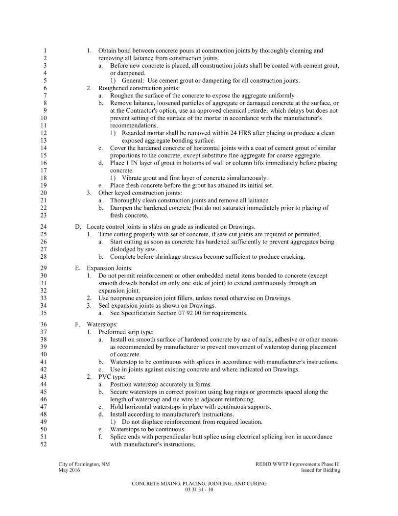
City of Farmington, NM REBID WWTP Improvements Phase III May 2016 Issued for Bidding
CONCRETE MIXING, PLACING, JOINTING, AND CURING 03 31 31 - 10
1. Obtain bond between concrete pours at construction joints by thoroughly cleaning and 1
removing all laitance from construction joints. 2
a. Before new concrete is placed, all construction joints shall be coated with cement grout, 3
or dampened. 4
1) General: Use cement grout or dampening for all construction joints. 5
2. Roughened construction joints: 6
a. Roughen the surface of the concrete to expose the aggregate uniformly 7
b. Remove laitance, loosened particles of aggregate or damaged concrete at the surface, or 8
at the Contractor's option, use an approved chemical retarder which delays but does not 9
prevent setting of the surface of the mortar in accordance with the manufacturer's 10
recommendations. 11
1) Retarded mortar shall be removed within 24 HRS after placing to produce a clean 12
exposed aggregate bonding surface. 13
c. Cover the hardened concrete of horizontal joints with a coat of cement grout of similar 14
proportions to the concrete, except substitute fine aggregate for coarse aggregate. 15
d. Place 1 IN layer of grout in bottoms of wall or column lifts immediately before placing 16
concrete. 17
1) Vibrate grout and first layer of concrete simultaneously. 18
e. Place fresh concrete before the grout has attained its initial set. 19
3. Other keyed construction joints: 20
a. Thoroughly clean construction joints and remove all laitance. 21
b. Dampen the hardened concrete (but do not saturate) immediately prior to placing of 22
fresh concrete. 23
D. Locate control joints in slabs on grade as indicated on Drawings. 24
1. Time cutting properly with set of concrete, if saw cut joints are required or permitted. 25
a. Start cutting as soon as concrete has hardened sufficiently to prevent aggregates being 26
dislodged by saw. 27
b. Complete before shrinkage stresses become sufficient to produce cracking. 28
E. Expansion Joints: 29
1. Do not permit reinforcement or other embedded metal items bonded to concrete (except 30
smooth dowels bonded on only one side of joint) to extend continuously through an 31
expansion joint. 32
2. Use neoprene expansion joint fillers, unless noted otherwise on Drawings. 33
3. Seal expansion joints as shown on Drawings. 34
a. See Specification Section 07 92 00 for requirements. 35
F. Waterstops: 36
1. Preformed strip type: 37
a. Install on smooth surface of hardened concrete by use of nails, adhesive or other means 38
as recommended by manufacturer to prevent movement of waterstop during placement 39
of concrete. 40
b. Waterstop to be continuous with splices in accordance with manufacturer's instructions. 41
c. Use in joints against existing concrete and where indicated on Drawings. 42
2. PVC type: 43
a. Position waterstop accurately in forms. 44
b. Secure waterstops in correct position using hog rings or grommets spaced along the 45
length of waterstop and tie wire to adjacent reinforcing. 46
c. Hold horizontal waterstops in place with continuous supports. 47
d. Install according to manufacturer's instructions. 48
1) Do not displace reinforcement from required location. 49
e. Waterstops to be continuous. 50
f. Splice ends with perpendicular butt splice using electrical splicing iron in accordance 51
with manufacturer's instructions. 52
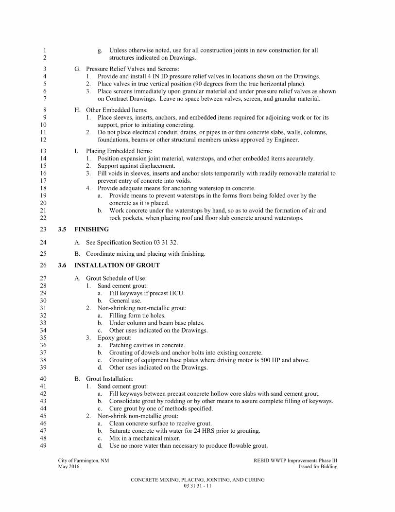
City of Farmington, NM REBID WWTP Improvements Phase III May 2016 Issued for Bidding
CONCRETE MIXING, PLACING, JOINTING, AND CURING 03 31 31 - 11
g. Unless otherwise noted, use for all construction joints in new construction for all 1
structures indicated on Drawings. 2
G. Pressure Relief Valves and Screens: 3
1. Provide and install 4 IN ID pressure relief valves in locations shown on the Drawings. 4
2. Place valves in true vertical position (90 degrees from the true horizontal plane). 5
3. Place screens immediately upon granular material and under pressure relief valves as shown 6
on Contract Drawings. Leave no space between valves, screen, and granular material. 7
H. Other Embedded Items: 8
1. Place sleeves, inserts, anchors, and embedded items required for adjoining work or for its 9
support, prior to initiating concreting. 10
2. Do not place electrical conduit, drains, or pipes in or thru concrete slabs, walls, columns, 11
foundations, beams or other structural members unless approved by Engineer. 12
I. Placing Embedded Items: 13
1. Position expansion joint material, waterstops, and other embedded items accurately. 14
2. Support against displacement. 15
3. Fill voids in sleeves, inserts and anchor slots temporarily with readily removable material to 16
prevent entry of concrete into voids. 17
4. Provide adequate means for anchoring waterstop in concrete. 18
a. Provide means to prevent waterstops in the forms from being folded over by the 19
concrete as it is placed. 20
b. Work concrete under the waterstops by hand, so as to avoid the formation of air and 21
rock pockets, when placing roof and floor slab concrete around waterstops. 22
3.5 FINISHING 23
A. See Specification Section 03 31 32. 24
B. Coordinate mixing and placing with finishing. 25
3.6 INSTALLATION OF GROUT 26
A. Grout Schedule of Use: 27
1. Sand cement grout: 28
a. Fill keyways if precast HCU. 29
b. General use. 30
2. Non-shrinking non-metallic grout: 31
a. Filling form tie holes. 32
b. Under column and beam base plates. 33
c. Other uses indicated on the Drawings. 34
3. Epoxy grout: 35
a. Patching cavities in concrete. 36
b. Grouting of dowels and anchor bolts into existing concrete. 37
c. Grouting of equipment base plates where driving motor is 500 HP and above. 38
d. Other uses indicated on the Drawings. 39
B. Grout Installation: 40
1. Sand cement grout: 41
a. Fill keyways between precast concrete hollow core slabs with sand cement grout. 42
b. Consolidate grout by rodding or by other means to assure complete filling of keyways. 43
c. Cure grout by one of methods specified. 44
2. Non-shrink non-metallic grout: 45
a. Clean concrete surface to receive grout. 46
b. Saturate concrete with water for 24 HRS prior to grouting. 47
c. Mix in a mechanical mixer. 48
d. Use no more water than necessary to produce flowable grout. 49

City of Farmington, NM REBID WWTP Improvements Phase III May 2016 Issued for Bidding
CONCRETE MIXING, PLACING, JOINTING, AND CURING 03 31 31 - 12
e. Place in accordance with manufacturer's instructions. 1
f. Provide under beam, column, and equipment base plates, in joints between precast 2
concrete filter slabs, and in other locations indicated on the Drawings. 3
g. Completely fill all spaces and cavities below the top of base plates. 4
h. Provide forms where base plates and bed plates do not confine grout. 5
i. Where exposed to view, finish grout edges smooth. 6
j. Except where a slope is indicated on the Drawings, finish edges flush at the base plate, 7
bed plate, member or piece of equipment. 8
k. Coat exposed edges of grout with cure or seal compound recommended by the grout 9
manufacturer. 10
3. Epoxy grout: 11
a. Mix and place in accordance with manufacturer's instructions. 12
b. Apply only to clean, dry, sound surface. 13
c. Completely fill all cavities and spaces around dowels and anchors without voids. 14
d. Grout base and bed plates as specified for non-shrinking, non-metallic grout. 15
e. Obtain manufacturer's field technical assistance as required to assure proper placement. 16
3.7 CURING AND PROTECTION 17
A. Protect concrete from premature drying, excessively hot or cold temperatures, and mechanical 18
injury immediately after placement, and maintain with minimal moisture loss at relatively 19
constant temperature for period necessary for hydration of cement, hardening, and compressive 20
strength gain. 21
1. Follow recommendations of ACI 308 except as modified herein. 22
B. Apply one of the following curing procedures immediately after completion of placement and 23
finishing, for concrete surfaces not in contact with forms. 24
1. Ponding or continuous sprinkling. 25
2. Application of absorptive mats or fabric kept continuously wet. 26
3. Application of sand kept continuously wet. 27
4. Continuous application of steam (not exceeding 150 DegF) or mist spray. 28
5. Application of waterproof sheet materials, conforming to ASTM C171. 29
6. Application of other moisture retaining covering as approved. 30
7. Application of a curing compound conforming to ASTM C309. 31
a. Apply curing compound in accordance with manufacturer's recommendations 32
immediately after any water sheen which may develop after finishing has disappeared 33
from concrete surface. 34
b. Do not use on any surface against which additional concrete or other material is to be 35
bonded unless it is proven that curing compound will not prevent bond. 36
c. Where a vertical surface is cured with a curing compound, the vertical surface shall be 37
covered with a minimum of two (2) coats of the curing compound. 38
1) Apply the first coat of curing compound to a vertical surface immediately after 39
form removal. 40
2) The vertical concrete surface at the time of receiving the first coat shall be damp 41
with no free water on the surface. 42
3) Allow the preceding coat to completely dry prior to applying the next coat. 43
4) A vertical surface: Any surface steeper than 1 vertical to 4 horizontal. 44
d. Curing compounds used in water treatment plant construction shall be non-toxic and 45
taste and odor free. 46
1) Curing compound to be NSF approved and have a moisture loss of not more than 47
0.62 kg/SQ meter per ASTM C156. 48
a) Atlas Tech Products Atlas Quantum-Cure. 49
2) Alternately, all tank surfaces shall be sand-blasted as required to remove non-NSF 50
approved curing compound. 51
C. Curing Concrete In Contact with Forms: 52

City of Farmington, NM REBID WWTP Improvements Phase III May 2016 Issued for Bidding
CONCRETE MIXING, PLACING, JOINTING, AND CURING 03 31 31 - 13
1. Minimize moisture loss from and temperature gain of concrete placed in forms exposed to 1
heating by sun by keeping forms wet and cool until they can be safely removed. 2
2. After form removal, cure concrete until end of time prescribed. 3
a. Use one of methods listed above. 4
3. Forms left in place shall not be used as a method of curing in hot weather. 5
4. The term "hot weather," where used in these specifications, is defined in ACI 305R. 6
5. In hot weather, remove forms from vertical surfaces as soon as concrete has gained 7
sufficient strength so that the formwork is no longer required to support the concrete. 8
D. Continue curing for at least seven (7) days for all concrete except high early strength concrete 9
for which period shall be at least three (3) days. 10
1. If one of curing procedures indicated above is used initially, it may be replaced by one of 11
other procedures indicated any time after concrete is one (1) day old, provided concrete is 12
not permitted to become surface dry during transition. 13
E. Cold Weather: 14
1. Follow recommendations of ACI 306R. 15
2. Maintain temperature of concrete between 50 and 70 DegF for required curing period, when 16
outdoor temperature is 40 DegF, or less. 17
3. Use heating, covering, insulating, or housing of the concrete work to maintain required 18
temperature without injury due to concentration of heat. 19
4. Do not use combustion heaters unless precautions are taken to prevent exposure of concrete 20
to exhaust gases which contain carbon dioxide. 21
5. Interior slabs in areas intended to be heated shall be adequately protected so that frost does 22
not develop in the supporting subgrade. 23
F. Hot Weather: 24
1. Follow recommendations of ACI 305R. 25
2. Make provision for cooling forms, reinforcement and concrete, windbreaks, shading, fog 26
spraying, sprinkling, ponding, or wet covering with a light colored material. 27
3. Provide protective measures as quickly as concrete hardening and finishing operations will 28
allow. 29
G. Rate of Temperature Change: 30
1. Keep changes in temperature of air immediately adjacent to concrete as uniform as possible, 31
during and immediately following curing period. 32
2. Do not exceed a temperature change of 5 DegF in any 1 HR or 50 DegF in any 24 HR 33
period. 34
H. Protection from Mechanical Injury: 35
1. Protect concrete from damaging mechanical disturbances, such as load stresses, heavy 36
shock, and excessive vibration. 37
2. Protect finished concrete surfaces from damage by construction equipment, materials, or 38
methods, and by rain or running water. 39
3. Do not load self supporting structures in such a way as to overstress concrete. 40
3.8 FIELD QUALITY CONTROL 41
A. Tests in accordance with Specification Section 03 05 05. 42
1. Perform a strength test on all concrete to which water or superplasticizer, above the amount 43
stated in the approved concrete mix design, has been added. 44
a. Perform sampling after water or superplasticizer has been added and additional mixing 45
has been performed. 46
B. Field samples of fabricated waterstop fittings (crosses, tees, etc.) will be selected at random by 47
the Engineer for testing by a laboratory at the Owner's expense. 48
1. When tested, they shall have a tensile strength across the joints equal to at least 600 psi. 49

City of Farmington, NM REBID WWTP Improvements Phase III May 2016 Issued for Bidding
CONCRETE MIXING, PLACING, JOINTING, AND CURING 03 31 31 - 14
END OF SECTION1

City of Farmington, NM REBID WWTP Improvements Phase III May 2016 Issued for Bidding
CONCRETE FINISHING AND REPAIR OF SURFACE DEFECTS 03 31 32 - 1
SECTION 03 31 32 1
CONCRETE FINISHING AND REPAIR OF SURFACE DEFECTS 2
PART 1 - GENERAL 3
1.1 SUMMARY 4
A. Section Includes: 5
1. Concrete finishing and repair of surface defects. 6
B. Related Specification Sections include but are not necessarily limited to: 7
1. Division 00 - Bidding Requirements, Contract Forms, and Conditions of the Contract. 8
2. Division 01 - General Requirements. 9
3. Section 03 11 13 - Formwork. 10
4. Section 03 31 30 - Concrete, Materials and Proportioning. 11
5. Section 03 31 31 - Concrete Mixing, Placing, Jointing and Curing. 12
1.2 QUALITY ASSURANCE 13
A. Referenced Standards: 14
1. American Concrete Institute (ACI): 15
a. 116R, Cement and Concrete Terminology. 16
2. ASTM International (ASTM): 17
a. C150, Standard Specification for Portland Cement. 18
b. C309, Standard Specification for Liquid Membrane-Forming Compounds for Curing 19
Concrete. 20
c. C1315, Standard Specification for Liquid Membrane-Forming Compounds Having 21
Special Properties for Curing and Sealing Concrete. 22
d. D4258, Standard Practice for Surface Cleaning Concrete for Coating. 23
e. D4259, Standard Practice for Abrading Concrete. 24
3. The Society for Protective Coatings/NACE International (SSPC/NACE): 25
a. SP 13/NACE No. 6, Surface Preparation of Concrete. 26
B. Qualifications: 27
1. Applicator of surfacer/filler must be approved, in writing, by manufacturer. 28
2. Manufacturer of surfacer/filler shall have minimum of five (5) years experience in 29
manufacturing of same with documented performance history for similar installations. 30
3. Installer/applicator of surfacer/filler shall have minimum of three (3) years experience 31
installing similar coatings and shall be licensed or approved in writing by manufacturer to 32
install/apply this product. 33
4. Applicator of concrete sealer, hardener, densifier shall be factory trained and approved, in 34
writing, by the manufacturer to apply the product. 35
a. Applicator shall have a minimum of five (5) years experience successfully applying 36
materials specified. 37
1.3 DEFINITIONS 38
A. Vertical Surface Defects: 39
1. Any void in the face of the concrete deeper than 1/8 IN, such as: 40
a. Tie holes. 41
b. Air pockets (bug holes). 42
c. Honeycombs. 43
d. Rock holes. 44
2. Scabbing: 45
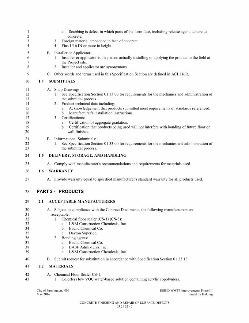
City of Farmington, NM REBID WWTP Improvements Phase III May 2016 Issued for Bidding
CONCRETE FINISHING AND REPAIR OF SURFACE DEFECTS 03 31 32 - 2
a. Scabbing is defect in which parts of the form face, including release agent, adhere to 1
concrete. 2
3. Foreign material embedded in face of concrete. 3
4. Fins 1/16 IN or more in height. 4
B. Installer or Applicator: 5
1. Installer or applicator is the person actually installing or applying the product in the field at 6
the Project site. 7
2. Installer and applicator are synonymous. 8
C. Other words and terms used in this Specification Section are defined in ACI 116R. 9
1.4 SUBMITTALS 10
A. Shop Drawings: 11
1. See Specification Section 01 33 00 for requirements for the mechanics and administration of 12
the submittal process. 13
2. Product technical data including: 14
a. Acknowledgement that products submitted meet requirements of standards referenced. 15
b. Manufacturer's installation instructions. 16
3. Certifications: 17
a. Certification of aggregate gradation. 18
b. Certification that products being used will not interfere with bonding of future floor or 19
wall finishes. 20
B. Informational Submittals: 21
1. See Specification Section 01 33 00 for requirements for the mechanics and administration of 22
the submittal process. 23
1.5 DELIVERY, STORAGE, AND HANDLING 24
A. Comply with manufacturer's recommendations and requirements for materials used. 25
1.6 WARRANTY 26
A. Provide warranty equal to specified manufacturer's standard warranty for all products used. 27
PART 2 - PRODUCTS 28
2.1 ACCEPTABLE MANUFACTURERS 29
A. Subject to compliance with the Contract Documents, the following manufacturers are 30
acceptable: 31
1. Chemical floor sealer (CS-1) (CS-3): 32
a. L&M Construction Chemicals, Inc. 33
b. Euclid Chemical Co. 34
c. Dayton Superior. 35
2. Bonding agents: 36
a. Euclid Chemical Co. 37
b. BASF Admixtures, Inc. 38
c. L&M Construction Chemicals, Inc. 39
B. Submit request for substitution in accordance with Specification Section 01 25 13. 40
2.2 MATERIALS 41
A. Chemical Floor Sealer CS-1: 42
1. Colorless low VOC water-based solution containing acrylic copolymers. 43

City of Farmington, NM REBID WWTP Improvements Phase III May 2016 Issued for Bidding
CONCRETE FINISHING AND REPAIR OF SURFACE DEFECTS 03 31 32 - 3
a. ASTM C1315, Class B, minimum 30 percent solids. 1
b. ASTM C309, Type 1. 2
c. Non-yellowing UV resistant. 3
d. Capable of being painted after cured. 4
2. L&M Construction Chemicals, Inc. Dress and Seal WB 30. 5
B. Bonding Agent: 6
1. For use only on concrete surfaces not receiving liquid water repellent coating: 7
a. High solids acrylic latex base liquid for interior or exterior application as a bonding 8
agent to improve adhesion and mechanical properties of concrete patching mortars. 9
b. Euclid Chemical Co. "Flex-Con." 10
c. BASF Admixtures, Inc. "Acryl-Set." 11
d. L&M Construction Chemicals, Inc. "Everbond." 12
e. Thoro System Products "Acryl 60." 13
2. For use only on concrete surface receiving liquid water repellent: 14
a. Non-acrylic base liquid for interior or exterior application as a bonding agent to 15
improve adhesion and mechanical properties of concrete patching mortars. 16
C. Cement: 17
1. ASTM C150, Type II Portland for areas exposed to sewage. 18
2. ASTM C150, Type I/II Portland elsewhere. 19
D. Aggregate: 20
1. Sand: Maximum size #30 mesh sieve. 21
2. For exposed aggregate finish surfaces: Same as surrounding wall. 22
E. Water: Potable. 23
F. Nonshrink Grout: See Specification Section 03 31 30 and Specification Section 03 31 31. 24
2.3 MIXES 25
A. Bonding Grout: One (1) part cement to one (1) part aggregate. 26
B. Patching Mortar: 27
1. One (1) part cement to two and one-half (2-1/2) parts aggregate by damp loose volume. 28
a. Substitute white Portland cement for a part of gray Portland cement to produce color 29
matching surrounding concrete. 30
PART 3 - EXECUTION 31
3.1 PREPARATION 32
A. For methods of curing, see Specification Section 03 31 31. 33
B. Preparation of Bonding Grout Mixture: 34
1. Mix cement and aggregate. 35
2. Mix bonding agent and water together in separate container in accordance with 36
manufacturer's instructions. 37
3. Add bonding agent/water mixture to cement/aggregate mixture. 38
4. Mix to consistency of thick cream. 39
5. Bonding agent itself may be used as bonding grout if approved by manufacturer and 40
Engineer. 41
C. Preparation of Patching Mortar Mixture: 42
1. Mix cement and aggregate. 43
2. Mix bonding agent and water together in separate container in accordance with 44
manufacturer's instructions. 45

City of Farmington, NM REBID WWTP Improvements Phase III May 2016 Issued for Bidding
CONCRETE FINISHING AND REPAIR OF SURFACE DEFECTS 03 31 32 - 4
3. Add only enough bonding agent/water mixture to cement/aggregate mixture to allow 1
handling and placing. 2
4. Let stand with frequent manipulation with a trowel, until mix has reached stiffest 3
consistency to allow placement. 4
D. Clean surfaces in accordance with ASTM D4258 to remove dust, dirt, form oil, grease, or other 5
contaminants prior to abrasive blasting, chipping, grinding or wire brushing. 6
1. Abrasive blast surfaces in accordance with ASTM D4259 and SSPC SP 13/NACE No. 6 to 7
completely open defects down to sound concrete and remove laitance. 8
a. If additional chipping or wire brushing is necessary, make edges perpendicular to 9
surface or slightly undercut. 10
b. No featheredges will be permitted. 11
2. Rinse surface with clean water and allow surface water to evaporate prior to repairing 12
surface defects. 13
E. Repairing Surface Defects: 14
1. This method of repairing surface defects is to be used only on vertical concrete surfaces, in 15
tanks containing water, surfaces to receive liquid water repellent and exterior surfaces. 16
2. Fill and repair using patching mortar mix specified in the MIXES Article in PART 2 of this 17
Specification Section. 18
a. Use nonshrink grout to fill tieholes as outlined in this Specification Section. 19
3. If required by bonding agent manufacturer, etch surfaces with a muriatic acid solution 20
followed by a thorough rinse with clean water. 21
a. Test concrete to determine pH level and continue flushing with clean water until 22
surface pH is within acceptable limits. 23
4. Dampen area to be patched and an area at least 6 IN wide surrounding it prior to application 24
of bonding grout. 25
5. Brush bonding grout into the surface after the surface water has evaporated. 26
6. Allow bonding grout to set for period of time required by bonding agent manufacturer 27
before applying premixed patching mortar. 28
7. Fill tie holes with nonshrink, nonmetallic grout. 29
a. Where exposed to view and scheduled to receive concrete Finish #2 or #5, hold grout 30
below surface of concrete and fill with patching mortar to match surrounding concrete. 31
8. Fill all other defects with patching mortar. 32
a. Match color of surrounding wall. 33
b. Do not use acrylic bonding agent in patching mortar for filling defects in surfaces to be 34
treated with liquid water repellent. 35
9. Consolidate grout or mortar into place and strike off so as to leave patch slightly higher than 36
surrounding surface. 37
10. Leave undisturbed for at least 60 minutes before finishing level with surrounding surface. 38
a. Do not use metal tools in finishing a patch in a formed wall which will be exposed or 39
coated with other materials. 40
11. Keep areas damp in accordance with grout manufacturer or bonding agent manufacturer's 41
directions. 42
3.2 INSTALLATION AND APPLICATION 43
A. Do not repair surface defects or apply wall or floor finishes when temperature is or is expected 44
to be below 50 DegF. 45
1. If necessary, enclose and heat area to between 50 and 70 DegF during repair of surface 46
defects and curing of patching material. 47
a. Use only clean fuel, indirect fired heating apparatus. 48
B. Chemical Floor Sealer Application: 49
1. Apply to floor areas indicated on the Drawings in accordance with manufacturer's 50
recommendations. 51

City of Farmington, NM REBID WWTP Improvements Phase III May 2016 Issued for Bidding
CONCRETE FINISHING AND REPAIR OF SURFACE DEFECTS 03 31 32 - 5
2. Apply at rate recommended by manufacturer. 1
3. After final coat of material is applied, remove surplus in accordance with manufacturer's 2
recommendations. 3
4. Do not apply sealer to floors scheduled to receive epoxy floor finish. 4
C. Concrete Finishes for Vertical Wall Surfaces: 5
1. General: Give concrete surfaces finish as specified below after removal of formwork and 6
repair of surface defects. 7
2. Finish #1 – As cast rough form finish: 8
a. Selected forming materials are not required. 9
b. Prepare surface in accordance with the PREPARATION Article in PART 3 of this 10
Specification Section and repair the following surface defects: 11
1) Tie holes. 12
2) Honeycombs deeper than 1/4 IN. 13
3) Air pockets deeper than 1/4 IN. 14
4) Rock holes deeper than 1/4 IN. 15
c. Chip or rub off fins exceeding 1/4 IN in height. 16
d. Use at unexposed surfaces such as foundations and backfilled surfaces of walls not to 17
be waterproofed. 18
3. Finish #2 - As cast form finish: 19
a. Form facing material shall produce a smooth, hard, uniform texture. 20
1) Use forms specified for surfaces exposed to view in accordance with Specification 21
Section 03 11 13. 22
b. Prepare surface in accordance with the PREPARATION Article in PART 3 of this 23
Specification Section and repair the following surface defects: 24
1) Tie holes. 25
2) Honeycombs deeper than 1/4 IN or larger than 1/4 IN DIA. 26
3) Air pockets deeper than 1/4 IN or larger than 1/4 IN DIA. 27
4) Rock holes deeper than 1/4 IN or larger than 1/4 IN DIA. 28
5) Scabbing. 29
c. Chip or rub off fins exceeding 1/8 IN in height. 30
1) Finish shall provide uniform color and texture. 31
d. Provide this finish for: 32
1) Inside walls(above liquid level) of wet wells, basins, clarifiers, tanks. 33
2) Walls being waterproofed. 34
3) Exposed surfaces not specified to receive another finish. 35
4. Finish #3 - Grout cleaned finish: 36
a. Form facing material shall produce a smooth, hard, uniform texture. Use forms 37
specified for surfaces exposed to view in accordance with Section 03 11 13. 38
b. Prepare surface in accordance with paragraph 3.1-A. and repair all surface defects. 39
c. All contiguous surfaces to be finished shall be completed and accessible before 40
finishing operation begins. 41
d. Mix one part Portland Cement and one and one-half parts fine sand with sufficient 42
bonding agent/water mixture to produce a grout with the consistency of thick paint. 43
1) White Portland cement shall be substituted for gray Portland cement to produce a 44
color that matches color of surrounding concrete as determined by trial patch for 45
areas not to be painted. 46
e. Wet surface of concrete to prevent absorption of water and uniformly apply grout. 47
f. Immediately after applying grout mix, scrub the surface with a cork float or stone to 48
coat surface and fill remaining air holes, etc. 49
g. While grout is still plastic, remove all excess grout by working surface with rubber float 50
or sack. 51
h. After the surface whitens from drying, rub vigorously with clean burlap. 52
i. Keep final finish damp for a minimum of 36 HRS after final rubbing. 53

City of Farmington, NM REBID WWTP Improvements Phase III May 2016 Issued for Bidding
CONCRETE FINISHING AND REPAIR OF SURFACE DEFECTS 03 31 32 - 6
j. Provide this finish on all surfaces which are to be painted, or to remain as grout cleaned 1
finish. 2
k. Construct mock-up to ensure finish matches existing concrete structures.” 3
D. Related Unformed Surfaces (Except Slabs): 4
1. Strike smooth and level tops of walls or buttresses, horizontal offsets, and similar unformed 5
surfaces occurring adjacent to formed surfaces after concrete is placed. 6
2. Float surface to a texture consistent with that of formed surfaces. 7
a. If more than one (1) finish occurs immediately adjacent to unformed surface, provide 8
surface with most stringent formed surface requirement. 9
3. Continue treatment uniformly across unformed surfaces. 10
E. Concrete Finishes for Horizontal Slab Surfaces: 11
1. General: 12
a. Tamp concrete to force coarse aggregate down from surface. 13
b. Screed with straightedge, eliminate high and low places, bring surface to required finish 14
elevations; slope uniformly to drains. 15
c. Dusting of surface with dry cement or sand during finishing processes not permitted. 16
2. Unspecified slab finish: 17
a. When type of finish is not indicated, use following finishes as applicable: 18
1) Surfaces intended to receive bonded applied cementitious applications: Scratched 19
finish. 20
2) Surfaces intended to receive roofing except future floors, or waterproofing 21
membranes: Floated finish. 22
3) Floors and roof surfaces which are future floors intended as walking surfaces or for 23
reception of floor coverings: Troweled finish. 24
4) Garage floors and ramps: Broom or belt finish. 25
5) Exterior slabs, sidewalks, platforms, steps and landings, and ramps, not covered by 26
other finish materials: Broom or belt finish. 27
6) All slabs to receive a floated finish before final finishing. 28
3. Scratched slab finish: After concrete has been placed, consolidated, struck off, and leveled 29
to a Class B tolerance, roughen surface with stiff brushes or rakes before final set. 30
4. Floated finish: 31
a. After concrete has been placed, consolidated, struck off, and leveled, do no further 32
work until ready for floating. 33
b. Begin floating when water sheen has disappeared and surface has stiffened sufficiently 34
to permit operations. 35
1) Use wood or cork float. 36
c. During or after first floating, check planeness of entire surface with a 10 FT 37
straightedge applied at not less than two (2) different angles. 38
d. Cut down all high spots and fill all low spots to produce a surface with Class B 39
tolerance throughout. 40
e. Refloat slab immediately to a uniform texture. 41
5. Troweled finish: 42
a. Float finish surface to true, even plane. 43
b. Power trowel, and finally hand trowel. 44
c. First troweling after power troweling shall produce a smooth surface which is relatively 45
free of defects, but which may still show some trowel marks. 46
d. Perform additional trowelings by hand after surface has hardened sufficiently. 47
e. Final trowel when a ringing sound is produced as trowel is moved over surface. 48
f. Thoroughly consolidate surface by hand troweling. 49
g. Leave finished surface essentially free of trowel marks, uniform in texture and 50
appearance and plane to a Class A tolerance. 51
h. On surfaces intended to support floor coverings, remove any defects that would show 52
through floor covering by grinding. 53
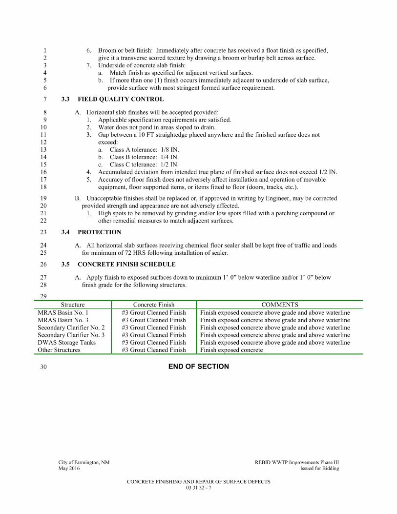
City of Farmington, NM REBID WWTP Improvements Phase III May 2016 Issued for Bidding
CONCRETE FINISHING AND REPAIR OF SURFACE DEFECTS 03 31 32 - 7
6. Broom or belt finish: Immediately after concrete has received a float finish as specified, 1
give it a transverse scored texture by drawing a broom or burlap belt across surface. 2
7. Underside of concrete slab finish: 3
a. Match finish as specified for adjacent vertical surfaces. 4
b. If more than one (1) finish occurs immediately adjacent to underside of slab surface, 5
provide surface with most stringent formed surface requirement. 6
3.3 FIELD QUALITY CONTROL 7
A. Horizontal slab finishes will be accepted provided: 8
1. Applicable specification requirements are satisfied. 9
2. Water does not pond in areas sloped to drain. 10
3. Gap between a 10 FT straightedge placed anywhere and the finished surface does not 11
exceed: 12
a. Class A tolerance: 1/8 IN. 13
b. Class B tolerance: 1/4 IN. 14
c. Class C tolerance: 1/2 IN. 15
4. Accumulated deviation from intended true plane of finished surface does not exceed 1/2 IN. 16
5. Accuracy of floor finish does not adversely affect installation and operation of movable 17
equipment, floor supported items, or items fitted to floor (doors, tracks, etc.). 18
B. Unacceptable finishes shall be replaced or, if approved in writing by Engineer, may be corrected 19
provided strength and appearance are not adversely affected. 20
1. High spots to be removed by grinding and/or low spots filled with a patching compound or 21
other remedial measures to match adjacent surfaces. 22
3.4 PROTECTION 23
A. All horizontal slab surfaces receiving chemical floor sealer shall be kept free of traffic and loads 24
for minimum of 72 HRS following installation of sealer. 25
3.5 CONCRETE FINISH SCHEDULE 26
A. Apply finish to exposed surfaces down to minimum 1’-0” below waterline and/or 1’-0” below 27
finish grade for the following structures. 28
29
Structure Concrete Finish COMMENTS
MRAS Basin No. 1 #3 Grout Cleaned Finish Finish exposed concrete above grade and above waterline
MRAS Basin No. 3 #3 Grout Cleaned Finish Finish exposed concrete above grade and above waterline Secondary Clarifier No. 2 #3 Grout Cleaned Finish Finish exposed concrete above grade and above waterline Secondary Clarifier No. 3 #3 Grout Cleaned Finish Finish exposed concrete above grade and above waterline DWAS Storage Tanks #3 Grout Cleaned Finish Finish exposed concrete above grade and above waterline Other Structures #3 Grout Cleaned Finish Finish exposed concrete
END OF SECTION 30

City of Farmington, NM REBID WWTP Improvements Phase III May 2016 Issued for Bidding
MASONRY CLEANING 04 01 20 - 1
SECTION 04 01 20 1
MASONRY CLEANING 2
PART 1 - GENERAL 3
1.1 SUMMARY 4
A. Section Includes: 5
1. Masonry cleaning. 6
B. Related Sections include but are not necessarily limited to: 7
1. Division 00 - Bidding Requirements, Contract Forms, and Conditions of the Contract. 8
2. Division 01 - General Requirements. 9
1.2 QUALITY ASSURANCE 10
A. Qualifications: 11
1. Use experienced workmen familiar with product and its application. 12
1.3 SUBMITTALS 13
A. Shop Drawings: 14
1. See Specification Section 01 33 00 for requirements for the mechanics and administration of 15
the submittal process. 16
2. Product technical data including: 17
a. Manufacturer's application instructions. 18
b. Manufacturer's dilution recommendations. 19
c. Manufacturer's recommendations on neutralizing rinse. 20
B. Certifications: 21
1. Certification that Contractor is experienced in this type of masonry cleaning. 22
PART 2 - PRODUCTS 23
2.1 ACCEPTABLE MANUFACTURERS 24
A. Subject to compliance with the Contract Documents, the following manufacturers are 25
acceptable: 26
1. Cleaning solution: Detergent type. 27
a. Pro So Co. 28
b. Diedrich Technologies, Inc. 29
2. Cleaning solution for manganese or vanadium stained masonry: 30
a. Pro So Co. 31
b. Diedrich Technologies, Inc. 32
B. Submit request for substitution in accordance with Specification Section 01 25 13. 33
2.2 MATERIALS 34
A. Detergent-Type Cleaning Solution: Pro So Co. "Sure Clean #600" detergent masonry cleaner. 35
B. Manganese or Vanadium-Stained Masonry: Pro So Co. "Vanatrol." 36
C. Water: Potable. 37
D. Neutralizing rinse as required by manufacturer. 38

City of Farmington, NM REBID WWTP Improvements Phase III May 2016 Issued for Bidding
MASONRY CLEANING 04 01 20 - 2
2.3 MIXES 1
A. Dilute cleaning solution with potable water at rate which will provide for the weakest solution 2
allowable for cleaning wall. 3
B. If project conditions require solution of greater than 5 percent acid, obtain permission from 4
Engineer in writing prior to applying solution to wall surface. 5
PART 3 - EXECUTION 6
3.1 PREPARATION 7
A. Allow 7 days after completion of masonry work before start of cleaning. 8
B. Remove excess mortar using wooden paddles and scrapers. 9
C. Protect adjacent surfaces not to be cleaned. 10
3.2 APPLICATION 11
A. Protect adjacent surfaces subject to potential damage by cleaning solution. 12
B. Apply masonry cleaner to exposed-to-view masonry surfaces. 13
1. Do not use wire brushes. 14
2. Use only tools free of rust. 15
3. Apply solution using fibered wall-washing brush. 16
C. Thoroughly rinse and pre-soak walls. 17
D. Flush all loose mortar and dirt from surface. 18
E. Wet to prevent "run-off" streaking. 19
F. Scrape off mortar and reapply cleaning solution. 20
G. After scrubbing, clean thoroughly with pressurized water. 21
H. Apply neutralizing rinse as recommended by manufacturer. 22
END OF SECTION 24
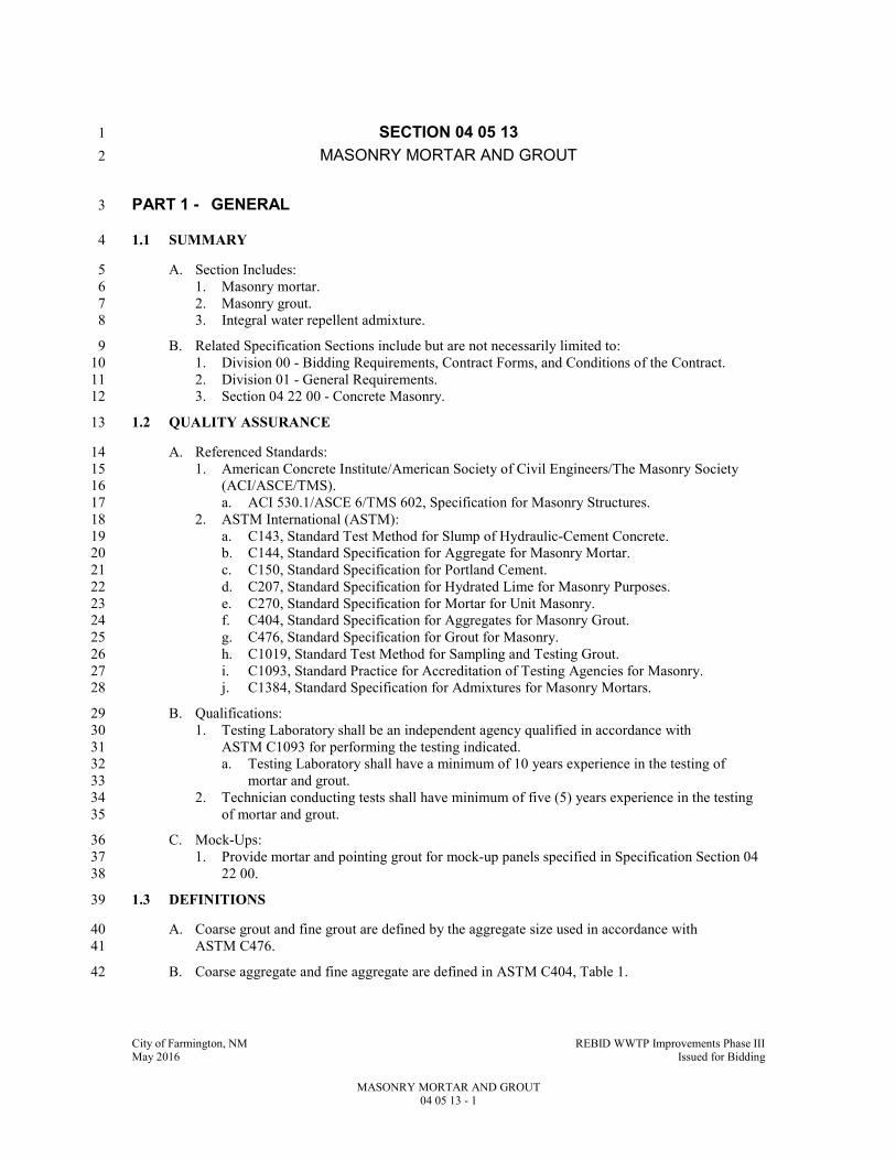
City of Farmington, NM REBID WWTP Improvements Phase III May 2016 Issued for Bidding
MASONRY MORTAR AND GROUT 04 05 13 - 1
SECTION 04 05 13 1
MASONRY MORTAR AND GROUT 2
PART 1 - GENERAL 3
1.1 SUMMARY 4
A. Section Includes: 5
1. Masonry mortar. 6
2. Masonry grout. 7
3. Integral water repellent admixture. 8
B. Related Specification Sections include but are not necessarily limited to: 9
1. Division 00 - Bidding Requirements, Contract Forms, and Conditions of the Contract. 10
2. Division 01 - General Requirements. 11
3. Section 04 22 00 - Concrete Masonry. 12
1.2 QUALITY ASSURANCE 13
A. Referenced Standards: 14
1. American Concrete Institute/American Society of Civil Engineers/The Masonry Society 15
(ACI/ASCE/TMS). 16
a. ACI 530.1/ASCE 6/TMS 602, Specification for Masonry Structures. 17
2. ASTM International (ASTM): 18
a. C143, Standard Test Method for Slump of Hydraulic-Cement Concrete. 19
b. C144, Standard Specification for Aggregate for Masonry Mortar. 20
c. C150, Standard Specification for Portland Cement. 21
d. C207, Standard Specification for Hydrated Lime for Masonry Purposes. 22
e. C270, Standard Specification for Mortar for Unit Masonry. 23
f. C404, Standard Specification for Aggregates for Masonry Grout. 24
g. C476, Standard Specification for Grout for Masonry. 25
h. C1019, Standard Test Method for Sampling and Testing Grout. 26
i. C1093, Standard Practice for Accreditation of Testing Agencies for Masonry. 27
j. C1384, Standard Specification for Admixtures for Masonry Mortars. 28
B. Qualifications: 29
1. Testing Laboratory shall be an independent agency qualified in accordance with 30
ASTM C1093 for performing the testing indicated. 31
a. Testing Laboratory shall have a minimum of 10 years experience in the testing of 32
mortar and grout. 33
2. Technician conducting tests shall have minimum of five (5) years experience in the testing 34
of mortar and grout. 35
C. Mock-Ups: 36
1. Provide mortar and pointing grout for mock-up panels specified in Specification Section 04 37
22 00. 38
1.3 DEFINITIONS 39
A. Coarse grout and fine grout are defined by the aggregate size used in accordance with 40
ASTM C476. 41
B. Coarse aggregate and fine aggregate are defined in ASTM C404, Table 1. 42
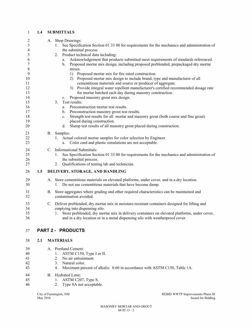
City of Farmington, NM REBID WWTP Improvements Phase III May 2016 Issued for Bidding
MASONRY MORTAR AND GROUT 04 05 13 - 2
1.4 SUBMITTALS 1
A. Shop Drawings: 2
1. See Specification Section 01 33 00 for requirements for the mechanics and administration of 3
the submittal process. 4
2. Product technical data including: 5
a. Acknowledgement that products submitted meet requirements of standards referenced. 6
b. Proposed mortar mix design, including proposed preblended, prepackaged dry mortar 7
mixes. 8
1) Proposed mortar mix for fire rated construction. 9
2) Proposed mortar mix design to include brand, type and manufacturer of all 10
cementitious materials and source or producer of aggregate. 11
3) Provide integral water repellent manufacturer's certified recommended dosage rate 12
for mortar batched each day during masonry construction. 13
c. Proposed masonry grout mix design. 14
3. Test results: 15
a. Preconstruction mortar test results. 16
b. Preconstruction masonry grout test results. 17
c. Strength test results for all mortar and masonry grout (both coarse and fine grout) 18
placed during construction. 19
d. Slump test results of all masonry grout placed during construction. 20
B. Samples: 21
1. Actual colored mortar samples for color selection by Engineer. 22
a. Color card and plastic simulations are not acceptable. 23
C. Informational Submittals: 24
1. See Specification Section 01 33 00 for requirements for the mechanics and administration of 25
the submittal process. 26
2. Qualifications of testing lab and technician. 27
1.5 DELIVERY, STORAGE, AND HANDLING 28
A. Store cementitious materials on elevated platforms, under cover, and in a dry location. 29
1. Do not use cementitious materials that have become damp. 30
B. Store aggregates where grading and other required characteristics can be maintained and 31
contamination avoided. 32
C. Deliver preblended, dry mortar mix in moisture-resistant containers designed for lifting and 33
emptying into dispensing silo. 34
1. Store preblended, dry mortar mix in delivery containers on elevated platforms, under cover, 35
and in a dry location or in a metal dispensing silo with weatherproof cover. 36
PART 2 - PRODUCTS 37
2.1 MATERIALS 38
A. Portland Cement: 39
1. ASTM C150, Type I or II. 40
2. No air entrainment. 41
3. Natural color. 42
4. Maximum percent of alkalis: 0.60 in accordance with ASTM C150, Table 1A. 43
B. Hydrated Lime: 44
1. ASTM C207, Type S. 45
2. Type SA not acceptable. 46

City of Farmington, NM REBID WWTP Improvements Phase III May 2016 Issued for Bidding
MASONRY MORTAR AND GROUT 04 05 13 - 3
3. Lime substitutes are not acceptable. 1
C. Mortar Aggregate: ASTM C144, free of gypsum. 2
D. Masonry Grout: 3
1. ASTM C476. 4
2. No admixtures allowed. 5
E. Grout Aggregate: ASTM C404. 6
F. Water: Potable. 7
G. Mortar Pigments: 8
1. Commercial colorants suitably compounded for use in mortar mixes. 9
2. Do not exceed manufacturer's recommended pigment-to-cement ratios. 10
H. Integral Water Repellent Admixture: 11
1. Liquid polymeric admixture: ASTM C1384. 12
2. Verify compatibility with liquid water repellent admixture being used in the fabrication of 13
concrete masonry units. 14
3. Do not use integral water repellent admixture in mortar for brick. 15
2.2 MIXES 16
A. Type "S" mortar shall be used: 17
1. Wherever a fire-resistance classification or rating is shown for unit masonry construction 18
provide mortar of type which has been tested and listed for construction indicated. 19
2. Comply with ASTM C270, Table No. 1. 20
3. Do not use masonry cement. 21
4. Mix materials minimum of three (3) minutes and maximum of five (5) minutes. 22
5. Adjust consistency to satisfaction of mason. 23
6. Do not use admixtures unless otherwise indicated. 24
7. Provide integral water repellent admixture in all mortar used for both interior and exterior 25
masonry work. 26
B. Masonry Grout: 27
1. Comply with ASTM C476. 28
2. Use no anti-freeze additives. 29
3. No fly ash additives will be accepted. 30
4. Mix 5 minutes minimum. 31
5. Slump: 8 to 11 IN. 32
6. Do not add integral water repellent admixture to masonry grout mix. 33
7. At Contractor's option, manufactured grout meeting the above minimum requirements may 34
be used. 35
8. Minimum 28-day compressive strength: 2,000 psi. 36
2.3 SOURCE QUALITY CONTROL 37
A. Perform preconstruction laboratory tests on proposed masonry grout mix prior to start of 38
masonry work. 39
1. Perform tests far enough in advance so that any necessary retesting can be accomplished 40
before masonry construction begins. 41
a. Test grout per ASTM C1019. 42
B. Source Limitations for Mortar Materials: 43
1. Obtain mortar ingredients of a uniform quality, including color for exposed masonry, from a 44
single manufacturer for each cementitious component and from one (1) source or producer 45
for each aggregate. 46

City of Farmington, NM REBID WWTP Improvements Phase III May 2016 Issued for Bidding
MASONRY MORTAR AND GROUT 04 05 13 - 4
PART 3 - EXECUTION 1
3.1 INSTALLATION 2
A. Install products in accordance with manufacturer's instructions and ACI 530.1/ASCE 6/TMS 3
602. 4
B. Use coarse grout in spaces with least dimension over 2 IN. 5
C. Consolidate all grout while installing. 6
1. Consolidate grout pours 12 IN or less in height by mechanical vibration or by puddling. 7
2. Consolidate grout pours exceeding 12 IN in height by mechanical vibration and 8
reconsolidate by mechanical vibration after initial water loss and settlement has occurred. 9
D. Use colored mortar to match existing. 10
3.2 FIELD QUALITY CONTROL 11
A. Mortar: 12
1. If standard gray mortar begins to stiffen, it may be retempered by adding water and 13
remixing {unless prohibited by water repellent admixture manufacturer}. 14
a. Standard gray mortar shall not be retempered more than one (1) time. 15
2. Colored mortar shall not be retempered. 16
3. All mortar must be used within 2-1/2 HRS maximum after initial mixing per ACI 17
530.1/ASCE 6/TMS 602. 18
B. Engineer reserves right to alter mix design based on initial rate of absorption of masonry units. 19
C. Masonry Grout: 20
1. Use grout within 1-1/2 HRS maximum after initial mixing. 21
2. Use no grout after it has begun to set. 22
3. Do not retemper grout after initial mixing. 23
4. Place grout in lifts not exceeding 4 FT. 24
D. Masonry Grout Testing: 25
1. Testing and inspection services will be provided by the Owner's special masonry inspector. 26
a. Do not include in the bid price the cost of these services. 27
2. Conduct compressive strength tests and slump tests on all masonry grout used during 28
masonry construction. 29
3. Perform all compressive strength test sampling, testing and reporting per ASTM C1019. 30
4. Perform all slump test sampling, testing, and reporting per ASTM C143. 31
5. Frequency of sampling: One (1) sample (three (3) specimens) collected each grouting 32
operation during masonry construction. 33
6. Compressive strength testing: 34
a. One (1) strength test shall be the average of three (3) specimens from the same sample, 35
tested at 28 days. 36
END OF SECTION 38

City of Farmington, NM REBID WWTP Improvements Phase III May 2016 Issued for Bidding
MASONRY ACCESSORIES 04 05 23 - 1
SECTION 04 05 23 1
MASONRY ACCESSORIES 2
PART 1 - GENERAL 3
1.1 SUMMARY 4
A. Section Includes: 5
1. Masonry accessories. 6
B. Related Specification Sections include but are not necessarily limited to: 7
1. Division 00 - Bidding Requirements, Contract Forms, and Conditions of the Contract. 8
2. Division 01 - General Requirements. 9
3. Section 04 22 00 - Concrete Masonry. 10
4. Section 05 50 00 - Metal Fabrications. 11
1.2 QUALITY ASSURANCE 12
A. Referenced Standards: 13
1. ASTM International (ASTM): 14
a. A82, Standard Specification for Steel Wire, Plain, for Concrete Reinforcement. 15
b. A153/A153M, Standard Specification for Zinc Coating (Hot-Dip) on Iron and Steel 16
Hardware. 17
c. A580, Standard Specification for Stainless Steel Wire. 18
d. A666, Standard Specification for Annealed or Cold-Worked Austenitic Stainless Steel 19
Sheet, Strip, Plate, and Flat Bar. 20
e. A951, Standard Specification for Steel Wire for Masonry Joint Reinforcement. 21
f. A1008, Standard Specification for Steel, Sheet, Cold-Rolled, Carbon, Structural, High-22
Strength Low-Alloy, High-Strength Low-Alloy with Improved Formability, Solution 23
Hardened, and Bake Hardenable. 24
g. D624, Standard Test Method for Tear Strength of Conventional Vulcanized Rubber and 25
Thermoplastic Elastomers. 26
h. D638, Standard Test Method for Tensile Properties of Plastics. 27
i. D2240, Standard Test Method for Rubber Property—Durometer Hardness. 28
j. D2287, Standard Specification for Nonrigid Vinyl Chloride Polymer and Copolymer 29
Molding and Extrusion Compounds. 30
2. Building code: 31
a. International Code Council (ICC): 32
1) International Building Code and associated standards, 2009 Edition including all 33
amendments, referred to herein as Building Code. 34
B. Mock-Ups: 35
1. Provide specified products for inclusion into mock-up panels required by Specification 36
Section 04 22 00. 37
2. Coordinate with built-in items and veneer coursing. 38
1.3 SUBMITTALS 39
A. Shop Drawings: 40
1. See Specification Section 01 33 00 for requirements for the mechanics and administration of 41
the submittal process. 42
2. Product technical data including: 43
a. Acknowledgement that products submitted meet requirements of standards referenced. 44
b. Manufacturer's installation instructions. 45
c. Detailed drawings of all factory or field formed stainless steel thru wall flashing. 46
d. Tear resistance of flashing material. 47

City of Farmington, NM REBID WWTP Improvements Phase III May 2016 Issued for Bidding
MASONRY ACCESSORIES 04 05 23 - 2
e. Manufacturer's recommendations for flashing adhesive. 1
f. Manufacturer's data sheet on each product. 2
PART 2 - PRODUCTS 3
2.1 ACCEPTABLE MANUFACTURERS 4
A. Subject to compliance with the Contract Documents, the following manufacturers are 5
acceptable: 6
1. Reglets: 7
a. Hohmann & Barnard, Inc. 8
b. W. P. Hickman Co. 9
c. Superior Concrete Accessories, Inc. 10
2. Masonry anchors, horizontal joint reinforcing veneer anchors for 4” CMU and 11
miscellaneous anchors: 12
a. Heckman. 13
b. Hohmann & Barnard, Inc. 14
c. Wire Bond. 15
3. Preformed control joint inserts: 16
a. Hohmann & Barnard, Inc. 17
b. Wire Bond. 18
c. Illinois Products Corporation (IPCO). 19
B. Submit request for substitution in accordance with Specification Section 01 25 13. 20
2.2 MANUFACTURED UNITS 21
A. Thru Wall Flashing : 22
1. Stainless steel, ASTM A666, Type 316. 23
a. Finish: ASTM A480, 2D. 24
b. Minimum 26 GA, 25
2. Maximum lengths of 10 FT. 26
3. Factory fabricated. 27
4. Factory fabricated one-piece inside and outside corners with a minimum return of 16 IN on 28
each leg. 29
a. Weld all joints and grind smooth. 30
5. Provide 1/2 IN drip on exterior side of wall. 31
6. Refer to the Drawings for required profiles. 32
7. Lap sealant: VULKEM 922. 33
B. Flashing Adhesive: As recommended by flashing manufacturer for sealing laps, sealing to 34
vertical masonry and concrete surfaces and sealing to stainless steel surfaces. 35
C. Reglets: 36
1. Products specified are manufactured by Hohmann & Barnard, Inc. 37
2. For masonry construction: Type #MR - Masonry Reglet. 38
D. Veneer Anchorage System for New Concrete Back-up: 39
1. Anchors, dovetail: 40
a. Hot-dipped galvanized, ASTM A153/A153M. 41
b. 16 GA corrugated steel with dovetail. 42
1) 1 IN wide x 5 1/2 IN long minimum or as required by Project conditions. 43
a) Provide minimum 2 IN embedment into veneer mortar joint. 44
2. Dovetail slots: 45
a. Hot-dipped galvanized, ASTM A153/A153M. 46
b. 22 GA steel. 47
c. 1 IN wide, 1 IN deep, nominal 5/8 IN throat with filler. 48

City of Farmington, NM REBID WWTP Improvements Phase III May 2016 Issued for Bidding
MASONRY ACCESSORIES 04 05 23 - 3
E. Veneer Anchorage System for Concrete Masonry Back-up: 1
1. Adjustable pintle and plate: 2
a. Conform to ASTM A951. 3
b. Cold drawn stainless steel steel wire pintle, ASTM A82. 4
c. 14 GA stainless steel plate, ASTM A1008. 5
d. Galvanized, ASTM A153/A153M, Class B2. 6
e. 3/16 IN DIA wire x length required to embed pintle minimum 2 IN into veneer mortar 7
joint. 8
F. Horizontal Joint Reinforcing: 9
1. General: 10
a. Conform to ASTM A951. 11
b. Cold drawn steel wire, ASTM A82. 12
c. 9 GA side rods. 13
d. 9 GA cross rods. 14
e. Hot-dipped galvanized, ASTM A153/A153M. 15
f. Prefabricated corner and tee sections with minimum length of 30 IN from point of 16
intersection. 17
2. Single wythe wall joint reinforcing: 18
a. Ladder design at walls with vertical reinforcing. 19
b. Truss design at walls without vertical reinforcing. 20
3. Composite wall joint reinforcing: Ladder design with double side rod. 21
4. Cavity wall joint reinforcing with masonry back-up: 22
a. Ladder design horizontal joint reinforcing. 23
b. Wire eyes welded to horizontal joint reinforcing. 24
1) Length as required to project through rigid insulation into airspace. 25
c. 3/16 IN DIA adjustable pintle veneer anchors. 26
1) Length as required to provide minimum 2 IN embed into veneer mortar joint. 27
d. Hohmann & Barnard "270 Ladder." 28
G. Rigid Steel Masonry Anchors: 29
1. 1 IN by 1/4 IN with ends turned up 2 IN. 30
2. Hot-dipped galvanized steel, ASTM A153/A153M. 31
3. Length: 32
a. 24 IN unless noted otherwise. 33
b. Where wall conditions such as jambs or other obstructions preclude the use of 24 IN 34
anchors, shorter anchors may be used. 35
H. Mesh Wall Ties: 36
1. Hot-dipped galvanized steel, ASTM A153/A153M. 37
2. 16 GA, 1/2 IN square mesh. 38
3. Width: 2 IN less than nominal wall thickness. 39
4. Length: As necessary to embed minimum 6 IN into each wall. 40
I. Grout Screen: 41
1. Polypropylene monofilament. 42
2. 1/4 x 1/4 IN mesh. 43
3. Width of grout screen to be 2 IN less than nominal width of CMU. 44
J. Preformed Rubber Control Joint Inserts: 45
1. ASTM D2000, 2AA-805. 46
2. Hardness: ASTM D2240, Shore A Durometer, 85 +/-5. 47
3. Ultimate elongation: 350 percent, ASTM D412. 48
4. Tensile strength: 1000 psi, ASTM D412. 49
5. Hohmann & Barnard #RS Series. 50
K. Block Insulation 51

City of Farmington, NM REBID WWTP Improvements Phase III May 2016 Issued for Bidding
MASONRY ACCESSORIES 04 05 23 - 4
1. Korfil block insulation 1
2. Meet ASTM C578 Type X and ASTM C90 for load bearing CMU 2
3. R-Value to be R-5 per inch. 3
PART 3 - EXECUTION 4
3.1 INSTALLATION 5
A. Install products in accordance with manufacturer's instructions. 6
B. Single Withe Flashing System by Mortar Net 7
1. Install to provide positive drainage of CMU moisture. 8
C. Butt joints of preformed control joint inserts tightly together and secure with adhesive or sealant 9
acceptable to insert manufacturer. 10
D. Anchoring Veneer: 11
1. Veneer with concrete block back-up: 12
a. Anchor veneer to new construction using horizontal joint reinforcing and adjustable 13
pintle veneer anchors. 14
2. Veneer with concrete back-up: 15
a. Anchor veneer to new construction using dovetail anchors and slots. 16
b. Anchor veneer to existing construction using adjustable pintle and plate. 17
c. Provide veneer anchorage at not more than 16 IN OC vertically and 16 IN OC 18
horizontally. 19
E. Reinforcing Masonry: 20
1. General: 21
a. Provide continuous horizontal joint reinforcing in all concrete masonry wall 22
construction. 23
1) Embed longitudinal side rods in mortar for entire length with minimum cover of 24
5/8 IN on exterior side of walls and 1/2 IN at other locations. 25
a) For interior partitions, the "exterior" side of the wall is considered the side 26
having the most corrosive atmosphere or the corridor side of the wall. 27
2) Lap reinforcement minimum of 12 IN at ends. 28
a) Remove cross wires on one (1) side of the lap splice and bend the side rods 29
slightly so the lap is provided with 12 IN of uninterrupted wire lap occurring 30
in the same plane. 31
3) Do not bridge control joints with horizontal joint reinforcing. 32
4) Do not bridge expansion joints with horizontal joint reinforcing. 33
5) At corners and wall intersections use prefabricated "L" and "T" horizontal joint 34
reinforcing sections. 35
6) Cut and bend as required. 36
b. Install reinforcing at 16 IN OC vertically unless noted otherwise on Drawings. 37
c. Install reinforcing 8 IN OC vertically for a minimum of 24 IN at starter courses. 38
1) Do not install horizontal joint reinforcing in veneer mortar joint having through-39
wall flashing. 40
d. In concrete masonry install horizontal joint reinforcing at 8 IN OC in parapets. 41
1) Parapets begin at the course immediately above the top of the roof structural 42
member or top of concrete topping slab on precast roof structure. 43
e. In concrete masonry, install additional horizontal joint reinforcing 16 IN OC in courses 44
on each side of vertical control joints and on each jamb of openings for full height of 45
joint or opening. 46
1) Alternate with normal wall horizontal joint reinforcing. 47
2) Extend reinforcing minimum 32 IN beyond joint or jambs of opening. 48
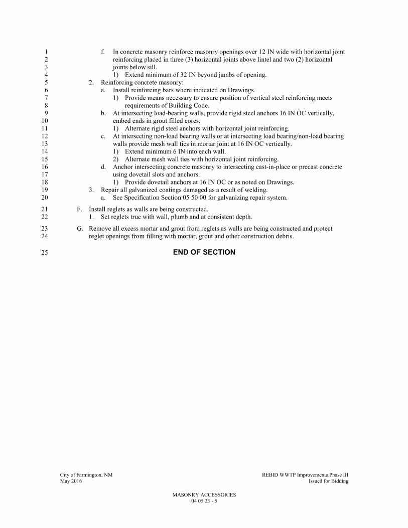
City of Farmington, NM REBID WWTP Improvements Phase III May 2016 Issued for Bidding
MASONRY ACCESSORIES 04 05 23 - 5
f. In concrete masonry reinforce masonry openings over 12 IN wide with horizontal joint 1
reinforcing placed in three (3) horizontal joints above lintel and two (2) horizontal 2
joints below sill. 3
1) Extend minimum of 32 IN beyond jambs of opening. 4
2. Reinforcing concrete masonry: 5
a. Install reinforcing bars where indicated on Drawings. 6
1) Provide means necessary to ensure position of vertical steel reinforcing meets 7
requirements of Building Code. 8
b. At intersecting load-bearing walls, provide rigid steel anchors 16 IN OC vertically, 9
embed ends in grout filled cores. 10
1) Alternate rigid steel anchors with horizontal joint reinforcing. 11
c. At intersecting non-load bearing walls or at intersecting load bearing/non-load bearing 12
walls provide mesh wall ties in mortar joint at 16 IN OC vertically. 13
1) Extend minimum 6 IN into each wall. 14
2) Alternate mesh wall ties with horizontal joint reinforcing. 15
d. Anchor intersecting concrete masonry to intersecting cast-in-place or precast concrete 16
using dovetail slots and anchors. 17
1) Provide dovetail anchors at 16 IN OC or as noted on Drawings. 18
3. Repair all galvanized coatings damaged as a result of welding. 19
a. See Specification Section 05 50 00 for galvanizing repair system. 20
F. Install reglets as walls are being constructed. 21
1. Set reglets true with wall, plumb and at consistent depth. 22
G. Remove all excess mortar and grout from reglets as walls are being constructed and protect 23
reglet openings from filling with mortar, grout and other construction debris. 24
END OF SECTION 25

City of Farmington, NM REBID WWTP Improvements Phase III May 2016 Issued for Bidding
COLD AND HOT WEATHER MASONRY CONSTRUCTION 04 05 50 - 1
SECTION 04 05 50
COLD AND HOT WEATHER MASONRY CONSTRUCTION
PART 1 - GENERAL
1.1 SUMMARY
A. Section Includes:
1. Cold weather protection.
2. Hot weather protection.
B. Related Specification Sections include but are not necessarily limited to:
1. Division 00 - Bidding Requirements, Contract Forms, and Conditions of the Contract.
2. Division 01 - General Requirements.
1.2 QUALITY ASSURANCE
A. Referenced Standards:
1. American Concrete Institute/American Society of Civil Engineers/The Masonry Society
(ACI/ASCE/TMS):
a. ACI 530.1/ASCE 6/TMS 602, Specification for Masonry Structures.
2. Brick Industry Association (BIA):
a. Tech Note 1, Cold and Hot Weather Construction.
3. International Masonry Industry All-Weather Council (IMIAWC):
a. Recommended Practices and Guide Specifications for Masonry Construction.
4. National Concrete Masonry Association (NCMA).
a. TEK 3-1C, All Weather Concrete Masonry Construction.
1.3 DEFINITIONS
A. Hot Weather Construction: Per ACI 530.1/ASCE 6/TMS 602, hot weather construction is
defined as occurring when ambient temperatures exceed 100 DegF or 90 DegF when the wind
velocity is greater than 8 mph.
B. Cold Weather Construction: Per ACI 530.1/ASCE 6/TMS 602, cold weather construction is
defined as occurring when ambient temperature falls below 40 DegF or when the temperature of
the masonry units is below 40 DegF.
PART 2 - PRODUCTS - (NOT APPLICABLE TO THIS SECTION)
PART 3 - EXECUTION
3.1 ERECTION AND APPLICATION
A. General:
1. Comply with NCMA TEK 3-1C and BIA Tech Note 1 recommendations and practices.
2. Do not use frozen or ice coated materials.
3. At end of each day or at shutdown, cover tops of all walls not enclosed or sheltered with
clear polyethylene minimum 6 mil thick.
a. Extend down each side of wall minimum of 16 IN and secure.
B. Temporary Facilities:
1. Construct and maintain temporary protection required to permit continuous and orderly
progress of work.
2. Provide and maintain heat sufficient to assure temperature above 32 DegF within protected
areas.

City of Farmington, NM REBID WWTP Improvements Phase III May 2016 Issued for Bidding
COLD AND HOT WEATHER MASONRY CONSTRUCTION 04 05 50 - 2
3. Remove all temporary facilities after completion of work.
C. Cold Weather Construction and Protection Requirements:
1. Prior to and during installation:
a. Air temperature 32 to 40 DegF: Heat mixing water or aggregate to produce mortar
temperatures between 40 and 120 DegF.
b. Air temperature 25 to 32 DegF:
1) Heat mixing water or aggregate to produce mortar temperatures between 40 and
120 DegF.
2) Maintain mortar temperatures above freezing until used.
c. Air temperature below 25 DegF:
1) Heat mixing water and aggregate to produce mortar temperatures between 40 and
120 DegF.
2) Maintain mortar temperatures above freezing until used.
3) Maintain temperature of units until laid at not less than 40 DegF.
4) Provide heat on both sides of walls under construction to maintain air temperature
above freezing.
5) Provide windbreaks or shelters when wind is in excess of 15 mph.
a) Wind breaks or shelters shall be translucent.
2. After installation:
a. Air temperature 32 to 40 DegF: Protect from rain or snow for not less than 24 HRS by
covering with weather-resistive translucent membrane.
b. Air temperature 25 to 32 DegF: Completely cover with translucent weather-resistive
membrane for not less than 24 HRS.
c. Air temperature 20 to 25 DegF: Completely protect with insulating blankets for not
less than 24 HRS or provide other protection approved by Engineer.
d. Air temperature below 20 DegF:
1) Provide enclosed translucent shelters and heating to maintain air temperature on
each side of wall above 32 DegF for 24 HRS.
2) Do not allow rapid drop in temperature after removal of heat.
e. Promptly repair all tears, holes, etc., to translucent membrane and shelter using
compatible patching material and tape as recommended by membrane manufacturer.
D. Hot Weather Construction and Protection Requirements:
1. Comply with requirements of IMIAWC, NCMA and ACI/ASCE/TMS.
2. Storage and preparation of materials.
a. Cover or shade masonry units and mortar materials from direct sun.
b. Maintain sand in a damp loose condition.
1) Sand moisture shall be maintained at minimum 8 percent.
2) Sprinkle with cool water as required to maintain moisture content.
c. Use cool water for mixing mortars.
d. Avoid using tools and equipment that have been sitting in the sun.
1) Sprinkle mortar boards, mortar pans, wheel barrows, mixers, etc., with cool water.
e. Do not wet concrete masonry units prior to use.
3. Installation:
a. Place masonry units within one minute of the spreading of the mortar.
1) Mortar beds shall not be spread more than 4 FT ahead of the masonry unit being
placed.
b. Provide wind screens and shading partitions as required to eliminate direct sunlight
exposure.
c. Wet installed units using fog spray of clean water.
d. Cover installed work immediately after installation to slow rate of loss of moisture from
units.
e. Fog-spray new masonry work until damp.

City of Farmington, NM REBID WWTP Improvements Phase III May 2016 Issued for Bidding
COLD AND HOT WEATHER MASONRY CONSTRUCTION 04 05 50 - 3
1) Repeat fog spraying minimum of three (3) times per day until masonry work has
cured for 72 HRS.
2) In high humidity conditions, Engineer reserves the right to discontinue fog
spraying if operation is found to be introducing excessive amounts of moisture into
the Work.
END OF SECTION

City of Farmington, NM REBID WWTP Improvements Phase III May 2016 Issued for Bidding
CONCRETE MASONRY 04 22 00 - 1
SECTION 04 22 00 1
CONCRETE MASONRY 2
PART 1 - GENERAL 3
1.1 SUMMARY 4
A. Section Includes: 5
1. Concrete masonry construction (CMU) including all standard concrete masonry units. 6
B. Related Specification Sections include but are not necessarily limited to: 7
1. Division 00 - Bidding Requirements, Contract Forms, and Conditions of the Contract. 8
2. Division 01 - General Requirements. 9
3. Section 03 21 00 - Reinforcement. 10
4. Section 04 05 13 – Masonry Mortar and Grout. 11
5. Section 04 05 23 - Masonry Accessories. 12
6. Section 04 05 50 – Cold and Hot Weather Masonry Construction 13
7. Section 04 01 20 - Masonry Cleaning. 14
8. Section 07 92 00 - Joint Sealants. 15
1.2 QUALITY ASSURANCE 16
A. Referenced Standards: 17
1. American Concrete Institute (ACI)/American Society of Civil Engineers (ASCE)/The 18
Masonry Society (TMS): 19
a. ACI 530.1/ASCE 6/TMS 602, Specification for Masonry Structures. 20
2. ASTM International (ASTM): 21
a. C33, Standard Specification for Concrete Aggregates. 22
b. C90, Standard Specification for Loadbearing Concrete Masonry Units. 23
3. National Concrete Masonry Association (NCMA): 24
a. TEK 2-3A, Architectural Concrete Masonry Units. 25
b. TEK 3-4B, Bracing Concrete Masonry Walls During Construction. 26
c. TEK 8-3A, Control and Removal of Efflorescence. 27
4. Building code: 28
a. International Code Council (ICC): 29
1) International Building Code and associated standards, 2009 Edition including all 30
amendments, referred to herein as Building Code. 31
B. Mock-Ups: 32
1. Prior to permanent wall construction, construct mock-up. 33
a. Mock-up shall be as large as required to properly display all components required by 34
the building masonry construction; however, the mock-up shall be a minimum 4 FT 35
high x 8 FT long. 36
b. Utilize all specified components for Engineer review and acceptance. 37
2. Mock-up shall constitute minimum standard of quality for actual construction. 38
a. Maintain mock-up during construction. 39
3. If not acceptable, construct additional mock-ups as required. 40
4. Remove when directed by Engineer. 41
5. Mock-up to include all special corners and other special CMU detailing including all 42
masonry types/colors to match masonry units on existing Pump / Blower building and 43
standard masonry units. 44
a. Step construction of mock-up to allow observation of all specified components. 45
b. Mock-up shall include, as a minimum, all types of masonry. 46

City of Farmington, NM REBID WWTP Improvements Phase III May 2016 Issued for Bidding
CONCRETE MASONRY 04 22 00 - 2
1) Mock-up shall include inside and outside corner showing thru wall flashing 1
lapping, jointing and sealing. 2
2) Mock-up shall include example of flashing condition at bearing end of lintels as 3
outlined in Specification Section 04 05 23. 4
C. All masonry units of any one (1) particular type, color or face style shall be from the same 5
production run. 6
1. Special shapes shall be factory fabricated unless noted otherwise. 7
1.3 DEFINITIONS 8
A. Definitions to be in accordance with Standard Unit Nomenclature Table 1, NCMA TEK 2-3A. 9
1.4 SUBMITTALS 10
A. Shop Drawings: 11
1. See Specification Section 01 33 00 for requirements for the mechanics and administration of 12
the submittal process. 13
2. Product technical data including: 14
a. Manufacturer's information on aggregate and cement type used in manufacture. 15
b. Scaled (minimum 1/8 IN per foot) drawings showing proposed locations of masonry 16
control joints. 17
3. Certifications: 18
a. Certification that concrete masonry units meet or exceed requirements of standards 19
referenced. 20
4. Qualifications of testing lab and technician. 21
5. Test results for all masonry testing. 22
B. Samples: 23
1. Minimum two (2) 2 x 8 x 8 IN samples of pre-colored masonry units of color selected or 24
specified. 25
a. Samples shall show color range and texture range to be expected in the Project. 26
C. Informational Submittals: 27
1. See Specification Section 01 33 00 for requirements for the mechanics and administration of 28
the submittal process. 29
1.5 DELIVERY, STORAGE, AND HANDLING 30
A. Deliver units on pallets with tight covers or deliver in cubes and store on dunnage. 31
B. Protect units from damage. 32
C. Inspect units upon delivery for damage, to assure color match with mock-up or approved 33
samples, dimensional quality, and trueness of unit. 34
1. Remove damaged or otherwise unacceptable units from the Project Site. 35
D. Store units in accordance with manufacturer's recommendations. 36
PART 2 - PRODUCTS 37
2.1 ACCEPTABLE MANUFACTURERS 38
A. Subject to compliance with the Contract Documents, the following manufacturers are 39
acceptable: 40
2.2 MATERIALS 41
A. Concrete Masonry Units: 42

City of Farmington, NM REBID WWTP Improvements Phase III May 2016 Issued for Bidding
CONCRETE MASONRY 04 22 00 - 3
1. Modular units, ASTM C90. 1
a. Provide aggregate in accordance with ASTM C33. 2
b. Total linear drying shrinkage: ASTM C90. 3
c. Weight: Minimum of 125 LB/CF. 4
d. Medium weight or light weight units are not acceptable. 5
2. Face shell and web thickness: ASTM C90, Table 1. 6
3. Water absorption: ASTM C90 Table 2. 7
4. Concrete bricks of same material, texture and quality. 8
5. Compressive strength: ASTM C90, Table 2. 9
6. Dimensional tolerance: ASTM C90. 10
B. Reinforcing Bars: Refer to Specification Section 03 21 00 and as indicated on Drawings. 11
C. Mortar: Refer to Specification Section 04 05 13. 12
D. Masonry Grout: Refer to Specification Section 04 05 13. 13
E. Masonry Accessories: Refer to Specification Section 04 05 23. 14
F. Sealants: Refer to Specification Section 07 92 00. 15
G. Polystyrene Masonry Core Insert Insulation: Refer to Specification Section 04 05 23 – Masonry 16
Accessories. 17
H. Integral Concrete Masonry Water Repellent: 18
1. Liquid polymeric admixture. 19
2. Water permeance of masonry: Capable of achieving a Class E Rating when evaluated using 20
ASTM E514 with the test extended to 72 HRS, using the rating criteria specified in 21
ASTM E514. 22
2.3 FABRICATION 23
A. Concrete Masonry Units: 24
1. Color: 25
a. Integral Colored to match existing masonry. 26
2. Design compressive strength: f'm=1,500 psi minimum. 27
a. Determine in accordance with unit strength method per ACI 530.1/ASCE 6/TMS 602. 28
3. Fire resistive units: Fabricate to meet the Building Code. 29
4. Fabricated in the manufacturing plant. 30
5. Provide square corners. 31
6. CMU Schedule: 32
a. CMU-1: Striated type. Integral color, similar to Crego (Copper) including all relooted 33
configurations 34
b. CMU-2: 8” and 12” Split/Flute Type. Integral color similar to Crego ESC) including 35
all allotted configurations. 36
c. CMU-3: Smooth Faced. Integral color similar to Crego (Copper) for all interior 37
masonry walls. 38
d. Refer to drawings for specific locations of various CMU. 39
PART 3 - EXECUTION 40
3.1 PREPARATION 41
A. Verify that anchors and flashings are correct. 42
B. Lay out walls in advance for uniform and accurate spacing of bond patterns and joints. 43
1. Properly locate openings, movement type joints, returns, and offsets weep joints and weep 44
vents. 45

City of Farmington, NM REBID WWTP Improvements Phase III May 2016 Issued for Bidding
CONCRETE MASONRY 04 22 00 - 4
3.2 INSTALLATION 1
A. Install products in accordance with manufacturer's instructions. 2
B. General: 3
1. Build cavity walls to thickness indicated on Drawings. 4
2. Build composite walls to thickness indicated on Drawings. 5
3. Build in flashing, reinforcing, reglets, weeps, weep vents and related accessory items. 6
a. See Specification Section 04 05 23 for installation of accessory items. 7
4. Perform all cutting with masonry saws using saw blades as recommended by masonry unit 8
manufacturer. 9
5. Drill holes with power drill using drill bits as recommended by masonry unit manufacturer. 10
6. Holes made by chipping unit will not be accepted. 11
7. Install field units in running bond. 12
a. Provide special coursing where indicated on the Drawings. 13
8. Cut as required to maintain bond pattern. 14
9. Use solid units where cutting or laying would expose holes and as noted on Drawings. 15
10. Avoid use of less than half size units, whenever possible. 16
11. Do not use chipped, cracked, spalled, stained or imperfect units exposed in finish work. 17
12. Do not wet concrete masonry units. 18
13. Build chases and recesses as indicated and required for work of other trades. 19
a. Provide not less than 8 IN of masonry between chase or recess and jamb of openings, 20
and between adjacent chases and recesses unless detailed otherwise on the Drawings. 21
14. In fire rated wall construction, install fire resistive units in accordance with the Building 22
Code. 23
C. Concrete Masonry Units: 24
1. Install grouted hollow units under lintel bearing points. 25
a. Refer to Specification Section 04 05 13 for grouting. 26
D. Laying and Tooling: 27
1. Lay masonry units with completely filled bed and head joints. 28
a. Provide full mortar bed on all block cross webs and completely fill head joints. 29
1) Do not slush head joints. 30
2) Protect cells requiring grout fill from mortar droppings. 31
3) Omit mortar from head joint at weep joint opening. 32
2. Maintain nominal 3/8 IN joint widths 33
a. Cut joints flush where concealed. 34
b. Tool exposed joints concave. 35
c. Compress mortar in below ground joints and in joints concealed by insulation in cavity 36
wall construction. 37
d. Provide wider joints where noted on Drawings. 38
1) In no case shall any mortar joint be more than 3/4 IN wide. 39
e. Where masonry sits on top of steel support omit the mortar joint on top of the support 40
and sit masonry directly on top of the thru wall flashing or the steel support member 41
unless a mortar joint is required to maintain coursing. 42
3. During tooling of joints, enlarge any voids or holes except weeps, and completely fill with 43
mortar. 44
4. Point-up all joints at corners, openings, and adjacent work to provide neat, uniform 45
appearance. 46
5. Remove masonry disturbed after laying. 47
a. Clean and relay in fresh mortar. 48
b. Do not pound units to fit. 49
c. If adjustments are required, remove units, clean, and reset in fresh mortar. 50
6. Where work is stopped and later resumed, rack back 1/2 masonry unit length in each course. 51
a. Remove loose units and mortar prior to laying fresh masonry. 52
City of Farmington, NM REBID WWTP Improvements Phase III May 2016 Issued for Bidding
CONCRETE MASONRY 04 22 00 - 5
7. As work progresses, build in items indicated on Drawings and specified. 1
a. Fill in solidly with mortar around built-in items. 2
b. Where built-in items are to be embedded in cores of hollow masonry units, place grout 3
screen in joint below and fill core solid with mortar. 4
E. Control Joints and Sealants: 5
1. Provide vertical expansion, control and isolation joints where indicated on Drawings. 6
2. Where not indicated on Drawings, submit proposed control joint locations in accordance 7
with the following requirements: 8
a. Provide control joints at maximum 30 FT OC. Unless noted otherwise on the drawings. 9
b. Provide at all T intersections. 10
c. Locate joints so as to allow lintels and bond beams above and below openings to extend 11
beyond the opening as indicated on the Drawings without control joints thru the lintel 12
or bond beam. 13
3. Rake out mortar in joint. 14
4. Refer to Specification Section 07 92 00 for sealant installation requirements. 15
a. Seal control and expansion joints. 16
F. Tolerances: 17
1. Maximum variation from plumb in vertical lines and surfaces of columns, walls, and arises: 18
a. 1/4 IN in 10 FT. 19
b. 3/8 IN in a story height not to exceed 20 FT. 20
c. 1/2 IN in 40 FT or more. 21
2. Maximum variation from plumb for external corners, expansion joints, and other 22
conspicuous lines: 23
a. 1/4 IN in any story or 20 FT maximum. 24
b. 1/2 IN in 40 FT or more. 25
3. Maximum variation from level of grades for exposed lintels, sills, parapets, horizontal 26
grooves, and other conspicuous lines: 27
a. 1/4 IN in any bay or 20 FT. 28
b. 1/2 IN in 40 FT or more. 29
4. Maximum variation from plan location of related portions of columns, walls, and partitions: 30
a. 1/2 IN in any bay or 20 FT. 31
b. 3/4 IN in 40 FT or more. 32
5. Maximum variation in cross-sectional dimensions of columns and thicknesses of walls from 33
dimensions shown on Drawings: 34
a. Minus 1/4 IN. 35
b. Plus 1/2 IN. 36
6. Maximum variation in mortar joint width: 37
a. Bed joints: 3/32 IN in 10 FT. 38
b. Head joints: 39
1) Minus 1/8 IN. 40
2) Plus 1/8 IN. 41
G. Protect against weather when work is not in progress. 42
1. During inclement weather conditions, cover top of walls with translucent waterproof 43
membrane. 44
2. See Specification Section 04 05 50. 45
H. Protect against cold/hot weather as specified in Specification Section 04 05 50. 46
3.3 FIELD QUALITY CONTROL 47
A. Bracing Concrete Masonry Walls During Construction: 48
1. At a minimum, provide bracing in accordance with NCMA TEK 3-4B. 49
2. Contractor is responsible for adequately bracing all masonry during construction. 50
City of Farmington, NM REBID WWTP Improvements Phase III May 2016 Issued for Bidding
CONCRETE MASONRY 04 22 00 - 6
B. Remove and replace loose, stained, damaged and other unacceptable units as directed by 1
Engineer. 2
1. Provide new units to match. 3
2. Install in fresh mortar. 4
3. Point to eliminate evidence of replacement. 5
C. Special Masonry Inspection: 6
1. Masonry inspection services will be provided during the following construction activities: 7
a. Cost of masonry inspection services will be paid by Owner. 8
b. During laying of units: 9
1) During the first day of the masonry construction, inspect proportions of site 10
prepared mortar, construction of mortar joints, location of all reinforcing and 11
connectors, size and location of structural elements, type, size and location of 12
anchors, protection of masonry during cold weather. 13
2) Inspection to be continuous the first full day of masonry construction which 14
requires special inspection. 15
a) Thereafter, a minimum of 3 HRS every third day of construction until the 16
concrete masonry work is complete. 17
3) Inspection while laying masonry units may be made concurrently with other 18
inspection duties provided all inspection duties are adequately performed. 19
4) When deficiencies are found, additional inspection shall be provided as required 20
until deficiencies have been corrected. 21
5) If masonry crews change, an additional full day of inspection is required during the 22
first day the new crew is on-site. 23
c. Placement of reinforcing steel: 24
1) Verification of all reinforcing including size, grade, lap lengths, and type. 25
2) Inspection may be periodic as required to verify all reinforcing. 26
3) Inspector to be present during the concrete pour in which any dowels connecting 27
concrete to masonry are cast to verify proper location of dowels. 28
d. Prior to each grouting operation, verify that grout space is clean, reinforcing is clean 29
and connectors are properly placed, proportions of site-prepared grout are correct and 30
mortar joints have been properly constructed. 31
1) Inspection may be periodic as required to verify proper grout space. 32
e. Verify compliance with Building Code and Specifications continuously during all 33
grouting operations. 34
f. Provide special inspection in accordance with the Building Code Table 1704.5.1 35
including observation of masonry work for conformance to the Contract Documents: 36
1) Provide inspection reports to the Engineer, Building Official and Owner. 37
a) Notify Contractor of discrepancies for correction. 38
b) Notify Engineer, Building Official and Owner, in writing, when discrepancies 39
have been satisfactorily corrected. 40
2) Submit final signed report stating that work requiring special inspection was, to the 41
best of the inspector's knowledge, in conformance to the Contract Documents and 42
the applicable workmanship previsions of the Building Code. 43
3.4 CLEANING 44
A. Clean concrete masonry as the wall is being constructed using fiber brushes, wooden paddles 45
and scrapers. 46
1. No acid-based cleaning solutions shall be used unless approved in writing by Engineer. 47
END OF SECTION 49

City of Farmington, NM REBID WWTP Improvements Phase III May 2016 Issued for Bidding
STRUCTURAL STEEL 05 12 00 - 1
SECTION 05 12 00 1
STRUCTURAL STEEL 2
PART 1 - GENERAL 3
1.1 SUMMARY 4
A. Section Includes: 5
1. Structural steel, including the fabrication and erection of support and bracing members, 6
including connections. 7
2. Connection detail design as required. 8
B. Related Specification Sections include but are not necessarily limited to: 9
1. Division 00 - Bidding Requirements, Contract Forms, and Conditions of the Contract. 10
2. Division 01 - General Requirements. 11
3. Section 09 91 00 - Painting and Protective Coatings. 12
1.2 QUALITY ASSURANCE 13
A. Referenced Standards: 14
1. American Institute of Steel Construction (AISC): 15
a. 303, Code of Standard Practice for Steel Buildings and Bridges. 16
b. 360, Specifications for Structural Steel Buildings. 17
c. Quality Certification Program for Fabricators. 18
2. American Society of Civil Engineers (ASCE). 19
3. American Society of Mechanical Engineers (ASME): 20
a. B18.22.1, Plain Washers. 21
4. ASTM International (ASTM): 22
a. A2, Standard Specification for Carbon Steel Girder Rails of Plain, Grooved, and Guard 23
Types. 24
b. A6/A6M, Standard Specification for General Requirements for Rolled Structural Steel 25
Bars, Plates, Shapes, and Sheet Piling. 26
c. A36/A36M, Standard Specification for Carbon Structural Steel. 27
d. A53/A53M, Standard Specification for Pipe, Steel, Black and Hot-Dipped, Zinc-28
Coated, Welded and Seamless. 29
e. A108, Standard Specification for Steel Bar, Carbon and Alloy, Cold-Finished. 30
f. A123/A123M, Standard Specification for Zinc (Hot-Dip Galvanized) Coatings on Iron 31
and Steel Products. 32
g. A153/A153M, Standard Specification for Zinc Coating (Hot-Dip) on Iron and Steel 33
Hardware. 34
h. A307, Standard Specification for Carbon Steel Bolts and Studs, 60,000 PSI Tensile 35
Strength. 36
i. A325, Standard Specification of Structural Bolts, Steel, Heat Treated, 120/105 ksi 37
Minimum Tensile Strength. 38
j. A490, Standard Specification for Structural Bolts, Alloy Steel, Heat Treated, 150 ksi 39
Minimum Tensile Strength. 40
k. A500/A500M, Standard Specification for Cold-Formed Welded and Seamless Carbon 41
Steel Structural Tubing in Rounds and Shapes. 42
l. A563, Standard Specification for Carbon and Alloy Steel Nuts. 43
m. A992/A992M, Standard Specification for Structural Steel Shapes. 44
n. A1064/A1064M, Standard Specification for Steel Wire and Welded Wire 45
Reinforcement, Plain and Deformed, for Concrete. 46
o. F436, Standard Specification for Hardened Steel Washers. 47

City of Farmington, NM REBID WWTP Improvements Phase III May 2016 Issued for Bidding
STRUCTURAL STEEL 05 12 00 - 2
p. F593, Standard Specification for Stainless Steel Bolts, Hex Caps Screws, and Studs. 1
q. F959, Standard Specification for Compressible-Washer-Type Direct Tension Indicators 2
for Use with Structural Fasteners. 3
r. F1554, Standard Specification for Anchor Bolts, Steel, 36, 55, and 105-ksi Yield 4
Strength. 5
s. F1852, Standard Specification for "Twist Off" Type Tension Control Structural 6
Bolt/Nut/Washer Assemblies, Steel, Heat Treated, 120/105 ksi Minimum Tensile 7
Strength. 8
5. American Welding Society (AWS): 9
a. A5.1/A5.1M, Specification for Carbon Steel Electrodes for Shielded Metal Arc 10
Welding. 11
b. A5.5/A5.5M, Specification for Low-Alloy Steel Electrodes for Shielded Metal Arc 12
Welding. 13
c. A5.17/A5.17M, Specification for Carbon Steel Electrodes and Fluxes for Submerged 14
Arc Welding. 15
d. A5.18/A5.18M, Specification for Carbon Steel Electrodes and Rods for Gas Shielded 16
Arc Welding. 17
e. A5.20/A5.20M, Specification for Carbon Steel Electrodes for Flux Cored Arc Welding. 18
f. A5.23/A5.23M, Specification for Low-Alloy Steel Electrodes and Fluxes for 19
Submerged Arc Welding. 20
g. A5.28/A5.28M, Specification for Low-Alloy Steel Electrodes and Rods for Gas 21
Shielded Arc Welding. 22
h. A5.29/A5.29M, Specification for Low-Alloy Steel Electrodes for Flux Cored Arc 23
Welding. 24
i. D1.1/D1.1M, Structural Welding Code - Steel. 25
1) Steel stud connectors and their installation to comply with requirements of 26
AWS D1.1/D1.1M. 27
6. National Institute of Steel Detailing (NISD). 28
7. Research Council on Structural Connections (RCSC): 29
a. Specification for Structural Joints Using High-Strength Bolts. 30
8. Building code: 31
a. International Code Council (ICC): 32
1) International Building Code and associated standards, 2009 Edition including all 33
amendments, referred to herein as Building Code. 34
B. Qualifications: 35
1. Steel fabricator: 36
a. Minimum of 5 years experience in fabrication of structural steel and participate in the 37
AISC Certification program and is designated an AISC Certified Plant, Category STD 38
at time of bid. 39
b. Fabricator plant quality control and inspection program: Meet requirements of the 40
Building Code and/or be approved by the project's governing authority to self perform 41
the Building Code required Special Inspections. 42
c. Use a professional engineer on fabrication staff. 43
2. Steel erector: 44
a. Minimum of 5 years of experience in erection of structural steel similar in the scope of 45
this project and certified as CSE under the AISC Quality Certification Program. 46
b. With an active and enforced quality assurance program in place, as described in the 47
applicable Codes. 48
3. Qualify welding procedures and welding operators in accordance with AWS. 49
4. Structural steel connections design: Professional engineer registered in the State of New 50
Mexico. 51
City of Farmington, NM REBID WWTP Improvements Phase III May 2016 Issued for Bidding
STRUCTURAL STEEL 05 12 00 - 3
1.3 DEFINITIONS 1
A. Owner: May mean the Owner's Designated Representative for Construction as defined by the 2
AISC 303. 3
B. Galvanizing: Hot-dipped galvanizing per ASTM A153/A153M and/or ASTM A123/A123M 4
with minimum coating of 2.0 OZ of zinc per square foot of metal (average of specimens) unless 5
noted otherwise or dictated by aforementioned standards. 6
1.4 SUBMITTALS 7
A. Shop Drawings: 8
1. See Specification Section 01 33 00 for requirements for the mechanics and administration of 9
the submittal process. 10
2. Product technical data including: 11
a. Acknowledgement that products submitted meet requirements of standards referenced. 12
b. Manufacturer's installation instructions. 13
c. Detailed supplemental specification relating to load indicator washers or high-strength 14
bolts. 15
1) Alternate design for Engineer approval (submitted at Contractor's option if desired 16
by Contractor for use). 17
d. Source and certification of quality for high-strength bolts, nuts and washers. 18
3. Fabrication and/or layout drawings: 19
a. Prepare Shop Drawings under NISD Quality Procedures Program certification. 20
b. Complete Shop Drawings for all of the work showing clearly all pieces, sizes, 21
dimensions, details, connections materials and shop coatings. 22
1) All Shop Drawings must be checked and signed "approved" before submittal. 23
2) Show all cuts, copes, and holes. 24
3) Indicate all shop and field bolts. 25
4) Indicate all shop and field welds using AWS symbols. 26
5) Be reviewed and sealed by a Professional Engineer retained by Contractor to verify 27
conformance with design criteria stipulated in the Contract Documents. 28
c. Prepare complete erection drawings showing the location and marks of all pieces. 29
1) Copies of up-to-date erection drawings shall accompany the Shop Drawings. 30
2) Use match marks on the erection drawings to indicate the sheet number on which 31
each particular member is detailed. 32
d. Correct any incorrect or unacceptable material or fabrication due to incorrect detailing, 33
shop work, or erection, without additional charge. 34
4. Certifications: 35
a. Certificates of compliance with standards specified for all major components and 36
fasteners incorporated into work. 37
b. Copies of current welding certificates for each welder assigned to perform welding 38
indicating compliance with testing specified by AWS. 39
c. Welder qualification data and prequalified procedures. 40
d. Special Inspections reports. 41
5. Test reports: 42
a. Certified copies of mill tests. 43
b. Manufacturer's load test and temperature sensitivity data for post-installed anchor bolts. 44
c. Test reports for all structural steel work. 45
City of Farmington, NM REBID WWTP Improvements Phase III May 2016 Issued for Bidding
STRUCTURAL STEEL 05 12 00 - 4
1.5 ADDITIONAL CONTRACTOR REQUIREMENTS 1
A. This project includes an “American Iron and Steel (AIS)” requirement that is required by Clean 2
Water State Revolving Loan Fund (CWSRF) and Drinking Water State Revolving Loan Fund 3
(SWSRF) projects to use iron and steel products that are produced in the United States for 4
projects for the construction, alteration, maintenance, or repair of a public water system or 5
treatment works. All iron and steel shall meet the requirements as stated in Volume I under the 6
“Implementation of American Iron and Steel provisions of P.L. 113-76, Consolidated 7
Appropriations Act, 2014. 8
B. See the Sample Certifications for AIS Compliance in Specification Section 01 33 00. 9
Documentation must be provided on company letterhead. 10
1.6 DELIVERY, STORAGE, AND HANDLING 11
A. Handle and store steel members above ground on skids or other supports. 12
1. Keep free of dirt and other foreign material and protect against corrosion. 13
PART 2 - PRODUCTS 14
2.1 ACCEPTABLE MANUFACTURERS 15
A. Subject to compliance with the Contract Documents, the following manufacturers are 16
acceptable: 17
1. High-strength bolts: 18
a. Portland Bolt and Manufacturing Company. 19
b. Lewis Bolt & Nut Company. 20
c. Nucor Fasteners. 21
d. St. Louis Screw and Bolt Company. 22
2. Load indicator washers for high-strength bolts: 23
a. Portland Bolt and Manufacturing Company. 24
b. Mid-South Bolt and Screw Co., Inc. 25
c. J and M Turner, Inc. 26
3. Alternate design high-strength bolts: 27
a. T. C. Bolt Corporation. 28
b. Construction Fastener Systems Division of Bristol Machine Company. 29
c. LeJuene Bolt Co. 30
4. Headed studs and deformed bar anchors: 31
a. Nelson Stud Welding Division, TRW, Inc. 32
b. Stud Welding Products, Inc. 33
5. Expansion anchor bolts: 34
a. Kwik Bolts by Hilti, Inc. 35
b. Trubolt by ITW Ramset/Red Head. 36
c. Powerbolt by Powers Rawl. 37
6. Adhesive anchors bolts: 38
a. HVA Adhesive Anchor System by Hilti. 39
b. HIT HY 150 Max Adhesive Anchor by Hilti. 40
c. HSE 2411 Epoxy Adhesive Anchor by Hilti. 41
d. EPCON Ceramic 6 Epoxy by ITW Ramset/Red Head. 42
e. Power Fast by Powers Rawl. 43
f. Needle Capsule Anchor Systems by Powers Rawl. 44
7. Anchor bolt sleeves: 45
a. Sinco/Wilson. 46
B. Submit request for substitution in accordance with Specification Section 01 25 13. 47
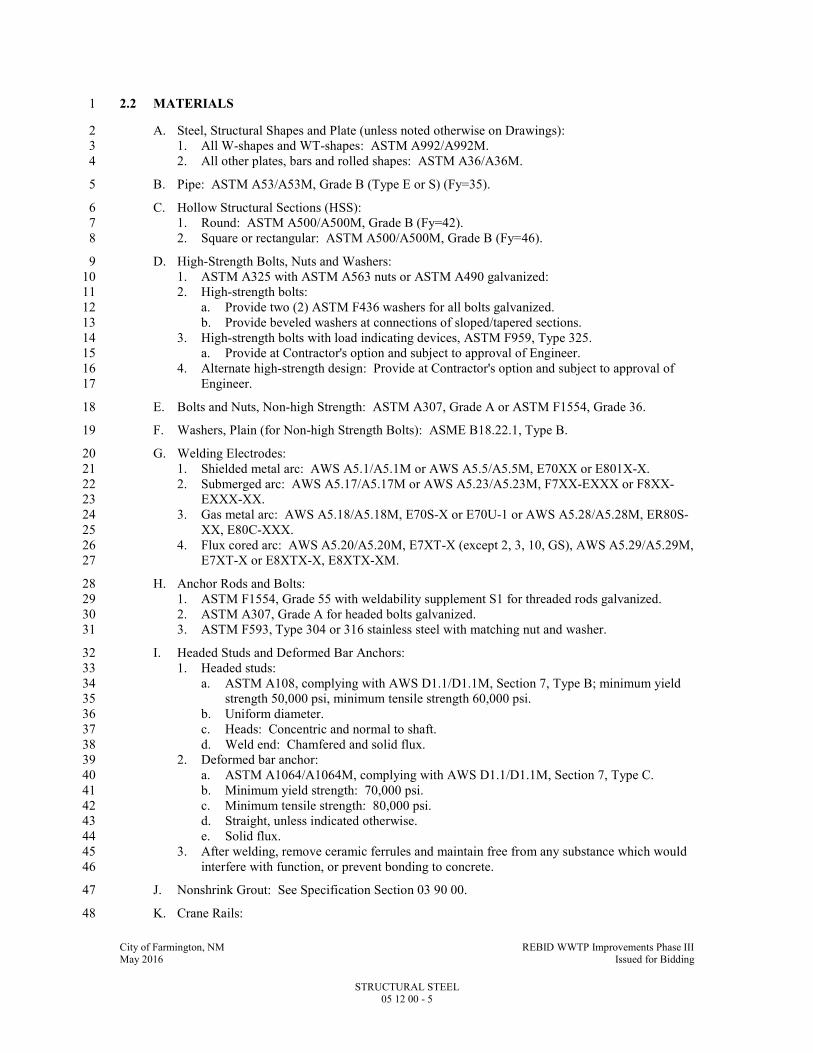
City of Farmington, NM REBID WWTP Improvements Phase III May 2016 Issued for Bidding
STRUCTURAL STEEL 05 12 00 - 5
2.2 MATERIALS 1
A. Steel, Structural Shapes and Plate (unless noted otherwise on Drawings): 2
1. All W-shapes and WT-shapes: ASTM A992/A992M. 3
2. All other plates, bars and rolled shapes: ASTM A36/A36M. 4
B. Pipe: ASTM A53/A53M, Grade B (Type E or S) (Fy=35). 5
C. Hollow Structural Sections (HSS): 6
1. Round: ASTM A500/A500M, Grade B (Fy=42). 7
2. Square or rectangular: ASTM A500/A500M, Grade B (Fy=46). 8
D. High-Strength Bolts, Nuts and Washers: 9
1. ASTM A325 with ASTM A563 nuts or ASTM A490 galvanized: 10
2. High-strength bolts: 11
a. Provide two (2) ASTM F436 washers for all bolts galvanized. 12
b. Provide beveled washers at connections of sloped/tapered sections. 13
3. High-strength bolts with load indicating devices, ASTM F959, Type 325. 14
a. Provide at Contractor's option and subject to approval of Engineer. 15
4. Alternate high-strength design: Provide at Contractor's option and subject to approval of 16
Engineer. 17
E. Bolts and Nuts, Non-high Strength: ASTM A307, Grade A or ASTM F1554, Grade 36. 18
F. Washers, Plain (for Non-high Strength Bolts): ASME B18.22.1, Type B. 19
G. Welding Electrodes: 20
1. Shielded metal arc: AWS A5.1/A5.1M or AWS A5.5/A5.5M, E70XX or E801X-X. 21
2. Submerged arc: AWS A5.17/A5.17M or AWS A5.23/A5.23M, F7XX-EXXX or F8XX-22
EXXX-XX. 23
3. Gas metal arc: AWS A5.18/A5.18M, E70S-X or E70U-1 or AWS A5.28/A5.28M, ER80S-24
XX, E80C-XXX. 25
4. Flux cored arc: AWS A5.20/A5.20M, E7XT-X (except 2, 3, 10, GS), AWS A5.29/A5.29M, 26
E7XT-X or E8XTX-X, E8XTX-XM. 27
H. Anchor Rods and Bolts: 28
1. ASTM F1554, Grade 55 with weldability supplement S1 for threaded rods galvanized. 29
2. ASTM A307, Grade A for headed bolts galvanized. 30
3. ASTM F593, Type 304 or 316 stainless steel with matching nut and washer. 31
I. Headed Studs and Deformed Bar Anchors: 32
1. Headed studs: 33
a. ASTM A108, complying with AWS D1.1/D1.1M, Section 7, Type B; minimum yield 34
strength 50,000 psi, minimum tensile strength 60,000 psi. 35
b. Uniform diameter. 36
c. Heads: Concentric and normal to shaft. 37
d. Weld end: Chamfered and solid flux. 38
2. Deformed bar anchor: 39
a. ASTM A1064/A1064M, complying with AWS D1.1/D1.1M, Section 7, Type C. 40
b. Minimum yield strength: 70,000 psi. 41
c. Minimum tensile strength: 80,000 psi. 42
d. Straight, unless indicated otherwise. 43
e. Solid flux. 44
3. After welding, remove ceramic ferrules and maintain free from any substance which would 45
interfere with function, or prevent bonding to concrete. 46
J. Nonshrink Grout: See Specification Section 03 90 00. 47
K. Crane Rails: 48

City of Farmington, NM REBID WWTP Improvements Phase III May 2016 Issued for Bidding
STRUCTURAL STEEL 05 12 00 - 6
1. Controlled-cooled, open-hearth carbon steel ASCE rails per ASTM A2, Class A, #1 rails, 1
unless noted otherwise, of size and weight indicated. 2
a. Furnish rails with milled tight end joints suitable for crane service, with standard 3
drilling, removable end stops and all related accessories required, including: 4
1) Joint bars: Match rail section and properties, drilled to match rail drilling. 5
2) Joint bar bolts and nuts: High strength. 6
3) Hardened washer: ASTM F436 for bar bolts. 7
4) Except as indicated otherwise, two-bolt type fixed or floating rail clamps to suit the 8
conditions, of forged or pressed steel, complete with ASTM A325 bolts, reversible 9
fillers, and self-locking nut or nut and lock washer. 10
L. Expansion Anchor Bolts and Adhesive Anchor Bolts for Fastening to Concrete: 11
1. Use of expansion bolts requires approval by Engineer. 12
2. Stainless steel, Type 304 or Type 316. 13
3. Provide minimum edge distance cover as recommended by manufacturer or as indicated on 14
Drawings. 15
4. Submit manufacturer's data and ICC report to verify at least the load test capacities and 16
anchor bolt capacities at the following embedment depths: 17
18
ANCHOR BOLT
DIAMETER (IN)
EMBEDMENT
(IN)
MINIMUM ULTIMATE
TENSION CAPACITY (KIP)*, **
3/8 3 4.8
1/2 4 8.1
5/8 5 11.4
3/4 6 15.4
7/8 7 20.0
1 8 24.7
1-1/4 10 34.3
* Data must be based on actual tests preformed in unreinforced mass concrete of not more 19
than 4000 psi compressive strength. 20
** Capacity must be at a concrete temperature of at least 130 DegF. 21
22
2.3 FABRICATION 23
A. Comply with requirements of applicable Building Code and AISC 360 with modifications and 24
additional requirements specified herein. 25
1. Identify high-strength steel material in fabricated members in accordance with 26
ASTM A6/A6M. 27
B. Minimize the amount of field welding. 28
1. Shop assemble components into largest size possible commensurate with transportation and 29
handling limitations. 30
2. Shop connections: Bolted with high-strength bolts or welded. 31
C. Connection Details: 32
1. Connections not fully detailed on Drawings shall be designed by a Professional Engineer 33
registered in the State of New Mexico, retained by Contractor, based on requirements of 34
Contract Documents. 35
2. Where beam reactions are shown on Drawings, design beam connection to support specified 36
loads. 37
3. Where no reactions are shown, design each beam connection to support one-half of total 38
uniform load capacity tabulated in AISC tables for "Uniform Load Constants for Beams" for 39
the given shape, span and steel grade specified. 40
4. Where indicated on the Drawings, design beam connections for the axial load or transfer 41
forces indicated in addition to the shear value indicated above. 42
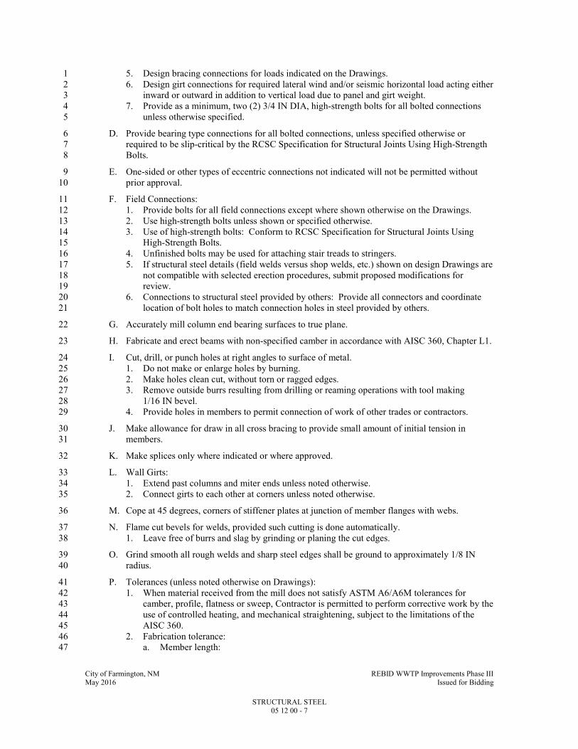
City of Farmington, NM REBID WWTP Improvements Phase III May 2016 Issued for Bidding
STRUCTURAL STEEL 05 12 00 - 7
5. Design bracing connections for loads indicated on the Drawings. 1
6. Design girt connections for required lateral wind and/or seismic horizontal load acting either 2
inward or outward in addition to vertical load due to panel and girt weight. 3
7. Provide as a minimum, two (2) 3/4 IN DIA, high-strength bolts for all bolted connections 4
unless otherwise specified. 5
D. Provide bearing type connections for all bolted connections, unless specified otherwise or 6
required to be slip-critical by the RCSC Specification for Structural Joints Using High-Strength 7
Bolts. 8
E. One-sided or other types of eccentric connections not indicated will not be permitted without 9
prior approval. 10
F. Field Connections: 11
1. Provide bolts for all field connections except where shown otherwise on the Drawings. 12
2. Use high-strength bolts unless shown or specified otherwise. 13
3. Use of high-strength bolts: Conform to RCSC Specification for Structural Joints Using 14
High-Strength Bolts. 15
4. Unfinished bolts may be used for attaching stair treads to stringers. 16
5. If structural steel details (field welds versus shop welds, etc.) shown on design Drawings are 17
not compatible with selected erection procedures, submit proposed modifications for 18
review. 19
6. Connections to structural steel provided by others: Provide all connectors and coordinate 20
location of bolt holes to match connection holes in steel provided by others. 21
G. Accurately mill column end bearing surfaces to true plane. 22
H. Fabricate and erect beams with non-specified camber in accordance with AISC 360, Chapter L1. 23
I. Cut, drill, or punch holes at right angles to surface of metal. 24
1. Do not make or enlarge holes by burning. 25
2. Make holes clean cut, without torn or ragged edges. 26
3. Remove outside burrs resulting from drilling or reaming operations with tool making 27
1/16 IN bevel. 28
4. Provide holes in members to permit connection of work of other trades or contractors. 29
J. Make allowance for draw in all cross bracing to provide small amount of initial tension in 30
members. 31
K. Make splices only where indicated or where approved. 32
L. Wall Girts: 33
1. Extend past columns and miter ends unless noted otherwise. 34
2. Connect girts to each other at corners unless noted otherwise. 35
M. Cope at 45 degrees, corners of stiffener plates at junction of member flanges with webs. 36
N. Flame cut bevels for welds, provided such cutting is done automatically. 37
1. Leave free of burrs and slag by grinding or planing the cut edges. 38
O. Grind smooth all rough welds and sharp steel edges shall be ground to approximately 1/8 IN 39
radius. 40
P. Tolerances (unless noted otherwise on Drawings): 41
1. When material received from the mill does not satisfy ASTM A6/A6M tolerances for 42
camber, profile, flatness or sweep, Contractor is permitted to perform corrective work by the 43
use of controlled heating, and mechanical straightening, subject to the limitations of the 44
AISC 360. 45
2. Fabrication tolerance: 46
a. Member length: 47
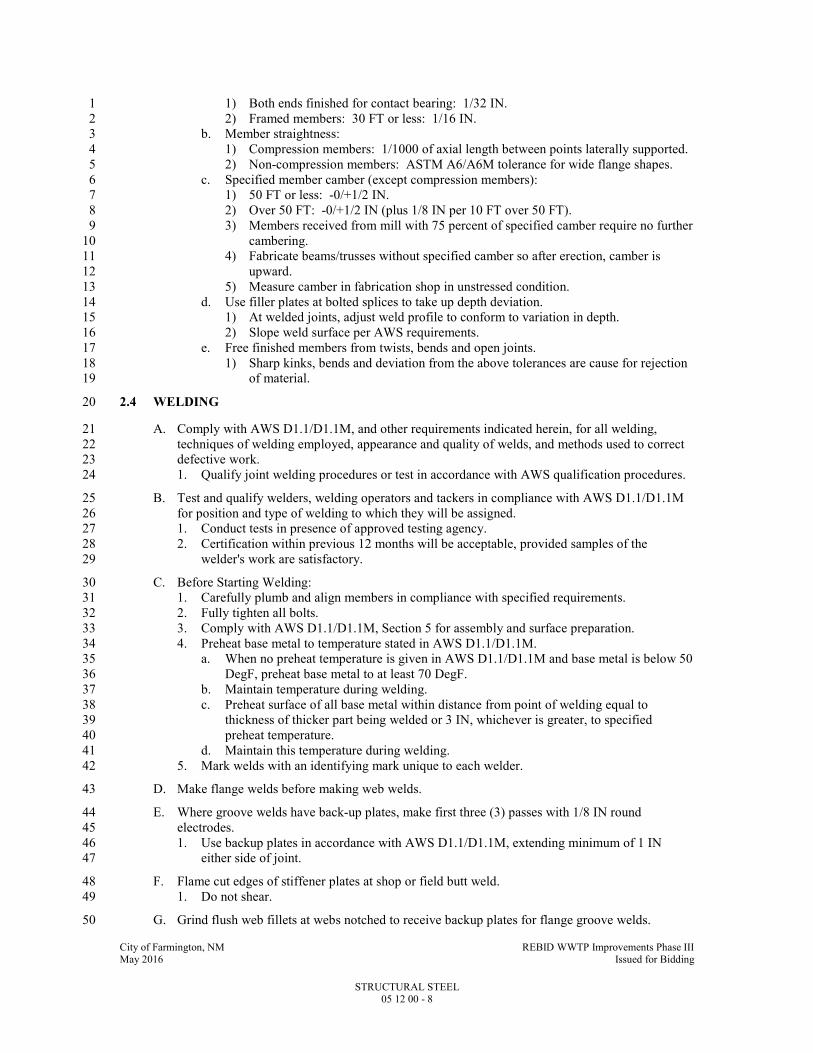
City of Farmington, NM REBID WWTP Improvements Phase III May 2016 Issued for Bidding
STRUCTURAL STEEL 05 12 00 - 8
1) Both ends finished for contact bearing: 1/32 IN. 1
2) Framed members: 30 FT or less: 1/16 IN. 2
b. Member straightness: 3
1) Compression members: 1/1000 of axial length between points laterally supported. 4
2) Non-compression members: ASTM A6/A6M tolerance for wide flange shapes. 5
c. Specified member camber (except compression members): 6
1) 50 FT or less: -0/+1/2 IN. 7
2) Over 50 FT: -0/+1/2 IN (plus 1/8 IN per 10 FT over 50 FT). 8
3) Members received from mill with 75 percent of specified camber require no further 9
cambering. 10
4) Fabricate beams/trusses without specified camber so after erection, camber is 11
upward. 12
5) Measure camber in fabrication shop in unstressed condition. 13
d. Use filler plates at bolted splices to take up depth deviation. 14
1) At welded joints, adjust weld profile to conform to variation in depth. 15
2) Slope weld surface per AWS requirements. 16
e. Free finished members from twists, bends and open joints. 17
1) Sharp kinks, bends and deviation from the above tolerances are cause for rejection 18
of material. 19
2.4 WELDING 20
A. Comply with AWS D1.1/D1.1M, and other requirements indicated herein, for all welding, 21
techniques of welding employed, appearance and quality of welds, and methods used to correct 22
defective work. 23
1. Qualify joint welding procedures or test in accordance with AWS qualification procedures. 24
B. Test and qualify welders, welding operators and tackers in compliance with AWS D1.1/D1.1M 25
for position and type of welding to which they will be assigned. 26
1. Conduct tests in presence of approved testing agency. 27
2. Certification within previous 12 months will be acceptable, provided samples of the 28
welder's work are satisfactory. 29
C. Before Starting Welding: 30
1. Carefully plumb and align members in compliance with specified requirements. 31
2. Fully tighten all bolts. 32
3. Comply with AWS D1.1/D1.1M, Section 5 for assembly and surface preparation. 33
4. Preheat base metal to temperature stated in AWS D1.1/D1.1M. 34
a. When no preheat temperature is given in AWS D1.1/D1.1M and base metal is below 50 35
DegF, preheat base metal to at least 70 DegF. 36
b. Maintain temperature during welding. 37
c. Preheat surface of all base metal within distance from point of welding equal to 38
thickness of thicker part being welded or 3 IN, whichever is greater, to specified 39
preheat temperature. 40
d. Maintain this temperature during welding. 41
5. Mark welds with an identifying mark unique to each welder. 42
D. Make flange welds before making web welds. 43
E. Where groove welds have back-up plates, make first three (3) passes with 1/8 IN round 44
electrodes. 45
1. Use backup plates in accordance with AWS D1.1/D1.1M, extending minimum of 1 IN 46
either side of joint. 47
F. Flame cut edges of stiffener plates at shop or field butt weld. 48
1. Do not shear. 49
G. Grind flush web fillets at webs notched to receive backup plates for flange groove welds. 50

City of Farmington, NM REBID WWTP Improvements Phase III May 2016 Issued for Bidding
STRUCTURAL STEEL 05 12 00 - 9
H. Low Hydrogen Electrodes: Dry and store electrodes in compliance with AWS D1.1/D1.1M. 1
I. Do not perform welding when ambient temperature is lower than 0 DegF or where surfaces are 2
wet or exposed to rain, snow, or high wind, or when welders are exposed to inclement 3
conditions. 4
J. Headed Studs and Deformed Bar Anchors: 5
1. Automatically end welded in accordance with the AWS D1.1/D1.1M and manufacturer's 6
recommendations. 7
2. Fillet welding of headed studs and deformed bar anchors is not allowed unless approved by 8
Engineer. 9
K. Test in-place studs in accordance with requirements of AWS D1.1/D1.1M to ensure satisfactory 10
welding of studs to members. 11
1. Replace studs failing this test. 12
L. When headed stud-type shear connectors are to be applied, clean top surface of members to 13
receive studs in shop to remove oil, scale, rust, dirt, and other materials injurious to satisfactory 14
welding. 15
1. Do not shop paint or galvanize metal surfaces to receive field applied studs. 16
2.5 SHOP COATING 17
A. Refer to Specification Section 09 91 00 and coordinate shop primer, surface preparation and 18
coating with field applied primers and coatings where specified. 19
B. Provide suitable methods of handling and transporting painted steel to avoid damage to coating. 20
C. Do not coat following surfaces: 21
1. Machined surfaces, surfaces adjacent to field welds, and surfaces fully embedded in 22
concrete. 23
2. All other members for which no coating is specified. 24
3. Contact surfaces at bolted slip-critical connections, unless surface condition conforms to the 25
RCSC Specification for Structural Joints Using High-Strength Bolts, Part 3.2.2. 26
D. Clean thoroughly all surfaces not coated before shipping. 27
1. Remove loose mill scale, rust, dirt, oil and grease. 28
2. Protect machined surfaces. 29
2.6 SOURCE QUALITY CONTROL 30
A. Testing Agency Responsibilities: 31
1. Inspect shop and field welding in accordance with AWS D1.1/D1.1M, Section 6 including 32
the following non-destructive testing: 33
a. Visually inspect all welds. 34
b. In addition to visual inspection, test 50 percent of full penetration welds and 20 percent 35
of fillet welds with liquid dye penetrant. 36
c. Test 20 percent of liquid dye penetrant tested full penetration welds with ultrasonic or 37
radiographic testing. 38
2. Inspect high-strength bolting in accordance with the RCSC Specification for Structural 39
Joints Using High-Strength Bolts, Section 9. 40
a. Verify proper pretension for slip-critical bolted connection. 41
b. Verify direct tension indicator gaps. 42
3. Inspect structural steel which has been erected. 43
4. Inspect stud welding in accordance with AWS D1.1/D1.1M, Section 7.8. 44
5. Prepare and submit inspection and test reports to Engineer. 45
a. Assist Engineer to determine corrective measures necessary for defective work. 46

City of Farmington, NM REBID WWTP Improvements Phase III May 2016 Issued for Bidding
STRUCTURAL STEEL 05 12 00 - 10
PART 3 - EXECUTION 1
3.1 GENERAL 2
A. Contractor is solely responsible for safety. 3
1. Construction means and methods and sequencing of work is the prerogative of the 4
Contractor. 5
2. Take into consideration that full structural capacity of many structural members is not 6
realized until structural assembly is complete; e.g., until slabs, decks, bracing or rigid 7
connections are installed. 8
3. Partially complete structural members shall not be loaded without an investigation by the 9
Contractor. 10
4. Until all elements of the permanent structure and lateral bracing system are complete, 11
provide temporary bracing designed, furnished, and installed by the Contractor for the 12
partially complete structure. 13
B. Adequate temporary bracing to provide safety, stability and to resist all loads to which the 14
partially complete structure may be subjected, including wind, construction activities, and 15
operation of equipment, is the responsibility of the Contractor. 16
1. Use temporary guys, braces, shoring, connections, etc., necessary to maintain the structural 17
framing plumb and in proper alignment until permanent connections are made, the 18
succeeding work is in place, and temporary work is no longer necessary. 19
2. Use temporary guys, bracing, shoring, and other work to prevent injury or damage to 20
adjacent work or construction from stresses due to erection procedures and operation of 21
erection equipment, construction loads, and wind. 22
3. Design of the temporary bracing system and consideration of the sequence and schedule of 23
placement of such elements and effects of loads imposed on the structural steel members by 24
partially or completely installed work, including work of all other trades, is the Contractor's 25
responsibility. 26
a. If not obvious from experience or from the Drawings, the Contractor shall confer with 27
the Engineer to identify those structural steel elements that must be complete before the 28
temporary bracing system is removed. 29
4. Remove and dispose of all temporary work and facilities off-site. 30
C. Examine work-in-place on which specified work is in any way dependent to ensure that 31
conditions are satisfactory for the installation of the work. 32
1. Report defects in work-in-place which may influence satisfactory completion of the work. 33
2. Absence of such notification will be construed as acceptance of work-in-place. 34
D. Field Measurement: 35
1. Take field measurements as necessary to verify or supplement dimensions indicated on the 36
Drawings. 37
2. Contractor is responsible for the accurate fit of the work. 38
E. Check the elevations of all finished footings or foundations and the location and alignment of all 39
anchor bolts before starting erection. 40
1. Notify Engineer of any errors or deviations found by such checking. 41
3.2 ERECTION 42
A. Framing member location tolerances after erection shall not exceed the frame tolerances listed in 43
the FIELD QUALITY CONTROL Article in PART 3 of this Specification Section. 44
B. Erect plumb and level; introduce temporary bracing required to support erection loads. 45
C. Use light drifting necessary to draw holes together. 46
1. Drifting to match unfair holes is not allowed. 47

City of Farmington, NM REBID WWTP Improvements Phase III May 2016 Issued for Bidding
STRUCTURAL STEEL 05 12 00 - 11
D. Welding: 1
1. Conform to AWS D1.1/D1/1M and requirements of this Specification Section. 2
2. Join two (2) sections of steel of different ASTM designations using welding techniques in 3
accordance with a qualified AWS D1.1/D1.1M procedure. 4
E. Shore existing members when unbolting of common connections is required. 5
1. Use new bolts for rebolting connections. 6
F. Clean stored material of all foreign matter accumulated during erection period. 7
G. Clean bearing and contact surfaces before assembly. 8
H. Set beam and column base and bearing plates accurately, as indicated, on nonshrink grout. 9
1. Set and anchor each base plate to proper line and elevation. 10
2. Use metal wedges, shims or setting nuts as required and tighten anchor bolts. 11
a. Use same metal as base plate. 12
b. Cut off protrusions of wedges and shims flush with edge of base plate. 13
3. Fill sleeves around anchor bolts with nonshrink grout. 14
4. Pack grout solidly between bottom of plate and bearing surface. 15
5. Refer to Specification Section 04 05 13 for nonshrink grout requirements. 16
I. Anchor Bolts: 17
1. Anchor bolt location tolerance per AISC 303, Section 7.5. 18
2. Tie anchor bolts in position to embedded reinforcing steel using wire. 19
3. Welding or tack welding is prohibited. 20
4. Provide steel templates for locating anchor bolts. 21
5. Coat bolt threads and nuts with heavy coat of clean grease. 22
J. Install high strength bolts with hardened washers. 23
1. Install and tighten in accordance with the RCSC Specification for Structural Joints Using 24
High-Strength Bolts, Section 8. 25
2. Coordinate installation with inspection. 26
a. Do not start installation until coordination with Testing Agency is complete. 27
3. Bearing-type connections: High-strength bolts shall be tightened to snug-tight condition. 28
4. Slip-critical connections: 29
a. Perform calibration testing for all methods of installation of high-strength bolts in 30
accordance with RCSC Specification for Structural Joints Using High-Strength Bolts, 31
Section 8.2. 32
b. Turn-of-nut tightening: 33
1) Inspector shall observe the pre-installation verification testing. 34
2) Subsequently, ensure by routine observation that the bolting crew properly rotates 35
the turned element relative to the unturned element by the amount specified. 36
3) Alternatively, when fastener assemblies are match-marked after the initial fitup of 37
the joint but prior to pretensioning, visual inspection after pretensioning is 38
permitted in lieu of routine observation. 39
c. Calibrated wrench tightening: Calibrate on a daily basis. 40
d. Direct tension indicator tightening: If previously approved by Engineer. 41
e. Installation of alternate design bolts: If previously approved by Engineer. 42
5. In the event any bolt in a connection is found to be defective, check and retighten all bolts in 43
the connection. 44
K. Do not use gas cutting to correct fabrication errors. 45
1. In case members do not fit or holes do not match, ream out the holes and insert the next 46
larger size bolt. 47
a. Drill new holes if the connections require new holes. 48
b. Make no such corrections without prior approval of the Engineer. 49
2. Burning of holes is not permitted. 50

City of Farmington, NM REBID WWTP Improvements Phase III May 2016 Issued for Bidding
STRUCTURAL STEEL 05 12 00 - 12
L. Prior to making field connections to existing structural steel, remove completely all paint from 1
existing steel which will be in contact with new steel and new welds. 2
M. Tighten and leave in place erection bolts used in welded construction. 3
N. Provide beveled washers to give full bearing to bolt head or nut where bolts are to be used on 4
surfaces having slopes greater than 1 in 20 with a plane normal to bolt axis. 5
O. After bolts are tightened, upset threads of non-high strength bolts and anchor bolts to prevent 6
nuts from backing off. 7
P. Crane Runways: 8
1. Erect crane runways complete with columns, beams, girders, bracing, crane rails, crane 9
stops, and other required components as indicated. 10
2. Stagger crane rail joints with respect to each other on opposite sides of the runway and do 11
not coincide with crane girder joints. 12
3. Center crane rails on top of crane girders and secure to girders with tight clamps and/or 13
floating clamps as appropriate; provide clamps in pairs spaced not over 3 FT OC along rail 14
length, with each clamp secured with two (2) high-strength bolts and self-locking nuts (or 15
nuts and lock washers), with reversible fillers used at each clamp to allow for alignment. 16
a. Do not use hook bolt type clamps. 17
4. Tolerances: 18
a. Center-to-center of crane rails: Not exceed plus or minus 1/4 IN from indicated 19
dimension. 20
b. Crane rail horizontal misalignment: Not exceed 1/4 IN per 50 FT of runway with a 21
maximum of 1/2 IN total deviation. 22
c. Vertical misalignment between crane rails and along a crane rail measured at 23
centerlines of columns: Not to exceed 1/4 IN per 50 FT of runway with a maximum of 24
1/2 IN total deviation. 25
5. Tight-fitting joints between rail sections and install so top of crane rails are flush at all 26
joints. 27
6. Secure the joints with joint bars on each side of rail, bolted together through rail with high-28
strength bolts, nuts and spring washers. 29
Q. After Erection: 30
1. Grind smooth all sharp surface irregularities resulting from field cutting or welding. 31
2. Power tool clean welds, bolts, washers and abrasions to shop coat removing all rust and 32
foreign matter. 33
R. Expansion Anchor Bolts and Adhesive Anchor Bolts: 34
1. Minimum embedment as recommended by manufacturer or specified herein, whichever is 35
larger. 36
2. Notify Engineer if required depth of embedment cannot be achieved at a particular bolt 37
location. 38
3. Follow manufacturer's recommendations for installation and torque. 39
3.3 FIELD QUALITY CONTROL 40
A. Testing Agency responsibilities are described in the SOURCE QUALITY CONTROL Article in 41
PART 2 of this Specification Section. 42
B. Erected Frame Tolerance, unless noted otherwise on the Drawings: 43
1. Do not exceed cumulative effect of rolling, fabrication and erection tolerance for overall 44
finished dimensions. 45
2. Erection tolerances are defined relative to member working points and working lines as 46
follows: 47
a. Actual centerline of top flange or surface at each end for horizontal members. 48
b. Actual center of member at each end for all other members. 49

City of Farmington, NM REBID WWTP Improvements Phase III May 2016 Issued for Bidding
STRUCTURAL STEEL 05 12 00 - 13
c. Other points may be used, providing they are based on these definitions. 1
d. Working line is straight line connecting member working points. 2
3. Tolerances on position and alignment are as specified in the Code, unless otherwise 3
modified. 4
a. Provide "adjustable items" such as lintels, wall supports, curb angles, window mullions 5
and similar members with adjustable connections to supporting structural frame. 6
4. Certification by steel erector: 7
a. Certify the location of erected structural steel is acceptable for plumbness, level and 8
aligned within tolerances specified. 9
b. Provide certification upon completion of any part of work. 10
c. Provide certification prior to start of work by other trades that may be supported; attach 11
to structural steel work. 12
3.4 CLEANING AND REPAIR OF SHOP PRIMER PAINT 13
A. After erection, clean all steel of mud or other foreign materials, and repair any damage. 14
1. Touchup coatings to comply with Specification Section 09 91 00. 15
END OF SECTION 16
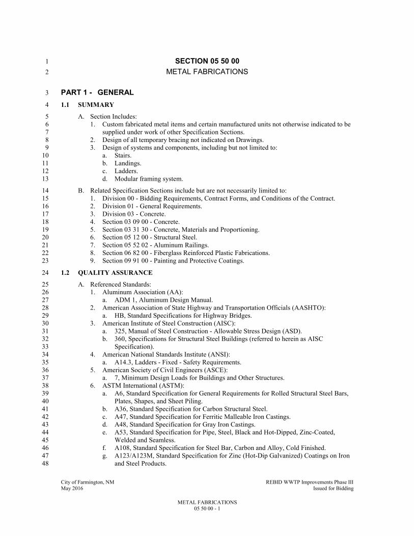
City of Farmington, NM REBID WWTP Improvements Phase III May 2016 Issued for Bidding
METAL FABRICATIONS 05 50 00 - 1
SECTION 05 50 00 1
METAL FABRICATIONS 2
PART 1 - GENERAL 3
1.1 SUMMARY 4
A. Section Includes: 5
1. Custom fabricated metal items and certain manufactured units not otherwise indicated to be 6
supplied under work of other Specification Sections. 7
2. Design of all temporary bracing not indicated on Drawings. 8
3. Design of systems and components, including but not limited to: 9
a. Stairs. 10
b. Landings. 11
c. Ladders. 12
d. Modular framing system. 13
B. Related Specification Sections include but are not necessarily limited to: 14
1. Division 00 - Bidding Requirements, Contract Forms, and Conditions of the Contract. 15
2. Division 01 - General Requirements. 16
3. Division 03 - Concrete. 17
4. Section 03 09 00 - Concrete. 18
5. Section 03 31 30 - Concrete, Materials and Proportioning. 19
6. Section 05 12 00 - Structural Steel. 20
7. Section 05 52 02 - Aluminum Railings. 21
8. Section 06 82 00 - Fiberglass Reinforced Plastic Fabrications. 22
9. Section 09 91 00 - Painting and Protective Coatings. 23
1.2 QUALITY ASSURANCE 24
A. Referenced Standards: 25
1. Aluminum Association (AA): 26
a. ADM 1, Aluminum Design Manual. 27
2. American Association of State Highway and Transportation Officials (AASHTO): 28
a. HB, Standard Specifications for Highway Bridges. 29
3. American Institute of Steel Construction (AISC): 30
a. 325, Manual of Steel Construction - Allowable Stress Design (ASD). 31
b. 360, Specifications for Structural Steel Buildings (referred to herein as AISC 32
Specification). 33
4. American National Standards Institute (ANSI): 34
a. A14.3, Ladders - Fixed - Safety Requirements. 35
5. American Society of Civil Engineers (ASCE): 36
a. 7, Minimum Design Loads for Buildings and Other Structures. 37
6. ASTM International (ASTM): 38
a. A6, Standard Specification for General Requirements for Rolled Structural Steel Bars, 39
Plates, Shapes, and Sheet Piling. 40
b. A36, Standard Specification for Carbon Structural Steel. 41
c. A47, Standard Specification for Ferritic Malleable Iron Castings. 42
d. A48, Standard Specification for Gray Iron Castings. 43
e. A53, Standard Specification for Pipe, Steel, Black and Hot-Dipped, Zinc-Coated, 44
Welded and Seamless. 45
f. A108, Standard Specification for Steel Bar, Carbon and Alloy, Cold Finished. 46
g. A123/A123M, Standard Specification for Zinc (Hot-Dip Galvanized) Coatings on Iron 47
and Steel Products. 48

City of Farmington, NM REBID WWTP Improvements Phase III May 2016 Issued for Bidding
METAL FABRICATIONS 05 50 00 - 2
h. A153/A153M, Standard Specification for Zinc Coating (Hot-Dip) on Iron and Steel 1
Hardware. 2
i. A197, Standard Specification for Cupola Malleable Iron. 3
j. A269, Standard Specification for Seamless and Welded Austenitic Stainless Steel 4
Tubing for General Service. 5
k. A276, Standard Specification for Stainless Steel Bars and Shapes. 6
l. A307, Standard Specification for Carbon Steel Bolts and Studs, 60,000 PSI Tensile 7
Strength. 8
m. A312, Standard Specification for Seamless, Welded, and Heavily Cold Worked 9
Austenitic Stainless Steel Pipes. 10
n. A325, Standard Specification for Structural Bolts, Steel, Heat Treated, 120/105 ksi 11
Minimum Tensile Strength. 12
o. A380, Standard Practice for Cleaning, Descaling, and Passivation of Stainless Steel 13
Parts, Equipment, and Systems. 14
p. A496, Standard Specification for Steel Wire, Deformed, for Concrete Reinforcement. 15
q. A500, Standard Specification for Cold-Formed Welded and Seamless Carbon Steel 16
Structural Tubing in Rounds and Shapes. 17
r. A501, Standard Specification for Hot-Formed Welded and Seamless Carbon Steel 18
Structural Tubing. 19
s. A536, Standard Specification for Ductile Iron Castings. 20
t. A554, Standard Specification for Welded Stainless Steel Mechanical Tubing. 21
u. A572, Standard Specification for High-Strength Low-Alloy Columbium-Vanadium 22
Structural Steel. 23
v. A666, Standard Specification for Annealed or Cold-Worked Austenitic Stainless Steel 24
Sheet, Strip, Plate, and Flat Bar. 25
w. A668, Standard Specification for Steel Forgings, Carbon and Alloy, for General 26
Industrial Use. 27
x. A780, Standard Practice for Repair of Damaged and Uncoated Areas of Hot-Dip 28
Galvanized Coatings. 29
y. A786, Standard Specification for Hot-Rolled Carbon, Low-Alloy, High-Strength Low-30
Alloy, and Alloy Steel Floor Plates. 31
z. A992, Standard Specification for Steel for Structural Shapes. 32
aa. A1064, Standard Specification for Steel Wire and Welded Wire Reinforcement, Plain 33
and Deformed, for Concrete. 34
bb. B26, Standard Specification for Aluminum-Alloy Sand Castings. 35
cc. B209, Standard Specification for Aluminum and Aluminum-Alloy Sheet and Plate. 36
dd. B221, Standard Specification for Aluminum and Aluminum-Alloy Extruded Bars, 37
Rods, Wire, Profiles, and Tubes. 38
ee. B308, Standard Specification for Aluminum-Alloy 6061-T6 Standard Structural 39
Profiles. 40
ff. B429, Standard Specification for Aluminum-Alloy Extruded Structural Pipe and Tube. 41
gg. B632, Standard Specification for Aluminum-Alloy Rolled Tread Plate. 42
hh. F467, Standard Specification for Nonferrous Nuts for General Use. 43
ii. F468, Standard Specification for Nonferrous Bolts, Hex Cap Screws, and Studs for 44
General Use. 45
jj. F593, Standard Specification for Stainless Steel Bolts, Hex Cap Screws, and Studs. 46
kk. F835, Standard Specification for Alloy Steel Socket Button and Flat Countersunk Head 47
Cap Screws. 48
ll. F879, Standard Specification for Stainless Steel Socket Button and Flat Countersunk 49
Head Cap Screws. 50
mm. F1554, Standard Specification for Anchor Bolts, Steel, 36, 55, and 105-ksi Yield 51
Strength. 52
nn. F1789, Standard Terminology for F16 Mechanical Fasteners. 53
7. American Welding Society (AWS): 54

City of Farmington, NM REBID WWTP Improvements Phase III May 2016 Issued for Bidding
METAL FABRICATIONS 05 50 00 - 3
a. A5.1/A5.1M, Specification for Carbon Steel Electrodes for Shielded Metal Arc 1
Welding. 2
b. D1.1, Structural Welding Code - Steel. 3
c. D1.2, Structural Welding Code - Aluminum. 4
d. D1.6/D1.6M, Structural Welding Code - Stainless Steel. 5
8. National Association of Architectural Metal Manufacturers (NAAMM): 6
a. AMP 510, Metal Stairs Manual. 7
b. AMP 555, Code of Standard Practice for the Architectural Metal Industry (Including 8
Miscellaneous Iron). 9
c. MBG 531, Metal Bar Grating Manual. 10
9. NACE International (NACE). 11
10. Nickel Development Institute (NiDI): 12
a. Publication 11 007, Guidelines for the welded fabrication of nickel-containing stainless 13
steels for corrosion resistant services. 14
11. Occupational Safety and Health Administration (OSHA): 15
a. 29 CFR 1910, Occupational Safety and Health Standards, referred to herein as OSHA 16
Standards. 17
12. Building code: 18
a. International Code Council (ICC): 19
1) International Building Code and associated standards, 2009 Edition including all 20
amendments, referred to herein as Building Code. 21
B. Qualifications: 22
1. Qualify welding procedures and welding operators in accordance with AWS. 23
2. Fabricator shall have minimum of 10 years experience in fabrication of metal items 24
specified. 25
3. Engineer for contractor-designed systems and components: Professional structural engineer 26
licensed in the State of New Mexico. 27
4. NACE certified inspector shall have minimum of two (2) years experience performing 28
inspections as indicated. 29
a. Have a current Level III coating inspector certification. 30
1.3 DEFINITIONS 31
A. Fasteners: As defined in ASTM F1789. 32
B. Galvanizing: Hot-dip galvanizing per ASTM A123/A123M or ASTM A153/A153M with 33
minimum coating of 2.0 OZ of zinc per square foot of metal (average of specimens) unless noted 34
otherwise or dictated by standard. 35
C. Hardware: As defined in ASTM A153/A153M. 36
D. Installer or Applicator: 37
1. Installer or applicator is the person actually installing or applying the product in the field at 38
the Project site. 39
2. Installer and applicator are synonymous. 40
1.4 SUBMITTALS 41
A. Shop Drawings: 42
1. See Specification Section 01 33 00 for requirements for the mechanics and administration of 43
the submittal process. 44
2. Fabrication and/or layout drawings and details: 45
a. Submit drawings for all fabrications and assemblies. 46
1) Include erection drawings, plans, sections, details and connection details. 47
b. Identify materials of construction, shop coatings and third party accessories. 48
3. Product technical data including: 49
a. Acknowledgement that products submitted meet requirements of standards referenced. 50

City of Farmington, NM REBID WWTP Improvements Phase III May 2016 Issued for Bidding
METAL FABRICATIONS 05 50 00 - 4
b. Manufacturer's installation instructions. 1
c. Provide manufacturer's standard allowable load tables for the following: 2
1) Grating and checkered plate. 3
2) Expansion anchor bolts. 4
3) Adhesive anchor bolts. 5
4) Castings, trench covers and accessories. 6
5) Modular framing systems. 7
4. Contractor designed systems and components, including but not limited to, stairs, landings 8
and ladders: 9
a. Certification that manufactured units meet all design loads specified. 10
b. Shop Drawings and engineering design calculations: 11
1) Indicate design live loads. 12
2) Sealed by a professional structural engineer. 13
3) Engineer will review for general compliance with Contract Documents. 14
B. Informational Submittals: 15
1. See Specification Section 01 33 00 for requirements for the mechanics and administration of 16
the submittal process. 17
2. Certification of welders and welding processes. 18
a. Indicate compliance with AWS. 19
3. NACE inspector qualifications. 20
4. NACE certification of surface preparation. 21
5. NACE certification of paint application. 22
1.5 ADDITIONAL CONTRACTOR REQUIREMENTS 23
A. This project includes an “American Iron and Steel (AIS)” requirement that is required by Clean 24
Water State Revolving Loan Fund (CWSRF) and Drinking Water State Revolving Loan Fund 25
(SWSRF) projects to use iron and steel products that are produced in the United States for 26
projects for the construction, alteration, maintenance, or repair of a public water system or 27
treatment works. All iron and steel shall meet the requirements as stated in Volume I under the 28
“Implementation of American Iron and Steel provisions of P.L. 113-76, Consolidated 29
Appropriations Act, 2014. 30
B. See the Sample Certifications for AIS Compliance in Specification Section 01 33 00. 31
Documentation must be provided on company letterhead. 32
1.6 DELIVERY, STORAGE, AND HANDLING 33
A. Deliver and handle fabrications to avoid damage. 34
B. Store above ground on skids or other supports to keep items free of dirt and other foreign debris 35
and to protect against corrosion. 36
PART 2 - PRODUCTS 37
2.1 ACCEPTABLE MANUFACTURERS 38
A. Subject to compliance with the Contract Documents, the following manufacturers are 39
acceptable: 40
1. Abrasive stair nosings (embedded in concrete stairs): 41
a. American Safety Tread. 42
b. Balco. 43
2. Headed studs and deformed bar anchors: 44
a. Nelson Stud Welding Div., TRW Inc. 45
b. Stud Welding Products, Inc. 46
3. Expansion anchor bolts: 47
a. Hilti Inc. 48
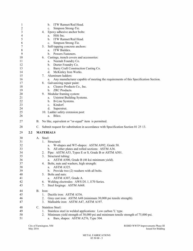
City of Farmington, NM REBID WWTP Improvements Phase III May 2016 Issued for Bidding
METAL FABRICATIONS 05 50 00 - 5
b. ITW Ramset/Red Head. 1
c. Simpson Strong-Tie. 2
4. Epoxy adhesive anchor bolts: 3
a. Hilti Inc. 4
b. ITW Ramset/Red Head. 5
c. Simpson Strong-Tie. 6
5. Self-tapping concrete anchors: 7
a. ITW Buildex. 8
b. Powers Fasteners. 9
6. Castings, trench covers and accessories: 10
a. Neenah Foundry Co. 11
b. Deeter Foundry Co. 12
c. Barry Craft Construction Casting Co. 13
d. McKinley Iron Works. 14
7. Aluminum ladders: 15
a. Any manufacturer capable of meeting the requirements of this Specification Section. 16
8. Galvanizing repair paint: 17
a. Clearco Products Co., Inc. 18
b. ZRC Products. 19
9. Modular framing system: 20
a. Unistrut Building Systems. 21
b. B-Line Systems. 22
c. Kindorf. 23
d. Superstrut. 24
10. Ladder safety extension post: 25
a. Bilco. 26
B. No like, equivalent or "or-equal" item is permitted. 27
C. Submit request for substitution in accordance with Specification Section 01 25 13. 28
2.2 MATERIALS 29
A. Steel: 30
1. Structural: 31
a. W-shapes and WT-shapes: ASTM A992, Grade 50. 32
b. All other plates and rolled sections: ASTM A36. 33
2. Pipe: ASTM A53, Types E or S, Grade B or ASTM A501. 34
3. Structural tubing: 35
a. ASTM A500, Grade B (46 ksi minimum yield). 36
4. Bolts, nuts and washers, high strength: 37
a. ASTM A325. 38
b. Provide two (2) washers with all bolts. 39
5. Bolts and nuts: 40
a. ASTM A307, Grade A. 41
6. Welding electrodes: AWS D1.1, E70 Series. 42
7. Steel forgings: ASTM A668. 43
B. Iron: 44
1. Ductile iron: ASTM A536. 45
2. Gray cast iron: ASTM A48 (minimum 30,000 psi tensile strength). 46
3. Malleable iron: ASTM A47, ASTM A197. 47
C. Stainless Steel: 48
1. Stainless steel in welded applications: Low carbon 'L' type. 49
2. Minimum yield strength of 30,000 psi and minimum tensile strength of 75,000 psi. 50
a. Bars, shapes: ASTM A276, Type 304. 51
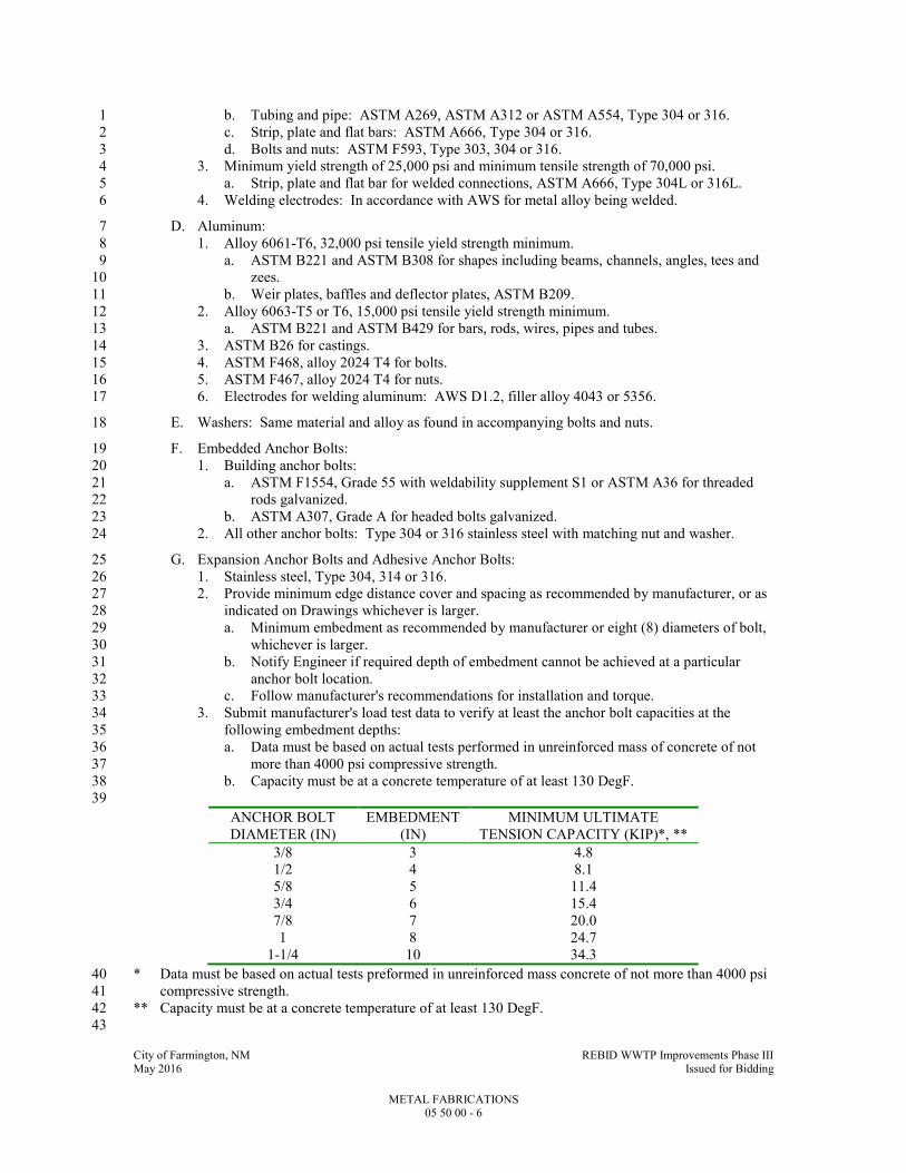
City of Farmington, NM REBID WWTP Improvements Phase III May 2016 Issued for Bidding
METAL FABRICATIONS 05 50 00 - 6
b. Tubing and pipe: ASTM A269, ASTM A312 or ASTM A554, Type 304 or 316. 1
c. Strip, plate and flat bars: ASTM A666, Type 304 or 316. 2
d. Bolts and nuts: ASTM F593, Type 303, 304 or 316. 3
3. Minimum yield strength of 25,000 psi and minimum tensile strength of 70,000 psi. 4
a. Strip, plate and flat bar for welded connections, ASTM A666, Type 304L or 316L. 5
4. Welding electrodes: In accordance with AWS for metal alloy being welded. 6
D. Aluminum: 7
1. Alloy 6061-T6, 32,000 psi tensile yield strength minimum. 8
a. ASTM B221 and ASTM B308 for shapes including beams, channels, angles, tees and 9
zees. 10
b. Weir plates, baffles and deflector plates, ASTM B209. 11
2. Alloy 6063-T5 or T6, 15,000 psi tensile yield strength minimum. 12
a. ASTM B221 and ASTM B429 for bars, rods, wires, pipes and tubes. 13
3. ASTM B26 for castings. 14
4. ASTM F468, alloy 2024 T4 for bolts. 15
5. ASTM F467, alloy 2024 T4 for nuts. 16
6. Electrodes for welding aluminum: AWS D1.2, filler alloy 4043 or 5356. 17
E. Washers: Same material and alloy as found in accompanying bolts and nuts. 18
F. Embedded Anchor Bolts: 19
1. Building anchor bolts: 20
a. ASTM F1554, Grade 55 with weldability supplement S1 or ASTM A36 for threaded 21
rods galvanized. 22
b. ASTM A307, Grade A for headed bolts galvanized. 23
2. All other anchor bolts: Type 304 or 316 stainless steel with matching nut and washer. 24
G. Expansion Anchor Bolts and Adhesive Anchor Bolts: 25
1. Stainless steel, Type 304, 314 or 316. 26
2. Provide minimum edge distance cover and spacing as recommended by manufacturer, or as 27
indicated on Drawings whichever is larger. 28
a. Minimum embedment as recommended by manufacturer or eight (8) diameters of bolt, 29
whichever is larger. 30
b. Notify Engineer if required depth of embedment cannot be achieved at a particular 31
anchor bolt location. 32
c. Follow manufacturer's recommendations for installation and torque. 33
3. Submit manufacturer's load test data to verify at least the anchor bolt capacities at the 34
following embedment depths: 35
a. Data must be based on actual tests performed in unreinforced mass of concrete of not 36
more than 4000 psi compressive strength. 37
b. Capacity must be at a concrete temperature of at least 130 DegF. 38
39
ANCHOR BOLT
DIAMETER (IN)
EMBEDMENT
(IN)
MINIMUM ULTIMATE
TENSION CAPACITY (KIP)*, **
3/8 3 4.8
1/2 4 8.1
5/8 5 11.4
3/4 6 15.4
7/8 7 20.0
1 8 24.7
1-1/4 10 34.3
* Data must be based on actual tests preformed in unreinforced mass concrete of not more than 4000 psi 40
compressive strength. 41
** Capacity must be at a concrete temperature of at least 130 DegF. 42
43
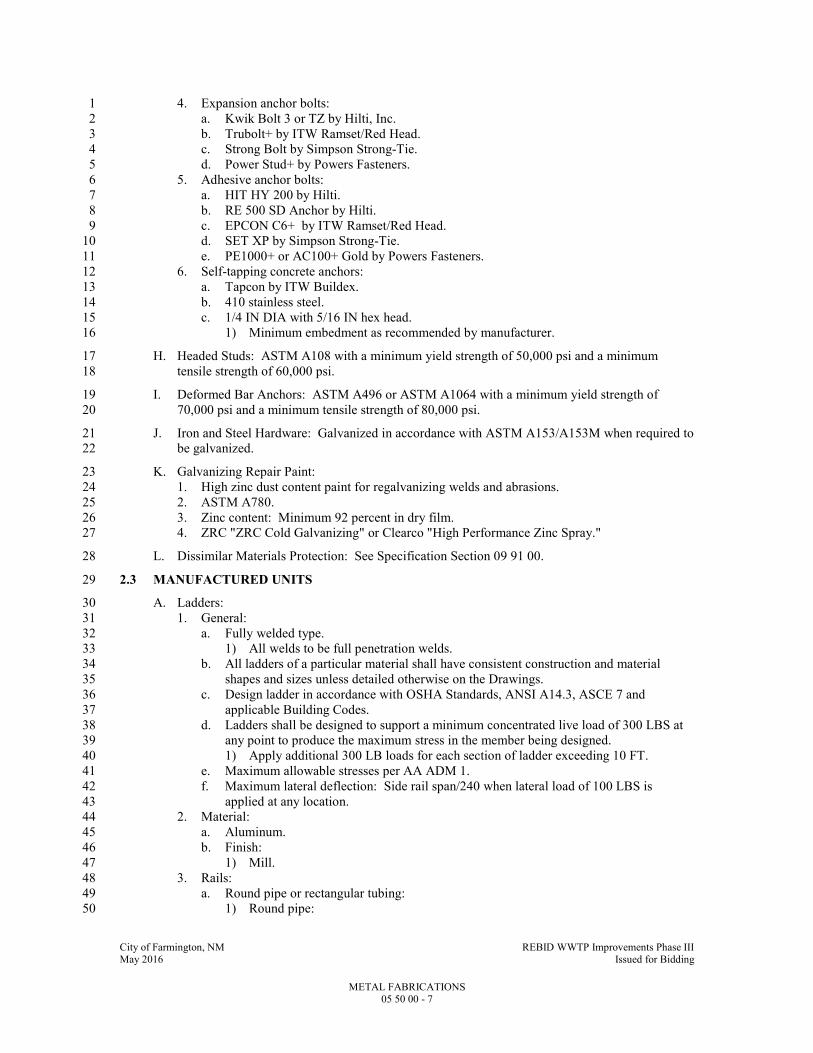
City of Farmington, NM REBID WWTP Improvements Phase III May 2016 Issued for Bidding
METAL FABRICATIONS 05 50 00 - 7
4. Expansion anchor bolts: 1
a. Kwik Bolt 3 or TZ by Hilti, Inc. 2
b. Trubolt+ by ITW Ramset/Red Head. 3
c. Strong Bolt by Simpson Strong-Tie. 4
d. Power Stud+ by Powers Fasteners. 5
5. Adhesive anchor bolts: 6
a. HIT HY 200 by Hilti. 7
b. RE 500 SD Anchor by Hilti. 8
c. EPCON C6+ by ITW Ramset/Red Head. 9
d. SET XP by Simpson Strong-Tie. 10
e. PE1000+ or AC100+ Gold by Powers Fasteners. 11
6. Self-tapping concrete anchors: 12
a. Tapcon by ITW Buildex. 13
b. 410 stainless steel. 14
c. 1/4 IN DIA with 5/16 IN hex head. 15
1) Minimum embedment as recommended by manufacturer. 16
H. Headed Studs: ASTM A108 with a minimum yield strength of 50,000 psi and a minimum 17
tensile strength of 60,000 psi. 18
I. Deformed Bar Anchors: ASTM A496 or ASTM A1064 with a minimum yield strength of 19
70,000 psi and a minimum tensile strength of 80,000 psi. 20
J. Iron and Steel Hardware: Galvanized in accordance with ASTM A153/A153M when required to 21
be galvanized. 22
K. Galvanizing Repair Paint: 23
1. High zinc dust content paint for regalvanizing welds and abrasions. 24
2. ASTM A780. 25
3. Zinc content: Minimum 92 percent in dry film. 26
4. ZRC "ZRC Cold Galvanizing" or Clearco "High Performance Zinc Spray." 27
L. Dissimilar Materials Protection: See Specification Section 09 91 00. 28
2.3 MANUFACTURED UNITS 29
A. Ladders: 30
1. General: 31
a. Fully welded type. 32
1) All welds to be full penetration welds. 33
b. All ladders of a particular material shall have consistent construction and material 34
shapes and sizes unless detailed otherwise on the Drawings. 35
c. Design ladder in accordance with OSHA Standards, ANSI A14.3, ASCE 7 and 36
applicable Building Codes. 37
d. Ladders shall be designed to support a minimum concentrated live load of 300 LBS at 38
any point to produce the maximum stress in the member being designed. 39
1) Apply additional 300 LB loads for each section of ladder exceeding 10 FT. 40
e. Maximum allowable stresses per AA ADM 1. 41
f. Maximum lateral deflection: Side rail span/240 when lateral load of 100 LBS is 42
applied at any location. 43
2. Material: 44
a. Aluminum. 45
b. Finish: 46
1) Mill. 47
3. Rails: 48
a. Round pipe or rectangular tubing: 49
1) Round pipe: 50
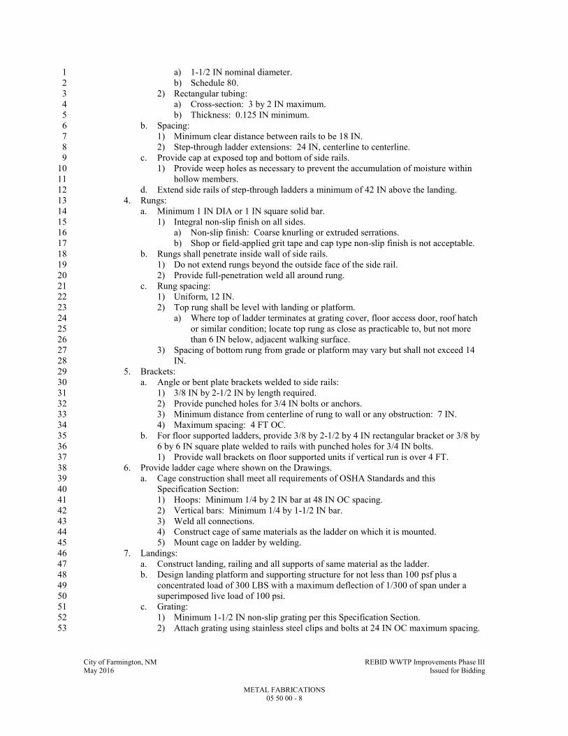
City of Farmington, NM REBID WWTP Improvements Phase III May 2016 Issued for Bidding
METAL FABRICATIONS 05 50 00 - 8
a) 1-1/2 IN nominal diameter. 1
b) Schedule 80. 2
2) Rectangular tubing: 3
a) Cross-section: 3 by 2 IN maximum. 4
b) Thickness: 0.125 IN minimum. 5
b. Spacing: 6
1) Minimum clear distance between rails to be 18 IN. 7
2) Step-through ladder extensions: 24 IN, centerline to centerline. 8
c. Provide cap at exposed top and bottom of side rails. 9
1) Provide weep holes as necessary to prevent the accumulation of moisture within 10
hollow members. 11
d. Extend side rails of step-through ladders a minimum of 42 IN above the landing. 12
4. Rungs: 13
a. Minimum 1 IN DIA or 1 IN square solid bar. 14
1) Integral non-slip finish on all sides. 15
a) Non-slip finish: Coarse knurling or extruded serrations. 16
b) Shop or field-applied grit tape and cap type non-slip finish is not acceptable. 17
b. Rungs shall penetrate inside wall of side rails. 18
1) Do not extend rungs beyond the outside face of the side rail. 19
2) Provide full-penetration weld all around rung. 20
c. Rung spacing: 21
1) Uniform, 12 IN. 22
2) Top rung shall be level with landing or platform. 23
a) Where top of ladder terminates at grating cover, floor access door, roof hatch 24
or similar condition; locate top rung as close as practicable to, but not more 25
than 6 IN below, adjacent walking surface. 26
3) Spacing of bottom rung from grade or platform may vary but shall not exceed 14 27
IN. 28
5. Brackets: 29
a. Angle or bent plate brackets welded to side rails: 30
1) 3/8 IN by 2-1/2 IN by length required. 31
2) Provide punched holes for 3/4 IN bolts or anchors. 32
3) Minimum distance from centerline of rung to wall or any obstruction: 7 IN. 33
4) Maximum spacing: 4 FT OC. 34
b. For floor supported ladders, provide 3/8 by 2-1/2 by 4 IN rectangular bracket or 3/8 by 35
6 by 6 IN square plate welded to rails with punched holes for 3/4 IN bolts. 36
1) Provide wall brackets on floor supported units if vertical run is over 4 FT. 37
6. Provide ladder cage where shown on the Drawings. 38
a. Cage construction shall meet all requirements of OSHA Standards and this 39
Specification Section: 40
1) Hoops: Minimum 1/4 by 2 IN bar at 48 IN OC spacing. 41
2) Vertical bars: Minimum 1/4 by 1-1/2 IN bar. 42
3) Weld all connections. 43
4) Construct cage of same materials as the ladder on which it is mounted. 44
5) Mount cage on ladder by welding. 45
7. Landings: 46
a. Construct landing, railing and all supports of same material as the ladder. 47
b. Design landing platform and supporting structure for not less than 100 psf plus a 48
concentrated load of 300 LBS with a maximum deflection of 1/300 of span under a 49
superimposed live load of 100 psi. 50
c. Grating: 51
1) Minimum 1-1/2 IN non-slip grating per this Specification Section. 52
2) Attach grating using stainless steel clips and bolts at 24 IN OC maximum spacing. 53

City of Farmington, NM REBID WWTP Improvements Phase III May 2016 Issued for Bidding
METAL FABRICATIONS 05 50 00 - 9
d. Structural support: Channel or tubular sections with bracing, plates, angles, etc., to 1
support guardrail and grating and to support landing off the side of the tank. 2
1) Weld or bolt all connections using stainless steel bolts, nuts and washers. 3
e. Guardrails: 4
1) Match ladder side rails. 5
a) Space intermediate rails equally between top rail and top of kickplate. 6
2) Provide 4 IN high x 3/8 IN thick toeboard each side of landing. 7
8. Gates: 8
a. Constructed of same material and sizes as the ladder system. 9
b. Hinges: 10
1) Stainless steel. 11
2) Heavy-duty, self-closing. 12
c. Gate stop: 13
1) Aluminum. Galvanized steel. Unless noted otherwise on the plans. 14
2) Positive self-latching. 15
9. Ladder safety extension post: 16
a. Telescoping tubular galvanized steel or stainless steel section that automatically locks 17
into place when fully extended. 18
b. Non-ferrous corrosion-resistant spring and hardware. 19
c. Factory assembled with all hardware necessary for mounting to ladder. 20
d. Bilco "LadderUp" safety post. 21
B. Bollards: 22
1. 8 IN DIA extra strength steel pipe, ASTM A53. 23
a. Galvanized. 24
b. See Specification Section 09 91 00 for painting requirements. 25
C. Abrasive Stair Nosings: 26
1. Two (2) component consisting of an embedded subchannel, installed with the concrete pour, 27
and an abrasive tread plate to be installed later. 28
2. 6063-T5 extruded aluminum, mill finished and heat treated. 29
3. Complete with concrete anchors and tread plate securing screws. 30
4. Tread plate: 31
a. Extruded aluminum. 32
b. Solid epoxy abrasive filler. 33
1) Color: Safety yellow. 34
5. Balco "DXH-330." 35
6. Length: 36
a. Concrete stairs: 37
1) 4 IN less than overall stair width. 38
2) Where tread mounted railing post occurs, hold nosing back 4 IN clear from railing 39
centerline. 40
b. Concrete landings at metal stairs: 4 IN less than clear width between stringers. 41
D. Metal Stairs: 42
1. Fabricated as indicated. 43
2. Treads: Grating as specified. 44
a. Provide integral corrugated non-slip nosing. 45
3. Risers: 46
a. Grating treads: Solid plate attached to trailing edge of tread as shown on Drawings. 47
4. Landings: 48
a. Grating as specified. 49
b. Provide integral corrugated non-slip nosing at edge acting as stair tread/nosing. 50

City of Farmington, NM REBID WWTP Improvements Phase III May 2016 Issued for Bidding
METAL FABRICATIONS 05 50 00 - 10
5. Fabricate and design stair, platforms and landings, and all connections to support a 100 psf 1
uniform live load or a concentrated load of 1000 LBS, whichever requires the stronger 2
component. 3
6. Design, fabricate, and install in compliance with NAAMM and applicable codes. 4
a. NAAMM AMP 510: 5
1) Exterior at site structures and equipment: Industrial Class. 6
2) Interior or exterior at buildings: Service Class. 7
7. Handrails and guardrails: Refer to Specification Section 05 52 02. 8
8. Material: 9
a. Aluminum. 10
E. Stairs, Concrete Filled Steel Pan: 11
1. Fabricated as indicated. 12
a. ASTM A36 steel. 13
2. Treads: Minimum 14 GA pans with self-furring metal lath welded in pan. 14
3. Risers: Minimum 14 GA. 15
4. Landings: minimum 10 GA pans with angle supports as required to support loading 16
indicated and concrete. 17
a. Provide self-furring metal lath reinforcing welded in the pan. 18
5. Fabricate and design stair, platforms and landings, and all connections to support a 100 psf 19
uniform live load or a concentrated load of 300 LB, whichever requires the stronger 20
component. 21
6. Design, fabricate, and install in compliance with NAAMM and applicable codes. 22
a. NAAMM AMP 510: Commercial Class . 23
7. Form surface of nosings with slip-resistant materials or provide separate slip-resistant 24
nosings. 25
8. Handrails and guardrails: Refer to Specification Section 05 52 02. 26
9. Galvanized entire assembly after fabrication. 27
F. Steel Checkered Plate: 28
1. Conform to ASTM A786. 29
a. Diamond pattern: No.3 (large) or No.4 (medium). 30
b. Use one (1) pattern throughout Project. 31
c. Material: 36 ksi minimum yield strength. 32
2. Design live load: 33
a. 100 psf, uniform load. 34
b. 300 LBS concentrated load on 4 IN square area. 35
c. All components to be adequate for the uniform load or the concentrated load, whichever 36
requires the stronger component. 37
d. Maximum deflection: 1/300 of span under a superimposed live load of 50 psf. 38
3. Reinforce as necessary with steel angles. 39
4. Plate sections: 40
a. Maximum 3 FT wide. 41
b. Minimum 1/4 IN thick. 42
c. Maximum 100 LBS per section if required to be removable. 43
5. Provide joints at center of all openings unless shown otherwise. 44
a. Reinforce joints and openings with additional angles to provide required load carrying 45
capacity. 46
6. Unless shown otherwise, frame for opening with steel checkered plate cover: 47
a. Steel support angles: 48
1) 3 by 2 by 1/4 IN minimum size with long leg vertical. 49
2) 5/8 IN DIA adhesive anchor bolts spaced at maximum of 24 IN OC along each side 50
with not less than two (2) anchor bolts per side. 51
b. Steel concrete insert seats: 52
1) 2 by 2 by 1/4 IN minimum size. 53

City of Farmington, NM REBID WWTP Improvements Phase III May 2016 Issued for Bidding
METAL FABRICATIONS 05 50 00 - 11
2) Auto-welded studs or strap anchors, ASTM A108 at 18 IN OC with not less than 1
two (2) studs or anchors per side. 2
c. Drill and tap frame to receive 3/8 IN DIA fasteners at not more than 24 IN OC with not 3
less than two (2) fasteners per side. 4
1) Fasteners: Flat countersunk cap screws, ASTM F835. 5
a) Galvanized, ASTM A153/A153M. 6
7. Provide galvanized checkered plate and edge supports. 7
G. Aluminum Checkered Plate: 8
1. Conform to ASTM B632. 9
a. Diamond pattern: Use one (1) pattern throughout Project. 10
b. Material: Type 6061-T6. 11
2. Design live load: 12
a. 100 psf, uniform load. 13
b. 300 LBS concentrated load on 4 IN square area. 14
c. All components to be adequate for the uniform load or the concentrated load, whichever 15
requires the stronger component. 16
d. Maximum deflection: 1/300 of span under a superimposed live load of 50 psf. 17
3. Reinforce as necessary with aluminum angles. 18
4. Plate sections: 19
a. Maximum 3 FT wide. 20
b. Minimum 1/4 IN thick. 21
c. Maximum 100 LBS per section if required to be removable. 22
5. Provide joints at center of all openings unless shown otherwise. 23
a. Reinforce joints and openings with additional angles to provide required load carrying 24
capacity. 25
6. Unless shown otherwise, frame for openings with aluminum checkered plate cover: 26
a. Aluminum support angles: 27
1) 3 by 2 by 1/4 IN minimum size with long leg vertical. 28
2) 5/8 IN DIA adhesive anchor bolts spaced at maximum of 24 IN OC along each side 29
with not less than two (2) anchor bolts per side. 30
b. Aluminum concrete insert seats: 31
1) 2 by 2 by 1/4 IN minimum size. 32
2) Auto-welded studs or strap anchors at 18 IN OC with not less than two (2) studs or 33
anchored per side. 34
c. Drill and tap frame to receive 3/8 IN DIA fasteners at not more than 24 IN OC with not 35
less than two (2) fasteners per side. 36
1) Fasteners: Stainless steel flat countersunk cap screws: ASTM F879. 37
H. Aluminum Grating: 38
1. NAAMM MBG 531. 39
2. Bearing bars: Rectangular, 1-1/2 by 3/16 IN at 1-3/16 IN OC spacing OR I-bar, 1-1/2 IN 40
deep with minimum 1/16 IN thick bar and minimum 1/4 IN flange width at 1-3/16 IN OC 41
spacing. 42
3. Cross bars: 43
a. Welded, swaged or pressure locked to bearing bars: 44
b. Maximum 4 IN/OC spacing. 45
4. Top edges of bars: Grooved or serrated. 46
5. Finish: Mill. 47
6. Clips and bolts: Stainless steel. 48
7. Seat angles: Aluminum. 49
I. Steel Grating: 50
1. NAAMM MBG 531. 51
2. Bearing bars: 52
City of Farmington, NM REBID WWTP Improvements Phase III May 2016 Issued for Bidding
METAL FABRICATIONS 05 50 00 - 12
a. Rectangular 1-1/2 by 3/16 IN unless shown otherwise on Drawings. 1
b. Maximum 1-3/16 IN OC spacing. 2
3. Cross bars: 3
a. Welded, swagged or pressure locked to bearing bars. 4
b. Maximum 4 IN OC spacing. 5
4. Top edges of bars: Serrated or grooved. 6
5. Removable grating sections: Not wider than 3 FT and not more than 100 LBS. 7
6. Finish: 8
a. Galvanized. 9
b. Clips and bolts: Stainless steel 10
c. Seat angles: Galvanized steel. 11
7. Ends and perimeter edges: Banded. 12
8. Openings through grating: Reinforced to provide required load carrying capacity and 13
banded with 4 IN high toe plate. 14
9. Provide joints at openings between individual grating sections. 15
J. Heavy-Duty Castings, Trench Covers, and Accessories: 16
1. Prefabricated, cast iron ASTM A48 or ductile iron ASTM A536. 17
2. Design load: AASHTO HS-20 wheel loading for indicated span. 18
3. Machine horizontal mating surfaces. 19
K. Access Cover: 20
1. Tank type manhole frame and solid lid: ASTM A48 or ASTM A536, cast iron. 21
2. Unless shown otherwise, design of cover shall be such that top of frame extends several 22
inches above slab to prevent surface water from entering tank. 23
3. Equip lid with four (4) stainless steel screws to secure lid to frame. 24
L. Loose Lintels: 25
1. Steel, ASTM A36 or ASTM A572 Grade 50, sizes as indicated on Drawings. 26
2. Hot-dip galvanized per ASTM A123/A123M. 27
M. Modular Framing System: 28
1. Materials: 29
a. Steel: ASTM A1011, stainless steel, Grade 33. 30
1) Hot-dipped galvanized, ASTM A123 or ASTM A153. 31
b. Aluminum: ASTM B221 or ASTM B209. 32
c. Stainless steel: ASTM A666. 33
d. Fiberglass: See Specification Section 06 82 00. 34
2. Channels and inserts: 35
a. Steel or stainless steel: Minimum 12 GA. 36
b. Aluminum: Minimum 0.080 IN. 37
c. Channels to have one (1) side with a continuous slot with in-turned lips. 38
1) Width: 1-5/8 IN. 39
2) Depth and configuration as necessary for loading conditions. 40
3. Fittings: Same material as system major components. 41
4. Fasteners: 42
a. Nuts: Toothed groves in top of nuts to engage the in-turned lips of channel. 43
b. Bolts: Hex-head cap screws. 44
c. Same material as system major components. 45
5. End caps: 46
a. At each exposed end of each piece mounted on walls, or guardrails, or suspended from 47
framing 7 FT or less above the floor or platform. 48
a) Plastic for all exposed ends 7 FT or more above floor or platform. 49
b) Plastic or metallic for all other exposed ends. 50
6. Schedule: 51
a. Interior wet areas: Aluminum. 52

City of Farmington, NM REBID WWTP Improvements Phase III May 2016 Issued for Bidding
METAL FABRICATIONS 05 50 00 - 13
b. Interior corrosive areas: Fiberglass. 1
c. Exterior areas: Aluminum. 2
d. All other areas not listed above: Hot-dipped galvanized steel. 3
7. Provide dissimilar materials protection in accordance with Specification Section 09 91 00. 4
8. Repair all cut ends or otherwise damaged areas of galvanized steel in accordance with 5
ASTM A780. 6
2.4 FABRICATION 7
A. Verify field conditions and dimensions prior to fabrication. 8
B. Form materials to shapes indicated with straight lines, true angles, and smooth curves. 9
1. Grind smooth all rough welds and sharp edges. 10
a. Round all corners to approximately 1/32 - 1/16 IN nominal radius. 11
C. Provide drilled or punched holes with smooth edges. 12
1. Punch or drill for field connections and for attachment of work by other trades. 13
D. Weld Permanent Shop Connections: 14
1. Welds to be continuous fillet type unless indicated otherwise. 15
2. Full penetration butt weld at bends in stair stringers and ladder side rails. 16
3. Weld structural steel in accordance with AWS D1.1 using Series E70 electrodes conforming 17
to AWS A5.1/A5.1M. 18
4. Weld aluminum in accordance with AWS D1.2. 19
5. Weld stainless steel in accordance with AWS D1.6. 20
a. Treat all welded areas in accordance with ASTM A380. 21
6. Weld stainless steel in accordance with AWS D1.6 and NiDI 11 007. 22
7. All headed studs to be welded using automatically timed stud welding equipment. 23
8. Grind smooth welds that will be exposed. 24
E. Conceal fastenings where practicable. 25
F. Fabricate work in shop in as large assemblies as is practicable. 26
G. Tolerances: 27
1. Rolling: 28
a. ASTM A6. 29
b. When material received from the mill does not satisfy ASTM A6 tolerances for camber, 30
profile, flatness, or sweep, the Contractor is permitted to perform corrective work by 31
the use of controlled heating and mechanical straightening, subject to the limitations of 32
the AISC Specification. 33
2. Fabrication tolerance: 34
a. Member length: 35
1) Both ends finished for contact bearing: 1/32 IN. 36
2) Framed members: 37
a) 30 FT or less: 1/16 IN. 38
b) Over 30 FT: 1/8 IN. 39
b. Member straightness: 40
1) Compression members: 1/1000 of axial length between points laterally supported. 41
2) Non-compression members: ASTM A6 tolerance for wide flange shapes. 42
c. Specified member camber (except compression members): 43
1) 50 FT or less: Minus 0/plus 1/2 IN. 44
2) Over 50 FT: Minus 0/plus 1/2 IN (plus 1/8 IN per 10 FT over 50 FT). 45
3) Members received from mill with 75 percent of specified camber require no further 46
cambering. 47
4) Beams/trusses without specified camber shall be fabricated so after erection, 48
camber is upward. 49
5) Camber shall be measured in fabrication shop in unstressed condition. 50

City of Farmington, NM REBID WWTP Improvements Phase III May 2016 Issued for Bidding
METAL FABRICATIONS 05 50 00 - 14
d. At bolted splices, depth deviation shall be taken up by filler plates. 1
1) At welded joints, adjust weld profile to conform to variation in depth. 2
2) Slope weld surface per AWS requirements. 3
e. Finished members shall be free from twists, bends and open joints. 4
1) Sharp kinks, bends and deviation from above tolerances are cause for rejection of 5
material. 6
H. Fabricate grating, checkered plate, stairs, ladders and accessories using aluminum unless shown 7
otherwise on Drawings. 8
1. Finish: 9
a. Mill, unless noted otherwise. 10
b. Coat surfaces in contact with dissimilar materials. 11
1) See Specification Section 09 91 00. 12
I. Fabricate grating in accordance with NAAMM MBG 531. 13
1. Maximum tolerance for difference in depth between grating depth and seat or support angle 14
depth: 1/8 IN. 15
2. Distance between edge of grating and face of embedded seat angle or face of wall or other 16
structural member: 1/4 IN. 17
a. Tolerance: NAAMM MBG 531. 18
3. Removable sections: Not wider than 3 FT and not more than 100 LBS. 19
4. Ends and perimeter edges: Banded. 20
a. Provide full depth banding unless noted otherwise. 21
b. Banding at trenches and sumps to be 1/4 IN less than grating depth to allow for 22
drainage. 23
5. Openings through grating: Reinforced to provide required load carrying capacity and 24
banded with 4 IN high toe plate. 25
6. Provide joints at openings between individual grating sections. 26
7. Fabricate grating so that bearing bars and cross bars in adjacent sections are aligned. 27
J. Fabricate checkered plate and miscellaneous metals in accordance with NAAMM AMP 555. 28
1. Workmanship: Class 2 unless noted otherwise. 29
K. See Specification Section 09 91 00 for preparation and painting of ferrous metals and other 30
surfaces. 31
L. Passivate stainless steel items and stainless steel welds after they have been ground smooth, 32
where indicated on Drawings. 33
1. ASTM A380. 34
2.5 SOURCE QUALITY CONTROL 35
A. Surface Preparation: 36
1. Refer to Specification Section 09 91 00 for surface preparation requirements. 37
2. All miscellaneous metal fabrication item surfaces shall be inspected and approved by NACE 38
certified coatings inspector prior to application of shop-applied paint coating. 39
a. Inspection shall be performed to determine depth of blast profile and cleanliness of 40
surface. 41
b. Fabricator shall reblast and or re-clean surfaces as required until acceptable. 42
B. Shop Applied Paint Coating Application: 43
1. Refer to Specification Section 09 91 00 for painting requirements. 44
2. After surface has been accepted in writing by NACE certified coatings inspector, fabricator 45
may proceed with application of paint coatings. 46
3. Application of paint coatings shall be observed and certified by NACE certified coatings 47
inspector. 48
C. OWNER Pays for Field Inspection and Testing: 49

City of Farmington, NM REBID WWTP Improvements Phase III May 2016 Issued for Bidding
METAL FABRICATIONS 05 50 00 - 15
1. Owner will employ and pay for services of an independent testing agency to inspect and test 1
structural steel shop and field work for compliance with this Specification Section. 2
2. Contractor responsible for testing to qualify shop and field welders and as needed for 3
Contractor's own quality control to ensure compliance with Contract Documents. 4
3. Contractor provides sufficient notification and access so inspection and testing can be 5
accomplished. 6
4. Contractor pays for retesting of failed tests and for additional testing required when defects 7
are discovered. 8
D. CONTRACTOR Pays for Shop Inspection and Testing: 9
1. Employ and pay for the services of a qualified independent testing agency to inspect and test 10
all structural steel work for compliance with Contract Documents. 11
2. Independent testing agency shall have a minimum of five (5) years performing similar work 12
and shall be subject to Owner's approval. 13
E. Responsibilities of Testing Agency: 14
1. Inspect shop and field welding in accordance with AWS Code including the following non-15
destructive testing: 16
a. Visually inspect all welds. 17
b. In addition to visual inspection, test 50 percent of full penetration welds and 20 percent 18
of fillet welds with liquid dye penetrant. 19
c. Test 20 percent of liquid dye penetrant tested full penetration welds with ultrasonic or 20
radiographic testing. 21
2. Inspect high-strength bolting in accordance with the RCSC Specification for Structural 22
Joints Using High-Strength Bolts, Section 9. 23
a. Verify direct tension indicator gaps. 24
3. Inspect structural steel which has been erected. 25
4. Inspect stud welding in accordance with AWS Code. 26
5. Prepare and submit inspection and test reports to Engineer. 27
a. Assist Engineer to determine corrective measures necessary for defective work. 28
PART 3 - EXECUTION 29
3.1 PREPARATION 30
A. Provide items to be built into other construction in time to allow their installation. 31
1. If such items are not provided in time for installation, cut in and install. 32
B. Prior to installation, inspect and verify condition of substrate. 33
C. Correct surface defects or conditions which may interfere with or prevent a satisfactory 34
installation. 35
1. Field welding aluminum is not permitted unless approved in writing by Engineer. 36
3.2 INSTALLATION 37
A. Set metal work level, true to line, plumb. 38
1. Shim and grout as necessary. 39
B. Contractor is solely responsible for safety. 40
1. Construction means and methods and sequencing of work is the prerogative of the 41
Contractor. 42
2. Take into consideration that full structural capacity of many structural members is not 43
realized until structural assembly is complete; e.g., until slabs, decks, and diagonal bracing 44
or rigid connections are installed. 45
3. Partially complete structural members shall not be loaded without an investigation by the 46
Contractor. 47
City of Farmington, NM REBID WWTP Improvements Phase III May 2016 Issued for Bidding
METAL FABRICATIONS 05 50 00 - 16
4. Until all elements of the permanent structure and lateral bracing system are complete, 1
temporary bracing for the partially complete structure will be required. 2
C. Adequate temporary bracing to provide safety, stability and to resist all loads to which the 3
partially complete structure may be subjected, including construction activities and operation of 4
equipment is the responsibility of the Contractor. 5
1. Plumb, align, and set structural steel members to specified tolerances. 6
2. Use temporary guys, braces, shoring, connections, etc., necessary to maintain the structural 7
framing plumb and in proper alignment until permanent connections are made, the 8
succeeding work is in place, and temporary work is no longer necessary. 9
3. Use temporary guys, bracing, shoring, and other work to prevent injury or damage to 10
adjacent work or construction from stresses due to erection procedures and operation of 11
erection equipment, construction loads, and wind. 12
4. Contractor shall be responsible for the design of the temporary bracing system and must 13
consider the sequence and schedule of placement of such elements and effects of loads 14
imposed on the structural steel members by partially or completely installed work, including 15
work of all other trades. 16
a. If not obvious from experience or from the Drawings, the Contractor shall confer with 17
the Engineer to identify those structural steel elements that must be complete before the 18
temporary bracing system is removed. 19
5. Remove and dispose of all temporary work and facilities off-site. 20
D. Examine work-in-place on which specified work is in any way dependent to ensure that 21
conditions are satisfactory for the installation of the work. 22
1. Report defects in work-in-place which may influence satisfactory completion of the work. 23
2. Absence of such notification will be construed as acceptance of work-in-place. 24
E. Field Measurement: 25
1. Take field measurements as necessary to verify or supplement dimensions indicated on the 26
Drawings. 27
2. Contractor responsible for the accurate fit of the work. 28
F. Check the elevations of all finished footings or foundations and the location and alignment of all 29
anchor bolts before starting erection. 30
1. Use surveyor's level. 31
2. Notify Engineer of any errors or deviations found by such checking. 32
G. Framing member location tolerances after erection shall not exceed the frame tolerances listed in 33
the FIELD QUALITY CONTROL Article in PART 3 of this Specification Section. 34
H. Erect plumb and level; introduce temporary bracing required to support erection loads. 35
I. Use light drifting necessary to draw holes together. 36
1. Drifting to match unfair holes is not allowed. 37
J. Welding: 38
1. Conform to AWS D1.1 and requirements of the FABRICATION Article in PART 2 of this 39
Specification Section. 40
2. When joining two (2) sections of steel of different ASTM designations, welding techniques 41
shall be in accordance with a qualified AWS D1.1 procedure. 42
K. Shore existing members when unbolting of common connections is required. 43
1. Use new bolts for rebolting connections. 44
L. Clean stored material of all foreign matter accumulated during erection period. 45
M. Bolt Field Connections: Where practicable, conceal fastenings. 46
N. Field Welding: 47
1. Follow AWS procedures. 48

City of Farmington, NM REBID WWTP Improvements Phase III May 2016 Issued for Bidding
METAL FABRICATIONS 05 50 00 - 17
2. Grind welds smooth where field welding is required. 1
O. Field cutting grating or checkered plate to correct fabrication errors is not acceptable. 2
1. Replace entire section. 3
P. Remove all burrs and radius all sharp edges and corners of miscellaneous plates, angles, framing 4
system elements, etc. 5
Q. Unless noted or specified otherwise: 6
1. Connect steel members to steel members with 3/4 IN DIA ASTM A325 high strength bolts. 7
2. Connect aluminum to aluminum with 3/4 IN DIA aluminum bolts. 8
3. Connect aluminum to structural steel using 3/4 IN DIA stainless steel bolts. 9
a. Provide dissimilar metals protection. 10
4. Connect aluminum and steel members to concrete and masonry using stainless steel 11
expansion anchor bolts or adhesive anchor bolts unless shown otherwise. 12
a. Provide dissimilar materials protection. 13
5. Provide washers for all bolted connections. 14
6. Where exposed, bolts shall extend a maximum of 3/4 IN and a minimum of 1/2 IN above 15
the top nut. 16
a. If bolts are cut off to required maximum height, threads must be dressed to allow nuts 17
to be removed without damage to the bolt or the nuts. 18
R. Install and tighten ASTM A325 high-strength bolts in accordance with the AISC 325, Allowable 19
Stress Design (ASD). 20
1. Provide hardened washers for all ASTM A325 bolts. 21
a. Provide the hardened washer under the element (nut or bolt head) turned in tightening. 22
S. After bolts are tightened, upset threads of ASTM A307 unfinished bolts or anchor bolts to 23
prevent nuts from backing off. 24
T. Secure metal to wood with lag screws of adequate size with appropriate washers. 25
U. Do not field splice fabricated items unless said items exceed standard shipping length or change 26
of direction requires splicing. 27
1. Provide full penetration welded splices where continuity is required. 28
V. Provide each fabricated item complete with attachment devices as indicated or required to 29
install. 30
W. Anchor such that work will not be distorted nor fasteners overstressed from expansion and 31
contraction. 32
X. Set beam and column base plates accurately on nonshrink grout as indicated on Drawings. 33
1. See Division 03 Specification Sections for non-shrink grout. 34
2. Set and anchor each base plate to proper line and elevation. 35
a. Use metal wedges, shims, or setting nuts for leveling and plumbing columns and 36
beams. 37
1) Wedges, shims and setting nuts to be of same metal as base plate they support. 38
2) Tighten nuts on anchor bolts. 39
b. Fill space between bearing surface and bottom of base plate with nonshrink grout. 40
1) Fill space until voids are completely filled and base plates are fully bedded on 41
wedges, shims, and grout. 42
c. Do not remove wedges or shims. 43
1) Where they protrude, cut off flush with edge of base plate. 44
d. Fill sleeves around anchor bolts solid with non-shrink grout. 45
Y. Tie anchor bolts in position to embedded reinforcing steel using wire. 46
1. Tack welding prohibited. 47
a. Coat bolt threads and nuts with heavy coat of clean grease. 48
City of Farmington, NM REBID WWTP Improvements Phase III May 2016 Issued for Bidding
METAL FABRICATIONS 05 50 00 - 18
2. Anchor bolt location tolerance: 1
a. 1/16 IN. 2
b. Provide steel templates for all column anchor bolts. 3
Z. Install bollards in concrete as detailed. 4
1. 48 IN projection above ground. 5
2. 48 IN embedment in concrete, unless detailed otherwise on Drawings. 6
3. Fill pipe with concrete and round off at top. 7
AA. Provide abrasive stair nosings in each tread and landing of all concrete stairs and at each 8
concrete stair landing having metal stair structure attaching to the concrete landing. 9
1. Center stair nosings in stair width. 10
2. Coordinate nosings with railing vertical posts. 11
a. Maintain 2 IN clear between end of nosing and edge of railing base plate. 12
BB. Accurately locate and place frames for openings before casting into floor slab so top of plate is 13
flush with surface of finished floor. 14
1. Keep screw holes clean and ready to receive screws. 15
CC. Attach grating to end and intermediate supports with grating saddle clips and bolts. 16
1. Maximum spacing: 2 FT OC with minimum of two (2) per side. 17
2. Attach individual units of aluminum grating together with clips at 2 FT OC maximum with 18
a minimum of two (2) clips per side. 19
DD. Coat aluminum surfaces in contact with dissimilar materials in accordance with Specification 20
Section 09 91 00. 21
EE. Repair damaged galvanized surfaces in accordance with ASTM A780. 22
1. Prepare damaged surfaces by abrasive blasting or power sanding. 23
2. Apply galvanizing repair paint to minimum 6 mils DFT in accordance with manufacturer's 24
instructions. 25
FF. Anchor ladder to concrete structure with minimum 3/4 IN stainless steel anchor bolts with 26
minimum 6 IN embedment. 27
GG. Anchor ladder to masonry structure with minimum 3/4 IN stainless steel anchor bolts with 28
minimum 6 IN embedment. 29
1. When anchoring into masonry, fill masonry cores with grout at anchor locations and each 30
masonry core within 8 IN of anchor 31
2. When anchoring into cavity wall construction, provide minimum 6 IN embedment into 32
concrete or masonry back-up wall. 33
a. At each anchor location, provide sleeve between back face of veneer and cavity face of 34
concrete or masonry back-up wall. 35
b. Cut cavity insulation as required and seal around sleeve. 36
1) Sleeve to be 1 IN DIA schedule 40 stainless steel tubing, TP-304L, ASTM A269. 37
a) Minimum wall thickness to be .065 IN. 38
2) Continuously weld 4 by 4 by 1/4 IN Type 304 stainless steel, ASTM A666 flange 39
onto each end of pipe. 40
a) Drill 1 IN hole in flange to match pipe. 41
b) Attach sleeve to concrete or masonry back-up with 1/4 IN self-tapping 42
concrete anchors. 43
3) Grout solid, area around bolt where bolt penetrates veneer. 44
4) Accurately locate sleeves to align with bolt locations on ladder. 45
HH. Anchor ladder to metal stud walls using minimum 1/2 IN stainless steel bolts, nuts and washers. 46
1. Verify that stud wall has been provided with adequate backing to accept ladder anchors. 47
II. Install manhole steps in cast-in-place concrete where indicated on the Drawings. 48
1. Provide in compliance with ASTM C478 and OSHA requirements for fixed ladders. 49
City of Farmington, NM REBID WWTP Improvements Phase III May 2016 Issued for Bidding
METAL FABRICATIONS 05 50 00 - 19
2. Tie steps to reinforcing or formwork. 1
a. Provide equal spacing from surface to first rung and equal spacing on remaining rungs. 2
1) Maximum spacing: 12 IN. 3
b. Minimum clear distance from face of wall to center of step: 7 IN. 4
c. Minimum embedment: 6 IN. 5
3. Provide dissimilar materials protection. 6
a. See Specification Section 09 91 00. 7
4. At the Contractor's option, manhole steps may be installed in drilled holes and grouted in 8
place. 9
a. Grout: See Specification Section 03 31 30. 10
5. Install deflector plate at bottom of roofhatch opening as indicated on Drawings. 11
a. Install in accordance with applicable OSHA Standards. 12
6. Install alternating tread stair in accordance with manufacturer's recommendations using 13
stainless steel fasteners. 14
JJ. Install ladder safety extension post in accordance with manufacturer's instructions. 15
1. Mount device opposite the climbing side. 16
2. Provide ladder safety extension device for all ladders unless noted otherwise. 17
KK. Mount ladder fall protection system with rail offset from ladder side rail approximately 3 IN. 18
LL. Install factory pre-fabricated stairs in location indicated in the Contract Documents. 19
3.3 FIELD QUALITY CONTROL 20
A. Tolerances shall meet structural requirements of Specification Section 05 12 00 for erecting 21
items of structural nature. 22
B. Tolerances (unless otherwise noted on the Drawings): 23
1. Frame placement, after assembly and before welding or tightening. 24
a. Deviation from plumb, level and alignment: 1 in 500, maximum. 25
b. Displacement of centerlines of columns: 1/2 IN maximum, each side of centerline 26
location shown in Drawings. 27
3.4 CLEANING 28
A. After fabrication, erection, installation or application, clean all miscellaneous metal fabrication 29
surfaces of all dirt, weld slag and other foreign matter. 30
B. All stainless steel products in addition to Paragraph A. above: 31
1. Remove all heat tint, rusting, discoloration by passivation, ASTM A380, or other acceptable 32
means as listed in NiDI 11 007 as approved by the Engineer. 33
C. Provide surface acceptable to receive field applied paint coatings specified in Specification 34
Section 09 91 00. 35
END OF SECTION 36

City of Farmington, NM REBID WWTP Improvements Phase III May 2016 Issued for Bidding
ALUMINUM RAILINGS 05 52 02 - 1
SECTION 05 52 02 1
ALUMINUM RAILINGS 2
PART 1 - GENERAL 3
1.1 SUMMARY 4
A. Section Includes: 5
1. Aluminum handrail, stair rail and guardrail. 6
2. Aluminum guardrail gates. 7
B. Related Specification Sections include but are not necessarily limited to: 8
1. Division 00 - Bidding Requirements, Contract Forms, and Conditions of the Contract. 9
2. Division 01 - General Requirements. 10
3. Section 05 50 00 - Metal Fabrications. 11
4. Section 09 91 00 - Painting and Protective Coatings. 12
1.2 QUALITY ASSURANCE 13
A. Referenced Standards: 14
1. Aluminum Association (AA): 15
a. ADM 1, Aluminum Design Manual. 16
2. American Society of Mechanical Engineers (ASME): 17
a. Section IX, Qualification Standard for Welding and Brazing Procedures, Welders, 18
Brazers, and Welding and Brazing Operators. 19
3. ASTM International (ASTM): 20
a. B108, Standard Specification for Aluminum-Alloy Permanent Mold Castings. 21
b. B209, Standard Specification for Aluminum and Aluminum-Alloy Sheet and Plate. 22
c. B221, Standard Specification for Aluminum and Aluminum-Alloy Extruded Bars, 23
Rods, Wire, Profiles, and Tubes. 24
d. B247, Standard Specification for Aluminum and Aluminum-Alloy Die Forgings, Hand 25
Forgings, and Rolled Ring Forgings. 26
e. B308, Standard Specification for Aluminum-Alloy 6061-T6 Standard Structural 27
Profiles. 28
f. B429, Standard Specification for Aluminum-Alloy Extruded Structural Pipe and Tube. 29
4. American Welding Society (AWS): 30
a. C5.5, Recommended Practices for Gas Tungsten Arc Welding. 31
b. D1.2, Structural Welding Code - Aluminum. 32
5. National Association of Architectural Metal Manufacturers (NAAMM): 33
a. AMP 521, Pipe Railing Systems Manual. 34
6. U.S. Department of Justice, Architectural and Transportation Barriers Compliance Board 35
(Access Board): 36
a. Americans with Disabilities Act (ADA): 37
1) Accessibility Guidelines for Buildings and Facilities (ADAAG). 38
7. Occupational Safety and Health Administration (OSHA): 39
a. 29 CFR 1910, Occupational Safety and Health Standards, referred to herein as OSHA 40
Standards. 41
8. Building code: 42
a. International Code Council (ICC): 43
1) International Building Code and associated standards, 2009 Edition including all 44
amendments, referred to herein as Building Code. 45
B. Qualifications: 46

City of Farmington, NM REBID WWTP Improvements Phase III May 2016 Issued for Bidding
ALUMINUM RAILINGS 05 52 02 - 2
1. Qualify welding procedures and welding operators in accordance with AWS and ASME 1
Section IX. 2
1.3 DEFINITIONS 3
A. Guardrail: A system of building components located near the open sides of elevated walking 4
surfaces for the purpose of minimizing the possibility of an accidental fall from the walking 5
surface to the lower level. 6
B. Handrail: A railing provided for grasping with the hand for support. 7
C. Railing: A generic term referring to guardrail, handrail and/or stair rails. 8
D. Stair Rail: A guardrail, installed at the open side of stairways with either a handrail mounted to 9
the inside face of the guardrail, or where allowed by applicable codes, with the top rail mounted 10
at handrail height and serving the function of a handrail. 11
1.4 SUBMITTALS 12
A. Shop Drawings: 13
1. See Specification Section 01 33 00 for requirements for the mechanics and administration of 14
the submittal process. 15
2. Fabrication and/or layout drawings: 16
a. Drawings showing profile, location, sections and fabrication details including all 17
welding information of each railing. 18
b. Type and details of anchorage. 19
c. Location and type of expansion joints. 20
d. Materials of construction, shop coatings and all third-party accessories. 21
3. Product technical data including: 22
a. Acknowledgement that products submitted meet requirements of standards referenced. 23
b. Manufacturer's installation details. 24
4. Certification that railings have been designed and fabricated to meet the loading 25
requirements specified. 26
5. Calculations for all proposed deviations from the Specification. 27
a. Calculations shall be performed, sealed, signed and dated by a registered professional 28
structural engineer licensed in the State of New Mexico. 29
b. Calculations shall be specific to this Project and shall include all assumptions, 30
references and design interpretations used to achieve the results obtained by the 31
Engineer. 32
c. Reduction in load criteria is not acceptable as reason for deviation from sizes indicated 33
in the Specification. 34
B. Informational Submittals: 35
1. See Specification Section 01 33 00 for requirements for the mechanics and administration of 36
the submittal process. 37
2. Certification of welders and welding procedures indicating compliance with AWS 38
requirements. 39
1.5 DELIVERY, STORAGE AND HANDLING 40
A. Deliver and handle railings to preclude damage. 41
B. Store railings on skids, keep free of dirt and other foreign matter which will damage railings or 42
finish and protect against corrosion. 43

City of Farmington, NM REBID WWTP Improvements Phase III May 2016 Issued for Bidding
ALUMINUM RAILINGS 05 52 02 - 3
PART 2 - PRODUCTS 1
2.1 ACCEPTABLE MANUFACTURERS 2
A. Subject to compliance with the Contract Documents, the following manufacturers are 3
acceptable: 4
1. Welded railing systems, Mechanically fastened systems are not acceptable. 5
a. Any manufacturer meeting this Specification Section. 6
B. Submit request for substitution in accordance with Specification Section 01 25 13. 7
2.2 MATERIALS 8
A. Alloy 6061-T6, 32,000 psi tensile yield strength minimum. 9
1. ASTM B209 for sheets and plates. 10
2. ASTM B221 and ASTM B308 for shapes - beams, channels, angles, tees, and zees. 11
3. ASTM B247 for forgings. 12
B. Alloy 6063-T5 or T6, 15,000 psi tensile yield strength minimum. 13
1. ASTM B221 and ASTM B429 for bars, rods, wires, pipes and tubes. 14
C. Cast Fittings: Aluminum, ASTM B108. 15
D. Shims: Aluminum of same alloy as component being shimmed. 16
E. Fasteners: See Specification Section 05 50 00. 17
F. Expansion and Adhesive Anchors: See Specification Section 05 50 00. 18
G. Electrodes for Welding: 19
1. Aluminum: AWS D1.2. 20
2. Filler alloy 5356 or 4043. 21
2.3 FABRICATION 22
A. General: 23
1. Verify field conditions and dimensions prior to fabrication. 24
2. For fabrication of items which will be exposed to view, use only materials which are smooth 25
and free of surface blemishes including pitting, seam marks, roller marks, rolled trade 26
names and roughness. 27
a. Remove blemishes by grinding and buffing or by welding and grinding, prior to 28
cleaning, treating and application of surface finishes. 29
3. Form exposed work with smooth, short radius bends, accurate angles and straight edges. 30
a. Ease exposed edges to a radius of approximately 1/32 IN. 31
b. Form bent-metal corners to smallest radius possible without causing grain separation or 32
otherwise impairing work. 33
c. Drill or punch holes with smooth edges. 34
4. Form exposed connections with flush, smooth, hairline joints, using stainless steel or 35
aluminum splice locks to splice sections together or by welding. 36
a. Ease the edges of top rail splices and expansion joints and remove all burrs left from 37
cutting. 38
5. Provide for anchorage of type indicated on Drawings or as required by field conditions. 39
a. Drill or punch holes with smooth edges. 40
6. Design railings and anchorage system in accordance with NAAMM AMP 521 to resist 41
loading as required by Building Code. 42
a. Maximum allowable stresses per AA ADM 1. 43
7. Design railings in accordance with accessibility requirements per the Building Code and 44
ADAAG. 45

City of Farmington, NM REBID WWTP Improvements Phase III May 2016 Issued for Bidding
ALUMINUM RAILINGS 05 52 02 - 4
B. Custom fabricate railings to dimensions and profiles indicated. 1
1. Guardrails: 2
a. Schedule 40 pipe. 3
b. Top rails: 2 IN nominal diameter. 4
c. Intermediate rails: 1-1/2 IN nominal diameter. 5
d. Vertical posts: 6
1) 2 IN nominal diameter. 7
2) Vertical posts that are to be side-bracket mounted to a vertical concrete surface or 8
metal structure shall use Alloy 6063-T6. 9
2. Handrail mounted to wall or to guardrail vertical posts: 1-1/4 IN nominal diameter 10
Schedule 40 pipe. 11
3. Where details are not indicated, space intermediate rails to requirements of the Building 12
Code or OSHA Standards, whichever requires the more restrictive design. 13
4. Space vertical posts as required by loading requirements but not more than 4 FT on center. 14
a. Avoid locating vertical posts at changes in direction of railing. 15
b. Hold vertical post back from corner and provide radiused corners. 16
5. Space handrail brackets as required by loading requirements but not more than 4 FT on 17
center. 18
6. Base plate for vertical guardrail posts mounted to top of concrete surface: 19
a. 3/8 x 6 x 6 IN square plate. 20
b. Predrilled to accept four (4) anchors. 21
c. Provide a 2 IN DIA x 8 IN long solid aluminum rod welded to the base plate. 22
d. Fit the vertical post over the solid rod and weld the post to the base plate. 23
7. Base plate for vertical guardrail post mounted to flange of metal structure: 24
a. 3/8 x 3 x 8 IN plate. 25
b. Predrilled to accept two (2) fasteners. 26
c. Provide a 2 IN DIA x 8 IN long solid aluminum rod welded to the base plate. 27
d. Fit the vertical post over the solid rod and weld the post to the base plate. 28
8. Mounting bracket for vertical guardrail post mounted to vertical concrete surface or web of 29
metal structural member: 30
a. Pair of 3/8 IN angles or bent plates. 31
b. Predrilled to accept two (2) fasteners each. 32
c. Weld angles or bent plates to vertical posts. 33
d. Provide toeboards on walkway side of all elevated walkways, platforms and stair 34
landings, and where indicated on the Drawings or required by OSHA Standards. 35
1) 4 IN high extruded toeboard with stiffener ribs and angled toe. 36
a) Similar to Wagner, Model "IR94102." 37
e. Guardrail gates: 38
1) Constructed of same material and sizes as the guardrail system. 39
2) Width of gate as shown on Drawings. 40
3) Hinges: 41
a) Cast aluminum. 42
b) Self-closing. 43
(1) Stainless steel torsion spring. 44
c) Similar to Wagner, Model "IR100." 45
4) Gate latch and stop: 46
a) Cast aluminum. 47
b) Spring-loaded pin latch. 48
(1) Stainless steel spring. 49
c) Similar to Wagner, Model "IR101." 50
C. Railing Fabrication: 51
1. All railings are to be welded systems. 52
2. Use wire welding for all joints. 53
3. All welding to be continuous in accordance with AWS C5.5 and AWS D1.2. 54

City of Farmington, NM REBID WWTP Improvements Phase III May 2016 Issued for Bidding
ALUMINUM RAILINGS 05 52 02 - 5
a. All welded railing joints shall have full penetration welds unless noted otherwise. 1
4. All exposed welds to be ground smooth and flush to match and blend with adjoining 2
surfaces. 3
a. NAAMM AMP 521, Type 2. 4
5. No ragged edges, surface defects, or undercutting of adjoining surfaces will be accepted. 5
6. Finishing joints with filler is not acceptable. 6
7. Provide flush weld fittings using locking weld connectors or coped drive-on connectors. 7
8. Fit exposed ends of guardrails and handrails with solid terminations. 8
a. Return ends of handrail to wall, but do not attach to wall. 9
b. Where guardrail terminates at a wall, provide a vertical post or end-loop 4 IN off the 10
wall to center of vertical member. 11
9. Preassemble items in shop to greatest extent possible to minimize field splicing and 12
assembly of units at project site. 13
10. Install weeps to drain water from hollow sections of railing at exterior and high humidity 14
conditions. 15
a. Drill 1/4 IN weep hole in railings closed at bottom: 16
1) 1 IN above walkway surface at bottom of posts set in concrete. 17
2) 1 IN above solid aluminum rod at posts having base plate. 18
3) At low point of intermediate rails. 19
b. Do not drill weep holes: 20
1) In bottom of base plate. 21
11. Expansion joints: 22
a. Joints to be designed to allow expansion and contraction of railing and still meet design 23
loads required. 24
1) Top rail splices and expansion joints shall be located within 8 IN of post or other 25
support. 26
2) Where railings span building or tank expansion joints; provide a railing expansion 27
joint in the span crossing the building or tank expansion joint. 28
b. Provide expansion joints in any continuous run exceeding 20 FT in length. 29
1) Space expansion joints at not more than 40 FT on center. 30
c. Provide minimum 0.10 IN of expansion joint for each 20 FT length of top rail for each 31
25 DegF differential between installation temperature and maximum design 32
temperature. 33
1) Maximum expansion joint width at time of installation shall not exceed 3/8 IN. 34
a) Provide additional expansion joints as required to limit expansion joint width. 35
d. Provide slip-joint with internal sleeve. 36
1) Extend slip joint min 2 IN beyond joint at maximum design width. 37
2) Fasten internal sleeve securely to one side 38
a) Provide allen-head set screw located in bottom of rail. 39
b) Rivets or exposed screw heads are not acceptable. 40
A. Finish: Mill. 41
PART 3 - EXECUTION 42
3.1 PREPARATION 43
A. Prior to installation, inspect and verify condition of substrate. 44
B. Correct surface defects or conditions which may interfere with or prevent a satisfactory 45
installation. 46
1. Field welding aluminum is not permitted unless approved in writing by Engineer. 47

City of Farmington, NM REBID WWTP Improvements Phase III May 2016 Issued for Bidding
ALUMINUM RAILINGS 05 52 02 - 6
3.2 INSTALLATION 1
A. Install handrails and guardrails to meet loading requirements of the Building Code. 2
B. Install products in accordance with manufacturer's instructions. 3
C. Set work accurately in location, alignment and elevation; plumb, level and true. 4
1. Measure from established lines and items which are to be built into concrete, masonry or 5
similar construction. 6
D. Align railings prior to securing in place to assure proper matching at butting and expansion 7
joints and correct alignment throughout their length. 8
1. Provide shims as required. 9
E. Install proper sized expansion joints based on temperature at time of installation and differential 10
coefficient of expansion of materials in all railings as recommended by manufacturer. 11
1. Lubricate expansion joint splice bar for smooth movement of railing sections. 12
F. Provide removable railing sections where indicated on Drawings. 13
G. Attach handrails to walls or guardrail with brackets designed for condition: 14
1. Provide brackets which provide a minimum 1-1/2 IN clearance between handrail and 15
nearest obstruction. 16
a. Handrails shall not project more than 4-1/2 IN into required stairway width. 17
2. Anchor handrail brackets to concrete or masonry walls with 1/2 IN stainless steel adhesive 18
anchors with stainless steel hex head bolts. 19
H. Anchor railings to concrete with minimum 1/2 IN stainless steel adhesive anchors with stainless 20
steel bolts, nuts and washers unless noted otherwise in the Contract Documents. 21
1. Where exposed, bolts shall extend minimum 1/2 IN and maximum 3/4 IN above the top nut. 22
a. If bolts are cut off to required height, threads must be dressed to allow nuts to be 23
removed without damage to the bolt or the nut. 24
b. Bevel the top of the bolt after cutting to provide a smooth surface. 25
I. Anchor railings to metal structure with minimum 3/4 IN stainless steel bolts, nuts and washers. 26
J. Install toeboards to fit tight to the walking surface. 27
1. Attach to railing vertical post with manufacturer's standard mounting clamp: 28
a. Adjustable. 29
b. Designed to engage in extruded slot on back of toeboard. 30
2. Provide splice bars, corner splices and brackets: 31
a. Manufacturer's standard items as required for a complete installation. 32
3. Notch toeboards at base plates or other obstructions. 33
4. Bottom of toeboard shall not exceed 1/4 IN above walking surface. 34
K. Coat aluminum in contact with dissimilar metal or concrete in accordance with Specification 35
Section 09 91 00. 36
L. Provide railings as required for stair construction identified in Specification Section 05 50 00. 37
M. Install guardrail gate plumb and level in location shown on Drawings. 38
1. Center gate in opening. 39
2. Top of gate to match top of guardrail. 40
3. Fasten hinges to gate and jamb post: 41
a. Minimum three (3) 1/4 IN stainless steel countersunk machine screws per leaf. 42
b. Drill and tap into railing and gate vertical posts. 43
4. Provide not less than two (2) hinges per gate. 44
5. Install gate latch and stop on strike side of opening. 45
a. Fasten to gate with 1/4 IN stainless steel countersunk machine screws. 46
b. Drill and tap into gate vertical post. 47

City of Farmington, NM REBID WWTP Improvements Phase III May 2016 Issued for Bidding
ALUMINUM RAILINGS 05 52 02 - 7
c. Drill hole in railing vertical post to receive latch pin. 1
6. Adjust to provide smooth operation: 2
a. Self-closing and self-latching. 3
END OF SECTION 4

City of Farmington, NM REBID WWTP Improvements Phase III May 2016 Issued for Bidding
ROUGH CARPENTRY 06 10 00 - 1
SECTION 06 10 00 1
ROUGH CARPENTRY 2
PART 1 - GENERAL 3
1.1 SUMMARY 4
A. Section Includes: 5
1. Rough carpentry. 6
B. Related Specification Sections include but are not necessarily limited to: 7
1. Division 00 - Bidding Requirements, Contract Forms, and Conditions of the Contract. 8
2. Division 01 - General Requirements. 9
3. Section 05 50 00 - Metal Fabrications. 10
4. Section 07 54 25 - Fully Adhered TPO Roofing 11
5. Section 07 92 00 - Joint Sealants. 12
1.2 QUALITY ASSURANCE 13
A. Referenced Standards: 14
1. APA - The Engineered Wood Association (APA): 15
a. PRP-108, Performance Standards and Qualification Policy for Structural Use Panels. 16
b. U450E, Storage and Handling of APA Trademarked Panels. 17
c. Y510T, Plywood Design Specification. 18
2. ASTM International (ASTM): 19
a. D2898, Standard Practice for Accelerated Weathering of Fire-Retardant-Treated Wood 20
for Fire Testing. 21
b. D4442, Standard Test Methods for Direct Moisture Content Measurement of Wood and 22
Wood-Base Materials. 23
c. D4444, Standard Test Method for Laboratory Standardization and Calibration of Hand-24
Held Moisture Meters. 25
d. E84, Standard Test Method for Surface Burning Characteristics of Building Materials. 26
3. American Wood Protection Association (AWPA): 27
a. M2, Standard for Inspection of Wood Products Treated with Preservatives. 28
b. M3, Standard Quality Control Procedures for Wood Preserving Plants. 29
c. M4, Standard for the Care of Preservative-Treated Wood Products. 30
d. P5, Standard for Waterborne Preservatives. 31
e. U1, Use Category System: User Specification for Treated Wood. 32
4. Environmental Protection Agency (EPA). 33
5. National Institute of Standards and Technology (NIST): 34
a. PS-1, Construction and Industrial Plywood. 35
b. PS-20, American Softwood Lumber Standard. 36
6. Underwriters Laboratories, Inc. (UL): 37
a. 723, Standard for Test for Surface Burning Characteristics of Building Materials. 38
7. Building code: 39
a. International Code Council (ICC): 40
1) International Building Code and associated standards, 2009 Edition including all 41
amendments, referred to herein as Building Code. 42
B. Qualifications: 43
1. Wood Treatment Plant: AWPA M3. 44
2. Treated Wood Inspection: AWPA M2. 45
C. Miscellaneous: 46
1. Factory marking: 47
City of Farmington, NM REBID WWTP Improvements Phase III May 2016 Issued for Bidding
ROUGH CARPENTRY 06 10 00 - 2
a. Lumber: 1
1) Identify type, grade, moisture content, inspection service, producing mill, and other 2
qualities specified. 3
2) Marking may be omitted, as allowed by Building Code, if certificate of inspection 4
is provided for each shipment. 5
1.3 SUBMITTALS 6
A. Shop Drawings: 7
1. See Specification Section 01 33 00 for requirements for the mechanics and administration of 8
the submittal process. 9
2. Fabrication drawings of all fabricated items. 10
3. Product technical data including: 11
a. Acknowledgement that products submitted meet requirements of standards referenced. 12
b. Manufacturer's installation instructions for all products specified. 13
4. Certifications: 14
a. Chemicals used in treatment process are registered with and approved by EPA. 15
b. Moisture content of material prior to treatment: 25 percent maximum. 16
c. Material has been kiln-dried after treatment (KDAT) to the moisture content specified. 17
5. Documentation of treatment of treated material in accordance with standards referenced. 18
1.4 DELIVERY AND STORAGE 19
A. Delivery, storage and handling of untreated wood products: 20
1. Lumber: As recommended by the grading agency indicated on the grade stamp. 21
2. Plywood: APA U450E. 22
B. Delivery, storage, handling and disposal of treated wood products: AWPA M4. 23
PART 2 - PRODUCTS 24
2.1 ACCEPTABLE MANUFACTURERS 25
A. Subject to compliance with the Contract Documents, the manufacturers listed in the applicable 26
Articles below are acceptable. 27
B. Submit request for substitution in accordance with Specification Section 01 25 13. 28
2.2 MATERIALS 29
A. General: 30
1. Lumber (for framing, blocking, nailers, furring, grounds and similar members): 31
a. NIST PS-20. 32
b. Species: 33
1) Treated material: As indicated in the appropriate AWPA standard. 34
a) Provide species of FRTM as necessary to achieve UL rating listed. 35
c. Grade: 36
1) For nominal sizes up to and including 2 x 4: Standard and better. 37
2) For nominal sizes up to 2 IN thick and wider than 4 IN: #2 and better. 38
2. Non-structural plywood: 39
a. NIST PS-1. 40
B. Preservative Treated Material: 41
1. Moisture content: 42
a. Prior to treatment: 25 percent. 43
b. Kiln-dry after treatment (KDAT), ASTM D4442 and ASTM D4444: 44
1) Lumber: 19 percent maximum. 45
2) Plywood: 18 percent maximum. 46
2. Preservative: 47

City of Farmington, NM REBID WWTP Improvements Phase III May 2016 Issued for Bidding
ROUGH CARPENTRY 06 10 00 - 3
a. Waterborne: AWPA P5. 1
b. As indicated in the appropriate AWPA standard. 2
3. Pressure-treat material in accordance with AWPA U1. 3
4. Wherever practicable, material to be treated shall be manufactured in its final form prior to 4
treatment. 5
C. Fire-Retardant Treated Material (FRTM): 6
1. Acceptable manufacturer: 7
a. Hoover Treated Wood Products, Inc.: 8
1) Interior: "Pyro-Guard". 9
2) Exterior: "Exterior Fire-X". 10
2. Maximum moisture content: 11
a. Prior to treatment: 25 percent. 12
b. Kiln-dry after treatment (KDAT), ASTM D4442 and ASTM D4444: 13
1) Lumber: 19 percent (KDAT). 14
2) Plywood: 15 percent (KD-15). 15
3. Fire-retardant preservative: 16
a. Provide protection against decay: 17
1) EPA registered for use as a wood preservative. 18
b. Shall not bleed-through or adversely affect bond of any finish. 19
4. Pressure-treat material in accordance with AWPA U1. 20
5. UL Classified: 21
a. FR-S, UL 723. 22
b. Exterior: No increase in classification when subjected to the Standard Rain Test, 23
ASTM D2898. 24
c. Provide UL mark on each piece of FRTM. 25
6. Maximum flame spread rating: 25, ASTM E84. 26
7. Wherever practicable, material to be treated shall be manufactured in its final form prior to 27
treatment. 28
D. Fasteners and Anchors: See Specification Section 05 50 00. 29
PART 3 - EXECUTION 30
3.1 PREPARATION 31
A. Verify measurements, dimensions, and shop drawing details before proceeding. 32
B. Coordinate location of studs, nailers, blocking, grounds and similar supports for attached work. 33
C. Eliminate sharp projections which would puncture roofing, flashing or underlayment material. 34
3.2 ERECTION AND INSTALLATION 35
A. General: 36
1. Provide preservative treated material for all wood used: 37
a. Outside building. 38
b. Below grade. 39
2. Provide fire-retardant treated material for all wood used: 40
a. Inside building. 41
b. Exterior building walls. 42
c. Roof construction. 43
d. Parapet walls. 44
e. Roofing nailers. 45
B. Attach work securely by anchoring and fastening as indicated or required to support applied 46
loading. 47
1. Provide anchors, bolts and nuts in accordance with Specification 05 50 00. 48

City of Farmington, NM REBID WWTP Improvements Phase III May 2016 Issued for Bidding
ROUGH CARPENTRY 06 10 00 - 4
a. Provide stainless steel, unless noted otherwise. 1
b. Provide washers under bolt heads and nuts. 2
2. Fasten plywood in accordance with APA recommendations. 3
a. Use galvanized nails and screws unless indicated otherwise. 4
b. When anchoring treated wood material use appropriately treated fasteners for corrosion 5
protection against the chemicals used in the wood treatment process. 6
3. Use common wire nails or screws for general work. 7
4. Use fasteners of size that will not penetrate members where opposite side will be exposed to 8
view or receive finish materials. 9
5. Install fasteners without splitting of wood; predrill as required. 10
6. Do not drive threaded friction type fasteners. 11
7. Tighten bolts and lag screws at installation and retighten as required. 12
C. Set work to required levels and lines, plumb, true. 13
1. Shim as required. 14
2. Cut and fit accurately. 15
D. Provide wood grounds, nailers, or blocking where required for attachment of other work and 16
surface applied items. 17
1. Install roofing nailers as indicated: 18
a. Install per roofing manufacturer's recommendations. 19
b. Match height of nailers to insulation. 20
c. Anchor nailers to resist force of 300 PLF unless required otherwise by roofing 21
manufacturer. 22
1) Metal decking attachment: 23
a) Attach base nailer to metal roof deck using self-tapping stainless steel sheet 24
metal screws (STSMS) with plate washers or with minimum 3/8 IN Type 304 25
stainless steel hex head bolts with nuts and washers. 26
b) Countersink heads of bolts flush with top of nailer. 27
c) Provide size and spacing of anchorage as required to meet loading criteria 28
specified. 29
2) Concrete decking attachment: 30
a) Attach base nailer to concrete roof deck using minimum 3/8 IN stainless steel 31
adhesive anchors with minimum 3 IN embedment. 32
b) Countersink heads of bolts flush with top of nailer. 33
c) Provide spacing of anchorage as required to meet loading criteria specified. 34
d. Provide 1/2 IN vent spaces between lengths of nailers. 35
e. Install nailers over vapor retarder. 36
E. When wood has been exposed to moisture allow to completely dry out prior to covering with 37
additional wood or another material. 38
F. Correct or replace wood which shows bowing, warping or twisting to provide a straight, plumb 39
and level substrate for applications of other materials. 40
END OF SECTION 42
City of Farmington, NM REBID WWTP Improvements Phase III May 2016 Issued for Bidding
FIBERGLASS REINFORCED PLASTIC FABRICATIONS 06 82 00 - 1
SECTION 06 82 00 1
FIBERGLASS REINFORCED PLASTIC FABRICATIONS 2
PART 1 - GENERAL 3
1.1 SUMMARY 4
A. Section Includes: 5
1. Fiberglass reinforced plastic (FRP) fabrications including but not limited to: 6
a. Solid plate. 7
b. Structural members. 8
c. Supporting structure design. 9
B. Related Specification Sections include but are not necessarily limited to: 10
1. Division 00 - Bidding Requirements, Contract Forms, and Conditions of the Contract. 11
2. Division 01 - General Requirements. 12
1.2 QUALITY ASSURANCE 13
A. Referenced Standards: 14
1. American National Standards Institute (ANSI): 15
a. A14.3, Ladders - Fixed - Safety Requirements. 16
2. ASTM International (ASTM): 17
a. E84, Standard Test Method for Surface Burning Characteristics of Building Materials. 18
3. Occupational Safety and Health Administration (OSHA): 19
a. 29 CFR 1910, Occupational Safety and Health Standards, referred to herein as OSHA 20
Standards. 21
4. Building code: 22
a. International Code Council (ICC): 23
1) International Building Code and associated standards, 2009 Edition including all 24
amendments, referred to herein as Building Code. 25
1.3 DEFINITIONS 26
A. Skid-resistant: 27
1. Manufacturer's standard applied abrasive grit coating. 28
2. Abrasive coated tape is not acceptable. 29
B. FRP: Fiberglass Reinforced Plastic. 30
1.4 SYSTEM DESCRIPTION 31
A. All fiberglass reinforced plastic support systems shall be designed by a registered professional 32
structural engineer licensed in the State of New Mexico. 33
1.5 SUBMITTALS 34
A. Shop Drawings: 35
1. See Specification Section 01 33 00 for requirements for the mechanics and administration of 36
the submittal process. 37
2. Product technical data including: 38
a. Acknowledgement that products submitted meet requirements of standards referenced. 39
b. Manufacturer's installation instructions. 40
c. Manufacturer's recommendations on reinforcing field cut openings. 41
3. Fabrication and/or layout drawings. 42
a. Plan showing profile, location, section and details of each item including anchorage or 43
support system(s). 44
b. Locations and type of expansion joints. 45

City of Farmington, NM REBID WWTP Improvements Phase III May 2016 Issued for Bidding
FIBERGLASS REINFORCED PLASTIC FABRICATIONS 06 82 00 - 2
c. Materials of construction including shop applied coatings. 1
d. Listing of all accessory items being provided indicating material, finish, etc. 2
4. Certifications: 3
a. Certification of Structural Engineer's qualifications. 4
b. Certification that all components and systems have been designed and fabricated to 5
meet the loading requirements specified. 6
5. Manufacturer's full line of colors available for each component. 7
B. Informational Submittals: 8
1. Complete design calculations of all supporting structure and fastening conditions. 9
a. Design calculations to be for information only. 10
b. Engineer will not review or take any action on submittal. 11
1.6 DELIVERY, STORAGE, AND HANDLING 12
A. Deliver and handle each item to preclude damage. 13
B. Store all items on skids above ground. 14
1. Keep free of dirt and other foreign matter which will damage items or finish and protect 15
from corrosion and UV exposure. 16
PART 2 - PRODUCTS 17
2.1 ACCEPTABLE MANUFACTURERS 18
A. Subject to compliance with the Contract Documents, the following manufacturers are 19
acceptable: 20
1. Structural shapes: 21
a. Enduro Composite Systems. 22
b. Fibergrate Composite Structures, Inc. 23
c. Strongwell. 24
2. Modular framing system: 25
a. AICKIN. 26
b. Enduro Composite Systems. 27
c. Seasafe, Inc. 28
d. Unistrut. 29
3. Launder Cover 30
a. Nefco 31
b. GlassSteel 32
B. Submit request for substitution in accordance with Specification Section 01 25 13. 33
2.2 MATERIALS 34
A. Fiberglass Reinforced Plastic (FRP): 35
1. Vinyl ester with fiberglass reinforcing. 36
a. Type V. 37
2. Fire retardant. 38
a. Flame spread: ASTM E84, 25 or less. 39
3. Color: To be selected by Engineer when more than one (1) color is available for any one (1) 40
component. 41
B. Fasteners, Clips, Saddles, and Miscellaneous Components: 42
1. Fiberglass where possible. 43
2. Stainless steel may be used if fiberglass component is not available. 44
C. Adhesive: Recommended by manufacturer. 45
D. Skid-resistant Surfacing: Manufacturer-applied abrasive grit coating. 46

City of Farmington, NM REBID WWTP Improvements Phase III May 2016 Issued for Bidding
FIBERGLASS REINFORCED PLASTIC FABRICATIONS 06 82 00 - 3
2.3 FABRICATION 1
A. General: 2
1. Verify field conditions and dimensions prior to fabrication. 3
2. Preassemble items in shop to greatest extent possible. 4
3. All components shall be treated with UV inhibitor. 5
4. Drill or punch holes with smooth edges. 6
5. Launder Covers shall be walkable. 7
B. Modular Framing System: 8
1. Material: Heavy duty pultruded. 9
2. Shapes as required for condition. 10
3. Fasteners: Stainless steel or fiberglass. 11
4. Provide end caps for all exposed terminations. 12
PART 3 - EXECUTION 13
3.1 INSTALLATION 14
A. Install products in accordance with manufacturer's instructions. 15
B. Set work accurately in location, alignment and elevation, plumb, level, and true. 16
1. Measure from established lines and levels. 17
2. Provide temporary bracing or anchors in formwork for items which are to be built into 18
concrete, masonry or similar construction. 19
3. Tolerances: 20
a. Maximum variation from plumb in vertical line: 1/8 IN in 3 FT. 21
b. Maximum variation from level of horizontal line: 1/4 IN in 20 FT. 22
c. Maximum variation from plan location: 1/4 IN in 20 FT. 23
C. Railings: NOT USED 24
D. Coat all exposed surfaces of stainless steel fasteners with minimum 15 mil gel coating to match 25
component being anchored. 26
E. File cut ends of all fiberglass to a 1/32 IN radius. 27
F. Seal cut ends of all items with catalyzed resin as recommended by manufacturer. 28
1. Provide same resin used in fabrication of item as a minimum. 29
G. Provide all modular framing components as required to suit condition. 30
1. Install in accordance with manufacturer's recommendations. 31
END OF SECTION 33
City of Farmington, NM REBID WWTP Improvements Phase III May 2016 Issued for Bidding
FLUID APPLIED WATERPROOFING 07 14 00 - 1
SECTION 07 14 00 1
FLUID APPLIED WATERPROOFING 2
PART 1 - GENERAL 3
1.1 SUMMARY 4
A. Section Includes: 5
1. Fluid applied waterproofing. 6
2. Protection course. 7
3. Specific concrete finishing requirements. 8
B. Related Specification Sections include but are not necessarily limited to: 9
1. Division 00 - Bidding Requirements, Contract Forms, and Conditions of the Contract. 10
2. Division 01 - General Requirements. 11
3. Division 03 - Concrete. 12
4. Section 07 21 00 - Building Insulation. 13
1.2 QUALITY ASSURANCE 14
A. Referenced Standards: 15
1. ASTM International (ASTM): 16
a. C836, Standard Specification for High Solids Content, Cold Liquid-Applied 17
Elastomeric Waterproofing Membrane for Use with Separate Wearing Course. 18
b. D4258, Standard Practice for Surface Cleaning Concrete for Coating. 19
2. International Concrete Repair Institute (ICRI): 20
a. 310.2, Selecting and Specifying Concrete Surface Preparation for Sealers, Coatings, 21
and Polymer Overlays. 22
3. The Society for Protective Coatings/NACE International (SSPC/NACE): 23
a. SP 6/NACE No. 3, Commercial Blast Cleaning. 24
b. SP 13/NACE No. 6, Surface Preparation of Concrete. 25
B. Qualifications: 26
1. Applicator(s) licensed or approved in writing by manufacturer. 27
2. Applicator(s) shall have minimum of seven (7) years experience in application of cold 28
liquid-applied elastomeric waterproofing membranes with minimum of two (2) years 29
installation of products specified or accepted for use on this Project. 30
a. Provide list of projects completed in last two (2) years using products proposed for use. 31
1) Include name of structure, area waterproofed (SF) and name of contact with phone 32
number. 33
C. Miscellaneous: 34
1. Manufacturer's authorized representative shall review substrate preparation and provide 35
written approval of substrate prior to installation of product. 36
1.3 DEFINITIONS 37
A. Installer or Applicator: 38
1. Installer or applicator is the person actually installing or applying the product in the field at 39
the Project site. 40
2. Installer and applicator are synonymous. 41
1.4 SUBMITTALS 42
A. Shop Drawings: 43
1. See Specification Section 01 33 00 for requirements for the mechanics and administration of 44
the submittal process. 45

City of Farmington, NM REBID WWTP Improvements Phase III May 2016 Issued for Bidding
FLUID APPLIED WATERPROOFING 07 14 00 - 2
2. Details showing flashing of penetrations, terminations, expansion joints, protection course 1
attachment and other special conditions. 2
3. Product technical data including: 3
a. Acknowledgement that products submitted meet requirements of standards referenced. 4
b. Manufacturer's installation instructions. 5
4. Certification of Applicator qualifications. 6
5. Applicator's experience record. 7
6. Listing of projects completed in last two (2) years. 8
B. Informational Submittals: 9
1. See Specification Section 01 33 00 for requirements for the mechanics and administration of 10
the submittal process. 11
2. Manufacturer's written approval of substrate. 12
3. Warranty. 13
PART 2 - PRODUCTS 14
2.1 ACCEPTABLE MANUFACTURERS 15
A. Subject to compliance with the Contract Documents, the following manufacturers are 16
acceptable: 17
1. Waterproofing system: 18
a. Tremco Sealants and Waterproofing. 19
b. Carlisle Coatings and Waterproofing. 20
B. Submit request for substitution in accordance with Specification Section 01 25 13. 21
2.2 MATERIALS 22
A. Primer: Manufacturer's recommended primer appropriate to substrate. 23
B. Waterproofing System: 24
1. One (1) or two (2) component, moisture curing polyurethane elastomer meeting 25
requirements of ASTM C836. 26
2. Flowing type for surfaces up to 5 percent slope. 27
3. Non-flow type for surfaces exceeding 5 percent. 28
4. Carlisle "Liquiseal CCW-525" or Tremco "TREMproof 201/60." 29
C. Adhesive: Manufacturer's standard. 30
D. Flashing Reinforcement: Woven uncoated fiberglass mesh. 31
E. Sealant: Manufacturer's recommended sealant. 32
F. Protection Course: 33
1. Material capable of protecting cured membrane from damage caused by rocks and other 34
debris in the backfill material. 35
2. Acceptable to waterproofing manufacturer. 36
G. Backer Rod: Closed cell polyurethane foam rod. 37
PART 3 - EXECUTION 38
3.1 PREPARATION 39
A. Cure concrete and masonry in accordance with manufacturer's recommendations. 40
1. Verify moisture content does not exceed manufacturer's maximum allowable. 41
2. Ensure that curing agents used are compatible with coating system. 42
B. Remove surface contamination by high pressure water cleaning per ASTM D4258. 43
City of Farmington, NM REBID WWTP Improvements Phase III May 2016 Issued for Bidding
FLUID APPLIED WATERPROOFING 07 14 00 - 3
C. Prepare substrate per manufacturer's published instructions and this Specification Section. 1
1. Concrete surfaces: 2
a. Abrasive blast in accordance with SSPC SP 13/NACE No. 6 to provide a profiled 3
surface. 4
1) Profile: ICRI 310.2, CSP 3 minimum. 5
2. Metal surfaces: 6
a. Abrasive blast in accordance with SSPC SP 6/NACE No. 3. 7
1) Minimum one (1) mil surface profile. 8
b. Prime coat all metal surfaces. 9
3. Flash all penetrations and other areas in accordance with manufacturer's instructions. 10
4. Clean and seal cracks and joints in accordance with manufacturer's instructions. 11
D. Protect adjacent surfaces. 12
3.2 APPLICATION AND INSTALLATION 13
A. Apply waterproofing system in accordance with manufacturer's printed instructions and this 14
Specification Section. 15
1. Provide minimum 60 mil dry film thickness. 16
2. Apply waterproofing to the exterior side of vertical concrete wall surfaces (surfaces against 17
earth) where finished interior building space occurs on the opposite side of the wall and 18
where indicated on the Drawings. 19
a. Terminate top of waterproofing in accordance with manufacturer's instructions 20
approximately 4 IN below finished grade unless shown otherwise on Drawings. 21
B. Extend coating over all previously flashed areas. 22
C. Allow vertical applications to cure minimum of 12 HRS at 75 DegF or as recommended by 23
manufacturer, prior to backfilling. 24
D. Protection Course: 25
1. Protection course is to be installed prior to any perimeter insulation specified in 26
Specification Section 07 21 00. 27
a. Secure protection course to prevent displacement during backfilling. 28
1) Adhere to cured waterproofing membrane. 29
2) Mechanical fasteners are not acceptable. 30
END OF SECTION 31
City of Farmington, NM REBID WWTP Improvements Phase III May 2016 Issued for Bidding
LIQUID WATER REPELLENT 07 19 00 - 1
SECTION 07 19 00 1
LIQUID WATER REPELLENT 2
PART 1 - GENERAL 3
1.1 SUMMARY 4
A. Section Includes: 5
1. Liquid water repellent. 6
B. Related Sections include but are not necessarily limited to: 7
1. Division 00 - Bidding Requirements, Contract Forms, and Conditions of the Contract. 8
2. Division 01 - General Requirements. 9
3. Division 03 - Concrete. 10
4. Section 03 31 32 - Concrete Finishing and Repair of Surface Defects. 11
5. Section 04 22 00 - Concrete Masonry. 12
1.2 QUALITY ASSURANCE 13
A. Material must not inhibit the adhesion of future paint coatings. 14
B. Mock-Ups: 15
1. Product shall be applied to mock-up erected under Division 03 and Specification Section 04 16
22 00. 17
1.3 SUBMITTALS 18
A. Shop Drawings: 19
1. See Specification Section 01 33 00 for requirements for the mechanics and administration of 20
the submittal process. 21
2. Product technical data including: 22
a. Acknowledgement that products submitted meet requirements of standards referenced. 23
b. Manufacturer's installation instructions. 24
B. Informational Submittals: 25
1. See Specification Section 01 33 00 for requirements for the mechanics and administration of 26
the submittal process. 27
2. Letter from manufacturer stating that product is suitable for intended use and is compatible 28
with and will not cause discoloration of {prefaced masonry units} {precolored masonry 29
units} {precolored concrete surfaces}. 30
3. Field conducted water spray test results. 31
4. Warranty. 32
1.4 WARRANTY 33
A. Provide manufacturer's standard five (5) year performance warranty. 34
PART 2 - PRODUCTS 35
2.1 ACCEPTABLE MANUFACTURERS 36
A. Subject to compliance with the Contract Documents, the following manufacturers are 37
acceptable: 38
1. Liquid water repellent: 39
a. L&M Construction Chemicals, Inc. 40
City of Farmington, NM REBID WWTP Improvements Phase III May 2016 Issued for Bidding
LIQUID WATER REPELLENT 07 19 00 - 2
b. Chemprobe Technologies, Inc. 1
c. Hydrozo, Inc. 2
d. Degussa 3
B. Submit request for substitution in accordance with Specification Section 01 25 13. 4
2.2 MATERIALS 5
A. Liquid Water Repellent Type 1: 6
1. Clear, penetrating micro-emulsion water repellent formulated for sealing concrete masonry. 7
a. Water based, VOC compliant, odorless. 8
1) VOC: Less than 195 g/L. 9
b. Non-yellowing, non-staining. 10
c. Provides both surface barrier and penetrating chemical action-forming barrier. 11
2. Surface barrier shall protect against water intrusion, mildew, dirt and airborne contaminants. 12
3. L&M Construction Chemicals, Inc. "HYDROBLOCK." 13
PART 3 - EXECUTION 14
3.1 PREPARATION 15
A. Protect adjacent surfaces not intended to be covered. 16
B. Clean surfaces to be covered in accordance with manufacturer's recommendations. 17
C. Make all mortar repairs at least 48 HRS prior to application. 18
D. Allow masonry surfaces to cure minimum of 10 days prior to application. 19
3.2 INSTALLATION AND APPLICATION 20
A. Install products in accordance with manufacturer's instructions. 21
1. At a minimum apply material in accordance with manufacturer's recommended application 22
rates using procedures and equipment recommended by manufacturer. 23
a. Apply two (2) coats of material. 24
B. Apply liquid water repellent "Type 1" to exterior and interior concrete block surfaces. 25
3.3 FIELD QUALITY CONTROL 26
A. Manufacturer or manufacturer's designated representative shall conduct a water spray test to an 27
area of the mock-up wall specified in Specification Section 03 31 32 and Specification Section 28
04 22 00 for a period of 5 HRS. 29
1. Water from the spray shall impact the wall at a 45-degree angle to the vertical and shall 30
cover an area of not less than 9 SF. 31
2. Water flow shall be minimum 5 gpm at 60 psi pressure. 32
3. If, within 5 HRS, moisture appears on the inside face of the wall within the test area, the 33
wall shall be recoated. 34
B. Retest as required. 35
C. Recoat as required until wall area remains dry within limits of testing procedure. 36
D. Results of this test shall be used to determine material quantity in excess of manufacturer's 37
minimum recommended amounts to be applied per square foot to the building surface. 38
E. Protect adjacent materials not required to be coated. 39
END OF SECTION 41
City of Farmington, NM REBID WWTP Improvements Phase III May 2016 Issued for Bidding
BUILDING INSULATION 07 21 00 - 1
SECTION 07 21 00 1
BUILDING INSULATION 2
PART 1 - GENERAL 3
1.1 SUMMARY 4
A. Section Includes: 5
1. Building insulation. 6
a. Does not include roof insulation or roof vapor retarder; see Specification Section 07 54 7
25 and 07 61 13. 8
B. Related Specification Sections include but are not necessarily limited to: 9
1. Division 00 - Bidding Requirements, Contract Forms, and Conditions of the Contract. 10
2. Division 01 - General Requirements. 11
3. Section 04 22 00 - Concrete Masonry. 12
1.2 QUALITY ASSURANCE 13
A. Referenced Standards: 14
1. ASTM International (ASTM): 15
a. C272, Standard Test Method for Water Absorption of Core Materials for Structural 16
Sandwich Constructions 17
b. C423, Standard Test Method for Sound Absorption and Sound Absorption Coefficients 18
by the Reverberation Room Method. 19
c. C518, Standard Test Method for Steady-State Thermal Transmission Properties by 20
Means of the Heat Flow Meter Apparatus. 21
d. C578, Standard Specification for Rigid, Cellular Polystyrene Thermal Insulation. 22
e. C665, Standard Specification for Mineral-Fiber Blanket Thermal Insulation for Light 23
Frame Construction and Manufactured Housing. 24
f. D1621, Standard Test Method for Compressive Properties of Rigid Cellular Plastics. 25
g. E96, Standard Test Methods for Water Vapor Transmission of Materials. 26
2. Underwriters Laboratories, Inc. (UL): 27
a. Building Materials Directory. 28
B. Mock-Ups: 29
1. Provide insulation for mock-ups required in Specification Section 04 22 00. 30
1.3 SUBMITTALS 31
A. Shop Drawings: 32
1. See Specification Section 01 33 00 for requirements for the mechanics and administration of 33
the submittal process. 34
2. Product technical data including: 35
a. Acknowledgement that products submitted meet requirements of standards referenced. 36
b. Manufacturer's installation instructions. 37
c. Manufacturer's recommendations on sealants, tapes and mastics. 38
B. Informational Submittals: 39
1. See Specification Section 01 33 00 for requirements for the mechanics and administration of 40
the submittal process. 41
2. Certification from insulation manufacturer stating that insulation proposed is acceptable for 42
intended use per the Drawings. 43

City of Farmington, NM REBID WWTP Improvements Phase III May 2016 Issued for Bidding
BUILDING INSULATION 07 21 00 - 2
1.4 SITE CONDITIONS 1
A. For purposes of this Specification Section, design frost line for this Project is 24” IN below 2
grade. 3
PART 2 - PRODUCTS 4
2.1 ACCEPTABLE MANUFACTURERS 5
A. Subject to compliance with the Contact Documents, the following manufacturers are acceptable: 6
1. Rigid extruded polystyrene board insulation: 7
a. Dow. 8
b. Diversifoam Products. 9
c. Owens Corning. 10
2. Rigid polyisocyanurate foam board insulation. 11
a. Dow. 12
b. Dyplast Products. 13
c. Hunter Panels. 14
d. Other manufacturers meeting the requirements of this Specification Section. 15
3. Blanket or batt thermal insulation: 16
a. Owens-Corning Fiberglass Corp. 17
b. United States Gypsum Company (USG). 18
c. CertainTeed. 19
4. Polystyrene masonry block core inserts: 20
a. Concrete Block Insulating Systems Company (CBIS). 21
B. Submit request for substitution in accordance with Specification Section 01 25 13. 22
2.2 MATERIALS 23
A. Rigid Polystyrene Board Insulation: 24
1. Extruded: ASTM C578, Type IV. 25
a. Water vapor transmission: ASTM E96, 1.1 perm-IN maximum. 26
b. Water absorption: ASTM C272, 0.3 percent maximum. 27
c. Thermal resistance: ASTM C518 at 75 DegF mean temperature, 5.0/IN. 28
2. Provide insulation designed for intended use. 29
a. Perimeter insulation and protection board. 30
1) Similar to Dow "Styrofoam PERIMATE." 31
2) Compressive strength: ASTM D1621, 30 psi. 32
3) Thickness: 33
a) Perimeter insulation: 2 IN. 34
b) Protection board: 1 IN. 35
4) Edges: 36
a) Long edge: Shiplap. 37
b) Short edge: Square. 38
b. Cavity insulation: 39
1) Similar to Dow "CAVITYMATE." 40
2) Compressive strength: ASTM D1621, 15 psi. 41
3) Thickness: 2 IN. 42
4) Edges: Square. 43
B. Rigid Polyisocyanurate Foam Board Insulation: 44
1. ASTM C1289, Type 1 Class 1. 45
2. Compressive Strength: ASTM D1621, Minimum 25 psi. 46
3. CFC and HCFC free. 47
4. Ozone depletion potential: 0. 48
5. Foil facers or foil/kraft/foil facer on front and back side. 49

City of Farmington, NM REBID WWTP Improvements Phase III May 2016 Issued for Bidding
BUILDING INSULATION 07 21 00 - 3
a. Facers shall be treated to eliminate corrosive action of aluminum foil contacting 1
masonry, mortar and concrete. 2
6. Fire resistance: ASTM E84. 3
a. Flame spread: Less than 25. 4
b. Smoke developed: Less than 450. 5
7. Provide insulation designed for intended use. 6
C. Polystyrene Masonry Block Core Inserts, ASTM C578: 7
1. Individually molded inserts designed to fit against both inside faces of concrete block cores. 8
2. Designed to be used with vertical reinforcing and grout filled cores without affecting the 9
structural strength of the wall. 10
3. Installed in the factory or at the project site. 11
4. Density: 1.0 PCF. 12
5. Thermal Conductivity (K-Factor): 0.26 (BTU/HR)/(SF)(DegF)/(IN). 13
6. Water vapor transmission: ASTM E96, maximum 5.0 perm IN. 14
7. Absorption: Maximum 4.0 percent. 15
D. Sealant and Mastic (for setting polystyrene and/or polyisocyanurate insulation board): 16
Manufacturer's recommended standard. 17
E. Rigid Polyisocyanurate Foam Board Insulation: 18
1. ASTM C1289, Type 1 Class 1. 19
2. Compressive Strength: ASTM D1621, Minimum 25 psi. 20
3. CFC and HCFC free. 21
4. Ozone depletion potential: 0. 22
5. Foil facers or foil/kraft/foil facer on front and back side. 23
a. Facers shall be treated to eliminate corrosive action of aluminum foil contacting 24
masonry, mortar and concrete. 25
6. Fire resistance: ASTM E84. 26
a. Flame spread: Less than 25. 27
b. Smoke developed: Less than 450. 28
7. Provide insulation designed for intended use. 29
F. Polystyrene Masonry Block Core Inserts, ASTM C578: 30
1. Individually molded inserts designed to fit against both inside faces of concrete block cores. 31
2. Designed to be used with vertical reinforcing and grout filled cores without affecting the 32
structural strength of the wall. 33
3. Installed in the factory or at the project site. 34
4. Density: 1.0 PCF. 35
5. Thermal Conductivity (K-Factor): 0.26 (BTU/HR)/(SF)(DegF)/(IN). 36
6. Water vapor transmission: ASTM E96, maximum 5.0 perm IN. 37
7. Absorption: Maximum 4.0 percent. 38
G. Sealant and Mastic (for setting polystyrene and/or polyisocyanurate insulation board): 39
Manufacturer's recommended standard. 40
H. Blanket or Batt Thermal Insulation: 41
1. Glass or other inorganic fibers and resinous binders formed into flexible blankets or semi-42
rigid sheets. 43
2. Unfaced: 44
a. ASTM C665, Type 1. 45
3. Minimum thickness as noted on Drawings. 46
I. Vapor Retarder: 47
1. Fire rated, reinforced, 3 ply, Class 1 material. 48
2. Perm rating: Not exceeding 0.035 grains/HR-FT2-IN-Hg when determined in accordance 49
with ASTM E96. 50

City of Farmington, NM REBID WWTP Improvements Phase III May 2016 Issued for Bidding
BUILDING INSULATION 07 21 00 - 4
3. Griffolyn "TX-1200FR." 1
J. Vapor Retarder Tape: As recommended by vapor retarder manufacturer. 2
PART 3 - EXECUTION 3
3.1 INSTALLATION 4
A. Install products in accordance with manufacturer's instructions. 5
B. General: 6
1. Insulate full thickness over surfaces to be insulated. 7
2. Fit tightly around obstructions, fill voids. 8
3. Cover all penetrations (electrical junction boxes, switch boxes, piping, conduits, etc.) with 9
insulation, taking care not to compromise the workings of the device. 10
4. Fit butted joints of batt or blanket insulations tightly together. 11
5. Apply single or double layer to achieve total thickness. 12
a. If double layer is provided, stagger all joints minimum 12 IN. 13
6. Do not use broken or torn pieces of insulation. 14
1. Install so that completed installation is vapor tight. 15
a. Seal all joints. 16
b. Seal to abutting materials to maintain vapor retarder integrity. 17
c. Provide manufacturer’s recommended vapor retarder tape for use with faced batt 18
insulation or separate vapor retarder. 19
1) If vapor retarder tape fails to adhere to any surface, apply sprayed-on adhesive as 20
recommended by tape manufacturer to promote adhesion. 21
d. Provide manufacturer’s recommended solvent-free sealant compatible with insulation 22
board for rigid board insulation. 23
1) Tape is not acceptable for use with rigid board insulation. 24
C. Blanket or Batt Insulation using Separate Vapor Retarder Sheet in Exterior Stud Wall Systems: 25
1. Verify that all piping, conduit, electrical box and other in-wall work is complete prior to 26
installing insulation and vapor retarder. 27
2. Install insulation friction fit between studs. 28
3. Tightly butt ends. 29
4. Install vapor retarder to warm side of building exterior wall. 30
a. Completely seal each wall area to surrounding construction. 31
5. Install vapor retarder vertically. 32
a. Use widest practical sheet. 33
b. Install in continuous sheets, floor to structure above, without horizontal joints. 34
c. Fold flaps of vapor retarder over studs. 35
d. Tape flaps together continuously. 36
e. Tape bottom and top edges to structure continuously. 37
f. After installation of any additional conduit, boxes, piping or other items within wall 38
system, repair all tears or penetrations of vapor retarder with vapor retarder tape prior to 39
installation of gypsum board. 40
D. Rigid Board Insulation in Cavity Walls: 41
1. Do not proceed with installation until subsequent work which conceals insulation is ready to 42
be performed. 43
2. Set each piece of insulation flush with the abutting piece to eliminate ledges in the face of 44
the insulation. 45
3. Install mastic on face of concrete or masonry back-up in accordance with mastic and 46
insulation manufacturer's recommendation. 47
4. Press courses of insulation between wall ties (horizontal reinforcing) with edges butted 48
tightly both ways. 49

City of Farmington, NM REBID WWTP Improvements Phase III May 2016 Issued for Bidding
BUILDING INSULATION 07 21 00 - 5
5. Set units firmly into mastic. 1
6. Seal all horizontal and vertical joints with sealant recommended by insulation manufacturer. 2
7. Do not use damaged insulation. 3
E. Rigid Insulation at Perimeter Below Grade and Under Slab: 4
1. Install insulation below grade on outside face of foundation walls. 5
a. Install in mastic with tight joints. 6
2. Where footings are located below the design frost line, extend insulation down to the design 7
frost line. 8
a. Where indicated on the Drawings, extend beyond the design frost line. 9
3. Where footings are located at the design frost line, extend insulation down to top of footing 10
or as indicated on Drawings. 11
4. Protect insulation from damage and/or displacement during backfilling and/or pouring of 12
floor slab. 13
F. Polystyrene Masonry Block Core Inserts: 14
1. Install inserts in all exterior wall concrete masonry block cores (except bond beams, cores 15
noted to be grouted solid and cores having vertical reinforcing) unless noted otherwise on 16
Drawings. 17
2. Install inserts in all interior wall concrete masonry block cores where specifically noted on 18
the Drawings. 19
3. Inspect all inserts as units are installed. 20
a. Do not install damaged inserts. 21
4. Install all inserts in accordance with manufacturer's recommendations. 22
5. Ensure that all inserts fit tightly to face of block core. 23
3.2 FIELD QUALITY CONTROL 24
A. Repair or replace damaged insulation and/or vapor retarder as directed by Engineer. 25
END OF SECTION 26

City of Farmington, NM REBID WWTP Improvements Phase III May 2016 Issued for Bidding
SPRAYED POLYURETHANE INSULATION
07 21 19 - 1
SECTION 07 21 19 1
SPRAYED POLYURETHANE INSULATION 2
PART 1 - GENERAL 3
1.1 SUMMARY 4
A. Section Includes: 5
1. Sprayed polyurethane insulation: 6
a. To be installed on existing fiberglass digester dome cover. 7
B. Related Sections include but are not necessarily limited to: 8
1. Division 00 - Bidding Requirements, Contract Forms, and Conditions of the Contract. 9
2. Division 01 - General Requirements. 10
1.2 QUALITY ASSURANCE 11
A. Referenced Standards: 12
1. ASTM International (ASTM): 13
a. B117, Standard Practice for Operating Salt Spray (Fog) Apparatus. 14
b. C273, Standard Test Method for Shear Properties of Sandwich Core Materials. 15
c. C518, Standard Test Method for Steady-State Thermal Transmission Properties by 16
Means of the Heat Flow Meter Apparatus. 17
d. D412, Standard Test Methods for Vulcanized Rubber and Thermoplastic Elastomers—18
Tension. 19
e. D471, Standard Test Method for Rubber Property—Effect of Liquids. 20
f. D822, Standard Practice for Filtered Open-Flame Carbon-Arc Exposures of Paint and 21
Related Coatings. 22
g. D903, Standard Test Method for Peel or Stripping Strength of Adhesive Bonds. 23
h. D1004, Standard Test Method for Tear Resistance (Graves Tear) of Plastic Film and 24
Sheeting. 25
i. D1621, Standard Test Method for Compressive Properties of Rigid Cellular Plastics. 26
j. D1622, Standard Test Method for Apparent Density of Rigid Cellular Plastics. 27
k. D1623, Standard Test Method for Tensile and Tensile Adhesion Properties of Rigid 28
Cellular Plastics. 29
l. D2126, Standard Test Method for Response of Rigid Cellular Plastics to Thermal and 30
Humid Aging. 31
m. D2240, Standard Test Method for Rubber Property—Durometer Hardness. 32
n. D2794, Standard Test Method for Resistance of Organic Coatings to the Effects of 33
Rapid Deformation (Impact). 34
o. D3363, Standard Test Method for Film Hardness by Pencil Test. 35
p. D4060, Standard Test Method for Abrasion Resistance of Organic Coatings by the Taber 36
Abraser. 37
q. D4541, Standard Test Method for Pull-Off Strength of Coatings Using Portable 38
Adhesion Testers. 39
r. E84, Standard Test Method for Surface Burning Characteristics of Building Materials. 40
s. E96, Standard Test Methods for Water Vapor Transmission of Materials. 41
2. The Society of the Plastics Industry Inc. (SPI): 42
a. Polyurethane Foam Contractors Division (PFCD). 43
3. Underwriters Laboratories, Inc. (UL). 44
B. Qualifications: 45

City of Farmington, NM REBID WWTP Improvements Phase III May 2016 Issued for Bidding
SPRAYED POLYURETHANE INSULATION
07 21 19 - 2
1. Applicator shall have minimum of five (5) years' experience with minimum three (3) 1
successfully completed projects of similar size, scope and complexity within past two (2) 2
years. 3
2. Applicator shall be current member of the Society of the Plastics Industry, Inc. (SPI), 4
Polyurethane Foam Contractors Division (PFCD). 5
C. Miscellaneous: 6
1. Manufacturer shall inspect application equipment and certify in writing that equipment is 7
acceptable for system specified. 8
1.3 DEFINITIONS 9
A. Installer or Applicator: 10
1. Installer or applicator is the person actually installing or applying the product in the field at 11
the Project site. 12
2. Installer and applicator are synonymous. 13
1.4 SUBMITTALS 14
A. Shop Drawings: 15
1. See Specification Section 01 33 00 for requirements for the mechanics and administration of 16
the submittal process. 17
2. Product technical data including: 18
a. Acknowledgement that products submitted meet requirements of standards referenced. 19
b. Manufacturer's installation instructions. 20
3. Owner to select color of final coating. 21
B. Contract Closeout Information: 22
1. Operation and Maintenance Data: 23
a. See Specification Section 01 33 04 for requirements for the mechanics, administration, 24
and the content of Operation and Maintenance Manual submittals. 25
C. Informational Submittals: 26
1. See Specification Section 01 33 00 for requirements for the mechanics and administration of 27
the submittal process. 28
2. Applicator qualifications and certification of membership in SPI/PFCD. 29
3. Manufacturer's approval of application equipment. 30
1.5 WARRANTY 31
A. Ten (10) year warranty covering material shall be issued starting on the date of Substantial 32
Completion. 33
PART 2 - PRODUCTS 34
A. Subject to compliance with the Contract Documents, the following manufacturers are acceptable: 35
1. Digester insulation and coating system: 36
a. Primer: 37
1) Jones Blair Industrial Coatings. 38
2) Roof-Tek Systems by Coating & Foam Solutions, LLC. 39
b. Sprayed-In-Place polyurethane foam: 40
1) BASF. 41
2) Roof-Tek Systems by Coating & Foam Solutions, LLC. 42
c. Elastomeric coating system: 43
1) NEOGARD Division of Jones Blair Industrial Coatings 44
2) Roof-Tek Systems by Coating & Foam Solutions, LLC. 45

City of Farmington, NM REBID WWTP Improvements Phase III May 2016 Issued for Bidding
SPRAYED POLYURETHANE INSULATION
07 21 19 - 3
2.2 MATERIALS 1
A. Digester Cover Attic Space Insulation and Coating System: 2
1. Sprayed Foam Insulation: 3
a. Two component, closed cell polyurethane. 4
5
Parameter Test Acceptable Test Values
Density (PCF) ASTM D1622 2.7 to 3.2
Compressive Strength ASTM D1621 40-60 psi
Tensile Strength ASTM D1623 50 psi minimum
Shear Strength @ Failure (PSI) ASTM C273 57-65
K-Factor, (Aged) ASTM C518 0.14-0.16
Dimensional stability
Humid Age @ 28 Days
(158DegF/100% RH)
ASTM D2126 15 percent maximum
Flame spread ASTM E84 75 aximum
6
2. Elastomeric Coating: 7
a. Base Coat: 8
1) Single component aromatic polyurethane. 9
2) Similar to NEOGARD “70620 Elastomeric Polyurethane Coating”. 10
b. Finish Coat: 11
1) Single component aromatic polyurethane. 12
2) Similar to NEOGARD “70611 Elastomeric Polyurethane Coating”. 13
14
Parameter/Test Base Coat Top Coat
Tensile strength, ASTM D412 1,000 psi 1,000 psi
Elongation, ASTM D412 375% 360 %
Permanent set, ASTM D412 < 10% < 10 %
Tear resistance, ASTM D1004 100 LB/IN 100 LB/IN
Water resistance, ASTM D471 < 3% @7 days < 3% @7 days
MVT @ 30 mils, ASTM E96 1.6 English 2.2 English
Taber abrasion, ASTM D4060 N/A 45 mg/1,000 CS-17
Shore A, ASTM D2240 50 - 55 70-75
Adhesion, ASTM D903 15 PLi 15 PLi
Weathering resistance, ASTM D822 N/A Slight chalk
Thermal shock, Alternate Heat/Cold No loss of adhesion No loss of adhesion
15
B. Polyurethane Foam Insulation: 16
1. Two-component closed-cell system with following minimum characteristics: 17
a. Compressive strength: 40 psi. 18
b. Initial K factor: 0.16-0.18. 19
c. Closed cell content: 90 percent minimum. 20
d. Density: 2.8-3.0 pcf. 21
e. Flame spread: ASTM E84, <75. 22
f. CFC free. 23
C. Protective Coating: 24
1. Sprayed single-component coating: 25
a. Silicone. 26
b. UL listed. 27

City of Farmington, NM REBID WWTP Improvements Phase III May 2016 Issued for Bidding
SPRAYED POLYURETHANE INSULATION
07 21 19 - 4
PART 3 - EXECUTION 1
3.1 APPLICATION 2
A. Prepare surface in accordance with manufacturer's recommendations. 3
B. Apply products in accordance with manufacturer's instructions. 4
C. Aged Fiberglass: 5
1. Existing aged Fiberglass will not typically require a primer. Surface must be clean, dry, and 6
paintable. 7
D. Digester Insulation and Coating System: 8
1. Insulation System: 9
a. Insulation: 10
1) I1=Minimum 3 IN polyurethane foam insulation to achieve R=15. 11
b. Base Coat: 12
1) B1=1 coat, 30 mils DFT, NEOGARD 70620 aromatic polyurethane. 13
c. Finish Coat: 14
1) F1=1 coat, 13 mils DFT, NEOGARD 70611 aromatic polyurethane. 15
E. Foam Insulation: 16
1. Apply with manufacturer's approved spray equipment. 17
2. Apply to minimum thickness of 3 IN. 18
3. Fill all miscellaneous voids completely to eliminate dead air spaces. 19
4. Perform minimum of one (1) thickness test per 50 SF. 20
F. Protective Coating: 21
1. Apply with manufacturer-approved spray equipment. 22
2. Apply to minimum thickness of 30 mils DFT or as recommended by coating manufacturer. 23
3. Completely cover sprayed insulation. 24
4. Apply in minimum two (2) coats. 25
5. Roofing Granules 26
a. Broadcast 3M granules or approved granules into wet topcoat to fully cover at a 27
minimum rate of 35-40 lbs per 100 SF. 28
3.2 FIELD QUALITY CONTROL 29
A. Tolerances: 30
1. Final thickness of foam insulation within minus 1/16 IN, plus 1/2 IN of specified thickness. 31
B. Provide on-the-job inspections, technical assistance and material application guidance as may be 32
necessary to complete the digester roofing material application in accordance with warranty 33
requirements. 34
C. Inspect completed digester cover system and correct all defects to meet the specification and 35
warranty requirements. 36
END OF SECTION 37

City of Farmington, NM REBID WWTP Improvements Phase III May 2016 Issued for Bidding
UNDER SLAB VAPOR RETARDER 07 26 00 - 1
SECTION 07 26 00 1
UNDER SLAB VAPOR RETARDER 2
PART 1 - GENERAL 3
1.1 SUMMARY 4
A. Section Includes: 5
1. Under slab vapor retarder. 6
B. Related Specification Sections include but are not necessarily limited to: 7
1. Division 00 - Bidding Requirements, Contract Forms, and Conditions of the Contract. 8
2. Division 01 - General Requirements. 9
1.2 QUALITY ASSURANCE 10
A. Referenced Standards: 11
1. American Concrete Institute (ACI): 12
a. 302.2R, Guide for Concrete Slabs that Receive Moisture-Sensitive Flooring Materials. 13
2. ASTM International (ASTM): 14
a. D882, Standard Test Method for Tensile Properties of Thin Plastic Sheeting. 15
b. D1709, Standard Test Methods for Impact Resistance of Plastic Film by the Free-16
Falling Dart Method. 17
c. E96, Standard Test Methods for Water Vapor Transmission of Materials. 18
d. E1643, Standard Practice for Selection, Design, Installation, and Inspection of Water 19
Vapor Retarders Used in Contact with Earth or Granular Fill Under Concrete Slabs. 20
e. E1745, Standard Specification for Plastic Water Vapor Retarders Used in Contact with 21
Soil or Granular Fill Under Concrete Slabs. 22
1.3 SUBMITTALS 23
A. Shop Drawings: 24
1. See Specification Section 01 33 00 for requirements for the mechanics and administration of 25
the submittal process. 26
2. Product technical data including: 27
a. Acknowledgement that products submitted meet requirements of standards referenced. 28
b. Product data sheet on vapor retarder sheet and vapor retarder tape. 29
c. All accessories proposed for use. 30
d. Manufacturer's installation instructions. 31
B. Samples: 32
1. Provide two (2) 6 IN x 6 IN samples of vapor retarder material taped together using the 33
vapor retarder tape proposed. 34
2. Provide two (2) samples of all accessories proposed for use. 35
C. Informational Submittals: Manufacturer's recommendation on vapor retarder tape. 36
PART 2 - PRODUCTS 37
2.1 ACCEPTABLE MANUFACTURERS 38
A. Subject to compliance with the Contract Documents, the following manufacturers are 39
acceptable: 40
1. Vapor retarder: 41
a. Fortifiber Corporation. 42
b. Layfield Group 43

City of Farmington, NM REBID WWTP Improvements Phase III May 2016 Issued for Bidding
UNDER SLAB VAPOR RETARDER 07 26 00 - 2
c. Raven Industries. 1
d. Reef Industries. 2
e. Stego Industries. 3
f. WR Meadows, Inc. 4
B. Submit request for substitution in accordance with Specification Section 01 25 13. 5
2.2 PERFORMANCE REQUIREMENTS 6
A. Vapor Retarder: 7
1. ASTM E1745, Class A. 8
2. Thickness: Minimum 15 mil. 9
3. Water vapor permeance: 0.03 maximum per ASTM E96. 10
4. Puncture resistance: ASTM D1709, Method B, 2200 grams. 11
5. Minimum tensile strength: 45 LBS/IN, ASTM D882. 12
2.3 ACCESSORIES 13
A. Pipe Boots: Manufacturer's standard boot fabricated to maintain the integrity of the vapor 14
retarder system. 15
B. Vapor Retarder Tape: As recommended by vapor retarder manufacturers. 16
PART 3 - EXECUTION 17
3.1 INSTALLATION 18
A. Install products in accordance with manufacturer's instructions, ASTM E1643 and ACI 302.2R. 19
B. Provide vapor retarder where indicated on the Drawings. 20
1. Place continuous vapor retarder above granular fill subgrade material, unless noted 21
otherwise. 22
C. Lap minimum 6 IN and seal in accordance with ASTM E1643 and manufacturer's 23
recommendations. 24
D. Extend to extremities of area and seal to adjacent elements. 25
E. Seal all penetrations: Provide pipe boot for all pipes or conduit penetrating the floor slab. 26
3.2 FIELD QUALITY CONTROL 27
A. Ensure proper precautions are implemented to prevent damage to installed vapor retarder 28
membrane prior to and during pouring of concrete floor slab. 29
B. Inspect vapor retarder immediately prior to placement of concrete. 30
1. Patch all punctures, tears, holes, etc. 31
a. Repair with additional layer of vapor retarder and seal entire patch with vapor retarder 32
tape or as recommended by manufacturer. 33
b. Lap all repairs minimum 6 IN. 34
END OF SECTION 35

City of Farmington, NM REBID WWTP Improvements Phase III May 2016 Issued for Bidding
FULLY ADHERED TPO ROOFING 07 54 25 - 1
SECTION 07 54 25 1
FULLY ADHERED TPO ROOFING 2
PART 1 - GENERAL 3
1.1 SUMMARY 4
A. Furnish labor, materials, tools, equipment, and services for Fully Adhered TPO Roofing in 5
accordance with provisions of Contract Documents. 6
B. Completely coordinate with work of other trades. 7
1.2 QUALITY ASSURANCE 8
A. Manufacturer authorized roofing installer. 9
B. Component products made by single manufacturer or approved for use with warranted system. 10
C. ASTM International (ASTM): 11
1. ASTM C1289, Standard Specification for Faced Rigid Cellular Polyisocyanurate Thermal 12
Insulation Board. 13
2. ASTM C1303 Standard Test Method for Predicting Long-Term Thermal Resistance of 14
Closed-Cell Foam Insulation 15
3. ASTM D6878 . 16
D. American National Standards Institute (ANSI) / Single Ply Roofing Industry (SPRI): 17
1. ANSI/SPRI RP-4 Wind Design Standard for Ballasted Single-Ply Roofing Systems 18
E. National Roofing Contractors Association (NRCA): 19
1. Roofing and Waterproofing Manual. 20
F. Sheet Metal and Air Conditioning Contractors' National Association (SMACNA): 21
1. Architectural Sheet Metal Manual. 22
G. Underwriters Laboratories (UL): 23
1. UL 790, Standard for Tests for Fire Resistance of Roof Covering Materials. 24
H. Concrete Moisture Vapor Testing: 25
1. Coordinate maximum moisture allowed in concrete deck with roofing manufacturer. 26
2. Test concrete decks for moisture in accordance with roofing manufacturer. 27
3. If moisture content exceeds manufacturer’s recommendation, install moisture control 28
system. 29
I. Fire Resistance Rating: 30
1. UL 790, Class A. 31
2. Assembly in conformance with fireproofing as specified. 32
J. Preinstallation Conference: 33
1. See Section 01 31 19. 34
1.3 SUBMITTALS 35
A. Shop Drawings: 36
1. Roof layout showing insulation thicknesses and details. 37
2. Indicate location of expansion joints, crickets, saddles, curbs, walkways, safety tiebacks, 38
vents, drains and other penetrations. 39
3. Indicate slope direction, slope amount, and key vertical elevation points. 40
4. Profiles of flashing assemblies. 41
5. Installation Drawings. 42

City of Farmington, NM REBID WWTP Improvements Phase III May 2016 Issued for Bidding
FULLY ADHERED TPO ROOFING 07 54 25 - 2
B. Product Data: 1
1. Manufacturer standard literature for vapor barrier, insulation and roofing system 2
components, including adhesives and accessories indicating compliance with specification 3
requirements. 4
2. Manufacturer standard literature for roof coping system indicating components and 5
accessories including anchor plate configuration. 6
C. Samples: 7
1. Roofing manufacturer’s facsimile of each sheet metal color for pre-selection. 8
2. 3 IN x 5 IN 75 mm x 125 mmsamples of roofing manufacturer’s sheet metal color for final 9
approval. 10
D. Project Information: 11
1. Minutes from Preinstallation Conference. 12
E. Contract Closeout Information: 13
1. Warranty. 14
2. Maintenance Data: 15
a. See Section 01 33 04. 16
1.4 WARRANTY 17
A. 15-year warranty of weathertightness signed by roofing materials manufacturer. 18
1. Warranty to include coverage for peak gusts of wind to: 19
a. 55 MPH 80 kphat 33 FT 10 m above ground. 20
2. Warranty to include the entire system: membrane, flashings, adhesives, sealants, 21
counterflashings, insulation, fasteners, fastener plates, fastener strips, hard rubber or metal 22
edging, metal termination bars, sheet metal copings and edge metal, and other material 23
authorized by manufacturer. 24
B. 20 year warranty on 70 percent PVDF (Kynar 500) coatings on edge metal and copings. 25
PART 2 - PRODUCTS 26
2.1 ACCEPTABLE MANUFACTURERS 27
A. Fully Adhered TPO Roofing: 28
1. Base: 29
a. Carlisle SynTec 30
2. Optional: 31
a. Firestone Building Products 32
b. GAF 33
c. Johns Manville 34
B. Sheathing: 35
1. Base: 36
a. Georgia-Pacific. 37
2. Optional: 38
a. Same as Membrane Manufacturer. 39
b. USG Corporation. 40
c. National Gypsum. 41
C. Vapor Retarder (VR): 42
1. Base: 43
a. Same as Membrane Manufacturer. 44
D. Walkways and Pavers: 45
1. Base: 46
a. Same as Membrane Manufacturer. 47

City of Farmington, NM REBID WWTP Improvements Phase III May 2016 Issued for Bidding
FULLY ADHERED TPO ROOFING 07 54 25 - 3
E. Sheet Metal Coping and Edge Metal: 1
1. Base: 2
a. Provided by manufacturer of roofing system. 3
F. Other Materials: 4
1. Manufacturers as noted. 5
G. Other manufacturers desiring approval comply with Section 01 25 13. 6
2.2 DESIGN CRITERIA 7
A. Determine per Wind Load Design Guide for Low Sloped Flexible Membrane Roofing Systems 8
published by SPRI. 9
B. Design roof system and anchorage fastener type and spacing needed to resist uplift pressures 10
including roof covering and metal edge securement to meet design loads and satisfy 11
requirements of applicable building codes, local amendments, and ANSI/SPRI RP-4. 12
C. Wind loads: Use the greater of the following: 13
1. Wind pressures as required per local building code based on wind speed, exposure factor 14
and importance factor noted in Structural Drawings. 15
2. Wind pressures defined by California Building Code with OSHPD amendments. 16
D. Requirements applicable to designated warranty. 17
E. Roof height and parapet height: As indicated. 18
F. Static pressure of building interior: < 0.5 IN 12.7 mm H2O (125 Pa)water. 19
2.3 MATERIALS 20
A. Air/Vapor Barrier: 21
1. Rubberized asphalt membrane adhered to polyethylene or polyolefin top sheet. 22
2. 30 mil 0.76 mm thick, minimum. 23
3. Vapor Permeance: Not exceeding 0.05 Perm 2.86 ng/s/m2/Pa. 24
4. UV protected for 90 day exposure. 25
5. Primer or adhesive as recommended for substrate by manufacturer. 26
6. Base: Carlisle 725TR. 27
B. Roof Insulation: 28
1. Furnished by roofing manufacturer. 29
2. UL listed for assembly indicated. 30
3. Provide crickets and saddles as required. 31
4. Polyisocyanurate (PISO) roof insulation: 32
a. Rigid, closed cell foam core bonded to heavy-duty glass fiber mat facers. 33
b. ASTM C1289 Type II, Class 1. 34
c. R-value: 5.6 per inch 1.0 per 25 mm in accordance with ASTM C1303, CAN/ULC 35
S770. 36
d. Compressive Strength: 20 PSI 138 kPa minimum per ASTM D1621, Grade 2. 37
e. Minimum Insulation Thickness: 38
C. Cover Board – Gypsum Base: 39
1. Water resistant gypsum core with fiberglass facings. 40
2. Minimum Thickness: 5/8 IN 16 mm. 41
3. Pre-primed. 42
4. Base: As approved by roofing manufacturer. 43
5. Optional: Dens-Deck Prime Roof Board by Georgia-Pacific. 44
D. TPO Roofing Membrane: 46
1. Material: Thermoplastic Polyolefin (TPO) single-ply roofing membrane. 47
a. Fire Retardant. 48
City of Farmington, NM REBID WWTP Improvements Phase III May 2016 Issued for Bidding
FULLY ADHERED TPO ROOFING 07 54 25 - 4
b. Polyester fabric reinforced. 1
2. Color: White. 2
3. Thickness: 60 mil thick. 3
4. Minimum Physical Properties: 4
a. Thickness over scrim: 15 mil 0.38 mmby ASTM D4637. 5
b. Tearing Strength: 55 LBS 24.9 kgMIN by ASTM D751. 6
c. Breaking Strength: 225 LBS 102 kgMIN by ASTM D751. 7
d. Heat Aging: retain 90 percent of original Breaking Strength and Elongation values. 8
e. Weather Resistance: 10,080 kJ/m2 by ASTM G155. 9
5. Base Product: SureWeld by Carlisle SynTec. 10
E. Membrane flashings, fasteners, adhesives, tapes, cements and sealants: 11
1. Roofing manufacturer’s standard. 12
F. Edge Metal and Coping:: 13
1. Roofing Manufacturer’s pre-engineered, prefabricated system for termination of roofing 14
membrane. 15
2. Field fabricated components approved by roofing manufacturer for warranted system. 16
3. Fasteners concealed from view. 17
4. Concealed splice plates, with color matching snap-on covers. 18
5. Anchor cleats: 19
a. Material: G90 galvanized steel. 20
b. Thickness: 20 GA. 21
6. Snap-on cover: 22
a. Material: G90 Z275 galvanized steel. 23
b. Thickness: 24
1) For dimensions less than 10 IN 250 mm: 24 GA 0.7 mm. 25
2) For dimensions 10 to 24 IN 250 mm to 610 mm: 22 GA 0.85 mm. 26
c. Finish: 70 percent PVDF Kynar 500. 27
d. Color: 28
1) To match Pump / Blower Building. 29
7. Wind Rating: Design for pressure indicated for balance of roof system. 30
8. Coverage of these items to be included in roof system warranty. 31
9. Comply with applicable standards. 32
10. Roof Edge/Fascia: 33
a. Match profiles indicated. 34
b. Include accessories such as pre-fabricated inside and outside corners, Overflow and 35
Downspout Scuppers, Edging Extensions, Fascia Sumps, and other items indicated. 36
c. Base: SecurEdge 200 Fascia by Carlisle SynTec. 37
11. Coping: 38
a. Match profiles indicated. 39
b. Include accessories such as pre-fabricated inside and outside corners (seamed), End 40
Caps, Saddles, Tee’s, Crosses, Transition Pieces and Radiused Copings, and other items 41
indicated. 42
c. Base: SecurEdge 200 Coping by Carlisle SynTec. 43
2.4 COLOR COATING 44
A. Nailing Strips: 45
1. As detailed and required. 46
B. Pipe Flashings: 47
1. Provide for each pipe penetration; include clamps, adhesive and sealants. 48
C. Underlayment for Pavers: 49
1. As recommended by roofing manufacturer. 50
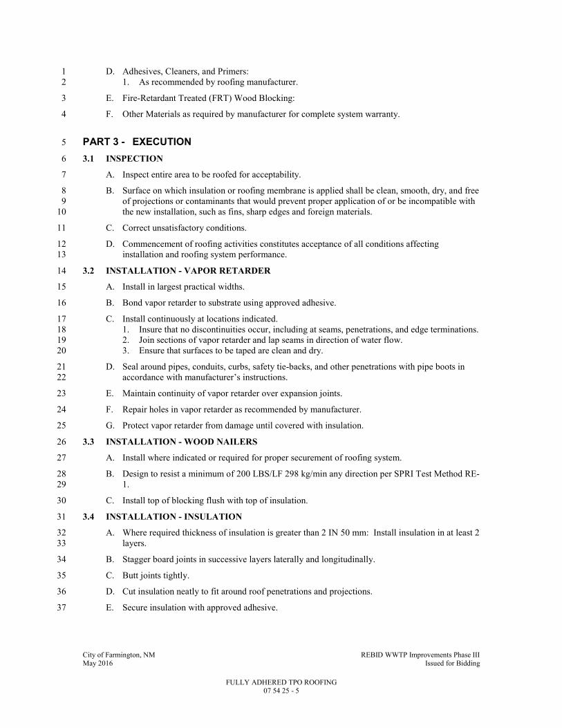
City of Farmington, NM REBID WWTP Improvements Phase III May 2016 Issued for Bidding
FULLY ADHERED TPO ROOFING 07 54 25 - 5
D. Adhesives, Cleaners, and Primers: 1
1. As recommended by roofing manufacturer. 2
E. Fire-Retardant Treated (FRT) Wood Blocking: 3
F. Other Materials as required by manufacturer for complete system warranty. 4
PART 3 - EXECUTION 5
3.1 INSPECTION 6
A. Inspect entire area to be roofed for acceptability. 7
B. Surface on which insulation or roofing membrane is applied shall be clean, smooth, dry, and free 8
of projections or contaminants that would prevent proper application of or be incompatible with 9
the new installation, such as fins, sharp edges and foreign materials. 10
C. Correct unsatisfactory conditions. 11
D. Commencement of roofing activities constitutes acceptance of all conditions affecting 12
installation and roofing system performance. 13
3.2 INSTALLATION - VAPOR RETARDER 14
A. Install in largest practical widths. 15
B. Bond vapor retarder to substrate using approved adhesive. 16
C. Install continuously at locations indicated. 17
1. Insure that no discontinuities occur, including at seams, penetrations, and edge terminations. 18
2. Join sections of vapor retarder and lap seams in direction of water flow. 19
3. Ensure that surfaces to be taped are clean and dry. 20
D. Seal around pipes, conduits, curbs, safety tie-backs, and other penetrations with pipe boots in 21
accordance with manufacturer’s instructions. 22
E. Maintain continuity of vapor retarder over expansion joints. 23
F. Repair holes in vapor retarder as recommended by manufacturer. 24
G. Protect vapor retarder from damage until covered with insulation. 25
3.3 INSTALLATION - WOOD NAILERS 26
A. Install where indicated or required for proper securement of roofing system. 27
B. Design to resist a minimum of 200 LBS/LF 298 kg/min any direction per SPRI Test Method RE-28
1. 29
C. Install top of blocking flush with top of insulation. 30
3.4 INSTALLATION - INSULATION 31
A. Where required thickness of insulation is greater than 2 IN 50 mm: Install insulation in at least 2 32
layers. 33
B. Stagger board joints in successive layers laterally and longitudinally. 34
C. Butt joints tightly. 35
D. Cut insulation neatly to fit around roof penetrations and projections. 36
E. Secure insulation with approved adhesive. 37
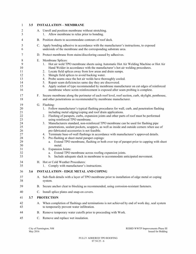
City of Farmington, NM REBID WWTP Improvements Phase III May 2016 Issued for Bidding
FULLY ADHERED TPO ROOFING 07 54 25 - 6
3.5 INSTALLATION – MEMBRANE 1
A. Unroll and position membrane without stretching. 2
1. Allow membrane to relax prior to bonding. 3
B. Position sheets to accommodate contours of roof deck. 4
C. Apply bonding adhesive in accordance with the manufacturer’s instructions, to exposed 5
underside of the membrane and the corresponding substrate area. 6
D. Protect membrane from stains/discoloring caused by adhesives. 7
E. Membrane Splices: 8
1. Hot air weld TPO membrane sheets using Automatic Hot Air Welding Machine or Hot Air 9
Hand Welder in accordance with the manufacturer’s hot air welding procedures. 10
2. Locate field splices away from low areas and drain sumps. 11
3. Shingle field splices to avoid bucking water. 12
4. Probe seams once the hot air welds have thoroughly cooled. 13
5. Repair seam deficiencies same day they are discovered. 14
6. Apply sealant of type recommended by membrane manufacturer on cut edges of reinforced 15
membrane where scrim reinforcement is exposed after seam probing is complete. 16
F. Secure membrane along the perimeter of each roof level, roof section, curb, skylight, penthouse, 17
and other penetrations as recommended by membrane manufacturer. 18
G. Flashing: 19
1. Follow manufacturer’s typical flashing procedures for wall, curb, and penetration flashing 20
including metal edging/coping and roof drain applications. 21
2. Flashing of parapets, curbs, expansion joints and other parts of roof must be performed 22
using reinforced TPO membrane. 23
3. Manufacturers standard, non-reinforced TPO membrane can be used for flashing pipe 24
penetrations, sealant pockets, scuppers, as well as inside and outside corners when use of 25
pre-fabricated accessories is not feasible. 26
4. Terminate base-of-wall flashings in accordance with manufacturer’s approved details. 27
5. Pre-flashing at sheet metal parapet copings: 28
a. Extend TPO membrane, flashing or both over top of parapet prior to capping with sheet 29
metal. 30
6. Expansion Joints: 31
a. Extend TPO membrane across roofing expansion joints. 32
b. Include adequate slack in membrane to accommodate anticipated movement. 33
H. Hot or Cold Weather Procedures: 34
1. Comply with manufacturer’s instructions. 35
3.6 INSTALLATION - EDGE METAL AND COPING 36
A. Sub-flash details with a layer of TPO membrane prior to installation of edge metal or coping 37
system. 38
B. Secure anchor cleat to blocking as recommended, using corrosion-resistant fasteners. 39
C. Install splice plates and snap-on covers. 40
3.7 PROTECTION 41
A. When completion of flashings and terminations is not achieved by end of work day, seal system 42
to temporarily prevent water infiltration. 43
B. Remove temporary water cutoffs prior to proceeding with Work. 44
C. Remove and replace wet insulation. 45

City of Farmington, NM REBID WWTP Improvements Phase III May 2016 Issued for Bidding
FULLY ADHERED TPO ROOFING 07 54 25 - 7
3.8 SCHEDULE OF ROOF SYSTEMS 1
A. Roof System – Fully Adhered TPO over Concrete Deck: 2
1. Air/Vapor 3
2. Insulation. 4
3. Cover Board. 5
4. TPO Membrane. 6
END OF SECTION 7

City of Farmington, NM REBID WWTP Improvements Phase III May 2016 Issued for Bidding
METAL ROOFING 07 61 13 - 1
SECTION 07 61 13
METAL ROOFING
PART 1 - GENERAL
1.1 SUMMARY
A. Section Includes:
1. Vapor retarder.
2. Roof insulation.
3. Ice dam membrane.
4. Standing seam metal roofing.
5. Prefinished gutters and downspouts.
6. Snow retention system.
7. Sheet metal work required for roofing.
B. Related Specification Sections include but are not necessarily limited to:
1. Division 00 - Bidding Requirements, Contract Forms, and Conditions of the Contract.
2. Division 01 - General Requirements.
3. Section 04 05 23 - Masonry Accessories.
4. Section 06 10 00 - Rough Carpentry.
1.2 QUALITY ASSURANCE
A. Referenced Standards:
1. American Architectural Manufacturers Association (AAMA):
a. 621, Voluntary Specifications for High Performance Organic Coatings on Coil Coated
Architectural Hot Dipped Galvanized (HDG) and Zinc-Aluminum Coated Steel
Substrates.
2. ASTM International (ASTM):
a. A653, Standard Specification for Steel Sheet, Zinc-Coated (Galvanized) or Zinc-Iron
Alloy-Coated (Galvannealed) by the Hot-Dip Process.
b. A792, Standard Specification for Steel Sheet, 55% Aluminum-Zinc Alloy-Coated by
the Hot-Dip Process.
c. C209, Standard Test Methods for Cellulosic Fiber Insulating Board.
d. C1289, Standard Specification for Faced Rigid Cellular Polyisocyanurate Thermal
Insulation Board.
e. D882, Standard Test Method for Tensile Properties of Thin Plastic Sheeting.
f. D1970, Standard Specification for Self-Adhering Polymer Modified Bituminous Sheet
Materials Used as Steep Roofing Underlayment for Ice Dam Protection.
g. D4833, Standard Test Method for Index Puncture Resistance of Geomembranes and
Related Products.
h. E96, Standard Test Methods for Water Vapor Transmission of Materials.
i. E1592, Standard Test Method for Structural Performance of Sheet Metal Roof and
Siding Systems by Uniform Static Air Pressure Difference.
j. E1646, Standard Test Method for Water Penetration of Exterior Metal Roof Panel
Systems by Uniform Static Air Pressure Difference.
k. E1680, Standard Test Method for Rate of Air Leakage Through Exterior Metal Roof
Panel Systems.
l. E1745, Standard Specification for Water Vapor Retarders Used in Contact with Soul or
Granular Fill under Concrete Slabs.
m. F593, Standard Specification for Stainless Steel Bolts, Hex Cap Screws, and Studs.
3. Sheet Metal and Air Conditioning Contractors' National Association (SMACNA):
a. Architectural Sheet Metal Manual, Sixth Edition, 2003.

City of Farmington, NM REBID WWTP Improvements Phase III May 2016 Issued for Bidding
METAL ROOFING 07 61 13 - 2
4. Underwriters Laboratories, Inc. (UL):
a. Building Materials Directory.
b. Fire Resistance Directory.
c. 580, Standard for Tests for Uplift Resistance of Roof Assemblies.
d. 790, Standard Test Methods for Fire Tests of Roof Coverings.
e. 1256, Fire Test of Roof Deck Constructions.
5. Building code:
a. International Code Council (ICC):
1) International Building Code and associated standards, 2009Edition including all
amendments, referred to herein as Building Code.
B. Qualifications:
1. Manufacturer shall have minimum of 10 years experience in the production of structural
standing seam metal roofing.
a. All structural components of the roof system shall be designed and sealed by registered
professional structural engineer licensed in the State of New Mexico
2. Installing contractor shall be licensed or approved in writing by manufacturer.
3. Contractor and installer shall have minimum of seven (7) years experience in the installation
of structural standing seam metal roof systems similar to system specified.
4. Contractor and installer shall have successfully completed two (2) projects of similar size,
scope and complexity within past two (2) years.
C. Completed roof system to be inspected by roof manufacturer's authorized factory trained
representative prior to issuance of roof warranty.
1.3 DEFINITIONS
A. Installer or Applicator:
1. Installer or applicator is the person actually installing or applying the product in the field at
the Project site.
2. Installer and applicator are synonymous.
B. Steep Slope: Having a pitch of 3:12 or greater.
C. Low Slope: Having a pitch less than 3:12 but greater than 1/4:12.
D. PVDF: Polyvinylidene fluoride.
1.4 SYSTEM DESCRIPTION
A. Prefinished, field-insulated, structural standing seam metal roof system, including but not
limited to:
1. Ice dam membrane.
2. Vapor retarder.
3. Roof insulation.
4. Structural standing seam metal roof panels.
a. Roof panel support and attachment system to be determined by standing seam roof
manufacturer.
B. All flashing and miscellaneous trim required for a complete water and airtight system, including
but not limited to:
1. Reglets.
2. Flashing.
3. Counterflashing.
4. Sealants.
C. Standing seam fascia system.Flat metal fascia system.
D. Prefinished gutters and downspouts.
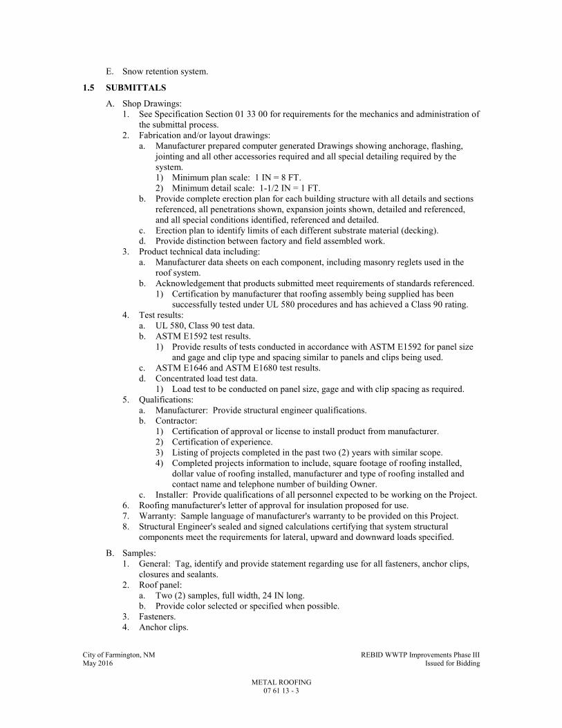
City of Farmington, NM REBID WWTP Improvements Phase III May 2016 Issued for Bidding
METAL ROOFING 07 61 13 - 3
E. Snow retention system.
1.5 SUBMITTALS
A. Shop Drawings:
1. See Specification Section 01 33 00 for requirements for the mechanics and administration of
the submittal process.
2. Fabrication and/or layout drawings:
a. Manufacturer prepared computer generated Drawings showing anchorage, flashing,
jointing and all other accessories required and all special detailing required by the
system.
1) Minimum plan scale: 1 IN = 8 FT.
2) Minimum detail scale: 1-1/2 IN = 1 FT.
b. Provide complete erection plan for each building structure with all details and sections
referenced, all penetrations shown, expansion joints shown, detailed and referenced,
and all special conditions identified, referenced and detailed.
c. Erection plan to identify limits of each different substrate material (decking).
d. Provide distinction between factory and field assembled work.
3. Product technical data including:
a. Manufacturer data sheets on each component, including masonry reglets used in the
roof system.
b. Acknowledgement that products submitted meet requirements of standards referenced.
1) Certification by manufacturer that roofing assembly being supplied has been
successfully tested under UL 580 procedures and has achieved a Class 90 rating.
4. Test results:
a. UL 580, Class 90 test data.
b. ASTM E1592 test results.
1) Provide results of tests conducted in accordance with ASTM E1592 for panel size
and gage and clip type and spacing similar to panels and clips being used.
c. ASTM E1646 and ASTM E1680 test results.
d. Concentrated load test data.
1) Load test to be conducted on panel size, gage and with clip spacing as required.
5. Qualifications:
a. Manufacturer: Provide structural engineer qualifications.
b. Contractor:
1) Certification of approval or license to install product from manufacturer.
2) Certification of experience.
3) Listing of projects completed in the past two (2) years with similar scope.
4) Completed projects information to include, square footage of roofing installed,
dollar value of roofing installed, manufacturer and type of roofing installed and
contact name and telephone number of building Owner.
c. Installer: Provide qualifications of all personnel expected to be working on the Project.
6. Roofing manufacturer's letter of approval for insulation proposed for use.
7. Warranty: Sample language of manufacturer's warranty to be provided on this Project.
8. Structural Engineer's sealed and signed calculations certifying that system structural
components meet the requirements for lateral, upward and downward loads specified.
B. Samples:
1. General: Tag, identify and provide statement regarding use for all fasteners, anchor clips,
closures and sealants.
2. Roof panel:
a. Two (2) samples, full width, 24 IN long.
b. Provide color selected or specified when possible.
3. Fasteners.
4. Anchor clips.

City of Farmington, NM REBID WWTP Improvements Phase III May 2016 Issued for Bidding
METAL ROOFING 07 61 13 - 4
5. Closures, (both metal and non-metallic).
6. Masonry reglet.
7. Factory and field applied sealants.
8. Color samples:
a. For initial preliminary color selection, provide manufacturer's color chart showing all
colors available.
b. For final color selection, provide two (2) 2 IN x 3 IN colored metal samples, for each
color selected during the initial color selection.
C. Contract Closeout Information:
1. Operation and Maintenance Data:
a. See Specification Section 01 33 04 for requirements for the mechanics, administration,
and the content of Operation and Maintenance Manual submittals.
D. Informational Submittals:
1. See Specification Section 01 33 00 for requirements for the mechanics and administration of
the submittal process.
2. Final warranty.
1.6 ADDITIONAL CONTRACTOR REQUIREMENTS
A. This project includes an “American Iron and Steel (AIS)” requirement that is required by Clean
Water State Revolving Loan Fund (CWSRF) and Drinking Water State Revolving Loan Fund
(SWSRF) projects to use iron and steel products that are produced in the United States for
projects for the construction, alteration, maintenance, or repair of a public water system or
treatment works. All iron and steel shall meet the requirements as stated in Volume I under the
“Implementation of American Iron and Steel provisions of P.L. 113-76, Consolidated
Appropriations Act, 2014.
B. See the Sample Certifications for AIS Compliance in Specification Section 01 33 00.
Documentation must be provided on company letterhead.
1.7 WARRANTY
A. Provide 10 year complete system warranty, including material for air and weather tightness of
entire roof assembly signed by manufacturer.
1. Warranty limits shall meet the minimum load capacity requirements of ASTM E1592.
B. Provide manufacturer's 20 year warranty on panel finish against fading, chipping, cracking and
peeling of the panel exterior finish.
PART 2 - PRODUCTS
2.1 ACCEPTABLE MANUFACTURERS
A. Metal roofing and fascia products specified are manufactured by Centria.
B. Manufacturers listed and other manufacturers not listed, but capable of meeting this
Specification Section, are expected to provide a system with similar profile, standing seam
height, spacing, construction and factory applied finish.
C. Subject to compliance with the Contract Documents, the following manufacturers are
acceptable:
1. Metal roofing and fascia
a. Centria.
b. Merchant and Evans - Zip Rib.
c. IMETCO.
d. Other manufacturers capable of providing structural standing seam system and profiles
similar to that specified will be considered.

City of Farmington, NM REBID WWTP Improvements Phase III May 2016 Issued for Bidding
METAL ROOFING 07 61 13 - 5
2. Vapor retarder:
a. Griffolyn.
3. Ice dam membrane.
a. GAF Materials Corporation.
b. Carlisle Coatings & Waterproofing.
c. Owens Corning.
4. Insulation: Any manufacturer meeting these specifications and approved by metal roofing
manufacturer.
5. PVDF resin:
a. PPG - DURANAR.
b. Valspar - Fluropon.
c. Arkema Inc. - KYNAR 500.
d. Solvay Solexis - HYLAR 5000.
e. Solvay Solexis - HYLAR 5000.
6. Snow retention system: Metal Roof Innovations, Ltd.
D. Submit request for substitution in accordance with Specification Section 01 25 13.
2.2 MATERIALS
A. Roof and Fascia Panels:
1. General:
a. Galvalume steel, ASTM A792, Class SS, Grade 50B.
1) Painted surfaces: AZ50.
2) Unpainted surfaces: AZ55.
B. Insulation:
1. Rigid polyisocyanurate.
a. Approved by roofing manufacturer.
C. Perimeter Trim, Panel Closures, Flashing and Counterflashing: Material and factory applied
finish to match roof panels.
D. Fasteners: 300 series stainless steel, ASTM F593.
E. Intermediate Support System:
1. Galvanized steel: ASTM A653, Class SS, Grade 50, G90.
F. Sealant: Manufacturer's standard non-curing butyl.
G. Ice dam membrane.
1. Self-adhesive, polymer modified bituminous sheet.
2. Thickness: Minimum 40 mil.
3. Manufactured to meet ASTM D1970.
4. Non-slip surface.
5. Acceptable to roofing manufacturer.
H. Masonry Reglets: See Specification Section 04 05 23.
2.3 ACCESSORIES
A. Gutters and Downspouts:
1. General:
a. Galvalume steel, ASTM A792, Class CS.
1) Painted surfaces: AZ50.
2) Unpainted surfaces: AZ55.
3) Minimum thickness: 22 GA.
4) All exposed surfaces to have finish and color to match roofing metal.
2. Gutters:
a. "Style D" to match Pump / Blower building gutter per SMACNA Figure 1-2.
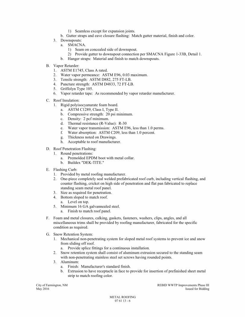
City of Farmington, NM REBID WWTP Improvements Phase III May 2016 Issued for Bidding
METAL ROOFING 07 61 13 - 6
1) Seamless except for expansion joints.
b. Gutter straps and eave closure flashing: Match gutter material, finish and color.
3. Downspouts:
a. SMACNA.
1) Seam on concealed side of downspout.
2) Provide gutter to downspout connection per SMACNA Figure 1-33B, Detail 1.
b. Hanger straps: Material and finish to match downspouts.
B. Vapor Retarder:
1. ASTM E1745, Class A rated.
2. Water vapor permeance: ASTM E96, 0.03 maximum.
3. Tensile strength: ASTM D882, 275 FT-LB.
4. Puncture strength: ASTM D4833, 72 FT-LB.
5. Griffolyn Type 105.
6. Vapor retarder tape: As recommended by vapor retarder manufacturer.
C. Roof Insulation:
1. Rigid polyisocyanurate foam board.
a. ASTM C1289, Class I, Type II.
b. Compressive strength: 20 psi minimum.
c. Density: 2 pcf minimum.
d. Thermal resistance (R-Value): R-30
e. Water vapor transmission: ASTM E96, less than 1.0 perms.
f. Water absorption: ASTM C209, less than 1.0 percent.
g. Thickness noted on Drawings.
h. Acceptable to roof manufacturer.
D. Roof Penetration Flashing:
1. Round penetrations:
a. Premolded EPDM boot with metal collar.
b. Buildex "DEK-TITE."
E. Flashing Curb:
1. Provided by metal roofing manufacturer.
2. One-piece completely seal welded prefabricated roof curb, including vertical flashing, and
counter flashing, cricket on high side of penetration and flat pan fabricated to replace
standing seam metal roof panel.
3. Size as required for penetration.
4. Bottom sloped to match roof.
a. Level on top.
5. Minimum 16 GA galvannealed steel.
a. Finish to match roof panel.
F. Foam and metal closures, calking, gaskets, fasteners, washers, clips, angles, and all
miscellaneous trims shall be provided by roofing manufacturer, fabricated for the specific
condition as required.
G. Snow Retention System:
1. Mechanical non-penetrating system for sloped metal roof systems to prevent ice and snow
from sliding off roof.
a. Provide splice fittings for a continuous installation.
2. Snow retention system shall consist of aluminum extrusion secured to the standing seam
with non-penetrating stainless steel set screws having rounded points.
3. Aluminum:
a. Finish: Manufacturer's standard finish.
b. Extrusion to have receptacle in face to provide for insertion of prefinished sheet metal
strip to match roofing color.

City of Farmington, NM REBID WWTP Improvements Phase III May 2016 Issued for Bidding
METAL ROOFING 07 61 13 - 7
4. Snow/Ice clips:
a. Aluminum or stainless steel.
b. Provide with rubber foot on end that sits on the metal roof pan.
5. Metal Roof Innovations, Ltd. S-5! "ColorGard" system.
2.4 FABRICATION
A. General:
1. Fabricate with square, true corners, mitered and welded.
2. Fabricate trim, flashings and closure pieces to match panel profile and finish.
3. Hem all edges.
4. Fabricate panels in full length with no end laps.
B. Standing Seam Metal Roof Panels:
1. Profile: Centria "SRS" System.
2. Height of standing seam: 2 IN.
3. Gage: Minimum 24.
4. Width:
a. 16 IN.
b. Longitudinal stiffening elements to minimize oil canning.
5. System shall be designed as a true structural standing seam shape.
6. Finish:
a. PVDF based with minimum 70 percent resin.
b. Three-coat system having minimum 0.8 mil epoxy primer coat on both sides of panel
with a 0.8 mil PVDF resin color coat and a 0.8 mil PVDF resin clear top coat on the
exterior side of the panel.
c. Meet or exceed requirements of AAMA 621.
d. Smooth finish.
e. Color:
1) To match Blower / Pump roof / gutter / downspout colors
7. Concealed fasteners:
a. Provide concealed fasteners in all locations.
b. If exposed fasteners are required by the roof panel manufacturer, because of location,
constructability issues or other critical design requirement, finish of fastener shall
match roof panel finish.
1) Exposed fasteners are to be approved by Engineer.
c. The use of deflection limiter devices is not allowed.
C. Intermediate Support System:
1. Roof panel anchor clips:
a. Manufacturer's standard one-piece clip suitable for condition.
1) Two-piece clips are acceptable if required by roofing manufacturer.
b. Minimum 16 GA steel.
1) Galvanized, ASTM A653, G90.
2. Roof panel manufacturer shall be responsible for designing and providing all necessary
intermediate "Z" or "hat-shaped" or other miscellaneous support members as required to
transfer roof panel loads into building roof framing members.
a. Design in accordance with Building Code and loads specified and shown on the
Drawings.
3. Bearing plates:
a. Sized by roofing manufacturer for roof loading indicated.
b. Minimum 16 GA steel.
1) Galvanized, ASTM A653, G90.
2.5 SOURCE QUALITY CONTROL
A. Roof assembly to be Class A roof covering assembly per UL 1256.

City of Farmington, NM REBID WWTP Improvements Phase III May 2016 Issued for Bidding
METAL ROOFING 07 61 13 - 8
B. Structural Testing:
1. The system shall be designed to safely resist the positive and negative loads per Building
Code and as shown on Drawings.
2. Structural-uniform uplift load capacity of the panel system shall be determined in
accordance with ASTM E1592.
a. The factor of safety on the test results shall be 1.65 for the panel, batten or clip ultimate
loads with no increase for wind.
b. The factor of safety for fasteners shall be 3.0 for one (1) single fastener per clip, 2.25
for two (2) fasteners per clip and 4.0 in masonry.
c. Design uplift capacity for conditions of gage, span or loading other than those tested
may be determined by interpolation of test results.
1) Extrapolation of conditions outside the range of the tests is not acceptable.
d. Deflection shall be L/180 for positive loading.
C. Water Penetration: No uncontrollable leakage at minimum 6.4 psf when tested in accordance
with ASTM E1646.
D. Air Infiltration: Maximum 0.00 scfm/SF when tested at 4.0 psf differential pressure when tested
in accordance with ASTM E1680.
E. Fire Resistance/Wind Uplift Rating:
1. UL 790, Class 1.
2. UL 580, Class 90.
F. The panels shall withstand a 250 LB concentrated load applied to a 4 SQ IN area at the center of
the panel at mid span between supports with no panel deformation, rib buckling, or panel sidelap
separation which will adversely affect the weather tightness of the system.
G. Support roofing panels on top of roof insulation using bearing plates attached to the structural
frame or connect to manufacturer-provided intermediate support system.
1. Bearing plate and standing seam roof panel anchor clip attachment is to be determined by
the roofing manufacturer and shall take precedent over this Specification.
a. Provide attachment to roof structural frame or deck as required for loading criteria
specified.
2. Roof panel anchor clips shall be designed to allow thermal movement of the panels except
where specific fixed points are indicated.
a. Roof panel manufacturer shall be responsible for determining fixed point locations
unless otherwise indicated.
3. Wood blocking shown at roof edge is strictly for attachment of miscellaneous flashings and
shall not be used for any structural value.
4. Maximum spacing of roof clips shall be determined by manufacturer.
H. Roof panel manufacturer shall be responsible for designing and installing all necessary
expansion joints in the roof system.
1. Where roof expansion joints occur, provide corresponding expansion joints in fascia, soffit
and gutters.
2.6 MAINTENANCE MATERIALS
A. Provide Owner with 4 OZ of touch-up paint to match each different color used in the system.
PART 3 - EXECUTION
3.1 INSTALLATION
A. General:

City of Farmington, NM REBID WWTP Improvements Phase III May 2016 Issued for Bidding
METAL ROOFING 07 61 13 - 9
1. Install products in accordance with manufacturer's instructions, SMACNA (where
referenced) and details shown on Drawings for a complete weathertight installation without
waves, warps buckles or distortions.
a. Provide all closures, trim, angles, plates, calking, gaskets, fasteners, washers, etc., as
necessary.
2. Attachments shall allow for thermal expansion and contraction.
3. Seal all joints as required for watertight installation.
4. Touch-up paint all damaged surfaces.
B. Vapor Retarder:
1. Install on winter warm side of roof assembly in accordance with manufacturer's
recommendations.
2. Lap joints minimum: 4 IN.
3. Seal to perimeter, tape all joints and repair all tears.
C. Roof Insulation:
1. Install in accordance with manufacturer’s recommendations.
2. If multiple layers are provided to achieve total thickness as shown on Drawings, stagger
joints minimum 12 IN in each direction.
D. Ice Dam Membrane:
1. Install per manufacturer's recommendations in areas indicated on Drawings.
2. Provide ice dam membrane from eave line to a point that is a minimum of 36 IN
horizontally inside the interior face of the exterior wall.
3. Provide at all ridges, hip ridges and hip valley lines extending minimum 36 IN up the slope
at valleys and down the roof slope each side of the ridge line.
E. Standing Seam Roofing Panels:
1. Install in one (1) continuous length from ridge to eave.
2. Hand crimp battens at each clip.
3. Seam panels and battens together with portable electric seaming machine supplied by the
manufacturer.
F. Snow Retention System:
1. Install starting 2 FT from the eave edge of the roof.
2. Install system in continuous lengths using manufacturer provided splice fittings.
3. Mount to metal roofing utilizing clamps fastened to standing seam with non-penetrating
bullet-nosed set-screws.
a. Fasteners shall be compatible with roof panel system and shall not void any roof
warranties.
b. Fasteners shall not damage panel finish.
4. Install metal color strip in face of extrusion.
a. Color strip to match color of standing seam roofing.
5. Provide snow/ice clips in each standing seam panel laterally across the roof or as
recommended by manufacturer.
a. Provide single clip for seam spacing of less than 16 IN and two (2) clips for seam
spacing 16 IN and greater.
G. Gutters:
1. Install gutters using gutter straps in accordance with SMACNA Table 1-8 and Figure 1-12
and per roofing manufacturer's recommendations.
a. Provide gutter brackets or hangers at 24 IN OC maximum.
b. Provide expansion joints in gutters per SMACNA and at expansion joint locations
shown on Drawings.
c. Install gutters to provide positive drainage to downspout locations.
d. Seal all joints in gutters to provide completely water tight system.

City of Farmington, NM REBID WWTP Improvements Phase III May 2016 Issued for Bidding
METAL ROOFING 07 61 13 - 10
H. Downspouts:
1. Install downspouts in locations shown on the Drawings.
2. Provide downspout hanger straps per SMACNA Figure 1-35 as appropriate for downspout
style.
3. Provide gutter to downspout connection per SMACNA Figure 1-33B, Detail 1.
4. Seal all joints in downspout for a complete watertight system.
a. Angle bottom of downspout out away from building.
5. Fasten hanger straps to building wall with stainless steel screws and anchor sleeves
appropriate for wall construction.
a. Provide minimum of two (2) fasteners per strap.
6. Maximum spacing of hanger straps shall be 10 FT with minimum of two (2) hanger straps
per vertical piece of downspout.
7. Spacing and location of hanger straps shall be consistent from downspout of downspout.
END OF SECTION

City of Farmington, NM REBID WWTP Improvements Phase III May 2016 Issued for Bidding
JOINT SEALANTS 07 92 00 - 1
SECTION 07 92 00 1
JOINT SEALANTS 2
PART 1 - GENERAL 3
1.1 SUMMARY 4
A. Section Includes: 5
1. Sealant work. 6
B. Related Specification Sections include but are not necessarily limited to: 7
1. Division 00 - Bidding Requirements, Contract Forms, and Conditions of the Contract. 8
2. Division 01 - General Requirements. 9
3. Section 09 91 00 - Painting and Protective Coatings. 10
C. Work included consists of but is not necessarily limited to: 11
1. Sealing all joints which will permit penetration of dust, air or moisture, unless sealing work 12
is specifically required under other Specification Sections. 13
a. Work includes but is not limited to: 14
1) Flashing, reglets and retainers. 15
2) Masonry control joints, brick expansion joints and between masonry and other 16
materials. 17
3) Flooring joints. 18
4) Isolation joints. 19
5) Joints between paving or sidewalks and building. 20
6) Concrete construction, control and expansion joints. 21
7) Joints between precast roof units, between precast roof units and walls, and joints 22
between precast wall panels. 23
8) Penetrations of walls, floors and decks. 24
9) Perimeters of door and window frames, louvers, grilles, etc. 25
10) Thresholds. 26
11) Plumbing fixtures. 27
12) Perimeter and penetrations of sound insulated walls. 28
13) Other joints where sealant, expanding foam sealant or compressible sealant is 29
indicated. 30
1.2 QUALITY ASSURANCE 31
A. Referenced Standards: 32
1. American Concrete Institute (ACI): 33
a. 302.1R, Guide for Concrete Floor and Slab Construction. 34
2. ASTM International (ASTM): 35
a. C834, Standard Specification for Latex Sealants. 36
b. C920, Standard Specification for Elastomeric Joint Sealants. 37
c. C1521, Standard Practice for Evaluating Adhesion of Installed Weatherproofing 38
Sealant Joints. 39
3. NSF International (NSF): 40
a. 61, Drinking Water System Components -- Health Effects. 41
4. Underwriters Laboratories, Inc. (UL). 42
B. Qualifications: Sealant applicator shall have minimum five (5) years experience using products 43
specified on projects with similar scope. 44
C. Mock-Ups: 45

City of Farmington, NM REBID WWTP Improvements Phase III May 2016 Issued for Bidding
JOINT SEALANTS 07 92 00 - 2
1. Before sealant work is started, a mock-up of each type of joint shall be sealed where 1
directed by the Engineer. 2
a. The approved mock-ups shall show the workmanship, bond, and color of sealant 3
materials as specified or selected for the work and shall be the minimum standard of 4
quality on the entire project. 5
b. Each sample shall cure for a minimum of seven (7) days at which time the sealant 6
manufacturer's authorized factory representative shall perform adhesion tests on each 7
sample joint. 8
1) Perform adhesion tests per ASTM C1521. 9
2) If mock-up is not acceptable or if adhesion test fails, provide additional mock-up 10
and adhesion testing as required until acceptable to Engineer. 11
1.3 DEFINITIONS 12
A. Corrosive Areas Include: See paragraph 1.3.E 13
B. Defective: Failure of watertightness or airtightness. 14
C. Finish sealant: Sealant material per this specification applied over face of compressible sealant 15
or expanding foam sealant specified, to provide a finished, colored sealant joint. 16
D. Installer or Applicator: 17
1. Installer or applicator is the person actually installing or applying the product in the field at 18
the Project site. 19
2. Installer and applicator are synonymous. 20
E. "Interior wet areas": Toilets, laboratories, wet wells, polymer room, thickening/dewatering 21
room, chemical rooms and similar areas. 22
F. "Seal," "sealing" and "sealant": Joint sealant work. 23
1.4 SUBMITTALS 24
A. Shop Drawings: 25
1. See Specification Section 01 33 00 for requirements for the mechanics and administration of 26
the submittal process. 27
2. Product technical data including: 28
a. Acknowledgement that products submitted meet requirements of standards referenced. 29
b. Manufacturer's installation instructions. 30
c. Manufacturer's recommendations for joint cleaner, primer, backer rod, tooling and bond 31
breaker. 32
3. Certification from sealant manufacturer stating product being used is recommended for and 33
is best suited for joint in which it is being applied. 34
4. Certification of applicator qualification. 35
B. Test Results: 36
1. Provide adhesion test results for each sealant sample including adhesion results compared to 37
adhesion requirements. 38
2. Manufacturer's authorized factory representative recommended remedial measures for all 39
failing tests. 40
C. Samples: 41
1. Cured sample of each color for Engineer's color selection. 42
2. Color chart not acceptable. 43
D. Informational Submittals: 44
1. See Specification Section 01 33 00 for requirements for the mechanics and administration of 45
the submittal process. 46

City of Farmington, NM REBID WWTP Improvements Phase III May 2016 Issued for Bidding
JOINT SEALANTS 07 92 00 - 3
1.5 DELIVERY, STORAGE, AND HANDLING 1
A. Deliver material in manufacturer's original unopened containers with labels intact: Labels shall 2
indicate contents and expiration date on material. 3
PART 2 - PRODUCTS 4
2.1 ACCEPTABLE MANUFACTURERS 5
A. Subject to compliance with the Contract Documents, the following manufacturers are 6
acceptable: 7
1. Compressible sealant: 8
a. Polytite Manufacturing Corporation. 9
b. Emseal. 10
c. Norton. 11
d. Sandell. 12
2. Expanding foam sealant: 13
a. Macklanburg Duncan. 14
b. Convenience Products. 15
c. FAI International, Inc. 16
d. Power Fasteners. 17
3. Fire-resistant sealant: See Specification Section 07 84 00. 18
4. Polyether sealants: 19
a. BASF Sonneborn. 20
b. ChemLink, Inc. 21
5. Polysulfide rubber sealant: 22
a. Pecora. 23
b. BASF Sonneborn. 24
c. PolySpec. 25
6. Polyurea joint filler: 26
a. Dayton Superior Specialty Chemical Corporation. 27
b. Euclid Chemical Co. 28
c. L&M Construction Chemicals, Inc. 29
d. BASF Sonneborn. 30
7. Polyurethane sealants: 31
a. Pecora. 32
b. Sika Chemical Corp. 33
c. BASF Sonneborn. 34
d. Tremco. 35
8. Silicone sealants: 36
a. ChemLink. 37
b. GE Construction Sealants. 38
c. Dow Corning. 39
d. Tremco. 40
9. Backer rod, compressible filler, primer, joint cleaners, bond breaker: As recommended by 41
sealant manufacturer. 42
B. Submit request for substitution in accordance with Specification Section 01 25 13. 43
2.2 MATERIALS 44
A. Sealants - General: 45
1. Provide colors matching materials being sealed. 46
2. Where compound is not exposed to view in finished work, provide manufacturer's color 47
which has best performance. 48

City of Farmington, NM REBID WWTP Improvements Phase III May 2016 Issued for Bidding
JOINT SEALANTS 07 92 00 - 4
3. Nonsagging sealant for vertical and overhead horizontal joints. 1
4. Sealants for horizontal joints: Self-leveling pedestrian/traffic grade. 2
5. Joint cleaner, primer, bond breaker: As recommended by sealant manufacturer. 3
6. Sealant backer rod and/or compressible filler: 4
a. Closed cell polyethylene, polyethylene jacketed polyurethane foam, or other flexible, 5
nonabsorbent, non-bituminous material recommended by sealant manufacturer to: 6
1) Control joint depth. 7
2) Break bond of sealant at bottom of joint. 8
3) Provide proper shape of sealant bead. 9
4) Serve as expansion joint filler. 10
B. Compressible Sealant: 11
1. Foamed polyurethane strip saturated with polymerized polybutylene waterproofing coated 12
on front face with nonreactive release agent that will act as bond breaker for applied sealant. 13
a. Polytite Manufacturing Corp. "Polytite-B." 14
2. Fire rated where required. 15
3. Adhesive: As recommended by sealant manufacturer. 16
C. Expanding Foam Sealant: 17
1. One (1) or two (2) component fire rated moisture cured expanding urethane. 18
2. Shall not contain formaldehyde. 19
3. Density: Minimum 1.5 pcf. 20
4. Closed cell content: Minimum 70 percent. 21
5. R-value: Minimum 5.0/IN. 22
6. Flame spread: Less than 25. 23
7. Smoke developed: Less than 25. 24
D. Fire-Resistant Sealant: See Specification Section 07 84 00. 25
E. Polyether Sealant: 26
1. Silyl-terminated polyether polymer. 27
2. ASTM C920, Type S, Grade NS, Class 50, Use NT, M, A, and O. 28
a. BASF Sonneborn Sonolastic 150 with VLM Technology. 29
b. ChemLink DuraLink. 30
F. Polysulfide Rubber Sealant: 31
1. One (1) or two (2) component. 32
2. Meet ASTM C920. 33
a. Pecora Synthacalk GC2+. 34
b. BASF Sonneborn - Sonolastic Polysulfide Sealant. 35
c. PolySpec THIOKOL 2235. 36
G. Polyurea Joint Filler: 37
1. Two (2) component, semi-rigid material for filling formed or saw-cut control joints in 38
interior concrete slabs. 39
a. Dayton Superior Specialty Chemical Corp. "Joint Fill, Joint Seal, Joint Saver II" as 40
required for condition and recommended by manufacturer. 41
b. Euclid Chemical Co. "EUCO QWIK" joint. 42
c. L&M Construction Chemicals, Inc. "Joint Tite 750". 43
d. BASF Sonneborn "TF-100" control joint filler. 44
2. Comply with ACI 302.1R performance recommendations regarding control and 45
construction joints. 46
3. Color: Gray. 47
H. Polyurethane Sealant: 48
1. One (1) or two (2) components. 49
2. Paintable. 50
City of Farmington, NM REBID WWTP Improvements Phase III May 2016 Issued for Bidding
JOINT SEALANTS 07 92 00 - 5
3. Meet ASTM C920 Type S or Type M, Grade NS or P, Class 25, Use NT, T, M, A and O. 1
a. Pecora Dynatrol-IXL, Dynatrol II, Urexpan NR-200, NR-201. 2
b. Sika Chemical Corporation Sikaflex-1a, Sikaflex-2C NS/SL. 3
c. BASF Sonneborn Sonolastic NP-1, NP-II, SL-1 SL-2. 4
d. Tremco Dymonic or Dymeric, Vulkem 116,227,45,245. 5
I. Silicone Sealant: 6
1. One (1) component. 7
2. Meet ASTM C920, Type S, Grade NS, Class 25, Use NT, G, A, O. 8
a. ChemLink: DuraSil. 9
b. General Electric: Silpruf, Silglaze II. 10
c. General Electric: Sanitary 1700 sealant for sealing around plumbing fixtures. 11
d. Dow Corning: 786 for sealing around plumbing fixtures. 12
e. Dow Corning: 790, 795. 13
f. Tremco: Spectrem 1, Spectrem 3, Tremsil 600. 14
3. Mildew resistant for sealing around plumbing fixtures. 15
PART 3 - EXECUTION 16
3.1 PREPARATION 17
A. Before use of any sealant, investigate its compatibility with joint surfaces, fillers and other 18
materials in joint system. 19
B. Use only compatible materials. 20
C. Where required by manufacturer, prime joint surfaces. 21
1. Limit application to surfaces to receive sealant. 22
2. Mask off adjacent surfaces. 23
D. Provide joint depth for joints receiving polyurea joint filler in accordance with manufacturer's 24
recommendations. 25
3.2 INSTALLATION 26
A. Install products in accordance with manufacturer's instructions and UL requirements. 27
B. Clean all joints. 28
C. Make all joints water and airtight. 29
D. Make depth of sealing compounds, except expanding foam and polyurea sealant, not more than 30
one-half width of joint, but in no case less than 1/4 IN nor more than 1/2 IN unless 31
recommended otherwise by the manufacturer. 32
E. Provide correctly sized backer rod, compressible filler or compressible sealant in all joints to 33
depth recommended by manufacturer: 34
1. Take care to not puncture backer rod and compressible filler. 35
2. Provide joint backer rod as recommended by the manufacturer for polyurea joint filler. 36
F. Apply bond breaker where required. 37
G. Tool sealants using sufficient pressure to fill all voids. 38
H. Upon completion, leave sealant with smooth, even, neat finish. 39
I. Where piping, conduit, ductwork, etc., penetrate wall, seal each side of wall opening. 40
J. Install compressible sealant to position at indicated depth. 41
1. Size so that width of material is twice joint width. 42

City of Farmington, NM REBID WWTP Improvements Phase III May 2016 Issued for Bidding
JOINT SEALANTS 07 92 00 - 6
2. Take care to avoid contamination of sides of joint. 1
3. Protect side walls of joint (to depth of finish sealant). 2
4. Install with adhesive faces in contact with joint sides. 3
5. Install finish sealant where indicated. 4
K. Install expanding foam sealant to minimum 4 IN depth or thickness of wall being penetrated if 5
less than 4 IN or as indicated on Drawings. 6
1. Provide adequate fire rated backing material as required. 7
2. Hold material back from exposed face of wall as necessary to allow for installation of 8
backer rod and finish sealant. 9
a. Allow expanding foam sealant to completely cure prior to installing backer rod and 10
finish sealant. 11
3. Trim off excess material flush with surface of the wall if not providing finished sealant. 12
3.3 FIELD QUALITY CONTROL 13
A. Adhesion Testing: 14
1. Perform adhesion tests in accordance with ASTM C1521 per the following criteria: 15
a. Water bearing structures: One (1) test per every 1000 LF of joint sealed. 16
b. Exterior precast concrete wall panels: One (1) test per every 2000 LF of joint sealed. 17
c. Chemical containment areas: One (1) test per every 1000 LF of joint sealed. 18
d. Building expansion joints: One (1) test per every 500 LF of joint sealed. 19
e. All other type of joints except butt glazing joints: One (1) test per every 3000 LF of 20
joint sealed. 21
f. Manufacturer's authorized factory representative shall recommend, in writing, remedial 22
measures for all failing tests. 23
3.4 SCHEDULE 24
A. Furnish sealant as indicated for the following areas: 25
1. Exterior areas: 26
a. Above grade: Polyether. 27
b. Below grade: Polyurethane. 28
2. Interior areas: 29
a. Noncorrosive areas: 30
1) Wet exposure: Polyether. 31
a) Toilet rooms, locker rooms, janitor closets or similar areas: Mildew resistant 32
silicone. 33
2) Dry exposure: Polyether, unless noted otherwise. 34
a) Sound insulated construction: Acoustical sealant. 35
b. Corrosive areas: 36
1) Wet exposure: Polysulfide. 37
2) Dry exposure: Polyurethane. 38
c. Sealant exposed to or having the potential of being exposed to concentrated chlorine 39
gas or chlorine liquid: Polysulfide. 40
d. Casework, countertops and solid surface materials: Silicone. 41
1) Sinks, fixtures or other areas subject to potential splash, spillage or condensation: 42
Mildew Resistant Silicone. 43
3. Immersion: 44
a. Prolonged contact with or immersion in: 45
1) Potable water: 46
a) Polysulfide. 47
b) NSF 61 approved. 48
2) Nonpotable water, wastewater or sewage: Polysulfide. 49
4. Compressible sealant: Where indicated. 50
5. Exterior wall penetrations: Expanding urethane foam, with finish sealant. 51
City of Farmington, NM REBID WWTP Improvements Phase III May 2016 Issued for Bidding
JOINT SEALANTS 07 92 00 - 7
a. Finish sealant: 1
1) Exterior side: 2
a) Above grade: Polyether. 3
b) Below grade: Polyurethane. 4
2) Interior side: 5
a) Noncorrosive area: 6
(1) Wet exposure: Polyether. 7
(2) Dry exposure: Polyether, unless noted otherwise. 8
b) Corrosive area: 9
(1) Wet exposure: Polysulfide. 10
(2) Dry exposure: Polyurethane. 11
6. Interior concrete slab formed or saw-cut control joints: Polyurea joint filler. 12
END OF SECTION 13
City of Farmington, NM REBID WWTP Improvements Phase III May 2016 Issued for Bidding
HOLLOW METAL DOORS AND DOOR/WINDOW FRAMES 08 11 00 - 1
SECTION 08 11 00 1
HOLLOW METAL DOORS AND DOOR/WINDOW FRAMES 2
PART 1 - GENERAL 3
1.1 SUMMARY 4
A. Section Includes: 5
1. Metal doors and frames. 6
B. Related Specification Sections include but are not necessarily limited to: 7
1. Division 00 - Bidding Requirements, Contract Forms, and Conditions of the Contract. 8
2. Division 01 - General Requirements. 9
3. Section 08 70 00 - Finish Hardware. 10
4. Section 08 81 00 - Glass and Glazing. 11
1.2 QUALITY ASSURANCE 12
A. Referenced Standards: 13
1. ASTM International (ASTM): 14
a. A653, Standard Specification for Steel Sheet, Zinc-Coated (Galvanized) or Zinc-Iron 15
Alloy-Coated (Galvannealed) by the Hot-Dip Process. 16
2. National Association of Architectural Metal Manufacturers (NAAMM): 17
a. Hollow Metal Manufacturers Association (HMMA). 18
3. Steel Door Institute (SDI): 19
a. 117, Manufacturing Tolerances for Standard Steel Doors and Frames. 20
b. All SDI publications. 21
4. Steel Door Institute/American National Standards Institute (SDI/ANSI): 22
a. A250.6, Recommended Practice for Hardware Reinforcing on Standard Steel Doors and 23
Frames. 24
b. A250.7, Nomenclature for Standard Steel Doors and Steel Frames. 25
c. A250.8 (formerly SDI 100), Recommended Specifications for Standard Steel Doors and 26
Frames. 27
d. A250.10, Test Procedure and Acceptance Criteria for Prime Painted Steel Surfaces for 28
Steel Doors and Frames. 29
e. A250.11, Recommended Erection Instructions for Steel Frames. 30
5. Building code: 31
a. International Code Council (ICC): 32
1) International Building Code and associated standards, 2009 Edition including all 33
amendments, referred to herein as Building Code. 34
B. Qualifications: Manufacturer must be current member of SDI, and NAAMM (HMMA). 35
C. Wipe coat galvanized steel is not acceptable as substitute for galvanizing finish specified. 36
1.3 DEFINITIONS 37
A. As identified in SDI/ANSI A250.7. 38
1.4 SUBMITTALS 39
A. Shop Drawings: 40
1. See Specification Section 01 33 00 for requirements for the mechanics and administration of 41
the submittal process. 42
2. Product technical data including: 43
a. Acknowledgement that products submitted meet requirements of standards referenced. 44
b. Manufacturer's installation instructions. 45

City of Farmington, NM REBID WWTP Improvements Phase III May 2016 Issued for Bidding
HOLLOW METAL DOORS AND DOOR/WINDOW FRAMES 08 11 00 - 2
3. Schedule of doors and frames using same reference numbers as used on Drawings. 1
4. SDI certification. 2
1.5 DELIVERY, STORAGE, AND HANDLING 3
A. Store doors and frames in accordance with SDI/ANSI A250.11. 4
PART 2 - PRODUCTS 5
2.1 ACCEPTABLE MANUFACTURERS 6
A. Subject to compliance with the Contract Documents, the following manufacturers are 7
acceptable: 8
1. Metal doors and frames: 9
a. CECO Corporation. 10
b. Steelcraft Manufacturing Co. 11
c. Curries Company. 12
B. Submit request for substitution in accordance with Specification Section 01 25 13. 13
2.2 MATERIALS 14
A. Steel Sheet: Hot-dipped galvannealed steel, ASTM A653, A60 coating. 15
B. Frames: Hot-dipped galvannealed steel, ASTM A653, A60 coating. 16
C. Supports and Reinforcing: Hot-dipped galvannealed steel, ASTM A653, A60 coating. 17
D. Inserts, Bolts and Fasteners: Manufacturer's standard. 18
E. Primer: Manufacturer's standard coating meeting SDI/ANSI A250.10. 19
F. Galvannealed Coating Repair: See Specification Section 09 91 00. 20
G. Thermal Insulation: Polyurethane, CFC free. 21
H. Sound Insulation: Fiberglass batt insulation or impregnated Kraft honeycomb. 22
2.3 ACCESSORIES 23
A. Glass Panels in Doors: 24
1. Fixed, integral stops on exterior face. 25
2. Snap-in stops or stops secured with countersunk Phillips head machine screws on interior 26
face. 27
3. Reinforce cut-out in door panel with minimum 20 GA galvannealed or galvanized steel 28
channel. 29
4. Glass: See Specification Section 08 81 00. 30
B. Frame Anchors: 31
1. Jamb anchors: 32
a. Masonry wire anchors: Minimum 0.1875 IN wire, galvanized. 33
b. Existing wall anchor: Minimum 18 GA, galvanized. 34
c. Stud partition and base anchors: Minimum 18 GA, galvanized. 35
2.4 FABRICATION 36
A. General: 37
1. SDI/ANSI A250.8. 38
2. Fabricate rigid, neat in appearance and free from defects. 39
3. Form to sizes and profiles indicated on Drawings. 40
a. Beveled edge. 41
4. Fit and assemble in shop wherever practical. 42
City of Farmington, NM REBID WWTP Improvements Phase III May 2016 Issued for Bidding
HOLLOW METAL DOORS AND DOOR/WINDOW FRAMES 08 11 00 - 3
5. Mark work that cannot be fully assembled in shop to assure proper assembly at site. 1
6. Continuously wire weld all joints, dress exposed joints smooth and flush. 2
7. Fabricate doors and frames to tolerance requirements of SDI 117. 3
8. Fit doors to SDI clearances. 4
9. All doors shall be handed. 5
10. Hinge cut-out depth and size on doors and frames shall match hinge specified in 6
Specification Section 08 70 00. 7
11. Design and fabricate doors to requirements of the Building Code. 8
B. Hollow Metal Doors: 9
1. General: 10
a. 1-3/4 IN thick. 11
b. Fabricate with flush top caps. 12
1) Thickness and material to match door face. 13
2) Exterior doors: Seal weld top cap to door face and grind smooth and flush. 14
3) Interior doors: 15
a) Attach top cap to door with concealed fasteners or by welding. 16
b) Factory seal if attached with fasteners. 17
c) No exposed fasteners will be accepted. 18
c. Continuously wire weld all joints and dress, smooth and flush. 19
2. All Doors: 20
a. Doors 48 IN wide, or less: SDI/ANSI A250.8, Level 3, and physical performance level 21
A, Model 2. 22
1) Face sheet minimum thickness: 16 GA. 23
2) Insulated: Minimum R10. 24
3) Min Stl 35. 25
C. Hollow Metal Frames: 26
1. Door frames: 27
a. Provide 2 IN face at all heads, jambs and mullions for frames in stud walls. 28
b. Provide 4 IN face at head where noted on Drawings or required by wall construction. 29
c. 26 GA galvannealed steel boxes welded to frame at back of all hardware cutouts. 30
d. Steel plate reinforcement welded to frame for hinge, strikes, closers and surface-31
mounted hardware reinforcing. 32
1) All plate reinforcement shall meet size and thickness requirements of 33
SDI/ANSI A250.8. 34
e. Split type frames not acceptable. 35
1) All horizontal and vertical mullions and transom bars shall be welded to adjacent 36
members. 37
f. Conceal all fasteners. 38
g. Frames shall be set up, all face joints continuously wire welded and dressed smooth. 39
h. Up to 4 FT wide: 16 GA. 40
i. Over 4 FT wide: 14 GA. 41
j. Provide removable spreaders at bottom of frame. 42
k. Window frames constructed out of same material and thickness as doors. Windows to 43
receive 1” insulated glazing unit. Refer to specification 08 81 00. 44
D. Prepare for finish hardware in accordance with hardware schedule, templates provided by 45
hardware supplier, and SDI/ANSI A250.6. 46
1. Locate finish hardware in accordance with SDI/ANSI A250.8. 47
2. See Specification Section 08 70 00 for hardware. 48
3. Prepare doors for swing direction indicated. 49
a. Preparing doors for non-handed hinges is not acceptable. 50
E. After fabrication, clean off mill scale and foreign materials and prime with rust inhibiting 51
primer. 52
City of Farmington, NM REBID WWTP Improvements Phase III May 2016 Issued for Bidding
HOLLOW METAL DOORS AND DOOR/WINDOW FRAMES 08 11 00 - 4
PART 3 - EXECUTION 1
3.1 INSTALLATION 2
A. Install doors and frames in accordance with SDI/ANSI A250.11, the Building Code and 3
manufacturer's instructions. 4
B. Plumb, align, and brace frames securely until permanently anchored. 5
1. After completion of walls, remove temporary braces and spreaders. 6
2. Anchor frames with minimum of three (3) anchors per jamb. 7
a. Number and location of anchors shall be in accordance with SDI and frame 8
manufacturer's recommendations. 9
C. At new masonry or metal stud construction, place frames in conjunction with construction of 10
walls or partitions. 11
1. Masonry construction: Anchor frames using masonry wire anchors. 12
2. Metal stud construction: 13
a. Anchor frames using steel stud anchors. 14
b. Attach wall anchors with self-tapping screws. 15
D. At concrete, precast concrete or existing masonry construction, place frames in rough opening 16
using existing opening anchors. 17
E. Use plastic plugs to keep silencer holes clear during construction. 18
F. Immediately after erection, sand smooth rusted or damaged areas. 19
1. Touch-up with rust-inhibiting primer. 20
2. Finish paint door and frame in accordance with Specification Section 09 91 00. 21
G. Install three (3) silencers on strike jamb of single door frame and two (2) on head of double door 22
frame. 23
1. See Specification Section 08 70 00. 24
H. Protect doors and frames during construction. 25
END OF SECTION 26
City of Farmington, NM REBID WWTP Improvements Phase III May 2016 Issued for Bidding
ALUMINUM ROLLING OVERHEAD DOORS 08 33 22 - 1
SECTION 08 33 22 1
ALUMINUM ROLLING OVERHEAD DOORS 2
PART 1 - GENERAL 3
1.1 SUMMARY 4
A. Section Includes: 5
1. Aluminum rolling overhead doors. 6
a. Motor operated. 7
B. Related Specification Sections include but are not necessarily limited to: 8
1. Division 00 - Bidding Requirements, Contract Forms, and Conditions of the Contract. 9
2. Division 01 - General Requirements. 10
3. Section 40 05 05 - Equipment: Basic Requirements. 11
1.2 QUALITY ASSURANCE 12
A. Referenced Standards: 13
1. Aluminum Association (AA): 14
a. DAF 45, Designation System for Aluminum Finishes. 15
2. ASTM International (ASTM): 16
a. A123/A123M, Standard Specification for Zinc (Hot-Dip Galvanized) Coatings on Iron 17
and Steel Products. 18
b. A501, Standard Specification for Hot-Formed Welded and Seamless Carbon Steel 19
Structural Tubing. 20
c. E283, Standard Test Method for Determining the Rate of Air Leakage Through 21
Exterior Windows, Curtain Walls, and Doors Under Specified Pressure Differences 22
Across the Specimen. 23
3. National Electrical Manufacturers Association (NEMA): 24
a. 250, Enclosures for Electrical Equipment (1000 Volts Maximum). 25
B. Qualifications: 26
1. Installer to be licensed or approved in writing by door manufacturer. 27
1.3 DEFINITIONS 28
A. Installer or Applicator: 29
1. Installer or applicator is the person actually installing or applying the product in the field at 30
the Project site. 31
2. Installer and applicator are synonymous. 32
1.4 SUBMITTALS 33
A. Shop Drawings: 34
1. See Specification Section 01 33 00 for requirements for the mechanics and administration of 35
the submittal process. 36
2. Product technical data including: 37
a. Acknowledgement that products submitted meet requirements of standards referenced. 38
b. Manufacturer's installation instructions. 39
3. Schedule of doors using same reference number for openings as indicated on Drawings. 40
4. Motor operator and accessories technical data including complete wiring and control 41
diagram for motor operators and control stations. 42
5. Certifications: 43
a. Certification of Installer's qualifications. 44
B. Samples: 45
City of Farmington, NM REBID WWTP Improvements Phase III May 2016 Issued for Bidding
ALUMINUM ROLLING OVERHEAD DOORS 08 33 22 - 2
1. Actual metal color samples of manufacturer's full line of colors available. 1
C. Operation and Maintenance Manuals: 2
1. See Specification Section 01 33 04 for requirements for: 3
a. The mechanics and administration of the submittal process. 4
b. The content of Operation and Maintenance Manuals. 5
D. Informational Submittals: 6
1. See Specification Section 01 33 00 for requirements for the mechanics and administration of 7
the submittal process. 8
PART 2 - PRODUCTS 9
2.1 ACCEPTABLE MANUFACTURERS 10
A. Subject to compliance with the Contract Documents, the following manufacturers are 11
acceptable: 12
1. Aluminum rolling overhead doors: 13
a. The Cookson Company. 14
b. Cornell Iron Works. 15
c. Wayne Dalton. 16
d. Overhead Door Corp. 17
e. Raynor. 18
B. Submit request for substitution in accordance with Specification Section 01 25 13. 19
2.2 MATERIALS 20
A. Door Curtain and Hood: Aluminum. 21
B. Weatherproofing: Neoprene or vinyl. 22
C. Guides: Extruded aluminum. 23
D. Headplates and Pipe Barrel: Galvanized steel. 24
E. Fasteners: Aluminum or stainless steel. 25
2.3 FABRICATION 26
A. Door Curtain: 27
1. Insulated flat profile with interlocking face sheets: 28
a. 2-5/8 IN high. 29
b. Exterior face: 0.040 IN. 30
c. Interior face: 0.024 IN. 31
d. Galvanized endlocks. 32
e. Core: Insulated. 33
2. Weatherstripping: Exterior and interior guide sealing adjustable weatherstripping at jambs, 34
interior hood and lintel (exterior doors only). 35
3. Bottom bar: 36
a. Aluminum. 37
4. Finish: 38
a. Architectural Class 1 coating per AA DAF 45. 39
b. Anodized: 40
1) AA-M12C22A41, clear. 41
B. Hood: 42
1. Minimum 0.040 IN aluminum or minimum 24 GA stainless steel. 43
2. Air baffle weatherstripping extending full length of all exterior door hoods. 44

City of Farmington, NM REBID WWTP Improvements Phase III May 2016 Issued for Bidding
ALUMINUM ROLLING OVERHEAD DOORS 08 33 22 - 3
C. Guides: 1
1. Mounting: 2
a. Interior face of wall. 3
2. Manufacturer's standard structural angle guide system for size of door specified. 4
a. Material: Aluminum. 5
b. Cold-rolled guides are not acceptable. 6
c. Finish: Match door. Brushed stainless steel. 7
D. Headplates: 8
1. Galvanized steel or stainless steel plate mounted to guides. 9
2. Sized to support counterbalance assembly, curtain, and hood. 10
E. Counterbalance Assembly: 11
1. Pipe barrel: 12
a. Steel, ASTM A501. 13
1) Galvanized, ASTM A123/A123M. 14
b. Maximum deflection: 0.03 IN/FT. 15
2. Torsion springs: 16
a. Oil-tempered helical torsion springs on cast anchors. 17
b. 100,000 cycle. 18
3. Adjustable tension wheel. 19
F. Trim Pieces: Material and finish to match door curtain. 20
G. Wind Load: Reference Structural components and cladding 21
H. Operation: Manual, chain operation with keeper 22
I. Insulated door system: Overhead Door Corp. "627" Series. 23
2.4 SOURCE QUALITY CONTROL 24
A. Air Infiltration: 1.55 CFM/SF of opening maximum when tested in accordance with 25
ASTM E283 with 25 mph wind load. 26
2.5 MAINTENANCE MATERIALS 27
A. Provide 2 OZ of touch-up paint properly labeled for each different color of door. 28
1. Touch-up paint shall be formulated to be compatible with finish specified and shall be 29
capable of being applied without special equipment or tools. 30
PART 3 - EXECUTION 31
3.1 INSTALLATION 32
A. Install products in accordance with manufacturer's instructions. 33
B. Installation shall be done by manufacturer's authorized representative. 34
C. Provide all required trim, weatherstripping, closures etc., for complete weather tight installation. 35
D. Adjust for proper counter balance. 36
E. Seal along bottom of vertical track (guides), seal the vertical joint between the two (2) separate 37
track angles (if not filled by welding) and seal all holes in vertical track (not being used for 38
fasteners) to provide a completely weather tight track and door system. 39
1. At fastener locations provide aluminum washers under bolt head to completely cover the 40
slotted holes in the vertical guide. 41
F. Electrical disconnect and conduit and wiring from standard three (3) pushbutton control to motor 42
operator is provided in the Electrical Design. 43

City of Farmington, NM REBID WWTP Improvements Phase III May 2016 Issued for Bidding
ALUMINUM ROLLING OVERHEAD DOORS 08 33 22 - 4
G. Provide aluminum or stainless steel bracing for motor operator to eliminate vibration. 1
H. Provide dissimilar materials protection on all surfaces coming in contact with dissimilar 2
materials. 3
3.2 ADJUSTMENT 4
A. Prior to occupancy, adjust door for smooth operation. 5
END OF SECTION 6
City of Farmington, NM REBID WWTP Improvements Phase III May 2016 Issued for Bidding
TRANSLUCENT PANEL SYSTEMS 08 45 00 - 1
SECTION 08 45 00
TRANSLUCENT PANEL SYSTEMS
PART 1 - GENERAL
1.1 SUMMARY
A. Section Includes:
1. Translucent panel system.
B. Related Specification Sections include but are not necessarily limited to:
1. Division 00 - Bidding Requirements, Contract Forms, and Conditions of the Contract.
2. Division 01 - General Requirements.
3. Section 07 92 00 - Joint Sealants.
1.2 QUALITY ASSURANCE
A. Referenced Standards:
1. Aluminum Association (AA):
a. DAF 45, Designation System for Aluminum Finishes.
2. ASTM International (ASTM):
a. C1363, Standard Test Method for Thermal Performance of Building Materials and
Envelope Assemblies by Means of a Hot Box Apparatus.
b. D635, Standard Test Method for Rate of Burning and/or Extent and Time of Burning of
Plastics in a Horizontal Position.
c. E84, Standard Test Method for Surface Burning Characteristics of Building Materials.
3. Society of the Plastics Industry (SPI):
a. Shatter Resistance Test.
4. Building code:
a. International Code Council (ICC):
1) International Building Code and associated standards, 2009 Edition including all
amendments, referred to herein as Building Code.
B. Qualifications:
1. Installer factory trained and approved in writing by system manufacturer.
2. Installer shall have a minimum of five (5) years experience installing system similar to
system specified.
3. Panel system shall be designed by Professional Structural Engineer licensed in the State of
New Mexico
1.3 DEFINITIONS
A. Installer or Applicator:
1. Installer or applicator is the person actually installing or applying the product in the field at
the Project site.
2. Installer and applicator are synonymous.
1.4 SUBMITTALS
A. Shop Drawings:
1. See Specification Section 01 33 00 for requirements for the mechanics and administration of
the submittal process.
2. Product technical data including:
a. Acknowledgement that products submitted meet requirements of standards referenced.
City of Farmington, NM REBID WWTP Improvements Phase III May 2016 Issued for Bidding
TRANSLUCENT PANEL SYSTEMS 08 45 00 - 2
3. Provide computer generated scaled elevation Drawings, Specification Sections and details
stamped and signed by a Professional Structural Engineer licensed in the State of New
Mexico incorporating the wall construction used for this Project to demonstrate anchorage,
flashing and sealing conditions.
4. Provide structural calculations specific to this Project stamped and signed by same Engineer
stamping and signing the Shop Drawings.
5. Warranty: Provide draft of warranty for Engineers review.
6. Certifications:
a. Certified test reports indicating conformance to material properties and design criteria
specified.
b. Certification of installer qualifications.
c. Certification of Engineers credentials.
B. Samples:
1. Provide two (2) 12 IN long pieces of proposed framing material in finish specified for
Engineers review and approval.
2. Provide two (2) 12 x 24 IN sections of insulated translucent panel system incorporating
insulation and inner and outer face sheets specified in color specified.
1.5 DELIVERY, STORAGE, AND HANDLING
A. Deliver products in protective cartons and store to protect from damage.
1.6 WARRANTY
A. Provide manufacturer’s warranty against material defects for five (5) years from date of
acceptance by Owner.
1. Warranty to cover:
a. Delamination of core from face sheets.
b. Discoloration pf face sheets.
c. Degradation of face sheet.
B. Warranty system to be weathertight for a period of five (5) years from date of acceptance by
Owner.
1. Warranty to be signed jointly by manufacturer and installer.
PART 2 - PRODUCTS
2.1 ACCEPTABLE MANUFACTURERS
A. Subject to compliance with the Contract Documents, the following manufacturers are
acceptable:
1. Translucent panel system:
a. Kalwall.
B. Submit request for substitution in accordance with Specification Section 01 25 13.
2.2 MATERIALS
A. Translucent Panels:
1. Factory fabricated sandwich panels of inner and outer face sheets bonded under heat and
pressure to core.
a. Light transmission: 30.
b. Face sheet color:
1) Exterior face: White.
2) Interior face: White.
c. Grid design: As indicated on the drawings.
d. Grid size: 12 IN x 24 IN.

City of Farmington, NM REBID WWTP Improvements Phase III May 2016 Issued for Bidding
TRANSLUCENT PANEL SYSTEMS 08 45 00 - 3
e. Panel:
1) Flat.
2) Thickness: 2-3/4 IN.
3) Length and width as indicated on Drawings.
B. Fasteners: Stainless steel.
C. Panel Framing System:
1. Extruded aluminum.
2. Manufacturer’s standard section capable of performing for intended use on this Project.
3. Sealant tape between frame and panel at inner and outer face.
4. Finish:
a. Architectural Class I coating per AA DAF 45.
1) AA-M12C22A41, clear anodized.
2) Anchor panel framing to building structure.
a) Fasteners: Stainless steel.
3) Factory pre-assemble framing and panels as far as practical.
b. Factory-applied; color as selected from manufacturer's standard colors.
c. Factory-applied; custom color selected by Architect.
D. Flashing: See Specification Section 07 62 00.
E. Face Sheets:
1. Fiberglass reinforced polymer resin manufactured specifically for intended use.
a. Uniform in color.
b. Flammability of interior sheet:
1) Flame spread:
a) Maximum 25 when tested in accordance with ASTM E84.
2) Smoke developed:
a) Maximum 300, when tested in accordance with ASTM E84.
3) Burn extent:
a) Maximum 1 IN, when tested in accordance with ASTM D635.
c. Weatherability:
d. Flatness: Free of imperfections which impair bonding.
e. Thickness:
1) Exterior sheet: 0.07 IN.
2) Interior sheet: 0.045 IN.
3) Thickness tolerance: +/-10 percent, maximum.
f. Impact strength: Resist 60 FT/LB, when tested in accordance with SPI.
F. Grid Core:
1. Structural aluminum members, 6063-T6 alloy.
2. Width of bonding face: 7/16 IN, minimum.
3. Dimensional tolerances:
a. Face to face dimension and difference in plane of faces at intersections restricted to
maximum allowable to provide full bonding face surface to contact face sheets.
4. Jointing: Mechanically interlocked.
G. Adhesive:
1. To bond face sheets to core.
2. Heat and pressure type, formulated for sandwich panel adhesive use.
H. Insulation:
1. Translucent fiberglass batt insulation.
a. Provide required thickness and density to achieve “U” values specified.
2. Manufactured specifically for use in translucent panels.
I. Sealant Tape: Factory applied; manufacturer's standard.
City of Farmington, NM REBID WWTP Improvements Phase III May 2016 Issued for Bidding
TRANSLUCENT PANEL SYSTEMS 08 45 00 - 4
2.3 DESIGN CRITERIA
A. Design Loads:
1. Design panels and framing systems to resist loadings, with maximum deflection of L/240:
a. Wind load: 1200 Pa 25 psf, horizontally.
b. Live load: 1900 Pa 40 psf, vertically.
c. Walls:
1) Wind loads: See Drawings.
B. Testing:
1. General:
a. Performed by independent testing agency.
2. "U" value:
a. 0.29 maximum.
b. Test in accordance with ASTM C1363.
c. Provide results for overall thermal value.
d. Calculated values are not acceptable.
PART 3 - EXECUTION
3.1 PREPARATION
A. Verify suitability of substrate to accept work.
B. Installation constitutes acceptance of substrate.
3.2 INSTALLATION
A. Install units in accordance with manufacturer’s written installation instructions.
B. Anchor units to resist loading indicated.
C. Seal perimeter of units in accordance with Specification Section 07 92 00.
3.3 CLEANING
A. Prior to final acceptance by Owner, wash inside and outside face sheets in accordance with
manufacturer’s instructions and clean frames and patch all scratches.
END OF SECTION
City of Farmington, NM REBID WWTP Improvements Phase III May 2016 Issued for Bidding
FINISH HARDWARE 08 70 00 - 1
SECTION 08 70 00
FINISH HARDWARE
PART 1 - GENERAL
1.1 SUMMARY
A. Section Includes:
1. Finish hardware.
1. Inspection and testing of door operation.
B. Related Specification Sections include but are not necessarily limited to:
1. Division 00 - Bidding Requirements, Contract Forms, and Conditions of the Contract.
2. Division 01 - General Requirements.
3. Section 08 11 00 - Metal Doors and Frames.
1.2 QUALITY ASSURANCE
A. All door hardware shall be provided by a single hardware supplier.
1. Hardware is to be provided under this Specification Section, unless noted otherwise, for
doors specified in:
a. Specification Section 08 11 00.
B. Referenced Standards:
1. Americans with Disabilities Act (ADA):
a. Accessibility Guidelines for Buildings and Facilities (ADAAG).
2. American National Standards Institute/Builders Hardware Manufacturers Association
(ANSI/BHMA):
a. A156.1, Butts and Hinges.
b. A156.3, Exit Devices.
c. A156.4, Door Controls -Closers.
d. A156.6, Architectural Door Trim.
e. A156.8, Door Controls - Overhead Stops and Holders.
f. A156.13, Mortise Locks and Latches Series 1000.
g. A156.16, Auxiliary Hardware.
h. A156.18, Materials and Finishes.
i. A156.21, Thresholds.
3. Door and Hardware Institute (DHI).
4. National Fire Protection Association (NFPA):
a. 101, Life Safety Code.
5. Steel Door Institute (SDI).
6. Building code:
a. International Code Council (ICC):
1) International Building Code and associated standards, 2009 Edition including all
amendments, referred to herein as Building Code.
C. Qualifications:
1. Installation shall be inspected by a certified Architectural Hardware Consultant (AHC).
1.3 DEFINITIONS
A. AHC: Architectural Hardware Consultant, certified by DHI.
B. Installer or Applicator:
1. Installer or applicator is the person actually installing or applying the product in the field at
the Project site.
2. Installer and applicator are synonymous.

City of Farmington, NM REBID WWTP Improvements Phase III May 2016 Issued for Bidding
FINISH HARDWARE 08 70 00 - 2
C. All weather: Capable of operation from -50 to +120 DegF.
D. Active Leaf: Right-hand leaf when facing door from keyed side unless noted otherwise on
Drawings.
1.4 SUBMITTALS
A. Shop Drawings:
1. See Specification Section 01 33 00 for requirements for the mechanics and administration of
the submittal process.
2. Qualifications
a. AHC qualifications and certification.
b. No submittals will be reviewed until Engineer has received AHC certification.
3. Product technical data including:
a. Acknowledgement that products submitted meet requirements of standards referenced.
b. Manufacturer's installation instructions.
4. Schedule of all hardware being used on each door.
a. Number hardware sets and door references same as those indicated on Drawings.
5. Technical data sheets on each hardware item proposed for use.
6. Certification from AHC stating all door hardware has been reviewed by AHC and verified
to be compatible with doors and frames.
7. Warranty information for all hardware devices having extended warranties.
B. Informational Submittals:
1. Certifications:
a. Certification from AHC stating all door hardware has been provided per approved Shop
Drawings, has been installed in accordance with manufacturer's recommended
installation instructions and all doors have been inspected and tested and found to be in
proper working order.
1) Door assemblies required to swing in the direction of egress have been inspected
and tested in accordance with NFPA 101.
1.5 WARRANTY
A. Provide all individual manufacturers' extended warranties as advertised.
PART 2 - PRODUCTS
2.1 ACCEPTABLE MANUFACTURERS
A. Subject to compliance with the Contract Documents, the following manufacturers are
acceptable:
1. Locksets and latchsets:
a. Corbin/Russwin.
b. Best Access Systems.
2. Closers:
a. LCN.
b. Norton.
c. Corbin/Russwin.
3. Hinges:
a. Stanley Works.
b. Hager Hinge Co.
c. McKinney Manufacturing Co.
4. Door stops and holders:
a. Trimco.
b. Rockwood.
c. Ives.
City of Farmington, NM REBID WWTP Improvements Phase III May 2016 Issued for Bidding
FINISH HARDWARE 08 70 00 - 3
5. Overhead stops:
a. Glynn-Johnson Corp.
b. Rockwood.
c. Trimco.
d. Rixson.
6. Weatherstripping and thresholds:
a. Pemko Manufacturing Co.
b. Reese Enterprises, Inc.
c. Zero Weatherstripping, Inc.
d. National Guard Products, Inc.
7. Exit devices:
a. Von Duprin, Inc.
b. Corbin/Russwin.
c. Precision.
d. Sargent.
8. Door bolts, coordinators and strikes:
a. Ives.
b. Trimco.
c. Hager.
d. Rockwood.
e. Dorma.
9. Other materials: As noted.
B. Submit request for substitution in accordance with Specification Section 01 25 13.
2.2 MATERIALS
A. General: As indicated in the FABRICATION Article in PART 2 of this Specification Section.
B. Fasteners: Stainless steel or aluminum.
C. Closers:
1. Standard closer:
a. Shell: Aluminum or cast iron.
b. Arms and piston: Forged steel.
D. Kickplates:
1. Stainless steel.
E. Thresholds: Aluminum.
F. Overhead Stops and Wall Stops: Stainless steel or aluminum.
G. Keys: Brass or bronze.
H. Weatherstripping and Smoke Seals: Polypropylene, neoprene, or EPDM.
I. Pulls and Push Plates: Stainless steel.
J. Silencers: Rubber.
2.3 ACCESSORIES
A. Strikes:
1. Curved lips.
a. Extended lips when required.
2. Furnish strike boxes.
3. Appropriate for function and hardware listed.
2.4 FABRICATION
A. Hardware - General:

City of Farmington, NM REBID WWTP Improvements Phase III May 2016 Issued for Bidding
FINISH HARDWARE 08 70 00 - 4
1. Generally prepare for Phillips head machine screw installation.
2. Exposed screws to match hardware finish or, if exposed in surfaces of other work, to match
finish of other work as closely as possible.
3. Provide concealed fasteners unless thru bolted.
4. Through bolt closers on all doors.
5. Furnish items of hardware for proper door swing.
6. Furnish lock devices which allow door to be opened from inside room without a key or any
special knowledge.
B. Hardware:
1. Provide following ANSI/BHMA A156.18 finishes:
a. Locksets, latchsets and strikes: 630.
b. Door pulls, push bars, push plates: 630.
c. Kickplates:
1) Stainless steel: 630.
d. Exit devices: 630 where available; 626 if 630 not available.
1) Provide 630 finish on trim.
e. Butt hinges: 630.
f. Door stops, dead locks, mortise bolts, and miscellaneous hardware: 630 where
available, 626 if 630 not available.
g. Door overhead stops: 630.
h. Closers: 600 prime coat with 689 finish coat, unless noted otherwise.
C. Mortise Locks and Latches:
1. ANSI/BHMA A156.13, Series 1000, Operational Grade 1, Security Grade 1.
a. Meet requirements of ADA.
2. Antifriction two-piece mechanical latchbolt with stainless steel anti-friction insert.
a. One-piece stainless steel deadbolt, minimum 1-1/4 IN x 9/ 16 IN thick with 1 IN throw.
b. 2-3/4 IN backset.
c. Cylinder: Brass, 6 pin, with interchangeable core.
d. ADA compliant thumb turn lever.
3. Locking, latching and retracting mechanism and lock case:
a. Steel, unless noted otherwise.
1) Chrome or zinc dichromate plated.
4. Trim design: Corbin/Russwin "NSP".
a. Functions as indicated in following table in accordance with ANSI/BHMA A156.13.
1) All electric lock hardware to be 24 Vdc.
MORTISE LOCK NUMBERS
ANSI FUNCTION CORBIN/RUSSWIN
F01 Passage ML2010
F19 Privacy ML2030
F05 Classroom ML2055
F07 Storeroom ML2057
F13 Entrance or Office ML2065
Electronic Lockset ML20905 x M92
D. Door Closers:
1. ANSI/BHMA A156.4, Grade 1.
2. Size door closers to comply with ANSI recommendations for door size and location.
3. Fabricate all closers with integral back check.
4. Provide integral stop unless noted otherwise.
City of Farmington, NM REBID WWTP Improvements Phase III May 2016 Issued for Bidding
FINISH HARDWARE 08 70 00 - 5
a. Do not provide integral stop at closers indicated to be installed on pull side of door.
b. Provide all weather fluid for all closers used in exterior doors and where otherwise
indicated.
5. Full cover.
a. Manufacturer's standard plastic cover.
6. Arms, brackets, and plates: As required for complete installation.
7. Closers:
a. LCN 4040 Series or Norton 7500 Series or Corbin-Russwin DC6200 Series.
8. Provide manufacturer's standard 10 year warranty.
E. Hinges:
1. Butt hinges:
a. ANSI/BHMA A156.1.
1) A5111: Stainless steel, full-mortise, anti-friction bearing, Grade 1.
b. Ball bearing.
c. Flat button tips.
d. Butt hinges:
1) Hager BB1199.
2) McKinney T4B3386.
e. Transfer hinge:
1) Hager BB1199ETW.
2) McKinney T4B3386CC.
f. Hinge size:
1) Doors up to and including 46 IN wide: 4.5 IN x 4.5 IN.
2) Doors over 46 IN up to and including 60 IN wide: 5 IN high x 4.5 IN.
F. Door Stops:
1. ANSI/BHMA A156.16.
a. Wall stops: Ives WS406-CVX or WS406-CCV.
G. Overhead Door Holders/Stop:
1. ANSI/BHMA A156.8.
2. Provide 'hold-open' function on all stops unless noted otherwise.
a. Do not provide ‘hold-open’ function at fire rated doors.
3. Surface mounted stops: Rockwood N14400 Series or Glynn Johnson 90 Series.
4. Concealed stops: Rockwood N11000 Series or Glynn Johnson 100 Series.
H. Kickplates:
1. ANSI/BHMA A156.6.
2. 8 IN high x 2 IN less than door width.
3. Beveled on all edges.
4. Thickness:
a. Stainless steel: 0.050 IN.
I. Thresholds:
1. ANSI/BHMA A156.21.
2. One-piece unit.
3. Height: 1/2 IN high maximum.
4. Width: As noted in hardware schedule.
5. Provide required bolt cutouts.
J. Exit Devices:
1. ANSI/BHMA A156.3, Grade 1.
2. Single doors: Rim.
3. Trim: Sargent “ET”.
a. Lever operation.
b. Lever style: Sargent "L".

City of Farmington, NM REBID WWTP Improvements Phase III May 2016 Issued for Bidding
FINISH HARDWARE 08 70 00 - 6
4. Sargent "80 Series".
a. Function as indicated on Hardware Schedule.
5. Coordinate power supply and electric option requirements with access control system and
electric door assisting device.
K. Weatherstripping:
1. Weather seal at jambs and head:
a. Self-adhesive strip: Reese #797W.
b. Color: Black.
c. Sweep at bottom of doors:
d. Reese 701.
e. Color: Clear anodized.
2. Weather seal astragal at meeting edges of pairs of doors:
a. Reese 92 each leaf.
b. Color: Clear anodized.
L. Silencers:
1. Hollow metal frames: Trimco 1229A or Rockwood 608.
2. Self-adhesive silencers are not acceptable.
M. Keying:
1. Establish keying with Owner.
a. Provide and set up complete visible card indexed system with key tags and control
slips.
b. Tag and identify keys.
c. Provide two (2) keys for each lock or cylinder.
d. Master key and key in groups as directed.
e. Provide construction master keys for all exterior doors.
N. Bolts:
1. ANSI/BHMAA 156.16.
2. Surface bolts: Ives SB1640 Series with top and bottom strikes.
PART 3 - EXECUTION
3.1 INSTALLATION
A. Install products in accordance with manufacturer's installation instructions.
1. Perform installation by or under the direct supervision of an AHC.
B. Provide all hardware in accordance with Building Code.
C. Fit hardware before final door finishing.
D. Permanently install hardware after door finishing operations are complete.
E. Use SDI mounting heights for hardware.
F. Butt Hinges:
1. Provide non-removable pin (NRP) at:
a. Exterior doors.
b. Reverse handed doors equipped with locks.
2. Quantities:
a. Door height 61-90 IN: Three (3).
b. Door height 91-114 IN: Four (4).
c. Door height 115-144 IN: Five (5).
d. Doors over 48 IN wide and over 96 IN high:
1) Provide top butt hinge within 6 IN of the top of the door to top of hinge.
City of Farmington, NM REBID WWTP Improvements Phase III May 2016 Issued for Bidding
FINISH HARDWARE 08 70 00 - 7
2) Provide one (1) additional butt hinge approximately 6 IN below the bottom of the
top butt hinge.
3. Provide transfer hinge as necessary where electrified lockset or exit device is specified or as
otherwise indicated in Hardware Schedule.
G. Closers:
1. Mount closers on push side of doors unless noted otherwise.
H. Provide coordinator when required by hardware specified.
I. Overhead Stops:
1. Provide overhead stop when corrosion resistant closer is specified.
2. Provide concealed overhead stop on doors scheduled to receive closer mounted on pull side
of door.
3. Provide at interior doors not scheduled to receive a closer as follows:
a. Doors that swing more than 105 degrees without encountering a wall or obstruction.
1) Stop shall limit swing of door from impacting wall or obstruction.
b. Inactive leafs of pairs of doors.
J. Wall Mount Door Stops:
1. Provide where specifically indicated on Hardware Schedule and at doors not otherwise
indicated to receive:
a. Overhead stop.
b. Closer with integral stop.
K. Floor mounted stops are not acceptable unless noted otherwise in this Specification Section.
L. Provide silencers for door frames.
1. Hollow metal frames: See Specification Section 08 11 00.
M. Provide weather seal, door sweep and threshold at all exterior doors and where scheduled on
interior doors.
1. Set thresholds in a full bed of sealant.
2. Mount door sweeps on exterior face of door.
3. Mount weather seal astragal at meeting edges of pairs of doors on the exterior face of the
doors.
N. Provide smoke seals on all fire rated doors.
O. Mount kickplates on push side of doors.
3.2 FIELD QUALITY CONTROL
A. Adjust and check each operating item of hardware to assure proper operation or function.
1. Lubricate moving parts with lubricant recommended by manufacturer.
B. During week prior to startup, make a final check and adjustment of all hardware items.
1. Clean and lubricate as necessary to assure proper function and operation.
2. Adjust door control devices to compensate for operation of heating and ventilating
equipment.
C. Inspection and Testing:
1. AHC shall inspect and test all door assemblies and provide written certification that door
assemblies are in proper working order.
a. Door assemblies required to swing in the direction of egress shall be inspected and
tested in accordance with NFPA 101.
2. Submit documentation and certification of testing in accordance with the certifications
paragraph in the SUBMITTALS Article in PART 1 of this Specification Section.
City of Farmington, NM REBID WWTP Improvements Phase III May 2016 Issued for Bidding
FINISH HARDWARE 08 70 00 - 8
3.3 SCHEDULES
A. Hardware Schedule:
1. 3.02 HARDWARE SETS
SPEXTRA: 219582
HARDWARE SET # 01 (UV DISINFECTION FACILITY)
DOORS # 101A 101B
EACH TO HAVE: 1 EA CONT. HINGE 112HD-DOOR HEIGHT 628 IVE
1 EA PANIC HARDWARE 99-NL-EMB PUSH-SNB 628 VON
1 EA CYLINDER 20-079 626 SCH
1 EA FSIC CONST. CORE 23-030-ICX SCH
1 EA FSIC CORE 23-030 626 SCH
1 EA SURFACE CLOSER 1461 SCUSH SRI FC TBSRT 689 LCN
1 EA STOP SPACER SRI 1460-61 689 LCN
1 EA DRIP CAP 16A-FRAME HEAD PLUS 4" CL NGP
1 SET SEALS 162S-HEAD & JAMBS AL NGP
1 EA DOOR SWEEP 1015VA-DOOR WIDTH CL NGP
1 EA THRESHOLD 896S SIA-FRAME WIDTH AL NGP
HARDWARE SET # 02 (UV DISINFECTION FACILITY)
DOORS # 101C
EACH TO HAVE: 2 EA PADLOCK KS43F3200 X 4" SHACKLE 606 SCH
2 EA FSIC CONST. CORE 23-030-ICX SCH
2 EA FSIC CORE 23-030 626 SCH
BALANCE HARDWARE PROVIDED BY THE DOOR MFG
OVERHEAD DOOR
HARDWARE SET # 03 (SOLIDS HANDLING BUILDING)
DOORS # 101B 101C 101D 102B 106B
EACH TO HAVE: 2 EA PADLOCK KS43F3200 X 4" SHACKLE 606 SCH
2 EA FSIC CONST. CORE 23-030-ICX SCH
2 EA FSIC CORE 23-030 626 SCH
BALANCE HARDWARE PROVIDED BY THE DOOR MFG
OVERHEAD DOOR
HARDWARE SET # 04 (SOLIDS HANDLING BUILDING)
City of Farmington, NM REBID WWTP Improvements Phase III May 2016 Issued for Bidding
FINISH HARDWARE 08 70 00 - 9
DOORS # 101A 101E 101G 106A
EACH TO HAVE: 1 EA CONT. HINGE 112HD-DOOR HEIGHT 628 IVE
1 EA PANIC HARDWARE 99-NL-EMB PUSH-SNB 628 VON
1 EA CYLINDER 20-079 626 SCH
1 EA FSIC CONST. CORE 23-030-ICX SCH
1 EA FSIC CORE 23-030 626 SCH
1 EA SURFACE CLOSER 1461 SCUSH SRI FC TBSRT 689 LCN
1 EA STOP SPACER SRI 1460-61 689 LCN
1 EA DRIP CAP 16A-FRAME HEAD PLUS 4" CL NGP
1 SET SEALS 162S-HEAD & JAMBS AL NGP
1 EA DOOR SWEEP 1015VA-DOOR WIDTH CL NGP
1 EA THRESHOLD 896S SIA-FRAME WIDTH AL NGP
HARDWARE SET # 05 (SOLIDS HANDLING BUILDING)
DOORS # 105A
EACH TO HAVE: 3 EA HW HINGE 5BB1HW 4.5 X 4.5 NRP 630 IVE
1 EA STOREROOM LOCK ND80TD SPA 626 SCH
1 EA FSIC CORE 23-030 626 SCH
1 EA FLOOR STOP FS18S BLK IVE
3 EA SILENCER SR64 GRY IVE
HARDWARE SET # 06 (SOLIDS HANDLING BUILDING)
DOORS # 104A
EACH TO HAVE: 3 EA HW HINGE 5BB1HW 4.5 X 4.5 NRP 630 IVE
1 EA PASSAGE SET ND10S SPA 626 SCH
1 EA DOOR BOLT OCC IND B571 X (6) 61-510 626 SCH
1 EA SURFACE CLOSER 1461 SCUSH SRI FC TBSRT 689 LCN
1 EA STOP SPACER SRI 1460-61 689 LCN
3 EA SILENCER SR64 GRY IVE
HARDWARE SET # 07 (SOLIDS HANDLING BUILDING)
DOORS # 101F 103A
EACH TO HAVE: 3 EA HW HINGE 5BB1HW 4.5 X 4.5 NRP 630 IVE
1 EA PANIC HARDWARE 99-L-17-EMB PUSH-SNB 628 VON

City of Farmington, NM REBID WWTP Improvements Phase III May 2016 Issued for Bidding
FINISH HARDWARE 08 70 00 - 10
1 EA CYLINDER 20-079 626 SCH
1 EA FSIC CONST. CORE 23-030-ICX SCH
1 EA FSIC CORE 23-030 626 SCH
1 EA SURFACE CLOSER 1461 SCUSH SRI FC TBSRT 689 LCN
1 EA STOP SPACER SRI 1460-61 689 LCN
3 EA SILENCER SR64 GRY IVE
HARDWARE SET # 08 (SOLIDS HANDLING BUILDING)
DOORS # 107A
EACH TO HAVE: 1 EA CONT. HINGE 112HD-DOOR HEIGHT 628 IVE
1 EA PANIC HARDWARE 99-L-17-EMB PUSH-SNB 628 VON
1 EA CYLINDER 20-079 626 SCH
1 EA FSIC CONST. CORE 23-030-ICX SCH
1 EA FSIC CORE 23-030 626 SCH
1 EA SURFACE CLOSER 1461 SCUSH SRI FC TBSRT 689 LCN
1 EA STOP SPACER SRI 1460-61 689 LCN
1 EA DRIP CAP 16A-FRAME HEAD PLUS 4" CL NGP
1 SET SEALS 162S-HEAD & JAMBS AL NGP
1 EA DOOR SWEEP 1015VA-DOOR WIDTH CL NGP
1 EA THRESHOLD 896S SIA-FRAME WIDTH AL NGP
HARDWARE SET # 09 (SOLIDS HANDLING BUILDING)
DOORS # 102A
EACH TO HAVE: 3 EA HW HINGE 5BB1HW 4.5 X 4.5 NRP 630 IVE
1 EA PASSAGE SET ND10S SPA 626 SCH
1 EA SURFACE CLOSER 1461 SCUSH SRI FC TBSRT 689 LCN
1 EA STOP SPACER SRI 1460-61 689 LCN
3 EA SILENCER SR64 GRY IVE
END OF SECTION

City of Farmington, NM REBID WWTP Improvements Phase III May 2016 Issued for Bidding
GLASS AND GLAZING 08 81 00 - 1
SECTION 08 81 00 1
GLASS AND GLAZING 2
PART 1 - GENERAL 3
1.1 SUMMARY 4
A. Section Includes: 5
1. Glass and glazing. 6
2. Fire resistance rated glass. 7
B. Related Specification Sections include but are not necessarily limited to: 8
1. Division 00 - Bidding Requirements, Contract Forms, and Conditions of the Contract. 9
2. Division 01 - General Requirements. 10
3. Section 07 92 00 - Joint Sealants. 11
4. Section 08 11 00 - Hollow Metal Doors and Frames. 12
5. Section 08 33 22 – Aluminum Rolling Overhead Doors. 13
1.2 QUALITY ASSURANCE 14
A. Referenced Standards: 15
1. American National Standards Institute (ANSI): 16
a. Z97.1, Glazing Materials Used in Buildings - Safety Performance Specifications and 17
Methods of Test. 18
2. ASTM International (ASTM): 19
a. C864, Standard Specification for Dense Elastomeric Compression Seal Gaskets, Setting 20
Blocks, and Spacers. 21
b. C1036, Standard Specification for Flat Glass. 22
c. C1048, Standard Specification for Heat-Treated Flat Glass-Kind HS, Kind FT Coated 23
and Uncoated Glass. 24
d. C1376, Standard Specification for Pyrolytic and Vacuum Deposition Coatings on Flat 25
Glass. 26
e. E119, Standard Test Methods for Fire Tests of Building Construction and Materials. 27
f. E2190, Standard Specification for Insulating Glass Unit Performance and Evaluation. 28
3. Code of Federal Regulations (CFR): 29
a. Title 16 - Commercial Practices, Chapter ii - Consumer Product Safety Commission 30
(CPSC), Subchapter B - Consumer Product Safety Act Regulations: 31
1) 16 CFR 1201, Safety Standard for Architectural Glazing Materials. 32
4. Glass Association of North America (GANA): 33
a. Glazing Manual. 34
5. Insulating Glass Certification Council (IGCC). 35
6. Insulating Glass Manufacturers Alliance (IGMA): 36
a. TM-3000, North American Glazing Guidelines for Sealed Insulating Glass Units for 37
Commercial and Residential Use. 38
7. National Fire Protection Association (NFPA). 39
a. 80, Standard for Fire Doors and Other Opening Protectives. 40
b. 251, Standard Methods of Tests of Fire Resistance of Building Construction and 41
Materials. 42
c. 252, Standard Methods of Fire Tests of Door Assemblies. 43
d. 257, Standard on Fire Test for Window and Glass Block Assemblies. 44
8. Underwriters Laboratories, Inc. (UL): 45
a. 9, Standard for Fire Tests of Window Assemblies. 46
b. 10B, Standard for Fire Tests of Door Assemblies. 47
c. 263, Standard for Fire Tests of Building Construction and Materials. 48

City of Farmington, NM REBID WWTP Improvements Phase III May 2016 Issued for Bidding
GLASS AND GLAZING 08 81 00 - 2
9. Building code: 1
a. International Code Council (ICC): 2
1) International Building Code and associated standards, 2012 Edition including all 3
amendments, referred to herein as Building Code. 4
1.3 DEFINITIONS 5
A. Installer or Applicator: 6
1. Installer or applicator is the person actually installing or applying the product in the field at 7
the Project site. 8
2. Installer and applicator are synonymous. 9
B. Safety Glazing: Glazing meeting the requirements of the Building Code and CPSC 16 CFR 10
1201. 11
C. Other terms as identified in CSPC 16 CFR 1201. 12
1.4 SUBMITTALS 13
A. Shop Drawings: 14
1. See Specification Section 01 33 00 for requirements for the mechanics and administration of 15
the submittal process. 16
2. Product technical data including: 17
a. Acknowledgement that products submitted meet requirements of standards referenced. 18
b. Manufacturer's installation instructions. 19
c. Certification that glass has been tested and approved for use in fire resistance rated 20
doors or walls. 21
1) Copies of all test criteria. 22
3. Certification that insulating glass units meet requirements of IGCC and are certified by 23
IGCC to ASTM E2190. 24
B. Samples: 25
1. Two (2) 12 x 12 IN sample of each type, color, and thickness specified. 26
a. Samples are not required for clear monolithic glass. 27
C. Informational Submittals: 28
1. Warranty. 29
1.5 WARRANTY 30
A. Provide manufacturer's written 10 year warranty to cover deterioration of glass, glass units, 31
coatings and ceramic frit. 32
1. Insulating glass units shall be warranted against failure of hermetic seal resulting in fogging 33
or film formation on the interior glass surfaces. 34
PART 2 - PRODUCTS 35
2.1 ACCEPTABLE MANUFACTURERS 36
A. Subject to compliance with the Contract Documents, the following manufacturers are 37
acceptable: 38
1. Glass: 39
a. Guardian Industries Corp. 40
b. Insulite Glass Co. 41
c. Pilkington. 42
d. PPG. 43
e. Viracon. 44
2. Fire Resistance Rated Glass: 45
a. SAFTIFIRST division of O'Keefe's, Inc. 46
City of Farmington, NM REBID WWTP Improvements Phase III May 2016 Issued for Bidding
GLASS AND GLAZING 08 81 00 - 3
b. Technical Glass Products. 1
c. Vetrotech. 2
3. Gaskets, glazing compounds, setting blocks, spacers, sealant, sealant tape, etc., as 3
recommended by glass manufacturer, glass unit fabricator. 4
a. Provide materials as required by NFPA for use in fire-rated units. 5
B. Submit request for substitution in accordance with Specification Section 01 25 13. 6
2.2 MATERIALS 7
A. General: 8
1. ASTM C1036. 9
a. Clear glass: Type I, Class 1, Quality Q3. 10
b. Tinted glass: Type I, Class 2, Quality Q3. 11
2. Thickness: 1/4 IN, unless noted otherwise. 12
B. Heat Strengthened and Fully Tempered Glass: ASTM C1048. 13
1. General use: Kind HS. 14
2. Safety glazing: Kind FT. 15
a. Meet requirements of ANSI Z97.1 and CSPC 16 CFR 1201. 16
3. Condition: 17
a. Clear or tinted vision glass: Condition A. 18
b. Spandrel Glass (ceramic coated): Condition B. 19
c. Coated vision glass: Condition C. 20
1) ASTM C1376, Kind CV or CO. 21
C. Fire Resistance Rated Glass: 22
1. ASTM E119 or UL 263 listed. 23
2. Fire rating required: as scheduled on Drawings. 24
a. Fire-rated glazing assemblies shall be marked in accordance with the Building Code. 25
3. Thickness required by fire rating. 26
a. Minimum 3/16 IN thick. 27
4. Optically clear, colorless and free from distortion. 28
5. Impact safety rated in addition to fire rating; meet ANSI Z97.1, Category 11. 29
2.3 MANUFACTURED UNITS 30
A. Insulating Glass Units: 31
1. ASTM E2190, Class A. 32
2. Two (2) lites of glass separated by a hermetically sealed air space. 33
a. Spacer: Stainless steel "warm edge" spacer. 34
1) Thickness: 1/2 IN. 35
2) Color: Black. 36
b. Perimeter Sealant: Silicone. 37
1) Color: Black. 38
2.4 ACCESSORIES 39
A. Glazing Compounds: 40
1. Non-sag, non-stain type. 41
2. Pigmented to match frame units not requiring painting. 42
3. Compatible with adjacent surfaces. 43
4. One- or two-part polyurethane or silicone sealant for use in setting glass. 44
a. Provide glazing compounds which will not be affected by chemicals stored in rooms 45
where glazing compounds are used. 46
B. Sealant Tape: Butyl rubber sealant tape or ribbon having a continuous neoprene shim. 47
C. Gaskets: 48

City of Farmington, NM REBID WWTP Improvements Phase III May 2016 Issued for Bidding
GLASS AND GLAZING 08 81 00 - 4
1. Flexible polyvinyl chloride or neoprene. 1
a. ASTM C864. 2
b. Provide gaskets which will not be affected by chemicals stored in rooms where gaskets 3
are used. 4
2. Extruded of profile and hardness required to receive glass and provide a watertight 5
installation. 6
3. Provide gaskets in accordance with NFPA in fire resistance rated glazing. 7
D. Setting Blocks and Spacers: 8
1. Neoprene or EPDM, compatible with sealants used. 9
a. ASTM C864. 10
E. Compressible Filler Stock: Closed cell polyethylene or polyethylene jacketed polyurethane 11
foam. 12
F. Shims, Clips, Screws and Other Miscellaneous Items: As required by condition. 13
PART 3 - EXECUTION 14
3.1 INSTALLATION 15
A. Install in accordance with recommendations of manufacturer, GANA Glazing Manual and 16
IGMA TM-3000. 17
B. Install setting blocks in adhesive or sealant. 18
C. Install spacers inside and out, of proper size and spacing, for all glass sizes larger than 50 united 19
inches, except where gaskets are used for glazing. 20
D. Provide 1/8 IN minimum bite of spacers on glass. 21
E. Spacer thickness to equal sealant width. 22
F. Prevent sealant exudation from glazing channels of insulating glass which is more than 1/2 IN 23
thick; colored, heat absorbing, coated or laminated glass sizes larger than 75 united inches; and 24
other glass more than 9/32 IN thick or larger than 125 united inches. 25
1. Leave void at heel (or install filler) at jambs and head. 26
2. Do not leave void (or install filler) at sill. 27
G. Miter cut and bond gasket ends together at corners. 28
H. Immediately after installation, attach crossed streamers to framing held away from glass. 29
I. Use polysulfide-based glazing sealants in window assembly and as perimeter sealant around 30
frames in areas which may be exposed to chlorine gas or chlorine liquid splash or spillage. 31
1. See Specification Section 07 92 00 for sealants. 32
J. Install fire resistance rated glass in accordance with manufacturer's recommendations and in 33
accordance with applicable fire testing criteria. 34
3.2 FIELD QUALITY CONTROL 35
A. Do not install glass with edge damage. 36
B. Do not apply anything to surfaces of glass. 37
C. Remove and replace damaged glass. 38
3.3 CLEANING 39
A. Maintain glass reasonably clean during construction, so that it will not be damaged by corrosive 40
action and will not contribute to deterioration of other materials. 41
City of Farmington, NM REBID WWTP Improvements Phase III May 2016 Issued for Bidding
GLASS AND GLAZING 08 81 00 - 5
B. Wash and polish glass on both faces not more than seven (7) days prior to acceptance of work in 1
each area. 2
1. Comply with glass manufacturer's recommendations. 3
3.4 SCHEDULES 4
A. General: 5
1. Provide safety glazing for all applications where required by the Building Code and CPSC 6
16 CFR 1201. 7
2. Provide heat strengthened glazing for all general use applications where safety glazing is not 8
required. 9
B. Glass Type 4: Insulating Units. 10
1. Exterior lite: 1/4 IN clear. 11
2. 1/2 IN dehydrated air space. 12
3. Interior lite: 1/4 IN clear. 13
4. Performance Requirements: 14
a. Transmittance: 15
1) Visible light: 76 percent. 16
b. U-Value 17
1) Winter: 0.47. 18
2) Summer: 0.49. 19
c. Solar Heat Gain Coefficient (SHGC): 0.70. 20
END OF SECTION 21

City of Farmington, NM REBID WWTP Improvements Phase III May 2016 Issued for Bidding
LOUVERS AND VENTS 08 90 00 - 1
SECTION 08 90 00 1
LOUVERS AND VENTS 2
PART 1 - GENERAL 3
1.1 SUMMARY 4
A. Section Includes: 5
1. Louvers and vents. 6
B. Related Sections include but are not necessarily limited to: 7
1. Division 00 - Bidding Requirements, Contract Forms, and Conditions of the Contract. 8
2. Division 01 - General Requirements. 9
3. Section 07 92 00 - Joint Sealants. 10
1.2 QUALITY ASSURANCE 11
A. Referenced Standards: 12
1. Aluminum Association (AA): 13
a. DAF 45, Designation System for Aluminum Finishes. 14
2. Air Movement and Control Association (AMCA). 15
3. ASTM International (ASTM): 16
a. B221, Standard Specification for Aluminum and Aluminum-Alloy Extruded Bars, 17
Rods, Wire, Profiles, and Tubes. 18
1.3 SUBMITTALS 19
A. Shop Drawings: 20
1. See Specification Section 01 33 00 for requirements for the mechanics and administration of 21
the submittal process. 22
2. Drawing showing location of each louver or vent, indicating size and arrangement of blank-23
off plates if required. 24
3. Product technical data including: 25
a. Acknowledgement that products submitted meet requirements of standards referenced. 26
b. Manufacturer's installation instructions. 27
c. Color chart showing manufacturer's full line of colors including exotic and special 28
colors for color selection by Engineer. 29
PART 2 - PRODUCTS 30
2.1 ACCEPTABLE MANUFACTURERS 31
A. Subject to compliance with the Contract Documents, the following manufacturers are 32
acceptable: 33
1. Louvers: 34
a. Airolite Co. 35
b. Construction Specialties, Inc. 36
c. Ruskin Manufacturing. 37
d. Industrial Louvers, Inc. 38
e. American Warming. 39
B. Submit request for substitution in accordance with Specification Section 01 25 13. 40
2.2 MANUFACTURED UNITS 41
A. Louvers: 42
1. 4 IN deep. 43
City of Farmington, NM REBID WWTP Improvements Phase III May 2016 Issued for Bidding
LOUVERS AND VENTS 08 90 00 - 2
2. Drainable with blades at 37-1/2 degrees. 1
3. Continuous blade appearance. 2
4. ASTM B221 extruded aluminum, alloy 6063T5, minimum 0.081 IN thick. 3
5. Minimum free area: 8.58 SF for 4 x 4 FT louver. 4
6. Maximum pressure drop: 0.10 IN of water at 700 fpm. 5
7. Water penetration: 0.01 OZ/SF at 873 fpm. 6
8. AMCA certified. 7
9. Ruskin "ELF 375DX". 8
10. Insect screen: 9
a. 18-16 mesh aluminum. 10
b. Install in standard aluminum frame. 11
B. Anchors, Fasteners, Reinforcing: Aluminum or stainless steel. 12
C. Finish: 13
1. Architectural Class 1 coating per AA DAF 45. 14
a. Finish to match louvers on Pump/Blower Building. 15
D. Size: Refer to Mechanical Drawings for louver size, and refer to Architectural Drawings for 16
louver shapes. 17
PART 3 - EXECUTION 18
3.1 INSTALLATION 19
A. Install products in accordance with manufacturer's instructions. 20
B. Install anchoring and bracing accessories as required. 21
C. Seal around perimeter on exterior and interior. 22
1. See Section 07 92 00. 23
D. Install 0.040 IN aluminum flashing at sill to match louver. 24
END OF SECTION 25
City of Farmington, NM REBID WWTP Improvements Phase III May 2016 Issued for Bidding
EPOXY FLOORING SYSTEM 09 67 00 - 1
SECTION 09 67 00 1
EPOXY FLOORING SYSTEM 2
PART 1 - GENERAL 3
1.1 SUMMARY 4
A. Section Includes: 5
1. Surface preparation of substrate. 6
2. Epoxy flooring system. 7
B. Related Sections include but are not necessarily limited to: 8
1. Division 00 - Bidding Requirements, Contract Forms, and Conditions of the Contract. 9
2. Division 01 - General Requirements. 10
3. Division 03 - Concrete. 11
1.2 QUALITY ASSURANCE 12
A. Referenced Standards: 13
1. ASTM International (ASTM): 14
a. C307, Standard Test Method for Tensile Strength of Chemical-Resistant Mortar, 15
Grouts, and Monolithic Surfacings. 16
b. D2240, Standard Test Method for Rubber Property—Durometer Hardness. 17
c. D4060, Standard Test Method for Abrasion Resistance of Organic Coatings by the 18
Taber Abrader. 19
d. D4414, Standard Practice for Measurement of Wet Film Thickness by Notch Gages. 20
e. D6132, Standard Test Method for Nondestructive Measurement of Dry Film Thickness 21
of Applied Organic Coatings Using an Ultrasonic Gage. 22
f. D7234, Standard Test Method for Pull-Off Adhesion Strength of Coatings on Concrete 23
Using Portable Pull-Off Adhesion Testers. 24
g. E337, Standard Test Method for Measuring Humidity with a Psychrometer (the 25
Measurement of Wet- and Dry-Bulb Temperatures). 26
2. International Concrete Repair Institute (ICRI): 27
a. 310.2, Selecting and Specifying Concrete Surface Preparation for Sealers, Coatings, 28
and Polymer Overlays. 29
3. The Society for Protective Coatings/NACE International (SSPC/NACE): 30
a. SP 13/NACE No. 6, Surface Preparation of Concrete. 31
B. Qualifications: 32
1. Applicator shall be licensed or approved, in writing, by manufacturer. 33
2. Applicator to have minimum of five (5) years experience installing epoxy flooring systems 34
similar to system specified. 35
1.3 DEFINITIONS 36
A. Installer or Applicator: 37
1. Installer or applicator is the person(s) actually installing or applying the product in the field 38
at the Project site. 39
2. Installer and applicator are synonymous. 40
B. DFT: Dry film thickness. 41
1.4 SUBMITTALS 42
A. Shop Drawings: 43
1. See Specification Section 01 33 00 for requirements for the mechanics and administration of 44
the submittal process. 45
City of Farmington, NM REBID WWTP Improvements Phase III May 2016 Issued for Bidding
EPOXY FLOORING SYSTEM 09 67 00 - 2
2. Product technical data including: 1
a. Acknowledgement that products submitted meet requirements of standards referenced. 2
b. Manufacturer's installation instructions. 3
c. Complete physical and chemical characteristics. 4
d. Manufacturer's recommendations for adhesives, primer, and miscellaneous materials 5
used. 6
e. Manufacturer's curing and finishing requirements for concrete floor substrates. 7
3. Applicator qualifications. 8
a. Certification that installer is licensed or approved in writing by manufacturer to install 9
material. 10
b. Provide references for minimum of three (3) projects in last five (5) years including: 11
1) Type of installation. 12
2) Product installed. 13
3) Square footage of material installed. 14
4) Name and telephone number of client contact. 15
4. Letter from manufacturer's authorized representative stating that the substrate surface 16
preparation is acceptable for installation of material. 17
B. Samples: 18
1. 4 x 4 IN color samples of manufacturer's full range of colors for Engineer's initial color 19
selection. 20
2. Provide range of skid resistance available. 21
PART 2 - PRODUCTS 22
2.1 ACCEPTABLE MANUFACTURERS 23
A. Subject to compliance with the Contract Documents, the following manufacturers are acceptable: 24
1. Epoxy Flooring System: 25
a. Dudick, Inc. 26
b. Stonhard. 27
c. Tnemec. 28
B. Submit request for substitution in accordance with Specification Section 01 25 13. 29
2.2 MATERIALS 30
A. Products listed below are manufactured by Tnemec. 31
1. Products of other listed manufacturers are acceptable for use providing the product is of the 32
same generic resin, requires comparable surface preparation, has comparable application 33
requirements, provides the same finish and color options and will withstand the atmospheric 34
conditions of the location where it is to be applied. 35
B. Filler-Surfacer: 100 percent solids epoxy with fumed silica. 36
1. Tnemec Series 215 Surfacing Epoxy. 37
C. Substrate Primer: 100 percent solids epoxy. 38
1. Tnemec Series 201 Epoxoprime. 39
D. Intermediate Coat: 100 percent solids epoxy with colored quartz aggregate. 40
1. Tnemec Series 222 Deco-Tread. 41
E. Grout Coat: 100 percent solids clear epoxy. 42
1. Tnemec Series 284 Deco-Clear. 43
F. Top Coat: Clear aliphatic moisture-cured urethane. 44
1. Tnemec Series 248 Everthane. 45

City of Farmington, NM REBID WWTP Improvements Phase III May 2016 Issued for Bidding
EPOXY FLOORING SYSTEM 09 67 00 - 3
2.3 ACCESSORIES 1
A. Cove base cap, termination strips and transition strips as necessary for type and thickness of 2
system. 3
2.4 PERFORMANCE REQUIREMENTS 4
A. Tensile Strength: ASTM 307, 2100 psi. 5
B. Hardness: ASTM D2240, Shore D 70. 6
C. Abrasion Resistance: ASTM D4060. 7
1. CS-17 wheel, 1,000 cycles; not more than 60 mg lost. 8
D. Adhesion: ASTM D7234, cohesive failure of concrete. 9
PART 3 - EXECUTION 10
3.1 PREPARATION 11
A. Prepare substrate in accordance with manufacturer's instructions. 12
1. Cure concrete in accordance with manufacturer's recommendations. 13
a. New concrete shall cure minimum 28 days prior to installation of flooring system. 14
2. Concrete to be free of oil, grease, curing compounds, form release agents, surface laitance, 15
dirt and any other contaminant that will prohibit the bonding of the flooring material. 16
3. Protect adjacent equipment and other surfaces not requiring coating. 17
4. Grind concrete surfaces as required to produce a smooth, level surface, and remove 18
contaminants. 19
5. Abrasive blast concrete surfaces scheduled to receive Epoxy Flooring System in accordance 20
with SSPC SP 13/NACE No. 6. 21
a. Provide Concrete Surface Profile 4 to 9 per ICRI 310.2. 22
6. Fill all voids with filler-surfacer compound as necessary to provide a smooth, flat substrate. 23
3.2 INSTALLATION 24
A. Install products in accordance with manufacturer's instructions. 25
1. Mix and place in accordance with manufacturer's instructions. 26
2. Cure each coat in accordance with manufacturer’s instructions and place subsequent coats 27
within allowable recoat window. 28
3. Match selected samples and mock-up. 29
B. Ensure substrate temperature, moisture content and pH are within manufacturer’s published 30
limitations. 31
C. Ensure application environment, temperature and humidity level are within manufacturer’s 32
published limitations. 33
D. Prime in accordance with manufacturer's instructions. 34
1. Apply primer at 150 to 250 SF per GAL. 35
2. Do not permit primer to collect in depressions. 36
3. If necessary, apply second primer coat to porous areas. 37
E. Install base and edge terminations and transition strips using adhesive concealed mechanical 38
anchorages. 39
1. No feathered edges will be accepted. 40
F. Place double-broadcast intermediate coat directly over primed concrete. 41
1. Provide 2 coats to a total thickness of 1/8 IN. 42
G. Apply the grout coat(s) over the intermediate coat. 43

City of Farmington, NM REBID WWTP Improvements Phase III May 2016 Issued for Bidding
EPOXY FLOORING SYSTEM 09 67 00 - 4
1. Apply 1 or 2 coats at 160 to 200 SF per GAL as necessary to provide 8.0 to 10.0 mil DFT 1
per coat as necessary to achieve texture and slip resistance to match approved mock-up. 2
H. Apply top coat over grout coat. 3
1. Apply top coat at 590 SF per GAL to provide 2.5 mil DFT. 4
I. Provide termination strips where abutting dissimilar materials. 5
J. Provide transition strips at stair openings, doorways or other areas adjacent to different floor 6
finishes. 7
K. Provide texture in accordance with approved mock-up for all skid resistant floor areas. 8
L. Flooring is to be installed in continuous single operation with no cold joints unless approved in 9
writing by Engineer. 10
1. If applicator requires cold joints, submit written request to Engineer identifying where the 11
joint is to be located and how the joint is to be treated to accomplish a "seamless" 12
appearance and a "seamless" performance in the floor. 13
M. Repair or remove and replace unacceptable flooring and base to satisfaction of Engineer at no 14
additional expense to Owner. 15
N. Cure coating in accordance with manufacturer's recommendations. 16
1. Allow no traffic on recently installed floor until completely cured. 17
3.3 FIELD QUALITY CONTROL 18
A. Contractor Performed Testing: 19
1. The Contractor shall provide ongoing testing and inspection as specified herein, including 20
but not limited to the following: 21
a. Thickness Testing: 22
1) Measure wet film thickness during application in accordance with ASTM D4414. 23
a) Ensure a monolithic coating and uniform thickness during the application 24
process. 25
2) Dry Film Thickness (DFT) shall be measured in accordance with ASTM D6132. 26
b. Bond Strength: 27
1) Measure bond strength of the protective coating to the concrete substrate in 28
accordance with ASTM D7234. 29
a) Bond strength of the coating to the concrete shall be greater then the tensile 30
strength of the concrete. 31
b) One 50 mm dolly shall be fixed to each location and pulled in accordance with 32
ASTM D7234. 33
(1) For each test that fails, two (2) additional tests shall be performed in the 34
adjacent area. 35
(2) Further bond tests may be performed to determine the extent of potentially 36
deficient bonded areas at no additional cost to the Owner. 37
(3) Repairs shall be made by applicator in strict accordance with 38
manufacturer’s recommendations. 39
(4) The number of test sites and locations to be tested shall be determined by 40
the Owner after application of coating. The Contractor will apply the 41
dollies, perform the tests and repair the coating in the presence of the 42
Owner. 43
(5) Any coated areas that do not pass the bond strength tests shall be removed 44
and replaced at the expense of the Contractor. 45
B. Instrumentation: 46
1. Contractor shall utilize instrumentation as necessary to measure, monitor and record 47
environmental surface conditions as indicated, including but not limited to the following: 48
a. Dry film thickness gage: 49
City of Farmington, NM REBID WWTP Improvements Phase III May 2016 Issued for Bidding
EPOXY FLOORING SYSTEM 09 67 00 - 5
1) Ultrasonic: ASTM D6132. 1
b. Wet Film Thickness Gauge: ASTM D4414. 2
c. Sling Psychrometer: ASTM E337. 3
d. Surface Temperature Thermometer. 4
e. Anemometer. 5
f. Moisture Meter. 6
g. Adhesion test apparatus: ASTM D7234. 7
2. Instrumentation shall be adequate to measure and record applicable data within the tolerance 8
indicated in the standard referenced for specific tests. 9
a. Calibrate all instrumentation prior to each use. 10
C. Maintain Daily Records: 11
1. Record the following information during application of each coat applied: 12
a. Date, starting time, end time, and all breaks taken by painters. 13
b. Air temperature: 14
1) Dry Bulb. 15
2) Wet Bulb. 16
c. Relative humidity. 17
d. Dew point. 18
e. Moisture content of concrete substrate prior to coating. 19
f. pH level of concrete substrate prior to coating. 20
g. Surface temperature of substrate. 21
h. Provisions utilized to maintain work area within manufacturer's recommended 22
application parameters including temporary heating, ventilation, cooling, 23
dehumidification and provisions utilized to mitigate wind blown dust and debris from 24
contaminating the wet paint film. 25
i. Record environmental conditions, substrate moisture content and surface temperature 26
information not less than once every 4 HRS during application. 27
1) Record hourly when: 28
a) Temperatures are below 50 DegF or above 100 DegF. 29
b) Significant changes in weather conditions occur. 30
c) Precipitation is imminent or occurring. 31
2. Record the following information daily for the coating manufacturer's recommended curing 32
period: 33
a. Date and start time of cure period for each item or area. 34
b. Record environmental conditions not less than once every 12 HRS. 35
1) Record not less than once every four (4) hours when: 36
a) Ambient temperature is below 35 DegF. 37
b) Significant changes in weather conditions occur. 38
c) Precipitation is imminent or occurring. 39
c. Provisions utilized to protect each item or area and to maintain areas within 40
manufacturer's recommended curing parameters. 41
3. Format for daily record to be computer generated. 42
4. Daily record shall be accessible to Engineer anytime during normal project working hours. 43
3.4 PROTECTION 44
A. After material has achieved initial cure, provide non-staining paper and 1/2 IN thick plywood or 45
particleboard protection until building is accepted by Owner. 46
3.5 CLEANING 47
A. Immediately prior to acceptance by Owner, remove floor protection and clean floors as 48
recommended by manufacturer. 49
City of Farmington, NM REBID WWTP Improvements Phase III May 2016 Issued for Bidding
EPOXY FLOORING SYSTEM 09 67 00 - 6
3.6 EPOXY FLOORING FINISH SCHEDULE 1
A. Apply epoxy flooring on slabs, equipment bases, pads, pedestals, etc. for the following. 2
1. Solids Handling Facility – All rooms unless otherwise notes on drawings. 3
2. UV Disinfection Facility – All exposed concrete floor and walls. 4
3. Existing Pump/Blower Building Lower and Upper Floors – All rooms. Existing floors are 5
painted, surface prep existing floors per manufacturer’s recommendations. 6
END OF SECTION 7
City of Farmington, NM REBID WWTP Improvements Phase III May 2016 Issued for Bidding
PAINTING AND PROTECTIVE COATINGS 09 91 00 - 1
SECTION 09 91 00 1
PAINTING AND PROTECTIVE COATINGS 2
PART 1 - GENERAL 3
1.1 SUMMARY 4
A. Section Includes: 5
1. High performance industrial coatings (HPIC). 6
2. Any other coating, thinner, accelerator, inhibitor, etc., specified or required as part of a 7
complete System specified in this Specification Section. 8
3. Minimum surface preparation requirements. 9
B. Related Specification Sections include but are not necessarily limited to: 10
1. Division 00 - Bidding Requirements, Contract Forms, and Conditions of the Contract. 11
2. Division 01 - General Requirements. 12
3. Section 03 31 32 - Concrete Finishing and Repair of Surface Defects. 13
4. Section 04 22 00 - Concrete Masonry. 14
5. Section 05 50 00 - Metal Fabrications. 15
6. Section 10 14 00 - Identification Devices. 16
7. Section 40 05 05 - Equipment: Basic Requirements. 17
1.2 QUALITY ASSURANCE 18
A. Referenced Standards: 19
1. ASTM International (ASTM): 20
a. D4258, Standard Practice for Surface Cleaning Concrete for Coating. 21
b. D4259, Standard Practice for Abrading Concrete. 22
c. D4261, Standard Practice for Surface Cleaning Concrete Unit Masonry for Coating. 23
d. D4262, Standard Test Method for pH of Chemically Cleaned or Etched Concrete 24
Surfaces. 25
e. D4263, Standard Test Method for Indicating Moisture in Concrete by the Plastic Sheet 26
Method. 27
f. E84, Standard Test Method for Surface Burning Characteristics of Building Materials. 28
2. NACE International (NACE). 29
3. National Association of Pipe Fabricators (NAPF): 30
a. 500-03, Surface Preparation Standard for Ductile Iron Pipe and Fittings in Exposed 31
Locations Receiving Special External Coatings and/or Special Internal Linings: 32
1) 500-03-04, Abrasive Blast Cleaning for Ductile Iron Pipe. 33
2) 500-03-05, Abrasive Blast Cleaning for Cast Ductile Iron Fittings. 34
4. National Bureau of Standards (NBS): 35
a. Certified Coating Thickness Calibration Standards. 36
5. National Fire Protection Association (NFPA): 37
a. 101, Life Safety Code. 38
6. NSF International (NSF). 39
7. Steel Door Institute/American National Standards Institute (SDI/ANSI): 40
a. A250.10, Test Procedure and Acceptance Criteria For Prime Painted Steel Surfaces for 41
Steel Doors and Frames. 42
8. The Society for Protective Coatings (SSPC): 43
a. PA 2, Measurement of Dry Coating Thickness with Magnetic Gages. 44
b. SP 1, Solvent Cleaning. 45
c. SP 2, Hand Tool Cleaning. 46
d. SP 3, Power Tool Cleaning. 47
City of Farmington, NM REBID WWTP Improvements Phase III May 2016 Issued for Bidding
PAINTING AND PROTECTIVE COATINGS 09 91 00 - 2
e. SP 16, Brush-off Blast Cleaning of Coated and Uncoated Galvanized Steel, Stainless 1
Steels, and Non-Ferrous Metals. 2
9. The Society for Protective Coatings/NACE International (SSPC/NACE): 3
a. SP 5/NACE No. 1, White Metal Blast Cleaning. 4
b. SP 6/NACE No. 3, Commercial Blast Cleaning. 5
c. SP 7/NACE No. 4, Brush-off Blast Cleaning. 6
d. SP 10/NACE No. 2, Near-White Blast Cleaning. 7
e. SP 12/NACE No. 5, Surface Preparation and Cleaning of Steel and Other Hard 8
Materials by High and Ultrahigh Pressure Water Jetting Prior to Recoating. 9
f. SP 13/NACE No. 6, Surface Preparation of Concrete. 10
B. Qualifications: 11
1. Coating manufacturer's authorized representative shall provide written statement attesting 12
that applicator has been instructed on proper preparation, mixing and application procedures 13
for coatings specified. 14
2. Applicators shall have minimum of 10 years experience in application of similar products 15
on similar project. 16
a. Provide references for minimum of three (3) different projects completed in last five (5) 17
years with similar scope of work. 18
b. Include name and address of project, size of project in value (painting) and contact 19
person. 20
C. Miscellaneous: 21
1. Furnish paint through one (1) manufacturer unless noted otherwise. 22
2. Coating used in all corridors and stairways shall meet requirements of NFPA 101 and 23
ASTM E84. 24
D. Deviation from specified mil thickness or product type is not allowed without written 25
authorization of Engineer. 26
E. Material shall not be thinned unless approved, in writing, by paint manufacturer's authorized 27
representative. 28
1.3 DEFINITIONS 29
A. Installer or Applicator: 30
1. Installer or applicator is the person actually installing or applying the product in the field at 31
the Project site. 32
2. Installer and applicator are synonymous. 33
B. Approved Factory Finish: Finish on a product in compliance with the finish specified in the 34
Specification Section where the product is specified or in Specification Section 40 05 05. 35
C. Corrosive Environment: Immersion in, or not more than 6 IN above, or subject to condensation, 36
spillage or splash of a corrosive material such as water, wastewater, or chemical solution; or 37
exposure to corrosive, caustic or acidic agent, chemicals, chemical fumes, chemical mixture, or 38
solutions with pH range of 5 to 9. 39
D. Highly Corrosive Environment: Immersion in, or not more than 6 IN above, or subject to 40
condensation, spillage or splash of a highly corrosive material such as water, wastewater, or 41
chemical solution; or exposure to highly corrosive, caustic or acidic agent, chemicals, chemical 42
fumes, chemical mixture, or solutions with pH range below five (5) or above nine (9). 43
E. Exposed Exterior Surface: 44
1. Surface which is exposed to weather but not necessarily exposed to view as well as surface 45
exposed to view. 46
2. Exterior surfaces are considered corrosive environment. 47
a. The following areas are considered highly corrosive: 48
1) All chemical unloading stations and areas within 10 FT-0 IN of containment areas. 49

City of Farmington, NM REBID WWTP Improvements Phase III May 2016 Issued for Bidding
PAINTING AND PROTECTIVE COATINGS 09 91 00 - 3
2) All chemical unloading station containment areas. 1
3) All areas within a 6 FT radius of chemical tank vents. 2
F. Finished Area: An area that is listed in or has finish called for on Room Finish Schedule or is 3
indicated on Drawings to be painted. 4
G. Immersion Surface: 5
1. Any surface immersed in water or some other liquid. 6
2. Surface of any pipe, valve, or any other component of the piping system subject to 7
condensation including the pipe support system. 8
H. Paint includes the following: 9
1. High performance industrial coatings (HPIC) include: Epoxies, urethanes, vinyl ester, 10
waterborne vinyl acrylic emulsions, acrylates, silicones, alkyds, acrylic emulsions and any 11
other coating listed as a HPIC. 12
I. Surface Hidden from View: Surfaces such as those within pipe chases, surfaces between top 13
side of ceilings (including drop-in tile ceilings) and underside of floor or roof structures above, 14
surfaces under overhanging walkways if over five feet above adjacent walking surfaces 15
J. AP: Architectural paints. 16
K. HPIC: High performance industrial coatings. 17
L. SC: Special coatings. 18
M. Water level for purposes of painting: See Drawings. 19
1.4 SUBMITTALS 20
A. Shop Drawings: 21
1. See Specification Section 01 33 00 for requirements for the mechanics and administration of 22
the submittal process. 23
2. Applicator experience qualifications. 24
a. No submittal information will be reviewed until Engineer has received and approved 25
applicator qualifications. 26
3. Product technical data including: 27
a. Acknowledgement that products submitted meet requirements of standards referenced. 28
b. Manufacturer's application instructions. 29
c. Manufacturer's surface preparation instructions. 30
d. If products being used are manufactured by Company other than listed in the 31
MATERIALS Article of this Specification Section, provide complete individual data 32
sheet comparison of proposed products with specified products including application 33
procedure, coverage rates and verification that product is designed for intended use. 34
e. Contractor's written plan of action for containing airborne particles created by blasting 35
operation and location of disposal of spent contaminated blasting media. 36
f. Coating manufacturer's recommendation on abrasive blasting. 37
g. Manufacturer's recommendation for universal barrier coat. 38
h. Manufacturer's recommendation for providing temporary or supplemental heat or 39
dehumidification or other environmental control measures. 40
4. Manufacturer's statement regarding applicator instruction on product use. 41
5. Certification that High Performance Coating Systems proposed for use have been reviewed 42
and approved by Senior Corrosion Specification Specialist employed by the coating 43
manufacturer. 44
B. Samples: 45
1. Manufacturer's full line of colors for Engineer's preliminary color selection. 46
2. After preliminary color selection by Engineer provide two (2) 3 x 5 IN samples of each final 47
color selected. 48

City of Farmington, NM REBID WWTP Improvements Phase III May 2016 Issued for Bidding
PAINTING AND PROTECTIVE COATINGS 09 91 00 - 4
C. Informational Submittals: 1
1. See Specification Section 01 33 00 for requirements for the mechanics and administration of 2
the submittal process. 3
2. Approval of application equipment. 4
3. Applicator's daily records: 5
a. Submit daily records at end of each week in which painting work is performed unless 6
requested otherwise by Engineer's on-site representative. 7
1.5 DELIVERY, STORAGE, AND HANDLING 8
A. Deliver in original containers, labeled as follows: 9
1. Name or type number of material. 10
2. Manufacturer's name and item stock number. 11
3. Contents, by volume, of major constituents. 12
4. Warning labels. 13
5. VOC content. 14
PART 2 - PRODUCTS 15
2.1 ACCEPTABLE MANUFACTURERS 16
A. Subject to compliance with the Contract Documents, only the following manufacturers are 17
acceptable: 18
1. High performance industrial coatings: 19
a. Tnemec. 20
b. ICI Devoe. 21
c. Carboline Protective Coatings. 22
d. Sherwin Williams. 23
e. Dampney Company, Inc. 24
f. PPG Industries/Amercoat. 25
B. Submit request for substitution in accordance with Specification Section 01 25 13. 26
1. Product VOC content will be an important factor when determining acceptability of 27
substitution. 28
2.2 MATERIALS 29
A. For unspecified materials such as thinner, provide manufacturer's recommended products. 30
B. Paint Systems - General: 31
1. P = prime coat. 32
2. F1, F2 . . . Fn = first finish coat, second finish coat . . . . nth finish coat, color as selected by 33
Engineer. 34
3. If two (2) finish coats of same material are required, Contractor may, at his option and by 35
written approval from paint manufacturer, apply one (1) coat equal to mil thickness of 36
two (2) coats specified. 37
C. HPIC products listed in the MATERIALS Article, Paint Systems paragraph are manufactured by 38
Tnemec. 39
1. Products of other listed manufacturers are acceptable for use providing the product is of the 40
same generic resin, requires comparable surface preparation, has comparable application 41
requirements, meets the same VOC levels or better, provides the same finish and color 42
options and will withstand the atmospheric conditions of the location where it is to be 43
applied. 44
D. Paint Systems (Systems not shown are not used): 45

City of Farmington, NM REBID WWTP Improvements Phase III May 2016 Issued for Bidding
PAINTING AND PROTECTIVE COATINGS 09 91 00 - 5
1. HPIC SYSTEM #1 - Polyamidoamine Epoxy Primer with Polyamidoamine Epoxy or 1
Waterborne Acrylic Polyurethane Finish Coat(s). 2
a. Prime coat: 3
1) P1 = 1 coat, 3 mils, Series L69 Epoxoline (Polyamidoamine Epoxy). 4
b. Finish coat(s): 5
1) Interior: 6
a) F1 = 1 coat, 3 mils, Series L69 Epoxoline (Polyamidoamine Epoxy). 7
b) F2 = 1 coat, 3 mils, Series L69 Epoxoline (Polyamidoamine Epoxy). 8
2) Exterior: 9
a) F1 = 1 coat, 3 mils, Series L69 Epoxoline (Polyamidoamine Epoxy). 10
b) F2 = 1 coat, 2.5 mils, Series 1080 Endura-Shield. W.B.(Waterborne Acrylic 11
Polyurethane). 12
2. HPIC SYSTEM #2 - Zinc-Rich Urethane Primer with Polyamidoamine Epoxy or 13
Waterborne Acrylic Polyurethane Finish Coat(s). 14
a. Prime coat: 15
1) P1 = 1 coat, 3.5 mils, Series 90-97 Tneme-Zinc (Zinc-Rich Urethane). 16
b. Finish coat(s): 17
1) Interior: 18
a) F1 = 1 coat, 6 mils, Series L69 Epoxoline (Polyamidoamine Epoxy). 19
2) Exterior: 20
a) F1 = 1 coat, 6 mils, Series L69 Epoxoline (Polyamidoamine Epoxy). 21
b) F2 = 1 coat, 2.5 mils, Series 1080 Endura-Shield W.B.(Waterborne Acrylic 22
Polyurethane). 23
3. HPIC SYSTEM #3 - Polyamidoamine Epoxy Primer with Polyamidoamine Epoxy or 24
Waterborne Acrylic Polyurethane Top Coat(s). 25
a. Prime coat: 26
1) P1 = 1 coat, 5 mils, Series L69 Epoxoline (Polyamidoamine Epoxy). 27
b. Finish coat(s): 28
1) Interior: 29
a) F1 = 1 coat, 5 mils, Series L69 Epoxoline (Polyamidoamine Epoxy). 30
2) Exterior: 31
a) F1 = 1 coat, 2.5 mils, Series 1080 Endura-Shield W.B. (Waterborne Acrylic 32
Polyurethane). 33
4. HPIC SYSTEM #4 - Zinc-Rich Urethane Primer with Polyamidoamine Epoxy or 34
Waterborne Acrylic Polyurethane Top Coat(s). 35
a. Prime coat: 36
1) P1 = 1 coat, 2.5 mils, Series 90-97 Tneme-Zinc (Zinc-Rich Urethane). 37
b. Finish coat(s): 38
1) Interior: 39
a) F1 = 1 coat, 3 mils, Series L69 Epoxoline (Polyamidoamine Epoxy). 40
2) Exterior: 41
a) F1 = 1 coat, 2.5 mils, Series 1080 Endura-Shield W.B. (Waterborne Acrylic 42
Polyurethane). 43
5. HPIC SYSTEM #5 - Modified Polyamidoamine Epoxy Primer with Polyamidoamine Epoxy 44
or Waterborne Acrylic Polyurethane Top Coat(s). 45
a. Prime coat: 46
1) P1 = 1 coat, 2.0 mils, Series 135 Chembuild (Modified Polyamidoamine Epoxy). 47
b. Finish coat(s): 48
1) Interior: 49
a) F1 = 1 coat, 2.5 mils, Series L69 Epoxoline (Polyamidoamine Epoxy). 50
2) Exterior: 51
a) F1 = 1 coat, 2.0 mils, Series 1080 Endura-Shield W.B. (Waterborne Acrylic 52
Polyurethane). 53

City of Farmington, NM REBID WWTP Improvements Phase III May 2016 Issued for Bidding
PAINTING AND PROTECTIVE COATINGS 09 91 00 - 6
6. HPIC SYSTEM #5.1 - Cycloaliphatic Amine Epoxy Primer with Aliphatic Polyester 1
Polyurethane Top Coat(s). 2
a. Prime coat: 3
1) P1 = 1 coat, 10 mils, Series 104 H.S. Epoxy (Amine Epoxy). 4
b. Finish coat: 5
1) F1 = 1 coat, 3.0 mils, Series 290 CRU (Aliphatic Polyester Polyurethane). 6
7. HPIC SYSTEM #6 - Modified Polyamidoamine Epoxy Primer with Polyamidoamine Epoxy 7
or Waterborne Acrylic Polyurethane Top Coat(s). 8
a. Prime coat: 9
1) P1 = 1 coat, 3 mils, Series 135 Chembuild (Modified Polyamidoamine Epoxy). 10
b. Finish coat(s): 11
1) Interior: 12
a) F1 = 1 coat, 4 mils, Series L69 Epoxoline (Polyamidoamine Epoxy). 13
2) Exterior: 14
a) F1 = 1 coat, 3 mils, Series 1080 Endura-Shield W.B. (Waterborne Acrylic 15
Polyurethane). 16
8. HPIC SYSTEM #7 - Zinc-Rich Urethane Primer with Polyamidoamine Epoxy or 17
Waterborne Acrylic Polyurethane Top Coat(s). 18
a. Prime coat: 19
1) P1 = 1 coat, 2.5 mils, Series 90-97 Tneme-Zinc (Zinc-Rich Urethane). 20
b. Finish coat(s): 21
1) Interior: 22
a) F1 = 1 coat, 5 mils, Series L69 Epoxoline (Polyamidoamine Epoxy). 23
2) Exterior: 24
a) F1 = 1 coat, 3.0 mils, Series 1080 Endura-Shield W.B. (Waterborne Acrylic 25
Polyurethane). 26
9. HPIC SYSTEM #8 - Air Dry Silicone Copolymer Primer with Silicone Copolymer Top 27
Coat. 28
a. Prime coat: 29
1) P1 = 1 coat, 2.0 mils, Dampney Thurmalox 260C Series (Air Dry Silicone 30
Copolymer). 31
b. Finish coat: 32
1) Interior or exterior: 33
a) F1 = 1 coat, 2.0 mils, Dampney Thurmalox 260C Series (Air Dry Silicone 34
Copolymer). 35
10. HPIC SYSTEM #9 - Modified Polyamidoamine Epoxy. 36
a. Prime coat: 37
1) P1 = 1 coat, 3 mils, Series 135 Chembuild (Modified Polyamidoamine Epoxy). 38
11. HPIC SYSTEM #10 - Modified Silicone Co-Polymer Primer with Modified Silicone Co-39
Polymer Top Coat(s). 40
a. Prime coat: 41
1) P1 = 1 coat, 4.0 to 5.0 mils, Dampney Thurmalox 225 HD (Modified Silicone Co-42
Polymer). 43
b. Finish coat(s): 44
1) F1 = 1 coat, 2.5 to 3.0 mils, Dampney Thurmalox 230C. 45
12. HPIC SYSTEM #11 - Zinc-Rich Aromatic Urethane Primer. 46
a. Prime coat: 47
1) P1 = 1 coat, 3.0 mils, 90-97 Tneme-Zinc (Zinc-Rich Urethane). 48
13. HPIC SYSTEM #12 - HDP Acrylic Polymer Primer and Top Coat. 49
a. Prime coat: 50
1) P1 = 1 coat, 2.5 mils, Series1029 Enduratone (HDP Acrylic Polymer). 51
b. Finish coat: 52
1) Interior: 53
a) F1 = 1 coat, 2.5 mils, Series1029 Enduratone (HDP Acrylic Polymer). 54

City of Farmington, NM REBID WWTP Improvements Phase III May 2016 Issued for Bidding
PAINTING AND PROTECTIVE COATINGS 09 91 00 - 7
14. HPIC SYSTEM #13 - Modified-Acrylate Elastomer Primer and Top Coat. 1
a. Prime coat: 2
1) P1 = 1 coat, 8 mils, Series 156 Enviro-Crete (Modified-Acrylate Elastomer). 3
b. Finish coat: 4
1) Exterior: 5
a) F1 = 1 coat, 8 mils, Series 156 Enviro-Crete (Modified-Acrylate Elastomer). 6
15. HPIC SYSTEM #14 - Waterborne Modified Polyamine Epoxy Primer with Specialized 7
Acrylate Waterborne Top Coats. 8
a. Prime coat: 9
1) P1 = 1 coat, 1.5 mils, Series 151 Elasto-Grip FC (Waterborne Modified Polyamine 10
Epoxy). 11
b. Finish coat(s): 12
1) Interior: 13
a) F1 = 1 coat, 6.5 to 7.5 mils, Series 158 Bio-Lastic (Specialized Waterborne 14
Acrylate). 15
b) F2 = 1 coat, 6.5 to 7.5 mils, Series 158 Bio-Lastic (Specialized Waterborne 16
Acrylate). 17
16. HPIC SYSTEM #15 - Polyamidoamine Epoxy Primer with Polyamidoamine Epoxy Top 18
Coat. 19
a. Prime coat: 20
1) P1 = 1 coat, 4 mils, Series L69 Epoxoline (Polyamidoamine Epoxy). 21
b. Finish coat: 22
1) Interior: 23
a) F1 = 1 coat, 6 mils, Series L69 Epoxoline (Polyamidoamine Epoxy). 24
b) F2 = 1 coat, 6 mils, Series L69 Epoxoline (Polyamidoamine Epoxy). 25
17. HPIC SYSTEM #16 - Polyamidoamine Epoxy Prime and Top Coat(s). 26
a. Prime coat: 27
1) P1 = 1 coat, 80 to 110 SF/GAL/coat, Series L69 Epoxoline (Polyamidoamine 28
Epoxy). 29
b. Finish coat(s): 30
1) Interior: 31
a) F1 = 1 coat, 175-200 SF/GAL/coat, Series L69 Epoxoline (Polyamidoamine 32
Epoxy). 33
18. HPIC SYSTEM #17 - Acrylic Emulsion Primer with Acrylic Emulsion Top Coat(s). 34
a. Prime coat: 35
1) P1 = 1 coat, 60 to 90 SF/GAL/coat, Series 180 W.B. Tneme-Crete (Acrylic 36
Emulsion). 37
b. Finish coat(s): 38
1) Exterior: 39
a) F1 = 1 coat, 125 to 150 SF/GAL/coat, Series 180 W.B. Tneme-Crete (Acrylic 40
Emulsion). 41
19. HPIC SYSTEM #18 - Modified Alkyd Primer with HDP Acrylic Polymer Top Coat(s). 42
a. Prime coat: 43
1) P1 = 1 coat, 2.5 mils, Series V10 Tnemec Primers (Modified Alkyd). 44
b. Finish coat(s): 45
1) Interior or exterior: 46
a) F1 = 1 coat, 2.5 mils, Series 1029 Enduratone (HDP Acrylic Polymer). 47
b) F2 = 1 coat, 2.5 mils, Series 1029 Enduratone (HDP Acrylic Polymer). 48
20. HPIC SYSTEM #19 - Polyamidoamine Epoxy Coating. 49
a. Prime coat: 50
1) P1 = 1 coat, 5 mils, Series L69 Epoxoline (Polyamidoamine Epoxy). 51
21. HPIC SYSTEM #21 - Modified Polyamidoamine Epoxy. 52
a. Prime coat: 53
1) P1 = 1 coat, 5 mils, 135-1243 Chembuild (Modified Polyamidoamine Epoxy). 54

City of Farmington, NM REBID WWTP Improvements Phase III May 2016 Issued for Bidding
PAINTING AND PROTECTIVE COATINGS 09 91 00 - 8
22. HPIC SYSTEM #22 - Modified Polyamine Epoxy Primer with Modified Polyurethane Top 1
Coat(s). 2
a. Prime coat: 3
1) P1 = 1 coat, 16 mils, Series 22 Pota-Pox 100 (Modified Polyamine Epoxy). 4
b. Finish coat(s): 5
1) Interior: 6
a) F1 = 1 coat, 25 mils, Series 264 Elasto-Shield (Modified Polyurethane). 7
b) F2 = 1 coat, 25 mils, Series 264 Elasto-Shield (Modified Polyurethane). 8
23. HPIC SYSTEM #23 - Zinc-Rich Urethane Potable Water Approved Primer with Polyamine 9
Epoxy Potable Water Approved Top Coats. 10
a. Prime coat: 11
1) P1 = 1 coat, 3 mils, Series 91 H20 Hydro-Zinc (Zinc-Rich Urethane). 12
b. Finish coat(s): 13
1) Interior: 14
a) F1 = 1 coat, 25 mils, Series 22 Pota-Pox 100 (Modified Polyamine Epoxy). 15
24. HPIC SYSTEM #24 - Vinyl Ester Primer with Vinyl Ester Top Coat. 16
a. Prime coat: 17
1) P1 = 1 coat, 17 mils, Series 120-5002 Vinester (Vinyl Ester). 18
b. Finish coat: 19
1) F1 = 1 coat, 17 mils, Series 120-5001 Vinester (Vinyl Ester). 20
25. HPIC SYSTEM #27 - Waterborne Acrylic Emulsion Prime and Top Coats. 21
a. Prime coat: 22
1) P1 = 1 coat, 80 to 110 SF/GAL/coat, Series 180, W.B. Tneme-Crete (Acrylic 23
Emulsion). 24
b. Finish coat: 25
1) Exterior: 26
a) F1 = 1 coat, 175 to 200 SF/GAL/coat, Series 180, W.B. Tneme-Crete (Acrylic 27
Emulsion). 28
26. HPIC SYSTEM #29 - Waterborne Epoxy-Amine Adduct Primer and Top Coat. 29
a. Prime coat: 30
1) P1 = 1 coat, 4 mils, Series 287 Enviro-Tread (Waterborne Epoxy-Amine Adduct). 31
b. Finish coat: 32
1) Interior: 33
a) F1 = 1 coat, 4 mils, Series 287 Enviro-Tread (Waterborne Epoxy-Amine 34
Adduct). 35
27. HPIC SYSTEM #31 - Polyamidoamine Epoxy Primer and Intermediate Coat with 36
Waterborne Polyester Polyurethane Top Coat with Glass Beads mixed in for slip resistance. 37
a. Prime coat: 38
1) P1 = 4 mils, Series L69 Epoxoline (Polyamidoamine Epoxy). 39
b. Finish coats: 40
1) Exterior and interior: 41
a) F1 = 4 mils, Series L69 Epoxoline (Polyamidoamine Epoxy). 42
b) F2 = 3 mils minimum (thickness as required to cover glass beads), Series 291 43
CRU (Waterborne Polyester Polyurethane). 44
c. Slip resistance: 45
1) Blend coarse glass beads into first finish coat (F1) at rate required to provide a 46
medium slip resistant texture. 47
a) Refer to accepted mock-up panel. 48
2) Apply second finish coat (F2) at minimum 3 mil DFT. 49
a) Apply additional coats of F2 product as required to achieve the non-slip 50
texture per the accepted mock-up panel. 51
d. Glass beads: TNEMEC Product #211-212 Coarse Glass Beads. 52
28. HPIC SYSTEM #32 - Waterborne Cementitious Acrylic Patching Compound/Filler with 53
Polyamidoamine Epoxy Top Coat. 54

City of Farmington, NM REBID WWTP Improvements Phase III May 2016 Issued for Bidding
PAINTING AND PROTECTIVE COATINGS 09 91 00 - 9
a. Patching/filling coat: 1
1) P/F1 = 1 coat, 60 to 80 SF/GAL/coat, Series 130 Envirofill (Waterborne 2
Cementitious Acrylic). 3
b. Finish coat: 4
1) Interior: 5
a) F1 = 1 coat, 175 to 200 SF/GAL/coat, Series L69 Epoxoline (Polyamidoamine 6
Epoxy). 7
b) F2 = 1 coat, 175 to 200 SF/GAL/coat, Series L69 Epoxoline (Polyamidoamine 8
Epoxy). 9
29. HPIC SYSTEM #33 - Waterborne Vinyl Acrylic Primer with Water-base Acrylic-Emulsion 10
Top Coat. 11
a. Prime coat(s): 12
1) P1 = 1 coat, 2.0 mils, Series 51-792 PVA Sealer. 13
b. Finish coat(s): 14
1) Interior and exterior: 15
a) F1 = 1 coat, 2.5 mils, Series 6 Tneme-Cryl. 16
30. HPIC SYSTEM #34 - Polyamidoamine Epoxy Primer with Polyamidoamine Epoxy Top 17
Coat (with silica sand broadcast for slip resistance). 18
a. Prime coat: 19
1) P1 = 1 coat, 5 mils, Series L69 Epoxoline II. 20
b. Slip resistance: 21
1) Blend dry, washed 30 to 50 mesh silica sand into first finish coat (F1) at rate 22
required to provide a medium slip resistant finish. 23
c. Finish coat: 24
1) F1 = 1 coat, 4 mils, Series L69 Epoxoline II. 25
2) F2 = 1 coat, Series L69 Epoxoline II. 26
a) F2 coat mil thickness is to be as required to achieve non-slip texture specified. 27
31. HPIC SYSTEM #35 - Polyamine Novolac Epoxy Primer with Polyamine Novolac Epoxy 28
Top Coat. 29
a. Prime coat: 30
1) P1 (horizontal surface) = 1 coat, 10 to 12 mils, Series 282 Tneme-Glaze. 31
2) P1 (vertical surface) = 1 coat, 8 to 10 mils, Series 282 Tneme-Glaze. 32
b. Finish coat: 33
1) F1 (horizontal surface) = 1 coat, 10 to 12 mils, Series 282 Tneme-Glaze. 34
2) F1 (vertical surface) = 1 coat, 8 to 10 mils, Series 282 Tneme-Glaze. 35
32. HPIC SYSTEM #36 - Epoxy Modified Surfacer/Filler with Polyamine Novolac Epoxy Top 36
Coats. 37
a. Filler/surfacer coat: 38
1) Filler = 1 coat, 0.0625 IN thick, Series 218 Mortar Clad. 39
b. Prime coat: 40
1) P1 (horizontal surface) = 1 coat, 10 to 12 mils, Series 282 Tneme-Glaze. 41
2) P1 (vertical surface) = 1 coat, 6 to 8 mils, Series 282 Tneme-Glaze. 42
c. Finish coat: 43
1) F1 (horizontal surface) = 1 coat, 10 to 12 mils, Series 282 Tneme-Glaze. 44
2) F1 (vertical surface) = 1 coat, 6 to 8 mils, Series 282 Tneme-Glaze. 45
33. HPIC SYSTEM #37 - Modified Polyamine Epoxy Primer with Modified Aliphatic Amine 46
Epoxy Mortar Intermediate Coat and Modified Polyamine Epoxy Top Coat(s) - (Over New 47
Concrete). 48
a. Prime coat: 49
1) P1 = 1 coat, 6 mils, Series 201 Epoxoprime (Modified Polyamine Epoxy). 50
b. Intermediate coat: 51
1) I1 = 1 coat, 1/8 IN or 125 mils, Series 434 Perma-Shield H2S (Modified Aliphatic 52
Amine Epoxy Mortar). 53
c. Finish coat: 54

City of Farmington, NM REBID WWTP Improvements Phase III May 2016 Issued for Bidding
PAINTING AND PROTECTIVE COATINGS 09 91 00 - 10
1) F1 = 1 coat, 20 mils, Series 435 Perma-Glaze (Modified Polyamine Epoxy). 1
34. HPIC SYSTEM #38 - Modified Polyamine Epoxy Primer with Epoxy Modified Mortar 2
Filler/Surfacer Repair Coat with Modified Aliphatic Amine Epoxy Mortar Intermediate 3
Coat and Modified Polyamine Epoxy Top Coat(s) - (Over Existing Concrete). 4
a. Prime coat - for exposed reinforcing steel (when applicable): 5
1) P1 = Prime all exposed reinforcing, 1 coat, 4 mils, Series L69 Epoxoline 6
(Polyamidamine Epoxy). 7
b. Filler/surfacer (for voids over 1/4 IN in depth): 8
1) Filler/surfacer: 1 coat, thickness as required to patch damaged area but not to 9
exceed manufacturer's recommended thickness, Series 219 Mortar Cast (Water Based 10
Epoxy Modified Cement). 11
c. Filler/surfacer (for voids up to 1/4 IN in depth): 12
1) Filler/surfacer: 1 coat, thickness as required to patch damaged area but not to 13
exceed 1/4 IN, Series 218 Mortar Clad (Epoxy Modified Mortar). 14
d. Prime coat: 15
1) P1 = 1 coat, 6 mils, Series 201 Epoxoprime (Modified Polyamine Epoxy). 16
e. Intermediate coat: 17
1) I1 = 1 coat, 1/8 IN or 125 mils, Series 434 Perma-Shield H2S (Modified Aliphatic 18
Amine Epoxy Mortar). 19
f. Finish coat: 20
1) F1 = 1 coat, 20 mils, Series 435 Perma-Glaze (Modified Polyamine Epoxy). 21
35. AP SYSTEM #39 - Architectural Paints (AP). 22
a. Cross Linked Acrylic, PPG Manor Hall "Timeless" Series. 23
b. Prime coat: 24
1) P1 = 1 coat, 3 mils, Interior PVA Drywall Primer. 25
c. Finish coat: 26
1) Interior: 27
a) F1 = 1 coat, 1.5 to 2.5 mils, PPG Manor Hall "Timeless" Series, Pearl finish. 28
b) F2 = 1 coat, 1.5 to 2.5 mils, PPG Manor Hall "Timeless" Series, Pearl finish as 29
needed for complete coverage. 30
36. SC SYSTEM #40 - Special Coatings (SC). 31
a. Water-based coating having pigmented resin particles suspended in an aqueous 32
solution. 33
b. Prime coat: 34
1) For new gypsum board surfaces: 35
a) P1 = Zo-Cryl Sealer 92. 36
2) For new concrete and concrete masonry surfaces: 37
a) For unfilled concrete and concrete masonry surfaces: 38
(1) Zo-Cryl Sealer 92. 39
(a) P1 = 1 coat, 60-80 SF/GAL, Series 54-562 Fine Masonry Filler 40
(Modified Epoxy). 41
b) For filled concrete and concrete masonry surfaces. 42
(1) Zo-Prime Block Filler 96. 43
(a) P2 = Z95 Primer. 44
c. Finish coat: 45
1) For new gypsum board surfaces: 46
a) F1 = Zolatone water-based coating. 47
(1) Color to be selected by Engineer. 48
2) For new unfilled concrete and concrete masonry surfaces: 49
a) F1 = Zolatone water-based coating. 50
(1) Color to be selected by Engineer. 51
3) For new filled concrete and concrete masonry surfaces: 52
a) F1 = Zolatone water-based coating. 53
(1) Color to be selected by Engineer. 54
City of Farmington, NM REBID WWTP Improvements Phase III May 2016 Issued for Bidding
PAINTING AND PROTECTIVE COATINGS 09 91 00 - 11
37. SYSTEM #41 - Touch-up of galvanized surfaces not requiring a top coat. 1
a. Refer to Specification Section 05 50 00. 2
38. SYSTEM #42 - Alkyd wood stain with water-based polyurethane varnish top coats. 3
a. Apply washcoat uniformly to wood at manufacturer's recommended application rate. 4
b. Wood stain: Color to be selected. 5
c. First coat of water-based polyurethane varnish: Gloss. 6
d. Second coat of water-based polyurethane varnish: Satin. 7
e. Third coat of water-based polyurethane varnish: Satin. 8
39. HPIC SYSTEM #43 - Polyamidoamine Epoxy Primer with Polyamidoamine Epoxy Top 9
Coat. 10
a. Prime coat: 11
1) P1 = 1 coat, 2.5 mils, Series L69 Epoxoline (Polyamidoamine Epoxy). 12
b. Finish coat: 13
1) Interior: 14
a) F1 = 1 coat, 3 mils, Series L69 Epoxoline (Polyamidoamine Epoxy). 15
40. HPIC SYSTEM #44 - Hydrophobic Aromatic Moisture-Cured Polyurethane Primer with 16
Hydrophobic Aromatic Moisture-Cured Polyurethane Top Coat(s). 17
a. Prime coat: 18
1) P1 = 1 coat, 5 mils, Series 446 Perma-Shield-MCU (Hydrophobic Aromatic 19
Moisture-Cured Polyurethane). 20
b. Finish coat(s): 21
1) F1 = 1 coat, 8 mils, Series 446 Perma-Shield-MCU. 22
2) F2 = 1 coat, 8 mils, Series 446 Perma-Shield-MCU. 23
41. HPIC SYSTEM #46 - Modified Aromatic Polyurethane Primer with Hydrophobic Aromatic 24
Moister-Cured Polyurethane Top Coat(s). 25
a. Prime coat: 26
1) P1 = 1 coat, 4 mils, Series 1 Omnithane (Modified Aromatic Polyurethane Primer). 27
b. Finish coat(s): 28
1) F1 = 1 coat, 8 mils, Series 446 Perma-Shield-MCU. 29
2) F2 = 1 coat, 8 mils, Series 446 Perma-Shield-MCU. 30
42. HPIC SYSTEM #47 – Polyamide Epoxy-Coal Tar. 31
a. Prime coat: 32
1) P1 = 1 coat, 4 – 6 mils, Series 161 Tneme-Fascure (Polyamide Epoxy). 33
b. Finish coat(s): 34
1) F1 = 1 coat, 16 – 20 mils, Series 46H-413 Hi-Build Tneme-Tar (Polyamide Epoxy-35
Coal Tar).” 36
PART 3 - EXECUTION 37
3.1 ITEMS TO BE PAINTED 38
A. General: 39
1. Paint the following surfaces in a corrosive or highly corrosive area, whether exposed to 40
view or not: 41
a. Concrete and/or concrete masonry units. 42
b. Conduit. 43
c. Ducts. 44
d. Galvanized metal surfaces. 45
B. Exposed Exterior Surfaces including: 46
1. Smooth face, split face. fluted, concrete block, concrete walls. 47
2. Piping, valves, fittings, hydrants and supports. 48
3. Ductwork and supports. 49
4. Conduit, device boxes, junction boxes, pull boxes. 50

City of Farmington, NM REBID WWTP Improvements Phase III May 2016 Issued for Bidding
PAINTING AND PROTECTIVE COATINGS 09 91 00 - 12
5. Miscellaneous ferrous metal surfaces. 1
6. Hollow metal doors and frames and window frames. 2
7. Steel pipe bollards (not galvanized). 3
8. Steel lintels. 4
9. Steel components of concrete lintels (plain or galvanized). 5
a. Steel components shall be completely painted (with both prime and finish coats) prior 6
to installing in the wall. 7
10. Exposed wood. 8
11. Structural steel. 9
12. Steel joists (including bridging). 10
13. Copper and brass surfaces. 11
14. External and internal surfaces of digester covers whether sealed from direct exposure of 12
outside atmosphere or digester atmosphere or not, and associated equipment. 13
a. Internal surfaces include trusses and other inside surfaces. 14
15. Gas appliance flue vents and cast iron pipe plumbing vents. 15
C. Interior Finished Areas: 16
1. Refer to Room Finish Schedule on Drawings. 17
2. If room is scheduled in the Room Finish Schedule, the space is considered to be a finished 18
area, therefore, paint all appurtenant surfaces within the space unless specifically noted not 19
to be painted in the Contract Documents. 20
a. If walls are not required to be painted, appurtenant concrete surfaces are not required to 21
be painted unless specifically noted otherwise. 22
b. Appurtenant surfaces include: 23
1) Concrete columns, equipment pads, pipe supports, and equipment supports, 24
underside of overhead concrete slabs which are exposed, semi-exposed or concealed 25
from view but still exposed to the adjacent atmosphere. 26
2) Piping, valves, fittings, hydrants and supports. 27
a) All bituminous coated ductile iron pipe to have coating completely removed 28
prior to painting. 29
3) Miscellaneous ferrous metal surfaces. 30
4) Steel lintels. 31
5) Steel components of concrete lintels (plain or galvanized). 32
a) Steel components shall be completely painted (with both prime and finish 33
coats) prior to installing in the wall. 34
D. Surfaces in Areas Not Considered Finished: 35
1. Paint following surfaces in areas not considered as finished area: 36
a. Piping, valves, fittings, and hydrants. 37
b. Miscellaneous ferrous metal surfaces. 38
c. Steel lintels. 39
d. Steel components of concrete lintels (plain or galvanized). 40
1) Steel components shall be completely painted (with both prime and finish coats) 41
prior to installing in the wall. 42
e. Outside of ferrous metal tankage. 43
f. Hollow metal doors and frames and borrowed lite window frames. 44
3.2 ITEMS NOT TO BE PAINTED 45
A. General: Do not paint items listed in this Article unless specifically noted in the Contract 46
Documents to be painted. 47
B. Items with Approved Factory Finish: These items may require repair of damaged painted areas 48
or painting of welded connections. 49
C. Electrical Equipment: 50

City of Farmington, NM REBID WWTP Improvements Phase III May 2016 Issued for Bidding
PAINTING AND PROTECTIVE COATINGS 09 91 00 - 13
1. Do not field paint electrical equipment except where painting is specifically stated 1
elsewhere in these Contract Documents, or where the equipment is subject to a corrosive 2
environment and is specifically noted to be painted. 3
D. Other Items: 4
1. Stainless steel surfaces except: 5
a. Piping where specifically noted to be painted. 6
b. Banding as required to identify piping. 7
2. Aluminum surfaces except: 8
a. Where specifically shown in the Contract Documents. 9
b. Where in contact with concrete. 10
c. Where in contact with dissimilar metals. 11
3. Fiberglass surfaces except: 12
a. Fiberglass piping where specifically noted to be painted. 13
b. Piping supports where specifically noted to be painted. 14
4. Interior of pipe, ductwork, and conduits. 15
5. Moving parts of mechanical and electrical units where painting would interfere with the 16
operation of the unit. 17
6. Code labels and equipment identification and rating plates. 18
7. Concealed surfaces of precolored masonry. 19
8. Structural steel or steel deck required to be fireproofed. 20
9. Clad aluminum, clad steel, anodized aluminum, PVDF coated aluminum and PVDF coated 21
steel. 22
10. Steel deck, unless specifically noted to be painted in these Contract Documents. 23
11. Standing seam metal roof, fascia, trim, and roof accessories. 24
12. Contact surfaces of friction-type connections. 25
13. Metal soffit. 26
14. Galvanized steel items, unless specifically noted to be painted. 27
15. Bituminous coated ductile iron pipe. 28
a. See the ITEMS TO BE PAINTED Article, Interior Finished Areas paragraph of this 29
Specification Section. 30
16. Exterior concrete slabs and concrete basins unless otherwise noted on drawings. 31
3.3 SCHEDULE OF ITEMS TO BE PAINTED AND PAINTING SYSTEMS 32
A. Concrete: 33
1. Interior cast-in-place and interior precast surfaces (other than prefinished panels): 34
SYSTEM #15. 35
a. Includes equipment bases, pads, walls, beams, slabs, columns, ceilings, pedestals, 36
pilasters, etc. 37
2. Exterior cast-in-place and exterior precast surfaces (other than prefinished panels): 38
SYSTEM #13. 39
B. Concrete Masonry Units: 40
1. Interior smooth faced standard (heavy) weight: SYSTEM #16. 41
2. Interior face of exterior precolored standard (heavy) weight: SYSTEM #16. 42
3. Interior smooth face of exterior prefaced masonry units: SYSTEM #32. 43
C. Steel: 44
1. Ferrous metal surfaces immersed in wastewater: SYSTEM #46. 45
a. Includes all structural and miscellaneous steel surfaces. 46
2. Structural: 47
a. Immersion or non-immersion surfaces subject to highly corrosive environment: 48
SYSTEM #24. 49
1) Does not include immersion in wastewater. 50

City of Farmington, NM REBID WWTP Improvements Phase III May 2016 Issued for Bidding
PAINTING AND PROTECTIVE COATINGS 09 91 00 - 14
b. Immersion surfaces subject to corrosive environment and not requiring NSF approval: 1
SYSTEM #2. 2
1) Does not include immersion in wastewater. 3
c. Immersion surfaces subject to corrosive or highly corrosive environment requiring NSF 4
approval: SYSTEM #23. 5
d. Non-immersion surfaces subject to corrosive environment: SYSTEM #7. 6
e. All other surfaces (non-corrosive dry environment): SYSTEM #1. 7
3. Joists: 8
a. Exposed: SYSTEM #6. 9
b. Above lay-in acoustical or suspended GWB ceiling: SYSTEM #9. 10
4. Potable water storage tanks and all ferrous metal items subject to contact with potable water 11
requiring NSF approval: SYSTEM #23. 12
a. Includes all ferrous metal surfaces subject to splash, spillage, vapor, condensation or 13
other chronic potable water exposure. 14
b. Also includes ferrous metal surfaces within concrete potable water storage tankage 15
requiring NSF approval. 16
c. Exterior surfaces of potable water storage tanks: SYSTEM #7. 17
5. Existing primary and secondary clarifiers to be recoated: SYSTEM #47. Sand blast to 18
SSPC-SP10 near-white blast cleaning. 19
D. Miscellaneous ferrous metals (non-corrosive dry environment): SYSTEM #1. 20
1. Not for coating galvanized steel, steel (hollow metal) doors, steel (hollow metal) door and 21
window frames, and products with approved factory finishes. 22
E. Ferrous metals subject to corrosive environment: SYSTEM #2. 23
1. Includes ferrous metal handrails and guardrails, piping, stairs, tank or equipment bridges, 24
pumps, and similar items. 25
2. Does not include items subject to contact with potable water. 26
3. Does not include items subject to contact with wastewater. 27
F. Ferrous metals subject to highly corrosive environment: SYSTEM #35. 28
1. Includes ferrous metal handrails and guardrails, piping, stairs, tank or equipment bridges, 29
pumps and similar items. 30
2. Does not include items subject to contact with potable water. 31
3. Does not include items subject to contact with wastewater. 32
G. Galvanized Metals: 33
1. Field touch-up where top coat is required: SYSTEM #3, prime and first finish coat only. 34
a. Prime paint only the damaged area. 35
2. Assembled galvanized steel items: SYSTEM #3. 36
3. Field touch-up of galvanized surfaces not requiring a finish top coat: SYSTEM #41. 37
a. Paint only damaged areas. 38
4. Galvanized pipe bollards: SYSTEM #3. 39
H. Steel (hollow metal) doors and frames and window frames primed in the factory in accordance 40
with SDI/ANSI A250.10. 41
1. For doors and frames in non-corrosive environments: SYSTEM #5. 42
2. For doors and frames in corrosive or highly corrosive environments: SYSTEM #5.1. 43
a. Specifically including all chemical room door openings having fiberglass reinforced 44
plastic doors with hollow metal frames. 45
I. Steel equipment with existing paint coating or factory-applied prime or finish coating not 46
complying with this Specification Section: SYSTEM #5. 47
1. Includes equipment specifically indicated in the Contract Documents to be painted. 48
2. Factory-applied coats to remain. 49
J. Non-ferrous metals (except galvanized): SYSTEM #3. 50
City of Farmington, NM REBID WWTP Improvements Phase III May 2016 Issued for Bidding
PAINTING AND PROTECTIVE COATINGS 09 91 00 - 15
1. Includes copper, brass, aluminum and aluminum flashing specifically indicated on the 1
Drawings to be painted. 2
K. Plastic Surfaces: 3
1. PVC, FRP, and CPVC surfaces: SYSTEM #3. 4
a. Includes tankage and piping. 5
L. Electrical Conduit: 6
1. Galvanized: SYSTEM #3. 7
2. PVC coated: SYSTEM #3. 8
M. Pipe, Valves, and Fittings: 9
1. Bare steel pipe bollards: SYSTEM #2. 10
2. Steel, cast-iron, and uncoated ductile iron not in immersion service: SYSTEM #2. 11
3. Stainless steel: SYSTEM #1. 12
4. Brass and bronze: SYSTEM #3. 13
5. Steel aeration piping not in immersion service: SYSTEM #8. 14
N. Pipe and duct insulation: SYSTEM #12. 15
O. Aluminum buried in concrete, between dissimilar metals and dissimilar materials: SYSTEM 16
#19. 17
P. Aluminum colored pipe thread touch-up, and aluminum colored finish where top coat is not 18
required: SYSTEM #21. 19
1. Not for coating aluminum material. 20
Q. Steel pipe, ducts, and equipment subject to maximum high temperatures of 400 DegF: 21
SYSTEM #8. 22
R. Emergency generator engine exhaust piping: SYSTEM #10. 23
S. Field painting of fusion bonded epoxy coated piping, valves, couplings, etc.: SYSTEM #43. 24
3.4 PREPARATION 25
A. General: 26
1. Verify that atmosphere in area where painting is to take place is within paint manufacturer's 27
acceptable temperature, humidity and sun exposure limits. 28
a. Provide temporary heating, shade and/or dehumidification as required to bring area 29
within acceptable limits. 30
1) Provide temporary dehumidification equipment properly sized to maintain 31
humidity levels required by paint manufacturer. 32
2) Provide clean heat with heat exchanger type equipment sufficient in size to 33
maintain temperature on a 24 HR basis. 34
a) Vent exhaust gases to exterior environment. 35
b) No exhaust gases shall be allowed to vent into the space being painted or any 36
adjacent space. 37
2. Prepare surfaces to be painted in accordance with coating manufacturer's instructions and 38
this Specification Section unless noted otherwise in this Specification Section. 39
a. Where discrepancy between coating manufacturer's instructions and this Specification 40
Section exists, the more stringent preparation shall be provided unless approved 41
otherwise, in writing, by the Engineer. 42
3. Remove all dust, grease, oil, compounds, dirt and other foreign matter which would prevent 43
bonding of coating to surface. 44
4. Adhere to manufacturer's recoat time surface preparation requirements. 45
a. Surfaces that have exceeded coating manufacturer's published recoat time and/or have 46
exhibited surface chalking shall be prepared prior to additional coating in accordance 47
with manufacturer's published recommendations. 48

City of Farmington, NM REBID WWTP Improvements Phase III May 2016 Issued for Bidding
PAINTING AND PROTECTIVE COATINGS 09 91 00 - 16
1) Minimum SSPC SP 7/NACE No. 4 unless otherwise approved by Engineer. 1
B. Protection: 2
1. Protect surrounding surfaces not to be coated. 3
2. Remove and protect hardware, accessories, plates, fixtures, finished work, and similar 4
items; or provide ample in-place protection. 5
C. Prepare and paint before assembly all surfaces which are inaccessible after assembly. 6
D. Ferrous Metal: 7
1. Prepare ductile iron pipe in accordance with pipe manufacturer's recommendations and 8
NAPF. 9
a. All piping, pumps, valves, fittings and any other component used in any water piping 10
system that requires preparation for painting shall be prepared in accordance with 11
requirements for immersion service. 12
1) Pipe: NAPF 500-03-04. 13
2) Fittings: NAPF 500-03-05 14
b. Prepare all areas requiring patch painting in accordance with recommendations of 15
manufacturer and NAPF. 16
c. Remove bituminous coating per piping manufacturer, paint manufacturer and NAPF 17
recommendations. 18
1) The most stringent recommendations shall apply. 19
2. Complete fabrication, welding or burning before beginning surface preparation. 20
a. Chip or grind off flux, spatter, slag or other laminations left from welding. 21
b. Remove mill scale. 22
c. Grind smooth rough welds and other sharp projections. 23
3. Solvent clean in accordance with SSPC SP 1 or detergent and low-pressure water clean in 24
accordance with SSPC SP 12/NACE No. 5 all surfaces scheduled to receive additional 25
SSPC surface preparation. 26
4. Surfaces subject to corrosive or highly corrosive environment and all surfaces subject to 27
immersion service: 28
a. Near-white blast clean in accordance with SSPC SP 10/NACE No. 2. 29
5. All interior and exterior structural steel not included in corrosive, highly corrosive or 30
immersion service surfaces: 31
a. Minimum commercial blast clean in accordance with SSPC SP 6/NACE No. 3. 32
6. Surfaces subject to high temperatures. 33
a. Heat in excess of 600 DegF: SSPC SP 10/NACE No. 2. 34
b. Heat in excess of 200 DegF but less than 600 DegF: SSPC SP 6/NACE No. 3. 35
7. Surfaces of steel joists and steel trusses: 36
a. Commercial blast clean the major portion of the truss in accordance with 37
SSPC SP 6/NACE No. 3. 38
b. Power tool or hand tool clean tight connection areas and other difficult to access areas 39
in accordance with SSPC SP 2 or SSPC SP 3. 40
8. Steel surfaces scheduled to receive SYSTEM #24 or #35: 41
a. White metal blast clean in accordance with SSPC SP 5/NACE No. 1. 42
b. Provide 2-1/2 to 3 mil anchor profile for SYSTEMS #24 and #35. 43
9. All fusion bonded epoxy coated surfaces identified to be field painted: 44
a. Remove all traces of gloss finish by sanding or by abrasive brush blasting. 45
b. Clean surface after removing gloss finish to remove sanding or blasting residue. 46
10. Restore surface of field welds and adjacent areas to original surface preparation. 47
11. Black iron piping: Remove surface varnish by solvent or waterjet and detergent cleaning or 48
brush-off blast cleaning in accordance with SSPC SP 7/NACE No. 4. 49
E. Hollow Metal: 50
1. Clean in accordance with SSPC SP 1 or SSPC SP 12/NACE No. 5 and in accordance with 51
hollow metal manufacturer. 52
City of Farmington, NM REBID WWTP Improvements Phase III May 2016 Issued for Bidding
PAINTING AND PROTECTIVE COATINGS 09 91 00 - 17
F. Galvanized Steel and Non-ferrous Metals: 1
1. Solvent clean in accordance with SSPC SP 1 followed by brush-off blast clean in 2
accordance with SSPC SP 16 to remove zinc oxide and other foreign contaminants. 3
a. Provide uniform 1 mil profile surface. 4
G. Abrasive blast clean the following equipment or surfaces regardless of previous finish, if any. 5
H. Concrete: 6
1. Cure for minimum of 28 days. 7
2. Verify that concrete surfaces have been cleaned and that voids have been patched in 8
accordance with Specification Section 03 31 32. 9
a. Concrete surfaces shall be cleaned in accordance with ASTM D4258. 10
3. Mechanically abrade concrete surfaces in accordance with ASTM D4259 as recommended 11
by coating manufacturer. 12
4. Abrasive blast concrete surfaces in accordance with SSPC SP 13/NACE No. 6 to provide 13
profile recommended by coatings manufacturer. 14
5. Test pH of surface to be painted in accordance with ASTM D4262. 15
a. If surface pH is not within coating manufacturer's required acceptable range, use 16
methods acceptable to coating manufacturer as required to bring pH within acceptable 17
range. 18
b. Retest pH until acceptable results are obtained. 19
6. Verify that moisture content of surface to be painted is within coating manufacturer's 20
recommended acceptable limits. 21
a. Test moisture content of surface to be coated in accordance with ASTM D4263. 22
b. After remedial measures have been taken to lower or raise moisture content, retest 23
surface until acceptable results are obtained. 24
I. Concrete Unit Masonry: 25
1. Cure for minimum of 28 days. 26
2. Remove all mortar spatters and protrusions. 27
3. Verify that concrete unit masonry surfaces have been cleaned in accordance with 28
Specification Section 04 22 00 and ASTM D4261. 29
4. Test pH of surface to be painted in accordance with ASTM D4262. 30
a. If surface pH is not within coating manufacturer's required acceptable range, use 31
methods acceptable to coating manufacturer as required to bring pH within acceptable 32
limits. 33
b. Retest pH until acceptable results are obtained. 34
5. Verify that moisture content of surface to be painted is within coating manufacturer's 35
recommended acceptable limits. 36
a. Test moisture content of surface to be coated in accordance with ASTM D4263. 37
b. After remedial measures have been taken to lower or raise moisture content, retest 38
surface until acceptable range is obtained. 39
J. Preparation by Abrasive Blasting: 40
1. All abrasive-blasted ferrous metal surfaces shall be inspected and approved in writing by 41
NACE certified coatings inspector immediately prior to application of paint coatings. 42
a. Inspection shall be performed to determine cleanliness and profile depth of blasted 43
surfaces and to certify that surface has been prepared in accordance with these 44
Specifications. 45
2. Schedule the abrasive blasting operation so blasted surfaces will not be wet after blasting 46
and before painting. 47
3. Perform additional blasting and cleaning as required to achieve surface preparation required. 48
a. Prior to painting, reblast surfaces allowed to set overnight and surfaces that show rust 49
bloom. 50
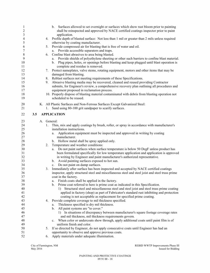
City of Farmington, NM REBID WWTP Improvements Phase III May 2016 Issued for Bidding
PAINTING AND PROTECTIVE COATINGS 09 91 00 - 18
b. Surfaces allowed to set overnight or surfaces which show rust bloom prior to painting 1
shall be reinspected and approved by NACE certified coatings inspector prior to paint 2
application. 3
4. Profile depth of blasted surface: Not less than 1 mil or greater than 2 mils unless required 4
otherwise by coating manufacturer. 5
5. Provide compressed air for blasting that is free of water and oil. 6
a. Provide accessible separators and traps. 7
6. Confine blast abrasives to area being blasted. 8
a. Provide shields of polyethylene sheeting or other such barriers to confine blast material. 9
b. Plug pipes, holes, or openings before blasting and keep plugged until blast operation is 10
complete and residue is removed. 11
7. Protect nameplates, valve stems, rotating equipment, motors and other items that may be 12
damaged from blasting. 13
8. Reblast surfaces not meeting requirements of these Specifications. 14
9. Abrasive blasting media may be recovered, cleaned and reused providing Contractor 15
submits, for Engineer's review, a comprehensive recovery plan outlining all procedures and 16
equipment proposed in reclamation process. 17
10. Properly dispose of blasting material contaminated with debris from blasting operation not 18
scheduled to be reused. 19
K. All Plastic Surfaces and Non-Ferrous Surfaces Except Galvanized Steel: 20
1. Sand using 80-100 grit sandpaper to scarify surfaces. 21
3.5 APPLICATION 22
A. General: 23
1. Thin, mix and apply coatings by brush, roller, or spray in accordance with manufacturer's 24
installation instructions. 25
a. Application equipment must be inspected and approved in writing by coating 26
manufacturer. 27
b. Hollow metal shall be spray applied only. 28
2. Temperature and weather conditions: 29
a. Do not paint surfaces when surface temperature is below 50 DegF unless product has 30
been formulated specifically for low temperature application and application is approved 31
in writing by Engineer and paint manufacturer's authorized representative. 32
b. Avoid painting surfaces exposed to hot sun. 33
c. Do not paint on damp surfaces. 34
3. Immediately after surface has been inspected and accepted by NACE certified coatings 35
inspector, apply structural steel and miscellaneous steel and steel joist and steel truss prime 36
coat in the factory. 37
a. Finish coats shall be applied in the factory. 38
b. Prime coat referred to here is prime coat as indicated in this Specification. 39
1) Structural steel and miscellaneous steel and steel joist and steel truss prime coating 40
applied in factory (shop) as part of Fabricator's standard rust inhibiting and protection 41
coating is not acceptable as replacement for specified prime coating. 42
4. Provide complete coverage to mil thickness specified. 43
a. Thickness specified is dry mil thickness. 44
b. All paint systems are "to cover." 45
1) In situations of discrepancy between manufacturer's square footage coverage rates 46
and mil thickness, mil thickness requirements govern. 47
c. When color or undercoats show through, apply additional coats until paint film is of 48
uniform finish and color. 49
5. If so directed by Engineer, do not apply consecutive coats until Engineer has had an 50
opportunity to observe and approve previous coats. 51
6. Apply materials under adequate illumination. 52

City of Farmington, NM REBID WWTP Improvements Phase III May 2016 Issued for Bidding
PAINTING AND PROTECTIVE COATINGS 09 91 00 - 19
7. Evenly spread to provide full, smooth coverage. 1
8. Work each application of material into corners, crevices, joints, and other difficult to work 2
areas. 3
9. Avoid degradation and contamination of blasted surfaces and avoid intercoat contamination. 4
a. Clean contaminated surfaces before applying next coat. 5
10. Smooth out runs or sags immediately, or remove and recoat entire surface. 6
11. Allow preceding coats to dry before recoating. 7
a. Recoat within time limits specified by coating manufacturer. 8
b. If recoat time limits have expired re-prepare surface in accordance with coating 9
manufacturer's printed recommendations. 10
12. Allow coated surfaces to cure prior to allowing traffic or other work to proceed. 11
13. Coat all aluminum in contact with dissimilar materials. 12
14. When coating rough surfaces which cannot be backrolled sufficiently, hand brush coating to 13
work into all recesses. 14
15. Backroll concrete and masonry surfaces with a roller if paint coatings are spray applied. 15
B. Prime Coat Application: 16
1. Prime all surfaces indicated to be painted. 17
a. Apply prime coat in accordance with coating manufacturer's written instructions and as 18
written in this Specification Section. 19
2. Ensure field-applied coatings are compatible with factory-applied coatings. 20
a. Ensure new coatings applied over existing coatings are compatible. 21
b. Employ services of coating manufacturer's qualified technical representative. 22
1) Certify through material data sheets. 23
2) Perform test patch. 24
c. If field-applied coating is found to be not compatible, require the coating 25
manufacturer's technical representative to recommend, in writing, product to be used as 26
barrier coat, thickness to be applied, surface preparation and method of application. 27
d. At Contractor's option, coatings may be removed, surface re-prepared, and new coating 28
applied using appropriate paint system listed in the MATERIALS Article, Paint Systems 29
paragraph of this Specification Section. 30
1) All damage to surface as result of coating removal shall be repaired to original 31
condition or better by Contractor at no additional cost to Owner. 32
3. Prime ferrous metals embedded in concrete to minimum of 1 IN below exposed surfaces. 33
4. Back prime all wood scheduled to be painted, prior to installation. 34
5. After application of primer to gypsum board surfaces, inspect surface and repair in 35
accordance with the PREPARATION Article of this Specification Section. 36
a. Re-prime repaired surfaces to uniform finish before application of finish coat(s). 37
6. Apply zinc-rich primers while under continuous agitation. 38
7. Ensure abrasive blasting operation does not result in embedment of abrasive particles in 39
paint film. 40
8. Brush or spray bolts, welds, edges and difficult access areas with primer prior to primer 41
application over entire surface. 42
9. Touch up damaged primer coats prior to applying finish coats. 43
a. Restore primed surface equal to surface before damage. 44
10. All surfaces of steel lintels and steel components of concrete lintels used in wall 45
construction shall be completely painted with both prime and finish coats prior to placing in 46
wall. 47
C. Finish Coat Application: 48
1. Apply finish coats in accordance with coating manufacturer's written instructions and in 49
accordance with this Specification Section; manufacturer instructions take precedent over 50
these Specifications. 51
2. Touch up damaged finish coats using same application method and same material specified 52
for finish coat. 53

City of Farmington, NM REBID WWTP Improvements Phase III May 2016 Issued for Bidding
PAINTING AND PROTECTIVE COATINGS 09 91 00 - 20
a. Prepare damaged area in accordance with the PREPARATION Article of this 1
Specification Section. 2
3.6 COLOR CODING 3
A. Color and band piping in accordance with the SCHEDULE Article of this Specification Section. 4
1. Band piping using maximum of three (3) different colors at 20 FT maximum centers. 5
2. Factory painted piping shall be color banded in the factory per the Schedule in the 6
SCHEDULE Article of this Specification Section. 7
3. Place bands: 8
a. Along continuous lines. 9
b. At changes in direction. 10
c. At changes of elevation. 11
d. On both sides of an obstruction (e.g., wall, ceiling) that painted item passes through. 12
4. Band width for individual colors (pipe diameter measured to outside of insulation, if 13
applicable): 14
a. Piping up to 8 IN DIA: 2 IN minimum. 15
b. Piping greater than 8 IN up to 24 IN DIA: 4 IN minimum. 16
c. Piping greater than 24 IN up to 48 IN DIA: 6 IN minimum. 17
d. Piping greater than 48 IN DIA: 8 IN minimum. 18
3.7 FIELD QUALITY CONTROL 19
A. Contractor to provide protection for surfaces painted with epoxy coatings to prevent chalking. 20
1. Surfaces showing chalking will not be accepted regardless of condition of paint film. 21
B. Maintain Daily Records: 22
1. Record the following information during application of each coat of paint applied: 23
a. Date, starting time, end time, and all breaks taken by painters. 24
b. For exterior painting: 25
1) Sky condition. 26
2) Wind speed and direction. 27
c. Air temperature. 28
d. Relative humidity. 29
e. Moisture content and surface temperature of substrate prior to each coat. 30
f. Provisions utilized to maintain work area within manufacturer's recommended 31
application parameters including temporary heating, ventilation, cooling, 32
dehumidification and provisions utilized to mitigate wind blown dust and debris from 33
contaminating the wet paint film. 34
g. Record environmental conditions, substrate moisture content and surface temperature 35
information not less than once every four (4) hours during application. 36
1) Record hourly when temperatures are below 50 DegF or above 100 DegF. 37
2. Record the following information daily for the paint manufacturer's recommended curing 38
period: 39
a. Date and start time of cure period for each item or area. 40
b. For exterior painting: 41
1) Sky conditions. 42
2) Wind speed and direction. 43
c. Record environmental conditions not less than once every 12 hours. 44
1) Record once every four (4) hours when ambient temperature is below 35 DegF. 45
d. Provisions utilized to protect each item or area and to maintain areas within 46
manufacturer's recommended curing parameters. 47
3. Format for daily record to be computer generated. 48
C. Measure wet coating with wet film thickness gages. 49
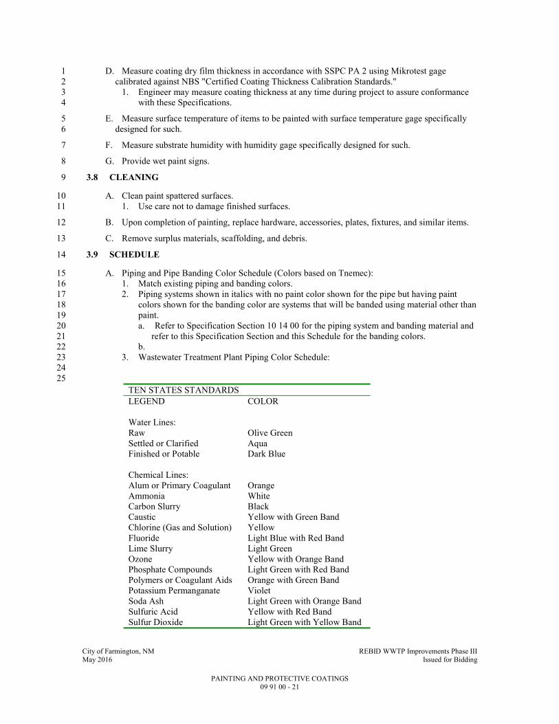
City of Farmington, NM REBID WWTP Improvements Phase III May 2016 Issued for Bidding
PAINTING AND PROTECTIVE COATINGS 09 91 00 - 21
D. Measure coating dry film thickness in accordance with SSPC PA 2 using Mikrotest gage 1
calibrated against NBS "Certified Coating Thickness Calibration Standards." 2
1. Engineer may measure coating thickness at any time during project to assure conformance 3
with these Specifications. 4
E. Measure surface temperature of items to be painted with surface temperature gage specifically 5
designed for such. 6
F. Measure substrate humidity with humidity gage specifically designed for such. 7
G. Provide wet paint signs. 8
3.8 CLEANING 9
A. Clean paint spattered surfaces. 10
1. Use care not to damage finished surfaces. 11
B. Upon completion of painting, replace hardware, accessories, plates, fixtures, and similar items. 12
C. Remove surplus materials, scaffolding, and debris. 13
3.9 SCHEDULE 14
A. Piping and Pipe Banding Color Schedule (Colors based on Tnemec): 15
1. Match existing piping and banding colors. 16
2. Piping systems shown in italics with no paint color shown for the pipe but having paint 17
colors shown for the banding color are systems that will be banded using material other than 18
paint. 19
a. Refer to Specification Section 10 14 00 for the piping system and banding material and 20
refer to this Specification Section and this Schedule for the banding colors. 21
b. 22
3. Wastewater Treatment Plant Piping Color Schedule: 23
24
25
TEN STATES STANDARDS
LEGEND COLOR
Water Lines:
Raw Olive Green
Settled or Clarified Aqua
Finished or Potable Dark Blue
Chemical Lines:
Alum or Primary Coagulant Orange
Ammonia White
Carbon Slurry Black
Caustic Yellow with Green Band
Chlorine (Gas and Solution) Yellow
Fluoride Light Blue with Red Band
Lime Slurry Light Green
Ozone Yellow with Orange Band
Phosphate Compounds Light Green with Red Band
Polymers or Coagulant Aids Orange with Green Band
Potassium Permanganate Violet
Soda Ash Light Green with Orange Band
Sulfuric Acid Yellow with Red Band
Sulfur Dioxide Light Green with Yellow Band

City of Farmington, NM REBID WWTP Improvements Phase III May 2016 Issued for Bidding
PAINTING AND PROTECTIVE COATINGS 09 91 00 - 22
Waste Lines:
Backwash Waste Light Brown
Sludge Dark Brown
Sewer (Sanitary or Other) Dark Gray
Other:
Compressed Air Dark Green
Gas Red
Other Lines Light Gray
SERVICE PIPE COLOR BANDING COLOR
Wastewater Piping:
Plant Influent 32GR-Gray 35GR-Black
Settled Primary 32GR-Gray YB24-Brown
Settled Final 32GR-Gray 07SF-Red
Final Effluent 32GR-Gray 05SF/YB24-International
Orange/Brown
Plumbing drains 32GR-Gray 11SF-Safety Blue
Supernatant 32GR-Gray 08SF-Safety Green filtrate
or centrate
Sump 32GR-Gray 11WH-White
Sludge Piping:
Raw (Primary) YB24-Brown 35GR-Black
Waste activated YB24-Brown 32GR/35GR-Gray/Black
Recirculated YB24-Brown 32GR/07SF-Gray/Red
waste activated
Thickened waste activated YB24-Brown 07SF/35GR-Red/Black
Thickened raw YB24-Brown 07SF/05SF-
Red/International
Orange
Thickened raw plus waste
activated
YB24-Brown 07SF/11SF-Red/Safety Blue
Digested or processed YB24-Brown 05SF/35GR-International
Orange/Black
Dewatered YB24-Brown 11SF/35GR-Safety
Blue/Black
Miscellaneous Sludge Piping:
Grease YB23-Dk. Brown 35GR-Black
Scum YB23-Dk. Brown 32GR-Gray
Grit YB23-Dk. Brown 07SF-Red
Water Piping:
Potable 25BL-Blue ---
Fire 06SF-Safety Red ---
Service 08SF-Safety Green 35GR-Black
Nonpotable 08SF-Safety Green 32GR-Gray
Make-up 08SF-Safety Green YB24-Brown
Thickener 08SF-Safety Green 07SF-Red
Potable Water Hot 08SF-Safety Green 05SF-InternationalOrange
Cooling 08SF-Safety Green 11SF-Safety Blue
Sampling 08SF-Safety Green 02SF-Safety Yellow
Condensate 08SF-Safety Green 35GR/32GR-Black/Gray
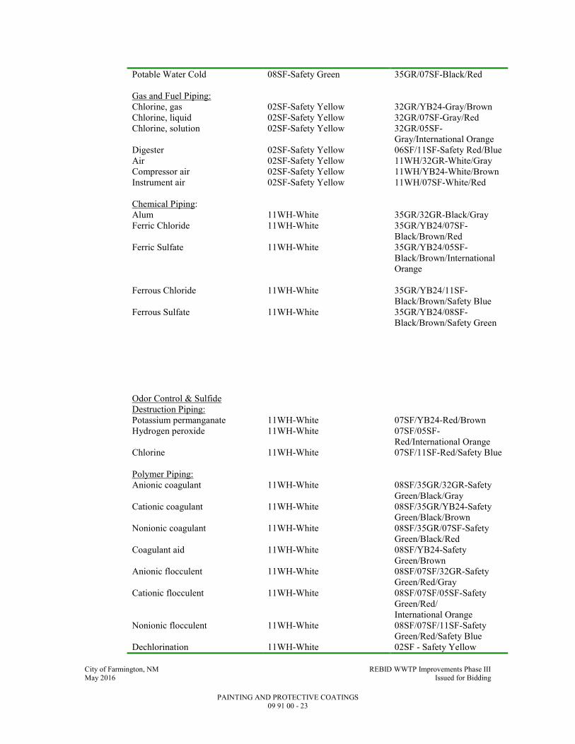
City of Farmington, NM REBID WWTP Improvements Phase III May 2016 Issued for Bidding
PAINTING AND PROTECTIVE COATINGS 09 91 00 - 23
Potable Water Cold 08SF-Safety Green 35GR/07SF-Black/Red
Gas and Fuel Piping:
Chlorine, gas 02SF-Safety Yellow 32GR/YB24-Gray/Brown
Chlorine, liquid 02SF-Safety Yellow 32GR/07SF-Gray/Red
Chlorine, solution 02SF-Safety Yellow 32GR/05SF-
Gray/International Orange
Digester 02SF-Safety Yellow 06SF/11SF-Safety Red/Blue
Air 02SF-Safety Yellow 11WH/32GR-White/Gray
Compressor air 02SF-Safety Yellow 11WH/YB24-White/Brown
Instrument air 02SF-Safety Yellow 11WH/07SF-White/Red
Chemical Piping:
Alum 11WH-White 35GR/32GR-Black/Gray
Ferric Chloride 11WH-White 35GR/YB24/07SF-
Black/Brown/Red
Ferric Sulfate 11WH-White 35GR/YB24/05SF-
Black/Brown/International
Orange
Ferrous Chloride 11WH-White 35GR/YB24/11SF-
Black/Brown/Safety Blue
Ferrous Sulfate 11WH-White 35GR/YB24/08SF-
Black/Brown/Safety Green
Odor Control & Sulfide
Destruction Piping:
Potassium permanganate 11WH-White 07SF/YB24-Red/Brown
Hydrogen peroxide 11WH-White 07SF/05SF-
Red/International Orange
Chlorine 11WH-White 07SF/11SF-Red/Safety Blue
Polymer Piping:
Anionic coagulant 11WH-White 08SF/35GR/32GR-Safety
Green/Black/Gray
Cationic coagulant 11WH-White 08SF/35GR/YB24-Safety
Green/Black/Brown
Nonionic coagulant 11WH-White 08SF/35GR/07SF-Safety
Green/Black/Red
Coagulant aid 11WH-White 08SF/YB24-Safety
Green/Brown
Anionic flocculent 11WH-White 08SF/07SF/32GR-Safety
Green/Red/Gray
Cationic flocculent 11WH-White 08SF/07SF/05SF-Safety
Green/Red/
International Orange
Nonionic flocculent 11WH-White 08SF/07SF/11SF-Safety
Green/Red/Safety Blue
Dechlorination 11WH-White 02SF - Safety Yellow

City of Farmington, NM REBID WWTP Improvements Phase III May 2016 Issued for Bidding
PAINTING AND PROTECTIVE COATINGS 09 91 00 - 24
Dual Purpose Piping: Aluminum-GR04 Lt. Gray Colors of Pipe color above.
1
END OF SECTION 2

City of Farmington, NM REBID WWTP Improvements Phase III May 2016 Issued for Bidding
IDENTIFICATION DEVICES 10 14 00 - 1
SECTION 10 14 00 1
IDENTIFICATION DEVICES 2
PART 1 - GENERAL 3
1.1 SUMMARY 4
A. Section Includes: 5
1. Tag, tape and stenciling systems for equipment, piping, valves, pumps, ductwork and 6
similar items, and hazard and safety signs. 7
B. Related Specification Sections include but are not necessarily limited to: 8
1. Division 00 - Bidding Requirements, Contract Forms, and Conditions of the Contract. 9
2. Division 01 - General Requirements. 10
1.2 QUALITY ASSURANCE 11
A. Referenced Standards: 12
1. American Society of Mechanical Engineers (ASME): 13
a. A13.1, Scheme for the Identification of Piping Systems. 14
2. Instrumentation, Systems, and Automation Society (ISA). 15
3. National Electrical Manufacturers Association/American National Standards Institute 16
(NEMA/ANSI): 17
a. Z535.1, Safety Color Code. 18
b. Z535.2, Environmental and Facility Safety Signs. 19
c. Z535.3, Criteria for Safety Symbols. 20
d. Z535.4, Product Safety Signs and Labels. 21
4. National Fire Protection Association (NFPA): 22
a. 70, National Electrical Code (NEC). 23
5. Occupational Safety and Health Administration (OSHA): 24
a. 29 CFR 1910.145, Specification for Accident Prevention Signs and Tags. 25
1.3 SUBMITTALS 26
A. Shop Drawings: 27
1. See Specification Section 01 33 00 for requirements for the mechanics and administration of 28
the submittal process. 29
2. Product technical data including: 30
a. Catalog information for all identification systems. 31
b. Acknowledgement that products submitted meet requirements of standards referenced. 32
3. Identification register, listing all items in PART 3 of this Specification Section to be 33
identified, type of identification system to be used, lettering, location and color. 34
PART 2 - PRODUCTS 35
2.1 ACCEPTABLE MANUFACTURERS 36
A. Subject to compliance with the Contract Documents, the following manufacturers are 37
acceptable: 38
1. W.H. Brady Co. 39
2. Panduit. 40
3. Seton. 41
4. National Band and Tag Co. 42
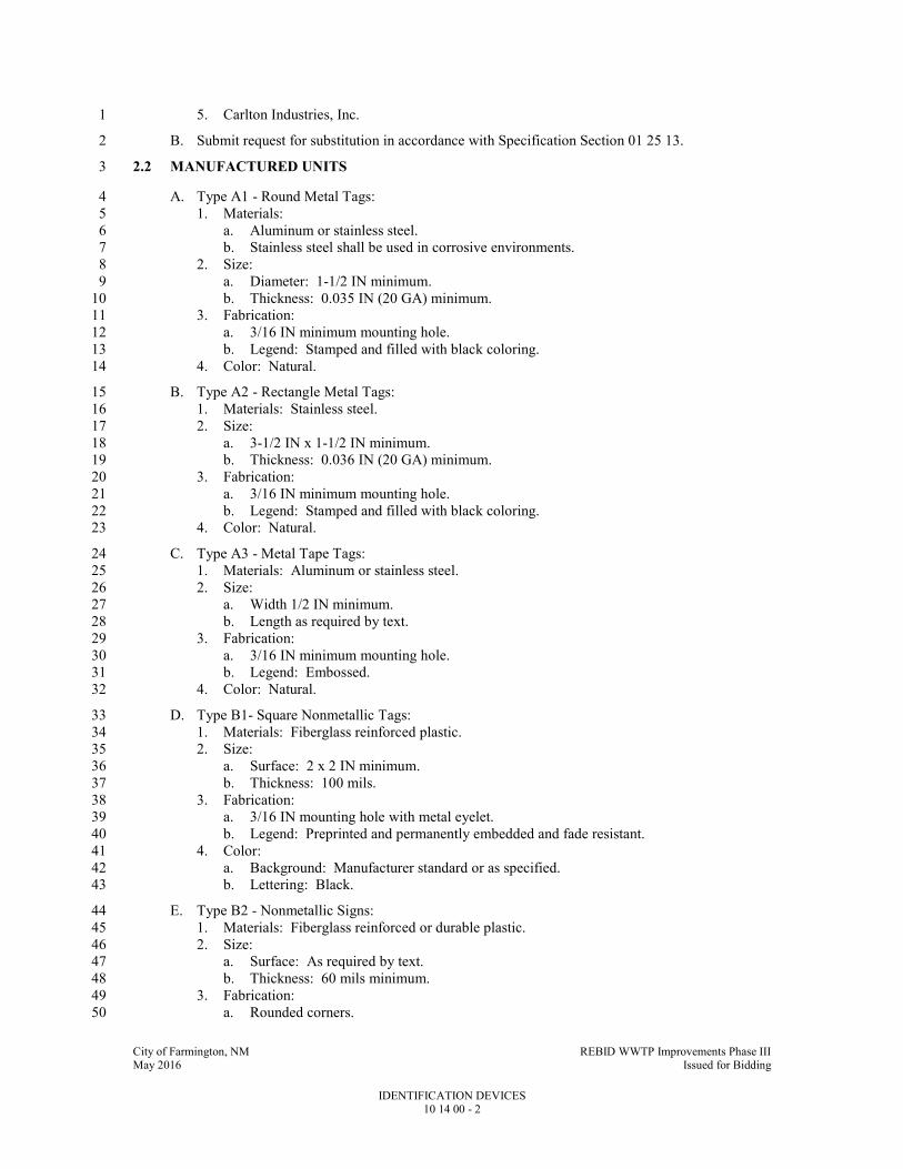
City of Farmington, NM REBID WWTP Improvements Phase III May 2016 Issued for Bidding
IDENTIFICATION DEVICES 10 14 00 - 2
5. Carlton Industries, Inc. 1
B. Submit request for substitution in accordance with Specification Section 01 25 13. 2
2.2 MANUFACTURED UNITS 3
A. Type A1 - Round Metal Tags: 4
1. Materials: 5
a. Aluminum or stainless steel. 6
b. Stainless steel shall be used in corrosive environments. 7
2. Size: 8
a. Diameter: 1-1/2 IN minimum. 9
b. Thickness: 0.035 IN (20 GA) minimum. 10
3. Fabrication: 11
a. 3/16 IN minimum mounting hole. 12
b. Legend: Stamped and filled with black coloring. 13
4. Color: Natural. 14
B. Type A2 - Rectangle Metal Tags: 15
1. Materials: Stainless steel. 16
2. Size: 17
a. 3-1/2 IN x 1-1/2 IN minimum. 18
b. Thickness: 0.036 IN (20 GA) minimum. 19
3. Fabrication: 20
a. 3/16 IN minimum mounting hole. 21
b. Legend: Stamped and filled with black coloring. 22
4. Color: Natural. 23
C. Type A3 - Metal Tape Tags: 24
1. Materials: Aluminum or stainless steel. 25
2. Size: 26
a. Width 1/2 IN minimum. 27
b. Length as required by text. 28
3. Fabrication: 29
a. 3/16 IN minimum mounting hole. 30
b. Legend: Embossed. 31
4. Color: Natural. 32
D. Type B1- Square Nonmetallic Tags: 33
1. Materials: Fiberglass reinforced plastic. 34
2. Size: 35
a. Surface: 2 x 2 IN minimum. 36
b. Thickness: 100 mils. 37
3. Fabrication: 38
a. 3/16 IN mounting hole with metal eyelet. 39
b. Legend: Preprinted and permanently embedded and fade resistant. 40
4. Color: 41
a. Background: Manufacturer standard or as specified. 42
b. Lettering: Black. 43
E. Type B2 - Nonmetallic Signs: 44
1. Materials: Fiberglass reinforced or durable plastic. 45
2. Size: 46
a. Surface: As required by text. 47
b. Thickness: 60 mils minimum. 48
3. Fabrication: 49
a. Rounded corners. 50
City of Farmington, NM REBID WWTP Improvements Phase III May 2016 Issued for Bidding
IDENTIFICATION DEVICES 10 14 00 - 3
b. Drilled holes in corners with grommets. 1
c. Legend: Preprinted, permanently embedded and fade resistant for a 10 year minimum 2
outdoor durability. 3
4. Color: 4
a. Background: Manufacturer standard or as specified. 5
b. Lettering: Black. 6
5. Standards for OSHA signs: NEMA/ANSI Z535.1, NEMA/ANSI Z535.2, NEMA/ANSI 7
Z535.3, NEMA/ANSI Z535.4, OSHA 29 CFR 1910.145. 8
F. Type C - Laminated Name Plates: 9
1. Materials: Phenolic or DR (high impact) acrylic. 10
2. Size: 11
a. Surface: As required by text. 12
b. Thickness: 1/16 IN. 13
3. Fabrication: 14
a. Outdoor rated and UV resistant when installed outdoors. 15
b. Two (2) layers laminated. 16
c. Legend: Engraved through top lamination into bottom lamination. 17
d. Two (2) drilled side holes, for screw mounting. 18
4. Color: Black top surface, white core, unless otherwise indicated. 19
G. Type D - Self-Adhesive Tape Tags and Signs: 20
1. Materials: Vinyl tape or vinyl cloth. 21
2. Size: 22
a. Surface: As required by text. 23
b. Thickness: 5 mils minimum. 24
3. Fabrication: 25
a. Indoor/Outdoor grade. 26
b. Weather and UV resistant inks. 27
c. Permanent adhesive. 28
d. Legend: Preprinted. 29
e. Wire markers to be self-laminating. 30
4. Color: White with black lettering or as specified. 31
5. Standards for OSHA signs: NEMA/ANSI Z535.1, NEMA/ANSI Z535.2, NEMA/ANSI 32
Z535.3, NEMA/ANSI Z535.4, OSHA 29 CFR 1910.145. 33
H. Type E - Heat Shrinkable Tape Tags: 34
1. Materials: Polyolefin. 35
2. Size: As required by text. 36
3. Fabrication: 37
a. Legend: Preprinted. 38
4. Color: White background, black printing. 39
I. Type F - Underground Warning Tape: 40
1. Materials: Polyethylene. 41
2. Size: 42
a. 6 IN wide (minimum). 43
b. Thickness: 3.5 mils. 44
3. Fabrication: 45
a. Legend: Preprinted and permanently imbedded. 46
b. Message continuous printed. 47
c. Tensile strength: 1750 psi. 48
4. Color: As specified. 49
J. Type G - Stenciling System: 50
1. Materials: 51

City of Farmington, NM REBID WWTP Improvements Phase III May 2016 Issued for Bidding
IDENTIFICATION DEVICES 10 14 00 - 4
a. Exterior type stenciling enamel. 1
b. Either brushing grade or pressurized spray can form and grade. 2
2. Size: As required. 3
3. Fabrication: 4
a. Legend: As required. 5
4. Color: Black or white for best contrast. 6
K. Underground Tracer Wire: 7
1. Materials: 8
a. Wire: 9
1) 12 GA AWG. 10
2) Solid. 11
b. Wire nuts: Waterproof type. 12
c. Split bolts: Brass. 13
2.3 ACCESSORIES 14
A. Fasteners: 15
1. Bead chain: #6 brass, aluminum or stainless steel. 16
2. Plastic strap: Nylon, urethane or polypropylene. 17
3. Screws: Self-tapping, stainless steel. 18
4. Adhesive, solvent activated. 19
2.4 MAINTENANCE MATERIALS 20
A. Where stenciled markers are provided, clean and retain stencils after completion and include in 21
extra stock, along with required stock of paints and applicators. 22
PART 3 - EXECUTION 23
3.1 GENERAL INSTALLATION 24
A. Install identification devices at specified locations. 25
B. All identification devices to be printed by mechanical process, hand printing is not acceptable. 26
C. Attach tags to equipment with sufficient surface or body area with solvent activated adhesive 27
applied to back of each tag. 28
D. Attach tags with 1/8 IN round or flat head screws to equipment without sufficient surface or 29
body area, or porous surfaces. 30
1. Where attachment with screws should not or cannot penetrate substrate, attach with plastic 31
strap. 32
E. Single items of equipment enclosed in a housing or compartment to be tagged on outside of 33
housing. 34
1. Several items of equipment mounted in housing to be individually tagged inside the 35
compartment. 36
F. Tracer Wire: 37
1. Attach to pipe at a maximum of 10 FT intervals with tape or tie-wraps. 38
2. Continuous pass from each valve box and above grade at each structure. 39
3. Coil enough wire at each valve box to extend wire a foot above the ground surface. 40
4. 1,000 FT maximum spacing between valve boxes. 41
5. If split bolts are used for splicing, wrap with electrical tape. 42
6. If wire nuts are used for splicing, knot wire at each splice point leaving 6 IN of wire for 43
splicing. 44
7. Use continuous strand of wire between valve box where possible. 45

City of Farmington, NM REBID WWTP Improvements Phase III May 2016 Issued for Bidding
IDENTIFICATION DEVICES 10 14 00 - 5
a. Continuous length shall be no shorter than 100 FT. 1
3.2 SCHEDULES 2
A. Process Systems: 3
1. General: 4
a. Provide arrows and markers on piping. 5
1) At 20 FT maximum centers along continuous lines. 6
2) At changes in direction (route) or obstructions. 7
3) At valves, risers, "T" joints, machinery or equipment. 8
4) Where pipes pass through floors, walls, ceilings, cladding assemblies and like 9
obstructions provide markers on both sides. 10
b. Position markers on both sides of pipe with arrow markers pointing in flow direction. 11
1) If flow is in both directions use double headed arrow markers. 12
c. Apply tapes and stenciling in uniform manner parallel to piping. 13
2. Trenches with piping: 14
a. Tag type: Type F - Underground Warning Tape 15
b. Location: Halfway between top of piping and finished grade. 16
c. Letter height: 1-1/4 IN minimum. 17
d. Natural gas or digester gas: 18
1) Color: Yellow with black letters. 19
2) Legend: 20
a) First line: “CAUTION CAUTION CAUTION” 21
b) Second line: “BURIED GAS LINE BELOW” 22
e. Potable water: 23
1) Color: Blue with black letters. 24
2) Legend: 25
a) First line: “CAUTION CAUTION CAUTION” 26
b) Second line: “BURIED WATER LINE BELOW” 27
f. Storm and sanitary sewer lines: 28
1) Color: Green with black letters. 29
2) Legend: 30
a) First line: “CAUTION CAUTION CAUTION” 31
b) Second line: “BURIED SEWER LINE BELOW” 32
g. (Nonpotable) water piping, except 3 IN and smaller irrigation pipe: 33
1) Color: Green with black letters. 34
2) Legend: 35
a) First line: “CAUTION CAUTION CAUTION” 36
b) Second line: “BURIED NONPOTABLE WATER LINE BELOW” 37
h. Chemical feed piping (e.g., chlorine solution, polymer solution, caustic solution, etc.): 38
1) Color: Yellow with black letters. 39
2) Legend: 40
a) First line: “CAUTION CAUTION CAUTION” 41
b) Second line: “BURIED CHEMICAL LINE BELOW” 42
i. Other piping (e.g., compressed air, irrigation, refrigerant, heating water, etc.): 43
1) Color: Yellow with black letters. 44
2) Legend: 45
a) First line: “CAUTION CAUTION CAUTION” 46
b) Second line: “BURIED PIPE LINE BELOW” 47
3. Yard valves, buried, with valve box and concrete pad: 48
a. Tag type: Type A2 - Rectangle Metal Tags. 49
b. Fastener: 3/16 IN x 7/8 IN plastic screw anchor with 1 IN #6 stainless steel pan head 50
screw. 51
c. Legend: 52
1) Letter height: 1/4 IN minimum. 53
City of Farmington, NM REBID WWTP Improvements Phase III May 2016 Issued for Bidding
IDENTIFICATION DEVICES 10 14 00 - 6
2) Valve designation as indicated on the Drawings (e.g., “V-xxx”). 1
4. Valves and slide gates: 2
a. Tag type: 3
1) Outdoor locations: Type B1 - Square Nonmetallic Tags. 4
2) Indoor noncorrosive: 5
a) Type A1 - Round Metal Tags. 6
b) Type B1 - Square Nonmetallic Tags. 7
3) Indoor corrosive: 8
a) Stainless steel Type A1 - Round Metal Tags. 9
b) Type B1 - Square Nonmetallic Tags. 10
b. Fastener: 11
1) Type A1: Chain of the same material. 12
2) Type B1: Stainless steel chain. 13
c. Color: Per ASME A13.1 corresponding to the piping system. 14
d. Legend: 15
1) Letter height: 1/4 IN minimum. 16
2) Valve designation as indicated on the Drawings (e.g., “V-xxx”). 17
5. Process equipment (e.g., pumps, pump motors, blowers, air compressors, bar screens, 18
clarifier drive mechanism, etc.): 19
a. Tag type: 20
1) Type B2 - Nonmetallic Signs. 21
2) Type D - Self-Adhesive Tape Tags and Signs. 22
3) Type G - Stenciling System. 23
b. Fastener: 24
1) Self. 25
2) Screws. 26
3) Adhesive. 27
c. Legend: 28
1) Letter height: 1/2 IN minimum. 29
2) Equipment designation as indicated on the Drawings (e.g., “Primary Sludge Pump 30
P-xxx”). 31
6. Piping systems: 32
a. Tag type: 33
1) Outdoor locations: Type G - Stenciling System. 34
2) Indoor locations: 35
a) Type D - Self-Adhesive Tape Tags and Signs. 36
b) Type G - Stenciling System. 37
b. Fastener: Self. 38
c. Color: Per ASME A13.1. 39
d. Legend: 40
1) Letter height: Manufacturers standard for the pipe diameter. 41
2) Mark piping in accordance with ASME A13.1. 42
3) Use piping designation as indicated on the Drawings. 43
4) Arrow: Single arrow. 44
7. Process tanks (over 1000 GAL) and basins, (e.g., chemical storage, clarifiers, trickling 45
filters, digesters, etc): 46
a. Tag type: 47
1) Type B2 - Nonmetallic Signs. 48
2) Type G - Stenciling System. 49
b. Fastener: 50
1) Screw. 51
2) Self. 52
c. Location as directed by Owner. 53
d. Legend: 54

City of Farmington, NM REBID WWTP Improvements Phase III May 2016 Issued for Bidding
IDENTIFICATION DEVICES 10 14 00 - 7
1) Letter height: 4 IN minimum. 1
2) Equipment designation as indicated on the Drawings (e.g., “Clarifier CL-xxx”). 2
8. Tanks (less than 1000 GAL) (e.g., break tanks, chemical tanks, hydro-pneumatic tanks, air 3
receivers, etc.): 4
a. Tag type: 5
1) Type D - Self-Adhesive Tape Tags and Signs. 6
2) Type G - Stenciling System. 7
b. Fastener: Self. 8
c. Legend: 9
1) Letter height: 2 IN minimum. 10
2) Equipment designation as indicated on the Drawings (e.g., “Polymer Storage Tank 11
Txxx”) 12
9. Equipment that starts automatically: 13
a. Tag type: 14
1) Type B2 - Nonmetallic Signs. 15
2) Type D - Self-Adhesive Tape Tags and Signs. 16
b. Fastener: 17
1) Type B2 - Screw or adhesive. 18
2) Type D - Self. 19
c. Size: 5 IN x 7 IN 20
d. Location as directed by the Owner. 21
e. Legend: 22
1) OSHA Warning Sign. 23
2) Description of Warning: “THIS MACHINE STARTS AUTOMATICALLY”. 24
B. Instrumentation Systems: 25
1. Instrumentation Equipment (e.g., flow control valves, primary elements, etc.): 26
a. Tag type: 27
1) Outdoor locations: Type B1 - Square Nonmetallic Tags. 28
2) Indoor noncorrosive: 29
a) Type A1 - Round Metal Tags. 30
b) Type B1 - Square Nonmetallic Tags. 31
3) Indoor corrosive: 32
a) Stainless steel Type A1 - Round Metal Tags. 33
b) Type B1 - Square Nonmetallic Tags. 34
b. Fastener: 35
1) Type A1: Chain of the same material. 36
2) Type B1: Stainless steel chain. 37
c. Legend: 38
1) Letter height: 1/4 IN minimum. 39
2) Equipment ISA designation as indicated on the Drawings (e.g., “FIT-xxx”). 40
2. Enclosure for instrumentation and control equipment, (e.g., PLC control panels, etc.): 41
a. Tag type: Type C - Phenolic Name Plates. 42
b. Fastener: Screws. 43
c. Legend: 44
1) Letter height: 1/2 IN minimum. 45
2) Equipment name (e.g., "PLC CONTROL PANEL PCP-xxx"). 46
3. Components inside equipment enclosure, (e.g., PLC’s, control relays, contactors, and 47
timers): 48
a. Tag type: Type D - Self-Adhesive Tape Tags. 49
b. Fastener: Self. 50
c. Legend: 51
1) Letter height: 3/16 IN minimum. 52
2) Description or function of component (e.g., "PLC-xxx” or “CR-xxx"). 53
City of Farmington, NM REBID WWTP Improvements Phase III May 2016 Issued for Bidding
IDENTIFICATION DEVICES 10 14 00 - 8
4. Through enclosure door mounted components (e.g., selector switches, controller digital 1
displays, etc.): 2
a. Tag type: Type C - Phenolic Name Plates. 3
b. Fastener: Screws. 4
c. Legend: 5
1) Letter height: 1/4 IN minimum. 6
2) Component ISA tag number as indicated on the Drawings (e.g., “HS-xxx”). 7
C. HVAC Systems: 8
1. General: 9
a. Provide arrows and markers on ducts. 10
1) At 20 FT maximum centers along continuous lines. 11
2) At changes in direction (route) or obstructions. 12
3) At dampers, risers, branches, machinery or equipment. 13
4) Where ducts pass through floors, walls, ceilings, cladding assemblies and like 14
obstructions provide markers on both sides. 15
b. Position markers on both sides of duct with arrow markers pointing in flow direction. 16
1) If flow is in both directions use double headed arrow markers. 17
c. Apply tapes and stenciling in uniform manner parallel to ducts. 18
2. HVAC Equipment (e.g., unit heaters, exhaust fans, air handlers, etc.): 19
a. Tag type: 20
1) Type B2 - Nonmetallic Signs. 21
2) Type C - Phenolic Name Plates. 22
b. Fastener: Screws. 23
c. Legend: 24
1) Letter height: 1 IN minimum. 25
2) Equipment designation as indicated on the Drawings (e.g., "EF-xxx"). 26
3. Ductwork: 27
a. Tag type: 28
1) Type D - Self-Adhesive Tape Tags and Signs. 29
2) Type G - Stenciling System. 30
b. Fastener: Self. 31
c. Legend: 32
1) Letter height: 1 IN minimum. 33
2) Description of ductwork, (e.g., “AIR SUPPLY”). 34
3) Arrows: Single arrow. 35
4. Enclosure for instrumentation and control equipment, (e.g., fan control panels, etc.): 36
a. Tag type: Type C - Phenolic Name Plates. 37
b. Fastener: Screws. 38
c. Legend: 39
1) Letter height: 1/2 IN minimum. 40
2) Equipment designation as indicated on the Drawings (e.g., "FAN CONTROL 41
PANEL FCP-xxx"). 42
5. Wall mounted thermostats: 43
a. Tag type: Type D - Self-Adhesive Tape Tags and Signs. 44
b. Fastener: Self. 45
c. Legend: 46
1) Letter height: 3/16 IN minimum. 47
2) Description of equipment controlled (e.g., "UH-xxx" or AHU-xxx"). 48
6. Components inside equipment enclosure, (e.g., controller’s, control relays, contactors, and 49
timers): 50
a. Tag type: Type D - Self-Adhesive Tape Tags and Signs. 51
b. Fastener: Self. 52
c. Legend: 53
1) Letter height: 3/16 IN minimum. 54
City of Farmington, NM REBID WWTP Improvements Phase III May 2016 Issued for Bidding
IDENTIFICATION DEVICES 10 14 00 - 9
2) Description or function of component (e.g., "CR-xxx"). 1
7. Through enclosure door mounted equipment (e.g., selector switches, controller digital 2
displays, etc.): 3
a. Tag type: Type C - Phenolic Name Plates. 4
b. Fastener: Screws. 5
c. Legend: 6
1) Letter height: 1/4 IN minimum. 7
2) Component tag number as indicated on the Drawings or as defined by contractor 8
(e.g., “HS-xxx”). 9
D. Electrical Systems: 10
1. Trenches with ductbanks, direct-buried conduit, or direct-buried wire and cable. 11
a. Tag type: Type F - Underground Warning Tape. 12
b. Letter height: 1-1/4 IN minimum. 13
c. Location: 14
1) Where trench is 12 IN or more below finished grade: In trench 6 IN below 15
finished grade. 16
2) Where trench is less than 12 IN below finished grade: In trench 3 IN below 17
finished grade. 18
d. Electrical power (e.g., low and medium voltage): 19
1) Color: Red with black letters. 20
2) Legend: 21
a) First line: “CAUTION CAUTION CAUTION”. 22
b) Second line: “BURIED ELECTRIC LINE BELOW”. 23
e. Communications (e.g., telephone, instrumentation, LAN, SCADA): 24
1) Color: Orange with black letters. 25
2) Legend: 26
a) First line: “CAUTION CAUTION CAUTION”. 27
b) Second line: “BURIED COMMUNICATION LINE BELOW”. 28
2. Switchgear, switchboards and motor control centers: 29
a. Tag type: Type C - Phenolic Name Plates. 30
b. Fastener: Screws. 31
c. Main equipment legend: 32
1) Letter height: 33
a) First line: 1 IN minimum. 34
b) Subsequent lines: 3/8 IN minimum. 35
2) First line: Equipment name (e.g., "MAIN SWITCHBOARD MSBxxx"). 36
3) Second line: 37
a) Source of power (e.g., "FED FROM MCCxxx LOCATED IN ROOM xxx"). 38
b) Include the building name or number if the source is in another building. 39
4) Third line: System voltage and phase (e.g., “480/277 V, 3PH”). 40
d. Main and feeder device legend: 41
1) Letter height: 3/8 IN minimum. 42
2) Description of load (e.g., “MAIN DISCONNECT”, "PUMP Pxxx" or 43
"PANELBOARD HPxxx"). 44
3. Panelboards and transformers: 45
a. Tag type: Type C - Phenolic Name Plates. 46
b. Fastener: Screws. 47
c. Legend: 48
1) Letter height: 49
a) First line: 3/8 IN minimum. 50
b) Subsequent lines: 3/16 IN minimum. 51
2) First line: Equipment name (e.g., "PANELBOARD LPxxx" or "TRANSFORMER 52
Txxx"). 53

City of Farmington, NM REBID WWTP Improvements Phase III May 2016 Issued for Bidding
IDENTIFICATION DEVICES 10 14 00 - 10
3) Second line (panelboards only): System voltage and phase (e.g., “208/120V, 1
3PH”). 2
4) Third line: 3
a) Source of power (e.g., "FED FROM MCCxxx LOCATED IN ROOM xxx"). 4
b) Include the building name or number if the source is in another building. 5
4. Transfer switches: 6
a. Tag type: Type C - Phenolic Name Plates. 7
b. Fastener: Screws. 8
c. Legend: 9
1) Letter height: 10
a) First line: 3/8 IN minimum. 11
b) Subsequent lines: 3/16 IN minimum. 12
2) First line: Equipment name (e.g., "AUTOMATIC TRANSFER SWITCH 13
ATSxxx"). 14
5. Safety switches, separately mounted circuit breakers and motor starters, VFD’s, etc.: 15
a. Tag type: Type C - Phenolic Name Plates. 16
b. Fastener: Screws. 17
c. Legend: 18
1) Letter height: 1/4 IN minimum. 19
2) First line: Description of load equipment is connected to (e.g., "PUMP Pxxx"). 20
6. Enclosure for instrumentation and control equipment, (e.g., lighting control panels, etc.): 21
a. Tag type: Type C - Phenolic Name Plates. 22
b. Fastener: Screws. 23
c. Legend: 24
1) Letter height: 1/2 IN minimum. 25
2) Equipment name (e.g., "LIGHTING CONTROL PANEL LCPxxx"). 26
7. Components inside equipment enclosures (e.g., circuit breakers, fuses, control power 27
transformers, control relays, contactors, timers, etc.): 28
a. Tag type: Type D - Self-Adhesive Tape Tags and Signs. 29
b. Fastener: Self. 30
c. Legend: 31
1) Letter height: 3/16 IN minimum. 32
2) Description or function of component (e.g., "M-xxx”, “CR-xxx” or “TR-xxx"). 33
8. Through enclosure door mounted equipment (e.g., selector switches, controller digital 34
displays, etc.): 35
a. Tag type: Type C - Phenolic Name Plates. 36
b. Fastener: Screws. 37
c. Legend: 38
1) Letter height: 1/4 IN minimum. 39
2) Component tag number as indicated on the Drawings or as defined by contractor 40
(e.g., “HS-xxx”). 41
9. Conductors in control panels and in pull or junction boxes where multiple circuits exist. 42
a. Tag type: Type D - Self-Adhesive Tape Tags. 43
b. Fastener: Self. 44
c. Tag conductor at both ends. 45
d. Legend: 46
1) Letter height: 1/8 IN minimum. 47
2) Circuit number or wire number as scheduled on the Drawings or as furnished with 48
the equipment. 49
10. Conductors in handholes and manholes. 50
a. Tag type: Type A3 - Metal Tape Tags. 51
b. Fastener: Nylon strap. 52
c. Tag conductor at both ends. 53
d. Legend: 54
City of Farmington, NM REBID WWTP Improvements Phase III May 2016 Issued for Bidding
IDENTIFICATION DEVICES 10 14 00 - 11
1) Letter height: 1/8 IN minimum. 1
2) Circuit number or wire number as scheduled on the Drawings. 2
11. Grounding conductors associated with grounding electrode system in accordance with the 3
following: 4
a. Tag type: Type D - Self-Adhesive Tape Tags. 5
b. Fastener: Self. 6
c. Legend: 7
1) Letter height: 1/8 IN minimum. 8
2) Function of conductor (e.g., "MAIN BONDING JUMPER", "TO GROUND 9
RING", "TO MAIN WATER PIPE"). 10
12. Flash protection for switchboards, panelboards, industrial control panels and motor control 11
centers: 12
a. Tag type: Type D - Self-Adhesive Tape Signs. 13
b. Fastener: Self. 14
c. Legend: Per NFPA 70. 15
13. Entrances to electrical rooms: 16
a. Tag type: Type B2 - Nonmetallic Signs. 17
b. Fastener: Screw or adhesive. 18
c. Size: 5 IN x 7 IN. 19
d. Location: Each door to room. 20
e. Legend: 21
1) OSHA Danger Sign. 22
2) Description of Danger: “HIGH VOLTAGE, AUTHORIZED PERSONNEL 23
ONLY”. 24
14. Equipment where more than one (1) voltage source is present: 25
a. Tag type: 26
1) Type B2 - Nonmetallic Signs. 27
2) Type D - Self-Adhesive Tape Signs. 28
b. Fastener: 29
1) Screw or adhesive. 30
2) Self. 31
c. Size: 1-3/4 IN x 2-1/2 IN. 32
d. Location: Exterior face of enclosure or cubical. 33
e. Legend: 34
1) OSHA Danger Sign. 35
2) Description of Danger: “MULTIPLE VOLTAGE SOURCES”. 36
3.3 HAZARD AND SAFETY SIGNS 37
A. Provide 50 Hazard and Safety Signs: 38
1. Types B2 and D. 39
2. Inscription as directed by Owner. 40
END OF SECTION 41

City of Farmington, NM REBID WWTP Improvements Phase III
May 2016 Issued for Bidding
SIGNAGE
10 14 23 - 1
SECTION 10 14 23 1
SIGNAGE 2
PART 1 - GENERAL 3
1.1 SUMMARY 4
A. Section Includes: 5
1. Room identification signs. 6
2. Other identification signs: 7
a. Fire and/or smoke barrier identification signs. 8
3. Aluminum letters. 9
B. Related Specification Sections include but are not necessarily limited to: 10
1. Division 00 - Bidding Requirements, Contract Forms, and Conditions of the Contract. 11
2. Division 01 - General Requirements. 12
3. Section 10 14 00 - Identification Devices. 13
1.2 QUALITY ASSURANCE 14
A. Referenced Standards: 15
1. Americans with Disabilities Act (ADA): 16
a. Accessibility Guidelines for Buildings and Facilities (ADAAG). 17
2. ASTM International (ASTM): 18
a. B26, Standard Specification for Aluminum-Alloy Sand Castings. 19
3. Building code: 20
a. International Code Council (ICC): 21
1) International Building Code and associated standards, 2009 Edition including all 22
amendments, referred to herein as Building Code. 23
1.3 DEFINITIONS 24
A. Wet and/or Corrosive Areas: For the purposes of this Specification Section, the following rooms 25
or areas are considered wet and/or corrosive: 26
1.4 SUBMITTALS 27
A. Shop Drawings: 28
1. See Specification Section 01 33 00 for requirements for the mechanics and administration of 29
the submittal process. 30
2. Product technical data including: 31
a. Acknowledgement that products submitted meet requirements of standards referenced. 32
b. Manufacturer's installation instructions. 33
c. Color charts for Engineer's color selection. 34
1) Color selection shall be made from manufacturer's complete color line including all 35
premium and special colors. 36
3. Schedule of all signs indicating text and graphics. 37
4. Layout drawings of all signage showing size, letter style, text, border, finish, and installation 38
detail. 39
a. Provide drawings for: 40
1) Room and stair identification signs. 41
2) Fire and/or smoke barrier identification signs. 42
3) Aluminum letters. 43
B. Samples: 44
1. Room and stair identification signs. 45

City of Farmington, NM REBID WWTP Improvements Phase III
May 2016 Issued for Bidding
SIGNAGE
10 14 23 - 2
2. Fire and/or smoke barrier identification signs. 1
3. Aluminum letters. 2
PART 2 - PRODUCTS 3
2.1 ACCEPTABLE MANUFACTURERS 4
A. Subject to compliance with the Contract Documents, the following manufacturers are 5
acceptable: 6
1. Room identification signs: 7
a. Andco. 8
b. ASE - Architectural Signs and Engraving. 9
c. ASI Sign Systems. 10
d. Best Manufacturing Co. 11
e. Mohawk Engraving Co., Inc. 12
f. Nelson-Harkins. 13
g. Southwell. 14
h. The Supersine Co. 15
2. Fire and/or smoke barrier identification signs: 16
a. Brady. 17
b. Panduit. 18
c. Seton. 19
d. Carlton Industries. 20
3. Aluminum letters: 21
a. Andco Industries Corp. 22
b. A R K Ramos Manufacturing Co., Inc. 23
c. ASI Sign Systems. 24
d. Leeds Architectural Letters. 25
e. Metal Arts. 26
f. Metallic Arts. 27
g. The Southwell Co. 28
B. Submit request for substitution in accordance with Specification Section 01 25 13. 29
2.2 MATERIALS 30
A. Room Identification Signs: 31
1. Interior: 32
a. Dry, non-corrosive areas: Melamine plastic suitable for raised lettering and Braille. 33
b. Wet and/or corrosive areas: Aluminum or fiberglass suitable for raised lettering and 34
Braille. 35
2. Exterior: Aluminum or fiberglass suitable for raised lettering and Braille. 36
B. Aluminum Letters: 37
1. Cast aluminum ASTM B26. 38
2. For machine cut letters, provide aluminum of appropriate alloy and hardness. 39
2.3 FABRICATION 40
A. Room Identification Signs: 41
1. General: 42
a. Raised text, border and graphics. 43
1) Minimum 1/32 IN height. 44
2) Provide international graphic symbology for all toilet, locker and shower rooms or 45
combinations thereof, and for unisex toilet rooms and stairs. 46
3) Provide handicap symbol on all signs for rooms meeting handicap requirements. 47

City of Farmington, NM REBID WWTP Improvements Phase III
May 2016 Issued for Bidding
SIGNAGE
10 14 23 - 3
b. Grade 2 Braille. 1
c. Finish: Eggshell. 2
1) Color: To be selected. 3
d. Text: 4
1) Typeface: Sans Serif. 5
2) Size: Minimum 3/4 IN high. 6
e. Text as indicated in the SCHEDULES Article in PART 3 of this Specification Section. 7
f. Exterior signs shall be rated for exterior use. 8
g. All signs shall comply with requirements of ADA. 9
B. Fire and/or Smoke Barrier Identification Signs: 10
1. Self-adhesive tape tags and signs: 11
a. Materials: Vinyl tape or vinyl cloth. 12
b. Size: 13
1) Surface: As required by text. 14
2) Thickness: 5 mils minimum. 15
c. Fabrication: 16
1) Indoor/Outdoor grade. 17
2) Weather and UV resistant inks. 18
3) Permanent adhesive. 19
4) Legend: Preprinted. 20
5) Self-laminating. 21
d. Color: White with black lettering or as specified. 22
2. Stenciling system: 23
a. Materials: 24
1) Exterior type stenciling enamel. 25
2) Either brushing grade or pressurized spray can form and grade. 26
b. Size: As required. 27
c. Fabrication: 28
1) Legend: As required. 29
d. Color: Black or white for best contrast. 30
C. Hazard Communication Signage (OSHA signage): See Specification Section 10 14 00. 31
D. Aluminum Letters: 32
1. General: 33
a. Cast aluminum, machine cut or laser cut aluminum. 34
b. Finish: Baked enamel or Anodized. 35
c. Color: to be selected. 36
d. Mounting: 37
1) 1 IN projected. 38
2) Provide stainless steel mounting studs. 39
e. Text as indicated in the SCHEDULES Article in PART 3 of this Specification Section. 40
2. Letters: 41
a. Style: to be selected. 42
b. Size: Upper case, 8 IN high. 43
c. Depth: 3/8 IN. 44
3. Provide true angles, crisp corners and straight edges with no burrs or pitting in the surface. 45
2.4 MAINTENANCE MATERIALS 46
A. Where stenciled markers are provided, clean and retain stencils after completion and include in 47
extra stock, along with required stock of paints and applicators. 48
City of Farmington, NM REBID WWTP Improvements Phase III
May 2016 Issued for Bidding
SIGNAGE
10 14 23 - 4
PART 3 - EXECUTION 1
3.1 INSTALLATION 2
A. Room Identification Signs: 3
1. Install signs on walls adjacent to the latch side of doors using foam tape for interior signs 4
and stainless steel screws (minimum of two (2)) for exterior signs. 5
a. Stainless steel screws shall be painted to match sign color. 6
2. Where no adjacent wall space is available, mount signs on nearest adjacent wall. 7
a. Mounting of signs shall be such that a person may approach to within 3 IN of sign 8
without encountering any protruding objects or standing in swing of door travel. 9
3. Mount 60 IN above finish floor to centerline of sign. 10
B. Fire and/or Smoke Barrier Identification Signs: 11
1. Provide marking and identification in compliance with Building Code. 12
2. Locate in accessible concealed floor, floor-ceiling, or attic spaces. 13
3. Repeat at intervals not exceeding 15 FT measured horizontally. 14
4. Lettering: Not less than 1/2 IN high. 15
C. Aluminum Letters: 16
1. Install letters where indicated on Drawings. 17
2. Mount to walls with 1 IN projection in accordance with manufacturer's instructions. 18
3.2 SCHEDULES 19
A. Room Identification Signs: See schedule on drawings 20
B. Fire and/or Smoke Barrier Identification Signs: 21
1. FIRE AND/OR SMOKE BARRIER - PROTECT ALL OPENINGS. 22
END OF SECTION 24

City of Farmington, NM REBID WWTP Improvements Phase III May 2016 Issued for Bidding
TOILET AND BATH ACCESSORIES 10 28 13 - 1
SECTION 10 28 13 1
TOILET AND BATH ACCESSORIES 2
PART 1 - GENERAL 3
1.1 SUMMARY 4
A. Section Includes: 5
1. Toilet and bath accessories. 6
B. Related Specification Sections include but are not necessarily limited to: 7
1. Division 00 - Bidding Requirements, Contract Forms, and Conditions of the Contract. 8
2. Division 01 - General Requirements. 9
1.2 QUALITY ASSURANCE 10
A. Referenced Standards: 11
1. Americans with Disabilities Act (ADA): 12
a. Accessibility Guidelines for Buildings and Facilities (ADAAG). 13
2. ASTM International (ASTM): 14
a. A269, Standard Specification for Seamless and Welded Austenitic Stainless Steel 15
Tubing for General Service. 16
b. A480, Standard Specification for General Requirements for Flat-Rolled Stainless and 17
Heat-Resisting Steel Plate, Sheet, and Strip. 18
1.3 SUBMITTALS 19
A. Shop Drawings: 20
1. See Specification Section 01 33 00 for requirements for the mechanics and administration of 21
the submittal process. 22
2. Product technical data including: 23
a. Acknowledgement that products submitted meet requirements of standards referenced. 24
b. Manufacturer's installation instructions. 25
c. Manufacturer's recommendation on fasteners. 26
3. Schedule of items being provided for each room. Reference rooms using room number 27
designated on Drawings. 28
4. Catalog cut sheet of each item proposed. 29
B. Operation and Maintenance Manuals: 30
1. See Specification Section 01 33 04 for requirements for: 31
a. The mechanics and administration of the submittal process. 32
b. The content of Operation and Maintenance Manuals. 33
1.4 DELIVERY, STORAGE, AND HANDLING 34
A. Deliver products in manufacturer's original packaging. 35
B. Store materials in a dry, conditioned location, until ready for installation. 36
PART 2 - PRODUCTS 37
2.1 ACCEPTABLE MANUFACTURERS 38
A. Product numbers scheduled are manufactured by Bobrick. 39

City of Farmington, NM REBID WWTP Improvements Phase III May 2016 Issued for Bidding
TOILET AND BATH ACCESSORIES 10 28 13 - 2
B. Subject to compliance with the Contract Documents, the following manufacturers are 1
acceptable: 2
1. American Specialties, Inc. 3
2. Bobrick. 4
3. Bradley Corp. 5
C. Submit request for substitution in accordance with Specification Section 01 25 13. 6
2.2 MATERIALS 7
A. Toilet Accessories: 8
1. General: ASTM A480, stainless steel. 9
2. Grab bars: ASTM A269, stainless steel. 10
B. Anchoring Devices: 11
1. Stainless steel. 12
2.3 FABRICATION 13
A. Toilet Accessories: 14
1. General: 15
a. Satin finish. 16
b. Items shall meet design requirements of ADA. 17
2. Grab bars: 18
a. Concealed mounting. 19
b. 3 IN DIA flange. 20
c. 1-1/2 IN OD. 21
d. Peened finish on gripping surface. 22
B. Anchoring Devices: 23
1. Designed to withstand minimum concentrated load of 250 LB applied at any point on grab 24
bar. 25
PART 3 - EXECUTION 26
3.1 PREPARATION 27
A. Verify adequate backing has been provided in wall or toilet partition. 28
3.2 INSTALLATION 29
A. Install in accordance with manufacturer's instruction and in accordance with ADA. 30
B. Install in locations indicated on Drawings. 31
C. Mount all items using manufacturer's recommended anchorage devices for the substrate to which 32
the accessory is to be mounted. 33
3.3 SCHEDULE 34
A. See Drawings for locations. 35
B. Model numbers indicated are Bobrick, unless noted otherwise. 36
1. TA-2: Toilet Tissue Dispenser (double non-controlled) - B-2740. 37
2. TA-6: Paper Towel Dispenser - B-262. 38
3. TA-7: Waste Receptacle - B-279. 39
4. TA-8: Liquid Soap Dispenser - B-2112. 40
5. TA-12: Mirror - B-290 x size indicated on Drawings. 41
6. TA-17: Shower curtains - with 204-1 hooks as necessary. 42
7. TA-18: Grab Bar - B-6806.99 x length indicated on Drawings. 43

City of Farmington, NM REBID WWTP Improvements Phase III May 2016 Issued for Bidding
TOILET AND BATH ACCESSORIES 10 28 13 - 3
END OF SECTION 1
City of Farmington, NM REBID WWTP Improvements Phase III May 2016 Issued for Bidding
FIRE EXTINGUISHERS 10 44 33 - 1
SECTION 10 44 33 1
FIRE EXTINGUISHERS 2
PART 1 - GENERAL 3
1.1 SUMMARY 4
A. Section Includes: 5
1. Fire extinguishers. 6
B. Related Specification Sections include but are not necessarily limited to: 7
1. Division 00 - Bidding Requirements, Contract Forms, and Conditions of the Contract. 8
2. Division 01 - General Requirements. 9
3. Section 05 50 00 - Metal Fabrications. 10
1.2 QUALITY ASSURANCE 11
A. Referenced Standards: 12
1. National Fire Protection Association (NFPA): 13
a. 10, Standard for Portable Fire Extinguishers. 14
2. Underwriters Laboratories, Inc. (UL): 15
a. Building Materials Directory. 16
1.3 DEFINITIONS 17
A. Authority Having Jurisdiction (AHJ): Building official, fire chief, fire marshal or other 18
individual having statutory authority. 19
1.4 SUBMITTALS 20
A. Shop Drawings: 21
1. See Specification Section 01 33 00 for requirements for the mechanics and administration of 22
the submittal process. 23
2. Product technical data including: 24
a. Acknowledgement that products submitted meet requirements of standards referenced. 25
b. Manufacturer's installation instructions. 26
B. Operation and Maintenance Manuals: 27
1. See Specification Section 01 33 04 for requirements for: 28
a. The mechanics and administration of the submittal process. 29
b. The content of Operation and Maintenance Manuals. 30
1.5 DELIVERY, STORAGE, AND HANDLING 31
A. Deliver and install filled and charged extinguishers just prior to building occupancy. 32
PART 2 - PRODUCTS 33
2.1 ACCEPTABLE MANUFACTURERS 34
A. Subject to compliance with the Contract Documents, the following manufacturers are 35
acceptable: 36
1. Fire extinguishers: 37
a. Amerex Corporation. 38
b. Ansul Fire Protection. 39

City of Farmington, NM REBID WWTP Improvements Phase III May 2016 Issued for Bidding
FIRE EXTINGUISHERS 10 44 33 - 2
c. Walter Kidde. 1
d. Potter - Roemer Inc. 2
2. Fire extinguisher signs: 3
a. Seton. 4
B. Submit request for substitution in accordance with Specification Section 01 25 13. 5
2.2 MANUFACTURED UNITS 6
A. Fire Extinguisher (FEXT): 7
1. Steel bodied, all metal top (head) and valves. 8
2. Multi-purpose dry chemical with hose and horn. 9
3. Provide one (1) UL rated 10A-120BC extinguisher for each fire extinguisher location 10
(FEXT) indicated on Drawings. 11
4. Finish: Red with epoxy finish coat. 12
B. Wall Brackets: 13
1. Bracket type to fit specified extinguisher. 14
2. Furnish bracket for each extinguisher not in cabinet. 15
3. Bracket to be finished in red or black enamel. 16
C. Fire Extinguisher Signage: 17
1. Single faced: SETON #21999. 18
2. Double faced: SETON #22001. 19
PART 3 - EXECUTION 20
3.1 INSTALLATION 21
A. Install products in accordance with manufacturer's instructions and NFPA 10. 22
1. Install units with extinguisher top not over 48 IN above floor. 23
2. Install wall brackets to concrete or masonry substrate with self-tapping concrete anchors. 24
a. See Specification Section 05 50 00. 25
B. Fire extinguisher locations shown on Drawings are approximate locations. 26
1. Verify all extinguisher mounting locations with the AHJ. 27
C. Provide "FIRE EXTINGUISHER" sign for each extinguisher location. 28
1. Provide single or double faced sign to provide optimum visibility for extinguisher location. 29
END OF SECTION 30
City of Farmington, NM REBID WWTP Improvements Phase III May 2016 Issued for Bidding
PIPE AND PIPE FITTINGS: PLUMBING SYSTEMS 22 05 03 - 1
SECTION 22 05 03 1
PIPE AND PIPE FITTINGS: PLUMBING SYSTEMS 2
PART 1 - GENERAL 3
1.1 SUMMARY 4
A. Section Includes: 5
1. Plumbing Piping. 6
B. Related Specification Sections include but are not necessarily limited to: 7
1. Division 00 - Bidding Requirements, Contract Forms, and Conditions of the Contract. 8
2. Division 01 - General Requirements. 9
3. Section 40 05 16 - Pipe Support Systems. 10
4. Section 40 05 51 - Valves: Basic Requirements. 11
5. Section 40 42 00 - Pipe, Duct and Equipment Insulation. 12
1.2 QUALITY ASSURANCE 13
A. Referenced Standards: 14
1. American Society of Mechanical Engineers (ASME): 15
a. B1.2, Gages and Gaging for Unified Screw Threads. 16
b. B31.1, Power Piping. 17
c. B31.3, Process Piping. 18
d. B31.9, Building Services Piping. 19
e. B40.100, Pressure Gauges and Gauge Attachments. 20
2. ASTM International (ASTM): 21
a. A53, Standard Specification for Pipe, Steel, Black and Hot-Dipped, Zinc-Coated, 22
Welded and Seamless. 23
b. A74, Standard Specification for Cast Iron Soil Pipe and Fittings. 24
c. A126, Standard Specification for Gray Iron Castings for Valves, Flanges, and Pipe 25
Fittings. 26
d. A234, Standard Specification for Pipe Fittings of Wrought Carbon Steel and Alloy 27
Steel for Moderate and High Temperature Service. 28
e. B32, Standard Specification for Solder Metal. 29
f. B88, Standard Specification for Seamless Copper Water Tube. 30
g. C564, Standard Specification for Rubber Gaskets for Cast Iron Soil Pipe and Fittings. 31
3. American National Standards Institute (ANSI/ASTM): 32
a. B16.3, Malleable Iron Threaded Fittings. 33
b. B16.18, Cast Copper Alloy Solder Joint Pressure Fittings. 34
c. B16.22, Wrought Copper and Bronze Solder - Joint Pressure Fittings. 35
d. B16.23, Cast Copper Alloy Solder Joint Drainage Fittings (DWV). 36
e. B16.26, Cast Copper Alloy Fittings for Flared Copper Tubes. 37
f. F877, Crosslinked Polyethlyene (PEX) Plastic Hot- and Cold-Water Distribution 38
Systems 39
g. F891, Coextruded Poly (Vinyl Chloride) (PVC) Plastic Pipe with a Cellular Core. 40
h. F437, Standard Specification for Threaded Chlorinated Poly (Vinyl Chloride) (CPVC) 41
Plastic Pipe Fittings, Schedule 80. 42
i. F438, Standard Specification for Socket-Type Chlorinated Poly (Vinyl Chloride) 43
(CPVC) Plastic Pipe Fittings, Schedule 40. 44
j. F439, Standard Specification for Chlorinated Poly (Vinyl Chloride) (CPVC) Plastic 45
Pipe Fittings, Schedule 80. 46
k. F441/F441M, Standard Specification for Chlorinated Poly (Vinyl Chloride) (CPVC) 47
Plastic Pipe, Schedules 40 and 80. 48
City of Farmington, NM REBID WWTP Improvements Phase III May 2016 Issued for Bidding
PIPE AND PIPE FITTINGS: PLUMBING SYSTEMS 22 05 03 - 2
l. F442/F442M, Standard Specification for Chlorinated Poly (Vinyl Chloride) (CPVC) 1
Plastic Pipe (SDR-PR). 2
m. F477, Standard Specification for Elastomeric Seals (Gaskets) for Joining Plastic Pipe. 3
n. F493, Solvent Cements for Chlorinated Poly (Vinyl Chloride) (CPVC) Plastic Pipe and 4
Fittings. 5
4. American Water Works Association (AWWA): 6
a. B300-10, Standard for Hypochlorites. 7
b. C110, Standard for Ductile-Iron and Gray-Iron Fittings. 8
c. C150, Standard for Rubber-Gasket Joints for Ductile-Iron Pressure Pipe and Fittings. 9
d. C151, Standard for Ductile-Iron Pipe, Centrifugally Cast, for Water. 10
e. C203, Coal-Tar Protective Linings for Steel. 11
f. C206, Field Welding of Steel Water Pipe. 12
g. C207, Steel Pipe Flanges for Waterworks Service. 13
h. C606, Grooved and Shouldered Joints. 14
i. C651, Disinfecting Water Mains. 15
j. M11, Steel Pipe- A Guide for Design and Installation. 16
5. American Welding Society (AWS): 17
a. A5.8M/A5.8, Specification for Filler Metals for Brazing and Braze Welding. 18
6. Chlorine Institute, Inc. (CI): 19
a. Pamphlet 6, Piping Systems for Dry Chlorine. 20
7. Cast Iron Soil Pipe Institute (CISPI): 21
a. 301, Standard Specification for Hubless Cast Iron Soil Pipe and Fittings for Sanitary 22
and Storm Drain, Waste, and Vent Piping Applications. 23
8. Building code: 24
a. International Code Council (ICC): 25
1) International Building Code and associated standards, 2009 Edition including all 26
amendments, referred to herein as Building Code. 27
2) International Plumbing Code and associated standards, 2009 Edition including all 28
amendments, referred to herein as Building Code. 29
B. Qualifications: 30
1. Use only certified welders meeting procedures and performance outlined in ASME Section 31
IX, AWWA C200 Section 3.3.3 and other codes and requirements per local building and 32
utility requirements. 33
1.3 SUBMITTALS 34
A. Shop Drawings: 35
1. See Specification Section 01 33 00 for requirements for the mechanics and administration of 36
the submittal process. 37
2. Product technical data including: 38
a. Acknowledgement that products submitted meet requirements of standards referenced. 39
b. Copies of manufacturer's written directions regarding material handling, delivery, 40
storage and installation. 41
c. Separate schedule sheet for each piping system scheduled in this Specification Section 42
showing compliance of all system components. 43
1) Attach technical product data on gaskets, pipe, fittings, and other components. 44
3. Welders’ certificates. 45
B. Operation and Maintenance Manuals: 46
1. See Specification Section 01 33 04 for requirements for: 47
a. The mechanics and administration of the submittal process. 48
b. The content of Operation and Maintenance Manuals. 49
C. Informational Submittals: 50
1. Qualifications of lab performing disinfection analysis on water systems. 51

City of Farmington, NM REBID WWTP Improvements Phase III May 2016 Issued for Bidding
PIPE AND PIPE FITTINGS: PLUMBING SYSTEMS 22 05 03 - 3
2. Test reports: 1
a. Copies of pressure test results on all piping systems. 2
b. Reports defining results of dielectric testing and corrective action taken. 3
c. Disinfection test report. 4
d. Notification of time and date of piping pressure tests. 5
PART 2 - PRODUCTS 6
2.1 ACCEPTABLE MANUFACTURERS 7
A. Subject to compliance with the Contract Documents, the following manufacturers are 8
acceptable: 9
1. Couplings: 10
a. Dresser. 11
b. Rockwell. 12
2. Mechanical Couplings: 13
a. Victaulic. 14
b. Tyler. 15
3. Expansion Fittings: 16
a. Flexicraft. 17
b. Mason. 18
c. Metraflex. 19
B. Submit request for substitution in accordance with Specification Section 01 25 13. 20
2.2 MATERIALS 21
A. Piping Systems: 22
1. Piping systems are scheduled by service in PART 3 of this specification. 23
B. Pipe and Tube 24
1. Crosslinked Polyethylene (PEX) 25
a. ASTM F877. 26
2. PVC 27
a. ASTM D1785. 28
b. Joints: Solvent Cement, ASTM D2564 and D2855. 29
3. CPVC 30
a. ASTM D2846/D2846M. 31
b. Joints: Solvent Cement, ASTM F493. 32
4. Copper 33
a. Type K, L, or M tube per ASTM B88. 34
b. Utilize only annealed (soft) type tubing where flared joints are used and drawn temper 35
(hard) type tubing where soldered or brazed joints are used. 36
c. Fittings: Per System Type: 37
1) Cast copper or bronze (pressure): Per ASTM B16.18. 38
2) Wrought copper or bronze (pressure, solder): ASTM B16.22. 39
3) Cast copper or bronze (DWV): Per ASTM B16.23 40
4) Wrought copper or bronze (pressure, flared): Per ASTM B16.26 41
d. Joints: 42
1) Flared. 43
2) Soldered or Brazed: 44
a) Above ground below 180 DegF: ASTM B32 solder with a tin/antimony ratio 45
of 95/5 and non-corrosive flux. 46
b) Above ground 180 DegF and above: use brazing alloy with melting 47
temperature above 1000 DegF and suitable flux. 48
c) Buried: Silver solder per AWS A5.8M/A5.8. 49

City of Farmington, NM REBID WWTP Improvements Phase III May 2016 Issued for Bidding
PIPE AND PIPE FITTINGS: PLUMBING SYSTEMS 22 05 03 - 4
d) Provide unions and valves and equipment. 1
e. Unions: Class 150, bronze. 2
5. Steel 3
a. Schedule 10, 40 or 80 per ASTM A53. 4
b. Finish: Black or hot-dip galvanized per ASTM A53. 5
c. Fittings: Per System Type: 6
1) Malleable iron: Per ASTM B16.3. 7
2) Forged Steel: Per ASTM A234. 8
3) Cast Iron: Per ASTM A126. 9
d. Joints: Per System Type: 10
1) Threaded. 11
a) With unions and valves and equipment. 12
2) Flanged with rubber gaskets. 13
3) Socket or butt welded. 14
e. Unions: Class 150, malleable iron, threaded. 15
6. Ductile Iron 16
a. Pressure class per system type per AWWA C150 or AWWA C151. 17
b. Fittings: Ductile or gray iron per AWWA C110, standard thickness 18
c. Joints: per System Type: 19
1) Flanged with rubber gasket. 20
2) Grooved coupling per AWWA C606. 21
7. Cast Iron Soil Pipe 22
a. Service weight, ASTM A74. 23
b. Fittings: Per System Type: 24
1) Hubless per CISPI 310. 25
2) Hub and spigot per ASTM A74. 26
c. Joints: Per System Type: 27
1) Neoprene gaskets and stainless steel clamp and shield assemblies per CISPI 310. 28
2) Rubber gasket joint devices per ASTM C564. 29
3) Lead and oakum per ASTM C564. 30
d. Coatings: 31
1) Bituminous. 32
2.3 MANUFACTURED UNITS 33
A. Unions 34
1. Copper pipe: 35
a. Copper ground joint unions for pipe sizes 2 IN and smaller. 36
b. Brass flanged unions for pipe sizes larger than 2 IN. 37
B. Couplings 38
1. Ductile Iron pipe: 39
a. Flanged: 40
1) Steel sleeve flange and followers. 41
2) Grade 30 rubber gasket. 42
3) Flanges to meet standards of adjoining flanges. 43
b. Compression sleeve: 44
1) Steel sleeve and followers. 45
2) Flanges to meet standards of adjoining flanges. 46
3) Provide field coating for buried couplings per AWWA C203. 47
c. Mechanical couplings: 48
1) In accordance with AWWA C606. 49
2.4 ACCESSORIES 50
A. Bellows-type Expansion Fitting: 51

City of Farmington, NM REBID WWTP Improvements Phase III May 2016 Issued for Bidding
PIPE AND PIPE FITTINGS: PLUMBING SYSTEMS 22 05 03 - 5
1. Single sphere style stainless steel construction. 1
2. Pressure rating: 25 PSIG. 2
3. Temperature Rating: 250 DegF. 3
4. Maximum Compression: 1-3/4 IN. 4
5. Maximum Extension: 1/4 IN. 5
6. Joint: As specified for individual piping system. 6
PART 3 - EXECUTION 7
3.1 PREPARATION 8
A. Ream pipe and tube ends. 9
B. Remove burrs. 10
C. Remove scale and dirt on inside and outside before assembly. 11
D. Prepare piping connections to equipment with flanges and unions. 12
E. Deep open ends of pipe free from scale and dirt. 13
F. Protect open ends with temporary plugs or caps. 14
3.2 EXTERIOR BURIED PIPING INSTALLATION 15
A. Unless otherwise shown on the Drawings, provide a minimum of 4 FT and maximum of 8 FT 16
earth cover over exterior buried piping systems and appurtenances conveying water, fluids, or 17
solutions subject to freezing. 18
B. Enter and exit through structure walls, floors, and ceilings by using penetrations and seals 19
specified in Specification Section 01 73 20 and as shown on Drawings. 20
C. When entering or leaving structures with buried mechanical joint piping, install joint within 2 FT 21
of point where pipe enters or leaves structure. 22
1. Install second joint not more than 6 FT or less than 4 FT from first joint. 23
D. Install expansion devices as necessary to allow expansion and contraction movement. 24
E. Laying Pipe in Trench: 25
1. Excavate and backfill trench in accordance with Specification Section 31 23 33. 26
2. Clean each pipe length thoroughly and inspect for compliance to specifications. 27
3. Grade trench bottom and excavate for pipe bell and lay pipe on trench bottom. 28
4. Install gasket or joint material according to manufacturer's directions after joints have been 29
thoroughly cleaned and examined. 30
5. Except for first two (2) joints, before making final connections of joints, install two (2) full 31
sections of pipe with earth tamped along side of pipe or final with bedding material placed. 32
6. Lay pipe in only suitable weather with good trench conditions. 33
a. Never lay pipe in water except where approved by Engineer. 34
7. Seal open end of line with watertight plug if pipe laying stopped. 35
8. Remove water in trench before removal of plug. 36
F. Lining Up Push-On Joint Piping: 37
1. Lay piping on route lines shown on Drawings. 38
2. Deflect from straight alignments or grades by vertical or horizontal curves or offsets. 39
3. Observe maximum deflection values stated in manufacturer's written literature. 40
4. Provide special bends when specified or where required alignment exceeds allowable 41
deflections stipulated. 42
5. Install shorter lengths of pipe in such length and number that angular deflection of any joint, 43
as represented by specified maximum deflection, is not exceeded. 44

City of Farmington, NM REBID WWTP Improvements Phase III May 2016 Issued for Bidding
PIPE AND PIPE FITTINGS: PLUMBING SYSTEMS 22 05 03 - 6
G. Anchorage and Blocking: 1
1. Provide reaction blocking, anchors, joint harnesses, or other acceptable means for 2
preventing movement of piping caused by forces in or on buried piping tees, wye branches, 3
plugs, or bends. 4
2. Place concrete blocking so that it extends from fitting into solid undisturbed earth wall. 5
a. Concrete blocks shall not cover pipe joints. 6
3. Provide bearing area of concrete in accordance with drawing detail. 7
H. Install underground hazard warning tape per Specification Section 10 14 00. 8
I. Install insulating components where dissimilar metals are joined together. 9
3.3 INTERIOR AND EXPOSED EXTERIOR PIPING INSTALLATION 10
A. Install piping in vertical and horizontal alignment as shown on Drawings. 11
B. Alignment of piping smaller than 4 IN may not be shown; however, install according to Drawing 12
intent and with clearance and allowance for: 13
1. Expansion and contraction. 14
2. Operation and access to equipment, doors, windows, hoists, moving equipment. 15
3. Headroom and walking space for working areas and aisles. 16
4. System drainage and air removal. 17
C. Enter and exit through structure walls, floor and ceilings using penetrations and seals specified 18
in Specification Section 01 73 20 and as shown on the Drawings. 19
D. Install vertical piping runs plumb and horizontal piping runs parallel with structure walls. 20
E. Pipe Support: 21
1. Use methods of piping support as shown on Drawings and as required in Specification 22
Section 40 05 07. 23
2. Where pipes run parallel and at same elevation or grade, they may be grouped and 24
supported from common trapeze-type hanger, provided hanger rods are increased in size as 25
specified for total supported weight. 26
a. The pipe in the group requiring the least maximum distance between supports shall set 27
the distance between trapeze hangers. 28
3. Size pipe supports with consideration to specific gravity of liquid being piped. 29
F. Locate and size sleeves and castings required for piping system. 30
1. Arrange for chases, recesses, inserts or anchors at proper elevation and location. 31
G. Use reducing fittings throughout piping systems. 32
1. Bushings will not be allowed unless specifically approved. 33
H. Equipment Drainage: 34
1. Provide drip pans and piping at equipment where condensation may occur. 35
2. Avoid piping over electrical components such as motor control centers, panelboards, etc. 36
a. If piping must be so routed, utilize 16 GA, 316 stainless steel drip pan under piping and 37
over full length of electrical equipment. 38
b. Hard pipe drainage to nearest floor drain. 39
I. Miscellaneous Piping: 40
1. If system is not otherwise specified, provide stainless steel tubing. 41
2. Size to handle application with 3/4 IN being minimum size provided. 42
J. Unions: 43
1. Install in position which will permit valve or equipment to be removed without dismantling 44
adjacent piping. 45
2. Mechanical type couplings may serve as unions. 46
3. Additional flange unions are not required at flanged connections. 47

City of Farmington, NM REBID WWTP Improvements Phase III May 2016 Issued for Bidding
PIPE AND PIPE FITTINGS: PLUMBING SYSTEMS 22 05 03 - 7
K. Install expansion devices as necessary to allow expansion/contraction movement. 1
L. Provide full face gaskets on all systems. 2
M. Anchorage and Blocking: 3
1. Block, anchor, or harness exposed piping subjected to forces in which joints are installed to 4
prevent separation of joints and transmission of stress into equipment or structural 5
components not designed to resist those stresses. 6
N. Equipment Pipe Connections: 7
1. Make piping connections to plumbing and HVAC equipment, including but not limited to 8
installation of fittings, strainers, pressure reducing valves, flow control valves and relief 9
valves provided with or as integral part of equipment. 10
2. Furnish and install sinks, fittings, strainers, pressure reducing valves, flow control valves, 11
pressure relief valves, and shock absorbers which are not specified to be provided with or as 12
integral part of equipment. 13
3. For each water supply piping connection to equipment, furnish and install union and gate or 14
angle valve. 15
a. Provide wheel handle stop valve at each laboratory sink water supply. 16
b. Minimum size: 1/2 IN. 17
4. Furnish and install "P" trap for each waste piping connection to equipment if waste is 18
connected directly to building sewer system. 19
a. Size trap as required by IPC. 20
5. Stub piping for equipment, sinks, lavatories, supply and drain fittings, key stops, "P" traps, 21
miscellaneous traps and miscellaneous brass through wall or floor and cap and protect until 22
such time when later installation is performed. 23
O. Provide insulating components where dissimilar metals are joined together. 24
3.4 CONNECTIONS WITH EXISTING PIPING 25
A. Where connection between new work and existing work is made, use suitable and proper fittings 26
to suit conditions encountered. 27
B. Perform connections with existing piping at time and under conditions which will least interfere 28
with service to customers affected by such operation. 29
C. Undertake connections in fashion which will disturb system as little as possible. 30
D. Provide suitable equipment and facilities to dewater, drain, and dispose of liquid removed 31
without damage to adjacent property. 32
E. Where connections to existing systems necessitate employment of past installation methods not 33
currently part of trade practice, utilize necessary special piping components. 34
F. Where connection involves potable water systems, provide disinfection methods as prescribed in 35
this Specification Section. 36
G. Once tie-in to each existing system is initiated, continue work continuously until tie-in is made 37
and tested. 38
3.5 ACCESS PROVISIONS 39
A. Provide access doors or panels in walls, floors, and ceilings to permit access to valves, piping 40
and piping appurtenances requiring service. 41
B. Size of access panels to allow inspection and removal of items served, minimum 10 x 14 IN size. 42
C. Fabricate door and frame of minimum 14 GA, stretcher leveled stock, cadmium plated or 43
galvanized after fabrication and fitted with screw driver lock of cam type. 44
D. Provide with key locks, keyed alike, in public use areas. 45

City of Farmington, NM REBID WWTP Improvements Phase III May 2016 Issued for Bidding
PIPE AND PIPE FITTINGS: PLUMBING SYSTEMS 22 05 03 - 8
E. Furnish panels with prime coat of paint. 1
F. Style and type as required for material in which door installed. 2
G. Where door is installed in fire-rated construction, provide door bearing UL label required for 3
condition. 4
3.6 CATHODIC PROTECTION 5
A. Isolate, dielectrically, all piping from all other metals including reinforcing bars in concrete 6
slabs, other pipe lines, and miscellaneous metal. 7
B. Make all connections from wire or cable by Thermit Cad welding accomplished by operators 8
experienced in this process. 9
C. Install all cables with a loop and overhead knot around each pipe and slack equal to at least 50 10
percent of the straight line length. 11
D. After cad welding, coat all exposed metallic surfaces with hot applied tape. 12
3.7 INSTALLATION – PIPE SYSTEM SPECIFIC 13
A. Potable Water Piping Installation: 14
1. Install drain tees with capped nipples of IPS brass 3 IN long at low points. 15
a. If low point occurs in concealed piping, provide approved flush access panel. 16
b. These drains are not shown on Drawings. 17
2. Slope water lines down to drain points not less than 1 IN in 60 FT. 18
3. Install all threaded piping with clean-cut tapered threads and with ends thoroughly reamed 19
after cutting to remove burrs. 20
a. Pipe joint cement permitted only on external threads. 21
4. For screwed nipples for connections to flush valves, lavatory supplies, and other equipment 22
with threaded connections use iron, copper, or brass pipe. 23
5. Install ball, butterfly and plug valves where indicated or required to adequately service all 24
parts of system and equipment. 25
a. Install valves on each branch serving restroom. 26
b. Install valves on inlet and outlet connections of heat exchangers and on other 27
equipment connected to water lines. 28
6. Install unions between valves and connections to each piece of equipment, and install 29
sufficient number of unions throughout piping system to facilitate installation and servicing. 30
a. On copper pipe lines, install wrought, solder-joint, copper to copper unions for lines 31
2 IN and smaller and, for lines 2-1/2 IN and over install brass flange unions. 32
7. Construct and equip plumbing fixtures and equipment with anti-siphon devices as to entirely 33
eliminate any danger of siphoning waste material into potable water supply system. 34
8. Where exposed pipes 6 IN in size and smaller pass through floors, finished walls, or 35
finished ceilings, fit with nickel or chrome-plated plates large enough to completely close 36
hole around pipes. 37
a. Secure plates to pipe by set screw in approved manner. 38
9. Size supply branches to individual fixtures as scheduled or indicated on Drawings. 39
10. Install piping so as to be free to expand with proper loops, anchors and joints without injury 40
to system or structure. 41
11. Provide branches to wall hydrants or hose bibbs in exterior locations with interior shutoff 42
and drain valves. 43
12. Provide approved type vacuum breaker and backflow preventer installations indicated or as 44
required by Code. 45
13. Install concealed in finished structures such as administration and office facilities and at 46
locations shown on Drawings. 47

City of Farmington, NM REBID WWTP Improvements Phase III May 2016 Issued for Bidding
PIPE AND PIPE FITTINGS: PLUMBING SYSTEMS 22 05 03 - 9
B. Soil and Waste Piping Installation: 1
1. Install horizontal soil or waste lines less than 4 IN diameter with a slope of not less than 1/4 2
IN/FT or 2 percent toward the point of disposal. 3
2. Install 4 IN and larger piping at 1/8 IN per foot. 4
3. Install as close to construction as possible to maintain maximum head room. 5
4. Make changes of direction with 1/8 bends and junctions with wye fittings. 6
5. Use short wye fittings in vertical pipe only. 7
6. Install handhole test tee at base of each stack. 8
7. Install cleanouts at dead ends, at changes of direction and at 50 FT intervals on horizontal 9
runs. 10
a. Where cleanouts occur in concealed spaces, provide with extensions to floors above or 11
to walls as required. 12
8. Install piping true to grade and alignment. 13
a. Begin at the system low point. 14
9. Locate vertical extensions of underground piping below partition walls for concealment in 15
wall. 16
a. In locations where hubs are wider than partition, set hubs 1 IN below final floor. 17
10. Install concealed, in finished structures such as administration and office facilities and at 18
locations shown on Drawings. 19
11. For hub and spigot joints, install hub facing flow. 20
C. Vent Piping Installation: 21
1. Run vent stack parallel to each soil or waste stack to receive branch vents from fixtures. 22
2. Originate each vent stack from soil or waste pipe at its base. 23
3. Where possible, combine soil, waste or vent stacks before passing through roof so as to 24
minimize roof openings. 25
4. Offset pipes running close to exterior walls away from such walls before passing through 26
roof to permit proper flashing. 27
5. Provide pipes passing through roofs with cast iron increaser’s minimum of 12 IN below roof 28
one size larger than pipe but in no case less than 4 IN. 29
6. Terminate each vent with approved frost proof jacket. 30
7. Carry vent stacks 4 IN and larger full size through roof. 31
a. Extend vent stacks at least 12 IN above roofing. 32
8. Pipe vents from pressure regulating devices in compliance with local codes. 33
9. Install concealed in finished structures such as administration and office facilities and at 34
locations shown on Drawings. 35
3.8 JOINING 36
A. Install products in accordance with manufacturer's instructions. 37
B. Joining Methods – Solvent Cement: 38
1. PVC and CPVC pipe shall have joints made with solvent cement elastomeric, threading, 39
(threading of Schedule 80 Pipe is allowed only where required for disconnection and 40
inspection; threading of Schedule 40 Pipe is not allowed), or mated flanged. 41
C. Joining Methods - Flanges: 42
1. Facing method: 43
a. Insert slip-on flange on pipe. 44
b. Assure maximum tolerances for flange faces, from normal with respect to axis of pipe, 45
is 0.005 IN per foot of flange diameter. 46
c. Test flanges after welding to pipe for true to face condition and reface, if necessary, to 47
bring to specified tolerance. 48
2. Joining method: 49
a. Leave 1/8 to 3/8 IN of flange bolts projecting beyond face of nut after tightening. 50
City of Farmington, NM REBID WWTP Improvements Phase III May 2016 Issued for Bidding
PIPE AND PIPE FITTINGS: PLUMBING SYSTEMS 22 05 03 - 10
b. Coordinate dimensions and drillings of flanges with flanges for valves, pumps, 1
equipment, tank, and other interconnecting piping systems. 2
c. When bolting flange joints, exercise extreme care to assure that there is no restraint on 3
opposite end of pipe or fitting which would prevent uniform gasket compression or 4
cause unnecessary stress, bending or torsional strains being applied to cast flanges or 5
flanged fittings. 6
1) Allow one (1) flange free movement in any direction while bolts are being 7
tightened. 8
d. Do not assemble adjoining flexible coupled, mechanical coupled or welded joints until 9
flanged joints in piping system have been tightened. 10
e. Gradually tighten flange bolts uniformly to permit even gasket compression. 11
f. Do not overstress bolts to compensate for poor installation. 12
D. Joining Method - Welded Joints: 13
1. Perform welding in accordance with AWWA C206 and this Section. 14
2. For flange attachment perform in accordance with AWWA C207. 15
3. Have each welding operator affix an assigned symbol to all his welds. 16
a. Mark each longitudinal joint at the extent of each operator's welding. 17
b. Mark each circumferential joint, nozzle, or other weld into places 180 degrees apart. 18
4. Welding for all process piping shall conform to ASME B31.3. 19
a. Welding of utility piping 125 psi and less shall be welded per ASME B31.9. 20
b. Utility piping above 125 psi shall conform to ASME B31.1. 21
5. Provide caps, tees, elbows, reducers, etc., manufactured for welded applications. 22
6. Weldolets may be used for 5 IN and larger pipe provided all slag is removed from inside the 23
pipe. 24
7. Weld-in nozzles may be used for branch connections to mains and where approved by 25
Engineer. 26
8. Use all long radius welding elbows for expansion loops and bends. 27
9. Use long radius reducing welding elbows 90 degree bends and size changes are required. 28
E. Joining Method - Couplings: 29
1. Compression sleeve: 30
a. Install coupling to allow space of not less than 1/4 IN but not more than 1 IN. 31
b. Provide harnessed joint. 32
1) Use joint harness arrangements detailed in AWWA M11. 33
c. Design harness assembly with adequate number of tie rods for test pressures indicated 34
in Section 40 05 00 and allow for expansion of pipe. 35
d. Provide ends to be joined or fitted with compression sleeve couplings of the plain end 36
type. 37
e. Grind smooth welds the length of one (1) coupling on either side of joint to be fitted 38
with any coupling. 39
f. Assure that outside diameter and out-of-round tolerances are within limits required by 40
coupling manufacturer. 41
2. Mechanical coupling: 42
a. Arrange piping so that pipe ends are in full contact. 43
b. Groove and shoulder ends of piping in accordance with manufacturer's 44
recommendations. 45
c. Provide coupling and grooving technique assuring a connection which passes pressure 46
testing requirements. 47
F. Joining Method - Threaded and Coupled (T/C): 48
1. Provide T/C end conditions that meet ASME B1.2 requirements. 49
2. Furnish pipe with factory-made T/C ends. 50
3. Field cut additional threads full and clean with sharp dies. 51
4. Leave not more than three (3) pipe threads exposed at each branch connection. 52

City of Farmington, NM REBID WWTP Improvements Phase III May 2016 Issued for Bidding
PIPE AND PIPE FITTINGS: PLUMBING SYSTEMS 22 05 03 - 11
5. Ream ends of pipe after threading and before assembly to remove burrs. 1
6. Use Teflon thread tape on male thread in mating joints. 2
3.9 FIELD QUALITY CONTROL 3
A. Pipe Testing - General: 4
1. Test piping systems as follows: 5
a. Test exposed, non-insulated piping systems upon completion of system. 6
b. Test exposed, insulated piping systems upon completion of system but prior to 7
application of insulation. 8
c. Test concealed interior piping systems prior to concealment and, if system is insulated, 9
prior to application of insulation. 10
d. Test buried piping (insulated and non-insulated) prior to backfilling and, if insulated, 11
prior to application of insulation. 12
2. Isolate equipment which may be damaged by the specified pressure test conditions. 13
3. Perform pressure test using calibrated pressure gages and calibrated volumetric measuring 14
equipment to determine leakage rates. 15
a. Select each gage so that the specified test pressure falls within the upper half of the 16
gage's range. 17
b. Notify the Engineer 24 HRS prior to each test. 18
4. Completely assemble and test new piping systems prior to connection to existing pipe 19
systems. 20
5. Acknowledge satisfactory performance of tests and inspections in writing to Engineer prior 21
to final acceptance. 22
6. Bear the cost of all testing and inspecting, locating and remedying of leaks and any 23
necessary retesting and re-examination. 24
B. Pressure Testing: 25
1. Testing medium: 26
a. Water systems: Water. 27
b. Waste and drain systems: Water. 28
2. Testing pressure: 29
a. See below for gravity systems. 30
b. For pumped systems, test at no less than 125% of pump head plus the system fill 31
pressure. 32
c. For pressurized systems, test at 150 psig. 33
3. Allowable leakage rates: 34
a. Natural gas systems, all exposed piping systems, all pressure piping systems and all 35
buried, insulated piping systems which are hydrostatically pressure tested shall have 36
zero leakage at the specified test pressure throughout the duration of the test. 37
b. Non-hazardous gas and air systems which are tested with air shall have a maximum 38
pressure drop of 5 percent of the specified test pressure throughout the duration of the 39
test. 40
4. Hydrostatic pressure testing methodology: 41
a. General: 42
1) All joints, including welds, are to be left exposed for examination during the test. 43
2) Provide additional temporary supports for piping systems designed for vapor or gas 44
to support the weight of the test water. 45
3) Provide temporary restraints for expansion joints for additional pressure load under 46
test. 47
4) Isolate equipment in piping system with rated pressure lower than pipe test 48
pressure. 49
5) Do not paint or insulate exposed piping until successful performance of pressure 50
test. 51
b. Soil, waste, drain and vent systems: 52
City of Farmington, NM REBID WWTP Improvements Phase III May 2016 Issued for Bidding
PIPE AND PIPE FITTINGS: PLUMBING SYSTEMS 22 05 03 - 12
1) Test at completion of installation of each stack or section of piping by filling 1
system with water and checking joints and fittings for leaks. 2
2) Eliminate leaks before proceeding with work or concealing piping. 3
3) Minimum test heights shall be 10 FT above highest stack inlet. 4
C. Dielectric Testing Methods and Criteria: 5
1. Provide electrical check between metallic non-ferrous pipe or appurtenances and ferrous 6
elements of construction to assure discontinuity has been maintained. 7
2. Wherever electrical contact is demonstrated by such test, locate the point or points of 8
continuity and correct the condition. 9
3.10 CLEANING, DISINFECTION AND PURGING 10
A. Cleaning: 11
1. Clean interior of piping systems thoroughly before installing. 12
2. Maintain pipe in clean condition during installation. 13
3. Before jointing piping, thoroughly clean and wipe joint contact surfaces and then properly 14
dress and make joint. 15
4. Immediately prior to pressure testing, clean and remove grease, metal cuttings, dirt, or other 16
foreign materials which may have entered the system. 17
5. At completion of work and prior to Final Acceptance, thoroughly clean work installed under 18
these Specifications. 19
a. Clean equipment, fixtures, pipe, valves, and fittings of grease, metal cuttings, and 20
sludge which may have accumulated by operation of system, from testing, or from 21
other causes. 22
b. Repair any stoppage or discoloration or other damage to parts of building, its finish, or 23
furnishings, due to failure to properly clean piping system, without cost to Owner. 24
6. Clean chlorine piping in accordance with CI Pamphlet 6. 25
B. Disinfection of Potable Water Systems: 26
1. After favorable performance of pressure test and prior to Final Acceptance, thoroughly flush 27
entire potable water piping system including supply, source and any appurtenant devices 28
and perform disinfection as prescribed. 29
2. Perform work, including preventative measures during construction, in full compliance with 30
AWWA C651. 31
3. Perform disinfection using sodium hypochlorite complying with AWWA B300-10. 32
4. Flush each segment of system to provide flushing velocity of not less than 2.5 FT per 33
second. 34
5. Drain flushing water to sanitary sewer. 35
a. Do not drain flushing water to receiving stream. 36
6. Use continuous feed method of application. 37
a. Tag system during disinfection procedure to prevent use. 38
7. After required contact period, flush system to remove traces of heavily chlorinated water. 39
8. After final flushing and before placing water in service, obtain an independent laboratory 40
approved by the Owner to collect samples and test for bacteriological quality. 41
a. Repeat entire disinfection procedures until satisfactory results are obtained. 42
9. Secure and deliver to Owner, satisfactory bacteriological reports on samples taken from 43
system. 44
a. Ensure sampling and testing procedures are in full compliance to AWWA C651, local 45
water purveyor and applicable requirements of State of New Mexico. 46
3.11 SCHEDULES 47
A. System 1: Potable Water 48
1. Piping symbol and service: 49
a. CW – Potable Water Cold 50
b. HW – Potable Water Hot 51

City of Farmington, NM REBID WWTP Improvements Phase III May 2016 Issued for Bidding
PIPE AND PIPE FITTINGS: PLUMBING SYSTEMS 22 05 03 - 13
c. TW – Tempered Water 1
d. An “R” designation after piping symbol denotes Recirculation. 2
2. Above ground, less than 3 IN diameter: 3
a. Pipe: Schedule 40 Galvanized Steel. 4
b. Fittings: Forged Steel. 5
c. Joints: Threaded. 6
3. Above ground, 3 IN diameter and larger: 7
a. Pipe: Schedule 40 Galvanized Steel. 8
b. Fittings: Forged Steel. 9
c. Joints: Threaded. 10
4. Buried, less than 3 IN diameter: 11
a. Pipe: Schedule 40 Galvanized Steel. 12
b. Fittings: Forged Steel. 13
c. Joints: Threaded. 14
5. Buried, 3 IN diameter and larger: 15
a. Pipe: Galvanized Steel. 16
b. Fittings: Forged Steel. 17
c. Joints: Threaded. 18
B. System 2: Non Potable Water 19
1. Piping symbol and service: 20
a. NPW – Nonpotable Water 21
2. Above Ground: 22
a. Pipe: Schedule 40 Galvanized Steel. 23
b. Fittings: Malleable Iron or Forged Steel. 24
1) Galvanized. 25
c. Joints: Threaded. 26
C. System 3: Waste and Vent 27
1. Piping symbol and service: 28
a. DRN – Process Drainage 29
b. SS – Sanitary Sewer 30
c. V – Vent 31
2. Above ground, less than 2 IN diameter: 32
a. Pipe: Schedule 40 PVC or CPVC. 33
b. Fittings: Schedule 40 PVC or CPVC to match pipe. 34
c. Joints: Threaded. 35
3. Above ground, 2 IN diameter and larger: 36
a. Pipe: Schedule 40 PVC or CPVC. 37
b. Fittings: Schedule 40 PVC or CPVC to match pipe. 38
c. Joints: Solvent Weld. 39
4. Buried: 40
a. Pipe: Schedule 40 PVC or CPVC. 41
b. Fittings: Schedule 40 PVC or CPVC to match pipe. 42
c. Joints: Solvent Weld. 43
D. System 4: Condensate and Equipment Drains 44
1. Piping symbol and service: 45
a. CD – Condensate Drain 46
b. ED – Equipment Drain 47
2. Above Ground (gravity drainage): 48
a. Pipe: DWV grade PVC. 49
b. Fittings: DWV PVC. 50
c. Joints: Solvent Weld 51
3. Above ground (pumped): 52

City of Farmington, NM REBID WWTP Improvements Phase III May 2016 Issued for Bidding
PIPE AND PIPE FITTINGS: PLUMBING SYSTEMS 22 05 03 - 14
a. Pipe: Schedule 40 PVC or CPVC (for systems above 100 DegF). 1
b. Fittings: Schedule 40 PVC or CPVC to match pipe. 2
c. Joints: Solvent weld. 3
END OF SECTION 4
5
City of Farmington, NM REBID WWTP Improvements Phase III May 2016 Issued for Bidding
PLUMBING FIXTURES AND EQUIPMENT 22 20 00 - 1
SECTION 22 20 00 1
PLUMBING FIXTURES AND EQUIPMENT 2
PART 1 - GENERAL 3
1.1 SUMMARY 4
A. Section Includes: 5
1. Plumbing fixtures, trim, and equipment. 6
B. Related Specification Sections include but are not necessarily limited to: 7
1. Division 00 - Bidding Requirements, Contract Forms, and Conditions of the Contract. 8
2. Division 01 - General Requirements. 9
3. Section 40 05 05 - Equipment: Basic Requirements. 10
4. Section 40 05 00 - Pipe and Pipe Fittings: Basic Requirements. 11
1.2 QUALITY ASSURANCE 12
A. Referenced Standards: 13
1. Americans with Disabilities Act (ADA): 14
a. Accessibility Guidelines for Buildings and Facilities (ADAAG). 15
2. American National Standards Institute (ANSI): 16
a. Z358.1, Emergency Eyewash and Shower Equipment. 17
3. American Society of Heating, Refrigerating and Air Conditioning Engineers/Illuminating 18
Engineering Society of North America (ASHRAE/IESNA): 19
a. 90.1 SI, Energy Standard for Buildings Except Low-Rise Residential Buildings. 20
4. American Society of Mechanical Engineers (ASME): 21
a. A112.19.3, Stainless Steel Plumbing Fixtures (Designed for Residential Use). 22
5. American Society of Sanitation Engineers (ASSE): 23
a. 1011, Performance Requirements for Hose Connection Vacuum Breaker. 24
6. Canadian Standards Association (CSA). 25
7. NSF International (NSF). 26
8. Underwriters Laboratories, Inc. (UL). 27
9. Building code: 28
a. International Code Council (ICC): 29
1) International Building Code and associated standards, 2009 Edition including all 30
amendments, referred to herein as Building Code. 31
1.3 SUBMITTALS 32
A. Shop Drawings: 33
1. See Specification Section 01 33 00 for requirements for the mechanics and administration of 34
the submittal process. 35
2. See Specification Section 40 05 00. 36
3. Color selection charts for Owner color selection. 37
4. Fabrication and/or layout drawings: 38
a. Layout plan(s) showing dimensions, elevations, etc. 39
b. Details showing connections, installation, rough-in locations, etc. 40
5. Product technical data including: 41
a. Acknowledgement that products submitted meet requirements of standards referenced. 42
b. Manufacturer's installation instructions. 43
c. Chemical-resistance data. 44
B. Operation and Maintenance Manuals: 45
1. See Specification Section 01 33 04 for requirements for: 46
a. The mechanics and administration of the submittal process. 47

City of Farmington, NM REBID WWTP Improvements Phase III May 2016 Issued for Bidding
PLUMBING FIXTURES AND EQUIPMENT 22 20 00 - 2
b. The content of Operation and Maintenance Manuals. 1
PART 2 - PRODUCTS 2
2.1 ACCEPTABLE MANUFACTURERS 3
A. Subject to compliance with the Contract Documents, the following manufacturers are 4
acceptable: 5
1. Plumbing fixtures (vitreous china): 6
a. American Standard. 7
b. Crane. 8
c. Kohler. 9
d. Eljer. 10
2. Water closet trim: 11
a. Zurn 12
b. Sloan 13
3. Lavatory trim: 14
a. American Standard. 15
b. Chicago Faucets. 16
c. Kohler. 17
d. Sloan. 18
4. Premolded shower: 19
a. Powers - Fiat. 20
b. Standard - Elsmer Granite Co. 21
c. Williams. 22
d. Florestone. 23
5. Shower fittings: 24
a. Symmons. 25
b. Leonard. 26
6. Floor and yard cleanouts 27
a. Zurn 28
b. Josam 29
c. Mifab 30
d. Smith 31
e. Wade 32
7. Emergency shower and eyewash: 33
a. Speakman. 34
b. Haws. 35
c. Guardian Equipment. 36
8. Floor drains, area drains, carriers, and water hammer arrestors: 37
a. Wade. 38
b. Josam. 39
c. Zurn. 40
d. Smith. 41
9. Trap guard: 42
a. Proset Trap Guard. 43
10. Hose reels: 44
a. Hannay and Son, Inc. 45
b. Aeromative Mfg Co. 46
11. Hose bibbs: 47
a. Nibco. 48
b. Woodford. 49
12. Wall hydrants: 50
a. Woodford. 51
City of Farmington, NM REBID WWTP Improvements Phase III May 2016 Issued for Bidding
PLUMBING FIXTURES AND EQUIPMENT 22 20 00 - 3
b. Wade. 1
c. Josam. 2
d. Smith. 3
13. Domestic water heater: 4
a. A. O. Smith. 5
b. Ruud. 6
c. Rheem. 7
d. State. 8
14. Reduced pressure backflow preventer: 9
a. Watts. 10
b. Febco. 11
c. Clayton. 12
15. Hot water circulating pump: 13
a. Bell and Gossett. 14
b. Thrush. 15
c. Taco. 16
d. Grundfos. 17
16. Hose racks: 18
a. Strahman Valves, Inc., Model HR-100. 19
17. Prefabricated trench drain system: 20
a. ACO Drain, Inc. 21
b. Poly Drain, Inc. 22
c. L.M. Scofield Company. 23
18. Hose valve: 24
a. Guardian Fire Equipment. 25
b. Wilkins. 26
19. Station monitor: 27
a. Stang Industrial Products. 28
b. Elkhart Brass Products. 29
20. Water Hammer Arrestors 30
a. Zurn 31
b. Smith 32
c. Wade 33
d. Josam 34
e. Watts 35
f. Mifab 36
21. Expansion Tanks 37
a. Amtrol 38
b. Taco 39
c. Wessels 40
22. Valve boxes 41
a. Mueller 42
b. A.Y. McDonald 43
c. Tyler Pipe 44
23. Remote Mixing Valves 45
a. Watts 46
b. Apollo 47
c. Bradley 48
d. Lawler 49
e. Powers 50
24. Emergency Mixing Valves 51
a. Leonard 52
b. Bradley 53
c. Lawler 54
City of Farmington, NM REBID WWTP Improvements Phase III May 2016 Issued for Bidding
PLUMBING FIXTURES AND EQUIPMENT 22 20 00 - 4
d. Powers 1
B. Submit request for substitution in accordance with Specification Section 01 25 13. 2
2.2 MANUFACTURED UNITS 3
A. Plumbing Fixtures (Vitreous China): 4
1. Water closet (WC-1): 5
a. Accessible floor mounted, white. 6
b. 1.28 GAL per flush. 7
c. Siphon jet. 8
d. Elongated bowl. 9
e. 1-1/2 IN top spud. 10
f. Bolt caps. 11
g. Type: 12
1) WC-1 American Standard 3451.128 13
2. Lavatory (L-1): 14
a. Wall mounted, white, 20”x18” overall size, 4” high contoured backsplash 15
b. Faucet holes on 8” centers drilled for concealed arm carrier. 16
c. Provide within pre-manufactured insulation kit for p-trap, stop valves, and supply lines 17
as manufactured by Truebro Lav-Guard, Brocar Products, McGuire, or Plumberex. 18
Armaflex is not acceptable. 19
d. Type: 20
1) L-1 American Standard 0356.015. 21
B. Water closet trim: 22
1. Exposed, manual operation, 1.28 gallons per flush, 11/1/2” rough-in, chrome plated, 1” IPS 23
2. Screwdriver stop-check valve with vandal resistant cap, high back pressure vacuum breaker 24
3. Non-hold open handle, adjustable tailpiece. 25
4. ADA compliant, 3 year warranty. 26
C. Toilet Seat: 27
1. Molded plastic. 28
2. Anti-microbial 29
3. Open front. 30
4. No cover. 31
5. Self-sustaining, stainless steel hinge with check. 32
6. For elongated bowl. 33
D. Lavatory Trim: 34
1. Handicapped lavatory faucets: 35
a. Two handle mixing faucet, brass construction, chrome-plated finish, rigid gooseneck 36
spout with 6” reach and aerator. 37
b. 4” wrist blade handles at 8” centers. 38
c. Perforated drain grate with 1-1/4” 17 gauge tailpiece 39
d. Maximum flow to be 0.5 GPM. Provide restrictive device as required. 40
e. Install MV-1 under lavatory in accessible location. 41
f. Type: 42
1) Zurn Z-831B4 43
E. Showers (SH-1): 44
1. Shower Enclosure 45
a. Three sided, reinforced fiberglass construction, gel coated finish, size shall be per plans, 46
right or left hand as shown on plans, slip resistant floor. 47
b. 2” floor drain, 4” nickel bronze strainer. 48
c. ASTM F-446, ANSI A117.1, and ADA Compliant. 49
d. Coordinate enclosure recessing in the field. 50

City of Farmington, NM REBID WWTP Improvements Phase III May 2016 Issued for Bidding
PLUMBING FIXTURES AND EQUIPMENT 22 20 00 - 5
e. Accessories 1
1) 1-1/2” 18 gauge stainless steel horizontal grab bar on back wall and valve wall. 2
2) Grab bars shall be mounted with stainless steel nuts and bolts and fastened from 3
the backside of the unit. 4
3) 1” stainless steel curtain rod with receiver cups. 5
4) Molded soap dishes. 6
5) Commercial grade vinyl shower curtain. 7
F. Shower Fittings: 8
1. Single handle pressure balanced mixing faucet, brass or bronze construction, washerless 9
design, off-cold-hot temperature range indicator dial, polished chrome cast metal lever 10
handle, integral check stops, adjustable temperature limit stop. 11
2. Adjustable spray hand held shower, chrome plated 24” mounting rail, chrome plated brass 12
swivel connector, 60” chrome plated metal hose and quick disconnect. 13
3. Chrome plated brass supply elbow with flange, chrome plated elevated vacuum breaker with 14
chrome plated piping and flanges. 15
4. ASSE 1016 listed. 16
5. Type: 17
a. Symmons 1-25 18
G. Emergency Fixtures: 19
1. Emergency shower and eye/face wash (ESEW-1): 20
a. Accessible, combination unit, freestanding, floor mounted with back inlet, stainless 21
steel shower head, brass/bronze stay open ball valve, stainless steel/aluminum pull rod, 22
stainless steel bowl with hinged dust cover, plastic spray heads with caps and retaining 23
chains/straps, brass supply arms, brass/bronze stay open ball valve, metal flag, integral 24
flow control fittings, stainless steel supply piping and fittings, universal identification 25
sign, ANSI Z358.1 compliant. 26
b. Minimum flow rate of shower shall be 20 GPM at 30 PSI. Minimum flow rate of 27
eye/face wash shall be3 GPM at 30 PSI. 28
c. Activation time shall be 1 second or less. Brass/bronze piping, fittings, and valves shall 29
be chrome-plated or chemical resistant powder coated. 30
d. ADA compliant. 31
e. Install MV-2 as indicated on the plans to serve ESEW-1. 32
f. Type: 33
1) Speakman SE-603. 34
H. Carriers: 35
1. Lavatories: Wade 520 series. 36
I. Floor drains and area drains: 37
1. Floor drain (FD-1): 38
a. Cast iron body, nickel bronze adjustable top. 39
b. 6” round with 2” bottom outlet. 40
c. Flashing collar, deep seal trap. 41
d. Install trap guard within floor drain. 42
e. Type: 43
1) Wade 1100 44
2. Area drain (AD-1): 45
a. Cast iron drain body. 46
b. Anchor flange. 47
c. Seepage openings. 48
d. Reversible clamping collar. 49
e. 6” cast iron adjustable top. 50
f. Stainless steel frame with secured slotted grate. 51
g. 4” bottom outlet. 52
City of Farmington, NM REBID WWTP Improvements Phase III May 2016 Issued for Bidding
PLUMBING FIXTURES AND EQUIPMENT 22 20 00 - 6
h. ASME Load Rating: Light duty. 1
i. Type: 2
1) Wade 1100-MR. 3
J. Traps: 4
1. Floor and equipment drains: 5
a. Same material and coating as the piping system. 6
b. 3 IN minimum seal. 7
2. Fixture drains: 8
a. 2 IN minimum seal. 9
b. Cast brass. 10
c. Chrome plated. 11
d. Size per plans. 12
K. Trap Guard: 13
1. Smooth, soft, flexible, elastomeric PVC material molded into shape of duck’s bill, open on 14
top with curl closure at bottom. 15
2. Allows wastewater to open and adequately discharge floor drain through its interior. 16
3. Closes and returns to original molded shape after wastewater discharge is complete to 17
eliminate wastewater smells from entering the space. 18
4. Compliance with ASME A112.6.3, NSF/ANSI 14, and CSA B 79. 19
5. Install on all floor drains per plans. 20
L. Cleanouts: 21
1. Floor Cleanouts (FCO) 22
a. Adjustable, cast iron housing, anchor flange, tapered thread plug, round secured 23
stainless steel top. 24
b. Top style shall match floor finish as follows: 25
1) Unfinished floor – Round solid scoriated top. 26
2) Tile or terrazzo – Round recessed top. 27
3) Carpet – Round top with carpet flange. 28
c. Type: 29
1) Zurn Z1400 30
2. Yard Cleanout (YCO) 31
a. 2-way round, dura-coated cast iron, size as listed on plans. 32
b. Double flanged heavy duty secured scoriated dura-coated cast iron cover. 33
c. Lifting device. 34
d. Bronze cleanout plug with gas/water tight seal. 35
e. Type: 36
1) Zurn 37
3. Additional cleanout requirements: 38
a. Provide cleanouts of same size as pipe up to 4 IN and not less than 4 IN for larger 39
pipes. 40
b. Close access openings for concealed cleanouts with flush floor plates. 41
c. Provide screws which match cover plate material. 42
M. Hose Bibb (HB-1): 43
1. Brass construction, standard finish, vacuum breaker, 3/4" hose thread, metal wheel handle. 44
2. Type: 45
a. Woodford 24. 46
N. Hose Valve: 47
1. Cast brass. 48
2. Minimum pressure rating 150 psi. 49
3. Angle configuration. 50
4. Hose outlet connection 1-1/2 IN or 2-1/2 IN as shown on Drawings or scheduled. 51

City of Farmington, NM REBID WWTP Improvements Phase III May 2016 Issued for Bidding
PLUMBING FIXTURES AND EQUIPMENT 22 20 00 - 7
5. Pin lug protective hose thread cap with chain. 1
O. Station Monitor: 2
1. Flanged connection. 3
2. All brass construction. 4
3. Swivel joints: 5
a. Cast brass swivel joints. 6
b. Bronze bearings in ball race. 7
c. Grease fitting at all joints. 8
4. Unobstructed waterway. 9
5. Vertical travel: 10
a. 90 degrees above horizontal. 11
b. 45 degrees below horizontal. 12
6. Horizontal travel: 360 degrees travel. 13
7. Smooth, lockable horizontal and vertical movement. 14
8. Provide smooth bore brass tip. 15
P. Hose Reel (HR): 16
1. HR-1: 17
a. Wall-mounted. 18
b. Capacity for 100 FT of 3/4 IN ID hose. 19
c. Direct crank rewind. 20
d. 1 IN IPT female swivel joint inlet and male garden hose thread outlet. 21
e. Isolation valve at inlet. 22
2. HR-2: 23
a. Capacity for 60 FT of 1/4 IN ID air hose. 24
b. Spring rewind with ratchet locking and hose stop. 25
c. Roller position VR. 26
d. 1/2 IN female IPT swivel joint inlet and 1/2 IN female IPT outlet. 27
e. Isolation valve at inlet. 28
Q. Hydrants: 29
1. Wall hydrant (WH-1): 30
a. Freezeless, brass valve body and seat, standard finish. 31
b. Non-ferrous metal stem, automatic draining, vacuum breaker, ¾”male hose thread. 32
c. Wall clamp, concealed in flush wall mounted lockable wall box, key operated. 33
d. ASSE 1019 approved and listed. 34
e. Verify number of key operators to be provided with Owner. Box cover and hydrant 35
shall use a common key. 36
f. Length as recommended by manufacturer for wall thickness. 37
g. Type: 38
1) Woodford B67. 39
2. Yard hydrant (YH): 40
a. Non-freeze. 41
b. Galvanized casing. 42
c. Bury depth per Specification Section 40 05 00. 43
d. Brass mechanism. 44
e. Type: YH-1 (post type, aluminum housing wheel operating handle, 1-1/2 IN inlet and 45
1-1/2 IN hose connection) Wade W-8610. 46
f. Casing guard. 47
R. Hose Racks: 48
1. Stainless steel. 49
2. 3/4 IN hose capacity: 50 FT. 50
S. Domestic Water Heater (GWH-0401 and GWH-0501): 51

City of Farmington, NM REBID WWTP Improvements Phase III May 2016 Issued for Bidding
PLUMBING FIXTURES AND EQUIPMENT 22 20 00 - 8
1. Gas-fired tank type: 1
a. Size and capacity as scheduled. 2
b. UL listed. 3
c. Certified by CSA and bear NSF approval. 4
d. Internal surfaces: 5
1) Glass-lined with alkaline borosilicate composition fused-to-steel. 6
2) Provide magnesium rods rigidly supported for cathodic protection. 7
e. Equip heaters with safety shutoff in case of pilot failure, gas pressure regulator, 8
certified draft diverter and pressure and temperature relief valve. 9
f. Insulate tank with vermin-proof glass fiber insulation or equal. 10
g. Heavy gage steel jacket with baked enamel finish over bonderized undercoating. 11
h. Warranty against corrosion for three (3) year period. 12
i. Provide water heaters meeting ASHRAE/IESNA 90.1 IP for energy efficiencies. 13
j. Sealed combustion. Exact size, termination, and routing of flue/combustion air shall 14
be per manufacturer requirements. 15
T. Reduced Pressure Backflow Preventer (BFP-1): 16
1. Bronze or FDA approved epoxy coated cast iron construction, size shall be same as pipe, 17
non-corrosive internal parts, stainless steel springs, differential pressure relief valve between 18
spring-loaded check valves, shutoff valves on inlet and outlet of unit, air gap drain fitting. 19
2. Test ports with shutoff valves, factory tested. 20
3. Rated for 175 PSI at 33°F to 140°F, 13 PSI maximum pressure drop at 10 FPS. 21
4. All parts to be serviceable without removing unit from line. 22
5. Approved by USC FCCC and HR, AWWA C511-92, ASSE 1013, IAPMO and SBCCI 23
listed. 24
6. Mount a maximum of 60” above finished floor. 25
7. Provide and install bronze or epoxy coated strainer upstream of each unit. Install additional 26
valve upstream from each strainer for servicing strainer. 27
8. Flow pressure drop curves shall be submitted. 28
9. Type: 29
a. Watts Series 909 30
U. Water Meter: 31
1. As indicated of a type approved by Water Department. 32
a. Coordinate meters furnished by Water Department as to type and size. 33
b. Obtain and pay necessary permits and approvals required to complete installation of 34
water service. 35
c. Provide valve on each side of meter and 3/4 IN drain valve spilling over floor drain. 36
2. Install full sized bypass line around meter with a sealed valve approved by Water 37
Department. 38
a. Meters 2 IN and less: Threaded fittings. 39
b. Meters 2-1/2 IN and larger: Flanged connections. 40
V. Domestic Hot Water Circulating Pump (CP-0401): 41
1. Pump casing and impeller: Bronze, designed for domestic water circulating. 42
2. Provide pump as scheduled on plans. 43
W. Prefabricated Trench Drain System: 44
1. Grating: Heavy-duty cast iron rated for 56,000 LB rubber tire wheel loads. 45
2. Grating frames: Galvanized steel. 46
X. Expansion Tanks 47
City of Farmington, NM REBID WWTP Improvements Phase III May 2016 Issued for Bidding
PLUMBING FIXTURES AND EQUIPMENT 22 20 00 - 9
1. Provide expansion tank as scheduled on plans. 1
2. Welded black steel construction. 2
3. ASME stamped. 3
4. Guaranteed airtight and leakproof. 4
5. Stainless steel system connection. 5
6. Heavy duty butyl diaphragm andrigid polypropylene liner mechanically bonded to tank to 6
provide a 100% non-corrosive water reservoir. 7
7. Diaphragm and liner shall be approved for use in potable water systems. 8
8. All wetted components shall be made of FDA approved materials. 9
9. Provide standard Schrader air valve for field charging. 10
Y. Water Hammer Arrestors (WHA-1): 11
1. Bellows type. 12
2. Pre-charged. 13
3. All stainless steel construction. 14
4. ASSE 1010 approved. 15
5. PDI Certified. 16
6. Rated for 1-11 fixture units 17
7. Type 18
a. WHA-1 Zurn Z1700 19
Z. Valve Boxes (VB-1) 20
1. Extension type valve box with arch pattern base and sufficient length to allow top to 21
terminate flush with finished grade. 22
2. Cast iron lid with integrally cast brass bushing and marked “Process Drain” in integrally 23
cast raised letters. 24
3. Furnished with valve operating wrench of sufficient length to extend 3' above finished grade 25
when engaged with valve. 26
AA. Remote Mixing Valves (MV-1) 27
1. Remote anti-scald thermostatic mixing valve for tempered water control. 28
2. All bronze/brass construction with rough finish, threaded inlets and tamper resistant 29
setpoint. 30
3. ASSE 1070 approved. 31
4. Type: 32
a. Watts USG-B 33
BB. Emergency Mixing Valves (MV-2) 34
1. Thermostatic mixing valve for combination emergency shower/eyewash fixture with surface 35
mounted 18 gauge stainless steel cabinet with 16 gauge locking door to enclose valve, inlet 36
stops, outlet thermometer, and outlet valves. 37
2. Dual thermostatic mixing and pressure regulating valves to deliver 25 GPM of tempered 38
water (65-90°F) with 10 PSI pressure differential. 39
3. ANSI Standard Z358.1 compliant. 40
4. Bronze body construction. 41
5. Cold water bypass. 42
6. Inlet and outlet thermometers. 43
7. Integral checkstops. 44
8. Outlet isolation valve. 45
9. Type: 46
a. Leonard TM 47
2.3 FABRICATION 48
A. Trench Sections: 49
1. Pre-cast fiberglass modular channel sections. 50

City of Farmington, NM REBID WWTP Improvements Phase III May 2016 Issued for Bidding
PLUMBING FIXTURES AND EQUIPMENT 22 20 00 - 10
2. Nominal Dimensions: 8 IN interior width, 1.0 percent slope built into the bottom, 6 FT 1
length. 2
3. Vertical side walls and a radiused bottom. 3
4. 2 IN bolted lap joint. 4
5. End caps: Same material as channel, design that allows the caps to interlock with channel 5
sections and either close off the end of the channel or provide for drain pipe connection. 6
6. Bottom outlet: 7
a. Where shown on Drawings. 8
b. Same material as channel. 9
PART 3 - EXECUTION 10
3.1 INSTALLATION 11
A. Cross Connection: Do not install any plumbing components that will provide a cross connection 12
between potable and non-potable or drainage systems. 13
B. Fixtures: 14
1. Install fixtures at locations indicated on Drawings and in compliance with local Codes. 15
2. Connect plumbing supply, drain and vent line sizes as shown on Drawings. 16
3. Set proper grounds to form secure base for each fixture and rigid setting. 17
4. Install fixtures except water closets with water supply above rim and with Code approved 18
backflow preventers. 19
5. Seal fixture joints abutting walls and floors with silicone sealant. 20
6. Connect exposed traps and supply pipes for fixtures and equipment to rough piping systems 21
at wall, unless otherwise specified. 22
7. Install emergency fixtures in accordance with ANSI Z358.1. 23
C. Drains: 24
1. Install drains at locations indicated on Drawings and in compliance with local Codes. 25
2. In quarry tile floors: 26
a. 24 x 24 IN 6 LB lead sheet clamped to drain. 27
b. Set 1-1/2 IN above structural slab for mortar set and 1/2 IN for thin set. 28
3. In uncovered concrete slabs: 29
a. Install at the low points of surface areas to be drained or as indicated. 30
b. Set tops of drains flush with the finished floor. 31
c. Install drain flashing collar or a flange so that no leakage occurs between the drain and 32
the adjoining surfaces. 33
d. Maintain the integrity of waterproof membranes, where penetrated. 34
4. Trench drains: 35
a. Install in accordance with manufacturer's instructions and approved Shop Drawings. 36
b. Install trench sections with the top edges level and straight at elevations indicated. 37
1) Support channel sections in place while concrete is placed under and around 38
sections as indicated. 39
D. Wall Hydrants: 40
1. Refer to plans for mounting height requirements. 41
2. Support units from the structure and mount flush with structure face. 42
3. Prior to final setting, fill the back of the face with a non-hardening silicone calk and press 43
firmly in place to stop infiltration and water leakage. 44
4. Install isolation valves in line to each wall hydrant. 45
E. Yard Hydrants: 46
1. Install plumb. 47
2. Provide concrete around pipe as shown on Drawing. 48
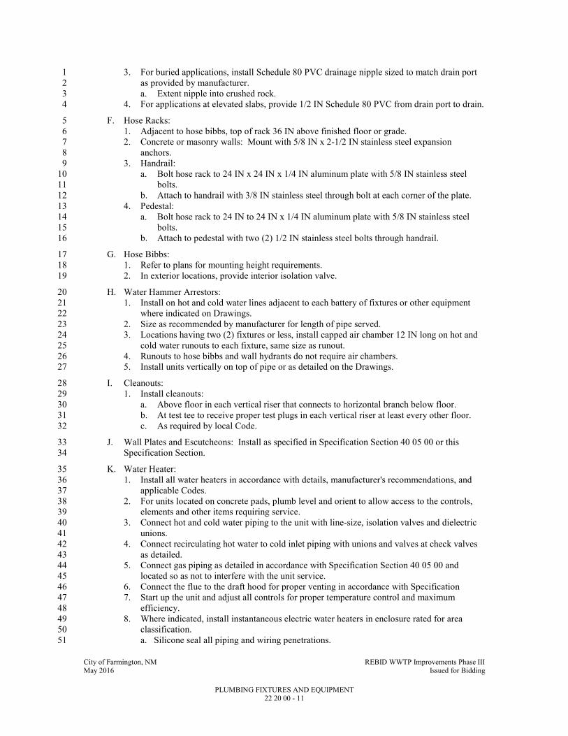
City of Farmington, NM REBID WWTP Improvements Phase III May 2016 Issued for Bidding
PLUMBING FIXTURES AND EQUIPMENT 22 20 00 - 11
3. For buried applications, install Schedule 80 PVC drainage nipple sized to match drain port 1
as provided by manufacturer. 2
a. Extent nipple into crushed rock. 3
4. For applications at elevated slabs, provide 1/2 IN Schedule 80 PVC from drain port to drain. 4
F. Hose Racks: 5
1. Adjacent to hose bibbs, top of rack 36 IN above finished floor or grade. 6
2. Concrete or masonry walls: Mount with 5/8 IN x 2-1/2 IN stainless steel expansion 7
anchors. 8
3. Handrail: 9
a. Bolt hose rack to 24 IN x 24 IN x 1/4 IN aluminum plate with 5/8 IN stainless steel 10
bolts. 11
b. Attach to handrail with 3/8 IN stainless steel through bolt at each corner of the plate. 12
4. Pedestal: 13
a. Bolt hose rack to 24 IN to 24 IN x 1/4 IN aluminum plate with 5/8 IN stainless steel 14
bolts. 15
b. Attach to pedestal with two (2) 1/2 IN stainless steel bolts through handrail. 16
G. Hose Bibbs: 17
1. Refer to plans for mounting height requirements. 18
2. In exterior locations, provide interior isolation valve. 19
H. Water Hammer Arrestors: 20
1. Install on hot and cold water lines adjacent to each battery of fixtures or other equipment 21
where indicated on Drawings. 22
2. Size as recommended by manufacturer for length of pipe served. 23
3. Locations having two (2) fixtures or less, install capped air chamber 12 IN long on hot and 24
cold water runouts to each fixture, same size as runout. 25
4. Runouts to hose bibbs and wall hydrants do not require air chambers. 26
5. Install units vertically on top of pipe or as detailed on the Drawings. 27
I. Cleanouts: 28
1. Install cleanouts: 29
a. Above floor in each vertical riser that connects to horizontal branch below floor. 30
b. At test tee to receive proper test plugs in each vertical riser at least every other floor. 31
c. As required by local Code. 32
J. Wall Plates and Escutcheons: Install as specified in Specification Section 40 05 00 or this 33
Specification Section. 34
K. Water Heater: 35
1. Install all water heaters in accordance with details, manufacturer's recommendations, and 36
applicable Codes. 37
2. For units located on concrete pads, plumb level and orient to allow access to the controls, 38
elements and other items requiring service. 39
3. Connect hot and cold water piping to the unit with line-size, isolation valves and dielectric 40
unions. 41
4. Connect recirculating hot water to cold inlet piping with unions and valves at check valves 42
as detailed. 43
5. Connect gas piping as detailed in accordance with Specification Section 40 05 00 and 44
located so as not to interfere with the unit service. 45
6. Connect the flue to the draft hood for proper venting in accordance with Specification 46
7. Start up the unit and adjust all controls for proper temperature control and maximum 47
efficiency. 48
8. Where indicated, install instantaneous electric water heaters in enclosure rated for area 49
classification. 50
a. Silicone seal all piping and wiring penetrations. 51

City of Farmington, NM REBID WWTP Improvements Phase III May 2016 Issued for Bidding
PLUMBING FIXTURES AND EQUIPMENT 22 20 00 - 12
L. Reduce Pressure Backflow Preventer: Install on water lines as shown on the plans. 1
3.2 FIELD QUALITY CONTROL 2
A. Test piping and fixtures for leaks per Specification Section 40 05 05 and 40 05 13. 3
END OF SECTION 4
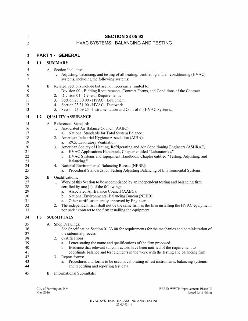
City of Farmington, NM REBID WWTP Improvements Phase III May 2016 Issued for Bidding
HVAC SYSTEMS: BALANCING AND TESTING 23 05 93 - 1
SECTION 23 05 93 1
HVAC SYSTEMS: BALANCING AND TESTING 2
PART 1 - GENERAL 3
1.1 SUMMARY 4
A. Section Includes: 5
1. Adjusting, balancing, and testing of all heating, ventilating and air conditioning (HVAC) 6
systems, including the following systems: 7
B. Related Sections include but are not necessarily limited to: 8
1. Division 00 - Bidding Requirements, Contract Forms, and Conditions of the Contract. 9
2. Division 01 - General Requirements. 10
3. Section 23 80 00 - HVAC: Equipment. 11
4. Section 23 31 00 - HVAC: Ductwork. 12
5. Section 23 09 23 - Instrumentation and Control for HVAC Systems. 13
1.2 QUALITY ASSURANCE 14
A. Referenced Standards: 15
1. Associated Air Balance Council (AABC): 16
a. National Standards for Total System Balance. 17
2. American Industrial Hygiene Association (AIHA): 18
a. Z9.5, Laboratory Ventilation. 19
3. American Society of Heating, Refrigerating and Air Conditioning Engineers (ASHRAE): 20
a. HVAC Applications Handbook, Chapter entitled "Laboratories." 21
b. HVAC Systems and Equipment Handbook, Chapter entitled "Testing, Adjusting, and 22
Balancing." 23
4. National Environmental Balancing Bureau (NEBB): 24
a. Procedural Standards for Testing Adjusting Balancing of Environmental Systems. 25
B. Qualifications: 26
1. Work of this Section to be accomplished by an independent testing and balancing firm 27
certified by one (1) of the following: 28
a. Associated Air Balance Council (AABC). 29
b. National Environmental Balancing Bureau (NEBB). 30
c. Other certification entity approved by Engineer. 31
2. The independent firm shall not be the same firm as the firm installing the HVAC equipment, 32
nor under contract to the firm installing the equipment. 33
1.3 SUBMITTALS 34
A. Shop Drawings: 35
1. See Specification Section 01 33 00 for requirements for the mechanics and administration of 36
the submittal process. 37
2. Certifications: 38
a. Letter stating the name and qualifications of the firm proposed. 39
b. Evidence that relevant subcontractors have been notified of the requirement to 40
coordinate balance and test elements in the work with the testing and balancing firm. 41
3. Report forms: 42
a. Procedures and forms to be used in calibrating of test instruments, balancing systems, 43
and recording and reporting test data. 44
B. Informational Submittals: 45
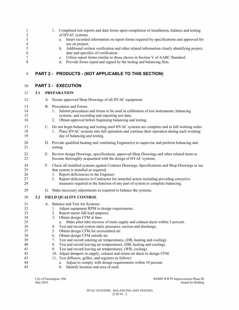
City of Farmington, NM REBID WWTP Improvements Phase III May 2016 Issued for Bidding
HVAC SYSTEMS: BALANCING AND TESTING 23 05 93 - 2
1. Completed test reports and data forms upon completion of installation, balance and testing 1
of HVAC systems. 2
a. Insert recorded information on report forms required by specifications and approved for 3
use on project. 4
b. Additional written verification and other related information clearly identifying project, 5
date and specifics of verification. 6
c. Utilize report forms similar to those shown in Section V of AABC Standard. 7
d. Provide forms typed and signed by the testing and balancing firm. 8
PART 2 - PRODUCTS - (NOT APPLICABLE TO THIS SECTION) 9
PART 3 - EXECUTION 10
3.1 PREPARATION 11
A. Secure approved Shop Drawings of all HVAC equipment. 12
B. Procedures and Forms: 13
1. Submit procedures and forms to be used in calibration of test instruments, balancing 14
systems, and recording and reporting test data. 15
2. Obtain approval before beginning balancing and testing. 16
C. Do not begin balancing and testing until HVAC systems are complete and in full working order. 17
1. Place HVAC systems into full operation and continue their operation during each working 18
day of balancing and testing. 19
D. Provide qualified heating and ventilating Engineer(s) to supervise and perform balancing and 20
testing. 21
E. Review design Drawings, specifications, approved Shop Drawings and other related items to 22
become thoroughly acquainted with the design of HVAC systems. 23
F. Check all installed systems against Contract Drawings, Specifications and Shop Drawings to see 24
that system is installed as required. 25
1. Report deficiencies to the Engineer. 26
2. Report deficiencies to Contractor for remedial action including providing corrective 27
measures required in the function of any part of system to complete balancing. 28
G. Make necessary adjustments as required to balance the systems. 29
3.2 FIELD QUALITY CONTROL 30
A. Balance and Test Air Systems: 31
1. Adjust equipment RPM to design requirements. 32
2. Report motor full load amperes. 33
3. Obtain design CFM at fans. 34
a. Make pitot tube traverse of main supply and exhaust ducts within 5 percent. 35
4. Test and record system static pressures, suction and discharge. 36
5. Obtain design CFM for recirculated air. 37
6. Obtain design CFM outside air. 38
7. Test and record entering air temperatures, (DB, heating and cooling). 39
8. Test and record leaving air temperatures, (DB, heating and cooling). 40
9. Test and record leaving air temperatures, (WB, cooling). 41
10. Adjust dampers in supply, exhaust and return air ducts to design CFM. 42
11. Test diffusers, grilles, and registers as follows: 43
a. Adjust to comply with design requirements within 10 percent. 44
b. Identify location and area of each. 45

City of Farmington, NM REBID WWTP Improvements Phase III May 2016 Issued for Bidding
HVAC SYSTEMS: BALANCING AND TESTING 23 05 93 - 3
c. Adjust face velocity to establish required CFM. 1
1) Retest after initial adjustments. 2
d. Adjust to minimize drafts and to ensure uniform air distribution in all areas. 3
12. Identify and list size, type and manufacturer of diffusers, grilles, registers, and HVAC 4
equipment. 5
a. Use manufacturer's ratings on equipment to make required calculations. 6
13. Adjust and assure that the operation of automatically operated dampers are as specified. 7
a. Check and calibrate controls. 8
Prepare and submit reports.. 9
END OF SECTION 10

City of Farmington, NM REBID WWTP Improvements Phase III May 2016 Issued for Bidding
INSTRUMENTATION AND CONTROL (DDC) FOR HVAC SYSTEMS 23 09 23 - 1
SECTION 23 09 23 1
INSTRUMENTATION AND CONTROL (DDC) FOR HVAC SYSTEMS 2
PART 1 - GENERAL 3
1.1 SUMMARY 4
A. Section Includes: 5
1. Instrumentation and control for HVAC systems. 6
2. Temperature control. 7
3. Ventilation control. 8
4. Heating control. 9
5. Cooling control. 10
6. Control wiring 11
7. Panels and accessories 12
8. Miscellaneous 13
B. Related Specification Sections include but are not necessarily limited to: 14
1. Division 00 - Bidding Requirements, Contract Forms, and Conditions of the Contract. 15
2. Division 01 - General Requirements. 16
3. Section 10 14 00 -Identification Devices. 17
4. Section 23 05 53 - Identification for HVAC Piping and Equipment. 18
5. Section 40 05 05 - Equipment: Basic Requirements. 19
6. Section 40 05 00 - Pipe and Pipe Fittings: Basic Requirements. 20
7. Section 23 05 93 - HVAC Systems: Balancing and Testing. 21
8. Section 23 31 00 - HVAC: Ductwork. 22
9. Section 23 34 00 - HVAC: Fans. 23
10. Division 26 – Electrical. 24
11. Section 40 05 51 – Valves: Basic Requirements. 25
12. Section 40 90 00 - Instrumentation for Process Control: Basic Requirements. 26
1.2 QUALITY ASSURANCE 27
A. See Specification Section 40 05 05 and 40 90 00. 28
B. Referenced Standards: 29
1. Work, materials, and equipment shall comply with the most restrictive of local, state, and 30
federal authorities’ codes and ordinances or these plans and specifications. As a minimum, 31
the installation shall comply with current editions in effect 30 days prior to receipt of bids of 32
the following: 33
a. American Conference of Governmental Industrial Hygienists (ACGIH): 34
1) Industrial Ventilation: A Manual of Practice for Design, 28th
Edition. 35
b. American Society of Mechanical Engineers (ASME): 36
1) B16.22 - Wrought Copper and Copper Alloy Solder Joint Pressure Fittings 37
c. ANSI/ASHRAE Standard 135, BACnet—A Data Communication Protocol for 38
Building Automation and Control Systems. 39
d. ASHRAE Handbook – Fundamentals. 40
e. ASTM International (ASTM): 41
1) B32 - Standard Specification for Solder Metal. 42
2) B280 - Standard Specification for Seamless Copper Tube for Air Conditioning and 43
Refrigeration Field Service. 44
3) D1693, Standard Test Method for Environmental Stress-Cracking of Ethylene 45
Plastics. 46
f. Canadian Standards Association. 47
g. The International Society of Automation (ISA). 48

City of Farmington, NM REBID WWTP Improvements Phase III May 2016 Issued for Bidding
INSTRUMENTATION AND CONTROL (DDC) FOR HVAC SYSTEMS 23 09 23 - 2
h. National Electrical Manufacturers Association (NEMA). 1
1) 250, Enclosures for Electrical Equipment (1000 Volts Maximum). 2
i. National Fire Protection Association (NFPA): 3
1) 70, National Electrical Code (NEC). 4
j. Underwriters Laboratories, Inc. (UL). 5
C. Miscellaneous: 6
1. Controls to be in compliance with Specification Section 26 05 00 for NEMA and NFPA 70 7
enclosure class requirements unless noted or specified otherwise. 8
2. Unless specifically noted otherwise, components of systems shall be industrial duty suitable 9
for moist, corrosive environments. 10
D. Installer and Manufacturer Qualifications. 11
1. Installer shall have an established working relationship with Control System Manufacturer 12
of not less than three years. 13
2. Installer must have directly comparable experience for projects of similar scope and size. 14
3. Installer shall have an established working relationship with the Control Systems 15
Manufacturer of not less than 5 years. 16
4. Installer shall have successfully completed Control Systems Manufacturer’s control system 17
training. Upon request, Installer shall present certification of completed training including 18
hours of instruction and course outlines. 19
5. Installer shall have a local office within 100 miles of the project site. The local office shall 20
be staffed with Engineers and technicians trained on the installation, commissioning, and 21
service of direct digital control systems based on the BACnet technology. The local office 22
shall provide complete maintenance and support services on a 24 HR, 7-day-a-week basis. 23
1.3 SYSTEM DESCRIPTION 24
A. Work shall be provided as an integrated operating system based on a high-speed, networked, 25
distributed system of fully intelligent, stand-alone controllers, operating in a multi-tasking, 26
multi-user environment, with central and remote hardware, software, and interconnecting wire 27
and conduit. 28
B. Provide a complete system of automatic temperature control, thermostats, relays, valves, damper 29
operators, thermometers, gages, and other associated controls and appurtenances required to 30
maintain minimum conditions described in detail herein and on the Drawings. 31
C. HVAC temperature controls shall be compatible with PLC equipment provided for process and 32
equipment controls installed by process control contractors. 33
1.4 SUBMITTALS 34
A. See Specification Section 01 33 00 for requirements for the mechanics and administration of the 35
submittal process. 36
B. Product Data: 37
1. Submit description and engineering data for each control system component, including 38
sizing as applicable, and software modules. 39
2. Submit a complete bill of materials of equipment to be used indicating quantity, 40
manufacturer, model number, and other relevant technical data. 41
3. Manufacturer’s description and technical data, such as performance curves, product 42
specification sheets, and installation/maintenance instructions for the items listed below and 43
other relevant items not listed below. 44
4. When manufacturer’s cut sheets apply to a product series rather than a specific product, the 45
data specifically applicable to the project shall be highlighted or clearly indicated by other 46
means. General catalogs shall not be accepted as cut sheets to fulfill submittal requirements. 47
C. Shop Drawings: 48

City of Farmington, NM REBID WWTP Improvements Phase III May 2016 Issued for Bidding
INSTRUMENTATION AND CONTROL (DDC) FOR HVAC SYSTEMS 23 09 23 - 3
1. Provide drawings as AutoCAD 2014 (or newer) compatible files on optical disk (file format: 1
.dwg, .dxf, .vsd, or comparable) with 11 × 17 IN prints of each drawing. 2
2. DDC System Hardware. 3
a. A complete bill of materials of equipment to be used indicating quantity, manufacturer, 4
model number, and other relevant technical data. 5
b. Manufacturer’s description and technical data, such as performance curves, product 6
specification sheets, and installation/maintenance instructions. 7
c. Wiring diagrams and layouts for each control panel. Show all termination numbers. 8
d. Schematic diagrams for all field sensors and controllers. Provide floor plans of all 9
sensor locations and control hardware. 10
3. Central System Hardware and Software. 11
a. A complete bill of material of equipment used, indicating quantity, manufacturer, 12
model number, and other relevant technical data. 13
b. Manufacturer’s description and technical data, such as product specification sheets and 14
installation/maintenance instructions. 15
c. Schematic diagrams for all control, communication, and power wiring. Provide a 16
schematic drawing of the central system installation. Label all cables and ports with 17
computer manufacturers’ model numbers and functions. Show all interface wiring to 18
the control system. 19
d. Riser diagrams of wiring between central control unit and all control panels. 20
4. Controlled Systems. 21
a. Riser diagrams showing control network layout, communication protocol, and wire 22
types. 23
b. A schematic diagram of each controlled system. The schematics shall have all control 24
points labeled with point names shown or listed. The schematics shall graphically show 25
the location of all control elements in the system. 26
c. A schematic wiring diagram for each controlled system. Each schematic shall have all 27
elements labeled. Where a control element is the same as that shown on the control 28
system schematic, it shall be labeled with the same name. All terminals shall be labeled. 29
d. An instrumentation list for each controlled system. Each element of the controlled 30
system shall be listed in table format. The table shall show element name, type of 31
device, manufacturer, model number, and product data sheet number. 32
e. A complete description of the operation of the control system, including sequences of 33
operation. The description shall include and reference a schematic diagram of the 34
controlled system. 35
5. Quantities of items submitted shall be reviewed but are the responsibility of the contractor. 36
6. A description of the proposed process along with all report formats and checklists to be used 37
in Part 3, “Control System Demonstration and Acceptance.” 38
7. A BACnet Protocol Implementation Conformance Statement (PICS) for each type of 39
controller and operator interface included in the submittal. 40
D. Project Record Documents: Upon completion of installation, submit three copies of record (as-41
built) documents. The documents shall be submitted for approval prior to final completion and 42
shall include: 43
1. Project Record Drawings: As-built versions of the submittal shop drawings provided as 44
AutoCAD 2004 (or newer) compatible files on optical media and as 11 × 17 IN prints. 45
2. Testing and Commissioning Reports and Checklists: Completed versions of reports, 46
checklists, and trend logs used to meet requirements of Part 3, “Control System 47
Demonstration and Acceptance.” 48
3. Operation and Maintenance (O & M) Manual. 49
4. As-built versions of submittal product data. 50
5. Names, addresses, and 24-hour telephone numbers of installing contractors and service 51
representatives for equipment and control systems. 52
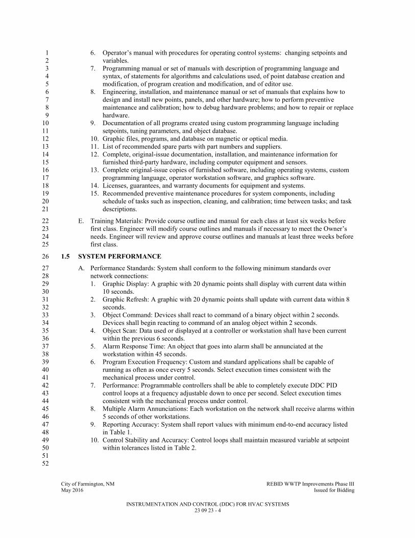
City of Farmington, NM REBID WWTP Improvements Phase III May 2016 Issued for Bidding
INSTRUMENTATION AND CONTROL (DDC) FOR HVAC SYSTEMS 23 09 23 - 4
6. Operator’s manual with procedures for operating control systems: changing setpoints and 1
variables. 2
7. Programming manual or set of manuals with description of programming language and 3
syntax, of statements for algorithms and calculations used, of point database creation and 4
modification, of program creation and modification, and of editor use. 5
8. Engineering, installation, and maintenance manual or set of manuals that explains how to 6
design and install new points, panels, and other hardware; how to perform preventive 7
maintenance and calibration; how to debug hardware problems; and how to repair or replace 8
hardware. 9
9. Documentation of all programs created using custom programming language including 10
setpoints, tuning parameters, and object database. 11
10. Graphic files, programs, and database on magnetic or optical media. 12
11. List of recommended spare parts with part numbers and suppliers. 13
12. Complete, original-issue documentation, installation, and maintenance information for 14
furnished third-party hardware, including computer equipment and sensors. 15
13. Complete original-issue copies of furnished software, including operating systems, custom 16
programming language, operator workstation software, and graphics software. 17
14. Licenses, guarantees, and warranty documents for equipment and systems. 18
15. Recommended preventive maintenance procedures for system components, including 19
schedule of tasks such as inspection, cleaning, and calibration; time between tasks; and task 20
descriptions. 21
E. Training Materials: Provide course outline and manual for each class at least six weeks before 22
first class. Engineer will modify course outlines and manuals if necessary to meet the Owner’s 23
needs. Engineer will review and approve course outlines and manuals at least three weeks before 24
first class. 25
1.5 SYSTEM PERFORMANCE 26
A. Performance Standards: System shall conform to the following minimum standards over 27
network connections: 28
1. Graphic Display: A graphic with 20 dynamic points shall display with current data within 29
10 seconds. 30
2. Graphic Refresh: A graphic with 20 dynamic points shall update with current data within 8 31
seconds. 32
3. Object Command: Devices shall react to command of a binary object within 2 seconds. 33
Devices shall begin reacting to command of an analog object within 2 seconds. 34
4. Object Scan: Data used or displayed at a controller or workstation shall have been current 35
within the previous 6 seconds. 36
5. Alarm Response Time: An object that goes into alarm shall be annunciated at the 37
workstation within 45 seconds. 38
6. Program Execution Frequency: Custom and standard applications shall be capable of 39
running as often as once every 5 seconds. Select execution times consistent with the 40
mechanical process under control. 41
7. Performance: Programmable controllers shall be able to completely execute DDC PID 42
control loops at a frequency adjustable down to once per second. Select execution times 43
consistent with the mechanical process under control. 44
8. Multiple Alarm Annunciations: Each workstation on the network shall receive alarms within 45
5 seconds of other workstations. 46
9. Reporting Accuracy: System shall report values with minimum end-to-end accuracy listed 47
in Table 1. 48
10. Control Stability and Accuracy: Control loops shall maintain measured variable at setpoint 49
within tolerances listed in Table 2. 50
51
52

City of Farmington, NM REBID WWTP Improvements Phase III May 2016 Issued for Bidding
INSTRUMENTATION AND CONTROL (DDC) FOR HVAC SYSTEMS 23 09 23 - 5
TABLE 1 Reporting Accuracy
Measured Variable Reported Accuracy
Space temperature ±1 DegF (±0.5°C)
Ducted air ±1 DegF (±0.5°C)
Outside air ±2 DegF (±1.0°C)
Dew point ±3 DegF (±1.5°C)
Delta-T ±0.25 DegF (±0.15°C)
Relative humidity ±5% RH
Airflow (terminal) ±10% of full
scale (see Note 1)
Airflow (measuring stations) ±5% of full scale
Airflow (pressurized spaces) ±3% of full scale
Air pressure (ducts) ±25 Pa (±0.1 IN w.g.)
Air pressure (space) ±3 Pa (±0.01 IN w.g.)
Electrical (A, V, W, power factor) ±1% of reading (see Note 3)
Note 1: Accuracy applies to 10%–100% of scale
Note 2: For both absolute and differential pressure
Note 3: Not including utility-supplied meters
1
TABLE 2 Control Stability and Accuracy
Controlled Variable Control Accuracy Range of Medium
Air pressure ±0.2 IN w.g. (±50 Pa )
±0.01 IN w.g.( ±3 Pa)
0–6 IN w.g. (0–1.5 kPa)
–0.1 to 0.1 IN w.g. (–25 to 25 Pa)
Airflow ±10% of full scale
Space temperature ±2.0 DegF (±1.0°C)
Duct temperature ±3 DegF (±1.5°C)
Humidity ±5% RH
Fluid pressure ±1.5 psi (±10 kPa)
±1.0 IN w.g. (±250 Pa)
1–150 psi (0–1 MPa)
(0–50 IN w.g.) differential
1.6 WARRANTY 2
A. Warrant work as required in the General Conditions. 3

City of Farmington, NM REBID WWTP Improvements Phase III May 2016 Issued for Bidding
INSTRUMENTATION AND CONTROL (DDC) FOR HVAC SYSTEMS 23 09 23 - 6
1.7 MAINTENANCE SERVICE AGREEMENT 1
A. A written proposal for a maintenance contract shall be provided to the Owner for on-site 2
preventive maintenance services related to the Instrumentation and Control system. The cost of 3
this maintenance contract shall not be included in the Contract Price. 4
B. This proposal shall be provided within 30 days after final acceptance for the purpose of entering 5
a contract for annual maintenance subsequent to the first year of maintenance. Standard per diem 6
rates for providing breakdown service shall be set forth in the contract. Such rates shall be fair 7
and reasonable and reflect the lowest rates offered to most favored customers. The fee quoted 8
shall be firm for a minimum of 90 days from date of issue. 9
C. This maintenance contract shall include all labor, parts, and emergency calls providing on-site 10
response within 24 hours, to provide complete system maintenance for a period of one year after 11
the date of Substantial Completion of the system for all equipment and software provided as part 12
of the scope of work. 13
D. Provide software updates throughout the maintenance contract period. Provide latest official 14
released version for all software provided under this Contract. Owner shall have the latest 15
software releases at the end of the maintenance contract period. 16
E. The maintenance contract shall also include a minimum of 4 preventive maintenance visits by 17
qualified service personnel of the Supplier who is familiar with the type of equipment provided 18
for this project. Each preventive maintenance visit shall include routine adjustment, calibration, 19
cleaning and lubrication of system equipment and verification of correct operation. 20
F. Visits to the sites to correct deficiencies under warranty shall not be included in this preventive 21
maintenance service contract. 22
G. Emergency maintenance procedures or plant visits may coincide with a preventive maintenance 23
visit, however, they shall not replace the work intended to be performed during a preventive 24
maintenance visit. The Supplier shall have full responsibility for the system hardware preventive 25
and corrective maintenance. 26
H. During the one-year maintenance period, observation of maintenance tasks performed under this 27
agreement by plant personnel and the instruction of said personnel in the details of the 28
maintenance work being performed, shall be provided. 29
1.8 MANUFACTURER SUPPORT 30
A. Provide a written proposal for a manufacturer support agreement for products specified herein 31
for a minimum of 12 months starting at final completion of the project. The cost of this 32
manufacturer support agreement shall not be included in the Contract Price unless part of the 33
manufacturer's standard terms of sale. The support agreement shall be executed in the name of, 34
and for the benefit of, the Owner. At a minimum, this agreement shall provide the Owner with: 35
1. 8 AM to 5 PM, 5 day per week manufacturer telephone support. 36
2. Access to the manufacturer's technical support website. 37
3. Software and firmware updates. 38
1.9 OWNERSHIP OF PROPRIETARY MATERIAL 39
A. All software provided under this Contract shall be licensed to the Owner at the time of purchase. 40
B. Project-specific software and documentation shall become the Owner’s property. This includes, 41
but is not limited to: 42
1. Graphics. 43
2. Record drawings. 44
3. Database. 45
4. Application programming source code. 46
5. Documentation. 47

City of Farmington, NM REBID WWTP Improvements Phase III May 2016 Issued for Bidding
INSTRUMENTATION AND CONTROL (DDC) FOR HVAC SYSTEMS 23 09 23 - 7
C. All software programs and documentation developed under this Contract shall be turned over to 1
the Owner in format so programs can be adjusted, reconfigured, or re-programmed by the Owner 2
or their representatives. 3
D. Turn over all keys and passwords to the system. Any passwords shall be turned over to the 4
Owner and the Owner shall have full access to modify the system after final completion. Any 5
changes made during or after testing, start-up, and commissioning shall be incorporated and 6
provided to the Owner. 7
1. Change Administrator Level Control of system software to the Owner following start up to 8
allow the Owner the ability to grant or restrict access to any user, including the system 9
supplier and the installing contractor. 10
1.10 DEFINITIONS 11
A. BACnet Interoperability Building Blocks (BIBB): A BIBB defines a small portion of BACnet 12
functionality that is needed to perform a particular task. BIBBS are combined to build the 13
BACnet functional requirements for a device in a specification. 14
B. BACnet/BACnet Standard: BACnet communication requirements as defined by the latest 15
version of ANSI/ASHRAE Standard 135 and approved addenda. 16
C. Control systems server: A computer(s) that maintain(s) the systems configuration and 17
programming database. 18
D. Controller: Intelligent stand-alone control device. 19
1. Controller is a generic reference to building controllers, custom application controllers, and 20
application specific controllers. 21
E. DDC: Microprocessor-based control including analog/digital conversion and program logic. 22
F. Gateway: Bi-directional protocol translator connecting control systems that use different 23
communication protocols. 24
G. Local Area Network: Computer or control system communications network limited to local 25
building or campus. 26
H. Master-Slave/Token Passing: Data link protocol as defined by the BACnet standard. 27
I. Point-to-Point: Serial communication as defined in the BACnet standard. 28
J. Primary Controlling LAN: High speed, peer-to-peer controller LAN connecting BCs and 29
optionally AACs and ASCs. Refer to Clause 8.2.5, “System Architecture” below. 30
K. Protocol Implementation Conformance Statement: A written document that identifies the 31
particular options specified by BACnet that are implemented in a device. 32
L. Router: A device that connects two or more networks at the network layer. 33
M. Wiring: Raceway, fittings, wire, boxes and related items. 34
PART 2 - PRODUCTS 35
2.1 APPROVED MANUFACTURERS 36
A. Subject to compliance with the Contract Documents, the following manufacturers are 37
acceptable: 38
1. Manufacturer's catalog numbers hereinafter are for reference to type, style, dimension, 39
related items and to establish a standard of quality. 40
a. Reference to a manufacturer's number hereinafter does not imply full compliance to 41
these Specifications. 42
2. Instrumentation and control systems: 43
City of Farmington, NM REBID WWTP Improvements Phase III May 2016 Issued for Bidding
INSTRUMENTATION AND CONTROL (DDC) FOR HVAC SYSTEMS 23 09 23 - 8
a. Primary Control Systems: 1
1) Honeywell. 2
2) Distech. 3
3) Delta. 4
4) Johnson Control Co. 5
5) Siemens. 6
6) Automated Logic. 7
3. Use operator workstation software, controller software, custom application programming 8
language, building controllers, custom application controllers, and application specific 9
controllers only from one of the manufacturers and product lines listed. 10
4. Other products specified herein, such as valves, sensors, dampers, and actuators, need not be 11
manufactured by the listed manufacturers. 12
5. Submit request for substitution in accordance with Specification Section 01 25 13. 13
2.2 MATERIALS 14
A. Use new products that the manufacturer is currently manufacturing and that have been installed 15
in a minimum of 25 installations. Do not use this installation as a product test site unless 16
explicitly approved in writing by the Owner or the Owner’s representative. 17
B. Spare parts shall be available for at least five years after completion of this contract. 18
2.3 OPEN, INTEROPERABLE, INTEGRATED SYSTEM ARCHITECTURES 19
A. The intent of this specification is to provide a peer-to-peer networked, stand-alone, distributed 20
control system with the capability to integrate ANSI/ASHRAE Standard 135-2001 BACnet™, 21
LonWorks™ technology, MODBUS ™, OPC, and other open and proprietary communication 22
protocols into one open, interoperable system. 23
B. The supplied computer software shall employ object-oriented technology (OOT) for 24
representation of all data and control devices within the system. In addition, adherence to 25
industry standards including ANSI / ASHRAE™ Standard 135-2001, BACnet and LonMark to 26
assure interoperability between all system components is required. For each LonWorks device 27
that does not have LonMark certification, the device supplier must provide an XIF file and a 28
resource file for the device. For each BACnet device, the device supplier must provide a 29
Protocol Implementation Conformance Statement (PICS) document showing the installed 30
device’s compliance level. Minimum compliance is Level 3; with the ability to support data 31
read and write functionality. Physical connection of BACnet devices shall be via Ethernet 32
(BACnet Ethernet/IP,) and/or RS-485 (BACnet MSTP) as specified. 33
C. All components and controllers supplied under this Division shall be true “peer-to-peer” 34
communicating devices. Components or controllers requiring “polling” by a host to pass data 35
shall not be acceptable. 36
D. The supplied system must incorporate the ability to access all data using standard Web browsers 37
without requiring proprietary operator interface and configuration programs. Systems requiring 38
proprietary database and user interface programs shall not be acceptable. 39
E. A hierarchical topology is required to assure reasonable system response times and to manage 40
the flow and sharing of data without unduly burdening the customer’s internal Intranet network. 41
Systems employing a “flat” single tiered architecture shall not be acceptable. 42
1. Maximum acceptable response time from any alarm occurrence (at the point of origin) to 43
the point of annunciation shall not exceed 5 seconds for local network connected user 44
interfaces. 45
2. Maximum acceptable response time from any alarm occurrence (at the point of origin) to 46
the point of annunciation shall not exceed 60 seconds for remote connected user interfaces. 47
City of Farmington, NM REBID WWTP Improvements Phase III May 2016 Issued for Bidding
INSTRUMENTATION AND CONTROL (DDC) FOR HVAC SYSTEMS 23 09 23 - 9
2.4 COMMUNICATION 1
A. Control products, communication media, connectors, repeaters, hubs, and routers shall comprise 2
a BACnet internetwork. Controller and operator interface communication shall conform to 3
ANSI/ASHRAE Standard 135, BACnet. 4
B. Each controller shall have a communication port for connection to an operator interface. 5
C. Internetwork operator interface and value passing shall be transparent to internetwork 6
architecture. 7
1. An operator interface connected to a controller shall allow the operator to interface with 8
each internetwork controller as if directly connected. Controller information such as data, 9
status, reports, system software, and custom programs shall be viewable and editable from 10
each internetwork controller. 11
2. Inputs, outputs, and control variables used to integrate control strategies across multiple 12
controllers shall be readable by each controller on the internetwork. Program and test all 13
cross-controller links required to execute specified control system operation. An authorized 14
operator shall be able to edit cross-controller links by typing a standard object address. 15
D. System shall be expandable to at least twice the required input and output objects with additional 16
controllers, associated devices, and wiring. Expansion shall not require operator interface 17
hardware additions or software revisions. 18
E. Workstations, Building Control Panels and Controllers with real-time clocks shall use the 19
BACnet Time Synchronization service. The system shall automatically synchronize system 20
clocks daily from an operator-designated device via the internetwork. The system shall 21
automatically adjust for daylight savings and standard time as applicable. 22
2.5 CONTROLS COMMUNICATION PROTOCOL 23
A. General: The electronic controls packaged with this equipment shall communicate with the 24
building DDC system. The DDC system shall communicate with these controls to read the 25
information and change the control setpoints as shown in the points list, sequences of operation, 26
and control schematics. The information to be communicated between the DDC system and 27
these controls shall be in the standard object format as defined in ASHRAE Standard 135. 28
Controllers shall communicate with other BACnet objects on the internetwork using the Read 29
(Execute) Property service as defined in Clause 15.5 of Standard 135. 30
B. Distributed Processing: The controller shall be capable of stand-alone operation and shall 31
continue to provide control functions without being connected to the network. 32
C. I/O Capacity: The controller shall contain sufficient I/O capacity to control the target system. 33
D. Communication: The controller shall reside on a BACnet network using the MS/TP Data 34
Link/Physical layer protocol. Each network of controllers shall be connected to one building 35
controller. 36
E. The controller shall have a BACnet Data Link/Physical layer compatible connection for a laptop 37
computer or a portable operator’s tool. 38
F. Environment: The hardware shall be suitable for the anticipated ambient conditions. 39
1. Controllers used outdoors and/or in wet ambient conditions shall be mounted within 40
waterproof enclosures and shall be rated for operation {-40 DegF to 150 DegF}. 41
2. Controllers used in conditioned space shall be mounted in dust-proof enclosures and shall be 42
rated for operation at 32 DegF to 120 DegF. 43
G. Serviceability: Provide diagnostic LEDs for power, communication, and processor. All wiring 44
connections shall be made to field-removable, modular terminal strips. Memory. The controller 45
shall maintain all BIOS and programming information in the event of a power loss for at least 90 46
days. 47

City of Farmington, NM REBID WWTP Improvements Phase III May 2016 Issued for Bidding
INSTRUMENTATION AND CONTROL (DDC) FOR HVAC SYSTEMS 23 09 23 - 10
H. Immunity to Power and Noise: Controller shall be able to operate at 90 percent to 110 percent of 1
nominal voltage rating and shall perform an orderly shutdown below 80 percent. Operation shall 2
be protected against electrical noise of 5 to 120 Hz and from keyed radios up to 5 watts at 3 feet. 3
I. Transformer: Power supply for the controller must be rated at a minimum of 125 percent of 4
ASC power consumption and shall be fused or current limiting type. 5
2.6 OPERATOR INTERFACE 6
A. Portable Operator’s Terminal: Furnish a portable operator’s terminal that shall be capable of 7
accessing all system data. This device may be connected to any point on the system network or 8
it may be connected directly to controllers using the BACnet point-to-point (PTP) data 9
link/physical layer protocol. The terminal shall use the read (initiate) and write (execute) 10
services as defined in Sections 15.5 and 15.9 of ASHRAE Standard 135 to communicate with 11
BACnet objects in the internetwork. The portables operator’s terminal shall be a notebook style 12
PC including all software and hardware required. The PC shall contain at a minimum: 13
1. Semi-ruggedized. 14
2. 4th Generation Intel Core i5 Processor. 15
3. 8 GB of RAM. 16
4. Latest compatible Windows software. 17
5. 4 USB ports. 18
6. Ethernet network interface. 19
7. 48x CD-RW/DVD optical drive. 20
8. 1 TB hard disk drive. 21
9. Touch pad mouse functionality. 22
10. Extended life batteries, power supply, and carrying case. 23
11. 15 inch minimum touch screen LCD monitor with at least 1920x1080 resolution. 24
2.7 CONTROLLER SOFTWARE 25
A. Furnish the following applications software for building and energy management. All software 26
applications shall reside and operate in the system controllers. Editing of applications shall 27
occur at the operator workstation. 28
B. System Security: 29
1. User access shall be secured using individual security passwords and user names. 30
2. Passwords shall restrict the user to the objects, applications, and system functions as 31
assigned by the system manager. 32
3. User log on/off attempts shall be recorded. 33
4. The system shall protect itself from unauthorized use by automatically logging off following 34
the last keystroke. The delay time shall be user-definable. 35
C. Scheduling: 36
1. Provide the capability to schedule each object or group of objects in the system. Each 37
schedule shall consist of the following: 38
a. Weekly Schedule: Provide a separate schedule for each day of the week. Each of these 39
schedules should include the capability for start, stop, optimal start, optimal stop, and 40
night economizer. Each schedule may consist of up to 10 events. When a group of 41
objects are scheduled together, provide the capability to adjust the start and stop times 42
for each member. 43
b. Exception Schedules: Provide the ability for the operator to designate any day of the 44
year as an exception schedule. Exception schedules may be defined up to a year in 45
advance. Once an exception schedule is executed, it will be discarded and replaced by 46
the standard schedule for that day of the week. 47

City of Farmington, NM REBID WWTP Improvements Phase III May 2016 Issued for Bidding
INSTRUMENTATION AND CONTROL (DDC) FOR HVAC SYSTEMS 23 09 23 - 11
c. Holiday Schedules: Provide the capability for the operator to define up to 99 special or 1
holiday schedules. These schedules may be placed on the scheduling calendar and will 2
be repeated each year. The operator shall be able to define the length of each holiday 3
period. 4
D. System Coordination: Provide a standard application for the proper coordination of equipment. 5
This application shall provide the operator with a method of grouping together equipment based 6
on function and location. This group may then be used for scheduling and other applications. 7
E. Binary Alarms: Each binary object shall be set to alarm based on the operator-specified state. 8
Provide the capability to automatically and manually disable alarming. 9
F. Analog Alarms: Each analog object shall have both high and low alarm limits. Alarming must 10
be able to be automatically and manually disabled. 11
G. Alarm Reporting: The operator shall be able to determine the action to be taken in the event of 12
an alarm. Alarms shall be routed to designated workstations. An alarm shall be able to start 13
programs, print, be logged in the event log, generate custom messages, and display graphics. 14
H. Remote Communication: The system shall have the ability to call out in the event of an alarm 15
using BACnet PTP. Receivers shall be BACnet workstations. 16
I. PID Control: A PID algorithm with direct or reverse action and anti-windup shall be supplied. 17
The algorithm shall calculate a time varying analog value that is used to position an output or 18
stage a series of outputs. The controlled variable, setpoint, and PID gains shall be user-19
selectable. 20
J. Staggered Start: This application shall prevent all controlled equipment from simultaneously 21
restarting after a power outage. The order, in which equipment (or groups of equipment) is 22
started, along with the time delay between starts, shall be user-selectable. 23
K. Anti-short Cycling: All binary output objects shall be protected from short cycling. This feature 24
shall allow a minimum on-time and off-time to be selected. 25
L. On/Off Control with Differential: Provide an algorithm that allows a binary output to be cycled 26
based on a controlled variable and setpoint. The algorithm shall be direct-acting or reverse-27
acting and incorporate an adjustable differential. 28
M. Runtime Totalization: Provide software to totalize runtimes for all binary input objects. A high 29
runtime alarm shall be assigned, if required, by the operator. 30
2.8 BUILDING CONTROLLERS 31
A. General: Provide an adequate number of building controllers to achieve the performance 32
specified in the Part 1 article on “system performance”. Each of these panels shall meet the 33
following requirements: 34
1. The building automation system shall be composed of one or more independent, stand-35
alone, microprocessor-based building controllers to manager the global strategies described 36
in the “System Software” section. 37
2. The building controller shall have sufficient memory to support its operating system, 38
database, and programming requirements. 39
3. Data shall be shared between networked building controllers. 40
4. The operating system of the building controller shall manage the input and output 41
communication signals to allow distributed controllers to share real and virtual object 42
information and allow for central monitoring and alarms. 43
5. Controllers that perform scheduling shall have a real-time clock. 44
6. The building controller shall continually check the status of its processor and memory 45
circuits. If an abnormal operation is detected, the controller shall: 46
a. Assume a predetermined failure mode. 47
b. Generate an alarm notification. 48

City of Farmington, NM REBID WWTP Improvements Phase III May 2016 Issued for Bidding
INSTRUMENTATION AND CONTROL (DDC) FOR HVAC SYSTEMS 23 09 23 - 12
7. The building controller shall communicate with other BACnet devices on the internetwork 1
using the read (execute and initiate) and write (execute and initiate) property services as 2
defined in Clauses 15.5 and 15.9 of ASHRAE Standard 135. 3
B. Communication: 4
1. Each building controller shall reside on a BACnet network using the ISO 8802-3 (Ethernet) 5
data link/physical layer protocol. Each building controller also shall perform BACnet 6
routing if connected to a network of custom application and application specific controllers. 7
2. The controller shall provide a service communication port using BACnet data link/physical 8
layer protocol for connection to a portable operator’s terminal. 9
C. Environment: 10
1. Controller hardware shall be suitable for the anticipated ambient conditions. 11
2. Controllers used outdoors and/or in wet ambient conditions shall be mounted within 12
waterproof enclosures and shall be rated for operation at 40 DegF to 150 DegF. 13
3. Controllers used in conditioned space shall be mounted in dust-proof enclosures and shall be 14
rated for operation at 32 DegF to 120 DegF. 15
D. Keypad: A local keypad and display shall be provided for each controller. An optional system 16
security password shall be available to prevent unauthorized use of the keypad and display. If 17
the manufacturer does not provide this keypad and display, provide a portable operator terminal. 18
E. Serviceability: Provide diagnostic LEDs for power, communication, and processor. All wiring 19
connections shall be made to field-removable, modular terminal strips or to a termination card. 20
F. Memory: The building controller shall maintain all BIOS and programming information in the 21
event of a power loss for at least 72 hours. 22
G. Immunity to power and noise: Controller shall be able to operate at 90 percent to 110 percent of 23
nominal voltage rating and shall perform and orderly shutdown below 80 percent nominal 24
voltage. Operation shall be protected against electrical noise of 5 to 120 Hz and from keyed 25
radios up to 5 watts at 3 FT 26
2.9 CUSTOM APPLICATION CONTROLLERS 27
A. General: Provide an adequate number of Custom Application Controllers to achieve the 28
performance specified in the Part 1 article on “system performance”. Each of these panels shall 29
meet the following requirements. 30
1. The custom application controller shall have sufficient memory to support its operating 31
system, database, and programming requirements. 32
2. Data shall be shared between networked custom application controllers. 33
3. The operating system of the controller shall manage the input and output communication 34
signals to allow distributed controllers to share real and virtual object information and allow 35
central monitoring and alarms. 36
4. Controllers that perform scheduling shall have a real-time clock. 37
5. The custom application controller shall continually check the status of its processor and 38
memory circuits. If an abnormal operation is detected, the controller shall: 39
a. Assume a predetermined failure mode. 40
b. Generate an alarm notification. 41
6. The custom application controller shall communicate with other BACnet devices on the 42
internetwork use the read (execute and initiate) and write (execute and initiate) property 43
services as defined in Clauses 15.5 and 15.9 of ASHRAE Standard 135. 44
B. Communication: 45
1. Each custom application controller shall reside on a BACnet network using the MS/TP Data 46
Link/Physical layer protocol. 47
2. The controller shall provide a service communication port using BACnet Data 48
Link/Physical layer protocol for connection to a portable operator’s terminal. 49
City of Farmington, NM REBID WWTP Improvements Phase III May 2016 Issued for Bidding
INSTRUMENTATION AND CONTROL (DDC) FOR HVAC SYSTEMS 23 09 23 - 13
C. Environment: 1
1. Controller hardware shall be suitable for the anticipated ambient conditions. 2
2. Controllers used outdoors and/or in wet ambient conditions shall be mounted within 3
waterproof enclosures and shall be rated for operation at 40 DegF to 150 DegF. 4
3. Controllers used in conditioned space shall be mounted in dust-proof enclosures and shall be 5
rated for operation at 32 DegF to 120 DegF. 6
D. Keypad: A local keypad and display shall be provided. An optional system security password 7
shall be available to prevent unauthorized use of the keypad and display. 8
E. Serviceability: Provide diagnostic LEDs for power, communication, and processor. All wiring 9
connections shall be made to field-removable, modular terminal strips. 10
F. Immunity to power and noise: Controller shall be able to operate at 90 percent to 110 percent of 11
nominal voltage rating and shall perform and orderly shutdown below 80 percent nominal 12
voltage. Operation shall be protected against electrical noise of 5 to 120 Hz and from keyed 13
radios up to 5 watts at 3 FT 14
2.10 APPLICATION SPECIFIC CONTROLLERS 15
A. General: Application specific controllers (ASCs) are microprocessor-based DDC controllers, 16
which through hardware or firmware design are dedicated to control a specific piece of 17
equipment. They are not fully user-programmable but are customized for operation within the 18
confines of the equipment they are designed to serve. Application specific controllers shall 19
communicate with other BACnet devices on the internetwork using the read (execute) property 20
service as defined in Clause 15.5 of ASHRAE Standard 135. 21
1. Each ASC shall be capable of stand-alone operation and shall continue to provide control 22
functions without being connected to the network. 23
2. Each ASC will contain sufficient I/O capacity to control the target system. 24
B. Communication: 25
1. Each custom application controller shall reside on a BACnet network using the MS/TP Data 26
Link/Physical layer protocol. 27
2. Each controller shall have a BACnet Data Link/Physical layer compatible connection for a 28
laptop computer or a portable operator’s tool. This connection shall be extended to a space 29
temperature sensor port where shown. 30
C. Environment: 31
1. Controller hardware shall be suitable for the anticipated ambient conditions. 32
2. Controllers used outdoors and/or in wet ambient conditions shall be mounted within 33
waterproof enclosures and shall be rated for operation at 40 DegF to 150 DegF. 34
3. Controllers used in conditioned space shall be mounted in dust-proof enclosures and shall be 35
rated for operation at 32 DegF to 120 DegF. 36
D. Serviceability: Provide diagnostic LEDs for power, communication, and processor. All wiring 37
connections shall be made to field-removable, modular terminal strips. 38
E. Memory: The ASC shall use nonvolatile memory and maintain all BIOS and programming 39
information in the event of a power loss for a minimum of 72 hours. 40
F. Immunity to power and noise: Controller shall be able to operate at 90 percent to 110 percent of 41
nominal voltage rating and shall perform and orderly shutdown below 80 percent nominal 42
voltage. Operation shall be protected against electrical noise of 5 to 120 Hz and from keyed 43
radios up to 5 watts at 3 FT 44
G. Transformer: Power supply for the ASC must be rated at a minimum of 125 percent of ASC 45
power consumption and shall be of the fused or current limiting type. 46
47
City of Farmington, NM REBID WWTP Improvements Phase III May 2016 Issued for Bidding
INSTRUMENTATION AND CONTROL (DDC) FOR HVAC SYSTEMS 23 09 23 - 14
2.11 INPUT/OUTPUT INTERFACE 1
A. Hardwired inputs and outputs may tie into the system through building, custom application, or 2
application specific conditions. 3
B. All input points shall be protected such that shorting of the point to itself, to another point, or to 4
ground will cause no damage to the controller. All input and output points shall be protected 5
from voltage up to 125 percent of rated voltage of any duration, such that contact with this 6
voltage will cause no damage to the controller. 7
C. Binary inputs shall allow the monitoring of ON/OFF signals from remote devices. The binary 8
inputs shall provide a wetting current of at least 12mA to be compatible with commonly 9
available control devices and shall be protected against the effects of contact bounce and noise. 10
Binary inputs shall sense “dry contact” closure without external power (other than that provided 11
by the controller) being applied. 12
D. Pulse accumulation input objects. This type of object shall conform to all the requirements of 13
binary input objects and also accept up to 10 pulses per second for pulse accumulation. 14
E. Analog inputs shall allow the monitoring of low-voltage (0 to 10 Vdc), current (4 to 20 mA), or 15
resistance signals (thermistor, RTD). Analog inputs shall be compatible with, and field 16
configurable to, commonly available sensing devices. 17
F. Binary outputs shall provide for ON/OFF operation or pulsed low-voltage signal for pulse width 18
modulation control. Binary outputs on building and custom application controllers shall have 19
three-position (ON/OFF/Auto) override switches and status lights. Outputs shall be selectable 20
for either normally open or normally closed operation. 21
G. I/O points shall be the universal type, i.e., controller input or output may be designated (in 22
software) as either a binary or analog type point with appropriate properties. Application 23
specific controllers are exempted from this requirement. 24
H. System Object Capacity: The system size shall be expandable to at least twice the number of 25
input/output objects required for this project. Additional controllers (along with associated 26
devices and wiring) shall be all that is necessary to achieve this capacity requirement. The 27
operator interfaces installed for this project shall not require hardware additions or software 28
revisions in order to expand the system. 29
2.12 POWER SUPPLIES 30
A. Control transformers shall be UL listed. Furnish Class 2 current-limiting type or furnish over-31
current protection in both primary and secondary circuits for Class 2 service in accordance with 32
NEC requirements. Limit connected loads to 80 percent of rated capacity. 33
1. DC power supply output shall match output current and voltage requirements. Unit shall be 34
full-wave rectifier type with output ripple of 5.0 mV maximum peak-to-peak. Regulation 35
shall be 1.0 percent line and load combined, with 100-microsecond response time for 50 36
percent load changes. Unit shall have built-in overvoltage and overcurrent protection and 37
shall be able to withstand a 150 percent current overload for at least three seconds without 38
trip-out or failure. 39
a. Unit shall operate between 32 DegF and 120 DegF. EM/RF shall meet FCC Class B 40
and VDE 0871 for Class B and MIL-STD 810C for shock and vibration. 41
b. Line voltage units shall be UL recognized and CSA approved. 42
2.13 AUXILIARY CONTROL DEVICES 43
A. Motorized control dampers: 44
1. Control dampers shall be as specified in Section 23 31 00. 45
B. Relays: 46

City of Farmington, NM REBID WWTP Improvements Phase III May 2016 Issued for Bidding
INSTRUMENTATION AND CONTROL (DDC) FOR HVAC SYSTEMS 23 09 23 - 15
1. Control relays shall be UL listed plug-in type with dust cover and LED “energized” 1
indicator. Contact rating, configuration, and coil voltage shall be suitable for application. 2
2. Time delay relays shall be UL listed solid-state plug-in type with adjustable time delay. 3
Delay shall be adjustable ±200 percent (minimum) from setpoint shown on plans. Contact 4
rating, configuration, and coil voltage shall be suitable for application. Provide NEMA 1 5
enclosure when not installed in local control panel. 6
C. Override timers: 7
1. Override timers shall be spring-wound line voltage, UL Listed, with contact rating and 8
configuration as required by application. Provide 0-to-6-hour calibrated dial unless 9
otherwise specified. Timer shall be suitable for flush mounting on control panel face and 10
located on local control panels or where shown. 11
D. Current transmitters: 12
1. AC current transmitters shall be the self-powered, combination split-core current 13
transformer type with built-in rectifier and high-gain servo amplifier with 4 to 20 mA two-14
wire output. Unit ranges shall be 10 A, 20 A, 50 A, 100 A, 150 A, and 200 A full scale, with 15
internal zero and span adjustment and ±1 percent full-scale accuracy at 500 ohm maximum 16
burden. 17
2. Transmitter shall meet or exceed ANSI/ISA S50.1 requirements and shall be UL/CSA 18
Recognized. 19
3. Unit shall be split-core type for clamp-on installation on existing wiring. 20
E. Current transformers: 21
1. AC current transformers shall be UL/CSA Recognized and completely encased (except for 22
terminals) in approved plastic material. 23
2. Transformers shall be available in various current ratios and shall be selected for ±1 percent 24
accuracy at 5 A full-scale output. 25
3. Transformers shall be fixed-core or split-core type for installation on new or existing wiring, 26
respectively. 27
F. Voltage transmitters: 28
1. AC voltage transmitters shall be self-powered single-loop (two-wire) type, 4 to 20 mA 29
output with zero and span adjustment. 30
2. Ranges shall include 100 to 130 VAC, 200 to 250 VAC, 250 to 330 VAC, and 400 to 600 31
VAC full-scale, adjustable, with ±1 percent full-scale accuracy with 500 ohm maximum 32
burden. 33
3. Transmitters shall be UL/CSA Recognized at 600 VAC rating and meet or exceed 34
ANSI/ISA S50.1 requirements. 35
G. Voltage transformers: 36
1. AC voltage transformers shall be UL/CSA Recognized, 600 VAC rated, complete with 37
built-in fuse protection. 38
2. Transformers shall be suitable for ambient temperatures of 4°C to 55°C (40 DegF to 130 39
DegF) and shall provide ±0.5 percent accuracy at 24 VAC and a 5 VA load. 40
3. Windings (except for terminals) shall be completely enclosed with metal or plastic material. 41
2.14 PRIMARY ELEMENTS 42
A. Binary Temperature Devices: 43
1. Low-voltage space thermostat shall be 24 V, bimetal-operated, mercury-switch type, with 44
either adjustable or fixed anticipation heater, concealed setpoint adjustment, 55 DegF to 85 45
DegF setpoint range, 2 DegF maximum differential, and vented ABS plastic cover. 46
2. Line-voltage space thermostat shall be bimetal-actuated, open contact type, or bellows-47
actuated, enclosed, snap-switch type or equivalent solid-state type, with heat anticipator, UL 48
listed for electrical rating, concealed setpoint adjustment, 55 DegF to 85 DegF setpoint 49
range, 2 DegF maximum differential, and vented ABS plastic cover. 50

City of Farmington, NM REBID WWTP Improvements Phase III May 2016 Issued for Bidding
INSTRUMENTATION AND CONTROL (DDC) FOR HVAC SYSTEMS 23 09 23 - 16
3. Low-limit thermostats: Low-limit airstream thermostats shall be UL listed, vapor pressure 1
type, with an element of 20 FT minimum length. Element shall respond to the lowest 2
temperature sensed by any 1 FT section. The low-limit thermostat shall be manual reset 3
only. 4
B. Temperature sensors: 5
1. Temperature sensors shall be RTD or thermistor. 6
2. Duct sensors shall be single point or averaging as shown. Averaging sensors shall be a 7
minimum of 5 FT in length per 10 ft^2 of duct cross section. 8
3. Immersion sensors shall be provided with a separable stainless steel well. Pressure rating of 9
well is to be consistent with the system pressure in which it is to be installed. The well must 10
withstand the flow velocities in the pipe. 11
4. Space sensors shall be equipped with setpoint adjustment, override switch, display, and/or 12
communication port as shown. 13
5. Provide matched temperature sensors for differential temperature measurement. 14
C. Current switches: 15
1. Current-operated switches shall be self-powered, solid-state with adjustable trip current. 16
2. The switches shall be selected to match the current of the application and output 17
requirements of the DDC system. 18
2.15 LOCAL CONTROL PANELS 19
A. All indoor control cabinets shall be fully enclosed NEMA 1 construction with (hinged door) 20
key-lock latch and removable subpanels. A single key shall be common to all field panels and 21
subpanels. 22
B. Interconnections between internal and face-mounted devices shall be prewired with color-coded 23
stranded conductors neatly installed in plastic troughs and/or tie-wrapped. Terminals for field 24
connections shall be UL listed for 600 volt service, individually identified per control/ interlock 25
drawings, with adequate clearance for field wiring. Control terminations for field connection 26
shall be individually identified per control drawings. 27
C. Provide on/off power switch with overcurrent protection for control power sources to each local 28
panel. 29
2.16 WIRING AND RACEWAYS 30
A. General: Provide copper wiring, plenum cable, and raceways as specified in the following 31
specifications: 32
1. Section 26 05 00. 33
2. Section 26 05 19. 34
3. Section 26 05 33. 35
B. All insulated wire to be copper conductors, UL labeled for 90 DegC minimum service. 36
2.17 VARIABLE FREQUENCY DRIVES (VFD) 37
A. Provide VFD(s) compliant with Specification Section 26 29 23, VARIABLE FREQUENCY 38
DRIVES: LOW VOLTAGE. 39
PART 3 - EXECUTION 40
3.1 EXAMINATION 41
A. The project plans shall be thoroughly examined for control device and equipment locations. 42
Any discrepancies, conflicts, or omissions shall be reported to the architect/engineer for 43
resolution before rough-in work is started. 44

City of Farmington, NM REBID WWTP Improvements Phase III May 2016 Issued for Bidding
INSTRUMENTATION AND CONTROL (DDC) FOR HVAC SYSTEMS 23 09 23 - 17
B. The contractor shall inspect the site to verify that equipment may be installed as shown. Any 1
discrepancies, conflicts, or omissions shall be reported to the engineer for resolution before 2
rough-in work is started. 3
C. The contractor shall examine the drawings and specifications for other parts of the work. If head 4
room or space conditions appear inadequate, or if any discrepancies occur between the plans and 5
the contractor’s work and the plans and the work of others, the contractor shall report these 6
discrepancies to the engineer and shall obtain written instructions for any changes necessary to 7
accommodate the contractor’s work with the work of others. Any changes in the work covered 8
by this specification made necessary by the failure or neglect of the contractor to report such 9
discrepancies shall be made by, and the expense of, the contractor. 10
3.2 PROTECTION 11
A. The contractor shall protect all work and material from damage by their work or employees and 12
shall be liable for all damage thus caused. 13
B. The contractor shall be responsible for their work and equipment until finally inspected, tested, 14
and accepted. The contractor shall protect any material that is not immediately installed. The 15
contractor shall close all open ends of work with temporary covers or plugs during storage and 16
construction to prevent entry of foreign objects. 17
3.3 COORDINATION 18
A. Site: 19
1. Where the mechanical work will be installed in close proximity to, or will interfere with, 20
work of other trades, the contractor shall assist in working out space conditions to make a 21
satisfactory adjustment. If the contractor installs his/her work before coordinating with other 22
trades, so as to cause any interference with work of other trades, the contractor shall make 23
the necessary changes in his/her work to correct the condition without extra charge. 24
2. Coordinate and schedule work with all other work in the same area, or with work that is 25
dependent upon other work, to facilitate mutual progress. 26
B. Submittals: Refer to the “Submittals” article in Part 1 of this specification for requirements. 27
C. Test and Balance: 28
1. The contractor shall furnish a single set of all tools necessary to interface to the control 29
system for test and balance purposes. 30
2. The contractor shall provide training in the use of these tools, during system training. 31
3. The contractor shall provide a qualified technician to assist in the test and balance process 32
{and commissioning process}. 33
D. Life Safety: 34
1. Duct smoke detectors required for air handler shutdown are supplied under Division 28 of 35
this specification. The contractor shall interlock smoke detectors to air handlers for 36
shutdown as described in Sequences of Operations. 37
2. Smoke dampers, fire/smoke dampers and actuators required for duct smoke isolation are 38
provided under Division 23. The contractor shall interlock smoke dampers to air handlers 39
for shutdown as described in Sequences of Operations. 40
E. Coordination with controls specified in other sections or divisions: Other sections and/or 41
divisions of this specification include controls and control devices that are to be part of or 42
interfaced to the control system specified in this section. These controls shall be integrated into 43
the system and coordinated by the contractor as follows: 44
1. All communication media and equipment shall be provided as specified in Part 2 45
“Communication” of this specification. 46
2. Each supplier of a controls product is responsible for configuration, programming, start-up, 47
and testing of that product to meet the sequences of operation described in this section. 48
City of Farmington, NM REBID WWTP Improvements Phase III May 2016 Issued for Bidding
INSTRUMENTATION AND CONTROL (DDC) FOR HVAC SYSTEMS 23 09 23 - 18
3. The contractor shall coordinate and resolve any incompatibility issues that arise between the 1
control products provided under this section and those provided under other sections or 2
divisions of the Specifications. 3
4. The contractor is responsible for providing all controls described in the contract documents 4
regardless of where within the contract documents these controls are described. 5
5. The contractor shall be responsible for the integration of indicated controls and control 6
devices into the system specified in this section, and the installation of any control devices 7
or appurtenances required by, but not provided with, equipment with standalone controls. 8
3.4 GENERAL WORKMANSHIP 9
A. Install equipment, piping, and wiring/raceway parallel to building lines (horizontal, vertical, and 10
parallel to walls) where possible. 11
B. Provide sufficient slack and flexible connections to allow for vibration of piping and equipment. 12
C. Install all equipment in readily accessible locations as defined by Chapter 1, Article 100, Part A 13
of the National Electric Code (NEC). 14
D. Verify integrity of all wiring to ensure continuity and freedom from shorts and grounds. 15
E. All equipment, installation, and wiring shall comply with acceptable industry specifications and 16
standards for performance, reliability, and compatibility and be executed in strict adherence to 17
local codes and standard practices. 18
3.5 FIELD QUALITY CONTROL 19
A. All work, materials, and equipment shall comply with the rules and regulations of applicable 20
local, state, and federal codes and ordinances as identified in Part 1. 21
B. Contractor shall continually monitor the field installation for code compliance and quality of 22
workmanship. 23
C. Contractor shall have work inspected by local and/or state authorities having jurisdiction over 24
the work. 25
3.6 WIRING 26
A. All control and interlock wiring shall comply with national and local electrical codes and 27
Specification section 26 05 19. 28
3.7 COMMUNICATION WIRING 29
A. All Communication Wiring shall comply with national and local electrical codes and 30
Specification Section 26 05 19. 31
3.8 INSTALLATION OF SENSORS 32
A. Install sensors in accordance with the manufacturer’s recommendations. 33
B. Mount sensors rigidly and adequately for the environment within which the sensor operates. 34
C. Temperature Sensors: 35
1. Room temperature sensors shall be installed on concealed junction boxes properly supported 36
by the wall framing. 37
2. All wires attached to sensors shall be air sealed in their raceways or in the wall to stop air 38
transmitted from other areas affecting sensor readings. 39
3. Sensors used in mixing plenums and hot and cold decks shall be of the averaging type. 40
Averaging sensors shall be installed in a serpentine manner vertically across the duct. Each 41
bend shall be supported with a capillary clip. 42
4. Low-limit sensors used in mixing plenums shall be installed in a serpentine manner 43
horizontally across duct. Each end shall be supported with a capillary clip. Provide 1 foot 44
of sensing element for each 1 square foot of coil area. 45

City of Farmington, NM REBID WWTP Improvements Phase III May 2016 Issued for Bidding
INSTRUMENTATION AND CONTROL (DDC) FOR HVAC SYSTEMS 23 09 23 - 19
5. All pipe-mounted temperature sensors shall be installed in wells. Install all liquid 1
temperature sensors with heat-conducting fluid in thermal wells. 2
D. Install outdoor air temperature sensors on north wall, complete with sun shield at designated 3
location. 4
3.9 ACTUATORS 5
A. Mount and link control damper actuators according to manufacturer’s instructions. 6
1. To compress seals when spring-return actuators are used on normally closed dampers, 7
power actuator to approximately 5 degrees open position, manually close the damper, and 8
then tighten the linkage. 9
2. Check operation of damper/actuator combination to confirm that actuator modulates damper 10
smoothly throughout stroke to both open and closed positions. 11
3. Provide all mounting hardware and linkages for actuator installation. 12
B. Electric/Electronic: 13
1. Dampers: Actuators shall be direct mounted on damper shaft or jackshaft unless shown as a 14
linkage installation. For low-leakage dampers with seals, the actuator shall be mounted with 15
a minimum 5 degrees available for tightening the damper seals. Actuators shall be mounted 16
following the manufacturer’s recommendations. 17
2. Valves: Actuators shall be connected to valves with adapters approved by the actuator 18
manufacturer. Actuators and adapters shall be mounted following the actuator 19
manufacturer’s recommendations. 20
3.10 CONTROLLERS 21
A. Provide a separator controller for each AHU or other HVAC system. A DDC controller may 22
control more than one system provided that all points associated with the system are assigned to 23
the same DDC controller. Points used for control loop reset, such as outside air or space 24
temperature, are exempt from this requirement. 25
B. Building Controllers and Custom Application Controllers shall be selected to provide a 26
minimum of 15 percent spare I/O capacity for each point type found at each location. If input 27
points are not universal, 15 percent of each type is required. If outputs are not universal, 15 28
percent of each type is required. A minimum of one spare is required for each type of point 29
used. 30
1. Future use of spare capacity shall require providing the field device, field wiring, point 31
database definition, and custom software. No additional controller boards or point modules 32
shall be required to implement use of these spare points. 33
3.11 PROGRAMMING 34
A. Provide sufficient internal memory for the specified sequences of operation and trend logging. 35
There shall be a minimum of 25 percent of available memory free for future use. 36
B. {See Drawings for point naming conventions.} 37
C. {Point Naming: System point names shall be modular in design, allowing easy operator 38
interface without the use of a written point index. Use the following naming convention: 39
AA.BBB.CCDDE where: 40
1. AA is used to designate the location of the point within the building, such as mechanical 41
room, wing, or level, or the building itself in a multi-building environment. 42
2. BBB is used to designate the mechanical system with which the point is associated (i.e. 43
A01, HTG, CLG, LTG). 44
3. CC represents the equipment or material referenced (i.e. SF for supply fan, RW for return 45
water, EA for exhaust air, ZN for zone). 46
4. D or DD may be used for clarification or for identification if more than one CC exists (i.e. 47
SF10, or ZNB). 48

City of Farmington, NM REBID WWTP Improvements Phase III May 2016 Issued for Bidding
INSTRUMENTATION AND CONTROL (DDC) FOR HVAC SYSTEMS 23 09 23 - 20
5. E represents the action or state of the equipment or medium (i.e. T for temperature, H for 1
humidity, C for control, S for status, D for damper control, I for current).} 2
D. Software Programming: 3
1. Provide programming for the system and adhere to the sequences of operation provided. All 4
other system programming necessary for the operation of the system, but not specified in 5
this document, also shall be provided by the contractor. Imbed into the control program 6
sufficient comment statements to clearly describe each section of the program. The 7
comment statements shall reflect the language used in the sequences of operation. Use the 8
appropriate technique based on the following programming types: 9
a. Text-based: 10
1) Must provide actions for all possible situations. 11
2) Must be modular and structured. 12
3) Must be commented. 13
b. Graphic-based: 14
1) Must provide actions for all possible situations. 15
2) Must be documented. 16
c. Parameter-based: 17
1) Must provide actions for all possible situations. 18
2) Must be documented. 19
E. Operator Interface: 20
1. Standard Graphics: Provide graphics for all mechanical systems and floor plans of the 21
building. This includes each chilled water system, hot water system, chiller, boiler, air 22
handler, and all terminal equipment. Point information on the graphic displays shall 23
dynamically update. Show on each graphic all input and output points for the system. Also 24
show relevant calculated points such as setpoints. 25
2. Show terminal equipment information on a “graphic” summary table. Provide dynamic 26
information for each point shown. 27
3. The contractor shall provide all the labor necessary to install, initialize, start up, and 28
troubleshoot all operator interface software and its functions as described in this section. 29
This includes any operating system software, the operator interface database, and any third-30
party software installation and integration required for successful operation of the operator 31
interface. 32
3.12 CONTROL SYSTEM CHECKOUT AND TESTING 33
A. Start-up Testing: All testing listed in this article shall be performed by the contractor and shall 34
make up part of the necessary verification of an operating control system. This testing shall be 35
completed before the Owner’s representative is notified of the system demonstration. 36
1. The contractor shall furnish all labor and test apparatus required to calibrate and prepare for 37
service of all instruments, controls, and accessory equipment furnished under this 38
specification. 39
2. Verify that all control wiring is properly connected and free of all shorts and ground faults. 40
Verify that terminations are tight. 41
3. Enable the control systems and verify calibration of all input devices individually. Perform 42
calibration procedures according to manufacturers’ recommendations. 43
4. Verify that all binary output devices (relays, solenoid valves, two-position actuators and 44
control valves, magnetic starters, etc.) operate properly and that the normal positions are 45
correct. 46
5. Verify that all analog output devices (I/Ps, actuators, etc.) are functional, that start and span 47
are correct, and that direction and normal positions are correct. The contractor shall check 48
all control valves and automatic dampers to ensure proper action and closure. The 49
contractor shall make any necessary adjustments to valve stem and damper blade travel. 50
City of Farmington, NM REBID WWTP Improvements Phase III May 2016 Issued for Bidding
INSTRUMENTATION AND CONTROL (DDC) FOR HVAC SYSTEMS 23 09 23 - 21
6. Verify that they system operation adheres to the sequences of operation. Simulate and 1
observe all modes of operation by overriding and varying inputs and schedules. Tune all 2
DDC loops and optimum start/stop routines. 3
7. Alarms and Interlocks: 4
a. Check each alarm separately by including an appropriate signal at a value that will trip 5
the alarm. 6
b. Interlocks shall be tripped using field contacts to check the logic, as well as to ensure 7
that the fail-safe condition for all actuators is in the proper direction. 8
c. Interlock actions shall be tested by simulating alarm conditions to check the initiating 9
value of the variable and interlock action. 10
3.13 CONTROL SYSTEM DEMONSTRATION AND ACCEPTANCE 11
A. Demonstration: 12
1. Prior to acceptance, the control system shall undergo a series of performance tests to verify 13
operation and compliance with this specification. These tests shall occur after the 14
Contractor has completed the installation, started up the system, and performed their own 15
tests. 16
2. The tests described in this section are to be performed in addition to the tests that the 17
contractor performs as a necessary part of the installation, start-up, and debugging process 18
and as specified in the “Control System Checkout and Testing” article in Part 3 of this 19
specification. The engineer shall be notified at least 10 days in advance of the start of the 20
testing procedures. 21
3. The demonstration process shall follow that approved in Part 1, “Submittals”. The approved 22
checklists and forms shall be completed for all systems as part of the demonstration. 23
4. The contractor shall provide at least two persons equipped with two-way communication 24
and shall demonstrate actual field operation of each control and sensing point for all modes 25
of operation including day, night, occupied, unoccupied, fire/smoke alarm, seasonal 26
changeover, and power failure modes. The purpose is to demonstrate the calibration, 27
response, and action of every point and system. Any test equipment required to prove the 28
proper operation shall be provided by and operated by the contractor. 29
5. As each control input and output is checked, a log shall be completed showing the date, 30
technician’s initials, and any corrective action taken or needed. 31
6. Demonstrate compliance with Part 1, “System Performance”. 32
7. Demonstrate compliance with sequences of operation through all modes of operation. 33
8. Demonstrate complete operation of operator interface. 34
9. Additionally, the following items shall be demonstrated: 35
a. DDC loop response: The contractor shall supply trend data output in a graphical form 36
showing the step response of each DDC loop. The test shall show the loop’s response 37
to a change in setpoint, which represents a change of actuator position of at least 25 38
percent of its full range. The sampling rate of the trend shall be from 10 seconds to 3 39
minutes, depending on the speed of the loop. The trend data shall show for each sample 40
the setpoint, actuator position, and controlled variable values. Any loop that yields 41
unreasonably under-damped or over-damped control shall require further tuning by the 42
contractor. 43
b. Optimum start/stop: The contractor shall supply a trend data output showing the 44
capability of the algorithm. The change-of-value or change-of-state trends shall include 45
the output status of all optimally started and stopped equipment, as well as temperature 46
sensor inputs of affected areas. 47
c. Interface to the building fire alarm system. 48
d. Operational logs for each system that indicate all setpoints, operation points, valve 49
positions, mode, and equipment status shall be submitted to the engineer. These logs 50
shall cover three 48 hour periods and have a sample frequency of not more than 10 51
minutes. The logs shall be provided in both printed and electronic formats. 52

City of Farmington, NM REBID WWTP Improvements Phase III May 2016 Issued for Bidding
INSTRUMENTATION AND CONTROL (DDC) FOR HVAC SYSTEMS 23 09 23 - 22
10. Any tests that fail to demonstrate the operation of the system shall be repeated at a later 1
date. The contractor shall be responsible for any necessary repairs or revisions to the 2
hardware or software to successfully complete all tests. 3
B. Acceptance: 4
1. All tests described in this specification shall have been performed to the satisfaction of both 5
the engineer and Owner prior to the acceptance of the control system as meeting the 6
requirements of completion. Any tests that cannot be performed due to circumstances 7
beyond the control of the contractor may be exempt from the completion requirements if 8
stated as such in writing by the Engineer. Such tests shall then be performed as part of the 9
warranty. 10
2. The system shall not be accepted until all forms and checklists completed as part of the 11
demonstration are submitted and approved as required in Part 1, “Submittals”. 12
3.14 TRAINING 13
A. Provide a minimum of one on-site or classroom training sessions for personnel designated by the 14
Owner. 15
B. Train the designated staff of Owner’s representative and Owner to enable them to do the 16
following: 17
1. Day-to-day Operators: 18
a. Proficiently operate the system. 19
b. Understand control system architecture and configuration. 20
c. Understand DDC system components. 21
d. Understand system operation, including DDC system control and optimizing routines. 22
e. Operate the workstation and peripherals. 23
f. Log on and off the system. 24
g. Access graphics, point reports, and logs. 25
h. Adjust and change system set points, time schedules, and holiday schedules. 26
i. Recognize malfunctions of the system by observation of the printed copy and graphical 27
visual signals. 28
j. Understand system drawings and Operation and Maintenance manual. 29
k. Understand the job layout and location of control components. 30
l. Access data form DDC controllers and ASCs. 31
m. Operate portable operator’s terminals. 32
2. Advanced Operators: 33
a. Make and change graphics on the workstation. 34
b. Create, delete, and modify alarms, including annunciation and routing of these. 35
c. Create, delete, and modify point trend logs and graph or print these both on ad ad-hoc 36
basis and at user-definable time intervals. 37
d. Create, delete, and modify reports. 38
e. Add, remove, and modify system’s physical points. 39
f. Create, modify, and delete programming. 40
g. Add panels when required. 41
h. Add operator interface stations. 42
i. Create, delete, and modify system displays, both graphical and others. 43
j. Perform DDC system field checkout procedures. 44
k. Perform DDC controller unit operation and maintenance procedures. 45
l. Perform workstation and peripheral operation and maintenance procedures. 46
m. Perform DDC system diagnostic procedures. 47
n. Configure hardware including PC boards, switches, communication, and I/O points. 48
o. Maintain, calibrate, troubleshoot, diagnose, and repair hardware. 49
p. Adjust, calibrate, and replace system components. 50
3. System Managers/Administrators: 51
a. Maintain software and prepare back-ups. 52

City of Farmington, NM REBID WWTP Improvements Phase III May 2016 Issued for Bidding
INSTRUMENTATION AND CONTROL (DDC) FOR HVAC SYSTEMS 23 09 23 - 23
b. Interface with job-specific, third-party operator software. 1
c. Add new user and understand password security procedures. 2
C. Provide course outline and materials in accordance with the “Submittals” article in Part 1 of this 3
specification. The instructor(s) shall provide one copy of training material per student. 4
D. The instructor(s) shall be factory-trained instructors experienced in presenting this material. 5
Instructors shall be thoroughly familiar with all aspects of the subject matter they are to teach. 6
E. Classroom training shall utilize a network of working controllers representative of the installed 7
hardware. 8
3.15 SEQUENCE OF OPERATION 9
A. Provide operation as shown in construction drawings. 10
3.16 CONTROL DAMPER INSTALLATION 11
A. Damper submittals shall be coordinated for type, quantity, and size to ensure compatibility with 12
sheet metal design. 13
B. Damper blades, axles, and linkage must operate without binding. Before system operation and 14
after installation, cycle damper to ensure proper operation. On multiple section assemblies, all 15
sections must open and close simultaneously. 16
C. Provide a visible and accessible indication of damper position on the drive shaft end. 17
. 18
3.17 START-UP AND CHECKOUT PROCEDURES 19
A. Start up, check out, and test all hardware and software and verify communication between all 20
components. 21
1. Verify that all control wiring is properly connected and free of all shorts and ground faults. 22
Verify that terminations are tight. 23
2. Verify that all analog and binary input/output points read properly. 24
3. Verify alarms and interlocks. 25
4. Verify operation of the integrated system. 26
27
END OF SECTION 28

City of Farmington, NM REBID WWTP Improvements Phase III May 2016 Issued for Bidding
HVAC: DUCTWORK 23 31 00 - 1
SECTION 23 31 00 1
HVAC: DUCTWORK 2
PART 1 - GENERAL 3
1.1 SUMMARY 4
A. Section Includes: 5
1. HVAC ductwork and accessories. 6
B. Related Specification Sections include but are not necessarily limited to: 7
1. Division 00 - Bidding Requirements, Contract Forms, and Conditions of the Contract. 8
2. Division 01 - General Requirements. 9
3. Section 08 90 00 - Louvers and Vents. 10
4. Section 40 05 05 - Equipment: Basic Requirements. 11
5. Section 23 09 00 - Instrumentation and Control for HVAC Systems. 12
1.2 QUALITY ASSURANCE 13
A. Referenced Standards: 14
1. American Society of Heating, Refrigerating and Air Conditioning Engineers (ASHRAE): 15
a. 52, Method of Testing Air Conditioning Devices Used in General Ventilation for 16
Removing Particulate Matter. 17
2. National Fire Protection Association (NFPA). 18
3. Sheet Metal and Air Conditioning Contractors' National Association (SMACNA): 19
a. Ducted Electric Heat Guide for Air Handling Systems. 20
b. HVAC Duct Construction Standards - Metal and Flexible. 21
4. Underwriters Laboratory, Inc. (UL): 22
a. 555, Standard for Safety Fire Damper and Ceiling Fire Damper. 23
b. 555S, Standard for Safety Leakage Rated Dampers for Use in Smoke Control Systems. 24
c. Building Materials Directory. 25
5. Building code: 26
a. International Code Council (ICC): 27
1) International Building Code and associated standards, 2009 Edition including all 28
amendments, referred to herein as Building Code. 29
B. Qualifications: 30
1. Fabricator: Firms regularly engaged in the manufacture of the specific product, of type, size 31
required, whose products have been in use in similar service for not less than three (3) years. 32
2. Installers: Firm with at least five (5) years installation experience on products similar to that 33
required for this Project. 34
1.3 DEFINITIONS 35
A. Installer or Applicator: 36
1. Installer or applicator is the person actually installing or applying the product in the field at 37
the Project site. 38
2. Installer and applicator are synonymous. 39
1.4 SUBMITTALS 40
A. Shop Drawings: 41
1. See Specification Section 01 33 00 for requirements for the mechanics and administration of 42
the submittal process. 43
2. See Specification Section 01 61 03. 44
3. Efficiency ratings per ASHRAE 52 for factory built and assembled filter units. 45
City of Farmington, NM REBID WWTP Improvements Phase III May 2016 Issued for Bidding
HVAC: DUCTWORK 23 31 00 - 2
4. Scaled ductwork drawings (1/4 IN equals 1 FT) showing duct and accessory layout and 1
support. 2
B. Operation and Maintenance Manuals: 3
1. See Specification Section 01 33 04 for requirements for: 4
a. The mechanics and administration of the submittal process. 5
b. The content of Operation and Maintenance Manuals. 6
C. Miscellaneous Submittal: 7
1. Documentation of qualifications for fabricators and installers. 8
PART 2 - PRODUCTS 9
2.1 ACCEPTABLE MANUFACTURERS 10
A. Subject to compliance with the Contract Documents, the following manufacturers are 11
acceptable: 12
1. Transverse joints (factory fabricated aluminum): 13
a. Ductmate Industries, Inc. 14
2. Flexible ducts: 15
a. Thermaflex. 16
b. Condu-flex. 17
c. Glass-flex. 18
3. Turning vanes: 19
a. Ductmate Industries, Inc. 20
b. Duro Dyne. 21
c. SEMCO Incorporated. 22
d. Ward Industries, Inc. 23
4. Flexible duct connections: 24
a. Vent Fabrics. 25
b. Duro Dyne. 26
5. Flexible connector thrust restraint: 27
a. Mason WB. 28
6. Access doors in ductwork: 29
a. Vent Fabrics. 30
b. American Warming. 31
7. Backdraft dampers: 32
a. Air Balance. 33
b. Ruskin. 34
c. American Warming. 35
8. Ceiling diffusers: 36
a. Anemostat. 37
b. Carnes. 38
c. Titus. 39
9. Grilles and registers: 40
a. Anemostat. 41
b. Carnes. 42
c. Titus. 43
d. Price. 44
10. Air filters: 45
a. American Air Filter. 46
b. Farr. 47
c. Continental. 48
11. Manual (volume) dampers: 49
a. Air Balance. 50

City of Farmington, NM REBID WWTP Improvements Phase III May 2016 Issued for Bidding
HVAC: DUCTWORK 23 31 00 - 3
b. Ruskin. 1
c. American Warming. 2
d. Greenheck. 3
12. Duct sealers: 4
a. Chicago Mastic. 5
b. 3M Co. 6
c. Permatex. 7
d. Benjamin Foster. 8
13. Temperature control and automatic dampers: 9
a. Air Balance. 10
b. Ruskin. 11
c. American Warming. 12
d. Greenheck. 13
14. Louvers: 14
a. Ruskin. 15
b. Air Balance. 16
c. American Warming. 17
d. Greenheck. 18
B. Submit request for substitution in accordance with Specification Section 01 25 13. 19
2.2 COMPONENTS 20
A. Duct and Fittings (Metallic): 21
1. Materials: 3003 H-14 aluminum alloy. 22
2. Fabrication: 23
a. Minimum sheet material thickness: 24
1) Ducts with largest side or diameter to 30 IN: 0.05 IN thick. 25
2) Ducts with largest side or diameter greater than 30 IN: 0.08 IN thick. 26
b. Utilize SMACNA HVAC Duct Construction Standards for minimum of 2 IN water 27
gage static pressure for the minimum sheet material thickness specified herein. 28
1) Heavier gage sheet material may be used with associated reinforcement as an 29
alternate to minimum thickness specified. 30
2) Lighter gage sheet material with associated reinforcement shall not be used as an 31
alternate to minimum thickness specified. 32
c. Longitudinal seams: 33
1) 0.050 material: 34
a) Pittsburgh seam. 35
b) Continuously welded. 36
2) 0.080 material: Continuously welded. 37
d. Continuously weld seams on factory assembled units. 38
e. Transverse joints (Alternate A): 39
1) SMACNA T-22 companion flange. 40
2) Gasketed. 41
3) Rigidity class: 42
a) Ducts with largest side or diameter to 30 IN: SMACNA Class D (1-1/2 x 1-43
1/2 x 1/8 IN angles). 44
b) Ducts with largest side or diameter greater than 30 to 54 IN: SMACNA Class 45
H (2-1/2 x 2-1/2 x 3/16 IN angles). 46
f. Transverse joints (Alternate B): 47
1) Materials and fabrication: 48
a) Angles: Aluminum. 49
(1) Ductmate 35. 50
b) Corners: Aluminum. 51
(1) Ductmate DC 35. 52
City of Farmington, NM REBID WWTP Improvements Phase III May 2016 Issued for Bidding
HVAC: DUCTWORK 23 31 00 - 4
c) Snap cleats: Aluminized or stainless steel. 1
d) Gaskets: Closed cell neoprene. 2
e) Bolts: Stainless steel. 3
f) Sheet metal screws: Self-drilling stainless steel with unthreaded section under 4
head. 5
2) Fabrication: 6
a) Rigidity class: SMACNA Class H. 7
b) 3/8 IN DIA x 1 IN bolts. 8
B. Supports and Hangers: 9
1. Materials: 10
a. Support angles: Aluminum or stainless steel, minimum 1-1/2 by 1-1/2 by 1/4 angle. 11
b. Hanger rods: Stainless steel. 12
c. Anchors: Stainless steel wedge type. 13
2. Fabrication: Trapeze type units. 14
C. Turning Vanes: 15
1. Materials: Same as duct. 16
2. Fabrication: 17
a. Fabricate double vane units. 18
b. Pressure drop through elbows: Maximum 20 percent of velocity pressure. 19
D. Flexible Connections: 20
1. Materials: Hypalon, double coated closely woven glass fabric. 21
2. Fabrication: Withstand 4.5 IN water column, positive and negative pressure. 22
E. Access Doors: 23
1. Materials: 24
a. Inner panel, out panel and frame: Same as duct. 25
b. Gaskets: Closed cell neoprene. 26
c. Insulation: 1 LB density fiberglass. 27
d. Hinges: Stainless steel. 28
e. Latches: 29
1) Aluminum-zinc alloy. 30
2) Outside lever handle. 31
3) Adjustable spacer. 32
4) Beveled inside flange. 33
5) Studs: 34
a) Minimum 3/8 IN DIA stud for doors up to 24 IN wide x 48 IN high. 35
b) Minimum 1/2 IN DIA stud for doors larger than 24 x 48 IN. 36
2. Fabrication: 37
a. Provide four-side continuous gaskets. 38
b. Utilize continuous piano hinges. 39
c. Latches required: 40
1) 12 IN in any direction: One (1). 41
2) Up to 18 x 18 IN: Two (2). 42
3) Up to 24 x 48 IN: Two (2) with inside handles. 43
4) Up to 24 x 72 IN: Three (3) with inside handles. 44
5) Minimum door size: 12 x 12 IN. 45
F. Volume Extractors: 46
1. Materials: 47
a. Mounting bracket: 0.071 IN aluminum. 48
b. Movement bar: 0.080 IN aluminum. 49
c. Blades: 0.050 IN aluminum. 50
2. Fabrication: 51

City of Farmington, NM REBID WWTP Improvements Phase III May 2016 Issued for Bidding
HVAC: DUCTWORK 23 31 00 - 5
a. Gang operated parallel blade, fully adjustable. 1
b. Minimum two (2) manually operated adjustment arms. 2
c. Rotating shaft: Minimum 3/8 IN SQ. 3
G. Flexible Duct: 4
1. Material: Continuous steel supporting spiral covered with 100 percent continuous filament 5
fiberglass with nonporous fiberglass/vinyl liner and reinforced Mylar/neoprene outer cover. 6
2. UL listed, Class 1 with flame spread of 25 or less and smoke development rating not to 7
exceed 50. 8
H. Drain Pan: 9
1. Materials: Aluminum. 10
2. Fabrication: 0.080 IN. 11
I. Acoustical Liners: 12
1. Materials: 13
a. Thickness: 1 IN. 14
b. 3 LBS/CF density fiberglass. 15
c. UL listed, Class 1, non-combustible. 16
J. Backdraft Dampers: 17
1. Material: 18
a. 6063 T5 aluminum. 19
b. Blade edge seals: Extruded vinyl. 20
2. Fabrication: 21
a. Frame thickness: 0.125 IN minimum. 22
b. Blade thickness: 0.070 IN minimum. 23
c. Linkage: 1/2 IN tie bars. 24
d. Bearings: Synthetic. 25
K. Diffusers: 26
1. Materials: 27
a. Body: Extruded aluminum. 28
b. Ceiling diffuser gaskets: Sponge rubber. 29
2. Fabrication: 30
a. Type: Square or rectangular with removable core. 31
b. Key operated opposed blade damper mounted in neck except where indicated on 32
Drawings to be omitted. 33
1) Dampers to be housed in round to square adapters. 34
c. Linear supply diffusers: 35
1) Internal pattern control vanes which also function as volume control dampers, 36
adjustable through slots. 37
2) Mounting: Hanger inside ductwork. 38
3) Length: As indicated on Drawings. 39
4) Number of slots, size, location, and throw: See Drawings. 40
d. Finish: 41
1) Circular diffusers: Clear satin anodized. 42
2) Interior of perforated supply and return diffusers: Flat black paint. 43
L. Volume Dampers and Flow Equalizers for Round Neck Diffusers: 44
1. Material: Aluminum. 45
2. Fabrication: 46
a. Design for neck velocity: 2500 FT/MIN. 47
b. Center rod operator accessible through diffuser without removing diffuser. 48
c. Furnish with screws, duct collars, transitions and air pattern deflectors as required. 49
M. Air Grille and Register Assembly: 50
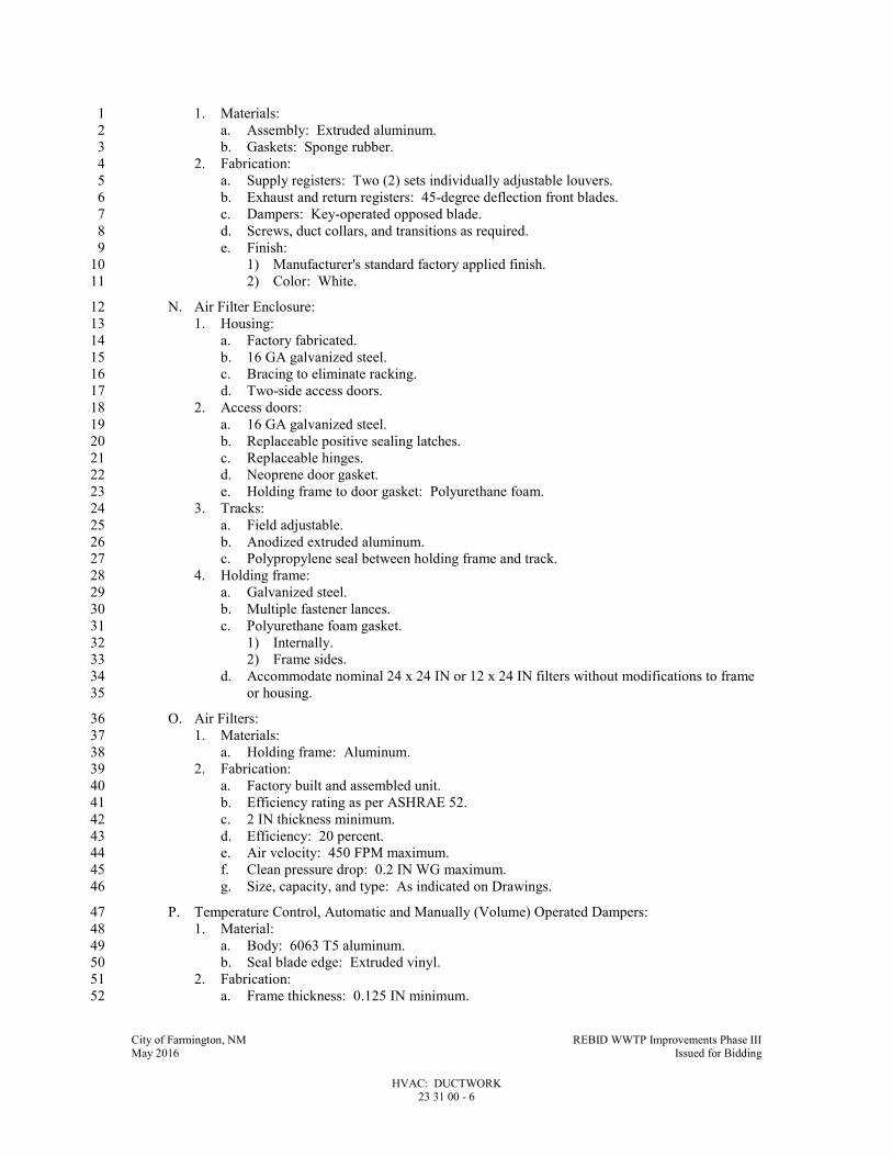
City of Farmington, NM REBID WWTP Improvements Phase III May 2016 Issued for Bidding
HVAC: DUCTWORK 23 31 00 - 6
1. Materials: 1
a. Assembly: Extruded aluminum. 2
b. Gaskets: Sponge rubber. 3
2. Fabrication: 4
a. Supply registers: Two (2) sets individually adjustable louvers. 5
b. Exhaust and return registers: 45-degree deflection front blades. 6
c. Dampers: Key-operated opposed blade. 7
d. Screws, duct collars, and transitions as required. 8
e. Finish: 9
1) Manufacturer's standard factory applied finish. 10
2) Color: White. 11
N. Air Filter Enclosure: 12
1. Housing: 13
a. Factory fabricated. 14
b. 16 GA galvanized steel. 15
c. Bracing to eliminate racking. 16
d. Two-side access doors. 17
2. Access doors: 18
a. 16 GA galvanized steel. 19
b. Replaceable positive sealing latches. 20
c. Replaceable hinges. 21
d. Neoprene door gasket. 22
e. Holding frame to door gasket: Polyurethane foam. 23
3. Tracks: 24
a. Field adjustable. 25
b. Anodized extruded aluminum. 26
c. Polypropylene seal between holding frame and track. 27
4. Holding frame: 28
a. Galvanized steel. 29
b. Multiple fastener lances. 30
c. Polyurethane foam gasket. 31
1) Internally. 32
2) Frame sides. 33
d. Accommodate nominal 24 x 24 IN or 12 x 24 IN filters without modifications to frame 34
or housing. 35
O. Air Filters: 36
1. Materials: 37
a. Holding frame: Aluminum. 38
2. Fabrication: 39
a. Factory built and assembled unit. 40
b. Efficiency rating as per ASHRAE 52. 41
c. 2 IN thickness minimum. 42
d. Efficiency: 20 percent. 43
e. Air velocity: 450 FPM maximum. 44
f. Clean pressure drop: 0.2 IN WG maximum. 45
g. Size, capacity, and type: As indicated on Drawings. 46
P. Temperature Control, Automatic and Manually (Volume) Operated Dampers: 47
1. Material: 48
a. Body: 6063 T5 aluminum. 49
b. Seal blade edge: Extruded vinyl. 50
2. Fabrication: 51
a. Frame thickness: 0.125 IN minimum. 52

City of Farmington, NM REBID WWTP Improvements Phase III May 2016 Issued for Bidding
HVAC: DUCTWORK 23 31 00 - 7
b. Provide flanged connections. 1
c. Blades: 2
1) Two-position damper: Parallel blade. 3
2) Mixing and volume damper: Opposed blade. 4
3) Airfoil shape. 5
4) Maximum 6 IN width. 6
d. Linkage: Concealed in frame. 7
e. Axles: 1/2 IN plated steel hex. 8
f. Bearings: Molded synthetic. 9
g. Seals: 10
1) Jamb: Flexible compression type. 11
h. Control shaft: Removable, 1/2 IN DIA. 12
i. Air leakage (4 FT SQ damper) at 4 IN WG pressure: 99 cfm maximum. 13
j. Motors for motor operated damper: See Specification Section 23 09 00. 14
k. Provide outboard support for operator linkage where damper motor is to be installed 15
outside of duct. 16
l. Provide stainless steel locking quadrants for manual (volume) dampers. 17
m. Provide fold out operator mounting bracket where damper motor is to be installed on 18
face of damper or inside duct. 19
n. Finish: 215 R1 anodized. 20
Q. Louvers: See Specification Section 08 90 00. 21
2.3 MAINTENANCE MATERIALS 22
A. Extra Materials: 23
1. Furnish Owner with the following extra materials: 24
a. Two complete filter media changes for each filter unit. 25
b. Filter media used during construction is in addition to this requirement. 26
PART 3 - EXECUTION 27
3.1 INSTALLATION 28
A. See Specification Section 40 05 05. 29
B. Metal Ductwork: 30
1. Install with longitudinal seams sealed for zero leakage. 31
a. For welded seams, submit sample for approval by Engineer. 32
2. Install gaskets at each transverse joint and fasten sections together with bolts. 33
a. Tighten for zero leakage. 34
3. Install supports and hangers with anchors in accordance with SMACNA HVAC Duct 35
Construction Standards. 36
4. Install turning vanes in square elbows: 37
a. Unsupported vane length not to exceed 48 IN. 38
b. Position vanes at proper angle to meet specified pressure drop. 39
5. Install flexible connections at fans: 40
a. Locate as close as possible to fan. 41
b. Allow 1 IN of slack to prevent vibration transmission. 42
c. Install thrust restraints across connectors. 43
6. Install access doors where indicated on Drawings and at smoke and fire damper in 44
accordance with NFPA requirements. 45
7. Volume extractors: 46
a. Install at supply registers, grilles, diffusers and supply branch connections from ducts. 47
b. Provide branch duct extensions into main duct above and below extractor when branch 48
duct is narrower than main duct. 49

City of Farmington, NM REBID WWTP Improvements Phase III May 2016 Issued for Bidding
HVAC: DUCTWORK 23 31 00 - 8
C. Flexible Ductwork: 1
1. Install in concealed areas between: low velocity duct work and diffusers, return air grilles 2
or exhaust outlets and ducts. 3
2. Use low loss fittings for connection to duct. 4
3. Connect to metal duct collars by means of non-combustible synthetic rubber sealing 5
compound and stainless steel drawband. 6
D. Drain Pans: 7
1. Install at fan coil cooling coils, control valves above finished ceilings and at other sources of 8
moisture. 9
2. Install metal tubing at drain and terminate above floor drain, equipment drain and as shown 10
on Drawings. 11
E. Acoustical Liners: 12
1. Install for a minimum length of 30 FT from equipment or mechanical room walls, 13
whichever is greater. 14
F. Dampers: 15
1. Install where indicated on Drawings of sizes shown. 16
2. Install fire and smoke dampers in ductwork passing through 1 HR or higher fire-rated 17
construction. 18
a. Install in wall and floor openings utilizing steel sleeves, angles and other materials 19
following practices required to provide installation in accordance with local Building 20
Codes. 21
G. Diffusers: 22
1. Install where shown on Drawings of size and capacities scheduled on Drawings. 23
2. Install painted lay-in type in lay-in ceilings. 24
3. Install prime painted diffusers in areas where duct work is concealed. 25
4. Install anodized diffusers in exposed duct work. 26
H. Air Grille and Register Assemblies: 27
1. Install where shown on Drawings of size and capacities scheduled on Drawings. 28
2. Install prime painted grilles and registers in areas where duct work is concealed. 29
a. Field paint to match adjacent surface finish. 30
I. Air Filters: 31
1. Install where shown on Drawings of size and capacity scheduled on Drawings. 32
2. Do not operate equipment during construction without filters. 33
34
END OF SECTION 35
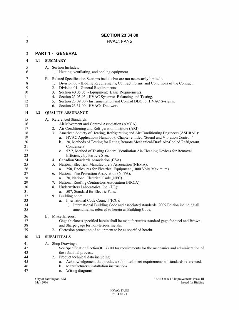
City of Farmington, NM REBID WWTP Improvements Phase III May 2016 Issued for Bidding
HVAC: FANS 23 34 00 - 1
SECTION 23 34 00 1
HVAC: FANS 2
PART 1 - GENERAL 3
1.1 SUMMARY 4
A. Section Includes: 5
1. Heating, ventilating, and cooling equipment. 6
B. Related Specification Sections include but are not necessarily limited to: 7
1. Division 00 - Bidding Requirements, Contract Forms, and Conditions of the Contract. 8
2. Division 01 - General Requirements. 9
3. Section 40 05 05 - Equipment: Basic Requirements. 10
4. Section 23 05 93 - HVAC Systems: Balancing and Testing. 11
5. Section 23 09 00 - Instrumentation and Control DDC for HVAC Systems. 12
6. Section 23 31 00 - HVAC: Ductwork. 13
1.2 QUALITY ASSURANCE 14
A. Referenced Standards: 15
1. Air Movement and Control Association (AMCA). 16
2. Air Conditioning and Refrigeration Institute (ARI). 17
3. American Society of Heating, Refrigerating and Air Conditioning Engineers (ASHRAE): 18
a. HVAC Applications Handbook, Chapter entitled "Sound and Vibration Control." 19
b. 20, Methods of Testing for Rating Remote Mechanical-Draft Air-Cooled Refrigerant 20
Condensers. 21
c. 52.2, Method of Testing General Ventilation Air-Cleaning Devices for Removal 22
Efficiency by Particle Size. 23
4. Canadian Standards Association (CSA). 24
5. National Electrical Manufacturers Association (NEMA): 25
a. 250, Enclosures for Electrical Equipment (1000 Volts Maximum). 26
6. National Fire Protection Association (NFPA): 27
a. 70, National Electrical Code (NEC). 28
7. National Roofing Contractors Association (NRCA). 29
8. Underwriters Laboratories, Inc. (UL): 30
a. 507, Standard for Electric Fans. 31
9. Building code: 32
a. International Code Council (ICC): 33
1) International Building Code and associated standards, 2009 Edition including all 34
amendments, referred to herein as Building Code. 35
B. Miscellaneous: 36
1. Gage thickness specified herein shall be manufacturer's standard gage for steel and Brown 37
and Sharpe gage for non-ferrous metals. 38
2. Corrosion protection of equipment to be as specified herein. 39
1.3 SUBMITTALS 40
A. Shop Drawings: 41
1. See Specification Section 01 33 00 for requirements for the mechanics and administration of 42
the submittal process. 43
2. Product technical data including: 44
a. Acknowledgement that products submitted meet requirements of standards referenced. 45
b. Manufacturer's installation instructions. 46
c. Wiring diagrams. 47

City of Farmington, NM REBID WWTP Improvements Phase III May 2016 Issued for Bidding
HVAC: FANS 23 34 00 - 2
d. Control diagrams. 1
e. Manufacturer's catalog cuts and technical data. 2
f. Corrosion-protection information. 3
g. Fan curves. 4
h. Sound data. 5
i. Vibration isolation. 6
j. Performance data on all equipment. 7
3. Certifications: 8
a. Provide certification of thickness of corrosion-protection coating. 9
B. Operation and Maintenance Manuals: 10
1. See Specification Section 01 33 04 for requirements for: 11
a. The mechanics and administration of the submittal process. 12
b. The content of Operation and Maintenance Manuals. 13
PART 2 - PRODUCTS 14
2.1 ACCEPTABLE MANUFACTURERS 15
A. Subject to compliance with the Contract Documents, the following manufacturers are 16
acceptable: 17
1. Vibration isolation assemblies: 18
a. Mason. 19
b. Vibration Mounting and Controls Co. 20
c. Vibro-Acoustics. 21
2. Corrosion-protective coatings: 22
a. Heresite and Chemical Co.; "Heresite." 23
b. Aero-Marine Engineering, Inc. 24
c. Luvata ElectroFin. 25
d. Energy Guard. 26
3. Rooftop centrifugal fans 27
a. Greenheck. 28
b. Cook. 29
c. Twin City. 30
4. Rooftop Fan Curbs 31
a. Pate. 32
b. RPS. 33
c. Thy. 34
d. Same as fan manufacturer. 35
5. Centrifugal fans: 36
a. Buffalo Forge. 37
b. New York Blower. 38
c. Aerovent. 39
d. Twin City. 40
e. Greenheck. 41
f. Cook. 42
6. In-line centrifugal fans : 43
a. New York Blower. 44
b. Aerovent. 45
c. Greenheck. 46
d. Cook. 47
e. Twin City. 48
7. Wall-mounted propeller-type exhaust fans: 49
a. Loren Cook. 50
b. Greenheck. 51

City of Farmington, NM REBID WWTP Improvements Phase III May 2016 Issued for Bidding
HVAC: FANS 23 34 00 - 3
c. PennBarry Ventilator Co., Inc. 1
d. Twin City. 2
8. Toilet room exhaust fans: 3
a. PennBarry Ventilator Co., Inc. 4
b. Loren Cook. 5
c. Greenheck. 6
d. Twin City. 7
B. Submit request for substitution in accordance with Specification Section 01 25 13. 8
2.2 GENERAL 9
A. All Manufactured Units: 10
1. Comply with Specification Section 40 05 05. 11
2. Factory wired and assembled. 12
3. Use fasteners made of same material as unit. 13
4. Fabricate motor assemblies and unit housings with vibration isolation assemblies: 14
a. Type: As per ASHRAE HVAC Applications Handbook. 15
B. Indicated manufactured units shall be constructed with corrosion-resistant materials or have 16
corrosion-resistant coating. 17
1. Type: 18
a. Corrosion-resistant materials: 19
1) Aluminum. 20
2) Stainless steel. 21
3) FRP. 22
b. Corrosion-resistant coating: 23
1) Phenolic-based coating or Epoxy-based coating. 24
2) 3 mil minimum dry thickness, air-dried coating, for surfaces exposed to 25
temperatures less than 150 DegF. 26
3) 5 mil baked-on coating for heat transfer surfaces and surfaces exposed to 27
temperatures greater than 150 DegF. 28
4) Factory applied. 29
5) Provide factory certification of application. 30
2.3 MANUFACTURED UNITS 31
A. Rooftop Centrifugal Fans 32
1. Fan Wheel: Centrifugal type, aluminum hub and wheel with backward inclined blades, 33
statically and dynamically balanced. 34
2. Housing: Removable, spun aluminum dome or rectangular top, with square, one piece, 35
aluminum base and curb cap with Venturi inlet cone. 36
3. Fan Shaft: Turned, ground and polished steel; keyed to wheel hub. 37
4. All steel parts galvanized or epoxy coated. Non-corrosive fasteners. 38
5. Direct drive, motor mounted outside of air stream and ventilated with outside air. 39
6. Aluminum or brass bird screen. Plastic mesh will not be allowed. 40
7. Furnish factory mounted and wired disconnect switch: Non-fusible type with thermal 41
overload protection mounted inside fan housing, factory wired through an aluminum 42
conduit. 43
8. Furnish solid-state dial speed controller. Mount and wire inside fan unless shown otherwise 44
on the drawings. Provide permanent marking at balanced point. 45
9. Furnish normally closed, electric motorized damper. Provide step-down transformer if 46
required. Install and wire damper to open when fan runs. 47
10. Dampers shall be aluminum with brass bushings, blade seals and blade tie rods. 48
11. Air-dried enamel custom color selected by Onwer/Architect. 49
12. Furnish permanently lubricated sealed ball type motor and drive shaft bearings. Motor and 50
wheel supported by vibration isolators. 51
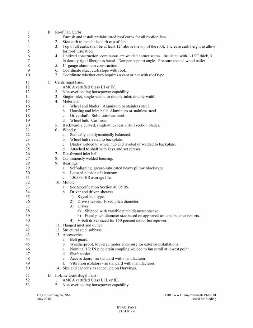
City of Farmington, NM REBID WWTP Improvements Phase III May 2016 Issued for Bidding
HVAC: FANS 23 34 00 - 4
B. Roof Fan Curbs 1
1. Furnish and install prefabricated roof curbs for all rooftop fans. 2
2. Size curb to match the curb cap of fan. 3
3. Top of all curbs shall be at least 12" above the top of the roof. Increase curb height to allow 4
for roof insulation. 5
4. Unitized construction, continuous arc welded corner seams. Insulated with 1-1/2” thick, 3 6
lb.density rigid fiberglass board. Damper support angle. Pressure treated wood nailer. 7
5. 14-gauge aluminum construction. 8
6. Coordinate exact curb slope with roof.. 9
7. Coordinate whether curb requires a cant or not with roof type. 10
C. Centrifugal Fans: 11
1. AMCA certified Class III or IV. 12
2. Non-overloading horsepower capability. 13
3. Single-inlet, single-width, or double-inlet, double-width. 14
4. Materials: 15
a. Wheel and blades: Aluminum or stainless steel. 16
b. Housing and inlet bell: Aluminum or stainless steel. 17
c. Drive shaft: Solid stainless steel. 18
d. Wheel hub: Cast iron. 19
5. Backwardly curved, single-thickness airfoil section blades. 20
6. Wheels: 21
a. Statically and dynamically balanced. 22
b. Wheel hub riveted to backplate. 23
c. Blades welded to wheel hub and riveted or welded to backplate. 24
d. Attached to shaft with keys and set screws. 25
7. Die-formed inlet bell. 26
8. Continuously welded housing. 27
9. Bearings: 28
a. Self-aligning, grease-lubricated heavy pillow block-type. 29
b. Located outside of airstream. 30
c. 150,000 HR average life. 31
10. Motor: 32
a. See Specification Section 40 05 05. 33
b. Driver and driven sheaves: 34
1) Keyed hub type. 35
2) Drive sheaves: Fixed pitch diameter. 36
3) Driver: 37
a) Shipped with variable pitch diameter sheave. 38
b) Fixed pitch diameter size based on approved test and balance reports. 39
4) V-belt drives sized for 150 percent motor horsepower. 40
11. Flanged inlet and outlet. 41
12. Structural steel subbase. 42
13. Accessories: 43
a. Belt guard. 44
b. Weatherproof, louvered motor enclosure for exterior installations. 45
c. Nominal 1/2 IN pipe drain coupling welded to fan scroll at lowest point. 46
d. Shaft cooler. 47
e. Access doors - as standard with manufacturer. 48
f. Vibration isolators - as standard with manufacturer. 49
14. Size and capacity as scheduled on Drawings. 50
D. In-Line Centrifugal Fans : 51
1. AMCA certified Class I, II, or III. 52
2. Non-overloading horsepower capability. 53

City of Farmington, NM REBID WWTP Improvements Phase III May 2016 Issued for Bidding
HVAC: FANS 23 34 00 - 5
3. Materials: 1
a. Wheel, impeller hub and blades: Aluminum or stainless steel. 2
b. Housing, innertube and belt well: Aluminum or stainless steel. 3
c. Inlet cone: Aluminum or stainless steel. 4
d. Driver shaft: Solid stainless steel. 5
4. Airfoil design blades. 6
a. All welded construction. 7
5. All welded housing, innertube and belt well. 8
6. Innertube construction: 9
a. Isolates bearings and drive from airstream. 10
b. Removable end covers. 11
7. Bearings: 12
a. Cast iron pillow blocks. 13
b. Concentric bearing locking collar for drive shafts 1 IN and larger. 14
1) SKF "ConCentra." 15
2) Dodge "D Lock." 16
c. Regreaseable. 17
d. 200,000 HR average life. 18
8. Motor: 19
a. See Specification Section 40 05 05. 20
b. Driver and driven sheaves: 21
1) Keyed hub type. 22
2) Drive sheaves: Fixed pitch diameter. 23
3) Driver: 24
a) Shipped with variable pitch diameter sheave. 25
b) Fixed pitch diameter size based on approved test and balance reports. 26
4) V-belt drives sized for 150 percent motor horsepower. 27
9. Adjustable motor base. 28
10. Automatic drive belt tensioner. 29
11. Flanged inlet and outlet. 30
12. Accessories: 31
a. Weatherproof, louvered motor enclosure for exterior installation. 32
b. Internal inlet damper with external control linkage. 33
c. Stack hood. 34
d. Cam type access door. 35
e. Ceramic felt shaft seal. 36
f. Extended grease links and fittings. 37
13. Size and capacity as scheduled on Drawings. 38
. 39
E. Wall-Mounted Propeller-Type Exhaust Fans: 40
1. AMCA certified. 41
2. Industrial quality. 42
3. Materials: 43
a. Propeller: Cast aluminum or aluminum. 44
b. Venturi: Spun aluminum. 45
c. Panel and supports: Aluminum or stainless steel. 46
d. Drive shaft: Solid stainless steel. 47
e. Sheaves: Cast iron. 48
4. Propellers: 49
a. Statically and dynamically balanced. 50
b. Airfoil design. 51
c. Minimum four (4) blades. 52
5. Bearings: 53
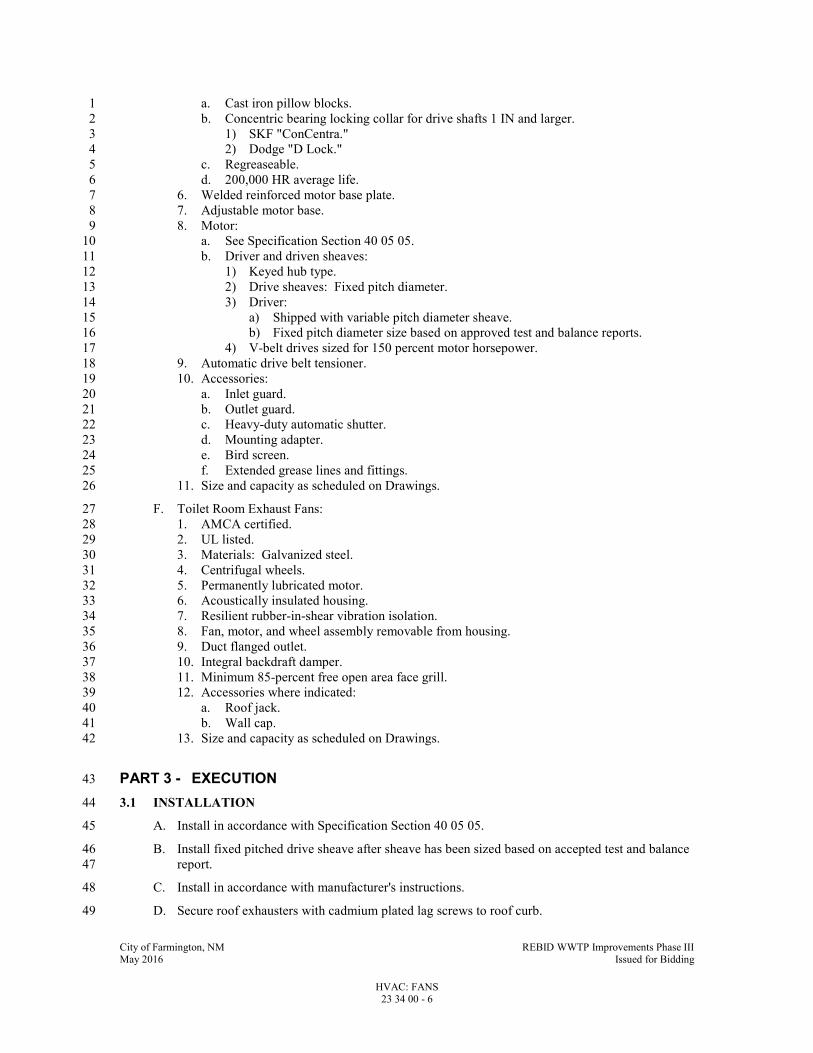
City of Farmington, NM REBID WWTP Improvements Phase III May 2016 Issued for Bidding
HVAC: FANS 23 34 00 - 6
a. Cast iron pillow blocks. 1
b. Concentric bearing locking collar for drive shafts 1 IN and larger. 2
1) SKF "ConCentra." 3
2) Dodge "D Lock." 4
c. Regreaseable. 5
d. 200,000 HR average life. 6
6. Welded reinforced motor base plate. 7
7. Adjustable motor base. 8
8. Motor: 9
a. See Specification Section 40 05 05. 10
b. Driver and driven sheaves: 11
1) Keyed hub type. 12
2) Drive sheaves: Fixed pitch diameter. 13
3) Driver: 14
a) Shipped with variable pitch diameter sheave. 15
b) Fixed pitch diameter size based on approved test and balance reports. 16
4) V-belt drives sized for 150 percent motor horsepower. 17
9. Automatic drive belt tensioner. 18
10. Accessories: 19
a. Inlet guard. 20
b. Outlet guard. 21
c. Heavy-duty automatic shutter. 22
d. Mounting adapter. 23
e. Bird screen. 24
f. Extended grease lines and fittings. 25
11. Size and capacity as scheduled on Drawings. 26
F. Toilet Room Exhaust Fans: 27
1. AMCA certified. 28
2. UL listed. 29
3. Materials: Galvanized steel. 30
4. Centrifugal wheels. 31
5. Permanently lubricated motor. 32
6. Acoustically insulated housing. 33
7. Resilient rubber-in-shear vibration isolation. 34
8. Fan, motor, and wheel assembly removable from housing. 35
9. Duct flanged outlet. 36
10. Integral backdraft damper. 37
11. Minimum 85-percent free open area face grill. 38
12. Accessories where indicated: 39
a. Roof jack. 40
b. Wall cap. 41
13. Size and capacity as scheduled on Drawings. 42
PART 3 - EXECUTION 43
3.1 INSTALLATION 44
A. Install in accordance with Specification Section 40 05 05. 45
B. Install fixed pitched drive sheave after sheave has been sized based on accepted test and balance 46
report. 47
C. Install in accordance with manufacturer's instructions. 48
D. Secure roof exhausters with cadmium plated lag screws to roof curb. 49

City of Farmington, NM REBID WWTP Improvements Phase III May 2016 Issued for Bidding
HVAC: FANS 23 34 00 - 7
E. If manufacturer has no recommendations, secure roof exhaust fans to curbs with 1/4”6 lag bolts 1
on 8” maximum centers. 2
F. MC shall install and wire factory provided damper to open when the fan runs if the manufacturer 3
does not provide an option to pre-wire the damper. 4
3.2 FIELD QUALITY CONTROL 5
A. Comply with Specification Section 23 05 93. 6
3.3 ADJUSTING 7
A. Install new filters on units which have been running prior to acceptance of Project. 8
END OF SECTION 10
City of Farmington, NM REBID WWTP Improvements Phase III May 2016 Issued for Bidding
REFRIGERANT PIPING SYSTEM 23 74 36 - 1
SECTION 23 74 36 1
REFRIGERANT PIPING SYSTEM 2
PART 1 - GENERAL 3
1.1 SUMMARY 4
A. Section Includes: 5
1. Refrigeration piping system. 6
B. Related Specification Sections include but are not necessarily limited to: 7
1. Division 00 - Bidding Requirements, Contract Forms, and Conditions of the Contract. 8
2. Division 01 - General Requirements. 9
3. Section 40 05 13 - Pipe and Pipe Fittings: Basic Requirements. 10
1.2 QUALITY ASSURANCE 11
A. Referenced Standards: 12
1. American Society of Heating, Refrigerating and Air Conditioning Engineers (ASHRAE): 13
a. 15, Safety Code for Mechanical Refrigeration. 14
2. ASTM International (ASTM): 15
a. B280, Standard Specification for Seamless Copper Tube for Air Conditioning and 16
Refrigeration Field Service. 17
3. Federal Specification (FS): 18
a. WW-T-799, Tube, Copper, Seamless, Water (For Use With Solder-Flared or 19
Compression-Type Fittings). 20
1.3 SUBMITTALS 21
A. Shop Drawings: 22
1. See Specification Section 01 33 00 for requirements for the mechanics and administration of 23
the submittal process. 24
2. Product technical data including: 25
a. Acknowledgement that products submitted meet requirements of standards referenced. 26
b. Manufacturer's installation instructions. 27
3. Test reports: 28
a. A dated declaration of the test of the refrigerant piping for each system shall be 29
provided. 30
1) The dated declaration shall include the information outlined in Article 12.3 of 31
ASHRAE 15. 32
b. Test reports of the refrigerant piping leak tests for all refrigerant piping systems 33
installed. 34
c. The test reports shall contain the following information: 35
1) System refrigerant and high and low side pressure used. 36
2) Listing of the necessary repairs made before the refrigerant piping system passed 37
the leak test. 38
3) Identification of specific system by referencing specific equipment identification 39
numbers. 40
4) Leak testing media used. 41
5) Suction and discharge refrigerant gas pressures and temperatures taken after the 42
refrigerant system has been charged. 43
B. Operation and Maintenance Manuals: 44
1. See Specification Section 01 33 04 for requirements for: 45
a. The mechanics and administration of the submittal process. 46
b. The content of Operation and Maintenance Manuals. 47

City of Farmington, NM REBID WWTP Improvements Phase III May 2016 Issued for Bidding
REFRIGERANT PIPING SYSTEM 23 74 36 - 2
1.4 WARRANTY 1
A. The completed refrigerant piping system shall be guaranteed to be sufficiently free from leaks so 2
that the loss of refrigerant for 18 months from the date of final payment shall not exceed 3
5 percent. 4
PART 2 - PRODUCTS 5
2.1 ACCEPTABLE MANUFACTURERS 6
A. Subject to compliance with the Contract Documents, the following manufacturers are 7
acceptable: 8
1. Refrigerant piping specialties: 9
a. Sporlan. 10
2. Expansion valves: 11
a. Sporlan. 12
b. Alcoa. 13
3. Silver solder - "Easy-Flow 45": 14
a. Harman. 15
4. Moisture indicator - "SEE-ALL": 16
a. Sporlan. 17
B. Submit request for substitution in accordance with Specification Section 01 25 13. 18
2.2 REFRIGERANT PIPING AND FITTINGS 19
A. Refrigerant Piping: 20
1. Copper tubing conforming to ASTM B280 and/or FS WW-T-799, dehydrated for refrigerant 21
use, with high-temperature soldered joints and wrought copper (400 psig) fittings. 22
a. For underground use: Type K. 23
b. For aboveground use: Type L. 24
B. Piping Joints: 25
1. Joints between copper tubing and fittings to be high temperature soldered (melting point not 26
less than 1000 DegF, but less than that of the metal being joined) with phos-copper alloys. 27
2. Joints between copper and brass, steel, etc., shall be silver soldered only. 28
a. Silver solder to be Handy Harmon "Easy-Flow 45." 29
C. Precharged Line Sets: Size per manufacturer's recommendations. 30
D. Field Assembled Units: 31
1. Size refrigeration lines according to manufacturer's published tables using pressure or 32
temperature drops as follows: 33
a. Suction lines: 2 DegF. 34
b. Liquid lines: 1 DegF or 2 psi. 35
c. Hot gas lines: 1 DegF or 3.6 psi. 36
d. Size discharge and hot gas risers for positive oil return to compressors. 37
E. Hangers: As specified in Specification Section 40 05 16. 38
2.3 REFRIGERANT PIPING SPECIALTIES 39
A. Refrigerant Dryer: 40
1. Sporlan material "CATCH-ALL" filter-drier with aluminum molded core: 41
2. In each liquid line. 42
3. A three-valve bypass around filter-drier. 43
4. Install so core can be removed without cutting or breaking any refrigerant line. 44
B. Moisture Indicator: 45
1. Show presence of moisture in system by change of color. 46

City of Farmington, NM REBID WWTP Improvements Phase III May 2016 Issued for Bidding
REFRIGERANT PIPING SYSTEM 23 74 36 - 3
2. Install full size in the main liquid line adjacent to the filter-drier. 1
3. Use Sporlan "SEE-ALL." 2
C. Strainers: 3
1. Design to permit removing screen without removing strainer from piping system. 4
2. Screens not larger than 80 mesh. 5
3. Strainers on liquid line serving each thermostatic expansion valve and in suction line 6
serving each refrigerant compressor not equipped with integral strainer. 7
D. Oil Traps: Provide in lines as indicated. 8
2.4 VALVES 9
A. All Valves: 10
1. All bronze. 11
2. 2 IN and less: Solder ends. 12
3. 3 IN and over: Four (4) bolt union ends. 13
B. Shut-Off Valves: 14
1. Packed type with gas-tight cap seal and hard metal seats and shoulders which permit 15
packing stuffing boxes wide open under pressure; or sealed diaphragm type. 16
2. Wheel, globe, angle or "T" handle. 17
C. Check Valves: 18
1. In liquid lines 5/8 IN and less: Lift check type. 19
2. In lines 3/4 to 2 IN: Swing check type. 20
3. In lines 3 IN and over: Wafer type swing check with bronze disc. 21
D. Expansion Valves: 22
1. Sized by manufacturer for refrigerant used. 23
2. Provide one (1) in each circuit with liquid distributor connection immediately after. 24
E. Vent and Test Valves: Angle cap type with seal and outlet caps. 25
PART 3 - EXECUTION 26
3.1 INSTALLATION 27
A. Precharged Line Sets: Install per manufacturer's recommendations. 28
B. Field Assembled Lines: 29
1. Refrigerant piping: 30
a. In accordance with Specification Section 40 05 13. 31
b. Purge refrigerant piping of all air while connections of refrigerant piping are being 32
made. 33
1) Shut-off valves. 34
2) Connect tank of dry nitrogen to line on back side of valve. 35
3) Introduce dry nitrogen into line as refrigerant piping joints are successively made 36
up from valve to each condenser. 37
2. Testing: 38
a. Refrigerant piping systems: Follow general testing guidelines of ASHRAE 15, except 39
as modified herein. 40
b. Pressurize the high and low pressure sides of the piping system after completion of the 41
refrigerant piping. 42
1) Pressurize at the test pressures specified in ASHRAE 15 for the refrigerant type to 43
be used in the system. 44
c. Repair any leaks and repeat tests until no further leaks are found and the system passes 45
a static leak test at test pressure for a duration of 24 HRS. 46
3. Cleaning: 47
City of Farmington, NM REBID WWTP Improvements Phase III May 2016 Issued for Bidding
REFRIGERANT PIPING SYSTEM 23 74 36 - 4
a. Disconnect suction and discharge lines from compressor for clean up after complete 1
system is tested. 2
b. Valve or blank off system into three (3) separate systems for purpose of cleanup. 3
1) Suction side including cooling coils. 4
2) Discharge side including air cooled condenser. 5
3) Hot gas reheat side including heating DX coils. 6
c. Thoroughly clean each system using pumped refrigerant until system is proven clean to 7
satisfaction of refrigeration compressor serviceman. 8
d. Notify Engineer for a visual inspection of both cleaning process and completely cleaned 9
system. 10
4. Evacuation and Drying: 11
a. After tests and cleaning have been completed and system proved tight, charge each 12
circuit with dry clean refrigerant to gas pressure as recommended by the equipment 13
manufacturer. 14
b. Evacuate to 100 micron Hg and hold for 72 HRS. 15
1) Use laboratory type vacuum pump capable of holding absolute pressure of 50 16
micron Hg. 17
2) Check the vacuum with a suitable mercury column gage. 18
c. Admit another drying charge of refrigerant and allow 4 to 6 HRS to absorb moisture 19
and install dryer cores. 20
d. Use second evacuation to remove all refrigerant and moisture. 21
e. After second evacuation, charge system with refrigerant. 22
f. Charge the system with refrigerant as required after final evacuation. 23
END OF SECTION25

City of Farmington, NM REBID WWTP Improvements Phase III May 2016 Issued for Bidding
HVAC: EQUIPMENT 23 80 00 - 1
SECTION 23 80 00 1
HVAC: EQUIPMENT 2
PART 1 - GENERAL 3
1.1 SUMMARY 4
A. Section Includes: 5
1. Heating, ventilating, and cooling equipment. 6
B. Related Specification Sections include but are not necessarily limited to: 7
1. Division 00 - Bidding Requirements, Contract Forms, and Conditions of the Contract. 8
2. Division 01 - General Requirements. 9
3. Section 40 05 05 - Equipment: Basic Requirements. 10
4. Section 23 05 93 - HVAC Systems: Balancing and Testing. 11
5. Section 23 09 23 - Instrumentation and Control DDC for HVAC Systems. 12
6. Section 23 31 00 - HVAC: Ductwork. 13
1.2 QUALITY ASSURANCE 14
A. Referenced Standards: 15
1. Air Movement and Control Association (AMCA). 16
2. Air Conditioning and Refrigeration Institute (ARI). 17
3. American Society of Heating, Refrigerating and Air Conditioning Engineers (ASHRAE): 18
a. HVAC Applications Handbook, Chapter entitled "Sound and Vibration Control." 19
b. 20, Methods of Testing for Rating Remote Mechanical-Draft Air-Cooled Refrigerant 20
Condensers. 21
c. 52.2, Method of Testing General Ventilation Air-Cleaning Devices for Removal 22
Efficiency by Particle Size. 23
4. Canadian Standards Association (CSA). 24
5. National Electrical Manufacturers Association (NEMA): 25
a. 250, Enclosures for Electrical Equipment (1000 Volts Maximum). 26
6. National Fire Protection Association (NFPA): 27
a. 70, National Electrical Code (NEC). 28
7. National Roofing Contractors Association (NRCA). 29
8. Underwriters Laboratories, Inc. (UL): 30
a. 507, Standard for Electric Fans. 31
9. Building code: 32
a. International Code Council (ICC): 33
1) International Building Code and associated standards, 2009 Edition including all 34
amendments, referred to herein as Building Code. 35
B. Miscellaneous: 36
1. Gage thickness specified herein shall be manufacturer's standard gage for steel and Brown 37
and Sharpe gage for non-ferrous metals. 38
2. Corrosion protection of equipment to be as specified herein. 39
1.3 SUBMITTALS 40
A. Shop Drawings: 41
1. See Specification Section 01 33 00 for requirements for the mechanics and administration of 42
the submittal process. 43
2. Fabrication and/or layout drawings. 44
3. Product technical data including: 45
a. Acknowledgement that products submitted meet requirements of standards referenced. 46
b. Manufacturer's installation instructions. 47
City of Farmington, NM REBID WWTP Improvements Phase III May 2016 Issued for Bidding
HVAC: EQUIPMENT 23 80 00 - 2
c. Wiring diagrams. 1
d. Control diagrams. 2
e. Manufacturer's catalog cuts and technical data. 3
f. Corrosion-protection information. 4
g. Fan curves. 5
h. Sound data. 6
i. Vibration isolation. 7
j. Control description. 8
k. Performance data on all equipment. 9
4. Certifications: 10
a. Provide certification of thickness of corrosion-protection coating. 11
B. Operation and Maintenance Manuals: 12
1. See Specification Section 01 33 04 for requirements for: 13
a. The mechanics and administration of the submittal process. 14
b. The content of Operation and Maintenance Manuals. 15
PART 2 - PRODUCTS 16
2.1 ACCEPTABLE MANUFACTURERS 17
A. Subject to compliance with the Contract Documents, the following manufacturers are 18
acceptable: 19
1. Vibration isolation assemblies: 20
a. Mason. 21
b. Vibration Mounting and Controls Co. 22
c. Vibro-Acoustics. 23
2. Corrosion-protective coatings: 24
a. Heresite and Chemical Co.; "Heresite." 25
b. Aero-Marine Engineering, Inc. 26
c. Luvata ElectroFin. 27
3. Cooling coils - direct expansion: 28
a. Carrier. 29
b. Daikin Applied. 30
c. Trane, 31
d. Johnson Controls. 32
4. Heating coil - electric: 33
a. Carrier. 34
b. Daikin Applied. 35
c. Trane. 36
d. Johnson Controls. 37
5. Unit heater - electric: 38
a. Brasch. 39
b. Chromalox. 40
c. QMark. 41
6. Duct heaters - electric: 42
a. Brasch. 43
b. Industrial Engineering and Equipment Co. 44
7. Make-up air units, electric: 45
a. Greenheck. 46
b. Cook. 47
c. Hastings. 48
d. Daikin Applied. 49
e. Trane. 50
f. Carrier. 51
City of Farmington, NM REBID WWTP Improvements Phase III May 2016 Issued for Bidding
HVAC: EQUIPMENT 23 80 00 - 3
g. Johnson Controls. 1
8. Air-cooled condensing units - split system: 2
a. Carrier. 3
b. Daikin Applied. 4
c. Trane. 5
d. Johnson Controls 6
9. Air-handling unit with coils: 7
a. Daikin Applied. 8
b. Trane. 9
c. Carrier. 10
d. Johnson Controls. 11
10. Unitary split system heat pump: 12
a. Carrier. 13
b. Lennox. 14
c. Bryant. 15
d. Trane. 16
e. Johnson Controls. 17
11. Positive pressurization unit: 18
a. Purafil. 19
b. American Air Filter. 20
c. Circul-Aire 21
B. Submit request for substitution in accordance with Specification Section 01 25 13. 22
2.2 GENERAL 23
A. All Manufactured Units: 24
1. Comply with Specification Section 40 05 05. 25
2. Factory wired and assembled. 26
3. Use fasteners made of same material as unit. 27
4. Fabricate motor assemblies and unit housings with vibration isolation assemblies: 28
a. Type: As per ASHRAE HVAC Applications Handbook. 29
B. Indicated manufactured units shall be constructed with corrosion-resistant materials or have 30
corrosion-resistant coating. 31
1. Type: 32
a. Corrosion-resistant materials: 33
1) Aluminum. 34
2) Stainless steel. 35
3) FRP. 36
b. Corrosion-resistant coating: 37
1) Phenolic-based or Epoxy based coating: 38
2) 3 mil minimum dry thickness, air-dried coating, for surfaces exposed to 39
temperatures less than 150 DegF. 40
3) 5 mil baked-on coating for heat transfer surfaces and surfaces exposed to 41
temperatures greater than 150 DegF. 42
4) Factory applied. 43
5) Provide factory certification of application. 44
2.3 MANUFACTURED UNITS 45
A. Equipment Coils: 46
1. Cooling coils - direct expansion: 47
a. ARI certified. 48
b. Material: 49
1) Aluminum. 50
2) Copper with aluminum fins for use in administration units only. 51
City of Farmington, NM REBID WWTP Improvements Phase III May 2016 Issued for Bidding
HVAC: EQUIPMENT 23 80 00 - 4
c. Fin spacing: Minimum 80 fins per foot. 1
d. Minimum standard operating limit: 250 psi. 2
e. Size and capacity as scheduled. 3
2. Heating coil - electric: 4
a. ARI certified. 5
b. 80-percent nickel, 20-percent chromium elements. 6
c. Maximum heating density: 35 watts/SQ IN. 7
d. Built-in thermal protection. 8
e. Airflow switch. 9
f. Built-in circuit fusing. 10
g. Control voltage transformer. 11
h. Terminal block. 12
i. Magnetic contactor. 13
j. Fused disconnect switch. 14
k. Step controller as required by instrumentation. 15
l. Single point electrical connection. 16
m. Size and capacity as scheduled on Drawings. 17
B. Unit Heater - Electric: 18
1. Type: Horizontal. 19
2. UL listed for non-rated areas. 20
3. Material: 21
a. Cabinet: 18 GA steel. 22
b. Heating elements: Copper-clad steel. 23
4. Fan motors: 24
a. See Specification Section 40 05 05. 25
b. Built-in automatic reset overload protection. 26
5. Dynamically balanced fan. 27
6. Built-in automatic reset cutout protection. 28
7. Accessories: 29
a. Mounting bracket. 30
b. 40 to 90 DegF, 5 DegF differential internal thermostat. 31
8. Electrical, fan motor, and airflow data as scheduled on Drawings. 32
C. Unit Heater - Electric: 33
1. UL listed, corrosion-resistant washable. 34
2. Material: 35
a. Fan: Non-sparking aluminum. 36
b. Heater case: Stainless steel. 37
c. Heating fintube. 38
d. Junction box: NEMA 4X. 39
3. Fan motor: 40
a. See Specification Section 40 05 05. 41
b. Built-in overload protection. 42
4. Louvered outlet grille. 43
5. Rear grille. 44
6. Built-in over temperature protection. 45
7. Accessories: 46
a. Mounting bracket: Stainless steel. 47
D. Duct Heaters - Electric: 48
1. UL listed for zero clearance. 49
2. Materials: 50
a. Frame: Stainless steel. 51
b. Heating elements: 80-percent nickel and 20-percent chromium. 52

City of Farmington, NM REBID WWTP Improvements Phase III May 2016 Issued for Bidding
HVAC: EQUIPMENT 23 80 00 - 5
c. Element terminals: Stainless steel. 1
d. Insulators and bracket bushings: Non-porous ceramic. 2
e. Terminal box: Aluminized steel. 3
3. Heating elements: 4
a. Coils: See paragraph(s) in Article 2.3, Equipment Coils. 5
4. Automatic reset thermal cutout. 6
5. Standard, manually replaceable, thermally operated secondary cutout. 7
6. Duct mounting: Slip-in. 8
7. Size and capacity as scheduled on Drawings. 9
E. Make-Up Air Units, Electric: 10
1. ARI certified. 11
2. Sectionalized construction. 12
3. Materials: 13
a. Cabinet: Galvanized steel. 14
b. Scroll housing: Galvanized steel. 15
4. Blower section: 16
a. Blower wheels: 17
1) Statically and dynamically balanced. 18
2) Forwardly curved double width, double inlet. 19
3) Mounted on solid turned ground steel shaft. 20
b. Bearings: 21
1) Self-aligning grease lubricated ball type. 22
2) Extended lubrication lines with external grease fittings. 23
3) Average life rating: 200,000 HRS. 24
c. Blower scrolls, bearings and adjustable base to be mounted on reinforced angle iron 25
frame. 26
d. Internal spring isolation. 27
e. Driver and driven sheaves: 28
1) Keyed hub type. 29
2) Drive sheaves: Fixed pitch diameter. 30
3) Driver: Variable pitch diameter sheave. 31
4) V-belt drives sized for 150 percent motor horsepower. 32
f. Motors: See Specification Section 40 05 05. 33
g. Insulated cabinet. 34
5. Heating section: 35
a. Coils: See paragraph(s) in Article 2.3, Equipment Coils. 36
b. Insulated cabinet. 37
6. Drain pan: Double pan construction, insulated. 38
7. Accessories: 39
a. Factory-built heavy-duty filter section with access doors. 40
b. Filters: See Specification Section 23 31 00. 41
c. Combination Angular filter and mixing box with parallel acting blade dampers. 42
d. Inlet hood with birdscreen. 43
e. Prefabricated insulated roof curb. 44
8. Motor starter. 45
9. Size and capacity as scheduled on Drawings. 46
F. Air-Cooled Condensing Units - Split System: 47
1. ARI rated. 48
2. UL listed. 49
3. Materials: 50
a. Casing: Galvanized steel. 51
b. Mounting/lifting rails: Steel. 52
c. Outdoor coil: Seamless aluminum tubing and aluminum fins. 53

City of Farmington, NM REBID WWTP Improvements Phase III May 2016 Issued for Bidding
HVAC: EQUIPMENT 23 80 00 - 6
d. Fan blades: Aluminum. 1
4. Weatherproof casing: 2
a. Hail screen for condenser coil. 3
b. Access panels. 4
5. Compressor: 5
a. Hermetically sealed. 6
b. Internal pressure protector. 7
c. Crankcase heater. 8
d. Internal spring mounts. 9
e. Centrifugal oil pump. 10
f. Built-in overload protection. 11
6. Condenser fans and motors: 12
a. Vertical discharge. 13
b. Direct drive. 14
c. Statically and dynamically balanced. 15
d. Motor: 16
1) See Specification Section 40 05 05. 17
2) Permanently lubricated bearings. 18
3) Built-in current and thermal overload protection. 19
7. Built-in refrigerant filter dryer. 20
8. Built-in liquid line and gas line service valves with gage ports. 21
9. Outdoor coil: 22
a. Fins mechanically bonded to tubing. 23
b. Lab tested to 2000 psi. 24
10. 24 V factory-wired controls to include fusing and control power transformer. 25
11. Size and capacity as scheduled on Drawings. 26
G. Air-Handling Unit with Coils: 27
1. ARI certified. 28
2. UL listed. 29
3. Unit Construction: 30
a. Fabricate unit with 16 GA channel posts and panels secured with mechanical fasteners. 31
1) Seal all panels, access doors, and ship sections with permanently applied bulb-type 32
gasket. 33
2) Loose shipped gasketing is not allowed. 34
b. Construct panels and access doors as a 2 IN nominal thick; thermal broke double wall 35
assembly, injected with foam insulation for an R-value of not less than R-13. 36
1) Construct the outer panel and the inner liner of G90 galvanized steel. 37
c. Panel deflection: 38
1) Do not exceed L/240 ratio at 125 percent of design static pressure, maximum 39
positive or negative 8 IN of static pressure. 40
2) Measure deflection at the midpoint of the panel height. 41
d. Casing leakage rate: Do not exceed 0.5 cfm per square foot of cabinet area at 6 IN of 42
negative static pressure or 5 IN of positive static pressure. 43
e. Module to module assembly: 44
1) Provide an overlapping, full perimeter, insulated, internal splice joint sealed with 45
bulb type gasketing on both mating modules to minimize on-site labor and meet 46
indoor air quality standards. 47
f. Entire unit: Provide a 4 IN full perimeter base rail for structural rigidity and condensate 48
trapping. 49
g. Access doors: 50
1) Flush mounted to cabinetry, with minimum of two (2), 6 IN long stainless steel 51
piano-type hinges, latch and full size (4.5 IN minimum) handle assembly (provide 52
inspection window for fan section). 53

City of Farmington, NM REBID WWTP Improvements Phase III May 2016 Issued for Bidding
HVAC: EQUIPMENT 23 80 00 - 7
2) Swing outward for unit sections under negative pressure (inward for unit sections 1
under positive pressure). 2
3) Provide a secondary latch to relieve pressure and prevent injury upon access on 3
doors limited from swinging inward (such as side access filter sections) on positive 4
pressure sections. 5
h. Construct drain pans from microbial resistant coated galvanized steel or stainless steel 6
with cross break and double sloping pitch to drain connection. 7
1) Provide drain pans under cooling coil section. 8
2) Drain connection centerline: A minimum of 3 IN above the base rail to aid in 9
proper condensate trapping. 10
3) Drain connections that protrude from the base rail are not acceptable. 11
4) There must be a full 2 IN thickness of insulation under drain pan. 12
4. Fan section: 13
a. Fans: 14
1) Double-width, double-inlet, multiblade centrifugal type. 15
2) Statically and dynamically balanced. 16
3) Solid shafts. 17
4) Forward curved fans. 18
5) Die formed fan housing. 19
6) 200,000 HR grease lubricated ball-bearings. 20
5. Motors: See Specification Section 40 05 05. 21
6. V-belts and drives sized for 150 percent motor capacity. 22
7. Heating coil section: 23
a. Water - steam: See paragraph(s) in Article 2.3, Equipment Coils. 24
b. Electric: See paragraph(s) in Article 2.3, Equipment Coils. 25
8. Cooling coil section: 26
a. Direct expansion: See paragraph(s) in Article 2.3, Equipment Coils. 27
b. Water: See paragraph(s) in Article 2.3, Equipment Coils. 28
9. Filter section: 29
a. Filters: See Specification Section 23 31 00. 30
b. Non-insulated cabinet. 31
c. Access doors for filter removal. 32
10. Insulated drain pan with drain connections. 33
11. Control panel for electric heat: 34
a. Integral. 35
b. Controls and safety devices, factory-wired, in accordance with NFPA 70 requirements. 36
c. NEMA 12 construction. 37
12. Type: Draw through. 38
13. Size and capacity as scheduled on Drawings. 39
H. Unitary Split System Heat Pump: 40
1. Outdoor Unit: 41
a. Casing and frame: 42
1) Material: Heavy gage galvanized steel, factory painted. 43
2) Insulation: 1 IN thick neoprene-coated glass fiber. 44
3) Installation: Base equipped with lifting brackets with lifting holes. 45
4) Removable end panel for access to components and connections. 46
b. Compressors: 47
1) Scroll type, with 5 year non-prorated warranty. 48
2) Suction and discharge service valves. 49
3) Crankcase heater. 50
4) Thermal overload protection. 51
c. Refrigeration circuit: 52
1) Sight glass. 53

City of Farmington, NM REBID WWTP Improvements Phase III May 2016 Issued for Bidding
HVAC: EQUIPMENT 23 80 00 - 8
2) Filter dryer. 1
3) Manual shut-off valve. 2
4) High pressure relief valve. 3
d. Compressor isolators. 4
e. Condenser coils: 5
1) Nominal 3/8 IN OD seamless copper mechanically bonded to corrugated aluminum 6
fins. 7
2) Factory leak tested at 315 psig under water. 8
f. Condenser fans: 9
1) Direct drive: See Specification Section 40 05 05. 10
2) Propeller type. 11
g. Condenser fan motors: 12
1) Heavy duty, inherently protected, non-reversing. 13
2) Permanently lubricated bearings. 14
3) Integral rain shield. 15
h. Defrost control: Defrost cycles at a preselected time interval when the outdoor coil is 16
below a preset initiation temperature. 17
i. Expansion valve: Designed and sized specifically for heat pump service. 18
j. Reversing valve: Four-way interchange reversing valve, operates on pressure 19
differential between the outdoor unit and indoor unit. 20
2. Indoor unit: 21
a. Materials: 22
1) Casing: Heavy gage steel. 23
2) Framework: Steel angle. 24
3) Pan insulation: Foam-in-place insulation. 25
4) Casing insulation: 1 IN, 3/4 LB fiberglass blanket. 26
b. Casing: 27
1) Sectionalized construction. 28
2) Removable access panels. 29
3) Insulated weatherproof casing. 30
c. Evaporated fans: 31
1) Double-width, double-inlet centrifugal type. 32
2) Forward curved or airfoil. 33
3) Solid steel shafts. 34
4) 200,000 HR relubricative ball-bearings. 35
d. Fan motors: 36
1) See Specification Section 01 61 03. 37
2) Relubricative ball-bearings. 38
3) Variable pitch sheave. 39
4) Adjustable base. 40
e. V-belts and drives sized for 150 percent motor capacity. 41
f. Isolated fan assembly. 42
g. Filter section: 43
1) Filters: See Specification Section 23 31 00. 44
2) Access doors for filter removal. 45
h. Evaporator coils: See paragraph(s) in Article 2.3, Equipment Coils. 46
i. Evaporator coil circuiting: 47
1) Adjustable thermal expansion valve per circuit with external equalizer. 48
2) Combination row/split face circuiting. 49
j. Drain pan: 50
1) Mastic-coated. 51
2) Threaded drain connections. 52
k. Electric heating coil: See paragraph(s) in Article 2.3, Equipment Coils. 53
1) Built-in static-pressure airflow switch. 54

City of Farmington, NM REBID WWTP Improvements Phase III May 2016 Issued for Bidding
HVAC: EQUIPMENT 23 80 00 - 9
l. Size and capacity as scheduled on Drawings. 1
I. Positive Pressurization Unit: 2
1. Self contained. 3
2. Pressurization air as scheduled. 4
3. Total delivered air with recirculation as scheduled. 5
4. Vertical configuration. 6
5. Four (4) stages of air purification. 7
a. First stage: ASHRAE 30 percent removal filter. 8
b. Second stage: Media modules filled with 50 LBS of media. 9
c. Third stage: Same as second. 10
d. Fourth stage: Varicel 2HC, MERV15. 11
6. Materials: 12
a. Unit: 14 GA cold rolled steel. 13
b. Modules: Perforated aluminum sheets. 14
c. Stage supports: Aluminum track with sealing material. 15
7. Blower: 16
a. Location: Between second and third stage. 17
b. Wheel: Backward curved, aluminum. 18
c. VFD drive. 19
d. Motor: See Specification Section 01 61 03. 20
8. Module media: 21
a. Pelletized. 22
b. Activated alumina impregnated with a minimum of 8 percent potasium permanganate. 23
c. 100 LB of media shall remove 14 LB hydrogen sulfide; 14 percent minimum by 24
weight. 25
d. Inorganic. 26
e. Non-toxic. 27
f. Non-flammable. 28
g. Shall not support bacterial or fungal growth. 29
9. Media performance certification (manufacturer's responsibility): 30
a. Performed by laboratory of Owner's (Engineer's) choice. 31
b. Test procedure: Pass moist (85 percent RH) air containing 10 (plus or minus 1) ppm 32
hydrogen sulfide gas at a rate of 2900 ml per minute through a 1.0 IN diameter by 6.0 33
IN deep uniformly packed bed. 34
c. Test shall run continuous for 48 HRS. 35
d. During test down stream concentration of hydrogen sulfide shall never exceed 0.05 36
ppm. 37
10. Gages: 38
a. Outside air flow. 39
b. Room pressure. 40
c. Pressure differential across first stage. 41
d. Pressure differential across final stage. 42
11. Size and capacity as scheduled on Drawings. 43
PART 3 - EXECUTION 44
3.1 INSTALLATION 45
A. Install in accordance with Specification Section 40 05 05. 46
B. Install fixed pitched drive sheave after sheave has been sized based on accepted test and balance 47
report. 48

City of Farmington, NM REBID WWTP Improvements Phase III May 2016 Issued for Bidding
HVAC: EQUIPMENT 23 80 00 - 10
3.2 FIELD QUALITY CONTROL 1
A. Comply with Specification Section 23 05 93. 2
3.3 ADJUSTING 3
A. Install new filters on units which have been running prior to acceptance of Project. 4
END OF SECTION 6
Copyright © 2022 FDOKUMEN