Hydropower Technology for Sustainable Energy Generation in ...
Upload
khangminh22Category
view
1download
0
New York State Energy Research and Development Authority
Hydropower from Wastewater
Final Report
December 2011
No 12-04
NYSERDArsquos Promise to New Yorkers New Yorkers can count on NYSERDA for
objective reliable energy-related solutions
delivered by accessiblededicated professionals
Our Mission Advance innovative energy solutions in ways that improve New Yorkrsquos
economy and environment
Our Vision Serve as a catalystmdashadvancing energy innovation and technology
transforming New Yorkrsquos economy and empowering people to choose
clean and efficient energy as part of their everyday lives
Our Core Values Objectivity integrity public service and innovation
Our Portfolios NYSERDA programs are organized into five portfolios each representing a complementary group of offerings with common areas of energy-related focus and objectives
Energy Efficiency amp Renewable Programs Helping New York to achieve its aggressive clean energy goals ndash
including programs for consumers (commercial municipal institutional
industrial residential and transportation) renewable power suppliers
and programs designed to support market transformation
Energy Technology Innovation amp Business Development
Helping to stimulate a vibrant innovation ecosystem and a clean
energy economy in New York ndash including programs to support product
research development and demonstrations clean-energy business
development and the knowledge-based community at the Saratoga
Technology + Energy Parkreg
Energy Education and Workforce Development
Helping to build a generation of New Yorkers ready to lead and work
in a clean energy economy ndash including consumer behavior K-12
energy education programs and workforce development and training
programs for existing and emerging technologies
Energy and the Environment
Helping to assess and mitigate the environmental impacts of
energy production and use ndash including environmental research and
development regional initiatives to improve environmental sustainability
and West Valley Site Management
Energy Data Planning and Policy
Helping to ensure that policy-makers and consumers have objective
and reliable information to make informed energy decisions ndash including
State Energy Planning policy analysis to support the Low-Carbon
Fuel Standard and Regional Greenhouse Gas Initiative nuclear policy
coordination and a range of energy data reporting including Patterns and Trends
HYDROPOWER FROM WASTEWATER
Final Report
Prepared for the
NEW YORK STATE ENERGY RESEARCH AND
DEVELOPMENT AUTHORITY
Albany NY nyserdanygov
Kathleen OConnor Senior Project Manager
Prepared by
ADVANCED ENERGY CONVERSION LLC SCHENECTADY NY
David A Torrey
Project Manager
NYSERDA NYSERDA 10879 December 2011
Report 12-04
NOTICE
This report was prepared by Advanced Energy Conversion LLC in the course of performing work for and sponsored by the New York State Energy Research and Development Authority (hereafter ldquoNYSERDArdquo) The opinions expressed in this report do not necessarily reflect those of NYSERDA or the State of New York and reference to any specific product service process or method does not constitute an implied or expressed recommendation or endorsement of it Further NYSERDA the State of New York and the contractor make no warranties or representations expressed or implied as to the fitness for particular purpose or merchantability of any product apparatus or service or the usefulness completeness or accuracy of the processes methods or other information contained described disclosed or referred to in this report NYSERDA the State of New York and the contractor make no representation that the use of any product apparatus process method or other information will not infringe privately owned rights and will assume no liability for any loss injury or damage resulting from or occurring in connection with the use of information contained described disclosed or referred to in this report
ii
Table of Contents Executive Summary 1
Introduction and Overview 2
Design of the Prototype TurbineGenerator System 3
Specification Development 3
Turbine Design 6
Generator Design11
Magnetic Design11
Mechanical Design 11
Electronic Power Conversion Design 13
Switched-Mode Rectifier 16
Utility Interactive Inverter 18
Evaluation of the Prototype TurbineGenerator System 20
Dry Testing 20
Wet Testing 24
Test Results25
Tear Down Analysis 33
Pilot Demonstration 33
Business Development of the TurbineGenerator System 37
Market Opportunity 37
Reasons for Wastewater Treatment Facilities as Target Market 37
The Opportunity I - Cost Benefits37
The Opportunity II - Environmental Benefits 38
AECrsquos Customers 38
End Customers ndash Decision Makers39
Market Size 39
Target Markets and Segmentation 39
Market Trends ndash Increasing Energy Prices 41
Market Trends ndash Increasing Governmental Support42
Market Trends - WWTPs Invest in Improving Energy Efficiency 42
Competition 42
Summary 44
iii
EXECUTIVE SUMMARY
This project designed prototyped and evaluated a 15kW integrated turbinegenerator system for application to capturing flow energy contained within the effluent stream at wastewater treatment plants The specification for the prototype system was based on a survey of wastewater treatment plants in New York State it is expected that plants of similar size and diversity exist in other states and countries The prototype system was designed to deliver 15kW of electric power to the utility grid when supplied with a flow of 12 million gallons per day (MGD) and a head of 12 feet
This project was undertaken through the collaborative efforts of Advanced Energy Conversion LLC (prime contractor) Turbo Solutions Engineering LLC and Clark Engineering amp Surveying PC all small businesses The objective of the project was to develop and demonstrate technology that could address capturing energy from flowing water and converting that energy into electricity that could be used to offset operating expenses or create an untapped revenue stream
Using concurrent design the turbine design was integrated into the design of a permanent magnet generator Consistent with the head and flow of the prototype turbine a propeller-type turbine was selected This choice was also consistent with the relatively low heads available at wastewater treatment plants The rotor of the generator was integrated into the outer rim of the turbine rotor
Design of the turbine rotor was supported by one- and three-dimensional flow analysis that was subsequently verified using computational fluid dynamics (CFD) analysis The generator design was based on a fractional slot stator winding that minimized end turn length and simplified the construction of the stator The stator of the generator was integrated into the mechanical design of the turbinegenerator support structure This support structure included a tapered inlet section that allowed the entire turbinegenerator to be housed within a section of pipe that was of standard size Mounting the turbine generator within a section of pipe allows for turbinegenerator maintenance without putting personnel at risk or requiring the flow at the WWTP outfall to be shut down even temporarily
Fabrication and test showed that the integrated system operated largely as designed The significance of the turbine efficiency curve on system performance was underestimated during the design process In hindsight it might have been appropriate to select a different type of turbine with a broader efficiency curve Selecting another style of turbine however would have substantially complicated the system design because of the challenges associated with routing the fluid through the turbine and generator
An analysis of the potential turbinegenerator market within wastewater treatment plants suggests a potential United States market size of $50 -- $100 million by serving the 2600 wastewater treatment plants that are viable candidates for the technology Accessing this market will require modest cost reductions in the turbinegenerator system that should be achievable
Extending the turbinegenerator to other markets is possible Nevertheless these markets are likely characterized by requiring higher head Operating at higher head allows the possibility of
1
increased energy capture without substantially increasing the size of the turbinegenerator Operation at higher head would require the selection of a different type of turbine which might improve overall system operation over varying speeds It would be vital to maintain as much simplicity in system design as possible
Introduction and Overview
There are more than 15000 publicly owned wastewater treatment facilities in the United States These facilities process in excess of 34000 million gallons of water per day (34000 MGD) There is energy of increasing value contained in the effluent stream representing an emerging business opportunity It is worthy of note that there are similar applications with substantially larger amounts of energy available These applications include raw water transmission lines run of river hydro water-intensive industrial processes and gravity fed public water supplies
The project described in this report evaluates the potential for building a business around harvesting energy in wastewater effluent streams This business could easily grow into other markets notably the potable public water supply in which pressure reduction valves are used to throttle (reduce) the pressure by dissipating energy rather than capturing it Industrial processes that are heavy users of water are also likely candidates This project focuses on wastewater because
bull Wastewater treatment plants (WWTPs) are large consumers of electrical energy thereby creating a ready use for any energy captured from the effluent stream Electricity is the second largest operating cost at WWTPs representing 25 to 40 of the total operating budget Pressure reduction valves distributed throughout the public water supply do not necessarily have the same natural load present where the energy is harvested
bull Wastewater treatment plants are hungry to reduce their energy consumption making them open to trying new technology with an acceptable risk mitigation plan
bull There are no licensing requirements as with many water flows
A business to serve the wastewater treatment industry must be based on
bull Developing an integrated turbinegenerator that can be installed in effluent flows converting flow power into electrical power The turbinegenerator must be able to be easily customized to the available head and flow at each facility Each installation cannot represent a custom design
bull Developing the associated power and control electronics that simplifies the interface of the captured energy into the wastewater treatment plant electricity grid through a motor control center or other appropriate interconnection point
bull Developing a generic installation approach that minimizes interruption to the operation of the wastewater treatment plant In addition the ability to bypass the turbinegenerator must be incorporated as well as a means for maintaining the equipment without interrupting the operation of the balance of the plant
2
bull Developing a business model for deploying the technology that respects the purchasing practicesrequirements of municipalities avoids capital construction projects for the wastewater treatment plant and goes beyond a simple equipment purchase to provide sustained cash flow
The following sections of this report address the technical development and demonstration of an integrated turbinegenerator system that was designed to support application in a wastewater treatment plant The business case is considered also with the technology case and the business case converging to support the project conclusions
Design of the Prototype TurbineGenerator System
The design of the prototype turbinegenerator system was driven by a review of requirements for various wastewater treatment facilities Emphasis was placed on New York State plants with the expectation that plants in other states and countries would have similar requirements
Specification Development
A review of data from the NYS Department of Environmental Conservation indicates that there are 78 WWTPs with a rated flow of 5 MGD broken down as follows
bull 28 in the range of 5 to 10 MGD bull 29 in the range of 10 to 40 MGD and bull 21 above 40 MGD
The plants having flow rates in the range of 10 to 40 MGD was selected for further analysis Seven of these plants were visited Detailed flow data were collected from 15 plants Survey data and interviews were conducted with 25 plants Subcontractor Clark Engineering amp Surveying PC assisted with this effort
Key findings from the interviews include
bull An intense interest and desire to use the technology bull There is a diverse range of operating conditions physical designs and economics bull The equipment must be designed suitably for installation it cannot interfere with
operations or EPA data requirements it must be low maintenance and it must have a 10 ndash 30 year life
bull A payback of five years is needed but plants have widely varying electricity costs ranging from $006 to $016 kWh plus varying demand charges
bull Over 50 of the plants are suited to installation of standardized intake structure at outfall after final process Other designs are also possible
bull For a target power yield of 10 ndash 20 kW an installed cost of less than $50k meets interest level
It was concluded by the design team that critical factors for commercial success include
bull The available head or velocity at the plant bull The ability of the turbinegenerator unit to be tolerant of submergence
3
(b) (a)
Figure 2 The most desirable locations of the turbinegenerator system (a) schematically at the outfall following the final process (b) a picture showing the flow can either be caught at the
outfall or in the pit where the flow is directed into the output channel
Figure 1 Possible locations of the turbinegenerator system
bull Ease of installation access bull Ease of maintenance access bull Absolutely no backwater impact on the process or EPA testing and bull Proximity to power usage is an important factor in the installation cost
Figure 1 depicts the possible locations of the turbinegenerator equipment From the survey it was clear that the equipment needed to be downstream of the last process Beyond that location is driven by energy capture ease of installation ease of maintenance and minimizing installation cost Given that cable lengths are minimized by locating the turbinegenerator equipment close to the final outfall Figure 2 suggests the preferred placement of the equipment
4
Figure 3 provides a distribution of the head and flow for the surveyed plants The plants with the highest product of head and flow represent the best opportunities For the prototype system emphasis was placed on average daily flows in excess of 10 MGD and heads of 10 ft or more
0 5 10 15 20 25 30 0
5
10
15
20
25
30
35 )t
ead (
fH
Average Daily Flow (MGD)
Vertical Drop
High Velocity Pipe
Both
Neither
Figure 3 The distribution of head and flow for the surveyed WWTPs
A summary of operator data collected during the interviews includes
bull 75 of the WWTPs have suitable hydraulic drop for energy recovery with over 50 in ldquoidealrdquo range
bull 30 of the WWTPs have pipes with significant velocity head some have both pipes and outfall opportunity
bull 25 of the WWTPs could accommodate 2 or more units bull Only 15 of the WWTPs have neither suitable hydraulic drop nor significant velocity
head bull Two thirds of the operators expressed a very strong interest in the project and are willing
to provide additional review and feedback bull 80 of the operators have a 480V MCC andor equipment for power utilization in close
proximity to the outfall and bull A 5 year return on investment is essential for energy saving capital budget approval
Specifications elements driven by market research include
bull Intake design must be flexible to match site requirements to turbine generator capacity bull Allow for customization and low cost bull Ease and low cost of installation removal and maintenance bull The equipment must survive constant contact with the effluent and bull Have a usable life of 10 to 30 years
5
Table 1 summarizes the operational parameter range of the turbinegenerator with the design target for the experimental prototype
Table 1 A summary of turbinegenerator parameters practical ranges to address the WWTP market and the design targets for the experimental system
Parameter Range Prototype Design Target Units Fluid Water with debris aeration
turbulence Water with debris aeration turbulence
Head 1 ndash 20 10 ndash 12 feet Volumetric Flow Rate 5 ndash 100 5 ndash 20 MGD Rotational Speed 400 ndash 800 600 rpm Turbine Efficiency 75 ndash 95 gt 90 Output Power 1 ndash 200 15 kW
Turbine Design
Turbo Solutions Engineering assisted Advanced Energy Conversion (AEC) in the design of a turbo-generator for use in wastewater treatment plants Figure 4 shows a turbine selection curve based on head and flow Because of the low head in the intended application the selected turbine runner is a fixed-pitch propeller type turbine with no wicket gates to assist in the control of the flow entering the runner Structural struts are located just downstream of the runner This type of hydraulic turbine tends to have an efficiency characteristic with a sharp peak because it has fixed geometry developed for a specific operating condition As shown in Figure 5 if the turbine is operating slightly off the design condition the efficiency will be reduced dramatically
6
Figure 4 A turbine selection chart based on flow and head
Figure 5 Efficiency characteristics as a function of normalized flow for different types of turbines
7
Turbine design was based on one- and three-dimensional hydrodynamic design and analysis Computational fluid dynamic (CFD) analysis was used to refine the design Solid modeling of the rotor inlet housing diffuser and structural supports were developed to build a complete picture of the turbine design Figure 6 shows the volumetric flow rate as a function of head at different turbine rotational speeds with contours of hydraulic efficiency superimposed Figure 7 shows the power output available as a function of head consistent with the turbine curves shown in Figure 6 To maximize power output operation at higher turbine speed is preferable This is also consistent with the desire to minimize generator size
Structural analysis was performed to determine rotor steady state stresses and natural frequencies Structural analysis was also applied to the rotor support structure
Figure 6 Volume flow rate as a function of head for turbine operation at various speeds
8
Figure 7 Turbine power as a function of head for operation at various speeds
A summary of the turbine design is given in Table 2
Table 2 A summary of turbine design parameters
During the evolution of the design of the turbine the design conditions changed while some of the operating parameters remained fixed The design head was increased significantly (from 4 ft to 12 ft of head) while the diameter and rotational speed of the runner were unchanged The reason for the change was that the design team realized that more head was available at most of the potential installation sites and the available power is directly proportional to the head so there was good cause for the change of the design condition The diameter was left unchanged for packaging reasons and the rotational speed was not increased for generator reliability
9
concerns This resulted in changes to the turbine design parameters that impact the preferred type of turbine or result in a performance penalty for the type of turbine that had been selected The best hydraulic efficiency that can be expected at the appropriate design conditions for a full-size full-optimized propeller type turbine that was selected early in the design process is about 90 as shown in Figure 5 At the size of the AEC machine Reynolds number and clearance effects will lower the maximum attainable efficiency In addition the struts downstream of the runner and exit diffuser (draft tube) restrictions will further lower the peak attainable efficiency
The power specifi c speed is a parameter that is used to determine the appropriate type of turbine to us e for a giv en rotational speed flow and head The equation for power specific
N-Ispeed is Ns = H54 In US units the N is the rotational speed in rpm P is power in hp
and H is head in ft Lower head values tend to result in higher power specific speeds and initially the design target was for a power specific speed of 160 to 180 As Figure 8 shows higher power specific speeds lead the designer to select axial flow turbines like a Kaplan or propeller type As the power specific speed drops the designer would tend to use a turbine with some radial component to the incoming flow During the design process for this project the change in head from 4 ft to 12 ft allowed P (power) to increase but N remained fixed at 400 rpm and the power specific speed dropped down to about 100 This level of power specific speed would lead the designer to favor a mixed flow (mixed radial and axial flow entering the turbine) more like a Francis type turbine rather than a propeller type turbine Using a Francis turbine requires additional components specifically wicket gates to control the flow entering the turbine At the point in the design process that the design head increased it was not feasible to change from the propeller type turbine to a mixed-flow turbine Also although a propeller turbine at the increased head took a hit in efficiency it is likely that the manufacturing costs are much less than they would be for a mixed-flow turbine and the fixed propeller turbine will still generate significantly more power than it would have at the lower head value
10
Figure 8 A guide for turbine type selection based on power specific speed
Generator Design
Magnetic Design
Early in the project it was determined that the priorities of the magnetic design were to maximize generator efficiency maximize the flatness of the generator efficiency curve and to minimize active magnetic material Maximizing efficiency over a wide speed range ensures that the turbine generator system would be widely applicable to a variety of flow conditions Minimizing active magnetic material reduces system cost and weight In addition to these three priorities all mechanical and electrical connection constraints had to be respected Several of the constraints are explored in more depth below
Mechanical Constraints
Turbine runner design at the design point of 12 ft head indicated peak efficiency at about 400 rpm with peak power delivered at 600 rpm These speeds were used to determine generator operation point and peak efficiency point
The generator design was constrained by the turbine runner and the desire to make the turbine-generator unit mate with a 30rdquo pipe bolt flange The generator design was limited to a ldquopancakerdquo aspect ratio by the diameter and axial length of the turbine runner Thermal constraints limit the generator power rating
Turbine Runaway Constraint
Further limiting design was the turbinersquos runaway speed As the electric machine was a permanent magnet machine (PMM) the voltage generated is a function of machine speed If the electronics detected a system fault such as a loss of grid power the electronics would be unable to load the generator With the turbine effectively unloaded it would speed up to its ldquorunawayrdquo speed the speed at which point the turbine delivers no torque At this speed the generator must not produce a voltage which is higher than the electronics can tolerate As a result the voltage which the generator produces in its operational range must be reduced in order to not exceed safe voltage during a runaway condition This has an unfortunate effect of reducing generator efficiency in the operational range Alternatively it can be thought of ldquodeshyratingrdquo the generator The generator is technically a 40 kW generator at 1200 rpm which is de-rated to a 20 kW generator at 600 rpm
Design Description
The generator is a 45 slot 40 pole 20 kW at 600 rpm design It is a ldquofractional slotrdquo machine which implies that there are a non-integer number of slots per pole (1125 slots per pole) Rated torque of the generator is 3183 Nm at 600 rpm above 600 rpm torque falls off inversely proportional to speed maintaining 20 kW output power out to 1280 rpm It should be noted that the torque fall off with speed is accomplished through the power electronics the generator design does not contain any element which would limit its output power above 600 rpm At 1200 rpm the generator produces 530 Vrms line to line consistent with an electrical interface with a 750 V DC bus
Finite element analysis of the generator at full torque was performed in house and by Magsoft see Figure 9 Both analyses agreed that the peak tooth flux density near 16 T indicating that
11
magnetic design is not being pushed it is likely that the generator could produce twice rated torque by pushing additional current through the windings A detailed thermal analysis would need to be performed however test results suggest the generator could tolerate increased currents
Analytical and numerical simulations of generator operation were performed to predict and optimize efficiency The predicted efficiency curve for the generator is given below in Figure 10 The efficiency curve uses a predicted power curve of the turbine for 12 ft of head Low speed efficiency is limited due to insufficient generator voltage (consistent with the runaway speed constraint) while high speed efficiency is low due to insufficient power supplied by turbine Regardless the efficiency curve of the generator is quite flat maintaining above 90 efficiency for over 900 rpm (75 of total speed range) Peak predicted generator efficiency was 973 occurring around 400 rpm
Figure 9 Magnitude of magnetic flux density in machine with machine producing rated torque
12
Figure 10 Analytical prediction of motor efficiency as a function of speed Efficiency prediction relies on a predicted power curve from turbine at 12 ft head Low efficiency at low speed is due to low motor voltage Low efficiency at high speed is due to a reduction in the amount of power
available from the turbine runner
Design Philosophy
The generator design was started after preliminary turbine design was completed in order to constrain the design In order to minimize system size reduce cost and meet mechanical requirements we determined that the electric machine should have a high pole count A higher pole count allows for a thinner rotor and stator ldquoback-ironrdquo due to a decrease in the magnetic flux that each pole must support This also has the benefit of reducing system weight and cost
In order to improve system efficiency we wished to maximize the coil area which implies that we should minimize the number of teeth An integral slot design would require a minimum of 3 slots per pole We therefore decided a fractional slot design would be appropriate The fractional slot design has the additional benefit of reducing cogging torque which will push down the low speed cutoff of the generator An 8 pole to 9 tooth ratio is a desirable ratio for a variety of reasons which allowed us to restrict our search We used numerical optimization methods to home in on a 40 pole 45 slot design A final round of magnetic optimizations was performed on the fractional slot design using finite element analysis
Mechanical Design
The turbinegenerator was intended to integrate into a wastewater environment as seamlessly as possible To that end the design interfaces natively with 18-inch ductile iron pipe - a common fixture at wastewater treatment facilities The inner and flange dimensions of this pipe style approximate the dimensions required for the generator and the standard mounting pattern
13
provides a common means of attachment across multiple installations The outermost housing diameter was limited so that the final assembly could easily fit within a size 30 ductile iron pipe sleeve to provide a wider variety of installation options Figure 11 shows a cutaway view of the turbine generator installed in a section of pipe
Figure 11 A cutaway view of the turbine-generator installed in a section of pipe
The generator housing is constructed in three primary sections O-ring seals were used between these sections to contain the flow of water To prevent water damage the generator windings were encapsulated with epoxy through a VPI (vacuum-pressure impregnation) process As the particular epoxy used in this process is talc-filled this also afforded reasonable heat conduction from the windings to the environment Figure 12 shows a picture of the encapsulated stator in its housing
14
Figure 12 The encapsulated stator in its housing
Due to the rotor speeds and operating conditions of this machine retention of the magnets was given special consideration Magnets were surface-mounted to the rotor via a magnet-bonding adhesive chosen both for bond strength and for reliability A carbon fiber wrap was also installed around the magnets This wrap not only secures the magnets in place but also protects them from debris and corrosion during operation
The prototype unit was outfitted with ports for thermocouples to measure bearing temperature during dry testing as well as three rings of four pressure taps each The pressure taps were machined integral to the turbinegenerator housing and located at the entrance to the generator immediately after the turbine runner and at the generator outlet These were intended to give a more accurate picture of turbine performance
The turbine-generator bearing system was selected primarily for ease of installation and availability of components As such it is not ideally suited for long-term exposure to underwater conditions The intention during wet testing of the machine was to determine the degree of corrosion and other degradation that could be expected of standard bearing components in a freshwater effluent environment
Electronic Power Conversion Design
The structure of the electronic power conversion system is shown in Figure 13 The system is comprised of a switched-mode rectifier that rectifies the generator output into a fixed dc bus voltage The switched-mode rectifier processes the variable voltage variable frequency output of the generator into dc A utility interactive inverter regulates the dc bus voltage exchanging power with the utility as required to do so Before the generator starts producing power the inverter will draw power from the utility to regulate the dc bus voltage Once the generator starts to output power through the switched-mode rectifier the inverter will send power to the utility such that the dc bus voltage is regulated For maximum flexibility the prototype conversion
15
electronics were designed to support 20kW even though the prototype system was intended to only generator 15kW
Figure 13 The structure of the electronic power conversion system
Switched-Mode Rectifier
A high-level schematic for the switched-mode rectifier (SMR) is given in Figure 14 Each phase of the generator is modeled as a voltage source acting behind phase resistance and inductance The SMR is formed using three diodes in a common-anode connection connected to the positive side of the dc bus Three fully-controllable devices with anti-parallel diodes complete the bridge connected to the negative side of the dc bus The three controllable devices are operated in unison When these devices are conducting the generator terminals are effectively shorted together When the controllable devices are off the generator terminals see a conventional uncontrolled rectifier The use of the controllable devices causes the generator to operate as if the dc bus voltage were at some value that falls between zero and the actual dc bus voltage
16
Figure 14 A high level schematic of the switched-mode rectifier
The SMR allows increased power extraction from the generator relative to that achievable with an uncontrolled rectifier This combined with the simple structure and control makes the SMR attractive relative to a fully-controlled inverter Through the SMR it is possible to implement maximum power point tracking to maximize the energy extracted from the generator By adjusting the percentage of time the controllable devices are conducting (also known as the duty ratio) it is possible to change the loading on the generator As the generator load increases the speed of the generator is reduced potentially increasing the output power It is also possible to decrease the load on the generator allowing the generator speed to increase and seek a more productive operating point
Figure 15 shows the expected output power as a function of SMR duty cycle for a dc bus voltage of 150V Similar characteristics are possible with other dc bus voltages with an appropriate change in duty cycle The objective of maximum power point tracking is to automatically adjust the duty ratio to maximize the output power regardless of the turbine speed or the dc bus voltage
17
Outp
ut P
ow
er (k
W)
40
35
30
25
20
15
10
5
0
150
250
RPM
RPM
350
450
RPM
RPM
550
650
750
RPM
RPM
RPM
04 05 06 07 08 09 1
Duty Cycle for Switches
Figure 15 The expected generator output power as a function of SMR duty ratio with a dc bus voltage of 150V
Utility Interactive Inverter
Figure 16 shows a high level schematic of the utility interactive inverter used to interface the SMR to the electric utility The voltage sources shown are the utility voltages The inductance is used within the inverter to support the instantaneous differences between the inverter output voltages and the utility phase voltages The resistance is the parasitic resistance of the inductor and the utility connection
18
Figure 16 A high level schematic of the utility-interactive inverter
Through the switching of the controllable devices it is possible to regulate the inverter output currents to be of high quality and in phase with the utility voltages This corresponds to high power factor operation It will be appreciated that operation at non-unity power factor may be desirable to support reactive power needs within the utility system Figure 17 shows representative waveforms created by the utility interactive inverter
Figure 17 Representative waveforms produced by the utility interactive inverter The pink yellow and blue waveforms correspond to the utility voltages on phases a b and c
respectively The green waveform is the phase a current It is seen to be out of phase with the phase a voltage indicating power is flowing from the dc bus to the utility
19
Figure 18 shows the electronic conversion system It is housed in an industrial enclosure A heat sink for cooling t he power semiconductors extends out the back of the enclosure The disconnect switches on the sides of the enclosure are for the generator (left) and utility (right) The SMR is at the top and the utility interactive inverter is on the bottom The components on the right side are filter components used in smoothing the inverter ac current waveforms
Figure 18 The prototype electronic power conversion system
SMR
Inverter
Inverter
output
filter
Evaluation of the Prototype TurbineGenerator System
Evaluation of the prototype turbinegenerator system consisted of dry testing and wet testing The dry testing was conducted in-house and the objective of the testing was to confirm that the generator was fabricated consistent with its design and that the interface to the electronics worked properly The dry testing provided an opportunity to evaluate the efficiency of the generator the SMR and the utility-interactive inverter
Wet testing was conducted at Alden Research Laboratory in Holden MA Alden has a long history of hydraulic testing The testing at Alden was based on the fully integrated turbinegenerator system and was intended to allow data collection to focus on the turbine performance as a function of flow and head
Dry Testing
Dry testing was comprised of the following elements
bull Basic Set-Up and Operationo Winding verification (rotor installed)
Phase inductance Phase resistance (tested with power applied)
20
o Mechanical clearances Vertical orientation Horizontal orientation
o Bearing and cogging torque Torque wrench Low-speed transducer measurement
o Back EMF waveform check Spin by hand 1rpm ~057V line to line Check using scope ndash 3 differential channels between line to line voltages Check for symmetry
o Shaft alignment bull FrequencyStructural Testing
o Frequency response Unloaded test ndash no SMR or load resistors Run a sweep from 0-800rpm (50rpm increments) Allow speed to settle between measurements Data to obtain
bull Actual speed bull Eddy current torque at each point bull Note any potential resonances bull Line to line back EMF waveforms at each point for 5 electrical
cycles at min sample rate = 73(20rpm60) Hz (5600Hz 800rpm)
bull Temperatures o Ambient o Magnets o Bearing o Stator slot o Stator end turn
o Magnet adhesive and wrap integrity test Slowly bring generator up to anticipated runaway speed (1250rpm
25rpm increments from 800rpm) Verify structural integrity of system Data to obtain
bull Actual speed bull Eddy current torque at each point bull Note any potential resonances bull Line to line back EMF RMS values for each phase bull Temperatures
o Ambient o Magnets o Bearing o Stator slot o Stator end turn
bull Generator Characterization o Drive motor in speed control (loaded tests)
Loaded tests ndash load resistor banks bull Resistor banks produce rated current at 600rpm bull At constant load 800rpm testing will overcurrent the phase
windings by 33
21
Run tests from 200-800rpm drive motor speed Data to obtain (for each test)
bull Actual load resistance used bull Actual speed bull Torque bull Measure a single line to line voltage and phase current for 5
electrical cycles at min sample rate = 73(20rpm60) Hz bull Extracted power (power meter) bull Available power (torque transducer and induction drive) bull Line to line back EMF RMS values for each phase bull Temperatures
o Stator slot o Stator end turn o Magnets o Ambient
o Drive motor in speed control (loaded tests) Loaded tests ndash SMR engaged Run tests from 200-800rpm drive motor speed at several SMR duty
ratios Data to obtain (for each test)
bull Actual speed bull Torque bull Measure a single line to line voltage and phase current for 5
electrical cycles at min sample rate = 73(20rpm60) Hz bull Inverter current THD bull Extracted power (controller output verified using power meter) bull Line to line back EMF RMS values for each phase bull RMS grid voltage and current bull Temperatures
o Stator slot o Stator end turn o Magnet (PWM heating) o Ambient
Verify overpower condition current-limiting bull Set current saturation to arbitrarily small value bull Assign drive motor speed control and generator speed command
setpoint such that the new current limit would be violated (but still be within electrical design limits)
o SMR Control Algorithm Testing (loaded tests) Loaded test ndash SMR engaged Wastewater Speed control algorithm
bull Set drive motor to a fixed torque command bull Set TG to various speed commands bull Data to obtain for each test
o Initial speed o Actual speed (instantaneous and waveform) o Torque o A single RMS Line to Line voltage and phase current o Real-Time Data
22
Torque commands (from controller) Current output (from controller) CAN bus can provide up to 200Hz data rate
o RMS grid voltage and current o Temperatures
Slot End turns Magnet Ambient
bull Verification made if speed held constant at command bull Adjust control constants if needed re-run test
o Drive motor in torque-speed mode (MPPT) MPPT control algorithm test 1
bull For two separate drive motor T-S curves bull Hold TG in speed control mode on desired side of peak available
power curve bull With system at speed and stable engage MPPT algorithm bull Repeat starting on other side of peak available power curve bull Data to obtain for each test
o Steady-state speed (and waveform) o Steady-state torque (and waveform) o A single RMS line to line voltage and phase current o Real-Time Data
Speed commands (from controller) Current output (from controller) CAN bus can provide up to 200Hz data rate
o RMS grid voltage and current o Power out using power meter o Settling time o Temperatures
Slot End turn Magnet Ambient
MPPT control algorithm test 2 bull For two separate drive motor T-S curves translated relative to
each other bull Hold TG in speed control mode on desired side of peak available
power curve bull With system at speed and stable engage MPPT algorithm bull When system is stable change drive motor T-S profile to other
curve bull Measure data for transition period between two curves bull Repeat test transitioning back to first curve bull Data to obtain for each test
o Steady-state speed (and waveform) o Steady-state torque (and waveform) o A single RMS line to line voltage and phase current o Real-Time Data
Speed commands (from controller)
23
Current output (from controller) CAN bus can provide up to 200Hz data rate
o RMS grid voltage and current o Power out using power meter o Settling time o Temperatures
Slot End turn Magnet Ambient
bull Limit Tests o Engage electronics from runaway (unloaded) conditions
Begin with lower rpm tests before testing runaway (verify expected response)
400rpm 800rpm 1250rpm test points Drive motor begins in torque mode with a maximum speed command set
at desired initial condition Engage generator speed control mode at a lower speed setpoint Repeat with MPPT algorithm (drive motor in T-S mode with maximum
speed command set at desired initial condition)
Wet Testing
Wet testing was comprised of the following elements
bull Set-Up Preparation o Attach pressure tap fittings before connection to Alden facility o Verify correct electronics grid connection o Ensure all test equipment electronics personnel are out of splash or leak
contact and are protected against electrical fault o Measure bearing torque
bull Verify runaway speed ndash No power extracted (open circuit) o Begin test at zero head o Slowly increase applied head in 2ft increments
Head to be determined by pressure drop across system (P1-P5) Allow rpm to settle before moving to the next point Make note of rpm settling time (for future time estimates)
o Data to obtain for each test point Pressures
bull P1 P5 from Alden bull P2 P3 P4 from controller (transducers)
Flow rate Actual speed Temperatures
bull Stator slot bull Stator end turn bull Water bull Ambient
o Test is complete when 12ft of head is reached OR turbine speed exceeds 1250rpm
24
o If speed is less than 1250rpm at end of test decision can be made to increase applied head until the calculated runaway speed is reached
bull Generator Characterization ndash Resistor Bank bull Generator Characterization ndash SMR Engaged
o Power Extraction Vs Head Set generator to speed control mode beginning at a 900 RPM setpoint At each speed setpoint adjust applied system head (P1-P5 as measured
by Alden) in 2ft increments from runaway head corresponding to starting speed up to a maximum of 14ft
Allow pressures and speed to settle - generator speed settles quickly while applied system head measurements are noisy and require time to settle at desired operating point
Data to obtain (for each test) bull Alden pressures (P1-P5) bull TG pressures (P2 P3 P4) bull Turbine speed bull Water flow rate bull Power extracted (meter) bull Phase voltage (RMS) bull Phase current (RMS) bull Temperatures
o Slot o End turn o Water o Ambient
o MPPT Testing Hold TG in speed control mode on desired side of peak available power
curve With system at speed and stable engage MPPT algorithm Measure accuracy of tracking and response time Repeat starting other side of peak available power curve
bull Final Required Tests o Bearing torque
Test Results
Figure 19 shows the combined efficiency of the generator SMR and inverter as a function of operating point These data were collected during dry testing Overall electrical performance is quite good with efficiencies hovering between 85 and 92 over much of the intended operating region Efficiency tends to fall off as power output drops This is typical of this type of system since the generator and power electronics will have losses that are relatively independent of operating point These losses become more significant as the output power is reduced leading to lower component and system efficiencies
Figure 20 shows the same data as in Figure 19 but as contours of efficiency The black line delimits the region explored during dry testing
25
94
80
100
88
90
92
Eff
icie
ncy
()
60 86
40 84
82
20 80
10000
15000
0
Power Out (W)
5000 400
600
800
Speed (RPM)
74
76
78
Figure 19 The combined efficiency of the generator SMR and inverter as a function of
operating speed and output power
157184 94
142964 92
128743 90
114523 88
Pow
er
Out
(W)
100303 86
860833 84
718632 80
82
576432 78
434231 76
292031 74
300
14983 360 420 480 540 600 660 720 780 840 900
Speed (RPM)
Figure 20 Electrical efficiency contours as a function of speed and output power
26
Figure 21 shows a surface plot of the output power as a function of turbine speed and applied head These data were collected during wet testing The steepness of the surface is not surprising given the efficiency characteristics of the propeller-type of turbine shown in Figure 5
14000
12000
10000
15000
10000
Pow
er
(W)
8000
5000 6000
0 4000
600
800
1000
Speed (RPM) 400 4
6 8
10
Head (ft)
12 14
0
2000
Figure 21 A surface plot of the output power as a function of turbine speed and applied head
Figure 22 provides a surface plot of the turbine efficiency as a function of turbine speed and applied head Turbine efficiency was backed out of the total system efficiency using the models of the generator SMR and inverter losses developed during the dry testing
50
45
50 40
40
Eff
icie
ncy
() 35
30 30
20 25
10 20
600
800
1000
0
Speed (RPM) 400 4
6 8
10
Head (ft)
12 14
0
5
10
15
Figure 22 A surface plot of turbine efficiency as a function of turbine speed and applied head
27
Figure 23 shows the combined electrical efficiency of the generator SMR and inverter as a function of turbine speed and applied head Efficiency has a tendency to drop off at high speeds and low heads an operating region where the turbinegenerator system is intended to spend little time
Figure 24 shows contours of output power as a function of head and turbine speed Peak output power is achieved in the range of 600-800rpm and a head of 14ft consistent with the system design The achieved output power of 128kW was lower than intended due to lower turbine efficiency
90
80 80
Eff
icie
ncy (
)
60 70
40 60
20
0 50
600
800
1000
Speed (RPM) 400 4
6 8
10
Head (ft)
12 14 40
Figure 23 A surface plot of electrical efficiency as a function of turbine speed and applied head
1184
120001095
1007 10000
918
Speed (
RP
M) 830 8000
653
742 6000
565 4000
388
476
2000
2
300 3 4 5
Head (ft)
6 8 9 10 11 12 14 0
Figure 24 A contour plot showing output power as a function of turbine speed and applied head
28
Figure 25 shows contours of system efficiency as a function of turbine speed and head Figure 26 shows contours of turbine efficiency as a function of turbine speed and applied head Figure 27 shows contours of electrical efficiency as a function of turbine speed and applied head A comparison of these three figures shows that the turbine efficiency is driving overall system efficiency much more than the electrical equipment It follows that a key to wide applicability of this technology requires broadening the efficiency map of the turbine This may be difficult to do without impacting cost and design simplicity
Figure 25 A contour plot showing overall system efficiency as a function of turbine speed and applied head
)M
PR
peed (
S
Head (ft)
2 3 4 5 6 8 9 10 11 12 14 300
388
476
565
653
742
830
918
1007
1095
1184
0
005
01
015
02
025
03
035
04
045
29
Figure 26 A contour plot showing turbine efficiency as a function of turbine speed and applied head
)M
PR
peed (
S
Head (ft)
2 3 4 5 6 8 9 10 11 12 14 300
388
476
565
653
742
830
918
1007
1095
1184
0
005
01
015
02
025
03
035
04
045
05
Figure 27 A contour plot showing electrical efficiency as a function of turbine speed and applied head
)M
PR
peed (
S
Head (ft)
2 3 4 5 6 8 9 10 11 12 14 300
388
476
565
653
742
830
918
1007
1095
1184
04
05
06
07
08
09
30
As indicated above during the evolution of the design of this turbine the design conditions changed while some of the operating parameters remained fixed The design head was increased significantly (from 4 ft to 12 ft of head) while the diameter and rotational speed of the runner were unchanged The reason for the change was that the design team realized that more head was available at most of the potential installation sites and the available power is directly proportional to the head so there was good cause for the change of the design condition The diameter was left unchanged for packaging reasons and the rotational speed was not increased for generator reliability concerns This resulted in changes to the turbine design parameters that impact the preferred type of turbine or result in a performance penalty for the type of turbine that had been selected
As Figure 8 shows higher power specific speeds lead the designer to select axial flow turbines like a Kaplan or propeller type As the power specific speed drops the designer would tend to use a turbine with some radial component to the incoming flow During the design process for this project the change in head from 4 ft to 12 ft allowed P (power) to increase but N remained fixed at 400 rpm and the power specific speed dropped down to about 100 This level of power specific speed would lead the designer to favor a mixed flow (mixed radial and axial flow entering the turbine) more like a Francis type turbine rather than a propeller type turbine Using a Francis turbine often requires additional components specifically wicket gates to control the flow entering the turbine At the point in the design process that the design head increased it was not feasible to change from the propeller type turbine to a mixed-flow turbine Also although a propeller turbine at the increased head took a hit in efficiency it is likely that the manufacturing costs are much less than they would be for a mixed-flow turbine and the fixed propeller turbine will still generate significantly more power than it would have at the lower head value
At the design condition the runner hydraulic efficiency (work supplied by rotor divided by the hydraulic energy available) was predicted to be about 90 The turbine configuration was analyzed using CFD The model that was analyzed was different from the actual tested turbine although the runner itself was the same The actual turbine was designed to be placed in the outfall of a wastewater treatment plant and the diffuser downstream of the turbine (draft tube) had to be compromised to due space constraints The overall hydraulic efficiency of the system was estimated at 52 for the as-design configuration The as-tested configuration was expected to have a higher efficiency due to improved static pressure recovery downstream of the turbine because the test configuration allowed a higher performance diffuser to be used Reviewing the test data from Alden it appears that near the design point of the turbine the water-to-wire efficiency of the entire turbo-generator was 64
Literature suggests that the best hydraulic efficiency to be expected from this type of turbine is about 85 to 90 Turbo Solutions was not able to find sufficient data to break out the hydraulic efficiency of the runner but assuming an efficiency beyond the turbine shaft (generator and power conditioning electronics) of 90 and a 64 water-to-wire efficiency the hydraulic efficiency of the overall device was about 71
Figure 28 shows a plot of the turbine efficiency versus feet of head for the analytical predictions and the test data at various rotational speeds The analytical points shown are the predicted hydraulic efficiency of the turbine with an estimated 90 efficiency decrement for generator and power electronic losses included which provides a valid comparison with the water-to-wire efficiency shown in the test data curves These curves show that the measured efficiency is very similar to the predicted efficiency The 400 rpm analytical point indicates a slightly lower
31
efficiency than the test data shows A possible explanation for this is that the model analyzed was in the wastewater outfall configuration which is expected to have lower performance than the tested configuration
Figure 28 Turbine efficiency as a function of head comparing calculated to measured quantities
In order to improve the hydraulic efficiency of the turbine without changing the fundamental configuration (adding wicket gates variable pitch blades runner type etc) the following options can be considered for investigation
1 Redesign runner for improved runner efficiency 2 Redesign struts to reduce losses 3 Improve the diffusion downstream of the runner and struts
At this point it is difficult to say if there is much room for improvement on options 1 and 2 additional test data andor analyses would be required to determine if changes would be helpful Regarding option 3 the test configuration did have some diffusion downstream of the turbine before the discharge pressure measurement location Additional diffusion would reduce the static pressure behind the turbine runner providing additional head across the runner so that it should produce more power effectively increasing the efficiency
In summary while there may be some room for efficiency improvement by modifying the geometry of various turbine stage components if the current rotational speed geometric constraints and overall head remain fixed the improvements will likely be modest
32
Tear Down Analysis
A complete tear-down of the turbine-generator was performed following wet testing Bearing torque measurements taken indicated that the test bearing system had survived complete immersion during the testing period Still bearing performance began to degrade approximately two weeks after the system was re-exposed to atmosphere Oxidation seen in the bearing system grease also became progressively worse during this period and several spacing rings used in the bearing architecture were heavily corroded Corrosion-resistant materials will be required in the construction of future bearing systems Figure 29 shows an example of the corrosion found on the spacing rings
Figure 29 Corrosion of bearing spacing rings was evident during tear-down analysis
Generator voltage tests performed after wet testing indicated that the magnets and laminations had not degraded to a measurable extent suggesting that the carbon fiber wrap was sufficient to protect the surface-mounted magnets from corrosion The wrap itself did seem to suffer some damage to its exterior in the form of pits and scratches likely due to debris encountered in the fluid stream Figure 30 shows the exterior of the rotor wrap In addition to this some oxide was visible on the surface of the runner This oxide was primarily concentrated around several unsealed holes used for data collection during dry testing leading into the rotor back iron Figure 31 shows some of the oxide that built up on the turbine runner Additional faint traces of iron oxide residue were also noted around several sealed holes also used during prototype construction indicating that additional sealing measures will need to be taken in the future The epoxy encapsulation also appeared to survive testing however some cracking and flaking was evident
33
Figure 30 The surface of the carbon fiber rotor wrap after testing
Figure 31 The exterior of the turbine runner after testing
34
Pilot Demonstration
A pilot demonstration of the turbinegenerator system was planned for the Albany (NY) North wastewater treatment plant Reasons for choosing this plant include
bull The plant meets the head and flow target of the prototype design bull The plant operator is an enthusiastic participant and bull The plant is in close proximity to project participants
The approach that would be taken would include
bull Using contractors known to the Albany North WWTP bull The project team would design and fabricate mounting hardware bull Contractors would install the system bull The project team would monitor and subsequently reduce system data and bull We will use a prototype turbine design modified as appropriate from the Alden test
results
The purpose of the field test is to
bull Conduct a real world test that will indicate how the system will perform in the field bull Conduct a test that will be at the mercy of the plant flow conditions bull Prove the installation process it is unsafe for people to be in the pit where the system
will be installed and bull Demonstrate that plant operations will not be significantly interrupted for installation and
removal of the system
Because of the nature of the pilot installation modifications to the system during testing will be minimized and must be carefully planned Further instrumentation and data acquisition will be limited probably to only flow input and electrical parameters It will be difficult to have proper instrumentation for breaking out component performance particularly that of the turbine
Figure 32 shows an elevation drawing and a picture of the outfall at the Albany North WWTP Our concept for a pilot installation is shown in Figure 33 It uses a rectangular trough that catches the effluent stream as it passes out of the flow measurement weir The trough is designed so that if the trough gets completely filled because the turbine is unable to swallow all of the flow the excess flow will spill over the long edge of the trough thereby preventing any impact on the stream leaving the plant This is very important since plant flow is measured at the discharge
35
Figure 32 The elevation view and a picture of the outfall at the Albany (NY) North wastewater treatment plant
Not shown in Figure 33 is a hoist that is mounted over the pipe in which the turbinegenerator is installed This hoist will allow the turbine to be raised for service without having to interrupt operation of the plant It will however be necessary to interrupt the plant output while the trough and its associated structure is installed With proper planning it should not be necessary to interrupt plant flow for more than three hours to complete installation
Figure 33 A concept for mounting the turbinegenerator in the outfall at the Albany North wastewater treatment plant
36
Table 3 summarizes the projected costs of fabricating a prototype system for installation in the Albany North WWTP These costs leverage the original prototype while making the modifications suggested by analysis of the prototype turbinegenerator performance and the subsequent tear-down analysis The budget is based on detailed monitoring of prototype performance for six months
Table 3 A summary of costs associated with installing a prototype turbinegenerator unit into the Albany North wastewater treatment plant
Item Description Cost Design Housing and process design $50000 Fabrication Materials Two prototype systems $75000 Process and Performance Demonstration
Installation and removal performance and wear analysis
$75000
Management Coordination documentation and reporting
$50000
Total $250000
Business Development of the TurbineGenerator System
Market Opportunity
Reasons for Wastewater Treatment Facilities as Target Market
The decision to enter the WWTP market prior to other markets (eg potable water) was influenced by several factors
bull Major energy consumers Wastewater treatment facilities are large energy consumers -(25 40 of their budget is spent on energy) and are therefore willing to find ways of
reducing those costs bull Few legal issues The restrictions and legal issues involved in installing a turbine in
wastewater treatment plants are small compared to other fields of application There are practically no environmental issues involved (no fish etc) Legal issues that arise are limited to municipal bidding procurement
bull Gran ts The government is currently subsidizing research on reducing the energy costs for wastewater treatment plants and implementing the technology Even though in a
-long term view subsidies shall not be seen as an important part of the business model they are an incentive in the stage of product development
The Opportunity I - Cost Benefits
The main value of AECrsquos turbinegenerator is its cheap and efficient way to generate energy out of water flows The levelized cost of energy of the turbine (LCOE) a metric indicating at which costs energy can be generated is estimated to be under 00375$kWh This is significantly
37
lower than the average price per kWh of industry applications in New York (01529$kWh1) Consequently the energy savings for WWTPs are large With these assumptions a 15kW turbine that could be installed in a medium size WWTP could generate annual cost savings of around $150002
The Opportunity II - Environmental Benefits
The environmental benefits are due to the avoided greenhouse gases associated with conventional electricity production The avoided CO2 gases of a 15kW turbine are around 50 tons per year Thus AECrsquos turbinegenerator offers the opportunity to gain almost emission free ldquogreenrdquo energy at very attractive cost-levels and contributes to a reduction in greenhouse gases As a result the turbine helps municipalities as owners of WWTPs to become greener and to follow the green trend that is furthered by the current federal administration
AECrsquos Customers
AECrsquos customers are companies that have an interest in licensing AECrsquos turbine The following categories of businesses seem to be the most promising customers
bull Private operators of wastewater treatment plants (can use the turbine to lower operating expenses ndash competitive advantage eg American Water Veolia)
bull Construction companies that build WWTPs (reduction of operating costs especially green WWTP with very low greenhouse gas emissions as another selling point thanks to turbine)
bull Service oriented engineering companies that repair WWTPs (could use turbine to expand their business to selling and maintaining the turbine as their product share in cost savings as compensation)
bull Companies that produce equipment for WWTPs like pressure reduction valves (valves be designed in such a way that the turbine is included energy otherwise lost)
bull Companies that deliver other technologies for energy savings to WWTPs and could use the turbine as an additional way to save energy
1 httpwwweiadoegovcneafelectricityepmtable5_6_bhtml 05302009
2 Assume
bull Turbine power 15000 Watt (15 kW) bull Levelized cost of energy of the turbine (LCOE) 00375$kWh (costs energy can be generated) bull Energy Price 01529$kWh (example price Jan 09 NY)
The energy savings of a 15kW turbine per year are calculated as
Energy Savings per year E = (Energy Price ndash Energy costs turbine)(hours per year)Power turbine = (01529$kWh - 00375$kWh) 365 24h 15kW = $15163
The annual savings in greenhouse gas emissions can be derived from 2005 New York State Energy Fast Facts published by NYSERDA According to this report the annual savings of CO2 are 336 tons per year for a 1 kW turbine making the total annual savings 15kW 336 tonskW = 504 tons
38
End Customers ndash Decision Makers
The owners of WWTPs are municipalities This is important because they will be the final decision maker deciding if the turbine should be implemented in the plant or not As a consequence their specific requirements for the technology will be incorporated in the turbine design Two issues are very important
bull Municipalities as operators of WWTPs are very risk averse bull Municipalities usually try to avoid large capital investments
AEC takes this into account by using a construction for the installation that minimizes the risk for WWTPs and by suggesting a cost sharing revenue model that requires no initial investment for the municipalities
Market Size
There are currently more than 15000 wastewater facilities in the United States that process 34000 million gallons of water a day As much as 24 to 40 of their operating budget is spent on electric energy New York State alone could decrease costs by about $2 million Still not all of the 15000 WWTPs can be served Some might have insufficient head which leads to the case that they have to pump water in the river if there is a flooding Examples such as this make an implementation difficult although the turbine is mostly independent from the head and is only affected by the total flow Additionally in some states energy prices are not high enough to generate sufficient high energy savings through the turbine Consequently a target market with especially promising states was defined
Target Markets and Segmentation
AEC will focus its effort to promote (but not limit) its turbine to licensees located in seven different states These states are New York New Jersey Massachusetts Pennsylvania Florida Texas and California These states are especially attractive because energy prices and the amount of wastewater in these states are both very high In Texas (and also Illinois) energy costs are more reasonable but the large number of WWTPs and the associated flow warrants consideration
Figure 34 shows the estimated energy prices in the US in 2011 These estimates are based on a rather conservative projection for future energy prices (increase of only 30) The analysis shows that especially attractive states are California Florida and many states in the northeast
39
Figure 34 Estimated energy prices in January 2011
Figure 35 The amount of wastewater by state
40
Figure 35 shows how much wastewater is produced in the different states in the US The scale is million gallons per day (MGD) Again Florida California and several states in the northeast seem to be promising Additionally Texas is an interesting target
Figure 36 The identified target market
Figure 36 shows the result of the analysis the target market Seven states were identified that have both high energy prices and plenty of wastewater and are consequently very attractive for AEC and especially its licensees These states are California Texas Florida Pennsylvania New Jersey New York and Massachusetts
The segmentation for the licensees will be regional Probably there will be one license per state and in large states like California maybe two divided by region eg north and south The total amount of wastewater treatment plants in the target market that can also be served by the technology is around 2600 With potential energy savings between $5000 and $30000 the total amount of potential energy savings in the whole target market per year is somewhere between $13 million and $78 million An exact calculation cannot be given because the potential energy savings per WWTP depend on many different factors that are only in parts publicly available
Market Trends ndash Increasing Energy Prices
One of the major trends that would help AEC to become significantly more profitable is a rising energy price The futures for many resources that are highly correlated to the energy prices indicate that the market expects doubling energy prices within the next year (for details see research paper one) This would increase the potential energy savings of a WWTP through the turbine significantly and would improve the attractiveness of the turbine even further
41
Additionally a higher market share through the improved attractiveness of the turbine is likely and will boost the profits even more
Market Trends ndash Increasing Governmental Support
Through the American Recovery and Reinvestment Act (ARRA) the economic stimulus especially in the fields of green energy means a great chance for all companies active in that sector President Obama already announced that 25 of the USrsquos energy should be gained through renewable sources by 2025 The FERC estimates that up to 20 of the hydropower generation in the Unites States can be produced by hydrokinetic turbines (currently less than 10)Thus this is a growing market for AECrsquos turbinegenerators and further governmental support for the technology likely
Market Trends - WWTPs Invest in Improving Energy Efficiency
As a result of the two prior defined trends many WWTPs are currently seeking improvements in the form of new motors better pumps and aeration systems to reduce the needed amount of energy They are considered to be worthwhile investments by many WWTPs Consequently a hydrokinetic turbine that helps to reduce the energy costs significantly without interfering in the daily operation of the WWTP should find many supporters among operators of WWTPs AEC should use this trend and leverage its potential benefits Additionally currently many WWTPs need renovations or have to be rebuilt in what is another opportunity for AEC to offer its turbine as a way to further increase the efficiency and environmental attractiveness of the new or renovated WWTPs
Competition
The turbinegenerator has to face competition not only against similar technologies but also against technologies that extract renewable and clean energy from other sources WWTPs can only invest in a limited number of technologies due to their limited budget
Direct Competitors
Several competitors are currently offering micro hydro turbines Except for Community Hydro -and Rentricity they are not (yet) targeting the wastewater treatment facility market Many manufacturers or project companies furthermore focus on applications in streams (rivers canals etc) This might be kept in mind before consider ing an expansion of the target market It is also possible that those companies may decide to enter the WWTP market
Competing Technologies
The most critical competing technologies are probably the gas turbine and Stirling engine The prices are very competitive in comparison to alternative sources of renewable energy and a high number of WWTPs in the ldquotargetrdquo states are using anaerobic digestion (necessary for gas turbines and Stirling engines) They are using the unique sources of energy (unlike wind power or photovoltaic) that can be found at WWTPs and that might otherwise be lost
42
Wind power may seem like a relatively good source of renewable energy it is however a rather unreliable source of energy and is often overestimated (and siting of WWTP are typically low elevations due to gravity feed while wind is typically sited at high elevations due to less ground friction and higher wind speeds) The popularity of solar energy is growing quickly Still solar energy has significantly higher LCOE than AECrsquos hydrokinetic turbine Nevertheless there are strong incentives from the government to invest in wind energy or solar panels Fuel cells are currently still too expensive too new and unreliable but they might become a future threat through massive incentives that are provided for this energy from NYSERDA
Expected Actions of Competitors
So far no direct competition is expected in the niche market of wastewater treatment facilities The market size is rather limited which makes this market not very attractive for large companies like GE This reduces the threat of a market entry of a large energy company significantly Consequently the niche market WWTPs becomes even more attractive for AEC Nevertheless it is likely that other direct companies that produce hydrokinetic turbines would try to enter the WWTP market as well if AEC achieves a big success in this market Consequently AEC will try to erect market entry barriers through a strong branding and potentially through long-term contracts with licensees
Expansion to Other Markets
The decision to enter a different market than the WWTP market is a great opportunity for AEC The number of wastewater treatment facilities is limited and consequently the total profit opportunities in this niche market are limited as well Exploiting new markets would provide AEC with great potential profit opportunities
The target group that could be served by AEC through modifying its turbine is quite large Any businesses that operate in the United States and process wastewater effluent streams eg industrial processes that are heavy users of water and also the state and provincial government municipalities that are the owners of the Water Energy Resources can be included in the target group
The largest category of water withdrawals for year 2000 was thermoelectric power (48 of total withdrawals) Irrigation accounted for 34 public supply 11 and self-supplied industrial 5 of the total withdrawals The major categories of water withdrawals that produce large outflow are industrial mining and thermoelectric-power withdrawals Water for thermoelectric power is used in generating electricity with steam-driven turbine generators The total quantity of water withdrawn for thermoelectric power for year 2000 was an estimated 195000 MGD (total amount wastewater US 34000 MGD) The largest total water withdrawals were in Texas California Florida Illinois states where there is also significant wastewater effluent3 Consequently this could be potential target markets for a future expansion
Some industries that use large amounts of water produce food paper chemicals refined petroleum or primary metals Industrial withdrawals for year 2000 were an estimated 19700 MGD The largest total water withdrawals were in Louisiana Indiana and Texas (almost 38 of
3 Thermoelectric Power Estimated Use of Water in the United States in 2000 httppubsusgsgovcirc2004circ1268htdocstext-pthtml
43
total industrial withdrawals)4 Mining withdrawals for year 2000 were an estimated 3490 MGD The largest total water withdrawals were in Texas Minnesota and Oklahoma5
Currently a large number of environmental legal and institutional constraints restrict the market entry in the US This is one main reason why AEC focused development work on the WWTP market Besides this AECrsquos decision to enter the WWTP market prior to other Water Energy Resources markets was influenced by the strong governmental incentives (grants) and few legal issues involved
The US Department of Energy (DOE) has estimated that approximately 5400 sites (rivers canals etc) could potentially be developed as small hydro plants and that those sites have a total hydropower potential of a little over 18000 MWs The feasible potential hydropower of the United States can be estimated approximately $18800 million6
All of the states are underutilizing their natural stream water energy resources and could realize significant gains in generation from new hydroelectric plant development 7 This is a vast market and there are a large number of opportunities for AEC to sell their product and increase US hydroelectric generation This makes AECrsquos hydrokinetic turbine project even more attractive and shows its huge profit potential which could be achieved through relatively small product modifications
Cost of Market Entry
Research shows that the market requires a cost for the turbinegenerator system to be $1500kW for prototype quantities moving toward $900kW for production quantities Table 4 summarizes projections of system cost for annual quantities of 1000 units Assumptions associated with this cost projection include
bull Tooling is amortized over the first 1000 units bull Rated power of the turbinegenerator system is 15kW bull Cast components include the turbine runner the stator backbone the stator end cap
the turbine baseplate assembly and the upstream encapsulator and bull Minimal machining is required for cast components
4 Industrial Estimated Use of Water in the United States in 2000
httppubsusgsgovcirc2004circ1268htdocstext-inhtml 5 Mining Estimated Use of Water in the United States in 2000
httppubsusgsgovcirc2004circ1268htdocstext-mihtml 6 US Department of Energy Feasibility Assessment of the Water Energy Resources of the United States
for New Low Power and Small Hydro Classes of Hydroelectric Plants (report) 2006 7 The US Department of Energy Wind and Hydropower Energy Program
httpwww1eereenergygovwindandhydro
44
Table 4 A summary of projected costs for a 15kW turbinegenerator system in annual volume of 1000 units
Element Cost Basis Cost Cast components Quotation $3440 Casting tooling amortization Quotation $1506 Finish machining of castings Estimate based on prototype costs $925 Generator statorrotor stacks Estimate based on scaling other designs $3332 Magnets Estimate based on scaling other designs $979 SMRInverter Industry norms $2250 Bearings mechanical components Estimate $325 Materials Subtotal $12757 Labor for assembly 4 hours $30hour fully loaded $120 Warranty Cost 5 of COGS $644 Shipping Cost $125 Total COGS $13646 Profit 40 gross margin $9097 Selling Price $22743 CostkW $1516kW
The data in Table 4 indicate cost reductions are necessary before the turbinegenerator system can be economically attractive without reliance on government-based incentive programs
It will be appreciated that the majority of the cost for the system is in the turbinegenerator hardware rather than the electronics To drive down the cost it is necessary to process more power with the same hardware This may be possible by applying the turbinegenerator to applications that support higher head thereby giving more output power with the same flow
Summary
This report has documented the design development and testing of an integrated turbinegenerator system for extraction of energy from wastewater effluent The majority of the technical objectives were accomplished In parallel with the technology development activities considerable effort was put into analyzing the potential market for the technology
In summary
bull A technical specification for the prototype turbinegenerator system was developed using analysis of the wastewater market in New York with the assumption that the market in other states would be similar
bull Concurrent design of the turbinegenerator system was undertaken To simplify the overall structure of the system a propeller-type turbine was selected This choice was also consistent with the relatively low heads available at wastewater treatment plants The rotor of the generator was integrated into the outer rim of the turbine rotor
bull Design of the turbine rotor was supported by one- and three-dimensional flow analysis that was subsequently verified using computational fluid dynamics (CFD) analysis
45
bull The generator design was based on a fractional slot stator winding that minimized end turn length and simplified the construction of the stator
bull The stator of the generator was integrated into the mechanical design of the turbinegenerator support structure This support structure included a tapered inlet section that allowed the entire turbinegenerator to be housed within a section of pipe that was of standard size Mounting the turbine generator within a section of pipe allows for turbinegenerator maintenance without putting personnel at risk or requiring the flow at the WWTP outfall to be shut down even temporarily
bull Fabrication and test showed that the integrated system operated largely as designed The significance of the turbine efficiency curve on system performance was underestimated during the design process In hindsight it might have been appropriate to select a different type of turbine with a broader efficiency curve Selecting another style of turbine however would have substantially complicated the system design because of the challenges associated with routing the fluid through the turbine and generator
bull An analysis of the potential turbinegenerator market within wastewater treatment plants suggests a potential United States market size of $50 -- $100 million by serving the 2600 wastewater treatment plants that are viable candidates for the technology Accessing this market will require modest cost reductions in the turbinegenerator system that should be achievable
bull Extending the turbinegenerator to other markets is possible Still these markets are likely characterized by requiring higher head Operating at higher head allows the possibility of increased energy capture without substantially increasing the size of the turbinegenerator Operation at higher head would require the selection of a different type of turbine which might improve overall system operation over varying speeds It would be vital to maintain as much simplicity in system design as possible
46
NYSERDA a public benefit corporation offers objective
information and analysis innovative programs technical
expertise and funding to help New Yorkers increase
energy efficiency save money use renewable energy
and reduce their reliance on fossil fuels NYSERDA
professionals work to protect our environment and
create clean-energy jobs NYSERDA has been
developing partnerships to advance innovative energy
solutions in New York since 1975
To learn more about NYSERDA programs and funding opportunities visit nyserdanygov
New York State Energy Research and
Development Authority
17 Columbia Circle Albany New York 12203-6399
toll free 1 (866) NYSERDA local (518) 862-1090 fax (518) 862-1091
infonyserdanygov nyserdanygov
Hydropower from Wastewater
Final Report
December 2011
State of New York New York State Energy Research and Development Authority
Andrew M Cuomo Governor Francis J Murray Jr President and CEO
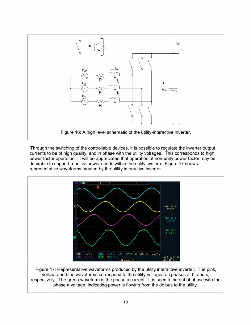
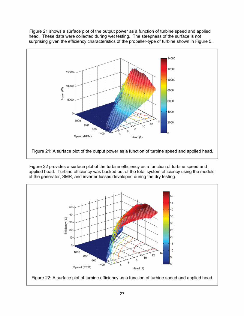

Hydropower from Wastewater
Final Report
December 2011
State of New York New York State Energy Research and Development Authority
Andrew M Cuomo Governor Francis J Murray Jr President and CEO
Copyright © 2022 FDOKUMEN