
Guidelines for Study of Hydropower Projects, 2018
306
-
Upload
khangminh22 -
Category
Documents
-
view
0 -
download
0
Transcript of Guidelines for Study of Hydropower Projects, 2018


Guidelines for Study of Hydropower Projects, 2018
Department of Electricity Development i
Government of Nepal
Ministry of Energy, Water Resources and Irrigation
Department of Electricity Development
GUIDELINES FOR STUDY OF HYDROPOWER PROJECTS
2018

Guidelines for Study of Hydropower Projects, 2018
Department of Electricity Development ii

Guidelines for Study of Hydropower Projects, 2018
Department of Electricity Development iii
Foreword Water resources are one of the key natural resources for economic development of Nepal. The perennial nature of rivers and steep gradients with favourable geo-physical features provide colossal opportunities for the development of hydropower projects in the country. Thus, the Government of Nepal (GoN) has prioritized development of hydropower projects as one of its focus area in the economic development of the nation by formulating various policies and plans.
In this connection, to harness the hydropower potential and to fulfil the increasing domestic energy demand, GoN has established various institutional arrangements, formulated several plans and policies to encourage both the public as well as private sector at the national and international level to be involved in the hydropower sector. Due to favourable government policies, various governmental, non-governmental, national and international developers have been developing hydropower projects for almost two decades.
The Department of Electricity Development (DoED) as the nodal government agency has been supporting the hydropower sector by facilitating both public and private developers in the implementation of hydropower projects. Along with awarding survey and generation licenses for implementation of hydropower projects, DoED has also published various guidelines to ensure uniformity and quality standards in the implementation and smooth operation of hydropower plants.
In the above backdrop, DoED had prepared the GUIDELINES FOR STUDY OF HYDROPOWER PROJECTS in December 2003. During these years, the Guidelines have been an important base for the development of feasibility studies that meet quality standards prescribed by DoED and it has also served as a bankable study. With time, the number and individual capacities of hydropower plants built in the country have increased and thus the need to update the guidelines incorporating standards for detailed design study was felt. Therefore, these guidelines have been updated in 2018.
I hope the Guidelines will serve as a useful reference material for project developers including practicing consultants and project proponents. DoED will use these guidelines as a basis while evaluating hydropower study reports submitted by consultant and developers at various stages of project development.
………………….. Nabin Raj Singh
Director General Department of Electricity Development


Guidelines for Study of Hydropower Projects, 2018
Department of Electricity Development v
Acknowledgments
This Guideline for Study of Hydropower Projects, 2018 was prepared with the continuous guidance and valuable contributions of government officials, Technical Advisory Group (TAG) members, individual and institutional experts and the consultant experts.
The TAG comprising experts in different sub sectors of hydropower field, viz. Mr. Sandip Kumar Dev, Mr. Gopi Prasad Sah, Mr. Sakriya Neupane, Dr. Gyanendra Lal Shrestha, Mr. Sushil Prasad Pradhan, Mr. Jaya Raj Bhandari, Mr. Surya Man Shakya, Mr. Ram Hari Sharma, Dr. Maheswor Shrestha and Dr. Pawan Bhattarai; deserve our sincere thanks for guiding the Consultant and DoED team at various stages during the preparation of this guideline.
DoED recognizes the valuable and significant contributions made to the preparation of this guideline by the following institutions: Ministry of Energy, Water Resources and Irrigation, Ministry of Forest and Environment, Water and Energy Commission Secretariat, Investment Board Nepal, Nepal Electricity Authority, Institute of Engineering, Vidyut Utpadan Company Ltd., Rastriya Prasaran Grid Company Ltd. and Independent Power Producers’ Association Nepal. It is not possible to list all the names of the institutions and experts in this brief acknowledgment. DoED acknowledges all those individuals and institutions for their involvement and valuable contributions.


Guidelines for Study of Hydropower Projects, 2018
Department of Electricity Development vii
Table of Contents
Symbols and Abbreviations ix
1. Introduction 1
1.1 Background 1
1.2 Objectives 2
1.3 Scope of Works 2
2. Reconnaissance/Desk Study 5
3. Formats for the Study of Hydropower Projects 7
A. Hydropower Study Guideline Based on Installed Capacity 7
A1. Installed Capacity > 1 and ≤ 10 MW 7
A2. Installed Capacity > 10 and ≤ 50 MW 52
A3. Installed Capacity > 50 and ≤ 100 MW 114
A4. Installed Capacity More Than 100 MW 179
B. Hydropower Study Guideline Based on Head 249
B1. High Head (Head > 300 m) 249
B2. Medium Head (50 m> Head > 300 m) 250
B3. Low Head (Head < 50 m) 251
C. Additional Requirements for Hydropower Projects based on Scheme Type 252
C1. Hydropower Study Guideline for PRoR Projects 252
C2. Additional Requirements for Storage Type Hydropower Projects 253
D. Additional Requirements for Hydropower Projects with Underground Structures 265
E. Additional Requirements for Export Oriented Hydropower Projects 273
F. Additional Requirements for Captive Type Hydropower Projects 274
G. Hydropower Study Guideline for Cascade Projects 275
H. Hydropower Study Guideline for Inter-Basin Diversion 277
I. Typical Report Format 278
J. Typical Salient Features Format 286
References 293


Guidelines for Study of Hydropower Projects, 2018
Department of Electricity Development ix
Symbols and Abbreviations
% Percentage
CA Catchment Area
amsl Above Mean Sea Level
B/C Benefit/ Cost
BoQ Bill of Quantities
CSP Community Support Programme
CT/PT Current Transformer/ Potential Transformer
DBM Design Basis Memorandum
DGPS Differential Global Positioning System
DHM Department of Hydrology & Meteorology
DoED Department of Electricity Development
DSCR Debt Service Coverage Ratio
EIA Environment Impact Assessment
EIRR Economic Internal Rate of Return
EM Electro-Mechanical
EMP Environmental Management Plan
EPA Environment Protection Act
ERT Electrical Resistivity Tomography
FDC Flow Duration Curve
FIRR Financial Internal Rate of Return
FSL Full Supply Level
GSI Geological Strength Index
GLOF Glacier Lake Outburst Flood
GoN Government of Nepal
GPS Global Positioning System
HM Hydro-Mechanical
HVAC Heating, Ventilation, Air Conditioning
Hz Hertz
ICOLD International Commission on Large Dams
IEE Initial Environmental Examination
INPS Integrated Nepal Power System
IRR Internal Rate of Return
km Kilometre

Guidelines for Study of Hydropower Projects, 2018
Department of Electricity Development x
kV Kilo Volt
kW Kilo Watt
LCOE Levelized Cost of Energy
LDOF Landslide Dam Outburst Flood
m Meter
mm Millimeter
m³/s Cubic Meter Per Second
MAM Micro-Tremor Array Measurement
MASW Multi-Channel Analysis of Surface Waves
MDE Maximum Design Earthquake
MoEWRI Ministry of Energy, Water Resources and Irrigation
MoFE Ministry of Forest and Environment
MV Medium Voltage
MW Mega Watt
NEA Nepal Electricity Authority
N Number
NPV Net Present Value
NPR Nepalese Rupees
OBE Operating Basis Earthquake
PGA Peak Ground Acceleration
PPA Power Purchase Agreement
PRoR Peaking Run of River
RCOD Required Commercial Operation Date
ROE Return on Equity
RMR Rock Mass Rating
RMi Rock Mass Index
RoR Run of River
Sq.km. Square Kilometre
SRT Seismic Refraction Tomography
ToR Terms of Reference
TL Transmission Line
TU Tribhuvan University
USD United States Dollar
VAT Value Added Tax

Guidelines for Study of Hydropower Projects, 2018 Introduction
Department of Electricity Development 1
1. INTRODUCTION
1.1 BACKGROUND
Water resources are important natural resources for the economic development of Nepal. Availability of abundant water resources along with favourable geophysical features (specifically steep topography) provides immense opportunities for hydropower production in the country. In a study conducted in early sixties, the theoretical hydro potential of Nepal was calculated as 83,000 MW. Later, basin master plan studies revealed that out of the theoretical potential, 40,000 to 45,000 MW would be techno-economically feasible. Less than 2.5% of total techno-economically feasible potential has been developed so far. Hydropower plants provide cost efficient and environment friendly power supply to improve energy services and in the context of Nepal, they also contribute in displacing imported (and expensive) fossil fuels. Hence the Government of Nepal has given high priority to developing this sector.
Realizing the potential for hydropower development, the Government of Nepal (GoN) has established various institutional arrangements, formulated several plans and policies to encourage both the public as well as the private sector to be involved in hydropower development. In this backdrop, GoN had formulated Water Resources Act, 2049 (1992); Water Resources Regulation, 2050 (1993); Electricity Act, 2049 (1992); Electricity Regulation, 2050 (1993) and Hydropower Development Policy, 2049 (1992). Similarly, realizing the need for a government line agency to develop, promote and regulate the hydropower sector, GoN had established the Department of Electricity Development (former Electricity Development Centre) on 16 July 1993 (1 Shrawan 2050). Previously, GoN had established the Nepal Electricity Authority (NEA) on 16 August 1985. Furthermore, in order to involve the private sector in hydropower development more efficiently and effectively, GoN developed Hydropower Development Policy, 2058 (2001). Thereafter, GoN formulated Water Resources Strategy, 2058 (2002) and National Water Plan, 2061 (2005). With these policies and strategies, GoN has emphasized the need to increase private sector involvement in hydropower development. It has provided various incentives to attract the private sector in hydropower development. Moreover, for protection of the environment, GoN published Environment Protection Act, 2053 (1997) and Environment Protection Rules, 2054 (1997) and National EIA Guidelines, 2050 (1993).
In the course of licensing for a survey of hydropower projects, a desk study/pre-feasibility study report should be submitted to DoED along with an application and other relevant documents. Pre-feasibility reports/progress reports need to be submitted during the period of survey work, whereas feasibility/detailed design study reports and engineering drawings should be submitted to DoED while applying for a generation license.
The quality, volume and depth of study submitted in the documents for the same category of licenses are not uniform and differ from one developer to another. Moreover, studies done for various hydropower projects under the same category of survey license also do not have the same quality. In many cases, for the same pre-feasibility, feasibility or detailed design level of studies, different developers/parties set up their own approach and carried out the studies at different depths.
The uncertainty as to which level of study should be considered during preliminary or reconnaissance, pre-feasibility, feasibility and detailed design study created a need for developing some objective criteria in the form of standards for different phases of studies as well as for different capacities and nature of hydropower projects in order to ensure uniformity and availability of required information to enable DoED to issue licenses. Hence, DoED prepared the GUIDELINES FOR STUDY OF HYDROPOWER PROJECTS in December 2003. Based on the experiences gained and lessons learnt from the use of these guidelines for a period of almost 15 years, DoED has recently decided to update this document and entrusted JV of GEOCE Consultants (P) Ltd., Sanima Hydro & Engineering (P) Ltd. and Beam Consultant (P) Ltd. for updating the guidelines.
The guidelines thus prepared will be used as the national standard for studies of hydropower projects in Nepal.

Guidelines for Study of Hydropower Projects, 2018 Introduction
Department of Electricity Development 2
1.2 OBJECTIVES
The main objectives of these guidelines are:
To enable DoED to objectively review various hydropower study documents submitted by developers in the course of approving survey and generation licenses for hydropower projects.
To develop and prepare the guidelines for each of the following studies: Reconnaissance or Preliminary or Desk Study, Pre-feasibility Study, Feasibility Study and Detail Design Study of Hydropower Projects based on their different capacities and scheme of hydropower projects covering various technical, economic, financial, environmental and other aspects of the hydropower projects.
Other overall objectives of the guidelines are: To ensure that the developer is aware of the minimum criteria are at each level of the studies, such
that survey and/or generation licenses can be obtained on time for the prospective hydropower projects.
To provide information on the depth and nature of investigations, analysis and studies required in each level of the studies based on the type and size of the hydropower project.
To provide depth of study prior to connection agreement/Power Purchase Agreement (PPA) (i.e. depth of feasibility study).
To standardize the depth of topographical survey, hydrological studies, sedimentation studies, geological and geotechnical studies, seismological studies and construction materials survey etc.
To ease out the problems and simplify the process associated in the course of license application and processing.
To establish and maintain standard criteria for different phases of the study of hydropower projects based on their capacity and scheme of hydropower projects.
To provide an approximate time estimate to conduct a hydropower study for different types of schemes.
To describe the various optimization studies to be carried out for hydropower projects such that the available water resources in the river basin (and country) are best utilized both technically and economically.
To provide guidelines for project evaluation techniques. To describe standard methods for verifying and evaluating the projects for the power purchaser,
investor and financing institution. To standardize the writing and presentation of hydropower studies based on types and capacities. To prepare an effective document for the regulatory bodies to check and update the progress status
as well as provide transparent, smooth and reliable services to the developers. To develop an appropriate reporting format to assist the developers during different development
phases of the hydropower projects. To minimize the project study period by providing a clear and standard methodology of study at each
stage of project development.
1.3 SCOPE OF WORKS
The guidelines, in general, cover the scope of work in defined formats for different phases of studies and also provide specific details for each of the phases. The following phases of study are covered in the guidelines:
1. Reconnaissance/Preliminary or Desk Study 2. Pre-feasibility Study 3. Feasibility Study and 4. Detailed Design Study
The sets of guidelines, prepared for each phase of the study, incorporate the following subclassifications of hydropower projects: A. Based on Capacity
1. >1 MW and ≤ 10 MW 2. >10 MW and ≤50 MW 3. >50 MW and ≤ 100MW 4. >100 MW

Guidelines for Study of Hydropower Projects, 2018 Introduction
Department of Electricity Development 3
B. Based on Head
1. Low head (<50 m) 2. Medium head (50 to 300 m) 3. High head (>300 m)
C. Based on Scheme 1. Run-of-River (RoR) type 2. Peaking Run-of-River (PRoR) type 3. Storage type
Classification of projects in section A has been made based on the power producing capacity of projects. Each of the capacity classes mentioned above in section A shall also include the subsets for each class mentioned above in sections B and C.
Furthermore, the storage type projects can be classified based upon the storage capacity and height of the dam. As per the International Commission on Large Dams (ICOLD), any dam higher than 15 m or with a minimum reservoir capacity of one million cubic meters is considered as a high dam. If funds from multilateral agencies are sought to develop such high dam projects, then all of the basic criterion stipulated in the ICOLD guidelines should also have to be followed.
Hydropower projects can also be classified into other forms based on the purpose, use and method of construction. These classifications include any of the classification mentioned in Section A, B or C and require additional studies in various phases of hydropower development as follows:
1. Project with underground structures 2. Export-oriented project 3. Captive plants 4. Cascade type project 5. Inter-basin diversion project
Besides, the above classifications, the guidelines for multipurpose project and different types of dams have also been incorporated.
For each type/class of the hydropower projects mentioned above, the guidelines cover the following list of the studies, based on the project development phases:
1. Topographical Surveys and Mapping 2. Hydrological and Sedimentation Studies 3. Geological/Geotechnical Investigation 4. Construction Materials Survey 5. Seismic Study 6. Selection of Project Configuration and Project Layout 7. Optimization Study 8. Project Description and Design 9. Energy Computation and Benefit Assessment 10. Cost Estimation 11. Construction Planning and Schedule 12. Environment Studies and Resettlement Issues 13. Project Evaluation 14. Presentation of Drawings, Maps, Charts and Tables 15. Risk and Disaster Analysis 16. Numerical and Physical Modelling
Formats for Guidelines for Study of Hydropower Projects
Various formats for the “Guidelines for Study of Hydropower Projects, 2018” applicable to different phases of study, Format A is related to capacity range (A1 is for capacity range > 1 MW 10 MW, A2 for > 10 MW 50 MW, A3 for > 50 MW 100 MW and A4 for capacities above 100 MW) have been presented along with additional requirements for projects as follow: Project based on head (high, medium and low) type of works as Format B Scheme (RoR/PRoR/Storage) type projects as Format C

Guidelines for Study of Hydropower Projects, 2018 Introduction
Department of Electricity Development 4
Projects with underground structure as Format D Export oriented type projects as Format E Captive type project as Format F Cascade type project as Format G Inter-basin diversion type project as Format H Typical report format as Format I Typical salient features format as Format J

Guidelines for Study of Hydropower Projects, 2018 Reconnaissance/Desk Study
Department of Electricity Development 5
2. RECONNAISSANCE/DESK STUDY
Hydropower studies often start from a reconnaissance or desk study phase where a quick assessment is made to determine whether a full feasibility study of the project should be carried out. This is because feasibility studies of a hydropower project require more time and investments based on the size of the project. A multi-disciplinary team of experts is required to carry out the feasibility study. Similarly, a number of investigations and tests (flow measurements, sediment analysis and geophysical tests etc.) have to be carried out during the course of the study.
The desk study, on the other hand, is done based on available information about the site, although a quick site visit is also sometimes carried out. If the findings of the desk study indicate the project could be technically feasible and financially viable, then a full feasibility study (or a pre-feasibility study) can be carried out. Furthermore, the desk study is also required to obtain a survey license from DoED. Once the survey license is issued, then the developer can carry out the pre-feasibility or feasibility study of the project.
The reconnaissance or desk study report, for all capacity ranges and types, should include at a minimum, the following salient features of the project with following information:
1. Project location including boundary points (four corners) of the project area in longitude and latitude.
2. Basic information about the river hydrology such as catchment area, expected mean annual flow, minimum mean monthly discharge and proposed design discharge.
3. Proposed project components with design parameter
a. Dam/weir location and type, type of intake (side, frontal) weir, side intake, settling basin
Settling basin: length, width and number of chambers.
b. Details about other waterways such as headrace tunnel, headrace canal or pipe, forebay or surge shaft and penstock pipe.
c. Powerhouse: tentative dimensions of the structures and whether this will be a surface or underground type of structure
d. Generating units: number of turbine/generator units, type and capacity
4. Transmission line: estimated length to interconnection point in the national electricity grid and voltage level.
5. Power and energy estimate:
a. Gross head b. Installed capacity c. Total annual energy d. Total dry energy e. Total wet energy
If based on the information available, the installed capacity cannot be ascertained, then a feasible range for the capacity can also be proposed. The proposed layout should be tentatively shown on the available topographic map. The requested study area coordinates should also be shown in this topographic map.
A brief description of the regional geology, as well as the geology of the project area, should be provided. This should also include discussions on seismicity in the project site. Based on current market prices or unit cost of recently built hydropower plants in the vicinity of the project area (or in similar areas), attempts should be made to estimate the cost of the proposed project. Based on estimates of energy generation and project cost, the desk study should recommend whether a full feasibility study should be carried out.
The desk study report should also estimate professional requirements (experts) and costs to carry out the full feasibility study. A proposed work schedule should be attached along with the desk study report.

Guidelines for Study of Hydropower Projects, 2018 Reconnaissance/Desk Study
Department of Electricity Development 6
Similarly, any environmental study (IEE or EIA) that is required according to the prevailing acts of the Government of Nepal should be mentioned. If there are water sharing issues in the project area or downstream requirements, these issues should also be mentioned in the study.

Guidelines for Study of Hydropower Projects, 2018 Installed Capacity > 1 and ≤ 10 MW
Department of Electricity Development 7
3. FORMATS FOR THE STUDY OF HYDROPOWER PROJECTS
A. Hydropower Study Guideline Based on Installed Capacity A1. Installed Capacity > 1 and ≤ 10 MW
S.N. Study Items Details of Study Requirements
Pre-Feasibility Study Feasibility Study Detailed Design Study
1 TOPOGRAPHICAL SURVEYS AND MAPPING
1.1 Available Maps and Images
1. Collect and make use of available contour maps of the project area published by the Department of Survey.
2. Enlarge the largest available scale Topo-map of the project area to 1:10,000 scale or larger.
3. Project the maps and images to match with the national coordinate system.
1. Collect and review the available maps and images. 2. Additional maps and updated images recommended in
the pre-feasibility level should be obtained.
1. Additional maps and updated images should be obtained as required.
1.2 Topographical Survey
1. Verify the coordinates of the key project components proposed in desk/reconnaissance study with GPS survey.
2. Carry out fly leveling, or use theodolite/total station to verify the gross topographic head.
1. Construct a safe foot trail to access the headworks, waterways and powerhouse of the project.
2. Establish control points/benchmarks. The benchmarks shall be a permanent type, generally constructed with concrete or prominently marked in rocks/big boulders.
3. Determine the coordinates of at least two benchmarks by DGPS, triangulation or any appropriate methods to tie with triangulation points of the national grid established by the Department of Survey.
4. Complete the traverse survey by using coordinates of the two known benchmarks.
5. Carry out a detailed topographical survey of headworks, waterways (strip survey), forebay/surge tank/surge shaft, adit portal(s), powerhouse, tailrace and switchyard area and prepare map with 1 m contour interval.
6. The point density of detailed survey should be sufficient to cover all ground features. The survey should cover at least impounding area upstream of the dams/weir and adequate area downstream of the tailrace. The survey should cover at least 20 m in elevation above the maximum flood mark or full supply level on both banks.
1. The topographical survey carried out during the feasibility study should be augmented with additional coverage required for the detailed design. Where the feasibility maps are adequate and to acceptable standards, it will only be necessary to update them to reflect the changes.
2. Additional survey is required, if there are changes in alignment or any addition or change of location of project component(s).
3. The coordinates of control points established during the feasibility study should be verified and revised, if necessary.
4. Establish additional benchmarks at the selected headworks, waterways and powerhouse that can be used during project construction.
Guidelines for Study of Hydropower Projects, 2018 Installed Capacity > 1 and ≤ 10 MW
Department of Electricity Development 8
S.N. Study Items Details of Study Requirements
Pre-Feasibility Study Feasibility Study Detailed Design Study
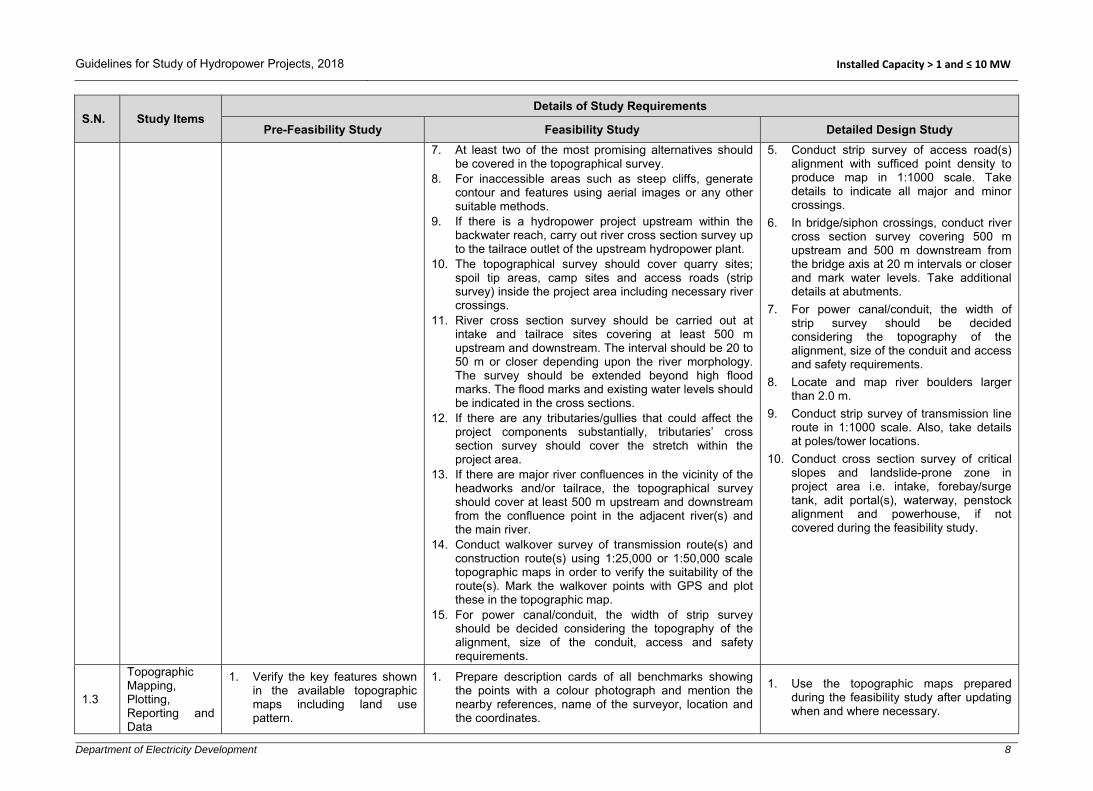
7. At least two of the most promising alternatives should be covered in the topographical survey.
8. For inaccessible areas such as steep cliffs, generate contour and features using aerial images or any other suitable methods.
9. If there is a hydropower project upstream within the backwater reach, carry out river cross section survey up to the tailrace outlet of the upstream hydropower plant.
10. The topographical survey should cover quarry sites; spoil tip areas, camp sites and access roads (strip survey) inside the project area including necessary river crossings.
11. River cross section survey should be carried out at intake and tailrace sites covering at least 500 m upstream and downstream. The interval should be 20 to 50 m or closer depending upon the river morphology. The survey should be extended beyond high flood marks. The flood marks and existing water levels should be indicated in the cross sections.
12. If there are any tributaries/gullies that could affect the project components substantially, tributaries’ cross section survey should cover the stretch within the project area.
13. If there are major river confluences in the vicinity of the headworks and/or tailrace, the topographical survey should cover at least 500 m upstream and downstream from the confluence point in the adjacent river(s) and the main river.
14. Conduct walkover survey of transmission route(s) and construction route(s) using 1:25,000 or 1:50,000 scale topographic maps in order to verify the suitability of the route(s). Mark the walkover points with GPS and plot these in the topographic map.
15. For power canal/conduit, the width of strip survey should be decided considering the topography of the alignment, size of the conduit, access and safety requirements.
5. Conduct strip survey of access road(s) alignment with sufficed point density to produce map in 1:1000 scale. Take details to indicate all major and minor crossings.
6. In bridge/siphon crossings, conduct river cross section survey covering 500 m upstream and 500 m downstream from the bridge axis at 20 m intervals or closer and mark water levels. Take additional details at abutments.
7. For power canal/conduit, the width of strip survey should be decided considering the topography of the alignment, size of the conduit and access and safety requirements.
8. Locate and map river boulders larger than 2.0 m.
9. Conduct strip survey of transmission line route in 1:1000 scale. Also, take details at poles/tower locations.
10. Conduct cross section survey of critical slopes and landslide-prone zone in project area i.e. intake, forebay/surge tank, adit portal(s), waterway, penstock alignment and powerhouse, if not covered during the feasibility study.
1.3
Topographic Mapping, Plotting, Reporting and Data
1. Verify the key features shown in the available topographic maps including land use pattern.
1. Prepare description cards of all benchmarks showing the points with a colour photograph and mention the nearby references, name of the surveyor, location and the coordinates.
1. Use the topographic maps prepared during the feasibility study after updating when and where necessary.

Guidelines for Study of Hydropower Projects, 2018 Installed Capacity > 1 and ≤ 10 MW
Department of Electricity Development 9
S.N. Study Items Details of Study Requirements
Pre-Feasibility Study Feasibility Study Detailed Design Study
Presentation 2. Prepare a map in appropriate scale showing nearest road-head, construction power source, using collected information and data from the Department of Survey.
2. Prepare topographical survey report and maps. If multiple surveys have been carried out, prepare a single report and include all findings.
3. Prepare access road(s) map in 1:1000 scale with 1 m contour intervals. Show cross sections along bridge/ culverts along the road alignment in appropriate scales. The general layout may be plotted in smaller scale.
4. For headworks, waterways, forebay/surge shaft/surge tank, adit portal(s), powerhouse, tailrace and switchyard areas, the contour intervals should be 1m and the scale of map may vary from 1:100 to 1:2000 depending upon the size of the area.
5. Prepare transmission route map in a scale of 1:25,000 or 1:50,000 showing key features such as agricultural land, forest area and settlements.
6. Prepare and verify the license boundary map showing project components and verify there is no conflict with other projects in the vicinity and ensure that backwater level is also within the license boundary.
2. HYDROLOGICAL AND SEDIMENTATION STUDIES
2.1 Hydrology
1. Along with the guidelines mentioned herein, the Hydrological Manual for Infrastructure, Water and Energy Commission Secretariat can be followed for hydrologic analysis.
2. Collect long term historical rainfall data and climatological data pertinent to the study area (preferably more than 30 years) where available.
3. Collect long term historical flow data and sediment data of the river under study. If not available, collect the data from other rivers with similar hydrological characteristics in
1. All the information obtained from pre-feasibility study shall be reviewed, verified and updated. If gauge stations have been established previously, measurements shall be continued.
2. Data logger can also be added and used for online monitoring of hydrological data.
3. Install a cableway at the intake and powerhouse site wherever necessary for discharge measurement.
4. Update the flow data and assess accordingly the mean daily flows and develop an upgraded flow duration curve.
5. For ungauged river basin, hydrologic modelling for the estimate of water availability shall be carried out. Hydrologic models that consider snow/glacier melt schemes shall be used for the catchment that has snow/glacier fed rivers.
6. Water surface/level profile modelling shall be carried out.
1. All the information obtained from the feasibility study shall be reviewed, verified and updated.
2. Data collection from previously established gauge stations in hydropower project shall be continued.

Guidelines for Study of Hydropower Projects, 2018 Installed Capacity > 1 and ≤ 10 MW
Department of Electricity Development 10
S.N. Study Items Details of Study Requirements
Pre-Feasibility Study Feasibility Study Detailed Design Study
the vicinity (preferably for more than 30 years).
4. Check the consistency of data.
5. Assess mean daily flow (if available) and develop a flow duration curve using daily hydrograph.
6. For the ungauged river, discharge (including flow duration curve) shall be estimated with empirical methods, rational method and catchment area ratio method selecting similar catchment, wherever applicable. Such discharge data shall be justified by checking rainfall runoff coefficient.
7. Snow/glacier melt contribution shall be considered, if the catchment has snow/glacier fed rivers.
8. Establish a gauging station as well as colour crest gauges at straight and stable control section for instantaneous flood recordings at the intake and powerhouse site. A data logger may also be used for automatic flow recordings.
9. Carry out discharge measurements at the intake site. Develop a rating curve at headworks and tailrace/powerhouse area.
10. Carry out three cross section surveys at headworks site and three cross section surveys at
7. Carry out cross section surveys at least 500m/1km upstream and downstream of the headworks site and the tailrace site covering the highest flood marks, preferably at the same locations as of the pre-feasibility study so that any change in the cross sections can be observed. If there are changes, check the magnitude of flood peaks with the previous ones.
8. Carry out discharge measurements/gauge readings intensively during the rainy season (June to September) to cover the peak floods at the intake and powerhouse sites, if the site is accessible during monsoon; if not, estimate the flood flows based on flood marks using appropriate hydrological models. In addition, take a reasonable number of measurements during the other months (October to May) at the control profile.
9. Check these measured data with the previous rating curve and upgrade these as necessary.
10. Update and upgrade the diversion floods computed during the pre-feasibility level study.
11. Update and upgrade the rating curves. 12. Update, validate and upgrade the design flow for power
generation. 13. Carry out the water quality analysis to determine the
corrosive effectiveness (hardness). 14. Collect the information on GLOF events in the past (if
such events have occurred) and assess the magnitude of the potential GLOF.
15. Generate sequence of flow for the case of storage projects.

Guidelines for Study of Hydropower Projects, 2018 Installed Capacity > 1 and ≤ 10 MW
Department of Electricity Development 11
S.N. Study Items Details of Study Requirements
Pre-Feasibility Study Feasibility Study Detailed Design Study
the tailrace site covering the highest flood marks.
11. The river high flood data (instantaneous high flood) obtained from DHM needs to be analysed for flood frequency estimation, if available.
12. Estimate the design floods for return periods of 10, 50, 100 and 200 years.
13. Conduct flood frequency analysis for the period of October to May for ascertaining construction diversion flood. The frequency should be 1 in 20 years.
14. Assess possibility of GLOF in the catchment area, if any.
2.2 Sediment
1. Identify in which zone of sedimentation the catchment lies (high, medium or low).
2. Estimate the sediment/bed load in the river using empirical methods.
3. Collect suspended sediment samples and perform necessary laboratory analysis to determine sediment concentration, particle size distribution and mineralogical content.
4. The sampling should cover at least one pre-monsoon, monsoon and post monsoon periods.
1. Collect sediment samples daily during the rainy season (June to September) and at a reasonable frequency during other months (October to May) to develop a rating curve for the sediment concentration against the discharge.
2. Continue collection of data from the gauging station established during the pre-feasibility study level and update the sediment rating curve.
3. Determine the tentative value for median grain size, d50 of the river bed/banks’ materials.
4. Analyse the sediment samples to evaluate the volumes and characteristics of solid material transportation including suspended sediment concentration, particle size distribution and mineral content analysis.
5. Estimate the daily sediment load and assess the annual load in the river.
6. Carry out particle size distribution analysis for river bed materials at gauging station(s), headworks and powerhouse sites and their immediate vicinity.
1. Review the findings of feasibility study and update, if necessary.
2. In case of substantial changes in the river morphology such as due to large landslides in the upstream catchment, carry out further suspended sediment sampling during the rainy season.

Guidelines for Study of Hydropower Projects, 2018 Installed Capacity > 1 and ≤ 10 MW
Department of Electricity Development 12
S.N. Study Items Details of Study Requirements
Pre-Feasibility Study Feasibility Study Detailed Design Study
7. Analyse sediment impact due to construction activities on downstream projects.
3 Geological/Geotechnical Investigation
3.1 Regional Geology Study
1. Collect and review available literature, topographical maps regional geological maps, geological sections, structural maps, available images and aerial photographs.
2. Prepare a brief report on regional geology with maps showing major structures (fault, fold, window and thrust).
1. Review pre-feasibility report. 2. Collect and review available literature, topographical
maps, regional geological maps, geological sections, structural maps and available images.
3. Prepare a report on regional geology and structures. 4. Include existing regional geological maps with plan and
section in available scale.
1. Review the findings of feasibility study and update as necessary.
3.2
General Geology and Geomorphology of the Project Area
1. Conduct a site visit to collect data for geological mapping, geomorphology survey and discontinuity survey.
2. Prepare geological maps with plan and section of the project area in 1:25,000-1:50,000 scale or on available larger scale maps.
3. Prepare a report on general geology and geomorphology of the project area.
1. Conduct detailed geological mapping of the project area and prepare a geological map with plan and section in 1:10,000 or larger scale.
2. Prepare a report on general geology and geomorphology of the project area.
1. Review and update previous reports and geological maps, if necessary.
2. Conduct additional detailed geological mapping where necessary.
3.3
Geological, Conditions and Geomorphology of Major Project Components
1. Describe geological and geomorphological conditions and potential geo-risks to major project components such as weir, intake, settling basin, waterways, forebay /surge tank/surge shaft/ penstock, powerhouse, tailrace and switchyard.
1. Prepare detailed geology and geomorphology report of the project components.
2. Conduct detailed engineering geological mapping of major structures such as weir, intake, settling basin, waterways, surge tank/forebay, penstock, powerhouse and tailrace in 1:1000 to 10,000 scale.
3. Review and conduct a risk assessment of landslide damming inundation and Landslide Dam Outburst Flood (LDOF) risks etc. in the project vicinity covering both upstream and downstream reach.
1. Review, and update maps and reports of previous studies. Conduct detailed mapping, if major components’ locations are changed.
2. Review mass wasting report and conduct detailed analysis and assessment of risks to major structures to consider protective measures.
3. Additional survey and geological mapping in appropriate scale (generally 1:1000 to 1:10,000) shall be required, if there are any modifications in project
Guidelines for Study of Hydropower Projects, 2018 Installed Capacity > 1 and ≤ 10 MW
Department of Electricity Development 13
S.N. Study Items Details of Study Requirements
Pre-Feasibility Study Feasibility Study Detailed Design Study
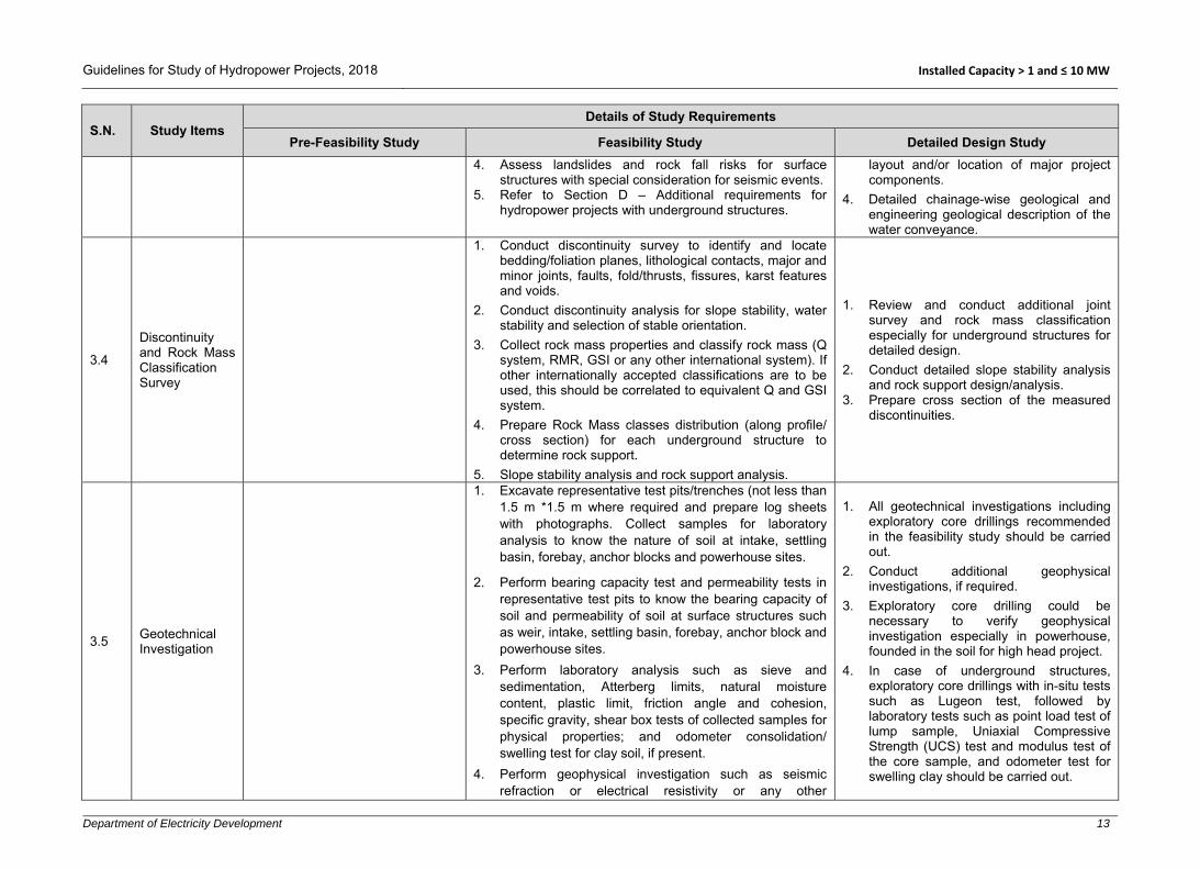
4. Assess landslides and rock fall risks for surface structures with special consideration for seismic events.
5. Refer to Section D – Additional requirements for hydropower projects with underground structures.
layout and/or location of major project components.
4. Detailed chainage-wise geological and engineering geological description of the water conveyance.
3.4
Discontinuity and Rock Mass Classification Survey
1. Conduct discontinuity survey to identify and locate bedding/foliation planes, lithological contacts, major and minor joints, faults, fold/thrusts, fissures, karst features and voids.
2. Conduct discontinuity analysis for slope stability, water stability and selection of stable orientation.
3. Collect rock mass properties and classify rock mass (Q system, RMR, GSI or any other international system). If other internationally accepted classifications are to be used, this should be correlated to equivalent Q and GSI system.
4. Prepare Rock Mass classes distribution (along profile/ cross section) for each underground structure to determine rock support.
5. Slope stability analysis and rock support analysis.
1. Review and conduct additional joint survey and rock mass classification especially for underground structures for detailed design.
2. Conduct detailed slope stability analysis and rock support design/analysis.
3. Prepare cross section of the measured discontinuities.
3.5 Geotechnical Investigation
1. Excavate representative test pits/trenches (not less than 1.5 m *1.5 m where required and prepare log sheets with photographs. Collect samples for laboratory analysis to know the nature of soil at intake, settling basin, forebay, anchor blocks and powerhouse sites.
2. Perform bearing capacity test and permeability tests in representative test pits to know the bearing capacity of soil and permeability of soil at surface structures such as weir, intake, settling basin, forebay, anchor block and powerhouse sites.
3. Perform laboratory analysis such as sieve and sedimentation, Atterberg limits, natural moisture content, plastic limit, friction angle and cohesion, specific gravity, shear box tests of collected samples for physical properties; and odometer consolidation/ swelling test for clay soil, if present.
4. Perform geophysical investigation such as seismic refraction or electrical resistivity or any other
1. All geotechnical investigations including exploratory core drillings recommended in the feasibility study should be carried out.
2. Conduct additional geophysical investigations, if required.
3. Exploratory core drilling could be necessary to verify geophysical investigation especially in powerhouse, founded in the soil for high head project.
4. In case of underground structures, exploratory core drillings with in-situ tests such as Lugeon test, followed by laboratory tests such as point load test of lump sample, Uniaxial Compressive Strength (UCS) test and modulus test of the core sample, and odometer test for swelling clay should be carried out.

Guidelines for Study of Hydropower Projects, 2018 Installed Capacity > 1 and ≤ 10 MW
Department of Electricity Development 14
S.N. Study Items Details of Study Requirements
Pre-Feasibility Study Feasibility Study Detailed Design Study
appropriate geophysical methods to find out overburden thickness and nature of soil strata/bearing capacity at major project components.
5. Carry out Multi-channel Analysis of Surface Waves (MASW) in boulder mixed heterogeneous soil, to determine the bearing capacity at foundations of major project components.
6. Survey and locate test pits/trenches, geophysical profile lines etc. on maps.
7. Perform exploratory core drillings at dam/weir, headrace tunnel, surge tank/forebay, surface powerhouse and underground caverns but not necessary, if exposed bedrock is very strong and massive with joint spacing > 1 m without faults. Perform tests on core sample as per requirement.
8. Refer to Section D – Additional requirements for hydropower projects with underground structures.
3.6 Geological Model
1. Prepare geological model (plan and sections, in appropriate scale of 1:1,000 to 1:10,000) for major surface structures such as weir, intake, settling basin, waterways, forebay, penstock, powerhouse and tailrace.
2. Prepare geological model (plan and sections, in appropriate scale of 1:1,000 to 1:10,000) along waterway covering at least 50 – 100 m both uphill and downhill sides from the centre-line and extend in critical areas showing landslides, debris flow, gully erosion, steep slope etc. for stability and risks assessment for design considerations.
3. Prepare geological model (plan and profiles) of underground structure in appropriate scale: 1:1,000 to 1:10,000. Prepare additional transverse/cross sections in low angle dipping beds for tunnel aligned parallel to the foliation/bedding planes.
1. Update or prepare new geological models of each structure by conducting additional engineering geological mapping and site investigations where necessary.
4 Construction Materials Survey
1. Identify sources and quarry
sites for the construction materials such as sand,
1. Take reference from pre-feasibility study. 2. Identify and investigate construction material sources
and quarry sites for the construction materials such as
1. Collect previous laboratory reports and results and verify the quality and quantity of construction materials.

Guidelines for Study of Hydropower Projects, 2018 Installed Capacity > 1 and ≤ 10 MW
Department of Electricity Development 15
S.N. Study Items Details of Study Requirements
Pre-Feasibility Study Feasibility Study Detailed Design Study
coarse aggregates, boulders, impervious soils, etc.
2. Locate the quarry sites in the available topographic map (1:25,000 or 1:50,000) observed during the site visit.
impervious soils, stones, boulders, sand and gravel as required.
3. Excavate test pits/trenches (not less than 1.5 m *1.5 m) and log the nature of soil at borrow locations including photographs and collect samples for laboratory analysis.
4. Perform laboratory tests: gradation and classification, unconfined compression, absorption and specific gravity, uniaxial compressive strength, point load, Los Angeles abrasion test, sulphate soundness, slake durability test, compaction test, alkali aggregate reaction, swelling test (if necessary), aggregate crushing value, mica and clay content.
5. Estimate available quantities at each borrow area to meet the requirement of the construction.
6. Collect rock block/boulders samples from each quarry site for laboratory tests.
7. Prepare location map with source areas in appropriate scale.
2. Carry out further investigations and laboratory tests, if required.
3. Prepare construction materials quarry site and burrow area location map.
5 Seismic Study
5.1 Tectonic Setting
1. Briefly describe the regional tectonic (structural) setting related to the project area using available literature and regional maps.
1. Describe tectonic settings related to the project area using available literature and regional maps.
5.2 Seismic Zoning
1. Identify the seismic zone of the project area based on the National Building Code (NBC) 105.
1. Review and update the previous study, if required 1. Review and update the previous study, if required.
5.3
Earthquake Catalogue and Historical and Instrumentally Recorded Earthquakes
1. Earthquake catalogue, especially for those historical and instrumentally recorded earthquakes, should be tabulated for earthquakes of magnitude 4.0 M and higher. For every significant earthquake event, the location, distance, magnitude and intensity should be shown in a map in a suitable scale.
5.4 Project Specific Seismic Hazard Analysis
1. Empirical laws may be applied to deduce intensity or
acceleration of the ground motion. The Peak Ground Acceleration (PGA) for Maximum Design Earthquake
1. Review and update the previous study, if required.

Guidelines for Study of Hydropower Projects, 2018 Installed Capacity > 1 and ≤ 10 MW
Department of Electricity Development 16
S.N. Study Items Details of Study Requirements
Pre-Feasibility Study Feasibility Study Detailed Design Study
(MDE) and Operating Basis Earthquake (OBE) should be given in reference from other existing nearby hydropower project(s) or national/international standards or codes.
6 Selection of Project Components and Project Layout
1. Assess and describe availability and condition of the access road(s) leading to the project site.
2. Identify and describe new access road(s)/ropeways/foot trails/tunnels or any other ways to be constructed for development of the project.
3. Identify the existing hydropower project(s) located at upstream and downstream of the project area and verify the project’s license boundary with existing hydropower project.
4. Conceptual layout of all possible schemes within the license boundary should be identified and studied.
5. Topographical, geological conditions of alternative layouts should be studied in order to select the location of project structures: weir, settling basin waterways, forebay, penstock, powerhouse, tailrace and switchyard.
6. While selecting the alternatives, socio-
1. Review the pre-feasibility study report and update the site accessibility conditions to the project area.
2. Detailed topographic maps and preliminary geological maps should be prepared for designing the project configuration/layout.
3. Use updated hydrological data/analysis results for the design of project components. The design discharge should be based on prevailing practices in the context of Nepal (e.g. 40-45 percentile flow/flow mentioned in survey license).
4. While selecting the alternatives, socio-environmental variables should be considered and compared.
5. Select the shortest and most economical access road(s) alignment with minimum numbers of crossing structures.
6. Follow the relevant national and international guidelines, norms and codes to design the project components.
7. For the selection of the location of the diversion weir, alternative sites for settling basin, water conveyance, river crossings, forebay/surge tank/surge shaft, powerhouse, tailrace and switchyard should be studied/ investigated in detail.
8. Prepare preliminary design and drawings of all alternatives (at least two covering both banks) and project structures in appropriate scale.
9. Conduct an alternative study of transmission line routes (at least two) and identify the shortest and most economical route, sub-station and voltage level.
10. Based on the design and drawings, quantity and cost estimations should be carried out for each alternative.
11. Calculate revenue from the project using saleable energy and prevailing energy prices.
1. Expert’s consultation is recommended to verify the project layout and components’ design.
2. Review the feasibility study incorporating expert’s recommendations, if any.
3. In case of significant changes to the layout, update the feasibility study.
4. Verify the updated project license boundary.
5. Carry out the detailed design of access roads within the project area, if required.
6. Carry out the detailed design of all components such as weir, intake, settling basin, water ways, forebay/surge tank/surge shaft, powerhouse, tailrace and switchyard.
7. Follow the relevant national and international guidelines, norms and codes to design the project components.

Guidelines for Study of Hydropower Projects, 2018 Installed Capacity > 1 and ≤ 10 MW
Department of Electricity Development 17
S.N. Study Items Details of Study Requirements
Pre-Feasibility Study Feasibility Study Detailed Design Study
environmental variables should be considered and compared.
7. Assess the location and condition of immediate upstream and downstream projects, if any. List out issues related to the existing project(s) to be addressed while finalizing the project configuration.
8. The locations and types of the structures of each scheme should be verified at site in terms of accessibility, topography, geology, river morphology, construction ease and technical, economic and socio-environmental considerations.
9. Prepare conceptual layout (project configuration) of at least the two most promising schemes with their major structures in appropriate scale using available maps and conduct the preliminary cost-benefit analysis.
10. Recommend area to be covered by topographical survey during the feasibility study phase as well as other site specific investigation.
12. Select the most optimum alternative scheme based on maximum benefit at minimum cost.
13. Prepare general layout drawings of the best alternative showing its components: headworks, waterway, forebay/surge tank/surge shaft, penstock, powerhouse, tailrace and switchyard using the detailed topographic map prepared during this stage of the study. Additionally, show transmission line route and access roads to all major project components
14. Expert consultation and verification of project layout and project structures should be carried out based on the complexity of the project.
7 Optimization Study
1. Installed capacity should be tentatively fixed considering preliminary technical, socio-environmental and economic assessment. If due to lack of data (e.g., hydrology), it is not
1. General Approach
For selection of parameters to be optimized, identify their ranges and establish a series of alternatives.
Carry out the conceptual design, drawings and cost estimate for each alternative.
1. Re-optimization should be carried out based on changes in project capacity and/or design discharge and/or changes in market price for materials and labour.
Guidelines for Study of Hydropower Projects, 2018 Installed Capacity > 1 and ≤ 10 MW
Department of Electricity Development 18
S.N. Study Items Details of Study Requirements
Pre-Feasibility Study Feasibility Study Detailed Design Study
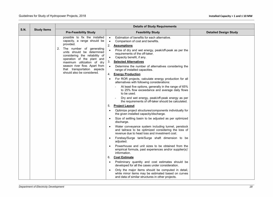
possible to fix the installed capacity, a range should be provided.
2. The number of generating units should be determined considering the reliability of operation of the plant and maximum utilization of dry season river flow. Apart from that transportation aspects should also be considered.
Estimation of benefits for each alternative. Comparison of cost and benefits.
2. Assumptions
Price of dry and wet energy, peak/off-peak as per the requirements of the off-taker.
Capacity benefit, if any. 3. Selected Alternatives
Determine the number of alternatives considering the range of installed capacities.
4. Energy Production
For ROR projects, calculate energy production for all alternatives with following considerations: - At least five options, generally in the range of 65%
to 25% flow exceedance and average daily flows to be used.
- Dry and wet energy, peak/off-peak energy as per the requirements of off-taker should be calculated.
5. Project Layout
Optimize project structures/components individually for the given installed capacity/discharge.
Size of settling basin to be adjusted as per optimized discharge.
Water conveyance system including tunnel, penstock and tailrace to be optimized considering the loss of revenue due to head loss and investment cost.
Forebay/Surge tank/Surge shaft dimension to be adjusted.
Powerhouse and unit sizes to be obtained from the empirical formula, past experiences and/or supplier(s)’ information.
6. Cost Estimate
Preliminary quantity and cost estimates should be developed for all the cases under consideration.
Only the major items should be computed in detail, while minor items may be estimated based on curves and data of similar structures in other projects.
Guidelines for Study of Hydropower Projects, 2018 Installed Capacity > 1 and ≤ 10 MW
Department of Electricity Development 19
S.N. Study Items Details of Study Requirements
Pre-Feasibility Study Feasibility Study Detailed Design Study
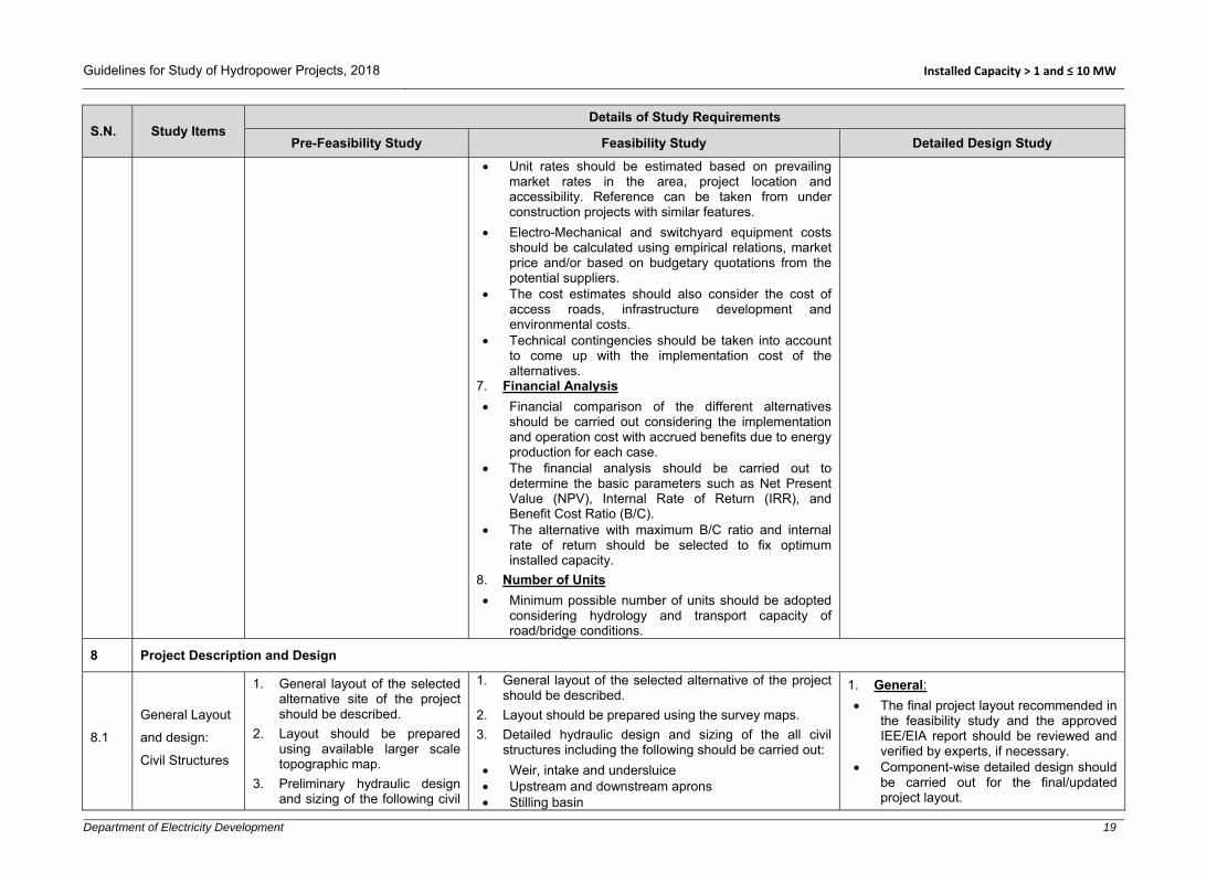
Unit rates should be estimated based on prevailing market rates in the area, project location and accessibility. Reference can be taken from under construction projects with similar features.
Electro-Mechanical and switchyard equipment costs should be calculated using empirical relations, market price and/or based on budgetary quotations from the potential suppliers.
The cost estimates should also consider the cost of access roads, infrastructure development and environmental costs.
Technical contingencies should be taken into account to come up with the implementation cost of the alternatives.
7. Financial Analysis
Financial comparison of the different alternatives should be carried out considering the implementation and operation cost with accrued benefits due to energy production for each case.
The financial analysis should be carried out to determine the basic parameters such as Net Present Value (NPV), Internal Rate of Return (IRR), and Benefit Cost Ratio (B/C).
The alternative with maximum B/C ratio and internal rate of return should be selected to fix optimum installed capacity.
8. Number of Units
Minimum possible number of units should be adopted considering hydrology and transport capacity of road/bridge conditions.
8 Project Description and Design
8.1
General Layout
and design:
Civil Structures
1. General layout of the selected alternative site of the project should be described.
2. Layout should be prepared using available larger scale topographic map.
3. Preliminary hydraulic design and sizing of the following civil
1. General layout of the selected alternative of the project should be described.
2. Layout should be prepared using the survey maps. 3. Detailed hydraulic design and sizing of the all civil
structures including the following should be carried out: Weir, intake and undersluice Upstream and downstream aprons Stilling basin
1. General: The final project layout recommended in
the feasibility study and the approved IEE/EIA report should be reviewed and verified by experts, if necessary.
Component-wise detailed design should be carried out for the final/updated project layout.

Guidelines for Study of Hydropower Projects, 2018 Installed Capacity > 1 and ≤ 10 MW
Department of Electricity Development 20
S.N. Study Items Details of Study Requirements
Pre-Feasibility Study Feasibility Study Detailed Design Study
structures should be carried out:
Weir &intake Gravel trap Settling basin Headrace canal/pipe/tunnel Forebay or surge tank Penstock Powerhouse Tailrace
4. Preliminary design of switchyard and sub-station’s civil structures should be carried out.
5. A brief description of major project components should be given.
6. Typical drawings of major project components should be prepared in appropriate scale.
Gravel trap Settling basin Headrace canal/pipe/tunnel Forebay/surge tank/surge shaft Penstock Powerhouse Tailrace
4. Design of temporary and permanent infrastructures such as camp facilities, construction power, access roads (ropeways, bridges, tunnel), drinking water supply and sewerage etc. should be carried out.
5. Design of switchyard and sub-station’s civil structures should be carried out.
6. Design and location of spoil tips should be carried out. 7. Design and drawing of temporary river diversion during
construction should be prepared. The diversion channel should be designed to pass 1:20 years return period dry season flood.
8. Necessary flood/debris/landslide protection works should be designed based on the river morphology, ground topography, possible debris flow area and the possibility of rock falls (rolling boulders) nearby powerhouse and switchyard area.
9. All project components should be described in detail. 10. Drawings of all project components should be prepared
in appropriate scale.
Headworks
All headworks components should be designed following “Design Guidelines for Headworks of Hydropower Projects” published by DoED, Nepal, 2006. 1. Weir/dam, intake, stilling basin, aprons and floodwalls
should be designed to pass safely the maximum flood of 1 in 50 years return period. Stability analysis should be done for 1 in 100 years return period flood.
2. Intake capacity should be about 130% of the design discharge in case of conventional gravel trap and settling basin flushing systems while the plant operates at full load during flushing.
Project definition report defining all project information, parameters and components should be prepared.
Project parameters and design criteria should be included in a Design Basis Memorandum (DBM) referring to relevant national and international guidelines, norms and codes, and past experiences.
Detailed hydraulic design and dimensioning of all components/structures carried out during the feasibility study should be reviewed and updated/refined/revised where necessary.
2. Infrastructures
Design of road components such as side drains, cross drainage structures, retaining walls, gabion and stone masonry structures should be carried out.
Plans, profiles and cross sections of access road including side drains, retaining structures, cross drainage structures should be prepared in appropriate scale.
Design of construction camps, temporary and permanent housings, water supply and sewerage system, bunker houses etc. should be prepared and presented in the drawings.
Necessary drainage system for surface runoff management should be designed.
Necessary design for construction power arrangement should be carried out.
3. Temporary River Diversion
Detailed hydraulic design and drawings of cofferdams, diversion channel and aprons should be carried out.

Guidelines for Study of Hydropower Projects, 2018 Installed Capacity > 1 and ≤ 10 MW
Department of Electricity Development 21
S.N. Study Items Details of Study Requirements
Pre-Feasibility Study Feasibility Study Detailed Design Study
3. Clear spacing of the coarse trash rack in intake should be fixed considering the transport capacity of gravel flushing conduit.
4. Settling basin should be designed for continuous supply of required design flow plus flushing discharge. The trapping efficiency should be 90% or higher for particle size greater than 0.2 mm depending on available head and mineral composition of sediments. Adequate justification should be provided, if smaller than 0.2 mm particle size is selected to be settled in the settling basin. It is suggested to divide the settling basin into 2 or more chambers.
5. Sediment handling, controlling and flow regulation mechanism should be defined in the project description.
6. An automatic/ungated spillway should be provided downstream of the settling basin at conveyance tank wherever possible.
7. Sediment/gravel flushing outlet should be located at shooting flow of the stilling basin/river.
Water Conveyance
All water conveyance system should be designed following “Design Guidelines for Water Conveyance System of Hydropower Projects” published by DoED, Nepal, 2006. 1. The power canal /headrace pipe/tunnel including all
hydraulic and cross-drainage structures from intake to forebay/surge tank/surge shaft should be designed for 110% design discharge or higher.
2. A number of saddle supports and anchor blocks should be designed and described in the report.
3. Slope stability analysis in critical sections of waterways including forebay/surge tank/surge shaft should be carried out.
4. Necessary drainage system for surface runoff management should be designed.
5. Type and size of water conveyance should be determined considering the design discharge, silting/scouring velocity for the selected materials used (e.g., concrete grade, masonry) applied concrete grade and topography.
The diversion channel and cofferdams should be designed to pass 20 years dry season return period flood.
4. Main Component Design
Detailed design of all surface and underground structures should be carried out.
The safety of component should be checked by conducting stability and structural analysis.
5. Seismic Design Criteria
Pseudo-static analysis procedures (seismic coefficient method) can be used in the seismic design and analysis of structures where appropriate.
The response of a structure to ground vibrations should be determined considering soil type, seismic zone, response reduction factor, importance factor, fundamental period of vibration and damping factor (ξ). These values can be referred from norms and codes such as NBC 105.
For structures with minor importance, the seismic coefficient can be reduced appropriately.
Both vertical and horizontal seismic components should be used in the design.
6. Foundation Design
The results from the geophysical investigation shall be used to design the foundations. In case of missing or unavailability of data, suitable values shall be assumed based on the local geology.
If foundation has to be placed in inferior soil type, a suitable foundation treatment method should be specified.
Detailed seepage analysis under the

Guidelines for Study of Hydropower Projects, 2018 Installed Capacity > 1 and ≤ 10 MW
Department of Electricity Development 22
S.N. Study Items Details of Study Requirements
Pre-Feasibility Study Feasibility Study Detailed Design Study
6. Corrosion, scratching, pipe diameter and transportation limitation factors should be considered while fixing the headrace pipe thickness.
Surge Control Structure and Penstock Pipe
1. An emergency spillway at the forebay should be provided. The forebay should have the effective volume at least equal to the volume of water in the penstock pipe while filled or to supply design flow for at least 120 seconds, whichever is larger.
2. For surge tank/surge shaft, various possible scenarios of transient analysis should be carried out to determine upsurge and down surge level.
3. The thickness of the steel pipe should be able to withstand any variable load conditions encountered during operation of the plant. While deriving the effective thickness of the pipe, steel grade, corrosion factor, welding factor and rolling factor should be considered.
4. Anchor blocks to hold penstock pipe should be designed at bends and also intermediately in long straight stretches.
Powerhouse and Tailrace
1. The powerhouse should be dimensioned to accommodate electro-mechanical equipment and its ancillaries.
2. The tailrace conduit should be designed considering turbine type, minimum power discharge available, minimum water depth requirement and the possible effect of river water level at the tailrace outlet.
3. Switchyard area should be arranged nearby the powerhouse and civil design of switchyard should be prepared.
weir/dam foundation and other water retaining structures should be carried out. Uplift pressure and under piping mechanism for cutoff wall, apron and protection works should be analysed and proper measures should be proposed to prevent damage related to foundation undermining.
The allowable bearing capacity of the foundation may be increased in extreme loading conditions as provisioned in the design codes. Similarly, the allowable bearing capacity may need to be reduced when fully water saturation conditions occur and placing foundation on steep slopes or adjacent to them.
7. Stability Analysis of Structures
The following loadings should be considered for stability analysis of project components: - Dead load - Live load - Water pressure - Weight of water - Hydro-dynamic load - Active earth pressure - At rest pressure - Passive earth pressure - Earthquake load - In-situ stresses - Impact load - Vibration load - Thermal - Uplift (buoyancy and seepage) - Surcharge/overburden loads - Water hammer - Wind - Snow - Construction and moving surface
loads: - Additional loads, if any.

Guidelines for Study of Hydropower Projects, 2018 Installed Capacity > 1 and ≤ 10 MW
Department of Electricity Development 23
S.N. Study Items Details of Study Requirements
Pre-Feasibility Study Feasibility Study Detailed Design Study
For the purpose of evaluating the stability and structural analysis, different load combinations that may occur during different phases of the project implementation and operation should be considered. Individual components/elements must be designed for the most unfavourable load combination. In general, the following conditions should be considered: - Construction - Normal operation - Special/emergency/extreme cases
The safety factor depends upon the codes and loading combination used.
8. Detailed Structural Analysis and Design
Appropriate codes (concrete, steel) should be referred for the detail design. All possible loading conditions should be considered.
The durability of the structure should be ensured in the design.
Material properties and allowable stresses for concrete, structural steel, reinforcement, etc. should be specified.
The structures should be analysed using acceptable methods manually or by using software.
All structures should be safe against internal and external forces/stresses and all kind of climatic conditions.
Reinforcement calculation should be done considering temperature and shrinkage effects.
The dynamic analysis should be carried out for the powerhouse and penstock and ensure that natural frequency does not create resonance phenomenon.

Guidelines for Study of Hydropower Projects, 2018 Installed Capacity > 1 and ≤ 10 MW
Department of Electricity Development 24
S.N. Study Items Details of Study Requirements
Pre-Feasibility Study Feasibility Study Detailed Design Study
Ensure that the settlement/deformation and deflections are within permissible limits.
9. Water Tightness
Control of cracking in concrete should be as per the requirement specified in IS 456:1978 and 2000 or BS 8007:1987 or BS 8110 Part II, BS 2007 or equivalent codes.
The type and location of joints should be specified. Contraction/expansion joints should generally be located in 15 to 25 m spacing. Construction joints should be provided considering construction sequence.
The appropriate type of water stops should be provided at expansion/contraction/construction joints.
10. Detailing and Drawings
The reinforcement should be detailed considering the ductility of the structure.
Reinforcement arrangement should be shown in drawings in appropriate scale. Special attention should be given at joints.
Prepare construction drawings, reinforcement drawings and bar bending schedules.
11. Field Verification of Design/Layout
The arrangement of all project components should be verified at the site by laying setting out points. Any changes that may occur should be addressed in the design.
12. Report Preparation
After finalizing the design, a detailed design report should be prepared showing all hydraulic, geotechnical,

Guidelines for Study of Hydropower Projects, 2018 Installed Capacity > 1 and ≤ 10 MW
Department of Electricity Development 25
S.N. Study Items Details of Study Requirements
Pre-Feasibility Study Feasibility Study Detailed Design Study
stability and structural analyses calculations. Based on the detailed design report, a draft operation and maintenance manual should be prepared.
8.2 Hydro-Mechanical Components
1. Preliminary selection/ estimation of hydro mechanical components such as gates, stoplogs, trashracks and penstock should be carried out.
2. A brief description of hydro-mechanical components should be provided in the report.
The following hydro-mechanical components should be designed and described: 1. Gates, stop logs, embedded parts, valves, trash racks,
bell mouths, manholes, expansion joints, saddle/wear plates, sizing of headrace and penstock pipes, bends, reducers, branches, steel lining works etc.
2. The hoisting system for gates and stop-logs.
1. General
This design is generally carried out by hydro-mechanical equipment manufacturers/suppliers, thus only preliminary design for preparing Terms of Reference of tender/contract documents shall be carried out in consultation with potential manufacturers/suppliers.
Design and dimensioning of all components/structures carried out during the feasibility study should be reviewed and updated where necessary and presented in the project definition report.
Component-wise design should be carried out for the final/updated project layout.
Project parameters and design criteria should be included in a Design Basis Memorandum (DBM) referring to relevant national and international guidelines, norms and codes, and past experiences.
While designing the hydro mechanical components, factors such as corrosion, welding defects, and plate inaccuracy/defects should be taken into account.
Individual components/elements must be designed for the most unfavourable load combination. In general, loading conditions which may occur during the following phases/cases should be considered: - Transportation

Guidelines for Study of Hydropower Projects, 2018 Installed Capacity > 1 and ≤ 10 MW
Department of Electricity Development 26
S.N. Study Items Details of Study Requirements
Pre-Feasibility Study Feasibility Study Detailed Design Study
- Erection/Construction - Testing in factory and site - Normal operation - Special/Emergency/Extreme cases
2. Design of Gates and Stop-Logs
The type of gate/stoplogs with embedded parts and its hoisting mechanism should be fixed.
The materials to be used for skin plates, stiffeners, girders, embedded parts and other components should be specified.
The gates/stoplogs with embedded parts shall be designed for the hydrostatic and hydrodynamic forces taking into consideration the forces arising from wave effects, water hammer, seismic loads, active soil load (sediment deposit), ice formation, friction, and thermal effect wherever applicable.
The internal stress should be ensured to be within the limit of allowable stress in normal and extreme operating conditions.
Sufficient corrosion allowance should be provided and corrosion prevention methods, if any, should be mentioned.
Types and material of seals should be mentioned.
Power-operated gates shall normally be capable of operation by alternate means in case of power supply failure.
If meant for regulation, it shall be capable of being held in partially open position without major damage to seal or deterioration due to cavitation and vibration.
Wherever necessary, model studies may be carried out for high head regulating gates.

Guidelines for Study of Hydropower Projects, 2018 Installed Capacity > 1 and ≤ 10 MW
Department of Electricity Development 27
S.N. Study Items Details of Study Requirements
Pre-Feasibility Study Feasibility Study Detailed Design Study
The deflection of the gate under various loading conditions should be within the permissible limits.
Dogging devices and lifting beams should be designed for operation of gates, stop logs etc.
Destructive and non-destructive testing procedures should be specified.
All the gates shall be checked for the aeration requirement at its immediate downstream.
3. Steel Pipes
The steel plate used for the pipes shall comply with National/International Standards.
The pipes should be designed considering the following loading conditions: - The normal condition includes static
head, surge and water hammer pressure.
- Special conditions include those during filling and draining of penstocks and a maximum surge in combination with pressure rise during emergency operations/events and test pressures.
- The exceptional condition includes transportation and erection stresses, pressure rise due to the unforeseen operation of regulating equipment in the most adverse manner resulting in an odd situation of extreme loading, the stress developed due to resonance in penstock, seismic forces etc.
Adequate safety factors should be provided for safety against hoop stress due to internal and external pressure including surge pressure, longitudinal stress, beam action, temperature variations.

Guidelines for Study of Hydropower Projects, 2018 Installed Capacity > 1 and ≤ 10 MW
Department of Electricity Development 28
S.N. Study Items Details of Study Requirements
Pre-Feasibility Study Feasibility Study Detailed Design Study
Stress should be checked at bends, branches, transition and stiffeners
Expansion joints should be provided just below the anchor block whenever possible.
Special design provision shall be made to protect the penstock pipes/conduits against possible rupture due to denting/negative pressure.
4. Other Structures
Other HM components such as valves, trash racks, manholes, saddle plates, bulk head gates, bell mouths, steel lining etc. shall be designed to meet structural and hydraulic requirements.
5. Report Preparation
After finalizing the design, a report should be prepared showing all hydraulic, and structural calculations. Similarly, operating conditions, hoisting mechanisms, opening sizes, design pressures, and dimension of all major components/elements should be mentioned. Based on the detailed design report, a draft operation and maintenance manual should be prepared.
8.3 Electro-Mechanical Equipment
1. Preliminary design/selection of the electro-mechanical equipment should be carried out based on design discharge and net head and number of units (based on hydrology and transportation).
2. A brief description of selected electro-mechanical equipment should be given describing the type of turbine and accessories, generator and accessories, transformers and switchgears.
1. The type and number of generating equipment with necessary equipment and power evacuation facilities should be designed and described.
2. Description of main mechanical equipment including the followings should be provided:
Hydraulic turbine Inlet valve Governor Lubricating (hydraulic) system Pressure oil system Compressed air system Cooling system Control system
1. General
This design is generally carried out by electro-mechanical equipment manufacturers/suppliers, thus only preliminary design for preparing Terms of Reference of tender/contract documents shall be carried out in consultation with potential manufacturers/suppliers.
Detailed design and dimensioning of all components/structures carried out during the feasibility study should be reviewed and updated/refined/revised where necessary and presented in the project definition report.

Guidelines for Study of Hydropower Projects, 2018 Installed Capacity > 1 and ≤ 10 MW
Department of Electricity Development 29
S.N. Study Items Details of Study Requirements
Pre-Feasibility Study Feasibility Study Detailed Design Study
3. Description of the main electrical equipment including the followings should be provided:
Generator Excitation system Switchgears Control panel Powerhouse earthing Power transformer Auxiliary transformer CT/PT for different voltages Earthing system for switchyard Hoisting mechanism/overhead crane
4. A single line electrical diagram depicting the
interconnection of all electrical equipment should be prepared.
5. For the smooth operation of the power station, following auxiliaries should be provided and described:
Grease lubricating system. Fire fighting system Station supply Lighting arrangement Heating Ventilation and Air Conditioning (HVAC)
Project parameters and design criteria should be included in a Design Basis Memorandum (DBM) referring to relevant national and international guidelines, norms and codes, and past experiences.
Individual components/elements must be designed for the most unfavourable load combination (mechanical and electrical). In general, loading conditions which may occur during the following phases/cases should be considered: - Transportation - Erection/construction - Testing in factory and site - Normal operation - Special/emergency/extreme cases
2. Mechanical Equipment
Appropriate turbines and their components should be designed.
Suitable inlet valves shall be provided before each turbine.
Draft tubes, spiral casing, covers, seals should be designed appropriately
A suitable governor system should be provided for flow control to the turbine.
Proper auxiliary systems such as heat exchanger system, lubrication system, pressure system, compressed air system, hydraulic system, cooling system, EOT crane, lighting system, fire extinguishing system shall be designed.
Control system with local unit and remote (to control room) controlling capability should be provided.
3. Electrical Equipment
Single line diagram and control diagram for all powerhouse equipment and interconnection points shall be prepared following the latest NEA Grid Code and other relevant standards.

Guidelines for Study of Hydropower Projects, 2018 Installed Capacity > 1 and ≤ 10 MW
Department of Electricity Development 30
S.N. Study Items Details of Study Requirements
Pre-Feasibility Study Feasibility Study Detailed Design Study
Generators shall be provided with all of their accessories including cooling and fire protection system, the hydraulic system including generator braking and heat exchanger system.
Excitation system shall be provided with an automatic voltage regulator, excitation transformer and bridge rectifier.
Power transformers to step up transmission voltage shall be provided with type of cooling, indoor/outdoor arrangement and other required accessories.
HV switching equipment with bus bars, circuit breakers, disconnecting switches, instrument transformers, etc. shall be provided.
Control equipment shall be provided consisting of governor monitoring, excitation monitoring, emergency shutting down, valve protection and other protection, etc.
Station service transformer for redundant power supply to the plant shall be provided.
Grounding including lightning protection shall be provided.
Fire protection and ventilation system should be designed and described in detail.
Emergency exit and safety plan should be described/provided as per available national/international guidelines.
Diesel Generators shall be provided for backup power and black start/isolation mode.
8.4 Power Evacuation and Transmission Line
1. Assess the possibility of power evacuation through national grid/Integrated Nepal Power System (INPS).
1. Design and describe the power transmission line and power evacuation system.
2. Prepare a single line diagram representing the major electrical equipment of the powerhouse, switchyard, and substation.
1. The transmission line should be designed following the latest off-takers’/NEA grid code.

Guidelines for Study of Hydropower Projects, 2018 Installed Capacity > 1 and ≤ 10 MW
Department of Electricity Development 31
S.N. Study Items Details of Study Requirements
Pre-Feasibility Study Feasibility Study Detailed Design Study
2. Carry out preliminary design to select voltage level, conductor type and the number of towers.
3. A brief description of the selected power evacuation system should be presented.
3. Describe the details of interconnection equipment as per standards.
4. Design and describe poles/towers, circuit type, type of conductor, other components and safety measures.
2. The route shall be finalized and described. Voltage level, number of circuits and length shall be confirmed.
3. Number and type of towers required shall be determined with location (coordinates) and their structure shall be designed. While designing the foundation of a transmission tower, geology and geotechnical conditions with socio-environmental assessment should be verified and additional investigation should be done, if required.
4. The size of conductors to be used shall be determined. The size of conductors must be selected so that the power loss doesn’t exceed the permissible limit as per latest off-taker’s/NEA Grid Code.
5. Sag, tension and loading in conductor shall be determined.
6. Auxiliary equipment in the transmission line such as insulators, clamps, guards, etc. shall be provided. Equipment to be installed in interconnection substation should be designed.
7. Power transformers shall be required, if the voltage level of a transmission line does not match the voltage level of interconnecting substation including HV switchgear (Circuit breaker, disconnecting switch, etc.), instrument transformers and control and protection equipment.
9 Energy Computation and Benefit Assessment
9.1 Energy Computation
1. Energy computation should be carried out considering the average monthly flow (daily flow, if available), net head, design discharge and turbine,
1. Energy computation should be carried out considering daily flow, net head, design discharge and turbine, generator and transformer efficiency. Furthermore, normal and forced outages should be considered referring to the off-taker/NEA Grid Code and/or norms
1. Energy estimated in feasibility study should be updated/refined, if there are significant changes.

Guidelines for Study of Hydropower Projects, 2018 Installed Capacity > 1 and ≤ 10 MW
Department of Electricity Development 32
S.N. Study Items Details of Study Requirements
Pre-Feasibility Study Feasibility Study Detailed Design Study
generator and transformer efficiency. Furthermore, normal and forced outages should be considered referring to the off-taker/NEA Grid Code and/or norms and practices. If power output cannot be ascertained at this stage, then the range of annual energy generation should be provided.
and practices. Such energy estimation should be based on fixed installed capacity.
2. During energy estimation, environmental and other necessary releases as recommended in EIA/IEE guidelines should be deducted from the available river flow.
3. Average daily, monthly energy and annual energy should be determined in Nepali and Georgian calendar months.
4. Estimated internal energy consumption within the power plant should be deducted from the total/monthly energy to derive saleable energy.
5. Annual estimated average dry and wet energy should be determined considering the dry/wet periods defined by off-taker/NEA. Furthermore, dry energy should be divided into peak/off-peak energy in case of PRoR and reservoir type projects.
9.2 Benefit Estimation
1. Average monthly/annual revenue throughout the license period should be calculated considering unit energy prices fixed by the NEA/off taking company/GoN for similar sized projects.
2. While calculating the annual revenue, base rates for dry, wet, peak, off-peak energy prices together with annual price escalation should be considered.
1. Estimated average monthly/annual revenue throughout the license period should be calculated considering unit energy prices fixed by the NEA/off taking company/GoN for similar sized projects.
2. While calculating the annual revenue, base rates for dry, wet, peak, off-peak energy prices together with annual price escalation should be considered.
1. Revenue estimated in feasibility study should be updated, if required.
2. If PPA has been concluded, the revenue estimates should be verified against the PPA.
10 Cost Estimation
10.1 Criteria and Assumptions
1. Cost estimate during this stage should be based on thumb rules, cost per unit of installed capacity for similar sized projects, and prevailing bulk market prices for civil works, hydro mechanical,
1. All the criteria and assumptions adopted for cost estimation should be mentioned including the following:
Consideration of the natural conditions prevailing at the site, construction scale, and levels of construction technology available in Nepal.
1. The criteria and assumptions for feasibility level study should be applied but should be based on detailed design with inclusion of items not included in the feasibility level study.
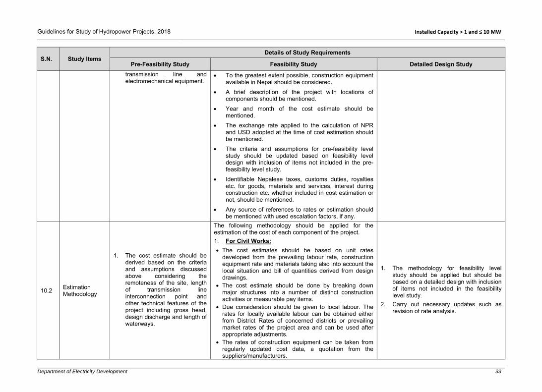
Guidelines for Study of Hydropower Projects, 2018 Installed Capacity > 1 and ≤ 10 MW
Department of Electricity Development 33
S.N. Study Items Details of Study Requirements
Pre-Feasibility Study Feasibility Study Detailed Design Study
transmission line and electromechanical equipment.
To the greatest extent possible, construction equipment available in Nepal should be considered.
A brief description of the project with locations of components should be mentioned.
Year and month of the cost estimate should be mentioned.
The exchange rate applied to the calculation of NPR and USD adopted at the time of cost estimation should be mentioned.
The criteria and assumptions for pre-feasibility level study should be updated based on feasibility level design with inclusion of items not included in the pre-feasibility level study.
Identifiable Nepalese taxes, customs duties, royalties etc. for goods, materials and services, interest during construction etc. whether included in cost estimation or not, should be mentioned.
Any source of references to rates or estimation should be mentioned with used escalation factors, if any.
10.2 Estimation Methodology
1. The cost estimate should be derived based on the criteria and assumptions discussed above considering the remoteness of the site, length of transmission line interconnection point and other technical features of the project including gross head, design discharge and length of waterways.
The following methodology should be applied for the estimation of the cost of each component of the project. 1. For Civil Works:
The cost estimates should be based on unit rates developed from the prevailing labour rate, construction equipment rate and materials taking also into account the local situation and bill of quantities derived from design drawings.
The cost estimate should be done by breaking down major structures into a number of distinct construction activities or measurable pay items.
Due consideration should be given to local labour. The rates for locally available labour can be obtained either from District Rates of concerned districts or prevailing market rates of the project area and can be used after appropriate adjustments.
The rates of construction equipment can be taken from regularly updated cost data, a quotation from the suppliers/manufacturers.
1. The methodology for feasibility level study should be applied but should be based on a detailed design with inclusion of items not included in the feasibility level study.
2. Carry out necessary updates such as revision of rate analysis.

Guidelines for Study of Hydropower Projects, 2018 Installed Capacity > 1 and ≤ 10 MW
Department of Electricity Development 34
S.N. Study Items Details of Study Requirements
Pre-Feasibility Study Feasibility Study Detailed Design Study
The construction materials to be used for construction work should be divided into;
- Materials locally available nearby project area. - Materials available in the local market. - Materials to be imported from neighbouring
countries. - Materials to be imported from overseas.
The rates of construction materials should be derived as per their source of supply. While calculating the construction materials’ rate, sufficient attention should also be given to the mode of transportation and their corresponding costs. When access roads for the project are not built (generally for small hydropower projects) the cost of air transportation for transporting heavy equipment from the nearest town to the project area should also be included.
From labour cost, material cost and equipment cost, the direct cost per unit of construction activity can be calculated.
The estimate should be of contractor's type and, therefore, should also include all other indirect costs such as office overheads, contractor's financing cost, insurance bonds, profit and risk margin.
A suitable percentage for contractor's expenses should be allocated. The total percentage should be used as a bid factor on direct cost. Thus calculated direct cost can be used to derive unit bid costs which in turn, be used to determine the total civil works cost.
2. For Electro-Mechanical Equipment The cost estimate for generating equipment, transformer
and switchyard equipment should either be based on quotations obtained from the supplier(s) or in-house estimate using established current international prices or price database from similar type and size projects. The cost should include the cost of control devices/system, auxiliary etc. transportation and erection.
3. Hydraulic Steel Works The cost of hydraulic steel works should be based on a
quotation of the supplier(s) or on market price, if they are locally available. Transportation and installation cost should also be added.

Guidelines for Study of Hydropower Projects, 2018 Installed Capacity > 1 and ≤ 10 MW
Department of Electricity Development 35
S.N. Study Items Details of Study Requirements
Pre-Feasibility Study Feasibility Study Detailed Design Study
4. Transmission Line
The cost of the transmission line can be calculated from per km rates of the transmission line. References of cost can be taken from current rates used by NEA/off-taker or constructed project of IPPs for same type/voltage of transmission lines taking into account different types of towers required, the conductors and types of terrains being crossed.
5. Land Acquisition and Access Road
Due attention should be given to the cost of land acquisition and construction of access roads.
Cost of land acquisition should be determined considering detailed risk assessment, future development of the project area, accessibility and public demand.
The length and type of access roads to be constructed or to be improved can be determined from preliminary design. Cost per km of different types of roads can be used to determine the cost of the access road.
6. Camp and Other Facilities
The costs of construction camps and permanent buildings required for operation and also of construction power facilities required should be included in cost estimation. A lump sum amount for this can be allocated depending upon the size of the project.
7. Social Development:
The cost of social development should be determined from reconnaissance field visits. Factors to determine the social development cost such as population density, available local resources and existing physical infrastructure in the project area should be considered. This cost can be derived as a lump sum taking a reasonable percentage of the project base cost.
8. Resettlement/Rehabilitation
Relocation and environment impact mitigation costs shall be as per existing Environmental Protection Act and Rules. At this stage, this cost can be derived as a lump sum taking a reasonable percentage of the project base cost.

Guidelines for Study of Hydropower Projects, 2018 Installed Capacity > 1 and ≤ 10 MW
Department of Electricity Development 36
S.N. Study Items Details of Study Requirements
Pre-Feasibility Study Feasibility Study Detailed Design Study
9. Community Support Program (CSP)
Include CSP cost as a fixed percentage of the total project cost as per the latest government policies.
10.3 Base Cost and Total Project Cost
1. The total of all costs indicated above will constitute the base cost of the project. To that, the following costs are to be added as a certain percentage of the project cost for obtaining the total capital cost: Engineering and
Management Owner's cost Insurance cost
2. Contingencies added to account for unforeseen cost increases due to uncertainties in site conditions for: Civil works Generating equipment
and transmission line 3. Interest during construction,
cost/amount.
1. The total of all costs indicated above will constitute the base cost of the project. To that, the following costs are to be added as a certain percentage of the project cost for obtaining the total capital cost:
Engineering and Management. Owner's cost Insurance cost.
2. Contingencies for civil works, hydro-mechanical, electromechanical, transmission line, price and physical contingencies etc. are to be updated/added to account for unforeseen cost increase due to various uncertainties during project construction.
3. Interest during construction should be calculated based on the prevailing interest rates and other parameters required for the calculation.
4. The exact percentage allocation for the above cost items should be based on prevailing market conditions and general practices.
1. At the detailed design level, due to use of more detailed information collected and minor items included and designs concretized, level of uncertainties will decrease particularly in civil works/HM works/EM equipment and TL works component. Hence, project cost with higher accuracy and reduced contingencies can be calculated
10.4
Local and Foreign Currency Breakdown
1. Local currency will be required for local labour, local materials, government cost tax, VAT, royalties and customs duties including land acquisition, resettlement, mitigation and management programs related to adverse socioeconomic environment impacts and bank interest.
2. Foreign currency will be required for imported materials and equipment and foreign experts.
3. The cost estimation should include a breakdown of local and foreign currency components
10.5 Presentation of Cost Estimate Data
1. The cost estimate derived at this stage should include the following:
Civil Hydro-Mechanical Electromechanical
1. In the main volume of the report summary cost estimate data broken down into the above mentioned major sub-headings and into foreign and local currency should be presented; while the details of cost estimates including rate analysis and the unit rate could be presented in the Annex volume.
1. The presentation should be done as in the feasibility level, but with the inclusion of more detailed items based on detailed design and other updated information.

Guidelines for Study of Hydropower Projects, 2018 Installed Capacity > 1 and ≤ 10 MW
Department of Electricity Development 37
S.N. Study Items Details of Study Requirements
Pre-Feasibility Study Feasibility Study Detailed Design Study
Transmission line Engineering and construction
supervision Others such as environment,
owner’s management.
10.6 Cash Disbursement Schedule
1. The costs incurred will spread over the whole construction period. Interest during construction will depend on how cash will be disbursed during the construction period. Hence cash disbursement schedule should be estimated with disbursement schedule based on experience with similar sized projects with similar criteria (e.g. access, geographical conditions, design parameters).
1. Cash disbursement schedule should be based on an updated and realistic project implementation schedule.
2. Year-wise cash disbursement against each of the major activities is to be prepared and presented in the report. Cash disbursement can be presented as a certain percentage of capital cost per annum during the construction period.
1. Cash disbursement schedule should be based on updated project implementation schedule, if required.
11 Construction Planning and Schedule
1. Access, availability of construction materials, waste disposal and construction of camps at the site should be described.
2. River diversion sequences during construction should be tentatively considered.
3. A preliminary construction schedule should be prepared for the project showing the major construction activities. The total construction period should be determined.
1. Review the construction schedule prepared during the pre-feasibility study and update as per the feasibility study’s findings and other prevailing conditions such as market conditions and available technology.
2. Plan contract/procurement/construction modality in coordination with client for pre-construction works, main civil works, hydro-mechanical, electro-mechanical and transmission line works.
3. Prepare a plan for pre-construction activities such as the construction of camps, the establishment of telecommunication facilities, construction/upgrading of the access road(s), arrangement of construction power, etc.
4. Prepare a plan for establishing necessary forest clearance, crusher plants, workshops, fuel depots, permanent camps for operators and site office(s). The plan should also take into account time for necessary government approvals.
5. Land acquisition and environmental mitigation plan should be incorporated.
1. Review the construction planning and schedule prepared during the feasibility study and update as necessary considering anticipated/planned Required Commercial Operation Date (RCOD).
4. Plan and confirm the availability, quality and quantity of all construction materials. Special consideration should be given for materials required for high grade concrete, high grade steel etc.

Guidelines for Study of Hydropower Projects, 2018 Installed Capacity > 1 and ≤ 10 MW
Department of Electricity Development 38
S.N. Study Items Details of Study Requirements
Pre-Feasibility Study Feasibility Study Detailed Design Study
6. Prepare a plan for temporary diversion of the river during construction. This may consist of construction of cofferdam(s) and diversion channel at headworks and powerhouse/tailrace outlet.
7. Prepare a plan for construction of headworks, waterways, forebay/surge-tank/surge-shaft, powerhouse, tailrace, switchyard and transmission line including all civil, hydro-mechanical and electro-mechanical works in consultation with potential contractors/suppliers and based on past experience of constructing similar project(s).
8. Describe anticipated construction methodology for all major structures.
9. Update/prepare construction schedule considering above mentioned plans/factors and the following aspects:
Seasonal constraints for temporary river diversion Local culture and national holidays Climatic conditions
12 Environmental Study
12.1 Reference for Environmental Study
1. Guidelines, Acts, Regulations and Manuals to be followed during the environmental study are as follows:
National EIA Guideline, 1993 Environment Protection Act, 1997 Environment Protection Regulations, 1997 DoED Manuals related to Environmental Study Working Procedure for Initial Environment Examination
(IEE) and Environment Impact Assessment (EIA) of Hydropower and Transmission Line Projects, 2073
Hydropower Environmental Impact Assessment Manual, July 2018.
1. Guidelines, Acts, Regulations and Manuals to be followed during updating and supplementary environmental study are as follows:
2. National EIA Guideline, 1993 3. Environment Protection Act, 1997 4. Environment Protection Regulations,
1997 5. DoED Manuals related to Environmental
Study 6. Working Procedure for Initial
Environment Examination (IEE) and Environment Impact Assessment (EIA) of Hydropower and Transmission Line Projects, 2073
7. Hydropower Environmental Impact Assessment Manual, July 2018.

Guidelines for Study of Hydropower Projects, 2018 Installed Capacity > 1 and ≤ 10 MW
Department of Electricity Development 39
S.N. Study Items Details of Study Requirements
Pre-Feasibility Study Feasibility Study Detailed Design Study
12.2
Initial Environment Examination (IEE)
1. Collect baseline data of the physical, biological and socio-cultural environment of project affected area to understand the socio-environmental situation.
2. Assess the impacts of major significance.
3. Develop mitigation and management programs to minimize the impacts.
1. Prepare Terms of Reference (ToR) for IEE which includes:
Environmental issues of greater significance. Baseline environmental data that supports the
relevancy of identified environmental issues. Approval of ToR for the IEE study from Ministry of
Energy, Water Resources and Irrigation. 2. Continue the IEE study based on approved ToR. 3. Collect baseline data of the physical, biological and
socio-cultural environment of project affected area as per approved ToR.
4. Prepare Initial Environmental Examination (IEE) report, which includes:
Baseline environment data Impacts of environmental issues identified in ToR Impact Mitigation and Enhancement Measures
5. Approve the IEE report from Ministry of Energy, Water Resources and Irrigation.
1. Update IEE (if there are changes in project design).
12.3
Environment Impact Assessment (EIA) (if the project included in schedule 2 of Environment Protection Regulations such as project area lies within the conservation area/national park/wildlife reserves etc.)
1. Collect baseline data of physical, biological and socio-cultural environment of project affected area to understand the socio-environmental situation.
2. Identify the major environmental issues in physical, biological, socio-economic and cultural environment.
3. Make environmental assessment by simple checklist
4. Assess impacts of major significance.
5. Assess the level of environmental assessment EIA as per the threshold of schedule 2 of EPR and its amendments.
1. Permission for conducting EIA from concerned ministry should be obtained, if the project lies within protected area (conservation area/national park/wildlife reserves).
2. Scoping document and Terms of Reference (ToR) for EIA should be prepared which should include the following:
Publication of 15 days’ public notice in a national daily newspaper for the scoping of the EIA study.
Collection of suggestion from the affected local government and other stake holders of the project area.
Record of environmental issues raised by stakeholders, concerned bodies, Government Authorities, local clubs and subject experts
Prioritized environmental issues. Baseline environmental data that supports the
relevancy of identified environmental issues. Review of relevant national and International
legislations.
1. Carryout EMP updates in EIA, if there are minor changes in project design and get it approved from Ministry of Forests and Environment.
2. Carryout supplementary EIA, if there are major changes in project design and get it approved from Ministry of Forests and Environment such as: (i) If there is change in the project area (ii) If the required forest area is increase
by 10 % (iii) If the resettlement population is more
than 100 people (iv) If there is significant impact in
environmental and biological biodiversity.

Guidelines for Study of Hydropower Projects, 2018 Installed Capacity > 1 and ≤ 10 MW
Department of Electricity Development 40
S.N. Study Items Details of Study Requirements
Pre-Feasibility Study Feasibility Study Detailed Design Study
Describe basic procedures to conduct EIA Approval of Scoping Report and TOR
3. Continue the EIA study based on approved ToR 4. Prepare Environment Impact Assessment (EIA) which
includes: Environmental Impacts of the Environmental Issues
prioritized in ToR plus additional environmental impacts identified during EIA.
Mitigation and Enhancement Measures for the environmental impacts and Environment Management Plan (including Monitoring and Auditing Plan).
Baseline on Physical, Biological and Socio-economic and cultural environment domain.
Review of relevant national and International legislations.
5. Prepare draft EIA Report 6. Conduct public hearing in the project area. Publication of the notice for the public hearing Muchulka of the public hearing in the project affected
areas. Collection of the recommendation letter from the
affected local governments. 7. Finalize EIA report including the recommendations of
concerned rural municipality and concerns of stakeholders raised during the public hearing.
8. The final EIA (after incorporating the issues raised in public hearing) has to be forwarded for approval to concerned ministry through Department of Electricity Development (DoED).
9. A Review Committee meeting will be held at DoED comprising related government agencies and independent environment experts.
10. Based on the recommendation of review committee, concerned ministry forwards the EIA for Approval.
11. A review committee meeting is organized to seek comments/suggestion on the final EIA report.
12. Further 30 days’ public notice is published in national daily newspaper to seek additional comments and

Guidelines for Study of Hydropower Projects, 2018 Installed Capacity > 1 and ≤ 10 MW
Department of Electricity Development 41
S.N. Study Items Details of Study Requirements
Pre-Feasibility Study Feasibility Study Detailed Design Study
suggestions on the EIA. The draft EIA report along with the public notice has to be placed in public places/office such as TU library, district level office, affected local bodies and concerned government offices.
13. Ministry of Forests and Environment approves the EIA based on the recommendations of review committee meeting and response to 30 days’ public notice.
12.4 Resettlement Study
1. Conduct field survey for gathering the data/information on the population, household lying in the project area and their socio-economic status. Collect information about the number of cattle lying in the project affected areas.
2. Identify the potential land area for resettlement of the displaced people from the project area through map study.
1. Conduct sampling survey over project area for verifying the data/information collected during the pre-feasibility study and collect additional data/information on population, household and their socio-economic status and number of cattle, lying in the project area.
2. Verify through a site visit the potential land area for resettlement identified during pre-feasibility study and identify the new sites, if any.
3. Collect the cost of lands proposed for resettlement. 4. Prepare the resettlement schedule and settlement area.
Resettlement area shall be facilitated by all human requirements such as security, health and education facilities, economic resources availability, social and cultural viability etc.
1. Review and update the data/information taken in previous studies.
2. Estimate the total resettlement cost including all requirements such as opportunity loss, educational and environmental effects, physiological, mental and physical health effect, security, social and economic impacts etc.
1. Update and finalize resettlement schedule and settlement area.
13 Project Evaluation
13.1
Economic Analysis (at least for projects under taken by governmental bodies)
1. All significant intangible benefits should be identified and quantified in terms of monetary value to the maximum extent possible. For example, better access roads and bridges, communication facilities and schools could be established around the project area. The regional/national benefits due to these improved infrastructure should be quantified.
2. Employment benefits during construction phase of the project should be quantified. Economic benefits due to increase in both regular and
1. Update the economic analysis based on additional information and data available at this stage.
1. Update the economic analysis based on additional information and data available at this stage.

Guidelines for Study of Hydropower Projects, 2018 Installed Capacity > 1 and ≤ 10 MW
Department of Electricity Development 42
S.N. Study Items Details of Study Requirements
Pre-Feasibility Study Feasibility Study Detailed Design Study
seasonal employment should be quantified.
3. Economic cost of the project should also take into account opportunity cost (together with construction costs).
4. Economic cost should not include the taxes, duties and royalties. Similarly, it should not include interest during construction.
5. Economic value of project should be calculated in terms of NPV, EIRR and B/C.
13.2 Financial Analysis
1. In performing financial analysis, the Financial Internal Rate of Return (FIRR) and the debt servicing parameters are examined based on financing conditions. The financial cost should include, construction cost, duties, taxes, periodic replacement cost, insurance and interest during construction. The benefits will comprise the revenue generation from the sale of electrical energy. As a result of the financial analysis, the financial cash flow showing operating expenses, debt service (loan repayment), royalty and tax payments should be presented.
2. NPV and FIRR could be used as financial indicators.
1. In performing financial analysis, the Financial Internal Rate of Return (FIRR) and the loan repayment capacity are examined based on financing conditions.
2. The financial cost should include investment cost/base cost (study, preconstruction, civil, HM, EM, TL), O & M cost, duties, royalties, taxes, price escalation, periodic replacement cost, project environment and management cost, insurance and interest during construction.
3. To determine the project’s life from a financing perspective, the concession period should be considered.
4. The benefits will comprise the revenue generation from the sales of electrical energy. As a result of the financial analysis, the financial cash flow showing operating expenses, debt service (loan repayment), royalty and tax payments should be presented.
5. All assumptions including finalizing conditions made for the analysis should be clearly stated.
6. NPV and Financial Internal Rate of Return (FIRR) method should be adopted.
7. In the detailed financial analysis, Net Present Value (NPV), Benefit-Cost Ratio (B/C), Project IRR, Return on Equity (RoE), Equity NPV, Annual Debt Service Coverage Ratio (ADSR), discounted payback period and Levelized Cost of Energy (LCOE) etc. should be calculated.
1. Review all previous analysis and update the financial parameters, assumptions and results based on updated market conditions and any updates on the government’s policy (e.g., tax, royalty etc.). The financial parameters such as NPV, IRR, B/C, Equity IRR and NPV, debt service coverage ratio etc. should be updated accordingly.

Guidelines for Study of Hydropower Projects, 2018 Installed Capacity > 1 and ≤ 10 MW
Department of Electricity Development 43
S.N. Study Items Details of Study Requirements
Pre-Feasibility Study Feasibility Study Detailed Design Study
8. General expected financial parameters are as follows: Internal Rate of Return on the project (IRR) - higher
than the discount rate. Net Present Value on the project (NPV) - positive. Debt Service Cover Ratio (DSCR)—higher than 1.0. Benefit Cost Ratio – higher than 1.0
13.3 Sensitivity Analysis
1. Sensitivity analysis is required to be performed in general, for the following cases:
Varied discounted or interest rates based on prevailing market rates.
Varying capital cost for possible best and worst case scenarios.
Reduction in revenue generation taking into account hydrological risks.
Delay in commissioning of the project. The cumulative effect of cost and time overruns.
1. Update the sensitivity analysis carried out in the feasibility study based on current market conditions and new information/data available at this stage.
14 Presentation Drawings, Maps, Charts and Tables
14.1 General
1. Prepare location Map in appropriate scale.
2. Prepare maps showing physiographic regions and geographical regions.
1. Prepare location map in appropriate scale. 2. Map showing physiographic regions and geographical
regions should be included. 3. Project general layout should be presented with the
license boundary in topomap in scale 1:25,000 or 1:50,000 as available.
1. Prepare location map in appropriate scale.
2. Map showing physiographic regions and geographical regions should be included.
3. Project general layout presented with license boundary in topomap in scale 1:25,000.
14.2 Topography/ Topographical Survey
1. Generally, this level of study is considered to be carried out based on available maps. Survey works, if carried out during this study including verification of head, license boundaries etc. should be documented in appropriate scales.
1. Control survey map showing benchmarks or travels stations and detailed features of the project area in appropriate scale should be presented.
2. Survey data and d-cards (with photographs) should be included in the appendix.
1. Control survey benchmarks or traverse stations with their x, y, z coordinates (in a separate table) should be given in general arrangement drawings (with contours) for all components for reference and further use during construction and operation phases of the project.
2. Updated (if any) survey maps, data and d-cards with photographs should be documented and presented in the Appendix.

Guidelines for Study of Hydropower Projects, 2018 Installed Capacity > 1 and ≤ 10 MW
Department of Electricity Development 44
S.N. Study Items Details of Study Requirements
Pre-Feasibility Study Feasibility Study Detailed Design Study
14.3 Hydrology
1. Drainage Basin Map showing area below 3000 amsl, 3000 to 5000 amsl and above 5000 amsl can be prepared.
2. Field measurement(s) should be presented in a tabular form with details, location, time and date.
3. Adopted monthly (daily, if available) flows and flood frequency table should be prepared.
4. Prepare Flow Duration Curve (FDC).
5. Prepare Reference Hydrograph and flood frequency charts.
1. Drainage Basin Map showing the area below 3000 amsl, 3000 to 5000 amsl and above 5000 amsl can be prepared.
2. Field measurements should be presented in a tabular form with details, location, time and date.
3. Rating curves of headworks site and tailrace site should be presented.
4. Long term series data should be included. 5. Various methods of flow estimation, adopted daily flow
and flood discharge in different return periods should be presented in tabular form.
6. Flow duration curve should be presented. 7. Prepare reference hydrograph and flood frequency
charts. 8. A discharge-sediment relationship should be presented. 9. Sediment sample and laboratory analysis report should
be included in the Appendix. 10. The result of sediment analysis and laboratory tests
should be summarized in tabular form and charts.
1. Updated hydrology report with recommended/adopted daily flow, FDC at headworks and tailrace outlet with tables, design floods and diversion flood during construction.
14.4 Geology and Seismicity
Prepare drawings as follows:
1. Regional geological maps (plan and section in scale 1:250,000 or in available larger scale).
2. Geological Map of Project Area (plan and section in scale 1:25,000 or 1:50,000 or larger, if available).
3. Site specific geological maps as follows:
Headworks in scale 1:500 Water conveyance route in
scale 1:5000 or larger Powerhouse in scale 1:500
4. Map showing Seismic Refraction Lines, Electrical
1. Prepare regional geological maps (plan and section in scale 1:250,000). Prepare drawings as follows:
2. Geological map of project area (plan, profile & section in scale 1:5,000).
3. Site specific geological maps (sections with drill whole logs, if any).
4. Headworks drawings in scale 1:500. 5. Water conveyance route in scale 1:2000. 6. Powerhouse in scale 1:500. 7. Map showing Seismic Refraction Lines, or Electrical
Resistivity (if required) in scale 1:2000 or larger. 8. The result of geological investigation to be presented in
a tabular format. 9. A Map showing Borrow Areas and Test Pits and
Trenches in scale 1:2000 or larger.
1. Prepare drawings for updated geology and seismicity report

Guidelines for Study of Hydropower Projects, 2018 Installed Capacity > 1 and ≤ 10 MW
Department of Electricity Development 45
S.N. Study Items Details of Study Requirements
Pre-Feasibility Study Feasibility Study Detailed Design Study
Resistivity, if available in scale 1:5,000.
5. Seismicity Map in available scale.
10. Seismicity Map in scale 1:2,000,000 or 1:1,000,000. The above mentioned scales are suggestive only. An appropriate scale should be used to make the information/ data presented in the drawings/report clear and readable/understandable.
14.5 Alternative Study
1. Location of alternative project components plans and alignments should be shown in appropriate scale.
2. Preliminary cost and energy comparison charts and tables should be prepared.
3. Financial evaluation charts and tables should be prepared.
1. Location of alternative project components plans and alignments should be presented in appropriate scale.
2. Cost and energy comparison charts and tables should be prepared.
3. Financial evaluation charts and tables should be prepared.
14.6 Optimization 1. Not required. 1. Optimization study charts and tables should be prepared.
14.7 Design and Drawings
1. Following drawings in suitable scale should be prepared:
Alternatives considered General arrangement of
selected project Headworks plan (general
arrangement, elevations andsections)
Settling basin (plan and sections)
Headrace water conduit system (plan and profile)
Forebay/surge tank (plan, sections, profiles)
Penstock (plan, sections, profiles)
Powerhouse and tailrace (plan, sections and profiles)
Switchyard layout
1. Following drawings should be prepared: Alternatives considered in scale 1:5000 or larger. General arrangement/layout of selected project in
scale 1:5000 or larger. Headworks (general arrangement, elevations and
sections) in scale 1:500 or larger Headworks components, weir, undersluice, intake,
gravel trap etc. plan, sections (L-section, cross sections) and elevations in appropriatescale.
Settling basin (plan and L-section in scale 1:500 and crosssections in scale 1:200 or larger).
Headrace water conduit system (plan and L-section in scale 1:2000, sections in scale 1:100 or larger).
Forebay/surge tank (plan and L-section in scale 1:200, cross sections in scale 1:100 or larger).
Penstock (plans and L-sections in scale 1:200 or larger, cross sections in scale 1:100 or larger).
Powerhouse (general arrangement in scale 1:500, plan and sections in scale 1:200 or larger).
Powerhouse –switchyard layout in scale 1:500 or larger.
1. Prepare civil general arrangement drawings of all components, showing benchmarks, setting out points with their coordinates and all necessary details.
2. Reinforcement drawings of all structures with bar bending schedules should be prepared.
3. Preliminary drawings of all hydro-mechanical components with necessary dimensions/schedules should be prepared.
4. Preliminary drawings of all electromechanical-mechanical components with necessary dimensions/schedules should be prepared.
5. Preliminary drawings of all switchyard components and accessories with necessary dimensions/schedules should be prepared.
6. Preliminary drawings of all transmission line components and accessories with

Guidelines for Study of Hydropower Projects, 2018 Installed Capacity > 1 and ≤ 10 MW
Department of Electricity Development 46
S.N. Study Items Details of Study Requirements
Pre-Feasibility Study Feasibility Study Detailed Design Study
Single line diagram Protection structures (plan in scale 1:200 and sections
in scale 1:100 or larger). The above mentioned scales are suggestive only. An appropriate scale should be used to make the information/data presented in the drawings/report clear and readable/understandable. Distorted scales are not recommended.
necessary dimensions/schedules should be prepared.
7. Preliminary drawings of all interconnection point’s components (switchyard/substation) accessories with necessary dimensions/schedules should be prepared.
Drawings of Civil Structures
The following civil drawings should be prepared: 1. General arrangement/layout of selected
project in scale 1:5000 or appropriate scale.
2. Headworks (general arrangement, elevations and sections) in scale 1:500 or larger.
3. Headworks components, weir, undersluice, intake, gravel trap etc. plan, sections (L-section, cross sections) and elevations in appropriate scale.
4. Settling basin (plan and L-section in scale 1:500 and cross sections in scale 1:50 to 1:200 or larger).
5. Headrace water conduit system (plan and L-section in scale 1:2000, sections in scale 1:100 or larger).
6. Forebay/surge tank (plan and L-section in scale 1:200, cross sections in scale 1:100 or larger).
7. Penstock (plans and L-sections in scale 1:200 or larger, cross sections in scale 1:100 or larger).
8. Powerhouse (general arrangement in scale 1:500, plan and sections in scale 1:50 to 1:200 or larger).
9. Powerhouse –switchyard layout in scale 1:500 or larger.
10. Single line diagram.

Guidelines for Study of Hydropower Projects, 2018 Installed Capacity > 1 and ≤ 10 MW
Department of Electricity Development 47
S.N. Study Items Details of Study Requirements
Pre-Feasibility Study Feasibility Study Detailed Design Study
11. Protection structures (plan in scale 1:200 and sections in scale 1:100 or larger).
Reinforcement Drawings
1. Reinforcement drawings should be prepared based on Civil General Arrangement drawings in scale 1:10 to 1:50 as appropriate.
Drawings of HM Components
1. Gates and accessories parts should be shown in appropriate scale.
2. Expansion joints, manhole covers, valves, gates driving system etc. should be shown in appropriate scale.
3. Other HM components should be prepared in appropriate scale.
Drawings of E-M Components
1. General layout should be prepared in scale 1:500 or larger.
2. L-Sections should be prepared in scale 1:500 or larger, cross sections in scale 1:100 to 1:200 or larger.
3. Details should be prepared in scale 1:10 or larger.
Drawings of Transmission Line (TL) Components
1. A general layout of TL alignment (plan in scale 1:5000 and profile in scale 1:500 to 1:2000 or larger).
2. Tower/pole in scale 1:100 to 1:200. 3. The support structure in scale 1:100 or
appropriate scale depending on size of structures.
4. General arrangement of connection bay/switchyard in scale 1:500 or appropriate standard scale.
5. Steel structures and equipment foundation in scale 1:10 to 1:100.

Guidelines for Study of Hydropower Projects, 2018 Installed Capacity > 1 and ≤ 10 MW
Department of Electricity Development 48
S.N. Study Items Details of Study Requirements
Pre-Feasibility Study Feasibility Study Detailed Design Study
6. Single line diagram. The above mentioned scales are indicative only. An appropriate scale should be used to make the information/data presented in the drawings clear and readable/understandable. Distorted scales are not recommended.
14.8 Energy and Revenue Calculation
1. Prepare monthly energy (daily, if data available) and revenue calculation tables and charts.
1. Prepare daily & monthly energy and revenue calculation tables and charts.
1. Updated daily & monthly energy and revenue calculation tables and charts in comparative format with proposed or agreed power and energy table of PPA (if available) should be prepared.
14.9 Power Supply 1. Present alternatives available
for interconnection points in the INPS.
1. Present a map of INPS (existing and planned) in appropriate scale.
2. Present a map showing transmission line alignment along with alternatives considered in appropriate scale.
1. Update maps prepared during the feasibility study as necessary
14.10 Access Road
1. Show access road drawings plan in suitable scale /best available map).
2. Show plan for alternative access (if any).
1. Access road drawings plan should be shown in suitable scale or drawn based on best available maps.
2. Plan of alternative access (if any) should be shown.
1. Access road map/drawings (plan in scale 1:5000, cross sections in scale 1:100 or larger and profile in scale 1:2000 or larger) should be prepared.
2. Drawings of ropeways and other alternative arrangements as required should be prepared in appropriate scale.
14.11 Construction Schedule and Planning
1. Preliminary construction planning and implementation schedule showing major activities should be prepared.
1. Detailed construction schedule should be prepared in standard format showing major project components including anticipated critical path.
1. Detailed construction schedule in standard format should be prepared showing major project components.
14.12 Cost Estimation
1. Prepare items rates for major works in tabular form.
2. Present project cost derived in tabular forms.
3. Rate analysis and quantity estimation tables should be attached in the Appendix.
1. Items rate for major works should be presented in tabular form.
2. Project cost derived should be presented in tabular form.
3. Pie charts and graphs as necessary should be included. 4. Rate analysis and quantity estimation tables should be
attached in the Appendix
1. Item rates for major works prepared during the feasibility study should be updated.
2. Detailed project cost/engineer’s estimate derived should be presented in tabular form.
14.13 Project Evaluation
1. Total project cost including financial cost derived in tabular form stating basis used and assumptions made while carrying out the financial evaluation should be included.
1. Total project cost including financial cost derived in tabular form stating basis used and assumptions made while carrying out the financial evaluation should be presented.
1. Updated total project cost including financial cost derived in tabular form stating basis used and assumptions made while carrying out the financial evaluation should be presented.

Guidelines for Study of Hydropower Projects, 2018 Installed Capacity > 1 and ≤ 10 MW
Department of Electricity Development 49
S.N. Study Items Details of Study Requirements
Pre-Feasibility Study Feasibility Study Detailed Design Study
2. Results of financial analyses for the base case and most likely case should also be presented in tabular form.
2. Results of financial analyses for the base case and most likely case should also be presented in tabular form.
3. Sensitivity results covering all possible scenarios studied/analysed should be presented in tabular form.
2. Results of financial analyses for the base case and most likely case should also be presented in tabular form.
3. Sensitivity results of feasibility study should be updated based on market conditions and new data/information available at this stage.
14.14 Report
1. Standard cover page, signature page, summary page, abbreviations, the body of report and conclusions and recommendations are required in standard report.
2. Generally accepted standard table of contents, list of figures, list of tables, heading’s font, size and style, paragraph arrangement, letter size, font and style, caption and cross reference, line spacing, etc. should be used in the report. The suggested report format given in Appendix, may be used.
3. The report should include: Main report Relevant annexes and
appendices Engineering drawings
1. Standard cover page, signature page, summary page, abbreviations, the body of report and conclusions and recommendations are required in standard report.
2. Generally accepted standard table of contents, list of figures, list of tables, heading’s font, size and style, paragraph arrangement, letter size, font and style, caption and cross reference, line spacing, etc. should be used in the report. The suggested report format given in the Appendix may be used.
3. Separate volumes of report as necessary including investigation data (if any) calculations and drawings should be prepared as follows:
Main report Relevant annexes and appendices. Drawings
4. Periodically updated information in the form of progress report should be provided to owner/client/executives agency/regulating authorities with a cover letter as and when required.
In case of significant change(s) to the layout, design and or any other project parameters, such change(s) shall be reported in time to the client and regulating authorities with necessary supporting documents for timely approval.
1. Standard formats/styles as suggested in the feasibility study report section should be followed while preparing all reports prepared as the outcome of detailed design. The following report should be prepared during the detailed design.
2. Project Definition Report: This is generally prepared at the beginning of detail design phase as guidelines for further design/development of the project. In the report, all base line data, up to date salient features of the project and project engineering parameters including relevant codes adopted, cost and revenue calculations financial indices, project implementation schedule, etc. should be briefly described.
3. When numerical and physical hydraulic model studies are carried out, separate reports should be prepared recommending further design refinements based on the outcomes of such studies.
4. Design Basis Memorandum (DBM): This document is prepared as project’s customized standards agreed for adoption in the detailed design of all components of project related to civil, hydro-mechanical, electro-mechanical and transmission line works. All relevant baseline information and other project information given in the project definition

Guidelines for Study of Hydropower Projects, 2018 Installed Capacity > 1 and ≤ 10 MW
Department of Electricity Development 50
S.N. Study Items Details of Study Requirements
Pre-Feasibility Study Feasibility Study Detailed Design Study
report, model study report, relevant codes and standards to be followed during detailed design should be documented in this report. DBM should be approved by the client before proceeding the detailed design further. Necessary amendments to the DBM should be made on need basis with timely approval from the client during the course of detailed design as and when required.
5. Detailed Design Report: Main outcomes of the detailed design are reports, drawings (general arrangement and reinforcement), and specifications. The reports, drawings and specifications together with design calculation sheets can be structured in different volumes. An example of detailed design report volume is suggested below:
Volume-1: Detailed design main report Volume-2: Detailed design annexes and
appendices Volume-3: Detailed design drawings:
- Volume-3A: Detailed design civil drawings
- Volume-3B: Reinforcement drawings
Volume-4: Technical specifications 6. The abovementioned report and
documents will be the basis for the preparation of tender documents which are usually prepared during detailed design phase of a hydropower project.
7. In addition to the abovementioned report it is suggested to prepare a draft operation and maintenance manual for the power plant which should be further refined/updated during construction/

Guidelines for Study of Hydropower Projects, 2018 Installed Capacity > 1 and ≤ 10 MW
Department of Electricity Development 51
S.N. Study Items Details of Study Requirements
Pre-Feasibility Study Feasibility Study Detailed Design Study
installation of the project. Such a manual should cover operation and maintenance guidelines for civil, H-M, E-M and TL components.
8. Periodically, updated information in the form of progress reports should be provided to owner/client/executive agency/regulating authorities with a cover letter as and when required.
In case of significant change(s) to the layout, design and or any other project parameters, such change(s) should be reported on time to the client and regulating authorities with necessary supporting documents for necessary approval.

Guidelines for Study of Hydropower Projects, 2018 Installed Capacity > 10 and ≤ 50 MW
Department of Electricity Development 52
A2. Installed Capacity > 10 and ≤ 50 MW
S.N. Study Items Details of Study Requirements
Pre-Feasibility Study Feasibility Study Detailed Design Study
1 TOPOGRAPHICAL SURVEYS AND MAPPING
1.1 Available Maps and Images
1. Collect and make use of available contour maps of the project area published by the Department of Survey.
2. Enlarge the largest available scale Topomap of the project area to 1:10,000 scale or larger.
3. Project the maps and images to match with the national coordinate system.
1. Collect and review the available maps and images.
2. Additional maps and updated images recommended in the pre-feasibility level should be obtained.
3. Satellite images and aerial photographs of the catchment area should be collected for additional interpretation and investigation.
4. If the project is a reservoir type or has a weak geological area or consists of a glacier lake in the catchment basin, additional recent satellite images, aerial photographs of the basin and the latest published reports should be collected for further interpretation and investigation.
1. Additional maps and updated images should be obtained, if required.
1.2 Topographical Survey
1. Construct a safe foot trail to access the headworks, waterways and powerhouse of the project.
2. Verify the coordinates of the key project components proposed in desk/reconnaissance study with GPS survey.
3. Carry out fly levelling, or use theodolite/total station to verify the gross topographic head.
1. Establish control points/benchmarks. The benchmarks shall be a permanent type, generally constructed with concrete or prominently marked in rocks/big boulders.
2. Determine the coordinates of at least two benchmarks by DGPS, triangulation or any other appropriate methods to tie with triangulation points of the national grid established by the Department of Survey.
3. Complete the traverse survey by using coordinates of the two known benchmarks.
4. Carry out a detailed topographical survey of headworks, waterways (strip survey), forebay/surge tank/surge shaft, adit portal(s), powerhouse, tailrace and Switchyard area and prepare map with 1 m contour interval.
5. The point density of detailed survey should be sufficient to cover all ground features. The survey should cover at least the impounding area upstream of the dams/weir and an adequate area downstream of the tailrace. The survey should cover at least 20 m in elevation above the maximum flood mark or full supply level on both the banks.
1. Topographic survey carried out during the feasibility study should be augmented with additional coverage required for the detailed design. Where the feasibility maps are adequate and up to acceptable standards, it will only be necessary to update them to reflect the changes.
2. An additional survey is required, if there are changes in alignment or any additions or changes of location of project component(s).
3. The coordinates of control points established during the feasibility study should be verified and revised, if necessary.
4. Establish additional benchmarks at the selected headworks, waterways and powerhouse that can be used during project construction.
5. Conduct strip survey of access road(s) alignment with sufficed point density to produce map in 1:1000 scale. Take details to indicate all major and minor crossings.

Guidelines for Study of Hydropower Projects, 2018 Installed Capacity > 10 and ≤ 50 MW
Department of Electricity Development 53
S.N. Study Items Details of Study Requirements
Pre-Feasibility Study Feasibility Study Detailed Design Study 6. At least two most promising alternatives should
be covered in the topographical survey. 7. For inaccessible areas such as steep cliffs,
generate contour and features using aerial/satellite images or any suitable methods. The maps generated by this method should be 1:2000 scale or larger.
8. If there is a hydropower project upstream within the backwater reach, carry out a river cross section survey up to the tailrace outlet of the upstream hydropower plant.
9. The topographical survey should cover quarry sites, spoil tip areas, camp sites and access roads (strip survey) inside the project area including necessary river crossings.
10. River cross section survey should be carried out at intake and tailrace sites covering at least 500 m upstream and downstream. The interval should be 20 to 50 m or closer depending upon river morphology. The survey should be extended beyond high flood marks. The flood marks and existing water levels should be indicated in the cross sections.
11. If there are any tributaries/gullies that could affect the project components substantially, tributaries’ cross section survey should cover the stretch within the project area.
12. If there are major river confluences in the vicinity of the headworks and/or tailrace, the topographical survey should cover at least 500 m upstream and downstream from the confluence point in the adjacent river(s) and the main river.
13. Conduct walkover survey of transmission route(s) and construction power route(s) using 1:25,000 or 1:50,000 scale topographic maps in order to verify the suitability of the route(s). Mark the walkover points with GPS and plot these in the topographic map.
14. For power canal/conduit, the width of strip survey should be decided considering the topography of the alignment, size of the conduit, access and safety requirements.
6. In bridge/siphon crossings, conduct river cross section survey covering 500 m upstream and 500 m downstream from the bridge axis at 20 m intervals or closer and mark water levels. Take additional details at abutments.
7. Conduct strip survey of transmission line route in 1:1000 scale. Also, take details at poles/tower locations.
8. Conduct cross section survey of critical slopes and landslide-prone zone in project area i.e. intake, forebay/surge tank, adit portal(s), waterway, penstock alignment and powerhouse, if not covered during the feasibility study.

Guidelines for Study of Hydropower Projects, 2018 Installed Capacity > 10 and ≤ 50 MW
Department of Electricity Development 54
S.N. Study Items Details of Study Requirements
Pre-Feasibility Study Feasibility Study Detailed Design Study 15. Survey of dam site area should extend up to an
elevation covering the top of the dam plus head over crest a during design flood with sufficient free board.
16. Reservoir area survey should cover up to an elevation of FSL with the adequatefree board.
17. Locate and map river boulders larger than2.0 m.
18. For tunneling, 100 m to 400 m wide strip along the tunnel alignment in a scale of 1:2000 to 1:5000 should be considered. Similarly, conduct additional detailing for portals and low overburden area.
1.3
Topographic Mapping, Plotting, Reporting and Data Presentation
1. Verify the key features shown in the available topographic maps including land use pattern.
2. Prepare a map in appropriate scale showing the nearest road head, construction power source, towns, and villages/settlements using collected information and data from the Department of Survey.
1. Prepare description cards of all benchmarks showing the points with a colour photograph and mention the nearby references, name of the surveyor, location and the coordinates.
2. Prepare the topographical survey report and maps. If multiple surveys have been carried out, prepare a single report and include all of the findings.
3. Prepare access road(s) map in 1:1000 scale with 1 m contour interval. Show cross sections along bridge/culverts along the road alignment in appropriate scales. The general layout may be plotted in a smaller scale.
4. For headworks, waterways, forebay/surge shaft/surge tank, adit portal(s), powerhouse, tailrace and switchyard areas, the contour interval should be 1m and the scale of map may vary from 1:100 to 1:2000 depending upon the size of the area.
5. Prepare transmission route map in a scale of 1:25,000 or 1:50,000 showing features such as agricultural land, forest area and settlements.
6. Prepare and verify the license boundary map showing project components and verify there is no conflict with other projects in the vicinity and ensure that backwater level is also within the license boundary.
1. Use the topographic maps prepared during the feasibility study after updating when and where necessary.

Guidelines for Study of Hydropower Projects, 2018 Installed Capacity > 10 and ≤ 50 MW
Department of Electricity Development 55
S.N. Study Items Details of Study Requirements
Pre-Feasibility Study Feasibility Study Detailed Design Study
2 HYDROLOGICAL AND SEDIMENTATION STUDIES
2.1 Hydrology
1. Along with the guidelines mentioned herein, Hydrological Manual for Infrastructure, Water and Energy Commission Secretariat can be followed for hydrologic analysis.
2. Collect long term historical rainfall data and climatological data pertinent to the study area (preferably more than 30 years) where available.
3. Collect long term historical flow data and sediment data of the river under study. If not available, collect the data from other rivers with similar hydrological characteristics in the vicinity. (preferably more than 30 years)
4. Check the consistency of data 5. Assess mean daily flow (if
available) and develop a flow duration curve using a daily hydrograph.
6. For the ungauged river, discharge (including flow duration curve) shall be estimated with empirical methods, rational method and catchment area ratio method selecting similar catchment, wherever applicable. Such discharge data shall be justified by checking rainfall runoff coefficient.
7. Snow/glacier melt contribution shall be considered, if the catchment has snow/glacier fed rivers.
1. All the information obtained from pre-feasibility study shall be reviewed, verified and updated. If gauge stations have been established previously, measurements should be continued.
2. Data logger can also be added and used for online monitoring of hydrological data.
3. Install a cableway at the intake and powerhouse site wherever necessary for discharge measurement.
4. Update the flow data and assess accordingly the mean daily flows and develop an upgraded flow duration curve.
5. For ungauged river basin, hydrologic modelling for the estimate of water availability shall be carried out. A hydrologic model that considers snow/glacier melt schemes shall be used for the catchment that has snow/glacier fed rivers.
6. Water surface/level profile modelling shall be carried out.
7. Carry out cross section surveys at least 500m/1km upstream and downstream of the headworks site and the tailrace site covering the highest flood marks, preferably at the same locations as of the pre-feasibility study so that any change in the cross sections can be observed. Check the magnitude of flood peaks with the previous ones.
8. Carry out discharge measurements intensively (or record gauge readings) during the rainy season (June to September) to cover the peak floods at the intake and powerhouse site and a reasonable number during other months (October to May) at the control profile, if the site is accessible during monsoon. If not, estimate the flood flows based on flood marks using appropriate hydrological models.
9. Check these measured data with the previous rating curve and upgrade these as necessary.
1. Review the analyses carried out during the feasibility study and collect additional data, if any and check the consistency of the data.
2. Review and update daily flow data, mean monthly flow data, mean monthly hydrograph and flow duration curve, if necessary.
3. Continue flow measurement and collecting gauge data.
4. Use the reviewed/updated data for further design. In case of a significant change in project layout, revisit the hydrological study.

Guidelines for Study of Hydropower Projects, 2018 Installed Capacity > 10 and ≤ 50 MW
Department of Electricity Development 56
S.N. Study Items Details of Study Requirements
Pre-Feasibility Study Feasibility Study Detailed Design Study 8. Establish a gauging station as
well as colour crest gauges at straight and stable control sections for instantaneous flood recordings at the intake and powerhouse site. A data logger may also be used for automatic flow recordings.
9. Carry out discharge measurements at the intake site. Develop a rating curve at headworks and tailrace/powerhouse area.
10. Carry out three cross section surveys at the headworks site and three cross section surveys at the tailrace site covering the highest flood marks.
11. The river high flood data (instantaneous high flood) obtained from DHM needs to be analysed for flood frequency estimation, if available.
12. Estimate the design floods for return periods of 10, 50, 100, 200 and 500 years.
13. Conduct flood frequency analysis for the period of October to May for ascertaining construction diversion flood.
14. Assess the possibility of GLOF in the catchment area.
10. Update and upgrade the diversion floods computed during the pre-feasibility level study.
11. Update and upgrade the rating curve for the tailrace site.
12. Update, validate and upgrade the design flow for power generation.
13. Carry out the water quality analysis to determine the corrosive effectiveness (hardness).
14. Collect the information on GLOF events in the past (if such events have occurred) and assess the magnitude of the potential GLOF.
15. Generate a sequence of flow for the case of storage projects.
16. Assess the impact of climate change with uncertainty analysis on the availability of flow based on long term data and other secondary information available.
2.2 Sediment
1. Identify in which zone of sedimentation the catchment lies (high, medium or low).
2. Estimate the sediment/bed load in the river using empirical methods
3. Collect suspended sediment samples and perform necessary laboratory analysis to determine
1. Collect sediment samples daily during the rainy season (June to September) and at a reasonable frequency during other months (October to May) to develop rating curve for the sediment concentration against the discharge.
2. Determine the tentative value for median grain size, d50 of the river bed/banks’ materials.
3. Analyse the sediment samples to evaluate the volumes and characteristics of solid material
1. Review the findings of the feasibility study and update, if necessary.
2. In case of substantial changes in the river morphology such as due to large landslides in the upstream catchment, carry out further suspended sediment sampling during the rainy season.

Guidelines for Study of Hydropower Projects, 2018 Installed Capacity > 10 and ≤ 50 MW
Department of Electricity Development 57
S.N. Study Items Details of Study Requirements
Pre-Feasibility Study Feasibility Study Detailed Design Study sediment concentration, particle size distribution and mineralogical content.
4. The sampling should cover at least one pre-monsoon and one post monsoon period.
transportation including suspended sediment concentration, particle size distribution and mineral content analysis.
4. Estimate the daily sediment load and assess the annual load in the river.
5. Carry out particle size distribution analysis for river bed materials at gauging station(s), headworks and powerhouse sites and their immediate vicinity.
6. Analyse sediment impact due to construction activities on downstream projects.
3 Geological/Geotechnical Investigation
3.1 Regional Geology Study
1. Collect and review available literature, topographic map, regional geological maps, geological sections, structural maps, available images and aerial photographs.
2. Prepare a brief report on regional geology with a map showing major structures (fault, fold, window, nappe and thrust).
1. Review pre-feasibility report. 2. Collect and review available literature,
topographic maps, regional geological maps, geological sections, structural maps and available images.
3. Prepare report on regional geology and structures.
4. Include existing regional geological maps with plan and section in available scale.
1. Review the feasibility report and update if necessary.
3.2 General Geology and Geomorphology of the Project Area
1. Conduct a site visit to collect data for geological mapping, geomorphology survey and discontinuity survey.
2. Prepare geological map with plan and section of the project area in 1:25,000 -1:50,000 scale or on available larger scale maps. Prepare a report on general geology and geomorphology of the project area.
1. Conduct detailed geological mapping of the project area and prepare a geological map focusing in different rock types, folds, faults, shear/weak zones, water bearing zone, karst features with plan and section in 1:10,000 or larger scale.
2. Prepare a report on general geology and geomorphology of the project area.
1. Review and update previous reports and geological maps, if necessary.
2. Conduct additional detailed geological mapping where necessary.
3.3
Geological Conditions and Geomorphology of Major Project Components
1. Describe geological and geomorphological conditions and potential geo-risks of major project components such as weir, intake, settling basin, waterways, forebay /surge
1. Conduct detailed engineering geological mapping of major project components such as weir, intake, settling basin, waterway, surge tank/forebay/surge shaft, penstock, powerhouse and tailrace in appropriate scale of 1:1,000 to 1:10,000.
1. Review, and update maps and reports of previous studies. Conduct detailed mapping, if major components’ locations are changed.
2. Review mass wasting report and conduct detailed analysis and assessment of risks

Guidelines for Study of Hydropower Projects, 2018 Installed Capacity > 10 and ≤ 50 MW
Department of Electricity Development 58
S.N. Study Items Details of Study Requirements
Pre-Feasibility Study Feasibility Study Detailed Design Study tank/surge shaft/penstock, powerhouse, tailrace and switchyard.
2. Conduct and describe reconnaissance mass wasting study using available images to identify potential landslides, inundation and LDOF risks in the project vicinity covering both upstream and downstream.
2. Review and conduct a risk assessment of landslide damming inundation and LDOF risks etc. in the project vicinity covering both upstream and downstream reach.
3. Assess landslides and rock fall risks for surface structures with especial considering for seismic events.
4. Analyse site investigation data and prepare detailed geological, and geotechnical report of the project components.
5. Refer to Section ‘D’ – Additional requirements for hydropower projects with underground structures.
to major structures to consider protective measures.
3. Additional survey and geological mapping in appropriate scale (generally 1:1000 to 1:10,000) shall be required for any modification in the project layout and location of major project components.
3.4 Discontinuity and Rock Mass Classification Survey
1. Collect joint sets properties and analyse the collected data in the preliminary stage for the major project components based on the site visit.
2. Collect rock mass properties and classify rock mass (Q system, RMR, GSI or any other international classification system) in the preliminary stage of the major components based on the site visit.
1. Conduct discontinuity survey to identify and locate bedding/foliation planes, lithological contacts, major and minor joints, faults, thrusts, shear/weak zones, fissures, karst features and voids with their properties.
2. Collect properties of joints such as orientation, spacing, roughness, apertures, filling and thickness, weathering and persistence for wedge failure analysis and selection of cavern orientation.
3. Conduct discontinuity analysis for slope stability of portals and surface components, wedge failure analysis and selection of stable caverns orientation.
4. Collect rock mass properties and classify rock mass (Q system, RMR, GSI, RMi or any other international classification system). If other internationally accepted classifications are to be used, this should be correlated to equivalent Q, RMR and GSI system.
5. Prepare Rock Mass classes distribution (along profile/cross section) for each underground structure to determine rock support.
6. Slope stability analysis and rock support analysis or design followed by numerical modelling.
1. Review and conduct additional joint survey and rock mass classification especially for underground structures for detailed design.
2. Conduct analysis for slope stability, tunnel stability and a section of the stable orientation.
3. Undertake data interpretation and prediction of rock mass quality along the tunnel alignment on the basis of surface geological discontinuities mapping and analysis.

Guidelines for Study of Hydropower Projects, 2018 Installed Capacity > 10 and ≤ 50 MW
Department of Electricity Development 59
S.N. Study Items Details of Study Requirements
Pre-Feasibility Study Feasibility Study Detailed Design Study
3.5 Geotechnical Investigation
1. Perform geophysical investigation such as seismic refraction or electrical resistivity or any other appropriate geophysical methods, if the project area lies in MCT, MBT, etc.
1. Perform combination of geophysical tests such as Seismic Refraction Tomography (SRT) and Electrical Resistivity Tomography (2D ERT) and MASW (for foundation) survey to delineate bedrock profile, overburden thickness and nature of soil strata/rock, foundation properties, rock mass quality, faults/shear zones, water table at weir/dam, intake, settling basin, waterway, forebay/surge tank/surge shaft, powerhouse, anchor blocks (surface penstock alignment), underground penstock (pressure shaft), powerhouse and tailrace sites.
2. Perform exploratory core drillings at dam/weir (minimum 2 holes), headrace tunnel (minimum 2 holes at inlet portal and outlet portal and additional holes as required in problematic areas such as shallow cover, faults/shear zones decided based on the geophysical investigation results), surge tank (minimum 1 hole) and surface powerhouse (minimum 2holes ) and underground caverns (1 deep hole or 2-3 short holes but not necessary, if exposed bedrock is very strong and massive with joint spacing > 1 m without faults).
3. Perform permeability test in soil and Lugeon test in rock in each drill hole at 3-5 m intervals.
4. Conduct a detailed survey of joints with properties, faults, shear zones, rock mass, weathering conditions, open joints or cracks, loose mass in both dam abutments.
5. Collect the sample for laboratory test such as cohesion and friction angle for soil and strength test for rock.
6. Perform necessary laboratory analysis and tests for soil such as particle size distribution analysis, Atterberg limits, natural moisture content, plastic limit, specific gravity, shear box tests of collected samples for physical properties and odometer test or X-ray differentiation test to find out swelling clay type and swelling pressure.
1. All geotechnical investigations including exploratory core drillings recommended in the feasibility study should be carried out.
2. Conduct additional geophysical investigations, if required.
3. Drilling could be necessary to verify geophysical investigation especially in powerhouse founded in the soil for the high head project.
4. In case of underground structure, exploratory core drillings with in-situ tests such as Lugeon test, followed by Laboratory tests such as point load test of lump sample, Uniaxial Compressive Strength test of the core sample, modulus test and odometer test for swelling clay should be carried out.
5. Perform additional permeability and Lugeon tests in each drill hole at 3-5m intervals to know the permeability of the rock for grouting design for the dam.
6. Perform additional laboratory tests of rock samples for caverns: tri-axial compressive strength test (if available), uniaxial compressive strength test, point load, modulus test, Poisson’s ratio, Brazilian test.
7. Carry out interpretation and analysis of the obtained test results and make available the verified result for design input.
8. Carry out test pits excavation and necessary in-situ test required for >132 kV transmission line tower foundation design.

Guidelines for Study of Hydropower Projects, 2018 Installed Capacity > 10 and ≤ 50 MW
Department of Electricity Development 60
S.N. Study Items Details of Study Requirements
Pre-Feasibility Study Feasibility Study Detailed Design Study 7. Laboratory test for rock unit weight, uniaxial
compressive strength, point load test, Brazilian test, modulus test, Poisson ratio, slake durability test swelling pressure test for swelling clay and petrography study.
8. Refer to section ‘D’ –additional requirements for hydropower projects with underground structures.
3.6 Geological Model
1. Prepare geological model (geological plan and profiles) of each major project component in appropriate scale of 1:1,000 to 1:10,000 based on the results of the investigations for design requirements showing soil, bedrock profile with bedding/foliation plane dip angle, rock types, water bearing zone/table, faults/shear zones, rock squeezing, joints, rock mass classes distribution based on rock support classes, landslides etc. and include rosette/major joints’ stereo net with tunnel/cavern alignment. Prepare the geological model (plan and adequate sections) of dam showing soil cover, bedrock profile with foliation/bedding dip angle, joints, paleo channels, water table, shear/weak zones etc.
2. Prepare geological model (plan and sections) along waterway and surface penstock alignment covering 50 – 100 m both uphill and downhill sides of the alignment and extend in critical areas such as landslides, debris flow, areas of gully erosion, steep slope etc. for stability and risks assessment for design considerations.
3. Prepare geological model (plan and profiles: additional cross/transverse sections in low angle dipping beds, if tunnel aligns parallel to the foliation/bedding planes) of headrace tunnel showing rock profiles with foliation/bedding dip angle, joints, rock mass distribution based on rock support classes, faults/shear zones, water bearing zones, rock squeezing and other problematic zones etc. and include rosette/major joints’ stereo net with
1. Update or prepare geological models of each project components by conducting additional engineering geological mapping and site investigations where necessary.
2. Prepare rock contour map for the design of dam foundation and abutments excavation.
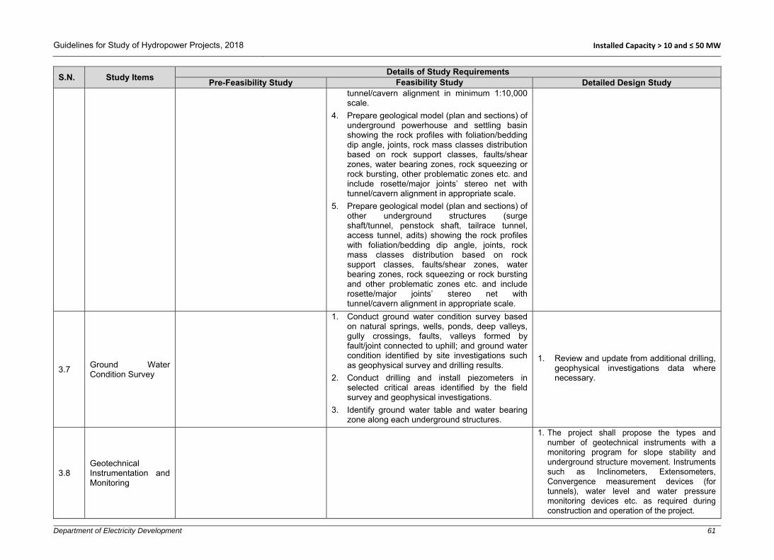
Guidelines for Study of Hydropower Projects, 2018 Installed Capacity > 10 and ≤ 50 MW
Department of Electricity Development 61
S.N. Study Items Details of Study Requirements
Pre-Feasibility Study Feasibility Study Detailed Design Study tunnel/cavern alignment in minimum 1:10,000 scale.
4. Prepare geological model (plan and sections) of underground powerhouse and settling basin showing the rock profiles with foliation/bedding dip angle, joints, rock mass classes distribution based on rock support classes, faults/shear zones, water bearing zones, rock squeezing or rock bursting, other problematic zones etc. and include rosette/major joints’ stereo net with tunnel/cavern alignment in appropriate scale.
5. Prepare geological model (plan and sections) of other underground structures (surge shaft/tunnel, penstock shaft, tailrace tunnel, access tunnel, adits) showing the rock profiles with foliation/bedding dip angle, joints, rock mass classes distribution based on rock support classes, faults/shear zones, water bearing zones, rock squeezing or rock bursting and other problematic zones etc. and include rosette/major joints’ stereo net with tunnel/cavern alignment in appropriate scale.
3.7 Ground Water Condition Survey
1. Conduct ground water condition survey based on natural springs, wells, ponds, deep valleys, gully crossings, faults, valleys formed by fault/joint connected to uphill; and ground water condition identified by site investigations such as geophysical survey and drilling results.
2. Conduct drilling and install piezometers in selected critical areas identified by the field survey and geophysical investigations.
3. Identify ground water table and water bearing zone along each underground structures.
1. Review and update from additional drilling, geophysical investigations data where necessary.
3.8 Geotechnical Instrumentation and Monitoring
1. The project shall propose the types and number of geotechnical instruments with a monitoring program for slope stability and underground structure movement. Instruments such as Inclinometers, Extensometers, Convergence measurement devices (for tunnels), water level and water pressure monitoring devices etc. as required during construction and operation of the project.

Guidelines for Study of Hydropower Projects, 2018 Installed Capacity > 10 and ≤ 50 MW
Department of Electricity Development 62
S.N. Study Items Details of Study Requirements
Pre-Feasibility Study Feasibility Study Detailed Design Study
4 Construction Material Survey
1. Identify sources and quarry sites for the construction materials such as sand, coarse aggregates, boulders, impervious soils, etc.
2. Locate the quarry sites in the available topographic map (1:25,000 or 1:50,000) observed during the site visit.
3. Make a preliminary estimation of available quantity at each borrow area for the construction.
1. Take reference from the pre-feasibility study, if any.
2. Identify and investigate construction material sources and quarry sites for the construction materials such as impervious soils, stones, boulders, sand and gravel as required.
3. Excavate test pits/trenches (minimum 1.5 m * 1.5 m and log the nature of soil at borrow locations including photographs and collect samples for laboratory analysis.
4. Perform laboratory tests: gradation and classification, unconfined compression, absorption and specific gravity, uniaxial compressive strength, point load, Los Angeles abrasion test, sulphate soundness, slake durability test, compaction test, alkali aggregate reaction, swelling test (if necessary), aggregate crushing value, mica and clay content.
5. Estimate the available quantity at each borrow area to meet the requirement of the construction.
6. Collect rock block/boulders samples from each quarry site for laboratory tests.
7. Prepare location map with source areas for the materials in appropriate scale.
1. Collect previous laboratory reports and results and verify the quality and quantity of construction materials.
2. Carry out further investigations and laboratory tests, if required.
3. Prepare a detail construction materials survey mass showing all the location.
5 Seismic Study
5.1 Tectonic Setting
1. Describe in brief tectonic setting related to the project area using available literature and regional maps.
1. Describe the tectonic setting related to the project area using available literature and regional maps.
5.2 Seismic Zoning 1. Identify the seismic zone of the
project based on the NBC 105. 1. Review and update the previous study, if
required. 1. Review the previous studies and update, if
required.
5.3
Earthquake Catalogue and Historical and Instrumentally Recorded Earthquakes
1. Earthquake catalogue, especially for those historical and instrumentally recorded earthquakes, should be prepared for earthquakes of magnitude 4.0 M and higher. For every significant earthquake event, the location, distance, magnitude and intensity should be shown in a map in a suitable scale.

Guidelines for Study of Hydropower Projects, 2018 Installed Capacity > 10 and ≤ 50 MW
Department of Electricity Development 63
S.N. Study Items Details of Study Requirements
Pre-Feasibility Study Feasibility Study Detailed Design Study
5.4 Project Specific Seismic Hazard Analysis
1. Empirical laws may be applied to deduce intensity or acceleration of the ground motion. The Peak Ground Acceleration (PGA) for Maximum Design Earthquake (MDE) and Operating Basis Earthquake (OBE) should be given in reference from other existing nearby hydropower project(s) or National/International standards or codes.
1. Review/Compute OBE and MDE on the basis of Deterministic approach and Probabilistic approach.
2. Review the previous studies and update, if required.
6 Selection of Project Components and Project Layout
1. Assess and describe availability and condition of the access road(s) leading to the project site.
2. Identify and describe new access road(s)/ropeways/foot trails/tunnels to be constructed for development of the project.
3. Identify the existing hydropower project (s) located at upstream and downstream of the project area and verify the project’s license boundary with existing hydropower project.
4. Conceptual layout of all possible schemes within the license boundary should be identified and studied.
5. Topographical, geological conditions of alternative layouts should be studied in order to select the location of project structures: weir, settling basin waterways, forebay, penstock, powerhouse, tailrace and switchyard.
6. While selecting the alternatives, socio-environmental variables should be considered and compared.
7. Assess the location and condition of immediate upstream and downstream projects, if any.
1. Review the pre-feasibility study report and update the site accessibility conditions to the project area.
2. Detailed topographic maps and preliminary geological maps should be prepared for designing the project configuration/layout.
3. Use updated hydrological data/analysis results for the design of project components. The design discharge should be based on prevailing practices in the context of Nepal (e.g. 40-45 percentile flow/flow mentioned in survey license).
4. While selecting the alternatives, socio-environmental variables should be considered and compared.
5. Select the shortest and most economical access road(s) alignment with the minimum numbers of crossing structures.
6. Follow the relevant national and international guidelines, norms and codes to design the project components.
7. For the selection of location of the diversion weir, alternative sites for the settling basin, water conveyance, river crossings, forebay/surge tank/surge shaft, powerhouse, tailrace and switchyard should be studied/ investigated in detail.
8. Prepare preliminary design and drawings of all alternatives (at least two covering both banks) and the project structures in appropriate scale.
9. Conduct an alternative study of transmission
1. Experts’ consultation is recommended to verify the project layout and components’ design.
2. Review the feasibility study incorporating expert’s recommendations, if any.
3. In case of significant changes to the layout, update the feasibility study.
4. Verify the updated project license boundary.
5. Carry out detailed design of access roads within the project area, if required.
6. Carry out detailed design of all components such as weir, intake, settling Basin, waterways, forebay/surge tank/surge-shaft, powerhouse, tailrace and switchyard.
7. Follow the relevant national and international guidelines, norms and codes to design the project components.

Guidelines for Study of Hydropower Projects, 2018 Installed Capacity > 10 and ≤ 50 MW
Department of Electricity Development 64
S.N. Study Items Details of Study Requirements
Pre-Feasibility Study Feasibility Study Detailed Design Study List out issues to be addressed related to the existing project(s) while finalizing the project configuration.
8. The locations and types of the structures of each scheme should be verified at the site in terms of accessibility, topography, geology, river morphology, construction ease and technical, economic and socio-environmental considerations.
9. Prepare conceptual layout (project configuration) of at least two of the most promising schemes with their major structures in appropriate scale using available maps and conduct a preliminary cost-benefit analysis.
10. Recommend area to be covered by the topographical survey for feasibility study during feasibility study phase as well as other site specific investigations.
line routes (at least two) and identify the shortest and most economical route, sub-station and voltage level.
10. Based on the design and drawings, quantity and cost estimations should be carried out for each alternative.
11. Calculate revenue from the project using saleable energy and prevailing energy prices.
12. Select the best alternative scheme based on the maximum benefit at minimum cost.
13. Prepare general layout drawings of the best alternative showing its components: headworks, waterway, forebay/surge tank/surge shaft, penstock, powerhouse, tailrace and switchyard using the detailed topographic map prepared during this stage of the study. Additionally, show transmission line route and access roads to all major project components.
14. Expert consultation and verification of project layout and project structures should be carried out based on the complexity of the project.
7 Optimization study
1. Installed capacity should be tentatively fixed considering preliminary technical, socio-environmental and economic assessment based on the findings of the up-to-date study and on past practices. If due to lack of data (e.g., hydrology), it is not possible to fix the installed capacity, a range should be provided.
2. The number of generating units should be determined considering the reliability of
1. General Approach
For a selection of parameters to be optimized, identify their ranges and establish a series of alternatives.
Carry out the conceptual design, drawings and estimate its cost for each alternative.
Estimation of benefits for each alternative. Comparison of cost and benefits.
2. Assumptions
Price of dry and wet energy, peak/off-peak as per the requirements of the off taker.
Capacity benefit, if any.
1. Re-optimization should be carried out based on changes in project capacity and/or design discharge and/or changes in market price for material and labour.

Guidelines for Study of Hydropower Projects, 2018 Installed Capacity > 10 and ≤ 50 MW
Department of Electricity Development 65
S.N. Study Items Details of Study Requirements
Pre-Feasibility Study Feasibility Study Detailed Design Study operation of the plant and maximum utilization of dry season river flow. Apart from that transportation aspects should also be considered.
3. Selected alternatives
Determine the number of alternatives considering the range of installed capacities.
4. Energy Production
For ROR projects calculate energy production for all alternatives with the following considerations: - At least five options, generally in the
range of 65% to 25% flow exceedance and average monthly flows to be used.
- Dry and Wet energy, peak/off-peak energy as per the requirements of off-taker should be calculated.
5. Project Layout
Optimize project structures/components individually for the given installed capacity/discharge.
Size of settling basin to be adjusted as per optimized design discharge.
Water conveyance system including tunnel, penstock and tailrace to be optimized considering the loss of revenue due to head loss and investment cost.
Forebay/Surge tank/Surge shaft dimension to be adjusted.
Powerhouse and unit sizes to be obtained from the empirical formula, past experiences and/or supplier(s)’ information.
6. Cost Estimate
Preliminary quantity and cost estimates should be developed for all the cases under consideration.
Only the major items should be computed in detail, while minor items may be estimated based on curves and data of similar structures in other projects.
Unit rates should be estimated based on prevailing market rates in the area, project location and accessibility. Reference can be taken from under construction projects with similar features.

Guidelines for Study of Hydropower Projects, 2018 Installed Capacity > 10 and ≤ 50 MW
Department of Electricity Development 66
S.N. Study Items Details of Study Requirements
Pre-Feasibility Study Feasibility Study Detailed Design Study Electro-Mechanical and switchyard equipment
costs should be calculated using empirical relations, market price and/or based on budgetary quotations from the potential suppliers.
The cost estimates should also consider the cost of access roads, infrastructure development and environmental costs.
Technical contingencies should be taken into account to come up with the implementation cost of the alternatives.
7. Financial Comparison
Financial comparison of the different alternatives should be carried out considering the implementation and operation cost with occurred benefits due to energy production for each case.
The financial analysis should be carried out to determine the basic economic parameters such as Net Present Value (NPV), Internal Rate of Return (IRR), and Benefit Cost Ratio (B/C).
The alternative with maximum B/C ratio and internal rate of return should be selected to fix optimum installed capacity.
8. Number of Units
Minimum possible number of units should be adopted considering hydrology, transport capacity of road/bridge conditions.
8 Project Description and Design
8.1 General Layout and Design: Civil Structures
1. General layout of the selected alternative site of the project should be described.
2. Layout should be prepared using the available larger scale topographic map.
3. Preliminary hydraulic design and sizing of the following civil structures should be carried out:
Weir & Intake
Project Layout
1. General layout of the selected alternative of the project should be described.
2. Layout should be prepared using the survey maps and geological and geotechnical information.
3. Detailed hydraulic design and sizing of the all civil structures including the following should be carried out:
Weir, intake and undersluice.
1. General
The final project layout recommended in the feasibility study and the approved IEE/EIA report should be reviewed and verified by experts, if necessary.
Component-wise detailed design should be carried out for the final/updated project layout.
Project definition report defining all project information, parameters and components should be prepared.

Guidelines for Study of Hydropower Projects, 2018 Installed Capacity > 10 and ≤ 50 MW
Department of Electricity Development 67
S.N. Study Items Details of Study Requirements
Pre-Feasibility Study Feasibility Study Detailed Design Study Gravel trap Settling basin Headrace canal/pipe/tunnel Forebay or surge tank Penstock Powerhouse Tailrace
4. Preliminary design of switchyard and sub-station’s civil structures should be carried out.
5. A brief description of major civil components should be given.
6. Typical drawings of major project components should be prepared in appropriate scale.
Upstream and downstream aprons. Stilling basin. Gravel trap. Settling basin. Headrace canal/pipe/tunnel. Forebay/surge tank/surge shaft. Penstock. Powerhouse. Tailrace.
4. Design of temporary and permanent infrastructures such as camp facilities, construction power, access roads (ropeways, bridges, tunnels), drinking water supply, etc. should be carried out.
5. Design of switchyard and sub-station’s civil structures should be carried out.
6. Design and location of spoil tips should be carried out.
7. Necessary flood/debris/landslide protection works should be designed based on the river morphology, ground topography, possible debris flow area and the possibility of rock falls (rolling boulders) nearby powerhouse and switchyard area.
8. All project components should be described in detail.
9. Drawings of all project components should be prepared in appropriate scale.
Diversion During Construction
1. A general plan to divert the river in the dry season in order to carry out the construction works at weir and intake sites should be prepared, which may require 2-4 dry seasons.
2. An upstream cofferdam should be designed in order to protect the working area at weir site. A cofferdam should also be provided to prevent river entering in working area from downstream.
3. Design and drawing of temporary river diversion during construction should be prepared. The diversion channel should be
Project parameters and design criteria should be included in a Design Basis Memorandum (DBM) referring to relevant national and international guidelines, norms and codes, and past experiences.
Detailed hydraulic design and dimensioning of all components/structures carried out during the feasibility study should be reviewed and updated/refined/revised where necessary.
2. Infrastructures
Design of road components such as side drains, cross drainage structures, retaining walls, gabion and stone masonry structures should be carried out.
Plans, profiles and cross sections of access roads including side drains, retaining structures, cross drainage structures should be prepared in appropriate scale.
Design of construction camps, temporary and permanent housing, water supply and sewerage system, bunker houses etc. should be done and presented in drawings.
Necessary drainage system for surface runoff management should be designed.
Necessary design for construction power arrangement should be carried out.
3. Temporary River Diversion
Detailed hydraulic design and drawings cofferdams, diversion channel and aprons should be carried out.
The diversion channel and cofferdams should be designed to pass construction flood.
In case of diversion tunnel, detailed rock support design based on rock mass classification should be carried out. The inlet and outlet portals should also be designed.

Guidelines for Study of Hydropower Projects, 2018 Installed Capacity > 10 and ≤ 50 MW
Department of Electricity Development 68
S.N. Study Items Details of Study Requirements
Pre-Feasibility Study Feasibility Study Detailed Design Study designed to pass 1:20 years return period dry season flood. If the headworks construction is to be continued during monsoon season, at least 1 in 10 years return period flood should be used.
Headworks
All headworks components should be designed following “Design Guidelines for Headworks of Hydropower Projects” published by DoED, Nepal, 2006. 1. Weir/dam, intake, stilling basin, aprons and
floodwalls should be designed to pass safely the maximum flood of 1 in 100 years return period. Stability analysis should be done for 1 in 200 years return period flood.
2. Weir crest level or spillway crest level should be determined and fixed considering clearance required between undersluice invert level and intake bottom sill-level, the height of intake opening and submergence requirement for intake opening in order to avoid/minimize entry of trash into the intake. Intake capacity should be about 130% of the design discharge in case of conventional gravel trap and settling basin flushing systems while the plant operates at full load during flushing.
3. For gated spillway/non-overflow spillway, either radial or vertical sluice gates should be designed considering N-1 gates will be operated during floods.
4. Carry out preliminary seepage analysis under the weir/dam foundation and other water retaining structures.
5. Sufficient freeboard should be provided for design flood between the design flood level and the operating platforms and other necessary areas/structures.
6. Under sluice structure of headworks should be designed to pass safely bed-load and flush sediment deposited in front of the intake and to pass a portion of flood discharge. Either vertical sluice gates or radial gates should be provided
4. Main Component Design
Detailed design of all surface and underground structures should be carried out.
The safety of components should be checked by conducting stability and structural analysis.
5. Seismic Design Criteria
Pseudo-static analysis procedures (seismic coefficient method) can be used in the seismic design and analysis of structures where appropriate.
The response of a structure to ground vibrations should be determined considering soil type, seismic zone, response reduction factor, importance factor, fundamental period of vibration and damping factor (ξ). These values can be referred from norms and codes such as the NBC 105.
For structures with minor importance, the seismic coefficient can be reduced appropriately.
Both vertical and horizontal seismic components should be used in the design.
6. Foundation Design
The results from the geophysical investigation shall be used to design the foundations. In case of missing or unavailability of data, suitable values shall be assumed based on the local geology.
If the foundation has to be placed in an inferior soil type, a suitable foundation treatment method should be specified.
Carry out detailed seepage analysis under the weir/dam foundation and other water retaining structures. Uplift pressure and under piping mechanism for cut offs wall, apron and protection works should be analysed and proper measures should

Guidelines for Study of Hydropower Projects, 2018 Installed Capacity > 10 and ≤ 50 MW
Department of Electricity Development 69
S.N. Study Items Details of Study Requirements
Pre-Feasibility Study Feasibility Study Detailed Design Study at under sluice with hydraulic or cable-drum type hoisting system.
7. A number of gates at undersluice should be made as per optimization and selected scope of the alternative study.
8. A stilling basin should be designed for energy dissipation before releasing spillway flows back into the river. Basin cross section, basin length and depth, apron elevation, side wall, minimum free board, drainage etc. should be designed and described.
9. The clear spacing of the coarse trash rack in intake should be fixed considering the transport capacity of gravel flushing conduit.
10. Gravel trap should be designed to trap greater than 2-5 mm particles and gravel flushing system should be designed to flush up to 200 mm particles.
11. Settling basin should be designed for continuous supply of required design flow plus flushing discharge. The trapping efficiency should be 90% or higher for particle size greater than 0.2 mm, depending on the available head and mineral composition of sediments. Adequate justification should be provided, if smaller than 0.2 mm particle size is selected to be settled in the settling basin. It is suggested to divide the settling basin into 2 or more chambers.
12. Sediment handling, controlling and flow regulation mechanism should be defined in the project description.
13. An automatic/ungated spillway should be provided downstream of the settling basin at conveyance tank wherever possible.
14. Sediment/gravel flushing outlets should be located at shooting flow areas of the stilling basin/river.
15. Design of fish ladder should be provided for the movement of the fish over the structures at the left or right abutment of the gated weir or dam.
be taken to prevent damage related to foundation undermining.
The allowable bearing capacity of the foundation may be increased in extreme loading conditions as provisioned in the design codes. Similarly, the allowable bearing capacity may need to be reduced when fully water saturated condition occurs and placing foundation on steep slopes or adjacent to them.
7. Stability Analysis of Structures
The following loadings should be considered for stability analysis of project components: Dead load Live load Water pressure Weight of water Hydro-dynamic load Active earth pressure At rest pressure Passive earth pressure Earthquake load In-situ stresses Impact load Vibration load Thermal Uplift (buoyancy and seepage) Surcharge/overburden loads Water hammer Wind Snow Construction and moving surface
loads: Additional loads, if any.
For the purpose of evaluating the stability and structural analysis, different load combinations may occur during different phases of the project implementation and operation should be considered. Individual components/elements must be

Guidelines for Study of Hydropower Projects, 2018 Installed Capacity > 10 and ≤ 50 MW
Department of Electricity Development 70
S.N. Study Items Details of Study Requirements
Pre-Feasibility Study Feasibility Study Detailed Design Study 16. Necessary flood protection, ground stabilization
and bio-engineering works should be carried out, if required.
Water Conveyance
All water conveyance system should be designed following “Design Guidelines for Water Conveyance System of Hydropower Projects” published by DoED, Nepal, 2006; considering the project specific data and information. 1. The power canal /headrace pipe/tunnel
including all hydraulic and cross-drainage structures from intake to forebay/surge tank/surge shaft should be designed for 110% design discharge or higher.
2. The configuration of the power tunnel should be given, comprising headrace tunnel and pressure tunnel with lining types finished diameter and length. Sufficient lateral cover and optimum overburden should be ensured. Tunnel support design should be carried out depending on rock quality.
3. A rock trap should be provided at the end of the headrace tunnel, upstream of the surge tank to trap loose rocks and displaced shotcrete. Suitable flushing system should be provisioned at rock trap.
4. A number of saddle supports and anchor blocks should be designed and described.
5. Slope stability analysis in critical sections of waterways including forebay/surge tank/surgeshaft should be carried out.
6. Necessary drainage system for surface runoff management should be designed.
7. Type and size of the headrace canal should be determined by considering the design discharge, silting/scouring velocity for the selected materials used (e.g., concrete grade, masonry) of applied concrete grade and topography.
8. Corrosion, scratching, pipe diameter and transportation limitation factors should be
designed for the most unfavourable load combination. In general, the following conditions should be considered:
Construction Normal operation Special/emergency/extreme cases
The safety factor depends upon the codes and
loading combination used. 8. Detailed Structural Analysis and Design
Appropriate codes (concrete, steel) should be referred for the detail design. All possible loading conditions should be considered.
The durability of the structure should be ensured in the design.
Material properties and allowable stresses for concrete, structural steel, reinforcement, etc. should be specified.
The structure should be analysed using acceptable methods manually or by using a software.
All structures should be safe against internal and external forces/stresses and all kind of climatic conditions.
Reinforcement calculation should be done also considering temperature and shrinkage effects.
The dynamic analysis should be carried out for powerhouse and penstock and ensure that natural frequency does not create resonance phenomenon.
Ensure that the settlement/deformation and deflection are within permissible limits.
9. Water Tightness
Control of cracking in concrete should be as per the requirement specified in IS 456:1978 and 2000 or BS 8007:1987 or BS 8110 Part II, BS 2007 or equivalent codes.
The type and location of joints should be

Guidelines for Study of Hydropower Projects, 2018 Installed Capacity > 10 and ≤ 50 MW
Department of Electricity Development 71
S.N. Study Items Details of Study Requirements
Pre-Feasibility Study Feasibility Study Detailed Design Study considered while fixing the headrace pipe thickness.
9. An emergency spillway at forebay should be provided. The volume of forebay should be based on the transient analysis.
10. The thickness of the steel pipe should be able to withstand any variable load conditions encountered during operation of the plant. While deriving the effective thickness of the pipe, steel grade, corrosion factor, welding factor, etc. should be considered.
11. Anchor blocks to hold penstock pipe should be designed at bends and also intermediary in long straight stretches.
12. Head losses through tunnel/pipe system at the design discharge should be determined.
Forebay/Surge Tank/Surge Shaft
1. Description of the forebay/surge tank/shaft type with its dimensions should be provided.
2. For surge tank/surge shaft, various possible scenarios of transient analysis should be carried out to determine upsurge and down surge level.
3. The invert level, upsurge and down surge levels of the forebay/surge tank/shaft should be shown in drawings.
Penstock Alignment 1. Valleys, landslides and rock fall areas and gully
crossings should be minimized, if they cannot be avoided, during the alignment selection.
2. The effective thickness of the steel pipe should be adequate to withstand the dynamic/water hammer/test pressure loading in addition to hydrostatic pressure.
3. Surface type or cut and cover type should be decided on the basis of the topographic and environmental considerations.
4. Necessary protection structures should be applied as per surface geology and topography.
specified. Contraction/Expansion joints should generally be located in 15 to 25 m spacing. Construction joints should be provided considering construction sequence.
The appropriate type of water stops should be provided at expansion/contraction/construction joints.
10. Detailing and Drawings
The reinforcement should be detailed considering the ductility of the structure.
Reinforcement arrangement should be shown in drawings in an appropriate scale. Special attention should be given at joints.
Prepare construction drawings, reinforcement drawings and bar bending schedules.
11. Field verification of Design/Layout
The arrangement of all project components should be verified at the site by laying setting out points. Any changes that may occur should be addressed in the design.
12. Report Preparation
After finalizing the design, a detailed design report should be prepared showing all hydraulic, geotechnical, stability and structural analyses calculations. Based on the detailed design report, a draft operation and maintenance manual should be prepared.

Guidelines for Study of Hydropower Projects, 2018 Installed Capacity > 10 and ≤ 50 MW
Department of Electricity Development 72
S.N. Study Items Details of Study Requirements
Pre-Feasibility Study Feasibility Study Detailed Design Study Vertical Shaft/Inclined Shaft /Penstock Tunnel1. If surface penstock is not feasible, either
vertical or inclined shaft should be designed. Dimensions of the shaft and type and thickness of the lining should be determined. In addition, appropriate temporary rock support during excavation should be designed.
Construction Adits 1. Provision of construction adits should be made
at various locations of tunnel alignment in order to meet the construction schedule.
2. Tunnel portals should be located at exposed bed rock and stable ground topography and should be designed properly.
Powerhouse and Tailrace 1. Powerhouse should be dimensioned to
accommodate electro-mechanical equipment and its ancillaries.
2. Description of the powerhouse building should be provided giving details of equipment layout at generator floor level, turbine floor level, drainage floor level, and foundation level. Dimensions of the powerhouse should be determined by consulting with potential electro-mechanical equipment supplier.
3. Proper layout of the following equipment and structures inside the powerhouse should be made: turbines, generators, powerhouse crane unit, control panels and excitation system, control room, battery room, main inlet valve, provision for runner removal for maintenance, sump tank, cooling water tank, compressor room, service bay, water supply and sanitary system, station service transformer, etc.
4. Fire protection and a ventilation system should be designed and described in detail.
5. Emergency exits and safety plan should be described/provided as per national/international guidelines.
6. The tailrace conduit should be designed considering turbine type, minimum power discharge available, minimum water depth

Guidelines for Study of Hydropower Projects, 2018 Installed Capacity > 10 and ≤ 50 MW
Department of Electricity Development 73
S.N. Study Items Details of Study Requirements
Pre-Feasibility Study Feasibility Study Detailed Design Study requirement and possible effect of river water level at the tailrace outlet.
7. Necessary flood/debris/landslide protection works should be carried out based on the river morphology, ground topography, possible debris flow area and possibility of rock falls (rolling boulders) near powerhouse and switchyard area.
8. An access tunnel should be provided for underground construction. A detailed description of adit/access tunnel should be provided including size, type, support design and portal location.
Switchyard 1. Dimensions of switchyard should be
determined by consulting with potential electro-mechanical equipment supplier(s).
2. Switchyard area should be arranged nearby the powerhouse and civil design of switchyard should be prepared.
8.2 Hydro-Mechanical Components
1. Preliminary design/estimation of hydro mechanical components such as gates, stoplogs, trashracks and penstock should be carried out.
2. A brief description of hydro-mechanical components should be provided in the report.
Following hydro-mechanical components should be designed and described: 1. Gates, stop logs, embedded parts, valves,
trash racks, bell mouths, manholes, expansion joints, saddle/wear plates, sizing of headrace and penstock pipes, bends, reducers, branches, steel lining works etc.
2. The hoisting system for gates and stop-logs.
1. General
This design is generally carried out by hydro-mechanical equipment manufactures/suppliers, thus only preliminary design for preparing the Terms of Reference of tender/contract documents shall be carried out in consultation with potential manufacturers/suppliers.
Design and dimensioning of all components/structures carried out during the feasibility study should be reviewed and updated where necessary and presented in the project definition report.
Component-wise design should be carried out for the final/updated project layout.
Project parameters and design criteria should be included in a Design Basis Memorandum (DBM) referring to relevant national and international guidelines, norms and codes, and past experiences.
While designing the hydro mechanical components, factors such as corrosion,

Guidelines for Study of Hydropower Projects, 2018 Installed Capacity > 10 and ≤ 50 MW
Department of Electricity Development 74
S.N. Study Items Details of Study Requirements
Pre-Feasibility Study Feasibility Study Detailed Design Study welding defects, and plate inaccuracy/defects should be taken in to account.
Individual components/elements must be designed for the most unfavourable load combination. In general, loading conditions which may occur during the following phases/cases should be considered: Transportation Erection/construction Testing in factory and site Normal operation Special/emergency/extreme cases
2. Design of Gates and Stop-Logs
The type of gate/stoplogs with embedded parts and its hoisting mechanism should be fixed.
The materials to be used for skin plates, stiffeners, girders, embedded parts and other components should be specified.
The gates/stoplog with embedded parts shall be designed for the hydrostatic and hydrodynamic forces taking into consideration the forces arising from wave effects, water hammer, seismic loads, active soil load (sediment deposit), ice formation, friction, and thermal effect wherever applicable.
The internal stress should be ensured to be within limit of allowable stress in normal and extreme operation conditions.
Sufficient corrosion allowance should be provided and corrosion prevention methods, if any, should be mentioned.
Type and material of seals should be mentioned.
Power-operated gates shall normally be capable of operation by alternate means in case of power supply failure.

Guidelines for Study of Hydropower Projects, 2018 Installed Capacity > 10 and ≤ 50 MW
Department of Electricity Development 75
S.N. Study Items Details of Study Requirements
Pre-Feasibility Study Feasibility Study Detailed Design Study If meant for regulation, it shall be capable
of being held in partially open position without major damage to seal or deterioration due to cavitation and vibration.
Wherever necessary, model studies may be carried out for high head regulating gates.
The deflection of the gate under various loading conditions should be within the permissible limits.
Dogging devices and lifting beams should be designed for operation of gates, stoplogs etc.
Destructive and non-destructive testing procedures should be specified.
All the gates shall be checked for the aeration requirement at its immediate downstream.
3. Steel Pipes
The steel plate used for the pipes shall comply with national/international standards. The pipes should be designed considering following loading conditions:
Normal condition includes static head, surge and water hammer pressure.
Special conditions include those during filling and draining of penstocks and maximum surge in combination with pressure rise during emergency operations/events and test pressures.
Exceptional condition includes transportation and erection stresses, pressure rise due to unforeseen operation of regulating equipment in the most adverse manner resulting in odd situation of extreme loading, stress developed due to resonance in penstock, seismic forces etc.

Guidelines for Study of Hydropower Projects, 2018 Installed Capacity > 10 and ≤ 50 MW
Department of Electricity Development 76
S.N. Study Items Details of Study Requirements
Pre-Feasibility Study Feasibility Study Detailed Design Study Adequate safety factor should be provided
for safety against hoop stress due to internal and external pressure, including surge pressure, longitudinal stress, beam action, temperature variations.
Stress should be checked in bends, branches, transition and stiffeners.
Expansion joint should be provided just below the anchor block whenever possible.
Special design provision shall be made to protect the penstock pipes/conduits against possible rupture due to denting/negative pressure.
4. Other Structures
Other HM components such as valves, trash racks, manholes, saddle plates, bulk head gates, bell mouths, steel lining etc. shall be designed to meet structural and hydraulic requirements.
5. Report Preparation
After finalizing the design, a report should be prepared showing all hydraulic, and structural calculations. Similarly, operating conditions, hoisting mechanisms, opening sizes, design pressures, and dimension of all major components/elements should be mentioned. Based on the detail design report, a draft operation and maintenance manual should be prepared.
8.3 Electro-Mechanical Equipment
1. Preliminary design/selection of the electro-mechanical equipment should be carried out based on design discharge and net head and number of units (based on hydrology and transportation).
Mechanical equipment: - Preliminary selection of
type and dimension of turbines should be carried
1. The type and number of generating equipment, and power evacuation facilities should be designed and described.
2. Description of main mechanical equipment including the followings should be provided:
Design criteria Mode of operation Hydraulic turbine-type and number Turbine efficiency Rated speed
1. General:
This design is generally carried out by electro-mechanical equipment manufactures/suppliers, thus only preliminary design for preparing Terms of Reference of tender/contract documents shall be carried out in consultation with potential manufacturers/suppliers.
Detailed design and dimensioning of all components/structures carried out during

Guidelines for Study of Hydropower Projects, 2018 Installed Capacity > 10 and ≤ 50 MW
Department of Electricity Development 77
S.N. Study Items Details of Study Requirements
Pre-Feasibility Study Feasibility Study Detailed Design Study out. A brief description of turbine auxiliaries should be provided.
Electrical Equipment: - Parameters of the generators should be determined. A brief description of excitation and electrical auxiliaries should be provided.
Single line diagram - An electrical single line diagram showing the major electrical equipment of powerhouse should be prepared.
Rated turbine output Inlet valve Other turbine specific features Governor Lubricating (hydraulic) system Pressure oil system Compressed air system Cooling system Control system Overhead crane Maintenance of turbine
3. Description of the main electrical equipment
including the followings should be provided: Generator- type, number Generator efficiency, rated output, frequency
generated voltage level Excitation system Switchgears Control panel Switchyard Powerhouse earthing Emergency diesel generator Control and protection system Power transformer –type, numbers, efficiency
frequency, rated output etc. Auxiliary transformer CT/PT Hoisting mechanism/overhead crane
4. A single line electrical diagram depicting the interconnection of all electrical equipment should be prepared.
5. For the smooth operation of the power station, following auxiliaries should be provided and described:
Grease lubricating system Fire fighting system Station supply Lighting arrangement Cooling system Oil filtering equipment
the feasibility study should be reviewed and updated/refined/revised where necessary presented in the project definition report.
Project parameters and design criteria should be included in a Design Basis Memorandum (DBM) referring to relevant national and international guidelines, norms and codes, and past experiences.
Individual components/elements must be designed for the most unfavourable load combination (mechanical and electrical). In general, loading conditions which may occur during the following phases/cases should be considered: Transportation Erection/construction Testing in factory and site Normal operation Special/emergency/extreme cases
2. Mechanical Equipment
Appropriate turbines and their components should be designed.
Suitable inlet valves shall be provided before each turbine.
Draft tube, spiral casing, covers, seals should be designed appropriately.
Suitable governor system should be provided for flow control to the turbine.
Proper auxiliary systems such as heat exchanger system, lubrication system, pressure system, compressed air system, hydraulic system, cooling system, EOT crane, lighting system, fire extinguishing system shall be designed.
Control system with local unit and remote (to control room) controlling capability should be provided.

Guidelines for Study of Hydropower Projects, 2018 Installed Capacity > 10 and ≤ 50 MW
Department of Electricity Development 78
S.N. Study Items Details of Study Requirements
Pre-Feasibility Study Feasibility Study Detailed Design Study DC power auxiliaries, Distribution to outlaying works Distribution to housing complex Fire fighting system Heating, Ventilation and Air Conditioning
(HVAC) Station supply
3. Electrical Equipment
Single line diagram and control diagram for all powerhouse equipment and interconnection point shall be prepared following latest NEA Grid Code and other relevant standards.
Generators shall be provided with all of their accessories including cooling and fire protection system, hydraulic system including generator braking and heat exchanger system.
Excitation system shall be provided with automatic voltage regulator, excitation transformer and bridge rectifier.
Switching equipment with bus bars, circuit breakers, disconnecting switches, instrument transformers, etc. shall be provided.
Power transformers to step up transmission voltage shall be provided with type of cooling, indoor/outdoor arrangement and other required accessories.
Control equipment shall be provided consisting of governor monitoring, excitation monitoring, emergency shutting down, valve protection and other protection, etc.
Station service transformer for redundant power supply to the plant shall be provided.
Grounding including lightning protection shall be provided.
Fire protection and ventilation system should be designed and described in detail.
Emergency exits and safety plan should be described/provided as per national/international guidelines.
Diesel Generators shall be provided for backup power and black start/isolation mode.

Guidelines for Study of Hydropower Projects, 2018 Installed Capacity > 10 and ≤ 50 MW
Department of Electricity Development 79
S.N. Study Items Details of Study Requirements
Pre-Feasibility Study Feasibility Study Detailed Design Study
8.4 Power Evacuation and Transmission Line
1. Assess the possibility of power evacuation through national grid /Integrated Nepal Power System (INPS).
2. Carry out preliminary design to select voltage level, conductor type and number of towers.
3. A single line electric diagram should be prepared representing the major electrical equipment of the powerhouse.
4. A brief description of selected power evacuation system should be presented.
1. Prepare updated single line diagram representing the major electrical equipment of the powerhouse, switchyard, and substation.
2. Finalize the most appropriate transmission line route, voltage level and length.
3. Describe the details of interconnection equipment.
4. Describe and design the total number of towers and support structures, circuit type, type of conductor used and other safety measures.
1. The transmission line should be designed following latest off-taker/NEA grid code.
2. The route shall be finalized and described. 3. Voltage level, number of circuits and
length shall be confirmed. 4. Number and type of towers required shall
be determined with location (co-ordinates) and their structure shall be designed. While designing the foundation of the transmission tower, geology and geotechnical conditions with socio-environmental assessment should be verified and additional investigation should be done, if required.
5. Conductors’ size to be used shall be determined. The size of conductors must be selected so that the power loss doesn’t exceed the permissible limit as per the latest off-taker/NEA Grid Code.
6. Sag, tension and loading in conductor shall be determined.
7. Auxiliary equipment in the transmission line such as insulators, clamps, guards, etc. shall be provided.
8. Necessary equipment to be installed in interconnection substation should be designed as follows: Power transformers shall be required,
if the voltage level of transmission line does not match voltage level of interconnecting substation,
HV switchgear (circuit breaker, disconnecting switch, etc.)
Instrument transformers Control and protection equipment.

Guidelines for Study of Hydropower Projects, 2018 Installed Capacity > 10 and ≤ 50 MW
Department of Electricity Development 80
S.N. Study Items Details of Study Requirements
Pre-Feasibility Study Feasibility Study Detailed Design Study
9 Energy Computation and Benefit Assessment
9.1 Energy Computation
1. Energy computation should be carried out considering the average monthly flow (daily flow, if available), net head, Turbine discharge and plant efficiency.
2. Average monthly energy and annual energy should be determined.
3. Total dry energy and wet energy is determined separately by considering the dry/wet periods fixed by the off-taker/NEA.
4. Gross monthly and annual revenue throughout license period should be determined considering per unit energy price fixed by the NEA/off-taker for small/large hydropower project or similar size of the hydropower project.
Energy Computation
1. Energy computation should be based on: Adopted hydrology (average flow) for average
annual energy 90% reliable average daily flow in the lowest flow month for firm energy.
Assumed design parameters (net head, turbine/available river discharge for power, consideration of compensation flow, installed capacity).
Secondary energy is computed as average annual energy minus firm energy. Secondary energy available on monthly basis should also be presented.
Deliverable or net energy should be determined considering the outage and local losses about 5% of generated gross energy or losses considered by the similar size project or prescribed by off-taker/NEA.
Total (monthly and annual) net dry and wet energy (day energy, peak energy and off-peak energy) should be computed separately as per off-taker’s/NEA’s requirements.
1. Energy estimated in feasibility study should be updated/refined, if there are significant changes.
9.2 Benefit Estimation
1. Average monthly/annual revenue throughout the license period should be calculated considering unit energy prices fixed by the NEA/off-taker company/GoN for similar sized projects.
2. While calculating the annual revenue, base rates for dry, wet, peak, off-peak energy prices together with annual price escalation should be considered.
1. Revenue estimated in pre-feasibility study should be updated based on the updated energy calculated/updated during feasibility study.
1. Revenue estimated in feasibility study should be updated, if required.

Guidelines for Study of Hydropower Projects, 2018 Installed Capacity > 10 and ≤ 50 MW
Department of Electricity Development 81
S.N. Study Items Details of Study Requirements
Pre-Feasibility Study Feasibility Study Detailed Design Study
10 Cost Estimation
10.1 Criteria and Assumptions
All the criteria and assumptions adopted for cost estimation should be mentioned including following: 1. Consideration of the natural
conditions prevailing at the site, construction scale, and levels of construction technology available in Nepal.
2. A brief description of the project with location should be mentioned.
3. Year and month of the cost estimate should be mentioned.
4. The exchange rate applied to the calculation of NPR and USD adopted at the time of cost estimation should be mentioned.
5. Identifiable Nepalese taxes, customs duties, royalties etc. for goods, materials and services, interest during construction etc. whether included in cost estimation or not should be mentioned.
6. Any source of references to rates or estimation should be mentioned with used escalation factors, if any.
1. The criteria and assumptions for the pre-feasibility level study should be applied but should be based on feasibility level design with inclusion of items not included in the pre-feasibility level study.
1. The criteria and assumptions for feasibility level study should be applied but should be based on a detailed level design with the inclusion of items not included in the feasibility level study.
10.2 Estimation Methodology
The following methodology should be applied for estimation of the cost of each component of the project. 1. For Civil Works:
The cost estimates should be based on unit rates developed from prevailing labour rates, construction equipment rate and materials taking also into account the local situation and unit rates for projects of similar nature.
The following methodology should be applied for estimation of the cost of each component of the project.
1. For Civil Works
The cost estimates should be based on unit rates developed from prevailing labour rate, construction equipment rate and materials taking also into account the local situation and bill of quantities derived from design drawings.
1. The methodology for feasibility level study should be applied but should be based on feasibility level design with inclusion of items not included in the feasibility level study.
2. Carry out necessary updates such as revision of rate analysis.

Guidelines for Study of Hydropower Projects, 2018 Installed Capacity > 10 and ≤ 50 MW
Department of Electricity Development 82
S.N. Study Items Details of Study Requirements
Pre-Feasibility Study Feasibility Study Detailed Design Study 2. For Electro-Mechanical
Equipment
The cost estimate for generating equipment, transformer and switchyard equipment should either be based on budgetary quotations obtained from supplier(s) or using established current international prices/relationships or price database from similar type and size projects. The cost should include cost of control devices/system, auxiliary etc. transportation and erection. 3. Hydraulic Steel Works:
The cost of hydraulic steel works should be based on budgetary quotation of supplier(s) or on market price, if they are locally available. Transportation and installation cost should also be added. 4. Transmission Line:
The cost of transmission line can be calculated from per km rates of the transmission line. References of cost can be taken from current rates used by Nepal Electricity Authority or constructed project of IPPs for same type/voltage of transmission lines taking into account different types of towers required, the conductors and types of terrains being crossed. 5. Others
Other costs expected (e.g., social and environmental costs, resettlement costs etc.) should be estimated based on prevailing market rates and government policies. Bench mark prices from similar nature projects can be adopted to estimate such costs.
The cost estimate should be done by breaking down major structures into a number of distinct construction activities or measurable pay items.
Due consideration should be given to local labours. The rates for locally available labours can be obtained either from District Rates of concerned districts or prevailing market rates of the project area and can be used after appropriate adjustments.
The rates of construction equipment can be taken from regularly updated cost data, a quotation from the suppliers/manufacturers.
The construction materials to be used for construction work should be divided into: Materials locally available nearby project
area. Materials available in local market. Materials to be imported from neighbouring
countries. Materials to be imported from overseas.
The rates of construction materials should be derived as per their source of supply. While calculating the construction materials’ rate, sufficient attention should also be given to the mode of transportation and their corresponding costs should also be included. When access roads for the project are not built (generally for small hydropower projects) the cost of air transportation for transporting heavy equipment from the nearest town to the project area should also be included.
From labour cost, material cost and equipment cost, the direct cost per unit of construction activity can be calculated.
The estimate should be of contractor's type and, therefore, should also include all other indirect costs such as office overheads, contractor's financing cost, insurance bonds, and profit and risk margin.
A suitable percentage for contractor's expenses should be allocated. The total percentage

Guidelines for Study of Hydropower Projects, 2018 Installed Capacity > 10 and ≤ 50 MW
Department of Electricity Development 83
S.N. Study Items Details of Study Requirements
Pre-Feasibility Study Feasibility Study Detailed Design Study should be used as a bid factor on direct cost. Thus calculated direct cost can be used to derive unit bid costs which in turn, be used to determine the total civil works cost.
2. For Electro-Mechanical Equipment
The cost estimate for generating equipment, transformer and switchyard equipment should either be based on budgetary quotations obtained from supplier(s) or using established current international prices or a price database from similar type and size projects. The cost should include cost of control devices/system, auxiliary etc. transportation and erection.
3. Hydraulic Steel Works:
The cost of hydraulic steel works should be based on a quotation of supplier(s) or on market price, if they are locally available. Transportation and installation cost should also be added.
4. Transmission Line:
The cost of transmission line can be calculated from per km rates of the transmission line. References of cost can be taken from current rates used by NEA/off-taker or constructed project of IPPs for same type/voltage of transmission lines taking into account different types of towers required, the conductors and types of terrains being crossed.
5. Land Acquisition and Access Road:
Due attention should be given to the cost of land acquisition and construction of access roads.
Cost of land acquisition should be determined considering detailed risk assessment, future development of project area, accessibility and public demand.
The length and type of access roads to be constructed or to be improved can be determined from preliminary design. Cost per km of different types of roads can be used to determine the cost of the access road.

Guidelines for Study of Hydropower Projects, 2018 Installed Capacity > 10 and ≤ 50 MW
Department of Electricity Development 84
S.N. Study Items Details of Study Requirements
Pre-Feasibility Study Feasibility Study Detailed Design Study 6. Camp and Other Facilities:
The costs of construction camps and permanent buildings required for operation and also of construction power facilities required should be included in cost estimation. A lump sum amount for this can be allocated depending upon the size of the project.
7. Social Development:
The cost of social development should be determined from reconnaissance field visits. Factors to determine the social development cost such as population density, available local resources and existing physical infrastructure in the project area should be considered. This cost can be derived as a lump sum taking a reasonable percentage of the project base cost.
8. Resettlement/Rehabilitation Relocation and environment impact mitigation
costs shall be as per existing Environmental Protection Act and Rules. This cost can be derived as a lump sum taking a reasonable percentage of the project base cost.
9. Community Support Program (CSP) Include CSP cost equivalent to 0.75% of total
project cost. This needs to be updated as per the latest government policies.
10.3 Base Cost and Total Project Cost
1. The total of all costs indicated above will constitute the base cost of the project. To that the following costs are to be added as a certain percentage of the project cost for obtaining the total capital cost:
Engineering and management Owner's cost Insurance cost
2. Contingencies for civil works, hydro-mechanical, electromechanical, transmission line, price and physical contingencies etc. are to be added to account for unforeseen
1. At feasibility level, due to use of more detailed information collected and minor items included and designs concretized, level of uncertainties will decrease particularly in civil works/HM works/EM equipment and TL works component.
1. At detailed design level, due to use of more detailed information collected and minor items included and designs concretized, level of uncertainties will decrease particularly in civil works/HM works/EM equipment and TL works component.

Guidelines for Study of Hydropower Projects, 2018 Installed Capacity > 10 and ≤ 50 MW
Department of Electricity Development 85
S.N. Study Items Details of Study Requirements
Pre-Feasibility Study Feasibility Study Detailed Design Study cost increases due to various uncertainties during project construction.
3. Interest during construction should be calculated based on the prevailing interest rates and other parameters required for the calculation.
10.4 Local and Foreign Currency Breakdown
1. Local currency will be required for local labour, local materials, government cost tax, VAT, royalties and customs duties including land acquisition, resettlement, mitigation and management programs related to adverse socioeconomic environment impacts and bank interest.
2. Foreign currency will be required for imported materials and equipment and foreign experts.
3. Hence, the cost estimation should include a breakdown of local and foreign currency components.
1. The breakdown needs to be updated based on the updates during feasibility study.
1. The breakdown needs to be updated based on the updates during detailed design.
10.5 Presentation of Cost Estimate Data
1. In the main volume of the report summary cost estimate data broken down into the above mentioned major sub-headings and into foreign and local currency should be presented, while the details of cost estimates including rate analysis and the unit rate could be presented in the Annex volume.
1. The presentation should be done as in the pre-feasibility level, but with the inclusion of more detailed items and updated information.
1. The presentation should be done as in the feasibility level, but with the inclusion of detailed items based on detailed design and other updated information.
10.6 Cash Disbursement Schedule
1. The costs incurred will spread over the whole construction period interest during construction will depend on how cash will be disbursed during the construction period. Hence cash disbursement schedule in accordance with the schedule of
1. Cash disbursement schedule should be based on updated and realistic project implementation schedule.
2. Year-wise cash disbursement against each of the major activities is to be prepared and presented in the report.
1. The disbursement schedule needs to be updated based on the revision of adopted parameters and criteria, if any.

Guidelines for Study of Hydropower Projects, 2018 Installed Capacity > 10 and ≤ 50 MW
Department of Electricity Development 86
S.N. Study Items Details of Study Requirements
Pre-Feasibility Study Feasibility Study Detailed Design Study construction activities needs to be prepared spreading over the project implementation period.
2. Year-wise disbursement is to be prepared and presented in the report.
11 Construction Planning and Schedule
1. Access, availability of
construction materials, waste disposal and construction of camps at site should be described.
2. River diversion sequences during construction should be analysed taking into account river flows and specifically low flows.
3. A preliminary construction schedule should be prepared for the project, showing the major construction activities. The total construction period should be determined.
1. Review the construction schedule prepared during the pre-feasibility study and update as per feasibility study findings and other prevailing conditions such as market conditions and available technology.
2. Plan contract/procurement/construction modality in coordination with client for pre-construction works, main civil works, hydro-mechanical, electro-mechanical and transmission line works.
3. Prepare a plan for pre-construction activities such as construction of camps, establishment of telecommunication facilities, construction/upgrading of access road(s), arrangement of construction power, etc.
4. Prepare a plan for establishing necessary forest clearance, crusher plants, workshops, fuel depots, permanent camps for operators’ and site office(s). The plan should also take in to account time for necessary government approvals.
5. Land acquisition and environment mitigation plan should be incorporated.
6. Prepare a plan for temporary diversion of the river during construction. This may consist of construction of cofferdam(s) and diversion channel at headworks and powerhouse/tailrace outlet sites.
7. Prepare a plan for construction of headworks, waterways, forebay/surge-tank/surge-shaft, powerhouse, tailrace, switchyard and transmission line including all civil, hydro-
1. Review the construction planning and schedule prepared during the feasibility study and update as necessary considering anticipated/planned Required Commercial Operation Date (RCOD).
2. Plan and confirm the availability, quality and quantity of all construction materials. Special consideration should be given for materials required for high grade concrete, high grade steel, etc.

Guidelines for Study of Hydropower Projects, 2018 Installed Capacity > 10 and ≤ 50 MW
Department of Electricity Development 87
S.N. Study Items Details of Study Requirements
Pre-Feasibility Study Feasibility Study Detailed Design Study mechanical and electro-mechanical works in consultation with potential contractors/suppliers and based on past experience of constructing similar project (s).
8. Describe anticipated construction methodology for all major structures.
9. Update/prepare construction schedule considering the above mentioned plans/factors and the following aspects:
Seasonal constraints for temporary river diversion
Local culture and national holidays Climatic conditions
12 Environmental Study
12.1 Reference for Environmental Study
1. Guidelines, Acts, Regulations and Manuals to be followed during environmental study are as follows:
National EIA Guideline, 1993 Environment Protection Act, 1997 Environment Protection Regulations, 1997 DoED Manuals related to Environmental Study Working Procedure for Initial Environment
Examination (IEE) and Environment Impact Assessment (EIA) of Hydropower and Transmission Line Projects, 2073
Hydropower Environmental Impact Assessment Manual, July 2018.
1. Guidelines, Acts, Regulations and Manual to be followed during updating and supplementary environmental Study are as follows:
National EIA Guideline, 1993 Environment Protection Act, 1997 Environment Protection Regulations, 1997 DoED Manuals related to Environmental
Study Working Procedure for Initial Environment
Examination (IEE) and Environment Impact Assessment (EIA) of Hydropower and Transmission Line Projects, 2073
Hydropower Environmental Impact Assessment Manual, July 2018.
12.2 Initial Environment Examination (IEE)
1. Collect baseline data of physical, biological and socio-cultural environment of project affected area to understand the socio-environmental situation.
2. Assess impacts of major significance.
3. Develop mitigation and management programs to minimize the impacts.
1. Prepare Terms of Reference (ToR) for IEE which includes:
Environmental Issues of greater significance Baseline environmental data that supports the
relevancy of identified environmental issues. Approval of ToR for the IEE study from
Ministry of Energy, Water Resources and Irrigation.
2. Continue the IEE study based on the approved ToR.
1. Update IEE (if there are changes in project design).

Guidelines for Study of Hydropower Projects, 2018 Installed Capacity > 10 and ≤ 50 MW
Department of Electricity Development 88
S.N. Study Items Details of Study Requirements
Pre-Feasibility Study Feasibility Study Detailed Design Study 3. Collect baseline data of physical, biological and
socio-cultural environment of project affected area as per approved ToR.
4. Prepare Initial Environmental Examination (IEE) report, which includes:
Baseline environment data Impacts of environmental issues identified in
ToR Impact Mitigation and Enhancement
Measures. Approve the IEE report from Ministry of
Energy, Water Resources and Irrigation.
12.3
Environment Impact Assessment (EIA) (if project included in Schedule 2 of Environment Protection Regulations such as project area lies within the conservation area/national park/wildlife reserves, etc.)
1. Collect baseline data of physical, biological and socio-cultural environment of project affected area to understand the socio-environmental situation.
2. Identify the major environmental issues in physical, biological, socio-economic and cultural environment.
3. Make environmental assessment by simple checklist
4. Assess impacts of major significance.
5. Assess the level of environmental assessment EIA as per the threshold of schedule 2 of EPR and its amendments.
1. Permission for conducting EIA from concerned ministry should be obtained, if the project lies within protected area (conservation area/national park/wildlife reserves).
2. Scoping document and Terms of Reference (ToR) for EIA should be prepared which should include the following:
Publication of 15 days' public notice in a national daily newspaper for the scoping of the EIA study.
Collection of suggestion from the affected local government and other stake holders of the project area.
Record of environmental issues raised by stakeholders, concerned bodies, Government Authorities, local clubs and subject experts
Prioritized environmental issues. Baseline environmental data that supports the
relevancy of identified environmental issues. Review of relevant national and International
legislations. Describe basic procedures to conduct EIA Approval of Scoping Report and TOR
3. Continue the EIA study based on approved ToR
4. Prepare Environment Impact Assessment (EIA) which includes:
Environmental Impacts of the Environmental
1. Carryout EMP update in EIA, if there are minor changes in project design and get it approved from Ministry of Forests and Environment.
2. Carryout supplementary EIA, if there are major changes in project design and get it approved from Ministry of Forests and Environment such as (i) If there is change in the project area (ii) If the required forest area is increased
by 10 % (iii) If the resettlement population is more
than 100 people (iv) If there is significant impact in environmental and biological biodiversity.

Guidelines for Study of Hydropower Projects, 2018 Installed Capacity > 10 and ≤ 50 MW
Department of Electricity Development 89
S.N. Study Items Details of Study Requirements
Pre-Feasibility Study Feasibility Study Detailed Design Study Issues prioritized in ToR plus additional environmental impacts identified during EIA.
Mitigation and Enhancement Measures for the environmental impacts and Environment Management Plan (including Monitoring and Auditing Plan).
Baseline on Physical, Biological and Socio-economic and cultural environment domain.
Review of relevant national and International legislations.
5. Prepare draft EIA Report 6. Conduct Public Hearing in the project area. Publication of the notice for the public hearing Muchulka of the public hearing in the project
affected areas. Collection of the recommendation letter from
the affected local governments. 7. Finalize EIA report including the
recommendations of concerned rural municipality and concerns of stakeholders raised during the public hearing.
8. The final EIA (after incorporating the issues raised in public hearing) has to be forwarded for approval to the concerned ministry through Department of Electricity Development (DoED).
9. A review committee meeting will be held at DoED comprising related government agencies and independent environment experts.
10. Based on the recommendation of review committee, concerned ministry forwards the EIA for approval.
11. A review committee meeting is organized to seek comments/suggestion on the final EIA report.
12. Further 30 days' public notice is published in national daily newspaper to seek additional comments and suggestions on the EIA. The draft EIA report along with the public notice has to be placed in public places/office such as TU library, district level office, affected local bodies and concerned government offices.

Guidelines for Study of Hydropower Projects, 2018 Installed Capacity > 10 and ≤ 50 MW
Department of Electricity Development 90
S.N. Study Items Details of Study Requirements
Pre-Feasibility Study Feasibility Study Detailed Design Study 13. Ministry of Forests and Environment approves
the EIA based on the recommendations of review committee meeting and response to 30 days’ public notice.
12.4 Resettlement Study
1. Conduct field survey for gathering the data/information on the population, household lying in the project area and their socio-economic status. Collect the information about the number of cattle lying in the project affected areas.
2. Identify the potential land area for resettlement of the displaced people from the project area through map study.
1. Conduct sampling survey over project area for verifying the data/information collected during the pre-feasibility study and collect additional data/information on population, household and their socio-economic status and number of cattle, lying in the project area.
2. Verify through site visit the potential land area for resettlement identified during pre-feasibility study and identify the new sites, if any.
3. Collect the cost of lands proposed for resettlement.
4. Prepare resettlement schedule and settlement area. Resettlement area shall be facilitated all human requirements such as security, health and education facilities, economic resources availability, social and cultural viability etc.
1. Review and update the data/information taken in previous studies.
2. Estimate the total resettlement cost including all requirements such as opportunity loss, educational and environmental effects, physiological, mental and physical health effect, security, social and economic impacts etc.
3. Update and finalize resettlement schedule and settlement area.
13 Project Evaluation
13.1
Economic Analysis (at least for projects under taken by governmental bodies)
1. All significant intangible benefits should be identified and quantified in terms of monetary value to the maximum extent possible. For example, better access roads and bridges, communication facilities and schools could be established around the project area. The regional/national benefits due to these improved infrastructure should be quantified.
2. Employment benefits during construction phase of the project should be quantified. Economic benefits due to increase in both regular and seasonal employment should be quantified.
1. Update the economic analysis based on additional information and data available at this stage.
1. Update the economic analysis based on additional information and data available at this stage.

Guidelines for Study of Hydropower Projects, 2018 Installed Capacity > 10 and ≤ 50 MW
Department of Electricity Development 91
S.N. Study Items Details of Study Requirements
Pre-Feasibility Study Feasibility Study Detailed Design Study 3. Economic cost of the project
should also take into account opportunity cost (together with construction costs).
4. Economic cost should not include the taxes, duties and royalties. Similarly, it should not include interest during construction.
5. Economic value of project should be calculated in terms of NPV, EIRR and B/C.
13.2 Financial Analysis
1. In performing financial analysis, the Financial Internal Rate of Return (FIRR) and the loan repayable capacity are examined based on financing conditions. The financial cost should include: construction cost, royalties, duties, taxes, periodic replacement cost, insurance and interest during construction.
2. The benefits will comprise the revenue generation from the sales of electrical energy. As a result of the financial analysis, the financial cash flow showing operating expenses, debt service (loan repayment), royalty and tax payments should be presented.
3. NPV and FIRR could be used as financial indicators.
1. In performing financial analysis, the Financial Internal Rate of Return (FIRR) and the loan repayment capacity are examined based on financing conditions.
2. The financial cost should include investment cost/base cost (study, preconstruction, civil, HM, EM, TL), O & M cost, duties, taxes, price escalation, periodic replacement cost, project environment and management cost, insurance and interest during construction.
3. To determine the project’s life from the financing perspective, a concession period should be considered.
4. The benefits will comprise the revenue generation from the sale of electrical energy. As a result of the financial analysis, the financial cash flow showing operating expenses, debt service (loan repayment), royalty and tax payments should be presented.
5. All assumptions made for the analysis should be clearly stated.
6. NPV and Financial Internal Rate of Return (FIRR) method should be adopted.
7. In detailed financial analysis, Net present value (NPV), Cost-Benefit Ratio (B/C), Project IRR, Return on Equity (RoE), Equity NPV, Annual Debt Service Coverage Ratio (ADSR), discounted payback period and Levelized Cost of Energy (LCoE) etc. should be calculated.
1. Review all previous analyses and update the financial parameters, assumptions and results based on current market conditions and any updates on government’s policy (e.g., tax, royalty etc.). The financial parameters such as NPV, IRR, B/C, Equity IRR and NPV, debt service coverage ratio etc. should be updated accordingly.

Guidelines for Study of Hydropower Projects, 2018 Installed Capacity > 10 and ≤ 50 MW
Department of Electricity Development 92
S.N. Study Items Details of Study Requirements
Pre-Feasibility Study Feasibility Study Detailed Design Study 8. General expected financial parameters are as
follows: Internal Rate of Return on the project (IRR) -
higher than the discount rate. Net Present Value on the project (NPV) -
positive. Debt Service Cover Ratio (DSCR)—higher
than 1.0 Benefit Cost Ratio – higher than 1.0
13.3 Sensitivity Analysis
1. Sensitivity analysis is required to be performed in general, for the following cases:
Varied discounted or interest rates based on prevailing market rates,
Varying capital cost for best and worst case scenarios. Reduction in revenue generation taking into account hydrological risks.
Delay in commissioning of the project. Cumulative effect of cost and time overruns.
1. Update the sensitivity analysis carried out in the feasibility study based on current market conditions and new information/data available at this stage.
14 Presentation Drawings, Maps, Charts and Tables
14.1 General
1. Prepare location map in appropriate scale.
2. Prepare maps showing physiographic regions and geographical regions.
1. Prepare location map in appropriate scale. 2. Map showing physiographic regions and
geographical regions. 3. Project general layout should be presented with
license boundary in topo map in scale 1:25,000 or 1:50,000 as available.
1. Prepare location map in appropriate scale. 2. Map showing physiographic regions and
geographical regions should be updated. 3. Project general layout should be updated in
appropriate scale.
14.2 Topography/ Topographical Survey
1. Generally, this level of study is considered to be carried out based on available maps. Survey works, if carried out during this study including verification of head, license boundaries etc. should be documented in appropriate scale.
1. Control survey map showing benchmarks or traverse stations and detailed features of the project area in appropriate scale should be presented.
2. Survey data and d-cards (with photographs) should be included in the appendix.
1. Control survey benchmarks or traverse stations with their x, y, z coordinates (in a separate table) should be given in general arrangement drawings (with contours) for all components for reference and further use during construction and operation phases of the project.
2. Updated (if any) survey maps, data and d-cards with photographs should be documented and presented in the appendix.
14.3 Hydrology 1. Drainage Basin Map showing
area below 3000 amsl, 3000 to 5000 amsl and above 5000 amslcan be prepared.
1. Drainage Basin Map showing the area below 3000 amsl, 3000 to 5000 amsl and above 5000 amslcan be included.
2. Field measurements should be presented in a tabular form with details, location, time and date.
1. Updated hydrology report with recommended/adopted daily flow, FDC at headworks and tailrace outlet with tables, design floods and diversion flood during construction.
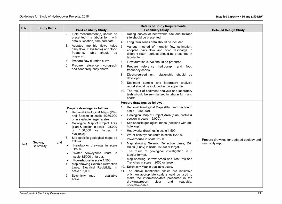
Guidelines for Study of Hydropower Projects, 2018 Installed Capacity > 10 and ≤ 50 MW
Department of Electricity Development 93
S.N. Study Items Details of Study Requirements
Pre-Feasibility Study Feasibility Study Detailed Design Study 2. Field measurement(s) should be
presented in a tabular form with details, location, time and date.
3. Adopted monthly flows (also daily flow, if available) and flood frequency table should be prepared.
4. Prepare flow duration curve. 5. Prepare reference hydrograph
and flood frequency charts.
3. Rating curves of headworks site and tailrace site should be presented.
4. Long term series data should be included. 5. Various method of monthly flow estimation,
adopted daily flow and flood discharge in different return periods should be presented in tabular form.
6. Flow duration curve should be prepared. 7. Prepare reference hydrograph and flood
frequency charts. 8. Discharge-sediment relationship should be
developed. 9. Sediment sample and laboratory analysis
report should be included in the appendix. 10. The result of sediment analysis and laboratory
tests should be summarized in tabular form and charts.
14.4 Geology and Seismicity
Prepare drawings as follows: 1. Regional Geological Maps (Plan
and Section in scale 1:250,000 or in available larger scale).
2. Geological Map of Project Area (plan & section in scale 1:25,000 or 1:50,000 or larger, if available).
3. Site specific geological maps as follows:
Headworks drawings in scale 1:500.
Water conveyance route in scale 1:5000 or larger.
Powerhouse in scale 1:500. 4. Map showing Seismic Refraction
Lines, Electrical Resistivity, in scale 1:5,000.
5. Seismicity map in available scale.
Prepare drawings as follows:
1. Regional Geological Maps (Plan and Section in scale 1:250,000).
2. Geological Map of Project Area (plan, profile & section in scale 1:5,000).
3. Site specific geological maps (sections with drill hole logs).
4. Headworks drawings in scale 1:500. 5. Water conveyance route in scale 1:2000. 6. Powerhouse in scale 1:500. 7. Map showing Seismic Refraction Lines, Drill
Holes (if any) in scale 1:2000 or larger. 8. The result of geological investigation in a
tabular format. 9. Map showing Borrow Areas and Test Pits and
Trenches in scale 1:2000 or larger. 10. Seismicity Map in available scale. 11. The above mentioned scales are indicative
only. An appropriate scale should be used to make the information/data presented in the drawings/report clear and readable/ understandable.
1. Prepare drawings for updated geology and seismicity report.

Guidelines for Study of Hydropower Projects, 2018 Installed Capacity > 10 and ≤ 50 MW
Department of Electricity Development 94
S.N. Study Items Details of Study Requirements
Pre-Feasibility Study Feasibility Study Detailed Design Study
14.5 Alternative Study
1. Location of alternative project components plans and alignments should be shown in appropriate scale.
2. Preliminary cost and energy comparison charts and tables should be prepared.
3. Financial evaluation charts and tables should be prepared.
1. Location of alternative project components, plans and alignments should be presented in appropriate scale.
2. Cost and energy comparison charts and tables should be prepared.
3. Financial evaluation charts and tables should be prepared.
14.6 Optimization 1. Optimization study charts and tables should be prepared.
14.7 Design and Drawings
1. Following drawings in suitable scale should be prepared:
Alternatives considered. General arrangement of
selected project. Headworks plan (general
arrangement, elevations and sections).
Settling basin (plan and sections).
Headrace water conduit system (plan and profile).
Forebay/surge tank (plan, sections, profiles).
Penstock (plan, sections, profiles).
Powerhouse and tailrace (plan, sections and profiles).
Switchyard layout.
1. Following drawings should be prepared in suitable scale:
Alternatives considered in scale 1:5000 or larger.
General arrangement/layout of selected project in scale 1:5000 or larger.
Headworks (general arrangement, elevations and sections) in scale 1:500 or larger.
Headworks components, weir, undersluice, intake, gravel trap etc. plan, sections (L-section, cross sections) and elevations in appropriate scale.
Settling basin (plan and L-section in scale 1:500 and cross sections in scale 1:200 or larger).
Headrace water conduit system (plan and L-section in scale 1:2000, Sections in scale 1:100 or larger).
Forebay/surge tank (plan and L-section in scale 1:200, cross sections in scale 1:100 or larger).
Penstock (plans and L-sections in scale 1:200 or larger, cross sections in scale 1:100 or larger).
Powerhouse (general arrangement in scale 1:500, plan and sections in scale 1:200 or larger).
Powerhouse –switchyard layout in scale 1:500 or larger.
1. Prepare civil general arrangement drawings of all components, showing benchmarks, setting out points with their coordinates and all necessary details.
2. Prepare reinforcement drawings of all structures with bar bending schedules.
3. Prepare preliminary drawings of all hydro-mechanical components with necessary dimensions/schedules.
4. Prepare preliminary drawings of all electromechanical-mechanical components with necessary dimensions/schedules.
5. Preliminary drawings of all switchyard components and accessories with necessary dimensions/schedules should be prepared.
6. Preliminary drawings of all transmission line components and accessories with necessary dimensions/schedules should be prepared.
7. Preliminary drawings of all interconnection point’s components (switchyard/ substation) accessories with necessary dimensions/schedules should be prepared.
Drawings of Civil Structures
The following civil drawings should be prepared 1. General arrangement/layout of selected
project in scale 1:5000 or appropriate scale.

Guidelines for Study of Hydropower Projects, 2018 Installed Capacity > 10 and ≤ 50 MW
Department of Electricity Development 95
S.N. Study Items Details of Study Requirements
Pre-Feasibility Study Feasibility Study Detailed Design Study Single line diagram Protection structures (plan in scale 1:200 and
sections in scale 1:100 or larger). The above mentioned scales are indicative only. An appropriate scale should be used to make the information/data presented in the drawings/report clear and readable/understandable. Distorted scales are not recommended.
2. Headworks (General Arrangement, Elevations and Sections) in scale 1:500 or larger.
3. Headworks components, weir, undersluice, intake, gravel trap etc. plan, sections (L-section, cross sections) and elevations in appropriate scale.
4. Settling basin (plan and L-section in scale 1:500 and cross sections in scale 1:50 to 1:200 or larger).
5. Headrace water conduit system (plan and L-section in scale 1:2000, sections in scale 1:100 or larger).
6. Forebay/surge tank (plan and L-section in scale 1:200, cross sections in scale 1:100 or larger).
7. Penstock (plans and L-sections in scale 1:200 or larger, cross sections in scale 1:100 or larger).
8. Powerhouse (general arrangement in scale 1:500, plan and sections in scale 1:50 to 1:200 or larger).
9. Powerhouse –switchyard layout in scale 1:500 or larger.
10. Single line diagram. 11. Protection structures (plan in scale 1:200
and sections in scale 1:100 or larger). Reinforcement Drawings
1. Reinforcement drawings should be prepared based on civil general arrangement drawings in scale 1:10 to 1:50 as appropriate.
Drawings of HM Components
1. Gates and accessories parts in appropriate scale.
2. Expansion joints, manhole covers, valves, gates driving system etc. in appropriate scale.
3. Other HM components in appropriate scale.

Guidelines for Study of Hydropower Projects, 2018 Installed Capacity > 10 and ≤ 50 MW
Department of Electricity Development 96
S.N. Study Items Details of Study Requirements
Pre-Feasibility Study Feasibility Study Detailed Design Study Drawings of E-M Components
1. General layout in scale 1:500 or larger. 2. L-Sections in scale 1:500 or larger, cross
sections in scale 1:100 to 1:200 or larger. 3. Details in scale 1:10 or larger. Drawings of Transmission Line (TL) Components
1. A general layout of TL alignment (plan in scale 1:5000 and profile in scale 1:500 to 1:2000 or larger.
2. The tower/pole in scale 1:100 to 1:200. 3. The support structure in scale 1:100 or
appropriate scale depending on size of structures.
4. General arrangement of connection bay/switchyard in scale 1:500 or appropriate standard scale.
5. Steel structure and equipment foundation in scale 1:10 to 1:100.
6. Single line diagram. The above mentioned scales are indicative only. An appropriate scale should be used to make the information/data presented in the drawings clear and readable/understandable. Distorted scales are not recommended.
14.8 Energy and Revenue Calculation
1. Prepare monthly energy (daily, if data available) and revenue calculation tables and charts.
1. Prepare daily & monthly energy and revenue calculation tables and charts.
1. Updated daily & monthly energy and revenue calculation tables and charts in comparative format with the proposed or agreed upon power and energy table of PPA (if available) should be prepared.
14.9 Power Supply
1. Map of Integrated Nepal Power System (existing and planned) should be shown in appropriate scale.
2. Present map showing transmission line requirements in appropriate scale.
3. Present alternatives available for interconnection points in the INPS.
1. Present map of Integrated Nepal Power System (existing and planned) in appropriate scale.
2. Present map showing transmission line alignment along with alternatives considered in appropriate scale.
1. Update maps prepared during the feasibility study as necessary.

Guidelines for Study of Hydropower Projects, 2018 Installed Capacity > 10 and ≤ 50 MW
Department of Electricity Development 97
S.N. Study Items Details of Study Requirements
Pre-Feasibility Study Feasibility Study Detailed Design Study
14.10 Access Road
1. Show access road drawings plan in suitable scale.
2. Show plan for alternative access (if any)
1. Access road drawings plan should be shown in suitable scale or drawn, based on best available map.
2. Plan of alternative access (if any) should be shown.
1. Access road map/drawings (plan in scale 1:5000, cross sections in scale 1:100 or larger and Profile in scale 1:2000 or larger) should be prepared.
2. Drawings of ropeways and other alternative arrangements as required should be prepared in appropriate scale.
14.11 Construction Schedule and Planning
1. Preliminary construction planning and implementation schedule showing major activities should be prepared.
1. Detailed construction schedule should be prepared in standard format showing major project components including anticipated critical path should be prepared.
1. Detailed construction schedule in standard format should be updated and the critical path should also be shown.
14.12 Cost Estimation
1. Prepare item rates for major works in tabular form.
2. Present project cost derived in tabular forms.
3. Rate analysis and quantity estimation tables should be attached in the appendix.
1. Item rates for major works should be presented in tabular form.
2. Project cost derived should be presented in tabular form.
3. Pie charts and graphs as necessary should be included.
4. Rate analysis and quantity estimation tables should be attached in the appendix.
1. Item rates for major works prepared during feasibility study should be updated.
2. Detailed project cost/engineer’s estimate derived during feasibility study should be updated.
14.13 Project Evaluation
1. Total project cost including financial cost derived in tabular form stating basis used and assumptions made while carrying out the financial evaluation should be included.
2. Results of financial analyses for the base case and most likely case should also be presented in tabular form.
1. Total project cost including financial cost derived in tabular form stating basis used and assumptions made while carrying out the financial evaluation should be presented.
2. Results of financial analyses for the base case and most likely case should be presented in tabular form.
3. Sensitivity results covering all possible scenarios studied/analysed should be presented in tabular form.
1. Updated total project cost including financial cost derived in tabular form stating basis used and assumptions made while carrying out the financial evaluation should be presented.
2. Results of financial analyses for the base case and most likely case should be presented in tabular form.
3. Sensitivity result of feasibility study should be updated based on market conditions and new data/information available at this stage.
14.14 Report
1. Standard cover page, signature page, summary page, abbreviations, the body of report and conclusions and recommendations are required in standard report.
2. Generally accepted standard table of contents, list of figures,
1. Standard cover page, signature page, summary page, abbreviations, the body of report and conclusions and recommendations are required in standard report.
2. Generally accepted standard table of contents, list of figures, list of tables, heading’s font, size and style, paragraph arrangement, letter size,
1. Standards formats/styles as suggested in the feasibility study report section should be followed while preparing all reports prepared as the outcome of detailed design. The following report should be prepared during the detailed design.
2. Project Definition Report: This is generally prepared at the beginning of the detailed

Guidelines for Study of Hydropower Projects, 2018 Installed Capacity > 10 and ≤ 50 MW
Department of Electricity Development 98
S.N. Study Items Details of Study Requirements
Pre-Feasibility Study Feasibility Study Detailed Design Study list of tables, headings’ font, size and style, paragraph arrangement, letter size, font and style, caption and cross reference, line spacing, etc. should be used in the report. A suggested report format given in Appendix, may be used.
3. The report should include: Main report Relevant annexes and
appendices Drawings
font and style, caption and cross reference, line spacing, etc. should be used in the report.
3. Separate volumes of report as necessary including investigation data, calculations and drawings should be prepared as follows:
Main report
Relevant annexes and appendices.
Drawings 4. Periodically, updated information in the form of
progress report should be provided to owner/client/executives agency/regulating authorities with a cover letter as and when required.
5. In case of significant change(s) to the layout, design and or any other project parameters, such change(s) shall be reported in time to the Client and regulating authorities with necessary supporting documents for timely approval.
design phase as guidelines for further design/development of the project. In the report, all base line data, up to date salient features of the project and project engineering parameters including relevant codes adopted, cost and revenue calculations, financial indices, project implementation schedule, etc. should be briefly described.
3. When numerical and physical hydraulic model studies are carried out, separate reports should be prepared recommending further design refinements based on the outcomes of such studies.
4. Design Basis Memorandum (DBM): This document is prepared as project’s customized standards agreed for adoption in the detailed design of all components of the project related to civil, hydro-mechanical, electro-mechanical and transmission line works. All relevant baseline information and other project information given in the Project Definition Report, Model Study Report, relevant codes and standards to be followed during detailed design should be documented in this report. DBM should be approved by the client before proceeding the detailed design further. Necessary amendments to the DBM should be made on need basis with timely approval from the client during the course of detailed design as and when required.
5. Detailed Design Report: Main outcomes of the detailed design are reports, drawings (general arrangement and reinforcement), and specifications. The reports, drawings and specifications together with design calculation sheets can be structured in different volumes. An example of detailed design report volume is suggested below:
Volume-1: Detail Design Main Report

Guidelines for Study of Hydropower Projects, 2018 Installed Capacity > 10 and ≤ 50 MW
Department of Electricity Development 99
S.N. Study Items Details of Study Requirements
Pre-Feasibility Study Feasibility Study Detailed Design Study Volume-2: Detailed Design Annexes and
appendices Volume-3: Detail Design Drawings: - Volume-3A: Detailed Design Civil
Drawings - Volume-3B: Reinforcement Drawings Volume-4: Technical Specifications 6. The abovementioned report and
documents will be basis for preparation of tender documents which are usually prepared during detailed design phase of a hydropower project.
7. In addition to the abovementioned report it is suggested to prepare a Draft Operation and Maintenance Manual for the power plant which should be further refined/updated during construction/installation of the project. Such a manual should cover operation and maintenance guidelines for civil, H-M, E-M and TL components.
8. Periodically, updated information in the form of progress report should be provided to owner/client/executive agency/regulating authorities with a cover letter as and when required.
9. In case of significant change(s) to the layout, design and or any other project parameters, such change(s) should be reported on time to the client and regulating authorities with necessary supporting documents for approval.
15 Risk analysis
15.1 Hydrological Risk
Hydrological risk can be determined by considering the following: 1. General
Calculate daily/monthly flow variation, seasonal variation and develop monthly hydrograph.
Collect previous drought records and minimum river flow analysis.
1. Review and update the previous study carried out during feasibility study.

Guidelines for Study of Hydropower Projects, 2018 Installed Capacity > 10 and ≤ 50 MW
Department of Electricity Development 100
S.N. Study Items Details of Study Requirements
Pre-Feasibility Study Feasibility Study Detailed Design Study Carry out catchment area analysis. Collect hydro-meteorological data such as
precipitation, wind velocity, temperature, relative humidity etc. of the project area.
Estimate upper and lower limit of energy generation and calculate daily/monthly revenue of the project.
2. Flood Hydrology
Probability and statistical approach should be adopted in fixing the level of flood risk.
Flood risk analysis should be based on slope stability and geology of nearby catchments. Also calculate flood risks caused by LDOF.
GLOFs are major risk factor of many hydro-projects in Nepal. Therefore, status of existing glacier lakes in the basin, condition of marine dam and volume of glacier lakes should be determined. Similarly, risk analysis should factor in that nearer projects (to Glacier Lake) are more vulnerable than those located far from glacier lakes.
3. Suspended Sediments Composition and density of sediments are
another major problem for hydropower projects. Therefore, sediment transportation phenomena, type of sediments composition and impacts of sediment on hydraulic structures and hydro-mechanical equipment shall be considered. Reference can be taken from existing hydropower projects located at similar topography, catchment basin, nature of sediments related activities.
15.2 Financial Risk
Financial risk should be carried out considering the following key points: 1. Materials price rate escalation and inflation
during the study period and construction period.
2. Status of locally available materials and their utilization.
3. Construction methodology and technology to be employed during construction.
Review and update the financial risk analysis carried out in the feasibility study and undertake further analysis considering the following additional key points:
1. Updated materials price rates, tools and equipment rates, human resource rates etc. and possibility of future price escalation.

Guidelines for Study of Hydropower Projects, 2018 Installed Capacity > 10 and ≤ 50 MW
Department of Electricity Development 101
S.N. Study Items Details of Study Requirements
Pre-Feasibility Study Feasibility Study Detailed Design Study 4. Construction planning, scheduling and
estimation of construction period. 5. Exchange rate fluctuation -market risk and
currency fluctuation risks during construction period should be considered.
6. Escalation on bank interest rate. 7. Significant technical and non-technical losses
created by natural or human made activities. 8. Possible revenue variations due to seasonal
and long term fluctuations in river flows. 9. Sensitivity analysis should be carried taking
into account changes in the level of risks.
2. Risks due to contract packages, contractor selections, modes of construction, status of infrastructure development etc.
3. Land acquisition and price escalation. 4. Fluctuation trends of foreign currency. 5. Updated bank interest rate. 6. Investment risk due to natural events in
project area, political activities, government policies, rules and planning etc.
7. Need to address demands for social and ecological development.
15.3 Geological Risk
1. Collect information on past geological events in the project area, such as land slide, rock fall, debris flow etc.
2. Collect geological investigation reports and results, discontinuity survey reports and drawings, geological model tests, type of rocks, rock quality, rock bedding, dip direction and dip amount etc. and determine the level of risk factor.
3. Error in geological investigation and interpretation, mapping and survey etc. should also be considered while setting the geological risk factor.
4. Conduct seismic risk analysis considering seismic design parameters, past seismic events and their effect in similar topography and geology as well as national and international practices.
5. Develop degree of seismic risk based on the deterministic as well as probabilistic approach and other international practices.
1. Review and update the risks accessed during the feasibility study.
2. Collect additional geological investigation reports and results, discontinuity survey reports and drawings, geological model study, type of rocks, rock quality, rock bedding, dip direction and dip amount etc. and update the level of risk factor.
15.4 Design and Construction Risk
Insufficient technical information and order, poor communication, design modification and alteration, construction technology and methodology play a vital role in increasing the design and construction risks. Thus, the following factors should be considered and clearly examined while determining the design and construction risks:
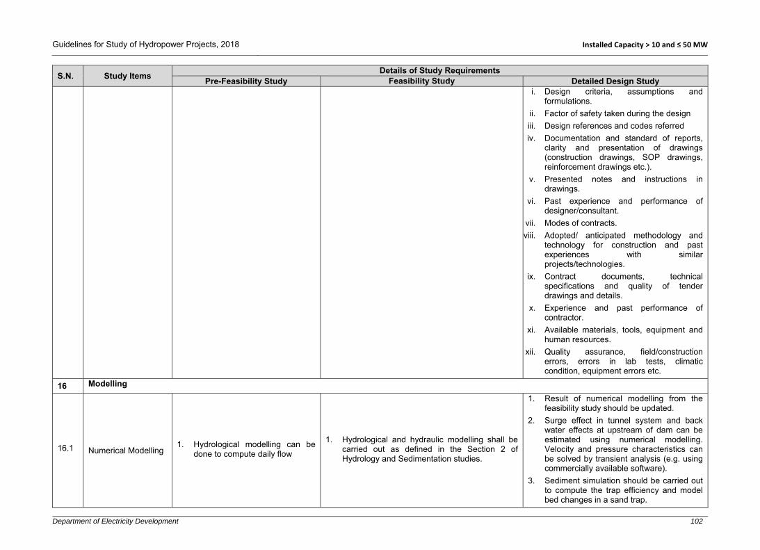
Guidelines for Study of Hydropower Projects, 2018 Installed Capacity > 10 and ≤ 50 MW
Department of Electricity Development 102
S.N. Study Items Details of Study Requirements
Pre-Feasibility Study Feasibility Study Detailed Design Study i. Design criteria, assumptions and
formulations. ii. Factor of safety taken during the design iii. Design references and codes referred iv. Documentation and standard of reports,
clarity and presentation of drawings (construction drawings, SOP drawings, reinforcement drawings etc.).
v. Presented notes and instructions in drawings.
vi. Past experience and performance of designer/consultant.
vii. Modes of contracts. viii. Adopted/ anticipated methodology and
technology for construction and past experiences with similar projects/technologies.
ix. Contract documents, technical specifications and quality of tender drawings and details.
x. Experience and past performance of contractor.
xi. Available materials, tools, equipment and human resources.
xii. Quality assurance, field/construction errors, errors in lab tests, climatic condition, equipment errors etc.
16 Modelling
16.1 Numerical Modelling 1. Hydrological modelling can be
done to compute daily flow
1. Hydrological and hydraulic modelling shall be carried out as defined in the Section 2 of Hydrology and Sedimentation studies.
1. Result of numerical modelling from the feasibility study should be updated.
2. Surge effect in tunnel system and back water effects at upstream of dam can be estimated using numerical modelling. Velocity and pressure characteristics can be solved by transient analysis (e.g. using commercially available software).
3. Sediment simulation should be carried out to compute the trap efficiency and model bed changes in a sand trap.

Guidelines for Study of Hydropower Projects, 2018 Installed Capacity > 10 and ≤ 50 MW
Department of Electricity Development 103
S.N. Study Items Details of Study Requirements
Pre-Feasibility Study Feasibility Study Detailed Design Study
16.2 Physical Modelling (depending on project capacity and if required)
1. The following philosophy and laws should be considered during physical modelling:
Laws of hydraulic similitude: relationship derived from Newton’s second law of motion.
Law of similarity. Dimensionless numbers and scaling laws
should be determined by considering criteria of similarity from a system of basic differential equation, similarity through dimension analysis and method of synthesis.
2. Geometric, kinematic, dynamic and mechanical similarities should be analysed during scaling process.
3. Froude law and Reynolds law, Weber number, Euler number, hydraulic model law etc. should be considered.
Selection of Scale
1. Before building a physical model, carry out appropriate topographical and hydrological field survey and define suitable similarity law and type of model.
2. Additional considerations such as maximum discharge, maximum head, floor area, ceiling height, construction considerations, instrumentation limitations, scale effects, laboratory space constraints and required equipment available in the market etc. should be analysed for scale selection.
3. The model should be designed as large as practicable, considering cost and benefit.
4. The linear scale of model (according to USBR) should be within the following ranges:
30 to 100 for spillway, weir/dam. 5 to 30 for settling basin, stilling basin,
outlet and inlet valves and gates etc. 3 to 20 for side channel spillway chutes,
drops, canal structures, etc.

Guidelines for Study of Hydropower Projects, 2018 Installed Capacity > 10 and ≤ 50 MW
Department of Electricity Development 104
S.N. Study Items Details of Study Requirements
Pre-Feasibility Study Feasibility Study Detailed Design Study 5. In addition to the above mentioned scales,
certain minimum dimension must be maintained for successful studies as follows:
At least 100 mm across for models of gates and conduits
At least 100 mm bottom width of canal structures.
To minimize the relative influence of viscosity and surface tension, spillway models should be scaled to provide flow depths over the crest of at least 75 mm for the normal operating range.
6. The position of instruments should be at the accessible locations for observation, with enough clearance between instruments and flow boundaries to provide accurate measurements. Therefore, the selected scale must be such that the magnitude of measured quantities is well within the range of available instruments and the sensitivity of the instruments is sufficient to obtain the results for different operating conditions.
7. Small discrepancies in the model can result in large differences, when transferring the results to the real structure scale/prototype. Therefore, the scale factor and construction techniques should be fixed as per required accuracy and precision.
Physical Model Observations Instrumentations and Interpretations
1. Observation, instrumentations and interpretations provide the necessary information to compare design alternatives, predict prototype performance, or develop generalized results applicable to a wide variety of situations. Therefore, the following simple instruments, such as point gauges, pitot tubes, manometers for the measurements

Guidelines for Study of Hydropower Projects, 2018 Installed Capacity > 10 and ≤ 50 MW
Department of Electricity Development 105
S.N. Study Items Details of Study Requirements
Pre-Feasibility Study Feasibility Study Detailed Design Study of static or slowly changing parameters, V notches and flumes, special ultrasonic or electronic devices, sediment feeding equipment etc. are required for measurement of discharge, water level, pressure, velocity, etc.
2. Discharge measurements at intake, weir/dam, spillway, undersluice, flushing conduits, settling basin etc. of physical models shall accurately be carried out with the standard V notches and flumes and/or electronic/ultrasonic devices.
3. Water surface level should be measured at headworks structures such as the weir, stilling basin, spillway, intake, settling basin etc. in different scenarios of the flow.
4. In case of spillway, intake structures and bottom outlets, stage-discharge relationship should be established for which observation of reservoir surface water level is of prime importance. Similarly, the observation of downstream water level for different discharge should be carried out in headworks model study.
5. Velocity is an important parameter for headworks design such as weir/dam, intake, gravel trap, settling basin etc. of RoR/PRoR project. Thus, velocity should be measured accurately by using classical or modern instruments. Three dimensional flow and turbulence velocity should be measured by using electromagnetic current meter, hot-wire and hot-film anemometers, etc.
6. Static and dynamic characteristics of positive, negative, differential or absolute pressures should be determined at stilling basin, chute surface spillway, immediate downstream of bottom outlets and gates, etc.
Design of Models
1. Before the construction of models, the

Guidelines for Study of Hydropower Projects, 2018 Installed Capacity > 10 and ≤ 50 MW
Department of Electricity Development 106
S.N. Study Items Details of Study Requirements
Pre-Feasibility Study Feasibility Study Detailed Design Study model drawings should be prepared accurately to prevent errors in the construction. These drawings should be able to provide sufficient information for the model construction.
2. Carry out clear operating program schedule.
3. The evaluation of model study should be carried out by qualitative and quantitative tests to meet the design and operation requirements.
4. Once the basic parameters are defined, the first step is to select a model scale. One or more of the scaling criteria can be selected for the design of the model as mentioned above.
5. The model should cover the enough area from far upstream to the downstream of the diversion structure so that the river behaviour and sediment management can be well studied. Normally, the diversion dam/weir, intake structure, spillway, stilling basin, fish passes, settling basin etc. are often subjected to free surface flow followed by Froude law. While bottom-outlet, gates or diversion tunnel spillway should be modelled by Reynolds Law.
6. Following data should be collected and compiled before the actual design of the model:
Purpose of design and drawings of headworks structures including upstream and downstream apron areas.
Hydrological and hydraulic calculation of the proposed design.
Structure layouts of relevant components and their sizes.
Suspended sediment data, bed load sediment data and their measurements and past behaviour of the river at headworks site supported by photographs, if available.

Guidelines for Study of Hydropower Projects, 2018 Installed Capacity > 10 and ≤ 50 MW
Department of Electricity Development 107
S.N. Study Items Details of Study Requirements
Pre-Feasibility Study Feasibility Study Detailed Design Study Topographical survey data and topo maps
including the river profiles (minimum three: along centre/thalweg, and along both banks depicting the water surface) and cross sections (at 20 m intervals or closer covering adequate length upstream of headworks and also immediate downstream of headworks). The cross sections survey should cover at least 20 m above the maximum flood mark on the both banks and also 20 m above future impounding area at upstream of the headworks along the both banks.
7. Additionally, the data on the armoured bed material and boulders that are influencing the river hydraulics along the selected stretch is very important especially for steep gradient Himalayan River.
8. Moreover, during model design, emergency spillway, by pass system, ice problems, oscillations (surge analysis), air trap and accumulations in tunnel and model calibrations are major issues in physical modelling. Because of this, necessary model modifications, scaling and transient analysis should be carried out such that these issues can be studied in the model.
Physical Model Preparation
1. After detailed design of physical models and collecting topographical and other morphological data from field survey, the model construction works should be carried out.
2. For model construction, a well-equipped workshop and experienced crafts persons are required and the model should be prepared with the required accuracy. The physical model construction may be divided in two main phases, namely:
Model construction of the river stretch on which the headworks and or other

Guidelines for Study of Hydropower Projects, 2018 Installed Capacity > 10 and ≤ 50 MW
Department of Electricity Development 108
S.N. Study Items Details of Study Requirements
Pre-Feasibility Study Feasibility Study Detailed Design Study structures that are planned to be constructed, covering adequately its immediate upstream and downstream areas. Before construction of the river model, a decision should be made whether it is necessary to construct a movable river bed or if a fixed river model would be enough.
Model construction of headworks and or other structures being studied.
3. Boulders, sand or gravel is often placed in the downstream to aid in the study of the scour patterns and designs are judged to some extent by their scouring tendencies.
4. For settling basin, the trapping efficiency and flushing pattern together with its flushing capacity of flushing gallery have to be visualized in the model study.
5. Due to difficulty to scale down sand, silt and other suspended sediments, walnut shell dust, saw dust or coal powders or artificial sediments ranging in size from 0.03 to 4 mm can be used in fine sediment simulation. The mean diameter of natural silt and fine sand shall be scaled down in proportion to the density or fall velocity.
6. For oscillations, transient analysis (one dimensional study/numerical modelling) should be carried out before preparation of physical model.
Operation of Model
1. After construction of the river stretch model, it should be validated. Validation is usually done against measured water levels at the site at different characteristic sections of the river stretch for at least three different flows/river discharges.
2. Before the model validation, the initial adjustments under pumping system or constant head tank, water leakage from model components, accessibility in and around the model instrumentation should be verified.

Guidelines for Study of Hydropower Projects, 2018 Installed Capacity > 10 and ≤ 50 MW
Department of Electricity Development 109
S.N. Study Items Details of Study Requirements
Pre-Feasibility Study Feasibility Study Detailed Design Study 3. Perform model verification and validation
properly as anticipated from the mathematical relations and collected field data and confirm that there are no errors or other inconsistencies because of miscalculation and or misrepresentation. The river model should be further refined and tested until validation results with acceptable accuracy are achieved.
4. After, initial adjustments, verification and validation of the model, existing situation tests (of the river) should be carried out The existing situation tests are usually carried out for the following flow situations:
Design discharge Non monsoon flows: Average annual flow “Minor floods”: Average monsoon flow “Large floods”: 2, 5, 10 years returned
period floods “Very large floods”: 20, 50, 100 years
return period flood “Extreme floods”: 200, 500, 1000 years
return period floods or larger, if the model facilities allow.
5. Hydraulic performance tests of the main structures including the following should be carried out.
Diversion Structures
1. Length of un-gated weir/spillway or gated spillway, dam height, abutment height, divide wall adjustment, upstream flood wall optimization, effective flow towards intake, determination of discharge coefficient at weir/spillway should be determined and finalized for design flood.
2. Discharge capacity, functions and location of trash passage and fish ladder should be determined and modified as per requirement.
3. For RoR project, un-gated spillway (simple overflow weir), discharge and bed load exclusion capacity of undersluice in

Guidelines for Study of Hydropower Projects, 2018 Installed Capacity > 10 and ≤ 50 MW
Department of Electricity Development 110
S.N. Study Items Details of Study Requirements
Pre-Feasibility Study Feasibility Study Detailed Design Study maximum design flood and partial blockage and chocking and possibility of bed load entry at intake etc. should be observed and modified as required.
Intake Structures
1. Discharge capacity, discharge coefficient, upstream and downstream water levels and required modification for different crest length and intake orifice opening size should be finalized.
2. Carry out observation for appropriate function of the intake structure for handling floating debris, excluding the bed loads, abstract enough water during low flow and safe operation during floods and modification should be carried out (if required). Desired flow pattern upstream and immediate downstream of intake and at gravel trap should be achieved.
Stilling Basin
1. The size and location of hydraulic jump, erosion problem at spillway, stilling basin and flushing sluice etc. should be determined up to maximum design flood and necessary modification of sizes and extension (location) of riprap, downstream protection blocks should be finalized according for design flood, if required.
Settling Basin
2. Flow velocity, fall velocity, trap efficiency, settlement of artificial sediments, flow pattern at entrance and exit, amount of turbulence and uniformity of flow in vertical and horizontal direction should be monitored.
3. Discharge capacity of sediment flushing conduits and pattern of flushing galleries, bottom shape, size and slope of settling basin based on sediment flushing capacity, number of bays, type and size of settling basin should be finalized.

Guidelines for Study of Hydropower Projects, 2018 Installed Capacity > 10 and ≤ 50 MW
Department of Electricity Development 111
S.N. Study Items Details of Study Requirements
Pre-Feasibility Study Feasibility Study Detailed Design Study 4. Discharge coefficient and capacity of
settling basin outlet and emergency spillway should be determined and necessary modifications should be carried out as required.
5. In addition, intake/tunnel inlet modifications and adjustment should be carried out considering the air accumulation/trapping problems in tunnel, bed load and trash accumulation.
6. For best results of physical modelling, accuracy of data recording and observation, documentations and reports preparation; manual measurements, series of photographs and video records and electronic and computerized data processing and observation should be carried out carefully.
7. During the study, model observation, many modifications, dismantling of some part of the model and re-construction, regular monitoring, evaluation and maintenance and regular measurements, data collections and instrumentations are required until satisfactory results are achieved.
8. Based on the test results, the best layout/design (recommended design) should be updated and agreed between Client and Model Study Consultant for final testing.
9. The final documentation study should include but not limited to the following tests with necessary measurements/records:
Different flows as agreed and tested during the existing situation tests
Floating debris transport pattern Bed load transport/deposition/scouring
pattern

Guidelines for Study of Hydropower Projects, 2018 Installed Capacity > 10 and ≤ 50 MW
Department of Electricity Development 112
S.N. Study Items Details of Study Requirements
Pre-Feasibility Study Feasibility Study Detailed Design Study Hydraulic performance/conditions
including preparation of rating curves for weir/spillway, undersluice gates, intake gates etc.
Proposed operation regime of the headworks and its different components (and other structures, if modelled and tested)
Scenario test for assurance of bed control in front of intake (by simulating extreme events like mass wasting).
Necessary additional tests for covering/recommending different operational aspects.
Final Reporting
1. Intermittent/progress reporting modality and deliverables should be agreed between client and model study consultant. The final reporting/output of the model study should cover but not be limited to the following:
i. Main Report: The main report should cover the following topics among others.
ii. Introduction/background of the study, input data, model study methodology, model validation, existing situation tests and results/records, conceptual studies and recommended final design/layout, final documentation study and records, tests and recommendations for smooth operation of project/hydropower plant, conclusions and recommendations.
iii. Appendices: Other data/information/records can be documented as appendices to the main report which should cover but not limited to the following:
Drawings: All necessary drawings (plan, L-sections, X-sections and details of the recommended layout/design should be prepared and presented in hard and soft

Guidelines for Study of Hydropower Projects, 2018 Installed Capacity > 10 and ≤ 50 MW
Department of Electricity Development 113
S.N. Study Items Details of Study Requirements
Pre-Feasibility Study Feasibility Study Detailed Design Study copies (in Auto-CAD or similar software). Furthermore, plans/layout drawings of all options studied should also be presented with necessary descriptions/discussions in the main report mentioned above.
All input parameters: All input parameters used for the model study should be documented in terms of figures, tables, photographs etc.
Evidences and records of model validation tests
Evidences and records of existing situation tests
Water depths/water levels, velocities, sediment deposition pattern measured/recorded during documentation study, operation aspect study and scenario tests in table, figure formats.
Photographs and videos of all the tests carried out during the documentation study, operation aspect study and scenario tests. Furthermore, photographs and video taken during validation and existing situation tests and other major tests carried out for the conceptual design finalization should also be recorded and documented.

Guidelines for Study of Hydropower Projects, 2018 Installed Capacity >50 MW and ≤ 100MW
Department of Electricity Development 114
A3. Installed Capacity > 50 MW and ≤ 100MW
S.N. Study Items Details of Study Requirements
Pre-Feasibility Study Feasibility Study Detailed Design
1 TOPOGRAPHICAL SURVEYS AND MAPPING
1.1 Available Maps and Images
1. Collect and make use of available contour maps of the project area published by the Department of Survey.
2. Enlarge the available largest scale Topographic map of the project area to 1:10,000 scale or larger.
3. Acquire satellite images of the project area to generate contour and features.
4. Project the maps and images to match with the national coordinate system.
1. Collect and review the available maps and images.
2. Additional maps and updated images recommended in the pre-feasibility level should be obtained.
3. Satellite images and aerial photographs of catchment area should be collected for additional interpretation and investigation.
4. If the project is a reservoir type or has a weak geological area or consists of a glacier lake in the catchment basin, additional recent satellite images, aerial photographs of the basin and the latest published reports should be collected for further interpretation and investigation.
1. Additional maps and updated images should be obtained, if required.
1.2 Topographical Survey
1. Construct a safe foot trail to access the headworks, waterways and powerhouse of the project.
2. Verify the coordinates of the key project components proposed in desk/reconnaissance study.
3. Carry out fly levelling, or use theodolite/total station to verify the gross topographic head.
4. Establish the control points and new benchmarks either by conducting traverse survey, DGPS triangulation or any suitable methods as appropriate. The benchmarks shall be of a permanent type generally constructed with reinforced concrete or marking in rocks.
5. Generate contour and features of the project area using satellite images in 1:2000 scale or larger.
1. Establish additional control points/benchmarks, if required.
2. Determine the coordinates of at least two benchmarks by DGPS, triangulation or any other appropriate methods to tie with triangulation points of the national grid established by the Department of Survey.
3. Complete the traverse survey by using coordinates of the two known benchmarks.
4. Carry out detailed topographical survey of headworks, waterways (strip survey), forebay/surge tank/surge shaft, adit portal(s), powerhouse, tailrace and Switchyard area and prepare map with 1 m contour interval.
5. The point density of detailed survey should be sufficient to cover all ground features. The survey should cover at least the impounding area upstream of the dams/weir and adequate area downstream of the tailrace. The survey should cover at least 20 m in elevation above the maximum flood mark or full supply level on both the banks.
1. Topographic survey carried out during feasibility study should be augmented with additional coverage required for detailed design. Where the feasibility maps are adequate and of acceptable standards of accuracy, it will only be necessary to update them to reflect the changes.
2. Additional survey is required, if there are changes in alignment or any addition or change of location of project component(s).
3. The coordinates of control points established during the feasibility study should be verified and revised, if necessary.
4. Establish additional benchmarks at the selected headworks, waterways and powerhouse that can be used during project construction.
5. Conduct strip survey of access road(s) alignment with sufficed point density to produce map in 1:1000 scale. Take details to indicate all major and minor crossings.

Guidelines for Study of Hydropower Projects, 2018 Installed Capacity >50 MW and ≤ 100MW
Department of Electricity Development 115
S.N. Study Items Details of Study Requirements
Pre-Feasibility Study Feasibility Study Detailed Design
6. At least two of the most promising alternatives should be covered in the topographical survey.
7. For inaccessible areas such as steep cliffs, generate contour and features using aerial/satellite images or any suitable methods. The maps generated by this method should be 1:2000 scale or larger.
8. If there is a hydropower project upstream within the backwater reach, carry out river cross section survey up to the tailrace outlet of the upstream hydropower plant.
9. The topographical survey should cover quarry sites, spoil tip areas, camp sites and access roads (strip survey) inside the project area including necessary river crossings.
10. The river cross section survey should be carried out at intake and tailrace sites covering at least 500 m upstream and downstream. The interval should be 20 to 50 m or closer depending upon river morphology. The survey should be extended beyond high flood marks. The flood marks and existing water levels should be indicated in the cross sections.
11. If there are any tributaries/gullies that could affect the project components substantially, tributaries’ cross section survey should cover the stretch within the project area.
12. If there are major river confluences in the vicinity of the headworks and/or tailrace, the topographical survey should cover at least 500 m upstream and downstream from the confluence point in the adjacent river(s) and the main river.
13. Conduct walkover survey of transmission route(s) and construction power route(s) using 1:25,000 or 1:50,000 scale topographic maps in order to verify suitability of the route(s). Mark the walkover points with GPS and plot these in the topographic map.
14. For a power canal/conduit, the width of strip survey should be decided considering the topography of the alignment, size of the conduit, access and safety requirements.
6. In bridge/siphon crossings, conduct river cross section survey covering 500 m upstream and 500 m downstream from the bridge axis at 20 m intervals or closer and mark water levels. Take additional details at abutments.
7. Conduct strip survey of transmission line route in 1:1000 scale. Also, take details at poles/tower locations.
8. Conduct cross section survey of critical slopes and landslide-prone zone in project area i.e. intake, forebay/surge tank, adit portal(s), waterway, penstock alignment and powerhouse, if not covered during feasibility study.

Guidelines for Study of Hydropower Projects, 2018 Installed Capacity >50 MW and ≤ 100MW
Department of Electricity Development 116
S.N. Study Items Details of Study Requirements
Pre-Feasibility Study Feasibility Study Detailed Design
15. Survey of dam site area should extend up to an elevation covering top of dam plus head over crest during deign flood with sufficient free board.
16. Reservoir area survey should cover up to an elevation of FSL with adequate free board.
17. Locate and map river boulders larger than 2.0 m.
18. For tunnelling, 100 m to 400 m wide strip along the tunnel alignment in a scale of 1:2000 to 1:5000 should be considered. Similarly, conduct additional detailing for portals and low overburden area.
1.3
Topographic Mapping, Plotting, Reporting and Data Presentation
1. Prepare description card of all benchmarks showing the point with a colour photograph and mention the nearby references, the name of local surveyor, place name and its coordinates.
2. Prepare topographical survey report and maps. If multiple surveys have been carried out, prepare a single report consisting of all findings.
3. Prepare contour plan in 1:2,000 scale with 2 m contour interval of the whole project area. Features such as a rocky cliff, slide zones, cultivated land, settlements, benchmarks etc., must be shown.
1. Prepare description card of all benchmarks showing the points with a colour photograph and mention the nearby references, name of the surveyor, location and the coordinates.
2. Prepare topographic survey report and maps. If multiple surveys have been carried out, prepare a single report and include all findings.
3. Prepare access road(s) map in 1:1000 scale with 1 m contour interval. Show cross sections along bridge/culverts along the road alignment in appropriate scales. The general layout may be plotted in smaller scale.
4. For headworks, waterways, forebay/surge shaft/surge tank, adit portal(s), powerhouse, tailrace and switchyard areas, the contour intervals should be 1m and the scale of map may vary from 1:100 to 1:2000 depending upon the size of the area.
5. Prepare transmission route map in a scale of 1:25,000 or 1:50,000 showing key features such as agricultural land, forest area and settlements.
6. Prepare and verify the license boundary map showing project components and verify there is no conflict with other projects in the vicinity and ensure that backwater level is also within the license boundary.
1. Use the topographic maps prepared during the feasibility study after updating when/where necessary.

Guidelines for Study of Hydropower Projects, 2018 Installed Capacity >50 MW and ≤ 100MW
Department of Electricity Development 117
S.N. Study Items Details of Study Requirements
Pre-Feasibility Study Feasibility Study Detailed Design
2 HYDROLOGICAL AND SEDIMENTATION STUDIES
2.1 Hydrology
1. Along with the guidelines mentioned herein, the Hydrological Manual for Infrastructure, Water and Energy Commission Secretariat can be followed for hydrologic analysis.
2. Collect long term historical rainfall data and climatological data pertinent to the study area (preferably more than 30 years) where available.
3. Collect long term historical flow data and sediment data of the river under study. If not available, collect the data from other rivers with similar hydrological characteristics in the vicinity (preferably more than 30 years).
4. Check the consistency of data. 5. Assess mean daily flow (if
available) and develop a flow duration curve using daily hydrograph.
6. For the ungauged river, discharge (including flow duration curve) shall be estimated with empirical methods, rational method and catchment area ratio method selecting similar catchment, wherever applicable. Such discharge data shall be justified by checking rainfall runoff coefficient.
7. Snow/glacier melt contribution shall be considered, if the catchment has snow/glacier fed rivers.
8. Establish a gauging station as well as colour crest gauges at
1. All the information obtained from pre-feasibility study shall be reviewed, verified and updated. If gauge stations have been established previously, measurements should be continued.
2. Data logger can also be added and used for online monitoring of hydrological data.
3. Install a cableway at the intake and powerhouse site wherever necessary for discharge measurement.
4. Update the flow data and assess accordingly the mean daily flows and develop an upgraded flow duration curve.
5. For ungauged river basin, hydrologic modelling for the estimate of water availability shall be carried out. Hydrologic model that consider snow/glacier melt schemes shall be used for the catchment that has snow/glacier fed rivers.
6. Water surface/level profile modelling shall be carried out.
7. Carry out cross section surveys at least 500 m/1 km upstream and downstream of the headworks site and the tailrace site covering the highest flood marks, preferably at the same locations as of the pre-feasibility study so that any change in the cross sections can be observed. Check the magnitude of flood peaks with the previous ones.
8. Carry out discharge measurements intensively (or record gauge readings) during the rainy season (June to September) to cover the peak floods at the intake and powerhouse site and a reasonable number during other months (October to May) at the control profile, if the site is accessible during monsoon. If not, estimate the flood flows based on flood marks using appropriate hydrological models.
1. All the information obtained from feasibility study shall be reviewed, verified and updated.
2. Data collection from previously established gauge stations in hydropower project shall be continued.

Guidelines for Study of Hydropower Projects, 2018 Installed Capacity >50 MW and ≤ 100MW
Department of Electricity Development 118
S.N. Study Items Details of Study Requirements
Pre-Feasibility Study Feasibility Study Detailed Design
straight and stable control section for instantaneous flood recordings at the intake and powerhouse site. A data logger may also be used for automatic flow recordings.
9. Carry out discharge measurements at the intake site. Develop a rating curve at headworks and tailrace/powerhouse area.
10. Carry out three cross section survey at headworks site and three cross section survey at tailrace site covering the highest flood marks.
11. The river high flood data (instantaneous high flood) obtained from DHM needs to be analysed for flood frequency estimation, if available.
12. Estimate the design floods for return periods of 10, 50, 100, 200, 500 and 1000 years.
13. Conduct flood frequency analysis for the period of October to May for ascertaining construction diversion flood.
14. Assess possibility of GLOF in the catchment area.
9. Check these measured data with the previous rating curve and upgrade these as necessary.
10. Update and upgrade the diversion floods computed during the pre-feasibility level study.
11. Update and upgrade the rating curve for the tailrace site.
12. Update, validate and upgrade the design flow for power generation.
13. Carry out the water quality analysis to determine the corrosive effectiveness (hardness).
14. Collect the information on GLOF events in the past (if such events have occurred) and assess the magnitude of the potential GLOF.
15. Generate sequence of flow for the case of storage projects.
16. Assess impact of climate change with uncertainty analysis on the availability of flow based on long term data and other secondary information available.
2.2 Sediment
1. Identify in which zone of sedimentation the catchment lies (high, medium or low).
2. Estimate the sediment/bed load in the river using empirical methods.
3. Collect suspended sediment samples and perform necessary laboratory analysis to determine sediment concentration, particle
1. Collect sediment samples daily during the rainy season (June to September) and at a reasonable frequency during other months (October to May) to develop rating curve for the sediment concentration against the discharge.
2. Determine the tentative value for median grain size, d50 of the river bed/banks’ materials.
3. Analyse the sediment samples to evaluate the volumes and characteristics of solid material transportation including suspended sediment
1. Review the findings of feasibility study and update, if necessary.
2. In case of substantial changes in the river morphology such as due to large landslides in the upstream catchment, carry out further suspended sediment sampling during the rainy season.

Guidelines for Study of Hydropower Projects, 2018 Installed Capacity >50 MW and ≤ 100MW
Department of Electricity Development 119
S.N. Study Items Details of Study Requirements
Pre-Feasibility Study Feasibility Study Detailed Design
size distribution and mineralogical content.
4. The sampling should cover at least one pre-monsoon, and post monsoon periods.
concentration, particle size distribution and mineral content analysis.
4. Estimate the daily sediment load and assess the annual load in the river.
5. Carry out particle size distribution analysis for river bed materials at gauging station(s), headworks and powerhouse sites and their immediate vicinity.
6. Analyse sediment impact due to construction activities on downstream projects.
7. For reservoir project, estimate and update the total sediment yield based on historical recorded data after pre-feasibility study or characteristics catchment area (rainfall intensity, wind velocity, rate of rock fragmentation, land slide events, gully erosion, heavy construction activities etc.
8. Plan for mitigations concerning sediment induced risks.
3 Geological/Geotechnical Investigation
3.1 Regional Geology Study
1. Collect and review available literature, topographic map, regional geological maps, geological sections, structural maps, available images and aerial photographs.
2. Prepare a brief report on regional geology with map showing major structures (fault, fold, window and thrust).
1. Review pre-feasibility report, if any. 2. Collect and review available literature,
topographic maps, regional geological maps, geological sections, structural maps and available images.
3. Prepare report on regional geology and structures.
4. Include existing regional geological maps with plan and section in available scale.
1. Review the feasibility report and update, if necessary.
3.2 General Geology and Geomorphology of the Project Area
1. Conduct a site visit to collect data for geological mapping, geomorphology survey and discontinuity survey.
2. Prepare geological map with plan and section of the project area in 1:10,000 -1:25,000 scale or in available scaled map.
3. Prepare a report on general geology and geomorphology of the project area.
1. Conduct detailed geological mapping of the project area and prepare a geological map focusing in different rock types, folds, faults, shear/weak zones, water bearing zone, karst features with plan and section in 1:10,000 or larger scale.
2. Prepare a report on general geology and geomorphology of the project area.
1. Review and update previous reports and geological maps, if necessary.
2. Conduct additional detailed geological mapping where necessary.

Guidelines for Study of Hydropower Projects, 2018 Installed Capacity >50 MW and ≤ 100MW
Department of Electricity Development 120
S.N. Study Items Details of Study Requirements
Pre-Feasibility Study Feasibility Study Detailed Design
3.3
Geological, Conditions and Geomorphology of Major Project Components
1. Describe geological and geomorphological conditions and potential geo-risks of major project components such as dam/weir, intake, settling basin, waterways, forebay/surge tank/surge shaft/penstock, powerhouse, tailrace and switchyard.
2. Conduct and describe reconnaissance mass wasting study using available images to identify potential landslides, inundation and LDOF risks in the project vicinity covering both upstream and downstream.
1. Conduct detailed engineering geological mapping of major project components such as weir, intake, settling basin, waterway, surge tank/forebay, penstock, powerhouse and tailrace in appropriate scale of 1:1,000 to 1:10,000.
2. Review and conduct a risk assessment of geo- hazards such as landslide damming inundation and LDOF risks etc. in the project vicinity covering both upstream and downstream reach.
3. Assess landslides and rock fall risks for surface structures with special consideration for seismic events.
4. Analyse site investigation data and prepare detailed geological, and geotechnical report of the project components.
5. Refer to Section ‘D’ – Additional requirements for hydropower projects with underground structures.
1. Review, and update maps and reports of previous studies. Conduct detailed mapping, if major components’ locations are changed.
2. Review mass wasting report and conduct detailed analysis and assessment of risks to major structures to consider protective measures.
3. If any modification in project layout and location of major project components, additional survey and geological mapping in appropriate scale (generally 1:1000 to 1:10,000) shall be required.
4. Carryout detail study to delineate intraformational fault.
3.4
Discontinuity and Rock Mass Classification Survey
1. Collect joint sets properties and analyse the collected data in preliminary stage for the major project components based on the site visit.
2. Collect rock mass properties and classify rock mass (Q system, RMR, GSI, RMi and any other international classification system) in the preliminary stage of the major components based on the site visit.
1. Conduct discontinuity survey to identify and collect properties of bedding/foliation planes, lithological contacts, major and minor joints, faults, shear/weak zones, thrusts, fissures, folds, karst features and voids with their properties.
2. Collect properties of joints such as orientation, spacing, roughness, apertures, filling and thickness, weathering and persistence for wedge failure analysis and selection of cavern orientation.
3. Conduct discontinuity analysis for slope stability of portals and surface components, wedge failure analysis and selection of stable caverns orientation.
4. Conduct and collect rock mass properties and classify rock mass (Q system, RMR, GSI, RMi or any other international classification system). If other internationally accepted classifications are to be used, this should be correlated to equivalent Q, RMR and GSI system.
1. Review and conduct additional joint survey and rock mass classification especially for underground structures and high dams.
2. Conduct analysis for slope stability, tunnel stability and section of the stable orientation.

Guidelines for Study of Hydropower Projects, 2018 Installed Capacity >50 MW and ≤ 100MW
Department of Electricity Development 121
S.N. Study Items Details of Study Requirements
Pre-Feasibility Study Feasibility Study Detailed Design
5. Prepare Rock Mass classes distribution (along profile/cross section) for each underground structure to determine rock support.
6. Slope stability analysis for natural and cut slope and rock support analysis for underground structure followed by numerical modelling.
3.5 Geotechnical Investigation
1. Perform geophysical investigation such as seismic refraction or electrical resistivity or any other appropriate geophysical methods. The geophysical investigation shall be followed by exploratory core drillings. Initially exploratory core drillings shall be carried out (few holes) at the major structure locations and geologically critical areas.
1. Perform combination of geophysical investigation such as Seismic Refraction Tomography (SRT), Micro Tremor Array Measurement (MAM), Electrical Resistivity Tomography (2D ERT) and MASW (for foundation) survey to construct bedrock profile, overburden thickness and nature of soil/rock strata, foundation properties, rock mass quality, faults/shear zones, water table at weir/dam, intake, settling basin, waterway alignment, forebay/surge tank/surge shaft, powerhouse, anchor blocks (surface penstock alignment), underground penstock (pressure shaft), powerhouse and tail race sites.
2. Perform exploratory core drillings at dam/weir (minimum 3 holes), headrace tunnel (minimum one each at portals and additional in problematic areas such as shallow cover, faults/shear zones decided based on the geophysical investigation results), surge tank (1 hole) and surface powerhouse (minimum 2 holes) and underground caverns (1 deep hole or 2-3 short holes but not necessary, if bedrock is very strong and massive with joint spacing > 1m without faults).
3. Perform permeability test in soil and Lugeon test in rock in each drill hole at 3-5 m intervals.
4. Conduct detailed survey of joints with properties, faults, shear zones, rock mass, weathering conditions, open cracks, loose mass in both dam abutments.
5. Collect sample for laboratory test such as cohesion and friction angle for soil and strength test for rock.
6. Perform necessary laboratory analysis and
1. All geotechnical investigations including exploratory core drillings recommended in the feasibility study should be carried out.
2. Conduct additional geophysical investigations, if required.
3. Additional drilling should be carried out to verify geophysical investigation especially in dam and powerhouse, if required.
4. In case of underground structure, exploratory core drillings with in-situ tests such as Lugeon test, necessary geophysical or other bore hole logging followed by laboratory tests such as point load test of lump sample, Uniaxial Compressive Strength test of the core sample, modulus test and odometer test for swelling clay should be carried out.
5. Perform additional permeability and Lugeon tests in each drill hole at 3-5m intervals to know the permeability of the rock for grouting design for dam.
6. Additional laboratory tests of rock samples for caverns: Tri-axial test (if available), uniaxial compressive strength test, point load, modulus test, Poisson’s ratio, Brazilian test.
7. In case of reservoir (peaking or seasonal), project with underground powerhouse, exploratory adit (drift) at both sides of dam abutments and powerhouse site are recommended. These shall be followed by various in-situ tests such as hydrofracturing, rock mass deformation modulus, and other various tests inside

Guidelines for Study of Hydropower Projects, 2018 Installed Capacity >50 MW and ≤ 100MW
Department of Electricity Development 122
S.N. Study Items Details of Study Requirements
Pre-Feasibility Study Feasibility Study Detailed Design
tests for soil such as particle size distribution analysis, Atterberg limits, natural moisture content, plastic limit, specific gravity, shear box tests of collected samples for physical properties and odometer test or X-ray differentiation test to find out swelling clay type and swelling pressure.
7. Laboratory test for rock unit weight, uniaxial compressive strength, point load test, Brazilian test, Deformation Modulus test, Passion’s ration, slake durability test, swelling pressure test for swelling clay and petrology study.
8. Refer to Section ‘D’ – Additional requirements for hydropower projects with underground structures.
the tunnel and cavern areas as per geological conditions.
8. Carry out test pits excavation, standard penetration tests (SPT) and core drillings or appropriate geophysical investigation methods at tower foundations of transmission line ≥ 132 kV.
3.6 Geological Model
1. Prepare preliminary geological model (plan and sections, in appropriate scale of 1:5,000 to 1:10,000) for dam.
1. Prepare geological model (geological plan and profiles) of each major project component in appropriate scale of 1:1,000 to 1:10,000 based on the results of the investigations for design requirements showing soil, bedrock profile with bedding/foliation plane dip angle, rock types, water bearing zone/table, faults/shear zones, rock squeezing or rock bursting, joints, rock mass classes distribution based on rock support classes, landslides etc. and include rosette/major joints’ stereonet with tunnel/cavern alignment.
2. Prepare geological model (plan and adequate sections) of dam showing soil cover, bedrock profile, pale channels, water table etc.
3. Prepare geological model (plan and sections) along the canal or pipe and surface penstock alignment covering 50 – 100 m both uphill and downhill sides of the alignment and extend in critical areas showing landslides, debris flow, gully erosion, steep slope etc. for stability and risks assessment for design considerations.
4. Prepare geological model (plan and profiles: Additional cross/transverse sections in low angle dipping beds, if tunnel aligns parallel to the foliation/bedding planes) of headrace tunnel
1. Update or prepare new geological models of each project components by conducting additional engineering geological mapping and site investigations where necessary.
2. Prepare rock contour map for design of dam foundation and abutments excavation.

Guidelines for Study of Hydropower Projects, 2018 Installed Capacity >50 MW and ≤ 100MW
Department of Electricity Development 123
S.N. Study Items Details of Study Requirements
Pre-Feasibility Study Feasibility Study Detailed Design
showing rock profiles with foliation/bedding dip angle, joints, rock mass distribution based on rock support classes, faults/shear zones, water bearing zones, rock squeezing or rock bursting and other problematic zones etc. and include rosette/major joints’ stereonet with tunnel/cavern alignment in minimum 1:10,000 scale.
5. Prepare geological model (plan and sections) of underground powerhouse and settling basin showing the rock profiles with foliation/bedding dip angle, joints, rock mass classes distribution based on rock support classes, faults/shear zones, water bearing zones, rock squeezing or rock bursting, other problematic zones etc. and include rosette/major joints’ stereonet with tunnel/cavern alignment in appropriate scale.
3.7 Ground Water Condition Survey
1. Conduct ground water condition survey based on natural springs, wells, ponds, deep valleys, gully crossings, faults, valleys formed by fault/joint connected to uphill and ground water condition identified by site investigations such as geophysical survey and drilling results.
2. Conduct drilling and install piezometers in selected critical areas identify by the field survey and geophysical investigations.
3. Identify ground water table and water bearing zone along each underground structures.
1. Review and update from additional drilling, geophysical investigations data where necessary.
3.8 Geo-hazard 1. Conduct Geo-hazard, and vulnerability
reduction and disaster mitigation measures.
3.9 Geotechnical Instrumentation and Monitoring
1. Project shall propose the types and number of geotechnical instruments with monitoring program for slope stability and underground structure movement. Instruments such as inclinometers, extensometers, convergence measurement devices (for tunnels), water level and water pressure monitoring devices etc. as required during construction and operation of the project.

Guidelines for Study of Hydropower Projects, 2018 Installed Capacity >50 MW and ≤ 100MW
Department of Electricity Development 124
S.N. Study Items Details of Study Requirements
Pre-Feasibility Study Feasibility Study Detailed Design
4 Construction Material Survey
1. Identify sources and quarry sites for the construction materials such as sand, coarse aggregates, boulders, impervious soils, etc.
2. Locate the quarry sites in the available topographic map (1:25,000 or 1:50,000) observed during the site visit.
3. Make preliminary estimation of available quantity at each borrow area for the construction.
1. Take reference from pre-feasibility study, if any. 2. Identify and investigate construction material
sources and quarry sites for the construction materials such as impervious soils, stones, boulders, sand and gravel as required.
3. Excavate test pits/trenches (minimum 1.5 m * 1.5 m) and log the nature of soil at borrow locations including photographs and collect samples for laboratory analysis.
4. Perform laboratory tests: gradation and classification, unconfined compression, absorption and specific gravity, uniaxial compressive strength, point load, Los Angeles abrasion test, sulphate soundness, slake durability test, compaction test, alkali aggregate reaction, swelling test (if necessary), aggregate crushing value, mica and clay content.
5. Estimate available quantities at each borrow area to meet the requirement of the construction.
6. Collect rock block/boulders samples from each quarry site for laboratory tests.
7. Prepare location map with source areas in appropriate scale.
1. Collect previous laboratory reports and results and verify the quality and quantity of construction materials.
2. Carry out further investigations and laboratory tests, if required.
5 Seismic Study
5.1 Tectonic Setting
1. Describe in brief tectonic setting related to the project area using available literature and regional maps.
1. Describe tectonic setting related to the project area using available literature and regional maps.
1. Review and update the previous studied, if required.
5.2 Seismic Zoning 1. Identify the seismic zone of the
project based on the NBC 105. 1. Review and update the previous study, if
required 1. Review and update the previous studied, if
required.
5.3
Earthquake Catalogue and Historical and Instrumentally Recorded Earthquakes
1. Earthquake catalogue especially for those historical and instrumentally recorded earthquakes, should be identified for earthquakes of magnitude 4.0 M and higher. For every significant earthquake event, the location, distance, magnitude and intensity should be shown in a map in a suitable scale.

Guidelines for Study of Hydropower Projects, 2018 Installed Capacity >50 MW and ≤ 100MW
Department of Electricity Development 125
S.N. Study Items Details of Study Requirements
Pre-Feasibility Study Feasibility Study Detailed Design
5.4 Project Specific Seismic Hazard Analysis
2. Empirical laws may be applied to deduce intensity or acceleration of the ground motion. The Peak Ground Acceleration (PGA) for Maximum Design Earthquake (MDE) and Operating Basis Earthquake (OBE) should be given in reference from other existing nearby hydropower project or National/International standards or code.
3. Risk assessment in consideration of ground movement, dislocation and rock shattering of fault, ground creep, landslide and rock fall due to earthquake should be taken into account.
1. Review/compute OBE and MDE on the basis of deterministic approach and probabilistic approach.
2. Review the previous studies and update, if required.
6 Selection of Project Components and Project Layout
1. Assess and describe availability and condition of access road(s) leading to the project site.
2. Identify and describe new access road(s)/ropeways/foot trails/tunnels/others to be constructed for development of the project.
3. Identify the existing hydropower project(s) located at upstream and downstream of the project area and verify the project’s license boundary with existing hydropower project.
4. Conceptual layout of all possible schemes within the license boundary should be identified and studied.
5. Topographical, geological conditions of alternative layouts should be studied in order to select the location of project structures: weir, settling basin waterways, forebay, penstock, powerhouse, tailrace and switchyard.
1. Review the pre-feasibility study report and update the site accessibility conditions to the project area.
2. Select the shortest and most economical access road(s) alignment with minimum numbers of crossing structures.
3. Detailed topographic maps and preliminary geological maps should be prepared for designing the project configuration/layout.
4. Use updated hydrological data/analysis results for the design of project components. The design discharge should be based on prevailing practices in the context of Nepal (e.g. 40-45 percentile flow/flow mentioned in survey license).
5. While selecting the alternatives, socio-environmental variables should be considered and compared.
6. For the selection of location of the diversion weir, several alternative sites identified during pre-feasibility study should be investigated in detail. Simultaneously, the alternative sites for settling basin, water conveyance, river crossings, forebay/surge tank/surge shaft, powerhouse, tailrace and switchyard should also be investigated in detail.
1. Expert consultation is recommended to verify the project layout and components’ design.
2. Review and update the feasibility study incorporating expert’s recommendations, if any.
3. In case of significant changes to the layout, updating the feasibility study is required.
4. Verify the updated project license boundary.
5. Carry out detailed design of access roads within the project area, if required.
6. Carry out detail design of all components such as: weir, intake, settling basin, waterways, forebay/surge tank/surge shaft, powerhouse, tailrace and switchyard.
7. Follow the relevant national and international guidelines, norm and codes to design the project components.

Guidelines for Study of Hydropower Projects, 2018 Installed Capacity >50 MW and ≤ 100MW
Department of Electricity Development 126
S.N. Study Items Details of Study Requirements
Pre-Feasibility Study Feasibility Study Detailed Design
6. While selecting the alternatives, socio-environmental variables should be considered and compared.
7. Assess location and condition of immediate upstream and downstream projects, if any. List out issues to be addressed related to the existing project(s) while finalizing the project configuration.
8. The locations and types of the structures of each schemes should be verified at site in terms of accessibility, topography, geology, river morphology, construction ease and technical, economical and socio-environmental considerations.
9. Prepare conceptual layout (project configuration) of at least two most promising schemes with its major structures in appropriate scale using available maps and conduct preliminary cost-benefit analysis.
10. Recommend area to be covered by topographical survey during feasibility study phase as well as other site specific investigations.
7. Prepare preliminary design and drawings of all alternatives (at least two covering both banks) and project structures in appropriate scale.
8. Conduct alternative study of transmission line routes (at least two) and identify the shortest and most economical route, sub-station and voltage level.
9. Based on the design and drawings, quantity and cost estimations should be carried out for each alternative.
10. Calculate revenue from the project using saleable energy and prevailing energy prices.
11. Select the most optimum alternative scheme based on maximum benefit at minimum cost.
12. Prepare general layout drawings of the best alternative showing its components: headworks, waterway, forebay/surge tank/surge shaft, penstock, powerhouse, tailrace and switchyard using the detailed topographic map prepared during this stage of the study. Additionally, show transmission line route and access roads to all major project components.
13. Expert consultation and verification of project layout and project structures should be carried out based on complexity of the project.
7 Optimization Study
1. Installed capacity should be tentatively fixed considering preliminary technical, socio-environmental and financial assessment. If due to insufficient data, it is not possible to fix the installed capacity this stage, then a range of installed capacity should be proposed.
1. General Approach
For selection of parameters to be optimized, identify their ranges and establish a series of alternatives.
Carry out the conceptual design, drawings and estimate its cost for each alternative.
Estimation of benefits for each alternative. Comparison of cost and benefits.
1. Re-optimization should be carried out based on changes in project capacity and/or design discharge and/or changes in market price for materials and labour.

Guidelines for Study of Hydropower Projects, 2018 Installed Capacity >50 MW and ≤ 100MW
Department of Electricity Development 127
S.N. Study Items Details of Study Requirements
Pre-Feasibility Study Feasibility Study Detailed Design
2. The number of generating units should be determined considering the reliability of operation of the plant and maximum utilization of dry season river flow. Apart from that transportation aspects should also be considered.
2. Assumptions
Price of dry and wet energy, peak/off-peak as per the requirements of the off-taker.
Capacity benefit, if any. 3. Selected Alternatives
Determine the number of alternatives considering the range of installed capacities.
4. Energy Production
For RoR projects calculate energy production for all alternatives with following consideration: - At least five options, generally in the range of
65% to 25% flow exceedance and average daily flows to be used.
- Dry and Wet energy, peak/off-peak energy as per the requirements of off-taker should be calculated.
5. Project Layout
Optimize project structures/components individually for the given installed capacity/discharge.
Size of settling basin to be adjusted as per optimized design discharge.
Water conveyance system including tunnel, penstock and tailrace to be optimized considering the loss of revenue due to head loss and investment cost.
Forebay/Surge tank/Surge shaft dimension to be adjusted.
Powerhouse and unit sizes to be obtained from the empirical formula, past experiences and/or supplier(s)’ information.
6. Cost Estimate
Preliminary quantity and cost estimates should be developed for all the cases under consideration.
Only the major items should be computed in detail, while minor items may be estimated based on curves and data of similar structures in other projects.

Guidelines for Study of Hydropower Projects, 2018 Installed Capacity >50 MW and ≤ 100MW
Department of Electricity Development 128
S.N. Study Items Details of Study Requirements
Pre-Feasibility Study Feasibility Study Detailed Design
Unit rates should be estimated based on prevailing market rates in the area, project location and accessibility. Reference can be taken from under construction projects with similar features.
Electro-Mechanical and switchyard equipment costs should be calculated using empirical relations, market price and/or based on budgetary quotation from the potential suppliers.
The cost estimates should also consider the cost of access roads, infrastructure development and environmental costs.
Technical contingencies should be taken into account to come up with implementation cost of the alternative.
7. Financial Comparison Financial comparison of the different
alternatives should be carried out considering the implementation cost and operation cost with occurred benefits due to energy production for each case.
The economic and financial analysis should be carried out to determine the basic economic parameters such as Net Present Value (NPV), Internal Rate of Return (IRR), and Benefit Cost Ratio (B/C).
The alternative with maximum B/C ratio and internal rate of return should be selected to fix optimum installed capacity.
8. Number of Units Minimum possible number of units should be
adopted considering hydrology, transport capacity of road/bridge conditions.
8 Project Description and Design
8.1 General Layout and Design: Civil Structures
General Layout 1. The general layout plan, profile
and sections of the selected scheme with optimum installed capacity should be described and presented in appropriate scale.
Project Layout1. General layout of the selected alternative of the
project should be described. 2. Layout should be prepared using the survey
maps and geological and geotechnical information.
General
1. The final project layout recommended in the feasibility study and the approved IEE/EIA report should be reviewed and verified by experts, if necessary.

Guidelines for Study of Hydropower Projects, 2018 Installed Capacity >50 MW and ≤ 100MW
Department of Electricity Development 129
S.N. Study Items Details of Study Requirements
Pre-Feasibility Study Feasibility Study Detailed Design
River diversion during construction
Headworks Headrace tunnel/canal
alignment Surge tank/shaft or forebay Penstock alignment and Powerhouse –tailrace area.
FOR PRoR 1. For PRoR, daily poundage
volume curve should be prepared.
2. The volume of the regulating poundage should be sufficient to ensure daily peak generation for 6 hours or as required by the off-taker.
3. Following main operating levels and corresponding storage volumes should be determined:
Full supply level Minimum operating level Live storage Dead storage
Civil Structures 1. Detail design of the project
should consider operating criteria of the project located upstream and downstream.
2. Design and description of the access road, construction road and alternative ropeway or mode of transportation.
3. Conduct design and drawings of cross-drainage structures along the access road alignment.
4. Conduct preliminary design and layout of site facilities such as camp and site office facilities, water supply and sanitary and communication facilities.
3. Detailed hydraulic design and sizing of the all civil structures including the following should be carried out:
Weir, intake and undersluice Upstream and downstream aprons Stilling basin Gravel trap Settling basin Headrace canal/pipe/tunnel Forebay/surge tank/surge shaft Penstock Powerhouse Tailrace
4. Design of temporary and permanent infrastructures such as camp facilities, construction power, access roads (ropeways, bridges, tunnel), drinking water supply, etc. should be carried out.
5. Design of switchyard and sub-station’s civil structures should be carried out.
6. Design and location of spoil tips should be carried out.
7. Necessary flood/debris/landslide protection works should be designed based on the river morphology, ground topography, possible debris flow area and possibility of rock falls (rolling boulders) nearby powerhouse and switchyard area.
8. All project components should be described in detail.
9. Drawings of all project components should be prepared in appropriate scale.
Diversion During Construction 1. A general plan to divert the river in dry season
in order to carry out the construction works at weir and intake sites should be prepared, which may require 2-4 dry seasons.
2. An upstream cofferdam should be designed in order to protect the working area at weir site. A cofferdam should also be provided to prevent river entering in working area from downstream.
2. Component-wise detailed design should be carried out for the final/updated project layout.
3. The findings and recommendations of numerical and physical hydraulic model studies should be incorporated in the final design. Furthermore, information gathered from test adit(s) should also be incorporated in the design, if any.
4. Project definition report defining all project information, parameters and components should be prepared.
5. Project parameters and design criteria should be included in a Design Basis Memorandum (DBM) referring to relevant national and international guidelines, norms and codes, and past experiences.
6. Detailed hydraulic design and dimensioning of all components/structures carried out during the feasibility study should be reviewed and updated/refined/revised where necessary.
Infrastructures
1. Geometric design and design of road components such as side drains, cross drainage structures, retaining walls gabion and stone masonry structures should be carried out.
2. Plans, profiles and cross sections of access road including side drains, retaining structures, cross drainage structures should be prepared in appropriate scale.
3. Design of construction camps, temporary and permanent housings, water supply and sewerage system, bunker houses etc. should be prepared and presented in the drawings.
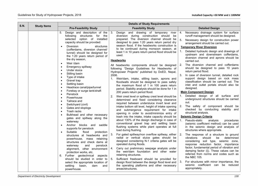
Guidelines for Study of Hydropower Projects, 2018 Installed Capacity >50 MW and ≤ 100MW
Department of Electricity Development 130
S.N. Study Items Details of Study Requirements
Pre-Feasibility Study Feasibility Study Detailed Design
5. Design and description of the following structures for the selected option of installed capacity should be provided:
Diversion structures (cofferdams, diversion channel/ tunnel) should be designed for the 1:20 years return period of the dry season,
Weir /dam Emergency spillway Under sluice Stilling basin Type of intake Gravel trap Settling basin Headrace canal/pipe/tunnel Forebay or surge tank/shaft Penstock Powerhouse Tailrace and Switchyard (civil) Gates and stoplogs Trash racks Bulkhead and other necessary
gates and spillway along the waterway
Anchor blocks and saddle supports for penstock
Suitable flood protection structures at headworks and powerhouse, mass retaining structures and check dams at waterway and penstock alignment, other environment protection works, etc.
6. Further geotechnical aspects should be studied in order to select the appropriate location of settling basin, dam and powerhouse.
3. Design and drawing of temporary river diversion during construction should be prepared. The diversion channel should be designed to pass 1:20 years return period dry season flood. If the headworks construction is to be continued during monsoon season, at least 1 in 10 years return period flood should be used.
Headworks
All headworks components should be designed following “Design Guidelines for Headworks of Hydropower Projects” published by DoED, Nepal, 2006. 1. Weir/dam, intake, stilling basin, aprons and
floodwalls should be designed to pass safely the maximum flood of 1 in 100 years return period. Stability analysis should be done for 1 in 200 years return period flood.
2. Weir crest level or spillway crest level should be determined and fixed considering clearance required between undersluice invert level and intake bottom sill level, height of intake opening and submergence requirement for intake opening in order to avoid/minimize entry of trash into the intake, intake capacity should be about 130% of the design discharge in case of conventional gravel trap and settling basin flushing systems while plant operates at full load during flushing.
3. For gated spillway/non overflow spillway, either radial or vertical sluice gates should be designed considering N-1 criteria gates will be operated during floods.
4. Carry out preliminary seepage analysis under the weir/dam foundation and other water retaining structures.
5. Sufficient freeboard should be provided for design flood between the design flood level and the operating platforms and other necessary areas/structures.
4. Necessary drainage system for surface runoff management should be designed.
5. Necessary design for construction power arrangement should be carried out.
Temporary River Diversion
1. Detailed hydraulic design and drawings of upstream and downstream cofferdams, diversion channel and aprons should be carried out.
2. The diversion channel and cofferdams should be designed to pass 10 years return period flood.
3. In case of diversion tunnel, detailed rock support design based on rock mass classification should be carried out. The inlet and outlet portals should also be designed.
Main Component Design 1. Detailed design of all surface and
underground structures should be carried out.
2. The safety of component should be checked by conducting stability and structural analysis.
Seismic Design Criteria 1. Pseudo-static analysis procedures
(seismic coefficient method) can be used in the seismic design and analysis of structures where appropriate.
2. The response of a structure to ground vibrations should be determined considering soil type, seismic zone, response reduction factor, importance factor, fundamental period of vibration and damping factor (ξ). These values can be referred from norms and codes such as the NBC 105.
3. For structures with minor importance, the seismic coefficient can be reduced appropriately.
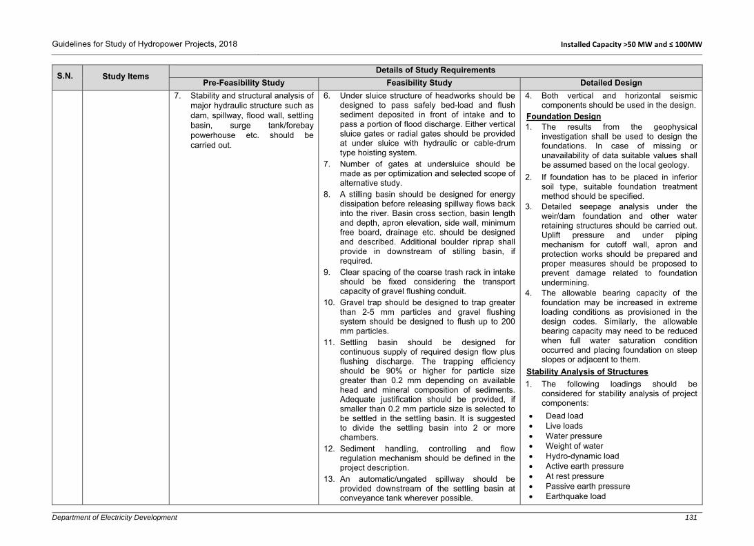
Guidelines for Study of Hydropower Projects, 2018 Installed Capacity >50 MW and ≤ 100MW
Department of Electricity Development 131
S.N. Study Items Details of Study Requirements
Pre-Feasibility Study Feasibility Study Detailed Design
7. Stability and structural analysis of major hydraulic structure such as dam, spillway, flood wall, settling basin, surge tank/forebay powerhouse etc. should be carried out.
6. Under sluice structure of headworks should be designed to pass safely bed-load and flush sediment deposited in front of intake and to pass a portion of flood discharge. Either vertical sluice gates or radial gates should be provided at under sluice with hydraulic or cable-drum type hoisting system.
7. Number of gates at undersluice should be made as per optimization and selected scope of alternative study.
8. A stilling basin should be designed for energy dissipation before releasing spillway flows back into the river. Basin cross section, basin length and depth, apron elevation, side wall, minimum free board, drainage etc. should be designed and described. Additional boulder riprap shall provide in downstream of stilling basin, if required.
9. Clear spacing of the coarse trash rack in intake should be fixed considering the transport capacity of gravel flushing conduit.
10. Gravel trap should be designed to trap greater than 2-5 mm particles and gravel flushing system should be designed to flush up to 200 mm particles.
11. Settling basin should be designed for continuous supply of required design flow plus flushing discharge. The trapping efficiency should be 90% or higher for particle size greater than 0.2 mm depending on available head and mineral composition of sediments. Adequate justification should be provided, if smaller than 0.2 mm particle size is selected to be settled in the settling basin. It is suggested to divide the settling basin into 2 or more chambers.
12. Sediment handling, controlling and flow regulation mechanism should be defined in the project description.
13. An automatic/ungated spillway should be provided downstream of the settling basin at conveyance tank wherever possible.
4. Both vertical and horizontal seismic components should be used in the design.
Foundation Design 1. The results from the geophysical
investigation shall be used to design the foundations. In case of missing or unavailability of data suitable values shall be assumed based on the local geology.
2. If foundation has to be placed in inferior soil type, suitable foundation treatment method should be specified.
3. Detailed seepage analysis under the weir/dam foundation and other water retaining structures should be carried out. Uplift pressure and under piping mechanism for cutoff wall, apron and protection works should be prepared and proper measures should be proposed to prevent damage related to foundation undermining.
4. The allowable bearing capacity of the foundation may be increased in extreme loading conditions as provisioned in the design codes. Similarly, the allowable bearing capacity may need to be reduced when full water saturation condition occurred and placing foundation on steep slopes or adjacent to them.
Stability Analysis of Structures
1. The following loadings should be considered for stability analysis of project components:
Dead load Live loads Water pressure Weight of water Hydro-dynamic load Active earth pressure At rest pressure Passive earth pressure Earthquake load

Guidelines for Study of Hydropower Projects, 2018 Installed Capacity >50 MW and ≤ 100MW
Department of Electricity Development 132
S.N. Study Items Details of Study Requirements
Pre-Feasibility Study Feasibility Study Detailed Design
14. Sediment/gravel flushing outlets should be located at shooting flow areas of the stilling basin/river.
15. Design of fish ladder should be provided for the movement of the fish over the structures at the left or right abutment of the gated weir or dam.
16. Necessary flood protection, ground stabilization and bio-engineering works should be carried out, if required.
Waterways Conveyance All water conveyance system should be designed following “Design Guidelines for Water Conveyance System of Hydropower Projects” published by DoED, Nepal, 2006; considering the project specific data and information. 1. The power canal /headrace pipe/tunnel
including all hydraulic and cross-drainage structures from intake to forebay/surge tank/surge shaft should be designed for 110% design discharge or higher.
2. Configuration of the power tunnel should be given, comprising headrace tunnel and pressure tunnel with lining types, finished diameter and length. Sufficient lateral cover and optimum overburden should be ensured. Tunnel support design should be carried out depending on rock quality.
3. A rock trap should be provided at the end of the headrace tunnel, upstream of the surge tank to trap loose rocks and displaced shotcrete. Suitable flushing system should be provisioned at rock trap.
4. A number of saddle supports and anchor blocks should be designed and described in the report.
5. Slope stability analysis in critical sections of waterways including forebay/surge tank/surge shaft should be carried out.
6. Necessary drainage system for surface runoff management should be designed.
7. Type and size of headrace canal should be determined by considering the design
In-situ stresses Impact load Vibration load Thermal Uplift (buoyancy and seepage) Surcharge/overburden loads Water hammer Wind Snow Construction and moving surface loads: Additional loads, if any.
2. For the purpose of evaluating the stability and structural analysis, different load combinations may occur during different phases of the project implementation and operation should be considered. Individual components/elements must be designed for the most unfavourable load combination. In general, the following conditions should be considered:
Construction - Normal operation - Special/emergency/extreme cases
The safety factor depends upon the codes and loading combination used. In general, following safety factors should be adopted. - Sliding- 1.2 for normal case and 1.05
for extreme case - Overturning: 1.5 for normal case and
1.05 for extreme case - Flotation: 1.2 for normal case and
1.05 for extreme case
Detail Structural Analysis and Design
1. Appropriate codes (concrete, steel) should be referred for the detail design. All possible loading conditions should be considered.
2. The durability of the structure should be ensured in the design.

Guidelines for Study of Hydropower Projects, 2018 Installed Capacity >50 MW and ≤ 100MW
Department of Electricity Development 133
S.N. Study Items Details of Study Requirements
Pre-Feasibility Study Feasibility Study Detailed Design
discharge, silting/scouring velocity for the selected materials used (e.g., concrete grade, masonry) of applied concrete grade and topography.
8. Corrosion, scratching, pipe diameter and transportation limitations factors should be considered while fixing the headrace pipe thickness.
9. An emergency spillway at forebay should be provided. The forebay should have effective volume at least equal to the volume of water in the penstock pipe while filled or to supply design flow for at least 120 seconds, whichever is larger.
10. The thickness of the steel pipe should be able to withstand any variable load conditions encountered during operation of the plant. While deriving the effective thickness of pipe, steel grade, corrosion factor, welding factor and rolling factor should be considered.
11. Anchor blocks to hold penstock pipe should be designed at bends and also intermediary in long straight stretches.
12. Head losses through tunnel/pipe system at the design discharge should be determined.
Forebay/Surge Tank/Surge Shaft 1. Description of the forebay/surge tank/shaft type
with its dimensions should be provided. 2. For surge tank/surge shaft, various possible
scenarios of transient analysis should be carried out to determine upsurge and down surge level.
3. The invert level, upsurge and down surge levels of the forebay/surge tank/shaft should be shown in drawings.
Penstock Alignment 1. Valleys, landslides and rock fall areas and gully
crossings should be minimized, if they cannot be avoided, during the alignment selection.
2. The effective thickness of the steel pipe should be adequate to withstand dynamic/water
3. Material properties and allowable stresses for concrete, structural steel, reinforcement, etc. should be specified.
4. The structure should be analysed using acceptable methods manually or by using software.
5. All structures should be safe against internal and external forces/stresses and all kind of climatic conditions.
6. Reinforcement calculation should be done also considering temperature and shrinkage effects.
7. Dynamic analysis should be carried out for powerhouse and penstock and ensure that natural frequency does not create resonance phenomenon.
8. Ensure that the settlement and deflection are within permissible limits.
Water Tightness
1. Control of cracking in concrete should be as per the requirement specified in IS 456:1978 and 2000 or BS 8007:1987 or BS 8110 Part II, BS 2007 or equivalent codes.
2. The type and location of joints should be specified. Contraction/Expansion joints should generally be located in 15 to 25 m spacing. Construction joints should be provided considering construction sequence.
3. Appropriate type of water stops should be provided at expansion/contraction/construction joints.
Detailing and Drawings
1. The reinforcement should be detailed considering ductility of the structure.
2. Reinforcement arrangement should be shown in drawings in appropriate scale. Special attention should be given at joints.
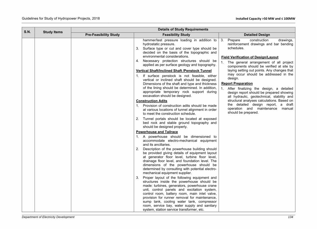
Guidelines for Study of Hydropower Projects, 2018 Installed Capacity >50 MW and ≤ 100MW
Department of Electricity Development 134
S.N. Study Items Details of Study Requirements
Pre-Feasibility Study Feasibility Study Detailed Design
hammer/test pressure loading in addition to hydrostatic pressure.
3. Surface type or cut and cover type should be decided on the basis of the topographic and environmental considerations.
4. Necessary protection structures should be applied as per surface geology and topography.
Vertical Shaft/Inclined Shaft /Penstock Tunnel
1. If surface penstock is not feasible, either vertical or inclined shaft should be designed. Dimensions of the shaft and type and thickness of the lining should be determined. In addition, appropriate temporary rock support during excavation should be designed.
Construction Adits 1. Provision of construction adits should be made
at various locations of tunnel alignment in order to meet the construction schedule.
2. Tunnel portals should be located at exposed bed rock and stable ground topography and should be designed properly.
Powerhouse and Tailrace 1. A powerhouse should be dimensioned to
accommodate electro-mechanical equipment and its ancillaries.
2. Description of the powerhouse building should be provided giving details of equipment layout at generator floor level, turbine floor level, drainage floor level, and foundation level. The dimensions of the powerhouse should be determined by consulting with potential electro-mechanical equipment supplier.
3. Proper layout of the following equipment and structures inside the powerhouse should be made: turbines, generators, powerhouse crane unit, control panels and excitation system, control room, battery room, main inlet valve, provision for runner removal for maintenance, sump tank, cooling water tank, compressor room, service bay, water supply and sanitary system, station service transformer, etc.
3. Prepare construction drawings, reinforcement drawings and bar bending schedules.
Field Verification of Design/Layout
1. The general arrangement of all project components should be verified at site by laying setting out points. Any changes that may occur should be addressed in the design.
Report Preparation
1. After finalizing the design, a detailed design report should be prepared showing all hydraulic, geotechnical, stability and structural analyses calculations. Based on the detailed design report, a draft operation and maintenance manual should be prepared.

Guidelines for Study of Hydropower Projects, 2018 Installed Capacity >50 MW and ≤ 100MW
Department of Electricity Development 135
S.N. Study Items Details of Study Requirements
Pre-Feasibility Study Feasibility Study Detailed Design
4. Fire protection and ventilation system should be designed and described in detail.
5. Emergency exit and safety plan should be described/provided as per national/ international guidelines.
6. The tailrace conduit should be designed considering turbine type, minimum power discharge available, minimum water depth requirement and possible effect of river water level at the tailrace outlet.
7. Necessary flood/debris/landslide protection works should be carried out based on the river morphology, ground topography, possible debris flow area and possibility of rock falls (rolling boulders) near powerhouse and switchyard area.
8. An access tunnel should be provided for underground construction. Detail description of adit/access tunnel should be provided including size, type, support design and portal location.
Switchyard 1. Dimensions of switchyard should be
determined by consulting with potential electro-mechanical equipment supplier.
2. Switchyard area should be arranged nearby the powerhouse and civil design of switchyard should be prepared.
For PRoR 1. Prepare daily poundage volume curve. 2. The volume required to maintain a minimum of
4 to 6 hours (if terrain permits) of operation of the plant at full capacity during peak load.
3. The minimum operating level should be fixed based on the flushing requirements of the settling structure which will set the minimum elevation of the intake from the river and further following levels and corresponding volume should be determined:
Full supply level Dead storage Live storage.

Guidelines for Study of Hydropower Projects, 2018 Installed Capacity >50 MW and ≤ 100MW
Department of Electricity Development 136
S.N. Study Items Details of Study Requirements
Pre-Feasibility Study Feasibility Study Detailed Design
8.2 Hydro-Mechanical Components
1. Preliminary design/estimation of hydro mechanical components such as gates, stoplogs, trashracks and penstock should be carried out.
2. A brief description of hydro-mechanical components should be provided in the report.
Following hydro-mechanical components should be designed and described: 1. Gates, stop logs, embedded parts, valves, trash
racks, bell mouths, manholes, expansion joints, saddle/wear plates, sizing of headrace and penstock pipes, bends, reducers, branches, steel lining works, etc.
2. The hoisting system for gates and stop-logs.
General 1. This design is generally carried out by
hydro-mechanical equipment manufactures/suppliers, thus only preliminary design for preparing Terms of Reference of tender/contract documents shall be carried out in consultation with potential manufacturers/suppliers.
2. Component-wise design should be carried out for the updated project layout.
3. Project parameters and design criteria should be included in a Design Basis Memorandum (DBM) referring to relevant national and international guidelines, norms and codes, and past experiences.
4. Design and dimensioning of all components/structures carried out during the feasibility study should be reviewed and updated/refined/revised where necessary.
5. While designing the hydro mechanical components, factors such as corrosion, welding defects, and plate inaccuracy/defects should be taken into account.
6. Individual components/elements must be designed for the most unfavourable load combination. In general, loading conditions which may occur during the following phases/cases should be considered:
Transportation Erection/construction Testing in factory and site Normal operation Special/emergency/extreme cases
Design of Gates and Stop-Logs 1. The type of gate/stoplogs and its hoisting
mechanism should be fixed. 2. The materials to be used for skin plates,

Guidelines for Study of Hydropower Projects, 2018 Installed Capacity >50 MW and ≤ 100MW
Department of Electricity Development 137
S.N. Study Items Details of Study Requirements
Pre-Feasibility Study Feasibility Study Detailed Design
stiffeners, girders, embedded parts and other components should be specified.
3. The gates/stoplogs shall be designed for the hydrostatic and hydrodynamic forces taking into consideration the forces arising from wave effects, water hammer, seismic loads, ice formation, friction, and thermal effect wherever applicable.
4. The internal stress should be ensured to be within limit of allowable stress in normal and extreme operation conditions.
5. Sufficient corrosion allowance should be provided and corrosion prevention methods, if any, should be mentioned.
6. Type and material of seals should be mentioned.
7. Power-operated gates shall normally be capable of operation by alternate means in case of power supply failure.
8. If meant for regulation, it shall be capable of being held in partially open position without major damage to seal or deterioration due to cavitation and vibration.
9. Wherever necessary, model studies may be carried out for high head regulating gates.
10. The deflection of the gate under various loading conditions should be within permissible limit.
11. Dogging devices and lifting beams should be designed for operation of gates, stoplogs etc.
12. Destructive and non-destructive testing procedure should be specified.
13. All the gates shall be checked for the aeration requirement at its immediate downstream.

Guidelines for Study of Hydropower Projects, 2018 Installed Capacity >50 MW and ≤ 100MW
Department of Electricity Development 138
S.N. Study Items Details of Study Requirements
Pre-Feasibility Study Feasibility Study Detailed Design
Steel Pipes1. The steel plate used for the pipes shall
comply with national/international standards.
2. The pipes should be designed considering following loading conditions:
Normal condition includes static head, surge and water hammer pressure.
Special conditions include those during filling and draining of penstocks and maximum surge in combination with pressure rise during emergency operations/events and test pressures.
Exceptional conditions include transportation and erection stresses, pressure rise due to unforeseen operation of regulating equipment in the most adverse manner resulting in odd situation of extreme loading, stress developed due to resonance in penstock, seismic forces etc.
3. Adequate safety factors should be provided for safety against hoop stress due to internal and external pressure including surge pressure, longitudinal stress, beam action, temperature variations.
4. Stress should be checked in bends, bifurcation, transition and stiffeners.
5. Expansion joint should be provided at suitable locations.
6. Special design provision shall be made to protect the penstock pipes/conduits against possible rupture due to denting/negative pressure.
Other Structures 1. Other HM components such as valves,
trash racks, expansion joints, pipe bends

Guidelines for Study of Hydropower Projects, 2018 Installed Capacity >50 MW and ≤ 100MW
Department of Electricity Development 139
S.N. Study Items Details of Study Requirements
Pre-Feasibility Study Feasibility Study Detailed Design
and reducers, Wyee bends, manholes, saddle plates, bulk head gate, bell mouth, steel lining etc. shall be designed to meet structural and hydraulic requirements.
Report Preparation 1. After finalizing the design, a report should
be prepared showing all hydraulic and structural calculations. Similarly, operating conditions, hoisting mechanisms, opening sizes, design pressures, and dimension of all major components/elements should be mentioned. Based on the detailed design report, a draft operation and maintenance manual should be prepared.
8.3 Electro-Mechanical Equipment
1. Preliminary design/selection of the electro-mechanical equipment should be carried out based on design discharge and net head and number of units (based on hydrology and transportation).
Mechanical equipment: - Preliminary selection of type
and dimension of turbines should be carried out. A brief description of turbine auxiliaries should be provided.
Electrical equipment: - Parameters of the generators
should be determined. A brief description of excitation and electrical auxiliaries should be provided.
Single line diagram: - An electrical single line
diagram showing the major electrical equipment of powerhouse should be prepared
1. The type and number of generating equipment, and power evacuation facilities should be designed and described.
2. Description of main mechanical equipment including the followings should be provided:
Design criteria Mode of operation Hydraulic turbine- type and number Turbine efficiency Rated sped Rated turbine output Inlet valve Runner size Draft tube Governor Lubricating (hydraulic) system Pressure oil system Compressed air system Cooling system Control system Overhead crane Maintenance of turbine
3. Description of the main electrical equipment including the followings should be provided:
General 1. This design is generally carried out by
electro-mechanical equipment manufactures/suppliers, thus only preliminary design for preparing Terms of Reference of tender/contract documents shall be carried out in consultation with potential manufacturers/suppliers.
2. Project parameters and design criteria should be included in a Design Basis Memorandum (DBM) referring to relevant national and international guidelines, norms and codes, and past experiences.
3. Detailed design and dimensioning of all components/structures carried out during the feasibility study should be reviewed and updated/refined/revised where necessary.
4. Individual components/elements must be designed for the most unfavourable load combination (mechanical and electrical). In general, loading conditions which may occur during the following phases/cases should be considered:
Transportation Erection/construction Testing in factory and site

Guidelines for Study of Hydropower Projects, 2018 Installed Capacity >50 MW and ≤ 100MW
Department of Electricity Development 140
S.N. Study Items Details of Study Requirements
Pre-Feasibility Study Feasibility Study Detailed Design
Generator- type, number Generator efficiency, rated output, frequency,
generated voltage level Excitation system Switchgears Control panel Switchyard Powerhouse earthing Emergency diesel generator Control and protection system Power transformer –type, numbers, efficiency,
frequency, rated output etc. Auxiliary transformer CT/PT Hoisting mechanism/overhead crane
4. A single line electrical diagram depicting the
interconnection of all electrical equipment should be prepared.
5. For the smooth operation of the power station, following auxiliaries should be provided and described:
Grease lubricating system. Fire fighting system Station supply Lighting arrangement Cooling system Oil filtering equipment DC power auxiliaries Distribution to outlaying works Distribution to housing complex Fire fighting system Station supply Heating, Ventilation, Air Conditioning (HVAC)
Normal operation Special/emergency/extreme cases
Mechanical Equipment 1. Appropriate turbines and their
components should be designed. Suitable inlet valves shall be provided before each turbine. Draft tubes, spiral casings, covers, seals, etc. should be designed appropriately. A suitable governor system should be provided for flow control to the turbine. Proper auxiliary systems such as lubrication system, pressure system, compressed air system, cooling system shall be designed. Control system with automatic/manual capability should be provided. Electrical Equipment 1. Single line diagram and control diagram
for all powerhouse equipment and interconnection point shall be prepared.
2. Generators shall be provided with all of their accessories including cooling and fire protection system.
3. Excitation system shall be provided with automatic voltage regulation.
4. Power transformers to step up transmission voltage shall be provided with all accessories.
5. Switching equipment with bus bars, circuit breakers, disconnecting switches, instrument transformers, etc. shall be provided.
6. Control equipment shall be provided consisting of governor monitoring, excitation monitoring, protection, etc.
7. Auxiliary/station transformer for power supply to the plant shall be provided.
8. Grounding including lightning protection shall be provided.

Guidelines for Study of Hydropower Projects, 2018 Installed Capacity >50 MW and ≤ 100MW
Department of Electricity Development 141
S.N. Study Items Details of Study Requirements
Pre-Feasibility Study Feasibility Study Detailed Design
9. Fire protection and ventilation system should be designed and described in detail.
10. Emergency exit and safety plan should be described/provided as per available national/international guidelines.
11. Diesel Generators shall be provided for backup power and black start.
8.4 Power Evacuation and Transmission Line
1. Assess the possibility of power evacuation through national grid/ Integrated Nepal Power System (INPS).
2. Carry out preliminary design to select voltage level, conductor type and number of towers.
3. A single line electric diagram should be prepared representing the major electrical equipment of the powerhouse.
4. A brief description of selected power evacuation system should be presented.
1. Prepare an updated single line diagram representing the major electrical equipment of the powerhouse, switchyard, and substation.
2. Finalize the most appropriate transmission line route, voltage level and length.
3. Describe the detail of interconnection equipment.
4. Describe and design the total number of towers, tower’s foundation and support structures, circuit type, type of conductor used and other safety measures.
1. The transmission line should be designed following latest off-taker/NEA grid code.
2. The route shall be finalized and described. 3. Voltage level, number of circuits and
length shall be confirmed. 4. Number and type of towers required shall
be determined and their structure shall be designed. While designing the foundation of transmission tower, geology and geotechnical conditions should be verified and additional investigation should be done, if required.
5. Conductors’ size to be used shall be determined. The size of conductors must be selected so that the power loss doesn’t exceed the permissible limit as per the latest off-taker’s/NEA Grid Code.
6. Sag and tension in conductor shall be determined.
7. Auxiliary equipment in the transmission line such as insulators, clamps, guards, etc. shall be provided.
8. Necessary equipment to be installed in interconnection substation should be designed.
9. Power transformers shall be required, if the voltage level of transmission line does not match voltage level of interconnecting substation including HV switchgears, instrument transformers and control and protection equipment.

Guidelines for Study of Hydropower Projects, 2018 Installed Capacity >50 MW and ≤ 100MW
Department of Electricity Development 142
S.N. Study Items Details of Study Requirements
Pre-Feasibility Study Feasibility Study Detailed Design
9 Energy Computation and Benefit Assessment
9.1 Energy Computation
1. Energy computation should be carried out considering the average monthly (daily flow, if available) flow, net head, design discharge and turbine, generator and transformer efficiency. Furthermore, normal and forced outages should be considered referring to off-taker/NEA Grid Code and/or norms and practices. If power output cannot be ascertained at this stage, then the range of annual energy generation should be provided.
2. During energy estimation, environmental and other necessary releases as recommended in EIA/IEE guidelines.
3. Average monthly energy and annual energy should be determined in Nepalese and Gregorian calendar months.
4. Estimated internal energy consumption within the power plant should be deducted from the total/monthly energy to derive saleable energy.
5. Annual estimated average dry and wet energy should be determined considering the dry/wet periods defined by NEA. Furthermore, dry energy should be divided into peak/off-peak energy in case of PRoR and reservoir type projects.
1. Energy computation should be carried out considering daily flow (average monthly flow, if daily flow is not available), net head, design discharge and turbine, generator and transformer efficiency. Furthermore, normal and forced outages should be considered referring to off-taker/NEA Grid Code and/or norms and practices.
2. Average daily, monthly energy and annual energy should be determined in Nepali and Gregorian calendar months.
3. Estimated internal energy consumption within the power plant should be deducted from the total/monthly energy to derive saleable energy.
4. Annual estimated average dry and wet energy should be determined considering the dry/wet months defined by NEA. Furthermore, dry energy should be divided into peak/off-peak energy in case of PRoR and reservoir type projects.
1. Energy estimated in feasibility study should be updated/refined, if there are significant changes.
9.2 Benefit Assessment
1. Estimated average monthly/annual revenue throughout the license period should be calculated considering
1. Revenue estimated in pre-feasibility study should be updated based on the updated energy calculated/updated during feasibility study.
1. Revenue estimated in feasibility study should be updated, if required.
2. If PPA has been concluded, the revenue estimates should be verified against the PPA.

Guidelines for Study of Hydropower Projects, 2018 Installed Capacity >50 MW and ≤ 100MW
Department of Electricity Development 143
S.N. Study Items Details of Study Requirements
Pre-Feasibility Study Feasibility Study Detailed Design
unit energy prices fixed by the NEA/off-taker company/GoN for similar sized projects.
2. While calculating the annual revenue, base rates for dry, wet, peak, off-peak energy prices together with annual price escalation should be considered.
10 Cost Estimation
10.1 Criteria and Assumptions
All the criteria and assumptions adopted for cost estimation should be mentioned including following: 1. Consideration of the natural
conditions prevailing at the site, construction scale, and levels of construction technology available in Nepal.
2. To the extent possible, construction equipment available in Nepal should be used.
3. A brief description of the project with location should be mentioned.
4. Year and month of the cost estimate should be mentioned.
5. The exchange rate applied to the calculation of NPR and USD adopted at the time of cost estimation should be mentioned.
6. Identifiable Nepalese taxes, customs duties, royalties etc. for goods, materials and services, interest during construction etc. whether included in cost estimation or not should be mentioned.
7. Any source of references to rates or estimation should be mentioned with used escalation factors, if any.
1. The criteria and assumptions for pre-feasibility level study should be applied but should be based on feasibility level design with inclusion of items not included in the pre-feasibility level study.
1. The criteria and assumptions for feasibility level study should be applied but should be based on detailed design with inclusion of items not included in the feasibility level study.

Guidelines for Study of Hydropower Projects, 2018 Installed Capacity >50 MW and ≤ 100MW
Department of Electricity Development 144
S.N. Study Items Details of Study Requirements
Pre-Feasibility Study Feasibility Study Detailed Design
10.2 Estimation Methodology
The following methodology should be applied for estimation of the cost of each component of the project: For Civil Works: 1. The cost estimates should be
based on unit rates developed from prevailing labour rate, construction equipment rate and materials taking also into account the local situation and bill of quantities derived from design drawings.
2. The cost estimate should be done by breaking down major structures into a number of distinct construction activities or measurable pay items.
3. Due consideration should be given to local labour. The rates for locally available labours can be obtained either from District Rates of concerned districts or prevailing market rates of the project area and can be used after appropriate adjustments.
4. The rates of skilled labour available around project area or within Nepal can be obtained from general inquiries and references of other projects.
5. The rates for skilled expatriates can be obtained from the reference to other projects or from a publication such as ‘international construction contractors’.
6. The rates of construction equipment can be taken from regularly updated cost data, a quotation from the suppliers/ manufacturers.
1. The methodology for pre-feasibility level study should be applied but should be based on feasibility level design with inclusion of items not included in the pre-feasibility level study.
2. Carry out necessary updates such as revision of rate analysis.
1. The methodology for feasibility level study should be applied but should be based on feasibility level design with inclusion of items not included in the “feasibility level study”.
2. Carry out necessary updates such as revision of rate analysis.

Guidelines for Study of Hydropower Projects, 2018 Installed Capacity >50 MW and ≤ 100MW
Department of Electricity Development 145
S.N. Study Items Details of Study Requirements
Pre-Feasibility Study Feasibility Study Detailed Design
7. The construction materials to be used for construction work should be divided into:
Materials locally available nearby project area.
Materials available in local market.
Materials to be imported from neighbouring countries.
Materials to be imported from overseas.
8. The rates of construction materials should be derived as per their source of supply. While calculating the construction materials’ rate, sufficient attention should also be given to the mode of transportation and their corresponding costs should also be included. When access roads for the project are not built (generally for small hydropower projects) the cost of air transportation for transporting heavy equipment from the nearest town to the project area should also be included.
9. From labour cost, material cost and equipment cost, the direct cost per unit of construction activity can be calculated.
10. The estimate should be of contractor's type and, therefore, should also include all other indirect costs such as office overhead, contractor's financing cost, insurance bonds, profit and risk margin.
11. A suitable percentage for contractor's expenses should be allocated. The total percentage should be used as a bid factor on

Guidelines for Study of Hydropower Projects, 2018 Installed Capacity >50 MW and ≤ 100MW
Department of Electricity Development 146
S.N. Study Items Details of Study Requirements
Pre-Feasibility Study Feasibility Study Detailed Design
direct cost. Thus calculated direct cost can be used to derive unit bid costs which in turn, be used to determine the total civil works cost.
For Electro-Mechanical Equipment 1. The cost estimate for generating
equipment, transformer and switchyard equipment should either be based on quotations obtained from supplier(s) or in-house estimate using established current international prices/ relationships or price database from similar type and size projects. The cost should include cost of control devices/system, auxiliary etc. transportation and erection.
Hydraulic Steel Works:
1. The cost of hydraulic steel works should be based on a quotation of supplier(s) or on market price, if they are locally available. Transportation and installation cost should also be added.
Transmission Line:
1. The cost of transmission line can be calculated from per km rates of the transmission line. References of cost can be taken from current rates used by Nepal Electricity Authority or constructed project of IPPs for same type/voltage of transmission lines taking into account different types of towers required, the conductors and types of terrain being crossed.

Guidelines for Study of Hydropower Projects, 2018 Installed Capacity >50 MW and ≤ 100MW
Department of Electricity Development 147
S.N. Study Items Details of Study Requirements
Pre-Feasibility Study Feasibility Study Detailed Design
Land Acquisition and Access Road: 1. Due attention should be given to
the cost of land acquisition and construction of access roads.
2. Cost of land acquisition should be determined considering detail risk assessment, future development of project area, accessibility and public demand.
3. The length and type of access roads to be constructed or to be improved can be determined from preliminary design. Cost per km of different types of roads can be used to determine the cost of the access road.
Camp and Other Facilities: 1. The costs of construction camps
and permanent buildings required for operation and also of construction power facilities required should be included in cost estimation. A lump sum amount for this can be allocated depending upon the size of the project.
Social Development: 1. The cost of social development
should be determined from reconnaissance field visits. Following factors should be considered to determine the social development cost such as population density, available local resources and existing physical infrastructure in the project area. This cost can be derived as lump sum taking reasonable percentage of the project base cost.

Guidelines for Study of Hydropower Projects, 2018 Installed Capacity >50 MW and ≤ 100MW
Department of Electricity Development 148
S.N. Study Items Details of Study Requirements
Pre-Feasibility Study Feasibility Study Detailed Design
2. Resettlement/rehabilitation, relocation and environment impact mitigation costs shall be as per existing Environmental Protection Act and Rules. This cost can be derived as a lump sum taking a reasonable percentage of the project base cost.
Community Support Program
1. Include CSP cost equivalent to 0.75% of total project cost. This needs to be updated as per latest government policies.
10.3 Base Cost and Total Project Cost
1. The total of all costs indicated above will constitute the base cost of the project. To that the following costs are to be added for obtaining the total capital cost of the project:
Engineering and management Owner's cost Insurance cost
2. Contingencies for civil works, hydro-mechanical, electromechanical, transmission line, price and physical contingencies etc. are to be added to account for unforeseen cost increase due to various uncertainties during project construction.
3. Interest during construction should be calculated based on the prevailing interest rates and other parameters required for the calculation.
1. At feasibility level, due to use of more detailed information collected and minor items included and designs concretized, level of uncertainties will decrease particularly in civil works/HM works/EM equipment and TL works component.
1. At detail design level, due to use of more detailed information collected and minor items included and designs concretized, level of uncertainties will decrease particularly in civil works/HM works/EM equipment and TL works component.
10.4 Local and Foreign Currency Breakdown
1. Local currency will be required for local labour, local materials, government cost tax, VAT, royalties and customs duties
1. The breakdown needs to be updated based on the updates during feasibility study, if any.
1. The breakdown needs to be updated based on the updates during detailed design, if any.

Guidelines for Study of Hydropower Projects, 2018 Installed Capacity >50 MW and ≤ 100MW
Department of Electricity Development 149
S.N. Study Items Details of Study Requirements
Pre-Feasibility Study Feasibility Study Detailed Design
including land acquisition, resettlement, mitigation and management programs related to adverse socioeconomic environment impacts and bank interest.
2. Foreign currency will be required for imported materials and equipment and foreign experts.
3. Hence, the cost estimation should include a breakdown of local and foreign currency components.
10.5 Presentation of Cost Estimate Data
1. The cost estimate derived at this stage should include the following:
Civil Hydro-Mechanical Electro-Mechanical Transmission line Engineering and construction
supervision Others such as environment,
owner’s management
1. The presentation should be done as in the pre-feasibility level, but with the inclusion of more detailed items based on more detailed design and other updated information.
1. The presentation should be done as in the feasibility level, but with the inclusion of more detailed items based on more detailed design and other updated information.
10.6 Cash Disbursement Schedule
1. The costs will incur not at once but will spread over the whole construction period. Interest during construction will depend on how cash will be disbursed during the construction period. Hence cash disbursement schedule in accordance with the schedule of construction activities needs to be prepared spreading over the project implementation period.
2. Year-wise disbursement is to be prepared and presented in the report.
1. Cash disbursement schedule should be based on updated and realistic project implementation schedule.
2. Year-wise cash disbursement against each of the major activities is to be prepared and presented in the report. Cash disbursement schedule can be presented as certain percentage of capital cost per annum during the construction period.
1. Cash disbursement schedule should be based on updated project implementation schedule.

Guidelines for Study of Hydropower Projects, 2018 Installed Capacity >50 MW and ≤ 100MW
Department of Electricity Development 150
S.N. Study Items Details of Study Requirements
Pre-Feasibility Study Feasibility Study Detailed Design
11 Construction Planning and Schedule
1. Access, availability of construction materials, waste disposal and construction of camps at site should be described.
2. River diversion sequences during construction should be analysed. Taking into account river flows and specifically low flows.
3. A preliminary construction schedule should be prepared for the project, showing the major construction activities. The total construction period should be determined.
1. Review the construction schedule prepared during the pre-feasibility study and update as per feasibility study’s findings and other prevailing conditions such as market conditions and available technology.
2. Plan contract/procurement/construction modality in coordination with client for pre-construction works, main civil works, hydro-mechanical, electro-mechanical and transmission line works.
3. Prepare a plan for pre-construction activities such as construction of camps, establishment of telecommunication facilities, construction/upgrading of access road(s), arrangement of construction power, etc.
4. Prepare a plan for establishing necessary forest clearance, crusher plants, workshops, fuel depots, permanent camps for operators’ and site office(s). The plan should also take into account time for necessary government approvals.
5. Land acquisition and environment mitigation plan should be incorporated.
6. Prepare a plan for temporary diversion of the river during construction. This may consist of construction of cofferdam(s) and diversion channel at headworks and powerhouse/tailrace outlet sites.
7. Prepare a plan for construction of headworks, waterways, forebay/surge-tank/surge-shaft, powerhouse, tailrace, switchyard and transmission line including all civil, hydro-mechanical and electro-mechanical works in consultation with potential contractor/suppliers and based on past experience of constructing similar project(s).
8. Describe the anticipated construction methodology for all major structures.
9. Update/prepare construction schedule
1. Review the construction planning and schedule prepared during the feasibility study and update as necessary considering anticipated/planned Required Commercial Operation Date (RCOD).
2. Plan and confirm the availability, quality and quantity of all construction materials. Special consideration should be given for materials required for high grade concrete, high grade steel, etc.

Guidelines for Study of Hydropower Projects, 2018 Installed Capacity >50 MW and ≤ 100MW
Department of Electricity Development 151
S.N. Study Items Details of Study Requirements
Pre-Feasibility Study Feasibility Study Detailed Design
considering above mentioned plans/factors and the following aspects:
Seasonal constraints for temporary river diversion
Local culture and national holidays Climatic conditions
12 Environmental Study
12.1 Reference for Environmental Study
1. Guidelines, Acts, Regulations and Manuals to be followed during environmental study are as follows:
National EIA Guideline, 1993 Environment Protection Act, 1997 Environment Protection Regulations, 1997 DoED Manuals related to Environmental Study Working Procedure for Initial Environment
Examination (IEE) and Environment Impact Assessment (EIA) of Hydropower and Transmission Line Projects, 2073
Hydropower Environmental Impact Assessment Manual, July 2018.
1. Guidelines, Acts, Regulations and Manuals to be followed during updating and supplementary environmental Study are as follows:
National EIA Guideline, 1993 Environment Protection Act, 1997 Environment Protection Regulations, 1997 DoED Manuals related to Environmental
Study Working Procedure for Initial Environment
Examination (IEE) and Environment Impact Assessment (EIA) of Hydropower and Transmission Line Projects, 2073
Hydropower Environmental Impact Assessment Manual, July 2018.
12.2 Environment Impact Assessment (EIA)
1. Collect baseline data of physical, biological and socio-cultural environment of project affected area to understand the socio-environmental situation.
2. Identify the major environmental issues in physical, biological, socio-economic and cultural environment.
3. Make environmental assessment by simple checklist
4. Assess impacts of major significance.
5. Assess the level of environmental assessment (IEE/EIA) as per the threshold of Schedule 1 and Schedule 2 of EPR and its amendments.
1. Permission for conducting EIA from concerned ministry should be obtained, if the project lies within protected area (conservation area/national park/wildlife reserves).
2. Scoping document and Terms of Reference (ToR) for EIA should be prepared which should include the following:
Publication of 15 days’ public notice in a national daily newspaper for the scoping of the EIA study.
Collection of suggestion from the affected local government and other stake holders of the project area.
Record of environmental issues raised by stakeholders, concerned bodies, Government Authorities, local clubs and subject experts.
1. Carryout EMP update in EIA, if there are minor changes in project design and get it approved from Ministry of Forests and Environment.
2. Carryout supplementary EIA, if there are major changes in project design and get it approved from Ministry of Forests and Environment such as (i) If there is change in the project area (ii) If the required forest area is increased
by 10 % (iii) If the resettlement population is more
than 100 people (iv) If there is significant impact in
environmental and biological biodiversity.
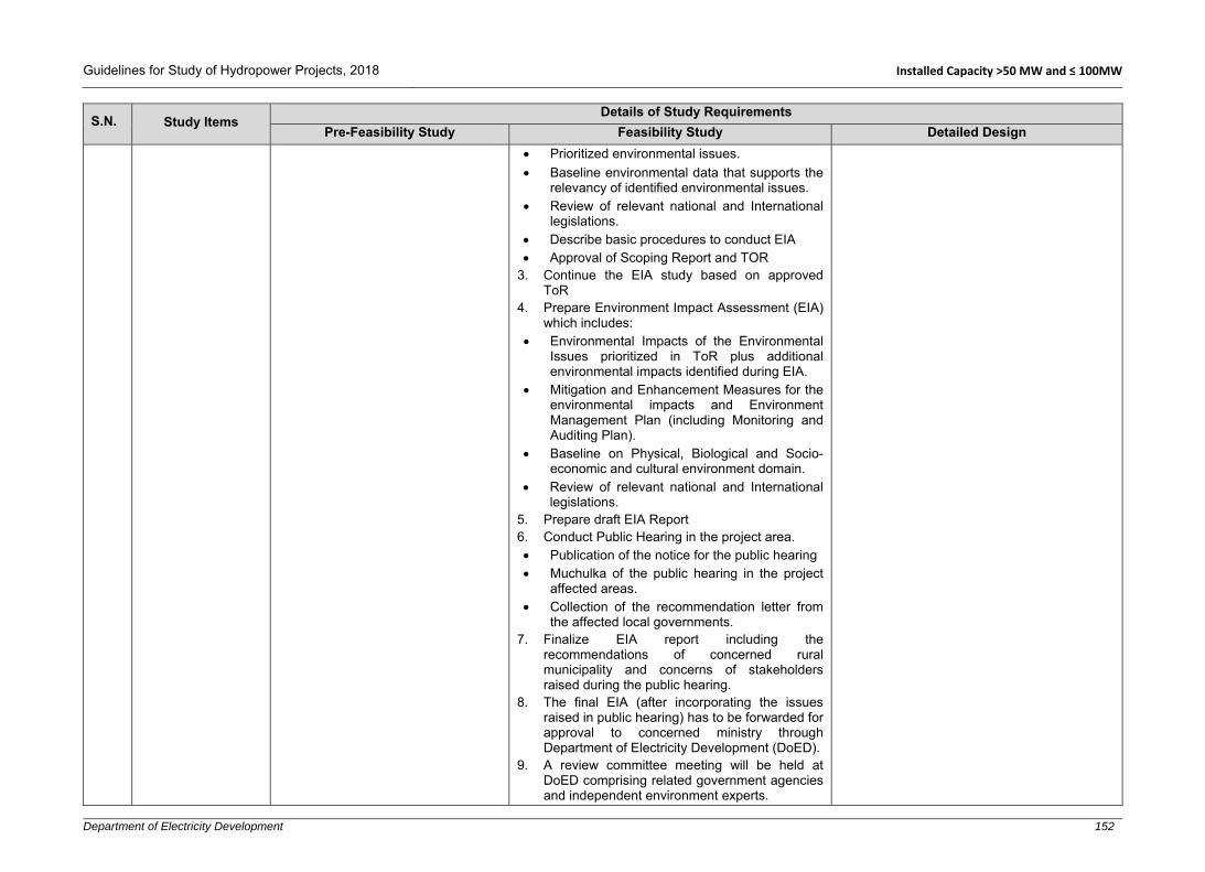
Guidelines for Study of Hydropower Projects, 2018 Installed Capacity >50 MW and ≤ 100MW
Department of Electricity Development 152
S.N. Study Items Details of Study Requirements
Pre-Feasibility Study Feasibility Study Detailed Design
Prioritized environmental issues. Baseline environmental data that supports the
relevancy of identified environmental issues. Review of relevant national and International
legislations. Describe basic procedures to conduct EIA Approval of Scoping Report and TOR
3. Continue the EIA study based on approved ToR
4. Prepare Environment Impact Assessment (EIA) which includes:
Environmental Impacts of the Environmental Issues prioritized in ToR plus additional environmental impacts identified during EIA.
Mitigation and Enhancement Measures for the environmental impacts and Environment Management Plan (including Monitoring and Auditing Plan).
Baseline on Physical, Biological and Socio-economic and cultural environment domain.
Review of relevant national and International legislations.
5. Prepare draft EIA Report 6. Conduct Public Hearing in the project area. Publication of the notice for the public hearing Muchulka of the public hearing in the project
affected areas. Collection of the recommendation letter from
the affected local governments. 7. Finalize EIA report including the
recommendations of concerned rural municipality and concerns of stakeholders raised during the public hearing.
8. The final EIA (after incorporating the issues raised in public hearing) has to be forwarded for approval to concerned ministry through Department of Electricity Development (DoED).
9. A review committee meeting will be held at DoED comprising related government agencies and independent environment experts.

Guidelines for Study of Hydropower Projects, 2018 Installed Capacity >50 MW and ≤ 100MW
Department of Electricity Development 153
S.N. Study Items Details of Study Requirements
Pre-Feasibility Study Feasibility Study Detailed Design
10. Based on the recommendation of review committee, concerned ministry forwards the EIA for Approval.
11. A review committee meeting is organized to seek comments/suggestion on the final EIA report.
12. Further 30 days’ public notice is published in national daily newspaper to seek additional comments and suggestions on the EIA. The draft EIA report along with the public notice has to be placed in public places/office such as TU library, district level office, affected local bodies and concerned government offices.
13. Ministry of Forests and Environment approves the EIA based on the recommendations of review committee meeting and response to 30 days’ public notice.
12.3 Resettlement Study
1. Conduct field survey for gathering the data/information on the population, household lying in the project area and their socio-economic status. Collect the information about the number of cattle lying in the project affected areas.
2. Identify the potential land area for resettlement of the displaced people from the project area through map study.
1. Conduct sampling survey over project area for verifying the data/information collected during the pre-feasibility study and collect additional data/information on population, household and their socio-economic status and number of cattle, lying in the project area.
2. Verify through site visit the potential land area for resettlement identified during pre-feasibility study and identify the new sites, if any.
3. Collect the cost of lands proposed for resettlement.
4. Prepare resettlement schedule and settlement area. Resettlement area shall be facilitated for all human requirements such as security, health and education facilities, economic resources availability, social and cultural viability etc.
1. Review and update the data/information taken in previous studies.
2. Estimate the total resettlement cost including all requirements such as opportunity loss, educational and environmental effects, physiological, mental and physical health effect, security, social and economic impacts etc.
3. Update and finalize resettlement schedule and settlement area.
13 Project Evaluation
13.1
Economic Analysis (at least for projects under taken by governmental bodies)
1. The economic analysis should take into account the cost and benefits to the region (or entire nation).
1. The economic analysis should take into account the cost and benefits to the region (or entire nation).
2. All significant intangible benefits should be identified and quantified in terms of monetary
1. Update the economic analysis based on additional information and data available at this stage.

Guidelines for Study of Hydropower Projects, 2018 Installed Capacity >50 MW and ≤ 100MW
Department of Electricity Development 154
S.N. Study Items Details of Study Requirements
Pre-Feasibility Study Feasibility Study Detailed Design
2. All significant intangible benefits should be identified and quantified in terms of monetary value to the maximum extent possible. For example, better access roads and bridges, communication facilities and schools could be established around the project area. The regional/national benefits due to these improved infrastructures should be quantified.
3. Significant forward linkages in the economy due to the project should be quantified. For example, various electricity consuming industries could be established once the project is built. The economic benefits due to establishment of such industries should be quantified.
4. Similarly, significant backward linkages in the economy due to the project should be quantified. Cement, aggregates and reinforcement/steel industries are some examples of backward linkages.
5. Employment benefits during construction phase of the project should be quantified. Economic benefits due to increase in both regular and seasonal employment should be quantified.
6. Economic cost of the project should also take into account the opportunity cost.
7. Economic value of project should be calculated in terms of NPV, EIRR and B/C.
value to the maximum extent possible. For example, better access roads and bridges, communication facilities and schools could be established around the project area. The regional/national benefits due to these improved infrastructures should be quantified.
3. Significant forward linkages in the economy due to the project should be quantified. For example, various electricity consuming industries could be established once the project is built. The economic benefits due to establishment of such industries should be quantified.
4. Similarly, significant backward linkages in the economy due to the project should be quantified. Cement, aggregates and reinforcement/steel industries are some examples of backward linkages.
5. Employment benefits during construction phase of the project should be quantified. Economic benefits due to increase in both regular and seasonal employment should be quantified.
6. Economic cost of the project should also take into account the opportunity cost (together with construction costs).
7. Economic cost should not include the taxes, duties and royalties. Similarly, it should not include price contingency and interest during construction.
8. Economic value of project should be calculated in terms of NPV, EIRR and B/C.

Guidelines for Study of Hydropower Projects, 2018 Installed Capacity >50 MW and ≤ 100MW
Department of Electricity Development 155
S.N. Study Items Details of Study Requirements
Pre-Feasibility Study Feasibility Study Detailed Design
13.2 Financial Analysis
1. Financial cost should include construction costs, periodic replacement cost, royalties, duties, taxes, VAT, price escalation, insurance cost and interest during construction.
2. All government’s policies, rules and regulation should be reviewed.
3. The benefits will comprise the revenue generation from the sale of electrical energy. As a result of the financial analysis, the financial cash flow showing operating expenses, debt service (loan repayment), royalty and tax payments should be presented.
4. For reservoir or multipurpose project, additional benefits should be derived from:
Flood control benefit Irrigation benefit Water supply and sanitation
benefits Local transportation and
navigation benefits and Other tourism related benefits
etc. 5. The analysis should include
inflation, variation due to foreign currency and revenue generation, if PPA has been carried out in local and/or foreign currency.
6. NPV and FIRR could be adopted as financial indicators.
7. All required assumption for financial analysis should be
1. In performing financial analysis, the Financial Internal Rate of Return (FIRR) and the loan repay capacity should be examined based on financing conditions.
2. The financial cost should include investment cost/base cost (study, preconstruction, civil, HM, EM, TL), O & M cost, duties, royalties, taxes, price escalation, periodic replacement cost, project environment and management cost, insurance and interest during construction.
3. To determine the project’s life from financing perspective, generation license period should be considered.
4. The benefits will comprise the revenue generation from the sale of electrical energy.
5. As a result of the financial analysis, the financial cash flow showing operating expenses, debt service (loan repayment), royalty and tax payments should be presented.
6. For reservoir or multipurpose project, additional benefits should be derived from:
Flood control benefit, Irrigation benefit, Water supply and sanitation benefits, Local transportation and navigation benefits, Fish farming Other tourism related benefits, etc. NPV and Financial Internal Rate of Return
(FIRR) method should be adopted. 7. General expected financial parameters are as
follows: Internal Rate of Return on the project (IRR) -
higher than discount rate. Net Present Value on the project (NPV) -
positive. Debt Service Cover Ratio (DSCR)—higher
than 1.0. Benefit cost ratio – higher than 1.0.
1. Review all previous analysis and update the financial parameters, assumptions and results based on updated current market conditions and any updates on government’s policy (e.g., tax, royalty etc.). The financial parameters such as NPV, IRR, B/C, Equity IRR and NPV, debt service coverage ratio etc. should be updated accordingly.

Guidelines for Study of Hydropower Projects, 2018 Installed Capacity >50 MW and ≤ 100MW
Department of Electricity Development 156
S.N. Study Items Details of Study Requirements
Pre-Feasibility Study Feasibility Study Detailed Design
mentioned and analysed. 8. Financial parameters, Net
present value (NPV), Benefit-Cost Ratio (B/C), Project IRR, rate of equity (ROE), equity NPV, annual debt service coverage ratio, discounted payback period and Levelized Cost of Energy (LCOE) etc. should be determined.
13.3 Sensitivity Analysis
1. The sensitivity analysis should cover possible cases such as increase in project cost, decrease in revenue and exchange risk in foreign currency.
Sensitivity analysis is required to be performed in general, for the following cases: 1. Varied discounted or interest rates. 2. Varying capital cost for possible best and worst
case scenarios. 3. Reduction in revenue generation taking into
account hydrological risks. Delay in commissioning of the project.
4. Cumulative effect of cost and time overruns. 5. Effect of inflation, foreign currency exchange
fluctuation.
1. Update the sensitivity analysis carried out in the feasibility study based on current market conditions and new information/data available at this stage.
14 Presentation Drawings, Maps, Charts and Tables
14.1 General
1. Prepare location map in appropriate scale.
2. Prepare maps showing physiographic regions and geographical regions.
1. Prepare location map in appropriate scale. 2. Map showing physiographic regions and
geographical regions should be prepared. 3. Project general layout should be prepared with
license boundary in topo map in scale 1:25,000 or 1:50,000 as available.
1. Prepare location map in appropriate scale. 2. Map showing physiographic regions and
geographical regions should be updated. 3. Project general layout should be updated
in appropriate scale.
14.2 Topography/ Topographical Survey
1. Generally, this level of study is considered to be carried out based on available maps. Survey works, if carried out during this study including verification of head, license boundaries, etc. should be documented in appropriate scale.
1. Control survey map showing benchmarks or traverse stations and detailed features of the project area in appropriate scale should be presented.
2. Survey data and d-cards (with photographs) should be included in the appendix.
1. Control survey benchmarks or traverse stations with their x, y, z coordinates (in a separate table) should be given in general arrangement drawings (with contours) for all components for reference and further use during construction and operation phases of the project.
Updated (if any) survey maps, data and d-cards with photographs should be documented and presented in the appendix.

Guidelines for Study of Hydropower Projects, 2018 Installed Capacity >50 MW and ≤ 100MW
Department of Electricity Development 157
S.N. Study Items Details of Study Requirements
Pre-Feasibility Study Feasibility Study Detailed Design
14.3 Hydrology
1. Drainage Basin Map showing area below 3000 amsl, 3000 to 5000 amsl and above 5000 amsl can be prepared.
2. Field measurement(s) should be presented in a tabular form with details, location, time and date.
3. Adopted monthly (daily, if available) flows and flood frequency table should be prepared.
4. Prepare flow duration curve. 5. Prepare reference hydrograph
and flood frequency charts.
1. Drainage Basin Map showing the area below 3000 amsl, 3000 to 5000 amsl and above 5000 amsl can be prepared.
2. Field measurements should be presented in a tabular form with details, location, time and date.
3. Rating curves of headworks Site and Tailrace Site should be presented.
4. Long term series data should be included.
5. Various method of daily/monthly flow estimation, adopted daily/monthly flow (include adopted daily flows, if available) and flood discharge in different return periods should be presented in tabular form.
6. Flow duration curve should be prepared. 7. Prepare reference hydrograph and flood
frequency charts. 8. Discharge-sediment relationship should be
developed. 9. Sediment sample and laboratory analysis report
should be included in the appendix. 10. Result of sediment analysis and laboratory
tests should be summarized in tabular form and charts.
1. Updated hydrology report with recommended/adopted daily flow, FDC at headworks and tailrace outlet with tables, design floods and diversion flood during construction.
14.4 Geology and Seismicity
Prepare drawings as follows:
1. Regional geological maps (plan and section in scale 1:250,000 or in available larger scale).
2. Geological map of project area (plan & section in scale 1:25,000 or 1:50,000 or larger, if available).
3. Site specific geological maps as follows:
Headworks drawings in scale 1:500
Water conveyance route in scale 1:5000 or larger
Prepare drawings as follows:
1. Regional geological maps (plan and section in scale 1:250,000).
2. Geological map of project area (plan, profile & section in scale 1:5,000).
3. Site specific geological maps (sections with drill hole logs).
4. Headworks drawings in scale 1:500. 5. Water conveyance route in scale 1:2000. 6. Powerhouse in scale 1:500. 7. Map showing seismic refraction lines, drill holes
in scale 1:2000 or larger.
1. Prepare drawings for updated geology and seismicity report.

Guidelines for Study of Hydropower Projects, 2018 Installed Capacity >50 MW and ≤ 100MW
Department of Electricity Development 158
S.N. Study Items Details of Study Requirements
Pre-Feasibility Study Feasibility Study Detailed Design
Powerhouse in scale 1:500 4. Map showing seismic refraction
lines, electrical resistivity, in available scale.
5. Seismicity map in available scale.
8. The result of geological investigation in a tabular format.
9. Map showing borrow areas and test pits and trenches in scale 1:2000 or larger.
10. Seismicity map in available scale. The above mentioned scales are indicative only. An appropriate scale should be used to make the information/data presented in the drawings/report clear and readable/understandable.
14.5 Alternative Study
1. Location of alternative project components plans and alignments should be shown in appropriate scale.
2. Preliminary cost and energy comparison charts and tables should be prepared.
3. Financial evaluation charts and tables should be prepared.
1. Location of alternative project components, plans and alignments should be presented in appropriate scale.
2. Cost and energy comparison charts and tables. Should be prepared.
3. Financial evaluation charts and tables should be prepared.
14.6 Optimization 1. Optimization study charts and
tables should be prepared. 1. Optimization study charts and tables should be
prepared.
14.7 Design and Drawings
Following drawings in suitable scale should be prepared:
Alternatives considered General arrangement of
selected project. Headworks plan (general
arrangement, elevations and sections).
Settling basin (plan and sections).
Headrace water conduit system (plan and profile).
Forebay/surge tank (Plan, sections, profiles).
Penstock (plan, sections, profiles).
Powerhouse and tailrace (plan, sections and profiles).
Switchyard layout.
Following drawings in suitable scale should be prepared:
Alternatives considered in scale 1:5000 or larger.
General arrangement/layout of selected project in scale 1:5000 or larger.
Headworks (general arrangement, elevations and sections) in scale 1:500 or larger
Headworks components, weir, undersluice, intake, gravel trap etc. plan, sections (L-section, cross sections) and elevations in appropriate scale.
Settling basin (plan and L-section in scale 1:500 and cross sections in scale 1:200 or larger).
Headrace water conduit system (plan and L-section in scale 1:2000, sections in scale 1:100 or larger).
Following drawings in suitable scale should be prepared
1. Civil general arrangement drawings of all components, showing benchmarks, setting out points with their coordinates and all necessary details.
2. Reinforcement drawings of all structures with bar bending schedules.
3. Preliminary drawings of all hydro-mechanical components with necessary dimensions/schedules.
4. Preliminary drawings of all electromechanical-mechanical components with necessary dimensions/schedules.
5. Preliminary drawings of all switchyard components and accessories with necessary dimensions/schedules.

Guidelines for Study of Hydropower Projects, 2018 Installed Capacity >50 MW and ≤ 100MW
Department of Electricity Development 159
S.N. Study Items Details of Study Requirements
Pre-Feasibility Study Feasibility Study Detailed Design
Forebay/surge tank (plan and L-section in scale 1:200, cross sections in scale 1:100 or larger).
Penstock (plans and L-sections in scale 1:200 or larger, cross sections in scale 1:100 or larger).
Powerhouse (general arrangement in scale 1:500, plan and sections in scale 1:200 or larger).
Powerhouse –switchyard Layout in scale 1:500 or larger.
Single line diagram. Protection structures (plan in scale 1:200 and
sections in scale 1:100 or larger). The above mentioned scales are indicative only. An appropriate scale should be used to make the information/data presented in the drawings/report clear and readable/understandable. Distorted scales are not recommended.
6. Preliminary drawings of all Transmission line components and accessories with necessary dimensions/schedules.
7. Preliminary drawings of all interconnection point’s components (switchyard/substation) accessories with necessary dimensions/schedules.
Drawings of Civil Structures
1. General arrangement/layout of selected project in scale 1:5000 or appropriate scale.
2. Headworks (general arrangement, elevations and sections) in scale 1:500 or larger.
3. Headworks components, weir, undersluice, intake, gravel trap etc. plan, sections (L-section, cross sections) and elevations in appropriate scale.
4. Settling basin (plan and L-section in scale 1:500 and cross sections in scale 1:50 to 1:200 or larger).
5. Headrace water conduit system (plan and L-section in scale 1:2000, Sections in scale 1:100 or larger).
6. Forebay/surge tank (plan and L-section in scale 1:200, cross sections in scale 1:100 or larger).
7. Penstock (plans and L-sections in scale 1:200 or larger, cross sections in scale 1:100 or larger).
8. Powerhouse (general arrangement in scale 1:500, plan and sections in scale 1:50 to 1:200 or larger).
9. Powerhouse –switchyard layout in scale 1:500 or larger.
10. Single line diagram. 11. Protection structures (plan in scale 1:200
and sections in scale 1:100 or larger).

Guidelines for Study of Hydropower Projects, 2018 Installed Capacity >50 MW and ≤ 100MW
Department of Electricity Development 160
S.N. Study Items Details of Study Requirements
Pre-Feasibility Study Feasibility Study Detailed Design
Reinforcement Drawings
1. Reinforcement drawings should be prepared based on civil general arrangement drawings in scale 1:10 to 1:50 as appropriate.
Drawings of HM Components
1. Gates and accessories parts in appropriate scale.
2. Expansion joints, manhole covers, valves, gates driving system etc. in appropriate scale.
3. Other HM components in appropriate scale.
Drawings of E-M Components
1. General layout in scale 1:500 or larger. 2. L-sections in scale 1:500 or larger, cross
sections in scale 1:100 to 1:200 or larger 3. Details in scale 1:10 or larger. Drawings of TL Components
4. A general layout of TL alignment (plan in scale 1:5000 and profile in scale 1:500 to 1:2000 or larger.
5. Tower/pole in scale 1:100 to 1:200. 6. The support structure in scale 1:100 or
appropriate scale depending on size of structures.
7. General arrangement of connection bay/switchyard in scale 1:500 or appropriate standard scale.
8. Steel structure and equipment foundation in scale 1:10 to 1:100.
9. Single line diagram. The above mentioned scales are indicative only. An appropriate scale should be used to make the information/data presented in the drawings clear and readable/understandable. Distorted scales are not recommended.

Guidelines for Study of Hydropower Projects, 2018 Installed Capacity >50 MW and ≤ 100MW
Department of Electricity Development 161
S.N. Study Items Details of Study Requirements
Pre-Feasibility Study Feasibility Study Detailed Design
14.8 Energy and Revenue Calculation
1. Prepare monthly energy (daily, if data available) and revenue calculation tables and charts.
1. Prepare daily & monthly energy and revenue calculation tables and charts.
1. Updated daily & monthly energy and revenue calculation tables and charts in comparative format with proposed or agreed power and energy table of PPA (if available) should be prepared.
14.9 Power Supply
1. Map of INPS (existing and planned) should be shown in appropriate scale.
2. Map showing transmission line requirements in appropriate scale.
3. Present alternatives available for interconnection point in the INPS
1. Map of INPS (existing and planned) should be shown in appropriate scale.
2. Maps showing transmission line requirements in appropriate scale (1:25,000 or 1:50,000) or larger.
3. Present the map showing transmission line alignment along with alternatives considered in appropriate scale
1. Update maps prepared during the feasibility study as necessary.
14.10 Access Road
1. Show access road drawings plan in suitable scale.
2. Show plan for alternative access, if any.
1. Show the access road drawings plan in suitable scale.
2. Show plan for alternative access, if any.
1. Access road map/drawings (plan in scale 1:5000, cross sections in scale 1:100 or larger and profile in scale 1:2000 or larger) should be prepared.
2. Drawings of ropeways and other alternative arrangements in appropriate scale as required should be prepared.
14.11 Construction Schedule and Planning
1. Preliminary construction planning and implementation schedule showing major activities should be prepared.
1. Detailed construction schedule in standard format showing major project components including anticipated critical path should be prepared.
1. Detailed construction schedule in standard format should be updated and the critical path should also be shown.
14.12 Cost Estimation
1. Item rates for major works should be presented in tabular form.
2. Project cost derived should be presented in tabular forms.
3. Rate analysis and quantity estimation tables should be attached in the appendix.
1. Item rates for major works should be presented in tabular form.
2. Project cost derived should be presented in tabular forms.
3. Pie charts and graphs as necessary should be prepared.
4. Rate analysis and quantity estimation tables should be attached in the appendix.
1. Prepare item rates for major works in tabular form.
2. Update detailed project cost/engineer’s estimate.
14.13 Project Evaluation
1. Total project cost including financial cost derived in tabular form stating basis used and assumptions made while carrying out the financial evaluation should be included.
2. Results of financial analyses for the base case and most likely
1. Total project cost including financial cost derived in tabular form stating basis used and assumptions made while carrying out the financial evaluation should be presented.
2. Results of financial analyses for the base case and most likely case should be presented in tabular form.
1. Updated total project cost including financial cost derived in tabular form stating basis used and assumptions made while carrying out the financial evaluation should be presented.
2. Results of financial analyses for the base case and most likely case should be presented in tabular form.

Guidelines for Study of Hydropower Projects, 2018 Installed Capacity >50 MW and ≤ 100MW
Department of Electricity Development 162
S.N. Study Items Details of Study Requirements
Pre-Feasibility Study Feasibility Study Detailed Design
case should also be presented in tabular form.
3. Sensitivity results showing all possible scenarios studied/ analysed should be presented.
3. Sensitivity results covering all possible scenarios studied/analysed should be presented in tabular form.
3. Sensitivity results of feasibility study should be updated based on market conditions and new data/information available at this stage.
14.14 Report
1. Standard cover page, signature page, summary page, abbreviations, the body of report and conclusions and recommendations are required in standard report.
2. Generally accepted standard table of contents, list of figures, list of tables, headings’ font, size and style, paragraph arrangement, letter size, font and style, caption and cross reference, line spacing, etc. should be used in the report.
3. The report should include: Main report Relevant annexes and
appendices Drawings
1. Standard cover page, signature page, summary page, abbreviations, the body of report and conclusions and recommendations are required in standard report.
2. Generally accepted standard table of contents, list of figures, list of tables, heading’s font, size and style, paragraph arrangement, letter size, font and style, caption and cross reference, line spacing, etc. should be used in the report.
3. Separate volumes of report as necessary including investigation data and calculations and drawings should be prepared as follows:
Main report Relevant annexes and appendices. Drawings
4. Periodically, updated information in the form of progress report should be provided to owner/client/executives agency/regulating authorities with a cover letter as and when required.
5. In case of significant change(s) to the layout, design and or any other project parameters, such change(s) shall be reported in time to the client and regulating authorities with necessary supporting documents for timely approval.
1. Standards formats/styles as suggested in the feasibility study report section should be followed while preparing all reports prepared as the outcome of detailed design. The following report should be prepared during the detailed design.
2. Project Definition Report: This is generally prepared at the beginning of detail design phase as guidelines for further design/development of the project. In the report, all base line data, up to date salient features of the project and project engineering parameters including relevant codes adopted, cost and revenue calculations, financial indices, project implementation schedule, etc. should be briefly described.
3. When numerical and physical hydraulic model studies are carried out, separate reports should be prepared recommending further design refinements based on the outcomes of such studies.
4. Design Basis Memorandum (DBM): This document is prepared as project’s customized standards agreed for adoption in the detailed design of all components of the project related to civil, hydro-mechanical, electro-mechanical and transmission line works. All relevant baseline information and other project information given in the Project Definition Report, Model Study Report, relevant codes and standards to be followed during detailed design should be documented in this report. DBM should be approved by the client before proceeding the detailed design further. Necessary amendments to the DBM should be made on need basis with timely approval from the client during

Guidelines for Study of Hydropower Projects, 2018 Installed Capacity >50 MW and ≤ 100MW
Department of Electricity Development 163
S.N. Study Items Details of Study Requirements
Pre-Feasibility Study Feasibility Study Detailed Design
the course of detailed design when and where required.
5. Detailed Design Report: Main outcomes of the detailed design are reports drawings (general arrangement and reinforcement), and specifications. The reports, drawings and specifications together with design calculation sheets can be structured in different volumes. An example of detailed design report volume is suggested below:
Volume-1: Detail design main report Volume-2: Detailed design annexes and
appendices Volume-3: Detail design drawings: - Volume-3A: Detailed design civil drawings - Volume-3B: Reinforcement drawings Volume-4: Technical specification 6. The above mentioned report and
documents will be basis for preparation of tender documents which are usually prepared during detailed design phase of a hydropower project.
7. In addition to the above mentioned report it is suggested to prepare a Draft Operation and Maintenance Manual for the power plant which should be further refined/updated during construction/ installation of the project. Such a manual should cover operation and maintenance guidelines for civil, H-M, E-M and TL components.
8. Periodically updated information in the form of progress report should be provided to owner/client/executive agency/regulating
authorities with a cover letter as and when required. 9. In case of significant change(s) to the
layout, design and or any other project parameters, such change(s) should be reported on time to the client and authorities with necessary supporting documents for approval.

Guidelines for Study of Hydropower Projects, 2018 Installed Capacity >50 MW and ≤ 100MW
Department of Electricity Development 164
S.N. Study Items Details of Study Requirements
Pre-Feasibility Study Feasibility Study Detailed Design
15 Risk Analysis
15.1 Hydrological Risk
Hydrological risk can be determined by considering the following: 1. Calculate daily/monthly flow variation, seasonal
variation and develop monthly hydrograph. 2. Collect previous drought records and minimum
river flow analysis 3. Carry out catchment area analysis 4. Collect hydro-meteorological data such as
precipitation, wind velocity, temperature, relative humidity, etc. of the project area.
5. Estimate upper and lower limit of energy generation and calculate daily/monthly revenue of the project.
Flood Hydrology: 1. Probability and statistical approach should be
adopted in fixing the level of flood risk. 2. Flood risk analysis should be based on slope
stability and geology of nearby catchments. Also calculate flood risk caused by LDOF.
3. GLOFs are major risk factor of many hydro-project in Nepal. Therefore, status of existing glacier lakes in the basin, condition of marine dam and volume of glacier lakes should be determined. Similarly, risk analysis should factor in that the nearest projects (to the glacier lake) are more vulnerable than those located far from glacier lakes.
Suspended Sediments:
1. Composition and density of sediments are another major problem for hydropower projects. Therefore, sediment transportation phenomena, type of sediments composition and impacts of sediment on hydraulic structures and hydro-mechanical equipment shall be considered. Reference can be taken from existing hydropower projects located at a similar topography, catchment basin, nature of sediments related activities.
1. Review and update the previous study carried out during the feasibility study.

Guidelines for Study of Hydropower Projects, 2018 Installed Capacity >50 MW and ≤ 100MW
Department of Electricity Development 165
S.N. Study Items Details of Study Requirements
Pre-Feasibility Study Feasibility Study Detailed Design
15.2 Financial Risk
Financial risk should be carried out considering the following key points: 1. Materials price rate escalation and inflation
during the study period and construction period. 2. Status of locally available materials and their
utilization. 3. Construction methodology and technology to be
employed during construction. 4. Construction planning, scheduling and
estimation of construction period. 5. Exchange rate fluctuation - market risk and
currency fluctuation risks during construction period should be considered.
6. Escalation on bank interest rate. 7. Significant technical and non-technical losses
created by natural or human made activities. 8. Additional risk related to site security. 9. Insurance and cost recovery. 10. Possible revenue variations due to seasonal
and long term fluctuations in river flows. 11. Sensitivity analysis should be carried out taking
into account changes in the level of risks.
Review and update the financial risk analysis carried out in the feasibility study and undertake further analysis considering the additional key points: 1. Updated materials price rates, tools and
equipment rates, human resource rates etc. and possibility of future price escalation.
2. Risks due to contract packages, contractor selections, modes of construction, status of infrastructure development, etc.
3. Land acquisition and price escalation. 4. Fluctuation trends of foreign currency. 5. Updated bank interest rate. 6. Need to address demands for social and
ecological development. 7. Financial risk due to natural calamities,
scarcity of construction materials, tools and equipment supply and delivery etc.
8. Project’s topography and geographical location and accessibility etc.
9. Investment risk due to natural events in project area, political activities, government policies, rules and planning, etc.
10. National prioritization for hydropower development, formulation, extension, importance and electricity demand in the market etc.
15.3 Geological Risk
1. Collect information on past geological events in the project area, such as land slide, rock fall, debris flow etc.
2. Collect geological investigation reports and results, discontinuity survey reports and drawings, geological model study, type of rocks, rock quality, rock bedding, dip direction and dip amount, etc. and determine the level of risk factor.
1. Review and update geological risk assessed during the feasibility study.
2. Collect additional geological investigation reports and results, discontinuity survey reports and drawings, geological model study, type of rocks, rock quality, rock bedding, dip direction and dip amount, etc. and update the level of risk factor.

Guidelines for Study of Hydropower Projects, 2018 Installed Capacity >50 MW and ≤ 100MW
Department of Electricity Development 166
S.N. Study Items Details of Study Requirements
Pre-Feasibility Study Feasibility Study Detailed Design
3. Error in geological investigation and interpretation, mapping and survey etc. should also be considered while setting the geological risk factor.
4. Conduct seismic risk analysis considering seismic design parameters, past seismic events and their effect in similar topography as well as national and international practices.
5. Develop a degree of seismic risk based on the deterministic and probabilistic approach as well as other international practices.
3. Error in geological investigation and interpretation, mapping and survey etc. should also be considered while setting the geological risk factor.
4. Conduct seismic risk analysis considering seismic design parameters, past seismic events and their effect in similar topography as well as national and international practices.
5. Develop a degree of seismic risk based on deterministic and probabilistic approach as well as other international practices.
15.4 Design and Construction Risk
Insufficient technical information and order, poor communication, design modification and alteration, construction technology and methodology play a vital role in increasing the design and construction risks. Thus, the following factors should be considered and clearly examined while determining the design and construction risks: i. Design criteria, assumptions and
formulations. ii. Factor of safety taken during the design. iii. Design references and codes referred to. iv. Documentation and standard of reports,
clarity and presentation of drawings (construction drawings, SOP drawings, reinforcement drawings etc.).
v. Presented notes and instructions in drawings.
vi. Past experience and performance of designer/consultant.
vii. Modes of contracts. viii. Bid amount and security deposits. ix. Adopted/anticipated methodology and
technology for construction and past experiences with similar projects/technologies.
x. Contract documents, technical specifications and quality of tender drawings and details.

Guidelines for Study of Hydropower Projects, 2018 Installed Capacity >50 MW and ≤ 100MW
Department of Electricity Development 167
S.N. Study Items Details of Study Requirements
Pre-Feasibility Study Feasibility Study Detailed Design
xi. Experience and past performance of contractor.
xii. Construction delay, workability and probability related to work progress and execution of work on time.
xiii. Available materials, tools, equipment and human resources.
xiv. Quality assurance, field/construction errors, errors in lab test, climatic condition, equipment errors etc.
15.5 Environmental Risk
Risk assessment related to environment impacts and impact mitigation should include: 1. Reliability of data collection during EIA study.
Additional data collection and verification should be carried out as necessary.
2. Environmental effects due to construction such as excavation and disposal (blasting, disposal of tunnel muck, disposal of explosive, soil spoil and barrow pits etc.) should be re-examined.
3. Water availability downstream of dam. 4. Beneficial utilization of water at downstream
reach and livelihood adaptations and ecological balance in upstream and downstream of dam and reservoir should be assessed.
5. Effect of seasonal flood in downstream of dam should be evaluated.
6. For PRoR and reservoir projects, loss of agricultural land, loss of physical/social/natural asset should be quantified.
1. Review and update the environment risk analysis, if required.
16 Modelling
16.1 Numerical Modelling 1. Hydrological modelling can be done to compute daily flow.
1. Hydrological and hydraulic modelling shall be carried out as defined in Section 2, Hydrology and Sedimentation Studies.
1. Result of numerical modelling from the feasibility study should be updated.
2. Surge effect in tunnel system and back water effects at upstream of dam can be estimated using numerical modelling. Velocities and pressures characteristic can be solved by transient analysis (e.g. using commercially available software).
3. Sediment simulation should be carried out to compute the trap efficiency and model bed changes in a sand trap.

Guidelines for Study of Hydropower Projects, 2018 Installed Capacity >50 MW and ≤ 100MW
Department of Electricity Development 168
S.N. Study Items Details of Study Requirements
Pre-Feasibility Study Feasibility Study Detailed Design
16.2 Physical Modelling (depending on project capacity and if required)
1. The following philosophy and laws should be considered during physical modelling:
Laws of hydraulic similitude Law of similarity Dimensionless numbers and scaling laws
should be determined by considering criteria of similarity from a system of basic differential equation, similarity through dimension analysis and method of synthesis.
2. Geometric, kinematic, dynamic and mechanical similarities should be analysed during scaling process.
3. Froude law and Reynolds law, Weber number, Euler number, hydraulic model law or similar other standard methods should be considered.
Selection of Scale
1. Before building a physical model, carry out appropriate topographic and hydrological field survey and define suitable similarity law and type of model.
2. Additional considerations such as maximum discharge, maximum head, floor area, ceiling height, construction considerations, instrumentation limitations, scale effects, laboratory space constraints and required equipment available in the market etc. should be analysed for scale selection.
3. Model should be designed as large as practicable, considering cost and benefit.
4. The linear scale of model (according to USBR) should be within the following ranges:
30 to 100 for spillway, weir/dam. 5 to 30 for settling basin, stilling basin,
outlet and inlet valves and gates etc. 3 to 20 for side channel spillway chutes,
drops, canal structures, etc. 5. In addition to above mentioned scales,

Guidelines for Study of Hydropower Projects, 2018 Installed Capacity >50 MW and ≤ 100MW
Department of Electricity Development 169
S.N. Study Items Details of Study Requirements
Pre-Feasibility Study Feasibility Study Detailed Design
certain minimum dimension must be maintained for successful studies as follows:
At least 100 mm across for models of gates and conduits
At least 100 mm bottom width of canal structures.
To minimize the relative influence of viscosity and surface tension, spillway models should be scaled to provide flow depths over the crest of at least 75 mm for the normal operating range.
6. The position of instruments should be at the accessible locations for observations, with enough clearance between instruments and flow boundaries to provide accurate measurements. Therefore, the selected scale must be such that the magnitude of measured quantities is well within the range of available instruments and the sensitivity of the instruments is sufficient to obtain the results for different operating conditions.
7. Small discrepancies in the model can result in large differences, when transferring the results to the real structure scale/prototype. Therefore, the scale factor and construction techniques should be fixed as per required accuracy and precision.
Physical Model Observations Instrumentations and Interpretations
1. Observation, instrumentations and interpretations provide the necessary information to compare design alternatives, predict prototype performance, or develop generalized results applicable to a wide variety of situations. Therefore, simple instruments, such as point gauges, pitot tubes, manometers for the measurements of static or slowly changing parameters, V

Guidelines for Study of Hydropower Projects, 2018 Installed Capacity >50 MW and ≤ 100MW
Department of Electricity Development 170
S.N. Study Items Details of Study Requirements
Pre-Feasibility Study Feasibility Study Detailed Design
notches and flumes, special ultrasonic or electronic devices, sediment feeding equipment, etc. are required for measurement of discharge, water level, pressure, velocity etc.
2. Discharge measurements at intake, weir/ dam, spillway, undersluice, flushing conduits, settling basin etc. of physical models shall accurately be carried out with the standard methods and devices.
3. Water surface level should be measured at headworks structures such as the weir, stilling basin, spillway, intake, settling basin, etc. in different scenarios of the flow.
4. In case of spillway, intake structures and bottom outlets, stage-discharge relationship should be established for which observation of reservoir surface water level is of prime importance. Similarly, the observation of downstream water level for different discharge should be carried out in headworks model study.
5. Velocity should be measured accurately by using classical or modern instruments. Three dimensional flow and turbulence velocity should be measured by using electromagnetic current meter, hot-wire and hot-film anemometers etc.
6. Static and dynamic characteristics of positive, negative, differential or absolute pressures should be determined at stilling basin, chute surface spillway, immediate downstream of bottom outlets and gates etc.
Design of Models 1. Before the construction of models, the
model drawings should be prepared accurately to prevent errors in the construction. These drawings should be able to provide sufficient information for the model construction.

Guidelines for Study of Hydropower Projects, 2018 Installed Capacity >50 MW and ≤ 100MW
Department of Electricity Development 171
S.N. Study Items Details of Study Requirements
Pre-Feasibility Study Feasibility Study Detailed Design
2. The evaluation of model study should be carried out by qualitative and quantitative tests to meet the design and operation requirements.
3. Once the basic parameters are defined, the first step is to select a model scale. One or more of the scaling criteria can be selected for the design of the model as mentioned above.
4. The model should cover enough area from far upstream to the downstream of the diversion structure so that the river behaviour and sediment management can be well studied. Normally, the diversion dam/weir, intake structure, spillway, stilling basin, fish passes, settling basin, etc. are often subjected to free surface flow followed by Froude law or similar standard methods. While bottom-outlet, gates or diversion tunnel spillway should be modelled by Reynolds Law or similar standard methods.
5. The following data should be collected and compiled before the actual design of the model:
Hydrological and hydraulic calculation of the proposed design.
Structure layouts of relevant components and their sizes.
Suspended sediment data, bed load sediment data and their measurements and past behaviour of the river at headworks site supported by photographs, if available.
Topographical survey data and topo maps including the river profiles (minimum three: along centre/thalweg, and along both banks depicting the water surface) and cross sections (at 20 m intervals or closer covering adequate length upstream of

Guidelines for Study of Hydropower Projects, 2018 Installed Capacity >50 MW and ≤ 100MW
Department of Electricity Development 172
S.N. Study Items Details of Study Requirements
Pre-Feasibility Study Feasibility Study Detailed Design
headworks and also immediate downstream of headworks). The cross sections survey should cover at least 20 m above the maximum flood mark on the both banks and also 20 m above future impounding area at upstream of the headworks along the both banks.
6. Additionally, the data on the armoured bed material and boulders that are influencing the river hydraulics along the selected stretch are very important especially for steep gradient Himalayan River.
7. Moreover, during model design, emergency spillway, by pass system, ice problems, oscillations (surge analysis), air trap and accumulations in tunnel and model calibrations are major issues in physical modelling. So, necessary model modifications, scaling and transient analysis should be carried out such that these issues can be studied in the model.
Physical Model Preparation
1. The physical model construction may be divided in two main phases, namely:
Model construction of the river stretch on which the headworks and or other structures that are planned to be constructed, covering adequately its immediate upstream and downstream areas. Before construction of the river model, decision should be made whether it is necessary to construct movable river bed or fixed river model would be enough.
Model construction of headworks and or other structures being studied.
2. Boulders, sand or gravel is often placed in the downstream to aid in the study of the scour patterns and designs are judged to some extent by their scouring tendencies.

Guidelines for Study of Hydropower Projects, 2018 Installed Capacity >50 MW and ≤ 100MW
Department of Electricity Development 173
S.N. Study Items Details of Study Requirements
Pre-Feasibility Study Feasibility Study Detailed Design
3. For settling basin, the trapping efficiency and flushing pattern together with its flushing capacity of flushing gallery have to be visualized in the model study.
4. Due to difficulty to scale down sand, silt and other suspended sediments, walnut shell dust, saw dust or coal powders or artificial sediments ranging in size from 0.03 to 4 mm can be used in fine sediment simulation. The mean diameter of natural silt and fine sand shall be scaled down in proportion to the density or fall velocity.
5. For oscillations, transient analysis (one dimensional study/numerical modelling) should be carried out before preparation of physical model.
Operation of Model
1. After construction of the river stretch model, it should be validated. Validation is usually done against measured water levels at the site at different characteristic sections of the river stretch for at least three different flows/river discharges.
2. Before the model validation, the initial adjustments under pumping system or constant head tank, water leakage from model components, accessibility in and around the model instrumentation should be verified.
3. Perform model verification and validation properly as anticipated from the mathematical relations and collected field data and confirm that there are no errors or other inconsistencies because of miscalculation and or misrepresentation. The river model should be further refined and tested until validation results with acceptable accuracy are achieved.
4. After initial adjustments, verification and validation of the model, existing situation tests (of the river) should be carried out.
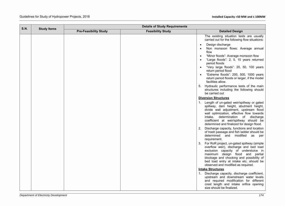
Guidelines for Study of Hydropower Projects, 2018 Installed Capacity >50 MW and ≤ 100MW
Department of Electricity Development 174
S.N. Study Items Details of Study Requirements
Pre-Feasibility Study Feasibility Study Detailed Design
The existing situation tests are usually carried out for the following flow situations:
Design discharge Non monsoon flows: Average annual
flow “Minor floods”: Average monsoon flow “Large floods”: 2, 5, 10 years returned
period floods “Very large floods”: 20, 50, 100 years
return period flood “Extreme floods”: 200, 500, 1000 years
return period floods or larger, if the model facilities allow.
5. Hydraulic performance tests of the main structures including the following should be carried out
Diversion Structures
1. Length of un-gated weir/spillway or gated spillway, dam height, abutment height, divide wall adjustment, upstream flood wall optimization, effective flow towards intake, determination of discharge coefficient at weir/spillway should be determined and finalized for design flood.
2. Discharge capacity, functions and location of trash passage and fish ladder should be determined and modified as per requirement.
3. For RoR project, un-gated spillway (simple overflow weir), discharge and bed load exclusion capacity of undersluice in maximum design flood and partial blockage and chocking and possibility of bed load entry at intake etc. should be observed and modified as required.
Intake Structures 1. Discharge capacity, discharge coefficient,
upstream and downstream water levels and required modification for different crest length and intake orifice opening size should be finalized.

Guidelines for Study of Hydropower Projects, 2018 Installed Capacity >50 MW and ≤ 100MW
Department of Electricity Development 175
S.N. Study Items Details of Study Requirements
Pre-Feasibility Study Feasibility Study Detailed Design
2. Carry out observation for appropriate function of the intake structure for handling floating debris, excluding the bed loads, abstract enough water during low flow and safe operation during floods and modification should be carried out (if required). Desired flow pattern upstream and immediate downstream of intake and at gravel trap should be achieved.
Stilling Basin
1. The size and location of hydraulic jump, erosion problem at spillway, stilling basin and flushing sluice, etc. should be determined up to maximum design flood and necessary modification of sizes and extension (location) of riprap, downstream protection blocks should be finalized according for design flood, if required.
Settling Basin
1. Flow velocity, fall velocity, trap efficiency, settlement of artificial sediments, flow pattern at entrance and exit, amount of turbulence and uniformity of flow in vertical and horizontal direction should be monitored.
2. Discharge capacity of sediment flushing conduits and pattern of flushing galleries, bottom shape, size and slope of settling basin based on sediment flushing capacity, number of bays, type and size of settling basin should be finalized.
3. Discharge coefficient and capacity of settling basin outlet and emergency spillway should be determined and necessary modifications should be carried out as required.
4. In addition, intake/tunnel inlet modifications and adjustments should be carried out considering the air accumulation/trapping problems in tunnel, bed load and trash accumulation.

Guidelines for Study of Hydropower Projects, 2018 Installed Capacity >50 MW and ≤ 100MW
Department of Electricity Development 176
S.N. Study Items Details of Study Requirements
Pre-Feasibility Study Feasibility Study Detailed Design
5. During the study, model observation, many modifications, dismantling of some part of the model and re-construction, regular monitoring, evaluation and maintenance and regular measurements, data collections and instrumentations are required until satisfactory results are achieved.
6. Based on the test results, the best layout/design (recommended design) should be updated and agreed for final testing.
7. The final documentation study should include but not limited to the following tests with necessary measurements/records:
Different flows as agreed and tested during the existing situation tests
Floating debris transport pattern Bed load transport/deposition/scouring
pattern Hydraulic performance/conditions
including preparation of rating curves for weir/spillway, undersluice gates, intake gates etc.
Proposed operation regime of the headworks and its different components (and other structures, if modelled and tested).
Scenario test for assurance of bed control in front of intake (by simulating extreme events like mass wasting).
Necessary additional tests for covering/recommending different operational aspects.
Final Reporting
1. Intermittent/progress reporting modality and deliverables should be required. The final reporting/output of the model study should cover but not be limited to the following:

Guidelines for Study of Hydropower Projects, 2018 Installed Capacity >50 MW and ≤ 100MW
Department of Electricity Development 177
S.N. Study Items Details of Study Requirements
Pre-Feasibility Study Feasibility Study Detailed Design
i. Main Report: The main report should cover the following topics among others: Introduction/background of the study, input data, model study methodology, model validation, existing situation tests and results/records, conceptual studies and recommended final design/layout, final documentation study and records, tests and recommendations for smooth operation of project/hydropower plant, conclusions and recommendations
ii. Appendices: Other data/information/records can be documented as appendices to the main report which should cover but not limited to the following:
Drawings: All necessary drawings (plan, L-sections, X-sections and details of the recommended layout/design should be prepared and presented in hard and soft copies (in Auto-CAD or similar software). Furthermore, plans/layout drawings of all options studied should also be presented with necessary descriptions/discussions in the main report mentioned above.
All input parameters: All input parameters used for the model study should be documented in terms of figures, tables, photographs etc.
Evidence and records of model validation tests
Evidence and records of existing situation tests
Water depths/water levels, velocities, sediment deposition pattern measured/recorded during documentation study, operation aspect study and scenario tests in table, figure formats.
Photographs and videos of all the tests carried out during the documentation

Guidelines for Study of Hydropower Projects, 2018 Installed Capacity >50 MW and ≤ 100MW
Department of Electricity Development 178
S.N. Study Items Details of Study Requirements
Pre-Feasibility Study Feasibility Study Detailed Design
study, operation aspect study and scenario tests. Furthermore, photographs and video taken during validation and existing situation tests and other major tests carried out for the conceptual design finalization should also be recorded and documented.

Guidelines for Study of Hydropower Projects, 2018 Installed Capacity More Than 100 MW
Department of Electricity Development 179
A4. Installed Capacity More Than 100 MW
S.N. Study Items Details of Study Requirements
Pre-Feasibility Study Feasibility Study Detailed Design Study
1 TOPOGRAPHICAL SURVEYS AND MAPPING
1.1 Available Maps and Images
1. Collect and make use of available contour maps of the project area published by the Department of Survey.
2. Enlarge the available largest scale Topo-map of the project area to 1:10,000 scale or larger.
3. Acquire satellite image of the project area to generate contour and features.
4. Project the maps and images to match with the national coordinate system.
1. Collect and review the available maps and images.
2. Additional maps and updated images recommended in the pre-feasibility level should be obtained.
3. Satellite image and aerial photograph of catchment area should be collected for additional interpretation and investigation.
4. If the project is a reservoir type or has a weak geological area or consists of a glacier lake in the catchment basin, additional recent satellite images, aerial photographs of the basin and the latest published reports should be collected for further interpretation and investigation.
1. Additional maps and updated images should be obtained, if required.
1.2 Topographical Survey
1. Construct a safe foot trail to access the headworks, waterways and powerhouse of the project.
2. Verify the coordinates of the key project components proposed in desk/reconnaissance study.
3. Carry out fly levelling, or use theodolite/total station to verify the gross topographic head.
4. Establish the control points and new benchmarks either by conducting traverse survey, DGPS triangulation or any suitable methods as appropriate. The benchmarks shall be permanent type generally constructed with reinforced concrete or marking in rocks.
5. Generate contour and features of the project area using satellite images in 1:2000 scale or larger.
1. Establish additional control points/benchmarks.
2. Determine the coordinates of at least two benchmarks by DGPS, triangulation or any appropriate methods to tie with triangulation points of the national grid established by the Department of Survey.
3. Complete the traverse survey by using coordinates of the two known benchmarks.
4. Carry out detailed topographical survey of headworks, waterways (strip survey), forebay/surge tank/surge shaft, adit portal(s), powerhouse, tailrace and switchyard area and prepare a map with 1 m contour interval.
5. The point density of detailed survey should be sufficient to cover all ground features. The survey should cover at least impounding area upstream of the dams/weir and adequate area downstream of the tailrace. The survey should cover at least 20
1. Topographic survey carried out during the feasibility study should be augmented with additional coverage required for detailed design. Where the feasibility maps are adequate to an acceptable standard, it will only be necessary to update them to reflect any changes.
2. Additional survey is required, if there are changes in alignment or any addition or change of location of project component(s).
3. The coordinates of control points established during the feasibility study should be verified and revised, if necessary.
4. Establish additional benchmarks at the selected headworks, waterways and powerhouse that can be used during project construction.
5. Conduct strip survey of the access road(s) alignment with sufficed point density to produce map in 1:1000 scale.

Guidelines for Study of Hydropower Projects, 2018 Installed Capacity More Than 100 MW
Department of Electricity Development 180
S.N. Study Items Details of Study Requirements
Pre-Feasibility Study Feasibility Study Detailed Design Study
m in elevation above the maximum flood mark or full supply level on both the banks.
6. At least two of the most promising alternatives should be covered in the topographical survey.
7. For inaccessible areas such as steep cliffs, generate contour and features using aerial/satellite images or any suitable methods. The maps generated by this method should be 1:2000 scale or larger.
8. If there is a hydropower project upstream within the backwater reach, carry out river cross section survey up to the tailrace outlet of the upstream hydropower plant.
9. The topographical survey should cover quarry sites, spoil tip areas, camp sites and access roads (strip survey) inside the project area including necessary river crossings.
10. River cross section survey should be carried out at intake and tailrace sites covering at least 500 m upstream and downstream. The interval should be 20 to 50 m or closer depending upon river morphology. The survey should be extended beyond high flood marks. The flood marks and existing water levels should be indicated in the cross sections.
11. If there are any tributaries/gullies that could affect the project components substantially, tributaries’ cross section survey should cover the stretch within the project area.
12. If there are major river confluences in the vicinity of the headworks and/or tailrace, the topographical survey should cover at least 500 m upstream and downstream from the confluence point in the adjacent river(s) and the main river.
13. Conduct walkover survey of transmission route(s) and construction power route(s) using 1:25,000 or 1:50,000 scale
Take details to indicate all major and minor crossings.
6. In bridge/siphon crossings, conduct river cross section survey covering 500 m upstream and 500 m downstream from the bridge axis at 20 m intervals or closer and mark water levels. Take additional details at abutments.
7. Conduct strip survey of transmission line route in 1:1000 scale. Also, take details at poles/tower locations.
8. Conduct cross section survey of critical slopes and landslide-prone zone in project area i.e. intake, forebay/surge tank, adit portal(s), waterway, penstock alignment and powerhouse, if not covered during feasibility study.

Guidelines for Study of Hydropower Projects, 2018 Installed Capacity More Than 100 MW
Department of Electricity Development 181
S.N. Study Items Details of Study Requirements
Pre-Feasibility Study Feasibility Study Detailed Design Study
topographic maps in order to verify suitability of the route(s). Mark the walkover points with GPS and plot these in the topographic map.
14. For power canal/conduit, the width of strip survey should be decided considering the topography of the alignment, size of the conduit, access and safety requirements.
15. Survey of dam site area should extend up to an elevation covering top of dam plus head over crest during deign flood with sufficient free board.
16. Reservoir area survey should cover up to an elevation of FSL with adequate free board.
17. Locate and map river boulders larger than 2 m.
18. For tunnelling, 100 m to 400 m wide strip along the tunnel alignment in a scale of 1:2000 to 1:5000 should be considered. Similarly, conduct an additional detailing for portals and low overburden areas.
1.3
Topographic Mapping, Plotting, Reporting and Data Presentation
1. Prepare description card of all benchmarks showing the point with a colour photograph and mention the nearby references, the name of local surveyor, place name and its coordinates.
2. Prepare topographical survey report and maps. If multiple surveys have been carried out, prepare a single report consisting all of the findings.
3. Prepare contour plan in 1:2,000 scale with 2 m contour interval of the whole project area. Features such as a rocky cliff, slide zones, cultivated land, settlement, benchmarks etc., must be shown.
1. Prepare description card of all benchmarks showing the points with a colour photograph and mention the nearby references, name of the surveyor, location and its coordinates.
2. Prepare topographical survey report and maps. If multiple surveys have been carried out, prepare a single report including all of the findings.
3. Prepare access road(s) map in 1:1000 scale with 1 m contour interval. Show the cross sections along bridge/culverts along the road alignment in appropriate scales. The general layout may be plotted in a smaller scale.
4. For headworks, waterways, forebay/surge shaft/surge tank, adit portal(s), powerhouse, tailrace and switchyard areas, the contour interval should be 1m and the scale of map may vary from 1:100 to 1:2000 depending upon the size of the area.
1. Use the topographic maps prepared during the feasibility study after updating as and when necessary.

Guidelines for Study of Hydropower Projects, 2018 Installed Capacity More Than 100 MW
Department of Electricity Development 182
S.N. Study Items Details of Study Requirements
Pre-Feasibility Study Feasibility Study Detailed Design Study
5. Prepare transmission route map in a scale of 1:25,000 or 1:50,000 showing key features such as agricultural land, forest area and settlements.
6. Prepare and verify the license boundary map showing project components and verify there is no conflict with other projects in the vicinity and ensure that backwater level is also within the license boundary.
2 HYDROLOGICAL AND SEDIMENTATION STUDIES
2.1 Hydrology
1. Along with the guidelines mentioned herein, the Hydrological Manual for Infrastructure, Water and Energy Commission Secretariat can be followed for hydrologic analysis.
2. Collect long term historical rainfall data and climatological data pertinent to the study area (preferably more than 30 years) where available.
3. Collect long term historical flow data and sediment data of the river under study. If not available, collect the data from other rivers with similar hydrological characteristics in the vicinity (preferably for more than 30 years).
4. Check the consistency of data. 5. Assess mean daily flow (if available) and
develop a flow duration curve using daily hydrograph.
6. For the ungauged river, discharge (including flow duration curve) shall be estimated with empirical methods, rational method and catchment area ratio method selecting similar catchment, wherever applicable. Such discharge data shall be justified by checking rainfall runoff coefficient.
7. Snow/glacier melt contribution shall be considered, if the catchment has snow/glacier fed rivers.
1. All information obtained from pre-feasibility study shall be reviewed, verified and updated. If gauge stations have been established previously, measurements should be continued.
2. Data logger can also be added and used for online monitoring of hydrological data.
3. Install a cableway at the intake and powerhouse site wherever necessary for discharge measurement.
4. Update the flow data and assess according to the mean daily flows and develop an upgraded flow duration curve.
5. For ungauged river basin, hydrologic modelling for the estimate of water availability shall be carried out. Hydrologic model that consider snow/glacier melt schemes shall be used for the catchment that has snow/glacier fed rivers.
6. Water surface/level profile modelling shall be carried out.
7. Carry out cross section surveys at least 500m/1km upstream and downstream of the headworks site and the tailrace site covering the highest flood marks, preferably at the same locations as of the pre-feasibility study so that any change in the cross sections can be observed. Check the magnitude of flood peaks with the previous ones.
1. All the information obtained from feasibility study shall be reviewed, verified and updated.
2. Data collection from previously established gauge stations in hydropower project shall be continued.

Guidelines for Study of Hydropower Projects, 2018 Installed Capacity More Than 100 MW
Department of Electricity Development 183
S.N. Study Items Details of Study Requirements
Pre-Feasibility Study Feasibility Study Detailed Design Study
8. Establish a gauging station as well as colour crest gauges at straight and stable control section for instantaneous flood recordings at the intake and powerhouse site. A data logger may also be used for automatic flow recordings.
9. Carry out discharge measurement at the intake site. Develop a rating curve at headworks and tailrace/powerhouse area.
10. Carry out three cross section surveys at headworks site and three cross section surveys at tailrace site covering the highest flood marks.
11. The river high flood data (instantaneous high flood) obtained from DHM needs to be analysed for flood frequency estimation, if available.
12. Estimate the design floods for return periods of 10, 50, 100, 200, 500, 1000, 10,000 years and PMF.
13. Conduct flood frequency analysis for the period of October to May for ascertaining construction diversion flood.
14. Assess the possibility of GLOF in the catchment area.
8. Carry out discharge measurements intensively (or record gauge readings) during the rainy season (June to September) to cover the peak floods at the intake and powerhouse site and a reasonable number during other months (October to May) at the control profile, if the site is accessible during monsoon. If not, estimate the flood flows based on flood marks using appropriate hydrological models.
9. Check these measured data with the previous rating curve and upgrade these as necessary.
10. Update and upgrade the diversion floods computed during the pre-feasibility level study.
11. Update and upgrade the rating curve for the tailrace site.
12. Update, validate and upgrade the design flow for power generation.
13. Carry out the water quality analysis to determine the corrosive effectiveness (hardness).
14. Collect the information on GLOF events in the past (if such events have occurred) and assess the magnitude of the potential GLOF.
15. Generate sequence of flow for the case of storage projects.
16. Assess impact of climate change with uncertainty analysis on the availability of flow based on long term data and other secondary information available.
2.2 Sediment 1. Identify in which zone of sedimentation
the catchment lies (high, medium or low).
1. Collect sediment samples daily during the rainy season (June to September) and at a reasonable frequency during other months (October to May) to develop rating curve for
1. Review the findings of feasibility study and update, if necessary.
2. In case of substantial changes in the river morphology such as due to large landslides in the upstream catchment,

Guidelines for Study of Hydropower Projects, 2018 Installed Capacity More Than 100 MW
Department of Electricity Development 184
S.N. Study Items Details of Study Requirements
Pre-Feasibility Study Feasibility Study Detailed Design Study
2. Estimate the sediment/bed load in the river using empirical methods.
3. Collect suspended sediment samples and perform necessary laboratory analysis to determine sediment concentration, particle size distribution and mineralogical content.
4. The sampling should cover at least one pre-monsoon, and post monsoon periods.
the sediment concentration against the discharge.
2. Determine the tentative value for median grain size, d50 of the river bed/banks’ materials.
3. Analyse the sediment samples to evaluate the volumes and characteristics of solid material transportation including suspended sediment concentration, particle size distribution and mineral content analysis.
4. Estimate the daily sediment load and assess the annual load in the river.
5. Carry out particle size distribution analysis for river bed materials at gauging station(s), headworks and powerhouse sites and their immediate vicinity.
6. Analyse sediment impact due to construction activities on downstream projects.
7. For reservoir project, estimate and update the total sediment yield based on historical recorded data after pre-feasibility study or characteristics catchment area (rainfall intensity, wind velocity, rate of rock fragmentation, land slide events, gully erosion, heavy construction activities etc.).
8. Plan for mitigations concerning sediment induced risks.
carry out further suspended sediment sampling during the rainy season.
3 Geological/Geotechnical Investigation
3.1 Regional Geology Study
1. Collect and review available literature, topographic maps, regional geological maps, geological sections, structural maps, available images and aerial photographs.
2. Prepare a brief report on regional geology with map showing major structures (fault, fold, window and thrust).
1. Review pre-feasibility report, if any. 2. Collect and review available literature,
topographic maps, regional geological maps, geological sections, structural maps and available images.
3. Prepare report on regional geology and structures
4. Include existing regional geological maps with plan and section in available scale.
1. Review the feasibility report and update, if necessary.

Guidelines for Study of Hydropower Projects, 2018 Installed Capacity More Than 100 MW
Department of Electricity Development 185
S.N. Study Items Details of Study Requirements
Pre-Feasibility Study Feasibility Study Detailed Design Study
3.2
General Geology and Geomorphology of the Project Area
1. Conduct a site visit to collect data for geological mapping, geomorphology survey and discontinuity survey.
2. Prepare geological map with plan and section of the project area in 1:10,000 -1:25,000 scale or on available larger scale maps.
3. Prepare a report on general geology and geomorphology of the project area.
1. Conduct detailed geological mapping of the project area focusing in different rock types, folds, faults, shear/weak zones, water bearing zone, karst features and prepare a geological map with plan and section in 1:10,000 or larger scale.
2. Prepare a report on general geology and geomorphology of the project area.
1. Review and update previous reports and geological maps, if necessary.
2. Conduct additional detailed geological mapping where necessary.
3.3
Geological Conditions and Geomorphology Major Project Components
1. Describe geological and geomorphological conditions and potential geo-risks of major project components such as dam/weir, intake, settling basin, waterways, forebay/surge tank/surge shaft/penstock, powerhouse, tailrace and switchyard.
2. Conduct and describe reconnaissance mass wasting study using available images to identify potential geo-hazards such as landslides, inundation and LDOF risks in the project vicinity covering both upstream and downstream.
1. Conduct detailed engineering geological mapping of major project components such as weir, intake, settling basin, waterway, surge tank/forebay, penstock, powerhouse and tailrace in appropriate scale of 1:1,000 to 1:10,000.
2. Review and conduct a risk assessment of geo-hazards such as landslide damming inundation and LDOF risks etc. in the project vicinity covering both upstream and downstream reach.
3. Assess landslides and rock fall risks for surface structures with special consideration for seismic events.
4. Analyse site investigation data and prepare detailed geological, and geotechnical report of the project components.
5. Refer to Section D – Additional requirements for hydropower projects with underground structures.
1. Review, and update maps and reports of previous studies. Conduct detailed mapping, if major components’ locations are changed.
2. Review mass wasting report and conduct detailed analysis and assessment of risks to major structures to consider protective measures.
3. If any modification in project layout and location of major project components, additional survey and geological mapping in appropriate scale (generally 1:1000 to 1:10,000) shall be required.
4. Carryout detail study to delineate intraformational fault.
3.4
Discontinuity and Rock Mass Classification Survey
1. Collect joint sets properties and analyse the collected data in preliminary stage for the major project components based on the site visit.
2. Collect rock mass properties and classify rock mass (Q system, RMR, GSI and any other internationally accepted methods) in the preliminary stage of the major components based on the site visit.
1. Conduct discontinuity survey to identify and locate bedding/foliation planes, lithological contacts, major and minor joints, faults, thrusts, shear/weak zones, folds, fissures, karst features and voids with their properties.
2. Collect properties of joints such as orientation, spacing, roughness, apertures, filling and thickness, weathering and persistence for wedge failure analysis and selection of cavern orientation.
1. Review and conduct additional joint survey and rock mass classification especially for underground structures and high dams.
2. Conduct analysis for slope stability, tunnel stability and section of the stable orientation.

Guidelines for Study of Hydropower Projects, 2018 Installed Capacity More Than 100 MW
Department of Electricity Development 186
S.N. Study Items Details of Study Requirements
Pre-Feasibility Study Feasibility Study Detailed Design Study
3. Conduct discontinuity analysis for slope stability of portals and surface components, wedge failure analysis and selection of stable caverns orientation.
4. Conduct and collect rock mass properties and classify rock mass (Q system, RMR, GSI, RMi or any other international classification system). If other internationally accepted classifications are to be used, this should be correlated to equivalent Q, RMR and GSI system. Prepare rock mass class distribution along all tunnels, adits, shafts and caverns.
5. Prepare Rock Mass classes distribution (along profile/cross section) for each underground structure to determine rock support.
6. Slope stability analysis for natural and cut slope and rock support analysis for underground structure followed by numerical modelling.
3.5 Geotechnical Investigations
1. Perform geophysical investigation such as seismic refraction or electrical resistivity or any other appropriate geophysical methods. The geophysical investigation shall be followed by exploratory core drillings. Initially exploratory core drillings shall be carried out (few holes) at the major structure locations and geologically at the critical areas.
1. Perform combination of geophysical investigations such as Seismic Refraction Tomography (SRT), Micro Tremor Array Measurement (MAM) and Electrical Resistivity Tomography (2D ERT) and MASW (for foundation) survey to construct bedrock profile, overburden thickness and nature of soil/rock strata, foundation properties, rock mass quality, faults/shear zones, water table at weir/dam, intake, settling basin, waterway alignment, forebay/surge tank/surge shaft, powerhouse, anchor blocks (surface penstock alignment), underground penstock (pressure shaft), powerhouse and tail race sites.
2. Perform exploratory core drillings at dam/ weir (minimum 6 holes), underground settling basin (minimum 2 holes), headrace tunnel (at least on at each portals and in problematic areas such as shallow cover,
1. All geotechnical investigations including exploratory core drillings recommended in the feasibility study should be carried out.
2. Conduct additional geophysical investigations, if required.
3. Additional drilling should be carried out to verify geophysical investigation especially in dam and powerhouse, if required.
4. In case of underground structure, core drillings with in-situ tests such as Lugeon test, necessary geophysical or other bore hole logging followed by laboratory tests such as point load test of lump sample, Uniaxial Compressive Strength test of the core sample, Modulus test and Odometer test for swelling clay should be carried out.

Guidelines for Study of Hydropower Projects, 2018 Installed Capacity More Than 100 MW
Department of Electricity Development 187
S.N. Study Items Details of Study Requirements
Pre-Feasibility Study Feasibility Study Detailed Design Study
faults/shear zones decided based on the geophysical investigation results; minimum 3 holes), surge shaft (minimum 1 hole), anchor block (minimum 1 hole) and surface powerhouse (minimum 3 holes) and underground caverns (minimum 1 deep hole or 2-3 short holes).
3. Perform permeability test in soil and Lugeon test in rock in each drill hole at 3-5 m intervals. Install piezometers in selected drill holes (minimum 2 in dam, 3 in tunnel and 1 in Powerhouse area) to monitor ground water table.
4. Conduct necessary geophysical analysis down the hole and other necessary logging in representative drill holes where necessary.
5. Conduct lineament survey from images for underground structures.
6. Conduct detailed survey of joints with properties, faults, shear zones, rock mass, weathering conditions, open cracks, loose mass in both dam abutments
7. Collect samples for laboratory test such as cohesion and friction angle for soil and shear strength tests for rock.
8. Perform necessary laboratory analysis and tests for soil such as particle size distribution analysis, Atterberg limits, natural moisture content, plastic limit, specific gravity, shear box tests of collected samples for physical properties and Odometer test or X-ray differentiation test to find out swelling clay type and swelling pressure.
9. Laboratory test for rock unit weight, uniaxial compressive strength, point load test, Brazilian test, deformation modulus test, Poisson’s ratio, slake durability test, swelling pressure test for swelling clay and petrographic study.
5. Perform additional permeability and Lugeon tests in each drill hole at 3-5m intervals to know the permeability of the rock for grouting design for dam.
6. Additional laboratory tests of rock samples for caverns: Tri-axial test (if available), uniaxial compressive strength test, point load, modulus test, Poisson’s ratio, Brazilian test.
7. For high dam projects, excavate test adits (optional) in both banks abutment and perform necessary in-situ test like dilatometer, flat jake, shear box etc. as required based on the dam types. Similarly, for the underground powerhouse, a test adit tunnel up to the powerhouse cavern and various in-situ tests are recommended.
8. For storage type project, gather reservoir side slope’s soil information by geophysical investigations, drillings and ground water conditions (using piezometer). Use the acquired information to conduct slope stability assessment against rapid drawdown by numerical modelling.
9. In underground cavern with high overburden (greater than 600 m), measure in-situ stresses by 3D over-coring or hydro-fracture and also measure deformation modulus.
10. Carry out test pits excavation, standard penetration tests (SPT) and core drillings or appropriate geophysical investigation methods at tower foundations of transmission line ≥ 132 kV.

Guidelines for Study of Hydropower Projects, 2018 Installed Capacity More Than 100 MW
Department of Electricity Development 188
S.N. Study Items Details of Study Requirements
Pre-Feasibility Study Feasibility Study Detailed Design Study
10. Refer to Section ‘D’ – Additional requirements for hydropower projects with underground structures.
3.6 Geological Model 1. Prepare preliminary geological model
(plan and sections, in appropriate scale of 1:5,000 to 1:10,000) for dam.
1. Prepare geological model (geological plan and profiles) of each major project component in appropriate scale of 1:1,000 to 1:10,000 based on the results of the investigations for design requirements showing soil, bedrock profile with bedding/foliation plane dip angle, rock types, water bearing zone/table, faults/shear zones, rock squeezing, joints, rock mass classes distribution based on rock support classes, landslides etc. and include rosette/major joints’ stereonet with tunnel/cavern alignment.
2. Prepare geological model (plan and adequate sections) of dam showing soil cover, bedrock profile with foliation/bedding dip angle, joints, pale channels, water table, faults/shear zones etc.
3. Prepare geological model (plan and sections) along waterway and surface penstock alignment covering 50 –100 m both uphill and downhill sides of the alignment and extend in critical areas showing landslides, debris flow, gully erosion, steep slope etc. for stability and risks assessment for design considerations.
4. Prepare geological model (plan and profiles: additional cross/transverse sections in low angle dipping beds, if tunnel aligns parallel to the foliation/bedding planes) of headrace tunnel showing rock profiles with foliation/bedding dip angle, joints, rock mass classes distribution based on rock support classes, faults/shear zones, water bearing zones, rock squeezing or rock bursting and other problematic zones etc. in minimum 1:10,000 scale.
5. Prepare geological model (plan and sections) of underground powerhouse and
1. Update or prepare new geological models of each project components by conducting an additional engineering geological mapping and site investigations where necessary.
2. Prepare rock contour map for the design of dam foundation and abutments excavation.

Guidelines for Study of Hydropower Projects, 2018 Installed Capacity More Than 100 MW
Department of Electricity Development 189
S.N. Study Items Details of Study Requirements
Pre-Feasibility Study Feasibility Study Detailed Design Study
settling basin showing the rock profiles with foliation/bedding dip angle, joints, rock mass classes distribution based on rock support classes, faults/shear zones, water bearing zones, rock squeezing or rock bursting and other problematic zones etc. and include rosette/major joints’ stereonet with tunnel/cavern alignment in appropriate scale.
6. Prepare geological model (plan and sections) of other underground structures (surge shaft/tunnel, penstock shaft, tailrace tunnel, access tunnel, adits) showing the rock profiles with foliation/bedding dip angle, joints, rock mass classes distribution based on rock support classes, faults/shear zones, water bearing zones, rock squeezing or rock bursting and other problematic zones etc. and include rosette/major joints’ stereonet with tunnel/cavern alignment in appropriate scale.
3.7 Ground Water Condition Survey
1. Conduct ground water condition survey based on natural springs, wells, pond, deep valleys, gully crossings, faults, valleys formed by fault/joint connected to uphill and ground water condition identified by site investigations such as geophysical surveys and drilling results.
2. Conduct drilling and install piezometers in selected critical areas identified by the field survey and geophysical investigations.
3. Identify ground water table and water bearing zone along each underground structures.
1. Review and update from additional drilling, geophysical investigations data where necessary.
3.8 Geo-hazard 1. Conduct geo-hazard, vulnerability
reduction and disaster mitigation measures.
3.9 Geotechnical Instrumentation and Monitoring
1. Project shall propose the types and number of geotechnical instruments with a monitoring program for slope stability and underground structure movement.

Guidelines for Study of Hydropower Projects, 2018 Installed Capacity More Than 100 MW
Department of Electricity Development 190
S.N. Study Items Details of Study Requirements
Pre-Feasibility Study Feasibility Study Detailed Design Study
Instruments such as inclinometers, extensometers, convergence measurement devices (for tunnels), water level and water pressure monitoring devices etc. as required during construction and operation of the project.
2. Install additional piezometer in drill holes at dam, tunnel and powerhouse areas, if required. Continue measuring ground water table from piezometer installed during the feasibility study and detailed design phases.
4 Construction Material Survey
1. Identify sources and quarry sites for the construction materials such as sand, coarse aggregates, boulders, impervious soils, etc.
2. Locate the quarry sites in the available topographic maps (1:25,000 or 1:50,000) observed during the site visit.
3. Make preliminary estimation of available quantity at each borrow area for the construction.
1. Take reference from the pre-feasibility study, if any.
2. Identify and investigate construction material sources and quarry sites for the construction materials such as impervious soils, stones, boulders, sand and gravel as required.
3. Excavate test pits/trenches (minimum 1.5 m * 1.5 m) and log the nature of soil at borrow locations including photographs and collect samples for laboratory analysis.
4. Perform laboratory tests: gradation and classification, unconfined compression, absorption and specific gravity, uniaxial compressive strength, point load, Los Angeles abrasion test, sulphate soundness, slake durability test, compaction test, alkali aggregate reaction, swelling test (if necessary), aggregate crushing value, mica and clay content.
5. Estimate available quantities at each borrow area to meet the requirement of the construction.
6. Collect rock block/boulders samples from each quarry site for laboratory tests.
7. Prepare location map with source areas in appropriate scale.
1. Collect previous laboratory reports and results and verify the quality and quantity of construction materials.
2. Carry out further investigations and laboratory tests, if required.

Guidelines for Study of Hydropower Projects, 2018 Installed Capacity More Than 100 MW
Department of Electricity Development 191
S.N. Study Items Details of Study Requirements
Pre-Feasibility Study Feasibility Study Detailed Design Study
5 Seismic Study
5.1 Tectonic Setting 1. Describe in brief tectonic settings related
to the project area using available literature and regional maps.
1. Describe tectonic settings related to the project area using available literature and regional maps.
1. Review and update the previous study, if required.
5.2 Seismic Zoning 1. Identify the seismic zone of the project
based on the NBC 105. 1. Review and update the previous study, if
required. 1. Review and update the previous study, if
required.
5.3 Arial Images and Remote Sensing Interpretation
1. Interpretation of aerial images and remote sensing studies should be critically reviewed to define the tectonic features of the project area including the neo-tectonics.
5.4 Fault and Paleoseismicity
1. Information on different faults characteristics should be accumulated.
1. Active and dormant faults occurred in the project area and surrounding regions need to be assessed in terms of length of faults, their distance from the project area, return period and reoccurrence nature.
2. Information on paleoseismicity for earthquakes that occurred in past useful to support the instrumental and historical major seismic data should be established.
1. Review and update the previous study, if required.
5.5
Earthquake Catalogue and Historical and Instrumentally Recorded Earthquakes
1. Information on regional seismicity should be discussed and reflected in a map at a suitable scale.
1. Earthquake catalogue, especially for those historical and instrumentally recorded earthquakes, should be identified for earthquakes of magnitude 4.0 M and above. For every significant earthquake event, the location, distance, magnitude and intensity should be shown in a map in a suitable scale.
5.6 Project Specific Seismic Hazard Analysis
1. The greatest earthquake likely to affect the construction during the life time or the maximum earthquake anticipated to occur in a particular period should be addressed. Attenuation law for the greatest ground motion at the site in terms of intensity or acceleration should be established in consideration of the known controlling earthquake.
2. The probability of exceeding different level of intensity or acceleration of the ground in the site during a particular period of time should be expressed. Empirical laws may be applied as necessary to determine the
1. Review/compute OBE and MDE on the basis of deterministic approach and probabilistic approach.
2. Review the previous studies and update, if required.
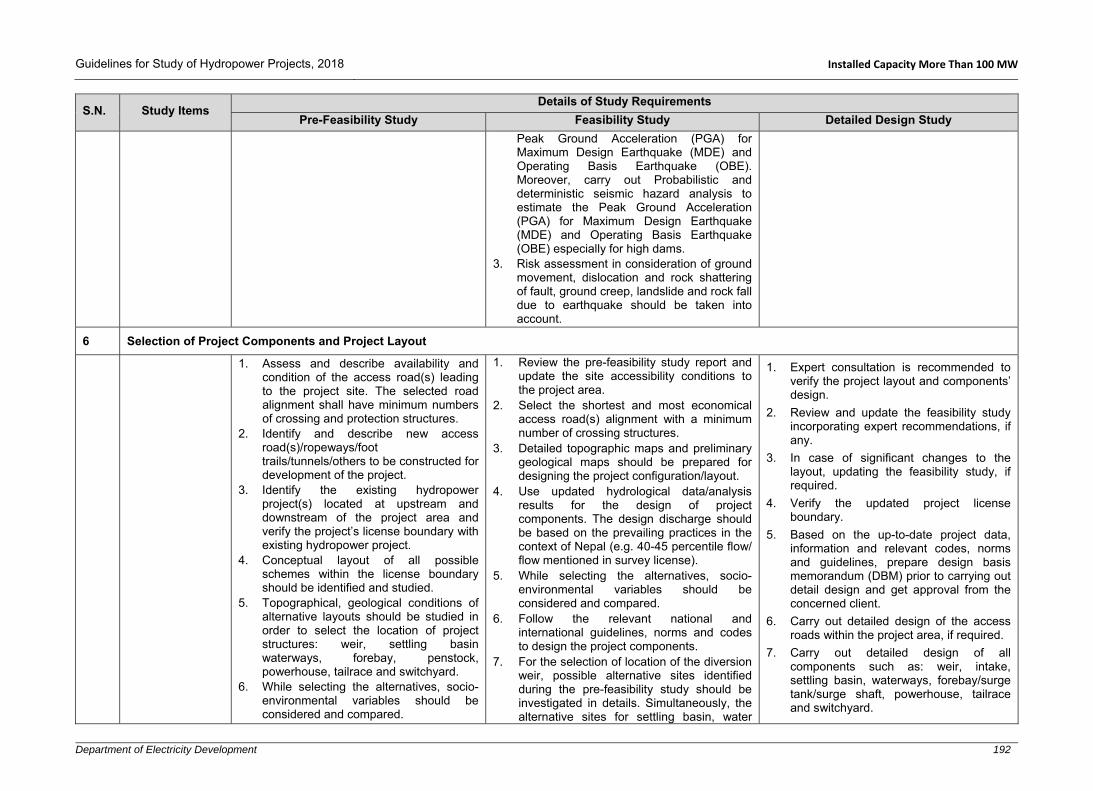
Guidelines for Study of Hydropower Projects, 2018 Installed Capacity More Than 100 MW
Department of Electricity Development 192
S.N. Study Items Details of Study Requirements
Pre-Feasibility Study Feasibility Study Detailed Design Study
Peak Ground Acceleration (PGA) for Maximum Design Earthquake (MDE) and Operating Basis Earthquake (OBE). Moreover, carry out Probabilistic and deterministic seismic hazard analysis to estimate the Peak Ground Acceleration (PGA) for Maximum Design Earthquake (MDE) and Operating Basis Earthquake (OBE) especially for high dams.
3. Risk assessment in consideration of ground movement, dislocation and rock shattering of fault, ground creep, landslide and rock fall due to earthquake should be taken into account.
6 Selection of Project Components and Project Layout
1. Assess and describe availability and condition of the access road(s) leading to the project site. The selected road alignment shall have minimum numbers of crossing and protection structures.
2. Identify and describe new access road(s)/ropeways/foot trails/tunnels/others to be constructed for development of the project.
3. Identify the existing hydropower project(s) located at upstream and downstream of the project area and verify the project’s license boundary with existing hydropower project.
4. Conceptual layout of all possible schemes within the license boundary should be identified and studied.
5. Topographical, geological conditions of alternative layouts should be studied in order to select the location of project structures: weir, settling basin waterways, forebay, penstock, powerhouse, tailrace and switchyard.
6. While selecting the alternatives, socio-environmental variables should be considered and compared.
1. Review the pre-feasibility study report and update the site accessibility conditions to the project area.
2. Select the shortest and most economical access road(s) alignment with a minimum number of crossing structures.
3. Detailed topographic maps and preliminary geological maps should be prepared for designing the project configuration/layout.
4. Use updated hydrological data/analysis results for the design of project components. The design discharge should be based on the prevailing practices in the context of Nepal (e.g. 40-45 percentile flow/ flow mentioned in survey license).
5. While selecting the alternatives, socio-environmental variables should be considered and compared.
6. Follow the relevant national and international guidelines, norms and codes to design the project components.
7. For the selection of location of the diversion weir, possible alternative sites identified during the pre-feasibility study should be investigated in details. Simultaneously, the alternative sites for settling basin, water
1. Expert consultation is recommended to verify the project layout and components’ design.
2. Review and update the feasibility study incorporating expert recommendations, if any.
3. In case of significant changes to the layout, updating the feasibility study, if required.
4. Verify the updated project license boundary.
5. Based on the up-to-date project data, information and relevant codes, norms and guidelines, prepare design basis memorandum (DBM) prior to carrying out detail design and get approval from the concerned client.
6. Carry out detailed design of the access roads within the project area, if required.
7. Carry out detailed design of all components such as: weir, intake, settling basin, waterways, forebay/surge tank/surge shaft, powerhouse, tailrace and switchyard.

Guidelines for Study of Hydropower Projects, 2018 Installed Capacity More Than 100 MW
Department of Electricity Development 193
S.N. Study Items Details of Study Requirements
Pre-Feasibility Study Feasibility Study Detailed Design Study
7. Assess the location and condition of immediate upstream and downstream projects, if any. List out issues related to the existing project(s) to be addressed while finalizing the project configuration.
8. The locations and types of the structures of each scheme should be verified at site in terms of accessibility, topography, geology, river morphology, construction ease and technical, economic and socio-environmental considerations.
9. Prepare conceptual layout (project configuration) of at least two of the most promising schemes with its major structures in appropriate scale using available maps and conduct a preliminary cost-benefit analysis.
10. Recommend area to be covered by topographical surveys for the feasibility study.
11. Prepare a preliminary hydraulic design and the drawings of alternative schemes.
12. Identify the shortest and most economical transmission route. Select the nearest substation for power evacuation.
13. Expert consultation and verification of project layout and project structures should be carried out based on topographical, hydrological, geological and maximum energy benefit at the minimum cost criteria.
conveyance, river crossings, forebay/surge tank/surge shaft, powerhouse, tailrace and switchyard should also be investigated in details.
8. Prepare preliminary design and drawings of all alternatives (at least two covering both the banks) and project structures in appropriate scale.
9. Conduct alternative study of transmission line routes (at least two) and identify the shortest and most economical route, sub-station and voltage level.
10. Based on the design and drawings, quantity and cost estimations should be carried out for each alternative.
11. Calculate revenue from the project using saleable energy and prevailing energy prices.
12. Select the best alternative scheme based on maximum benefit at minimum cost.
13. Prepare general layout drawings of the best alternative showing its components: headworks, waterways, forebay/surge tank/surge shaft, penstock, powerhouse, tailrace and switchyard using the detailed topographic map prepared during this stage of the study. Additionally, show transmission line route and access roads to all major project components.
14. Expert consultation and verification of project layout and project structures should be carried out based on the complexity of the project.
15. If the surface topographical conditions are not favourable, then underground option should also be studied.
7 Optimization Study
1. Installed capacity should be fixed tentatively considering preliminary technical, socio-environmental and economic assessment based on the
1. Objectives
Optimization of the following project components should be carried out:
1. Re-optimization should be carried out based on changes in project capacity and/or design discharge and/or changes in market price for materials and labour.

Guidelines for Study of Hydropower Projects, 2018 Installed Capacity More Than 100 MW
Department of Electricity Development 194
S.N. Study Items Details of Study Requirements
Pre-Feasibility Study Feasibility Study Detailed Design Study
findings of an up-to-date study and past practices.
2. The number of generating units should be determined considering the reliability of operation of the plant and maximum utilization of dry season river flow. Apart from that transportation aspects should also be considered.
The Full Supply Level of dam (FSL). The water conveyance system comprising
the low pressure headrace tunnel or the high pressure tunnel section and the tailrace tunnel/conduit.
Optimum installed capacity of the plant and the number of units.
Spillway arrangement for the dam. For PRoR, to determine the optimum
levels/effective volume of the poundage for generating the required peak power.
2. General Approach
The general optimization procedure should be as follows: An economic analysis should be carried
out for the optimization of headworks, water conveyance, the plant capacity and the spillway arrangement.
Conceptual layouts should be developed for each alternative from which the cost estimates are to be prepared.
A comparison between the cost and power benefits for each alternative should be done. On that basis the optimum size of the plant should be determined, which would maximize the benefits.
Project layout and design 3. Headworks
For the selected location of spillway, an optimization exercise should be carried out to find the most economic arrangement for the weir/dam/gated spillway.
For this purpose, number of spillway gates should be varied while maintaining the capacity to pass the design flood at FSL and finding the corresponding freeboard required between FSL and the top of core/ structure to pass the PMF.
Cost comparison between various options should be carried out.

Guidelines for Study of Hydropower Projects, 2018 Installed Capacity More Than 100 MW
Department of Electricity Development 195
S.N. Study Items Details of Study Requirements
Pre-Feasibility Study Feasibility Study Detailed Design Study
Economic sizing of settling basin should be studied based on mineral composition and concentration of sediments.
4. Water Conveyance/Canal/Pipe/Tunnel
The size/optimal diameter of various canal/pipe/tunnel sections comprising the power waterways should be determined for the range of flows corresponding to the installed capacities used in the capacity optimization.
Analysis of the following types of tunnels should be carried out: - Nominally unlined or shotcrete lined
tunnel or shotcrete and concrete lined. - Concrete lined tunnel. - Steel lined tunnel.
Optimize the size, location and type of surge shaft, surge tank and forebay.
The optimization should be based on the following economic and cost parameters: - Estimated value of energy - Discount rate - Capacity benefit - Unit cost of tunnel excavation - Unit cost of concrete lining - Unit cost of steel lining
5. Full Supply Level and Installed Capacity
General The optimization of the FSL (dam height) and installed capacity should be based on the following assumptions: Firm flows are defined as those with 90%
probability of exceedance on a monthly basis.
Secondary energy is defined as the difference between the monthly average energy and the monthly firm energy.
Dry, wet, peak/off-peak and spill energy (if any) should be defined and estimated as per the requirement of the off-taker.
100% of the firm power produced by the plant is utilized.

Guidelines for Study of Hydropower Projects, 2018 Installed Capacity More Than 100 MW
Department of Electricity Development 196
S.N. Study Items Details of Study Requirements
Pre-Feasibility Study Feasibility Study Detailed Design Study
Major overhaul period (years) of turbines, generator and other equipment should be based on manufacturers guidelines regarding their operating hours as well as best international practices.
The plant will be used to supply the domestic/international market only.
A compensation flow (10% of lowest monthly flow or amount of downstream release recommended by IEE/EIA study) should be released downstream, which should be deducted from the available dry season flows for the computation of the energy estimates.
6. Range of Options
The optimization of FSL and plant capacity should be carried out simultaneously.
A capacity range with equal intervals should be adopted for at least five options, generally in the range of 65% to 25% of flow exceedence and average monthly flows should be used. However, daily flows are preferable while calculating the energy benefits.
The Low Supply Level (LSL) in the reservoir should be fixed at a certain levels, so as to provide sufficient volume to trap sediments and maintain the live storage throughout the economic life of the power plant.
Following assumptions and calculations with regard to efficiencies and head loss in the power waterway should be made for derivation of flows from the installed capacities and heads:
Head loss estimations should be based on detailed hydraulic calculations. Turbine, generator and transformer efficiencies should be based on manufacturers’ datasheet and prevailing standard practices.

Guidelines for Study of Hydropower Projects, 2018 Installed Capacity More Than 100 MW
Department of Electricity Development 197
S.N. Study Items Details of Study Requirements
Pre-Feasibility Study Feasibility Study Detailed Design Study
7. Determination of Storage
The storage capacity of the daily poundage basin for each installed capacity should be determined.
The storage should be sufficient to produce the daily 6 hours peak energy for each case for PRoR. The peaking pond capacity should be decided considering the requirements of the off-taker.
8. Cost Estimates
A base case layout should be adopted with a storage volume close to the optimized storage found from the pre-feasibility study.
The layout should be adjusted for different dam heights to accommodate the diversion tunnel and spillway arrangement.
Quantities should be calculated for each capacity option in possible details.
The cost of electro-mechanical equipment should be derived from in house experience and/or the data from manufacturers.
For the power tunnel, rock mass classification method should be used to estimate rock support requirements.
Calculate quantities of excavation, shotcrete, rock bolts, concrete lining and steel ribs.
Cost of transmission line should be based on supply to domestic market only.
Environmental costs should be taken on a lump sum basis on the basis of general practice from past experience.
Appropriate contingencies should be applied for all alternative cases.
Summaries and detailed cost estimates should be provided.

Guidelines for Study of Hydropower Projects, 2018 Installed Capacity More Than 100 MW
Department of Electricity Development 198
S.N. Study Items Details of Study Requirements
Pre-Feasibility Study Feasibility Study Detailed Design Study
9. Estimate of Capacity and Energy Potential
The energy outputs should be calculated using relevant computer programs.
Monthly, average energy (wet, dry, peak/off-peak, firm etc.) for each capacity and reservoir option should be calculated as required/differentiated by the off-taker.
Mean operating level for the reservoir should be computed for each capacity option.
The energy output of the plants should be calculated assuming an annual outage rate of 5%.
100% of the power produced by the plant should be utilized. For this, an approximate simulation of reservoir operation assuming average in flows should be carried out.
Transmission loss of up to 4% should be considered.
10. Economic Parameters
Following economic parameters should be adopted for optimization: A discount rate of 10% (variable to actual
situations). Cost and benefits should be expressed at
current prices and discounted to first year of construction.
An economic project life of 50 years should be assumed for the evaluation of benefits.
Economic cost should not include duties and taxes.
Energy and capacity benefits should be evaluated using the prevailing energy prices from NEA/off-taker.
Capacity benefit could also be considered where the off-taker provides a premium for such installed capacity.

Guidelines for Study of Hydropower Projects, 2018 Installed Capacity More Than 100 MW
Department of Electricity Development 199
S.N. Study Items Details of Study Requirements
Pre-Feasibility Study Feasibility Study Detailed Design Study
11. Plant Maintenance
For the optimization purposes it may be assumed that for storage projects with reservoirs acting as a sediment trap, major maintenance will be required on the guide vanes and runners at some stage in the life of the plant. In absence of relevant data or information regarding plant outages, a conservatively high value in the range of 5- 8% may be adopted for optimization.
12. Benefit Cost Analysis Procedure
The net present value (NPV) method should be used to assess the economic viability of each of the capacity and FSL options.
Sensitivity analysis should be carried out in different scenarios of cost and energy variation, for e.g. from 5 to 20% either simultaneously or individually.
Compute the project IRR, RoE and B/C ratio.
Revenue should be calculated based on the saleable energy (wet, dry, peak/off-peak etc.) and prevailing energy prices.
13. Number of Units
The number of units should be chosen as minimum as possible.
The size of a unit should not exceed 10% of the total INPS at the time of commissioning.
Transportation and maintenance limitations should be considered for the project site.
A cost comparison between various numbers of units should also be carried out.
14. Power Evacuation Optimization
Economic voltage level shall be chosen depending on the line length and power to be evacuated.

Guidelines for Study of Hydropower Projects, 2018 Installed Capacity More Than 100 MW
Department of Electricity Development 200
S.N. Study Items Details of Study Requirements
Pre-Feasibility Study Feasibility Study Detailed Design Study
Power loss in the line should not exceed as fixed by NEA/off-taker.
A cost comparison between capital cost and loss shall be carried out to determine the optimum conductor and tower size.
The route shall be as short as possible considering the technical, social and environmental conditions.
8 Project Description and Design
8.1 General Layout and Design: Civil Structures
General Layout
1. The general layout plan, profile and sections of the selected scheme with optimum installed capacity should be described and present in appropriate scale.
River diversion during construction Headworks Headrace tunnel/canal alignment Surge tank/shaft or forebay Penstock alignment and Powerhouse –tailrace area.
FOR PRoR 1. For PRoR, daily poundage volume curve
should be prepared. 2. The volume of the regulating poundage
should be sufficient to ensure daily peak generation for 6 hours or as required by the off-taker.
3. The following main operating levels and corresponding storage volumes should be determined:
Full supply level Minimum operating level Live storage Dead storage
Civil Structures 1. Detail design of the project should
consider the operating criteria of projects located upstream and downstream.
Project Layout1. General layout of the selected alternative of
the project should be described. 2. Layout should be prepared using the survey
maps and geological and geotechnical information.
3. Detailed hydraulic design and sizing of the all civil structures including the following should be carried out:
Weir, intake and undersluice Upstream and downstream aprons Stilling basin Gravel trap Settling basin Headrace canal/pipe/tunnel Forebay/surge tank/surge shaft Penstock Powerhouse Tailrace
4. Design of temporary and permanent infrastructures such as camp facilities, construction power, access roads (ropeways, bridges, tunnel), drinking water supply, etc. should be carried out.
5. Design of switchyard and sub-station’s civil structures should be carried out.
6. Design and location of spoil tips should be carried out.
7. Necessary flood/debris/landslide protection works should be designed based on the river morphology, ground topography,
General:
1. The final project layout recommended in the feasibility study and the approved IEE/EIA report should be reviewed and verified by experts, if necessary.
2. Component-wise detailed design should be carried out for the final/updated project layout.
3. The findings and recommendations of numerical and physical hydraulic model studies should be incorporated in the final design. Furthermore, information gathered from test adit(s) should also be incorporated in the design, if any.
4. Prepare project definition report defining all project information, parameters and components.
5. Project parameters and design criteria should be included in a Design Basis Memorandum (DBM) referring to relevant national and international guidelines, norms and codes, and past experiences.
6. Detailed hydraulic design and dimensioning of all components/structures carried out during the feasibility study should be reviewed and updated/refined/revised where necessary.
Infrastructures 1. Geometric design and design of road
components side drains, cross drainage

Guidelines for Study of Hydropower Projects, 2018 Installed Capacity More Than 100 MW
Department of Electricity Development 201
S.N. Study Items Details of Study Requirements
Pre-Feasibility Study Feasibility Study Detailed Design Study
2. Design and description of the access road, construction road and alternative ropeway or mode of transportation.
3. Conduct the design and drawings of cross drainage structures along the access road alignment.
4. Conduct a preliminary design and layout of site facilities such as camp and site office facilities, water supply and sanitary and communication facilities.
5. Design and description of the following structures for the selected option of installed capacity should be provided:
Diversion structures (cofferdams, diversion channel/tunnel) should be designed for the 1:20 years return period of the dry season,
Weir/dam Emergency spillway Under sluice Stilling basin Type of intake Gravel trap Settling basin Headrace canal/pipe/tunnel Forebay or surge tank/shaft Penstock Powerhouse Tailrace and Switchyard (civil) Gates and stoplogs Trash racks Bulkhead and other necessary gates
and spillway along the waterway Anchor blocks and saddle supports for
penstock Suitable flood protection structures at
headworks and the powerhouse, mass retaining structures and check dams at
possible debris flow area and possibility of rock falls (rolling boulders) nearby powerhouse and switchyard area.
8. All project components should be described in details.
9. Drawings of all project components should be prepared in appropriate scale.
Diversion During Construction 1. A general plan to divert the river in dry
season in order to carry out the construction works at weir and intake sites should be prepared, which may require 2-4 dry seasons.
2. An upstream cofferdam should be designed in order to protect the working area at weir site. A cofferdam should also be provided to prevent river entering in working area from downstream.
3. Design and drawing of temporary river diversion during construction should be prepared. The diversion channel should be designed to pass 1:20 years return period dry season flood. If the headworks construction is to be continued during monsoon season, at least 1 in 10 years return period flood should be used.
Headworks All headworks components should be designed following “Design Guidelines for Headworks of Hydropower Projects” published by DoED, Nepal, 2006. 1. Weir/dam, intake, stilling basin, aprons and
floodwalls should be designed to pass safely the maximum flood of 1 in 200 years return period. Stability analysis should be done for 1 in 500 years return period flood.
2. Weir crest level or spillway crest level should be determined and fixed considering clearance required between undersluice invert level and intake bottom sill level, height of intake opening and submergence
structures, retaining walls such as gabion and stone masonry structures should be carried out.
2. Plans, profiles and cross sections of the access road including side drain, retaining structures, cross drainage structures should be prepared in appropriate scale.
3. Design of construction camps, temporary and permanent housings, water supply and sewerage system, bunker houses etc. should be done and presented in drawings.
4. Necessary drainage system for surface runoff management should be designed.
5. Necessary design for construction power arrangement should be carried out.
Temporary River Diversion
1. Detailed hydraulic design and drawings of upstream and downstream cofferdams, diversion channel and aprons should be carried out.
2. The diversion channel and cofferdams should be designed to pass 10 years return period flood.
3. In case of diversion tunnel, carry out detailed rock support design based on rock mass classification. Design the inlet and outlet portals.
Main component design
1. Detailed design of all surface and underground structures should be carried out.
2. The safety of components should be checked by conducting stability analysis and structural analysis.
Seismic Design Criteria
1. Pseudo-static analysis procedures (seismic coefficient method) can be used

Guidelines for Study of Hydropower Projects, 2018 Installed Capacity More Than 100 MW
Department of Electricity Development 202
S.N. Study Items Details of Study Requirements
Pre-Feasibility Study Feasibility Study Detailed Design Study
waterway and penstock alignment, other environment protection works etc.
6. Further geotechnical aspects should be studied in order to select the most appropriate location for settling basin, dam and powerhouse.
7. Stability and structural analysis of major hydraulic structures such as: dam, spillway, flood wall, settling basin, surge tank/forebay powerhouse etc. should be carried out.
requirement for intake opening in order to avoid/minimize entry of trash into the intake, intake capacity should be about 130% of the design discharge in case of conventional gravel trap and settling basin flushing systems while plant operates at full load during flushing.
3. For gated spillway/non overflow spillway, either radial or vertical sluice gates should be designed considering N-1 gates will be operated during floods.
4. Carry out preliminary seepage analysis under the weir/dam foundation and other water retaining structures.
5. Sufficient freeboards should be provided for design flood between the design flood level and the operating platforms and other necessary areas/structures.
6. Under sluice structure of headworks should be designed to pass safely bed-load and flush sediment deposited in front of intake and to pass a portion of flood discharge. Either vertical sluice gates or radial gates should be provided at under sluice with hydraulic or cable-drum type hoisting system.
7. Number of gates at undersluice should be made as per optimization and selected scope of alternative study.
8. A stilling basin should be designed for energy dissipation before releasing spillway flows back into the river. Basin cross section, basin length and depth, apron elevation, side wall, minimum free board, drainage etc. should be designed and described. Additional boulder riprap shall be provided in downstream of stilling basin, if required.
9. Clear spacing of the coarse trash rack in intake should be fixed considering the transport capacity of gravel flushing conduit.
in the seismic design and analysis of structures where appropriate.
2. The response of a structure to ground vibrations should be determined considering the soil type, seismic zone, response reduction factor, importance factor, fundamental period of vibration and damping factor (ξ). These values can be referred from norms and codes such as the NBC 105.
3. For structures with minor importance, the seismic coefficient can be reduced appropriately.
4. Both vertical and horizontal seismic components should be used in the design.
Foundation Design
1. The results from the geophysical and geotechnical investigation shall be used to design the foundations. In case of missing or unavailability of data, suitable values shall be assumed based on the local geology.
2. If the foundation has to be placed in an inferior soil type, a suitable foundation treatment method should be specified.
3. Carry out detailed seepage analysis under the weir/dam foundation and other water retaining structures. Uplift pressure and under piping mechanism for cutoff wall, apron and protection works should be analysed and proper measures should be taken to prevent damage related to foundation undermining.
4. The allowable bearing capacity of the foundation may be increased in extreme loading conditions as provisioned in the design codes. Similarly, the allowable bearing capacity may need to be reduced when fully water saturated condition occurs and placing foundation on steep slopes or adjacent to them.

Guidelines for Study of Hydropower Projects, 2018 Installed Capacity More Than 100 MW
Department of Electricity Development 203
S.N. Study Items Details of Study Requirements
Pre-Feasibility Study Feasibility Study Detailed Design Study
10. Gravel trap should be designed to trap greater than 2-5 mm particles and gravel flushing system should be designed to flush up to 200 mm particles.
11. Settling basin should be designed for continuous supply of required design flow plus flushing discharge. The trapping efficiency should be 90% or higher for particle size greater than 0.2 mm depending on available head and mineral composition of sediments. It is suggested to divide the settling basin into 2 or more chambers. For high head projects, the settling basin should be designed for greater than 0.15 mm particles with 90% trapping efficiency.
12. Sediment handling, controlling and flow regulation mechanism should be defined in the project description.
13. An automatic/ungated spillway should be provided downstream of the settling basin at conveyance tank wherever possible.
14. Sediment/gravel flushing outlets should be located at shooting flow areas of the stilling basin/river.
15. Design of fish ladder should be provided for the movement of the fish over the structures at the left or right abutment of the gated weir or dam.
16. Necessary flood protection, ground stabilization and bio-engineering works should be carried out, if required.
Water Conveyance All water conveyance systems should be designed following “Design Guidelines for Water Conveyance System of Hydropower Projects” published by DoED, Nepal, 2006; considering the project specific data and information. 1. The power canal /headrace pipe/tunnel
including all hydraulic and cross-drainage structures from intake to forebay/surge
Stability Analysis of Structures1. The following loadings should be
considered for stability analysis of project components.
Dead load Live loads Water pressure Weight of water Hydro-dynamic load Active earth pressure At rest pressure Passive earth pressure Earthquake load In-situ stresses Impact load Vibration load Thermal Uplift (buoyancy and seepage) Surcharge/overburden loads Water hammer Wind Snow Construction and moving surface loads Additional loads, if any
2. For the purpose of evaluating the stability and structural analysis, different load combinations may occur during different phases of the project implementation and operation should be considered. Individual components/elements must be designed for the most unfavourable load combination. In general, the following conditions should be considered:
Construction - Normal operation - Special/emergency/extreme cases
The safety factor depends upon the codes and loading combination used. In general, the following safety factors should be adopted:

Guidelines for Study of Hydropower Projects, 2018 Installed Capacity More Than 100 MW
Department of Electricity Development 204
S.N. Study Items Details of Study Requirements
Pre-Feasibility Study Feasibility Study Detailed Design Study
tank/surge shaft should be designed for 110% design discharge or higher.
2. Configuration of the power tunnel should be given, comprising headrace tunnel and pressure tunnel with lining types, finished diameter and length. Sufficient lateral cover and optimum overburden should be ensured. Tunnel support design should be carried out depending on rock quality.
3. A rock trap should be provided at the end of the headrace tunnel, upstream of the surge tank to trap loose rocks and displaced shotcrete. Suitable flushing system should be provisioned at rock trap.
4. A number of saddle supports and anchor blocks should be designed and described.
5. Conduct slope stability analysis in critical sections of waterways including forebay/surge tank/surge shaft.
6. Necessary drainage system for surface runoff management should be designed.
7. Type and size of headrace canal should be determined by considering the design discharge, silting/scouring velocity of applied concrete grade and topography.
8. Corrosion, scratching, pipe diameter and transportation limitations factors should be considered while fixing the headrace pipe thickness.
9. An emergency spillway at forebay should be provided. The forebay should have effective volume to supply design flow for at least 120 seconds.
10. The thickness of the steel pipe should be able to withstand any variable load conditions encountered during operation of the plant. While deriving the effective thickness of pipe, steel grade, corrosion factor, welding factor, etc. should be considered.
- Sliding- 1.2 for Normal case and 1.05 for extreme case
- Overturning: 1.5 for Normal case and 1.05 for extreme case
- Flotation: 1.2 for Normal case and 1.05 for extreme case
Detail Structural Analysis and Design 1. Appropriate codes (concrete, steel)
should be referred to for the detail design. All possible loading conditions should be considered.
2. The durability of the structure should be ensured in the design.
3. Material properties and the allowable stresses for concrete, structural steel, reinforcement, etc. should be specified.
4. The structure should be analysed using acceptable methods manually or by using software.
5. All structures should be safe against internal and external forces/stresses and all kind of climatic conditions.
6. Reinforcement calculation should be done considering the temperature and shrinkage effects.
7. Dynamic analysis should be carried out for the powerhouse and penstock and ensure that natural frequency does not create resonance phenomenon.
8. Ensure the settlement/deformation and deflection are within the permissible limits.
9. For underground structures, Section D. Additional requirements for hydropower projects with underground structures needs to be referred.
Water Tightness 1. Control of cracking in concrete should be
as per the requirement specified in IS 456:1978 and 2000 or BS 8007:1987 or BS 8110 Part II, BS 2007 or equivalent codes.

Guidelines for Study of Hydropower Projects, 2018 Installed Capacity More Than 100 MW
Department of Electricity Development 205
S.N. Study Items Details of Study Requirements
Pre-Feasibility Study Feasibility Study Detailed Design Study
11. Anchor blocks to hold the penstock pipe should be designed at bends and also intermediary in long straight stretches.
12. Head losses through tunnel/pipe system at the design discharge should be determined.
Forebay/Surge Tank/Surge Shaft: 1. Description of the forebay/surge tank/shaft
type with its dimensions should be provided. 2. For surge tank/surge shaft, various possible
scenarios of transient analysis should be carried out to determine upsurge and down surge level.
3. The invert level, upsurge and down surge levels of the forebay/surge tank/shaft should be shown in drawings.
Penstock alignment
1. Valley, landslide and rock falls area and gully crossing should be minimized, if cannot be avoided, during the alignment selection.
2. The effective thickness of the steel pipe should be adequate to withstand dynamic/water hammer/test pressure loading in addition to hydrostatic pressure.
3. Surface type or cut and cover type should be decided on the basis of the topographic and environmental considerations.
4. Necessary protection structures should be applied as per surface geology and topography.
Vertical Shaft/Inclined Shaft /Penstock Tunnel 1. If surface penstock is not feasible, either
vertical or inclined shaft should be designed. Dimensions of the shaft and type and thickness of the lining should be determined. In addition, appropriate temporary rock support during excavation should be designed.
2. The type and location of joints should be specified. Contraction/expansion joints should generally be located in 15 to 25 m spacing. Construction joints should be provided considering construction sequence.
3. Appropriate type of water stops should be provided at expansion/ contraction/construction joints.
Detailing and Drawings 1. The reinforcement should be detailed
considering ductility of the structure. 2. Reinforcement arrangement should be
shown in drawings in appropriate scale. Special attention should be given at joints.
3. Prepare construction drawings, reinforcement drawings and bar bending schedules.
Field Verification of Design/Layout 1. The general arrangement of all project
components should be verified at site by laying setting out points. Any changes occurred should be addressed in the design.
Report Preparation 1. After finalizing the design, a detailed
design report should be prepared showing all hydraulic, geotechnical, stability and structural analysis calculations. Based on the detail design report, a draft operation and maintenance manual should be prepared.

Guidelines for Study of Hydropower Projects, 2018 Installed Capacity More Than 100 MW
Department of Electricity Development 206
S.N. Study Items Details of Study Requirements
Pre-Feasibility Study Feasibility Study Detailed Design Study
Construction Adits1. Provision of construction adits should be
made at various locations of tunnel alignment in order to meet the construction schedule.
2. Tunnel portals should be located at exposed bed rock and stable ground topography and should be designed properly.
Powerhouse and Tailrace 1. A powerhouse should be dimensioned to
accommodate electro- mechanical equipment and its ancillaries.
2. Description of the powerhouse building should be provided giving details of equipment layout at generator floor level, turbine floor level, drainage floor level, and foundation level. Dimension of powerhouse should be determined by consulting with potential electro-mechanical equipment supplier.
3. Proper layout of the following equipment and structures inside the powerhouse should be made: turbines, generators, powerhouse crane unit, control panels and excitation system, control room, battery room, main inlet valve, provision for runner removal for maintenance, sump tank, cooling water tank, compressor room, service bay, water supply and sanitary system, station service transformer, etc.
4. Fire protection and a ventilation system should be designed and described in detail.
5. Emergency exits and safety plan should be described/provided as per national/international guidelines.
6. The tailrace conduit should be designed considering turbine type, minimum power discharge available, minimum water depth requirement and possible effect of river water level at the tailrace outlet.
7. Necessary flood/debris/landslide protection works should be carried out based on the

Guidelines for Study of Hydropower Projects, 2018 Installed Capacity More Than 100 MW
Department of Electricity Development 207
S.N. Study Items Details of Study Requirements
Pre-Feasibility Study Feasibility Study Detailed Design Study
river morphology, ground topography, possible debris flow area and possibility of rock falls (rolling boulders) near powerhouse and switchyard area.
8. Access tunnel should be provided for underground construction. Detail description of adit/access tunnel should be provided including size, type, support design and portal location.
Switchyard
1. The dimension of the switchyard should be determined by consulting with potential electro-mechanical equipment supplier.
2. The switchyard area should be arranged nearby the powerhouse and civil design of switchyard should be prepared.
For PRoR 1. Prepare daily poundage volume curve. 2. The volume required to maintain a minimum
of 4 to 6 hours (if terrain permits) of operation of the plant at full capacity during the peak load.
3. The Minimum Operating Level (MOL) should be fixed based on the flushing requirements of the settling structure which will set the minimum elevation of the intake from the river and further following levels and corresponding volume should be determined:
Full supply level Dead storage Live storage.
8.2 Hydro-Mechanical Components
1. Preliminary design/estimation of hydro mechanical components such as gates, stoplogs, trashracks and penstock should be done.
2. A brief description of hydro-mechanical components should be given.
Following Hydro-Mechanical components should be designed and described: 1. Gates, stop logs, embedded parts, valves,
trash racks, bell mouths, manholes, expansion joints, saddle/wear plates, sizing of headrace and penstock pipes, bends, reducers, branches, steel lining works, etc.
2. The hoisting system for gates and stop-logs.
General: 1. This design is generally carried out by
hydro-mechanical equipment manufactures/suppliers, thus only preliminary design for preparing Terms of Reference of tender/contract documents shall be carried out in consultation with potential manufacturers/suppliers.

Guidelines for Study of Hydropower Projects, 2018 Installed Capacity More Than 100 MW
Department of Electricity Development 208
S.N. Study Items Details of Study Requirements
Pre-Feasibility Study Feasibility Study Detailed Design Study
2. Design and dimensioning of all components/structures carried out during the feasibility study should be reviewed and updated/refined/revised where necessary and presented in the project definition report.
3. Component-wise design should be carried out for the updated project layout
4. Project parameters and design criteria should be included in a Design Basis Memorandum (DBM) referring to relevant national and international guidelines, norms and codes, and past experiences.
5. While designing the hydro-mechanical components, factors such as corrosion, welding defects, and plate inaccuracy/defects should be taken into account.
6. Individual components/elements must be designed for the most unfavourable load combination. In general, loading conditions which may occur during the following phases/cases should be considered:
Transportation Erection/construction Testing in factory and site Normal operation Special/emergency/extreme cases
Design of Gates and Stop-logs
1. The type of gate/stoplogs with embedded parts and its hoisting mechanism should be fixed.
2. The materials to be used for skin plates, stiffeners, girders, embedded parts and other components should be specified.
3. The gates/stoplogs with embedded parts shall be designed for the hydrostatic and hydrodynamic forces taking into consideration the forces arising from

Guidelines for Study of Hydropower Projects, 2018 Installed Capacity More Than 100 MW
Department of Electricity Development 209
S.N. Study Items Details of Study Requirements
Pre-Feasibility Study Feasibility Study Detailed Design Study
wave effects, water hammer, seismic loads, active soil load (sediment deposit), ice formation, friction, and thermal effect wherever applicable.
4. The internal stress should be ensured to be within the limits of allowable stress in normal and extreme operating conditions.
5. Sufficient corrosion allowance should be provided and corrosion prevention methods, if any, should be mentioned.
6. Type and material of seals should be mentioned.
7. Power-operated gates shall normally be capable of operation by alternate means in case of power supply failure.
8. If meant for regulation, it shall be capable of being held in partially open position without major damage to seal or deterioration due to cavitation and vibration.
9. Wherever necessary, model studies may be carried out for high head regulating gates.
10. The deflection of the gate under various loading conditions should be within permissible limit.
11. Dogging devices and lifting beams should be designed for operation of gates, stop logs etc.
12. Destructive and non-destructive testing procedure should be specified.
13. All the gates shall be checked for the aeration requirement at its immediate downstream.
Steel Pipes
1. The steel plate used for the pipes shall comply with national/international standards.

Guidelines for Study of Hydropower Projects, 2018 Installed Capacity More Than 100 MW
Department of Electricity Development 210
S.N. Study Items Details of Study Requirements
Pre-Feasibility Study Feasibility Study Detailed Design Study
2. The pipes should be designed considering the following loading conditions:
3. Normal condition includes the static head, surge and water hammer pressure.
4. Special conditions include those during filling and draining of penstocks and maximum surge in combination with pressure rise during emergency operations/events and test pressures.
5. Exceptional conditions include the transportation and erection stresses, pressure rise due to unforeseen operation of regulating equipment in the most adverse manner resulting in odd situation of extreme loading, stress developed due to resonance in penstock, seismic forces, etc.
6. Adequate safety factor should be provided for safety against hoop stress due to internal and external pressure, longitudinal stress, beam action, temperature variations.
7. Stress should be checked in bends, branches, transition and stiffeners
8. Expansion joints should be provided just below the anchor block whenever possible.
9. Special design provision shall be made to protect the penstock pipes/conduits against possible rupture due to denting/negative pressure.
Other Structures
1. Other HM components such as valves, trash racks, manholes, saddle plates, bulk head gate, bell mouth, steel lining etc. shall be designed to meet structural and hydraulic requirements.

Guidelines for Study of Hydropower Projects, 2018 Installed Capacity More Than 100 MW
Department of Electricity Development 211
S.N. Study Items Details of Study Requirements
Pre-Feasibility Study Feasibility Study Detailed Design Study
Report Preparation1. After finalizing the design, a report should
be prepared showing all hydraulic, and structural calculations mechanisms. Similarly, the operating conditions, hoisting mechanisms, opening sizes, design pressures, and dimension of all major components/elements should be mentioned. Based on the detail design report, a draft operation and maintenance manual should be prepared.
8.3 Electro-Mechanical Equipment
1. Preliminary design/selection of the electro-mechanical equipment should be carried out based on the design discharge and net head and number of units (based on hydrology and transportation).
Mechanical equipment: - Preliminary selection of type and
dimension of turbines should be carried out. A brief description of turbine auxiliaries should be provided.
Electrical equipment: - Parameters of the generators
should be determined. A brief description of the excitation and electrical auxiliaries should be provided.
Single line diagram: - An electrical single line diagram
showing the major electrical equipment of powerhouse should be prepared.
1. The type and number of generating equipment, and power evacuation facilities should be designed and described.
2. Description of the main mechanical equipment including the followings should be provided:
Design criteria Mode of operation Hydraulic turbine- type and number Turbine efficiency Rated speed Rated turbine output Inlet valve Spiral casing Nozzles Runner size Draft tube Governor Lubricating (hydraulic) system Pressure oil system Compressed air system Cooling system Control system Overhead crane Maintenance of turbine
3. Description of the main electrical equipment including the followings should be provided:
Generator- type, number Generator efficiency, rated output,
frequency, generated voltage level
General:1. This design is generally carried out by
electro-mechanical equipment manufactures/suppliers, thus only preliminary design for preparing Terms of Reference of tender/contract documents shall be carried out in consultation with the potential manufacturers/suppliers.
2. Detailed design and dimensioning of all components/structures carried out during the feasibility study should be reviewed and updated/refined/revised where necessary presented in the project definition report.
3. Project parameters and design criteria should be included in a Design Basis Memorandum (DBM) referring to the relevant national and international guidelines, norms and codes, and past experiences.
4. Individual components/elements must be designed for the most unfavourable load combination (mechanical and electrical). In general, loading conditions which may occur during the following phases/cases should be considered: Transportation Erection/construction Testing in factory and site Normal operation Special/emergency/extreme cases

Guidelines for Study of Hydropower Projects, 2018 Installed Capacity More Than 100 MW
Department of Electricity Development 212
S.N. Study Items Details of Study Requirements
Pre-Feasibility Study Feasibility Study Detailed Design Study
Excitation system Switchgears Control panel Switchyard Powerhouse earthling Emergency diesel generator Control and protection system Power transformer –type, numbers,
efficiency, frequency, rated output, etc. Auxiliary transformer CT/PT Hoisting mechanism/overhead crane
4. A single line electrical diagram depicting the interconnection of all electrical equipment should be prepared.
5. For the smooth operation of the power station, the following auxiliaries should be provided and described:
Grease lubricating system Fire fighting system Lighting arrangement Cooling system Oil filtering equipment DC power auxiliaries Distribution to outlaying works Distribution to housing complex Fire fighting system Station supply, etc.
Mechanical Equipment
1. Appropriate turbines and their components should be designed.
2. Suitable inlet valves shall be provided before each turbine.
3. Draft tubes, spiral casing, covers, seals should be designed appropriately.
4. Suitable governor system should be provided for flow control to the turbine.
5. Proper auxiliary systems such as heat exchanger system, lubrication system, pressure system, compressed air system, hydraulic system, cooling system, EOT crane, lighting system, fire extinguishing system, etc. shall be designed.
6. Control system with local unit and remote (to control room) controlling capability should be provided.
Electrical Equipment 1. Single line diagram and control diagram
for all the powerhouse equipment and interconnection points shall be prepared following the latest NEA Grid Code and other relevant standards.
2. Generators shall be provided with all of their accessories including the cooling and fire protection system, hydraulic system including generator braking and heat exchanger system.
3. Excitation system shall be provided with automatic voltage regulator, excitation transformer and bridge rectifier.
4. Switching equipment with bus bars, circuit breakers, disconnecting switches, instrument transformers, etc. shall be provided.
5. Power transformers to step up transmission voltage shall be provided with type of cooling, indoor/outdoor

Guidelines for Study of Hydropower Projects, 2018 Installed Capacity More Than 100 MW
Department of Electricity Development 213
S.N. Study Items Details of Study Requirements
Pre-Feasibility Study Feasibility Study Detailed Design Study
arrangement and other required accessories.
6. LV/MV/HV switching equipment with bus bars, circuit breakers, disconnecting switches, instrument transformers, etc. shall be provided.
7. Control equipment shall be provided consisting of governor monitoring, excitation monitoring, emergency shutting down, valve protection and other protection, etc.
8. Station service transformer for redundant power supply to the plant shall be provided.
9. Grounding including lightning protection shall be provided.
10. Fire protection and ventilation system should be designed and described in detail.
11. Emergency exits and safety plan should be described/provided as per the available national/international guidelines.
12. Diesel generators shall be provided for backup power and black start/isolation mode.
8.4 Transmission
Line
1. Assess the possibility of power evacuation through national grid/ Integrated Nepal Power System (INPS).
2. Carry out preliminary design to select voltage level, conductor type and number of towers.
3. A single line electric diagram should be prepared representing the major electrical equipment of the powerhouse.
4. A brief description of selected power evacuation system should be presented.
1. Prepare updated single line diagram representing the major electrical equipment of the powerhouse, switchyard, and substation.
2. Finalize the most appropriate transmission line route, voltage level and length.
3. Describe the detail of interconnection equipment.
4. Describe and design the total number of towers, tower’s foundation and support structures, circuit type, type of conductor used and other safety measures.
1. The transmission line should be designed following the latest off-taker/NEA grid code.
2. The route shall be finalized and described.
3. Voltage level, number of circuits and length shall be confirmed.
4. Number and type of towers required shall be determined with location (co-ordinates) and their structure shall be designed. While designing foundation of transmission tower, geology and geotechnical conditions with socio-environmental assessment should be

Guidelines for Study of Hydropower Projects, 2018 Installed Capacity More Than 100 MW
Department of Electricity Development 214
S.N. Study Items Details of Study Requirements
Pre-Feasibility Study Feasibility Study Detailed Design Study
verified and additional investigation should be done, if required.
5. Conductors’ size to be used shall be determined. The size of conductors must be selected so that the power loss doesn’t exceed the permissible limits as per the latest off-taker/NEA Grid Code.
6. Sag, tension and loading in conductor shall be determined.
7. Auxiliary equipment in the transmission line such as insulators, clamps, guards, etc. shall be provided.
8. Equipment to be installed in interconnection/substation should be designed.
9. Power transformers shall be required, if the voltage level of transmission line does not match with the voltage level of interconnecting substation including HV switchgear (circuit breaker, disconnecting switch, etc.), instrument transformers and control and protection equipment.
9 Energy Computation and Benefit Assessment
9.1 Energy Computation
1. Energy computation should be carried out considering the average monthly flow (daily flow if available), net head, design discharge and turbine, generator and transformer efficiency. Furthermore, normal and forced outages should be considered referring to off-taker/NEA Grid Code and/or norms and practices. If power output cannot be ascertained at this stage, then the range of annual energy generation should be provided
2. During energy estimation, environmental and other necessary releases as recommended in EIA/IEE guidelines.
3. Average monthly energy and annual energy should be determined in Nepalese and Gregorian calendar months.
1. Energy computation should be carried out considering the daily flow, net head, design discharge and turbine, generator and transformer efficiency. Furthermore, normal and forced outages should be considered referring to NEA Grid Code and/or norms and practices.
2. Energy estimated during the pre-feasibility study needs to be reviewed and updated based on the findings of the feasibility study.
3. Average daily, monthly and annual energy should be determined in Nepali and Gregorian calendar months.
4. Estimated internal energy consumption within the power plant should be deducted from the total/monthly energy to derive the net saleable energy.
1. Energy estimated in the feasibility study should be updated/refined, if there are significant changes.

Guidelines for Study of Hydropower Projects, 2018 Installed Capacity More Than 100 MW
Department of Electricity Development 215
S.N. Study Items Details of Study Requirements
Pre-Feasibility Study Feasibility Study Detailed Design Study
4. Estimated internal energy consumption within the power plant should be deducted from the total/monthly energy to derive the net saleable energy.
5. Annual estimated average dry and wet energy should be determined considering the dry/wet periods defined by NEA. Furthermore, dry energy should be divided into peak/off-peak energy in case of PRoR and reservoir type projects.
5. Annual estimated average dry and wet energy should be determined considering the dry/wet months defined by NEA/off-taker. Furthermore, dry energy should be divided into peak/off-peak energy in case of PRoR and reservoir type projects.
9.2 Benefit Assessment
1. Estimated average monthly/annual revenue throughout the license period should be calculated considering unit energy prices fixed by the NEA/off-taking company/GoN for similar sized projects.
2. While calculating the annual revenue, base rates for dry, wet, peak, off-peak energy prices together with annual price escalation should be considered.
1. Revenue estimated in the pre-feasibility study should be updated based on the updated energy calculation/update during the feasibility study.
1. Revenue estimated in the feasibility study should be updated, if required.
2. If PPA has been concluded, the revenue estimate should be verified against the PPA.
10 Cost Estimation
10.1 Criteria and Assumptions
All the criteria and assumptions adopted for cost estimation should be mentioned including the following: 1. Consideration of the natural conditions
prevailing at the site, construction scale, and levels of construction technology available in Nepal.
2. To the maximum extent possible, construction equipment available in Nepal should be used.
3. A brief description of the project with location should be mentioned.
4. Year and month of the cost estimate should be mentioned.
5. The exchange rate applied to the calculation of NPR and USD adopted at the time of cost estimation should be mentioned.
1. The criteria and assumptions for the pre-feasibility level study should be applied but should be based on the feasibility level design with inclusion of items not included in the pre-feasibility level study.
1. The criteria and assumptions for the feasibility level study should be applied but should be based on detail design level with inclusion of items not included in the feasibility level study.

Guidelines for Study of Hydropower Projects, 2018 Installed Capacity More Than 100 MW
Department of Electricity Development 216
S.N. Study Items Details of Study Requirements
Pre-Feasibility Study Feasibility Study Detailed Design Study
6. Identifiable Nepalese taxes, customs duties, royalties, etc. for the goods, materials and services, interest during construction etc. whether included in cost estimation or not should be mentioned.
7. Any source of references to rates or estimation should be mentioned with used escalation factors, if any.
10.2 Estimation Methodology
The following methodology should be applied for estimation of the cost of each component of the project. 1. For Civil Works:
The cost estimates should be based on unit rates developed from prevailing labour rates, construction equipment rates and materials considering the local situation and unit rates for projects of similar nature. 2. For Electro-Mechanical Equipment
The cost estimate for generating equipment, transformer and switchyard equipment should either be based on budgetary quotations obtained from supplier(s) or using established current international prices/ relationships or price database from similar type and size projects. The cost should include cost of control devices/system, auxiliary etc. transportation and erection. 3. Hydraulic Steel Works:
The cost of hydraulic steel works should be based on budgetary quotation of supplier(s) or on market price, if they are locally available. Transportation and installation cost should also be added. 4. Transmission Line:
The cost of transmission line can be calculated from per km rates of the transmission line. References of cost can be taken from current rates used by the Nepal
The following methodology should be applied for estimation of the cost of each component of the project.
For Civil Works:
1. The cost estimates should be based on unit rates developed from prevailing labour rate, construction equipment rate and materials taking also into account the local situation and bill of quantities derived from design drawings.
2. The cost estimate should be done by breaking down the major structures into a number of distinct construction activities or measurable pay items.
3. Due consideration should be given to local labour. The rates for locally available labour can be obtained either from district rates of concerned districts or prevailing market rates of the project area and can be used after appropriate adjustments.
4. The rates of skilled labour available around project area or within Nepal can be obtained from general inquiries and references of other projects.
5. The rates for skilled expatriates can be obtained from the reference to other projects or from a publication such as ‘International Construction Contractors’.
6. The rates of construction equipment can be taken from regularly updated cost data, a quotation from the suppliers/manufacturers.
1. The methodology for the feasibility level study should be applied but should be based on the feasibility level design with inclusion of items not included in the pre-feasibility level study.
2. Carry out necessary updates such as revision of the rate analysis.

Guidelines for Study of Hydropower Projects, 2018 Installed Capacity More Than 100 MW
Department of Electricity Development 217
S.N. Study Items Details of Study Requirements
Pre-Feasibility Study Feasibility Study Detailed Design Study
Electricity Authority or constructed project of IPPs for same type/voltage of transmission lines taking into account different types of towers required, the conductors and types of terrains being crossed. 5. Others
Other costs expected (e.g., social and environmental costs, resettlement costs etc.) should be estimated based on prevailing market rates and the government policies. Benchmark prices from similar nature projects can be adopted to estimate such costs.
7. The construction materials to be used for construction work should be divided into:
Materials locally available nearby project area.
Materials available in local market. Materials to be imported from neighbouring
countries. Materials to be imported from overseas.
8. The rates of construction materials should be derived as per their source of supply. While calculating the construction materials’ rate, sufficient attention should also be given to the mode of transportation and their corresponding costs. When the access roads for the project are not built (generally for small hydropower projects) the cost of air transportation for transporting heavy equipment from the nearest town to the project area should also be included.
9. From labour cost, material cost and equipment cost, the direct cost per unit of construction activity can be calculated.
10. The estimate should be of contractor's type and, therefore, should also include all other indirect costs such as office overheads, contractor's financing cost, insurance bonds, and profit and risk margin.
11. A suitable percentage for contractor's expenses should be allocated. The total percentage should be used as a bid factor on direct cost. Thus, the calculated direct cost can be used to derive unit bid cost which in turn, should be used to determine the total civil works cost.
For Electro-Mechanical Equipment
1. The cost estimate for generating equipment, transformer and switchyard equipment should either be based on budgetary quotations obtained from supplier(s) or using established current international

Guidelines for Study of Hydropower Projects, 2018 Installed Capacity More Than 100 MW
Department of Electricity Development 218
S.N. Study Items Details of Study Requirements
Pre-Feasibility Study Feasibility Study Detailed Design Study
prices/relationships or price database from similar type and size projects. The cost should include cost of control devices/system, auxiliary etc. transportation and erection.
Hydraulic Steel Works:
1. The cost of hydraulic steel works should be based on a quotation of supplier(s) or on market price, if they are locally available. Transportation and installation cost should also be added.
Transmission Line:
1. The cost of transmission line can be calculated from per km rates of the transmission line. References of cost can be taken from current rates used by the Nepal Electricity Authority or constructed project of IPPs for same type/voltage of transmission lines taking into account different types of towers required, the conductors and types of terrain being crossed.
Land Acquisition and Access Road:
1. Due attention should be given to the cost of land acquisition and construction of access roads.
2. Cost of land acquisition should be determined considering detail risk assessment, future development of project area, accessibility and public demand.
3. The length and type of access roads to be constructed or to be improved can be determined from preliminary design. Cost per km of different types of roads can be used to determine the cost of the access road.
Camp and Other Facilities:
1. The costs of construction camps and permanent buildings required for operation and also for construction power facilities required should be included in the cost

Guidelines for Study of Hydropower Projects, 2018 Installed Capacity More Than 100 MW
Department of Electricity Development 219
S.N. Study Items Details of Study Requirements
Pre-Feasibility Study Feasibility Study Detailed Design Study
estimation. A lump sum amount for this can be allocated depending upon the size of the project.
Social Development:
1. The cost of social development should be determined from reconnaissance field visits. Following factors should be considered to determine the social development cost such as population density, available local resources and existing physical infrastructure in the project area. This cost can be derived as a lump sum taking a reasonable percentage of the project base cost.
Resettlement/Rehabilitation
1. Relocation and environmental impact mitigation costs shall be as per the existing Environmental Protection Act and Rules. This cost can be derived as a lump sum taking a reasonable percentage of the project base cost.
Community Support Program
1. Include CSP cost equivalent to 0.5% of total project cost. This needs to be updated as per the latest government policies.
10.3 Base Cost and Total Project Cost
1. The total of all costs indicated above will constitute the base cost of the project. To that the following costs are to be added as a certain percentage of the project cost for obtaining the total capital cost:
Engineering and management Owner's cost Insurance cost
2. Contingencies for civil works, hydro-mechanical, electromechanical, transmission line, price and physical contingencies, etc. are to be added to account for unforeseen cost increase
1. At feasibility level, due to use of more detailed information collected and minor items included and designs concretized, level of uncertainties will decrease particularly in civil works/HM works/EM equipment and TL works component.
1. At detail design level, due to use of more detailed information collected and minor items included and designs concretized, level of uncertainties will decrease particularly in civil works/HM works/EM equipment and TL works component.

Guidelines for Study of Hydropower Projects, 2018 Installed Capacity More Than 100 MW
Department of Electricity Development 220
S.N. Study Items Details of Study Requirements
Pre-Feasibility Study Feasibility Study Detailed Design Study
due to various uncertainties during project construction.
3. Interest during construction should be calculated based on the prevailing interest rates and other parameters required for the calculation.
10.4 Local and Foreign Currency Breakdown
1. Local currency will be required for local labour, local materials, government cost tax, VAT, royalties and customs duties including land acquisition, resettlement, mitigation and management programs related to adverse socioeconomic environment impacts and bank interest.
2. Foreign currency will be required for imported materials and equipment and foreign experts.
3. The cost estimation should include a breakdown of local and foreign currency components.
1. The breakdown needs to be updated based on the updates during the feasibility study, if any.
1. The breakdown needs to be updated based on the updates during the detailed design, if any.
10.5 Presentation of Cost Estimate Data
1. In the main volume of the report summary cost estimate data broken down into above mentioned major sub-headings and into foreign and local currency should be presented, while the details of cost estimates including rate analysis and the unit rate could be presented in the Annex volume.
1. The presentation should be done as in the pre-feasibility level, but with the inclusion of more detailed items based on more detailed design and other updated information.
1. The presentation should be done as in the feasibility level, but with the inclusion of more detailed items based on more detailed design and other updated information.
10.6 Cash Disbursement Schedule
1. The costs will incur not at once but will spread over the whole construction period. Interest during the construction will depend on how cash will be disbursed during the construction period. Hence cash disbursement schedule in accordance with the schedule of construction activities needs to be prepared spreading over the project implementation period.
2. Year-wise disbursement is to be prepared and presented in the report.
1. Cash disbursement schedule should be based on updated and realistic project implementation schedule.
2. Year-wise cash disbursement against each of the major activities is to be prepared and presented in the report. For example, cash disbursement schedule for small size project could be assumed approximately 40% in 1st year and 60% in 2nd year for a two years construction period.
1. Disbursement schedule needs to be updated based on the revision of adopted parameters and criteria, if any.

Guidelines for Study of Hydropower Projects, 2018 Installed Capacity More Than 100 MW
Department of Electricity Development 221
S.N. Study Items Details of Study Requirements
Pre-Feasibility Study Feasibility Study Detailed Design Study
11 Construction Planning and Schedule
1. Access, availability of construction
materials, waste disposal and construction of camps at site should be described.
2. River diversion sequences during construction should be analysed. Taking into account the river flows and specifically low flows
3. A preliminary construction schedule should be prepared for the project, showing the major construction activities. The total construction period should be determined.
1. Review the construction schedule prepared during the pre-feasibility study’s findings and update as per the feasibility study’s findings and other prevailing conditions such as market conditions and available technology.
2. Plan contract/procurement/construction modality in coordination with client for pre-construction works, main civil works, hydro-mechanical, electro-mechanical and transmission line works.
3. Prepare a plan for pre-construction activities such as construction of camps, establishment of telecommunication facilities, construction/upgrading of access road(s), arrangement of construction power, etc.
4. Prepare a plan for establishing necessary forest clearance, crusher plants, workshops, fuel depots, permanent camps for operators’ and site office(s). The plan should also take into account time for necessary government approvals.
5. Land acquisition and environmental mitigation plan should be incorporated.
6. Prepare a plan for temporary diversion of the river during construction. This may consist of construction of cofferdam(s) and diversion channel at headworks and powerhouse/tailrace outlet sites.
7. Prepare a plan for construction of headworks, waterways, forebay/surge-tank/surge-shaft, powerhouse, tailrace, switchyard and transmission line including all civil, hydro-mechanical and electro-mechanical works in consultation with potential contractor/suppliers and based on past experience of constructing similar project(s).
1. Review the construction planning and schedule prepared during the feasibility study and update as necessary considering anticipated/planned Required Commercial Operation Date (RCOD).
2. Plan and confirm the availability, quality and quantity of all construction materials. Special consideration should be given to the materials required for high grade concrete, high grade steel etc.

Guidelines for Study of Hydropower Projects, 2018 Installed Capacity More Than 100 MW
Department of Electricity Development 222
S.N. Study Items Details of Study Requirements
Pre-Feasibility Study Feasibility Study Detailed Design Study
8. Describe anticipated construction methodology for all major structures.
9. Update/prepare construction schedule considering above mentioned plans/factors and the following aspects:
Seasonal constraints for temporary river diversion
Local culture and national holidays Climatic conditions
12 Environmental Study
12.1 Reference for Environmental Study
1. Guidelines, Acts, Regulations and Manuals to be followed during the environmental study are as follows:
National EIA Guidelines, 1993 Environment Protection Act, 1997 Environment Protection Regulations, 1997 DoED Manuals related to Environmental
Study Working Procedure for Initial Environment
Examination (IEE) and Environment Impact Assessment (EIA) of Hydropower and Transmission Line Projects, 2073
Hydropower Environmental Impact Assessment Manual, July 2018
1. Guidelines, Acts, Regulations and Manuals to be followed during the updating and supplementary environmental study are as follows:
National EIA Guidelines, 1993 Environment Protection Act, 1997 Environment Protection Regulations,
1997 DoED Manuals related to Environmental
Study Working Procedure for Initial
Environment Examination (IEE) and Environment Impact Assessment (EIA) of Hydropower and Transmission Line Projects, 2073
Hydropower Environmental Impact Assessment Manual, July 2018
12.2 Environment Impact Assessment (EIA)
1. Collect baseline data of physical, biological and socio-cultural environment of project affected area to understand the socio-environmental situation.
2. Identify the major environmental issues in physical, biological, socio-economic and cultural environment.
3. Make environmental assessment by simple checklist.
4. Assess impacts of major significance.
1. Permission for conducting EIA from concerned ministry should be obtained, if the project lies within protected area (conservation area/national park/wildlife reserves).
2. Scoping document and Terms of Reference (ToR) for EIA should be prepared which should include the following:
Publication of 15 days’ public notice in a national daily newspaper for the scoping of the EIA study.
1. Carryout EMP update in EIA, if there are minor changes in project design and get it approved from Ministry of Forests and Environment.
2. Carryout supplementary EIA, if there are major changes in project design and get it approved from Ministry of Forests and Environment such as (i) If there is change in the project area (ii) If the required forest area is increased
by 10 %

Guidelines for Study of Hydropower Projects, 2018 Installed Capacity More Than 100 MW
Department of Electricity Development 223
S.N. Study Items Details of Study Requirements
Pre-Feasibility Study Feasibility Study Detailed Design Study
5. Assess the level of environmental assessment EIA as per the threshold of schedule 2 of EPR and its amendments.
Collection of suggestion from the affected local government and other stake holders of the project area.
Record of environmental issues raised by stakeholders, concerned bodies, Government Authorities, local clubs and subject experts.
Prioritized environmental issues. Baseline environmental data that supports
the relevancy of identified environmental issues.
Review of relevant national and International legislations.
Describe basic procedures to conduct EIA Approval of Scoping Report and TOR
3. Continue the EIA study based on approved ToR.
4. Prepare Environment Impact Assessment (EIA) which includes:
Environmental impacts of the Environmental Issues prioritized in ToR plus additional environmental impacts identified during EIA.
Mitigation and Enhancement Measures for the environmental impacts and Environment Management Plan (including Monitoring and Auditing Plan).
Baseline on Physical, Biological and Socio-economic and cultural environment domain.
Review of relevant national and International legislations.
5. Prepare draft EIA Report 6. Conduct public hearing in the project area. Publication of the notice for the public
hearing Muchulka of the public hearing in the
project affected areas. Collection of the recommendation letter
from the affected local governments. 7. Finalize EIA report including the
recommendations of concerned rural
(iii) If the resettlement population is more than 100 people
(iv) If there is significant impact in environmental and biological biodiversity.

Guidelines for Study of Hydropower Projects, 2018 Installed Capacity More Than 100 MW
Department of Electricity Development 224
S.N. Study Items Details of Study Requirements
Pre-Feasibility Study Feasibility Study Detailed Design Study
municipality and concerns of stakeholders raised during the public hearing.
8. The final EIA (after incorporating the issues raised in public hearing) has to be forwarded for approval to concerned ministry through Department of Electricity Development (DoED).
9. A Review Committee meeting will be held at DoED comprising related government agencies and independent environment experts.
10. Based on the recommendation of review committee, concerned ministry forwards the EIA for approval.
11. A review committee meeting is organized to seek comments/suggestion on the final EIA report.
12. Further 30 days’ public notice is published in national daily newspaper to seek additional comments and suggestions on the EIA. The draft EIA report along with the public notice has to be placed in public places/office such as TU library, district level office, affected local bodies and concerned government offices.
13. Ministry of Forests and Environment approves the EIA based on the recommendations of review committee meeting and response to 30 days’ public notice.
12.3 Resettlement Study
1. Conduct a field survey for gathering the data/information on the population, household lying in the project area and their socio-economic status. Collect information about the number of cattle lying in the project affected areas.
2. Identify the potential land area for resettlement of the displaced people from the project area through map study.
1. Conduct sampling survey over the project area for verifying the data/information collected during the pre-feasibility study and collect additional data/information on population, household and their socio-economic status and number of cattle, lying in the project area.
2. Verify through a site visit the potential land area for resettlement identified during the pre-feasibility study and identify the new sites, if any.
1. Review and update the data/information taken in the previous studies.
2. Estimate the total resettlement cost including all requirements such as opportunity loss, educational and environmental effects, physiological, mental and physical health effect, security, social and economic impacts etc.
3. Update and finalize resettlement schedule and settlement area.

Guidelines for Study of Hydropower Projects, 2018 Installed Capacity More Than 100 MW
Department of Electricity Development 225
S.N. Study Items Details of Study Requirements
Pre-Feasibility Study Feasibility Study Detailed Design Study
3. Collect the cost of lands proposed for resettlement.
4. Prepare the resettlement schedule and settlement area. Resettlement area shall facilitate all human requirements such as security, health and education facilities, economic resources availability, social and cultural viability etc.
13 Project Evaluation
13.1 Economic Analysis
1. The economic analysis should take into account the cost and benefits to the region (or entire nation) and not just to the project developer.
2. All significant intangible benefits should be identified and quantified in terms of monetary value to the maximum extent possible. For example, better access roads and bridges, communication facilities and schools could be established around the project area. The regional/national benefits due to these improved infrastructure should be quantified.
3. Significant forward linkages in the economy due to the project should be quantified. For example, various electricity consuming industries could be established once the project is built. The economic benefits due to establishment of such industries should be quantified.
4. Similarly, significant backward linkages in the economy due to the project should be quantified. Cement, aggregates and reinforcement/steel industries are some examples of backward linkages.
5. Employment benefits during construction phase of the project should be quantified. Economic benefits due to increase in both regular and seasonal employment should be quantified.
1. Update the economic analysis based on additional information and data available at this stage.

Guidelines for Study of Hydropower Projects, 2018 Installed Capacity More Than 100 MW
Department of Electricity Development 226
S.N. Study Items Details of Study Requirements
Pre-Feasibility Study Feasibility Study Detailed Design Study
6. Economic cost of the project should also take into account the opportunity cost.
7. Economic value of project should be calculated in terms of NPV, EIRR and B/C.
6. Economic cost of the project should also take into account the opportunity cost (together with construction costs).
7. Economic cost should not include the taxes, duties and royalties. Similarly, it should not include price contingency and interest during construction.
8. Economic value of project should be calculated in terms of NPV, EIRR and B/C.
13.2 Financial Analysis
1. Financial cost should include construction costs, periodic replacement cost, royalties, duties, taxes, VAT, price escalation, insurance cost and interest during construction.
2. All government’s policies, rules and regulations should be reviewed.
3. The benefits will comprise the revenue generation from the sale of electrical energy. As a result of the financial analysis, the financial cash flow showing operating expenses, debt service (loan repayment), royalty and tax payments should be presented.
4. For reservoir or multipurpose project, additional benefits should be derived from:
Flood control benefit Irrigation benefit Water supply and sanitation benefits Local transportation and navigation
benefits and Other tourism related benefits, etc.
5. The analysis should include inflation, variation due to foreign currency and revenue generation, if the PPA has been carried out in local and/or foreign currency.
6. NPV and FIRR could be adopted as financial indicators.
7. All required assumptions for financial analysis should be mentioned and analysed.
1. In performing financial analysis, the Financial Internal Rate of Return (FIRR) and the loan repay capacity should be examined based on the financing conditions.
2. The financial cost should include investment cost/base cost (study, preconstruction, civil, HM, EM, TL), O & M cost, duties, taxes, price escalation, periodic replacement cost, project environment and management cost, insurance and interest during construction.
3. To determine the project life, generation license period or PPA duration can be considered.
4. The benefits will comprise the revenue generation from the sales of energy.
5. As a result of the financial analysis, the financial cash flow showing operating expenses, debt service (loan repayment), royalty and tax payments are required to be presented.
6. The NPV and Financial Internal Rate of Return (FIRR) method should be adopted.
7. Generally expected financial parameters are as follows:
Internal Rate of Return on the project (IRR) - higher than prevailing interest rate (for example, of a commercial bank lending rate to a project of comparable size).
Net Present Value on the project (NPV) - positive.
Debt Service Cover Ratio (DSCR)—higher than 1
Benefit Cost Ratio – higher than 1.
1. Update the financial analysis, if there are major updates in input parameters as outcome of the feasibility study and detailed design.

Guidelines for Study of Hydropower Projects, 2018 Installed Capacity More Than 100 MW
Department of Electricity Development 227
S.N. Study Items Details of Study Requirements
Pre-Feasibility Study Feasibility Study Detailed Design Study
8. Financial parameters, Net present value (NPV), Benefit-Cost Ratio (B/C), Project IRR, Return on Equity (RoE), NPV, annual debt service coverage ratio, discounted payback period and Levelized Cost of Energy (LCOE) etc. should be determined.
13.3 Sensitivity Analysis
1. The sensitivity analysis should cover possible cases such as increase in project cost, decrease in revenue and exchange risk with foreign currency.
Sensitivity analysis is required to be performed in general, for the following cases: 1. Variance in interest rates based on market
conditions. 2. Increase in capital cost. 3. Decrease in revenue generation due to
change in hydrology and on the basis of further risk analysis.
4. Delay in commissioning of the project. 5. Commutative effect of cost and time
overruns. 6. Effect of inflation, foreign currency
exchange fluctuation.
1. Update the analysis based on the updates in base case analysis.
14. Presentation Drawings, Maps, Charts and Tables
14.1 General
1. Prepare location map in appropriate scale.
2. Prepare maps showing physiographic regions and geographical regions.
1. Prepare location map in appropriate scale. 2. Map showing physiographic regions and
geographical regions should be prepared. 3. Project’s general layout should be prepared
with license boundary in topo map in scale 1:25,000 or 1:50,000 as available.
1. Prepare location map in appropriate scale.
2. Map showing physiographic regions and geographical regions should be updated.
3. Project’s general layout should be updated in appropriate scale.
14.2 Topography/ Topographical Survey
1. Generally, this level of study is considered to be carried out based on available maps. Survey works, if carried out during this study including verification of head, license boundaries etc. should be documented in appropriate scale.
1. Control survey map showing benchmarks or traverse stations and detailed features of the project area in appropriate scale should be presented.
2. Survey data and d-cards (with photographs) should be included in the appendix.
1. Control survey benchmarks or traverse stations with their x, y, z coordinates (in a separate table) should be given in general arrangement drawings (with contours) for all components for reference and further use during construction and operation phases of the project.
2. Updated (if any) survey maps, data and d-cards with photographs should be documented and presented in the appendix.

Guidelines for Study of Hydropower Projects, 2018 Installed Capacity More Than 100 MW
Department of Electricity Development 228
S.N. Study Items Details of Study Requirements
Pre-Feasibility Study Feasibility Study Detailed Design Study
14.3 Hydrology
1. Drainage Basin Map showing area below 3000 amsl, 3000 to 5000 amsl and above 5000 amsl can be prepared.
2. Field measurement(s) should be presented in tabular form with details, location, time and date.
3. Adopted monthly (also daily, if available) flows and flood frequency table should be prepared.
4. Prepare Flow Duration Curve. 5. Prepare Reference Hydrograph and
flood frequency charts.
1. Drainage Basin Map showing the area below 3000 amsl, 3000 to 5000 amsl and above 5000 amsl can be prepared.
2. Field measurements should be presented in a tabular form with details, location, time and date.
3. Rating curves of headworks site and tailrace site should be presented.
4. Long term series data should be included. 5. Various method of monthly flow estimation,
adopted daily/monthly flow (include adopted daily flows for 365 days, if available) and flood discharge in different return periods should be presented in tabular form.
6. Flow Duration Curve should be prepared. 7. Prepare Reference Hydrograph and flood
frequency charts. 8. Discharge-sediment relationship should be
developed. 9. Sediment sample and laboratory analysis
report should be included in the appendix. 10. Result of sediment analysis and laboratory
tests should be summarized in tabular form and charts.
1. Updated hydrology report with recommended/adopted daily flow, FDC at headworks and tailrace outlet with tables, design floods and diversion flood during construction
14.4 Geology and Seismicity
Prepare drawings as follows:
1. Regional Geological Maps (plan and section in scale 1:250,000 or in available larger scale).
2. Geological map of project area (plan & section in scale 1:25,000 or 1:50,000 or larger, if available).
3. Site specific geological maps as follows: Headworks drawings in scale 1:500 Water conveyance route in scale
1:5000 or larger Powerhouse in scale 1:500
4. Map showing Seismic Refraction Lines, Electrical Resistivity, in available scale.
Prepare drawings as follows:
1. Regional Geological Maps (plan and section in scale 1:250,000).
2. Geological map of project area (plan, profile & section in scale 1:5,000).
3. Site specific geological maps (sections with drill hole logs).
4. Headworks drawings in scale 1:500. 5. Water conveyance route in scale 1:2000. 6. Powerhouse in scale 1:500. 7. Map showing Seismic Refraction Lines, drill
holes in scale 1:2000 or larger. 8. The result of geological investigation in a
tabular format.
1. Prepare drawings for updated geology and seismicity report.

Guidelines for Study of Hydropower Projects, 2018 Installed Capacity More Than 100 MW
Department of Electricity Development 229
S.N. Study Items Details of Study Requirements
Pre-Feasibility Study Feasibility Study Detailed Design Study
5. Seismicity map in available scale. 9. Map showing borrow areas and test pits and trenches in scale 1:2000 or larger.
10. Seismicity map in available scale. The above mentioned scales are indicative only. An appropriate scale should be used to make the information/data presented in the drawings/report clear and readable/understandable.
14.5 Alternative Study
1. Location of alternative project components plans and alignments should be shown in appropriate scale.
2. Preliminary cost and energy comparison charts and tables should be prepared.
3. Financial evaluation charts and tables should be prepared.
1. Location of alternative project components, plans and alignments should be presented in appropriate scale.
2. Cost and energy comparison charts and tables should be prepared.
3. Financial evaluation charts and tables should be prepared.
14.6 Optimization 1. Optimization study charts and tables
should be prepared. 1. Optimization study charts and tables should
be prepared.
14.7 Design and Drawings
The following drawings in a suitable scale should be prepared:
1. Alternatives considered. 2. General arrangement of selected
project. 3. Headworks plan (general arrangement,
elevations and sections). 4. Settling basin (plan and sections). 5. Headrace water conduit system (plan
and profile). 6. Forebay/surge tank (plan, sections,
profiles). 7. Penstock (plan, sections, profiles). 8. Powerhouse and tailrace (plan, Sections
and profiles). 9. Switchyard layout.
The following drawings in a suitable scale should be prepared:
1. Alternatives considered in scale 1:5000 or larger.
2. General arrangement/layout of selected project in scale 1:5000 or larger.
3. Headworks (general arrangement, elevations and sections) in scale 1:500 or larger
4. Headworks components, weir, undersluice, intake, gravel trap etc. plan, sections (L-section, cross sections) and elevations in appropriate scale.
5. Settling basin (plan and L-section in scale 1:500 and cross sections in scale 1:200 or larger).
6. Headrace water conduit system (plan and L-section in scale 1:2000, sections in scale 1:100 or larger).
7. Forebay/surge tank (plan and L-section in scale 1:200, cross sections in scale 1:100 or larger).
The following drawings in a suitable scale should be prepared:
Tender SOP of civil and TL Construction (civil, reinforcement, HM,
TL, EM etc.). 1. Drawings of Civil Structures:
General arrangement/layout of selected project in scale 1:5000 or appropriate scale.
Headworks (general arrangement, elevations and sections) in scale 1:1000.
Headworks components, weir, undersluice, intake, gravel trap, gravel flushing etc. plan, sections, L-section, cross sections and elevations are in appropriate scale.
Settling basin (plan in scale 1:1000 and sections & elevations in scale 1:50 to 1:200).
Headrace water conduit system (plan in scale 1:1000, sections in scale 1:100 and L-section in scale 1:100 V and 1:1000 H).

Guidelines for Study of Hydropower Projects, 2018 Installed Capacity More Than 100 MW
Department of Electricity Development 230
S.N. Study Items Details of Study Requirements
Pre-Feasibility Study Feasibility Study Detailed Design Study
8. Penstock (plans and L-sections in scale 1:200 or larger, cross sections in scale 1:100 or larger).
9. Powerhouse (general arrangement in scale 1:500, plan and sections in scale 1:200 or larger).
10. Powerhouse –switchyard layout in scale 1:500 or larger.
11. Single line diagram. 12. Protection structures (plan in scale 1:200
and sections in scale 1:100 or larger). The above mentioned scales are indicative only. An appropriate scale should be used to make the information/data presented in the drawings/report clear and readable/ understandable. Distorted scales are not recommended.
Forebay/surge tank to tailrace (plan in scale 1:1000, sections in scale 1:100 and L-section in scale 1:500 V and 1:1000 H).
Forebay/surge tank (elevations and Sections in scale 1:200 to 1:50).
Powerhouse (general arrangement in scale 1:1000, plan and sections in scale 1:200 to 1:50).
Powerhouse –switchyard layout in scale 1:1000.
Protection structures (plan in scale 1:1000 and sections in scales 1:100).
Reinforcement drawings of all structures with bar bending schedules.
2. Drawings of HM Components Gates, penstock pipes, stoplogs and
accessories parts in appropriate scale. Expansion joints, pipes, bends, manhole
covers, valves, gates driving system etc. in scale 1:10 or in appropriate scale.
Other HM components in appropriate scale.
3. Drawings of EM Components Preliminary drawings of all
electromechanical components with necessary dimensions/schedules.
Preliminary drawings of all switchyard components and accessories with necessary dimensions/schedules.
Single line diagram with necessary details.
4. Drawings of TL Components
A general layout of TL alignment (plan in scale 1:5000 and profile in scale 1:500 V and 1:5000 H).
Tower in scale 1:200 to 1:500. The support structure in scale 1:200 or
appropriate scale depending on size of structures.
General arrangement of connection bay/switchyard in scale 1:1000 or appropriate standard scale.

Guidelines for Study of Hydropower Projects, 2018 Installed Capacity More Than 100 MW
Department of Electricity Development 231
S.N. Study Items Details of Study Requirements
Pre-Feasibility Study Feasibility Study Detailed Design Study
Steel structure and equipment foundation in scale 1:10 to 1:100.
Single line diagram. The above mentioned scales are indicative only. An appropriate scale should be used to make the information/data presented in the drawings/report clear and readable/understandable.
14.8 Energy and Revenue Calculation
1. Prepare monthly energy (daily, if data available) and revenue calculation tables and charts.
1. Prepare daily and monthly energy and revenue calculation tables and charts.
1. Updated daily and monthly energy and revenue calculation tables and charts in comparative format with proposed or agreed power and energy table of PPA (if available) should be prepared.
14.9 Power Supply
1. Map of Integrated Nepal Power System (existing and planned) should be shown in appropriate scale.
2. Map showing transmission line requirements in appropriate scale.
3. Present alternatives available for interconnection points in the INPS.
1. Map of Integrated Nepal Power System (existing and planned) in appropriate scale.
2. Map showing transmission line requirements in appropriate scale (1:25,000 or 1:50,000) or larger.
3. Present map showing transmission line alignment along with alternatives considered in appropriate scale.
1. Update maps prepared during the feasibility study as necessary.
14.10 Access Road 1. Show access road drawings plan in
suitable scale. 2. Show plan for alternative access, if any.
1. Show access road drawings plan in suitable scale.
2. Show plan for alternative access, if any.
1. Access road map (plan in scale 1:5000, cross sections in scale 1:200 and profile in scale V1:500 & H 1:5000).
2. Drawings of protection structures, culverts and bridge in scale 1:200.
3. Construction schedule of the access road.
14.11 Construction Schedule and Planning
1. Preliminary construction planning and implementation schedule showing the major activities should be prepared.
1. Detailed construction schedule in standard format showing the major project components including anticipated critical path should be prepared.
1. Detailed construction schedule in standard format should be updated and the critical path should also be shown.
14.12 Cost Estimation
1. Item rates for major works should be presented in tabular form.
2. Project cost derived should be presented in tabular forms.
3. Rate analysis and quantity estimation tables should be attached in the appendix.
1. Item rates for major works should be presented in tabular form.
2. Project cost derived should be presented in tabular forms.
3. Pie charts and graphs as necessary should be prepared.
4. Rate analysis and quantity estimation tables should be attached in the appendix.
1. Prepare item rates for major works in tabular form.
2. Update detailed project cost/engineer’s estimate.

Guidelines for Study of Hydropower Projects, 2018 Installed Capacity More Than 100 MW
Department of Electricity Development 232
S.N. Study Items Details of Study Requirements
Pre-Feasibility Study Feasibility Study Detailed Design Study
14.13 Project Evaluation
1. Total project cost including the financial cost derived in tabular form stating basis used and assumptions made while carrying out the financial evaluation should be included.
2. Results of financial and economic analyses for the base case and most likely case should also be presented in tabular form.
3. Sensitivity results showing all possible scenarios studied/analysed should be presented.
1. Total project cost including the financial cost derived in tabular form stating basis used and assumptions made while carrying out the financial evaluation should be presented.
2. Results of financial and economic analyses for the base case and most likely case should be presented in tabular form.
3. Sensitivity results covering all possible scenarios studied/analysed should be presented in tabular form.
1. Updated total project cost including financial cost derived in tabular form stating basis used and assumptions made while carrying out the financial evaluation should be presented.
14.14 Report
1. Standard cover page, signature page, summary page, abbreviations, the body of report and conclusions and recommendations are required in standard report.
2. Generally accepted standard table of contents, list of figures, list of tables, headings’ font, size and style, paragraph arrangement, letter size, font and style, caption and cross reference, line spacing, etc. should be used in the report.
3. The report should include: Main report Relevant annexes and appendices Drawings
1. Standard cover page, signature page, summary page, abbreviations, the body of report and conclusions and recommendations are required in standard report.
2. Generally accepted standard table of contents, list of figures, list of tables, heading’s font, size and style, paragraph arrangement, letter size, font and style, caption and cross reference, line spacing, etc. should be used in the report.
3. Separate volumes of report as necessary including investigation data and calculations and drawings should be prepared as follows:
Main report Relevant annexes and appendices Drawings
4. Periodically updated information in the form of progress report should be provided to owner/client/executives agency/regulating authorities with a cover letter as and when required.
5. In case of significant change(s) to the layout, design and or any other project parameters, such change(s) shall be reported in time to the client and regulating authorities with necessary supporting documents for timely approval.
1. Standards formats/styles as suggested in the feasibility study report section should be followed while preparing all reports prepared as the outcome of detailed design. The following report should be prepared during the detailed design.
2. Project Definition Report: This is generally prepared at the beginning of detail design phase as guidelines for further design/development of the project. In the report, all base line data, up-to-date salient features of the project and project engineering parameters including relevant codes adopted, cost and revenue calculations, financial indices, project implementation schedule, etc. should be briefly described.
3. When numerical and physical hydraulic model studies are carried out, separate reports should be prepared recommending further design refinements based on the outcomes of such studies.
4. Design Basis Memorandum (DBM): This document is prepared as project’s customized standards agreed for adoption in the detailed design of all components of the project related to civil, hydro-mechanical, electro-mechanical and transmission line works. All relevant

Guidelines for Study of Hydropower Projects, 2018 Installed Capacity More Than 100 MW
Department of Electricity Development 233
S.N. Study Items Details of Study Requirements
Pre-Feasibility Study Feasibility Study Detailed Design Study
baseline information and other project information given in the Project Definition Report, Model Study Report, relevant codes and standards to be followed during detailed design should be documented in this report. DBM should be approved by the client before proceeding the detailed design further. Necessary amendments to the DBM should be made on need basis with timely approval from the client during the course of detailed design when and where required.
5. Detailed Design Report: Main outcomes of the detailed design are reports drawings (general arrangement and reinforcement), and specifications. The reports, drawings and specifications together with design calculation sheets can be structured in different volumes. An example of detailed design report volume is suggested below:
Volume-1: Detail Design Main Report Volume-2: Detailed Design Annexes
and appendices Volume-3: Detail Design Drawings:
- Volume-3A: Detailed Design Civil Drawings
- Volume-3B: Reinforcement Drawings
Volume-4: Technical Specification 6. The above mentioned report and
documents will be basis for preparation of the tender documents which are usually prepared during detailed design phase of a hydropower project.
7. In addition to the above mentioned report, it is suggested to prepare a draft Operation and Maintenance Manual for the power plant which should be further refined/updated during the construction/installation of the project.

Guidelines for Study of Hydropower Projects, 2018 Installed Capacity More Than 100 MW
Department of Electricity Development 234
S.N. Study Items Details of Study Requirements
Pre-Feasibility Study Feasibility Study Detailed Design Study
Such a manual should cover operation and maintenance guidelines for civil, H-M, E-M and TL components.
8. Periodically update information in the form of progress report should be provided to owner/client/executive agency/regulating authorities with a cover letter as and when required.
9. In case of significant change(s) to the layout, design and or any other project parameters, such change(s) should be reported on time to the client and authorities with necessary supporting documents for approval.
15 Risk Analysis
15.1 Hydrological Risk
Hydrological risk can be determined by considering the followings: 1. Calculate daily and monthly flow variation,
seasonal variation and develop monthly hydrograph.
2. Collect previous drought records and minimum river flow analysis.
3. Carry out catchment area analysis. 4. Collect hydro-meteorological data such as
precipitation, wind velocity, temperature, relative humidity etc. of the project area.
5. Estimate upper and lower limits of energy generation and calculate monthly revenue of the project.
Flood Hydrology: 1. Probability and statistical approach should
be adopted in fixing the level of flood risk. 2. Flood risk analysis should be based on
slope stability and geology of nearby catchments. Also calculate flood risk caused by LDOF.
3. GLOFs are major risk factor of many hydro-project in Nepal. Therefore, status of existing glacier lakes in the basin, condition
1. Review and update the previous study carried out during the feasibility study.
2. GLOFs, LDOF and high flood (PMF) are major factors to be considered in risk analysis.
3. Change in the hydrological parameters due to climate change and global warming should be carried out and the impacts of climate change should be listed and adaptation techniques should be recommended.
4. For reservoir type projects, sediments transportation and deposition problem is directly related to project life, project optimization and reservoir operation and planning. Thus, sediments related risk should be carried out considering topography and geology of project’s basin. This should also include changes due to future development in the basin such as infrastructures development road, bridge, agricultural activities, rate of soil erosion and rock fragmentation, existing vegetation and rate of deforestation in the basin etc.

Guidelines for Study of Hydropower Projects, 2018 Installed Capacity More Than 100 MW
Department of Electricity Development 235
S.N. Study Items Details of Study Requirements
Pre-Feasibility Study Feasibility Study Detailed Design Study
of marine dam and volume of glacier lakes should be determined. Similarly, risk analysis should factor in that; the nearest projects (to the glacier lake) are more vulnerable than those located far from glacier lakes.
4. Suspended sediments: Composition and density of sediments are another major problem for hydropower projects. Therefore, sediment transportation phenomena, type of sediments composition and impacts of sediment on hydraulic structures and hydro-mechanical equipment shall be considered. Reference can be taken from existing hydropower projects located at similar topography, catchment basin, nature of sediments related activities.
15.3 Financial Risk
Financial risk should be carried out considering the following key points:
1. Materials price rate escalation and inflation during the study period and construction period.
2. Status of locally available materials and their utilization.
3. Construction methodology and technology to be employed during construction.
4. Construction planning, scheduling and estimation of construction period.
5. Exchange rate fluctuation -market risk and currency fluctuation risks during construction period should be considered.
6. Escalation on bank interest rate. 7. Significant technical and non-technical
losses created by natural or human made activities.
8. Additional risk related to site security. 9. Insurance and cost recovery. 10. Possible revenue variations due to seasonal
and long term fluctuations in river flows.
1. Review and update the financial risk analysis carried out in the feasibility study and undertake further analysis considering the additional key points.
2. Updated materials price rates, tools and equipment rates, human resource rates etc. and possibility of future price escalation.
3. Risks due to contract packages, contractor selections, modes of construction, status of infrastructure development etc.
4. Land acquisition and price escalation. 5. Fluctuation trends of foreign currency. 6. Updated bank interest rate. 7. Need to address demands for social and
ecological development. 8. Financial risk due to natural calamities,
scarcity of construction materials, tools and equipment supply and delivery etc.
9. Project’s topography and geographical location and accessibility etc.

Guidelines for Study of Hydropower Projects, 2018 Installed Capacity More Than 100 MW
Department of Electricity Development 236
S.N. Study Items Details of Study Requirements
Pre-Feasibility Study Feasibility Study Detailed Design Study
11. Sensitivity analysis should be carried out taking into account changes in the level of risks.
10. Investment risk due to natural events in project area, political activities, government policies, rules and planning etc.
11. National prioritization for hydropower development, formulation, extension, importance and electricity demand in the market etc.
15.4 Geological Risk
1. Collect information on past geological events in the project area, such as land slide, rock fall, debris flow etc.
2. Collect geological investigation reports and result, discontinuity survey reports and drawings, geological model study, type of rocks, rock quality, rock bedding, dip direction and dip amount etc. and determine the level of risk factor.
3. Error in geological investigation and interpretation, mapping and survey etc. should also be considered while setting the geological risk factor.
4. Conduct seismic risk analysis considering seismic design parameters, past seismic events and their effect in similar topography as well as national and international practices.
5. Develop degree of seismic risk based on the deterministic and probabilistic approach as well as other international practices.
1. Review and update geological risks assessed during the feasibility study.
2. Collect additional geological investigation reports and result, discontinuity survey reports and drawings, geological model tests, type of rocks, rock quality, rock bedding, dip direction and dip amount etc. and update the level of risk factor.
3. Error in geological investigation and interpretation, mapping and survey etc. should also be considered while setting the geological risk factor.
4. Conduct seismic risk analysis considering seismic design parameters, past seismic events and their effect in similar topography as well as national and international practices.
5. Develop degree of seismic risk based on deterministic and probabilistic approach as well as other international practices.
15.5 Design and Construction Risk
1. Insufficient technical information and order, poor communication, design modification and alteration, construction technology and methodology play a vital role in increasing the design and construction risks. Thus, the following factors should be considered and clearly examined while determining the design and construction risks:
Design criteria, assumptions and formulations.

Guidelines for Study of Hydropower Projects, 2018 Installed Capacity More Than 100 MW
Department of Electricity Development 237
S.N. Study Items Details of Study Requirements
Pre-Feasibility Study Feasibility Study Detailed Design Study
Factor of safety taken during the design. Design references and codes referred to. Documentation and standard of reports,
clarity and presentation of drawings (construction drawings, SOP drawings, reinforcement drawings etc.).
Presented notes and instructions in drawings.
Past experience and performance of designer/consultant.
Modes of contracts. Bid amount and security deposits. Adopted methodology and technology for
construction and past experiences with similar projects/technologies.
Contract documents, technical specifications and quality of tender drawings and details.
Experience and past performance of contractor.
Construction delay, workability and probability related to work progress and execution of work on time.
Available materials, tools, equipment and human resources.
Quality assurance, field/construction errors, errors in lab test, climatic condition, equipment errors etc.
15.6 Environmental Risk
Risk assessment related to environment impacts and impact mitigation should include: 1. Reliability of data collection during EIA
study. Additional data collection and verification should be carried out as necessary.
2. Environmental effects due to construction such as excavation and disposal (blasting, disposal of tunnel muck, disposal of explosive, soil spoil and barrow pits etc.) should be re-examined.
1. Review and update the environment risk analysis, if required.

Guidelines for Study of Hydropower Projects, 2018 Installed Capacity More Than 100 MW
Department of Electricity Development 238
S.N. Study Items Details of Study Requirements
Pre-Feasibility Study Feasibility Study Detailed Design Study
3. Water availability downstream of dam. 4. Beneficial utilization of water at downstream
reach and livelihood adaptations and ecological balance in upstream and downstream of dam and reservoir should be assessed.
5. Effect of seasonal flood in downstream of dam should be evaluated.
6. For PRoR and reservoir projects, loss of agricultural land, loss physical/social/natural asset should be quantified.
16 Modelling
16.1 Numerical Modelling
1. Hydrological modelling can be done to compute daily flow.
1. Hydrological and hydraulic modelling shall be carried out as defined in Section 2 Hydrology and Sedimentation studies.
1. Result of numerical modelling from the feasibility study should be updated.
2. Surge effect in tunnel system and back water effects at upstream of dam can be estimated using numerical modelling. Velocities and pressures characteristic can be solved by transient analysis (e.g. using commercially available software).
3. Sediment simulation should be carried out to compute the trap efficiency and model bed changes in a sand trap.
16.2 Physical Modelling
1. The following philosophy and laws should be considered during physical modelling:
Laws of hydraulic similitude. Law of similarity. Dimensionless numbers and scaling
laws should be determined by considering criteria of similarity from a system of basic differential equation, similarity through dimension analysis and method of synthesis.
2. Geometric, kinematic, dynamic and mechanical similarities should be analysed during scaling process.
3. Froude Law and Reynolds Law, Weber number, Euler number, hydraulic model law or similar other standard methods should be considered.

Guidelines for Study of Hydropower Projects, 2018 Installed Capacity More Than 100 MW
Department of Electricity Development 239
S.N. Study Items Details of Study Requirements
Pre-Feasibility Study Feasibility Study Detailed Design Study
Selection of Scale
1. Before building a physical model, carry out appropriate topographic and hydrological field survey and define suitable similarity law and type of model.
2. Additional considerations such as maximum discharge, maximum head, floor area, ceiling height, construction considerations, instrumentation limitations, scale effects, laboratory space constraints and required equipment available in the market etc. should be analysed for scale selection.
3. Model should be designed as large as practicable, considering cost and benefit.
4. The linear scale of model (according to USBR) should be within the following ranges:
30 to 100 for spillway, weir/dam. 5 to 30 for settling basin, stilling basin,
outlet and inlet valves and gates etc. 3 to 20 for side channel spillway chutes,
drops, canal structures, etc. 5. In addition to above mentioned scales,
certain minimum dimension must be maintained for successful studies as follows:
At least 100 mm across for models of gates and conduits.
At least 100 mm bottom width of canal structures.
To minimize the relative influence of viscosity and surface tension, spillway models should be scaled to provide flow depths over the crest of at least 75 mm for the normal operating range.
6. The position of instruments should be at the accessible locations for observations, with enough clearance between instruments and flow boundaries to provide accurate measurements.

Guidelines for Study of Hydropower Projects, 2018 Installed Capacity More Than 100 MW
Department of Electricity Development 240
S.N. Study Items Details of Study Requirements
Pre-Feasibility Study Feasibility Study Detailed Design Study
Therefore, the selected scale must be such that the magnitude of measured quantities is well within the range of available instruments and the sensitivity of the instruments is sufficient to obtain the results for different operating conditions.
7. Small discrepancies in the model can result in large differences, when transferring the results to the real structure scale/prototype. Therefore, the scale factor and construction techniques should be fixed as per required accuracy and precision.
Physical Model Observations Instrumentations and Interpretations
1. Observation, instrumentations and interpretations provide the necessary information to compare design alternatives, predict prototype performance, or develop generalized results applicable to a wide variety of situations. Therefore, simple instruments, such as point gauges, pitot tubes, manometers for the measurements of static or slowly changing parameters, V notches and flumes, special ultrasonic or electronic devices, sediment feeding equipment etc. are required for measurement of discharge, water level, pressure, velocity etc.
2. Discharge measurements at intake, weir/dam, spillway, undersluice, flushing conduits, settling basin etc. of physical models shall accurately be carried out with the standard methods and devices.
3. Water surface level should be measured at headworks structures such as the weir, stilling basin, spillway, intake, settling basin etc. in different scenarios of the flow.

Guidelines for Study of Hydropower Projects, 2018 Installed Capacity More Than 100 MW
Department of Electricity Development 241
S.N. Study Items Details of Study Requirements
Pre-Feasibility Study Feasibility Study Detailed Design Study
4. In case of spillway, intake structures and bottom outlets, stage-discharge relationship should be established for which observation of reservoir surface water level is of prime importance. Similarly, the observation of downstream water level for different discharge should be carried out in headworks model study.
5. Velocity should be measured accurately by using classical or modern instruments. Three dimensional flow and turbulence velocity should be measured by using electromagnetic current meter, hot-wire and hot-film anemometers, etc.
6. Static and dynamic characteristics of positive, negative, differential or absolute pressures should be determined at stilling basin, chute surface spillway, immediate downstream of bottom outlets and gates etc.
Design of Models
1. Before the construction of models, the model drawings should be prepared accurately to prevent errors in the construction. These drawings should be able to provide sufficient information for the model construction.
2. The evaluation of model study should be carried out by qualitative and quantitative tests to meet the design and operation requirements.
3. Once the basic parameters are defined, the first step is to select a model scale. One or more of the scaling criteria can be selected for the design of the model as mentioned above.
4. The model should cover the enough area from far upstream to the downstream of the diversion structure so that the river behaviour and sediment management can be well studied. Normally, the

Guidelines for Study of Hydropower Projects, 2018 Installed Capacity More Than 100 MW
Department of Electricity Development 242
S.N. Study Items Details of Study Requirements
Pre-Feasibility Study Feasibility Study Detailed Design Study
diversion dam/weir, intake structure, spillway, stilling basin, fish passes, settling basin etc. are often subjected to free surface flow followed by Froude law or similar standard methods. While bottom-outlet, gates or diversion tunnel spillway should be modelled by Reynolds Law or similar standard methods.
5. Following data should be collected and compiled before the actual design of the model:
Hydrological and hydraulic calculation of the proposed design.
Structure layouts of relevant components and their sizes.
Suspended sediment data, bed load sediment data and their measurements and past behaviour of the river at headworks site supported by photographs, if available.
Topographical survey data and topo maps including the river profiles (minimum three: along centre/thalweg, and along both banks depicting the water surface) and cross sections (at 20 m intervals or closer covering adequate length upstream of headworks and also immediate downstream of headworks). The cross sections survey should cover at least 20 m above the maximum flood mark on the both banks and also 20 m above future impounding area at upstream of the headworks along the both banks.
6. Additionally, the data on the armoured bed material and boulders that are influencing the river hydraulics along the selected stretch is very important especially for steep gradient Himalayan River.
7. Moreover, during model design, emergency spillway, by pass system, ice

Guidelines for Study of Hydropower Projects, 2018 Installed Capacity More Than 100 MW
Department of Electricity Development 243
S.N. Study Items Details of Study Requirements
Pre-Feasibility Study Feasibility Study Detailed Design Study
problems, oscillations (surge analysis), air trap and accumulations in tunnel and model calibrations are major issues in physical modelling. So, necessary model modifications, scaling and transient analysis should be carried out such that these issues can be studied in the model.
Physical Model Preparation
1. The physical model construction may be divided in two main phases, namely:
Model construction of the river stretch on which the headworks and or other structures that are planned to be constructed, covering adequately its immediate upstream and downstream areas. Before construction of the river model, decision should be made whether it is necessary to construct movable river bed or fixed river model would be enough.
Model construction of headworks and or other structures being studied.
2. Boulders, sand or gravel is often placed in the downstream to aid in the study of the scour patterns and designs are judged to some extent by their scouring tendencies.
3. For settling basin, the trapping efficiency and flushing pattern together with its flushing capacity of flushing gallery have to be visualized in the model study.
4. Due to difficulty to scale down sand, silt and other suspended sediments, walnut shell dust, saw dust or coal powders or artificial sediments ranging in size from 0.03 to 4 mm can be used in fine sediment simulation. The mean diameter of natural silt and fine sand shall be scaled down in proportion to the density or fall velocity.

Guidelines for Study of Hydropower Projects, 2018 Installed Capacity More Than 100 MW
Department of Electricity Development 244
S.N. Study Items Details of Study Requirements
Pre-Feasibility Study Feasibility Study Detailed Design Study
5. For oscillations, transient analysis (one dimensional study/numerical modelling) should be carried out before preparation of physical model.
Operation of Model
1. After construction of the river stretch model, it should be validated. Validation is usually done against measured water levels at the site at different characteristic sections of the river stretch for at least three different flows/river discharges.
2. Before the model validation, the initial adjustments under pumping system or constant head tank, water leakage from model components, accessibility in and around the model instrumentation should be verified.
3. Perform model verification and validation properly as anticipated from the mathematical relations and collected field data and confirm that there are no errors or other inconsistencies because of miscalculation and or misrepresentation. The river model should be further refined and tested until validation results within acceptable accuracy are achieved.
4. After, initial adjustments, verification and validation of the model, existing situation tests (of the river) should be carried out the existing situation tests are usually carried out for the following flow situations:
Design discharge. Non monsoon flows: Average annual
flow. “Minor floods”: Average monsoon flow. “Large floods”: 2, 5, 10 years returned
period floods. “Very large floods”: 20, 50, 100 years
return period flood.

Guidelines for Study of Hydropower Projects, 2018 Installed Capacity More Than 100 MW
Department of Electricity Development 245
S.N. Study Items Details of Study Requirements
Pre-Feasibility Study Feasibility Study Detailed Design Study
“Extreme floods”: 200, 500, 1000 years return period floods or larger, if the model facilities allow.
5. Hydraulic performance tests of the main structures including the following should be carried out.
Diversion Structures
1. Length of un-gated weir/spillway or gated spillway, dam height, abutment height, divide wall adjustment, upstream flood wall optimization, effective flow towards intake, determination of discharge coefficient at weir/spillway should be determined and finalized for design flood.
2. Discharge capacity, functions and location of trash passage and fish ladder should be determined and modified as per requirement.
3. For RoR project, un-gated spillway (simple overflow weir), discharge and bed load exclusion capacity of undersluice in maximum design flood and partial blockage and chocking and possibility of bed load entry at intake etc. should be observed and modified as required.
Intake Structures
1. Discharge capacity, discharge coefficient, upstream and downstream water levels and required modification for different crest length and intake orifice opening size should be finalized.
2. Carry out observation for appropriate function of the intake structure for handling floating debris, excluding the bed loads, abstract enough water during low flow and safe operation during floods and modification should be carried out (if required). Desired flow pattern upstream and immediate downstream of intake and at gravel trap should be achieved.

Guidelines for Study of Hydropower Projects, 2018 Installed Capacity More Than 100 MW
Department of Electricity Development 246
S.N. Study Items Details of Study Requirements
Pre-Feasibility Study Feasibility Study Detailed Design Study
Stilling Basin
1. The size and location of hydraulic jump, erosion problem at spillway, stilling basin and flushing sluice etc. should be determined up to maximum design flood and necessary modification of sizes and extension (location) of riprap, downstream protection blocks should be finalized according for design flood, if required.
Settling Basin
1. Flow velocity, fall velocity, trap efficiency, settlement of artificial sediments, flow pattern at entrance and exit, amount of turbulence and uniformity of flow in vertical and horizontal direction should be monitored.
2. Discharge capacity of sediment flushing conduits and pattern of flushing galleries, bottom shape, size and slope of settling basin based on sediment flushing capacity, number of bays, type and size of settling basin should be finalized.
3. Discharge coefficient and capacity of settling basin outlet and emergency spillway should be determined and necessary modifications should be carried out as required.
4. In addition, intake/tunnel inlet modifications and adjustment should be carried out considering the air accumulation/trapping problems in tunnel, bed load and trash accumulation.
5. During the study, model observation, many modifications, dismantling of some part of the model and re-construction, regular monitoring, evaluation and maintenance and regular measurements, data collections and instrumentations are required until satisfactory results are achieved.

Guidelines for Study of Hydropower Projects, 2018 Installed Capacity More Than 100 MW
Department of Electricity Development 247
S.N. Study Items Details of Study Requirements
Pre-Feasibility Study Feasibility Study Detailed Design Study
6. Based on the test results, the best layout/design (recommended design) should be updated and agreed for final testing.
7. The final documentation study should include but not limited to the following tests with necessary measurements/records:
Different flows as agreed and tested during the existing situation tests.
Floating debris transport pattern. Bed load transport/deposition/scouring
pattern. Hydraulic performance/conditions
including preparation of rating curves for weir/spillway, undersluice gates, intake gates etc.
Proposed operation regime of the headworks and its different components (and other structures, if modelled and tested).
Scenario test for assurance of bed control in front of intake (by simulating extreme events like mass wasting).
Necessary additional tests for covering/recommending different operational aspects.
Final Reporting
1. Intermittent/progress reporting modality and deliverables should be required. The final reporting/output of the model study should cover but not be limited to the following:
2. Main Report: The main report should cover the following topics among others: introduction/background of the study, input data, model study methodology, model validation, existing situation tests and results/records, conceptual studies and recommended final design/layout, final documentation study and records, tests and recommendations for smooth

Guidelines for Study of Hydropower Projects, 2018 Installed Capacity More Than 100 MW
Department of Electricity Development 248
S.N. Study Items Details of Study Requirements
Pre-Feasibility Study Feasibility Study Detailed Design Study
operation of project/hydropower plant, conclusions and recommendations.
3. Appendices: Other data/information/records can be documented as appendices to the main report which should cover but not limited to the following:
Drawings: All necessary drawings (plan, L-sections, X-sections and details of the recommended layout/design should be prepared and presented in hard and soft copies (in Auto-CAD or similar software). Furthermore, plans/layout drawings of all options studied should also be presented with necessary descriptions/discussions in the main report mentioned above.
All input parameters: All input parameters used for the model study should be documented in terms of figures, tables, photographs etc.
Evidence and records of model validation tests.
Evidence and records of existing situation tests.
Water depths/water levels, velocities, sediment deposition pattern measured/recorded during documentation study, operation aspect study and scenario tests in table, figure formats.
Photographs and videos of all the tests carried out during the documentation study, operation aspect study and scenario tests. Furthermore, photographs and video taken during validation and existing situation tests and other major tests carried out for the conceptual design finalization should also be recorded and documented.

Guidelines for Study of Hydropower Projects, 2018 Based on Head
Department of Electricity Development 249
B. Hydropower Study Guideline Based on Head
Additional requirements for the hydropower project (all categories of project capacity) in addition to Basic Format A:
B1. High Head (Head > 300 m)
S.N. Study Items Details of Study Requirements
Pre-Feasibility Study Feasibility Study Detailed Design Study
1 Hydrological and Sediment Studies
1.1 Sediment
1. Carry out suspended sediment sampling and laboratory analyses (concentration, particles size distribution and mineralogical content) covering at least one pre-monsoon (April-May), monsoon (June-September) and post monsoon (October-November) periods.
2
Selection of Project Components and Project Layout
1. Ropeways can be efficient mode of transportation in difficult topography. Ropeways can be considered as an option during the study of alternative access routes.
3 Optimization Study
1. Alternative study for settling basin (e.g. other sediment removal mechanism) should be carried out considering the required trapping efficiency based on particle size to be settled.
1. Alternative study for settling basin should be carried out considering the required trapping efficiency based on particle size to be settled.
2. Cost and revenue analysis should be carried out for all alternative conveyance systems, tunnel and steel pipe.
1. In general, 95% trapping efficiency and 0.15 mm particle size should be settled can be assumed for the design of settling basin.
4 Project Description and Design
4.1 General Layout and Civil Structures
1. For difficult topography, water conveyance systems should be optimized.
2. Headrace pipe can be considered for low discharge and favourable topography (e.g. gently sloping terrain).
3. The lower stretch of penstock and powerhouse should be founded on a sound rock. Alternatively, the foundation should be well treated to achieve required bearing capacity.
4. Surface/underground surge tank could be more favourable compared to forebay.

Guidelines for Study of Hydropower Projects, 2018 Based on Head
Department of Electricity Development 250
S.N. Study Items Details of Study Requirements
Pre-Feasibility Study Feasibility Study Detailed Design Study
4.2 Hydro-Mechanical Components
1. Selection of the suitable type of hydro-
mechanical components considering operation in high head should be mentioned.
1. High tensile strength steel should be considered for penstock.
4.3 Electro-Mechanical Equipment
1. For high head projects, Pelton turbine should be considered.
1. Both Pelton and Francis turbine should be considered for power generation.
2. Pelton turbines can be considered for high head and medium to low discharge conditions.
3. Francis turbines can be considered for high head and high to medium discharge conditions.
1. For high head projects, Pelton turbine should be considered.
B2. Medium Head (50 m> Head > 300 m)
S.N. Study Items Details of Study Requirements
Pre-Feasibility Study Feasibility Study Detailed Design Study
1 Hydrological and Sediment Studies
1.1 Sediment
1. Carry out suspended sediment sampling and laboratory analyses (concentration, particles size distribution and mineralogical content) covering at least one pre-monsoon (April-May) and one monsoon (June-September) period.
2 Optimization Study
1. Alternative study for settling basin has to be carried out considering the required trapping efficiency based on particle size to be settled.
1. Alternative study for settling basin has to be carried out considering the required trapping efficiency based on particle size to be settled.
2. Cost and revenue analysis should be carried out for both alternative conveyance systems; tunnel and steel pipe.
1. In general, 95% trapping efficiency and 0.15 mm particle size to be settled can be assumed for the design of settling basin.
3 Project Description and Design
3.1 General Layout and Civil Structures
1. The surface/underground surge tank is more favourable as compared to forebay. However, forebay is also favourable based on space availability, topography and if the location for spillway is available.

Guidelines for Study of Hydropower Projects, 2018 Based on Head
Department of Electricity Development 251
3.2 Hydro-Mechanical Components
1. Selection of the suitable type of hydro-mechanical components considering operation in medium head conditions should be mentioned.
3.3 Electro-Mechanical Equipment
1. Both Francis and Pelton turbines should be considered for power generation.
2. Pelton turbine can be considered favourable for medium head and low discharge conditions.
3. Francis turbines can be considered for medium head and high to medium discharge conditions.
B3. Low Head (Head < 50 m)
S.N. Study Items Details of Study Requirements
Pre-Feasibility Study Feasibility Study Detailed Design Study
1 Hydrological and Sediment Studies
1.1 Sediment
1. Carry out suspended sediment sampling and laboratory analyses (concentration, particles size distribution and mineralogical content) covering at least one monsoon (June-September) period.
2 Optimization Study
1. In general, 90% trapping efficiency and 0.2
mm particle size to be settled can be assumed for settling basin design.
3 Project Description and Design
3.1 Hydro-Mechanical Components
1. Selection of the suitable type of hydro-mechanical components considering operation in low head conditions should be mentioned.
3.2 Electro-Mechanical Equipment
1. For a low head project, both Francis and Kaplan/propeller turbine should be considered for power generation.
2. Francis turbines can be considered for low head and medium discharge conditions.
3. Kaplan turbines can be considered for low head and high discharge conditions.

Guidelines for Study of Hydropower Projects, 2018 Additional Requirement for Scheme: PRoR type
Department of Electricity Development 252
C. Additional Requirements for Hydropower Projects Based on Scheme Type
C1. Hydropower Study Guideline for PRoR Projects
Additional requirements for the hydropower project (all categories of project capacity) in addition to Basic Format A
S. N. Study items Details of Study Requirements
Pre-feasibility Study Feasibility Study Detailed Design Study
1 Geology
Carry out additional investigations for peaking ponds. If peaking is considered upstream of the dam, conduct additional studies in a similar way as shown in Format D (reservoir project).
2 Selection of Project Components and Project Layout
1. Identify a suitable location to construct peaking pond/reservoir either upstream or immediate downstream of weir along the waterway.
Verify the poundage volume based on topography and minimum and maximum operating levels.
1. Update the findings of the feasibility study, if required.
3 Optimization Study Fix the reservoir volume based on peak/off-peak energy and prevailing relevant energy price/rates for PRoR type project by conducting an optimization study.
4 Project Description and Design
Add and describe all additional components including the peaking pond/reservoir.
4.1 Electro-Mechanical Equipment
The sizing of EM equipment must be done considering daily flow variation when the plan is run in peaking mode/base load mode.
5 Energy Computation and Benefit Assessment
Estimate annual average dry energy, wet energy, dry peak and dry off-peak energy and calculate benefit using respective prevailing energy rates.
5.1 Benefit Assessment Carry out additional benefits, if any.
6 Project Evaluation Carry out financial analyses with and without peaking facilities and compare.
6.1 Sensitivity Analysis
If the project cannot be operated during peak energy generation time for some period (or needs to be operated as RoR project only) the financial impacts due to such a case need to be analysed.

Guidelines for Study of Hydropower Projects, 2018 Additional Requirement for Scheme: Storage Type
Department of Electricity Development 253
C2. Additional Requirements for Storage Type Hydropower Projects
(All categories of project)
S.N. Study Items Details of Study Requirements
Pre-Feasibility Study Feasibility Study Detailed Design Study
1 TOPOGRAPHICAL SURVEYS AND MAPPING
1.2 Reservoir Mapping
1. Tentative delineation of reservoir area should be presented based on its purpose and utility.
1. Verification and update of the delineation of the reservoir area done in the pre-feasibility stage should be carried out.
2. Use the latest satellite images and aerial photographs for further interpretation and investigation.
1. Review and update the previous studies.
2 HYDROLOGICAL AND SEDIMENTATION STUDIES
2.1 Reservoir Sedimentation Study
1. Continue the sediment samplings and discharge measurements at the intake site.
2. Collect the sediment data pertinent to the study river from the secondary sources.
3. Collect the data/information on reservoir sedimentation of the projects within the country and in the neighbouring countries.
4. Estimate the sediment yield including bed load.
5. Develop a sediment rating curve at the dam axis.
6. Based on empirical area reduction method, predict the distribution of deposited sediment and their effect on reservoir area-capacity relationship to find out the dead storage volume and live storage volume of the reservoir at appropriate intervals of years till the reservoir is full.
1. Review the studies carried out during the pre-feasibility level study.
2. Continue the sediment samplings and discharge measurements at the intake site.
3. Update the database including all newly collected data.
4. Upgrade the sediment rating curve. 5. Upgrade the prediction of the distribution of
deposited sediment and their effect on reservoir area-capacity relationship and accordingly the dead storage volume and live storage volume of the reservoir at appropriate intervals of years till the reservoir is full.
6. Conduct numerical modelling on dynamics of sedimentation.
1. Review and update the previous studies. 2. Continue the sediment sampling and
discharge measurement at proposed dam axis and develop the updated sediment rating curve and sediment-discharge relationship.
3. Upgrade the distribution of deposited sediment and their effect on reservoir area-capacity relationship and dead storage volume and live storage volume of the reservoir at appropriate intervals of years till the reservoir is full.
4. Analyse possibility of the sediment exclusion/trapping before entering the main reservoir and extension of reservoir life such as:
Construction of auxiliary dam before entering the main reservoir.
Erosion control, gully protection, bio-engineering etc.
Sediment bypass systems.

Guidelines for Study of Hydropower Projects, 2018 Additional Requirement for Scheme: Storage Type
Department of Electricity Development 254
S.N. Study Items Details of Study Requirements
Pre-Feasibility Study Feasibility Study Detailed Design Study
3 Geological/Geotechnical Investigation
3.1 Geotechnical Investigations
1. Perform geophysical investigation such as seismic refraction or electrical resistivity or any other appropriate geophysical methods. Survey for overburden thickness and nature of soil strata/bearing capacity at different dam sites.
2. Prepare preliminary geological model (plan and sections, in appropriate scale of 1:5,000 to 1:10,000) for the dam.
1. Perform combination of seismic refraction (SRT), Micro Tremor Array Measurement (MAM) and Electrical resistivity (2D ERT) and MASW (foundation) survey to construct bedrock profile, overburden thickness and nature of soil/rock strata, foundation properties, rock mass quality, faults/shear zones, water table at dam and major components.
2. Perform core drillings at the dam (minimum 6 holes).
3. Perform permeability test in soil and Lugeon test in rock in each drill hole at 3-5 m intervals. Install piezometers in selected drill holes (minimum 4 in dam) to monitor ground water table.
4. Conduct necessary geophysical borehole and other necessary logging in representative drill holes where necessary.
5. Conduct a detailed survey of joints with properties, faults, shear zones, rock mass, weathering conditions, open cracks, loose mass in both dam abutments.
6. Prepare rock contour map of the dam for soil and loose rock excavation and design.
7. Collect samples for laboratory test such as cohesion and friction angle for soil and mechanical strength tests for rock.
8. Perform necessary laboratory analysis and tests for soil such as Particle Size Distribution analysis, Atterberg limits, natural moisture content, plastic limit, specific gravity, shear box tests of collected samples for physical properties and odometer test or X-ray diffraction test to find out swelling clay type and swelling pressure.
9. Laboratory test for rock unit weight, uniaxial compressive strength, point load test, Brazilian test, modulus test, Poisson’s ratio, Slake
1. All geotechnical investigations including exploratory core drillings recommended in the feasibility study should be carried out.
2. Conduct additional geophysical investigations in the dam, if required.
3. Additional drilling should be carried out to verify geophysical investigation, especially in dam and powerhouse, if required.
4. Perform additional permeability and Lugeon tests in each drill hole at 3-5m intervals to know the permeability of the rock for grouting design for the dam.

Guidelines for Study of Hydropower Projects, 2018 Additional Requirement for Scheme: Storage Type
Department of Electricity Development 255
S.N. Study Items Details of Study Requirements
Pre-Feasibility Study Feasibility Study Detailed Design Study
durability test, swelling pressure test for swelling clay and petrology study.
10. Prepare the geological model (plan and adequate sections) of dam showing soil cover, bedrock profile with foliation/bedding, dip angle, joints, pale channels, water table, faults/shear zones etc.
11. Conduct a risk assessment of geo-hazards such as landslide damming inundation and LDOF risks etc. in the project vicinity covering both upstream and downstream.
12. Carry out a risk assessment and determine GLOF probability, if any, upstream of project area.
13. Assess landslides and rock fall risks especially for dam during seismic events.
3.2
Reservoir Slope Stability Geological Investigations and Analysis
1. Conduct preliminary mapping and identify thick soil deposits potential for landslides and possible rock slides area during the rapid draw down and prepare a map in 1:10,000 to 1:25,000 scale showing potential sliding area.
2. Conduct and describe reconnaissance mass wasting study using available images to identify potential geo-hazards such as landslides, inundation and LDOF risks in the project vicinity covering both upstream and downstream.
1. Review pre-feasibility report. 2. Conduct engineering geological mapping of
reservoir area and record all soil deposits potential for landslide, rock outcrops, rock mass conditions, weathering condition and discontinuity properties, landslides, deposits etc. and prepare the map in appropriate scale of 1:1,000 to 10,000.
3. Identify and separate rock and soil, old & new rock slide and soil slide, debris flow, alluvial fan, land use pattern, classify slopes.
4. Identify and mark all possible steep slopes which are prone to landslide due to rapid draw down.
5. Prepare slope stability hazard map and classify critical slopes.
6. Carry out site investigations in selected critical slopes by 2D ERT, SRT and drilling to construct a ground model and permeability tests, ground water table, installation of Piezometer for ground water monitoring, test pits for sample collection.
a. Laboratory test for soil properties: cohesion, friction angle, grading, unit weight, drained or
1. Review and update the previous studies report.
2. Conduct additional site investigations and reservoir slope stability where required. Conduct slope stability analysis by software in rapid draw down condition.
3. Proposed mitigation measures where required.
4. Prepare a report of reservoir slope stability.
5. If reservoir area is large, carry out air-borne geophysical investigation such as Electro-Magnetic (EM) survey.

Guidelines for Study of Hydropower Projects, 2018 Additional Requirement for Scheme: Storage Type
Department of Electricity Development 256
S.N. Study Items Details of Study Requirements
Pre-Feasibility Study Feasibility Study Detailed Design Study
un-drained condition, and rock shear strength parameters.
b. Conduct slope stability analysis by software in rapid draw down condition.
c. Proposed mitigation measures where require. d. Prepare report of reservoir slope stability.
3.3 Test Adit and in- situ Tests
1. For high dam projects, excavate minimum 2 test adits in both banks abutment and perform in-situ test like dilatometer, flat Jake, shear box etc. if necessary based on the dam types to confirm the feasibility of dam abutment.
2. Conduct geological mapping of adits and record all types of rocks, shear/weak zones, joints, voids and weathering grades etc. in the plan (1:100 scale).
3. Conduct a discontinuity survey such as bedding/foliation planes, lithological contacts, major and minor joints, faults, thrusts and folds with their characteristic properties such as orientation, spacing, thickness, aperture, roughness, filling, persistence, weathering, water.
4. Conduct a discontinuity analysis by computer software or other methods for abutment stability.
5. Prepare an analytical report.
1. Review and update previous the study. 2. Perform additional tests such as
seepage analysis, infiltration capacity and standard permeability test etc.
3. Prepare an analytical report.
3.4 Grout Curtain Pattern and Investigations
1. Collect Lugeon values and pattern from dam drilling holes and prepare grout curtain design and prepare plan for additional drilling and tests.
1. Review and update the grout curtain design, grouting plan, additional tests in a different location of dam and reservoir area, drilling and logging, permeability/Lugeon tests etc. as mentioned in the feasibility study.
2. Prepare methodology for grout curtain works.
3. Perform additional drilling where necessary and carry out Lugeon test in dam body area to develop a grout curtain design.
4. Prepare a plan for additional drilling during construction.

Guidelines for Study of Hydropower Projects, 2018 Additional Requirement for Scheme: Storage Type
Department of Electricity Development 257
S.N. Study Items Details of Study Requirements
Pre-Feasibility Study Feasibility Study Detailed Design Study
3.5 Geotechnical Instrumentation and Monitoring
1. The project shall propose different types and number of geotechnical instruments with a monitoring program for slope stability and underground structure movement. Instruments such as inclinometers, extensometers, convergence measurement devices (for tunnels), water level and water pressure monitoring devices etc. as required. These instruments are proposed for construction and operation phase of the project.
2. Provisions of piezometer in drill holes at dam, tunnel and powerhouse areas should be made, if required.
1. Collect and interpret data for any additional requirements of study or change in design.
2. Data collection of ground water table from piezometer installed during the feasibility study shall be interpreted and incorporated.
3. The project shall propose different types and number of geotechnical instruments with a monitoring program for slope stability and underground structure movement. Instruments such as inclinometers, extensometers, convergence measurement devices (for tunnels), water level and water pressure monitoring devices etc. as required. These instruments are proposed for construction and operation phase of the project.
4 Seismic Study
4.1 Seismicity
1. Perform and obtain project site specific seismic hazard analysis based on the national building code, Indian seismic code and other national and international codes.
2. Carry out probabilistic and deterministic seismic hazard analysis to estimate the Peak Ground Acceleration (PGA) for maximum design earthquake (MDE) and Operating Basis Earthquake (OBE) especially for the high dam and major structures of the project.
3. Conduct assessment of reservoir water induced seismicity.
4. Installation of a micro-seismic network will be necessary for the large category high storage dam type project.
5. Seismic risk should be specified in term of value and kinematic of co-seismic displacement and the return period in case of earthquake due to cross cutting of the active fault in the structural components of the dam.
1. Review and update the design and seismic analysis carried out in the feasibility study.

Guidelines for Study of Hydropower Projects, 2018 Additional Requirement for Scheme: Storage Type
Department of Electricity Development 258
S.N. Study Items Details of Study Requirements
Pre-Feasibility Study Feasibility Study Detailed Design Study
5 Selection of Project Components and Project Layout
5.1
Selection of Dam Type, Safety and Cost Consideration
1. Dams for storage hydropower projects, generally, fall in large category both in terms of height (>15 m) and volume as classified by the International Commission on Large Dams due to the reason that:
Sufficient volume is required not only for sediment accumulation but also for regulation of flood flows.
Head of water is to be created for power generation.
e. The basic principle underlying the location and design of the dam is economy and safety. For safety, a dam must be relatively impervious, in both foundations and dam itself and stable under all conditions.
f. All possible alternatives appropriate for the given site conditions need to be analysed in order to arrive at a particular type of dam.
g. Stability (geologic and tectonic consideration) and cost effectiveness should be the criteria for choice. Flood handling facilities (spillway, diversion and outlet facilities) also need to be taken into account for the choice of dam type. The recommendation of dam type and height needs to be supported by relevant analysis.
1. More detailed analysis of the recommended type of dam, particularly in terms of stability should be carried out. Such analysis should be carried out for other possible types of the dam as well from safety and cost point of view, if the difference found at the pre-feasibility level study for different types of dams is marginal.
2. Dam height optimization in consideration with spillway is to be carried out.
3. Reservoir routing for selected alternative is to be presented.
4. For embankment dam (earth fill/rock fill dam), seepage analysis, upstream/downstream slope stability analysis, stability against overtopping, sliding, overturning, uplift, bearing capacity should be carried out.
5. For concrete gravity dam, stability analysis under piping, uplift, overturning, sliding etc. should be carried out.
6. Sufficient factor of safety for serviceability of dam shall be considered as per international practices.
7. Auxiliary spillway (emergency either gated or free overflow spillway) has to be designed depending on type of dam, if required.
8. Dam break analysis and disaster analysis and mitigation planning should be required while designing the large dam defined by international commission of large dam.
1. Review and update the previous studies. 2. Dam height optimization in consideration
with spillway capacity, reservoir capacity, reservoir life, geology of dam and reservoir area, beneficial utilization of water and other benefit sharing is to be carried out.
3. Reservoir routing for selected type of dam, and dam height is to be required.
4. Dam break analysis, transient analysis, physical and comprehensive numerical modelling considering all possible scenarios should be carried out.
5. Stability analysis has to be carried out considering the following loads and their combination:
Dead load Live load Silt and sediments load Wind load Wave load Earth pressure and uplift load Upstream and downstream hydrostatic
load etc. 6. Arrange inspection galleries and
drainage systems in dam. 7. Sufficient factor of safety and freeboard
for serviceability of dam shall follow as per guidelines of the International Commission of Large Dam.
8. Emergency spillway either gated or free overflow depending on type of dam, spillway profile type, stilling basin etc. has to be designed considering the type of dam, geology of foundation etc.

Guidelines for Study of Hydropower Projects, 2018 Additional Requirement for Scheme: Storage Type
Department of Electricity Development 259
S.N. Study Items Details of Study Requirements
Pre-Feasibility Study Feasibility Study Detailed Design Study
6 Optimization Study
6.1 Optimization of Dam Height and Position
1. Assess the dam height required to impound the required volume of water. Deduce the objective, constraints and enumerate decision variables required for the optimization of dam height and position as per the purpose of the dam.
1. Perform optimization on the basis of objective, constraints and decision variable deduced in the pre-feasibility study. The financial constraint, technical capability constraint, socio-economic constraints, environmental constraint, geo-hazard constraints, the hydrological constraint should be considered against the purpose/objective.
1. Review and update the optimization on the basis of additional constraint and decision variables, if required.
7 Project Design and Description
7.1 Reservoir Loss
1. Collect the evaporation data from the secondary sources for the catchment and assess the average monthly evaporation from the catchment.
2. The creation of reservoir produces net losses from the open water surface, which will be high in comparison to the natural evapotranspiration of the area prior to the creation of the reservoir. So due attention should be given in the reservoir evaporation losses.
3. Analyse the existing network of the evaporation stations. Determine and establish at least the minimum requirement of the pan evaporation station in the reservoir area to record daily evaporation.
4. Start collection of the data. 5. Update the average monthly
evaporation. 6. Estimate evapotranspiration by
reservoir. 7. Analyse the reservoir seepage.
1. Review the study conducted in the pre-feasibility level study.
2. Collect additional data from the stations established during the pre-feasibility level study and other stations.
3. Collect the required data for the estimation of reservoir loss such as:
Air temperature Daily minimum, average and maximum
sunshine hours. Relative humidity Solar radiation Wind velocity Infiltration capacity of reservoir capacity etc.
4. Update the database and upgrade the average monthly evaporation, seepage and evapotranspiration data.
1. Review and update the previous results and methodology of reservoir loss estimation.
7.2 Reservoir Operation Study
1. Reservoir operation simulation studies should be carried out for assessing the energy availability at
1. Review and update the previous study. The time interval used for any study should not exceed one month. Feasibility estimate of firm
1. Review and update the previous study.

Guidelines for Study of Hydropower Projects, 2018 Additional Requirement for Scheme: Storage Type
Department of Electricity Development 260
S.N. Study Items Details of Study Requirements
Pre-Feasibility Study Feasibility Study Detailed Design Study
different FSL and MOL for optimization study and finding out effective reservoir operation pattern for a selected alternative. In a storage project, particularly, the dam type storage hydropower project where a large variation in available head occurs, estimation of energy output using flow-duration curve would not be appropriate. Therefore, the sequential stream flow routing method should be used to obtain more accurate energy output conclusions. This method is based on the continuity equation, i.e., change in reservoir storage at any time interval is dictated by reservoir inflow, reservoir outflow and losses (evaporation, diversion, leakage, etc.). Accuracy depends on the chosen time interval.
2. The constant energy mode of operation for the proposed power station should be preferred for simulation.
energy during critical periods of the year should be based even on daily time interval.
2. The yearly-use method, where it is intended practically to empty the reservoir at the end of each water (hydrologic) year, is to be applied for simplicity of operation study. During reservoir operation study, operation mode and energy outputs of the existing storage plant(s) of the system needs to be taken into account.
7.3 Re-regulation Study
1. Storage hydropower projects are designed also for peak operation in addition to flow regulation purpose. The storage projects functioning as peak power supply plants particularly in dry season, changes the daily water flow regime at downstream in an unacceptable manner ranging from a minimum of compensation flow requirement to a maximum corresponding to all installed turbines operated in full capacity. Smoothening of such daily variation in flows is to be carried out to maintain natural revering environment and not to
1. Re-regulating dam needs to be designed incorporating hydropower plant(s), if possible. If the dam is located on the main river course, it should also take into account the flood discharge that will be spilled from the spillway of main dam.
2. Additional geological study, hydraulic and stability analysis should be carried out. Optimization of re-regulating reservoir is to be carried out considering the seasonal variation of water demand, beneficial utilization of water, downstream water requirements for multipurpose activities, environmental consideration etc.
3. Select the type and height of dam considering the geology of dam foundation, topography,
1. Review and update the previous studies.

Guidelines for Study of Hydropower Projects, 2018 Additional Requirement for Scheme: Storage Type
Department of Electricity Development 261
S.N. Study Items Details of Study Requirements
Pre-Feasibility Study Feasibility Study Detailed Design Study
adversely impact the downstream uses by construction of a re-regulating reservoir, in which even a base load power plant could be accommodated depending upon site condition. Study of such re-regulating facilities needs to be considered as a part of the storage project except in the case where the storage project is designed as a base load plant. The volume of re-regulating facilities to be created depends on the extent of daily peaking role of the project.
water requirements, materials availability, dam safety and cost consideration.
8 Energy Computation and Benefit Assessment
8.1
Consideration of Flow Regulation Benefits other than Hydropower
1. Preliminary assessment of flow regulation benefits in terms of flood control, irrigation and augmented water supply in dry season should be carried out. The study could be based on the map study and preliminary field visit.
1. Assessment of downstream benefits both from flood control, irrigation and dry season augmented water supply should be done based on necessary mapping and field survey.
2. Assessment of economic analysis and financial viability of the project due to benefits sharing such as flood control, irrigation, water supply and sanitary etc.
1. Conduct additional economic analysis, if required.
9 Environment Study
9.1 Reservoir Water Quality
1. The water quality analysis of the rivers in-flowing into the reservoir should be focused to cover these aspects.
2. Collect samplings for water quality analysis from each of the main steam of the rivers.
1. Conduct samplings for water quality analysis from each of the main steam of the rivers in-flowing into the reservoir in the following periods:
Winter Summer Rainy season Before plantation of the main crop During flowering season and After harvesting of the crop etc.
2. Carry out studies for assessing the possible consequences in reservoir water quality. Following tests such as BOD, COD, DO, temperature, organic matter, chemical/pesticide composition etc. should be carried out.
1. Review and update the water quality of main stream.

Guidelines for Study of Hydropower Projects, 2018 Additional Requirement for Scheme: Storage Type
Department of Electricity Development 262
S.N. Study Items Details of Study Requirements
Pre-Feasibility Study Feasibility Study Detailed Design Study
9.2
Study of Resources Lost due to Submergence
1. Conduct field survey for gathering the data/information on assets and infrastructures lying in the reservoir submergence area.
2. Verify the loss of land estimated during the reconnaissance level study and categorize it for different land uses.
3. Estimate the cost of lost resources at current price level.
1. Review the data/information on resources losses collected during the pre-feasibility level study.
2. Conduct sampling survey and verifying the data/information collected during the pre-feasibility study and collect additional data/information on assets and infrastructures lying in the reservoir submergence area.
3. Confirm the loss of land and its categorization in different uses estimated at the pre-feasibility study.
4. Update the cost of the lost resources.
1. Review and update the data/information collected during the previous studies.
2. Estimate the total losses such as natural asset, physical/social/financial asset in term of money at current price level.
9.3 Resettlement Study
1. Conduct field survey for gathering the data/information on the population, household lying in the reservoir submergence area and project area and their socio-economic status. Collect the information about the number of cattle lying in the reservoir submergence area and project affected areas.
2. Identify the potential land area for resettlement of the displaced people from the reservoir submergence area through map study.
1. Conduct sampling survey over reservoir and project area for verifying the data/information collected during the pre-feasibility study and collect additional data/information on population, household and their socio-economic status and number of cattle, lying in the reservoir submergence area.
2. Verify through site visit the potential land area for resettlement identified during pre-feasibility study and identify the new sites, if any.
3. Collect the cost of lands proposed for resettlement.
4. Prepare resettlement schedule and settlement area. Resettlement area shall be facilitated all human requirements such as security, health and education facilities, economic resources availability, social and cultural viability etc.
1. Review and update the data/information taken in previous studies.
2. Estimate the total resettlement cost including all requirements such as opportunity loss, educational and environmental effects, physiological, mental and physical health effect, security, social and economic impacts etc.
3. Update and finalize resettlement schedule and settlement area.
10 Project Evaluation
10.1 Economic and Financial Analysis
1. Prepare a framework for the assessment of economic and financial analysis.
1. Conduct multipurpose utilization and benefit assessment such as; flood control, drought mitigation, irrigation and fish farming, community water supply, local transportation and recreation etc. these benefit as mentioned above considered while caring out the economic viability and sustainable development of national economic system.
2. Project life for economic analysis shall consider
1. Review and update the previous studies carried out at feasibility level.

Guidelines for Study of Hydropower Projects, 2018 Additional Requirement for Scheme: Storage Type
Department of Electricity Development 263
S.N. Study Items Details of Study Requirements
Pre-Feasibility Study Feasibility Study Detailed Design Study
until decommissioning the project or not less than 50 years. However, project life for financial analysis can be used up to project’s valid license or PPA period. In general, for large project life for financial analysis is 30 to 40 years.
3. All financial and economical parameters and indicators shall determine and upgrade/or modification can be done considering the financial and economic viability.
11 Risk/Disaster Analysis
1. A preliminary level of flood inundation mapping, hazard mapping, dam break analysis, identification of socio-environmental impacts both downstream and upstream should be performed.
Conduct the following works for disaster/risk analysis and mitigation: 1. Hazard mapping and identification. 2. Flood plain mapping. 3. Extension of flood zone. 4. Planning and design of additional flood by-pass
channel. 5. Protection and improvement of flood zone. 6. Training, preparedness and mitigation planning. 7. Estimation and valuation of assets such as
physical asset, natural asset, human and social asset etc. in current/updated price rates.
8. Insurance of all asset, if possible. 9. Emergency rescue and health related training,
awareness plan etc. 10. Resettlement plan. 11. Installation of early warning system. 12. Geological mapping along reservoir and
reservoir affected area. 13. Installation of hydrological gauge and
meteorological stations. 14. Set up of dam instrumentation and monitoring
systems. Social Risk Analysis: Challenges for resettlement and rehabilitation shall be considered as: Social security Economic loss
1. Review and update the disaster analysis and mitigation plan carried out in the feasibility study and further analysis should be carried out, if required.

Guidelines for Study of Hydropower Projects, 2018 Additional Requirement for Scheme: Storage Type
Department of Electricity Development 264
S.N. Study Items Details of Study Requirements
Pre-Feasibility Study Feasibility Study Detailed Design Study
Additional expenses to enhance the public economy, health facilities, securities, infrastructure development such as road, bridge, security post, school and college, health-posts and hospitals etc.
Environmental Risk: Carry out risk analysis considering the following key points: Upstream/downstream ecological balance and
maintenance Implementation of environment impact
mitigation planning National and international environment rules
and regulations, policies etc.

Guidelines for Study of Hydropower Projects, 2018 Additional Requirement for Hydropower Projects with Underground Structures
Department of Electricity Development 265
D. Additional Requirements for Hydropower Projects with Underground Structures
(All categories of project)
S.N. Study Items Details of Study Requirements
Pre-Feasibility Study Feasibility Study Detailed Design Study
1 Additional geological and geotechnical investigation with respect of different underground structural components
1.1
Detailed Geological and Engineering Geological Mapping
1. Conduct detailed geological mapping of the project area focusing in different rock types, joints, folds, faults, shear/weak zones, water bearing zone, karst features, soil cover and prepare a geological map with plan and section in appropriate 1:1,000 to 1:10,000 scale.
2. Conduct detailed engineering geological mapping of the project area focusing in soil/rock types, soil cover, rock outcrop, landslides, other mass wasting events and prepare the map with plan and section in appropriate 1:1,000 to 1:10,000 scale.
1. Review and update the maps with additional investigations where necessary.
1.2 Discontinuity Survey
1. Conduct a discontinuity survey such as major and minor joints, including bedding/foliation planes, lithological contacts, faults, and shear/weak zones with properties at each underground components.
2. Collect properties of joints such as orientation, spacing, roughness, apertures, filling and thickness, weathering and persistence for wedge failure analysis, the orientation of tunnels and selection of cavern orientation.
3. Conduct discontinuity analysis by computer software for slope stability of portals, wedge failure analysis and selection of stable caverns orientation and prepare analytical results.
1. Review and update the joint survey analysis and results.
2. Conduct additional discontinuity survey at each major underground components where necessary.
3. Conduct an additional detailed discontinuity survey at settling basin and powerhouse caverns.
4. Conduct additional detailed analysis of joints for large tunnels and caverns to identify wedge failures and define the stable orientation of caverns and prepare analytical results.
1.3
Site Investigations, Geology and Geotechnical Report
1. Prepare site investigations, geology and geotechnical report.
1. Review and update the report. 2. Carry out site investigations and
laboratory testing, if required
1.4 Geological Model 1. Prepare geological model (geological plan and
profiles) of each major project component in appropriate scale of 1:1,000 to 1:10,000 based on the results of the investigations for design
1. Review and update geological models (plan and sections) of all underground structures showing rock mass distribution, faults/shear zones, water

Guidelines for Study of Hydropower Projects, 2018 Additional Requirement for Hydropower Projects with Underground Structures
Department of Electricity Development 266
S.N. Study Items Details of Study Requirements
Pre-Feasibility Study Feasibility Study Detailed Design Study
requirements showing soil, bedrock profile with bedding/foliation plane dip angle, rock types, water bearing zone/table, faults/shear zones, rock squeezing or rock bursting, joints, rock mass classes distribution based on rock support classes, landslides etc. and include rosette/major joints’ stereonet with tunnel/cavern alignment.
2. Prepare geological model (plan and profiles: Additional cross/transverse sections in low angle dipping beds, if tunnel aligns parallel to the foliation/bedding planes) of headrace tunnel showing rock profiles with foliation/bedding dip angle, joints, rock mass classes distribution based on rock support classes, faults/shear zones, water bearing zones, rock squeezing or rock bursting and other problematic zones etc. in minimum 1:10,000 scale.
3. Prepare geological model (plan and sections) of underground powerhouse and settling basin showing the rock profiles with foliation/bedding dip angle, joints, rock mass classes distribution based on rock support classes, faults/shear zones, water bearing zones, rock squeezing or rock bursting and other problematic zones etc. and include rosette/major joints’ stereonet with tunnel/cavern alignment in appropriate scale.
4. Prepare geological model (plan and sections) of other underground structures (surge shaft/tank/tunnel, penstock, tailrace tunnel, access tunnel, adits) showing the rock profiles with foliation/bedding dip angle, joints, rock mass classes distribution based on rock support classes, faults/shear zones, water bearing zones, rock squeezing or rock bursting and other problematic zones etc. and include rosette/major joints’ stereonet with tunnel/cavern alignment in appropriate scale.
bearing zones, rock squeezing or rock bursting and other problematic zones etc. in appropriate scale: 1:1,000 to 1:10,000 for design by conducting additional engineering geological mapping and site investigations where necessary.
1.5 Rock Mass Classification Survey
1. Conduct a rock mass classification survey
along each underground structure in accordance with Q system, RMR, RMi and GSI
1. Review and update adequacy of the previous studies.

Guidelines for Study of Hydropower Projects, 2018 Additional Requirement for Hydropower Projects with Underground Structures
Department of Electricity Development 267
S.N. Study Items Details of Study Requirements
Pre-Feasibility Study Feasibility Study Detailed Design Study
Classification methods or any other international classification system.
2. Prepare rock mass classes distribution (along profile/cross section) for each underground structure to determine rock support.
2. Review and conduct additional rock mass classification survey where necessary.
3. Update and prepare rock mass classes distribution (along profile/cross section) for each underground structure to determine rock support.
1.6 Test Adit
1. Excavate test adits as required especially for high overburden (greater than 600 m) to find out geotechnical and mechanical properties of rock mass and type of support required during construction and to carry out in-situ tests.
2. Conduct geological mapping of adit and record all necessary information such as rock types, joints with properties, shear/weak zones with properties, ground water condition, folds, weathering grades and rock mass condition with stability and prepare tunnel map in 1:100 scale.
3. Collect properties of joints such as orientation, spacing, roughness, apertures, filling and thickness, weathering and persistence for wedge failure analysis and selection of cavern orientation.
4. Conduct a discontinuity analysis by computer software or other methods to define major orientations and prepare analytical results in graphical format.
5. Carry out regular observations and instrumentations at the tests.
1.7 Rock Mechanics Tests
1. Conduct rock samples tests in the lab: UCS, Point load, triaxial tests, unit weight, Poisson ratio, modulus, slake durability, swelling pressure test, if swelling clay and petrographic study.
2. Prepare lab test report.
1. Conduct in-situ tests such as in-situ stresses by 3D over-coring or hydro-fracture and deformation modulus by dilatometer or flat Jack tests.
2. Conduct additional rock samples tests such as UCS, point load, Poisson ratio,

Guidelines for Study of Hydropower Projects, 2018 Additional Requirement for Hydropower Projects with Underground Structures
Department of Electricity Development 268
S.N. Study Items Details of Study Requirements
Pre-Feasibility Study Feasibility Study Detailed Design Study
unit weight, swelling pressure test etc. for numerical modelling.
3. Carry out close monitoring in underground structures.
4. Prepare test reports.
1.8 Tunnel Alignment Selection Design
1. The following criteria will be considered for selection of HRT alignment:
2. Shortest alignment length. 3. Check vertical and side cover for risk of
squeezing, bursting and rock slide in future. 4. The minimum vertical cover ≥ 50 m fresh rock +
weathering zone + soil cover and 0.6 x internal water head as a thumb rule for the safety of hydro fracturing. Concrete or steel lining shall consider if the rock cover is not sufficient and risk of hydro-fracturing.
5. Maximum vertical cover for stress induced geo-risks less than 10 x UCS of rock as a thumb rule.
6. Minimum fresh rock cover (except overburden + weathering zone) for hydro-fracturing safety should be 0.6 x internal water head.
7. For unlined low pressure tunnel minimum side rock cover (fresh rock + weathering zone + soil cover) cover should be 0.6 x internal water head with either injection grouting or concrete lining to prevent leakage.
8. For unlined high pressure tunnel minimum rock cover should be 0.6 x internal water head as thumb rule and side rock cover should be twice of vertical rock cover with thickly foliated (>0.5m) to massive rock mass without steep persistence joints parallel to the valley slope for hydro-fracturing safety, in-situ stress measurement test will be compulsory to validate the unlined pressure tunnel.
9. Align perpendicular to the shear/weak zones and faults to minimize geo-risks as much as possible.
10. Try to avoid landslides, soils, low cover section, shear/fault zones.
1. Review and update based on the additional investigations and tests results.

Guidelines for Study of Hydropower Projects, 2018 Additional Requirement for Hydropower Projects with Underground Structures
Department of Electricity Development 269
S.N. Study Items Details of Study Requirements
Pre-Feasibility Study Feasibility Study Detailed Design Study
1.9 Cavern Design
1. The following five principal steps shall be considered for the design of settling basin and underground caverns:
Selection of suitable rocks such as strong and widely foliated/bedded (>0.2m) quartzite, gneiss, limestone, granite, metallic slate, dolomite, amphibolite and sandstone free from shear/weak zones and faults.
Selection of a site such as topography and rock cover with the optimum rock stability conditions,
Selection of suitable orientation of the cavern length axis with respect to joint sets in shallow/intermediate depth and in-situ stresses orientation in high overburden to give a minimum of stability problems for wedge failure and stress induced risks.
Selection of the cavern shape such as curvature in the crown/wall and high/short wall in accordance with the mechanical properties, the joining of the rock mass and the in-situ stress conditions.
Selection of appropriate dimension such as span and length of caverns which give an optimum economic result.
1. Review and update design of caverns based on the additional site investigations and in-situ tests results in test adit.
1.10 Rock Support Design
1. Collect all necessary data such as rock mass condition (Q, RMR and GSI values), ground water condition, overburden condition, shear/weak zones along the underground structures for the design of rock support.
2. Predict expected geo-risks such as over break, wedge failure, rock squeezing, rock burst, water ingress, flowing ground condition and design treatment and excavation method.
3. Carry out rock support design based on the Q rock support chart and other internationally accepted methods.
4. Classify rock support types in different classes based on the rock mass quality and tunnel size.
5. Validate the estimated rock support design in different rock support classes by 2D numerical modelling.
1. Review and update adequacy of rock support design.
2. Review and conduct 2D numerical modelling of large size tunnels and caverns for the design of rock support and construction sequence based on the tests result of in-situ stresses and rock mechanics tests.
3. Conduct 3D numerical modelling for caverns (optional).
4. Plan for monitoring of underground structures.

Guidelines for Study of Hydropower Projects, 2018 Additional Requirement for Hydropower Projects with Underground Structures
Department of Electricity Development 270
S.N. Study Items Details of Study Requirements
Pre-Feasibility Study Feasibility Study Detailed Design Study
6. Conduct 2D numerical modelling of large size tunnels and caverns for the design of rock support and construction sequence.
7. Carry out wedge failure analysis of caverns by computer software and identify possible wedges and define rock support.
1.11
Rock Squeezing Prediction and Rock Support Design
1. Collect stress (overburden), the strength of rock/shear zone, shear zone/fault and weak rocks containing a considerable amount of non-swelling clay and micaceous minerals, the orientation of discontinuities, and pore water pressure for prediction of rock squeezing.
2. Predict the intensity of squeezing by empirical prediction methods.
3. Carry out 2D numerical modelling of rock support design in rock squeezing.
4. The following rock support design techniques shall be considered based on the degree of squeezing:
Over excavation: 10-20% over excavation depends on squeezing intensity.
Shape of the tunnel: The circular shape is the best for extreme squeezing (>15%).
Pre-reinforcement: Fore poling, fibre glass reinforcement, spilling etc.
Excavation methods: Heading benching, side drift, multi drift, full face depending on the size of the tunnel.
Shotcrete with compressional slots. Yielded steel sets: Sliding joints. Yielded rock bolts: Longer bolt with yielding
ends.
1. Review and update adequacy of rock support design.
2. Review and conduct 2D numerical modelling for design of rock support and construction sequence based on the tests result of in-situ stresses and rock mechanics tests.
3. Conduct 3D numerical modelling for caverns (optional).
4. Plan for monitoring of underground structures.
2
Hydraulic Transient Analysis (for long water way)
1. In order to ensure that the plant can operate stably, a study on the transient behaviour of the water conveyance system should be carried out by computer simulation. This study is essential for medium and large projects.
2. The transient state parameters, basically, the closure and opening time for the turbine wicket gates should be determined.
1. Review and update the previous studies, if required.

Guidelines for Study of Hydropower Projects, 2018 Additional Requirement for Hydropower Projects with Underground Structures
Department of Electricity Development 271
S.N. Study Items Details of Study Requirements
Pre-Feasibility Study Feasibility Study Detailed Design Study
3. Calculations should be carried out to estimate the over pressure and excess speed for different closure times during a plant shut down from full load condition.
4. The analysis should be carried out for both load rejection and load acceptance. Maximum upsurge and maximum down surge for both the cases should be determined.
3 Settling Basin Cavern
Access Facilities
1. Settling basin access tunnel and inspection galleries should be designed, the invert level of the portal should be above the maximum water level estimated for 1:100 year flood depending on project capacity.
2. A separate construction adit should be provided to facilitate the construction of settling basin cavern.
3. Headpond/forebay, emergency spillway and separate spillway tunnel should be designed. However, depending on project capacity, the flushing tunnel can be used in term of spillway and access tunnel.
4. Gates and flow regulation structures should be arranged at the head pond.
1. Review and update the previous studies and designs. If any modification is required, updated designs and drawings should be prepared as per the new requirements.
4 Surge Shaft/Surge Tunnel
1. Sufficient rock cover and ventilation/access tunnel should be considered while designing the surge shaft.
2. Carry out hydraulic transient analysis and determine the invert level, upsurge and down surge level, cross section area etc. of surge shaft.
1. Review and update the previous study and design. If any modification is required, updated design and drawings should be prepared as per the new requirements.
5 Powerhouse Carven
Access Facilities
1. Main access tunnel to the powerhouse and transformer gallery should be designed, the invert level of the portal should be above the maximum water level estimated for 1:100 year flood, length and gradient of the tunnel should be determined.
2. Branch off the main access tunnel should be provided to facilitate the connection of the steel
1. Review and update the previous studies and design. If any modification is required, updated design and drawings should be prepared as per the new requirements.

Guidelines for Study of Hydropower Projects, 2018 Additional Requirement for Hydropower Projects with Underground Structures
Department of Electricity Development 272
S.N. Study Items Details of Study Requirements
Pre-Feasibility Study Feasibility Study Detailed Design Study
lined penstock and the steel tunnel manifold. The bud and curves of these access tunnel should be sufficient to transport the steel liner cans.
3. A separate construction adit should be provided to facilitate the excavation of the powerhouse and transformer gallery.
Design of Powerhouse Cavern
Support design of the cavern should be carried out on the basis of detail geological and geotechnical information. Bus Duct Tunnels
Bus duct tunnels should be provided connecting the powerhouse to the transformer gallery. Transformer Gallery
The transformer gallery should have sufficient space for accommodation of all the transformers and switchgear. It must have vehicular access. A spare transformer bay should be provided to facilitate transformer replacement/repair.
6 Ground Water Condition Survey
1. Conduct ground water condition survey based on natural springs, wells, pond, deep valleys, gully crossings, faults, valleys formed by fault/joint connected to uphill and ground water condition identified by site investigations such as geophysical survey and drilling results.
2. Conduct drilling and install piezometers in selected critical areas identified by the field survey and geophysical investigations.
3. Construct ground water table and identify water bearing zone along each underground structures.
1. Review and update from additional drilling, geophysical investigations data where necessary.

Guidelines for Study of Hydropower Projects, 2018 Additional Requirement for Export Oriented Hydropower Projects
Department of Electricity Development 273
E. Additional Requirements for Export Oriented Hydropower Projects
S. N. Study items Details of Study Requirements
Pre-feasibility Study Feasibility Study Detailed Design Study
1 Power Market
1. Calculate the energy planned for export: daily, seasonal.
2. Carry out the status of power requirement at the intended country of export.
1. Study the market rates for sale of electrical energy at present condition, trend/variation of the rates in past years.
2. Check the past energy demand and forecast future demand.
3. Study the development of energy supply to the targeted area that can affect the energy rates in the future.
1. Expand the power market study including additional details such as proposed substation, where the power will be evacuated, and expected conditions of PPA or spot market rates.
2 Licenses, Permits and Taxes
1. Check the applicable taxes in Nepal and in the country of export for such projects.
2. Check, if permits and licenses (e.g., export license in Nepal and import license in country of export) are required.
1. Include required application formats for taxes, permits and licenses in the appendices.
2. Estimate the cost of licenses, permits and taxes.
3 Transmission Line
1. Check the existence of grid availability in the targeted market.
2. Check the voltage, power, grid stability and evacuating capacity.
1. Check the power loss and voltage regulation up to nearest substation.
2. List the interconnection requirements at the evacuation point.
1. Design additional interconnection facilities required at the interconnection point.
4 Economic and Financial Evaluation
1. Review of market rates at targeted areas/countries.
2. Note all required parameters, criteria to be considered for export-oriented projects.
1. Carry out the financial analysis to check whether the project is feasible.
2. Check the economic viability due to export including the opportunity cost of such exported power.
1. Include billing mechanism for revenue to be earned due to the export of power and energy.

Guidelines for Study of Hydropower Projects, 2018 Additional Requirement for Captive Type Hydropower Projects
Department of Electricity Development 274
F. Additional Requirements for Captive Type Hydropower Projects
S. N. Study items Details of Study Requirements
Pre-feasibility/Feasibility Study Detailed Design Study
1 Energy Demand
1. Study the purpose of the project, energy requirement and whether the overall costs justify establishing the captive plant.
2. Check the variation in energy requirement during a day, season and throughout a year.
3. Analyse the supply and demand curve.
4. Check, if the surplus energy is available for connection to the gird.
1. Provide a further detailed description on how the captive plant will serve the specific industry.
2 Transmission Line 1. Check the existing grid capacity for evacuation of the excess energy.
2. Check the voltage, power evacuating capacity.
1. Provide details on the transmission line connecting the captive plant with the intended industry that will utilize the power/energy (e.g. power wheeling, dedicated feeder etc.).
3 Financial Evaluation
1. Check whether the project is financially viable as off-grid mode/ connection to grid.
1. Carry out both financial and economic viability study taking into account both the captive plant and the industry as a single project.

Guidelines for Study of Hydropower Projects, 2018 Additional Requirement for Cascade Projects
Department of Electricity Development 275
G. Hydropower Study Guideline for Cascade Projects
Additional requirements for the hydropower project (all categories of project capacity) in addition to Basic Format A
S. N. Study items Details of Study Requirements
Pre-feasibility Study Feasibility Study Detailed Design Study
1 Hydrology and Sediment Studies
1.1 Hydrology
1. Use design flow and mean monthly flows of the upstream project. Carry out preliminary hydrological analysis for deriving flood flows and other hydrological parameters as mentioned in Format A. If there is any tapping of additional flow, carry out hydrology study as mentioned in Format A.
1. Take reference of the study carried out in the upstream project(s). If there is any tapping of additional flow, carry out hydrology study in a similar method as mentioned in Format A.
1.2 Sediment
1. Use sediment related information/data of the upstream project. If there is any tapping of additional flow, carry out sediment study in a similar method as mentioned in Format A.
1. Take reference of the study carried out in the upstream project(s). If there is any tapping of additional flow, carryout sediment study in a similar method as mentioned in Format A.
2 Selection of Project Components and Project Layout
1. Add a bypass structure in the upstream project(s) to allow uninterrupted supply to the downstream project(s)
2. Identify suitable structures to divert the tail water from the upstream project to the water conveyance system of downstream project.
1. Update findings of the pre-feasibility study incorporating topographic, geology and hydrology data/information.
1. Update the findings of the feasibility study, if required.
3 Optimization Study
1. A combined optimization model should be developed considering both upstream and downstream projects. In case of an already constructed upstream project, optimization study should be carried out considering possible consequences related to planned and forced shutdowns of the upstream project.
4 Project Description and Design
4.1 General Layout and Civil Structures
1. Bypass valve at powerhouse/waterway of the
upstream project, if any, should be designed with suitable energy dissipater.
5 Energy Computation and Benefit Assessment
1. Carry out energy and benefit estimation as in
Format A by considering the net annual average energy of the upstream project and

Guidelines for Study of Hydropower Projects, 2018 Additional Requirement for Cascade Projects
Department of Electricity Development 276
S. N. Study items Details of Study Requirements
Pre-feasibility Study Feasibility Study Detailed Design Study
also additional energy due to the additional taping of river flow available between the upstream/main project’s headworks and headworks of the cascade project.
6 Benefit Assessment
1. The benefit arising from common headworks, access roads, transmission line, should be considered.
2. The effect of the shutdown of an upstream project due to the closure of headworks (e.g. during major maintenance, forced shutdowns), the chain effect on revenue loss in the downstream project should be considered.
7 Construction Schedule
1. The construction schedule should be made such that, the upstream project is completed prior to completion of the downstream project (if constructed around the same time).
8 Environment Study 1. The cumulative effect of longer dewater river stretch should be considered.
9 Sensitivity Analysis 1. The effect of outages arising due to planned
and forced shutdowns of the upstream project should be checked/considered.

Guidelines for Study of Hydropower Projects, 2018 Additional Requirement for Inter Basin Diversion
Department of Electricity Development 277
H. Hydropower Study Guideline for Inter-Basin Diversion Additional requirements for the hydropower project (all categories of project capacity) in addition to Basic Format A
S. N. Study items Details of Study Requirements
Pre-feasibility Study Feasibility Study Detailed Design Study
1 Hydrology & Sediment Study
1.1 Hydrology
1. Hydrology study should be carried out for both the supplying basin and receiving basin.
2. Effect on flow hydrology in the downstream side of supplying basin should be studied along with environmental impacts in both basins due to change in flow regime.
1.2 Sediment
1. Sediment study on each basin should be carried out.
2. Effect of sediment load (concentration and minerals) should be considered.
2 Geology 1. Geology study of both the basins should be
carried out similar to Format A.
3 Project Description and Design
3.1 Civil Design 1. The design should be done considering the
minimum impact on the ecosystem of both basins.
4 Energy Computation and Benefit Assessment
4.1 Benefit Assessment
1. Additional indirect benefits/losses that may occur in the receiving basin due to change in water use pattern should be monetized and added in the benefit estimations.
5 Environment Studies 1. The effect due to change in water quality
(temperature, BOD, DO), if any, in the receiving basin should be assessed.
6 Risk Assessment 1. The risk due to change in hydrology in both
basins and their cumulative effects should be considered.

Guidelines for Study of Hydropower Projects, 2018 Typical Report Format
Guidelines for Study of Hydropower Projects 278
I. Typical Report Format
I1. Typical Table of Contents for Pre-feasibility Study Report
Chapter 1. Background
Chapter 2. Introduction
Chapter 3. Survey license for further studies
Chapter 4. Location
Chapter 5. Available map
Chapter 6. Hydrological data
Chapter 7. Geology
Chapter 8. Project description
Chapter 9. Power and energy output
Chapter 10. The scope of work for further study
Chapter 11. Professional personnel requirements
Chapter 12. Cost estimate
Chapter 13. Work schedule
Chapter 14. Conclusion and recommendations

Guidelines for Study of Hydropower Projects, 2018 Typical Report Format
Guidelines for Study of Hydropower Projects 279
I2. Typical Table of Contents for Feasibility Study Report Volume I: Main Project Report
i. Cover Page ii. Sign and approval page iii. Table of contents iv. List of figures v. List of tables vi. List of equations vii. List of abbreviations viii. Executive summary ix. Salient features
Chapter 1: Introduction Chapter 2: Review of previous studies Chapter 3: Topographical survey and mapping Chapter 4: Hydrology and sedimentology Chapter 5: Geology and geotechnical study Chapter 6: Alternative study and project optimization Chapter 7: Numerical and physical modelling (optional) Chapter 8: Project design and descriptions Chapter 9: Power and energy study Chapter 10: Environmental study Chapter 11: Transmission and power evacuation system Chapter 12: Risk analysis and disaster management/mitigation planning (compulsory only for more than 100 MW and reservoir projects) Chapter 13: Cost estimation and BOQ preparation Chapter 14: Construction schedule and planning Chapter 15: Financial analysis and project evaluation Chapter 16: Conclusions and recommendations
Volume II: Drawings
i. Cover page ii. Sign and approval page iii. List of drawings and details
1. Project location map 2. The general layout of project components 3. Geological drawings 4. Infrastructure development drawings (access road, construction power, camp facilities etc.) 5. Civil drawings 6. Hydro-Mechanical drawings 7. Electrical and transmission line drawings
Volume III: Appendices
Part I: Topographical survey and mapping Part II: Hydrology and sedimentology studies Part III: Geological mapping and geotechnical investigations and construction materials survey Part IV: Alternative study and optimization Part V: Numerical and Physical modelling Part VI: Project design and calculations Part VII: Energy estimation and revenue calculations Part VIII: Quantity calculation, rate analysis, cost calculation and BoQ Part IX: Financial analysis and project evaluation

Guidelines for Study of Hydropower Projects, 2018 Typical Report Format
Guidelines for Study of Hydropower Projects 280
I3. Typical Table of Contents for Detailed Design Study Report
Volume 1: General Design
Chapter 1 Introduction
1.1 Purpose and scope
1.2 Project overview
1.3 Project’s salient features
1.4 Organization of the report
Chapter 2 General design data and information
2.1 Survey, mapping and controls
2.2 Geology and geotechnical conditions
2.3 Engineering geological condition of major project components
2.4 Climate
2.5 Hydrology
Chapter 3 Codes, standards and material properties
3.1 Civil engineering codes and standards
3.2 Hydro-Mechanical design codes and standards
3.3 Electromechanical design codes and standards
Chapter 4 Design rationale of project components
Chapter 5 Construction statements
5.1 Construction materials
5.2 Construction methods for project components
Chapter 6 Conclusion
Volume 2: Hydraulic Design
Chapter 1. Introduction
Chapter 2. General design data and information
2.1 Hydrology
2.2 Hydraulic parameters
Chapter 3. Codes, standards and material properties
Chapter 4. Hydraulic design of project components
Chapter 5. Power and energy
Chapter 6. Conclusion
Volume 3: Structural Design
Chapter 1. Introduction
Chapter 2. Standards and codes
2.1 Codes and Standards
2.2 System of units
2.3 Loading and design of sections
Chapter 3. Details of analysis and design
3.1 Material properties

Guidelines for Study of Hydropower Projects, 2018 Typical Report Format
Guidelines for Study of Hydropower Projects 281
3.2 Loading criteria
3.3 Stability analysis criteria
3.4 Structural analysis and reinforcement calculations criteria
Chapter 4. Design of project components design
Chapter 5. Conclusion
Volume 4: Hydro-Mechanical Design
Chapter 1. Introduction
Chapter 2. Standard and codes
2.1 Codes used
2.2 System of units
2.3 Standard for design and testing
Chapter 3. Design requirements
3.1 Classification and types of gates
3.2 Material specifications
3.3 Design criteria
3.4 Design loads
3.5 Allowable stresses
Chapter 4. Design of Gates and Stoplogs
4.1 Gates
4.2 Stoplogs
4.3 Design of trash racks
Chapter 5. Design of steel penstock/pressure shaft, appurtenances & transitions
5.1 Selection criteria
5.2 Loading of penstock
5.3 Stresses in penstock shell
5.4 Minimum thickness of penstock
5.5 Appurtenances
5.5.1 Bends
5.5.1 Bifurcation
Chapter 6. Design of steel lining
Chapter7. Conclusion
Volume 5: Electro-Mechanical and Transmission Line Design
Chapter 1. Introduction
Chapter 2. General design data and information
Chapter 3. Codes, standards and material properties
Chapter 4. Specific electromechanical design
4.1 Dimensioning of main equipment
4.2 Number of units
Chapter 5 Selection and design of turbine
5.1 Trial speed

Guidelines for Study of Hydropower Projects, 2018 Typical Report Format
Guidelines for Study of Hydropower Projects 282
5.2 Actual speed of the turbine
5.3 Shaft size
5.4 Stator frame diameter
5.5 Air gap diameter
5.6 Weight of generator rotor
5.7 Weight of runner
5.8 Layout of powerhouse
Chapter 6 Auxiliaries
6.1 Governors
6.2 Oil system
6.3 Compressed air system
6.4 Heating, ventilating and ac system
6.5 Fire protection system
6.6 Water supply system
6.7 Dewatering and drainage system
6.8 Engine generator set
6.9 Maintenance shop
6.10 Control system
Chapter 7. Switchyard and transmission line
Chapter 8. Conclusion
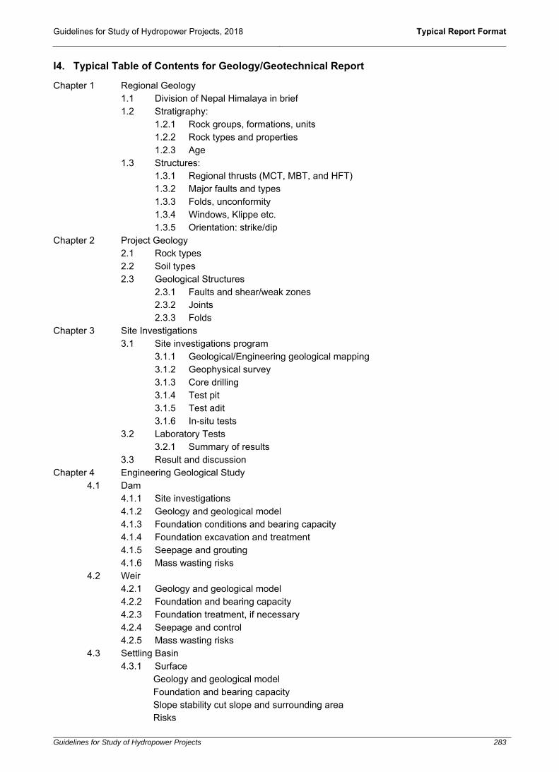
Guidelines for Study of Hydropower Projects, 2018 Typical Report Format
Guidelines for Study of Hydropower Projects 283
I4. Typical Table of Contents for Geology/Geotechnical Report
Chapter 1 Regional Geology 1.1 Division of Nepal Himalaya in brief 1.2 Stratigraphy:
1.2.1 Rock groups, formations, units 1.2.2 Rock types and properties 1.2.3 Age
1.3 Structures: 1.3.1 Regional thrusts (MCT, MBT, and HFT) 1.3.2 Major faults and types 1.3.3 Folds, unconformity 1.3.4 Windows, Klippe etc. 1.3.5 Orientation: strike/dip
Chapter 2 Project Geology 2.1 Rock types 2.2 Soil types 2.3 Geological Structures
2.3.1 Faults and shear/weak zones 2.3.2 Joints 2.3.3 Folds
Chapter 3 Site Investigations 3.1 Site investigations program
3.1.1 Geological/Engineering geological mapping 3.1.2 Geophysical survey 3.1.3 Core drilling 3.1.4 Test pit 3.1.5 Test adit 3.1.6 In-situ tests
3.2 Laboratory Tests 3.2.1 Summary of results
3.3 Result and discussion Chapter 4 Engineering Geological Study
4.1 Dam 4.1.1 Site investigations 4.1.2 Geology and geological model 4.1.3 Foundation conditions and bearing capacity 4.1.4 Foundation excavation and treatment 4.1.5 Seepage and grouting 4.1.6 Mass wasting risks
4.2 Weir 4.2.1 Geology and geological model 4.2.2 Foundation and bearing capacity 4.2.3 Foundation treatment, if necessary 4.2.4 Seepage and control 4.2.5 Mass wasting risks
4.3 Settling Basin 4.3.1 Surface
Geology and geological model Foundation and bearing capacity Slope stability cut slope and surrounding area Risks

Guidelines for Study of Hydropower Projects, 2018 Typical Report Format
Guidelines for Study of Hydropower Projects 284
4.3.2 Underground Geology and geological model Settling basin alignment and design Rock support design Ground water table
4.4 Waterways 4.4.1 Tunnel
Geology Faults, shear zones and weak zones Joint systems Geological model Tunnel alignment and design Rock mass classifications Ground water table and water leakage Rock support design Numerical Modelling (necessary for tunnel span greater than 5m) Rock squeezing analysis (necessary for severe squeezing) Adit Portal and Adits
4.4.2 Pipe/Canal Geology and geotechnical Alignment and stability Slope stability analysis Geo-risks and mitigation design
4.5 Forebay/Surge shaft/surge tank Geology and geological model Site selection and design Rock mass classifications Ground water table and water leakage Rock support design
4.6 Penstock 4.6.1 Surface
Geology and geotechnical Alignment design and rock cover Rock support design
4.6.2 Underground Geology and geotechnical Geological model Pressure Shaft/Penstock alignment and design Rock mass classifications Ground water table and water leakage Rock support design
4.7 Powerhouse 4.7.1 Surface
Geology and geotechnical Geological model Foundation and bearing capacity Slope stability of cut slope and surrounding area Mass wasting risks

Guidelines for Study of Hydropower Projects, 2018 Typical Report Format
Guidelines for Study of Hydropower Projects 285
4.7.2 Underground Geology and geotechnical Geological model Powerhouse orientation and design Rock mass classifications Ground water table and water leakage Rock support design Numerical Modelling Rock squeezing analysis
4.8 Tailrace 4.8.1 Surface
Geology and geotechnical Geological model Foundation and bearing capacity Slope stability of cut slope and surrounding area Mass wasting risks
4.8.2 Underground
Geology Geological model Alignment and design Rock mass classifications Rock support design Rock squeezing analysis
4.9 Spoil tips area Chapter 5 Reservoir Slope Stability Chapter 6 Rock Support Design Chapter 7 Anticipated Geological Problems Chapter 8 Mass Wasting Study Chapter 9 Construction Materials
9.1 Location, sources and quantity 9.2 Quarry 9.3 Lab test and quality
Chapter 10 Conclusions Chapter 11 Recommendations

Guidelines for Study of Hydropower Projects, 2018 Typical Salient Features
Guidelines for Study of Hydropower Projects 286
J. Typical Salient Features Format
1 GENERAL a. Name of the Project b. Name of the River c. Type of Scheme d. Project Location e. License boundary coordinates Latitude, Longitude (degree, minutes,
seconds) f. Nearest settlement g. Access road name 2 ORAGNIZATION a. Developer b. Consultant 3 HYDROLOGY
a. Catchment area at intake site (sq. km) b. Catchment area at powerhouse site (sq. km) c. Design discharge (X% exceedance) d. Average annual discharge (m3/s) e. Minimum monthly discharge (m3/s) f. Maximum monthly discharge (m3/s) g. Minimum environmental release (m3/s) h. Flood discharge for headworks design (N years) i. Flood discharge for powerhouse/tailrace design (N years) j. Construction flood discharge for headworks (N years) k. Construction flood discharge for powerhouse/tailrace (N years) 4 SEDIMENT STUDY a. Average annual sediment load (metric ton) b. Maximum sediment load (kg/m3) c. Design suspended sediment load (ppm) d. Estimated annual sediment yield (metric ton) 5 GEOLOGY a. Regional Geology b. Major rock types in headworks c. Major rock type in waterways

Guidelines for Study of Hydropower Projects, 2018 Typical Salient Features
Guidelines for Study of Hydropower Projects 287
d. Major rock type in powerhouse 6 STRUCTURES a. Dam/Weir b. Crest Level (m amsl) c. Type d. Length (m) e. Lowest River Bed Level at Weir Axis (m amsl) f. Foundation type g. Provision of stilling basin h. Water level in stilling basin for design flood (m amsl) i. For storage/peaking type projects j. Maximum operating level (m amsl) k. Minimum operating level (m amsl) l. Total capacity of the reservoir (cubic m) m. Live storage volume (cubic m) n. Dead storage volume (cubic m) o. Regulation method p. Inundation area (sq. m) q. Back water length (m) r. Peaking duration (hours, days, months) 7 DIVERSION DURING CONSTURCTION a. Construction flood (m3/s)
b. Diversion type
c. Length (m)
d. Section details
7a INTAKE a. Intake type b. Number of orifice c. Size (B x H, m) d. Top sill level (m amsl)
e. Invert sill level (m amsl) f. Gate type
g. Hoisting system
h. Trashrack dimension and opening (Lx B, m)

Guidelines for Study of Hydropower Projects, 2018 Typical Salient Features
Guidelines for Study of Hydropower Projects 288
i. Clear opening of trash rack (mm)
j. Trash rack cleaning mechanism
7b UNDERSLUICE
a. Number of Bays b. Dimension (L x B, m) c. Undersluice Invert level (m amsl) d. Gate type 7c 7d
GRAVEL TRAP AND GRAVEL FLUSHING
a. Type
b. Settling Criteria
c. Number of Basin
d. Gravel Trap Size (L x B x H, m)
e. Size of Flushing Canal (L x B x H, m)
APPROACH CULVERT/CANAL
a. Type b. Number c. Culvert/Canal Size (B x H, m) d. Length (m) e. Bed slope (1V:x H) f. Support type (if underground)
7e SETTLING BASIN a. Type b. Settling Criteria c. Size of particle to settle (mm) d. Settling design temperature (oC) e. Settling efficiency (mm) f. Number of Bays g. Inlet Transition Length (m) h. Settling Basin Size (L x B, m) i. Flushing System j. Size of Flushing Channel (B x H) k. Longitudinal Slope (1V:x H) l. Support type (if underground)
7f WATER CONVEYANCE

Guidelines for Study of Hydropower Projects, 2018 Typical Salient Features
Guidelines for Study of Hydropower Projects 289
a. Type b. Material c. Length (m) d. Dimension/Diameter (m) e. Thickness (mm) f. Inlet invert level (m amsl)
g. Outlet invert level (m amsl)
h. Support type (if underground)
7g SURGE SHAFT/SURGE TANK/FOREBAY
a. Type b. Diameter/Dimension (m) c. Upsurge level (m amsl)
d. Down surge level (m amsl)
e. Invert level (m amsl)
7h PENSTOCK
a. Material b. Length (m) c. Internal diameter (m) d. Thickness (mm) e. Maximum surge pressure (m) f. Number of anchor block g. Number of saddle support
h. Saddle spacing
i. Support type (if underground)
7i POWERHOUSE a. Type b. Plan Dimensions (L x B x H, m) c. Machine floor level (m amsl) d. Minimum foundation level (m amsl)
e. Overhead hoisting type
f. Overhead hoisting capacity (metric tons)
g. Foundation type

Guidelines for Study of Hydropower Projects, 2018 Typical Salient Features
Guidelines for Study of Hydropower Projects 290
h. Support type (if underground)
7j TAILRACE
a. Type b. Numbers c. Size (B x H, m) d. Length (m) e. Outlet water level at river f. Minimum tail water level (m amsl)
g. Normal tail water level (m amsl)
h. Invert level of tailrace at outlet (m amsl)
i. Support type (if underground)
8 TURBINE a. Type b. Number of Unit c. Maximum head (m) d. Minimum head (m) e. Rated Net Head (m) f. Rated Capacity per Unit (kilowatts) g. Discharge per Unit (m3/s) h. Turbine Axis Elevation (m amsl) i. Turbine efficiency (%) 9 GENERATOR a. Type of Generators b. Centre line elevation (m amsl) c. Number of Unit d. Rated Output (kVA) e. Generation Voltage (kV) f. Frequency (Hz) g. Power Factor h. Excitation System i. Speed (rpm) j. Generator efficiency (%) 10 TRANSFORMER

Guidelines for Study of Hydropower Projects, 2018 Typical Salient Features
Guidelines for Study of Hydropower Projects 291
a. Type b. Number of phase c. Number of Units d. Frequency (Hz.) e. Vector Group f. Voltage Ratio g. Transformer Efficiency 11
SWITCHYARD
a. Dimensions
12 TRANSMISSION LINE a. Transmission voltage (kV) b. Length (km) c. Connection point (location) d. Number of poles/towers
e. Power and Energy 13
FIRM POWER (90 percentile flow)
a. Installed Capacity (kilowatts) b. Gross Head (m) c. Dry Season Energy (GWh) d. Wet Season Energy (GWh) e. Annual peak energy (GWh) f. Annual off-Peak energy (GWh) g. Total Annual Energy 14
LAND REQUIREMENT
a. Government land requirement (sq. m)
b. Private land requirement (sq. m)
c. Temporary land requirement (sq. m)
15
FINANCIAL PARAMETER
a. Total investment
b. Base year
c. Total project duration after construction (years)
d. Loan repayment period
e. Debt, equity ratio

Guidelines for Study of Hydropower Projects, 2018 Typical Salient Features
Guidelines for Study of Hydropower Projects 292
f. Project Benefit/Cost (B/C) Ratio
g. Project Internal Rate of Return (IRR)
h. Financial Internal Rate of Return (FIRR)
i. Economic Internal Rate of Return (EIRR)
j. Net Present Value (NPV)
k. Cost per kilowatt hour (NPR)
l. Cost per kilowatt (NPR)

Guidelines for Study of Hydropower Projects, 2018 References
Guidelines for Study of Hydropower Projects 293
REFERENCES
Alternate Hydro Energy Center (AHEC). (2013). Standards/Manuals/Guidelines for Small Hydro Development. Roorkee, India: Indian Institute of Technology (IIT).
Central Electricity Authority (CEA). (2015). Guidelines for Formulation of Detailed Project Reports for Hydro Electric Schemes, their Acceptance and Examination for Concurrence. New Delhi, India: CEA.
Dam Safety Organization. (1987). Guidelines for Safety Inspection of Dams. New Delhi: Central Water Commission, Ministry of Water Resources, Government of India.
Department of Electricity Development (DoED). (2003). Guidelines for Study of Hydropower Projects. Kathmandu, Nepal: Government of Nepal (GoN).
Department of Electricity Development (DoED). (2005). Procedures for License Application of Hydropower Development in Nepal. Government of Nepal (GoN) in Collaboration with United States Agency for International Development (USAID) and International Resource Group (IRG).
Department of Electricity Development (DoED). (2017). Guidelines for Operation and Maintenance of Hydropower Plants, Substations and Transmission Lines Kathmandu, Nepal: Government of Nepal (GoN).
Department of Electricity Development (DoED). (2015). Guideline for Power System Optimization of Hydropower Projects Kathmandu, Nepal: Government of Nepal (GoN).
Federal Energy Regulatory Commission (FERC). (1987). Engineering Guidelines for the Evaluation of Hydropower Projects. Washington, DC: FERC Office of Hydropower Licensing.
His Majesty's Government (HMG). (2001). The Hydropower Development Policy. Kathmandu, Nepal: Ministry of Water Resources (MoWR).
Hydrologic Engineering Center (U.S.), & Institute for Water Resources (U.S.). (1979). Feasibility Studies for Small Scale Hydropower Additions: A Guide Manual. Washington, DC: U.S. Army Corps of Engineers.
International Finance Corporation (IFC). (n.d.). Hydroelectric Power, A Guide for Developers and Investors. IFC, World Bank Group.
Japan International Cooperation Agency (JICA). (2011). Guideline and Manual for Hydropower Development Vol. 1, Conventional Hydropower and Pumped Storage Hydropower. Japan International Cooperation Agency (JICA).
Japan International Cooperation Agency (JICA). (2011). Guideline and Manual for Hydropower Development Vol. 2, Small Scale Hydropower. Japan International Cooperation Agency (JICA).
Norwegian Institute of Technology. (1992). Hydropower Development, Planning and Implementation of Hydropower Projects. Division of Hydraulic Engineering.
Scottish Environment Protection Agency (SEPA). (2015). Guidance for Developers of Run-of-River Hydropower Schemes. Scotland: Natural Scotland.
Thematic Network on Small Hydropower (TNSHP). (2004). Guide on How to Develop a Small Hydropower Plant. European Small Hydropower Association (ESHA).
U.S. Army Corps of Engineers. (1995). Planning and Design of Hydroelectric Power Plant Structures. Washington, DC: Department of Army.
Water for Welfare Secretariat. (2008). Hydropower Policies and Guidelines. Roorkee, India: Indian Institute of Technology (IIT).
Civil Engineering Guideline for Planning and Designing Hydroelectric Development (in five volumes), American Society of Civil Engineers (ASCE), 1989.
Dams and Development –The Report of the World Commission on Dams, 2000. Inventory of Glaciers and Glacial Lakes of Nepal, ICIMOD and UNEP, 2001 (at a final stage of publication). Engineering and Design – Hydropower, Department of the Army Corps of Engineers, USA, 1985.
Dapice, D. (2015). Hydropower in Myanmar: Moving Electricity Contracts from Colonial to Commercial. Proximity Designs, Myanmar.http://ash.harvard.edu/files/ash/files/hydropower_in_myanmar_-moving_from_colonial_to_commercial_dec_16_2015.pdf?m=1450363888
IEA Hydro, (2010). Update of Recommendation for Hydropower and the Environment, briefing document. IEA Hydro: International Energy Agency Technology Collaboration Programme on Hydropower
www.ieahydro.org/media/.../FinalAnnexXII_Task2_BriefingDocument_Oct2010.pdf Kjellen, U. (2012). Managing safety in hydropower projects in emerging markets – Experiences in developing from
a reactive to a proactive approach. Safety Science, 50 (10), 1941-1951, https://doi.org/10.1016/j.ssci.2011.07.018 Mishra et al. (2015). Small hydro power in India: Current status and future perspectives. Renewable and
Sustainable Energy Reviews, 51, 101-115. https://doi.org/10.1016/j.rser.2015.05.075. Sperling, E.V. (2012). Hydropower in Brazil: Overview of Positive and Negative Environmental Aspects. Energy
Procedia, 18, 110-118. https://doi.org/10.1016/j.egypro.2012.05.023. His Majesty's Government (HMG). (2001). The Hydropower Development Policy. Kathmandu, Nepal: Ministry of Energy (MoEn).www.moen.gov.np/pdf_files/hydropower_development_policy_2001.pdf
His Majesty's Government (HMG). (1992). The Hydropower Development Policy. Kathmandu, Nepal: Ministry of Energy (MoEn).

Guidelines for Study of Hydropower Projects, 2018 References
Guidelines for Study of Hydropower Projects 294
www.nea.org.np/admin/assets/.../4561Hydropower%20Development%20Policy.pdf His Majesty's Government (HMG). (1992). Water Resources Act, 2049 (1992). Kathmandu, Nepal: Ministry of
Energy (MoEn). www.moen.gov.np/pdf_files/Water_Resources_Act_2049-english.pdf
His Majesty's Government (HMG). (1993). Water Resources Rules 2050 (1993). Kathmandu, Nepal: Ministry of Energy (MoEn). erg.com.np/wp-content/uploads/2014/09/Water-Resources-Rules.pdf
His Majesty's Government (HMG). (2002). Water Resources Strategy. Kathmandu, Nepal: Ministry of Energy (MoEn). www.moen.gov.np/pdf_files/water_resources_strategy.pdf
His Majesty's Government (HMG). (2005). National Water Plan. Kathmandu, Nepal: Ministry of Energy (MoEn). www.moen.gov.np/pdf_files/national_water_plan.pdf
Water and Energy Commission Secretariat. (2018).The Hydrological Manual for Infrastructure, Water and Energy Commission Secretariat, Government of Nepal.