Construction and Commissioning of the 'Muela Hydropower ...
12
LESOTHO HIGHLANDS WATER PROJECT Construction and Commissioning of the 'Muela Hydropower Project I. Danisovic, D. Jurisch, L. Maran, D. Garner, A. Seckel, R. Stock Abstract ~ The Lesotl~ Highlands Water Project involves impounding the surplus water from the rivers in the Highlands for trar,~fer through the Maluti mountains and across the border to South Africa, where it will supplement the overtaxed water resources of the Vaal River basin. The first phase of the project just before the completion of Phase 1A includes the construction of Katse Dam, 82 km of tunnels through the mountains, a 72-MW hydropower station and regulation dam at 'Muela, and all associated infrastructure. This paper discusses the contracts for the electromechanical equipment for the 'Muela Hydropower Project portion of the LHWP. © t999 Published by Elsevier Science Ltd. All rights reserved. Introduction A major binational project,the Lesotho Highlands Water Projectinvolvesimpounding the surplus wa ter from the rivers in the Highlands for transfer through the Maluti mountains and across the border to South Africa, where it will supplement the overtaxed water resources ofthe Vaal River basin. The first phase of the project just beforethe completion ofPhase 1Aincludes the constructionof Katse Dam, 82 km of tunnels through the mountains, a 72-MV~ hydropower station and regula- tion dam at 'Muela, and all associated infrastructure. The 'Muela Hydropower Project is situated approxi- mately midway between the Katse Dam and the Outfallin South Africa (see Flig. 1). The concrete-lined Transfer Tunnel from the Katse Intake structure to the 'Muela Hydropower Station is45 km long,with an inner diameter of 4.35 m, following by a 100-m-long steel lining of a diameter of 3.35 m with connection via a throttle to the Upstream Surge Shaft, which is 165 m high. Via a steel linedreduction piecec~3.35 m/¢2.5 m, a horizontalpenstock continues intothe Penstock Guard Valve Chamber, where a bi-plane butterflyvalve 2.5 m in diameter is provided. Further, via a steel-lined verticalPenstock Shaft approxi- mately 155 m high mad a horizontal Low Level Penstock, both 2.5m in diameter, water isrouted via two bifurcations and three manifolds~,each 1.15 m in diameter, into the Powerhouse Cavern I~ the Turbine InletValves (TIVs). The Powerhouse Cavern (Figs.2 and 3) is 60 m long,30 m high and 15 m wide and houses three turbine generator units. Adjacent to the Powerhouse Cavern is a Trans- Present address: Ivan Danisovic, Commissioning Mechanical Engineer and Coordinator; Dieter Jurisch, Resident Electrical Engineer; Liviu Maralt, Resident Mechanical Engineer; Dave Garner, SCADA Engineer; Andreas Seckel, Transmission Line Engineer; and Raymond Stock, Chief Resident Engineer, Lahmeyer MacDonald Consortium,, c/o LHTP (Mohale), Private Bag A394, Maseru 100, Leeotho. former Cavern accommodating three Unit Transformers. Access to the Cavern is via a access tnnnel 6.5 m, 6.5 m wide and approximately 780 m long. Passing the hydraulic Francis turbines after power generation, water is discharged from the draft tubes and concrete-lined connection tunnels into the 40-m-high Down- stream Surge Chamber and, via a 1.4-kin-long Tailrace Tunnel of 4.1 m diameter, enters the 'Muela Reservoir. Because water transfer to South Africa to deliver maxi- mum 32.5 m3/sec was required before the 'Muela Hydro- power Station could be completed and commissioned for commercial operation, a Station By-Pass had been de- signed and constructed. Through a steel lined bifurcation of¢3.35 m/~2.0 m, situated about 800 m upstream of the above mentioned Upstream Surge Shaft, the water is diverted by a steel-lined, 515-m-long tunnel of 2.0 m diameter to the Station By-Pass Building, which includes a Guard Valve (GV) of a bi-plane butterfly type of 2.0 m diameter and a Energy Dissipation Valve (EDV) of a Howell-Bunger fixed cone type of 1.5 m diameter. Well aerated water from the EDV, impinged onto the walls of the dissipation structure, is then discharged through a 350-m-long concrete-lined chute down to the stilling basin; and, via an upgraded river channel, approximately I km long, the water finally reaches the 'Muela Reservoir. The electro-mechanical works concerning the 'Muela Hydropower Project, in addition to other civil works, are included in the following Contracts: * Contract LHDA 129A: Underground Power Facilities; * Contract LHDA 129B: Tluela Dam and Appurte- nant Works; • Contract LHDA 134: Turbines, Generators and Ancillary Plant, consisting of - Mechanical Works divided into 11 Sections, - Electrical Works, divided into 18 Sections, - 8CADA System, and - HVAC System. Tunnelling and Underground Spnee Technology, Vo]. 14, No. 1, pp. 55-66, 1999 0886-7798/99/$- see front matter ~ 1999 Published by Elsevier Science Ltd. All rights reserved. PII:S0886-7798(99)00013-9 Pergamon
-
Upload
khangminh22 -
Category
Documents
-
view
1 -
download
0
Transcript of Construction and Commissioning of the 'Muela Hydropower ...

LESOTHO HIGHLANDS WATER PROJECT
Construction and Commissioning of the 'Muela Hydropower Project
I. Danisovic, D. Jurisch, L. Maran, D. Garner, A. Seckel, R. Stock
Abstract ~ The Lesotl~ Highlands Water Project involves impounding the surplus water from the rivers in the Highlands for trar,~fer through the Maluti mountains and across the border to South Africa, where it will supplement the overtaxed water resources of the Vaal River basin. The first phase of the project just before the completion of Phase 1A includes the construction of Katse Dam, 82 km of tunnels through the mountains, a 72-MW hydropower station and regulation dam at 'Muela, and all associated infrastructure. This paper discusses the contracts for the electromechanical equipment for the 'Muela Hydropower Project portion of the LHWP. © t999 Published by Elsevier Science Ltd. All rights reserved.
Introduction A major binational project, the Lesotho Highlands
Water Project involves impounding the surplus wa ter from the rivers in the Highlands for transfer
through the Maluti mountains and across the border to South Africa, where it will supplement the overtaxed water resources of the Vaal River basin. The first phase of the project just before the completion of Phase 1Aincludes the construction of Katse Dam, 82 km of tunnels through the mountains, a 72-MV~ hydropower station and regula- tion dam at 'Muela, and all associated infrastructure.
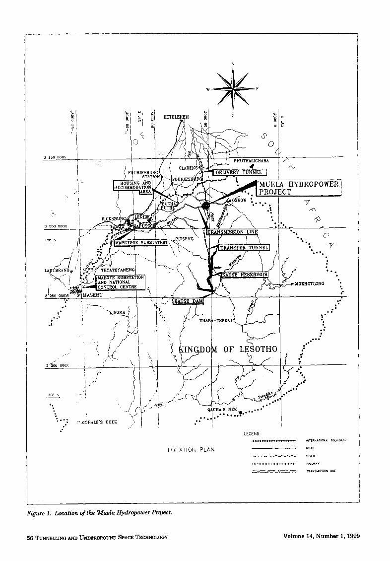
The 'Muela Hydropower Project is situated approxi- mately midway between the Katse Dam and the Outfall in South Africa (see Flig. 1). The concrete-lined Transfer Tunnel from the Katse Intake structure to the 'Muela Hydropower Station is 45 km long, with an inner diameter of 4.35 m, following by a 100-m-long steel lining of a diameter of 3.35 m with connection via a throttle to the Upstream Surge Shaft, which is 165 m high. Via a steel lined reduction piece c~3.35 m/¢2.5 m, a horizontal penstock continues into the Penstock Guard Valve Chamber, where a bi-plane butterfly valve 2.5 m in diameter is provided. Further, via a steel-lined vertical Penstock Shaft approxi- mately 155 m high mad a horizontal Low Level Penstock, both 2.5 m in diameter, water is routed via two bifurcations and three manifolds~, each 1.15 m in diameter, into the Powerhouse Cavern I~ the Turbine Inlet Valves (TIVs).
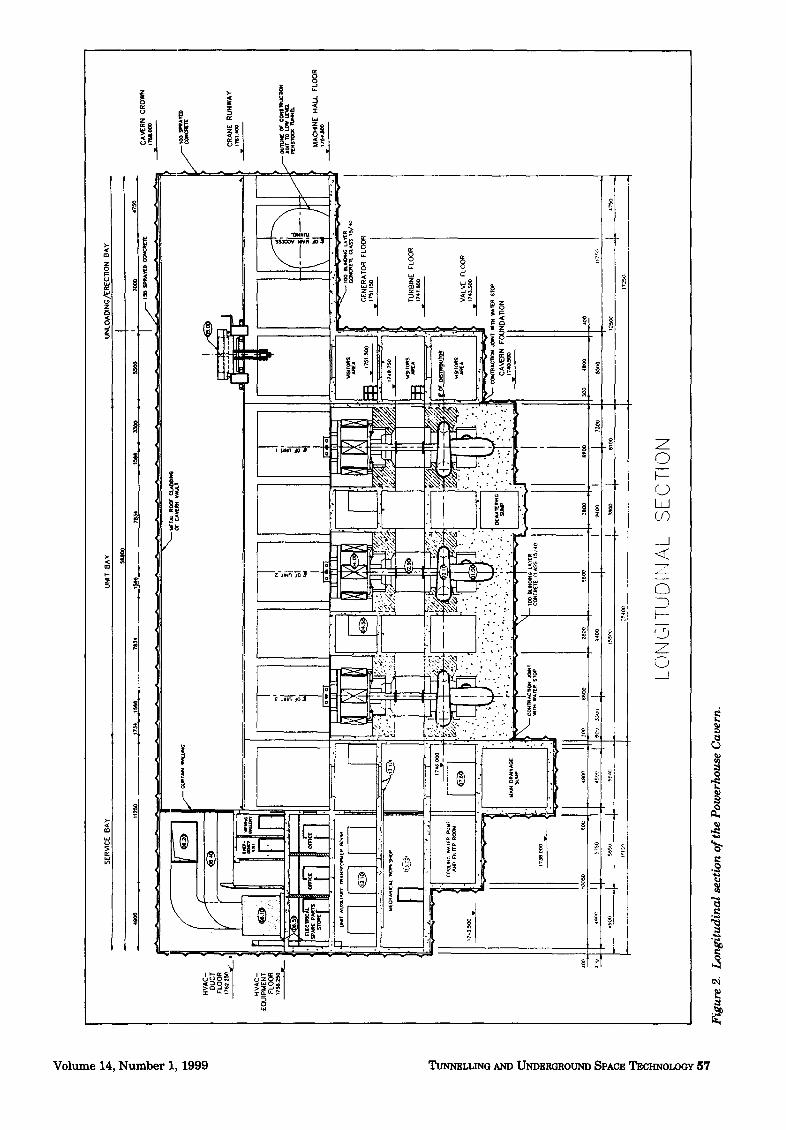
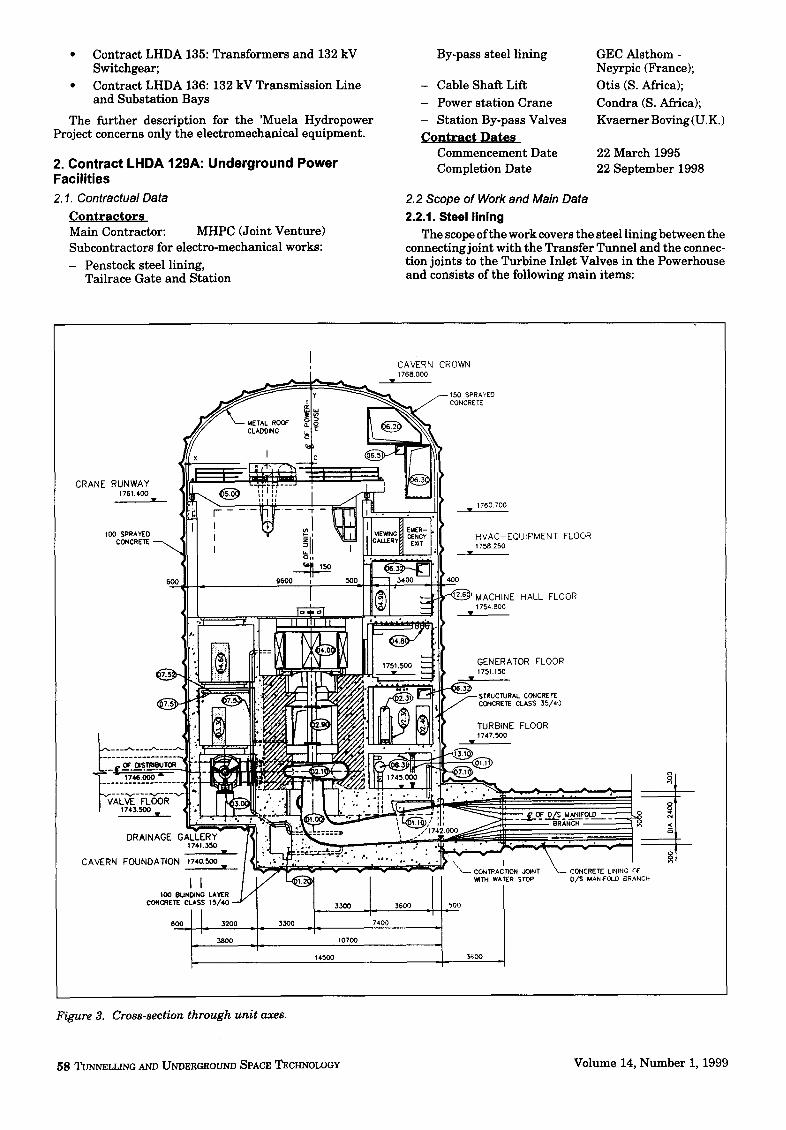
The Powerhouse Cavern (Figs. 2 and 3) is 60 m long, 30 m high and 15 m wide and houses three turbine generator units. Adjacent to the Powerhouse Cavern is a Trans-
Present address: Ivan Danisovic, Commissioning Mechanical Engineer and Coordinator; Dieter Jurisch, Resident Electrical Engineer; Liviu Maralt, Resident Mechanical Engineer; Dave Garner, SCADA Engineer; Andreas Seckel, Transmission Line Engineer; and Raymond Stock, Chief Resident Engineer, Lahmeyer MacDonald Consortium,, c/o LHTP (Mohale), Private Bag A394, Maseru 100, Leeotho.
former Cavern accommodating three Unit Transformers. Access to the Cavern is via a access tnnnel 6.5 m, 6.5 m wide and approximately 780 m long.
Passing the hydraulic Francis turbines after power generation, water is discharged from the draft tubes and concrete-lined connection tunnels into the 40-m-high Down- stream Surge Chamber and, via a 1.4-kin-long Tailrace Tunnel of 4.1 m diameter, enters the 'Muela Reservoir.
Because water transfer to South Africa to deliver maxi- mum 32.5 m3/sec was required before the 'Muela Hydro- power Station could be completed and commissioned for commercial operation, a Station By-Pass had been de- signed and constructed. Through a steel lined bifurcation of¢3.35 m/~2.0 m, situated about 800 m upstream of the above mentioned Upstream Surge Shaft, the water is diverted by a steel-lined, 515-m-long tunnel of 2.0 m diameter to the Station By-Pass Building, which includes a Guard Valve (GV) of a bi-plane butterfly type of 2.0 m diameter and a Energy Dissipation Valve (EDV) of a Howell-Bunger fixed cone type of 1.5 m diameter. Well aerated water from the EDV, impinged onto the walls of the dissipation structure, is then discharged through a 350-m-long concrete-lined chute down to the stilling basin; and, via an upgraded river channel, approximately I km long, the water finally reaches the 'Muela Reservoir.
The electro-mechanical works concerning the 'Muela Hydropower Project, in addition to other civil works, are included in the following Contracts:
* Contract LHDA 129A: Underground Power Facilities;
* Contract LHDA 129B: Tluela Dam and Appurte- nant Works;
• Contract LHDA 134: Turbines, Generators and Ancillary Plant, consisting of
- Mechanical Works divided into 11 Sections, - Electrical Works, divided into 18 Sections, - 8CADA System, and - HVAC System.
Tunnelling and Underground Spnee Technology, Vo]. 14, No. 1, pp. 55-66, 1999 0886-7798/99/$- see front matter ~ 1999 Published by Elsevier Science Ltd. All rights reserved. PII:S0886-7798(99)00013-9
Pergamon
t
3 t50 O00X
-+.
. )
3 200 O00X
/il j t / ,0~ 0
~.+BRAND,,~ : I C~'"
-:'~, I ¢.fl
:.-
3 ~O(J 000X
30 °
N
to 0
- PHUTHALICHABA /~
- c~RzNs /~-~_________~ />" ERY TUNNEL ]
[----HOUSING AND L 'MUELA HYDROPOWER |ACCOMMODATION ~ # PROJECT
~APUT~ • f
Z . . . . . ' . . . . . " " o j "" ..
,,., RANSFER TUNNEL *
::~ "rEYATEYANENG * " s , ~ " ~ SUBSTATION ' \ ! " . • ~ - ~ AND NATIONAL J' ~ M01~OTLONG ~ ' ~ CONTROL CENTRE , f "
MASZR~ / =.. # J "
-_t,t~OM A ¢ W~_ ~' • : • ~'1. . '" | "~* "~ i TH~B-TsZZ*, I "
-r ( ,' i o~
:( / ~?/ !.~ ~IN~O. OF LESOTHO~ J"
i ~, f J 4 e ° * • °
, , • e e '../ ( ) Q~ :Hit'S N E K Q . . . , . - "
"t/ I. . 2 " " "" . . . . . . '? MOHALE'S HOEK "t / •
LEGEND:
LOCATION PLAN
INTERtIATIONAL BOUN0 ~.R Y
ROA0
RI',~R
RAILWAY
'~AN.~aI$~ON UNE
Figure 1. Location of the "Muela Hydropower Project.
56 ~nL~G AND Um)zROaOU~m SPACZ Tzc~mo~Y Volume 14, Number I, 1999
o E"
~D
HV
AC
- D
UC
T FL
OO
R
HV
AC
- EQ
UIP
MEN
T FL
OO
R
17~l~
250,1
"
SER
VIC
E B
AY
U
NIT
BA
Y
UN
LOAD
ING
/~R
ECTI
ON
B
AY
.. 49
00
• 11
2~0
~ J7
~4
I.TM
~ 78
34
. ,1
5~5,
,
7634
1~
_ _
3300
.
. 55
00
_L
70~0
,
47,T~
,0 .
F-
~O ~
A~
O
~ C
AVER
N C
RO
WN
I
171u
1.¢~
o
17~3
500
•
~' 2,
5'
~A
N
ci~'~=
'~ ~
III
I I
I I ;
I I
I I
I I6
~z~
I I
I I
I : I
I I I
,a~m
es
1746
.000
~R~G
W
aTEP
~MF
AN
D nt
Tce
RO0~
CR
AN
E R
UN
WAY
C4I
I~E
C~ r CO
NS11
~l~O
N AO
IT TO
LOW
p~
xs~r
Oo(
"WNN
Ig.
MAC
HIN
E H
ALL
FLO
OR
1 ~
'a6.
Jwo
w
MAI
N DR
~NAG
IE
Stra
p
• /..'....::..'-.
:! ,'.: :, ...
r.
: ,
. ~
-"''
: "'
.'..
:
CO~C
R[T(
CL~
S5 ~S
/40
GEN
ERAT
OR F
LOO
R
1151
1SO
I -- 1
00 ~
LIM~4
NL~ LA
~ER
i -
--
CONC
RET~
CLAS
S 15/
40
ce~o
.lo
o
..[_
I ~
:~,o
o '1
I I I 6t
qOO
-!-
~1¢,O
J 17
~8 C~O
v
I*tP-
,
TUR
BIN
E FL
OO
R
1747
.5oo
4a,:,3
ee
~o
"l"
" -
..
..
..
..
..
_1
2 ...
...
..I
VALV
E FL
OO
R
1743
.~.,o0
:0~m
~CltO
~ *J
OINT
I'm W
ATER
S/~ e
C
AVER
N
FOU
ND
ATIO
N
-II SSIF$O
117rP,
i
1725O
LON
GIT
UD
INA
L S
EC
TIO
N
Fig
ure
2. L
ongi
tudi
nal s
ecti
on o
f the
Pow
erho
use
Cav
ern.
• Contract LHDA 135: Transformers and 132 kV Switchgear;
* Contract LHDA 136:132 kV Transmission Line and Substation Bays
The further description for the 'Muela Hydropower Project concerns only the electromechanical equipment.
2. Contract LHDA 129A: Underground Power Facilities 2.1. Contractual Data
Contractors Main Contractor: MHPC (Joint Venture) Subcontractors for electro-mechanical works:
- Penstock steel lining, Tailrace Gate and Station
By-pass steel lining
- Cable Shaft Lift
- Power station Crane - Station By-pass Valves
Contract Dates Commencement Date Completion Date
GEC Alsthom - Neyrpic (France); Otis (S. Africa);
Condra (S. Africa); Kvaerner Boving (U.K.)
22 March 1995 22 September 1998
2.2 Scope of Work and Main Data 2.2.1. Steel lining
T h e scope o f t h e w o r k c o v e r s t h e s t e e l l i n i n g b e t w e e n t h e connecting joint with the Transfer Tunnel and the connec- tion joints to the Turbine Inlet Valves in the Powerhouse and consists of the following main items:
cAvERN CROWN 1768.000
~ ~ 1 5 0 SPRAYED J CONCRETE
d / CL,+O..~ ~ i I L - 7 - - - ~ 5 \ \ \
CRA.E R%~+ i l l ~ \ @ "V'T " ' I ~ LV--JIIt " ItM+ - : " . . :If .,To.To
++..y~o F , ~ + ~ I....oB+~.+:itl' 10o ~1 I " ~, ~ 1 i1~?~' ;1~.¢: [11 H V A C - E Q U I P M E N T FLOOR ~ON~RE~-~ ~. : ~" +7" I I~'~"'B Ex.T I:ll. 1,++=+o
+ 1 1 . o +o
Of" OISTRIE~J TOR
LVE FLOOR 17,1.3.500 •
--I--
- ~ ' - J MACHINE HALL FLOOR 1754 800
:-'-- IAI
GENERATOR FLOOR 1751.150
TRUCTURAL CONCRETE cSoNcREE 35 /40 CLASS
F ~I F ~ . i l g g V l~ITt "ruRS,NEFLO0+, • 1747.500
" = + + ~+ t u ~ i ,
. . . . . . . ~ k - " ~ - ~ ~ . . - ' t : ',11 ~ _ f . . . o t ' _ o/s ,,,~.,,FOU:) ~ a[
~ ~ ' .~~. .~-~. ~., . ~ . ~ _ _ ~ . ~ = = = ~ +. ...... _~. . . . . . . . . , • , • • .4.. • o-o '. ~ ~T
' = ~ " ~ " " I P \ \ " J c v ~- ~ v v " - - CONTRACTION JOINT ~ CONCRETE LINItlC- I,.~F
14500 ]gO0 L F --
DRAINAGE GALLERY 1741.3~
CAVERN FOUNDATION t74ox~o
II IOO BUNOING LAYER
CONCREE CLASS 1 5 / 4 0 -
,~_1 I_ ,~
Figure 3. Cross-section through unit axes.
58 TUNNEL~INO AND UNDERGROUND SPACE TECHNOLOGY Volume 14, Number 1, 1999
• Headrace tunne:L steel lining: Inner diameter 3.35 m Length 100 m
• Steel lining to surge shaft riser: Inner diameter 2.5 m Throttle diameber 1.85 m
• Penstock steel lining: Inner diameter 2.5 m
• Penstock and manifolds with two bifurcations: first one, of inner diameters 2.5 m/2.05 m/1.45 m second one, of inner diameters 2.5 m]1.45 m]1.45 m
• Inspection cart.
Work i m p l e m e n t a t i o n . The steel lining was manu- factured by Deutsche :Babcock (Nigel, South Africa), in the form of spools, 5,9 m--8.9 m long. The installation of the steel lining at the site started in November 1996. Some parts of the manifold and riser were pressure tested in the workshop in December 1996.
The installation of the steel lining upstream of the Penstock Guard Valve was completed in April 1998, fol- lowed by the re-impoauding of the Transfer Tunnel on 3 April 1998. The inspection cart was installed and operated for testing and traini~ag purposes in April 1998.
2.2.2 Cable shaft lift The following main data pertains to the cable shaft lift
and associated equipment installed in the shaft between the underground Powerhouse and the access tunnel to the valve chamber:
• Lifting capacity 630 kg or 8 persons * Rated speed 2.5 m/s • Lift travel 168.5 m
Work implementation. The cable shaft lift was in- spected during manufacturing in the OTIS workshop in Johannesburg in November 1996 and April 1997. The installation was completed and the lift was commissioned in January 1999.
2.2.3 Powerstation crane The Powerstation crane installed in the underground
Powerhouse Cavern serves for assembly, installation and maintenance of the turbine-generator units, turbine inlet valves and associated equipment. The following data per- rain to the Powerstation crane:
• Lifting capacity: - Main hoist 60 ton - Auxiliary hoist 5 ton
• Rail track length 48 m
Work i m p l e m e n t a t i o n . The Powerstation crane was inspected during manufacturing in the CONDRA work- shop in Johannesburg in November 1996 and April 1997. The crane erection was completed and the crane was commissioned in December 1997.
2.2.4. Tailrace gate The tailrace gate, a vertical slide gate type, is operated
by means of a mechanical gate hoist under balanced pres- sure. It closes the tailrace tunnel of the 'Muela Power
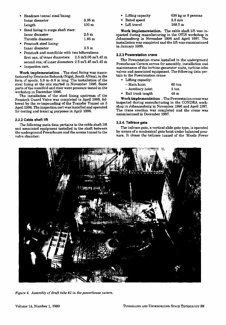
Figure 4. Assembly c,f draft tube #1 in the powerhouse cavern.
Volume 14, Number 1, 1999 TUNNELLING AND UNDERGROUND SPACE TECHNOLOGY 5 9
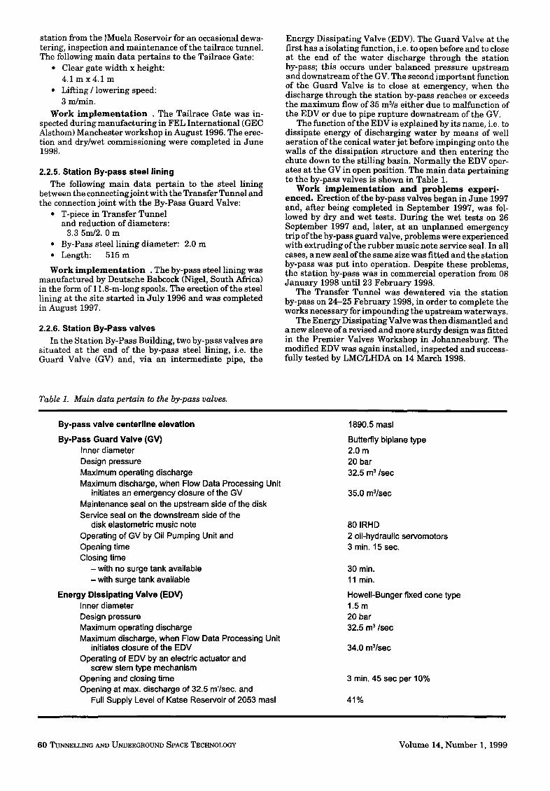
station from the }Muela Reservoir for an occasional dewa- tering, inspection and maintenance of the tailrace tunnel. The following main data pertains to the Tailrace Gate:
• Clear gate width x height: 4 . 1 m x 4 . 1 m
• Lifting / lowering speed: 3 ndmin.
Work i m p l e m e n t a t i o n . The Tailrace Gate was in- spected during manufacturing in FEL International (GEC Alsthom) Manchester workshop in August 1996. The erec- tion and dry/wet commissioning were completed in June 1998.
2.2.5. Station By-pass steel lining The following main data pertain to the steel lining
between the connecting joint with the Transfer Tunnel and the connection joint with the By-Pass Guard Valve:
• T-piece in Transfer Tunnel and reduction of diameters:
3.3 5m/2.0 m • By-Pass steel lining diameter: 2.0 m • Length: 515 m
Work implementat ion . The by-pass steel lining was manufactured by Deutsche Babcock (Nigel, South Africa) in the form of l l .8-m-long spools. The erection of the steel lining at the site started in July 1996 and was completed in August 1997.
2.2.6. Station By-Pass valves In the Station By-Pass Building, two by-pass valves are
situated at the end of the by-pass steel lining, i.e. the Guard Valve (GV) and, via an intermediate pipe, the
Energy Dissipating Valve (EDV). The Guard Valve at the first has a isolating function, i.e. to open before and to close at the end of the water discharge through the station by-pass; this occurs under balanced pressure upstream and downstream of the GV. The second important function of the Guard Valve is to close at emergency, when the discharge through the station by-pass reaches or exceeds the maximum flow of 35 m3/s either due to malfunction of the EDV or due to pipe rupture downstream of the GV.
The function of the EDV is explained by its name, i.e. to dissipate energy of discharging water by means of well aeration of the conical water jet before impinging onto the walls of the dissipation structure and then entering the chute down to the stilling basin. Normally the EDV oper- ates at the GV in open position. The main data pertaining to the by-pass valves is shown in Table 1.
Work implementat ion and problems exper i - enced . Erection of the by-pass valves began in June 1997 and, aider being completed in September 1997, was fol- lowed by dry and wet tests. During the wet tests on 26 September 1997 and, later, at an unplanned emergency trip of the by-pass guard valve, problems were experienced with extruding of the rubber music note service seal. In all cases, a new seal of the same size was fitted and the station by-pass was put into operation. Despite these problems, the station by-pass was in commercial operation from 08 January 1998 until 23 February 1998.
The Transfer Tunnel was dewatered via the station by-pass on 24-25 February 1998, in order to complete the works necessary for impounding the upstream waterways.
The Energy Dissipating Valve was then dismantled and a new sleeve of a revised and more sturdy design was fitted in the Premier Valves Workshop in Johannesburg. The modified EDV was again installed, inspected and success- fully tested by LMC/LHDA on 14 March 1998.
Table 1. Main data pertain to the by-pass valves.
By-pass valve centerline elevation
By-Pass Guard Valve (GV) Inner diameter Design pressure Maximum operating discharge Maximum discharge, when Flow Data Processing Unit
initiates an emergency closure of the GV Maintenance seal on the upstream side of the disk Service seal on the downstream side of the
disk elastometric music note Operating of GV by Oil Pumping Unit and Opening time Closing time
- with no surge tank available - with surge tank available
Energy Dissipating Valve (EDV) Inner diameter Design pressure Maximum operating discharge Maximum discharge, when Flow Data Processing Unit
initiates closure of the EDV Operating of EDV by an electric actuator and
screw stern type mechanism Opening and closing time Opening at max. discharge of 32.5 m'/sec, and
Full Supply Level of Katse Reservoir of 2053 masl
1890.5 masl
Butterfly biplane type 2.0m 20 bar 32.5 m 3/sec
35.0 @/sec
80 IRHD 2 oil-hydraulic servomotors 3 min. 15 sec.
30 min. 11 min.
HowelI-Bunger fixed cone type 1.5m 20 bar 32.5 m 3/sec
34.0 m3/sec
3 min. 45 sec per 10%
41%
60 TUNNELLING AND UNDERGROUND SPACE TECHNOLOGY Volume 14, Number I, 1999
The Guard Valve was fitted with a new rubber service seal on bottom tolerance limit after the clamp ring seg- ments were grid-blasted in order to increase friction hold- ing seal in place, and the re-watering of the Transfer Tunnel started on 02 April 1998.
On 27 April 1998, following the integration of the upstream surge shaft into the hydraulic waterways sys- tem, a full flow emergency closure test of the GV was undertaken under the following conditions: Katse Reser- voir level, 2053.00 masl; static head U/S of the valve, 16.3 bar, flow 35 m3/sec.; reduced closing time of the GV to 11 min. 5 sec.
The valve failedto close again, remaining open about 12 mm measured on servomotor piston. The following morn- ing on 28 April 1998, it was possible to close the valve completely, and during inspection it was observed the seal had extruded betweerL 10 o'clock and 2 o'clock positions. The damaged seal was again replaced and the station by-pass re-started the water discharge on 29 April 1998.
To overcome this situation and problems with the Guard Valve, a new seal design inserting fiber fabric reinforce- ment into the rubber seal and a new modified clamp ring were proposed by the Sub-Contractor KBO. The new seal arrangement was tested at the KBO premises in December 1998. The installation of the new seal and clamp ring, and the emergency closure of the Guard Valve, as a final proof of its faultless and reliable operation, is scheduled for April 1999.
3.0 Contract LHDA 129B: 'Muela Dam and Appurtenant Works; 3.1 Contractual Data
C o n t r a c t o r s : Main Contractor: MHPC (Joint Venture) Subcontractors for Bottom Outlet
and Compensation Water Outlet: Stewart Scott, Premier Valves, Ainsworth Engineering (all South Africa), Blackball Engineering (U.K.), Abb Kent- Taylor (Italy)
C o n t r a c t D a t e s : Commencement Date 01 March 1994 Completion Date 30 Janua ry 1998
3.1. Scope of Work and Main Data
3.2.1. Bottom Outlet ;rod Compensation Water Outlet The bottom outlet equipment discharges a total of 8 mS/
s through the 'Muela dam for emergency drawdown, silt discharge, and downst ream compensation flow when required. The total di~scharge of 8 mS/s is obtained by 7.56 mS/s through the bottom outlet line and 0.44 mVs through the compensation water outlet.
The bottom outlet line consists of an isolating gate valve (DN 900 m m , PN 10 bar) and a sleeve valve (DN 700 ram, PN 10 bar) for flow control. The compensation water line is provided with an isolating gate valve (DN 3 00 mm, PN 10 bar), a Larner Johnson valve (DN 300 ram, PIN 10 bar) for flow control and a digital flowmeter device.
All valves are manual ly actuated, and, with exception of the Larner Johnson valve, they are manufactured from stainless steel.
W o r k i m p l e m e n t a t i o n . The gate valve (DN 900 ram) and the sleeve valve (DN 700 mm) were pressure tested in the workshop in March 1996 and February 1997.
The installation of the equipment s tar ted in April 1997, and the site dry and wet tests were performed from Sep- tember 1997 through November 1997 in parallel with the impounding of 'Muela reservoir.
4.0 'Muela Hydropower Station Contract LHDA 134: Turbines Generators and Ancillary Plant 4. I. Contractual Data
C o n t r a c t o r C o n s o r t i u m : ABBGKBC Consortium Par tner for - Electrical Works and
SCADA System ABB Generation (Sweden) - Mechanical Works and
HVAC System Kvaerner Bovine (U.K.)
C o n t r a c t D a t e s : Contract Commencement Date 1 April 1994 Commissioning April 1997 to November 1998 Contract Completion Date
(original date) 17 October 1997 Contract Completion Date
(after 1st EOT) 22 September 1998 Contract Completion Date
(after 2nd EOT) 21 December 1998
It may be noted tha t a t ime extension ( ls t EOT, 341 days) with respect to the original contract date had to be given to synchronize the time schedule for the equipment under LHDA 134 with those of the civil works under contracts LHDA 129A and 129B, which had suffered a considerable delay in award of the contracts.
A further t ime extension had to be granted (2nd EOT, 90 days) to compensate for a workforce strike in 1996, and other delays meanwhile incurred through the civil works.
4.2 Main Data for Generating Units and Essential Equipment
T u r b i n e s . The main data pertaining to each of the three Francis turbine-generator units installed in the Powerhouse Cavern is given in Table 2.
Each turbine assembly consists of the following major assemblies: draft tube liner, suction cone, spiral case and stay ring, bottom cover, top cover, runner and shafts, guide bearing, guide vane apparatus, and overspeed device.
The draft tube liner assembly is a steel welded fabrica- tion, manufactured in two pieces, tha t was installed and welded on site. The suction cone assembly, supplied as an removable upper and lower cone section, is provided with a manhole for inspection inside of the draft tube.
The draft tube liner and the suction cone incorporate tappings for thermodynamic field efficiency test measure- ment, pressure pulsation measurement during commis- sioning and testing of the turbine, suction cone pressure monitoring, and water level check.
The spiral case (Fig. 5), partially embedded in concrete, was completely manufactured and tested in the workshop and incorporates tappings for flow measurement (Winter- Kennedy) and pressure measurement during commission- ing and testing of the turbine.
The runner assembly (single piece stainless steel cast- ing Cr Ni 17 4) is via turbine shaft and intermediate shaft coupled to the generator rotor shaft. The direction of rotation is counterclockwise, viewed from the generator, with the rotating mass supported by the generator thrust bearing.
The turbine is provided with self-lubricated guide bear- ing with six bearing pads. The measurement and protec- tion instrumentat ion of the turbine include indicators, alarms and trip protection devices for the guide bearing, shaft seal and the overspeed device.
G e n e r a t o r s . The following main data pertains to the generators:
Rated capacity 32 MVA Maximum capacity 35.2 MVA
Volume 14, Number l , 1999 TUNNELLIN~ AND UNDERGROUND SPACE TECHNOLOGY 61
Rated voltage 11 _+ 10 % Rated power factor 0.85 Rated frequency 50 Hz Flywheel effect 84 tm 2 Weights:
-Complete stator 50 ton -Complete rotor 3 7.5 ton
Turb ine in le t v a l v e s (TIVs). Three turbine inlet valves (TIVs) control water inlet to the respective turbines. The TIVs allow the turbines to be dewatered and the penstock flow to be shut off in case of emergency. The following main data pertains to each TIV:
Inner diameter 1.15 m Design pressure 36 bar Normal flow 12 m3/sec Emergency free flow 45 m 3/sec Operating times:
- Service seal OFF and opening of TIV approx. 40 sec. - Closing of TIV and service seal ON approx. 45 sec.
Weight complete 18 ton
Each TIV is rigidly connected to the respective inlet penstock section and, via a sliding and dismantling joint assembly, to the spiral case inlet. This ar rangement allows the TIV to slide axially on its foundations to accommodate slight elongation of penstock length caused by pressure differences when the valve opens or closes, and does not t ransmit any axial loads from the TIV to the spiral case.
Normally the TIV operates in balanced condition (i.e. at zero flow with the turbine guide vanes closed), but in a case of emergency it is capable of closing against full turbine flow. Each TIV is opened and closed by a servomotor operated by oil pressure supplied from a separate oil pumping unit.
The TIV is provided with a service seal activated by the penstock water pressure and a maintenance seal activated manually by hydraulic oil pressure by means of a portable hand pump.
Draft Tube Flap Gates . As integral parts of the turbine draft tube linings, three draft tube flap gates shut off the tailrace water from the turbines and allow turbine
dewatering for inspection and maintenance. Each draft tube flap gate operates under balanced pressure by means of oil operated servomotors. The draft tube flap gates are hydraulically and electrically interlocked with the Turbine Inlet Valves (TIVs), which inhibits closing of the draft tube flap gate when the TIV is open, and to open the TIV when the draft tube flap gate is closed. The draft tube flap gate in the open position is a condition for the start ing sequence of the Unit. Each draft tube flap gate has the following main characteristics:
Clear width 2.680 m Clear height 1.477 m Operating times:
- Opening approx. 50 sec. - Closing approx. 50 sec.
Weight 14 ton
G o v e r n i n g S y s t e m . The 'Muela Powerstation is de- signed for manual, automatic and remote control. The control system allows the following modes of operation:
• manual and automatic control of each unit from the Unit Control Board (UCB) in the Powerstation at the Machine hall Floor;
• automatic control of each unit from the control room in the Operation Building and remote control; and
• supervision from the National Control Center (NCC) in the future.
The governing systems for the three Francis turbines consists of the following principal components: governor electronic digital control unit, governor oil pumping set with auto isolating valve (AIV); air/oil pressure accumula- tor, oil piping system with valves, guide vane servomotors, guide vane position transducer and guide vane position multi-limit switch.
The turbine governing system controls the guide vanes of the Francis turbine and provides the following main functions: speed control at no load operation, automatic s tar t and stop frequency regulation sequences including automatic synchronization, power output control, under isolated network conditions with possibility of switching over to an alternate feed back loop in the case of change-over
Table 2. Main data for each of the three Francis turbine-generator units installed in the Powerhouse Cavern.
Net Heads, depending on Upstream Water Levels (Katse Reservoir), Downstream Water Levels (Muela Reservoir) and operation of units:
Rated net head 236 m Maximum net head (one unit at full load) 287 m Minimum net head (three units at maximum guide vane opening) 196 m
Outputs, guaranteed by the Contractor: Rated turbine output at rated net head of 236 m Maximum turbine output, one unit at full load at max. net head of 287 m Turbine output, three units at max. opening and min. net head of 196 m
Runner nominal diameter Number of runner blades Number of guide vanes Synchronous speed Guaranteed maximum runaway speed Design and maximum guaranteed pressure for spiral case and TIV Guaranteed maximum speed rise for load rejection of all three units from
full load 55% Guaranteed Weighted Efficiency at five different net heads and
loads from 50 % to full load 92.84%
25.20 MW 33.45 MW 18.3 0 MW 1.072 m 17 20 750 rpm 1450rpm 36 bar
62 TUNNELLING AND UNDERGROUND SPACE TECHNOLOGY Volume 14, Number 1, 1999
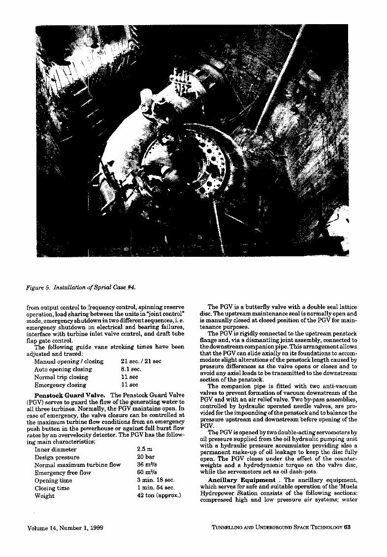
Figure 5. Installation of Sprial Case #4.
from output control to frequency control, spinning reserve operation, load sharing between the units in "joint control" mode, emergency shutdown in two different sequences, i. e. emergency shutdown ,on electrical and bearing failures, interface with turbine inlet valve control, and draft tube flap gate control.
The following guide vane stroking times have been adjusted and traced:
Manual opening / closing Auto opening closing Normal trip closing Emergency closing
Penstock Guard Valve .
21 sec. / 21 sec 8.1 sec. 11 sec 11 sec
The Penstock Guard Valve (PGV) serves to guard the flow of the generating water to all three turbines. Normally, the PGV maintains open. In case of emergency, the valve closure can be controlled at the maximum turbine flow conditions from an emergency push button in the powerhouse or against full burst flow rates by an overvelocity detector. The PGV has the follow- ing main characteristics:
Inner diameter Design pressure Normal maximum turbine flow Emergency free flow Opening t ime Closing time Weight
2 .5m 20 bar 36 mVs 60 mS/s 3 min. 18 sec. I min. 54 sec. 42 ton (approx.)
The PGV is a butterfly valve with a double seal lattice disc. The upstream maintenance seal is normally open and is manually closed at closed position of the PGV for main- tenance purposes.
The PGV is rigidly connected to the upstream penstock flange and, via a dismantling joint assembly, connected to the downstream companion pipe. This arrangement allows that the PGV can slide axially on its foundations to accom- modate slight alterations of the penstock length caused by pressure differences as the valve opens or closes and to avoid any axial loads to be transmitted to the downstream section of the penstock.
The companion pipe is fitted with two anti-vacuum valves to prevent formation of vacuum downstream of the PGV and with an air relief valve. Two by-pass assemblies, controlled by hydraulic operated needle valves, are pro- vided for the impounding of the penstock and to balance the pressure upstream and downstream before opening of the PGV.
The PGV is opened by two double-acting servomotors by oil pressure supplied from the oil hydraulic pumping unit with a hydraulic pressure accumulator providing also a permanent make-up of oil leakage to keep the disc fully open. The PGV closes under the effect of the counter- weights and a hydrodynamic torque on the valve disc, while the servomotors act as oil dash-pots.
A n c i l l a r y E q u i p m e n t . The ancillary equipment, which serves for safe and suitable operation of the 'Muela Hydrepower Station consists of the following sections: compressed high and low pressure air systems; water
Volume 14, Number 1, 1999 TUNNELLING AND UNDERGROUND SPACE TECHNOLOGY 63
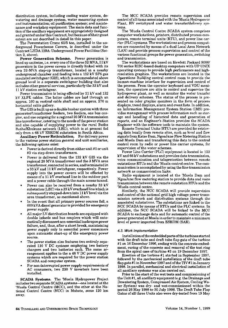
distribution system, including cooling water system, de- watering and drainage system, water measuring system and instrumentation; oil purification system; and mainte- nance and workshop equipment. The main data and func- tion of the ancillary equipment are appropriately designed and granted under this Contract, but because of their great extent are not described in detail in this paper.
The Powerstation Crane 60/5 ton, installed in the un- derground Powerhouse Cavern, is described under the Contract LHDA 129A: Underground Power Facilities (Sec- tion 2, above).
P o w e r G e n e r a t i o n Scheme. Power generation is lined up unitwise, i.e. every one of the three 32 MVA, I I kV generators in the power cavern is directly linked with its own 32-MVA step-up transformer, located in a nearby underground chamber and feeding into a 132 kV SF6 gas insulated switchgear (GIS), which is accommodated above ground level in a separate switchgear building that also includes other general services, particularly the 33 kV and 11 kV station switchgear.
Power transmission is being effected by 11 kV and 132 kV XLPE cables. The latter cables are laid through an approx. 160 m vertical cable shaft and an approx. 270 m horizontal cable gallery.
The GIS is built up as a double busbar system with three generator/transformer feeders, two feeders, one bus cou- pler, and one outgoing for a regional 20 MVA transmission line transformer, catering to the needs of the power station and also capable of supplying power to the rural Butha Buthe/Khukune network (LEC), which is at present fed only from a 66 kV ESKOM substation in South Africa.
Auxiliary Power Reticulat ion. For delivery power to the various power station general and unit auxiliaries, the following options exist:
• Power is derived directly from either unit # 1 or unit #3 via step-down transformers.
• Power is delivered from the 132 kV GIS via the regional 20 MVA transformer and the 3 MVA area transformer, connected in series, and terminated in a 33 kV and 11 kV switchgear, respectively. Power supply into the power cavern will be effected by means of a 11 kV overhead line in the outdoor part and a power cable through the main access tunnel.
• Power can also be received from a nearby 33 kV substation (LEC) via a 33 kV overhead line which is subsequently stepped-down into 11 kV level via the area transformer, as mentioned above.
• In the event that all primary power sources fail, a 600 kVA diesel generator is provided for emergency power supply.
• All major LV distribution boards are equipped with double infeeds and bus couplers which will auto- matically disconnect non-essential loads upon power failure, and, thus, after a short break, maintaining power supply only to essential power consumers upon automatic start-up of the emergency power source.
• The power station also features two entirely sepa- rated 110 V DC systems employing two battery chargers and two batteries each. The same ar- rangement applies to the a 48 V DC power supply systems which are required for the power station SCADA and computer system.
• For non-interrupted power supply requirements of AC consumers, two 230 V inverters have been installed.
SCADA Systems. The 'Muela Hydropower Project includes two separate SCADA systems--one located at the 'Muela Control Centre (MCC), and the other at the Na- tional Control Centre (NCC) in Mabote, some 120 km away.
The MCC SCADA provides remote supervision and control of all items associated with the 'Muela Hydropower Plant, HV switchyard and water transfer/delivery sys- tems.
The 'Muela Control Centre SCADA system comprises computer workstations, printers, distributed process com- puters, remote terminal units (RTU), and power line car- rier (PLC) systems. The workstations and process comput- ers are connected by means of a dual Local Area Network (LAN) and provide process supervision and control of the various functional groups for power generation, switching and transmission.
The workstations are based on Hewlett Packard 9000/ 700 series RISC-based desktop computers with UP UNIX operating systems to provide high performance and high- resolution graphics. The workstations are located in the Operations Building central control room to provide the human-machine interface for supervision and control of the process. From the operator keyboard and VDU moni- tors, the operators are able to control and supervise the hydropower plant, as well as monitor the water transfer and delivery schemes. The status of the process is pre- sented on color graphic monitors in the form of process displays, trend displays, alarm and event lists. In addition, an Information Management System Station (IMS) pro- vides management with process information such as stor- age and handling of historical data and generation of reports, and an Engineer's Station provides the SCADA Engineer with the software tools to maintain the system.
Remote Terminal Units (RTU) are provided for retriev- ing data locally from remote sites, such as level and flow signals from Katse Dam, NgoaJane Flow Metering Station and Muela Dam and transferring this data to the central control room by radio or power line carrier systems, for supervision of the water schemes.
Power Line Carrier (PLC) equipment is located in 132 kV and 66 kV substations and provides data transmission, voice communication and teleprotection between remote outstations RTUs and the 'Muela control centre. The com- munication is accomplished by using the line transmission network as communication links.
Radio equipment is located at the 'Muela Dam and NgoaJane flow metering station to provide data and voice transmission between the remote outstation RTUs and the 'Muela control centre.
Similarly, the NCC SCADA will provide supervision and control of the national grid high voltage power trans- mission network and distribution systems through the associated substations. The substations are linked to the NCC SCADA by means of RTUs and the PLC systems. In addition, the NCC SCADA will be linked to the MCC SCADA to exchange data and for automatic control of the power generated at Muela in order to maintain a minimum level of power imported from ESKOM (SAR).
4.3. Work Implementation
Installation of the embedded parts of the turbines started with the draft tube and draft tube flap gate of the turbine #1 on 16 December 1996, ending with the concrete embed- ment, curing of the concrete and removal of the test ring from the spiral case of turbine #3 on 19 December 1997.
Erection of the turbine #1 started in September 1997, followed by the mechanical installation of the draft tube flap gate #1 in November 1997 and of the TIV #1 in January 1998. In parallel, mechanical and electrical installation of all ancillary systems was also carried out.
Prior to the start of the wet tests and commissioning of the Unit #1, all ancillary equipment (e.g. the Drainage and Dewatering System, Compressed Air System, Cooling Wa- ter System) was dry- and wet-commissioned within the period 26 May 1998 to 30 July 1998. The Draft Tube Flap Gates of all three Units also were dry-tested from 19 May
64 TUNNELLING AND UNDERGROUND SPACE TECHNOLOGY Volume 14, Number i, 1999
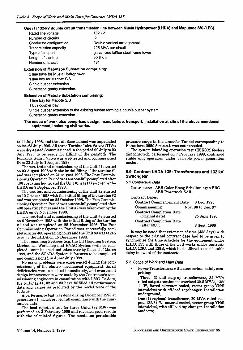
Table 3. Scope of Work and Main Data for Contract LHDA 136.
One (1) 132-kV double circuit transmission line between Muela Hydropower (LHDA) and Maputsoe SiS (LEC). Rated line voltage 132 kV Number of circuits 2 Conductor configuration Double vertical arrangement Transmission capacity 105 MVA per circuit Type of support galvanized lattice steel frame tower Length of the line 60.8 km Number of towers 181
Extension of Mapultsoe Substation comprising: 2 line bays for Muela Hydropower 1 line bay for Mabote S/S Single busbar extension Substation gantr/extension.
Extension of Mabote Substation comprising: 1 line bay for Mabote S/S 1 bus coupler bay Single busbar extension to the existing busbar forming a double busbar system Substation gantry extension.
The scope of work also comprises design, manufacture, transport, installation at site of the above-mentioned equipment, including civil works.
to 11 July 1998, and the Tail Race Tunnel was impounded on 22-23 July 1998. A1]. three Turbine Inlet Valves (TIVs) were dry-tested / commissioned in the period 09 July to 20 July 1998 to be ready for filling of the penstock. The Penstock Guard Valve was wet-tested and commissioned from 23 July to 1 August 1998.
The wet-test and commissioning of the Unit #1 star ted on 03 August 1998 with the initial filling of the turbine #1 and was completed on 21 August 1998. The Post Commis- sioning Operation Period was successfully completed after 400 operating hours, and the Unit # 1was taken over by the LHDA on 9 September 1998.
The wet test and coramissioning of the Unit #2 started on 10 October 1998 with the initial filling of the turbine #2 and was completed on 2;2 October 1998. The Post Commis- sioning Operation Period was successfully completed after 400 operating hours and the Unit #2 was taken over by the LHDA on 08 November 1998.
The wet-test and commissioning of the Unit #3 started on 9 November 1998 with the initial filling of the turbine #1 and was completed on 25 November 1998. The Post Commissioning Operation Period was successfully com- pleted after 400 operating hours and the Unit 93 was taken over by the LHDA on 15 December 1998.
The remaining Sections (e.g. the Oil Handling System, Mechanical Workshop and HVAC System) will be com- pleted, commissioned and taken over by the end of March 1999, and the SCADA System is foreseen to be completed and commissioned in June/July 1999.
No major problems were experienced during the com- missioning of the electro -mechanical equipment. Small deficiencies were remedied immediately, and even small design improvements were made by the Contractor's com- missioning engineers in consultation with LMC. To date, the turbines 41, #2 and #3 have fulfilled all performance data and values as predicted by the model tests of the turbine.
A performance test was done during December 1998 at generator #1, which proved full compliance with the guar- anteed data.
The load rejection test for three Units (82 MW) was performed on 3 February 1999 and revealed good results with the calculated fil,mres. The maximum permissible
pressure surge in the Transfer Tunnel corresponding to Katse level 2050.8 m.a.s.l, was not exceeded.
The system islanding operation test (ESKOM feeders disconnected), performed on 7 February 1999, confirmed stable unit operation under variable power generation modes.
5.0 Contract LHDA 135: Transformers and 132 kV Switchgear 5.1 Contractual Data
Contractors: ABB Calor Emag Schaltanlagen FRG ABB Powertech SAR
Contract Dates: Contract Commencement Date 8 Dec. 1993 Commissioning Nov. 96 to Dec. 97 Contract Completion Date
(original date) 25 June 1997 Contract Completion Date
(after EOT) 3 Sept. 1998
It may be noted that extension of time (455 days) with respect to the original contract date had to be given to synchronize the time schedule for the equipment under LHDA 135 with those of the civil works under contracts LHDA 129A and 129B, which had suffered a considerable delay in award of the contracts.
5.2. Scope of Work and Main Data
• Power Transformers with accessories, mainly com- prising: -Three (3) unit step-up transformers, 32 MVA rated output (continuous overload 32.5 MVA), 138/ 11 W, forced oil/water cooled, vector group YNdl (star/delta) with off-load tapchanger. Installation underground;
-One (1) regional transformer, 20 MVA rated out- put, 132/34 W, natural cooled, vector group YNdl (star/delta), with off-load tap changer. Installation outdoors;
Volume 14, Number i, 1999 ~LLING AND UNDERGROUND SPACE TECHNOLOGY 65

- O n e (1) area transformer, 3 MVA rated output, 33/ 12 W, natural cooled, vector groupYNyn0 (star/ star) with on-load tap-changer. Installation out- doors;
- O n e (1) lot of siliciumoxyde surge arresters for the above transformers;
- O n e (1) fire deluge system for 3 unit step-up trans- formers;
• One (1) 132 kV SF6 gas insulated, double busbar switchgear installation (GIS) with associated equip- ment, indoor installed plant, mainly comprising:
-Two (2) transmission line feeders to Maputsoe S/S; -Three (3) cable feeders for unit step-up transformers; -One (1) t ransformer for regional transformer; -One (1) busbar coupler.
• Outdoor installed equipment, mainly comprising: -S ix (6) capacitive voltage transformers (CVT) for
measuring and coupling to power line carrier sys- tems, connected to the 2*3 phases of the outgoing transmission lines;
-S ix (6) siliciumoxyde surge arresters (SA), con- nected to the 2*3 phases of the outgoing transmis- sion lines;
-Two (2) line traps for blocking of power line carrier signals installed in the center phase of every trans- mission line system;
- O n e (1) terminal gantry of the galvanized, steel lattice tower type.
• The scope of work also comprises design manufac- ture, transport, installation, commissioning of the mentioned equipment, excluding civil works.
5.3. Work Implementation
Installation of the GIS began in October 1996 and was completed in February 1997. The GIS is installed indoor in a substation building next to the Plant Operation Building. The outdoor portion (gantry, CVT, and SA) forms the physical interface with the transmission line under con- tract LHDA 136.
During assembly of the GIS, a series of mechanical tests (gas tightness, functional operation of switchgear, etc.) was performed. There was no fur ther activity throughout one year following the erection progress of the power station electromechanical equipment under contract LHDA 134.
In December 1997 all electrical functional tests and interface signal checks were performed, and permanent energizing took ult imately place on 6 August 1998.
Delivery and site assembly of the various transformers followed a different schedule which was governed by the availability of the relevant t ransformer foundations:
• Three unit step-up t ransformers located in the power c a v e r n as t he l ink b e t w e e n the hydrogenerators and the GIS were delivered to site and assembled in sequence during August/Septem- ber 1997; site tests were performed subsequently. Energizing took place in line with the unit commis- sioning program.
• One regional t ransformer installed outdoor next to the GIS and also fed from the same is to fulfill a dual purpose, i.e. to provide auxiliary power for the hydropower station and to expert power into the regional area of Khukune and Butha Buthe as part of the rural LEC 33 kV network.
The transformer was delivered to site and assembled during November 96 and subsequently site tested. Permanent energizing took place only late in con- junction with the GIS. One area t ransformer installed outdoor next to the regional t ransformer is linked with the regional t ransformer on the 33 kV side and is meant to supply 11 kV power solely for the hydropower sta- tion. Installation and permanent energizing of this t ransformer followed the same schedule as the regional transformer.
6.0 Contract LHDA 136:132 kV Transmission Lines and Substation Bays 6.1. Contractual Data
C o n t r a c t o r s : Main contractor - - Norelec (France) Subcontractor for civil works - - Thescons (Lesotho) Subcontractor for tower erection - - Helibib CC Sar
Contract Commencement Date 25 July 1995 Start Commissioning 19 February 1998 Contract Completion Date 13 June 1998
6.2 Scope of Work and Main Data The scope of the work and main technical data for this
contract are given in Table 3.
6.3 Work Implementation A most essential par t of the works under this contract
was construction of the 132 kV transmission line. The final land survey of the transmission line route was
completed at the beginning of July 1996, followed by a soil investigation on 34 locations typical of the landscape dur- ing February 1997.
In the course of 1997, all tower foundations were con- structed, and the first tower erection test was done in December of same year. Due to the part ly inaccessible terrain and a t ime delay already encountered, the Contrac- ter decided to erect the towers with the help of a helicopter.
At the end oftewer erection, the working procedure was highly optimized by preassembly of tower segments, re- fined logistics, and experience ofworkforce: 3 towers could be erected per 45 minutes, yielding 15 towers per day. In the total run, an average of 9 towers could be erected per day.
Since tower erection with helicopter is a highly skilled and risky task for all participants, it is worth mentioning that no major injuries or accidents occurred during this process.
Stringing of conductors had to be carried out "under tension", i.e conductors could not touch the ground or other obstacles. This procedure is a special technology and had never been carried out in Lesotho before. Therefore, local employees had to undergo a period of training before the expected progress and performance could be achieved. Stringing was completed in July 1998, with an average progress of 2.8 km per week.
Parallel with erection of the transmission line, installa- tion of the electrical equipment in both of the substations was undertaken without problems.
Upon contract completion all equipment was handed over to LEC, the Lesotho network operator.
66 TUNNELLING AND UNDERGROUND SPACE TECHNOLOGY Volume 14, Number 1, 1999