CS2060 -HIGH SPEED NETWORKS PART-A UNIT I -HIGH SPEED NETWORKS
Upload
khangminh22Category
view
0download
0
. ------IND- 2007 0384 D-- EN- ------ 20070907 --- --- PROJET Design Principles High-speed Maglev System (MSB) Information
Introduction
Technical systems are developed, realised, approved and operated on the basis of gener-
ally accepted codes of engineering practice. There is no self-contained body of rules for
high-speed maglev systems. We have therefore compiled a set of generally applicable
guidelines for a high-speed maglev system that have been derived from development,
testing, approval and operation.
Project-neutral design principles have been drafted for high-speed maglev systems and
their individual subsystems. The "Eisenbahn-Bundesamt" (EBA - German Federal Railway
Authority) proposes to apply this documentation as "engineering rules" in the sense of
Section 3 Paragraph 1 of the "Magnetschwebebahn-Bau- und Betriebsordnung" (MbBO -
Maglev Construction and Operation Regulations).
Scope
This documentation applies to maglev systems in the Federal Republic of Germany in
accordance with the "Allgemeines Magnetschwebebahngesetz" (AMbG - General Maglev
System Act).
Structure of the Documentation
Similar to a basic standard, this documentation lays down the generally accepted techni-
cal and operational requirements for a high-speed maglev railway system that are pro-
ject-neutral. These requirements constitute the principles for the design, planning, reali-
sation and operation of high-speed maglev projects. Reference is also made to existing
engineering rules that apply to high-speed maglev systems.
The regulations according to DIN 820 have been applied by analogy in the preparation of
this documentation. The degree to which the requirements are binding has been defined
by reference to DIN 820, Part 2, E, and has been taken into consideration when formulat-
ing the individual requirements.
The documentation comprises the MSB design principles listed in the table below.

Complete System
Doc.No.
50630 Complete System
(GS)
67536 GS – Annex 1 Abbreviations and Definitions
67539 GS – Annex 2 Statutes, Regulations, Standards and Directives
67285 GS – Annex 3 Environmental Conditions
69061 GS – Annex 4 Rules for Operation (Train Operation and Maintenance)
72963 GS – Annex 5 Noise
Vehicle
Doc.No.
67698 Vehicle Part I General Requirements
67694 Vehicle Part II Design
67650 Vehicle Part III Kinematic Gauge
73388 Vehicle Part IV Levitation/Guidance System
73389 Vehicle Part V Brake System
Drive and energy supply
Doc.No.
50998 Drive and energy supply
Operation Control System
Doc.No.
53328 Operation Control System

Guideway
Doc.No.
57284 Guideway Part I Primary Requirements
57288 Guideway Part II Design
41727 Guideway Part III Geometry
60640 Guideway Part IV Alignment
60641 Guideway Part V Surveying
63842 Guideway Part VI Maintenance
Table: MSB Design Principles
Copyright
The copyright in the published documentation and all attachments remains with the re-
spective author according to the relevant statutory provisions. All rights reserved.
Status of the Procedure
The acceptance of the documentation by the various individual Technical Committees on
15.02.2007 completes the process of national agreement.
Procedure for the Provision of Information pursuant to Directive
98/34/EC
The requirements of Directive 98/34 are complied with on completion of the process of
national agreement.
Publication by the Federal Railway Authority
The Federal Railway Authority publishes the documentation in its capacity as manage-
ment of the high-speed maglev system technical committees. The technical committees
alone are responsible for the content of the documentation.
Equivalence Clause
Vehicles and operating plant from other Member States of the European Community or
Turkey or from an EFTA State that is a party to the EEA Agreement are also permitted
provided the same level of traffic safety as contained in the high-speed maglev system
design principles is guaranteed.
Note
The obligations laid down in Directive 98/34/EC of the European Parliament and of the
Council of 22 June 1998 laying down a procedure for the provision of information in the
field of technical standards and regulations and of rules on Information Society services
(OJ L 204 Page 37), as amended by Directive 98/48/EC of the European Parliament and
of the Council of 20 July 1998 (OJ L 217 Page 18), have been complied with.

Revision status of the complete document
Revised 20.06.2007

Rapid Maglev System
Design Principles Maglev Technical
CommitteeComplete System
Title High-speed Maglev System Design Principles
Complete System
Doc.No.: 50630 Version White paper
Issue date 15.02.2007 Page 5
Prin
tout
: 13/
09/2
007
10:4
2:00
High-speed Maglev System Design Principles Complete System
The author reserves the copyright in this document and all attachments. All rights reserved

Rapid Maglev System
Design Principles Maglev Technical
CommitteeComplete System
Title High-speed Maglev System Design Principles
Complete System
Doc.No.: 50630 Version White paper
Issue date 15.02.2007 Page 6
Prin
tout
: 13/
09/2
007
10:4
2:00
Distribution This document has been released for publication by the Technical Committee "Complete Sys-tem".

Rapid Maglev System
Design Principles Maglev Technical
CommitteeComplete System
Title High-speed Maglev System Design Principles
Complete System
Doc.No.: 50630 Version White paper
Issue date 15.02.2007 Page 7
Prin
tout
: 13/
09/2
007
10:4
2:00
Change history Release date: 15.02.2007; white paper, Technical Committee "Complete System"

Rapid Maglev System
Design Principles Maglev Technical
CommitteeComplete System
Title High-speed Maglev System Design Principles
Complete System
Doc.No.: 50630 Version White paper
Issue date 15.02.2007 Page 8
Prin
tout
: 13/
09/2
007
10:4
2:00
List of contents
Distribution ............................................................................................................................................ 6
Change history ...................................................................................................................................... 7
List of contents...................................................................................................................................... 8
General ................................................................................................................................................. 14 Purpose of the document, scope........................................................................................................... 14 High-speed Maglev System Design Principles...................................................................................... 14 Abbreviations and definitions ................................................................................................................ 15 Statutes, regulations, standards and directives .................................................................................... 15 Identification and binding value of requirements................................................................................... 15
System Characteristics....................................................................................................................... 17 Function................................................................................................................................................. 17 Transport ............................................................................................................................................... 17 Speed .................................................................................................................................................... 17 Acceleration........................................................................................................................................... 18 Track alignment ..................................................................................................................................... 18 Alignment data....................................................................................................................................... 19 Dimensioning limiting accelerations ...................................................................................................... 22 Clearance gauge and line cross-section ............................................................................................... 22 System structure.................................................................................................................................... 23 Availability.............................................................................................................................................. 23 Reliability ............................................................................................................................................... 24 Failure performance/failure frequency of active modules ..................................................................... 24 Failure performance/failure frequency of structural and cladding components .................................... 24 Maintainability........................................................................................................................................ 24 Requirements for modules and cabling................................................................................................. 24 Inspectability of modules ....................................................................................................................... 25 Maintenance .......................................................................................................................................... 25 Basic approach...................................................................................................................................... 25 Repairs .................................................................................................................................................. 25 Useful life ............................................................................................................................................... 25

Rapid Maglev System
Design Principles Maglev Technical
CommitteeComplete System
Title High-speed Maglev System Design Principles
Complete System
Doc.No.: 50630 Version White paper
Issue date 15.02.2007 Page 9
Prin
tout
: 13/
09/2
007
10:4
2:00
Rating of parts and modules ................................................................................................................. 26 Safety..................................................................................................................................................... 26 Safety concept....................................................................................................................................... 26 Project-specific safety requirements ..................................................................................................... 26 Project-neutral safety requirements ...................................................................................................... 27 Protection of persons............................................................................................................................. 27 Fire safety.............................................................................................................................................. 28 Fire safety in the vehicle........................................................................................................................ 28 Fire safety in installations ...................................................................................................................... 28 Collisions ............................................................................................................................................... 28 Collision avoidance................................................................................................................................ 28 Collision behaviour ................................................................................................................................ 29 Departure from the guideway ................................................................................................................ 30 Unscheduled stop.................................................................................................................................. 30 Track sections adjacent to the platform area of stations....................................................................... 30 Service stopping places (BHPL)............................................................................................................ 30 Drive malfunctions ................................................................................................................................. 31 Rescue concept..................................................................................................................................... 33 Proof of safety ....................................................................................................................................... 33 Environment .......................................................................................................................................... 33 Effects from the environment ................................................................................................................ 33 Wind....................................................................................................................................................... 33 Winter .................................................................................................................................................... 33 Electromagnetic interference................................................................................................................. 34 Effects on the environment.................................................................................................................... 34 Noise...................................................................................................................................................... 34 Magnetic, electric and electromagnetic interference............................................................................. 34 Travelling comfort .................................................................................................................................. 34 Comfort-relevant aspects of alignment.................................................................................................. 34 Comfort-relevant vibration (rms values) ................................................................................................ 34 Pressure fluctuations in tunnels ............................................................................................................ 35
System concept/design ...................................................................................................................... 36 Subsystems ........................................................................................................................................... 36 MSB Vehicle .......................................................................................................................................... 36

Rapid Maglev System
Design Principles Maglev Technical
CommitteeComplete System
Title High-speed Maglev System Design Principles
Complete System
Doc.No.: 50630 Version White paper
Issue date 15.02.2007 Page 10
Prin
tout
: 13/
09/2
007
10:4
2:00
Structure ................................................................................................................................................ 36 Vehicle boundary................................................................................................................................... 36 Car body ................................................................................................................................................ 36 Functions ............................................................................................................................................... 36 Support and guide ................................................................................................................................. 36 Safe Brake............................................................................................................................................. 37 On-board energy supply ........................................................................................................................ 38 Configuration parameters ...................................................................................................................... 38 Vehicle configuration ............................................................................................................................. 38 Running resistance................................................................................................................................ 39 Aerodynamics........................................................................................................................................ 40 Drive and energy supply........................................................................................................................ 40 Structure ................................................................................................................................................ 40 Functions ............................................................................................................................................... 41 Configuration parameters ...................................................................................................................... 43 Operation Control System ..................................................................................................................... 44 Structure ................................................................................................................................................ 44 Functions ............................................................................................................................................... 44 Configuration parameters ...................................................................................................................... 46 Guideway............................................................................................................................................... 47 Structure ................................................................................................................................................ 47 Functions ............................................................................................................................................... 48 Configuration parameters ...................................................................................................................... 48 Guideway superstructures..................................................................................................................... 48 Guideway substructures ........................................................................................................................ 50 Track-switching devices ........................................................................................................................ 50 Special structures .................................................................................................................................. 50 Route peripherals .................................................................................................................................. 52 Guideway equipment............................................................................................................................. 52 Boundary lines and dimensions for fixed internals and vehicles........................................................... 56 Tolerances, deviations of position ......................................................................................................... 56 Other operating plant............................................................................................................................. 56 Stations.................................................................................................................................................. 57 Substations............................................................................................................................................ 58 Operations centre .................................................................................................................................. 58

Rapid Maglev System
Design Principles Maglev Technical
CommitteeComplete System
Title High-speed Maglev System Design Principles
Complete System
Doc.No.: 50630 Version White paper
Issue date 15.02.2007 Page 11
Prin
tout
: 13/
09/2
007
10:4
2:00
Stopping places ..................................................................................................................................... 58 Maintenance installations ...................................................................................................................... 58 Special vehicle....................................................................................................................................... 58 Interfaces and cross-subsystem functions ............................................................................................ 59 Loads and effects .................................................................................................................................. 59 Positioning ............................................................................................................................................. 62 Purpose and structure ........................................................................................................................... 62 Functional requirements ........................................................................................................................ 62 Constructional requirements ................................................................................................................. 63 Verification............................................................................................................................................. 63 Operation............................................................................................................................................... 63 Difference between Operation and Modes............................................................................................ 63 Definition of Operation........................................................................................................................... 63 Definition of Modes................................................................................................................................ 64 Principles for the application of the modes............................................................................................ 65 Operational functions and procedures .................................................................................................. 65 Journey inputs and operations monitoring ............................................................................................ 65 Departure from a station in normal operation........................................................................................ 65 Approach to a station in normal operation............................................................................................. 65 Activating and deactivating of MSB vehicles......................................................................................... 65 Processing automatic stops of MSB vehicles........................................................................................ 66 Constraints for moving the special vehicles .......................................................................................... 66
Quality management ........................................................................................................................... 67
Figures.................................................................................................................................................. 68 Document tree ....................................................................................................................................... 68 System structure and system of coordinates ........................................................................................ 69 MSB vehicle sections for passenger transport ...................................................................................... 74 Levitation/guide system......................................................................................................................... 78 Braking curve Safe Brake...................................................................................................................... 79 Running resistance................................................................................................................................ 80 Pressure effect (outside tunnels)........................................................................................................... 81 Structure of the energy supply .............................................................................................................. 82 Structure and functions of the drive....................................................................................................... 83 Structure and functions of the operation control system....................................................................... 85

Rapid Maglev System
Design Principles Maglev Technical
CommitteeComplete System
Title High-speed Maglev System Design Principles
Complete System
Doc.No.: 50630 Version White paper
Issue date 15.02.2007 Page 12
Prin
tout
: 13/
09/2
007
10:4
2:00
Structure of the positioning.................................................................................................................... 89 Elevated guideway ................................................................................................................................ 90 At-grade guideway................................................................................................................................. 90 Beam dimension.................................................................................................................................... 91 Guideway equipment and functional planes.......................................................................................... 92 Stator pack arrangement ....................................................................................................................... 93 Long-stator winding ............................................................................................................................... 94 Track-switching devices ........................................................................................................................ 95 Protective structures............................................................................................................................ 101 Route peripherals ................................................................................................................................ 103
Annex: High-speed Maglev System Data........................................................................................ 105 List of illustrations Figure 1: Document tree High-speed Maglev System Design Principles...............................68 Figure 2: System structure .....................................................................................................71 Figure 3: System of coordinates.............................................................................................71 Figure 4: System of coordinates and direction of travel .........................................................72 Figure 5: Layout of winding legs, reference position, exciter poles........................................73 Figure 6: Vehicle sections for passenger transport long-haul (example) ...............................75 Figure 7: Vehicle end sections for passenger transport airport link (example) ......................76 Figure 8: Vehicle centre sections for passenger transport airport link (example) ..................77 Figure 9: Levitation/guide system (example)..........................................................................78 Figure 10: Braking characteristic of safe brake for an MSB vehicle section. .........................79 Figure 11: Running resistance (airport link - planning status 2006) .......................................80 Figure 12: Pressure effect from a passing MSB vehicle (outside tunnels) (airport link -
planning status 2006) ......................................................................................................81 Figure 13: Structure of the energy supply (example) .............................................................83 Figure 14: Structure of the drive (example)............................................................................83 Figure 15: Functions of the drive............................................................................................84 Figure 16: Placement and interfaces of the OCS...................................................................85 Figure 17: OCS functions and data flows...............................................................................87 Figure 18: Structure of the positioning (example) ..................................................................89 Figure 19: Elevated guideway (example) ...............................................................................90 Figure 20: At-grade guideway (example) ...............................................................................90 Figure 21: Beam dimension - Relationship between component length and system length ..91
Rapid Maglev System
Design Principles Maglev Technical
CommitteeComplete System
Title High-speed Maglev System Design Principles
Complete System
Doc.No.: 50630 Version White paper
Issue date 15.02.2007 Page 13
Prin
tout
: 13/
09/2
007
10:4
2:00
Figure 22: Functional elements, functional planes and installation spaces on the guideway, dimensions (nominal).......................................................................................................92
Figure 23: Stator pack arrangement (example)......................................................................93 Figure 24: Long-stator winding (example)..............................................................................94 Figure 25: Point (example) .....................................................................................................96 Figure 26: Traverser (example)..............................................................................................98 Figure 27: Turntable (example) ............................................................................................100 Figure 28: Noise barrier and fence on at-grade guideway (example) ..................................101 Figure 29: Noise barrier on elevated guideway (example)...................................................102 Figure 30: Route peripherals with at-grade guideway (example).........................................103 Figure 31: Route peripherals with elevated guideway (example).........................................104
List of tables Table 1: Alignment data for maglev stops ..............................................................................19 Table 2: General alignment data ............................................................................................20 Table 3: Dependence Rxz min on warping α' ............................................................................20 Table 4: Overview of minimum vertical radii RVmin and horizontal radii RH .............................21 Table 5: Speed-dependent track centres ...............................................................................22 Table 6: Definition of effect conditions A / B...........................................................................60 Table 7: Effects at the vehicle/guideway interfaces ...............................................................61
Rapid Maglev System
Design Principles Maglev Technical
CommitteeComplete System
Title High-speed Maglev System Design Principles
Complete System
Doc.No.: 50630 Version White paper
Issue date 15.02.2007 Page 14
Prin
tout
: 13/
09/2
007
10:4
2:00
General
Purpose of the document, scope This documents lays down the technical and operational minimum requirements for a high-speed maglev rail system (MSB system) that are project-neutral. These requirements consti-tute the basis for the design, planning, realisation and operation of high-speed maglev pro-jects. Reference is also made to existing standards and directives that apply to high-speed maglev systems. These design principles apply to a high-speed maglev system according to the General Maglev System Act /AMbG/.
High-speed Maglev System Design Princi-ples This document forms part of a documentation for high-speed maglev systems consisting of multiple design principles. The document tree is shown in Figure 1. These high-level "com-plete system" design principles and their annexes apply uniformly for the whole documenta-tion. The documentation consists of the existing • High-speed Maglev System Design Principles Complete System, Doc. No.: 50630,
/MSB AG-GESAMTSYS/, with annexes: • Annex 1: Abbreviations and Definitions, Doc. No.: 67536, /MSB AG-ABK&DEF/ • Annex 2: Statutes, Regulations, Standards and Directives, Doc. No.: 67539, /MSB
AG-NORM&RILI/ • Annex 3: Environmental Conditions, Doc. No.: 67285, /MSB AG-UMWELT/ • Annex 4: Rules for Operation (Train Operation and Maintenance), Doc. No.:
69061, /MSB AG-BTR/ • Annex 5: Noise, Doc. No.: 72963, /MSB AG-SCHALL/
as well as the jointly applicable low-level documents: • High-speed Maglev System Design Principles Vehicle, Part I: General Requirements,
Doc. No.: 67698, /MSB AG-FZ GEN/ • High-speed Maglev System Design Principles Vehicle, Part II: Dimensioning, Doc.
No.: 67694, /MSB AG-FZ BEM/ • High-speed Maglev System Design Principles Vehicle, Part III: Kinematic Gauge,
Doc. No.: 67650, /MSB AG-FZ KIN/

Rapid Maglev System
Design Principles Maglev Technical
CommitteeComplete System
Title High-speed Maglev System Design Principles
Complete System
Doc.No.: 50630 Version White paper
Issue date 15.02.2007 Page 15
Prin
tout
: 13/
09/2
007
10:4
2:00
• High-speed Maglev System Design Principles Vehicle, Part IV: Support/Guidance System, Doc. No.: 73388, /MSB AG-FZ TRAFÜ/
• High-speed Maglev System Design Principles Vehicle, Part V: Brake System, Doc. No.: 73389, /MSB AG-FZ BREMS/
• High-speed Maglev System Design Principles Drive and Power Supply, Doc. No.: 50998, /MSB AG-ANT/
• High-speed Maglev System Design Principles Operation Control System, Doc. No.: 53328, /MSB AG-BLT/
• High-speed Maglev System Design Principles Guideway, Part I: High-level Require-ments, Doc No.: 57284, /MSB AG-FW ÜBG/
• High-speed Maglev System Design Principles Guideway, Part II: Dimensioning, Doc. No.: 57288, /MSB AG-FW BEM/
• High-speed Maglev System Design Principles Guideway, Part III: Geometry, Doc. No.: 41727, /MSB AG-FW GEO/
• High-speed Maglev System Design Principles Guideway, Part IV: Track Alignment, Doc. No.: 60640, /MSB AG-FW TRAS/
• High-speed Maglev System Design Principles Guideway, Part V: Surveying, Doc. No.: 60641, /MSB AG-FW VERM/
• High-speed Maglev System Design Principles Guideway, Part VI: Maintenance, Doc. No.: 63842, /MSB AG-FW IH/
Abbreviations and definitions The abbreviations and definitions given in /MSB AG-ABK&DEF/ apply.
Statutes, regulations, standards and direc-tives The normative documents listed in /MSB AG-NORM&RILI/ contain requirements that form part of the High-speed Maglev System Design Principles by cross reference in the High-speed Maglev System Design Principles. Where normative documents in /MSB AG-NORM&RILI/ are dated, subsequent changes or revisions of these publications do not apply. With undated references, the latest version of the normative document that is referred to applies. The version of the standards and directives to be observed in an MSB project must be decided bindingly on a project-specific basis.
Identification and binding value of require-ments The requirements of /DIN 820/ were essentially applied in the preparation of this document.

Rapid Maglev System
Design Principles Maglev Technical
CommitteeComplete System
Title High-speed Maglev System Design Principles
Complete System
Doc.No.: 50630 Version White paper
Issue date 15.02.2007 Page 16
Prin
tout
: 13/
09/2
007
10:4
2:00
In the following chapters and the annexes of this document • Requirements are shown in normal font • Explanations, guide values and examples are shown in italics
The degree to which the requirements are binding has been defined by reference to /DIN 820/, Part 2, Annex G, and has been taken into consideration when formulating the individual re-quirements.

Rapid Maglev System
Design Principles Maglev Technical
CommitteeComplete System
Title High-speed Maglev System Design Principles
Complete System
Doc.No.: 50630 Version White paper
Issue date 15.02.2007 Page 17
Prin
tout
: 13/
09/2
007
10:4
2:00
System Characteristics The coordinate system, direction of travel and assignment between reference points, phase windings and exciter poles are shown in Figure 3, Figure 4 and Figure 5.
Function The high-speed maglev system must be constructed as a track-guided transport system for passenger and/or goods traffic, and must have the following characteristics:
• Noncontact support/guidance function by controlled electromagnets (electromag-netic levitation technology, EMS), Chapter 0,
• Noncontact drive and brake function by synchronous long-stator linear drive, transformation of the controlled traction power at stationary plants, Chapter 0,
• Noncontact on-board energy supply of the MSB vehicles above a project-specifically defined speed at which the on-board power demand is fully covered, Chapter 0,
• Fully technically and automatically controlled train operation, Chapter 0, • Guideway elevated or at grade, Chapter 0.
The geometry of the guideway and the geometry of the devices that support and guide the vehicles must be harmonised with one another such that track guidance is guaranteed at the respective permitted speeds and with the alignment parameters, even when utilising the per-missible tolerances of the components. The forces that occur at the interface between the guideway and the devices for supporting, guiding, driving and braking in the vehicles, must be safely absorbed and transmitted, includ-ing in case of failure.
Transport
Speed The vehicle maximum speed, guideway maximum speed and tunnel maximum speed must be defined project-specifically. (see Chapter 0). Typical values for vehicle and guideway maximum speeds:
• long-haul traffic 400-500 km/h • airport link 300-400 km/h.
The journey maximum speed must be derived from the vehicle maximum speed, the guide-way maximum speed and the tunnel maximum speed. The design of the MSB vehicle must be based on the vehicle maximum speed. The design of the guideway must be based on the guideway maximum speed. The technical maximum speed can be defined project-specifically.

Rapid Maglev System
Design Principles Maglev Technical
CommitteeComplete System
Title High-speed Maglev System Design Principles
Complete System
Doc.No.: 50630 Version White paper
Issue date 15.02.2007 Page 18
Prin
tout
: 13/
09/2
007
10:4
2:00
Journeys in the speed range above the journey maximum speed and up to the technical maxi-mum speed may be carried out using reserves in dimensioning only after testing and approval in each separate case. During the design stage, the site-dependent nominal speed that is required for train opera-tions shall be calculated having regard to operational and economic aspects, and realised by the system configuration. For the definitions and relationships of the speed relative to each other, see also /MSB AG-ABK&DEF/, Chapter 5.
Acceleration Section 13, (5) /MbBO/ must be taken into consideration. This requirement is met as follows: The start-up and brake-related acceleration of a vehicle must not exceed 1.5 m/s². Exceptional influences shall be allowed for according to the requirements of Chapter 0. The mean and maximum drive acceleration should be defined project-specifically and accord-ing to site, and having regard to operational and economic aspects. The operationally usable brake retardation is limited by the braking capacity of the Safe Brake, by the train resistance and by the maximum running profile monitored by the OCS. For requirements relating to acceleration in the y and z direction, see Chapter 0.
Track alignment Section 13, (1) and Section 13, (7) /MbBO/ must be taken into consideration.

Rapid Maglev System
Design Principles Maglev Technical
CommitteeComplete System
Title High-speed Maglev System Design Principles
Complete System
Doc.No.: 50630 Version White paper
Issue date 15.02.2007 Page 19
Prin
tout
: 13/
09/2
007
10:4
2:00
Alignment data Section 13, (2); Section 13, (3); Section 13, (4) und Section 13, (6) /MbBO/ must be taken into consideration. The following values should also be adhered to: Values Criterion Platform area Scheduled stop Transverse inclination * ≤ 3.0 ° Wheelchair users, risk of
falling when boarding and alighting
Linear inclination ≤ 5 ‰ Service stopping place for operational stopping
Unscheduled stop, e.g. in case of operational or techni-cal faults
Transverse inclination ≤ 6 ° Wheelchair users, risk of falling
Linear inclination ≤ 100 ‰ according to proof of the holding function
Holding function
Other service stops Unscheduled infrequent stop, essentially for technical faults
Transverse inclination ≤ 12° Linear inclination ≤ 100 ‰
according to proof of the holding function
Holding function
Evacuation stops Unscheduled infrequent stop, in emergencies
Transverse inclination **) ≤ 6 ° Possibility of evacuation Linear inclination **) ≤ 5 ‰ Open stretch, outside stops
Unscheduled stop in excep-tional and very rare failure situations
Transverse inclination ≤ 12 ° up to 16 ° in special cases
Usability for alignment
Linear inclination ≤ 100 ‰ Usability for alignment *) /MbBO/ Section 13 (3) limits the permissible transverse inclination in the stationary train in the platform area to 3.4 °. The max. permitted transverse inclination of 3.0 ° for the align-ment is derived from this. **) Figures apply to the platform or walkway area within evacuation stops; the figures for other service stop apply outside these areas Table 1: Alignment data for maglev stops

Rapid Maglev System
Design Principles Maglev Technical
CommitteeComplete System
Title High-speed Maglev System Design Principles
Complete System
Doc.No.: 50630 Version White paper
Issue date 15.02.2007 Page 20
Prin
tout
: 13/
09/2
007
10:4
2:00
Characteristic Area Criterion for maximum value
Warping ≤ 0.10°/m, in special cases up to 0.15°/m *)
Kinematics of the MSB vehi-cle
Lateral and vertical jerk
• basically ≤ 0.5 m/s³ Comfort
• as an exception e.g. in station proximity
≤ 1 m/s³ Comfort
• on points at junction ≤ 2 m/s³ Comfort
Omnidirectional jerk (not at points)
≤ 1 m/s³ Comfort
*) Transverse inclination > 12 ° and warping > 0.10 °/m only at constraints of the alignment after testing and approval in each case. Table 2: General alignment data
The following values must also be adhered to as minimum radius in cases where horizontal radii and vertical radii are superimposed:
H
2
Vzx, Rcossin
Rcos
R1 βαα ∗
−=
β Linear inclination, positive on an incline, negative on a decline α Transverse inclination, positive on a right-hand bend, negative on a left-hand bend (in the direction of ascending kilometre markers) RH Horizontal radius RV Vertical radius, positive on a crown, negative in a trough α' [°/m] 0 0,01 0,02 0,03 0,04 0,05 0,06 0,07 0,08 0,09 0,10 0,11 0,12 0,13 0,14 0,15 Rx,z min [m]
530 550 590 630 670 710 770 830 900 990 1.100 1.230 1.410 1.640 1.950 2.430
Table 3: Dependence Rxz min on warping α'
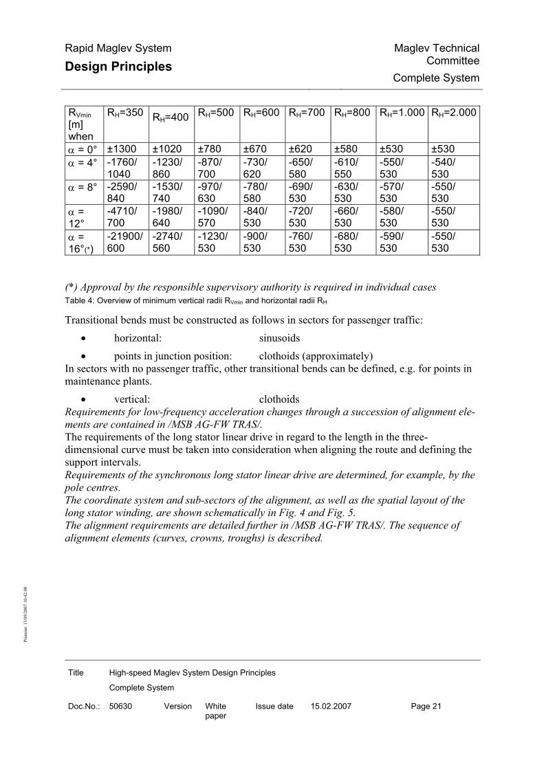
Allowing for the Rx,z criterion there is a minimum vertical radius RVmin with transverse incli-nation α of the guideway and horizontal radius RH according to the following table:
Rapid Maglev System
Design Principles Maglev Technical
CommitteeComplete System
Title High-speed Maglev System Design Principles
Complete System
Doc.No.: 50630 Version White paper
Issue date 15.02.2007 Page 21
Prin
tout
: 13/
09/2
007
10:4
2:00
RVmin [m] when
RH=350 RH=400 RH=500 RH=600 RH=700 RH=800 RH=1.000 RH=2.000
α = 0° ±1300 ±1020 ±780 ±670 ±620 ±580 ±530 ±530 α = 4° -1760/
1040 -1230/ 860
-870/ 700
-730/ 620
-650/ 580
-610/ 550
-550/ 530
-540/ 530
α = 8° -2590/ 840
-1530/ 740
-970/ 630
-780/ 580
-690/ 530
-630/ 530
-570/ 530
-550/ 530
α = 12°
-4710/ 700
-1980/ 640
-1090/ 570
-840/ 530
-720/ 530
-660/ 530
-580/ 530
-550/ 530
α = 16°(*)
-21900/ 600
-2740/ 560
-1230/ 530
-900/ 530
-760/ 530
-680/ 530
-590/ 530
-550/ 530
(*) Approval by the responsible supervisory authority is required in individual cases Table 4: Overview of minimum vertical radii RVmin and horizontal radii RH
Transitional bends must be constructed as follows in sectors for passenger traffic: • horizontal: sinusoids • points in junction position: clothoids (approximately)
In sectors with no passenger traffic, other transitional bends can be defined, e.g. for points in maintenance plants.
• vertical: clothoids Requirements for low-frequency acceleration changes through a succession of alignment ele-ments are contained in /MSB AG-FW TRAS/. The requirements of the long stator linear drive in regard to the length in the three-dimensional curve must be taken into consideration when aligning the route and defining the support intervals. Requirements of the synchronous long stator linear drive are determined, for example, by the pole centres. The coordinate system and sub-sectors of the alignment, as well as the spatial layout of the long stator winding, are shown schematically in Fig. 4 and Fig. 5. The alignment requirements are detailed further in /MSB AG-FW TRAS/. The sequence of alignment elements (curves, crowns, troughs) is described.

Rapid Maglev System
Design Principles Maglev Technical
CommitteeComplete System
Title High-speed Maglev System Design Principles
Complete System
Doc.No.: 50630 Version White paper
Issue date 15.02.2007 Page 22
Prin
tout
: 13/
09/2
007
10:4
2:00
Dimensioning limiting accelerations The free lateral acceleration (lateral to the guideway table) must not exceed the following values:
• Standard guideway 1.5 m/s² • Points 2.0 m/s².
The free dynamic normal acceleration (normal to the guideway table) must not exceed the following values:
• Crown 0.6 m/s² • Trough 1.2 m/s².
The lateral and vertical accelerations to be achieved in normal operation from aspects of com-fort should be defined project-specifically.
Clearance gauge and line cross-section The typical cross section must be defined project-specifically. Aspects of maintenance and safety must be taken into consideration as well as the clearance gauge according to /MbBO/. Clearance, track centres For the clearance gauges of the single and double track guideway, refer to /MSB AG-FW TRAS/. The values according to Table 5 must be achieved. Unit Design speed ve
Abb. [km/h] ≤ 300 ≤ 300*) 300 < ve ≤ 400 400 < ve ≤ 500 Track centres S [m] 4.40 4.50 4.80 5.10 Width of the line cross-section**) b [m] 10.10 10.20 10.50 11.40 *) for special conditions: 10° < α or 5° < α ≤ 10° and RH ≤ 3,500 m **) Figures for α = 0°. The values given allow for the clearance conditions for curve radii and guideway transverse inclination with the above limits, i.e. no increase in track centres on curves. Table 5: Speed-dependent track centres

Rapid Maglev System
Design Principles Maglev Technical
CommitteeComplete System
Title High-speed Maglev System Design Principles
Complete System
Doc.No.: 50630 Version White paper
Issue date 15.02.2007 Page 23
Prin
tout
: 13/
09/2
007
10:4
2:00
System structure Section 2, (2) and Section 2, (3) /MbBO/ must be taken into consideration. Within the scope of these design principles, the MSB system is divided into the following sub-systems contrary to the designation in the /MbBO/ (see Figure 2):
• MSB vehicle • Drive and energy supply • Operation Control System • Guideway • Other operating plant • Special vehicle.
Availability The complete system must have the following characteristics in order to achieve a high degree of availability:
• a guideway dimensioned to be operationally stable, no permanent geometry or sur-face alterations of the guideway beams as a result of defined operational and envi-ronmental impacts, adjustable guideway beam position to offset plastic soil defor-mations,
• realisation of the operationally necessary active functions to be extensively modu-lar, with autonomous, redundant modules,
• continuation of schedule operation following isolated faults in any desired mobile or static module,
• extensively status-oriented maintenance based on automatic failure disclosure with electrical/electronic modules,
• automated detection of significant changes in position of the guideway functional surface and largely automated initiation of maintenance actions,
• maintenance work carried out with the least possible impact on train operations. The quantitative requirements for the system availability should be defined project-specifically. The system availability should be measured in every project. A fault tree analysis can be used for this purpose, for example. The system must be designed so that:
• train operations according to Chapter 0 are assured, • the required availability is achieved by high module reliability or by redundancy or
both,

Rapid Maglev System
Design Principles Maglev Technical
CommitteeComplete System
Title High-speed Maglev System Design Principles
Complete System
Doc.No.: 50630 Version White paper
Issue date 15.02.2007 Page 24
Prin
tout
: 13/
09/2
007
10:4
2:00
• MSB vehicles do not have to stop between two stations because of individual technical faults,
• in case of an availability-relevant fault the train can still be moved to the mainte-nance facility.
It must be remembered that MSB vehicles cannot be towed away.
Reliability
Failure performance/failure frequency of active modules In case of failure of an operationally relevant active module
• a redundant module must assume the function, • there must be automatic failure disclosure, • an automatic test and reactivation while maintaining the safe condition during and
after reactivation must take place as soon as the cause of the failure is no longer present.
The MTBF times must be determined for operationally relevant active modules.
Failure performance/failure frequency of structural and cladding components Structural parts of vehicle and guideway as well as vehicle cover panels must be sustainable, stable and fit for purpose. The resulting requirements for construction/choice of materials and proofs are contained in the "Design Principles Vehicle/Guideway". The influences to be allowed for in the design are given in /MSB AG-FZ BEM/ and /MSB AG-FW BEM/.
Maintainability Requirements for maintainability are contained in the Design Principles for the various indi-vidual subsystems. Basic requirements are listed below.
Requirements for modules and cabling So far as is economically meaningful, the service life of electrical and mechanical modules should be designed for the expected useful life of the respective subsystem. Modules whose service life is less than the expected useful life of the subsystems should be easy to access and replace. Modifications or rework should not be necessary when replacing modules. Testing and adjustment after module replacement should be avoided so far as possible by the appropriate design of the modules (e.g. self-calibration, self-test etc.). Opportunities for assembly and installation errors should be eliminated so far as possible by design. For plug-and-socket connections that carry safety-relevant signals, appropriate techni-cal measures (e.g. slot coding) should be taken to ensure that they can only be connected to their assigned location / device / module.

Rapid Maglev System
Design Principles Maglev Technical
CommitteeComplete System
Title High-speed Maglev System Design Principles
Complete System
Doc.No.: 50630 Version White paper
Issue date 15.02.2007 Page 25
Prin
tout
: 13/
09/2
007
10:4
2:00
Modules, cables and lines must be identified clearly, uniquely and systematically. A module's designation must clearly identify its version and, if applicable, the software release. A systematic identification must be used for the installation position of modules. It must be possible for failures to be disclosed by automatic diagnostic devices and / or by scheduled planned inspections.
Inspectability of modules Modules that must be inspected according to a maintenance schedule must be accessible for inspection.
Maintenance Section 8(1) Section 8(2) and Section 8(3) of the /MbBO/ must be observed. Requirements for operating rules (train operations and maintenance) are defined in /MSB AG-BTR/. Maintenance must conform to /DIN 31051/. The integration of maintenance into operations, and the dovetailing of maintenance with train operations must be defined project-specifically. A project-specific maintenance concept must be created.
Basic approach The specified maintenance actions must have an instruction manual for their execution which includes test reports /checklists for documenting the results. The maintenance of the subsystems must be integrated in the maintenance of the complete system, and a Maintenance Manual (MM) must be created for this purpose. The MSB subsystems may be divided up into suitable subject or topic units in which stan-dardised maintenance procedures can then be carried out. The effectiveness and appropriateness of the measures must be regularly reviewed on the ba-sis of the documented results. Suitable information systems must be put in place for this purpose, and for the purpose of supporting the maintenance management. The maintenance must be subject to quality management comparable with /DIN EN ISO 9000/.
Repairs A repair should be performed by the replacement of modules or on the basis of the smallest replaceable units that must be defined project-specifically. Each module or smallest replaceable unit must be replaceable and testable in itself. The lifecycle of replaced / repaired modules / smallest replaceable units must be clearly and traceably documented together with a description of the fault, particulars of the cause of the fault and the repair (or replacement by a new part as applicable).
Useful life The useful lives of subsystems and components must be defined project-specifically.

Rapid Maglev System
Design Principles Maglev Technical
CommitteeComplete System
Title High-speed Maglev System Design Principles
Complete System
Doc.No.: 50630 Version White paper
Issue date 15.02.2007 Page 26
Prin
tout
: 13/
09/2
007
10:4
2:00
The complete system must fulfil the specified requirements during the useful life when used according to specification (train operations and maintenance).
Rating of parts and modules Mechanical/structural parts/modules must be rated and proven
• according to the criteria of stability / load withstand capability and • fitness for purpose
on the basis of • the maximum influences arising out of operation and environment according to
/MSB AG-UMWELT/ and • the parameter range and failure behaviour specified in this document.
The dimensioning action combinations and loads are defined in /MSB AG-FZ BEM/ und /MSB AG-FW BEM/. The influences from operation and the environment on the basis of which the service strength and predicted service life of parts and modules is determined are defined in /MSB AG-FZ BEM/ and /MSB AG-FW BEM/. The limiting values that apply to all subsystems and on which the design must be based should be taken from Chapter 0.
Safety
Safety concept
Project-specific safety requirements Section 23, (1) and Section 23, (2) /MbBO/ must be observed. Guidance for design is given in the official justification for Section 23 /MbBO/. A project-specific safety concept must be created based on /EN 50126/. The safety concept must analyse and assess the project-specific risks on the basis of the safety-relevant requirements and characteristics of the MSB system specified in the Design Principles (see Figure 1), and must define risk-reducing measures (technical, structural, opera-tional and organisational). The safety concept must define project-specific safety objectives and a risk acceptance crite-rion. The project-specific risk analysis and assessment can be carried out as part of a risk analysis according to /EN 50126/. Information on methods will be found in /prEN 50126-2/ and /prR009-004/. The risk-reducing measures can be described in an action catalogue or action list. The requirements for the rescue concept, in particular procedures, decision criteria and re-sponsibilities, must be defined in the safety concept project-specifically. The risk analysis, risk list, action catalogue and rescue concept can form part of the project-specific safety concept.

Rapid Maglev System
Design Principles Maglev Technical
CommitteeComplete System
Title High-speed Maglev System Design Principles
Complete System
Doc.No.: 50630 Version White paper
Issue date 15.02.2007 Page 27
Prin
tout
: 13/
09/2
007
10:4
2:00
The risk analysis, risk list, action catalogue and rescue concept must be harmonised with each other project-specifically. Compliance with the maximum permissible number of persons in the MSB vehicle must be described in the safety concept. The residual risk should not exceed the defined risk acceptance criterion.
Project-neutral safety requirements The requirements listed in the following sections represent separate requirements for individ-ual risk aspects that are not the preserve of project-specific safety requirements. They shall not be a substitute for the systematic and project-specific analysis and assessment of all risks. The safety requirements for the functions must be derived from the risk analysis. Safety-relevant functions must be demonstrated according to the CENELEC standards (/ DIN EN 50126/, / DIN EN 50128/ and /DIN EN 50129/). The components and modules which are used to perform these functions must be demon-strated according to the product-specific standards (e.g. parent standard /DIN EN 61508-1/). Other requirements for safety-relevant functions are described in
• Chapter 0 and in the Design Principles for the subsystems, see Figure 1 and
• Chapter 0 for the protection of train operations.
Protection of persons Construction characteristics
• for fire safety are described in Chapter 0, • for the protection of persons in the MSB vehicle are described in /MSB AG-FZ
GEN/,
• for the protection of persons on the platform are described in Chapter 0 . The protective effect against a risk to persons from electrostatic discharge from the outer skin of the MSB vehicle according to /MbBO/ Section 17, (4) must be demonstrated. Specific measures for the occupational safety of the maintenance personnel must be defined project-specifically. For operations carried out within the danger area of the guideway (from the special vehicle or independently of it), e.g. maintenance or vegetation control, protection for the persons con-cerned must be defined project-specifically. The danger area must be defined project-specifically. Work carried out within the danger area of the guideway must be signalled in such a way that train movements that may put the persons affected at risk are made impossible. The route sec-tion that is affected must be closed before work commences and may not be signalled clear until work is complete. This line clear detection is a precondition for the issue of a clearance for the corresponding route section.

Rapid Maglev System
Design Principles Maglev Technical
CommitteeComplete System
Title High-speed Maglev System Design Principles
Complete System
Doc.No.: 50630 Version White paper
Issue date 15.02.2007 Page 28
Prin
tout
: 13/
09/2
007
10:4
2:00
If train operations with MSB vehicles are to take place while the work is in progress, it must be possible for the person responsible for the work to close route sections by means of techni-cal devices and signal them clear again. A collective fall protection must be provided for work on the guideway. Further safety measures for the protection of persons can be defined project-specifically.
Fire safety Project-specific fire safety concepts must be defined. Fire alarms must be signalled at the operation centre. Requirements for the transmission of fire alarms must be derived from the project-specific safety concept. The fire safety concept may infer restrictions on the carriage of baggage and goods.
Fire safety in the vehicle The technical fire safety requirements for MSB vehicles are described in /MSB AG-FZ GEN/. The technical fire safety requirements for the devices of the OCS in the MSB vehicle must be defined project-specifically having regard to the fire safety concept of the vehicle. Fire safety requirements for special vehicles must be defined project-specifically.
Fire safety in installations The design of tunnels must taken into account the fire safety requirements according to /EBA-RL MSB Tunnel/. The design of stations must taken into account the fire safety requirements according to /EBA-Lf MSB Station/. The need for and design of fire safety concepts for other installations must be decided project-specifically.
Collisions
Collision avoidance A collision between vehicles must be reliably prevented (guide value for probability of occur-rence as per SIL 4 according to /DIN EN 61508-1/). Passing a danger point must be reliably prevented (guide value for probability of occurrence as per SIL 4 according to /DIN EN 61508-1/). Clearance violations due to the failure of a guideway module must be prevented in order to avoid collisions. Failures in magnetic control loops that can lead to contact between magnets and stator or lat-eral guide rail with excessive force transference into the structure of the MSB vehicle and guideway must be prevented. The guideway must be dimensioned having regard to the effects of local probable earthquake intensity according to /MSB AG-UMWELT/.

Rapid Maglev System
Design Principles Maglev Technical
CommitteeComplete System
Title High-speed Maglev System Design Principles
Complete System
Doc.No.: 50630 Version White paper
Issue date 15.02.2007 Page 29
Prin
tout
: 13/
09/2
007
10:4
2:00
Protective structures and devices must be provided according to the safety concept having regard to /EN 1317/ and the /RPS/. The following principles must be applied:
• for traffic routes under the MSB guideway: Supports, guideway beam bearers etc. must be dimensioned to allow for impact by road vehicles (see /MSB AG-FW BEM/). The guideway must be provided with a collision barrier on the basis of a risk analysis,
• for traffic routes above the MSB guideway: Protection must be provided against the falling of vehicles and objects onto the guideway on the basis of a risk analysis.
• for traffic routes parallel to the guideway: A collision barrier for the supports of the elevated guideway and at-grade guideway must be provided on the basis of a risk analysis.
The following organisation and operational measures must be provided: • special forest maintenance along the route of the high-speed maglev system so that the
MSB clearance gauge according to /MbBO/ remains free, even from falling trees etc., • measures for winter operations according to Chapter 0, • other project-specific measures to be define in the safety concept (see Chapter 0).
Collision behaviour The following representative collision cases must be considered:
• 15 kg stone on slide rail, • 50 kg round stone in centre of guideway table or beside the guideway beam level
with the levitation magnets of the MSB vehicle, • Tree (length 18 m, trunk diameter at point of impact 20 cm), lying at 45° on the
elevated guideway or horizontally across the at-grade guideway table,
• 75 kg hydrobody on the guideway table. The maximum speed to be defined project-specifically must be taken into consideration. For these representative collisions, accelerations in the passenger compartment must be lim-ited to the extent that the risk remains at least tolerable (assessment criterion: Head Injury Criterion (HIC)). For these representative collisions, accelerations must not result in a danger to the track guid-ance or the stability of the guideway. For these representative collisions, deformations of the passenger cell must be limited to the extent that persons are not trapped in the passenger compartment. The penetration strength of the car body cell in a head-on collision with an obstacle must be designed according to the penetration strength for windows (against a standard projectile, mass 1kg, impact velocity 600 km/h) according to /UIC 651/.

Rapid Maglev System
Design Principles Maglev Technical
CommitteeComplete System
Title High-speed Maglev System Design Principles
Complete System
Doc.No.: 50630 Version White paper
Issue date 15.02.2007 Page 30
Prin
tout
: 13/
09/2
007
10:4
2:00
The way in which the above collision cases are diagnosed and the follow-up measures that must be taken must be decided on a project-specific basis.
Departure from the guideway Unintended vehicle departure from the guideway must be prevented. Departure from the guideway is conceivable at guideway ends or at open ends of track-switching devices. For this purpose, the following must be defined project-specifically:
• Danger points before guideway ends and • Danger points before the open ends of track-switching devices.
Unscheduled stop The unscheduled stop of a train outside the platform area of stations must occur either within a defined section of track adjacent to the platform area or at a service stopping place. The unscheduled stop of an MSB vehicle outside a stopping place may therefore only occur when there is a simultaneous coincidence of certain fault conditions and other failures. Situa-tions arising from this must be allowed for in the safety concept. Example: If while accelerating immediately after an unscheduled stop at a service stopping place the energy supply to the drive fails before the speed needed to reach the next stopping place is attained.
Track sections adjacent to the platform area of stations Track sections adjacent to the platform area of stations must have the characteristics of a ser-vice stopping place (see Chapter 0) and should be equipped throughout with external on-board energy supply. These areas may be interrupted by individual short sections in which
• the permitted linear or transverse inclination for service stopping places according to Chapter 0 is exceeded, or
• the evacuation of an MSB vehicle is possible with difficulty only, e.g. where the train crosses traffic routes.
An unscheduled stop should be made outside such sections. Guide value for the length of line sections adjacent to the platform: 1 to 2 km.
Service stopping places (BHPL) Service stopping places must be designed project-specifically. The project-specific design must observe the following principles:
• There must always be one service stopping place that can be reached under the con-trolled use of the kinetic energy of the MSB vehicle.
• To reach a service stopping place, driving, braking and levitation profiles must be de-fined which allow for locally specified conditions.

Rapid Maglev System
Design Principles Maglev Technical
CommitteeComplete System
Title High-speed Maglev System Design Principles
Complete System
Doc.No.: 50630 Version White paper
Issue date 15.02.2007 Page 31
Prin
tout
: 13/
09/2
007
10:4
2:00
• The braking profiles must be achievable by both the long stator drive and the Safe Brake at least for all of the service stopping places where a stop for operational rea-sons is to be expected. Braking profiles to other service stopping places may be designed so that they are achieved with the Safe Brake but not by the long stator drive.
• Monitoring by the OCS against passing a danger point must be realised with a failure probability that must be derived project-specifically. The probability of failure as per SIL 4 according to /DIN EN 61508-1/ is a guide value.
• Monitoring by the OCS for reaching a reachability point must be realised with a fail-ure probability that must be derived project-specifically. The probability of failure as per SIL 3 according to /DIN EN 61508-1/ is a guide value.
The permitted probabilities of occurrence for passing a danger point and for not reaching a reachability point must be defined on the basis of the project-specific risk analysis (Chapter 0). A service stopping place is determined by a reachability and a danger point. In case of an impending violation of the braking and levitation profiles there is a safe drive shutdown. The MSB vehicle slows under controlled conditions with the Safe Brake to the cur-rent BHPL. Service stopping places at which a stop for operational reasons is expected should be equipped with al external on-board energy supply. On line sections with an exceptionally long and steep gradient, a service stopping place must be provided at the start of the gradient section. Provision must be made to ensure that in the event of reverse hover to the service stopping place at the start of the gradient section, this line section is protected by the OCS. Guide value for the probability of failure as per SIL 4 according to /DIN EN 61508-1/. According to /MSB AG-BLT/, in the event of an automatic train stop in such a gradient sec-tion (e.g. 5 % over 10 km), the passed service stopping place at the start of the gradient sec-tion can be approached. Guide value for the minimum length of service stopping places: train length + 350 m. Requirements for alignment at service stopping places according to Chapter 0. Construction and equipment according to Chapter 0.
Drive malfunctions Consideration must be given to the following in conjunction with drive malfunctions:
• synchronous fault currents with significant residence times and an effect that gen-erates shearing force, in regard to forces and accelerations in the x-direction, and
• synchronous fault currents with significant residence times and an effect that weakens or strengthens the field of the levitation magnet.
The fault current strength must not result in

Rapid Maglev System
Design Principles Maglev Technical
CommitteeComplete System
Title High-speed Maglev System Design Principles
Complete System
Doc.No.: 50630 Version White paper
Issue date 15.02.2007 Page 32
Prin
tout
: 13/
09/2
007
10:4
2:00
• a force that is unacceptable for the design of the MSB vehicle and guideway, or • an unacceptable acceleration (with a violation of limiting running profiles or a risk
to persons in the vehicle). The fault current strength must be monitored and limited for this purpose. Effect that generates shearing force:
• Faulty drive force The faulty drive force must be limited so that the force in the x-direction used as the basis to design the MSB vehicle and guideway (as per the "Exceptional Effects", see Chapter 0, No. 7. (2)) is exceeded by no more than a probability of occurrence according to SIL 4 (guideline). Stability of the guideway and design of the MSB vehicle, classification according to /DIN EN 61508-1/.
• Faulty drive acceleration The faulty positive drive acceleration in the direction of travel must be limited so that the maximum acceleration on which the maximum running profile is based is exceeded by no more than the probability of occurrence specified for it by the OCS. The limitation of the probability of occurrence for the event "passing the danger point" (see Chapter 0) applies. The faulty drive acceleration must be allowed for pro rata. Rat-ing is according to /DIN EN 61508-1/. The faulty negative drive acceleration (deceleration) in the direction of travel must be lim-ited so that the maximum acceleration on which the minimum running profile is based is exceeded by no more than a probability of occurrence specified for it by the OCS. The limitation of the probability of occurrence for the event "not reaching the reachability point" (see Chapter 0) applies. The faulty drive acceleration must be allowed for pro rata.
Effect that weakens or strengthens the field of the levitation magnet: A faulty drive current with an effect that weakens the field of the levitation magnet on one motor / guideway side may occur. Stability of the guideway and design of the MSB vehicle, rating in regard to the probabil-ity of failure according to /DIN EN 61508-1/, one-sided setting-down is considered as a special load case. A faulty drive current with an effect that weakens the field of the levitation magnet on both motor / guideway sides may occur at most with a probability of occurrence according to SIL 4 (guideline). A faulty drive current with an effect that strengthens the field of the levitation magnet must be limited so that the resulting force in the x-direction on which the design of MSB vehicle and guideway is based (as per the "Exceptional Effects", see Chapter 0, No. 7) is exceeded by no more than a probability of occurrence according to SIL 4 (guideline). Stability of the guideway and design of the MSB vehicle, classification according to /DIN EN 61508-1/.
Earth fault detection and shutdown: The earth fault detection and shutdown must be implemented with a project-specifically defined availability.

Rapid Maglev System
Design Principles Maglev Technical
CommitteeComplete System
Title High-speed Maglev System Design Principles
Complete System
Doc.No.: 50630 Version White paper
Issue date 15.02.2007 Page 33
Prin
tout
: 13/
09/2
007
10:4
2:00
No direct faulty force effect occurs in this case.
Rescue concept The requirements for rescue must be defined in a project-specific rescue concept. The rescue concept must be part of the project-specific safety concept. The rescue concept gives particular consideration to the safety of persons in the event of a fire in the MSB vehicle. The rescue concept should be based on the self-rescue principle. External rescue measures must be additionally included. The rescue concept must describe the sequence of a time-critical evacuation under the project-specific conditions and the interaction of all safety measures (technical, structural, operational and organisational) for the case of evacuation. Based on the requirements of the rescue concept, the risk analysis (see Chapter 0) assesses whether the residual risk is acceptable for the case of evacuation.
Proof of safety Proof of system safety according to Section 4 (2) /MbBO/ must be provided project-specifically as proof of safety on the basis of /DIN EN 50129/.
Environment
Effects from the environment The modules and subsystems of the MSB system must be rated and qualified on the basis of the data of the primary environment /MSB AG-UMWELT/. If environmental data beyond the primary environment data must be considered in a project area, then these must be covered by a special design. If the specified environmental data are likely to be exceeded, then operations must be re-stricted or stopped by project-specific operating regulations.
Wind The impact of side wind, including gusting (as per /MSB AG-UMWELT/) and traversing ar-eas sheltered from the wind, must be offset by the electromagnetic guidance system. Where exceptional side wind gusts are overlaid, the electromagnetic guidance system may be temporarily assisted by the mechanical lateral guidance without this affecting the train opera-tions. Following winds and head winds must be allowed for when designing the stopping distances and distances from stopping places.
Winter Installations and vehicles must be designed so that danger to third parties from snow, water or ice is avoided.

Rapid Maglev System
Design Principles Maglev Technical
CommitteeComplete System
Title High-speed Maglev System Design Principles
Complete System
Doc.No.: 50630 Version White paper
Issue date 15.02.2007 Page 34
Prin
tout
: 13/
09/2
007
10:4
2:00
When aligning the at-grade guideway, the gradient height must be defined project-specifically taking account of the anticipated climatic effects (e.g. build-up of snow). The guideway table must be constructed so that rain and melt water can run off unimpeded. The magnetic support, guidance and drive function must not be affected by icing according to /MSB AG-UMWELT/ of MSB vehicle and guideway. The operation and stopping distance of the Safe Brake according to Chapter 0 must allow for icing of the guideway unless this is prevented by, for example, design measures. Winter service measures must be defined project-specifically. Rescue equipment must be included in the winter service.
Electromagnetic interference The immunity of the MSB system from electromagnetic interference from outside must con-form to the requirements of /DIN EN 50121/. Lightning protection must conform to /DIN V VDE V 0185-3/.
Effects on the environment
Noise The /MSB-LSchV/ applies. The method for determining the correction factors DFz and DFb is described in Annex 5 to the Design Principles Complete System.
Magnetic, electric and electromagnetic interference Standards /DIN EN 50121-2/, /DIN EN 50121-5/ and /26th BImSchV/ must be applied.
Travelling comfort Comfort requirements should be defined project-specifically.
Comfort-relevant aspects of alignment Requirements for acceleration and jolt are given in Chapter 0. Requirements regarding low-frequency changes in acceleration and jolts from a succession of alignment elements are given in /MSB AG-FW TRAS/, Chapter 6.2.
Comfort-relevant vibration (rms values) Acceleration should achieve the following guide values for the rms values: 0.2 m/s2 in x, y and z direction on 95 % of all evaluation sections (with rating filter as per /ISO 2631, ORE B 153/, evaluation sections 5 s or 500 m each).

Rapid Maglev System
Design Principles Maglev Technical
CommitteeComplete System
Title High-speed Maglev System Design Principles
Complete System
Doc.No.: 50630 Version White paper
Issue date 15.02.2007 Page 35
Prin
tout
: 13/
09/2
007
10:4
2:00
Pressure fluctuations in tunnels Based on the maximum pressure load in tunnels given in Chapter 6.1.1.3.3., the pressure seal-tightness and compressive rigidity of the MSB vehicle should be designed so that the comfort requirements are complied with. The permitted pressure fluctuations acting on passengers in the MSB vehicle must be defined project-specifically. Guide value for the maximum change in pressure in the passenger compartment in tunnels 500 Pa in 1 s 800 Pa in 3 s 1000 Pa in 10 s. For the aerodynamic requirements arising out of the design of the vehicle, refer to Chapter 0. For the building requirements for tunnels, refer to Chapter 0.

Rapid Maglev System
Design Principles Maglev Technical
CommitteeComplete System
Title High-speed Maglev System Design Principles
Complete System
Doc.No.: 50630 Version White paper
Issue date 15.02.2007 Page 36
Prin
tout
: 13/
09/2
007
10:4
2:00
System concept/design
Subsystems
MSB Vehicle
Structure The structure of the MSB vehicle is shown in Figure 9.
Vehicle boundary Proof of kinematic boundary line according to /MSB AG-FZ KIN/.
Car body Section 18(1) and Section 18(3) /MbBO/ must be taken into consideration. For pressure stresses on the car body, refer to Chapter 0.
Functions
Support and guide Section19 /MbBO/ must be taken into consideration. This requirement must be met as fol-lows: Structure/Function The magnetic drivetrain must transmit the support/guidance/drive forces to the guideway as area loads. The MSB vehicles have a magnetic drivetrain which extends over the entire length of the ve-hicle and consists of a series of levitation chassis and levitation/guide magnets. Section 17(4) and Section 20(1) /MbBO/ must be taken into consideration. These require-ments must be met as follows. Requirements for the mechanical support function:
• The support skid must realise the function of the mechanical support and of the holding brake of the set-down, stationary MSB vehicle in areas where stationary vehicles must be secured against inadvertent movement.
• The support skids must be able to bring the MSB vehicle to a stop below the set-down speed.
• Upon the failure of the two support control circuits on a levitation frame, the sup-port skids must assume the support function while travelling.
• The sliding behaviour between the slide rail and the support skid must be matched so that the static and dynamic loads on which the design of the guideway and the MSB vehicle are based are complied with.

Rapid Maglev System
Design Principles Maglev Technical
CommitteeComplete System
Title High-speed Maglev System Design Principles
Complete System
Doc.No.: 50630 Version White paper
Issue date 15.02.2007 Page 37
Prin
tout
: 13/
09/2
007
10:4
2:00
• The failure of the magnetic support function in one support control circuit must be detected and must initiate an automatic system response with the aim of limiting the sliding distance to a project-specifically defined dimension.
See Figure 10: Braking characteristic of safe brake for an MSB vehicle section. Guide value for the sliding distance of a levitation frame set down on support skids: 100 to 200 km Requirements for the mechanical guide function:
• Upon the failure of both guide control circuits on a levitation frame, the mechani-cal guide function must be provided by the sliding of mechanical guide elements on lateral guide rails.
• The sliding behaviour between the lateral guide rail and the mechanical guide ele-ment must be matched so that the static and dynamic loads on which the design of the guideway and the MSB vehicle are based are complied with.
Safe Brake Functional characteristics The braking capability of the MSB vehicle must be available to comply with the maximum running profile monitored by the OCS. If a Safe Brake is used with a different operating principle than the drive, then it must be en-sured that the Safe Brake function is not unacceptably affected (e.g. by the drive). A fault or a failure that occurs within the devices that trigger the brake system must generate at least the same braking effect as an operational triggering. The maximum value of the braking force must be compatible with the design loads for the guideway and the MSB vehicle. The safely attainable minimum value of the braking force must be matched to the running profiles under unfavourable conditions (e.g. a strong following wind) that are monitored for safety-technical purposes. The vehicle's own Safe Brake must be designed so that the MSB vehicle is able to autono-mously execute a braking manoeuvre to a stopping place with the OCS devices that are built into it. For specific projects, the Safe Brake can be supplemented by the braking effect of shading coils when designing the Safe Brake profile, see also /MSB AG-ANT/, Chapter 5.3. Exceeding the braking force assumed in the design loads must be prevented. If this cannot be achieved by the design, then the prevention of a simultaneous action of the braking force of the long stator drive and the vehicle's own Safe Brake by the operation control system with a probability of occurrence of SIL 4 (guide value) must be proven (see Chapter 0). A set-down MSB vehicle must not be influenced by the long-stator drive. This is achieved by the excitation for the long-stator drive being absent in the set-down condi-tion. The function of the holding brake must be proven for line sections in which MSB vehicles must be secured against inadvertent movement.
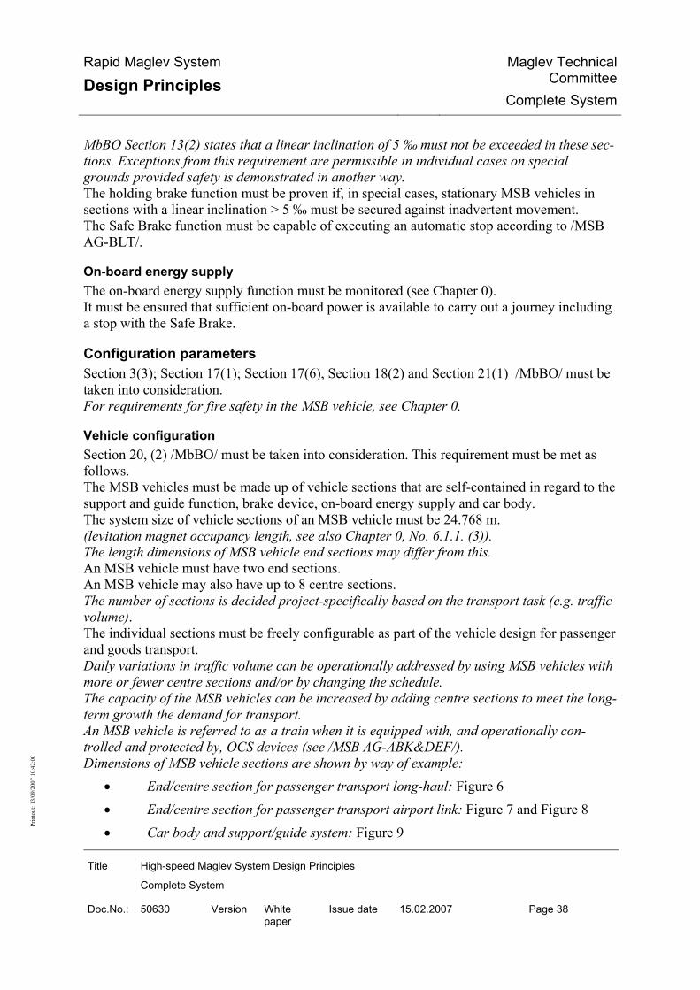
Rapid Maglev System
Design Principles Maglev Technical
CommitteeComplete System
Title High-speed Maglev System Design Principles
Complete System
Doc.No.: 50630 Version White paper
Issue date 15.02.2007 Page 38
Prin
tout
: 13/
09/2
007
10:4
2:00
MbBO Section 13(2) states that a linear inclination of 5 ‰ must not be exceeded in these sec-tions. Exceptions from this requirement are permissible in individual cases on special grounds provided safety is demonstrated in another way. The holding brake function must be proven if, in special cases, stationary MSB vehicles in sections with a linear inclination > 5 ‰ must be secured against inadvertent movement. The Safe Brake function must be capable of executing an automatic stop according to /MSB AG-BLT/.
On-board energy supply The on-board energy supply function must be monitored (see Chapter 0). It must be ensured that sufficient on-board power is available to carry out a journey including a stop with the Safe Brake.
Configuration parameters Section 3(3); Section 17(1); Section 17(6), Section 18(2) and Section 21(1) /MbBO/ must be taken into consideration. For requirements for fire safety in the MSB vehicle, see Chapter 0.
Vehicle configuration Section 20, (2) /MbBO/ must be taken into consideration. This requirement must be met as follows. The MSB vehicles must be made up of vehicle sections that are self-contained in regard to the support and guide function, brake device, on-board energy supply and car body. The system size of vehicle sections of an MSB vehicle must be 24.768 m. (levitation magnet occupancy length, see also Chapter 0, No. 6.1.1. (3)). The length dimensions of MSB vehicle end sections may differ from this. An MSB vehicle must have two end sections. An MSB vehicle may also have up to 8 centre sections. The number of sections is decided project-specifically based on the transport task (e.g. traffic volume). The individual sections must be freely configurable as part of the vehicle design for passenger and goods transport. Daily variations in traffic volume can be operationally addressed by using MSB vehicles with more or fewer centre sections and/or by changing the schedule. The capacity of the MSB vehicles can be increased by adding centre sections to meet the long-term growth the demand for transport. An MSB vehicle is referred to as a train when it is equipped with, and operationally con-trolled and protected by, OCS devices (see /MSB AG-ABK&DEF/). Dimensions of MSB vehicle sections are shown by way of example:
• End/centre section for passenger transport long-haul: Figure 6 • End/centre section for passenger transport airport link: Figure 7 and Figure 8 • Car body and support/guide system: Figure 9

Rapid Maglev System
Design Principles Maglev Technical
CommitteeComplete System
Title High-speed Maglev System Design Principles
Complete System
Doc.No.: 50630 Version White paper
Issue date 15.02.2007 Page 39
Prin
tout
: 13/
09/2
007
10:4
2:00
Running resistance For a definition of running resistance, see /MSB AG-NORM&RILI/. The running resistance is made up of the following components:
• Aerodynamics, • Magnetisation, • On-board power generation.
The local downslope force must be taken into consideration in addition to the running resis-tance when defining running profiles and determining levitation and braking distances. Guide values for the running resistance for MSB vehicles with 2 to 10 sections at 0 to 400 km/h and its components: Figure 11 The running resistance must be project-specifically defined and allowed for in the design (see Figure 11): Total running resistance: FW = FA + FM + FB
Aerodynamics: FA = 2.8 kN * (v/[m/s])² * (0.53 * N/2 + 0.30) * 10-3
Aerodynamic increases in running resistance through tunnels must be additionally allowed for on a project-specific basis. The aerodynamics component is largely proportional to v² but it also includes a small component proportional to v to allow for the air removal for ventilation and air condition-ing. This component proportional to v can be taken as contained in the component pro-portional to v².
Magnetisation: FM = N * (0.1 kN * (v/[m/s])0.5 + 0.02 kN * (v/[m/s])0.7) applies when using the recommended material for the lateral guide rails according to Chapter 0.
On-board power generation: FB = 0 for 0 to 20 km/h FB = N * 7.3 kN for 20 to 70 km/h FB = N * (146 kN / v/[m/s] - 0.2 kN) for 70 to 500 km/h
where v - velocity of MSB vehicle N - number of vehicle sections
for steady-state operation
• without a supply from an external on-board energy supply (when operating with ex-ternal on-board energy supply up to 100 km/h, FB = 0),

Rapid Maglev System
Design Principles Maglev Technical
CommitteeComplete System
Title High-speed Maglev System Design Principles
Complete System
Doc.No.: 50630 Version White paper
Issue date 15.02.2007 Page 40
Prin
tout
: 13/
09/2
007
10:4
2:00
• without recharging of the on-board batteries,
• without wind influence, and • for mean ambient temperature in moderate climate (as per /MSB AG-UMWELT/)
with a corresponding air conditioning rating.
Aerodynamics The aerodynamic loading resulting from oncoming traffic and in tunnels must be allowed for as per /EN 14067-2/ and /EN 14067-3/. The vehicle must be designed to allow for the maximum permissible pressure difference (in-ternal/external) in tunnels and the pressure effect from oncoming traffic. The pressure difference (internal/external) in tunnels is determined by the change in external pressure that depends on the tunnel length and cross-section, and the delayed change in in-ternal pressure. The change in internal pressure is determined by the pressure seal-tightness and compressive rigidity of the car body. The tunnel cross-section, the comfort requirements and the vehicle characteristics must therefore be coordinated. See also 0 and 0. The maximum pressure difference (internal/external) may not exceed 5,500 Pa (limit). The maximum value of the pressure difference (internal/external) that occurs in tunnels must be determined project-specifically. The pressure effect with an oncoming train on open track is shown in Figure 12. The pressure effect on static equipment along the guideway on open track when a vehicle passes by is also shown in Figure 12.
Drive and energy supply The Drive and Energy Supply subsystem must supply other subsystems of the MSB system with the necessary energy, and propel MSB vehicles according to the requirements of the op-eration control system. The Drive and Energy Supply subsystem must observe the following interfaces with other subsystems:
• Guideway (stator of the synchronous long-stator motor, track-switching devices, reference locations),
• MSB vehicles (levitation magnet as the exciter of the synchronous long-stator mo-tor, absolute and relative position information, external on-board energy supply),
• Operation control system (running requirements, safe drive shutdown),
• Other MSB system components (auxiliary energy supply).
Structure Depending on location, the Drive and Energy Supply subsystem must consist of the following components:
• Central devices for operating and observing and for diagnosis, • Energy supply (structure Figure 13) with

Rapid Maglev System
Design Principles Maglev Technical
CommitteeComplete System
Title High-speed Maglev System Design Principles
Complete System
Doc.No.: 50630 Version White paper
Issue date 15.02.2007 Page 41
Prin
tout
: 13/
09/2
007
10:4
2:00
• Devices in substations for auxiliary and traction energy supply, if neces-sary also for the external on-board energy supply and
• Trackside devices for the auxiliary energy supply of the trackside devices of the MSB system and, if necessary, the external on-board energy supply,
• Drive (Figure 14) with • Devices in substations for transforming the electrical energy and for regu-
lating/controlling, and • Drive circuit along the guideway to distribute the electrical energy along
the guideway and for control, comprising of circuit cables, switch points and stator sections.
Functions At central control stations it must be possible to observe the status of the complete subsys-tem and operators must be able to carry out the necessary operating actions. Manual operating actions must not be necessary during undisturbed scheduled operation. The energy supply must include the subfunctions of energy matching and distribution, auxil-iary energy supply, external on-board energy infeed, traction energy supply, power factor cor-rection and control energy supply. The energy matching and distribution must (where necessary) match the voltage level pro-vided at the interface with the public mains to the mains design used in the drive, and distrib-ute it to the functional units of the energy supply described below. The auxiliary energy supply must supply the drive regulation/control system, the OCS, the points and any other components of the MSB system with the energy required in each case. The energy supply must be uninterruptible for selected components. The external on-board energy infeed must provide energy according to the power demand of the MSB vehicles at locations to be defined. It must transform the energy according to the construction of the external on-board energy supply and feed it to the guideway-side compo-nents. The traction energy supply must supply the drive with the energy needed for traction. If necessary, the power factor correction must ensure compliance with the required connec-tion conditions at the interface with the public energy supply grid. The control energy supply must monitor all energy supply devices and in case of a fault ini-tiate protection responses and if necessary automatic redundancy changeovers. It must also check switching actions entered at the operator terminal for plausibility with the existing in-terlock conditions and initiate the necessary switching actions. The drive must fulfil the following subfunctions according to Figure 15: The converters must transform the provided energy according to the vehicle location, the ve-hicle speed and the required acceleration. The transformers must be constructed so that the brake energy can be fed back into the public grid. The line must be divided up into drive sectors in which an MSB vehicle can be driven ac-cording to OCS requirements.

Rapid Maglev System
Design Principles Maglev Technical
CommitteeComplete System
Title High-speed Maglev System Design Principles
Complete System
Doc.No.: 50630 Version White paper
Issue date 15.02.2007 Page 42
Prin
tout
: 13/
09/2
007
10:4
2:00
The components of the drive circuit are assigned to a drive sector at any given point in time. The drive sectors usually coincide with the safety areas of the operation control system. Within the drive sectors, the electrical traction power must be converted to mechanical power in synchronous long-stator motors. The excitation is generated by the levitation magnets installed on the MSB vehicle. The drive regulation/control system must coordinate all operations that are drive sector-wide and overarching:
• Creating and cancelling drive units and synchronising neighbouring drive units un-til the vehicle guidance is passed from one drive unit to the next,
• Coordinating the use of the converters, stator sections and redundancies, • Controlling the operating modes for all drive devices as a function of their status
and the current OCS input. The vehicle guidance system must guide an MSB vehicle over a drive circuit according to the running profile input by the OCS, allowing for the comfort conditions. The following must be provided for this:
• Communication with the operating control system to receive the inputs for destina-tion, direction of travel and speed,
• Communication with the MSB vehicle to receive the relative and absolute position information,
• Calculation of target braking speeds, • Distance and speed control, • Phase regulating (determining the vehicle position relative to the long stator).
The circuit controller must coordinate the control and monitoring of the various controlgear of the drive circuit as a function of stator section change procedures, vehicle position and speed, with the following functions:
• Generating control signals for on/off switching of the stator section switches and circuit switches,
• Monitoring switch messages, • Circuit cable and long stator protection.
The current regulation system must regulate the stator current by frequency, amount and phase angle, with:
• Determining the rotor voltage induced by the MSB vehicle in the long stator, • Translating the inputs of vehicle guidance and drive control into manipulated
variables for the converter regulation/control system. The converter regulation/control system must control and regulate all the components of a converter according to the inputs of the current controller and drive controller, with:
• Actual-value capture on the grid and motor side and in the converter power circuit,
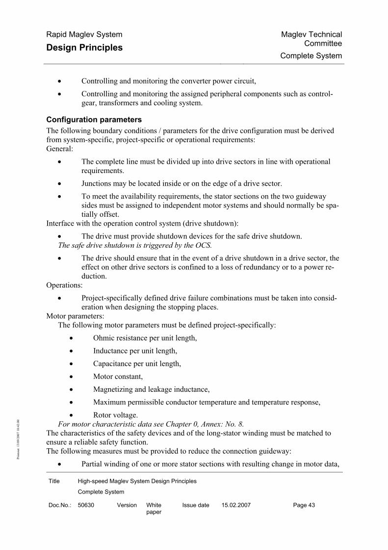
Rapid Maglev System
Design Principles Maglev Technical
CommitteeComplete System
Title High-speed Maglev System Design Principles
Complete System
Doc.No.: 50630 Version White paper
Issue date 15.02.2007 Page 43
Prin
tout
: 13/
09/2
007
10:4
2:00
• Controlling and monitoring the converter power circuit, • Controlling and monitoring the assigned peripheral components such as control-
gear, transformers and cooling system.
Configuration parameters The following boundary conditions / parameters for the drive configuration must be derived from system-specific, project-specific or operational requirements: General:
• The complete line must be divided up into drive sectors in line with operational requirements.
• Junctions may be located inside or on the edge of a drive sector. • To meet the availability requirements, the stator sections on the two guideway
sides must be assigned to independent motor systems and should normally be spa-tially offset.
Interface with the operation control system (drive shutdown): • The drive must provide shutdown devices for the safe drive shutdown. The safe drive shutdown is triggered by the OCS. • The drive should ensure that in the event of a drive shutdown in a drive sector, the
effect on other drive sectors is confined to a loss of redundancy or to a power re-duction.
Operations: • Project-specifically defined drive failure combinations must be taken into consid-
eration when designing the stopping places. Motor parameters:
The following motor parameters must be defined project-specifically: • Ohmic resistance per unit length, • Inductance per unit length, • Capacitance per unit length, • Motor constant, • Magnetizing and leakage inductance, • Maximum permissible conductor temperature and temperature response, • Rotor voltage.
For motor characteristic data see Chapter 0, Annex: No. 8. The characteristics of the safety devices and of the long-stator winding must be matched to ensure a reliable safety function. The following measures must be provided to reduce the connection guideway:
• Partial winding of one or more stator sections with resulting change in motor data,

Rapid Maglev System
Design Principles Maglev Technical
CommitteeComplete System
Title High-speed Maglev System Design Principles
Complete System
Doc.No.: 50630 Version White paper
Issue date 15.02.2007 Page 44
Prin
tout
: 13/
09/2
007
10:4
2:00
• Temporary or permanent interconnection of one or more stator sections or parts of stator sections on both sides at the neutral point (short-circuit).
Operation Control System Section 15(3) and Section 15(4) /MbBO/ must be taken into consideration. These require-ments must be executed according to /MSB AG-BLT/.
Structure The operation control system must provide the components for securing, monitoring and con-trolling the train operations. The operation control system must connect the subsystems of the high-speed maglev system functionally into a complete system that is ready for operation. The neighbouring subsystems and operative levels of the OCS are (see Figure 16):
• Station master, • Guideway and stations (incl. track-switching devices and reference points for po-
sitioning) • Vehicle (all MSB vehicles and project-dependently technically secured special ve-
hicles), • Drive and energy supply (substations with drive units), • Maintenance.
The components of the operation control system may be mobile (e.g. backup computer for a vehicle) or fixed (e.g. backup computer for a guideway section). The fixed components can be subdivided into central components and decentral components. The configuration must be made as part of project planning according to the operator's re-quirements.
Functions The operation control system must provide the following functions:
• Journey sequence control,
• Guideway protection, • Running profile monitoring, • Vehicle protection,
• Drive shutdown, • Secure positioning, • Data transmission.
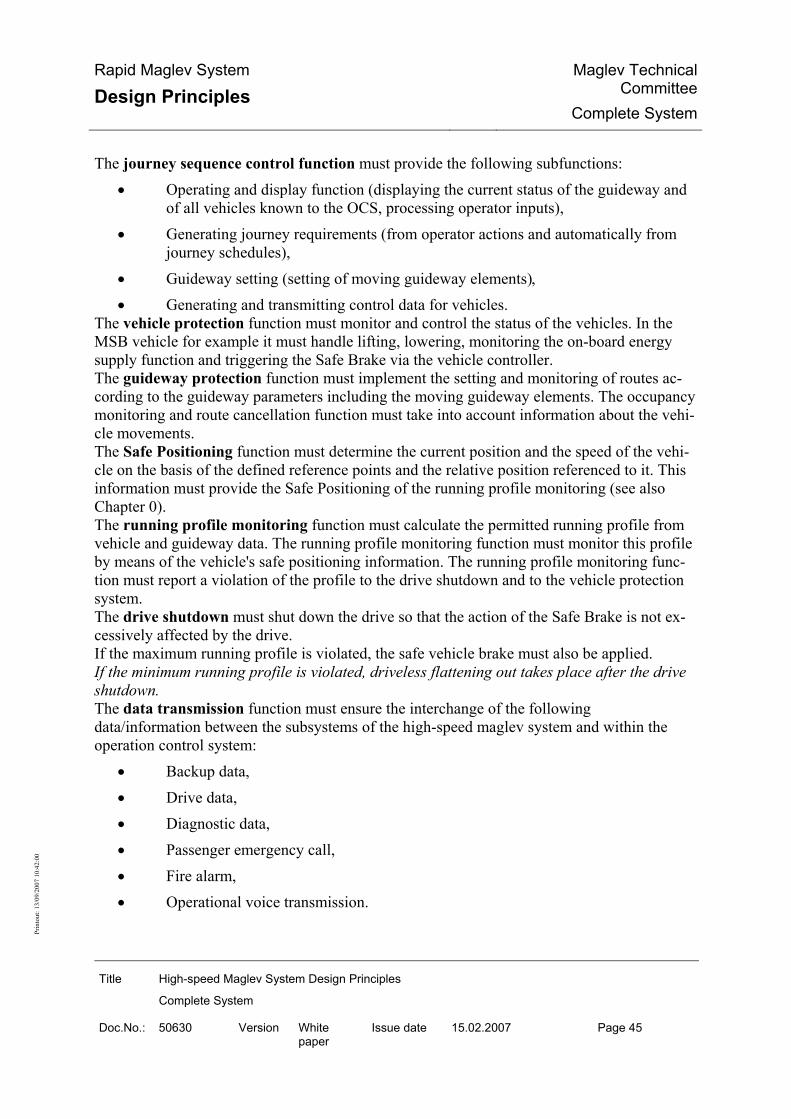
Rapid Maglev System
Design Principles Maglev Technical
CommitteeComplete System
Title High-speed Maglev System Design Principles
Complete System
Doc.No.: 50630 Version White paper
Issue date 15.02.2007 Page 45
Prin
tout
: 13/
09/2
007
10:4
2:00
The journey sequence control function must provide the following subfunctions: • Operating and display function (displaying the current status of the guideway and
of all vehicles known to the OCS, processing operator inputs), • Generating journey requirements (from operator actions and automatically from
journey schedules),
• Guideway setting (setting of moving guideway elements), • Generating and transmitting control data for vehicles.
The vehicle protection function must monitor and control the status of the vehicles. In the MSB vehicle for example it must handle lifting, lowering, monitoring the on-board energy supply function and triggering the Safe Brake via the vehicle controller. The guideway protection function must implement the setting and monitoring of routes ac-cording to the guideway parameters including the moving guideway elements. The occupancy monitoring and route cancellation function must take into account information about the vehi-cle movements. The Safe Positioning function must determine the current position and the speed of the vehi-cle on the basis of the defined reference points and the relative position referenced to it. This information must provide the Safe Positioning of the running profile monitoring (see also Chapter 0). The running profile monitoring function must calculate the permitted running profile from vehicle and guideway data. The running profile monitoring function must monitor this profile by means of the vehicle's safe positioning information. The running profile monitoring func-tion must report a violation of the profile to the drive shutdown and to the vehicle protection system. The drive shutdown must shut down the drive so that the action of the Safe Brake is not ex-cessively affected by the drive. If the maximum running profile is violated, the safe vehicle brake must also be applied. If the minimum running profile is violated, driveless flattening out takes place after the drive shutdown. The data transmission function must ensure the interchange of the following data/information between the subsystems of the high-speed maglev system and within the operation control system:
• Backup data, • Drive data, • Diagnostic data, • Passenger emergency call, • Fire alarm, • Operational voice transmission.
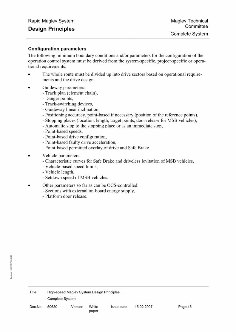
Rapid Maglev System
Design Principles Maglev Technical
CommitteeComplete System
Title High-speed Maglev System Design Principles
Complete System
Doc.No.: 50630 Version White paper
Issue date 15.02.2007 Page 46
Prin
tout
: 13/
09/2
007
10:4
2:00
Configuration parameters The following minimum boundary conditions and/or parameters for the configuration of the operation control system must be derived from the system-specific, project-specific or opera-tional requirements: • The whole route must be divided up into drive sectors based on operational require-
ments and the drive design. • Guideway parameters:
- Track plan (element chain), - Danger points, - Track-switching devices, - Guideway linear inclination, - Positioning accuracy, point-based if necessary (position of the reference points), - Stopping places (location, length, target points, door release for MSB vehicles), - Automatic stop to the stopping place or as an immediate stop, - Point-based speeds, - Point-based drive configuration, - Point-based faulty drive acceleration, - Point-based permitted overlay of drive and Safe Brake.
• Vehicle parameters: - Characteristic curves for Safe Brake and driveless levitation of MSB vehicles, - Vehicle-based speed limits, - Vehicle length, - Setdown speed of MSB vehicles.
• Other parameters so far as can be OCS-controlled: - Sections with external on-board energy supply, - Platform door release.

Rapid Maglev System
Design Principles Maglev Technical
CommitteeComplete System
Title High-speed Maglev System Design Principles
Complete System
Doc.No.: 50630 Version White paper
Issue date 15.02.2007 Page 47
Prin
tout
: 13/
09/2
007
10:4
2:00
Guideway
Structure Section 12, (1), Section 12, (2) and Section 12, (3) and Section 14 /MbBO/ must be taken into consideration. The guideway is part of the installations and is divided into:
• Guideway superstructures, • Guideway substructures, • Track-switching devices, • Special structures, • Route peripherals, • Guideway equipment.
The boundary lines and clearances defined in Figure 22 should be adhered to, but they may be adapted depending on design and subject to project-specific review. The maintenance of the guideway should be carried out from the guideway beam. This rule may be disregarded, especially for the repair of guideway substructures. Guideway beams and items of equipment may only be operated in an application project after qualification. Before they are used as standard designs in an application project, guideway beams and items of equipment must also be trialled under boundary conditions that are as near to the applica-tion as possible. The effects of individual modules of the guideway on each other, especially under the dy-namic loading of vehicles and environmental impacts, must be allowed for depending on the design. The modules of the guideway must be clearly defined in a project-specific schedule of struc-tures. The schedule of structures must provide the following minimum information:
• Alignment parameters (three-dimensional chainage, transverse tile, linear inclina-tion, horizontal radius, vertical radius, guideway coordinates, guideway elevation, ground level elevation),
• Support number, • Beam number and length, • Special structures, • Longitudinal and crossing infrastructure (incl. headroom), • Stator pack layout (indicating the gap), • Location and coding of the position reference strips,

Rapid Maglev System
Design Principles Maglev Technical
CommitteeComplete System
Title High-speed Maglev System Design Principles
Complete System
Doc.No.: 50630 Version White paper
Issue date 15.02.2007 Page 48
Prin
tout
: 13/
09/2
007
10:4
2:00
• Sections with external on-board energy supply, • Stopping places, • Position and layout of the motor winding relative to the stator pack layout, • Cable routing on the substructures.
Other requirements for the guideway are defined in Design Principles Guideway Parts I to VI. The requirements described in it apply to all modules installed directly on the guideway or in the immediate vicinity of the route.
Functions The loads that result from operations and the environment and which act on the guideway must be defined project-specifically. The guideway must withstand these loads and transmit them into the subsoil. The loads resulting from the drive and vehicle are transmitted to the guideway through the functional planes of the guideway beam. The structures of the guideway and of its mount-on parts should be designed to be fault-tolerant, fault-disclosing and/or redundant. The guideway beams must accept the guideway-side modules of the MSB-specific guideway equipment. The constructions must be designed such that, under the simultaneous influence of the guide-way's dead weight and the loads from operations and the environment, the functional planes display at most deviations from the requirements of the three-dimensional curve according to /MSB-FW GEO/ and /MSB-FW BEM/.
Configuration parameters
Guideway superstructures The guideway superstructures form the running tracks of the guideway. The guideway superstructures must accept the guideway equipment (according to Chapter 0). The guideway superstructures must take down the acting loads into the guideway substruc-tures (through the bearers if necessary). MSB routes should be planned with the following standard guideway types; other types may be used for specific projects:
• Guideway type I: Single/multiple bay beam with system lengths of > 16 m (guide value: 24.768 m),
• Guideway type II: Single/multiple bay beam with system lengths of ≤ 16 m (guide value: 12.384 m),
• Guideway type III: Multiple bay slabs with system lengths of 6 m, for example (guide value: 6.192 m).

Rapid Maglev System
Design Principles Maglev Technical
CommitteeComplete System
Title High-speed Maglev System Design Principles
Complete System
Doc.No.: 50630 Version White paper
Issue date 15.02.2007 Page 49
Prin
tout
: 13/
09/2
007
10:4
2:00
Guideway types I and II are normally supported discretely on supports with individual foot-ings. The bearing forces of guideway type III are normally transferred to the subsoil through strip footings. The definition of the respective guideway type and system lengths must be project-specific. Contrary to the above guide values for system lengths, beams with a shorter system length may be used:
To compensate for the radial displacement of the system axes with the dual-track guide-way or at alignment constraints, guideway superstructures can be used on the track on the inside of the bend whose system length in a grid of 86 mm can be shortened by up to 4*86 mm. With longer system lengths (approx. > 31 m) either special beams or primary support structures with a standard guideway mounted on top will have to be used.
The following "construction methods" must be used for the guideway superstructures: • Concrete beam/slab with integrated (concrete) cantilever arms, • Steel beam/slab with integrated (steel) cantilever arms, • Hybrid beam/slab as concrete beam/slabs with attached steel modules to take the
guideway equipment, • Concrete slab on steel beams or steel plate on concrete beams.
A distinction is made between at-grade and elevated guideways according to the position of the gradient to the ground level elevation (guideway elevation). Elevated guideway Guideways with a guideway elevation of between 3.5 m and 20 m (> 20 m in special cases) are referred to as elevated guideways. The elevated guideway (see Figure 19) is usually constructed in beam design with discrete substructures as:
• Single-bay beams constrained at one end, • Dual-bay beams constrained on the centre support.
At-grade guideway Guideways with a guideway elevation of up to 3.5 m (minimum height in special cases: 1.25 m) are referred to as at-grade guideways. The at-grade guideway can be constructed with the following methods:
• slab construction with continuous substructures (see Figure 20), • beam construction with discrete substructures as per the elevated guideway.

Rapid Maglev System
Design Principles Maglev Technical
CommitteeComplete System
Title High-speed Maglev System Design Principles
Complete System
Doc.No.: 50630 Version White paper
Issue date 15.02.2007 Page 50
Prin
tout
: 13/
09/2
007
10:4
2:00
Guideway substructures The guideway substructures must
• transmit the loads from the guideway superstructures into the subsoil, and • allow the attachment of supply lines to the guideway equipment.
The guideway substructures comprise • guideway foundation, • guideway supports, • other guideway substructures (including mass-spring system).
The deviations of the guideway support points in the x-direction due to the elastic deforma-tion of the substructures must be limited to the following values:
• 10 mm due to changeable effects, • 20 mm due to exceptional effects.
Track-switching devices The requirements of /MbBO/, Section 12, (2) must be respected. Track-switching devices must enable the MSB vehicles and special vehicles to change from one running track to another. A general distinction is made between track-switching devices that require no journey break (points) (see Figure 25) and track-switching devices that require a journey break (turntables and traversers). Track-switching devices must be provided with equipment that locks the end position reached after the track-switching operation and secure it from inadvertent adjustment. The end position and end position locking are monitored for safety by the OCS. The end position of the track-switching device must be maintained irrespective of failures of the control system, monitoring or energy supply. The failure of an individual electrical, electronic or electromechanical module in actuating and locking devices, control system, monitoring and/or power supply must have no effect on the adjustment function. The track-switching may only be adjusted
• at the request of the OCS or • under a special operating instruction, with personnel responsibility.
The following constraints must be defined project-specifically: • Adjustment frequencies, • Required adjustment times, • MTBF and • required electrical power.
Special structures

Rapid Maglev System
Design Principles Maglev Technical
CommitteeComplete System
Title High-speed Maglev System Design Principles
Complete System
Doc.No.: 50630 Version White paper
Issue date 15.02.2007 Page 51
Prin
tout
: 13/
09/2
007
10:4
2:00
Tunnels Planning and execution must be project-specific. Tunnels must meet the following requirements:
• Receive the guideway, • Receive the line peripherals, • Requirements of the project-specific safety concept, • Comply with the defined clearances and boundary lines.
The tunnel must be constructed so that the compressive stress of the MSB vehicle according to Chapter 0 is not exceeded. The tunnel should be constructed so that the changes in pressure to be defined project-specifically acting on the passenger inside the MSB vehicle according to Chapter 0 are not exceeded. The construction of the complete tunnel structure must take account of the following project-specific factors:
• tunnel length, number of tracks and vehicle length, • spatial requirements that go beyond the clearance (e.g. line peripherals), • vibration transmissions, • tunnel boom effects, • waste heat emissions (e.g. cables), • any existing exhaust emissions from special vehicles.
The planning and construction of the complete tunnel structure must also be based on the relevant regulations for tunnel structures. Compliance with the geometrical requirements for the guideway must be separately demon-strated for the transition between the guideway resting on the tunnel invert and the adjacent guideway supported directly off the subsoil. Primary structures Planning and execution must be project-specific. Compliance with the geometrical requirements for the guideway must be separately demon-strated for the transition between the guideway resting on the primary structure and the adja-cent guideway supported directly off the subsoil. A transitional structure must be provided if necessary. The long-stator in the transitional structure should be executed without a drive function. The positioning function must be separately demonstrated for the area of the transitional structure.

Rapid Maglev System
Design Principles Maglev Technical
CommitteeComplete System
Title High-speed Maglev System Design Principles
Complete System
Doc.No.: 50630 Version White paper
Issue date 15.02.2007 Page 52
Prin
tout
: 13/
09/2
007
10:4
2:00
Route peripherals The route peripherals comprise the following modules:
• functionally necessary small structures that are needed close to the guideway route (e.g. radio masts, sectioning points),
• project-specific structures that are necessary locally, positioned close to the route (e.g. noise barriers, sight screens).
Excessive effects of route peripheral installations on the system must be avoided. Planning and execution must be project-specific.
Guideway equipment The guideway equipment is divided into: • MSB-specific guideway equipment (including the appropriate fasteners) with
• long-stator with stator pack and long-stator winding, • slide rail, • lateral guide rail, • guideway-side positioning modules, • guideway-side modules of the external on-board energy supply,
• design-specific guideway equipment with • beam supports, • beam gap covers, • earthing and lightning protection,
• and other built-ons, with • temporary and/or project-specific built-ons, including fasteners, and • rigs for maintenance on the guideway.
Stator pack The stator packs with their underside form the stator plane and must meet the following re-quirements:
• Carry the magnetic flow generated by the levitation magnets, withstanding and transmitting the forces generated by the magnetic flow (levitation forces),
• Withstand and transmit the acceleration and braking forces from the motor wind-ing (drive forces),
• Form the reference surface (stator plane) for measuring the air gap between stator pack and levitation magnet,

Rapid Maglev System
Design Principles Maglev Technical
CommitteeComplete System
Title High-speed Maglev System Design Principles
Complete System
Doc.No.: 50630 Version White paper
Issue date 15.02.2007 Page 53
Prin
tout
: 13/
09/2
007
10:4
2:00
• Form the reference surface for the guideway inspection, • Form the tooth/slot sequence for positioning, • Form the tooth/slot geometry for flow modulation for the inductive energy trans-
mission to the MSB vehicle (on-board energy supply). The steel sheet grade should fulfil M 800-50 A as per /EN 10106/, alternative project-specific decisions may be taken following functional testing. The tooth/slot geometry must conform to the system grid of 86 mm. The stator pack pitch must be 1032 mm, based on the three-dimensional curve. The dimensions defined in /MSB AG-FW GEO/ for offsets, gaps and the angle-change crite-rion of the stator plane must be achieved in the assembled unstressed condition at reference temperature. Long-stator winding The thrust forces from the drive and the other forces (e.g. dead weight, from dynamic excita-tion) must be transmitted to the stator packs through the fastening of the long-stator winding in the slots of the stator pack. The long-stator winding must be constructed as a 3-phase winding (see Figure 24 and Figure 5). The nominal length of a winding period must be 516 mm corresponding to the wavelength of the magnetic moving field (6 tooth/slot periods). The guide value for the cable length of a single conductor is 2.35m per linear metre of guide-way. The following requirements must be achieved:
• the electrical data and properties of the motor winding according to Chapter 0 Drive,
• the requirements for long-stator protection as per /MSB AG-ANT/ , • connection of the winding earth to the earth of the guideways as per /MSB AG-
FW ÜBG/, • the connection of the motor winding must be made at suitable points (e.g. at sup-
ports) allowing for the clearances as per Figure 22 and /MSB AG-FW ÜBG/, • Temperature and load-related min. and max. gaps in the stator plane must be al-
lowed for when laying the motor winding. The motor section ends should be laid on guideway beam ends.

Rapid Maglev System
Design Principles Maglev Technical
CommitteeComplete System
Title High-speed Maglev System Design Principles
Complete System
Doc.No.: 50630 Version White paper
Issue date 15.02.2007 Page 54
Prin
tout
: 13/
09/2
007
10:4
2:00
Slide rails / slide plane The slide plane can be an integral part of the guideway beam or be constructed as a slide rail. The slide plane must meet the following requirements:
• withstand the effects introduced by special vehicles while allowing for effects from the environment,
• allow for the arising static and dynamic forces while withstanding the effects from the environment at the support skid/slide plane interface,
• withstand a maximum linear force of 250 kN per MSB vehicle section and trans-mit it to the guideway beam,
• the linear force between the skid of the MSB vehicle and the slide plane of the guideway that is due to static friction must, given the project-specifically defined environmental conditions and linear inclinations, be greater than the pro rata downhill force and the wind force in the x-direction (see Chapter 0) in areas in which the vehicles must be secured against inadvertent movement.
• the dimensions defined in /MSB AG-FW GEO/ for offsets, gaps and the angle-change criterion of the slide rail must be achieved in the assembled unstressed condition at reference temperature,
• satisfy the defined min. and max. values for the gaps and offsets under live load, both in the planning phase and after the completion of the guideway, with project-specific proof,
• be executed at equidistant spacing parallel to the three-dimensional curve. The slide rails should be constructed along the length of the beam. Lateral guide rails/lateral guide plane The lateral guide rails form with their surface the lateral guide plane, and must meet the fol-lowing requirements:
• meet the requirements of a reaction rail for the guide magnets and the brake mag-net,
• withstand all static and dynamic effects from operations and the environment at the guide magnet/lateral guide plane interface brake magnet/lateral guide plane in-terface,
• withstand the effects introduced from special vehicles, • must meet the dimensions defined in /MSB AG-FW GEO/ for offsets, gaps and the
angle-change criterion of the lateral guide plane in the assembled unstressed con-dition at reference temperature.
The lateral guide rails should be executed along the length of the beam and at equidistant spacing to the three-dimensional curve. The lateral guide rails should be made from special steel with an electrical conductivity re-duced by a factor of 3 compared with S235 (ST37-2), or equivalent material. The system de-

Rapid Maglev System
Design Principles Maglev Technical
CommitteeComplete System
Title High-speed Maglev System Design Principles
Complete System
Doc.No.: 50630 Version White paper
Issue date 15.02.2007 Page 55
Prin
tout
: 13/
09/2
007
10:4
2:00
sign should allow for a change of brake characteristics and running resistance for an alterna-tive choice of material. Guideway-side modules of the on-board energy supply of MSB vehicles The guideway-side modules of the on-board energy supply transmit electrical energy to the vehicle-side modules of the external on-board energy supply in the low speed range, and must be defined project-specifically. Guideway-side positioning modules, The guideway-side modules of the positioning system act as reference points. Requirements for their arrangement along the guideway must be defined project-specifically. Beam support The beam support must facilitate an adjustment to compensate for plastic subsoil deformation. The beam support must ensure the take-down of all forces from the guideway beams. Beam gap covers Gaps between consecutive guideway beams must be closed if they
• can be larger than 20 mm and • are in route sections with a maximum section speed of more than 150km/h.
Earthing and lightning protection To protect persons and to protect against the effects of electrostatic discharge as well as in regard to electromagnetic compatibility (EMV), the electrical effects of
• lightning strike, • differences in potential and • earth currents and residual currents
of the vehicles and of all modules of the guideway must be taken into consideration when designing an earthing and lightning protection system for the guideway. A project-specific earthing and lightning protection concept must be created for this purpose. Other built-ons Other built-ons on the guideway (due for example to the qualification of new modules, meas-urements or project-specific requirements) must be designed so that
• under the project-specific environmental conditions they reliably withstand all loads specified for them during the project-specifically defined service life, and
• have no unwanted effects on the system.

Rapid Maglev System
Design Principles Maglev Technical
CommitteeComplete System
Title High-speed Maglev System Design Principles
Complete System
Doc.No.: 50630 Version White paper
Issue date 15.02.2007 Page 56
Prin
tout
: 13/
09/2
007
10:4
2:00
Boundary lines and dimensions for fixed internals and vehicles The following boundary lines must be complied with when designing the guideway modules:
• Boundary line for the kinematic space requirement of the vehicle, • Clearance for maintenance systems (e.g. vehicle wash), • boundary line for fixed installations, • boundary lines for station platforms and platform doors.
The position of the individual elements of the guideway equipment in relation to the three-dimensional curve, and the installation spaces available for the equipment are shown in Figure 22. The space available between the installation spaces and the boundary lines may be used for local incoming and outgoing lines and as assembly space. The use must be defined project-specifically to avoid multiple occupancies of this space.
Tolerances, deviations of position The position (Y, Z position) of the functional surfaces and the installation spaces defined for them must be achieved as indicated in Figure 22. All particulars of the guideway geometry relate to the functional planes in the installed, painted condition (mechanical dimensions, not electrically effective dimensions). The defined dimensions apply to the unloaded condition (guideway without live load and un-der its own dead weight only) at project-specifically defined reference temperature. The maximum and minimum gaps must also be achieved having regard to the thermal linear expansion of the guideway, the elastic deformation of the substructures under the effect of load, and the assembly tolerances. The geometrical requirements and tolerances of the functional planes are defined in the /MSB AG-FW GEO/.
Other operating plant The layout of structures near to the route and of the other operating plants must be defined project-specifically. Consideration must be given to the system requirements in regard to:
• Clearance, • Boundary lines, • Aerodynamic influences, • Influences on the MSB radio system, • Dimensioning, • Maintenance and • other project-specific requirements.

Rapid Maglev System
Design Principles Maglev Technical
CommitteeComplete System
Title High-speed Maglev System Design Principles
Complete System
Doc.No.: 50630 Version White paper
Issue date 15.02.2007 Page 57
Prin
tout
: 13/
09/2
007
10:4
2:00
Stations Section 3(3); Section 15(1) to Section 15(6) /MbBO/ must be taken into consideration. These requirements must be met as follows: Stations Stations must be designed for a project-specifically defined pass-through speed that may not exceed the local maximum line speed. Requirements for weather protection must be defined project-specifically. Equipping with glazed doors and walls must be carried out according to /DIN EN ISO 12543/ with safety glass. Lighting, lightning protection/fire protection, floorcoverings, entrances/exits and access for rescue services must be defined project-specifically and based on local regulations. The guideway within the stations (platforms and adjacent line sections according to Chapter 5.4.4) should be equipped with external on-board energy supply. The clearances and gaps between vehicle and platform must be defined project-specifically based on the vehicle boundary of MSB vehicles. The construction/equipment of the stations must be project-specific. Platform doors Platform doors are used to prevent hazards to persons while boarding and alighting and from passing trains in automatic train operations (analogous with Section 31(5) BOStrab). It must be ensured irrespective of the train movements that
• Persons cannot enter the clearance area of the moving train or fall or jump onto the guideway from the platform,
• Objects cannot enter the clearance area of the train from the platform, and • Persons on the platform cannot be put at risk by the effects of passing trains.
The positioning accuracy, the width and the distance of the outer doors of MSB vehicles and the configuration of the platform doors must be coordinated project-specifically in such a way that during a stop and with the vehicle and platform doors open, a defined clear passage width is available with a defined probability. This will avoid hazards to passengers while boarding and alighting due to the passage width being too narrow. The Safe Positioning, control engineering relevant positioning or inde-pendent positioning means of the platform door system can be used as positioning equipment. The design of the platform doors must ensure that automatic departure from the secured end position without release by the safety device is not possible. It should be possible to temporarily set up local operation (e.g. for maintenance work). Guideway reserving and local operation must be mutually exclusive. At the platform door system it must be possible to manually lock malfunctioning platform doors, secure them from movement and take them out of technical control and monitoring. This bypasses the actuation and monitoring of the platform door that is affected. The signalling of the secured end position (closed, locked and secured from opening) may not be bypassed until the door has been manually locked in the closed position. Platform doors that have been manually locked and secured against movement may only be released for movement under personnel responsibility.

Rapid Maglev System
Design Principles Maglev Technical
CommitteeComplete System
Title High-speed Maglev System Design Principles
Complete System
Doc.No.: 50630 Version White paper
Issue date 15.02.2007 Page 58
Prin
tout
: 13/
09/2
007
10:4
2:00
Platform doors must have emergency unlocking devices that must be operable on the guide-way side by passengers and allow the train to be evacuated irrespective of the positioning of the MSB vehicle.
Substations Substations must be planned and constructed project-specifically.
Operations centre Operations centres must be planned and constructed project-specifically.
Stopping places Service stopping places The layout and equipment of the service stopping places is carried out project-specifically having regard to the requirements in Chapter 0. Service stopping places must guarantee that passengers and personnel are able to alight in the event of malfunctions. Alighting is normally assisted by alighting aids carried in the MSB vehicle. For other requirements see Chapter 0.
Maintenance installations The maintenance installations are divided into:
• central maintenance installations, • decentral maintenance installations and • bases for special vehicles.
The maintenance installations must be designed project-specifically.
Special vehicle Special vehicles can be driven by their own power. The technical equipment which special vehicles must have must be defined project-specifically. The work that is to be done with the special vehicles must be taken into consideration (e.g. maintenance operations). Trailers of special vehicles which will be deployed independently of those special vehicles must conform to the regulations for special vehicles. The following applies to the safety of special vehicles:
• Where the operations programme provides for simultaneous train operations with MSB vehicles and special vehicles, special vehicles must be incorporated into the technical safety system. In this case, special vehicles should contain technical devices for detecting the ve-hicle position and for controlling/monitoring the vehicle brakes (service and park-ing brake) and the vehicle's drive.

Rapid Maglev System
Design Principles Maglev Technical
CommitteeComplete System
Title High-speed Maglev System Design Principles
Complete System
Doc.No.: 50630 Version White paper
Issue date 15.02.2007 Page 59
Prin
tout
: 13/
09/2
007
10:4
2:00
• If no simultaneous operation with MSB vehicles and special vehicles are to take place, this must be ensured by appropriate measures.
There is no simultaneous operation of MSB vehicles and special vehicles when all special vehicles are at their intended park positions or are in isolated route sections during the op-eration of MSB vehicles, or when all MSB vehicles are at intended park positions during op-erations with special vehicles. This does not affect exemptions, e.g. for the commissioning phase, for unscheduled mainte-nance or in conjunction with the rescue concept. Special vehicles are guided by technical devices. These must be designed so that a tipping of the vehicle from the guideway (even if transversely inclined) is prevented. The introduced loads from special vehicles must not generate stresses that become decisive for the rating of the guideway. The mechanical properties of the special vehicle including existing attachments to fulfil their intended purpose (e.g. work platforms, cranes, snow plough) must in regard to
• Geometry (dimensions of car body and chassis, e.g. gauge width), • Weight and weight distribution,
be matched to the design limits given in /MSB AG-FW BEM/ for position-dependent and time-dependent acceleration effects and clearance requirements as per /MSB AG-FW GEO/.
Interfaces and cross-subsystem functions
Loads and effects Criteria for designing the structure of vehicle and guideway: a) The nature and extent of relevant effects (constant, variable and exceptional) must be known. b) The relevant effects must be known in terms of their frequency of occurrence (assumptions are permitted). c) The effect combinations and resulting loads on the modules must be known. d) Loads from effect combinations with a probability of occurrence less than SIL 4 (according to /DIN EN 61508-1/) need not be allowed for in the design. e) A risk assessment according to EN 50126 should be carried out for hazard cases due to effect combinations according to d). Statistical data and empirical values from the field service of comparable sys-tems/modules/materials can be used when determining the probability of occurrence accord-ing to d). Vehicle weight The weight of the MSB vehicles must be defined according to Annex 0, Point 4.3. The following load conditions must be allowed for to Annex 0 :
• Unladen weight (without payload), • Mean vehicle weight (e.g. 80% of permissible load capacity) for passenger vehi-
cles,

Rapid Maglev System
Design Principles Maglev Technical
CommitteeComplete System
Title High-speed Maglev System Design Principles
Complete System
Doc.No.: 50630 Version White paper
Issue date 15.02.2007 Page 60
Prin
tout
: 13/
09/2
007
10:4
2:00
• Permissible vehicle weight (100% permissible load capacity for passenger and goods vehicles),
• Maximum vehicle weight (e.g. exceptional operating situations such as evacuation to adjacent sections of passenger vehicles).
Load capacity is defined as: • The weight of passengers with baggage (passenger vehicles), • The weight of the payload (goods vehicles).
The frequencies of occurrence of the load conditions must be defined project-specifically. The load conditions to be taken into consideration in the design may be defined differently on the basis of the frequencies of occurrence. Effects: On the basis of the project-specifically defined vehicle weights and constraints such as
• permissible accelerations in the x, y and z direction, • operational and maximum travelling speeds, • environmental conditions (e.g. side wind, temperatures) • permissible operating situations,
the effect variables to be applied at the force-transmitting vehicle/guideway interfaces must be determined having regard to the requirements in /MSB AG-FW BEM/ and /MSB AG-ANT/. The drive current must be limited so that the maximum permissible force according to Chap-ter 0 No. 7. (1) is not exceeded. The drive current must be limited so that the maximum permissible acceleration/deceleration according to Section 13(5), /MbBO/ is not exceeded. The limitation of the drive current in case of a malfunction is dealt with in Chapter 0.
Effect conditions Frequency of occurrence A: System condition without failures or faults of modules.
Frequent variable effects
B: System condition with failures or faults of modules.
Rare and extremely rare variable effects
Table 6: Definition of effect conditions A / B
The following effects must be observed. Interface Effect conditions A Effect conditions B
Levitation magnet / long stator
Forces in z-direction from - Vehicle's dead weight - Load capacity allowing for additional mass forces resulting from - the speed and
Increased levitation magnet force of adjacent levitation magnets on failure of the levitation magnet control circuit Increased forces due to drive faults

Rapid Maglev System
Design Principles Maglev Technical
CommitteeComplete System
Title High-speed Maglev System Design Principles
Complete System
Doc.No.: 50630 Version White paper
Issue date 15.02.2007 Page 61
Prin
tout
: 13/
09/2
007
10:4
2:00
Interface Effect conditions A Effect conditions B - the line route (radii, transverse and linear inclination) Effects on the vehicle (esp. aerody-namics) Forces in x-direction from the long-stator drive Effects on the levitation field from drive currents (value and duration must be defined project-specifically)
Increased payload weight in excep-tional operating situations
Guide magnet / lateral guide rail
Forces in y-direction with trans-versely inclined guideway from - vehicle dead weight - load capacity allowing for additional mass forces resulting from - the speed and - the line route (radii, transverse and linear inclination) Aerodynamic effects on the vehicle
Increased guide magnet force of adjacent guide magnets on failure of the guide magnet control circuit Mechanical guide function on fail-ure of two adjacent guide magnet control circuits
Support skid / slide rail
Forces in x, y and z-direction from - vehicle dead weight - load capacity allowing for the guideway position (radii, transverse and linear inclina-tion) and coefficient of friction in x and y-direction.
Mechanical levitation function on failure of two adjacent levitation magnet control circuits Setting down of the MSB vehicle at v > 0 km/h due to drive faults
Vehicle brake / lateral guide rail
Mechanical and/or magnetic forces in x and y-direction when braking with the Safe Brake
Table 7: Effects at the vehicle/guideway interfaces
The dimensioning effects must be defined on the basis of /MSB AG-FZ BEM/ and /MSB AG-FW BEM/ and documented in a project-specific specification.

Rapid Maglev System
Design Principles Maglev Technical
CommitteeComplete System
Title High-speed Maglev System Design Principles
Complete System
Doc.No.: 50630 Version White paper
Issue date 15.02.2007 Page 62
Prin
tout
: 13/
09/2
007
10:4
2:00
Positioning
Purpose and structure Positioning is a facility for determining the position and speed of technically protected vehi-cles. The main function "positioning" is divided up into devices and functions within the subsys-tems Vehicle (if the vehicles are technically protected), Guideway, Operation Control System and Drive Figure 18).
Functional requirements The requirements for positioning (equipment for detecting position and speed information) must be defined by all subsystems. Devices for detecting the position and speed information are referred to as "control system-relevant positioning" (see Figure 18). There must be fixed components for ascertaining reference points and relative points. The detection of position and speed information of technically protected vehicles is achieved by scanning features of the guideway, e.g. position reference points installed on the guideway (position reference strips, LRL) and the stator packs (slot / tooth periodicity). The guideway-side position information must be captured by vehicle-side devices and further processed:
• The following information must be provided for the drive (see also /MSB AG-ANT/): • Vehicle location, • Vehicle position signal (rotor angle), • Vehicle identifier.
• The following information must be provided for the "Safe Positioning" function of the operation control system (see /MSB AG-BLT/): • Vehicle location, • Vehicle speed, • Direction of travel.
• Position information must also be provided for diagnostic purposes. The accuracy, up-to-dateness and backup procedures on the transmission paths of all position information must be defined project-specifically and, if necessary, dependent on position and speed. The coordinate system (chainage points/kilometre markers) and its relation to the vehicle must be defined project-specifically allowing for the vehicle length. Other requirements for the interfaces between the participating subsystems must be defined project-specifically. The reference points along the line and in the approach to

Rapid Maglev System
Design Principles Maglev Technical
CommitteeComplete System
Title High-speed Maglev System Design Principles
Complete System
Doc.No.: 50630 Version White paper
Issue date 15.02.2007 Page 63
Prin
tout
: 13/
09/2
007
10:4
2:00
• Stations, • Stopping places, • Parking places and • Track-switching devices
must be defined project-specifically.
Constructional requirements Installation positions of the vehicle-side devices (e.g. sensors for scanning the slot/tooth pe-riodicity of the long stator and the reference point information, also electronic evaluator mod-ules) must be defined project-specifically. The following particular factors should be considered for the vehicle-side devices:
• the space required by the guideway-side components (see Figure 22) allowing for dynamic movements of the moving vehicle,
• the environmental conditions and mechanical requirements according to /MSB AG-UMWELT/, /EN 50125-1/ and /EN 61373/.
Details of the requirements for the guideway-side devices will be found in /MSB AG-FW ÜBG/. Other requirements for the interfaces between the participating subsystems must be defined project-specifically.
Verification Safety requirements for the positioning system including responsibilities for verification must be defined project-specifically in interface documents. Their compliance must be proven across all subsystems for the complete functionality. Typical requirements are:
• Diversity and independence in both the detection and processing of the data, • Fault disclosure (permissible failure disclosure time, system responses),
• Safety of isolated failures.
Operation
Difference between Operation and Modes
Definition of Operation "Operation" is the totality of all measures used to carry passengers and goods (/MbBO/, Sec-tion 2). This comprises the provision of the complete MSB system as well as the preparation and exe-cution of journeys (train operations) and the performance of maintenance work.

Rapid Maglev System
Design Principles Maglev Technical
CommitteeComplete System
Title High-speed Maglev System Design Principles
Complete System
Doc.No.: 50630 Version White paper
Issue date 15.02.2007 Page 64
Prin
tout
: 13/
09/2
007
10:4
2:00
Requirements for operation must also be laid down in the Operation Manual to be produced by the MSB contractor (/MbBO/, Section 24). Project-specific consideration must be given to the characteristics of the MSB system and the operational/organisational framework condi-tions of the MSB contractor and relevant statutory requirements. Building or maintenance work (including associated journeys) can take place simultaneously during train operations. Project-specific arrangements must be laid down for this. Project-specific special arrangements must be made and, if necessary, additional safety meas-ures put in place for journeys for the first-time putting into service of the system and for dem-onstration journeys during the commissioning phase. Requirements for rules for operation (train operations and maintenance) should be taken from /MSB AG-BTR /.
Definition of Modes "Modes" are defined and clearly delimited types of train operation which differ in their tech-nical and nontechnical measures for the execution of journeys. Modes are vehicle-related, i.e. a mode is set for each vehicle participating in the train opera-tion. The train operation must be carried out in one of the following two modes: • "Normal operation":
Journeys under complete technical safety,
• "Departure from normal operation": Journeys not under complete technical safety Complete technical safety of the guideway should be present for train operations with MSB vehicles conducted in the "Departure from normal operation" mode. The OCS func-tions of journey sequence control, guideway securing, running profile monitoring, drive shutdown and Safe Positioning should not be impaired. It is permissible for the monitor-ing of safety-relevant vehicle-side status signals (monitored by the OCS 'vehicle securing' function) to be not fully available. This mode may be necessary for transfer journeys to a maintenance installation, for ex-ample. Project-specific decisions must be taken regarding the operational arrangements to be ap-plied to carry out journeys in the "Departure from normal operation" mode.
For special vehicles, the constraints on train operations must be decided project-specifically depending on their technical equipment. Exceptions such as the securing of train operations within maintenance facilities must be de-fined project-specifically. For the simultaneous operation of MSB vehicles and special vehicles, see Chapter 0.

Rapid Maglev System
Design Principles Maglev Technical
CommitteeComplete System
Title High-speed Maglev System Design Principles
Complete System
Doc.No.: 50630 Version White paper
Issue date 15.02.2007 Page 65
Prin
tout
: 13/
09/2
007
10:4
2:00
Principles for the application of the modes Train operations with passengers with MSB vehicles must be carried out in the normal opera-tion mode as a matter of principle. Exceptions are only permitted in malfunctions and emer-gencies that must be defined separately. For train operations in the "Departure from normal operation" mode, the measures for the non-technical monitoring of the vehicle status must be defined in the rules for operation. The simultaneous operation of vehicles in different modes must be regulated project-specifically.
Operational functions and procedures
Journey inputs and operations monitoring Manual and automatically generated journey inputs must be possible for journeys in the modes according to Chapter 0. The train operation personnel must be able to carry out monitoring and controlling tasks. Train operation personnel must be able to change modes. For other requirements, see /MSB AG-BLT/.
Departure from a station in normal operation Securing the MSB vehicle outer doors: See /MSB AG-BLT/, Chapter 6.3.3.5. Securing the platform doors: See /MSB AG-BLT/, Chapter 6.3.2.7. Optical and acoustic signals for passengers that signal the time to departure should be pro-vided at the stations.
Approach to a station in normal operation MSB vehicles must approach stations accurately and set down automatically. Securing the MSB vehicle outer doors: See /MSB AG-BLT/, Chapter 6.3.3.5. Securing the platform doors: See /MSB AG-BLT/, Chapter 6.3.2.7. Passing through stations with locked platform doors must be possible; the maximum passing speed must be defined project-specifically.
Activating and deactivating of MSB vehicles Treatment of the Safe Brake (brake test): See /MSB AG-BLT/, Chapter 6.3.3.2. Control / monitoring on-board energy supply: See /MSB AG-BLT/, Chapter 6.3.3.3. A direct-acting deactivation and shutdown of on-board electrical systems for a particular rea-son that is done without a technical consent check must be regulated as a project-specific, operational special measure (operation under personnel responsibility). From vehicles that are parked while activated,
• the status of the fire alarms should still be transmitted and
• diagnostic data should be transmitted and incorporated into operational dispatch-ing.

Rapid Maglev System
Design Principles Maglev Technical
CommitteeComplete System
Title High-speed Maglev System Design Principles
Complete System
Doc.No.: 50630 Version White paper
Issue date 15.02.2007 Page 66
Prin
tout
: 13/
09/2
007
10:4
2:00
Processing automatic stops of MSB vehicles Treatment of automatic stops is dealt with in /MSB AG-BLT/, including in Chapters 6.3.3.7 ("Automatic Stop") and 6.3.4 ("Running Profile Monitoring"). Forced braking should normally be carried out by the drive. Cases that require immediate activation of the Safe Brake are given in /MSB AG-BLT/. The sequence of an automatic stop with the Safe Brake is described in /MSB AG-BLT/, Chap-ter 6.3.3.4, its cancellation is described in /MSB AG-BLT/, Chapter 6.3.3.7.
Constraints for moving the special vehicles It must be possible to operate special vehicles outside the environmental conditions defined in /MSB AG-UMWELT/ (e.g. for winter service operations). The limits to be observed must be defined project-specifically. If the special vehicles cannot travel the whole MSB guideway because of their design, then appropriate restrictions and exclusions must be laid down project-specifically. Further requirements for the treatment of special vehicles in operating procedures are given in /MSB AG-BTR /.

Rapid Maglev System
Design Principles Maglev Technical
CommitteeComplete System
Title High-speed Maglev System Design Principles
Complete System
Doc.No.: 50630 Version White paper
Issue date 15.02.2007 Page 67
Prin
tout
: 13/
09/2
007
10:4
2:00
Quality management The requirements of standard /DIN EN ISO 9001/ must be fulfilled in all phases of planning, execution and operation of the MSB system by introducing and maintaining a quality man-agement system. /DIN EN ISO 9004/ also provides additional guidance for improving the effectiveness and efficiency of the quality management system to be put in place. A project-specific quality management plan must be produced for each subsystem.

Rapid Maglev System
Design Principles Maglev Technical
CommitteeComplete System
Title High-speed Maglev System Design Principles
Complete System
Doc.No.: 50630 Version White paper
Issue date 15.02.2007 Page 68
Prin
tout
: 13/
09/2
007
10:4
2:00
Figures
Document tree
Part V: Brake System(Doc No: 73389)
Part IV: Levitation/Guidance System(Doc No: 73388)
Rapid Maglev SystemConstruction Guideline
Operation Control System
(Doc No: 53328)
Rapid Maglev SystemConstruction Guideline
Complete System
(Doc No: 50630)
Rapid Maglev SystemConstruction Guideline
Drive and Energy Supply(Doc No: 50998)
Part VI: Maintenance(Doc No: 63842)
Part V: Surveying(Doc No: 60641)
Part IV: Alignment(Doc No: 60640)
Part III: Geometry (Doc No: 41727)
Part II: Design (Doc No: 57288)
Rapid Maglev SystemConstruction Guideline
GuidewayPart I: Primary Requirements
(Doc No: 57284)
Part III:Kinematic Gauge(Doc No: 67650)
Part II: Design(Doc No: 67694)
Rapid Maglev SystemConstruction Guideline
VehiclePart I: General Requirements
(Doc No: 67698)
Annex 1: Abbreviations and Definitions(Doc No: 67536)
Annex 2: Statutes, Regulations, Standards and Directives (Doc No: 67539)
Annex 3: Environmental Conditions(Doc No: 67285)
Annex 4: Rules for Operation (Train Operation and Maintenance) (Doc No: 69061)
Annex 5: Noise(Doc No: 72963)
Figure 1: Document tree High-speed Maglev System Design Principles

Rapid Maglev System
Design Principles Maglev Technical
CommitteeComplete System
Title High-speed Maglev System Design Principles
Complete System
Doc.No.: 50630 Version White paper
Issue date 15.02.2007 Page 69
Prin
tout
: 13/
09/2
007
10:4
2:00
System structure and system of coordinates

Rapid Maglev System
Design Principles Maglev Technical
CommitteeComplete System
Title High-speed Maglev System Design Principles
Complete System
Doc.No.: 50630 Version White paper
Issue date 15.02.2007 Page 70
Prin
tout
: 13/
09/2
007
10:4
2:00
Complete system
WK ∆yp8 ∆yp1 δxy
C ∆zp8 (Level recor-ding point, at the back) ∆zp1 (Level recor-ding point, at the front) γxz η0yz
α ηyz Centre of rota-tion C Stator sur-face Lateral gui-de rail Slid
Installations
MSB - Drive and Energy supply
Guideway
System structure as per MbBO
System structure as per MSB Design Principles
Special vehicle
MSB Vehicle En
OCS
Other installations
System
S

Rapid Maglev System
Design Principles Maglev Technical
CommitteeComplete System
Title High-speed Maglev System Design Principles
Complete System
Doc.No.: 50630 Version White paper
Issue date 15.02.2007 Page 71
Prin
tout
: 13/
09/2
007
10:4
2:00
Figure 2: System structure
y – Transverse direction
z – Vertical direction
x – Linear direction
Other coordinate systems are defined in the subsystems to show special circumstances.
Direction of travel
Figure 3: System of coordinates

Rapid Maglev System
Design Principles Maglev Technical
CommitteeComplete System
Title High-speed Maglev System Design Principles
Complete System
Doc.No.: 50630 Version White paper
Issue date 15.02.2007 Page 72
Prin
tout
: 13/
09/2
007
10:4
2:00
Figure 4: System of coordinates and direction of travel
End section 2 Centre section n+1 End section 1 Centre section n=1
Direction of travel(vehicle-related)
x
y
View from above Z
Forward (toward end section 1)
Start / End Line section B
right side of guideway
ascending kilometre markers
left side of vehicle
right side of vehicle
Direction of travel(vehicle-related)
In direction of ascending kilometre markersIn direction of descending kilometre markers
Vehicle and section centrewith 3, 5 etc.sections
Reverse (toward end section 2)
EndLine section A
left side of guideway
Gradiente Y
Z Fahrze hoveringReferen 10 mm
Guideway
Gradient Y
Z Vehicle Reference hover gap10 mm
Vehicle and Guideway Coordinates
y
z

Rapid Maglev System
Design Principles Maglev Technical
CommitteeComplete System
Title High-speed Maglev System Design Principles
Complete System
Doc.No.: 50630 Version White paper
Issue date 15.02.2007 Page 73
Prin
tout
: 13/
09/2
007
10:4
2:00
Figure 5: Layout of winding legs, reference position, exciter poles
V W U
U V W
V W U
U V W
U V W
V W U
U V W
V W U
Î
Î/2
Î
Î/2
Î/2
Î/2
Î
Î
U V Wtt0Î
3-phase system:
Reference time t 0 of the 3-phase systemVehicle reference pointto guideway reference point Pole position angle 0° View of guideway from above
Vehicle reference point:Centre of levitation magnet in train centre
Lev. magnet exciter poles
Position ref. strip
n winding periods
right side of guidewayleft side of guideway km marker Guideway reference point:
centreline of the middle position reference strip
Stator pack
Direction of thrust
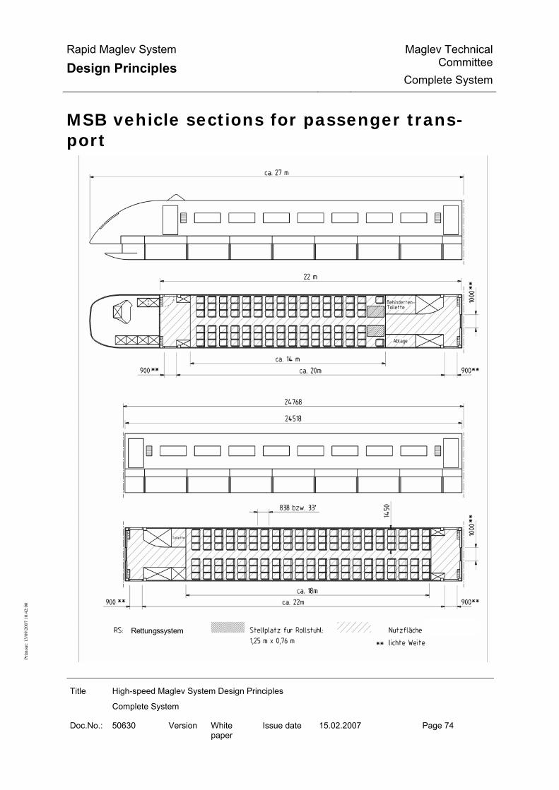
Rapid Maglev System
Design Principles Maglev Technical
CommitteeComplete System
Title High-speed Maglev System Design Principles
Complete System
Doc.No.: 50630 Version White paper
Issue date 15.02.2007 Page 74
Prin
tout
: 13/
09/2
007
10:4
2:00
MSB vehicle sections for passenger trans-port
Rettungssystem

Rapid Maglev System
Design Principles Maglev Technical
CommitteeComplete System
Title High-speed Maglev System Design Principles
Complete System
Doc.No.: 50630 Version White paper
Issue date 15.02.2007 Page 75
Prin
tout
: 13/
09/2
007
10:4
2:00
Figure 6: Vehicle sections for passenger transport long-haul (example)
Behindertentoilette Disabled toilet
Ablage Storage
bzw. or
Rettungssystem Rescue system
Stellplatz für Rollstuhl Place for wheelchair
Nutzfläche Useful surface area
lichte Weite Clear width

Rapid Maglev System
Design Principles Maglev Technical
CommitteeComplete System
Title High-speed Maglev System Design Principles
Complete System
Doc.No.: 50630 Version White paper
Issue date 15.02.2007 Page 76
Prin
tout
: 13/
09/2
007
10:4
2:00
LBG
A
ir tre
atm
ent a
ppar
atus
SS
S
witc
hing
cup
boar
d
RS
R
escu
e sy
stem
GP
L
ugga
ge s
pace
DD
P
ress
ure-
tight
duc
t
Figure 7: Vehicle end sections for passenger transport airport link (example)

Rapid Maglev System
Design Principles Maglev Technical
CommitteeComplete System
Title High-speed Maglev System Design Principles
Complete System
Doc.No.: 50630 Version White paper
Issue date 15.02.2007 Page 77
Prin
tout
: 13/
09/2
007
10:4
2:00
LBG
Ai
r tre
atm
ent a
ppar
atus
SS
Sw
itchi
ng c
upbo
ard
RS
R
escu
e sy
stem
GP
L
ugga
ge a
rea
DD
P
ress
ure-
tight
duc
t
Sta
ndin
g ar
eas
A, B
, C, D
1, D
2
Figure 8: Vehicle centre sections for passenger transport airport link (example)

Rapid Maglev System
Design Principles Maglev Technical
CommitteeComplete System
Title High-speed Maglev System Design Principles
Complete System
Doc.No.: 50630 Version White paper
Issue date 15.02.2007 Page 78
Prin
tout
: 13/
09/2
007
10:4
2:00
Levitation/guide system
Figure 9: Levitation/guide system (example)
Wagenkasten-Zelle Body cell
Trag-/Führsystem Support/guidance system
Schwebegestell Levitation chassis
Schweberahmen Levitation frame
Tragmagnet Support magnet
Führmagnet Guidance magnet
Bremsmagnet Braking magnet
Einbaustruktur Mounting structure
Tragkufe Support skid
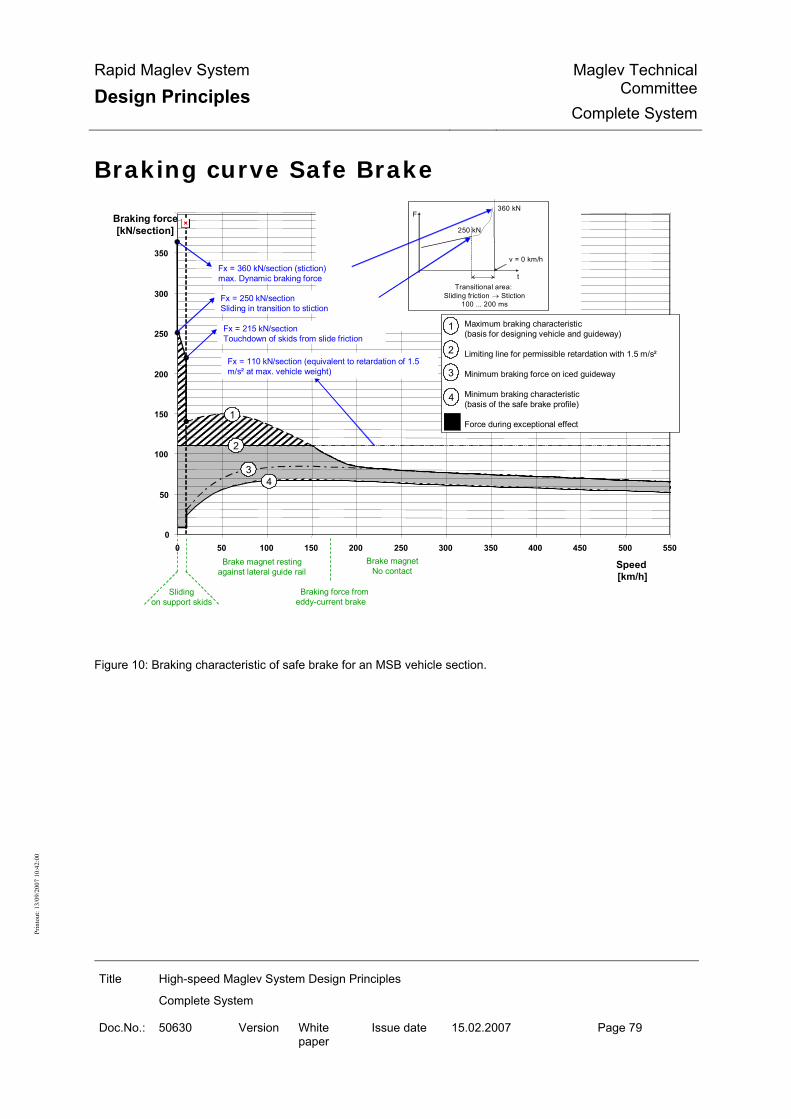
Rapid Maglev System
Design Principles Maglev Technical
CommitteeComplete System
Title High-speed Maglev System Design Principles
Complete System
Doc.No.: 50630 Version White paper
Issue date 15.02.2007 Page 79
Prin
tout
: 13/
09/2
007
10:4
2:00
Braking curve Safe Brake
0
50
100
150
200
250
300
350
0 50 100 150 200 250 300 350 400 450 500 550
Speed[km/h]
Braking force[kN/section]
34
250 kN
360 kN
v = 0 km/h
Transitional area:Sliding friction → Stiction
100 ... 200 ms
t
F
1
2
Maximum braking characteristic(basis for designing vehicle and guideway)
Limiting line for permissible retardation with 1.5 m/s²
Minimum braking force on iced guideway
Minimum braking characteristic(basis of the safe brake profile)
Force during exceptional effect
1
2
3
4
Slidingon support skids
Braking force fromeddy-current brake
Brake magnet restingagainst lateral guide rail
Brake magnetNo contact
Fx = 360 kN/section (stiction)max. Dynamic braking force
Fx = 250 kN/sectionSliding in transition to stiction
Fx = 215 kN/sectionTouchdown of skids from slide friction
Fx = 110 kN/section (equivalent to retardation of 1.5m/s² at max. vehicle weight)
Figure 10: Braking characteristic of safe brake for an MSB vehicle section.

Rapid Maglev System
Design Principles Maglev Technical
CommitteeComplete System
Title High-speed Maglev System Design Principles
Complete System
Doc.No.: 50630 Version White paper
Issue date 15.02.2007 Page 80
Prin
tout
: 13/
09/2
007
10:4
2:00
Running resistance
0
20
40
60
80
100
120
140
160
180
200
220
0 50 100 150 200 250 300 350 400 450 500v [km/h]
F W[k
N]
10 Sections
9 Sections
8 Sections
7 Sections
6 Sections
5 Sections
4 Sections
3 Sections
2 Sections
For explanation see Chapter 0 Figure 11: Running resistance (airport link - planning status 2006)

Rapid Maglev System
Design Principles Maglev Technical
CommitteeComplete System
Title High-speed Maglev System Design Principles
Complete System
Doc.No.: 50630 Version White paper
Issue date 15.02.2007 Page 81
Prin
tout
: 13/
09/2
007
10:4
2:00
Pressure effect (outside tunnels)
Figure 12: Pressure effect from a passing MSB vehicle (outside tunnels)
(airport link - planning status 2006)
Druckverlauf Pressure curve
für die Geschwindigkeitsabhängigkeit gilt the following applies to the velocity function
Abstand in m Distance in m

Rapid Maglev System
Design Principles Maglev Technical
CommitteeComplete System
Title High-speed Maglev System Design Principles
Complete System
Doc.No.: 50630 Version White paper
Issue date 15.02.2007 Page 82
Prin
tout
: 13/
09/2
007
10:4
2:00
Druckeinwirkung auf ebenen Flächen… Pressure effect on even surfaces parallel to direction of travel, fixed or moving in parallel
Abstand der Fahrzeug-Seitenwände… Distance between vehicle side walls when trains meet
Spurmittenabstand gem. Tab. 5 Track centres according to Table 5
Querneigung Incline
Äußere Wagenkastenbreite… External body width according to Annex 4.2 (4)
Fahrwegquerneigung Guideway incline
Structure of the energy supply
Hilfsenergie-versorgung
Externe Bordenergie-einspeisung
Steuerung Energie-versorgung
Streckenseitige Einrichtungen
Unterwerk n+1
SteuerungEnergie-
versorgung
Energieanpassung und -verteilung
Hilsenergie-versorgung
Blindleistungs-kompensation
Traktions-energie-
versorgung
Unterwerk n
Externe Bordenergie-einspeisung
Steuerung Energie-
versorgung
Hilfsenergie-versorgung
Blindleistungs-kompensation
Traktions-energie-
versorgung
Externe Bordenergie-einspeisung
Energieanpassung und -verteilung
Unterwerk Substructure
Steuerung Energie-versorgung Control of energy supply

Rapid Maglev System
Design Principles Maglev Technical
CommitteeComplete System
Title High-speed Maglev System Design Principles
Complete System
Doc.No.: 50630 Version White paper
Issue date 15.02.2007 Page 83
Prin
tout
: 13/
09/2
007
10:4
2:00
Energieanpassung und -verteilung Energy adaption and distribution
Hilfsenergieversorgung Auxiliary energy supply
Blindleistungskompensation Reactive power compensation
Externe Bordenergie-einspeisung External onboard energy supply
Traktions-energie-versorgung Traction energy supply
Streckenseitige Einrichtungen Track-side equipment
Figure 13: Structure of the energy supply (example)
Structure and functions of the drive
Streckenkabel
SchaltstelleFahrwegseite
Unterwerk n Unterwerk n+1
UmrichterUmrichter
Statorab-schnitt
Antriebsstrecke m
Antriebsregelung/-steuerung Antriebsregelung/-
steuerung
Figure 14: Structure of the drive (example)
Unterwerk Substructure
Antriebsregelung/-steuerung Propulsion system regulation/control
Umrichter Converter
Antriebsstrecke Drive section

Rapid Maglev System
Design Principles Maglev Technical
CommitteeComplete System
Title High-speed Maglev System Design Principles
Complete System
Doc.No.: 50630 Version White paper
Issue date 15.02.2007 Page 84
Prin
tout
: 13/
09/2
007
10:4
2:00
Streckenkabel Section cable
Fahrwegseite Guideway side
Statorabschnitt Stator section
Schaltstelle Switching point
Antriebssteuerung
Umrichter
Betriebsleittechnik Fahrzeug
Streckensteuerung Fahrzeugführung
Stromregelung
Umrichterregelung / -steuerung
Antriebsstrecke
AntriebsvorgabenAntriebsvorgaben Ortsinformation
über Datenübertragung der BLT
Betriebsart
Betriebsart
BetriebsartSchaltbefehle Stellgrößen
Istwerte Motor
SteuerbefehleIstwerte
aktiver Statorabschnitt Sollvorgabe Statorstrom
Fahrzeugort, -geschwindigkeit
AbschaltbefehlBetriebsart
Drive functions are shown in oval boxes and external components in rectangular boxes. Figure 15: Functions of the drive
Betriebsleittechnik Operational control system (BLT)
Fahrzeug Vehicle
Antriebsvorgaben Propulsion system settings
Ortsinformation über Datenübertragung der BLT Location information regarding data transmission from BLT
Abschaltbefehl Shutdown command
Betriebsart Type of operation
Antriebssteuerung Propulsion system control

Rapid Maglev System
Design Principles Maglev Technical
CommitteeComplete System
Title High-speed Maglev System Design Principles
Complete System
Doc.No.: 50630 Version White paper
Issue date 15.02.2007 Page 85
Prin
tout
: 13/
09/2
007
10:4
2:00
Streckensteuerung Section control
Fahrzeugart, -geschwindigkeit Vehicle type, speed
Fahrzeugführung Vehicle guidance
aktiver Statorabschnitt active stator section
Stromregelung power control
Sollvorgabe Statorstrom Desired settings for stator power
Stellgrößen Istwerte Motor Variables for actual values for motor
Schaltbefehle Switching commands
Umrichterregelung/-steuerung Convertor regulation/control
Steuerbefehle Istwerte Control commands actual values
Antriebsstrecke Propulsion system section
Umrichter Covnertor
Structure and functions of the operation control system
BLTFahrweg ,Stationen
Fahrdienst -leitung
Instandhaltung
Fahrzeug
Antrieb
Figure 16: Placement and interfaces of the OCS

Rapid Maglev System
Design Principles Maglev Technical
CommitteeComplete System
Title High-speed Maglev System Design Principles
Complete System
Doc.No.: 50630 Version White paper
Issue date 15.02.2007 Page 86
Prin
tout
: 13/
09/2
007
10:4
2:00
Fahrdienstleitung Traffic controller
Fahrweg, Stationen Guideway, stations
Fahrzeug Vehicle
Antrieb Propulsion system
Instandhaltung Maintenance

Rapid Maglev System
Design Principles Maglev Technical
CommitteeComplete System
Title High-speed Maglev System Design Principles
Complete System
Doc.No.: 50630 Version White paper
Issue date 15.02.2007 Page 87
Prin
tout
: 13/
09/2
007
10:4
2:00
Sichere OrtungAntriebsabschaltung
Fahrwegsicherung Fahrzeugsicherung
Fahrablaufsteuerung
Fahrprofil -überwachung
FahrzeugAntriebFahrweg,Stationen
Ort,Geschindigkeit
Ortungs-parameter
Profilverletzung
Abschaltbefehl
Antriebsvorgaben
Fahrtvorgaben
FahrzeugparameterFahrwegparameter
Stellbefehle Eingaben
Stellbefehle,Ausgaben
Fahrwegdaten Fahrzeugdaten
Fahrzeug-bewegung Profilverletzung
Ort,Geschwindigkeit
Meldungen,Anzeigen
Datenübertragung
Daten
Daten Daten
FahrzeugdatenFahrweggdaten
Fahrdienstleitung
Instandhaltung
Daten
Lageinformation,Meldungen
OCS functions are shown in oval boxes and external components in rectangular boxes. Figure 17: OCS functions and data flows
Fahrdienstleitung Traffic controller
Meldungen, anzeigen Messages, displays
Fahrtvorgaben Trip settings
Fahrablaufsteurerung Trip progress control

Rapid Maglev System
Design Principles Maglev Technical
CommitteeComplete System
Title High-speed Maglev System Design Principles
Complete System
Doc.No.: 50630 Version White paper
Issue date 15.02.2007 Page 88
Prin
tout
: 13/
09/2
007
10:4
2:00
Fahrwegparameter Guideway parameters
Fahrzeugparameter Vehicle parameters
Fahrwegdaten Guideway data
Fahrzeugdaten Vehicle data
Fahrwegsicherung Guideway protection
Fahrprofilüberwachung Driving profile monitoring
Fahrzeugsicherung Vehicle protection
Fahrzeugbewegung Vehicle movement
Profilverletzung Profile violation
Ortungsparameter Location parameters
Lageinformationen, Meldungen Position information, messages
Antriebsvorgaben Propulsion system settings
Ort, Geschwindigkeit Location, speed
Stellbefehle, Ausgaben Actuator commands and output
Antriebsabschaltung Propulsion system shutdown
Sichere Ortung Safe location
Stellbefehle Actuator commands
Eingaben Inputs
Abschaltbefehl Shutdown command
Ort, Geschwindigkeit Location, speed
Fahrweg, Stationen Guideway, stations
Antrieb Propulsion system
Instandhaltung Maintenance
Fahrzeug Vehicle
Daten Data
Datenübertragung Data transmission

Rapid Maglev System
Design Principles Maglev Technical
CommitteeComplete System
Title High-speed Maglev System Design Principles
Complete System
Doc.No.: 50630 Version White paper
Issue date 15.02.2007 Page 89
Prin
tout
: 13/
09/2
007
10:4
2:00
Structure of the positioning
Steuerungstechnisch relev anteOrtung
Sichere Ortung
Antriebsregelung
BLT-Funktionen
Relativ ort
DatenübertragungMobil-Ortsf est
Ref erenzorte
Anzeige
Einrichtungen am Fahrzeug
Einrichtungen am Fahrweg
AntriebBetriebsleittechnik
Figure 18: Structure of the positioning (example)
Einrichtungen am Fahrzeug Equipment on vehicle
Anzeige Display
Betriebsleittechnik Operational control system (BLT)
Antrieb Propulsion system
Sichere Ortung Safe location
BLT-Funktionen BLT functions
Steuerungstechnisch relevante Ortung Location that is relevant to the controls
Datenübertragung Mobil-Ortsfest Transmission of data between mobile and fixed locations
Antriebsregelung Regulation of propulsion system
Referenzorte Reference locations
Relativort Relative location
Einrichtungen am Fahrweg Equipment on guideway

Rapid Maglev System
Design Principles Maglev Technical
CommitteeComplete System
Title High-speed Maglev System Design Principles
Complete System
Doc.No.: 50630 Version White paper
Issue date 15.02.2007 Page 90
Prin
tout
: 13/
09/2
007
10:4
2:00
Elevated guideway
Superstruct
Substructur
Boundary line for the kinematic space requirementof the vehicle
Clearance gauge
e.g. 24768
12°
Figure 19: Elevated guideway (example)
At-grade guideway C learance gau ge
Bound ary lie for the k inem atic space requ irem entof the veh ic le
12°
6192
3096 3096
Figure 20: At-grade guideway (example)

Rapid Maglev System
Design Principles Maglev Technical
CommitteeComplete System
Title High-speed Maglev System Design Principles
Complete System
Doc.No.: 50630 Version White paper
Issue date 15.02.2007 Page 91
Prin
tout
: 13/
09/2
007
10:4
2:00
Beam dimension
3D curve
R
Stator axis (outside of bend)
System axis System axis
Stator axis (inside of bend) H
System length of guideway beam
Gap at beam joint
Component length (L)
(L )Sys
Figure 21: Beam dimension - Relationship between component length and system length

Rapid Maglev System
Design Principles Maglev Technical
CommitteeComplete System
Title High-speed Maglev System Design Principles
Complete System
Doc.No.: 50630 Version White paper
Issue date 15.02.2007 Page 92
Prin
tout
: 13/
09/2
007
10:4
2:00
Guideway equipment and functional planes
3D curveSlide rail GLLateral guide rail SFS
Slide plane GE
Stator plane SE
( ) Figures in brackets are design-specific
250
1110
(R 235.0)
Late
ral g
uide
pla
neS
FE1400
min. 30
305
240
Gui
dew
ay C
/L
653
310
15
89.5
913
(270
)
885
165
Hov
er c
lear
ance
398
18512
0
max. 240 max. 240
842.5
715
938
1250
1102
240
250
x 4
5°
10
285Stator pack mounting
Guideway boundary
Gauge 2800
Space for externalonboard energy supply
Space forLSW incoming and outgoing cable
Space for positioning modules
Space formotor winding
Figure 22: Functional elements, functional planes and installation spaces on the guideway, dimensions (nominal)

Rapid Maglev System
Design Principles Maglev Technical
CommitteeComplete System
Title High-speed Maglev System Design Principles
Complete System
Doc.No.: 50630 Version White paper
Issue date 15.02.2007 Page 93
Prin
tout
: 13/
09/2
007
10:4
2:00
Stator pack arrangement
103 2 (S y ste m di m en sion) 103 2 (Sy ste m dim en sion)
1/2 ga p 1/2 ga pgap
(bend o u tsid e)
S ta to r p a ck arra n g em en t o n s tra igh t gu id e w a y
103 2 (S y ste m di m en sion) 103 2 (Sy ste m dim en sion)
1/2 ga p be nd o utsid eG ap b en d ou tsi de
1/2 ga p be nd in side G ap b en d insid e
1/2 ga p be nd o utsid e
1/2 ga p be nd in side
103 2 (S y ste m di m en sion) + d ifferenc xe for ou tsid e be nd 103 2 (S y ste m di m en sion) + d if ferenc e for ou tsid e b end
103 2 (Sy ste m di m en sion) – dif ferenc e for insi de b en d 103 2 (S y ste m di m en sion) – dif ferenc e for insi de b en d
3D c ur ve
(bend in sid e)
S ta to r p ac k arran g e m en t o n h o riz o n ta lly cu rv e d g u id ew ay
The lengths of the individual stator pack types must be defined project-specifically. Figure 23: Stator pack arrangement (example)

Rapid Maglev System
Design Principles Maglev Technical
CommitteeComplete System
Title High-speed Maglev System Design Principles
Complete System
Doc.No.: 50630 Version White paper
Issue date 15.02.2007 Page 94
Prin
tout
: 13/
09/2
007
10:4
2:00
Long-stator winding
Figure 24: Long-stator winding (example)
Wicklungsperiode entspr. 6 Statornutteilungen = Winding period corresponding to 6 stator slot pitches

Rapid Maglev System
Design Principles Maglev Technical
CommitteeComplete System
Title High-speed Maglev System Design Principles
Complete System
Doc.No.: 50630 Version White paper
Issue date 15.02.2007 Page 95
Prin
tout
: 13/
09/2
007
10:4
2:00
Track-switching devices

Rapid Maglev System
Design Principles Maglev Technical
CommitteeComplete System
Title High-speed Maglev System Design Principles
Complete System
Doc.No.: 50630 Version White paper
Issue date 15.02.2007 Page 96
Prin
tout
: 13/
09/2
007
10:4
2:00
Figure 25: Point (example)
Querschnitt Cross-section
Ansicht Front view
Festlager Fixed bearing
Stützort Support point
Systemlänge (beispielhaft) System length (example)
Draufsicht Plan view
Verriegelungsblöcke Locking blocks

Rapid Maglev System
Design Principles Maglev Technical
CommitteeComplete System
Title High-speed Maglev System Design Principles
Complete System
Doc.No.: 50630 Version White paper
Issue date 15.02.2007 Page 97
Prin
tout
: 13/
09/2
007
10:4
2:00

Rapid Maglev System
Design Principles Maglev Technical
CommitteeComplete System
Title High-speed Maglev System Design Principles
Complete System
Doc.No.: 50630 Version White paper
Issue date 15.02.2007 Page 98
Prin
tout
: 13/
09/2
007
10:4
2:00
Figure 26: Traverser (example)
Querschnitt Cross-section
Ansicht Front view
Stützort Support point
Systemlänge (beispielhaft) System length (example)
Draufsicht Plan view
Verriegelungsblöcke Locking blocks

Rapid Maglev System
Design Principles Maglev Technical
CommitteeComplete System
Title High-speed Maglev System Design Principles
Complete System
Doc.No.: 50630 Version White paper
Issue date 15.02.2007 Page 99
Prin
tout
: 13/
09/2
007
10:4
2:00

Rapid Maglev System
Design Principles Maglev Technical
CommitteeComplete System
Title High-speed Maglev System Design Principles
Complete System
Doc.No.: 50630 Version White paper
Issue date 15.02.2007 Page 100
Prin
tout
: 13/
09/2
007
10:4
2:00
Figure 27: Turntable (example)
Querschnitt Cross-section
Ansicht Front view
Festlager Fixed bearing
Stützort Support point
Systemlänge (beispielhaft) System length (example)
Draufsicht Plan view
Verriegelungsblöcke Locking blocks

Rapid Maglev System
Design Principles Maglev Technical
CommitteeComplete System
Title High-speed Maglev System Design Principles
Complete System
Doc.No.: 50630 Version White paper
Issue date 15.02.2007 Page 101
Prin
tout
: 13/
09/2
007
10:4
2:00
Protective structures
Grade
12°
3D curve
12°
3D curve Possible site of noise barrier orpossible site of fence on theclearance boundary
Clearance gauge
s
Frost protection layer
Boundary line for the kinematic space requirementof the vehicle
Figure 28: Noise barrier and fence on at-grade guideway (example)

Rapid Maglev System
Design Principles Maglev Technical
CommitteeComplete System
Title High-speed Maglev System Design Principles
Complete System
Doc.No.: 50630 Version White paper
Issue date 15.02.2007 Page 102
Prin
tout
: 13/
09/2
007
10:4
2:00
800
800
s
Clearance gauge
3D curve 3D curve
12°12°
Walkwaylevel
1600
1600
Boundary line for thekinematic space requirementof the vehicle
Figure 29: Noise barrier on elevated guideway (example)

Rapid Maglev System
Design Principles Maglev Technical
CommitteeComplete System
Title High-speed Maglev System Design Principles
Complete System
Doc.No.: 50630 Version White paper
Issue date 15.02.2007 Page 103
Prin
tout
: 13/
09/2
007
10:4
2:00
Route peripherals
12°
3D curve
12°
3D curve
700
400
1200
hG, Grade - Gradient height above grade after completion
hG, G
rade
> 22
00M
ast h
eigh
t abo
ve3D
cur
ves
>500
0
possiblesite of theswitch point /transformer station /emergency power /BE station
Clearance gauge
s
≥ 330
0<4
300
Frost protection layer
* except special cases
1200
Radio mast minimum clearance *
3254 (12°)(3150 2 %)
Space for cables für
Boundary line for thekinematic space requirementof the vehicle
Space for cables
Figure 30: Route peripherals with at-grade guideway (example)

Rapid Maglev System
Design Principles Maglev Technical
CommitteeComplete System
Title High-speed Maglev System Design Principles
Complete System
Doc.No.: 50630 Version White paper
Issue date 15.02.2007 Page 104
Prin
tout
: 13/
09/2
007
10:4
2:00
700
400
1200
400
700
Space for cablesSpace for cables
s
Clearance gauge
H – Headroom as per requirements for overpass of railway or road
possiblesite ofswitching point /transformer station /emergency power /BE station
1200
Radio mast Minimum clearance *
3254 (12°)(3150 2 %)
Mas
t hei
ght a
bove
3D
cur
ve>5
000
≥330
0<4
300
* except special cases
3D curve 3D curve
12°12°
Walkwaylevel
H
Boundary line for thekinematic space requirementof the vehicle
Figure 31: Route peripherals with elevated guideway (example)

Rapid Maglev System
Design Principles Maglev Technical
CommitteeComplete System
Title High-speed Maglev System Design Principles
Complete System
Doc.No.: 50630 Version White paper
Issue date 15.02.2007 Page 105
Prin
tout
: 13/
09/2
007
10:4
2:00
Annex: High-speed Maglev System Data

Rapid Maglev System
Design Principles Maglev Technical
CommitteeComplete System
Title High-speed Maglev System Design Principles
Complete System
Doc.No.: 50630 Version White paper
Issue date 15.02.2007 Page 106
Prin
tout
: 13/
09/2
007
10:4
2:00
The system data defined below are required in order to design subsystems and modules of the MSB. The system data that are identified in this Annex as "system parameters" apply to all projects. The project-specific or product-specific data (not specially identified here as "system parameters") must be confirmed project-specifically by application of the Design Principles, or defined differently. The defini-tions must be allowed for in the verification process.
No. Name Symbol
Systempara-meter
Value Unit Explanation
1. Transport / operational pa-rameters
1.1. Speed (1) Maximum vehicle speed vFz,max 500 km/h Constant speed derived from the per-
missible continuous loads for the vehi-cle.
(2) Vehicle speed limit vFz,limit - km/h Constant speed derived from the per-missible vehicle loads (special load cases). To be defined project-specifically based on incident analyses.
(3) Maximum guideway speed vFw,max (x) ≤ 500 km/h Position-dependent profile of the per-missible speed for an aligned route derived from the strength of the guide-way.
(4) Guideway speed limit vFw,limit (x) - km/h Position-dependent profile of the per-missible speed for an aligned route derived from the strength of the guide-way under exceptional effects. To be defined project-specifically based on incident analyses.
1.2. Schedule (1) Signal headway - min Project-specific decision
2. Track alignment 2.1. Horizontal radius (1) Minimum horizontal radius RH min x 350 m 2.2. Limits of transverse inclination (1) - in platform area αmax (BS) x 3 ° *) /MBbO Section 13 (3) limits the
permissible transverse inclination in the stationary train in the platform area to 3.4 °. The max. permitted transverse inclination of 3.0 ° for line routing is derived from this.
(2) - at service stopping places for opera-tionally related stop
αmax (HP_2) 6 ° Comfort guide value as per project-specific definition
(3) - at other service stopping places αmax (HP_1) x 12 °

Rapid Maglev System
Design Principles Maglev Technical
CommitteeComplete System
Title High-speed Maglev System Design Principles
Complete System
Doc.No.: 50630 Version White paper
Issue date 15.02.2007 Page 107
Prin
tout
: 13/
09/2
007
10:4
2:00
(4) - outside stopping places αmax (ST) x 12 16
° MbBO Section 13, (3) MbBO Section 13, (3) for approval in individual cases
(5) Desired transverse inclination to drain the top of the guideway beam
αmin (ST) ≥ 1.15 ° equivalent to 2%
2.3. Vertical radius (1) Minimum vertical radius RV min x 530 m 2.4. Limits of linear inclination (1) - in platform area smax (BS) (β) x 5 ‰ MbBO Section 13, (2) (2) - in areas in which standing vehicles
must be secured from inadvertent movement
smax (BE) (β) x 5 ‰ MbBO Section 13, (2), exception per-mitted as per MbBO Section 5, (1)
(3) - at stopping places smax (HP) (β) ≤ 100 ‰ Defined project-specifically according to proof of the hold function
(4) - outside stopping places smax (ST) (β) x 100 ‰ 2.5. Limits of guideway warp (1) Limits of guideway warp ∆αmax (ST) x 0.10 °/m up to 0.15°/m in special cases
combination of transverse inclination over 12° and warp over 0.1°/m only after verification in individual cases.
2.6. Overlaying of alignment elements
(1) Rx,z criterion Rx,z min x fx,z(∆α) m (2) Rx,y criterion Rx,y min x fx,y(∆α) m 2.7. Other alignment parameters (1) Track centres SM x ≥ 4,400 mm according to MbBO, speed-dependent (2) Clearance gauge − x - mm according to MbBO
3. Accelerations, jolts, vibra-tion and pressures
3.1. Acceleration 3.1.1. Linear acceleration (x-direction)
(1) Maximum value of drive acceleration ax,max,accelerate x ≤ 1.5 m/s² MbBO Section 13, (5) (2) Maximum value of brake acceleration ax,max,brake x ≥ -1.5 m/s² MbBO Section 13, (5)
3.1.2. Unbalanced (free) lateral accelera-tion (y-direction)
(1) Line ay,max x ≤ 1.5 m/s² to outside of bend, MbBO Section 13, (4)
(2) Track-switching device ay,max,SWE x ≤ 2.0 m/s² to outside of bend, MbBO Section 13, (4)
3.1.3. Normal acceleration (z-direction) (1) Trough az,max ≤ 1.2 m/s² (2) Crown az,min ≥ -0.6 m/s²
MbBO Section 13, (6), may be ex-ceeded in individual cases (variable effects)
3.2. Jolt (1) Lateral pressure åy,max 0.5 m/s³ Comfort criterion, for city entrances at
constraints: up to 1.0 m/s³ in individual cases
(2) Lateral jolt, point at junction åy,max,SWE 2.0 m/s³ Comfort criterion (3) Vertical jolt åz,max 0.5 m/s³ Comfort criterion, in individual cases at
constraints: up to 1.0 m/s³

Rapid Maglev System
Design Principles Maglev Technical
CommitteeComplete System
Title High-speed Maglev System Design Principles
Complete System
Doc.No.: 50630 Version White paper
Issue date 15.02.2007 Page 108
Prin
tout
: 13/
09/2
007
10:4
2:00
4. MSB Vehicle 4.1. Vehicle configuration (1) Number of vehicle sections NSekt 2 … 10 no. (2) Useful area per vehicle section ANutz - m² (3) Seats per vehicle section NSitz - - (4) Standing places per vehicle section NSteh - - (5) Payload per vehicle section NL - kg
Project-specific decision
4.2. Vehicle geometry Airport link - planning status 2006 (1) Geometrical length, end section LES approx.
25 m
(2) Geometrical length, centre section (system length vehicle section)
LMS x 24.768 m see also No. 6.1.1. (3): Levitation magnet occupancy length, centre section
(3) Geometrical length of vehicle LFzg m LFZG=2*LES+(NSekt-2)*LMS (4) Exterior width of car body BWK-A x 3.7 m (5) Height of car body over gradient (excl.
antenna) HWK-Grd approx.
3.3 m Vehicle set down, to be defined project-
specifically
(6) Height of top of floor above gradient HFOK-Grd approx. 0.93
m Vehicle set down, to be defined project-specifically
(7) Height of vehicle (incl. antenna) over gradient
HFzg-Grd approx. 3.8
m Vehicle set down, to be defined project-specifically
(8) Ext. height car body over top of floor HWK-FOK approx. 2.4
m to be defined project-specifically
(9) Height of gradient over bottom of vehicle
HGrd-Fzg.UK approx. 0.9
m Vehicle set down, to be defined project-specifically
(10) Overall height of vehicle (excl. an-tenna)
HFzg.Ges approx. 4.2
m to be defined project-specifically
4.3. Vehicle weights The line loads given below are the basis for the guideway design. A toler-ance of +/- 5% of the line loads is permissible on the vehicle side.
(1) Dead weight of a vehicle section MEG ≥ kg The vehicle dead weight may not be less than the value equivalent to a line load of 19 kN/m averaged over the system length of a vehicle section.
(2) Mean weight of a vehicle section MMG ≤ kg The mean vehicle weight is equivalent to a mean line load of 26 kN/m aver-aged over the system length of a vehi-cle section.
(3) Permissible weight of a vehicle sec-tion
MZG ≤ kg The permissible vehicle weight may not exceed the value equivalent to a line load of 29 kN/m averaged over the system length of a vehicle section.
(4) Maximum weight of a vehicle section MXG ≤ kg The maximum vehicle weight may not exceed the value equivalent to a line load of 31 kN/m averaged over the system length of a vehicle section.
5. Guideway 5.1. Guideway configuration
5.1.1. Basic dimensions

Rapid Maglev System
Design Principles Maglev Technical
CommitteeComplete System
Title High-speed Maglev System Design Principles
Complete System
Doc.No.: 50630 Version White paper
Issue date 15.02.2007 Page 109
Prin
tout
: 13/
09/2
007
10:4
2:00
(1) Stator pack system length LSP,Sys x 1,032 mm see also Fig. 23 /MSB AG-GESAMTSYS/, Chapter 8.16
5.1.2. Standard beam lengths (1) Standard guideway type I LSys,Typ I > 16 m Usually supported discretely on individ-
ual footings. To be defined project-specifically.
(2) Standard guideway type II LSys,Type II ≤16 m Usually supported discretely on individ-ual footings. To be defined project-specifically.
(3) Standard guideway type III LSys,Typ III approx. 6 m Usually supported discretely on strip footings. To be defined project-specifically.
5.2. Guideway geometry (1) Gauge (distance between lateral
guide planes) SSFE x 2,800 mm
(2) Guideway hover clearance slide plane/stator plane
TZM,GLE-SE x 398 mm
5.3. Deviations of position of the func-tional planes
5.3.1. Tolerance guideway hover clear-ance
(1) Guideway hover clearance in beam bay
+3 / -5 mm
(2) Relative difference in hover clear-ances at beam joint
∆TZM
± 0.4 mm
5.3.2. Gauge width tolerance (1) Gauge width in beam bay ± 2 mm (2) Relative gauge difference at beam
joint
max ∆S ± 1 mm
5.4. Guideway superstructure deforma-tion
5.4.1. in x-direction due to traffic (1) at beam joint 10
20 mm periodical
with autom. braking
5.4.2. in z-direction due to traffic (1) Single-bay beam x LSt/4,000 mm with static effect at permissible vehicle
weight
(2) Dual-bay beam x LSt/4,800 mm with static effect at permissible vehicle weight
(3) Guideway plates
max fz,Fzg
The construction must be assessed in individual cases.
5.4.3. in y-direction due to traffic (1) Single-bay beam x LSt/15,000 mm with static effect at permissible vehicle
weight and ay,max
(2) Dual-bay beam x LSt/18,000 mm with static effect at permissible vehicle weight and ay,max
(3) Guideway plates
max fy,Fzg
The construction must be assessed in individual cases.
5.5. Track-switching devices (1) Turnaround time of a 2-way point from
end position to end position 30 s Typical value
6. Geometry of the vehi-cle/guideway interfaces
6.1. Levitation magnet / long stator

Rapid Maglev System
Design Principles Maglev Technical
CommitteeComplete System
Title High-speed Maglev System Design Principles
Complete System
Doc.No.: 50630 Version White paper
Issue date 15.02.2007 Page 110
Prin
tout
: 13/
09/2
007
10:4
2:00
6.1.1. Levitation magnet (1) Levitation magnet system length
(standard length magnet) Lsys,TM x 3,096 mm
(2) Levitation magnet centres in y-direction
ey,TM x 2,220 mm
(3) Levitation magnet occupancy length centre section
LTM-B,MS x 24,768 mm
(4) Levitation magnet occupancy length end section
LTM-B,ES 23,753 mm no system dimension, may vary pro-ject-specifically
6.1.2 Long stator (1) Lang stator centres in y-direction ey,SP x 2220 mm Nom. dim. (2) Width of stator pack (geometrical) by,SP ≥ 185 mm Typical embodiment: 185 mm, to be
defined project-specifically
(3) Pole centres ex,pole centres x 258 mm Nom. dim., 3-phase motor winding (4) Slot pitch (centres of the motor wind-
ing cable) ex,slot pitch x 86 mm Nom. dim.
6.2. Guide magnet - lateral guide rail 6.2.1. Guide magnet
(1) Guide magnet system length Lsys,FM x 3,096 mm 6.2.2. Lateral guide rail
(1) Lateral guide rail height hSFS x 310 mm (2) Lateral guide rail thickness dSFS ≥ 30 mm 30 mm, Typical embodiment, to be
defined project-specifically
6.3. Brake magnet - lateral guide rail (1) Brake magnet centres in x-direction ex,BM 24,768 mm Guide value, different dimensions may
be defined project-specifically.
6.4. Support skid / slide plane 6.4.1 Support skid (1) Support skid length Lx,TK 740 mm Guide value, different dimensions may
be defined project-specifically.
(2) Support skid width by,TK 110 mm Guide value, different dimensions may be defined project-specifically.
(3) Skid centres in x-direction ex,TK 3,096 mm (4) Skid centres in y-direction ey,TK x 2,220 mm
6.4.2 Slide plane (1) Slide plane / slide rail width min by,GL ≥ 150 mm
7. Effects at the vehi-cle/guideway interfaces in x-direction
(1) Variable effects with drive/brakes max stat px 4.8 kN/m Local maximum; mean over a vehicle section 4.4 kN/m for a centre section of length 24.768 m. Drive current is limited so that the maximum permissible force is not exceeded.
(2) Exceptional effects (symmetrical) max px 10.0 kN/m Equivalent to approx. 250 kN/vehicle section for a centre section of length 24.768 m

Rapid Maglev System
Design Principles Maglev Technical
CommitteeComplete System
Title High-speed Maglev System Design Principles
Complete System
Doc.No.: 50630 Version White paper
Issue date 15.02.2007 Page 111
Prin
tout
: 13/
09/2
007
10:4
2:00
(3) Exceptional effects (asymmetrical) max px r,l 5.5 or 2.0
kN/m Equivalent to a maximum total force of 185 kN/vehicle section for a centre section of length 24.768 m and a maximum uneven distribution of 0.73 : 0.27 between the two guideway/vehicle sides
8. Drive 8.1. Motor geometry
see Levitation magnet and Long stator - 8.2. Motor constants (1) Shear force constant per centre sec-
tion cM,MS - N/A Correlated quantity equation: cM,MS =
43.0 * √(mMS[t] / 64.5 t) with mMS - actual weight of centre section Values may vary at very high and very low temperatures due to the expansion of long MSB vehicles.
(2) Shear force constant per end section cM,ES - N/A Correlated quantity equation: cM,ES = 41.3 * √(mES[t] / 62.0 t) with mES - actual weight of end sectionValues may vary at very high and very low temperatures due to the expansion of long MSB vehicles.
(3) Induced motor voltage per vehicle section long side
up - V Equivalent to 1/6 * cM * speed
(4) Conductor cross-section AS 300 mm Guide value for aluminium conductor (5) Conductor resistance RS 0.23 Ω Guide value per km stator length at
20°C and 0-30 Hz
(6) Resistance/temp. coefficient θSt 0.004 1/°C Guide value factor is: (1+θSt*(temperature-20°C))
(7) Resistance/frequency coefficient fSt 0.004 s Guide value factor is: (1+fSt*(frequency-30Hz))
(8) Leakage inductance LS 2.6 mH Guide value per km stator length with-out vehicle
(9) Vehicle magnetizing inductance Lh 0.1 mH Guide value per section and side incl. LS
(10) Earth capacitance CS 1 uF Guide value per km stator length (11) Length factor moving field line/long
stator 2.35 Guide value
(12) Max. conductor temperature TLmax 70 °C Guide value for service life reasons, technically 90°C
(13) Thermal time constant τStat 1...5 h Guide value (14) Nom. voltage UNenn 10...20 kV Guide value interlinked fundamental
component rms
8.3. Motor interconnection (1) Motor section length ds 1,200 m Guide value, individually between
approx. 0.5 and 3 km
(2) Motor section offset vers 300 m Guide value, individually between 0 and ds/2
9. Operation Control System 9.1 Safe positioning

Rapid Maglev System
Design Principles Maglev Technical
CommitteeComplete System
Title High-speed Maglev System Design Principles
Complete System
Doc.No.: 50630 Version White paper
Issue date 15.02.2007 Page 112
Prin
tout
: 13/
09/2
007
10:4
2:00
(1) Positional information tolerance, static 2 m Typical value. The value must be de-termined project-specifically.
(2) Speed information tolerance 5 km/h Typical value. The value must be de-termined project-specifically.
9.2 Vehicle-related speeds (1) Setdown speed 5 km/h Typical value. The value must be de-
termined project-specifically.
9.3 Deceleration and running times (1) Max. drive shutdown time 2.3 s Guide value for the shutdown time of
the drive and braking energy for a safety-relevant shutdown reason by the OCS
10. Aerodynamics 10.1. Pressure during vehicle passage (1) Max. pressure amplitude on the vehi-
cle sides x 2,400 Pa
(2) Pressure amplitude on structures on the guideway
- Pa dependent on clearance and vehicle speed
(3) Pressure load on guideway table and vehicle underfloor
x -7.6 to 15.2
kN/m2
10.2. Pressure in tunnel (1) Design pressure for tunnel design 5,500 Pa Differential pressure vehicle inte-
rior/exterior (2) Design pressure for vehicle design 6,000 Pa Differential pressure vehicle inte-
rior/exterior

Rapid Maglev System
Design Principles Maglev Technical
CommitteeComplete System
Title High-speed Maglev System Design Principles
Complete System
Doc.No.: 50630 Version White paper
Issue date 15.02.2007 Page 113
Prin
tout
: 13/
09/2
007
10:4
2:00

Rapid Maglev System
Design Principles Maglev Technical
CommitteeComplete System
Title High-speed Maglev System Design Principles
Complete System
Doc.No.: 50630 Version White paper
Issue date 15.02.2007 Page 114
Prin
tout
: 13/
09/2
007
10:4
2:00

High-speed Maglev System
Design Principles Maglev Technical
CommitteeComplete System
Title High-speed Maglev System Design Principles
Complete System, Annex 1 Abbreviations and Definitions
Doc.No.: 67536 Version White pa-per
Issue date 15.02.2007 Page 1
Prin
tout
: 13/
09/2
007
10:4
2:00
High-speed Maglev System Design Principles
Complete System
Annex 1 Abbreviations and definitions
The author reserves the copyright in this document and all attachments. All rights reserved

High-speed Maglev System
Design Principles Maglev Technical
CommitteeComplete System
Title High-speed Maglev System Design Principles
Complete System, Annex 1 Abbreviations and Definitions
Doc.No.: 67536 Version White pa-per
Issue date 15.02.2007 Page 2
Prin
tout
: 13/
09/2
007
10:4
2:00
Distribution This document has been released for publication by the Technical Committee "Complete Sys-tem".

High-speed Maglev System
Design Principles Maglev Technical
CommitteeComplete System
Title High-speed Maglev System Design Principles
Complete System, Annex 1 Abbreviations and Definitions
Doc.No.: 67536 Version White pa-per
Issue date 15.02.2007 Page 3
Prin
tout
: 13/
09/2
007
10:4
2:00
Change history Release date: 15.02.2007; white paper, Technical Committee "Complete System"

High-speed Maglev System
Design Principles Maglev Technical
CommitteeComplete System
Title High-speed Maglev System Design Principles
Complete System, Annex 1 Abbreviations and Definitions
Doc.No.: 67536 Version White pa-per
Issue date 15.02.2007 Page 4
Prin
tout
: 13/
09/2
007
10:4
2:00
List of contents
1 Distribution ...................................................................................................................................... 2
2 Change history ................................................................................................................................ 3
3 List of contents ............................................................................................................................... 4
4 General ............................................................................................................................................. 5 4.1 Purpose of the document, scope ................................................................................................... 5 4.2 High-speed Maglev System Design Principles .............................................................................. 5 4.3 Abbreviations and definitions ......................................................................................................... 5 4.4 Statutes, regulations, standards and directives ............................................................................. 5 4.5 Identification and binding value of requirements ........................................................................... 6
5 Overviews ........................................................................................................................................ 7
6 Abbreviations .................................................................................................................................. 9
7 Definitions...................................................................................................................................... 21 List of illustrations Figure 1: Chart of operation, modes.........................................................................................7 Figure 2: Chart of speed terms.................................................................................................8

High-speed Maglev System
Design Principles Maglev Technical
CommitteeComplete System
Title High-speed Maglev System Design Principles
Complete System, Annex 1 Abbreviations and Definitions
Doc.No.: 67536 Version White pa-per
Issue date 15.02.2007 Page 5
Prin
tout
: 13/
09/2
007
10:4
2:00
General
Purpose of the document, scope This document contains abbreviations and definitions for high-speed maglev systems. These design principles apply to a high-speed maglev system according to the General Maglev System Act /AMbG/.
High-speed Maglev System Design Princi-ples This document is an annex to the Design Principles Complete System and so forms part of a documentation for high-speed maglev systems consisting of several design principles. The document tree is shown in Figure 1 /MSB AG-GESAMTSYS/. The high-level "complete system" design principles and their annexes apply uniformly for the whole documentation: • High-speed Maglev System Design Principles Complete System, Doc. No.: 50630,
/MSB AG-GESAMTSYS/ • Annex 1: Abbreviations and Definitions, Doc. No.: 67536, /MSB AG-ABK&DEF/ • Annex 2: Statutes, Regulations, Standards and Directives, Doc. No.: 67539, /MSB
AG-NORM&RILI/ • Annex 3: Environmental Conditions, Doc. No.: 67285, /MSB AG-UMWELT/ • Annex 4: Rules for Operation and Maintenance, Doc. No.: 69061, /MSB AG-
BTR/ • Annex 5: Noise, Doc. No.: 72963, /MSB AG-SCHALL/
Abbreviations and definitions Abbreviations and definitions are listed in this document. Further specific abbreviations and definitions may be defined in the lower-level design prin-ciples.
Statutes, regulations, standards and direc-tives The normative documents listed in /MSB AG-NORM&RILI/ contain requirements that form part of the High-speed Maglev System Design Principles by cross reference in the High-speed Maglev System Design Principles. Where normative documents in /MSB AG-NORM&RILI/ are dated, subsequent changes or revisions of these publications do not apply. With undated references, the latest version of the normative document that is referred to applies.

High-speed Maglev System
Design Principles Maglev Technical
CommitteeComplete System
Title High-speed Maglev System Design Principles
Complete System, Annex 1 Abbreviations and Definitions
Doc.No.: 67536 Version White pa-per
Issue date 15.02.2007 Page 6
Prin
tout
: 13/
09/2
007
10:4
2:00
The version of the standards and directives to be observed in an MSB project must be decided bindingly on a project-specific basis.
Identification and binding value of require-ments The requirements of /DIN 820/ were essentially applied in the preparation of this document. In the following chapters and the annexes of this document
• Requirements are shown in normal font • Explanations, guide values and examples are shown in italics
The degree to which the requirements are binding has been defined by reference to /DIN 820-2/ Annex G, and has been taken into consideration when formulating the individual require-ments.

High-speed Maglev System
Design Principles Maglev Technical
CommitteeComplete System
Title High-speed Maglev System Design Principles
Complete System, Annex 1 Abbreviations and Definitions
Doc.No.: 67536 Version White pa-per
Issue date 15.02.2007 Page 7
Prin
tout
: 13/
09/2
007
10:4
2:00
Overviews The following terms and definitions must be used for the High-speed Maglev System Design Principles. The terms and definitions are summarised alphabetically below in Chapters 0 and 0.
Figure 32: Chart of Operation, Modes
Limiting running profile
Guideway speed limit
Vehicle speed limit
Safe brakingprofile
min
Max. running profile
Max. vehicle speed
Max. line speed
Drive control tolerance,
Positioning tolerance
Safety engineering responses
Special loads
Continuous loads
Nominal running profile
Recomm. speed for comfort
Actual running profile(s)
Drive performance
Design speed
Alignment Project inputs(noise control, energy demand,
comfort values, journey times etc)
Max. operating speed
Safe levitationprofile
Min. running profile
Alignment
Technical maximum speed
Minimum line speed
Failure scenarios
Line speed limit
Recommended line speed
Project-dependentspecial decisions
min
min
Max. guideway speed
min
Nominal speed
min
min
SP related non SP related
for tech. reasons not for tech. reasons
Tunnel speed limit
Max. tunnel speed
Alignment
Abweichungen vom Normalbetrieb
Nicht vollständig technisch gesicherter Fahrbetrieb unter
Personalverantwortung.
Normalbetrieb
Vollständig technisch gesicherter Fahrbetrieb.Hinweis: Dieser Begriff Normalbetrieb resultiert aus einer betri eblichen Betrachtung gemäß MbBO §24.
Fahrbetrieb
Vorbereiten und Durchführen von Fahrten mit Fahrzeugen und
Sonderfahrzeugen.
Instandhaltung
Kombination aller technischen und administrativen Maßnahmen
einschließlich Überwachungsmaßnahmen, mit
denen eine Betrachtungseinheit im funktionalen Zustand erhalten oder in ihn zurückversetzt werden soll.
(gemäß /EN 50129/)
Betrieb
Betrieb ist die Gesamtheit aller Maßnahmen, die der Beförderung von Personen und Gütern dienen (§ 2, (1)
/MbBO/)
Departure from normal operation
Not fully technically protected trainoperations under
personnel responsibility.
Normal operation
Fully technically protected train operations.Note: The term ‚normal operation’ is the result of an operational analysis according to MbBO §24
Train operations
Preparation and execution of journeys with vehicles and
special vehicles.
Maintenance
Combination of all technical and administrative measures
including monitoring measures with which
an item is maintained in, or restored to, its functional condition (according to EN 50129/)
Operation
Operation is the totality of all measures used to carry personsand goods (Section 2, (1)
/MbBO/)

High-speed Maglev System
Design Principles Maglev Technical
CommitteeComplete System
Title High-speed Maglev System Design Principles
Complete System, Annex 1 Abbreviations and Definitions
Doc.No.: 67536 Version White pa-per
Issue date 15.02.2007 Page 8
Prin
tout
: 13/
09/2
007
10:4
2:00
Figure 33: Chart of Speed Terms
Notes on the "Chart of Speed Terms": The speed terms are divided up into: • stopping place-related speeds ("profiles") for the approach to stopping places, and • non stopping place-related speeds ("speeds") Only profiles are directly monitored by the safety systems. Stopping place-related: The alignment and various system characteristics determine the safe levitation profile and the safe braking profile. The minimum and maximum running profiles of the stopping place are obtained by forming the minimum value with the line speed limit (leads to the limiting running profile) and allow-ing for the safety-technical reactions. These profiles are monitored by the OCS to ensure safe compliance with the safe levitation profile / braking profile and/or the limiting running pro-file. The nominal running profile which should be run by the drive is obtained after deducting drive control tolerances and positioning tolerances and allowing for the nominal speed. The profile which the drive actually runs because of its efficiency is known as the actual profile. A minimum line speed which can still be run in operation and that is independent of stopping places also arises from defined failure scenarios of the drive. Not stopping place-related: The defined special loads and the alignment determine the corresponding speed limits for vehicle, tunnel and guideway. The minimum of these three components is referred to as the line speed limit. This limit must never be exceeded and so forms part of the limiting running profile. The defined continuous loads for vehicle, tunnel and guideway determine the corresponding maximum speeds. The minimum of the three components it the maximum line speed. This represents the restriction on the nominal speed for technical reasons. There is also the rec-ommended line speed as a further limitation on the nominal speed. This consists of comfort-related and possibly other non safety-related project inputs. The nominal speed forms part of the nominal running profile (see above). In addition to all other speeds there is the technical maximum speed which, on a project-specific basis, is the maximum speed that may be run under defined special conditions, e.g. for individual journeys for verification purposes.

High-speed Maglev System
Design Principles Maglev Technical
CommitteeComplete System
Title High-speed Maglev System Design Principles
Complete System, Annex 1 Abbreviations and Definitions
Doc.No.: 67536 Version White pa-per
Issue date 15.02.2007 Page 9
Prin
tout
: 13/
09/2
007
10:4
2:00
Abbreviations Abbreviation Definition p averaged, static line load α Guideway transverse inclination α Ellipsoidal azimuth at the zero point (P0) of the inclined conform projec-
tion (MKS) α’ Change in transverse inclination of guideway (superelevation angle) β Guideway linear inclination (incline +, decline -) of the three-
dimensional guideway axis ∆ Delta, difference δ or δxy Yaw angle (rotation about the z-axis) ∆α Angular deviation of the y-z-plane, change in guideway transverse incli-
nation (guideway warp) ∆αmax Maximum permissible guideway warp ∆αy Difference in the unbalanced lateral acceleration from sinusoid or clot-
hoid end and beginning ∆αz Difference in the normal acceleration of clothoid end and beginning ∆λ Ellipsoidal linear difference relative to P0 ∆ϕ Ellipsoidal width difference relative to P0 ∆Τ Linear temperature difference δ0xy Static yaw angle due to load asymmetry ∆Fpz Deviation of z-oscillation force from nominal load ∆fy Force-dependent static y-downward deflection of the chassis structure
with excited guide magnet and deviation from nominal load ∆fz Force-dependent static downward / upward deflection with deviations
from the nominal load ∆fzG Force-dependent static downward / upward deflection of the chassis
structure with deviations from the nominal load ∆fzTK Static deflection of the support skid with vehicle setdown ∆fzTM Force-dependent static downward / upward deflection of the levitation
magnet link with deviations from the nominal load ∆P Wear to guide magnet pole strip ∆s Dynamic gap deviation, air gap levitation/guidance ∆s1 Gap difference at guide magnet centre on bends ∆s2 Gap difference at guide magnet end on bends ∆T0 Linear temperature difference between top and bottom of beam at which
nominal precamber /MSB AG-FW GEO/ occurs in the unstressed condi-tion
∆TM Linear temperature difference ∆TM,y Linear temperature difference in y-direction

High-speed Maglev System
Design Principles Maglev Technical
CommitteeComplete System
Title High-speed Maglev System Design Principles
Complete System, Annex 1 Abbreviations and Definitions
Doc.No.: 67536 Version White pa-per
Issue date 15.02.2007 Page 10
Prin
tout
: 13/
09/2
007
10:4
2:00
Abbreviation Definition ∆TM,z Linear temperature difference in z-direction ∆TN Total variation in constant temperature component ∆Tre/li Temperature difference of the right and left side ∆VTK Support slid lining wear ∆Wy y-construction tolerances, guideway gauge ∆Wz z-construction tolerances, guideway hover clearance ∆xA,E Dimension for the distance from system axis to beam beginning and end∆y y-construction tolerances, vehicle gauge ∆yi y-offset, levitation frame i ∆z z-construction tolerances, vehicle hover clearance ∆zi z-offset, levitation frame i η Angle of articulation η or ηyz Roll angle (rotation about x axis) η0yz Static roll angle due to load asymmetry ηyzα’ Roll angle of car body from guideway superelevation ηyzFy Roll angle of car body from mass force and side wind γ Factor of safety, partial factor of safety γ bzw. γxz Pitch angle (rotation about y axis) γ0xz Static pitch angle due to load asymmetry γA Partial factor of safety for exceptional effects γG Partial factor of safety for continuous effects γQ Partial factor of safety for variable effects λ Ellipsoidal length λ Wavelength of vehicle-side excitations or effects λ0 Ellipsoidal length of the projection zero point µ Weight per unit area of the guideway beam µ Coefficient of friction µH Coefficient of friction for the holding brake function µH min Minimum coefficient of friction for the holding brake function on an
iced guideway ϕ Dynamic superelevation factor, vibration coefficient ϕ Ellipsoidal width ϕ0 Ellipsoidal width of the projection zero point ψ Combination factor ψ0 Combination factors for variable effects ψ1 Combination factors for frequent effects (/1/week) ψ1' Combination factors for non frequent effects (1/year) ψ2 Combination factors for quasi-continuous effects ρ° Symbol rho, factor for converting the unit radian to degree [°]

High-speed Maglev System
Design Principles Maglev Technical
CommitteeComplete System
Title High-speed Maglev System Design Principles
Complete System, Annex 1 Abbreviations and Definitions
Doc.No.: 67536 Version White pa-per
Issue date 15.02.2007 Page 11
Prin
tout
: 13/
09/2
007
10:4
2:00
Abbreviation Definition τ Points angle tau ϑ Tangential torsion at beam joints a Acceleration, deceleration a In the MKS: lateral distance from the geodetic line projected true-to-
length a Outside track A Clothoid parameter A Start A Area A Lift A Load cases of exceptional effects a(t) Acceleration amplitude at time t ABE Drive sector aeff or aRMS Root-mean-square of acceleration ai Acceleration in x ,y ,z direction (i=x,y,z) ai max Maximum acceleration in x ,y ,z direction (i=x,y,z) (S-loads) ai mitt Mean operational acceleration in x ,y ,z direction (i=x,y,z)
(A-loads) AL Starting strip AW Lift from wind effects ax Drive and braking acceleration ax max Permitted maximum value for the drive and braking acceleration ay Unbalanced free y-lateral acceleration (on bends) ay max Permissible maximum value for the unbalanced free lateral acceleration az Normal acceleration (g + trough/crown run) az max Permissible maximum value for normal acceleration B, b Width (general) bG Maximum lateral distance of a passenger from the three-dimensional
curve (centre of the outside seat in each case) Bg Component, global BHPL Service stopping place Bl Component, local OCS Operation Control System BM Braking magnet BSK Fire safety concept BZ Operations centre c Spring constant cηWK Roll rigidity of car body, relative to pendulum CAD Computer Aided Design cpiE Rigidity of the z-setdown spring i, relative to the pendulum axis cZF Rigidity of y-auxiliary spring

High-speed Maglev System
Design Principles Maglev Technical
CommitteeComplete System
Title High-speed Maglev System Design Principles
Complete System, Annex 1 Abbreviations and Definitions
Doc.No.: 67536 Version White pa-per
Issue date 15.02.2007 Page 12
Prin
tout
: 13/
09/2
007
10:4
2:00
Abbreviation Definition d Distance of guide magnet gap sensors D Damping factor, Lehr's damping factor D Permissible conflict between outward and return path of geometrical
levelling D Pressure DIN Deutsches Institut für Normung (German Standards Institute) DSV Three-step method dyn dynamic e Distances in general, centres E End E Elastic modulus E Outcomes of effects (deformation, <stress resultants, stresses, bearing
forces) EBA Eisenbahn-Bundesamt (German Federal Railway Authority) EFT Single-bay beam EG Load case designation for vehicle tare weight EI Flexural strength elas elastic Em Mean actual value of a line observation EMF Electromagnetic fields EMS Electromagnetic levitation EMC Electromagnetic compatibility EN European Standard EP End pole of the levitation magnets ES End section ESD Electrostatic discharge EVU Energy utility company f Frequency; deformation F Force FA Aerodynamic running resistance FA Vehicle exterior, FB Running resistance from on-board energy generation FBrems Braking force of the vehicle through the effect of vehicle-side brakes FEM Finite Element Method FG Total braking force of the vehicle FH Holding brake force FI Vehicle interior, FKz1 z-coupling force, section coupling end section 1 to centre section FKz2 z-coupling force, section coupling end section 2 to centre section FM Running resistance from magnetisation of stator and lateral guide rail FM Guide magnet

High-speed Maglev System
Design Principles Maglev Technical
CommitteeComplete System
Title High-speed Maglev System Design Principles
Complete System, Annex 1 Abbreviations and Definitions
Doc.No.: 67536 Version White pa-per
Issue date 15.02.2007 Page 13
Prin
tout
: 13/
09/2
007
10:4
2:00
Abbreviation Definition FMEA Failure Mode & Effect Analysis FMT Section of guide magnet assigned to a guidance control circuit = partial
magnet FmWKy y-inertial force of car body (superelevation deficit) FmWKz z-inertial force of car body Fp1z z-oscillation force, tail levitation frame, end section Fpiy y-oscillation force, levitation frame i Fpiz z-oscillation force levitation frame i FpzLFi z-oscillation force air suspension circuit i FW Running resistance of the vehicle FW Guideway Fx,Schub Drive force installed in the guideway FxTM x-force at the levitation magnet link FyFM y-force at the guide magnet link FyFM0 Guide magnet preload FySW Side wind force on end section E, centre section M FyWK y-forces car body end section E, centre section M fz z-offsets fz,Fzg Deformation of guideway in z-direction by the maglev vehicle fz,Fzg,max Maximum deformation of guideway in z-direction by the maglev vehi-
cle FZFiy y-force at y-aux. spring levitation frame i Fzg Vehicle FzTM z-force at the levitation magnet link FzWK z-forces car body end section E, centre section M g Normal case acceleration (acceleration due to gravity G Weight G Load cases continuous effects G Shear modulus GAv Shearing rigidity ges, Ges total GL Slide rail GLE, GE Slide plane GLM Slide rail centres GPS Global Positioning System H horizontal H, h Height (general) HG Load case name for increased vehicle weight hG,Gelände Gradient height above grade after completion HIC Head Injury Criterion HL Northing in the national system

High-speed Maglev System
Design Principles Maglev Technical
CommitteeComplete System
Title High-speed Maglev System Design Principles
Complete System, Annex 1 Abbreviations and Definitions
Doc.No.: 67536 Version White pa-per
Issue date 15.02.2007 Page 14
Prin
tout
: 13/
09/2
007
10:4
2:00
Abbreviation Definition HP Main pole of the levitation magnets i Inside track I Moment of inertia i, j Integer control variable IH Maintenance ILT Infrastructure control system INKREFA Incremental Vehicle Location System K Curvature, reciprocal of radius K Crown k Factor, coefficient Kw Shortwave deviation l left, left-hand L Length (general) LA Long-stator centreline Lb Clear width Le Total length of an alignment element LES Vehicle length, end section LFM Magnet length, guide magnet LFM-B Guide magnet occupancy length of the vehicle LFw Length, bay width from support centres Li Beam segment length LK Length of clothoid LK min Minimum length of clothoid LM System length of a module in x-direction LMS Vehicle length, centre section LP Length of the element up to point P lp Pendulum length LPZ Lighting Protection Zone as per /DIN EN 62305-1/ LRL Location reference lug LS Length of sinusoid LS min Minimum length of sinusoid LSt Guideway beam spans (centres between bearing axes, usually a multiple
of 1.032 m and relative to the centres of the support axes in the 3D curve)
LSys System length of the beam LTangente Tangential length LTM Levitation magnet length LTM-B Levitation magnet occupancy length of the vehicle Lv Length distortion as scale difference Lw Long-wave deviation m Masse

High-speed Maglev System
Design Principles Maglev Technical
CommitteeComplete System
Title High-speed Maglev System Design Principles
Complete System, Annex 1 Abbreviations and Definitions
Doc.No.: 67536 Version White pa-per
Issue date 15.02.2007 Page 15
Prin
tout
: 13/
09/2
007
10:4
2:00
Abbreviation Definition m Linear effects due to torsion M Moment (general) M Modular construction max maximum mb Set-down component of the vehicle mass MbBO Magnetschwebebahn-Bau- und Betriebsordnung (Maglev Construction
and Operation Regulations) MDT Mean Down Time MFE Mechanical guidance element, e.g. guide magnet strips or startup strips MG Load case designation for mean vehicle weight min minimum MKS Maglev coordinate system MRE Magnet control unit MREB Magnet control unit, braking MREF Magnet control unit, guidance MRET Magnet control unit, levitation MRK Magnet control circuit comprising of the control circuit elements: mag-
net, magnet control unit and if necessary the gap measuring unit MS Centre section MSB Magnetic levitation railway, high-speed maglev system mSekt Total weight of a vehicle section (with or without payload) MSF Scale factor of the projection distortion MSH Special magnetic steel from the 'Heinrichshütte' (special magnetic steel
with good magnetic properties) MT Car body rolling moment MTBF Mean Time Between Failures MTTR Mean Time to Repair mWK Mass of car body n Number, general n Number of sections N Number of bays of a beam NBT Normal operation NGK Inclination change criterion [mm/m] NL Payload NLÜ Payload excess NT Slot arm o top OG Upper chord, top of guideway OK Top, top edge P Maximum pole strip wear P Any desired point on the alignment element

High-speed Maglev System
Design Principles Maglev Technical
CommitteeComplete System
Title High-speed Maglev System Design Principles
Complete System, Annex 1 Abbreviations and Definitions
Doc.No.: 67536 Version White pa-per
Issue date 15.02.2007 Page 16
Prin
tout
: 13/
09/2
007
10:4
2:00
Abbreviation Definition P0 Zero point for the MKS, also the apex of the ellipsoidal azimuth and
projection zero point PK Pole core PL Pole strip plas plastic PMitte Point in the centre of the alignment element PRW Rotor angle px, py, pz Line or track load x, y and z direction Q Load cases of variable effects QS Quality assurance qx, qy, qz Area load in x, y and z direction r Earth radius r right, right-hand R Guideway radius of curvature R Radius R Regulation RAMS R - Reliability
A - Availability M - Maintainability S - Safety
RH Horizontal radius RH Horizontal curve radius RH min Minimum permissible horizontal radius RH,P Horizontal radius at point P RK,W Vertical radius (crown, trough in the gradient) ≡ RV RKK Three-dimensional curve coordinate system RKK Three-dimensional curve coordinate system Rl Regulation Rm Mean earth radius (for calculating projection distortions) RMS RMS Value (Root Mean Square) RV Vertical radius RV Vertical curve radius RV min Minimum permissible vertical radius Rx,y Three-dimensional radius by overlaying a gradient curvature (radius)
with a horizontal curvature (radius) Rx,z Three-dimensional radius by overlaying horizontal curvature and gradi-
ent curvature Rx,zmin Minimum permissible three-dimensional radius (as a function of the
guideway warp) Rxy Curve radius s Section, distance

High-speed Maglev System
Design Principles Maglev Technical
CommitteeComplete System
Title High-speed Maglev System Design Principles
Complete System, Annex 1 Abbreviations and Definitions
Doc.No.: 67536 Version White pa-per
Issue date 15.02.2007 Page 17
Prin
tout
: 13/
09/2
007
10:4
2:00
Abbreviation Definition S Guideway gauge S Track centres S Gap dimension S Wake S Centre of gravity s0 Nominal air gap levitation magnet / guide magnet SA Stator section SB Safe Brake SE Stator plane Sekt Section SF Nominal gap, guiding SFE Lateral guide rail plane SFS Lateral guide rail SFZ Railway vehicle SGN Sign (algebraic) of a number SIAB sichere Antriebsabschaltung (safe drive shutdown) SK Lateral force SP Stator pack SPB Stator pack mounting, fastener SPD Surge Protection Device as per
/DIN EN 62305-1/ SR Nominal gap, guiding on bend SS Number of vibration cycles St Support, support point, span ST Support skid gap stat static SW Safety wind t Sheet metal thickness t Time T Temperature T0 Nominal / construction temperature TFK Beam fabrication coordinate system TK Support skid Tl Temperature of the left-hand edge of the loadbearing cross-section TM Levitation magnet TMT A "levitation magnet half" (= partial magnet) assigned to a levitation
control circuit To Object temperature at the upper chord TP Trigonometrical survey point Tr Temperature of the right-hand edge of the loadbearing cross-section TRS Traction regulation and control

High-speed Maglev System
Design Principles Maglev Technical
CommitteeComplete System
Title High-speed Maglev System Design Principles
Complete System, Annex 1 Abbreviations and Definitions
Doc.No.: 67536 Version White pa-per
Issue date 15.02.2007 Page 18
Prin
tout
: 13/
09/2
007
10:4
2:00
Abbreviation Definition Tu Object temperature at the lower chord TVE Transrapid Versuchsanlage Emsland (Transrapid Test Facility) tZM Hover clearance (nominal dimension distance stator plane to slide plane)u bottom URS Converter regulation and control USV Uninterruptible Power Supply (UPS) UW Substation v Speed V Vertical V Offset V Transfer force (at bearers) VDE Verband Deutscher Elektrotechniker (German Association for Electri-
cal, Electronic & Information Technologies) VDI Verein Deutscher Ingenieure (German Institute of Engineers ve Design speed vEinsatz Working speed of the on-board energy supply vFzg Vehicle speed vGrenz Vehicle speed limit vmax Location-dependent maximum speed for the maximum running profile Vor Preload vW Wind speed w Deflection W Trough W Wind WK Car body WLZ Wind load zone WSB Eddy-current brake WSE Material fatigue WSV Alternating step method Wy Guideway track width (distance between lateral guide rails) Wz Nominal hover clearance of guideway between top of slide plane and
bottom of stator pack X Designation for the longitudinal axis of the MKS (= determining straight
line) through P0 X0 Addend for the zero offset in X direction in the MKS x2E Distance of levitation frame 2 end section to section coupling xi x-value at point "i"(i=1→n) xiE Distance of the z-setdown spring i from the section coupling xNiE Distance of the z-setdown spring i from the car body pitch pivot point xsE x-distance from centre of gravity end section to section coupling

High-speed Maglev System
Design Principles Maglev Technical
CommitteeComplete System
Title High-speed Maglev System Design Principles
Complete System, Annex 1 Abbreviations and Definitions
Doc.No.: 67536 Version White pa-per
Issue date 15.02.2007 Page 19
Prin
tout
: 13/
09/2
007
10:4
2:00
Abbreviation Definition xsi Distance from resulting force application point air suspension circuit i to
section coupling xSWE Distance from side wind force end section to section coupling xZFi Distance from y-auxiliary spring i to section coupling Y Designation for the transverse axis of the MKS
(perpendicular to X) Y Vehicle track width Y0 Addend for the zero offset in Y direction in the MKS Y0 Vehicle nominal track width with non excited guide magnets (vehicle
set down) yi y-value at point "i"(i=1→n) yK y-offset of the section coupling yLw,Ist y-actual-value for the longwave deviation yLw,max Permissible maximum y-value for the longwave deviation yp y-coordinate car body oscillation force application point ypiE y-displacement pendulum i end section ysWK y-centre of gravity coordinates car body Z Hover clearance between bottom of support skid and top of levitation
magnet Z0 Hover clearance: nominal dimension
(Hover clearance vehicle: Distance between the bottom of the support skid and the top of the levitation magnet based on nominal load on the levitation magnet with the vehicle hovering)
zC z-coordinate pivot point, car body axial rotation ZG Load case designation for permissible vehicle weight zi z-value at point "i"(i=1 to n) zi,Ist z-value in actual position at point "i" ZIst Hover clearance: existing z-actual-value zK z-offset of the section coupling zpiE z-displacement pendulum i end section zsE z-distance from centre of gravity end section to section coupling ZSoll Hover clearance: planned nominal value zsWK z-centre-of-gravity coordinate car body Zw Gusset solution ZWK Constraining force ÜA Beginning of clothoid ÜE End of clothoid åo Omnidirectional jolt åo max Maximum permissible omnidirectional jolt åx Linear jolt åy Lateral jolt

High-speed Maglev System
Design Principles Maglev Technical
CommitteeComplete System
Title High-speed Maglev System Design Principles
Complete System, Annex 1 Abbreviations and Definitions
Doc.No.: 67536 Version White pa-per
Issue date 15.02.2007 Page 20
Prin
tout
: 13/
09/2
007
10:4
2:00
Abbreviation Definition åy max Maximum permissible lateral jolt åz Vertical jolt åz max Maximum permissible vertical jolt

High-speed Maglev System
Design Principles Maglev Technical
CommitteeComplete System
Title High-speed Maglev System Design Principles
Complete System, Annex 1 Abbreviations and Definitions
Doc.No.: 67536 Version White pa-per
Issue date 15.02.2007 Page 21
Prin
tout
: 13/
09/2
007
10:4
2:00
Definitions Term Definition Acceleration deficit (downhill force) Unbalanced lateral acceleration which on a trans-
versely inclined guideway acts towards the down-angled surface of the guideway (inside of the bend).
Acceleration surplus Unbalanced lateral acceleration which on a trans-versely inclined guideway acts towards the outside of the bend, towards the up-angled surface of the guideway.
Actual running profile Location-dependent speed profile that sets in accord-ing to the input of the nominal running profile de-pending on the given constraints (e.g. the available power).
Alignment-accompanying height da-tum point field
Height datum points as a basis for the construction-accompanying survey work in the elevation compo-nent (Z) of the maglev coordinate system.
Alignment-accompanying position datum point field
Position datum points as a basis for the construction-accompanying survey work in the ground plan com-ponent (X,Y) of the maglev coordinate system.
A-loads Loads from normal operation for fatigue strength calculations.
Alternating step method Stator section changeover method with two right-hand and two left-hand motor systems with recipro-cally offset stator sections. Within a motor system, the changeover is currentless, usually causing a dip in thrust.
Aptitude Aptitude denotes the fulfilment of psychological and cognitive requirements for a person to perform a de-fined activity.
Automatic braking Braking manoeuvre automatically initiated by the operation control system to the stopping place cur-rently defined by the OCS.
Automatic mode Operating mode in which the protection of train op-erations is completely technical and the control is automatic.
Automatic stop Stop by a train at a stopping place after initiation and execution of automatic braking to that place.
Automatic stop service station Stop by a train at a service station after initiation and execution of automatic braking to that place.

High-speed Maglev System
Design Principles Maglev Technical
CommitteeComplete System
Title High-speed Maglev System Design Principles
Complete System, Annex 1 Abbreviations and Definitions
Doc.No.: 67536 Version White pa-per
Issue date 15.02.2007 Page 22
Prin
tout
: 13/
09/2
007
10:4
2:00
Term Definition Availability The ability of a product to be in a state in which it
can fulfil a required function under given conditions at a given time or during a given period or provided that the required external aids are made available (as per /EN 50126/).
Azimuth Angle which at a point P forms a random surface curve with the meridian through P. In the ellipsoidal azimuth, the lines run on the surface of the selected ellipsoid of revolution.
Bending point Track-switching device that uses elastic deformation of the guideway superstructure (multiple-bay beam) to facilitate the switch to other tracks while comply-ing with the geometrical inputs.
Brake acceleration Acceleration component which brings about the re-tardation of the vehicle in the longitudinal direction of the guideway centreline and parallel to the guide-way surface, sign (-).
Buffer time Addition to the minimum signal headway that must be allowed for when designing the schedule so as to minimise the delay carryover in case of irregularities.
Building coordinate system A system of coordinates (X,Y,Z) used for the three-dimensional design, alignment and monitoring of engineering structures.
Building horizon Mean elevation to which the ground plan components of the maglev system of coordinates (X,Y) are re-duced.
Calibration guideway Section of the maintenance guideway with height-ened requirements for the positional accuracy of the functional planes for commissioning the MSB vehi-cle or individual modules.
Cantilever arm Lateral sections of the guideway superstructures which support the long stator, the lateral guide rails and the slide rails.
Car body The car body encompasses all loadbearing parts in the primary power stream above the magnetic drivetrain. It includes all components which are at-tached to these parts and which directly contribute to its strength, rigidity and stability.
Cartesian coordinates Coordinates which determine points in space, ex-pressed by values (x, y, z) on axes that are perpen-dicular to each other.

High-speed Maglev System
Design Principles Maglev Technical
CommitteeComplete System
Title High-speed Maglev System Design Principles
Complete System, Annex 1 Abbreviations and Definitions
Doc.No.: 67536 Version White pa-per
Issue date 15.02.2007 Page 23
Prin
tout
: 13/
09/2
007
10:4
2:00
Term Definition Chainage Continuous true-to-length dimensioning (kilometre
marking) of the guideway or line axis, either in ground plan or in three-dimensional space according to requirements.
Cleaning Cleaning tasks and measures which according to Sec-tion 3 /MdBO/ support safe and proper operation or which, as a marketing instrument, assist the positive overall image of the MSB.
Clearance gauge Contour line in a section plane normal to the guide-way axis - or in the case of dual-track guideways normal to the line axis - which defines the space that must be kept clear of obstructions and which rotates with the transverse inclination of the guideway about the three-dimensional curve. Dedicated system struc-tures may be present up to the "limiting line for fixed internals".
Clothoid Transitional bend with a linearly increasing or dimin-ishing curvature.
Collision Collision between vehicles or between vehicles and other objects.
Conformal projection A map projection which is a conformal mapping, i.e. one for which local (infinitesimal) angles on a sphere are mapped to the same angles in the projection. Used for example in the cylindrical projections ac-cording to Gauß-Krüger or in the Universal Trans-verse Mercator Grid System (UTM).
Connection guideway Distance between the danger point and the destina-tion point of a stopping place (both relative to the front of the train).
Constraint Point strictly specified locally or by planning that must be allowed for in the detailed alignment.
Converter Device for generating a traction current for a motor system.
Converter regulation/control Part of the drive regulation/control system for regu-lating and controlling the converter.
Criterion of inclination change Angle deviation of two adjacent 1 m long functional-plane elements in y and z direction.
Cross-over Device which uses bending points to facilitate the switch from one track to another parallel track with-out interrupting the journey.
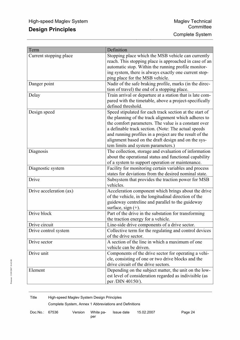
High-speed Maglev System
Design Principles Maglev Technical
CommitteeComplete System
Title High-speed Maglev System Design Principles
Complete System, Annex 1 Abbreviations and Definitions
Doc.No.: 67536 Version White pa-per
Issue date 15.02.2007 Page 24
Prin
tout
: 13/
09/2
007
10:4
2:00
Term Definition Current stopping place Stopping place which the MSB vehicle can currently
reach. This stopping place is approached in case of an automatic stop. Within the running profile monitor-ing system, there is always exactly one current stop-ping place for the MSB vehicle.
Danger point Nadir of the safe braking profile, marks (in the direc-tion of travel) the end of a stopping place.
Delay Train arrival or departure at a station that is late com-pared with the timetable, above a project-specifically defined threshold.
Design speed Speed stipulated for each track section at the start of the planning of the track alignment which adheres to the comfort parameters. The value is a constant over a definable track section. (Note: The actual speeds and running profiles in a project are the result of the alignment based on the draft design and on the sys-tem limits and system parameters.)
Diagnosis The collection, storage and evaluation of information about the operational status and functional capability of a system to support operation or maintenance.
Diagnostic system Facility for monitoring certain variables and process states for deviations from the desired nominal state.
Drive Subsystem that provides the traction power for MSB vehicles.
Drive acceleration (ax) Acceleration component which brings about the drive of the vehicle, in the longitudinal direction of the guideway centreline and parallel to the guideway surface, sign (+).
Drive block Part of the drive in the substation for transforming the traction energy for a vehicle.
Drive circuit Line-side drive components of a drive sector. Drive control system Collective term for the regulating and control devices
of the drive sector. Drive sector A section of the line in which a maximum of one
vehicle can be driven. Drive unit Components of the drive sector for operating a vehi-
cle, consisting of one or two drive blocks and the drive circuit of the drive sectors.
Element Depending on the subject matter, the unit on the low-est level of consideration regarded as indivisible (as per /DIN 40150/).

High-speed Maglev System
Design Principles Maglev Technical
CommitteeComplete System
Title High-speed Maglev System Design Principles
Complete System, Annex 1 Abbreviations and Definitions
Doc.No.: 67536 Version White pa-per
Issue date 15.02.2007 Page 25
Prin
tout
: 13/
09/2
007
10:4
2:00
Term Definition Elevated guideway Sections of guideway at a guideway height of 3.5 m
< H ≤ 20 m (H > 20 m in special cases) are referred to as elevated.
Elevation reference surface Equipotential surface as a reference for elevations. Empirical value Value assessed conservatively based on measure-
ments on the existing MSB system. Must be re-viewed project-specifically.
Energy supply Subsystem for providing the energy for the complete system.
Entrepreneur (according to AEG/)
Railways are public utilities or private enterprises which provide rail traffic services (rail traffic compa-nies) or which operate a railway infrastructure (rail-way infrastructure companies). Rail traffic services are the carriage of persons or goods on a railway in-frastructure. Rail traffic companies must be able to ensure train traction.
Environment Totality of all influences to which a system, subsys-tem or component is actually exposed or could be exposed during manufacture, storage, transport, inte-gration and use.
Equipment Functional, physical item (as per /DIN 50129/). Equipotential surface Surface of constant gravity potential. Evacuation stopping place Defined section of line to allow the stopping of trains
in emergencies, provided with facilities for the rapid and easy evacuation of persons from the vehicle onto an alighting platform.
External on-board energy infeed Stationary items of equipment for the energy supply of vehicles that are assigned to the Drive and Energy Supply subsystem. They do not include the transmis-sion components on the guideway and in the vehicle.
External on-board energy supply All electrical items of equipment for the supply of the MSB vehicles with electrical energy.
Fail-safe Concept incorporated in the design of a product to ensure that, if it fails, it will enter or maintain a safe state (as per /EN 50129/).
Fault-tree analysis An analytical method for determining which failure types of the product, of the sub-product or external events or combinations of these can lead to an agreed failure type of the product; the analysis being repre-sented in the form of a fault tree (as per /EN 50126/).
Fitness Fitness refers to the fulfilment of the physical re-quirements to perform a defined activity by a person.

High-speed Maglev System
Design Principles Maglev Technical
CommitteeComplete System
Title High-speed Maglev System Design Principles
Complete System, Annex 1 Abbreviations and Definitions
Doc.No.: 67536 Version White pa-per
Issue date 15.02.2007 Page 26
Prin
tout
: 13/
09/2
007
10:4
2:00
Term Definition Free (unbalanced) lateral acceleration Acceleration surplus (acts towards the outside of a
bend: ay = positive), Acceleration deficit (acts towards the inside of a bend: ay = negative).
Free bearing Bearing of a geodesic grid (1, 2 or 3-dimensional) on approximate coordinates while minimising the re-maining gaps. Deformation of the grid by connection constraints is avoided in this way.
Function Type of action or activity by which a product fulfils its intended purpose (as per /EN 50129/).
Functional plane System-characterising reference planes for the levita-tion/guidance functions of the vehicle
Functional unit Item that is delineated according to task or action. Derived terms as a function of the consideration cri-teria are:
• Constructional unit • Operational unit • Maintenance unit
(as per /DIN 40150/) Geoid A shape of the Earth described by an equipotential
surface of the Earth's gravitational field (normal to the force of gravity) level with mean seal level no-tionally continued under the continents.
Global Positioning System Satellite-assisted method for absolute or relative posi-tioning.
Gradient Course of the three-dimensional curve of the guide-way in longitudinal section.
Grid North The direction of the gridlines running parallel with the main meridian of the geodetic system of coordi-nates.
Guide value Value which, if necessary together with other guide values, is according to practice capable of fulfilling the requirements.
Guideway Track structure which absorbs all forces resulting from the vehicles and the environment and transmits them to the subsoil, and which contains or carries the modules that are necessary for vehicle hovering (levi-tation, guidance, drive and brakes).
Guideway axis The centreline between the slide planes of the guide-way. It is equivalent to the three-dimensional curve.
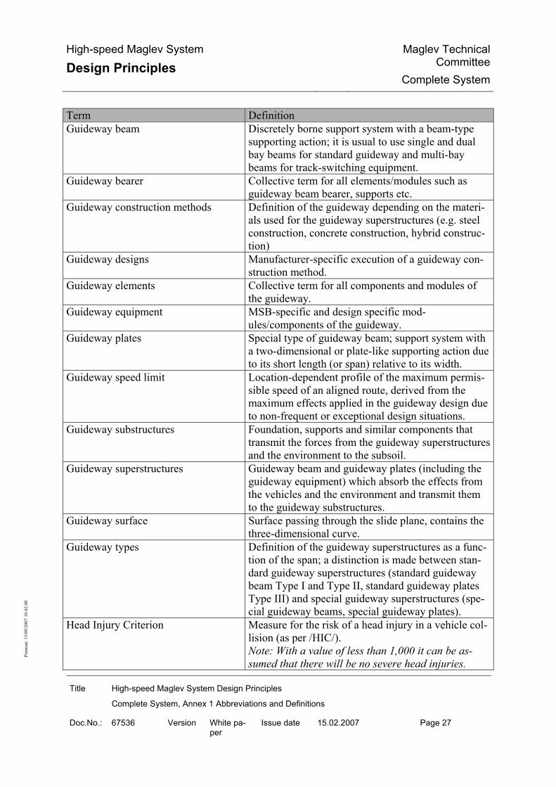
High-speed Maglev System
Design Principles Maglev Technical
CommitteeComplete System
Title High-speed Maglev System Design Principles
Complete System, Annex 1 Abbreviations and Definitions
Doc.No.: 67536 Version White pa-per
Issue date 15.02.2007 Page 27
Prin
tout
: 13/
09/2
007
10:4
2:00
Term Definition Guideway beam Discretely borne support system with a beam-type
supporting action; it is usual to use single and dual bay beams for standard guideway and multi-bay beams for track-switching equipment.
Guideway bearer Collective term for all elements/modules such as guideway beam bearer, supports etc.
Guideway construction methods Definition of the guideway depending on the materi-als used for the guideway superstructures (e.g. steel construction, concrete construction, hybrid construc-tion)
Guideway designs Manufacturer-specific execution of a guideway con-struction method.
Guideway elements Collective term for all components and modules of the guideway.
Guideway equipment MSB-specific and design specific mod-ules/components of the guideway.
Guideway plates Special type of guideway beam; support system with a two-dimensional or plate-like supporting action due to its short length (or span) relative to its width.
Guideway speed limit Location-dependent profile of the maximum permis-sible speed of an aligned route, derived from the maximum effects applied in the guideway design due to non-frequent or exceptional design situations.
Guideway substructures Foundation, supports and similar components that transmit the forces from the guideway superstructures and the environment to the subsoil.
Guideway superstructures Guideway beam and guideway plates (including the guideway equipment) which absorb the effects from the vehicles and the environment and transmit them to the guideway substructures.
Guideway surface Surface passing through the slide plane, contains the three-dimensional curve.
Guideway types Definition of the guideway superstructures as a func-tion of the span; a distinction is made between stan-dard guideway superstructures (standard guideway beam Type I and Type II, standard guideway plates Type III) and special guideway superstructures (spe-cial guideway beams, special guideway plates).
Head Injury Criterion Measure for the risk of a head injury in a vehicle col-lision (as per /HIC/). Note: With a value of less than 1,000 it can be as-sumed that there will be no severe head injuries.
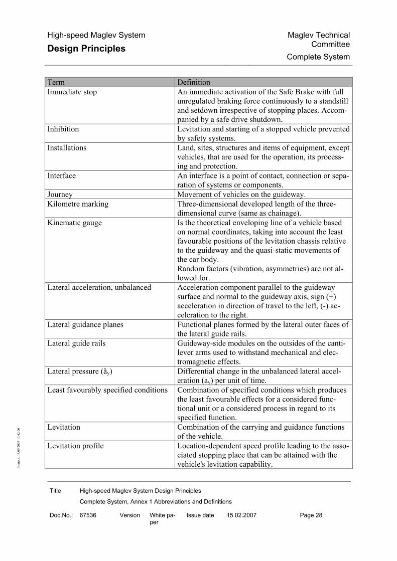
High-speed Maglev System
Design Principles Maglev Technical
CommitteeComplete System
Title High-speed Maglev System Design Principles
Complete System, Annex 1 Abbreviations and Definitions
Doc.No.: 67536 Version White pa-per
Issue date 15.02.2007 Page 28
Prin
tout
: 13/
09/2
007
10:4
2:00
Term Definition Immediate stop An immediate activation of the Safe Brake with full
unregulated braking force continuously to a standstill and setdown irrespective of stopping places. Accom-panied by a safe drive shutdown.
Inhibition Levitation and starting of a stopped vehicle prevented by safety systems.
Installations Land, sites, structures and items of equipment, except vehicles, that are used for the operation, its process-ing and protection.
Interface An interface is a point of contact, connection or sepa-ration of systems or components.
Journey Movement of vehicles on the guideway. Kilometre marking Three-dimensional developed length of the three-
dimensional curve (same as chainage). Kinematic gauge Is the theoretical enveloping line of a vehicle based
on normal coordinates, taking into account the least favourable positions of the levitation chassis relative to the guideway and the quasi-static movements of the car body. Random factors (vibration, asymmetries) are not al-lowed for.
Lateral acceleration, unbalanced Acceleration component parallel to the guideway surface and normal to the guideway axis, sign (+) acceleration in direction of travel to the left, (-) ac-celeration to the right.
Lateral guidance planes Functional planes formed by the lateral outer faces of the lateral guide rails.
Lateral guide rails Guideway-side modules on the outsides of the canti-lever arms used to withstand mechanical and elec-tromagnetic effects.
Lateral pressure (åy) Differential change in the unbalanced lateral accel-eration (ay) per unit of time.
Least favourably specified conditions Combination of specified conditions which produces the least favourable effects for a considered func-tional unit or a considered process in regard to its specified function.
Levitation Combination of the carrying and guidance functions of the vehicle.
Levitation profile Location-dependent speed profile leading to the asso-ciated stopping place that can be attained with the vehicle's levitation capability.

High-speed Maglev System
Design Principles Maglev Technical
CommitteeComplete System
Title High-speed Maglev System Design Principles
Complete System, Annex 1 Abbreviations and Definitions
Doc.No.: 67536 Version White pa-per
Issue date 15.02.2007 Page 29
Prin
tout
: 13/
09/2
007
10:4
2:00
Term Definition Limiting running profile Speed profile that allows for all speed limitations that
must be observed for safety purposes (line speed limit and safe braking profile) depending on the loca-tion. The profile is dependent on the stopping place.
Line Is the aligned course of one or more parallel-laid guideways equipped with safety equipment, chainage and ancillary installations.
Line axis The course of the centreline of two guideway axes on dual-track guideways.
Line cable system Three-phase medium-voltage cable arrangement that connects the switching points to the substations.
Line cross-section Representation of guideway and peripheral line equipment in cross-section at any point on the line.
Line speed limit Location-dependent minimum out of vehicle speed limit, tunnel speed limit and guideway speed limit.
Linear generator Vehicle-side equipment for on-board energy genera-tion.
Linear inclination (s, b) Angle (b) by which the guideway axis is inclined to the horizontal in the direction of chainage. (s) = Tan-gent value of the angle (b). Sign (+) for rising, (-) for falling guideway axis, expressed in [°] or [%].
Linear jolt (åx) Differential change in the drive and brake accelera-tion (ax) per unit of time
Local maintenance depot Maintenance facility where parts of the maintenance resources and maintenance management are held locally on site for the maintenance of MSB subsys-tems.
Long stator Guideway-side module of the drive system consisting of stator packs, stator pack attachment, motor wind-ing and the associated earthing.
Long-stator drive Device for propelling and braking MSB vehicles, consisting of components of the Drive subsystem (supplying the tractive power) and the long-stator motors themselves.
Long-stator winding Motor winding with earthing equipment and connec-tion to the switching points.
Long-wave deviation Determined deviation from the nominal position on the basis of discrete measurements.
Maglev Coordinate System (MKS) Special object-based system of position and elevation coordinates for three-dimensional detailing, construc-tion and structure monitoring (X,Y,Z).

High-speed Maglev System
Design Principles Maglev Technical
CommitteeComplete System
Title High-speed Maglev System Design Principles
Complete System, Annex 1 Abbreviations and Definitions
Doc.No.: 67536 Version White pa-per
Issue date 15.02.2007 Page 30
Prin
tout
: 13/
09/2
007
10:4
2:00
Term Definition Magnetic drivetrain The magnetic drivetrain includes all supporting parts
beneath the car body which lie within the primary force flow. It comprises the loadbearing parts of the structure, the secondary suspension and x-articulation as interface with the car body, the magnet articula-tions and the magnets (levitation, guidance and brake magnets). It also includes all components which are attached to these parts and which directly contribute to their strength, rigidity and stability.
Main alignment point Point on the three-dimensional curve at which 2 adja-cent alignment elements of ground plan or elevation coincide.
Maintenance Combination of all technical and administrative measures and management measures during the life-cycle of an item to maintain or restore its functional condition so that it can perform the required function. 'Item' in this context means any part, component, device, subsystem, any functional unit, equipment or system which can be considered on its own (EN 31051 and DIN EN 13306). For distinctions, see also Winter service and Vegeta-tion control.
Maintenance centre Maintenance facility where the essential maintenance resources and maintenance management for the maintenance of the MSB subsystems are held cen-trally.
Maintenance concept Concept for the operational and organisational per-formance of maintenance.
Maintenance guideway Guideway within a vehicle maintenance area with heightened requirements in regard to access to the modules of the MSB vehicle.
Maintenance installations Installations for the maintenance of all subsystems. Depending on the specific project, they can be cen-tral, decentral or an appropriate combination of both.

High-speed Maglev System
Design Principles Maglev Technical
CommitteeComplete System
Title High-speed Maglev System Design Principles
Complete System, Annex 1 Abbreviations and Definitions
Doc.No.: 67536 Version White pa-per
Issue date 15.02.2007 Page 31
Prin
tout
: 13/
09/2
007
10:4
2:00
Term Definition Maintenance instructions Maintenance instructions are written by the manufac-
turer of a system / item. They contain all instructions, data and steps that are necessary to perform a main-tenance operation. They also contain information about occupational health and safety and environ-mental protection necessitated by the individual steps or the supplies and consumables used, and informa-tion about the necessary maintenance aids. Mainte-nance instructions are project and location dependent.
Maintenance management All management activities which determine the ob-jectives, strategy and responsibilities of maintenance and implement them through means such as mainte-nance planning, control and monitoring and im-provement of the organisation methods including commercial aspects (as per /EN 13306/).
Maintenance management system Electronic system to assist maintenance management (/DIN EN 13306/).
Maintenance programme Definition of the maintenance measures for a subsys-tem. Maintenance programmes are updated in line with operational experience.
Maintenance resources Includes infrastructure, personnel, material, work equipment and inspection and test equipment for maintenance.
Maximum acceleration deficit of the drive
Maximum acceleration limit which may act from the drive to accelerate or retard the MSB vehicle in the longitudinal direction (x-direction) of the guideway axis in the event of a fault, allowing for least fa-vourably specified drive parameters.
Maximum guideway speed Location-dependent profile of the maximum permis-sible speed of an aligned route, derived from the maximum effects of frequent design situations used in the guideway design.
Maximum line speed Location-dependent minimum out of maximum vehi-cle speed, maximum tunnel speed and maximum guideway speed.
Maximum operational speed The maximum speed that is desirable for operational reasons. It can be defined by sections.

High-speed Maglev System
Design Principles Maglev Technical
CommitteeComplete System
Title High-speed Maglev System Design Principles
Complete System, Annex 1 Abbreviations and Definitions
Doc.No.: 67536 Version White pa-per
Issue date 15.02.2007 Page 32
Prin
tout
: 13/
09/2
007
10:4
2:00
Term Definition Maximum power deficit of the drive Maximum power limit which the drive may generate
in the event of a fault, allowing for least favourably specified drive parameters, as the interface force be-tween long stator (guideway) and the MSB vehicle in the longitudinal direction (x-direction) of the guide-way axis.
Maximum running profile OCS-monitored, location-dependent and stopping place-dependent maximum speed profile for achiev-ing the limiting running profile. If exceeded, there is a Safe Drive Shutdown and the Safe Brake is acti-vated.
Maximum speed profile Maximum speed profile dependent on the location and stopping place which can be used operationally from a technical viewpoint. Lies around the standard tolerance of the drive under the maximum running profile and may not exceed the maximum line speed.
Maximum tunnel speed Location-dependent profile of the greatest permissi-ble speed in a tunnel, derived from the greatest per-missible pressure loads of the vehicle in the tunnel for frequent design situations.
Maximum vehicle speed Maximum permissible speed (constant variable) de-rived from the maximum effects of frequent design situations used in the vehicle design.
Maximum vehicle weight Dead weight of the vehicle with increased payload in an exceptional operating situation (e.g. evacuation of adjacent sections in case of fire).
Mean Down Time The average time for which a failed module is not available pending re-commissioning.
Mean Time Between Failures The average time between two failures of a module. Mean Time to Repair The average repair time. Mean vehicle weight Dead weight of the vehicle with frequently expected
payload component. Minimum line speed Location-dependent speed that is at least attainable
by the drive taking account of project-specifically defined constraints and failure scenarios. Must be allowed for when designing stopping places.
Minimum running profile OCS-monitored, location-dependent and stopping place-dependent minimum speed profile for achiev-ing the safe levitation profile. If undershot, the drive is reliably shut down.

High-speed Maglev System
Design Principles Maglev Technical
CommitteeComplete System
Title High-speed Maglev System Design Principles
Complete System, Annex 1 Abbreviations and Definitions
Doc.No.: 67536 Version White pa-per
Issue date 15.02.2007 Page 33
Prin
tout
: 13/
09/2
007
10:4
2:00
Term Definition Modes Defined and clearly delimited types of train operation
which differ in their technical and nontechnical measures for the execution of journeys.
Module Mass-produced or individually manufactured compo-nent, or a functional set of mass-produced or indi-vidually manufactured components, which form a whole (as per /EN 61508-4/).
Motor regulation/control Central part of the drive regulation/control system for primary regulation/control tasks such as vehicle guidance and organisation of the drive unit.
Motor system Consists of one or more converters, line controlgear and a line cable system with the associated switching points and stator sections. A drive unit consists of one or two motor systems.
MSB Vehicle Vehicle equipped with magnetic levitation and guid-ance functions for the carriage of passengers and/or goods.
National reference system System of coordinates of the official national survey. Nominal precamber Superelevation of the guideway beam in the z-
direction, to largely offset the deformations due to vehicle and temperature effects.
Nominal running profile Location-dependent minimum out of nominal speed and maximum running profile less positioning and drive control tolerances as nominal values for the drive to approach the destination point of a stopping place.
Nominal speed Location-dependent minimum out of recommended line speed and maximum line speed as graduated and smoothed nominal values for the drive, e.g. for pur-poses of travelling-time simulation.
Normal acceleration (az) acceleration component normal to the guideway sur-face that deviates from the normal free-fall accelera-tion (vertical direction), sign (+) in the direction of normal free-fall acceleration, sign (-) contrary to the direction of normal free-fall acceleration.
Normal free-fall acceleration (g) Acceleration due to gravity (g = 9.81 m/s2). Normal operation Fully technically protected train operations.
Note: The term 'normal operation' results from an operational analysis according to /MbBO/ Section 24.

High-speed Maglev System
Design Principles Maglev Technical
CommitteeComplete System
Title High-speed Maglev System Design Principles
Complete System, Annex 1 Abbreviations and Definitions
Doc.No.: 67536 Version White pa-per
Issue date 15.02.2007 Page 34
Prin
tout
: 13/
09/2
007
10:4
2:00
Term Definition Offset Linear deviation of two adjacent functional plane
elements in y and z-direction. Operate and observe Part of the Man/Machine Interface of the Drive and
Energy Supply subsystem. System for process moni-toring and operation.
Operating manual Contractor's instructions for the safe execution and monitoring of train operations which take into con-sideration normal operation as well as non-standard operating states and the interface with maintenance.
Operation Operation is the totality of all measures used to carry passengers and goods (Section 2, (1) /MbBO/).
Operation Control System The operation control system provides the compo-nents for securing, monitoring and controlling the operation.
Operation personnel See Public employee. Operationally related active module Module that is required to maintain regular operation
or fault-mode operation. Operations control centre Central installation with equipment for signalling,
control and communication and with operating and display devices of the MSB subsystems.
Payload Weight of the persons (incl. baggage) or goods that are being carried.
Permissible vehicle weight Vehicle tare weight with maximum payload. Personnel responsibility The performance of defined safety-related duties by
personnel. Pitching Rotational motion of the car body or levitation chas-
sis about the y-axis Planning coordinate system (planning system)
The coordinate system used for the particular plan-ning purpose. Here: National system for preliminary design, rough planning and/or maglev coordinate system for detailed alignment and construction.
Point Guideway element that permits switching from one track to another at track changes or line junctions without interrupting the journey. Points in the high-speed maglev are bending points.
Polygonal line Used for determining datum points of position by lines. The polygonal points to be coordinated are derived from the measured side lengths of the train and the angles of refraction measured at its vertices.

High-speed Maglev System
Design Principles Maglev Technical
CommitteeComplete System
Title High-speed Maglev System Design Principles
Complete System, Annex 1 Abbreviations and Definitions
Doc.No.: 67536 Version White pa-per
Issue date 15.02.2007 Page 35
Prin
tout
: 13/
09/2
007
10:4
2:00
Term Definition Primary datum point frame Primary position and elevation datum points of the
maglev coordinate system as a basis for the detailed alignment and for laying out the position and eleva-tion datum point fields that accompany the align-ment.
Primary environment The environment which acts on a subsystem of the maglev without being influenced by it ("original cli-mate").
Primary structure Special building structure to take the guideway su-perstructures and if necessary structural installations of the line peripherals (e.g. bridge with noise attenua-tion).
Process instructions Process instructions contain general information and regulations for work procedures (e.g. processes, or-ganisation, ordering of maintenance work, general guidelines for performing work, documentation of measures etc.). Process instructions are project and site dependent.
Projection reduction Any necessary improvements that must be made to measured variables when projecting on the flat sur-face.
Projection surface Mathematically defined surface onto which points or objects of the physical surface of the Earth are pro-jected.
Proof of safety Documented proof that a product meets the specified safety requirements (as per /EN 50129/).
Proximity principle Basic principle of all geodesic measurements, calcu-lations and marking-out, which states that particular attention must be given to existing geometric rela-tionships between neighbouring object points.
Public employee Section 26, (2) /MbBO/ A public employee is a person who is engaged 1. in train operations, 2. in the control or monitoring of operations, 3. as a responsible person in the maintenance of in-stallations or vehicles, 4. as manager or supervisor of operational personnel according to Numbers 1 to 3.
Quality Quality is the entirety of properties and characteris-tics of a product or service that relates to its ability to fulfil defined or implied requirements.

High-speed Maglev System
Design Principles Maglev Technical
CommitteeComplete System
Title High-speed Maglev System Design Principles
Complete System, Annex 1 Abbreviations and Definitions
Doc.No.: 67536 Version White pa-per
Issue date 15.02.2007 Page 36
Prin
tout
: 13/
09/2
007
10:4
2:00
Term Definition Quality assurance process Verification of whether the system-technical re-
quirements of the Design Principles and, if applica-ble, of the project specifications have been complied with. The verification is carried out as part of quality assurance process when planning and executing the particular subsystem.
Raised walkway An elevated walkway running alongside the guide-way that is provided for the rescue and evacuation of passengers at special evacuation stopping places.
High-speed Maglev System A magnetic levitation railway as defined by the All-gemeines Magnetschwebebahngesetz (/AMbG/).
Reachability point Nadir of the levitation profile, marks (in the direction of travel) the start of a stopping place.
Recommended line speed Minimum recommended speed out of travelling com-fort and maximum operating speed, possibly allow-ing for other project-specific inputs (e.g. energy de-mand, sound attenuation).
Recommended speed for travelling comfort
Local speed at which exactly the project-specifically defined comfort parameters are achieved with the given alignment.
Redundancy Provision of one or more additional, usually identical measures in order to maintain the failure tolerance (/DIN 50129/).
Reference position Reference position used to synchronise the position-ing system at defined reference points on the line.
Reference temperature Project-related reference temperature for the geomet-rical design and tolerancing of components. Usually half-way between the max. and min. anticipated component temperature.
Regular operation Operation action without the operator's responsibility for safety, i.e. without personnel responsibility. Re-sponsibility for safety lies with the OCS.
Relative position The relative position is formed continuously during the journey and is based on the last valid reference position.
Reliability Ability of a unit to provide a required function under given conditions for a given time (as per /EN 50129/).
Reserve Setting of the moving guideway elements, continuous and fully technical protection of the guideway to be travelled, and assignment of only one OCS-protected vehicle to that guideway.
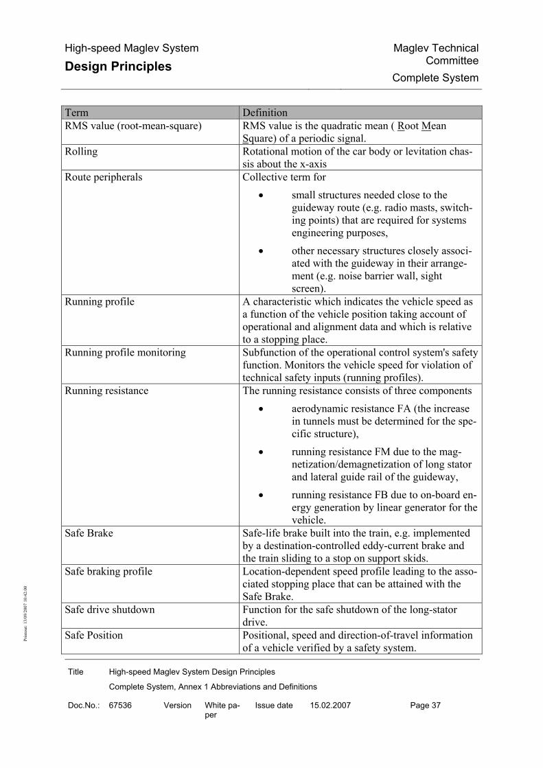
High-speed Maglev System
Design Principles Maglev Technical
CommitteeComplete System
Title High-speed Maglev System Design Principles
Complete System, Annex 1 Abbreviations and Definitions
Doc.No.: 67536 Version White pa-per
Issue date 15.02.2007 Page 37
Prin
tout
: 13/
09/2
007
10:4
2:00
Term Definition RMS value (root-mean-square) RMS value is the quadratic mean ( Root Mean
Square) of a periodic signal. Rolling Rotational motion of the car body or levitation chas-
sis about the x-axis Route peripherals Collective term for
• small structures needed close to the guideway route (e.g. radio masts, switch-ing points) that are required for systems engineering purposes,
• other necessary structures closely associ-ated with the guideway in their arrange-ment (e.g. noise barrier wall, sight screen).
Running profile A characteristic which indicates the vehicle speed as a function of the vehicle position taking account of operational and alignment data and which is relative to a stopping place.
Running profile monitoring Subfunction of the operational control system's safety function. Monitors the vehicle speed for violation of technical safety inputs (running profiles).
Running resistance The running resistance consists of three components • aerodynamic resistance FA (the increase
in tunnels must be determined for the spe-cific structure),
• running resistance FM due to the mag-netization/demagnetization of long stator and lateral guide rail of the guideway,
• running resistance FB due to on-board en-ergy generation by linear generator for the vehicle.
Safe Brake Safe-life brake built into the train, e.g. implemented by a destination-controlled eddy-current brake and the train sliding to a stop on support skids.
Safe braking profile Location-dependent speed profile leading to the asso-ciated stopping place that can be attained with the Safe Brake.
Safe drive shutdown Function for the safe shutdown of the long-stator drive.
Safe Position Positional, speed and direction-of-travel information of a vehicle verified by a safety system.

High-speed Maglev System
Design Principles Maglev Technical
CommitteeComplete System
Title High-speed Maglev System Design Principles
Complete System, Annex 1 Abbreviations and Definitions
Doc.No.: 67536 Version White pa-per
Issue date 15.02.2007 Page 38
Prin
tout
: 13/
09/2
007
10:4
2:00
Term Definition Safe-life Describes a property/function that is pre-
sent/available throughout the entire useful life; im-plemented alternatively by
• Failure prevention based on operationally safe design and comprehensive inspection and testing in production and mainte-nance, or
• Redundancy with failure tolerance for re-dundant modules, and a residual probabil-ity of failure of the function that is accept-able compared with the risk and proven by fault-tree analysis.
Safety Freedom from unacceptable risks of loss (as per /DIN 50129/).
Safety management Safety management is the organisation put in place by an MSB contractor and the precautions he takes to guarantee the safe control of his operational proce-dures.
Schedule Definition of the planned journeys of the trains in regard to departure and arrival stations, traffic days, travel times.
Secondary environment Environmental characteristics induced by the opera-tion of a technical system and a downstream con-structional unit. Compared with the primary envi-ronment, the secondary environment may involve new characteristics that differ from one another for individual modules.
Sector overlap A functionality that in defined sections of track al-lows the drive and safety functions of those drive and/or safety sections to be taken over by neighbour-ing drive and/or safety sections.
Security Measures to protect, monitor and prevent attacks on MSB installations.
Service journey A journey with no passengers, e.g. transfer journeys. Service life Predicted minimum period of time in which a part or
module displays service strength against a defined load population. Depending on the loads which actu-ally occur in operation, the predicted service life is reviewed on the basis of the results of the inspections according to the maintenance programme and ad-justed as necessary.

High-speed Maglev System
Design Principles Maglev Technical
CommitteeComplete System
Title High-speed Maglev System Design Principles
Complete System, Annex 1 Abbreviations and Definitions
Doc.No.: 67536 Version White pa-per
Issue date 15.02.2007 Page 39
Prin
tout
: 13/
09/2
007
10:4
2:00
Term Definition Service station Stopping place where repairs to the vehicle can be
carried out. Service stopping place Section of line used for unscheduled stops by trains. Service strength Load-bearing capacity taking account of the effect
from operation and the environment with a defined frequency and duration of the load.
Setdown speed Speed at which the vehicle setdown sequence is initi-ated by the OCS.
Short interruption of the grid Loss of public energy supply for a period ≥ 1s (based on /EN 50160/).
Shortwave deviation Overlaying of the longwave deviation as absolute boundary for the spatial extent of a functional plane.
Sinusoid Transitional bend with a sinusoidally increasing or diminishing curvature.
Slide plane Functional plane formed by the surfaces of the slide rails.
Slide rail Guideway-side modules on top of the cantilever arms used to take mechanical effects.
Sliding distance Distance which a new sliding skid can cover on the slide rail with the vehicle at nominal mass and in dry conditions until the skid requires maintenance.
Special guideway beams Guideway beams whose design (e.g. cross-section, span) differs from the project-specifically defined standard guideway beam types.
Special structures Usually one-off/special structures to take the guide-way (primary support structures and tunnels).
Special vehicle Vehicles (wheeled vehicles or MSB vehicles with special equipment) which run on the guideway dur-ing the construction and commissioning of the MSB or for maintenance, winter service, vegetation control or rescue duties.
Standard (regular) guideway beam Characterisation of guideway beams by project-specific input of constraints (e.g. standard span) which constitutes the basis for economical manufac-ture in regard to economies of scale; standard guide-way beam types can be constructed by different methods and in different designs.
Start journey Journey to verify the start point given by the traffic movement director and for failure disclosure of posi-tioning.
Station Operating installation for the scheduled stop of trains and the switching of passengers and freight.

High-speed Maglev System
Design Principles Maglev Technical
CommitteeComplete System
Title High-speed Maglev System Design Principles
Complete System, Annex 1 Abbreviations and Definitions
Doc.No.: 67536 Version White pa-per
Issue date 15.02.2007 Page 40
Prin
tout
: 13/
09/2
007
10:4
2:00
Term Definition Stator pack Part of the long stator; core stack consisting of
bonded magnetic sheet steel laminations with a de-fined geometry, coating and integrated elements for mounting onto the cantilever arms.
Stator planes Functional planes formed by the underside of the stator packs.
Stator section Switchable stator winding section on a guideway side that can be supplied independently.
Stator section changeover Transition from one stator section to the next syn-chronous with the vehicle's motion over the corre-sponding stator sections. Different methods are used, e.g. alternating step method und three-step method.
Stopping place A defined section of track for the scheduled or un-scheduled stopping of trains; stopping places are sta-tions (scheduled stop) and service stopping places (unscheduled stop).
Substation Enclosed electrical plant which essentially contains the components of the drive, the energy supply and the OCS.
Subsystem Part of a system which fulfils a specific function (/DIN 50129/).
Switching point Line-side device for switching stator sections. System Set of subsystems which interact according to a de-
sign (as per /DIN 50129/). System engineering trials Provision of the required proofs under near-
application (boundary) conditions, integrated into the complete system of vehicle, drive, operation control system and guideway.
System lengths Dimensions in the x-direction, derived from the dis-tance between the individual phases of the motor winding (n × 86 mm, smallest divisible system di-mension).
System parameter Generic, non derivable variable by which the maglev system is characterised in the given version.
Three-dimensional curve / spatial guideway axis
Spatial course of the axis line of the guideway. The three-dimensional curve is generated by computa-tionally superimposing the alignment and gradient definitions.
Three-step method Stator section changeover method with three circuit cable systems in which the left and right separate and mutually offset stator sections are fed independently of each other and without a changeover delay.

High-speed Maglev System
Design Principles Maglev Technical
CommitteeComplete System
Title High-speed Maglev System Design Principles
Complete System, Annex 1 Abbreviations and Definitions
Doc.No.: 67536 Version White pa-per
Issue date 15.02.2007 Page 41
Prin
tout
: 13/
09/2
007
10:4
2:00
Term Definition Tilting Rotation of a functional plane about the measurement
point of the y/z plane. Track alignment Axial curve of the guideway in plan view. Synony-
mous with alignment axis. Track centres Horizontal distance between the guideway axes of
the dual-track guideway. Track-switching devices Moving guideway elements used to switch a vehicle
from one track to other tracks. Train Technically protected guideway-bound vehicle in
operation. Train journey A train journey is a controlled, technically monitored
and technically protected movement by a train be-tween a start point and a destination point.
Train operations The preparation and execution of journeys with vehi-cles and special vehicles.
Transformation Conversion of points from one coordinate system to another.
Translation Displacement (usually along one of the coordinate axes).
Transverse inclination Angle by which the guideway surface is rotated from the horizontal, sign (+) for clockwise rotation, (-) for counterclockwise rotation (looking in the direction of ascending kilometre markings), expressed in [°].
Transverse inclination tolerance Deviation from the nominal transverse inclination. Traverser A track-switching device by which a stationary vehi-
cle can be switched to different tracks by the parallel traversing of the guideway superstructure.
Tunnel speed limit Location-dependent profile of the maximum permis-sible speed in a tunnel, derived from the maximum permissible pressure loads of the vehicle in the tunnel as a result of non frequent or exceptional design situations.

High-speed Maglev System
Design Principles Maglev Technical
CommitteeComplete System
Title High-speed Maglev System Design Principles
Complete System, Annex 1 Abbreviations and Definitions
Doc.No.: 67536 Version White pa-per
Issue date 15.02.2007 Page 42
Prin
tout
: 13/
09/2
007
10:4
2:00
Term Definition Tunnels Tunnels are structures which allow a man-made un-
derground passage. When they are constructed • underground they count as tunnels irrespec-
tive of length, • by the open cut tunnelling method they count
as tunnels from a closed length of 300 m and over. For shorter structures, the requirements defined for tunnels must be applied analo-gously in regard to stability and design.
Turntable A track-switching device by which a stationary vehi-cle can be switched to different tracks by swivel-ling/rotating the guideway superstructure.
Undulation of the geoid Separation between the geoid and the ellipsoid. Uninterruptible Power Supply (UPS) Equipment for generating a supply voltage without
interruptions in the event of a mains power failure. Usability "Usability is the extent to which a product can be
used by specified users to achieve specified goals with effectiveness, efficiency and satisfaction in a specified context of use. The context of use consists of the users, tasks, equipment (hardware, software and materials) and the physical and societal environ-ments in which the product is used." (EN ISO 9241, Part 11)
Useful life Guide value for the period of time in which a subsys-tem can be used. The useful life is used as a basis for the maintenance strategy and when planning spare parts supplies. Parts/modules with a life shorter than the useful life are replaced as part of in-operation maintenance.
Vegetation control Totality of all measures for keeping the defined clearance gauge of the MSB system clear of vegeta-tion including preventive measures against falling trees.
Vehicle MSB vehicles and special vehicles (see also the defi-nitions of MSB vehicle and special vehicle).
Vehicle exterior Term used for the various EMC and lightning protec-tion areas provided on the outside of the vehicle.
Vehicle gauge Contour line based on the cross-section to be investi-gated, that may not be crossed by any part of the ve-hicle (vehicle contour).
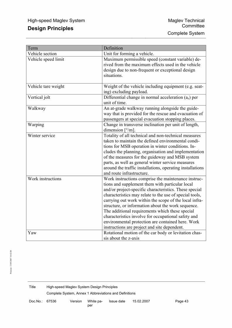
High-speed Maglev System
Design Principles Maglev Technical
CommitteeComplete System
Title High-speed Maglev System Design Principles
Complete System, Annex 1 Abbreviations and Definitions
Doc.No.: 67536 Version White pa-per
Issue date 15.02.2007 Page 43
Prin
tout
: 13/
09/2
007
10:4
2:00
Term Definition Vehicle section Unit for forming a vehicle. Vehicle speed limit Maximum permissible speed (constant variable) de-
rived from the maximum effects used in the vehicle design due to non-frequent or exceptional design situations.
Vehicle tare weight Weight of the vehicle including equipment (e.g. seat-ing) excluding payload.
Vertical jolt Differential change in normal acceleration (az) per unit of time.
Walkway An at-grade walkway running alongside the guide-way that is provided for the rescue and evacuation of passengers at special evacuation stopping places.
Warping Change in transverse inclination per unit of length, dimension [°/m].
Winter service Totality of all technical and non-technical measures taken to maintain the defined environmental condi-tions for MSB operation in winter conditions. In-cludes the planning, organisation and implementation of the measures for the guideway and MSB system parts, as well as general winter service measures around the traffic installations, operating installations and route infrastructure.
Work instructions Work instructions comprise the maintenance instruc-tions and supplement them with particular local and/or project-specific characteristics. These special characteristics may relate to the use of special tools, carrying out work within the scope of the local infra-structure, or information about the work sequence. The additional requirements which these special characteristics involve for occupational safety and environmental protection are contained here. Work instructions are project and site dependent.
Yaw Rotational motion of the car body or levitation chas-sis about the z-axis

High-speed Maglev System
Design Principles Maglev Technical
CommitteeComplete System
Title High-speed Maglev System Design Principles
Complete System Annex 2 Statutes, Regulations, Standards and Directives
Doc.No.: 67539 Version White pa-per
Issue date 15.02.2007 Page 1
Prin
tout
: 13/
09/2
007
10:4
2:00
High-speed Maglev System Design Principles
Complete System
Annex 2 Statutes, regulations, standards and di-
rectives
The author reserves the copyright in this document and all attachments. All rights reserved

High-speed Maglev System
Design Principles Maglev Technical
CommitteeComplete System
Title High-speed Maglev System Design Principles
Complete System Annex 2 Statutes, Regulations, Standards and Directives
Doc.No.: 67539 Version White pa-per
Issue date 15.02.2007 Page 2
Prin
tout
: 13/
09/2
007
10:4
2:00
Distribution This document has been released for publication by the Technical Committee "Complete Sys-tem".

High-speed Maglev System
Design Principles Maglev Technical
CommitteeComplete System
Title High-speed Maglev System Design Principles
Complete System Annex 2 Statutes, Regulations, Standards and Directives
Doc.No.: 67539 Version White pa-per
Issue date 15.02.2007 Page 3
Prin
tout
: 13/
09/2
007
10:4
2:00
Change history Release date: 15.02.2007; white paper, Technical Committee "Complete System"

High-speed Maglev System
Design Principles Maglev Technical
CommitteeComplete System
Title High-speed Maglev System Design Principles
Complete System Annex 2 Statutes, Regulations, Standards and Directives
Doc.No.: 67539 Version White pa-per
Issue date 15.02.2007 Page 4
Prin
tout
: 13/
09/2
007
10:4
2:00
List of contents
Distribution .............................................................................................................................................2
Change history .......................................................................................................................................3
List of contents.......................................................................................................................................4
General ....................................................................................................................................................5 Purpose of the document, scope..............................................................................................................5 MSB Design Principles .............................................................................................................................5 Abbreviations and definitions ...................................................................................................................5 Statutes, regulations, standards and directives .......................................................................................5 Identification and binding value of requirements......................................................................................5
Design Principles ...................................................................................................................................7
Statutes and Ordinances .......................................................................................................................8
Standards and Directives ....................................................................................................................10
List of tables Table 1: Design Principles........................................................................................................7 Table 2: Statutes and Ordinances............................................................................................9 Table 3: Standards and Directives .........................................................................................21

High-speed Maglev System
Design Principles Maglev Technical
CommitteeComplete System
Title High-speed Maglev System Design Principles
Complete System Annex 2 Statutes, Regulations, Standards and Directives
Doc.No.: 67539 Version White pa-per
Issue date 15.02.2007 Page 5
Prin
tout
: 13/
09/2
007
10:4
2:00
General
Purpose of the document, scope This document contains statutes, regulations, standards and directives for MSB systems.
MSB Design Principles This document is an annex to the Design Principles Complete System and so forms part of a documentation for high-speed maglev systems consisting of different design principles. The high-level "complete system" design principles and their annexes apply uniformly for the whole documentation: • MSB Design Principles Complete System, Doc. No.: 50630, /MSB AG-
GESAMTSYS/ • Annex 1: MSB Abbreviations and Definitions, Doc. No.: 67536, /MSB AG-
ABK&DEF/ • Annex 2: MSB Statutes, Regulations, Standards and Directives, Doc. No.: 67539,
/MSB AG-NORM&RILI/ • Annex 3: MSB Environment, Doc. No.: 67285, /MSB AG-UMWELT/ • Annex 4: MSB Rules for Operation and Maintenance, Doc. No.: 69061, /MSB
AG-BTR/ • Annex 5: MSB Noise, Doc. No.: 72963, /MSB AG-SCHALL/
Abbreviations and definitions The abbreviations and definitions given in /MSB AG-ABK&DEF/ apply.
Statutes, regulations, standards and direc-tives The statutes, regulations, standards and directives are listed in this document.
Identification and binding value of require-ments The requirements of /DIN 820/ were applied analogously in the preparation of this document. In the following chapters and the annexes of this document
• Requirements are shown in normal font • Explanations, guide values and examples are shown in italics

High-speed Maglev System
Design Principles Maglev Technical
CommitteeComplete System
Title High-speed Maglev System Design Principles
Complete System Annex 2 Statutes, Regulations, Standards and Directives
Doc.No.: 67539 Version White pa-per
Issue date 15.02.2007 Page 6
Prin
tout
: 13/
09/2
007
10:4
2:00
The degree to which the requirements are binding has been defined by reference to /DIN 820-2/ Annex G, and has been taken into consideration when formulating the individual require-ments.

High-speed Maglev System
Design Principles Maglev Technical
CommitteeComplete System
Title High-speed Maglev System Design Principles
Complete System Annex 2 Statutes, Regulations, Standards and Directives
Doc.No.: 67539 Version White pa-per
Issue date 15.02.2007 Page 7
Prin
tout
: 13/
09/2
007
10:4
2:00
Design Principles Short form Description
/MSB AG-GESAMTSYS/ MSB Design Principles Complete System, Doc. No.: 50630, with the annexes:
/MSB AG-ABK&DEF/ Annex 1: MSB Abbreviations and Definitions, Doc. No.: 67536,
/MSB AG-NORM&RILI/ Annex 2: MSB Statutes, Regulations, Standards and Directives, Doc. No.: 67539,
/MSB AG-UMWELT/ Annex 3: MSB Environmental Conditions, Doc. No.: 67285,
/MSB AG-BTR/ Annex 4: MSB Rules for Operation (Train Operation and Maintenance), Doc. No.: 69061,
/MSB AG-SCHALL/ Annex 5: MSB Noise, Doc. No.: 72963,
/MSB AG-FZ GEN/ MSB Design Principles Vehicle, Part I: General Requirements, Doc. No.: 67698,
/MSB AG-FZ BEM/ MSB Design Principles Vehicle, Part II: Dimensioning, Doc. No.: 67694,
/MSB AG-FZ KIN/ MSB Design Principles Vehicle, Part III: Kinematic Gauge, Doc. No.: 67650,
/MSB AG-FZ TRAFÜ/ MSB Design Principles Vehicle, Part IV: Support/Guidance System, Doc. No.: 73388,
/MSB AG-FZ BREMS/ MSB Design Principles Vehicle, Part V: Brake System, Doc. No.: 73389,
/MSB AG-ANT/ MSB Design Principles Drive and Energy Supply, Doc. No.: 50998,
/MSB AG-BLT/ MSB Design Principles Operation Control System, Doc. No.: 53328,
/MSB AG-FW ÜBG/ MSB Design Principles Guideway, Part I: High-level Requirements, Doc. No.: 57284,
/MSB AG-FW BEM/ MSB Design Principles Guideway, Part II: Dimensioning, Doc. No.: 67694,
/MSB AG-FW GEO/ MSB Design Principles Guideway, Part III: Geometry, Doc. No.: 41727,
/MSB AG-FW TRAS/ MSB Design Principles Guideway, Part IV: Alignment, Doc. No.: 60640,
/MSB AG-FW VERM/ MSB Design Principles Guideway, Part V: Surveying, Doc. No.: 60641,
/MSB AG-FW IH/ MSB Design Principles Guideway, Part VI: Maintenance, Doc. No.: 63842,
Table 8: Design Principles

High-speed Maglev System
Design Principles Maglev Technical
CommitteeComplete System
Title High-speed Maglev System Design Principles
Complete System Annex 2 Statutes, Regulations, Standards and Directives
Doc.No.: 67539 Version White pa-per
Issue date 15.02.2007 Page 8
Prin
tout
: 13/
09/2
007
10:4
2:00
Statutes and Ordinances The statutes and ordinances used in the MSB Design Principles are listed below. The edition indicated is the version of the statutes and ordinances at the time of issue of the MSB Design Principles. Statute Description
/26. BImSchV/ Twenty-Sixth Ordinance on the Implementation of the Federal Immission Control Law (Electromag-netic Field Ordinance - 26. BImSchV) "Ordinance on Electromagnetic Fields of 16 December 1996 (BGBl. I p. 1966)"
/AMbG/ "General Magnetic Levitation Railway Law of 19 July 1996 (BGBl. I p. 1019), last amended by Arti-cle 303 of the Ordinance of 31 October 2006 (BGBl. I p. 2407)"
/Occupation Safety/ Statutes and ordinances on occupational safety /ArbSchG/, /ArbstättV/, /ASiG/, /BaustellV/, /BetrSichV/, /BildscharbV/, /GPSG/, /GPSGV/, /GSGV/, /LasthandhabV/, /PSA-BV/.
/ArbSchG/ "Occupational Safely Law of 07 August 1996 (BGBl. I p. 1246), last amended by Article 227 of the Ordinance of 31 October 2006 (BGBl. I p. 2407)"
/ArbStättV/ "Health and safety at work act of 12 August 2004 (BGBl. I p. 2179), amended by Article 388 of the Ordinance of 31 October 2006 (BGBl. I p. 2407)"
/ASiG/ "Law on company doctors, safety engineers and other specialists for occupational safety of 12 December 1973 (BGBl. I p. 1885), last amended by Article 226 of the Ordinance of 31 October 2006 (BGBl. I p. 2407)"
/BaustellV/ "Construction Site Ordinance of 10 June 1998 (BGBl. I p. 1283), amended by Article 15 of the Ordi-nance of 23 December 2004 (BGBl. I p. 3758)"
/BetrSichV/ "Ordinance on Industrial Safety and Health of 27 September 2002 (BGBl. I p. 3777), last amended by Article 439 of the Ordinance of 31 October 2006 (BGBl. I p. 2407)"
/BildscharbV/ "VDU Work Ordinance of 04 December 1996 (BGBl. I p. 1843), last amended by Article 437 of the Ordinance of 31 October 2006 (BGBl. I p. 2407)"
/BImSchG/ "Federal Immission Control Law in the version of the proclamation of 26 September 2002 (BGBl. I p. 3830), last amended by Article 3 of the Law of 18 December 2006 (BGBl. I p. 3180)"
/BNatSchG/ "Federal Nature Conservation Law of 25 March 2002 (BGBl. I p. 1193), last amended by Article 8 of the Law of 09 December 2006 (BGBl. I p. 2833)"
/ChemG/ "Chemicals Law in the version of the proclamation of 20 June 2002 (BGBl. I p. 2090), last amended by Article 231 of the Ordinance of 31 October 2006 (BGBl. I p. 2407)"
/GefStoffV/ "Hazardous Substances Ordinance of 23 December 2004 (BGBl. I p. 3758, 3759), last amended by Article 442 of the Ordinance of 31 October 2006 (BGBl. I p. 2407)"
/GPSG/ "Equipment and Product Safety Law of 06 January 2004 (BGBl. I p. 2 (219)), last amended by Arti-cle 3 Paragraph 33 of the Law of 07 July 2005 (BGBl. I p. 1970)"
/GPSGV/ Machine Ordinance "Ninth Ordinance on the Equipment and Product Safety Law (Machine Ordinance) of 12 May 1993 (BGBl. I p. 704), last amended by Article 14 of the Ordinance of 23 December 2004 (BGBl. I p. 3758)"
/KrW- AbfG/ "Recycling and Waste Management Law of 27 September 1994 (BGBl. I p. 2705), last amended by Article 7 of the Law of 09 December 2006 (BGBl. I p. 2819)"

High-speed Maglev System
Design Principles Maglev Technical
CommitteeComplete System
Title High-speed Maglev System Design Principles
Complete System Annex 2 Statutes, Regulations, Standards and Directives
Doc.No.: 67539 Version White pa-per
Issue date 15.02.2007 Page 9
Prin
tout
: 13/
09/2
007
10:4
2:00
Statute Description
/LasthandhabV/ "Load Handling Ordinance of 04 December 1996 (BGBl. I p. 1842), last amended by Article 436 of the Ordinance of 31 October 2006 (BGBl. I p. 2407)"
/MbBO/ "Maglev Construction and Operation Ordinance of 23 September 1997 (BGBl. I p. 2329)"
/MSB-LSchV/ "Maglev Noise Control Ordinance of 23 September 1997 (BGBl. I p. 2329, 2338)“
/PERSCH/ Legislation on the protection of persons /ArbSchG/, /BetrSichV/, /BildscharbV/, /PSA-BV/, /LasthandhabV/, /ArbStättV/, /BaustellV/, /GPSG/, /GPSGV/, /ASiG/, /ChemG/, /GefStoffV/.
/PSA-BV/ "Ordinance on the Use of PPE of 04 December 1996 (BGBl. I p. 1841)"
/Directive 2004/49/EC/ Corrigendum to Directive 2004/49/EC of the European Parliament and of the Council of 29 April 2004 on safety on the Community’s railways and amending Council Directive 95/18/EC on the li-censing of railway undertakings and Directive 2001/14/EC on the allocation of railway infrastructure capacity and the levying of charges for the use of railway infrastructure and safety certification ("Railway Safety Directive") Official Journal of the European Union L 164 of 30 April 2004)
/Directive 98/37/ Directive 98/37/EC Directive 98/37/EC of the European Parliament and of the Council of 22 June 1998 on the approxi-mation of the laws of the Member States relating to machinery Official journal no. L 207 of 23.07.1998 p. 0001 - 0046
/Environment/ Environmental protection laws /BImSchG/, /BNatSchG/, /ChemG/, /GefStoffV/, /KrW- AbfG/, /WHG/
/WHG/ "Water Management Law in the version of the proclamation of 19 August 2002 (BGBl. I p. 3245), last amended by Article 2 of the Law of 25 June 2005 (BGBl. I p. 1746)"
Table 9:Statutes and Ordinances

High-speed Maglev System
Design Principles Maglev Technical
CommitteeComplete System
Title High-speed Maglev System Design Principles
Complete System Annex 2 Statutes, Regulations, Standards and Directives
Doc.No.: 67539 Version White pa-per
Issue date 15.02.2007 Page 10
Prin
tout
: 13/
09/2
007
10:4
2:00
Standards and Directives The standards and guidelines referred to in the MSB Design Principles are listed below. The edition indicated is the version of the standards and guidelines at the time of issue of the MSB Design Principles. Standard Description
/BrandReg/ "Rules for the fire safety assessment of rail vehicles as part of acceptance according to Section 32 EBO - Principles of fire safety requirements based on EN 45545", EBA 2006-06-01
/DIN 1055-100/ Effects on Structures - Part 100: Fundamentals of structural engineering - Safety concept and design rules 2001-03-01
/DIN 1076/ Highway structures - Testing and inspection 1999-11-01
/DIN 18014/ Foundation earth electrodes 1994-02-01
/DIN 31051/ Fundamentals of Maintenance 2003-06-01
/DIN 4149/ Structures in German earthquake zones - Design loads, dimensioning and construction of conventional buildings 2005-04-01
/DIN 5510-1/ Preventive fire protection in railway rolling stock; fire protection classes, fire protection measures and proofs 1988-10-01
/DIN 5510-2/ Preventive fire protection in railway rolling stock - Part 2: Combustion behaviour and secondary combustion phenomena of materials and components; Classifi-cation, requirements and test methods Draft 2003-09-01
/DIN 5510-4/ Preventive fire protection in railway rolling stock; Design engineering of vehi-cles; Safety engineering requirements 1988-10-01
/DIN 5510-5/ Preventive fire protection in railway rolling stock; Electrical equipment; Safety engineering requirements 1988-10-01
/DIN 5510-6/ Preventive fire protection in rail vehicles; Accompanying measures; Function of the emergency brake, information systems, fire alarms, fire fighting equipment; Safety engineering requirements 1988-10-01
/DIN 57510/ /DIN VDE 0510/ /VDE 0510/
VDE Regulations for accumulators and battery systems 1977-01-01

High-speed Maglev System
Design Principles Maglev Technical
CommitteeComplete System
Title High-speed Maglev System Design Principles
Complete System Annex 2 Statutes, Regulations, Standards and Directives
Doc.No.: 67539 Version White pa-per
Issue date 15.02.2007 Page 11
Prin
tout
: 13/
09/2
007
10:4
2:00
Standard Description
/DIN 820-2/ Standardization - Part 2: Presentation of documents (ISO/IEC Directives - Part 2, modified); Trilingual version CEN/CENELEC-Internal Regulations - Part 3: Rules for the structure and drafting of CEN/CENELEC publications 2004-10-01
/DIN EN 12663/ Railway applications - Structural requirements of rolling stock bodies; (German version EN 12663:2000) 2000-10-01
/DIN EN 13306/ Maintenance terminology; Trilingual version EN 13306:2001 2001-09-01
/DIN EN 14750-1/ Railway applications - Air conditioning for urban and suburban rolling stock - Part 1: Comfort parameters; (German version EN 14750-1:2006) 2006-08-01
/DIN EN 50121/ Standard series: Railway applications - Electromagnetic Compatibility
/DIN EN 50121-1/ (VDE 0115-121-1)
Railway applications - Electromagnetic Compatibility - Part 1: General; (German version EN 50121-1:2000 / DIN V ENV 50121-1 (1997-02) also ap-plies up to 2003-04-01.) 2001-05-01
/DIN EN 50121-2/ (VDE 0115-121-2)
Railway applications - Electromagnetic Compatibility - Part 2: Radiated EMI of the whole rail system into the environment; (German version EN 50121-2:2000 / DIN V ENV 50121-2 (1997-02) also ap-plies up to 2003-04-01.) 2001-05-01
/DIN EN 50121-3-1/ (VDE 0115-121-3-1)
Railway applications - Electromagnetic Compatibility - Part 3-1: Railway vehi-cles; train and complete vehicle; (German version EN 50121-3-1:2000 / DIN V ENV 50121-3-1 (1997-02) also applies up to 2003-04-01.) 2001-05-01
/DIN EN 50121-3-2/ (VDE 0115-121-3-2)
Railway applications - Electromagnetic Compatibility - Part 3-2: Railway vehi-cles; Devices; (German version EN 50121-3-2:2000 / DIN V ENV 50121-3-2 (1997-02) also applies up to 2003-04-01.) 2001-05-01
/DIN EN 50121-4/ (VDE 0115-121-4)
Railway applications - Electromagnetic Compatibility - Part 4: Radiated EMI and immunity of signalling and communications equipment; (German version EN 50121-4:2000 / DIN V ENV 50121-4 (1997-02) also ap-plies up to 2003-04-01.) 2001-05-01
/DIN EN 50121-5/ (VDE 0115-121-5)
Railway applications - Electromagnetic Compatibility - Part 5: Radiated EMI and immunity of stationary installations and equipment of the railway energy supply (German version EN 50121-5:2000 / DIN V ENV 50121-5 (1997-02) also ap-plies up to 2003-04-01.) 2001-05-01
/DIN EN 50126/ (VDE 0115-103)
Railway applications - The specification and demonstration of Reliability, Avail-ability, Maintainability and Safety (RAMS); (German version EN 50126:1999) 2000-03-01
/DIN EN 50128/ (VDE 0831-128)
Railway applications - Communications, signalling and processing systems - Software for railway control and protection systems; (German version EN 50128:200) 2001-11-01
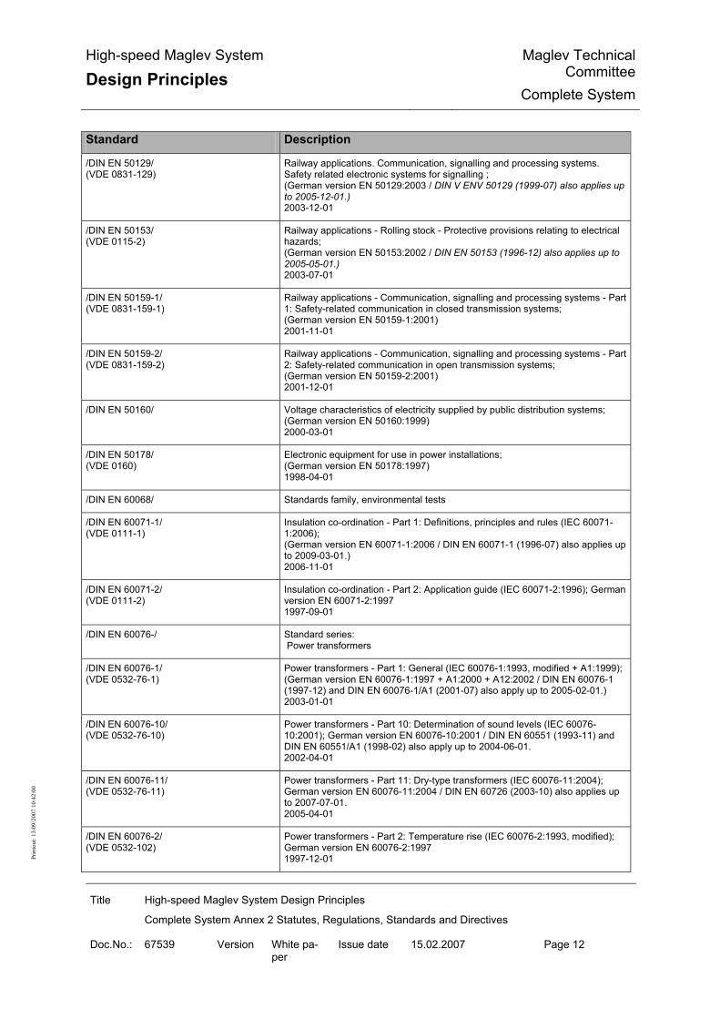
High-speed Maglev System
Design Principles Maglev Technical
CommitteeComplete System
Title High-speed Maglev System Design Principles
Complete System Annex 2 Statutes, Regulations, Standards and Directives
Doc.No.: 67539 Version White pa-per
Issue date 15.02.2007 Page 12
Prin
tout
: 13/
09/2
007
10:4
2:00
Standard Description
/DIN EN 50129/ (VDE 0831-129)
Railway applications. Communication, signalling and processing systems. Safety related electronic systems for signalling ; (German version EN 50129:2003 / DIN V ENV 50129 (1999-07) also applies up to 2005-12-01.) 2003-12-01
/DIN EN 50153/ (VDE 0115-2)
Railway applications - Rolling stock - Protective provisions relating to electrical hazards; (German version EN 50153:2002 / DIN EN 50153 (1996-12) also applies up to 2005-05-01.) 2003-07-01
/DIN EN 50159-1/ (VDE 0831-159-1)
Railway applications - Communication, signalling and processing systems - Part 1: Safety-related communication in closed transmission systems; (German version EN 50159-1:2001) 2001-11-01
/DIN EN 50159-2/ (VDE 0831-159-2)
Railway applications - Communication, signalling and processing systems - Part 2: Safety-related communication in open transmission systems; (German version EN 50159-2:2001) 2001-12-01
/DIN EN 50160/ Voltage characteristics of electricity supplied by public distribution systems; (German version EN 50160:1999) 2000-03-01
/DIN EN 50178/ (VDE 0160)
Electronic equipment for use in power installations; (German version EN 50178:1997) 1998-04-01
/DIN EN 60068/ Standards family, environmental tests
/DIN EN 60071-1/ (VDE 0111-1)
Insulation co-ordination - Part 1: Definitions, principles and rules (IEC 60071-1:2006); (German version EN 60071-1:2006 / DIN EN 60071-1 (1996-07) also applies up to 2009-03-01.) 2006-11-01
/DIN EN 60071-2/ (VDE 0111-2)
Insulation co-ordination - Part 2: Application guide (IEC 60071-2:1996); German version EN 60071-2:1997 1997-09-01
/DIN EN 60076-/ Standard series: Power transformers
/DIN EN 60076-1/ (VDE 0532-76-1)
Power transformers - Part 1: General (IEC 60076-1:1993, modified + A1:1999); (German version EN 60076-1:1997 + A1:2000 + A12:2002 / DIN EN 60076-1 (1997-12) and DIN EN 60076-1/A1 (2001-07) also apply up to 2005-02-01.) 2003-01-01
/DIN EN 60076-10/ (VDE 0532-76-10)
Power transformers - Part 10: Determination of sound levels (IEC 60076-10:2001); German version EN 60076-10:2001 / DIN EN 60551 (1993-11) and DIN EN 60551/A1 (1998-02) also apply up to 2004-06-01. 2002-04-01
/DIN EN 60076-11/ (VDE 0532-76-11)
Power transformers - Part 11: Dry-type transformers (IEC 60076-11:2004); German version EN 60076-11:2004 / DIN EN 60726 (2003-10) also applies up to 2007-07-01. 2005-04-01
/DIN EN 60076-2/ (VDE 0532-102)
Power transformers - Part 2: Temperature rise (IEC 60076-2:1993, modified); German version EN 60076-2:1997 1997-12-01

High-speed Maglev System
Design Principles Maglev Technical
CommitteeComplete System
Title High-speed Maglev System Design Principles
Complete System Annex 2 Statutes, Regulations, Standards and Directives
Doc.No.: 67539 Version White pa-per
Issue date 15.02.2007 Page 13
Prin
tout
: 13/
09/2
007
10:4
2:00
Standard Description
/DIN EN 60076-3 CORRIGENDUM 1/ (VDE 0532-3 CORRIGENDUM 1)
Corrigenda to DIN EN 60076-3 (VDE 0532 Part 3):2001-11 2002-04-01
/DIN EN 60076-3/ (VDE 0532-3)
Power transformers - Part 3: Insulation levels, dielectric tests and external clearances in air (IEC 60076-3:2000 + Corrigendum:2000); German version EN 60076-3:2001 / DIN VDE 0532-3 (1987-07) and DIN VDE 0532-3/A1 (1995-12) also apply up to 2004-01-01. 2001-11-01
/DIN EN 60076-4/ (VDE 0532-76-4)
Power transformers - Part 4: Guide to the lightning impulse and switching im-pulse testing of power transformers and reactors (IEC 60076-4:2002); German version EN 60076-4:2002 / DIN VDE 0532-13 (1984-07) also applies up to 2005-09-01. 2003-06-01
/DIN EN 60076-5/ (VDE 0532-76-5)
Power transformers - Part 5: Ability to withstand short-circuit (IEC 60076-5:2006); German version EN 60076-5:2006 / DIN EN 60076-5 (2001-11) also applies up to 2009-04-01. 2007-01-01
/DIN EN 60228/ (VDE 0295)
Conductors of insulated cables (IEC 60228:2004); (German version EN 60228:2005 + Corrigendum:2005 / DIN VDE 0295 (1992-06) also applies up to 2007-12-01.) 2005-09-01
/DIN EN 60529/ (VDE 0470-1)
Degrees of protection provided by enclosures (IP code) (IEC 60529:1989 + A1:1999); (German version EN 60529:1991 + A1:2000 / DIN VDE 0470-1 (1992-11) also applies up to 2003-01-01.) 2000-09-01
/DIN EN 60664-1/ (VDE 0110-1)
Insulation coordination for equipment within low-voltage systems - Part 1: Prin-ciples, requirements and tests (IEC 60664-1:1992 + A1:2000 + A2:2002); (German version EN 60664-1:2003 / DIN VDE 0110-1 (1997-04) also applies up to 2006-04-01.) 2003-11-01
/DIN EN 60694/ (VDE 0670-1000)
Common specifications for high-voltage switchgear and controlgear standards (IEC 60694:1996 + Corr. 1:2001 + A1:2000 + A2:2001 + Corr. 1:2001); (German version EN 60694:1996 + A1:2000 + A2:2001 / DIN EN 60694 (1998-10) also applies up to 2003-11-01.) 2002-09-01
/DIN EN 60695-1-1/ (VDE 0471-1-1)
Fire hazard testing - Part 1-1: Guidance for assessing fire hazard of electro-technical products; General guidance (IEC 60695-1-1:1999 + Corrigendum 2000); (German version EN 60695-1-1:2000 / DIN EN 60695-1-1 (1996-07) also ap-plies up to 2003-01-01.) 2000-10-01
/DIN EN 60909-0/ (VDE 0102)
Short-circuit currents in three-phase a.c. systems - Part 0: Calculation of cur-rents (IEC 60909-0:2001); (German version EN 60909-0:2001 / DIN VDE 0102 (1990-01) also applies up to 2003-01-01.) 2002-07-01
/DIN EN 61378-1/ (VDE 0532-41)
Converter transformers - Part 1: Transformers for industrial applications (IEC 61378-1:1997); (German version EN 61378-1:1998 + Corrigendum 1998) 1999-09-01

High-speed Maglev System
Design Principles Maglev Technical
CommitteeComplete System
Title High-speed Maglev System Design Principles
Complete System Annex 2 Statutes, Regulations, Standards and Directives
Doc.No.: 67539 Version White pa-per
Issue date 15.02.2007 Page 14
Prin
tout
: 13/
09/2
007
10:4
2:00
Standard Description
/DIN EN 61508-1/ (VDE 0803-1)
Functional safety of electrical/electronic/programmable electronic safety-related systems - Part 1: General requirements (IEC 61508-1:1998 + Corrigendum 1999); (German version EN 61508-1:2001) 2002-11-01
/DIN EN 61508-2/ (VDE 0803-2)
Functional safety of electrical/electronic/programmable electronic safety-related systems - Part 2: Requirements for electrical/electronic/programmable elec-tronic safety-related systems (IEC 61508-2:2000); German version EN 61508-2:2001 2002-12-01
/DIN EN 61508-3/ (VDE 0803-3)
Functional safety of electrical/electronic/programmable electronic safety-related systems - Part 3: Software requirements (IEC 61508-3:1998 + Corrigendum 1999); German version EN 61508-3:2001 2002-12-01
/DIN EN 61508-4/ (VDE 0803-4)
Functional safety of electrical/electronic/programmable electronic safety-related systems - Part 4: Definitions and abbreviations (IEC 61508-4:1998 + Corrigen-dum 1999); German version EN 61508-4:2001 2002-11-01
/DIN EN 61508-5/ (VDE 0803-5)
Functional safety of electrical/electronic/programmable electronic safety-related systems - Part 5: Examples of methods for the determination of safety integrity levels (IEC 61508-5:1998 + Corrigendum 1999); German version EN 61508-5:2001 2002-11-01
/DIN EN 61508-6/ (VDE 0803-6)
Functional safety of electrical/electronic/programmable electronic safety-related systems - Part 6: Guidance on the application of IEC 61508-2 and IEC 61508-3 (IEC 61508-6:2000); German version EN 61508-6:2001 2003-06-01
/DIN EN 61508-7/ (VDE 0803-7)
Functional safety of electrical/electronic/programmable electronic safety-related systems - Part 7: Overview of techniques and measures (IEC 61508-7:2000); German version EN 61508-7:2001 2003-06-01
/DIN EN 61642/ (VDE 0560-430)
Industrial a.c. networks affected by harmonics. Application of filters and shunt capacitors (IEC 61642:1997); (German version EN 61642:1997) 1998-11-01
/DIN EN 62040/ Standard series: Uninterruptible Power System (UPS)
/DIN EN 62040-1-1/ (VDE 0558-511)
Uninterruptible power systems (UPS) - Part 1-1: General and safety require-ments for UPS used in operator access areas (IEC 62040-1-1:2002 + Corrigen-dum 2002); (German version EN 62040-1-1:2003 / DIN EN 50091-1-1 (1997-07) also ap-plies up to 2005-11-01.) 2003-10-01
/DIN EN 62040-1-2/ (VDE 0558-512)
Uninterruptible power systems (UPS) - Part 1-2: General and safety require-ments for UPS used in restricted access locations (IEC 62040-1-1:2002 + Corrigendum 2002); (German version EN 62040-1-2:2003 / DIN EN 50091-1-2 (1999-05) and DIN EN 50091-1-2 Corrigendum 1 (2000-07) also apply up to 2005-11-01.) 2003-10-01

High-speed Maglev System
Design Principles Maglev Technical
CommitteeComplete System
Title High-speed Maglev System Design Principles
Complete System Annex 2 Statutes, Regulations, Standards and Directives
Doc.No.: 67539 Version White pa-per
Issue date 15.02.2007 Page 15
Prin
tout
: 13/
09/2
007
10:4
2:00
Standard Description
/DIN EN 62040-2/ (VDE 0558-520)
Uninterruptible power systems (UPS) - Part 2: Electromagnetic compatibility (EMC) requirements (IEC 62040-2:2005); German version EN 62040-2:2006 / DIN EN 50091-2 (1996-05) also applies up to 2008-10-01.) 2006-07-01
/DIN EN 62040-3/ (VDE 0558-530)
Uninterruptible power systems (UPS) - Part 3: Methods of specifying the per-formance and test requirements (IEC 62040-3:1999, modified); (German version EN 62040-3:2001 / DIN VDE 0558-5 (1988-09) and DIN VDE 0558-6 (1992-04) also apply up to 2003-08-01.) 2002-02-01
/DIN EN 62271/ Standard series: High voltage switchgear and controlgear
/DIN EN 62271-100/ (VDE 0671-100)
High-voltage switchgear and controlgear - Part 100: High-voltage alternating-current circuit-breakers (IEC 62271-100:2001 + A1:2002 + Corrigendum 1:2002 + Corrigendum 2:2003); (German version EN 62271-100:2001 + A1:2002 / DIN VDE 0670-101 (1992-12), DIN VDE 0670-102 (1992-12), DIN VDE 0670-103 (1992-10), DIN VDE 0670-104 (1992-10), DIN VDE 0670-105 (1992-10) and DIN VDE 0670-106 (1992-10) also apply up to 2004-09-01.) 2004-04-01
/DIN EN 62271-102/ (VDE 0671-102)
High-voltage switchgear and controlgear - Part 102: Alternating current discon-nectors and earthing switches (IEC 62271-102:2001 + Corrigendum 1:2002 + Corrigendum 2:2003); (German version EN 62271-102:2002 / DIN EN 60129 (1998-03), DIN EN 61129 (1995-02), DIN EN 61129/A1 (1998-01) and DIN EN 61259 (1996-06) also apply up to 2005-03-01.) 2003-10-01
/DIN EN 62271-105/ (VDE 0671-105)
High-voltage switchgear and controlgear - Part 105: Alternating current switch-fuse combinations (IEC 62271-105:2002); (German version EN 62271-105:2003 / DIN EN 60420 (1994-09) also applies up to 2005-10-01.) 2003-12-01
/DIN EN 62271-107/ (VDE 0671-107)
High-voltage switchgear and controlgear - Part 107: Alternating current fused circuit-switchers for rated voltages above 1 kV up to and including 52 kV (IEC 62271-107:2005); (German version EN 62271-107:2005) 2006-07-01
/DIN EN 62271-108/ (VDE 0671-108)
High-voltage switchgear and controlgear - Part 108: High-voltage alternating current disconnecting circuit-breakers for rated voltages of 72.5 kV and above (IEC 62271-108:2005); (German version EN 62271-108:2006) 2006-10-01
/DIN EN 62271-110/ (VDE 0671-110)
High-voltage switchgear and controlgear - Part 110: Inductive load switching (IEC 62271-110:2005); (German version EN 62271-110:2005) 2006-07-01
/DIN EN 62271-2/ (VDE 0671-2)
High-voltage switchgear and controlgear - Part 2: Seismic qualification for rated voltages of 72.5 kV and above (IEC 62271-2:2003); ( German version EN 62271-2:2003 2004-01-01

High-speed Maglev System
Design Principles Maglev Technical
CommitteeComplete System
Title High-speed Maglev System Design Principles
Complete System Annex 2 Statutes, Regulations, Standards and Directives
Doc.No.: 67539 Version White pa-per
Issue date 15.02.2007 Page 16
Prin
tout
: 13/
09/2
007
10:4
2:00
Standard Description
/DIN EN 62271-200/ (VDE 0671-200)
High-voltage switchgear and controlgear - Part 200: A.C. metal-enclosed switchgear and controlgear for rated voltages above 1 kV and up to and includ-ing 52 kV (IEC 62271-200:2003); (German version EN 62271-200:2004 / DIN EN 60298 (1998-05), DIN EN 60298 Corrigendum 1 (1999-03) and DIN EN 60298 Corrigendum 2 (2001-09) also apply up to 2007-02-01.) 2004-10-01
/DIN EN 62271-203/ (VDE 0671-203)
High-voltage switchgear and controlgear - Part 203: Gas-insulated metal-enclosed switchgear for rated voltages above 52 kV (IEC 62271-203:2003); (German version EN 62271-203:2004 / DIN EN 60517 (1998-10) and DIN EN 60517 Corrigendum 1 (2001-08) also apply up to 2007-02-01.) 2004-11-01
/DIN EN 62305/ Standard series: Protection against lightning
/DIN EN 62305-1/ (VDE 0185-305-1)
Protection against lightning - Part 1: General principles (IEC 62305-1:2006); (German version EN 62305-1:2006 / DIN V VDE V 0185-1 (2002-11) also applies up 2008-10-01.) 2006-10-01
/DIN EN 62305-2/ (VDE 0185-305-2)
Protection against lightning - Part 2: Risk management (IEC 62305-2:2006); (German version EN 62305-2:2006 / DIN V VDE V 0185-2 (2002-11), DIN V VDE V 0185-2 Corrigendum 1 (2004-02) and DIN V VDE V 0185-2 Supplement 1 (2004-06) also apply up to 2008-10-01.) 2006-10-01
/DIN EN 62305-3/ (VDE 0185-305-3)
Protection against lightning - Part 3: Physical damage to structures and life hazard (IEC 62305-3:2006, modified); (German version EN 62305-3:2006 / DIN V VDE V 0185-3 (2002-11) and DIN V VDE V 0185-3/A1 (2005-06) also apply up to 2008-10-01.) 2006-10-01
/DIN EN 62305-4/ (VDE 0185-305-4)
Protection against lightning - Part 4: Electrical and electronic systems within structures (IEC 62305-4:2006); (German version EN 62305-4:2006 / DIN V VDE V 0185-4 (2002-11) also applies up 2008-10-01.) 2006-10-01
/DIN EN ISO 12944-1/ Paints and varnishes - Corrosion protection of steel structures by protective paint systems - Part 1: General introduction (ISO 12944-1:1998); (German version EN ISO 12944-1:1998) 1998-07-01
/DIN EN ISO 12944-2/ Paints and varnishes - Corrosion protection of steel structures by protective paint systems - Part 2: Classification of environments (ISO 12944-2:1998); (German version EN ISO 12944-2:1998) 1998-07-01
/DIN EN ISO 12944-3/ Paints and varnishes - Corrosion protection of steel structures by protective paint systems - Part 3: Design considerations (ISO 12944-3:1998); (German version EN ISO 12944-3:1998) 1998-07-01
/DIN EN ISO 12944-4/ Paints and varnishes - Corrosion protection of steel structures by protective paint systems - Part 4: Types of surface and surface preparation (ISO 12944-4:1998); (German version EN ISO 12944-4:1998) 1998-07-01

High-speed Maglev System
Design Principles Maglev Technical
CommitteeComplete System
Title High-speed Maglev System Design Principles
Complete System Annex 2 Statutes, Regulations, Standards and Directives
Doc.No.: 67539 Version White pa-per
Issue date 15.02.2007 Page 17
Prin
tout
: 13/
09/2
007
10:4
2:00
Standard Description
/DIN EN ISO 12944-5/ Paints and varnishes - Corrosion protection of steel structures by protective paint systems - Part 5: Protective paint systems (ISO 12944-5:1998); (German version EN ISO 12944-5:1998) 1998-07-01
/DIN EN ISO 12944-6/ Paints and varnishes - Corrosion protection of steel structures by protective paint systems - Part 6: Laboratory performance test methods and assessment criteria (ISO 12944-6:1998); (German version EN ISO 12944-6:1998) 1998-07-01
/DIN EN ISO 12944-7/ Paints and varnishes - Corrosion protection of steel structures by protective paint systems - Part 7: Execution and supervision of paint work (ISO 12944-7:1998); (German version EN ISO 12944-7:1998) 1998-07-01
/DIN EN ISO 12944-8/ Paints and varnishes - Corrosion protection of steel structures by protective paint systems - Part 8: Development of specifications for new work and mainte-nance (ISO 12944-8:1998); (German version EN ISO 12944-8:1998) 1998-07-01
/DIN EN ISO 3095/ Railway applications - Acoustics - Measurement of noise emitted by railbound vehicles (ISO 3095:2005); (German version EN ISO 3095:2005) 2005-11-01
/DIN EN ISO 9000/ Quality management systems - Fundamentals and vocabulary (ISO 9000:2005); Trilingual version EN ISO 9000:2005 DIN EN ISO 9000
/DIN EN ISO 9001/ Quality management systems - Requirements (ISO 9001:2000-09); Trilingual version EN ISO 9001:2000 2000-12-01
/DIN EN ISO 9004/ Quality management systems - Guidelines for performance improvements (ISO 9004:2000); Trilingual version EN ISO 9004:2000 2000-12-01
/DIN Technical Report 101/ Actions on bridges; March 2003; ISBN-3-410-15007-2; 2003-01-01
/DIN VDE 0100/ (VDE 0100)
Provisions for the Erection of Power Installations with Rated Voltages Below 1000 V / 01 November 1958 in the version of May 1973 / Was withdrawn in error. The sections that are reproduced in Supplement 2 of May 2001 in Table 2 still apply / observe the transitional period defined by DIN VDE 0100-443 (2002-01) and DIN VDE 0100-530 (2005-06), up to 2006-05-31. 1973-05-01
/DIN VDE 0101/ (VDE 0101)
Power installations exceeding 1 kV; (German version HD 637 S1:1999 / DIN VDE 0101 (1989-05) and DIN VDE 0141 (1989-07) also apply up to 2001-01-01. / observe the transitional period defined by DIN EN 60204-11 (2001-05), up to 2003-09-01.) 2000-01-01
/DIN VDE 0105-100/ (VDE 0105-100)
Operation of electrical installations - Part 100: General requirements / DIN VDE 0105-100 (2000-06) and DIN VDE 0105-100/A3 (2003-11) also apply up to 2007-07-01. 2005-06-01

High-speed Maglev System
Design Principles Maglev Technical
CommitteeComplete System
Title High-speed Maglev System Design Principles
Complete System Annex 2 Statutes, Regulations, Standards and Directives
Doc.No.: 67539 Version White pa-per
Issue date 15.02.2007 Page 18
Prin
tout
: 13/
09/2
007
10:4
2:00
Standard Description
/DIN VDE 0276-632/ (VDE 0276-632)
Power cables with extruded insulation and their accessories for rated voltages above 36 kV (U<(Index)m> = 42 kV) up to 150 kV (U<(Index)m> = 170 kV); (German version HD 632 S1 Parts 1, 3D, 4D, 5D:1998) 1999-05-01
/DIN VDE 0888/ Standard series: Optical fibre cables for communication systems
/DIN VDE 0888-3 CORRIGENDUM 1/ /VDE 0888-3 CORRIGENDUM 1/
Corrigendum to DIN VDE 0888-3 (VDE 0888 Part 3):1999-10 2001-08-01
/DIN VDE 0888-3/ (VDE 0888-3)
Optical fibre cables for communication systems - Part 3: Outdoor cables 1999-10-01
/DIN VDE 0888-4/ (VDE 0888-4)
Optical fibre cables for communication systems - Part 4: Indoor cables with one fibre 1999-10-01
/DIN VDE 0888-5/ (VDE 0888-5)
Optical fibre cables for communication systems - Part 5: Outdoor fan-out cables1999-10-01
/DIN VDE 0888-6/ (VDE 0888-6)
Optical fibre cables for communication systems - Part 6: Indoor cables with several fibres 1999-10-01
/EBA-Lf Station/ EBA - Guide "Fire protection in passenger transport installations of the federal railways"; January 2001 also additional information for the guide when used for passenger transport installations of maglev railways; April 2002
/EBA-RL MSB Tunnel/ Guide for the construction and operation of maglev tunnels in regard to fire and emergency management and hazard prevention; German Federal Railway Authority; 2005-03-01
/EN 10106/ Cold rolled non-oriented electrical steel sheet and strip delivered in the fully processed state; German version EN 10106:1995 1996-02-01
/EN 1317-1/ Road restraint systems - Part 1: Terminology and general criteria for test meth-ods 1998-04-01
/EN 1363-1/ Fire resistance tests - Part 1: General requirements 1999-08-01
/EN 14067-2/ Railway applications - Aerodynamics - Part 2: Aerodynamics on open track 2003-04-01
/EN 14067-3/ Railway applications - Aerodynamics - Part 3: Aerodynamics in tunnels 2003-04-01
/EN 1990/ Eurocode: Basis of structural design 2002-04-01
/EN 1991/ Standard series Eurocode 1: Actions on structures
/EN 1991-1-1/ Eurocode 1: Actions on structures- Part 1-1: Densities, self-weight, imposed loads for buildings 2002-04-01

High-speed Maglev System
Design Principles Maglev Technical
CommitteeComplete System
Title High-speed Maglev System Design Principles
Complete System Annex 2 Statutes, Regulations, Standards and Directives
Doc.No.: 67539 Version White pa-per
Issue date 15.02.2007 Page 19
Prin
tout
: 13/
09/2
007
10:4
2:00
Standard Description
/EN 1991-1-2/ Eurocode 1 - Actions on structures - Part 1-2: General actions; Actions on structures exposed to fire 2002-11-01
/EN 1991-1-3/ Eurocode 1 - Actions on structures - Part 1-3: General actions, snow loads 2003-07-01
/EN 1991-1-4/ Eurocode 1 - Actions on structures - Part 1-4: General actions, wind loads 2005-04-01
/EN 1991-1-5/ Eurocode 1 - Actions on structures - Part 1-5: General actions; temperature actions 2003-11-01
/EN 1991-1-6/ Eurocode 1 - Actions on structures - Part 1-6: General actions - Actions during execution 2005-06-01
/EN 1991-1-7/ Eurocode 1 - Actions on structures - Part 1-7: General actions - accidental actions 2006-07-01
/EN 1991-2/ Eurocode 1: Actions on structures - Part 2: Traffic loads on bridges 2003-09-01
/EN 1991-3/ Eurocode 1 - Actions on structures - Part 3: Actions induced by cranes and machinery 2006-07-01
/EN 1992/ Standard series Eurocode 2: Design of concrete structures
/EN 1992-1-1/ Eurocode 2: Design of concrete structures - Part 1-1: General rules for build-ings 2004-12-01
/EN 1992-1-2/ Eurocode 2: Design of concrete structures - Part 1-2: General rules - Structural fire design 2004-12-01
/EN 1992-2/ Eurocode 2 - Design of concrete structures - Part 2: Concrete bridges - Design and detailing rules 2005-10-01
/EN 1992-3/ Eurocode 2 - Design of concrete structures - Part 3: Liquid retaining and con-tainment structures 2006-06-01
/EN 1993/ Standards family Eurocode 3: Design of steel structures; July 2005
/EN 1998/ Standards family Eurocode 8: Design of structures for earthquake resistance; December 2004
/EN 1999/ Standards family Eurocode 9: Design of aluminium structures; Preliminary standard: October 2000
/EN 50124-1/ Railway applications - Insulation coordination - Part 1: Basic requirements; Clearances and creepage distances for all electrical and electronic equipment 2001-03-01
/EN 50125/ Standards series - Railway applications

High-speed Maglev System
Design Principles Maglev Technical
CommitteeComplete System
Title High-speed Maglev System Design Principles
Complete System Annex 2 Statutes, Regulations, Standards and Directives
Doc.No.: 67539 Version White pa-per
Issue date 15.02.2007 Page 20
Prin
tout
: 13/
09/2
007
10:4
2:00
Standard Description
/EN 50125-1/ Railway applications - Environmental conditions for equipment - Part 1: Equip-ment on board rolling stock 1999-09-01
/EN 50125-2/
Railway applications - Environmental conditions for equipment - Part 2: Fixed electrical installations 2002-12-01
/EN 50125-3/ Railway applications - Environmental conditions for equipment - Part 3: Equip-ment for signalling and telecommunications 2003-01-01
/EN 50207/ Railway applications - Electronic power converters for rolling stock 2000-09-01
/EN 60721/ Standard series: Classification of environmental conditions
/EN 60721-1/ Classification of environmental conditions - Part 1: Environmental parameters and their severities (IEC 60721-1:1990 + A1:1992) 1995-04-01
/EN 60721-1/A2 Classification of environmental conditions - Part 1: Environmental parameters and their limits; Amendment A2 (IEC 60721-1:1990/A2:1995) 1995-07-01
/EN 60721-3-0/ Classification of environmental conditions - Part 3: Classification of groups of environmental parameters and their severities - Introduction (IEC 60721-3-0:1984 + A1:1987) 1993-07-01
/EN 60721-3-1/ Classification of environmental conditions - Part 3: Classification of groups of environmental parameters and their severities; section 1: Storage (IEC 60721-3-1:1997) 1997-03-01
/EN 60721-3-2/ Classification of environmental conditions - Part 3: Classification of groups of environmental parameters and their severities; section 2: Transport (IEC 60721-3-2:1997) 1997-03-01
/EN 60721-3-3/ Classification of environmental conditions - Part 3: Classification of groups of environmental parameters and their severities - Section 3: Stationary use at weatherprotected locations (IEC 60721-3-3:1994) 1995-01-01
/EN 60721-3-3/A2/ Classification of environmental conditions - Part 3: Classification of groups of environmental parameters and their severities - Section 3: Stationary use at weatherprotected locations; Amendment A2 (IEC 60721-3-3:1994/A2:1996)) 1997-01-01
/EN 60721-3-4/ Classification of environmental conditions - Part 3: Classification of groups of environmental parameters and their severities - Section 4: Stationary use at non-weatherprotected locations (IEC 60721-3-4:1994) 1995-02-01
/EN 60721-3-4/A1/ Classification of environmental conditions - Part 3: Classification of groups of environmental parameters and their severities - Section 4: Stationary use at non-weatherprotected locations; Amendment A1 (IEC 60721-3-4:1995/A1:1996) 1997-01-01

High-speed Maglev System
Design Principles Maglev Technical
CommitteeComplete System
Title High-speed Maglev System Design Principles
Complete System Annex 2 Statutes, Regulations, Standards and Directives
Doc.No.: 67539 Version White pa-per
Issue date 15.02.2007 Page 21
Prin
tout
: 13/
09/2
007
10:4
2:00
Standard Description
/EN 60721-3-5/ Classification of environmental conditions - Part 3: Classification of groups of environmental parameters and their severities; Section 5: Ground vehicle instal-lations (IEC 60721-3-5:1997) 1997-04-01
/EN 61373/ Railway applications - Rolling stock equipment - Shock and vibration tests (IEC 61373:1999) 1999-04-01
/EN ISO 12543/ Standard series: Glass in building - Laminated glass and laminated safety glass -
/ERRI B 153 RP-1/ APPLICATION OF STANDARD ISO 2631 TO RAILWAY ROLLING STOCK Study of the different application methods of ISO 2631 used in the railway sector 1981-09-01
/ISO 2631/ Standard series: Mechanical Vibration
/ISO 2631-1/ Mechanical vibration and shock - Evaluation of human exposure to whole-body vibration - Part 1: General requirements - / Corrected version of July 1997 1997-05-01
/ISO 2631-2/ Mechanical vibration and shock - Evaluation of human exposure to whole-body vibration - Part 2: Vibration in buildings (1 Hz - 80 Hz) 2003-04-01
/ISO 2631-5/ Mechanical vibration and shock - Evaluation of human exposure to whole-body vibration - Part 5: Method for evaluation of vibration containing multiple shocks 2004-02-01
/prEN 50126-2/ Railway Applications The Specification and Demonstration of Reliability, Availability, Maintainability and Safety (RAMS) Part 2: Guide to the application on EN 50126 for Safety Draft July 05
/R009-004/ Railway specifications. Systematic allocation of safety integrity requirements. CENELEC Report R009-004:2001
/RI-EDV-AP-2001/ Guideline for the preparation and testing of IT-aided stability calculations; National Association of Checking Engineers in Construction; April 2001
/RPS/ Guidelines for passive safety equipment on highways HIGHWAYS AND TRANSPORT RESEARCH ASSOCIATION, WORKING PARTY ON TRAFFIC GUIDANCE AND SAFETY 1989
/TL 918300 Sheet 87/ Deutsche Bahn AG, corrosion protection, technical delivery conditions;
/UIC 651/ Layout on drivers’ cab in locomotives, railcars, multiple-unit trains and driving trailers; July 2002
/Wiesinger/ Prof. Dr. Wiesinger Study into the lightning threat and electrostatic threat to maglev railways, May 1979
Table 10: Standards and Directives

High-speed Maglev System
Design Principles Maglev Technical
CommitteeComplete System
Title High-speed Maglev System Design Principles
Complete System Annex 3 Environmental Conditions
Doc.No.: 67285 Version White pa-per
Issue date 15.02.2007 Page 1
Prin
tout
: 13/
09/2
007
10:4
2:00
High-speed Maglev System Design Principles
Complete System
Annex 3 Environmental Conditions
The author reserves the copyright in this document and all attachments. All rights reserved

High-speed Maglev System
Design Principles Maglev Technical
CommitteeComplete System
Title High-speed Maglev System Design Principles
Complete System Annex 3 Environmental Conditions
Doc.No.: 67285 Version White pa-per
Issue date 15.02.2007 Page 2
Prin
tout
: 13/
09/2
007
10:4
2:00
Distribution This document has been released for publication by the Technical Committee "Complete Sys-tem".

High-speed Maglev System
Design Principles Maglev Technical
CommitteeComplete System
Title High-speed Maglev System Design Principles
Complete System Annex 3 Environmental Conditions
Doc.No.: 67285 Version White pa-per
Issue date 15.02.2007 Page 3
Prin
tout
: 13/
09/2
007
10:4
2:00
Change history Release date: 15.02.2007; white paper, Technical Committee "Complete System"

High-speed Maglev System
Design Principles Maglev Technical
CommitteeComplete System
Title High-speed Maglev System Design Principles
Complete System Annex 3 Environmental Conditions
Doc.No.: 67285 Version White pa-per
Issue date 15.02.2007 Page 4
Prin
tout
: 13/
09/2
007
10:4
2:00
List of contents
List of illustrations
List of tables
General
Purpose of the document, scope This document specifies the environmental conditions of the MSB system independently of any particular project. This design principles applies to a high-speed maglev system according to the General Maglev System Act /AMbG/. The parameters of the primary environment specified in this document should be used as a basis for the design of the MSB system in an application project. To guarantee the required degree of resistance to environmental conditions, the said condi-tions should be used as a basis for the system development, qualification and verification of subsystems and modules for the particular application project. Parameters that differ in specific projects must be taken into consideration in the design and the necessary verifications carried out. The monitoring of the primary environmental parameters specified in this document, and the taking of the appropriate measures if the limits indicated here are exceeded, is not a matter for this document and will be dealt with in the corresponding project-specific documents. The environmental conditions for operation, storage and transport according to /EN 60721/ are defined in Chapter 5. The environmental conditions prevailing inside buildings or other weather-protected installa-tions are not a matter for this document. Conditions that are a function of a specific project-dependent route alignment, e.g. local geol-ogy/hydrology, are not covered by this document.
MSB Design Principles This document is an annex to the Design Principles Complete System and so forms part of a documentation for high-speed maglev systems consisting of different design principles. The document tree is shown in Figure 1 /MSB AG-GESAMTSYS/. The high-level "complete system" design principles and its annexes apply uniformly for the whole documentation: • MSB Design Principles Complete System, Doc. No.: 50630, /MSB AG-
GESAMTSYS/
• Annex 1: Abbreviations and Definitions, Doc. No.: 67536, /MSB AG-ABK&DEF/

High-speed Maglev System
Design Principles Maglev Technical
CommitteeComplete System
Title High-speed Maglev System Design Principles
Complete System Annex 3 Environmental Conditions
Doc.No.: 67285 Version White pa-per
Issue date 15.02.2007 Page 5
Prin
tout
: 13/
09/2
007
10:4
2:00
• Annex 2: Statutes, Regulations, Standards and Directives, Doc. No.: 67539, /MSB AG-NORM&RILI/
• Annex 3: Environmental Conditions, Doc. No.: 67285, /MSB AG-UMWELT/ • Annex 4: Rules for Operation (Train Operation and Maintenance), Doc. No.:
69061, /MSB AG-BTR/
• Annex 5: Noise, Doc. No.: 72963, /MSB AG-SCHALL/
Abbreviations and definitions The abbreviations and definitions given in /MSB AG-ABK&DEF/ apply.
Statutes, regulations, standards and guide-lines
The normative documents listed in /MSB AG-NORM&RILI/ contain requirements that form part of the High-speed Maglev System Design Principles by cross reference in the High-speed Maglev System Design Principles. Where normative documents in /MSB AG-NORM&RILI/ are dated, subsequent changes or revisions of these publications do not apply. With undated references, the latest version of the normative document that is referred to applies. The version of the standards and guidelines to be observed in an MSB project must be decided bindingly on a project-specific basis.
Identification and binding value of require-ments
The requirements of /DIN 820/ were essentially applied in the preparation of this document. In the following chapters and the annexes of this document
• Requirements are shown in normal font
• Explanations, guide values and examples are shown in italics The degree to which the requirements are binding has been defined by reference to /DIN 820-2/ Annex G, and has been taken into consideration when formulating the individual require-ments.

High-speed Maglev System
Design Principles Maglev Technical
CommitteeComplete System
Title High-speed Maglev System Design Principles
Complete System Annex 3 Environmental Conditions
Doc.No.: 67285 Version White pa-per
Issue date 15.02.2007 Page 6
Prin
tout
: 13/
09/2
007
10:4
2:00
Resistance to environmental conditions This Design Principles Environment is intended to facilitate, for a design of a high-speed maglev system, a resistance to environmental conditions according to the characteristics and data specified below. The MSB system must be designed so that unrestricted operation is possible within the envi-ronmental conditions specified below.
Climate The climatic data are based on the key data of the climatic class "widespread" according to /EN 60721-2/. The associated climatic classes for operation, transport and storage must conform to the re-quirements of /EN 60721-3-1/, /EN 60721-3-2/, /EN 60721-3-3/, /EN 60721-3-4/ und /EN 60721-3-5/ where applicable. The following requirements must be observed:
Air pressure Climatic classes according to /EN 60721-3-4/, /EN 60721-3-1/ and /EN 60721-3-2/: 4K3, 1K5, 2K4. Parameter Value Unit Air pressure (train operation, storage, maritime and land transport) 70 - 106
(equivalent to 0 m to 3000 m above SL) kPa
Table 11: Air pressure for train operation, storage, maritime and land transport
Parameter Value Unit
Air pressure (air cargo conditions) 55 kPa
Table 12: Air pressure, air transport
Relative humidity Climatic classes according to /EN 60721-3-4/, /EN 60721-3-1/ and /EN 60721-3-2/: 4K3, 1K5, 2K4 or /DIN EN 50125-3/ Table 3; Climatic class T1. Parameter Value Unit
Relative humidity (train operation, storage, maritime and land transport) 15 to 100 %
Table 13: Relative humidity, train operation, storage, maritime and land transport
Climatic classes according to /EN 60721-3-4/, /EN 60721-3-1/ and /EN 60721-3-2/: 4K3, 1K5, 2K4.

High-speed Maglev System
Design Principles Maglev Technical
CommitteeComplete System
Title High-speed Maglev System Design Principles
Complete System Annex 3 Environmental Conditions
Doc.No.: 67285 Version White pa-per
Issue date 15.02.2007 Page 7
Prin
tout
: 13/
09/2
007
10:4
2:00
Parameter Value Unit
Relative humidity (air cargo conditions) 20 to 40 %
Table 14: Relative humidity, air transport
Air temperature Climatic class according to /EN 60721-3-5/: 5K2 or /DIN EN 50125-3/, Table 2; Climatic class T1 (outdoors). Parameter Value Unit
Air temperature (train operation) -25 to + 40 °C
Table 15: Air temperature, train operation
Climatic classes according to /EN 60721-3-1/ and /EN 60721-3-2/: 1K5, 2K4. Parameter Value Unit
Air temperature (storage and transport) -40 to + 70 °C
Table 16: Air temperature, storage and transport
Parameter Value Unit
Annual mean temperature, Temperate Zones 10 °C
Annual mean temperature, Subtropical Zones 20 °C
Table 17: Annual mean temperatures
Change in weather in the course of a day Parameter Value Unit
Temperature change per day max. 40 K/day
Temperature change per day, mean 15 K/day
Temperature change, operation, max. 10 K/h
Temperature change, storage and transport max. 20 K/h
Table 18: Temperature change
Parameter Value Unit
Humidity change max. 50 %
Table 19: Humidity change

High-speed Maglev System
Design Principles Maglev Technical
CommitteeComplete System
Title High-speed Maglev System Design Principles
Complete System Annex 3 Environmental Conditions
Doc.No.: 67285 Version White pa-per
Issue date 15.02.2007 Page 8
Prin
tout
: 13/
09/2
007
10:4
2:00
Parameter Value Unit
Air pressure change max. 10 kPa
Table 20: Air pressure change
Wind Maintaining train operations with the project-specifically defined maximum line speed must be possible for the wind speeds given below for the "10-min average for every 10 years" ac-cording to wind load zone II as per /DIN EN 1991-1-4 /. Train operation may be continued at a higher wind speed with project-dependent additional operational measures (e.g. reduced running speed) and/or special measures (e.g. structural measures). Typical wind speeds in m/s for wind load zone II according to /DIN EN 1991-1-4/ at heights of 5m, 10m and 20m: Parameter Value Unit
Wind speed at 5m height, max. 10 min. average
per year 19.0 m/s
every 10 years 22.4 m/s
every 50 years 24.7 m/s
every 100 years 25.8 m/s
Table 21: Wind speed at 5m height, max. 10 min. average
Parameter Value Unit
Wind speed at 10m height, max. 10 min. average
per year 21.3 m/s
every 10 years 25.0 m/s
every 50 years 27.6 m/s
every 100 years 28.8 m/s
Table 22: Wind speed at 10m height, max. 10 min. average

High-speed Maglev System
Design Principles Maglev Technical
CommitteeComplete System
Title High-speed Maglev System Design Principles
Complete System Annex 3 Environmental Conditions
Doc.No.: 67285 Version White pa-per
Issue date 15.02.2007 Page 9
Prin
tout
: 13/
09/2
007
10:4
2:00
Parameter Value Unit
Wind speed at 20m height, max. 10 min. average
per year 23.7 m/s
every 10 years 27.9 m/s
every 50 years 30.8 m/s
every 100 years 32.0 m/s
Table 23: Wind speed at 20m height, max. 10 min. average
Parameter Value Unit Gusting speed for height 5m
per year 1-second value 30.7 m/s
per year 5-second value 27.2 m/s
every 10 years 1-second value 36.1 m/s
every 10 years 5-second value 32.2 m/s
Table 24: Gusting speed for height 5m
Parameter Value Unit
Gusting speed for height 10m
per year 1-second value 33.1 m/s
per year 5-second value 29.4 m/s
every 10 years 1-second value 39.0 m/s
every 10 years 5-second value 34.6 m/s
Table 25: Gusting speed for height 10m
Parameter Value Unit
Gusting speed for height 20m
per year 1-second value 35.7 m/s
per year 5-second value 31.7 m/s
every 10 years 1-second value 42.1 m/s
every 10 years 5-second value 37.3 m/s
Table 26: Gusting speed for height 20m

High-speed Maglev System
Design Principles Maglev Technical
CommitteeComplete System
Title High-speed Maglev System Design Principles
Complete System Annex 3 Environmental Conditions
Doc.No.: 67285 Version White pa-per
Issue date 15.02.2007 Page 10
Prin
tout
: 13/
09/2
007
10:4
2:00
Parameter Value Unit
Annual action time of the 10-minute averages at 10 m height
Wind speed > 10 m/s 74 h
Wind speed >17 m/s 3 h
Table 27: Annual action time of the 10-minute averages at 10 m height
Rain Limit for transport and operation according to /EN 60721-3-2/, /EN 60721-3-5/:2K4, 5K3 or DIN EN 50125-3, Chapter 4.6, Climatic class T1. Parameter Value Unit
Rain volume - general 6 mm/min
Rain volume - Limit for radio design project-specific *)
*) The propagation properties of radio links, especially at higher frequencies, depend on precipitation, among other factors. Precipitation leads to higher path attenuation, so appropriate signal level reserves (headroom) must be allowed for when designing the links. Rain has the greatest effect on path attenuation and so is used when calculating the signal level reserve. The path attenuation due to rain is due chiefly to the rainfall rate measured in mm/h, besides other factors such as the distri-bution of the raindrop size. For the purpose of designing radio links therefore, the upper limit for rain intensity is not defined according to a climatic class but from an analysis of rainfall statistics from the local weather service. As well as the rainfall rate, the probability of occurrence of the upper limit must also be determined for the project zone. A guideline figure here is that the defined upper limit for the rainfall rate is not exceeded with a time probability of >99.99 % p.a. This is not a limit in the strict sense of leading to a system malfunction if exceeded, rather that beyond this recommended value the system's reserves are generally reduced in terms of radio range in individual sections of the line that are affected. This would not normally impact on train operations. Table 28: Rainfall rate
Snow Parameter Value Unit
Tolerable depth of snow on guideway table 10 cm
Table 29: Depth of snow

High-speed Maglev System
Design Principles Maglev Technical
CommitteeComplete System
Title High-speed Maglev System Design Principles
Complete System Annex 3 Environmental Conditions
Doc.No.: 67285 Version White pa-per
Issue date 15.02.2007 Page 11
Prin
tout
: 13/
09/2
007
10:4
2:00
Ice
Parameter Value Unit
Permissible guideway icing
mean layer thicknesses on the slide plane 10 mm
mean layer thicknesses in levitation/guidance area 5 mm
max. local layer thicknesses, max. 2 m long on the slide plane 20 mm
local layer thicknesses, max. 2 m long in levitation/guidance area 10 mm
Table 30: Permissible guideway icing
Solar irradiation Climatic classes according to /EN 60721-3-1/ to /EN 60721-3-5/: 1K4, 2K4, 4K3, 5K3 or /DIN EN 50125-3/ Chapter 4.9. Parameter Value Unit
Maximum hourly global irradiation 1120 W/m2
Table 31: Solar irradiation (for storage, transport and operation)
Atmospheric parameters
Rain Parameter Value Unit
pH rain 3.4 to 7.6 (mean value 5.4) * -
*: The natural pH of rain is approx. 5.5, while the pH of "acid rain" in Germany is 4...4.6. This value for the pH of rain is a "meaningful" figure with an "adequate safety reserve" which takes account of the average range of rain pH value observed in Nature. Table 32: pH of rain
This figure must be reviewed project-specifically and adjusted as necessary.

High-speed Maglev System
Design Principles Maglev Technical
CommitteeComplete System
Title High-speed Maglev System Design Principles
Complete System Annex 3 Environmental Conditions
Doc.No.: 67285 Version White pa-per
Issue date 15.02.2007 Page 12
Prin
tout
: 13/
09/2
007
10:4
2:00
Chemically Active Substances Contaminant load as per /EN 60721-3-4/ 4C3 for the mean values, and /EN 60721-3-4/ 4C4 for the peak value / limits. Requirement for the mean values identical with /EN 50125-3/, Table 4, heavy contamination. Environmental parameter Mean * Limit ** Unit Sea salt Occurrence of salt spray --- Sulphur dioxide 5.0 40 mg/m3 Hydrogen sulphide 3.0 70 mg/m3 Chlorine 0.3 3.0 mg/m3 Hydrogen chloride 1.0 5.0 mg/m3 Hydrogen fluoride 0.1 2.0 mg/m3 Ammonia 10 175 mg/m3 Ozone 0.1 2.0 mg/m3 Nitrous oxides (given in equivalent values to nitrogen dioxide)
3.0 20 mg/m3
*) Figures are the mean values of Class 4C3 of EN 60721-3-4 **) Figures are the mean values of Class 4C3 of EN 60721-3-4 Table 33: Air, loading by chemically active substances
Mechanically active substances Loading from mechanically active substances according to /EN 60721-3-4/.
Class Environmental parameter
4S1 * 4S2 ** Unit Sand in the air 30 300 mg/m3 Dust (suspended matter) 0.5 5 mg/m3 Dust (precipitation) 15.0 20 mg / (m2 h) *) Used in sparsely populated areas, not near to sources of sand **) Used in areas with sources of sand or dust, including densely populated areas Table 34: Air, loading by mechanically active substances

High-speed Maglev System
Design Principles Maglev Technical
CommitteeComplete System
Title High-speed Maglev System Design Principles
Complete System Annex 3 Environmental Conditions
Doc.No.: 67285 Version White pa-per
Issue date 15.02.2007 Page 13
Prin
tout
: 13/
09/2
007
10:4
2:00
Lightning The MSB system must be protected from the actions of lightning specified below. Lightning protection for structures must comply with local building regulations.
Frequency Parameter Value Unit
Lightning strikes 20 * strikes per square kilometre/year
*) This frequency of lightning strike is a meaningful figure with an adequate "safety interval" from the average "lightning charac-teristics" observed in nature based on /WIESINGER/. Table 35: Frequency of lightning strike
Intensity according to /DIN EN 62305-1/ (VDE 0185-305-1)
Figure 34: First lightning discharge impulse and subsequent discharge impulse
Figure 35: Sustained discharge impulse

High-speed Maglev System
Design Principles Maglev Technical
CommitteeComplete System
Title High-speed Maglev System Design Principles
Complete System Annex 3 Environmental Conditions
Doc.No.: 67285 Version White pa-per
Issue date 15.02.2007 Page 14
Prin
tout
: 13/
09/2
007
10:4
2:00
Lightning current parameters of the first lightning discharge impulse Parameter Value Unit
Peak current I 200 kA
Front time T1 10 µs
Time to half-value T2 350 µs
Charge of the transient discharge pulse Qs 100 C
Specific energy W/R 10 MJ/Ω
Table 36: Lightning current parameters of the first lightning discharge impulse (see Figure 34)
Lightning current parameters of the subsequent lightning discharge impulse Parameter Value Unit
Peak current I 50 kA
Front time T1 0.25 µs
Time to half-value T2 100 µs
Mittlere Steilheit I/T1 200 kA/µs
Table 37: Lightning current parameters of the subsequent lightning discharge impulse (see Figure 34)
Lightning current parameters of the sustained lightning discharge impulse Parameter Value Unit
Charge QI 200 C
Time T 0.5 s
Table 38: Lightning current parameters of the sustained lightning discharge impulse (see Figure 35)
Electrical and magnetic field strengths Parameter Value Unit
dH/dt 3.2*1011 A/(m*s)
H 3.2*105 A/m
dE/dt 5.0 * 1011 V/(m*s)
E 5*105 V/m
Table 39: Distance from main lightning current path: 0.1 m

High-speed Maglev System
Design Principles Maglev Technical
CommitteeComplete System
Title High-speed Maglev System Design Principles
Complete System Annex 3 Environmental Conditions
Doc.No.: 67285 Version White pa-per
Issue date 15.02.2007 Page 15
Prin
tout
: 13/
09/2
007
10:4
2:00
Parameter Value Unit
dH/dt 3.2*1010 A/(m*s)
H 3.2*104 A/m
dE/dt 5.0 * 1011 V/(m*s)
E 5*105 V/m
Table 40: Distance from main lightning cur-rent path: 1 mEarthquake
The local building regulations must be complied with in regard to earthquake safety when designing structures for a specific project. For projects in Germany, and depending on the specific project, the relevant earthquake strengths according to /DIN 4149/, "Structures in German earthquake zones" must be determined and used as a basis for structure design.
Immunity from electromagnetic interference The immunity of MSB subsystems from interference must basically conform to European standard DIN EN 50121 (Electromagnetic Compatibility; Railway Applications). The in-tended performance characteristics of the MSB system must not be impaired by interference-field strengths or conducted interference up to the limits given below. Subsystems Limits as per standard
Stationary installations and equipment for the drive and energy supply DIN EN 50121-5
Vehicle DIN EN 50121-3-1
appliances installed in vehicles DIN EN 50121-3-2
Signalling and communications equipment incl. OCS radio DIN EN 50121-4
Table 41: European standards for the immunity of MSB subsystems

High-speed Maglev System
Design Principles Maglev Technical
CommitteeComplete System
Title High-speed Maglev System Design Principles
Complete System Annex 3 Environmental Conditions
Doc.No.: 67285 Version White pa-per
Issue date 15.02.2007 Page 16
Prin
tout
: 13/
09/2
007
10:4
2:00
Specification of parameters for the secondary environment This chapter lists the parameters for the secondary environment for the subsystems 'MSB ve-hicle' and 'Installations'. It specifies the environmental spaces and EMC/ lightning protection zones according to /DIN EN 62305-1/ (VDE 0185-305-1). The following figures are based on operational experience with the secondary environment. They reflect the current level of knowledge and should be confirmed project-specifically and/or adjusted and verified as required. Adjusted values must be indicated in the project-specific documentation (delivery specification, technical reports). The values in this document apply in the absence of an explicit agreement. The operational experience reflected in this document is based on MSB vehicles TR07 and TR08 on the TVE and on the Shanghai Transrapid project. The parameters for the EMC / lightning protection zones must allow for the radiation-related electromagnetic effects due to lightning strike and to all types of field-related interference effects, e.g. radio transmitters.
Secondary environment in MSB vehicle The following requirements apply to all components and mount-on parts in and on the MSB vehicle. The environmental spaces of the MSB vehicle are shown in Figure 36 .

High-speed Maglev System
Design Principles Maglev Technical
CommitteeComplete System
Title High-speed Maglev System Design Principles
Complete System Annex 3 Environmental Conditions
Doc.No.: 67285 Version White pa-per
Issue date 15.02.2007 Page 17
Prin
tout
: 13/
09/2
007
10:4
2:00
A A
B B
FI 3
FI 3
FA 2
FA 2
FI 1
U
nter
flur
S
chw
eber
ahm
en
Sen
sore
n
kl
imat
isie
rter B
erei
ch
nich
t klim
atis
ierte
r Ber
eich
E
inba
urau
m S
chal
tsch
rank
B
erei
ch z
wis
chen
Inne
n-
verk
leid
ung
und
Auße
nhau
t
FI 4
FA 1
:FA
2 :
FA 3
:
FI 1
:FI
2 :
FI 3
:FI
4 :
Fah
rzeu
ginn
enra
um fü
r P
erso
nens
ektio
n da
rges
tellt
B -
B
FA 2
A -
A
FI 2
FA 1
Fah
rzeu
ginn
enra
um fü
r G
üter
sekt
ion
darg
este
llt
FA 2
FA 3
TRI-D
ok.N
r. 80
295

High-speed Maglev System
Design Principles Maglev Technical
CommitteeComplete System
Title High-speed Maglev System Design Principles
Complete System Annex 3 Environmental Conditions
Doc.No.: 67285 Version White pa-per
Issue date 15.02.2007 Page 18
Prin
tout
: 13/
09/2
007
10:4
2:00
Figure 36: Environmental spaces of the MSB vehicle (typical arrangement)
Vehicle Exterior (FA):
• Underfloor (FA1), Space envelope for electrical/electronic modules, cable trunking, compressed air supply equipment
• Levitation frame (FA2), - Space envelope for guide magnets - Space envelope for brake magnets - Space envelope for sensor electronics - Panelling and mechanical structure levitation frame
• Space envelope (FA3) for - Levitation magnets - Sensors.
Vehicle Interior (FI): • Airconditioned area (FI1),
Space envelope for service/communication/operating equipment • Non airconditioned area (FI2)
Space envelope for loading equipment • Control cubicle vehicle section (FI3)
Space envelope for control/safety equipment • Ceiling/wall behind panelling (FI4)
Space envelope for cables, lighting.
Vehicle - Exteriors (FA)
Exterior - Underfloor (FA1) Parameter Value Unit
Temperature
Min. operating temperature for electronic components/batteries*) -25 °C
Max. temperature rise compared with primary environment 10 K
Mean temperature rise compared with primary environment 5 K
*) When used with outside air temperature -25 °C to -40 °C it must be ensured that
• the components do not fall below min. operating temperature during train operations,
• parked vehicles are not allowed to cool to below -25 °C before startup and during preparation for train operation. Parameter Value Unit
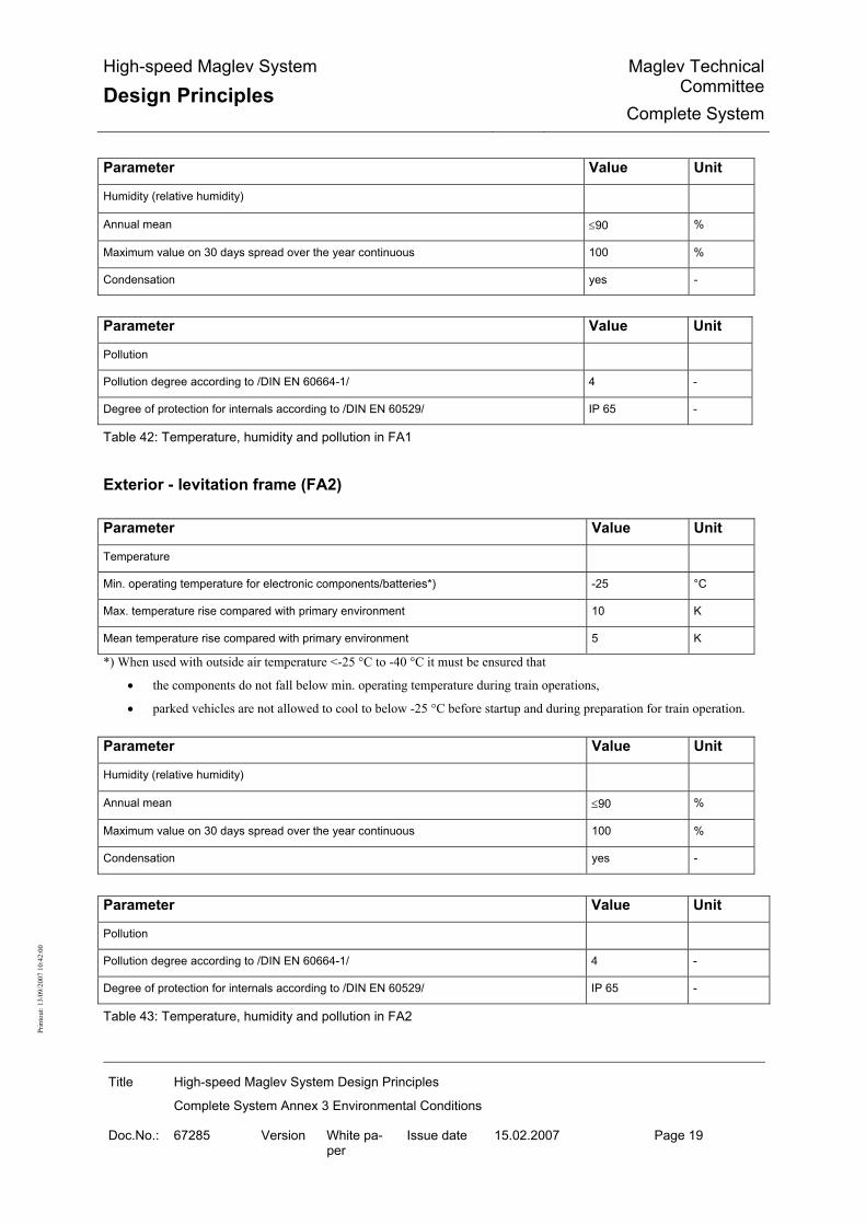
High-speed Maglev System
Design Principles Maglev Technical
CommitteeComplete System
Title High-speed Maglev System Design Principles
Complete System Annex 3 Environmental Conditions
Doc.No.: 67285 Version White pa-per
Issue date 15.02.2007 Page 19
Prin
tout
: 13/
09/2
007
10:4
2:00
Parameter Value Unit
Humidity (relative humidity)
Annual mean ≤90 %
Maximum value on 30 days spread over the year continuous 100 %
Condensation yes -
Parameter Value Unit
Pollution
Pollution degree according to /DIN EN 60664-1/ 4 -
Degree of protection for internals according to /DIN EN 60529/ IP 65 -
Table 42: Temperature, humidity and pollution in FA1
Exterior - levitation frame (FA2) Parameter Value Unit
Temperature
Min. operating temperature for electronic components/batteries*) -25 °C
Max. temperature rise compared with primary environment 10 K
Mean temperature rise compared with primary environment 5 K
*) When used with outside air temperature <-25 °C to -40 °C it must be ensured that
• the components do not fall below min. operating temperature during train operations,
• parked vehicles are not allowed to cool to below -25 °C before startup and during preparation for train operation. Parameter Value Unit
Humidity (relative humidity)
Annual mean ≤90 %
Maximum value on 30 days spread over the year continuous 100 %
Condensation yes -
Parameter Value Unit
Pollution
Pollution degree according to /DIN EN 60664-1/ 4 -
Degree of protection for internals according to /DIN EN 60529/ IP 65 -
Table 43: Temperature, humidity and pollution in FA2

High-speed Maglev System
Design Principles Maglev Technical
CommitteeComplete System
Title High-speed Maglev System Design Principles
Complete System Annex 3 Environmental Conditions
Doc.No.: 67285 Version White pa-per
Issue date 15.02.2007 Page 20
Prin
tout
: 13/
09/2
007
10:4
2:00
Exterior - Space envelope for levitation magnets, sensors (FA3) Parameter Value Unit
Temperature
Min. operating temperature for electronic components/batteries*) -25 °C
max. Temperature rise compared with primary environment Space envelope for sensor electronics in the magnet back
25
K
Max. temperature rise compared with primary environment Space envelope for sensors in the magnet pole area on the side facing the winding
80 K
Mean temperature rise compared with primary environment Space envelope for sensor electronics in the magnet back
10
K
Mean temperature rise compared with primary environment Space envelope for sensors in the magnet pole area on the side facing the winding
30 K
*) When used with outside air temperature < -25 °C to -40 °C it must be ensured that • the components do not fall below min. operating temperature during train operations, • parked vehicles are not allowed to cool to below -25 °C before startup and during preparation for train operation.
Parameter Value Unit
Humidity (relative humidity)
Annual mean ≤90 %
Maximum value on 30 days spread over the year continuous 100 %
Condensation yes -
Parameter Value Unit
Pollution
Pollution degree according to /DIN EN 60664-1/ 4 -
Degree of protection for internals according to /DIN EN 60529/ IP 65 -
Table 44: Temperature, humidity and pollution in FA3

High-speed Maglev System
Design Principles Maglev Technical
CommitteeComplete System
Title High-speed Maglev System Design Principles
Complete System Annex 3 Environmental Conditions
Doc.No.: 67285 Version White pa-per
Issue date 15.02.2007 Page 21
Prin
tout
: 13/
09/2
007
10:4
2:00
Vehicle - Interiors (FI)
Interior - Airconditioned area (FI1) Parameter Value Unit
Temperature
Min. interior temperature *) 5 °C
Mean temperature in train operations (active air-conditioning) **)
Max. temperature rise compared with primary environment in train operation (inactive air-conditioning)
10 K
*) Vehicles parked during breaks in operation are air-conditioned such that the minimum interior temperature is maintained. Maintenance with vehicle deactivation is carried out in a heated workshop. The minimum interior temperature following maintenance is tested with the air-conditioning off according to the maintenance manual. **) The mean room temperature follows the temperature curve shown in Annex A of /DIN EN 14750-1/ as a function of the outside temperature.
Parameter Value Unit
Humidity (relative humidity)
Annual mean ≤65 %
Maximum value on 60 days spread over the year continuous 85 %
Condensation no -
Parameter Value Unit
Pollution
Pollution degree according to /DIN EN 60664-1/ 2 -
Degree of protection according to /DIN EN 60529/ IP 54 -
Table 45: Temperature, humidity and pollution in FI1
Interior - Non airconditioned area (FI2) Parameter Value Unit
Temperature
Min. interior temperature -25 °C
Mean temperature in train operations (active air-conditioning) ------ -
Max. temperature rise compared with primary environment in train operation (inactive air-conditioning)
10 K

High-speed Maglev System
Design Principles Maglev Technical
CommitteeComplete System
Title High-speed Maglev System Design Principles
Complete System Annex 3 Environmental Conditions
Doc.No.: 67285 Version White pa-per
Issue date 15.02.2007 Page 22
Prin
tout
: 13/
09/2
007
10:4
2:00
Parameter Value Unit
Humidity (relative humidity)
Annual mean ≤65 %
Maximum value on 60 days spread over the year continuous 85 %
Condensation light condensation -
Parameter Value Unit
Pollution
Pollution degree according to /DIN EN 60664-1/ 2 -
Degree of protection according to /DIN EN 60529/ IP 54 -
Table 46: Temperature, humidity and pollution in FI2
Interior - Control cubicle vehicle section (FI3) Parameter Value Unit
Temperature
Min. interior temperature *) 5 °C
Mean temperature in train operations (active air-conditioning) 25 °C
Max. temperature rise compared with primary environment in train operation (inactive air-conditioning).**)
10 K
Max. temperature rise compared with primary environment in train operation (inactive air-conditioning).**)
5 K
*) Vehicles parked during breaks in operation are air-conditioned such that the minimum interior temperature is maintained. Maintenance with vehicle deactivation is carried out in a heated workshop. The minimum interior temperature following maintenance is tested with the air-conditioning off according to the maintenance manual. **) The interior temperature following maintenance is tested with the air-conditioning off according to the maintenance manual. ***)When used with outside air temperature > 40 °C to 45 °C, the space envelope is ventilated with ambient air.
Parameter Value Unit
Humidity (relative atmospheric humidity)
Annual mean ≤65 %
Maximum value on 60 days spread over the year continuous 85 %
Condensation no -
Parameter Value Unit
Pollution

High-speed Maglev System
Design Principles Maglev Technical
CommitteeComplete System
Title High-speed Maglev System Design Principles
Complete System Annex 3 Environmental Conditions
Doc.No.: 67285 Version White pa-per
Issue date 15.02.2007 Page 23
Prin
tout
: 13/
09/2
007
10:4
2:00
Parameter Value Unit
Pollution degree according to /DIN EN 60664-1/ 2 -
Degree of protection according to /DIN EN 60529/ IP 54 -
Table 47: Temperature, humidity and pollution in FI3
Interior - Ceiling/wall behind panelling (FI4) Parameter Value Unit
Temperature
Min. interior temperature - 25 °C
Mean temperature in train operations (active air-conditioning) ----- -
Max. temperature rise compared with primary environment in train operation (inactive air-conditioning)
15 K
Parameter Value Unit
Humidity (relative humidity)
Annual mean ≤65 %
Maximum value on 60 days spread over the year continuous 85 %
Condensation no -
Parameter Value Unit
Pollution
Pollution degree according to /DIN EN 60664-1/ 2 -
Degree of protection according to /DIN EN 60529/ IP 54 -
Table 48: Temperature, humidity and pollution in FI4

High-speed Maglev System
Design Principles Maglev Technical
CommitteeComplete System
Title High-speed Maglev System Design Principles
Complete System Annex 3 Environmental Conditions
Doc.No.: 67285 Version White pa-per
Issue date 15.02.2007 Page 24
Prin
tout
: 13/
09/2
007
10:4
2:00
Mechanical excitation The vehicle is excited to vibrate as its passes over the beams. The figures given below should be regarded as actions on the components of the vehicle's exterior areas. Source Length Max. frequency *)
Bay-wide guideway beams, beam precamber and longwave devia-tion from the nominal position
31 m 4.5 Hz
Stator pack, fitting tolerance 1.032 m 135 Hz
Stator slot pitch 86 mm 1.6 kHz
*) The effect may be reduced if a maximum vehicle speed of less than 500 km/h is proposed in the application project con-cerned. Table 49: Source of vibration excitation at v = 500 km/h.
The actions due to vibration and shock are given in /MSB AG-FZ BEM/.
ESD Protection The secondary environment in the vehicle can be electrostatically charged during noncontact levitation relative to the stationary installations. From the safety aspect, the secondary envi-ronment in the vehicle must be electrostatically discharged in such a way that the energy re-maining after the discharge according to Section 17, Paragraph MbBO is less than 350 mJ.
EMC / Lightning protection
Definition of EMC / lightning protection zones The EMC / lightning protection zones must be separated by electromagnetic shields. Lines with cross the zone boundaries must be provided with protective circuits. Four EMC / lightning protection zones are defined for the vehicle, and are characterised by the following threats (see Figure 39) : Zone 0A • Direct lightning strike possible. • Main and partial stroke current paths are inside the zone • Unattenuated field effect Zone 0B • No direct lightning strike possible • No main and partial stroke current paths • Virtually unattenuated field effect Zone 1

High-speed Maglev System
Design Principles Maglev Technical
CommitteeComplete System
Title High-speed Maglev System Design Principles
Complete System Annex 3 Environmental Conditions
Doc.No.: 67285 Version White pa-per
Issue date 15.02.2007 Page 25
Prin
tout
: 13/
09/2
007
10:4
2:00
• No direct lightning strike possible • No main and partial stroke current paths • Field attenuation must satisfy the following minimum values:
- for magnetic fields: as per Figure 37 - for electrical fields: as per Figure 38
Zone 2 • No direct lightning strike possible • No main and partial stroke current paths • Field attenuation must satisfy the following minimum values:
- for magnetic fields based on Zone 0A: as per Figure 37 - for magnetic fields based on Zone 1: as per Figure 37 - for electrical fields based on Zone 0A: as per Figure 38 - for electrical fields based on Zone 1: as per Figure 38
0
10
20
30
40
50
0,001 0,01 0,1 1 3010 100f (MHz)
Dämpfung(dB)
Zone 0→1Zone 1→2
Zone 0→2
Figure 37: Magnetic field attenuation

High-speed Maglev System
Design Principles Maglev Technical
CommitteeComplete System
Title High-speed Maglev System Design Principles
Complete System Annex 3 Environmental Conditions
Doc.No.: 67285 Version White pa-per
Issue date 15.02.2007 Page 26
Prin
tout
: 13/
09/2
007
10:4
2:00
0
10
20
30
40
50
0,01 0,1 1
f (MHz) 10 300
Attenuation (dB)
100
Zone 0->2
1000
Zone 0->1Zone 1->2
Attenuation for f > 10 GHz: 0 dB
Figure 38: Electrical field attenuation

High-speed Maglev System
Design Principles Maglev Technical
CommitteeComplete System
Title High-speed Maglev System Design Principles
Complete System Annex 3 Environmental Conditions
Doc.No.: 67285 Version White pa-per
Issue date 15.02.2007 Page 27
Prin
tout
: 13/
09/2
007
10:4
2:00
Assignment of the EMC / lightning protection zones to the space envelopes The EMC / lightning protection zones are assigned to the space envelopes as follows: Zone 0A • Exposed areas • Unshielded or unprotected underfloor area Zone 0B • Car body interior, outside control cubicles and other shields • Underfloor areas protected from main and partial lightning currents Zone 1 • Shielded cable trunking • Interior of control cubicles inside the car body • Cores outside singly shielded cables • Housing interiors Zone 2 Housing or cable shield interior. The housings and cables can be inside zones 0A, 0B or 1. The required shield attenuation values must be achieved.

High-speed Maglev System
Design Principles Maglev Technical
CommitteeComplete System
Title High-speed Maglev System Design Principles
Complete System Annex 3 Environmental Conditions
Doc.No.: 67285 Version White pa-per
Issue date 15.02.2007 Page 28
Prin
tout
: 13/
09/2
007
10:4
2:00
Figure 39: EMC / lightning protection zones of the MSB vehicle

High-speed Maglev System
Design Principles Maglev Technical
CommitteeComplete System
Title High-speed Maglev System Design Principles
Complete System Annex 3 Environmental Conditions
Doc.No.: 67285 Version White pa-per
Issue date 15.02.2007 Page 29
Prin
tout
: 13/
09/2
007
10:4
2:00
Direct lightning strike - Threat levels for EMC / lightning protection zone 0A At least two lightning flashover points per lightning impulse current, i.e. at least two lightning current paths, must be expected in the event of a lightning strike into the vehicle. The design of the lightning current-carrying equipotential bonding conductors, the shielding and the electronic components is based on two partial stroke impulse currents with identical lightning parameters. This results in the following reduction factors compared with the lightning parameters given in Chapter 0: • Lightning current peak value: 2 • Lightning impulse charge: 2 • Specific lightning energy: 4 For sustained current, the parameters are taken from Chapter 0. A minimum distance of 0.1 m between the sink and the lightning current paths is assumed when determining the limits of the lightning threat. The minimum distance must be guaranteed by design engineering. With greater distances, the threat values decrease proportional to the distance. The maximum magnetic field threat values H or dH/dt are given according to /DIN EN 62305-4/ by the distance and the maximum lightning current values I or dI/dt. H and I are derived from the first stroke, dH/dt and dI/dt from the subsequent strokes. In the event of lightning strike according to / DIN EN 62305-4/ the electrical field E or dE/dt is largely independent of distance at ranges of up to approx. 100 m from the strike point.
Lightning strike current Lightning strike current (see Figure 35 and Figure 34): Parameter Value Unit
Peak current I 100 kA
Charge of the transient discharge pulse Qs 50 C
Specific energy W/R 2.5 MJ/Ω
Table 50: Lightning current parameters of the first lightning discharge impulse
Parameter Value Unit
Peak current I 25 kA
Mean steepness I/T1 100 kA/µs
Table 51: Lightning current parameters of the subsequent discharge impulse

High-speed Maglev System
Design Principles Maglev Technical
CommitteeComplete System
Title High-speed Maglev System Design Principles
Complete System Annex 3 Environmental Conditions
Doc.No.: 67285 Version White pa-per
Issue date 15.02.2007 Page 30
Prin
tout
: 13/
09/2
007
10:4
2:00
Parameter Value Unit
Peak current value main lightning current path 100 kA
Peak current value partial lightning current path 5 kA
Current profile as first lightning discharge impulse, see Figure 34
-
Table 52: Currents in the lightning and partial lightning current paths
Fields and induced voltages Parameter EMC / Lightning Protection Zones Unit
0A 0B 1 2
dH/dt 1.6.1011 1.6.1011 1.6.1010 1.6.109 A/ms
H 1.6.105 1.6.105 1.0.105 6.3.104 A/m
dE/dt 5.0.1011 <5.0.1011 <5.0.1010 <5.0.109 V/ms
E 5.0.105 <5.0.105 <5.0.104 <5.0.103 V/m
Table 53: Fields and field changes; distance from lightning current path: 0.1 m
Parameter EMC / Lightning Protection Zones Unit
0A 0B 1 2
dH/dt 1.6.1010 1.6.1010 1.6.109 1.6.108 A/ms
H 1.6.104 1.6.104 1.0.104 6.3.103 A/m
dE/dt 5.0.1011 <5.0.1011 <5.0.1010 <5.0.109 V/ms
E 5.0.105 <5.0.105 <5.0.104 <5.0.103 V/m
Table 54: Fields and field changes; distance from lightning current path: 1 m
Parameter EMC / Lightning Protection Zones Unit
0A 0B 1 2
Uind in 10x10 cm measurement loop with one turn 2 000 2 000 200 20 V
Uind in 2-core cable, core spacing: 1 cm, length: 1 m
20 000 20 000 2 000 200 V
Table 55: Induced voltages by magnetic field in lightning strike; distance from lightning current path: 0.1 m

High-speed Maglev System
Design Principles Maglev Technical
CommitteeComplete System
Title High-speed Maglev System Design Principles
Complete System Annex 3 Environmental Conditions
Doc.No.: 67285 Version White pa-per
Issue date 15.02.2007 Page 31
Prin
tout
: 13/
09/2
007
10:4
2:00
Parameter EMC / Lightning Protection Zones Unit
0A 0B 1 2
Uind in 10x10 cm measurement loop with one turn 200 2 00 20 2 V
Uind in zweiadriges Kabel, core spacing: 1 cm, length: 1 m
2 000 2 000 200 20 V
Table 56: Induced voltages by magnetic field in lightning strike; distance from lightning current path: 1 m
Radiated Interference The immunity of the MSB vehicle to radiated interference must meet the requirements of /DIN EN 50121/ Part 3-1. The requirements of /DIN EN 50121/ Part 3-2 must be satisfied for the immunity of devices and equipment installed in the vehicle. The above requirements must be permanently guaranteed by design engineering measures.
Limits of immunity for high frequency fields Parameter EMC / Lightning Protection Zones
Field strength in [V/m] 0A 0B 1 2
Frequency range 0.15 MHz - 1 GHz 20 20 < 12 < 1.2
Frequency range 1-4 GHz
• Vehicle interior (FI1-FI3)
- at 0.2 m min. distance from mobile radio devices -
20 < 20 < 20
• Underfloor area (FA1-FA3)
- at 0.4 m min. distance from mobile radio devices -
20 20 < 20 < 20
Frequency range 37-39.5 GHz
- Vehicle interior (FI1-FI3) 2.1 < 2.1 < 2.1
- Underfloor area (FA1-FA3)
- Field strength is greatly reduced compared with primary environ-ment as the lightning protection zones are not in the radio beam range -
0.21 0.21 < 0.21 < 0.21
Table 57: Electromagnetic interference field strengths in the EMC / lightning protection zones

High-speed Maglev System
Design Principles Maglev Technical
CommitteeComplete System
Title High-speed Maglev System Design Principles
Complete System Annex 3 Environmental Conditions
Doc.No.: 67285 Version White pa-per
Issue date 15.02.2007 Page 32
Prin
tout
: 13/
09/2
007
10:4
2:00
Limits of immunity for magnetic fields Parameter EMC / Lightning Protection Zones
Continuous magnetic field strength in [A/m] 0A 0B 1 2
16 2/3 Hz 100 100 100 100
50 Hz 100 100 100 100
Table 58: Magnetic interference field strengths in the EMC / lightning protection zones
It must be assumed that the fields in Zone 0B are attenuated by the car body compared with Zone 0A. However the car body attenuation is not separately measured so it is conservatively taken to be 0 dB, i.e. without attenuation. The levels for Zone 0B contain possible room resonances in the vehicle interior and the fields of mobile radio devices. The shield attenuation in Zones 1 and 2 is maintained by design reserves and/or by mainte-nance.
Secondary environment in installations The proper operation of the following installations muss must be guaranteed within the sec-ondary environmental conditions specified in the sections below.
Secondary environment on the long stator The following environmental conditions that are given for the long-stator winding also apply by analogy to other items of equipment and mount-on parts of the guideway beams. It must be remembered that the secondary environmental conditions depend on the design of the guideway beams and substructures. The following values must be verified and defined project-specifically.
Temperature Parameter Value Unit
Max. temperature rise of the long-stator space envelope compared with the primary environ-ment
5 K
Table 59: Temperature

High-speed Maglev System
Design Principles Maglev Technical
CommitteeComplete System
Title High-speed Maglev System Design Principles
Complete System Annex 3 Environmental Conditions
Doc.No.: 67285 Version White pa-per
Issue date 15.02.2007 Page 33
Prin
tout
: 13/
09/2
007
10:4
2:00
Mechanical load on the long-stator winding The following effects from the guideway beam taken into consideration when determining the mechanical load:
• Effects from the static and dynamic deformation of the beam due to operations and to the beam's natural oscillations that can be caused especially by slow moving MSB vehicles.
• Effects from deformation of the beam due to temperature changes - Linear expansion - Deformation due to non-uniform temperature distribution
• Deformation of the substructures due to operation (driving/braking) The natural oscillation behaviour of the various items of equipment and mount-on parts must also be allowed for when determining the mechanical load. Parameter Value Unit
Effect on the long-stator winding from guideway beam vibration
Max. frequency 35 Hz
Acceleration in x-direction (RMS) 20 m/s²
Acceleration in y-direction (RMS) 50 m/s²
Acceleration in z-direction (RMS) 50 m/s²
Tägliche Dauer der Einwirkung (akkumuliert) 5 min
Table 60: Typical vibration effects on a the long stator
Parameter Value Unit
Mechanical movement at the beam joints
Limits of deviation from nom. dimension -32 to +63 mm
Table 61: Deviation from nominal dimension at beam joints
Parameter Value Unit
Movement cycle at the beam joints due to temperature response curve
Maximum daily beam expansion gap change in x-direction 30 mm
Mean daily beam expansion gap change in x-direction 12 mm
Mean annual beam expansion gap change in x-direction 12 mm
Table 62: Thermal effect at the beam joints

High-speed Maglev System
Design Principles Maglev Technical
CommitteeComplete System
Title High-speed Maglev System Design Principles
Complete System Annex 3 Environmental Conditions
Doc.No.: 67285 Version White pa-per
Issue date 15.02.2007 Page 34
Prin
tout
: 13/
09/2
007
10:4
2:00
Parameter Value Unit
Movement cycle due to effects from operation
Max. number of cycles 200 1/day
Min. cycle time resulting from min. train length 1 s
Max. change in beam expansion gap in x-direction (at max. speed) 3.5 mm
Mean change in beam expansion gap in x-direction (at max. speed) 2 mm
Table 63: Effect of vehicle acceleration and retardation and resulting change in beam expansion gap
Pollution Degree The requirements of /DIN EN 60664-1/ for pollution degree 4 must be satisfied.
EMC / Lightning protection The requirements defined in / DIN EN 62305-4/ for LPZ 0B must be satisfied.
Secondary environment inside buildings (e.g. substations, switching points, point switching boxes)
The values for airconditioned service/machine rooms must be defined project-specifically.
Climate Must be defined project-specifically.
Pollution Degree The requirements of /DIN EN 60664-1/ for pollution degree 2 must be satisfied.
EMC / Lightning protection The requirements defined in / DIN EN 62305-4/ for LPZ 0B must be satisfied as a minimum. Any necessary defining of areas with Zones LPZ 1 or LPZ 2 must be done as part of the EMC building design.

High-speed Maglev System
Design Principles Maglev Technical
CommitteeComplete System
Title High-speed Maglev System Design Principles
Complete System Annex 3 Environmental Conditions
Doc.No.: 67285 Version White pa-per
Issue date 15.02.2007 Page 35
Prin
tout
: 13/
09/2
007
10:4
2:00
Environmental conditions with covered guideway sections The following differences compared with guideway sections directly exposed to the actions of the primary environment must be considered for guideway sections that are covered over: Characteristic Differences
Temperature The max. limits of the primary environment are not achieved.
Humidity Higher than the average for the primary environment
Wind max. 10 min. mean: 10 m/s
Ice/snow No snow or ice cover of the guideway's functional surfaces
Effective length of the cover in relation to wind and ice/snow
The length of the covered structure less 10 m for each transitional section is used as a guide value. The actual length must be defined project-specifically.
Table 64: Environmental conditions in covered guideway sections
Environmental conditions in tunnel sections In a tunnel, the environmental conditions of temperature, humidity, air movement / wind must be considered depending on the particular locality and as a function of parameters such as the number of tracks, tunnel structure, train sequence etc. The environmental conditions for a particular tunnel will therefore have to be defined project-specifically. The data given the following sections, based on Annex A of /DIN EN 50125-2/, must therefore be regarded as guide values.
Temperature For tunnels less than 2000 m long and in the first and last 1000 m section of tunnels longer than 2000 m, the same temperature assumptions should be made as for open air. The lowest temperature in the central section of long tunnels (> 2000 m) can be assumed to be 20 K higher than in open air and the highest temperature can be reduced by 5 K.
Humidity Humidity tends to be low where the tunnel walls can prevent a significant amount of humidity from penetrating. Structural measures against humidity penetration must be defined project-specifically. The max. absolute humidity in the tunnel must be assumed according to /DIN EN 50125-3/, Table 3 as 30 g/m3.
Wind A figure of 3 m/s can be assumed for the 10 min. mean wind speed.

High-speed Maglev System
Design Principles Maglev Technical Committee
Rules for Operation
Title High-speed Maglev System Design Principles
Complete System Annex 4, Rules for Operation
Doc. no.: 69061 Version White paper Issue date 15.02.2007 Page 1
Prin
tout
: 13.
09.2
007
10:4
2:00
High-speed Maglev System Design Principles
Complete System
Annex 4 Rules for Operation (Train Operation and Maintenance)
The author reserves the copyright in this document and all attachments. All rights reserved

High-speed Maglev System
Design Principles Maglev Technical Committee
Rules for Operation
Title High-speed Maglev System Design Principles
Complete System Annex 4, Rules for Operation
Doc. no.: 69061 Version White paper Issue date 15.02.2007 Page 2
Prin
tout
: 13.
09.2
007
10:4
2:00
Distribution This documents has been approved for publication by the Technical Committee Rules for Op-eration (Train Operation and Maintenance).

High-speed Maglev System
Design Principles Maglev Technical Committee
Rules for Operation
Title High-speed Maglev System Design Principles
Complete System Annex 4, Rules for Operation
Doc. no.: 69061 Version White paper Issue date 15.02.2007 Page 3
Prin
tout
: 13.
09.2
007
10:4
2:00
Change history Release date: 15.02.2007, white paper, Technical Committee Rules for Operation

High-speed Maglev System
Design Principles Maglev Technical Committee
Rules for Operation
Title High-speed Maglev System Design Principles
Complete System Annex 4, Rules for Operation
Doc. no.: 69061 Version White paper Issue date 15.02.2007 Page 4
Prin
tout
: 13.
09.2
007
10:4
2:00
List of contents
1 Distribution ..................................................................................................................................... 2
2 Change history ............................................................................................................................... 3
3 List of contents............................................................................................................................... 4
4 General ............................................................................................................................................ 6 4.1 Purpose of the document, scope .............................................................................................. 6 4.2 High-speed Maglev System Design Principles ......................................................................... 6 4.3 Abbreviations and definitions .................................................................................................... 7 4.4 Statutes, regulations, standards and directives ........................................................................ 7 4.5 Indentification and binding value of requirements .................................................................... 7
5 Preparation of the body of rules for operation ........................................................................... 8
6 Structure, breakdown and scope of the body of rules for operation ....................................... 9 6.1 Structure and breakdown of the body of rules .......................................................................... 9 6.2 Parts of the body of rules .......................................................................................................... 9
7 Management types and systems................................................................................................ 11 7.1 Safety Management System (SMS) ......................................................................................... 11 7.2 Quality Management (QM) ....................................................................................................... 11 7.3 Occupational Safety Management.......................................................................................... 11 7.4 Environmental Protection Management.................................................................................. 11
8 Need for regulation - Train operations and maintenance ........................................................ 12 8.1 High-level requirements .......................................................................................................... 12 8.1.1 Monitoring of Limits.......................................................................................................... 12 8.1.2 Requirements for the train operations and maintenance personnel ............................... 12 8.1.3 Communication requirements.......................................................................................... 12 8.2 Need for regulation - Train operations .................................................................................... 12 8.2.1 Rules for train operations................................................................................................. 12 8.2.2 "Normal operation" mode................................................................................................. 13 8.2.3 "Departure from normal operation" mode........................................................................ 14 8.2.4 Train operations with special vehicles ............................................................................. 15 8.2.5 Need for regulation for special measures........................................................................ 15 8.2.5.1 Security..................................................................................................................... 15 8.2.5.2 Winter service........................................................................................................... 16 8.2.5.3 Vegetation control..................................................................................................... 16 8.3 Need for regulation - Maintenance.......................................................................................... 17

High-speed Maglev System
Design Principles Maglev Technical Committee
Rules for Operation
Title High-speed Maglev System Design Principles
Complete System Annex 4, Rules for Operation
Doc. no.: 69061 Version White paper Issue date 15.02.2007 Page 5
Prin
tout
: 13.
09.2
007
10:4
2:00
8.3.1 Rules for Maintenance..................................................................................................... 17 8.3.1.1 Contents of the rules for maintenance ..................................................................... 17 8.3.1.2 Maintenance programme.......................................................................................... 17 8.3.1.3 Maintenance instructions.......................................................................................... 18 8.3.1.4 Rules for the performance of maintenance measures ............................................. 18 8.3.1.5 Rules for the sequence / oganisation of maintenance measures ............................ 18 8.3.2 Maintenance management .............................................................................................. 19 8.3.3 Maintenance measures ................................................................................................... 19 8.3.3.1 Principles for the performance of maintenance measures....................................... 19 8.3.3.2 Planning of maintenance measures ......................................................................... 20 8.3.3.3 Ordering of maintenance measures ......................................................................... 20 8.3.3.4 Performance of maintenance measures .................................................................. 20 8.3.3.5 Completion of maintenance measures..................................................................... 20 8.3.3.6 Confirmation/documentation of maintenance measures.......................................... 20 8.4 Need for regulation - Interface between train operations and maintenance........................... 21 8.4.1 Principles of interfacing between train operations and maintenance .............................. 21 8.4.2 Clearance procedure ....................................................................................................... 22 8.4.3 Hand-over and acceptance procedure ............................................................................ 23 8.4.4 Trains operations support by Maintenance ..................................................................... 23

High-speed Maglev System
Design Principles Maglev Technical Committee
Rules for Operation
Title High-speed Maglev System Design Principles
Complete System Annex 4, Rules for Operation
Doc. no.: 69061 Version White paper Issue date 15.02.2007 Page 6
Prin
tout
: 13.
09.2
007
10:4
2:00
General
Purpose of the document, scope This design principles applies to a high-speed maglev system according to the General Maglev System Act /AMbG/. Sections 24 and 8 /MbBO/ require the MSB entrepreneur to establish rules for operation. This document contains the non project-specific requirements for rules for the operation of MSB systems, consisting of train operation and maintenance. This Design Principles applies in conjunction with the High-speed Maglev System Design Principles Complete System /MSB AG-GESAMTSYS/ and its Annexes. This Design Principles governs the operation of MSB systems. Separate rules must be established for operation during the construction and commissioning of MSB systems. The following statements relate to the MSB entrepreneur's rules for operation (train operation and maintenance), referred to hereafter as the "body of rules", for the use of MSB systems to carry passengers. The carriage of goods must be considered separately. The requirements are addressed to MSB entrepreneurs (as per Section 5 /AMbG/). The requirements are also addressed to the manufacturers of the MSB system and its compo-nents in so far as they make statements about required documentation and impose conditions on the organisation and procedures for the operation of the MSB system that must be taken into consideration in the design of all subject areas of the MSB system. Where the MSB entrepreneur's or manufacturer's internal rules differ from the requirements of this Design Principles, those internal rules may be retained subject to evidence of equivalent safety or, in the case of definitions and vocabulary, subject to proof of analogous meaning.
High-speed Maglev System Design Principles This document forms part of documentation for high-speed maglev systems consisting of a series of Design Principles. The document tree is shown in Figure 1 /MSB AG-GESAMTSYS/. The high-level "complete system" design principles and its annexes apply uniformly for the whole documentation:
• High-speed Maglev System Design Principles Complete System, Doc. No.: 50630, /MSB AG-GESAMTSYS/
• Annex 1: High-speed Maglev System Abbreviations and Definitions, Doc. No.: 67536, /MSB AG-ABK&DEF/
• Annex 2: High-speed Maglev System Statutes, Regulations, Standards and Direc-tives, Doc. No.: 67539, /MSB AG-NORM&RILI/

High-speed Maglev System
Design Principles Maglev Technical Committee
Rules for Operation
Title High-speed Maglev System Design Principles
Complete System Annex 4, Rules for Operation
Doc. no.: 69061 Version White paper Issue date 15.02.2007 Page 7
Prin
tout
: 13.
09.2
007
10:4
2:00
• Annex 3: High-speed Maglev System Environmental Conditions, Doc. No.: 67285, /MSB AG-UMWELT/
• Annex 5: High-speed Maglev System Noise, Doc. No.: 72963, /MSB AG-SCHALL/
Abbreviations and definitions The abbreviations and definitions given in /MSB AG-ABK&DEF/ apply. Instead of the term "train operation" as used in this document, the term "operation" is also in commonly used among operators of track-guided transport systems and may therefore be used in the body of rules of the MSB entrepreneur instead of the term "train operation". This also applies to corresponding word combinations.
Statutes, regulations, standards and guide-lines The normative documents listed in /MSB AG-NORM&RILI/ contain requirements that form part of the High-speed Maglev System Design Principles by cross reference in the High-speed Maglev System Design Principles. Where normative documents in /MSB AG-NORM&RILI/ are dated, subsequent changes or revisions of these publications do not apply. With undated references, the latest version of the normative document that is referred to ap-plies. The version of the standards and guidelines to be observed in an MSB project must be decided bindingly on a project-specific basis. A list of statutes, ordinances, standards and directives for the MSB entrepreneur's body of rules will be found in the document Maglev High-speed System Design Principles Complete System, Annex 2: Statutes, Regulations, Standards and Directives /MSB AG-NORM&RILI/.
Identification and binding value of require-ments The requirements of /DIN 820/, Part 2, were essentially applied in the preparation of this document. In the following chapters and the annexes of this document
• Requirements are shown in normal font • Explanations, guide values and examples are shown in italics

High-speed Maglev System
Design Principles Maglev Technical Committee
Rules for Operation
Title High-speed Maglev System Design Principles
Complete System Annex 4, Rules for Operation
Doc. no.: 69061 Version White paper Issue date 15.02.2007 Page 8
Prin
tout
: 13.
09.2
007
10:4
2:00
Preparation of the body of rules for operation The entirety of the rules must be:
• complete, • consistent, • free from contradiction
within themselves. The rules must conform to the MSB entrepreneur's requirements relating to safety manage-ment, especially according to /DIN EN 61508/, /DIN EN 50126/ and /DIN EN 50129/ (see Chapter 0). Requirements in the body of rules must be checked for consistency with the project-specific safety, operation and maintenance concept. The terms and abbreviations used in the body of rules must be clearly defined. The defined terms and abbreviations must be used consistently. The structure of the body of rules must be user-friendly. A body of rules is user-friendly in particular when
• it directly addresses the individual target groups, • its contents are presented in a clear, understandable and descriptive manner, and • the auxiliary verbs in it are used according to DIN 820-2/ Annex G.
The body of rules must be practicable. A body of rules is practicable when
• the rules it contains optimally support the specified functionality of the deployed technology, and
• all users can apply the rules well and without particular difficulty in operation. The body of rules should be modular in structure. It is modular in structure when it consists of individual self-contained modules which are mutually compatible.

High-speed Maglev System
Design Principles Maglev Technical Committee
Rules for Operation
Title High-speed Maglev System Design Principles
Complete System Annex 4, Rules for Operation
Doc. no.: 69061 Version White paper Issue date 15.02.2007 Page 9
Prin
tout
: 13.
09.2
007
10:4
2:00
Structure, breakdown and scope of the body of rules for operation
Structure and breakdown of the body of rules The body of rules must present the structure and breakdown of the rules in a suitable form, e.g. as a table of contents. Additional provisions can be published as annexes or supplements. The body of rules may contain printed forms to aid working. If the MSB entrepreneur stipulates uniform principles for the drafting, structure, presentation and documentation of rules, then these principles should be applied to the entire body of rules.
Parts of the body of rules The basic understanding of the MBS system that is necessary for the work by the personnel must be conveyed to the personnel. The description and presentation must include the installations that are relevant for operation. The installations should be presented in clear form in a location plan. The MSB vehicles and special vehicles used in the project as well as any trailers and work scaffolding must be described. The body of rules for the operation of the MSB system consists of:
• rules for train operations, • rules for maintenance, • general organisational rules for operation (train operations and maintenance).
General organisational rules must at least describe the division and distribution of responsi-bilities within the MSB entrepreneur's organisation. General organisational rules can exist either as a separate document or can be incorporated into the rules for train operations or rules for maintenance. The general organisational rules must be formulated so that it is clear how the defined safety objectives are to be achieved under the given project-specific system preconditions and within the project-specific operational framework. The rules must clearly set out the principle for the division of responsibility for safety related and non safety related (e.g. commercial) factors of operation in the organisation as well as in the work and management processes, systems and types. Other applicable documents must be defined in the body of rules. They are subject to the same quality criteria as the body of rules itself. Examples of other applicable documents:
• Operating instructions of the MSB system manufacturers, • Maintenance instructions of the MSB system manufacturers.
Basic documents used to prepare the body of rules do not form part of it. Examples of basic documents:
• the safety related instructions for use (SAV) of the MSB system manufacturers,

High-speed Maglev System
Design Principles Maglev Technical Committee
Rules for Operation
Title High-speed Maglev System Design Principles
Complete System Annex 4, Rules for Operation
Doc. no.: 69061 Version White paper Issue date 15.02.2007 Page 10
Prin
tout
: 13.
09.2
007
10:4
2:00
• the instructions according to /Directive 98/37/EC/, • conditions and secondary provisions in official decisions / permits, • documents necessitated by requirements in relevant legislation, regulations, stan-
dards and directives (e.g. manuals for Safety Management / Quality Management).

High-speed Maglev System
Design Principles Maglev Technical Committee
Rules for Operation
Title High-speed Maglev System Design Principles
Complete System Annex 4, Rules for Operation
Doc. no.: 69061 Version White paper Issue date 15.02.2007 Page 11
Prin
tout
: 13.
09.2
007
10:4
2:00
Management types and systems
Safety Management System (SMS) The MSB entrepreneur must put in place a safety management system based on /Directive 2004/49/EC/. The SMS is the organisation established by an MSB entrepreneur and the precautions he takes to guarantee the safe execution of his operational procedures. The SMS must guarantee that the rules for organisation, train operations and maintenance which arise out of the project-specific safety concept are incorporated into the body of rules.
Quality Management (QM) The measures and rules for quality management must be presented in the body of rules and conform to the applicable regional, national and international regulations, standards (e.g. /standards series EN ISO 9000 ff./) and the MSB entrepreneur's QM Manual. Rules for quality assurance, quality planning and the quality procedures must be contained in the body of rules if they relate to the safety of the operation of the MSB system.
Occupational Safety Management The measures and arrangements put in place for occupational safety must be set out in the body of rules and must satisfy the applicable regional, national and international rules, stan-dards, regulations and national legislation. Personnel protection must be assured by appropriate arrangements. The national legislation includes a collection of statutes and ordinances on this subject that are contained in /MSB AG-NORM&RILI/ /PERSSCH/. The occupational safety arrangements may be summarised in a suitable manner, e.g. in the form of an occupational safety management system.
Environmental Protection Management The measures and arrangements put in place for environmental protection must be set out in the body of rules and must satisfy the applicable regional, national and international rules, standards, regulations and national legislation. The current environmental findings must be taken into consideration. The national legislation includes a collection of statutes and ordinances on this subject that are contained in /MSB AG-NORM&RILI/ /PERSSCH/. The reviews of work processes and work contents and their impact on the environment and the measures for reviewing compliance with environmental protection measures must be de-fined in the body of rules. The environmental protection arrangements may be summarised in a suitable manner, e.g. in the form of an environmental protection management system.

High-speed Maglev System
Design Principles Maglev Technical Committee
Rules for Operation
Title High-speed Maglev System Design Principles
Complete System Annex 4, Rules for Operation
Doc. no.: 69061 Version White paper Issue date 15.02.2007 Page 12
Prin
tout
: 13.
09.2
007
10:4
2:00
Need for regulation - Train operations and maintenance
High-level Requirements
Monitoring of Limits The MSB entrepreneur must monitor compliance with the limits and other specified values defined in the Design Principles Complete System and Subsystems. The corresponding rules, recording and analysis procedures, assessment criteria and the measures to be taken in case of noncompliance must be defined project-specifically in the body of rules. The body of rules must define how the effects of special load cases are registered their reli-ability assured in accordance with the MSB Design Principles Complete System /MSB AG-GESAMTSYS/.
Requirements for the train operation and maintenance per-sonnel
The body of rules must describe for each workplace the requirements which the MSB entre-preneur makes regarding personnel suitability, fitness and qualification. The body of rules must stipulate that every activity in train operations and maintenance may only be carried out by suitable, fit and qualified personnel. The procedures used to determine the suitability and fitness of personnel, the regular review and requirements governing review intervals, periods and documentation must be laid down in the body of rules. Personnel training/qualification must be anchored in the body of rules at least to the extent that it is clearly stated which duties, competences and responsibilities of the personnel are associated with which minimum qualification. It must be clearly stated how the qualification is obtained, if necessary how it is regularly re-peated and/or received, and how all qualifications of the personnel are organised, documented and administered.
Communication requirements Rules for safety related communication including technical and organisational requirements must be defined. Technical communications equipment, its fallback policies in the event of fault or failure, and its integration into operational procedures must be described. The rules for recording and storing communications must be defined.
Need for regulation - Train operations
Rules for train operations The rules for train operations must be defined in the Operation Manual according to Section 24 /MbBO/ and must cover at least the entire train operations.

High-speed Maglev System
Design Principles Maglev Technical Committee
Rules for Operation
Title High-speed Maglev System Design Principles
Complete System Annex 4, Rules for Operation
Doc. no.: 69061 Version White paper Issue date 15.02.2007 Page 13
Prin
tout
: 13.
09.2
007
10:4
2:00
The train operations must be carried out in one of the following two modes (see High-speed Maglev System Design Principles Complete System /MSB AG-GESAMTSYS/, Chapter 6.3.1.2):
• Normal operation • Departure from normal operation.
The option of executing both modes simultaneously must be provided so far as is technically possible and desirable for operational reasons. The body of rules must lay down the conditions under which maintenance operations may be performed in the event of disruptions in train operations. Responsibilities during this process must be described. Arrangements must be put in place in the event of an nonscheduled stop by the MSB vehicle. In the event of disruptions in train operations which involve evacuation of the MSB vehicle, the body of rules must state how the evacuation must be initiated and carried out. The safety related planning and dispatching processes for the train operations must be de-scribed. Planning and dispatching processes are safety related when they ensure that specified limits for the MSB system are complied with or their realisation may affect the integrity of persons and property.
"Normal operation" mode The constraints for normal operation (see Annex 1: High-speed Maglev System Abbreviations and Definitions /MSB AG-ABK&DEF/ ) must be laid down and described in the rules for train operations. In the body of rules, the MSB entrepreneur must define (see also Section 22 /MbBO/):
• operational preconditions for the start and sequence of normal operation, • technical preconditions for the start and sequence of normal operation, • changes between manually and automatically generated journey inputs within
normal operation, • conditions for leaving the normal operation mode,
• requirements and procedures for return to the normal operation mode, • procedures when journey preconditions are no longer met.
When individual processes require actions by the operating personnel in normal operation, these actions must be described. The actions and restrictions necessary to prevent or avert potential hazardous states in normal operation must be described. The measures that must be taken in the event of foreseeable technical and operational disrup-tions in the operation flow must be described. The measures that must be taken in the event of foreseeable hazardous incidents must be de-scribed. The monitoring activities, measures and intervention in the control and protection of train operations to be carried out by operating personnel in response to technical or operational requirements must be described.

High-speed Maglev System
Design Principles Maglev Technical Committee
Rules for Operation
Title High-speed Maglev System Design Principles
Complete System Annex 4, Rules for Operation
Doc. no.: 69061 Version White paper Issue date 15.02.2007 Page 14
Prin
tout
: 13.
09.2
007
10:4
2:00
Where train operations are carried out simultaneously with construction and/or maintenance operations, it must be decided
• whether and how far construction and/or maintenance operations (e.g. subsystem related, locally closed sections of line) may take place during normal operation, and
• how the areas in which construction and/or maintenance operations are being car-ried out should be closed off and secured.
Responsibilities during this process must be defined.
"Departure from normal operation" mode The functions that are not contained in the technical protection system must be defined in the rules for train operation. If necessary, appropriate safety measures (technical and/or organisational) must be described in the body of rules. The measures to be taken under personnel responsibility must be described in the body of rules. In the body of rules, the MSB entrepreneur must define (see also Section 22 /MbBO/):
• operational preconditions for the start and sequence of the "departure from normal operation" mode,
• technical preconditions for the start and sequence of the "departure from normal operation" mode,
• changes between manually and automatically generated journey inputs within the "departure from normal operation" mode,
• conditions for leaving the "departure from normal operation" mode, • requirements and procedures for return to the "departure from normal operation"
mode, • procedures when journey preconditions are no longer met.
Provisions in the body of rules must ensure that the "departure from normal operation" mode does not lead to an unsafe state of the MSB system. The body of rules must define the conditions under which train operations are to be inter-rupted due to the "departure from normal operation" mode. Project-specific technical characteristics of the installations and of the MSB vehicles must be taken into consideration when defining actions and measures taken under personnel responsi-bility. Automatic responses by the technical MSB equipment during the "departure from normal op-eration" mode and the extent of the remaining technical protection must be described for the train operation personnel. This also applies to the monitoring activities, measures and intervention in the control and protection of train operations to be carried out by operating personnel in response to technical or non technical requirements. Operations-monitoring measures for the systematic detection, identification/evaluation and documentation of causes for the "departure from normal operation" mode must be defined in the body of rules.

High-speed Maglev System
Design Principles Maglev Technical Committee
Rules for Operation
Title High-speed Maglev System Design Principles
Complete System Annex 4, Rules for Operation
Doc. no.: 69061 Version White paper Issue date 15.02.2007 Page 15
Prin
tout
: 13.
09.2
007
10:4
2:00
The body of rules must define how the traffic movement director is to be informed of circum-stances that may lead to the "departure from normal operation" mode. The nature, format and scope of communication during the "departure from normal operation" mode must be specified in the body of rules. Actions for individual measures and operator interventions to ensure the required level of safety under personnel responsibility, especially in an emergency situation, must be defined in the body of rules in a suitable format (checklists, flow charts etc.). Where train operations are carried out simultaneously with construction and/or maintenance operations, it must be decided
• whether and how far construction and/or maintenance operations (e.g. subsystem related, locally closed sections of line) may take place during "departure from normal operation" mode, and
• how the areas in which construction and/or maintenance operations are being car-ried out should be closed off and secured.
Responsibilities during this process must be defined.
Train operations with special vehicles The body of rules must define types of special vehicles project-specifically. Rules for moving special vehicles must be defined project-specifically. Sequences, operator actions and communication as well as technical and non technical meas-ures will depend on the technical equipment of the special vehicles. The body of rules must indicate the conditions under which special vehicles may travel on the MSB line (environmental conditions, MSB vehicles in service etc.). Depending on the equipment of the special vehicles, measures against gauge profile violations must be laid down. Depending on the equipment of the special vehicles, measures for the avoidance of collisions with
• other special vehicles, • MSB vehicles, • installations, • persons and objects that project into the gauge profile
must be defined. Parking and standby positions for special vehicles and the measures for immobilising the spe-cial vehicles must be defined project-specifically.
Need for regulation for special measures
Security The body of rules must describe the security system and security tasks in relation to the MSB system. It must describe:
• the principles and objectives of security, • the responsibility and acting persons for security,

High-speed Maglev System
Design Principles Maglev Technical Committee
Rules for Operation
Title High-speed Maglev System Design Principles
Complete System Annex 4, Rules for Operation
Doc. no.: 69061 Version White paper Issue date 15.02.2007 Page 16
Prin
tout
: 13.
09.2
007
10:4
2:00
• the tasks and scope of building security, • the tasks and scope of organisational security, • the documentation, verification and reporting of security.
It must be stipulated which security measures must be defined as a minimum. This relates to all active and passive measures such as:
• security of vehicles and installations from unauthorised access and unauthorised intervention,
• response to alarms and emergency calls, • Co-operation with authorities and organisations with security duties (BOS), • involvement of surveillance and security services.
Winter service The rules for train operations must define the limits within which the safe operation of the MSB system is also possible under winter weather conditions. The limits are specified in An-nex 3: High-speed Maglev System Environmental conditions /MSB AG-UMWELT/. The following limits are mentioned by way of example:
• the permissible thickness of guideway icing (levitation / guidance areas), • the acceptable depth of snow on the guideway table and under the gradient.
The rules for train operations must state that the MSB system may only be operated within the specified limits. They must also indicate the responsibilities and measures for an approach to the limits being detected in good time and being responded to with the necessary measures in accordance with requirements. General winter service measures around the traffic installations, the maintenance centre and the transport routes that may also be performed by third parties must be project-specifically regulated.
Vegetation control Vegetation stocks long the MSB route must be monitored and cared for by regular inspec-tions. Measures must be defined for keeping the clearance gauge free. The following categories must be taken into consideration:
• Measures to protect against clearance gauge violation, • Measures for detecting a clearance gauge violation, • Measures for eliminating a clearance gauge violation.
The vegetation control measures must take into account that encroachment into the clearance gauge due to natural growth is impossible and due to environmental influences (e.g. wind break, snow loads on the vegetation) is largely prevented.

High-speed Maglev System
Design Principles Maglev Technical Committee
Rules for Operation
Title High-speed Maglev System Design Principles
Complete System Annex 4, Rules for Operation
Doc. no.: 69061 Version White paper Issue date 15.02.2007 Page 17
Prin
tout
: 13.
09.2
007
10:4
2:00
Need for regulation - Maintenance
Rules for maintenance
Contents of the rules for maintenance The principles of maintenance and the complete subdivision of maintenance into its basic ac-tions are laid down in /DIN 31051/. The basic terminology of maintenance and the classification of maintenance into different types are defined in /DIN EN 13306/. /DIN EN 50126/ also applies. These principles, subdivisions, terms and classifications must be used in the body of rules for maintenance. The maintenance of the MSB subsystems must be combined in an appropriate manner with the maintenance of the MSB Complete System. The rules for maintenance must reflect this. The rules for maintenance consist of:
• maintenance programme, • maintenance instructions (for all of the maintenance measures listed in the mainte-
nance programme), • rules containing project-specific or location specific supplements (e.g. as work in-
structions and procedures).
Maintenance programme A maintenance programme for the Complete System must be prepared on the basis of the “Principles and procedures for creating the maintenance programme” (see /MbBO/ Section 8). The maintenance programme must be prepared having particular regard to the following points:
• The maintenance programmes for the subsystems must contain all necessary main-tenance measures for the particular subsystem.
• The maintenance programmes for the subsystems must cover the Complete Sys-tem.
• The manufacturer of a particular item must list the possible faults and malfunctions of that item and clearly assign them to a fault class.
• The necessary responses and action by personnel must be defined for each fault class. The action must at least take account of the impact of malfunctions and faults on the safety of the system.
• To identify the necessary maintenance measures, structural and/or functional analyses of all MSB subsystems must be carried out, and the action defined, based on accepted methods (e.g. FMEA /MSB AG-ABK&DEF/). The frequen-cies/intervals of the maintenance measures must be defined on this basis.
• A product structure plan is the basis for the structural and functional analysis. • A classification and/or prioritisation of maintenance measures in regard to their
safety relevance must be provided.

High-speed Maglev System
Design Principles Maglev Technical Committee
Rules for Operation
Title High-speed Maglev System Design Principles
Complete System Annex 4, Rules for Operation
Doc. no.: 69061 Version White paper Issue date 15.02.2007 Page 18
Prin
tout
: 13.
09.2
007
10:4
2:00
The body of rules must clearly indicate the differentiation of responses to different classes / priorities of maintenance measure. Further requirements governing the creation of the maintenance programme - where they exist - are contained in the respective Design Principles for the subsystems.
Maintenance instructions Maintenance instructions must exist for all maintenance measures defined in the maintenance programme. The maintenance instructions must be prepared by the manufacturer of the particular technical item under consideration (e.g. subsystem manufacturer). They should be uniform in structure and presentation. The maintenance instructions must contain all the information that is necessary to carry out the maintenance measure.
Rules for the performance of maintenance measures The maintenance rules must contain project and/or location specific information and instruc-tions for the technical performance of the maintenance measures, e.g. in the form of work instructions. These supplement the maintenance instructions. The naming of the project and/or location specific information and instructions for the techni-cal performance of maintenance measures shall be at the discretion of the entrepreneur. The project and/or location specific information and instructions should contain at the least the following particulars:
• description of how the maintenance measures are carried out, • use of specific work aids/tools, • particulars about the use of the infrastructure, • specific information about occupational safety/environmental protection and the
use of personal protective equipment, • specific details about personnel qualification.
The project and/or location specific information and instructions, details and additions must not unduly alter the contents of the maintenance instructions.
Rules for the sequence / organisation of maintenance measures The maintenance rules must contain project and/or location specific information and instruc-tions about the sequence and/or organisation of maintenance measures, e.g. in the form of process instructions. These supplement the maintenance instructions. The naming of the project and/or location specific information and instructions about the se-quence and/or organisation of maintenance measures shall be at the discretion of the entre-preneur. The project and/or location specific information and instructions should contain at the least the following particulars:
• procedures for access to and presence in maintenance areas, • logging in/out, and safety procedures as well as warning procedures for mainte-
nance work,

High-speed Maglev System
Design Principles Maglev Technical Committee
Rules for Operation
Title High-speed Maglev System Design Principles
Complete System Annex 4, Rules for Operation
Doc. no.: 69061 Version White paper Issue date 15.02.2007 Page 19
Prin
tout
: 13.
09.2
007
10:4
2:00
• ordering maintenance work, • carrying out maintenance work, • completion and confirmation of maintenance work, • documenting maintenance work.
For fast moving and automatically operated vehicles, warning procedures are not suitable as organisational measures for the protection of personnel inside the guideway danger area, and must be excluded. The project and/or location specific information and instructions, details and additions must not unduly alter the contents of the maintenance instructions.
Maintenance management The body of rules must present the complete maintenance process for the vehicles and instal-lations, including maintenance management and the maintenance strategy. All planning and scheduling processes for maintenance must be described. The safety related planning and scheduling processes must be identified. Planning and dispatching processes are safety related when they ensure that specified limits for the MSB system are complied with or their realisation may affect the integrity of persons and property. Consideration must be given to the following requirements for maintenance management in addition to the requirements of Chapter 0:
• The body of rules for maintenance must be linked through the interface rules for train operations and maintenance to the rules for train operations, and be consistent with them.
• Rules arising out of existing statutes, standards and directives (e.g. occupational safety, environmental protection, fire safety, quality management etc.) must be an-chored in the body of rules. This can be done by defining specific rules or by ref-erences to the applicable documents.
Maintenance measures
Principles for the performance of maintenance measures The "performance of maintenance measures" process sequence comprises the sub-processes of planning, ordering, performing, completion and confirmation/documentation. The sub-processes must be comprehensively described in the body of rules. The description must provide at least the following particulars for all sub-processes:
• contents of the sub-process, • sub-process sequence, • acting and responsible persons, • input variables of the sub-process, • output variables of the sub-process.

High-speed Maglev System
Design Principles Maglev Technical Committee
Rules for Operation
Title High-speed Maglev System Design Principles
Complete System Annex 4, Rules for Operation
Doc. no.: 69061 Version White paper Issue date 15.02.2007 Page 20
Prin
tout
: 13.
09.2
007
10:4
2:00
The sub-process in which a maintenance measure is, and the person responsible for signing off that maintenance measure, must be identifiable at all times. The technical and/or organisa-tional arrangements that are necessary for this must be written down.
Planning of maintenance measures Planning means the preparation of the future performance of maintenance measures. This preparation relates to the resources of time, dates, personnel, material and infrastructure. The planning must cover at least those measures identified in the maintenance programme as safety related and measures covered by a statutory duty to produce supporting documentation. Beside the requirements referred to in Chapter 0, the body of rules must also contain particu-lars of the planning time and planning period and about how the planning is made known.
Ordering of maintenance measures The principle of maintenance performance, "no work without an order", must be enshrined in the body of rules. The contents of the order and the format (printed paper forms, computer forms etc.) must be defined. The ordering of maintenance measures must be verifiable.
Performance of maintenance measures The maintenance measures must be performed according to the manufacturer's technical in-structions and the organisational rules of Maintenance. Procedures for monitoring the maintenance measures must be defined. The procedures and the acting and responsible persons for controlling the maintenance tasks (e.g. in the event of plan/actual deviations) must be defined. Rules must be laid down for executing vehicle movements for maintenance purposes. The rules must relate to the items listed in Chapter 0.
Completion of maintenance measures The completion of maintenance measures determined by reporting the technical completion of the ordered measure. Additional special rules must be made for safety related activities (e.g. the 'two pairs of eyes' principle). The contents of the completion report and the format (printed paper forms, computer forms etc.) must be defined. The completion report must be verifiable.
Confirmation/documentation of maintenance measures The confirmation of a maintenance measure is determined by the detailed description of the activity that has actually been carried out. The data that are required for the confirmation of the completed measures must be defined. The contents of the confirmation and the format (printed paper forms, computer forms etc.) must be defined. The confirmation must be verifiable.

High-speed Maglev System
Design Principles Maglev Technical Committee
Rules for Operation
Title High-speed Maglev System Design Principles
Complete System Annex 4, Rules for Operation
Doc. no.: 69061 Version White paper Issue date 15.02.2007 Page 21
Prin
tout
: 13.
09.2
007
10:4
2:00
The lifecycle of replaced/repaired modules/smallest replaceable units must be clearly and verifiably documented together with a fault description, the cause of the fault and the repair carried out (if applicable, destruction of the faulty part and replacement by a new part).
Need for regulation Interface between train operations and maintenance
Principles of interfacing between train operations and maintenance
The operation of the MSB system is divided into train operations and maintenance. There may be different areas of responsibility in the train operations and the maintenance of the MSB system. The individual areas of responsibility must be clearly described and separated from each other in the body of rules. In train operations and in maintenance, the areas of responsibility must be clearly allocated at all times. Train operations and maintenance can take place both simultaneously and consecutively. Where train operations and maintenance take place simultaneously, the body of rules must define criteria for the nature and scope of admissibility. The framework conditions and prerequisites must be described and regulated. Train operations and maintenance can take place simultaneously when reciprocal safety risks do not arise. If train operations and maintenance take place consecutively the body of rules must contain arrangements for the transfer of responsibility. In both instances, the body of rules must describe:
• the organisation of the interfaces, • the technical systems involved in the interface, • the content and limits of the activities, • responsibility for initiating the measures, • the boundaries of responsibility for the complete system or subsystems, • the acting function owners, • the communication and information flows, • the necessary documentation, • the issuing of orders and suspension / clearance procedures, • the safety procedures, • the hand-over and acceptance procedures, • the performance of the maintenance measures.
The following communication rules in particular must be put in writing for train operations and for the interface between train operations and maintenance:

High-speed Maglev System
Design Principles Maglev Technical Committee
Rules for Operation
Title High-speed Maglev System Design Principles
Complete System Annex 4, Rules for Operation
Doc. no.: 69061 Version White paper Issue date 15.02.2007 Page 22
Prin
tout
: 13.
09.2
007
10:4
2:00
• information about vehicle movements, • warning procedures, • written instructions, • information about temporary/local restrictions and special features, • rules governing how the persons responsible interact, • transmission of clearances and suspensions.
For fast moving and automatically operated vehicles, warning procedures are not suitable as organisational measures for the protection of personnel inside the guideway danger area, and must be excluded.
Clearance procedure The body of rules must define responsibility for technical clearances of the system or - if in-tended - of system components, both for the organisation and for the management and work processes. Technical and non technical journey preconditions must be met before train operations can commence. These journey preconditions must be described in the body of rules according to /MbBO/ Sec-tion 22. The various responsibilities for confirming compliance with the individual journey precondi-tions must also be defined in the body of rules. Compliance with the journey precondition must be confirmed according to an appropriate clearance procedure. The clearance procedure must also describe the associated verification processes. Compliance with the technical journey preconditions must be established and confirmed by the area of responsibility of Maintenance. This confirmation certifies that the technical re-quirements (functional capability as per /DIN 31051/ and /DIN EN 13306/) for the use of the system (subsystem, complete system) are fulfilled. The non technical journey preconditions must be confirmed in the area of responsibility of train operations. If there is provision for clearing the parts of a subsystem, then the above mentioned descrip-tions must relate accordingly to the level of those parts of the subsystems. The parts must be defined. The clearance procedures, clearance conditions and the withdrawal of clearances must be de-scribed in the body of rules. The description must cover at least the following points:
• the persons acting (person responsible, recipient etc.), • the content of the message (technical, operational, subsystem etc.),
• an indication of the criteria against which checks are made, • the possible restrictions/constraints, • the format and/or manner (e.g. in writing, electronic),
• the documentation.

High-speed Maglev System
Design Principles Maglev Technical Committee
Rules for Operation
Title High-speed Maglev System Design Principles
Complete System Annex 4, Rules for Operation
Doc. no.: 69061 Version White paper Issue date 15.02.2007 Page 23
Prin
tout
: 13.
09.2
007
10:4
2:00
Hand-over and acceptance procedure Responsibility for the handed over/accepted system/subsystem changes upon hand-over/acceptance. If there is provision for handing over/accepting the parts of a subsystem, then the above mentioned descriptions must relate accordingly to the level of those parts of the subsystems. The parts must be defined. The technical and organisational procedures of the hand-over and acceptance must be de-scribed in the body of rules. This description must at least contain:
• the persons acting in the hand-over/acceptance (person responsible, recipient etc.), • the content of the hand-over/acceptance report (technical, operational, subsystem
etc.), • the basis for the hand-over/acceptance (the criteria it is checked against), • the format and/or manner of the hand-over/acceptance (e.g. in writing, electronic), • the documentation of the hand-over/acceptance.
For mobile systems (MSB vehicles, special vehicles etc.) the local hand-over/acceptance point must be indicated and any particular features of the process must be described.
Train operations support by Maintenance Support for the train operations personnel by the maintenance personnel may be necessary depending on the technical equipment of the MSB system. If this support is required, it must be described in the body of rules. The scope of the support must include at least the following points:
• monitoring the technical operating status, • evaluating the technical operating status, • documenting particular aspects during the train operations, • support and assistance when malfunctions occur.
The necessary reporting and communication paths and the interaction between the function owners of train operations and maintenance must be described. If necessary, hierarchically graded courses of action must be described depending on the po-tential impacts of malfunctions on the safety of the MSB system.

High-speed Maglev System
Design Principles Maglev Technical Committee
Complete System
Title High-speed Maglev System Design Principles
Complete System Annex 5, Sound
Doc. no.: 72963 Version White paper Issue date 15.02.2007 Page 1
Prin
tout
: 13.
09.2
007
10:4
2:00
High-speed Maglev System
Design Principles
Complete System, Annex 5 Sound
The author owns the copyright to this document and all attachments. • All rights reserved

High-speed Maglev System
Design Principles Maglev Technical Committee
Complete System
Title High-speed Maglev System Design Principles
Complete System Annex 5, Sound
Doc. no.: 72963 Version White paper Issue date 15.02.2007 Page 2
Prin
tout
: 13.
09.2
007
10:4
2:00
Distribution
• This document was released for publication by the Complete System Technical Committee.

High-speed Maglev System
Design Principles Maglev Technical Committee
Complete System
Title High-speed Maglev System Design Principles
Complete System Annex 5, Sound
Doc. no.: 72963 Version White paper Issue date 15.02.2007 Page 3
Prin
tout
: 13.
09.2
007
10:4
2:00
Amendment Summary
• Date of release: 15.02.2007, White paper, Complete System Technical Committee

High-speed Maglev System
Design Principles Maglev Technical Committee
Complete System
Title High-speed Maglev System Design Principles
Complete System Annex 5, Sound
Doc. no.: 72963 Version White paper Issue date 15.02.2007 Page 4
Prin
tout
: 13.
09.2
007
10:4
2:00
Table of Contents
Distribution .............................................................................................................................................2
Amendment Summary ...........................................................................................................................3
Table of Contents ...................................................................................................................................4
General ....................................................................................................................................................7 Document purpose and scope .................................................................................................................7 High-speed Maglev System Implementation Bases.................................................................................7 Abbreviations, definitions and symbols ....................................................................................................9 Acts, Orders, Standards and Directives .................................................................................................11 Identification and mandatory requirements ............................................................................................12
Compiling a test specification ............................................................................................................13
Taking measurements..........................................................................................................................14 General measurement terms of reference .............................................................................................14 Requirements for measurement and immission locations .....................................................................14 Requirements for vehicles and their passes ..........................................................................................15 Velocity rating and number of passes ....................................................................................................15 Weather requirements ............................................................................................................................16 Measurement variable and measuring equipment .................................................................................16 Additional measurement conditions for the determination of DFz ...........................................................16 Additional measurement conditions for the determination of DFb...........................................................16 Additional measurement conditions when determining DFb on short laid lengths of guideway test specimen ................................................................................................................................................17 Measurement method with single microphones at a reduced measuring distance ...............................17 Measurement method with a microphone array.....................................................................................18 Documentation of measurement procedure...........................................................................................20
Evaluation of measurement data ........................................................................................................21 Calculation of hourly averaging level......................................................................................................21 Additional terms of reference for evaluations with short laid lengths of guideway test specimen .........22 Data evaluation in the measuring method with single microphones at a reduced measuring distance.22 Data evaluation in the array measurement method ...............................................................................22 Documentation for measurement data evaluation .................................................................................24
Determination of DFz and DFb sound level differences......................................................................25 Determination of DFz,me and DFz,ae values ...............................................................................................25

High-speed Maglev System
Design Principles Maglev Technical Committee
Complete System
Title High-speed Maglev System Design Principles
Complete System Annex 5, Sound
Doc. no.: 72963 Version White paper Issue date 15.02.2007 Page 5
Prin
tout
: 13.
09.2
007
10:4
2:00
Determination of the DFb value ...............................................................................................................27 Additional terms of reference for the determination of DFb on short laid lengths of the guideway test specimen ................................................................................................................................................29 Documentation for determination of DFz and DFb sound level differences .............................................29
Annex.....................................................................................................................................................31 Example for determination of DFz sound level differences DFz,me and DFz,ae...........................................32 Example for determination of sound level difference DFb.......................................................................33 Determination of auxiliary variables DFzH,me and DFzH,ae .........................................................................33 Determination of DFb value for a guideway test specimen with long extension .....................................35 Determination of DFb value for a guideway test specimen of short laid length.......................................38 Degree of automation of the inspections................................................................................................20

High-speed Maglev System
Design Principles Maglev Technical Committee
Complete System
Title High-speed Maglev System Design Principles
Complete System Annex 5, Sound
Doc. no.: 72963 Version White paper Issue date 15.02.2007 Page 6
Prin
tout
: 13.
09.2
007
10:4
2:00
List of Figures Figure 1: Explanation of measuring time TM and event time TE .............................................21 Figure 2: Corrected LAm,1h,corr hourly averaging levels, equalising polynomial LAm,1h,corr(v)
and total rating sound level Lr(v) based on the DFz values determined by the iteration method 32
Figure 3: Sound level difference ∆LDiff(v) of total rating sound level and equalising polynomial from Figure 2 ................................................................................................33
Figure 4: LAm,1h,ref hourly averaging level, equalising polynomial LAm,1h,ref(v) and Lr(v) total rating sound level based on the DFzH values determined by the modified iteration method 34
Figure 5: ∆LDiff(v) sound level differential of total rating sound level and equalising polynomial from Figure 4 .................................................................................................34
Figure 6: LAm,1h,test hourly averaging level and equalising polynomial LAm,1h,test(v)...............36 Figure 7: ∆LAm,1h(v) sound level differential ........................................................................36 Figure 8: Calculated DFb,test values of a guideway test specimen for hypothetical
measurements on a specimen with a “long” extension....................................................37 Figure 9: Calculated DFb,test values of a guideway test specimen for hypothetical
measurements on a specimen of “short” laid length........................................................38 List of Tables and Equations Table 0-1: Microphone positions in the WH10x array ............................................................19 Table 0-1: Sub-arrays of the WH10x array with associated microphones and frequency
ranges..............................................................................................................................23 Table 0-1: Hourly averaging levels hypothetically determined at the measuring point with the
reference concrete guideway...........................................................................................31 Table 0-2: Hypothetical hourly averaging levels determined at the measuring point with the
guideway test specimen ..................................................................................................35 Equations (1a-1i) ....................................................................................................................25 Equation (2)............................................................................................................................26 Equation (3)............................................................................................................................26 Equation (4)............................................................................................................................26 Equation (5)............................................................................................................................28 Equation (6)............................................................................................................................28

High-speed Maglev System
Design Principles Maglev Technical Committee
Complete System
Title High-speed Maglev System Design Principles
Complete System Annex 5, Sound
Doc. no.: 72963 Version White paper Issue date 15.02.2007 Page 7
Prin
tout
: 13.
09.2
007
10:4
2:00
General
Document purpose and scope The present document defines the procedures for the determination by measurement of the DFz,me and DFz,ae sound level differences for new vehicles and DFb for new guideways as the basis for certification within the meaning of the footnote provision of the Maglev Noise Aba-tement Order [Magnetschwebebahn-Lärmschutzverordnung /MSB-LSV/]. The setting of the sound level differences listed in the Maglev Noise Abatement Order may need additional cer-tification with regard to permanence. Each of the tables listed in the Maglev Noise Abatement Order for “DFz,me and DFz,ae sound level differences due to different vehicle types” (/MSB-LSV/, Table 3) and “DFb sound level differences due to different guideway types” (/MSB-LSV/, Table 4) contains footnotes in-structing that appropriate correction values, i.e. other values for DFz,me, DFz,ae and DFb, be used for other noise emission proven in the long term. In defining the certification procedures for the above sound level differences, use is essential-ly made of the procedure in the “Project-accompanying Sound 03/Sound -Transrapid Com-mittee”, which worked on the text of the current /MSB-LSV/. The present document contains a detailed description of all the necessary measurements and evaluation methods on the basis of which determination of the DFz,me, DFz,ae and DFb sound level differences must be carried out. The present document shall be used as the base document for the certification of vehicle and guideway subsystems. The present Design Principles apply to a high-speed maglev system pursuant to the General Maglev Act [Allgemeines Magnetschwebebahngesetz /AMbG/].
High-speed Maglev System Implementation Bases
This document forms part of a set of documentation for high-speed maglev systems compri-sing several Implementation Bases. The document tree is shown in Figure 1 /MSB AGGESAMTSYS/. The overriding Complete System Design Principles and its Annexes apply uniformly to the full set of documentation:
• High-speed Maglev System Design Principles Complete System, doc. no.: 50630, /MSB AG-GESAMTSYS/, with annexes:
• Annex 1: Abbreviations and definitions, doc. no.: 67536, /MSB AG-ABK&DEF/
• Annex 2: Acts, Orders, Standards and Directives, doc. no.: 67539, /MSB AG-NORM&RILI/
• Annex 3: Environment, doc. no.: 67285, /MSB AG-ENVIRONMENT/

High-speed Maglev System
Design Principles Maglev Technical Committee
Complete System
Title High-speed Maglev System Design Principles
Complete System Annex 5, Sound
Doc. no.: 72963 Version White paper Issue date 15.02.2007 Page 8
Prin
tout
: 13.
09.2
007
10:4
2:00
• Annex 4: Rules for operation and maintenance, doc. no.: 69061, /MSB AG-BTR/
• Annex 5: Sound, doc. no.: 72963, /MSB AG-SCHALL/, (present document)
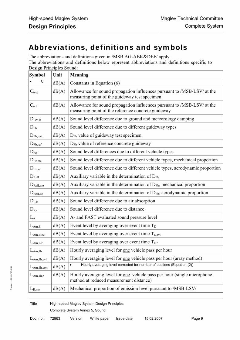
High-speed Maglev System
Design Principles Maglev Technical Committee
Complete System
Title High-speed Maglev System Design Principles
Complete System Annex 5, Sound
Doc. no.: 72963 Version White paper Issue date 15.02.2007 Page 9
Prin
tout
: 13.
09.2
007
10:4
2:00
Abbreviations, definitions and symbols The abbreviations and definitions given in /MSB AG-ABK&DEF/ apply. The abbreviations and definitions below represent abbreviations and definitions specific to Design Principles Sound: Symbol Unit Meaning • C dB(A) Constants in Equation (6)
Ctest dB(A) Allowance for sound propagation influences pursuant to /MSB-LSV/ at the measuring point of the guideway test specimen
Cref dB(A) Allowance for sound propagation influences pursuant to /MSB-LSV/ at the measuring point of the reference concrete guideway
DBM,k dB(A) Sound level difference due to ground and meteorology damping
DFb dB(A) Sound level difference due to different guideway types
DFb,test dB(A) DFb value of guideway test specimen
DFb,ref dB(A) DFb value of reference concrete guideway
DFz dB(A) Sound level differences due to different vehicle types
DFz,me dB(A) Sound level difference due to different vehicle types, mechanical proportion
DFz,ae dB(A) Sound level difference due to different vehicle types, aerodynamic proportion
DFzH dB(A) Auxiliary variable in the determination of DFb
DFzH,me dB(A) Auxiliary variable in the determination of DFb, mechanical proportion
DFzH,ae dB(A) Auxiliary variable in the determination of DFb, aerodynamic proportion
DL,k dB(A) Sound level difference due to air absorption
Ds,k dB(A) Sound level difference due to distance
LA dB(A) A- and FAST evaluated sound pressure level
LAm,E dB(A) Event level by averaging over event time TE
LAm,E,evl dB(A) Event level by averaging over event time TE,evl
LAm,E,r dB(A) Event level by averaging over event time TE,r
LAm,1h dB(A) Hourly averaging level for one vehicle pass per hour
LAm,1h,evl dB(A) Hourly averaging level for one vehicle pass per hour (array method)
LAm,1h,corr dB(A) • Hourly averaging level corrected for number of sections (Equation (2))
LAm,1h,r dB(A) Hourly averaging level for one vehicle pass per hour (single microphone method at reduced measurement distance)
LE,me dB(A) Mechanical proportion of emission level pursuant to /MSB-LSV/

High-speed Maglev System
Design Principles Maglev Technical Committee
Complete System
Title High-speed Maglev System Design Principles
Complete System Annex 5, Sound
Doc. no.: 72963 Version White paper Issue date 15.02.2007 Page 10
Prin
tout
: 13.
09.2
007
10:4
2:00
Symbol Unit Meaning
LE,ae dB(A) Aerodynamic proportion of emission level pursuant to /MSB-LSV/
Lr dB(A) Total rating sound level pursuant to /MSB-LSV/
∆LAm,1h dB(A) Difference between the hourly averaging level (Equation (5)) taken at the measuring point of the guideway test specimen and at the measuring point of the reference concrete guideway
∆LDiff dB(A) Difference between total rating sound level and corrected hourly averaging level (Equation (4))
∆Lk dB(A) Sum of sound level differences in the part section method according to /MSB-LSV/
∆LSec dB(A) Sound level difference due to number of vehicle sections
a, b, c - Coefficients of a second grade equalising polynomial (Equation (3))
k - Running index in the part section method according to /MSB-LSV/
l m Length of vehicle from nose tip to rear end
lk m Part section length
p Pa Sound pressure
R m Radius of route
S dB(A) Correction level to allow for special features of lines
t s Time
t1 s Time at start of averaging time TE
t1,evl s Time at start of averaging time TE,evl (array method)
t1,r s Time at start of averaging time TE,r (single microphone method at reduced measuring distance)
t2 s Time at end of averaging time TE
t2,evl s Time at end of averaging time TE,evl (array method)
t2,r s Time at end of averaging time TE,r (single microphone method at reduced measuring distance)
TE s Averaging time for the event level
TE,evl s Averaging time for the event level (array method)
TE,r s Averaging time for the event level (single microphone method at reduced measuring distance)
TM s Measuring time
v km/h Vehicle velocity

High-speed Maglev System
Design Principles Maglev Technical Committee
Complete System
Title High-speed Maglev System Design Principles
Complete System Annex 5, Sound
Doc. no.: 72963 Version White paper Issue date 15.02.2007 Page 11
Prin
tout
: 13.
09.2
007
10:4
2:00
Symbol Unit Meaning
v0 km/h Reference velocity (v0 = 100 km/h)
•
Term/
Abbreviation
Meaning
Emission location Top guideway edge at guideway support centre in the measurement cross-section according to /MSB-LSV/
Immission locati-on
Location of a microphone or microphone array
Short laid length Guideway test specimen of laid length > 24 m and < 250 m
Maximum sound level
Maximum sound level in time behaviour LA(t) during passage of the vehicle
Measuring point Immediate surroundings within range of emission and immission location
Measurement cross-section
Plane through immission location with guideway as the normal
Section With a vehicle unit assumed at approx. 25 m in length
TGE Top guideway edge
TETF Transrapid Emsland Test Facility
Acts, Orders, Standards and Directives The normative documents listed in /MSB AG-NORM&RILI/ contain stipulations which be-come part of the High-speed Maglev System Design Principles by virtue of reference in the High-speed Maglev System Implementation Bases. When normative documents in /MSB AG-NORM&RILI/ are dated, later amendments or revisions of these publications do not apply. When references are undated, the most recent issue of the normative document referred to is applicable. The issue date of the Standards and Directives to be taken into account in a maglev project shall be fixed with binding force for that specific project. The abbreviations and definitions below represent specific abbreviations and definitions of Design Principles Sound: In this document particular reference is made to the Orders and Standards listed below. Abbreviation Orders and Standards
/MbBO/ High-speed Maglev System – Construction and Operating Regulations [Magnetschwebebahn – Bau- und Betriebsordnung – MbBO] (Article 1 of the Maglev Construction and Operating Regulations)
/MSB-LSV/ Maglev System – Noise Abatement Order [Magnetschwebebahn – Lärm-schutzverordnung]

High-speed Maglev System
Design Principles Maglev Technical Committee
Complete System
Title High-speed Maglev System Design Principles
Complete System Annex 5, Sound
Doc. no.: 72963 Version White paper Issue date 15.02.2007 Page 12
Prin
tout
: 13.
09.2
007
10:4
2:00
(Article 2 of the Maglev Construction and Operating Regulations) • /DIN EN ISO 3095/ Acoustics – Measurement of noise emitted by railbound vehicles
Identification and mandatory requirements In compiling the present document, the regulations conforming to /DIN 820/ were applied by analogy. In the following chapters of this document
• requirements are denoted by regular font
• explanatory notes, guideline values and examples are denoted by italics.

High-speed Maglev System
Design Principles Maglev Technical Committee
Complete System
Title High-speed Maglev System Design Principles
Complete System Annex 5, Sound
Doc. no.: 72963 Version White paper Issue date 15.02.2007 Page 13
Prin
tout
: 13.
09.2
007
10:4
2:00
Compiling a test specification
The contractor selected to take measurements and evaluate data for determination of the DFz sound level differences of a new vehicle and the DFb sound level difference of a guideway test specimen shall submit a test specification to the client. Before measurements are taken, this shall be discussed and agreed with the competent supervisory and licensing authority or with an expert appointed by same. The test specification shall contain the following essential points:
• a statement to the effect that the measurement conditions at the planned measuring points in the area of the reference concrete guideway and of the guideway test specimen conform to the data specified in Chapter 0, particularly as regards the position of the immission lo-cations,
• a statement to the effect that the acoustic condition of the vehicle to be used when taking the measurements meets the requirements stipulated in Chapter 0,
• the submission of a flow chart guaranteeing the number and velocities of the vehicle pas-ses for each measuring point required according to Chapter 0.
• a list of the measurement and data recording equipment anticipated for use, and
• proof of familiarity with the methods of data evaluation and determination of DFz and DFb sound level differences described in Chapter 0 and particularly in Chapter 0.
NB: The intended contractor shall in particular describe the details of his knowledge of the measurement and evaluation methods used (see Chapters 0 and 0) to the Supervisory and Licensing Authority or the appointed expert, a prerequisite being that the contractor has had sufficient practical experience of these methods of measurement.

High-speed Maglev System
Design Principles Maglev Technical Committee
Complete System
Title High-speed Maglev System Design Principles
Complete System Annex 5, Sound
Doc. no.: 72963 Version White paper Issue date 15.02.2007 Page 14
Prin
tout
: 13.
09.2
007
10:4
2:00
Taking measurements
In the measurements described in this chapter to determine DFz sound level differences, i.e. of DFz,me and DFz,ae, and of DFb sound level differences, there shall be compliance with the gene-ral terms of reference in Chapter 0. The following two chapters give further measurement conditions relating solely to the determination of DFz sound level differences (Chapter 0) and the determination of the DFb sound level difference (Chapter 0). Here the DFb value of a gui-deway test specimen shall in principle be determined at only one measuring point at which the line comprises a “long” extension of the test specimen guideway type (see Chapter 0). Should this exceptionally be impossible since, as a prototype carrier, the guideway test specimen only has a “short” laid length of typically between 25 and 60 m, DFb shall be determined by means of a single microphone method at a reduced measuring distance and by means of a method using a microphone array. The special measurement conditions in this regard are described in Chapter 0. Chapter 0 further gives the points required for all the measurement methods within the measurement documentation framework.
General measurement terms of reference When taking measurements on vehicles and guideways the following requirements, based on /DIN EN ISO 3095/, shall be met for proof of sound emission. The general terms of reference for measurements comprise requirements for measurement and immission location, the vehic-les and their passes, the velocity classification and number of same, the weather conditions, and data relating to measurement quantity and measuring equipment.
Requirements for measurement and immission locations The terrain at the measuring location shall be open and level, at least on the side of the route on which sound immission is measured. As little reflection as possible shall be ensured on the away-facing side. There should be arable land and/or meadows in the area between guideway and immission location; low growth is permissible. Sound propagation, interfering obstacles and unacceptable reflecting surfaces are not permitted in the surroundings of the immission location on the route side of the measurement for up to three times the measuring distance. The measuring locations used shall only be sections in which the route runs straight (R > 10.000 m). Guideway banking of ≤ 2° is permitted. In the area of the measuring location the guideway must be constructed from the identical guideway type over a “long” extension. A “long” extension means that the same guideway type is present for at least 125 m on either side of the measurement cross-section. The measuring location shall be selected so that the background noise can be ignored during all vehicle passes. For this the A- and FAST-rated sound pressure level caused by interfering sound sources shall be at least 15 dB(A) below the maximum sound level measured during a pass and also the third-octave levels relevant to the maximum level shall be at least 15 dB(A) above those of the background noise. Should it be impossible to comply with the requisite sound level difference of 15 dB(A) due to an unforeseen sound event (e.g. overflying aircraft) during an individual pass, the measurement in question shall be discarded and the pass repea-ted as a matter of principle.

High-speed Maglev System
Design Principles Maglev Technical Committee
Complete System
Title High-speed Maglev System Design Principles
Complete System Annex 5, Sound
Doc. no.: 72963 Version White paper Issue date 15.02.2007 Page 15
Prin
tout
: 13.
09.2
007
10:4
2:00
Where the guideway to be tested is of the “long” extension type, the measurement cross-
section shall without exception be located centrally between two adjacent supports. The
measurement distance between guideway support centre and immission location projected
vertically to the ground in the measurement cross-section shall be 25 m.
The height of the immission location shall be:
• 3.5 m above ground at TGE heights of up to 7.0 m above ground,
• 3.5 m below TGE at TGE heights over 7.0 m above ground.
Requirements for vehicles and their passes When taking measurements to determine the DFz sound level differences, the vehicle shall be in the acoustic condition corresponding to the operational application, or for which the DFz sound level differences pursuant to /MSB-LSV/ are to be determined. As part of the determi-nation of the DFb sound level difference the vehicle may also have a different acoustic condi-tion during measurement, as prior to determining DFb’ the DFzH auxiliary variables (see Chap-ter 0) of the current vehicle must he measured and then used. The vehicle length and number of sections during the measurements described here are optional. NB: Corrections in respect of number of sections are allowed for in the DFz determination in Chapter 0. In all the measurements taken here the requirement is for passes at a constant velocity, in each case in the range of 125 m plus half the vehicle length on either side of the measurement cross-section. As previous experience has shown that the direction of travel, the section actu-ally in front, the facing side of the vehicle and the loading condition of the vehicle have no influence on the sound pressure level measured at the immission location, runs in different directions and at different loadings may be used when determining DFz and DFb. However, a record shall be made of the direction of travel, the forward section, the facing side of the ve-hicle and the loading. With new vehicles a test shall be conducted (e.g. using design documentation and/or measu-rements) to determine whether their sound emission is the same on both sides of the vehicle. Where emissions differ according to vehicle side, the DFz values of the vehicle shall be deter-mined for the side of the vehicle with the higher sound emission. When emissions differ ac-cording to vehicle side, the auxiliary variable DFzH pursuant to Chapter 0 and the DFb value of the guideway shall always be determined on the same side of the vehicle.
Velocity rating and number of passes Each of the velocity ranges required to determine DFz and DFb sound level differences is gi-ven in Chapters 0 and 0. In every case, however, pass velocities shall be graduated in steps of 10 km/h. At least two runs shall be measured for each velocity step. At least three measure-ments shall be taken at maximum velocity.

High-speed Maglev System
Design Principles Maglev Technical Committee
Complete System
Title High-speed Maglev System Design Principles
Complete System Annex 5, Sound
Doc. no.: 72963 Version White paper Issue date 15.02.2007 Page 16
Prin
tout
: 13.
09.2
007
10:4
2:00
Weather requirements Wind speeds for immission location measurements shall not exceed 5 m/s. There shall be no snow on the ground within the measuring point area. No measurements shall be taken when it is raining.
Measurement variable and measuring equipment The measurement variable is the sound pressure p at the immission location. In each case the measurement variable shall be recorded either as the time curve of the sound pressure p(t) or as the time curve of the A- and FAST-rated sound pressure level LA(t) over a sufficient mea-surement period TM. Measurement commences when the noise of passage starts to be clearly distinguishable from the background noise, and ends when the noise of passage is once again masked by the background noise. The p(t) and LA(t) time curves obtained for the individual vehicle passes shall be evaluated as specified in Chapter 0. The requirements for measuring equipment and the calibration thereof shall be those specified in /DIN EN ISO 3095/. The entire equipment chain and the sound level meter shall be calibra-ted on each measuring day before and after measurement. If the equipment chain is modified, fresh calibrations shall be carried out before and after the modification. The calibration signals shall be stored and the calibration process logged.
Additional measurement conditions for the determination of DFz
When taking measurements to determine the DFz sound level differences, the following mea-surement conditions shall be met in addition to the general requirements for measurements stipulated in Chapter 0:
• The vehicle passes shall be measured at a measuring location at which the route comprises the reference concrete guideway of construction phase 1 or 2 of the TETF, i.e. construc-ted prior to 1989. A DFb value of 0 dB(A) is set for this type of guideway in /MSB-LSV/.
• Passes in the velocity range from 130 to at least 400 km/h shall be measured, i.e. subject to the criteria of Chapter 0 the number of runs shall be at least 57.
Additional measurement conditions for the determination of DFb
The following measurement conditions shall be met in addition to the general requirements for measurements in accordance with Chapter 0 when taking measurements to determine the DFb sound level difference:
• It is permissible to give the DFb value of a guideway type for limited velocity ranges, na-mely up to and including 300 km/h, from > 300 km/h up to and including 400 km/h and

High-speed Maglev System
Design Principles Maglev Technical Committee
Complete System
Title High-speed Maglev System Design Principles
Complete System Annex 5, Sound
Doc. no.: 72963 Version White paper Issue date 15.02.2007 Page 17
Prin
tout
: 13.
09.2
007
10:4
2:00
from > 400 km/h up to the maximum authorised guideway velocity. Passes on the guide-way test specimen may therefore only be required in commensurately restricted velocity ranges. Hence from case to case the velocity range in the measurements for the determina-tion of DFb may extend from 130 to 300 km/h, from 130 to 400 km/h or up to the maxi-mum authorised velocity for the guideway. The relevant minimum numbers of passes are obtained according to Chapter 0.
• Determination of the DFb value assumes knowledge of the DFzH, i.e. DFzH,me and DFzH,ae auxiliary variables of the vehicle which carried out the passes on the guideway test speci-men. The DFzH values may actually be calculated from this vehicle’s existing measurement data taken during the measurement of passes on the reference concrete guideway, but they should preferably be determined by a new measurement taken just beforehand with this vehicle on the reference concrete guideway (cf. Chapter 0). If relevant modifications were carried out on the vehicle since the last sound emission measurement, the DFzH auxiliary variables shall be re-determined. When determining DFb, DFzH values shall refer to the ve-locity range of up to at least 400 km/h, irrespective of any restricted velocity range.
Additional measurement conditions when determining DFb on short laid lengths of guideway test specimen
With a guideway test specimen of “short” laid length, the DFb value shall be determined by means of the single microphone method at a reduced measuring distance and by means of the array method, the stipulation being to take these measurements by both methods simultane-ously. There should be a slight deviation from the requirement that the measurement cross-section be located exactly centrally between two adjacent supports if there is a reflecting object centrally between the supports.
Measurement method with single microphones at a re-duced measuring distance
When taking measurements with a single microphone on a “short” laid length of guideway test specimen, the measuring distance shall be reduced in order to minimise the influence of adjacent guideways of a different type; the measuring distance between the centre of the gui-deway support and immission location in the measurement cross-section projected vertically to the ground shall be 12.5 m if the laid length of the test specimen is ≥ 49 m and < 250 m, and 6.5 m if the test specimen length is > 24 m and < 49 m. Furthermore, allowance shall be made for the vertical directional characteristic of guideway and vehicle by means of simulta-neous measurement at the required distance at two immission locations of different height, so that two sound pressure signals p(t) and two sound level patterns LA(t) must be recorded. The heights of the immission locations shall be fixed as follows:
• the top immission location is at TGE level,

High-speed Maglev System
Design Principles Maglev Technical Committee
Complete System
Title High-speed Maglev System Design Principles
Complete System Annex 5, Sound
Doc. no.: 72963 Version White paper Issue date 15.02.2007 Page 18
Prin
tout
: 13.
09.2
007
10:4
2:00
• the bottom immission location is 3.5 m below TGE, but at least 1.0 m above ground.
Due to the “short” laid length of the guideway test specimen, the minimum range of the vehic-le’s constant pass velocity is reduced to the actual length of the test specimen plus half the vehicle length before and after the test specimen. As the determination of the DFb value in Chapter 0 is based on a comparative measurement at the reference concrete guideway, the measurements at the most recent measuring location must be taken at the same reduced measuring distance as at the guideway test specimen, at two immission heights corresponding to the TGE height of the reference concrete guideway. NB: During passage of the vehicle, particularly at high velocities, instantaneous pressure fluctuations occur at the nose and rear end area of the vehicle; these may produce signal saturation at immission locations 6.5 m away, so for this measuring distance it is recommended that if necessary a high-pass filter with a limit frequency of approx. 20 Hz be inserted at the signal amplifica-tion input.
Measurement method with a microphone array To determine the DFb value of a guideway test specimen with a “short” laid length, a measu-rement method with a microphone array is specified in addition to the method described in Chapter 0. The array method serves to measure the DFb value of the immission location at a distance of 25 m from the guideway support centre, i.e. at
• a height of 3.5 m above ground for TGE levels of up to 7.0 m above ground and
• a height of 3.5 m below TGE for TGE levels above 7.0 m above ground.
During measurement a linear, hence one-dimensional, array in horizontal and parallel orienta-tion to the guideway is used, the central microphone of which is located in the measurement cross-section. While the sound emissions of adjacent guideways of different design are cut out by the strong horizontal directivity of this array, such an array has the characteristics of a sin-gle microphone in the vertical direction, i.e. influences on the immission level are correctly reproduced during measurement due to the vertical directional characteristic of guideway and vehicle as well as due to ground reflection. Lateral, and hence unwanted, portions of sound are sufficiently reduced by the array on recep-tion if, when straight focussing centrally between two supports, the array resolution and the width of the array main lobe in the object plane is a maximum of 5 m at a distance of 25 m. Furthermore, with such a resolution for the suppression of the emissions of adjacent carriers, a distance between the array main lobe and the secondary lobes, i.e. an array dynamic of at least 10 dB is required, as is obtained by a linear array even without shading. As the resolution of an array depends greatly on the frequency, and the main lobe width
when straight focussing in the whole frequency range evaluated should deviate by no more
than ±20 % relative to a mean value, the array configuration used here is a “box array”, i.e.
an array in which there are a number of sub-arrays. Each sub-array is designed for a definite

High-speed Maglev System
Design Principles Maglev Technical Committee
Complete System
Title High-speed Maglev System Design Principles
Complete System Annex 5, Sound
Doc. no.: 72963 Version White paper Issue date 15.02.2007 Page 19
Prin
tout
: 13.
09.2
007
10:4
2:00
frequency range, each of which has a mean resolution of 4 m in the object plane at a dis-
tance of 25 m.
Here the use of the array described below, the “WH10x array”, is mandatory as the implemen-tation of an array satisfying the above requirements. By multiple use its total 27 microphones are split into groups for 10 sub-arrays. Each sub-array comprises seven microphones, only the sub-array with the smallest microphone distance of 4 cm comprises nine microphones. Table 3 lists the microphone positions in the WH10x-Array, with microphone number 14 re-presenting the array centre.
Microphone number Position [m] Microphone number Position [m] 1 3.52 15 -0.04 2 2.56 16 -0.08 3 1.92 17 -0.12 4 1.28 18 -0.16 5 0.96 19 -0.24 6 0.64 20 -0.32
7 0.48 21 -0.48 8 0.32 22 -0.64 9 0.24 23 -0.96
10 0.16 24 -1.28 11 0.12 25 -1.92 12 0.08 26 -2.56 13 0.04 27 -3.52 14 0 - -
• Table 0-1: Microphone positions in the WH10x array
As in measurements with single microphones, the requirements formulated in Chapter 0 apply to the array microphones and their calibration. Because of the limited frequency range in array measurements (125 to 8000 Hz in the WH10x array, see Chapter 0), the criteria in respect of constancy and consistency of the amplitude and phase characteristics of the individual array microphones must only be met in this limited frequency range. Owing to the simultaneous signal detection of the 27 microphones in the WH10x array and at least one further time signal which, due to a trigger mechanism (e.g. by means of a light bar-rier), receives information on the vehicle position relative to the time signals of the array mic-rophones and on vehicle velocity, at least a 28-channel, i.e. usually a 32-channel data acquisi-tion system shall be used when taking measurements. At a minimum sampling frequency of 25 kHz per channel, required because of array technology, the storage capacity of the data acquisition systems shall be designed to allow the continuous recording of signals over a time span of up to 15 s. The deep pass filters required for each channel in A/D conversion shall be designed at least as 2nd order filters with a limit frequency corresponding to the sampling frequency selected. The data acquisition system must allow the recorded signals to be checked immediately after
each measurement, i.e. vehicle pass (monitoring saturation, interference, adequate vehicle
pass lead time and wake time, etc.), so that the doubtful pass can be repeated if necessary.

High-speed Maglev System
Design Principles Maglev Technical Committee
Complete System
Title High-speed Maglev System Design Principles
Complete System Annex 5, Sound
Doc. no.: 72963 Version White paper Issue date 15.02.2007 Page 20
Prin
tout
: 13.
09.2
007
10:4
2:00
The data loss of at most one channel or microphone during recording can be tolerated, as
long as it is not microphone number 14 or the channel with the trigger signal.
As in the measurement procedure in Chapter 0, the array measurement shall also be carried out both at the measuring location with the guideway test specimen and at the measuring loca-tion with the reference concrete guideway, as the comparative data are needed for the deter-mination of DFb according to Chapter 0.
Documentation of measurement procedure The measurement procedure shall be logged in the measurement report. This shall describe at least the following:
• the purpose of the measurements,
• the measuring location with its acoustically relevant boundary conditions (on both si-des of the route),
• the guideway type and its TGE height above ground in the measurement cross-section as well as the extension of this guideway type on either side of the measurement cross-section,
• the position of the immission location(s) with regard to distance from the guideway support centre as well as the height(s) of the immission location(s) above ground,
• the vehicle, its number of sections and length, its loading condition and, if necessary, data on acoustically-relevant modifications,
• the chronological sequence of measurements and passes, giving the vehicle velocity, direction of travel, the lead section, the facing side of the vehicle, the loading and any problems which may have occurred,
• the meteorological data during individual vehicle passes (temperature, air pressure, atmospheric humidity, wind speed and direction), and
• the measuring equipment used, i.e. the equipment chain from microphones to data re-cording equipment or sound level meters, giving details of calibration and calibration times.
Further documentation requirements relating to data evaluation are given in Chapter 0 and to the determination of DFz and DFb in Chapter 0.

High-speed Maglev System
Design Principles Maglev Technical Committee
Complete System
Title High-speed Maglev System Design Principles
Complete System Annex 5, Sound
Doc. no.: 72963 Version White paper Issue date 15.02.2007 Page 21
Prin
tout
: 13.
09.2
007
10:4
2:00
Evaluation of measurement data
After taking the measurements in accordance with Chapter 0, analog or digitally stored time signals of the sound pressure p(t) or time curves of the sound pressure level LA(t) over a suffi-cient measuring time TM in each case (see Chapter 0) are available for the determination of both the DFz sound level differences and the DFb sound level difference for specific numbers of vehicle passes in each case. The evaluation of these measurement data is described in the present chapter.
Calculation of hourly averaging level The hourly averaging level LAm,1h shall be calculated for each pass measured and for each immission location. First the event level LAm,E is calculated by averaging LA(t) over the ave-raging time TE. Here TE = t2 - t1 is the “event time”, which begins relative to a vehicle pass at time t1, when the level LA during the vehicle’s approach is for the first time 15 dB(A) below the maximum level during the vehicle’s passage, and ends at time t2, when after the vehicle’s passage the level LA has for the last time faded by 15 dB(A) relative to the maximum level. Figure 40 shows the measuring time TM and the event time TE with times t1 and t2 using the example of a typical sound level curve LA(t) during the passage of a vehicle.
Messzeit TM
Maximalpegel
15 dB
(A)
Ereigniszeit TE
Sch
alld
ruck
peg
el [
dB
(A)]
t1 t2 Zeit [s]
• Figure 40: Explanation of measuring time TM and event time TE
• Schalldruckpegel = sound pressure level; Maximalpegel = maximum level; Ereigniszeit = event time; Messzeit = measuring time; Zeit = time

High-speed Maglev System
Design Principles Maglev Technical Committee
Complete System
Title High-speed Maglev System Design Principles
Complete System Annex 5, Sound
Doc. no.: 72963 Version White paper Issue date 15.02.2007 Page 22
Prin
tout
: 13.
09.2
007
10:4
2:00
The hourly averaging level follows from the event level LAm,E by adding the term 10lg(TE/3600 s), the result being mathematically rounded to one decimal place. The hourly averaging levels LAm,1h thus calculated for one pass per hour in each case constitute the basis for determination of the DFz and DFb sound level differences in Chapter 0.
Additional terms of reference for evalua-tions with short laid lengths of guideway test specimen
Separate terms of reference shall be observed with regard to evaluation of the sound pressure signals p(t) or sound level patterns LA(t) recorded by the measurement method using single microphones at a reduced measuring distance according to Chapter 0 and by the array method according to Chapter 0, as described in the following two chapters.
Data evaluation in the measuring method with single mi-crophones at a reduced measuring distance
In the present measuring method the hourly averaging level LAm,1h is calculated in principle as described in Chapter 0, but a reduced event time TE,r = t2,r - t1,r is introduced. Here t1,r is the time at which the vehicle nose reaches the guideway test specimen, and t2,r the time at which the rear end of the vehicle leaves the guideway test specimen. This definition of times t1,r and t2,r ensures that during the event time at least one part of the vehicle is travelling over the gui-deway test specimen. By averaging over the time TE,r, first the event level LAm,E,r is calculated, then the hourly averaging level LAm,1h,r by adding the term 10lg(TE,r /3600 s) and mathematical rounding to one decimal place. The hourly averaging level LAm,1h,r for the top and bottom immission location shall be given for each vehicle pass. For reasons of comparability, the hourly averaging levels at the measu-ring location shall be determined with the reference concrete guideway under the same geo-metric conditions as with measurement at the guideway test specimen, i.e. the extension of the reference concrete guideway on either side of the measurement cross-section shall be assumed to be identical with the extension of the guideway test specimen on either side of the measu-rement cross-section. From this it follows that the difference t2,r - t1,r and therefore the event time TE,r are the same at both measuring locations. The hourly averaging levels LAm,1h,r thus calculated at the reference concrete guideway and the guideway test specimen are the input variables for the determination of DFb in Chapters 0 and 0.
Data evaluation in the array measurement method The recorded signals of the 27 microphones in the WH10x array shall be evaluated separately without using shading factors by means of the “delay-and-sum beam forming” algorithm (see I.E. Johnson and D. E. Dudgeon, Array Signal Processing: Concepts and Techniques, P T R Prentice Hall, 1993) in the time range for each of the 10 sub-arrays. Table 0-1 shows the as-signment of individual microphones to the sub-arrays. When calculating the composite array signals, the requisite sampled values of the microphone signals shall be generated by linear

High-speed Maglev System
Design Principles Maglev Technical Committee
Complete System
Title High-speed Maglev System Design Principles
Complete System Annex 5, Sound
Doc. no.: 72963 Version White paper Issue date 15.02.2007 Page 23
Prin
tout
: 13.
09.2
007
10:4
2:00
interpolation of the real time signal sample values. The results of beam forming in the indivi-dual sub-arrays apply to the frequency ranges listed in Table 0-1. The WH10x array conse-quently accounts for the total frequency range of 125 to 8000 Hz sufficient for the determina-tion of DFb .
Sub-array Contains microphones numbered Frequency range [Hz] WH128 1, 2, 4, 14, 24, 26, 27 125 - 250 WH096 2, 3, 5, 14, 23, 25, 26 250 - 355 WH064 3, 4, 6, 14, 22, 24, 25 355 - 500 WH048 4, 5, 7, 14, 21, 23, 24 500 - 710 WH032 5, 6, 8, 14, 20, 22, 23 710 - 1000 WH024 6, 7, 9, 14, 19, 21, 22 1000 - 1410 WH016 7, 8, 10, 14, 18, 20, 21 1410 - 2000 WH012 8, 9, 11, 14, 17, 19, 20 2000 - 2820 WH008 9, 10, 12, 14, 16, 18, 19 2820 - 4000 WH004 10, 11, 12, 13, 14, 15, 16, 17, 18 4000 - 8000
• Table 0-1: Sub-arrays of the WH10x array with associated microphones and frequency ranges
The evaluation mode chosen during beam forming shall be a fixed focus with vertical a-lignment to the line of microphones. Here – in accordance with the positioning of the array during measurements – the focal point shall be 25 m from the array. Data evaluation shall be carried out at each sub-array for measuring and focal points at 1.0 m intervals along the pas-sing vehicle, i.e. at time intervals corresponding to the progression of the vehicle by 1.0 m at the current vehicle velocity. At each of these measuring points the composite array signal shall again be averaged over a time which equals the progression of the vehicle by 5.0 m. Data evaluation shall commence approx. 100 m in front of the vehicle nose and finish approx.
100 m behind the end of the vehicle. The trigger signal recorded at the same time serves to
link the vehicle position with the sound pressure signals.
The sound level patterns thus calculated and also A-rated for each sub-array in the part fre-quency ranges of Table 0-1 shall then be energetically totalled, thus giving the time curve of the sound pressure level in the 125 to 8000 Hz frequency range measured by the WH10x array for the relevant vehicle pass. In the array method the determination of the associated event level is linked to the “extended vehicle length” “(evl)”, i.e. with the length of the vehicle ex-tended by 24.0 m: the event time TE,evl commences at time t1,evl, at which the nose of the ve-hicle is still 12.0 m in front of the measurement cross-section, and finishes at time t2,evl, at which, once the vehicle has passed, its rear end is 12.0 m away from the measurement cross-section. By averaging over the event time TE,evl = t2,evl - t1,evl first the event level LAm,E,evl, then the hourly averaging level LAm,1h,evl is calculated by adding 10lg(TE,evl /3600 s) and mathema-tical rounding to one decimal place. The method of data evaluation thus described shall be applied equally to the measurements at the vehicle test specimen as well as at the reference concrete guideway. The relevant hourly averaging levels LAm,1h,evl are the input variables for the determination of DFb in Chapters 0 and 0.

High-speed Maglev System
Design Principles Maglev Technical Committee
Complete System
Title High-speed Maglev System Design Principles
Complete System Annex 5, Sound
Doc. no.: 72963 Version White paper Issue date 15.02.2007 Page 24
Prin
tout
: 13.
09.2
007
10:4
2:00
Documentation for measurement data evaluation
The results of the measurement data evaluation carried out in accordance with Chapters 0 and 0 shall be fully documented in tabular form in the measurement report, i.e. for each measured pass and for each immission location the vehicle velocity, the event time TE (and TE,r or TE,evl), the event level LAm,E (and LAm,E,r or LAm,E,evl) and the hourly averaging level LAm,1h (and LAm,1h,r or LAm,1h,evl) shall be given, the vehicle velocity being the velocity notified for the measuring point by the operator of the maglev section. Results of passes in which the calcula-ted levels appear doubtful owing to an obvious measuring error shall still be listed in the table, but shall be highlighted. However they shall not be taken into account when determining DFz and. DFb in Chapter 0. The causes of the measuring error shall be described. In addition to the above documentation of the measurement results in tabular form, the curves LA(t) for all the passes and for each immission location shall be represented in graph form over the measuring period TM. In this sound level recording the times t1 and t1,r , t2 and t2,r shall be identified for calculation of the event level. When measurements are made with the microphone array, the time curves of the composite array signal calculated according to Chap-ter 0 with the times t1,evl and t2,evl shall be logged as sound level recording LA(t). The represen-tation of the most recent sound level recording may be restricted to the area approx. 100 m in front of the nose of the vehicle to approx. 100 m behind the end of the vehicle instead of the measuring time TM. Furthermore, sound pressure third-octave spectra shall be compiled in absolute levels from the 25 Hz third-octave centre frequency to the 10 kHz third-octave centre frequency – but in the array method only for the third octaves from 160 to 6300 Hz. For this the evaluation of each run at 150, 200, 250, 300 and, depending upon the requisite velocity range, 350 and 400 km/h is sufficient. For the third-octave spectra the time signal p(t) – in the array method the compo-site signal of the time signals p(t) of the array microphones – shall be evaluated over the event time of the relevant pass. The representation of unrated or A-rated third-octave spectra is permissible; the corresponding choice shall be made clear in the ordinate labelling. Each third-octave spectrum must, moreover, give the “linear”, i.e. unrated and A-rated total sound level as the energetic sum of the aforementioned third-octave levels.

High-speed Maglev System
Design Principles Maglev Technical Committee
Complete System
Title High-speed Maglev System Design Principles
Complete System Annex 5, Sound
Doc. no.: 72963 Version White paper Issue date 15.02.2007 Page 25
Prin
tout
: 13.
09.2
007
10:4
2:00
Determination of DFz and DFb sound level differences
The LAm,1h hourly averaging levels for the individual vehicle passes calculated according to Chapter 0 are the basis for determining DFz sound level differences, i.e. DFz,me and DFz,ae desc-ribed below, as well as the DFb sound level difference.
Determination of DFz,me and DFz,ae values To determine DFz,me and DFz,ae values only the measurement results for the passes on the refe-rence concrete guideway according to Chapter 0 shall be used under the measurement condi-tions also given in this chapter. As, according to Chapter 0, the length of the vehicle and its number of sections is optional in measurements to determine DFz, with reference to the mea-sured hourly averaging levels LAm,1h this means a necessary correction by values ∆LSec, which depend on the number of sections and the vehicle velocity and are given below for 2- to 10-section vehicles. NB: The compilation of /MSB-LSV/ was based on measured immission levels from passes of the TR 07/1 comprising two sections. Values for multiple-section vehicles were predicted with the aid of model calculations based on a sound source location on the TR 07/1. These predic-ted values were used as substitutes for the missing measurements for multi-section vehicles and used to compile the formulae (2.1) and (2.2) in /MSB-LSV/ for taking the vehicle length into consideration. Within this method the immission levels during the measurement and mo-del calculations were below the arithmetic values then laid down in /MSB-LSV/ (by up to 1.2 dB(A) for a 2-section vehicle and by up to 2.1 dB(A) for a 4-section vehicle). These diffe-rences were accepted as a conservative assessment and are reflected in the∆LSec correction values. The ∆LSec values for correction of the measured LAm,1h hourly averaging levels are given by Equations (1a-1i), and in the calculation below shall be mathematically rounded to two deci-mal places: ∆LSec(2 sections,v) = -2.7 + 16.5 ⋅ lg(v/v0) – 17.9 ⋅ (lg(v/v0))2 [dB(A)], (1a) ∆LSec(3 sections,v) = -2.5 + 17.5 ⋅ lg(v/v0) – 18.7 ⋅ (lg(v/v0))2 [dB(A)], (1b) ∆LSec(4 sections,v) = -2.4 + 18.4 ⋅ lg(v/v0) – 19.6 ⋅ (lg(v/v0))2 [dB(A)], (1c) ∆LSec(5 sections,v) = -2.4 + 19.0 ⋅ lg(v/v0) – 19.5 ⋅ (lg(v/v0))2 [dB(A)], (1d) ∆LSec(6 sections,v) = -2.4 + 19.5 ⋅ lg(v/v0) – 19.4 ⋅ (lg(v/v0))2 [dB(A)], (1e) ∆LSec(7 sections,v) = -2.4 + 19.4 ⋅ lg(v/v0) – 18.7 ⋅ (lg(v/v0))2 [dB(A)], (1f) ∆LSec(8 sections,v) = -2.3 + 19.3 ⋅ lg(v/v0) – 18.0 ⋅ (lg(v/v0))2 [dB(A)], (1g) ∆LSec(9 sections,v) = -2.3 + 18.9 ⋅ lg(v/v0) – 17.0 ⋅ (lg(v/v0))2 [dB(A)], (1h) ∆LSec(10 sections,v) = -2.2 + 18.5 ⋅ lg(v/v0) – 16.0 ⋅ (lg(v/v0))2 [dB(A)]. (1i)
• Equations (1a-1i)
NB: Equations (1a-1i) are based on a section length of approx. 25 m. Should the section length deviate substantially from this, the equation for the nearest vehicle length shall be u-sed. Accordingly the corrected LAm,1h,corr hourly averaging levels for the measured passes at the relevant velocity v with ∆LSec for the number of sections during measurement are LAm,1h,corr = LAm,1h + ∆LSec [dB(A)]. (2)

High-speed Maglev System
Design Principles Maglev Technical Committee
Complete System
Title High-speed Maglev System Design Principles
Complete System Annex 5, Sound
Doc. no.: 72963 Version White paper Issue date 15.02.2007 Page 26
Prin
tout
: 13.
09.2
007
10:4
2:00
• Equation (2)
The next thing to determine, on the basis of the thus corrected LAm,1h,corr hourly averaging le-vels available in 10 km/h steps from 130 to at least 400 km/h, is an equalising second grade polynomial of the form LAm,1h,corr(v) = a + b ⋅ lg(v/v0) + c ⋅ (lg(v/v0))2 [dB(A)], (3)
• Equation (3)
the coefficients a, b and c being calculated by the smallest error square method and the vehic-le velocities of the individual LAm,1h,corr hourly averaging levels being the velocities given by the operator of the maglev sector. The polynomial LAm,1h,corr(v) is the representative of the measured values in the following. It is basically only valid within the range of the velocities measured. An exception, however, is the velocity range below 170 km/h where, according to the ruling in /MSB-LSV/ sub-section 2.5, the hourly averaging levels shall be set to the value at 170 km/h. Furthermore, in cases where LAm,1h,corr hourly averaging levels above the pass measured at the highest velocity are required, these may be extrapolated by using the polyno-mial up to velocities which are no more than 5 % higher than the highest measured velocity. Determination of the values of DFz,me and DFz,ae is carried out as part of the iterative procedure described below. Here the levels of the polynomial LAm,1h,corr(v) are compared with those of the total rating sound level Lr(v) calculated according to /MSB-LSV/. To do this the total ra-ting sound level is calculated as the energetic sum of the mechanical and aerodynamic rating sound level for different combinations of DFz,me and DFz,ae for the period of one hour for one pass in this time by means of the part-section method for the geometric situation when taking the measurement at the reference concrete guideway. Here part sections over a length of at least 500 m on both sides of the measurement cross-section shall be included. When calcula-ting the rating sound level, the correction level S allowing for the special features of railways (see /MSB-LSV/) shall be ignored. The iteration method comprises the following part steps:
1) Calculation of the total rating sound level Lr(v) for a combination of DFz,me and DFz,ae values,
2) Calculation of the sound level differences ∆LDiff(v) between the calculated total rating sound level Lr(v) and the polynomial LAm,1h,corr(v) in the velocity range of 170 km/h to at least 400 km/h in steps of 1 km/h according to ∆LDiff(v) = Lr(v) - LAm,1h,corr(v) [dB(A)], (4)
• Equation (4)
3) Mathematical rounding of the values of ∆LDiff(v) to one decimal place,
4) Variation of the DFz,me and DFz,ae values in 0.5 dB steps to determine the com-bination of values at which both the following conditions are met:
a) The rounded sound level differences ∆LDiff (v) ≥ 0 for all the velocities between 170 km/h and the highest velocity (at least 400 km/h, see Chapter 0); this con-dition shall be checked at 1 km/h steps to ensure that the predicted total rating

High-speed Maglev System
Design Principles Maglev Technical Committee
Complete System
Title High-speed Maglev System Design Principles
Complete System Annex 5, Sound
Doc. no.: 72963 Version White paper Issue date 15.02.2007 Page 27
Prin
tout
: 13.
09.2
007
10:4
2:00
sound levels always lie above the measured values (represented by the values of the polynomial LAm,1h,corr(v)).
b) In the range from 170 km/h to the highest velocity (at least 400 km/h, see Chapter 0), the sum of the squares of the rounded ∆LDiff(v) sound level diffe-rences is minimal. When calculating this sum the graduation is again 1 km/h.
The combination of DFz values found on completion of step 4 of the iteration process repre-sents the values for DFz,me und DFz,ae sought for a new vehicle.
Determination of the DFb value Determination of the DFb value assumes knowledge of the DFzH auxiliary variables, i.e. of DFzH,me and DFzH,ae, of the vehicle with which the passes on the guideway test specimen were carried out and for which the DFb value is to be determined. Here the DFzH values in principle represent the DFz sound level differences; however they are determined without the ∆LSec cor-rections relating to the number of sections. In general they are based on preliminary measu-rements at the reference concrete guideway taken just prior to the actual measurements at the guideway test specimen. Preliminary measurements and data evaluation for determination of DFzH values The preliminary measurements to determine the DFzH values on the reference concrete guide-way are subject to the requirements given in Chapter 0. Even evaluation of the measurement data does not differ from that for the determination of DFz. The calculation of DFzH,me and DFzH,ae is therefore carried out analogously using the iteration method from Chapter 0. Howe-ver four exceptions should be noted here:
• The LAm,1h hourly averaging levels are not acted upon by the correction values ∆LSec, so that the equalising polynomial from Equation (3) is derived from the values actually measured for the hourly averaging levels.
• The rounding of ∆LDiff (v) in step 3 of the iteration process is omitted.
• In step 4 of the iteration process the variation of the DFzH,me and DFzH,ae values is car-ried out in 0.1 dB steps and
• the condition ∆LDiff (v) ≥ 0 is not applicable.
The combination of DFzH values found on completion of step 4 of the iteration process repre-sents the values sought for DFzH,me and DFzH,ae.

High-speed Maglev System
Design Principles Maglev Technical Committee
Complete System
Title High-speed Maglev System Design Principles
Complete System Annex 5, Sound
Doc. no.: 72963 Version White paper Issue date 15.02.2007 Page 28
Prin
tout
: 13.
09.2
007
10:4
2:00
Determination of DFb value on the basis of DFzH values To determine the DFb value of the guideway test specimen, the differential curve ∆LAm,1h(v) is first created from the LAm,1h,test hourly averaging levels measured at the measuring location with the guideway test specimen and from the LAm,1h,ref sound levels measured at the reference location with the reference concrete guideway in the velocity range common to both measu-ring locations, namely ∆LAm,1h(v) = LAm,1h,test(v) - LAm,1h,ref(v) [dB(A)], (5)
• Equation (5)
where LAm,1h,test(v) and LAm,1h,ref(v) are equalising polynomials to be determined according to Equation (3). The curve path ∆LAm,1h(v) is therefore representative of the sound level diffe-rence determined at the immission location with the guideway test specimen relative to the immission location with the reference concrete guideway subject to the velocity. Knowing the auxiliary variables DFzH,me and DFzH,ae of the current vehicle, i.e. the vehicle with which the passes on the guideway test specimen were carried out, the DFb value of the guideway test specimen, i.e. DFb,test, is calculated using Equation (6):
[dB(A)] )101010lg(10)v(D 10/)LL(10/)LLCL(10/)CL(
testFb,meE,aeE,meE,aeE,Am,1hAm,1h −−+−∆−∆ −+= (6)
• Equation (6)
where LE,me = 40 + DFzH,me + 10lg(l/100 m) + 20lg(v/v0) + DFb,ref [dB(A)], LE,ae = 24 + DFzH,ae + 10lg((0.6⋅l + 40)/100 m) + 60lg(v/v0) [dB(A)], DFb,ref = 0 C = Ctest - Cref [dB(A)],
where ∑ ∆=
k
10/Ltest
testk,10lg10C [dB(A)] (according to the part-section method of
/MSB-LSV/),
∑ ∆=
k
10/Lref
refk,10lg10C [dB(A)] (according to the part-section method of
MSB-LSV/), where ∆Lk,test = 18 + 10lg(lk,test) + Ds,k,test + DL,k,test + DBM,k,test [dB(A)], ∆Lk,ref = 18 + 10lg(lk,ref) + Ds,k,ref + DL,k,ref + DBM,k,ref [dB(A)]. NB: The terms Ctest and Cref allow for different above-ground heights of the guideway top edge and of the immission location at the measuring point of the guideway test specimen and the reference concrete guideway. If the heights of the top guideway edge at both measuring locations are the same, the difference Ctest - Cref is zero, so that term C in Equation (6) is not applicable. Equation (6) applies expressly only to the boundary conditions to be observed during measu-rements under the terms of reference in Chapter 0. It should again be noted that in (6) part-sections over a length of at least 500 m on either side of the measurement cross-section must be included within the framework of the part-section method. The maximum value of DFb,test determined according to Equation (6) in the velocity range from 170 km/h onwards shall be rounded up in 0.5 dB steps. The resultant value represents the sought DFb value of the guideway test specimen. According to Chapter 0 it is permissible to give the DFb value of the guideway test specimen in velocity ranges, namely up to and inc-

High-speed Maglev System
Design Principles Maglev Technical Committee
Complete System
Title High-speed Maglev System Design Principles
Complete System Annex 5, Sound
Doc. no.: 72963 Version White paper Issue date 15.02.2007 Page 29
Prin
tout
: 13.
09.2
007
10:4
2:00
luding 300 km/h, from > 300 km/h up to and including 400 km/h and in the range above that, so the determination of DFb by means of Equation (6) shall if necessary be carried out separa-tely in the individual velocity ranges. The DFb values thus obtainable shall be identified in relation to their scope.
Additional terms of reference for the determina-tion of DFb on short laid lengths of the guide-way test specimen
The greater value determined in each case from the single microphone method at a reduced measuring distance and the array method is set as the DFb value of the guideway test speci-men. This rule applies to the total velocity range from 170 km/h onwards, and also separately for the partial velocity ranges possible according to Chapter 0. The following details should also be noted:
• The determination of DFb by the single microphone method at reduced measuring di-stance is effected in principle as described in Chapter 0. However, for the ∆LAm,1h(v) sound level differences in Equation (5), when calculating the polynomials LAm,1h,test(v) and LAm,1h,ref(v) according to Equation (3), all the LAm,1h,r hourly averaging levels de-termined at one measuring point, i.e. the levels from both immission heights, are inc-luded at the same time. If term C in Equation (6) has to be taken into account due to the different heights of the immission locations at both measuring locations, the height of the immission location for each measuring location required to calculate Ctest and Cref shall be averaged from both immission location heights of each measuring locati-on.
• The determination of DFb by the array method is effected congruently as described in Chapter 0. The LAm,1h,evl hourly averaging levels are used when calculating the poly-nomials LAm,1h,test(v) and LAm,1h,ref(v) according to Equation (3).
NB: By taking into account the hourly averaging levels measured in two immission location heights by the single microphone method, the averaging obtained in the polynomial calculation for each measuring location reduces the errors caused by the vertical directional characteristic of guideway and vehicle.
Documentation for determination of DFz and DFb sound level differences
The documentation relating to the values for DFz,me and DFz,ae for a new vehicle found by the iterative method in Chapter 0 comprises two graphs intended to illustrate the “best” ad-justment of the total rating sound levels calculated according to /MSB-LSV/ to the corrected hourly averaging levels measured at the reference concrete guideway. The first graph shall compare:
• the individual corrected LAm,1h,corr hourly averaging levels,
• the equalising polynomial LAm,1h,corr(v) derived from these values, and

High-speed Maglev System
Design Principles Maglev Technical Committee
Complete System
Title High-speed Maglev System Design Principles
Complete System Annex 5, Sound
Doc. no.: 72963 Version White paper Issue date 15.02.2007 Page 30
Prin
tout
: 13.
09.2
007
10:4
2:00
• the curve of the total rating sound level Lr(v) calculated according to /MSB-LSV/.
Plotted in the second graph is the curve of the ∆LDiff(v) sound level difference according to (4) which led to discontinuation of the iteration process. As part of the determination of the DFb value for the guideway test specimen, a graph is first drawn by analogy with the determination of DFz values in respect of the values for DFzH,me and DFzH,ae resulting from the iteration process according to Chapter 0. This graph shall show
• the individual measured hourly averaging levels LAm,1h,
• the equalising polynomial LAm,1h(v) derived from these values, and
• the curve of the total rating sound level Lr(v) calculated according to /MSB-LSV/ with DFzH,me for DFz,me and DFzH,ae for DFz,ae
for the case of “best” adjustment of the total rating sound level to be calculated and the hourly averaging levels measured. This “best” adjustment shall be illustrated by another graph in which is plotted the curve of the ∆LDiff(v) sound level difference according to (4) which led to discontinuation of the iteration process. Furthermore, the measured values at the guideway test specimen shall be recorded in a graph
• the individual measured LAm,1h,test hourly averaging levels and
• the equalising polynomial LAm,1h,test(v) derived from these values.
To record the DFb value determined by means of Equation (6), two graphs shall be drawn showing
• the measured ∆LAm,1h sound level difference as a function of velocity, and
• the calculated DFb,test values as a function of velocity
in the velocity range from 170 km/h onwards. On the one hand the latter graph illustrates the dependence of the DFb,test values on the velocity of the vehicle, on the other it shows the velo-city at which the maximum value of DFb,test , and hence ultimately the DFb value, of the guide-way test specimen was determined.

High-speed Maglev System
Design Principles Maglev Technical Committee
Complete System
Title High-speed Maglev System Design Principles
Complete System Annex 5, Sound
Doc. no.: 72963 Version White paper Issue date 15.02.2007 Page 31
Prin
tout
: 13.
09.2
007
10:4
2:00
Annex
In this Annex an example is used to illustrate the determination of DFz-, DFzH- and DFb values and the result documentation. Table 0-1 lists hypothetical LAm,1h hourly averaging levels which should have been measured under conditions according to Chapter 0 at the reference concrete guideway and determined according to the terms of reference given in Chapter 0. The present example assumes the following boundary conditions and hypothetical readings:
• single microphone at a distance of 25 m from the guideway support centre
• “long” extension of guideway,
• top guideway edge in the measurement cross-section at a height of 6.7 m above the ground,
• vehicle of 79.2 m in length. v
[km/h] LAm,1h
[dB(A)] v
[km/h] LAm,1h
[dB(A)] v
[km/h] LAm,1h
[dB(A)]
129.9 41.9 229.2 46.6 330.1 53.6
130.0 42.5 230.3 46.8 330.5 53.8
139.9 42.5 240.1 47.4 339.9 54.4
140.1 42.2 240.3 47.9 340.3 54.8
150.1 41.9 249.9 48.2 349.7 55.3
150.4 42.5 250.3 48.5 350.1 55.1
160.0 42.3 260.2 48.8 360.1 55.6
160.1 42.7 260.5 49.2 360.4 55.2
170.1 42.6 269.8 49.7 369.7 56.5
170.4 43.4 270.2 50.3 370.1 56.3
180.1 43.5 280.0 50.2 379.7 56.8
180.2 42.7 280.2 50.5 380.1 56.7
190.1 43.6 289.9 51.2 390.0 57.0
190.3 44.4 290.2 51.5 390.2 57.4
200.1 44.4 300.2 51.9 400.1 58.0
200.3 44.7 300.6 52.3 400.3 57.7
210.2 44.9 310.5 52.3 409.6 58.4
210.4 45.1 310.8 52.6 409.9 58.9
219.8 45.9 319.9 52.8 410.3 58.6
220.2 45.5 320.1 53.1 - -
• Table 0-1: Hourly averaging levels hypothetically determined at the measuring location with the reference concrete guideway

High-speed Maglev System
Design Principles Maglev Technical Committee
Complete System
Title High-speed Maglev System Design Principles
Complete System Annex 5, Sound
Doc. no.: 72963 Version White paper Issue date 15.02.2007 Page 32
Prin
tout
: 13.
09.2
007
10:4
2:00
Example for determination of DFz sound level differences DFz,me and DFz,ae
The LAm,1h hourly averaging levels from Table 0-1 are first corrected with regard to the num-ber of sections of the vehicle according to Equation (2). The resultant LAm,1h,corr hourly avera-ging levels are entered in Figure 41 (in accordance with Chapter 0). From the LAm,1h,corr levels the equalising polynomial LAm,1h,corr(v) is then formed according to Equation (3) and added to Figure 41 (see Chapter 0). In the present example the values a = 38.90, b = 12.62 and c = 35.70 are obtained for the coefficients of the equalising polynomials. By applying the iteration process set out in Chapter 0, the DFz,me and DFz,ae values are determi-ned which deliver the “best” adjustment of the Lr(v) total rating sound level calculated in ac-cordance with /MSB-LSV/ to the equalising polynomial LAm,1h,corr(v), special note being taken of the fact that the calculated total rating sound level must always be above the equalising polynomial. In this example the values determined are DFz,me = -0.5 dB(A) and DFz,ae = -0.5 dB(A). The curve of the total rating sound level for both these values is also entered in Figure 41 (see Chapter 0). For the rest, the value for Cref needed for calculation of the total rating sound level at the refe-rence concrete guideway based on the geometric conditions given above and the part sections taken into consideration over ± 500 m on either side of the measurement cross-section is 0.0218 dB(A).
100 150100 200100 250100 300100 350100 400100 500 100 450 40
45
50
55
60
65 Corrected reading Equalising polynomial Total rating sound level
Hou
rly a
vera
ging
sou
nd le
vel [
dB(A
)]
Velocity v [km/h] • Figure 41: Corrected LAm,1h,corr hourly averaging levels, equalising polynomial LAm,1h,corr(v) and total rating
sound level Lr(v) based on the DFz values determined by the iteration method
According to the terms of reference in Chapter 0, in Figure 42 the curve of the ∆LDiff sound level differential according to Equation (4) is shown as the difference of the total rating sound level and equalising polynomial curves from Figure 41. Figure 42 serves as proof that in the determination of DFz,me and DFz,ae the condition ∆LDiff ≥ 0 was complied with the total velocity range from 170 km/h to the maximum velocity.

High-speed Maglev System
Design Principles Maglev Technical Committee
Complete System
Title High-speed Maglev System Design Principles
Complete System Annex 5, Sound
Doc. no.: 72963 Version White paper Issue date 15.02.2007 Page 33
Prin
tout
: 13.
09.2
007
10:4
2:00
100 150100 200100 250100 300100 350100 400100 500 100 450 -0.5
-0.4
-0.3
-0.2
-0.1
0.0
0.1
0.2
0.3
0.4
0.5
Sou
nd le
vel d
iffer
entia
l ∆L D
iff [d
B(A
)]
Velocity v [km/h] • Figure 42: Sound level difference ∆LDiff(v) of total rating sound level and equalising polynomial from
Figure 41
Example for determination of sound level difference DFb
In a first step, measurements are taken at the reference guideway to determine for the vehicle the auxiliary variables DFzH,me and DFzH,ae at which the runs on the guideway test specimen were carried out. The sound level difference DFb is then determined from the difference bet-ween the hourly averaging levels measured at the guideway test specimen and at the reference concrete guideway.
Determination of auxiliary variables DFzH,me and DFzH,ae First, in accordance with Chapter 0, the hourly averaging levels LAm,1h = LAm,1h,ref from Table 0-1 determined at the reference concrete guideway are represented by a graph (see Figure 43). No correction is made in respect of the number of vehicle sections. An equalising polynomial LAm,1h,ref(v) is adjusted to these values using Equation (3) and also represented by a graph (see Figure 43). In the example the values given for the coefficients of this equalising polynomial are a = 41.43, b = -4.81 and c = 54.38. Using the iteration method modified according to Chapter 0, the auxiliary variables DFzH,me and DFzH,ae are determined by the “best” adjustment of the Lr(v) total rating sound level to the equalising polynomial LAm,1h,ref(v) calculated according to /MSB-LSV/. In accordance with Chapter 0, the curve of Lr(v) in Figure 43 predicted by the values found for DFzH,me and DFzH,ae is added. In the present example the iteration method gives the values DFzH,me = -1.6 dB(A) and DFzH,ae = -2.2 dB(A). For the DFzH values thus determined the curve of the ∆LDiff sound level differential according to Equation (4) is shown in accordance with Chapter 0 in a separa-

High-speed Maglev System
Design Principles Maglev Technical Committee
Complete System
Title High-speed Maglev System Design Principles
Complete System Annex 5, Sound
Doc. no.: 72963 Version White paper Issue date 15.02.2007 Page 34
Prin
tout
: 13.
09.2
007
10:4
2:00
te graph (see Figure 44) as the difference of the total rating sound level and equalising poly-nomial curves from Figure 43.
100 150100 200100 250100 300100 350100 400100 500 100 450 40
45
50
55
60
65 Readings Equalising polynomial Total rating sound level
Hou
rly a
vera
ging
sou
nd le
vel
[dB(
A)]
Velocity v [km/h] • Figure 43: LAm,1h,ref hourly averaging level, equalising polynomial LAm,1h,ref(v) and Lr(v) total rating sound
level based on the DFzH values determined by the modified iteration method
•
100 150100 200100 250100 300100 350100 400 100 500 100 450 -0.5
-0.4
-0.3
-0.2
-0.1
0.0
0.1
0.2
0.3
0.4
0.5
Sou
nd le
vel d
iffer
entia
l ∆L D
iff [d
B(A)
]
Velocity v [km/h]
• Figure 44: ∆LDiff(v) sound level differential of total rating sound level and equalising polynomial from Figure 43

High-speed Maglev System
Design Principles Maglev Technical Committee
Complete System
Title High-speed Maglev System Design Principles
Complete System Annex 5, Sound
Doc. no.: 72963 Version White paper Issue date 15.02.2007 Page 35
Prin
tout
: 13.
09.2
007
10:4
2:00
Determination of DFb value for a guideway test specimen with long extension
Once the auxiliary variables DFzH,me and DFzH,ae are determined, the DFb value of the guideway test specimen can be calculated using Equation (6). For this Table 0-2 lists hypothe-tical LAm,1h hourly averaging levels which should have been measured under conditions ac-cording to Chapter 0 on the guideway test specimen and determined according to the terms of reference in Chapter 0. The present example assumes the following boundary conditions and hypothetical readings:
• single microphone at a distance of 25 m from the guideway support centre,
• “long” extension of guideway,
• Top guideway edge in the measured cross-section at a height of 6.5 m above ground.
v [km/h]
LAm,1h [dB(A)]
v [km/h]
LAm,1h [dB(A)]
v [km/h]
LAm,1h [dB(A)]
130.1 44.6 229.7 49.4 329.8 55.0
130.3 45.0 230.1 49.7 330.4 55.4
139.8 44.9 240.0 50.2 340.0 55.6
140.0 44.6 240.2 50.6 340.4 56.1
149.8 44.3 249.8 50.6 349.9 56.5
150.2 44.8 250.1 51.0 350.3 56.2
159.9 44.6 260.1 51.3 359.8 56.7
160.1 45.0 260.5 51.6 360.3 56.4
170.0 44.9 269.7 51.7 369.7 57.6
170.3 45.6 270.1 52.3 370.3 57.3
179.9 45.8 279.5 52.4 379.9 57.7
180.1 45.1 280.1 52.8 380.2 57.5
189.8 46.0 289.8 53.1 390.1 57.7
190.1 46.9 290.2 53.3 390.4 58.2
199.9 47.0 299.7 53.7 399.8 58.6
200.3 47.4 300.3 54.0 400.4 58.4
210.0 47.8 310.1 54.1 409.6 59.0
210.4 48.1 310.5 54.3 410.0 59.3
219.7 48.8 319.9 54.4 410.4 59.1
220.2 48.5 320.3 54.6 - -
• Table 0-2: Hypothetical hourly averaging levels determined at the measuring location with the guideway test specimen

High-speed Maglev System
Design Principles Maglev Technical Committee
Complete System
Title High-speed Maglev System Design Principles
Complete System Annex 5, Sound
Doc. no.: 72963 Version White paper Issue date 15.02.2007 Page 36
Prin
tout
: 13.
09.2
007
10:4
2:00
The equalising polynomial LAm,1h,test(v) is first formed from the hourly averaging levels LAm,1h = LAm,1h,test in Table 0-2, and in accordance with Chapter 0 represented together with the LAm,1h,test sound levels (see Figure 45). In the present example the values for the coeffi-cients of the equalising polynomial are a = 42.62, b = 6.06 and c = 34.69.
100 150100 200100 250100 300100 350100 400100 500 100 450 40
45
50
55
60
65 Readings Equalising polynomial
Hou
rly a
vera
ging
sou
nd le
vel
[dB(
A)]
Velocity v [km/h]
• Figure 45: LAm,1h,test hourly averaging level and equalising polynomial LAm,1h,test(v)
With the polynomial LAm,1h,ref(v) already calculated above, Equation (5) is used to obtain the ∆LAm,1h(v) sound level differential which represents the input variable for Equation (6) resul-ting from the measurements. The curve of ∆LAm,1h(v) is represented in a separate graph accor-ding to Chapter 0 as an important intermediate variable in the determination of DFb (see Figure 46).
•
100 150100 200100 250100 300100 350100 400 100 500 100 450 0
1
2
3
Sou
nd le
vel d
iffer
entia
l ∆L A
m,1
h [dB
(A)]
Velocity v [km/h]
• Figure 46: ∆LAm,1h(v) sound level differential

High-speed Maglev System
Design Principles Maglev Technical Committee
Complete System
Title High-speed Maglev System Design Principles
Complete System Annex 5, Sound
Doc. no.: 72963 Version White paper Issue date 15.02.2007 Page 37
Prin
tout
: 13.
09.2
007
10:4
2:00
The next step is to determine DFb,test(v) from ∆LAm,1h(v) using Equation (6). Here the term C = Ctest - Cref must be calculated at both measuring locations with due regard to the geometric circumstances. The value 0.0218 dB(A) was already determined for Cref in Chapter 0 . Due to the slightly changed geometric situation relative to the reference concrete guideway at the measuring location with the guideway test specimen (see above) this gives Ctest = 0.0144 dB(A), so that for C a value of -0.0075 dB(A) is obtained. In Figure 47, as a result of the calculations using Equation (6), the values of DFb,test(v) are plotted as a function of vehicle velocity. The DFb value of the guideway test specimen is now obtained from the maximum value of DFb,test rounded up in 0.5 dB steps, either in the total velocity range from 170 km/h onwards or in the part ranges possible according to Chapter 0. In the present example these are:
• DFb = 4.5 dB(A) in the total velocity range up to 410 km/h,
• DFb = 4.5 dB(A) in the part range up to 300 km/h,
• DFb = 4.5 dB(A) in the part range 300 < v ≤ 400 km/h,
• DFb = 3.5 dB(A) in the part range 400 < v ≤ 410 km/h.
150 200 250 300 350 400100 450 500 1
2
3
4
5
6
Velocity v [km/h]
Soun
d le
vel d
iffer
entia
l D
Fb,p
rüf [
dB(A
)]
• Figure 47: Calculated DFb,test values of a guideway test specimen for hypothetical measurements on a
specimen with a “long” extension

High-speed Maglev System
Design Principles Maglev Technical Committee
Complete System
Title High-speed Maglev System Design Principles
Complete System Annex 5, Sound
Doc. no.: 72963 Version White paper Issue date 15.02.2007 Page 38
Prin
tout
: 13.
09.2
007
10:4
2:00
Determination of DFb value for a guideway test specimen of short laid length
Finally, for a guideway test specimen of “short” laid length, Figure 48 shows the example of a DFb determination result using the single microphone method at a reduced measurement di-stance and the array method, whereby the terms of reference in Chapter 8.3 shall be noted. These stipulate in particular that the DFb value of the guideway test specimen shall be the greater of the two values determined by both methods, both in the total velocity range from 170 km/h onwards and separately in the part velocity ranges. Consequently the DFb value in the present example after being rounded up in 0.5 dB steps is
• DFb = 6.0 dB(A) in the total velocity range to 410 km/h, determined from the single microphone measurement,
• DFb = 4.0 dB(A) in the part range up to 300 km/h, determined from the array measurement,
• DFb = 6.0 dB(A) in the part range 300 < v ≤ 400 km/h, determined from the single microphone measurement,
• DFb = 6.0 dB(A) in the part range 400 < v ≤ 410 km/h, determined from the single microphone measurement.
150 200 250 300 350 400100 450 500 1
2
3
4
5
6 Array method Single microphone method
Velocity v [km/h]
Sou
nd le
vel d
iffer
entia
l D
Fb,p
rüf [
dB(A
)]
• Figure 48: Calculated DFb,test values of a guideway test specimen for hypothetical measurements on a
specimen of “short” laid length
NB: Re the very different curves of DFb,test as a function of velocity in Figure 47 and Figure 48, it should be noted that Figure 47 reflects a possible case in which the increased sound emission of the guideway test specimen is based solely on an additional proportion with a

High-speed Maglev System
Design Principles Maglev Technical Committee
Complete System
Title High-speed Maglev System Design Principles
Complete System Annex 5, Sound
Doc. no.: 72963 Version White paper Issue date 15.02.2007 Page 39
Prin
tout
: 13.
09.2
007
10:4
2:00
mechanical cause. In the hypothetical case of Figure 48, on the other hand, both mechanical and aerodynamic causes are responsible for the greater radiation of the test specimen.

High-speed Maglev System
Design Principles Maglev Technical Commit-
teeVehicle
Title High-speed Maglev System Design Principles
Vehicle Part I, General Requirements
Doc. no.: 67698 Version White paper Issue date 15.02.2007 Page 1 of 991
Last
prin
ted
13.0
9.20
07 1
0:42
:00
High-speed Maglev System Design Principles
Vehicle Part I
General Requirements
The author owns the copyright to this document and all attachments. • All rights reserved

High-speed Maglev System
Design Principles Maglev Technical Commit-
teeVehicle
Title High-speed Maglev System Design Principles
Vehicle Part I, General Requirements
Doc.no.: 67698 Version White paper Issue date 15.02.2007 Page 2
Last
prin
ted
13.0
9.20
07 1
0:42
:00
Distribution This document was released for publication by the Vehicle Technical Committee.

High-speed Maglev System
Design Principles Maglev Technical Commit-
teeVehicle
Title High-speed Maglev System Design Principles
Vehicle Part I, General Requirements
Doc.no.: 67698 Version White paper Issue date 15.02.2007 Page 3
Last
prin
ted
13.0
9.20
07 1
0:42
:00
Amendment summary:
Date of release: 15.02.2007; White Paper, Vehicle Technical Committee.

High-speed Maglev System
Design Principles Maglev Technical Commit-
teeVehicle
Title High-speed Maglev System Design Principles
Vehicle Part I, General Requirements
Doc.no.: 67698 Version White paper Issue date 15.02.2007 Page 4
Last
prin
ted
13.0
9.20
07 1
0:42
:00
Table of Contents
Distribution...................................................................................................................................... 2
Amendment summary:................................................................................................................... 3
Table of Contents ........................................................................................................................... 4
General ............................................................................................................................................ 6 Purpose and scope........................................................................................................................... 6 High-speed Maglev System Implementation Bases......................................................................... 6 Abbreviations and definitions............................................................................................................ 8 Acts, Orders, Standards and Directives ........................................................................................... 8 Identification and binding force of requirements............................................................................... 9 References ....................................................................................................................................... 9
Definitions (vehicle-specific)....................................................................................................... 10
General requirements .................................................................................................................. 20 Function .......................................................................................................................................... 20 Design of mechanical components................................................................................................. 20 Fundamental design principles....................................................................................................... 20 Collision behaviour ......................................................................................................................... 20 Safety requirements ....................................................................................................................... 21 Safety-related functions.................................................................................................................. 21 Fire safety ....................................................................................................................................... 21
Body............................................................................................................................................... 24
Support/guidance system, braking equipment ......................................................................... 25
Annex Weighing the Maglev Vehicle .......................................................................................... 26 Preparation ..................................................................................................................................... 26 Terms of reference and boundary conditions................................................................................. 26 Measurement below support skids................................................................................................. 28 Measurement beneath the backs of the support magnets ............................................................. 29 Supplementary measured quantities.............................................................................................. 30 Evaluation ....................................................................................................................................... 30 Documentation................................................................................................................................ 32
Annex List of requirements for acceptance (example)............................................................. 33

High-speed Maglev System
Design Principles Maglev Technical Commit-
teeVehicle
Title High-speed Maglev System Design Principles
Vehicle Part I, General Requirements
Doc.no.: 67698 Version White paper Issue date 15.02.2007 Page 5
Last
prin
ted
13.0
9.20
07 1
0:42
:00
Table of Figures Fig. 10: Side view and front view of a vehicle (schematic diagram).................................11 Fig. 11: Vehicle cross-section (schematic diagram).........................................................12 Fig. 12: Main subdivision of vehicle .................................................................................13 Fig. 13: Subdivision of body.............................................................................................14 Fig. 14: Subdivision of support/guidance system.............................................................15 Fig. 15: Designations of essential body structure assemblies (examples).......................16 Fig. 16: Designations of fairing elements of body and support/guidance system
(schematic diagram) ..................................................................................................17 Fig. 17: Designations of essential assemblies of the support/guidance system (schematic
diagram side view).....................................................................................................18 Fig. 18: Designations of essential assemblies and dimensions of the support/guidance
system (schematic diagram cross-section) ...............................................................18 Fig. 19: Designations of essential assemblies of the underbody structure (schematic
diagram) ....................................................................................................................19 Fig. 20: Schematic diagram for the method of measurement beneath the support skid ..28 Fig. 21: Schematic diagram of the method of measurement beneath the backs of the
support magnets........................................................................................................29 Fig. 22: Example of measurement results for a vehicle with three sections in the form of a
table and chart (hypothetical measured values) ........................................................31 Fig. 23: Example of a schematic diagram for the coupling supporting forces and their
effective direction on a vehicle with three sections....................................................31 Fig. 24: Example of a schematic diagram showing the supplementary measured
quantities for pneumatic spring pressure, levelling position, coupling supporting force and position of the extra weights on a vehicle with three sections ............................32
High-speed Maglev System
Design Principles Maglev Technical Commit-
teeVehicle
Title High-speed Maglev System Design Principles
Vehicle Part I, General Requirements
Doc.no.: 67698 Version White paper Issue date 15.02.2007 Page 6
Last
prin
ted
13.0
9.20
07 1
0:42
:00
General
Purpose and scope The present Design Principles Vehicle Part I “General Requirements” lay down the gene-ral requirements for the vehicle and the certification procedure The present Design Principles apply to a high-speed maglev system pursuant to the Gene-ral Maglev Act [Allgemeines Magnetschwebebahngesetz /AMbG/]. The present document shall be applied to the specification, execution and certification of maglev vehicles. Project-specific requirements shall be agreed between the approval authority, high-speed maglev system operator (operator) and vehicle supplier. These shall be documented in the target requirements (supply and performance specification) based on the maglev opera-tor’s specification. The term “vehicle” in the Design Principles Vehicle (Parts I – V) shall exclusively be taken to mean a levitated vehicle of a high-speed maglev system. Deviations from the requirements and stipulations in this document require proof of iden-tical safety. This Part I of the Design Principles Vehicle comprises: • Definitions of the vehicle structure and assemblies;
• General requirements for vehicles;
• Requirements for acceptance.
High-speed Maglev System Implementa-tion Bases
This document forms part of a set of documentation for high-speed maglev systems comprising several Implementation Bases. The documentation tree is shown in Figure 1 /MSB AG-GESAMTSYS/. The parent Design Principles Complete System and the Annexes thereof apply uniformly to the full set of documentation:
• High-speed Maglev System Design Principles Complete System, doc. no.: 50630, /MSB AG-GESAMTSYS/, with Annexes:
• Annex 1: Abbreviations and definitions, doc. no.: 67536, /MSB AG-ABK&DEF/
• Annex 2: Acts, Orders, Standards and Directives, doc. no.: 67539, /MSB AG-NORM&RILI/

High-speed Maglev System
Design Principles Maglev Technical Commit-
teeVehicle
Title High-speed Maglev System Design Principles
Vehicle Part I, General Requirements
Doc.no.: 67698 Version White paper Issue date 15.02.2007 Page 7
Last
prin
ted
13.0
9.20
07 1
0:42
:00
• Annex 3: Environmental Conditions, doc. no.: 67285, /MSB AG-ENVIRONMENT/
• Annex 4: Operating Rules (Driving and Maintenance), doc. no.: 69061, /MSB AG-BTR/
• Annex 5: Sound, doc. no.: 72963, /MSB AG-SCHALL/ The documentation relating to the vehicle comprises the following:
• High-speed Maglev System Design Principles Vehicle, Part I: General Require-ments, doc. no.: 67698, /MSB AG-FZ GEN/
• High-speed Maglev System Design Principles Vehicle, Part II: Dimensioning, doc. no.: 67694, /MSB AG-FZ BEM/
• High-speed Maglev System Design Principles Vehicle, Part III: Kinematic gauge, doc. no.: 67650, /MSB AG-FZ KIN/
• High-speed Maglev System Design Principles Vehicle, Part IV: Support/guidance Engineering, doc. no.: 73388, /MSB AG-FZ TRAFÜ/
• High-speed Maglev System Design Principles Vehicle, Part V: Brake Engineering, doc. no.: 73389, /MSB AG-FZ BREMS/
Overriding definitions of the interfaces between the individual subsystems are given in High-speed Maglev System Complete System /MSB AG-GESAMTSYS /. The High-speed Maglev System Design Principles Complete System shall therefore always be used in conjunction with the other Implementation Bases. The contents of Parts I to V of the High-speed Maglev System Implementation Bases Ve-hicle are summarised under the bullet points below:
Part I General Requirements • Definitions of the vehicle structure and assemblies;
• General requirements for vehicles;
• Requirements for acceptance.
Part II Design • Stipulation of operating conditions, influences and combinations of influences;
• Certification of static strength and fatigue strength, stability and rigidity.
Part III Kinematic gauge

High-speed Maglev System
Design Principles Maglev Technical Commit-
teeVehicle
Title High-speed Maglev System Design Principles
Vehicle Part I, General Requirements
Doc.no.: 67698 Version White paper Issue date 15.02.2007 Page 8
Last
prin
ted
13.0
9.20
07 1
0:42
:00
• Definition of the kinematic functions;
• Definition of the relevant geometric data and failure states;
• Terms of reference for proof of gauge.
Part IV Support/guidance Engineering • Definition of the support/guidance system;
• Requirements for support/guidance system functions;
• Influences of the support/guidance system on the guideway.
Part V Brake Engineering • Definition of braking equipment;
• Requirements for functions of the braking equipment;
• Influences of braking equipment on the guideway.
Abbreviations and definitions The abbreviations and definitions given in /MSB AG-ABK&DEF/ apply.
Acts, Orders, Standards and Directives The normative documents listed in /MSB AG-NORM&RILI/ contain stipulations which become part of the High-speed Maglev System Implementation Bases by virtue of refe-rence in the High-speed Maglev System Implementation Bases. When normative docu-ments in /MSB AG-NORM&RILI/ are dated, later amendments or revisions of these publications do not apply. When references are undated, the most recent issue of the nor-mative document referred to is applicable. The issue date of the Standards and Directives to be taken into account in a maglev pro-ject shall be fixed with binding force for that specific project. The checklist in Annex 0 of this document mentions Standards, compliance with which – inasmuch as applicable to the high-speed maglev system – can be checked in principle on acceptance of the vehicle pursuant to Section 6 /MbBO/. The attached checklist serves as an example. It shall be agreed on a project-specific basis between the approval authority, the high-speed maglev system operator and the vehicle supplier, together with the Standards and test and certification procedures to be used. If Standards for the high-speed maglev system are not recognised as uniquely applicable, further maglev-specific Implementation Bases may be compiled by the Maglev Technical Committee Vehicle.
There are, in addition, other Standards, e.g. material standards, fabrication standards, maintenance standards, compliance with which is not explicitly checked as part of ac-

High-speed Maglev System
Design Principles Maglev Technical Commit-
teeVehicle
Title High-speed Maglev System Design Principles
Vehicle Part I, General Requirements
Doc.no.: 67698 Version White paper Issue date 15.02.2007 Page 9
Last
prin
ted
13.0
9.20
07 1
0:42
:00
ceptance pursuant to Section 6 /MbBO/, but compliance with which is the responsibil-ity of the manufacturer or operator.
Identification and binding force of re-quirements
In compiling the present document, the regulations conforming to /DIN 820/ were essen-tially applied. In the following chapters and annexes of this document
• requirements are denoted by regular font
• explanatory notes, guideline values and examples are denoted by italics.
If references are made in this document to project-specific regulations in an individual case, this means that agreement shall be reached between manufacturer and operator (e.g. in specifications or a contractual arrangement) in consultation with the approval authori-ty.
References The references listed below represent a summary of the reference sources referred to in this document. A complete list of all the reference documentation referred to in the MSB Implementation Bases will be found in /MSB AG-NORM&RILI/. Document Description
/BrandReg/ Regulation for the fire safety rating of railbound vehicles as part of acceptance in accordance with Section 32 EBO; Principles of fire safety requirements with reference to EN 45545; Agreement between Federal Railways Office, Deutsche Bahn AG, German Railway Industry Association, 01.06.2006

High-speed Maglev System
Design Principles Maglev Technical Commit-
teeVehicle
Title High-speed Maglev System Design Principles
Vehicle Part I, General Requirements
Doc.no.: 67698 Version White paper Issue date 15.02.2007 Page 10
Last
prin
ted
13.0
9.20
07 1
0:42
:00
Definitions (vehicle-specific)
Fig. 49 and Fig. 50 show the side and front view and cross-section of a typical ve-hicle and explain the characteristic dimensions. The vehicles shall be formed from vehicle sections which are autarkic in respect of support and guidance function, braking equipment, on-board energy supply and bodywork. The connection of vehicle sections may be effected by section-connecting lift magnets and by a section coupling (see Fig. 49, Fig. 54, Fig. 56). There are end sections and mid sections. An end section differs from a mid secti-on in having a nose additional to the cell structure (Fig. 54). The underbody structure of the support/guidance system below the nose may be a nose fairing rigidly mounted to the frame (see Fig. 55). The equipment of the operational control system, radio facilities and detection devices required for the functioning of the operational controls and the drive can be integrated in the end sections. A vehicle may have 2 end sections and up to 8 mid sections1). The system length of a vehicle section must correspond to the geometric length of an LMS mid section. LMS is equivalent to 8 times the lift magnet system length (Lsys,TM) and 96 times the pole pitch (ex,pole pitch): LMS = 8 · Lsys,TM = 96 · ex,pole pitch = 8 · 3 096 mm = 96 · 258 mm = 24 768 mm LMS is the geometric length of a mid section over centre of section coupling or centre of section-connecting lift magnets. The geometric length of the end section LES may deviate from the system length of the mid section LMS – depending on the design and dimensions of the nose. The geometric vehicle length LVeh of a vehicle with 2 end sections and n mid sec-tions is: LVeh = 2 · LES + n · LMS .
1) Vehicles with only one end section may be used for special applications. Correspon-ding project-specific adjustments are required. Vehicles with up to 20 sections may be configured for special applications; here separate certification is required.

High-speed Maglev System
Design Principles Maglev Technical Commit-
teeVehicle
Title High-speed Maglev System Design Principles
Vehicle Part I, General Requirements
Doc.no.: 67698 Version White paper Issue date 15.02.2007 Page 11
Last
prin
ted
13.0
9.20
07 1
0:42
:00
• Fig. 49: Side view and front view of a vehicle (schematic diagram)
End section side view (E1)
Mid section side view (M)
End section side view (E2)
End section length LES
Mid section length LMS
End section length LES
Front view

High-speed Maglev System
Design Principles Maglev Technical Commit-
teeVehicle
Title High-speed Maglev System Design Principles
Vehicle Part I, General Requirements
Doc.no.: 67698 Version White paper Issue date 15.02.2007 Page 12
Last
prin
ted
13.0
9.20
07 1
0:42
:00
• Fig. 50: Vehicle cross-section (schematic diagram)
Designation Abbreviation
External body width BWK-A
Height body over grade line (without antenna) HWK-Grd
Height floor top edge over grade line HFTE-Grd
Height vehicle (incl. antenna) over grade line HVeh-Grd
Height outside body over floor top edge HWK-FTE
Height grade line over vehicle bottom edge HGrd-Veh.BE
Total vehicle height (without antenna) HVeh.tot
BWK-A
H V
eh-G
rd
H
WK
-Grd
H W
K-F
TE
H
Grd
-Veh
.BE
grade line
HV
ehTo
t
H FT
E-G
rd

High-speed Maglev System
Design Principles Maglev Technical Commit-
teeVehicle
Title High-speed Maglev System Design Principles
Vehicle Part I, General Requirements
Doc.no.: 67698 Version White paper Issue date 15.02.2007 Page 13
Last
prin
ted
13.0
9.20
07 1
0:42
:00
The vehicle is divided up as shown in the diagrams (Fig. 51 to Fig. 53). The vehicle section may comprise the body and support/guidance system (Fig. 51). The bodywork may comprise the body structure with cell and underfloor as well as the body equipment (Fig. 52). The cell may comprise the cell structure, nose (end section only) and windows (Fig. 54). The cell structure may comprise floor, side walls, windows and roof. The outer shell may comprise the elements shown in Fig. 55. The support/guidance system may comprise the structural assemblies including the shell (magnetic running gear) and the functional assemblies (electrical and electronic sub-assemblies) including the on-board energy supply. The braking equipment may be integrated in the support/guidance system. The brake po-wer may be generated by brake magnets and removed via the support/guidance structure (Fig. 56, Fig. 57). The operational control engineering equipment may be integrated in the body as part of the technical equipment and have interfaces for the vehicle’s on-board energy supply as well as for body equipment (e.g. doors) using control and monitoring signals, and for the support/guidance system (magnetic running gear) including braking equipment. These interfaces shall be specified between control engineering and vehicle. Equipment for position fixing for the operation of drive and control engineering may be integrated in the support/guidance system. The requirements for position fixing shall be specified from the drive or control enginee-ring side.
Fahrzeug
Wagen-kasten
Trag- / Führsystem
• Fahrzeug = vehicle; Wagenkasten = body; Trag-/Führsystem = support/guidance system
•
• Fig. 51: Main subdivision of vehicle

High-speed Maglev System
Design Principles Maglev Technical Commit-
teeVehicle
Title High-speed Maglev System Design Principles
Vehicle Part I, General Requirements
Doc.no.: 67698 Version White paper Issue date 15.02.2007 Page 14
Last
prin
ted
13.0
9.20
07 1
0:42
:00
• Fig. 52: Subdivision of body
• *) Position and velocity information needed for vehicle operation can be generated by the func-tional assemblies of the support/guidance system and/or by the position fixing equipment for the drive and operational control engineering functions.
Body
Body structure Body equipment
Cell
Cell structure
Nose
Windows
Underfloor
Mounting structu-
re
Section coupling
Body bridging panel
Technical equip-ment
External doors
Section transition
Air conditioning system
Interior equipment
Interior trim
Seating
Luggage racks / hand rails
Fire safety system
Lighting system
Pneumatic supply system
Safety equipment
Rescue equipment
Communication / information equip-
ment
Cargo transporta-tion equipment
Plumbing unit
(WC)
Radio equipment
Position fixing equipment
Vehicle-integrated equip-ment for drive and opera-tional control engineering
*) functions

High-speed Maglev System
Design Principles Maglev Technical Commit-
teeVehicle
Title High-speed Maglev System Design Principles
Vehicle Part I, General Requirements
Doc.no.: 67698 Version White paper Issue date 15.02.2007 Page 15
Last
prin
ted
13.0
9.20
07 1
0:42
:00
•
• Fig. 53: Subdivision of support/guidance system
• *) Position and velocity information needed for vehicle operation can be generated by the func-tional assemblies of the support/guidance system and/or by the position fixing equipment for the drive and operational control engineering functions.
Support/guidance system Part IV
Structural assemblies Support/guidance system (magnetic running gear)
Brake equipment Part V
Underbody structu-
re
Body coupling/ secondary suspen-
sion
Magnets / magnetic coupling
Support skids
Support
Guidance
On-board energy supply
(incl. battery container)
Control / Monitoring
Position fixing equipment sensors
Equipment for drive and operational
control engineering function *)
Functional assemblies Support/guidance system

High-speed Maglev System
Design Principles Maglev Technical Commit-
teeVehicle
Title High-speed Maglev System Design Principles
Vehicle Part I, General Requirements
Doc.no.: 67698 Version White paper Issue date 15.02.2007 Page 16
Last
prin
ted
13.0
9.20
07 1
0:42
:00
•
• Fig. 54: Designations of essential body structure assemblies (examples)
body bridging panel
nose
cell structure
window
external door
Underfloor area
section coupling
mounting structure

High-speed Maglev System
Design Principles Maglev Technical Commit-
teeVehicle
Title High-speed Maglev System Design Principles
Vehicle Part I, General Requirements
Doc.no.: 67698 Version White paper Issue date 15.02.2007 Page 17
Last
prin
ted
13.0
9.20
07 1
0:42
:00
• Fig. 55: Designations of fairing elements of body and support/guidance system (schematic diagram)
nose fairing rigidly mounted to underbody
outer under-body fairing
body bridging panel
inner under-body fairing

High-speed Maglev System
Design Principles Maglev Technical Commit-
teeVehicle
Title High-speed Maglev System Design Principles
Vehicle Part I, General Requirements
Doc.no.: 67698 Version White paper Issue date 15.02.2007 Page 18
Last
prin
ted
13.0
9.20
07 1
0:42
:00
•
• Fig. 56: Designations of essential assemblies of the support/guidance system (schematic diagram side view)
• Fig. 57: Designations of essential assemblies and dimensions of the support/guidance system (sche-
matic diagram cross-section)
TM = lift magnet FM = guide magnet BM = brake magnet SG = levitation underbody SR = levitation frame SF = secondary spring LV = longitudinal connection
TM BM FM
SF SR
LV
SG1 SG2 SG3 SG4
Lsys,TM 1 2 3 4 5 6 7 8
Lsys,TM
TM = lift magnet FM = guide magnet BM = brake magnet TK = support skid SF = secondary spring
vehicle gau-ge
vehi
cle
grip
per
dim
ensi
on
TM
FM/BM
TK
SF
ey,TM
ey,TK
lift magnet centre distance ey,TM = support skid centre distance ey,TK

High-speed Maglev System
Design Principles Maglev Technical Commit-
teeVehicle
Title High-speed Maglev System Design Principles
Vehicle Part I, General Requirements
Doc.no.: 67698 Version White paper Issue date 15.02.2007 Page 19
Last
prin
ted
13.0
9.20
07 1
0:42
:00
• Fig. 58: Designations of essential assemblies of the underbody structure (schematic diagram)
Underbody strap
body coupling
levitation frame
longitudinal connecti-on
levitation frame unit
traverse module
transverse member air suspension rocker

High-speed Maglev System
Design Principles Maglev Technical Commit-
teeVehicle
Title High-speed Maglev System Design Principles
Vehicle Part I, General Requirements
Doc.no.: 67698 Version White paper Issue date 15.02.2007 Page 20
Last
prin
ted
13.0
9.20
07 1
0:42
:00
General requirements
Function • This is covered by the description in /MSB AG-GESAMTSYS/.
Design of mechanical components
Fundamental design principles • The design of load-transmitting structural and fairing parts as well as of externally mounted and built-in components which do not perform a load-transmitting function shall be governed by Part II /MSB AG-FZ BEM/.
Collision behaviour
The obstructions defined in /MSB AG-GESAMTSYS/ shall be regarded as a representati-ve spectrum of collision-causing obstructions which can get into the free space of the ve-hicle due to environmental or third-party influence. Collision behaviour shall be determined using numerical simulation calculations und as-sessed with regard to the impact on vehicle structure and human safety. In order to obtain the collision behaviour specified in /MSB AG-GESAMTSYS/, chapter 5.4.7.2, the following requirements shall be met: • no separation of support skids and magnets from the vehicle structure,
• no deformation of cable ducts leading to the failure of safety-related functions,
• no passenger compartment deformation which could pose a threat to personal safety (deformation with possible threat to personal safety is limited to the end section nose).
• The acceleration acting on the entire vehicle caused by collision in accordance with defined scenarios shall be tolerated by the assemblies not directly affected by the col-lision in such a manner that they do not become detached and hence do not affect per-sonal safety.
The nose space shall not be accessible to passengers. The nose space is not a workplace.2
2 If the nose space is defined as a workplace, the collision scenarios shall take this into consideration.

High-speed Maglev System
Design Principles Maglev Technical Commit-
teeVehicle
Title High-speed Maglev System Design Principles
Vehicle Part I, General Requirements
Doc.no.: 67698 Version White paper Issue date 15.02.2007 Page 21
Last
prin
ted
13.0
9.20
07 1
0:42
:00
Safety requirements
Safety-related functions A safety certificate taking account of the requirements arising from the project-specific safety concept (see also /MSB AG-FZ TRAFÜ/ and /MSB AG-FZ BREMS/) shall be furnished for the following functions: • Support and guidance,
• Safe braking,
• On-board energy supply.
Other safety-related functions and equipment shall be implemented and certified in accor-dance with the relevant Standards. See Chapter 0, Annex for definition and certification. The list of acceptance requirements in Chapter 0, Annex is based on experience gained on railways and high-speed maglev systems. /EN 50128/ shall be used for software-implemented safety-related functions.
Fire safety
Fire safety design
In the fire safety design of the vehicles due regard shall be paid to the safety objectives given in Design Principles Complete System Chapter 5.4.1.1. Essential fire safety requirements are specified in /MbBO/ (Chapter 4 Vehicles, Section 17 (5). This relates, among other things, to classification of the maglev vehicle according to DIN 5510-1, fire safety level 4, as well as to the fact that in the event of fire in one ve-hicle section, people must be protected for at least 30 min. in the other vehicle sections pending rescue. The subject-specific regulations from /BrandReg/ shall be used3) to the extent applicable to the fire safety design and acceptance of maglev vehicles. The fire safety requirements of the MbBO are covered by /BrandReg/. Based on /BrandReg/, the maglev vehicle for passenger transportation corresponding to vehicle type “electric and diesel train units – d” (Chapter 3.2) must be operated with the classification E4 (Chapter 3.3) if side evacuation is impossible or presents considerable difficulty on a section of more than 500 m.
3) The scope of /BrandReg/ relates to rail vehicles. /BrandReg/ does not cover automatically propelled trains. The accep-tance of maglev vehicles is effected according to Section 6, /MbBO/.

High-speed Maglev System
Design Principles Maglev Technical Commit-
teeVehicle
Title High-speed Maglev System Design Principles
Vehicle Part I, General Requirements
Doc.no.: 67698 Version White paper Issue date 15.02.2007 Page 22
Last
prin
ted
13.0
9.20
07 1
0:42
:00
The manufacturer shall draw up a vehicle-related fire safety concept (FSC). This shall be used as the basis for the fire safety design and certification of the vehicle as well as for the safety concept in accordance with /MbBO/. Here special allowance shall be made for the fact that during automatic operation there may be no trained personnel in the vehicle. One component of the FSC shall be a consideration of fire risks and their possible im-pacts. Here there shall be an indication of the system-specific interlinking of engineering, structural and operational measures. In accordance with /MbBO/, Section 17 (5) (4), the vehicles shall be equipped with auto-matic fire alarms and portable fire extinguishers. The fire extinguishers shall be kept in easily accessible locations inside the vehicle and clearly labelled. They shall be distribu-ted uniformly throughout the length of the vehicle and provided at the ends of the vehicle. In addition to this, the following areas shall be monitored by fire alarms:
• all areas accessible to passengers,
• the fresh air supply,
• toilets (if present),
• separate engineering areas and separate luggage areas (depending on the fire risk).
When the fire alarm device is activated, the fire alarm shall sound in the vehicle and im-mediately be transmitted to the operations centre and displayed there. Automatic control procedures shall be triggered by the fire alarm system installed in the vehicle. For e-xample, this includes shutting down the air treatment system, if there is one, and trigge-ring the fire-fighting system. The engineering equipment of the vehicle shall be designed as far as possible to preclude the starting of a fire, and so that the impacts with reference to the safety targets defined in /MSB AG-GESAMTSYS/, Chapter 5.4.1.1 remain acceptable. The specification of the equipment shall be based on the fire risk analysis, among other things. With reference to the safety targets defined in the Implementation Bases Complete System Chapter 5.4.1.1, the requirement with regard to a fire event focussing on “waiting areas” is fleshed out as follows: A possible fire event in a vehicle section or in the engineering area shall not lead to loss of the support, guidance or safe braking functions, or of vehicle stability or vehicle-side operational control engineering, at least for the period required to reach a suitable stop-ping place for evacuation4. Over this period and the evacuation period the people waiting in the vehicle shall be guaranteed conditions acceptable for health. With regard to minimising the danger to rescue teams, technical installations not associa-ted with an emergency function shall be shut down. This shall be indicated to the rescue teams in suitable form. If this is not possible, an appropriate shutdown device shall be provided on the vehicle. If necessary, further fire safety measures shall be laid down on a project-specific basis, depending on the operational function and defined operational boundary conditions.
4 Suitable stopping places for evacuation must be laid down on a project-specific basis.
High-speed Maglev System
Design Principles Maglev Technical Commit-
teeVehicle
Title High-speed Maglev System Design Principles
Vehicle Part I, General Requirements
Doc.no.: 67698 Version White paper Issue date 15.02.2007 Page 23
Last
prin
ted
13.0
9.20
07 1
0:42
:00
Fire safety certification
With due regard to the certification requirements listed in /BrandReg/, individual certifi-cates shall be provided for the following, depending on the transport function (e.g. pas-senger transport): • Fire safety certificate of suitability of materials used
(e.g. seats),
• Certificates for fire compartmentalising assemblies and functions (e.g. end doors),
• Proof of functionality of electrical safety equipment (e.g. contactors),
• Proof of functionality of fire detection systems and fire-fighting systems, if present,
• Proof of the support/guidance function of the high-speed maglev system; the magnetic support function of the vehicle gives the motivity of the vehicle together with the operational viability of the drive,
• Proof of functionality of operational control engineering equipment in the vehicle, see /MSB AG-GESAMTSYS/, chapter 5.4.1.2.2.1; the fire safety features of the vehicle’s operational control engineering equipment shall be covered as part of vehicle fire safety testing,
• Proof of functionality of communications equipment (e.g. emergency call equipment),
• Proof of functionality of emergency exits (e.g. door opening from inside) and rescue equipment (e.g. ladders),
• Installation plans for fire safety aids (e.g. fire extinguishers) and communications e-quipment (e.g. monitors) as well as signs (e.g. pictograms),
• Proof of third-party rescue facilities (e.g. emergency door opening from outside),
• Proof of equal safety for measures deviating from regulatory requirements (e.g. mate-rial requirements),
• Proof of an adequate time span for passenger evacuation based on the “passenger compartment” design fire scenario at a continuously increasing heat release rate to a maximum value of at least 120 kW after 5 min. (minimum fire load of 136 MJ as well as calorific value at 21 MJ/kg); a different specification may be agreed on a project-specific basis, depending on transport function.

High-speed Maglev System
Design Principles Maglev Technical Commit-
teeVehicle
Title High-speed Maglev System Design Principles
Vehicle Part I, General Requirements
Doc.no.: 67698 Version White paper Issue date 15.02.2007 Page 24
Last
prin
ted
13.0
9.20
07 1
0:42
:00
Body
Characteristic body bending frequency: see /MSB AG-FZ BEM/, proof of rigidity. The data specified in /MSB AG-FZ TRAFÜ/ applies to fairing parts and the seals thereof.
Lighting system
Once the on-board electrical system has been inactivated, emergency lighting in the pas-senger compartment shall be effective for a period of 1 h, see Chapter 0, (III). The need for persistent escape signs shall be checked on a project-specific basis.

High-speed Maglev System
Design Principles Maglev Technical Commit-
teeVehicle
Title High-speed Maglev System Design Principles
Vehicle Part I, General Requirements
Doc.no.: 67698 Version White paper Issue date 15.02.2007 Page 25
Last
prin
ted
13.0
9.20
07 1
0:42
:00
Support/guidance system, braking equipment
The requirements for the support/guidance system are covered in /MSB AG-FZ TRAFÜ/. The requirements for the braking equipment are covered in /MSB AG-FZ BREMS/. The requirements for the on-board energy supply from the S/G system, the braking e-quipment and the operational control equipment integrated in the vehicle are described in /MSB AG-FZ TRAFÜ/. Battery containers
The supply and removal of air from the battery container housings shall be monitored. See /DIN 57510/, /VDE 0510/ for ventilation periods (e.g. overrun after vehicle shutdown). The intake and outlet battery container ventilation apertures shall be geometrically arran-ged to preclude battery waste air being sucked in by the air conditioning equipment when the vehicle is moving or at a standstill. Air conduction shall be guaranteed under all cli-matic conditions, including winter. Inadvertent opening of the containers shall be impossible at voltages over 60V.

High-speed Maglev System
Design Principles Maglev Technical Commit-
teeVehicle
Title High-speed Maglev System Design Principles
Vehicle Part I, General Requirements
Doc.no.: 67698 Version White paper Issue date 15.02.2007 Page 26
Last
prin
ted
13.0
9.20
07 1
0:42
:00
Annex Weighing the Maglev Vehicle
Preparation A project-specific test specification shall be submitted before taking the measurements for the determination of weight. This serves the purpose of defining the prerequisites, sequence, basic conditions and type of documentation prior to measurement. The test specification shall include the following essential points: • Objective and background of measurements,
• Definition of essential basic conditions (e.g. separate section couplings etc.),
• Description of test method (sequence, plausibility checks etc.),
• Planning variables for the trial (e.g. time requirement, boundary conditions in conduct of testing),
• Description of measuring equipment (accuracy class, calibration),
• Description of requisite documentation (tables, photographs etc.).
Terms of reference and boundary condi-tions
Different terms of reference may apply to the determination of weight for maglev vehic-les, depending on target definition and measurement conditions (e.g. section coupling condition / measurement below support skid or back of support magnet). To determine the vehicle weight for maglev vehicles, the measurements shall be taken at the individual levitation frames of the left and right side of the vehicle in each case. Two categories may be taken into consideration for the condition of the vehicle during measurement: • Measurement of vehicle weight without section coupling engaged,
• Measurement with section coupling engaged, the supporting forces transmitted by the section coupling then having to be measured as well.
The following boundary conditions shall be met in order to ensure a representative weight determination: • The vehicle shall be in the equipped condition (at least with active levelling control).
• The vehicle shall be in the weigher, i.e. the permissible deviations within the support skid bottom edge reference plane are ± 2 mm relative to the skid linings when new. This tolerance applies in relation to the levitation frame currently to be measured, at least to all the levitation frames assigned to the same pneumatic spring circuit, and to

High-speed Maglev System
Design Principles Maglev Technical Commit-
teeVehicle
Title High-speed Maglev System Design Principles
Vehicle Part I, General Requirements
Doc.no.: 67698 Version White paper Issue date 15.02.2007 Page 27
Last
prin
ted
13.0
9.20
07 1
0:42
:00
the levitation frames assigned to the adjacent pneumatic spring circuit in the current section belonging to the same pneumatic spring circuit in the adjacent section, the last requirement only relating to the case when measurement is carried out without a sepa-rated section coupling. These conditions apply in the further course of the text if this tolerance is named.
• The whole train must have levitated completely at least once prior to measurement, so that internal distortion forces are reduced.
• The bellows present in section transition areas shall be dismantled during measure-ment in order to preclude any force transmission through same.
• When weight is determined without first detaching the section coupling, the coupling forces transmitted shall also be measured.
• During sequential measurement, i.e. when the weight is not measured simultaneously at all levitation frames, sufficient repeat measurements shall be carried out in order to preclude the influence of any existing distortions or other error sources.
• The tolerance of the measuring equipment shall not exceed ± 2 %.
The weight of the vehicle may be measured at various locations. Two commonly used methods and the boundary conditions specifically to be taken into account are described below. As a rule measurement is accompanied by a weight statement tracking the changes cau-sed by items fitted and/or removed. Any deviation from the specified procedure before or during measurement shall be agreed on a project-specific basis.

High-speed Maglev System
Design Principles Maglev Technical Commit-
teeVehicle
Title High-speed Maglev System Design Principles
Vehicle Part I, General Requirements
Doc.no.: 67698 Version White paper Issue date 15.02.2007 Page 28
Last
prin
ted
13.0
9.20
07 1
0:42
:00
Measurement below support skids When measurements are taken below the support skids, the measuring equipment must be located between the support skid and sliding face or top guideway edge with the vehicle lowered.
• Fig. 59: Schematic diagram for the method of measurement beneath the support skid
During measurement, care shall be taken to comply with the maximum deviation of ± 2 mm in the plane of the support skid bottom edges. It shall also be ensured that the level-ling control is in the steady state. The following applies to measurement: • For simultaneous measurement at all levitation frames of the section, measuring e-
quipment is placed beneath the support skids.
• For sequential measurement, the section is completely packed underneath with equali-sing plates which are successively exchanged for measuring equipment of the same height.
In the aforementioned measurement method beneath the support skids it may be possible to achieve easier introduction of the measuring equipment (weighing plates between sup-port skids and guideway) with a different parameter set (smaller support gap).
measuring equipment and equalising plate
support skid
sliding face plane
guide magnet
support magnet
levitation frame

High-speed Maglev System
Design Principles Maglev Technical Commit-
teeVehicle
Title High-speed Maglev System Design Principles
Vehicle Part I, General Requirements
Doc.no.: 67698 Version White paper Issue date 15.02.2007 Page 29
Last
prin
ted
13.0
9.20
07 1
0:42
:00
Measurement beneath the backs of the support magnets
When determining the vehicle weight beneath the backs of the support magnets, the mea-suring equipment must be located between support magnet bottom edge and a support (e.g. prop). In this measurement method the vehicle shall be lowered onto the supports from the levitating state. It shall be ensured that the support skids have no contact with the guideway during measurement.
•
•
•
• Fig. 60: Schematic diagram of the method of measurement beneath the backs of the support magnets
Care shall be taken not to exceed a deviation of ± 2 mm in the plane of the support skid bottom edges during measurement. Here it shall also be ensured that the levelling control is in the steady state. It is recommended that reference marks be introduced in order to comply with the tole-rances relative to the support skid bottom edges. However these should not be located in areas of which the geometric position (relative to the bottom edge of the support skids) is influenced by the introduction of a load to the underbody straps.
guide magnet
support with measuring e-quipment
support magnet
support skid

High-speed Maglev System
Design Principles Maglev Technical Commit-
teeVehicle
Title High-speed Maglev System Design Principles
Vehicle Part I, General Requirements
Doc.no.: 67698 Version White paper Issue date 15.02.2007 Page 30
Last
prin
ted
13.0
9.20
07 1
0:42
:00
The following applies to measurement: • For simultaneous measurements at all levitation frames of the section, measuring e-
quipment shall be placed at an appropriate height beneath the backs of the support magnets and the vehicle lowered on top.
• For sequential measurement, the section shall be supported completely at the ap-propriate height beneath the backs of the support magnets. To determine the weight at individual levitation frames, the supports shall be successively replaced by a support with integrated measuring equipment.
Supplementary measured quantities In order to ensure that recording of the relevant influencing factors is as complete as pos-sible when taking weight measurements, the additional measurement of the pneumatic spring pressures and the vehicle’s levelling position is advisable. When determining the vehicle’s weight and simultaneously measuring the coupling force, it is advisable to take further measurements with an extra weight (mass > 500 kg) at vari-ous x-positions in the body, so as to mathematically simulate the influence of a variable payload on the support behaviour of the section coupling.
Evaluation The evaluation of the weighing shall list the weights determined at all levitation frames, in each case separately by left and right side of the vehicle. This data shall be supplemented by the calculated total weight of the individual sections. For a visual representation of the weight distribution over the total length of the vehicle, a supplementary schematic dra-wing similar to Fig. 61 is recommended.

High-speed Maglev System
Design Principles Maglev Technical Commit-
teeVehicle
Title High-speed Maglev System Design Principles
Vehicle Part I, General Requirements
Doc.no.: 67698 Version White paper Issue date 15.02.2007 Page 31
Last
prin
ted
13.0
9.20
07 1
0:42
:00
• Linke Fahrzeugseite = left side of vehicle; Rechte Fahrzeugseite = right side of vehicle
• Fig. 61: Example of measurement results for a vehicle with three sections in the form of a table and
chart (hypothetical measured values)
A schematic diagram like the example shown in Fig. 62 is recommended for giving the coupling supporting forces and their effective direction. This shall clearly show how the force acts on the different components.
• Fig. 62: Example of a schematic diagram for the coupling supporting forces and their effective direc-
tion on a vehicle with three sections • (Arrows show the direction of force with which the sections act on the coupling bolts / hypo-
thetical measured values)
E1-SR1-L 2700 kg 2750 kg E1-SR1-RE1-SR2-L 3950 kg 3900 kg E1-SR2-RE1-SR3-L 4000 kg 4050 kg E1-SR3-RE1-SR4-L 4150 kg 4100 kg E1-SR4-RE1-SR5-L 3900 kg 56900 kg 3950 kg E1-SR5-RE1-SR6-L 3450 kg 3400 kg E1-SR6-RE1-SR7-L 3200 kg 3250 kg E1-SR7-RE1-SR8-L 3100 kg 3050 kg E1-SR8-R
M-SR1-L 3150 kg 3200 kg M-SR1-RM-SR2-L 3250 kg 3200 kg M-SR2-RM-SR3-L 3200 kg 3250 kg M-SR3-RM-SR4-L 3300 kg 3250 kg M-SR4-RM-SR5-L 3400 kg 51900 kg 3450 kg M-SR5-RM-SR6-L 3250 kg 3200 kg M-SR6-RM-SR7-L 3250 kg 3300 kg M-SR7-RM-SR8-L 3150 kg 3100 kg M-SR8-R
E2-SR1-L 3100 kg 3150 kg E2-SR1-RE2-SR2-L 3200 kg 3150 kg E2-SR2-RE2-SR3-L 3450 kg 3500 kg E2-SR3-RE2-SR4-L 3900 kg 3850 kg E2-SR4-RE2-SR5-L 4150 kg 56900 kg 4200 kg E2-SR5-RE2-SR6-L 4000 kg 3950 kg E2-SR6-RE2-SR7-L 3950 kg 4000 kg E2-SR7-RE2-SR8-L 2700 kg 2650 kg E2-SR8-R
E1
M
E2
0 kg 500 kg 1000 kg 1500 kg 2000 kg 2500 kg 3000 kg 3500 kg 4000 kg 4500 kg
E1-1
E1-2
E1-3
E1-4
E1-5
E1-6
E1-7
E1-8
M-1
M-2
M-3
M-4
M-5
M-6
M-7
M-8
E2-1
E2-2
E2-3
E2-4
E2-5
E2-6
E2-7
E2-8
Linke Fahrzeugseite Rechte Fahrzeugseite
M
E 1
E 2
E1 E2M
7.6 kN 8.1 kN

High-speed Maglev System
Design Principles Maglev Technical Commit-
teeVehicle
Title High-speed Maglev System Design Principles
Vehicle Part I, General Requirements
Doc.no.: 67698 Version White paper Issue date 15.02.2007 Page 32
Last
prin
ted
13.0
9.20
07 1
0:42
:00
If the weight measurements are supplemented by the quantities given in Chapter 0, a re-presentation according to the schematic diagram illustrated as an example in Fig. 63 is recommended. The graphics should show the pneumatic spring pressures, the levelling position of the body, the measured coupling supporting force and the position of the extra weight ( ).
• Fig. 63: Example of a schematic diagram showing the supplementary measured quantities for pneu-
matic spring pressure, levelling position, coupling supporting force and position of the extra weights on a vehicle with three sections
• (showing individual measurement in which one coupling force is measured / hypothetical measured values)
Documentation The documentation of weighing serves to ensure the reproducibility of measurement re-sults.
Documentation shall contain the elements below: • Weighing sequence (particularly for sequential measurement of individual levitation
frames) and status of section couplings,
• Note on the weight of the missing transition magnets if individual sections are measu-red,
• Documentation of the vehicle’s equipment status using a list and/or photographs (mis-sing or additional components etc.),
• Representation of results of additional measurements for plausibility testing,
• Calibration results of measuring equipment.
7.00 bar 5.10 bar 5.25 bar 7.10 bar
E1
9.7 kN
-1.3mm 0.7mm 0.9mm 0.4mm 0.2mm 0.4mm
E2

High-speed Maglev System
Design Principles Maglev Technical Commit-
teeVehicle
Title High-speed Maglev System Design Principles
Vehicle Part I, General Requirements
Doc.no.: 67698 Version White paper Issue date 15.02.2007 Page 33
Last
prin
ted
13.0
9.20
07 1
0:42
:00
Annex List of requirements for acceptance (example)
Requirements for the acceptance of high-speed maglev system vehicles in accordance with Section 6 (1) /MbBO/. The attached checklist serves as an example. It shall be agreed on a project-specific basis between the approval authority, the high-speed maglev system operator and the vehicle supplier, together with Standards and test and certification procedures to be used. The list of requirements for acceptance included in this Chapter is based on experience gained on railways and high-speed maglev systems. It supplements /MSB AG-NORM&RILI/. In the “Documents” column the certification documents relating to the relevant features shall be named on a project-specific basis. Overview:
I. General
II. Basic vehicle parameters
III. Vehicle requirements
IV. Construction and fabrication requirements
V. Body requirements
VI. Support/guidance system
VII. Software
VIII. Braking equipment
IX. Systems subject to monitoring
X. Interior equipment
XI. On-board energy supply / electrical equipment
XII. Controls and communications, other safety equipment
XIII. Environmental protection provisions
XIV. Occupational safety / personal safety
XV. Fire safety

High-speed Maglev System
Design principles Maglev Technical Committee
Vehicle
Title High-speed Maglev System Design Principles
Vehicle Part I, General Requirements
Doc.no.: 67698 Version White paper Issue date 15.02.2007 Page 1
I. General 1 Filing of applica-
tion Filing of application
Including a declaration as to the section or route network on which the vehicle will be used within the scope of AMbG.
2 Declaration on compliance with MbBO
Declaration that no deviation from the stan-dards of the MbBO is intended and that MbBO standards will be complied with.
Section 3 MbBO
Section 5 MbBO
3 Declaration on compliance with accepted code of engineering prac-tice
Declaration that no deviation from the ac-cepted code of engineering practice is in-tended.
In the event of deviations: furnish approval authority with proof of identical safety
Section 3 MbBO
Section 3 (2) sentence 2 MbBO
4 Declaration of compliance with all safety concept requirements
Safety concept (incl. rescue concept)
Safety targets
Proof of implementation of the measures in the vehicle with detailed reference to the corresponding reference in the safety con-cept
Section 23 MbBO
Implementation of the safety concept for the section or route network on which the vehicle will be opera-ted. In addition to the requirements directly contained in the MbBO and the accepted code of engineering practice, the safety concept according to Section 23 MbBO may give rise to further requirements from a maglev vehicle. In part these requirements first crea-te the prerequisite for the application of a Standard (e.g. specification of a safety requirement level con-forming to DIN EN 50128).
5 Complete system contract specification Analogous to VwV Section 32 EBO 6 Performance specification Analogous to VwV Section 32 EBO 7 Certificate of conformity with the principles
and procedures for compilation of the main-tenance programs
Principles and procedures for the compilation of maintenance programs in accordance with Section 8 (2) MbBO

High-speed Maglev System
Design principles Maglev Technical Committee
Vehicle
Title High-speed Maglev System Design Principles
Vehicle Part I, General Requirements
Doc.no.: 67698 Version White paper Issue date 15.02.2007 Page 2
8 Interface documents / Complete system contract specification (5),Complete system performance specification (6)
Design Principles Complete System / Design Principles of further sub-systems
9 Certification of manufacturer’s / supplier’s quality management system
DIN ISO 9001 The approval authority may conduct a random check on the effectiveness of the quality management sys-tem.

High-speed Maglev System
Design principles Maglev Technical Committee
Vehicle
Title High-speed Maglev System Design Principles
Vehicle Part I, General Requirements
Doc.no.: 67698 Version White paper Issue date 15.02.2007 Page 3
II. Basic vehicle parameters 1 General techni-
cal specificati-ons
Technical data on vehicle
Performance specification
Application for acceptance Section 6 MbBO
1.1 Designation of vehicle type 1.2 Vehicle no. 1.3 Serial no. 1.4 Year of manufacture 1.5 Manufacturer 1.6 Owner/operator 2 Driving capacity 2.1 not applicable 2.2 Operating concept from contract specifica-
tion / performance specification
Maximum velocity, Operational control velocity
See Design Principles Complete System Annex 1
2.3 Vehicle length 2.4 Unladen weight
Skid loads
Loads on section couplings
Position of centre of gravity
See Chapter 0, Annex Weighing
Analogous to TETF Practice
2.5 Permissible total weight

High-speed Maglev System
Design principles Maglev Technical Committee
Vehicle
Title High-speed Maglev System Design Principles
Vehicle Part I, General Requirements
Doc.no.: 67698 Version White paper Issue date 15.02.2007 Page 4
2.6 Max. vehicle weight per unit of length 2.7 Number of places (number of seats and
standing places), persons per unit of area
2.8 Number of compartments 2.10 Number of toilets, washrooms 2.11 Number of other spaces (e.g. luggage sto-
wage spaces)
2.12 Number of vehicle sections 2.13 Levitation frames: arrangement and design,
number of levitation frames, distance bet-ween levitation frames
2.14 Max. loads acting on support and guidance units
Design Principles Vehicle Part II Design Shall be derived from contract specification and complete system performance specification
2.15 Drive power see Point I, (8) On a project-specific basis, see contract specification and complete system performance specification
2.16 Smallest practicable radius Design Principles Complete System

High-speed Maglev System
Design principles Maglev Technical Committee
Vehicle
Title High-speed Maglev System Design Principles
Vehicle Part I, General Requirements
Doc.no.: 67698 Version White paper Issue date 15.02.2007 Page 5
III. Vehicle requirements 1 Vehicle limitati-
on, vehicle ki-nematics
Drawing, proof in accordance with /MSB AG-BEM/
Section 17 (3) MbBO in conjunction with Annex to Section 14 MbBO and IB Vehicle Part III, Section 14 MbBO
Based on the methodology of UIC 505.
The expert report on kinematic vehicle limitation should contain the following statement: “I hereby confirm that the vehicle loading gauge was calcula-ted (according to …..). The loading gauge for the kinematic space requirement of the vehicle shown in the Annex to Section 14 MbBO is not exceeded, not even in cases where ….”.
Certificate according to IB Vehicle Part III 2 Signal equipment Drawing/ description:
- head light
- release signal
DS / DV 301 “Signal book” Deviations shall be agreed on a project-specific basis
3 Vehicle addres-ses
Drawing/ description; list of signs and addresses
UIC 640
ISO 7001:1990 (pictograms)
Deviations shall be agreed on a project-specific basis
4 Vehicle-side gap bridging in em-barkation area
Performance specification
Section 15 MbBO
DIN EN 14752 (Railway applications – bodyside entrance systems), compliance with TSI-PRM
If present
Ensure coordination with platform doors (Section 15 MbBO)!
5 Malfunction and emergency con-cept / emer-gency exit con-cept
Number, description, drawing with position of emergency exits
Safety concept
Section 18 (3) MbBO
DIN 5510
EBA Manual Fire Safety in Passenger Trans-port Systems of the Federal Railways
Differentiation in rescue concept according to Secti-on 23 MbBO: Rescue concept according to Section 23 MbBO lays down emergency concept (relative to complete sys-tem).
As part of vehicle acceptance pursuant to Section 6 MbBO, checking to see whether the measures within

High-speed Maglev System
Design principles Maglev Technical Committee
Vehicle
Title High-speed Maglev System Design Principles
Vehicle Part I, General Requirements
Doc.no.: 67698 Version White paper Issue date 15.02.2007 Page 6
Signage concept /BrandReg/
the safety concept (and rescue concept) as well as the statutory requirements and accepted code of engineering practice have been implemented in the actual vehicle.
6 Pressure tight-ness / Pressure viability
Contract specification
Performance specification
UIC 660
/MSB AG-GESAMTSYS/
Shall be derived for subsequent implementation from contract specification and complete system performance specification
7 Pressure wave effects
Contract specification
Performance specification
Shall be derived for subsequent implementation from contract specification and complete system performance specification
8 Climatic envi-ronmental condi-tions
Contract specification
Performance specification
In accordance with /MSB AG-Environment/
To be stipulated on a project-specific basis.
Official explanatory notes to Section 17 MbBO: the vehicles shall meet all the operating and environ-mental conditions to be covered
9 Aerodynamics Performance specification
En 14067, UIC 660, DB RIL 807-04 (side wind)

High-speed Maglev System
Design principles Maglev Technical Committee
Vehicle
Title High-speed Maglev System Design Principles
Vehicle Part I, General Requirements
Doc.no.: 67698 Version White paper Issue date 15.02.2007 Page 7
IV. Construction and fabrication requirements 1 Bolted joints Drawings/ descriptions/ testing of structure
for proof against loss;
Performance specification
Setting the scope of certification and certi-fication procedure (if necessary experimen-tally)
Environmental requirements in the relevant installation space
DIN 25201
Securing of bolted joints
Proof against loss is particularly important in maglev vehicles, as the guideway gradient is considerably greater than in railways and the velocities are also higher as a rule.
2 Rivet joints Drawings
Setting the scope of certification and certi-fication procedure (if necessary experimen-tally)
Test report on relevant component tests
Project-specific certification required.
Frictional connection / positive connection (depen-dent on rivet type and material pairing)
3 Welded as-semblies
Drawings “Administrative Directive for requirements for the welding of rail vehicles and parts within the purview of the EBA”;
DIN 6700
Particularly DIN 6700 Part 2
EBA-recognised specialist welding companies!
4 Adhesive joints Drawings/ descriptions/strength certificates/ Manufacturing procedure for vehicle const-ruction (bodywork mechanics)
DIN 6701, Part 1 and 2
DVS Fact sheet M 1618 (01/2002 edition) Elastic thick layer adhesion in rail vehicle construction
For elastic thick layer adhesive joints (nose)
V. Bodywork requirements

High-speed Maglev System
Design principles Maglev Technical Committee
Vehicle
Title High-speed Maglev System Design Principles
Vehicle Part I, General Requirements
Doc.no.: 67698 Version White paper Issue date 15.02.2007 Page 8
1 Determination of vehicle weight
Mathematical proof and proof by measure-ment
The measurement method is described in Chapter 0 of this document.
2 Vehicle construc-tion
General drawing (shell and levitation un-derbody) with dimensioning; vehicle body measurement (drawing and measurement sheet)
Statement of materials used (load transmit-ting parts)
Arrangement of individual components
Jointing procedures
3 Determination of position of centre of gravity
Mathematical or experimental proof Each vehicle section
4 Representation of lifting points
Drawings, Transportation requirement
All lifting points shall, where applicable, be inde-libly marked on the hardware concerned
5 Clearance at ends of vehicle
Drawing
Description clearance at coupling end
UIC 521, Couplings.
If present
6 Bodywork of one section including equipment
Proof relating to collision scenarios Contract specification/performance specifica-tion
Section 17 (2) MbBO
MSB document Basis of Dimensioning IB Vehicle Part II, IB Complete System
Section 17 (2) MbBO: “The impact of the vehicle on the guideway shall not exceed the impact allowed for during guideway design”.
The impact shall be derived for subsequent imple-mentation from contract specification and complete system performance specification.
7 Coupling of sections
Description of construction, mathematical and experimental proof
Section 20 (2) MbBO
UIC 572
IB Vehicle Part II

High-speed Maglev System
Design principles Maglev Technical Committee
Vehicle
Title High-speed Maglev System Design Principles
Vehicle Part I, General Requirements
Doc.no.: 67698 Version White paper Issue date 15.02.2007 Page 9
The measurement method for determining the loading of the section coupling is described in Chapter 0 of this document.
8 Externally moun-ted components
Drawing/ description/ proof of structural durability and proof against loss under the environmental conditions ruling at the in-stallation location
Contract specification/ performance speci-fication
IB Vehicle Part II Example: radome
9 Transitions Drawing/ description Contract specification / performance specifi-cation
10 External panes Section 18 (1) MbBO 10.1 Windscreens
(where present) Drawing / description UIC 651
TSI HGV Vehicles: Chapters 6.3.2 and 4.3.19
Criteria:
Optical quality
De-icing, condensation prevention. Windscreen cleaning effected according to pro-ject-specific terms of reference.
Projectile strike 10.2 Side windows
Drawing / description UIC 564 – 1
UIC 660
UIC 567
BN 918511
PA-1300, DB Systems engineering test pro-gram for window systems, 2005 edition.
UIC 564-1 does not cover the HGV velocity range. HGV side windows are therefore tested under PA-1300, 2005 edition DB Systems engineering test program for window systems. Testing is conducted with reference to UIC 564-1.
The load level and number of load cycles shall be agreed on the basis of the usage spectrum (load collective) and meaningful additions.
11 Doors Section 18 (1) MbBO

High-speed Maglev System
Design principles Maglev Technical Committee
Vehicle
Title High-speed Maglev System Design Principles
Vehicle Part I, General Requirements
Doc.no.: 67698 Version White paper Issue date 15.02.2007 Page 10
11.1 Entrance doors Safety concept
Departure preparation procedure
Drawing / description
Proof of safety functions under given envi-ronmental conditions according to contract specification
Section 18 (2) (1) and (2) MbBO
VDV 111
DIN EN 14752
UIC 560
UIC 566
DIN 32974 (Acoustic signals)
Cf. also official explanatory notes on Section 18 MbBO: “Door locking according to paragraph 2 is of particular importance at high velocities.”
Automatic door locking when the vehicle is not lowered shall be defined by means of risk analysis.
Description of the interaction of vehicle door, plat-form door and gap bridging.
11.2 Section transition doors
Drawing / description
Safety concept
Proof of safety functions
Section 17 (5) (3) MbBO
if necessary DIN 5510
VDV 111
DIN EN 14752
UIC 560
If necessary Section 17 (5)(3) MbBO: 30 min – criterion
11.3 WC doors Drawing / description 12 Handles, hand
rails, steps Drawing / description According to pertinent Railway Standards
13
Fastening devi-ces for luggage containers
Drawing / description Movement of containers may be safety-related

High-speed Maglev System
Design principles Maglev Technical Committee
Vehicle
Title High-speed Maglev System Design Principles
Vehicle Part I, General Requirements
Doc.no.: 67698 Version White paper Issue date 15.02.2007 Page 11
VI. Support/guidance system 1 Support/guidance
structure (levita-tion frame, sup-port and guidan-ce magnets)
Support skids etc.
Proof of static and dynamic strength (ma-thematical and / or experimental)
Details of materials used, particularly sup-port skids:
Thermal behaviour
Mechanical behaviour, breaking strength
Wear
Coefficient of friction support skid / sliding face
Implementation |Basis Vehicle Part IV Sup-port /guidance system & Part II Design
Nominal values shall be set on a project-specific basis.
2 Functions of levitation engi-neering:
safe support function,
safe guidance function
in conjunction with safe on-board energy supply
Safety concept
Drawings/ descriptions:
Gap measurement units
Magnet controls
Failure behaviour
Design Principles Vehicle Part IV Support /guidance system
3 Vertical loads, transverse forces, longitudinal forces
Proof that max. vertical loads plus transver-se and longitudinal forces are not exceeded
Design Principles Part IV T/F System and Part II Design

High-speed Maglev System
Design principles Maglev Technical Committee
Vehicle
Title High-speed Maglev System Design Principles
Vehicle Part I, General Requirements
Doc.no.: 67698 Version White paper Issue date 15.02.2007 Page 12
VII. Software 1 Classification of
software Classification as
Non safety-related software, safety requirement level (SRL) = 0
or
Safety-related SRL > 0
EN 50128
EN 61508
Examples:
Support /guidance system
On-board energy supply
Braking equipment
Door controls
Air conditioning equipment
Fire safety equipment
Communications equipment 2 Safety-related
functions e.g.:
Brakes,
Embarkation and debarkation,
Interfaces to train protection etc.
all equipment which
o engages with the functional train control system,
o causes the station master to act,
o diagnoses temperatures or fumes.
Safety concept
EN 50128
Guide for the application of EN 50128 to rail vehicles (09/2005 Edition)
3 Software creati-on process
Expert opinion on execution of the Standard EN 50128 The experimental model shall be executed with the SRL hereby formed in accordance with the appli-cable level of EN 50128.
All steps shall be documented and filed and if neces-sary validated by the expert.

High-speed Maglev System
Design principles Maglev Technical Committee
Vehicle
Title High-speed Maglev System Design Principles
Vehicle Part I, General Requirements
Doc.no.: 67698 Version White paper Issue date 15.02.2007 Page 13
VIII. Braking equipment Brakes 1 Braking equip-
ment Drawing,
Performance specification,
Description of braking system, compo-nents and operation, braking calculati-on,
Service brake, safe brake, stop brake etc.
Brake testing.
Section 20 MbBO in conjunction with Secti-on 13
Design Principles Vehicle Part V
Boundary conditions on a project-specific basis according to contract specification / performance specification
2 Brake enginee-ring tests
Braking power etc. Boundary conditions on a project-specific basis according to contract specification / performance specification

High-speed Maglev System
Design principles Maglev Technical Committee
Vehicle
Title High-speed Maglev System Design Principles
Vehicle Part I, General Requirements
Doc.no.: 67698 Version White paper Issue date 15.02.2007 Page 14
IX. Systems subject to monitoring 1 Pressure vessel
systems (pneu-matic springs etc.)
Description of system with air requirement calculation
General drawing of vehicle with position of pressure vessels, safety valves and pressure control devices and pipeline configuration
Pipe connection diagram, vessel drawing with parts list
Declaration of conformity according to Article 11 of Directive 87/404 EEC or test certificate issued by a recognised expert
Certificate for component-tested safety valves according to AD Fact Sheet A2, paragraph 10
Compressor ratings
Commissioning certificate, test certificates of the technical expert according to TRB 505, 511,512, 513, and pre-commissioning test certificate according to Section 21 (2) MbBO
Maintenance requirements
Operating instructions
Section 21 MbBO
in conjunction with “Directive for systems of Federal Railway vehicles subject to monito-ring under Section 33 EBO”, Issued: 1.11.2003, in particular Annex 2
Pressure Equipment Directive 97/23/EC
AD 2000
DIN EN 286-4
DIN 31051

High-speed Maglev System
Design principles Maglev Technical Committee
Vehicle
Title High-speed Maglev System Design Principles
Vehicle Part I, General Requirements
Doc.no.: 67698 Version White paper Issue date 15.02.2007 Page 15
2 Batteries incl. ventilation
Description of system, drawings, etc.
Safety
Earthing
DIN 57510 VDE 0510
Contract specification/performance specifica-tion
Safety concept
Section 21 MbBO in conjunction with “Directive for systems of Federal Railway vehicles subject to monito-ring under Section 33 EBO”, Issued: 1.11.2003, in particular Annex 4.7

High-speed Maglev System
Design principles Maglev Technical Committee
Vehicle
Title High-speed Maglev System Design Principles
Vehicle Part I, General Requirements
Doc.no.: 67698 Version White paper Issue date 15.02.2007 Page 16
X. Interior equipment 1 Passenger com-
partment Description/drawing Section 17 (1) MbBO in conjunction with
Section 3 (3) MbBO
Disabled Equality Act [Behindertengleich-stellungsgesetz (BGG)]
TSI vehicles: Chapter 7.4.3 (Study COST 335)
Compliance with DIN 33402-1 and DIN 33402-3
TSI PRM
UIC 565-3
UIC 563
Federal Ministry of Transport, Construction and Housing [BMVBW] - Manual “direct”, 56/2001 Computer-aided detection and eva-luation of barriers
Deutsche Bahn AG program (Publisher: DB Personenverkehr, P.VMX, 06.2006)
Ease of access for people with disabilities; installati-on of secure wheelchair places;
possibly Federal Register 49 (USA)

High-speed Maglev System
Design principles Maglev Technical Committee
Vehicle
Title High-speed Maglev System Design Principles
Vehicle Part I, General Requirements
Doc.no.: 67698 Version White paper Issue date 15.02.2007 Page 17
2 Interior trim Description/drawing of
insulation
floor construction
partitions
wall cladding
ceilings
materials used
luggage and coat hooks
mirrors and other glass components
restraining equipment
seats
restraints for wheelchairs
Performance specification
Section 18 (1) MbBO
DIN 5510 / level 4 in conjunction with /BrandReg/
UIC 562
UIC 564 – 1
DB TT73 Basic principles for the constructi-on and testing of passenger seats in rail ve-hicles
Deutsche Bahn AG program (Publisher: DB Personenverkehr, P.VMX, 06.2006)
3 Side corridor Description/drawing UIC 567 - 1
UIC 567 - 2
4 Vestibules Description 5 Air conditioning Description / drawing / certificates
vibration test
performance test
CO2 content
emergency lighting
Safety concept
EN14750-1 and EN 14750-2
EN 13129-1, EN 13129-2,
DIN EN 61373 in conjunction with /MSB AG-FZ BEM/
Classification in Cat. A or B is made on a project-specific basis according to EN 14750-1.
6 WC Description where present 7 Drinking water Approval certificate Section 72 Infection Protection Act [Infekti- where present

High-speed Maglev System
Design principles Maglev Technical Committee
Vehicle
Title High-speed Maglev System Design Principles
Vehicle Part I, General Requirements
Doc.no.: 67698 Version White paper Issue date 15.02.2007 Page 18
system Drawing with parts lists
Description
onsschuzgesetz (IfSG)],
Section 23 Drinking Water Order [Trinkw-VO] in conjunction with Directive on “Exer-cise of official supervision under Section 72 of the Infection Protection Act in the Federal Railways sphere in drinking water supply and waste water removal installations in rail ve-hicles and fixed installations for the filling and disposal thereof”;
EN1508
DIN 1988 Codes of Practice for drinking water installations
DVGW Code of Practice W270: Multiplica-tion of micro-organisms on materials for the drinking water sphere
KTW Plastics and drinking water
8 Service water system
Drawing EN 1508 where present
9 Wastewater system Drawing Water Management Act [Wasserhaushaltsge-setz (WHG)]
UIC 563
where present
10 Repeater Functional description, incorporation in EMC plan
See XI, 2 where present
11 Emergency escape windows
Functional description Regulation for the testing of emergency entrance and exit windows in rail vehicles, EBA, 27.03.2006, (http://www.eisenbahn-bundesamt.de/Service/files/31_32_33_6_1_VwV_NEA.pdf)
where present

High-speed Maglev System
Design principles Maglev Technical Committee
Vehicle
Title High-speed Maglev System Design Principles
Vehicle Part I, General Requirements
Doc.no.: 67698 Version White paper Issue date 15.02.2007 Page 19
XI. On-board energy supply / electrical equipment 1 Current collector Description of type, drawing, strength cal-
culation, determination of loads acting on the conductor rail
EN 50121 where present
EMC rail applications 2 Electrical equip-
ment Description
Block diagram/ flow diagrams
Supply from linear generator / batteries/ conductor rail
Earthing concept (impedance test), in particular earthing via the support skids
High-voltage test (test report)
Lightning protection
Electromagnetic compatibility (EMC) test
Safety precautions relative to electrical hazards
Section 17 (4) MbBO
EMVG Act relating to the electromagnetic compatibility of equipment,
EN 50121 EMC Rail Applications
RL 89/336/EC Electromagnetic Compatibili-ty Directive
EBA Supplement on compliance with e-lectromagnetic compatibility (EMC) limit values by rail vehicles
DIN EN 50155 VDE 0115-200:2004-01
Rail applications – Electronic devices on rail vehicles – German version EN 50155:2001 + A1:2002 + Corrigendum 2003
Electric strength according to VDE 0160
Electric field strength according to DIN EN 61000-4-3 = VDE 0847-4-3
Magnetic field strength according to DIN EN 61000-4-8 = VDE 0847-4-8
Burst according to DIN EN 61000-4-4 = VDE 0847-4-4
Surge according to DIN EN 61000-4-5 = VDE 0847-4-5
ESD according to DIN EN 61000-4-2 = VDE 0847-4-2
Induced disturbance variables according to DIN EN 61000-4-6 = VDE 0847-4-6
Overvoltages according to DIN EN 50178 = VDE 0160
Standards according to test specifications
DIN EN 50121-1 VDE 0115-121-1:2001-05
Rail applications – Electromagnetic compatibility - General – German version EN 50121-1:2000
DIN EN 50121-2 VDE 0115-121-2:2001-05

High-speed Maglev System
Design principles Maglev Technical Committee
Vehicle
Title High-speed Maglev System Design Principles
Vehicle Part I, General Requirements
Doc.no.: 67698 Version White paper Issue date 15.02.2007 Page 20
Rail applications - Electromagnetic compatibility – Total rail system interference emission to the outside world – German version EN 50121-2:2000
DIN EN 50121-3-1 VDE 0115-121-3-1:2001-05
Rail applications - Electromagnetic compatibility – Rail vehicles – Train and complete vehicle - German version EN 50121-3-1:2000
DIN EN 50121-3-2 VDE 0115-121-3-2:2001-05
Rail applications - Electromagnetic compatibility – Rail vehicles - Equipment - German version EN 50121-3-2:2000
DIN EN 50121-4 VDE 0115-121-4:2001-05
Rail applications - Electromagnetic compatibility – Interference emission and interference resistance of signal and telecommunications equipment - German version EN 50121-4:2000
DIN EN 50121-5 VDE 0115-121-5:2001-05
Rail applications - Electromagnetic compatibility – Interference emission and interference resistance of fixed installations and equipment of the rail energy supply - German version EN 50121-5:2000
3 Lighting / Emer-
gency lighting Description
Performance / service life
UIC 555, Safety concept
EN 13272
EN 50172
Application EN 50172 on a project-specific basis (on decision to use e.g. persistent escape sign)

High-speed Maglev System
Design principles Maglev Technical Committee
Vehicle
Title High-speed Maglev System Design Principles
Vehicle Part I, General Requirements
Doc.no.: 67698 Version White paper Issue date 15.02.2007 Page 21
XII. Controls and communications, other safety equipment 1 Control enginee-
ring (hardware/ soft-ware)
Description / safety certificate of signal processing
DIN EN 50155 VDE 0115-200:2004-01
Rail applications - Electronic equipment on rail vehicles - German version EN 50155:2001 + A1:2002 +Corrigendum 2003
DIN EN 50126
IEC 61508
DIN EN 50128
EBA Fact Sheet
Guide for the application of EN 50128 on rail vehicles (Issue 09/2005)
2 Emergency call equipment /
Loudspeaker system for broadcasting
Description / certificates Safety concept
Section 18 (2) number 3 MbBO
TSI Vehicles: Chapter 4.3.16
3 Emergency ligh-ting
see Lighting EN 13272 XI.3
4 Emergency ven-tilation
see Air conditioning X.5
5 Emergency door release
see Entrance doors V.11
XIII. Environmental protection provisions

High-speed Maglev System
Design principles Maglev Technical Committee
Vehicle
Title High-speed Maglev System Design Principles
Vehicle Part I, General Requirements
Doc.no.: 67698 Version White paper Issue date 15.02.2007 Page 22
1 Safety data sheets
Application Fact Sheet Mid Section
Application Fact Sheet End Section
Comparable ICE specimen
2 Sanitary installa-tions
Proof of environmental compatibility of sanitary installation
UIC 567
UIC 563
where present
3 Absence of as-
bestos Declaration / proof Asbestos Prohibition
4 Absence of CFCs Declaration / proof CFC- Halogen Prohibition Order 5 Outside noise Proof of sound emission High-speed Maglev System Order Article 2:
Maglev Noise Abatement Order
Design Principles Complete System Annex 5
DIN EN ISO 3095
6 Recycling VDI-2243

High-speed Maglev System
Design principles Maglev Technical Committee
Vehicle
Title High-speed Maglev System Design Principles
Vehicle Part I, General Requirements
Doc.no.: 67698 Version White paper Issue date 15.02.2007 Page 23
XIV. Occupational safety / Personal safety
1 Occupational
safety Proof of compliance with occupational safety
Measurement and evaluation of whole-body vibration
Light conditions in passenger com-partments
Contract specification
UIC 651
DIN 45641
ISO 2631
UIC 513
EN 13272
ERRI B 153
VDI 2057
Where work spaces are provided.
Efforts should be made to obtain the opinion / parti-cipation of the responsible accident insurer.
2 Internal noise UIC 567
DIN ISO 3381 (11.05)
TSI-HGV Vehicles, Chapter 4.2.7.6, Rev. 2006
Fixing of internal noise level project specific
TSI relates to driver’s cab
3 Protection a-gainst electric shocks
MbBO Section 17 (4)
EN 50153, EN 50125-1, EN 60309, VDE 0115 Part 2, UIC 533
EN 50215

High-speed Maglev System
Design principles Maglev Technical Committee
Vehicle
Title High-speed Maglev System Design Principles
Vehicle Part I, General Requirements
Doc.no.: 67698 Version White paper Issue date 15.02.2007 Page 24
XV. Fire Safety 1 Structural design,
equipment and concept
Proof of compliance with fire safety provi-sions
Section 17 (5) MbBO
/BrandReg/ (01.06. 2006)
DIN 5510
VBG 125 (Fire extinguisher pictogram)
DIN 4844 (Safety identification)
EN 1363-1 (Component testing fireproof bulkhead)
EN 60695 (Test for evaluation of fire risk)
DB TT73 Principles for the construction and testing of passenger seats in rail vehicles
BN 918 433
Fire safety level 4
See Chapter 0
2 Automatic fire alarm
Description / drawings / certificates (trial) Section 17 (5) (4) MbBO
EN 61508
EBA Fact Sheet “Ionisation smoke alarms in trackbound vehicles”
3 Portable fire extinguishers
Description / drawing Section 17 (5) (4) MbBO
4 Dangers in res-cue force access
Safety concept
Documents for rescue services: Application Fact Sheet Mid Section, Application Fact Sheet End Section, Emergency equipment
5 First aid resour-ces
Description Section 18 (2) (4) MbBO

Rapid Maglev System
Design Principles Maglev Technical
CommitteeVehicle
Title High-speed Maglev System Design Principles
Vehicle, Part II, Dimensioning
Doc.No.: 67694 Version White paper
Issue date 15.02.2007 Page 1
High-speed Maglev System Design principles
Vehicle Part II
Dimensioning
The author retains the copyright in this document and all attachments. All rights reserved

Rapid Maglev System
Design Principles Maglev Technical
CommitteeVehicle
Title High-speed Maglev System Design Principles
Vehicle, Part II, Dimensioning
Doc.No.: 67694 Version White paper
Issue date 15.02.2007 Page 2
Distributor
This document was released for publication by the Vehicle Technical Committee.

Rapid Maglev System
Design Principles Maglev Technical
CommitteeVehicle
Title High-speed Maglev System Design Principles
Vehicle, Part II, Dimensioning
Doc.No.: 67694 Version White paper
Issue date 15.02.2007 Page 3
Summary of amendments
Date of release: 15.02.2007; White Paper, Vehicle Technical Committee.

Rapid Maglev System
Design Principles Maglev Technical
CommitteeVehicle
Title High-speed Maglev System Design Principles
Vehicle, Part II, Dimensioning
Doc.No.: 67694 Version White paper
Issue date 15.02.2007 Page 4
Table of Contents 1 Distributor 2
2 Summary of amendments 3
3 Table of contents 4
4 General 7 4.1 Objective and scope 7 4.2 High-speed Maglev System – Design principles 8 4.3 Abbreviations and definitions 9 4.4 Acts, Orders, Standards and Guidelines 9 4.5 Identification and compulsory nature of the requirements 9 4.6 References 9
5 Definitions (subsystem-specific) 10 5.1 Coordinate system 10 5.2 Articulation forces 11 5.3 General 12 5.4 Vehicle weights for passenger transport 12 5.4.1 Vehicle deadweight 12 5.4.2 Payload for passenger vehicles 12 5.4.3 Vehicle weight with payload 13 5.4.4 Maximum vehicle weight 13 5.5 Vehicle weights for goods transport 13
6 Design release 14
7 Structural requirements 15 7.1 General 15 7.2 Parameters influencing maglev vehicles 16 7.2.1 Design loads 16 7.2.2 Materials 16 7.2.3 Uncertainties 17 7.3 Demonstration of static strength and structural stability 19 7.3.1 Demonstration of load-bearing capacity 19 7.3.2 Demonstration of rigidity 21 7.3.3 Demonstration of fatigue strength 22 7.3.4 Experimental demonstration of strength 23
8 Load cases 27

Rapid Maglev System
Design Principles Maglev Technical
CommitteeVehicle
Title High-speed Maglev System Design Principles
Vehicle, Part II, Dimensioning
Doc.No.: 67694 Version White paper
Issue date 15.02.2007 Page 5
8.1 A-loads (load cases for demonstration of fatigue strength) 27 8.1.1 Inertia forces Error! Bookmark not defined. 8.1.2 Constraining forces resulting from alignment 32 8.1.3 Initial stress caused by guidance magnet loads 32 8.1.4 Aerodynamic loads 32 8.1.5 Loads resulting from temperature changes 37 8.2 S-loads in failure-free system state for demonstration of load-bearing capacity 38 8.2.1 Inertia forces Error! Bookmark not defined. 8.2.2 Constraining forces resulting from alignment Error! Bookmark not defined. 8.2.3 Initial stress caused by guidance magnet loads 41 8.2.4 Aerodynamic loads 41 8.2.5 Loads resulting from temperature changes 42 8.3 S-loads during operation with failures for demonstration of load-bearing capacity 42 8.3.1 Automated application of brakes with safety brake in the case of brake control-circuit failure 42 8.3.2 Failure of an on-board power supply 43 8.3.3 Local mechanical guidance 44 8.3.4 Local mechanical support 44 8.3.5 Uncontrolled settling of support skids on one side 45 8.3.6 Slipping/vibration 46 8.3.7 Change in coefficient of friction in sliding, settled maglev vehicle 46 8.3.8 Stopping shock from automated application of brakes with the safety brake 46 8.3.9 Exceeding of payload in exceptional operating situations 47 8.3.10 Exceeding the maximum track speed 47 8.3.11 Exceeding of thrust as a result of propulsion failures 47 8.3.12 Entering the shading coil 47 8.3.13 Position of the maglev vehicle with maximum lateral inclination 48 8.3.14 Elevation of maglev vehicle with frozen support skids 48 8.3.15 Failure of nose pneumatic spring 48 8.4 Collision situations 49 8.5 Transport 49
9 Superimposition of load cases 50 9.1 Demonstration of load-bearing capacity 50 9.2 Demonstration of fatigue strength 52 9.2.1 Demonstration of endurance limit 52 9.2.2 Demonstration of structural durability 52
10 Annex – Loading from mounting parts and attachments 53

Rapid Maglev System
Design Principles Maglev Technical
CommitteeVehicle
Title High-speed Maglev System Design Principles
Vehicle, Part II, Dimensioning
Doc.No.: 67694 Version White paper
Issue date 15.02.2007 Page 6
10.1 Definition of environmental spaces 53 10.2 Test levels Error! Bookmark not defined. LIST OF ILLUSTRATIONS Figure 1: Articulation forces on the frame structure 11 Figure 2: Zoning of the end section with regard to aerodynamic effects 33 Figure 3: Alternating pressure wave nose/rear effect 35 Figure 4: Environmental spaces MSB AG-UMWELT 53 Figure 5: Environmental spaces (categories) from DIN EN 61373 55 LIST OF TABLES Table 1: Terms used for the articulation forces............................................................................... 11 Table 2: Example of pressure amplitudes with trains passing ........................................................ 35 Table 3: Snow densities for different aggregation states ................................................................ 39 Table 4: Superimposition of the S-loads from operation in failure-free state .................................. 50 Table 5: S-loads from load cases in the event of failure and/or exceptional actions ...................... 51 Table 6: Superimpostion of the A-loads from operation in failure-free state................................... 52 Table 7: Comparison of the clearances .......................................................................................... 56 Table 8: Test levels for oscillation/shock ........................................................................................ 56

Rapid Maglev System
Design Principles Maglev Technical
CommitteeVehicle
Title High-speed Maglev System Design Principles
Vehicle, Part II, Dimensioning
Doc.No.: 67694 Version White paper
Issue date 15.02.2007 Page 7
General
Objective and scope • This document contains the non-project-specific requirements for dimensioning of maglev vehicles.
These design principles are applicable to high-speed maglev systems pursuant to the General Maglev Act (German designation: AmbG). •
• Part II of the “High-speed Maglev System Design Principles, Vehicle” • lays down the operating conditions, load cases and load case combinations,
• covers demonstration of load-bearing capacity (static strength, stability and rigidity) and fa-tigue strength,
• defines the safety factors for the material parameters to be used,
• and includes the principles for guaranteeing the structure by means of tests.
The principles for establishing the characteristic and representative values of the loads are contained mainly in MSB AG-GESAMTSYS. The indicated values are based on operating experience and/or are guidelines pursuant to the Maglev Construction and Operation Order (German designation: MbBO) for dimensioning and demonstration of maglev vehicles. The targets in this document re-present the current level of knowledge and must be confirmed and/or altered and verified on a pro-ject-specific basis. Altered values must be indicated in the project-specific documents (delivery specification, technical reports). If no explicit agreement is reached, the values in this document shall apply. The operating experience on which this document is based relates to the maglev vehicles TR07 and TR08 on the TVE (Transrapid testing facility) and on the Transrapid Shanghai Project. As a result of this operating experience, it has been verified that, with dimensioning using the targets contained in this document, the loadings which occur during operation, including a sufficient margin, do not exceed the permissible load-bearing capability of the components. These design principles were drawn up following the existing standards of wheel-rail technology in DIN EN 12663 and DIN EN 13749. The demonstration procedure, which consists of theoretical proof and testing, ands the general requirements regarding strength have been extensively adopted, including the content on materials, safety factors etc. The individual load cases and the load case combinations have been defined specifically for maglev vehicles and therefore differ from these standards.

Rapid Maglev System
Design Principles Maglev Technical
CommitteeVehicle
Title High-speed Maglev System Design Principles
Vehicle, Part II, Dimensioning
Doc.No.: 67694 Version White paper
Issue date 15.02.2007 Page 8
High-speed Maglev System - Design Principles This document forms part of reference material for high-speed maglev systems consisting of several design principles. The documentation tree is shown in figure 1 of MSB AG-GESAMTSYS. The overarching Design Principles (Overall System) and the annexes thereto apply uniformly to all the reference material:
• High-speed Maglev System Design Principles (Overall System), Doc. No: 50630, MSB AG-GESAMTSYS, with annexes:
• Annex 1: Abbreviations and Definitions, Doc. No: 67536, MSB AG-ABK&DEF • Annex 2: Acts, Orders, Standards and Guidelines, Doc. No: 67539, MSB AG-
NORM&RILI • Annex 3: Environmental Conditions, Doc. No: 67285, MSB AG-UMWELT • Annex 4: Rules for operation (driving and maintenance), Doc. No: 69061, MSB AG-
BTR • Annex 5: Sound, Doc. No: 72963, MSB AG-SCHALL
The reference material regarding the vehicle includes the following documents:
• High-speed Maglev System Design Principles, Vehicle Part I: General Requirements, Doc. No: 67698, MSB AG-FZ GEN
• High-speed Maglev System Design Principles, Vehicle Part II: Dimensioning, Doc. No: 67694, MSB AG-FZ BEM
• High-speed Maglev System Design Principles, Vehicle Part III: Kinematic Gauge, Doc. No: 67650, MSB AG-FZ KIN
• High-speed Maglev System Design Principles, Vehicle Part IV: Support/Guidance Enginee-ring, Doc. No: 73388, MSB AG-FZ TRAFÜ
• High-speed Maglev System Design Principles, Vehicle Part V: Braking Technology, Doc. No: 73389, MSB AG-FZ BREMS

Rapid Maglev System
Design Principles Maglev Technical
CommitteeVehicle
Title High-speed Maglev System Design Principles
Vehicle, Part II, Dimensioning
Doc.No.: 67694 Version White paper
Issue date 15.02.2007 Page 9
Abbreviations and Definitions • The abbreviations and definitions set out in MSB AG-ABK&DEF are applicable.
Acts, Orders, Standards and Guidelines The standards documents listed in MSB AG-NORM&RILI include provisions which become part of the High-speed Maglev System Design Principles as a result of being referred to in the High-speed Maglev System Design Principles. In the case of dated standards documents in MSB AG-NORM&RILI, subsequent amendments or revisions of these publications are not applicable. In the case of undated references, the latest edition of the standards document in question is applicable. The status of the standards and guidelines to be taken into account in a maglev project must be laid down on a project-specific basis.
Identification and compulsory nature of the requirements
• Essentially, the rules pursuant to DIN 820 have been used in drawing up this document.
• In the following chapters of this document, • requirements / targets are identified in standard text
• explanations, standard values and examples are identified in italics
• in accordance with MSB AG-FZGEN.
• If, in particular cases, this document refers to project-specific arrangements, this means that agreement must be reached between manufacturer and contractor (e.g. in specifications or a contractual arrangement) with consultation of the licensing authority.
References Document Description DIN EN 12663 Structural requirements of railway vehicle bodies,
October 2000 DIN EN 13749 Methods of specifying structural requirements of bogie frames,
July 2005

Rapid Maglev System
Design Principles Maglev Technical
CommitteeVehicle
Title High-speed Maglev System Design Principles
Vehicle, Part II, Dimensioning
Doc.No.: 67694 Version White paper
Issue date 15.02.2007 Page 10
Definitions (subsystem-specific)
Coordinate system • x-direction: in running direction of the vehicle
• y-direction: at right angles to the running direction positive axis in running direction oriented to the right
• z-direction: vertical to the running direction, positive axis oriented downwards
• Origin of the coordinate system is the intersection point of mean perpendicular and sliding surface of the guideway.

Rapid Maglev System
Design Principles Maglev Technical
CommitteeVehicle
Title High-speed Maglev System Design Principles
Vehicle, Part II, Dimensioning
Doc.No.: 67694 Version White paper
Issue date 15.02.2007 Page 11
•
Articulation forces • The directions of the forces which are passed via the linkages of the support and guidance magnets to the frame structure, as outlined in Figure 64, are applicable.
• The terms used for the forces are explained in Table 3.
•
• FxTM, FzTM • Articulation forces of the support magnets
• FyFM • Articulation forces of the guidance magnets
Table 3: Terms used for the articulation forces
• •
Figure 64: Articulation forces on the frame structure
FzTM
FxTM
FyFM
Structure Suspension frame
FyFM
FxTM
FzTM
FyFM
FxTM
FzTM
FyFM
FxTM
FzTM
FyFM
FxTM
FzTM
FzTM
FxTM
FyFM

Rapid Maglev System
Design Principles Maglev Technical
CommitteeVehicle
Title High-speed Maglev System Design Principles
Vehicle, Part II, Dimensioning
Doc.No.: 67694 Version White paper
Issue date 15.02.2007 Page 12
•
•
General A-loads Loads from operation in failure-free state for demonstration of fati-
gue strength
S-loads Maximum possible loads during operation in failure-free state and/or subject to exceptional actions for demonstration of load-bearing capacity
Vehicle weights for passenger transport • The weight of the maglev vehicles and the payloads to be taken into account shall be laid down specific to each project.
• Vehicle sections for passenger transport include luggage compartments (e.g. for passen-gers’ luggage).
Vehicle deadweight
• Definition of the vehicle deadweight, see MSB AG-ABK&DEF Annex 1: Weight of the vehi-cle incl. equipment (e.g. seating) without payload.
• The overall masses of the operating staff and working stocks are included – where present.
Payload for passenger vehicles
• Typical passenger weights • Long-distance traffic 80 kg per passenger with luggage
• Regional traffic 70 kg per passenger
• Airport link 90 kg per passenger with luggage
• Typical passenger densities in standing room areas • Long-distance traffic no standing room
• Regional traffic 320 kg/m²
• Airport link 1 person / m² (80 % of journeys) 2 people / m² (15 % of journeys) 320 kg/m² (5 % of journeys)
• Typical weight per unit area in luggage area:

Rapid Maglev System
Design Principles Maglev Technical
CommitteeVehicle
Title High-speed Maglev System Design Principles
Vehicle, Part II, Dimensioning
Doc.No.: 67694 Version White paper
Issue date 15.02.2007 Page 13
• 300 kg/m²
• The weights to be assessed must be confirmed specific for each project or be laid down differently.
Vehicle weight with payload
• Weight of the fully equipped vehicle with payload
• Average vehicle weight: 80% payload
• Permissible vehicle weight: 100% payload
• The payload for vehicle sections for passenger transport depends on the number of pas-senger seats and, in standing room areas, on the number of passengers per m². These values are set by the operator taking into account the legal provisions regarding this matter and give the mass of the load and/or passengers which may be carried on the maglev train.
Maximum vehicle weight
• Weight of the fully equipped vehicle subject to exceptional action.
• The maximum vehicle weight of a section occurs in exceptional operating situations (evacuation into neighbouring sections).
• Typical value for standing room area: see Chapter 0
Vehicle weights for goods transport • The payload for goods sections shall be laid down on a project-specific basis and gives the weight of the load which may be carried on the maglev train.

Rapid Maglev System
Design Principles Maglev Technical
CommitteeVehicle
Title High-speed Maglev System Design Principles
Vehicle, Part II, Dimensioning
Doc.No.: 67694 Version White paper
Issue date 15.02.2007 Page 14
Design release
• For the release of the design, a release programme must be implemented by the manufac-turer of the vehicle.
• The aim of the release programme is to demonstrate that the design of the carriage body and of the magnetic running gear complies with the conditions laid down in the technical specifica-tion.
• The release programme must show that the behaviour of the vehicle assemblies manufac-tured according to design targets permits appropriate operation without the occurrence of failure or breakdown, permanent deformation or fatigue cracks. In addition, it must be demonstrated that further components or sub-assemblies are not adversely affected.
• The release programme must contain detailed information concerning how release of the design should proceed and must indicate the necessary parameters for application of the various parts of the procedure. These parameters must be laid down in three stages: • the release procedure (e.g. combination of load cases for calculations and static tests, pro-
grammes for fatigue tests, tracks for track tests);
• the values of the different load cases;
• the release criteria (processing of the measured or calculated values, loading limits, criteria for implementing fatigue tests).
• The details regarding the release programme are listed in the following section 0.
•

Rapid Maglev System
Design Principles Maglev Technical
CommitteeVehicle
Title High-speed Maglev System Design Principles
Vehicle, Part II, Dimensioning
Doc.No.: 67694 Version White paper
Issue date 15.02.2007 Page 15
Structural requirements
General • The maglev vehicles of the maglev system must withstand the maximum loads in accor-dance with the operating requirements and must achieve the required service life under normal operating conditions with appropriate probability of survival.
• The capacity of the maglev vehicle to resist permanent deformations and breakdown must be demonstrated by means of calculation and/or testing.
• The vehicle strength shall be assessed according to the following criteria: • Assessment of the exceptional loads, i.e. the maximum stresses which must be withstood
while maintaining full operating capacity (S-loads).
• Observation of sufficient safety so that uncertainties are covered in the demonstration, and no risks occur for passengers or third parties if the specified loads are exceeded.
• Demonstration of sufficient rigidity so that the deformations under specified loads and the characteristic frequencies of the structures conform to the limits determined by the operating requirements.
• Tolerability of operating or cyclical loads so that structural strength is not impaired during the stated service life (A-loads).
• The above requirements shall be demonstrated by means of calculations in accordance with Chapter 0 by demonstrating the load-bearing capacity or in accordance with Chapter 0 by demonstrating the fatigue strength.
• The operator must provide all data which determine the expected operating conditions, (“project-specific statement”). In cooperation with the operator, it is the task of the manufacturer to deduce all major load cases from these data so that they can be used as evidence and to ensure that the design complies with them.
• Where designs of existing vehicles for which safety has already been demonstrated are developed further, earlier data may be used for a comparative demonstration if operating condi-tions are the same. Changes in assemblies must generally be indicated. If changes which are rele-vant for dimensioning are proposed, after agreement with the licensing authorities, the components must be recalculated, if necessary, and/or be checked by means of a test. When using construc-tion materials, the vehicle manufacturer or its sub-contractor must ensure that they have appropri-ate data regarding compliance with the materials requirements. These data (standards etc) must conform to the current state of the art.

Rapid Maglev System
Design Principles Maglev Technical
CommitteeVehicle
Title High-speed Maglev System Design Principles
Vehicle, Part II, Dimensioning
Doc.No.: 67694 Version White paper
Issue date 15.02.2007 Page 16
Parameters influencing maglev vehicles
Design loads
• All design loads which are used as a basis for the vehicle design must include all necessary tolerances for uncertainties in their values. The design loads laid down in Chapter 0 include these tolerances.
Materials General
• The minimum values of the material properties in accordance with the specifications for the materials used must be used for the design of the vehicle structure. If the material properties are affected by, for example, • stress speed,
• time (e.g. ageing),
• environment (absorption of humidity, temperature etc.),
• welding or other manufacturing processes,
• suitable minimum material characteristics must be used.
• Permitted material characteristics
Static strength
• The underlying static material characteristics, where available, must comply with the mini-mum yield and/or proof stresses and the tensile strength of the materials data. The values used should be taken from the corresponding European or national standards. If such standards are not available, the most appropriate alternative data sources must be used on a project-specific basis.
Fatigue strength
• The strength behaviour of the materials under oscillating loading must be taken from the current European or national standards. If such standards are not available, the most appropriate alternative data sources must be used. At the same time, reference may also be made to alterna-tive data sources of equivalent status on a project-specific basis. The manufacturer must identify substantiated materials data. Such materials data may be established by means of suitable tests with regard to the use.

Rapid Maglev System
Design Principles Maglev Technical
CommitteeVehicle
Title High-speed Maglev System Design Principles
Vehicle, Part II, Dimensioning
Doc.No.: 67694 Version White paper
Issue date 15.02.2007 Page 17
• In general, suitable materials data must satisfy the following requirements: • Use of the fatigue strength data from recognised standards such as Eurocode 3 for steel mate-
rials and Eurocode 9 for aluminium materials.
• A preferred probability of survival of 97.5%, at least 95%.
• For materials not included in recognised standards, for which the values are established from other reliable sources or from tests:
o A minimum number of 2 ⋅106 cycles with constant amplitude for steel materials, in accordance with the endurance limit,
o A minimum number of 1 ⋅ 107 cycles with constant amplitude for aluminium materi-als, in accordance with the fatigue limit.
• Classification of the designs (including the stress concentrations) in relation to stress concen-trations.
• Data regarding capacity to withstand stresses obtained from small bar-shaped test objects shall be checked on actual components with regard to their transferability.
• The stress-number curve, which is used to represent the fatigue behaviour of a material, must show the influences named in Chapter 0 and the lower limit of the reproducibility defined pre-viously.
• The manufacturing and quality assurance procedures must highlight product qualities which conform to the design data.
Uncertainties
• The following influences produce uncertainties in the design and must be taken into ac-count:
• a) Dimensional tolerances
• In general it is acceptable to use the nominal sizes of the components as a basis for the calculations. Minimum dimensions have to be taken into account only if substantial reductions in the thickness (because of wear etc.) are typical for operation of the component. Appropriate pro-tection against corrosion is an integral part of the vehicle specification. The loss of material caused by this can usually be disregarded.
• b) Manufacturing process
• The characteristics displayed by the material in an actual component may differ from those deduced from test samples. Such differences can be traced back to variations in the manufacturing process and to the workmanship, which cannot be detected in any practicable quality control pro-cedure.
• c) Accuracy of calculations
• Every calculation procedure includes approximate values and simplifications. It is the manu-facturer’s responsibility to apply the calculation procedure deliberately conservatively to the design. Allowance must be made in the calculation procedure for the uncertainties described in a) and b) by means of a factor. This “safety factor”, denoted by S, must be used when the calculated stress is compared with the material limit value.

Rapid Maglev System
Design Principles Maglev Technical
CommitteeVehicle
Title High-speed Maglev System Design Principles
Vehicle, Part II, Dimensioning
Doc.No.: 67694 Version White paper
Issue date 15.02.2007 Page 18
•

Rapid Maglev System
Design Principles Maglev Technical
CommitteeVehicle
Title High-speed Maglev System Design Principles
Vehicle, Part II, Dimensioning
Doc.No.: 67694 Version White paper
Issue date 15.02.2007 Page 19
Demonstration of static strength and structural stability
• The following statements represent the minimum requirements for metallic materials and must be taken into account. For non-metallic materials, the safety factors shall be agreed between operator, manufacturer and supervisory authority.
Demonstration of load-bearing capacity
• Calculation and testing (see Chapter 0) shall be used to demonstrate that no permanent deformation or breakdown of the entire structure and/or individual parts will occur in the prescribed load cases pursuant to Chapter 0 and the load case combinations in accordance with Chapter 0. These requirements must be met by observing Chapter 0. If the structure is also restricted by the conditions in Chapter 0 and Chapter 0, these must also be observed.
• General stress demonstration
Yield or proof stress
• If the strength of the structure is established exclusively by means of calculation, S1 must = 1.15 for metallic materials for each individual load case. For specific projects, S1 may be assumed to be 1.0, if: • the load cases are checked by tests or
• it can be shown that the uncertainties referred to in Chapter 0 are very small, or
• the superimposition of the load cases is demonstrated by means of calculation (see Chapter 0) and
• there is sufficient operating experience. This must be substantiated in a comprehensible man-ner.
• Under the static load cases, as set out in Chapter 0, the ratio of the permissible to the cal-culated stress must be greater than or equal to S1:
1SR
be
≥σ
• Where: R is the material yield stress (Rel) or 0.2% - proof stress (Rp02), in N/mm². σbe is the calculated stress in N/mm²
• When determining the stress levels of ductile materials, it is not necessary to take into ac-count features which produce a local stress concentration. However, if the calculation includes local stress concentrations, the theoretical stress may exceed the material yield stress or 0.2% -

Rapid Maglev System
Design Principles Maglev Technical
CommitteeVehicle
Title High-speed Maglev System Design Principles
Vehicle, Part II, Dimensioning
Doc.No.: 67694 Version White paper
Issue date 15.02.2007 Page 20
proof stress. These ranges in local plastic deformation in connection with stress concentrations must be so small that they do not cause any significant permanent deformation when the load is removed.
Tensile strength
• It is necessary to provide a safety margin between the maximum stress and the load-bearing capability. This is achieved by incorporating a safety factor S2, where the ratio between tensile strength and calculated stress must be greater than or equal to S2. (S2 includes the safety factor S1)
2SR
be
m ≥σ
• Where: Rm is the tensile strength of the material in N/mm², σbe is the calculated stress in N/mm².
• As a rule S2 is equal to 1.5, but the factor can be reduced if at least one of the following conditions is met: • there are alternative elements with sufficient load-bearing capacity;
• parts of the structure are designed in such a way that they fail in a controlled way;
• the calculations are so accurate that there is great confidence in the load-bearing capacity of the critical structural areas.
• The processing of stress concentrations as described in Chapter 0 is also applicable to this case. The effect of stress concentrations must be taken into account in more detail for non-ductile, if such stresses cannot be relieved by local plastic deformations.
• A lower value for S2 must be laid down on a project-specific basis.
• Stability failure
• Local instability in the form of elastic buckling is permitted provided that alternative ele-ments with sufficient load-bearing capacity are present and the yield or proof stress criterion is ob-served. • The vehicle design must include a margin of safety against a global failure as a result of instability. This is achieved by ensuring that the ratio between critical buckling or warping stress and calculated stress is greater than or equal to S3 is:
3S
be
kKB ≥σσ
• Where: σkKB is the critical buckling or warping stress in N/mm², σbe is the calculated stress in N/mm².

Rapid Maglev System
Design Principles Maglev Technical
CommitteeVehicle
Title High-speed Maglev System Design Principles
Vehicle, Part II, Dimensioning
Doc.No.: 67694 Version White paper
Issue date 15.02.2007 Page 21
• As a rule S3 is equal to 1.5. The factor can be reduced if the structure is designed so that it fails in a controlled way. A lower value for S3 must be laid down on a project-specific basis.
•
Demonstration of rigidity
• The rigidities of the vehicle assemblies must ensure the transmission of the specified loads while observing the necessary loading gauges and preventing undue dynamic reactions.
• The necessary rigidity may be set as maximum deformation under a prescribed load or as minimum natural frequency. The requirements are applicable to the complete carriage body and/or the magnetic running gear and also to individual components or assemblies.
• The necessary body rigidity is fixed by means of the minimum natural frequency (bending natural frequency).
• The first bending natural frequency for the fully equipped carriage body assumed to be freely levitated must be at least 7 Hz at an operating maximum speed of 500 km/h (experimental value).
• This value is obtained from the quotient of the vehicle maximum speed 500 km/h and the guideway-support length 25 m plus reserve.
• At an operating maximum speed of less than 500 km/h the natural frequency can be re-duced to 500 km/h in linear proportion to the operating maximum speed.
• At an operating maximum speed of 400 km/h a bending natural frequency of 5.6 Hz is suffi-cient.
• The requirement applies even where guideway supports with a support length > 25 m are used.
• The natural frequency must be demonstrated theoretically.
• Requirements in excess of this must be laid down on a project-specific basis.

Rapid Maglev System
Design Principles Maglev Technical
CommitteeVehicle
Title High-speed Maglev System Design Principles
Vehicle, Part II, Dimensioning
Doc.No.: 67694 Version White paper
Issue date 15.02.2007 Page 22
Demonstration of fatigue strength
• The required service life or endurance limit of the structure in the prescribed load cases pursuant to Chapter 0 and the load case combinations pursuant to Chapter 0 must be demon-strated by means of calculations and testing (see Chapter 0). The proofs must comply with the requirements in Chapter 0 and Chapter 0.
• General
• Account must be taken of the fact that the carriage body of the maglev vehicle as well as the magnetic running gear are exposed to a great many dynamic loads of varying sizes during their operating life.
• The effect of these loads is most obvious in critical areas of the structure. Examples of such areas are: • sites where forces are introduced (including mounts for items of equipment),
• connections between components (e.g. welds, bolted connections),
• changes in geometry leading to stress concentrations (e.g. corners of doors and windows).
• These critical areas must be identified. In this, the manufacturers’ experience must be taken in to account in conjunction with the results of calculations and tests. Detailed investigations of the local areas may be necessary.
• Fatigue strength may be demonstrated using two different calculation methods: • Demonstration of endurance limit (see Chapter 0),
• Demonstration of structural durability (see Chapter 0).
• Account must be taken of the fact that the nature and quality of the available data affect the choice of the procedures described in Chapter 0. The procedure applied must be laid down on a project-specific basis.
• If the investigated dynamic load cases in the fatigue calculation already include tolerances for uncertainties, and provided that the minimum material characteristics as described in Chapter 0 are used, no further safety factor is necessary in this calculation.
• Procedures to demonstrate fatigue behaviour experimentally or to check the calculation results are described in Chapter 0.

Rapid Maglev System
Design Principles Maglev Technical
CommitteeVehicle
Title High-speed Maglev System Design Principles
Vehicle, Part II, Dimensioning
Doc.No.: 67694 Version White paper
Issue date 15.02.2007 Page 23
Calculation method
Demonstration of endurance limit
• This is permissible if the materials data show that there is a fatigue limit. The fatigue limit is the stress at which no fatigue damage occurs provided that all dynamic load cycles remain below it.
• The necessary fatigue strength has been demonstrated if the stresses as a result of all suitable combinations of steady load situations as laid down in Chapter 0 remain below the fatigue limit.
Demonstration of structural durability
• This is to be demonstrated if it is impractical to keep the stress level below the endurance limit for all fundamental load combinations, or if no endurance limit can be laid down for the mate-rial.
• Each load case defined in Chapter 0 must be shown with regard to amplitude and number of cycles by means of representative curves. Due account must be taken of concurrent load com-binations. Damage as a result of each such case is then assessed again using a suitable material S-N curve (stress-number curve). The total damage is determined in accordance with a proven damage accumulation hypothesis (such as Palmgren-Miner, for example).
• Load curves and combinations may be simplified provided that this produces results which are reliable in appropriate respects.
Experimental demonstration of strength
• The release procedure for the strength of vehicle assemblies provides for experimental proof in addition to proof based on calculations: • static tests,
• fatigue tests,
• track tests.
• Usually, tests must be carried out to provide complete proof of strength and stability in ac-cordance with the requirements of Chapter 0. It is not necessary to carry out tests if checked data from earlier tests on similar structures are available and tests and calculations agree with each other. If, however, there have been significant changes in the design or the operating conditions, tests must be carried out.
• The test programme must be laid down on a project-specific basis.

Rapid Maglev System
Design Principles Maglev Technical
CommitteeVehicle
Title High-speed Maglev System Design Principles
Vehicle, Part II, Dimensioning
Doc.No.: 67694 Version White paper
Issue date 15.02.2007 Page 24
• The specific aims of the static tests and fatigue tests are: • to test the strength of the structure when this is exposed to the maximum load,
• to check that there is no permanent deformation after the maximum load has been removed,
• to demonstrate the strength of the structure in the operating load cases,
• to determine the dynamic behaviour of the structure.
• If necessary, see above, the tests must include the following: • static simulation of selected load cases,
• measurement of stresses by means of a strain gauge or other suitable procedure,
• measurement of structural deformation under loading,
• measurement of natural frequency behaviour.
• The tested components and/or assemblies must be of the same kind and manufacture as those subsequently used in operation. The test stand equipment must be properly and practicably capable of applying the same loading to which the components and/or assemblies are exposed in subsequent operation when they have been installed. Static tests
• The general purpose of static tests is to establish that components and/or assemblies are not exposed to the risk of excessive deflections or permanent deformation in the case of excep-tional loads.
• Tests can be carried out to verify the proofs provided by means of calculations.
Generally, in the tests, strain controls are carried out in the areas of the components and/or as-semblies subject to heavy stresses by means of resistance strain gauges, which measure in one di-rection at points where the stress act in only one direction, but in at least two directions at all other points. • The test programme for static tests must include the following information: • size and position of the forces to be applied,
• combination of the forces to be applied,
• evaluation and interpretation procedure for the measured stresses,
• stress limit values,
• all further release criteria,
• measuring point plan for strain controls.
• The measurements to be carried out in the entire test must be recorded in such a way as to allow analysis of all measuring points in each load case, i.e. it must be ensured that at least the minimum and maximum stress is determined.
• The maximum value of the principal stress σmax and the minimum value of the principal stress σmin define the mean value σm and the amplitude σa.

Rapid Maglev System
Design Principles Maglev Technical
CommitteeVehicle
Title High-speed Maglev System Design Principles
Vehicle, Part II, Dimensioning
Doc.No.: 67694 Version White paper
Issue date 15.02.2007 Page 25
• Mean values and amplitudes of the principal stress according to subsequent correlation must be compared with the load-bearing capability of the material (e.g. fatigue limits) and evalu-ated.
• Where: σm is the mean value of the principal stress σa is the amplitude of the principal stress σmax is the maximum value of the principal stress σmin is the minimum value of the principal stress
Structural durability and endurance limit tests
• Endurance tests consist of a main test and, possibly, additional specific tests.
• The aim of the main test is to confirm that the strength of the assemblies and/or compo-nents is sufficient with regard to the principle loads acting in them. Principal loads are loads which trigger stresses in the entire structure.
• Further tests may be carried out if necessary, particularly in the light of the results of calcu-lations or static tests. These tests relate to forces which act only locally.
• Fatigue tests must be carried out on vehicle parts of the primary power flux which are ex-posed to dynamic loads, if the calculation includes uncertainties or if measurement results from the operation of that detail type are not available.
• Fatigue tests shall be carried out for components of the magnetic running gear (levitation chassis and secondary suspension). For the frame of the carriage body, the mathematical model must at least be verified by means of static tests.
• The following test types may be used: • Laboratory fatigue tests in which suitable load curves are applied to the vehicle assemblies for
the entire service life. No cracks which would adversely affect the safety or availability of the structure may occur;
• Fatigue calculation on the basis of strain controls using the data from the test or from other static tests;
• Fatigue calculation on the basis of strain controls using the data on representative operating conditions.
• The test programme for endurance tests must include the following information: • forces to be applied and their position (static constant loads and dynamic parts),
• combination of the different forces, taking into account the phase relationships of different cy-clical forces and their relative frequency,
• number of cycles (loadings),
• evaluation process,

Rapid Maglev System
Design Principles Maglev Technical
CommitteeVehicle
Title High-speed Maglev System Design Principles
Vehicle, Part II, Dimensioning
Doc.No.: 67694 Version White paper
Issue date 15.02.2007 Page 26
• release criteria,
• measuring points plan for strain controls.
• In general, for reasons of costs and time, only one assembly and/or one component is ex-amined in the endurance test. As soon as it has been demonstrated that the specimen conforms to the initial requirements, the test loads can be gradually increased. In this way it is possible to de-termine the safety margin which covers the spread of the endurance limits.
• For materials which have similar spreads in load-bearing capability, such as welds in steel structures, the test procedure and the decision-making criterion in accordance with DIN EN 13749, Annex G are used.
Track tests
• Track tests must be carried out in order to demonstrate the operational requirements re-garding the vehicle as well as the design loads and stresses in service.
• As a rule, they are carried out as part of the commissioning of the vehicle and must be laid down on a project-specific basis.
The programme for track tests must contain at least the following information:
• the vehicle to be used as well as the guideway-support types,
• description of the journeys to be undertaken (load cases, speeds, etc.),
• load conditions of the vehicle,
• assessment and interpretation procedures for the stresses,
• permissible load limits,
• all additional release criteria,
• measuring points plan for e.g. position measurements, acceleration measurements, power and strain controls.

Rapid Maglev System
Design Principles Maglev Technical
CommitteeVehicle
Title High-speed Maglev System Design Principles
Vehicle, Part II, Dimensioning
Doc.No.: 67694 Version White paper
Issue date 15.02.2007 Page 27
Load cases
• This section sets out the load cases which are to be used when designing maglev vehicle structures (carriage bodies, magnetic running gear, cowling parts etc.). It contains the minimum load cases to be taken into account for demonstrating the load-bearing capacity and the fatigue strength.
• The targets indicated for the load cases represent minimum requirements. If an operator considers higher values to be necessary to achieve safe operation, it must lay down the require-ment. A lower value is acceptable for certain operating conditions or structural features if there are technical grounds to prove this. In addition to the fixed load cases and all further requirements or variations determined by the operator, it is the manufacturer’s responsibility to ensure that the structure can withstand every other relevant static or dynamic load which occurs during the opera-tion of the maglev vehicle.
• The load cases for mechanical assemblies are classified in the following way according to the probability of their occurrence: • operation in failure-free state: continuous occurrence,
• exceptional loads (operation with failures and/or subject to exceptional actions): frequency of occurrence 10 per annum per component of 100 per annum per section.
• These values represent the current level of knowledge and must be verified by recording evaluations of mechanical assemblies as part of maintenance. The demonstrations must be ad-justed on the basis of these recordings, if necessary.
• In accordance with MSB AG-GESAMTSYS, load cases resulting from malfunctions or fail-ures, for which the probability of occurrence is less than 10-6 per annum, are not demonstrated.
A-loads (load cases for demonstration of fa-tigue strength)
• The data regarding A-loads apply with regard to demonstration of fatigue strength as dem-onstration of endurance limit. For cases in which it is necessary or wiser to demonstrate structural durability, load spectra based on the following information must be deduced.
Inertia forces Vehicle weight
• The possible loading states (vehicle deadweight, vehicle weight with payload) must be taken into account.
• The average vehicle weight is assessed for long-distance vehicles with restriction on ac-cess (no standing room). Non-uniform load distributions as a result of payload fluctuations (non-uniform distribution of the payload in x- and y-direction) are covered by the increase in the support magnetic forces. An increase of 5% in the mean ultimate load per support magnet linkage is as-sessed as the experimental value.

Rapid Maglev System
Design Principles Maglev Technical
CommitteeVehicle
Title High-speed Maglev System Design Principles
Vehicle, Part II, Dimensioning
Doc.No.: 67694 Version White paper
Issue date 15.02.2007 Page 28
• For vehicles such as airport links with a restriction on the number of seats and 320 kg/m² of standing room area, the following typical load states serve as guideline values:
• Case 1: 80 % of the journeys with all seats occupied and standing room density of one per-son/m² (standard capacity utilisation)
• Case 2: 15 % of the journeys with all seats occupied and standing room density of two per-sons/m² (full use of capacity)
• Case 3: 5 % of the journeys with all seats occupied and a maximum standing room density of 320 kg/m² (maximum use of capacity).
• The endurance limit must be demonstrated with the loading state ‘full use of capacity in accordance with case 2. Accumulations of snow must be taken into account in accordance with Chapter 0 on a project-specific basis.
• In the case of operation with no restriction on access, passenger numbers must be re-corded during operation (e.g. statistical evaluation) and, if necessary, appropriate measures must be taken.
• Unless otherwise agreed with the operator, the data for airport links are used for regional transport.
• Passing over concave and/or convex transition curves
• Allowance must be made for the inertia forces when passing over the alignment elements of concave/convex transition curves by assessment of the target for the maximum free vertical ac-celeration.
• Target: •
azmax (convex transition curve) = -06 m/s²
azmax (concave transition curve) = 1.2 m/s²
Operational accumulations of snow
• Loads resulting from accumulations of snow are not relevant for the carriage body and the secondary suspension.
• Accumulations of snow in cavities of the magnetic running gear, anticipated during opera-tion, must be taken into account for the purposes of the demonstration. A covering of snow and ice on the cowling of the magnetic running gear – inside and outside – may result in an increase in the quantities in the magnetic running gear. Additional constraining forces caused by a reduction in the maglev vehicle kinematics or a change in the maglev vehicle aerodynamics do not occur because of the cowling of the magnetic running gear. If necessary, additional measures must be agreed with the operator until project-specific operating experience is available.
• The snow quantities to be assessed in operation for the load case of snow accumulation in the maglev vehicle depend on the climatic zone of use and must be laid down on a project-specific basis.

Rapid Maglev System
Design Principles Maglev Technical
CommitteeVehicle
Title High-speed Maglev System Design Principles
Vehicle, Part II, Dimensioning
Doc.No.: 67694 Version White paper
Issue date 15.02.2007 Page 29
• Unless otherwise agreed, the quantities are calculated on the basis of wet snow in accor-dance with Table 5.
•
• Acceleration / braking with propulsion alternating step process
• The thrust forces are transmitted as quasi-static forces between long stator and support magnet by interaction of support magnetic field and synchronous long stator current.
• The inertia forces occurring during acceleration/braking with long stator propulsion must be taken into account.
• There are various, project-specific processes available for motor section switching: alternat-ing step, three-step, leapfrog and time-shifting processes.
• The following points must be taken into account: • A location- and time-dependent thrust change, which is different on both sidewalls of the
maglev vehicle, acts on the maglev vehicle during motor section switching. In order to mini-mise the onset of the thrust, the propulsion force on the active motor side can be increased. There is no thrust on the opposite side at this time.
• To deduce the inertia forces, only the alternating step process at the time of section switching is taken into account, as the stresses caused by the asymmetrical load introduction during the section switching process are the greatest, and this covers all other processes.
• By agreement with the operator, the three-step process can also be taken into account on a project-specific basis, as the loads are lower in this case as a result of the symmetrical intro-duction of the force.
• The x-force to be assessed in the alternating step process corresponds to half of the thrust on a maglev vehicle section and is applied on one vehicle side. The mean propulsion acceleration axmitt is assessed for operation in failure-free state. Specification (experimental value from TVE): Acceleration: axmitt = ± 0.8 m/s² Thrust of the active motor side: 73 % of the propulsive force per section
Normal running with propulsion alternating step procedure
• It is necessary to allow for the fact that forces from normal running are covered, see Chap-ter 0. If structural durability is demonstrated instead of endurance limit, the vehicle thrust is to be determined subject to the aerodynamic loads and the alignment for ax = 0 m/s².
• Free lateral acceleration
• The inertia forces from unbalanced lateral accelerations can be taken into account by as-sessing the maximum operational free lateral acceleration.
• That means that, for simplification, it is conservatively assumed that curves ≥ 1000 m are taken exclusively with maximum free operational lateral acceleration.
• Maximum value for cornering:

Rapid Maglev System
Design Principles Maglev Technical
CommitteeVehicle
Title High-speed Maglev System Design Principles
Vehicle, Part II, Dimensioning
Doc.No.: 67694 Version White paper
Issue date 15.02.2007 Page 30
• aymax = ± 1,5 m/s². Dynamics of vehicle movement
• The dynamic forces and moments (vehicle movement dynamics) resulting from the long-wave positional tolerances of the functional surfaces of long stator and lateral guide rails must be combined with the static reaction forces at the interfaces.
• Alternating forces resulting from the magnetic action of the long stator nuts on the support magnets and from short-wave positional tolerances or misalignments of stator packs and lateral guide rails act as high-frequency noise and may be disregarded in the demonstrations. These al-ternating forces must be taken into account when assessing the natural oscillation and resonance behaviour and must be established as mechanical stress due to oscillation in the environmental spaces of the maglev vehicle on a project-specific basis.
• If the vehicle movement dynamics are taken into account via forces, no additional oscilla-tory factor must be used.
Carriage body
• An oscillatory factor of f = 1.0 ± 0.12 (verified value for carriage bodies with pneumatic sus-pension) must be assessed as the target for dimensioning of the bodies.
Support/guidance system structure
• Parts of the dynamic loads from vehicle movement dynamics must be added to the existing constant load from propulsion/braking, support and guidance as quasi-static loads for each levita-tion chassis on the most unfavourable basis. It is not necessary to allow for an additional adjust-ment over and above an oscillatory factor.
• Target for each linkage: (verified values for the structure of the support/guidance system):
• ∆FxTMA = ± 1.0 kN propulsion/braking (includes alternating step process)
• ∆FyFMA = ± 9.0 kN guidance
• ∆FzTMA = ± 4.0 kN support
Cowlings
• The following acceleration values must be assessed as the targets for the external and internal frame cowlings for the environmental space of the levitation frame (maximum values from TVE experience):
• ax = ± 2.0 m/s²
• ay = ± 15 m/s²
• az = ± 15 m/s²
•
• Target for the nose cowling fixed to the frame:
• ax = ± 8.m/s²

Rapid Maglev System
Design Principles Maglev Technical
CommitteeVehicle
Title High-speed Maglev System Design Principles
Vehicle, Part II, Dimensioning
Doc.No.: 67694 Version White paper
Issue date 15.02.2007 Page 31
• ay = ± 15.0 m/s²
• az = +15.0 m/s² / -10.0 m/s²

Rapid Maglev System
Design Principles Maglev Technical
CommitteeVehicle
Title High-speed Maglev System Design Principles
Vehicle, Part II, Dimensioning
Doc.No.: 67694 Version White paper
Issue date 15.02.2007 Page 32
• Target for the carriage body transition plate: • ax = ± 3.5 m/s²
• ay = ± 10.0 m/s²
• az = ± 3.2 m/s²
• For other vehicle configurations or suspension characteristics, estimates should be made on the basis of adjusted oscillatory factors or dynamic loads and be verified when brought into ser-vice.
• Settled maglev vehicle
• Lifting/settling at vFzg = 0 km/h at stations and service stops.
• As a rule, loads for the settled vehicle are to be taken into account only for the magnetic running gear (load reversal at the support magnet linkages). Operating loads can be disregarded for the carriage bodies.
Constraining forces resulting from alignment
• Account must be taken of the fact that return forces occur in the magnetic running gear when horizontal radius RH is < 2000 m and guideway distortion α’ is greater than 0,1°/m.
• Unless the project-specific parameters are different, the following alignment parameters must be used for the demonstration:
• Allowance may be made for the constraining forces which are relevant for operation by su-perimposing the curve radius RH = 1000 m, the operationally aligned guideway gradient α = 120
and the guideway distortion α‘ = 0.1 0/m.
Initial stress caused by guidance magnet loads
• If there are no project-specific data available, allowance must be made for an initial stress force on the guidance magnet linkages.
• Target:
• FyFM0 = 4.5 kN (approx. 50% of the vehicle movement dynamics)
Aerodynamic loads
• A distinction must be made when considering aerodynamic loads for the individual maglev vehicle sections (carriage body nose, cylindrical area of the body, nose inlets, vehicle undercar-riage, frame cowlings).
• The following points must be taken into account: • A location-dependent, non-uniform pressure distribution occurs on the surface of the nose
area in the leading and following-on section.
• In the cylindrical area of the maglev vehicle the pressure loads are to a large extent constant.

Rapid Maglev System
Design Principles Maglev Technical
CommitteeVehicle
Title High-speed Maglev System Design Principles
Vehicle, Part II, Dimensioning
Doc.No.: 67694 Version White paper
Issue date 15.02.2007 Page 33
• The end section can therefore be divided into two zones. The division in the zones can be taken from the following illustration.
Zone 1 Zone 2
Figure 65: Zoning of the end section with regard to aerodynamic effects
• Zone 1 comprises the nose area up to the transition to the cylindrical area of the body. The flap of the external frame cowling at the transition from zone 1 to zone 2 is still completely attached to zone 1. The middle sections are calculated with loads from zone 2.
• If the aerodynamic loads are not indicated specifically for the project, data from worked ve-hicles can be used if the shape of the head is comparable.
• Unless agreed differently with the operator, the endurance limit demonstration can be pro-vided at aerodynamic loads for the maximum vehicle speed and for the maximum tunnel speed. Aerodynamic loads from relative wind
• The speed-dependent local pressure distribution in the nose area (zone 1) and the constant pressure distribution in the cylindrical area of the maglev vehicle (zone 2) must be taken into ac-count as quasi-static loads acting on the surface of the maglev vehicle.
• Loads from relative wind on the internal frame cowling and body undercarriage cowlings may likewise be assessed as quasi-static loads.
• Loads from relative wind include the effects of contrary wind. The wind-speed value to be taken into account for A-loads, vW = 10 m/s, is lower than 10 % of the maximum vehicle speed.
• Aerodynamic loads from crosswind
• Unless different arrangements are made, the following targets are applicable (see also MSB AG-Umwelt, Chapter 5.1.5):
• A permanently acting, operational crosswind of vW = 10 m/s is taken to be the statically ap-plied load.
• On the basis of experience so far, the effective duration of a 10 min. mean value for wind > 10 m/s in a 10 m high guideway is 74 h per annum. That means that, for 99 % of the annual oper-ating time, a wind of ≤ 10 m/s can be expected.
• The overall height of the vehicle excluding aerial shall be assessed as the relevant height for determining crosswind forces.

Rapid Maglev System
Design Principles Maglev Technical
CommitteeVehicle
Title High-speed Maglev System Design Principles
Vehicle, Part II, Dimensioning
Doc.No.: 67694 Version White paper
Issue date 15.02.2007 Page 34
Forces on the carriage body
• The body transition plate must be taken into account in the carriage body (see illustration in MSB AG-FZ GEN.
• The resulting force from the crosswind may be taken into account as a quasi-static area force acting on the carriage body.
• This load is dispersed by the support/guidance system.
• Account must be taken of the fact that substantially higher aerodynamic loads are acting on the leading nose section than on the following-on nose section in a crosswind and that these are therefore determining for ascertaining the interface loads.
Forces on the external frame cowling
• Account must be taken of the fact that the maximum loads act on the external frame cowl-ing of zone 1. The resulting forces on the external frame cowling must, therefore, be deduced from the pressure distribution in zone 1 and taken into account as a quasi-static load.
• Account must be taken of the fact that the internal frame cowling and the body undercar-riage are not subject to any relevant loads as a result of crosswind. Aerodynamic loads from trains passing
• The amplitudes of the pressure action on the bodies in free field shall be deduced as a function of speed, track centre distance and the guideway lateral inclination.
• The pressure amplitude acting at the vehicle speed and the projected guideway lateral in-clination must be assumed for each passing of trains.
• A corresponding function is included in MSB AG-GESAMTSYS.
• If there are no specified data to the contrary available, this function may be used in the demonstration. These data must be verified as part of the approval pursuant to MbBO.
• For the global and local stresses on the structure or individual assemblies, the maximum amplitude of the alternating pressure wave for the maximum vehicle speed vmax may be used for the demonstration compared with operating loads.
• The alternating pressure wave may be conservatively idealised as a step function. It may be assumed that the loads act as quasi-static alternating quantities on a vehicle side, where two alternating pressure waves have to be taken into account for trains passing (action of nose and rear).

Rapid Maglev System
Design Principles Maglev Technical
CommitteeVehicle
Title High-speed Maglev System Design Principles
Vehicle, Part II, Dimensioning
Doc.No.: 67694 Version White paper
Issue date 15.02.2007 Page 35
Figure 66: Alternating pressure wave nose/rear effect
• The following points must be taken into account: • The length of the pressure/drag load assessed in accordance with Figure 66 is 4 m in each
case, the two pressure/drag amplitudes 8 m.
• The alternating pressure waves run along the entire train.
• The most unfavourable positions lengthwise along the vehicle must be taken into account for the demonstration.
• An oscillatory factor of 1.15 must be taken into account to allow for structural dynamics. The assumptions must be verified as part of commissioning.
• Additional loads caused by trains passing are not to be taken into account when dimension-ing the guidance system.
• The maximum vehicle speed vmax must be applied for the A-loads.
• Example for deducing the alternating pressure amplitude in accordance with MSB AG-GESAMTSYS: Cylindrical part of body Nose/rear of body Trains passing (vmax = 400 km/h)
∆p = ± 1900 ⋅ 1.15
∆p = p(x, y, z) ± 1900 ⋅ 1.15
∆p Pressure change in [Pa] p(x, y, z) Pressure at nose resulting from cp-distribution Distance between side walls of passing vehicles 1.1 m Guideway lateral inclination α = 12° Table 70: Example of pressure amplitudes with trains passing
4 m
8 m
Pressure function for demonstration
of ∆p
Real pressure distribution
of ∆p
∆p
∆p

Rapid Maglev System
Design Principles Maglev Technical
CommitteeVehicle
Title High-speed Maglev System Design Principles
Vehicle, Part II, Dimensioning
Doc.No.: 67694 Version White paper
Issue date 15.02.2007 Page 36
• The frame cowlings can be treated in the same way as the cylindrical part of the carriage body – unless otherwise agreed for specific projects.

Rapid Maglev System
Design Principles Maglev Technical
CommitteeVehicle
Title High-speed Maglev System Design Principles
Vehicle, Part II, Dimensioning
Doc.No.: 67694 Version White paper
Issue date 15.02.2007 Page 37
Aerodynamic loads when passing through tunnels and open cuts
• Compression stresses as a result of tunnel operation, with/without trains passing in single and double tubes, must be taken into account on a project-specific basis.
• Trains passing are only to be taken into account where there is appropriate alignment or appropriate operating concepts.
• For the A-loads, the scheduled vehicle speed vmax(Tunnel) is to be assessed in the tunnel.
• As a result of the pressure difference between external and internal pressure, varying loads occur on the pressure-tight carriage body. The amplitude and the number of relevant pressure changes (loadings), which are dependent on vehicle speed, tunnel length, size of the obstruction and the pressure tightness coefficient of the carriage body, must be ascertained on a project-specific basis or may be taken from comparable applications.
• The following must be taken into account:
• The differential pressure between “pressure-tight” interior and external area of the vehicle is dimensioning. In this case, the stationary maximum differential pressure is assessed for the maxi-mum vehicle speed in the tunnel. The pressure/drag loads are applied as a constant value on the total carriage body. The areas of the magnetic running gear which are not designed as pressure-tight are not subject to any relevant stresses as a result of the pressure compensation.
• The internal and external compressive values to be assessed must be determined and as-sessed on a project-specific basis by means of suitable simulation and measurement processes.
• The ∆p –values must be multiplied by a dynamic factor 1.15.
• The compressive values for zone 1 must be superimposed with the pressure distribution from steady travel outside the tunnel (free-field travel).
• If project-specific pressure curves are available, these may be used.
• To allow for passing through open cuts, the assessments for tunnel operation apply mutatis mutandis.
• The assumptions regarding tunnel operation and passing through open cuts must be veri-fied by appropriate measurements on a project-specific basis as part of the approval.
• Aerodynamic loads from lift
• The aerodynamic lift of the carriage body acts in the opposite direction to the gravitational force and can be disregarded in dimensioning of the body. The loads via the vehicle movement dynamics, see Chapter 0, are recorded for the magnetic running gear.
Loads resulting from temperature changes
• Allowance must be made for stresses on structures (e.g. carriage body) resulting from tem-perature changes.
• Effects of a possible temperature-dependent extension of long vehicles (more than 8 sec-tions) on the propulsion thrust must be adjusted to the propulsion subsystem on a project-specific basis.

Rapid Maglev System
Design Principles Maglev Technical
CommitteeVehicle
Title High-speed Maglev System Design Principles
Vehicle, Part II, Dimensioning
Doc.No.: 67694 Version White paper
Issue date 15.02.2007 Page 38
S-loads in failure-free system state for demon-stration of load-bearing capacity
• In principle, the statements pursuant to Chapter 0 are applicable. Differences to allow mainly for maximum operating loads are described below.
Inertia forces Vehicle weight
• The weight with 100 % payload (permissible vehicle weight, see Chapter 0) is to be taken into account.
• Passing over concave and/or convex transition curves Allowance must be made for the inertia forces when passing over the alignment elements of con-cave/convex transition curves with the accelerations pursuant to Chapter 0.
Maximum snow accumulations
• The maximum snow accumulations to be expected in the cavities of the magnetic running gear must be taken into account for the demonstration.
• Appropriate measures must be taken to preclude the occurrence of inadmissible constrain-ing forces inside the magnetic running gear through a reduction of the kinematics of the vehicle as a result of snow covering. If necessary, provision must be made for operational measures in ex-treme winter conditions, and the snow loads to be assessed and the supplementary measures must be laid down until project-specific operating data are available.
• The maximum snow quantities to be assessed for the load case of snow accumulation in the vehicle depend on the climatic zone where the vehicle is used and must be laid down for the specific project.
• To demonstrate load-bearing capacity, the snow accumulations are determined by the maximum possible volume of the magnetic running gear. The manufacturer must make realistic assumptions regarding the possible volume and the snow density. If necessary, additional meas-ures must be laid down until project-specific experience is available.
• The snow densities indicated in Table 5 must be assessed to calculate the weight of snow. Unless otherwise agreed, the quantities are to be calculated on the basis of wet snow.
Snow condition Density of snow
[kg/m3]
New snow 100
Old snow 300

Rapid Maglev System
Design Principles Maglev Technical
CommitteeVehicle
Title High-speed Maglev System Design Principles
Vehicle, Part II, Dimensioning
Doc.No.: 67694 Version White paper
Issue date 15.02.2007 Page 39
Wet snow 500
Table 5: Snow densities for different aggregation conditions
Acceleration / braking with propulsion alternating step process
• As stated in Chapter 0, the alternating step process must be taken into account at the mo-ment of motor section switching to demonstrate the acceleration/braking loads.
• For operation in failure-free state with S-loads, the maximum propulsion acceleration pur-suant to MSB AG-GESAMTSYS axmax must be assessed.
• Maximum value: axmax = ± 1.5 m/s² Target: Thrust of the active motor side: 73 % of the propulsive force per section
• Dynamic canting may be disregarded as the maximum thrust is used for calculation.
• Normal running with propulsion alternating step procedure
• Account must be taken of the fact that the inertia forces correspond to the A-loads from Chapter 0 and are covered by the loads from Chapter 0 for demonstration of load-bearing capacity.
• Free lateral acceleration
• The maximum specified free lateral acceleration must be assessed to record the maximum operational inertia forces from unbalanced lateral accelerations.
• Maximum value for travel over points:
• aymax = ± 2.0 m/s²

Rapid Maglev System
Design Principles Maglev Technical
CommitteeVehicle
Title High-speed Maglev System Design Principles
Vehicle, Part II, Dimensioning
Doc.No.: 67694 Version White paper
Issue date 15.02.2007 Page 40
Dynamics of vehicle movement
Carriage body
• The same oscillatory factors as for the A-loads in Chapter 0 are applied for dimensioning for S-loads.
Magnetic running gear
• Part of the dynamic loads from vehicle movement dynamics must be added to the existing constant load from propulsion/braking, support and guidance as quasi-static loads for the magnetic running gear. An additional adjustment over and above an oscillatory factor is not necessary.
• Target (verified values for magnetic running gear TR08):
• ∆FxTMA = ± 1.2 kN propulsion/braking (includes alternating step process)
• ∆FyFMA = ± 9 kN guidance
• ∆FzTMA = ± 5 kN support
Cowlings
• The same values as for the A-loads in Chapter 0 are applied for dimensioning of the exter-nal and internal frame cowlings.
• Target for the nose cowling fixed to the frame:
• ax = ± 16.0 m/s²
• ay = ± 25.0 m/s²
• az = +21.0 m/s² / -10.0 m/s²
• The same values as for the A-loads in Chapter 0 are assessed for dimensioning of the body transition plate.
• For other vehicle configurations or suspension characteristics, estimates must be made on the basis of appropriately adjusted oscillatory factors or dynamic loads, analogous to Chapter 0, and must be verified when brought into service.
• Settled maglev vehicle
• The same values as for the A-loads in 0 are assessed for dimensioning of the vehicle as-semblies for S-loads. Demonstration of the inertia forces is covered by Chapter 0.

Rapid Maglev System
Design Principles Maglev Technical
CommitteeVehicle
Title High-speed Maglev System Design Principles
Vehicle, Part II, Dimensioning
Doc.No.: 67694 Version White paper
Issue date 15.02.2007 Page 41
Constraining forces resulting from alignment
• The two cases, “minimum horizontal radius without guideway lateral inclination” and “max. guideway distortion”, must be taken into account to determine the maximum operating constraining forces.
• Unless other arrangements have been laid down between operator and manufacturer, the following alignment parameters must be used for the demonstration:
• Case 1: Minimum horizontal radius, radius RH = 350 m, α = 0° (vFzg = 100 km/h)
• Case 2: Maximum guideway distortion, radius RH = RV = ∞, α‘ = 0.15°/m
Initial stress caused by guidance magnet loads
• The same values as for the A-loads in Chapter 0 must be used for dimensioning of the ve-hicle assemblies for S-loads.
Aerodynamic loads
• The statements in Chapter 0 shall be applied mutatis mutandis with the following targets for vehicle speed: Line travel without tunnel: vgrenz = vehicle limit speed
Tunnel operation vgrenz(tunnel) = specified tunnel limit speed of the vehicle
• Aerodynamic loads from relative wind
• The statements in Chapter 0 are applicable. Unlike the A-loads, the vehicle limit speed must be fixed. Aerodynamic loads from crosswind
• The statements in Chapter 0 are applicable.
• The following load cases may be assessed to allow for the maximum operating loads; see also MSB AG-Umwelt, Chapter 5.1.5:
• Case 1: Continuous maximum crosswind of vW = 37.3 m/s at vmitt
• Case 2: Continuous maximum crosswind of vW = 37.3 m/s at vmax
• Case 3: Continuous maximum crosswind of vW = 10.0 m/s at vmax
•
• The 5-second gust of vW = 37.3 m/s at a height of 20 m, occurring every 10 years, is treated as maximum load in the combinations of actions. Primary supporting frameworks, which are con-

Rapid Maglev System
Design Principles Maglev Technical
CommitteeVehicle
Title High-speed Maglev System Design Principles
Vehicle, Part II, Dimensioning
Doc.No.: 67694 Version White paper
Issue date 15.02.2007 Page 42
structed with additional wind protection where appropriate, are provided for higher guideway sec-tions.
• In cases 2 and 3, the maximum vehicle speed is set as the vehicle speed.
• Aerodynamic loads from trains passing
• The statements in Chapter 0 are applicable.
• Unlike the A-loads, the vehicle limit speed must be set in order to establish the pressure alternating amplitude.
• Aerodynamic loads from tunnel operation
• The statements in Chapter 0 are applicable.
• The demonstration must be at maximum static pressure difference during tunnel operation.
• Maximum value: ∆p = ± 5500 Pa.
• The demonstration must be at a pressure of ± 6000 Pa for the design (increased safety factor 500 Pa).
• Allowance for trains passing may result in higher pressure/drag loads. These must be laid down on a project-specific basis.
• Aerodynamic loads from lift
• See Chapter 0.
Loads resulting from temperature changes
• See Chapter 0.
S-loads during operation with failures for dem-onstration of load-bearing capacity
• Because there is little probability of occurrence of the exceptional load cases and the corre-sponding load case combinations pursuant to Chapter 0, a safety factor of S = 1.0 can be used in calculating for the demonstration.
Automated application of brakes with safety brake in the case of brake control-circuit failure
• During automated application of brakes with the safety brake (eddy current brake) and long stator drive switched off, the vehicle settles steadily at the specified settling speed. The load case

Rapid Maglev System
Design Principles Maglev Technical
CommitteeVehicle
Title High-speed Maglev System Design Principles
Vehicle, Part II, Dimensioning
Doc.No.: 67694 Version White paper
Issue date 15.02.2007 Page 43
pursuant to Chapter 0 relates to the state before settling. Loads from the state “settled vehicle” are covered by specified special load cases.
• The following effects must be taken into account for the load case represented by auto-mated application of brakes with safety brake (eddy current brake) with failure of a brake circuit: • Magnetic braking and accelerating forces as well as mechanical compressive and frictional
forces at the interface between braking magnet and lateral guide rails.
• Because of the non-uniform braking force of the individual maglev vehicle sections, the as-sumed simultaneous failure of a brake control circuit also leads to a quasi-static transmission of braking forces between the maglev vehicle sections.
• Non-uniform braking forces of the individual maglev vehicle sections also occur with local guideway icing (different friction values of the braking magnets adjacent to the lateral guide rails).
• The asymmetrical braking magnet-accelerating forces resulting from failure of a brake circuit are dispersed on both sides of the guideway via the adjacent guidance control circuits.
• Where applicable, account must be taken on a project-specific basis of superimposition of the drive and eddy current brake and the superimposition of the eddy current and skid brake (set-tled skid), if the probability of their occurring is > 10-6 per annum.
• Allowance must be made for the following effects from the safety brake as the subject of additional operating cases: • slipping of the vehicle on support skids at a vehicle speed ≤ settling speed including stopping
shock (see Chapters 0, 0),
• non-uniform braking forces of the individual maglev vehicle sections as a result of local guide-way icing (different friction values at the support skids where the vehicle slips, see Chapter 0).
• The maximum decelerations occurring and the forces at the vehicle/guideway interface (frictional forces) must be laid down and taken into account on a project-specific basis.
Failure of an on-board power supply
• The load case covers operation with support/guidance control circuits switched off, either separately or in combination. The failure of an on-board power supply causes the failure of individ-ual support and guidance control circuits distributed over several levitation frames. The sup-port/guidance control circuits are not adjacent.
• The load case relates to the non-contact levitated vehicle, as support and guidance control circuits are redundant and the support/guidance function is maintained. The loads at the interfaces between support magnet and long stator and between guidance magnet and lateral guide rails are transmitted in accordance with the target for the magnet control circuits.
• Dual failures of adjacent support or guidance control circuits result in mechanical load dis-persal via contact forces (see mechanical support, Chapter 0 or mechanical guidance, Chapter 0.
• As a result of failure of a support control circuit, increased magnetic quasi-static and dy-namic forces occur at the support magnet – long stator interface, and as a result of failure of a guidance control circuit at the guidance magnet – lateral guide rail interface.
• The moment of the failure up to and including partial venting of the pneumatic springs must be taken into account for support control circuits.

Rapid Maglev System
Design Principles Maglev Technical
CommitteeVehicle
Title High-speed Maglev System Design Principles
Vehicle, Part II, Dimensioning
Doc.No.: 67694 Version White paper
Issue date 15.02.2007 Page 44
• The maximum decelerations occurring must be laid down and taken into account on a pro-ject-specific basis.
Local mechanical guidance
• In local mechanical guidance, the guidance loads are dispersed by mechanical contact of the guidance magnets with the guideway lateral guide rails.
• The mechanical compressive forces occurring at the interface between guidance magnet and lateral guide rail must be taken into account.
• With local mechanical guidance, a distinction must be made between: • Running along onto the lateral guide rails as a result of failure of two adjacent guidance control
circuits and operation with mechanically guided levitation frame over a track to be set with the operator on a project-specific basis.
• Running into local ice layers: The maximum impact load must be set on a project-specific basis. If transferable data are available from comparable structures, these may be set. Otherwise, the loads and stresses must be ascertained by numerical simulation and/or experimental proof.
• The maximum decelerations occurring and the forces at the vehicle-guideway interface (frictional forces) must be laid down and taken into account with the operator on a project-specific basis.
• Running into layers of ice, the depths of which exceed the permissible values, must be treated as collision with an obstacle. It is not necessary to refer to the loads occurring for dimen-sioning with regard to load-bearing capacity, but it is necessary to ensure that no parts can break off and leave the maglev vehicle.
• The dynamic loads when running along on lateral guide rails must be taken into account with an oscillatory coefficient of 1.15. Otherwise, dynamic forces on the guidance magnet, which result from the positional tolerances and misalignments of the lateral guide rails during sliding and act as high-frequency noise, may be disregarded.
• The mechanical guidance function over the specified track and the magnitude of the oscilla-tory factor may be demonstrated by means of experimental values with work vehicles. If it is not possible to refer to experience with work vehicles and implemented slide combinations, trial inves-tigations agreed with the operator must be carried out as part of the commissioning process.
Local mechanical support
• In local mechanical support, the support forces at the support skids are dispersed by me-chanical contact with the guideway sliding surface.
• The mechanical forces occurring at the interface between support magnet and slide rail must be taken into account.
• With local mechanical support, a distinction must be made between: • Settling of a support skid as a result of dual failure of two adjacent support control circuits
with/without venting of the pneumatic springs. Afterwards, operation with mechanically supported levitation frame over a track agreed with the operator on a project-specific basis, taking into account mechanical support with non, par-

Rapid Maglev System
Design Principles Maglev Technical
CommitteeVehicle
Title High-speed Maglev System Design Principles
Vehicle, Part II, Dimensioning
Doc.No.: 67694 Version White paper
Issue date 15.02.2007 Page 45
tially or fully vented pneumatic springs. The forces during controlled settling must be taken into account as static forces. The impact factor for controlled settling of the vehicle is 1.0 (experimental value).
• Running of a support skid into a local, specified layer of ice: The loads occurring in x- and z-direction are covered by the load case “uncontrolled settling” (see 0) and are not demonstrated separately.
• The maximum decelerations occurring and the forces at the vehicle/guideway interface (frictional forces) must be laid down and taken into account on a project-specific basis.
• Dynamic forces on the support skids resulting from the positional tolerances and misalign-ments of the slide rail during sliding must be taken into account by means of an oscillatory factor of 1.15.
• The mechanical support function of a levitation frame over the specified track and the oscil-latory factor may be demonstrated by means of experimental values with work vehicles. If it is not possible to refer on experience with work vehicles and implemented slide combinations, trial inves-tigations agreed with the operator must be carried out as part of the commissioning process.
• Target for the maximum permissible impact load:
• Fz = 100 kN (corresponds to an impact factor of approx. 2).
• Permissible ice-layer thicknesses must be fixed with the operator on a project- specific ba-sis.
• Running onto layers of ice, the depths of which exceed the permissible values, must be treated as collision with an obstacle. If transferable data from comparable structures are available, these may be applied. Otherwise, the loads and stresses must be determined by numerical simula-tion and/or demonstrated experimentally. It is not necessary to refer to the loads occurring in a collision for dimensioning with regard to load-bearing capacity.
Uncontrolled settling of support skids on one side
• The load case relates to the uncontrolled settling of the maglev vehicle on one side onto the support skids (of one side of a vehicle) as a result of a defective short circuit in a long stator motor section. The magnetic feedback of the short circuit currents in the long stator lead to the support control circuit being switched off, which is reversible.
• The information in Chapter 0 must be used for the maximum impact load / support skid.
• Target for friction coefficient: µR = 0.3.
• The maximum vehicle speed and the maximum support skid gap (at settling speed) must be set for the simulation of uncontrolled settling on one side.
• The support skid gap is made up of the static nominal value and a gap variance – resulting from the control dynamics and the component tolerances.
• A simultaneity factor of ψ = 0.8 must be set for the distribution of the individual skid gaps over the vehicle.

Rapid Maglev System
Design Principles Maglev Technical
CommitteeVehicle
Title High-speed Maglev System Design Principles
Vehicle, Part II, Dimensioning
Doc.No.: 67694 Version White paper
Issue date 15.02.2007 Page 46
Slipping/vibration
• Slipping/vibration (asynchronous movement of the maglev vehicle with the magnetic long stator-travelling field) causes increased magnetic, quasi-static and dynamic forces at the lift mag-net/long stator interface.
• Slipping /vibration must be taken into account as an action:
• Target for magnetic forces: FzTM = ± 2.5 kN/m FxTM = ± 2.0 kN/m
• Maximum frequency 538 Hz.
• Demonstration of the load case is covered by demonstration of the alternating step process pursuant to Chapter Error! Reference source not found.. •
•
Change in coefficient of friction in sliding, settled maglev vehi-cle
• Where changes occur in the coefficient of friction as a result of the environment (icing of guideway, wet track etc.), allowance must be made for local differences in the coefficient of friction in accordance with minimum or maximum coefficients of friction laid down on a project-specific basis. The stresses initiated as a result of non-uniform distribution of interface loads must be taken into account.
• The different coefficients of friction at the support skids or at the braking magnet slide plates result in non-uniform braking forces of the individual maglev vehicle sections.
• Target for the change in coefficient of friction: ∆µR = 0.3.
Stopping shock from automated application of brakes with the safety brake
• Account must be taken of the stopping shock from slipping of the vehicle as a result of mov-ing from sliding friction to static friction at the support skid / slide rail interface.
• Target for sliding of support skid: µR = 0.3.
• Target for moving from sliding friction to static friction: µTK-GL→Haft = 0.5.
• The coefficient of friction covers the short-term peak forces of the stopping shock (approx - 200 ms).

Rapid Maglev System
Design Principles Maglev Technical
CommitteeVehicle
Title High-speed Maglev System Design Principles
Vehicle, Part II, Dimensioning
Doc.No.: 67694 Version White paper
Issue date 15.02.2007 Page 47
Exceeding of payload in exceptional operating situations
• Evacuation of a section in the case of fire must be taken to represent exceeding of the pay-load in exceptional operating situations.
• The passengers from the section to be evacuated are led to the adjacent section so that the maximum payload is exceeded.
• It may be assumed that the increased weight to be demonstrated is evenly distributed as a result of the high density of people.
• Target for maglev vehicles: All seats occupied, standing room density 500 kg/m².
• The weight targets must be agreed with the operator.
Exceeding the maximum track speed
• The load case takes into account incorrect exceeding of maximum guideway speed as a result of an error in propulsion control/control system.
• The values for accelerations for cornering and passing through concave transition curves must be increased to demonstrate the load case.
• Target: Increase in accelerations by 20 %.
• The effect of the aerodynamic loads must be tested separately (load cases are not super-imposed).
Exceeding of thrust as a result of propulsion failures
• The following propulsion failures must be taken into account: • Failure of the propulsion function of one guideway side (single-sided propulsion), introduction
of a load into the vehicle on the opposite side; this failure acts like propulsion via alternating step process at the time of motor section switch.
• Exceeding the thrust through the long stator propulsion as a result of defective control of the long stator current with uniform distribution to the left and right side of the vehicle. Target: Thrust Fx = 250 kN per maglev vehicle (see MSB AG-GESAMTSYS, Chapter 9, No 7).
• The yawing moment caused by the introduction of thrust on one side results in increased magnetic force at the guidance magnet/lateral guide rail interface.
• Because of the low probability of this occurring, a safety factor of S = 1.0 can be used for calculating this load case.
Entering the shading coil
• Braking of the maglev vehicle by entering areas of the long stator system with shading coil at the end of the track.

Rapid Maglev System
Design Principles Maglev Technical
CommitteeVehicle
Title High-speed Maglev System Design Principles
Vehicle, Part II, Dimensioning
Doc.No.: 67694 Version White paper
Issue date 15.02.2007 Page 48
• The load case is covered by the other load cases for operation with failure or exceptional action during propulsion and braking.
Position of the maglev vehicle with maximum lateral inclina-tion
• Allowance must be made for the load case of lifting / settling / standing of the maglev vehi-cle according to worst-case stop on guideway with maximum lateral inclination.
• The load case “position of the maglev vehicle at maximum wind speed of 37.3 m/s to be taken into account (100-year maximum value)” is not considered. Loads from this action are not relevant for dimensioning of the maglev vehicle structure, as experience shows that the impact pressure caused by crosswinds for the 100-year maximum value at a height of 20 m in wind load zone III is clearly below the static and dynamic design pressure of the carriage body. At a consid-ered maglev vehicle height of 4.16 m, the force transmitted to the guideway every m from the im-pact pressure on the magnetic running gear is lower than the force which is transmitted in the case of a stationary maglev vehicle with 16° guideway lateral inclination at right angles to the longitudi-nal axis.
• The stopping forces in the x- and y-direction with longitudinally and laterally inclined guide-way must be taken into account as static forces.
• Maximum values: α = 16°
Elevation of maglev vehicle with frozen support skids
• The load case must be demonstrated unless specific agreements concerning additional measures have been reached with the operator (heated stop etc.).
• The x- and z-loads when detaching a support skid which is frozen to the slide rail must be taken into account in the demonstration of the components in the power flux.
• Target for each support skid:
• Tractive force in z-direction Fz = 50.0 kN,
• Thrust in x-direction Fx = 25.0 kN.
Failure of nose pneumatic spring
• During operation in failure-free state, the body is supported over all z-supports of the car-riage body.
• The loads at the z-support (pendulum) result from the pressure of the related pneumatic spring. After venting of a pneumatic spring, in the case of partial venting reduced loads are dis-persed by the associated pendulum, and in the case of full venting no loads are dispersed. The differential forces are in part taken over by the other pendulums by rearrangement of the loads.
• For dimensioning the body with mounting structure, the case of full venting at the nose pneumatic springs (pendulum at the nose without power) must be demonstrated as the most unfa-vourable load case.

Rapid Maglev System
Design Principles Maglev Technical
CommitteeVehicle
Title High-speed Maglev System Design Principles
Vehicle, Part II, Dimensioning
Doc.No.: 67694 Version White paper
Issue date 15.02.2007 Page 49
Collision situations • The representative collision situations pursuant to MSB AG-GESAMTSYS or MSB AG-FZ GEN must be established numerically.
• The collision situations must be defined in the corresponding specifications of the assem-blies; they are not relevant for dimensioning within the meaning of this document.
• Separate documentary proof must be drawn up for the design of the assemblies relevant in collisions, with the following objectives: • compliance with the acceleration values in the body, as given in MSB AG-GESAMTSYS,
• no risk to tracking or to the stability of the guideway,
• continuation of the journey after a collision (no “blocking” of the vehicle), termination of pas-senger travel and travel to maintenance for inspection and repair / replacement of the compo-nents concerned,
• deformations of the body must be limited so that people are not trapped in the compartment,
• risk examination to assess components which fly off on a case-related basis.
Transport • Allowance is made for transport of the maglev vehicle without magnet modules, with static ultimate/lifting loads and a proportion of the impact load during transport and assembly.
• The following actions must be demonstrated for the vehicle configurations to be trans-ported: • Elevation with special lifting devices.
• To demonstrate elevation, a factor of 1.1 must be taken into account. The masses actually elevated must be taken into account.
• It must be possible for the vehicle structure to be transported without magnet modules (levi-tation frame with support, guidance and braking magnets).

Rapid Maglev System
Design Principles Maglev Technical
CommitteeVehicle
Title High-speed Maglev System Design Principles
Vehicle, Part II, Dimensioning
Doc.No.: 67694 Version White paper
Issue date 15.02.2007 Page 50
Superimposition of load cases
Demonstration of load-bearing capacity • The load cases from A-loads must be superimposed in accordance with Table 72 for the demonstrations. Only the most unfavourable combinations have to be demonstrated.
Loads from running (S-loads) Load case combinations S 1 2 3 4 5 6 Inertia forces from: • Vehicle weight from Chapter 0 X X X X X X • Acceleration/braking with alternating step process with
axmax = 1.5 m/s² X X X X X
• Passing over concave/convex transition curves with azmax= + 1.2 m/s² / -0.6 m/s²
X X X X X
• Free lateral acceleration with aymax = 2.0 m/s²
X X X X X
• Vehicle movement dynamics X X X X • Settled maglev vehicle X Constraining forces resulting from alignment • Radius RH = 350 m, α = 0 0 (vFzg ≤ 1 00 km/h) X • Radius RH = RV = ∞, α‘ = 0.15 0/m X X X Initial stress caused by guidance magnet loads X X X X X Aerodynamic loads from • Relative wind vgrenz X X • Relative wind vmax X • Crosswind vW = 10.0 m/s X X
vW = 37.3 m/s X • Trains passing, pressure load at vgrenz X • Tunnel operation, pressure load at vgrenz (tunnel) X Temperature X X X X X X Snow accumulation maglev vehicle (maximum) X X X X X X
Table 72: Superimposition of the S-loads from operation in failure-free state
• Comments on Table 72: Trains passing and crosswind are not superimposed because of the shadow effect. The load case of normal running is not taken into account in the superimposition table, as the stres-ses from the load cases of propulsion/braking with alternating step process are greater. At a running speed of v < 100 km/h, the vehicle movement dynamics and the actions from aerodynamics are dis-regarded because of the negligible effect. If relevant for the specific project, tunnel operation and trains passing must be superimposed. • The following points must be taken into account: • The load case combinations from operation in failure-free state in accordance with Table 72
may occur in combination with certain load cases in the event of failure or exceptional action from Table 73.

Rapid Maglev System
Design Principles Maglev Technical
CommitteeVehicle
Title High-speed Maglev System Design Principles
Vehicle, Part II, Dimensioning
Doc.No.: 67694 Version White paper
Issue date 15.02.2007 Page 51
• Because of the low probability of occurrence, superimposition is undertaken in that case with a maximum of one of the load cases in the event of failure or exceptional action.
The superimpositions must be determined on a project-specific basis.
Loads in the event of failure and/or exceptional actions (S-loads) - Automated application of brakes with safety brake with asymmetric introduction of
braking force in the case of brake control-circuit failure Failure of an on-board power supply - Local mechanical guidance - Local mechanical support - Uncontrolled settling of support skids on one side - Slipping/vibration - Change in coefficient of friction in sliding, settled maglev vehicle - Stopping shock from automated application of brakes - Exceeding of payload in exceptional operating situations (maximum vehicle weight in
accordance with Chapter 0) - Exceeding of maximum track speed - Exceeding of thrust as a result of propulsion failure - Entering the shading coil - Failure of nose pneumatic spring - Position of the maglev vehicle with lateral inclination α = 16° - Elevation of maglev vehicle with frozen support skids - Transport/assembly conditions: maglev vehicle equipped, without magnet modules
Table 73: S-loads from load cases in the event of failure and/or exceptional actions
•
• Comments on Table 73:
• The load case “position of the maglev vehicle with lateral inclination” with a maximum marked-out lateral inclination of α = 16° is dimensioning for forces in y-direction only for the sup-port skid and its fixing. The load case “elevation of maglev vehicle with frozen support skids” is dimensioning in the x- and y-direction only for establishing the layers on the support skids. These two combinations of actions must therefore taken into account separately, and not combined with other actions.
• The combination of the load case “change in coefficient of friction in sliding, settled maglev vehicle” with a running speed of vmax does not occur as, in operation, the maglev vehicle is settled only at vFzg < settling speed.
• Similarly, the combination of the load case “change in coefficient of friction in sliding, settled maglev vehicle” with tunnel operation does not occur, as it is assumed that the coefficient of friction of the slide rail in the tunnel always remains within the usual tolerance.

Rapid Maglev System
Design Principles Maglev Technical
CommitteeVehicle
Title High-speed Maglev System Design Principles
Vehicle, Part II, Dimensioning
Doc.No.: 67694 Version White paper
Issue date 15.02.2007 Page 52
Demonstration of fatigue strength
Demonstration of endurance limit
• The load situations from A-loads must be superimposed in accordance with Table 74 for the demonstrations. Only the most unfavourable combinations have to be demonstrated.
• Loads from running (A-loads) Load case combinations A 1 2 3 4 5 6 Inertia forces from: • Total weight according to Chapter 0 X X X X X X • Acceleration / braking with alternating step process,
axmitt X X X
• Normal running with alternating step process X X • Passing over concave/convex transition curves with
azmax= + 1.2 m/s² / -0.6 m/s² X X X X X
• Free lateral acceleration with aymax = 1.5 m/s²
X X X X X
• Vehicle movement dynamics/oscillatory factor X X X X X • Settled maglev vehicle X Constraining forces resulting from alignment • Radius RH = 1000 m, α = 12 0, α‘ = 0.1 0/m X X X X Aerodynamic loads from • Relative wind with vmax X X X X • Crosswind vW = 10.0 m/s X X • Trains passing, pressure load at vmax X X • Tunnel operation, pressure load at vmax (Tunnel) X
Snow accumulation, maglev vehicle (operational) X X X X X X
Table 74: Superimposition of the A-loads from operation in failure-free state
Comments on Table 74: Trains passing and crosswind are not superimposed because of the shadow effect. The superim-posing of A3 and A4 are covered by A1 and A2. If relevant for the specific project, tunnel operation and trains passing must be superimposed.
Demonstration of structural durability
• Load spectrums for the demonstration of structural durability must be agreed with the op-erator or the licensing authority on the basis of project-specific data – unless transferable data from earlier applications are available.
• The demonstration must relate to the service life required by the operator. In this respect, the vehicle service life and the life of the individual assemblies are not identical in all cases. For assemblies which have a life shorter than the vehicle service life, maintenance measures must be agreed in consultation with the operator (inspection intervals, repair and replacement measures,

Rapid Maglev System
Design Principles Maglev Technical
CommitteeVehicle
Title High-speed Maglev System Design Principles
Vehicle, Part II, Dimensioning
Doc.No.: 67694 Version White paper
Issue date 15.02.2007 Page 53
information regarding disclosure of defects). If required, additional demonstration methods such as failure mode and effects analyses (FMEA) may be taken into consideration in order to assess component failures.
Annex – Loading of mounting parts and attachments
• The test criteria for qualification of the mounting parts and attachments with regard to load-bearing capability against “vibration/shock” effects are set out below with reference to DIN EN 61373 and MSB AG-UMWELT.
Definition of environmental spaces
A
A
B
B
FI 3FI 3
FA 2FA 2
FI 1
Unterflur Schweberahmen Sensoren
klimatisierter Bereich nicht klimatisierter Bereich Einbauraum Schaltschrank Bereich zwischen Innen- verkleidung und Außenhaut
FI 4
FA 1 :FA 2 :FA 3 :
FI 1 :FI 2 :FI 3 :FI 4 :
Fahrzeuginnenraum für Personensektion dargestellt
B - B
FA 2
A - A
FI 2
FA 1
Fahrzeuginnenraum für Gütersektion dargestellt
FA 2
FA 3
Figure 67: Environmental spaces from MSB AG-UMWELT
Fl 2 Fl 1 FA 1: under-floor Vehicle interior shown Vehicle interior shown FA 2: levitation frame for goods section for passenger section FA 3: sensors Fl 1: air-conditioned area Fl 2: non-air-conditioned area Fl 3: switchgear clearance Fl 4: Area between internal cladding

Rapid Maglev System
Design Principles Maglev Technical
CommitteeVehicle
Title High-speed Maglev System Design Principles
Vehicle, Part II, Dimensioning
Doc.No.: 67694 Version White paper
Issue date 15.02.2007 Page 54
and outer skin

Rapid Maglev System
Design Principles Maglev Technical
CommitteeVehicle
Title High-speed Maglev System Design Principles
Vehicle, Part II, Dimensioning
Doc.No.: 67694 Version White paper
Issue date 15.02.2007 Page 55
I = cabinet/housing in the vehicle M = installation place for equipment K = sub-assembly N = vehicle body J = under-floor container G = bogie H = wheel set
Category Position Description of the installation place of the equipment
1 Class A
M, N, O, I and J
Describes components/equipment which are fixed on or in the vehicle body
1 Class B
D Describes components/equipment, installed in a container, which is fixed in the underframe to the vehicle body
1 Class B
K and E Describes components/equipment, installed in a large cabinet/ housing, which is fixed to the vehicle body
1 Class B
F Describes components/equipment as a part of a subassembly, installed in a cabinet/housing, which is fixed to the vehicle body
2
G Casings, components/equipment, which are fixed to the bogie of a rail vehicle
3
H Casings, components/equipment, which are fixed to the wheel set of a rail vehicle
Figure 68: Environmental spaces (categories) from DIN EN 61373
: Maglev – Design Principles Overall System, Annex 3 MAGLEV – Environmental spaces MSB AG-UMWELT
DIN EN 61373
Environmental space Category FA 3 Category 3 FA 2 Category 2 FA 1 Category 1 Class B FI 1 – FI 4 Category 1 Class A or Class B

Rapid Maglev System
Design Principles Maglev Technical
CommitteeVehicle
Title High-speed Maglev System Design Principles
Vehicle, Part II, Dimensioning
Doc.No.: 67694 Version White paper
Issue date 15.02.2007 Page 56
Table 75: Comparison of the clearances
Test levels • The relevant actions for loading of the mounting parts and attachments by “vibration/shock” are taken from measurements on vehicles TR07, TR08 and Transrapid Shanghai.
• The actions determined on the basis of the results of these measurements are shown in Table 76. The values in Table 76 must be referred to as test levels for functional testing of the as-semblies. The test levels and test duration for the life testing must be deduced on the basis of DIN EN 61373.
• The values given in the following table must be verified for modified components or configu-rations of the vehicle and guideway engineering.
• Environ-mental space cate-gory
Direction Acceleration level (FRTL-
level pursuant to
DIN EN 61373) [m/s2]
Test level of the life testing as ac-
tual value
[m/s2]
Test du-ration
[h]
Test fre-quency
[Hz] lengthwise (x) 0.20 1.6 5 transverse (y) 0.45 3.6 5
FA 1 Cat 1/ Cl B
vertical (z) 0.75 6.0 5
10 – 150
lengthwise (x) 1) 1.0 8 5 transverse (y) 1) 4.0 32 5
FA 2 Cat 2
vertical (z)1) 5.0 40 5
10 - 1600
lengthwise (x) 1) 25.0 100 73 transverse (y) 1) 30.0 100 152
FA 3 Cat 3
vertical (z) 1) 30.0 100 152
10 – 1600
lengthwise (x) 0.20 1.6 5 transverse (y) 0.45 3.6 5
FI 1-4 Cat 1/ Cl A Cat 1/ Cl B vertical (z) 0.75 6.0 5
10 -150
Peak acceleration
[m/s²]
Shock duration
[ms] vertical 300 11 transverse 300 11 All lengthwise 300 11
1) Test frequency for all support and/or guidance magnets in accordance with DIN EN 61373
Table 76: Test levels for vibration/shock

High-speed Maglev system
Design principles Maglev Technical Committee
Vehicle
Title High-speed Maglev system design principles
Vehicle, Part III, Kinematic Gauge
Document no.:
67650 Version White Paper Issue date 15.02.2007 Page 1
Dat
e la
st p
rinte
d 13
.09.
2007
10:
42:0
0
High-speed Maglev System Design Principles
Vehicle Part III
Kinematic Gauge
The author retains the copyright in this document and all attachments. All rights reserved

High-speed Maglev system
Design principles Maglev Technical Committee
Vehicle
Title High-speed Maglev system design principles
Vehicle, Part III, Kinematic Gauge
Document no.:
67650 Version White Paper Issue date 15.02.2007 Page 2
Dat
e la
st p
rinte
d 13
.09.
2007
10:
42:0
0
Distributor:
This document was released for publication by the Vehicle Technical Committee.

High-speed Maglev system
Design principles Maglev Technical Committee
Vehicle
Title High-speed Maglev system design principles
Vehicle, Part III, Kinematic Gauge
Document no.:
67650 Version White Paper Issue date 15.02.2007 Page 3
Dat
e la
st p
rinte
d 13
.09.
2007
10:
42:0
0
Summary of amendments
Date of release: 15.02.2007; White Paper, Vehicle Technical Committee.

High-speed Maglev system
Design principles Maglev Technical Committee
Vehicle
Title High-speed Maglev system design principles
Vehicle, Part III, Kinematic Gauge
Document no.:
67650 Version White Paper Issue date 15.02.2007 Page 4
Dat
e la
st p
rinte
d 13
.09.
2007
10:
42:0
0
Table of Contents 1 Distributor: Error! Bookmark not defined.
2 Summary of amendments Error! Bookmark not defined.
3 Table of contents 4
4 General 6 4.1 Objective and scope 6 4.2 High-speed Maglev System – Design Principles 7 4.3 Abbreviations and definitions 8 4.4 Acts, Orders, Standards and Guidelines 8 4.5 Identification and compulsory nature of the requirements 8 4.6 References 8
5 Definitions (subsystem-specific) 9 5.1 Coordinate system 9 5.2 Concepts 11 5.3 Abbreviations 12 5.4 Definitions and terminology 15 5.5 Alignment parameters 18 5.6 Loading gauge 18
6 Demonstration procedure 21
7 Kinematic degrees of freedom of carriage body 23 7.1 Rolling of carriage body 23 7.1.1 Concepts regarding carriage body rolling 23 7.1.2 Rolling load cases to be examined 25 7.2 Z-displacements / pitching of carriage body 26 7.2.1 Concepts regarding carriage body z-displacements / pitching 26 7.2.2 Z-displacement / pitching load cases to be examined Error! Bookmark not defined. 7.3 Y-displacement / yawing of carriage body 29 7.3.1 Concepts regarding carriage body y-displacements / yawing 29 7.3.2 Y-displacement / yawing load cases to be examined 31
8 Kinematics between levitation chassis and guideway 32 8.1 Kinematic degrees of freedom of levitation chassis 32 8.2 Displacements of levitation chassis 33 8.2.1 Support gap and support skid gap 33

High-speed Maglev system
Design principles Maglev Technical Committee
Vehicle
Title High-speed Maglev system design principles
Vehicle, Part III, Kinematic Gauge
Document no.:
67650 Version White Paper Issue date 15.02.2007 Page 5
Dat
e la
st p
rinte
d 13
.09.
2007
10:
42:0
0
8.2.2 Guidance gap 35 8.3 Torsions of the levitation chassis 36
9 Demonstration of the vehicle kinematic gauge 37 9.1 Guidance cross-sections 37 9.2 Load cases / geometric situations to be considered 38 9.2.1 Operational load cases 38 9.2.2 Specific operational cases 41
10 Annex (for information purposes) 42 10.1 Deduction of the kinematic degrees of freedom of carriage body 42 10.1.1 Roll angle of carriage body 42 10.1.2 Z-displacements and pitch angle of carriage body 43 10.1.3 Y-displacements and yaw angle of carriage body 47 10.2 Guidance gap correction for curved guideway 48 LIST OF ILLUSTRATIONS
Figure 1: Vehicle coordinate system 10 Figure 2: Side view and cross-section of a vehicle (diagrammatic representation) 15 Figure 3: Relevant geometric definitions of guideway dimensions 16 Figure 4: Characteristic quantities for the kinematics of maglev vehicles 17 Figure 5: Loading gauge of maglev vehicles – straight track 19 Figure 6: Loading gauge of maglev vehicles – curve radius 350 m to 3500 m 20 Figure 7: Vehicle kinematics – rolling of carriage body 24 Figure 8: Vehicle kinematics – z-displacements / pitching of carriage body 27 Figure 9: Vehicle kinematics – y-displacements / yawing of carriage body 30 Figure 10: Vehicle kinematics – gap balance support (z-direction) 33 Figure 11: Vehicle kinematics – gap balance guidance (y-direction) 35 Figure 12: Positioning of vehicle on guideway 37 Figure 13: Guidance gap correction for cornering 49
LIST OF TABLES
Table 1: Operating cases for vehicle kinematics 38 Table 2: Effect of radius of curve on guidance magnet air gap 49

High-speed Maglev system
Design principles Maglev Technical Committee
Vehicle
Title High-speed Maglev system design principles
Vehicle, Part III, Kinematic Gauge
Document no.:
67650 Version White Paper Issue date 15.02.2007 Page 6
Dat
e la
st p
rinte
d 13
.09.
2007
10:
42:0
0
General
Objective and scope • These “High-speed Maglev System Design Principles, Vehicle Part III – kinematic gauge”
lay down the procedure for demonstrating the kinematic gauge of maglev vehicles pursuant to MSB AG-FZ GEN.
These design principles are applicable to high-speed maglev systems pursuant to the General Maglev Act (German designation: AmbG).
• The design principles give a general description for demonstration of the kinematic space requirement of the vehicle. It is to be used for furnishing proof regarding the vehicle. 5
• This document includes the
definition of the vehicle kinematics to be taken into account,
definition of the relevant actions,
procedure for demonstrating the loading gauge.
• The following points must be taken into account:
Unlike DIN EN 27505, the necessary loading gauge is not calculated; however the swept envelope is considered in accordance with the Maglev Construction and Operation Order (German designa-tion: MbBO), fig. 1, to ensure compliance with the default loading gauge. The geometrically possi-ble vehicle states must be determined for this purpose, and it must be demonstrated that space remains for clearance and/or the centre is not impaired.
The loading gauge pursuant to the MbBO, fig. 1 is applicable (see also Chapter 0). The design principles describe the minimum requirements for the demonstration procedure. Departures from the design principles are permissible only if equivalent safety can be demonstrated.
The demonstration is confined to the moving vehicle and to the stationary vehicle with closed en-trance doors. Open doors may exceed the loading gauge profile pursuant to MbBO, fig. 1 (see also Chapter 0) only during changeover of passengers and during cleaning and maintenance. Following the example of UIC 505-1, only operationally relevant vehicle states, and no worst-case situations, are considered in order to demonstrate the kinematic gauge. Certain abnormal incidents which result in the maglev vehicles exceeding the loading gauge must be investigated by the manufac-turer, and if necessary their effects must be the subject of special measures (operating arrange-ments, fault reports etc.), which are to be drawn up by the operator.
5 To provide a general understanding, design-specific features of the Transrapid are used in part for explaining the demonstration procedure. The corresponding features are applicable on a pro-ject-specific basis.

High-speed Maglev system
Design principles Maglev Technical Committee
Vehicle
Title High-speed Maglev system design principles
Vehicle, Part III, Kinematic Gauge
Document no.:
67650 Version White Paper Issue date 15.02.2007 Page 7
Dat
e la
st p
rinte
d 13
.09.
2007
10:
42:0
0
High-speed Maglev System – Design Principles This document forms part of reference material regarding high-speed maglev systems consisting of several design principles. The documentation tree is shown in figure 1 of MSB AG-GESAMTSYS. The overarching design principles (Overall System) and the annexes thereto apply uniformly to all the reference material:
• High-speed Maglev System Design Principles (Overall System), Doc. No: 50630, MSB AG-GESAMTSYS, with annexes:
• Annex 1: Abbreviations and Definitions, Doc. No: 67536, MSB AG-ABK&DEF • Annex 2: Acts, Orders, Standards and Guidelines, Doc. No: 67539, MSB AG-
NORM&RILI • Annex 3: Environmental Conditions, Doc. No: 67285, MSB AG-UMWELT • Annex 4: Rules for operation (driving and maintenance), Doc. No: 69061, MSB AG-
BTR • Annex 5: Sound, Doc. No: 72963, MSB AG-SCHALL
The reference material regarding the vehicle includes the following documents:
• High-speed Maglev System Design Principles, Vehicle Part I: General Requirements, Doc. No: 67698, MSB AG-FZ GEN
• High-speed Maglev System Design Principles, Vehicle Part II: Dimensioning, Doc. No: 67694, MSB AG-FZ BEM
• High-speed Maglev System Design Principles, Vehicle Part III: Kinematic Gauge, Doc. No: 67650, MSB AG-FZ KIN
• High-speed Maglev System Design Principles, Vehicle Part IV: Support/Guidance Enginee-ring, Doc. No: 73388, MSB AG-FZ TRAFÜ
• High-speed Maglev System Design Principles, Vehicle Part V: Braking Technology, Doc. No: 73389, MSB AG-FZ BREMS

High-speed Maglev system
Design principles Maglev Technical Committee
Vehicle
Title High-speed Maglev system design principles
Vehicle, Part III, Kinematic Gauge
Document no.:
67650 Version White Paper Issue date 15.02.2007 Page 8
Dat
e la
st p
rinte
d 13
.09.
2007
10:
42:0
0
Abbreviations and definitions The abbreviations and definitions set out in MSB AG-ABK&DEF are applicable.
Acts, Orders, Standards and Guidelines The standards documents listed in MSB AG-NORM&RILI include provisions which become part of the High-speed Maglev System Design Principles as a result of being referred to in the High-speed Maglev System Design Principles. In the case of dated standards documents in MSB AG-NORM&RILI, subsequent amendments or revisions of these publications are not applicable. In the case of undated references, the latest edition of the standards document in question is applicable. The status of the standards and guidelines to be taken into account in a maglev project must be laid down on a project-specific basis.
Identification and compulsory nature of the requirements
• Essentially, the rules pursuant to DIN 820 have been used in drawing up this document.
• In the following chapters of this document
requirements are identified in standard text
explanations, standard values and examples are identified in italics
• in accordance with MSB AG-FZGEN.
• If, in particular cases, this document refers to project-specific arrangements, this means that agreement must be reached between manufacturer and contractor (e.g. in specifica-tions or a contractual arrangement) with consultation of the licensing authority.
References Document Description DIN 27505 Railway vehicles -
Vehicle gauge and obstruction gauge Position: Draft 01.01.1999
UIC 505-1 Rail Transport Stock - Rolling stock constructional gauge Position: November 2003 (9th edition)

High-speed Maglev system
Design principles Maglev Technical Committee
Vehicle
Title High-speed Maglev system design principles
Vehicle, Part III, Kinematic Gauge
Document no.:
67650 Version White Paper Issue date 15.02.2007 Page 9
Dat
e la
st p
rinte
d 13
.09.
2007
10:
42:0
0
Definitions (subsystem-specific)
Coordinate system • Coordinate system, see Figure 69:
x-direction: in direction of end section 1 of the vehicle
y-direction: at right angles to the running direction in the sliding surface
to the right
z-direction: vertical to the running direction, positive axis oriented
downwards
• Origin of the coordinate system is the gradients of the guideway and, in the x-direction for the vehicle, the guideway centre; see MSB AG-GESAMTSYS, figure 3 and figure. When considering individual sections, the origin lies in the x-direction in the centre of the section coupling.
z
z
WK∆y 8
WK∆y 8

High-speed Maglev system
Design principles Maglev Technical Committee
Vehicle
Title High-speed Maglev system design principles
Vehicle, Part III, Kinematic Gauge
Document no.:
67650 Version White Paper Issue date 15.02.2007 Page 10
Dat
e la
st p
rinte
d 13
.09.
2007
10:
42:0
0
Figure 69: Vehicle coordinate system

High-speed Maglev system
Design principles Maglev Technical Committee
Vehicle
Title High-speed Maglev system design principles
Vehicle, Part III, Kinematic Gauge
Document no.:
67650 Version White Paper Issue date 15.02.2007 Page 11
Dat
e la
st p
rinte
d 13
.09.
2007
10:
42:0
0
Concepts • The definitions in MSB AG-ABK&DEF are applicable. The concepts explained in this chap-
ter are necessary for understanding of this document. They complement the concepts in MSB AG-ABK&DEF.
Normal coordinates Orthogonal coordinates defined in a plane normal to the centreline of the guideway in nominal position. Horizontal axis (y-axis): intersection of the specified plane and the sliding surface (running surface in the case of railway vehicles). Vertical axis (z-axis): Perpendicular to horizontal axis, at equal distance from the slide rails (rails in the case of railway vehicles).
Maximum construc-tion gauge
Profile, in relation to the cross section to be investigated, which the various parts of the vehicles must respect (vehicle profile)
Kinematic gauge This is the theoretical centre of a vehicle in relation to the normal coordi-nates, taking into account the most unfavourable positions of the levitation chassis on the guideway and the quasi-static movements of the carriage body. No account is taken of random factors (oscillations, asymmetries).
Rolling Rotational motion of the carriage body or levitation chassis around the x-axis
Pitching Rotational motion of the carriage body or levitation chassis around the y-axis
Yawing Rotational motion of the carriage body or levitation chassis around the z-axis

High-speed Maglev system
Design principles Maglev Technical Committee
Vehicle
Title High-speed Maglev system design principles
Vehicle, Part III, Kinematic Gauge
Document no.:
67650 Version White Paper Issue date 15.02.2007 Page 12
Dat
e la
st p
rinte
d 13
.09.
2007
10:
42:0
0
Abbreviations • The abbreviations pursuant to MSB AG-ABK&DEF are applicable. The abbreviations ex-
plained in this chapter are necessary for understanding of this document. They complement the concepts in MSB AG-ABK&DEF.
•
GE Sliding surface GL Slide rail GLM Sliding surface centre distance ay Free y-lateral acceleration (cornering) az z-acceleration (g + passing over concave / convex transition curves) C Centre of rotation of the carriage body rotation c Spring constants cpiE Stiffness of the z-settling springs i, in relation to the swing axle cZF Stiffness of the y-auxiliary springs cηWK Roll stiffness of carriage body, in relation to pendulum d Distance between guidance magnet gap sensors FKz1 z-coupling force of section coupling of end section 1 to central section FKz2 z-coupling force of section coupling of end section 2 to central section FmWKy y-inertia force of carriage body (cant deficiency) FmWKz z-inertia force of carriage body Fpiy y-pendular force of levitation frame i Fpiz z-pendular force of levitation frame i Fp1z z-pendular force of nose levitation frame end section ∆Fpz Deviation of z-pendular force from nominal load FpzLFi z-pendular force pneumatic spring circuit i FZFiy y-force at y-auxiliary springs of levitation frame i FySW Crosswind force on end section E, central section M FzWK z-forces of carriage body end section E, central section M FyWK y-forces of carriage body end section E, central section M ∆fy Force-dependent static y- deflection of the frame structure with excited guidance
magnet and deviation from the nominal load ∆fz Force-dependent static deflection or rebound in the case of deviations from the nomi-
nal load ∆fzG Force-dependent static deflection or rebound of the frame structure in the case of
deviations from the nominal load ∆fzTM Force-dependent static deflection or rebound of the support magnet linkage in the

High-speed Maglev system
Design principles Maglev Technical Committee
Vehicle
Title High-speed Maglev system design principles
Vehicle, Part III, Kinematic Gauge
Document no.:
67650 Version White Paper Issue date 15.02.2007 Page 13
Dat
e la
st p
rinte
d 13
.09.
2007
10:
42:0
0
case of deviations from the nominal load ∆fzTK Static deflection of the support skid in settled vehicle F Nominal gap guidance FR Guidance gap on cornering (nominal gap) fz z-displacements LFM Magnet length of guidance magnet lp Pendulum length mWK Carriage body mass MT Rolling moment carriage body ∆P Wear on terminal strip of guidance magnet P Maximum terminal strip wear R Guideway radius of curvature (Rxz or Rxy) Rxz Radius convex / concave transition curve Rxy Radius of curve S Projection in cornering s0 Nominal air gap of support / guidance magnet ∆s Dynamic gap deviation in support / guidance air gap ∆s1 Gap difference in guidance magnet centre during cornering ∆s2 Gap difference at the guidance magnet end during cornering T Support skid gap ∆V Wear on support skid coating Wz Nominal dimension of guideway gripper between top of the sliding surface and lower
surface of the stator pack ∆Wz z-construction tolerances of guideway gripper dimension Wy Guideway track gauge (distance between lateral guide rails) ∆Wy y-construction tolerances of guideway track gauge xiE Distance from the z-settling spring i to the section coupling xNiE Distance from the z-settling spring i to the pivot point of carriage body pitching xsi Distance from resulting point of application of force of pneumatic spring circuit i to
section coupling xsE x-distance from end section centre of gravity to section coupling xSWE Distance from end section crosswind to section coupling xZFi Distance from y-auxiliary spring i to section coupling x2E Distance from levitation frame of end section 2 to section coupling yK y-displacement of the section coupling ysWK y-centre of gravity coordinates of carriage body ypiE y-displacement of pendulum i of end section

High-speed Maglev system
Design principles Maglev Technical Committee
Vehicle
Title High-speed Maglev system design principles
Vehicle, Part III, Kinematic Gauge
Document no.:
67650 Version White Paper Issue date 15.02.2007 Page 14
Dat
e la
st p
rinte
d 13
.09.
2007
10:
42:0
0
∆yi y-displacement of levitation frame i Y Vehicle track gauge YA Vehicle track gauge in failure situations or with mechanical guidance Y0 Nominal vehicle track gauge with non-excited guidance magnets (settled vehicle) ∆y y-construction tolerances of vehicle track gauge yp y-coordinates point of application of force of carriage body pendulum zK z-displacement of the section coupling zsE z-distance from end section centre of gravity to section coupling zpiE z-displacement of pendulum i end section zsWK z-centre of gravity coordinates of carriage body zC z-coordinates pivot point of carriage body rolling ∆zi z-displacement of levitation frame i Z Gripper dimension between lower surface of support skid and top of support magnet Z0 Nominal dimension of vehicle gripper between lower surface of support skid and top
of support magnet in relation to the nominal load on the support magnet (levitated vehicle)
∆z z-construction tolerances vehicle gripper dimension
α Guideway – angle of lateral inclination
γ bzw. γxz Pitch angle (rotation around y-axis)
γ0xz Static pitch angle from asymmetry of loading
δ bzw. δxy Yaw angle (rotation around the z-axis)
δ0xy Static yaw angle from asymmetry of loading
η bzw. ηyz Roll angle (rotation around x-axis) η0yz Static roll angle from asymmetry of loading ηyzFy Roll angle of carriage body from centrifugal force and crosswind
ηyzα’ Roll angle of carriage body from guideway canting

High-speed Maglev system
Design principles Maglev Technical Committee
Vehicle
Title High-speed Maglev system design principles
Vehicle, Part III, Kinematic Gauge
Document no.:
67650 Version White Paper Issue date 15.02.2007 Page 15
Dat
e la
st p
rinte
d 13
.09.
2007
10:
42:0
0
Definitions and terminology
Pneumatic spring
Figure 70: Side view and cross-section of a vehicle (diagrammatic representation)
WK∆ WK
∆
WK ∆
WK∆
WK ∆
WK ∆
WK ∆
WK ∆
WK WK WK WK WK WK WK WK
WK ∆
WK ∆yp8 ∆yp1 δxy
C ∆zp8 (Level
WK ∆yp8
WK WK
WK
WK
WK ∆yp8
WK
WK
WK
WK WK
WK ∆yp8
WK
WKWK WK

High-speed Maglev system
Design principles Maglev Technical Committee
Vehicle
Title High-speed Maglev system design principles
Vehicle, Part III, Kinematic Gauge
Document no.:
67650 Version White Paper Issue date 15.02.2007 Page 16
Dat
e la
st p
rinte
d 13
.09.
2007
10:
42:0
0
Figure 71: Relevant geometric definitions of guideway dimensions
WK
WK
WK
WK

High-speed Maglev system
Design principles Maglev Technical Committee
Vehicle
Title High-speed Maglev system design principles
Vehicle, Part III, Kinematic Gauge
Document no.:
67650 Version White Paper Issue date 15.02.2007 Page 17
Dat
e la
st p
rinte
d 13
.09.
2007
10:
42:0
0
Figure 72: Characteristic quantities for the kinematics of maglev vehicles
WK
WK
WK
WK
WK
WK

High-speed Maglev system
Design principles Maglev Technical Committee
Vehicle
Title High-speed Maglev system design principles
Vehicle, Part III, Kinematic Gauge
Document no.:
67650 Version White Paper Issue date 15.02.2007 Page 18
Dat
e la
st p
rinte
d 13
.09.
2007
10:
42:0
0
Alignment parameters • The following alignment parameters must be taken into account:
Concave transition curve: Vertical radius Rxz 530 m
Convex transition curve: Vertical radius Rxz 530 m
Curve: Horizontal radius Rxy 1000 m
• Different values may be agreed on a project-specific basis. Smaller specified alignment pa-rameters must be demonstrated by the manufacturer with regard to the aspect of non-contact between guideway and vehicle.
• These investigations do not form part of the demonstration regarding the kinematic gauge.
Loading gauge • The loading gauge shown in Figure 73 corresponds to the loading gauge line C (MbBO) for
straight tracks. Figure 74 shows the loading gauge for curve radii < 3500 m. Dimensions of the guideway boundary not shown in the MbBO have been added without an indication of tolerances.

High-speed Maglev system
Design principles Maglev Technical Committee
Vehicle
Title High-speed Maglev system design principles
Vehicle, Part III, Kinematic Gauge
Document no.:
67650 Version White Paper Issue date 15.02.2007 Page 19
Dat
e la
st p
rinte
d 13
.09.
2007
10:
42:0
0
Figure 73: Gauge of maglev vehicles – straight track

High-speed Maglev system
Design principles Maglev Technical Committee
Vehicle
Title High-speed Maglev system design principles
Vehicle, Part III, Kinematic Gauge
Document no.:
67650 Version White Paper Issue date 15.02.2007 Page 20
Dat
e la
st p
rinte
d 13
.09.
2007
10:
42:0
0
Figure 74: Loading gauge of maglev vehicles – curve radius 350 m to 3500 m
Key Begrenzungslinie Gerade = Loading gauge straight track Kurven Aussenseite = Outside of curves Kurven Innenseite = Inside of curves

High-speed Maglev system
Design principles Maglev Technical Committee
Vehicle
Title High-speed Maglev system design principles
Vehicle, Part III, Kinematic Gauge
Document no.:
67650 Version White Paper Issue date 15.02.2007 Page 21
Dat
e la
st p
rinte
d 13
.09.
2007
10:
42:0
0
Demonstration procedure
• The following procedure should be used to demonstrate the kinematic gauge of the maglev vehicle. Differences must be agreed on a project-specific basis.
• The displacements and torsions of the carriage body and the displacements of the levitation chassis must be applied to the guideway.
• The superimposing of the carriage body displacements with the displacements of the levita-tion chassis produces the overall displacements of the carriage body.
• The overall displacement of the carriage body must be determined by superimposing the carriage body displacement with the displacements of the levitation chassis.
• The resulting displacements of the vehicle external profile must be checked against the loading gauge in the MbBO.
• The carriage body must then be regarded as a rigid body. The elastic forces of the levita-tion chassis to be taken into account must then be included in the corresponding displace-ments of the levitation chassis.
• The displacements / deformations of the carriage body and the levitation chassis must be determined separately and then superimposed.
• The displacements are deduced for the carriage body in Chapter 0, and for the levitation chassis in Chapter 0.
• Analytical procedures or suitable software applications (e.g. CAD software products) may be used for this definitive examination of the boundary envelope.
• The following conditions must form the basis for the demonstration procedure, where appli-cable:
Centres of rotation are assumed in order to deduce the displacements from rolling / pitching / yaw-ing. The resulting centre of rotation shifts as a result of superimposing of the displacements. The position of the resulting centre of rotation precludes certain superimpositions because of the constraining kinematic conditions. The position of the resulting centre of rotation must be tested. The individual movements must be corrected subsequently when the individual displacements are superimposed.
Construction tolerances of the carriage body must be taken into account. The construction toler-ances of the levitation chassis should be disregarded as support and guidance gaps are ad-justed to the specified dimension.
The specified wear caused by vehicles on the support skid coatings and the terminal strips of the guidance magnets must be taken into account.
Wear and construction tolerances in respect of the guideway are disregarded. These are recorded above range B, MbBO, fig. 1.
Deflections and elastic deformations (bending, torsion) for the carriage body must not be taken into account. The elastic deformations from support (z-loads) and guidance (y-loads) must be taken into ac-count for the levitation chassis.
Pneumatic suspension: A distinction must be made between the cases of pressurised and/or deflated cushions. With

High-speed Maglev system
Design principles Maglev Technical Committee
Vehicle
Title High-speed Maglev system design principles
Vehicle, Part III, Kinematic Gauge
Document no.:
67650 Version White Paper Issue date 15.02.2007 Page 22
Dat
e la
st p
rinte
d 13
.09.
2007
10:
42:0
0
depressurised pneumatic springs, allowance must be made for the spring suspension via the settling springs.
Rubber and steel springs Deflection under static load must be taken into account, if necessary allowance for additional deflection from dynamic stresses. Deflections because of suspension tolerances may be disre-garded. These are included in the adjustment tolerances of the magnet linkages.
The support/guidance function of the maglev vehicle is designed as an active system; in the case of failure, the function of the individual systems is taken over by adjacent systems on the basis of the redundant design. Corresponding proof is provided inter alia by means of FMEA analy-ses during the development of the Transrapid vehicles. Adequate support behaviour is also validated by means of the demonstration. Component failure of structural assemblies of the support / guidance system (components in the primary power flux, e.g. support bracket) may not lead to the loading gauges pursuant to Chapter 0 being breached.
In the case of a specified failure of the magnetic support or guidance function, the loads are dis-persed mechanically via the support skids and/or guidance magnets. This state must be taken into account when deducing the support or guidance gap.
Crosswind action must be taken into account. The aerodynamic lift on the carriage body may be disregarded. Local aerodynamic loads from trains passing and tunnel operation may also be disregarded.6
The different loading states must be taken into account (vehicle deadweight, mean and permissible vehicle weight as well as maximum vehicle weight, see also MSB AG-FZ BEM). Maximum carriage body load: assessment of the larger value of
a. 30 % excess load in relation to the maximum payload at maximum capacity utilisation,
b. Load in the case of evacuation (maximum vehicle weight), if relevant for the application.
An additional clearance requirement for attachments to the carriage body (e.g. radio aerials, Figure 80) must be taken into account on a project-specific basis.
6 Local effects are not taken into account because the carriage body is regarded as a rigid body. The required vehicle rigidity is dealt with in MSB AG-FZ BEM.

High-speed Maglev system
Design principles Maglev Technical Committee
Vehicle
Title High-speed Maglev system design principles
Vehicle, Part III, Kinematic Gauge
Document no.:
67650 Version White Paper Issue date 15.02.2007 Page 23
Dat
e la
st p
rinte
d 13
.09.
2007
10:
42:0
0
Kinematic degrees of freedom of carriage body
• The carriage body has the following rigid-body degrees of freedom:
z-displacement of carriage body (deflection, rebound),
y-displacements (lateral movements),
rolling around the longitudinal axis (roll in the case of rail vehicles),
pitching around the transverse axis (non-uniform z-displacement),
yawing around the vertical axis (non-uniform y-displacement).
• Below, the z-displacements are considered with pitching of the carriage body, and the y-displacements together with yawing of the carriage body.
• To obtain the absolute carriage body displacements, the displacements of the levitation chassis must be superimposed with the displacements deduced below.
• The statements in the sections of Chapter 0 must be taken into account.
Rolling of carriage body • The quasi-static rolling of the carriage body is considered on the basis of the characteristics
of the secondary suspension. Stops which limit the movement of the carriage body to the levitation chassis are taken into account. Characteristic quantity is the roll angle ηyz.
Concepts regarding carriage body rolling Pivot point of carriage body rolling
• The centre of rotation of carriage body rolling C (roll centre C in rail vehicles) is not fixed because of the pendulum characteristics. For straight rolling it is situated in the vehicle cen-tre in the section coupling (Figure 75). The centre of rotation C moves upwards as a result of the lateral displacement caused by the gravity pendulum.
• As the roll angle would be reduced as a result of the upward displacement of the centre of rotation, the centre of rotation C is situated in the section coupling for the purposes of dem-onstration and is assumed to be fixed.
• Asymmetry η0yz
• Asymmetry η0yz is the static roll angle of the carriage body as a result of offset of the load with a level guideway. The offset is recorded by means of the position of the carriage body centre of gravity xSE.
• Guideway canting
• Guideway canting (lateral inclination α) means the difference in elevation of the inner curve of the stator surfaces compared to the outer curve.

High-speed Maglev system
Design principles Maglev Technical Committee
Vehicle
Title High-speed Maglev system design principles
Vehicle, Part III, Kinematic Gauge
Document no.:
67650 Version White Paper Issue date 15.02.2007 Page 24
Dat
e la
st p
rinte
d 13
.09.
2007
10:
42:0
0
Rolling caused by cant deficiency
• The cant deficiency is the dimension by which the actual guideway cant differs from the compensatory cant. The maximum lateral acceleration ay is set for the investigations.
• Rolling caused by gravity
• When the vehicle is standing on a canted guideway, the sliding surface of which forms an angle α with the horizontal line, the carriage body rotates and forms an angle ηyz with the perpendicular to the guideway.
• The roll angle is dependent on the load state of the vehicle. The greatest load value in the most unfavourable load state is taken into account.
Figure 75: Vehicle kinematics – Rolling of carriage body
WK
WK
WK∆y 8
WK

High-speed Maglev system
Design principles Maglev Technical Committee
Vehicle
Title High-speed Maglev system design principles
Vehicle, Part III, Kinematic Gauge
Document no.:
67650 Version White Paper Issue date 15.02.2007 Page 25
Dat
e la
st p
rinte
d 13
.09.
2007
10:
42:0
0
Rolling load cases to be examined
• The roll angle can be calculated in accordance with Chapter 0. The calculation method
applies to maglev vehicles in accordance with MSB AG-FZ GEN.
• The settling springs are disregarded when determining the roll stiffness. Depressurised pneumatic springs, i.e. where the carriage body is supported on the 16 settling springs, re-sult in a higher roll stiffness and thus a reduced roll angle. The structure leaves the loading gauge as a result of the simultaneous lowering of the level. Thus, an intact pneumatic sus-pension (if present) is taken into consideration for rolling.
• The following cases must be tested:
Vehicle stands on maximum canted guideway – rolling caused by gravity
Vehicle runs on guideway with cant deficiency – rolling caused by centrifugal force
The effect of crosswind and asymmetry η0yz must be taken into account for both cases. • The input parameters for deducing the roll angle of the carriage body are given in Chapter
0. Depending on the superimposition of load cases, the data to be taken into account such as guideway alignment, lateral accelerations to be assessed, carriage body dimensions, asymmetries of the load and crosswind speeds are given in the chapter.

High-speed Maglev system
Design principles Maglev Technical Committee
Vehicle
Title High-speed Maglev system design principles
Vehicle, Part III, Kinematic Gauge
Document no.:
67650 Version White Paper Issue date 15.02.2007 Page 26
Dat
e la
st p
rinte
d 13
.09.
2007
10:
42:0
0
Z-displacements / pitching of carriage body • The quasi-static deflection/rebound and pitching of the carriage body is considered on the
basis of the secondary suspension characteristics.
• Stops which limit the movement of the carriage body to the levitation chassis are taken into account. Characteristic quantity: displacement z and pitch angle γxz.
Concepts regarding carriage body z-displacements / pitching Pivot point of carriage body pitching
• With active pneumatic suspension the pivot point is situated in the section coupling (Figure 76).
• With full venting of a pneumatic spring circuit, the pivot point ideally lies in the level re-cording point of the adjacent active pneumatic spring circuit of the section. The level re-cording points are vehicle-specific and, pursuant to MSB AG-FZ GEN, are located in the first and last levitation frame for maglev vehicles (Figure 76).
• Vehicle height
The vehicle heights for the empty (unloaded) and full (loaded) vehicle considered. Downward vertical displacements f1
• The vertical displacement f1 7 is made up of the deflection ∆fz and the supplementary dis-placements fz (see 0). In a levitated vehicle, the deflection ∆fz is made up of the spring travel of the secondary suspension, the spring travel of the support magnet linkage and the elastic force of the levitation chassis. In a settled vehicle, the deflection ∆ fz consists of the spring travel of the secondary suspension and the deflection of the support skid. The values for spring travel of the secondary suspension correspond to the derived carriage body dis-placements.
• The deflection of the levitation chassis is considered separately in 0.
• The vertical deflection is taken into account at max. operating loading.
Upward vertical displacement f2
• The vertical displacement f2 7 is obtained from the rebound ∆fz of the secondary suspension and the levitation chassis.
• In a levitated vehicle, the rebound ∆fz is made up of the spring travel of the secondary sus-pension, the spring travel of the support magnet linkage and the elastic force of the levita-tion chassis.
• In a settled vehicle, the rebound ∆fz corresponds to the spring travel of the secondary sus-pension, i.e. the derived carriage body displacements.
7 For terminology, see DIN 27505

High-speed Maglev system
Design principles Maglev Technical Committee
Vehicle
Title High-speed Maglev system design principles
Vehicle, Part III, Kinematic Gauge
Document no.:
67650 Version White Paper Issue date 15.02.2007 Page 27
Dat
e la
st p
rinte
d 13
.09.
2007
10:
42:0
0
• The rebound of the levitation chassis is considered separately in 0.
• Allowance is for the vertical rebound in the case of an unoccupied carriage body, taking into account the dynamic displacements and the new state.
Additional vertical displacements fz
• Additional vertical displacements caused by a longitudinal and lateral inclination of the car-riage body.
Lateral compression of one body side: deflection in phase on all levitation frames towards the same guideway side. The displacements are covered in the chapter on rolling 0.
Longitudinal compression of one body end: deflection in phase on the opposite levitation frames of the levitation chassis (pitching), e.g. in the event of failure of a pneumatic spring circuit.
Additional vertical displacement from the suspension gap control of the levitation chassis. The dis-placements of the levitation chassis are taken into account in the kinematics of the levitation chas-sis in Chapter 0. Asymmetry γ0xz
• Asymmetry γ0xz is the static pitch angle of the carriage body as a result of offset of the load in the longitudinal direction of the vehicle with a level guideway. The action is taken into ac-count via the position of the carriage body centre of gravity.
Figure 76: Vehicle kinematics - z-displacements / pitching of carriage body
WK
WK ∆yp8 ∆yp1
WK ∆yp8 ∆yp1
WK∆y

High-speed Maglev system
Design principles Maglev Technical Committee
Vehicle
Title High-speed Maglev system design principles
Vehicle, Part III, Kinematic Gauge
Document no.:
67650 Version White Paper Issue date 15.02.2007 Page 28
Dat
e la
st p
rinte
d 13
.09.
2007
10:
42:0
0
Z-displacement / pitching load cases to be examined
• The highest z-level of the carriage body occurs with active pneumatic suspension (pressur-ised pneumatic springs). If individual springs fail, the level is maintained by the level control; negligible pitching occurs. The operational pitching is deduced taking into account the ac-tive pneumatic spring system.
• The maximum pitching occurs for the “theoretically constructible” operating malfunction of a depressurised pneumatic spring circuit.
• The design of the pneumatic spring circuits and the allocation of the springs to the pneu-matic spring circuits must be such that the probability of occurrence of undue pitching is negligible.
• The maximum pitch angles of a section occur for the case of an active pneumatic spring circuit (z-level in the level recording point in nominal position) and a depressurised pneu-matic spring circuit (z-level lowered on the settling springs). For information purposes, the correlations for deduction of the pitch angle are included in the annex. The case of upward rebound (pressure of pneumatic spring circuits above nominal pressure) is not considered as, for this case, the pitch angle is clearly smaller compared to the stated malfunction situa-tions and anyway is covered by the load case of empty weight or loading asymmetry.
• The pitch angle and the z-displacements of the carriage body may be calculated in ac-cordance with Chapter 0.
Vehicle in nominal operation (two active pneumatic spring circuits) with max. z-level in accordance with Chapter 0
Vehicle on depressurised pneumatic springs in accordance with Chapter 0 with minimum z-level
Vehicle in the case of malfunction with depressurised nose spring circuit in accordance with Chap-ter 0 with maximum negative pitch angle (nose lowering)
Vehicle in the case of malfunction with depressurised rear spring circuit in accordance with Chap-ter 0 with maximum positive pitch angle (rear lowering)
• The following cases must be examined:
Deflection/rebound of carriage body as a result of load states (empty weight, max. weight in accor-dance with Chapter 0)
Vehicle running on guideway with vertical radius Rxz
Deflection/rebound of one end of carriage body as a result of starting / braking at maximum accel-eration / deceleration
• The effect of crosswind and asymmetry γ0xz must be taken into account for the cases.
• In addition, the fault “lowering of one end of carriage body as a result of failure of a pneu-matic spring circuit” must be assessed by the manufacturer, and a supplementary operating measure, where necessary, must be defined.
• Only the end section has to be considered in all demonstrations. The middle sections are covered by the demonstrations.
• The input parameters for deducing the pitch angle and z-displacements of the carriage body are given in Chapter 0. Depending on the superimposition of load cases, the data to

High-speed Maglev system
Design principles Maglev Technical Committee
Vehicle
Title High-speed Maglev system design principles
Vehicle, Part III, Kinematic Gauge
Document no.:
67650 Version White Paper Issue date 15.02.2007 Page 29
Dat
e la
st p
rinte
d 13
.09.
2007
10:
42:0
0
be taken into account such as accelerations / decelerations to be assessed, carriage body dimensions and asymmetries of the load are given in the chapter.
Y-displacement / yawing of carriage body • The quasi-static yawing of the carriage body is considered on the basis of the secondary
suspension properties.
• The lateral displacements and/or the yawing of the carriage body depend on the suspen-sion characteristics of the secondary suspension (gravity pendulum, arrangement of the y-auxiliary springs).
• Characteristic quantity: Lateral displacement y, yaw angle δxy (see Figure 77).
Concepts regarding carriage body y-displacements / yawing
Yawing pivot point
• The pivot point is situated in the section coupling. Geometric overthrow
Offset of a vehicle element caused by cornering On the same side of the guideway centreline, it is assumed that all points in the same carriage body cross-section have the same geometric overthrow (regarded as rigid body). S projections
Offset of the vehicle end cross-sections caused by cornering Asymmetry δ0xy
Asymmetry δ0xy is the static yaw angle of the carriage body as a result of offset of the load in the longitudinal direction of the vehicle with a straight guideway. The action is taken into account via the position of the carriage body centre of gravity. Lateral displacements
The lateral displacement of the carriage body is made up of the following parts: Geometric displacement caused by the vehicle position on a curve and on a straight track where the vehicle vertical axis is located perpendicular to the guideway;
Quasi-static displacement y of the secondary suspension;
Quasi-static lateral displacement of the levitation chassis. The displacements of the levitation chassis are taken into account in the kinematics of the levitation chassis in Chapter 0.

High-speed Maglev system
Design principles Maglev Technical Committee
Vehicle
Title High-speed Maglev system design principles
Vehicle, Part III, Kinematic Gauge
Document no.:
67650 Version White Paper Issue date 15.02.2007 Page 30
Dat
e la
st p
rinte
d 13
.09.
2007
10:
42:0
0
Figure 77: Vehicle kinematics – y-displacements / yawing of carriage body
WK
WK WK

High-speed Maglev system
Design principles Maglev Technical Committee
Vehicle
Title High-speed Maglev system design principles
Vehicle, Part III, Kinematic Gauge
Document no.:
67650 Version White Paper Issue date 15.02.2007 Page 31
Dat
e la
st p
rinte
d 13
.09.
2007
10:
42:0
0
Y-displacement / yawing load cases to be examined
• The yaw angle and y-displacements of the carriage body may be calculated in accor-dance with Chapter 0.
• The following cases must be examined:
Vehicle runs on guideway with cant deficiency – displacement and yawing as a result of centrifugal force
Vehicle runs on guideway with horizontal radius Rxy.
• The effect of crosswind and asymmetry δ0xy must be taken into account for both cases.
• The geometric overthrow and S projections when all displacements (carriage body and running gear) are superimposed can be determined by means of suitable calculation meth-ods (e.g. CAD models).
• The input parameters for deducing the yaw angle and y-displacements are given in Chapter 0. Depending on the superimposition of load cases, the data to be taken into account such as guideway alignment, lateral accelerations to be assessed, carriage body dimensions, asymmetries of the load and crosswind speeds are given in the chapter.

High-speed Maglev system
Design principles Maglev Technical Committee
Vehicle
Title High-speed Maglev system design principles
Vehicle, Part III, Kinematic Gauge
Document no.:
67650 Version White Paper Issue date 15.02.2007 Page 32
Dat
e la
st p
rinte
d 13
.09.
2007
10:
42:0
0
Kinematics between levitation chassis and guideway
• The statements in the sections of Chapter 0 must be taken into account.
Kinematic degrees of freedom of levitation chassis
• The non-contact support and guidance allows the following rigid body degrees of freedom of the levitation chassis:
z-displacement of levitation chassis through support gap control
y-displacement of levitation chassis through guidance gap control (track centre control)
rolling around the longitudinal axis caused by non-uniform support gap left/right (non-uniform z-displacements)
pitching around the transverse axis caused by non-uniform support gap front/ rear (non-uniform z-displacement),
yawing around the vertical axis caused by non-uniform guidance gap front/rear (non-uniform y-displacement)
• In normal operation the relative movements of the levitation chassis to the guideway result from the dynamic gap differences at the support and guidance magnets.
• The maximum displacements occur in the case of failures of the electromagnetic sup-port/guidance system. These possible movements are limited as follows:
In the z-direction, upwards by minimum gap monitoring or, in borderline cases, by touching of the support magnet on the stator, downwards mechanically by the support skid.
In the y-direction, mechanically by the track channel of the guidance magnets (start-up of guidance magnet on lateral guide rail).
• The support and/or guidance gaps are measured at the position of the gap sensors.
• The following operating states must be taken into account:
Controlled settling of the whole vehicle in a standing position
Normal operation with support gap and track centre control
• In addition to the operating states, the following specific operating cases must be taken into account:
Settling of individual support frames after failure of two dedicated support control circuits (local mechanical support on support skid)
Failure of two dedicated guidance magnet control circuits (local mechanical guidance with guid-ance magnet)
Controlled settling of the whole vehicle from low speed after automatic application of brakes with eddy current brake
Uncontrolled settling on one side in the case of a short circuit in the propulsion coil

High-speed Maglev system
Design principles Maglev Technical Committee
Vehicle
Title High-speed Maglev system design principles
Vehicle, Part III, Kinematic Gauge
Document no.:
67650 Version White Paper Issue date 15.02.2007 Page 33
Dat
e la
st p
rinte
d 13
.09.
2007
10:
42:0
0
Displacements of levitation chassis • The air gaps between levitation chassis and guideway are deduced below.
• These determine the possible displacements of the levitation chassis and their position in relation to the guideway.
Support gap and support skid gap
• In nominal state, the vehicle levitates at a defined support gap s0. Upward displacement of the vehicle is limited by the support magnet resting on the stator surface, and downward displacement by the contact of the support skid with the sliding surface.
•
Figure 78: Vehicle kinematics – Gap balance support (z-direction)

High-speed Maglev system
Design principles Maglev Technical Committee
Vehicle
Title High-speed Maglev system design principles
Vehicle, Part III, Kinematic Gauge
Document no.:
67650 Version White Paper Issue date 15.02.2007 Page 34
Dat
e la
st p
rinte
d 13
.09.
2007
10:
42:0
0
• Allowing for skid wear ∆V, the actual gripper dimension of the vehicle between the top of the support magnet and the lower surface of the support skid is calculated generally to be
Z = Z0 ± ∆z + ∆fz + ∆V Equation 1
• To demonstrate the loading gauge 0, the ∆Wz tolerances for the guideway are set at zero.
•
• For the levitated vehicle, the deflection/rebound of the levitation chassis and of the sup-port magnet linkage must be taken into account if there is a deviation from the nominal load.
∆fz = ∆fzG+∆fzTM Equation 2
•
• For the settled vehicle, the rebound of the levitation chassis and the support magnet link-age and the deflection of the support skid must be taken into account.
∆fz = ∆fzG+∆fzTM +∆fzTK Equation 3
•
• The levitated vehicle is shown in nominal position in the construction documents.
• ∆fz= 0
•
• The support gap determines the maximum upward displacement of the levitation frame. Allowing for the support dynamics in accordance with
• Figure 78, it amounts to
s = s0 ± ∆s Equation 4
• For the tests, the gap s0 corresponds to the max. value for upward displacement.
•
• The support skid gap determines the maximum downward displacement of the levitation frame. Allowing for the support dynamics in accordance with
• Figure 78, it amounts to
T = Z0 + ∆z + ∆V – Wz – (s0 ± ∆s ) Equation 5
•

High-speed Maglev system
Design principles Maglev Technical Committee
Vehicle
Title High-speed Maglev system design principles
Vehicle, Part III, Kinematic Gauge
Document no.:
67650 Version White Paper Issue date 15.02.2007 Page 35
Dat
e la
st p
rinte
d 13
.09.
2007
10:
42:0
0
Guidance gap
• In nominal state, the vehicle levitates at a defined guidance gap F. Lateral displacement of the vehicle is limited in both directions ± by the guidance magnet resting on the lateral guide rails of the guideway.
• With track centre control, the track gauge of the vehicle between the guidance magnets is
Y = Y0 ± ∆y - ∆fy Equation 6
•
• For the levitated vehicle, deflection/rebound of the levitation chassis ∆fy occurs if there is a deviation from the nominal load. This value can generally be disregarded.
• The maximum guidance gap occurs during mechanical guidance. The guidance magnet of one side of the levitation frame rests on the lateral guide rail and is not subject to any force. The opposite guidance magnet is subject to applied force.
• The vehicle gauge is then
YA = Y0 ± ∆y +∆P Equation 7
Figure 79: Vehicle kinematics – Gap balance guidance (y-direction)

High-speed Maglev system
Design principles Maglev Technical Committee
Vehicle
Title High-speed Maglev system design principles
Vehicle, Part III, Kinematic Gauge
Document no.:
67650 Version White Paper Issue date 15.02.2007 Page 36
Dat
e la
st p
rinte
d 13
.09.
2007
10:
42:0
0
•
• P represents the maximum abrasion of the terminal strips.
• As it concerns a wear state defined as the most unfavourable, the wear should not be as-sessed simultaneously for all guidance magnets. Therefore, the full wear is assessed only for one vehicle side.
• ∆P = P
• Thus, the sum of both guidance gaps is calculated at
FAmax = Y0 + ∆y + P – Wy Equation 8
• To demonstrate the loading gauge 0, the ∆Wy tolerances for the guideway are set at zero.
• For the side of the levitation frame resting on the guideway, the value of the displacement of the levitation chassis from the nominal position is
• dy = FAmax - F
• where F corresponds to the nominal gap of the starting position.
•
• The reduction in the guidance gap during cornering in accordance with 0 can be taken into account with radii of curve of < 1000 m.
•
Torsions of the levitation chassis • The z- and y-displacements of the levitation chassis (support and guidance gap, support
skid gap) cause rolling, pitching and yawing of the levitation chassis.
• For the vehicle kinematic gauge, the unfavourable carriage body positions occur with the onset of displacements (support and guidance gap).
• The pitch and yaw torsions reduce the displacements of the carriage body and do not have to be taken into account.
• The rolling of the levitation chassis must be taken into account since the vehicle roll angle increases.

High-speed Maglev system
Design principles Maglev Technical Committee
Vehicle
Title High-speed Maglev system design principles
Vehicle, Part III, Kinematic Gauge
Document no.:
67650 Version White Paper Issue date 15.02.2007 Page 37
Dat
e la
st p
rinte
d 13
.09.
2007
10:
42:0
0
Demonstration of the vehicle kinematic gauge
Guidance cross-sections • The following statements regarding processing of the guidance cross-sections must be
taken into account:
• The adjustment of the vehicle in relation to the guideway is determined by means of the ve-hicle cross-sections.
• Maglev vehicles have 4 levitation chassis per section.
• To demonstrate the kinematic gauge, the guidance cross-sections are located in the first and last levitation chassis.
• The position of the carriage body in relation to the two levitation chassis is determined from the position of the linkage consoles of the x-linkage of the carriage body (x- and y-position centre of levitation chassis, y-position centre carriage body).
• The position of the two middle levitation chassis must be checked for this defined carriage body position.
• The two middle chassis have a fixed relationship to the guideway and to the carriage body; in terms of the guideway via the support and guidance gaps, in terms of the carriage body via the pendulum (y- and z-displacements).
• If a geometric constraining condition occurs because of these chassis, the position of the carriage body must be adjusted, otherwise the middle levitation chassis are disregarded.
Führungsquerschnitt 1 Führungsquerschnitt 2
Beispiel für Anbauteil: Funkantenne
Führungsquerschnitt 1 Führungsquerschnitt 2
Beispiel für Anbauteil: Funkantenne
Example of attachment: radio aerial Guidance cross-section 1 Guidance cross-section 2
Figure 80: Positioning of vehicle on the guideway

High-speed Maglev system
Design principles Maglev Technical Committee
Vehicle
Title High-speed Maglev system design principles
Vehicle, Part III, Kinematic Gauge
Document no.:
67650 Version White Paper Issue date 15.02.2007 Page 38
Dat
e la
st p
rinte
d 13
.09.
2007
10:
42:0
0
Load cases / geometric situations to be con-sidered
• As a minimum requirement, the operating load cases in accordance with Chapter 0 must be demonstrated.
• The specific operating cases, see Chapter 0, must be examined by the manufacturer with regard to possible effects. Any operational measures which may be required must be named and must be agreed and laid down with the operator and the licensing authority.
Operating load cases
• The following table contains the load case combinations A to D of the running train which have to be considered. In addition, the table shows which actions are superimposed when determining vehicle kinematics. The actions to be taken into account in maintenance facili-ties for demonstrating the kinematic gauge must be agreed with the operator.
• Operating cases – vehicle kinematics Case A B C D Inertial forces from: • Empty weight X X
• Maximum operational loading (1.3 times maximum payload)
X X
• Maximum deceleration / acceleration ax X X X X
• Maximum lateral acceleration ay X X
• Maximum vertical acceleration from concave/convex transition curve az
X X
• Asymmetry of the load X X
Alignment • Vehicle on curved track X X
• Vehicle on straight track, concave/ con-vex transition curve incl. vehicle move-ment dynamics
X X
Crosswind • Crosswind acting constantly during operation X X X X
Table 77: Operating cases for vehicle dynamics
• The values to be assessed for wind speeds, weights and alignment as well as the asymme-try of the load must be laid down on a project-specific basis. Superimposition of load cases may also be laid down on a project-specific basis.
• Unless otherwise agreed for specific projects, the following values are applicable:
Alignment parameter in accordance with Chapter 0 The vehicle movement dynamics of the carriage body as a consequence of the guideway are to be set as ∆z= ± 10mm (experimental value).

High-speed Maglev system
Design principles Maglev Technical Committee
Vehicle
Title High-speed Maglev system design principles
Vehicle, Part III, Kinematic Gauge
Document no.:
67650 Version White Paper Issue date 15.02.2007 Page 39
Dat
e la
st p
rinte
d 13
.09.
2007
10:
42:0
0
Operational crosswind vw = 10 m/s.

High-speed Maglev system
Design principles Maglev Technical Committee
Vehicle
Title High-speed Maglev system design principles
Vehicle, Part III, Kinematic Gauge
Document no.:
67650 Version White Paper Issue date 15.02.2007 Page 40
Dat
e la
st p
rinte
d 13
.09.
2007
10:
42:0
0
As the maximum levitation chassis displacements are not dependent on suspension character-istics, a conservative assumption of an “extreme position” of the first levitation chassis is used (guidance cross-section of the section nose in accordance with Chapter 0) with simultaneous nominal position of the second levitation chassis (guidance cross-section of the section rear in ac-cordance with Chapter 0). This method is sensible, as only the first or, where appropriate, last levi-tation chassis is considered and the two middle levitation chassis in between are disregarded. If these intervening middle chassis are taken into account, this produces smaller pitch and yaw an-gles.
Levitation chassis position of guidance cross-section of nose: The guidance magnets of the guidance-cross sections rest on the inside of the curve during cornering; allowance is made for the operationally permissible wear on the terminal strips. Two cases are distinguished for the z-position of the levitation frames: a) the support magnet of the first chassis rests on the lower edge of the guideway (maxi-
mum pitch of carriage body caused by upward displacements of the levitation chassis)
b) taking into account the static deflection and the permissible operational wear, the sup-port skid of the first chassis rests on the slide rail (maximum pitch of carriage body cau-sed by downward displacements of the levitation chassis)
Levitation chassis position of guidance cross-section of rear:
• Nominal dimensions for support, guidance and skid gaps:
• Examples of gap dimensions:
Support gap 10 mm Guidance gap 11 mm Support skid gap 16 mm
• Examples of wear values:
Operational wear, and not the maximum possible wear, is assessed for the support skid coatings and terminal strips. The wear parameters must be laid down on a project-specific basis. Skid coatings: CFC: 1.5 mm GKB 5: 5 mm Terminal strips guidance magnet: 1.0 mm.

High-speed Maglev system
Design principles Maglev Technical Committee
Vehicle
Title High-speed Maglev system design principles
Vehicle, Part III, Kinematic Gauge
Document no.:
67650 Version White Paper Issue date 15.02.2007 Page 41
Dat
e la
st p
rinte
d 13
.09.
2007
10:
42:0
0
Specific operating cases
• The following cases should be assessed by the manufacturer as part of the examination of malfunctions. The cases are not superimposed with other load cases. Worst-case load cases: malfunctions in the sense of a marginal consideration, which can be disregarded on the basis of the probability of their occurrence:
• failure of individual pneumatic spring circuits
• carriage body on settling springs (discharged pneumatic springs)
• Specific load cases: specified specific operating cases:
maximum crosswind 37 m/s
maximum carriage body load (evacuation case)
uncontrolled settling on one side in the event of winding short circuit
maximum support skid wear
• The maximum wear may be utilised only in the case of mechanical support of a levitation frame, which counts as a specific operating case, as far as a stopping place to be laid down on a project-specific basis (see also MSB AG-BLT, Chapter 6.3.3.1). Maintenance meas-ures are carried out after occurrence of this event.
• The levitation chassis (guidance cross-sections) must be arranged in nominal position.

High-speed Maglev system
Design principles Maglev Technical Committee
Vehicle
Title High-speed Maglev system design principles
Vehicle, Part III, Kinematic Gauge
Document no.:
67650 Version White Paper Issue date 15.02.2007 Page 42
Dat
e la
st p
rinte
d 13
.09.
2007
10:
42:0
0
Annex (for information purposes)
Deduction of the kinematic degrees of freedom of carriage body
Roll angle of carriage body
The pendular forces ∆Fpz from y-carriage body forces FyWk are calculated as
p
CsWKyWKpz y
zzFF −⋅⋅=∆ 5,0
Equation 9
where FyWk = FySW + FmWKy Equation 10
FmWKy = mWK ⋅ ay Equation 11
The carriage body roll angle from crosswind and centrifugal forces ηyzFy occurs as
WK
CsWKyWK
WK
ppz
WK
TyzFy c
zzFc
yFcM
ηηη
η −⋅=⋅∆⋅
==2
WK
CsWKySWyWKyzFy c
zzFamη
η −⋅+⋅= )(
Equation 12
The carriage body roll angle from guideway canting ηyzα’ occurs with the rolling moment MTα’
mWKzCsWKT FzzM ⋅⋅−= 'sin)(' αα where FmWKz = mWK ⋅ az z-inertial force of carriage body
'sin' αηηη
α ⋅−
⋅==WK
CsWKmWKz
WK
Tyz c
zzFcM
'sin' αηηη
α ⋅−
⋅⋅==WK
CsWKzWK
WK
Tyz c
zzamcM
Equation 13

High-speed Maglev system
Design principles Maglev Technical Committee
Vehicle
Title High-speed Maglev system design principles
Vehicle, Part III, Kinematic Gauge
Document no.:
67650 Version White Paper Issue date 15.02.2007 Page 43
Dat
e la
st p
rinte
d 13
.09.
2007
10:
42:0
0
Z-displacements and pitch angle of carriage body Active suspension
The z-pendular forces are deduced as follows for a 3-section vehicle on the basis of the 5 + 3 pneu-matic spring interconnection of the end section. As the end section is relevant for the investigation, the number of sections is of no importance. A change in the pneumatic spring interconnection requi-res adjustment of the equations. Statically defined, a carriage body is supported via two pneumatic spring circuits, with levitation frames 1 to 5 of the end section (nose) being supplied by pneumatic spring circuit 1, and levitation frames 6 to 8 of the end section and levitation frames 1 – 4 of the middle section by pneumatic spring circuit 2. The pneumatic springs of a circuit have the same pressure p1 or p2 with the pendu-lar forces FpzLF1 (pneumatic spring circuit 1) and FpzLF2 (pneumatic spring circuit 2). On the basis of the installed pneumatic spring, the pendular force of the first suspension spring is Fp1z = 0.5 ⋅ FpzLF1 nose levitation frame Equation 14
The residual pendular forces occur at Fpiz = FpzLF1 i = 2.5 end section Equation 15
Fpiz = FpzLF2 i = 6.8 end section Equation 16 Fpiz = FpzLF2 i = 1.4 middle section Equation 17 The pendular forces FpzLF1 and FpzLF2 as well as the coupling force FKz are calculated via the system of equations to be solved by means of determinants, for example. bxA =⋅ at
⎥⎥⎥
⎦
⎤
⎢⎢⎢
⎣
⎡
⋅+⋅
+⋅=
⎥⎥⎥
⎦
⎤
⎢⎢⎢
⎣
⎡⋅
⎥⎥⎥
⎦
⎤
⎢⎢⎢
⎣
⎡
sExWKEsEzWKE
zWKE
zWKMzWKE
Kz
pzLF
pzLF
ss zFxFF
FF
FFF
xx
2
06916902818
2
1
21 Equation 18

High-speed Maglev system
Design principles Maglev Technical Committee
Vehicle
Title High-speed Maglev system design principles
Vehicle, Part III, Kinematic Gauge
Document no.:
67650 Version White Paper Issue date 15.02.2007 Page 44
Dat
e la
st p
rinte
d 13
.09.
2007
10:
42:0
0
Nose pneumatic spring circuit depressurised
If the nose pneumatic spring circuit is depressurised, the carriage body end section is supported on levitation frames 1 to 5 via the settling springs. In deducing the pendular forces and the pitch angle, it is assumed that the residual pendular loads are supported via the pneumatic suspension. The forces of the settling springs in relation to the swing axle are FpizE = cpiE ⋅ zpiE For the pitch angle η, the distance xNiE from the settling springs to the assumed pitch pivot point of the carriage body (level measuring point of the adjacent pneumatic spring circuit) gives a settling spring deflection of zpiE = tan η ⋅ xNiE Equation 19 The pendular forces are calculated as FpizE1 = cpiE ⋅ zpiE i = 1.5 end section 1 (nose pneumatic
spring circuit depressurised) Equation 20 FpizE1 = FpzLF2 i = 6.8 end section 1 Equation. 21 FpizM = FpzLF2 i = 1.4 middle section Equation 22 Fp1zE2 = 0.5 ⋅ FpzLF1 nose levitation frame end section 2 Equation 23 FpizE2 = FpzLF1 i = 2.5 end section 2 Equation. 24 The pitch angle η, the pneumatic spring circuit forces FpzLF1 and FpzLF2 as well as the coupling forces FKz1 (end section 1) and FKz2 (end section 2) are obtained by solving the following system of equa-tions: bxA =⋅ at
⎥⎥⎥⎥⎥⎥
⎦
⎤
⎢⎢⎢⎢⎢⎢
⎣
⎡
⋅+⋅
⋅+⋅+⋅
=
⎥⎥⎥⎥⎥⎥
⎦
⎤
⎢⎢⎢⎢⎢⎢
⎣
⎡
⋅
⎥⎥⎥⎥⎥⎥⎥⎥⎥
⎦
⎤
⎢⎢⎢⎢⎢⎢⎢⎢⎢
⎣
⎡
⋅⋅
⋅
⋅⋅⋅
⋅
∑
∑
∑
=
=
=
sExWKEsEzWKE
zWKE
zWKE
sExWKEsEzWKE
zWKMzWKE
Kz
Kz
pzLF
pzLF
ss
iNiEpiE
si
iENiEpiE
iNiEpiE
zFxFFF
zFxFFF
FF
FF
xx
xc
xxxc
xc2tan
0069010690
0160)(
0060)(
00289)(
1
1
2
1
21
5
1
2
5
1)
5
1 η
Equation 25

High-speed Maglev system
Design principles Maglev Technical Committee
Vehicle
Title High-speed Maglev system design principles
Vehicle, Part III, Kinematic Gauge
Document no.:
67650 Version White Paper Issue date 15.02.2007 Page 45
Dat
e la
st p
rinte
d 13
.09.
2007
10:
42:0
0
For non-linear characteristics ciE or cpiE, the system of equations must be solved iteratively, where applicable.
Pneumatic spring circuit of E/M section junction depressurised
If the pneumatic spring circuit at the E/M section junction is depressurised, the carriage body end section is supported on levitation frames 1 to 5 via the pneumatic springs of the nose pneumatic spring circuit and the settling springs of levitation frames 6 to 8. To deduce the pendular forces and the pitch angle, only the end section is considered. i.e. the sup-port from the middle section is disregarded. The level recording point (z-displacement zero) is loca-ted on levitation frame 2. This point is also the pivot point. The forces of the settling springs in relation to the swing axle are FpizE = cpiE ⋅ zpiE For the pitch angle η, the distance xNiE from the settling springs to the assumed pitch pivot point of the carriage body (level measuring point of the nose pneumatic spring circuit) gives a settling spring deflection of zpiE = tanη ⋅ xNiE Equation 26 The pendular forces are calculated as Fp1z = 0.5 ⋅ FpzLF1 nose levitation frame Equation 27 Fpiz = FpzLF1 i = 2.5 levitation frames 2 to 5 Equation 28 FpizE1 = cpiE ⋅ zpiE i = 6.8 (pneumatic spring circuit 2
depressurised) Equation 29 The pitch angle η and the pneumatic spring circuit forces FpzLF1 are obtained by solving the follo-wing system of equations: bxA =⋅ at
[ ]
[ ] ⎥⎦
⎤⎢⎣
⎡⋅+⋅
=⎥⎦
⎤⎢⎣
⎡
⎥⎥⎥⎥
⎦
⎤
⎢⎢⎢⎢
⎣
⎡
−⋅⋅⋅
−⋅
∑
∑
=
=
sExWKEsEzWKE
zWKEpzLF
iiEEiEiEs
iiEEiE
zFxFFF
xxxcx
xxc
ηtan)(9
)(91
8
6
221
8
62
Equation 30

High-speed Maglev system
Design principles Maglev Technical Committee
Vehicle
Title High-speed Maglev system design principles
Vehicle, Part III, Kinematic Gauge
Document no.:
67650 Version White Paper Issue date 15.02.2007 Page 46
Dat
e la
st p
rinte
d 13
.09.
2007
10:
42:0
0
All pneumatic spring circuits depressurised – support on settling springs
With pneumatic springs depressurised, the carriage body is supported exclusively on the settling springs. The forces of the settling springs in relation to the swing axle are: FpizE = cpiE ⋅ zpiE The pitch pivot point of the carriage body is located in the section coupling. The displacement z0 of the section coupling gives the following values for the z-displacements of the settling springs: zpiE = zK + ∆zpiE Equation 31 and with the distance xiE from the settling springs to the section coupling the pitch angle η is
iE
piE
xz
arctan=η Equation 32
The pendular forces are calculated as FpizE1 = cpiE ⋅ zpiE end section Equation 33 The pitch angle η and the static basic deflection zK are obtained from the following system of equa-tions: bxA =⋅ at
⎥⎦
⎤⎢⎣
⎡⋅+⋅
+=⎥
⎦
⎤⎢⎣
⎡⋅
⎥⎥⎥⎥
⎦
⎤
⎢⎢⎢⎢
⎣
⎡
⋅⋅
⋅+
∑∑
∑∑ ∑
==
== =
)(5,025,05,0
tan)()(
)(0
8
1
28
1
8
1
8
1
4
1
sExWKEsEzWKE
zWKMzWKE
iiEpiE
iiEpiE
iiEpiE
i ipiMpiE
zFxFFFz
xcxc
xccc
η
Equation 34

High-speed Maglev system
Design principles Maglev Technical Committee
Vehicle
Title High-speed Maglev system design principles
Vehicle, Part III, Kinematic Gauge
Document no.:
67650 Version White Paper Issue date 15.02.2007 Page 47
Dat
e la
st p
rinte
d 13
.09.
2007
10:
42:0
0
Y-displacements and yaw angle of carriage body
The y-pendular loads and the yaw angle of the carriage body can be deduced analogously to the z-pendular loads and the pitch angle. Similarly, a 5 + 3 pneumatic spring interconnection of the end section is taken as the basis. Y-auxiliary springs are arranged at levitation frames 2 and 3 and also at 6 and 7, parallel to the pen-dulums. As has already been stated, if the pneumatic spring interconnection and/or the arrangement of the y-auxiliary springs are changed, it is necessary to adjust the equations. The static basic displacement in a lateral direction is y0; this corresponds to the y-displacement of the section coupling yK. The additional y-displacement from yawing ∆yi for the levitation frames i = 1.8 results from the yaw angle δxy
ZFi
ixy x
y∆=δtan
Equation 35 The y-displacement of the points of application of the end-section pendulum is ypi = yK + ∆yi where i = 1.8 Equation 36 The pendular forces are calculated at
pizp
pipiy F
ly
F ⋅= i = 1.8 Equation 37
The forces at the y-auxiliary spring are obtained from the correlation FZFiy = cZF⋅ypi Equation 38 The yaw angle δxy and the static basic deflection yK are obtained from the following system of equa-tions: bxA =⋅ where
∑=
+++⋅+⋅=8
176321 )()(2
iEEEEZF
p
iEpizE xxxxc
lxFf
∑=
+++⋅+⋅=8
1
27
26
23
22
2
2 )()(2i
EEEEZFp
iEpizE xxxxc
lxFf

High-speed Maglev system
Design principles Maglev Technical Committee
Vehicle
Title High-speed Maglev system design principles
Vehicle, Part III, Kinematic Gauge
Document no.:
67650 Version White Paper Issue date 15.02.2007 Page 48
Dat
e la
st p
rinte
d 13
.09.
2007
10:
42:0
0
∑ ∑
= =
⋅++=8
1
4
13 622
iZF
ipizM
ppizE
p
cFl
Fl
f
))((2
7632
8
124 EEEE
iEZFiEpizE
p
xxxxxcxFl
f +++⋅++⋅= ∑=
⎥⎦
⎤⎢⎣
⎡+++
⋅+⋅=⎥
⎦
⎤⎢⎣
⎡⋅⎥
⎦
⎤⎢⎣
⎡
ySWMySWEyWKMyWKE
SWEySWEsEyWKE
xy FFFFxFxFy
ffff
5,05,0tan0
43
21
δ Equation 39
Guidance gap correction for curved guideway In a curved guideway, location-dependent deviations in the actual air gap compared to the set gap occur over the magnet length as a result of the curvature of the lateral guide rail. The size of this deviation depends on the radius of curve R and on the position of the gap sensors (distance d). The guideway curvature reduces the free air gap. In accordance with Figure 81 the set air gap occurs at the measuring position of the gap sensors; between the sensors the air gap is reduced by ∆s1, and at the magnet end it increases by ∆s2. The gap ∆s1 is relevant. The cumulative gap on cornering is FR = ∆s1 + ∆s2 Equation 40 2
2
2⎟⎠⎞
⎜⎝⎛−−= FM
RLRRF
Equation 41 The gap difference at the centre of the guidance magnet is calculated at 2
21 2
⎟⎠⎞
⎜⎝⎛−−=∆
dRRs, Equation 42
The gap difference at the end of the guidance magnet is calculated at ∆s2 = FR - ∆s1 Equation 43 Correction values for a designed magnet length LTM = 3050 mm and a sensor distance of approx. 2300 mm.

High-speed Maglev system
Design principles Maglev Technical Committee
Vehicle
Title High-speed Maglev system design principles
Vehicle, Part III, Kinematic Gauge
Document no.:
67650 Version White Paper Issue date 15.02.2007 Page 49
Dat
e la
st p
rinte
d 13
.09.
2007
10:
42:0
0
Radius [m]
FR [mm]
∆s1 [mm]
∆s2 [mm]
350 3,3 1,8 1,5 1000 1,2 0,7 0,5 2000 0,6 0,3 0,3 Straight track 0 0 0 Table 78: Effect of radius of curve on guidance magnet air gap
Figure 81: Guidance gap correction for cornering

High-speed Maglev system
Design principles Maglev Technical Committee
Vehicle
Title High-speed Maglev system design principles
Vehicle, Part IV, Levitation and guidance systems
Document no.:
73388 Version White Paper Issue date 15.02.2007 Page 1
Dat
e la
st p
rinte
d 13
.09.
2007
10:
42:0
0
High-speed Maglev system Design principles
Vehicle Part IV
Levitation and guidance systems
Copyright of this document and all enclosures remains with the author.

High-speed Maglev system
Design principles Maglev Technical Committee
Vehicle
Title High-speed Maglev system design principles
Vehicle, Part IV, Levitation and guidance systems
Document no.:
73388 Version White Paper Issue date 15.02.2007 Page 2
Dat
e la
st p
rinte
d 13
.09.
2007
10:
42:0
0
All rights reserved

High-speed Maglev system
Design principles Maglev Technical Committee
Vehicle
Title High-speed Maglev system design principles
Vehicle, Part IV, Levitation and guidance systems
Document no.:
73388 Version White Paper Issue date 15.02.2007 Page 3
Dat
e la
st p
rinte
d 13
.09.
2007
10:
42:0
0
Distribution
The Vehicle Committee has released this document for publication.

High-speed Maglev system
Design principles Maglev Technical Committee
Vehicle
Title High-speed Maglev system design principles
Vehicle, Part IV, Levitation and guidance systems
Document no.:
73388 Version White Paper Issue date 15.02.2007 Page 4
Dat
e la
st p
rinte
d 13
.09.
2007
10:
42:0
0
Revisions
Date of release: 15.02.2007; White Paper, Vehicle Committee.

High-speed Maglev system
Design principles Maglev Technical Committee
Vehicle
Title High-speed Maglev system design principles
Vehicle, Part IV, Levitation and guidance systems
Document no.:
73388 Version White Paper Issue date 15.02.2007 Page 5
Dat
e la
st p
rinte
d 13
.09.
2007
10:
42:0
0
Contents Distribution....................................................................................................................................................... 3
Revisions.......................................................................................................................................................... 4
Contents ........................................................................................................................................................... 5
General ............................................................................................................................................................. 8
Purpose and applications 8
High-speed MAGLEV railway general specifications 8
Abbreviations and Definitions 9
Legislation, regulations, standards and directives 9
Identification and mandatory nature of requirements 9
Definitions (vehicle-specific)........................................................................................................................ 10
General specifications for the levitation and guidance system ............................................................... 13
Operation 13
Design and ratings 13
Safety requirements 14
General ............................................................................................................................................................ 14 Requirements for the on-board energy supply ................................................................................................ 14 Requirements for the execution of a set-down command............................................................................... 16 Systematic faults in the magnet control equipment......................................................................................... 16 Maintenance of the safety characteristic of magnet control circuits................................................................ 16 Lightning overspill ............................................................................................................................................ 17 ESD.................................................................................................................................................................. 17
Requirements for the assemblies of the levitation and guidance system .............................................. 18
Structural assemblies of the levitation and guidance system 18
Chassis structure and panelling ...................................................................................................................... 18 Carriage body pivot / secondary suspension .................................................................................................. 18 Magnet pivot .................................................................................................................................................... 20 Support skid..................................................................................................................................................... 20 Functional assemblies of the levitation and guidance system 21
Levitation function............................................................................................................................................ 21 Guidance function............................................................................................................................................ 23 On-board energy supply .................................................................................................................................. 24 Safety-relevant control / supervision ............................................................................................................... 26
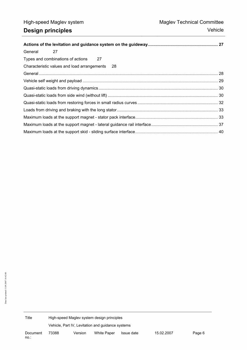
High-speed Maglev system
Design principles Maglev Technical Committee
Vehicle
Title High-speed Maglev system design principles
Vehicle, Part IV, Levitation and guidance systems
Document no.:
73388 Version White Paper Issue date 15.02.2007 Page 6
Dat
e la
st p
rinte
d 13
.09.
2007
10:
42:0
0
Actions of the levitation and guidance system on the guideway............................................................. 27
General 27
Types and combinations of actions 27
Characteristic values and load arrangements 28
General ............................................................................................................................................................ 28 Vehicle self weight and payload ...................................................................................................................... 29 Quasi-static loads from driving dynamics........................................................................................................ 30 Quasi-static loads from side wind (without lift) ................................................................................................ 30 Quasi-static loads from restoring forces in small radius curves ...................................................................... 32 Loads from driving and braking with the long stator........................................................................................ 33 Maximum loads at the support magnet - stator pack interface........................................................................ 33 Maximum loads at the support magnet - lateral guidance rail interface.......................................................... 37 Maximum loads at the support skid - sliding surface interface........................................................................ 40

High-speed Maglev system
Design principles Maglev Technical Committee
Vehicle
Title High-speed Maglev system design principles
Vehicle, Part IV, Levitation and guidance systems
Document no.:
73388 Version White Paper Issue date 15.02.2007 Page 7
Dat
e la
st p
rinte
d 13
.09.
2007
10:
42:0
0
List of figures Fig. 1: Side view and cross-section (showing the principle) ........................................................... 10 Fig. 2: Magnet module (example) ................................................................................................... 11 Fig. 3: Levitation / Guidance magnets (Example) ........................................................................... 11 Fig. 4: Support skid (example) ........................................................................................................ 12 Fig. 5: Typical curve for stat pz ± ∆ stat pz....................................................................................... 29 Fig. 6: Typical curve for py, SW where vFzg= 400 km/h and SW = 37m/s........................................... 31 Fig. 7: Typical curve for py, ZWG ........................................................................................................ 32 Fig. 8: Typical load arrangement for support magnet without technical faults and breakdowns
(Example) ................................................................................................................................. 35 Fig. 9: Typical load arrangement for support magnet in the event of a support magnet circuit failure
(Example) ................................................................................................................................. 36 Fig. 10: Typical load arragements of guidance magnets (example) ............................................... 40 List of tables Table 1: Summary of vehicle loading conditions............................................................................. 28 Table 2: Characteristic static line loads of the vehicle (averaged).................................................. 29 Table 3: Actions resulting in side wind on the vehicle..................................................................... 31 Table 4: Maximum local constraining force..................................................................................... 32 Table 5: Driving and braking forces with the long stator ................................................................. 33 Table 6: Maximum support magnet load......................................................................................... 34 Table 7: Maximum line loads .......................................................................................................... 37 Table 8: Maximum impact force...................................................................................................... 38 Table 9: Maximum support skid forces ........................................................................................... 40

High-speed Maglev system
Design principles Maglev Technical Committee
Vehicle
Title High-speed Maglev system design principles
Vehicle, Part IV, Levitation and guidance systems
Document no.:
73388 Version White Paper Issue date 15.02.2007 Page 8
Dat
e la
st p
rinte
d 13
.09.
2007
10:
42:0
0
General
Purpose and applications This "High-speed magnetic levitation railway vehicle design principles, part IV - levitation and guidance systems" sets out the requirements for the traction and driving systems of the high-speed MAGLEV system vehicles that do not depend on the project concerned. This design principles applies to a Maglev system in accordance with the General Maglev System Act /AMbG/. Part IV is to be used for the specification, execution and certification of the levitation and guidance system of Maglev vehicles and covers:
• Definition of the levitation and guidance system,
• Requirements for the functions of the levitation and guidance system,
• The actions of the levitation and guidance system on the guideway.
High-speed MAGLEV system design principles This document is part of the documentation for high-speed magnetic levitation railways consisting of a number of design principles. Figure 1 /MSB AG-GESAMTSYS/ shows the documentation tree. The overall design principles for the complete system and its appendices apply uniformly to all the documentation: • High-speed MAGLEV system design principles, complete system, Document no.: 50630,
/MSB AG-GESAMTSYS/, with appendices: • Annex 1: Abbreviations and definitions, Document no.: 67536, /MSB AG-
ABK&DEF/ • Annex 2: Legislation, regulations, standards and directives, Document no.: 67539,
/MSB AG-NORM&RILI/ • Annex 3: Environmental constraints, Document no.: 67285, /MSB AG-UMWELT/ • Annex 4: Operating rules (operation and maintenance), Document no.: 69061, /MSB
AG-BTR/ • Annex 5: Noise, Document no.: 72963, /MSB AG-SCHALL/
The documentation on the vehicle consists of the following documents: • High-speed Maglev system design principles, vehicle, Part I.: Design principles, Document
no.: 67698, /MSB AG-FZ GEN/ • High-speed Maglev system design principles, vehicle, Part II.: Design, document no.:
67694, /MSB AG-FZ BEM/ • High-speed Maglev system design principles, vehicle, Part III.: Kinematic limits, Document
no.: 67650, /MSB AG-FZ KIN/

High-speed Maglev system
Design principles Maglev Technical Committee
Vehicle
Title High-speed Maglev system design principles
Vehicle, Part IV, Levitation and guidance systems
Document no.:
73388 Version White Paper Issue date 15.02.2007 Page 9
Dat
e la
st p
rinte
d 13
.09.
2007
10:
42:0
0
• High-speed Maglev system design principles, vehicle, Part IV.: Levitation and guidance systems, Document no.: 73388, /MSB AG-FZ TRAFÜ/
• High-speed Maglev system design principles, vehicle, Part V.: Braking system, Document no.: 73389, /MSB AG-FZ BREMS/
Abbreviations and Definitions The abbreviations and definitions supplied in /MSB AG-ABK&DEF/ should be used.
Legislation, regulations, standards and directi-ves The prescriptive documents listed in /MSB AG-NORM&RILI/ contain definitions that are referred to in the high-speed Maglev system design principles and have become part of the high-speed Maglev system design principles. Where prescriptive documents in /MSB AG-NORM&RILI/ are dated, subsequent changes or revisions of these publications do not apply. Where references are undated, the latest edition of the prescriptive documents referred to is applicable. The edition of the standards and guidelines to be adhered to in a Maglev project must be made bind-ing for each specific project.
Identification and mandatory nature of requi-rements
The content of the present document is substantially based on the provisions of /DIN 820/ . In the following chapters of this document, and in the appendices, • Requirements are shown in standard type
• Explanations, guidelines and examples are shown in italic.
Where notes on project-specific regulations are given in this document for individual cases, (e.g. in a specification or a contractual regulation) this means that the manufacturer and the contractor must consult the approvals authorities and come to an agreement.

High-speed Maglev system
Design principles Maglev Technical Committee
Vehicle
Title High-speed Maglev system design principles
Vehicle, Part IV, Levitation and guidance systems
Document no.:
73388 Version White Paper Issue date 15.02.2007 Page 10
Dat
e la
st p
rinte
d 13
.09.
2007
10:
42:0
0
Definitions (vehicle-specific)
Fig. 82: Side view and cross-section (showing the principle)
TM BM FM
SR
SG1 SG2 SG3 SG4 1 2 3 4 5 6 7 8
Longitudinal connector
SG = Levitation chassis SR = Levitation undercarriage (2 levitation frames + connecting parts) TM = Support magnet FM = Guidance magnet BM = Braking magnet TK = Support skid WK = Carriage body
Levitation chassis (without magnets)
Longitudinal connectorTK
SR
Vehicle guideway width
Vehicle frame dimen-
TM
FM
TK
Pneumatic spring Pendulum
Support magnet centre distance = support skid centre distance
Pneum. spring
Z support for carriage body Roll stabiliser
Additional Y spring
WK ∆y

High-speed Maglev system
Design principles Maglev Technical Committee
Vehicle
Title High-speed Maglev system design principles
Vehicle, Part IV, Levitation and guidance systems
Document no.:
73388 Version White Paper Issue date 15.02.2007 Page 11
Dat
e la
st p
rinte
d 13
.09.
2007
10:
42:0
0
Fig. 83: Magnet module (example)
Fig. 84: Levitation / Guidance magnets (example)
Levitation clearance Support magnet
Guidance magnet
Main pole
GM coil Rear of mag-net
Rear of mag-net
High core poleEnd pole
Guidance clearance measuring unit
Pole barGuidance clearance measuring unit
Support magnet
Guidance magnet Levitation frame

High-speed Maglev system
Design principles Maglev Technical Committee
Vehicle
Title High-speed Maglev system design principles
Vehicle, Part IV, Levitation and guidance systems
Document no.:
73388 Version White Paper Issue date 15.02.2007 Page 12
Dat
e la
st p
rinte
d 13
.09.
2007
10:
42:0
0
Fig. 85: Support skid (example)
Sliding surface lining
Housing

High-speed Maglev system
Design principles Maglev Technical Committee
Vehicle
Title High-speed Maglev system design principles
Vehicle, Part IV, Levitation and guidance systems
Document no.:
73388 Version White Paper Issue date 15.02.2007 Page 13
Dat
e la
st p
rinte
d 13
.09.
2007
10:
42:0
0
Design principles for the levitation and guidance system
Operation See description in /MSB AG-GESAMTSYS/. The levitation and guidance system of the Maglev vehicles must perform the following functions over the whole of the specified speed and distance ranges: • Magnetic support and guidance by means of controlled stored levitation and guidance magnets.
• Mechanical support using support skids in accidental situations or breakdowns or when the ve-hicle is standing (set down), for frequency compare /MSB AG-FZ BEM/, chapter 8.
• Mechanical guidance, e.g. using sliding elements on the guidance magnets in the event of rare technical faults or breakdowns and in accidental operating situations (superimposition of the actions of extreme operating situations). In tight curves (RH < 600 m) it may be necessary to limit the speed in order to have freedom of movement.
Design
The loads that are borne by the structural components and pivots of the levitation and guidance sys-tem must be determined using /MSB AG-FZ BEM/ and taken into account in their design.
These loads must be documented in a specification (Design loads). Proof of load-bearing capability (general stress certificate) and fatigue resistance according to the requirements set out in /MSB AG-FZ BEM/ must be provided for the components that transfer the load. Determination of the clearance between the support magnets and the stator pack, between the guid-ance magnets and the lateral guidance rails and between the support skids and sliding surface must take account of structural tolerances, load-dependent deformation, relevant operational influences (e.g. route, speed, wear on the sliding surface lining, etc.) and environmental conditions and must be documented in a clearance statement.

High-speed Maglev system
Design principles Maglev Technical Committee
Vehicle
Title High-speed Maglev system design principles
Vehicle, Part IV, Levitation and guidance systems
Document no.:
73388 Version White Paper Issue date 15.02.2007 Page 14
Dat
e la
st p
rinte
d 13
.09.
2007
10:
42:0
0
Safety requirements The levitation and guidance system, consisting of the magnetic and mechanical equipment, must conform to the safety requirements as per §19, /MbBO/.
General The levitation and guidance function must be executed so that it is safe for all of its service life. This property must be proven by means of a safety certificate to /EN 50126/. The safety certificate is based on a risk analysis. The risk analysis must include the following elements: • Description of the levitation and guidance system and the protective functions,
• Description of the assemblies participating in the levitation and guidance system, their func-tions, connections and actions on each other,
• Identification of assemblies and functions that are responsible for safety.
Information on methods of performing the risk analysis is given in /prEN 50126-2/ and /prR009-004/. The requirements for and tests on the structural assemblies of the levitation and guidance system are given in chapter 0. The requirements for and tests on the functional assemblies of the levitation and guidance system are given in chapter 0. The SIL level according to /EN 50129/ for the electronic equipment of the levitation and guidance system must be determined on the basis of the risk analysis and must be taken into account when performing the hardware certification. The level of the safety requirements for the software in the levitation and guidance system that has been determined on the basis of the risk analysis must be taken into consideration when performing the certification to /EN 50128/. Possible faults must be identified using a suitable analysis and must be taken into account in the safety certificate. A suitable analysis must include consideration of at least the following faults: • Fault in the on-board energy supply,
• Untimely execution of a set-down command,
• System failure (of software or hardware). Certification of the lifetime safety of the levitation and guidance system must be performed using a suitable method of analysis before the system is commissioned. The theoretical certificate must be verified after the start of operation by evaluating the life cycle data of the assemblies.
Requirements for the on-board energy supply

High-speed Maglev system
Design principles Maglev Technical Committee
Vehicle
Title High-speed Maglev system design principles
Vehicle, Part IV, Levitation and guidance systems
Document no.:
73388 Version White Paper Issue date 15.02.2007 Page 15
Dat
e la
st p
rinte
d 13
.09.
2007
10:
42:0
0
The specifications for the on-board energy supply can be found in the specifications for the levita-tion and guidance system, the safe brake and the other vehicle systems that are relevant to safety. The following information applies to the levitation and guidance system. The availability of the on-board energy supply as a whole must be guaranteed to match the require-ments of the safety design (e.g. Failure of the collector rail power from more than one subnetwork), if, as a consequence of this, the vehicle should be wholly or partly set down or the safe brake should fail. Since it is not possible to prevent individual faults in electrical systems with sufficient certainty, there is an inevitable requirement for redundancy, i.e. the number of independent and electrically / mechanically separate networks provided for each section must be sufficient to ensure that one faulty network does not affect the remaining networks and the levitation and guidance function is maintained. To increase availability, these networks should be potential-free, i.e. without a direct electrical con-nection to the vehicle chassis, so that they do not switch off in the event of a short-circuit. Furthermore equipment must be provided to guarantee the required performance from the mains to maintain the levitation and guidance function (e.g. batteries) and to guarantee that the vehicle levi-tates and brakes safely once it has started off (see also/MSB AG-BLT/, chapter 6.3.3.1 and chapter 6.3.3.3). The possible untimely switching off of all networks that are needed to maintain the levitation and guidance function and the braking function during a mission, e.g. by triggering a central shutdown command, must be prevented by means of a suitable technical device. A shutdown command must only be effective when the vehicle is stationary and set down. Faults and failures in the shutdown control must not lead to an unwanted shutdown. If the shutdown command becomes ineffective as a result of a fault or failure it must still be possible to shut the vehicle down. Access to the corresponding shutdown equipment must be obstructed in such a way that only trained operators can actuate the shutdown. The following must be taken into account: Evidence that a failure of the on-board energy supply is sufficiently unlikely is deemed to be pro-vided if the on-board energy supply has been certified in accordance with chapter 0 and the follow-ing certificates are available: 1) Adequate redundancy
Adequate redundancy means that the number of separate independent electric and mechanical networks is such that in spite of increasing network failure there is still enough on-board power available to maintain the functions of levitation and guidance according to the specifications of the safety system.
2) Electrical and mechanical separation of networks Networks are deemed to be electrically and mechanically separate if they have a certificate of conformance with the requirements of /EN 50124-1/ "Railway applications - Insulation coordi-nation". Certification requires type testing of the assemblies, manufacturing tests during con-struction of the vehicle and commissioning tests on a vehicle.
3) Performance of the networks Proof is required, in the form of figures and actual practice, that the planned and available de-vices for maintaining the performance of the networks perform their functions in the event of

High-speed Maglev system
Design principles Maglev Technical Committee
Vehicle
Title High-speed Maglev system design principles
Vehicle, Part IV, Levitation and guidance systems
Document no.:
73388 Version White Paper Issue date 15.02.2007 Page 16
Dat
e la
st p
rinte
d 13
.09.
2007
10:
42:0
0
the partial or complete failure of the external on-board power supplies. Certification must take place for representative driving profiles under the conditions of use specific to the project.
4) Shutdown Proof using circuit documentation and practical trials is required that the central shutdown command is only effective when the vehicle is stationary and set down. A safety certificate for the shutdown control must be based on a suitable analysis. Evidence is required that every anticipated failure leads to a safe response, i.e. not to the triggering of a shutdown. Furthermore proof is required, through examination of the design drawings and the vehicle con-trols, that access to manually operated shutdown devices has been made so difficult that only trained operators can actuate the shutdown command.
Requirements for the execution of a set-down command The central set-down command must be generated - and must be linked in each levitation and guid-ance unit by a logical AND to the independently determined speed - in such a way that the com-mand to set down can only be decentrally effective when the vehicle speed is lower than the permit-ted set-down speed. A certificate is required for the set-down control to the effect that the set-down command can only become effective below the set-down speed and, with sufficient probability, also in the event of all foreseeable failures.
Systematic faults in the magnet control equipment Certification that systematic faults are sufficiently unlikely is required in accordance with EN 50128 and EN 50129. This applies to the hardware and, if present, the software of the equipment that is relevant to safety in the measurement, control, regulation and monitoring systems of the magnet regulating circuits. Diagnostic and control equipment should be provided separately as part of the hardware.
Maintenance of the safety characteristic of magnet control cir-cuits Electromagnetic levitation is a controlled state in which a preset air gap between the stator pack or lateral guidance rail and the levitation and guidance magnets is maintained to defined tolerances according to a project-specific clearance balance. Faults in the power pack or in the equipment for measurement, control, regulation and supervision of the magnet control circuits can cause the magnetic force to increase such that the clearance be-comes zero and non-permissible forces act on the structure of the vehicle and guideway. This type of failure must therefore be prevented by a suitable and sufficiently reliable failsafe monitoring sys-tem. If a permanent fault occurs in the monitoring equipment this must also lead to the release of the magnetic field. The monitoring equipment must be assigned to each magnet control circuit inde-pendently.

High-speed Maglev system
Design principles Maglev Technical Committee
Vehicle
Title High-speed Maglev system design principles
Vehicle, Part IV, Levitation and guidance systems
Document no.:
73388 Version White Paper Issue date 15.02.2007 Page 17
Dat
e la
st p
rinte
d 13
.09.
2007
10:
42:0
0
For the magnet control circuit monitoring equipment that is to be executed so as to fail safe, certifi-cation must use an analysis of the actions of failure to show that the probability of these actions causing the magnetic circuit to shut down immediately in the event of failure is sufficient. Examination of the circuit diagrams and practical tests of the complete magnet control circuits must show that the monitoring equipment is inevitably activated when the magnet clearance regulation is switched on and that it is not subject to external influences.
Lightning overspill For levitating vehicle sections paths and lightning overspill points to the guideway must be defined on the vehicle as provision for lightning overspill.
ESD Electrostatic discharge from the vehicle must be dissipated in all operating conditions where there is a possibility of contact between the vehicle and persons connected to earth potential. /MbBO/, §17(4) applies.

High-speed Maglev system
Design principles Maglev Technical Committee
Vehicle
Title High-speed Maglev system design principles
Vehicle, Part IV, Levitation and guidance systems
Document no.:
73388 Version White Paper Issue date 15.02.2007 Page 18
Dat
e la
st p
rinte
d 13
.09.
2007
10:
42:0
0
Requirements for the assemblies of the levitation and guidance system
Structural assemblies of the levitation and gui-dance system The structural assemblies of the levitation and guidance system must be designed according to /MSB AG-FZ BEM/.
Chassis structure and panelling
Chassis structure
The functionality of components for vehicle dynamics and driving on bends, over rises and in de-pressions and the corresponding clearances must be designed in such a way that there is no impair-ment of the driving performance of the vehicle under the environmental conditions set out in /MSB AG-UMWELT/ or defined specifically for the project. Fastenings and connections must be accessible for inspection. Steps must be taken to ensure against loss of components. The structure of the chassis must be executed so that if one component fails it does not cause a po-tentially unsafe condition. This property must be demonstrated with a failure modes and effects analysis (FMEA). The structure of the chassis must be executed so that the specific behaviour in the cases of collision described in chapter 8.4 of /MSB AG-FZ BEM/ is guaranteed.
Panelling of the chassis
The parts of the panelling must be designed to have endurance strength, taking into account the de-sign loads to /MSB AG-FZ BEM/ and considering forms of natural vibration and resonance behav-iour and also considering the stresses arising from manual operations during maintenance. Where parts of the outer panelling have to be removable for purposes of accessibility to the under-floor cavities during maintenance, fasteners should be provided that show (e.g. visually) when their condition, locked or unlocked, has been changed, but not their actual current position.
Carriage body pivot / secondary suspension
Z suspension Support for the carriage bodies is determined statically and must be made dynamically separate from the levitation and guidance system (preferably by means of pneumatic springs). The travel of the spring between the levitation chassis and the carriage body must be limited both upwards and downwards.

High-speed Maglev system
Design principles Maglev Technical Committee
Vehicle
Title High-speed Maglev system design principles
Vehicle, Part IV, Levitation and guidance systems
Document no.:
73388 Version White Paper Issue date 15.02.2007 Page 19
Dat
e la
st p
rinte
d 13
.09.
2007
10:
42:0
0
Level regulation / pneumatic spring control
The supply and discharge of air in the pneumatic spring bellows must only be possible when the control unit is actively controlled. Provision must be made for an adjustable partial reduction of the pressure in the pneumatic spring bellows. Monitoring of the pressures in the distribution lines and the individual pneumatic springs must be provided. A failure should be reported by the vehicle diagnostic system for repair purposes. Data from the diagnostics should unambiguously identify and locate the affected assembly. The system reaction must be defined for each specific project.
Y suspension
Displacements in the Y direction must be taken into account in /MSB AG-FZ KIN/.
Roll stabiliser
Possible rolling of the carriage body must be taken into account in /MSB AG-FZ KIN/. For reasons of comfort, rolling of the carriage body against the levitation undercarriage must be restricted and the amount defined specifically for the project. In the event of side wind or maximum lateral acceleration, the preset carriage body roll value of 1.5° must be taken into account.
Behaviour in the event of failure
The failure of individual pneumatic and electrical assemblies of the Z suspension, together with the action of the mechanical assemblies of the secondary suspension, must not cause any interruption of movement. This property must be demonstrated with a suitable analysis, see chapter 0. The operation and failure behaviour of the pneumatic and electrical assemblies of the Z suspension, together with the action of the mechanical assemblies of the secondary suspension, must be verified as part of commissioning the vehicle. If a defined pressure in the pneumatic springs is not reached the bellows concerned must be sepa-rated from the collective line.

High-speed Maglev system
Design principles Maglev Technical Committee
Vehicle
Title High-speed Maglev system design principles
Vehicle, Part IV, Levitation and guidance systems
Document no.:
73388 Version White Paper Issue date 15.02.2007 Page 20
Dat
e la
st p
rinte
d 13
.09.
2007
10:
42:0
0
Magnet pivot The magnet pivot must be executed in such a way that the failure of an individual part does not im-pair the safety and availability of the levitation and guidance function. This property must be dem-onstrated with a suitable analysis. This means that if there is a failure operation can continue and a safe condition is maintained. Failures must be detected by inspections.
Support skid The limit values for static and dynamic forces must be verified specifically for the project. The execution of the support skids and the equipment from which they hang must have sufficient suspension and damping to ensure that the limits for the loads arising in the event of uncontrolled setting down are not exceeded. Damage to the sliding surface lining or the support skid suspension must not result in loss of me-chanical load-bearing capacity. Failures and wear must be detected by inspections. Behaviour in the event of failure must be demonstrated with a suitable analysis, see chapter 0. Sliding behaviour must be demonstrated with reference to the wear and heating criteria with proto-types and/or a representative vehicle. The impact load behaviour must be demonstrated by means of tests or digital simulations.

High-speed Maglev system
Design principles Maglev Technical Committee
Vehicle
Title High-speed Maglev system design principles
Vehicle, Part IV, Levitation and guidance systems
Document no.:
73388 Version White Paper Issue date 15.02.2007 Page 21
Dat
e la
st p
rinte
d 13
.09.
2007
10:
42:0
0
Functional assemblies of the levitation and guidance system
Levitation function
Levitation control
Decentralized control of the levitation clearance must be provided in autonomous redundant assem-blies. If project-specific limits (e.g. minimum clearance) are contravened, the control circuit must switch off so rapidly that there is no possibility of the project-specific design loads for the vehicle and guideway being exceeded. This process must be reversible.
Measuring the levitation clearance.
The levitation clearance between the pole surface of the support magnets and the surface of the sta-tor bundles facing the support magnet must be checked using a contactless levitation clearance measurement system. When designing the levitation clearance measurement system the expansion gaps at the ends of the guideway beams, at track switching devices, at transitions from supports to primary load-bearing structures and between neighbouring stator packs must be observed. Factors influencing accuracy of measurement of the levitation clearance must be taken into account. Levitation clearance measurement requirements for the stator bundle properties must be defined specifically for the project, see /MSB AG-FW ÜBG/.
Power generation
An example of the levitation chassis with support magnets is shown in Fig. 83. Project-specific limits are required for the rolling of the support magnet about the X axis during levitation. The action of possible rolling on the distribution of power and the size of the clearance must be taken into account. Provision must be made for the poles of a support magnet to be electrically distributed between at least two independent control circuits. The control circuits should permit translatory motion in the z direction and rotation about the y axis.
Behaviour in the event of failure
The levitation control circuits must have monitoring equipment that, in the event of failure of an operational component and loss of redundancy, switches off the control circuit sufficiently quickly to ensure that there is no possibility of the project-specific design loads for the vehicle and guide-way being exceeded.

High-speed Maglev system
Design principles Maglev Technical Committee
Vehicle
Title High-speed Maglev system design principles
Vehicle, Part IV, Levitation and guidance systems
Document no.:
73388 Version White Paper Issue date 15.02.2007 Page 22
Dat
e la
st p
rinte
d 13
.09.
2007
10:
42:0
0
If an individual levitation control circuit fails the levitation function of the levitation undercarriage must be maintained by a redundant levitation circuit. In the event of faults leading to the failure of the magnetic levitation function on one levitation un-dercarriage, the distance travelled must be automatically restricted by the operational control sys-tems to the specified permissible slide path of the support skid / sliding surface. In this case the levi-tation function of the undercarriage must be transferred to a support skid. Operational reaction and repair are to be defined specifically for the project. In the event of a short circuit of the long stator winding on one side of the guideway beam, reversi-ble failure of the magnetic levitation function of the corresponding longitudinal side of the vehicle and the uncontrolled setting down of the vehicle on one side can be tolerated. The magnetic levita-tion function must be automatically restored when the vehicle has left the area of the shorted wind-ing. The levitation function must be guaranteed in the event of lightning striking the vehicle. It is per-missible for individual circuits to switch off momentarily but there must be no permanent failure of the individual assemblies of the control circuit. Afterwards the control circuits that switched off must automatically re-energize.
Failure reporting, diagnostics
For maintenance purposes, loss of redundancy because of the failure of assemblies must be detected and made obvious by vehicle diagnostics. Data from the diagnostics should unambiguously identify and locate the affected assembly. Where devices that are relevant to safety do not automatically report failure, periodic functional tests / inspections must make failures obvious. The test criteria and intervals must be determined by means of a suitable analysis.
Certificates
A qualification test with prototypes must be performed on the assemblies of the magnet regulation circuit to certify the operation, failure behaviour, reporting of failures and environmental resistance. A suitable analysis must be carried out to certify the lifetime reliability of the levitation and guid-ance function, see chapter 0. Behaviour in the event of failure must be verified in tests by simulating the failure of components on individual levitation undercarriages on a test rig and in operation. The reliability of the electronic assemblies of the magnet control circuit must be verified by deter-mining the MTBF from the evaluation of life cycle data on representative assemblies after the start of operation. The compatibility of the MTBF verified from life cycle data with the forecast statements of the analysis must be demonstrated. Static and dynamic nominal stress on a test rig must demonstrate that the magnet control circuits are stable in operation.

High-speed Maglev system
Design principles Maglev Technical Committee
Vehicle
Title High-speed Maglev system design principles
Vehicle, Part IV, Levitation and guidance systems
Document no.:
73388 Version White Paper Issue date 15.02.2007 Page 23
Dat
e la
st p
rinte
d 13
.09.
2007
10:
42:0
0
Guidance function
Guidance control
Decentralized control of the guidance clearance must be provided in autonomous redundant assem-blies.
Measurement of the guidance clearance
The guidance clearance between the pole surface of the guidance magnets and the surface of the lateral guidance rails must be checked using a contactless guidance clearance measurement system. When designing the guidance clearance measurement system the expansion gaps at the ends of the guideway beams, at track switching devices, and transitions from supports to primary load-bearing structures and between neighbouring guidance rail elements must be observed. Factors influencing accuracy of measurement of the guidance clearance must be taken into account. Guidance clearance measurement requirements for the lateral guidance rail properties must be de-fined specifically for the project.
Power generation
An example of the levitation chassis with guidance magnets is shown in Fig. 83. Project-specific limits are required for the rolling of the guidance magnet about the X axis during levitation. The action of possible rolling on the distribution of power and the size of the clearance must be taken into account. Provision must be made for the windings of a guidance magnet to be electrically distributed be-tween at least two independent control circuits. The control circuits should permit translatory motion in the y direction and rotation about the z axis.
Behaviour in the event of failure
The individual guidance control circuits must have monitoring devices that reliably switch the con-trol circuit off in the event of failure of an operational component. If an individual guidance control circuit fails the guidance function of the levitation undercarriage must be maintained by a redundant guidance circuit. In the event of faults leading to the loss of the electromagnetic guidance function of one levitation undercarriage, the distance travelled must be automatically restricted by the operational control sys-tems to the specified permissible slide path of the mechanical sliding elements on the lateral guid-ance rail. After failure of the magnetic guidance function on one levitation undercarriage the guidance func-tion must be transferred to a mechanical guidance unit. Limiting values of the loads occurring and the permissible wear must be defined for the specific project.

High-speed Maglev system
Design principles Maglev Technical Committee
Vehicle
Title High-speed Maglev system design principles
Vehicle, Part IV, Levitation and guidance systems
Document no.:
73388 Version White Paper Issue date 15.02.2007 Page 24
Dat
e la
st p
rinte
d 13
.09.
2007
10:
42:0
0
Reactions in the event of a lightning strike must be similar to those described in chapter 0.
Failure reporting, diagnostics
Failure reporting must be along the lines of chapter 0.
Certificates
Certification procedure must be similar to that described in chapter 0 according to chapter 0.
On-board energy supply
Properties and functions
An on-board energy supply that will be reliable for all of its service life must be provided to ensure that the "levitation and guidance", "safe braking" and other vehicle systems that are relevant to safety are reliable for the lifetime of the vehicle. Environmental conditions must be observed in accordance with /MSB AG-UMWELT/ or as defined for the project. The on-board supply must also display lifetime reliability during and after the actions of lightning. On-board circuits must be designed so that the vehicle can be set down with the power on at any time without the need for safety-related supervision by personnel.
Electrical safety
The on-board energy supply equipment must satisfy the following requirements: • Protection against shock current,
• Production and maintenance of a zero potential condition during maintenance,
• Protection against overload and short circuit,
in accordance with the provisions of /EN 50153/ and /EN 50207/.
Uninterruptible power supply
In order to perform forced braking with the safe brake an uninterruptible power supply must be pro-vided. This must take account of the most adverse environmental and operating conditions that have been specified. An additional project-specific on-board energy reserve must be available when operating during a malfunction. There must be an adequate supply of stored power, as defined for the project, to operate emergency lighting, emergency ventilation and communication devices after a stop resulting from a fault.

High-speed Maglev system
Design principles Maglev Technical Committee
Vehicle
Title High-speed Maglev system design principles
Vehicle, Part IV, Levitation and guidance systems
Document no.:
73388 Version White Paper Issue date 15.02.2007 Page 25
Dat
e la
st p
rinte
d 13
.09.
2007
10:
42:0
0
Where batteries are used, explosion prevention measures suitable for the battery type and in accor-dance with the safety design must be put in place (e.g. battery ventilation with indication of failure and thermal monitoring and fan run-on after reset).
Control and monitoring function
In the event of the failure of one or more devices that are relevant to the safe condition of the vehi-cle (e.g. on-board power units or battery ventilation) in one section of the vehicle, there must be an automatic fail-safe system reaction. If there is less than the minimum power requirement in the energy store for the uninterruptible power supply to provide for a forced stop with the safe brake plus the minimum operating time for the safety consumers needed during the stoppage (e.g. emergency lighting, ventilation and commu-nication), there must be an automatic fail-safe system reaction.
Behaviour in the event of failure
The failure of individual on-board energy supply assemblies or the failure of an individual on-board energy supply must not have any effect on operation. It must be possible to continue the journey as far as the next scheduled station. Fault tolerance against earth faults must be provided , e.g. by IT networks with insulation monitor-ing, see also chapter 0.
Failure reporting, diagnostics
A loss of redundancy owing to assembly failure must be signalled by the vehicle diagnostic system for repair purposes. Data from the diagnostics should unambiguously identify and locate the affected assembly.
Certificates
A qualification test with prototypes must be performed on the MSB-specific assemblies of the on-board energy supply to certify the operation, failure behaviour, reporting of failures and environ-mental resistance. A suitable analysis must be carried out to certify the lifetime reliability of the function, see chapter 0. Failure behaviour must be demonstrated in tests, e.g. by means of simulated assembly failures on a representative vehicle. The reliability of the electronic assemblies for the supply of power to safety functions must be veri-fied by determining the MTBF from the evaluation of life cycle data on representative assemblies after the start of operation. The compatibility of the MTBF verified from life cycle data with the forecast statements of the analysis must be demonstrated.

High-speed Maglev system
Design principles Maglev Technical Committee
Vehicle
Title High-speed Maglev system design principles
Vehicle, Part IV, Levitation and guidance systems
Document no.:
73388 Version White Paper Issue date 15.02.2007 Page 26
Dat
e la
st p
rinte
d 13
.09.
2007
10:
42:0
0
Safety-relevant control / supervision
General
Safety-relevant control functions of the levitation and guidance system include: • the transmission of control commands from the operational control system to devices for the
regulation, control and supervision of the levitation and guidance function and the on-board en-ergy supply,
• the generation of safety-relevant status information of the levitation and guidance function and the on-board energy supply and transmission to the operational control system.
Behaviour in the event of failure
The safety-relevant control and supervision must be designed to be redundant. An individual instance must not lead to the loss or limitation of the control and monitoring func-tions. Failure of the control and monitoring functions must bring about an automatic failsafe reac-tion.
Failure reporting, diagnostics
A loss of redundancy must be signalled by the vehicle diagnostic system for repair purposes. Data from the diagnostics should unambiguously identify and locate the affected assembly.
Certificates
Qualification tests of the control and monitoring equipment must be carried out with prototypes or on a representative vehicle. The safety certification of the control and supervision for the levitation and guidance function and on-board energy supply must be performed in accordance with chapter 0.

High-speed Maglev system
Design principles Maglev Technical Committee
Vehicle
Title High-speed Maglev system design principles
Vehicle, Part IV, Levitation and guidance systems
Document no.:
73388 Version White Paper Issue date 15.02.2007 Page 27
Dat
e la
st p
rinte
d 13
.09.
2007
10:
42:0
0
Actions of the levitation and guidance system on the guideway
General The forces given below correspond to the characteristic values8 of the actions of the vehicle on the guideway at the vehicle-guideway interfaces.
Types and combinations of actions The actions of the levitation and guidance system on the guideway act upon the following inter-faces:
• Support magnet - stator pack
• Guidance magnet - lateral guidance rail,
• Support skid - sliding surface
The forces acting on the guideway arise from the following functions: • Magnetic and mechanical levitation,
• Magnetic and mechanical guidance,
• Driving and braking with the long stator propulsion system.
The forces are influenced by the following actions: • Operation with a variable payload under varying environmental conditions,
• Operation following failure situations and accidental operating situations,
• Operation using the "safe brake" with the loads ensuing therefrom.
The actions of the levitation and guidance system on the structure must be taken into consideration in accordance with chapter 0 when designing the assemblies. The variable actions of the vehicle on the guideway must be taken into account when designing the guideway on the basis of /MSB AG-FW BEM/. To ensure that the characteristic values for the actions arising from operation of the vehicle that are assumed in /MSB AG-FW BEM/ agree well enough with actions arising in practice, the values given in chapter 0 for the forces introduced into the guideway by the vehicle must not be exceeded (permissible tolerance when verifying the magnitude of the actions is 5%).
8) The most representative value of an action, from which it is assumed that there is a given probability that it will be neither exceeded or undershot during the reference period, taking into account the service life of the load-bearing struc-ture and the corresponding measurement situation. In the case of a variable action the characteristic value is either an upper value for which there is a given probability that is not exceeded during the defined reference time or a defined nominal value if there is no known probability distribution (see also DIN EN 1990).

High-speed Maglev system
Design principles Maglev Technical Committee
Vehicle
Title High-speed Maglev system design principles
Vehicle, Part IV, Levitation and guidance systems
Document no.:
73388 Version White Paper Issue date 15.02.2007 Page 28
Dat
e la
st p
rinte
d 13
.09.
2007
10:
42:0
0
The magnitude of the characteristic values of the actions must be set down in a mandatory project-specific specification for every application. The magnitudes of the characteristic values of the actions must be verified by taking measurements on a representative vehicle.
Characteristic values and load arrangements
General The typical system length of a vehicle section (centre section) LMS = 24.768 m (support magnet occupied length) is to be used as the reference value for the overall actions induced in the guideway by the support magnets and the guidance magnets in the x, y and z directions. Half the length of a support magnet system LSYS,TM / 2 is to be used for determining the reference value of the local actions induced in the guideway by the support magnets and the guidance mag-nets in the x, y and z directions. The definitive loading conditions given in Table 79 below must be defined for certification pur-poses. In the context of the project, it may also be necessary to consider increased vehicle weight as a consequence of accumulated snow in the vehicle structure. Value Definition
Vehicle self weight Weight of the vehicle section without payload 1)
Mean vehicle weight Weight of the vehicle section with standard load 2)
Permitted vehicle weight Weight of the vehicle section with maximum load 3)
Maximum vehicle weight Weight of the vehicle section in accidental operating situations 4)
1) The payload is the weight of passengers with luggage or freight / freight containers 2) The mean weight can be defined, e.g. for a payload that is not exceeded in 80% of the journeys. This must be determined separately for each project. 3) Payload at maximum planned loading that is only exceeded in accidental operating situations; this must be determined separately for each project, e.g. all seats occupied, assuming 90 kg per passenger plus 320 kg pro m² of standing room. 4) Maximum possible payload in accidental operating situations; this must be determined separately for each project, e.g. all seats occupied, assuming 90 kg per passenger plus 500 kg pro m² of standing room.
Table 79: Summary of vehicle loading conditions

High-speed Maglev system
Design principles Maglev Technical Committee
Vehicle
Title High-speed Maglev system design principles
Vehicle, Part IV, Levitation and guidance systems
Document no.:
73388 Version White Paper Issue date 15.02.2007 Page 29
Dat
e la
st p
rinte
d 13
.09.
2007
10:
42:0
0
Vehicle self weight and payload The characteristic values of the static actions resulting from the vehicle loading conditions are given as the line load determined over the vehicle length in Table 80. The static line loads given in Table 80 are to be used as a basis for determining the characteristic values of actions of the vehicle.
Static line load per m vehicle length (support magnet oc-cupied length) without snow in [kN/m]
Vehicle self weight
Mean vehicle weight
Permitted vehicle weight
Maximum vehicle weight
stat pz 19 1 (21) 26 29 31 1 applies to light goods vehicles, for passenger vehicles a mean line load of 21 kN/m can be assumed.
Table 80: Characteristic static line loads of the vehicle (averaged)
The permitted weight G Sekt zul of a vehicle section can be calculated with the aid of the following equation: G Sekt zul = stat pz ⋅ LMS / g where g = 9.81 m/s² . Any possible local increases in the line load ∆stat pz as a result of uneven distribution of the vehicle weight over its length should be kept to a minimum.
A typical diagram for stat pz ± ∆ stat pz is shown in Fig. 86.
Fig. 86: Typical diagram for stat pz ± ∆ stat pz

High-speed Maglev system
Design principles Maglev Technical Committee
Vehicle
Title High-speed Maglev system design principles
Vehicle, Part IV, Levitation and guidance systems
Document no.:
73388 Version White Paper Issue date 15.02.2007 Page 30
Dat
e la
st p
rinte
d 13
.09.
2007
10:
42:0
0
Last der Teilmagnete Load on partial magnets
Teilmagnete Tragen Partial support magnets
gemittelte Streckenlast Mean line load
Endsektion End section
Mittelsektion Centre section
Evidence of stat pz and ∆ stat pz for the defining loading conditions must be provided by weighting. In certain cases the values of stat pz and ∆ stat pz for the vehicle with payload can be calculated on the basis of the weighting in the unloaded state.
Quasi-static loads from driving dynamics Driving over elements of the route such as bends, rises and depressions causes accelerations in the y and z directions and during driving and braking of the vehicle quasi-static loads are generated in the x, y and z directions and moments about the x, y and z axes which are affected by the location of the centre of gravity of the vehicle sections in the z direction. These actions must be taken into account on the guideway side as mass forces in the x, y and z di-rections in accordance with /MSB AG-FW BEM/. The centre of gravity of a section of the vehicle in the z direction must not exceed the following values9:
• For vehicle self weight 600 mm above the sliding surface,
• For mean vehicle weight: 700 mm above the sliding surface,
• For permitted vehicle weight: 850 mm above the sliding surface,
• For maximum vehicle weight: 950 mm above the sliding surface.
Quasi-static loads from side wind (without lift) As a consequence of the quasi-stationary effect of side wind (mean value over 5 s according to/MSB AG-UMWELT/) on the vehicle, the vehicle transfers quasi-static loads to the guideway. The magni-tude of the loads is determined by the speed of the side wind, the speed of the vehicle and the height and geometry of the front of the vehicle. These actions resulting from side wind on the vehicle must be taken into account on the guideway side in accordance with /MSB AG-FW BEM/. The actions given in the guideway design specifications and the associated distribution over the length of the vehicle are respected if the maximum local line load owing to side wind in the y direc-tion py, SW does not exceed the values given in Table 81. 9) The data is needed in this form for designing the guideway.

High-speed Maglev system
Design principles Maglev Technical Committee
Vehicle
Title High-speed Maglev system design principles
Vehicle, Part IV, Levitation and guidance systems
Document no.:
73388 Version White Paper Issue date 15.02.2007 Page 31
Dat
e la
st p
rinte
d 13
.09.
2007
10:
42:0
0
Vehicle speed Maximum local line load from side wind in [kN/m] 200 km/h 300 km/h 400 km/h 500 km/h
py, SW 11.0 14.1 24.4 32.4
pz, SW ± 5.4 ± 6.4 ±6.9 ± 7.4
The loads apply for a side wind speed of 37 m/z to wind load zone II at a height of 20 m above ground.
Table 81: Actions resulting in side wind on the vehicle
The load certification can be done by calculation and simulation of flow behaviour with a verified simulation model.
Fig. 87: Typical course of py, SW where vFzg= 400 km/h and SW = 37m/s
Teilmagnelasten infolge Seitenwind Loads on partial magnets as a result of side wind
Teilmagnete Führen Partial guidance magnets
Bremsmagnet braking magnet
Endsektion End section
Mittelsektion Centre section

High-speed Maglev system
Design principles Maglev Technical Committee
Vehicle
Title High-speed Maglev system design principles
Vehicle, Part IV, Levitation and guidance systems
Document no.:
73388 Version White Paper Issue date 15.02.2007 Page 32
Dat
e la
st p
rinte
d 13
.09.
2007
10:
42:0
0
Quasi-static loads from restoring forces in small radius curves In small radius curves, reset forces arise between the levitation chassis of the levitation and guid-ance system and the carriage body (constraining forces), and these are transmitted to the guideway as quasi-static loads in the y direction. The maximum loads in each instance are transferred from the guidance magnets to the ends and in the area of the centre of the section. The actions given in the guideway design specifications and their distribution over the length of the vehicle (see Fig. 88) are respected if the maximum local constraining force in the y direction py, ZWG does not exceed the values given in Table 82.
Characteristic values of the maxi-mum constraining force in curves
in [kN/m]
Radius of curve RH =
350 m
Radius of curve RH =
1,000 m
Radius of curve RH =
2,000 m
py, ZWG 21 7 0
Table 82: Maximum local constraining force
The forces can be determined by calculation. The calculation must be verified by measuring individual restoring forces in a representative vehicle and curved section.
Fig. 88: Typical response for py, ZWG
Endsektionen End sections
Mittelsektionen Centre sections

High-speed Maglev system
Design principles Maglev Technical Committee
Vehicle
Title High-speed Maglev system design principles
Vehicle, Part IV, Levitation and guidance systems
Document no.:
73388 Version White Paper Issue date 15.02.2007 Page 33
Dat
e la
st p
rinte
d 13
.09.
2007
10:
42:0
0
Bogenaußen Bow outside
Bogeninnen Bow inside
Führmagnet Guidance magnet
Bremsmagnet Braking magnet
Die Nummern 1 ... 16 entsprechen den angegebenen Führmagnetkräften.
The numbers 1-16 correspond to the guidance mag-net forces shown.
Zugkräfte der bogenaußenliegenden Furhmagnete Tensile forces of the guidance magnets outside the bow
Zugkräfte der bogeninnenliegenden Furhmagnete Tensile forces of the guidance magnets inside the bow
nachfolgende Sektionen Following sections
Hecksektion = Bugsektion Tail section = bow section
nachfolgende Mittelsektionen wie dargestellte Mit-telsektion
Following centre sections as centre section shown
Loads from driving and braking with the long stator For the maximum overall actions of a vehicle section on the guideway a maximum force in the x direction that is obtained from the product of the permitted vehicle weight with the maximum per-mitted acceleration or braking deceleration of (ax = 1.5 m/s²) is to be used as a regularly repeating action (see Table 83). This also covers the propulsion/braking situations where the track rises and falls. For the maximum overall actions of a vehicle section on the guideway a maximum force in the X direction of 250 kN / section is to be used as accidental action (see Table 83).
Characteristic values of maximum forces as a result of propulsion and using the propulsion system for braking
Regularly repeating action with permitted vehicle weight (ax ≤ 1.5 m/s²) Fx = 110 kN / section
Case 1: Fx = 185 kN / section (distribution ratio 0.73 / 0.27 on the right and left sides of the vehicle) Accidental action
e.g. if the propulsion function is faulty Case 2: Fx = 250 kN / section (uniform distribution ratio on the right and left sides of the vehicle)
Table 83: Driving and braking forces with the long stator
The following relationships between the local action in the z direction pz and the local action in the x direction px must be taken into account: px ± ∆ px = ( pz ± ∆ p ) ⋅ax / g
Maximum loads at the support magnet - stator pack interface

High-speed Maglev system
Design principles Maglev Technical Committee
Vehicle
Title High-speed Maglev system design principles
Vehicle, Part IV, Levitation and guidance systems
Document no.:
73388 Version White Paper Issue date 15.02.2007 Page 34
Dat
e la
st p
rinte
d 13
.09.
2007
10:
42:0
0
Induced loads
At the interface between the support magnet (TM) and the stator level there is a magnetic transfer of quasi-static and dynamic tensile forces in the z direction and there is a magnetic transfer of thrust forces in the x direction via the propulsion function of the long stator. The following values must be taken into consideration as characteristic values for the maximum loads per metre of half magnet length:
Design situations Direction of action
Load per m of support magnet
Max. static tensile force from - permitted total weight z direction 16 kN/m
Max. dynamic tensile force from - permitted total weight - ay = 1.5m/s², az = 1.2m/s², Side wind 10m/s at 400 km/h
z direction 20 kN/m
Max. local tensile force in sectional magnet operation and - permitted total weight - ay = 1.5m/s², az = 1.2m/s², Side wind 37m/s at 400 km/h, Fz_dyn_max
z direction 45 kN/m
Maximum thrust of the propulsion system without technical failures or faults(max ax = 1.5 m/s²) from - permitted overall weight (inc. uneven distribution)
x direction 2.25 kN/m
Case 1: 5.5 kN/m Maximum thrust in the event of failure of the propulsion system(see Table 83) x direction
Case 2: 5.0 kN/m
Max. local thrust in the event of failure of a levitation control device x direction 4 kN/m
The maximum levitation force of the support magnet must be limited to 45 kN/m.
Table 84: Maximum support magnet load
For local load distribution see Fig. 89 and Fig. 90.
Dynamic excitation
The local distribution of the forces of the support magnets in the x direction is subject to periodicity of phase spacing that acts on the guideway as a force wave and moves along the guideway at the vehicle speed v. In the guideway the force wave coming from the vehicle acts as a locally pulsating steady force at a frequency fe that is dependent on the wavelength of the force λe, its harmonics and the vehicle speed. fe = v / λe The following actions must be taken into account with respect to dynamic excitation of the guide-way: Continuously acting variable forces as the vehicle travels over the guideway:

High-speed Maglev system
Design principles Maglev Technical Committee
Vehicle
Title High-speed Maglev system design principles
Vehicle, Part IV, Levitation and guidance systems
Document no.:
73388 Version White Paper Issue date 15.02.2007 Page 35
Dat
e la
st p
rinte
d 13
.09.
2007
10:
42:0
0
• Geometry of the support magnet poles magnetic effect of the pole geometry at the surface of the pole. e.g. from slots for linear genera-tors
• Geometry of the arrangement of the support magnet poles in the response of a support magnet, local movement of the force along the support magnet
• Geometry of the arrangement of the support magnet poles at the ends of a support magnet, local movement of the force in the area between two support magnets resulting from a different geometry at the end of the magnet poles from that in the centre
• Force caused by pitching of the support magnet because of the propulsion forces transmitted, torsion of the individual support magnets about the y axis, "misalignment" (Fig. 89)
Variable forces acting occasionally as the vehicle travels over the guideway: • Forces in the region of two support magnets after the failure of one magnet control device (Fig.
90)
Fig. 89: Typical load arrangement for support magnet without technical faults and breakdowns (Example)
Bedingung Condition
Endpolen EP tragen die Hälfte der last von Haupt-polen HP
End poles bear half of the loads of main poles HP
Führmagnet Guidance magnet
Tragmagnet Support magnet
Umlagerung infolge Nickmoment bei px ≠ 0 Superimposition owing to pitching moment when px ≠
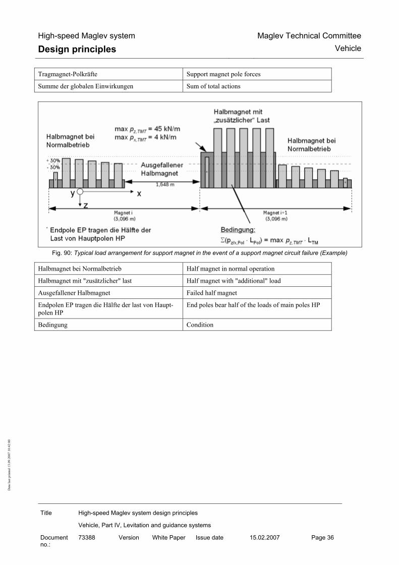
High-speed Maglev system
Design principles Maglev Technical Committee
Vehicle
Title High-speed Maglev system design principles
Vehicle, Part IV, Levitation and guidance systems
Document no.:
73388 Version White Paper Issue date 15.02.2007 Page 36
Dat
e la
st p
rinte
d 13
.09.
2007
10:
42:0
0
Tragmagnet-Polkräfte Support magnet pole forces
Summe der globalen Einwirkungen Sum of total actions
Fig. 90: Typical load arrangement for support magnet in the event of a support magnet circuit failure (Example)
Halbmagnet bei Normalbetrieb Half magnet in normal operation
Halbmagnet mit "zusätzlicher" last Half magnet with "additional" load
Ausgefallener Halbmagnet Failed half magnet
Endpolen EP tragen die Hälfte der last von Haupt-polen HP
End poles bear half of the loads of main poles HP
Bedingung Condition

High-speed Maglev system
Design principles Maglev Technical Committee
Vehicle
Title High-speed Maglev system design principles
Vehicle, Part IV, Levitation and guidance systems
Document no.:
73388 Version White Paper Issue date 15.02.2007 Page 37
Dat
e la
st p
rinte
d 13
.09.
2007
10:
42:0
0
Maximum loads at the support magnet - lateral guidance rail interface
Induced loads
The following loads are transmitted at the interface between the guidance magnet (FM) and the lateral guidance rail (SFS): • Magnetic quasi-static and dynamic tensile forces in the y direction during operation without
technical failures or faults,
• Mechanical quasi-static and dynamic compressive forces in the y direction during operation with technical failures or faults,
• Frictional forces in the x direction as a result of mechanical compressive forces during special operation.
The following values must be taken into consideration as characteristic values for the maximum loads per metre of partial magnet length.
Design situations Direction of action
Load per m of guidance magnet
Max. tensile force and - permitted total weight - ay = 1.5 m/s², ax = 1.1 m/s² (WSV), Side wind 10 m/s at 400 km/h, RH = 1000 m
y direction 25 kN/m
Max. tensile force in sectional magnet operation and - permitted total weight - ay = 1.5 m/s², ax = 1.1 m/s²(WSV), RH = 1000 m - Side wind 37 m/s at 400 km/h, Fz_dyn_mittel
y direction 32 kN/m 10
- Max quasi-stationary compressive force in the event of failure of the magnetic guidance function in an individual levitation undercarriage
y direction 25 kN/m
- Frictional force from quasi-stationary compressive force x direction 7.5 kN/m
The centre of gravity of the load introduced in the z direction varies with the type of guidance magnet and in the event of guidance control equipment failure.
The maximum guidance force of a guidance magnet must be limited to 16 kN/m for a single pole and 32 kN/m for a double pole.
Table 85: Maximum line loads
For local load distribution and the definition of single pole / double pole see Fig. 91. 10) If the maximum guidance force of 32 kN/m is exceeded this leads to mechanical lateral guidan-ce(see chapter 0).

High-speed Maglev system
Design principles Maglev Technical Committee
Vehicle
Title High-speed Maglev system design principles
Vehicle, Part IV, Levitation and guidance systems
Document no.:
73388 Version White Paper Issue date 15.02.2007 Page 38
Dat
e la
st p
rinte
d 13
.09.
2007
10:
42:0
0
The following values must be taken into consideration as characteristic values for the maximum impact force:
Design situations Direction of action
Load per guidance magnet
- Max dynamic impact force in the event of failure of the magnetic guidance function in an individual levita-tion undercarriage and gusts of side wind.
y direction 115 kN
- Frictional force from dynamic impact force x direction 34.5 kN
The centre of gravity of the load introduced in the z direction varies with the type of guidance magnet and in the event of guidance control equipment failure.
Table 86: Maximum impact force

High-speed Maglev system
Design principles Maglev Technical Committee
Vehicle
Title High-speed Maglev system design principles
Vehicle, Part IV, Levitation and guidance systems
Document no.:
73388 Version White Paper Issue date 15.02.2007 Page 39
Dat
e la
st p
rinte
d 13
.09.
2007
10:
42:0
0
Dynamic excitation
In the case of the guideway, possible excitation from the arrangement of the guidance magnets must be taken into account.
Double pole: right-hand guidance magnet (corner magnet)
Single pole: left-hand guidance magnet (corner magnet) Guidance magnet (centre)

High-speed Maglev system
Design principles Maglev Technical Committee
Vehicle
Title High-speed Maglev system design principles
Vehicle, Part IV, Levitation and guidance systems
Document no.:
73388 Version White Paper Issue date 15.02.2007 Page 40
Dat
e la
st p
rinte
d 13
.09.
2007
10:
42:0
0
Fig. 91: Typical load arrangements of guidance magnets (example)
Führmagnet-Polleistenkräfte Guidance magnet pole strip forces
Bedingung Condition
Führmagnet (Eckmagnet) Guidance magnet (corner magnet)
Führmagnet-Polleisten Guidance magnet pole strips
Führmagnet (Mitte) Guidance magnet (centre)
Maximum loads at the support skid - sliding surface interface
Induced loads
In the event of levitation system failures the sliding surface (GL) at the interface between the sup-port skid and the sliding surface is subjected to the following loads: In the z direction (compressive load): • proportional quasi-static and dynamic load of a sliding levitation undercarriage • transient impact load from the uncontrolled setting down of a levitation undercarriage in the x direction: • force resulting from the load in the z direction and the coefficient of friction.
The following values must be taken into consideration as characteristic values for the maximum loads imposed by an individual support skid.
Characteristic values of the maximum skid forces in [kN]
Direction of action
Load per support skid
Static vehicle at 16° transverse inclination y 14
z 50 Quasi-static and dynamic com-pressive force x 15 or 25 in the event
of stiction
z 100
Levitating vehicle
Impact force limit x 30
z -50 Frozen-on support skid
x 25
Table 87: Maximum support skid forces
For local load distribution see Fig. 92.

High-speed Maglev system
Design principles Maglev Technical Committee
Vehicle
Title High-speed Maglev system design principles
Vehicle, Part IV, Levitation and guidance systems
Document no.:
73388 Version White Paper Issue date 15.02.2007 Page 41
Dat
e la
st p
rinte
d 13
.09.
2007
10:
42:0
0
Dynamic excitation
Excitation as a result of local actions of the support skid can be ignored as far as the guideway is concerned.
ex,TK = 3096 mm ex,TK = 3096 mm
ey,TK = 2220 mm
Gleitebene
Fx,TKFz,TK
Fy,TK
740 mm
110 mm
TMTi TMTi+1
Fig. 92: Load arrangements of support skid (example
abgesetzte Tragkufe Set down support skid
Gleitebene Slideway

High-speed Maglev System Design principles
Maglev Technical Commit-tee
Vehicle
Title High-speed Maglev system Design principles
Vehicle, Part V, Braking system
Document no.:
73389 Version White Pa-per
Issue date 15.02.2007 Page 1
Dat
e la
st p
rinte
d 13
.09.
2007
10:
42:0
0
High-speed Maglev System Design principles
Vehicle Part V
Brake system
Copyright of this document and all enclosures remains with the author. All rights reserved

High-speed Maglev System Design principles
Maglev Technical Commit-tee
Vehicle
Title High-speed Maglev system Design principles
Vehicle, Part V, Braking system
Document no.:
73389 Version White Pa-per
Issue date 15.02.2007 Page 2
Dat
e la
st p
rinte
d 13
.09.
2007
10:
42:0
0
Distribution The Vehicle Committee has released this document for publication.

High-speed Maglev System Design principles
Maglev Technical Commit-tee
Vehicle
Title High-speed Maglev system Design principles
Vehicle, Part V, Braking system
Document no.:
73389 Version White Pa-per
Issue date 15.02.2007 Page 3
Dat
e la
st p
rinte
d 13
.09.
2007
10:
42:0
0
Revisions Date of release: 15.02.2007; White Paper, Vehicle Committee.

High-speed Maglev System Design principles
Maglev Technical Commit-tee
Vehicle
Title High-speed Maglev system Design principles
Vehicle, Part V, Braking system
Document no.:
73389 Version White Pa-per
Issue date 15.02.2007 Page 4
Dat
e la
st p
rinte
d 13
.09.
2007
10:
42:0
0
Contents
Distribution....................................................................................................................................................... 2
Change history................................................................................................................................................. 3
List of contents ................................................................................................................................................ 4
General ............................................................................................................................................................. 5
Distribution....................................................................................................................................................... 2
Revisions.......................................................................................................................................................... 3
Contents ........................................................................................................................................................... 4
General ............................................................................................................................................................. 6 Purpose and applications .................................................................................................................................. 6 High-speed Maglev system design principles ................................................................................................... 6 Abbreviations and Definitions ............................................................................................................................ 7 Legislation, regulations, standards and directives............................................................................................. 8 Identification and mandatory nature of requirements ........................................................................................ 8
Definitions (vehicle-specific).......................................................................................................................... 9
General requirements of the braking system ............................................................................................. 12 Subsystems and equipment ............................................................................................................................ 12 Operation ......................................................................................................................................................... 15 Design and ratings........................................................................................................................................... 17 Safety requirements......................................................................................................................................... 18 Requirements for the on-board energy supply ................................................................................................ 19 Requirements for the execution of a set-down command. .............................................................................. 19 Systematic faults in the braking system .......................................................................................................... 19 Taking friction pairing into account .................................................................................................................. 19 Braking magnet / lateral guidance rail, ............................................................................................................ 19 Support skids / sliding surface......................................................................................................................... 20
Requirements for the braking equipment ................................................................................................... 21 Generation of braking force ............................................................................................................................. 21 Properties and functions.................................................................................................................................. 21 Effect of failure................................................................................................................................................. 21 Failure reporting............................................................................................................................................... 21

High-speed Maglev System Design principles
Maglev Technical Commit-tee
Vehicle
Title High-speed Maglev system Design principles
Vehicle, Part V, Braking system
Document no.:
73389 Version White Pa-per
Issue date 15.02.2007 Page 5
Dat
e la
st p
rinte
d 13
.09.
2007
10:
42:0
0
Certificates....................................................................................................................................................... 21 Control and monitoring of the braking effect ................................................................................................... 23 Properties and functions.................................................................................................................................. 23 Behaviour in the event of failure ...................................................................................................................... 23 Certificates....................................................................................................................................................... 23
Actions of the braking equipment on the guideway.................................................................................. 24 General ............................................................................................................................................................ 24 Types and combinations of actions ................................................................................................................. 24 Forces and load arrangements........................................................................................................................ 25 Overall actions on the guideway...................................................................................................................... 25 Braking magnet - lateral guidance rail interface .............................................................................................. 25 Support skid / sliding surface interface............................................................................................................ 26
List of figures Fig. 12: Side view and cross-section of a vehicle, identifying the braking equipment (schematic) . 10 Fig. 13: Magnet module (example) ................................................................................................. 10 Fig. 14: View of a braking magnet (example), definition of the essential components ................... 10 Fig. 15: Support skid (example) ...................................................................................................... 11 Fig. 16: Subsystems and equipment involved in safe braking (example) ....................................... 13 Fig. 17: Braking characteristic for the safe brake for a vehicle section (Figure 10 taken from chapter
8.5 of /MSB AG-GESAMTSYS/)............................................................................................... 17 Fig. 18: Project structure for safety-relevant systems (Part I / project-specific example) ............... 27 Fig. 19: Project structure for safety-relevant systems (Part II / project-specific example) .............. 28 List of tables TOC

High-speed Maglev System Design principles
Maglev Technical Commit-tee
Vehicle
Title High-speed Maglev system Design principles
Vehicle, Part V, Braking system
Document no.:
73389 Version White Pa-per
Issue date 15.02.2007 Page 6
Dat
e la
st p
rinte
d 13
.09.
2007
10:
42:0
0
General
Purpose and applications • This "High-speed magnetic levitation railway vehicle design principles, part V - Brake sys-
tems" sets out the requirements for the safe braking systems installed in the vehicle.
• It applies to a Maglev system in accordance with the General Maglev System Act /AMbG/.
• The "long stator" control braking system is not covered in this document (see /MSB AG-GESAMTSYS/).
• Part V is to be used for the specification, execution and certification of the braking systems of MAGLEV vehicles.
• Any deviations from the requirements and definitions given in this document require equal safety in accordance with /MbBO/ of the certificate.
• Part V of the "MAGLEV vehicle performance specification" comprises:
Definition of the braking equipment;
Requirements for the braking equipment;
The actions of the braking equipment on the guideway;
Description of the interfaces with other systems (on-board operational control system (BLT), on-board energy supply).
• The requirements for a secure vehicle braking system are summarized. The document does not include a description of the braking control and monitoring by the BLT. This is given in /MSB AG-BLT/.
High-speed Maglev system design principles • This document is part of the documentation for high-speed magnetic levitation railways
consisting of a number of design principles. Figure 1 /MSB AG-GESAMTSYS/ shows the documentation tree.
• The overall design principles for the complete system and its appendices apply uniformly to all the documentation.
• High-speed Maglev system design principles, complete system, Document no.: 50630, /MSB AG-GESAMTSYS/, with appendices:
• Annex 1: Abbreviations and definitions, Document no.: 67536, /MSB AG-ABK&DEF/ • Annex 2: Legislation, regulations, standards and directives, Document no.: 67539, /MSB
AG-NORM&RILI/ • Annex 3: Environmental constraints, Document no.: 67285, /MSB AG-UMWELT/ • Annex 4: Operating rules (operation and maintenance), Document no.: 69061, /MSB
AG-BTR/

High-speed Maglev System Design principles
Maglev Technical Commit-tee
Vehicle
Title High-speed Maglev system Design principles
Vehicle, Part V, Braking system
Document no.:
73389 Version White Pa-per
Issue date 15.02.2007 Page 7
Dat
e la
st p
rinte
d 13
.09.
2007
10:
42:0
0
• Annex 5: Noise, Document no.: 72963, /MSB AG-SCHALL/ The documentation on the vehicle consists of the following documents: • High-speed Maglev system design principles, vehicle, Part I.: Design principles, Document
no.: 67698, /MSB AG-FZ GEN/ • High-speed Maglev system design principles, vehicle, Part II.: Design, document no.:
67694, /MSB AG-FZ BEM/ • High-speed Maglev system design principles, vehicle, Part III.: Kinematic limits, Document
no.: 67650, /MSB AG-FZ KIN/ • High-speed Maglev system design principles, vehicle, Part IV.: Levitation and guidance
systems, Document no.: 73388, /MSB AG-FZ TRAFÜ/ • High-speed Maglev system design principles, vehicle, Part V.: Braking system, Document
no.: 73389, /MSB AG-FZ BREMS/
Abbreviations and Definitions • The abbreviations and definitions supplied in /MSB AG-ABK&DEF/ should be used.
• The following abbreviations apply in addition to /MSB AG-ABK&DEF/:
• a Braking delay (instantaneous value)
FG Baking force of the vehicle
FBrems Braking force of the vehicle as a result of the action of the braking equipment
FW Train resistance of the vehicle
FH Holding brake effort
m Vehicle earth
mb Set-down part of the vehicle mass
s Local variable
v speed (instantaneous)
v0 Braking output rate
µH Coefficient of friction for the holding brake function
µH min Minimum coefficient of friction for the holding brake function on an iced-up guideway

High-speed Maglev System Design principles
Maglev Technical Commit-tee
Vehicle
Title High-speed Maglev system Design principles
Vehicle, Part V, Braking system
Document no.:
73389 Version White Pa-per
Issue date 15.02.2007 Page 8
Dat
e la
st p
rinte
d 13
.09.
2007
10:
42:0
0
Legislation, regulations, standards and directi-ves
• The prescriptive documents listed in /MSB AG-NORM&RILI/ contain definitions that are re-ferred to in the high-speed Maglev system design principles and have become part of the high-speed Maglev system design principles. Where prescriptive documents in /MSB AG-NORM&RILI/ are dated, subsequent changes or revisions of these publications do not ap-ply. Where references are undated, the latest edition of the prescriptive documents referred to is applicable.
• The edition of the standards and guidelines to be adhered to in a Maglev project must be made binding for each specific project.
Identification and mandatory nature of requi-rements
• The content of the present document is substantially based on the provisions of /DIN 820/ .
• In the following chapters of this document, and in the appendices,
Requirements are shown in standard type
Explanations, guidelines and examples are shown in italic.
•
• Where notes on project-specific regulations are given in this document for individual cases, (e.g. in a specification or a contractual regulation) this means that the manufacturer and the contractor must consult the approvals authorities and come to an agreement.

High-speed Maglev System Design principles
Maglev Technical Commit-tee
Vehicle
Title High-speed Maglev system Design principles
Vehicle, Part V, Braking system
Document no.:
73389 Version White Pa-per
Issue date 15.02.2007 Page 9
Dat
e la
st p
rinte
d 13
.09.
2007
10:
42:0
0
Definitions (vehicle-specific)
TM BM FM
SR
SG1 SG2 SG3 SG4 1 2 3 4 5 6 7 8
Longitudinal connector
SG = Levitation chassis (LC) SR = Levitation undercarriage (2 levitation frames +connecting parts) TM = Support magnet FM = Guidance magnet BM = Braking magnet TK = Support skid WK = Carriage body
Levitation chassis (without magnets)
Longitudinal connectorTK
SR
Vehicle frame dimension
Vehicle guideway width
TM
BM
TK
Pneumatic spring Pendulum
Support magnet centre distance =support skid centre distance
Pneumatic
Z support for carriage body Roll stabiliser
Additional Y spring

High-speed Maglev System Design principles
Maglev Technical Commit-tee
Vehicle
Title High-speed Maglev system Design principles
Vehicle, Part V, Braking system
Document no.:
73389 Version White Pa-per
Issue date 15.02.2007 Page 10
Dat
e la
st p
rinte
d 13
.09.
2007
10:
42:0
0
Fig. 93: Side view and cross-section of a vehicle, identifying the braking equipment (schematic)
Fig. 94: Magnet module (example)
MagnetrückenBremspol GleitplattenBremsmagnet MagnetrückenBremspol GleitplattenBremsmagnet
Fig. 95: View of a braking magnet (example), definition of the essential components
Bremsmagnet Braking magnet
Bremspol Braking pole
Gleitplatten Sliding plates
Magnetrücken Rear of magnet
Support magnet
Braking magnet Levitation frame

High-speed Maglev System Design principles
Maglev Technical Commit-tee
Vehicle
Title High-speed Maglev system Design principles
Vehicle, Part V, Braking system
Document no.:
73389 Version White Pa-per
Issue date 15.02.2007 Page 11
Dat
e la
st p
rinte
d 13
.09.
2007
10:
42:0
0
Fig. 96: Support skid (example)
Sliding surfacelining
Housing

High-speed Maglev System Design principles
Maglev Technical Commit-tee
Vehicle
Title High-speed Maglev system Design principles
Vehicle, Part V, Braking system
Document no.:
73389 Version White Pa-per
Issue date 15.02.2007 Page 12
Dat
e la
st p
rinte
d 13
.09.
2007
10:
42:0
0
General requirements of the braking system
Subsystems and equipment • The description in /MSB AG-GESAMTSYS/ is applicable.
• The following brakes are available for the vehicle:
Braking function of the long stator propulsion system, used in fault-free condition (operating brake);
Safety brake, controlled by BLT devices in the vehicle.
• The "long stator propulsion" braking function is not covered in this document (see /MSB AG-GESAMTSYS/).
• This design principles controls the demands that the vehicle makes on the braking system (safe brake) and their actions on the guideway. The propulsion system shutdown and the vehicle's own braking system are controlled by the operational control system, which also prevents inadmissible superimposition effects. This design principles does not cover these functions11.
• Examples of the subsystems and equipment used in the safety brake are defined in Fig. 97. In this example the control and monitoring of the safe brake that the BLT has to implement is done in the vehicle using the following subsystems and equipment:
The control signals from the BLT to activate the braking function and to control the effect of braking are transmitted to the braking magnet control devices.
The braking magnet control devices control the current in the braking magnets and perform distributed monitoring of the brake devices concerned.
The monitoring signals from the brakes of the magnet control devices are transmitted to the BLT.
The braking magnets generate speed-dependent eddy currents in the lateral guidance rails of the guideway and these result in deceleration forces on the braking magnets. In addition the braking magnets create forces of attraction on the lateral guidance rails. In the lower speed range the brak-ing magnets apply themselves because of the forces of attraction on the lateral guidance rails and generate frictional forces between the sliding plates of the braking magnets and the lateral guidance rails.
The forces acting on the brake are directed into the vehicle by the guidance parts and structural parts of the brake.
Immediately before the vehicle comes to a standstill, the BLT switches the brake off and the vehicle is set down by the support skids on the sliding surface, acting on control signals from the BLT to the support magnet control devices.
The support skids take over the function of a holding brake.
The monitoring signals from the on-board networks and the support magnet control devices are trans-mitted to the BLT.
11The design principles describes the construction requirements for the safe brake that are not pro-ject-dependent and are based on specific construction features.

High-speed Maglev System Design principles
Maglev Technical Commit-tee
Vehicle
Title High-speed Maglev system Design principles
Vehicle, Part V, Braking system
Document no.:
73389 Version White Pa-per
Issue date 15.02.2007 Page 13
Dat
e la
st p
rinte
d 13
.09.
2007
10:
42:0
0
• The generation of the braking force as per chapter 0 (in Fig. 97 Braking magnet, structural guidance parts for the brake, braking magnet control equipment and the control and super-vision of the braking effect in accordance with chapter 0 (in Fig. 97 Transmission of brake control and monitoring signals from and to the BLT, generation of safety-relevant status in-formation in the magnet control equipment) are part of this design principles (/MSB AG-FZ BREMS/).
SeitenführschieneGleitebene
Struktur- / Anlenk-teile BremseTrag-
kufe
Brems-magnet
Magnetregel-Einrichtungen
Tragen
Bremseinrichtungen
Trag-/ Führstruktur
Mobile Einrichtungen der BLT
Übertragung von sicherheitsrelevanten Steuerungs- und Überwachungssignalen
Fahrweg
Fahrzeug
Steuerung / Überwachung Sichere Bremse
BordnetzeMagnetregel-einrichtungen
Bremsen
Fig. 97: Subsystems and equipment involved in safe braking (example) Mobile Einrichtungen der BLT Mobile BLT equipment
Steuerung/Überwachung sichere Bremse Control/monitoring of the safe brake

High-speed Maglev System Design principles
Maglev Technical Commit-tee
Vehicle
Title High-speed Maglev system Design principles
Vehicle, Part V, Braking system
Document no.:
73389 Version White Pa-per
Issue date 15.02.2007 Page 14
Dat
e la
st p
rinte
d 13
.09.
2007
10:
42:0
0
Übertragung von sicherheitsrelevanten Steuerungs- und Überwachungssignalen
Transmission of safety-relevant control and monito-ring signals
Magnetregel-Einrichtungen Tragen Magnet control equipment for support
Bordnetze On-board power supplies
Magnetregel-Einrichtungen Bremsen Magnet control equipment for brakes
Fahrzeug Vehicle
Tragkufe Support skid
Struktur/Anlenkteile Bremse Structural and pivoting parts for brakes
Bremsmagnet Braking magnet
Gleitebene Sliding surface
Fahrweg Guideway
Seitenführschiene Lateral guidance rail
Bremseinrichtungen Braking equipment

High-speed Maglev System Design principles
Maglev Technical Commit-tee
Vehicle
Title High-speed Maglev system Design principles
Vehicle, Part V, Braking system
Document no.:
73389 Version White Pa-per
Issue date 15.02.2007 Page 15
Dat
e la
st p
rinte
d 13
.09.
2007
10:
42:0
0
• Functions of the BLT that are necessary for the use of safe braking
Control and supervision of brake testing,
Control and supervision of safe braking,
Maximum profile monitoring,
Minimum profile monitoring,
Safe location,
Safe propulsion shutdown,
• are in the design principles for the BLT (/MSB AG-BLT/).
• The levitation and guidance structure and the support and guidance magnet regulation de-vices are dealt with in the design principles for the levitation and guidance system (/MSB AG-FZ TRAFÜ/).
• The design of the structural components of the brake is given in /MSB AG-FZ BEM/.
Operation • The vehicle's own safe brake must be designed in such a way that the vehicle can brake
independently at a defined stopping place using its own operational control system equip-ment.
• The vehicle's own safe brake must have the following functions:
BLT can actuate the brake at any time,
BLT can control the magnitude of the braking effect,
Stopping brake function.
• Sections 13 and 20 of the MbBO apply to the stopping brake function. The conversion must be certified separately for each project. The requirements of /MSB AG-GESAMTSYS/ are applicable. A stopping position, once adopted, must be maintained.
• Braking ability is determined by the speed-dependent effective braking power of the vehicle FG when long stator propulsion is switched off and by the brake winding time te after activa-tion by the BLT.
• The following applies in general for FG: •
FG = FBrems + FW
where FBrems : Braking force of the vehicle as a result of the action of the braking equipment
FW: Train resistance of the vehicle
• Braking ability must be verified by means of tests.
• The speed-dependent braking force for a given vehicle mass m is calculated as •
FG (v) = a (v) ⋅ m .

High-speed Maglev System Design principles
Maglev Technical Commit-tee
Vehicle
Title High-speed Maglev system Design principles
Vehicle, Part V, Braking system
Document no.:
73389 Version White Pa-per
Issue date 15.02.2007 Page 16
Dat
e la
st p
rinte
d 13
.09.
2007
10:
42:0
0
• The train resistance FW must be verified by means of suitable levitation tests with the vehi-cle not propelled and not braked in the same way as FG .
• The stopping brake function can be achieved by setting the vehicle down on the support skids.
• The stopping brake force FH is determined by the set-down proportion of the vehicle mass mb and the coefficient of friction µH acting on the area of contact between the guideway and the vehicle.
• The stopping brake function is present when the stopping brake force is greater than the force acting on the stationary vehicle in the x direction. This is made up of the incline output force during longitudinal inclination and the aerodynamic force due to wind in the x direc-tion.
• When certifying the stopping brake function, a project-specific safety factor > 1 must be taken into account.
• An example of the maximum and minimum braking characteristics that can be achieved with the safe braking system for a vehicle section is given in Fig. 98.
• For each project the limits must be balanced against the requirements of the BLT and the design of the guideway. The project-specific defined values must be adhered to.
0
50
100
150
200
250
300
350
0 50 100 150 200 250 300 350 400 450 500 550
Geschwindigkeit [km/h]
Bremskraft[kN/Sektion]
34
250 kN
360 kN
v = 0 km/h
Übergangsbereich: Gleitreibung → Haftreibung
100 ... 200 ms
t
F
1
2
Maximale Bremskennlinie (Grundlage zur Bemessung von Fahrzeug und Fahrweg)
Grenzlinie für zulässige Verzögerung mit 1,5 m/s²
Minimale Bremskraft bei vereistem Fahrweg
Minimale Bremskennlinie (Grundlage für das sichere Bremsprofil)
Kraft bei außergewöhnlicher Einwirkung
1
2
3
4
Ausgleiten auf Tragkufen
Bremskraft aus Wirbelstrombremse
Bremsmagnet an Seitenführschiene anliegend
Bremsmagnet berührungsfrei
Fx = 360 kN/Sektion (Haftreibung)max. dynamische Bremskraft
Fx = 250 kN/Sektion Ausgleiten bei Übergang zur Haftreibung
Fx = 215 kN/Sektion Aufsetzen der Tragkufen aus Gleitreibung
Fx = 110 kN/Sektion (entspricht der Bremsverzögerung 1,5 m/s² bei zulässigem Fahrzeuggewicht)

High-speed Maglev System Design principles
Maglev Technical Commit-tee
Vehicle
Title High-speed Maglev system Design principles
Vehicle, Part V, Braking system
Document no.:
73389 Version White Pa-per
Issue date 15.02.2007 Page 17
Dat
e la
st p
rinte
d 13
.09.
2007
10:
42:0
0
Fig. 98: Braking characteristic for the safe brake for a vehicle section (Figure 10 taken from chapter 8.5 of /MSB AG-GESAMTSYS/)
Bremskraft [kN /Sektion] Braking force [kN/section]
Fx = 360 kN/Sektion (Haftreibung) Fx = 360 kN/section (stiction)
max. dynamische Bremskraft Max dynamic braking force
Fx = 250 kN/Sektion Fx = 250 kN/section
Ausgleiten bei Übergang zur haftreibung Slip on transition to stiction
Fx = 215 kN/Sektion Fx = 215 kN/section
aufsetzen der Tragkufen aus Gleitreibung Support skids applied by sliding friction
Fx = 110 kN/Sektion Fx = 110 kN/section
(entspricht der Bremsverzögerung 1,5 m/s2 bei zu-lässigem Fahrzeuggewicht)
(equivalent to braking delay of 1.5 m/s2 for permis-sible vehicle weight)
Übergangsbereich: Gleitreibung Haftreibung Transition area: sliding friction stiction
Maximale Bremskennlinie (Grundlage für Bemes-sung fon Fahrzeug und Fahrweg)
Maximum braking characteristic (Design basis for vehicle and guideway)
Grenzlinie für zulässiger Verzögerung mit 1,5 m/s2 Threshold for permissible braking at 1.5 m/s2
Minimale Bremskraft bei vereistem Fahrweg Minimum braking force for iced-up guideway
Minimale Bremskennlinie Minimum braking characteristic
Kraft bei außergewöhnlicher einwirkung Force in the event of accidental action
Ausgleiten auf Tragkufen Slip on support skids
Bremsmagnet an Seitenführscheine anliegend Braking magnet adjacent to lateral guidance rail
Bremskraft aus Wirbelstrombremse Braking force from eddy current brake
Bremsmagnet berührungsfrei Braking magnet not in contact
Geschwindigkeit Speed
Design and ratings • The loads that are borne by the structural components and pivots of the equipment produc-
ing the braking force must be taken into account, using the Vehicle design principles, Part II /MSB AG-FW BEM/, during the design process.
• The loads specific to the project must be documented.
• Proof of load-bearing capability (general stress certificate) and fatigue resistance according to the requirements set out in Part II /MSB AG-FW BEM/ must be provided for the compo-nents that transfer the load.
• The braking elements must take all of the geometric constraints in accordance with /MSB AG-FW GEO/ fully into account. At the same time it must be ensured that the action of braking has no effect on the permitted surface deviations that would place the system at risk.

High-speed Maglev System Design principles
Maglev Technical Commit-tee
Vehicle
Title High-speed Maglev system Design principles
Vehicle, Part V, Braking system
Document no.:
73389 Version White Pa-per
Issue date 15.02.2007 Page 18
Dat
e la
st p
rinte
d 13
.09.
2007
10:
42:0
0
Safety requirements • The systems relevant to safety must be planned and certified to /DIN EN 50126/ as a gen-
eral rule.
• Fig. 99 and Fig. 100 give examples of a structure for this task.
• The control and operation of the safe brake with spot braking must be safe over the entire speed range for its lifetime (Safe-Life). The permissible failure rate for the safe brake over an assumed period of operation (being driven and at a standstill) must be determined by a risk analysis.
• Information on methods of performing the risk analysis is given in /prEN 50,126-2/ and /prR009-004/.
• The speed range must include the maximum speed according to the maximum trip profile right down to a standstill. The speed range can be covered by one or more braking sys-tems, e.g. an eddy current system combined with a friction brake.
• The safe life requirement must cover the most unfavourable specified boundary conditions such as maximum load, following wind, descent, actions from the primary environment, par-ticularly wintry weather and lightning, and also technical faults and breakdowns.
• To achieve the required failure rate the safe brake can be executed with redundant braking equipment. Breakdowns in the redundant safe brake or a reduction in braking force due to technical faults or breakdowns must not affect the safe-life qualities of the safe brake.
• Certification of the safe-life property must be performed using a suitable method of analy-sis, e.g. a fault tree analysis before the system is commissioned. This theoretical certificate must be backed up by experimental verification of the assembly failure rates assumed in the analysis and by practical tests to demonstrate the failure behaviour in the event of the failure of assemblies. The analysis must include a common cause fault analysis.
• A safety certificate including risk analysis to /DIN EN 50126/ is required for the safe brake.
• The requirements for and tests on the equipment for producing the braking force are given in chapter 0.
• The requirements for and tests on the equipment for controlling and monitoring the braking force are given in chapter 0.
• The SIL level according to /DIN EN 50129/ for the electronic equipment for producing the braking force and for controlling and monitoring it must be determined on the basis of the risk analysis and must be taken into account when performing the certification.
• The level of the safety requirements for the software in the braking system that has been determined on the basis of the risk analysis must be taken into consideration when per-forming the certification to /DIN EN 50128/.
• A suitable analysis must include consideration of at least the following faults:
Fault in the on-board energy supply,
Anticipated or delayed execution of a set-down command,
System failure (of software or hardware),.

High-speed Maglev System Design principles
Maglev Technical Commit-tee
Vehicle
Title High-speed Maglev system Design principles
Vehicle, Part V, Braking system
Document no.:
73389 Version White Pa-per
Issue date 15.02.2007 Page 19
Dat
e la
st p
rinte
d 13
.09.
2007
10:
42:0
0
Untimely lifting of the vehicle.
Requirements for the on-board energy supply • The system characteristics of the safe brake set functional and safety-relevant require-
ments for the on-board energy supply and proof is required that these have been met, see / MSB AG-FZ TRAFÜ/.
• In order to perform forced braking with the safe brake an uninterruptible power supply must be provided. This must take account of the most adverse environmental and operating con-ditions that have been specified.
Requirements for the execution of a set-down command. • The set-down command must be generated in such a way - and must be linked by a logical
AND with the speed determined independently in each levitation and guidance unit in such a way - that the command to set down can only be decentrally effective when the vehicle speed is lower than the permitted set-down speed.
• A certificate is required for the set-down control to the effect that the set-down command can only become effective below the set-down speed and, with sufficient probability, also in the event of all foreseeable failures.
Systematic faults in the braking system • Certification that systematic faults are sufficiently unlikely or that their effects are under con-
trol is required in accordance with /DIN EN 50129/. This applies to the hardware and, if pre-sent, the software of the equipment that is relevant to safety in the measurement, control, regulation and monitoring systems of the magnet regulating circuits of the safe brake.
• Diagnostic and control equipment should be provided separately as part of the hardware and software.
•
Taking friction pairing into account
Braking magnet / lateral guidance rail, • The mutual action of the forces from the braking magnet and lateral guidance rail compo-
nents guarantees the effectiveness of the safe brake. The braking effect is created by an eddy current effect and, in the lower speed range, by mechanical friction.
• The normal forces, frictional characteristics and surface pressure acting between the lateral guidance rail and sliding plate must be taken into account during design work.
• Wear on the sliding plates must be taken into account in the maintenance schedule.
• The properties of the frictional pairing of sliding plate and lateral guidance rails must be de-fined and certified for each project. Suitable test rig results can be used for this.

High-speed Maglev System Design principles
Maglev Technical Commit-tee
Vehicle
Title High-speed Maglev system Design principles
Vehicle, Part V, Braking system
Document no.:
73389 Version White Pa-per
Issue date 15.02.2007 Page 20
Dat
e la
st p
rinte
d 13
.09.
2007
10:
42:0
0
Support skids / sliding surface • The support skid and sliding surface come into mechanical contact when the magnetic levi-
tation function is interrupted.
• This happens
when the vehicle is set down,
when the levitation system is in emergency running mode,
as a contributory braking function of the safe brake at low speeds, e.g. ≤ 10 km/h (project-specific figure),
as a stopping brake function.
• Wear on the support skids must be taken into account in the maintenance schedule.
• The properties of the frictional pairing of support skid and sliding surface must be defined and certified for each project. Suitable test rig results can be used for this.

High-speed Maglev System Design principles
Maglev Technical Commit-tee
Vehicle
Title High-speed Maglev system Design principles
Vehicle, Part V, Braking system
Document no.:
73389 Version White Pa-per
Issue date 15.02.2007 Page 21
Dat
e la
st p
rinte
d 13
.09.
2007
10:
42:0
0
Requirements for the braking equipment
Generation of braking force
Properties and functions • The braking forces of the safe brake are generated by:
Braking systems that give rise to braking forces via the interface with the guideway,
Braking systems that give rise to a stopping force via the interface with the guideway when the vehicle is at a standstill.
Effect of failure • The failure of one braking system must not adversely affect the operation of the other brak-
ing systems.
• The risk of the following failures occurring within the braking systems per year and per ve-hicle, which must be determined in advance in a risk analysis, must not exceed:
Failures that lead to the partial or complete activation of the safe brake by the BLT without a com-mand,
Failures that lead to the defined maximum braking force being exceeded,
Failures that lead to the defined minimum braking force being exceeded.
• Where they interact with the levitation and guidance system, failures of brake systems must be taken into account in the design and execution of the levitation and guidance system.
• Where they interact with the operation of the safe brake, failures in the levitation and guid-ance system must be taken into account in the design and execution of the braking sys-tems.
Failure reporting • In addition to notification from and to the BLT, failures in the braking systems must be fail-
safe.
• Where monitoring devices that are relevant to safety do not automatically report failure, pe-riodic functional tests / inspections must make failures obvious.
• The times of failure reporting that are required in order to comply with the preset failure rate according to the risk analysis must be adhered to.
• The test criteria and intervals must be determined by means of a suitable analysis, e.g. fault tree analysis, FMEA
Certificates • A qualification test with prototypes must be performed on the braking systems to certify the
operation, failure behaviour, reporting of failures and environmental resistance.

High-speed Maglev System Design principles
Maglev Technical Commit-tee
Vehicle
Title High-speed Maglev system Design principles
Vehicle, Part V, Braking system
Document no.:
73389 Version White Pa-per
Issue date 15.02.2007 Page 22
Dat
e la
st p
rinte
d 13
.09.
2007
10:
42:0
0
• the speed-dependent curves for braking power FBrems, both at full availability and also at a specified maximum number of failed brake circuits , and the train resistance FW must be certified by performing tests on a representative vehicle under defined environmental condi-tions and rated load.
• The speed-dependent curve of the minimum effective braking force FBrems under the most unfavourable environmental conditions, rated load and failure conditions can be obtained by calculation.
• The braking force certificate must take into account those failures that are within the ac-ceptable failure rate according to the risk analysis (see chapter 0).
• A suitable analysis must be carried out to certify the safe life function, e.g. fault tree analy-sis. The analysis must include a common cause fault analysis.
• A suitable analysis, e.g. a fault tree analysis, must show that the following events have a risk of occurring per year and per vehicle that is to be determined beforehand in a risk analysis:
Full or partial application of the brakes without a command or control from the BLT,
Failure to reach a required braking force or exceeding the maximum permitted braking force over the whole of the speed range including standstill.
• Failure behaviour must be demonstrated in tests that simulate assembly failures.
• The reliability of the electronic braking systems must be verified by determining the MTBF from the evaluation of life cycle data on representative assemblies during operation.
• The compatibility of the MTBF verified from life cycle data with the forecast statements of the analysis must be demonstrated.

High-speed Maglev System Design principles
Maglev Technical Commit-tee
Vehicle
Title High-speed Maglev system Design principles
Vehicle, Part V, Braking system
Document no.:
73389 Version White Pa-per
Issue date 15.02.2007 Page 23
Dat
e la
st p
rinte
d 13
.09.
2007
10:
42:0
0
Control and monitoring of the braking effect
Properties and functions • The safety-relevant control and monitoring functions of the safe brake include:
transmission of control commands from the BLT to the baking systems in order to activate the braking function and control the braking effect
generation of safety-relevant status information to monitor the braking systems and transmission of this information to the BLT.
• This design principles does not cover non-safety-relevant status information (e.g. diagnostic messages).
Behaviour in the event of failure • An individual failure of the control / monitoring systems must not lead to the loss or limita-
tion of a safety-relevant control and monitoring function.
• The failure of a safety-relevant control / monitoring system that is due to the multiple failure of redundant assemblies must lead to an automatic failsafe system reaction.
• The triggering of this failsafe system reaction is guaranteed by the operational control sys-tem and is not part of this design principles.
Certificates • Qualification tests of the assemblies must be carried out with prototypes or on a represen-
tative vehicle.
• The control and monitoring equipment must be taken into account in the analysis to show the probability of occurrence of an insufficient or unforeseen application of the brakes (see chapter 6.1). The analysis must include a common cause fault analysis.

High-speed Maglev System Design principles
Maglev Technical Commit-tee
Vehicle
Title High-speed Maglev system Design principles
Vehicle, Part V, Braking system
Document no.:
73389 Version White Pa-per
Issue date 15.02.2007 Page 24
Dat
e la
st p
rinte
d 13
.09.
2007
10:
42:0
0
Actions of the braking equipment on the guideway
General • The forces given below correspond to the characteristic values of the actions of the vehicle
on the guideway at the vehicle-guideway interfaces.
Types and combinations of actions • The actions of the braking system on the guideway act upon the following interfaces:
• • Braking magnet - lateral guidance rail,
• Support skid - sliding surface
• The forces acting on the guideway are the result of the following functions:
• • magnetic braking effect caused by the eddy currents induced in the lateral guidance rails by
the braking magnet,
• magnetic tensile force on the lateral guidance rails as reaction rails of the braking magnets,
• mechanical braking effect owing to friction between the braking magnet and the lateral guidance rail,
• mechanical braking effect owing to friction between the support skid and the sliding surface.
• The effect of weathering on the magnetic braking effect can be disregarded.
• The magnetic braking effect is influenced by variations in environmental conditions via the effective coefficient of friction.
• The actions of the braking systems on the structure and the force introduction into the levi-tation and guidance system must be taken into consideration in accordance with chapter 0 when designing the assemblies.
• The actions on the guideway must be taken into account in the guideway design specifica-tions as variable and/or unusual actions from the vehicle.
• To ensure that the actions arising from operation of the vehicle that are assumed in the guideway design specifications agree well enough with actions arising in practice, the val-ues given in chapter 0 for the forces transmitted by the vehicle must not be exceeded (per-missible tolerance when verifying the magnitude of the actions is 5%).
• The magnitude of the characteristic values of the actions must be set down in a mandatory project-specific specification for every application.
• The magnitude of the actions must be demonstrated by calculation or by testing on a repre-sentative vehicle.

High-speed Maglev System Design principles
Maglev Technical Commit-tee
Vehicle
Title High-speed Maglev system Design principles
Vehicle, Part V, Braking system
Document no.:
73389 Version White Pa-per
Issue date 15.02.2007 Page 25
Dat
e la
st p
rinte
d 13
.09.
2007
10:
42:0
0
Forces and load arrangements
Overall actions on the guideway • A characteristic value of a force of 250 kN in the x direction is to be used for the maximum
overall braking effect of a vehicle section on the guideway given a permitted overall weight according to chapter 9 of /MSB AG-GESAMTSYS/ and a speed v > 0 km/h.
• At the changeover from v > 0 km/h to v = 0 km/h the effect of the transition from sliding fric-tion to static friction must be taken into consideration. At this point a transient maximum force of 360 kN in the x direction can occur, with a duration of action in the order of 100 ms to 200 ms.
Braking magnet - lateral guidance rail interface • At the interface between the braking magnet (BM) and the lateral guidance rail (SFS) there
is a magnetic transfer of tensile forces in the y direction and a magnetic and mechanical transfer of braking forces in the x direction.
• The material of the lateral guidance rail must satisfy the requirements of /MSB AG-GESAMTSYS/, chapter 6.1.4.3.6. The energy contributed by the braking system of the safe brake to the lateral guidance rail, which is converted to heat, must also be taken into con-sideration.
• Magnetic braking forces in the x direction arise as a result of eddy currents induced in the SFS by the braking magnets.
• Mechanical braking forces in the x direction arise as a result of frictional forces resulting from the magnetic attraction between the BM and the SFS.
• The following values must be taken into consideration as characteristic values for the maximum quasi-static loads imposed by an individual braking magnet.
• Type of action
Direction of action
Load per braking magnet
Load per m of SFS
Tensile force
y direction 50 kN 25 kN/m 1)
Longitudi-nal force
x direction 75 kN 37.5 kN/m
1) Locally the load may be 50 % higher Table 88: Characteristic values for the maximum quasi-static loads imposed by an individual braking magnet

High-speed Maglev System Design principles
Maglev Technical Commit-tee
Vehicle
Title High-speed Maglev system Design principles
Vehicle, Part V, Braking system
Document no.:
73389 Version White Pa-per
Issue date 15.02.2007 Page 26
Dat
e la
st p
rinte
d 13
.09.
2007
10:
42:0
0
Support skid / sliding surface interface • At the interface between the support skid and the sliding surface (GE) there is a transfer of
quasi-static weight force in the z direction and a force resulting from weight force and the coefficient of friction in the x direction.
• The following values must be taken into consideration as characteristic values for the maximum quasi-static loads imposed by an individual support skid.
Type of ac-
tion Direction of
action Load per support skid
Compressive force
z direction 50 kN
Longitudinal force
x direction 15 kN quasi-stationary when i v > 0 km/h max. 25 kN transient when v → 0 km/h
Table 89: Characteristic values for the maximum quasi-static loads imposed by an individual support skid

High-speed Maglev System Design principles
Maglev Technical Commit-tee
Vehicle
Title High-speed Maglev system Design principles
Vehicle, Part V, Braking system
Document no.:
73389 Version White Pa-per
Issue date 15.02.2007 Page 27
Dat
e la
st p
rinte
d 13
.09.
2007
10:
42:0
0
Fig. 99: Project structure for safety-relevant systems (Part I / project-specific example)
Maglev system"Safe brake" section
Description of the "Safe brake" section
Organisation and quality management Project organisation Organisations and subordinate organisations involved (organigram) Quality management and quality assurance Contact person
Safety management 1. Safety objectives taken from the MbBO
Bring the vehicle to a safe stop. Keep the vehicle still when stopped. Lower the vehicle speed and stop (e.g. when crossing points, etc.)
2. Safety management process Planning the "Safe brake" section life cycle
3. Safety organisation Distribution of functions Employees, their responsibility and place in the organisation
4. Safety plan 5. Safety concept
Hazard log book (hazards found during the project) 6. Specification of safety requirements
Hazard analyses Detection and naming of hazards
Assessment and classification of risk Assignment of safety requirements and objectives to functions, modules, work, etc.
7. Operating safety requirements and planned implementation thereof 8. Performance of the safety review according to schedule 9. Safety verification and validation and justification for same 10. Handing over of sections of the vehicle to the client
Organisation of inspection 11. Operation and maintenance

High-speed Maglev System Design principles
Maglev Technical Commit-tee
Vehicle
Title High-speed Maglev system Design principles
Vehicle, Part V, Braking system
Document no.:
73389 Version White Pa-per
Issue date 15.02.2007 Page 28
Dat
e la
st p
rinte
d 13
.09.
2007
10:
42:0
0
Fig. 100: Project structure for safety-relevant systems (Part II / project-specific example)

High-speed Maglev system
Design principles Maglev Technical Committee
Propulsion system and po-wer supply
Title High-speed Maglev system Design principles
Propulsion system and power supply
Docu-ment no.:
50998 Version White Pa-per
Issue date 15.02.2007 Page1
Prin
ted:
13.
09.2
007
10:4
2:00
High-speed Maglev system Design principles
Propulsion system and power supply
Copyright of this document and all enclosures remains with the author. All rights reserved

High-speed Maglev system
Design principles Maglev Technical Committee
Propulsion system and po-wer supply
Title High-speed Maglev system Design principles
Propulsion system and power supply
Docu-ment no.:
50998 Version White Pa-per
Issue date 15.02.2007 Page2
Prin
ted:
13.
09.2
007
10:4
2:00
Distribution The Propulsion and Power Supply Committee has released this document for publication.

High-speed Maglev system
Design principles Maglev Technical Committee
Propulsion system and po-wer supply
Title High-speed Maglev system Design principles
Propulsion system and power supply
Docu-ment no.:
50998 Version White Pa-per
Issue date 15.02.2007 Page3
Prin
ted:
13.
09.2
007
10:4
2:00
Revisions Date of release: 15.02.2007; White Paper, Propulsion and Power Supply Committee.

High-speed Maglev system
Design principles Maglev Technical Committee
Propulsion system and po-wer supply
Title High-speed Maglev system Design principles
Propulsion system and power supply
Docu-ment no.:
50998 Version White Pa-per
Issue date 15.02.2007 Page4
Prin
ted:
13.
09.2
007
10:4
2:00
Contents
TOC

High-speed Maglev system
Design principles Maglev Technical Committee
Propulsion system and po-wer supply
Title High-speed Maglev system Design principles
Propulsion system and power supply
Docu-ment no.:
50998 Version White Pa-per
Issue date 15.02.2007 Page5
Prin
ted:
13.
09.2
007
10:4
2:00
General
Purpose of the document and scope of applica-tion These design principles lay down the generally applicable technical and operational requirements for the propulsion and energy supply sections of a high-speed Maglev system. They are the basic criteria for design, planning and approval and for the implementation and operation of high-speed Maglev system projects. These design principles are only applicable in combination with /MSB AG-GESAMTSYS/. This defines the basic functions of the complete system and the associated sections. These design principles applies to a high-speed Maglev system in accordance with the General Maglev System Act /AMbG/.
High-speed Maglev system design principles This document is part of the documentation for high-speed Maglev systems consisting of a number of design principles. Figure 1 /MSB AG-GESAMTSYS/ shows the documentation tree. The overall design principles for the complete system and its appendices apply uniformly to all the documentation. • High-speed Maglev system design principles, complete system, Document no.: 50630,
/MSB AG-GESAMTSYS/, with appendices: • Annex 1: Abbreviations and definitions, Document no.: 67536, /MSB AG-ABK&DEF/ • Annex 2: Legislation, regulations, standards and directives, Document no.: 67539, /MSB
AG-NORM&RILI/ • Annex 3: Environmental constraints, Document no.: 67285, /MSB AG-UMWELT/ • Annex 4: Operating rules (operation and maintenance), Document no.: 69061,
/MSB AG-BTR&IH/ • Annex 5: Noise, Document no.: 72963, /MSB AG-SCHALL/
Abbreviations and Definitions The abbreviations and definitions supplied in /MSB AG-ABK&DEF/ should be used.
Legislation, regulations, standards and directi-ves The prescriptive documents listed in /MSB AG-NORM&RILI/ contain definitions that are referred to in the high-speed Maglev system design principles and have become part of the high-speed Maglev system design principles. Where prescriptive documents in /MSB AG-NORM&RILI/ are dated, subsequent changes or revisions of these publications do not apply. Where references are undated, the latest edition of the prescriptive documents referred to is applicable.

High-speed Maglev system
Design principles Maglev Technical Committee
Propulsion system and po-wer supply
Title High-speed Maglev system Design principles
Propulsion system and power supply
Docu-ment no.:
50998 Version White Pa-per
Issue date 15.02.2007 Page6
Prin
ted:
13.
09.2
007
10:4
2:00
The edition of the standards and guidelines to be adhered to in a Maglev project must be made bind-ing for each specific project. The following standards relating to the propulsion system and power supply must be given particu-lar attention. /DIN VDE 0100/ Erection of power installations with rated voltages up to 1000 V /DIN VDE 0101/ Power installations with rated voltages above 1 kV /DIN VDE 0105/ Operation of power installations /DIN EN 62305/ Protection against lightning /DIN EN 50121/ Railway applications - Electromagnetic compatibility /DIN EN 60071/ Insulation coordination (for rated voltages above 1 kV) /DIN EN 60228/ Conductors of insulated cables /DIN VDE 0276/ Power cables with extruded insulation /DIN EN 60664/ Insulation coordination for equipment with low-voltage systems /DIN EN 60909-0/ Short-circuit currents in three-phase a.c. systems - Part 0: Calculation of currents /DIN VDE 0888/ Fibre optic cable for communication systems and data processing installations /DIN EN 60076/ Power transformers /DIN EN 60694/, Common specifications for high-voltage switchgear and control gear standards /DIN EN 62271/, High-voltage switchgear and control gear /DIN EN 61642/ Industrial a.c. networks - Application of filters and shunt capacitors /DIN EN 62040/ Uninterruptible power systems (UPS) /DIN EN 61378-1/ Converter transformers /DIN EN 50178/ Electronic equipment for use in power installations Safety certificates for functions of the propulsion and power supply section must comply in all re-spects with the applicable standard /DIN EN 61508/.
Identification and mandatory nature of requi-rements The content of the present document is substantially based on the provisions of /DIN 820/ . In the following chapters of this document, and in the appendices,
• Requirements are shown in standard type • Explanations, guidelines and examples are shown in italic.
The degree to which the requirements are mandatory has been laid down on the basis of /DIN 820-2/ Annex G and is reflected in the formulation of each requirement.

High-speed Maglev system
Design principles Maglev Technical Committee
Propulsion system and po-wer supply
Title High-speed Maglev system Design principles
Propulsion system and power supply
Docu-ment no.:
50998 Version White Pa-per
Issue date 15.02.2007 Page7
Prin
ted:
13.
09.2
007
10:4
2:00
System requirements
Structure and design Chapter 6.1.2 of /MSB AG GESAMTSYS/ deals with the structure and gives precedence to explain-ing the structure, functions and configuration parameters. Figures 13, 14 and 15 of chapter 8 of /MSB AG GESAMTSYS/ also show the design and structure of the propulsion system and power supply. The propulsion system and power supply must be designed specifically for each project. The design should be based on the operating schedule, sequence of trains, train configuration and design speed, among other things. Other basic data according to chapter 9 (Annex 1) of /MSB AG GESAMTSYS/ must be defined spe-cifically for each project. The propulsion system and power supply section should be configured so that functional units can be planned, manufactured, installed, commissioned and tested independently of each other as far as possible. To achieve functional redundancy with tolerance of individual assembly failures, the stator sections must be distributed over at least two independent motor systems and must be so arranged that a Maglev vehicle always has at least two motor systems assigned to it. Only one levitating vehicle must be present in a propulsion area. A number of set-down Maglev vehicles must be able to be present in one propulsion area. A propulsion area can have fixed sections of the route assigned to it, or certain sections optionally assigned to it (overlapping sections). Propulsion areas must be assigned to safe areas that have been made safe by the operational control system. As a rule, propulsion areas should be identical with areas that have been made safe by the opera-tional control system. However, it is also possible for a number of propulsion areas to be assigned to a single safe area and vice versa. However, there must never be any propulsion areas that are not assigned to an area that has been made safe by the operational control system. Procedure for changing sections The propulsion system must control the procedure for changing sections, which must be defined separately for each project. The alternating-step method and the three-step method are examples of section switching proce-dures. Stator section switches should be planned at locations where jumps in the electrical angle of the long stator of >90° (1/2 phase spacing) can be expected. Exceptions can be defined for specific pro-jects if the area concerned is substantially shorter than the length of the vehicle. Supply procedure The propulsion system must control the procedure for supplying current, which must be defined separately for each project. Examples of supply procedures are single supply (supply of propulsion energy to a motor system from a substation) and double supply (simultaneous supply of propulsion energy to a motor system from two different substations). Design of the propulsion section

High-speed Maglev system
Design principles Maglev Technical Committee
Propulsion system and po-wer supply
Title High-speed Maglev system Design principles
Propulsion system and power supply
Docu-ment no.:
50998 Version White Pa-per
Issue date 15.02.2007 Page8
Prin
ted:
13.
09.2
007
10:4
2:00
The propulsion section must be designed as a system with insulated neutral point and earth-fault monitoring. In an earthed network, earth currents would arise as a result of the jumps in potential from the con-verters. The IT system thus enables the propulsion section including the long stator to be checked for faults. A simple earth fault does not yet lead to a short circuit in the IT system. The long stator winding wires must have screening and this is to be suitably earthed so that non-permissible voltages cannot be built up by the passing support magnets of the Maglev vehicle. In functional terms, the screening arrangement is a cable screen but does not necessarily have to be a screen wire in the conventional sense, e.g. high-resistance conductive outer sheaths are also pos-sible. When a vehicle passes by the support magnets create alternating magnetic fields that induce voltages in the screening. Thus non-permissible potentials can arise both inside the screening and against earths. In order to prevent this a quasi-continuous screen earthing is preferred, e.g. by con-tacting the screening in the stator grooves. Earthing of the screening is an essential prerequisite for the detection of earth faults in the long stator winding wires.
Behaviour in the event of failure Brief interruptions of the supply network on the basis of /DIN EN 50160/ with a duration of <1s should not, as a general rule, lead to the interruption of a trip or to a timetable delay.
Safety requirements The propulsion system and power supply section should not include any safety functions for opera-tion in the sense of signal safety. Failures or faulty behaviour of the propulsion that lead to violation of the minimum or maximum driving profile trigger a safe propulsion shutdown by the BLT. In addition to violation of the driving profile, the shutdown command for the propulsion system is also generated by multiple failure of some assemblies in the operational control system, e.g. in the event of radio failure. Facilities for shutting down the propulsion system safely (SIAB) must be provided in the propulsion system and power supply section and these must prevent the flow of traction energy with adequate reliability. The propulsion system must have protective devices that prevent non-permissible forces affecting the guideway and the Maglev vehicle. Corresponding protective thresholds are subject to project-specific definition. In addition, the difference in tractive forces between the right and left stators must not exceed that given in /MSB AG GESAMTSYS/ chapter 9, no. 7. Squirrel-cage windings (stator windings with neutral points at both ends for creating braking forces) must be designed to be sufficiently safe when they are taken into account in determining the safe braking profile. The permissible failure probability for SIAB, protective devices and squirrel-cage windings is de-rived from a project-specific risk analysis, see chapters 5.4.1 and 6.1.3. of /MSB AG-GESAMTSYS/.
Regulation / Control The propulsion system must be fully automatically regulated and controlled in accordance with the control commands and reference values of the BLT.

High-speed Maglev system
Design principles Maglev Technical Committee
Propulsion system and po-wer supply
Title High-speed Maglev system Design principles
Propulsion system and power supply
Docu-ment no.:
50998 Version White Pa-per
Issue date 15.02.2007 Page9
Prin
ted:
13.
09.2
007
10:4
2:00
The BLT transmits to the propulsion system the location data that it needs to regulate and control it. The requirements for the accuracy of the location and pole position data for the propulsion system are subject to project-specific definition. A suitable configuration management system must be set up for all the regulation and control pa-rameters and the software of the propulsion system. The correct implementation of safety-relevant regulation and control parameters (protective thresh-olds) must be certified as part of the approval procedure. These design parameters are used, e.g. in calculating the safety-relevant connecting guideways. When assemblies are replaced the handover/acceptance procedure must apply to the whole of the regulation parameter set. There must be no need for individual regulation and control parameters to be set separately when assemblies are replaced. The propulsion system must comply with the speed requirements of the BLT, taking accuracy of regulation into consideration. The propulsion system moves the Maglev vehicle, keeping to the acceleration limits (see 0) set by the BLT and as rapidly as possible with the available power. The accuracy of the regulation is subject to project-specific definition. This accuracy affects the speeds, and therefore the trip times, that can be achieved. The accuracy with which the propulsion system must control the target stop is subject to project-specific definition. Stator section changes must comply with standard /ISO 2631/ relating to comfortable accelerations and jerking in the x direction. For commissioning purposes a special operating mode must be provided in which the BLT and the propulsion system can be tested without moving a Maglev vehicle. In this case the simulated actual vehicle values must be transmitted to the BLT. Project-specific data and software must be stored in such a way that if the supply voltage fails they are not lost and operation can recommence without local intervention on the resumption of power.

High-speed Maglev system
Design principles Maglev Technical Committee
Propulsion system and po-wer supply
Title High-speed Maglev system Design principles
Propulsion system and power supply
Docu-ment no.:
50998 Version White Pa-per
Issue date 15.02.2007 Page10
Prin
ted:
13.
09.2
007
10:4
2:00
Requirements for the power supply The power supply is used to provide electrical energy in accordance with the requirements of the Maglev sections. The requirements are substantially covered by the relevant electrotechnical stan-dards (see /MSB AG-NORM&RILI/). In addition to these there are the Maglev-specific require-ments set out in chapter 5. The standards listed in chapter 4.4 must be observed.

High-speed Maglev system
Design principles Maglev Technical Committee
Propulsion system and po-wer supply
Title High-speed Maglev system Design principles
Propulsion system and power supply
Docu-ment no.:
50998 Version White Pa-per
Issue date 15.02.2007 Page11
Prin
ted:
13.
09.2
007
10:4
2:00
Requirements for the propulsion system
Converters Operation The converters must convert the electrical energy from the given mains voltage and frequency into alternating current systems with continuously regulated voltage and frequency to supply the long stator windings. The converters and section cables must be able to be connected together and disconnected from each other by means of switchgear. Configuration The converters must be designed for propulsion and braking by the motor for 4-quadrant operation. It must be possible to design the converters to supply current back to the mains. Installation The converters must be installed in closed electrical operating areas so that they are protected from unauthorised access.
Regulation / Control of the propulsion system The functions of the propulsion regulation and control system are described in chapter 6.1.2 of /MSB AG-GESAMTSYS/. Some further details of requirements for the functions are given below. Control of the propulsion system The following input variable must be observed: • Propulsion enable command from the BLT. The following output variable must be provided: • Status messages of fault classes (i.e. proportion of power still available out of total power) to
the BLT with a high degree of reliability. The following control function must be fulfilled: • Automatic start-up and shut-down of the propulsion and power supply section. Driving the vehicle The propulsion system must drive a vehicle within a propulsion area according to instructions from the BLT. The following input parameters (as per /MSB AG-GESAMTSYS/) must be processed: from the BLT: • Target location, • Preset speed profiles (upper and lower limits), • Section data (to detect the position of track change equipment), • Reference travel direction, • Acceleration limits, • Operating mode (see /MSB AG-GESAMTSYS/, Fig. 15),

High-speed Maglev system
Design principles Maglev Technical Committee
Propulsion system and po-wer supply
Title High-speed Maglev system Design principles
Propulsion system and power supply
Docu-ment no.:
50998 Version White Pa-per
Issue date 15.02.2007 Page12
Prin
ted:
13.
09.2
007
10:4
2:00
• Vehicle identification; from the location detection in the Maglev vehicle, direct radio transmission: • Vehicle location, • Vehicle position signal, • Vehicle identification. The propulsion system must calculate the target braking curves vsoll(x) to reach the prescribed target point according to /MSB AG-GESAMTSYS/ chapter 5.4.1.2.4.2 taking the maximum driving pro-file into account. When calculating the target braking curves vsoll(x) for the prescribed target point to /MSB AG-GESAMTSYS/ chapter 5.4.1.2.4.2, the currently available braking power of the propulsion system must be taken into account so that if the available propulsion power is lower than this the maximum driving profile is not violated and the safe brake does not have to be activated. According to chapter 5.4.1.2.4.2 of /MSB AG-GESAMTSYS/ it is also possible for a project to have target points for which the two requirements for the propulsion system that are given above do not have to be met. These are target points of functional stopping places that are not required during operation but are used for technical purposes. These could include e.g. total failure in the location system, the data transmission system, the BLT or the propulsion system itself, i.e. cases where the propulsion system is usually shut down immediately on grounds of safety. These target points are then reached using the safe brake when needed. Failures of the propulsion system that occur after target braking calculations are completed can lead to violation of the profile. For system behaviour in the event of profile violation see /MSB AG-GESAMTSYS/, chapter 6.1.3.2. In addition the following functions must be provided: • Standstill control (local control when setting down/lifting) • Limitation of speed, acceleration and jerking in accordance with /MSB AG-GESAMTSYS/,
chapter 9. Section control The section control must switch the supply and neutral point switches on and off at precisely the correct locations and must monitor feedback. Long stator protection Earth faults and interruptions must be recorded. The stator section concerned must be switched off. A short circuit in the windings must be prevented with a high degree of reliability by earth fault monitoring in the stator sections and the switching off of high earth fault currents, see chapter 5.4 of /MSB AG GESAMTSYS/. As the cables of the long stator winding have an earthed screen or are earthed at the surface, an earth fault occurs before a short circuit. Because the network is not earthed, a second earth fault is already equivalent to a short circuit. Short circuits in the long stator winding can have repercus-sions on the levitation function of Maglev vehicles and cause the vehicle to be set down on one side in the vicinity of neutral points. Setting down on one side is a non-safety-relevant load case that is taken into account in the dimension design of the guideway and the vehicle. If an earth fault is detected the earth fault current must be switched off by using a suitable switching device (supply switch or neutral point switch) to galvanically open the long stator winding at the supply or neutral point. Reconnection must be inhibited until the winding has been repaired.

High-speed Maglev system
Design principles Maglev Technical Committee
Propulsion system and po-wer supply
Title High-speed Maglev system Design principles
Propulsion system and power supply
Docu-ment no.:
50998 Version White Pa-per
Issue date 15.02.2007 Page13
Prin
ted:
13.
09.2
007
10:4
2:00
Operation must be able to continue with propulsion on one side in the affected section. At this time the defective stator section must not connect to earth, as this would cause a short circuit in the winding. Appropriate operating and maintenance regulations must be drawn up in respect of inhibition, earthing, repair and switching on again. If it is not possible to detect all earth faults during operation, additional provision must be made for daily earth fault testing outside operation. It must be possible to test the function of the earth fault detection. The checking intervals are sub-ject to project-specific definition. Protection of propulsion section All installed parts of the propulsion section must be protected in accordance with the standards in force (see /MSB AG-NORM&RILI/). The fact that an IT system is present must be taken into ac-count, particularly for earth fault recording. Current regulation Operation of the linear motor at either maximum efficiency or maximum thrust must be possible. The stator current must normally be set in phase with the rotor voltage. Reactive power control/current ripple (stator current in advance over rotor voltage) to maximise thrust in the event of voltage limitation must be possible. If current ripple is used, the duration and magnitude of the current components working against the support magnet field of the Maglev vehicle is subject to project-specific definition in an interface specification with the vehicle section. Converter and stator currents must be limited (to protect the installation) in accordance with the dynamic and thermal limits of the converter, section cables and stator winding. The maximum thrust must be able to be limited by setting suitable current limits (see chapter 9 of /MSB AG GESAMTSYS/). The substation output voltage must be limited to the permitted values in order to protect the installa-tion. Two converters must be able to provide a regulated supply to one motor system (double supply as per chapter 5.1). Regulation / Control of the converter The converter must be protected against overvoltage, overcurrent, overheating and earth fault (to protect the installation). After the converter has been switched off because of a fault it must be possible for it to switch on again automatically once the cause of the fault has been eliminated or has disappeared.
Propulsion section The energy must be transmitted from the substation to the long stator along the section cables and switching points. The design of the equipment must take into account the Maglev-specific load that actually arises (variable frequency and amplitude, intermittent operation, harmonics). Switching points The switching points must make a remote-controlled switchable connection between the section cables and the stator sections.

High-speed Maglev system
Design principles Maglev Technical Committee
Propulsion system and po-wer supply
Title High-speed Maglev system Design principles
Propulsion system and power supply
Docu-ment no.:
50998 Version White Pa-per
Issue date 15.02.2007 Page14
Prin
ted:
13.
09.2
007
10:4
2:00
A functional distinction must be made between supply switches and neutral point switches. It must be possible to integrate these spatially in a building if necessary. The neutral point switches must also be switchable by remote control so that phase separation of the stator section is possible for checking for absence of earth faults and to enable operation to continue in the event of an earth fault. The switch settings must be reported back. Section cables Section cables must be provided to transmit the traction energy from the substations to the switch-ing points. The particular requirements for laying the cables in the tunnel according to /MSB AG GESAMTSYS/, must be observed. Error reporting Earth faults and interruptions must be recorded. To expedite maintenance, the location of a fault must be able to be limited to a cable area between the two long stator supply points (switching points) closest to the location of the fault. Behaviour in the event of failure Reported faults must lead to the automatic switching off of cable supply in an outgoing switching station (switching station at the section cable terminal in the substation) and to the switching off of the switches in the switching points. Long stator winding interface The data given in chapter 6.1.2.3 of /MSB AG GESAMTSYS/ must be observed or defined specifi-cally for the project. Fixed-location pole position acquisition For special layouts it must be possible to carry out fixed-location pole position acquisition (acquisi-tion of the vehicle position in relation to the long stator winding) that enables acquisition of the relative vehicle position without reference to the location equipment in the vehicle itself. This must take into account the interface with the guideway section. This equipment comes under the heading "Other extensions" in /MSB AG-FW/ Part 1.

High-speed Maglev system
Design principles Maglev Technical Committee
Propulsion system and po-wer supply
Title High-speed Maglev system Design principles
Propulsion system and power supply
Docu-ment no.:
50998 Version White Pa-per
Issue date 15.02.2007 Page15
Prin
ted:
13.
09.2
007
10:4
2:00
Operation
Running of operation Operation must be able to run fully automatically in accordance with /MSB AG-GESAMTSYS/. The BLT must be able to power up (bring to a state of readiness) and power down (bring to a de-energized state) the propulsion system. It must be possible to start up and shut down the energy supply by remote control. The propulsion system must move the Maglev vehicle automatically according to the settings in the BLT.
Operating personnel As the propulsion functions needed for operation run automatically according to the settings in the BLT, no operating personnel should be needed for the propulsion system and energy supply in normal operation.
Maintenance Maintenance of the propulsion system and power supply section must be included in the mainte-nance of the complete system. A maintenance schedule within this framework must be drawn up. Every assembly must be capable of separate replacement and inspection.

High-speed magnetic levitation railway
Design principles Maglev Technical Committee
Operational control systems
Title High-speed Maglev system design principles
Operational control systems
Docu-ment no.:
53328 Version White Pa-per
Publication date
15.02.2007 Page1
Prin
ted:
13.
09.2
007
10:4
2:00
High-speed magnetic levitation railway Design principles
Operational control systems
Copyright of this document and all enclosures remains with the author. All rights reserved

High-speed magnetic levitation railway
Design principles Maglev Technical Committee
Operational control systems
Title High-speed Maglev system design principles
Operational control systems
Docu-ment no.:
53328 Version White Pa-per
Publication date
15.02.2007 Page2
Prin
ted:
13.
09.2
007
10:4
2:00
Distribution The Operational Control Committee has released this document for publication.

High-speed magnetic levitation railway
Design principles Maglev Technical Committee
Operational control systems
Title High-speed Maglev system design principles
Operational control systems
Docu-ment no.:
53328 Version White Pa-per
Publication date
15.02.2007 Page3
Prin
ted:
13.
09.2
007
10:4
2:00
Revisions Date of release: 15.02.2007; White Paper, Operational Control Committee.

High-speed magnetic levitation railway
Design principles Maglev Technical Committee
Operational control systems
Title High-speed Maglev system design principles
Operational control systems
Docu-ment no.:
53328 Version White Pa-per
Publication date
15.02.2007 Page4
Prin
ted:
13.
09.2
007
10:4
2:00
Contents
TOC
List of figures TOC

High-speed magnetic levitation railway
Design principles Maglev Technical Committee
Operational control systems
Title High-speed Maglev system design principles
Operational control systems
Docu-ment no.:
53328 Version White Pa-per
Publication date
15.02.2007 Page5
Prin
ted:
13.
09.2
007
10:4
2:00
General
Purpose and applications This design principles specifies the characteristics of the operational control system for a high-speed Maglev system. Together with the other design principles and design specifications, these are the basic criteria for the design, planning and approval and implementation and operation of high-speed Maglev system projects. This design principles applies to a high-speed Maglev system in accordance with the General Maglev System Act /AMbG/.
High-speed Maglev system design principles This document is part of the documentation for high-speed magnetic levitation railways consisting of various design principles. The overall design principles documents for the complete system and their appendices apply uni-formly to all the documentation. They are: • High-speed Maglev system design principles, complete system, Document no.: 50630,
/MSB AG-GESAMTSYS/, with appendices: • Annex 1: Abbreviations and definitions, Document no.: 67536, /MSB AG-ABK&DEF/ • Annex 2: Legislation, regulations, standards and directives, Document no.: 67539, /MSB
AG-NORM&RILI/ • Annex 3: Environmental constraints, Document no.: 67285, /MSB AG-UMWELT/ • Annex 4: Operating rules (operation and maintenance), Document no.: 69061,
/MSB AG-BTR&IH/ • Annex 5: Noise, Document no.: 72963, /MSB AG-SCHALL/
Abbreviations and Definitions The abbreviations and definitions supplied in /MSB AG-ABK&DEF/ should be used. Definition of the BLT The following definitions explain the specific meanings of the terms in the context of the BLT. Operation Operation is the sum of all the technical and non-technical means
used for the preparation and performance of trips using the high-speed Maglev system that is approved for them.
Guideway (safety-related) Uninterrupted and unbranched sequence of guideway sections that is temporarily formed for the control, monitoring and protection of trips. A safety-related guideway consists of at least one guideway section and always has one direction of travel.
Guideway section From the purposes of the BLT, the physical guideway is divided into safety-related guideway sections along the guideway axis, without gaps or overlapping. The guideway section is the smallest unit for forming safety-related guideways.
Guideway element A stationary device that is permanently assigned to a guideway

High-speed magnetic levitation railway
Design principles Maglev Technical Committee
Operational control systems
Title High-speed Maglev system design principles
Operational control systems
Docu-ment no.:
53328 Version White Pa-per
Publication date
15.02.2007 Page6
Prin
ted:
13.
09.2
007
10:4
2:00
(safety-related) section for the control, monitoring and protection of trips. Track changing equipment (points), platform doors and equipment that violates the structure gauge are all guideway elements.
Vehicle (safety-related)
Maglev vehicles and other vehicles equipped with BLT. Other vehicles without BLT are therefore not vehicles within the context of the BLT design principles.
Trips A trip is a controlled, technically monitored and technically se-cured movement of a train between a departure point and a desti-nation point. A trip begins when all the technical and operational requirements for travel are met. A trip ends according to plan when the destination is arrived at and the train is at a safe stand-still.
Legislation, regulations, standards and directi-ves The prescriptive documents listed in /MSB AG-NORM&RILI/ contain definitions that are referred to in the high-speed Maglev system design principles and have become part of the high-speed Maglev system design principles. Where prescriptive documents in /MSB AG-NORM&RILI/ are dated, subsequent changes or revisions of these publications do not apply. Where references are undated, the latest edition of the prescriptive documents referred to is applicable. The edition of the standards and guidelines to be adhered to in a Maglev project must be made bind-ing for each specific project.
Identification and mandatory nature of requi-rements The content of the present document is substantially based on the provisions of /DIN 820/ . In the following chapters of this document, and in the appendices,
• Requirements are shown in standard type • Explanations, guidelines and examples are shown in italic.
Requirements that are (must be) met by other sections are also shown in italic. The degree to which the requirements are mandatory has been laid down on the basis of /DIN 820, Part 2, E and is reflected in the formulation of each requirement.

High-speed magnetic levitation railway
Design principles Maglev Technical Committee
Operational control systems
Title High-speed Maglev system design principles
Operational control systems
Docu-ment no.:
53328 Version White Pa-per
Publication date
15.02.2007 Page7
Prin
ted:
13.
09.2
007
10:4
2:00
Overview of the operational control system This overview describes the usual organisation of the "operational control system" in a track-guided railway system, as applied to the Transrapid type of high-speed Maglev system. Other struc-tures or functional divisions are possible and are not intended to be excluded by this overview.
BLTFahrweg,Stationen
Fahrdienst -leitung
Instandhaltung
Fahrzeug
Antrieb
Figure 101: Organisation and interfaces of the operational control system
Fahrdienstleitung Traffic controller
Fahrweg, Stationen Guideway, stations
Fahrzeug Vehicle
Antrieb Propulsion system
Instandhaltung Maintenance
The operational control system must include the components and functions for protecting, monitor-ing and controlling operation. This design principles does not apply to the infrastructure control system, which includes: • Building control system, e.g. to control the lighting or ventilation of buildings, stations, tun-
nels etc. • Engineering control rooms, e.g. for controlling and monitoring escalators or lifts • Passenger information equipment • Telecommunications equipment.

High-speed magnetic levitation railway
Design principles Maglev Technical Committee
Operational control systems
Title High-speed Maglev system design principles
Operational control systems
Docu-ment no.:
53328 Version White Pa-per
Publication date
15.02.2007 Page8
Prin
ted:
13.
09.2
007
10:4
2:00
The operational control system must connect the sections of the high-speed Maglev system to an overall system that is ready for operation. The adjacent sections and operative levels of the BLT are:
• Traffic superintendents • Guideway and stations (including track change equipment and reference points for loca-
tion) • Vehicle (all technically protected vehicles) • Propulsion system and power supply (substations with propulsion units) • Maintenance.
The BLT includes the ability to control train traffic in automatic operation in accordance with a prearranged timetable. The traffic superintendent must also be able to enter settings into the BLT manually. The components of the operational control system can be mobile, e.g. security computer for a vehi-cle, or static, e.g. security computer for an area of guideway. The fixed-location components can be further divided into central components of an operations centre and decentralized components. The central components are divided into areas for operation and display, the timetable system and the diagnostic system and depending on the project these components can be brought together in a common operator interface. It must be configured at the planning stage in accordance with the operator's specifications.

High-speed magnetic levitation railway
Design principles Maglev Technical Committee
Operational control systems
Title High-speed Maglev system design principles
Operational control systems
Docu-ment no.:
53328 Version White Pa-per
Publication date
15.02.2007 Page9
Prin
ted:
13.
09.2
007
10:4
2:00
System requirements The BLT must satisfy the requirements of /DIN EN 50126/, /DIN EN 50128/ and /DIN EN 50129/. Characteristics of the safe state of the high-speed Maglev system are that every technically secured vehicle does not exceed a location-dependent speed under all foreseeable fault and emergency situa-tions within a technically secured section with defined hazard rates and does not overrun a defined danger point and reaches a stopping place while levitating. Characteristics of a fully technically secured system state are that the trips made are fully techni-cally secured and that they are unsupervised. The BLT must also enable release levels in addition to a fully technically secured system state. An example of a release level can be an operating mode that requires the responsibility of person-nel. The following chapters describe the demands that this makes on the BLT.
Basic requirements Operation must be controlled according to the requirements of an operating design that is to be drawn up specifically for the project concerned. The traffic superintendent must be able to allow trip settings to be executed automatically. The traffic superintendent must be able to input manual settings to control operation. Supervised operational manoeuvres, e.g. interventions by the traffic superintendent at safety level, must be secured by operational and technical procedures. The operational and technical procedures refer to operational regulations and technical process protection. When the BLT is responsible for safety during operation it must not leave its safe system condition while personnel are performing control operations. Operating errors by personnel in operations centres and trip personnel must have no effect on the operability of the BLT. E.g. if the traffic superintendent enters a wrong input this must not cause the BLT system to crash. Operations that are not right for a given situation can have an adverse effect on operation. Super-vised operations that do not comply with the rules can have an adverse effect on safety. The reaction of the BLT to individual faults of a component must be error-tolerant but must not cause normal operation to stop.
Overview of functions Figure 102 gives an overview of the most important operational control functions and data flows. BLT functions are shown in oval boxes and external components in rectangular boxes.

High-speed magnetic levitation railway
Design principles Maglev Technical Committee
Operational control systems
Title High-speed Maglev system design principles
Operational control systems
Docu-ment no.:
53328 Version White Pa-per
Publication date
15.02.2007 Page10
Prin
ted:
13.
09.2
007
10:4
2:00
Sichere OrtungAntriebsabschaltung
Fahrwegsicherung Fahrzeugsicherung
Fahrablaufsteuerung
Fahrprofil -überwachung
FahrzeugAntriebFahrweg ,Stationen
Ort,Geschindigkeit
Ortungs-parameter
Profilverletzung
Abschaltbefehl
Antriebsvorgaben
Fahrtvorgaben
FahrzeugparameterFahrwegparameter
Stellbefehle Eingaben
Stellbefehle,Ausgaben
Fahrwegdaten Fahrzeugdaten
Fahrzeug-bewegung Profilverletzung
Ort,Geschwindigkeit
Meldungen,Anzeigen
Datenübertragung
Daten
Daten Daten
FahrzeugdatenFahrweggdaten
Fahrdienstleitung
Instandhaltung
Daten
Lageinformation,Meldungen
Figure 102: Overview of BLT functions and data flows
Fahrdienstleitung Traffic controller
Meldungen, anzeigen Messages, displays
Fahrtvorgaben Trip settings
Fahrablaufsteurerung Trip progress control
Fahrwegparameter Guideway parameters
Fahrzeugparameter Vehicle parameters
Fahrwegdaten Guideway data
Fahrzeugdaten Vehicle data
Fahrwegsicherung Guideway protection

High-speed magnetic levitation railway
Design principles Maglev Technical Committee
Operational control systems
Title High-speed Maglev system design principles
Operational control systems
Docu-ment no.:
53328 Version White Pa-per
Publication date
15.02.2007 Page11
Prin
ted:
13.
09.2
007
10:4
2:00
Fahrprofilüberwachung Driving profile monitoring
Fahrzeugsicherung Vehicle protection
Fahrzeugbewegung Vehicle movement
Profilverletzung Profile violation
Ortungsparameter Location parameters
Lageinformationen, Meldungen Position information, messages
Antriebsvorgaben Propulsion system settings
Ort, Geschwindigkeit Location, speed
Stellbefehle, Ausgaben Actuator commands and output
Antriebsabschaltung Propulsion system shutdown
Sichere Ortung Safe location
Stellbefehle Actuator commands
Eingaben Inputs
Abschaltbefehl Shutdown command
Ort, Geschwindigkeit Location, speed
Fahrweg, Stationen Guideway, stations
Antrieb Propulsion system
Instandhaltung Maintenance
Fahrzeug Vehicle
Daten Data
Datenübertragung Data transmission
Functional requirements According to /DIN EN 50126/ the operator is responsible for determining the safety requirements for the functions of the high-speed Maglev system in a risk analysis and assigning the results to the BLT functions. Depending on the risks arising in the event or an operational failure, the functions of the BLT are divided into safety-relevant and non-safety relevant functions. The division must be done within the framework of the project-specific risk analysis that has been drawn up and the safety requirements for the various functions. The safety-relevant functions of the BLT usually include vehicle protection, guideway protection, safe location, driving profile monitoring and safe shutdown of the propulsion system. If safety-relevant functions fail, the safe system state must be maintained. The probability of a function failing to the hazardous side must be made sufficiently low in accor-dance with the project-specific safety requirements that have been determined. The safety-relevant functions must be implemented and certified in accordance with the correspond-ing specific safety requirements. It must be possible to remove the safety-relevant functions of the BLT in a sequence of steps that build on each other.

High-speed magnetic levitation railway
Design principles Maglev Technical Committee
Operational control systems
Title High-speed Maglev system design principles
Operational control systems
Docu-ment no.:
53328 Version White Pa-per
Publication date
15.02.2007 Page12
Prin
ted:
13.
09.2
007
10:4
2:00
Control of trip progress
Safe operation and display The safety-relevant operations are supported by error-free status displays of the process during operation. The status of mobile plant and equipment in guideway areas in which technically protected trips take place must be displayed by the safety and security system. This includes, for example:
• Track change equipment • Platform doors
Areas (e.g. maintenance plant) in which fully protected trips do not take place can be project-specifically defined. Sections of the guideway that are occupied by or reserved for a vehicle must be displayed by the safety and security system. If the propulsion system is switched off this state must be displayed to the traffic superintendent. For supervised operations, a safe procedure command input must be provided, e.g. to release locked sections of the guideway or for the use of vehicles.
Generation of trip settings An operation schedule must be drawn up for each project and must contain the relevant data for automatic operation. The timetable settings will be derived from the operation schedule. It must be possible to generate timetables automatically on the basis of timetable settings. It must also be possible to draw timetables up manually. Timetables must be available in a form that can be used as input data for automatic operation. Timetables must be drawn up in such a way that an operation can be carried out as far as possible without stopping at operational stopping points. The following data, for example, may be relevant in a timetable: Line number, trip number, destina-tion, departure point and departure time. It must be possible to generate trip settings for Maglev vehicles and the guideway automatically from the timetables. It must also be possible to enter trip settings manually in the operations centre. Alternatively, trip settings for the Maglev vehicle must be able to be entered manually in the vehi-cle. These can be trip settings such as speed and direction of travel. The BLT must be able to log actual trip details. The logged trip details can be converted to timetables. External interface: Propulsion system settings must be transmitted to the propulsion system. Propulsion trip settings include details of the reserved guideway, driving profile and limiting values for the trip. It must be possible to generate and transmit other control data for the activation or deactivation of propulsion system functions, e.g. release commands and powering up or down, for specific projects. Failure behaviour and the effect of failure In the event of failure of the automatically generated trip settings, it must also be possible to enter manual trip settings in the operations centre.

High-speed magnetic levitation railway
Design principles Maglev Technical Committee
Operational control systems
Title High-speed Maglev system design principles
Operational control systems
Docu-ment no.:
53328 Version White Pa-per
Publication date
15.02.2007 Page13
Prin
ted:
13.
09.2
007
10:4
2:00
If the automatically generated trip settings fail, the traffic superintendent may not be able to main-tain operation according to the timetable, as all the trip settings will need to be entered by hand and this will be time-consuming.
Guideway setting It must be possible for an operator to enter a changeover command for individual movable elements of the guideway. It should be possible to set all the movable elements of the guideway for a predetermined combina-tion of departure point and destination. The implementation of guideway reservation requests and guideway settings from predetermined combinations of departure point and destination must take guideway safety requirements into ac-count. Failure behaviour and the effect of failure If changeover commands for individual movable elements of the guideway are no longer possible the movable elements of the guideway can no longer be controlled remotely. If changeover commands for individual movable elements of the guideway are no longer possible trips must still be able to take place on the guideway as it is set. If the setting for a combination of departure point and destination is no longer possible, the guide-way can no longer be set remotely. If the setting for a combination of departure point and destination is no longer possible, it must still be possible to send changeover commands for individual movable elements of the guideway.
Generation and transmission of control data for the vehicle Other control data for the activation or deactivation of vehicle system functions, e.g. air condition-ing system, vehicle headlamps, internal lighting, can be generated and transmitted for specific pro-jects. Control data must be able to be generated automatically, depending on location or time. It must also be possible to input control data manually. It must be possible to transmit control data from the operations centre to the vehicle. Failure behaviour and the effect of failure Interruption during transmission of control data must not lead to malfunctions of the BLT. A control data transmission failure must not lead to a direct safety reaction by the BLT.
Automatic operation Automatic operation means that there is no need for any operations by personnel in order for a trip to take place. The traffic superintendent starts a defined program for trips and this is available as a timetable. The timetable will then run automatically. The automatic control of trips is based on timetables that must be able to be stored in the BLT and then called up again. The trip settings generated for the Maglev vehicles and the guideway from the timetables must run automatically without any manual operations. This also includes, for example, triggering of the reservation of guideways, (chapter 0) and the set-ting of points (chapter )0). The automatic control of trips must be independent of the technical protection system and free of reactions from it.

High-speed magnetic levitation railway
Design principles Maglev Technical Committee
Operational control systems
Title High-speed Maglev system design principles
Operational control systems
Docu-ment no.:
53328 Version White Pa-per
Publication date
15.02.2007 Page14
Prin
ted:
13.
09.2
007
10:4
2:00
In automatic operation, the execution of trip settings must take into account the conditions of full technical protection. In automatic operation only control operations, i.e. unsupervised operations, are permitted to be executed automatically. In automatic operation it must be possible for the traffic superintendent to carry out manual opera-tions. Automatic mode must be designed in such a way that the Maglev vehicles depart on time in fault-free operation. Deviations from the timetable, e.g. delays, must be automatically detected and displayed. In the event of deviations from the timetable the planned schedule must be reinstated automatically. This can be achieved, for example, by shortening standing times. The measures needed or permissi-ble to achieve this are subject to project-specific definition. Protection of the guideway The guideway protection system must include all the guideways on which trips are to take place under the responsibility of technical safety. These can be guideways in free sections, stations, stabling locations and maintenance locations. Data on guideway protection must be prepared for the operations centre. Guideway protection status messages are displayed in the operations centre. Stationary equipment that violates the structure gauge must be included in the guideway protection system. Stationary equipment within this definition may include shed doors and washing installations. Project-specific exceptions are permissible for supervised trips. Failure behaviour and the effect of failure If the guideway protection system fails completely a forced stop at a stopping place must be exe-cuted.
Reservation of guideways A guideway must be reserved so that a trip can take place. Reservation of a guideway for a trip consists in setting the movable elements of the guideway, tech-nically protecting the guideway to be travelled over without gaps and completely, and assigning this guideway exclusively to a vehicle. Only the vehicle to which this reservation is assigned is allowed onto the reserved guideway. Sections of reserved guideways must not be reserved for other trips. This ensures that no other technically protected vehicle can enter a reserved guideway. The BLT must ensure that a technically protected vehicle does not leave the guideway that has been reserved for it. It must not be possible for track change equipment in reserved sections of guideway to be reposi-tioned. This applies to the repositioning of track change equipment either technically via the system or via manual intervention.
Occupation of guideways The BLT must display a section of guideway as occupied and treat it as such when a technically protected vehicle is in this section. A section of guideway must only be displayed and treated as no longer occupied when the techni-cally protected vehicle has completely left it.

High-speed magnetic levitation railway
Design principles Maglev Technical Committee
Operational control systems
Title High-speed Maglev system design principles
Operational control systems
Docu-ment no.:
53328 Version White Pa-per
Publication date
15.02.2007 Page15
Prin
ted:
13.
09.2
007
10:4
2:00
Sections of guideway that are occupied by a vehicle must only be included in a guideway reserva-tion for this technically protected vehicle. Control operations must not cause this occupation status to change.
Cancelling the reservation of guideways After the technically protected vehicle has completely left a reserved section of guideway, reserva-tion for this section must be automatically cancelled. This requirement can be a project-specific condition for automatic operation. In a climb where the kinetic energy of the vehicle is not sufficient for the next stopping place in the direction of travel to be reached, the guideway as far as the next stopping place behind the vehicle (including this stopping place) must remain reserved until the next stopping place in the direction of travel can be reached using the kinetic energy of the vehicle. It must also be possible to cancel guideway reservations manually. It should also be possible to use automatic trip settings to cancel guideway reservations (chapter 0). Guideway reservations may be cancelled when there is no vehicle in the reserved guideway. Guideway reservations may be cancelled when the vehicle in the reserved guideway is at a safe standstill. Guideway reservations may be cancelled if this reserved guideway is not needed to reach a stopping point.
Blocking of guideways It must be possible to block guideway sections manually. Guideway reservations over blocked sections must only be done with supervision. It must not be possible to block a guideway in a reserved guideway section. This is to avoid, e.g. a blocked guideway causing a vehicle to stop outside a stopping place. Failure behaviour and the effect of failure After the failure and restoration of the guideway protection system the guideway blocking should be restored automatically. This automatic restoration can be a project-specific requirement, depending on the risk analysis or the complexity of the installation. If the guideway blocking is not automatically restored after a failure of the guideway protection system, the traffic superintendent must be shown that supervised restoration of guideway blockings is needed.
Release of guideway blocks Manual guideway blocks must be released under supervision. Manually blocked guideway sections must only be released one at a time.
Protection of track switching equipment In general, a distinction is made between track switching equipment that does not require interrup-tion of the trip (points) and track switching equipment that may require the trip to be interrupted (slewing platforms and sliding platforms). A track switching device in a secured end position must have reached an end position, be locked and protected against readjustment. The track switching equipment must only be included in guideway reservations when it is in its se-cured end position.

High-speed magnetic levitation railway
Design principles Maglev Technical Committee
Operational control systems
Title High-speed Maglev system design principles
Operational control systems
Docu-ment no.:
53328 Version White Pa-per
Publication date
15.02.2007 Page16
Prin
ted:
13.
09.2
007
10:4
2:00
Vehicles must only be allowed to run over the track switching equipment when it is in its secured end position. It must not be possible to readjust a track switching device in a reserved guideway section. It must not be possible to readjust switching points when they have a vehicle on them. Adjustment of a sliding or slewing platform with a vehicle on it is only permissible when the whole of the vehicle is on the sliding or slewing platform and is at a safe standstill. It must be possible to issue a manual release to the local track switching equipment operator. Release of local manual operation must only be possible when the track switching equipment is not included in a guideway reservation. After release of local manual operation the track switching equipment must not be included in a guideway reservation. It must be possible to lock track switching equipment manually to prevent readjustment. Track switching equipment that has been locked to prevent readjustment must only be released un-der supervision. Failure behaviour and the effect of failure Failure of the protection function must not lead to release of the adjustment process. The design of the track switching equipment must ensure that it is not possible for it to leave the secured end position by itself unless it has been released via the protection equipment. If a safe end position has been reached after an adjustment process and no further release for ad-justment has been issued, it should be possible to run vehicles over the track switching device even after failure of the end position feedback or the protection equipment. After the safe end position has been reached the track switching equipment must remain in this po-sition independently of failures of the control, monitoring or power supply systems. If track switching devices are blocked to prevent readjustment, it should be possible to restore the block automatically after the failure and restoration of the track change switching device protection. This automatic restoration can be a project-specific requirement, depending on the risk analysis or the complexity of the installation. If this blocking is not automatically restored after a failure of the protection system, the traffic su-perintendent must be shown that supervised restoration of the blocking is needed.
Protection of the platform door system Platform doors in a secured end position must be closed, locked and protected against opening. Vehicles must only be allowed to run into a guideway section with platform doors when all the doors are in the secured end position. The operational control system must only release platform doors for opening when the Maglev ve-hicle is opposite the platform doors and safely stopped. A platform door must only be allowed to open automatically when the platform door is opposite a vehicle door and the gap between the two doors is as small as possible. Vehicles must only be allowed to levitate and depart when all the platform doors are in the secured end position. Project-specific local operation of platform doors may be provided for door and/or station mainte-nance purposes. If local operation of platform doors is provided in a specific project, it must be possible for the local operation of platform doors to be enabled manually. Release of local manual operation must only be possible when the guideway with the platform doors is not included in a guideway reservation.

High-speed magnetic levitation railway
Design principles Maglev Technical Committee
Operational control systems
Title High-speed Maglev system design principles
Operational control systems
Docu-ment no.:
53328 Version White Pa-per
Publication date
15.02.2007 Page17
Prin
ted:
13.
09.2
007
10:4
2:00
After release of local manual operation the guideway with the platform doors must not be included in a guideway reservation. Where other entrances or exits are provided in addition to the platform doors, project-specific re-quirements may be defined, e.g. depending on the risk analysis. Failure behaviour and the effect of failure Failure of the protection function must not lead to release of the opening process. The design of the platform doors ensures that it is not possible for them to leave the secured end position independently unless they has been released via the protection equipment. The BLT must show an alert in the event of failure of the safe end position report. If the safe end position report for a platform door fails to arrive, a project-specific engineering re-action must take place. This can take the operating situation into account, e.g. arrival, departure or stop. Local manual locking of platform doors with defective control or feedback must be possible (with supervision, apart from the BLT). This will bypass the control and monitoring functions for the door concerned. Vehicle protection systems Vehicle protection systems must monitor and control the safety-relevant functions and conditions of Maglev vehicles that are described below. They must therefore handle e.g. levitation, setting down, monitoring on-board energy and control of the safe brake via the vehicle control system. It may be necessary to have a project-specific subset of these functions and conditions for other technically protected vehicles.
Monitoring the redundancy of safety-relevant vehicle functions The vehicle section reports to the BLT that no failures or losses of redundancy of safety-relevant vehicle functions such as levitation/guidance, safe brake and on-board energy supply are present. The BLT must continuously monitor the reports from the vehicle section concerning the failure-free state and complete redundancy of the safety-relevant vehicle functions. The safety-relevant vehicle functions themselves are checked by the vehicle section without being initiated by the BLT. The BLT must trigger a safety-related reaction if the report is cancelled. The safety-related reaction should be in stages and run one step at a time. A possible sequence for the multi-stage safety-related reaction is given below.
1. Forced stop at a service station (continued trip via operational stopping places and stations) 2. Inhibition (continued trip via operational stopping places) 3. Forced stop at the current stopping place (trip not continued)####
The stages and sequence of the safety-related reaction by the BLT are subject to project-specific definition. The actual sequences and times must be defined at the interface between the BLT and the vehicle section. Failure behaviour and the effect of failure If the failure or loss of redundancy is reported on powering up the vehicle, the BLT must react im-mediately by inhibiting the Maglev vehicle concerned. The most severe consequence of a complete loss of redundancy monitoring of vehicle functions is a forced stop at the current stopping place.

High-speed magnetic levitation railway
Design principles Maglev Technical Committee
Operational control systems
Title High-speed Maglev system design principles
Operational control systems
Docu-ment no.:
53328 Version White Pa-per
Publication date
15.02.2007 Page18
Prin
ted:
13.
09.2
007
10:4
2:00
Control and supervision of brake testing The following requirements only apply if the technically protected vehicles are fitted with an active safe braking system, e.g. eddy current braking circuits. The BLT must monitor that functional testing of defined components of the safe braking system is initiated at fixed intervals (brake test). The BLT must ensure that the brakes are not tested during a trip. The BLT must ensure that the brakes are tested between powering up the vehicle and the end of the failure disclosure time. If the brake check is not initiated between powering up the vehicle and the end of the failure disclo-sure time a safety-related reaction must be started. The safety-related reaction should be executed in stages before the end of the failure disclosure time. The BLT must ensure that the vehicle only levitates and departs after the brakes have been tested and confirmed OK. It must be possible to initiate the brake check manually. This is necessary, for example, after maintenance work on the safe brake components. It should also be possible to initiate the brake check automatically from the timetable. To maintain operational availability the brake test should be performed in due time before the ex-piry of the failure disclosure time.
Control and supervision of the on-board energy supply Charge status of the on-board energy supply The vehicle section must send a report to the BLT that the charge needed to complete a trip, includ-ing a stop with the safe brake, is guaranteed. The BLT must monitor the reported charging status of the on-board energy supply of the Maglev vehicle. This ensures that safety-relevant functions such as levitation and the safe brake can be executed according to specification. The BLT must trigger a safety-related reaction if the report is cancelled. Depending on the design of the on-board energy supply, a project-specific definition is required to state whether this safety-related reaction should be a forced stop or an immediate stop. The BLT must ensure that the vehicle does not levitate and depart if the brakes have not been con-firmed OK. Loss of redundancy in the on-board energy supply If the on-board energy supply loses redundancy the vehicle section sends a report to the BLT. The BLT must monitor the reported redundancy status of the on-board energy supply of the Maglev vehicle. The on-board energy supply must guarantee the levitation and safe braking of a vehicle after depar-ture and as far as the next stop. The BLT must report loss of redundancy to ensure that a stopped vehicle does not levitate and de-part.

High-speed magnetic levitation railway
Design principles Maglev Technical Committee
Operational control systems
Title High-speed Maglev system design principles
Operational control systems
Docu-ment no.:
53328 Version White Pa-per
Publication date
15.02.2007 Page19
Prin
ted:
13.
09.2
007
10:4
2:00
External on-board energy supply Depending on the specific project, components of the Maglev vehicle for the external on-board en-ergy supply must be included in the control and monitoring done by the BLT. Where current collectors are used, a safety-relevant enable signal, for example, must be produced for the current collectors. Failure behaviour and the effect of failure In the event of loss of the control and monitoring functions of the on-board energy supply, or the loss of parts of these functions, the BLT must react when the Maglev vehicle is set down by inhibit-ing the vehicle concerned. Loss of the control and monitoring functions of the on-board energy supply, or loss of parts of these functions during operation must lead to a forced stop at the current stopping place. The on-board energy supply must guarantee the levitation and safe braking of a vehicle after depar-ture and as far as the next stop.
Control and supervision of safe braking The vehicle must be fitted with a safe brake. This enables it to be stopped safely in the event of pro-pulsion system faults or certain BLT faults. The safe brake must be controlled and monitored by the BLT. Whenever the vehicle comes to a forced stop with the safe brake, the propulsion system must be switched off before the braking command is issued. Depending on the location, it must be possible for the safe brake and the propulsion system to be effective simultaneously under exceptional circumstances. The locations concerned are subject to project-specific definition. These exceptional circumstances are allowed, if for example the guideway loads, vehicle loads and prescribed acceleration values are not exceeded. The vehicle section monitors the brake circuits of the Maglev vehicle and transmits a report to the BLT that sufficient operation of the brake circuits is guaranteed. The BLT must trigger a forced stop at the next service station if this report is cancelled. Failure behaviour and the effect of failure If the "Control and supervision of safe braking" function fails, maximum control of the safe brake must be used. This leads to an uncontrolled stop of the vehicle without approaching a stopping place. In the event of the complete failure of the location system or certain combinations of failures (mul-tiple failures) of the BLT hardware maximum control of the safe brake is used and this can lead to a momentary superimposition of the traction or braking forces of the propulsion system and the safe brake. The probability of occurrence and the maximum duration of superimposition of the braking forces of the propulsion system and the safe brake are subject to project-specific definition. This superimposition must be regarded as a special load when designing the guideway and the ve-hicle, depending on the probability of its occurrence and the maximum duration. Failures of redundancy must not cause untimely switching on or off of the safe brake.
Protection of the outer doors of the vehicle Vehicle outer doors in a secured end position must be closed, locked and protected against opening. Vehicles must only be allowed to levitate and depart when all the vehicle doors are in the secured end position.

High-speed magnetic levitation railway
Design principles Maglev Technical Committee
Operational control systems
Title High-speed Maglev system design principles
Operational control systems
Docu-ment no.:
53328 Version White Pa-per
Publication date
15.02.2007 Page20
Prin
ted:
13.
09.2
007
10:4
2:00
The operational control system must only release vehicle doors for opening when the Maglev vehi-cle is safely stopped. This door release must only be triggered at designed locations for the sides that are permitted there. The door release must be able to be triggered automatically or manually by the traffic superinten-dent. The safe end position status of the outer vehicle doors must be transmitted to the operations centre. Failure behaviour and the effect of failure Failure of the protection function for outer vehicle doors must lead to the BLT assuming that the doors are not locked and the BLT must react by inhibiting the Maglev vehicle concerned. Failure of the protection function must not lead to release of the opening process. The design of the vehicle outer doors ensures that it is not possible for them to leave the secured end position independently unless they has been released via the protection equipment. The BLT must show an alert in the event of failure of the safe end position report. If the safe end position report for a vehicle outer door fails to arrive, a project-specific engineering reaction must take place. This can take the operating situation into account, e.g. moving or stopped. Manual local locking of doors with defective control or feedback must be possible (with supervi-sion, apart from the BLT). This will bypass the control and monitoring functions for the door concerned.
Control and supervision of levitation The levitation control and monitoring function is the operational control part of the levitation func-tion. The BLT must control and monitor the levitation and setting down of the Maglev vehicle. The BLT must ensure that the release for levitation of the Maglev vehicle can only be issued if all the safety-related requirements for travel are met and the departure order has been given. The safety-related requirements for travel include, e.g. locking of the outer doors of the vehicle. Other project-specific safety-related requirements can be defined. The BLT must ensure that the release for levitation of the Maglev vehicle can only be cancelled if all the safety-related requirements for setting down are met. The safety-related requirements for setting down include, e.g. that the vehicle speed is lower than a setting-down speed that has been defined for the BLT. Other project-specific safety-related re-quirements for setting down can be defined. Control-related requirements should also be met before the release for levitation can be cancelled. The control-related requirements for setting down include e.g. a report from the propulsion system that the trip is completed. After the release has been given for levitation of the Maglev vehicle by the BLT, the vehicle's levi-tation function must continue to be monitored until the next time it is set down. So long as the BLT receives reports that the vehicle function levitation can no longer be main-tained, the BLT must initiate a forced stop at the next service station. If no stopping place identified as a service station is reached within a time subject to project-specific definition, a forced stop must be automatically initiated. This requires that until the forced stop at a service station is completed the vehicle levitation func-tion is maintained. Maglev vehicles must be set down while passengers board and leave the train. Failure behaviour and the effect of failure

High-speed magnetic levitation railway
Design principles Maglev Technical Committee
Operational control systems
Title High-speed Maglev system design principles
Operational control systems
Docu-ment no.:
53328 Version White Pa-per
Publication date
15.02.2007 Page21
Prin
ted:
13.
09.2
007
10:4
2:00
Complete loss of the levitation control function must lead to cancellation of the levitation release command. Setting the vehicle down must then be the responsibility of the vehicle levitation function.
Forced stop Forced stops are automatically generated by the BLT functions. It must be possible to trigger forced stops manually. It must be possible for personnel in the operations centre and in the Maglev vehicle to trigger a manual forced stop. Specific projects may specify manual forced stops at other places, e.g. stations. Manual forced stops can be executed as a forced stop at the current stopping place or as an imme-diate stop. Automatic forced stops can be executed as a forced stop at a service station or a forced stop at the current stopping place or as an immediate stop. The forced stop at the current stopping place can also be executed as a reversible forced stop. Project-specific definition is required as to whether after cancellation of a manual forced stop, while the Maglev vehicle is at a standstill, it is permitted for it to start again immediately or whether this must be initiated by restating the trip settings. Failure behaviour and the effect of failure Faults in the forced stop function must lead to a safety-related reaction. Monitoring of the driving profile The BLT must monitor the vehicle speed, which must be within a permitted speed range. The permitted speed range is between the maximum driving profile corresponding to the locally permissible maximum speed and the minimum driving profile corresponding to the local minimum speed for reaching the current stopping place. The BLT must calculate the permitted speed range taking into consideration the current operating situation, e.g. from the position of points and low speed areas.
Monitoring of the maximum driving profile The BLT must ensure that hazard points are not exceeded and the driving profile limit is observed. Every hazard point must therefore have a local maximum driving profile defined for it in the BLT. To determine the maximum driving profile, the BLT must take into account relevant system pa-rameters such as reaction times, the safe brake characteristic and the route. If the maximum driving profile is violated the propulsion system must be safely shut down and a reversible forced stop to the current stopping place using the safe brake must be triggered. The forced braking may only be cancelled when the maximum driving profile is no longer ex-ceeded. Failure behaviour and the effect of failure Faults in the maximum driving profile monitoring system must lead to a forced stop. If the maximum driving profile monitoring system fails completely an immediate stop must be exe-cuted.
Monitoring of the minimum driving profile The BLT must ensure that the Maglev vehicle can also reach the current stopping place without the propulsion system. Every stopping place must therefore have a local minimum driving profile defined for it in the BLT.

High-speed magnetic levitation railway
Design principles Maglev Technical Committee
Operational control systems
Title High-speed Maglev system design principles
Operational control systems
Docu-ment no.:
53328 Version White Pa-per
Publication date
15.02.2007 Page22
Prin
ted:
13.
09.2
007
10:4
2:00
To determine the minimum driving profile, the BLT must take into account relevant system pa-rameters such as the safe levitation profile, reaction times and the route. If the minimum profile is violated the BLT must actuate a safe shutdown of the propulsion system braking forces. The safe brake can be used to stop the Maglev vehicle when it arrives at the stopping place. The BLT must ensure that the Maglev vehicle is set down when the stopping place is reached. The propulsion system shutdown command may only be cancelled when the minimum driving pro-file is reached again. After starting out from a station it is not immediately possible to monitor the minimum driving pro-file. Project-specific provision should be made for evacuation facilities and an external on-board energy supply to cover the starting out areas in operational use. The minimum driving profile monitoring system must be automatically activated when the mini-mum driving profile of the stopping place following the starting out area is exceeded. It must be possible to switch off the monitoring of the minimum driving profile manually. It is necessary to switch monitoring of the minimum driving profile off if, for example, travel at less than the minimum speed is necessary for operational reasons. Safe propulsion system shutdown The propulsion system in the high-speed Maglev system converts both traction energy and braking energy. The propulsion system and power supply section must be equipped with devices for shutting down the propulsion system safely so that the flows of both traction energy and braking energy can be safely stopped. The BLT must trigger the safe shutdown of the propulsion energy flow:
• If the maximum or minimum driving profile (chapter 0) is violated • Before a forced braking manoeuvre with the safe brake (chapter 0) • If the transmission of safety data (chapter 0) fails • In the event of an immediate stop.
Depending on the reason for the shutdown, the propulsion energy in the section to be switched off must be reliably switched off within a defined time after the reason for switching off has arisen. If there is a reason to switch off and a Maglev vehicle
• is in more than one propulsion area, e.g. during a change of propulsion, or • is in a propulsion area that more than one converter can supply,
it must be ensured that no converter can supply current in these areas. The safe shutdown of the propulsion system can be reversible or non-reversible. If the propulsion system shutdown is reversible and the reason for shutting down is no longer pre-sent, the BLT must automatically re-enable the propulsion system. Reasons for switching off reversible propulsion system shutdowns include forced braking when the driving profile is violated and the temporary failure of the transmission of safety data. The BLT must not automatically re-enable the propulsion system after irreversible propulsion sys-tem shutdowns. The propulsion system shuts down irreversibly on an immediate stop, e.g. after a complete failure of the safe location function (chapter Error! Reference source not found.) or the complete failure of maximum driving profile monitoring )chapter 0)

High-speed magnetic levitation railway
Design principles Maglev Technical Committee
Operational control systems
Title High-speed Maglev system design principles
Operational control systems
Docu-ment no.:
53328 Version White Pa-per
Publication date
15.02.2007 Page23
Prin
ted:
13.
09.2
007
10:4
2:00
After irreversible propulsion system shutdowns the traffic superintendent must re-enable the pro-pulsion system manually. Failure behaviour and the effect of failure If the safe propulsion system shutdown fails completely the shutdown of the propulsion energy flow must be actuated. How this is to be done must be defined at the interface between the BLT and the propulsion system. If the safe propulsion system shutdown function fails completely during the braking procedure of the propulsion system, the vehicle may possibly stop before the current stopping place but within the reserved section. Safe location In accordance with /MSB AG-GESAMTSYS/ safe location consists of the safe location components of the BLT and their interfaces with the control-relevant localization and BLT functions.
Steuerungstechnisch relevante Ortung
Referenzorte Relativort
Datenübertragung Mobil-Ortsfest
Sichere Ortung BLT-Funktionen
Antriebs-regelung
Fahrweg
Betriebsleittechnik Antrieb
FahrzeugAnzeige
Figure 103: Structure of the location system
Fahrzeug Vehicle
Anzeige Display
Betriebsleittechnik Operational control system (BLT)
Antrieb Propulsion system
Sichere Ortung Safe location
BLT-functionen BLT functions
Steuerungstechnisch relevante Ortung Location that is relevant to the controls
Datenübertragung Mobil-Ortsfest Transmission of data between mobile and fixed locations
Antriebsregelung Regulation of propulsion system
Referenzorte Reference locations
Relativort Relative location

High-speed magnetic levitation railway
Design principles Maglev Technical Committee
Operational control systems
Title High-speed Maglev system design principles
Operational control systems
Docu-ment no.:
53328 Version White Pa-per
Publication date
15.02.2007 Page24
Prin
ted:
13.
09.2
007
10:4
2:00
Fahrweg Guideway
In order for a trip to take place under complete technical protection the location, speed and direction of travel of every vehicle must be known to the safety-related BLT at all times (safe location). The safe location includes the availability of reliable data on location, speed and direction of travel. After a setting trip has been successfully completed the data on location, speed and direction of travel is deemed to be reliable. The location data supplied from the control-relevant location equipment is checked by the BLT, e.g. by plausibility checking, mirroring against preset data and comparison with the individual items of location data. Certain malfunctions, e.g. detection of direction of travel, can only be detected during travel. After the Maglev vehicle has been equipped, after a failure of the safe location function or when the standstill time has exceeded the failure reporting time, a setting journey must be undertaken. The permissible tolerances for location data must be defined on the basis of the specific properties of the location procedure selected and the project-specific extensions. The permissible tolerances for vehicle speed must be defined on the basis of the specific properties of the location procedure selected and the project-specific extensions. The permissible tolerances for detection of the direction of travel must be defined on the basis of the specific properties of the location procedure selected and the project-specific extensions. The tolerances of every location procedure have physical limits. These depend on the structure and the selected location procedure. The tolerances affect the system layout and other system functions, e.g. stopping accuracy. The requirements for them are taken into account when selecting the loca-tion procedure. If the safe location system fails completely the existing guideway reservation for this vehicle must be maintained. A guideway reservation for this vehicle may only be cancelled after a complete failure of the safe location function when a safe location for this vehicle is known once again. A safe location can also become known if it is reported under supervision and entered by means of a supervised operation. Failure behaviour and the effect of failure Loss of redundancy in the safe location function or its sections must lead, at its most severe, to a forced stop. If the safe location system fails completely the BLT must execute an immediate stop. Data transmission Data transmission between the components of the BLT is identified by the volume of data, repetition rate, availability, bit error rate and the division into safety-relevant and non-safety-relevant trans-mission. Data transmission takes place
• between fixed and fixed, and • between fixed and mobile
components of the BLT. The requirements for data transmission are subject to project-specific definition. Project-specific definitions include the number of vehicles to be looked after at any one time.

High-speed magnetic levitation railway
Design principles Maglev Technical Committee
Operational control systems
Title High-speed Maglev system design principles
Operational control systems
Docu-ment no.:
53328 Version White Pa-per
Publication date
15.02.2007 Page25
Prin
ted:
13.
09.2
007
10:4
2:00
Transmission of safety data Suitable transmission procedures for safety-relevant communication in closed or open transmission systems must be laid down on the basis of the requirements for the transmission of safety-relevant data. Project-specific definitions are required for every data transmission, whether the system is an open one or a closed one as described in /DIN EN 50159/. This definition will give rise to various different requirements for the safety measures implemented in the transmission system. When safety-relevant data is being transmitted corrupted data (mutilated sender identity, type error, mutilated value) and time errors (data delay too long, sequence errors) must be reliably detected. This is the minimum requirement. Where safety-relevant data and non-safety-relevant data are transmitted together, the absence of interaction with the safety-relevant data must be guaranteed. Since the transmission of safety-relevant data has precedence, there may be restrictions on the transmission of non-safety-relevant data. The unsecured data transmission of the BLT should be open for use by other sections. Project-specific use can be made of the BLT transmission function, e.g. to transmit passenger in-formation data and communication data between the operations centre and the Maglev vehicle. Since the transmission of data to and from the BLT components that is necessary for operation has precedence, there may restrictions on use by other sections. Failure behaviour and the effect of failure In the event of failure of the fixed-mobile transmission of safety-relevant data while the vehicle is moving a safe propulsion shutdown must take place. If, additionally, a profile violation occurs, a reversible forced braking procedure to the current stop-ping place must take place as described in chapter 0.
Transmission of propulsion system data The data transmission system of the BLT should be able to transmit data from the control-relevant location equipment to the propulsion regulation system. Failure behaviour and the effect of failure A failure of transmission from the control-relevant location equipment to the propulsion regulation system must not lead to a direct safety reaction by the BLT. This can have an adverse effect on control of the destination stop accuracy of the propulsion system
Transmission of diagnostic data The data transmission system of the BLT should be able to transmit diagnostic data from the fixed and mobile sections to central diagnostic equipment. The requirements for diagnostic data transmission are subject to project-specific definition. Failure behaviour and the effect of failure A diagnostic data transmission failure must not lead to a direct safety reaction by the BLT.
Transmission of a passenger emergency call Every Maglev vehicle is fitted with passenger emergency call equipment. A passenger emergency call that is actuated in the Maglev vehicle must be reported in the opera-tions centre. The report must show which vehicle the passenger emergency call comes from.

High-speed magnetic levitation railway
Design principles Maglev Technical Committee
Operational control systems
Title High-speed Maglev system design principles
Operational control systems
Docu-ment no.:
53328 Version White Pa-per
Publication date
15.02.2007 Page26
Prin
ted:
13.
09.2
007
10:4
2:00
The BLT function is only to transmit the emergency call. In addition to the passenger emergency call, a two-way intercom connection must be provided be-tween the person actuating the emergency call and the personnel in the operations centre who are responsible for such calls. This two-way intercom connection must be useable at the same time as, and independently of, the operational speech transmissions (chapter 0). Failure behaviour and the effect of failure The reaction of the BLT to a failure of the passenger emergency call function must be subject to project-specific provisions. A failure of fixed-mobile data transmission by the operational control system also leads to failure of the passenger emergency call function.
Transmission of a fire alarm Every Maglev vehicle is fitted with an automatic fire alarm. A fire alarm that is set off in the vehicle must be reported in the operations centre. The report must show which vehicle the fire alarm comes from. Whether section-specific fire alarms are needed can be determined on a project-specific basis. Failure behaviour and the effect of failure The reaction of the BLT to a failure of the fire alarm function must be subject to project-specific provisions. A failure of fixed-mobile data transmission by the operational control system also leads to failure of the fire alarm function.
Operational speech transmission Every Maglev vehicle is equipped with two-way speech transmission between the vehicle and the operations centre. This can be used for communication with the driver during maintenance trips or when the Maglev system is being commissioned. This operational speech transmission must be useable at the same time as, and independently of, the two-way intercom connection of the passenger emergency call (chapter 0). The quality of the speech transmission must be adequate for operational purposes, e.g. speech must be comprehensible over background noise. Failure behaviour and the effect of failure Failure of the operational speech transmission system must not affect the operations of the BLT. A failure of fixed-mobile data transmission by the operational control system also leads to failure of the operational speech transmission function. If the speech connection fails the trip personnel and operations centre personnel can communicate over a diversity commercial radio system.
Environmental requirements The environmental conditions and their limiting values are laid down in Annex 3 /MSB AG-UMWELT/ of the design principles documents. The BLT must be able to operate within the limits given in /MSB AG-UMWELT/.
BLT diagnostics
High-speed magnetic levitation railway
Design principles Maglev Technical Committee
Operational control systems
Title High-speed Maglev system design principles
Operational control systems
Docu-ment no.:
53328 Version White Pa-per
Publication date
15.02.2007 Page27
Prin
ted:
13.
09.2
007
10:4
2:00
Failures of BLT components must be reported and displayed in the operations centre. This also applies to the failure of redundant functional units and communications channels, even when availability is still unrestricted. The diagnostic system must enable failed units to be located, provided that they supply the required information. If failures of components that are not part of the BLT are detected, the diagnostic system should report these to the BLT. Whether diagnostic messages are displayed to the traffic superintendent or on the central diagnos-tic device is subject to project-specific definition.
Reporting of failures to interfaces with other subsystems It may be worthwhile in certain projects to treat the failure of equipment in other subsystems partly or fully with operational control system resources if a suitable interface is available. For every interface between the operational control system and another device, there must be a definition of the part played by the operational control system in reporting failure of the other de-vice. In accordance with the basic principle that functions that are not responsible for safety must be separated from those that are, failure reporting from a different device must only be reported to the operational control system in justified individual cases. When the operational control system reports the failure of other equipment a definition is required as to whether the failure report
• is relevant to availability or • is relevant to safety.
If the report of the failure of other equipment is relevant to safety, the anticipated failure rate of the other equipment at the interface and a maximum failure reporting time must be defined for the pro-ject. Once the anticipated failure rate and maximum failure reporting time have been allocated, it should be possible for the operational control centre and the other equipment to check their safety status virtually independently. The other subsystem must guarantee compliance with the maximum failure reporting time. This can be done, for instance, by performing automatic self-tests or operational settings or certifications that guarantee the regular stressing of the other equipment, e.g. the end position sensors of a track switching device.

High-speed magnetic levitation railway
Design principles Maglev Technical Committee
Operational control systems
Title High-speed Maglev system design principles
Operational control systems
Docu-ment no.:
53328 Version White Pa-per
Publication date
15.02.2007 Page28
Prin
ted:
13.
09.2
007
10:4
2:00
Operation
Operating modes of the BLT Operating modes are defined and unambiguously delimited types of operation that differ in their technical and non-technical measures for the running of trips. The BLT must have provision for the following operating modes for Maglev vehicles:
Normal operation Deviations from normal operation
Areas that are not protected by BLT equipment and in which vehicle movements are executed exclu-sively by personnel are exceptions. The BLT must have provision for operating modes for special vehicles. The operating modes for special vehicles are subject to project-specific definition. "Normal operation" mode Normal operation must be fully protected by the BLT. In normal operation, it must be possible for the necessary trip settings for the guideway to be done either automatically or manually by the traffic superintendent. In normal operation, it must be possible for the necessary trip settings for the vehicle to be done automatically or manually by the traffic superintendent or by operating equipment in the vehicle. "Deviations from normal operation" mode In the "Deviations from normal operation" mode, the guideway is fully technically protected and the BLT functions of controlling starting up, protecting the guideway, monitoring the driving pro-file, shutting down the propulsion system and safe location are unaffected. The safety-relevant status signals from the vehicle (monitored by the vehicle protection function of the BLT) are not fully monitored. This operating mode may be needed, e.g. for transportation to a maintenance in-stallation. Responsibility for the vehicle equipment and for selection of this operating mode and the trip settings is borne by the operating or maintenance personnel in accordance with the regulations that are to be drawn up. In "Deviations from normal" operation, it must be possible for the necessary trip settings for the guideway to be done either automatically or manually by the traffic superintendent. In "Deviations from normal" operation, it must be possible for the necessary trip settings for the vehicle to be done either manually by the traffic superintendent or by operating equipment in the vehicle. In "Deviations from normal" operation, the operational control system must ignore the (project-specific definitions of) impediments that prevent a vehicle in fully technically protected operation from running and as far as necessary, suitable (project-specifically defined) safety measures must be taken. In "Deviations from normal" operation the BLT must ignore, e.g. a missing vehicle doors secured message. Special rules for maintenance areas are subject to project-specific definition.
Maglev vehicle maintenance The BLT must have a maintenance mode for the Maglev vehicle.

High-speed magnetic levitation railway
Design principles Maglev Technical Committee
Operational control systems
Title High-speed Maglev system design principles
Operational control systems
Docu-ment no.:
53328 Version White Pa-per
Publication date
15.02.2007 Page29
Prin
ted:
13.
09.2
007
10:4
2:00
In the maintenance mode, technical protection is not complete. Responsibility for the vehicle equipment and for selection of maintenance mode and the trip settings is borne by the operating or maintenance personnel in accordance with the regulations that are to be drawn up. While in "Maintenance mode" the BLT must maintain a safe shutdown of the propulsion system. It must be possible for the Maglev vehicle to levitate while maintenance mode is active in spite of any inhibition.

High-speed Maglev system
Design principles Maglev Technical Committee
Guideway
Title High-speed Maglev system design principles
Guideway Part I – Overriding requirements
Doc.no.: 57284 Version White paper Issue date
15.02.2007 Page 1
High-speed Maglev system design principles
Guideway
Part I Overriding requirements
Copyright of this document and all annexes remains with the author.. All rights reserved

High-speed Maglev system
Design principles Maglev Technical Committee
Guideway
Title High-speed Maglev system design principles
Guideway Part I – Overriding requirements
Doc.no.: 57284 Version White paper Issue date
15.02.2007 Page 2
Distributor: The Guideway Technical Committee has released this document for publication.

High-speed Maglev system
Design principles Maglev Technical Committee
Guideway
Title High-speed Maglev system design principles
Guideway Part I – Overriding requirements
Doc.no.: 57284 Version White paper Issue date
15.02.2007 Page 3
Revisions: Release date: 15.02.2007, white paper, Guideway Technical Committee.

High-speed Maglev system
Design principles Maglev Technical Committee
Guideway
Title High-speed Maglev system design principles
Guideway Part I – Overriding requirements
Doc.no.: 57284 Version White paper Issue date
15.02.2007 Page 4
Contents
Distributor: ....................................................................................................................................................... 2
Revisions:......................................................................................................................................................... 3
Contents ........................................................................................................................................................... 4
General ............................................................................................................................................................. 8 Purpose and application .................................................................................................................................... 8 High-speed Maglev system design principles ................................................................................................... 8 Abbreviations and definitions........................................................................................................................... 10 Laws, regulations, standards, and guidelines ................................................................................................. 10 Description and obligation of requirements ..................................................................................................... 11
Operational systems ..................................................................................................................................... 13
Overriding requirements............................................................................................................................... 14 General ............................................................................................................................................................ 14 Functional requirements .................................................................................................................................. 14 Design requirements........................................................................................................................................ 14 Verification procedure...................................................................................................................................... 19 Handling, transport and assembly ................................................................................................................... 21 General requirements for maintainability......................................................................................................... 21
Guideway superstructure ............................................................................................................................. 23 General ............................................................................................................................................................ 23 Functional requirements .................................................................................................................................. 24 Design requirements........................................................................................................................................ 24 Verification process ......................................................................................................................................... 25 Handling, transport and assembly ................................................................................................................... 25
Guideway substructures............................................................................................................................... 26 General ............................................................................................................................................................ 26 Functional requirements .................................................................................................................................. 27 Design requirements........................................................................................................................................ 27 Verification process ......................................................................................................................................... 28 Handling, transport and assembly ................................................................................................................... 28
High-speed Maglev system-specific guideway equipment....................................................................... 29 General ............................................................................................................................................................ 29 Long stator....................................................................................................................................................... 30 General ............................................................................................................................................................ 30

High-speed Maglev system
Design principles Maglev Technical Committee
Guideway
Title High-speed Maglev system design principles
Guideway Part I – Overriding requirements
Doc.no.: 57284 Version White paper Issue date
15.02.2007 Page 5
Functional requirements .................................................................................................................................. 30 Design requirements........................................................................................................................................ 31 Verification process ......................................................................................................................................... 33 Handling, transport and assembly ................................................................................................................... 35 Lateral guidance rails/lateral guidance levels.................................................................................................. 36 General ............................................................................................................................................................ 36 Functional requirements .................................................................................................................................. 36 Design requirements........................................................................................................................................ 36 Verification procedure...................................................................................................................................... 37 Handling, transport and assembly ................................................................................................................... 38 Gliding strips/gliding surfaces.......................................................................................................................... 38 General ............................................................................................................................................................ 38 Functional requirements .................................................................................................................................. 38 Design requirements........................................................................................................................................ 38 Verification process ......................................................................................................................................... 39 Handling, transport and assembly ................................................................................................................... 40 Components of the external on-board energy supply; .................................................................................... 41 General ............................................................................................................................................................ 41 Conductor rails................................................................................................................................................. 41 Inductive energy transfer ................................................................................................................................. 43 Positioning system components ...................................................................................................................... 44 General ............................................................................................................................................................ 44 Functional requirements .................................................................................................................................. 44 Design requirements........................................................................................................................................ 44 Verification process ......................................................................................................................................... 45 Handling, transport and assembly ................................................................................................................... 45
Construction style specific guideway equipment...................................................................................... 46 General ............................................................................................................................................................ 46 Guideway support............................................................................................................................................ 46 Functional requirements .................................................................................................................................. 46 Design requirements........................................................................................................................................ 46 Verification process ......................................................................................................................................... 47 Handling, transport and assembly ................................................................................................................... 49 Earth/lightning protection................................................................................................................................. 50 General ............................................................................................................................................................ 50 Functional requirements .................................................................................................................................. 50

High-speed Maglev system
Design principles Maglev Technical Committee
Guideway
Title High-speed Maglev system design principles
Guideway Part I – Overriding requirements
Doc.no.: 57284 Version White paper Issue date
15.02.2007 Page 6
Design requirements........................................................................................................................................ 50 Verification process ......................................................................................................................................... 51 Handling, transport and assembly ................................................................................................................... 51 Beam gap covers............................................................................................................................................. 53 General ............................................................................................................................................................ 53 Functional requirements .................................................................................................................................. 53 Design requirements........................................................................................................................................ 53 Verification process ......................................................................................................................................... 53 Handling, transport and assembly ................................................................................................................... 53
Other add ons. ............................................................................................................................................... 54 General ............................................................................................................................................................ 54 Functional requirements .................................................................................................................................. 54 Design layout ................................................................................................................................................... 54 Verification process ......................................................................................................................................... 56 Handling, transport and assembly ................................................................................................................... 56
Track switching equipment .......................................................................................................................... 57 General ............................................................................................................................................................ 57 Functional requirements .................................................................................................................................. 58 Design requirements........................................................................................................................................ 58 Verification process ......................................................................................................................................... 61 Handling, transport and assembly ................................................................................................................... 61
Special structures.......................................................................................................................................... 62 Tunnels ............................................................................................................................................................ 62 General ............................................................................................................................................................ 62 Primary load bearing elements........................................................................................................................ 62 General ............................................................................................................................................................ 62 Functional requirements .................................................................................................................................. 62 Design requirements........................................................................................................................................ 62 Verification process ......................................................................................................................................... 62 Handling, transport and assembly ................................................................................................................... 63
Edge of line .................................................................................................................................................... 64 General ............................................................................................................................................................ 64 Functional requirements .................................................................................................................................. 64 Design requirements........................................................................................................................................ 64 Verification process ......................................................................................................................................... 65 Handling, transport and assembly ................................................................................................................... 65

High-speed Maglev system
Design principles Maglev Technical Committee
Guideway
Title High-speed Maglev system design principles
Guideway Part I – Overriding requirements
Doc.no.: 57284 Version White paper Issue date
15.02.2007 Page 7
Quality management and quality assurance .............................................................................................. 66 General ............................................................................................................................................................ 66 Verification of the guideway with regard to compatibility to the complete system........................................... 67
Documentation............................................................................................................................................... 70 General ............................................................................................................................................................ 70 Verification process for modules/components................................................................................................. 70 Project specific requirements .......................................................................................................................... 70 Technical documents for construction ............................................................................................................. 70 System technical guideway equipment list ...................................................................................................... 71 Documents for maintenance............................................................................................................................ 72
Annex I-A Maximum dimensions for guideway superstructures ............................................................. 73
Annex I-B Arrangement of the maglev train specific guideway equipment (informative) ..................... 77
Annex I-C Stator pack and motor winding (informative) ........................................................................... 79
Annex I-D Diverse redundant securings for stator packs (examples) ..................................................... 81
Annex I-E Support systems of guideway superstructures ....................................................................... 83

High-speed Maglev system
Design principles Maglev Technical Committee
Guideway
Title High-speed Maglev system design principles
Guideway Part I – Overriding requirements
Doc.no.: 57284 Version White paper Issue date
15.02.2007 Page 8
General
Purpose and application This "Design principles, guideway, Part I - overriding requirements" document contains the general project-independent requirements for the subsystem "Guideway" and describes its interfaces with the other high-speed Maglev system sub-systems on the basis of the principles of design and construction complete system /MSB AG-GESAMTSYS/.
These design principles apply to a high-speed Maglev system in accordance with the Allgemeinem Magnetschwebebah-ngesetz /AMbG/ (General Maglev System Act).
The general system-related requirements of the guideway are predominantly based on research carried out on previously tested guideway construction types. In the case of new construction types, total adherence to these requirements must be proven or requirements compatible with the complete system must be determined in agreement with the local supervi-sory authority. Part I of the high-speed Maglev system, design principles, guideway covers:
• Functional requirements;
• Design requirements;
• Verification procedure requirements;
• Operations, transport and assembly requirements;
• Quality assurance and documentation requirements.
The guideway must be constructed in accordance with the MbBO Maglev System Construction and Operat-ing Regulations (for use in Germany) and other relevant regulations, in such a manner that it fulfils safety and regulation requirements. The guideway must conform to the MbBO regulations to fulfil the requirements or, in so far as these do not contain any applicable regulations, the relevant transferable generally accepted technical rules and standards (see § 3 paragraph (1) of the MbBO).
Furthermore it must fulfil the system-specific functional requirements as described in the high-speed Maglev system principles of design and construction guideway.
Any deviations from the requirements of the principles of design and construction guideway require verifica-tion of compatibility with the complete system and the approval of the responsible inspectorate.
High-speed Maglev system design principles This document is part of the documentation for high-speed Maglev systems consisting of several design principles documents. The document tree is shown on figure 1 /MSB AG-GESAMTSYS/.
The overriding design principles, complete system and its annexes apply to the entire documentation:
• High-speed Maglev system design principles, doc. no.: 50630, /MSB AG-GESAMTSYS/, with its annexes:
• Annex 1: Abbreviations and definitions, doc. no.: 67536, /MSB AG-ABK&DEF/
• Annex 2: Laws, regulations, standards, and guidelines doc. no.: 67539, /MSB AG-NORM&RILI/

High-speed Maglev system
Design principles Maglev Technical Committee
Guideway
Title High-speed Maglev system design principles
Guideway Part I – Overriding requirements
Doc.no.: 57284 Version White paper Issue date
15.02.2007 Page 9
• Annex 3: Environmental factors, doc. no: 67285, /MSB AG-UMWELT/
• Annex 4: Rules of operation (vehicle operation and maintenance) doc. no.: 69061, /MSB AG-BTR&IH/
• Annex 5: Noise, doc.no.: 72963, /MSB AG-SCHALL/ As well as the subordinate, applicable documents:
• High-speed Maglev system design principles, part I: General requirements, doc. no: 67698, /MSB AG-FZ GEN/
• High-speed Maglev system design principles, part II: Design, doc. no: 67694, /MSB AG-FZ BEM/
• High-speed Maglev system design principles, part III: Kinematic gauge, doc. no.: 67650, /MSB AG-FZ KIN/
• High-speed Maglev system design principles, part IV: Support/guidance technology, doc. no: 73388, /MSB AG-FZ TRAFÜ/
• High-speed Maglev system, design principles, part V: Braking technology, doc. no.: 73389, /MSB AG-FZ BREMS/
• High-speed Maglev system design principles, propulsion and energy supply doc. no.: 50998, /MSB AG-ANT/
• High-speed Maglev system design principles, operational control systems, doc. no.: 53328, /MSB AG-BLT/
• High-speed Maglev system design principles, guideway part I: Overriding requirements, doc. no: 57284, /MSB AG-FW ÜBG/
• High-speed Maglev system design principles, guideway part II: Design, doc. no: 57288, /MSB AG-FW BEM/
• High-speed Maglev system design principles, guideway part III: Geometry, doc. no.: 41727, /MSB AG-FW GEO/
• High-speed Maglev system design principles, guideway part IV: Trassierung, Dok.-Nr.: 60640, /MSB AG-FW TRAS/
• High-speed Maglev system design principles, part V: Surveying, doc. no: 60641, /MSB AG-FW VERM/
• High-speed Maglev system design principles, guideway part VI: Maintenance, doc. no: 63842, /MSB AG-FW IH/
The following is a bullet point summary of parts I to VI of the high-speed Maglev system design principles, guideway:
Part I Overriding requirements
(1) Description of the structure of the guideway subsystem and its components;
(2) Definition of functional and design requirements of the individual components/modules;
(3) Definition of the verification procedure requirements;
(4) Definition of the required QA measures;
(5) Examples of tested system-related design and construction variations;
Part II Design

High-speed Maglev system
Design principles Maglev Technical Committee
Guideway
Title High-speed Maglev system design principles
Guideway Part I – Overriding requirements
Doc.no.: 57284 Version White paper Issue date
15.02.2007 Page 10
(1) Definition of actions on the guideway (incl. vehicle/guideway interaction);
(2) Definition of limit values for the guideway verification procedure (structural safety, material fatigue and serviceability);
(3) Definition of permissible deformations;
(4) Verification procedure guidelines;
Part III Geometry
(1) Definition of the target geometry of the guideway and permissible deviations (tolerances in the form of displacement, slope differences and gaps in functional levels);
(2) Benchmark definition for surveying the functional levels;
Part IV Line routeing
(1) Guideway line routeing guidelines;
(2) Definition of the permissible line routeing elements and routeing parameters;
Part V Surveying
(1) Description of the application of available coordinate systems;
(2) Requirements of the high-speed Maglev system coordinate system;
(3) Surveying method requirements;
Part VI Maintenance
(1) General; requirements for guideway maintenance;
(2) Fundamental requirements regarding the order of maintenance procedures;
(3) Fundamental requirements for the creation and content of maintenance programmes for guideway modules (incl. maintenance personnel requirements);
(4) Definition of the requirements for special vehicles on the guideway;
Abbreviations and definitions The abbreviations and definitions provided in /MSB AG-ABK&DEF/ apply.
Laws, regulations, standards, and guidelines The normative documents listed in /MSB AG-NORM&RILI/ contain stipulations that are referred to in the high-speed Maglev system design principles and thus form part of that document. In the case of dated normative documents in /MSB AG-NORM&RILI/ later modifications or revisions of those publications do not apply. In the case of undated references, the last edition of the normative document in question applies.

High-speed Maglev system
Design principles Maglev Technical Committee
Guideway
Title High-speed Maglev system design principles
Guideway Part I – Overriding requirements
Doc.no.: 57284 Version White paper Issue date
15.02.2007 Page 11
The edition of the standards and guidelines to be observed in a high-speed Maglev sys-tem project must be bindingly agreed upon for each specific project. Description and obligation of requirements
Guidelines according to /DIN 820/ were generally used in the creation of this document.
In the following chapters and annexes of this document
− Requirements are shown in standard font − Explanations, values and examples are shown in italics
. Following the example of /DIN 820/, part 2, Annex G, the degree of obligation of the requirements has been determined and reflected in the phrasing of the requirements. Table 90 shows the verb forms that have been used from /DIN 820/, tables G1 to G4. The additional verb form "shall" / "shall not" has also been added. Meaning Verb form Paraphrase (only used in special cir-
cumstances) Use
Requirement: Order
must is to… is required The requirement is that … has to only … permissible It is necessary
Requirement: Prohibition
must not is not permissible, [permitted], [authorized] it is forbidden is not to… is not to
… For binding requirements, i.e. those that must be ob-served without alteration.
Requirement: Limited order
shall
The requirement is initially binding. However, in valid special cases exceptions may be allowed. Individual necessary excep-tions must be justified in writing by the user and

High-speed Maglev system
Design principles Maglev Technical Committee
Guideway
Title High-speed Maglev system design principles
Guideway Part I – Overriding requirements
Doc.no.: 57284 Version White paper Issue date
15.02.2007 Page 12
Requirement: Limited prohibi-tion
shall not verification of an equal level of safety and system compatibility must be pro-vided.
should It is recommended that … Is generally …
Recommendation
should not is not recommended should be avoided
When one of several options is particularly recom-mended, without referring to or excluding other op-tions, or when (negative form) advising against a particular option, but not forbidding it.
may is permitted is permissible … also …
Permissibility
need not… is not required … is not necessary
… To convey that something is allowed.
can might It is possible that … allows… is able to …
Possibility
can not might not It is not possible that … does not allow…
… To convey a possibility.
Table 90: Verb forms used

High-speed Maglev system
Design principles Maglev Technical Committee
Guideway
Title High-speed Maglev system design principles
Guideway Part I – Overriding requirements
Doc.no.: 57284 Version White paper Issue date
15.02.2007 Page 13
Operational systems
The static systems for the high-speed Maglev system are referred to as operational systems. They includes the guideway, other structures and static facilities such as substations und stations.
Operational systems
Guideway superstructures
Guideway substructures
Special contructions
Route periphery
Guideway
Operations centre
Stations
Substations
Maintenance systems
Track switching equipment
Guideway equipment
Maglev-specific guideway equipment
Construction style-specific guideway equipment
Other constructions
Propulsion/energy supply
Operational control system
Other operational systems
Figure 104: Overview of operational systems

High-speed Maglev system
Design principles Maglev Technical Committee
Guideway
Title High-speed Maglev system design principles
Guideway Part I – Overriding requirements
Doc.no.: 57284 Version White paper Issue date
15.02.2007 Page 14
Overriding requirements
General The overriding requirements for all guideway modules and components of the Maglev system are defined below. The overriding guideway elements which form part of the operational systems can be seen on Figure 104.
Functional requirements The overriding functional requirements relating to guideway modules/components are:
(1) The guideway must safely resist all actions resulting from operation and from the environ-ment and transfer them to the foundations.
(2) Only tested components/modules should be used for Maglev operation. Otherwise it must be verified that they are compatible with the complete system.
(3) Throughout its required service life, the guideway must comply with the serviceability re-quirements without fail, under the specific boundary conditions. The service life must be de-termined for each individual project. 80 years can be used as a guide value.
(4) Risk of spontaneous failure of the guideway and/or its elements must be eliminated.
(5) The designs should be fault-tolerant and fault-revealing or redundant and fault-revealing.
(6) Risk of clearance violations through breakdown/failure of a component or a module (break, unacceptable deformation) and loss of function must be eliminated.
(7) Deformation changes or changes in gradient and/or displacement in the function levels as a result of failure (e.g. of fastening elements) must be recognisable during non-interruptive checks, before permissible deformation, gradient or displacements are exceeded.
Design requirements The following overriding design requirements must be observed when designing and constructing all compo-nents/modules:
(1) All components/modules must be constructed so that they are able to safely withstand the specific action effects resulting from project-specific environmental conditions throughout their entire service life.
(2) The guideway must be designed so that the functional levels do not deviate in a non-permissible way from the three-dimensional curve path under the simultaneous influence of the actions from the vehicle and environment.
(3) The vehicle operation must not be adversely affected by potential vibration of the guideway as determined by the dynamic characteristics (stiffness, weight application, damping).
(4) Environmental requirements must be taken into consideration for each specific project in agreement with the responsible inspectorate. This includes, among others, wind, thermal, precipitation, ice and seismic actions.

High-speed Maglev system
Design principles Maglev Technical Committee
Guideway
Title High-speed Maglev system design principles
Guideway Part I – Overriding requirements
Doc.no.: 57284 Version White paper Issue date
15.02.2007 Page 15
(5) All guideway components/modules must be designed so that environmental emissions do not exceed the permissible values (see relevant regulations and legislation incl. MbB0). If per-missible emission limit values cannot be adhered to along the line, additional measures must be implemented.
(6) The suitability of the selected materials and manufacturing processes must be verified by appropriate tests and/or certificates/documents/approval notifications.
(7) Where guideways are installed in tunnels and enclosed spaces, the current requirements for fire and catastrophe protection for guideways in tunnels or enclosed spaces must be ob-served when selecting materials. Individual requirements must be determined for each pro-ject.
(8) The position of the guideway is defined by the three-dimensional curves of the individual tracks determined within the framework of the project-specific line routeing and the accom-panying guideway transverse gradient information α. The defined guideway coordinate sys-tems (local and global) for the positions of these three-dimensional curves and construction (productions and assembly) of the guideway can be seen on Figure 105. The local coordi-nate system (beam production coordinate system) is explained in design principles, guide-way, part III "Geometry" /MSB AG-FW GEO/. The global coordinate system (high-speed Maglev system coordinate system) is explained in design principles, guideway, part V "Sur-veying" /MSB AG-FW VERM/.
(9) The numbering of the guideway components/modules and other relevant details (bearing arrangement, type, etc.) are to be included in the maintenance documentation and the build-ing directory.
(10) It must be possible to carry out maintenance of the guideway; especially the guideway su-perstructure and guideway equipment from the guideway surface (e.g. using special vehi-cles). The guideway design should be maintenance-free, require little service and allow automated inspection to be carried out.

High-speed Maglev system
Design principles Maglev Technical Committee
Guideway
Title High-speed Maglev system design principles
Guideway Part I – Overriding requirements
Doc.no.: 57284 Version White paper Issue date
15.02.2007 Page 16
Figure 105: Local and global coordinate system
(11) Overriding values for clearance (loading gauge, kinematic envelope, boundary for fixed in-stallations and the track centre distance) are defined in /MSB AG-GESAMTSYS/ If neces-sary, deviations from these values must be approved by the responsible inspectorate. Space requirements for guideway equipment are defined in /MSB AG-GESAMTSYS/.
(12) Space requirements for high-speed Maglev system-specific guideway equipment are shown on the following Figure 106. Measurements for the space requirements are defined in /MSB AG-FW GEO/ on the basis of /MSB AG-GESAMTSYS/.
(13) The maximum measurements for guideway superstructures provided as standard gauge in the annex for standard guideway types should be adhered to.
Z -Richtungglobal (MKS)
Y-Richtung global (MKS)
X -Richtungglobal (MKS)
z -Richtung lokal li
x -Richtunglokal rey -Richtung
lokalli
„α“ Querneigung„β“ Längsneigung
z -Richtunglokal re
x-Richtunglokal li
y-Richtunglokal re
RichtungHöhe (MKS)
Richtung Rechts (MKS)
RichtungHoch (MKS)
z -Richtung lokal li
x -Richtunglokal rey -Richtung
lokalli
„α“ Querneigung„β“ Längsneigung
z -Richtunglokal re
x-Richtunglokal li
y-Richtunglokal re
Z -Richtungglobal (MKS)
Y-Richtung global (MKS)
X -Richtungglobal (MKS)
z -Richtung lokal li
x -Richtunglokal rey -Richtung
lokalli
„α“ Querneigung„β“ Längsneigung
z -Richtunglokal re
x-Richtunglokal li
y-Richtunglokal re
directionheight (MKS)
directionright (MKS)
directionvertical (MKS)
z -directionlocal li
x -directionlocal rey -direction
local li
„α“ transverse gradient β“ longitudinal gradient
z -directionlocal re
x-directionlocal li
y-directionlocal re

High-speed Maglev system
Design principles Maglev Technical Committee
Guideway
Title High-speed Maglev system design principles
Guideway Part I – Overriding requirements
Doc.no.: 57284 Version White paper Issue date
15.02.2007 Page 17
Guideway beam
Vehicle
Sliding strip GLLa
tera
l gu
idan
ce ra
il LG
RLong stator
(stator pack withmotor winding)
Vehicle boundary
Guideway-side modules for the external on-board energy supply
Sliding surface GE
Stator level SL
Late
ral
guid
ance
rail
leve
l LG
L
Space for attachment elements for motor winding supply and other project-specific guideway equipment
Guideway-side positioning modules (e.g. PRS)
Guideway beam middle
axis / symmetry axis
y
z
x
Three-dimensional curve
Figure 106: Overview of the space requirements of the high-speed Maglev system-specific guideway equipment
(14) The system lengths of guideway superstructures must be derived from the interval of the individual phases of the motor winding of 86 mm, which results from the pole pitch of the long stator motor of 258 mm (3 · 86 mm), and the resulting model system lengths of a standard stator pack of 1032 mm from 12 · 86 mm (n · 86 mm). This results in the following potential control system span lengths (cf. Figure 111, 112, 113) of the guideway superstructures:
− Guideway type I: n · 24.768 m or n · 30.960 m (24 or 30 · 1.032 m); − Guideway type II: n · 12.384 m (12 · 1.032 m); − Guideway type III: 6.192 m (6 · 1.032 m);
(with n = 1 for single-span beam and n ≥ 2 for two and multiple-span beams)
(15) The system lengths must relate to the three-dimensional curve. In the case of curved guide-ways or guideways in dips or on hills, deviating lengths, which result on the functional levels /MSB AG-FW GEO/ and /MSB AG-FW TRA/, must be taken into account.
(16) A guideway, whose gradient lies at least 3.5 m above the ground, must be designated as an "elevated guideway”. Guideway type I is normally used for this type of guideway.

High-speed Maglev system
Design principles Maglev Technical Committee
Guideway
Title High-speed Maglev system design principles
Guideway Part I – Overriding requirements
Doc.no.: 57284 Version White paper Issue date
15.02.2007 Page 18
(17) A guideway, whose gradient lies between 1.25 m and 3.50 m above the ground, must be designated as an "at grade guideway”. Guideway type II or III is normally used for this type of guideway. The minimum gradient height of an at grade guideway depends on the existing transverse gradient of the installation area and project-specific boundary conditions (e.g. potential snow accumulation).

High-speed Maglev system
Design principles Maglev Technical Committee
Guideway
Title High-speed Maglev system design principles
Guideway Part I – Overriding requirements
Doc.no.: 57284 Version White paper Issue date
15.02.2007 Page 19
Verification procedure The following verification procedure requirements are overriding for all guideway components/modules:
(1) The "Fundamentals of structural design" in Eurocode EN 1990 and DIN 1055-100 was used as the basis for the structure verification procedure.
(2) DIN VDE 0100 and DIN VDE 0101 were used as the basis of the verification procedure for electrical components and modules.
(3) The notes contained in the "Eisenbahnspezifischen Liste Technischer Baubestimmungen" (ELTB) (List of railway technical construction regulations) drawn up by the EBA (Federal Railway Authority) must be observed.
(4) The verification procedure for all guideway components and modules must be carried out using the following methodology, taking into account the actions resulting from the environ-ment and operation detailed in /MSB AG-FW BEM/, the additional project-specific boundary conditions (service life, operating parameters etc.) as well as complying with the generally accepted technical rules and standards:
− Theoretical verification procedure (calculations);
− Empirical verification procedure (action effect measurements/test bench trials).
(5) If the verification procedure and its parameters are not defined in existing regulations (e.g. design principles, guideway, standards, guidelines, etc.) then they must be determined and agreed upon with the responsible inspectorate.
(6) The requirements of the high-speed Maglev system design principles must be adhered to during the verification process of project independent standardised components/modules. If, in exceptional cases, there are reasons why these requirements cannot be adhered to, it must be verified that it is equally as safe and a serviceability verification must be carried out.
(7) During the verification process, special attention must be paid to the dynamic excitation of the guideway resulting from the vehicle (see /MSB AG-FW BEM/).
(8) Environmental resistance and other characteristics such as effects on aerodynamics, noise, etc. must be verified.
(9) Potential time-dependent influences (e.g. subsidence of anti-corrosion coatings around prestressed screw connections, creep of prestressed elements) must be taken into consid-eration, and include a safety margin, in the verification procedure.
(10) If there are no permissible limit values available for certain components/modules, then these must be determined by test bench trials (e.g. component test, material test).
(11) Untested construction methods, components and modules may only be used commercially after they have undergone inspection and suitability tests in a test carried out under applica-tion-specific boundary conditions.
(12) In the case of untested materials, construction methods, components and modules, or un-tested combinations, it must be demonstrated that they are compatible with the complete system.

High-speed Maglev system
Design principles Maglev Technical Committee
Guideway
Title High-speed Maglev system design principles
Guideway Part I – Overriding requirements
Doc.no.: 57284 Version White paper Issue date
15.02.2007 Page 20
(13) The influential action effects and combined action effects determined by the theoretical tests should be reproducibly verified by measurements.
(14) The theoretical hypotheses used in the verification process, in particular actions not yet proven in a test run, must be verified by measurements during commissioning.
(15) The guideway safety level should at the very least correspond to the safety level of similar railway public transport.
(16) The project-specific risk analysis created on the basis of DIN EN 50126 can result in exten-sive safety-related requirements for the guideway and its components/modules.
(17) During the verification process, all guideway components/modules must be assessed (e.g. by FMEA) with regard to behaviour as the result of failure.
(18) Failure of components/modules must be excluded with sufficient reliability, taking into ac-count the consequences of failure and economic viability. For fail-safe designs additional verification process requirements must generally be taken into consideration:
− The influential action effects determined by the theoretical tests and the combined action effects applied in the verification process must be empirically verified before commercial use.
− Characteristics that are crucial for the correct functioning of the components/modules (e.g. material, absence of cracks, strength, compliance with specified measurements, pretensioning of screws) must be recognised as critical characteristics. For these charac-teristics a complete test appropriate to the significance of the component must be carried out.
(19) Fault-tolerant designs can be achieved with robust construction, for example:
− Components/modules do not break down suddenly and/or loss of sufficient bearing ca-pacity is signalled by "large"/timely visible deformations or formation of cracks.
(20) Fault-tolerant designs can be verified by failure effect analysis (failure behaviour in the case of component failure), for example:
− In the case of theoretical (sudden) failure of a component, it must be proven that through load deflection, the bearing strength and the serviceability of all components and modules lying in the force path can be relied upon during their remaining service life or until repair.
− Load deflection can be carried out with diverse or homogeneous redundant load paths. In the event of component failure, it is permissible for the forces to be transferred along a load path that is also in operation when the system is functional ("hot" redundancy).
− In the case of redundant load paths that are not directly used when the system is func-tioning ("cold" redundancy), only the environmental actions and indirect actions from op-eration (e.g. beam vibrations) need be considered.
− The failure situations to be detected must be determined in agreement with the responsi-ble inspectorate for all affected components/modules taking maintenance into considera-tion (failure detection, inspection intervals, etc.).
− In the event of a permissible fault reporting an operationally stable layout of the compo-nents/modules lying in the force path, which are to be considered in the failure situation,

High-speed Maglev system
Design principles Maglev Technical Committee
Guideway
Title High-speed Maglev system design principles
Guideway Part I – Overriding requirements
Doc.no.: 57284 Version White paper Issue date
15.02.2007 Page 21
specifying the permissible load cycle (vehicle passing) is sufficient for a project-specific utilisation profile. The permissible fault reporting/detection as part of guideway mainte-nance must be verified.
(21) The requirements to be fulfilled with regard to the necessary quality of the compo-nents/modules must be clearly and fully defined.
(22) If the evaluation methods for inspecting the required quality of the components/modules are not laid down in the present standards, etc., then they must be determined in agreement with the responsible inspectorate. Evidence that the evaluation methods were used in the evalua-tion must be provided.
(23) The production/assembly must be carried out in such a way that the boundary conditions used as a basis for the verification process are adhered to, with proof. Production/assembly instructions, which determine the processes and tools, all parameter values that must be ad-hered to and the permitted tolerances of the parameters, must be drawn up.
(24) The correct position of the high-speed Maglev system-specific guideway equipment must be verified before the guideway is commissioned by a clearance test and an inspection of the long and short wave deviations and the displacements.
(25) Adherence to the following general requirements is a prerequisite for achieving the required reliability und serviceability of the guideway:
− Qualified persons are appointed for the development, design and the verification process.
− It is constructed by carefully trained and qualified personnel.
− Appropriate supervision is ensured at the manufacturing plants, the production plants and at the construction site.
− The guideway is used in accordance with the planning assumptions.
− The guideway elements are correctly maintained. Prerequisite for this is a maintenance programme drawn up by the manufacturer.
Handling, transport and assembly The manufacturer should draw up detailed instructions on handling, transport, assembly and disassembly for all guideways. These must take specific boundary conditions into account (layout, actions as a result of transport, etc.).
There is no need to create detailed instructions for handling, transport, assembly and disassembly for tried and tested subordinate components/modules.
All manufacturing/assembly procedures must be documented as part of the verification procedure.
General requirements for maintainability The following basic requirements for the maintainability of guideway components and modules must be ad-hered to:

High-speed Maglev system
Design principles Maglev Technical Committee
Guideway
Title High-speed Maglev system design principles
Guideway Part I – Overriding requirements
Doc.no.: 57284 Version White paper Issue date
15.02.2007 Page 22
All guideway components and modules must be designed in a way that keeps maintenance expenditure to a minimum. Fault-tolerant, robust and if possible redundant designs are preferred.
(1) Guideway components and modules should be maintenance-free and require minimal ser-vice.
(2) Maintenance should only be planned when it is unavoidable (e.g. for moveable parts of the track switching equipment) or if maintenance is more favourable economically or in terms of operation in comparison to inspection/repair.
(3) The requirements from chapter 5.3.3 in /MSB AG-GESAMTSYS/ and /MSB AG-BTR&IH/ with regard to maintenance must be taken into account in the design of the guideway com-ponents and modules.
(4) Damage must reveal itself so that it can be reliably detected during the appropriate inspec-tion process.
(5) Multiple failure of components/modules must be detectable by monitoring measures taking the individual designs into account in accordance with /MSB AG-BTR&IH/ and must be able to be restored to their normal state.
(6) The failure of a single component or a single module should not cause problems or interrupt vehicle operation. Note: In the not entirely excluded event of entire guideway beams requiring replacement, vehicle op-eration can be restricted.
(7) During development and manufacture of the guideway, it is important to reduce the probabil-ity of (or ideally prevent) repair measures being required.
(8) Careful, error-free and proper manufacturing (assisted by a quality assurance system) will result in a high-quality guideway.
(9) All components and modules must be operationally stable, taking into consideration actions resulting from the environment and operation, throughout their designed service life.
(10) Designs that allow non-interruptive, predominantly automated inspection, are preferred.
(11) If direct detection of failure is not possible, then it must be verified that a potential fault can be detected indirectly (e.g. as a result of displacement changes on the functional level) be-fore the fault becomes unacceptable.
(12) All guideway components and modules must be constructed in a way that keeps inspection to a minimum.
(13) Modules and components must be marked in order to enable clear classification as part of the automatic inspection process so that clear work orders can be issued.
(14) The maintenance period must be defined according to the specific project.
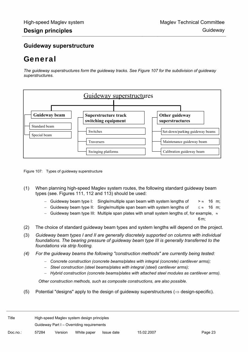
High-speed Maglev system
Design principles Maglev Technical Committee
Guideway
Title High-speed Maglev system design principles
Guideway Part I – Overriding requirements
Doc.no.: 57284 Version White paper Issue date
15.02.2007 Page 23
Guideway superstructure
General The guideway superstructures form the guideway tracks. See Figure 107 for the subdivision of guideway superstructures.
Figure 107: Types of guideway superstructure
(1) When planning high-speed Maglev system routes, the following standard guideway beam
types (see. Figures 111, 112 and 113) should be used:
− Guideway beam type I: Single/multiple span beam with system lengths of > ≈ 16 m; − Guideway beam type II: Single/multiple span beam with system lengths of ≤ ≈ 16 m; − Guideway beam type III: Multiple span plates with small system lengths of, for example, ≈
6 m;
(2) The choice of standard guideway beam types and system lengths will depend on the project.
(3) Guideway beam types I and II are generally discretely supported on columns with individual foundations. The bearing pressure of guideway beam type III is generally transferred to the foundations via strip footing.
(4) For the guideway beams the following "construction methods" are currently being tested:
− Concrete construction (concrete beams/plates with integral (concrete) cantilever arms); − Steel construction (steel beams/plates with integral (steel) cantilever arms); − Hybrid construction (concrete beams/plates with attached steel modules as cantilever arms).
Other construction methods, such as composite constructions, are also possible.
(5) Potential "designs" apply to the design of guideway superstructures (⇒ design-specific).
Guideway superstructures
Guideway beam Superstructure trackswitching equipment
Other guideway superstructures
Standard beam
Special beamSwitches
Traversers
-Set-down/parking guideway beams
Maintenance guideway beam
Calibration guideway beam Swinging platforms
-

High-speed Maglev system
Design principles Maglev Technical Committee
Guideway
Title High-speed Maglev system design principles
Guideway Part I – Overriding requirements
Doc.no.: 57284 Version White paper Issue date
15.02.2007 Page 24
Functional requirements The influential functional requirements for guideway superstructures are:
(1) Reliable support of actions resulting from operation and the environment and transferral to the guideway substructures;
(2) Reliable support of the Maglev-specific guideway equipment;
(3) Reliable support of other guideway equipment designs and methods;
(4) Guarantee of required positional accuracy of the Maglev-specific guideway equipment (toler-ances and deformations).
Design requirements The design requirements for guideway superstructures are:
(1) The cross section of the guideway superstructures should comply with the guidelines on Fig-ures 106, 111, 112 and 113 as well as the defined installation space requirements for the system guideway equipment in accordance with /MSB AG-FW GEO/, whereby all guideway equipment connections should be accessible and serviceable in accordance with the design layout.
(2) The cross sections illustrated in Figures 106, 111, 112 and 113 may be exceeded if compati-bility with the complete system is proven. The beam lengths provided are just examples (see chapter (7) 0).
(3) Materials (incl. corrosion protection) should be selected by taking into consideration the re-quired service life according to state-of-the-art technology.
(4) Maintenance expenditure and unfavourable acoustic effects (noise emissions) should be kept to a minimum through an optimised cross section and surface design.
(5) The general requirements on corrosion protection must be observed to ensure durability and to minimise maintenance expenditure.
(6) All load-bearing components should be easily accessible for maintenance purposes.
(7) Box beams/cavities should be designed so there is no need to inspect the inside of them (e.g. closed steel box beam).
(8) The drainage for the guideway superstructures should be designed so that all rain water is able to run off the guideway. Drainage via the lateral guidance rails is permitted. On straight guideway areas, the guideway should be designed with a transverse gradient of 1.15° (cor-responds to 2 %) for drainage.
(9) Transverse gaps between successive guideway beams should be closed (e.g. by a beam gap cover) if they can become larger than 20 mm (influencing variables: deformation of sub-structures, variation in the length of the superstructure as a result of temperature and con-crete creep and shrinkage) and lie in sections that have vehicle passing speeds in accor-dance with the sectional actual travelling speed of > 150 km/h. The construction requirement and areas affected are subject to project-specific definition.

High-speed Maglev system
Design principles Maglev Technical Committee
Guideway
Title High-speed Maglev system design principles
Guideway Part I – Overriding requirements
Doc.no.: 57284 Version White paper Issue date
15.02.2007 Page 25
(10) Longitudinal gaps and other openings on the guideway surface should be avoided. (11) To enable components to be mounted on the guideway superstructures, suitable connection
points must be included in the design (e.g. spaces in reinforcing cage). (12) If these connections affect the project independent structural verification of the guideway
superstructures (structural safety and fatigue strength) type approval, then these connections must be taken into consideration when the verification process is created.The guideway su-perstructures must be clearly numbered according to project-specific guidelines. Track num-bering is carried out continuously. The numbers must be legible and permanently marked on the upper surface of the guideway superstructures (if necessary above the relevant support point). It is recommended that the numbers are also marked on the sides. The numbering of the guideway superstructures and substructures must be coordinated.
(14) The design must ensure that the guideway superstructures can be inspected, as far as pos-sible, with the aid of automated procedures (e.g. evaluation of video recordings).
(15) The design should ensure that repair measures that do not have to be planned well in ad-vance (lead time < 3 months) can be carried out in the time available under all potential pro-ject-specific environmental conditions.
Verification process The overriding requirements for the guideway verification process specified in chapter 0 must be observed.
This applies to the following in particular:
(1) In addition to the theoretical verification, guideway superstructures must be empirically clas-sified with regard to the following characteristics:
− Verification of the dynamic behaviour and the dynamic action effects as the vehicle travels over the guideway at a velocity between v = 0 km/h (with a levitating vehicle) and v = vmax;
− Verification of satisfactory bearing strength and service strength;
− Verification of serviceability
− Adherence to noise emission limit values according to /MSB AG-GESAMTSYS/;
− Verification of maintainability (ease of inspection, accessibility, etc.).
(2) Research and findings from previous classifications (e.g. from a test run, from running appli-cation projects) must be drawn upon during the verification process for new guideway super-structures.
Handling, transport and assembly (1) Devices appropriate for the design must be used for the transport and assembly of guideway
superstructures to avoid mechanical damage and permanent deformation.
(2) The assembly process and the fine positioning of the guideway superstructures must be op-timised for precision, speed and be able to be carried out in all weathers. Assembly and posi-tioning instructions must be drawn up with all required details.

High-speed Maglev system
Design principles Maglev Technical Committee
Guideway
Title High-speed Maglev system design principles
Guideway Part I – Overriding requirements
Doc.no.: 57284 Version White paper Issue date
15.02.2007 Page 26
Guideway substructures
General The purpose of guideway substructures is to:
− bridge the height difference between the guideway substructures and the ground (guideway supports);
− transfer forces from the guideway superstructures to the foundations taking system-related re-quirements into account.
Concrete and steel designs are currently being tested for the columns. Other designs are also possible.
The guideway foundations are generally made of concrete.
The arrangement of the guideway substructures is primarily dependent on rigidity requirements, which are determined by the permissible deformation and distortion according to /MSB AG-FW BEM/. The aesthetic arrangement of the substructures depends on the following functional and design require-ments.
See Figure 108 for the subdivision of guideway substructures.
Figure 108: Types of guideway substructures
Guideway substructures
Guideway foundation Guideway supports Other guideway substructures
Standard foundation
Deep foundation
Individual supports
Frames
Substructures in tunnels
Substructures onprimary supproting structuresSupport plates
Substructures of track switching equipment
Continuouslongitudinal beam
Mass-spring system

High-speed Maglev system
Design principles Maglev Technical Committee
Guideway
Title High-speed Maglev system design principles
Guideway Part I – Overriding requirements
Doc.no.: 57284 Version White paper Issue date
15.02.2007 Page 27
Functional requirements The influential functional requirements for guideway substructures are:
(1) Guideway substructures must directly support the actions from the superstructures via the guideway bearing and reliably transfer them to the foundations (reliable support from guide-way superstructures).
(2) Guideway equipment components and modules (e.g. motor winding power line and the ex-ternal on-board energy supply) must be reliably incorporated.
(3) Guideway substructures must permanently guarantee the required positional accuracy of the superstructures.
Design requirements The following design requirements must be considered when designing substructures:
(1) Safety devices must normally be included according to the project-specific safety concept to prevent impact of vehicles and devices on crossing and parallel routes.
(2) Separate substructures for consecutive guideway superstructures should be avoided.
(3) Dimensioned attachment points for connecting the guideway superstructure lightning protec-tion system to the substructure reinforcement must be included in the design in accordance with generally accepted technical rules and standards.
(4) The design of the transitions between:
− Special structures and adjacent standard tracks,
− Discretely and continuously supported guideways and
− Guideways on mass-spring systems and adjacent guideways
must be verified as being compatible with the complete system.
(5) To enable components to be fitted retrospectively on the guideway substructures, suitable design measures must be included in the design (e.g. spaces in reinforcing cage). These must be agreed upon for each specific project.
(6) Attachment options for the long stator and external on-board energy supply cables must be included on all columns in the design.
(7) The guideway superstructures for the two tracks of the double track guideway should rest on shared substructures that are arranged radial to the line routeing axis.
Deviations from this are permitted e.g. in the case of expansion of the track centre distance or use of guideway beam type III. Sensitive areas of the guideway substructures (e.g. the area around the guideway support) must be designed so that damage can be detected through automated guide-way inspection procedures

High-speed Maglev system
Design principles Maglev Technical Committee
Guideway
Title High-speed Maglev system design principles
Guideway Part I – Overriding requirements
Doc.no.: 57284 Version White paper Issue date
15.02.2007 Page 28
Verification process The overriding requirements for the guideway verification process specified in chapter 0 must be observed.
The following requirements should be highlighted:
(1) When designing guideway substructures pay attention to the following project-specific points:
− Actions resulting from the superstructures, environment and operation; − Permissible deformations; − Static system for each guideway superstructure; − Local foundation conditions; − Local gradient heights of the tracks.
(2) When designing the foundations the (high) loading velocity and the dynamic forces (fre-quency, amplitudes) from the superstructures must also be observed.
(3) If there is no research available for a substructure construction type, then extensive theoreti-cal and/or empirical verification must be provided.
Handling, transport and assembly Guideway substructures are generally created by cast in-situ concrete methods. If using prefabricated parts (concrete prefabricated parts, stanchions, composite supports) then corresponding instructions for handling, transport, assembly must be created.

High-speed Maglev system
Design principles Maglev Technical Committee
Guideway
Title High-speed Maglev system design principles
Guideway Part I – Overriding requirements
Doc.no.: 57284 Version White paper Issue date
15.02.2007 Page 29
High-speed Maglev system-specific guideway equipment
General "High-speed Maglev system-specific guideway equipment" includes all components and modules that are necessary for the operation of the train irrespective of the guideway construction (see Figure 109 and Figure 114).
The high-speed Maglev system-specific guideway equipment consists of:
− Long stator; − Lateral guidance rails; − Gliding strips; − Guideway-side components for the external onboard energy supply; − Guideway-side components for positioning; − Lightning protection and earthing of guideway equipment..
The following describes the general requirements of high-speed Maglev system-specific guideway equip-ment elements.
Figure 109: High-speed Maglev system-specific guideway equipment
Magnetschnellbahn-spezifische Fahrwegausrüstung
fahrwegsei -tige Bauteile der Ortung (inkl. Befestigung)
fahrwegseitige Bauteile der externen Bordenergiever -sorgung (inkl. Befestigung)
Langstator Seitenführschienen (inkl. Befestigung)
Gleitleisten (inkl. Befestigung)
Statorpakete (inkl. Befestigung)
Motorwicklung mit Erdung (inkl. Befestigung)
Maglev-specific guideway equipment
Guideway-side positioning component (inc. attach-ment)
Guideway-side components for the external on-board energy supply (inc. at-tachment)
Long stator Lateral guidance (inc. attachment)
Sliding strip (inc. attachment)
Stator pack (inc. attachment
Motor winding with earthing (inc. attachment)

High-speed Maglev system
Design principles Maglev Technical Committee
Guideway
Title High-speed Maglev system design principles
Guideway Part I – Overriding requirements
Doc.no.: 57284 Version White paper Issue date
15.02.2007 Page 30
Long stator
General The long stator is part of the guideway and is used to propel Maglev vehicles.
It consists of the following elements:
(1) Stator pack, made up of:
− An electric sheet steel pack with slots to receive the motor windings and to receive inte-grated elements for attachment to guideway superstructures (An example stator pack is shown in Figure 115 in the annex);
− Integrated elements for attachment to the stator pack on the guideway superstructure (e.g. slot traverses);
− Protective coating (corrosion protection). (2) Elements for attaching the stator packs to guideway superstructures (i.e. screws);3-phase
motor winding (Figure 116 shows part of a long stator with a motor winding whose cables are individually laid one after the other);
(4) Motor winding earthing and additional fixture for the motor winding in the stator pack slots (e.g. earthing sleeves and cable).
Figure 117 and Figure 118 in the annex show an example of a redundant stator pack attachments solution.
The long stator is directly protected from lightning strike due to its position under the guideway. However, to avoid damage from indirect actions as a result of lightning strike, it must be guaranteed that lightning is con-ducted through the attachment in the supporting structure’s earthing system.
Functional requirements Stator packs
The interface between stator pack and motor winding must be designed so that the motor winding stays safely in place under all considered actions in accordance with /MSB AG-FW BEM/.
The stator pack performs the following functions:
(1) Controls the magnetic flux created by the vehicle support magnets, receives and conducts the forces generated by the magnetic flux (bearing forces);Receives and transfers the accel-eration and braking force;
(2) Forms the reference surface (stator level) for measuring the air gap between stator pack and support magnet;
(3) Forms the reference surface for guideway monitoring (e.g. position monitoring using dis-placement measurement);
(4) Forms the tooth-slot effect for vehicle positioning;
(5) Forms the tooth-slot geometry for flux modulation to induce an electrical voltage in the vehi-cle’s linear generators (on-board energy supply).

High-speed Maglev system
Design principles Maglev Technical Committee
Guideway
Title High-speed Maglev system design principles
Guideway Part I – Overriding requirements
Doc.no.: 57284 Version White paper Issue date
15.02.2007 Page 31
Attachment of stator pack
The following requirements must be taken into consideration for attaching stator packs to the guideway su-perstructures:
(1) The stator pack attachment must reliably hold the stator pack in place through all actions resulting from the environment and operation throughout the duration of the project-specific service life, according to /MSB AG-FW BEM/ see /MSB AG-FW GEO/).
(2) If the failure of one or more attachment elements cannot be excluded, limited safe vehicle operation must be guaranteed for a time period to be defined on a project-specific basis.
(3) Failure of attachment elements must be detectable by monitoring measures in accordance with /MSB AG-BTR&IH/ and elements must be able to be restored to their normal state.
(4) Violation of the permissible position deviations of the stator packs according to /MSB AG-FW GEO/ must be prevented.
Motor winding
(1) An electrical moving field is created via the motor winding, from which a thrust force for ac-celeration and deceleration of the vehicle is created through interaction with the magnetic field of the vehicle support magnet.
(2) The thrust forces are transferred to the supporting structure via the stator packs and their attachments.
Design requirements Stator pack
(1) The stator pack components (sheet pack, coating and the integrated attachment elements) must be designed and assembled so that they meet the required service life taking into con-sideration actions from the environment and operation in accordance with /MSB AG-GESAMTSYS/.
(2) It should be designed so as to minimise maintenance expenditure.
(3) The quality of the electric sheet must meet the requirements of /MSB AG-GESAMTSYS/.
(4) The stacking factor of the sheet pack must not be less than 0.97 according to EN 10106.
(5) Normative dimensions of the sheet pack must be taken into consideration in accordance with /MSB AG-GESAMTSYS/;
(6) Stator pack length: The system length of a stator pack is 1032 mm.
Due to the different lengths between the inside and outside of a curve, different physical sta-tor pack lengths are required to create the guideway geometry. The mechanical distance to the front surface of the stator packs should equal 0.5 mm to 2 mm in the support area. In areas with a small horizontal radius and in the case of track switching equipment, a maximum range of 0 to 10 mm must be adopted.

High-speed Maglev system
Design principles Maglev Technical Committee
Guideway
Title High-speed Maglev system design principles
Guideway Part I – Overriding requirements
Doc.no.: 57284 Version White paper Issue date
15.02.2007 Page 32
The required lengths of the individual stator packs and their arrangement on the guideway are project-specific and must be compatible with the vehicle levitation and guidance system.
(7) The geometry of the mounted stator packs must (taking into consideration the project-specific tolerances of the guideway attachment surface) meet the tolerance requirements of the stator level as defined in /MSB AG-FW GEO/.
(8) A consistent tooth-slot geometry must be adhered to with a grid of 86 mm.
(9) The coating material (corrosion protection) should be selected by taking into consideration the required service life and project-specific environmental factors. Suitable design and pro-duction measures should ensure that the permissible coating thickness on the stator level is not exceeded, thereby reducing the mechanical gap to an unacceptable level. The coating must not affect the electrical and electromagnetic properties of the sheet pack. The corrosion protection must completely cover the stator pack. It should also be permanently ductile and resistant to abrasion.
(10) The maximum permissible thickness for the corrosion protection on the stator levels may not exceed 1.8 mm (incl. all tolerances, tapers, etc.).
(11) The permissible stator pack installation space is shown on Figure 106 and in /MSB AG-FW GEO/.
(12) The dimensions of the integrated attachment elements must be defined according to the type of attachments, the static requirements and taking into consideration maintenance factors.
(13) The contact surfaces between the guideway cantilever arm and integrated elements for at-taching the stator pack (e.g. slot traverse) must be designed so that the forces from the envi-ronment and operation cannot lead to unacceptable displacement of the stator packs.
(14) For the transfer of forces from actions to be considered, the contact surfaces between the stator pack attachment and the connecting surface on the supporting structure must satisfy the friction parameter that is used as the basis for the dimensioning.
Attachment of stator packet
(1) The attachment must be reasonably simple to detach without causing any damage to adja-cent structures.
(2) It must be determined, on a project-specific basis, whether the falling off of failed attachment elements resulting in danger to third-parties must be prevented by implementing protection measures on project-specific guideway sections (e.g. at intersections with other infrastruc-ture).
(3) Attachment elements, whose failure cannot be excluded, must be easy to replace (in be-tween operating periods) in the event of their failure.
(4) The construction-specific connection design (guideway cantilever arm and integrated ele-ments for stator pack attachment) must be taken into consideration in the development and dimensioning of attachment elements.
(5) The space available for the stator pack attachment (see Figure 106 und /MSB AG-FW GEO/) must be defined in agreement with the suppliers of the stator pack and the guideway beam. It must be individually verified as compatible with the complete system.

High-speed Maglev system
Design principles Maglev Technical Committee
Guideway
Title High-speed Maglev system design principles
Guideway Part I – Overriding requirements
Doc.no.: 57284 Version White paper Issue date
15.02.2007 Page 33
(6) Materials and manufacturing methods must be used that, in the event of a systematic failure, will not lead to a failure of the attachment (e.g. hydrogen embrittlement). The costs associ-ated with using such materials and methods must be kept within reasonable limits.
(7) When selecting materials, the environmental influences (corrosion and ageing behaviour) must be taken into account with regard to the required service life .
Motor winding
(1) The motor winding must be designed so that the required service life is achieved, taking into consideration the specified actions from the environment and operation.
(2) Violation of the permissible clearance during the required service life must be excluded (tak-ing specified actions from the environment and operation into consideration).
(3) The mechanical and geometrical characteristics of the cable used for the motor winding must be taken into consideration during the project-specific design of the attachment and assem-bly (attachment in stator pack slots taking into account the motor winding earthing and the tooth-slot geometry).
(4) The permissible minimum bending radius of the motor winding cable and the permissible installation space for the motor winding according to Figure 106, /MSB AG-FW GEO/ and /MSB AG-GESAMTSYS/ must be adhered to.
(5) The requirements for the electrical function of the motor winding are defined in /MSB AG-GESAMTSYS/.
(6) The requirements for the motor winding earthing result from the long stator protection and can be found in Maglev design principles, propulsion and energy supply /MSB AG-ANT/.
(7) The motor winding cable must be self-extinguishing to prevent fire.
(8) Additional requirements for the motor winding material in tunnels and at stations (enclosed spaces) can be defined on a project-specific basis (toxicity in the event of fire).
(9) The earthing design and the connection points for the motor winding must be determined on a project-specific basis, whereby the connection points for the motor winding earthing must be integrated into the earthing/lightning protection system of the guideway.
(10) On beam joints it must be ensured, through dimensionally stable arrangement of the motor windings, that movement of the beams in the x-, y- and z directions, resulting from operation and environment throughout the course of the required service life, does not lead to violation of the permissible installation space and to loss of serviceability.
(11) The determination of the local phase position of the motor winding must include verification of compatibility with the complete system. (see /AG MSB-GESAMTSYS/ chapter 8.2 fig. 5)
(12) An example of the 3-phase motor winding can be found in the annex (Figure 116).
(13) The interface between stator pack and motor winding must be designed so that the motor winding stays safely in place under all considered actions in accordance with /MSB AG-FW BEM/.
Verification process

High-speed Maglev system
Design principles Maglev Technical Committee
Guideway
Title High-speed Maglev system design principles
Guideway Part I – Overriding requirements
Doc.no.: 57284 Version White paper Issue date
15.02.2007 Page 34
Stator packs
The following component/module-specific requirements for the stator pack must also be observed as well as the overriding requirements for the guideway verification process specified in chapter 0.
(1) The verification process must focus on the following:
− Verification of the fatigue resistance taking into account dynamic loads; − Verification of the dimensional accuracy, quality and durability of the coating; − Verification of the electrical and electromagnetic characteristics.
(2) To ensure the quality of every individual stator pack a test instruction must be created that contains all the acceptance criteria to be verified along with the permissible tolerances. The acceptance tests must be recorded.
(3) For traceability, all stator packs must be clearly, individually and permanently marked.
Attachment of stator pack
The following component/module-specific requirements for the stator pack attachment must also be ob-served as well as the overriding requirements for the guideway verification process specified in chapter 0.
(1) Verification must also be drawn up for failure situations, assuming that failure of attachment elements is not excluded. The failure situations to be considered in connection with the de-tection system must be determined after verification of compatibility and in agreement with the responsible inspectorate.
(2) It must be verified that for the failure situations all the components and modules in the force path are designed for the entire project-specific service life.
(3) In the event of a credible fault appearance, an operationally stable design of the compo-nents/modules in the force path in the failure situation, specifying the permissible load cycle (vehicle passing), is sufficient. Credible fault appearance/detection as part of guideway main-tenance must be verified.
Motor winding
The following component/module-specific requirements for the motor winding must also be observed as well as the overriding requirements for the guideway verification process specified in chapter 0.
(1) Adherence to the specified thermal behaviour of the long stator must be verified metrologi-cally during operation.
(2) The theoretical load assumptions and serviceability must be verified by measurements both during prototype development as well as during operation of the final system.
(3) The current carrying capacity of the circuit, the shield and the electric strength of the wind-ings must be verified.
(4) The fatigue resistance of the winding attachment, including the dimensional stability of the winding head, must be verified empirically.
(5) The material and structural strength of the motor winding must be verified through the me-chanical load on the beam joint.

High-speed Maglev system
Design principles Maglev Technical Committee
Guideway
Title High-speed Maglev system design principles
Guideway Part I – Overriding requirements
Doc.no.: 57284 Version White paper Issue date
15.02.2007 Page 35
(6) Adherence to the lightning-impulse strength in accordance with /MSB AG-UMWELT/ as well as project-specific instructions must be verified.
(7) The permissible continuous current RMS value and current max. value must be empirically verified, taking into consideration the project-specific cycle time parameter and running time.
(8) It must be verified that the long stator protection is functioning correctly (earth-fault monitor-ing).
Handling, transport and assembly Stator packs
Instructions on handling (transport and storage)and assembly must be drawn up for the stator pack. The following factors must be included:
(1) Mechanical damage must be prevented by appropriate transport methods and packaging to protect against impact.
(2) The intermediate storage surfaces must be designed so that the stator packs and and/or their transport packaging can be correctly set down and lifted again without causing any damage.
(3) The stator packs should be attached to the guideway superstructures by the manufacturer.
(4) If stator packs are fitted retrospectively at the site, then additional construction documents (assembly instructions and acceptance specifications) must be drawn up and verified as be-ing compatible with the complete system and submitted to the responsible inspectorate for inspection.
Attachment of stator pack
(1) The assembly process and parameters must be specified in transport, storage and assembly instructions.
(2) The assembly parameters, such as starting torque/rotation angle, must be defined, moni-tored and documented.
(3) Connecting parts that have been used before (e.g. screws, washers, nuts) should not be reused. In exceptional cases (e.g. use of inserts that are embedded in concrete with thread (see Figure 117)) it must be checked whether the part is reusable before replacing the stator pack or attachment element.
Motor winding
(1) Detailed instructions for assembly, transport and intermediate storage must be drawn up in the form of assembly instructions according to the specific project and design employed.
(2) The free space within the gauge for the kinematic space requirement of the vehicle according to /MSB AG-GESAMTSYS/ (or beyond, following project-dependent agreement) is available for the manufacture and/or laying of windings from the guideway.
(3) Assembly devices for the long stator motor winding must fulfil the special vehicle require-ments.

High-speed Maglev system
Design principles Maglev Technical Committee
Guideway
Title High-speed Maglev system design principles
Guideway Part I – Overriding requirements
Doc.no.: 57284 Version White paper Issue date
15.02.2007 Page 36
Lateral guidance rails/lateral guidance levels
General The lateral guidance rails, which are an element of the high-speed Maglev system-specific guideway equip-ment, receive the mechanical and electromagnetic actions from the vehicle and special vehicles..
The fundamental arrangement of the lateral guidance rails on the cantilever arms of the guideway super-structures can be found in Figure 106 and /MSB AG-FW GEO/.
Functional requirements Lateral guidance rails
The lateral guidance rails perform the following functions:
(1) Guide the magnetic flux from the guidance and braking magnet;
(2) Enable the generation of electrical eddy currents by interacting with the braking magnets;
(3) Receive the magnetic forces generated by the guidance and braking magnets and transfer them to the cantilever arm structure;
(4) Receive the forces initiated by special vehicles and transfer these to the cantilever arm struc-ture;
(5) Mechanical guidance in the event of failure of the magnetic guidance function of the guid-ance magnets;
(6) Mechanical guidance of the braking magnets on the lateral guidance rails, receive and trans-fer the forces;
(7) Forms the reference surface for measuring the air gap between guidance magnet and lateral guidance rail;
(8) Forms the reference surface for guideway monitoring (e.g. displacement or displacement change detection);
(9) Transferral of excess voltage resulting from lightning on the vehicle;
(10) Lightning protection function for the motor winding.
Attachment of lateral guidance rails
(1) The attachment elements must reliably transfer the forces from the lateral guidance rails to the cantilever arm of the guideway superstructures.
Design requirements Lateral guidance rails
(1) The lateral guidance rails should follow the course of the three-dimensional curve (transverse gradient, dips/hills, curves).

High-speed Maglev system
Design principles Maglev Technical Committee
Guideway
Title High-speed Maglev system design principles
Guideway Part I – Overriding requirements
Doc.no.: 57284 Version White paper Issue date
15.02.2007 Page 37
(2) Subject to the design used for the support, the lateral guidance rails may have a polygonal arrangement if it can be verified that this is compatible with the complete system.
(3) It must be guaranteed that inspection equipment will detect geometry changes and/or dis-placement before the permissible limit values for these deformations is exceeded.
(4) The range of possible materials for lateral guidance rails is defined in /MSB AG-GESAMTSYS/.
(5) Geometry:
− Thickness: tLGR ≥ 30 mm − Height: HLGR ≥ 300 mm − Length: Depending on the system, beam-length lateral guidance rails are advantageous.
Shorter lengths can be used depending on the project.
(6) It must be verified that lateral guidance rails with segment lengths shorter than approx 3.0 m are compatible with the complete system. The edges of lateral guidance rails must be rounded on the joints within a carrier field or a beam joint according to the instructions in /MSB AG-FW GEO/.
(7) The requirements for the levelness and positional accuracy of lateral guidance rails are listed in /MSB AG-FW GEO/.
(8) The lateral guidance rails must be given a coating that will barely be damaged by potential mechanical loads and guarantee sufficient resistance to corrosive attack from the environ-ment (see DIN EN ISO 12 944 Part 1 - 8 and TL 918300, page 87).
(9) The suitability of the coating must be proven with regard to the vehicle side guidance gap measurement (guidance gap sensors).
(10) The coefficients of friction must be adhered to in accordance with /MSB AG-FW BEM/.
(11) The lateral guidance rails must be connected to the guideway lightning protection system.
Attachment of lateral guidance rails
(1) The attachment elements for the lateral guidance rails must be designed, according to the selected design, so that they can safely and reliably withstand all actions to be considered from the environment and operation throughout the required service life (see /MSB AG-GESAMTSYS/).
(2) The attachment of the lateral guidance rails must not affect the correct functioning of the guidance sensors in an unacceptable manner. The guidance gap measurement areas are shown in /MSB AG-FW GEO/. If attachment elements are absolutely necessary in these ar-eas, then the suitability of the design must be verified with regard to the guidance gap meas-urement.
(3) The attachment must be optimised with regard to maintainability (ease of access for inspec-tion and repair).
Verification procedure Lateral guidance rails
The overriding requirements for the guideway verification process specified in chapter 0 must be observed.

High-speed Maglev system
Design principles Maglev Technical Committee
Guideway
Title High-speed Maglev system design principles
Guideway Part I – Overriding requirements
Doc.no.: 57284 Version White paper Issue date
15.02.2007 Page 38
Attachment of lateral guidance rails
The requirements according to chapter 0 (stator pack attachment) must be observed alongside the overrid-ing requirements for the guideway verification process given in chapter 0.
Handling, transport and assembly (1) The lateral guidance rails and their attachment elements (specific to the design) must be
handled correctly.
(2) The lateral guidance rails are normally attached to the guideway beams or guideway plates by the manufacturer as integrated parts of the supporting structure of the guideway super-structure or cantilever arm.
(3) If lateral guidance rails are fitted retrospectively, then construction documents (assembly instructions and acceptance specifications) must be drawn up and verified as being compati-ble with the complete system and submitted to the responsible inspectorate for inspection.
Gliding strips/gliding surfaces
General The gliding strips, which are an element of the high-speed Maglev system-specific guideway equipment, are required during normal operation to deflect the mechanical forces from the stationary set-down vehicle via the support skids and to receive the mechanical actions from special vehicles. In the event of a malfunction, the force of the support skids from the moving vehicles are to be transferred to the guideway superstruc-tures.
Functional requirements The gliding strip performs the following functions:
(1) The gliding strip and its attachment element must be made so that they can reliably with-stand the specified mechanical and thermal loads along with project-specific environmental conditions throughout the required service life in accordance with /MSB AG-GESAMTSYS/.
(2) Forms a fault-tolerant gliding surface with surface conditions defined on a project-specific basis for the mechanical support/gliding of the vehicle support skids;
(3) Receives the forces in the x-, y- and z-directions resulting from the support skids incl. the voltages resulting from temperature changes due to support skid friction as well as transfer-ring these to the guideway superstructures;
(4) Receives the forces in the x-, y- and z-directions resulting from special vehicles as well as transferring these to the guideway superstructures;
Design requirements Gliding strip/gliding surface
(1) The gliding strip can be designed as follows:

High-speed Maglev system
Design principles Maglev Technical Committee
Guideway
Title High-speed Maglev system design principles
Guideway Part I – Overriding requirements
Doc.no.: 57284 Version White paper Issue date
15.02.2007 Page 39
− As an integral part of the beam or plate (e.g. part of the deck plate); − Attached as a sealed, screwed or dowelled joint to the cantilever arm; − Indirectly attached to the cantilever arm (e.g. as an integral part of a functional module).
The position of the gliding surface is shown on Figure 106 and in /MSB AG-FW GEO/.
(2) The gliding surface must follow the course of the three-dimensional curve, taking the trans-verse gradient into account.
(3) Subject to the design, the gliding surface elements may have a polygonal arrangement if it can be verified that this is compatible with the complete system.
(4) Steel should be used for the gliding strips. If other materials are used, their suitability must be verified.
(5) Gliding surfaces must be given a coating that will barely be damaged by potential mechanical loads and guarantee a high degree of resistance to corrosive attack from the environment - including under conditions of mechanical stress (for metal gliding surfaces, see DIN EN ISO 12 944 Part 1 - 8 and TL 918300 page 87).
(6) Geometry:
− Thickness: Depends on static requirements − Width: BSS ≥ 150 mm − Length: Depending on the system, beam-length gliding surface elements are advantageous.
Shorter lengths can be used depending on the project.
(7) It must be proven by extensive verification that gliding surface elements with segment lengths shorter than approx 3.0 m are compatible with the complete system.
(8) The requirements for the levelness and positional accuracy of gliding surfaces are listed in /MSB AG-FW GEO/.
(9) It must be guaranteed that inspection equipment (according to /MSB AG-GESAMTSYS/) will detect geometry changes and/or displacement before the permissible limit values for these deformations is exceeded.
(10) The maximum values for the coefficients of friction given in /MSB AG-FW BEM/ must be ad-hered to. Minimum values for the coefficients of frictions must be agreed on a project-specific basis.
(11) Metallic gliding surface elements must be correctly connected to the guideway lightning pro-tection system.
Gliding strip attachment
(1) Attachment should be carried out according to the selected design.
(2) Attachment must be optimised with regard to maintainability (ease of access for inspection and repair).
Verification process Gliding strip/gliding surface
The overriding requirements for the guideway verification process specified in chapter 0 must be observed.

High-speed Maglev system
Design principles Maglev Technical Committee
Guideway
Title High-speed Maglev system design principles
Guideway Part I – Overriding requirements
Doc.no.: 57284 Version White paper Issue date
15.02.2007 Page 40
Gliding strip attachment
The requirements according to chapter 0 (stator pack attachment) must be observed during the verification process for gliding surface attachment alongside the overriding requirements for the guideway verification process given in chapter 0.
Handling, transport and assembly (1) The gliding strips and their attachment elements (specific to the design) must be handled
correctly.
(2) The gliding strips are normally attached to the guideway beams or guideway plates by the manufacturer as integrated parts of the supporting structure of the guideway superstructure or cantilever arm.
(3) If the gliding strips are fitted retrospectively, then special construction documents (assembly instructions and acceptance specifications) must be drawn up and verified as being compati-ble with the complete system and submitted to the responsible inspectorate for inspection.

High-speed Maglev system
Design principles Maglev Technical Committee
Guideway
Title High-speed Maglev system design principles
Guideway Part I – Overriding requirements
Doc.no.: 57284 Version White paper Issue date
15.02.2007 Page 41
Components of the external on-board energy supply;
General The external on-board energy supply provides electrical energy to the vehicle in areas in which it travels at a lower velocity (e.g. in stations including limited acceleration areas, at selected operational stopping points, evacuation points, parking areas and in maintenance areas).
The route sections requiring an external on-board energy supply are determined on a project-specific basis.
Potential designs for the external on-board energy supply are:
(1) Current transfer via conduction: Conductor rail (guideway)/current collector (vehicle) as con-ductor rail system;
(2) Non-contact energy transfer through induction.
(3) The installation space for the guideway-side modules of the external energy supply can be seen in Figure 106 and in /MSB AG-FW GEO/.
The external on-board energy requirements defined in this document must be extended according to the project with requirements for the guideway, vehicle and propulsion subsystems depending on the design (loads, geometry, electrical properties, design details).
Conductor rails Functional requirements
The conductor rails and their attachment elements must be made so that they can reliably withstand the specified mechanical and thermal loads along with project-specific environmental conditions throughout the required service life in accordance with /MSB AG-GESAMTSYS/.
The conductor rails perform the following functions:
(1) Form a contact surface for the vehicle current collector;
(2) Receive the contact forces in the x-, y- and z-directions resulting from the current collector as well as transferring these to the supporting structure;
(3) Transfer energy for uninterrupted vehicle energy supply;
(4) Enable reliable detection of unacceptable geometry changes and/or displacements.
Design requirements
(1) The conductor rails on the guideway beam should be made up of conductor rail profiles joined together by fixed and extendable connectors, which are attached to the guideway beam by a conductor rail support. Note: The connectors should be part of the scope of supply of the conductor rail profile. The conductor rail support should be part of the scope of supply of the guideway beam.

High-speed Maglev system
Design principles Maglev Technical Committee
Guideway
Title High-speed Maglev system design principles
Guideway Part I – Overriding requirements
Doc.no.: 57284 Version White paper Issue date
15.02.2007 Page 42
(2) The conductor rail profile should be attached to the conductor rail support by a connection mechanism (isolator). Note: This connection mechanism should be part of the scope of supply of the conductor rail profile;
(3) The conductor rail supports must be arranged, designed and verified for each individual sup-port design and track switching device.
(4) Guideway superstructure movements (in x, y and z direction) must be taken into considera-tion when designing and arranging the fixed and extendable connectors.
(5) Conductor rails, connection mechanisms and their attachments to the conductor rail support must be designed as permanent elements without play.
(6) The conductor rail support and its attachments to the guideway must be designed as perma-nent elements without play.
(7) Conducting components must be adequately isolated.
(8) The position of the supply point for the conductor rail system must be agreed along with the supply points for the motor winding when compatibility with the complete system has been verified.
(9) Attachment mechanisms must be provided for the cable routing (e.g. anchor rails) at the supply points on the guideway super/substructures.
(10) An infringement of the space reserved for the vehicle by the conductor rail (e.g. due to failure of the conductor rail attachment) must be excluded.
(11) Failure of individual attachment elements must not result in loss of serviceability or structural safety and must be detectable.
(12) The position and dimensions of the space for the conductor rails and their attachment ele-ments can be found in Figure 106 and /MSB AG-FW GEO/.
Verification process
The requirements according to chapter 0 (stator pack attachment) must be observed alongside the overrid-ing requirements for the guideway verification process given in chapter 0.
In particular the following requirements must be observed:
(1) The design must use the project-specific specifications for the current collector/conductor rail interface on the basis of the overriding actions from the environment and operation specified in /MSB AG-FW BEM/.
(2) The vibration behaviour of the guideway superstructures (dependent on the design of the guideway, the vehicle and the vehicle passing speed) and the free vibration behaviour of the conductor rail support, as well as the conductor rail modules/components, must be taken into consideration when designing and arranging the conductor rail support, modules and com-ponents.
(3) The load assumptions and serviceability must be verified metrologically both during prototype development as well as during operation of the finished system;
(4) Temperature-related deformation of the guideway superstructures (longitudinal strain, verti-cal and lateral deformation) must be taken into account.

High-speed Maglev system
Design principles Maglev Technical Committee
Guideway
Title High-speed Maglev system design principles
Guideway Part I – Overriding requirements
Doc.no.: 57284 Version White paper Issue date
15.02.2007 Page 43
Handling, transport and assembly
Detailed instructions for assembly, transport and intermediate storage must be determined according to the specific project and design employed in the form of assembly instructions.
Inductive energy transfer Inductive energy transfer is currently still in the development stage. The specific requirements for this module will be added once development is finished.
High-speed Maglev system
Design principles Maglev Technical Committee
Guideway
Title High-speed Maglev system design principles
Guideway Part I – Overriding requirements
Doc.no.: 57284 Version White paper Issue date
15.02.2007 Page 44
Positioning system components
General The modules attached to the guideway provide the positioning system modules installed in the vehicle clear information on the absolute position and orientation of the vehicle.
Information can be transferred from the guideway to the vehicle using various systems. One solution that has been used is to transfer data via guideway-side position reference strips (PRR) and vehicle-side sensors (INKREFA read unit).
The PRR consists of a plastic plate with dimensions of approx. 260 mm x 150 mm x 5 mm (W x H x D).
They are attached to the beam with supports.
Functional requirements (1) Providing coded reference information (reference spot) for vehicle-side determination of the
absolute location and the vehicle orientation according to /MSB AG-GESAMTSYS/ (e.g. by position reference strips);
(2) When determining the exact location of the reference spots, the phase arrangement of the motor winding and the requirements of the operational control systems must be considered (see also /MSB AG-GESAMTSYS/).
Design requirements (1) The design requirements for the guideway-side positioning system modules result from the
choice of transmission technology. Non-contact information transmission to the vehicle (if using position reference strips) can be taken as a starting point.
(2) The position of the positioning system modules lengthways on the guideway are determined on a project-specific basis.
(3) A reference spot is normally marked on each side of the guideway using three position refer-ence strips (i.e. each reference spot is marked by 6 position reference strips).
(4) Attachment of the vehicle-side modules to the guideway must be carried out using special fixtures e.g. position reference strip support (PRS support), which must be made by the manufacturer of the guideway superstructure in accordance with the design.
(5) The space for guideway-side modules is specified in Figure 106 and /MSB AG-FW GEO/.
(6) Failure of attachment elements (supports) must be demonstrably excluded or detectable in good time.
(7) Temperature-related deformation of the guideway superstructures (longitudinal strain, verti-cal and lateral deformation) must be taken into account.
(8) Both the design-specific, dynamic excitation of the supports and their attachments, as well as the vibrations caused by the passing vehicle, must be considered in the design.

High-speed Maglev system
Design principles Maglev Technical Committee
Guideway
Title High-speed Maglev system design principles
Guideway Part I – Overriding requirements
Doc.no.: 57284 Version White paper Issue date
15.02.2007 Page 45
Verification process (1) Along with the overriding requirements for the guideway verification process in chapter 0 the
requirements according to chapter 0 (attachment of stator pack) are to be observed in par-ticular.
(2) The vibration behaviour of the guideway superstructures and the free vibration behaviour of the locating modules/components for the guideway and their attachments are to be taken into account in the design of the locating modules/components close for the guideway and the elements used to secure them.
Handling, transport and assembly (1) The detailed instructions for the assembly, transport and intermediate storage are to be set
down in the form of assembly instructions specific to the project and design.
(2) The guideway positioning modules and components are only to be fitted following complete assembly of the guideway superstructures.
(3) For the project it is to be specifically prescribed whether guideway positioning modules and components are to be attached before or after installation of the motor winding and which modules and components specifically.

High-speed Maglev system
Design principles Maglev Technical Committee
Guideway
Title High-speed Maglev system design principles
Guideway Part I – Overriding requirements
Doc.no.: 57284 Version White paper Issue date
15.02.2007 Page 46
Construction style specific guideway equipment
General The modules/components of the guideway equipment, the requirement and design development of which is dependent on the respective construction style and method of the guideway and is not maglev specific, will subsequently be identified as construction style specific guideway equipment.
The significant elements/modules of the construction style specific guideway equipment are:
(1) Guideway supports/mountings;
(2) Earth and lightning protection installation;
(3) Beam gap covers;
(4) Other add ons
Guideway support
Functional requirements The external and internal forces and moments from the guideway superstructures are reliable and are to be passed on via the guideway supports/mountings to the guideway substructures while taking into account all specific boundary conditions (e.g. deformation of the guideway substructures).
Design requirements The essential requirements of the design layout of the guideway supports are:
(1) The design development of the guideway supports is to be selected in connection with the static layout of the complete guideway superstructure and guideway substructure system.
(2) Suitable supporting systems are to be selected in accordance with the static system of the guideway superstructures (in figure 119 proven support instructions of single span and twin span support beam systems are given as an example).
(3) The determination of the support arrangement in the route taken (sequence fixed-/loose sup-ports of beams following on from each other and in connection with the mounting of primary load bearing elements and other guideway superstructures (e.g. track switching equipment) requires verification of compatibility with the complete system.
(4) The guideway supports and especially the anchorings are to be constructed robustly.
(5) There must be no possibility of the failure of individual parts affecting the function of the rele-vant guideway support in a way which is inadmissible.
(6) The guideway supports must be clearly identifiable. This must be possible without disman-tling of add on parts.
(7) For discretely supported guideway beams additional anchoring elements are not admissible. In order to guarantee positional stability the distance of the guideway support in direction y (support spread) must be sufficiently large and all project specific routing parameters and ef-fects are to be taken into consideration.

High-speed Maglev system
Design principles Maglev Technical Committee
Guideway
Title High-speed Maglev system design principles
Guideway Part I – Overriding requirements
Doc.no.: 57284 Version White paper Issue date
15.02.2007 Page 47
(8) For cases of rare actions and combinations of actions it is possible to guarantee the required positional stability via additional fixtures which are normally not required in normal operation according to /MSB AG-FW BEM/ (i.e. are inactive).
(9) By choosing appropriate materials the wear and tear of the moving guideway supports is to be minimised.
(10) Shortcomings, damage and the wear to supports should be clearly noticeable and capable of diagnosis from outside without opening panels (e.g. automation).
(11) The guideway supports are to be developed in such a way that the guideway superstructures can be adjusted in the shortest possible time at the lowest possible cost in the case of build-ing subsidence. The degrees of adjustment are to be prescribed specifically for the project. In the choice of gradation of the adjustment steps the admissible offsets between the guideway superstructures following /MSB AG-FW GEO/ are to be taken into account.
Values of ± 10 mm (at-grade guideway) up to ± 20 mm (elevated guideway with around 5m support height) can be used as guide values depending on the type of guideway in directions y and x. In direction z the guide value up to – 20 mm can be used.
(12) If the admissible value limits of the deformations and displacements are exceeded, a balance should be aimed for by adjusting the guideway supports. If this is not possible a simple ex-change of the wearing parts must be guaranteed.
(13) If it is not possible to rule out actions by earthquakes or impact of crossing traffic on the guideway, then inadmissible displacement of the guideway superstructures must be pre-vented by suitable additional securing elements on the guideway supports.
(14) The position of moving guideway supports must be testable in direction x (e.g. automatic).
(15) The underside of the guideway support must lie above the upper side of the ground. Guide value for the minimum distance of ground to underside of support: 20 cm
(16) In the case of direct connection of the guideway superstructures to the guideway substruc-tures (e.g. in the case of direct casting of guideway plates and guideway substructures) the durability and safety is to be guaranteed by a robust and error tolerant design.
(17) For carrying out repairs to supports the guideway superstructures should not be raised more than 5mm. The location of presses for raising the guideway superstructures is to be defined and marked on the beam.
(18) Secondary measures for maintaining guideway supports such as removing windings are to be avoided.
(19) The maintenance (inspection and if appropriate the exchange of wearing parts) must be pos-sible from the guideway superstructure where the guideway is raised (special vehicle).
Verification process The overriding requirements indicated in chapter 0 concerning the guideway verification process are to be observed.
The following requirements are to be given particular attention:
(1) The friction coefficients accepted in the dimensioning of the guideway superstructures and substructures of the moving guideway supports are to be indicated by giving their functions and value limits.

High-speed Maglev system
Design principles Maglev Technical Committee
Guideway
Title High-speed Maglev system design principles
Guideway Part I – Overriding requirements
Doc.no.: 57284 Version White paper Issue date
15.02.2007 Page 48
(2) The friction coefficient values given for the guideway supports are to be proven. The speed of movement of the supports is to be taken into account in the theoretical estimation of the wear of the guideway support (verification of serviceability).

High-speed Maglev system
Design principles Maglev Technical Committee
Guideway
Title High-speed Maglev system design principles
Guideway Part I – Overriding requirements
Doc.no.: 57284 Version White paper Issue date
15.02.2007 Page 49
Handling, transport and assembly (1) It is recommended to fit the guideway supports of discretely supported guideway beams to
the guideway superstructures on site and to cast the anchoring of the supports in the frame-work of the fine positioning of the guideway superstructures in the recesses of the guideway substructures provided for this purpose.
(2) The supports are to be protected against damage when transporting the guideway super-structures.
(3) Fitting instructions for the securing of the guideway supports to the guideway superstructures and substructures are to be created.

High-speed Maglev system
Design principles Maglev Technical Committee
Guideway
Title High-speed Maglev system design principles
Guideway Part I – Overriding requirements
Doc.no.: 57284 Version White paper Issue date
15.02.2007 Page 50
Earth/lightning protection
General In order to guarantee faultless and reliable operation, effective earth and potential balancing appliances are to be provided.
The leakage conductance from excess voltage resulting from lightning action on the vehicle is made over the functional levels of the guideway.
Along with the general instructions for the layout of earth and lightning protection appliances of DIN VDE 0100, DIN 18014, DIN VDE 0101 and DIN VDE 0185, the following requirements are to be observed.
Functional requirements (1) For protection of personnel and protection against the effects of electrostatic charges as well
as in regard to the electromagnetic compatibility (EMC) the electrical actions from:
− Lightning strikes, − Potential differences and − System related earth and fault currents of all components and modules of the guideway
are to be drawn off into the ground via an earth and lightning protection system of the guide-way superstructure and substructure. All electrically conducting components and modules of the guideway are to be included in this.
(2) All electrical connections are to be constructed in such a way that they reliably meet the specified requirements in the project specific environmental conditions during the whole ser-vice life.
(3) For the guideway/vehicle interface the guideway is to be constructed in such a way that
− The earth of the vehicle in set down state − The leakage conductance from excess voltage resulting from lightning actions on the ve-
hicle
is assured over the function levels of the vehicle.
Design requirements (1) The lateral guidance rails attached to the cantilever arms of the guideway superstructures
and metallic sliding strips present if appropriate must be incorporated into the lightning pro-tection system as a lightning current arrester of the lightning protection.
(2) Guideway equipment for which earth and lightning protection connections are to be provided in accordance with valid standards are to be integrated into the lightning protection system of the guideway superstructures. The earthing cable of the motor winding is to be integrated into the earth and lightning pro-tection system at the start and end of the beam and at both ends of the guideway beams. For guideway beam type III the distances between two connecting points along the length of the guideway must not exceed 30 m. Note: Corresponding connection points on the earth/lightning protection system are to be taken into account as early as during the design of the beam.

High-speed Maglev system
Design principles Maglev Technical Committee
Guideway
Title High-speed Maglev system design principles
Guideway Part I – Overriding requirements
Doc.no.: 57284 Version White paper Issue date
15.02.2007 Page 51
(3) The earth/lightning protection system of the guideway superstructures is to be connected with the earth/lightning protection system of the guideway substructures. For this purpose the earth conductors of the guideway superstructures and substructures are to be made at ex-ternal connecting points at each support point so that an electrically conductive connection can be made. For guideway beam type III this is to be provided at each first and last back up ring.
(4) For testing and measurement tasks, and also for external installations which are to be incor-porated in the earth system, connecting points are to be provided in the lower area of the support connecting points on the earth/lightning protection system. The exact position and number of these connecting points is to be determined specifically for the project.
(5) The reinforcement steels with the function of conducting lightning currents are to be identified in the reinforcement plans.
(6) The reinforcement steels with the function of conducting lightning currents are to be con-nected to one another durably and with electrical conductivity in line with the generally rec-ognised rules of engineering.
(7) The clearance spaces defined in /MSB AG-GESAMTSYS/ and /MSB AG-FW GEO/ are to be taken into account.
(8) The external joining and/or connecting points must be capable of being visually inspected without dismantling of panels (e.g. with the help of automatic image processing).
(9) All electrical connections are to be constructed in such a way that they reliably meet the specified requirements in the project specific environmental conditions during the whole ser-vice life.
(10) In the dimensioning, sufficient mechanical protection of the external electrical connection conductor must be guaranteed.
Verification process The overriding requirements indicated in chapter 0 concerning the guideway verification process are to be observed.
The following requirements are to be given particular attention:
(1) The layout of the earth and lightning protection system is to be carried out appropriately in line with the state of technology and documented (dimensioning and construction/design).
(2) The suitability of the planned measures is to be tested by the appropriate board of control and their expert if appropriate.
(3) For the planning of the construction, verification of compatibility with the complete system is to be provided.
(4) Following manufacture of the guideway, the earth resistance of the guideway substructures (foundation earth electrode) and the transit resistance between the guideway superstructures and guideway substructures is to be measured and recorded with random samples and in agreement with the board of control.
Handling, transport and assembly

High-speed Maglev system
Design principles Maglev Technical Committee
Guideway
Title High-speed Maglev system design principles
Guideway Part I – Overriding requirements
Doc.no.: 57284 Version White paper Issue date
15.02.2007 Page 52
(1) Electrical connections between the guideway superstructures and the guideway substruc-tures are to be made on site.
(2) The accessibility of the connecting points is to be taken into account in the design layout.
(3) Pre-fabricated connecting leads are recommended.

High-speed Maglev system
Design principles Maglev Technical Committee
Guideway
Title High-speed Maglev system design principles
Guideway Part I – Overriding requirements
Doc.no.: 57284 Version White paper Issue date
15.02.2007 Page 53
Beam gap covers
General The horizontal gap between consecutive guideway beams are to be closed in accordance with chapter 7.3 (21) as this gap can lead to inadmissible aerodynamic loads for the vehicle (variations in pressure in the sub nose area).
Subsequently the system technical requirements for the required beam gap cover are specified.
Functional requirements (1) The fluctuations in pressure between the upper side of the guideway and the bottom of it
when crossing beam gaps with the vehicle are to be reduced / prevented.
Design requirements The design requirements of the beam gap covers are:
(1) Appropriate choice of material and connections;
(2) Appropriate choice of corrosion protection;
(3) Consideration of the movements of the guideway (temperature and substructure deforma-tions);
(4) Robust and error tolerant design of all components and modules;
(5) Minimisation of maintenance expenditure;
(6) Optimisation of ease of inspection;
(7) Minimisation of possible negative effects on aerodynamics and noise;
(8) Consideration of vibrations of the guideway;
(9) Consideration of possible mechanical and functional repercussions on the guideway;
(10) Possible installation spaces are to be prescribed specifically for the design;
(11) Exclusions of incursions on clearance space through failure of parts;
(12) Minimisation of collections of depressions;
(13) Consideration of aerodynamic actions from the vehicle crossing (pressure/suction);
(16) The upper side of the guideway superstructure should be made level.
Verification process The overriding requirements indicated in chapter 0 concerning the guideway verification process are to be observed.
Handling, transport and assembly

High-speed Maglev system
Design principles Maglev Technical Committee
Guideway
Title High-speed Maglev system design principles
Guideway Part I – Overriding requirements
Doc.no.: 57284 Version White paper Issue date
15.02.2007 Page 54
Where there are particular requirements of assembly and handling, these are to be prescribed in an assembly and acceptance instruc-tion. Other add ons.
General All additional modules/components which are secured to the guideway superstructure or guideway substruc-ture and were not covered in the previous chapters of guideway equipment are categorised under the term “Other add ons”.
Examples of these other extensions are:
(1) Appliances for maintenance (e.g. fixed ladders and protective bars);
(2) Temporary add ons for testing of new modules/components;
(3) Appliances for evacuation of passengers.
Functional requirements (1) The add ons must be made in such a way that they meet all requirements reliably in the pro-
ject specific operating and environmental conditions during the service life demanded.
(2) The add ons must be made in such a way that they do not have any inadmissible effects on the operation.
(3) The specific functional requirements on the modules and components of the other add ons are to be defined individually.
Design layout The design layout of the add ons is to be formed dependent on the specific requirements with the following general factors being taken into consideration:
(1) Appropriate choice of material and connections;
(2) Appropriate choice of corrosion protection;
(3) Robust and error tolerant design;
(4) Minimisation of maintenance expenditure;
(5) Minimisation of possible negative effects on aerodynamics and noise;
(6) Consideration of vibrations of the guideway as a result of dynamic load actions from opera-tion and the environment;
(7) Consideration of possible mechanical and functional repercussions on the guideway;
(8) Consideration of possible plastic and elastical deformations of the guideway;
(9) Consideration of possible repercussions on the whole system (e.g. radio system);

High-speed Maglev system
Design principles Maglev Technical Committee
Guideway
Title High-speed Maglev system design principles
Guideway Part I – Overriding requirements
Doc.no.: 57284 Version White paper Issue date
15.02.2007 Page 55
(10) Possible installation spaces, geometry and admissible tolerances in the area of the guideway are to be prescribed specifically for the project;
(11) Incursions on clearance space as a result of failure of parts are to be ruled out in the design.

High-speed Maglev system
Design principles Maglev Technical Committee
Guideway
Title High-speed Maglev system design principles
Guideway Part I – Overriding requirements
Doc.no.: 57284 Version White paper Issue date
15.02.2007 Page 56
Verification process The overriding requirements indicated in chapter 0 concerning the guideway verification process are gener-ally to be observed.
The following requirements are to be given particular attention:
(1) For all designs verification of compatibility with the complete system must be given.
(2) Dependent on the type and design of the other add ons, further requirements of the verifica-tion process are to be taken into account where appropriate.
(3) The load assumptions and serviceability are to be proved by measurements both in the de-velopment of prototypes and in the commissioning of the system realised.
Handling, transport and assembly (1) The other add ons are to be handled and fitted appropriately.
(2) Where there are particular requirements of fitting and handling, these are to be prescribed in a fitting and acceptance instruction.

High-speed Maglev system
Design principles Maglev Technical Committee
Guideway
Title High-speed Maglev system design principles
Guideway Part I – Overriding requirements
Doc.no.: 57284 Version White paper Issue date
15.02.2007 Page 57
Track switching equipment
General The general designs/types of track switching equipment are shown in figure 110.
Figure 110: Designs/types of track switching equipment
The use of the individual types of track switching equipment is dependent on the operational requirements.
These are divided into
(1) Track switching equipment which does not require an interruption to the journey (switches and transfer connections as combinations of switches) and
(2) Track switching equipment which requires an interruption to the journey (transfer tables, swinging platform),
.
Switches in a turning off position can be ridden over at various speeds depending on the geometry (bending line) (normal arrangement: Slow travel switch and quick travel switch, see /MSB AG-FW TRAS/). Transfer connections which make the switch to a track which runs parallel possible can be realised through a combi-nation of switches (see /MSB AG-FW TRAS/).The track switching equipment is normally made up of the following principal groups:
− Guideway superstructure (e.g. bendable supports with horizontal beams and abutments); − Positioning elements (normally electro mechanical propulsion systems); − Locking devices; − Air gap bypasses; − Sensor technology and control; − Energy supply; − Switchgear areas; − Guideway equipment.
Track switching equipment
Switches Swinging platformsTraversers

High-speed Maglev system
Design principles Maglev Technical Committee
Guideway
Title High-speed Maglev system design principles
Guideway Part I – Overriding requirements
Doc.no.: 57284 Version White paper Issue date
15.02.2007 Page 58
Functional requirements The following functional requirements are to be taken into account with regard to the operational safety (in-corporation into the operational control systems) and availability:
(1) The track switching equipment must make a secure, reliable switch of track possible for vehi-cles and special vehicles.
(2) The information about the status “track switching equipment can be travelled over safely” is needed by the operational control systems BLT for testing. For this purpose the track switching equipment must make the required signals available for the systems control technology.
(3) After reaching a secure end position the track switching equipment must retain its safe end position regardless of failures in the sensor technology, monitoring or energy supply.
(4) The design of the track switching equipment must ensure that it is not possible to leave the secured end position without clearance by the systems control technology.
(5) The failure of an individual electrical, electronic or electromechanical assembly in positioning or locking devices, control, monitoring or current supply must remain without effect on the ability to adjust and the correct message about the condition (safe end position) and the posi-tion of the track switching equipment on the systems control technology.
(6) The correct message about the condition (safe end position) and the position of the track switching equipment (e.g. straight ahead position) must come to the systems control tech-nology in the case of failure of an individual mechanical assembly too.
(7) A diagnostic device for online diagnosis is to be integrated.
(8) A device for adjustment of the track switching equipment on site is to be provided (on site adjustment operation).
Design requirements (1) The interchange of the design is to be taken into account back in the planning phase if the
service life of the track switching equipment does not correspond to the service life of the section of line.
(2) The time cost for the exchange of modules/components of the track switching equipment must correspond to the operational boundary conditions. Prescriptions regarding this must occur in a project specific way.
(3) The project specific adjustment times to be prescribed must be taken into account in the di-mensioning of the propulsion elements.
(4) The control and monitoring must make it impossible for the support safety and serviceability of the track switching equipment or their components and modules to be affected adversely as a result of incorrect function of individual actuating drives (e.g. through monitoring of syn-chronised operation). The actions from the incorrect function are to be included in the verifi-cation process of the track switching equipment.

High-speed Maglev system
Design principles Maglev Technical Committee
Guideway
Title High-speed Maglev system design principles
Guideway Part I – Overriding requirements
Doc.no.: 57284 Version White paper Issue date
15.02.2007 Page 59
(5) The devices for adjusting and locking of the track switching equipment are to be constructed with robust and error tolerant modules which are as low maintenance as possible.
(6) An interruption free supply of current is to be guaranteed for the securing of the track switch-ing equipment.
(7) All modules/components are to be developed/integrated in such a way that the maintenance expenditure is kept to a minimum.
(8) In order to achieve high availability of the track switching equipment, functional redundancy of the propulsion systems is to be attained.
(9) The guideway substructures of at-grade track switching equipment consist of foundation with elements for supporting and locking the horizontal beams.
(10) The guideway substructures of elevated track change devices consist of foundation, supports and support head plates with elements for supporting and locking the horizontal beams.
(11) The static system of track switching equipment is to be defined dependent on the static and system technical requirements (e.g. bending line). The prescription of the static system re-quires proof of the compatibility with the complete system.
(12) The routing technical requirements of the track switching equipment are set down in /MSB AG-FW TRAS/.
(13) The requirements of the geometry of the function levels are set down in /MSB AG-FW GEO/.
(14) Mountings are to be equipped with stop/anti derail devices and bolts for removal of the sup-porting forces and these devices are to keep the track switching equipment reliably in the re-quired position while taking all actions from operation and environment into account.
(15) Short guideway elements (abutment; L ≥ 1,032 m) are to be used as intermediate elements between the moving guideway superstructures of the track switching equipment and the guideway superstructures of the connecting guideway or the moving end of connecting track switching equipment. The modules for locking and if appropriate gap filling are to be inte-grated into these abutments.
(16) The most robust possible products are to the used for the modules and components of the track switching equipment.
(17) In order to guarantee fault free winter operation, snow and ice sensitive control equipment is to be heated and protected against collection and compression of snow where appropriate.
(18) Rain water is generally to be drained off in such a way that icing up between moving parts can be ruled out.
(19) The structure of the control of the track switching equipment and the structure of the inter-faces for securing the track switching equipment are to be defined project specifically in agreement with the operational control systems. Suitable installation spaces are to be pro-vided.
(20) The control and monitoring of the control and locking equipment (for coming to the position given by the systems control technology) usually occurs at the instigation of the systems con-trol technology). A device for manual adjustment of the track switching equipment is to be provided.
(21) Buildings (if appropriate areas in existing buildings) which are to be as uniform as possible are to provided very close to the track switching equipment for the control, safety and current supply devices.

High-speed Maglev system
Design principles Maglev Technical Committee
Guideway
Title High-speed Maglev system design principles
Guideway Part I – Overriding requirements
Doc.no.: 57284 Version White paper Issue date
15.02.2007 Page 60
These buildings form part of the periphery of the track.
(22) For returning of the cable of the long stator winding from the mobile to the fixed switch end, suitable holding fixtures are to be provided.
(23) It is recommended that there is a possibility of illuminating track switching equipment. For elevated track change devices the fitting of a work surface (e.g. grating) under the continu-ous girders can be effective. Both help to speed up maintenance measures during breaks in operation.
(24) The compatibility of the horizontal gap developing at the mobile switch end (to the adjacent guideway) with the requirements of the complete system is to be proved.

High-speed Maglev system
Design principles Maglev Technical Committee
Guideway
Title High-speed Maglev system design principles
Guideway Part I – Overriding requirements
Doc.no.: 57284 Version White paper Issue date
15.02.2007 Page 61
Verification process The overriding requirements indicated in chapter 0 concerning the guideway verification process are gener-ally to be observed.
The following requirements are to be given particular attention:
(1) Particular attention in the testing and commissioning of track switching equipment must be aimed at the proof of incorporation of the track switching equipment into the systems control technology.
(2) The adherence of the required transition times for each installed track switching device is to be proved.
(3) The frequency of adjustment to be taken as a basis for the dimensioning is to be prescribed specifically for the project.
(4) Instructions for the required reliability of the modules/components (e.g. MTBF values) must occur in a project specific way.
(5) The electrical power required for operation of the track switching equipment is to be estab-lished in a project specific way for the dimensioning of the energy supply.
(6) In track switching equipment, verification of the correct position of the maglev specific guide-way equipment for each possible operating condition which may be observed (e.g. branching off or straight ahead positions at switches) must be provided.
Handling, transport and assembly (1) For the appropriate transport and error free assembly of the track switching equipment in-
structions are to be created.

High-speed Maglev system
Design principles Maglev Technical Committee
Guideway
Title High-speed Maglev system design principles
Guideway Part I – Overriding requirements
Doc.no.: 57284 Version White paper Issue date
15.02.2007 Page 62
Special structures
Tunnels
General The standards for tunnels are to be taken from /MSB AG-GESAMTSYS/
Primary load bearing elements
General Under the term „primary load bearing element” all structures are included which hold the guideway super-structure as an interim construction in the place of the usual guideway substructures and whose loads drain off via its own foundation into the ground. Generally primary load bearing elements are used in order to bridge large spans (e.g. valley bridges).
Functional requirements (1) The functional requirements of the primary load bearing elements correspond to the require-
ments of the guideway substructures (see chapter (2)). (2) In addition the consideration of location and/or project specific requirements for holding indi-
vidual modules of the line periphery may be required.
Design requirements (1) The required holding of elements/modules of the other guideway equipment or line periphery
is to be prescribed in a project specific way with verification of compatibility with the complete system.
(2) The necessity of providing gangplanks for the evacuation of people and other rescue devices is to be prescribed individually as a function of the project specific safety and operating de-sign.
(3) For primary support elements in two stage or multi stage construction the fixed bearing is to be arranged in the central primary support element area.
(4) With large spans the gaps which occur at the crossing to the next guideway are to be defined in such a way by measures which are to be defined in a project specific way that the value limits given in /MSB AG-FW BEM/ und /MSB AG-FW GEO/ are not exceeded. Essentially here the temperature related shifts and/or deformations on the primary load bearing element in x and y direction and the various settlements in direction z with regard to the subsequent guideway are to be taken into account.
(5) The project specific requirements for winter service are to be adhered to (e.g. falling snow when clearing intersection areas).
Verification process The overriding requirements indicated in chapter 0 concerning the guideway verification process are gener-ally to be observed.
The following requirements are to be given particular attention:

High-speed Maglev system
Design principles Maglev Technical Committee
Guideway
Title High-speed Maglev system design principles
Guideway Part I – Overriding requirements
Doc.no.: 57284 Version White paper Issue date
15.02.2007 Page 63
(1) The dynamic behaviour of the primary load bearing element is to be verified.
(2) Settlements, expansion gaps and changes in incline at the crossing to the next guideway are to be shown.
(3) The requirements and serviceability are to be proved by measurements on commissioning the system achieved. The scope is to be agreed with the inspectorate.
(4) The theoretical assumptions applied for the calculations of the deviations in the geometry of the function levels (between primary load bearing element and subsequent guideway) result-ing from different structure temperatures are to be verified metrologically.
Handling, transport and assembly For appropriate transport and error free fitting of the individual components and modules on the primary load bearing element, project specific instructions are to be created.

High-speed Maglev system
Design principles Maglev Technical Committee
Guideway
Title High-speed Maglev system design principles
Guideway Part I – Overriding requirements
Doc.no.: 57284 Version White paper Issue date
15.02.2007 Page 64
Edge of line
General The edge of the line includes
(1) system technically required small structural appliances which are used in the environment close to the route (e.g. radio mast, power houses) and
(2) other required structures which follow the guideway in their position (e.g. noise insulation wall, visual protection, deviation protection etc).
The edge of the line also includes e.g.:
− Power houses of the propulsion system; − power houses of the track change devices; − radio masts; − cable channels; − enclosures; − impact protection structures; − noise protection structures; − sight protection structures; − supporting walls, troughs.
Functional requirements The functional requirements of the appliances of the edge of the track result from their tasks and are thus individually different.
The appliances must however all be made in such a way that they
(1) reliably meet all requirements during the required service life at project specific operating and environmental conditions (such as e.g. the requirements as a result of aerodynamic actions, vibrations, consideration of the natural vibration behaviour) and
(2) have no inadmissible effects on operation.
Design requirements (1) The design requirements of the modules/components at the edge of the track are to be pre-
scribed specifically for the project.
(2) For components at the edge of the track, verification of compatibility with the complete sys-tem is to be given. This also relates to the arrangement of the components and modules in planning in particu-
lar.

High-speed Maglev system
Design principles Maglev Technical Committee
Guideway
Title High-speed Maglev system design principles
Guideway Part I – Overriding requirements
Doc.no.: 57284 Version White paper Issue date
15.02.2007 Page 65
Verification process (1) The verification for the appliances at the edge of the track are to be made in line with the
state of technology with possible maglev railway specific actions being taken into account.
(2) The overriding requirements indicated in chapter 0 concerning the guideway verification process are generally to be observed.
Handling, transport and assembly (1) For the individual appliances at the edge of the track, instructions for handling, transport and
assembly are to be created if this is not yet prescribed in the design planning. This can be done without in the case of reliable ancillary components/modules.

High-speed Maglev system
Design principles Maglev Technical Committee
Guideway
Title High-speed Maglev system design principles
Guideway Part I – Overriding requirements
Doc.no.: 57284 Version White paper Issue date
15.02.2007 Page 66
Quality management and quality assurance
General A comprehensive quality assurance is required in all phases from the planning up to the manufacture and use of the guideway in order to able to assure adherence to the guideway standards.
These phases are:
− Development; − Planning (outline/design planning of the routing and structures); − Verification process (design and qualification); − Manufacture (production, equipment, transport and assembly); − Commissioning and testing; − Maintenance (inspection, servicing, repair).
The measures for assuring the required quality of the guideway are to be set down in a comprehensive qual-ity management system (QS) – following DIN ISO 9000ff. This system must take all aspects of quality assur-ance into account and is to be agreed by the supplier with the responsible inspection bodies directly after the start of the project (e.g. in the form of test specifications, test instructions or work instructions).
The supplier/manufacturer must use quality management and quality assurance to ensure that
(1) adherence to the system technical and safety technical requirements is assured, verified and documented in terms of development and manufacture. The aim of the quality assurance is to ensure and document the adherence to the minimum requirements by testing the required verifications. This is the prerequisite for the orderly integration of the guideway subsystem into the complete system.
(2) the relevant quality documentation is made available for his scope of supply.
(3) the project dependent quality risks are analysed and suitable measures are prescribed indi-vidually. The analysis should occur before the start of the project and in coordination between the subsystems (guideway, vehicle, propulsion/energy supply and systems control technol-ogy)and the responsible inspectorate and building manager. For this all interfaces of the guideway subsystem are to be balanced with those of the other subsystems.
(4) an assessment and if appropriate an adaptation of the prescribed measures is carried out at intervals to be prescribed (e.g. at the end of individual project phases) or when unexpected circumstances arise.
(5) the results of the quality assurance are documented in a suitable form (test reports, result records etc), comprehensibly archived and made available in a suitable form for maintenance and later use.
(6) the use of the guideway can take place in line with the project specific requirements.

High-speed Maglev system
Design principles Maglev Technical Committee
Guideway
Title High-speed Maglev system design principles
Guideway Part I – Overriding requirements
Doc.no.: 57284 Version White paper Issue date
15.02.2007 Page 67
In detail it is recommended that
(1) all required standards are specified.
(2) the required design regulations and methods are stated and matched to the project engineer-ing and technologies.
(3) Methods, processes and tools are prescribed and used in order to prove that all standards were verified (e.g. through analysis, examination, testing, design review, audit).
(4) there is a prescribed qualification standard for each module/component which makes it pos-sible to show that the unit is laid out and designed in such a way that it reliably fulfils all pro-ject specific standards for operation and environment.
(5) the design is producible and repeatable and the resultant product can be verified and used within the operational limits given.
(6) appropriate monitoring measures for acquiring components, materials, software and hard-ware elements and services are taken.
(7) Manufacture, integration, testing and maintenance are demonstrably carried out in such a way that the end product matches the valid configuration.
(8) a monitoring system for non conformities is introduced and maintained so that they can be followed up systematically and their recurrence can be prevented.
(9) quality notes are made and analysed in order to record and report trends punctually for pre-ventative and corrective measures.
(10) all required testing equipment and tools for checking, measuring and testing the mod-ules/components are available and they are regularly calibrated in order to assure their accu-racy.
(11) Processes and instructions for marking, separating, handling, packing, preserving, storing and transporting of all modules/components are introduced.
Verification of the guideway with regard to compatibility to the complete system
The verification of compatibility of the components and modules of the guideway to the complete system must be planned and carried out in a project specific way.
The responsibility for this lies with the supplier of the guideway or the respective component or module.
The verification helps to assure serviceability (availability, ability to maintain, functionality) of the respective component/module for use within the complete system and also assures the function of the complete system when using the respective component/module.
The verification of compatibility with the complete system includes testing of adherence to the system techni-cal minimum requirements
(1) of development and design documents.

High-speed Maglev system
Design principles Maglev Technical Committee
Guideway
Title High-speed Maglev system design principles
Guideway Part I – Overriding requirements
Doc.no.: 57284 Version White paper Issue date
15.02.2007 Page 68
(2) for the routing (dynamic handling test, geometrical routing test, test of the distribution of sup-ports and linked to this the maglev specific guideway equipment).
(3) for project specific planning and design documents including the planned arrangement of the guideway equipment and edge of the track.
(4) for manufacturing and assembly processes.
(5) for the modules and components realised for the guideway.
(6) for the measurements to be defined project specifically (e.g. noise, ride comfort, aerodynam-ics, vibrations, interaction of guideway/vehicle).
For the testing of adherence to the system technical minimum requirements on modules and com-ponents which have been completed, the following verifications must be provided at the very least:
(7) Verification of quality assurance in the factory (e.g. geometrical checking of guideway beams);
(8) Verification of carrying out the interim inspection of the guideway following fine positioning as a prerequisite for clearance for use with guideway bound special vehicles (and the subse-quent on site installation of the guideway equipment); The interim inspection of the guideway must include the following at the very least:
− the establishment of positive results of the quality tests of the materials or components in the framework of the building design;
− a visual test which includes components which are hard to access with emphasis placed on the supporting and load discharging components and modules (e.g. supports, cantile-ver arm);
− the documentation of the test and all deviations established from the desired state.
(9) Verification of the carrying out of the final system technical inspection of the guideway follow-ing completed installation of the guideway equipment as a prerequisite for clearance for rid-ing with vehicles; The final system technical inspection must include the following at the very least:
− the establishment and documentation of the rectification of all shortcomings and damage and deviations from the planning documents;
− the geodesic three dimensional recording of the space curve of the routing with devia-tions from the desired state (if this has not occurred in connection with the assembly);
− the geodesic three dimensional recording of the position of the foundations (if this has not occurred in connection with the assembly);
− the verification of adherence to the system technical minimum requirements (in accor-dance with /MSB AG-FW ÜBG/ and /MSB AG-FW GEO/);
− the documentation of the test and all deviations established from the desired state;
− the documentation of the results of an examination which may be repeated after elimina-tion of deviations.

High-speed Maglev system
Design principles Maglev Technical Committee
Guideway
Title High-speed Maglev system design principles
Guideway Part I – Overriding requirements
Doc.no.: 57284 Version White paper Issue date
15.02.2007 Page 69
The final system technical inspection serves to establish the “zero condition” (condition of the guideway be-fore commissioning). This condition is the basis for the assessment of the effects of all changes which occur later.
Following this test and following commissioning of the vehicles, the reference runs of the automated meas-urement systems must be carried out within a short period of time and these must be assigned to the geo-desic measurement data.
The measures demanded in this chapter are required from a system technical viewpoint. They form part of the total acceptance test. In the course of creating the components, tests and inspections carried out can be assessed as part of the building supervisory acceptance if it can be assumed that there have not been any sig-nificant changes in the meantime.

High-speed Maglev system
Design principles Maglev Technical Committee
Guideway
Title High-speed Maglev system design principles
Guideway Part I – Overriding requirements
Doc.no.: 57284 Version White paper Issue date
15.02.2007 Page 70
Documentation
General The documentation of the guideway includes:
(1) technical documents of the guideway components and modules;
(2) documentation of the project specific boundary conditions;
(3) technical documents on construction (including quality assurance documentation);
(4) Documentation for guideway maintenance.
Verification process for modules/components (1) The stability verification (supporting stability, proof of material fatigue), serviceability verifica-
tion and the associated drawings are to be stated with the generally recognised rules of en-gineering being taken into consideration. For electronic data processing supported verifica-tion of stability the “guideline for stating and testing of electronic data processing supported stability verification” /Ri–EDV–AP–2001/ applies.
Project specific requirements The project specific boundary conditions (requirements and instructions) for the guideway are to be pre-scribed in a project specification for the guideway.
This specification is to contain at least the following:
(1) project specific supplementation of the guideway design basis;
(2) project specific system technical guideway equipment list;
(3) Maintenance plan/programme for the guideway with an interface to the overriding mainte-nance plan/programme of the complete system;
(4) Definitions for guideway equipment (position and coding of the reference rails, position and arrangement of the stator packs and arrangement of the motor winding, definition of the ar-eas with external on-board energy supply);
(5) Definition of the stopping places;
(6) Creation of a top and limiting velocity from guideway dimensioning;
(7) Examinations of the actions from the environment (e.g. of snow and ice on the minimum gra-dient height and/or crossings of the infrastructure).
Technical documents for construction

High-speed Maglev system
Design principles Maglev Technical Committee
Guideway
Title High-speed Maglev system design principles
Guideway Part I – Overriding requirements
Doc.no.: 57284 Version White paper Issue date
15.02.2007 Page 71
The technical documents for construction must contain design documents and verification of mod-ules/components of the guideway and neighbouring structures (graphic representation of the component with corresponding uniformity, serviceability verification, verification of dynamic strength etc) and also the follow-ing in particular:
(1) Documents for appliances on the edge of the track and structures on the edge of the track (with regard to the adherence to system technical requirements);
(2) Documents on transitions between special structures/special designs and the standard guideway (with regard to the adherence to the system technical requirements);
(3) Documents on interfaces of the guideway with stations and stops (to assure adherence to the system technical requirements);
(4) Documents for design of the complete lightning protection and earth system including all in-accessible cables and connections within the guideway superstructures and substructures;
(5) Quality assurance programmes of the guideway manufacturer to realise a guideway (proce-dure to ensure that the system technical and safety technical requirements are adhered to);
(6) results of quality assurance in the factory (e.g. geometrical checking of guideway beams in the factory);
(7) results of fine positioning;
(8) Routing (layout, gradients, banking);
(9) Maintenance programmes for the individual components and modules of the guideway;
(10) Documents about add ons on the guideway in the project specific system technical guideway equipment list.
System technical guideway equipment list In the framework of the design planning a system technical guideway equipment list is to be created.
This document is to contain at least the following information in rising kilometres for each track:
− Track data (space curve, ranges, radius, banking, gradient height over ground etc);
− Substructures (with component numbering, location reference to space curve, and infor-mation about special structures, track switching equipment and mass spring systems);
− Beams (with component numbering, location reference to space curve, information on the exact system length of the beam and support arrangement);
− Stator pack arrangement (for each beam with information about the nominal gap on the beam crossing, type indication of the used stator packs and complemented with module arrangement if appropriate);
− phase related position of the motor winding (in relation to the use of the stator packs) and definition of the cable entries and exits (in relation to the substructures);
− the guideway modules of the location system with location reference to the position of the motor winding (e.g. arrangement and coding of the support reference strips);
− Stopping place areas;

High-speed Maglev system
Design principles Maglev Technical Committee
Guideway
Title High-speed Maglev system design principles
Guideway Part I – Overriding requirements
Doc.no.: 57284 Version White paper Issue date
15.02.2007 Page 72
− Areas with external on-board energy supply (with definition of the cable structures on the substructures).
The system technical guideway equipment list should be complemented with additional information for the edge of the track in a project specific way (such as e.g. radio aerials, cable routings, protective structures etc).
Documents for maintenance see /MSB AG-FW IH/

High-speed Maglev system
Design principles Maglev Technical Committee
Guideway
Title High-speed Maglev system design principles
Guideway Part I – Overriding requirements
Doc.no.: 57284 Version White paper Issue date
15.02.2007 Page 73
Raumkurve
Trägerfeld
1250
Auflagerbereich(Lagerpratzen)
14001400 500500
2750<=
2500
300
mögl. Einbaubereich für Lager
14001400500
500
Auflagerbereich(Lagerpratzen)
1250
2750
300
mögl. Einbaubereich für Lager
<=25
00
Raumkurve
Trägerfeld
Raumkurve
Trägerfeld
1250
Raumkurve
Trägerfeld
1250
Auflagerbereich(Lagerpratzen)
14001400 500500
2750<=
2500
300
mögl. Einbaubereich für Lager
Auflagerbereich(Lagerpratzen)
14001400 500500
2750<=
2500
300
mögl. Einbaubereich für Lager
14001400500
500
Auflagerbereich(Lagerpratzen)
1250
2750
300
mögl. Einbaubereich für Lager
14001400500
500
Auflagerbereich(Lagerpratzen)
1250
2750
300
mögl. Einbaubereich für Lager
<=25
00
Raumkurve
Trägerfeld
Annex I-A Maximum dimensions for guideway superstructures
In the following figures the maximum dimensions for guideway superstructures of the standard guideway types I, II and III are given. These dimensions are to be taken into account in the development of new guideway superstructures along with the requirements for clearance following Figure 106.
Figure 111: Maximum sectional dimension for standard guideway type I (example)

High-speed Maglev system
Design principles Maglev Technical Committee
Guideway
Title High-speed Maglev system design principles
Guideway Part I – Overriding requirements
Doc.no.: 57284 Version White paper Issue date
15.02.2007 Page 74
Raumkurve Space curve
Trägerfeld Beam field
Auflagerbereich (Lagerpratzen) Support area (support paws)
Mögl. Einbaubereich für Lager Possible installation area for supports
(Variabel, siehe Kapitel 6.3) (Variable, see chapter 6.3)
Figure 112: Maximum sectional dimension for standard guideway type II (example)

High-speed Maglev system
Design principles Maglev Technical Committee
Guideway
Title High-speed Maglev system design principles
Guideway Part I – Overriding requirements
Doc.no.: 57284 Version White paper Issue date
15.02.2007 Page 75
Figure 113: Maximum sectional dimension for standard guideway type III (example)
Raumkurve Space curve
Auflagerbereich (Lagerpratzen) Support area (support paws)
1250
Raumkurve
>=16
00
Auflager-bereich
1400
1400500
6192 (variabel, siehe Kapitel 6.3 (14))
30963096
Raumkurve
>= 1
350
1250
14001400 500500
Auflager-bereich

High-speed Maglev system
Design principles Maglev Technical Committee
Guideway
Title High-speed Maglev system design principles
Guideway Part I – Overriding requirements
Doc.no.: 57284 Version White paper Issue date
15.02.2007 Page 76
(Variabel, siehe Kapitel 6.3) (Variable, see chapter 6.3)

High-speed Maglev system
Design principles Maglev Technical Committee
Guideway
Title High-speed Maglev system design principles
Guideway Part I – Overriding requirements
Doc.no.: 57284 Version White paper Issue date
15.02.2007 Page 77
Annex I-B Arrangement of the maglev train specific guideway equip-ment (informative)
In figure 114 the arrangement of the maglev specific guideway equipment on the guideway beam is shown as an example.
Figure 114: Arrangement of the maglev train specific guideway equipment on the guideway beam
Seitenführschiene Lateral guidance rail
Gleitleiste Sliding strip
Statorpaket Stator pack
Erdungsmanschetten Earth sleeves
Erdungskabel Earth cable
Externe Bordenergieversorgung External on-board energy supply
Motorwicklung Motor winding

High-speed Maglev system
Design principles Maglev Technical Committee
Guideway
Title High-speed Maglev system design principles
Guideway Part I – Overriding requirements
Doc.no.: 57284 Version White paper Issue date
15.02.2007 Page 78
Lagereferenzleiste Position reference rail
Lager support

High-speed Maglev system
Design principles Maglev Technical Committee
Guideway
Title High-speed Maglev system design principles
Guideway Part I – Overriding requirements
Doc.no.: 57284 Version White paper Issue date
15.02.2007 Page 79
Annex I-C Stator pack and motor winding (informative)
Figure 115: Example of a completed stator pack
Nuttraversen als integrierte Befestigungselemente inkl. Ober-flächenbeschichtung
Groove cross beams as integrated securing elements including surface coating
Bohrungen für die Schrauben zur Befestigung an den Fahr-wegüberbauten
Bores for the bolts for securing to the guideway su-perstructure
Elektroblechpaket mit Nuten zur Aufnahme der Motorwick-lung und der Nuttraversen inkl. Oberflächen beschichtung
Electro laminated core with slots for accepting the motor winding and the groove cross beams including surface coating
Nuttraversen als integrierteBefestigungselemente inkl.Oberflächenbeschichtung
Bohrungen für die Schraubenzur Befestigung an den Fahr-
wegüberbauten
Elektroblechpaket mit Nuten zur Aufnahme derMotorwicklung und der Nuttraversen inkl.
Oberflächenbeschichtung
Nuttraversen als integrierteBefestigungselemente inkl.Oberflächenbeschichtung
Bohrungen für die Schraubenzur Befestigung an den Fahr-
wegüberbauten
Elektroblechpaket mit Nuten zur Aufnahme derMotorwicklung und der Nuttraversen inkl.
Oberflächenbeschichtung

High-speed Maglev system
Design principles Maglev Technical Committee
Guideway
Title High-speed Maglev system design principles
Guideway Part I – Overriding requirements
Doc.no.: 57284 Version White paper Issue date
15.02.2007 Page 80
Figure 116: Example of a 3 phase motor winding
Untere Lage Lower position
Mittlere Lage Middle position
Obere Lage Upper position

High-speed Maglev system
Design principles Maglev Technical Committee
Guideway
Title High-speed Maglev system design principles
Guideway Part I – Overriding requirements
Doc.no.: 57284 Version White paper Issue date
15.02.2007 Page 81
Annex I-D Diverse redundant securings for stator packs (examples)
In the following figures examples for diverse redundant securings for stator packs are shown. The solutions shown (figure 117 and figure 118) are used in prototypes of the Transrapid test facility in Emsland (TVE) and in the Shanghai stretch.
The primary fixing in these solutions consists of a pre-tensioned bolt (primary fixing) The redundancy con-sists of the grooves by the cantilever arm and the cantilever arms of the groove cross beams by the stator pack. If bolts fail the stator pack settles on the grooves by the cantilever arm. The play between the cantile-ver arms of the groove cross beams and the surfaces of the fixings by the beams is such that automatic de-tection in accordance with “design basis guideway part III” /MSB AG-FW GEO/ and “design basis guideway part IV” /MSB AG-FW IH/ is possible.
Befestigungsschraube
Nuttraverse
Insert
Befestigungsschraube
Nuttraverse
Insert
Figure 117: Example of a diverse redundant stator pack fixing on a concrete cantilever arm
Insert insert
Redundanzbefestigung Redundancy securing attachment
Nuttraverse Grooved crossbeam
Befestigungsschraube Securing bolt
Redundanzbefestigung

High-speed Maglev system
Design principles Maglev Technical Committee
Guideway
Title High-speed Maglev system design principles
Guideway Part I – Overriding requirements
Doc.no.: 57284 Version White paper Issue date
15.02.2007 Page 82
Figure 118: Example of a diverse redundant stator pack fixing on a steel cantilever arm
Redundanzbefestigung Redundancy securing attachment
Befestigungsmutter Securing nut
Nuttraverse Grooved cross beam
Befestigungsschraube Securing bolt
Statorträgergurt Stator support belt
Befestigungsschraube
Nuttraverse
Statorträgergurt Befestigungsmutter
Befestigungsschraube
Nuttraverse
Statorträgergurt Befestigungsmutter
Redundanzbefestigung

High-speed Maglev system
Design principles Maglev Technical Committee
Guideway
Title High-speed Maglev system design principles
Guideway Part I – Overriding requirements
Doc.no.: 57284 Version White paper Issue date
15.02.2007 Page 83
Annex I-E Support systems of guideway superstructures
In figure 119 examples of possible support systems on single and two span beams are given.
Einfeldträger
Zweifeldträger
Festlager
längsverschiebbares Lager
Losloger
Einfeldträger
Zweifeldträger
Festlager
längsverschiebbares Lager
Losloger
Figure 119: Exemplary support arrangement for single and two span beam systems Einfeldträger Single span beam
Zweifeldträger Twin span beam
Allseits unverschiebliches Lager Support fixed on all sides
Längsverschiebliches Lager Support which can be moved longitudinally
Allseits verschiebliches Lager Support which can be moved in all directions
Spiegelung an x-Achse möglich Mirroring to x-axis possible
(Spiegelung an X-Achse möglich)
allseits unverschiebliches Lager längsverschiebliches Lager allseits verschiebliches Lager
X-Achse
X-Achse

High-speed maglev systems
Design principles Maglev Technical Committee
Guideway
Title High-speed Maglev Systems - Design principles
Guideway - Part II: Design
Doc. no.: 57288 Version White Paper Issue date 15.02.2007 Page 1
Aus
druc
k: 1
3.09
.200
7 10
:42:
00
Maglev Design principles
Guideway
Part II Design
The copyright for this document and all annexes remains with the writer All rights reserved

High-speed maglev systems
Design principles Maglev Technical Committee
Guideway
Title High-speed Maglev Systems - Design principles
Guideway - Part II: Design
Doc. no.: 57288 Version White Paper Issue date 15.02.2007 Page 2
Aus
druc
k: 1
3.09
.200
7 10
:42:
00
Distributor This document was cleared by the guideway Technical Committee for publication.

High-speed maglev systems
Design principles Maglev Technical Committee
Guideway
Title High-speed Maglev Systems - Design principles
Guideway - Part II: Design
Doc. no.: 57288 Version White Paper Issue date 15.02.2007 Page 3
Aus
druc
k: 1
3.09
.200
7 10
:42:
00
Revisions Date of release: 15.02.2007, White paper, Guideway Technical Committee.
High-speed maglev systems
Design principles Maglev Technical Committee
Guideway
Title High-speed Maglev Systems - Design principles
Guideway - Part II: Design
Doc. no.: 57288 Version White Paper Issue date 15.02.2007 Page 4
Aus
druc
k: 1
3.09
.200
7 10
:42:
00
Table of contents
Distributor ........................................................................................................................................................ 2
Revisions.......................................................................................................................................................... 3
Table of contents ............................................................................................................................................. 4
General ........................................................................................................................................................... 13 Purpose of the document and area of application........................................................................................... 13 Design fundamentals ....................................................................................................................................... 15 Abbreviations and definitions........................................................................................................................... 15 Laws, regulations, standards and guidelines .................................................................................................. 17 Labelling and liability........................................................................................................................................ 17 References ...................................................................................................................................................... 18
Design situations........................................................................................................................................... 20 General ............................................................................................................................................................ 20 Vehicle related design situations ..................................................................................................................... 20 Frequent design situations .............................................................................................................................. 20 Infrequent and accidental design situations .................................................................................................... 20 Guideway related design situations................................................................................................................. 21 Environment related design situations............................................................................................................. 21 Surrounding area related design situations..................................................................................................... 21
Velocities and acceleration .......................................................................................................................... 22 Value limits of the travelling speeds ................................................................................................................ 22 Acceleration value limits .................................................................................................................................. 23
Actions on the guideway .............................................................................................................................. 24 Arrangement of the actions ............................................................................................................................. 24 Permanent actions........................................................................................................................................... 24 Variable actions ............................................................................................................................................... 25 Accidental actions............................................................................................................................................ 26 Combination of the actions .............................................................................................................................. 27 Power transferring interfaces vehicle - guideway............................................................................................ 28 General ............................................................................................................................................................ 28 Designation and numbering of the partial magnets......................................................................................... 30 Interface support magnet – long stator............................................................................................................ 30 Functions ......................................................................................................................................................... 30 Geometry ......................................................................................................................................................... 31 Interface guidance magnet – lateral guidance rails......................................................................................... 32

High-speed maglev systems
Design principles Maglev Technical Committee
Guideway
Title High-speed Maglev Systems - Design principles
Guideway - Part II: Design
Doc. no.: 57288 Version White Paper Issue date 15.02.2007 Page 5
Aus
druc
k: 1
3.09
.200
7 10
:42:
00
Functions ......................................................................................................................................................... 32 Geometry ......................................................................................................................................................... 32 Interface braking magnet – lateral guidance rails............................................................................................ 34 Functions ......................................................................................................................................................... 34 Geometry ......................................................................................................................................................... 34 Interface support skid – sliding strip ................................................................................................................ 36 Functions ......................................................................................................................................................... 36 Geometry ......................................................................................................................................................... 36 Other interfaces ............................................................................................................................................... 37 Dynamic step up of requirements.................................................................................................................... 38 General ............................................................................................................................................................ 38 Influence quantities on the dynamic step up ................................................................................................... 38 General ............................................................................................................................................................ 38 Influence quantities of the guideway ............................................................................................................... 38 Influence quantities of the vehicle ................................................................................................................... 38 Influential excitation mechanisms.................................................................................................................... 38 Excitation mechanism I.................................................................................................................................... 38 Excitation mechanism II................................................................................................................................... 39 Excitation mechanism III.................................................................................................................................. 39 Excitation mechanism IV ................................................................................................................................. 39 Excitation mechanism V .................................................................................................................................. 39 Excitation mechanism VI ................................................................................................................................. 40 Damping characteristics .................................................................................................................................. 40 Establishment of the dynamic requirements.................................................................................................... 40 General ............................................................................................................................................................ 40 Dynamic step ups as a consequence of magnet regulation............................................................................ 41 Time variability of the magnet forces............................................................................................................... 41 Excitation of characteristic forms through the magnet regulation ................................................................... 42 Dynamic step ups as a consequence of mobile operation.............................................................................. 42 Mathematical establishment of the dynamic requirements ............................................................................. 42 Establishment of the dynamic requirements with the help of vibration coefficients ........................................ 43 General ............................................................................................................................................................ 43 Mathematically established vibration coefficients............................................................................................ 43 Test technical proven vibration coefficients..................................................................................................... 44 Limitation of the dynamic step ups .................................................................................................................. 44
Characteristic values of the actions............................................................................................................ 45 Permanent actions........................................................................................................................................... 45

High-speed maglev systems
Design principles Maglev Technical Committee
Guideway
Title High-speed Maglev Systems - Design principles
Guideway - Part II: Design
Doc. no.: 57288 Version White Paper Issue date 15.02.2007 Page 6
Aus
druc
k: 1
3.09
.200
7 10
:42:
00
Self-weight(G1)................................................................................................................................................ 45 Planned pre-tension/force (G2) ....................................................................................................................... 45 Creeping and shrinkage of the concrete (G3) ................................................................................................. 45 Constant water compressive forces (G4) ........................................................................................................ 45 Probable ground movements (G5) .................................................................................................................. 46 Guideway superstructure................................................................................................................................. 46 Guideway substructure.................................................................................................................................... 46 Earth pressure (G6) ......................................................................................................................................... 46 Variable actions ............................................................................................................................................... 47 Variable actions as a consequence of the vehicle .......................................................................................... 47 Coordinate system of the actions .................................................................................................................... 47 Vehicle weight (self-weight and payload) (Q1, Q2) ......................................................................................... 49 Centre of gravity of the vehicle ........................................................................................................................ 50 Position of the vehicle centre of gravity in x-direction (Q3) ............................................................................. 50 Position of the vehicle centre of gravity in y-direction (Q4) ............................................................................. 50 Position of the vehicle centre of gravity in z-direction ..................................................................................... 50 Frequent variable actions (Q1...Q10) .............................................................................................................. 51 General ............................................................................................................................................................ 51 Actions as a consequence of braking and accelerating (Q1/Q2) .................................................................... 52 Actions in y-direction........................................................................................................................................ 54 General ............................................................................................................................................................ 54 Guidance magnet initial loading ...................................................................................................................... 54 Free lateral acceleration (Q1, Q2) ................................................................................................................... 55 Lateral forces from the guidance dynamics (Q5) ............................................................................................ 56 Reactive forces with small horizontal radii RH (Q6) ......................................................................................... 56 Guidance magnet forces from one sided propulsion....................................................................................... 57 Actions in z-direction (Q1.. Q3) ....................................................................................................................... 60 Acceleration in z-direction ............................................................................................................................... 60 Acceleration and braking ................................................................................................................................. 61 Special operating situations............................................................................................................................. 62 Regulated setting down of the vehicle at v = 0 km/h (Q1, Q2)........................................................................ 62 Set down vehicle (Q1, Q2) .............................................................................................................................. 62 Levitating vehicle and hovering (Q1, Q2) ........................................................................................................ 62 Aerodynamic actions from the vehicle (Q7, Q8).............................................................................................. 63 Meeting of trains (Q7a) .................................................................................................................................... 63 Tunnel travel (Q7b).......................................................................................................................................... 63 Actions on structures close to track/tunnels (Q7c) .......................................................................................... 63 Impulse (Q8a) .................................................................................................................................................. 64

High-speed maglev systems
Design principles Maglev Technical Committee
Guideway
Title High-speed Maglev Systems - Design principles
Guideway - Part II: Design
Doc. no.: 57288 Version White Paper Issue date 15.02.2007 Page 7
Aus
druc
k: 1
3.09
.200
7 10
:42:
00
Direct pressure/suction action on the guideway (Q8b).................................................................................... 64 Wind on the vehicle (Q9) ................................................................................................................................. 65 General ............................................................................................................................................................ 65 Action as a consequence of side wind on the vehicle (Q9a)........................................................................... 66 Aerodynamic impulse as a consequence of wind (Q9b) ................................................................................. 67 Wind with unfavourable aerodynamic influences ............................................................................................ 70 Thermal action as a consequence of propulsion (Q10)................................................................................... 70 Infrequent variable actions (Q11a...Q11k)....................................................................................................... 71 General ............................................................................................................................................................ 71 Exceeding of payload (Q11a) .......................................................................................................................... 71 Failure of a support magnet circuit (Q11b)...................................................................................................... 71 Failure of neighbouring support magnet circuits (Q11c) ................................................................................. 72 Failure of a guidance magnet circuit (Q11d) ................................................................................................... 73 Failure of neighbouring support magnet circuits (Q11e) ................................................................................. 73 Use of the vehicle "safe brake" (Q11f) ............................................................................................................ 74 Rule.................................................................................................................................................................. 74 Special cases................................................................................................................................................... 75 Velocity deviations (Q11g)............................................................................................................................... 77 Propulsion system failure (Q11h) .................................................................................................................... 78 One-sided propulsion system failure ............................................................................................................... 78 Other propulsion system malfunctions ............................................................................................................ 78 One-sided set-down of the vehicle (Q11i) ....................................................................................................... 78 General ............................................................................................................................................................ 78 Design situation 1 ............................................................................................................................................ 79 Design situation 2 ............................................................................................................................................ 79 Activating/contact with magnets (Q11j) ........................................................................................................... 79 Support magnets ............................................................................................................................................. 79 Guidance magnets........................................................................................................................................... 79 Raising frozen support skids (Q11k) ............................................................................................................... 80 Increase in vehicle weight due to snow (Q11l)................................................................................................ 80 Actions resulting from maintenance (Q30) ...................................................................................................... 80 Environmental temperature (Q50) ................................................................................................................... 81 General ............................................................................................................................................................ 81 Thermal fluctuations in the guideway superstructure (Q50a).......................................................................... 81 Linear temperature difference (Q50b) ............................................................................................................. 81 General ............................................................................................................................................................ 81 Guideway superstructure................................................................................................................................. 82 Guideway substructures .................................................................................................................................. 82

High-speed maglev systems
Design principles Maglev Technical Committee
Guideway
Title High-speed Maglev Systems - Design principles
Guideway - Part II: Design
Doc. no.: 57288 Version White Paper Issue date 15.02.2007 Page 8
Aus
druc
k: 1
3.09
.200
7 10
:42:
00
Uneven heating of components due to environmental factors (Q50c) ............................................................ 82 Table 2 - thermal fluctuations and linear temperature differencesEffect of wind on the supporting structure (Q51)................................................................................................................................................................ 83 Effect of wind on the supporting structure (Q51)............................................................................................. 84 Effect of both wind and traffic on the supporting structure (Q51).................................................................... 84 Effect of wind without traffic on the supporting structure (Q51) ...................................................................... 84 Snow and ice loads (Q52) ............................................................................................................................... 84 Variable water pressure forces (Q53).............................................................................................................. 84 Wind load in construction stages (Q54)........................................................................................................... 85 Maintenance conditions (Q55)......................................................................................................................... 85 Construction stages (Q56)............................................................................................................................... 85 Actions on track switching equipment (Q57) ................................................................................................... 85 Elastic bending of deflection switches (Q57a)................................................................................................. 85 Actions resulting from the propulsion system (Q57b)...................................................................................... 85 Displacement resistance of bearings (Q58) .................................................................................................... 85 Failure of supporting structure elements (Q59)............................................................................................... 85 Lateral earth pressure from variable actions (Q60)......................................................................................... 85 Accidental actions............................................................................................................................................ 86 General ............................................................................................................................................................ 86 Accidental actions resulting from the vehicle .................................................................................................. 86 Actions as a result of loading gauge violations (A1)........................................................................................ 86 Safety wind load on the vehicle (A2) ............................................................................................................... 86 Accidental actions resulting from maintenance (A3) ....................................................................................... 87 Safety wind load on the supporting structure (A4) .......................................................................................... 87 Possible foundation movements (A5).............................................................................................................. 87 Impact .............................................................................................................................................................. 87 General ............................................................................................................................................................ 87 Impact of track-guided vehicles (A6) ............................................................................................................... 87 Road vehicle impact (A7) ................................................................................................................................ 88 Ice jam, thermal ice pressure, impact from watercraft (A8)............................................................................. 88 Earthquakes (A9)............................................................................................................................................. 88
Vehicle load arrangements........................................................................................................................... 89 General ............................................................................................................................................................ 89 Global load arrangements ............................................................................................................................... 89 Inertia forces .................................................................................................................................................... 89 Wind on the vehicle ......................................................................................................................................... 93 Local load arrangements ................................................................................................................................. 96 Support magnet/long stator interface (stator pack) ......................................................................................... 96

High-speed maglev systems
Design principles Maglev Technical Committee
Guideway
Title High-speed Maglev Systems - Design principles
Guideway - Part II: Design
Doc. no.: 57288 Version White Paper Issue date 15.02.2007 Page 9
Aus
druc
k: 1
3.09
.200
7 10
:42:
00
Actions from frequent design situations (Q1...Q10) ........................................................................................ 96 Actions from infrequent design situations........................................................................................................ 97 Failure of a support magnet control system (Q11b) ........................................................................................ 97 Dual failure of support magnet control systems (Q11c) .................................................................................. 97 Other infrequent design situations (Q11a, Q11d to Q11i) ............................................................................... 97 Local component dynamic............................................................................................................................... 97 Guidance magnets – lateral guidance rails interface ...................................................................................... 98 Actions from frequent design situations (Q1...Q10) ........................................................................................ 98 Actions from infrequent design situations........................................................................................................ 99 Failure of a guidance magnet control system (Q11d) ..................................................................................... 99 Dual failure of guidance magnet control systems (Q11e) ............................................................................. 100 Local component dynamic............................................................................................................................. 100 Braking magnet/lateral guidance rails interface ............................................................................................ 101 Infrequent design situations (Q11f) ............................................................................................................... 101 Local component dynamic............................................................................................................................. 101 Support skid/gliding strip interface................................................................................................................. 102 Actions from frequent design situations (Q1...Q10) ...................................................................................... 102 Actions from infrequent design situations...................................................................................................... 102 Dual failure of support magnet control systems (Q11c) ................................................................................ 102 Use of the vehicle "safe brake" (Q11f) .......................................................................................................... 102 One-sided set down of the vehicle (Q11i) ..................................................................................................... 102 Local component dynamic............................................................................................................................. 103 Other interfaces ............................................................................................................................................. 103
Verification ................................................................................................................................................... 104 General .......................................................................................................................................................... 104 Verification of the ultimate limit states ........................................................................................................... 106 General .......................................................................................................................................................... 106 Partial safety factors of the actions................................................................................................................ 106 Combination values ....................................................................................................................................... 109 Proof of the performance capability limit states............................................................................................. 111 General .......................................................................................................................................................... 111 Global deformations in discretely mounted guideway superstructures ......................................................... 111 General .......................................................................................................................................................... 111 Deformations in the z direction ...................................................................................................................... 112 Effects resulting from the vehicle................................................................................................................... 112 General .......................................................................................................................................................... 112 Simple beam N = 1 ........................................................................................................................................ 112

High-speed maglev systems
Design principles Maglev Technical Committee
Guideway
Title High-speed Maglev Systems - Design principles
Guideway - Part II: Design
Doc. no.: 57288 Version White Paper Issue date 15.02.2007 Page 10
Aus
druc
k: 1
3.09
.200
7 10
:42:
00
Two-span beams with the same spans N = 2 ............................................................................................... 114 Two-span beams with unequal spans ........................................................................................................... 114 Multiple span girders N > 2............................................................................................................................ 114 Temperate differential.................................................................................................................................... 115 Simple beam N = 1 ........................................................................................................................................ 115 Two-span beams with the same spans N = 2 ............................................................................................... 115 Two-span beams with unequal spans ........................................................................................................... 115 Multiple span girders N > 2............................................................................................................................ 115 Deformations specific to the building material ............................................................................................... 115 Deformations in the y direction ...................................................................................................................... 116 Effects resulting from the vehicle................................................................................................................... 116 General .......................................................................................................................................................... 116 Simple beam N = 1 ........................................................................................................................................ 116 Two-span beams with the same spans N = 2 ............................................................................................... 116 Two-span beams with unequal spans N = 2 ................................................................................................. 116 Multiple span girders N > 2............................................................................................................................ 116 Temperate differential.................................................................................................................................... 116 General .......................................................................................................................................................... 116 Simple beam N = 1 ........................................................................................................................................ 116 Two-span beams with the same spans N = 2 ............................................................................................... 116 Two-span beams with unequal spans N = 2 ................................................................................................. 117 Multiple span girders N > 2............................................................................................................................ 117 Deformations specific to the building material ............................................................................................... 117 Wind............................................................................................................................................................... 117 Deformations in the x direction ...................................................................................................................... 117 Traffic ............................................................................................................................................................. 117 Temperature .................................................................................................................................................. 117 Creeping and shrinkage ................................................................................................................................ 117 Wind............................................................................................................................................................... 117 Deformation as a result of torsion around the x axis ..................................................................................... 118 Permitted local support structure deformations............................................................................................. 118 Permitted deformations in guideway plates................................................................................................... 118 Dynamic deformations when stimulating inherent frequencies ..................................................................... 118 Permitted offsets in the functional levels ....................................................................................................... 119 Variable effects to be specified...................................................................................................................... 119 Permitted offsets in the stator and slider levels............................................................................................. 119 Permitted offsets in the lateral guide rail level............................................................................................... 119 Proof of the gap in the x direction along girder joints .................................................................................... 119

High-speed maglev systems
Design principles Maglev Technical Committee
Guideway
Title High-speed Maglev Systems - Design principles
Guideway - Part II: Design
Doc. no.: 57288 Version White Paper Issue date 15.02.2007 Page 11
Aus
druc
k: 1
3.09
.200
7 10
:42:
00
Variable effects to be specified...................................................................................................................... 119 Control gaps .................................................................................................................................................. 119 Elastic gap changes as a result of traffic ....................................................................................................... 119 Limit values for the gap in the x direction ...................................................................................................... 120 Proof of freedom from shear.......................................................................................................................... 120 Special gaps .................................................................................................................................................. 120 Elastic and plastic deformation in substructures ........................................................................................... 120 General .......................................................................................................................................................... 120 Substructure deformation in the x direction................................................................................................... 120 Substructure deformation in the y direction................................................................................................... 121 Plastic substructure deformation ................................................................................................................... 121 Elastic substructure deformation ................................................................................................................... 121 Substructure deformation in the z direction................................................................................................... 123 Plastic substructure deformation ................................................................................................................... 123 Elastic substructure deformation ................................................................................................................... 123 Deformation of continuous strip foundations ................................................................................................. 124 Primary supporting framework deformation .................................................................................................. 124 Deformations in the event of collisions on the guideway............................................................................... 125 Metal fatigue .................................................................................................................................................. 125 General .......................................................................................................................................................... 125 Framework conditions which are specific to high-speed maglev systems .................................................... 125 Point of intersection between the longitudinal stator and the levitation magnet ........................................... 126 Point of intersection between the lateral guide rail and the guidance magnet.............................................. 126
Annex............................................................................................................................................................ 127 Annex II-A: Allocation of the effects at the points of intersection .................................................................. 128 Annex II-B: Calculated vibration coefficients ................................................................................................. 130 General .......................................................................................................................................................... 130 Area of application ......................................................................................................................................... 131 Examples of application................................................................................................................................. 132 Examples of vibration coefficient diagrams ................................................................................................... 133 General .......................................................................................................................................................... 133 Vibration coefficient diagrams for simple beams where LSt = 12.384 m ....................................................... 134 Vibration coefficients for 2-section vehicles................................................................................................... 134 Vibration coefficients for 4-section vehicles................................................................................................... 135 Vibration coefficients for 6-section vehicles................................................................................................... 136 Vibration coefficients for 10-section vehicles ................................................................................................ 137 Vibration coefficient diagrams for simple beams where LSt = 24.768 m ....................................................... 138

High-speed maglev systems
Design principles Maglev Technical Committee
Guideway
Title High-speed Maglev Systems - Design principles
Guideway - Part II: Design
Doc. no.: 57288 Version White Paper Issue date 15.02.2007 Page 12
Aus
druc
k: 1
3.09
.200
7 10
:42:
00
Vibration coefficients for 2-section vehicles................................................................................................... 138 Vibration coefficients for 4-section vehicles................................................................................................... 139 Vibration coefficients for 6-section vehicles................................................................................................... 140 Vibration coefficients for 10-section vehicles ................................................................................................ 141 Annex II-C: Limit values for routing elements................................................................................................ 142 Annex II-D: General limit values relating to deformation ............................................................................... 142 Annex II-E: Tables of the magnetic forces as a result of cross-winds (Q9a) ................................................ 142 Annex II-F: Calculating the levitation magnet pole forces ............................................................................. 164

High-speed maglev systems
Design principles Maglev Technical Committee
Guideway
Title High-speed Maglev Systems - Design principles
Guideway - Part II: Design
Doc. no.: 57288 Version White Paper Issue date 15.02.2007 Page 13
Aus
druc
k: 1
3.09
.200
7 10
:42:
00
General
Purpose of the document and area of applicati-on
(1) The system specific fundamentals described in this design basis for the design and verifica-tion process of the maglev guideway (including building structures close to the lines12) are in-dependent of the project.13
(2) These fundamentals are to be used as dimensioning instructions in the sense of a calculating instruction for the guideway (see also /MSB AG-FW ÜBG/).
(3) These fundamentals have the general system requirements in /MSB AG-GESAMTSYS/ as a basis and also the overriding requirements of the guideway /MSB AG-FW ÜBG/.
(4) Any available potential regarding a special layout for e.g. higher transport capacity14 is not taken into account here. For this the required structural verifications are to be provided in each individual case in agreement with the responsible inspectorate.
(5) The setting down of the system specific requirements for the guideway (e.g. value limits of the deformations) is based mainly on the experiences with proven guideway structural meth-ods so far.
(6) For new types of construction the unlimited practicability of these standards is to be checked. If appropriate suitable standards are to be set in agreement with the responsible inspector-ate.
(7) The system specific fundamentals for laying out maglev guideways include information about: • the documents to be used; • the description of the actions to be taken into account; • the characteristic and representative values of the actions; • the geometry (actions images and weak points) of the actions; • the fundamentals for proof of the dynamic behaviour of the guideway; • the instructions for the verification process of the support safety, serviceability and material fatigue
with the associated standards and value limits;
(8) The fundamentals for establishing the characteristic and representative values of the actions are included in /MSB AG-GESAMTSYS/ as overriding.
(9) All components and modules of the guideway, also those for which no information for layout is given in this design basis, are to be dimensioned and proven following the generally ac-cepted rules of engineering in agreement with the responsible inspectorate.
(10) For the following components and modules of the maglev specific guideway equipment, pro-ject and style specific additional requirements of their verification processes are to be set down:
12 In so far as system specific actions are to be taken into account (e.g. aerodynamic actions). 13 Applies for applications as regional transport and long distance transport in Germany following /MSB AG-GESAMTSYS/. Project dependent boundary conditions like local climatic (wind, temperature etc), geological relations (earthquake, ground etc) and operational requirements are to be correspondingly set down project specifically. 14 Increase e.g. through increasing the payload or increase of the section number (n>10).

High-speed maglev systems
Design principles Maglev Technical Committee
Guideway
Title High-speed Maglev Systems - Design principles
Guideway - Part II: Design
Doc. no.: 57288 Version White Paper Issue date 15.02.2007 Page 14
Aus
druc
k: 1
3.09
.200
7 10
:42:
00
• Long stator winding including securing attachment; • Guideway equipment for recording the guideway position including securing attachment; • Guideway equipment for external on-board energy supply including securing attachment;

High-speed maglev systems
Design principles Maglev Technical Committee
Guideway
Title High-speed Maglev Systems - Design principles
Guideway - Part II: Design
Doc. no.: 57288 Version White Paper Issue date 15.02.2007 Page 15
Aus
druc
k: 1
3.09
.200
7 10
:42:
00
(11) The guideway must be made in such a way following the MbBO15 or other comparable, na-tional regulations that it satisfies the requirements of safety and order. These requirements are met if the guideway meets the MbBO regulations or, if these do not contain the relevant regulations, the generally recognised rules of engineering (see § 3 paragraph (1) of the MbBO).
(12) The design is to be carried out in such a way on the basis of the following information that the stability and serviceability is economically and environmentally assured during the re-quired period of use. The design is to be formed in such a way that the required maintenance cost for guaranteeing these requirements is minimised (for standards for this see /MSB AG-FW ÜBG/).
(13) If at least the same safety is proved as when observing the generally recognised rules of engineering, then a deviation from the generally recognised rules can be made. Verification of at least equal safety is to be provided to the responsible inspectorate (for this see § 3 paragraph (2) of the MbBO).
(14) All deviations from the standards of this document require the agreement of the responsible inspectorate and verification of the compatibility within the complete system and to the rele-vant subsystems by the supplier.
(15) This design basis applies for a maglev railway in accordance with the General Maglev Sys-tem Act /AMbG/.
Design fundamentals (16) This document forms part of documentation for maglev trains made up of various design fun-
damentals. The document tree is presented in figure 1 /MSB AG-GESAMTSYS/. (17) The overriding documents for the design basis for the whole system and its annexes apply
uniformly for the whole documentation: • Maglev design principles for the complete system, doc nr: 50630,
/MSB AG-GESAMTSYS/ • Annex 1: Maglev abbreviations and definitions, doc nr: 67536,
/MSB AG-ABK&DEF/ • Annex 2: Maglev laws, regulations, standards and guidelines, doc nr: 67539, /MSB
AG-NORM&RILI/ • Annex 3: Maglev environment, Doc.-Nr: 67285,
/MSB AG-UMWELT/ • Annex 4: Maglev rules for operation and maintenance, doc nr: 69061,
/MSB AG-BTR/ • Annex 5: Maglev noise, Doc.-Nr: 72963,
/MSB AG-SCHALL/
Abbreviations and definitions (18) The abbreviations and definitions given in /MSB AG-ABK&DEF/ apply.
15 Applies for application in Germany.

High-speed maglev systems
Design principles Maglev Technical Committee
Guideway
Title High-speed Maglev Systems - Design principles
Guideway - Part II: Design
Doc. no.: 57288 Version White Paper Issue date 15.02.2007 Page 16
Aus
druc
k: 1
3.09
.200
7 10
:42:
00

High-speed maglev systems
Design principles Maglev Technical Committee
Guideway
Title High-speed Maglev Systems - Design principles
Guideway - Part II: Design
Doc. no.: 57288 Version White Paper Issue date 15.02.2007 Page 17
Aus
druc
k: 1
3.09
.200
7 10
:42:
00
Laws, regulations, standards and guidelines (1) The laws, regulations, standards and guidelines shown in /MSB AG-NORM&RILI/ must be
observed. (2) The normative documents shown in /MSB AG-NORM&RILI/ contain arrangements which
become a part of the Maglev design principles through reference in the design principles. (3) For dated normative documents in /MSB AG-NORM&RILI/, later changes or revisions of
these publications do not apply. For undated references the last edition of the normative document referred to applies.
(4) The status of the standards and guidelines to be taken into account in a Maglev project must be set down bindingly in a project specific way.
•
Labelling and liability (1) All numerical values contained in this design basis (e.g. characteristic values of the actions
from the vehicle, dimensions etc) are based on the table of the system characteristic values contained in /MSB AG-GESAMTSYS/ or describe typical designs. In this table the size indi-cations are divided into system constants/system value limits and project specific variable characteristic values.
(2) For each application project it must be checked whether the information contained in this document on typical designs is appropriate.
(3) The project specific variable values to be applied are to be documented in a project specific specification of the values to be applied in every case.
(4) In the creation of this document the regulations in accordance with /DIN 820/ were largely applied.
(5) In the following chapters • the requirements are shown in standard script and the • explanations and examples in italics
•

High-speed maglev systems
Design principles Maglev Technical Committee
Guideway
Title High-speed Maglev Systems - Design principles
Guideway - Part II: Design
Doc. no.: 57288 Version White Paper Issue date 15.02.2007 Page 18
Aus
druc
k: 1
3.09
.200
7 10
:42:
00
References (1) Maglev design principles /MSB AG-GESAMTSYS/ Maglev design principles, complete system
Doc.-Nr. 50630
/MSB AG-ABK&DEF/ Maglev design principles, complete system, enclosure 1: Maglev abbreviations and definitions
Doc.-Nr. 67536
/MSB AG-NORM&RILI/ Maglev design principles, complete system, enclosure 2: Maglev laws, regulations, standards and guidelines
Doc.-Nr. 67539
/MSB AG-FW ÜBG/ Maglev design principles, guideway Part I: Overriding requirements
Doc.-Nr. 57284
/MSB AG-FW GEO/ Maglev design principles, guideway Part III: Geometry
Doc.-Nr. 41727
/MSB AG-FW TRAS/ Maglev design principles, guideway Part IV: Routeing
Doc.-Nr. 60640
/MSB AG-FW VERM/ Maglev design principles, guideway Part V: Measurement
Doc.-Nr. 60641
/MSB AG-FW IH/ Maglev design principles, guideway Part VI: Maintenance
Doc.-Nr. 63842
(2) Other references
• /R 1/ Mangerig; Zapfe: WEP Project 28 - Studie zum temperaturoptimierten Einfeld-
Fahrwegträger im Weiterentwicklungsprogramm Magnetschwebebahntechnologie - Septem-ber 2002 (Study on the temperature optimised single span guideway beam in the further development plan of magnetic levitating railway technology – September 2002)

High-speed maglev systems
Design principles Maglev Technical Committee
Guideway
Title High-speed Maglev Systems - Design principles
Guideway - Part II: Design
Doc. no.: 57288 Version White Paper Issue date 15.02.2007 Page 19
Aus
druc
k: 1
3.09
.200
7 10
:42:
00
/R 2/ Lutzenberger, S.; Lutzens J.: Grundsatzuntersuchungen zur Bestimmung des vertikalen globalen Schwingbeiwert ϕBg,z von Transrapid Fahrwegträgern, Endbericht, Statisches System Einfeldträger mit LSt = LSys = 24,768 m. Im Auftrag der Transrapid International GmbH, 2005. (Examinations of principles for determining the vertical global swing coefficient ###Bg,z of Transrapid guideway beams, final report, static system single span beam with LSt = LSys = 24,768 m. On behalf of the Transrapid International GmBH, 2005.)
/R 3/ Lutzenberger, S.; Lutzens J.: Grundsatzuntersuchungen zur Bestimmung des vertikalen globalen Schwingbeiwert ϕBg,z von Transrapid Fahrwegträgern, Endbericht, Statisches System Einfeldträger mit LSt = LSys = 12,384 m. Im Auftrag der Transrapid International GmbH, 2006. (Examinations of principles for determining the vertical global swing coefficient ###Bg,z of Transrapid guideway beams, final report, static system single span beams with LSt = LSys = 12,384 m. On behalf of the Transrapid International GmBH, 2006.)
/R 4/ Lutzenberger, S.; Lutzens J.: Weiterführende Grundsatzuntersuchungen zur Bestimmung des vertikalen globalen Schwingbeiwert ϕBg,z von Transrapid Fahrwegträgern, Endbericht, Sta-tisches System Einfeldträger mit LSt = LSys = 24,768 m. Im Auftrag der Transrapid International GmbH, 2006. (Further examinations of principles for determining the vertical global swing coefficient of ###Bg,z Transrapid guideway beams, final report static system single span beam with LSt = LSys = 24,768 m. On behalf of the Transrapid International GmBH, 2006.2)

High-speed maglev systems
Design principles Maglev Technical Committee
Guideway
Title High-speed Maglev Systems - Design principles
Guideway - Part II: Design
Doc. no.: 57288 Version White Paper Issue date 15.02.2007 Page 20
Aus
druc
k: 1
3.09
.200
7 10
:42:
00
Design situations
General (19) Subsequently the maglev railway specific design situations for rating of the guideway which
are to be taken into account are given. (20) Details of the combination possibilities of actions for the vehicles are given in chapter 0 and
in the chapters 0 and 0
Vehicle related design situations Frequent design situations
(1) The frequent design situations of the vehicle contain all vehicle related situations without losses or faults of modules. They are subsequently summarised and are to be taken into account in the verification process.
(2) Raising and setting down of the vehicle at vFzg = 0 km/h (including short time of hovering for a period of around 30 s) ⇒ 0;
(3) vehicles alongside one another in track sections provided for this purpose (stations with α ≤ 3° and s ≤ 0.5%);
(4) maximum delay on a track and maximum acceleration on the other track at each point of the guideway with opposite direction of travel (in this way travel operation is also covered in the same direction as parallel operation);
(5) Layout of the individual tracks (e.g. for double track guideways) for both directions of travel;
(6) Vehicles with n =2… 10 sections (≈ 50 m ... 250m) are to be taken into account regardless of the pro-ject;
(7) The weight of the vehicles without or with payload (vehicle weight) from /MSB AG-GESAMTSYS/ (see also chapter ⇒ 0);
(8) Travel in a straight direction with dips or hills or curved travel with dips or hills for the operating condi-tions “stationary operation”, “accelerate” and “delay” respectively including airstream and dynamic lat-eral forces 16 ⇒ 0 ... 0;
(9) Operation with stationary and gusty wind ⇒ 0;
(10) Passing by structures close to the line and other structures ⇒ (54);
(11) Travel through tunnel with “tunnel entry”, “travel in tunnel” and tunnel exit” ⇒ (50);
(12) Meeting of trains with opposite directions of travel at each point of the guideway ⇒ 0;
Infrequent and accidental design situations
(1) The subsequent vehicle related rating situations result from losses or faults of modules and are – re-lated to individual guideway elements- as a rule to be regarded as infrequent or accidental situations.
(2) Worst-Case-Halt following /MSB AG-GESAMTSYS/: standing or adjacent vehicles or slow travelling vehicles at each point of the guideway outside the stopping points provided (the speed of travel is less than the layout speed for frequent design situations set down which is dependent on the project and routing);
16 Also contains the crossing of non-continuous and continuous deviations (offsets and "waves").

High-speed maglev systems
Design principles Maglev Technical Committee
Guideway
Title High-speed Maglev Systems - Design principles
Guideway - Part II: Design
Doc. no.: 57288 Version White Paper Issue date 15.02.2007 Page 21
Aus
druc
k: 1
3.09
.200
7 10
:42:
00
(3) Standing or adjacent vehicles outside stations in sections of track provided for this purpose (opera-tional stopping points and defined areas of track connected with platform areas following /MSB AG-GESAMTSYS/) with α ≤ 12° and s ≤ 0.5% (with a possibility of icing) and s ≤ 5% (without a possibility of icing);
(4) Setting down of the whole vehicle on the support skids at vFzg > 0 km/h ⇒ 0;
(5) Braking with the vehicle’s own safe brake (for travelling straight and through curves, dips or hills) fol-lowing failure of the long stator propulsion or other faults following /MSB AG-GESAMTSYS/ (in an ex-tremely small number of cases at the same time in the same direction) ⇒ (8);
(6) Switching off or failure of magnets ⇒ 0 ... 0;
(7) Use of the regulation braking system (propulsion) and safe brake at the same time;
(8) Varied propulsion (acceleration/deceleration) on both sides of a track outside areas of motor section switching during the alternating step method⇒ 0;
(9) “Falling out of step” of the propulsion (slip/oscillation) ⇒ covered by the dynamic forces in 0;
(10) Braking through short circuit winding of danger points (e.g. at the connection area of platforms at end stations or before track change installations) ⇒ covered by (8);
(11) One sided setting down of the vehicle ⇒ 0;
(12) Touching/activation of magnets ⇒ 0;
Guideway related design situations (1) Following /MSB AG-FW ÜBG/ it is required that no unexpected guideway related failures/faults occur
through the layout and maintenance of the guideway (safe for service life; safe life) which can lead to increased actions.
(2) The actions/loads as a consequence of possible failures/faults on the guideway (e.g. modified load removal for activated redundancies) are to be taken into account.
Environment related design situations
(1) Environment related operating situations with actions as a consequence of wind (on vehicle and guideway), temperature and earthquake are to be taken into account in line with the project specific requirements
(2) If higher actions occur in comparison to the value limits of actions from the environment set down in /MSB AG-GESAMTSYS/ then these are to be correspondingly taken into account.
Surrounding area related design situations
(1) Project specific conditions of the surroundings such as e.g. crossing lines of traffic are to be taken into account.

High-speed maglev systems
Design principles Maglev Technical Committee
Guideway
Title High-speed Maglev Systems - Design principles
Guideway - Part II: Design
Doc. no.: 57288 Version White Paper Issue date 15.02.2007 Page 22
Aus
druc
k: 1
3.09
.200
7 10
:42:
00
Velocities and acceleration
Value limits of the travelling speeds (1) In the layout of the guideway the project specific location dependent guideway speed limit vFzg,FW,grenz
(x) and the project specific location dependent guideway highest speed vFzg,FW,höchst (x) are to be taken into account following /MSB AG-GESAMTSYS/. The maglev train specific maximum values for this are: • max location dependent guideway speed limit : max vFzg,FW,grenz (x) ≤ 530 km/h; • max location dependent guideway highest speed : max vFzg,FW,grenz (x) ≤ 500 km/h;
(2) The location dependent guideway speed limit vFzg,FW,grenz (x) defines the location dependent course of the maximum admissible speed of a marked out stretch derived from the maximum actions applied in the rating of the guideway as a consequence of infrequent or accidental design situations.
(3) The location dependent guideway highest speed vFzg,FW,grenz (x) defines the location dependent course of the maximum admissible speed of a marked out stretch derived from the maximum actions applied in the rating of the guideway of frequent situations.
(4) The local guideway speed may be exceeded in individual cases under certain boundary conditions for demonstration and qualification purposes (e.g. limitation of the admissible wind speed). For this a spe-cial project specific proof is necessary and this is to be approved by the responsible inspectorate.
(5) The local maximum speed max vFzg,häufig (x) may not exceed the guideway highest speed as a frequent design situation under consideration of all speed tolerances and the local marking out.
(6) The local minimum speed min vFzg,häufig (x) may not be dropped below under consideration of all speed tolerances and the project dependent comfort requirements.
(7) The local maximum and minimum speeds result project specifically on the basis of the actual travel profile.
(8) There are few situations where the local minimum speed vFzg,häufig (x) can be dropped below or the local maximum speed max vFzg,häufig (x) can be exceeded(vFzg,selten (x) < min vFzg,häufig (x) or. vFzg,selten (x) > max vFzg,häufig (x)).

High-speed maglev systems
Design principles Maglev Technical Committee
Guideway
Title High-speed Maglev Systems - Design principles
Guideway - Part II: Design
Doc. no.: 57288 Version White Paper Issue date 15.02.2007 Page 23
Aus
druc
k: 1
3.09
.200
7 10
:42:
00
Acceleration value limits (1) The acceleration value limits for frequent and infrequent design situations are to be taken from the
following table 91.
Direction Designation Value Limits
x Acceleration and braking - 1.5 m/s² ≤ ax ≤ + 1.5 m/s²
y free lateral acceleration - 1.5 m/s² ≤ ay ≤ + 1.5 m/s²
z normal acceleration (incl. g = 9.81 m/s²) + 9.21 m/s² ≤ az ≤ + 11.01 m/s²
(from g - 0.6 m/s² or g + 1.2 m/s²)
Accelerations which deviate from this are to be taken into account in the following design situations:
a) With points the maximum free lateral acceleration is to be applied with ay = 2.0 m/s² if no project specific deviating setting occurs.
b) For a vehicle which is in α = 12° banking (vFzg = 0 km/h) there results a free lateral acceleration of ay = -2.04 m/s² for example or ay = -2.70 m/s² at α = 16° (Q11g).
c) Increasing of the longitudinal acceleration for error functions of the propulsion (Q11h) and when using the “safe brake” (Q11f)
Table 91 – Value limits of the accelerations in x-,y and z-direction

High-speed maglev systems
Design principles Maglev Technical Committee
Guideway
Title High-speed Maglev Systems - Design principles
Guideway - Part II: Design
Doc. no.: 57288 Version White Paper Issue date 15.02.2007 Page 24
Aus
druc
k: 1
3.09
.200
7 10
:42:
00
Actions on the guideway
Arrangement of the actions (1) The actions (F) to be taken into account are divided into permanent (G), variable (Q) and accidental
actions (A) in the following tables following /EN 1990/. The basis for the actions is /MSB AG-GESAMTSYS/. If appropriate project specific additions are necessary and deletions are admissible.
(2) The variable actions are divided into frequent (normally: frequency > 1/week) and infrequent (normally: frequency < 1/year) effects.
Permanent actions
Definition:
A permanent action (G) following /EN 1990/ is an actions which is required to apply during the com-plete service life and the change in size over time of which is negligible or in which the change up to attaining a particular value limit always takes place in the same direction evenly.
Nr. Permanent actions Chapter G1 Permanent weight of the components 0 G2 Planned pre-tension/force (3) G3 Creeping and shrinkage (e.g. of the concrete) (6) G4 Constant water compressive forces (8) G5 Possible ground movements (9) G6 Constant earth pressure 0
Table 92 – Permanent actions

High-speed maglev systems
Design principles Maglev Technical Committee
Guideway
Title High-speed Maglev Systems - Design principles
Guideway - Part II: Design
Doc. no.: 57288 Version White Paper Issue date 15.02.2007 Page 25
Aus
druc
k: 1
3.09
.200
7 10
:42:
00
Variable actions
Definition:
A variable action (Q) is an action following /EN 1990/ the change in size over time of which is not negligible or in which the change does not always take place in the same direction.
Nr. Actions Chapter
Frequent actions Q1 Inertia forces including dynamics from vehicle self-weight 0 Q2 Inertia forces including dynamics from payload 0 Q3 Unequal distribution of the vehicle weight in x direction 0 Q4 Unequal distribution of the vehicle weight in x direction (19) Q5 Travel dynamics (dynamic forces from the track) 0 Q6 Reactive forces in narrow radii 0 Q7a Aerodynamic forces from meeting of trains 0 Q7b Aerodynamic forces from tunnel travel (50) Q7c Aerodynamic forces on building structures close to the track (54) Q8a Actions from prevailing wind: Uplift (59) Q8b Actions from prevailing wind: Pressure/suction 0 Q9a Lateral forces as a consequence of wind from environment 0 Q9b Uplift as a consequence of wind from environment 0 Q10 Temperature as a result of propulsion 0
Infrequent actions Q11a Increased vehicle weight 0 Q11b Failure of a support magnet control system 0 Q11c Dual failure of a support magnet control circuit 0 Q11d Failure of a guidance magnet control system 0 Q11e Dual failure of a guidance magnet control circuit 0 Q11f Use of the vehicle “safe brake” (8) Q11g Velocity deviation 0 Q11h Propulsion system failure 0 Q11i Actions resulting from a windings short circuit 0 Q11j Activating/contact with magnets (Q11j) 0 Q11k Raising of support skids, which are frozen on the sliding surface 0 Q11l Increase in vehicle weight due to snow 0
Table 93 – Variable (frequent/infrequent) actions from the vehicle

High-speed maglev systems
Design principles Maglev Technical Committee
Guideway
Title High-speed Maglev Systems - Design principles
Guideway - Part II: Design
Doc. no.: 57288 Version White Paper Issue date 15.02.2007 Page 26
Aus
druc
k: 1
3.09
.200
7 10
:42:
00
Nr. Actions Chapter
Q30 Actions from maintenance 0 Q50a Environmental temperature: Thermal fluctuations 0 Q50b Environmental temperature: Linear temperature differences 0 Q50c Environmental temperature: Uneven heating of components 0 Q51 Wind on the supporting structure 0 Q52 Snow and ice loads 0 Q53 Variable water pressure forces 0 Q54 Wind load on construction stages Q55 Maintenance conditions 0 Q56 Construction conditions 0 Q57a Track switching equipment: Elastical bending of switches 0 Q57b Track switching equipment: Inertia forces from shifting 0 Q58 Displacement resistance of bearings 0 Q59 Failure of supporting structure elements 0 Q60 Lateral earth pressure from variable actions 0
Table 94 – Other variable actions
Accidental actions
Definition:
Following /EN 1990/ an accidental action (A) is an action which is usually for a short period but of considerable significance and which can however occur with no great probability during the planned service life of the supporting element.
Nr. Actions Chapter Actions from the vehicle A1 Actions as a result of loading gauge violations 0 A2 Safety wind on vehicle (v=0 km/h) 0 Other accidental actions A3 Maintenance 0 A4 Safety wind on supporting element 0 A5 Possible ground movements 0 A6 Impact of track guided vehicles 0 A7 Impact of road vehicles 0 A8 Ice jam, thermal ice pressure, impact from watercraft 0 A9 Earthquake 0
Table 95 – Accidental actions

High-speed maglev systems
Design principles Maglev Technical Committee
Guideway
Title High-speed Maglev Systems - Design principles
Guideway - Part II: Design
Doc. no.: 57288 Version White Paper Issue date 15.02.2007 Page 27
Aus
druc
k: 1
3.09
.200
7 10
:42:
00
Combination of the actions (1) The whole of the design values for the verification of reliability of the supporting structure for a bound-
ary conditions with the simultaneousness of its occurrence being taken into account is referred to as a combination of actions following /EN 1990/.
(2) The actions are to be combined in such a way with the possibilities given in the following table 96 that unfavourable requirements for the rating result.
(3) The reduction and combination factors indicated in the following chapters may be applied taking into account the fact that certain actions with sufficient probability do not occur simultaneously with their maximum sizes.
Actions Actions situa-tions 1)
constant actions G following tab 2. with - Actions from the vehicle
Q1 Vehicle self weight max min Q2 Payload 2) max min Q3 Q4
Unequal distribution of the vehicle self weight in x and y direction 3)
Q5 dynamic lateral forces from guidance dynamics 4) with without
Q6 Reactive forces in narrow radii 5) with - Q7 aerodynamic lateral forces 6) with withoutQ8 Actions from prevailing wind 6) with withoutQ10 Temperature as a result of propulsion with withoutQ11 Infrequent actions with without
Actions from the environment Q9 Wind action on vehicle 6) with withoutQ50 Temperature from environment with withoutQ51 Wind on supporting structure with withoutQ52 Snow and ice loads with withoutQ53 Variable water compressive forces with without
Q60 Earth pressure from variable actions with without
other actions Q30 Actions from maintenance 7) with withoutQ55 Maintenance conditions 8) with without
Q57a Elast. deformation of the bendable switches with without
Q58 Support-shifting resistances with withoutQ59 Failure of load support elements with without
Observations:
For 1) incl. Following operating conditions: - travelling vehicle (min v, max v) - standing vehicle setting down vehicle levitating vehicle track situations (α, s, RH, RK,W) For 2) A proven partial payload may be used for proof of the operating stability (see chap 0).
For 3) see chap 0
For 4) as a result of guideway deformations and guideway tolerances
For 5) dependent on the radius in the x-y-plane
For 6) dependent on the travelling speed
For 7) see chap 0 For 8) see chap 0
Table 96 – Typical action situations for formation of the decisive combinations

High-speed maglev systems
Design principles Maglev Technical Committee
Guideway
Title High-speed Maglev Systems - Design principles
Guideway - Part II: Design
Doc. no.: 57288 Version White Paper Issue date 15.02.2007 Page 28
Aus
druc
k: 1
3.09
.200
7 10
:42:
00
Power transferring interfaces vehicle - guide-way
General
(1) The power transferring interfaces vehicle – guideway (see figure 120) • Support magnet – long stator, • Guidance magnet – lateral guidance rails • Braking magnet – lateral guidance rails and • Support skid – sliding strip
are described in the following chapters.
(2) The basis for this is the designs set down in /MSB AG-GESAMTSYS/. Apart from these interfaces it is generally only aerodynamic forces (pressure/suction) which are transferred to the guideway.
(3) In addition forces can be transferred in the area of other guideway equipment elements (e.g. external on board energy supply) and these are to be set down for the individual case.
(4) The inertia forces from special vehicles are usually guided to the guideway via the above interfaces. (5) The geometry of the guideway interface modules is set down in /MSB AG-FW ÜBG/ and /MSB AG-FW
GEO/. In addition the system specific measurements and dimensions which describe the power trans-ferring interfaces between vehicle and guideway are given for typical designs.
(6) Further information on the interfaces is compiled in chapter 0with the description of the load figures. (7) In the Annex of chapter 0the vehicle actions on the guideway are assigned to the individual interfaces
in Error! Reference source not found. (8) The support magnet lengths are to be used as reference sizes for the establishment of the require-
ments: • End sections: LES = LTM-B, ES = 23,753 m • Middle sections: LMS = LTM-B, MS = 24,768 m

High-speed maglev systems
Design principles Maglev Technical Committee
Guideway
Title High-speed Maglev Systems - Design principles
Guideway - Part II: Design
Doc. no.: 57288 Version White Paper Issue date 15.02.2007 Page 29
Aus
druc
k: 1
3.09
.200
7 10
:42:
00
Figure 120 – Interfaces vehicle-guideway
Mechanisches Tragen Mechanical support
Gleitleiste-Tragkufe Sliding strip – support skid
Führen/Bremsen Guidance/braking
Seitenführschiene – Führ -/Bremsmagnet Lateral guidance rail – guidance/braking magnet
Tragen/Beschleunigung/Bremsen Support/acceleration/braking
Langstator -Tragmagnet Long stator – support magnet
Tragen/Beschleunigung/Bremsen Langstator - Tragmagnet
Führen/Bremsen Seitenführschiene – Führ- /Bremsmagnet
mechanisches Tragen Gleitleiste - Tragkufe

High-speed maglev systems
Design principles Maglev Technical Committee
Guideway
Title High-speed Maglev Systems - Design principles
Guideway - Part II: Design
Doc. no.: 57288 Version White Paper Issue date 15.02.2007 Page 30
Aus
druc
k: 1
3.09
.200
7 10
:42:
00
Designation and numbering of the partial magnets
(1) The designation and numbering of the partial magnets for supporting TMT and guiding FMT is to be taken from figure 121 for the end and middle sections.
(2) In this the left (le) and right (ri) vehicle/guideway side must be distinguished between. (3) The current state of technology for vehicles means that the partial magnets FMT 1 for guiding and
FMT 16 are not present because no section crossing guidance magnets are available. (4) The partial magnets for support TMT(1) and TMT(16) of the end sections correspond to the lengthen-
ing of the nose or tail magnets.
Endsektionen ES
2 3 4 5 6 7 BM 10 11 12 13 14 15 16 (1)
(1)+2 3 4 5 6 7 10 11 12 13 14 15 16 (1)8 9
Teilmagnete Führen FMTi
Teilmagnete Tragen TMTi
(MS/ES)
Mittelsektionen MS
2 3 4 5 6 7 BM 10 11 12 13 14 15 16 (1)
2 3 4 5 6 7 10 11 12 13 14 15 16 (1)8 9
Teilmagnete Führen FMTi
Teilmagnete Tragen TMTi
(MS/ES)
(16) 1
(16) 1
(ES/MS)
(Bug/Heck)
i i+1Magnet
Bremsmagnet BM
Figure 121 – Designation of the partial magnets (supporting and guidance)
Magnet Magnet
Bremsmagnet Braking magnet
Bug/Heck Nose/tail
Endsektionen End sections
Mittelsektionen Middle sections
Teilmagnete Führen Partial magnets guidance
Teilmagnete Tragen Partial magnets support
Interface support magnet – long stator Functions (1) –Only electromagnetic forces in the +z-direction and electromagnetic longitudinal forces in the ± x
direction resulting from propulsion and braking are transferred via the support magnet-long stator in-terfaces (see figure 120) arranged on both sides of the guideway and vehicle.
(2) If a partial magnet fails the neighbouring magnet takes over the forces of the failed magnet as a rule (Q11b). If a neighbouring partial magnet fails the assigned support skid takes over the forces of the failed partial magnets (Q11c).

High-speed maglev systems
Design principles Maglev Technical Committee
Guideway
Title High-speed Maglev Systems - Design principles
Guideway - Part II: Design
Doc. no.: 57288 Version White Paper Issue date 15.02.2007 Page 31
Aus
druc
k: 1
3.09
.200
7 10
:42:
00
Geometry (1) The geometry of the support magnets and the power transferring components of the support magnets
(pole bodies) is presented in figure 122. (2) In the sense of this design basis the length of the vehicle corresponds to the length covered by the
support magnet LTM-B. The length of a section covered by the support magnet LTM-B results from the sum of the system lengths of the available support magnets Lsys,TM. The length covered by the support magnets LTM-B for vehicles with n-sections (n≥ 2) with the length covered by the support magnets for end and middle sections taken into account amounts to: LTM-B = 2 ⋅ LTM-B,ES + (n-2) · LTM-B,MS
(3) The regulating support magnets have 10 main and 2 end poles (exception: typical design of the nose and tail magnets with 2 additional main poles).
(4) The system length of the regulation support magnets amounts to 3096mm (exception: typical design of the nose/tail support magnets: Lsys,TM = 3629 mm).
(5) The smallest system unit with reference to support magnet force amounts to: Lsys,TMT = 1548 mm = Lsys,TM / 2 (exception: typical design on nose/tail: Lsys,TMT,nose/tail = 2081 mm).
(6) The dimensions given are to be applied for all ranges and radii of the guideway track.
Endsektion MittelsektionenTMTimit i = 1 2 3 4 5 6 7 8 9 10 11 12 13 14 15 16 1 2 3 4 5 6 7 8 9 10 11 ...16 …1
1 2 3 4 5 6 7 8 9 10 11 12 21 3 4 5 6 7 8 9 10 21
Endpol Hauptpol
Bug- / Heck-Tragmagnet Regel-Tragmagnet
88 80 166 100
(TMT1) TMT2 TMT3 TMT4 TMT5 TMTi
Lsys,TM,Bug = 3629 Lsys,TM = 3096
3096
170
OK Fahrweg (Gleitebene)y
Langstator
Tragspalt
Tragmagnet-pol
Seitenführ-Schiene
Fahrspurmittenachse
185
x
z
LTM-B,ES = 23753 LTM-B,MS = 24768
z
x
Zangenmaß398
176
px Beschleunigung/ Bremsen
pz Tragen
Alle Maße sind Nennmaßein [mm]
ey,TM = 2220
176y 166 100
Figure 122 – Typical geometry of the actions support magnet – long stator
Endsektion End section
Mittelsektionen Middle sections
Bug -/Heck-Tragmagnet Nose -/tail-support magnet

High-speed maglev systems
Design principles Maglev Technical Committee
Guideway
Title High-speed Maglev Systems - Design principles
Guideway - Part II: Design
Doc. no.: 57288 Version White Paper Issue date 15.02.2007 Page 32
Aus
druc
k: 1
3.09
.200
7 10
:42:
00
Regel-Tragmagnet Regulation-support magnet
Beschleunigung/Bremsen Acceleration/braking
Tragen Support
Fahrweg Guideway
Gleitebene Sliding surface
Fahrspurmittenachse Track central axis
Seitenführschiene Lateral guidance rail
Langstator Long stator
Tragspalt Support gap
Tragmagnet -pol Support magnet -pole
Zangenmass Grip measurement
Alle Masse sind Nennmasse in (mm) All measurements are nominal measurements in (mm)
Interface guidance magnet – lateral guidance rails Functions (1) Electromagnetic tractive forces in y direction are transferred from the actions in y-direction via the guid-
ance magnet-lateral guidance rails interface arranged on the both guideway and vehicle (see figure 123).
(2) In infrequent situations (e.g. failed magnetic regulating circuits for guiding(Q11d, Q11e)or with unfa-vourable overlapping of extreme actions) local mechanical tractive forces are exerted in y-direction and frictional forces in +x direction.
Geometry (1) The magnetic and mechanical forces are transferred via 2 or 4 longitudinal pole strips (Pl) onto the lat-
eral guidance rails (see figure 123). In the longitudinal direction gaps of 46 mm (2.23 mm) are present every 3096m (guidance magnet system length Lsys,FM = 3,096 m). The force transferring pole-strip length amounts to LPL,FM = 3,050 m or LPL,FMT = 1,525 m. The arrangement of the guidance magnets and guidance magnet poles or partial magnets over the length of the vehicle is variable. A typical arrange-ment of the individual guidance magnets is presented in figure 123.
(2) The mechanical forces for double failure of neighbouring guidance magnet circuits are transferred to the ends of the guidance magnets via the start strips onto the guideway (bz,AL = 283 mm; bx,AL = 5 mm; see Figure 123)
(3) For establishing the actions as a consequence of friction, typical friction coefficients between guidance magnet and lateral guidance rails are to be taken from table 97.
(4) The lengths covered by the guidance magnets LFM-B,ES and LFM-B,MS can be derived from figure 124. (5) The dimensions are to be applied for all ranges and radii of the guideway track.

High-speed maglev systems
Design principles Maglev Technical Committee
Guideway
Title High-speed Maglev Systems - Design principles
Guideway - Part II: Design
Doc. no.: 57288 Version White Paper Issue date 15.02.2007 Page 33
Aus
druc
k: 1
3.09
.200
7 10
:42:
00
Endsektion Mittelsektionen
FM_E FM_M FM_E FM_E FM_M FM_M FM_M FM_M FM_M FM_E FM_E
BM FM_T2 FM_T1 FM_T1 FM_T1 FM_T1 BM FM_T1
170
170
Eckmagnet FM_E
Mittelmagnet FM_M
Polleistenlänge LPL,FM = 3050
Teilmagnetlänge LPL,FMT = 1525
Systemlänge Lsys, FM = 3096
5 5
Anlaufleiste AL
FMTimit i = 2 3 4 5 6 7 10 11 12 13 14 15 16 1 2 3 4 5 6 7 10 11 .....
23 23
Führmagnet Seitenführ-schiene
OK Fahrweg
OK Fahrweg
y x
z
x
z
y
z
MitteFührmagnet
MitteFührmagnet
3 x 3096 = 9288
Teilmagnetlänge LPL,FMT = 1525
25
z
Alle Maße sind Nennmaßein [mm]
25
25
25
90
90
25
25
90
Polleisten PL
Polleisten PL
3,5 x 3096 = 10836 3,5 x 3096 = 10836
Figure 123 – Typical geometry of the actions support magnet – lateral guidance rails
Endsektion End section
Mittelsektionen Middle sections
Eckmagnet Corner magnet
Fahrweg Guideway
Führmagnet Guidance magnet
Polleisten Pole strips
Mittelmagnet Middle magnet
Anlaufleiste Start up strip
Seitenführschiene Lateral guidance rail
Alle Masse sind Nennmasse in (mm) All measurements are nominal measurements in (mm)
Teilmagnetlänge Partial magnet length
Polleistenlänge Pole strip length
Systemlänge System length
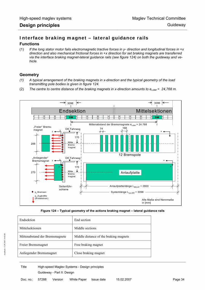
High-speed maglev systems
Design principles Maglev Technical Committee
Guideway
Title High-speed Maglev Systems - Design principles
Guideway - Part II: Design
Doc. no.: 57288 Version White Paper Issue date 15.02.2007 Page 34
Aus
druc
k: 1
3.09
.200
7 10
:42:
00
Interface braking magnet – lateral guidance rails Functions (1) If the long stator motor fails electromagnetic tractive forces in y- direction and longitudinal forces in +x
direction and also mechanical frictional forces in +x direction for set braking magnets are transferred via the interface braking magnet-lateral guidance rails (see figure 124) on both the guideway and ve-hicle.
Geometry (1) A typical arrangement of the braking magnets in x-direction and the typical geometry of the load
transmitting pole bodies is given in figure 124. (2) The centre to centre distance of the braking magnets in x-direction amounts to ex,BM = 24,768 m.
Endsektion MittelsektionenBM FM_T2 FM_T1 FM_T1 FM_T1 FM_T1 BM FM_T1
288
170
170
Anlaufplatte
Anlaufplattenlänge LBM,AP = 2800
Systemlänge Lsys,BM = 3096
„Anliegender“Bremsmagnet
OK Fahrweg
OK Fahrweg
y
z
x
x
z
y
z
MitteBrems-magnet
MitteBrems-magnet
Seitenführ-schiene
„Freier“ Brems-magnet
Mittenabstand der Bremsmagnete ex,BM = 24 768
12 Bremspole
270
74 168
x
x
3096 3096
Alle Maße sind Nennmaßein [mm]
px Bremsen
py Zugkräfte (Wirbelstrom)
z
Figure 124 – Typical geometry of the actions braking magnet – lateral guidance rails
Endsektion End section
Mittelsektionen Middle sections
Mittenabstand der Bremsmagnete Middle distance of the braking magnets
Freier Bremsmagnet Free braking magnet
Anliegender Bremsmagnet Close braking magnet

High-speed maglev systems
Design principles Maglev Technical Committee
Guideway
Title High-speed Maglev Systems - Design principles
Guideway - Part II: Design
Doc. no.: 57288 Version White Paper Issue date 15.02.2007 Page 35
Aus
druc
k: 1
3.09
.200
7 10
:42:
00
Fahrweg Guideway
Bremspole Braking poles
Anlaufplatte Axial buffer disk
Anlaufplattenlänge Axial buffer disk length
Systemlänge System length
Alle Masse sind Nennmasse in (mm) All measurements are nominal measurements in (mm)
Seitenführschiene Lateral guidance rails
Bremsen Brakes
Zugkräfte (Wirbelstrom) Tractive forces (eddy current)
(3) The maximum friction coefficients µBM-SFS between the braking magnet and lateral guidance rails to be
applied as a function of the travel speed are to be taken from table 97.
Adhesive fric-tion
Dynamic friction
vFzg [km/h] 0 v → 0 10 20 30 50 100 200 > 300 µBM-SFS [-] 0.50 0.30 0.25 0.22 0.20 0.18 0.14 0.12 0.10
Table 97 – Typical frictional coefficients braking magnet – lateral guidance rails (dry guideway)

High-speed maglev systems
Design principles Maglev Technical Committee
Guideway
Title High-speed Maglev Systems - Design principles
Guideway - Part II: Design
Doc. no.: 57288 Version White Paper Issue date 15.02.2007 Page 36
Aus
druc
k: 1
3.09
.200
7 10
:42:
00
Interface support skid – sliding strip Functions (1) –Forces in the z and friction in the ±x and ±y direction are transferred via the support skid-sliding strips
interfaces arranged on both sides of the guideway and vehicle (see figure 125) (normally at vFzg = 0 km/h, in infrequent design situations at vFzg ≥ 0 km/h).
(2) The process for establishing the actions to be taken into account is described in the subsequent chap-ters.
(3) The maximum friction coefficientsµTK-GL to be applied as a function of the travel velocity between sup-port skid and sliding strip are to be taken from table 98 to establish the actions in x-direction as a con-sequence of friction.
Adhesive
friction Dynamic friction
vFzg [km/h] 0 v → 0 10 20 30 50 100 200 > 300 µTK-GL[-] 0.50 * 0.30 ** 0.24 0.21 0.20 0.18 0.14 0.12 0.10
* Coefficient for taking into account the adhesive friction ** The max. friction coefficient for vFzg → 0 km/h is to be tested project specifically.
Table 98 – Typical frictional coefficients support skid – sliding strip (dry guideway)
Geometry (1) A typical arrangement of the support skids on the vehicle with the typical dimensions of the support
skids is presented in figure 125.
BM FM_T2 FM_T1 FM_T1 FM_T1 FM_T1 BM FM_T1
OK Fahrweg
yz
x
z
Tragkufen
ex,TK = 3096
150Lx,TK = 740
Spurmittenachse
Endsektion Mittelsektionen
ey,TK = 2220
Gleitebenen
by,TK = 110
Tragkufen
Fx/y/z,TKFx/y/z,TKFx/y/z,TK
Alle Maße sindNennmaße in [mm]
Figure 125 – Typical geometry of the actions support skid – sliding strip
Endsektion End section
Mittelsektionen Middle sections
Tragkufen Support skids

High-speed maglev systems
Design principles Maglev Technical Committee
Guideway
Title High-speed Maglev Systems - Design principles
Guideway - Part II: Design
Doc. no.: 57288 Version White Paper Issue date 15.02.2007 Page 37
Aus
druc
k: 1
3.09
.200
7 10
:42:
00
Gleitebenen Sliding strips
Fahrweg Guideway
Spurmittenachse Track central axis
Alle Masse sind Nennmasse in (mm) All measurements are nominal measurements in (mm)
Other interfaces
(1) The interfaces to the components of the external on board energy supply and to the components for recording the vehicle position (location) are described in /MSB AG-FW ÜBG/.
(2) The characteristic values of the actions are to be set down specifically for the project and the design.

High-speed maglev systems
Design principles Maglev Technical Committee
Guideway
Title High-speed Maglev Systems - Design principles
Guideway - Part II: Design
Doc. no.: 57288 Version White Paper Issue date 15.02.2007 Page 38
Aus
druc
k: 1
3.09
.200
7 10
:42:
00
Dynamic step up of requirements General (1) As a consequence of the transient actions on the guideway, oscillations/vibrations occur as a rule which
lead to a rise in the static guideway requirements (dynamic step up) such as to radiation of sound and solid base noise (vibrations).
Influence quantities on the dynamic step up General (1) The parameters and characteristic values described subsequently influence the dynamic behaviour and
the dynamic reaction of the guideway when a vehicle travels over and thus the size of the dynamic step ups.
Influence quantities of the guideway (1) Characteristic frequencies and forms of the guideway structure
The dynamic behaviour of the guideway and its ability to be stimulated is determined decisively by the associated characteristic frequencies and forms along the function planes and by the load arrangement. Global and local characteristic frequencies and forms depend on the mass, torsional rigidity, the static systems and the support conditions of the designs.
(2) Damping characteristics of the guideway structure The guideway characteristics of the guideway significantly influence the size of the dynamic step ups with harmonic stimulation above all. The damping characteristics are dependent on the materials used and the design characteristics of the structure. The most accurate possible of the respective damping characteristics of the guideway is required for a mathematical establishment of the dynamic require-ments.
(3) Accuracy of position of the function planes The greater the geometrical deviations from the ideal guideway position (e.g. positional inaccuracies of the long stator, offset at end of beam) are, the greater the dynamic step ups of the requirements ex-pected (for admissible deviations in position see /MSB AG-FW GEO).
Influence quantities of the vehicle (1) Load image of the vehicle and geometrical regularities contained in it
The load image of the vehicle is decisive for the size of the dynamic step up for intermittent load. Possible vehicle excitation frequencies result from the geometrical regularities in the load arrangement and in the development of the support magnets/magnetic poles as a function of the travel speed.
(2) Travel speed of the vehicle Significantly increased oscillations of the guideway beams can occur as a function of the travel speed. Dynamic step ups are mainly to be expected at resonant travel speeds, at high travel speeds (intermit-tent load) and at low travel speed (slow travel/hovering).
(3) Dynamic characteristics of the vehicle All factors which the time variability of the magnetic forces influence (e.g. gap distance) have an effect on the dynamic step up of the guideway requirements.
Influential excitation mechanisms (1) The influential system specific mechanisms and their influence quantities are shown subsequently.
Excitation mechanism I

High-speed maglev systems
Design principles Maglev Technical Committee
Guideway
Title High-speed Maglev Systems - Design principles
Guideway - Part II: Design
Doc. no.: 57288 Version White Paper Issue date 15.02.2007 Page 39
Aus
druc
k: 1
3.09
.200
7 10
:42:
00
(1) Intermittent load of the guideway through crossing of the vehicle: For vehicle lengths, guideway geometries and travel velocities present the size of the dynamic load in-creases with the travel speed. This effect can be relevant for high travel speeds in particular.
Excitation mechanism II (1) Geometrical regularities of the vehicle (length of the support magnet LTM; section length of the vehicle
LES/MS) lead to a periodic excitation of the guideway, the frequency of which is dependent on the travel velocity. Stepped up guideway oscillations can result from this. The harmonic excitation of the guideway can also lead to vibrations in the ground.
(2) The decisive wavelengths of the action result from the geometry and arrangement of the vehicle actions (e.g. support magnets and support magnet poles or guidance magnets and guidance magnet poles). Typical wavelengths for the actions in z-direction are e.g. λi = Lλ/i ⋅ with i = 1; 2 … and Lλ = 3,096 m; 24,768 m; 49,536 m.
(3) With the help of equation (1) the associated speed dependent excitation frequencies can be calculated.
fAnregung = vFzg / λi [Hz] ( 1)
(4) A large number of exciter frequencies thus result for the guideway which can lead to resonant dynamic step ups in the area of guideway natural frequencies (for this see chapter 0 (4)).
Excitation mechanism III (1) Periodic fluctuations in the magnetic forces transferred from the vehicle to the guideway through the
tooth/slot development of the long stator. (2) As a consequence of the low dimensions these mainly have an effect on structures with short influential
lengths and at low travel velocities and lead to a periodic exciting of the guideway, the frequency of which depends on the travel velocity.
Excitation mechanism IV (1) Vehicle vibrations can cause periodic fluctuations of the vehicle loads. Possible causes of an exciting of
vibration of the vehicle are subsequently described. (2) Parameter excited oscillation of the vehicle (exciter mechanism IV.a):
As a consequence of a regular, final length of the guideway beams, the rigidity of the guideway under the support magnets can change periodically (e.g. support area, beam field). If an excitation frequency resulting from the travel velocity and the support distance of the guideway beams is close to the natural frequency of the vehicle or the guideway, this can lead to stepped up vibrations of the vehicle and thus also the guideway.
(3) Excitations from the roughness of the track (excitation mechanism IV.b): Deviations of the function planes from the ideal position (e.g. position inaccuracies of the stator packs or displacements on the beam joints) lead to a dynamic exciting of the vehicle during crossing and thus to vehicle vibrations which again have a retrospective effect on the guideway as a consequence.
Excitation mechanism V (1) Dynamic effects from the regulation of the vehicle and thus in the coupling of the vehicle to the guide-
way can lead to strongly stepped up vibrations especially during slow travel/hovering and especially in the area of natural frequencies of the guideway structure.

High-speed maglev systems
Design principles Maglev Technical Committee
Guideway
Title High-speed Maglev Systems - Design principles
Guideway - Part II: Design
Doc. no.: 57288 Version White Paper Issue date 15.02.2007 Page 40
Aus
druc
k: 1
3.09
.200
7 10
:42:
00
(2) The associated exchange forces can be limited by measurements on e.g. prototype vehicles.
Excitation mechanism VI (1) Excitations as a result of infrequent actions such as e.g. fault of propulsion regulation of the long stator
linear motor (slip, swing), regulated setting down of the vehicle when using the safe brake or starting up a support magnet on the stator pack.
Damping characteristics (1) With regard to a reduction of dynamic step ups it is recommended to use designs/construction methods
with a high degree of natural damping. (2) The damping measurements following EN 1991-2:2003 Tab. 6.6 or experimentally established damping
values may be used if these can be proved as representative for the respective case of application and are agreed with the responsible inspectorate.
(3) If damping measurements following (2) are not available, the values given in table 99 can be used for the dynamic tests as a conservative damping measurement D in % of the critical damping (damping factor).
Beam/component from Conservative damping measurement D [%]
welded steel structures 0.3
screwed steel structures 0.4 .. 0.6 (dependent on the design)
Ferro concrete 0.6
Pre-stressed concrete 0.6
Steel bonding 0.6
Ground project specific
Table 99 – damping measurements D in % of the critical damping
Establishment of the dynamic requirements General (1) The general requirements for furnishing proof of dynamic actions are to be taken from
• DIN specialised report 101 chap. -6.4; Annex H;
• DIN 1055-100, chap. 5.4 • Eurocodes (e.g. EN 1990 - chap. 4.1.5; chap. 5.1.3 and EN 1991-2 - chap. 6.4)
(2) In establishing the dynamic requirements all actions from the travelling operation and if appropriate the environment (wind, earthquake) are to be taken into account with their special characteristics.
(3) The local increase as a consequence of the magnet regulation is to be taken into account in line with chapter 0.
(4) In the mathematical determination of dynamic requirements while using suitable calculation pro-grammes, the information in chapter 0 is to be taken into account
(5) Dynamic actions may be accepted as quasi-permanent actions in so far as vibration coefficients are available and agreed with the responsible inspectorate.

High-speed maglev systems
Design principles Maglev Technical Committee
Guideway
Title High-speed Maglev Systems - Design principles
Guideway - Part II: Design
Doc. no.: 57288 Version White Paper Issue date 15.02.2007 Page 41
Aus
druc
k: 1
3.09
.200
7 10
:42:
00
(6) For verification of the serviceability of the guideway with regard to its vibration behaviour, the require-ments for system compatibility of vibration amplitudes contained in chapter Error! Reference source not found. is to be taken into account.
(7) Dynamic requirements in the resonance area are to be demonstrably limited through suitable measures (e.g. damping by oscillation/vibration dampers) in such a way that the serviceability, the support safety and operating stability can be proven for the project specific service life required with the resonance re-quirements being taken into account.
(8) The theoretical assumptions and calculation results are to be verified through measurement of the dy-namic requirements following /MSB AG-FW ÜBG/.
Dynamic step ups as a consequence of magnet regulation
Time variability of the magnet forces (1) In order to adhere to the required air gap at the support magnet/long stator and guidance
magnet/lateral guidance rail interfaces, the magnetic forces are regulated in line with the lo-cal and temporary gap ratios (see reliable guideway tolerances following /MSB AG-FW GEO/.
(2) The time variability (dynamic) of the magnetic forces (reaction forces as a consequence of position tolerances of the long stator and the lateral guidance rails, slip, oscillation) which re-sults from this is to be taken into account for local proofs in the interface area (support mag-net-long stator, guidance magnet-lateral guidance rails) for respectively one partial magnet for support or guidance (see chapter 7.3 and 9.3).
(3) For the verification process the following step up coefficients ϕRl are to be applied:
min ϕRl,x/y/z = 0.8 and max ϕRl,x/y/z = 1.2
(4) The higher value limits of the static actions indicated in chapter 9 are to be used as capacity limits of the support and guidance magnets. The step ups maxϕRl,x/y/z are already included in this.

High-speed maglev systems
Design principles Maglev Technical Committee
Guideway
Title High-speed Maglev Systems - Design principles
Guideway - Part II: Design
Doc. no.: 57288 Version White Paper Issue date 15.02.2007 Page 42
Aus
druc
k: 1
3.09
.200
7 10
:42:
00
Excitation of characteristic forms through the magnet regulation (1) During slow travel and hovering in particular characteristic forms of guideway elements can be excited
by variable magnetic forces as a consequence of the gap regulation. The requirements and deforma-tions as a consequence of these excitations are to be proved.
(2) The type/method of the verification process is to be agreed with the responsible inspectorate. (3) Possibilities for the verification process are:
• Theoretical verification process through dynamic FEM calculations e.g. through response analysis; (the excitation forces and associated frequency areas are to be set down in agreement with the re-sponsible inspectorate in a project specific way.)
• If no values are set down in agreement with the responsible inspectorate, excitation forces as in harmonic varying forces in the characteristic frequencies of the beam with maximum power ampli-tudes of ∆pz = ∆py = ± 1 kN/m can be assumed for estimation of the dynamic step ups. Here the frequency range of 0 to 30 Hz is decisive.
• Measurement of the dynamic deformations and requirements of a prototype beam with simultane-ous verification of the system behaviour;
• Checking of guideway elements in the test stand; (4) In addition to a mathematical verification, an inspection of the guideway designs through test technical
checking of the dynamic behaviour and measurement of the dynamic requirements for slow crossing and hovering is required.
Dynamic step ups as a consequence of mobile operation
Mathematical establishment of the dynamic requirements (1) In the mathematical establishment of the dynamic requirements to be proven, the load arrangements
of chapter 0 are to be applied. In addition the influence quantities and excitation mechanisms de-scribed above are to be taken into account.
(2) The models for the guideway structures are to be chosen in such a way that geometry, rigidity, support ratios and distributions of mass and the dynamic characteristics (natural frequency, characteristic forms, damping) can be represented sufficiently realistically. The structures are to be portrayed via suitable methods such as e.g. the finite elements method. The parameters of the guideway beams are to be varied in their whole (or project specific) band width. The damping is to be estimated conserva-tively following chapter 0. The influence of the guideway substructure and guideway foundation is also to be recorded in the calculation of the dynamic requirements as far as this is necessary. The exami-nation of the global reaction of the guideway beam can normally occur with models.
(3) The depiction of the periodic excitation from the slot-tooth development of the long stator can occur through an increased (reduced) power transfer of the magnetic forces with location equality with the teeth (grooves) of the long stator. Here it is to be assumed that the total power transfer occurs over the teeth of the long stator.
(4) The actions from the vehicle must depict the characteristics of the vehicle sufficiently accurately (e.g. geometry of the support/guidance magnets). In particular the decisive excitation mechanism must be covered by the assumptions.
(5) For known natural frequencies of the guideway, the travel speeds at which a resonant excitation of the guideway construction is to be expected can be determined by equation (1).
(6) The information contained in chapter 0 is to be taken into account for consideration of the dynamic step ups as a consequence of the magnet regulation at low travel speeds and when hovering.
(7) If models for other dynamic actions (e.g. wind, earthquake) are used, these must depict the size, posi-tion, direction and course, positional and time variability, frequency of repetition and excitation fre-quencies of the individual parts of the action sufficiently accurately.

High-speed maglev systems
Design principles Maglev Technical Committee
Guideway
Title High-speed Maglev Systems - Design principles
Guideway - Part II: Design
Doc. no.: 57288 Version White Paper Issue date 15.02.2007 Page 43
Aus
druc
k: 1
3.09
.200
7 10
:42:
00
(8) For carrying out of the dynamic simulation calculation a time integration function is to be chosen which guarantees sufficient result quality. The size of the time step is to be chosen sufficiently finely.
(9) The simulation calculations are to be carried out up to maximum design speed for a sufficient number of speeds (e.g. with a speed pattern of ∆vFzg = 1 m/s). The speed ranges in which the excitation fre-quencies of the vehicle coincide with the natural frequencies of the guideway are to be given particular examination. Here the extension of the period of the time integration process for establishing reso-nance speed is to be taken into account.
Establishment of the dynamic requirements with the help of vibration coefficients
General (1) As a rule the effect of the non resting actions on the guideway can be established by quasi-permanent
verification as the actions are multiplied with vibration coefficients ϕ. (2) The vibration coefficients are to cover the decisive effects of the excitation as a function of the damp-
ing here. (3) The dynamic step ups can as a rule be established by global vibration coefficients ϕBg and local vibra-
tion coefficients ϕBl: • The global vibration coefficients ϕBg refer to the requirements in the main support direction (x-, y-
and z- direction) of the guideway beams and are also to be taken into account in the layout of the substructure.
• In the immediate area of the interfaces between the vehicle and guideway locally greater dynamic step ups result as a function of the local design boundary conditions (rigidity and damping ratios) and the load arrangements of the actions (geometry and frequency) and these are to be taken into account through local vibration coefficients ϕBl. Local vibration coefficients are thus to be taken into account in e.g. the cantilever arm area of discretely supported guideway beams and for short guideway elements such as e.g. guideway plates.
(4) The time variability of the magnetic forces is taken into account through the local vibration coefficients given in chapter 0.
(5) With reference to the serviceability of the guideway a maximum vibration coefficient of 1.5 is to be aimed for as the upper limit for the dynamic step up of the requirements.
(6) The vibration coefficients can be established mathematically or experimentally taking into account the notes given in the subsequent sections.
Mathematically established vibration coefficients (1) Design dependent vibration coefficients can be derived from mathematically determined dynamic re-
quirements. These can be used for the dimensioning of the guideway elements if the assumptions made are confirmed by the responsible inspectorate. Notes on the mathematical establishment of dy-namic requirements (instructions and boundary conditions) are compiled in chapter 0 for this purpose.
(2) For single span beam systems with typical support scopes, exemplary rating figures for the global vibration coefficient ϕBg,z for actions in a vertical direction as a function of the damping in accordance with table 1 and the vehicle length (2,4,6 and 10 sections) are given independent of design and ex-plained with reference to their application limits. As long as there are no more precise findings, no vi-bration coefficients smaller than ϕBg,z and ϕBg,z,WSE may be used for horizontal actions and for effective torsion moments in accordance with Annex II-B.
(3) As long as there are no more accurate findings or own mathematical examinations, no vibration coeffi-cients smaller than for single span beam systems should be used for twin span beam systems with the same support scope.

High-speed maglev systems
Design principles Maglev Technical Committee
Guideway
Title High-speed Maglev Systems - Design principles
Guideway - Part II: Design
Doc. no.: 57288 Version White Paper Issue date 15.02.2007 Page 44
Aus
druc
k: 1
3.09
.200
7 10
:42:
00
Test technical proven vibration coefficients
(1) The use of test technically established and proven vibration coefficients is admissible as long as the following boundary conditions are met: • The design of the guideway beam to be proven is similar to guideway designs already verified (ri-
gidity, mass per unit area, support scopes, support systems). • The operational boundary conditions of the test technical furnishing of proof (vehicle geometry and
equipment and also operating and track parameters) cover the project specific requirements. • The travel speeds resulting from equation (1) in which a resonant excitation of the guideway de-
sign is to be expected are covered by the tests. (2) The current state of knowledge regarding the test technically proven vibration coefficients and the
associated boundary conditions can be requested from the responsible inspectorate.
Limitation of the dynamic step ups (1) The dynamic response of the guideway is to be limited by suitable measures such as e.g. by increas-
ing the damping (e.g. use of vibration dampers) in case: • the admissible deformations following section 10.3 are exceeded, • the required period of use cannot be attained as a consequence of dynamic step up of the re-
quirements and/or • the behaviour of the linked system vehicle/guideway is not system compatible.

High-speed maglev systems
Design principles Maglev Technical Committee
Guideway
Title High-speed Maglev Systems - Design principles
Guideway - Part II: Design
Doc. no.: 57288 Version White Paper Issue date 15.02.2007 Page 45
Aus
druc
k: 1
3.09
.200
7 10
:42:
00
Characteristic values of the actions
Permanent actions Self-weight(G1)
(1) The self-weights of the components are to be determined following the relevant standards and regula-tions.
(2) For the maglev railway specific equipment components the following values are to be assumed: • Long stator including motor winding, earth and securing attachment : 1.4 kN/m 17) • Lateral guidance rails, sliding strips : 18) • Components of the external on board energy supply including securing attachment : 0.25 kN/m • Supplement for other add on parts : 0.10 kN/m
(3) The above actions from the individual components of the maglev railway specific guideway equipment are to be proven by measurement of weight.
Planned pre-tension/force (G2)
(4) The pre tension for pre-stressed concrete is a permanent action. For practical reasons it may however be treated differently (see EN 1992). Force in the sense of G2 can for example be a forced deforma-tion of beam through its weight or pretensioning against a support.
(5) Pre-tension can be created by pre-stressing elements, anchorings (e.g. on guideway plates), change of the support conditions, pre-loading or other measures,
(6) Planned pre-tension and force are to be taken into account.
Creeping and shrinkage of the concrete (G3)
(7) Creeping and relaxation are action dependent and are thus to be assigned to the creating action com-binations.
(8) The actions from creeping and shrinkage may be taken into account if the requirements become more favourable. They must be taken into account if the requirements become less favourable as a result.
Constant water compressive forces (G4)
(9) The actions from constant hydraulic pressure are to be taken into account following the relevant regu-lations and standards.
17 per side of the guideway beam; 18 The self-weights of the lateral guidance rails and sliding strips are to be established in accordance with the general requirements (dimensions and materials) from /MSB AG-FW ALLG/ under consideration of the respective design layout.

High-speed maglev systems
Design principles Maglev Technical Committee
Guideway
Title High-speed Maglev Systems - Design principles
Guideway - Part II: Design
Doc. no.: 57288 Version White Paper Issue date 15.02.2007 Page 46
Aus
druc
k: 1
3.09
.200
7 10
:42:
00
Probable ground movements (G5) Guideway superstructure
(1) The values of the probable ground movements to be applied for rating of the guideway superstructure correspond to the value limits of the admissible deformations of the guideway substructure (see chap-ter Error! Reference source not found.). These values are to be applied in every unfavourable posi-tion.
(2) In an individual case (e.g. for flow through systems with short support scopes) the probable ground movements to be applied may however be reduced in agreement with the responsible inspectorate and on proof of the compatibility to the vehicle. In this way it is to be guaranteed through maintenance that the guideway is adjusted before exceeding the reduced values.
(3) Before reaching the system value limits of the subsidence (established in the verification of service-ability) the supports are to be adjusted. If this system value limit is applied as a possible ground movement, γQ = 1.0 may be applied for the guideway superstructure (see also ENV 1991-3: C2.3).
Guideway substructure (10) The guideway substructure is to be formed in such a way that the probable ground movements can be
balanced by adjustment of the supports of the guideway superstructure in each case (see also /MSB AG-FW ÜBG/, chapter 10.2.2).
(11) The support positions following adjustment of the supports are to be taken into account in the guide-way verification process (weak points of the support forces).
Earth pressure (G6)
(12) The earth pressure is to be established and proved following the generally recognised rules of engi-neering.

High-speed maglev systems
Design principles Maglev Technical Committee
Guideway
Title High-speed Maglev Systems - Design principles
Guideway - Part II: Design
Doc. no.: 57288 Version White Paper Issue date 15.02.2007 Page 47
Aus
druc
k: 1
3.09
.200
7 10
:42:
00
Variable actions Variable actions as a consequence of the vehicle Coordinate system of the actions (21) The following actions refer to the Cartesian coordinates system presented in figure 126. (22) For this see also/MSB AG-FW TRAS/, /MSB AG-FW VERM/.
Figure 126 – Coordinate system of the actions
Fahrwegquerneigung Guideway transverse inclination
Fahrweglängsneigung Guideway lengthways inclination
Ursprung, liegt auf der Raumkurve Origin, lies on the space curve
Spurmittenabstand S
y
Z
X
Y
z
x
"0"
y1
Einzelspurfahrweg
Doppelspurfahrweg
X1
x1
Z1z1
Y
y2
X2
x2
Z2z2
Y2
"01" α1 α2
α1 α2
α
α
β
β2 β1
"02"
α Fahrwegquerneigung β Fahrweglängsneigung "0" Ursprung, liegt auf der Raumkurve X,Y,Z globale Fahrwegkoordinaten X- u. Y-Achse waagrecht Z-Achse lotrecht x, y, z lokale Fahrwegkoordinaten x-Achse mit β mitdrehend y- u. z-Achse mit α mitdrehend 1..n Nummerierung der Spuren bei mehreren Fahrspuren n>1 (siehe Beispiel Doppelspurfahrweg)

High-speed maglev systems
Design principles Maglev Technical Committee
Guideway
Title High-speed Maglev Systems - Design principles
Guideway - Part II: Design
Doc. no.: 57288 Version White Paper Issue date 15.02.2007 Page 48
Aus
druc
k: 1
3.09
.200
7 10
:42:
00
Globale Fahrwegkoordinaten X- u. Y-Achse waagrecht Z-Achse lotrecht
Global guideway coordinates X and Y axis horizontal Z-axis perpendicular
Lokale Fahrwegkoordinaten x-Achse mit β mitdrehend y-u.z Achse mit α mitdrehend
Local guideway coordinates –axis with β rotating in same direction
Nummerierung der Spuren bei meheren Fahrspuren n>1 (siehe Beispiel Doppelspurfahrweg)
Numbering of the tracks for several tracks n>1 (see example double track guideway)
Einzelspurfahrweg Single track guideway
Spurmittenabstand Track centre distance
Doppelspurfahrweg Double track guideway

High-speed maglev systems
Design principles Maglev Technical Committee
Guideway
Title High-speed Maglev Systems - Design principles
Guideway - Part II: Design
Doc. no.: 57288 Version White Paper Issue date 15.02.2007 Page 49
Aus
druc
k: 1
3.09
.200
7 10
:42:
00
Vehicle weight (self-weight and payload) (Q1, Q2) (13) As a static action as a consequence of vehicle weight (vehicle self-weight and payload) the inertia
forces p Z following table 100 are to be applied for the dimensioning of the guideway following /MSB AG-GESAMTSYS/.
(14) The track loads provided for the vehicle weight are averaged across the support magnet occupation length LTM-B (see figure 122). For the design of the guideway the local actions about the vehicle length are to be determined from these average track loads while applying the equations and tables indicated in the subsequent chapters.
(15)
(16) A possible unequal distribution of the payloads in x- and y- direction (Q3, Q4) is to be taken into ac-count in accordance with the chapters 0 and 0.
(17) The use of the average track loads or own simplifications of the subsequent load arrangements is admissible if it is proved that the requirements established through the simplification are on the safe side.
Designation Averaged, static track load [kN/m] Frequency *
Vehicle self weight EG (minimum vehicle weight) p Z, EG = 21,0 ** -
medium vehicle weight MG (for normal load) p Z, MG = 26,0 *** 80 %
admissible vehicle weight ZG (for maximum load) p Z, ZG = 29,0 *** 20 %
maximum vehicle weight HG (e.g. in the case of fire, evacuation of a section) ****
p Z, HG = 31,0 -
Observations: *
** ***
****
The frequencies indicated are to be tested for each product and adapted if appropriate. For the use of lighter vehicles a reduced track load for the vehicle self weight can be set down project spe-cifically (e.g. light goods vehicle with p Z,EG = 19,0 kN/m). For proof of fatigue a vehicle weight MG* = p can be applied more simply in place of the actions from the middle vehicle weight MG (80%) and the admissible vehicle weight ZG (205) The classification of the maximum vehicle weight HG is to be set down project specifically as frequent, infrequent or unusual action. As a rule the maximum vehicle weight is to be assumed as an unusual action.
Table 100 – Typical mean, static actions from the vehicle weight

High-speed maglev systems
Design principles Maglev Technical Committee
Guideway
Title High-speed Maglev Systems - Design principles
Guideway - Part II: Design
Doc. no.: 57288 Version White Paper Issue date 15.02.2007 Page 50
Aus
druc
k: 1
3.09
.200
7 10
:42:
00
Centre of gravity of the vehicle
Position of the vehicle centre of gravity in x-direction (Q3)
(18) The centre of gravity of the vehicle weight can shift through uneven distribution of the payload and the vehicle self weight in x-direction (Q3). This uneven distribution is passed on over the vehicle structure (e.g. distribution of the loads over air spring systems) to the support and guidance magnets and is taken into account in the subsequent tables of actions (e.g. table 105).
(19) With vehicles for goods transport it is to be assured through a project specific loading instruction that an uneven loading in x-direction does not lead to load distributions more unfavourable than those indi-cated in table 105.
Position of the vehicle centre of gravity in y-direction (Q4)
(20) The centre of gravity of the vehicle weight can be shifted in the y-direction (Q4) through uneven distri-bution of the payload. This shifting of the centre of gravity is negligible when including the track loads in Table 100.
(21) With vehicles for goods transport it is to be assured through a project specific loading instruction by the operator that there is no uneven loading in y-direction.
Position of the vehicle centre of gravity in z-direction (1) The highest position of the vehicle centre of gravity above the level of the sliding strips
amounts to: • minimum vehicle weight sz,EG = - 600 mm; • medium vehicle weight sz,MG = - 700 mm; • admissible vehicle weight sz,ZG = - 850 mm; • maximum vehicle weight sz,HG = - 950 mm;
These centre of gravity positions are to be taken account of with the inertia forces in x- and y- di-rection.

High-speed maglev systems
Design principles Maglev Technical Committee
Guideway
Title High-speed Maglev Systems - Design principles
Guideway - Part II: Design
Doc. no.: 57288 Version White Paper Issue date 15.02.2007 Page 51
Aus
druc
k: 1
3.09
.200
7 10
:42:
00
Frequent variable actions (Q1...Q10)
General (2) The connection between the track parameters, the speed of travel and the acceleration is
defined through the following relations:
• acceleration ax (x) in x-direction from starting up and braking
|ax (x)| ≤ 1,5 m/s²ax (x)| ≤ 1,5 m/s² ( 2)
• Free lateral acceleration ay (x) in y-direction
(x)sin
(x)Rv(x)(x)cosg(x)cos(x)cos
(x)Rv(x)=(x)a
K/WV,
22
H
2
y α⋅⎟⎟⎠
⎞⎜⎜⎝
⎛
−+β⋅−β⋅α⋅
( 3)
• Normal acceleration az (x) in z-direction
(x)cos
(x)Rv(x)(x)cosg(x)cos(x)sin
(x)Rv(x)=(x)a
K/WV,
22
H
2
z α⋅⎟⎟⎠
⎞⎜⎜⎝
⎛
−+β⋅+β⋅α⋅
( 4)
with:
ax(x), ay(x), az(x)
[m/s²] in direction of the local coordinate axes, location dependent accelera-tions;
v(x) [m/s] Location dependent speed of travel;
RH (x) [m] Location dependent horizontal radius of the space curve in the ground plan;
RV (x) [m] Location dependent vertical radius of the space curve in the gradient with
RV,K : Peak (+) and RV,W : Depression (-);
α(x) [°] Location dependent angle of rotation of the guideway round the x-axis (guideway banking);
β(x) [°] Location dependent angle of rotation of the guideway round the y-axis (guideway longitudinal gradient);
(3) The connection between actions F, acceleration a and vehicle mass m is given by Newton’s law:
F = m ⋅ a ( 5)

High-speed maglev systems
Design principles Maglev Technical Committee
Guideway
Title High-speed Maglev Systems - Design principles
Guideway - Part II: Design
Doc. no.: 57288 Version White Paper Issue date 15.02.2007 Page 52
Aus
druc
k: 1
3.09
.200
7 10
:42:
00
(4) The connection between accelerations and track parameters is presented in figure 127. The possibility of overlapping of track elements is limited by the Rx,z –criterion given in /MSB AG-FW TRAS/. The value limits of possible combinations are compiled in Annex II-C.
(5) The maximum possible guideway actions are set down by the limitation of the admissible accelerations following chapter 0. The acceleration values can deviate downwards project specifically limitation of the admissible accelerations).
(6) The equations (3) and (4) also apply for the standing vehicle.
Figure 127 – Connection between accelerations and track parameters
Fläche Surface
Gradiente Gradient
Waagrecht “Grundriss” Horizontal “layout”
Raumkurve Space curve
Gleitleistenebene Sliding strip surface
Actions as a consequence of braking and accelerating (Q1/Q2)
(22) The thrust in each route section and the max. permissible longitudinal force resulting from max. ax according to Table 91 is to be set as a frequently variable action in the x-direction.
(23) The force in x-direction is location dependent and takes into account acceleration stretches (starting up and braking), inertia stretches, incline, fall and the aerodynamic travel resistance (incl. headwind).
(24) A force of 110 Kn/middle section with reference to the vehicle weight is to be taken into account as limit force in x-direction in frequent design situations (see also table 101 line 3).
(25) The actions to be taken into account as a consequence of propulsion (braking/accelerating) are to be taken from table 101 for max ax = 1.5 m/s² for the various vehicle weights.
Static actions max px,Schub for frequent rating situations from:
x, a x
Z, gRV, K/W
z, aZ
y,a y
Y,aYR H
X, a X
β
α Fläche
waagrecht, "Grundriß" . ..
Fläche "Gradiente"
Fläche xy Gleitleistenebene R xy
R xz
Raumkurve
"0
z, az

High-speed maglev systems
Design principles Maglev Technical Committee
Guideway
Title High-speed Maglev Systems - Design principles
Guideway - Part II: Design
Doc. no.: 57288 Version White Paper Issue date 15.02.2007 Page 53
Aus
druc
k: 1
3.09
.200
7 10
:42:
00
1 minimum vehicle weight max px,Q1/Q2,EG = p Z,EG / g ⋅ max ax = 3.2 kN/m
2 medium vehicle weight max px,Q1/Q2,MG = p Z,MG / g ⋅ max ax = 4.0 kN/m
3 admissible vehicle weight max px,Q1/Q2,ZG = p Z,ZG / g ⋅ max ax = 4.5 kN/m (value limit)
4 maximum vehicle weight max px,Q1/Q2,HG = max px, Q1/Q2,ZG = 4.5 kN/m (value limit) Table 101 – Maximum forces in x-direction from propulsion and braking
(26) As a rating the value the action px ,Q1/Q2 following (6) is to be applied.
px ,Q1/Q2 = max px, Q1/Q2 ( 6)
(27) In the area outside of motor section switching the following is to be applied:
px,links = px,rechts = 0,5 ⋅ px ( 7)
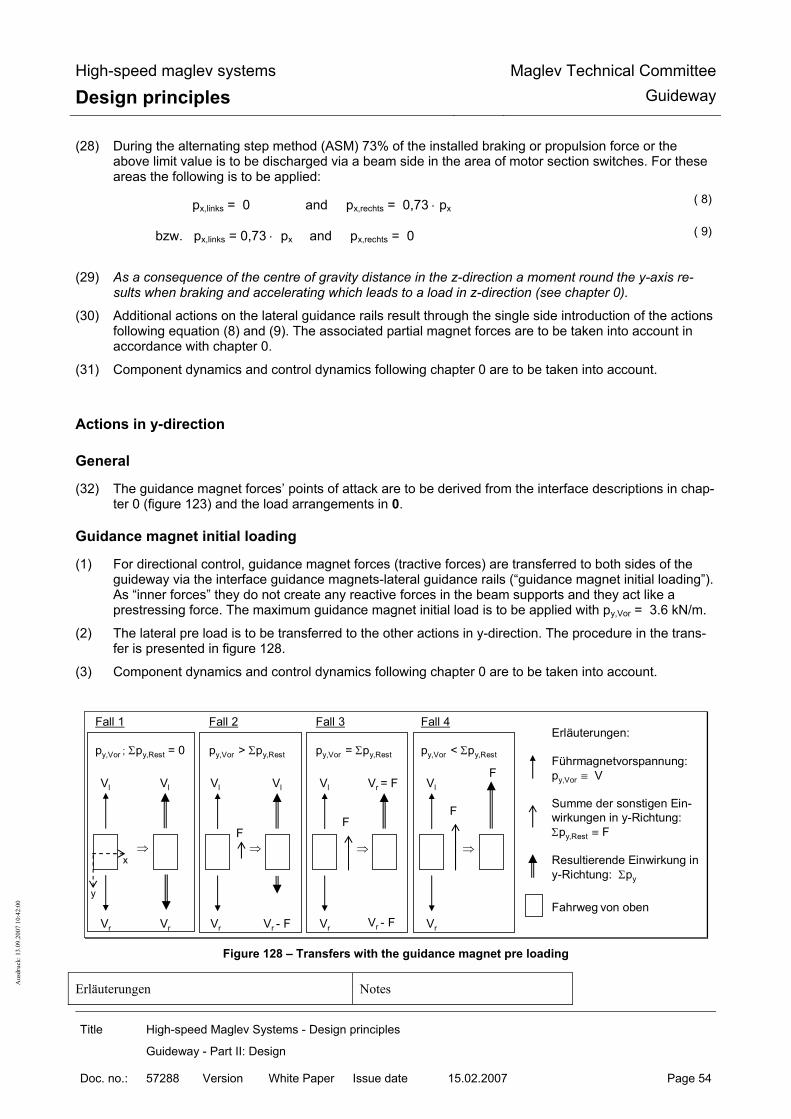
High-speed maglev systems
Design principles Maglev Technical Committee
Guideway
Title High-speed Maglev Systems - Design principles
Guideway - Part II: Design
Doc. no.: 57288 Version White Paper Issue date 15.02.2007 Page 54
Aus
druc
k: 1
3.09
.200
7 10
:42:
00
(28) During the alternating step method (ASM) 73% of the installed braking or propulsion force or the above limit value is to be discharged via a beam side in the area of motor section switches. For these areas the following is to be applied:
px,links = 0 and px,rechts = 0,73 ⋅ px ( 8)
bzw. px,links = 0,73 ⋅ px and px,rechts = 0 ( 9)
(29) As a consequence of the centre of gravity distance in the z-direction a moment round the y-axis re-
sults when braking and accelerating which leads to a load in z-direction (see chapter 0).
(30) Additional actions on the lateral guidance rails result through the single side introduction of the actions following equation (8) and (9). The associated partial magnet forces are to be taken into account in accordance with chapter 0.
(31) Component dynamics and control dynamics following chapter 0 are to be taken into account.
Actions in y-direction
General
(32) The guidance magnet forces’ points of attack are to be derived from the interface descriptions in chap-ter 0 (figure 123) and the load arrangements in 0.
Guidance magnet initial loading
(1) For directional control, guidance magnet forces (tractive forces) are transferred to both sides of the guideway via the interface guidance magnets-lateral guidance rails (“guidance magnet initial loading”). As “inner forces” they do not create any reactive forces in the beam supports and they act like a prestressing force. The maximum guidance magnet initial load is to be applied with py,Vor = 3.6 kN/m.
(2) The lateral pre load is to be transferred to the other actions in y-direction. The procedure in the trans-fer is presented in figure 128.
(3) Component dynamics and control dynamics following chapter 0 are to be taken into account.
Erläuterungen:
Führmagnetvorspannung:py,Vor ≡ V
Summe der sonstigen Ein-wirkungen in y-Richtung: Σpy,Rest ≡ F
Resultierende Einwirkung in y-Richtung: Σpy
Fahrweg von oben
⇒ ⇒ ⇒
Fall 2
py,Vor > Σpy,Rest
⇒
Fall 1
py,Vor ; Σpy,Rest = 0
Vl
Vr
Vl
Vr
Vl
Vr
Vl
Vr
Vl
Vr
FF
F
Vl
Vr - F Vr - F
Vr = FF
x
y
Fall 3
py,Vor = Σpy,Rest
Fall 4
py,Vor < Σpy,Rest
Figure 128 – Transfers with the guidance magnet pre loading
Erläuterungen Notes
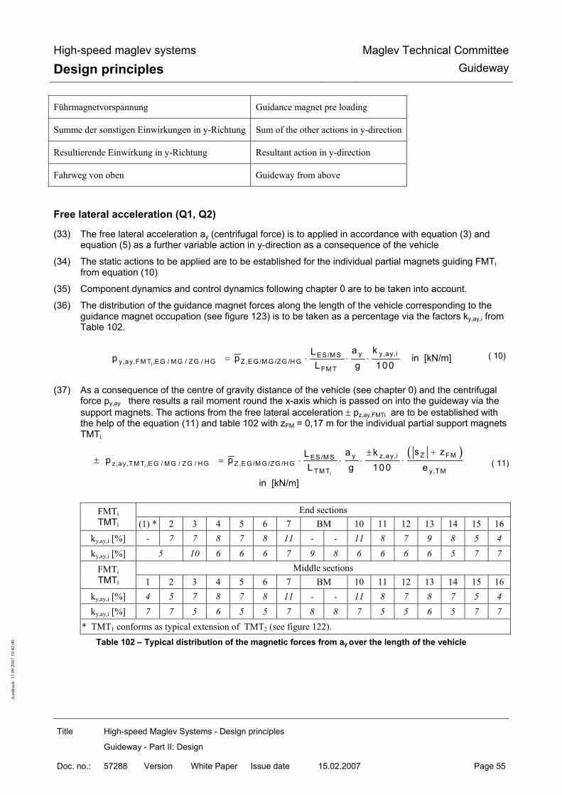
High-speed maglev systems
Design principles Maglev Technical Committee
Guideway
Title High-speed Maglev Systems - Design principles
Guideway - Part II: Design
Doc. no.: 57288 Version White Paper Issue date 15.02.2007 Page 55
Aus
druc
k: 1
3.09
.200
7 10
:42:
00
Führmagnetvorspannung Guidance magnet pre loading
Summe der sonstigen Einwirkungen in y-Richtung Sum of the other actions in y-direction
Resultierende Einwirkung in y-Richtung Resultant action in y-direction
Fahrweg von oben Guideway from above
Free lateral acceleration (Q1, Q2)
(33) The free lateral acceleration ay (centrifugal force) is to applied in accordance with equation (3) and equation (5) as a further variable action in y-direction as a consequence of the vehicle
(34) The static actions to be applied are to be established for the individual partial magnets guiding FMTi from equation (10)
(35) Component dynamics and control dynamics following chapter 0 are to be taken into account.
(36) The distribution of the guidance magnet forces along the length of the vehicle corresponding to the guidance magnet occupation (see figure 123) is to be taken as a percentage via the factors ky,ay,i from Table 102.
i
y y,ay,iE S /M Sy,ay,FM T ,E G / M G / ZG / H G Z,E G /M G /ZG /H G
FM T
a kLp p
L g 100= ⋅ ⋅ ⋅ in [kN/m] ( 10)
(37) As a consequence of the centre of gravity distance of the vehicle (see chapter 0) and the centrifugal force py,ay there results a rail moment round the x-axis which is passed on into the guideway via the support magnets. The actions from the free lateral acceleration ± pz,ay,FMTi are to be established with the help of the equation (11) and table 102 with zFM = 0,17 m for the individual partial support magnets TMTi.
( )i
i
Z FMy z,ay,iES /M Sz,ay,T M T ,E G / M G / ZG / H G Z,E G /M G /ZG /H G
T M T y,T M
s za kLp p
L g 100 e
+±± = ⋅ ⋅ ⋅ ⋅
in [kN/m]
( 11)
End sections FMTi
TMTi (1) * 2 3 4 5 6 7 BM 10 11 12 13 14 15 16 ky,ay,i [%] - 7 7 8 7 8 11 - - 11 8 7 9 8 5 4 ky,ay,i [%] 5 10 6 6 6 7 9 8 6 6 6 6 5 7 7
Middle sections FMTi TMTi 1 2 3 4 5 6 7 BM 10 11 12 13 14 15 16
ky,ay,i [%] 4 5 7 8 7 8 11 - - 11 8 7 8 7 5 4 ky,ay,i [%] 7 7 5 6 5 5 7 8 8 7 5 5 6 5 7 7
* TMT1 conforms as typical extension of TMT2 (see figure 122). Table 102 – Typical distribution of the magnetic forces from ay over the length of the vehicle

High-speed maglev systems
Design principles Maglev Technical Committee
Guideway
Title High-speed Maglev Systems - Design principles
Guideway - Part II: Design
Doc. no.: 57288 Version White Paper Issue date 15.02.2007 Page 56
Aus
druc
k: 1
3.09
.200
7 10
:42:
00
Lateral forces from the guidance dynamics (Q5)
(38) Dynamic lateral forces SK for taking into account the guidance dynamics as a result of global guide-way tolerances of the lateral guidance rails are to be applied according to the following relationship:
Fzgy,S K
v km /hp 1
500 km /h
⎛ ⎞⎡ ⎤⎣ ⎦± = ± +⎜ ⎟⎜ ⎟⎡ ⎤⎣ ⎦⎝ ⎠ in [kN/m] ( 12)
(39) For set down vehicle with vFzg = 0 , py,SK = 0 is to be applied.
(40) The action py,SK is a dynamic action and thus contains the global component dynamics.
(41) Local component dynamics and control dynamics following chapter 0 are to be taken into account.
Reactive forces with small horizontal radii RH (Q6)
(42) With small horizontal radii local reactive forces determined by the vehicle geometry are to be trans-ferred in y-direction to the other actions from the guidance magnets.
(43) The characteristic reactive forces to be applied for the corresponding horizontal radii are to be taken from table 103. As an addition to this the distribution of the actions is presented in figure 129.
(44) Component dynamics and control dynamics following chapter 0 are to be taken into account.
py,ZWG,i [kN/m] End sections Middle sections RH = 350 m RH = 1000 m RH = 350 m RH = 1000 m
py,ZWG,1 - - 18.0 7 py,ZWG,2 21.0 7 0 0 py,ZWG,3 0 0 0 0 py,ZWG,4 1.0 0 6.0 0 py,ZWG,5 2.0 0 1.0 0 py,ZWG,6 -4.5 0 -5 -1 py,ZWG,7 -21.0 -7 -21.0 -6
BM - - - - py,ZWG,10 -21.0 -7 -21.0 -6 py,ZWG,11 -4.5 0 -5 -1 py,ZWG,12 1.0 0 1.0 0 py,ZWG,13 7.0 0 6.0 0 py,ZWG,14 0 0 0 0 py,ZWG,15 1.0 0 1.0 0 py,ZWG,16 18.0 7 18.0 7
Interim values may interpolated or extrapolated in a linear way.
Table 103 – Typical reactive forces py,ZWG,i for small horizontal radii

High-speed maglev systems
Design principles Maglev Technical Committee
Guideway
Title High-speed Maglev Systems - Design principles
Guideway - Part II: Design
Doc. no.: 57288 Version White Paper Issue date 15.02.2007 Page 57
Aus
druc
k: 1
3.09
.200
7 10
:42:
00
2
14
13
125
6
7
11
9
10
4
3
15
4
7
11
12
13145
3
6
= Führmagnet
Die Nummern 1..16 entsprechen den in der zugehörgenTabelle angegebenen Teilmagnetkräften der Führmagnete: + ⇒ Zugkräfte der bogenaußenliegenden Führmagnete- ⇒ Zugkräfte der bogeninnenliegenden Führmagnete
y
x
= Bremsmagnet (WSB)
15
16 1
2
10
15
16
Endsektionen Mittelsektionen
bogenaußen
bogeninnen
z
Figure 129 – Typical distribution of the reactive forces in tight horizontal radii RH
bogenaussen Outside of curve
bogeninnen Inside of curve
Endsektionen End sections
Mittelsektionen Middle sections
Führmagnet Guidance magnet
Bremsmagnet Braking magnet
Die Nummern 1..16 entsprechen den in der zugehörigen Tabelle angegebenen Teilmagnetkräfte der Führmagnete:
The numbers 1..16 correspond to the part magnet forces of the guidance magnets in the associated table:
Zugkräfte der bogenaussenliegenden Führmagnete Tractive forces of the guidance magnets on the out-side of the curve
Zugkräfte der bogeninnenenliegenden Führmagnete Tractive forces of the guidance magnets on the in-side of the curve
Guidance magnet forces from one sided propulsion

High-speed maglev systems
Design principles Maglev Technical Committee
Guideway
Title High-speed Maglev Systems - Design principles
Guideway - Part II: Design
Doc. no.: 57288 Version White Paper Issue date 15.02.2007 Page 58
Aus
druc
k: 1
3.09
.200
7 10
:42:
00
(7) The moment round the z-axis from one sided propulsion (e.g. following chapter 0 change over step process) is introduced to the guideway via the guidance magnets.
(1) The actions to be applied are to be determined with equation ( 13) and table 104 for the guidance magnets shown in figure 121, whereby the existing acceleration ax,WSV at point (x) of the guideway is to be applied.
x,W S V i x,W S V
x,W S V Z ,E G /M G /Z G /H Gy,a ,FM T ,E G / M G / Z G / H G y,a ,i,Z G
x,m a x Z,Z G
vo rh a ( x ) pp p
0 ,73 a p= ⋅ ⋅
⋅ in [kN/m]
( 13)
Whereby max ax = + 1.5 m/s² or – 1.5 m/s² , ax,WSV (x) ≤ 0.73 ⋅ max ax
and py,axWSV,i,ZG from table 104;
(2) As a consequence of the mechanical linking of the magnets guidance magnet forces can work as tractive forces on the right (r)and left (l) side of the beam simultaneously (see figure 130).
(3) Component dynamics and control dynamics following chapter 0 are to be taken into account. •
p y,axW SV,i,ZG (l)
p y,axW SV,i,ZG (r)
zpx,axWSV
y
Be ispie l EndsektionBug
16151413121110B M765432
16151413121110B M765432
x
F M T i, (r)
F M T i (l)
Figure 130 – Typical distribution of the guidance magnets from ax,WSV
Bug Nose
Besipiel Endsektion Example end section
End sections FMTi in [kN/m] - 2 3 4 5 6 7 BM 10 11 12 13 14 15 16
py,axWSV,i,ZG (r) - 2.2 3.7 4.7 0 0 4.5 - - 0 1.1 5.6 0 0 1.4 4.4

High-speed maglev systems
Design principles Maglev Technical Committee
Guideway
Title High-speed Maglev Systems - Design principles
Guideway - Part II: Design
Doc. no.: 57288 Version White Paper Issue date 15.02.2007 Page 59
Aus
druc
k: 1
3.09
.200
7 10
:42:
00
py,axWSV,i,ZG (l) - 8.5 0.5 0 6.2 0.5 0 - - 4.6 0 0 4.8 1.1 0 0
Middle sections FMTi in [kN/m] 1 2 3 4 5 6 7 BM 10 11 12 13 14 15 16
py,axWSV,i,ZG (r) 0 0 1.7 4.3 0 0 4.7 - - 0 1.1 5.8 0 0 1.4 4.4
py,axWSV,i,ZG (l) 5 0.8 0 0 6.2 0.6 0 - - 4.8 0 0 4.9 1.1 0 0 The actions listed in this table take into account the permissible vehicle weight according to Table 100 and the max. permissible braking/propulsion acceleration according to Table 91. The force balance of the end sections is not balanced (transfer of a remaining force over the section coupling).
Table 104 – Typical distribution of the guidance magnets from ax,WSV

High-speed maglev systems
Design principles Maglev Technical Committee
Guideway
Title High-speed Maglev Systems - Design principles
Guideway - Part II: Design
Doc. no.: 57288 Version White Paper Issue date 15.02.2007 Page 60
Aus
druc
k: 1
3.09
.200
7 10
:42:
00
Actions in z-direction (Q1.. Q3)
Acceleration in z-direction (4) The actions from the vehicle weight as a consequence of az (see equation (4)) in z-direction
are to be established with the help of the subsequent equations (14) and (15) and the distri-bution given in table 105 over the vehicle length (see chapter 0).
z
zz,a ,EG /M G /ZG /H G Z,E G /M G /ZG /H G
ap p
g= ⋅ in [kN/m] ( 14)
(5) The limit values for az are to be taken from Table 91. (6) For the individual partial magnets TMTi according to figure 121 the corresponding forces are
to be determined according to equation ( 15). In the distribution of the partial magnet actions the unequal distribution through the factors kz,az,i (see table 105) as a consequence of vehi-cle centre of gravity position in x-direction is included following chapter 0.
ii
z,az,iE S /M S zz,az,T M T ,E G /M G /ZG /H G Z,E G /M G /ZG /H G
T M T
kL ap 0 ,5 p
L g 100= ⋅ ⋅ ⋅ ⋅ in [kN/m] ( 15)
(7) Component dynamics and control dynamics following chapter 0 are to be taken into account.
End sections TMTi
1 * 2 3 4 5 6 7 8 9 10 11 12 13 14 15 16 kz,az,i [%]
10 10 5 7 7 7 7 7 7 7 6 6 6 6 6 6
Middle sections TMTi
1 2 3 4 5 6 7 8 9 10 11 12 13 14 15 16 kz,az,i
[%] 6 6 6 6 6 6 7 7 7 7 6 6 6 6 6 6
* TMT1 conforms as typical extension of TMT2 (see figure 122).
Table 105 – Typical distribution of the guidance magnet forces from az over the length of the vehicle

High-speed maglev systems
Design principles Maglev Technical Committee
Guideway
Title High-speed Maglev Systems - Design principles
Guideway - Part II: Design
Doc. no.: 57288 Version White Paper Issue date 15.02.2007 Page 61
Aus
druc
k: 1
3.09
.200
7 10
:42:
00
Acceleration and braking
(1) The pitching moments of the carriage body round the y-axis as a consequence of the centre of gravity distance in z-direction (see chapter 0) while braking and accelerating are to be taken into account in accordance with the load arrangement (loading and unloading) in accordance with figure 131 (circuits of air suspension connection) (here see also the force distribution from the tilting of the support-guidance structure following chapter 0).
(2) This load arrangement is to the unfavourably transferred to the static guideway load following chapter 0.
(3) Component dynamics and control dynamics following chapter 0 are to be taken into account.
M itte lsektionenE ndsektionen
0 bzw . + (-) ∆p z,ax
0 b zw . -(+ ) ∆p z,ax
z
x
y
0 bzw . + (-) ∆p z,ax
0 b zw . -(+ ) ∆p z,ax
M it m ax ∆p z,ax = + (-) 0 ,5 kN /m bei ax = 1 ,5 m /s²(+ ∆pz,ax be i B rem sung , - ∆p z,ax be i B eschleunig ung )
14,465 m 9,288 m 12,384 m 12,384 m
Figure 131- Typical additional loads in z-direction as a consequence of braking/accelerating
Endsektionen End sections
Mittelsektionen Middle sections
Mit max With max
Bei Bremsung For braking
Bei Beschleunigung For acceleration

High-speed maglev systems
Design principles Maglev Technical Committee
Guideway
Title High-speed Maglev Systems - Design principles
Guideway - Part II: Design
Doc. no.: 57288 Version White Paper Issue date 15.02.2007 Page 62
Aus
druc
k: 1
3.09
.200
7 10
:42:
00
Special operating situations
Regulated setting down of the vehicle at v = 0 km/h (Q1, Q2)
(45) With regulated setting down in stations and operating structures dynamic actions are created on the guideway via the support skids. The static action from a support skid is to be established in the follow-ing way:
j j+1z,TK ,j/j+1 z,az,TM T z,az,TM T sys,TM TF (p p ) L ;= + ⋅ in [kN]
with pz,az,TMT from equation ( 15) and j = 1, 3, 5, 7, 9, 11, 13, 15 ( 16)
(46) Component dynamics and control dynamics following chapter 0 are to be taken into account.
(47) The time function of the regulated setting down to be taken into account is to be taken from figure 135 in chapter (8)
(48) The forces which occur as a consequence of guideway longitudinal and crossways tilting as a conse-quence of the friction coefficient µ (see table 98) for a support skid Fx/y,TK in x- and/or y-direction which are limited by the maximum forces max Fx/y,TK dependent on the friction coefficient are to be applied following equation (17) and (18).
yy,T K z,T K
z
aF F
a= ⋅ whereby y,T K z,T Km ax F µ F ;= ⋅ in [kN] ( 17)
and
xx,T K z,T K
z
aF F
a= ⋅ whereby x,T K z,T Km ax F µ F ;= ⋅ in [kN] ( 18)
Set down vehicle (Q1, Q2)
(49) The actions from the operating condition “set down vehicle” are covered by the actions from the regu-lated setting down process (see chapter 0).
Levitating vehicle and hovering (Q1, Q2)
(1) The magnetic forces analogous to the previous chapter are to be applied.
(2) Component dynamics and control dynamics following chapter 0 are to be taken into account. In this a possible excitation of natural frequencies of the guideway is to be observed through the magnet regu-lation above all (see chapter 0).

High-speed maglev systems
Design principles Maglev Technical Committee
Guideway
Title High-speed Maglev Systems - Design principles
Guideway - Part II: Design
Doc. no.: 57288 Version White Paper Issue date 15.02.2007 Page 63
Aus
druc
k: 1
3.09
.200
7 10
:42:
00
Aerodynamic actions from the vehicle (Q7, Q8)
Meeting of trains (Q7a)
(50) Additional guidance magnet forces as a consequence of a meeting of trains may be ignored on adher-ence to the track centre distances stipulated.
Tunnel travel (Q7b)
(51) Direct actions from the vehicle A reduced space (tunnel cross section) for the displacement of the air results through the tunnel. The values indicated in table 107 for pressure and suction are to be applied with a 10% increase.
(52) Indirect actions as a consequence of the variability of the all-round pressure of the surrounding area A change in pressure from 5500 Pa only effects the pressure tight closed cavities (e.g. cavity boxes of guideway beams which are sealed through welding). This action is not to be transferred with the in-creased pressure/suction value. It is recommended, in guideway areas in which corresponding changes in pressure are possible not to use pressure tight guideway designs.
(53) Indirect actions as a consequence of reflected blast/suction waves Actions as a consequence of reflected blast/suction waves are negligible.
(54) Unequal pressure distribution / air buffeting The characteristic values of possible actions as a consequence of unequal pressure distribution and air buffeting are to be set down project specifically with the available boundary conditions (tunnel cross section, tunnel length, travel speed) being taken into consideration.
Actions on structures close to track/tunnels (Q7c)
(55) The actions on structures close to the track are to be taken from EN 1991-2 chapter 6.6 with the vehi-cle width being taken into account. Here the width of the track vehicle is to be applied with 3.07m and the width of the maglev vehicle with 3.70 m.
(56) The values for higher speeds are to be extrapolated in proportion to the squares of the speed.
(57) The factor k1 from EN 1991-2 chapter 6.6 for consideration of a favourable aerodynamic form is to be applied with k1 = 0.6 (streamlined vehicle)
(58) Further coefficients are to be taken into account in line with EN 1991-2 chapter 6.6.
(59) Dynamic step ups through excitation of natural forms are to be proven.
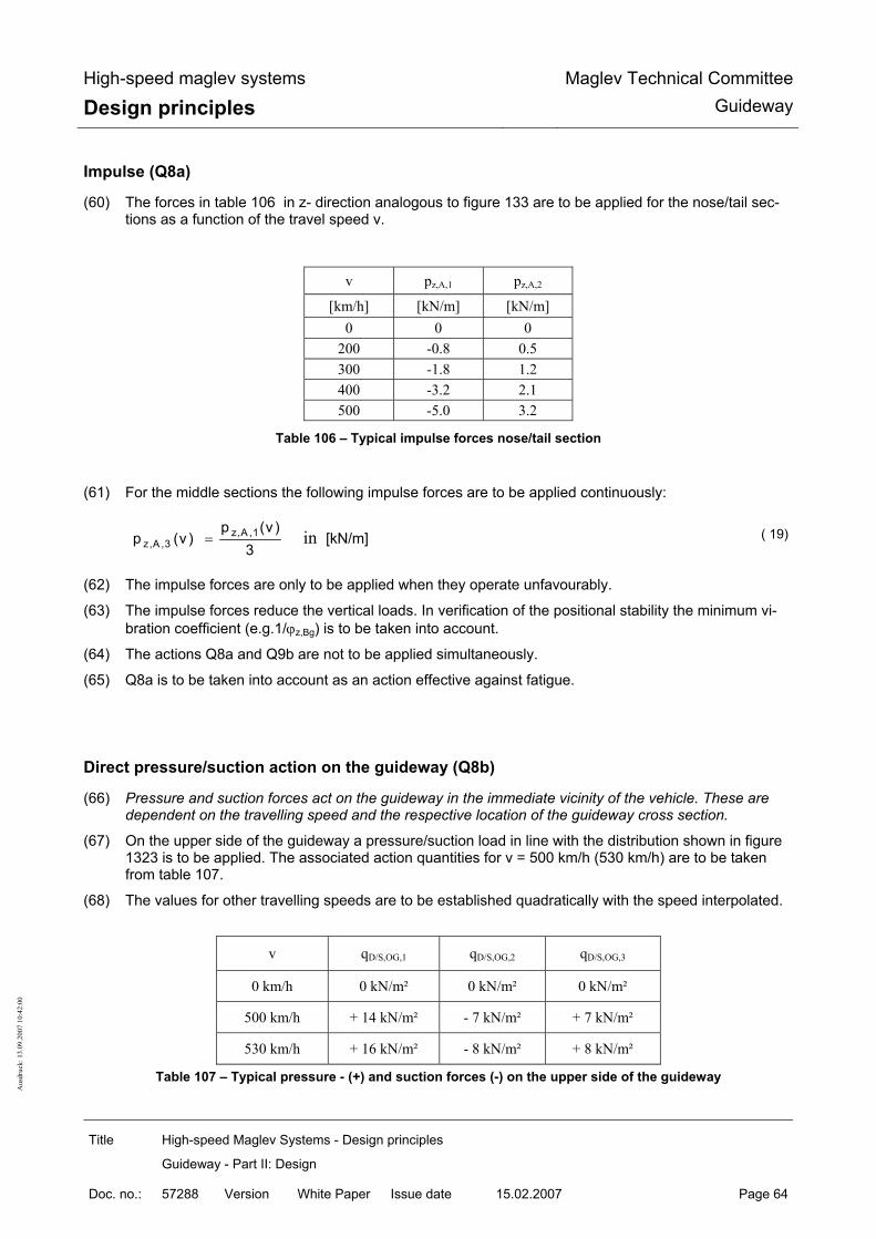
High-speed maglev systems
Design principles Maglev Technical Committee
Guideway
Title High-speed Maglev Systems - Design principles
Guideway - Part II: Design
Doc. no.: 57288 Version White Paper Issue date 15.02.2007 Page 64
Aus
druc
k: 1
3.09
.200
7 10
:42:
00
Impulse (Q8a)
(60) The forces in table 106 in z- direction analogous to figure 133 are to be applied for the nose/tail sec-tions as a function of the travel speed v.
v pz,A,1 pz,A,2 [km/h] [kN/m] [kN/m]
0 0 0 200 -0.8 0.5 300 -1.8 1.2 400 -3.2 2.1 500 -5.0 3.2
Table 106 – Typical impulse forces nose/tail section
(61) For the middle sections the following impulse forces are to be applied continuously:
z,A ,1z,A ,3
p (v )p (v )
3= in [kN/m] ( 19)
(62) The impulse forces are only to be applied when they operate unfavourably.
(63) The impulse forces reduce the vertical loads. In verification of the positional stability the minimum vi-bration coefficient (e.g.1/ϕz,Bg) is to be taken into account.
(64) The actions Q8a and Q9b are not to be applied simultaneously.
(65) Q8a is to be taken into account as an action effective against fatigue.
Direct pressure/suction action on the guideway (Q8b)
(66) Pressure and suction forces act on the guideway in the immediate vicinity of the vehicle. These are dependent on the travelling speed and the respective location of the guideway cross section.
(67) On the upper side of the guideway a pressure/suction load in line with the distribution shown in figure 1323 is to be applied. The associated action quantities for v = 500 km/h (530 km/h) are to be taken from table 107.
(68) The values for other travelling speeds are to be established quadratically with the speed interpolated.
v qD/S,OG,1 qD/S,OG,2 qD/S,OG,3
0 km/h 0 kN/m² 0 kN/m² 0 kN/m²
500 km/h + 14 kN/m² - 7 kN/m² + 7 kN/m²
530 km/h + 16 kN/m² - 8 kN/m² + 8 kN/m²
Table 107 – Typical pressure - (+) and suction forces (-) on the upper side of the guideway

High-speed maglev systems
Design principles Maglev Technical Committee
Guideway
Title High-speed Maglev Systems - Design principles
Guideway - Part II: Design
Doc. no.: 57288 Version White Paper Issue date 15.02.2007 Page 65
Aus
druc
k: 1
3.09
.200
7 10
:42:
00
2,5 m
2 m
0,7 m
1,0 m**
3 m* 3 m
Fahrtrichtung
Endsektionen
qD/S,OG,1 qD/S,OG,3
x
z
y
y
z
x
1/3 qD/S,OG,i
qD/S,OG,i
Verteilung in Fahrwegquerrichtung
Verteilung in FahrweglängsrichtungDruck Sog
Druck
* Druck 22 ms bei v=500 km/h** Sog 7 ms "
qD/S,OG,2
Figure 132 – Typical distribution of the pressure/suction action on the upper side of the guideway
Fahrtrichtung Direction of travel
Endsektionen End sections
Verteilung in Fahrweglängsrichtung Distribution in guideway longitudinal direction
Druck Pressure
Sog Suction
Verteilung in Fahrwegquerrichtung Distribution in guideway transverse direction
(69) If required the pressure/suction actions for other points on the guideway beam are to be specially es-
tablished whereby the diagram shown in figure 6 from /DIN Fachbericht 101/ for pressure load when a vehicle travels by is to be used.
(70) Component dynamics are to be taken into account following chapter 0.
Wind on the vehicle (Q9)
General
(71) Subsequently the actions to be taken into account as a consequence of wind on stationary and mov-ing vehicles are given (basis is /MSB AG-UMWELT/).

High-speed maglev systems
Design principles Maglev Technical Committee
Guideway
Title High-speed Maglev Systems - Design principles
Guideway - Part II: Design
Doc. no.: 57288 Version White Paper Issue date 15.02.2007 Page 66
Aus
druc
k: 1
3.09
.200
7 10
:42:
00
(72) Wind can bring about lateral forces and y-direction and moments via the weak point of the resulting wind power round the x- and z- axis and impulse forces in z-direction.
(73) The sizes and the weak points of the actions as a consequence of wind on the vehicle are dependent on the: • Travel speed vFzg • Wind speed vW,b or vW,m • Geometry of the vehicle (c-value)
(74) The travel speed and the wind speed which occurs are dependent on the project and the location.
Action as a consequence of side wind on the vehicle (Q9a)
(75) As a basis for the wind speeds to be taken into account in the layout of the guideway the following rounded nominal gust wind speeds (5 sec.-mean value) vb,10 at hW,Gelände = 10 m, which occur once per year are to be assumed. • Wind zone I vW,b,10 = 27 m/s • Wind zone II 19 vW,b,10 = 30 m/s • Wind zone III vW,b,10 = 34 m/s • Wind zone IV vW,b,10 = 38 m/s
(76) Opposite the ground speed vW,m,10 (10 min-mean value in 10m height and in 10 years) with a wind speedvW,m,10 = 25 m/s for the wind zone II, there results a gust factor of 1.44 (e.g. wind zone II: (30 m/s)² / (25 m/s)² = 1.44). This factor covers a possible dynamic step up of the guideway requirement from the wind on the vehicle at constant wind (10 min mean value; ground speed).
(77) Nominal gust wind speeds with different heights hW (in m) over land surface are to be calculated with the help of equation (20) and zW= approx 1.3m and rounded up to whole numbers.
W
0,11W ,b ,h W
W ,b,10
v h
v 10 m⎛ ⎞
= ⎜ ⎟⎝ ⎠
with hW = hG, Gelände + zW in [m/s] ( 20)
(78) As a consequence of the distance of the resultant force of the wind force in z-direction a track moment is effective round the axis. The pair of forces which results from this in z-direction is introduced to the guideway via the support magnets and is to be taken into account.
19 Decisive wind zone of the guideway regulation dimensioning for German applications.
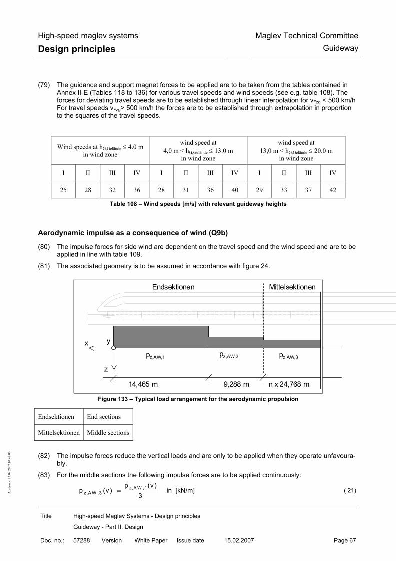
High-speed maglev systems
Design principles Maglev Technical Committee
Guideway
Title High-speed Maglev Systems - Design principles
Guideway - Part II: Design
Doc. no.: 57288 Version White Paper Issue date 15.02.2007 Page 67
Aus
druc
k: 1
3.09
.200
7 10
:42:
00
(79) The guidance and support magnet forces to be applied are to be taken from the tables contained in Annex II-E (Tables 118 to 136) for various travel speeds and wind speeds (see e.g. table 108). The forces for deviating travel speeds are to be established through linear interpolation for vFzg < 500 km/h For travel speeds vFzg> 500 km/h the forces are to be established through extrapolation in proportion to the squares of the travel speeds.
Wind speeds at hG,Gelände ≤ 4.0 m in wind zone
wind speed at 4,0 m < hG,Gelände ≤ 13.0 m
in wind zone
wind speed at 13,0 m < hG,Gelände ≤ 20.0 m
in wind zone
I II III IV I II III IV I II III IV
25 28 32 36 28 31 36 40 29 33 37 42
Table 108 – Wind speeds [m/s] with relevant guideway heights
Aerodynamic impulse as a consequence of wind (Q9b)
(80) The impulse forces for side wind are dependent on the travel speed and the wind speed and are to be applied in line with table 109.
(81) The associated geometry is to be assumed in accordance with figure 24.
Endsektionen Mittelsektionen
pz,AW,1 pz,AW,2 pz,AW,3
x
z
14,465 m 9,288 m n x 24,768 m
y
Figure 133 – Typical load arrangement for the aerodynamic propulsion
Endsektionen End sections
Mittelsektionen Middle sections
(82) The impulse forces reduce the vertical loads and are only to be applied when they operate unfavoura-
bly.
(83) For the middle sections the following impulse forces are to be applied continuously:
z,A W ,1z,A W ,3
p (v )p (v )
3= in [kN/m] ( 21)

High-speed maglev systems
Design principles Maglev Technical Committee
Guideway
Title High-speed Maglev Systems - Design principles
Guideway - Part II: Design
Doc. no.: 57288 Version White Paper Issue date 15.02.2007 Page 68
Aus
druc
k: 1
3.09
.200
7 10
:42:
00
(84) For the rear section the aerodynamic impulse forces are smaller than for the nose section. Therefore the values of the nose section can also be applied safely for the rear section.

High-speed maglev systems
Design principles Maglev Technical Committee
Guideway
Title High-speed Maglev Systems - Design principles
Guideway - Part II: Design
Doc. no.: 57288 Version White Paper Issue date 15.02.2007 Page 69
Aus
druc
k: 1
3.09
.200
7 10
:42:
00
(85) The actions as a consequence of Q8a and Q9b are not to be taken into account at the same time as the action Q9b contains the action Q8a.
vFzg = 0 km/h vFzg = 200 km/h vFzg = 300 km/h vFzg = 400 km/h vFzg = 500 km/h vFzg = 530 km/h vW [m/s] pz,AW,1 pz,AW,2 pz,AW,1 pz,AW,2 pz,AW,1 pz,AW,2 pz,AW,1 pz,AW,2 pz,AW,1 pz,AW,2 pz,AW.1 pz,AW.2
40 -2.4 -1.5 -7.5 -9.6 -8.1 -8.9 -9.0 -6.9 -10.2 -5.1 -10.6 -4.5 39 -2.3 -1.4 -7.2 -9.2 -7.8 -8.3 -8.6 -6.4 -9.8 -4.6 -10.2 -4.1 38 -2.2 -1.4 -6.9 -8.7 -7.4 -7.8 -8.3 -5.9 -9.5 -4.2 -9.9 -3.7 37 -2.1 -1.3 -6.6 -8.3 -7.1 -7.2 -8.0 -5.4 -9.2 -3.7 -9.6 -3.3 36 -2.0 -1.2 -6.3 -7.9 -6.8 -6.7 -7.7 -4.9 -8.9 -3.3 -9.2 -2.9 35 -1.9 -1.1 -6.0 -7.5 -6.5 -6.2 -7.4 -4.5 -8.6 -2.9 -8.9 -2.5 34 -1.8 -1.1 -5.7 -7.1 -6.2 -5.7 -7.1 -4.1 -8.2 -2.6 -8.6 -2.2 33 -1.6 -1.0 -5.4 -6.7 -5.9 -5.2 -6.8 -3.6 -7.9 -2.2 -8.3 -1.8 32 -1.6 -1.0 -5.1 -6.3 -5.6 -4.8 -6.5 -3.2 -7.6 -1.9 -8.0 -1.5 31 -1.5 -0.9 -4.8 -5.8 -5.3 -4.3 -6.2 -2.9 -7.4 -1.6 -7.7 -1.3 30 -1.4 -0.8 -4.5 -5.3 -5.1 -3.9 -6.0 -2.5 -7.1 -1.3 -7.4 -1.0 29 -1.3 -0.8 -4.2 -4.9 -4.8 -3.5 -5.7 -2.2 -6.8 -1.1 -7.2 -0.7 28 -1.2 -0.7 -4.0 -4.5 -4.6 -3.1 -5.5 -1.9 -6.5 -0.8 -6.9 -0.5 27 -1.1 -0.7 -3.7 -4.1 -4.3 -2.8 -5.2 -1.6 -6.3 -0.6 -6.7 -0.3 26 -1.0 -0.6 -3.5 -3.7 -4.1 -2.4 -5.0 -1.3 -6.0 -0.4 -6.4 -0.1 25 -0.9 -0.6 -3.2 -3.3 -3.9 -2.1 -4.8 -1.1 -5.8 -0.2 -6.2 0.1 24 -0.9 -0.5 -3.0 -3.0 -3.7 -1.8 -4.5 -0.8 -5.6 0 -5.9 0.3 23 -0.8 -0.5 -2.8 -2.6 -3.5 -1.6 -4.3 -0.6 -5.4 0.2 -5.7 0.4 22 -0.7 -0.5 -2.6 -2.3 -3.3 -1.3 -4.1 -0.4 -5.1 0.3 -5.5 0.6 21 -0.7 -0.4 -2.4 -2.0 -3.1 -1.1 -3.9 -0.3 -4.9 0.5 -5.3 0.7 20 -0.6 -0.4 -2.2 -1.7 -2.9 -0.8 -3.7 -0.1 -4.8 0.6 -5.1 0.8 19 -0.5 -0.3 -2.1 -1.5 -2.7 -0.7 -3.5 0 -4.6 0.7 -4.9 0.9 18 -0.5 -0.3 -1.9 -1.2 -2.6 -0.5 -3.4 0.2 -4.4 0.8 -4.8 1.0 17 -0.4 -0.3 -1.8 -1.0 -2.4 -0.3 -3.2 -0.3 -4.3 0.9 -4.6 1.1 16 -0.4 -0.2 -1.6 -0.8 -2.2 -0.2 -3.0 0.4 -4.1 1.0 -4.5 1.2 15 -0.3 -0.2 -1.5 -0.6 -2.1 -0.1 -2.9 0.5 -4.0 1.1 -4.4 1.3 14 -0.3 -0.2 -1.4 -0.5 -2.0 0 -2.8 0.6 -3.9 1.2 -4.3 1.4 13 -0.3 -0.2 -1.2 -1.3 -1.8 0.1 -2.7 0.6 -3.8 1.3 -4.2 1.5 12 -0.2 -0.1 -1.1 -1.2 -1.7 0.2 -2.6 0.7 -3.7 1.3 -4.2 1.6 11 -0.2 -0.1 -1.0 -0.1 -1.6 0.3 -2.5 0.8 -3.7 1.4 -4.1 1.7 10 -0.2 -0.1 -0.9 0 -1.5 0.3 -2.4 0.8 -3.7 1.5 -4.1 1.8
Table 109 – Typical side wind determined impulse forces of the nose section

High-speed maglev systems
Design principles Maglev Technical Committee
Guideway
Title High-speed Maglev Systems - Design principles
Guideway - Part II: Design
Doc. no.: 57288 Version White Paper Issue date 15.02.2007 Page 70
Aus
druc
k: 1
3.09
.200
7 10
:42:
00
Wind with unfavourable aerodynamic influences
(86) In the area of tunnel exits and entrances, on valley bridges and for other unfavourable dynamic influ-ences higher actions are to be taken into account project specifically.
(87) The actions from possible higher wind speeds in the entrance and exit area of tunnels and on valley bridges are to be limited in such a way (e.g. through wind protection measures) that the actions indi-cated in chapters 0 and 0 are not exceeded. In addition aerodynamic influences such as e.g. exposed positions are to be taken into account in line with the regulations of the standards and directions.
Thermal action as a consequence of propulsion (Q10)
(88) Between the stator packs of the long stator and the beam cantilever arm a maximum temperature difference of max ∆TAntrieb = 15 K is to be taken into account.20
(89) The temperature difference is caused by the propulsion and is to be transferred with the temperature difference from the environment. For this action a vibration cycle of max SS(∆TAntrieb) = 2 SS/Tag is to be assumed. The vibration cycles take into account 2 phases with compressed travel operation (morn-ing and evening).
20 Should the actions in x-direction only be transferred into the cantilever arm of the guideway beams through friction in the connecting contacts of the stator pack securing attachment (e.g. pre-stressed screw connection), then there results maximum power from the maximum pre-stressing force and the maximum friction coefficient as a consequence of propulsion and environment from temperature action.

High-speed maglev systems
Design principles Maglev Technical Committee
Guideway
Title High-speed Maglev Systems - Design principles
Guideway - Part II: Design
Doc. no.: 57288 Version White Paper Issue date 15.02.2007 Page 71
Aus
druc
k: 1
3.09
.200
7 10
:42:
00
Infrequent variable actions (Q11a...Q11k)
General
(90) Subsequent infrequent actions from the vehicle are to be taken into account with regard to the safety level analogous to the frequent variable actions if • no guideway inspection is to be carried out immediately following start of the action and/or • a statement of the start of the action is not assured and thus an inspection cannot be carried out.
(91) If a safety risk through e.g. redundant elements or moving of the load etc can be ruled out, then a re-duction of the partial safety factors may occur in agreement with the responsible inspectorate for tak-ing into account the small probability of the infrequent actions occurring.
(92) In the formation of combinations in line with chapter 0 The infrequent actions are to be applied as guiding actions with γF = 1,35.
(93) Dynamic step ups following chapter 0 are to be taken into account in each of the subsequent actions if nothing expressly to the contrary is indicated.
Exceeding of payload (Q11a)
(94) A possible exceeding of the payload during unusual operating systems such as fire with evacuation in neighbouring sections is covered by the maximum vehicle weight.
Failure of a support magnet circuit (Q11b)
(95) With the failure of a magnet regulating circuit for support MRET the proportionate supporting force of the failed partial magnet is passed on into the guideway through the neighbouring partial magnet of the neighbouring support magnet.
(96) The following maximum magnetic actions (limit capacity of the support magnets21) is to be applied for local proofs for these neighbouring support magnets on a length of Lsys,TMT = 1,548 m • in z-direction: max pz,TMT,Q11b = 45,0 kN/m • in x-direction: max px,TMT,Q11b = ± 4,0 kN/m
(97) The regulating factor is to be applied with ϕRl =1,0.
(98) The associated load arrangement is to be taken from Figure 149.
(99) For global proofs replacement loads may be applied in place of the above value limits of the support magnet forces which result from the global actions following chapter 0.
21 The capacity limit is derived from the maximum half magnet force which results from the most unfavour-able vehicle action combination (incl. fail situations) on the most unfavourable position of the vehicle.

High-speed maglev systems
Design principles Maglev Technical Committee
Guideway
Title High-speed Maglev Systems - Design principles
Guideway - Part II: Design
Doc. no.: 57288 Version White Paper Issue date 15.02.2007 Page 72
Aus
druc
k: 1
3.09
.200
7 10
:42:
00
Failure of neighbouring support magnet circuits (Q11c)
(1) When regulating circuits of neighbouring support magnets fail, the assigned support skid stops on the sliding strip. The maximum local actions from the support skid (incl. local component dynamics) are to be applied • Impact load max Fz,TK,Stoß = 100 kN • quasi-static load max Fz,TK,stat = 50 kN .
(2) The maximum value is limited to 100kN by the vehicle for the most unfavourable situation. The dy-namic effects can be proved e.g. with the help of the force time course following figure 134.
(3) The associated power in x-direction from the above impact force and the maximum friction coefficients following table 98 is to be applied as follows: • from impact force (with µTK-GL = 0,30) max Fx,TK,Stoß = 30 kN • from quasi-static load (with µTK-GL,Haft = 0,50) max Fx,TK,stat = 25 kN
(4) The friction coefficient may be reduced with the minimum location dependent travel speed following table 98 being taken into account.
(5) As a consequence of friction between support skid and sliding plane the support skid heats up. The maximum amount of heat stored in the sliding surfaces of the support skid amounts to 650kJ. With a stopping vehicle this leads to heating of the sliding strip/sliding plane in the area of the support skid. The resultant temperature increase is to be established dependent on the design.
max Fz,TK,Stoß = 100 kN
max Fz,TK,stat = 50 kN
Fz
t
10...15 ms
Figure 134 – Typical force-time course of the dynamic support skid force
(6) The local deformations as a consequence of the impact load are to be established. The verification of compatibility to the vehicle is to be shown for the deformations to be expected.
(7) The surface loads are to be established as follows with the dimensions in figure 125 being taken into account:
max qz,TK = max Fz,TK / (LTK ⋅ bTK) max qz,TK = max Fz,TK / (LTK ⋅ bTK) ( 22)
max qx,TK = µ ⋅ max Fz,TK / (LTK ⋅ bTK)max qx,TK = µ ⋅ max Fz,TK / (LTK ⋅ bTK) ( 23)
(8) For global proofs replacement loads may be applied in place of the above value limits of the support skid forces which result from the global actions following chapter 0.

High-speed maglev systems
Design principles Maglev Technical Committee
Guideway
Title High-speed Maglev Systems - Design principles
Guideway - Part II: Design
Doc. no.: 57288 Version White Paper Issue date 15.02.2007 Page 73
Aus
druc
k: 1
3.09
.200
7 10
:42:
00
Failure of a guidance magnet circuit (Q11d)
(1) With failure of a magnet regulating circuit for guidance MREF the proportionate guidance force of the failed partial magnet (see load arrangement) is transferred from the neighbouring partial magnet of the neighbouring guidance magnet.
(2) For local proofs the following maximum magnetic forces in y-direction are to be applied for this action (limit capacity of the guidance magnets):
• max py,FMT = 16 kN/m for guidance magnets with magnetic poles below • max py,FMT = 32 kN/m for guidance magnets with magnetic poles below and above
(3) The associated load arrangement is to be taken from Figure 152 (chapter 0)
(4) For global proofs replacement loads may be applied in place of the above value limits of the guidance magnet forces which result from the global actions following chapter 0.
Failure of neighbouring support magnet circuits (Q11e)
(1) With failure of both magnet regulating circuits on one levitating framework the start strips of the guid-ance magnets opposite transfer the proportionate guidance forces to the lateral guidance rails me-chanically (compressive force).
(2) The maximum local impact force on the lateral guidance rails (incl. local component dynamics) is to be applied as follows for local proofs: • max Fy,FM,Q11e1 = 63 kN (with γF =1,35) without wind • max Fy,FM,Q11e2 = 115 kN (with γF =1,00) 22 with wind (vW = 25 m/s)
(3) The action Fy,FM,Q11e2 is to be classified as “accidental action” with reference to the probability of oc-currence.
(4) The associated maximum power in x-direction is to be established from the above impact force and the maximum friction coefficient of µFM,SFS = 0,3 at v ⇒ 0 km/h as follows:
max Fx,FM = µFM_SFS ⋅ max Fy,FM ( 24)
(5) The coefficient of friction may be reduced, taking into consideration the local minimum operating ve-locity in accordance with Tabelle 97 .
(6) The geometry of the action is to be taken from Figure 153.
(7) The temperature increase as a consequence of mechanical guiding (start up) is covered by the action from the safe brake.
(8) For global proofs replacement loads may be applied in place of the above value limits of the start up forces of the guidance magnet which result from the global actions following chapter 0.
22 If the serviceability and safety are not affected inadmissibly, local plastic deformations with the application of max Fy1FMQ11e2 can be permitted in agreement with the responsible inspectorate.

High-speed maglev systems
Design principles Maglev Technical Committee
Guideway
Title High-speed Maglev Systems - Design principles
Guideway - Part II: Design
Doc. no.: 57288 Version White Paper Issue date 15.02.2007 Page 74
Aus
druc
k: 1
3.09
.200
7 10
:42:
00
•
Use of the vehicle "safe brake" (Q11f)
Rule
If the braking system (long stator motor) fails, the vehicle safe brake is activated (for the geometry and posi-tioning of the braking magnets on the vehicle see Figure 124). The braking process is divided into two sections according to the actions on the guideway (see Figure 137):
• Section I: Non-contact application of the eddy-current braking force ("free" braking magnet) • Section II: Applying the braking magnets to the lateral guidance rails
In the case of an empty vehicle, the braking forces may be reduced in accordance with the lower mass in the
ratio of the dead weight of the vehicle to its permitted total weight (see chapter 0).
For section I (≈200 km/h ≤ vVeh ≤ 530 km/h) the following actions must be taken into account: Non-contact application of the eddy-current braking force Fx,BM,, whereby the magnetic force increases as the
velocity decreases: max Fx,BM,I = 63 kN/section ... ≈ 85 kN/section 23
The accompanying magnetic tensile force py,BM,I on the lateral guidance rails, which takes effect as an "inner force" similar to the prestressing force of the guidance magnet, taking into account the tolerances and range, amounts to:
max py,BM,I ≤ 37.5 kN/m For the support magnets near the eddy-current brakes, an uneven distribution of the support magnet force of
around 30% must be set, as shown in Figure 148. This combination must also be considered in the following braking section II.
In section II (0 km/h < vFzg < ≈200 km/h) the following actions must be taken into account: At vFzg < ≈200 km/h the braking magnets are applied to the lateral guidance rails. The amount of acting fricti-
onal force in the x-direction, together with the decreasing magnetic braking force is limited to a maxi-mum braking force, max Fx,BM,II of:
max Fx,BM,II ≤ 110 kN/section The maximum tensile force in the y-direction max py,BM,II is: max py,BM,II = 37.5 kN/m Compressive force does not occur in the y-direction. When using max py,BM,II, ϕRl = 1.0 can be used. At vVeh = 5 km/h the set-down command comes into force and the vehicle is set down on the guideway in a
controlled manner. As the support skids are lowered onto the sliding surfaces, the vehicle’s velocity vFzg = 0 km/h. The support skids’ strength can be determined in a similar manner to that in chapter 0, taking the corresponding vibration coefficient into consideration. The time function of the controlled set down of the vehicle is shown in Figure 135. This must be taken into account when verifying the dyna-mics in the x- and z-directions.
The increase in temperature on the lateral guidance rails caused by the braking magnets must be set at ∆TBM_SFS ≤ 8 K for a 10 section vehicle. This temperature increase must be superimposed with the en-vironmental thermal actions in accordance with chapter 0.
The load arrangement for the braking magnets must be taken from Figure 154.
As with braking and acceleration via the long stator, the overturning moment occurs around the y-axle when the "safe brake" is applied. The resulting z-force distribution must be taken into account.
23 Intermediate values may be added linearly.

High-speed maglev systems
Design principles Maglev Technical Committee
Guideway
Title High-speed Maglev Systems - Design principles
Guideway - Part II: Design
Doc. no.: 57288 Version White Paper Issue date 15.02.2007 Page 75
Aus
druc
k: 1
3.09
.200
7 10
:42:
00
Controlled vehicle set-dow n on the support skids
-20
0
20
40
60
80
100
120
Tim e [s]
Supp
ort s
kid
forc
e as
% o
f tot
al fo
rce
Increase of force in the support skids during contro lled set down
Unloaded support skids /l i i h i l
Loaded support skids when support skids are set downSet-down tim e 0.5 ..2 s
100 %
Figure 135 – Typical, simplified time function of controlled vehicle set down
Special cases When the braking power of the braking magnets (see Figure 137: line 1), the slide vVeh ⇒ 0 of a vehicle with
permitted weight placed on the support skids (see Figure 137: area vveh < 10 km/h) and γQ = 1.0 is ex-ceeded, this must be considered as an accidental design situation.
For these special cases, when designing the guideway observe the time lapse provided in the following Figu-re 136 for the acceleration ax during the transition from sliding to static friction.
0.10 s … 0.25 s
µHaft = 0.5
vFzg = 0 km/h
Transition regionSliding to static friction
t
µGleit = 0.3 … 0.35
Figure 136 - Typical acceleration time function for sliding on the support skids

High-speed maglev systems
Design principles Maglev Technical Committee
Guideway
Title High-speed Maglev Systems - Design principles
Guideway - Part II: Design
Doc. no.: 57288 Version White Paper Issue date 15.02.2007 Page 76
Aus
druc
k: 1
3.09
.200
7 10
:42:
00
Figure 137 - "Safe brake" braking force progression
Bereich: Ausgleiten auf Tragkufen als außergewöhnliche Einwirkung
Area: Sliding on support skids as accidental action
Bremskraft aus WSB Braking force from WSB
Max. dynamischer Bremskraft Fx = 360 Kn/Sektion (Haftreibung)
Max. dynamic braking force Fx = 360 Kn/section (static friction)
Maximale Bremskraft bei trockenem Fahrweg Maximum braking force on a dry guideway
Grenzlinie des Streubereiches der Bremssteuerung Limit of the range of dispersion of the braking control
Minimale Bremskraft bei vereistem Fahrweg Minimum braking force on icy guideway
Sollvorgabe für Bremsteuerung Target values for braking control
Ausgleiten mit Fx = 250 kN/Sektion bei Übergang zur Haftreibung
Sliding at Fx = 250 Kn/section during transition to static friction
Aufsetzen der Tragkufen Fx = 215 kN/Sektion aus Gleit-reibung
Setting down of the support skids Fx = 215 Kn/section from sliding friction
Bremsmagnete an Seitenführschiene anliegend Braking magnet placed on lateral guidance rail
Fx = 110 Kn/Sektion (entspricht der Bremsverzögerung Fx = 110 Kn/section (corresponds to brake retardation

High-speed maglev systems
Design principles Maglev Technical Committee
Guideway
Title High-speed Maglev Systems - Design principles
Guideway - Part II: Design
Doc. no.: 57288 Version White Paper Issue date 15.02.2007 Page 77
Aus
druc
k: 1
3.09
.200
7 10
:42:
00
von Ax = 1.5 m/s² bei zulässigem Fahrzeuggewicht)
of Ax = 1.5 m/s² with permissible vehicle weight)
Streubereich für außergewöhnliche Einwirkung Range of dispersion for accidental action
Streubereich der Bremssteuerung Range of dispersion of the braking control
Bremsmagnet berührungsfrei Contactless braking magnet
Geschwindigkeit in km/h Velocity in km/h
Bremskraft in kN/Sektion Braking force in kN/section
Velocity deviations (Q11g) Actions resulting from velocity deviations (e.g. stationary vehicles outside stations or slow moving vehicles
on 12° guideway transverse gradients (ay ⇒ 2.04 m/s²)) must be regarded as infrequent variable ac-tions in comparison to frequent variable actions (for more information regarding this see chapter 0).

High-speed maglev systems
Design principles Maglev Technical Committee
Guideway
Title High-speed Maglev Systems - Design principles
Guideway - Part II: Design
Doc. no.: 57288 Version White Paper Issue date 15.02.2007 Page 78
Aus
druc
k: 1
3.09
.200
7 10
:42:
00
Propulsion system failure (Q11h)
One-sided propulsion system failure The "one-sided propulsion system failure" malfunction must be considered as described and covered in
chapter 0 (actions relating to motor section switching during the alternating step method).
Other propulsion system malfunctions In the case of unfavourable side-selective unequal distribution 0.73/0.27, a maximum thrust of Fx,Q11h1,HG =
185 kN/middle section should be taken into account24. This results in the following forces on each side
of the guideway: max px, Q11h1, HG, right/left = 0.73 ⋅ 185 kN / 24.768 m = 5.5 kN/m min px, Q11h1,HG, left/right = 0.27 ⋅ 185 kN / 24.768 m = 2.0 kN/m (without dynamic force) When there are equally effective, maximum resulting actions in the x-direction on both guideway sides in the
event of malfunction, take into consideration the following force: px,Q11h2 = 250 kN / middle section = 250 kN / 24.768 m = approx. 10.0 kN/m
A typical (simplified) function of the action dependent on velocity and vehicle length (number of sections) as a result of propulsion system malfunction is shown as an example on Figure 138. In the case of pro-ject independent verification, the specified reduction must be applied.
With regard to probability of occurrence, the action px,Q11h2 must be considered unusual (γQ = 1.0). Whether it is necessary to consider these actions and the scale of the reduction depends on the project and
must always be confirmed on a case by case basis. Forces resulting from pitching moments must be taken into consideration as in chapter 0
250 250
60
20
010
020
030
0
0 50 100 150 200 250 300 350 400 450 500Travelling velocity [km/h]
Gui
dew
ay lo
ngitu
dina
l for
ce
[kN
/sec
tion]
2 Sections
>= 7 Sections
Figure 138 - Velocity function of the x-forces as a result of propulsion system malfunction
One-sided set-down of the vehicle (Q11i)
General 24 The actions for the other vehicle weights are: Fx,Q11h1,ZG = 180 kN/middle section, Fx,Q11h1,MG = 170 kN/middle section and max Fx,Q11h1,EG = 150 kN/middle section

High-speed maglev systems
Design principles Maglev Technical Committee
Guideway
Title High-speed Maglev Systems - Design principles
Guideway - Part II: Design
Doc. no.: 57288 Version White Paper Issue date 15.02.2007 Page 79
Aus
druc
k: 1
3.09
.200
7 10
:42:
00
In the event of a short circuit of the long stator winding, the two following design situations must be conside-red with regard to the actions on the guideway.
Design situation 1 There is a short circuit on the windings, the vehicle is above the location of the short circuit, which is near to
the winding star point (motor section switching) and the velocity is v ≥ 25 km/h. This results in the ve-hicle being set-down on one side on the sliding surface of the guideway beams. The support skids come into contact with the gliding strips one after the other. The side of the vehicle opposite the short circuit continues to levitate.
Taking the vehicle weight into consideration, the unilateral section loads qz,set and qz,fun will be as follows: • Set down side:
qz,Q11i,set. = 0.5 ⋅ stat pz ⋅ az /g ( 25)
• "functional" (levitating) side:
qz,Q11i,fun. = 0.5 ⋅ stat pz ⋅ az / g ( 26)
Other actions (e.g. centrifugal force) must be superimposed according to chapter 0. The skid forces on the set down side must be calculated using ex,SS = support skid centre distance, as follows:
Fz,SS,Q11i = qz,Q11i,set ⋅ ex,SS ( 27)
The velocity-dependent coefficient of friction can be found in Table 98.
An additional vibration coefficient of max. ϕB,z,Q11i = 1.8 must be taken into account for the set down side. Determine the vibration coefficient in the z-direction with a min. of ϕB,z,Q11i = 0.9 for the functioning op-posite side.
The effect from the propulsion system may be positive (braking), negative (acceleration) or zero in accordan-ce with chapter 0.
The different forces in the x-direction on both the functional and set down side cause a moment to act on the z-axle. This moment ensures that the forces on the lateral guidance rails (y-direction) are balanced. The guidance magnet forces act in a similar manner to that described in chapter 0. The remaining ac-tions in the y-direction must be determined in a similar way to the frequent actions.
Only take into account the combination that has the vehicle weight as the leading variable action.
Design situation 2 The short circuit location is not near the cable winding star point or the vehicle has travelled over an already
existing short circuit.
This design situation has an effect on the short circuit side on the support magnet/long stator interface bra-king force, which is globally covered by the x-forces from a) and locally covered by the x-forces from Q11b.
Activating/contact with magnets (Q11j)
Support magnets The vehicle-side minimum gap monitoring prevents a force-induced activation of the support magnets on the
stator packs.
Potential activation due to interference as a result of unfavourable boundary conditions (guideway toleran-ces, state of motion and load status of the support magnet) is covered by the actions listed in chapter 0.
Guidance magnets

High-speed maglev systems
Design principles Maglev Technical Committee
Guideway
Title High-speed Maglev Systems - Design principles
Guideway - Part II: Design
Doc. no.: 57288 Version White Paper Issue date 15.02.2007 Page 80
Aus
druc
k: 1
3.09
.200
7 10
:42:
00
If the ultimate bearing capacity of the guidance magnets is exceeded as described in chapter 0, this may lead to contact with the guidance magnets positioned opposite.
Actions caused by contact with guidance magnets are described in chapter 0 "Failure of neighbouring sup-port magnet circuits (Q11e)".
Raising frozen support skids (Q11k)
The tension and thrust created by releasing a frozen support skid is transferred to the supporting structure via the gliding strips.
The maximum actions caused by raising frozen support skids are applied locally using the following forces:
• Tension in z-direction Fz,Q11k = 50.0 kN / skid • Thrust in x-direction Fz,Q11k = 25.0 kN / skid
It is unwise to assume that the locally assigned support magnets on the frozen support skid do not receive any of the force (see chapter 0).
Increase in vehicle weight due to snow (Q11l) Take into account that snow accumulation on the vehicle increases the section load, using the following va-
lues: • ∆pZ,EG,Q11l(1) = 1.6 kN/m → infrequent • ∆pZ,EG,Q11l(2) = 3.2 kN/m → accidental
The frequency of occurrence and the characteristic values to be applied must be determined on an individual
basis (see also /MSB AG-FW IH/; reference carrier, monitoring). The centroidal distance of the snow accumulation in the z-direction must be set at sz,Q11l = 400 mm.
Actions resulting from maintenance (Q30)
Action effects including potential dynamic step-ups resulting from maintenance (incl. the associated special vehicles, devices and payloads) must not be measured.
High-speed maglev systems
Design principles Maglev Technical Committee
Guideway
Title High-speed Maglev Systems - Design principles
Guideway - Part II: Design
Doc. no.: 57288 Version White Paper Issue date 15.02.2007 Page 81
Aus
druc
k: 1
3.09
.200
7 10
:42:
00
Environmental temperature (Q50) General /DIN technical report 101/chapter V describes the rules and procedures for the determination of thermal ac-
tions on bridges, including their sections. The characteristic values of the actions, as far as they are applicable to the guideway elements of the high-speed Maglev system, can be taken from there. It does not include application-dependent thermal actions.
The following will be referred to: • Thermal fluctuation: a regular change in the centroidal temperature of all components (see /DIN
technical report 101/chapter V, 6.3.1.3) • Linear temperature difference: linear thermal gradient between opposite edges of components
(see /DIN technical report 101/chapter V, 6.3.1.4) • Uneven heating of components: a jump (thermal difference) between the centroidal temperature of
individual components, which are not joined together and/or are made of different types of material (see /DIN technical report 101/chapter V, 6.3.1.6)
The thermal expansion coefficient for the components must be taken from /DIN technical report 101/. Thermal fluctuations in the guideway superstructure (Q50a) If the min. and max. outside air temperature cannot be determined more exactly, then the typical values gi-
ven in Table 110 (column 1) can be used for central European projects. These refer to outside air temperatures between –24°C and +37°C over a period of 50 years.
When calculating the bearing play and (expansion) joints increase the values in Table 110 by 25%. The possibility of reducing the actions described in Table 110 must be agreed upon on an individual basis
with the responsible inspectorate. Linear temperature difference (Q50b)
General The temperature differences that need to be taken into account are, among other things, dependent on the
condition of the surface, the geometry and climatic conditions. The following symbols apply to the subsequent threshold values:
∆TM linear temperature difference To - Tu or Tl - Tr To Top chord temperature Tu Bottom chord temperature Tl Temperature of the left edge of the load-bearing cross section Tr Temperature of the right edge of the load-bearing cross section (For full cross sections use the values on the cross section edge for To and Tu.)

High-speed maglev systems
Design principles Maglev Technical Committee
Guideway
Title High-speed Maglev Systems - Design principles
Guideway - Part II: Design
Doc. no.: 57288 Version White Paper Issue date 15.02.2007 Page 82
Aus
druc
k: 1
3.09
.200
7 10
:42:
00
Guideway superstructure Characteristic values for linear temperature differences for various types of bridge superstructure and varying
bridge surface thicknesses can be found in /DIN technical report 101/chapter V, 6.3.1.4. These values are upper limit values for the linear temperature differences for typical examples of the bridge geo-metry of roads and railway bridges.
The following guidelines must also be considered for the high-speed Maglev system’s guideway beams: • Guideway type I and II
For discretely supported guideway beams, the characteristic values provided in Table 110 (column 2) can be used, if their cross section and surface is similar. Check the suitability of these values for each individual case with the responsible inspectorate.
• Guideway type III and other guideway designs For guideway plate systems and other guideway constructions that are not covered by the values provided in Table 110, then the values are to be agreed upon with the responsible inspectorate (if necessary by theoretical investigation on the basis of calculation simulations).
• Guideways in tunnels In the case of guideways in tunnels, there is generally no need to apply a temperature difference as a result of environmental factors.
• Track switching equipment see Table 110
To ensure an optimal guideway position in peak periods, (this is to be determined on an individual project basis), when determining the supporting theoretical position, take into account an expected linear temperature difference T0 - TU for this period, during the determination of the theoretical pre-curve. This temperature difference results in an optimal guideway position (i.e. the guideway position cor-responds to the guideway gradient when the vehicle is on it).
For cross sections not covered in Table 110, hypotheses for the temperature scales must be determined in cooperation with the responsible inspectorate with reference to Table 100 and any other experience or findings. If necessary, these hypotheses must be proven by measurements.
Guideway substructures Environmental thermal actions for guideway substructures can be found in /DIN technical report 101/chapter
V, 6.3.2. Uneven heating of components due to environmental factors (Q50c) Set ∆T = ± 15 K as the temperature difference between steel and concrete parts for the cases described in
/DIN technical report 101/chapter 6.3.1.6. With steel and concrete components that are connected by an entire surface (e.g. LGR or SS on concrete
girders) use temperature differences of ∆T = ± 10 K when lower temperatures have not been verified. The uneven heating mentioned above is to be superimposed on components, whose temperature increases
as a result of traffic.

High-speed maglev systems
Design principles Maglev Technical Committee
Guideway
Title High-speed Maglev Systems - Design principles
Guideway - Part II: Design
Doc. no.: 57288 Version White Paper Issue date 15.02.2007 Page 83
Aus
druc
k: 1
3.09
.200
7 10
:42:
00
Thermal fluctua-tion TN
Linear temperature difference ∆Tz,My
vertical [K]
Linear temperature difference ∆Ty,Mz lat-
eral [K] Construction method Cross section
1 2 3
Concrete con-struction
(Height: 2 m)
-15 °C ≤ TN ≤ 35 °C -5 ≤ ∆Tz,My ≤ 17 -10 ≤ ∆Ty,Mz ≤ 10
Steel construction
(Height: 2 m)
-20 °C ≤ TN ≤ 50 °C -5 ≤ ∆Tz,My ≤ 25 -17 ≤ ∆Ty,Mz ≤ 17
Hybrid construc-tion I
(Height: 2 m)
-15 °C ≤ TN ≤ 35 °C -5 ≤ ∆Tz,My ≤ 15 -10 ≤ ∆Ty,Mz ≤ 10 *
Hybrid construc-tion II
(Height: 2.2 m)
-15 °C ≤ TN ≤ 35 °C -5 ≤ ∆Tz,My ≤ 10 -10 ≤ ∆Ty,Mz ≤ 10 *
Concrete con-struction
(Height: 1 m) -15 °C ≤ TN ≤ 35 °C -5 ≤ ∆Tz,My ≤ 17 -5 ≤ ∆Ty,Mz ≤ 5
Steel construction (Height: 1 m)
-20 °C ≤ TN ≤ 50 °C -8 ≤ ∆Tz,My ≤ 25 -13 ≤ ∆Ty,Mz ≤ 13
Flexible steel (bendable girder WxH: 0.45 m x 1.5 m)
-20 °C ≤ TN ≤ 50 °C -10 ≤ ∆Tz,My ≤ 20 -10 ≤ ∆Ty,Mz ≤ 10
The characteristic values provided for the thermal actions were determined according to the information given in /DIN technical report 101/, the theoretical calculation results in /R 1/ and the measurement results from TVE.
* on the supporting concrete cross section
Table 110 - thermal fluctuations and linear temperature differences

High-speed maglev systems
Design principles Maglev Technical Committee
Guideway
Title High-speed Maglev Systems - Design principles
Guideway - Part II: Design
Doc. no.: 57288 Version White Paper Issue date 15.02.2007 Page 84
Aus
druc
k: 1
3.09
.200
7 10
:42:
00
Effect of wind on the supporting structure (Q51) Effect of both wind and traffic on the supporting structure (Q51) Assess wind actions in conjunction with traffic on the supporting structure as described in /DIN technical
report 101/. It is assumed that the guideway is not susceptible to vibration with regard to wind actions, otherwise more
exact verification is required. Assume the wind direction is horizontal. In the case of double track guideways, measure the individual tracks for the full wind load from both directi-
ons. In the case of wind and traffic acting on the supporting structure, only the area of the guideway not covered
by the vehicle is used as the wind exposed surface. The dynamic pressure to be considered for the nominal wind gust velocity vb,10 (5 second average, once a
year) in wind zones I, II,III and IV for various gradients across ground must be taken from Table 111. Form factors and other factors for determining the size of the action on the supporting structure caused by
wind must be taken from the existing regulations of the relevant structure.
Gradient height hG,ground
WZ I vW qW,supporting
structure
[m/s] [kN/m²]
WZ II vW qW,supporting
structure
[m/s] [kN/m²]
WZ II
vW qW,supporting
structure
[m/s] [kN/m²]
WZ IV
vW qW,supporting
structure
[m/s] [kN/m²] ≤ 4.0 m 25 0.40 28 0.50 32 0.65 36 0.80
> 4.0 m … 13.0 m 28 0.50 31 0.60 36 0.80 40 1.00 > 13.0 m … 20.0 m 29 0.55 33 0.70 37 0.85 42 1.10
Table 111 - dynamic pressure qW,supporting structure on the supporting structure
Effect of wind without traffic on the supporting structure (Q51) Verify wind actions without traffic on the supporting structure in accordance with the /DIN technical report
101/. It is assumed that the guideway is not susceptible to vibration with regard to wind actions, otherwise more
exact verification is required.
Snow and ice loads (Q52)
With traffic: The assumed snow depth with traffic is 10 cm. Take into account an area load of qsnow = 0.5 kN/m², this corresponds to assuming a unit weight of 5 kN/m³ (wet snow).
Without traffic: For snow without traffic use the values in /DIN technical report 101/. For the guideway beams, this ac-tion combination is covered by traffic actions.
Variable water pressure forces (Q53)
• Variable water pressure forces must be taken into account as appropriate for local cir-cumstances.

High-speed maglev systems
Design principles Maglev Technical Committee
Guideway
Title High-speed Maglev Systems - Design principles
Guideway - Part II: Design
Doc. no.: 57288 Version White Paper Issue date 15.02.2007 Page 85
Aus
druc
k: 1
3.09
.200
7 10
:42:
00
Wind load in construction stages (Q54)
Wind actions in construction stages must be regarded as variable actions on the basis of /DIN technical report 101/.
Maintenance conditions (Q55)
Actions resulting from maintenance conditions or similar conditions (e.g. due to raising the suppor-ting structure to replace bearings and bearing parts) must be taken into account.
Construction stages (Q56)
Actions as a result of construction and assembly stages must be considered when dimensioning the suppor-ting structure.
In order the take into account the actions as a result of the assembly of the stator packs and the long stator winding, the following actions must be applied locally for the verification of the stator packs and their attachment to the guideway structure:
dyn pz = - 5.0 kN/m dyn px = 5.0 kN/m
Actions on track switching equipment (Q57) Elastic bending of deflection switches (Q57a) Calculate the flexural tensile stresses from forced bending of the deflection switches and the ad-
justment forces using the elastic deflection curve of the relevant switch. Actions resulting from the propulsion system (Q57b) Take into consideration actions resulting from the inertia, friction and asynchronism of the location
of the track switching equipment drive system (deflection switches, travelling platforms).
Displacement resistance of bearings (Q58)
Actions from bearing friction must be considered in accordance with the legal construction regulati-ons.
Failure of supporting structure elements (Q59)
It must be verified that the guideway will remain fit for traffic for a defined amount of time in the event of failu-re of the supporting structure elements.
The measures required for this (e.g. redundancy) and the verification process must be agreed upon with the responsible inspectorate.
Lateral earth pressure from variable actions (Q60)
• Lateral earth pressure from variable actions must be considered in accordance with the ge-nerally accepted technical rules and standards.

High-speed maglev systems
Design principles Maglev Technical Committee
Guideway
Title High-speed Maglev Systems - Design principles
Guideway - Part II: Design
Doc. no.: 57288 Version White Paper Issue date 15.02.2007 Page 86
Aus
druc
k: 1
3.09
.200
7 10
:42:
00
Accidental actions General
The strategies and regulations for protecting the structural works of the guideway from identifiable and non-identifiable accidental actions can be found in the appropriate standards and regulations (e.g. EN 1991).
Accidental actions resulting from the vehicle Actions as a result of loading gauge violations (A1) Provided that the measures on how to avoid loading gauge violations described in /MSB AG-GESAMTSYS/
are taken into account, actions as a result of loading gauge violation by the vehicle do not need to be explored.
Safety wind load on the vehicle (A2) An additional stability verification taking into account the hundred year wind ("safety wind load") must be
carried out for the operating situation "guideway with stationary vehicle". The safety wind load on the vehicle must be applied using the following nominal wind gust velocities vb,10 (5 second average) at a height of 10 m and a probability of occurrence of once every 100 years: • Wind zone I vb,10 = 36 m/s • Wind zone II vb,10 = 40 m/s • Wind zone III vb,10 = 46 m/s • Wind zone IV vb,10 = 52 m/s
The buoyancy forces on the vehicle that result from the wind velocity must be taken from Table 112. The actions must be determined in accordance with chapter 0.
The guidance magnet forces py,SW,FMTi and the accompanying forces from the moment around the x-axle must be determined in a similar manner to that described in chapter 0 and annex II-E.
Actions in kN/m Gradient height hG,ground ≤ 4.0 m
Gradient height 4.0 m < hG,ground ≤ 13.0 m
Gradient height 13.0 m < hG,ground ≤ 20.0 m
Wind zone I pz,SA,1
pz,SA,2 -1.8 -1.1
-1.9 -1.1
-2.2 -1.4
Wind zone II pz,SA,1
pz,SA,2 -2.2 -1.4
-2.3 -1.4
-2.7 -1.7
Wind zone III pz,SA,1
pz,SA,2 -2.8 -1.7
-3.1 -1.9
-3.6 -2.3
Wind zone IV pz,SA,1
pz,SA,2 -3.6 -2.3
-3.9 -2.4
-4.6 -2.8
Table 112 - Typical actions from vehicle buoyancy as a result of safety wind load

High-speed maglev systems
Design principles Maglev Technical Committee
Guideway
Title High-speed Maglev Systems - Design principles
Guideway - Part II: Design
Doc. no.: 57288 Version White Paper Issue date 15.02.2007 Page 87
Aus
druc
k: 1
3.09
.200
7 10
:42:
00
Accidental actions resulting from maintenance (A3)
Action effects from maintenance do not have to verified for the vehicle. In accordance with /MSB AG-FW ÜBG/, all special vehicles, devices and payloads required for maintenance
must be dimensioned so that action effects resulting from maintenance are covered by the Maglev ve-hicle action effects.
Safety wind load on the supporting structure (A4)
Apply the wind actions according to /DIN technical report 101/ annex N.2 as the actions as a result of the safety wind load (SW) on the supporting structure.
Possible foundation movements (A5)
Possible foundation movements must be taken into consideration in accordance with the generally accepted technical rules and standards and the local guideway circumstances with regard to stability and servi-ceability (see chapter 0).
Impact General If necessary, project specific additional verification must be carried out for the structural works of the guide-
way taking into account accidental actions as a result of an impact. Potential measures to prevent impact and/or required verification for the consideration of impact on columns
and pillars can be found in existing regulations (e.g. /DIN technical report 101/). Apply a vehicle impact load of at least 500 kN in the most unfavourable direction for all columns and pillars
e.g. even in areas in agricultural use. The load acts horizontally 1.25 m above the ground and must be regarded as an accidental action. A dual-layer reinforcement design and a shattering layer are not ne-cessary.
For all situations, the application of measures selected to prevent impact and/or required verification for the consideration of impact with guideway beams must be carried out in accordance with the generally accepted technical rules and standards and agreed upon with the responsible inspectorate.
Annex B of the prEN 199117:2005 contains advice on planning and implementing risk analysis.
Impact of track-guided vehicles (A6) The requirements that must be considered regarding the impact of track-guided vehicles (railroad cars) must
be agreed upon with the responsible inspectorate. The /DIN technical report 101/, the prEN 199117:2005, section 4.4 and the accompanying national attach-
ment contain information on verifying accidental actions resulting from impacts.

High-speed maglev systems
Design principles Maglev Technical Committee
Guideway
Title High-speed Maglev Systems - Design principles
Guideway - Part II: Design
Doc. no.: 57288 Version White Paper Issue date 15.02.2007 Page 88
Aus
druc
k: 1
3.09
.200
7 10
:42:
00
Road vehicle impact (A7) Accidental actions as a result of road vehicle impact on supporting substructures and guideway superstructu-
res must be considered on the basis of EN 1991-1-7, section 4.3. For personal safety, the guideway supports must also be measured for the following simultaneously acting,
resultant forces, in order to verify stability in the event of a road vehicle impact on guideway beams: Resultant force in y-direction: FY,impact,bearing = 1000 kN; Resultant force in z-direction: FZ,impact,bearing = -300 kN; Set the response time of the resultant forces at 60 ms. The resultant forces apply to discretely supported guideway beams made of steel and concrete with design
characteristics (stiffness, area density) similar to the TVE guideway beams. The transferability of the resultant forces to other boundary conditions (guideway and vehicle data) or signs
of deviating resultant forces must be verified for the responsible inspectorate. Observe the permissible deformations for accidental actions as a result of impact on columns and guideway
beams according to chapter 0.
Ice jam, thermal ice pressure, impact from watercraft (A8)
The actions and verification processes to apply for each individual case must be agreed upon with the responsible inspectorate.
Accidental actions resulting from ship collisions must be taken from EN 1991-1-7, section 4.6.
Earthquakes (A9)
As a general rule, the design conditions according to the applicable technical construction regulations and the generally accepted technical rules and standards (e.g. according to Eurocode EN 1998 "Design of structures for earthquake resistance") can be used.
If in doubt, consult the responsible inspectorate as to which earthquake actions are to be taken into account.

High-speed maglev systems
Design principles Maglev Technical Committee
Guideway
Title High-speed Maglev Systems - Design principles
Guideway - Part II: Design
Doc. no.: 57288 Version White Paper Issue date 15.02.2007 Page 89
Aus
druc
k: 1
3.09
.200
7 10
:42:
00
Vehicle load arrangements
General The following load arrangements must be applied according to the size of the structure being examined for
global and/or local verifications of the vehicle.
Global load arrangements Inertia forces
The load arrangements for the vehicle-side inertia forces (incl. dynamic lateral loads and constraint forces) in the x-, y- and z-direction must be taken from Figure 139, Figure 143 and Figure 144 in accordance with chapter 0
The global actions p*, px, py, pz and mx, my and mz resulting from the vehicle give rise to the interface forces px, py, pz, Fx, Fy, and Fz.
See load arrangementGuidance magnet
1110 mm1110 mm
Sz,Fzg
398 mm
2220 mm
SFzg (Vehicle centre of gravity)ay
ax
GL
GLSP
SP
SFS
SFS
y
z
x
mx
pxpy ,my
pz ,mz
py*
py ,r
py ,l
pz ,r
pz ,l
px ,r
px ,l
„0“
α
az
py* : Dynamic lateral forces and constraint
forces
• In the x-direction, take into account the magnet array lengths in accordance with chapter 0
Figure 139 - Global load arrangement for the levitating vehicle
The distribution of the inertia forces resulting from az and ay across the length of the vehicle is shown on the
following illustrations. Determine the individual magnitudes using the equations provided.

High-speed maglev systems
Design principles Maglev Technical Committee
Guideway
Title High-speed Maglev Systems - Design principles
Guideway - Part II: Design
Doc. no.: 57288 Version White Paper Issue date 15.02.2007 Page 90
Aus
druc
k: 1
3.09
.200
7 10
:42:
00
Typical distribution of the support magnet force of az along the vehicle length
(1) 2 3 4 5 6 7 8 9 10 11 12 13 14 15 16 1 2 3 4 5 6 7 8 9 10 11 12 13 14 15 16
End section Middle section Partial magnets support TMTi
Figure 140 - Typical load arrangement for the force distribution of pz,az according to equation ( 15)

High-speed maglev systems
Design principles Maglev Technical Committee
Guideway
Title High-speed Maglev Systems - Design principles
Guideway - Part II: Design
Doc. no.: 57288 Version White Paper Issue date 15.02.2007 Page 91
Aus
druc
k: 1
3.09
.200
7 10
:42:
00
Typical distribution of the guidance magnet forces of ay across the vehicle length
(1) 2 3 4 5 6 7 8 9 10 11 12 13 14 15 16 1 2 3 4 5 6 7 8 9 10 11 12 13 14 15 16
End section Middle section Partial magnet guidance FMTi
BM BM
Figure 141 - Typical load arrangement for the force distribution of py,ay according to equation
i
y y,ay,iE S /M Sy,ay,FM T ,E G / M G / ZG / H G Z,E G /M G /ZG /H G
FM T
a kLp p
L g 100= ⋅ ⋅ ⋅
in [kN/m]
Typical distribution of the support magnet forces of ay across the length of the vehicle
(1) 2 3 4 5 6 7 8 9 10 11 12 13 14 15 16 1 2 3 4 5 6 7 8 9 10 11 12 13 14 15 16
End section Middle section Partial magnet supportTMTi
Figure 142 - Typical load arrangement for the force distribution of pz,ay according to equation ( 11)

High-speed maglev systems
Design principles Maglev Technical Committee
Guideway
Title High-speed Maglev Systems - Design principles
Guideway - Part II: Design
Doc. no.: 57288 Version White Paper Issue date 15.02.2007 Page 92
Aus
druc
k: 1
3.09
.200
7 10
:42:
00
S e e lo a d a r ra n g e m e n tG u id a n c e m a g n e t
1 1 1 0 m m1 1 1 0 m m
S z,F zg
3 9 8 m m
2 2 2 0 m m
S F zg(V e h ic le c e n t re o f g ra v i ty )
a y
a x
G L
G LS P
S P
S F S
S F S
y
z
x
m x
p xp y ,m y
p z ,m z
p y*
p y ,r
p y ,l
F z , T K , r
F x ,T K , r
„ 0 “
α F x ,T K , l
F z , T K , l
F y , T K , r*
F y , T K , l*
a z
• py* : Dynamic lateral forces and constraint forces
• In the x-direction, take into account the magnet array lengths in accordance with chapter 0
• Fy, TK,r/l * act only when the guidance magnets are deactivated py, r = py, l = 0 Figure 143 - Global load arrangement for the levitating vehicle / stationary vehicle
See load arrangementsGuidance magnet
1110 mm1110 mm
Sz,Fzg
398 mm
2220 mm
SFzg (Vehic le centre of gravity)ay
ax
GL
GLSP
SP
SFS
SFS
y
z
x
mx
pxpy ,my
pz ,mz
py*
py ,r
py ,l
Fz , TK, r
pz ,l
Fx, TK, r
px ,l
„0“
α
Vehicle side setting down
Levitating vehicle saz
• py* : Dynamic lateral forces and constraint forces
• In the x-direction, take into account the magnet array lengths in accordance with chapter 0
Figure 144 - Global load arrangement for the design situation Q11i

High-speed maglev systems
Design principles Maglev Technical Committee
Guideway
Title High-speed Maglev Systems - Design principles
Guideway - Part II: Design
Doc. no.: 57288 Version White Paper Issue date 15.02.2007 Page 93
Aus
druc
k: 1
3.09
.200
7 10
:42:
00
Wind on the vehicle
The load arrangement for actions as a result of "wind on the vehicle" and "buoyancy" according to chapter 0 must be taken from Figure 145.
The global actions p*, px, py, pz and mx, my und mz resulting from the vehicle give rise to the interface forces px, py, pz, Fx, Fy, und Fz.
See load arrangement guidance magnet!
1110 mm1110 mm
398 mm
2220 mm
SW (wind attack point)Lateral wind W(parallel to guideway table)
SS
SSSP
SP
LGR
LGR
y
z
x
mx, W
py ,W
pz, A , mz, W
py ,r, W
(py ,l, W)
pz ,r, A/W
pz ,l, A/W
„0“
α
Uplift A(normal to the guideway table)
980 mm *
• In the x-direction, take into account the magnet array lengths in accordance with chapter 0 and the
wind force distribution in accordance with chapter 0
• * height of the guideway beams, independent of the vehicle
Figure 145 - Global load arrangement "wind" and "buoyancy" on levitating vehicle
The global load arrangement for actions resulting from "wind on the vehicle" and "buoyancy" must be deter-
mined for the infrequent operating situation "one-sided set down of the vehicle as a result of a short circuit at the windings" as shown on Figure 144.
Figure 143 applies mutatis mutandis to the set down vehicle. The following illustrations show the distributions of the support and guidance magnet forces as a result of
cross wind along the length of the vehicle. Determine the individual intensities using the equations provided.

High-speed maglev systems
Design principles Maglev Technical Committee
Guideway
Title High-speed Maglev Systems - Design principles
Guideway - Part II: Design
Doc. no.: 57288 Version White Paper Issue date 15.02.2007 Page 94
Aus
druc
k: 1
3.09
.200
7 10
:42:
00
Typical distribution of the guidance magnet forces from lateral wind along the length of the vehicle
(1) 2 3 4 5 6 7 8 9 10 11 12 13 14 15 16 1 2 3 4 5 6 7 8 9 10 11 12 13 14 15 16
End section Middle section Partial magnet guidance FMTi
BM BM
Figure 146 - Typical load arrangement for py,W with vW = 25 m/s and vFzg = 500 km/h
Typical distribution of the support magnet forces from lateral wind along the length of the vehicle
(1) 2 3 4 5 6 7 8 9 10 11 12 13 14 15 16 1 2 3 4 5 6 7 8 9 10 11 12 13 14 15 16
End section Middle section Partial magnets support TMTi
Figure 147 - Typical load arrangement for pz,W with vW = 25 m/s and vFzg = 500 km/h

High-speed maglev systems
Design principles Maglev Technical Committee
Guideway
Title High-speed Maglev Systems - Design principles
Guideway - Part II: Design
Doc. no.: 57288 Version White Paper Issue date 15.02.2007 Page 95
Aus
druc
k: 1
3.09
.200
7 10
:42:
00

High-speed maglev systems
Design principles Maglev Technical Committee
Guideway
Title High-speed Maglev Systems - Design principles
Guideway - Part II: Design
Doc. no.: 57288 Version White Paper Issue date 15.02.2007 Page 96
Aus
druc
k: 1
3.09
.200
7 10
:42:
00
Local load arrangements Support magnet/long stator interface (stator pack) Actions from frequent design situations (Q1...Q10) For frequently variable design situations, calculate the local interface forces from the vehicle taking into ac-
count the relevant position of the potential vehicle-side combination groups and those resulting from global actions.
For local verification, the control dynamic factor must also be taken into account for the structural dynamics (see chapter 0). The minimum unit length is 1.548 m (partial magnet length). The maximum actions must be increased or reduced for 2 adjacent partial magnets, taking the total loading into account.
In the case of simultaneous transfer of forces along the long stator in the x-direction with max. thrust, an additional force redistribution of max. of 30% (see Figure 148) from the inclination of the support mag-nets must be taken into consideration. In the case of lower thrust, this redistribution must be linearly reduced according to the existing thrust force.
The action geometry (see Figure 148) must be superimposed as most unfavourable with the actions on the lateral guidance rails/guidance magnet interfaces.
The load arrangement can also be used for global verification, i.e. the total of the forces remains the same. The following figures show a control support magnet. The first and last magnets on a vehicle (nose and tail
magnets) may have two additional poles (see also Figure 122). Information for determining the pole forces incl. 30 % redistribution: See annex chapter 0;
Condition:Σ(pz/x,PK ⋅ LPK) = Σ pz/x,i ⋅ LTM
* End pole EP bears 50% of the load from the main pole MP
+ 30 %- 30 %
Support magnetPole forcespz/x,PKTotal of global actionsΣ pz/x,i
yz
x
Support magnet xz
y
MP
EP
Guidance magnet
MP
EP
Redistribution as result ofpitching moment at px ≠ 0
TMTi TMTi+1
pz/x,PKLPK
Figure 148 - Typical load arrangement for the support magnet during operation without technical failure

High-speed maglev systems
Design principles Maglev Technical Committee
Guideway
Title High-speed Maglev Systems - Design principles
Guideway - Part II: Design
Doc. no.: 57288 Version White Paper Issue date 15.02.2007 Page 97
Aus
druc
k: 1
3.09
.200
7 10
:42:
00
Actions from infrequent design situations
Failure of a support magnet control system (Q11b) The action geometry for the failure of a support magnet control system must be taken from Figure 149. The corresponding action must be applied locally as a maximum value.
Partial magnet with“additional” load TMTi+1
Partial magnet without failureTMTi+2
MalfunctioningPartial magnet TMTi
max pz,TMT,Q11b = 45 kN/mmax px,TMT,Q11b = 4 kN/m
•End pole EP bears 50% of the load from the main poles MP
Condition:Σ(pz/x,PK ⋅ LPK) = max pz,TMT,Q11b ⋅ LTM
yz
x
Partial magnet without failureTMTi+2
Figure 149 - Typical load arrangement for the failure of a support magnet control system (Q11b)
Dual failure of support magnet control systems (Q11c) The dual failure of the support magnet control systems on a levitation frame results in an action from the
levitation frame’s support skid (see 0).
Other infrequent design situations (Q11a, Q11d to Q11i) The design situations Q11a, Q11d to Q11i must be handled according to Figure 148. Local component dynamic See chapter 0.

High-speed maglev systems
Design principles Maglev Technical Committee
Guideway
Title High-speed Maglev Systems - Design principles
Guideway - Part II: Design
Doc. no.: 57288 Version White Paper Issue date 15.02.2007 Page 98
Aus
druc
k: 1
3.09
.200
7 10
:42:
00
Guidance magnets – lateral guidance rails interface Actions from frequent design situations (Q1...Q10) For frequently variable design situations, calculate the local interface forces from the vehicle taking into con-
sideration the relevant position of the potential vehicle-side combination groups and those resulting from global actions. Make sure that the guidance forces can only be transferred by magnetic force.
For local verification, the control dynamic factor must also be taken into account for the structural dynamics (see chapter 0). the actions must be increased or reduced for a max. of 2 adjacent partial magnets, taking the total loading into account.
The action geometry (see chapter 0) must be superimposed as most unfavourable with the actions on the long stator/support magnet interface.
xz
y
Condition:Σ(py,PL ⋅ LPL) = Σ py,i ⋅ ex,FM
y
zx
Guidance magnetPole strip forces py,PL
ex,FM = 3.096 mLx,FM = 3.05 m or 1.525 m
4 guidance magnet pole strips
Guidance magnet (corner m
Figure 150 - Typical load arrangement of a guidance magnet (corner magnet)c
xz
y
Condition:Σ(py,PL ⋅ LPL) = Σ py,i ⋅ ex,FM
y
zx
Guidance magnetPole strip forces py,PL
ex,FM = 3.096 mLx,FM = 3.05 m or 1.525 m
4 guidance magnet pole strips
Guidance magnet (corner m
Figure 151 - Typical load arrangement of a guidance magnet (middle magnet)

High-speed maglev systems
Design principles Maglev Technical Committee
Guideway
Title High-speed Maglev Systems - Design principles
Guideway - Part II: Design
Doc. no.: 57288 Version White Paper Issue date 15.02.2007 Page 99
Aus
druc
k: 1
3.09
.200
7 10
:42:
00
Actions from infrequent design situations
Failure of a guidance magnet control system (Q11d) The action geometry for the failure of a guidance magnet control system (MREF) must be taken from Figure
152.
Max py,FMT, Q11d = 32 kN/m
Condition:Σ(py,PL ⋅ LFMT,PL) = Σ py,i ⋅ LFMT,PL
zy
xLFM = 3.096 m
LFM,PL = 3.05 m
GMi GMi+1
py,PL
py,PL, Q11d
Partial magnet with “additional”loadFMTi
Partial magnet without failureFMTi-1
Partial magnet without failureFMTi+2py,PL
Malfunctioning partial magnet
FMTi+1
LFM = 3.096 m
LFM,PL = 3.05 m
LFMT,PL, Q11d = 3.05 m / 2
Figure 152 - Typical load arrangement for the failure of a guidance magnet control system (Q11d)

High-speed maglev systems
Design principles Maglev Technical Committee
Guideway
Title High-speed Maglev Systems - Design principles
Guideway - Part II: Design
Doc. no.: 57288 Version White Paper Issue date 15.02.2007 Page 100
Aus
druc
k: 1
3.09
.200
7 10
:42:
00
Dual failure of guidance magnet control systems (Q11e) The failure of two adjacent guidance magnet control systems results in an action from the guidance magnets
positioned opposite (activation of guidance magnets). The action geometry for this local action must be taken from Figure 153.
y
Guidance magnet i Guidance magnet i+1
py,PL,
Partial magnet without failure
Partial magnet without failure
py,PL
Malfunctioning partial magnet
Malfunctioning partial magnet
Forces from the activation of the guidance magnets opposite (activation strips)
Lateral guidance rails x, vz
283 mm
5 mm 5 mm
Centre distanceapprox. 41 mm
Fy,FM
Fx,FM
z x, vyLateral guidance rail
170 mm
Sliding strips level
Running surface of the guidance magnetactivation strips
Figure 153 - Typical load arrangement in the event of dual failure of the guidance magnet control systems (Q11e)
Local component dynamic For the actions as a result of the dual failure of guidance magnet control systems (activation of the guidance
magnets) according to chapter 0 an additional dynamic scaling factor to account for a local, design-dependent component dynamic must not be applied, as the maximum dynamic loads of a potential dynamic are already taken into account.

High-speed maglev systems
Design principles Maglev Technical Committee
Guideway
Title High-speed Maglev Systems - Design principles
Guideway - Part II: Design
Doc. no.: 57288 Version White Paper Issue date 15.02.2007 Page 101
Aus
druc
k: 1
3.09
.200
7 10
:42:
00
Braking magnet/lateral guidance rails interface Infrequent design situations (Q11f) The action geometry for the actions from the non-contact or adjoining braking magnets must be taken from
Figure 154. The braking magnet actions must be superimposed as infrequent variable actions, with the corresponding
actions from the support/guidance systems taking into account the conditions in 0 and 0 (see also (8)).
x
y
z
Figure 154 - Typical load arrangement for the braking magnets (non-contact or adjacent)
Rechte Fahrzeugseite Right-hand side of the vehicle
Seitenführschienen Lateral guidance rails
Zugkräfte je Magnetpol Tensile force for each magnet pole
Bremskräfte je Magnetpol Braking force for each magnet pole
Je Bremsmagnet 12 Pole 12 poles per braking magnet
Linke Fahrzeugseite Left-hand side of the vehicle
Abgesetzte Tragkufe Set down support skid
Local component dynamic See chapter 0.

High-speed maglev systems
Design principles Maglev Technical Committee
Guideway
Title High-speed Maglev Systems - Design principles
Guideway - Part II: Design
Doc. no.: 57288 Version White Paper Issue date 15.02.2007 Page 102
Aus
druc
k: 1
3.09
.200
7 10
:42:
00
Support skid/gliding strip interface Actions from frequent design situations (Q1...Q10) The support skids’ load arrangement as a result of actions in frequent design situations (stationary vehicle
being set down or stationary set down vehicle) must be taken from Figure 155 (see also chapter 0). All actions from the vehicle are transferred to the guideway via the support skids. Actions from infrequent design situations
Dual failure of support magnet control systems (Q11c) Apply the max. impact force given in chapter 0 as the action from the support skid. Assume that the 2 partial
support magnets (TMTi and TMTi+1) directly assigned to the support skid, are inactive.
ex,TK = 3096 mm ex,TK = 3096 mm
ey,TK = 2220 mm
Gleitleisten
Fx,TKFz,TK
Fy,TK
740 mm
110 mm
TMTi TMTi+1
Figure 155 - Typical load arrangement of support skids
Gleitleisten Sliding srtip
abgesetzte Tragkufe Set down support skid
Use of the vehicle "safe brake" (Q11f) For the design situation "vehicle being set down" "safe brake" apply the load arrangements shown in Figure
155 and Figure 143.
One-sided set down of the vehicle (Q11i) For the design situation "one-sided set down of the vehicle", the skids arranged on one side of the vehicle
bear the load (see also Figure 144).

High-speed maglev systems
Design principles Maglev Technical Committee
Guideway
Title High-speed Maglev Systems - Design principles
Guideway - Part II: Design
Doc. no.: 57288 Version White Paper Issue date 15.02.2007 Page 103
Aus
druc
k: 1
3.09
.200
7 10
:42:
00
Local component dynamic An additional dynamic scaling factor to take into account a local design-dependent component dynamic does
not need to be applied for the infrequent design situation "dual failure of support magnet control sys-tems", as the max. dynamic loads from the support skid are already taken into account.
Other interfaces Action and load arrangement guidelines for other vehicle/guideway interfaces (e.g. external on-board energy
supply) must be determined individually for each project. These guidelines must be approved for use by the responsible inspectorate.

High-speed maglev systems
Design principles Maglev Technical Committee
Guideway
Title High-speed Maglev Systems - Design principles
Guideway - Part II: Design
Doc. no.: 57288 Version White Paper Issue date 15.02.2007 Page 104
Aus
druc
k: 1
3.09
.200
7 10
:42:
00
Verification
General Verification requirements are defined in detail, for example, in /EN 1990/ and DIN 1055 Part 100. As a rule, the following must be verified:
Verification of the ultimate limit states
• Verification of the capacity of the components, cross sections and joints to withstand stress (tension verification)
• Verification of the stability of the supporting structure • Verification of stability • Verification of material fatigue (verification of the service strength by cumulative damage or verifica-
tion of damage-equivalent stress variation range) Verification for serviceability limit states
• Verification of deformation limit values specific to the high-speed Maglev system • Verification of dynamic effects • Verification of limit values specific to the building material
If the rules regarding applicability to the high-speed Maglev system guideway are not clear, then they must
be determined in agreement with the responsible inspectorate. To carry out the verification specified above, on the basis of the actions put together in this design principles
document taking into account project-specific information on the significant operating and geometric parameters for the sections to be verified, it is recommended that action tables are created (in simpli-fied form if necessary). These tables can be created according to the verification process to individual-ly assemble the significant combinations of actions. They must be approved by the responsible in-spectorate as part of the verification audit.
The safety and serviceability of the guideway must be preserved during the planned (project-specific) period of use by specific maintenance measures that are appropriate for the guideway construction.
The following general observations regarding actions must be considered during verification: • The inertia forces must be calculated by taking into consideration the permissible accelerations
and velocities (min vFzg, max vFzg). • The dead weight of the vehicle given in chapter 0 for the middle and end sections takes into ac-
count goods and passenger vehicles. • Allow for dynamic step-ups of the actions. Dynamic factors and dynamic lateral forces do not need
to be applied when vFzg = 0 km/h. However, the control dynamic must always be considered. • Actions resulting from interdependent causes must be applied together. • Within the braking profile provided for the vehicle-side "safe brake" the actions must be classed as
infrequent. With regard to the braking process, setting down at vFzg ≤ 5 km/h must be only consid-ered an infrequent event in defined sections (restricted area at and in front of the stopping place).
• Setting down at vFzg > 5 km/h with skidding of the set down vehicle on any area of the guideway must be considered an accidental design situation (Worst-Case-Halt).
• Actions arising from maintenance must be considered and verified if necessary (see also /MSB AG-FW ÜBG/). If necessary, potential actions arising from guideway maintenance must be classed as variable or accidental actions according to the probability of them occurring.
• For the verification of shared guideway substructures for double track guideways, a shadow factor may be applied for cross wind actions on the 2nd track (see EN 1991-1-4).

High-speed maglev systems
Design principles Maglev Technical Committee
Guideway
Title High-speed Maglev Systems - Design principles
Guideway - Part II: Design
Doc. no.: 57288 Version White Paper Issue date 15.02.2007 Page 105
Aus
druc
k: 1
3.09
.200
7 10
:42:
00
In agreement with the responsible inspectorate the safety factors can be adjusted to account for the low pro-bability of occurrence of infrequent operating situations. Depending on the probability of occurrence and the expected results, an inspection of the guideway is not necessarily required.
Simplification of the actions and/or load arrangements is permissible if it is clear or proven that the simplifica-tions are on the safe side.

High-speed maglev systems
Design principles Maglev Technical Committee
Guideway
Title High-speed Maglev Systems - Design principles
Guideway - Part II: Design
Doc. no.: 57288 Version White Paper Issue date 15.02.2007 Page 106
Aus
druc
k: 1
3.09
.200
7 10
:42:
00
Verification of the ultimate limit states General Verification must be carried out for the actions resulting from the line routeing and operating parameters (e.g.
for straight guideway beams ay = 0) within the limits laid down by the MbBO and with the limits provi-ded for the vehicle weight, accelerations and other actions.
To verify the ultimate limit states, the design parameters for the decisive loading cases/design situations must be determined from the actions by a combination of the simultaneously occurring actions.
The combination rules can be found in /EN 1990/ chapter 6.4.3. If it is not clear which is the leading action, consider each variable action in turn as the leading variable action. Combinations for designing acci-dental situations are based either on an explicit accidental action or applied to the situation (condition) according to an accidental event.
Combinations may be simplified. However, it must be verified that simplified combinations are on the safe side in comparison to the standard combinations.
Partial safety factors of the actions The partial safety factors of the actions for the verification of the ultimate limit states must be taken from
Table 113. When forming the loading cases or combinations, apply the representative and characteristic values of the
actions in accordance with the Eurocodes and the notes for Table 113 with the appropriate partial sa-fety factors.
The partial safety factors of the actions cover, in accordance with DIN 1055 part 100, • The possibility of unfavourable deviations of the actions (magnitude and distribution of the actions), • The possibility of inaccurate model assumptions for the actions and • Uncertainty in the determination of the effects.
The partial safety factors are assigned to the following actions:
• Permanent actions ⇒ γG • Variable actions (frequent and infrequent) ⇒ γQ • Accidental actions ⇒ γA
For the accidental actions (A), the safety margins given in Table 113 are permissible under acceptance of
sectional damage. If the result is relatively low local action effects, then a check must be carried out to see whether small ad-
justments to the system or the geometry of the actions will result in larger action effects or vice versa. If necessary, additional buffers for the action effects must be provided.

High-speed maglev systems
Design principles Maglev Technical Committee
Guideway
Title High-speed Maglev Systems - Design principles
Guideway - Part II: Design
Doc. no.: 57288 Version White Paper Issue date 15.02.2007 Page 107
Aus
druc
k: 1
3.09
.200
7 10
:42:
00
Partial safety factors γ Effect Symbol Situations * G/Q A
Permanent actions G1… G6: See Eurocodes and DIN technical report Variable actions from the vehicle
unfavourable γQi 1.35 1 Q1...Q6 Inertia forces from permissible and maximum
vehicle weight, constraint forces, lead dynamic favourable γQi 1.0 / 0 0
1)
unfavourable γQi 1.35 1 Q7...Q8 Aerodynamic actions from vVeh
favourable γQi 0 0
1)
unfavourable γQi 1.5 1 Q9 Aerodynamic actions from wind on the vehicle
favourable γQi 0 0
1)
unfavourable γQi 1.35 1 Q10 Temperature as a result of propulsion system
favourable γQi 0 0
1)
unfavourable γQi 1.35 0 Q11 Actions resulting from technical failure or
malfunction favourable γQi 0 0
2)
Other variable actions
unfavourable γQi 1.5 1 Q30 Actions resulting from maintenance
favourable γQi 0 0
2)
unfavourable γQi 1.5 1 o general
favourable γQi 0 0
unfavourable γQi 1.35 1 Q50 ... Q60
o with verified limit values favourable γQi 0 0
3)
Accidental actions
A1...A9 General γAi 1 4)
* G/Q: Permanent and variable situations; A: Accidental situations
Table continues overleaf.
Table 91 - Partial safety factors of the actions

High-speed maglev systems
Design principles Maglev Technical Committee
Guideway
Title High-speed Maglev Systems - Design principles
Guideway - Part II: Design
Doc. no.: 57288 Version White Paper Issue date 15.02.2007 Page 108
Aus
druc
k: 1
3.09
.200
7 10
:42:
00
Table cont.: Partial safety factors of the actions
Notes
1) Taking limit values from actions resulting from the vehicle into consideration (e.g. vehicle dead weight,
payloads, permissible accelerations), which have been determined in accordance with current regula-tions, a partial safety value of γQi = 1.35 can be applied on agreement with the responsible inspectorate . The classification of the possible vehicle weight conditions according to Table 100 must also be observed.
2) The vehicle-side actions resulting from technical failure or malfunction relating to individual guideway elements (e.g. guideway beams) are rare or very rare events. Due to their low probability of occurrence they should be regarded as predominantly static actions. Superimposing several such actions in accor-dance with Table 93 is not required. In agreement with the responsible inspectorate the partial safety fac-tor can be reduced, if necessary, to account for the low probability of them occurring. There is no need to superimpose the vehicle-side actions from infrequent design situations Q11 (a...k) with accidental actions A1...A9 due to their low probability of occurrence.
3) If the environmental thermal actions are determined by secure measurements, a lower value, which must be determined in agreement with the responsible inspectorate (e.g. γQ50 = 1.35 ), may be used instead of γQ50 = 1.50. When superimposing the snow/ice loads given in 0 (limit value taking into account the space between the vehicle and guideway) with traffic loads, a value of γQ50 = 1.00 may be used.
4) Whether it is necessary to form accidental design situations taking into account actions from mainte-nance must be checked from case to case and agreed upon with the responsible inspectorate.

High-speed maglev systems
Design principles Maglev Technical Committee
Guideway
Title High-speed Maglev Systems - Design principles
Guideway - Part II: Design
Doc. no.: 57288 Version White Paper Issue date 15.02.2007 Page 109
Aus
druc
k: 1
3.09
.200
7 10
:42:
00
Combination values When forming combinations of actions according to the combination rules provided in /EN 1990/, the combi-
nation factors ψ compiled in the following tables must be used to take into account the simultaneity and probability of occurrence of the actions, whilst observing the accompanying notes.
The combination factors of the variable actions are arranged into the following groups based on the probabi-lity of occurrence of the actions:
• For variable actions ⇒ ψ0 • For infrequent actions (1/year) ⇒ ψ1' • For frequent actions (1/week) ⇒ ψ1 • For quasi-permanent actions ⇒ ψ2
Combination factors ψ ψ0 ψ1' ψ1 ψ2 Notes
Actions resulting from the vehicle Q1/Q2 Dynamic inertia forces from the vehicle weight 1 1 1 1 Q3/Q4 Uneven distribution of the payload 1 1 1 0
Q5 Lead dynamic (dyn. lateral forces) 1 1 1 1 Q6 Constraint forces in tight radii 1 1 1 1 Q7 Aerodynamic lateral forces 1 1 1 0 Q8 Airstream actions 1 1 1 1 Q9 Wind actions on the vehicle 0.6 0.6 0.5 0 4)
Q10 Temperature as a result of propulsion system 1 1 1 1
Q11a..k Actions resulting from technical failure or malfunc-tion 1 0 0 0 5) 6)
Q11l Increase in vehicle weight due to snow 0.7 0.2 0.2 0
Other variable actions Q30 Actions from maintenance 1) Q50 Environment temperature 0.6 0.8 0.6 0.5 4) 5) 7) 8)Q51 Wind on the supporting structure 0.6 0.6 0.5 0 4) Q52 Snow and ice loads 0.7 0.2 0.2 0 Q53 Variable water pressure forces 2) Q54 Wind load on construction stages 2) Q55 Maintenance conditions 2) Q56 Construction stages 2) Q57 Actions from track switching equipment 1.0 1.0 1.0 1.0 Q58 Displacement resistance of bearings 2) Q59 Failure of supporting structure elements 2) 3) Q60 Lateral earth pressure from variable actions 2)
Table continues overleaf. Table 92 - Combination factors ψi of actions

High-speed maglev systems
Design principles Maglev Technical Committee
Guideway
Title High-speed Maglev Systems - Design principles
Guideway - Part II: Design
Doc. no.: 57288 Version White Paper Issue date 15.02.2007 Page 110
Aus
druc
k: 1
3.09
.200
7 10
:42:
00
Table cont.: Combination factors ψi of actions Notes 1) The combination factors for actions resulting from maintenance must be determined individually and
agreed upon with the responsible inspectorate.
2) The combination factors for the respective actions can either be taken from /EN 1990/ or the appropriate rules, standards and regulations or determined on a individual basis in agreement with the responsible inspectorate.
3) The loss of, for example, a screw connection or other component must be considered a permanent ac-tion if it cannot be guaranteed that it will be repaired immediately.
4) When using Q9 and Q51 as the leading variable action, a combination factor of ψ0 = 0.5 can be set for Q50b+c, and vice versa.
5) When thermal actions resulting from braking magnet BM, support skids SS and mechanical guidance elements MGE, are superimposed with environmental thermal actions, the environmental uneven heat-ing (Q50c) between different components can be reduced to half the value.
6) Due to the low probability of occurrence, the combination factors ψ1 or ψ1 can be used with the remaining actions in Q11a, Q11b, Q11c, Q11d, Q11e, Q11g, Q11i (case 1), Q11j , Q11k as leading variable actions for forming the combinations of actions. The actions Q11a..k do not need to be applied simultaneously. If the action Q11l must specifically be considered for a project, combine Q11l(1) as opposed to Q11l(2) with the remaining Q11 actions.
7) Maximum temperature differences between the upper and bottom chord of the beam and maximum temperature difference between the left and right sides of the beam must not be considered simultane-ously with their maximum values. When superimposing temperature differences, one of the two tem-perature differences should be reduced by 1/3.
8) When superimposing the beam temperature difference in accordance with chapter 0 with actions as a result of traffic, apply the appropriate value for ∆T in accordance with Table 110.
9) For the verification of the serviceability limit state do not apply the actions from Q11a .. Q11k.

High-speed maglev systems
Design principles Maglev Technical Committee
Guideway
Title High-speed Maglev Systems - Design principles
Guideway - Part II: Design
Doc. no.: 57288 Version White Paper Issue date 15.02.2007 Page 111
Aus
druc
k: 1
3.09
.200
7 10
:42:
00
Proof of the performance capability limit states
General (1) The limit values relating to guideway deformation and the regulations concerning the furnishing of
proof which are specific to high-speed maglev systems are indicated below. These reflect current ex-perience levels and, when observed, generally result in guideways which are fit for their purpose, i.e. guideways which are in keeping with the system.
(2) Permitted deformations, offsets, displacements and gap changes are defined as follows in relation to the functional areas comprising stator level, lateral guide rail level and slider level, as well as in rela-tion to the position of the space curve in the three directions according to the local coordinate system: • permitted long- or short-wave deformations in the support structures (e.g. global girder deflection)
which are the result of actions • permitted displacements in the functional areas at the girder joint and in the girder section which
are the result of actions • permitted elastic and plastic deformations in the guideway substructures (long-wave alteration in
the position of the functional areas) (3) In addition to the static deformations resulting from the actions of vehicles, the dynamic behaviour
(vibrational behaviour) influences the performance capability of the guideway. Specifications in this re-gard are given in Chapter 10.3.5.
(4) The combinations of effects regarding the performance capability limit states are generally laid down by means of the equations defined in EN 1990.
(5) The general combination factors shall be taken from Table 114. (6) In addition, the load model, effects and combinations of effects which are specific to high-speed
maglev systems shall be taken into consideration in accordance with the following sections. (7) The effects arising from Q11a to Q11k shall not be specified. (8) In addition to these requirements which are specific to high-speed maglev systems, the corresponding
provisions adopted by the building inspectorate concerning proof of performance capability shall be taken into consideration (e.g. the limiting of compressive strains and crack widths in the concrete con-struction).
(9) If the following chapters or Annex (Chapter 11.4) do not stipulate any applicable requirements in rela-tion to limit values and combinations of effects which are specific to high-speed maglev systems as proof of performance capability, proof of the vehicle’s compatibility must be furnished in relation to the accepted limit values and combinations.
(10) In each individual case, proof of the vehicle’s compatibility must be furnished as proof of the perform-ance capability of construction methods and structural forms not qualified previously.
Global deformations in discretely mounted guideway super-structures General (1) As regards the deformation limit values below, a maximum free lateral acceleration of ay = ± 1.5 m/s²
is taken as a basis. (2) In the case of discretely mounted support structures, proof of global deformations in functional areas
may generally be furnished in the form of proof of the centre of gravity displacement of the support structures, provided functional area deformation is negligibly small compared with the amount of de-formation in the support structure.
High-speed maglev systems
Design principles Maglev Technical Committee
Guideway
Title High-speed Maglev Systems - Design principles
Guideway - Part II: Design
Doc. no.: 57288 Version White Paper Issue date 15.02.2007 Page 112
Aus
druc
k: 1
3.09
.200
7 10
:42:
00
(3) As regards the static proofs of deflections in the y and z directions given below, maximum dynamic cambers of 20% in the z direction and 40% in the y direction form the basis for permitted deflections. If dynamic tests establish greater dynamic cambers, static deflections must be reduced to the extent that the permitted deformations specified below are not exceeded, taking into account the existing dynamic camber.
(4) Proof must be furnished in a particular case as to the extent to which static deflection may be in-creased in the case of smaller dynamic cambers.
Deformations in the z direction Effects resulting from the vehicle
General
(1) Proof of permitted deflection in the z direction must be furnished for all routing scenarios, girder con-structions and static systems under the following girder loads (see Chapter 8.2.1.2): pz,fz = p z,ZG = 29 kN/m
(2) As regards the static systems indicated below, consideration must be given to the following limit val-ues as regards deformation in the z direction. Generally speaking, the span of the support structures LSt shall be used as the reference length when furnishing proof of the global deformations in guideway superstructures. Depending on the support structure mounting conditions, LSt may differ for the y and z directions.
(3) The permitted deformations indicated correspond to a tangential torsion at the end of the girder of ϑy = 0.0008 rad.
(4) Permitted girder deformation progression (e.g. maximum deflection) in the case of girders with sudden changes in rigidity shall be specified in a particular case.
(5) When determining the load-free design precurvature of the support structures in the z direction in ac-cordance with the Guideway design principles for high-speed maglev systems - Part III: Geometry, the actual maximum deflection under the effect of the mean vehicle weight p z,MG = 26 kN/m shall be specified as the load for all girder sections.
Simple beam N = 1 (1) Maximum permitted deflection in the midspan of the simple beam:
max fz,Fzg ≤ LSt / 4000 ( 28)

High-speed maglev systems
Design principles Maglev Technical Committee
Guideway
Title High-speed Maglev Systems - Design principles
Guideway - Part II: Design
Doc. no.: 57288 Version White Paper Issue date 15.02.2007 Page 113
Aus
druc
k: 1
3.09
.200
7 10
:42:
00
pz,fz
LSt
max fz,Fzg
x
z
y
Fig. 156 - Permitted deformation in the z direction caused by a vehicle in the case of simple beams

High-speed maglev systems
Design principles Maglev Technical Committee
Guideway
Title High-speed Maglev Systems - Design principles
Guideway - Part II: Design
Doc. no.: 57288 Version White Paper Issue date 15.02.2007 Page 114
Aus
druc
k: 1
3.09
.200
7 10
:42:
00
Two-span beams with the same spans N = 2 (1) Maximum permitted deflection in the girder section where xmax fz = 0.421⋅ LSt, in which connection, both
girder sections are subjected to loads:
max fz,Fzg ≤ LSt / 4800 ( 29)
pz,fz
LSt,1
max fz,Fzg,2x
z
y max fz,Fzg,1 xmax fz,2xmax fz,1
LSt,2
Fig. 157 - Deflection in the z direction in the case of two-span beams with the same spans
Two-span beams with unequal spans (1) The cross-sectional values for the girder sections shall be chosen such that, when both sections are
subjected to loads, the requirements pertaining to two-span beams with the same spans (see Chapter 10.3.2.2.1.3) are observed in relation to each section.
Multiple span girders N > 2 (1) The cross-sectional values for girders with more than two sections shall be chosen such that when all
the sections are subjected to loads, the following requirements are observed: • Edge sections: limit value the same as with two-span beams • Internal sections: limit value the same as with simple beams

High-speed maglev systems
Design principles Maglev Technical Committee
Guideway
Title High-speed Maglev Systems - Design principles
Guideway - Part II: Design
Doc. no.: 57288 Version White Paper Issue date 15.02.2007 Page 115
Aus
druc
k: 1
3.09
.200
7 10
:42:
00
Temperate differential (1) Deformations resulting from differences in temperature between the top and bottom booms may not
exceed the following limit values (also refer in this regard to Chapter 8.2.3.3). (2) If a temperature differential ∆T0 is already taken into consideration when stipulating the load-free de-
sign precurvature (e.g. ∆T0 = 7 K, i.e. the theoretical position which is not subject to a load is adjusted with a temperature differential of 7 K), this nominal temperature differential may be taken into account accordingly when proving deformations as a result of a temperature differential as per Chapter 8.2.3.3.2.
Simple beam N = 1
to > tu: max fz,∆T = LSt / 6500 ( 30)
to < tu: max fz,∆T = + LSt / 5400 ( 31)
Two-span beams with the same spans N = 2
to > tu: max fz,∆T = LSt / 8000 ( 32)
to < tu: max fz,∆T = + LSt / 6500 ( 33)
Two-span beams with unequal spans (1) The cross-sectional values for the girder sections shall be chosen such that, when specifying ∆T in
both sections, the requirements pertaining to two-span beams with the same spans (see Chapter 10.3.2.2.2.2) are observed in relation to each section.
Multiple span girders N > 2 (1) The cross-sectional values for girders with more than two sections shall be chosen such that when
specifying ∆T in all sections, the following requirements are observed: • Edge sections: limit value the same as with two-span beams • Internal sections: limit value the same as with simple beams
Deformations specific to the building material (1) Long-wave deviations from the support structure theoretical position as a result of properties which are
specific to the building materials (e.g. creeping/shrinkage of the concrete) shall be estimated for the requisite period of use using approved calculation methods.
(2) The calculated values shall be incorporated within the permitted tolerance band for long-wave devia-tion which is laid down in the Guideway design principles for high-speed maglev systems - Part III: Geometry.

High-speed maglev systems
Design principles Maglev Technical Committee
Guideway
Title High-speed Maglev Systems - Design principles
Guideway - Part II: Design
Doc. no.: 57288 Version White Paper Issue date 15.02.2007 Page 116
Aus
druc
k: 1
3.09
.200
7 10
:42:
00
Deformations in the y direction Effects resulting from the vehicle
General (1) Proof of permitted deflection in the y direction must be furnished for all routing scenarios, girder con-
structions and static systems under the following girder loads: py,fy = p z,ZG ⋅ max ay / g = 29 kN/m ⋅ 1.5 m/s² / 9.81 m/s² = 4.5 kN/m
(2) Permitted girder deformations relate to girders which have constant rigidity. As regards support struc-tures with different girder rigidities (e.g. sudden changes in rigidity), the permitted deformation pro-gression shall be specified in a particular case.
Simple beam N = 1 (1) Maximum permitted deflection in the y direction as per fig. 156 in the midspan:
max fy,Fzg ≤ LSt / 15000 ( 34)
Two-span beams with the same spans N = 2 (1) Maximum permitted deflection in the y direction as per fig. 157 in the girder section where x = 0.421⋅
LSt:
max fy,Fzg ≤ LSt / 18000 ( 35)
Two-span beams with unequal spans N = 2 (1) The cross-sectional values for the girder sections shall be chosen such that, when both sections are
subjected to loads, the requirements pertaining to two-span beams with the same spans (see Chapter 10.3.2.3.1.3) are observed in relation to each section.
Multiple span girders N > 2 (1) The cross-sectional values for girders with more than two sections shall be chosen such that when all
the sections are subjected to loads, the following requirements are observed: • Edge sections: limit value the same as with two-span beams • Internal sections: limit value the same as with simple beams
Temperate differential
General (1) Deformations resulting from differences in temperature between the left and right sides of the support
structure girder should not exceed the following limit values (also refer in this regard to Chapter 8.2.3.3).
Simple beam N = 1
max fy,∆T = ± LSt / 5800 ( 36)
Two-span beams with the same spans N = 2
max fy,∆T = ± LSt / 6960 ( 37)

High-speed maglev systems
Design principles Maglev Technical Committee
Guideway
Title High-speed Maglev Systems - Design principles
Guideway - Part II: Design
Doc. no.: 57288 Version White Paper Issue date 15.02.2007 Page 117
Aus
druc
k: 1
3.09
.200
7 10
:42:
00
Two-span beams with unequal spans N = 2 (1) The cross-sectional values for the girder sections shall be chosen such that the requirements pertain-
ing to two-span beams with the same spans (see Chapter 10.3.2.3.2.3) are observed in relation to each section.
Multiple span girders N > 2 (1) The cross-sectional values for girders with more than two sections shall be chosen such that the fol-
lowing requirements are observed: • Edge sections: limit value the same as with two-span beams • Internal sections: limit value the same as with simple beams
Deformations specific to the building material (1) Long-wave deviations from the support structure theoretical position as a result of properties which are
specific to the building materials (e.g. creeping/shrinkage of the concrete) shall be estimated for the requisite period of use using approved calculation methods.
(2) The calculated values shall be incorporated within the permitted tolerance band for long-wave devia-tion which is laid down in the Guideway design principles for high-speed maglev systems - Part III: Geometry.
Wind (1) Additional support structure deformations as a result of wind are compatible with the system when
observing the requirements mentioned in Chapters 10.3.2.3.1 and 10.3.2.3.2 pertaining to rigidity and maximum wind speeds (see Q9) in wind zone II up to a height of hG,Ground = 20 m (see Table 108), tak-ing into account note 7 to Table 113. Proof of deformation as a result of wind is therefore not required.
(2) With higher wind speeds, the data contained in Chapter 8.2.1.4.7 must be taken into account. System compatibility shall be examined in this instance.
Deformations in the x direction Traffic (1) The permitted gap changes between the support structures must be observed (see Chapter 10.3.7). (2) Gap changes in the x direction may also be caused, for instance, by support structure deformations in
the area of the x solid bearing (e.g. crosswise bending of support brackets or as a result of elastic de-formation of the bearings themselves).
Temperature (1) The permitted gap changes between the support structures must be observed (see Chapter 10.3.7).
Creeping and shrinkage (1) The permitted gap changes between the support structures must be observed (see Chapter 10.3.7).
Wind (1) Support structure deformations in the x direction as a result of wind are not definitive.

High-speed maglev systems
Design principles Maglev Technical Committee
Guideway
Title High-speed Maglev Systems - Design principles
Guideway - Part II: Design
Doc. no.: 57288 Version White Paper Issue date 15.02.2007 Page 118
Aus
druc
k: 1
3.09
.200
7 10
:42:
00
Deformation as a result of torsion around the x axis (1) On account of the gap between the centre of gravity of the vehicle and the shear centre of the guide-
way in the y and z directions, torsion in the girder cross-section around the x-axis arises as a result of effects in the y and z directions.
(2) Torsion brings about displacement of the functional areas in the y and z directions. The level of dis-placement in the y direction is negligible.
(3) In simplified terms, displacement of the functional areas in the z direction as a result of torsion is lim-ited by the following rules:
a) The calculated deformation fz,rot,x of the stator level in the z direction as a result of torsion may ex-ceed the permitted deformation in the z direction due to vertical effects (see Chapter 10.3.2.2.1) at any point by a maximum of 20% of the permitted deformation as per Chapter 10.3.2.2.1.
b) If the calculated, actual static deformation as a result of vertical effects is smaller than the limit value as per Chapter 10.3.2.2.1, deformation as a result of torsion may be no more than 50% of the limit value as per Chapter 10.3.2.2.1, in which connection the limit as per a) may not be exceeded.
c) The static line load stat py,fy = 4.5 kN/m as per Chapter 10.3.2.3.1 shall be specified as an action in the vehicle’s centre of gravity.
Permitted local support structure deformations
(1) Local guideway superstructure deformations should not result in the respective assemblies being posi-tioned in areas where they are not allowed (contact freedom).
(2) Limit values for the allowable positions of the lateral guide rails, sliding rails and the longitudinal stator are laid down in the Principles concerning the overall system design of high-speed maglev systems and the Guideway design principles for high-speed maglev systems - Part III: Geometry.
(3) As regards the stator level, a maximum offset of 4 mm in the z direction between two stator plates is permitted temporarily in a particular case (e.g. with an “activated” redundant attachment).
(4) As regards support structures whose functional areas comprising the lateral guide rail level and slider level are interrupted in a grid smaller than 6.192 m, the limit values specified below do not generally apply to offsets. To this end, construction-dependent limit values shall be laid down, providing evi-dence of the vehicle’s compatibility.
Permitted deformations in guideway plates (1) Given the small spans of guideway plates (approx. 6 m), as regards the guideway plates, the dis-
placement criteria between the individual plates are generally definitive (see Chapter 10.3.6). (2) Since guideway plates are generally repeatedly mounted in a statically indeterminate manner on con-
tinuous strip foundations, an overall deformation assessment of the plates / foundation system is nec-essary in an individual case.
Dynamic deformations when stimulating inherent frequencies
(1) As a result of vehicles stimulating the guideway itself, dynamic oscillation amplitudes may be gener-ated in the functional levels which may result in minimal magnet disconnections (also refer to Chapter 7.4 in this regard).
(2) Magnet disconnections are not anticipated when these oscillation amplitudes are limited to a maxi-mum of ± 3 mm.
(3) System compatibility must be verified in each case by means of tests.

High-speed maglev systems
Design principles Maglev Technical Committee
Guideway
Title High-speed Maglev Systems - Design principles
Guideway - Part II: Design
Doc. no.: 57288 Version White Paper Issue date 15.02.2007 Page 119
Aus
druc
k: 1
3.09
.200
7 10
:42:
00
Permitted offsets in the functional levels Variable effects to be specified (1) Q1 ÷ Q60 (minus Q11) or the effects indicated in Chapters 10.3.6.2 and 10.3.6.3 where γi = 1.0, com-
bination factors ψi as per Table 114 and combinations of effects as per EN 1990. (2) The limit values below apply irrespective of the type and design of the guideway substructures, i.e.
also in the case of separate substructures along girder joints.
Permitted offsets in the stator and slider levels (1) as a result of a live load in the x direction (braking force) as per Chapter 8.2.1.2 (Q1+Q2) arising from
the elastic deformation of the guideway substructures:
permitted ∆Vz,1 = 0.4 mm
(2) as a result of a live load as per Chapter 8.2.1.4 (Q1+Q2) arising from the elastic deformation of the guideway superstructures, the guideway bearings and the guideway substructures:
permitted ∆Vz,2 = 0.6 mm
(3) as a result of the plastic deformation of the guideway substructures:
permitted ∆Vz,3 = 0.5 mm
Permitted offsets in the lateral guide rail level (1) as a result of a live load in the y direction as per Chapter 8.2.1.2 (Q1+Q2) arising from elastic beam
bending and as a result of the elastic and plastic deformation of the substructures (subsoil settlement, plastic creeping and shrinkage deformations):
permitted ∆Vy,1 = 0.3 mm
Proof of the gap in the x direction along girder joints Variable effects to be specified (1) Q1 ÷ Q60 (as a Q11 effect, only Q11(f) is to be specified) or the effects indicated in Chapter 10.3.7.2
where γi = 1.0, combination factors ψi as per Table 114 and combinations of effects as per EN 1990.
Control gaps Elastic gap changes as a result of traffic (1) The following values must be considered as limit values for the gap change in the x direction along the
functional areas as a result of elastic deformation of the guideway substructures and support struc-tures (deviation from the guideway support locations in the longitudinal direction as per the Principles concerning the overall system design of high-speed maglev systems):
a) periodically by driving and braking as a frequently occurring operational situation: max. ∆Sx,Q1/Q2 = 10 mm
b) in the case of uncommon and unusual operational situations: max. ∆Sx,Q11/A = 20 mm
High-speed maglev systems
Design principles Maglev Technical Committee
Guideway
Title High-speed Maglev Systems - Design principles
Guideway - Part II: Design
Doc. no.: 57288 Version White Paper Issue date 15.02.2007 Page 120
Aus
druc
k: 1
3.09
.200
7 10
:42:
00
Limit values for the gap in the x direction (1) Proof of the maximum gap width max Sx shall be furnished by ∆Tr with proof of the minimum gap width
min Sx furnished by ∆Tf. (2) min/max Sx as per the Guideway design principles for high-speed maglev systems - Part III: Geometry (3) A minimum gap of 5 mm between the function components shall be guaranteed, where necessary, by
suitable structural measures (e.g. axial force buffer).
Proof of freedom from shear (1) With ∆TN, proof must be furnished that the support structures are free from shear in accordance with
Chapter 8.2.3.2. If proof cannot be furnished, shear forces must be taken into account.
Special gaps (1) In the case of interrupted long stator winding, larger gaps are permitted (refer to the Guideway design
principles for high-speed maglev systems - Part III: Geometry, for the limit values) in relation to gauge change devices, transition structures in the case of guideways on primary supporting frameworks, etc.
Elastic and plastic deformation in substructures General (1) As a result of elastic and plastic deformations in the guideway substructures (e.g. supports, founda-
tions, subsoil), angles η result along the support structure support sites (see figs. 158 - 160) in the functional areas which are specific to high-speed maglev systems. These angles along the functional areas are limited in all coordinate directions by means of the definition of permitted guideway sub-structure deformations which is dependent on the system length.
(2) When the permissible deviations in the positions of guideway substructures are exceeded (= probable subsoil movements), readjustment of the guideway bearings is necessary for ensuring system com-patibility.
(3) Generally speaking, the system length of the girder sections for the direction under consideration each time shall be used as the reference length LSys. Depending on the support structure mounting condi-tions, LSys may differ for the y and z directions. In the case of supports along which support structures with unequal system lengths (LSys,1 ≠ LSys,2) rest, the mean of the two system widths shall be specified for determining permitted substructure deformation.
(4) Substructure deformation is limited by the stipulations of the following chapters. These limits involve differential deformations, i.e. positional deviations between the individual mounting points. With regard to clearance, proof must also be furnished of the absolute deformations in relation to the space curve. Proof must also be furnished for uncommon design situations.
(5) To determine substructure deformations, the combinations of effects as per the equations in Chapter 10.3.1 shall be applied.
(6) In this regard, the partial safety coefficients as regards the characteristic values of the effects shall be specified at γi = 1.0.
Substructure deformation in the x direction (1) Elastic and plastic substructure deformation in the x direction shall be limited in such a way that the
limit values indicated in Chapter 10.3.7 (e.g. freedom from shear) are observed.

High-speed maglev systems
Design principles Maglev Technical Committee
Guideway
Title High-speed Maglev Systems - Design principles
Guideway - Part II: Design
Doc. no.: 57288 Version White Paper Issue date 15.02.2007 Page 121
Aus
druc
k: 1
3.09
.200
7 10
:42:
00
Substructure deformation in the y direction Plastic substructure deformation (1) The following limit values for guideway substructure deformation in the y direction must be observed
by both simple beams and multiple span girders:
• Supports with girder joints: ∆ySt,1,plas = ± LSys / 6000 ( 38)
• King posts in the case of multiple span girders: ∆ySt,2,plas = ± LSys / 4500
( 39)
(2) When the limit value is exceeded, the support structure mounting must be readjusted.
x
y
z
Mittelstützen(z.B. bei Zweifeldträgern)
∆ySt,2,plas
∆ySt,1,plas x
y
z
Trägerstöße(z.B. bei Einfeldträgern)
LSys LSys LSys LSys
LSysLSysLSysLSys
Fig. 158 - Plastic substructure deformation in the y direction (example)
[Key to diagram: Tragerstöße (z.B. bei Einfeldträgern) = girder joints (e.g. in the case of simple beams) Mittelstützen (z.B. bei Zweifeldträgern) = king posts (e.g. in the case of two-span beams)] Elastic substructure deformation (1) The following limit values must be observed as regards the elastic deformation of substructures in the
y direction as a result of the variable effects Q1 ÷ Q10 and Q50 ÷ Q60:

High-speed maglev systems
Design principles Maglev Technical Committee
Guideway
Title High-speed Maglev Systems - Design principles
Guideway - Part II: Design
Doc. no.: 57288 Version White Paper Issue date 15.02.2007 Page 122
Aus
druc
k: 1
3.09
.200
7 10
:42:
00
• Supports with girder joints: ∆ySt,1,elas = ± LSys · (0.0013 -1/ 6000) ⋅ k ( 40)
• King posts in the case of multiple span girders: ∆ySt,2,elas = ± LSys · (0,0015 -1/ 4500) ⋅ k
( 41)
where k = hG,Ground [m]/ 20 m, hG,Ground ≥ 3 m and k ≤ 1
LSys LSys LSys LSys
x
y
z
Mittelstützen(z.B. bei Zweifeldträgern)
∆ySt,2,elas
LSys
∆ySt,1,elas
LSys LSys LSys
x
y
z
Trägerstöße(z.B. bei Einfeldträgern)
Fahrzeug
Fig. 159 - Elastic substructure deformation in the y direction (example 1)
[Key to diagram: Fahrzeug = vehicle Tragerstöße (z.B. bei Einfeldträgern) = girder joints (e.g. in the case of simple beams) Mittelstützen (z.B. bei Zweifeldträgern) = king posts (e.g. in the case of two-span beams)]

High-speed maglev systems
Design principles Maglev Technical Committee
Guideway
Title High-speed Maglev Systems - Design principles
Guideway - Part II: Design
Doc. no.: 57288 Version White Paper Issue date 15.02.2007 Page 123
Aus
druc
k: 1
3.09
.200
7 10
:42:
00
∆ySt,2,elasMittelstützen(z.B. bei Zweifeldträgern)
∆ySt,1,elas
LSys LSys LSys LSys
x
y
zTrägerstöße (z.B. bei Einfeldträgern)
∆ySt,1,elas
LSys LSys LSys LSys
x
y
z∆ySt,2,elas
Fahrzeug
Fig. 160 - Elastic substructure deformation in the y direction (example 2)
[Key to diagram: Fahrzeug = vehicle Tragerstöße (z.B. bei Einfeldträgern) = girder joints (e.g. in the case of simple beams) Mittelstützen (z.B. bei Zweifeldträgern) = king posts (e.g. in the case of two-span beams)] Substructure deformation in the z direction Plastic substructure deformation (1) The following limit values for plastic substructure deformation in the z direction (representation similar
to fig. 158) must be observed by both simple beams and multiple span girders:
• Supports with girder joints: ∆zSt,1,plas = ± LSys / 6000 ( 42)
• King posts in the case of multiple span girders: ∆zSt,2,plas = ± LSys / 4500 ( 43)
(2) When the limit value is exceeded, the support structure mounting must be readjusted. Elastic substructure deformation (1) The following limit values must be observed as regards the elastic deformation of substructures in the
z direction as a result of the variable effects Q1 ÷ Q10 and Q50 ÷ Q60 (representation similar to figs. 159 and 160):
• Supports with girder joints: ∆zSt,1,elas = ± LSys / 6000 ( 44)
• King posts in the case of multiple span girders: ∆zSt,2,elas = ± LSys / 4500
( 45)

High-speed maglev systems
Design principles Maglev Technical Committee
Guideway
Title High-speed Maglev Systems - Design principles
Guideway - Part II: Design
Doc. no.: 57288 Version White Paper Issue date 15.02.2007 Page 124
Aus
druc
k: 1
3.09
.200
7 10
:42:
00
Deformation of continuous strip foundations (1) An assessment of the deformation of continuous strip foundations (e.g. the guideway plate) shall be
conducted in a particular case. As a rule in this regard, the limiting of permitted offsets at the functional levels (stator, lateral guide and slider levels) is decisive (see Chapter 10.3.6).
(2) The equations and figures from Chapter 10.3.8 are not applicable here.
Primary supporting framework deformation
(1) The permitted deformation of primary supporting frameworks (e.g. viaducts with “laid” support structu-res of low-lying/ground level design) shall be limited such that the abovementioned requirements per-taining to • the end tangent angle of rotation ϑ (see figs. 156 and 157), • the gap dimensions and • offsets are satisfied.
(2) Following agreement with the competent supervisory authority, taking into account the framework condition whereby the guideway position on the primary supporting framework corresponds to the standard camber of 100%, as regards primary supporting frameworks, the limit values for supporting framework deflection in the z direction as set out in Chapter 10.3.2.2.1 may be doubled where justified in exceptional circumstances (i.e. unstressed, 100% camber, 100% deflection under a load).
(3) Proof must be furnished of the compatibility of primary supporting frameworks in relation to the vehicle.

High-speed maglev systems
Design principles Maglev Technical Committee
Guideway
Title High-speed Maglev Systems - Design principles
Guideway - Part II: Design
Doc. no.: 57288 Version White Paper Issue date 15.02.2007 Page 125
Aus
druc
k: 1
3.09
.200
7 10
:42:
00
Deformations in the event of collisions on the guideway (1) If a collision on the guideway is to be considered in accordance with Chapter 8.3.6, the offsets which
remain between the “functional levels” (stator levels, lateral guide rail levels) along girder joints follow-ing a collision involving supports or support structures should not exceed 3 mm.
Metal fatigue
General (1) The general principles concerning the furnishing of proof of structural durability/fatigue evaluation (fa-
tigue classes with the associated stress-number line, partial safety coefficients of the resistance side, etc.) shall be taken from EN 1990 and the respective standards and guidelines, as well as other per-mitted regulations and the Guideway design principles for high-speed maglev systems - Part I: Princi-ple requirements.
(2) Selected parameters which are dependent on the structure shall be substantiated when proof is fur-nished.
Framework conditions which are specific to high-speed maglev systems
(1) Unless otherwise stipulated in relation to a specific project, the following typical formulations apply to the proofs concerning metal fatigue: • vehicle weights Q1…Q4 and the appurtenant frequencies as per Chapter 8.2.1.2 • 130 journeys per traffic lane per day (basis: approx. 20 hours/day with 6 journeys/hour) • a service life of 80 years (365 days/year) • free lateral acceleration ay = - 0.5 m/s² … 1.5 m/s² • vertical acceleration (incl. g) az = 9.21 m/s² …11.01 m/s² • load in the x direction as per Table 101 with the option of a project-specific grading of the longitudi-
nal forces based on the propulsion design for a project-specific design (of the guideway substructu-res, for instance)
• taking into account the dynamics as per Chapter 7.4 • taking into account the pertinent global/local load scenarios • allowing for the travel dynamics (dynamic lateral forces) and constraint forces • allowing for a head wind • taking into consideration the numerous variable environmental effect values25 • taking into account the bending load of the points arising from the adjustment procedure to the
branch positions • with increased vehicle weight as a result of snow (the frequency and size of the load shall be stipu-
lated in relation to the particular project) • disregarding the effects of uncommon operational situations • disregarding unusual influences
(2) As regards the local support components at the points of intersection between the longitudinal stator
and the levitation magnet and the lateral guide rail and the guidance magnet, the conditions specified in Chapters 10.4.3 and 10.4.4 apply.

High-speed maglev systems
Design principles Maglev Technical Committee
Guideway
Title High-speed Maglev Systems - Design principles
Guideway - Part II: Design
Doc. no.: 57288 Version White Paper Issue date 15.02.2007 Page 126
Aus
druc
k: 1
3.09
.200
7 10
:42:
00
Point of intersection between the longitudinal stator and the levitation magnet
• the project-dependent design of the building components and assemblies as per Chapter 10.4.2; • consideration of the levitation magnet pole division as per Chapter 7.3; • where the building components and assemblies are designed independent of the project, the action limit
values must be taken into consideration. • allowing for the structural and control dynamics;26
Point of intersection between the lateral guide rail and the guidance magnet
• the project-dependent design of the building components and assemblies as per Chapter 10.4.2; • the smallest device for considering the control dynamics is the part magnet (1525 mm). Interruptions in
the pole terminal strips in the x direction between two adjacent guidance magnets and within the guidan-ce magnets are negligible;
• where the building components and assemblies are designed independent of the project, the action limit values must be taken into consideration;
• allowing for the structural and control dynamics;27

High-speed maglev systems
Design principles Maglev Technical Committee
Guideway
Title High-speed Maglev Systems - Design principles
Guideway - Part II: Design
Doc. no.: 57288 Version White Paper Issue date 15.02.2007 Page 127
Aus
druc
k: 1
3.09
.200
7 10
:42:
00
Annex

High-speed maglev systems
Design principles Maglev Technical Committee
Guideway
Title High-speed Maglev Systems - Design principles
Guideway - Part II: Design
Doc. no.: 57288 Version White Paper Issue date 15.02.2007 Page 128
Aus
druc
k: 1
3.09
.200
7 10
:42:
00
Annex II-A: Allocation of the effects at the points of intersection
No. Effects resulting from the vehicle/drive SE
SFE
GL E Comments
Common design situations
Q1 Forces of gravity, incl. dynamics arising from a vehicle’s own weight x x x
Q2 Forces of gravity, incl. dynamics arising from the live load x x x
Q3 Unequal distribution of the vehicle weight in the x direction x x x
Q4 Unequal distribution of the vehicle weight in the y direction x x
Q5 Travel dynamics (dynamic forces arising from tracking) x
Q6 Constraint forces in narrow radii x
Q7a Aerodynamic forces arising from train crossings x
Q7b Aerodynamic forces arising from journeys through tunnels (x) (x) (x)
Q7c Aerodynamic forces on structural works situated close to the guideway
Q8a Effects of the head wind: lift x
Q8b Effects of the head wind: pressure/pull (x) (x) (x)
Q9a Lateral forces as a result of atmospheric wind x x x
Q9b Lift as a result of atmospheric wind x
Q10 Temperature as a result of propulsion x
Uncommon design situations
Q11a Increased vehicle weight x x x
Q11b Failure of a magnet control circuit, support x
Q11c Double failure of magnet control circuits, support x
Q11d Failure of a magnet control circuit, guidance x
Q11e Double failure of magnet control circuits, guidance x
Q11f Use of the “secure brake” x x x
Q11g Speed fluctuations x x (x)
Q11h Propulsion mechanism malfunction x (x)
Q11i Effects as a result of a motor short circuit x x
Q11j Magnet start up x
Q11k Lifting up skid pads frozen to the guideway x
Q11l Increased vehicle weight as a result of snow in the vehicle x x x
Unusual effects (analogous)
Table 115 - Assignment of effects to the functional levels
[Key to table: SE = stator level SFE = lateral guide rail level

High-speed maglev systems
Design principles Maglev Technical Committee
Guideway
Title High-speed Maglev Systems - Design principles
Guideway - Part II: Design
Doc. no.: 57288 Version White Paper Issue date 15.02.2007 Page 129
Aus
druc
k: 1
3.09
.200
7 10
:42:
00
GLE = slider level]

High-speed maglev systems
Design principles Maglev Technical Committee
Guideway
Title High-speed Maglev Systems - Design principles
Guideway - Part II: Design
Doc. no.: 57288 Version White Paper Issue date 15.02.2007 Page 130
Aus
druc
k: 1
3.09
.200
7 10
:42:
00
Annex II-B: Calculated vibration coefficients
General (1) The examples of the vibration coefficient diagrams given below include the global vibration coefficient
ϕBg,z or ϕBg,z,WSE for simple beams with spans LSt = 12.384 m and LSt = 24.768 m. This coefficient is not dependent on the structural design or the construction method. In this regard, the vibration coefficients indicate the dynamic camber as a result of the effects of the moved vehicle in the z direction.
(2) Using the example of the loads E in the centre of the girder (e.g. deflection, internal forces, stresses), the diagrams below show how the load develops over time in principle as a result of a vehicle passing over and the associated assessment variables.
Fig. 161 - Passage of the vehicle along the simple beam with the assessment variable w in the midspan
Fig. 162 - Load development over time as a result of a vehicle passing along the simple beam
E(t) max Edyn
min Edyn
max ∆Edyn∆E-
E
max Estat

High-speed maglev systems
Design principles Maglev Technical Committee
Guideway
Title High-speed Maglev Systems - Design principles
Guideway - Part II: Design
Doc. no.: 57288 Version White Paper Issue date 15.02.2007 Page 131
Aus
druc
k: 1
3.09
.200
7 10
:42:
00
(3) Idealised mathematical models form the basis of the diagrams. These diagrams consider the dynamic cambers as a result of period and harmonic stimulations (“Impact" and “Resonance”); cf. in this regard R2, R3 and R4.
(4) The following parameters form the basis of the diagrams: • Span, simple beam, where: LSt = 12.384 m and LSt = 24.768 m • Vehicle lengths: 2; 4; 6; 10 sections • Damping factor D: 0%; 0.3%; 0.6%; 1.6% • Vehicle load scenarios: as per Chapter 9
(5) The following assessment variables are also covered by the diagrams: • Deflection max/min wdyn • Bending moment max/min My,dyn • Shearing load max/min Vz,dyn
(6) The diagrams were prepared in relation to furnishing the following proof: • The vibration coefficient for furnishing proof of performance capability and loadbearing capacity
ϕ = dynBg,z
stat
max Emax E
• The vibration coefficient for furnishing proof of metal fatigue for determining the maximum load amplitude:
( )−
ϕ = dyn dynBg,z,WSE
stat
max E min Emax E
(7) The vibration coefficients are read off using the non-dimensional value k in the diagrams. The value k is established as follows depending on the span LSt, the speed of the vehicle vFzg and the first vertical natural bending frequency fz,1 of the support structure:
Stz,1
Fzg
Lk f
v= ⋅
Area of application (1) When using vibration coefficient diagrams (figs. 164 to 179), the following area of application must be
considered: • a span which is approximately equal to the system length LSt ≈ LSys; • girder-like, rigidly supported simple beams with an approximately constant weight per unit area µ
and flexural strength EI; • with an approximately rigid connection (GAV → ∞); • specification of the damping (damping factor D = 0%; 0.3%; 0.6%; 1.6%);
(for values in-between, the next smallest damping factor should conservatively be specified.) • vehicle load scenarios as per Chapter 9; • magnet end poles of the levitation magnets shall carry at least 25% of the main magnet pole
loads; • calculation only for vertical components of the effects arising from the vehicle, globally in the z di-
rection; • application to deflection w, the bending moment My and the shearing load Vz; • the diagrams do not generally apply to vehicle speeds where the vehicle - guideway interaction as
a result of magnet control must be considered (low vehicle speeds vFzg < 50 m/s), and especially not to stationary vehicles vFzg = 0 m/s.

High-speed maglev systems
Design principles Maglev Technical Committee
Guideway
Title High-speed Maglev Systems - Design principles
Guideway - Part II: Design
Doc. no.: 57288 Version White Paper Issue date 15.02.2007 Page 132
Aus
druc
k: 1
3.09
.200
7 10
:42:
00
(2) The vibration coefficients for metal fatigue ϕBg,z,WSE assist in determining the maximum load amplitude max ∆Edyn = ϕBg,z,WSE ⋅ max Estat = max Edyn - min Edyn, which shall only be specified once per vehicle crossing.
When specifying a single-stage unit, it must be examined whether the existing double amplitudes of the load progression are below the cut-off limit as a result of vibrations ∆Edyn. This is satisfied as long as the following applies to ∆Edyn:
dyn Fl stat Bg,z cut off limit MfE 2 max E ( 1) E /− −∆ = ⋅ γ ⋅ ⋅ ϕ − < ∆ γ . If this condition is not satisfied, and for materials or fatigue details without a “cut off limit” area, these oscilla-tion amplitudes must also be considered in the metal fatigue proofs.
Examples of application (1) To illustrate the application of the vibration coefficient diagrams, examples are cited below of type I
support structures which are constructed in concrete or steel.
(2) The following parameters form the basis of the examples: • cross-sections in the panel area as per fig. 163; • data concerning the rigidity EI and the weight per unit area µ from R1; • simple beams with a span of LSt = 24.768 m; • a damping factor of D = 0.6% for prestressed concrete girders; • a damping factor of D = 0.3% for welded steel girders; • a vehicle length consisting of 4 sections; • max vFzg = 450 km/h = 125 m/s;
Type I, concrete construction Type I, steel construction
EIy = 18800 MNm2 µ = 3900 kg/m
EIy = 23200 MNm2 µ = 2000 kg/m
Fig. 163 - Support structures for the example of application - cross-sections in the panel area
[Key to diagram: Schott = bulkhead]

High-speed maglev systems
Design principles Maglev Technical Committee
Guideway
Title High-speed Maglev Systems - Design principles
Guideway - Part II: Design
Doc. no.: 57288 Version White Paper Issue date 15.02.2007 Page 133
Aus
druc
k: 1
3.09
.200
7 10
:42:
00
(3) Determining the k values for reading off the global vibration coefficients from the diagrams • As regards the Type 1 concrete construction support structure:
10
z,1 2
1,88 10f 5,62 Hz39002 24,768
π ⋅= ⋅ =
⋅ → St z,1
Fzg
L f 24,768 5,62k 1,11v 125
⋅ ⋅= = =
⇒ from fig. 174: ( )ϕ = + ⋅ − =Bg,z 1,15 1,0 1,4 k 1,44 ⇒ from fig. 175: ϕ =Bg,z,WSE 1,8
• As regards the Type 1 steel construction support structure:
10
z,1 2
2,32 10f 8,72 Hz20002 24,768
π ⋅= ⋅ =
⋅ → 24,768 8,72k 1,73
125⋅
= =
⇒ from fig. 174: Bg,z 1,15ϕ = ⇒ from fig. 175: Bg,z,WSE 1,3ϕ =
(4) When choosing the damping factor, Chapter 7.4.3 must be taken into consideration.
(5) The actual (measured) natural frequencies may deviate from the natural frequencies which have been calculated. The other results shall then be adapted accordingly.
Examples of vibration coefficient diagrams General
(1) The following diagrams present examples of the vibration coefficients ϕBg,z and ϕBg,z,WSE in relation to the spans and vehicle lengths listed in Table 116.
(2) As a result of the investigations in R2, R3 and R4, vibration coefficient calculation lines were deter-mined in relation to different areas of k and the damping values analysed which take into account the dynamic cambers as a result of period and harmonic stimulation following a vehicle crossing.
Span Vehicle length Page
2 sections Figs. 164 and 165
4 sections Figs. 166 and 167
6 sections Figs. 168 and 169 LSt = 12.384 m
10 sections Figs. 170 and 171
2 sections Figs. 172 and 173
4 sections Figs. 174 and 175
6 sections Figs. 176 and 177 LSt = 24.768 m
10 sections Figs. 178 and 179
Table 116 - Spans and vehicle lengths of the vibration coefficient diagrams provided by way of example

High-speed maglev systems
Design principles Maglev Technical Committee
Guideway
Title High-speed Maglev Systems - Design principles
Guideway - Part II: Design
Doc. no.: 57288 Version White Paper Issue date 15.02.2007 Page 134
Aus
druc
k: 1
3.09
.200
7 10
:42:
00
Vibration coefficient diagrams for simple beams where LSt = 12.384 m Vibration coefficients for 2-section vehicles
0.75 1.4 4.5 8 101
1.1
1.2
1.3
1.4
1.5
1.6
1.7
1.8
1.9
k [-]
φ
D = 0 %; 0,3 %; 0,6 %D = 1,6 %
Fig. 164 - ϕBg,z for simple beams where LSt = 12.384 m - 2-section vehicle
0.75 1 1.4 4.5 8.5 101
1.1
1.2
1.3
1.4
1.6
1.8
2
2.2
2.3
2.4
2.5
k [-]
φ
D = 0 %D = 0,3 %D = 0,6 %D = 1,6 %
Fig. 165 - ϕBg,z, WSE for simple beams where LSt = 12.384 m - 2-section vehicle
D = 1.6% D = 0%; 0.3%; 0.6%; 1.6%
D = 0%; 0.3%; 0.6%
ϕBg,z
k D = 0%; 0.3%; 0.6% D = 1.6% 0.75 ≤ k ≤ 1.4 1.2 + 1.077 (1.4-k) 1.1 + 1.231 (1.4-k) 1.4 < k ≤ 4.5 1.2 1.1 4.5 < k < ∞ 1.1 1.1
1.1
1.2
1.3
1.4
1.5
1.6
1.7
1.8
1.9
2.5
D = 0% - 1.6% D = 0.6%, 1.6%
D = 1.6%
D = 0%, 0.3%, 0.6%
ϕBg,z,WSE
k D = 0% D = 0.3% D = 0.6% D = 1.6% 0.75 ≤ k ≤ 1.0 2.5 2.4 2.4 2.3 1.0 ≤ k ≤ 1.4 1.3 + 3.0 (1.4-k) 1.3 + 2.75 (1.4-k) 1.3 + 2.75 (1.4-k) 1.2 + 2.75 (1.4-k) 1.4 < k ≤ 4.5 1.3 1.3 1.3 1.2 4.5 < k ≤ 8.5 1.2 1.2 1.1 1.1 8.5 < k < ∞ 1.1 1.1 1.1 1.1
D = 0%, 0.3%
D = 0% D = 0.3%, 0.6%
D = 1.6%
1.1
1.2
1.3
1.4
1.6
1.8
2
2.2
2.3
2.4
1

High-speed maglev systems
Design principles Maglev Technical Committee
Guideway
Title High-speed Maglev Systems - Design principles
Guideway - Part II: Design
Doc. no.: 57288 Version White Paper Issue date 15.02.2007 Page 135
Aus
druc
k: 1
3.09
.200
7 10
:42:
00
Vibration coefficients for 4-section vehicles
0.75 1.4 4.5 108.51
1.1
1.2
1.3
1.4
1.6
1.7
1.8
1.9
2
k [/]
φ
D = 0 %D = 0,3 %D = 0,6 %D = 1,6 %
Fig. 166 - ϕBg,z for simple beams where LSt = 12.384 m - 4-section vehicle
0.75 1.4 4.5 8.5 101
1.1
1.2
1.3
1.4
1.5
1.6
1.7
1.8
2
2.2
2.4
2.6
2.8
3
k [-]
φ
D = 0 %D = 0,3 %D = 0,6 %D = 1,6 %
Fig. 167 - ϕBg,z, WSE for simple beams where LSt = 12.384 m - 4-section vehicle
D = 0.3%; 0.6%; 1.6%
D = 0%
D = 0%
D = 0% - 1.6%
D =1.6%
D = 0.3%; 0.6%
ϕBg,z
k D = 0% D = 0.3%; 0.6% D = 1.6% 075 ≤ k ≤ 1.4 1.4 + 0.923 (1.4-k) 1.3 + 0.923 (1.4-k) 1.2 + 0.769 (1.4-k) 1.4 < k ≤ 4.5 1.4 1.3 1.2 4.5 < k ≤ 8.5 1.2 1.1 1.1 8.5 < k < ∞ 1.1 1.1 1.1
1.1
1.2
1.3
1.4
1.6
1.7
1.8
1.9
2
1
D = 0%
D = 0%
D = 0.3% - 1.6%
D = 1.6% D = 0.3%, 0.6%
ϕBg,z,WSE
k D = 0% D = 0.3% D = 0.6% D = 1.6% 0.75 ≤ k ≤ 1.4 1.7 + 2.0 (1.4-k) 1.6 + 1.846 (1.4-k) 1.5 + 2.0 (1.4-k) 1.3 + 2.0 (1.4-k) 1.4 < k ≤ 4.5 1.7 1.6 1.5 1.3 4.5 < k ≤ 8.5 1.4 1.2 1.2 1.1 8.5 < k < ∞ 1.2 1.1 1.1 1.1
D = 0.6% D = 0.3%
1.1
1.2
1.3
1.4
1.5
1.6
1.7
1.8
2
2.2
2.4
2.6
2.8
3
1
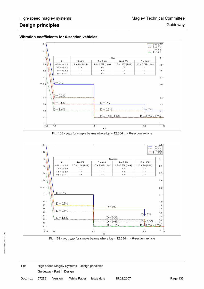
High-speed maglev systems
Design principles Maglev Technical Committee
Guideway
Title High-speed Maglev Systems - Design principles
Guideway - Part II: Design
Doc. no.: 57288 Version White Paper Issue date 15.02.2007 Page 136
Aus
druc
k: 1
3.09
.200
7 10
:42:
00
Vibration coefficients for 6-section vehicles
0.75 1.4 4.5 108.51
1.1
1.2
1.3
1.4
1.6
1.7
1.8
1.9
2
2.1
2.2
k [/]
φ
D = 0 %D = 0,3 %D = 0,6 %D = 1,6 %
Fig. 168 - ϕBg,z for simple beams where LSt = 12.384 m - 6-section vehicle
0.75 1.4 4.5 8.5 101
1.1
1.2
1.3
1.4
1.5
1.6
1.7
1.8
2
2.2
2.4
2.6
2.8
3
3.2
3.4
k [-]
φ
D = 0 %D = 0,3 %D = 0,6 %D = 1,6 %
Fig. 169 - ϕBg,z, WSE for simple beams where LSt = 12.384 m - 6-section vehicle
D = 0.6%; 1.6%
D = 0%
D = 0%
D = 0.3% - 1.6%
D = 1.6%
D = 0.3%
D = 0.6%
D = 0.3% D = 0%
ϕBg,z
k D = 0% D = 0.3% D = 0.6% D = 1.6% 0.75 ≤ k ≤ 1.4 1.6 + 0.923 (1.4-k) 1.4 + 1.077 (1.4-k) 1.3 + 1.077 (1.4-k) 1.2 + 0.769 (1.4-k) 1.4 < k ≤ 4.5 1.6 1.4 1.3 1.2 4.5 < k ≤ 8.5 1.3 1.2 1.1 1.1 8.5 < k < ∞ 1.2 1.1 1.1 1.1
1.1
1.2
1.3
1.4
1.6
1.7
1.8
1.9
2
2.1
2.2
1
D = 0%
D = 0.6% - 1.6%
D = 1.6%
D = 0.3%
D = 0.6% D = 0%
D = 0%
D = 0.3% D = 0.3% D = 0.6% D = 1.6%
ϕBg,z,WSE
k D = 0% D = 0.3% D = 0.6% D = 1.6% 0.75 ≤ k ≤ 1.4 2.0 + 2.154 (1.4-k) 1.7 + 2.308 (1.4-k) 1.5 + 2.308 (1.4-k) 1.3 + 2.0 (1.4-k) 1.4 < k ≤ 4.5 2.0 1.7 1.5 1.3 4.5 < k ≤ 8.5 1.6 1.3 1.2 1.1 8.5 < k < ∞ 1.4 1.2 1.1 1.1
1
1.1
1.21.31.41.5
1.6
1.7
1.8
2
2.2
2.4
2.6
2.8
3
3.2
3.4

High-speed maglev systems
Design principles Maglev Technical Committee
Guideway
Title High-speed Maglev Systems - Design principles
Guideway - Part II: Design
Doc. no.: 57288 Version White Paper Issue date 15.02.2007 Page 137
Aus
druc
k: 1
3.09
.200
7 10
:42:
00
Vibration coefficients for 10-section vehicles
0.75 1.4 4.5 108.51
1.1
1.2
1.3
1.5
1.4
1.6
1.7
1.8
1.9
2
2.2
2.3
2.4
2.5
k [/]
φ
D = 0 %D = 0,3 %D = 0,6 %D = 1,6 %
Fig. 170 - ϕBg,z for simple beams where LSt = 12.384 m - 10-section vehicle
0.75 1.4 4.5 8.5 101
1.11.21.31.4
1.6
1.81.9
2
2.2
2.4
2.62.72.8
3
3.2
3.4
3.6
3.8
4
k [-]
φ
D = 0 %D = 0,3 %D = 0,6 %D = 1,6 %
Fig. 171 - ϕBg,z, WSE for simple beams where LSt = 12.384 m - 10-section vehicle
D = 0.6%; 1.6%
D = 0%
D = 0.3% - 1.6%
D =1.6%
D = 0.3%
D = 0.6%
D = 0.3%
ϕBg,z
k D = 0% D = 0.3% D = 0.6% D = 1.6% 0.75 ≤ k ≤ 1.4 1.9 + 0.923 (1.4-k) 1.5 + 1.231 (1.4-k) 1.4 + 1.231 (1.4-k) 1.2 + 0.769 (1.4-k) 1.4 < k ≤ 4.5 1.9 1.5 1.4 1.2 4.5 < k ≤ 8.5 1.5 1.2 1.1 1.1 8.5 < k < ∞ 1.3 1.1 1.1 1.1
1.1
1.2
1.3
1.5
1.4
1.6
1.7
1.8
1.9
2
2.2
2.3
2.4
2.5
1
D = 0.6%
D = 0.6% - 1.6%
D = 1.6%
D = 0.3% D = 0%
D = 0.3%
D = 0.3% D = 0.6% D = 1.6%
ϕBg,z,WSE
k D = 0% D = 0.3% D = 0.6% D = 1.6% 0.75 ≤ k ≤ 1.4 2.7 + 2.0 (1.4-k) 1.9 + 2.923 (1.4-k) 1.6 + 3.077 (1.4-k) 1.3 + 2.615 (1.4-k) 1.4 < k ≤ 4.5 2.7 1.9 1.6 1.3 4.5 < k ≤ 8.5 1.9 1.4 1.2 1.1 8.5 < k < ∞ 1.6 1.2 1.1 1.1
11.11.21.31.4
1.6
1.81.92
2.2
2.4
2.62.72.8
3
3.2
3.4
3.6
3.8
4

High-speed maglev systems
Design principles Maglev Technical Committee
Guideway
Title High-speed Maglev Systems - Design principles
Guideway - Part II: Design
Doc. no.: 57288 Version White Paper Issue date 15.02.2007 Page 138
Aus
druc
k: 1
3.09
.200
7 10
:42:
00
Vibration coefficient diagrams for simple beams where LSt = 24.768 m Vibration coefficients for 2-section vehicles
1.05 1.4 2.5 4.5 8.5 101
1.05
1.1
1.15
1.2
1.25
1.3
1.35
1.4
1.45
1.5
k [-]
φ
D = 0 %, 0,3 %, 0,6 %, 1,6 %
Fig. 172 - ϕBg,z for simple beams where LSt = 24.768 m - 2-section vehicle
1.05 1.4 2.5 4.5 8.5 10
1.05
1.1
1.2
1.3
1.4
1.5
1.6
1.7
k [-]
φ
D = 0 %, 0,3 %, 0,6 %, 1,6 %
Fig. 173 - ϕBg,z, WSE for simple beams where LSt = 24.768 m - 2-section vehicle
ϕBg,z
k D = 0%; 0.3%; 0.6%; 1.6%
1.05 ≤ k ≤ 1.4 1.2 + 0.857 (1.4-k) 1.4 < k ≤ 2.5 1.2 2.5 < k ≤ 4.5 1.1 4.5 < k < ∞ 1.05
D = 0%; 0.3%; 0.6%; 1.6%
1
1.05
1.1
1.15
1.2
1.25
1.3
1.35
1.4
1.45
1.5
ϕBg,z,WSE
k D = 0%; 0.3%; 0.6%; 1.6%
1.05 ≤ k ≤ 1.3 1.7 1.3 ≤ k ≤ 1.4 1.3 + 4.0 (1.4-k) 1.4 < k ≤ 2.5 1.3 2.5 < k ≤ 4.5 1.2 4.5 < k ≤ 8.5 1.1 8.5 < k < ∞ 1.05
D = 0%; 0.3%; 0.6%; 1.6%
1.05
1.1
1.2
1.3
1.4
1.5
1.6
1.7
11
1.3
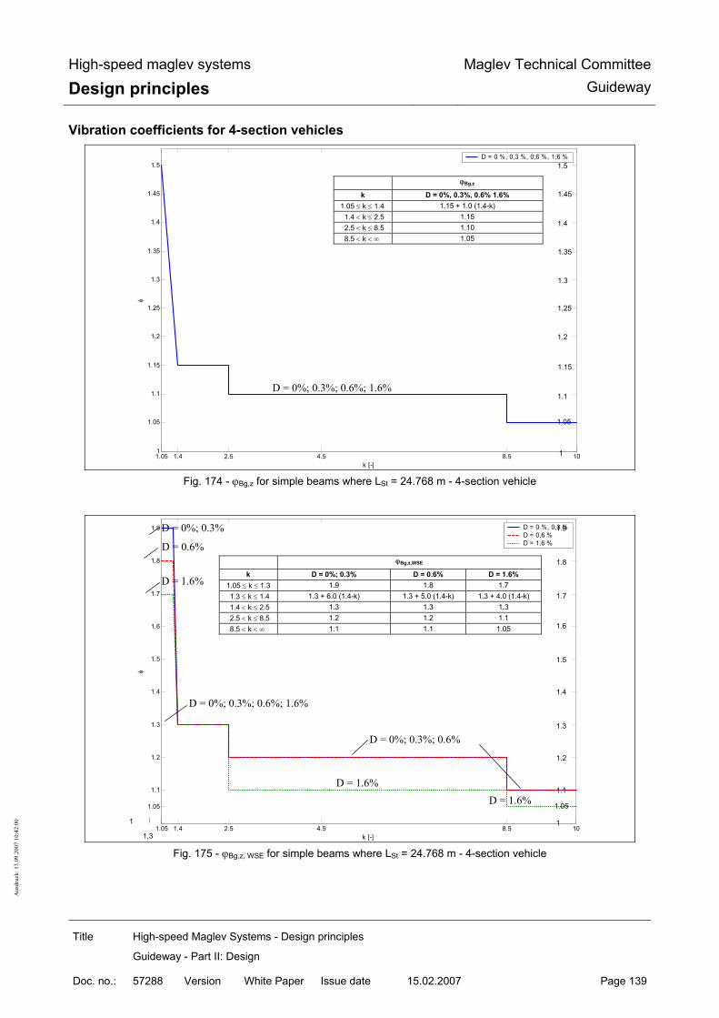
High-speed maglev systems
Design principles Maglev Technical Committee
Guideway
Title High-speed Maglev Systems - Design principles
Guideway - Part II: Design
Doc. no.: 57288 Version White Paper Issue date 15.02.2007 Page 139
Aus
druc
k: 1
3.09
.200
7 10
:42:
00
Vibration coefficients for 4-section vehicles
1.05 1.4 2.5 4.5 8.5 101
1.05
1.1
1.15
1.2
1.25
1.3
1.35
1.4
1.45
1.5
k [-]
φ
D = 0 %, 0,3 %, 0,6 %, 1,6 %
Fig. 174 - ϕBg,z for simple beams where LSt = 24.768 m - 4-section vehicle
1.05 1.4 2.5 4.5 8.5 10
1.05
1.1
1.2
1.3
1.4
1.5
1.6
1.7
1.8
1.9
k [-]
φ
D = 0 %, 0,3 %D = 0,6 %D = 1,6 %
Fig. 175 - ϕBg,z, WSE for simple beams where LSt = 24.768 m - 4-section vehicle
ϕBg,z
k D = 0%, 0.3%, 0.6% 1.6%
1.05 ≤ k ≤ 1.4 1.15 + 1.0 (1.4-k) 1.4 < k ≤ 2.5 1.15 2.5 < k ≤ 8.5 1.10 8.5 < k < ∞ 1.05
D = 0%; 0.3%; 0.6%; 1.6%
1
1.05
1.1
1.15
1.2
1.25
1.3
1.35
1.4
1.45
1.5
ϕBg,z,WSE
k D = 0%; 0.3% D = 0.6% D = 1.6% 1.05 ≤ k ≤ 1.3 1.9 1.8 1.7 1.3 ≤ k ≤ 1.4 1.3 + 6.0 (1.4-k) 1.3 + 5.0 (1.4-k) 1.3 + 4.0 (1.4-k) 1.4 < k ≤ 2.5 1.3 1.3 1.3 2.5 < k ≤ 8.5 1.2 1.2 1.1 8.5 < k < ∞ 1.1 1.1 1.05
D = 0%; 0.3%; 0.6%; 1.6%
D = 0%; 0.3%; 0.6%
D = 1.6%
D = 0%; 0.3%
D = 1.6%
D = 0.6%
1.05
1.1
1.2
1.3
1.4
1.5
1.6
1.7
1.8
1.9
1 1
D = 1.6%
1,3

High-speed maglev systems
Design principles Maglev Technical Committee
Guideway
Title High-speed Maglev Systems - Design principles
Guideway - Part II: Design
Doc. no.: 57288 Version White Paper Issue date 15.02.2007 Page 140
Aus
druc
k: 1
3.09
.200
7 10
:42:
00
Vibration coefficients for 6-section vehicles
1.05 1.4 2.5 4.5 8.5 101
1.05
1.1
1.15
1.2
1.25
1.3
1.35
1.4
1.45
1.5
k [-]
φ
D = 0 %D = 0,3 %, 0,6 %D = 1,6 %
Fig. 176 - ϕBg,z for simple beams where LSt = 24.768 m - 6-section vehicle
1.05 1.4 2.5 4.5 8.5 10
1.05
1.1
1.2
1.25
1.3
1.35
1.4
1.5
1.6
1.7
1.8
1.9
2
2.1
k [-]
φ
D = 0 %D = 0,3 %D = 0,6 %D = 1,6 %
Fig. 177 - ϕBg,z, WSE for simple beams where LSt = 24.768 m - 6-section vehicle
ϕBg,z,WSE
k D = 0% D = 0.3% D = 0.6% D = 1.6% 1.05 ≤ k ≤ 1.3 2.1 2.0 1.9 1.8 1.3 ≤ k ≤ 1.4 1.4 + 7.0 (1.4-k) 1.35 + 6.5 (1.4-k) 1.3 + 6.0 (1.4-k) 1.25 + 5.5 (1.4-k) 1.4 < k ≤ 2.5 1.4 1.35 1.3 1.25 2.5 < k ≤ 8.5 1.4 1.25 1.2 1.1 8.5 < k < ∞ 1.2 1.1 1.1 1.05
D = 1.6% D = 1.6%
D = 0%
D = 0% D = 0.3% D = 0.6%
1.3
1.05
1.1
1.2
1.25
1.3
1.35
1.4
1.5
1.6
1.7
1.8
1.9
2
2.1
1 1
D = 0.3% - 0.6%
D = 0.3% - 1.6%
ϕBg,z
k D = 0% D = 0.3%; 0.6% D = 1.6% 1.05 ≤ k ≤ 1.4 1.2 + 0.857 (1.4-k) 1.15 + 1.0 (1.4-k) 1.1 + 1.143 (1.4-k) 1.4 < k ≤ 8.5 1.2 1.15 1.1 8.5 < k < ∞ 1.1 1.05 1.05
D = 0.3%; 0.6%
D = 1.6%
D = 0%
D = 0%
1
1.05
1.1
1.15
1.2
1.25
1.3
1.35
1.4
1.45
1.5

High-speed maglev systems
Design principles Maglev Technical Committee
Guideway
Title High-speed Maglev Systems - Design principles
Guideway - Part II: Design
Doc. no.: 57288 Version White Paper Issue date 15.02.2007 Page 141
Aus
druc
k: 1
3.09
.200
7 10
:42:
00
Vibration coefficients for 10-section vehicles
1.05 1.4 2.5 4.5 8.5 101
1.05
1.1
1.15
1.2
1.25
1.3
1.35
1.4
1.45
1.5
k [-]
φ
D = 0 %D = 0,3 %, 0,6 %D = 1,6 %
Fig. 178 - ϕBg,z for simple beams where LSt = 24.768 m - 10-section vehicle
1.05 1.4 2.5 4.5 8.5 10
1.05
1.1
1.2
1.3
1.4
1.5
1.6
1.7
1.8
1.9
2
2.1
2.2
2.3
k [-]
φ
D = 0 %D = 0,3 %D = 0,6 %D = 1,6 %
Fig. 179 - ϕBg,z, WSE for simple beams where LSt = 24.768 m - 10-section vehicle
ϕBg,z
k D = 0% D = 0.3%; 0.6% D = 1.6% 1.05 ≤ k ≤ 1.4 1.3 + 0.571 (1.4-k) 1.2 + 0.857 (1.4-k) 1.15 + 0.714 (1.4-k) 1.4 < k ≤ 2.5 1.3 1.2 1.15 2.5 < k ≤ 8.5 1.3 1.2 1.05 8.5 < k < ∞ 1.1 1.05 1.05
D = 0.3%; 0.6%
D = 0.3% - 1.6%
D = 0%
D = 0%
D = 1.6% 1.05
1.1
1.15
1.2
1.25
1.3
1.35
1.4
1.45
1.5
1
ϕBg,z,WSE
k D = 0% D = 0.3% D = 0.6% D = 1.6% 1.05 ≤ k ≤ 1.4 1.5 + 2.286 (1.4-k) 1.4 + 2.0 (1.4-k) 1.4 + 1.714 (1.4-k) 1.3 + 1.429 (1.4-k) 1.4 < k ≤ 2.5 1.5 1.4 1.4 1.3 2.5 < k ≤ 8.5 1.5 1.4 1.2 1.1 8.5 < k < ∞ 1.2 1.1 1.1 1.05
D = 0%
D = 1.6% D = 1.6%
D = 0.6%
D = 0.3%
D = 0%
D = 0.3% - 0.6%
D = 0.3%; 0.6%
D = 1.6%
1.051.1
1.2
1.3
1.4
1.5
1.6
1.7
1.8
1.9
2
2.1
2.2
2.3
1 1

High-speed maglev systems
Design principles Maglev Technical Committee
Guideway
Title High-speed Maglev Systems - Design principles
Guideway - Part II: Design
Doc. no.: 57288 Version White Paper Issue date 15.02.2007 Page 142
Aus
druc
k: 1
3.09
.200
7 10
:42:
00
Annex II-C: Limit values for routing elements According to Chapter 4.1.7 of the Guideway design principles for high-speed maglev systems - Part IV: Routing, the combination of the routing elements - horizontal radius RH, vertical radius RV and the lateral incline of the guideway α - is limited by the Rx,z criterion. In this regard, the limit value Rx,z is also dependent on the guideway distortion ∆α. Table 117 gives examples of combination possibilities for routing parameter limit values.
The longitudinal incline (slope, gradient) is set at s = 0% in Table 117.
Rx,z,min = 530 m where the distortion ∆α = 0°/m
Lateral incline α Horizontal radius RH Vertical radius RV,(K/W)
RV,W ≤ - 530 m 0° 350 m
RV,K ≥ 530 m
RV,W ≤ - 756 m 350 m
RV,K ≥ 530 m
RV,W ≤ - 530 m
12°
5050 m
RV,K ≥ 554 m
Rx,z,min = 1100 m where the distortion ∆α = 0.1°/m
RV,W ≤ - 1100 m 0° 350 m
RV,K ≥ 1100 m
RV,W ≤ - 3105 m 12° 350 m
RV,K ≥ 651 m
Table 117 - Limit values for combinations of routing elements
Annex II-D: General limit values relating to de-formation The tables of general limit values relating to deformation are in the process of being drawn up. The deforma-tion limit values to be specified shall be coordinated with the competent supervisory authority, where neces-sary, until the report is complete.
Annex II-E: Tables of the magnetic forces as a result of cross-winds (Q9a) The following tables indicate the appurtenant guidance and levitation magnet forces of the advancing end and middle sections for vehicle speeds of 0 km/h, 200 km/h, 300 km/h, 400 km/h and 500 km/h and cross-

High-speed maglev systems
Design principles Maglev Technical Committee
Guideway
Title High-speed Maglev Systems - Design principles
Guideway - Part II: Design
Doc. no.: 57288 Version White Paper Issue date 15.02.2007 Page 143
Aus
druc
k: 1
3.09
.200
7 10
:42:
00
wind speeds of 10 m/s up to 40 m/s. The forces for speeds of travel in between these values, for instance, shall be determined in relation to a specific project by interpolation/extrapolation.

High-speed maglev systems
Design principles Maglev Technical Committee
Guideway
Title High-speed Maglev Systems - Design principles
Guideway - Part II: Design
Doc. no.: 57288 Version White Paper Issue date 15.02.2007 Page 144
Aus
druc
k: 1
3.09
.200
7 10
:42:
00
Guidance magnet forces py,W,FMTi in [kN/m] vW [m/s]
1 2 3 4 5 6 7 BM BM 10 11 12 13 14 15 16 40 - 37.1 13.6 19.5 14.1 13.6 13.8 - - 11.0 8.1 7.5 6.1 4.9 1.8 1.3 39 - 35.5 13.1 18.9 13.6 13.0 13.3 - - 10.5 7.8 7.2 5.9 4.7 1.8 1.2 38 - 33.9 12.7 18.2 13.0 12.5 12.7 - - 10.1 7.5 6.9 5.7 4.5 1.7 1.2 37 - 32.4 12.2 17.6 12.5 12.0 12.2 - - 9.7 7.2 6.7 5.4 4.3 1.6 1.1 36 - 30.9 11.7 16.9 12.0 11.5 11.6 - - 9.2 6.9 6.4 5.2 4.2 1.6 1.1 35 - 29.4 11.3 16.3 11.4 11.0 11.1 - - 8.8 6.6 6.1 5.0 4.0 1.5 1.0 34 - 27.9 10.8 15.6 10.9 10.5 10.6 - - 8.4 6.3 5.8 4.7 3.8 1.5 1.0 33 - 26.5 10.4 15.0 10.4 10.0 10.1 - - 8.0 6.0 5.6 4.5 3.6 1.4 0.9 32 - 25.1 9.9 14.4 9.9 9.5 9.6 - - 7.6 5.7 5.3 4.3 3.4 1.3 0.9 31 - 23.8 9.5 13.8 9.4 9.0 9.1 - - 7.2 5.4 5.1 4.1 3.3 1.3 0.9 30 - 22.5 9.1 13.2 9.0 8.6 8.6 - - 6.8 5.1 4.8 3.9 3.1 1.2 0.8 29 - 21.2 8.6 12.6 8.5 8.1 8.2 - - 6.4 4.9 4.6 3.7 2.9 1.2 0.8 28 - 19.9 8.2 12.0 8.0 7.7 7.7 - - 6.1 4.6 4.3 3.5 2.8 1.1 0.7 27 - 18.7 7.8 11.4 7.6 7.3 7.3 - - 5.7 4.3 4.1 3.3 2.6 1.0 0.7 26 - 17.5 7.4 10.8 7.1 6.8 6.8 - - 5.4 4.1 3.9 3.1 2.5 1.0 0.7 25 - 16.3 7.0 10.3 6.7 6.4 6.4 - - 5.0 3.8 3.6 2.9 2.3 0.9 0.6
Levitation magnet forces pz,W,TMTi in [kN/m] (+/-) vW [m/s]
(1) 2 3 4 5 6 7 8 9 10 11 12 13 14 15 16 40 7.4 5.6 6.8 4.7 8.3 2.0 5.6 3.2 3.8 4.2 4.8 2.6 5.0 1.4 3.7 39 7.1 5.4 6.5 4.5 8.0 1.9 5.4 3.1 3.6 4.0 4.6 2.5 4.8 1.4 3.6 38 6.8 5.2 6.3 4.4 7.7 1.8 5.2 3.0 3.5 3.9 4.4 2.4 4.6 1.3 3.4 37 6.5 5.0 6.0 4.2 7.4 1.8 5.0 2.8 3.3 3.7 4.2 2.3 4.4 1.3 3.3 36 6.3 4.8 5.7 4.0 7.1 1.7 4.7 2.7 3.2 3.5 4.0 2.2 4.2 1.2 3.1 35 6.0 4.6 5.5 3.8 6.7 1.6 4.5 2.6 3.1 3.4 3.9 2.1 4.1 1.2 3.0 34 5.7 4.4 5.2 3.7 6.4 1.5 4.3 2.5 2.9 3.2 3.7 2.0 3.9 1.1 2.9 33 5.4 4.2 5.0 3.5 6.1 1.5 4.1 2.3 2.8 3.1 3.5 1.9 3.7 1.1 2.7 32 5.2 4.0 4.7 3.3 5.8 1.4 3.9 2.2 2.6 2.9 3.3 1.8 3.5 1.0 2.6 31 4.9 3.8 4.5 3.2 5.6 1.3 3.7 2.1 2.5 2.8 3.2 1.7 3.3 1.0 2.5 30 4.7 3.6 4.2 3.0 5.3 1.2 3.6 2.0 2.4 2.7 3.0 1.6 3.2 0.9 2.3 29 4.4 3.5 4.0 2.9 5.0 1.2 3.4 1.9 2.2 2.5 2.8 1.5 3.0 0.9 2.2 28 4.2 3.3 3.8 2.7 4.7 1.1 3.2 1.8 2.1 2.4 2.7 1.4 2.8 0.8 2.1 27 3.9 3.1 3.6 2.5 4.5 1.0 3.0 1.7 2.0 2.2 2.5 1.4 2.7 0.8 2.0 26 3.7 2.9 3.4 2.4 4.2 1.0 2.8 1.6 1.9 2.1 2.4 1.3 2.5 0.7 1.9 25 3.5 2.8 3.1 2.3 3.9 0.9 2.7 1.5 1.8 2.0 2.2 1.2 2.4 0.7 1.7
Table 118 - Magnetic forces as a result of cross-winds: end section, vFzg = 500 km/h, vW = 25 .. 40 m/s

High-speed maglev systems
Design principles Maglev Technical Committee
Guideway
Title High-speed Maglev Systems - Design principles
Guideway - Part II: Design
Doc. no.: 57288 Version White Paper Issue date 15.02.2007 Page 145
Aus
druc
k: 1
3.09
.200
7 10
:42:
00
Guidance magnet forces py,W,FMTi in [kN/m] vW [m/s]
1 2 3 4 5 6 7 BM BM 10 11 12 13 14 15 16 25 - 16.3 7.0 10.3 6.7 6.4 6.4 - - 5.0 3.8 3.6 2.9 2.3 0.9 0.6 24 - 15.2 6.6 9.7 6.3 6.0 6.0 - - 4.7 3.6 3.4 2.7 2.2 0.9 0.6 23 - 14.1 6.2 9.2 5.9 5.6 5.6 - - 4.4 3.4 3.2 2.5 2.0 0.8 0.5 22 - 13.1 5.8 8.6 5.5 5.2 5.2 - - 4.1 3.1 3.0 2.3 1.9 0.8 0.5 21 - 12.0 5.5 8.1 5.1 4.9 4.8 - - 3.8 2.9 2.8 2.2 1.8 0.7 0.5 20 - 11.1 5.1 7.6 4.7 4.5 4.4 - - 3.5 2.7 2.6 2.0 1.6 0.7 0.4 19 - 10.1 4.7 7.0 4.4 4.1 4.1 - - 3.2 2.5 2.4 1.9 1.5 0.6 0.4 18 - 9.2 4.4 6.5 4.0 3.8 3.7 - - 2.9 2.3 2.2 1.7 1.4 0.6 0.4 17 - 8.3 4.0 6.1 3.7 3.5 3.4 - - 2.6 2.1 2.0 1.5 1.2 0.5 0.3 16 - 7.5 3.7 5.6 3.3 3.2 3.1 - - 2.4 1.9 1.8 1.4 1.1 0.5 0.3 15 - 6.7 3.4 5.1 3.0 2.8 2.8 - - 2.1 1.7 1.7 1.3 1.0 0.4 0.3 14 - 5.9 3.1 4.6 2.7 2.5 2.5 - - 1.9 1.5 1.5 1.1 0.9 0.4 0.3 13 - 5.2 2.8 4.2 2.4 2.3 2.2 - - 1.7 1.4 1.3 1.0 0.8 0.4 0.2 12 - 4.5 2.5 3.8 2.1 2.0 1.9 - - 1.5 1.2 1.2 0.9 0.7 0.3 0.2 11 - 3.9 2.2 3.3 1.8 1.7 1.7 - - 1.3 1.0 1.0 0.8 0.6 0.3 0.2 10 - 3.3 1.9 2.9 1.6 1.5 1.4 - - 1.1 0.9 0.9 0.7 0.5 0.2 0.2
Levitation magnet forces pz,W,TMTi in [kN/m] (+/-) vW [m/s]
(1) 2 3 4 5 6 7 8 9 10 11 12 13 14 15 16 25 3.5 2.8 3.1 2.3 3.9 0.9 2.7 1.5 1.8 2.0 2.2 1.2 2.4 0.7 1.7 24 3.3 2.6 2.9 2.1 3.7 0.9 2.5 1.4 1.6 1.9 2.1 1.1 2.2 0.6 1.6 23 3.0 2.4 2.7 2.0 3.5 0.8 2.3 1.3 1.5 1.7 2.0 1.1 2.1 0.6 1.5 22 2.8 2.3 2.5 1.8 3.2 0.7 2.2 1.2 1.4 1.6 1.8 1.0 1.9 0.6 1.4 21 2.6 2.1 2.4 1.7 3.0 0.7 2.0 1.1 1.3 1.5 1.7 0.9 1.8 0.5 1.3 20 2.4 2.0 2.2 1.6 2.8 0.6 1.9 1.0 1.2 1.4 1.6 0.8 1.6 0.5 1.2 19 2.2 1.8 2.0 1.5 2.5 0.6 1.7 0.9 1.1 1.3 1.4 0.8 1.5 0.4 1.1 18 2.0 1.7 1.8 1.3 2.3 0.5 1.6 0.9 1.0 1.2 1.3 0.7 1.4 0.4 1.0 17 1.9 1.5 1.7 1.2 2.1 0.5 1.4 0.8 0.9 1.1 1.2 0.6 1.3 0.4 0.9 16 1.7 1.4 1.5 1.1 1.9 0.4 1.3 0.7 0.8 1.0 1.1 0.6 1.1 0.3 0.9 15 1.5 1.3 1.4 1.0 1.7 0.4 1.2 0.6 0.8 0.9 1.0 0.5 1.0 0.3 0.8 14 1.4 1.2 1.2 0.9 1.6 0.4 1.1 0.6 0.7 0.8 0.9 0.5 0.9 0.3 0.7 13 1.2 1.0 1.1 0.8 1.4 0.3 0.9 0.5 0.6 0.7 0.8 0.4 0.8 0.2 0.6 12 1.1 0.9 0.9 0.7 1.2 0.3 0.8 0.4 0.5 0.6 0.7 0.4 0.7 0.2 0.5 11 0.9 0.8 0.8 0.6 1.1 0.2 0.7 0.4 0.5 0.5 0.6 0.3 0.6 0.2 0.5 10 0.8 0.7 0.7 0.5 0.9 0.2 0.6 0.3 0.4 0.5 0.5 0.3 0.5 0.2 0.4
Table 119 - Magnetic forces as a result of cross-winds: end section, vFzg = 500 km/h, vW = 10 .. 25 m/s

High-speed maglev systems
Design principles Maglev Technical Committee
Guideway
Title High-speed Maglev Systems - Design principles
Guideway - Part II: Design
Doc. no.: 57288 Version White Paper Issue date 15.02.2007 Page 146
Aus
druc
k: 1
3.09
.200
7 10
:42:
00
Guidance magnet forces py,W,FMTi in [kN/m] vW [m/s]
1 2 3 4 5 6 7 BM BM 10 11 12 13 14 15 16 40 2.4 1.8 4.4 6.0 6.2 6.4 8.1 - - 9.6 9.5 9.8 12.6 10.7 6.1 2.6 39 2.3 1.7 4.3 5.7 5.9 6.2 7.8 - - 9.1 9.1 9.4 12.1 10.3 5.9 2.5 38 2.2 1.7 4.1 5.5 5.7 5.9 7.5 - - 8.7 8.7 9.0 11.6 9.9 5.6 2.4 37 2.1 1.6 4.0 5.3 5.5 5.7 7.2 - - 8.3 8.3 8.7 11.1 9.5 5.4 2.3 36 2.0 1.6 3.8 5.1 5.2 5.5 6.9 - - 7.9 7.9 8.3 10.7 9.1 5.2 2.2 35 1.9 1.5 3.6 4.8 5.0 5.2 6.6 - - 7.5 7.5 7.9 10.2 8.7 5.0 2.2 34 1.8 1.5 3.5 4.6 4.8 5.0 6.3 - - 7.1 7.2 7.6 9.7 8.3 4.8 2.1 33 1.7 1.4 3.3 4.4 4.6 4.8 6.0 - - 6.7 6.8 7.2 9.3 8.0 4.6 2.0 32 1.6 1.3 3.2 4.2 4.4 4.5 5.7 - - 6.3 6.5 6.9 8.9 7.6 4.3 1.9 31 1.5 1.3 3.0 4.0 4.2 4.3 5.4 - - 6.0 6.1 6.5 8.4 7.2 4.1 1.8 30 1.5 1.2 2.9 3.8 4.0 4.1 5.2 - - 5.6 5.8 6.2 8.0 6.9 3.9 1.8 29 1.4 1.2 2.7 3.6 3.8 3.9 4.9 - - 5.3 5.5 5.9 7.6 6.5 3.7 1.7 28 1.3 1.1 2.6 3.4 3.6 3.7 4.6 - - 4.9 5.2 5.6 7.2 6.2 3.5 1.6 27 1.2 1.1 2.5 3.2 3.4 3.5 4.4 - - 4.6 4.8 5.2 6.8 5.8 3.4 1.5 26 1.1 1.0 2.3 3.0 3.2 3.3 4.1 - - 4.3 4.5 4.9 6.4 5.5 3.2 1.5 25 1.1 1.0 2.2 2.8 3.0 3.1 3.9 - - 4.0 4.3 4.6 6.0 5.2 3.0 1.4
Levitation magnet forces pz,W,TMTi in [kN/m] (+/-) vW [m/s]
1 2 3 4 5 6 7 8 9 10 11 12 13 14 15 16 40 1.5 1.6 2.7 1.8 2.5 2.6 1.9 2.1 2.7 1.3 3.9 2.6 3.0 3.9 1.8 1.5 39 1.4 1.6 2.6 1.8 2.4 2.5 1.8 2.0 2.6 1.3 3.8 2.5 2.8 3.8 1.8 1.4 38 1.3 1.5 2.5 1.7 2.3 2.4 1.8 1.8 2.5 1.2 3.6 2.4 2.7 3.6 1.7 1.3 37 1.3 1.4 2.3 1.6 2.2 2.3 1.7 1.7 2.4 1.1 3.5 2.3 2.6 3.5 1.6 1.3 36 1.2 1.4 2.2 1.5 2.1 2.2 1.6 1.6 2.3 1.1 3.3 2.2 2.5 3.3 1.5 1.2 35 1.2 1.3 2.1 1.5 2.0 2.1 1.5 1.5 2.2 1.0 3.2 2.1 2.4 3.2 1.5 1.2 34 1.1 1.3 2.1 1.4 1.9 2.0 1.5 1.4 2.1 1.0 3.0 2.0 2.3 3.0 1.4 1.1 33 1.1 1.2 2.0 1.3 1.8 1.9 1.4 1.3 2.0 1.0 2.9 1.9 2.2 2.9 1.3 1.1 32 1.0 1.1 1.9 1.3 1.7 1.8 1.3 1.2 2.0 0.9 2.8 1.8 2.1 2.7 1.3 1.0 31 1.0 1.1 1.8 1.2 1.7 1.7 1.3 1.1 1.9 0.9 2.6 1.7 2.0 2.6 1.2 1.0 30 0.9 1.0 1.7 1.2 1.6 1.6 1.2 1.1 1.8 0.8 2.5 1.6 1.9 2.5 1.2 0.9 29 0.9 1.0 1.6 1.1 1.5 1.5 1.1 1.0 1.7 0.8 2.4 1.5 1.8 2.3 1.1 0.9 28 0.8 0.9 1.5 1.0 1.4 1.5 1.1 0.9 1.6 0.7 2.3 1.4 1.7 2.2 1.0 0.8 27 0.8 0.9 1.4 1.0 1.3 1.4 1.0 0.8 1.5 0.7 2.1 1.4 1.6 2.1 1.0 0.8 26 0.7 0.8 1.3 0.9 1.2 1.3 0.9 0.8 1.4 0.6 2.0 1.3 1.5 2.0 0.9 0.7 25 0.7 0.8 1.3 0.9 1.2 1.2 0.9 0.7 1.4 0.6 1.9 1.2 1.4 1.8 0.9 0.7
Table 120 - Magnetic forces as a result of cross-winds: middle section, vFzg = 500 km/h, vW = 25 .. 40 m/s

High-speed maglev systems
Design principles Maglev Technical Committee
Guideway
Title High-speed Maglev Systems - Design principles
Guideway - Part II: Design
Doc. no.: 57288 Version White Paper Issue date 15.02.2007 Page 147
Aus
druc
k: 1
3.09
.200
7 10
:42:
00
Guidance magnet forces py,W,FMTi in [kN/m] vW [m/s]
1 2 3 4 5 6 7 BM BM 10 11 12 13 14 15 16 25 1.1 1.0 2.2 2.8 3.0 3.1 3.9 - - 4.0 4.3 4.6 6.0 5.2 3.0 1.4 24 1.0 0.9 2.1 2.7 2.8 2.9 3.6 - - 3.7 4.0 4.3 5.7 4.9 2.8 1.3 23 0.9 0.9 1.9 2.5 2.6 2.7 3.4 - - 3.4 3.7 4.1 5.3 4.5 2.6 1.2 22 0.9 0.8 1.8 2.3 2.5 2.5 3.1 - - 3.2 3.4 3.8 4.9 4.2 2.5 1.2 21 0.8 0.8 1.7 2.2 2.3 2.4 2.9 - - 2.9 3.2 3.5 4.6 3.9 2.3 1.1 20 0.7 0.7 1.6 2.0 2.1 2.2 2.7 - - 2.7 2.9 3.3 4.3 3.7 2.1 1.0 19 0.7 0.7 1.5 1.8 2.0 2.0 2.5 - - 2.4 2.7 3.0 3.9 3.4 2.0 1.0 18 0.6 0.6 1.3 1.7 1.8 1.9 2.3 - - 2.2 2.4 2.8 3.6 3.1 1.8 0.9 17 0.6 0.6 1.2 1.5 1.7 1.7 2.1 - - 2.0 2.2 2.5 3.3 2.8 1.7 0.8 16 0.5 0.6 1.1 1.4 1.5 1.5 1.9 - - 1.8 2.0 2.3 3.0 2.6 1.5 0.8 15 0.4 0.5 1.0 1.3 1.4 1.4 1.7 - - 1.6 1.8 2.1 2.7 2.3 1.4 0.7 14 0.4 0.5 0.9 1.1 1.2 1.3 1.5 - - 1.4 1.6 1.8 2.4 2.1 1.2 0.6 13 0.4 0.4 0.8 1.0 1.1 1.1 1.4 - - 1.2 1.4 1.6 2.2 1.9 1.1 0.6 12 0.3 0.4 0.7 0.9 1.0 1.0 1.2 - - 1.0 1.2 1.4 1.9 1.7 1.0 0.5 11 0.3 0.3 0.6 0.8 0.8 0.9 1.0 - - 0.9 1.0 1.3 1.7 1.4 0.9 0.5 10 0.2 0.3 0.6 0.7 0.7 0.7 0.9 - - 0.7 0.9 1.1 1.4 1.2 0.7 0.4
Levitation magnet forces pz,W,TMTi in [kN/m] (+/-) vW [m/s]
1 2 3 4 5 6 7 8 9 10 11 12 13 14 15 16 25 0.7 0.8 1.3 0.9 1.2 1.2 0.9 0.7 1.4 0.6 1.9 1.2 1.4 1.8 0.9 0.7 24 0.6 0.7 1.2 0.8 1.1 1.1 0.8 0.6 1.3 0.6 1.8 1.1 1.3 1.7 0.8 0.6 23 0.6 0.7 1.1 0.8 1.0 1.1 0.8 0.6 1.2 0.5 1.7 1.0 1.2 1.6 0.8 0.6 22 0.6 0.6 1.0 0.7 1.0 1.0 0.7 0.5 1.1 0.5 1.5 1.0 1.2 1.5 0.7 0.6 21 0.5 0.6 1.0 0.7 0.9 0.9 0.7 0.5 1.1 0.5 1.4 0.9 1.1 1.4 0.7 0.5 20 0.5 0.5 0.9 0.6 0.8 0.9 0.6 0.4 1.0 0.4 1.3 0.8 1.0 1.3 0.6 0.5 19 0.4 0.5 0.8 0.6 0.8 0.8 0.6 0.4 0.9 0.4 1.2 0.8 0.9 1.2 0.6 0.4 18 0.4 0.5 0.7 0.5 0.7 0.7 0.5 0.3 0.8 0.4 1.1 0.7 0.8 1.1 0.5 0.4 17 0.4 0.4 0.7 0.5 0.6 0.7 0.5 0.3 0.8 0.3 1.0 0.6 0.8 1.0 0.5 0.4 16 0.3 0.4 0.6 0.4 0.6 0.6 0.4 0.2 0.7 0.3 0.9 0.6 0.7 0.9 0.4 0.3 15 0.3 0.3 0.6 0.4 0.5 0.5 0.4 0.2 0.6 0.3 0.8 0.5 0.6 0.8 0.4 0.3 14 0.3 0.3 0.5 0.3 0.5 0.5 0.3 0.2 0.6 0.2 0.8 0.5 0.6 0.7 0.3 0.3 13 0.2 0.3 0.4 0.3 0.4 0.4 0.3 0.1 0.5 0.2 0.7 0.4 0.5 0.6 0.3 0.2 12 0.2 0.2 0.4 0.3 0.4 0.4 0.3 0.1 0.5 0.2 0.6 0.4 0.4 0.6 0.3 0.2 11 0.2 0.2 0.3 0.2 0.3 0.3 0.2 0.1 0.4 0.2 0.5 0.3 0.4 0.5 0.2 0.2 10 0.2 0.2 0.3 0.2 0.3 0.3 0.2 0.1 0.4 0.1 0.4 0.3 0.3 0.4 0.2 0.2
Table 121 - Magnetic forces as a result of cross-winds: middle section, vFzg = 500 km/h, vW = 10 .. 25 m/s

High-speed maglev systems
Design principles Maglev Technical Committee
Guideway
Title High-speed Maglev Systems - Design principles
Guideway - Part II: Design
Doc. no.: 57288 Version White Paper Issue date 15.02.2007 Page 148
Aus
druc
k: 1
3.09
.200
7 10
:42:
00
Guidance magnet forces py,W,FMTi in [kN/m] vW [m/s]
1 2 3 4 5 6 7 BM BM 10 11 12 13 14 15 16 40 - 27.9 13.4 18.6 13.2 12.7 12.9 - - 10.2 7.6 7.1 5.6 4.6 1.9 1.0 39 - 26.7 12.9 18.0 12.7 12.2 12.4 - - 9.8 7.3 6.8 5.4 4.4 1.8 0.9 38 - 25.5 12.4 17.4 12.2 11.7 11.9 - - 9.4 7.0 6.5 5.2 4.2 1.8 0.9 37 - 24.4 11.9 16.7 11.7 11.2 11.4 - - 9.0 6.7 6.3 5.0 4.0 1.7 0.9 36 - 23.3 11.4 16.1 11.2 10.7 10.9 - - 8.6 6.4 6.0 4.7 3.9 1.6 0.8 35 - 22.2 11.0 15.5 10.7 10.3 10.4 - - 8.2 6.1 5.7 4.5 3.7 1.6 0.8 34 - 21.1 10.5 14.9 10.2 9.8 9.9 - - 7.8 5.9 5.5 4.3 3.5 1.5 0.8 33 - 20.0 10.0 14.3 9.7 9.3 9.4 - - 7.4 5.6 5.3 4.1 3.3 1.4 0.7 32 - 19.0 9.6 13.7 9.3 8.9 9.0 - - 7.0 5.3 5.0 3.9 3.2 1.4 0.7 31 - 18.0 9.2 13.1 8.8 8.5 8.5 - - 6.7 5.1 4.8 3.7 3.0 1.3 0.7 30 - 17.0 8.7 12.6 8.4 8.0 8.1 - - 6.3 4.8 4.5 3.5 2.9 1.3 0.6 29 - 16.1 8.3 12.0 7.9 7.6 7.6 - - 6.0 4.6 4.3 3.3 2.7 1.2 0.6 28 - 15.1 7.9 11.4 7.5 7.2 7.2 - - 5.6 4.3 4.1 3.2 2.6 1.1 0.6 27 - 14.2 7.5 10.9 7.1 6.8 6.8 - - 5.3 4.1 3.9 3.0 2.4 1.1 0.5 26 - 13.3 7.0 10.3 6.7 6.4 6.4 - - 5.0 3.8 3.6 2.8 2.3 1.0 0.5 25 - 12.5 6.6 9.8 6.3 6.0 6.0 - - 4.7 3.6 3.4 2.6 2.1 1.0 0.5
Levitation magnet forces pz,W,TMTi in [kN/m] (+/-) vW [m/s]
(1) 2 3 4 5 6 7 8 9 10 11 12 13 14 15 16 40 6.6 5.4 6.4 4.4 7.9 1.8 5.3 3.0 3.5 3.9 4.5 2.4 4.7 1.3 3.5 39 6.3 5.2 6.1 4.2 7.6 1.7 5.1 2.9 3.4 3.7 4.3 2.3 4.5 1.2 3.3 38 6.1 5.0 5.8 4.0 7.2 1.7 4.8 2.7 3.2 3.6 4.1 2.2 4.3 1.2 3.2 37 5.8 4.8 5.6 3.9 6.9 1.6 4.6 2.6 3.1 3.4 3.9 2.1 4.1 1.1 3.1 36 5.6 4.6 5.4 3.7 6.7 1.5 4.4 2.5 3.0 3.3 3.8 2.0 4.0 1.1 2.9 35 5.3 4.4 5.1 3.5 6.4 1.5 4.3 2.4 2.8 3.2 3.6 1.9 3.8 1.0 2.8 34 5.1 4.2 4.9 3.4 6.1 1.4 4.1 2.3 2.7 3.0 3.4 1.8 3.6 1.0 2.7 33 4.8 4.0 4.6 3.2 5.8 1.3 3.9 2.2 2.6 2.9 3.3 1.7 3.4 1.0 2.5 32 4.6 3.8 4.4 3.1 5.5 1.3 3.7 2.1 2.4 2.7 3.1 1.7 3.3 0.9 2.4 31 4.4 3.6 4.2 2.9 5.2 1.2 3.5 2.0 2.3 2.6 3.0 1.6 3.1 0.9 2.3 30 4.2 3.5 4.0 2.8 5.0 1.1 3.3 1.9 2.2 2.5 2.8 1.5 2.9 0.8 2.2 29 3.9 3.3 3.7 2.6 4.7 1.1 3.1 1.8 2.1 2.3 2.7 1.4 2.8 0.8 2.1 28 3.7 3.1 3.5 2.5 4.5 1.0 3.0 1.7 2.0 2.2 2.5 1.3 2.6 0.7 2.0 27 3.5 3.0 3.3 2.4 4.2 0.9 2.8 1.6 1.9 2.1 2.4 1.3 2.5 0.7 1.8 26 3.3 2.8 3.1 2.2 4.0 0.9 2.6 1.5 1.7 2.0 2.2 1.2 2.3 0.7 1.7 25 3.1 2.6 2.9 2.1 3.7 0.8 2.5 1.4 1.6 1.9 2.1 1.1 2.2 0.6 1.6
Table 122 - Magnetic forces as a result of cross-winds: end section, vFzg = 400 km/h, vW = 25 .. 40 m/s

High-speed maglev systems
Design principles Maglev Technical Committee
Guideway
Title High-speed Maglev Systems - Design principles
Guideway - Part II: Design
Doc. no.: 57288 Version White Paper Issue date 15.02.2007 Page 149
Aus
druc
k: 1
3.09
.200
7 10
:42:
00
Guidance magnet forces py,W,FMTi in [kN/m] vW [m/s]
1 2 3 4 5 6 7 BM BM 10 11 12 13 14 15 16 25 - 12.5 6.6 9.8 6.3 6.0 6.0 - - 4.7 3.6 3.4 2.6 2.1 1.0 0.5 24 - 11.6 6.3 9.2 5.9 5.6 5.6 - - 4.3 3.4 3.2 2.5 2.0 0.9 0.4 23 - 10.8 5.9 8.7 5.5 5.3 5.2 - - 4.0 3.2 3.0 2.3 1.9 0.9 0.4 22 - 10.0 5.5 8.2 5.1 4.9 4.8 - - 3.8 2.9 2.8 2.1 1.7 0.8 0.4 21 - 9.2 5.1 7.7 4.8 4.6 4.5 - - 3.5 2.7 2.6 2.0 1.6 0.7 0.4 20 - 8.5 4.8 7.2 4.4 4.2 4.1 - - 3.2 2.5 2.4 1.8 1.5 0.7 0.3 19 - 7.8 4.4 6.7 4.1 3.9 3.8 - - 2.9 2.3 2.2 1.7 1.4 0.6 0.3 18 - 7.1 4.1 6.2 3.7 3.6 3.5 - - 2.7 2.1 2.1 1.6 1.3 0.6 0.3 17 - 6.4 3.7 5.8 3.4 3.3 3.2 - - 2.4 1.9 1.9 1.4 1.2 0.6 0.3 16 - 5.8 3.4 5.3 3.1 3.0 2.9 - - 2.2 1.8 1.7 1.3 1.0 0.5 0.2 15 - 5.2 3.1 4.9 2.8 2.7 2.6 - - 2.0 1.6 1.6 1.2 0.9 0.5 0.2 14 - 4.6 2.8 4.4 2.5 2.4 2.3 - - 1.8 1.4 1.4 1.0 0.8 0.4 0.2 13 - 4.1 2.5 4.0 2.2 2.1 2.0 - - 1.6 1.3 1.2 0.9 0.8 0.4 0.2 12 - 3.5 2.2 3.6 2.0 1.9 1.8 - - 1.4 1.1 1.1 0.8 0.7 0.3 0.2 11 - 3.1 2.0 3.2 1.7 1.6 1.6 - - 1.2 1.0 1.0 0.7 0.6 0.3 0.1 10 - 2.6 1.7 2.8 1.5 1.4 1.3 - - 1.0 0.8 0.8 0.6 0.5 0.3 0.1
Levitation magnet forces pz,W,TMTi in [kN/m] (+/-) vW [m/s]
(1) 2 3 4 5 6 7 8 9 10 11 12 13 14 15 16 25 3.1 2.6 2.9 2.1 3.7 0.8 2.5 1.4 1.6 1.9 2.1 1.1 2.2 0.6 1.6 24 2.9 2.5 2.7 2.0 3.5 0.8 2.3 1.3 1.5 1.7 2.0 1.0 2.1 0.6 1.5 23 2.7 2.3 2.6 1.8 3.3 0.7 2.2 1.2 1.4 1.6 1.8 1.0 1.9 0.5 1.4 22 2.5 2.2 2.4 1.7 3.0 0.7 2.0 1.1 1.3 1.5 1.7 0.9 1.8 0.5 1.3 21 2.3 2.0 2.2 1.6 2.8 0.6 1.9 1.0 1.2 1.4 1.6 0.8 1.7 0.5 1.2 20 2.2 1.9 2.0 1.5 2.6 0.6 1.7 1.0 1.1 1.3 1.5 0.8 1.5 0.4 1.1 19 2.0 1.7 1.9 1.4 2.4 0.5 1.6 0.9 1.0 1.2 1.3 0.7 1.4 0.4 1.0 18 1.8 1.6 1.7 1.2 2.2 0.5 1.5 0.8 1.0 1.1 1.2 0.7 1.3 0.4 1.0 17 1.7 1.5 1.6 1.1 2.0 0.4 1.3 0.7 0.9 1.0 1.1 0.6 1.2 0.3 0.9 16 1.5 1.3 1.4 1.0 1.8 0.4 1.2 0.7 0.8 0.9 1.0 0.5 1.1 0.3 0.8 15 1.4 1.2 1.3 0.9 1.6 0.4 1.1 0.6 0.7 0.8 0.9 0.5 1.0 0.3 0.7 14 1.2 1.1 1.1 0.8 1.5 0.3 1.0 0.5 0.6 0.7 0.8 0.4 0.9 0.2 0.6 13 1.1 1.0 1.0 0.7 1.3 0.3 0.9 0.5 0.6 0.7 0.7 0.4 0.8 0.2 0.6 12 0.9 0.9 0.9 0.7 1.2 0.2 0.8 0.4 0.5 0.6 0.6 0.3 0.7 0.2 0.5 11 0.8 0.8 0.8 0.6 1.0 0.2 0.7 0.4 0.4 0.5 0.6 0.3 0.6 0.2 0.4 10 0.7 0.7 0.7 0.5 0.9 0.2 0.6 0.3 0.4 0.4 0.5 0.3 0.5 0.1 0.4
Table 123 - Magnetic forces as a result of cross-winds: end section, vFzg = 400 km/h, vW = 10 .. 25 m/s

High-speed maglev systems
Design principles Maglev Technical Committee
Guideway
Title High-speed Maglev Systems - Design principles
Guideway - Part II: Design
Doc. no.: 57288 Version White Paper Issue date 15.02.2007 Page 150
Aus
druc
k: 1
3.09
.200
7 10
:42:
00
Guidance magnet forces py,W,FMTi in [kN/m] vW [m/s]
1 2 3 4 5 6 7 BM BM 10 11 12 13 14 15 16 40 1.4 2.1 4.2 5.0 5.7 5.9 7.4 - - 8.7 8.8 9.2 10.8 8.6 4.4 2.3 39 1.4 2.0 4.1 4.8 5.4 5.7 7.1 - - 8.3 8.5 8.8 10.3 8.2 4.3 2.2 38 1.3 2.0 3.9 4.6 5.2 5.4 6.8 - - 7.9 8.1 8.5 9.9 7.9 4.1 2.1 37 1.3 1.9 3.8 4.4 5.0 5.2 6.5 - - 7.5 7.7 8.1 9.5 7.6 3.9 2.1 36 1.2 1.8 3.6 4.2 4.8 5.0 6.2 - - 7.2 7.4 7.8 9.1 7.3 3.8 2.0 35 1.2 1.8 3.5 4.1 4.6 4.8 6.0 - - 6.8 7.0 7.4 8.7 7.0 3.6 1.9 34 1.1 1.7 3.3 3.9 4.4 4.6 5.7 - - 6.4 6.7 7.1 8.3 6.7 3.5 1.8 33 1.0 1.7 3.2 3.7 4.2 4.4 5.4 - - 6.1 6.4 6.8 8.0 6.4 3.3 1.8 32 1.0 1.6 3.0 3.5 4.0 4.2 5.2 - - 5.8 6.0 6.4 7.6 6.1 3.2 1.7 31 0.9 1.5 2.9 3.3 3.8 4.0 4.9 - - 5.4 5.7 6.1 7.2 5.8 3.0 1.6 30 0.9 1.5 2.8 3.2 3.6 3.8 4.7 - - 5.1 5.4 5.8 6.9 5.5 2.9 1.6 29 0.8 1.4 2.6 3.0 3.4 3.6 4.4 - - 4.8 5.1 5.5 6.5 5.2 2.7 1.5 28 0.8 1.3 2.5 2.9 3.3 3.4 4.2 - - 4.5 4.8 5.2 6.2 4.9 2.6 1.4 27 0.7 1.3 2.4 2.7 3.1 3.2 3.9 - - 4.2 4.5 4.9 5.8 4.7 2.4 1.4 26 0.7 1.2 2.2 2.5 2.9 3.0 3.7 - - 3.9 4.2 4.6 5.5 4.4 2.3 1.3 25 0.7 1.2 2.1 2.4 2.7 2.8 3.5 - - 3.6 4.0 4.4 5.2 4.1 2.2 1.2
Levitation magnet forces pz,W,TMTi in [kN/m] (+/-) vW [m/s]
1 2 3 4 5 6 7 8 9 10 11 12 13 14 15 16 40 1.3 1.5 2.4 1.7 2.3 2.3 1.8 1.9 2.5 1.2 3.6 2.4 2.7 3.7 1.8 1.3 39 1.3 1.4 2.3 1.6 2.2 2.3 1.7 1.8 2.4 1.2 3.5 2.3 2.6 3.5 1.7 1.3 38 1.2 1.4 2.2 1.6 2.1 2.2 1.6 1.7 2.3 1.1 3.3 2.2 2.5 3.4 1.6 1.2 37 1.2 1.3 2.1 1.5 2.0 2.1 1.6 1.6 2.2 1.1 3.2 2.1 2.4 3.2 1.6 1.2 36 1.1 1.3 2.0 1.4 1.9 2.0 1.5 1.5 2.2 1.0 3.1 2.0 2.3 3.1 1.5 1.1 35 1.1 1.2 2.0 1.4 1.9 1.9 1.4 1.4 2.1 1.0 2.9 1.9 2.2 2.9 1.4 1.1 34 1.0 1.2 1.9 1.3 1.8 1.8 1.4 1.3 2.0 0.9 2.8 1.8 2.1 2.8 1.4 1.0 33 1.0 1.1 1.8 1.2 1.7 1.7 1.3 1.2 1.9 0.9 2.7 1.8 2.0 2.7 1.3 1.0 32 0.9 1.1 1.7 1.2 1.6 1.6 1.2 1.1 1.8 0.8 2.5 1.7 1.9 2.6 1.2 0.9 31 0.9 1.0 1.6 1.1 1.5 1.6 1.2 1.0 1.7 0.8 2.4 1.6 1.8 2.4 1.2 0.9 30 0.8 0.9 1.5 1.1 1.4 1.5 1.1 1.0 1.6 0.8 2.3 1.5 1.7 2.3 1.1 0.8 29 0.8 0.9 1.5 1.0 1.4 1.4 1.0 0.9 1.6 0.7 2.2 1.4 1.6 2.2 1.1 0.8 28 0.7 0.8 1.4 1.0 1.3 1.3 1.0 0.8 1.5 0.7 2.1 1.3 1.6 2.1 1.0 0.7 27 0.7 0.8 1.3 0.9 1.2 1.3 0.9 0.8 1.4 0.6 1.9 1.3 1.5 1.9 0.9 0.7 26 0.7 0.8 1.2 0.9 1.1 1.2 0.9 0.7 1.3 0.6 1.8 1.2 1.4 1.8 0.9 0.7 25 0.6 0.7 1.1 0.8 1.1 1.1 0.8 0.6 1.3 0.6 1.7 1.1 1.3 1.7 0.8 0.6
Table 124 - Magnetic forces as a result of cross-winds: middle section, vFzg = 400 km/h, vW = 25 .. 40 m/s

High-speed maglev systems
Design principles Maglev Technical Committee
Guideway
Title High-speed Maglev Systems - Design principles
Guideway - Part II: Design
Doc. no.: 57288 Version White Paper Issue date 15.02.2007 Page 151
Aus
druc
k: 1
3.09
.200
7 10
:42:
00
Guidance magnet forces py,W,FMTi in [kN/m] vW [m/s]
1 2 3 4 5 6 7 BM BM 10 11 12 13 14 15 16 25 0.7 1.2 2.1 2.4 2.7 2.8 3.5 - - 3.6 4.0 4.4 5.2 4.1 2.2 1.2 24 0.6 1.1 2.0 2.2 2.6 2.6 3.3 - - 3.4 3.7 4.1 4.8 3.9 2.0 1.2 23 0.6 1.0 1.9 2.1 2.4 2.5 3.1 - - 3.1 3.4 3.8 4.5 3.6 1.9 1.1 22 0.5 1.0 1.7 1.9 2.3 2.3 2.8 - - 2.9 3.2 3.6 4.2 3.4 1.8 1.0 21 0.5 0.9 1.6 1.8 2.1 2.2 2.6 - - 2.6 2.9 3.3 3.9 3.2 1.7 1.0 20 0.4 0.9 1.5 1.7 1.9 2.0 2.4 - - 2.4 2.7 3.1 3.6 2.9 1.5 0.9 19 0.4 0.8 1.4 1.5 1.8 1.8 2.3 - - 2.2 2.5 2.8 3.4 2.7 1.4 0.8 18 0.4 0.8 1.3 1.4 1.7 1.7 2.1 - - 2.0 2.3 2.6 3.1 2.5 1.3 0.8 17 0.3 0.7 1.2 1.3 1.5 1.5 1.9 - - 1.8 2.1 2.4 2.8 2.3 1.2 0.7 16 0.3 0.7 1.1 1.2 1.4 1.4 1.7 - - 1.6 1.9 2.1 2.6 2.1 1.1 0.7 15 0.3 0.6 1.0 1.1 1.2 1.3 1.6 - - 1.4 1.7 1.9 2.3 1.9 1.0 0.6 14 0.2 0.5 0.9 1.0 1.1 1.1 1.4 - - 1.2 1.5 1.7 2.1 1.7 0.9 0.6 13 0.2 0.5 0.8 0.8 1.0 1.0 1.2 - - 1.1 1.3 1.5 1.9 1.5 0.8 0.5 12 0.2 0.5 0.7 0.7 0.9 0.9 1.1 - - 0.9 1.1 1.4 1.6 1.3 0.7 0.5 11 0.2 0.4 0.6 0.7 0.8 0.8 0.9 - - 0.8 1.0 1.2 1.4 1.2 0.6 0.4 10 0.1 0.4 0.5 0.6 0.7 0.7 0.8 - - 0.7 0.8 1.0 1.2 1.0 0.5 0.4
Levitation magnet forces pz,W,TMTi in [kN/m] (+/-) vW [m/s]
1 2 3 4 5 6 7 8 9 10 11 12 13 14 15 16 25 0.6 0.7 1.1 0.8 1.1 1.1 0.8 0.6 1.3 0.6 1.7 1.1 1.3 1.7 0.8 0.6 24 0.6 0.7 1.1 0.8 1.0 1.0 0.8 0.6 1.2 0.5 1.6 1.0 1.2 1.6 0.8 0.6 23 0.5 0.6 1.0 0.7 0.9 1.0 0.7 0.5 1.1 0.5 1.5 1.0 1.1 1.5 0.7 0.5 22 0.5 0.6 0.9 0.7 0.9 0.9 0.7 0.5 1.0 0.5 1.4 0.9 1.1 1.4 0.7 0.5 21 0.5 0.5 0.9 0.6 0.8 0.8 0.6 0.4 1.0 0.4 1.3 0.8 1.0 1.3 0.6 0.5 20 0.4 0.5 0.8 0.6 0.8 0.8 0.6 0.4 0.9 0.4 1.2 0.8 0.9 1.2 0.6 0.4 19 0.4 0.5 0.7 0.5 0.7 0.7 0.5 0.3 0.8 0.4 1.1 0.7 0.8 1.1 0.5 0.4 18 0.4 0.4 0.7 0.5 0.6 0.7 0.5 0.3 0.8 0.3 1.0 0.7 0.8 1.0 0.5 0.4 17 0.3 0.4 0.6 0.4 0.6 0.6 0.4 0.3 0.7 0.3 0.9 0.6 0.7 0.9 0.4 0.3 16 0.3 0.3 0.6 0.4 0.5 0.6 0.4 0.2 0.7 0.3 0.9 0.5 0.6 0.8 0.4 0.3 15 0.3 0.3 0.5 0.4 0.5 0.5 0.3 0.2 0.6 0.2 0.8 0.5 0.6 0.8 0.4 0.3 14 0.2 0.3 0.5 0.3 0.4 0.4 0.3 0.2 0.5 0.2 0.7 0.4 0.5 0.7 0.3 0.2 13 0.2 0.2 0.4 0.3 0.4 0.4 0.3 0.1 0.5 0.2 0.6 0.4 0.5 0.6 0.3 0.2 12 0.2 0.2 0.4 0.3 0.3 0.3 0.2 0.1 0.4 0.2 0.5 0.3 0.4 0.5 0.3 0.2 11 0.2 0.2 0.3 0.2 0.3 0.3 0.2 0.1 0.4 0.1 0.5 0.3 0.4 0.5 0.2 0.2 10 0.1 0.2 0.3 0.2 0.2 0.3 0.2 0.1 0.3 0.1 0.4 0.3 0.3 0.4 0.2 0.1
Table 125 - Magnetic forces as a result of cross-winds: middle section, vFzg = 400 km/h, vW = 10 .. 25 m/s

High-speed maglev systems
Design principles Maglev Technical Committee
Guideway
Title High-speed Maglev Systems - Design principles
Guideway - Part II: Design
Doc. no.: 57288 Version White Paper Issue date 15.02.2007 Page 152
Aus
druc
k: 1
3.09
.200
7 10
:42:
00
Guidance magnet forces py,W,FMTi in [kN/m] vW [m/s]
1 2 3 4 5 6 7 BM BM 10 11 12 13 14 15 16 40 - 15.1 9.6 15.7 12.1 11.7 11.7 - - 9.2 6.9 6.5 5.0 4.1 1.8 0.6 39 - 14.5 9.2 15.2 11.6 11.2 11.2 - - 8.8 6.6 6.2 4.8 3.9 1.8 0.6 38 - 13.8 8.9 14.7 11.2 10.7 10.7 - - 8.4 6.4 6.0 4.6 3.8 1.7 0.6 37 - 13.2 8.5 14.1 10.7 10.3 10.3 - - 8.0 6.1 5.7 4.4 3.6 1.6 0.6 36 - 12.6 8.2 13.6 10.2 9.9 9.8 - - 7.7 5.8 5.5 4.2 3.5 1.6 0.5 35 - 12.0 7.8 13.1 9.8 9.4 9.4 - - 7.3 5.6 5.3 4.0 3.3 1.5 0.5 34 - 11.4 7.5 12.6 9.4 9.0 8.9 - - 7.0 5.3 5.0 3.8 3.2 1.5 0.5 33 - 10.9 7.2 12.1 8.9 8.6 8.5 - - 6.6 5.1 4.8 3.7 3.0 1.4 0.5 32 - 10.3 6.8 11.6 8.5 8.2 8.1 - - 6.3 4.8 4.6 3.5 2.9 1.3 0.5 31 - 9.8 6.5 11.1 8.1 7.8 7.7 - - 6.0 4.6 4.4 3.3 2.7 1.3 0.4 30 - 9.2 6.2 10.6 7.7 7.4 7.3 - - 5.7 4.4 4.1 3.1 2.6 1.2 0.4 29 - 8.7 5.9 10.1 7.3 7.0 6.9 - - 5.4 4.1 3.9 3.0 2.4 1.2 0.4 28 - 8.2 5.6 9.7 6.9 6.6 6.5 - - 5.1 3.9 3.7 2.8 2.3 1.1 0.4 27 - 7.7 5.3 9.2 6.5 6.2 6.1 - - 4.8 3.7 3.5 2.7 2.2 1.0 0.3 26 - 7.2 5.0 8.7 6.1 5.9 5.8 - - 4.5 3.5 3.3 2.5 2.1 1.0 0.3 25 - 6.7 4.7 8.3 5.8 5.5 5.4 - - 4.2 3.3 3.1 2.3 1.9 0.9 0.3
Levitation magnet forces pz,W,TMTi in [kN/m] (+/-) vW [m/s]
(1) 2 3 4 5 6 7 8 9 10 11 12 13 14 15 16 40 5.7 4.9 5.8 3.9 7.2 1.6 4.8 2.7 3.2 3.5 4.0 2.1 4.2 1.2 3.1 39 5.5 4.8 5.5 3.8 6.9 1.5 4.6 2.6 3.1 3.4 3.9 2.0 4.1 1.1 3.0 38 5.3 4.6 5.3 3.6 6.7 1.5 4.4 2.5 2.9 3.3 3.7 2.0 3.9 1.1 2.9 37 5.0 4.4 5.1 3.5 6.4 1.4 4.2 2.4 2.8 3.1 3.6 1.9 3.7 1.0 2.8 36 4.8 4.2 4.9 3.3 6.1 1.3 4.1 2.3 2.7 3.0 3.4 1.8 3.6 1.0 2.6 35 4.6 4.0 4.6 3.2 5.8 1.3 3.9 2.2 2.6 2.9 3.3 1.7 3.4 0.9 2.5 34 4.4 3.9 4.4 3.0 5.6 1.2 3.7 2.1 2.4 2.7 3.1 1.6 3.3 0.9 2.4 33 4.2 3.7 4.2 2.9 5.3 1.2 3.5 2.0 2.3 2.6 3.0 1.6 3.1 0.9 2.3 32 4.0 3.5 4.0 2.7 5.1 1.1 3.4 1.9 2.2 2.5 2.8 1.5 3.0 0.8 2.2 31 3.8 3.4 3.8 2.6 4.8 1.0 3.2 1.8 2.1 2.4 2.7 1.4 2.8 0.8 2.1 30 3.6 3.2 3.6 2.5 4.6 1.0 3.0 1.7 2.0 2.2 2.5 1.3 2.7 0.7 2.0 29 3.4 3.1 3.4 2.4 4.3 0.9 2.9 1.6 1.9 2.1 2.4 1.3 2.5 0.7 1.9 28 3.2 2.9 3.2 2.2 4.1 0.9 2.7 1.5 1.8 2.0 2.3 1.2 2.4 0.7 1.8 27 3.0 2.7 3.0 2.1 3.9 0.8 2.6 1.4 1.7 1.9 2.1 1.1 2.2 0.6 1.7 26 2.9 2.6 2.8 2.0 3.6 0.8 2.4 1.3 1.6 1.8 2.0 1.1 2.1 0.6 1.6 25 2.7 2.4 2.7 1.9 3.4 0.7 2.3 1.2 1.5 1.7 1.9 1.0 2.0 0.6 1.5
Table 126 - Magnetic forces as a result of cross-winds: end section, vFzg = 300 km/h, vW = 25 .. 40 m/s

High-speed maglev systems
Design principles Maglev Technical Committee
Guideway
Title High-speed Maglev Systems - Design principles
Guideway - Part II: Design
Doc. no.: 57288 Version White Paper Issue date 15.02.2007 Page 153
Aus
druc
k: 1
3.09
.200
7 10
:42:
00
Guidance magnet forces py,W,FMTi in [kN/m] vW [m/s]
1 2 3 4 5 6 7 BM BM 10 11 12 13 14 15 16 25 - 6.7 4.7 8.3 5.8 5.5 5.4 - - 4.2 3.3 3.1 2.3 1.9 0.9 0.3 24 - 6.3 4.5 7.8 5.4 5.2 5.0 - - 3.9 3.1 2.9 2.2 1.8 0.9 0.3 23 - 5.8 4.2 7.4 5.0 4.8 4.7 - - 3.6 2.9 2.8 2.1 1.7 0.8 0.3 22 - 5.4 3.9 6.9 4.7 4.5 4.4 - - 3.4 2.7 2.6 1.9 1.6 0.8 0.3 21 - 5.0 3.6 6.5 4.4 4.2 4.1 - - 3.1 2.5 2.4 1.8 1.5 0.7 0.2 20 - 4.6 3.4 6.1 4.0 3.9 3.7 - - 2.9 2.3 2.2 1.6 1.3 0.7 0.2 19 - 4.2 3.1 5.7 3.7 3.6 3.4 - - 2.6 2.1 2.0 1.5 1.2 0.6 0.2 18 - 3.8 2.9 5.3 3.4 3.3 3.1 - - 2.4 1.9 1.9 1.4 1.1 0.6 0.2 17 - 3.5 2.7 4.9 3.1 3.0 2.9 - - 2.2 1.8 1.7 1.3 1.0 0.5 0.2 16 - 3.1 2.4 4.5 2.8 2.7 2.6 - - 2.0 1.6 1.6 1.1 0.9 0.5 0.2 15 - 2.8 2.2 4.1 2.6 2.4 2.3 - - 1.8 1.5 1.4 1.0 0.9 0.4 0.1 14 - 2.5 2.0 3.7 2.3 2.2 2.1 - - 1.6 1.3 1.3 0.9 0.8 0.4 0.1 13 - 2.2 1.8 3.4 2.0 1.9 1.8 - - 1.4 1.2 1.1 0.8 0.7 0.4 0.1 12 - 1.9 1.6 3.0 1.8 1.7 1.6 - - 1.2 1.0 1.0 0.7 0.6 0.3 0.1 11 - 1.6 1.4 2.7 1.6 1.5 1.4 - - 1.1 0.9 0.9 0.6 0.5 0.3 0.1 10 - 1.4 1.2 2.4 1.3 1.3 1.2 - - 0.9 0.8 0.8 0.5 0.4 0.2 0.1
Levitation magnet forces pz,W,TMTi in [kN/m] (+/-) vW [m/s]
(1) 2 3 4 5 6 7 8 9 10 11 12 13 14 15 16 25 2.7 2.4 2.7 1.9 3.4 0.7 2.3 1.2 1.5 1.7 1.9 1.0 2.0 0.6 1.5 24 2.5 2.3 2.5 1.7 3.2 0.7 2.1 1.2 1.4 1.6 1.8 0.9 1.9 0.5 1.4 23 2.3 2.2 2.3 1.6 3.0 0.6 2.0 1.1 1.3 1.5 1.7 0.9 1.7 0.5 1.3 22 2.2 2.0 2.2 1.5 2.8 0.6 1.8 1.0 1.2 1.4 1.5 0.8 1.6 0.5 1.2 21 2.0 1.9 2.0 1.4 2.6 0.5 1.7 0.9 1.1 1.3 1.4 0.8 1.5 0.4 1.1 20 1.9 1.7 1.8 1.3 2.4 0.5 1.6 0.9 1.0 1.2 1.3 0.7 1.4 0.4 1.0 19 1.7 1.6 1.7 1.2 2.2 0.5 1.5 0.8 0.9 1.1 1.2 0.6 1.3 0.4 0.9 18 1.6 1.5 1.6 1.1 2.0 0.4 1.3 0.7 0.9 1.0 1.1 0.6 1.2 0.3 0.9 17 1.4 1.4 1.4 1.0 1.8 0.4 1.2 0.7 0.8 0.9 1.0 0.5 1.1 0.3 0.8 16 1.3 1.2 1.3 0.9 1.7 0.4 1.1 0.6 0.7 0.8 0.9 0.5 1.0 0.3 0.7 15 1.2 1.1 1.1 0.8 1.5 0.3 1.0 0.5 0.6 0.8 0.8 0.4 0.9 0.2 0.6 14 1.1 1.0 1.0 0.7 1.4 0.3 0.9 0.5 0.6 0.7 0.7 0.4 0.8 0.2 0.6 13 0.9 0.9 0.9 0.7 1.2 0.2 0.8 0.4 0.5 0.6 0.7 0.4 0.7 0.2 0.5 12 0.8 0.8 0.8 0.6 1.1 0.2 0.7 0.4 0.4 0.5 0.6 0.3 0.6 0.2 0.4 11 0.7 0.7 0.7 0.5 0.9 0.2 0.6 0.3 0.4 0.5 0.5 0.3 0.5 0.2 0.4 10 0.6 0.6 0.6 0.4 0.8 0.2 0.5 0.3 0.3 0.4 0.4 0.2 0.5 0.1 0.3
Table 127 - Magnetic forces as a result of cross-winds: end section, vFzg = 300 km/h, vW = 10 .. 25 m/s

High-speed maglev systems
Design principles Maglev Technical Committee
Guideway
Title High-speed Maglev Systems - Design principles
Guideway - Part II: Design
Doc. no.: 57288 Version White Paper Issue date 15.02.2007 Page 154
Aus
druc
k: 1
3.09
.200
7 10
:42:
00
Guidance magnet forces py,W,FMTi in [kN/m] vW [m/s]
1 2 3 4 5 6 7 BM BM 10 11 12 13 14 15 16 40 1.8 1.7 3.3 4.9 5.0 5.2 6.6 - - 7.8 8.0 8.3 10.2 8.7 4.6 2.6 39 1.8 1.6 3.2 4.7 4.8 5.0 6.3 - - 7.4 7.6 8.0 9.8 8.3 4.4 2.6 38 1.7 1.6 3.0 4.5 4.6 4.8 6.1 - - 7.1 7.3 7.7 9.4 8.0 4.2 2.5 37 1.6 1.5 2.9 4.3 4.4 4.6 5.8 - - 6.7 7.0 7.4 9.1 7.7 4.0 2.4 36 1.5 1.5 2.8 4.1 4.2 4.4 5.6 - - 6.4 6.7 7.0 8.7 7.4 3.9 2.3 35 1.5 1.4 2.7 4.0 4.1 4.2 5.3 - - 6.1 6.3 6.7 8.3 7.0 3.7 2.2 34 1.4 1.4 2.6 3.8 3.9 4.0 5.1 - - 5.8 6.0 6.4 7.9 6.7 3.6 2.1 33 1.3 1.3 2.5 3.6 3.7 3.9 4.9 - - 5.4 5.7 6.1 7.6 6.4 3.4 2.0 32 1.3 1.3 2.4 3.4 3.5 3.7 4.6 - - 5.1 5.4 5.8 7.2 6.1 3.2 2.0 31 1.2 1.2 2.2 3.3 3.4 3.5 4.4 - - 4.8 5.2 5.6 6.9 5.8 3.1 1.9 30 1.1 1.2 2.1 3.1 3.2 3.3 4.2 - - 4.6 4.9 5.3 6.5 5.5 2.9 1.8 29 1.1 1.1 2.0 2.9 3.0 3.2 4.0 - - 4.3 4.6 5.0 6.2 5.3 2.8 1.7 28 1.0 1.1 1.9 2.8 2.9 3.0 3.7 - - 4.0 4.3 4.7 5.9 5.0 2.7 1.6 27 0.9 1.0 1.8 2.6 2.7 2.8 3.5 - - 3.8 4.1 4.5 5.5 4.7 2.5 1.6 26 0.9 1.0 1.7 2.5 2.6 2.7 3.3 - - 3.5 3.8 4.2 5.2 4.4 2.4 1.5 25 0.8 0.9 1.6 2.3 2.4 2.5 3.1 - - 3.3 3.6 3.9 4.9 4.2 2.2 1.4
Levitation magnet forces pz,W,TMTi in [kN/m] (+/-) vW [m/s]
1 2 3 4 5 6 7 8 9 10 11 12 13 14 15 16 40 1.2 1.4 2.2 1.5 2.1 2.1 1.6 1.7 2.3 1.1 3.3 2.2 2.5 3.3 1.6 1.2 39 1.2 1.3 2.1 1.4 2.0 2.0 1.5 1.6 2.2 1.0 3.2 2.1 2.4 3.1 1.5 1.2 38 1.1 1.3 2.0 1.4 1.9 2.0 1.5 1.5 2.1 1.0 3.1 2.0 2.3 3.0 1.5 1.1 37 1.1 1.2 1.9 1.3 1.8 1.9 1.4 1.4 2.0 0.9 2.9 1.9 2.2 2.9 1.4 1.1 36 1.0 1.2 1.8 1.3 1.7 1.8 1.3 1.3 2.0 0.9 2.8 1.8 2.1 2.8 1.4 1.0 35 1.0 1.1 1.8 1.2 1.7 1.7 1.3 1.3 1.9 0.9 2.7 1.7 2.0 2.6 1.3 1.0 34 0.9 1.1 1.7 1.2 1.6 1.6 1.2 1.2 1.8 0.8 2.6 1.7 1.9 2.5 1.2 0.9 33 0.9 1.0 1.6 1.1 1.5 1.6 1.2 1.1 1.7 0.8 2.4 1.6 1.8 2.4 1.2 0.9 32 0.8 1.0 1.5 1.1 1.4 1.5 1.1 1.0 1.6 0.7 2.3 1.5 1.7 2.3 1.1 0.8 31 0.8 0.9 1.5 1.0 1.4 1.4 1.1 0.9 1.6 0.7 2.2 1.4 1.7 2.2 1.1 0.8 30 0.8 0.9 1.4 1.0 1.3 1.3 1.0 0.9 1.5 0.7 2.1 1.4 1.6 2.1 1.0 0.8 29 0.7 0.8 1.3 0.9 1.2 1.3 0.9 0.8 1.4 0.6 2.0 1.3 1.5 1.9 1.0 0.7 28 0.7 0.8 1.2 0.9 1.2 1.2 0.9 0.7 1.4 0.6 1.9 1.2 1.4 1.8 0.9 0.7 27 0.6 0.7 1.2 0.8 1.1 1.1 0.8 0.7 1.3 0.6 1.8 1.1 1.3 1.7 0.9 0.6 26 0.6 0.7 1.1 0.8 1.0 1.1 0.8 0.6 1.2 0.5 1.7 1.1 1.3 1.6 0.8 0.6 25 0.6 0.6 1.0 0.7 1.0 1.0 0.7 0.6 1.1 0.5 1.6 1.0 1.2 1.5 0.8 0.6
Table 128 - Magnetic forces as a result of cross-winds: middle section, vFzg = 300 km/h, vW = 25 .. 40 m/s

High-speed maglev systems
Design principles Maglev Technical Committee
Guideway
Title High-speed Maglev Systems - Design principles
Guideway - Part II: Design
Doc. no.: 57288 Version White Paper Issue date 15.02.2007 Page 155
Aus
druc
k: 1
3.09
.200
7 10
:42:
00
Guidance magnet forces py,W,FMTi in [kN/m] vW [m/s]
1 2 3 4 5 6 7 BM BM 10 11 12 13 14 15 16 25 0.8 0.9 1.6 2.3 2.4 2.5 3.1 - - 3.3 3.6 3.9 4.9 4.2 2.2 1.4 24 0.8 0.9 1.5 2.2 2.3 2.3 2.9 - - 3.0 3.3 3.7 4.6 3.9 2.1 1.3 23 0.7 0.8 1.4 2.0 2.1 2.2 2.7 - - 2.8 3.1 3.5 4.3 3.7 2.0 1.3 22 0.7 0.8 1.3 1.9 2.0 2.0 2.6 - - 2.6 2.9 3.2 4.0 3.4 1.8 1.2 21 0.6 0.7 1.3 1.8 1.8 1.9 2.4 - - 2.4 2.7 3.0 3.7 3.2 1.7 1.1 20 0.6 0.7 1.2 1.6 1.7 1.8 2.2 - - 2.2 2.4 2.8 3.5 3.0 1.6 1.0 19 0.5 0.7 1.1 1.5 1.6 1.6 2.0 - - 2.0 2.2 2.5 3.2 2.7 1.5 1.0 18 0.5 0.6 1.0 1.4 1.5 1.5 1.9 - - 1.8 2.0 2.3 2.9 2.5 1.4 0.9 17 0.4 0.6 0.9 1.3 1.3 1.4 1.7 - - 1.6 1.9 2.1 2.7 2.3 1.2 0.8 16 0.4 0.5 0.8 1.2 1.2 1.2 1.5 - - 1.4 1.7 1.9 2.4 2.1 1.1 0.8 15 0.3 0.5 0.8 1.0 1.1 1.1 1.4 - - 1.3 1.5 1.8 2.2 1.9 1.0 0.7 14 0.3 0.4 0.7 0.9 1.0 1.0 1.2 - - 1.1 1.3 1.6 2.0 1.7 0.9 0.7 13 0.3 0.4 0.6 0.8 0.9 0.9 1.1 - - 1.0 1.2 1.4 1.8 1.5 0.8 0.6 12 0.2 0.4 0.5 0.7 0.8 0.8 1.0 - - 0.8 1.0 1.2 1.6 1.3 0.7 0.5 11 0.2 0.3 0.5 0.6 0.7 0.7 0.8 - - 0.7 0.9 1.1 1.4 1.2 0.6 0.5 10 0.2 0.3 0.4 0.5 0.6 0.6 0.7 - - 0.6 0.8 0.9 1.2 1.0 0.6 0.4
Levitation magnet forces pz,W,TMTi in [kN/m] (+/-) vW [m/s]
1 2 3 4 5 6 7 8 9 10 11 12 13 14 15 16 25 0.6 0.6 1.0 0.7 1.0 1.0 0.7 0.6 1.1 0.5 1.6 1.0 1.2 1.5 0.8 0.6 24 0.5 0.6 1.0 0.7 0.9 0.9 0.7 0.5 1.1 0.5 1.5 0.9 1.1 1.4 0.7 0.5 23 0.5 0.6 0.9 0.6 0.8 0.9 0.6 0.5 1.0 0.4 1.4 0.9 1.0 1.3 0.7 0.5 22 0.5 0.5 0.8 0.6 0.8 0.8 0.6 0.4 0.9 0.4 1.3 0.8 1.0 1.2 0.6 0.5 21 0.4 0.5 0.8 0.5 0.7 0.8 0.6 0.4 0.9 0.4 1.2 0.8 0.9 1.2 0.6 0.4 20 0.4 0.4 0.7 0.5 0.7 0.7 0.5 0.3 0.8 0.3 1.1 0.7 0.8 1.1 0.5 0.4 19 0.4 0.4 0.7 0.5 0.6 0.7 0.5 0.3 0.8 0.3 1.0 0.6 0.8 1.0 0.5 0.4 18 0.3 0.4 0.6 0.4 0.6 0.6 0.4 0.3 0.7 0.3 0.9 0.6 0.7 0.9 0.4 0.3 17 0.3 0.3 0.6 0.4 0.5 0.5 0.4 0.2 0.6 0.3 0.9 0.5 0.6 0.8 0.4 0.3 16 0.3 0.3 0.5 0.4 0.5 0.5 0.4 0.2 0.6 0.2 0.8 0.5 0.6 0.7 0.4 0.3 15 0.3 0.3 0.5 0.3 0.4 0.4 0.3 0.2 0.5 0.2 0.7 0.4 0.5 0.7 0.3 0.3 14 0.2 0.3 0.4 0.3 0.4 0.4 0.3 0.1 0.5 0.2 0.6 0.4 0.5 0.6 0.3 0.2 13 0.2 0.2 0.4 0.3 0.3 0.4 0.2 0.1 0.4 0.2 0.6 0.3 0.4 0.5 0.3 0.2 12 0.2 0.2 0.3 0.2 0.3 0.3 0.2 0.1 0.4 0.1 0.5 0.3 0.4 0.5 0.2 0.2 11 0.2 0.2 0.3 0.2 0.3 0.3 0.2 0.1 0.3 0.1 0.4 0.3 0.3 0.4 0.2 0.2 10 0.1 0.1 0.2 0.2 0.2 0.2 0.2 0.1 0.3 0.1 0.4 0.2 0.3 0.4 0.2 0.1
Table 129 - Magnetic forces as a result of cross-winds: middle section, vFzg = 300 km/h, vW = 10 .. 25 m/s

High-speed maglev systems
Design principles Maglev Technical Committee
Guideway
Title High-speed Maglev Systems - Design principles
Guideway - Part II: Design
Doc. no.: 57288 Version White Paper Issue date 15.02.2007 Page 156
Aus
druc
k: 1
3.09
.200
7 10
:42:
00
Guidance magnet forces py,W,FMTi in [kN/m] vW [m/s]
1 2 3 4 5 6 7 BM BM 10 11 12 13 14 15 16 40 - 11.7 8.3 12.2 10.3 10.0 9.9 - - 11.0 8.1 7.5 6.1 4.9 1.8 1.3 39 - 11.3 8.0 11.8 9.9 9.6 9.5 - - 10.5 7.8 7.2 5.9 4.7 1.8 1.2 38 - 10.8 7.7 11.4 9.5 9.2 9.1 - - 10.1 7.5 6.9 5.7 4.5 1.7 1.2 37 - 10.4 7.4 11.0 9.1 8.9 8.7 - - 9.7 7.2 6.7 5.4 4.3 1.6 1.1 36 - 10.0 7.1 10.6 8.7 8.5 8.3 - - 9.2 6.9 6.4 5.2 4.2 1.6 1.1 35 - 9.6 6.8 10.2 8.4 8.1 7.9 - - 8.8 6.6 6.1 5.0 4.0 1.5 1.0 34 - 9.1 6.5 9.8 8.0 7.7 7.6 - - 8.4 6.3 5.8 4.7 3.8 1.5 1.0 33 - 8.7 6.2 9.4 7.6 7.4 7.2 - - 8.0 6.0 5.6 4.5 3.6 1.4 0.9 32 - 8.3 5.9 9.0 7.3 7.0 6.8 - - 7.6 5.7 5.3 4.3 3.4 1.3 0.9 31 - 7.9 5.6 8.6 6.9 6.7 6.5 - - 7.2 5.4 5.1 4.1 3.3 1.3 0.9 30 - 7.5 5.4 8.2 6.6 6.3 6.2 - - 6.8 5.1 4.8 3.9 3.1 1.2 0.8 29 - 7.2 5.1 7.9 6.2 6.0 5.8 - - 6.4 4.9 4.6 3.7 2.9 1.2 0.8 28 - 6.8 4.8 7.5 5.9 5.7 5.5 - - 6.1 4.6 4.3 3.5 2.8 1.1 0.7 27 - 6.4 4.6 7.1 5.5 5.4 5.2 - - 5.7 4.3 4.1 3.3 2.6 1.0 0.7 26 - 6.1 4.3 6.8 5.2 5.1 4.9 - - 5.4 4.1 3.9 3.1 2.5 1.0 0.7 25 - 5.7 4.1 6.4 4.9 4.7 4.6 - - 5.0 3.8 3.6 2.9 2.3 0.9 0.6
Levitation magnet forces pz,W,TMTi in [kN/m] (+/-) vW [m/s]
(1) 2 3 4 5 6 7 8 9 10 11 12 13 14 15 16 40 5.0 4.3 5.0 3.5 6.1 1.4 4.1 2.3 2.7 3.1 3.5 1.8 3.7 1.0 2.7 39 4.8 4.1 4.8 3.3 5.9 1.4 3.9 2.2 2.6 3.0 3.4 1.8 3.5 1.0 2.6 38 4.6 3.9 4.6 3.2 5.6 1.3 3.8 2.2 2.5 2.8 3.2 1.7 3.4 0.9 2.5 37 4.4 3.8 4.4 3.1 5.4 1.3 3.6 2.1 2.4 2.7 3.1 1.6 3.2 0.9 2.4 36 4.2 3.6 4.2 2.9 5.2 1.2 3.5 2.0 2.3 2.6 2.9 1.5 3.1 0.8 2.3 35 4.0 3.5 4.0 2.8 4.9 1.2 3.3 1.9 2.2 2.5 2.8 1.5 3.0 0.8 2.2 34 3.8 3.3 3.8 2.7 4.7 1.1 3.2 1.8 2.1 2.4 2.7 1.4 2.8 0.8 2.1 33 3.6 3.2 3.6 2.6 4.5 1.0 3.0 1.7 2.0 2.3 2.6 1.3 2.7 0.7 2.0 32 3.5 3.0 3.5 2.4 4.3 1.0 2.9 1.6 1.9 2.2 2.4 1.3 2.6 0.7 1.9 31 3.3 2.9 3.3 2.3 4.1 0.9 2.7 1.5 1.8 2.1 2.3 1.2 2.4 0.7 1.8 30 3.1 2.8 3.1 2.2 3.9 0.9 2.6 1.5 1.7 2.0 2.2 1.2 2.3 0.6 1.7 29 3.0 2.6 2.9 2.1 3.7 0.8 2.5 1.4 1.6 1.9 2.1 1.1 2.2 0.6 1.6 28 2.8 2.5 2.8 2.0 3.5 0.8 2.3 1.3 1.5 1.8 2.0 1.0 2.1 0.6 1.5 27 2.6 2.4 2.6 1.9 3.3 0.8 2.2 1.2 1.4 1.7 1.8 1.0 1.9 0.5 1.4 26 2.5 2.2 2.5 1.8 3.1 0.7 2.1 1.2 1.3 1.6 1.7 0.9 1.8 0.5 1.3 25 2.3 2.1 2.3 1.7 2.9 0.7 1.9 1.1 1.3 1.5 1.6 0.9 1.7 0.5 1.3
Table 130 - Magnetic forces as a result of cross-winds: end section, vFzg = 200 km/h, vW = 25 .. 40 m/s

High-speed maglev systems
Design principles Maglev Technical Committee
Guideway
Title High-speed Maglev Systems - Design principles
Guideway - Part II: Design
Doc. no.: 57288 Version White Paper Issue date 15.02.2007 Page 157
Aus
druc
k: 1
3.09
.200
7 10
:42:
00
Guidance magnet forces py,W,FMTi in [kN/m] vW [m/s]
1 2 3 4 5 6 7 BM BM 10 11 12 13 14 15 16 25 - 5.7 4.1 6.4 4.9 4.7 4.6 - - 5.0 3.8 3.6 2.9 2.3 0.9 0.6 24 - 5.4 3.8 6.1 4.6 4.4 4.3 - - 4.7 3.6 3.4 2.7 2.2 0.9 0.6 23 - 5.0 3.6 5.7 4.3 4.2 4.0 - - 4.4 3.4 3.2 2.5 2.0 0.8 0.5 22 - 4.7 3.3 5.4 4.0 3.9 3.7 - - 4.1 3.1 3.0 2.3 1.9 0.8 0.5 21 - 4.4 3.1 5.0 3.7 3.6 3.4 - - 3.8 2.9 2.8 2.2 1.8 0.7 0.5 20 - 4.1 2.9 4.7 3.5 3.3 3.2 - - 3.5 2.7 2.6 2.0 1.6 0.7 0.4 19 - 3.7 2.7 4.4 3.2 3.1 2.9 - - 3.2 2.5 2.4 1.9 1.5 0.6 0.4 18 - 3.4 2.5 4.1 2.9 2.8 2.7 - - 2.9 2.3 2.2 1.7 1.4 0.6 0.4 17 - 3.2 2.2 3.8 2.7 2.6 2.4 - - 2.6 2.1 2.0 1.5 1.2 0.5 0.3 16 - 2.9 2.1 3.5 2.4 2.3 2.2 - - 2.4 1.9 1.8 1.4 1.1 0.5 0.3 15 - 2.6 1.9 3.2 2.2 2.1 2.0 - - 2.1 1.7 1.7 1.3 1.0 0.4 0.3 14 - 2.3 1.7 2.9 2.0 1.9 1.8 - - 1.9 1.5 1.5 1.1 0.9 0.4 0.3 13 - 2.1 1.5 2.6 1.7 1.7 1.6 - - 1.7 1.4 1.3 1.0 0.8 0.4 0.2 12 - 1.9 1.3 2.3 1.5 1.5 1.4 - - 1.5 1.2 1.2 0.9 0.7 0.3 0.2 11 - 1.6 1.2 2.1 1.3 1.3 1.2 - - 1.3 1.0 1.0 0.8 0.6 0.3 0.2 10 - 1.4 1.0 1.8 1.2 1.1 1.0 - - 1.1 0.9 0.9 0.7 0.5 0.2 0.2
Levitation magnet forces pz,W,TMTi in [kN/m] (+/-) vW [m/s]
(1) 2 3 4 5 6 7 8 9 10 11 12 13 14 15 16 25 2.3 2.1 2.3 1.7 2.9 0.7 1.9 1.1 1.3 1.5 1.6 0.9 1.7 0.5 1.3 24 2.2 2.0 2.2 1.5 2.7 0.6 1.8 1.0 1.2 1.4 1.5 0.8 1.6 0.4 1.2 23 2.0 1.9 2.0 1.4 2.5 0.6 1.7 0.9 1.1 1.3 1.4 0.8 1.5 0.4 1.1 22 1.9 1.7 1.9 1.3 2.4 0.5 1.6 0.9 1.0 1.2 1.3 0.7 1.4 0.4 1.0 21 1.8 1.6 1.7 1.3 2.2 0.5 1.5 0.8 0.9 1.1 1.2 0.7 1.3 0.4 1.0 20 1.6 1.5 1.6 1.2 2.0 0.5 1.4 0.7 0.9 1.0 1.1 0.6 1.2 0.3 0.9 19 1.5 1.4 1.5 1.1 1.9 0.4 1.2 0.7 0.8 0.9 1.0 0.6 1.1 0.3 0.8 18 1.4 1.3 1.3 1.0 1.7 0.4 1.1 0.6 0.7 0.9 1.0 0.5 1.0 0.3 0.7 17 1.3 1.2 1.2 0.9 1.6 0.4 1.0 0.6 0.7 0.8 0.9 0.5 0.9 0.3 0.7 16 1.1 1.1 1.1 0.8 1.4 0.3 0.9 0.5 0.6 0.7 0.8 0.4 0.8 0.2 0.6 15 1.0 1.0 1.0 0.7 1.3 0.3 0.9 0.5 0.5 0.7 0.7 0.4 0.8 0.2 0.6 14 0.9 0.9 0.9 0.7 1.1 0.3 0.8 0.4 0.5 0.6 0.6 0.3 0.7 0.2 0.5 13 0.8 0.8 0.8 0.6 1.0 0.2 0.7 0.4 0.4 0.5 0.6 0.3 0.6 0.2 0.4 12 0.7 0.7 0.7 0.5 0.9 0.2 0.6 0.3 0.4 0.5 0.5 0.3 0.5 0.1 0.4 11 0.6 0.6 0.6 0.5 0.8 0.2 0.5 0.3 0.3 0.4 0.4 0.2 0.5 0.1 0.3 10 0.5 0.5 0.5 0.4 0.7 0.1 0.4 0.2 0.3 0.3 0.4 0.2 0.4 0.1 0.3
Table 131 - Magnetic forces as a result of cross-winds: end section, vFzg = 200 km/h, vW = 10 .. 25 m/s

High-speed maglev systems
Design principles Maglev Technical Committee
Guideway
Title High-speed Maglev Systems - Design principles
Guideway - Part II: Design
Doc. no.: 57288 Version White Paper Issue date 15.02.2007 Page 158
Aus
druc
k: 1
3.09
.200
7 10
:42:
00
Guidance magnet forces py,W,FMTi in [kN/m] vW [m/s]
1 2 3 4 5 6 7 BM BM 10 11 12 13 14 15 16 40 1.1 1.6 3.2 3.8 4.3 4.5 5.6 - - 6.6 6.9 7.2 8.9 7.8 4.8 2.5 39 1.0 1.5 3.1 3.7 4.2 4.3 5.4 - - 6.3 6.6 6.9 8.6 7.5 4.6 2.5 38 1.0 1.5 3.0 3.5 4.0 4.2 5.1 - - 6.0 6.3 6.7 8.2 7.2 4.4 2.4 37 0.9 1.4 2.9 3.4 3.8 4.0 4.9 - - 5.7 6.0 6.4 7.9 6.9 4.2 2.3 36 0.9 1.4 2.8 3.2 3.7 3.8 4.7 - - 5.4 5.7 6.1 7.6 6.6 4.1 2.2 35 0.9 1.3 2.6 3.1 3.5 3.7 4.5 - - 5.1 5.5 5.8 7.3 6.4 3.9 2.1 34 0.8 1.3 2.5 3.0 3.4 3.5 4.3 - - 4.9 5.2 5.6 6.9 6.1 3.7 2.0 33 0.8 1.2 2.4 2.8 3.2 3.3 4.1 - - 4.6 5.0 5.3 6.6 5.8 3.6 2.0 32 0.7 1.2 2.3 2.7 3.1 3.2 3.9 - - 4.4 4.7 5.1 6.3 5.5 3.4 1.9 31 0.7 1.1 2.2 2.6 2.9 3.0 3.7 - - 4.1 4.5 4.8 6.0 5.3 3.2 1.8 30 0.7 1.1 2.1 2.4 2.8 2.9 3.5 - - 3.9 4.2 4.6 5.7 5.0 3.1 1.7 29 0.6 1.0 2.0 2.3 2.6 2.7 3.3 - - 3.6 4.0 4.3 5.4 4.7 2.9 1.7 28 0.6 1.0 1.9 2.2 2.5 2.6 3.2 - - 3.4 3.7 4.1 5.1 4.5 2.8 1.6 27 0.6 1.0 1.8 2.1 2.4 2.4 3.0 - - 3.2 3.5 3.9 4.8 4.2 2.6 1.5 26 0.5 0.9 1.7 1.9 2.2 2.3 2.8 - - 3.0 3.3 3.6 4.6 4.0 2.5 1.4 25 0.5 0.9 1.6 1.8 2.1 2.2 2.6 - - 2.8 3.1 3.4 4.3 3.8 2.3 1.4
Levitation magnet forces pz,W,TMTi in [kN/m] (+/-) vW [m/s]
1 2 3 4 5 6 7 8 9 10 11 12 13 14 15 16 40 1.0 1.2 1.9 1.3 1.8 1.8 1.4 1.5 2.0 0.9 2.9 1.8 2.2 2.8 1.4 1.0 39 1.0 1.1 1.8 1.3 1.7 1.8 1.3 1.4 1.9 0.9 2.8 1.8 2.1 2.7 1.3 1.0 38 0.9 1.1 1.7 1.2 1.6 1.7 1.3 1.3 1.8 0.8 2.7 1.7 2.0 2.6 1.3 0.9 37 0.9 1.0 1.7 1.2 1.6 1.6 1.2 1.2 1.8 0.8 2.6 1.6 1.9 2.5 1.2 0.9 36 0.9 1.0 1.6 1.1 1.5 1.5 1.2 1.2 1.7 0.8 2.4 1.5 1.9 2.3 1.2 0.9 35 0.8 1.0 1.5 1.1 1.4 1.5 1.1 1.1 1.6 0.7 2.3 1.5 1.8 2.2 1.1 0.8 34 0.8 0.9 1.5 1.0 1.4 1.4 1.1 1.0 1.6 0.7 2.2 1.4 1.7 2.1 1.1 0.8 33 0.8 0.9 1.4 1.0 1.3 1.3 1.0 0.9 1.5 0.7 2.1 1.3 1.6 2.0 1.0 0.8 32 0.7 0.8 1.3 0.9 1.2 1.3 1.0 0.9 1.4 0.6 2.0 1.3 1.5 1.9 1.0 0.7 31 0.7 0.8 1.3 0.9 1.2 1.2 0.9 0.8 1.4 0.6 1.9 1.2 1.5 1.8 0.9 0.7 30 0.6 0.7 1.2 0.8 1.1 1.2 0.9 0.8 1.3 0.6 1.8 1.2 1.4 1.7 0.9 0.6 29 0.6 0.7 1.1 0.8 1.1 1.1 0.8 0.7 1.2 0.5 1.7 1.1 1.3 1.7 0.8 0.6 28 0.6 0.7 1.1 0.8 1.0 1.0 0.8 0.6 1.2 0.5 1.7 1.0 1.3 1.6 0.8 0.6 27 0.5 0.6 1.0 0.7 0.9 1.0 0.7 0.6 1.1 0.5 1.6 1.0 1.2 1.5 0.7 0.5 26 0.5 0.6 0.9 0.7 0.9 0.9 0.7 0.5 1.0 0.4 1.5 0.9 1.1 1.4 0.7 0.5 25 0.5 0.6 0.9 0.6 0.8 0.9 0.6 0.5 1.0 0.4 1.4 0.9 1.0 1.3 0.6 0.5
Table 132 - Magnetic forces as a result of cross-winds: middle section, vFzg = 200 km/h, vW = 25 .. 40 m/s

High-speed maglev systems
Design principles Maglev Technical Committee
Guideway
Title High-speed Maglev Systems - Design principles
Guideway - Part II: Design
Doc. no.: 57288 Version White Paper Issue date 15.02.2007 Page 159
Aus
druc
k: 1
3.09
.200
7 10
:42:
00
Guidance magnet forces py,W,FMTi in [kN/m] vW [m/s]
1 2 3 4 5 6 7 BM BM 10 11 12 13 14 15 16 25 0.5 0.9 1.6 1.8 2.1 2.2 2.6 - - 2.8 3.1 3.4 4.3 3.8 2.3 1.4 24 0.5 0.8 1.5 1.7 2.0 2.0 2.5 - - 2.6 2.9 3.2 4.0 3.5 2.2 1.3 23 0.4 0.8 1.4 1.6 1.9 1.9 2.3 - - 2.4 2.7 3.0 3.8 3.3 2.1 1.2 22 0.4 0.7 1.3 1.5 1.7 1.8 2.2 - - 2.2 2.5 2.8 3.5 3.1 1.9 1.1 21 0.4 0.7 1.2 1.4 1.6 1.6 2.0 - - 2.0 2.3 2.6 3.3 2.9 1.8 1.1 20 0.3 0.7 1.1 1.3 1.5 1.5 1.9 - - 1.8 2.1 2.4 3.0 2.7 1.7 1.0 19 0.3 0.6 1.1 1.2 1.4 1.4 1.7 - - 1.7 1.9 2.2 2.8 2.5 1.5 0.9 18 0.3 0.6 1.0 1.1 1.3 1.3 1.6 - - 1.5 1.8 2.0 2.6 2.3 1.4 0.9 17 0.3 0.5 0.9 1.0 1.2 1.2 1.4 - - 1.4 1.6 1.9 2.3 2.1 1.3 0.8 16 0.2 0.5 0.8 0.9 1.1 1.1 1.3 - - 1.2 1.4 1.7 2.1 1.9 1.2 0.7 15 0.2 0.4 0.7 0.8 1.0 1.0 1.2 - - 1.1 1.3 1.5 1.9 1.7 1.1 0.7 14 0.2 0.4 0.7 0.7 0.9 0.9 1.1 - - 0.9 1.1 1.4 1.7 1.5 1.0 0.6 13 0.2 0.4 0.6 0.6 0.8 0.8 0.9 - - 0.8 1.0 1.2 1.5 1.4 0.9 0.6 12 0.1 0.3 0.5 0.6 0.7 0.7 0.8 - - 0.7 0.9 1.1 1.4 1.2 0.8 0.5 11 0.1 0.3 0.5 0.5 0.6 0.6 0.7 - - 0.6 0.8 0.9 1.2 1.1 0.7 0.5 10 0.1 0.3 0.4 0.4 0.5 0.5 0.6 - - 0.5 0.6 0.8 1.0 0.9 0.6 0.4
Levitation magnet forces pz,W,TMTi in [kN/m] (+/-) vW [m/s]
1 2 3 4 5 6 7 8 9 10 11 12 13 14 15 16 25 0.5 0.6 0.9 0.6 0.8 0.9 0.6 0.5 1.0 0.4 1.4 0.9 1.0 1.3 0.6 0.5 24 0.5 0.5 0.8 0.6 0.8 0.8 0.6 0.4 0.9 0.4 1.3 0.8 1.0 1.2 0.6 0.5 23 0.4 0.5 0.8 0.6 0.7 0.8 0.6 0.4 0.9 0.4 1.2 0.7 0.9 1.1 0.6 0.4 22 0.4 0.5 0.7 0.5 0.7 0.7 0.5 0.4 0.8 0.3 1.1 0.7 0.9 1.1 0.5 0.4 21 0.4 0.4 0.7 0.5 0.6 0.7 0.5 0.3 0.8 0.3 1.1 0.6 0.8 1.0 0.5 0.4 20 0.3 0.4 0.6 0.4 0.6 0.6 0.4 0.3 0.7 0.3 1.0 0.6 0.7 0.9 0.5 0.3 19 0.3 0.4 0.6 0.4 0.5 0.6 0.4 0.3 0.7 0.3 0.9 0.5 0.7 0.8 0.4 0.3 18 0.3 0.3 0.5 0.4 0.5 0.5 0.4 0.2 0.6 0.2 0.8 0.5 0.6 0.8 0.4 0.3 17 0.3 0.3 0.5 0.3 0.5 0.5 0.3 0.2 0.6 0.2 0.8 0.5 0.6 0.7 0.3 0.3 16 0.2 0.3 0.4 0.3 0.4 0.4 0.3 0.2 0.5 0.2 0.7 0.4 0.5 0.6 0.3 0.2 15 0.2 0.2 0.4 0.3 0.4 0.4 0.3 0.1 0.5 0.2 0.6 0.4 0.5 0.6 0.3 0.2 14 0.2 0.2 0.4 0.3 0.3 0.3 0.2 0.1 0.4 0.2 0.6 0.3 0.4 0.5 0.3 0.2 13 0.2 0.2 0.3 0.2 0.3 0.3 0.2 0.1 0.4 0.1 0.5 0.3 0.4 0.5 0.2 0.2 12 0.2 0.2 0.3 0.2 0.3 0.3 0.2 0.1 0.3 0.1 0.4 0.3 0.3 0.4 0.2 0.2 11 0.1 0.1 0.2 0.2 0.2 0.2 0.2 0.1 0.3 0.1 0.4 0.2 0.3 0.3 0.2 0.1 10 0.1 0.1 0.2 0.1 0.2 0.2 0.1 0.1 0.3 0.1 0.3 0.2 0.2 0.3 0.1 0.1
Table 133 - Magnetic forces as a result of cross-winds: middle section, vFzg = 200 km/h, vW = 10 .. 25 m/s

High-speed maglev systems
Design principles Maglev Technical Committee
Guideway
Title High-speed Maglev Systems - Design principles
Guideway - Part II: Design
Doc. no.: 57288 Version White Paper Issue date 15.02.2007 Page 160
Aus
druc
k: 1
3.09
.200
7 10
:42:
00
Guidance magnet forces py,W,FMTi in [kN/m] vW [m/s]
1 2 3 4 5 6 7 BM BM 10 11 12 13 14 15 16 40 - 3.2 3.2 3.6 3.2 3.6 5.0 - - 5.0 3.6 3.2 4.1 3.6 2.2 1.9 39 - 3.0 3.0 3.4 3.0 3.4 4.8 - - 4.8 3.4 3.0 3.9 3.4 2.1 1.8 38 - 2.8 2.8 3.3 2.8 3.3 4.5 - - 4.5 3.3 2.8 3.7 3.3 2.0 1.7 37 - 2.7 2.7 3.1 2.7 3.1 4.3 - - 4.3 3.1 2.7 3.5 3.1 1.9 1.6 36 - 2.6 2.6 2.9 2.6 2.9 4.1 - - 4.1 2.9 2.6 3.3 2.9 1.8 1.5 35 - 2.4 2.4 2.8 2.4 2.8 3.8 - - 3.8 2.8 2.4 3.1 2.8 1.7 1.4 34 - 2.3 2.3 2.6 2.3 2.6 3.6 - - 3.6 2.6 2.3 3.0 2.6 1.6 1.4 33 - 2.1 2.1 2.5 2.1 2.5 3.4 - - 3.4 2.5 2.1 2.8 2.5 1.5 1.3 32 - 2.0 2.0 2.3 2.0 2.3 3.2 - - 3.2 2.3 2.0 2.6 2.3 1.4 1.2 31 - 1.9 1.9 2.2 1.9 2.2 3.0 - - 3.0 2.2 1.9 2.5 2.2 1.3 1.1 30 - 1.8 1.8 2.0 1.8 2.0 2.8 - - 2.8 2.0 1.8 2.3 2.0 1.2 1.1 29 - 1.7 1.7 1.9 1.7 1.9 2.6 - - 2.6 1.9 1.7 2.2 1.9 1.2 1.0 28 - 1.5 1.5 1.8 1.5 1.8 2.5 - - 2.5 1.8 1.5 2.0 1.8 1.1 0.9 27 - 1.4 1.4 1.7 1.4 1.7 2.3 - - 2.3 1.7 1.4 1.9 1.7 1.0 0.9 26 - 1.3 1.3 1.5 1.3 1.5 2.1 - - 2.1 1.5 1.3 1.7 1.5 0.9 0.8 25 - 1.2 1.2 1.4 1.2 1.4 2.0 - - 2.0 1.4 1.2 1.6 1.4 0.9 0.7
Levitation magnet forces pz,W,TMTi in [kN/m] (+/-) vW [m/s]
(1) 2 3 4 5 6 7 8 9 10 11 12 13 14 15 16 40 0.8 1.7 1.0 1.0 1.0 1.1 1.5 1.4 1.0 1.0 1.0 1.0 0.8 1.1 1.1 39 0.8 1.6 1.0 1.0 1.0 1.1 1.4 1.3 1.0 1.0 1.0 1.0 0.8 1.1 1.1 38 0.7 1.6 0.9 0.9 0.9 1.0 1.4 1.3 0.9 0.9 0.9 0.9 0.7 1.0 1.0 37 0.7 1.5 0.9 0.9 0.9 1.0 1.3 1.2 0.9 0.9 0.9 0.9 0.7 1.0 1.0 36 0.7 1.4 0.9 0.9 0.9 1.0 1.2 1.1 0.9 0.9 0.9 0.9 0.7 1.0 1.0 35 0.6 1.4 0.8 0.8 0.8 0.9 1.2 1.1 0.8 0.8 0.8 0.8 0.6 0.9 0.9 34 0.6 1.3 0.8 0.8 0.8 0.9 1.1 1.0 0.8 0.8 0.8 0.8 0.6 0.9 0.9 33 0.6 1.3 0.7 0.8 0.7 0.8 1.1 1.0 0.7 0.8 0.7 0.7 0.6 0.8 0.8 32 0.6 1.2 0.7 0.7 0.7 0.8 1.0 0.9 0.7 0.7 0.7 0.7 0.6 0.8 0.8 31 0.5 1.1 0.7 0.7 0.7 0.7 1.0 0.9 0.7 0.7 0.7 0.7 0.5 0.8 0.8 30 0.5 1.1 0.6 0.6 0.6 0.7 0.9 0.8 0.6 0.6 0.6 0.6 0.5 0.7 0.7 29 0.5 1.0 0.6 0.6 0.6 0.7 0.9 0.8 0.6 0.6 0.6 0.6 0.5 0.7 0.7 28 0.4 1.0 0.6 0.6 0.6 0.6 0.8 0.8 0.6 0.6 0.6 0.6 0.4 0.6 0.6 27 0.4 0.9 0.5 0.5 0.5 0.6 0.8 0.7 0.5 0.5 0.5 0.5 0.4 0.6 0.6 26 0.4 0.9 0.5 0.5 0.5 0.6 0.7 0.7 0.5 0.5 0.5 0.5 0.4 0.6 0.6 25 0.4 0.8 0.5 0.5 0.5 0.5 0.7 0.6 0.5 0.5 0.5 0.5 0.4 0.5 0.5
Table 134 - Magnetic forces as a result of cross-winds: end section, vFzg = 0 km/h, vW = 25 .. 40 m/s

High-speed maglev systems
Design principles Maglev Technical Committee
Guideway
Title High-speed Maglev Systems - Design principles
Guideway - Part II: Design
Doc. no.: 57288 Version White Paper Issue date 15.02.2007 Page 161
Aus
druc
k: 1
3.09
.200
7 10
:42:
00
Guidance magnet forces py,W,FMTi in [kN/m] vW [m/s]
1 2 3 4 5 6 7 BM BM 10 11 12 13 14 15 16 25 - 1.2 1.2 1.4 1.2 1.4 2.0 - - 2.0 1.4 1.2 1.6 1.4 0.9 0.7 24 - 1.1 1.1 1.3 1.1 1.3 1.8 - - 1.8 1.3 1.1 1.5 1.3 0.8 0.7 23 - 1.0 1.0 1.2 1.0 1.2 1.7 - - 1.7 1.2 1.0 1.4 1.2 0.7 0.6 22 - 1.0 1.0 1.1 1.0 1.1 1.5 - - 1.5 1.1 1.0 1.2 1.1 0.7 0.6 21 - 0.9 0.9 1.0 0.9 1.0 1.4 - - 1.4 1.0 0.9 1.1 1.0 0.6 0.5 20 - 0.8 0.8 0.9 0.8 0.9 1.3 - - 1.3 0.9 0.8 1.0 0.9 0.6 0.5 19 - 0.7 0.7 0.8 0.7 0.8 1.1 - - 1.1 0.8 0.7 0.9 0.8 0.5 0.4 18 - 0.6 0.6 0.7 0.6 0.7 1.0 - - 1.0 0.7 0.6 0.8 0.7 0.4 0.4 17 - 0.6 0.6 0.7 0.6 0.7 0.9 - - 0.9 0.7 0.6 0.7 0.7 0.4 0.3 16 - 0.5 0.5 0.6 0.5 0.6 0.8 - - 0.8 0.6 0.5 0.7 0.6 0.4 0.3 15 - 0.4 0.4 0.5 0.4 0.5 0.7 - - 0.7 0.5 0.4 0.6 0.5 0.3 0.3 14 - 0.4 0.4 0.4 0.4 0.4 0.6 - - 0.6 0.4 0.4 0.5 0.4 0.3 0.2 13 - 0.3 0.3 0.4 0.3 0.4 0.5 - - 0.5 0.4 0.3 0.4 0.4 0.2 0.2 12 - 0.3 0.3 0.3 0.3 0.3 0.5 - - 0.5 0.3 0.3 0.4 0.3 0.2 0.2 11 - 0.2 0.2 0.3 0.2 0.3 0.4 - - 0.4 0.3 0.2 0.3 0.3 0.2 0.1 10 - 0.2 0.2 0.2 0.2 0.2 0.3 - - 0.3 0.2 0.2 0.3 0.2 0.1 0.1
Levitation magnet forces pz,W,TMTi in [kN/m] (+/-) vW [m/s]
(1) 2 3 4 5 6 7 8 9 10 11 12 13 14 15 16 25 0.4 0.8 0.5 0.5 0.5 0.5 0.7 0.6 0.5 0.5 0.5 0.5 0.4 0.5 0.5 24 0.3 0.8 0.4 0.5 0.5 0.5 0.7 0.6 0.4 0.5 0.4 0.4 0.3 0.5 0.5 23 0.3 0.7 0.4 0.4 0.4 0.5 0.6 0.5 0.4 0.4 0.4 0.4 0.3 0.5 0.5 22 0.3 0.7 0.4 0.4 0.4 0.4 0.6 0.5 0.4 0.4 0.4 0.4 0.3 0.4 0.4 21 0.3 0.6 0.4 0.4 0.4 0.4 0.5 0.5 0.4 0.4 0.4 0.4 0.3 0.4 0.4 20 0.3 0.6 0.3 0.3 0.3 0.4 0.5 0.4 0.3 0.3 0.3 0.3 0.3 0.4 0.4 19 0.2 0.6 0.3 0.3 0.3 0.3 0.4 0.4 0.3 0.3 0.3 0.3 0.2 0.3 0.3 18 0.2 0.5 0.3 0.3 0.3 0.3 0.4 0.4 0.3 0.3 0.3 0.3 0.2 0.3 0.3 17 0.2 0.5 0.3 0.3 0.3 0.3 0.4 0.3 0.3 0.3 0.3 0.3 0.2 0.3 0.3 16 0.2 0.4 0.2 0.2 0.2 0.3 0.3 0.3 0.2 0.2 0.2 0.2 0.2 0.3 0.3 15 0.2 0.4 0.2 0.2 0.2 0.2 0.3 0.3 0.2 0.2 0.2 0.2 0.2 0.2 0.2 14 0.1 0.3 0.2 0.2 0.2 0.2 0.3 0.2 0.2 0.2 0.2 0.2 0.1 0.2 0.2 13 0.1 0.3 0.2 0.2 0.2 0.2 0.2 0.2 0.2 0.2 0.2 0.2 0.1 0.2 0.2 12 0.1 0.3 0.1 0.2 0.1 0.2 0.2 0.2 0.1 0.2 0.1 0.1 0.1 0.2 0.2 11 0.1 0.2 0.1 0.1 0.1 0.1 0.2 0.2 0.1 0.1 0.1 0.1 0.1 0.1 0.1 10 0.1 0.2 0.1 0.1 0.1 0.1 0.2 0.1 0.1 0.1 0.1 0.1 0.1 0.1 0.1
Table 135 - Magnetic forces as a result of cross-winds: end section, vFzg = 0 km/h, vW = 10 .. 25 m/s

High-speed maglev systems
Design principles Maglev Technical Committee
Guideway
Title High-speed Maglev Systems - Design principles
Guideway - Part II: Design
Doc. no.: 57288 Version White Paper Issue date 15.02.2007 Page 162
Aus
druc
k: 1
3.09
.200
7 10
:42:
00
Guidance magnet forces py,W,FMTi in [kN/m] vW [m/s]
1 2 3 4 5 6 7 BM BM 10 11 12 13 14 15 16 40 1.9 2.2 3.2 3.6 3.2 3.6 5.0 - - 5.0 3.6 3.2 3.6 3.2 2.2 1.9 39 1.8 2.1 3.0 3.4 3.0 3.4 4.8 - - 4.8 3.4 3.0 3.4 3.0 2.1 1.8 38 1.7 2.0 2.8 3.3 2.8 3.3 4.5 - - 4.5 3.3 2.8 3.3 2.8 2.0 1.7 37 1.6 1.9 2.7 3.1 2.7 3.1 4.3 - - 4.3 3.1 2.7 3.1 2.7 1.9 1.6 36 1.5 1.8 2.6 2.9 2.6 2.9 4.1 - - 4.1 2.9 2.6 2.9 2.6 1.8 1.5 35 1.4 1.7 2.4 2.8 2.4 2.8 3.8 - - 3.8 2.8 2.4 2.8 2.4 1.7 1.4 34 1.4 1.6 2.3 2.6 2.3 2.6 3.6 - - 3.6 2.6 2.3 2.6 2.3 1.6 1.4 33 1.3 1.5 2.1 2.5 2.1 2.5 3.4 - - 3.4 2.5 2.1 2.5 2.1 1.5 1.3 32 1.2 1.4 2.0 2.3 2.0 2.3 3.2 - - 3.2 2.3 2.0 2.3 2.0 1.4 1.2 31 1.1 1.3 1.9 2.2 1.9 2.2 3.0 - - 3.0 2.2 1.9 2.2 1.9 1.3 1.1 30 1.1 1.2 1.8 2.0 1.8 2.0 2.8 - - 2.8 2.0 1.8 2.0 1.8 1.2 1.1 29 1.0 1.2 1.7 1.9 1.7 1.9 2.6 - - 2.6 1.9 1.7 1.9 1.7 1.2 1.0 28 0.9 1.1 1.5 1.8 1.5 1.8 2.5 - - 2.5 1.8 1.5 1.8 1.5 1.1 0.9 27 0.9 1.0 1.4 1.7 1.4 1.7 2.3 - - 2.3 1.7 1.4 1.7 1.4 1.0 0.9 26 0.8 0.9 1.3 1.5 1.3 1.5 2.1 - - 2.1 1.5 1.3 1.5 1.3 0.9 0.8 25 0.7 0.9 1.2 1.4 1.2 1.4 2.0 - - 2.0 1.4 1.2 1.4 1.2 0.9 0.7
Levitation magnet forces pz,W,TMTi in [kN/m] (+/-) vW [m/s]
1 2 3 4 5 6 7 8 9 10 11 12 13 14 15 16 40 1.1 1.1 0.8 1.0 0.8 0.8 1.1 1.4 1.3 1.1 0.8 0.8 1.0 0.8 1.1 1.1 39 1.1 1.1 0.8 1.0 0.8 0.8 1.1 1.4 1.3 1.1 0.8 0.8 1.0 0.8 1.1 1.1 38 1.0 1.0 0.7 0.9 0.7 0.7 1.0 1.3 1.2 1.0 0.7 0.7 0.9 0.7 1.0 1.0 37 1.0 1.0 0.7 0.9 0.7 0.7 1.0 1.2 1.2 1.0 0.7 0.7 0.9 0.7 1.0 1.0 36 1.0 1.0 0.7 0.9 0.7 0.7 1.0 1.1 1.2 1.0 0.7 0.7 0.9 0.7 1.0 1.0 35 0.9 0.9 0.6 0.8 0.6 0.6 0.9 1.1 1.1 0.9 0.6 0.6 0.8 0.6 0.9 0.9 34 0.9 0.9 0.6 0.8 0.6 0.6 0.9 1.0 1.1 0.9 0.6 0.6 0.8 0.6 0.9 0.9 33 0.8 0.8 0.6 0.8 0.6 0.6 0.8 0.9 1.0 0.8 0.6 0.6 0.8 0.6 0.8 0.8 32 0.8 0.8 0.6 0.7 0.6 0.6 0.8 0.9 1.0 0.8 0.6 0.6 0.7 0.6 0.8 0.8 31 0.8 0.8 0.5 0.7 0.5 0.5 0.7 0.8 0.9 0.7 0.5 0.5 0.7 0.5 0.8 0.8 30 0.7 0.7 0.5 0.6 0.5 0.5 0.7 0.7 0.9 0.7 0.5 0.5 0.6 0.5 0.7 0.7 29 0.7 0.7 0.5 0.6 0.5 0.5 0.7 0.7 0.8 0.7 0.5 0.5 0.6 0.5 0.7 0.7 28 0.6 0.6 0.4 0.6 0.4 0.5 0.6 0.6 0.8 0.6 0.5 0.4 0.6 0.4 0.6 0.6 27 0.6 0.6 0.4 0.5 0.4 0.4 0.6 0.6 0.8 0.6 0.4 0.4 0.5 0.4 0.6 0.6 26 0.6 0.6 0.4 0.5 0.4 0.4 0.6 0.5 0.7 0.6 0.4 0.4 0.5 0.4 0.6 0.6 25 0.5 0.5 0.4 0.5 0.4 0.4 0.5 0.5 0.7 0.5 0.4 0.4 0.5 0.4 0.5 0.5
Table 136 - Magnetic forces as a result of cross-winds: middle section, vFzg = 0 km/h, vW = 25 .. 40 m/s

High-speed maglev systems
Design principles Maglev Technical Committee
Guideway
Title High-speed Maglev Systems - Design principles
Guideway - Part II: Design
Doc. no.: 57288 Version White Paper Issue date 15.02.2007 Page 163
Aus
druc
k: 1
3.09
.200
7 10
:42:
00
Guidance magnet forces py,W,FMTi in [kN/m] vW [m/s]
1 2 3 4 5 6 7 BM BM 10 11 12 13 14 15 16 25 0.7 0.9 1.2 1.4 1.2 1.4 2.0 - - 2.0 1.4 1.2 1.4 1.2 0.9 0.7 24 0.7 0.8 1.1 1.3 1.1 1.3 1.8 - - 1.8 1.3 1.1 1.3 1.1 0.8 0.7 23 0.6 0.7 1.0 1.2 1.0 1.2 1.7 - - 1.7 1.2 1.0 1.2 1.0 0.7 0.6 22 0.6 0.7 1.0 1.1 1.0 1.1 1.5 - - 1.5 1.1 1.0 1.1 1.0 0.7 0.6 21 0.5 0.6 0.9 1.0 0.9 1.0 1.4 - - 1.4 1.0 0.9 1.0 0.9 0.6 0.5 20 0.5 0.6 0.8 0.9 0.8 0.9 1.3 - - 1.3 0.9 0.8 0.9 0.8 0.6 0.5 19 0.4 0.5 0.7 0.8 0.7 0.8 1.1 - - 1.1 0.8 0.7 0.8 0.7 0.5 0.4 18 0.4 0.4 0.6 0.7 0.6 0.7 1.0 - - 1.0 0.7 0.6 0.7 0.6 0.4 0.4 17 0.3 0.4 0.6 0.7 0.6 0.7 0.9 - - 0.9 0.7 0.6 0.7 0.6 0.4 0.3 16 0.3 0.4 0.5 0.6 0.5 0.6 0.8 - - 0.8 0.6 0.5 0.6 0.5 0.4 0.3 15 0.3 0.3 0.4 0.5 0.4 0.5 0.7 - - 0.7 0.5 0.4 0.5 0.4 0.3 0.3 14 0.2 0.3 0.4 0.4 0.4 0.4 0.6 - - 0.6 0.4 0.4 0.4 0.4 0.3 0.2 13 0.2 0.2 0.3 0.4 0.3 0.4 0.5 - - 0.5 0.4 0.3 0.4 0.3 0.2 0.2 12 0.2 0.2 0.3 0.3 0.3 0.3 0.5 - - 0.5 0.3 0.3 0.3 0.3 0.2 0.2 11 0.1 0.2 0.2 0.3 0.2 0.3 0.4 - - 0.4 0.3 0.2 0.3 0.2 0.2 0.1 10 0.1 0.1 0.2 0.2 0.2 0.2 0.3 - - 0.3 0.2 0.2 0.2 0.2 0.1 0.1
Levitation magnet forces pz,W,TMTi in [kN/m] (+/-) vW [m/s]
1 2 3 4 5 6 7 8 9 10 11 12 13 14 15 16 25 0.5 0.5 0.4 0.5 0.4 0.4 0.5 0.5 0.7 0.5 0.4 0.4 0.5 0.4 0.5 0.5 24 0.5 0.5 0.4 0.5 0.3 0.4 0.5 0.4 0.6 0.5 0.4 0.3 0.5 0.3 0.5 0.5 23 0.5 0.5 0.3 0.4 0.3 0.3 0.5 0.4 0.6 0.5 0.3 0.3 0.4 0.3 0.5 0.5 22 0.4 0.4 0.3 0.4 0.3 0.3 0.4 0.4 0.6 0.4 0.3 0.3 0.4 0.3 0.4 0.4 21 0.4 0.4 0.3 0.4 0.3 0.3 0.4 0.3 0.5 0.4 0.3 0.3 0.4 0.3 0.4 0.4 20 0.4 0.4 0.3 0.3 0.3 0.3 0.4 0.3 0.5 0.4 0.3 0.3 0.3 0.3 0.4 0.4 19 0.3 0.3 0.2 0.3 0.2 0.2 0.3 0.2 0.5 0.3 0.2 0.2 0.3 0.2 0.3 0.3 18 0.3 0.3 0.2 0.3 0.2 0.2 0.3 0.2 0.4 0.3 0.2 0.2 0.3 0.2 0.3 0.3 17 0.3 0.3 0.2 0.3 0.2 0.2 0.3 0.2 0.4 0.3 0.2 0.2 0.3 0.2 0.3 0.3 16 0.3 0.3 0.2 0.2 0.2 0.2 0.2 0.2 0.3 0.3 0.2 0.2 0.2 0.2 0.3 0.3 15 0.2 0.2 0.2 0.2 0.2 0.2 0.2 0.1 0.3 0.2 0.2 0.2 0.2 0.2 0.2 0.2 14 0.2 0.2 0.1 0.2 0.1 0.2 0.2 0.1 0.3 0.2 0.2 0.1 0.2 0.1 0.2 0.2 13 0.2 0.2 0.1 0.2 0.1 0.1 0.2 0.1 0.3 0.2 0.1 0.1 0.2 0.1 0.2 0.2 12 0.2 0.2 0.1 0.2 0.1 0.1 0.2 0.1 0.2 0.2 0.1 0.1 0.2 0.1 0.2 0.2 11 0.1 0.1 0.1 0.1 0.1 0.1 0.1 0.1 0.2 0.1 0.1 0.1 0.1 0.1 0.1 0.1 10 0.1 0.1 0.1 0.1 0.1 0.1 0.1 0.1 0.2 0.1 0.1 0.1 0.1 0.1 0.1 0.1
Table 137 - Magnetic forces as a result of cross-winds: middle section, vFzg = 0 km/h, vW = 10 .. 25 m/s

High-speed maglev systems
Design principles Maglev Technical Committee
Guideway
Title High-speed Maglev Systems - Design principles
Guideway - Part II: Design
Doc. no.: 57288 Version White Paper Issue date 15.02.2007 Page 164
Aus
druc
k: 1
3.09
.200
7 10
:42:
00
Annex II-F: Calculating the levitation magnet pole forces Without rearrangement for standard and front and rear-mounted levitation magnets (see figs. 180 and 181) Example
1 Line load, part magnets i, i+1
iz,az,EG/MG/ZG/HG,TMTp
i+1z,az,EG/MG/ZG/HG,TMTp from equation 15
10
5 kN/m
2 Levitation
magnet termi-nal pole forces
Pz,EP,i/i+1 0.5⋅pz,az,EG/MG/ZG/HG,TMT(i/i+1) ⋅Lsys,TMT(i/i+1) / 5.5
or 0.5⋅pz,az,EG/MG/ZG/HG,TMT(i/i+1) ⋅Lsys,TMT(i/i+1) / 7.5 *
1.41; 0.70
1.39 * kN
3 Levitation
magnet main pole forces
Pz,HP,i/i+1 pz,az,EG/MG/ZG/HG,TMT(i/i+1) ⋅Lsys,TMT(i/i+1) / 5.5
or pz,az,EG/MG/ZG/HG,TMT(i/i+1) ⋅Lsys,TMT(i/i+1) / 7.5 *
2.82; 1.40
2.77 * kN
* with a front and rear-mounted levitation magnet Table 138 - Levitation magnet pole forces without rearrangement
With 30% rearrangement for standard levitation magnets (see fig. 180) Example
1 Line load, part magnets i, i+1
iz,az,EG/MG/ZG/HG,TMTp
≥
i+1z,az,EG/MG/ZG/HG,TMTp
from equation 15 10
5
kN/m
2 Result of the
uneven distribu-tion TMTi
RTMTi,30% i iz,az,EG/MG/ZG/HG,TMT sys,TMTp 30% L / 2⋅ ⋅ 2.32 kN
3 Levitation mag-net terminal pole
force i Pz,EP,30,i Pz,EP,i + RTMTi,30% · 3 / 18 1.79 kN
4 Levitation mag-net main pole
force 1,i Pz,HP1,30,i Pz,HP,i + RTMTi,30% · 5 / 18 3.46 kN
5 Levitation mag-net main pole
force 2,i Pz,HP2,30,i Pz,HP,i + RTMTi,30% · 4 / 18 3.33 kN
6 Levitation mag-net main pole
force 3,i Pz,HP3,30,i Pz,HP,i + RTMTi,30% · 3 / 18 3.20 kN
7 Levitation mag-net main pole
force 4,i Pz,HP4,30,i Pz,HP,i + RTMTi,30% · 2 / 18 3.07 kN
8 Levitation mag-net main pole
force 5,i Pz,HP5,30,i Pz,HP,i + RTMTi,30% · 1 / 18 2.94 kN
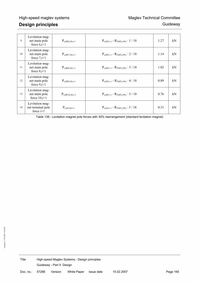
High-speed maglev systems
Design principles Maglev Technical Committee
Guideway
Title High-speed Maglev Systems - Design principles
Guideway - Part II: Design
Doc. no.: 57288 Version White Paper Issue date 15.02.2007 Page 165
Aus
druc
k: 1
3.09
.200
7 10
:42:
00
9 Levitation mag-net main pole
force 6,i+1 Pz,HP6,30,i+1 Pz,HP,i+1 - RTMTi,30% · 1 / 18 1.27 kN
10 Levitation mag-net main pole
force 7,i+1 Pz,HP7,30,i+1 Pz,HP,i+1 - RTMTi,30% · 2 / 18 1.14 kN
11 Levitation mag-net main pole
force 8,i+1 Pz,HP8,30,i+1 Pz,HP,i+1 - RTMTi,30% · 3 / 18 1.02 kN
12 Levitation mag-net main pole
force 9,i+1 Pz,HP9,30,i+1 Pz,HP,i+1 - RTMTi,30% · 4 / 18 0.89 kN
13 Levitation mag-net main pole force 10,i+1
Pz,HP10,30,i+1 Pz,HP,i+1 - RTMTi,30% · 5 / 18 0.76 kN
14 Levitation mag-net terminal pole
force i+1 Pz,EP,30,i+1 Pz,EP,i+1 - RTMTi,30% · 3 / 18 0.31 kN
Table 139 - Levitation magnet pole forces with 30% rearrangement (standard levitation magnet)

High-speed maglev systems
Design principles Maglev Technical Committee
Guideway
Title High-speed Maglev Systems - Design principles
Guideway - Part II: Design
Doc. no.: 57288 Version White Paper Issue date 15.02.2007 Page 166
Aus
druc
k: 1
3.09
.200
7 10
:42:
00
With 30% rearrangement for front and rear-mounted levitation magnets (see fig. 181) Example
1 Line load, part magnets i, i+1
iz,az,EG/MG/ZG/HG,TMTp
≥
i+1z,az,EG/MG/ZG/HG,TMTp
from equation 15
10
5
kN/m
2 Result of the
uneven distribu-tion TMTi
RTMTi,30% iz,az,EG/MG/ZG/HG,TMT sys,TMT,Bug / Heckp 30% L / 2⋅ ⋅
3.12 kN
3 Levitation mag-net terminal pole
force i Pz,EP,30,i Pz,EP,i + RTMTi,30% · 4 / 32 1.77 kN
4 Levitation mag-net main pole
force 1,i Pz,HP1,30,i Pz,HP,i + RTMTi,30% · 7 / 32 3.45 kN
5 Levitation mag-net main pole
force 2,i Pz,HP2,30,i Pz,HP,i + RTMTi,30% · 6 / 32 3.36 kN
6 Levitation mag-net main pole
force 3,i Pz,HP3,30,i Pz,HP,i + RTMTi,30% · 5 / 32 3.26 kN
7 Levitation mag-net main pole
force 4,i Pz,HP4,30,i Pz,HP,i + RTMTi,30% · 4 / 32 3.16 kN
8 Levitation mag-net main pole
force 5,i Pz,HP5,30,i Pz,HP,i + RTMTi,30% · 3 / 32 3.06 kN
9 Levitation mag-net main pole
force 6,i Pz,HP6,30,i Pz,HP,i + RTMTi,30% · 2 / 32 2.97 kN
10 Levitation mag-net main pole
force 7,i Pz,HP7,30,i Pz,HP,i + RTMTi,30% · 1 / 32 2.87 kN
11 Levitation mag-net main pole
force 8,i+1 Pz,HP8,30,i+1 Pz,HP,i+1 - RTMTi,30% · 1 / 18 1.23 kN
12 Levitation mag-net main pole
force 9,i+1 Pz,HP9,30,i+1 Pz,HP,i+1 - RTMTi,30% · 2 / 18 1.06 kN
13 Levitation mag-net main pole force 10,i+1
Pz,HP10,30,i+1 Pz,HP,i+1 - RTMTi,30% · 3 / 18 0.88 kN
14 Levitation mag-net main pole force 11,i+1
Pz,HP11,30,i+1 Pz,HP,i+1 - RTMTi,30% · 4 / 18 0.71 kN
15 Levitation mag-net main pole
Pz,HP12,30,i+1 Pz,HP,i+1 - RTMTi,30% · 5 / 18 0.54 kN

High-speed maglev systems
Design principles Maglev Technical Committee
Guideway
Title High-speed Maglev Systems - Design principles
Guideway - Part II: Design
Doc. no.: 57288 Version White Paper Issue date 15.02.2007 Page 167
Aus
druc
k: 1
3.09
.200
7 10
:42:
00
force 12,i+1
16 Levitation mag-net terminal pole
force i+1 Pz,EP,30,i+1 Pz,EP,i+1 - RTMTi,30% · 3 / 18 0.18 kN
Table 140 - Levitation magnet pole forces with 30% rearrangement (front and rear-mounted levitation magnets)

High-speed maglev systems
Design principles Maglev Technical Committee
Guideway
Title High-speed Maglev Systems - Design principles
Guideway - Part II: Design
Doc. no.: 57288 Version White Paper Issue date 15.02.2007 Page 168
Aus
druc
k: 1
3.09
.200
7 10
:42:
00
Regel-Tragmagnete
0.0
0.5
1.0
1.5
2.0
2.5
3.0
3.5
4.0
EP HP1 HP2 HP3 HP4 HP5 HP6 HP7 HP8 HP9 HP10 EP
Tragmagnetpole
Polk
raft
(kN
/Pol
) ohne 30 % mit 30 %
Fig. 180 - Levitation magnet pole forces; example of standard levitation magnets
[Key to diagram: Regel-Tragmagnete = standard levitation magnets ohne 30% = less 30% mit 30% = plus 30% Polkraft = pole force Tragmagnetpole = levitation magnet poles]
Bug-/Heck-Tragmagnete
0,0
0,5
1,0
1,5
2,0
2,5
3,0
3,5
4,0
EP HP1 HP2 HP3 HP4 HP5 HP6 HP7 HP8 HP9 HP10 HP11 HP12 EP
Tragmagnetpole
Polk
raft
(kN
/Pol
) ohne 30 % mit 30 %
Fig. 181 - Levitation magnet pole forces; example of front and rear-mounted levitation magnets

High-speed maglev systems
Design principles Maglev Technical Committee
Guideway
Title High-speed Maglev Systems - Design principles
Guideway - Part II: Design
Doc. no.: 57288 Version White Paper Issue date 15.02.2007 Page 169
Aus
druc
k: 1
3.09
.200
7 10
:42:
00
[Key to diagram: Bug-/Heck-Tragmagnete = front and rear-mounted levitation magnets ohne 30% = less 30% mit 30% = plus 30% Polkraft = pole force Tragmagnetpole = levitation magnet poles]

High-speed maglev systems
Design principles Maglev Technical Committee
Guideway
Title High-speed Maglev Systems - Design principles
Guideway - Part III: Geometry
Doc. no.: 41727 Version White Paper Issue date 15.02.2007 Page 1
Principles for the design of high-speed maglev systems
Guideway
Part III Geometry
The author has copyright over this document and all of its annexes. All rights reserved

High-speed maglev systems
Design principles Maglev Technical Committee
Guideway
Title High-speed Maglev Systems - Design principles
Guideway - Part III: Geometry
Doc. no.: 41727 Version White Paper Issue date 15.02.2007 Page 2
Distributor This document was released for publication by the Guideway Technical Committee.

High-speed maglev systems
Design principles Maglev Technical Committee
Guideway
Title High-speed Maglev Systems - Design principles
Guideway - Part III: Geometry
Doc. no.: 41727 Version White Paper Issue date 15.02.2007 Page 3
Revision history Date of release: 15.02.2007, White Paper published by the Guideway Technical Committee

High-speed maglev systems
Design principles Maglev Technical Committee
Guideway
Title High-speed Maglev Systems - Design principles
Guideway - Part III: Geometry
Doc. no.: 41727 Version White Paper Issue date 15.02.2007 Page 4
Table of contents List of diagrams

High-speed maglev systems
Design principles Maglev Technical Committee
Guideway
Title High-speed Maglev Systems - Design principles
Guideway - Part III: Geometry
Doc. no.: 41727 Version White Paper Issue date 15.02.2007 Page 5
General
Object and area of application This document sets out in detail the generally applicable technical requirements concerning the guideway geometry of the maglev train system. These design principles apply to a maglev train in accordance with the General Maglev Systems’ Act.
Document structure These design principles set out in detail the geometric requirements pertaining to the functional levels of maglev train support structures.
Requirements concerning the precise positioning of the girders are set out in the Guideway design principles for high-speed maglev systems - Part IV: Surveying. The explanatory notes concerning positional deviations, specifications and tolerances assist in a basic understanding of the construction of a maglev train guideway.
Based on the correlation between the individually stipulated limit values, taking into account the system as a whole, the limit values may be shifted in either direction. The requirements as per the Principles concerning the overall system design of high-speed maglev systems are included in the overall assessment in this regard. The limit values indicated assist in observing the travel comfort offered by the system as a whole as well as its technical requirements.
Explanatory note concerning application The document defines the permitted variations and positional deviations in the functional levels of the support structures which are to be observed in the equipped and precisely positioned states, without a live load, the only load coming from the girder’s own weight.
In a further step, taking into account the envisaged manufacturing process, the manufacturing tol-erances concerning guideway manufacture (the raw materials used in the guideway, its equipment and assembly) and maintenance shall be derived from this.
Unless expressly noted to the contrary, all data relates to a guideway under a project-specific refe-rence temperature. All data relates to the functional levels in the placed, coated state.
The stipulation of requirements in terms of guideway dimensions (e.g. limit values in terms of the permissible deviation, in combination with the guideway’s deformation) is essentially based on ex-periences with guideways which have been tested previously and their interaction with magnetic trains which are driven under test and operational conditions.
The individual permitted variations partly produce overlaps during an overall tolerance assessment. With additional tolerance stipulations or those which are independent from one another, care must be taken that the respective individual tolerance is observed or that those stipulations with smaller tolerance values have priority. If the document does not list permissible deviations of individual functional levels in terms of form and position, from the point of view of the system as a whole, there is no inducement to this end.
This case presupposes a manufacturing tolerance as per DIN ISO 2768-1 and DIN ISO 2768-2.

High-speed maglev systems
Design principles Maglev Technical Committee
Guideway
Title High-speed Maglev Systems - Design principles
Guideway - Part III: Geometry
Doc. no.: 41727 Version White Paper Issue date 15.02.2007 Page 6
Principles for the design of high-speed maglev systems This document is part of the documentation relating to high-speed maglev systems con-sisting of several design principles. The document tree is presented in fig. 1 of the Prin-ciples concerning the overall system design of high-speed maglev systems. The primary overall system design documentation and its annexes apply in a uniform manner to the documentation as a whole:
• Principles concerning the overall system design of high-speed maglev systems, do-cument number 50630, and its annexes:
• Annex 1: Abbreviations and definitions, document number 67536 [Principles for the design of high-speed maglev systems - Abbreviations and definitions]
• Annex 2: Acts, Orders, Standards and Guidelines, document number 67539 [Principles for the design of high-speed maglev systems - Standards and guide-lines]
• Annex 3: Environmental conditions, document number 67285 [Principles for the design of high-speed maglev systems - The environment]
• Annex 4: Rules for operation (driving and maintenance), document number 69061 [Principles for the design of high-speed maglev systems - Driving and maintenance]
• Annex 5: Sound, document number 72963 [Principles for the design of high-speed maglev systems - Sound]
Abbreviations and definitions The abbreviations and definitions specified in the Principles for the design of high-speed maglev systems - Abbreviations and definitions - apply.
Acts, Orders, Standards and Guidelines The normative documents listed in the Principles for the design of high-speed maglev systems - Standards and guidelines, contain stipulations which, by reference to the Principles for the design of high-speed maglev systems, become part of the same. Later amendments or revisions to these publications do not apply to dated, normative documents found in the Principles for the design of high-speed maglev systems - Standards and guidelines. Where references are not dated, the most recent version of the normative document referred to applies. The status of the standards and guidelines to be taken into consideration in a maglev train project must be laid down in a binding manner specific to the project.
Indicating requirements and their binding nature The provisions pursuant to DIN 820 were essentially applied when preparing this document. In the chapters following and the annexes to this document,
• requirements are set out in standard type and
• explanatory notes, standard values and examples are set out in italics

High-speed maglev systems
Design principles Maglev Technical Committee
Guideway
Title High-speed Maglev Systems - Design principles
Guideway - Part III: Geometry
Doc. no.: 41727 Version White Paper Issue date 15.02.2007 Page 7
(refer to the Guideway design principles for high-speed maglev systems - Part I: Principle require-ments).

High-speed maglev systems
Design principles Maglev Technical Committee
Guideway
Title High-speed Maglev Systems - Design principles
Guideway - Part III: Geometry
Doc. no.: 41727 Version White Paper Issue date 15.02.2007 Page 8
Clearances for built-in guideway fixtures The placement clearances for guideway equipment which is specific to high-speed maglev sys-tems are laid down below in figs. 182, 183 and 184 based on the Principles concerning the overall system design of high-speed maglev systems. In addition, the dimensions specified in the Annex of the Guideway design principles for high-speed maglev systems - Part I: Principle requirements, in relation to standard guideway types must be observed as standard gauges. A definition of “clearance” is to be found in the Guideway design principles for high-speed maglev systems - Part IV: Alignment.
Raumkurve
Gleitleiste GL
Seitenführschiene SFS
Gleitebene GE
Statorebene SE
( ) Werte in Klammern sind bauartspezifisch
250
1110
(R 235
.0)
Seite
nfüh
rebe
ne S
FE
1400
min. 30
305240
Fahr
weg
achs
e
653
310
15
89.5
913
(270
)
885
165
Zang
enm
aß 3
98
185
120
max. 240 max. 240
842.5
715
938
1250
1102
240
250
x 4
5°
10
285Statorpaketbefestigung
Fahrwegumgrenzung
Spurweite 2800
Freiraum für externeBordenergieversorgung
Freiraum für LSW Zu- und Ableitung
Freiraum für Ortungsbaugruppen
Freiraum für Motorwicklung
Fig. 182: Clearances for the guideway equipment which is specific to high-speed maglev systems and the support structures
[Key to diagram: Spurweite = guideway gauge Seitenführebene = lateral guide level

High-speed maglev systems
Design principles Maglev Technical Committee
Guideway
Title High-speed Maglev Systems - Design principles
Guideway - Part III: Geometry
Doc. no.: 41727 Version White Paper Issue date 15.02.2007 Page 9
Seitenführschiene = lateral guide rail Raumkurve = space curve Gleitebene = slider level Gleitleiste = slider strip Statorpaketbefestigung = stator plate attachment Fahrwegachse = guideway axis Zangenmaß = hover clearance Statorebene = stator level Fahrwegumgrenzung = guideway boundary Freiraum für externe Bordenergieversorgung = clearance for external inductive power supply Freiraum für Ortungsbaugruppen = clearance for location-finding assemblies Freiraum für LSW Zu- und Ableitung = clearance for LSW supply lines and offtakes Freiraum für Motorwicklung = clearance for motor winding Werte in Klammern sind bauartspezifisch = the values in brackets are specific to the design]

High-speed maglev systems
Design principles Maglev Technical Committee
Guideway
Title High-speed Maglev Systems - Design principles
Guideway - Part III: Geometry
Doc. no.: 41727 Version White Paper Issue date 15.02.2007 Page 10
Explanatory notes to fig. 182: 1) The guideway boundary line describes the maximum feasible wrap-around of the support
structure, including its tolerances. 2) Design-specific deviations from the guideway boundary line are only permitted once they
have been tested for compatibility with the system as a whole. 3) Provision is made for a clearance for securing the guideway equipment between that e-
quipment which is specific to high-speed maglev systems and the support structures. The si-ze of this clearance depends on the choice of mounting structure and requires a check con-firming its compatibility with the system as a whole.
Abstand UK Kragarmvon GE ist
bauartspezifisch 1)
Führ
spal
t-m
essb
erei
ch 2)
Sei
tenf
ühre
bene
SFE
Führ
spal
t-m
essb
erei
ch 2)
BefestigungSeitenführschiene-Trägerkragarm 3)
Statorebene
Seitenführschiene SFSGleitebene GE
1110 zur Raumkurve
1400 halbe Spurweite zur Raumkurve
Raumkurve
4)
5886
5286
170
Langstatormittachse
Abstand UK Kragarmvon GE ist
bauartspezifisch 1)
Führ
spal
t-m
essb
erei
ch 2)
Sei
tenf
ühre
bene
SFE
Führ
spal
t-m
essb
erei
ch 2)
BefestigungSeitenführschiene-Trägerkragarm 3)
Statorebene
Seitenführschiene SFSGleitebene GE
1110 zur Raumkurve
1400 halbe Spurweite zur Raumkurve
Raumkurve
4)
8652
86
170
Langstatormittachse
Abstand UK Kragarmvon GE ist
bauartspezifisch 1)
Führ
spal
t-m
essb
erei
ch 2)
Sei
tenf
ühre
bene
SFE
Führ
spal
t-m
essb
erei
ch 2)
BefestigungSeitenführschiene-Trägerkragarm 3)
Statorebene
Seitenführschiene SFSGleitebene GE
1110 zur Raumkurve
1400 halbe Spurweite zur Raumkurve
Raumkurve
4)
5886
5286
170
Langstatormittachse
Abstand UK Kragarmvon GE ist
bauartspezifisch 1)
Führ
spal
t-m
essb
erei
ch 2)
Sei
tenf
ühre
bene
SFE
Führ
spal
t-m
essb
erei
ch 2)
BefestigungSeitenführschiene-Trägerkragarm 3)
Statorebene
Seitenführschiene SFSGleitebene GE
1110 zur Raumkurve
1400 halbe Spurweite zur Raumkurve
Raumkurve
4)
8652
86
170
Langstatormittachse
Fig. 183: Guide span position
[Key to diagram: Langstatormittachse = centre axis of the longitudinal stator Raumkurve = space curve Seitenführschiene = lateral guide rail Gleitebene = slider level Führspaltmessbereich = guide span Befestigung Seitenführschiene-Trägerkragarm = lateral guide rail girder jib boom attachment Abstand UK Kragarm von GE ist bauartspezifisch = the distance between the bottom side of the jib boom and the slider level is specific to the design Seitenführebene = lateral guide level Statorebene = stator level zur Raumkurve = in relation to the space curve halbe Spurweite zur Raumkurve = half the guideway gauge in relation to the space curve] Explanatory notes to fig. 183:

High-speed maglev systems
Design principles Maglev Technical Committee
Guideway
Title High-speed Maglev Systems - Design principles
Guideway - Part III: Geometry
Doc. no.: 41727 Version White Paper Issue date 15.02.2007 Page 11
1) The distance between the bottom side of the jib boom and the slider level is specific to the design and is established by the type of stator plate mounting and the motor winding hou-sing.
2) The guide sensor areas depicted correspond to the position when the vehicle is hovering with a reference loadbearing gap of 10 mm.
3) The mounting for the lateral guide rails and the clearance which is required shall be stipu-lated in accordance with the particular design.
4) Centre point of the guidance magnets of the hovering vehicle with a reference loadbearing gap of 10 mm;
480
1560
1560
105
110
147.5 185 147.5
1)
50
120
R60
R60R15
Statorebene SE
Statorpaket FreiraumMotorwicklung
45°
Freiraum zur Befestigungder Statorpakete und fürErdungsbauteile
Seitenführschiene SFS
R15
Fig. 184: Long stator winding housing
[Key to diagram: Seitenführschiene = lateral guide rail Freiraum zur Befestigung der Statorpakete und für Erdungsbauteile = clearance for attaching the stator pla-tes and for earthing elements Statorpaket = stator plate Freiraum Motorwicklung = clearance for motor winding Statorebene = stator level] Explanatory notes to fig. 184:
1) The motor winding housing depicted also takes into account the space required by the motor winding cable for the assembly process. The clearances required by the mounting device lie within the vehicle’s gauge.

High-speed maglev systems
Design principles Maglev Technical Committee
Guideway
Title High-speed Maglev Systems - Design principles
Guideway - Part III: Geometry
Doc. no.: 41727 Version White Paper Issue date 15.02.2007 Page 12
Dimensional relationships, principal measuring points, reference planes and influencing variables
Functional levels and principal measuring point locations The locations of the functional levels and the associated measuring points in the x, y and z directi-ons are depicted in figs. 185, 186, 187 and 188.
y-Achse
Statorebene SE
1110
Seite
nfüh
rebe
ne S
FE
1400Fa
hrw
egac
hse
(z-A
chse
)
170
Zang
enm
aß 3
98
Spurweite 2800
2
3
5
4
6
Lang
stat
orm
itten
achs
eLA Langstatorm
ittenachseLA
Statorebene SE
Gleitebene GE
Spurweite: Messpunkt 5, 6Zangenmaß: Messpunkt 1, 3 bzw. 2, 4
170
1110
Sei
tenf
ühre
bene
SFE
1400
1
Fig. 185: Functional levels and principle measuring points in the y and z directions
[Key to diagram: Spurweite = guideway gauge Seitenführebene = lateral guide level Gleitebene = slider level Zangenmaß = hover clearance y-Achse = y-axis Statorebene = stator level Langstatormittenachse = centre axis of the longitudinal stator Fahrwegachse (z-Achse) = guideway axis (z-axis) Spurweite: Messpunkt 5, 6 = guideway gauge: measuring points 5, 6 Zangenmaß: Messpunkt 1, 3 bzw. 2, 4 = hover clearance: measuring points 1, 3 or 2, 4]

High-speed maglev systems
Design principles Maglev Technical Committee
Guideway
Title High-speed Maglev Systems - Design principles
Guideway - Part III: Geometry
Doc. no.: 41727 Version White Paper Issue date 15.02.2007 Page 13
Gleitebene GE
Seitenführebene SFE
Statorebene SE
Systemachse
letzter Vollzahn
erster Vollzahn
erster Vollzahn
Messpunkte1. Statorpaket
Messpunkte2. Statorpaket
letzter Vollzahn
letzter Vollzahn
Messpunkte3. Statorpaket
170
Zangenmaß 398
Messpunkt
Messpunkt
Bei gekürzten Trägerlängen sind Endmaße entsprechend anzupassen.
erster Vollzahn
letzter Vollzahn
erster Vollzahn
erster Vollzahn
Messpunkten. Statorpaket
Messpunkte(n-1). Statorpaket
letzter Vollzahn
letzter VollzahnMesspunkte
(n-2). Statorpaket
Systemachse
1032 (Raumkurve) 1032 (Raumkurve) 1032 (Raumkurve)
100
1032 (Raumkurve)1032 (Raumkurve)1032 (Raumkurve)
100
Fig. 186: Principal measuring points in the x and z directions
[Key to diagram: Systemachse = system axis Raumkurve = space curve Zangenmaß = hover clearance Gleitebene = slider level Seitenführebene = lateral guide level Statorebene = stator level letzter Vollzahn = last full-depth tooth erster Vollzahn = first full-depth tooth Messpunkte = measuring points Statorpaket = stator plate Bei gekürzten Trägerlängen sind Endmaße entsprechend anzupassen = with shorter girder lengths, the final dimensions shall be adapted accordingly Messpunkt = measuring point] The principal measuring point locations in the x direction (refer to fig. 186 for the longitudinal di-rection) shall be selected such that a measured value for evaluation purposes is at least established within the system grid dimension of 1032 mm. Where functional levels which have already been divided up are present, the gap dividing grid must be observed. In this instance, a measuring point shall be arranged on both sides of the gap. The first measuring point at the beginning or end of the support structure shall be placed at a uni-form distance of 100 mm from the system axis and should be durably marked.
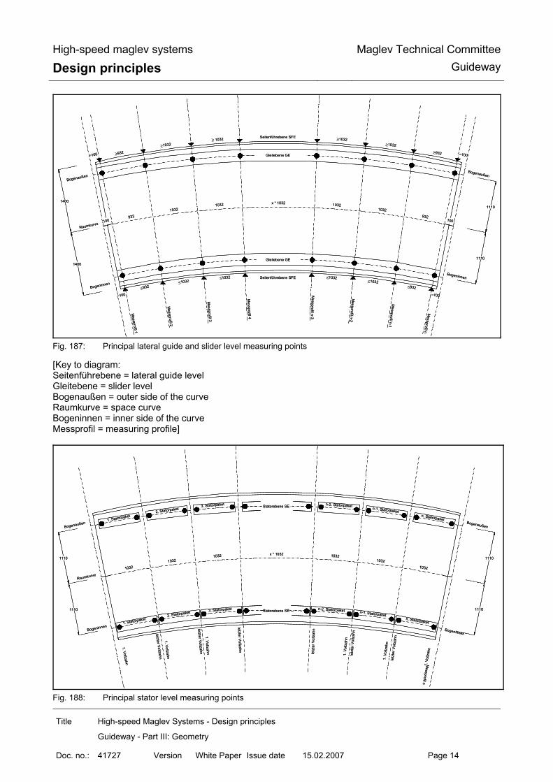
High-speed maglev systems
Design principles Maglev Technical Committee
Guideway
Title High-speed Maglev Systems - Design principles
Guideway - Part III: Geometry
Doc. no.: 41727 Version White Paper Issue date 15.02.2007 Page 14
x * 103210321032
932100
≥ 1032
≥1032
≥932=100
≤1032≤1032
≤932
=100
10321032
932100
≥1032≥1032
≥932 =100
≤1032≤1032
≤932
=100
Seitenführebene SFE
Gleitebene GE
Gleitebene GE
Seitenführebene SFE
Bogenaußen
Bogeninnen
Raumkurve
Messprofil 1
Messprofi l 2
Messpro fi l 3
Messprofil 4
Messprofil n-3
Messprofil n-2
Messprofil n-1
Messprofil n
1400
1400
Bogenaußen
Bogeninnen
1110
1110
Fig. 187: Principal lateral guide and slider level measuring points
[Key to diagram: Seitenführebene = lateral guide level Gleitebene = slider level Bogenaußen = outer side of the curve Raumkurve = space curve Bogeninnen = inner side of the curve Messprofil = measuring profile]
x * 103210321032
1032
10321032
1032
Statorebene SE
Statorebene SE
Raumkurve
1. Vollzahn
letzter Vollzahn
1. Vollzahn
letzter Vollzahn
Messprofil n
Bogenaußen
Bogeninnen
1110
Bogenaußen
Bogeninnen
1110
1110 1110
1. Vollzahn
letzter Voll zahn
1. Statorpaket2. Statorpaket 3. Statorpaket
3. Statorpaket
2. Statorpaket
1. Statorpaket
1. V
ollz
ahn
letz
ter V
ollz
ahn
1. V
ollz
ahn
l et z
ter V
ollz
ahn
1. V
ollz
ahn
letz
ter V
oll z
ahn
n. Statorpaket
n-1. Statorpaket
n-2. Statorpaket
n-2. Statorpaket n-1. Statorpaketn. Statorpaket
Fig. 188: Principal stator level measuring points

High-speed maglev systems
Design principles Maglev Technical Committee
Guideway
Title High-speed Maglev Systems - Design principles
Guideway - Part III: Geometry
Doc. no.: 41727 Version White Paper Issue date 15.02.2007 Page 15
[Key to diagram: Bogenaußen = outer side of the curve Statorpaket = stator plate Statorebene = stator level Raumkurve = space curve Bogeninnen = inner side of the curve 1. Vollzahn = first full-depth tooth letzter Vollzahn = last full-depth tooth Messprofil = measuring profile]
Requirements pertaining to principal measur-ing points and measured values The measured values determined for the principal measuring points must allow a representative statement on the location of the functional level. This means that measurement procedures and methods which are suitable for determining the measured value shall be applied which eliminate one-off influences on the measuring result (e.g. graduated edges, flaws in the material, local surface finishings, anomalies in the coating).

High-speed maglev systems
Design principles Maglev Technical Committee
Guideway
Title High-speed Maglev Systems - Design principles
Guideway - Part III: Geometry
Doc. no.: 41727 Version White Paper Issue date 15.02.2007 Page 16
Coordinate systems The tolerances given in the document relate to the coordinate axis designations
• y, x, z relate to the space curve coordinate system (girder-related sector of the space curve with a redefined zero point, see also Chapter 6.6), and
• Y, X, Z relate to the girder production coordinate system (machine-related production coordinate system taken into consideration in the design pre-curvature and production corrections which may be required).
Fig. 189 presents the correlations. As regards work on the building site (staking out, constructing foundations, precise positioning of the guideway), the coordinates of the maglev train coordinate system are used. (refer to the Guideway design principles for high-speed maglev systems - Part IV: Surveying re-garding the x, y and z coordinates in the maglev train coordinate system)
The beginning and end coordinates of the support structures from the space curve coordinate sys-tem are transformed into the maglev train coordinate system at the same time via reference points.
Fig. 189: Geometric correlation between the coordinate systems (girder production coordinate system and local
guideway coordinates)
[Key to diagram: Querneigungsdifferenz = lateral incline differential Längsneigungsdifferenz = longitudinal gradient differential Ursprung TFK im Trägerraster liegt auf Raumkurve = the zero point of the girder fabrication coordinates in the girder grid lies on the space curve globale Trägerfertigungskoordinaten (TFK) X, Y, Z Achsen rechtwinkelig zueinander, fahrwegträgerbezogen = global girder production coordinates X, Y, Z axes at right angles to one another, relative to the guideway lokale Fahrwegkoordinaten (RKK) x-Achse mit β mitdrehend y- u. z-Achse mit α mitdrehend = local guideway coordinates

High-speed maglev systems
Design principles Maglev Technical Committee
Guideway
Title High-speed Maglev Systems - Design principles
Guideway - Part III: Geometry
Doc. no.: 41727 Version White Paper Issue date 15.02.2007 Page 17
x-axis with β rotating in the same direction y- and Z-axes with α rotating in the same direction]

High-speed maglev systems
Design principles Maglev Technical Committee
Guideway
Title High-speed Maglev Systems - Design principles
Guideway - Part III: Geometry
Doc. no.: 41727 Version White Paper Issue date 15.02.2007 Page 18
System and building component lengths All measurements along the space curve which represent a multiple of 86 mm (this corresponds to a groove/tooth period according to the Principles concerning the overall system design of high-speed maglev systems) can be designated system lengths. Support structure lengths are specified when converting the route into system lengths. Their actual length (building component length) depends on the design of the functional levels at the beginning and end of the support structure, as well as the horizontal and vertical radii (see fig. 190).
Raumkurve
R
Statorachse (bogenaußen)
Systemachse Systemachse
Statorachse (bogeninnen) H
Systemlänge des Fahrwegträgers
Spalt am Trägerstoß
Bauteillänge (L)
(L )Sys
Fig. 190: Correlation between building component length and system length
[Key to diagram: Bauteilänge = building component length Systemachse = system axis Statorachse (bogenaußen) = stator axis (outer side of the curve) Systemlänge des Fahrwegträgers = system length of the support structure Raumkurve = space curve Statorachse (bogeninnen) = stator axis (inner side of the curve) Spalt am Trägerstoß = opening in the girder joint]
Sign stipulations The sign conventions facilitate a clear interpretation of the maglev train / guideway interface on the following basis: When considered from the point of view of increasing chainage (positive x direction), a negative sign always indicates a deviation towards the space curve, while a positive sign points to a deviati-on away from the same curve or towards the outside. Regarding the guideway gauge, a negative sign therefore indicates a reduction, and a positive sign an increase, in the guideway gauge. When applying the following equations, a clear direction of the deviation from the theoretical posi-tion is possible by means of the result sign. In the case of vibrations in elements, the displacement
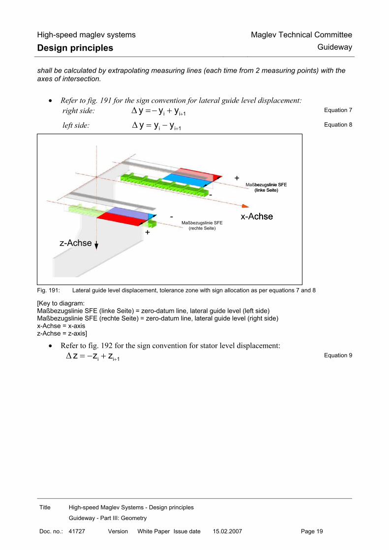
High-speed maglev systems
Design principles Maglev Technical Committee
Guideway
Title High-speed Maglev Systems - Design principles
Guideway - Part III: Geometry
Doc. no.: 41727 Version White Paper Issue date 15.02.2007 Page 19
shall be calculated by extrapolating measuring lines (each time from 2 measuring points) with the axes of intersection.
• Refer to fig. 191 for the sign convention for lateral guide level displacement: right side: +∆ = − +i i 1y y y Equation 7
left side: +∆ = −i i 1y y y Equation 8
Fig. 191: Lateral guide level displacement, tolerance zone with sign allocation as per equations 7 and 8
[Key to diagram: Maßbezugslinie SFE (linke Seite) = zero-datum line, lateral guide level (left side) Maßbezugslinie SFE (rechte Seite) = zero-datum line, lateral guide level (right side) x-Achse = x-axis z-Achse = z-axis]
• Refer to fig. 192 for the sign convention for stator level displacement: +∆ = − +i i 1z z z Equation 9
x-Achse
z-Achse
-
+Maßbezugslinie SFE
(linke Seite)
+
-Maßbezugslinie SFE
(rechte Seite)
x-Achse
z-Achse
-
+Maßbezugslinie SFE
(linke Seite)
+
-Maßbezugslinie SFE
(rechte Seite)
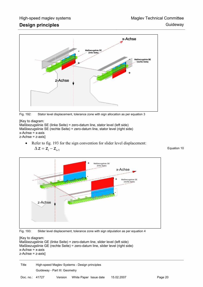
High-speed maglev systems
Design principles Maglev Technical Committee
Guideway
Title High-speed Maglev Systems - Design principles
Guideway - Part III: Geometry
Doc. no.: 41727 Version White Paper Issue date 15.02.2007 Page 20
Fig. 192: Stator level displacement, tolerance zone with sign allocation as per equation 3
[Key to diagram: Maßbezugslinie SE (linke Seite) = zero-datum line, stator level (left side) Maßbezugslinie SE (rechte Seite) = zero-datum line, stator level (right side) x-Achse = x-axis z-Achse = z-axis]
• Refer to fig. 193 for the sign convention for slider level displacement: +∆ = −i i 1z z z Equation 10
Fig. 193: Slider level displacement, tolerance zone with sign stipulation as per equation 4
[Key to diagram: Maßbezugslinie GE (linke Seite) = zero-datum line, slider level (left side) Maßbezugslinie GE (rechte Seite) = zero-datum line, slider level (right side) x-Achse = x-axis z-Achse = z-axis]
x-Achse
z-Achse
-
+
Maßbezugslinie SE(rechte Seite)
-
+
Maßbezugslinie SE(linke Seite)
x-Achse
z-Achse
-
+
Maßbezugslinie SE(rechte Seite)
-
+
Maßbezugslinie SE(linke Seite)
x-Achse
z-Achse
-
+
Maßbezugslinie SE(rechte Seite)
-
+
Maßbezugslinie SE(linke Seite)
x-Achse
z-Achse
+
-
Maßbezugslinie GE(rechte Seite)
+
-
Maßbezugslinie GE(linke Seite)
x-Achse
z-Achse
+
-
Maßbezugslinie GE(rechte Seite)
+
-
Maßbezugslinie GE(linke Seite)

High-speed maglev systems
Design principles Maglev Technical Committee
Guideway
Title High-speed Maglev Systems - Design principles
Guideway - Part III: Geometry
Doc. no.: 41727 Version White Paper Issue date 15.02.2007 Page 21
• Refer to fig. 194 for the sign convention for altering the guideway gauge (S):
+∆ = − +s i i 1y S S ; = +1 2i i iS y y Equation 11
Fig. 194: Altering the guideway gauge, tolerance zones with sign stipulation as per equation 11
[Key to diagram: Maßbezugslinie SFE (linke Seite) = zero-datum line, lateral guide level (left side) Maßbezugslinie SFE (rechte Seite) = zero-datum line, lateral guide level (right side) x-Achse = x-axis z-Achse = z-axis]
• The sign convention for the gradient-altering criterion of the lateral guide level within the girder, and at the girder joint and element transition, is extrapolated in accordance with equation 14 while observing the intervals between measuring points. Refer to fig. 195 for the graphic representation of the sign convention: right side:
i 1 i 1SFE i
y yNGK 2 * y2
− +⎡ ⎤+⎛ ⎞= − + ⎜ ⎟⎢ ⎥⎝ ⎠⎣ ⎦Equation 12
left side:
i 1 i 1SFE i
y yNGK 2 * y2
− +⎡ ⎤+⎛ ⎞= − ⎜ ⎟⎢ ⎥⎝ ⎠⎣ ⎦ Equation 13
x-Achse
z-Achse
-
+Maßbezugslinie SFE
(rechte Seite)
+
-Maßbezugslinie SFE
(linke Seite)
x-Achse
z-Achse
-
+Maßbezugslinie SFE
(rechte Seite)
+
-Maßbezugslinie SFE
(linke Seite)
x-Achse
z-Achse
-
+Maßbezugslinie SFE
(rechte Seite)
+
-Maßbezugslinie SFE
(linke Seite)

High-speed maglev systems
Design principles Maglev Technical Committee
Guideway
Title High-speed Maglev Systems - Design principles
Guideway - Part III: Geometry
Doc. no.: 41727 Version White Paper Issue date 15.02.2007 Page 22
Fig. 195: Gradient-altering criterion of the lateral guide level, tolerance zones and sign stipulation as per equations
12 and 13
[Key to diagram: Maßbezugslinie SFE (linke Seite) = zero-datum line, lateral guide level (left side) Maßbezugslinie SFE (rechte Seite) = zero-datum line, lateral guide level (right side) x-Achse = x-axis z-Achse = z-axis]
• The sign convention for the gradient-altering criterion of the stator level over four measu-ring points (first and last full-depth tooth of the stator plate numbered continuously (z1, z2, z3 and z4)). Refer to fig. 196 for the graphic representation of the sign:
( )⎡ ⎤= − + −⎣ ⎦SE 1 2 4 31000NGK (z z ) z z *860
Equation 14
Fig. 196: Gradient-altering criterion of the stator level, tolerance zones with sign allocation as per equation 14
[Key to diagram: Maßbezugslinie SE (linke Seite) = zero-datum line, stator level (left side)
x-Achse
+
-Maßbezugslinie SFE
(rechte Seite)
-
+Maßbezugslinie SFE
(linke Seite)
z-Achse
x-Achse
+
-Maßbezugslinie SFE
(rechte Seite)
-
+Maßbezugslinie SFE
(linke Seite)
z-Achse
x-Achse
+
-Maßbezugslinie SFE
(rechte Seite)
-
+Maßbezugslinie SFE
(linke Seite)
z-Achse
x-Achse
z-Achse
-
+
Maßbezugslinie SE(rechte Seite)
-
+
Maßbezugslinie SE(linke Seite)
x-Achse
z-Achse
-
+
Maßbezugslinie SE(rechte Seite)
-
+
Maßbezugslinie SE(linke Seite)
x-Achse
z-Achse
-
+
Maßbezugslinie SE(rechte Seite)
-
+
Maßbezugslinie SE(linke Seite)

High-speed maglev systems
Design principles Maglev Technical Committee
Guideway
Title High-speed Maglev Systems - Design principles
Guideway - Part III: Geometry
Doc. no.: 41727 Version White Paper Issue date 15.02.2007 Page 23
Maßbezugslinie SE (rechte Seite) = zero-datum line, stator level (right side) x-Achse = x-axis z-Achse = z-axis]
• Refer to fig. 197 for the sign convention for the gradient-altering criterion of the slider le-vel:
− +⎡ ⎤+⎛ ⎞= − ⎜ ⎟⎢ ⎥⎝ ⎠⎣ ⎦i 1 i 1
GLE iz zNGK 2 * z
2 Equation 15
Fig. 197: Gradient-altering criterion of the slider level, tolerance zones with sign allocation as per equation 15
[Key to diagram: Maßbezugslinie GE (linke Seite) = zero-datum line, slider level (left side) Maßbezugslinie GE (rechte Seite) = zero-datum line, slider level (right side) x-Achse = x-axis z-Achse = z-axis]
x-Achse
+
-
Maßbezugslinie GE(rechte Seite)
+
-
Maßbezugslinie GE(linke Seite)
z-Achse
x-Achse
+
-
Maßbezugslinie GE(rechte Seite)
+
-
Maßbezugslinie GE(linke Seite)
z-Achse
High-speed maglev systems
Design principles Maglev Technical Committee
Guideway
Title High-speed Maglev Systems - Design principles
Guideway - Part III: Geometry
Doc. no.: 41727 Version White Paper Issue date 15.02.2007 Page 24
Definitions and stipulations for tolerances and positional deviations The tolerances and positional deviations described below relate exclusively to the girder production coordinate system. Assuming a bearing arrangement, a distinction is drawn between simple beams, two-span beams and multiple span girders as well as gauge change devices. When stipulating the tolerance zones, guideway plates are treated as simple beams. In the diagrams which follow, the x-axis of the coordinate system mirrors the layout of the space curve.
Design precurvature The design precurvature is designed to compensate the deflection of the support structure in the z direction as a result of the live load (mean vehicle weight under normal load conditions as per the Guideway design principles for high-speed maglev systems - Part II: Dimensioning) and also taking into account the project-specific prevailing temperature differentials in the guideway cross-section (change in temperature between the top and bottom booms) under operating conditions. In the case of concrete girders, where necessary, consideration must be given to the creep and shrinkage cha-racteristics over the first 25-30 years (refer to the Guideway design principles for high-speed maglev systems - Part II: Dimensioning). The aim as regards the guideway functional levels arranged in the z direction is that the reference surface is as flat as possible during operation. In this connection, the progression of the design precurvature generally relates to the position of the stator level under operating conditions (the theoretical position in the operating state corresponds in this connection to the progression of the space curve). For determining the share of deformation to be taken into consideration as a result of the guideway temperature differential, a project-specific temperature change shall be stipulated (taking into ac-count, inter alia, the design of the girder and the material used in its construction, the typical day-time temperature distribution within the girder and the gradient). In the load-free theoretical position, for instance, during production (no live load, uniform building component temperature [∆ T = 0 K], the building component temperature = the project-specific reference temperature), the functional levels arranged in the z direction (stator, slider levels) are therefore deflected upwards (see fig. 198, exception: refer to fig. 203 for stipulating the gauge change devices).

High-speed maglev systems
Design principles Maglev Technical Committee
Guideway
Title High-speed Maglev Systems - Design principles
Guideway - Part III: Geometry
Doc. no.: 41727 Version White Paper Issue date 15.02.2007 Page 25
Fig. 198: Design precurvature and its proportions (the diagram does not take account of creep and shrinkage charac-
teristics)
[Key to diagram: Soll-Vorkrümmung (z i / soll); entspr. Soll-Lage der Funktionsebene, bei T= 0 K im unbelasteten Zustand = design precurvature (z i / soll); corresponding to the theoretical position of the functional level, where T = 0 K in the load-free state Soll-Lage der Statorebene im Betriebszustand (entspr. Verlauf der Raumkurve) = theoretical position of the stator level in the operating state (corresponding to the progression of the space curve) x-Achse = x-axis z-Achse = z-axis]
Design precurvature in the case of simple beams Between the girder supports, the progression of the design precurvature can be determined in the case of simple beams as per equation 16 (see also fig. 201). To stipulate the progression of the design precurvature in the support structure areas from the sup-port axes up to the beginning or end of the girder, tangents are laid at the design precurvature curve determined using support axis x values. The progression of the design precurvature in relation to the z coordinates, by way of example:
⎛ ⎞= − +⎜ ⎟
⎝ ⎠
3 4i i i
i,Soll max 3 4St St St
384 x 2 * x xz z * *120 L L L
[mm] Equation 16
Limit values for zmax = fz, Fzg – fz, ∆T o as per the Guideway design principles for high-speed
maglev systems - Part II: Dimensioning
LSt
L
LSt / 2
fz, Fzg
Soll-Vorkrümmung (z i, Soll );entspr. Soll-Lage der Funktionsebene,bei ∆T= 0 K im unbelasteten Zustand
x-Achse
z-A
chse
f z, ∆T 0
Soll-Lageder Statorebene im Betriebszustand
(entspr. Verlauf der Raumkurve)
LSt
L
LSt / 2
fz, Fzg
Soll-Vorkrümmung (z i, Soll );entspr. Soll-Lage der Funktionsebene,bei ∆T= 0 K im unbelasteten Zustand
x-Achse
z-A
chse
f z, ∆T 0
Soll-Lageder Statorebene im Betriebszustand
(entspr. Verlauf der Raumkurve)

High-speed maglev systems
Design principles Maglev Technical Committee
Guideway
Title High-speed Maglev Systems - Design principles
Guideway - Part III: Geometry
Doc. no.: 41727 Version White Paper Issue date 15.02.2007 Page 26
Design precurvature in the case of two-span beams In the case of two-span beams with the same spans, the progression of the design precurvature can be determined for each span from the existing, calculated maximum deflection of the beam where both spans are subjected to loads depending on the length of the beam and its rigidity as per equati-on 17 (see also fig. 202). The maximum deflection each time is 0.421* L St viewed from the section support axis. To stipulate the progression of the design precurvature in the areas of the guideway from the section support axes up to the beginning or end of the girder, tangents are laid at the design precurvature curve determined using support axis x values. The progression of the design precurvature of two-span beams with unequal spans or different gir-der section rigidities shall be determined in the same way for every Li. The progression of the design precurvature in relation to the z coordinates, by way of example:
⎛ ⎞= − +⎜ ⎟⎜ ⎟
⎝ ⎠i i i
3 4i i i
i,Soll max 3 4St St St
185 x 3 * x 2 * xz z * *48 L L L
[mm] Equation 17
Limit values for zmax = fz, Fzg - fz, ∆T o as per the Guideway design principles for high-speed maglev systems - Part II: Dimensioning
Design precurvature in the case of multiple span girders and gauge change devices In the case of multiple span girders, a decision shall be reached on taking into account the design precurvature depending on the elastic line which is adjusted and the resulting deflections in the z direction and the end tangent angle at the beginning and end of the girder. In the case of gauge change devices, as a rule, no design precurvature is taken into consideration.
Long-wave deviation
The definition of long-wave deviation is based, in principle, on the elastic line characteristic of the support structure to which a maximum permitted excursion (“deflection”) is assigned in both direc-tions (+/-) for each section under consideration. The following stipulations are laid down as regards the upper and lower tolerance zone limits in terms of the long-wave deviation from the theoretical position (see also figs. 201, 202 and 203):
• In the case of simple and two-span beams, the x value of the maximum long-wave deviation is consistent with the x value of the maximum theoretical guideway deformation as a result of the impact of loads.
• In the case of simple and two-span beams, the progression from the maximum point to the beginning or end of the support structure may be described by equations 18 and 19 respecti-vely.28 As regards a design precurvature in the functional level which is to be taken into considera-tion, the limits can be determined in a simplified manner according to equation 20.
• In the case of simple and two-span beams, the functions of the theoretical elastic lines bet-ween the support locations are used as a basis for determining the tolerance band for long-

High-speed maglev systems
Design principles Maglev Technical Committee
Guideway
Title High-speed Maglev Systems - Design principles
Guideway - Part III: Geometry
Doc. no.: 41727 Version White Paper Issue date 15.02.2007 Page 27
wave deviation. The beginning and end of the girder of the first or final section, as well as the support locations, shall be assigned the absolute value “0”. It is assumed that deviations from “0” which may occur during production at the support lo-cations are compensated during assembly and precise positioning.
• Determining the progression of the precurvature in the case of multiple span girder systems (> 2 sections) does not constitute part of this document.
The actual location of the long-wave deviation (see fig. 199) may be determined from the continu-ous measured values, taking the functions to be assumed as a basis (see above), using Gauss’ law of errors and the method of least squares, or by means of areal compensation. The actual progression determined in this way as a function f(x) of the functional level considered, in conjunction with the superimposed tolerance zone of the short-wave deviation reflects the maxi-mum possible deviations in terms of the continuous measured values from the actual location of the long-wave deviation.
The possible progression of the actual position of the long-wave deviation is limited in this regard by the long-wave deviation tolerance zone (see figs. 201, 202 and 203).

High-speed maglev systems
Design principles Maglev Technical Committee
Guideway
Title High-speed Maglev Systems - Design principles
Guideway - Part III: Geometry
Doc. no.: 41727 Version White Paper Issue date 15.02.2007 Page 28
Fig. 199: Correlation between continuous measured values, the actual location of the long-wave deviation and the
associated short-wave deviation limit values
[Key to diagram: Obergrenze der kurzwelligen Abweichung = upper limit for short-wave deviation diskrete Meßwerte zur Ermittlung der Ist-Lage der langwelligen Abweichung = continuous measured values for determining the actual position of the long-wave deviation Ist-Lage der langwelligen Abweichung = actual position of the long-wave deviation Untergrenze der kurzwelligen Abweichung = lower limit for short-wave deviation Soll-Lage (als Gerade dargestellt) = theoretical position (portrayed as a straight line) x-Achse = x-axis z-Achse = z-axis] When determining the long-wave deviation, the projected ∆ zi of the gusset solution (Chapter 6.6.5) must be taken into consideration when using the continuous measured values.
Long-wave deviation in the case of simple beams
The diagrams and equations below relating to the long-wave deviation tolerance zone have been drawn up in relation to the z coordinates by way of example and can be applied, by analogy, to the y coordinates. As regards simple beams, long-wave deviation progression as regards the tolerance zone is descri-bed by the following equation:
⎛ ⎞∆ = ± ∆ − +⎜ ⎟
⎝ ⎠
3 4i i i
i,Lw Lw 3 4384 x 2 * x xz max z * *120 L L L
[mm] Equation 18
X-Achse
Z-A
chs
LSt
L
LSt / 2
Ist – Lage derlangwelligen Abweichung
Obergrenze der kurzwelligen Abweichung
Untergrenze der kurzwelligen Abweichung
x-Achse
z-Ac
hse
diskrete Meßwerte zur Ermittlung derIst – Lage der langwelligen Abweichung
Soll – Lage(als Gerade dargestellt)
X-Achse
Z-A
chs
LSt
L
LSt / 2
Ist – Lage derlangwelligen Abweichung
Obergrenze der kurzwelligen Abweichung
Untergrenze der kurzwelligen Abweichung
x-Achse
z-Ac
hse
diskrete Meßwerte zur Ermittlung derIst – Lage der langwelligen Abweichung
X-Achse
Z-A
chs
LSt
L
LSt / 2
Ist – Lage derlangwelligen Abweichung
Obergrenze der kurzwelligen Abweichung
Untergrenze der kurzwelligen Abweichung
x-Achse
z-Ac
hse
diskrete Meßwerte zur Ermittlung derIst – Lage der langwelligen Abweichung
Soll – Lage(als Gerade dargestellt)

High-speed maglev systems
Design principles Maglev Technical Committee
Guideway
Title High-speed Maglev Systems - Design principles
Guideway - Part III: Geometry
Doc. no.: 41727 Version White Paper Issue date 15.02.2007 Page 29
Fig. 200: The progression and position of the long-wave deviation tolerance zone in the case of simple beams with-
out precurvature, using the example of the stator level
[Key to diagram: Obergrenze für die langwellige Abweichung = upper limit for long-wave deviation Untergrenze für die langwellige Abweichung = lower limit for long-wave deviation x-Achse = x-axis z-Achse = z-axis]
Fig. 201: The progression and position of the long-wave deviation tolerance zone in the case of simple beams with
precurvature, using the example of the stator level
[Key to diagram: Obergrenze für die langwellige Abweichung = upper limit for long-wave deviation Soll-Vorkrümmung = design precurvature
LSt
L
LSt / 2
Obergrenze für die langwellige Abweichung
Untergrenze für die langwellige Abweichung
∆ zi,Lw max ∆ zLw
x-Achse
z-A
chse
LSt
L
LSt / 2
Obergrenze für die langwellige Abweichung
Untergrenze für die langwellige Abweichung
∆ zi,Lw max ∆ zLw
x-Achse
z-A
chse
X-Achse
Z-A
chse
LSt
L
LSt / 2
max. Sollvorkrümmung
Soll-Vorkrümmung
Obergrenze für die langwellige Abweichung
Untergrenze für die langwellige Abweichung
∆ zi,Lw
max ∆ zLw
x-Achse
z-A
chse
X-Achse
Z-A
chse
LSt
L
LSt / 2
max. Sollvorkrümmung
Soll-Vorkrümmung
Obergrenze für die langwellige Abweichung
Untergrenze für die langwellige Abweichung
∆ zi,Lw
max ∆ zLw
x-Achse
z-A
chse

High-speed maglev systems
Design principles Maglev Technical Committee
Guideway
Title High-speed Maglev Systems - Design principles
Guideway - Part III: Geometry
Doc. no.: 41727 Version White Paper Issue date 15.02.2007 Page 30
max. Soll-Vorkrümmung = maximum design precurvature Untergrenze für die langwellige Abweichung = lower limit for long-wave deviation x-Achse = x-axis z-Achse = z-axis]

High-speed maglev systems
Design principles Maglev Technical Committee
Guideway
Title High-speed Maglev Systems - Design principles
Guideway - Part III: Geometry
Doc. no.: 41727 Version White Paper Issue date 15.02.2007 Page 31
Long-wave deviation in the case of two-span beams and multiple span girders as well as gauge change devices
The diagrams and equations below relating to the long-wave deviation tolerance zone have been drawn up in relation to the z coordinates by way of example and can be applied, by analogy, to the y coordinates. As regards two-span beams, long-wave deviation progression as regards the tolerance zone in the area of the beginning or end of the girder as far as the centre support is described by the following equation:
⎛ ⎞∆ = ± ∆ − +⎜ ⎟
⎝ ⎠
3 4i i i
i,Lw Lw 3 4i i i
185 x 3 * x 2 * xz max z * *48 L L L
[mm] Equation 19
The following equation is used for a simplified determination of the long-wave deviation tolerance zone in the case of bowed functional levels of simple and two-span beams between the beginning or end of the girder and the centre support:
∆ = ± i,Solli,Lw
Soll
zz
max z [mm] Equation 20
Fig. 202: The progression and position of the long-wave deviation tolerance zone in the case of two-span beams with
precurvature, using the example of the stator level
[Key to diagram: Obergrenze für die langwellige Abweichung = upper limit for long-wave deviation Soll-Vorkrümmung = design precurvature max. Soll-Vorkrümmung = maximum design precurvature
x-Achse
z-A
chse
L St 1
0,421* L St 1
Soll-Vorkrümmung
Obergrenze für die langwellige Abweichung
Untergrenze für die langwellige Abweichung
∆ z i, Lw
L St 2
max ∆ z Lw
0,421* L St 2
L = L1+ L2
max Sollvorkrümmung
x-Achse
z-A
chse
L St 1
0,421* L St 1
Soll-Vorkrümmung
Obergrenze für die langwellige Abweichung
Untergrenze für die langwellige Abweichung
∆ z i, Lw
L St 2
max ∆ z Lw
0,421* L St 2
L = L1+ L2
max Sollvorkrümmung

High-speed maglev systems
Design principles Maglev Technical Committee
Guideway
Title High-speed Maglev Systems - Design principles
Guideway - Part III: Geometry
Doc. no.: 41727 Version White Paper Issue date 15.02.2007 Page 32
Untergrenze für die langwellige Abweichung = lower limit for long-wave deviation x-Achse = x-axis z-Achse = z-axis]
Fig. 203: The progression and position of the long-wave deviation tolerance zone using the example of the stator
level of a gauge change device without design precurvature
[Key to diagram: Soll-Lage der SE (= Gradientenverlauf) = theoretical position of the stator level (= progression of the gra-dient) Obergrenze für die langwellige Abweichung = upper limit for long-wave deviation Untergrenze für die langwellige Abweichung = lower limit for long-wave deviation x-Achse = x-axis z-Achse = z-axis]
Short-wave deviation
Short-wave deviation superimposes the actual location of the long-wave deviation. It comprises all tolerances as regards material, production and placement of those elements which determine the functional levels.
All absolute values at the local measurement points of the functional area, as well as all areas be-tween the individual measurement points, must lie within its tolerance zone.
Up to the area of the immediate beginning and end of the girder, the tolerance width remains constant over the length of the support structure (see also figs. 204, 205 and 206). The design at the beginning and end of the girder is characterised by the gradient-altering criterion which is permitted there (Chapter 6.6.5).
The diagrams below relating to short-wave deviation have been drawn up in relation to the z coor-dinates by way of example and can be applied, by analogy, to the y coordinates.
Soll-Lage der SE (= Gradientenverlauf)
Obergrenze für die langwellige Abweichung
Untergrenze für die langwellige Abweichung
L St 1
L L St n
z-A
chse
x-Achse
max ∆ z i, Lw ∆ z i, Lw
Soll-Lage der SE (= Gradientenverlauf)Obergrenze für die langwellige Abweichung
Untergrenze für die langwellige Abweichung
L St 1
L L St n
z-A
chse
x-Achse
max ∆ z i, Lw ∆ z i, Lw
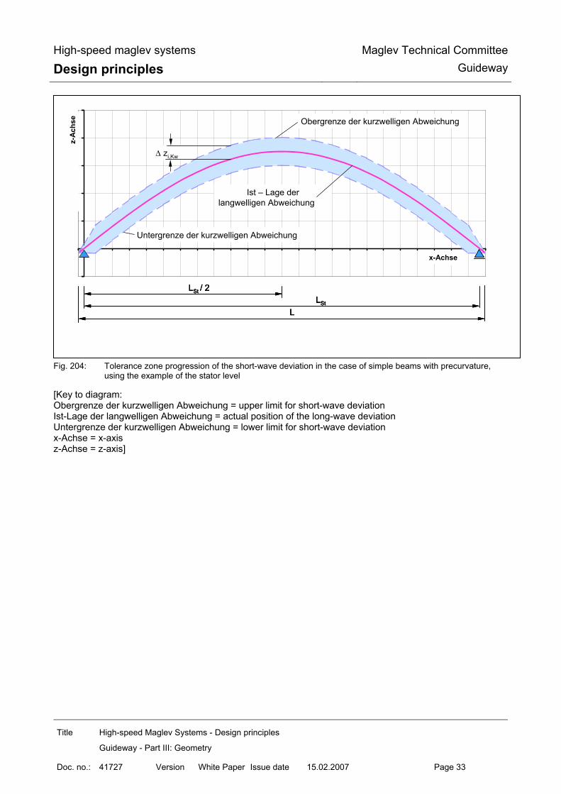
High-speed maglev systems
Design principles Maglev Technical Committee
Guideway
Title High-speed Maglev Systems - Design principles
Guideway - Part III: Geometry
Doc. no.: 41727 Version White Paper Issue date 15.02.2007 Page 33
Fig. 204: Tolerance zone progression of the short-wave deviation in the case of simple beams with precurvature,
using the example of the stator level
[Key to diagram: Obergrenze der kurzwelligen Abweichung = upper limit for short-wave deviation Ist-Lage der langwelligen Abweichung = actual position of the long-wave deviation Untergrenze der kurzwelligen Abweichung = lower limit for short-wave deviation x-Achse = x-axis z-Achse = z-axis]
X-Achse
Z-A
chs
LSt
L
LSt / 2
Ist – Lage derlangwelligen Abweichung
Obergrenze der kurzwelligen Abweichung
Untergrenze der kurzwelligen Abweichung
∆ zi,Kw
x-Achse
z-A
chse
X-Achse
Z-A
chs
LSt
L
LSt / 2
Ist – Lage derlangwelligen Abweichung
Obergrenze der kurzwelligen Abweichung
Untergrenze der kurzwelligen Abweichung
∆ zi,Kw
X-Achse
Z-A
chs
LSt
L
LSt / 2
Ist – Lage derlangwelligen Abweichung
Obergrenze der kurzwelligen Abweichung
Untergrenze der kurzwelligen Abweichung
∆ zi,Kw
x-Achse
z-A
chse

High-speed maglev systems
Design principles Maglev Technical Committee
Guideway
Title High-speed Maglev Systems - Design principles
Guideway - Part III: Geometry
Doc. no.: 41727 Version White Paper Issue date 15.02.2007 Page 34
Fig. 205: Tolerance zone progression of the short-wave deviation in the case of two-span beams with design precur-vature and reference to the actual location of the long-wave deviation, using the example of the stator level
[Key to diagram: Obergrenze der kurzwelligen Abweichung = upper limit for short-wave deviation Ist-Lage der langwelligen Abweichung = actual position of the long-wave deviation Untergrenze der kurzwelligen Abweichung = lower limit for short-wave deviation x-Achse = x-axis z-Achse = z-axis]
LSt1
L
0,421*LSt1
Ist – Lage derlangwelligen Abweichung
Untergrenze der kurzwelligen Abweichung
∆ zi, Kw
LSt2
Obergrenze der kurzwelligen Abweichung
x-Achse
z-A
chse
LSt1
L
0,421*LSt1
Ist – Lage derlangwelligen Abweichung
Untergrenze der kurzwelligen Abweichung
∆ zi, Kw
LSt2
Obergrenze der kurzwelligen Abweichung
x-Achse
z-A
chse

High-speed maglev systems
Design principles Maglev Technical Committee
Guideway
Title High-speed Maglev Systems - Design principles
Guideway - Part III: Geometry
Doc. no.: 41727 Version White Paper Issue date 15.02.2007 Page 35
Fig. 206: Tolerance zone progression of the short-wave deviation of a gauge change device with reference to the
actual location of the long-wave deviation, using the example of the stator level
[Key to diagram: Ist-Lage der langwelligen Abweichung = actual position of the long-wave deviation Soll-Lage der SE (= Gradientenverlauf) = theoretical position of the stator level (= progression of the gra-dient) Obergrenze der kurzwelligen Abweichung = upper limit for short-wave deviation Untergrenze der kurzwelligen Abweichung = lower limit for short-wave deviation x-Achse = x-axis z-Achse = z-axis]
Gradient-altering criterion The angle deviation in mm, determined at the measurement points defined under point 6.1 of two adjacent 1 m long part elements of a functional level moving lengthwise along the guideway (x a-xis), constitutes the gradient-altering criterion.
When assessing the gradient-altering criterion, the following approach shall be assumed:
When examining tolerances, a gradient-altering criterion which is to be found in the girder may be regarded as constant depending on operation and temperature.
However, the gradient-altering criterion at the girder transition has the following properties:
• a fixed girder production portion which is determined by the portion from the design pre-curvature and the tolerance range definition of the short-wave deviation at the beginning or end of the girder,
• additionally, a variable portion which is dependent on the deformation of the girder under the effects of load and temperature at the place of installation during the period of operati-on.
This means that, depending on the deformation characteristics of the girder, the tolerance zones for short-wave deviation at the beginning or end of the girder shall be stipulated in observance of the system-related contractual limit values (refer to the Principles concerning the overall system design of high-speed maglev systems).
Soll-Lage der SE (= Gradientenverlauf)
L St 1
L L St n
z-A
chse
x-Achse
Obergrenze der kurzwelligen Abweichung
Untergrenze der kurzwelligen Abweichung
Ist - Lage der langwelligen Abweichung
∆ z i, Kw
Soll-Lage der SE (= Gradientenverlauf)
L St 1
L L St n
z-A
chse
x-Achse
Obergrenze der kurzwelligen Abweichung
Untergrenze der kurzwelligen Abweichung
Ist - Lage der langwelligen Abweichung
∆ z i, Kw
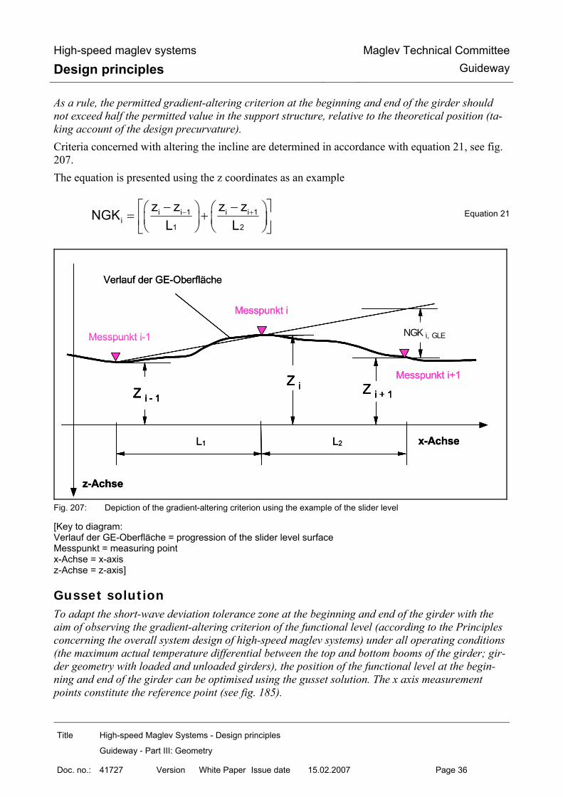
High-speed maglev systems
Design principles Maglev Technical Committee
Guideway
Title High-speed Maglev Systems - Design principles
Guideway - Part III: Geometry
Doc. no.: 41727 Version White Paper Issue date 15.02.2007 Page 36
As a rule, the permitted gradient-altering criterion at the beginning and end of the girder should not exceed half the permitted value in the support structure, relative to the theoretical position (ta-king account of the design precurvature). Criteria concerned with altering the incline are determined in accordance with equation 21, see fig. 207. The equation is presented using the z coordinates as an example
− +⎡ ⎤− −⎛ ⎞ ⎛ ⎞= +⎜ ⎟ ⎜ ⎟⎢ ⎥⎝ ⎠ ⎝ ⎠⎣ ⎦i i 1 i i 1
i1 2
z z z zNGKL L
Equation 21
NGK i, GLE
Z i - 1
Z i Z i + 1
L1
Verlauf der GE-Oberfläche
NGK i, GLEMesspunkt i-1
Z i - 1
Z i Z i + 1
L2
z-Achse
x-Achse
Messpunkt i
Messpunkt i+1
NGK i, GLE
Z i - 1
Z i Z i + 1
L1
Verlauf der GE-Oberfläche
NGK i, GLEMesspunkt i-1
Z i - 1
Z i Z i + 1
L2
z-Achse
x-Achse
Messpunkt i
Messpunkt i+1
Fig. 207: Depiction of the gradient-altering criterion using the example of the slider level
[Key to diagram: Verlauf der GE-Oberfläche = progression of the slider level surface Messpunkt = measuring point x-Achse = x-axis z-Achse = z-axis]
Gusset solution To adapt the short-wave deviation tolerance zone at the beginning and end of the girder with the aim of observing the gradient-altering criterion of the functional level (according to the Principles concerning the overall system design of high-speed maglev systems) under all operating conditions (the maximum actual temperature differential between the top and bottom booms of the girder; gir-der geometry with loaded and unloaded girders), the position of the functional level at the begin-ning and end of the girder can be optimised using the gusset solution. The x axis measurement points constitute the reference point (see fig. 185).

High-speed maglev systems
Design principles Maglev Technical Committee
Guideway
Title High-speed Maglev Systems - Design principles
Guideway - Part III: Geometry
Doc. no.: 41727 Version White Paper Issue date 15.02.2007 Page 37
The gusset solution is currently only applied at the stator level, depending on the rigidity of the girder in the z direction.
The procedure, in principle, for stipulating the theoretical position is evident from fig. 208.
Fig. 208: Gusset solution design in the stator level
[Key to diagram: System-Achse am Trägerstoß = system axis at the girder joint Verlauf der Soll-Vorkrümmung unter Berücksichtigung der Zwickellösung = progression of the design precur-vature, taking into account the gusset solution Verlauf der Soll-Vorkrümmung = progression of the design precurvature x-Achse = x-axis z-Achse = z-axis]
Fig. 209: Short-wave deviation progression of the stator level at the girder transition when applying the gusset solu-
tion
[Key to diagram: Verlauf der Soll-Vorkrümmung am Trägerstoß, unter Berücksichtigung der Zwickellösung = progression of the design precurvature along the girder joint, taking into account the gusset solution
X - A c h s e
Verlauf der Soll-Vorkrümmung x-Achse
z-A
chse
Verlauf der Soll-Vorkrümmungunter Berücksichtigung der Zwickellösung
max ∆ Z i,Zw
∆ Z i+1,Zw
System-Achse am Trägerstoß
∆ Z i -1,Zw
X - A c h s e
Verlauf der Soll-Vorkrümmung x-Achse
z-A
chse
Verlauf der Soll-Vorkrümmungunter Berücksichtigung der Zwickellösung
max ∆ Z i,Zw
∆ Z i+1,Zw
System-Achse am Trägerstoß
∆ Z i -1,Zw
X - A c h s e
Verlauf der Soll-Vorkrümmung x-Achse
z-A
chse
Verlauf der Soll-Vorkrümmungunter Berücksichtigung der Zwickellösung
max ∆ Z i,Zw
∆ Z i+1,Zw
System-Achse am Trägerstoß
∆ Z i -1,Zw
X - A c h s e
Z-A
ch
x-Achse
z-A
chse Verlauf der kurzwelligen Abweichung
am Trägerstoßunter Berücksichtigung der Zwickellösung
∆ Zi,Kw
∆ Zi,Kw
Verlauf der Soll-Vorkrümmungam Trägerstoß
unter Berücksichtigung der Zwickellösung
Z-Achse entspr. System-Achse am Trägerstoß
X - A c h s e
Z-A
ch
x-Achse
z-A
chse Verlauf der kurzwelligen Abweichung
am Trägerstoßunter Berücksichtigung der Zwickellösung
∆ Zi,Kw
∆ Zi,Kw
Verlauf der Soll-Vorkrümmungam Trägerstoß
unter Berücksichtigung der Zwickellösung
Z-Achse entspr. System-Achse am Trägerstoß
X - A c h s e
Z-A
ch
x-Achse
z-A
chse Verlauf der kurzwelligen Abweichung
am Trägerstoßunter Berücksichtigung der Zwickellösung
∆ Zi,Kw
∆ Zi,Kw
Verlauf der Soll-Vorkrümmungam Trägerstoß
unter Berücksichtigung der Zwickellösung
Z-Achse entspr. System-Achse am Trägerstoß

High-speed maglev systems
Design principles Maglev Technical Committee
Guideway
Title High-speed Maglev Systems - Design principles
Guideway - Part III: Geometry
Doc. no.: 41727 Version White Paper Issue date 15.02.2007 Page 38
Verlauf der kurzwelligen Abweichung am Trägerstoß, unter Berücksichtigung der Zwickellösung = progressi-on of the short-wave deviation along the girder joint, taking into account the gusset solution Z-Achse entspr. System-Achse am Trägerstoß = z-axis corresponding to the system axis at the girder joint x-Achse = x-axis z-Achse = z-axis] Giving consideration to the gusset solution at the time the girder is manufactured leads to a displa-cement of the short-wave deviation tolerance zone in the girder start and end area, see fig. 209.
Displacement The difference between the absolute values of two adjacent functional level elements at the immedi-ate transition is designated as displacement, see figs. 210 and 211.
Fig. 210: Presentation of negative displacement at the lateral guide rail level with superimposed gradient-altering criterion
[Key to diagram: Versatz = displacement NGK = gradient-altering criterion x-Achse = x-axis y-Achse = y-axis]
Vers
atz
„∆
y “
x - Achse
y -A
chse
NGK/2
Vers
atz
„∆
y “
x - Achse
y -A
chse
NGK/2
x - Achse
y -A
chse
NGK/2

High-speed maglev systems
Design principles Maglev Technical Committee
Guideway
Title High-speed Maglev Systems - Design principles
Guideway - Part III: Geometry
Doc. no.: 41727 Version White Paper Issue date 15.02.2007 Page 39
Fig. 211: Presentation of positive displacement at the lateral guide rail level with superimposed gradient-altering
criterion
[Key to diagram: Versatz = displacement NGK = gradient-altering criterion x-Achse = x-axis y-Achse = y-axis]
Tilting Functional level torsion at the measurement point (fig. 185) around the functional level longitudi-nal axis (x axis) is described as tilting.
Lateral incline tolerance If a functional level or geometric parameter, such as the lateral incline of the guideway, is made up of two or more part areas (e.g. right and left stator levels), the lateral incline tolerance reflects the deviation in the mean actual locations (e.g. zi,Ist) of the respective part areas at the same reference point xi, from the theoretical position.
The lateral incline tolerance is only defined within the girder and comprises the actual progressions of the short-wave deviation tolerance range of the functional levels in question.
Superimposition of tolerances and positional deviations The positional deviations and tolerances listed in the preceding chapters are defined in relation to the measurement point each time. Consequently, displacement which is considered, for instance, over the entire extension of the functional level in the y direction, is the sum of the displacement portions and the associated tilting portion (see fig. 212). Gradient-altering criteria values only reflect the actual angle deviation of adjacent functional le-vels, excluding any additional displacements which may be present (see figs. 210 and 211).
x - Achsey
-Ach
seVe
rsat
z „∆
y “
NGK/2x - Achse
y -A
chse
Vers
atz
„∆
y “
NGK/2

High-speed maglev systems
Design principles Maglev Technical Committee
Guideway
Title High-speed Maglev Systems - Design principles
Guideway - Part III: Geometry
Doc. no.: 41727 Version White Paper Issue date 15.02.2007 Page 40
y - Achse
z -A
chse
Verkippung „ ∆ α“bezogen auf den
Meßpunkt
Versatz „ ∆ z “bezogen auf den
Meßpunkte
max. Versatz „ ∆ z “über die Breite der
Funktionsebene
FunktionsebeneMeßpunkt (Kap. 5.1)
y - Achse
z -A
chse
Verkippung „ ∆ α“bezogen auf den
Meßpunkt
Versatz „ ∆ z “bezogen auf den
Meßpunkte
max. Versatz „ ∆ z “über die Breite der
Funktionsebene
FunktionsebeneMeßpunkt (Kap. 5.1)
y - Achse
z -A
chse
Verkippung „ ∆ α“bezogen auf den
Meßpunkt
Versatz „ ∆ z “bezogen auf den
Meßpunkte
max. Versatz „ ∆ z “über die Breite der
Funktionsebene
FunktionsebeneMeßpunkt (Kap. 5.1)
y - Achse
z -A
chse
Verkippung „ ∆ α“bezogen auf den
Meßpunkt
Versatz „ ∆ z “bezogen auf den
Meßpunkte
max. Versatz „ ∆ z “über die Breite der
Funktionsebene
FunktionsebeneMeßpunkt (Kap. 5.1)
Fig. 212: Superimposition of displacement and tilting along the same adjacent functional levels (e.g. in the case of stator plates in the stator level)
[Key to diagram: Verkippung “ α” bezogen auf den Meßpunkt = tilting “ α” relative to the measuring point max. Versatz “ z” über die Breite der Funktionsebene = maximum displacement “ z” over the width of the functional level Versatz “ z” bezogen auf den Meßpunkt = displacement “ z” relative to the measuring point Funktionsebene = functional level Meßpunkt (Kap. 5.1) = measuring point (chapter 5.1) y-Achse = y-axis z-Achse = z-axis] The mutual influence exerted by the individual positional deviations and tolerances is presented in summary form in the following chapters in relation to the functional levels each time.
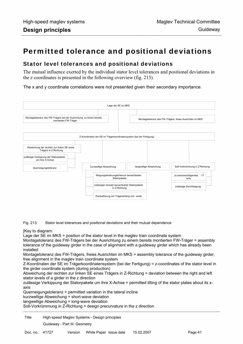
High-speed maglev systems
Design principles Maglev Technical Committee
Guideway
Title High-speed Maglev Systems - Design principles
Guideway - Part III: Geometry
Doc. no.: 41727 Version White Paper Issue date 15.02.2007 Page 41
Permitted tolerance and positional deviations
Stator level tolerances and positional deviations The mutual influence exerted by the individual stator level tolerances and positional deviations in the z coordinates is presented in the following overview (fig. 213).
The x and y coordinate correlations were not presented given their secondary importance.
Fig. 213: Stator level tolerances and positional deviations and their mutual dependence
[Key to diagram: Lage der SE im MKS = position of the stator level in the maglev train coordinate system Montagetoleranz des FW-Trägers bei der Ausrichtung zu einem bereits montierten FW-Träger = assembly tolerance of the guideway girder in the case of alignment with a guideway girder which has already been installed Montagetoleranz des FW-Trägers, freies Ausrichten im MKS = assembly tolerance of the guideway girder, free alignment in the maglev train coordinate system Z-Koordinaten der SE im Trägerkoordinatensystem (bei der Fertigung) = z-coordinates of the stator level in the girder coordinate system (during production) Abweichung der rechten zur linken SE eines Trägers in Z-Richtung = deviation between the right and left stator levels of a girder in the z direction zulässige Verkippung der Statorpakete um ihre X-Achse = permitted tilting of the stator plates about its x-axis Querneigungstoleranz = permitted variation in the lateral incline kurzwellige Abweichung = short-wave deviation langwellige Abweichung = long-wave deviation Soll-Vorkrümmung in Z-Richtung = design precurvature in the z direction
Lage der SE im MKS
Montagetoleranz des FW-Trägers, freies Ausrichten im MKSMontagetoleranz des FW-Trägers bei der Ausrichtung zu einem bereits montierten FW-Träger
Z-Koordinaten der SE im Trägerkoordinatensystem (bei der Fertigung)
Abweichung der rechten zur linken SE eines Trägers in Z-Richtung
zulässige Verkippung der Statorpakete um ihre X-Achse
zulässiger Versatz benachbarter Statorpakete in Z-Richtung
Zwickellösung am Trägeranfang und -ende
langwellige Abweichungkurzwellige Abweichung
Neigungsänderungskriterium benachbarter Statorpakete
Soll-Vorkrümmung in Z-Richtung
zu berücksichtigendes ∆T to/tu
zulässige Durchbiegung
Querneigungstoleranz

High-speed maglev systems
Design principles Maglev Technical Committee
Guideway
Title High-speed Maglev Systems - Design principles
Guideway - Part III: Geometry
Doc. no.: 41727 Version White Paper Issue date 15.02.2007 Page 42
Neigungsänderungskriterium benachbarter Statorpakete = gradient-altering criterion of adjacent stator plates zu berücksichtigendes T to/tu = T to/tu to be considered zulässiger Versatz benachbarter Statorpakete in Z-Richtung = permitted displacement in adjacent stator plates in the z direction zulässige Durchbiegung = permitted bending Zwickellösung am Trägeranfang und –ende = spandrel solution at the beginning and end of the girder]
Permitted positional deviation of the stator plates in the x direction The theoretical position of the individual stator plates in the support structure and, consequently, their positioning in the x direction, are stipulated in relation to the project, taking into consideration the Principles concerning the overall system design of high-speed maglev systems. Moreover, at the support structure crossovers, the envisaged position of the motor winding cable must be observed. The manufacturing tolerances for incorporating the stator plates shall be selected in such a way that when observing the stipulations set out in the Guideway design principles for high-speed maglev systems - Part II: Dimensioning (guideway load and deformation), adjacent stator plates in the x direction shall remain free from contact. In the girder section, the mechanical gaps at the sides of the stator plates should be 0.5 to 2 mm.

High-speed maglev systems
Design principles Maglev Technical Committee
Guideway
Title High-speed Maglev Systems - Design principles
Guideway - Part III: Geometry
Doc. no.: 41727 Version White Paper Issue date 15.02.2007 Page 43
Permitted positional deviation of the centre axis of the longitudinal stator in the y direction The permitted positional deviation of the centre axis of the longitudinal stator (see fig. 185) in the y direction in relation to the theoretical position is uniformly
mmy 2max ±=∆
Stator level tolerances in the z direction
Design precurvature The theoretical progression between the support axes of simple and two-span beams can be deter-mined in accordance with equations 16 or 17. Similar equations concerning deflection shall be used for multiple span elements. The deflection which is characteristic of the respective girder under a vehicle load shall be calculated as zmax. The permitted deflection is determined in accordance with the Guideway design principles for high-speed maglev systems - Part II: Dimensioning. When calculating the design precurvature, consideration must be given to the deformation in the girder as a result of the difference in temperature within the girder cross-section ∆TBe according to the Guideway design principles for high-speed maglev systems - Part II: Dimensioning.
Long-wave deviation in the stator level The long-wave deviation tolerance zone progression relative to the progression of the design pre-curvature is described as follows depending on the design of the girder: Simple beams
< <Trägeranfang i Trägerendex x x ∆ i,Lwz ⇒ equations 18 or 20
Two-span beams
1Trägeranfang i Lx x x≤ ≤ ∆ i,Lwz ⇒ equations 19 or 20
2L i Trägerendex x x≤ ≤ ∆ i,Lwz ⇒ equations 19 or 20
When using equations 18 and 19 to determine the upper and lower limits ∆ =Lwmax z 1mm shall be used.

High-speed maglev systems
Design principles Maglev Technical Committee
Guideway
Title High-speed Maglev Systems - Design principles
Guideway - Part III: Geometry
Doc. no.: 41727 Version White Paper Issue date 15.02.2007 Page 44
Multiple span girders (gauge change devices)
1Trägeranfang i Lx x x≤ ≤ ∆ i,Lwz ⇒ follows the mathematical description of the elastic line *
1 nL i Lx x x≤ ≤ ∆ i,Lwz ⇒ follows the mathematical description of the elastic line *
nL i Trägerendex x x≤ ≤ ∆ i,Lwz ⇒ follows the mathematical description of the elastic line *
* see Chapter 6.6.2; i,Lwmax z 1mm∆ = i = number of sections
Short-wave deviation in relation to the actual location of the stator level (long-wave devia-tion), tolerances at the girder joint
The short-wave deviation tolerance zone progression relative to the progression of the actual long-wave deviation is described by the following basic data in a standard manner for the simple beam and multiple span girder:
Trägeranfangx ; Trägerendex ∆ =z 0
+< <Trägeranfang i 0 n*1032x x x ; − < <L n*1032 i Trägerendex x x , n = 1, 2..* ∆ ≤ ±iz 1mm
+ −< <0 n*1032 i L n*1032x x x ∆ = ±z 1mm
* n shall be stipulated in observance of the maximum permitted gradient-altering criterion
Gradient-altering criterion within the short-wave deviation
Within the short-wave deviation tolerance zone, to protect the proximity relation, a gradient-altering criterion of
SENGK 1,5mm≤ must be observed in the stator level. For determining the tolerance zone progression of the stator level at the beginning and end of the girder (girder transition), consideration must be given to the system-related limit values set out in the Principles concerning the overall system design of high-speed maglev systems and the permit-ted limit values from the Guideway design principles for high-speed maglev systems - Part II: Di-mensioning. Relative to the theoretical progression of the functional level, a gradient-altering criterion of SE,Anfang;EndeNGK 0,75mm≤ shall be specified as a starting point. As regards the gradient-altering criterion to be defined at these points for inspection and acceptance measurements, the measurement conditions and references must be specified unconditionally.

High-speed maglev systems
Design principles Maglev Technical Committee
Guideway
Title High-speed Maglev Systems - Design principles
Guideway - Part III: Geometry
Doc. no.: 41727 Version White Paper Issue date 15.02.2007 Page 45
Permitted stator level displacements / tilting The following tolerances relate to the measurement points according to fig. 185. In the x direction, the first and last full-depth tooth of the adjacent stator plates are used as the measurement point each time (see Chapter 6.1). The tolerances are the same for all guideway designs.
• Displacements: within the girder ∆ =
maxiz 0,4mm
at the girder joint ∆ =maxiz 0,6mm
Displacement at the girder joint in this regard is purely an assembly tolerance which is only adjusted following precise positioning of the girder. The maximum permitted displacement of the stator level in the event of the failure of the primary fixing device must be stipulated in relation to the specific project.
• tilting (relative to the measurement point in the centre axis of the longitudinal stator):
( )∆ α = ±maxSE arctan 0,2mm/ 92,5mm
Stator level lateral incline tolerance The lateral incline tolerance is only defined for simple and two-span beams.
Trägeranfangx ; Trägerendex ∆ α = °0 shall be set for calculation purposes
< <Trägeranfang i Trägerendex x x ( )∆ α = ±max arctan 2mm/1110mm * * only permitted on condition that the tolerances are observed for each individual stator level to be considered.
Lateral guide rail level tolerances and positional deviations The position of the two lateral guide levels is decisive as regards the horizontal alignment (guide-way guidance) of the maglev train. Both levels are joined via the guideway gauge. The theoretical position in the girder production coordinate system is determined by the position of the guideway’s centre axis. The mutual influence exerted by the individual tolerances and positional deviations in the y coordi-nates is presented in the following overview (fig. 214). The x and z coordinate correlations were not presented given their secondary importance.

High-speed maglev systems
Design principles Maglev Technical Committee
Guideway
Title High-speed Maglev Systems - Design principles
Guideway - Part III: Geometry
Doc. no.: 41727 Version White Paper Issue date 15.02.2007 Page 46
Fig. 214: Lateral guide level tolerances and positional deviations and their mutual dependence
[Key to diagram: Lage der SFE im MKS = position of the lateral guide rail level in the maglev train coordinate system Montagetoleranz des FW-Trägers bei der Ausrichtung zu einem bereits montierten FW-Träger = assembly tolerance of the guideway girder in the case of alignment with a guideway girder which has already been installed Montagetoleranz des FW-Trägers, freies Ausrichten im MKS = assembly tolerance of the guideway girder, free alignment in the maglev train coordinate system Abrückung = retraction Y-Koordinaten der SFE im Trägerkoordinatensystem (bei der Fertigung) = Y coordinates of the lateral guide rail level in the girder coordinate system (during production) Abweichung der rechten zur linken SFE eines Trägers in Y-Richtung = deviation between the right and left lateral guide rail levels of a girder in the Y direction Spurweitentoleranz = guideway gauge tolerance Spurweitentoleranz am Trägeranfang und Ende = guideway gauge tolerance at the beginning and end of the girder zulässige Verkippung der SFE um ihre X-Achse = permitted tilting of the lateral guide rail level about its x-axis kurzwellige Abweichung = short-wave deviation langwellige Abweichung = long-wave deviation Neigungsänderungskriterium am Anfang und Ende der SFE = gradient-altering criterion at the beginning and end of the lateral guide rail level Neigungsänderungskriterium benachbarter Seitenführschienenelemente = gradient-altering criterion of adja-cent lateral guide rail elements zulässiger Versatz benachbarter Seitenführschienenelemente in Y-Richtung = permitted displacement in adjacent lateral guide rail elements in the Y direction]
Lage der SFE im MKS
Montagetoleranz des FW-Trägers, freies Ausrichten im MKSMontagetoleranz des FW-Trägers bei der Ausrichtung zu einem bereits
montierten FW-Träger
Y-Koordinaten der SFE im Trägerkoordinatensystem (bei der Fertigung)
Abweichung der rechten zur linken SFE eines Trägers in Y-Richtung
zulässige Verkippung der SFE um ihre X-Achse
zulässiger Versatz benachbarter Seitenführschienenelemente in Y-Richtung
langwellige Abweichungkurzwellige Abweichung
Neigungsänderungskriterium benachbarter Seitenführschienenelemente
Spurweitentoleranz
Neigungsänderungskriterium am Anfang und Ende der SFE
Spurweitentoleranz am Trägeranfang und Ende
Abrückung

High-speed maglev systems
Design principles Maglev Technical Committee
Guideway
Title High-speed Maglev Systems - Design principles
Guideway - Part III: Geometry
Doc. no.: 41727 Version White Paper Issue date 15.02.2007 Page 47
Lateral guide rail level tolerances in the x direction To determine the minimum gap at the support structure crossover, i.e. the gap to the system axis, the heat expansion of the guideway elements under the Guideway design principles for high-speed maglev systems - Part II: Dimensioning, the arrangement of the fixed and movable bearings and the permitted substructure deformation as per the Principles concerning the overall system design of high-speed maglev systems must be taken into consideration. The following standard values are specified: The gap between the start or end of the element and the system axes are as follows:
Support structure (12 m ≤ system length ≤ 25 m) A,Ex 20mm∆ =
Guideway plates (system length ≤ 6 m) A,Ex 10mm∆ =
Intermediate parameters shall be explained in accordance with the introductory remarks. For all support structure crossovers, the aim shall be to have girder joints of equal size at a defined reference temperature. In the case of interruptions to the lateral guide rail level in the support structure which are the result of its design (e.g. with a modular design), the positional stability and form deviation of the lateral guide rail level attachment must be taken into consideration when determining the theoretical gap widths. In the case of deflections, the required minimum gap between the lateral guide rail level elements is determined in accordance with equation 22, taking into account the deformations in the bending position.
( )M M H Hx L L * R S / 2 /R 2∆ ≥ − − + [mm] Equation 22
A collision between like, adjacent functional level elements must be avoided. The joints in the lateral guide rail level shall be designed in accordance with fig. 215.

High-speed maglev systems
Design principles Maglev Technical Committee
Guideway
Title High-speed Maglev Systems - Design principles
Guideway - Part III: Geometry
Doc. no.: 41727 Version White Paper Issue date 15.02.2007 Page 48
Fig. 215: Surface design of the lateral guide rail level at the girder joint or in the event of interruptions
[Key to diagram: Spalt = opening x-Achse = x-axis y-Achse = y-axis]
Positional deviation of the lateral guide rail level in the y direction
Theoretical position The theoretical position of the two lateral guide rail levels is specified by the routing. Long-wave deviation tolerance zone progression relates to these theoretical positions. The following data per-taining to long- and short-wave deviation relates to every individual lateral guide rail level. The compulsorily existing dependency of the actual positions of the two long-wave deviations is not taken into consideration with a view to observing the guideway gauge tolerance. Possible deformation as a result of the vehicle load impact and temperature differences in the guideway are disregarded when determining the theoretical position of the lateral guide rail level.
Long-wave deviation in the lateral guide rail level
Long-wave deviation tolerance zone progression is described as follows depending on the design of the girder: Simple beams
Trägeranfang i Trägerendex x x< < i,Lwy∆ as per equation 18 *
≤ ∆ =
> ∆ =Lw
Lw
* L 12384 max y 1,0L 12384 max y L * 2,0 / 24768
[mm]
22 mm
∆ X
R 7
0 m
m x - Achsey
-Ach
se
Spalt
22 mm
∆ X
R 7
0 m
m x - Achsey
-Ach
se
Spalt

High-speed maglev systems
Design principles Maglev Technical Committee
Guideway
Title High-speed Maglev Systems - Design principles
Guideway - Part III: Geometry
Doc. no.: 41727 Version White Paper Issue date 15.02.2007 Page 49
Two-span beams
Trägeranfang i 1x x L≤ ≤ i,Lwy∆ as per equation 19 *
2 i TrägerendeL x x≤ ≤ i,Lwy∆ as per equation 19 **
≤ ∆ =
> ∆ =1 Lw
1 Lw 1
* L 12384 max y 1,0L 12384 max y L * 2,0 / 24768
[mm]
≤ ∆ =
> ∆ =1 Lw
1 Lw 2
* * L 12384 max y 1,0L 12384 max y L * 2,0 / 24768
[mm]
Multiple span girders (gauge change devices)
Trägeranfang i 1x x L≤ ≤ i,Lwy∆ ⇒ follows the mathematical description of the elastic line *
2 i n 1L x L −< < i,Lwy∆ ⇒ follows the mathematical description of the elastic line *
n i TrägerendeL x x≤ ≤ i,Lwy∆ ⇒ follows the mathematical description of the elastic line *
≤ ∆ =
> ∆ =i Lw
i Lw i
* L 12384 max y 1,0L 12384 max y L * 2,0 / 24768
[mm]
i = 1,...n see Chapter 6.6.2;
Short-wave deviation in relation to the actual location of the lateral guide rail level (long-wave deviation), tolerances at the girder joint
Short-wave deviation tolerance zone progression relative to the actual progression of the long-wave deviation is described by the following basic data in a standard manner for the simple beam and multiple span girder:
Trägeranfangx ; Trägerendex y 0∆ =
Trägeranfang i 0 n*1032x x x +< < ;
L n*1032 i Trägerendex x x− < < n 1,2... *= iy 2mm∆ ≤ ±
0 n*1032 i L n*1032x x x+ −< < y 2mm∆ = ±
* n shall be stipulated in observance of the maximum permitted gradient-altering criterion

High-speed maglev systems
Design principles Maglev Technical Committee
Guideway
Title High-speed Maglev Systems - Design principles
Guideway - Part III: Geometry
Doc. no.: 41727 Version White Paper Issue date 15.02.2007 Page 50
Within the short-wave deviation tolerance zone, the following proximity relation must be observed in the lateral guide rail level:
SFENGK 2,0mm≤
For determining the tolerance zone progression of the lateral guide rail level at the beginning and end of the girder (girder transition), a gradient-altering criterion, relative to the theoretical position, of
SFE,Anfang;EndeNGK 1,0mm≤
shall be calculated. The permitted limit values set out in the Guideway design principles for high-speed maglev systems - Part II: Dimensioning, must be observed in this regard. As regards the gradient-altering criterion to be defined at these points for inspection and acceptance measurements, the measurement conditions must be specified.
Permitted lateral guide rail level displacements / tilting The following tolerances relate to the measurement points according to fig. 185 and the stipulations concerning the choice of the pertinent x coordinates. The tolerances listed below are the same for all types of guideway.
- Displacements: within the girder maxiy 0,6mm *∆ =
* the assumed segment length in this regard is 6 m, With different lengths, the value shall be taken from the diagram below:

High-speed maglev systems
Design principles Maglev Technical Committee
Guideway
Title High-speed Maglev Systems - Design principles
Guideway - Part III: Geometry
Doc. no.: 41727 Version White Paper Issue date 15.02.2007 Page 51
Fig. 216: Permitted displacements in the lateral guide rail level within a support structure depending on the segment
lengths of the lateral guides
[Key to diagram: zulässiger Versatz am Segmentstoß = permitted displacement at the segment joint Segmentlänge = segment length]
at the girder joint maxiy 1,0mm∆ =
Displacement at the girder joint is adjusted following precise positioning of the girder and presupposes a guideway gauge tolerance of ± 1mm (see point 6.7.2.3).
- tilting (relative to the measurement point):
within the girder ∆ α = ±maxSFE arctan(1,0mm/155mm)
inside, at lateral guide rail level joints maxSFE arctan(0,7mm/155mm)∆ α = ±
at the girder joint maxSFE arctan(0,5mm/155mm)∆ α = ±
Permitted guideway gauge tolerance Changes in the guideway gauge as a result of a uniform change in the girder temperature in relation to the reference temperature (“temperature at the time of installation”) must be considered over and above the permitted tolerance. The guideway gauge tolerance for all types of guideway is as follows: within the support structure S 2mm∆ = ±
Segmentlänge [m]
zulä
ssig
er V
ersa
tz a
m S
egm
ents
toß
[mm
]
Segmentlänge [m]
zulä
ssig
er V
ersa
tz a
m S
egm
ents
toß
[mm
]

High-speed maglev systems
Design principles Maglev Technical Committee
Guideway
Title High-speed Maglev Systems - Design principles
Guideway - Part III: Geometry
Doc. no.: 41727 Version White Paper Issue date 15.02.2007 Page 52
at the beginning/end of the support structure Anfang;EndeS 1mm∆ = ±

High-speed maglev systems
Design principles Maglev Technical Committee
Guideway
Title High-speed Maglev Systems - Design principles
Guideway - Part III: Geometry
Doc. no.: 41727 Version White Paper Issue date 15.02.2007 Page 53
Slider level tolerances and positional deviations
The slider level becomes the functional area when a maglev train sets off. In terms of considerations regarding tolerance and positional deviation, its relationship with the actual progression of the stator level is given by means of the hover clearance. In other words, the actual long-wave deviation in the stator level shall be taken into consideration when determining the theoretical progression of the slider level (see fig. 219). If a slider level reference to the theoretical position of the stator level is necessary for production-related reasons, when stipulating the slider level tolerance zone, inter alia, the two extremes in terms of long-wave stator level deviation must be taken into account. The tolerance in terms of the hover clearance and data concerning the gradient-altering criterion limit values for the slider level must also be observed. The mutual influence exerted by the individual tolerances and positional deviations in the z coordi-nates is presented in the following overview (fig. 217). The x and y coordinate correlations were not presented given their secondary importance.
Fig. 217: Slider level tolerances and positional deviations in the z direction and their mutual dependence
[Key to diagram: Lage der GE im MKS = position of the slider level in the maglev train coordinate system Montagetoleranz des FW-Trägers bei der Ausrichtung zu einem bereits montierten FW-Träger = assembly tolerance of the guideway girder in the case of alignment with a guideway girder which has already been installed Montagetoleranz des FW-Trägers, freies Ausrichten im MKS = assembly tolerance of the guideway girder, free alignment in the maglev train coordinate system Z-Koordinaten der GLE im Trägerkoordinatensystem (bei der Fertigung) = z-coordinates of the slider level in the girder coordinate system (during production) Abweichung der rechten zur linken GE eines Trägers in Z-Richtung (Querneigungstoleranz) = deviation bet-ween the right and left slider levels of a girder in the z direction (lateral incline tolerance) kurzwellige Abweichung GE = short-wave deviation in the slider level zulässige Verkippung der GE um ihre X-Achse = permitted tilting of the slider level about its x-axis langwellige Abweichung der SE + Zangenmaß = long-wave deviation in the stator level + the hover clearan-ce Neigungsänderungskriterium innerhalb der GE = gradient-altering criterion within the slider level
Lage der GE im MKS
Montagetoleranz des FW-Trägers, freies Ausrichten im MKSMontagetoleranz des FW-Trägers bei der Ausrichtung zu einem bereits
montierten FW-Träger
Z-Koordinaten der GLE im Trägerkoordinatensystem (bei der Fertigung)
Abweichung der rechten zur linken GE eines Trägers in Z-Richtung (Querneigungstoleranz)
zulässige Verkippung der GE um ihre X-Achse
Ausbildung der GE am Trägeranfang und -ende
kurzwellige Abweichung GE
Neigungsänderungskriterium innerhalb der GE
langwellige Abweichung der SE + Zangenmaß

High-speed maglev systems
Design principles Maglev Technical Committee
Guideway
Title High-speed Maglev Systems - Design principles
Guideway - Part III: Geometry
Doc. no.: 41727 Version White Paper Issue date 15.02.2007 Page 54
Ausbildung der GE am Trägeranfang und –ende = slider level formation at the beginning and end of the gir-der]

High-speed maglev systems
Design principles Maglev Technical Committee
Guideway
Title High-speed Maglev Systems - Design principles
Guideway - Part III: Geometry
Doc. no.: 41727 Version White Paper Issue date 15.02.2007 Page 55
Permitted slider level tolerances in the x direction
Permitted gap in the x direction within the sliding rail
The maximum permitted gap widths depending on their position in the guideway are defined in the Principles concerning the overall system design of high-speed maglev systems. In the case of a one-piece slider level design over the entire length of the support structure, its heat expansion as set out in the Guideway design principles for high-speed maglev systems - Part II: Dimensioning, must be taken into consideration relative to the system axes at the beginning and end of the girder. To determine the minimum gap, i.e. the distance from the beginning and end of the girder to the system axis, in the case of support structures, the arrangement of the fixed and movable bearings, as well as the permitted support deformation as per the Principles concerning the overall system design of high-speed maglev systems, must be taken into consideration. The following standard values are specified: The gap between the start or end of the girder and the system axes: Support structure (12 m ≤ system length ≤ 25 m) A,Ex 20mm∆ =
Guideway plates (system length ≤ 6 m) A,Ex 10mm∆ = The aim will be to achieve uniform girder joints at the reference temperature. In the case of interruptions to the slider level which are the result of its design (e.g. with a modular design), the positional stability and form deviation of the slider level elements must be taken into consideration when determining the theoretical gap widths in the support structure. In the case of points, the minimum gap which is required within the point between the slider level elements is determined in accordance with equation 22. The number of gaps in the slider level is to be kept to a minimum (6.7.3.3.4). A collision between like, adjacent functional level elements must be avoided. The joints in the slider level shall be designed in accordance with fig. 218.

High-speed maglev systems
Design principles Maglev Technical Committee
Guideway
Title High-speed Maglev Systems - Design principles
Guideway - Part III: Geometry
Doc. no.: 41727 Version White Paper Issue date 15.02.2007 Page 56
Fig. 218: Surface design of the slider level at the girder joint or in the event of interruptions
[Key to diagram: Spalt = opening x-Achse = x-axis z-Achse = z-axis]
Permitted slider level tolerances in the Y direction Relative to the centre axis of the longitudinal stator, the following uniform tolerance applies to all types of guideway from the beginning of the support structure to the end:
y 16mm∆ = ±
Permitted slider level tolerances in the z direction
Theoretical position The theoretical position of the slider level is stipulated in relation to the stator level by means of the hover clearance (-398 mm to the actual position of the stator level base). As a basis for the actual position in this regard, the long-wave deviation progression, which is de-termined using the continuous stator level measured values, is used (see fig. 219).
22 mm
∆ XR
50
mm x - Achse
z -A
chse
Spalt
22 mm
∆ XR
50
mm x - Achse
z -A
chse
Spalt

High-speed maglev systems
Design principles Maglev Technical Committee
Guideway
Title High-speed Maglev Systems - Design principles
Guideway - Part III: Geometry
Doc. no.: 41727 Version White Paper Issue date 15.02.2007 Page 57
LSt
L
LSt / 2
z-A
chse
x-Achse
Ist – Lage derlangwelligen Abweichung der SE
Obergrenze der kurzwelligen Abweichung
Untergrenze der kurzwelligen Abweichung
∆ zi,Kw
Zangenmaß 398 mm
projizierte Ist – Lage derlangwelligen Abweichung der SE
LSt
L
LSt / 2
z-A
chse
x-Achse
Ist – Lage derlangwelligen Abweichung der SE
Obergrenze der kurzwelligen Abweichung
Untergrenze der kurzwelligen Abweichung
∆ zi,Kw
Zangenmaß 398 mm
projizierte Ist – Lage derlangwelligen Abweichung der SE
Fig. 219: The progression and position of the slider level’s short-wave deviation using the example of a simple beam
with precurvature
[Key to diagram: Obergrenze der kurzwelligen Abweichung = upper limit for short-wave deviation projizierte Ist-Lage der langwelligen Abweichung der SE = projected actual position of the long-wave deviati-on in the stator level Untergrenze der kurzwelligen Abweichung = lower limit for the short-wave deviation Zangenmaß = hover clearance Ist-Lage der langwelligen Abweichung der SE = actual position of the long-wave deviation in the stator level x-Achse = x-axis z-Achse = z-axis] The tolerances given below are valid for each slider level (right and left sides). A direct dependence on one another of the theoretical positions of the two slider levels is not envisaged.
Long-wave deviation in the slider level The slider level tolerance range is determined by the actual long-wave progression of the stator le-vel. For this purpose, the latter is displaced by the hover clearance. A separate examination is dispensed with (see fig. 219).

High-speed maglev systems
Design principles Maglev Technical Committee
Guideway
Title High-speed Maglev Systems - Design principles
Guideway - Part III: Geometry
Doc. no.: 41727 Version White Paper Issue date 15.02.2007 Page 58
Short-wave deviation in the slider level The actual long-wave progression of the stator level is shifted upwards by the amount of the hover clearance. The upper and lower limit range is superimposed on this, which is described in a uniform manner for all guideway types by the following basic data:
0x ; Lx ∆ = ±iz 0,4mm +< <0 i 0 nx x x ; − < <L n i Lx x x n 1,2... *= i3mm z 5mm− ≤ ∆ ≤ +
( )n i L nx x x> < −< < i3mm z 5mm− = ∆ = +
* n shall be stipulated in observance of the maximum permitted gradient-altering criterion
At each point, the criterion concerned with the gradient-altering criterion must also be observed (see 6.7.3.4).
Within the short-wave deviation tolerance zone, the following proximity relation must be observed in the slider level:
≤GENGK 3,0mm
For determining the tolerance range progression of the slider level at the beginning and end of the girder (girder transition), a gradient-altering criterion, relative to the theoretical position of the sta-tor level, of ≤GE,Anfang;EndeNGK 1,5mm shall be applied. The permitted limit values set out in the Guideway design principles for high-speed maglev sys-tems - Part II: Dimensioning, must be observed in this regard.

High-speed maglev systems
Design principles Maglev Technical Committee
Guideway
Title High-speed Maglev Systems - Design principles
Guideway - Part III: Geometry
Doc. no.: 41727 Version White Paper Issue date 15.02.2007 Page 59
Permitted slider level displacements / tilting The following tolerances relate to the measurement points according to fig. 185 and the stipulations concerning the choice of the pertinent x coordinates. The tolerances listed below are the same for all types of guideway.
• Displacements: within the girder
maxiz 0,2mm *∆ =
* Depending on the frequency with which they occur, tolerances may be exceeded in conti-guous guideway sections under the conditions presented in fig. 220:
0
0,1
0,2
0,3
0,4
0,5
0,6
0 10 20 30
Anzahl aller GLE-Unterbrechungen in den Fahrwegträgern
Vers
atz
zu g
leic
hen
bena
chba
rten
GLE
-Ele
men
te
Anzahl aller GLE-Unterbrechungen in den Fahrwegträgern [%]
zulä
ssig
er V
ersa
tz z
u be
nach
barte
n G
LE- E
lem
ente
n [m
m]
0
0,1
0,2
0,3
0,4
0,5
0,6
0 10 20 30
Anzahl aller GE-Unterbrechungen in den Fahrwegträgern
Vers
atz
zu g
leic
hen
bena
chba
rten
GE-
Elem
ente
-
0
0,1
0,2
0,3
0,4
0,5
0,6
0 10 20 30
Anzahl aller GLE-Unterbrechungen in den Fahrwegträgern
Vers
atz
zu g
leic
hen
bena
chba
rten
GLE
-Ele
men
te
0
0,1
0,2
0,3
0,4
0,5
0,6
0 10 20 30
Anzahl aller GLE-Unterbrechungen in den Fahrwegträgern
Vers
atz
zu g
leic
hen
bena
chba
rten
GLE
-Ele
men
te
Anzahl aller GLE-Unterbrechungen in den Fahrwegträgern [%]
zulä
ssig
er V
ersa
tz z
u be
nach
barte
n G
LE- E
lem
ente
n [m
m]
0
0,1
0,2
0,3
0,4
0,5
0,6
0 10 20 30
Anzahl aller GE-Unterbrechungen in den Fahrwegträgern
Vers
atz
zu g
leic
hen
bena
chba
rten
GE-
Elem
ente
-
Fig. 220: Permitted displacements in the slider level within the support structure depending on their extent and the
frequency with which they occur
[Key to diagram: Anzahl aller GE-Unterbrechungen in den Fahrwegträgern = number of all the slider level interruptions in the support structures Versatz zu gleichen benachbarten GE-Elemente = displacement in relation to similar adjacent slider level elements]
at the girder joint maxiz 0,6mm∆ =
The displacement at the girder joint comprises the tolerance width of the short-wave deviati-on for the slider level at the girder joint, the portion of tolerance relating to the hover clea-rance (Chapter 6.7.3.4) and the assembly tolerance.
• tilting (relative to the measurement point in the centre axis of the longitudinal stator):
( )∆ α = ±maxGE arctan 0,5mm/ 75mm

High-speed maglev systems
Design principles Maglev Technical Committee
Guideway
Title High-speed Maglev Systems - Design principles
Guideway - Part III: Geometry
Doc. no.: 41727 Version White Paper Issue date 15.02.2007 Page 60
Hover clearance The permitted hover clearance is established from a calculation of the permitted short-wave toleran-ces regarding the stator and slider levels (see Chapter 6.7.3.3.3 and fig. 219). The following dimensions may be used as standard values for a punctual, geometric inspection u-sing sample points without taking into account the long- and short-wave tolerances:
Nominal size: 398 mm Standard value within the girder: from 393 mm to 401 mm Standard value at the beginning/end of the girder: from 397.6 mm to 398.4 mm

High-speed maglev systems
Design principles Maglev Technical Committee
Guideway
Title High-speed Maglev Systems - Design principles
Guideway - Part III: Geometry
Doc. no.: 41727 Version White Paper Issue date 15.02.2007 Page 61
Guideway assembly The tolerances relating to precise positioning are specified in the Guideway design principles for high-speed maglev systems - Part IV: Surveying.
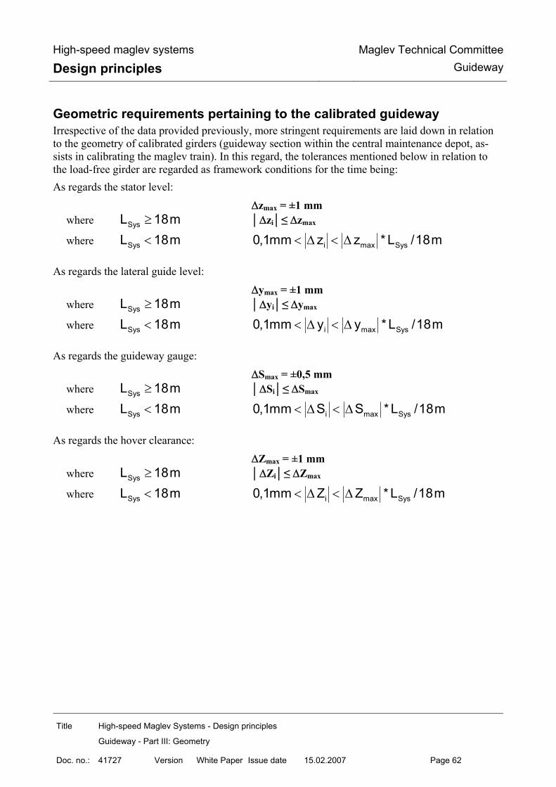
High-speed maglev systems
Design principles Maglev Technical Committee
Guideway
Title High-speed Maglev Systems - Design principles
Guideway - Part III: Geometry
Doc. no.: 41727 Version White Paper Issue date 15.02.2007 Page 62
Geometric requirements pertaining to the calibrated guideway Irrespective of the data provided previously, more stringent requirements are laid down in relation to the geometry of calibrated girders (guideway section within the central maintenance depot, as-sists in calibrating the maglev train). In this regard, the tolerances mentioned below in relation to the load-free girder are regarded as framework conditions for the time being: As regards the stator level: ∆zmax = ±1 mm
where SysL 18m≥ ∆zi≤ ∆zmax
where SysL 18m< i max Sys0,1mm z z * L /18m< ∆ < ∆ As regards the lateral guide level: ∆ymax = ±1 mm
where SysL 18m≥ ∆yi≤ ∆ymax
where SysL 18m< i max Sys0,1mm y y * L /18m< ∆ < ∆ As regards the guideway gauge: ∆Smax = ±0,5 mm
where SysL 18m≥ ∆Si≤ ∆Smax
where SysL 18m< i max Sys0,1mm S S * L /18m< ∆ < ∆
As regards the hover clearance: ∆Zmax = ±1 mm
where SysL 18m≥ ∆Zi≤ ∆Zmax
where SysL 18m< i max Sys0,1mm Z Z * L /18m< ∆ < ∆
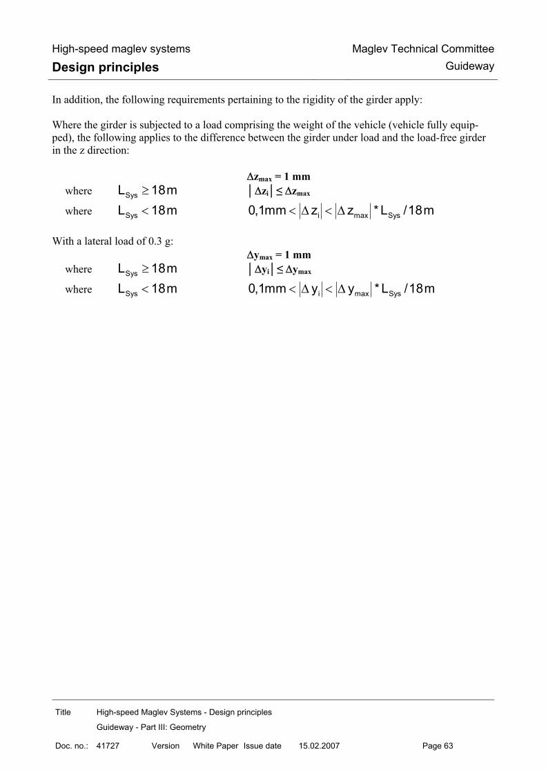
High-speed maglev systems
Design principles Maglev Technical Committee
Guideway
Title High-speed Maglev Systems - Design principles
Guideway - Part III: Geometry
Doc. no.: 41727 Version White Paper Issue date 15.02.2007 Page 63
In addition, the following requirements pertaining to the rigidity of the girder apply: Where the girder is subjected to a load comprising the weight of the vehicle (vehicle fully equip-ped), the following applies to the difference between the girder under load and the load-free girder in the z direction: ∆zmax = 1 mm
where SysL 18m≥ ∆zi≤ ∆zmax
where SysL 18m< i max Sys0,1mm z z * L /18m< ∆ < ∆ With a lateral load of 0.3 g: ∆ymax = 1 mm
where SysL 18m≥ ∆yi≤ ∆ymax
where SysL 18m< i max Sys0,1mm y y * L /18m< ∆ < ∆

High-speed maglev systems
Design principles Maglev Technical Committee
Guideway
Title High-speed Maglev Systems - Design principles
Guideway - Part III: Geometry
Doc. no.: 41727 Version White Paper Issue date 15.02.2007 Page 64
Positional requirements relating to guideway ancillary devices and equipment items
Position of the motor winding The clearance required for motor winding installation is defined in the Principles concerning the overall system design of high-speed maglev systems. The motor winding shall be positioned such that the clearance is observed under all operating con-ditions. The arrangement and location of the individual phases in relation to each other are defined in the Principles concerning the overall system design of high-speed maglev systems. The distances between the meander of the motor winding and their x grids are determined by the chosen arrangement of the stator plates in the x direction. The basic meander grid is 258 mm.
Location of the positional reference guide rail The clearance in the y and z directions which is required for installation of the positional reference guide rail is defined in the Principles concerning the overall system design of high-speed maglev systems. The arrangement in the x direction is based on the position of the girder reference locations which is dependent on the actuation period. Positional reference guide rails are secured to the guideway at the reference locations by means of special supports. The design of the supports and their attachment is defined in relation to the speci-fic project. The guideway reference locations are laid down in relation to the project with the drive design and the operational process control system.
Location of the external inductive power sup-ply guideway-side assemblies
Location of the conductor rail guideway-side assemblies The location of the conductor rails is laid down for individual sections of guideway in relation to the specific project. The clearance in the y and z directions which is required for installation of the conductor rails is defined in the Principles concerning the overall system design of high-speed maglev systems. The location, in principle, of the conductor rail supports is laid down in the Guideway design prin-ciples for high-speed maglev systems - Part I: Principle requirements.

High-speed maglev systems
Design principles Maglev Technical Committee
Guideway
Title High-speed Maglev Systems - Design principles
Guideway - Part III: Geometry
Doc. no.: 41727 Version White Paper Issue date 15.02.2007 Page 65
Location of the inductive power transmission guideway-side assemblies The inductive power transmission is currently still at the development stage. The requirements per-taining to this assembly are therefore added. Temporarily, the project-independent requirements relating to “other guideway equipment as-semblies” and project-specific stipulations apply.

High-speed maglev systems
Design principles Maglev Technical Committee
Guideway
Title High-speed Maglev Systems - Design principles
Guideway - Part III: Geometry
Doc. no.: 41727 Version White Paper Issue date 15.02.2007 Page 66
Proofs Building components and assemblies shall be measured within the framework of quality assurance following the production steps and variance comparisons carried out and documented. The production documentation shall specify the date and the dimensions to be checked. The tole-rance to be considered at the time of testing shall be determined in accordance with the overall tole-rance assessment. The fundamental requirements pertaining to quality assurance, building and acceptance shall be taken from the Guideway design principles for high-speed maglev systems - Part I: Principle requi-rements. The approved measuring instruments and methods which are suitable for acceptance measurements shall be applied to prove observance of the tolerances in accordance with these design principles.

High-speed maglev systems
Design principles Maglev Technical Committee
Guideway
Title High-speed Maglev Systems - Design principles
Guideway - Part III: Geometry
Doc. no.: 41727 Version White Paper Issue date 15.02.2007 Page 67
Annex III-A Stator plate attachment (support structure side) The diagrams below (figs, 221, 222, 223 and 224) are examples of a solution for incorporating the stator plates along a continuous stator girder boom. As an alternative, so called inserts are possible. The specified dimensions and tolerances apply to both variants.
Fig. 221: Dimensions and tolerances for designing stator plate incorporation in a steel construction (top view)
[Key to diagram: Draufsicht = top view Abstand zur Mittenachse benachbartes Statorpaket = distance to the centre axis of the adjacent stator plate]
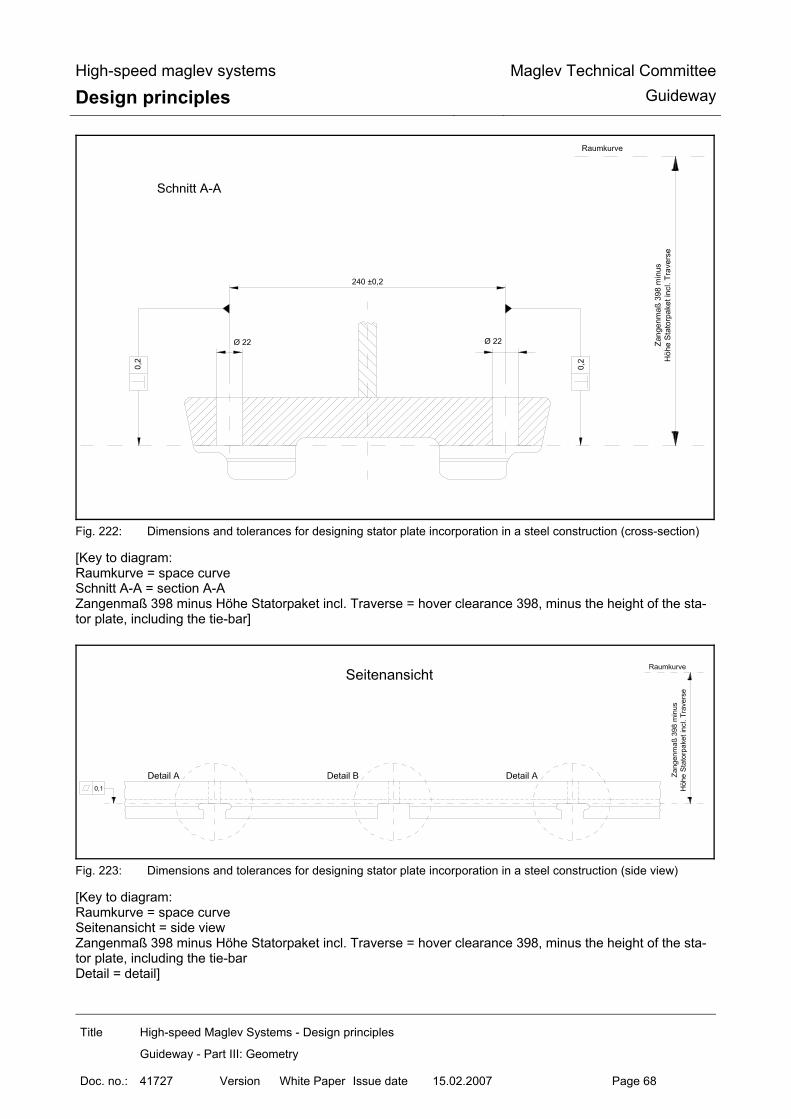
High-speed maglev systems
Design principles Maglev Technical Committee
Guideway
Title High-speed Maglev Systems - Design principles
Guideway - Part III: Geometry
Doc. no.: 41727 Version White Paper Issue date 15.02.2007 Page 68
Fig. 222: Dimensions and tolerances for designing stator plate incorporation in a steel construction (cross-section)
[Key to diagram: Raumkurve = space curve Schnitt A-A = section A-A Zangenmaß 398 minus Höhe Statorpaket incl. Traverse = hover clearance 398, minus the height of the sta-tor plate, including the tie-bar]
Fig. 223: Dimensions and tolerances for designing stator plate incorporation in a steel construction (side view)
[Key to diagram: Raumkurve = space curve Seitenansicht = side view Zangenmaß 398 minus Höhe Statorpaket incl. Traverse = hover clearance 398, minus the height of the sta-tor plate, including the tie-bar Detail = detail]
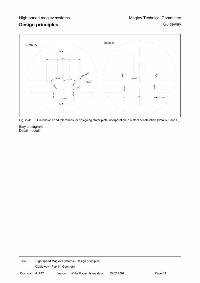
High-speed maglev systems
Design principles Maglev Technical Committee
Guideway
Title High-speed Maglev Systems - Design principles
Guideway - Part III: Geometry
Doc. no.: 41727 Version White Paper Issue date 15.02.2007 Page 69
Fig. 224: Dimensions and tolerances for designing stator plate incorporation in a steel construction (details A and B)
[Key to diagram: Detail = detail]

High-speed maglev systems
Design principles Maglev Technical Committee
Guideway
Title High-speed Maglev Systems - Design principles
Guideway - Part III: Geometry
Doc. no.: 41727 Version White Paper Issue date 15.02.2007 Page 70
Annex III-B Stator plate fixing axes The diagrams below (figs. 225, 226 and 227) are examples of stator plate fixing axes.
Fig. 225: Stator plate fixing axes (top view)
Fig. 226: Stator plate fixing axes (cross-section)

High-speed maglev systems
Design principles Maglev Technical Committee
Guideway
Title High-speed Maglev Systems - Design principles
Guideway - Part III: Geometry
Doc. no.: 41727 Version White Paper Issue date 15.02.2007 Page 71
Fig. 227: Stator plate fixing axes (side view)

High-speed Maglev system
Design principles Maglev Technical Committee
Guideway
Title High-speed Maglev system, design principles
Guideway, Part IV, Routing
Doc. No.: 60640 Version White pa-per
Issue date 15.02.2007 Page 1
High-speed maglev systems Design principles
Guideway
Part IV Routing
The author has copyright over this document and all of its annexes. All rights reserved

High-speed Maglev system
Design principles Maglev Technical Committee
Guideway
Title High-speed Maglev system, design principles
Guideway, Part IV, Routing
Doc. No.: 60640 Version White pa-per
Issue date 15.02.2007 Page 2
Distributor This document was released for publication by the Guideway Technical Committee.

High-speed Maglev system
Design principles Maglev Technical Committee
Guideway
Title High-speed Maglev system, design principles
Guideway, Part IV, Routing
Doc. No.: 60640 Version White pa-per
Issue date 15.02.2007 Page 3
Revision history Date of release: 15.02.2007, White Paper published by the Guideway Technical Committee

High-speed Maglev system
Design principles Maglev Technical Committee
Guideway
Title High-speed Maglev system, design principles
Guideway, Part IV, Routing
Doc. No.: 60640 Version White pa-per
Issue date 15.02.2007 Page 4
Table of contents List of diagrams
List of Tables

High-speed Maglev system
Design principles Maglev Technical Committee
Guideway
Title High-speed Maglev system, design principles
Guideway, Part IV, Routing
Doc. No.: 60640 Version White pa-per
Issue date 15.02.2007 Page 5
General
Object and area of application This document sets out in detail the generally applicable technical stipulations regarding the routing of guideways for high-speed maglev systems. These design principles apply to a maglev train in accordance with the General Maglev Systems’ Act.
Principles for the design of high-speed maglev systems This document is part of the documentation relating to high-speed maglev systems consisting of several design principles. The document tree is presented in fig. 1 of the Principles concerning the overall system design of high-speed maglev systems. The primary overall system design documentation and its annexes apply in a uniform manner to the documentation as a whole:
• Principles concerning the overall system design of high-speed maglev systems, document number 50630, and its annexes:
• Annex 1: Abbreviations and definitions, document number 67536 [Principles for the de-sign of high-speed maglev systems - Abbreviations and definitions]
• Annex 2: Acts, Orders, Standards and Guidelines, document number 67539 [Principles for the design of high-speed maglev systems - Standards and guidelines]
• Annex 3: Environmental conditions, document number 67285 [Principles for the design of high-speed maglev systems - The environment]
• Annex 4: Rules for operation (driving and maintenance), document number 69061 [Principles for the design of high-speed maglev systems - Driving and maintenance]
• Annex 5: Sound, document number 72963 [Principles for the design of high-speed maglev systems - Sound]
Abbreviations and definitions The abbreviations and definitions specified in the Principles for the design of high-speed maglev systems - Abbreviations and definitions - apply.
Acts, Orders, Standards and Guidelines The normative documents listed in the Principles for the design of high-speed maglev systems - Standards and guidelines, contain stipulations which, by reference to the Principles for the design of high-speed maglev systems, become part of the same. Later amendments or revisions to these publications do not apply to dated, normative documents found in the Principles for the design of high-speed maglev systems - Standards and guidelines. Where references are not dated, the most recent version of the normative document referred to applies.

High-speed Maglev system
Design principles Maglev Technical Committee
Guideway
Title High-speed Maglev system, design principles
Guideway, Part IV, Routing
Doc. No.: 60640 Version White pa-per
Issue date 15.02.2007 Page 6
The status of the standards and guidelines to be taken into consideration in a maglev train project must be laid down in a binding manner specific to the project.

High-speed Maglev system
Design principles Maglev Technical Committee
Guideway
Title High-speed Maglev system, design principles
Guideway, Part IV, Routing
Doc. No.: 60640 Version White pa-per
Issue date 15.02.2007 Page 7
Indicating requirements and their binding na-ture The provisions pursuant to DIN 820 were essentially applied when preparing this document. In the chapters following and the annexes to this document,
• requirements are set out in standard type and
• explanatory notes, standard values and examples are set out in italics
(refer to the Guideway design principles for high-speed maglev systems - Part I: Principle require-ments).

High-speed Maglev system
Design principles Maglev Technical Committee
Guideway
Title High-speed Maglev system, design principles
Guideway, Part IV, Routing
Doc. No.: 60640 Version White pa-per
Issue date 15.02.2007 Page 8
Routing
General principles governing routing Taking into account the technical options available, the routing should be chosen in such a way that during operation involving the theoretical path taken as a basis, economically optimum coordi-nation is achieved between requirements in terms of travel dynamics, travel comfort, building and repair costs.
The ultimate aim is for the vehicle to be able to travel over long sections at a constant speed.
Other requirements which are relevant from the point of view of routing, for instance, environmental and sound insulation reasons, networking with other highways, aesthetic points of view and prod-uct design, may influence the planning of the line’s location and shall be included in relation to the specific project.
Guideway axis (space curve)
Guideway axes (space curves) consist of the three-dimensional superimposition of the horizontal and vertical plan alignment.
Guideway axes shall be provided with a clear designation. This should be numerical and comprise three digits.
In the case of multi-guideways, every guideway axis shall be routed separately.
Chainage
Based on the use of finished parts as a result of their system and design, chainage shall relate to the spatial termination of the guideway axis (space curve).
Horizontal and vertical plan alignment
Horizontal and vertical plan routing should be effected separately in the first instance.
The space curve established as a result of the superimposition of the horizontal and vertical plan alignment must fulfil all the requirements contained in this design principle.
Routing of the stretch as a whole shall be examined using the definitive, simulated actual paths to ensure that it fully satisfies the projected comfort limit values.
Inclusion of the routing design in calculations
Routing design should be carried out on the basis of general pans and gradient diagrams, together with their image systems.
The geometric and geodetic bases of the general pans and gradient diagrams shall be examined in terms of their applicability.

High-speed Maglev system
Design principles Maglev Technical Committee
Guideway
Title High-speed Maglev system, design principles
Guideway, Part IV, Routing
Doc. No.: 60640 Version White pa-per
Issue date 15.02.2007 Page 9
In terms of design-related follow-up work (stipulating the division of supports, bridge structures, points systems) and as regards subsequent staking, the graphic design shall be included in the maglev train coordinate system as set out in the Guideway design principles for high-speed maglev systems - Part IV: Surveying, according to location and elevation.
Existing constraining points shall be surveyed, coordinated and taken into consideration in the cal-culation.
Inclusion in calculations shall be effected in such a way that • the progression of the line corresponds to the graphic representation given in the design
plans to the standard degree of precision,
• strictly tangential transitions exist along the main points of the line,
• a steady progression exists in the curvature string and cross-fall string (the exception being the curvature string deflection and vmax < 100 km/h) and
• the three-dimensional x, y and z coordinates of all the main line points are determined using the corresponding chainages.
The calculations shall identify
• coordinates and elevations to four decimal places (1/10 mm) and
• data concerning angles to five decimal places.
Horizontal plan routing elements
Standard guideway Horizontal plan routing elements are as follows:
• straight lines (RH = ∞)
• arcs [of a circle] (RH = constant)
• sinusoids (standard scenario, as a transition curve)
• clothoids (special scenario, as a transition curve)
Sinusoids should be used as transition curves. In the case of sinusoids, curvature, cross-fall, unbalanced lateral acceleration and lateral jolts are established as a function of time and the distance travelled. Clothoids in the form of transition curves can be used in the accelerating and braking areas at sta-tions and in areas where there are no passengers (e.g. IHZ approaches). This only applies to sec-tions of guideway on which the theoretical path speed does not exceed 100 km/h. Subsequent use of that part of the guideway with a higher maximum speed (e.g. in the case of a network expansion and possible through passage at this station) should be assessed.

High-speed Maglev system
Design principles Maglev Technical Committee
Guideway
Title High-speed Maglev system, design principles
Guideway, Part IV, Routing
Doc. No.: 60640 Version White pa-per
Issue date 15.02.2007 Page 10
Cant gradients (S jolts) shall be routed as an element (continuous sinusoids). The geometric characteristics of the sinusoids and clothoids and those concerning travel dynamics are presented below in figs. 228 and 229. The calculation of the minimum sinusoid and clothoid lengths is explained under point 6.2.4.
Fig. 228: Geometric characteristics of the sinusoids and those concerning travel dynamics
[Key to diagram: Gerade = straight line Sinusoide = sinusoid Kreis = circle

High-speed Maglev system
Design principles Maglev Technical Committee
Guideway
Title High-speed Maglev system, design principles
Guideway, Part IV, Routing
Doc. No.: 60640 Version White pa-per
Issue date 15.02.2007 Page 11
Krümmungsband = curvature string oder gon = or gon Querneigung = lateral incline freie Seitenbeschleunigung = free lateral acceleration Seitenruck = lateral jolt] The lateral incline has a sinusoidal structure in a similar way to the curvature.
Fig. 229: Geometric characteristics of the clothoids and those concerning travel dynamics
[Key to diagram: Gerade = straight line Klotoide = clothoid Kreis = circle

High-speed Maglev system
Design principles Maglev Technical Committee
Guideway
Title High-speed Maglev system, design principles
Guideway, Part IV, Routing
Doc. No.: 60640 Version White pa-per
Issue date 15.02.2007 Page 12
Krümmungsband = curvature string oder gon = or gon Querneigung (gilt nicht für Weichen) = lateral incline (does not apply to points) freie Seitenbeschleunigung = free lateral acceleration Seitenruck = lateral jolt]

High-speed Maglev system
Design principles Maglev Technical Committee
Guideway
Title High-speed Maglev system, design principles
Guideway, Part IV, Routing
Doc. No.: 60640 Version White pa-per
Issue date 15.02.2007 Page 13
Vertical plan routing elements
Standard guideway The standard guideway vertical plan includes the following:
• straight lines (RV = ∞) • radii (arcs [of a circle], RV = constant) • clothoids (transition curve)
Between the straight lines and the radii, clothoids shall be engaged to prevent curvature jumps in the progression of the gradient (vertical jolt åz = ∞). The maximum permitted longitudinal gradient in the straight lines is laid down under point 6.1.1.
Points Points should not be arranged in the area of vertical fillets. The maximum permitted longitudinal gradient in the straight lines is laid down under point 6.1.1.

High-speed Maglev system
Design principles Maglev Technical Committee
Guideway
Title High-speed Maglev system, design principles
Guideway, Part IV, Routing
Doc. No.: 60640 Version White pa-per
Issue date 15.02.2007 Page 14
Routing parameters
Geometric routing parameters Explicitly identified special cases require authorisation. Section 3(2) and Section 5(1)(2) of the Maglev Construction and Operation Ordinance apply to e-xemptions from these provisions.
Limit values for the longitudinal gradient of the guideway The limit values for the longitudinal gradient of the guideway are listed in Table 141. Place Area Limit value Stipulated by Open section of guide-way outside stopping places
s= 100‰ Section 13(2) of the Maglev Construction and Operation Ordi-nance
Platform area
s= 5‰ Section 13(2) of the Maglev Construction and Operation Ordi-nance
Operational-related stopping places
s= 100‰ in accordance with the proof of the halting function
Section 13(2) of the Maglev Construction and Operation Ordi-nance
Other operational stop-ping places
s= 100‰ in accordance with the proof of the halting function
Section 13(2) of the Maglev Construction and Operation Ordi-nance
Within stopping places
Stopping places for evacuation purposes
s= 5‰
Section 13(2) of the Maglev Construction and Operation Ordi-nance
Table 141: Longitudinal gradient of the guideway
Sign convention: + s = slope - s = gradient

High-speed Maglev system
Design principles Maglev Technical Committee
Guideway
Title High-speed Maglev system, design principles
Guideway, Part IV, Routing
Doc. No.: 60640 Version White pa-per
Issue date 15.02.2007 Page 15
Limit values for the lateral incline of the guideway The guideway levels shall be planned with a lateral incline to eliminate or reduce the unbalanced lateral acceleration which occurs when going round bends. The limit values are listed in Table 142.
The lateral incline is produced by rotating the guideway superstructures around the guideway axis which maintain their heights (gradients). Consequently, the vehicle’s centre of gravity always main-tains the same gap from the guideway axis. When stopping (at platforms or operational stopping places), the lateral incline causes acceleration towards the inside of the bend. Place Area Limit value Stipulated by
α = 12° Section 13(3) of the Maglev Construction and Operation Ordi-nance
Open section of gui-deway outside stop-ping places
α = 16° in special cases
Section 13(3) of the Maglev Construction and Operation Ordi-nance
Platform area
α = 3.0° * the system as a whole
Operational-related stopping places
α = 6.0°
the system as a whole Corresponds to ay = 1.0 m/s² (inside of the bend)
Other operational stopping places
α = 12°
the system as a whole Corresponds to ay = 2.0 m/s² (inside of the bend)
Within stopping pla-ces
Stopping places for evacuation purposes
α = 6.0°
the system as a whole Corresponds to ay = 1.0 m/s² (inside of the bend)
Points
α = 0°
the system as a whole Upright or bending position (calculated where s = 0 ‰)
Table 142: Lateral incline of the guideway

High-speed Maglev system
Design principles Maglev Technical Committee
Guideway
Title High-speed Maglev system, design principles
Guideway, Part IV, Routing
Doc. No.: 60640 Version White pa-per
Issue date 15.02.2007 Page 16
*) In Section 13(3) of the Maglev Construction and Operation Ordinance, the permitted lateral in-cline of a stationary vehicle in the platform area is limited to 3.4°. The maximum permitted lateral incline of 3.0° is laid down for system-related reasons.
The guideway should be drained via the top side of the guideway superstructures according to the Guideway design principles for high-speed maglev systems - Part I: Principle requirements. The minimum lateral incline of the guideway is
α = 1.15 ° (corresponds to 2%). (Areas where the direction of the lateral incline changes (e.g. S jolts) are exempt, along with par-king and maintenance lanes, stations and points). Sign convention: + α = clockwise rotation (viewed in the direction of the chainage) + α = anti-clockwise rotation (viewed in the direction of the chainage)

High-speed Maglev system
Design principles Maglev Technical Committee
Guideway
Title High-speed Maglev system, design principles
Guideway, Part IV, Routing
Doc. No.: 60640 Version White pa-per
Issue date 15.02.2007 Page 17
Guideway distortion and the minimum permitted distortion length The distortion section is the transition area between constant lateral incline sections. The start and end points of distortion sections and transition curves in the case of horizontal plan routing should coincide with the position. In a particular case, distortion sections can also be arranged in guideway sections with a constant horizontal plan curvature (also refer to the formula for calculating the lateral incline α where Le = the length of the distortion in point 5.2.1). The progression of the distortion in the cross-fall string should be similar to the progression of the curvature in the horizontal plan routing. When using sinusoids in the horizontal plan routing, the guideway distortion should be of sinusoi-dal design. However, if distortion coincides with a clothoid in the horizontal plan, the distortion shall be linear, i.e. with a uniform change in the lateral incline over the length of the element (see fig. 229).
Distortion Stipulated by Maximum value
∆αmax = 0.10 °/m
the system as a whole (geometry of the vehic-le)
Limit value according to the project-specific agreement
∆αmax = 0.15 °/m
the system as a whole (geometry of the vehic-le)
The minimum permitted length of the distortion section is established from the maximum permitted distortion, the maximum lateral jolt (see 6.2.3.1) and the maximum vertical jolt (see 6.2.3.2 and 6.2.4).
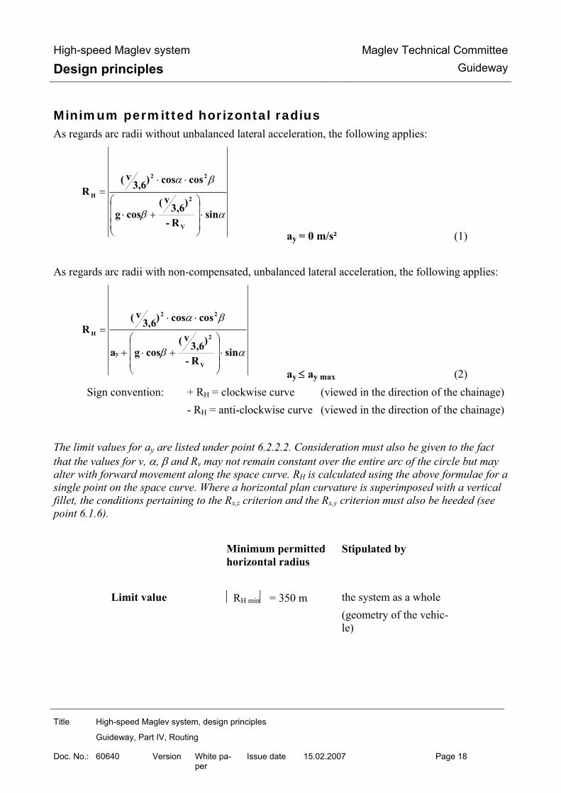
High-speed Maglev system
Design principles Maglev Technical Committee
Guideway
Title High-speed Maglev system, design principles
Guideway, Part IV, Routing
Doc. No.: 60640 Version White pa-per
Issue date 15.02.2007 Page 18
Minimum permitted horizontal radius As regards arc radii without unbalanced lateral acceleration, the following applies:
αβ
βα
sinR-
)3,6v(
cosg
coscos)3,6v(
R
V
2
22
H
⋅⎟⎟⎟
⎠
⎞
⎜⎜⎜
⎝
⎛+⋅
⋅⋅=
ay = 0 m/s² (1) As regards arc radii with non-compensated, unbalanced lateral acceleration, the following applies:
αβ
βα
sinR-
)3,6v(
cosga
coscos)3,6v(
R
V
2
y
22
H
⋅⎟⎟⎟
⎠
⎞
⎜⎜⎜
⎝
⎛+⋅+
⋅⋅=
ay ≤ ay max (2) Sign convention: + RH = clockwise curve (viewed in the direction of the chainage) - RH = anti-clockwise curve (viewed in the direction of the chainage)
The limit values for ay are listed under point 6.2.2.2. Consideration must also be given to the fact that the values for v, α, β and Rv may not remain constant over the entire arc of the circle but may alter with forward movement along the space curve. RH is calculated using the above formulae for a single point on the space curve. Where a horizontal plan curvature is superimposed with a vertical fillet, the conditions pertaining to the Rx,z criterion and the Rx,y criterion must also be heeded (see point 6.1.6).
Minimum permitted horizontal radius
Stipulated by
Limit value
RH min = 350 m
the system as a whole (geometry of the vehic-le)

High-speed Maglev system
Design principles Maglev Technical Committee
Guideway
Title High-speed Maglev system, design principles
Guideway, Part IV, Routing
Doc. No.: 60640 Version White pa-per
Issue date 15.02.2007 Page 19
Fig. 230 below shows an example of the progression of the minimum permitted horizontal radius depending on the speed of the vehicle if stipulations in terms of travel dynamics are to be taken into consideration (see Chapter 6.2.2.2). In this example, a lateral incline of the guideway of 12° is as-sumed and the smallest horizontal radii are sought for an unbalanced lateral acceleration of 0.0 m/s² or 1.5 m/s².
0
1000
2000
3000
50 100 150 200 250 300 350V [km/h]
RH
[m]
Min zulässiger Horizontalradius(bei ay = 0,0 m/s², α = 12°)
Min zulässiger Horizontalradius(bei ay = 1,5 m/s², α = 12°)
0
1000
2000
3000
50 100 150 200 250 300 350V [km/h]
RH
[m]
Min zulässiger Horizontalradius(bei ay = 0,0 m/s², α = 12°)
Min zulässiger Horizontalradius(bei ay = 1,5 m/s², α = 12°)
Fig. 230: Minimum permitted horizontal radius
[Key to diagram: Min. zulässiger Horizontalradius (bei ay = ........) = minimum permitted horizontal radius (where ay = ........)]

High-speed Maglev system
Design principles Maglev Technical Committee
Guideway
Title High-speed Maglev system, design principles
Guideway, Part IV, Routing
Doc. No.: 60640 Version White pa-per
Issue date 15.02.2007 Page 20
Minimum permitted vertical radius The radii chosen should be such that the standard acceleration which occurs is as low as possible. Using the limit values for acceleration which are cited under point 6.2.1, the minimum fillet radii values are established as follows:
max zH
22
2
minV
aR
βcossinα)3,6v(1)cosβ(cosαg
cosα)3,6v(
R−
⋅⋅+−⋅⋅
⋅=
(3) Sign convention: + RV = peaks - RV = troughs
Different limit values for az max apply to peaks and troughs. Here, too, a point on the space curve is calculated and consideration must be given to the possible change in v, α, β and RH during the journey as a result of the radius when determining the result.
Minimum permitted vertical radius
Stipulated by
Limit value
RV min = 530 m
the system as a whole (geometry of the vehic-le)
Points should not be located in the area of vertical fillets.
The sign convention is required on account of using transition curves in the gradient calculation.

High-speed Maglev system
Design principles Maglev Technical Committee
Guideway
Title High-speed Maglev system, design principles
Guideway, Part IV, Routing
Doc. No.: 60640 Version White pa-per
Issue date 15.02.2007 Page 21
Fig. 231 below provides an example of the minimum permitted vertical diameter depending on the speed of the vehicle for the maximum standard acceleration which is permitted each time at peaks and in troughs. The stipulations concerning travel dynamics are used to calculate RV min according to equation (3) above.
0
1000
2000
3000
4000
5000
6000
7000
8000
9000
10000
50 100 150 200 250 300 350V [km/h]
RV
[m]
Min zulässiger Halbmesser (Wanne)
Min zulässiger Halbmesser (Kuppe)
0
1000
2000
3000
4000
5000
6000
7000
8000
9000
10000
50 100 150 200 250 300 350V [km/h]
RV
[m]
Min zulässiger Halbmesser (Wanne)
Min zulässiger Halbmesser (Kuppe)
Fig. 231: Minimum permitted vertical radius
[Key to diagram: Min. zulässiger Halbmesser (Wanne) = minimum permitted radius (trough) Min. zulässiger Halbmesser (Kuppe) = minimum permitted radius (peak)]

High-speed Maglev system
Design principles Maglev Technical Committee
Guideway
Title High-speed Maglev system, design principles
Guideway, Part IV, Routing
Doc. No.: 60640 Version White pa-per
Issue date 15.02.2007 Page 22
Rx,z criterion When superimposing a gradient curvature (radius) with a horizontal curvature (radius), the Rx,z cri-terion (spatial radius) must be heeded.
H
2
Vzx, Rβcossinα
Rcosα
R1 ⋅
−= (4)
Refer to Chapters 6.1.1 to 6.1.5 for the sign conventions of the parameters used.
Minimum permitted Rx,z criterion
Stipulated by
Limit value
Rx,z min = 530 m where ∆α = 0.00 °/m
the system as a whole (geometry of the vehicle)
With additional superimposition involving distortion, the spatial radius depends on the distortion which exists locally. The limit values laid down in Table 143 depend on the geometry of the vehicle which is specific to the particular project. (The Intermediate values must be determined by linear interpolation).
∆α [°/m] 0.00 0.01 0.02 0.03 0.04 0.05
Rx,z min [m] 530 550 590 630 670 710
∆α [°/m] 0.06 0.07 0.08 0.09 0.10 0.11
Rx,z min [m] 770 830 900 990 1100 1230
∆α [°/m] 0.12 0.13 0.14 0.15
Rx,z min [m] 1410 1640 1950 2430
Table 143: Limit values for Rx,z in the case of guideway distortion
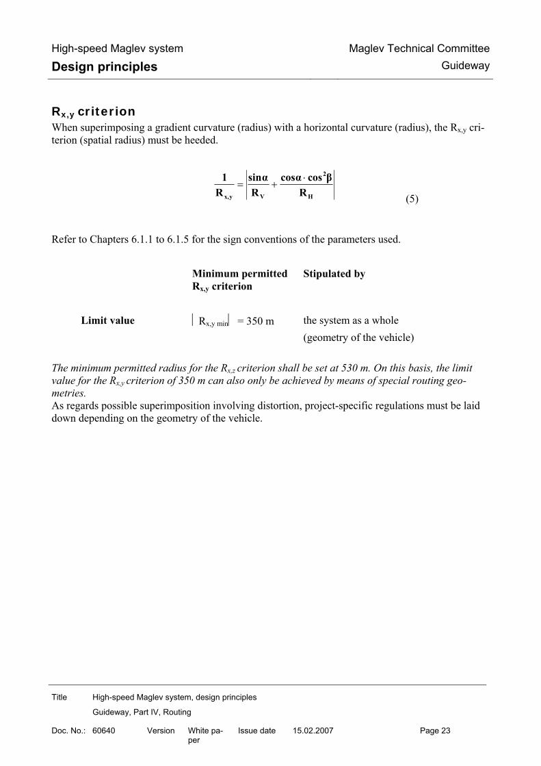
High-speed Maglev system
Design principles Maglev Technical Committee
Guideway
Title High-speed Maglev system, design principles
Guideway, Part IV, Routing
Doc. No.: 60640 Version White pa-per
Issue date 15.02.2007 Page 23
Rx,y criterion When superimposing a gradient curvature (radius) with a horizontal curvature (radius), the Rx,y cri-terion (spatial radius) must be heeded.
H
2
Vyx, Rβcoscosα
Rsinα
R1 ⋅
+= (5)
Refer to Chapters 6.1.1 to 6.1.5 for the sign conventions of the parameters used.
Minimum permitted Rx,y criterion
Stipulated by
Limit value
Rx,y min = 350 m
the system as a whole (geometry of the vehicle)
The minimum permitted radius for the Rx,z criterion shall be set at 530 m. On this basis, the limit value for the Rx,y criterion of 350 m can also only be achieved by means of special routing geo-metries. As regards possible superimposition involving distortion, project-specific regulations must be laid down depending on the geometry of the vehicle.

High-speed Maglev system
Design principles Maglev Technical Committee
Guideway
Title High-speed Maglev system, design principles
Guideway, Part IV, Routing
Doc. No.: 60640 Version White pa-per
Issue date 15.02.2007 Page 24
Driving dynamic specifications
Target line speed and permissible line speed The target line speed is the local minimum, defined on the basis of the maximum running speed, the target speed from the point of view of ride comfort and further project specifications (see /MSB AG-ABK&DEF/ for diagram). For the guideway dimensioning, the following upper limits are defined for the permissible speed for guideways and tunnels:
Line section Permissible speed Defined by Open track
vmax ≤ 500 km/h
Guideway (steady loads)
Tunnel sections (de-pendent upon cross-section)
vmax ≤ 500 km/h
Guideway (steady loads)
Switches in straight position
vmax ≤ 500 km/h
Guideway (steady loads)
Switches in turnout position
Model-specific
Guideway (steady loads)
Taking into account also the permissible speed for the vehicle (project-specific or /MSB AG-GESAMT/), the permissible speed for the line is determined from the above-mentioned permissible speeds. The programmed speed is the minimum of target line speed and permissible line speed. The actual driving profile required for the driving-dynamic simulations (see /MSB AG-ABK&DEF/ for diagram) is generated by additional drive simulations, in which the actual project-related per-formance of the drive is taken into account.

High-speed Maglev system
Design principles Maglev Technical Committee
Guideway
Title High-speed Maglev system, design principles
Guideway, Part IV, Routing
Doc. No.: 60640 Version White pa-per
Issue date 15.02.2007 Page 25
Accelerations Depending upon their direction of action, the accelerations are divided into:
• Drive or braking acceleration ax
• Uncompensated lateral acceleration ay
• Normal acceleration (comfort value) az
• Normal case acceleration (acceleration due to gravity) g The acceleration limit values for the uncompensated lateral acceleration and for the normal accele-ration should be adhered to by the three-dimensional guideway axis (three-dimensional curve). The drive subsystem is responsible for adherence to the limit values for the drive or braking acceleration (see /MSB AG-ANT/). For reasons of ride comfort, the lowest possible uncompensated lateral and normal acceleration va-lues should be striven for by a suitable choice of route parameters. At switches, compensation for lateral acceleration is not possible since the guideway may not be tilted. Figure 232 shows in cross-section a high-speed Maglev vehicle (viewed in direction of increasing kilometrage) upon which the acceleration in question acts with a positive sign.
(Blickrichtung =aufsteigende
Kilometrierung)
Raumkurve +ax
+az +g
+ay
+α
Figure 232: Sign of accelerations
Raumkurve Three-dimensional curve
(Blickrichtung = … (Viewing direction = rising kilometrage)

High-speed Maglev system
Design principles Maglev Technical Committee
Guideway
Title High-speed Maglev system, design principles
Guideway, Part IV, Routing
Doc. No.: 60640 Version White pa-per
Issue date 15.02.2007 Page 26
Drive and braking acceleration The drive subsystem is responsible for adherence to the limit values for the drive / braking accelera-tion (see /MSB AG-ANT/). Adherence to the limit values for the drive and braking acceleration should be checked at selected points, taking into consideration the predetermined maximum driving profile and the slope of the guideway resulting from the route study.
Drive and braking acceleration
Determined by
Limit value
|ax max | = 1.5 m/s²
MbBO
Comfort-determined maximum values (ride comfort) can be defined on a project-specific basis.
Uncompensated lateral acceleration The uncompensated lateral acceleration is calculated as follows:
α⋅⎟⎟⎟
⎠
⎞
⎜⎜⎜
⎝
⎛+β⋅−β⋅α⋅= sin
R-
)3.6v(
cosgcoscosR
)3.6v(
aV
2
2
H
2
y (6)
The sign of the calculated uncompensated lateral acceleration indicates the direction of the accele-ration for the passenger: In the case of a positive sign towards the left in direction of travel, In the case of a negative sign towards the right in direction of travel.
Limit value Uncompensated late-ral acceleration
Determined by
For normal guideway
|ay max | = 1.5 m/s²
MbBO (towards outside of curve)
For switches
|ay max | = 2.0 m/s²
Complete system (dimensioning of switches)
Comfort-determined maximum values (ride comfort) can be defined on a project-specific basis. If the speed of the vehicle is optimally adapted to the lateral tilt and the radius no lateral accelera-tion will occur (ay = 0). If the speed is higher, it acts towards the outside of the curve, i.e. upwards on the tilted surface of guideway as “excess acceleration”.

High-speed Maglev system
Design principles Maglev Technical Committee
Guideway
Title High-speed Maglev system, design principles
Guideway, Part IV, Routing
Doc. No.: 60640 Version White pa-per
Issue date 15.02.2007 Page 27
If it is lower, it acts towards the inside of the curve, i.e. downwards on the tilted surface of the gui-deway as deficient acceleration (descending force). The relationship of the current horizontal radius in the direction of travel, the associated direction of guideway lateral tilt and the sign of ay from the calculation is shown in Table 144 for information.
Right-hand curve and positive lateral tilt
Left-hand curve and negative la-teral tilt
Route parameters in direction of travel
RH and α with positive sign (+)
RH and α with negative sign (-)
ay with positive sign (+)
Acceleration in direction of
travel towards the left = excess acceleration
Acceleration in direction of tra-
vel towards the left = deficient acceleration
ay with negative sign (-)
Acceleration in direction of
travel towards the right = deficient acceleration
Acceleration in direction of tra-
vel towards the right = excess acceleration
Table 144: Direction of excess and deficient acceleration
In the /MSB AG-FW BEM/, in deviation from these design principles, the direction of action of the free lateral acceleration is differentiated exclusively according to whether it is towards the inside or outside of curve. A negative sign in the /MSB AG-FW BEM/ always describes acceleration towards the inside of the curve (deficient acceleration) and a positive sign always describes an acceleration towards the outside of the curve (excess acceleration).
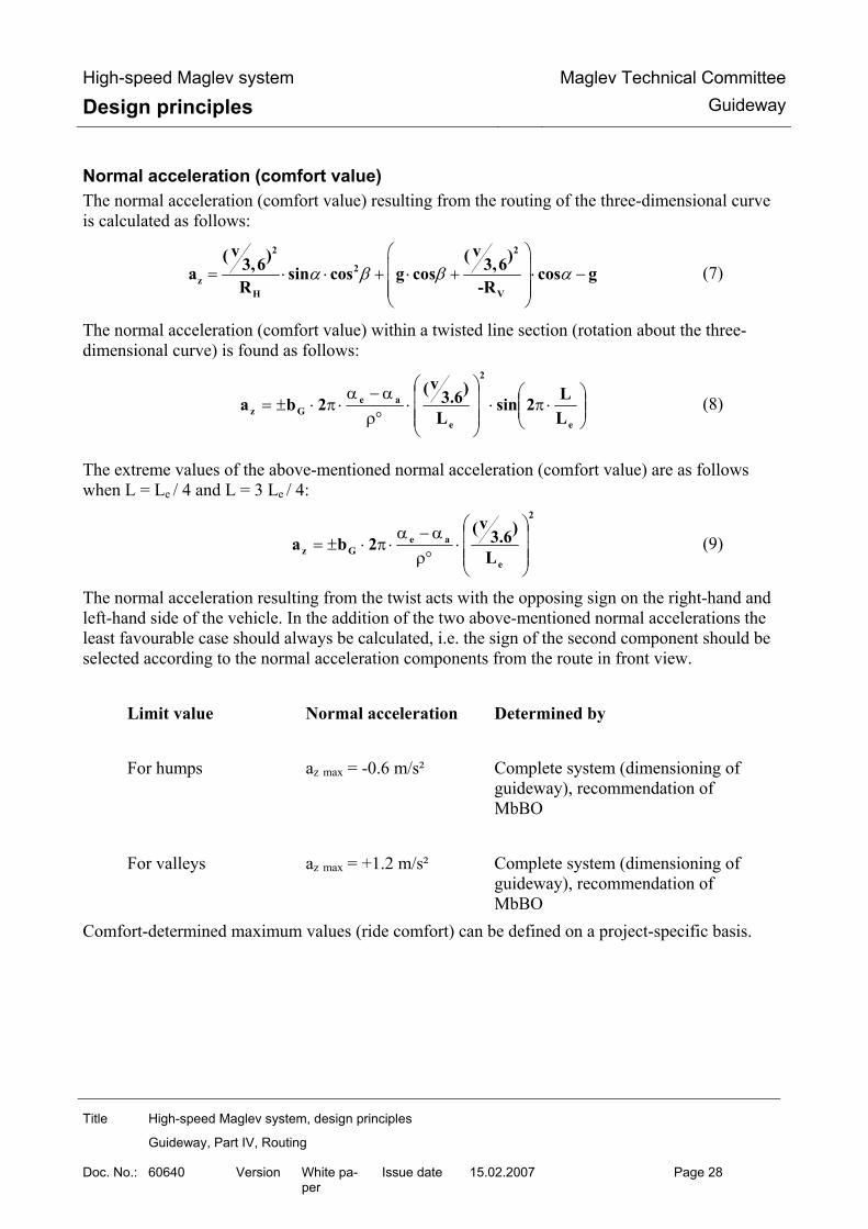
High-speed Maglev system
Design principles Maglev Technical Committee
Guideway
Title High-speed Maglev system, design principles
Guideway, Part IV, Routing
Doc. No.: 60640 Version White pa-per
Issue date 15.02.2007 Page 28
Normal acceleration (comfort value) The normal acceleration (comfort value) resulting from the routing of the three-dimensional curve is calculated as follows:
α β β α⎛ ⎞⎜ ⎟= ⋅ ⋅ + ⋅ + ⋅ −⎜ ⎟⎜ ⎟⎝ ⎠
2 2
2z
H V
v v( ) ( )3,6 3,6a sin cos g cos cos gR -R
(7)
The normal acceleration (comfort value) within a twisted line section (rotation about the three-dimensional curve) is found as follows:
⎟⎟⎠
⎞⎜⎜⎝
⎛⋅π⋅
⎟⎟⎟
⎠
⎞
⎜⎜⎜
⎝
⎛⋅
°ρα−α
⋅π⋅±=e
2
e
aeGz L
L2sinL
)3.6v(
2ba (8)
The extreme values of the above-mentioned normal acceleration (comfort value) are as follows when L = Le / 4 and L = 3 Le / 4:
2
e
aeGz L
)3.6v(
2ba⎟⎟⎟
⎠
⎞
⎜⎜⎜
⎝
⎛⋅
°ρα−α
⋅π⋅±= (9)
The normal acceleration resulting from the twist acts with the opposing sign on the right-hand and left-hand side of the vehicle. In the addition of the two above-mentioned normal accelerations the least favourable case should always be calculated, i.e. the sign of the second component should be selected according to the normal acceleration components from the route in front view.
Limit value Normal acceleration Determined by For humps
az max = -0.6 m/s²
Complete system (dimensioning of guideway), recommendation of MbBO
For valleys
az max = +1.2 m/s²
Complete system (dimensioning of guideway), recommendation of MbBO
Comfort-determined maximum values (ride comfort) can be defined on a project-specific basis.

High-speed Maglev system
Design principles Maglev Technical Committee
Guideway
Title High-speed Maglev system, design principles
Guideway, Part IV, Routing
Doc. No.: 60640 Version White pa-per
Issue date 15.02.2007 Page 29
Jerks
Jerks are differential changes in the acceleration per unit time.
The jerks are calculated based upon the three-dimensional guideway axis (three-dimensional curve). Transition curves should be routed so that the maximum values for the jerks (differential changes in acceleration per unit time) are not exceeded. The jerks are divided as follows depending upon direction of action:
• Lateral jerk åy
• Vertical jerk åz
• Longitudinal jerk åx
• Omnidirectional jerk (not at switches) åo The lowest possible jerk values increase the subjective ride enjoyment of the passengers (good ride comfort). This can be achieved for example by extending the transition curve in the ground plan. The formulae listed below for the calculation of the jerk values are only applicable if the path of the curve and twist sections are the same. If no analogous path is available, adherence to the limit va-lues should be checked at selected points.
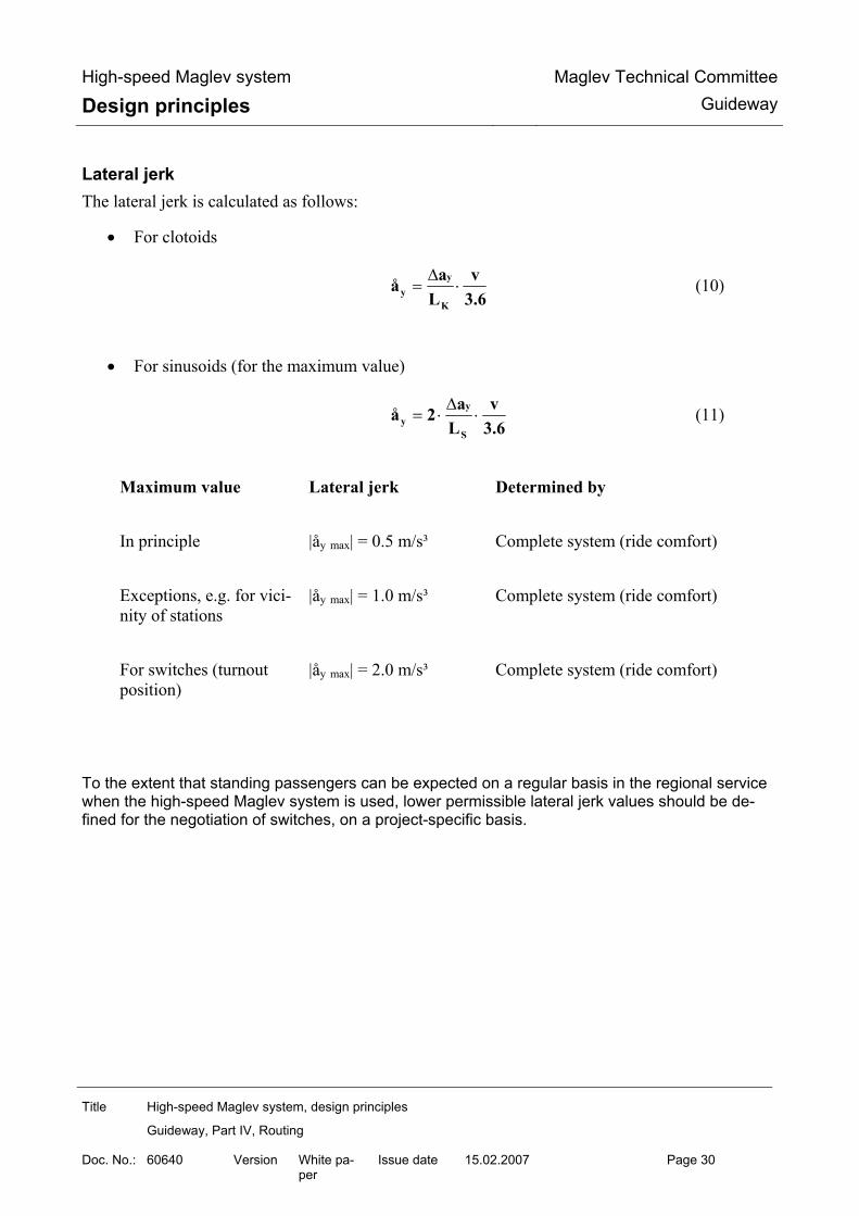
High-speed Maglev system
Design principles Maglev Technical Committee
Guideway
Title High-speed Maglev system, design principles
Guideway, Part IV, Routing
Doc. No.: 60640 Version White pa-per
Issue date 15.02.2007 Page 30
Lateral jerk The lateral jerk is calculated as follows:
• For clotoids
3.6v
LaåK
yy ⋅
∆= (10)
• For sinusoids (for the maximum value)
3.6v
La2åS
yy ⋅
∆⋅= (11)
Maximum value Lateral jerk Determined by In principle
|åy max| = 0.5 m/s³
Complete system (ride comfort)
Exceptions, e.g. for vici-nity of stations
|åy max| = 1.0 m/s³
Complete system (ride comfort)
For switches (turnout position)
|åy max| = 2.0 m/s³
Complete system (ride comfort)
To the extent that standing passengers can be expected on a regular basis in the regional service when the high-speed Maglev system is used, lower permissible lateral jerk values should be de-fined for the negotiation of switches, on a project-specific basis.

High-speed Maglev system
Design principles Maglev Technical Committee
Guideway
Title High-speed Maglev system, design principles
Guideway, Part IV, Routing
Doc. No.: 60640 Version White pa-per
Issue date 15.02.2007 Page 31
Vertical jerk The vertical jerk is calculated as follows:
3.6v
LaåK
zz ⋅
∆= (12)
The vertical jerk component within a twistroad (rotation about the three-dimensional curve) is as follows:
⎟⎟⎠
⎞⎜⎜⎝
⎛⋅π⋅
⎟⎟⎟
⎠
⎞
⎜⎜⎜
⎝
⎛⋅
°ρα−α
⋅π⋅±=e
3
e
ae2Gz L
L2cosL
)3.6v(
4bå (13)
The extreme values of the above-mentioned vertical jerk component are as follows where L = 0, L = Le / 2 and L = Le:
3
e
ae2Gz L
)3.6v(
4bå⎟⎟⎟
⎠
⎞
⎜⎜⎜
⎝
⎛⋅
°ρα−α
⋅π⋅±= (14)
The vertical jerk component resulting from the twist acts with an opposing sign on the right-hand and left-hand sides of the vehicle. In the addition of the two above-mentioned vertical jerk compo-nents the least favourable case should always be used for the calculation, i.e. the sign of the second component should be selected according to that of the vertical jerk component from the routing of the three-dimensional curve.
Special cases with increased vertical jerk are permissible after testing for compatibility in the indi-vidual case.
Maximum value Vertical jerk Determined by In principle
|åz max| = 0.5 m/s³
Complete system (ride comfort)
Exceptions, e.g. for the vicinity of stations
|åz max| = 1.0 m/s³
Complete system (ride comfort)

High-speed Maglev system
Design principles Maglev Technical Committee
Guideway
Title High-speed Maglev system, design principles
Guideway, Part IV, Routing
Doc. No.: 60640 Version White pa-per
Issue date 15.02.2007 Page 32
Longitudinal jerk
The longitudinal jerk is not primarily dependent upon the path of the three-dimensional curve but upon the path of speed.
The operator requirements of longitudinal jerk should be adhered to by the driving profile.
Omnidirectional jerk The spatial superposition of longitudinal jerk, lateral jerk and vertical jerk yield the omnidirectional jerk. This is calculated as follows:
2
z
2
y
2
x å+å+å=åo (15)
Special cases with increased omnidirectional jerk are permissible after testing for compatibility in the individual case.
No maximum value for omnidirectional jerk is specified for switches (turnout position).
Maximum value Omnidirectional jerk Determined by In principle
|åo max| = 1.0 m/s³
Complete system (ride comfort)

High-speed Maglev system
Design principles Maglev Technical Committee
Guideway
Title High-speed Maglev system, design principles
Guideway, Part IV, Routing
Doc. No.: 60640 Version White pa-per
Issue date 15.02.2007 Page 33
Minimum length of sinusoid In the route path the sinusoids in question (including in s-twist amongst others) are defined by the length L and the radii RHa or RHe, whereby a radius can also be RH = ∞ (straight). The minimum length is found from the criteria of the maximum lateral jerk, the maximum permis-sible twist or the maximum vertical jerk using the formulae listed below, whereby the greatest length is always definitive.
3.6v)SGN(Ra)SGN(Ra
2Lmax y
ay,ey,
åaH,eH,
min S⋅
−⋅⋅=
⋅
(16)
max
ae
∆ααα
2Lmin S
−= ⋅ (17)
3
max z
ae23
åραα
π)( 4Gb3.6vL
min S ⋅°
−⋅⋅= ⋅ (18)
The listed formulae for the calculation of the minimum length of the sinusoids only apply if curve and twistroads have identical start and end points along the guideway axis. If no identical path e-xists, particular care should be taken that the limit values are adhered to. In the event of the superposition of twists with vertical transitions, adherence to the limit values should be checked at selected points, since the vertical jerk component from the three-dimensional curve is not taken into consideration in the above-mentioned formula (see 0).).
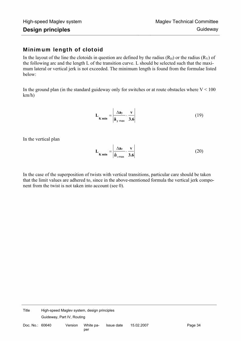
High-speed Maglev system
Design principles Maglev Technical Committee
Guideway
Title High-speed Maglev system, design principles
Guideway, Part IV, Routing
Doc. No.: 60640 Version White pa-per
Issue date 15.02.2007 Page 34
Minimum length of clotoid In the layout of the line the clotoids in question are defined by the radius (RH) or the radius (RV) of the following arc and the length L of the transition curve. L should be selected such that the maxi-mum lateral or vertical jerk is not exceeded. The minimum length is found from the formulae listed below: In the ground plan (in the standard guideway only for switches or at route obstacles where V < 100 km/h)
3.6va
Lå
y
min K⋅
∆=
maxy
(19)
In the vertical plan
3.6va
Lz
min K⋅
∆=
maxå z
(20)
In the case of the superposition of twists with vertical transitions, particular care should be taken that the limit values are adhered to, since in the above-mentioned formula the vertical jerk compo-nent from the twist is not taken into account (see 0).

High-speed Maglev system
Design principles Maglev Technical Committee
Guideway
Title High-speed Maglev system, design principles
Guideway, Part IV, Routing
Doc. No.: 60640 Version White pa-per
Issue date 15.02.2007 Page 35
Comfort criteria in relation to the overall journey time for the routed section
For the routing, not only should the specification of the individual route elements and their combi-nation be checked from a system-technical point of view, the criteria of ride comfort should also be taken into account. In this connection, the overall sequence of route elements and their effect upon the passenger are important. In what follows the dimensioning and evaluation of the comfort of a planned route section are shown based upon the line layout and the envisaged maximum driving profile for this, independently of the vehicle and the passenger behaviour. The effective value of accelerations (RMS value) is drawn upon as an evaluation criterion for the assessment of ride comfort. This value is found using the equation (21):
∫==T
0
2rmseff dt (t)a
T1aa (21)
where a(t) = acceleration amplitude at point in time t and T = overall journey time (complete section length)
For the route design the following requirements are defined:
For the ground plan routing
- The effective value of uncompensated lateral acceleration must lie below the (sometimes extrapolated) limit values shown in the diagram “Ride comfort for longitudinal and lateral acceleration”. This diagram is shown in Figure 232.
- The action time corresponds to the overall journey time.
- A minimum length for the ground plan elements ‘straight line’ and ‘circle’ is not necessary for the consideration of the effective value.
For vertical plan routing
- The effective value of the normal acceleration must lie below the limit vales shown in the diagram “Ride comfort for normal acceleration”, for example to avoid kinetosis effects (tra-vel sickness) this should be 20% below the limit value. This diagram is shown in Figure 234.
- The action time corresponds with the overall journey time.
- The periodic arrangement of transitions over an extended route section should be avoided.
- A minimum length for the vertical plan elements ‘straight line’ and ‘radius’ is not necessary.

High-speed Maglev system
Design principles Maglev Technical Committee
Guideway
Title High-speed Maglev system, design principles
Guideway, Part IV, Routing
Doc. No.: 60640 Version White pa-per
Issue date 15.02.2007 Page 36
Figure 233: Ride comfort for longitudinal and lateral acceleration (according to ISO 2631)
Frequency [Hz]Acceleration limits as a function of the frequency and action time
a(rm
s) [m
/s²]
20 16 12,5 10 8,0 6,3 5,0 4,0 3,15 2,5 2,0 1,6 1,25 1,0 0,8 0,63 0,50 0,40 0,315 0,25 0,20 0,16 0,125 0,10
80 63 50 40 31,525201612,5108,06,35,04,03,152,5 2,0 1,6 1,25 1,00,8 0,63 0,5 0,4 0,016
8 h
2,5 h
1 h
25 min.
16 min.

High-speed Maglev system
Design principles Maglev Technical Committee
Guideway
Title High-speed Maglev system, design principles
Guideway, Part IV, Routing
Doc. No.: 60640 Version White pa-per
Issue date 15.02.2007 Page 37
Figure 234: Ride comfort – normal acceleration (according to ISO 2631)
0,016 0,20 0,25 0,315 0,4 0,5 0,63 0,8 1,0 1,25 1,6 2,0 2,5 3,154,0 5,0 6,3 8,0 10 12,516 20 25 31,5 40
0,10 0,125 0,16 0,20 0,25 0,315 0,40 0,50 0,63 0,8 1,0 1,25 1,6 2,0 2,5 3,15 4,0 5,0 6,3 8,0 10 12,5 16 20
a(rm
s) [m
/s²]
Frequency [Hz]Acceleration limits as a function of the frequency and action time
8 h
2,5 h
1 h
25 min.
16 min.

High-speed Maglev system
Design principles Maglev Technical Committee
Guideway
Title High-speed Maglev system, design principles
Guideway, Part IV, Routing
Doc. No.: 60640 Version White pa-per
Issue date 15.02.2007 Page 38
Support division and field widths
Single track guideway After the determination of the three-dimensional curve path the field widths preferred from a tech-nical and economic point of view for further planning should be considered. The support divisions relate to the defined field widths (/MSB AG-FW ÜBG/) and are assigned to the three-dimensional curve. The field widths are determined on a project-specific basis. Shorter field widths can also be used at route obstacles. It is possible to reduce the field width by an integer multiple of a groove / tooth period (86 mm). The calculation of the system lengths of gui-deway beams is performed using the following formula:
861032 ×−×= mnL (22)
where 4≤m (number of reductions)

High-speed Maglev system
Design principles Maglev Technical Committee
Guideway
Title High-speed Maglev system, design principles
Guideway, Part IV, Routing
Doc. No.: 60640 Version White pa-per
Issue date 15.02.2007 Page 39
Double or multiple track guideway In the case of the support division for double / multiple guideways, reduced field widths (/MSB AG-FW ÜBG, 7.1) can also be used in order to achieve an approximately radial arrangement of the support heads. Track switching equipment connect routing axis sections. The spatial lengths of these routing axis sections between line changing devices must be an integer multiple of a drive period (516 mm). These routing axis sections can be shortened by an integer multiple of a groove / tooth period (86 mm). Figure 235 shows as an example two routing axes that run from a common start point in a track switching device to a common end point in a track switching device and the spatial lengths of which must comply with the stated condition.
Figure 235: Three-dimensional curve lengths in the case of multiple track guideway
In the case of geometric constraints the deviations of individual routing axis sections (< 516 mm) from the am/ condition can be uniformly distributed among the field widths within this routing axis section. As a guide value for planning, a maximum 6.5 mm extension or up to 0.5 mm reduction can be used for a field width of 24.7680 m.
Length of axis 1: a * 1032 + n * 86 [mm] Length of axis 2: b * 1032 + n * 86 [mm]
Axis 2
Axis 1

High-speed Maglev system
Design principles Maglev Technical Committee
Guideway
Title High-speed Maglev system, design principles
Guideway, Part IV, Routing
Doc. No.: 60640 Version White pa-per
Issue date 15.02.2007 Page 40
Guideway pitch and clearance
Guideway pitch In the routing of parallel lines at least the guideway pitches described in Table 2 (in relation to the design speed Ve) should be adhered to. In addition, there is a differentiation between the minimum guideway pitch due to the lateral tilt (α) and the horizontal radius (RH) used to avoid the intersection of clearances in category 1 (Ve ≤ 300 km/h).
This rule applies only for lateral tilts up to a maximum of 12° and where the three-dimensional curve heights (gradients) are the same for adjacent tracks. If the gradient heights are not the same the clearances of both tracks should be investigated with regard to a possible intersection and the guideway pitch S modified accordingly.
Category Design speed ve
Lateral tilt α
Horizontal radius RH
Guideway pitch S
[km/h] [°] [m] [m] 1 ve ≤ 300 4.40 α > 10° 4.50
5° < α ≤ 10° RH ≤ 3500
2 300 < ve ≤ 400 4.80 3 400 < ve ≤ 500 5.10
Table 145: Guideway pitch
Accuracy The guideway pitch should be adhered to 2 decimal places (in accordance with /MbBO/).
Non-parallelism of sinusoids In the routing of parallel lines, sinusoids cannot be routed such that they are precisely geometrical-ly parallel. The deviations are included in the space requirement for positional deviations and tolerances of the guideways in relation to the three-dimensional curve and need not be taken into account here.

High-speed Maglev system
Design principles Maglev Technical Committee
Guideway
Title High-speed Maglev system, design principles
Guideway, Part IV, Routing
Doc. No.: 60640 Version White pa-per
Issue date 15.02.2007 Page 41
Clearance and gauges The figures from the /MbBO/ were used as the basis for Figures 9 to 13 and supplemented by the lateral tilt area.
Figure 236: Clearance and gauges of the Maglev system single track guideway, α = 0°
Raumbedarf für Toleranzen des Fahrweg… Space requirement for tolerances of the guideway and its line layout
Zulässig sind Einragungen .. The protrusion of structures is permissible if re-quired by the operation of the high-speed Maglev system, and protrusions in the case of construction work, if the required safety measures are taken
Raum für Fahrwegträger Space for guideway beams
Geschwindigkeitsabhängige Maße … Speed-dependent dimensions of the clearance gauge
bis up to
Radiusabhängige Abstände … Radius-dependent spacing of gauges

High-speed Maglev system
Design principles Maglev Technical Committee
Guideway
Title High-speed Maglev system, design principles
Guideway, Part IV, Routing
Doc. No.: 60640 Version White pa-per
Issue date 15.02.2007 Page 42
bogenaußenseitig Outside of curve
und and
bogeninnenseitig Inside of curve
Lichtraumbegrenzung Clearance limit
Grenzlinie für feste Anlagen Boundary for fixed structures
Begrenzungslinie für den kinematischen Raumbe-darf des Fahrzeugs
Gauge for the kinematic space requirement of the vehicle
Fahrwegbegrenzung Guideway limit
Figure 237: Clearance and gauges of the Maglev system double track guideway, α = 0°
Raumbedarf für Toleranzen des Fahrweg… Space requirement for tolerances of the guideway and its line layout
Zulässig sind Einragungen .. The protrusion of structures is permissible if re-quired by the operation of the high-speed Maglev system, and protrusions in the case of construction work, if the required safety measures are taken

High-speed Maglev system
Design principles Maglev Technical Committee
Guideway
Title High-speed Maglev system, design principles
Guideway, Part IV, Routing
Doc. No.: 60640 Version White pa-per
Issue date 15.02.2007 Page 43
Raum für Fahrwegträger Space for guideway beams
Geschwindigkeitsabhängige Maße … Speed-dependent dimensions of the clearance gauge
bis up to
Radiusabhängige Abstände … Radius-dependent spacing of gauges
bogenaußenseitig Outside of curve
und and
bogeninnenseitig Inside of curve
Lichtraumbegrenzung Clearance limit
Grenzlinie für feste Anlagen Boundary for fixed structures
Begrenzungslinie für den kinematischen Raumbe-darf des Fahrzeugs
Gauge for the kinematic space requirement of the vehicle
Fahrwegbegrenzung Guideway limit
Figure 238: Clearance and gauges of the Maglev system single track guideway, α <= 12°

High-speed Maglev system
Design principles Maglev Technical Committee
Guideway
Title High-speed Maglev system, design principles
Guideway, Part IV, Routing
Doc. No.: 60640 Version White pa-per
Issue date 15.02.2007 Page 44
Raumbedarf für Toleranzen des Fahrweg… Space requirement for tolerances of the guideway and its line layout
Zulässig sind Einragungen .. The protrusion of structures is permissible if re-quired by the operation of the high-speed Maglev system, and protrusions in the case of construction work, if the required safety measures are taken
Raum für Fahrwegträger Space for guideway beams
Geschwindigkeitsabhängige Maße … Speed-dependent dimensions of the clearance gauge
bis up to
Radiusabhängige Abstände … Radius-dependent spacing of gauges
bogenaußenseitig Outside of curve
und and
bogeninnenseitig Inside of curve
Lichtraumbegrenzung Clearance limit
Grenzlinie für feste Anlagen Boundary for fixed structures
Begrenzungslinie für den kinematischen Raumbe-darf des Fahrzeugs
Gauge for the kinematic space requirement of the vehicle
Fahrwegbegrenzung Guideway limit

High-speed Maglev system
Design principles Maglev Technical Committee
Guideway
Title High-speed Maglev system, design principles
Guideway, Part IV, Routing
Doc. No.: 60640 Version White pa-per
Issue date 15.02.2007 Page 45
Figure 239: Clearance and gauges for the Maglev system double track guideway, α ≤ 12°
Raumbedarf für Toleranzen des Fahrweg… Space requirement for tolerances of the guideway and its line layout
Zulässig sind Einragungen .. The protrusion of structures is permissible if re-quired by the operation of the high-speed Maglev system, and protrusions in the case of construction work, if the required safety measures are taken
Raum für Fahrwegträger Space for guideway beams
Geschwindigkeitsabhängige Maße … Speed-dependent dimensions of the clearance gauge
bis up to
Radiusabhängige Abstände … Radius-dependent spacing of gauges
bogenaußenseitig Outside of curve
und and
bogeninnenseitig Inside of curve
Lichtraumbegrenzung Clearance limit

High-speed Maglev system
Design principles Maglev Technical Committee
Guideway
Title High-speed Maglev system, design principles
Guideway, Part IV, Routing
Doc. No.: 60640 Version White pa-per
Issue date 15.02.2007 Page 46
Grenzlinie für feste Anlagen Boundary for fixed structures
Begrenzungslinie für den kinematischen Raumbe-darf des Fahrzeugs
Gauge for the kinematic space requirement of the vehicle
Fahrwegbegrenzung Guideway limit
Figure 240: Clearance of the Maglev system in relation to α ≤ 12°
Berechnung der Breite ... Calculation of the width of the route cross-section for double track (b) and single track (bE) as well as the height of the route cross-section (a) in rela-tion to the lateral tilt (α)
Geschwindigkeitsabhängige Maße … Speed-dependent dimensions of the clearance gauge
bis up to

High-speed Maglev system
Design principles Maglev Technical Committee
Guideway
Title High-speed Maglev system, design principles
Guideway, Part IV, Routing
Doc. No.: 60640 Version White pa-per
Issue date 15.02.2007 Page 47
Lichtraumbegrenzung Clearance limit
Grenzlinie für feste Anlagen Boundary for fixed structures
Begrenzungslinie für den kinematischen Raumbe-darf des Fahrzeugs
Gauge for the kinematic space requirement of the vehicle
Fahrwegbegrenzung Guideway limit

High-speed Maglev system
Design principles Maglev Technical Committee
Guideway
Title High-speed Maglev system, design principles
Guideway, Part IV, Routing
Doc. No.: 60640 Version White pa-per
Issue date 15.02.2007 Page 48
Track switching equipment
General Figure 241 shows the current variants of track switching equipment.
Spurwechseleinrichtungen
Weichen
Schnellfahrweichen
2 - Wege - SFW
Langsamfahrweichen
2 - Wege - LFW
3 - Wege - LFW
Überleitstelle
mit 2 - Wege - SFW
mit 2 - Wege - LFW
X-Überleitverbindung mit Spurmitenabstand 5,10 m
Schiebebühne
Schwenkbühne
Figure 241: Classification of track switching devices
Spurwechseleinrichtungen Line changing devices
Weichen Switches
Schnellfahrweichen High-speed switches
2-Wege SFW 2-way HSS
Langsamfahrweiche Low-speed switches
2-Wege LFW 2-way LSS
3-Wege LFW 3-way LSS
Überleitstelle Cross-over

High-speed Maglev system
Design principles Maglev Technical Committee
Guideway
Title High-speed Maglev system, design principles
Guideway, Part IV, Routing
Doc. No.: 60640 Version White pa-per
Issue date 15.02.2007 Page 49
mit 2-Wege SFW With 2-way HSS
mit 2-Wege LFW With 2-way LSS
X-Überleitverbindung mit Spurmittenabstand 5.10 m
X-connection with guideway pitch 5.10 m
Schiebebühne Travelling platform
Schwenkbühne Swinging platform
Switches
General The following principles should be observed for the layout of switches:
• The entire switch support can be bent from the straight position to the turnout position. • In the ground plan the geometric sequence is as follows: straight-clotoid-circle-clotoid-
straight. This sequence largely approximates the bending line of the switch support. Figure 11 shows the elements of the curve band of a switch in the turnout position.
• For reasons of comfort it is recommended that a straight section (RH = ∞) be included in the layout of the turnout track behind a switch for the travel time of 2 seconds. This recommendation does not apply for connections, since in this case a second switch is negotiated immediately after the first.
• In the gradient only the radius RV = ∞ is permissible.
• The planned lateral tilt of the switch is 0°. • The planned longitudinal tilt of the switch is up to 100 ‰.
If a longitudinal tilt not equal to 0 ‰ is used route elements not mathematically defined in the ground plan of the turnout position occur.
K
K = 1/RH
RH = ∞ RH = ∞L
Kreis
Klotoide Klotoide
Figure 242: Curve band for switch

High-speed Maglev system
Design principles Maglev Technical Committee
Guideway
Title High-speed Maglev system, design principles
Guideway, Part IV, Routing
Doc. No.: 60640 Version White pa-per
Issue date 15.02.2007 Page 50
Klotoide Clotoid
Kreis Circle
Design examples of switch Currently known design examples are shown below. Further switches can be defined on a project-specific basis. The design examples include the geometric sequence of the route elements and a table containing the permissible speeds and the resulting lateral acceleration and lateral jerk values. The title “medium-section / long-section application” and “regional application” arose due to the vehicle design (sitting passengers / standing passengers). The values for the “regional application” should be taken as a recommendation. The recommendations given in the following tables for regional applications are based upon com-fort investigations focussing upon standing passengers. Connections consist of 2 bendable switches and a locking device. X-connections consist of 4 bendable switches, the guideway pitch is 5.100 m. In the turnout position it is necessary to set even the non-negotiated bendable switch in the turnout position, as otherwise the gauge for fixed installations would be exceeded (Chapter 0).

High-speed Maglev system
Design principles Maglev Technical Committee
Guideway
Title High-speed Maglev system, design principles
Guideway, Part IV, Routing
Doc. No.: 60640 Version White pa-per
Issue date 15.02.2007 Page 51
High-speed switch The route elements of the high-speed switch are shown in Figure 12 in ground-plan form and not to scale, and are listed in Table 3. The driving dynamic values for this switch are listed in Table 4.
18,5760
1
Verriegelung2
3
4
5
Verriegelung
Abbiegestellungl = 74,3040
3,6500
3,5708
1,9228
0,0968
148,5417
148,6080
146,9276
111,4299
0,0000
1,0320
37,1518
74,1537
l = 1,6160
l = 35,5360
l = 36,120l = 1,0320 t=74,4774
RH
= 8
A = 282,5334
RH
= 8A
= 284,8456
RH
= 2246,3179
A = 284,8456
RH
= 2246,3179A = 282,5334
321
4
5
1,0320 17,5440 18,5760 18,5760 1,6160
Stütze 0Festlager Stütze 2 Stütze 4Stütze 3 Stütze 6 Stütze 8
Geradeausstellung
Stütze 1
18,5760
Stütze 5 Stütze 7
16,960018,576018,5760
Figure 243: Route elements for high-speed switch (design example)
Verriegelung Lock
Abbiegestellung Turnout position
Geradeausstellung Straight position
Stütze Support
Festlager Fixed bearing
No. Element Length
[m] Radius
[m] Abscissa
[m] Ordinate
[m] τ
[gon] τ [°]
WA 0.0000 0.0000 0,00000 0,000001 Straight 1.0320 1.0320 0.0000 0,00000 0,000002 Clotoid 36.1200 37.1518 0.0968 0,51183 0,460653 Arc 74.3040 -2246.3179 111.4299 1.9228 2,10582 1,895244 Clotoid 35.5360 146.9276 3.5708 0,50356 0,453205 Straight 1.6160 148.5417 3.6500 0,00000 0,00000∑ 148.6080 3.12121 2.80909 Table 146: Route parameters for high-speed switch (design example) Variable Medium section application /
Long section applicationRegional application (Recommendation)
Permissible speed straight position
vmax 500 [km/h] 500 [km/h]

High-speed Maglev system
Design principles Maglev Technical Committee
Guideway
Title High-speed Maglev system, design principles
Guideway, Part IV, Routing
Doc. No.: 60640 Version White pa-per
Issue date 15.02.2007 Page 52
Permissible speed turnout position
vmax 195 [km/h] 155 [km/h]
Uncompensated lateral acceleration
ay 1.31 [m/s²] 0.83 [m/s²]
Lateral jerk (1st / 2nd clotoid)
åy 1.96 / 1.99 [m/s3] 0.98 / 1.00 [m/s3]
Table 147: Driving dynamic values for high-speed switch (design example)

High-speed Maglev system
Design principles Maglev Technical Committee
Guideway
Title High-speed Maglev system, design principles
Guideway, Part IV, Routing
Doc. No.: 60640 Version White pa-per
Issue date 15.02.2007 Page 53
Low-speed switch The route elements of the low-speed switch are shown in Figure 13 in ground plan form and not to scale, and are listed in Table 5. The driving dynamic values for this switch are listed in Table 6.
1
Verriegelung2
3
4
5
Verriegelung
Abbiegestellungl = 45,4080
3,6500
3,5003
2,1766
0,0612
78,3074
78,4320
76,6983
61,8613
0,0000
1,0320
16,5118
39,0802
l = 1,6160
l = 14,8960
l = 15,4800l = 1,0320 t=39,3966
RH
= 8
A = 98,6343
RH
= 8A
= 100,5492
RH
= 653,1102
A = 100,5492
RH
= 653,1102A = 98,6343
321
4
5
1,0320 15,4800 14,4480 16,5120 14,4480 14,8960 1,6160
Geradeausstellung
Stütze 0Festlager Stütze 1 Stütze 2 Stütze 3 Stütze 4 Stütze 5
Figure 244: Route elements for 2-way low-speed switch (design example)
Verriegelung Lock
Abbiegestellung Turnout position
Geradeausstellung Straight position
Stütze Support
Festlager Fixed bearing
No. Element Length
[m] Radius
[m] Abscissa
[m] Ordinate
[m] τ
[gon] τ [°]
WA 0.0000 0.0000 0.00000 0,000001 Straight 1.0320 1.0320 0.0000 0.00000 0,000002 Clotoid 15.4800 16.5118 0.0612 0.75446 0,679013 Arc 45.4080 -653.1102 61.8613 2.1766 4.42615 3,983544 Clotoid 14.8960 76.6983 3.5003 0.72599 0,653395 Straight 1.6160 78.3074 3.6500 0.00000 0,00000∑ 78.4320 5.90660 5.31594 Table 148: Route parameters for 2-way low-speed switch (design example)
Size Medium section application / Long section application
Regional application (Recommendation)

High-speed Maglev system
Design principles Maglev Technical Committee
Guideway
Title High-speed Maglev system, design principles
Guideway, Part IV, Routing
Doc. No.: 60640 Version White pa-per
Issue date 15.02.2007 Page 54
Permissible speed straight position
vmax 500 [km/h] 500 [km/h]
Permissible speed turnout position
vmax 97 [km/h] 77 [km/h]
Uncompensated lateral acceleration
ay 1.10 [m/s²] 0.69 [m/s²]
Lateral jerk (1st / 2nd clotoid)
åy 1.91 / 1.98 [m/s3] 0.95 / 0.99 [m/s3]
Table 149: Driving dynamic values of the 2-way low-speed switch (design example)
The geometric dimensions of the 3-way low-speed switch correspond to those of the 2-way low-speed switch (see Figure 244 and Table 148) with the straight direction as the axis of symmetry. Figure 245 shows the position variants.
Verriegelung
Verriegelung
Geradeausstellung
3,6500
Verriegelung
3,6500
Abbiegestellung 1
Abbiegestellung 2
1,0320 15,4800 14,4480 16,5120 14,4480 14,8960 1,6160
Stütze 0Festlager Stütze 1 Stütze 2 Stütze 3 Stütze 4 Stütze 5
Figure 245: Position variants of the 3-way low-speed switch (design example)
Verriegelung Lock
Abbiegestellung Turnout position
Geradeausstellung Straight position
Stütze Support
Festlager Fixed bearing

High-speed Maglev system
Design principles Maglev Technical Committee
Guideway
Title High-speed Maglev system, design principles
Guideway, Part IV, Routing
Doc. No.: 60640 Version White pa-per
Issue date 15.02.2007 Page 55
Connection with high-speed switch Connections between tracks running in parallel are produced by the combination of several ben-dable switches. Figure 246 shows the sequence of route elements for a connection with high-speed switches, depic-tion is not to scale, Table 150 shows the route elements. Table 151 contains the driving dynamic values for this connection.
148,5418
1,0320
1
l = 298,1144
l = 148,6080
1,0308
0,05
06
Verriegelung
Biegeweiche
Biegeweiche
7,35
06
3,6500
Verriegelung
Verriegelung
3,65
00
l = 148,6080
2
3
4
56
7
8
9
10 11
Figure 246: Route elements for the connection with high-speed switches (design example)
Verriegelung Lock
Biegeweiche Bendable switch
No. Element Length
[m] Radius
[m] Abscissa
[m] Ordinate
[m] τ
[gon] τ [°]
WA 0.0000 0.0000 0,00000 0,000001 Straight 0.5000 0.5000 0.0000 0,00000 0,000002 Clotoid 36.6520 37.1518 0.0992 0,51687 0,465183 Arc 74.3040 -2257.1800 111.4300 1.9252 2,09569 1,886124 Clotoid 36.0680 147.4591 3.5969 0,50863 0,457775 Straight 1.0840 148.5418 3.6500 0,00000 0,000006 Straight 0.5000 149.5726 3.7006 0,00000 0,000007 Straight 1.0840 150.6553 3.7537 0,00000 0,000008 Clotoid 36.0680 186.6844 5.4254 -0,50863 -0,457779 Arc 74.3040 +2257.1800 260.9626 7.2514 -2,09569 -1,8861210 Clotoid 36.6520 297.6144 7.3506 -0,51687 -0,4651811 Straight 0.5000 298.1144 7.3506 0,00000 0,00000∑ 298.248 0.00000 0.00000 Table 150: Route parameters for the connection with high-speed switches (design example)

High-speed Maglev system
Design principles Maglev Technical Committee
Guideway
Title High-speed Maglev system, design principles
Guideway, Part IV, Routing
Doc. No.: 60640 Version White pa-per
Issue date 15.02.2007 Page 56
Variable Medium section application /
Long section applicationRegional application (Recommendation)
Permissible speed straight position
vmax 500 [km/h] 500 [km/h]
Permissible speed turnout position
vmax 196 [km/h] 124 [km/h]
Uncompensated lateral acceleration
ay 1.31 [m/s²] 0.53 [m/s²]
Lateral jerk (1st / 2nd clotoid)
åy 1.95 / 1.98 [m/s3] 0.49 / 0.50 [m/s3]
Table 151: Driving dynamic values of the connection with high-speed switches (design example)

High-speed Maglev system
Design principles Maglev Technical Committee
Guideway
Title High-speed Maglev system, design principles
Guideway, Part IV, Routing
Doc. No.: 60640 Version White pa-per
Issue date 15.02.2007 Page 57
Connection with low-speed switch Figure 247 shows the routing sequence for a connection with low-speed switches, depiction is not to scale, Table 152 shows the route elements. Table 153 contains the driving dynamic values for this connection.
78,3074
l = 157,6423
l = 78,4320
1,0275
0,09
56
7,39
56
3,6500
Verriegelung
Verriegelung
3,65
00
l = 78,4320
1,0320
1
Verriegelung
Biegeweiche
Biegeweiche
2
3
4
56
7
8
9
1110
Figure 247: Route elements of the connection with low-speed switches (design example)
No. Element Length [m]
Radius [m]
Abscissa [m]
Ordinate [m]
τ [gon]
τ [°]
WA 0.0000 0.0000 0,00000 0,000001 Straight 1.0320 1.0320 0.0000 0,00000 0,000002 Clotoid 15.4800 16.5118 0.0612 0,75446 0,679013 Arc 45.4080 -653.1102 61.8613 2.1766 4,42615 3,983544 Clotoid 14.8960 76.6983 3.5003 0,72599 0,653395 Straight 1.6160 78.3074 3.6500 0,00000 0,000006 Straight 1.0320 79.3349 3.7456 0,00000 0,000007 Straight 1.6160 80.9440 3.8953 0,00000 0,000008 Clotoid 14.8960 95.7810 5.2190 -0.72599 -0,653399 Arc 45.4080 +653.1102 141.1305 7.3345 -4.42615 3,9835410 Clotoid 15.4800 156.6103 7.3956 -0.75446 -0,6790111 Straight 1.0320 157.6423 7.3956 0.00000 0,00000∑ 157.8960 0.00000 0.00000 Table 152: Route parameters of the connection with low-speed switches (design example)

High-speed Maglev system
Design principles Maglev Technical Committee
Guideway
Title High-speed Maglev system, design principles
Guideway, Part IV, Routing
Doc. No.: 60640 Version White pa-per
Issue date 15.02.2007 Page 58
Variable Medium section application /
Long section applicationRegional application (Recommendation)
Permissible speed straight position
vmax 500 [km/h] 500 [km/h]
Permissible speed turnout position
vmax 97 [km/h] 61 [km/h]
Uncompensated lateral acceleration
ay 1.10 [m/s²] 0.44 [m/s²]
Lateral jerk (1st / 2nd clotoid)
åy 1.91 / 1.98 [m/s3] 0.47 / 0.49 [m/s3]
Table 153: Driving dynamic values of the connection with low-speed switches (design example)
X-connection with low-speed switches for a guideway pitch of 5.10 m The arrangement of low-speed switches into an X-connection with a guideway pitch of 5.10 m can be routed as a space saving variant (Figure 248, Table 154, Table 155). The open ends of the straight tracks must be turned outwards at the connection in order to maintain the required clearances.
78,3714
l = 156,8640
l = 78,4320
5,10
00
l = 78,4320
Biegeweiche
1 2
3
4
5
67
8
9
10 11
2,54612,
5461
Figure 148: X-connection with low-speed switches (guideway pitch 5.10 m) (design example)
No. Element Length [m]
Radius [m]
Abscissa [m]
Ordinate [m]
τ [gon]
τ [°]
WA 0,0000 0,0000 0.00000 0.000001 Straight 1.0320 1.0320 0.0000 0.00000 0.000002 Clotoid 15.4800 16.5119 0.0426 0.52604 0.473443 Arc 45.4080 -936.7000 61.8915 1.5181 3.08612 2.777514 Clotoid 14.8960 76.7588 2.4416 0.50619 0.455575 Straight 1.6160 78.3714 2.5461 0.00000 0.000006 geom. gap 0.1216 78.4926 2.5539 0.00000 0.000007 Straight 1.6160 80.1053 2.6584 0.00000 0.000008 Clotoid 14.8960 94.9726 3.5820 -0.50619 -0.455579 Arc 45.4080 +936.7000 140.3521 5.0574 -3.08612 -2.7775110 Clotoid 15.4800 155.8320 5.1000 -0.52604 -0.4734411 Straight 1.0320 156.8640 5.1000 0.00000 0.00000

High-speed Maglev system
Design principles Maglev Technical Committee
Guideway
Title High-speed Maglev system, design principles
Guideway, Part IV, Routing
Doc. No.: 60640 Version White pa-per
Issue date 15.02.2007 Page 59
∑ 157.8960 0.00000 0.00000 Table 154: Route parameters of the X-connection with low-speed switches (guideway pitch 5.10 m) (design example)

High-speed Maglev system
Design principles Maglev Technical Committee
Guideway
Title High-speed Maglev system, design principles
Guideway, Part IV, Routing
Doc. No.: 60640 Version White pa-per
Issue date 15.02.2007 Page 60
Variable Medium section application /
Long section applicationRegional application (Recommendation)
Permissible speed straight position
vmax 500 [km/h] 500 [km/h]
Permissible speed turnout position
vmax 109 [km/h] 69 [km/h]
Uncompensated lateral acceleration
ay 1.98 [m/s²] 0.39 [m/s²]
Lateral jerk (1st / 2nd clotoid)
åy 1.91 / 1.98 [m/s3] 0.47 / 0.50 [m/s3]
Table 155: Driving dynamic values of the X-connection with low-speed switches (guideway pitch 5.10 m) (design ex-ample)

High-speed Maglev system
Design principles Maglev Technical Committee
Guideway
Title High-speed Maglev system, design principles
Guideway, Part IV, Routing
Doc. No.: 60640 Version White pa-per
Issue date 15.02.2007 Page 61
Travelling platform and swinging platform The travelling platform (Figure 249) and the swinging platform (Figure 250) are routed as straight track (RH = ∞) in the ground plan. In the gradient path, depiction as hump or valley is possible. The travelling platform and the swinging platform are moved while the vehicle is stationary. Ac-cording to Chapter Error! Reference source not found. slopes should not be used.
Figure 249: Travelling platform (example)
Figure 250: Swinging platform (example)

High-speed Maglev system
Design principles Maglev Technical Committee
Guideway
Title High-speed Maglev system, design principles
Guideway, Part IV, Routing
Doc. No.: 60640 Version White pa-per
Issue date 15.02.2007 Page 62
Operations facilities Operations facilities such as stations or maintenance facilities will be designed on a project-specific basis. They are therefore not part of these design principles for the layout of high-speed Maglev guide-ways. The routing limit values given in this document however also apply for the operations facilities. Within operations facilities, clotoids in the form of transition curves can be used as route elements in the ground plan under the above-mentioned conditions. If a platform is planned between the guideways of a laterally tilted double track, the height differen-ce between the entry levels should be compensated by parallel height adjustment of the gradients, so that the platform can run horizontally in the transverse direction.

High-speed Maglev system
Design principles Maglev Technical Committee
Guideway
Title High-speed Maglev system, design principles
Guideway, Part V, Surveying
Doc. No.: 60641 Version White pa-per
Issue date 15.02.2007 Page 1
High-speed Maglev System Design Principles
Guideway
Part V Surveying
The copyright to this document and all appendices remains the property of the creator. All rights reserved

High-speed Maglev system
Design principles Maglev Technical Committee
Guideway
Title High-speed Maglev system, design principles
Guideway, Part V, Surveying
Doc. No.: 60641 Version White pa-per
Issue date 15.02.2007 Page 2
Distributor This document was released for publication by the ‘Guideway’ committee of experts.

High-speed Maglev system
Design principles Maglev Technical Committee
Guideway
Title High-speed Maglev system, design principles
Guideway, Part V, Surveying
Doc. No.: 60641 Version White pa-per
Issue date 15.02.2007 Page 3
Overview of revisions Date of release: 15.02.2007, currently valid version, ‘Guideway’ committee of experts.

High-speed Maglev system
Design principles Maglev Technical Committee
Guideway
Title High-speed Maglev system, design principles
Guideway, Part V, Surveying
Doc. No.: 60641 Version White pa-per
Issue date 15.02.2007 Page 4
Table of Contents Driving dynamic specifications ........................................................................................................................ 24 Target line speed and permissible line speed ................................................................................................. 24 Accelerations ................................................................................................................................................... 25 Drive and braking acceleration ........................................................................................................................ 26 Uncompensated lateral acceleration ............................................................................................................... 26 Normal acceleration (comfort value)................................................................................................................ 28 Jerks ................................................................................................................................................................ 29 Lateral jerk ....................................................................................................................................................... 30 Vertical jerk ...................................................................................................................................................... 31 Longitudinal jerk............................................................................................................................................... 32 Omnidirectional jerk ......................................................................................................................................... 32 Minimum length of sinusoid ............................................................................................................................. 33 Minimum length of clotoid................................................................................................................................ 34 Comfort criteria in relation to the overall journey time for the routed section .................................................. 35
Support division and field widths ................................................................................................................ 38 Single guideway............................................................................................................................................... 38 Double or multiple guideway ........................................................................................................................... 39
Guideway pitch and clearance ..................................................................................................................... 40 Guideway pitch ................................................................................................................................................ 40 Accuracy .......................................................................................................................................................... 40 Non-parallelism of sinusoids............................................................................................................................ 40 Clearance and gauges..................................................................................................................................... 41
Line changing devices .................................................................................................................................. 48 General ............................................................................................................................................................ 48 Switches .......................................................................................................................................................... 49 General ............................................................................................................................................................ 49 Design examples of switch .............................................................................................................................. 50 High-speed switch ........................................................................................................................................... 51 Low-speed switch ............................................................................................................................................ 53 Connection with high-speed switch ................................................................................................................. 55 Connection with low-speed switch................................................................................................................... 57 X-connection with low-speed switches for a guideway pitch of 5.10 m........................................................... 58 Travelling platform and swinging platform....................................................................................................... 61
Operations facilities ...................................................................................................................................... 62

High-speed Maglev system
Design principles Maglev Technical Committee
Guideway
Title High-speed Maglev system, design principles
Guideway, Part V, Surveying
Doc. No.: 60641 Version White pa-per
Issue date 15.02.2007 Page 5
Distributor ........................................................................................................................................................ 2
Overview of revisions...................................................................................................................................... 3
Table of Contents ............................................................................................................................................ 4
General ............................................................................................................................................................. 9 Purpose and field of application ........................................................................................................................ 9 High-speed Maglev system – design principles ................................................................................................ 9 Abbreviations and definitions............................................................................................................................. 9 Laws, decrees, standards and directives .......................................................................................................... 9 Identification and binding nature of requirements ........................................................................................... 10
System of co-ordinates................................................................................................................................. 11 National co-ordinate systems .......................................................................................................................... 11 High-speed Maglev co-ordinate system (MCS)............................................................................................... 11 Beam production co-ordinate system (BPC) ................................................................................................... 12 Three-dimensional curve co-ordinate system (TCC)....................................................................................... 12
Requirements of the high-speed Maglev co-ordinate system (MCS)....................................................... 13 Properties ........................................................................................................................................................ 13 Determination of the positional components ................................................................................................... 13 Projection and transformation.......................................................................................................................... 16 Height component............................................................................................................................................ 17 Realisation ....................................................................................................................................................... 17
Higher-level fixed point network of the MCS .............................................................................................. 19 Position determination ..................................................................................................................................... 19 Height determination........................................................................................................................................ 20 Marking out ...................................................................................................................................................... 21 Transformation of the planning system in MCS .............................................................................................. 23
Route-related fixed-point network in the MCS ........................................................................................... 24 Position determination ..................................................................................................................................... 25 Height determination........................................................................................................................................ 26
Detailed positioning of the guideway beams ............................................................................................. 27
Documentation............................................................................................................................................... 30
Annex V-A Gauß-Krüger co-ordinate system.......................................................................................... 31
Annex V-B Universal, transversal mecator projection ........................................................................... 33
Distributor ........................................................................................................................................................ 2
Overview of revisions...................................................................................................................................... 3
Table of contents ............................................................................................................................................. 4

High-speed Maglev system
Design principles Maglev Technical Committee
Guideway
Title High-speed Maglev system, design principles
Guideway, Part V, Surveying
Doc. No.: 60641 Version White pa-per
Issue date 15.02.2007 Page 6
General ............................................................................................................................................................. 6 Purpose and field of application ........................................................................................................................ 6 Design principles for high-speed Maglev systems ............................................................................................ 6 Abbreviations and definitions............................................................................................................................. 7 Laws, decrees, standards and directives .......................................................................................................... 7 Identification and binding nature of requirements ............................................................................................. 7
Requirements regarding guideway maintenance ........................................................................................ 8 Basic principles.................................................................................................................................................. 8 Specifications and recommendations for the maintenance strategy................................................................. 9 Specifications..................................................................................................................................................... 9 Recommendations........................................................................................................................................... 10 Requirements relating to personnel................................................................................................................. 10
Servicing......................................................................................................................................................... 11
Inspections..................................................................................................................................................... 12 General requirements relating to inspections.................................................................................................. 12 Monitoring ........................................................................................................................................................ 12 Investigations................................................................................................................................................... 13 Appraisals ........................................................................................................................................................ 14 Special inspections .......................................................................................................................................... 14
Maintenance ................................................................................................................................................... 16
Other measures ............................................................................................................................................. 17
Requirements regarding the sequences of maintenance processes ...................................................... 18
Technical notes on the performance of inspections ................................................................................. 20 Possibilities for monitoring............................................................................................................................... 20 Degree of automation of the inspections......................................................................................................... 20 Inspection of the geometry .............................................................................................................................. 20 Visual inspections ............................................................................................................................................ 21 Inspection by means of stationary measuring devices.................................................................................... 21 Other inspections............................................................................................................................................. 21
Fundamental requirements regarding documentation.............................................................................. 22

High-speed Maglev system
Design principles Maglev Technical Committee
Guideway
Title High-speed Maglev system, design principles
Guideway, Part V, Surveying
Doc. No.: 60641 Version White pa-per
Issue date 15.02.2007 Page 7
Table of figures Figure 1: Sign of accelerations..................................................................................................... 25 Figure 2: Ride comfort for longitudinal and lateral acceleration (according to ISO 2631)............ 36 Figure 3: Ride comfort – normal acceleration (according to ISO 2631) ....................................... 37 Figure 4: Three-dimensional curve lengths in the case of multiple guideway.............................. 39 Figure 5: Clearance and gauges of the Maglev system single guideway, α = 0°......................... 41 Figure 6: Clearance and gauges of the Maglev system double guideway, α = 0° ....................... 42 Figure 7: Clearance and gauges of the Maglev system single guideway, α <= 12° .................... 43 Figure 8: Clearance and gauges for the Maglev system double guideway, α ≤ 12° .................... 45 Figure 9: Clearance of the Maglev system in relation to α ≤ 12° ................................................. 46 Figure 10: Classification of line changing devices ...................................................................... 48 Figure 11: Curve band for switch ................................................................................................. 49 Figure 12: Route elements for high-speed switch (design example) ........................................... 51 Figure 13: Route elements for 2-way low-speed switch (design example) .................................. 53 Figure 14: Position variants of the 3-way low-speed switch (design example) ............................ 54 Figure 15: Route elements for the connection with high-speed switches (design example)........ 55 Figure 16: Route elements of the connection with low-speed switches (design example) .......... 57 Figure 17: X-connection with low-speed switches (guideway pitch 5.10 m) (design example).... 58 Figure 18: Travelling platform (example) ..................................................................................... 61 Figure 19: Swinging platform (example) ...................................................................................... 61 Figure 20: Parameter representation of the high-speed Maglev co-ordinate system ................. 14 Figure 21: Lateral limitation of the MCS....................................................................................... 15 Figure 22: Examples of the design of fixed-point marking out ..................................................... 21 Figure 23: Recommended layout accompanying fixed-point field................................................ 24 Figure 24: Requirements of the fine positioning of the guideway beams.................................... 27 Figure 25: Scale distortion in the Gauß-Krüger system ............................................................... 31 Figure 26: Scale distortion in the UTM system ............................................................................ 33
Table of tables Table 1: Direction of excess and deficient acceleration ............................................................... 27 Table 2: Guideway pitch .............................................................................................................. 40 Table 3: Route parameters for high-speed switch (design example)........................................... 51 Table 4: Driving dynamic values for high-speed switch (design example)................................... 52 Table 5: Route parameters for 2-way low-speed switch (design example).................................. 53 Table 6: Driving dynamic values of the 2-way low-speed switch (design example)..................... 54 Table 7: Route parameters for the connection with high-speed switches (design example) ....... 55 Table 8: Driving dynamic values of the connection with high-speed switches (design example) 56

High-speed Maglev system
Design principles Maglev Technical Committee
Guideway
Title High-speed Maglev system, design principles
Guideway, Part V, Surveying
Doc. No.: 60641 Version White pa-per
Issue date 15.02.2007 Page 8
Table 9: Route parameters of the connection with low-speed switches (design example).......... 57 Table 10: Driving dynamic values of the connection with low-speed switches (design example) 58 Table 11: Route parameters of the X-connection with low-speed switches (guideway
pitch 5.10 m) (design example) ................................................................................................ 59 Tabelle 12: Driving dynamic values of the X-connection with low-speed switches (guideway
pitch 5.10 m) (design example) ................................................................................................ 60 Table 13: Depiction distortions..................................................................................................... 15

High-speed Maglev system
Design principles Maglev Technical Committee
Guideway
Title High-speed Maglev system, design principles
Guideway, Part V, Surveying
Doc. No.: 60641 Version White pa-per
Issue date 15.02.2007 Page 9
General
Purpose and field of application This document specifies the requirements for the surveying of high-speed Maglev systems. The network of fixed points (position and height) to be created from it forms the basis for the planning, construction and the monitoring based on surveying technology during the maintenance of high-speed Maglev guideways. These design principles apply independently of projects and serve as the basis for further surveying and calculation concepts. Supplementary to this, to improve clarity in this document, explanations and justifications will be provided regarding the surveying and calculation procedures. These design principles apply for a high-speed Maglev system in accordance with the Allgemeinem Magnetschwebebahngesetzt /AMbG/ (General Magnetic Levitation Systems Act).
High-speed Maglev system – design principles This document is part of the documentation for high-speed Maglev systems consisting of several design principles. The document tree is shown in Figure 1 /MSB AG-GESAMTSYS/. The higher-level document Design principles, complete system and its appendices apply consis-tently for the entire documentation:
• High-speed Maglev system – design principles, complete system, doc. no.: 50630, /MSB AG-GESAMTSYS/ with the appendices:
• Annex 1: Abbreviations and definitions, doc. no.: 67536, /MSB AG-ABK&DEF/
• Annex 2: Laws, regulations, standards and directives, doc. no.: 67539, /MSB AG-NORM&RILI/
• Annex 3: Environmental conditions, doc. no.: 67285, /MSB AG-UMWELT/
• Annex 4: Rules for operation (train service and maintenance), doc. no.: 69061, /MSB AG-BTR&IH/
• Annex 5: Noise, doc. no.: 72963, /MSB AG-SCHALL/
Abbreviations and definitions The abbreviations and definitions set down in /MSB AG-ABK&DEF/ apply.
Laws, regulations, standards and directives The normative documents listed in /MSB AG-NORM&RILI/ contain statements that become part of the design principles for high-speed Maglev systems by reference to them in the design prin-ciples for high-speed Maglev systems. In the case of dated normative documents in /MSB AG-NORM&RILI/ subsequent changes or revisions to these publications do not apply. In the case of undated references the latest edition of the normative document in question applies.

High-speed Maglev system
Design principles Maglev Technical Committee
Guideway
Title High-speed Maglev system, design principles
Guideway, Part V, Surveying
Doc. No.: 60641 Version White pa-per
Issue date 15.02.2007 Page 10
The version of the standards and directives to be observed in a high-speed Maglev system project must be stated in binding terms on a project-specific basis.
Identification and binding nature of require-ments When this document was drawn up the rules in accordance with /DIN 820/ were in the main ap-plied. In the sections that follow and in the appendices of this document
• requirements are given in standard type and
• explanations, guide values and examples are given in italics
(see /MSB AG-FW ÜBG/).

High-speed Maglev system
Design principles Maglev Technical Committee
Guideway
Title High-speed Maglev system, design principles
Guideway, Part V, Surveying
Doc. No.: 60641 Version White pa-per
Issue date 15.02.2007 Page 11
Co-ordinate system In the first instance, the existing official maps based upon national co-ordinate systems can be used as the technical basis for planning high-speed Maglev projects. For the detailed routing of the three-dimensional curves of the guideways in question including the spacing of supports and beams (/MSB AG-FW TRAS/) and for the realisation of the structure a standardised, low-stress and structure-related geodetic reference system should be created. Despite ongoing improvements in the national network with regard to homogeneity and accuracy, which have been achieved by satellite measuring technology, existing fixed point fields – determi-ned by locality and history – still exhibit various shortcomings, for example
• different projection properties,
• differences in up-to-dateness,
• inadequate quality (accuracy), stability, density and configuration.
National co-ordinate systems In surveying the co-ordinate systems for position and height are separated based upon the different calculation surfaces (rotational ellipsoid or quasigeoid).
The height relates to the quasigeoid, a level surface at the height of the average sea level, at which all perpendiculars are vertical.
For the position system, conformal (i.e. differentially isogonal) projections are primarily used of the surface of the earth for the calculation or map plan in question, which is approximated by a rotational ellipsoid. The co-ordinate system used in surveying can generally not be used for the further measurements due to projection distortions and inhomogeneities due to different observation procedures, differen-ces in up-to-dateness and grid voltages (e.g. deformations). These influences are superimposed u-pon one another and can lead to a loss of accuracy in the guideway surveying that is intolerable for the high-speed Maglev system. Information on the projection and scale distortion is given in Annex A for the Gauß-Krüger projec-tion system and in Annex B for the ETRS89/UTM projection system.
High-speed Maglev co-ordinate system (MCS) For the detailed routing and realisation of the structure, a network of fixed points that fulfils the specific requirements should be planned, marked out, geodetically determined, calculated and main-tained in a high-speed Maglev co-ordinate system (MCS). (Chapter 0).

High-speed Maglev system
Design principles Maglev Technical Committee
Guideway
Title High-speed Maglev system, design principles
Guideway, Part V, Surveying
Doc. No.: 60641 Version White pa-per
Issue date 15.02.2007 Page 12
Beam production co-ordinate system (BPC) The planning, production and approval of guideway beams takes place within the beam production co-ordinate system specified for each beam /MSB AG-FW GEO/.
The co-ordinate axes are designated Y, X and Z /MSB AG-FW GEO/ and are not described in these design principles.
Three-dimensional curve co-ordinate system (TCC) The functional levels stator level, lateral guidance rail and gliding surface /MSB AG-FW GEO/, the clearance and the gauges /MSB AG-FW TRAS/ plus the installation space for the guideway equip-ment /MSB AG-FW ÜBG/ relate to the co-ordinate system following three-dimensional curve with local lateral tilt.
The co-ordinate axes are designated y, x and z /MSB AG-FW GEO/ and are not described in these design principles.

High-speed Maglev system
Design principles Maglev Technical Committee
Guideway
Title High-speed Maglev system, design principles
Guideway, Part V, Surveying
Doc. No.: 60641 Version White pa-per
Issue date 15.02.2007 Page 13
Requirements of the high-speed Maglev co-ordinate system (MCS) The high-speed Maglev co-ordinate system (MCS) should be defined and geodetically realised as a technical special network. The MCS should be designed in two network stages:
(1) Higher-level fixed point network (1st order) with point spacing of approx. 3 km as the basis for detailed routing.
(2) Routing fixed point network (2nd order) with point spacing of approx. 200 m, as the basis for surveying tasks during construction.
In the MCS the route obstacles of the routing are recorded as the basis for the detailed route. This takes place by geodetic measurement or by transformation (see Chapter 0), if these route obstacles are not present in the MCS. It is also used for the performance of all subsequent surveying work during construction.
Properties The MCS projects the surface of the earth in a suitably conformal (i.e. differentially isogonal) man-ner in the planning and calculation planes.
Any (unavoidable) distance distortions that occur are limited to an order of magnitude that is non-critical for a project with high sensitivity to length preservation.
Requirements regarding
• the quality of the marking out (frost-free basis, uniform centering accuracy),
• homogeneity (same equal creation date, equivalent observation procedure),
• adjacency preserving (high quality requirement for geometric adjacency relationships),
• a reasonable point density (suitable for planning, marking out, approval and calculation) and
• a suitable configuration (suitable marking-out geometry) are made of the MCS. The realisation of the MCS takes place separately in the ground plan and vertical plan components.
This takes place on the basis of the different types of reference surfaces for the position (rotational ellipsoid) and the height (level surface) as well as the measuring methods for the determination of position and height that are sometimes still different today.
Determination of the positional components A plane longitude / latitude system in the form of an inclined-axis, conformal projection of the el-lipsoid is selected as the positional component of the MCS.

High-speed Maglev system
Design principles Maglev Technical Committee
Guideway
Title High-speed Maglev system, design principles
Guideway, Part V, Surveying
Doc. No.: 60641 Version White pa-per
Issue date 15.02.2007 Page 14
In this projection a geodetic line, defined by the point PO and the azimuth α, is projected with length preservation. To minimise the distance distortions, which increase with lateral distance a, the geodetic line is pla-ced over the route as an averaging straight line. Figure 251 shows as an example the fictitious position of a high-speed Maglev route and an advan-tageously positioned geodetic line, as well as the axis designations.
Figure 251: Parameter representation of the high-speed Maglev co-ordinate system (MCS)
Landessystem National system
ausmittelnde Gerade (geodätische Linie) Averaging line (geodetic line)
Magnetschnellbahntrasse High-speed Maglev route
Rechts Longitude
Hoch Latitude
The remaining distance distortions (scale differences) can be estimated by:
2
2
2 mRaLv⋅
≈
(1)
where Rm = average radius of the Earth (6378 km)
The increase of these distance distortions with growing distance from the averaging straight line is shown in Table 156 based upon calculated examples.

High-speed Maglev system
Design principles Maglev Technical Committee
Guideway
Title High-speed Maglev system, design principles
Guideway, Part V, Surveying
Doc. No.: 60641 Version White pa-per
Issue date 15.02.2007 Page 15
Lateral distance a
[km] Distance distortion Lv per 100 m
[mm/100 m]
10 +0.1 25 +0.8 50 +3.1 75 +6.9
Table 156: Projection distortions
The maximum lateral distance of the route to the selected geodetic line through PO should be around 25 km. This limitation means that the remaining deviations (projection distortions) lie in an order of magni-tude of 1 mm per 100 m and are thus within tolerable magnitudes. They can thus be disregarded in all subsequent calculations / measurements. The required calculations can then take place according to the simple formulae of plane trigonome-try. In particular, the application of projection reductions can be dispensed with. If the recommended maximum lateral distance a ≤ 25 km cannot be adhered to, several MCS secti-ons with sufficiently large areas of overlap (at least 3 points of the higher-level fixed-point frame each, corresponding to approx. 6 km length) should be defined. Such an arrangement is shown in Figure 252.
Figure 252: Lateral limitation of the MCS
Magnetschnellbahntrasse High-speed Maglev route

High-speed Maglev system
Design principles Maglev Technical Committee
Guideway
Title High-speed Maglev system, design principles
Guideway, Part V, Surveying
Doc. No.: 60641 Version White pa-per
Issue date 15.02.2007 Page 16
Regardless of the properties of the above-mentioned projection, route measurements (in additional to the normal instrument and atmospheric corrections) must be geometrically reduced in the deter-mination of the fixed-point network and during construction (reduction to the horizontal and const-ruction horizon and taking into account the curvature of the earth). The determination of the MCS (position) should take place in the following sub-steps:
(1) Determination by maps of an averaging straight line such that the lateral distances be-tween route and averaging straight lines are no more than 25 km (subdividing into sev-eral sections if necessary).
(2) Graphical determination of a reference point PO (ϕo, λo) on the averaging straight line in the central area of the route (with rounded ellipsoidal co-ordinates if appropriate).
(3) Determination graphically or by calculation of the ellipsoidal azimuth α of the averaging straight line at this reference point PO.
(4) Determination of the MCS such that - the zero point is identical with the above-mentioned reference point PO and - the positive latitude axis corresponds to the geographical North in PO.
(5) Projection of this North-oriented system in the map or calculation level in accordance with the rules for an inclined-axis conformal projection. Here the averaging straight line run-ning through the reference point PO (ϕo, λo) at the geographic direction angle α (corre-sponds to the ellipsoid of a geodetic line) is projected in the plane system with length preservation.
(6) Rotation in the (longitude / latitude) co-ordinate system (oriented in the main direction of the route) with subsequent additive zero-point displacement by the values latitudeO and longitudeO (to avoid negative co-ordinates).
- latitude = longitudeLK · sin(α) + latitudeLK · cos(α) + latitudeo - longitude = longitudeLK · cos(α) - latitudeLK · sin(α) + longitudeo (2)
Projection and transformation The projection by calculation of the ellipsoidal co-ordinates for the points of the higher-level fixed point framework (cf. Chapter Error! Reference source not found.), generally derived from GPS measurements, takes place on the basis of the above-mentioned definitions (ϕo, λo and α). For expedience, this projection is based upon the same ellipsoidal parameters (large semiaxis and oblateness) of the reference ellipsoid (currently WGS84), upon which the ellipsoidal co-ordinates are based. We will dispense here with the representation of the comprehensive and confusing functions of the inclined-axis conformal projection. The mathematical principles can be found in geodetic technical literature. The above-mentioned transformation equations are series, the development of which is limited to a corresponding calculation accuracy. In addition to the above-mentioned distance distortions to the

High-speed Maglev system
Design principles Maglev Technical Committee
Guideway
Title High-speed Maglev system, design principles
Guideway, Part V, Surveying
Doc. No.: 60641 Version White pa-per
Issue date 15.02.2007 Page 17
side of the line to be projected with length preservation (and the resulting maximum stripe width of 25 km to each side; see Chapter 0) this also limits the field of application (longitudinal extension). This limitation is primarily dependent upon the following parameters:
(1) Geographic width ϕo of the reference point PO,
(2) Orientation α of the primary axis (latitude), (3) Longitudinal extension of the MCS, (4) Stripe width of the MCS and (5) Break off criterion in the calculation program used.
In order to keep calculation errors low enough to be negligible, the following are defined as reliable calculation accuracies:
(1) Maximum 1 mm between adjacent points at a distance of 1 km, (2) Maximum 20 mm for the most distant point in relation to the co-ordinate origin.
In order to keep subsequent height reductions low the MCS is defined at an average construction horizon. From a calculation point of view the consideration of the construction horizon takes place for expedience by the adaptation of the parameters of the reference ellipsoid in the above-mentioned calculations. Depending upon the topography of the route it is sometimes possible to avoid height reductions in this manner, which is particularly advantageous during the detailed rout-ing and the pegging out during construction.
Height component As a height system, a fixed-point field is created that guarantees the adjacency preservation nec-essary for the routing of the high-speed Maglev system.
The height network is connected to the ordnance survey height reference area via connecting mea-surements. This simplifies co-ordination with other technical planning and the acceptance of data regarding the existing infrastructure. The adjustment of the height network should be performed by a constraint-free positioning.
If there are different national height networks within the route, subsections can be created. If indi-vidual points or groups of points are connected to several height systems (e.g. system of Deutsche Bahn AG, the German waterways and shipping administration, etc.), independent point numbers should be issued for unique identification.
Realisation The MCS is realised by the totality of all fixed points for position and height. The network structure is performed in two stages (for both position and height), these are broken down into:

High-speed Maglev system
Design principles Maglev Technical Committee
Guideway
Title High-speed Maglev system, design principles
Guideway, Part V, Surveying
Doc. No.: 60641 Version White pa-per
Issue date 15.02.2007 Page 18
(1) Creation of a higher-level fixed point network with point spacing of approx. 3000 m (cf. Chapter 0) for the performance of the work required for detailed routing and for subse-quent integration in sections of the fixed point field for the route. The plane co-ordinates (longitude / latitude) or the height are determined according to the data in Chapter 0 and Error! Reference source not found..
(2) The creation of a fixed point network for the route with point spacings of approx. 200 m (cf. Section 0) for surveying to assist construction. The co-ordination of these points (position and height) takes place under forced connec-tion to the higher-level fixed point framework.
The following reasons, amongst others, exist for the two-stage network structure:
(1) The necessary network homogeneity over the entire planning and construction phase; (2) The technically well-balanced connection to the national system that can be made at a
reasonable economic cost (see Chapter 0); (3) Different measurement procedures used.

High-speed Maglev system
Design principles Maglev Technical Committee
Guideway
Title High-speed Maglev system, design principles
Guideway, Part V, Surveying
Doc. No.: 60641 Version White pa-per
Issue date 15.02.2007 Page 19
Higher-level fixed point network of the MCS According to the fundamental geodetic principle “from big to small”, a wide-meshed network with point spacings of approx. 3000 m should be set up along the route. This point field firstly serves the detailed planning or detailed routing. Furthermore, it forms the framework into which the route-related fixed point network for the const-ruction-related surveying work (see Section 0) is linked. The points of the higher-level fixed-point network should be found such that
(1) Permanent point stability is guaranteed, (2) GPS measurements can be performed (low shadowing), (3) Route obstacles can be detected for the detailed routing, (4) The subsequent connection of the route-related fixed point network (with higher point
density) is facilitated (accessibility, visual connections, stability) and (5) If possible, there are visual connections to the adjacent points of the higher-level fixed-
point framework. The investigation should be documented in the network design including an explanatory report ta-king into account the measuring procedure used. The network design should be checked with regard to quality and economic viability by means of a simulated adjustment calculation and optimised if necessary. The plane co-ordinates (longitude / latitude) and the height are determined according to the specifi-cations in Chapter 0 and Error! Reference source not found..
Position determination The determination of the position of the points of the higher-level fixed point framework should take place using satellite-assisted measurement procedures. For independent checking of scale, selected side lengths of the fixed-point network should be de-termined by means of conventional procedures (electro-optical distance measurement). The free positioning in the national system takes place using identical points (e.g. EUREF, DREF points or higher-order TPs). A scale reduction should be applied if necessary. The resulting positional co-ordinates are converted into the plane, right-angled MCS in accordance with Chapter 0. All parameters should be three-dimensionally balanced out together with the GPS measurements.

High-speed Maglev system
Design principles Maglev Technical Committee
Guideway
Title High-speed Maglev system, design principles
Guideway, Part V, Surveying
Doc. No.: 60641 Version White pa-per
Issue date 15.02.2007 Page 20
The positional accuracies listed should be adhered to:
• Point-related accuracy in accordance with HELMERT < 5 mm
• Relative accuracy of the base lines < (5 mm + 1 ppm)
Height determination The height determination of the fixed points of the higher-level fixed-point framework takes place by means of geometric detailed levelling. The stated discrepancy (D) of the forward and backward levelling between two adjacent fixed points should be adhered to:
[ ] [ ]kmS3mmD ⋅±= (3) See Chapter Error! Reference source not found. for the definition of the height system of the MCS and for the adjustment sequence according to the procedure.

High-speed Maglev system
Design principles Maglev Technical Committee
Guideway
Title High-speed Maglev system, design principles
Guideway, Part V, Surveying
Doc. No.: 60641 Version White pa-per
Issue date 15.02.2007 Page 21
Marking out The individual fixed points (position and height) should be marked out in a stable and permanent manner. The marking out (see Figure 253 for example) should be performed in good time due to possible initial settling. Local concrete pillars with positive centering and concreted-in height pegs
Base point with centering hole and height pegs
1,60
m -
2,20
m
0,80 m - 1,00 m
0,10 m - 0,20 m
Figure 253: Examples of the design of fixed-point markers
Lasche für Hängeschloß Shackle for padlock
Abdeckhaube Covering cap
Lasche Shackle
Zentrierplatte Centering plate
Ortbeton mit Bewehrung Site-mixed reinforced concrete
Schutzgerüst Guard scaffolding

High-speed Maglev system
Design principles Maglev Technical Committee
Guideway
Title High-speed Maglev system, design principles
Guideway, Part V, Surveying
Doc. No.: 60641 Version White pa-per
Issue date 15.02.2007 Page 22
Höhenbolzen Height peg
Rammpfahl Driven foundation pile
Abdeckplatte Covering plate
Messingplatte mit Zentrierbohrung u. Höhenbol-zen
Brass plate with centering hole and height peg

High-speed Maglev system
Design principles Maglev Technical Committee
Guideway
Title High-speed Maglev system, design principles
Guideway, Part V, Surveying
Doc. No.: 60641 Version White pa-per
Issue date 15.02.2007 Page 23
Transformation of the planning system in MCS The planning documents from the national system should each be transferred into the MCS in secti-ons by means of a 4-parameter transformation. In addition, from each two adjacent fixed points of the higher-level fixed-point network the parame-ters
(1) 2 x translation (2) 1 x rotation (3) 1 x scale factor
should be determined for the 4-parameter positional transformations. Graphical planning contents should be transformed in sections using the determined transformation parameters.

High-speed Maglev system
Design principles Maglev Technical Committee
Guideway
Title High-speed Maglev system, design principles
Guideway, Part V, Surveying
Doc. No.: 60641 Version White pa-per
Issue date 15.02.2007 Page 24
Route-related fixed-point network in the MCS As the basis for all construction-related surveying work (marking out, detailed positioning, accep-tance, etc.) the higher-level fixed-point network described in Chapter 0 should be compressed. The point spacing of the route-related fixed-point network is approx. 200 m. The lateral distance of the fixed points to the planned guideway is generally 30 m to 60 m (see Fi-gure 254). In special cases (e.g. vicinity of stations, grade separation structures) a smaller compression interval or a smaller lateral distance from the high-speed Maglev layout is possible.
2 - 3 km
ca. 200m
Übergeordneter Festpunktrahmen (z.B mittles GPS-Messungen)
Trassenbegleitendes Festpunktfeld (Verdichtung z.B mittels Tachymetermessungen)
geplante MSB-Trasse
Abstand ca. 30 - 60m
Figure 254: Recommended route-related fixed-point field
geplante MSB-Trasse Planned high-speed Maglev route
Distance Spacing
ca. approx.
Übergeordneter Festpunktrahmen (e.g. mittles GPS-Messungen)
Higher-level fixed-point framework (e.g. central GPS measurements)
Trassenbegleitendes Festpunktfeld (Verdichtung z.B. mittels Tachymetermessungen)
Route-related fixed-point field (compression e.g. by means of tachymeter measurements)
The co-ordination of these points (position and height) takes place under forced connection to the higher-level fixed-point network.

High-speed Maglev system
Design principles Maglev Technical Committee
Guideway
Title High-speed Maglev system, design principles
Guideway, Part V, Surveying
Doc. No.: 60641 Version White pa-per
Issue date 15.02.2007 Page 25
Position determination The position determination of the route-related fixed-point field should be performed at a high level of accuracy in accordance with the latest measuring technology developments. The listed positional accuracies should be adhered to:
• Point-related accuracy according to HELMERT < 2 mm The measuring accuracies for the route-related positional fixed-point network are defined as fol-lows:
Standard deviation of the arithmetic mean
• of a measured direction sa(Hz) = 0.2 mgon
• of a measured distance to adjacent point sa(Sh) = 1.0 mm The calculation of co-ordinates (position) of all newly defined fixed points between two points of the higher-level fixed-point framework takes place by common network adjustment in the plane (longitude / latitude) system of the MCS. The individual measuring elements should be assigned a weighting based on their standard deviati-ons. The adjustment accuracy below should be adhered to:
sa((∆long, ∆lat) = 1.0 mm adjusted co-ordinate difference Standard deviations of the adjusted co-ordinate difference ∆longitude or ∆latitude of two ad-jacent route-related fixed-points

High-speed Maglev system
Design principles Maglev Technical Committee
Guideway
Title High-speed Maglev system, design principles
Guideway, Part V, Surveying
Doc. No.: 60641 Version White pa-per
Issue date 15.02.2007 Page 26
Height determination The height determination of the route-related fixed-point network takes place by means of geo-metric detailed levelling. The stated discrepancy (D) between the forwards and backwards levelling between two adjacent route-related fixed points should be adhered to:
[ ] [ ]kmS3mmD ⋅±= (4) The measured values should arranged in sections to form height networks and adjusted under forced connection to the higher-level height fixed-point framework. If height points of the national height fixed-point field are drawn into the MCS then these are treated as new points, i.e. the existing natio-nal heights remain unconsidered. The adjustment accuracy stated below should be adhered to:
sa((∆height) = 1.0 mm adjusted height difference Standard deviation of an adjusted height deviation between two adjacent route-related fixed points

High-speed Maglev system
Design principles Maglev Technical Committee
Guideway
Title High-speed Maglev system, design principles
Guideway, Part V, Surveying
Doc. No.: 60641 Version White pa-per
Issue date 15.02.2007 Page 27
Detailed positioning of the guideway beams The detailed positioning of the guideway beams takes place some time after the rough assembly (the laying) of the guideway beams.
The procedure for the detailed positioning should be drawn up on a project-specific basis.
The geometric requirements of the functional levels within the guideway beams are described in /MSB AG-FW GEO/.
The longwave deviations should be calculated for the two functional levels stator level (in z-direction) and lateral guidance level (in y-direction), taking into account the calculated target pre-bending.
The requirements for the relative spatial position are derived from the permissible longwave devia-tion within the guideway beam.
Adherence to the permissible tolerances for these longwave deviations in the y- and z-direction of the BPC (beam production co-ordinate system), (/MSB AG-FW GEO/) prevents unplanned accel-erations and jerks.
relative Solllage
1. Relative Lage der Fahrwegträger zueinander
dy1
LSysLSys LLSys Sys
globale Solllage (Raumkurve)
2. Absolute Lage der Fahrwegträger zur Raumkurve
dy2
-5
+5
dy2 dy2 dy2 dy2
relative Solllage
1. Relative Lage der Fahrwegträger zueinander
dy1
LSysLSys LLSys Sys
globale Solllage (Raumkurve)
2. Absolute Lage der Fahrwegträger zur Raumkurve
dy2
-5
+5
dy2
relative Solllage
1. Relative Lage der Fahrwegträger zueinander
dy1
LSysLSys LLSys Sys
globale Solllage (Raumkurve)
2. Absolute Lage der Fahrwegträger zur Raumkurve
dy2
-5
+5
dy2 dy2 dy2 dy2dy2 dy2 dy2
Figure 255: Requirements of the detailed positioning of the guideway beams

High-speed Maglev system
Design principles Maglev Technical Committee
Guideway
Title High-speed Maglev system, design principles
Guideway, Part V, Surveying
Doc. No.: 60641 Version White pa-per
Issue date 15.02.2007 Page 28
Relative Lage der Fahrwegträger zueinander Position of guideway beams in relation to one another
relative Solllage Relative target position
Absolute Lage der Fahrwegträger zur Raumkurve Absolute position of guideway beams on three-dimensional curve
globale Sollage (Raumkurve) Global target position (three-dimensional curve)
For the detailed positioning of a guideway beam the requirements are divided into the
• relative spatial position (in each case considering the previous and next guideway beam) and
• absolute spatial position (position of the guideway in relation to the three-dimensional cur-ve).
The measuring points on the functional levels stator level, lateral guidance rails and sliding surfaces are defined in /MSB AG-FW GEO/ within the beam. The requirements relate to the average beam position in the beam joint (system axis). The permis-sible tolerance of the relative spatial position of the guideway beam (spanning beams) in the beam joint is:
For beam lengths > 12.384 m:
sys1 L24768
0.2dy ⋅±= [mm] (5)
sys1 L
247680.2dz ⋅±=
[mm] (6) where Lsys = field width (e.g. 24768 mm)
For beam lengths < 12.384 m: 0.1dy1 ±= [mm] 0.1dz1 ±= [mm]
The geometric requirements of the offset and the NGK in the beam joint are defined in /MSB AG-FW GEO/.
The permissible tolerance of the absolute spatial position of the guideway beam in relation to the planned three-dimensional curve is as follows in the beam joint:

High-speed Maglev system
Design principles Maglev Technical Committee
Guideway
Title High-speed Maglev system, design principles
Guideway, Part V, Surveying
Doc. No.: 60641 Version White pa-per
Issue date 15.02.2007 Page 29
0.5dy2 ±= [mm] 0.5dz2 ±= [mm]

High-speed Maglev system
Design principles Maglev Technical Committee
Guideway
Title High-speed Maglev system, design principles
Guideway, Part V, Surveying
Doc. No.: 60641 Version White pa-per
Issue date 15.02.2007 Page 30
Documentation The requirements of the quality assurance and documentation are set down in /MSB-AG FW ÜBG/.

High-speed Maglev system
Design principles Maglev Technical Committee
Guideway
Title High-speed Maglev system, design principles
Guideway, Part V, Surveying
Doc. No.: 60641 Version White pa-per
Issue date 15.02.2007 Page 31
Appendix V-A Gauß-Krüger co-ordinate system Official topographical maps, in particular those with large and medium scale, build upon the Gauß-Krüger co-ordinate system. Gauß-Krüger co-ordinates are a conformal projection of the ellipsoid of the earth as a plane. The earth is divided into meridian stripes 3° wide. Its limiting meridians lie precisely 3° apart. In the centre of the meridian stripe runs the so-called central meridian. Each meridian stripe has a reference figure. In the classic determination this is derived from the integer multiplication of 3° for the central meridian (0°, 3°, 6°, etc.).
Figure 256: Scale distortion in the Gauß-Krüger system
Nordpol North pole
Querschnitt Cross-section
Kartenebene Map plane
Erdoberfläche Surface of the earth
Äquator Equator
GK-System GK system
Mittelmeridian Central meridian
For mapping the curved surface of the earth is projected onto the map plane. The projection distor-tions that arise increase with increasing distance from the central meridian (see Figure 256). These locally-differing length distortions must be taken into account by calculation in the detailed planning (detailed routing) and the local conversion of all relevant subsystems of the high-speed Maglev system. A continuous routing calculation with “true” distances is not possible.

High-speed Maglev system
Design principles Maglev Technical Committee
Guideway
Title High-speed Maglev system, design principles
Guideway, Part V, Surveying
Doc. No.: 60641 Version White pa-per
Issue date 15.02.2007 Page 32
All relevant components (e.g. guideway beams, longitudinal stators) and e.g. the directory of e-quipment would have to be taken into account in the planning co-ordinate system with correspon-ding scale factors.

High-speed Maglev system
Design principles Maglev Technical Committee
Guideway
Title High-speed Maglev system, design principles
Guideway, Part V, Surveying
Doc. No.: 60641 Version White pa-per
Issue date 15.02.2007 Page 33
Annex V-B Universal, transversal mecator projection For the ordnance surveying of all German Länder the ETRS89 (European Terrestrial Reference System 1989) with UTM projection will be compulsory as of 2009. The ETRS89 is a three-dimensional Cartesian co-ordinate system. It relates to geocentric co-ordinates the origin of which lies in the geocentre (centre of gravity of the earth). In UTM projecti-on, the ellipsoid of the earth is divided into 6° wide stripes, which all run through the poles and are at the greatest distances from each other at the equator.
Figure 256: Scale distortion in the UTM system
Nordpol North pole
Querschnitt Cross-section
Äquator Equator
Strecke wird verkürzt abgebildet Section is shortened in projection
Kartenebene Map plane
Erdoberfläche Surface of the earth
Mittelmeridian Central meridian
Durchdringungskreis Penetration circle
Strecke wird verlängert abgebildet Section is extended in projection
For UTM projection the curved surface of the earth is projected onto the map plan using 2 penetra-tion circles. Only on the penetration circles is the depiction length-preserving. Between the penetra-tion circles, distances are compressed, outside the penetration circles, distances are extended (see Figure 256).

High-speed Maglev system
Design principles Maglev Technical Committee
Guideway
Title High-speed Maglev system, design principles
Guideway, Part V, Surveying
Doc. No.: 60641 Version White pa-per
Issue date 15.02.2007 Page 34
These locally differing length distortions must be taken into account in the detailed planning (detai-led routing) and the local conversion of all relevant subsystems of the high-speed Maglev system by calculation. A continuous routing calculation with “true” lengths is not possible. All relevant components (e.g. guideway beams, long stators) and e.g. the list of equipment would have to be taken into account in the planning co-ordinate system with suitable scale factors.

High-speed Maglev system
design principles Maglev Technical Committee
Guideway
Title High-speed Maglev system design principles
Guideway Part VI – Maintenance
Doc.no.: 63842 Version White paper Issue date
15.02.2007 Page 1
High-speed Maglev system Design principles
Guideway
Part VI Maintenance
The copyright to this document and all appendices remains the property of the creator. All rights reserved

High-speed Maglev system
design principles Maglev Technical Committee
Guideway
Title High-speed Maglev system design principles
Guideway Part VI – Maintenance
Doc.no.: 63842 Version White paper Issue date
15.02.2007 Page 2
Distributor This document was released for publication by the ‘Guideway’ committee of experts.

High-speed Maglev system
design principles Maglev Technical Committee
Guideway
Title High-speed Maglev system design principles
Guideway Part VI – Maintenance
Doc.no.: 63842 Version White paper Issue date
15.02.2007 Page 3
Overview of revisions Date of release: 15.02.2007, currently valid version, ‘Guideway’ committee of experts.

High-speed Maglev system
design principles Maglev Technical Committee
Guideway
Title High-speed Maglev system design principles
Guideway Part VI – Maintenance
Doc.no.: 63842 Version White paper Issue date
15.02.2007 Page 4
Table of contents
Distributor ........................................................................................................................................................ 2
Overview of revisions...................................................................................................................................... 3
Table of contents ............................................................................................................................................. 4
General ............................................................................................................................................................. 6 Purpose and field of application ........................................................................................................................ 6 Design principles for high-speed Maglev systems ............................................................................................ 6 Abbreviations and definitions............................................................................................................................. 7 Laws, decrees, standards and directives .......................................................................................................... 7 Identification and binding nature of requirements ............................................................................................. 7
Requirements regarding guideway maintenance ........................................................................................ 8 Basic principles.................................................................................................................................................. 8 Specifications and recommendations for the maintenance strategy................................................................. 9 Specifications..................................................................................................................................................... 9 Recommmendations.......................................................................................... Error! Bookmark not defined. Requirements of personnel ............................................................................................................................. 10
Servicing......................................................................................................................................................... 11
Inspections..................................................................................................................................................... 12 General requirements relating to inspections.................................................................................................. 12 Monitoring ........................................................................................................................................................ 12 Investigations................................................................................................................................................... 13 Appraisals ........................................................................................................................................................ 14 Special inspections .......................................................................................................................................... 14
Maintenance ................................................................................................................................................... 16
Other measures ............................................................................................................................................. 17
Requirements regarding the sequences of maintenance processes ...................................................... 18
Technical notes on the performance of inspections ................................................................................. 20 Possibility of monitoring................................................................................................................................... 20 Degree of automation of the inspections......................................................................................................... 20 Inspection of the geometry .............................................................................................................................. 20 Visual inspections ............................................................................................................................................ 21 Inspection by means of stationary measuring devices.................................................................................... 21 Other inspections............................................................................................................................................. 21

High-speed Maglev system
design principles Maglev Technical Committee
Guideway
Title High-speed Maglev system design principles
Guideway Part VI – Maintenance
Doc.no.: 63842 Version White paper Issue date
15.02.2007 Page 5
Fundamental requirements regarding documentation.............................................................................. 22

High-speed Maglev system
design principles Maglev Technical Committee
Guideway
Title High-speed Maglev system design principles
Guideway Part VI – Maintenance
Doc.no.: 63842 Version White paper Issue date
15.02.2007 Page 6
General
Purpose and field of application This document specifies in binding terms the general specifications for the maintenance of high-speed Maglev guideways, insofar as safety and order are involved. Furthermore, these design prin-ciples contain recommendations. This document is one of the foundations that should be taken into account in the design, planning, realisation and operation of application projects of the high-speed Maglev. The statements in the document are subordinate to those of the MbBO and are based upon the e-xisting state of the art for the maintenance of structures. Part VI of the guideway design principles should be used in association with Parts I to V of the gui-deway design principles, the complete system design principles and the design principles relating to the other subsystems. This document includes: • General requirements for guideway maintenance; • Fundamental requirements for the processes of guideway maintenance; • Fundamental requirements for the technical performance of monitoring; • Fundamental requirements for documentation; The requirements of this document should be more precisely specified and supplemented on a pro-ject-specific basis and according to the current status of the project. Requirements regarding the maintainability of the individual assemblies can be found in the /MSB AG-FW ÜBG/. These design principles apply for a high-speed Maglev system in accordance with the Allgemeinem Magnetschwebebahngesetzt /AMbG/ (General Law on Magnetic Levitation Systems).
Design principles for high-speed Maglev sys-tems This document is part of the documentation for high-speed Maglev systems comprising several sets of design principles. The document tree is shown in Figure 1 /MSB AG-GESAMTSYS/. The higher-level document ‘Design principles, complete system’ and its appendices apply consis-tently for the entire documentation:
• High-speed Maglev system design principles, complete system, doc. no.: 50630, /MSB AG-GESAMTSYS/ with the appendices:
• Annex 1: Abbreviations and definitions, doc. no.: 67536, /MSB AG-ABK&DEF/
• Annex 2: Laws, regulations, standards and directives, doc. no.: 67539, /MSB AG-NORM&RILI/
• Annex 3: Environmental conditions, doc. no.: 67285, /MSB AG-UMWELT/

High-speed Maglev system
design principles Maglev Technical Committee
Guideway
Title High-speed Maglev system design principles
Guideway Part VI – Maintenance
Doc.no.: 63842 Version White paper Issue date
15.02.2007 Page 7
• Annex 4: Rules for operation (train service and maintenance), doc. no.: 69061, /MSB AG-BTR&IH/
• Annex 5: Noise, doc. no.: 72963, /MSB AG-SCHALL/
Abbreviations and definitions The abbreviations and definitions given in /MSB AG-ABK&DEF/ apply.
The assemblies of the guideway are defined in ‘Design Principles, Guideway, Part I’. In deviation from the terminology in the other design principles, the terms shortcoming, error and damage are used in accordance with the terminology of construction in guideway design principles. A shortcoming in the sense of the document is an impermissible deviation of an assembly from the target state that existed at the moment of acceptance. It is insignificant here whether the shortco-ming was recognised at the moment of acceptance or not until later. A shortcoming can cause one or more cases of damage. An error is an inappropriate action or an omission which can lead to one or more shortcomings and / or cases of damage. Damage is an impermissible deviation of an assembly from the target state which occurs during use.
Laws, regulations, standards and directives The normative documents listed in /MSB AG-NORM&RILI/ contain statements that become part of the high-speed Maglev design principles when referred to in the high-speed Maglev design princi-ples. In the case of dated normative documents in /MSB AG-NORM&RILI/ subsequent changes or revisions to these publications do not apply. In the case of undated references the latest edition of the normative document referred to applies. The status of the standards and directives to be taken into consideration in a Maglev project must be specified on a project-specific and binding basis.
Identification and binding nature of require-ments In the creation of this document the rules in accordance with /DIN 820/ were mainly applied. In the sections that follow and in the appendices to this document
• requirements are printed in standard type and
• explanations, guide values and examples are printed in italics
(see /MSB AG-FW ÜBG/).

High-speed Maglev system
design principles Maglev Technical Committee
Guideway
Title High-speed Maglev system design principles
Guideway Part VI – Maintenance
Doc.no.: 63842 Version White paper Issue date
15.02.2007 Page 8
Requirements regarding guideway maintenance
Basic principles In accordance with DIN 31051 the maintenance of the guideway comprises (1) Inspection, (2) Servicing,
(3) Maintenance and improvements of the named components of the guideway (the improvements are dealt with in this document to-gether with other, e.g. operationally determined measures). The overriding goal of maintenance is to put in place the technical prerequisites for the continuation of the operation of the high-speed Maglev system in accordance with regulations. Preventative and condition-oriented maintenance should ensure that repairs leading to disruption to the guideway are not necessary. The monitoring and testing of the guideway should accompany operation and should be automated as far as possible. The safety level achieved may not be lower than in a conventional structure test on the basis of /DIN 1076/ or the valid regulations regarding wheel/rail technology. The time inter-vals specified in these regulations can however be adapted to the peculiarities of a high-speed Maglev route where appropriate. The purpose of the regular monitoring is to recognise shortcomings and any damage that have oc-curred early enough that the necessary measures can be taken at an early stage or to rectify short-comings and any defects that have arisen before safety and availability are impaired. Furthermore, the necessary data material for a forward-looking maintenance planning should be provided. The independence of the personnel entrusted with the maintenance for the guideway regarding technical decisions in relation to (1) the necessity of the performance of inspection measures;
(2) the technical release; shall be ensured by appropriate organisational rules. A project-specific maintenance concept shall be drawn up for the engineering structures of the gui-deway in accordance with /MSB AG-FW ÜBG/, containing statements regarding the monitoring and testing of the structures of the guideway for the high-speed Maglev system in relation to stabili-ty, traffic safety and durability. Note: According to MbBO there is a duty of disclosure towards the supervising and testing agency with regard to data and findings that are relevant to the monitoring and testing of the structure and that are detected and assessed within the framework of operation. It should be ensured that in addition to the person responsible for the system, the works manager and the responsible supervisory body, third parties who can demonstrate a legitimate interest in the results of investigation (e.g. project manager for crossing traffic routes), are informed of maintenan-ce events that are relevant to them.

High-speed Maglev system
design principles Maglev Technical Committee
Guideway
Title High-speed Maglev system design principles
Guideway Part VI – Maintenance
Doc.no.: 63842 Version White paper Issue date
15.02.2007 Page 9
Specifications and recommendations for the maintenance strategy
Specifications The maintenance of the guideway rests upon a known condition. This condition is recorded and documented in the framework of the manufacture and maintenance of the guideway as the “zero condition” on the finished guideway (section) before its first negotiation by a Maglev vehicle. During subsequent operation all significant changes from the original “zero condition” are continu-ously documented and assessed and if necessary set down as a new reference condition. Any substitution of components in the existing equipment (e.g. exchange of a stator assembly) can necessitate the definition of a new reference condition, which then forms the basis for future moni-toring. Maintenance programs should be drawn up in accordance with “Principles and procedures for the drawing up of the maintenance program”, Section 5.3.3 in /MSB AG-GESAMTSYS/ and the /MSB AG-BTR&IH/. Maintenance programs should be drawn up for all assemblies by the manufacturer / supplier in question. The individual maintenance programs should be summarised in a maintenance program. The guideway maintenance program developed from this must be compatible with the requirements of the complete system. The guideway maintenance program should be drawn up on the basis of the database of structures. For each individual measure included in the maintenance program the manufacturer / supplier should drawn up an instruction card for the maintenance in accordance with Section 5.3.3 in /MSB AG-GESAMTSYS/ and /MSB AG-BTR&IH/. The construction of the components and assemblies of the guideway should be designed in accor-dance with the ‘Design Principles, Guideway, Part I’ such that it is fault-tolerant, so that maintenan-ce need not take place immediately after the detection of damage. Maintenance-related feedback on other subsystems (e.g. levitation/guidance signals from the vehic-le) should be taken into consideration in the maintenance of the guideway). The maintenance must be performed exclusively by suitably qualified personnel (see also /MSB AG-BTR&IH/). Possible influence by third parties should be taken into consideration in the maintenance strategy on a project-specific basis. Findings and documentation from the manufacture and commissioning should be documented and drawn upon for the maintenance.

High-speed Maglev system
design principles Maglev Technical Committee
Guideway
Title High-speed Maglev system design principles
Guideway Part VI – Maintenance
Doc.no.: 63842 Version White paper Issue date
15.02.2007 Page 10
Recommendations The monitoring of the guideway (where appropriate with the exception of special structures and the route periphery) should be performed continuously (or at short intervals of time), as far as possible on an automated basis, and in a manner that supports operations. Maintenance measures should be performed from the guideway (special vehicle) as far as possible. The maintenance measures should be planned such that they can be performed within the space defined for them on a project-specific basis. The time period available for maintenance measures should be defined on a project-specific basis (it should take place in the pause in operations to be defined on a project-specific basis). The evaluation and assessment of the inspection results should take place within a short period of time. Specially monitored reference objects should be defined at points in the route to be defined on a project-specific basis. Drawing upon the other findings from operation and maintenance, the monitoring of the reference objects should facilitate a condition analysis for the guideway. Measures relating to structures (e.g. the renewal of the corrosion protection on steel components after long periods) should be considered separately in the maintenance planning. Assemblies for which a planned replacement is necessary during the required period of use of the route or for which the probability of failure leads to the expectation that replacement will be necessary should be kept in stock in a sufficient number on a project-specific basis.
Requirements relating to personnel The overriding requirements of the personnel are defined in the design principles for the complete system. The leader of the agency responsible for monitoring and testing the guideway must be entitled to manage the title “engineer”. The position must be occupied by a person with the necessary technical knowledge and relevant vocational experience of at least five-years.

High-speed Maglev system
design principles Maglev Technical Committee
Guideway
Title High-speed Maglev system design principles
Guideway Part VI – Maintenance
Doc.no.: 63842 Version White paper Issue date
15.02.2007 Page 11
Servicing Planning, performance and revision of servicing must take place on the basis of the specifications defined in Section 5.3.3 in /MSB AG-GESAMTSYS/ and in /MSB AG-BTR&IH/. Specifications regarding the servicing of the assemblies in the maintenance program and in the maintenance instructions should take place on a make- and model-specific basis. The following principles apply for servicing: (1) The servicing of the individual assemblies should not obstruct the operation of the system; (2) It should be possible to perform the servicing within the times defined on a project-specific
basis; (3) It should be possible to perform the servicing within the space to be defined for the mainte-
nance on a project-specific basis; (4) It should be possible to perform the servicing using the resources (personnel, equipment) and
processes defined on a project-specific basis; (5) The realisability of the servicing tasks should be demonstrated (on a prototype if appropriate)
under preconditions similar to those of application.

High-speed Maglev system
design principles Maglev Technical Committee
Guideway
Title High-speed Maglev system design principles
Guideway Part VI – Maintenance
Doc.no.: 63842 Version White paper Issue date
15.02.2007 Page 12
Inspections
General requirements relating to inspections Planning, performance and revision of the inspections must take place on the basis of the specifica-tions defined in Section 5.3.3 in /MSB AG-GESAMTSYS/ and in /MSB AG-BTR&IH/. Inspections can be subdivided into: (1) Monitoring (2) Investigations (3) Expert opinions (4) Special inspections Information on the inspection of the assemblies in the maintenance programs and in the maintenan-ce instructions should take place on a make- and model-specific basis. The following principles apply for inspections: (5) The inspections of the individual assemblies should not obstruct the operation of the system; (6) It should be possible to perform the inspections within the times defined on a project-specific
basis; (7) It should be possible to perform the inspections within the space to be defined for the mainte-
nance on a project-specific basis; (8) It should be possible to perform the inspections using the resources (personnel, equipment)
and processes defined on a project-specific basis; (9) The realisability of the inspections should be demonstrated. This should take place, using a prototype where appropriate, under preconditions similar to those of application. The inspection intervals should be defined on a model-dependent and project-specific basis in ac-cordance with “Principles and Procedures for the Drawing up of the Maintenance Program”. If the inspection of the assemblies of the guideway does not take place on the basis of /DIN 1076/ or the current state of the art for wheel/rail technology, demonstration of an equal safety level is necessary.
Monitoring Monitoring takes place by the annual viewing of the guideway and/or by taking photographs. Furthermore, at short intervals (continuously where appropriate) supplementary procedures (e.g. monitoring of functional level geometry) should be applied. Monitoring is a part of planned inspections to be performed. It can be vehicle assisted or special vehicle assisted. Project-specific procedures are also possible. The monitoring of the guideway should take place on a project-specific basis and in a manner de-pendent upon the make and model. Regardless of model-specific peculiarities, particular attention should be paid to the following du-ring monitoring:

High-speed Maglev system
design principles Maglev Technical Committee
Guideway
Title High-speed Maglev system design principles
Guideway Part VI – Maintenance
Doc.no.: 63842 Version White paper Issue date
15.02.2007 Page 13
(1) Monitoring of the shortwave geometry of the functional levels; (2) Monitoring of the longwave guideway geometry; (3) Monitoring the condition of the supports; (4) Surface changes (e.g. cracks in the concrete, flaking off of corrosion protection); (5) Monitoring of the guideway equipment; (6) Monitoring of the defined spaces;
(7) Monitoring of the special structures and the route periphery; (8) Determination of the effects of external influences (collision at road crossings, winter service,
vegetation, earthquakes, vandalism, etc.); (9) Where appropriate, monitoring of selected reference objects. The results should be evaluated continuously and within a short period of time in accordance with project-specific specifications, so that any shortcomings/damage jeopardising safety and order can be found without delay. The necessity of reference objects, and their number and position should be determined on a pro-ject-specific basis. Note: These reference objects are, for example, a few guideway beams in exposed positions, to be specified in co-ordination with the responsible supervisory authorities and their recognised repre-sentatives. These should be particularly monitored using measuring technology (e.g. temperature path, carbonisation, coating thickness of the corrosion protection, etc.). The results of the monitoring of the reference beams are used to evaluate the overall condition of the route and to evaluate the individual findings.
Investigations The periods for the investigations should be adjusted in line with the peculiarities of the structural shape, the loads and the sensitivity of the assemblies. The periods should be stated on a model-specific basis for all assemblies of the guideway in the project-specific maintenance plan (inspecti-on plans). The assemblies of the guideway should be regularly closely inspected for obvious shortcomings or damage in the framework of the investigation. This close inspection should initially be performed every year. This interval can be altered depending upon the project-specific preconditions. The maximum interval between two investigations is six years. In the close investigation, particular attention should be paid to shortcomings / damage that are ex-ternally visible but cannot be detected by the guideway monitoring systems. The investigation also includes a viewing and evaluation of the monitoring results for the route section that is to be subject to close investigation.

High-speed Maglev system
design principles Maglev Technical Committee
Guideway
Title High-speed Maglev system design principles
Guideway Part VI – Maintenance
Doc.no.: 63842 Version White paper Issue date
15.02.2007 Page 14
Appraisals In an appraisal it should be determined whether: (1) The soundness of the assemblies still complies with the specifications from the planning pha-
se and the status of the preceding appraisal; (2) There is a danger of the progression of shortcomings and damage within the next six years to
an extent that could significantly impair the fitness for use or soundness; (3) Shortcomings, damage or dimensional deviations from the planned condition exist that ne-
cessitate a more detailed investigation. The appraisal extends to all assemblies of the guideway. Operational influences, which exhibit a not inconsiderable importance for the guideway (e.g. vegetation in the surrounding area, change to the peripheral development in the area near the route) should be taken into account. Appraisals should be performed every six years. The time between an investigation and an appraisal should be no greater than 3 years. In the appraisal, all significant shortcomings and damage in the guideway should be assessed and documented. Any impairment to soundness should be established, evaluated and also documented, as should the remaining safety and durability. If necessary, special investigations (e.g. additional geodetic measurements on the guideway) should also be commissioned. To provide evidence of the appraisal, a detailed report should be drawn up on the scope of the in-spection, the depth of the inspection and the inspection results. This report should include a predic-tion on the further course of the shortcomings and damage found. Furthermore, recommendations should be formulated within it on changes to the maintenance periods and on the maintenance work necessary within the next appraisal interval. If procedures for the automated monitoring of the guideway are installed and used and / or reference objects are monitored, inspection results can be used as part of the appraisal. If the appraisal of the assemblies of the guideway does not take place on the basis of /DIN 1076/ or according to the current state of the art in wheel/rail technology, the appraisal should take place by the evaluation of the results of the previous inspections. The following points should be taken into account in this connection: (4) Continuous monitoring of the guideway or the assemblies covered by this regulation; (5) Documentation and evaluation of all inspection results; (6) Evaluation of the findings of the monitoring of reference beams; (7) Regular close viewing in the framework of the investigations with the focus upon those as-
semblies that are not automatically monitored; (8) Accessibility of guideway documentation.
Special inspections Special inspections must be performed after special events influencing the condition of the guide-way, or if stipulated by the results of structure inspections. Events that necessitate a special inspection can be: (1) Findings from monitoring, investigation and appraisal; (2) Collision of (road) vehicles on the guideway;

High-speed Maglev system
design principles Maglev Technical Committee
Guideway
Title High-speed Maglev system design principles
Guideway Part VI – Maintenance
Doc.no.: 63842 Version White paper Issue date
15.02.2007 Page 15
(3) Unforeseen mode of operation of a vehicle with significant effect upon the guideway; (4) Conclusion of measures covering structures or maintenance measures on the guideway, if
there is any possibility that the guideway may be damaged due to this work; (5) Extraordinary environmental influences. This list is not comprehensive. In the framework of a special inspection the stability of the assemblies can also be demonstrated by experiment (e.g. by loading experiments). In this connection, the performance of tests should be supported by calculations so that damage to the guideway due to overloading is ruled out. These experiments may only be planned and performed by specially qualified personnel, and require the approval of the responsible supervisory bodies.

High-speed Maglev system
design principles Maglev Technical Committee
Guideway
Title High-speed Maglev system design principles
Guideway Part VI – Maintenance
Doc.no.: 63842 Version White paper Issue date
15.02.2007 Page 16
Maintenance Planning, performance and revision of maintenance must take place on the basis of the specificati-ons defined in Section 5.3.3 in /MSB AG-GESAMTSYS/ and in /MSB AG-BTR&IH/. The following principles apply for maintenance: (1) The maintenance of the individual assemblies should not obstruct the operation of the system; (2) It should be possible to perform the maintenance within the times defined on a project-
specific basis; (3) It should be possible to perform the inspections within the space to be defined for the mainte-
nance on a project-specific basis; (4) It should be possible to perform the inspections using the resources (personnel, equipment)
and processes defined on a project-specific basis; (5) The realisability of the inspections should be demonstrated (where appropriate on a prototype)
under boundary conditions approximating those of practical application. The instructions to be drawn up for the maintenance of the guideway must cover at least the follo-wing points: (1) Required personnel (number and qualifications); (2) Required equipment and materials;
(3) Required working time; (4) Technological specifications (e.g. hardening times, etc.); (5) Predictions regarding environmental influences. Comprehensive maintenance measures that influence operation should be considered separately and on a project-specific basis as special measures (examples of this are the full replacement of the cor-rosion protection on steel components or a fundamental concrete refurbishment).

High-speed Maglev system
design principles Maglev Technical Committee
Guideway
Title High-speed Maglev system design principles
Guideway Part VI – Maintenance
Doc.no.: 63842 Version White paper Issue date
15.02.2007 Page 17
Other measures Other measures can be operationally determined or become necessary due to maintenance and should be defined on a project-specific basis. They typically include: (1) Improvements of/to assemblies; (2) Comprehensive maintenance measures that influence operation; (3) Measures for the care and control of vegetation; (4) Winter service measures. Similarly, the technical requirements of maintenance as described in this document also apply to the performance of the other measures. Project-specific concepts and programs should be developed in good time before the performance of the measures.

High-speed Maglev system
design principles Maglev Technical Committee
Guideway
Title High-speed Maglev system design principles
Guideway Part VI – Maintenance
Doc.no.: 63842 Version White paper Issue date
15.02.2007 Page 18
Requirements regarding the sequences of maintenance processes The following requirements are made of the sequences of maintenance processes: (1) The specifications in /MSB AG-GESAMTSYS/ and /MSB AG-BTR&IH/ take precedence; (2) Maintenance processes that are proven, are not time-critical, can be performed in any
weather and that require little special knowledge on the part of staff should be given prefer-ence;
(3) The condition before first use (time of creation) or after maintenance has taken place (actual condition) must fulfil the specifications according to the plan; this condition should be docu-mented, it then serves as a reference condition for the evaluation of changes that have occur-red;
(4) Determination of the actual condition; The actual condition, which changes over time and should ideally be known at all times, is compared with the reference condition and evaluated with regard to the changes that have ta-ken place; the limits at which measures must be implemented should be defined and set down for the guideway;
(5) For all assemblies a preventative, condition-oriented maintenance should be the goal; (6) It is possible to deviate from the preventative maintenance for technical, economic or opera-
tional reasons; (7) By additional inspections or inspections carried out at closer intervals an extension of the
period of use of assemblies can be achieved; (8) Severe damage to the guideway, which cannot be rectified by a simple repair should be taken
into account in the planning of maintenance; (9) The required measures (emergency support, replacement of entire beams, etc.) should be con-
ceptually planned in advance to the extent that the maintenance work can be begun within a short period of time after the occurrence of the damage;
(10) Measures on third-party systems should be performed in accordance with the general statutory provisions;
(11) Express reference is made to the Magnetschwebebahnplanungsgesetz (MBPlG) (Magnetic Levitation System Planning Act) and the project-specific crossing agreements to be conclu-ded;
(12) Measures in the immediate vicinity of the route require project-specific handover and release procedures.
Note: the following steps should typically be observed in such cases: (13) Drawing up of a work order e.g. by the organisational unit charged with the maintenance of
the guideway and co-ordination with the train service; (14) Recorded handover of the work area (e.g. guideway section) from train service to maintenan-
ce; (15) Performance of the measures and recording of the information required for documentation; (16) Technical release of the work area by the maintenance;

High-speed Maglev system
design principles Maglev Technical Committee
Guideway
Title High-speed Maglev system design principles
Guideway Part VI – Maintenance
Doc.no.: 63842 Version White paper Issue date
15.02.2007 Page 19
(17) Recorded acceptance of the work area from the maintenance by the train service; (18) Documentation of the measures performed. Note: to make work easier the operational departments can be jointly represented in relation to the agency charged with the maintenance of the guideway by a “Co-ordinator for train services / struc-ture testing”. The co-ordinator has a duty of reporting / disclosure in relation to the agency charged with the maintenance of the guideway and to the supervisory bodies.

High-speed Maglev system
design principles Maglev Technical Committee
Guideway
Title High-speed Maglev system design principles
Guideway Part VI – Maintenance
Doc.no.: 63842 Version White paper Issue date
15.02.2007 Page 20
Technical notes on the performance of inspections
Possibilities for monitoring Normally the monitoring procedures to be used can be broken down as follows: (1) Measurements from the vehicle (during train service); (2) Monitoring by measurement from special vehicle (generally during breaks in train service); (3) Stationary monitoring by measuring (generally ongoing); (4) Other procedures. In the selection of the monitoring systems those systems that recognise damage or changes that in-dicate damage as early as possible should be given preference. The data transfer of the results of individual monitoring processes generally does not take place online. The evaluation of the data therefore generally takes place after a time delay; model- and project-specific preconditions should be taken into account in the setting of evaluation periods. A decision should be made regarding the necessity of online transfer of monitoring information to the district control office on a project-specific basis.
Degree of automation of the inspections The aim should be the maximum possible automation of the monitoring of the guideway. The degree of automation and the tasks to be performed by the automated inspections should be defined on a project-specific basis. If the intention is to draw conclusions about the condition of a large number of assemblies from the automated inspection of individual assemblies, the number and exposure of the monitoring sensors should be defined to facilitate a safe prediction. The functionality of the automated inspection systems should be monitored. The method of recogni-sing the failure of the automated system should be defined. The measures that will be taken to ensure that the inspection tasks are still performed even after the failure of an individual automated system should be defined on a project-specific basis. For the assemblies with particular relevance to safety, it may be necessary to provide the possibility of independent checking in an automated inspection for the verification of the measurement or test results.
Inspection of the geometry The inspection of the guideway geometry covers the inspection of the shortwave and the longwave geometry. In both cases the monitoring should take place on the basis of the documented reference condition. The inspection of the shortwave geometry (offset, NGK, track gauge, guideway depth, gap) shall take place according to the state of the art. Adherence to the specifications defined in /MSB AG-FW GEO/ should be monitored. Model-specific preconditions (failure recognition, redundancy, error loops) should be taken into account when specifying the inspection technique.

High-speed Maglev system
design principles Maglev Technical Committee
Guideway
Title High-speed Maglev system design principles
Guideway Part VI – Maintenance
Doc.no.: 63842 Version White paper Issue date
15.02.2007 Page 21
The inspection of the longwave geometry takes place on the basis of a reference measurement and according to the state of the art. Geodetic measurements should be performed and documented du-ring commissioning (see Section 0). Subsequent geodetic measurements can be used to quantify any changes found or to evaluate the changes.
Visual inspections Visual inspections can be both close and automated. The specifications for these should be made on a project-specific basis and according to the state of the art.
Inspection by means of stationary measuring devices Stationary measuring devices are installed at reference objects. They should correspond with the current state of the art and should be selected by model and in agreement with the responsible supervisory authorities and where appropriate their recognised representatives. The method of recognising the failure of stationary measuring devices should be determined. If weather data is recorded along the route, the measuring points should be in the immediate proximi-ty of individual reference objects in order to be able to produce direct relationships between weather data and measuring data.
Other inspections Further inspections that are required from the point of view of maintenance or that cover operatio-nal aspects such as clearance monitoring, the accumulation of snow and ice, vegetation control, etc. should be defined on a project-specific basis. These inspections should correspond with the current state of the art and be selected on a model-specific basis and in co-ordination with the responsible supervisory authorities and where ap-propriate their recognised representatives.

High-speed Maglev system
design principles Maglev Technical Committee
Guideway
Title High-speed Maglev system design principles
Guideway Part VI – Maintenance
Doc.no.: 63842 Version White paper Issue date
15.02.2007 Page 22
Fundamental requirements regarding documentation The specifications in /MSB AG-GESAMTSYS/ and /MSB AG-BTR&IH/ take precedence. A database of structures should be created on a project-specific basis. It should either be generated from the system-based directory of equipment or a clear relationship to this document should be created. The database of structures contains all important data on the guideway (or refers to it) that is ne-cessary for the fulfilment of the monitoring and testing tasks on an object-related basis. All relevant results of the maintenance must be entered into the database of structures. The database of structures must contain at least the following information: (1) Representation and brief description of the assemblies or equipment components; (2) Type and location of the storage of documents or storage of data, from which detailed infor-
mation about planning, approval, manufacture, previous investigations and measurement re-sults can be drawn;
(3) Conservation and maintenance measures performed; (4) Significant changes to the guideway equipment or supporting structure. The database should
be updated and maintained on a continuous basis. Data from the phases (5) Planning of structures and approval; (6) Construction of structures;
(7) Commissioning; (8) Acceptance of structures; (9) Ongoing maintenance, repairs and renovation should be acquired. The method of preparation and representation of data should be defined on a project-specific basis. The documentation should make a trend in the changes of conditions recognisable. This requires for example that bearing distances are always related to the same reference temperature.
Copyright © 2022 FDOKUMEN