Vinnare i årets klubbmästerskap 370 Lars-Göran och Irene Lindström
Upload
khangminh22Category
view
3download
0
CCC HOCHELAGA REFURBISHMENT
Projet n° 550-2-370-3801
SPECIFICATIONS

Section 00 01 10 TABLE OF CONTENTS Project No. 550-2-370-3801 Page 1 de 1
Section Number
Section Title
No. of Pages
01 33 00 Submittal Procedures 4 01 35 29 Health and Safety requirements 4 01 74 11 Cleaning 2 01 78 00 Closeout submittals 7 02 41 13 Selective Site Demolition 2 04 05 00 Common Work Results for Masonry 7 05 51 29 Metal Stairs and Ladders 3 06 10 00 Rough Carpentry 3 06 20 00 Finishing Woodwork 2 06 40 00 Architectural Woodwork 5 07 21 29 Sprayed Insulation Polyurethane Foam 3 07 26 00 Vapour Retarders 3 07 52 00 Modified Bituminous membrane Roofing 9 07 62 00 Sheet Metal Flashing and Trim 4 07 84 00 Fire Stopping 4 07 92 00 Joint Sealants 4 08 11 00 Metal Doors and Frames 7 08 14 16 Flush Wood Door 3 08 50 00 Windows 4 08 71 00 Door Hardware + Hardware List 5 09 21 16 Gypsum Board Assemblies 5 09 30 13 Ceramic Tiling 4 09 65 16 Resilient Sheet Flooring 4 09 65 19 Resilient Tile Flooring 4 09 91 20 Painting 11 10 28 10 Toilet and Bath Accessories 4
END OF SECTION
Section 01 33 00 Project No. 550-2-370-3801 SUBMITTAL PROCEDURES Page 1 of 4
Part 1 General
1.1 ADMINISTRATIVE
.1 Submit to Departmental Representative submittals listed for review. Submit promptly and in orderly sequence to not cause delay in Work. Failure to submit in ample time is not considered sufficient reason for extension of Contract Time and no claim for extension by reason of such default will be allowed.
.2 Do not proceed with Work affected by submittal until review is complete.
.3 Present shop drawings, product data, samples and mock-ups in SI Metric units.
.4 Where items or information is not produced in SI Metric units converted values are acceptable.
.5 Review submittals prior to submission to Departmental Representative. This review represents that necessary requirements have been determined and verified, or will be, and that each submittal has been checked and co-ordinated with requirements of Work and Contract Documents. Submittals not stamped, signed, dated and identified as to specific project will be returned without being examined and considered rejected.
.6 Notify Departmental Representative, in writing at time of submission, identifying deviations from requirements of Contract Documents stating reasons for deviations.
.7 Verify field measurements and affected adjacent Work are co-ordinated.
.8 Contractor's responsibility for errors and omissions in submission is not relieved by Departmental Representative’s review of submittals.
.9 Contractor's responsibility for deviations in submission from requirements of Contract Documents is not relieved by Departmental Representative review.
.10 Keep one reviewed copy of each submission on site.
1.2 SHOP DRAWINGS AND PRODUCT DATA
.1 The term "shop drawings" means drawings, diagrams, illustrations, schedules, performance charts, brochures and other data which are to be provided by Contractor to illustrate details of a portion of Work.
.2 Submit drawings stamped and signed by professional engineer registered or licensed in Province of Quebec.
.3 Indicate materials, methods of construction and attachment or anchorage, erection diagrams, connections, explanatory notes and other information necessary for completion of Work. Where articles or equipment attach or connect to other articles or equipment, indicate that such items have been co-ordinated, regardless of Section under which adjacent items will be supplied and installed. Indicate cross references to design drawings and specifications.
.4 Allow 10 days for Departmental Representative's review of each submission.
Section 01 33 00 Project No. 550-2-370-3801 SUBMITTAL PROCEDURES Page 2 of 4
.5 Make changes in shop drawings as Departmental Representative may require, consistent with Contract Documents. When resubmitting, notify Departmental Representative in writing of revisions other than those requested.
.6 Accompany submissions with transmittal letter, in [duplicate], containing:
.1 Date.
.2 Project title and number.
.3 Contractor's name and address.
.4 Identification and quantity of each shop drawing, product data and sample.
.5 Other pertinent data.
.7 Submissions include:
.1 Date and revision dates.
.2 Project title and number.
.3 Name and address of: .1 Subcontractor. .2 Supplier. .3 Manufacturer.
.4 Contractor's stamp, signed by Contractor's authorized representative certifying approval of submissions, verification of field measurements and compliance with Contract Documents.
.5 Details of appropriate portions of Work as applicable: .1 Fabrication. .2 Layout, showing dimensions, including identified field dimensions, and
clearances. .3 Setting or erection details. .4 Capacities. .5 Performance characteristics. .6 Standards. .7 Operating weight. .8 Wiring diagrams. .9 Single line and schematic diagrams. .10 Relationship to adjacent work.
.8 After Departmental Representative's review, distribute copies.
.9 .1 For all CAD drawings whose reading format in greater than 11” x 1”, submit a PDF copy and 2 paper copies according to the reading format (A-2, A-1, B-1, etc..) to the Departmental Representative. One of the paper copies will be returned to the Contractor. The Contractor will have to scan that copy and have it printed according to his needs. The (scanned) electronic version of the examined drawings will be sent to the Departmental Representative, the Architect and the Engineer, when relevant. The Contractor will always keep a paper copy of the examined drawings on the side.
.2 For all CAD drawings or product data sheets whose reading format is 11” x 1” or less, submit a PDF copy to the relevant professionals. Those will return an

Section 01 33 00 Project No. 550-2-370-3801 SUBMITTAL PROCEDURES Page 3 of 4
examined copy to the Contractor, who will have to distribute it according to his needs.
.10 Submit 1electronic copy of product data sheets or brochures for requirements requested in specification Sections and as requested by Departmental Representative where shop drawings will not be prepared due to standardized manufacture of product.
.11 Submit 1 electronic copy of test reports for requirements requested in specification Sections and as requested by Departmental Representative.
.1 Report signed by authorized official of testing laboratory that material, product or system identical to material, product or system to be provided has been tested in accord with specified requirements.
.2 Testing must have been within 3 years of date of contract award for project.
.12 Submit 1electronic copy of certificates for requirements requested in specification Sections and as requested by Departmental Representative.
.1 Statements printed on manufacturer's letterhead and signed by responsible officials of manufacturer of product, system or material attesting that product, system or material meets specification requirements.
.2 Certificates must be dated after award of project contract complete with project name.
.13 Submit 1 electronic copy of manufacturers instructions for requirements requested in specification Sections and as requested by Departmental Representative.
.1 Pre-printed material describing installation of product, system or material, including special notices and Material Safety Data Sheets concerning impedances, hazards and safety precautions.
.14 Submit 1 electronic copy of Manufacturer's Field Reports for requirements requested in specification Sections and as requested by Departmental Representative.
.15 Submit 1 electronic copy of Operation and Maintenance Data for requirements requested in specification Sections and as requested by Departmental Representative.
.16 Delete information not applicable to project.
.17 Supplement standard information to provide details applicable to project.
.18 If upon review by Departmental Representative, no errors or omissions are discovered or if only minor corrections are made, [transparency] [copies] will be returned and fabrication and installation of Work may proceed. If shop drawings are rejected, noted copy will be returned and resubmission of corrected shop drawings, through same procedure indicated above, must be performed before fabrication and installation of Work may proceed.
1.3 SAMPLES
.1 Submit for review samples in duplicate as requested in respective specification Sections. Label samples with origin and intended use.
.2 Deliver samples prepaid to Departmental Representative's business address.
Section 01 33 00 Project No. 550-2-370-3801 SUBMITTAL PROCEDURES Page 4 of 4
.3 Notify Departmental Representative in writing, at time of submission of deviations in samples from requirements of Contract Documents.
.4 Where colour, pattern or texture is criterion, submit full range of samples.
.5 Make changes in samples which Departmental Representative may require, consistent with Contract Documents.
.6 Reviewed and accepted samples will become standard of workmanship and material against which installed Work will be verified.
1.4 MOCK-UPS
.1 Erect mock-ups in accordance with the requirements of the various specification sections.
.2 Once examined and approved the mock-ups will serve as the quality reference in evaluating the rest of the work.
1.5 PHOTOGRAPHIC DOCUMENTATION
.1 Submit electronic digital photography in jpg format, standard resolution, monthly with progress statement, and as directed by Departmental Representative.
.2 Project identification: name and number of project and date of exposure indicated.
.3 Number of viewpoints:
.1 Viewpoints and their location as determined by Departmental Representative.
.4 Frequency of photographic documentation: as directed by Departmental Representative.
.1 Upon completion of foundation, framing and services before concealment of work and as directed by Departmental Representative.
1.6 CERTIFICATES AND TRANSCRIPTS
.1 Immediately after award of Contract, submit Workers' Compensation Board status.
.2 Submit transcription of insurance immediately after award of Contract.
Part 2 Products
2.1 NOT USED
.1 Not Used.
Part 3 Execution
3.1 NOT USED
.1 Not Used.
END OF SECTION 01 33 00
Section 01 35 29 Project No. 550-2-370-3801 HEALTH AND SAFETY REQUIREMENTS Page 1 of 4
Part 1 General
1.1 SECTION INCLUDES
.1 Health and safety considerations required to ensure that PWGSC shows due diligence towards health and safety on construction sites, and meets the requirements laid out in PWGSC/RPB Departmental Policy DP 073 - Occupational Health and Safety - Construction.
1.2 REFERENCES
.1 Canada Labour Code, Part 2, Canada Occupational Safety and Health Regulations
.2 Health Canada/Workplace Hazardous Materials Information System (WHMIS)
.1 Material Safety Data Sheets (MSDS).
1.3 SUBMITTALS
.1 Make submittals in accordance with Section 01 33 00 - Submittal Procedures.
.2 Submit site-specific Health and Safety Plan: Within 7 days after date of Notice to Proceed and prior to commencement of Work. Health and Safety Plan must include:
.1 Results of site specific safety hazard assessment.
.2 Results of safety and health risk or hazard analysis for site tasks and operation found in work plan.
.3 Submit 1 copy of Contractor's authorized representative's work site health and safety inspection reports to Departmental Representative weekly.
.4 Submit copies of reports or directions issued by Federal, Provincial and Territorial health and safety inspectors.
.5 Submit copies of incident and accident reports.
.6 Submit WHMIS MSDS - Material Safety Data Sheets.
.7 Departmental Representative will review Contractor's site-specific Health and Safety Plan and provide comments to Contractor within 7 days after receipt of plan. Revise plan as appropriate and resubmit plan to Departmental Representative within 7 days after receipt of comments from Departmental Representative.
.8 Departmental Representative's review of Contractor's final Health and Safety plan should not be construed as approval and does not reduce the Contractor's overall responsibility for construction Health and Safety.
.9 Medical Surveillance: where prescribed by legislation, regulation or safety program, submit certification of medical surveillance for site personnel prior to commencement of Work, and submit additional certifications for any new site personnel to Departmental Representative.
Section 01 35 29 Project No. 550-2-370-3801 HEALTH AND SAFETY REQUIREMENTS Page 2 of 4
.10 On-site Contingency and Emergency Response Plan: address standard operating procedures to be implemented during emergency situations.
1.4 FILING OF NOTICE
.1 File Notice of Project with Provincial authorities prior to beginning of Work.
1.5 SAFETY ASSESSMENT
.1 Perform site specific safety hazard assessment related to project.
1.6 MEETINGS
.1 Schedule and administer Health and Safety meeting with Departmental Representative prior to commencement of Work.
1.7 GENERAL REQUIREMENTS
.1 Develop written site-specific Health and Safety Plan based on hazard assessment prior to beginning site Work and continue to implement, maintain, and enforce plan until final demobilization from site. Health and Safety Plan must address project specifications.
.2 Departmental Representative may respond in writing, where deficiencies or concerns are noted and may request re-submission with correction of deficiencies or concerns.
1.8 RESPONSIBILITY
.1 Be responsible for health and safety of persons on site, safety of property on site and for protection of persons adjacent to site and environment to extent that they may be affected by conduct of Work.
.2 Comply with and enforce compliance by employees with safety requirements of Contract Documents, applicable federal, provincial, territorial and local statutes, regulations, and ordinances, and with site-specific Health and Safety Plan.
1.9 COMPLIANCE REQUIREMENTS
.1 Comply with Occupational Health and Safety Act, Industrial and Commercial Establishments Regulation, R.R.Q.
.2 Comply with Canada Labour Code, Canada Occupational Safety and Health Regulations.
1.10 UNFORSEEN HAZARDS
.1 When unforeseen or peculiar safety-related factor, hazard, or condition occur during performance of Work, follow procedures in place for Employee's Right to Refuse Work in accordance with Acts and Regulations of Province of Quebec having jurisdiction and advise Departmental Representative verbally and in writing.
Section 01 35 29 Project No. 550-2-370-3801 HEALTH AND SAFETY REQUIREMENTS Page 3 of 4 1.11 HEALTH AND SAFETY CO-ORDINATOR
.1 Employ and assign to Work, competent and authorized representative as Health and Safety Co-ordinator. Health and Safety Co-ordinator must:
.1 Have site-related working experience specific to activities associated with selective site demolition and construction.
.2 Have working knowledge of occupational safety and health regulations.
.3 Be responsible for completing Contractor's Health and Safety Training Sessions and ensuring that personnel not successfully completing required training are not permitted to enter site to perform Work.
.4 Be responsible for implementing, enforcing daily and monitoring site-specific Contractor's Health and Safety Plan.
.5 Be on site during execution of Work and report directly to and be under direction of site supervisor.
1.12 POSTING OF DOCUMENTS
.1 Ensure applicable items, articles, notices and orders are posted in conspicuous location on site in accordance with Acts and Regulations of Province having jurisdiction, and in consultation with Departmental Representative.
1.13 CORRECTION OF NON-COMPLIANCE
.1 Immediately address health and safety non-compliance issues identified by authority having jurisdiction or by Departmental Representative.
.2 Provide Departmental Representative with written report of action taken to correct non-compliance of health and safety issues identified.
.3 Departmental Representative may stop Work if non-compliance of health and safety regulations is not corrected.
1.14 POWDER ACTUATED DEVICES
.1 Use powder actuated devices only after receipt of written permission from Departmental Representative.
1.15 WORK STOPPAGE
.1 Give precedence to safety and health of public and site personnel and protection of environment over cost and schedule considerations for Work.
Part 2 Products
2.1 NOT USED
.1 Not used.

Section 01 35 29 Project No. 550-2-370-3801 HEALTH AND SAFETY REQUIREMENTS Page 4 of 4 Part 3 Execution
3.1 NOT USED
.1 Not used.
END OF SECTION 01 35 29

Section 01 74 11 Project No. 550-2-370-3801 CLEANING Page 1 of 2
Part 1 General
1.1 REFERENCES
.1 Canadian Construction Documents Committee (CCDC)
.1 CCDC 2, Stipulated Price Contract.
.2 Public Works Government Services Canada (PWGSC) Standard Acquisition Clauses and Conditions (SACC)-ID: R0202D, Title: General Conditions "C", In Effect as Of: May 14, 2004.
1.2 PROJECT CLEANLINESS
.1 Maintain Work in tidy condition, free from accumulation of waste products and debris, [including] [other than] that caused by Owner or other Contractors.
.2 Remove waste materials from site at daily regularly scheduled times or dispose of as directed by Departmental Representative.
.3 Clear snow and ice from access to building.
.4 Make arrangements with and obtain permits from authorities having jurisdiction for disposal of waste and debris.
.5 Provide on-site containers for collection of waste materials and debris.
.6 Dispose of waste materials and debris off site.
.7 Clean interior areas prior to start of finishing work, and maintain areas free of dust and other contaminants during finishing operations.
.8 Store volatile waste in covered metal containers, and remove from premises at end of each working day.
.9 Provide adequate ventilation during use of volatile or noxious substances. Use of building ventilation systems is not permitted for this purpose.
.10 Use only cleaning materials recommended by manufacturer of surface to be cleaned, and as recommended by cleaning material manufacturer.
.11 Schedule cleaning operations so that resulting dust, debris and other contaminants will not fall on wet, newly painted surfaces nor contaminate building systems.
1.3 FINAL CLEANING
.1 When Work is Substantially Performed remove surplus products, tools, construction machinery and equipment not required for performance of remaining Work.
.2 Remove waste products and debris other than that caused by others, and leave Work clean and suitable for occupancy.
Section 01 74 11 Project No. 550-2-370-3801 CLEANING Page 2 of 2
.3 Prior to final review remove surplus products, tools, construction machinery and equipment.
.4 Remove waste products and debris including that caused by Owner or other Contractors.
.5 Clean and polish glass, mirrors, hardware, wall tile, stainless steel, chrome, porcelain enamel, baked enamel, plastic laminate, and mechanical and electrical fixtures. Replace broken, scratched or disfigured glass.
.6 Remove stains, spots, marks and dirt from decorative work, electrical and mechanical fixtures, furniture fitments, walls, and floors, and ceiling and stairs.
.7 Clean lighting reflectors, lenses, and other lighting surfaces.
.8 Vacuum clean and dust building interiors, behind grilles, louvres and screens.
.9 Wax, seal, shampoo or prepare floor finishes, as recommended by manufacturer.
.10 Inspect finishes, fitments and equipment and ensure specified workmanship and operation.
.11 Broom clean and wash exterior walks, steps and surfaces; rake clean other surfaces of grounds.
.12 Remove dirt and other disfiguration from exterior surfaces.
.13 Clean and sweep roofs, gutters, areaways, and sunken wells.
.14 Sweep and wash clean paved areas.
.15 Clean equipment and fixtures to sanitary condition; clean or replace filters of mechanical equipment.
.16 Clean roofs, downspouts, and drainage systems.
.17 Remove debris and surplus materials from crawl areas and other accessible concealed spaces.
.18 Remove snow and ice from access to building.
Part 2 Products
2.1 NOT USED
.1 Not Used.
Part 3 Execution
3.1 NOT USED
.1 Not Used.
END OF SECTION 01 74 11
Section 01 78 00 Project No. 550-2-370-3801 CLOSEOUT SUBMITTALS Page 1 of 7
Part 1 General
1.1 ADMINISTRATIVE REQUIREMENTS
.1 Pre-warranty Meeting:
.1 Convene meeting one week prior to contract completion with contractor's representative and Departmental Representative to: .1 Verify Project requirements. .2 Review manufacturer's installation instructions and warranty
requirements. .2 Departmental Representative to establish communication procedures for:
.1 Notifying construction warranty defects.
.2 Determine priorities for type of defects.
.3 Determine reasonable response time. .3 Contact information for bonded and licensed company for warranty work action:
provide name, telephone number and address of company authorized for construction warranty work action.
.4 Ensure contact is located within local service area of warranted construction, is continuously available, and is responsive to inquiries for warranty work action.
1.2 ACTION AND INFORMATIONAL SUBMITTALS
.1 Provide submittals in accordance with Section 01 33 00 - Submittal Procedures.
.2 Two weeks prior to Substantial Performance of the Work, submit to the Departmental Representative, four 4 final copies of operating and maintenance manuals in English and French.
.3 Provide spare parts, maintenance materials and special tools of same quality and manufacture as products provided in Work.
.4 Provide evidence, if requested, for type, source and quality of products supplied.
1.3 FORMAT
.1 Organize data as instructional manual.
.2 Binders: vinyl, hard covered, 3 'D' ring, loose leaf 219 x 279 mm with spine and face pockets.
.3 When multiple binders are used correlate data into related consistent groupings.
.1 Identify contents of each binder on spine.
.4 Cover: identify each binder with type or printed title 'Project Record Documents'; list title of project and identify subject matter of contents.
.5 Arrange content by systems, under Section numbers and sequence of Table of Contents.
Section 01 78 00 Project No. 550-2-370-3801 CLOSEOUT SUBMITTALS Page 2 of 7
.6 Provide tabbed fly leaf for each separate product and system, with typed description of product and major component parts of equipment.
.7 Text: manufacturer's printed data, or typewritten data.
.8 Drawings: provide with reinforced punched binder tab.
.1 Bind in with text; fold larger drawings to size of text pages.
.9 Provide 1:1 scaled CAD files in dwg format on CD.
1.4 CONTENTS - PROJECT RECORD DOCUMENTS
.1 Table of Contents for Each Volume: provide title of project;
.1 Date of submission; names.
.2 Addresses, and telephone numbers of Consultant and [Contractor] [Design-Builder] with name of responsible parties.
.3 Schedule of products and systems, indexed to content of volume.
.2 For each product or system:
.1 List names, addresses and telephone numbers of subcontractors and suppliers, including local source of supplies and replacement parts.
.3 Product Data: mark each sheet to identify specific products and component parts, and data applicable to installation; delete inapplicable information.
.4 Drawings: supplement product data to illustrate relations of component parts of equipment and systems, to show control and flow diagrams.
.5 Typewritten Text: as required to supplement product data.
.1 Provide logical sequence of instructions for each procedure, incorporating manufacturer's instructions.
1.5 AS -BUILT DOCUMENTS AND SAMPLES
.1 Maintain, in addition to requirements in General Conditions, at site for Departmental Representative one record copy of:
.1 Contract Drawings.
.2 Specifications.
.3 Addenda.
.4 Change Orders and other modifications to Contract.
.5 Reviewed shop drawings, product data, and samples.
.6 Field test records.
.7 Inspection certificates.
.8 Manufacturer's certificates.
.2 Store record documents and samples in field office apart from documents used for construction.
.1 Provide files, racks, and secure storage.
Section 01 78 00 Project No. 550-2-370-3801 CLOSEOUT SUBMITTALS Page 3 of 7
.3 Label record documents and file in accordance with Section number listings in List of Contents of this Project Manual.
.1 Label each document "PROJECT RECORD" in neat, large, printed letters.
.4 Maintain record documents in clean, dry and legible condition.
.1 Do not use record documents for construction purposes.
.5 Keep record documents and samples available for inspection by Departmental Representative].
1.6 RECORDING INFORMATION ON PROJECT RECORD DOCUMENTS
.1 Record information on set of black line opaque drawings, provided by Departmental Representative.
.2 Use felt tip marking pens, maintaining separate colours for each major system, for recording information.
.3 Record information concurrently with construction progress.
.1 Do not conceal Work until required information is recorded.
.4 Contract Drawings and shop drawings: mark each item to record actual construction, including:
.1 Measured depths of elements of foundation in relation to finish first floor datum.
.2 Field changes of dimension and detail.
.3 Changes made by change orders.
.4 Details not on original Contract Drawings.
.5 References to related shop drawings and modifications.
.5 Specifications: mark each item to record actual construction, including:
.1 Manufacturer, trade name, and catalogue number of each product actually installed, particularly optional items and substitute items.
.2 Changes made by Addenda and change orders.
.6 Other Documents: maintain manufacturer's certifications, inspection certifications, field test records, required by individual specifications sections.
.7 Provide digital photos, if requested, for site records.
1.7 EQUIPMENT AND SYSTEMS
.1 For each item of equipment and each system include description of unit or system, and component parts.
.1 Give function, normal operation characteristics and limiting conditions.
.2 Include performance curves, with engineering data and tests, and complete nomenclature and commercial number of replaceable parts.
.2 Panel board circuit directories: provide electrical service characteristics, controls, and communications.
Section 01 78 00 Project No. 550-2-370-3801 CLOSEOUT SUBMITTALS Page 4 of 7
.3 Include installed colour coded wiring diagrams.
.4 Operating Procedures: include start-up, break-in, and routine normal operating instructions and sequences.
.1 Include regulation, control, stopping, shut-down, and emergency instructions.
.2 Include summer, winter, and any special operating instructions.
.5 Maintenance Requirements: include routine procedures and guide for trouble-shooting; disassembly, repair, and reassembly instructions; and alignment, adjusting, balancing, and checking instructions.
.6 Provide servicing and lubrication schedule, and list of lubricants required.
.7 Include manufacturer's printed operation and maintenance instructions.
.8 Include sequence of operation by controls manufacturer.
.9 Provide original manufacturer's parts list, illustrations, assembly drawings, and diagrams required for maintenance.
.10 Provide installed control diagrams by controls manufacturer.
.11 Provide Contractor's co-ordination drawings, with installed colour coded piping diagrams.
.12 Provide charts of valve tag numbers, with location and function of each valve, keyed to flow and control diagrams.
.13 Provide list of original manufacturer's spare parts, current prices, and recommended quantities to be maintained in storage.
.14 Include test and balancing reports as specified.
.15 Additional requirements: as specified in individual specification sections.
1.8 MATERIALS AND FINISHES
.1 Building products, applied materials, and finishes: include product data, with catalogue number, size, composition, and colour and texture designations.
.2 Instructions for cleaning agents and methods, precautions against detrimental agents and methods, and recommended schedule for cleaning and maintenance.
.3 Moisture-protection and weather-exposed products: include manufacturer's recommendations for cleaning agents and methods, precautions against detrimental agents and methods, and recommended schedule for cleaning and maintenance.
.4 Additional requirements: as specified in individual specifications sections.
1.9 MAINTENANCE MATERIALS
.1 Spare Parts:
Section 01 78 00 Project No. 550-2-370-3801 CLOSEOUT SUBMITTALS Page 5 of 7
.1 Provide spare parts, in quantities specified in individual specification sections.
.2 Provide items of same manufacture and quality as items in Work.
.3 Deliver to site; place and store.
.4 Receive and catalogue items. .1 Submit inventory listing to Departmental Representative. .2 Include approved listings in Maintenance Manual.
.5 Obtain receipt for delivered products and submit prior to final payment.
.2 Extra Stock Materials:
.1 Provide maintenance and extra materials, in quantities specified in individual specification sections.
.2 Provide items of same manufacture and quality as items in Work.
.3 Deliver to location as directed; place and store.
.4 Receive and catalogue items. .1 Submit inventory listing to Departmental Representative. .2 Include approved listings in Maintenance Manual.
.5 Obtain receipt for delivered products and submit prior to final payment.
.3 Special Tools:
.1 Provide special tools, in quantities specified in individual specification section.
.2 Provide items with tags identifying their associated function and equipment.
.3 Deliver to [site] [location as directed]; place and store.
.4 Receive and catalogue items. .1 Submit inventory listing to Departmental Representative. .2 Include approved listings in Maintenance Manual.
1.10 DELIVERY, STORAGE AND HANDLING
.1 Store spare parts, maintenance materials, and special tools in manner to prevent damage or deterioration.
.2 Store in original and undamaged condition with manufacturer's seal and labels intact.
.3 Store components subject to damage from weather in weatherproof enclosures.
.4 Store paints and freezable materials in a heated and ventilated room.
.5 Remove and replace damaged products at own expense and for review by Departmental Representative.
1.11 WARRANTIES AND BONDS
.1 Develop warranty management plan to contain information relevant to Warranties.
.2 Submit warranty management plan, thirty (30) days before planned pre-warranty conference, to Departmental Representative approval.
.3 Warranty management plan to include required actions and documents to assure that Departmental Representative receives warranties to which it is entitled.
Section 01 78 00 Project No. 550-2-370-3801 CLOSEOUT SUBMITTALS Page 6 of 7
.4 Provide plan in narrative form and contain sufficient detail to make it suitable for use by future maintenance and repair personnel.
.5 Submit, warranty information made available during construction phase, to Departmental Representative for approval prior to each monthly pay estimate.
.6 Assemble approved information in binder, submit upon acceptance of work and organize binder as follows:
.1 Separate each warranty or bond with index tab sheets keyed to Table of Contents listing.
.2 List subcontractor, supplier, and manufacturer, with name, address, and telephone number of responsible principal.
.3 Obtain warranties and bonds, executed in duplicate by subcontractors, suppliers, and manufacturers, within ten (10) days after completion of applicable item of work.
.4 Verify that documents are in proper form, contain full information, and are notarized.
.5 Co-execute submittals when required.
.6 Retain warranties and bonds until time specified for submittal.
.7 Except for items put into use with Owner's permission, leave date of beginning of time of warranty until Date of Substantial Performance is determined.
.8 Conduct joint six (6) months warranty inspection, measured from time of acceptance, by Departmental Representative.
.9 Include information contained in warranty management plan as follows:
.1 Roles and responsibilities of personnel associated with warranty process, including points of contact and telephone numbers within the organizations of Contractors, subcontractors, manufacturers or suppliers involved.
.2 Listing and status of delivery of Certificates of Warranty for extended warranty items, to include roofs, HVAC balancing, pumps, motors, transformers, and commissioned systems such as fire protection, alarm systems, sprinkler systems, lightning protection systems.
.3 Provide list for each warranted equipment, item, feature of construction or system indicating: .1 Name of item. .2 Model and serial numbers. .3 Location where installed. .4 Name and phone numbers of manufacturers or suppliers. .5 Names, addresses and telephone numbers of sources of spare parts. .6 Warranties and terms of warranty: include one-year overall warranty of
construction. Indicate items that have extended warranties and show separate warranty expiration dates.
.7 Cross-reference to warranty certificates as applicable.
.8 Starting point and duration of warranty period.
.9 Summary of maintenance procedures required to continue warranty in force.
Section 01 78 00 Project No. 550-2-370-3801 CLOSEOUT SUBMITTALS Page 7 of 7
.10 Cross-Reference to specific pertinent Operation and Maintenance manuals.
.11 Organization, names and phone numbers of persons to call for warranty service.
.12 Typical response time and repair time expected for various warranted equipment.
.4 Contractor's plans for attendance at six (6) months post-construction warranty inspections.
.5 Procedure and status of tagging of equipment covered by extended warranties.
.6 Post copies of instructions near selected pieces of equipment where operation is critical for warranty and/or safety reasons.
.10 Respond in timely manner to oral or written notification of required construction warranty repair work.
.11 Written verification to follow oral instructions.
Part 2 Products
2.1 NOT USED
.1 Not Used.
Part 3 Execution
3.1 NOT USED
.1 Not Used.
END OF SECTION 01 78 00
Section 02 41 13 Project No. 550-2-370-3801 SELECTIVE SITE DEMOLITION Page 1 of 2
Part 1 General
1.1 REFERENCES
.1 Canadian Standard Association CDA International:
.1 CSA S350-FM1980(R1998) Code of Practice for Safety in Demolition of Structures.
1.2 SUBMITTALS
.1 Submittals in accordance with Section 01 33 00 - Submittal Procedures.
.2 Shop drawings.
.1 Submit for approval drawings, diagrams or details showing sequence of demolition work and supporting structures and underpinning, where required by authorities having jurisdiction.
.2 Submit drawings stamped and signed by qualified professional engineer registered or licensed in Quebec.
1.3 WASTE MANAGEMENT AND DISPOSAL .1 Remove materials that cannot be salvaged for reuse or recycling and dispose of
in accordance with applicable codes at licensed facilities.
1.4 EXISTING CONDITIONS
.1 Remove contaminated or hazardous materials as defined by authorities having jurisdiction from site, prior to start of demolition Work, and dispose of at designated disposal facilities in safe manner in accordance with TDGA and other applicable regulatory requirements. Do not start work before receiving instructions from Departmental Representative as regards contaminated or hazardous materials.
Part 2 Products
.1 Not applicable.
Part 3 Execution
3.1 PREPARATION
.1 Inspect site with Departmental Representative and verify extent and location of items designated for removal, disposal, alternative disposal, recycling, salvage and items to remain.
.2 Locate and protect utilities. Preserve active utilities traversing site in operating condition.
.3 Notify and obtain approval of utility companies before starting demolition.
.4 Disconnect and Cap Designated Mechanical Services.
Section 02 41 13 Project No. 550-2-370-3801 SELECTIVE SITE DEMOLITION Page 2 of 2
.5 Protect existing construction which remains as is. In particular, protect with a polyethylene sheet and plywood floor finishes which are kept. Contractor is solely responsible for the means of protection.
3.2 REMOVAL OPERATIONS
.1 Remove items as indicated.
.2 Do not disturb items designated to remain in place.
.3 At the end of day, close tightly openings used for transporting removed items.
.4 Avoid spreading of dust outside of the building.
3.3 REMOVAL FROM SITE
.1 Dispose of materials following work progress. Do not overload floors with concentrated materials and do not leave materials outside of site perimeter. Follow municipal regulations as regards acceptable noise levels at various time of day.
END OF SECTION 02 41 13
Section 04 05 00 Project No. 550-2-370-3801 COMMON WORK RESULTS FOR MASONRY Page 1 of 7
Part 1 General
1.1 RELATED REQUIREMENTS
.1 Section 06 10 00: Rough Carpentry.
1.2 REFERENCES
.1 CSA-A165 Series-04, Standards on Concrete Masonry Units.
.2 CSA A179-04, Mortar and Grout for Unit Masonry.
.3 CSA A370-04, Masonry Connectors
.4 CSA-A371-04, Masonry Construction for Buildings.
.5 ASTM C216-10, Standard Specification for Facing Brick.
1.3 ADMINISTRATIVE REQUIREMENTS
.1 Pre-installation meetings: Conduct pre-installation meeting one (1) week prior to commencing on-site installations to:
.1 Verify project requirements, including mock-up requirements.
.2 Verify substrate conditions.
.3 Co-ordinate products, installation methods and techniques.
.4 Sequence work of related sections.
1.4 ACTION SUBMITTALS
.1 Provide submittals in accordance with Section 01 33 00 - Submittal Procedures.
.2 Product Data:
.1 Provide manufacturer's printed product literature, specifications and datasheet and include product characteristics, performance criteria, limitations and colours.
.3 Samples:
.1 Provide samples as follows: .1 Two (2) of each type specified. .2 Two (2) samples of mortar. Two (2) of each type of masonry accessory
and flashing specified. .3 Two (2) of each type of masonry anchorage, reinforcement and
connector proposed for use.
1.5 INFORMATION SUBMITTALS
.1 Certificates: provide manufacturer's product certificates certifying materials comply with specified requirements.
Section 04 05 00 Project No. 550-2-370-3801 COMMON WORK RESULTS FOR MASONRY Page 2 of 7
.2 Test and Evaluation Reports:
.1 Test reports to certify compliance of masonry units with specified performance characteristics and physical properties.
.2 Provide data for masonry units, in addition to requirements set out in referenced CSA and ASTM Standards, indicating initial rates of absorption (standard ASTM C67).
1.6 CLOSEOUT SUBMITTALS
.1 Provide manufacturer's instructions for care, cleaning and maintenance of prefaced masonry units for incorporation into manual specified in Section 01 78 00 - Closeout Submittals.
1.7 QUALITY ASSURANCE
.1 Qualifications:
.1 Masons: company or person specializing in masonry installations with five (5) years documented experience with masonry work similar to this project. .1 Masons employed on this project must demonstrate ability to reproduce
mock-up standards.
.2 Mock-ups:
.1 Fill one of the openings of former windows of the rear façade.
.2 Mock-up used: .1 To judge workmanship, substrate preparation, operation of equipment
and material application. .3 Allow 24 hours for inspection of mock-up by Departmental Representative
before proceeding with work. .4 When accepted by Departmental Representative, mock-up will demonstrate
minimum standard for this work. Mock-up may remain as part of finished work. .5 Start work only upon receipt of written acceptance of mock-up by Departmental
Representative.
1.8 DELIVERY, STORAGE, AND HANDLING
.1 Deliver, store and handle materials in accordance with manufacturer's written instructions.
.2 Storage and Handling Protection:
.1 Keep materials dry until the moment that can be installed.
.2 Store under waterproof cover on pallets or plank platforms held off ground by means of plank or timber skids.
1.9 SITE CONDITIONS
.1 Ambient Conditions: assemble and erect components when temperatures are above four (4) degrees C.
.2 Cold weather requirements:
Section 04 05 00 Project No. 550-2-370-3801 COMMON WORK RESULTS FOR MASONRY Page 3 of 7
.1 To CSA-A371 with following requirements. .1 Maintain temperature of mortar between 5 degrees C and 50 degrees C
until batch is used or becomes stable. .2 Maintain ambient temperature of masonry work and it's constituent
materials between 5 degrees C and 50 degrees C and protect site from windchill.
.3 Maintain temperature of masonry above 0 degrees C for minimum of seven (7) days, after mortar is installed.
.4 Preheat unheated wall sections in enclosure for minimum 72 hours above 10 degrees C, before applying mortar.
.2 Hot weather requirements: .1 Protect freshly laid masonry from drying too rapidly, by means of
waterproof, non-staining coverings. .2 Keep masonry dry using waterproof, non-staining coverings that extend
over walls and down sides sufficient to protect walls from wind driven rain, until masonry work is completed and protected by flashings or other permanent construction.
.3 Spray mortar surface at intervals and keep moist for maximum of three (3) days after installation.
1.10 WARRANTY
.1 For Work in this Section 04 05 00 - Common Work Results for Masonry, twelve (12) months warranty period is extended to twenty-four (24) months.
1.11 ACCEPTANCE PRODUCTS AND MATERIALS
.1 When products and materials are specified by their trade mark, refer to the «Instructions to Bidders» in order to follow the procedure regarding the request for approval for substitute products and materials.
Part 2 Products
2.1 MANUFACTURERS
.1 Ensure manufacturer has minimum five (5) years experience in manufacturing components similar to or exceeding requirements of project.
2.2 MATERIALS
.1 Masonry units: burned clay bricks of the same dimensions, color and texture than the existing bricks (75 x 87 x 190). Those bricks are produced by Hanson. The also have to conform to ASTM C-216-10, type FBS, category SW. In order to match existing bricks, include the application of a tinting product such as NAWKAW NECT-90.
.2 Mortars:
.1 Bedding mortar: .1 Acceptable products: BETOMIX PLUS mortar produced by Daubois or
KING1-1-6 produced by King. All materials must be premixed in the
Section 04 05 00 Project No. 550-2-370-3801 COMMON WORK RESULTS FOR MASONRY Page 4 of 7
production plan, then mixed with water on site to obtain a type N of mortar. The color of the mortar must match that of the existing one. submit samples for approval to the Departmental Representative. Prepare mortar according to the manufacturer’s instructions.
.2 Repointing mortar: acceptable products: RESTOMIX mortar, by Dubois or MASONCARE’ by King. All materials will be premixed in the production plant, then mixed with water on site to obtain a type O mortar. The color of the mortar must match that of the existing one. Submit samples for approval to the Departmental Representative.
.3 Stucco: use a type N mortar and a latex additive such as Mapei PLANICRETE AC or an approved equivalent.
.3 Accessories:
.1 Wall flashing: TWF membrane, manufactured by Bakor, along with required primer and joint sealant.
.2 Weep holes: 20 ga zinc plated steel weep holes.
.3 Vents: plastic vents, to be put in vertical joints, with a plastic top to prevent mortar from penetrating the joint.
.4 Masonry anchors: such as BLOKLOK BL-407, made of hot dipped galvanized steel plate, 1.25 mm thick, with a 4.75 mm diameter steel wire. Use self tapping #10-16 stainless steel to fix anchors into wood studs.
.5 All masonry anchors must be ordered and installed on site in order that they penetrate the mortar joints by at least 60 mm without being transformed or distorted to adapt the actual condition on site. The Contractor must take into account the various depths of the wall cavity and order the anchors accordingly.
.4 Other products:
.1 Cracks injection product: prepare the cracks by giving their edges a V shape and by putting the injection inserts. The cracks will be filled with a polyurethane filler of appropriate viscosity to fill the entire depth of the cracks.
Part 3 Execution
3.1 INSTALLERS
.1 Experienced and qualified masons to carry out erection, assembly and installation of masonry work.
3.2 MANUFACTURER'S INSTRUCTIONS
.1 Compliance: comply with manufacturer's written data, including product technical bulletins, product catalogue installation instructions, product carton installation instructions, and data sheets.
3.3 EXAMINATION
.1 Examine conditions, substrates and work to receive work of this Section.
.2 Verification of Conditions:
.1 Verify that:
Section 04 05 00 Project No. 550-2-370-3801 COMMON WORK RESULTS FOR MASONRY Page 5 of 7
.1 Substrate conditions which have been previously installed under other sections or contracts, are acceptable for product installation in accordance with manufacturer's instructions prior to installation of brick.
.2 Field conditions are acceptable and are ready to receive work.
.3 Built-in items are in proper location, and ready for roughing into masonry work.
.2 Commencing installation means acceptance of existing substrates.
3.4 PREPARATION
.1 Establish and protect lines, levels, and coursing.
.2 Protect adjacent materials from damage and disfiguration. Make sure all openings are properly sealed to prevent water, dust and materials to get into the building.
.3 Take out all window protecting screens and gratings. Numbered them and store them temporarily in order to put them back after completion of masonry work.
3.5 INSTALLATION
.1 Do masonry work in accordance with CSA-A371 except where specified otherwise.
.2 Build masonry plumb, level, and true to line, with vertical joints in alignment, respecting construction tolerances permitted by CSA-A371.
.3 Layout coursing and bond to achieve correct coursing heights, and continuity of bond above and below openings, with minimum of cutting.
3.6 CONSTRUCTION
.1 Exposed masonry:
.1 Remove chipped, cracked, and otherwise damaged units, in accordance with CSA A-165, in exposed masonry and replace with undamaged units.
.2 Jointing:
.1 Allow joints to set just enough to remove excess water, then tool with round jointer to provide smooth, joints true to line, compressed, uniformly concave joints where concave joints are indicated.
.3 Cutting:
.1 Cut out for electrical switches, outlet boxes, and other recessed or built-in objects.
.2 Make cuts straight, clean, and free from uneven edges.
.4 Building-In:
.1 Build in items required to be built into masonry.
.2 Prevent displacement of built-in items during construction. Check plumb, location and alignment frequently, as work progresses.
Section 04 05 00 Project No. 550-2-370-3801 COMMON WORK RESULTS FOR MASONRY Page 6 of 7
.5 Wetting of bricks:
.1 Except in cold weather, wet bricks having initial rate of absorption exceeding 1 g/minute/1000 mm2: wet to uniform degree of saturation, 3 to 24 hours before laying, and do not lay until surface dry.
.2 Wet tops of walls built of bricks qualifying for wetting, when recommencing work on such walls.
.6 Provision for movement:
.1 Leave six (6) mm space below shelf angles.
.7 Interface with other work:
.1 Cut openings in existing work as indicated.
.2 Openings in walls: approved by the Departmental Representative.
.3 Make good existing work. Use materials to match existing.
3.7 OPENINGS AND PARAPET
.1 When it is required to demolish partly a brick veneer, proceed carefully in order not to weaken the existing brick which is kept.
.2 Complete the insulation and the air barrier before installing the new veneer.
.3 Install the new veneer in accordance with the original layout.
3.8 REGULAR REPOINTING
.1 Empty joints to a 25 mm depth.
.2 Wet the surfaces up to the point at which no water accumulates onto the surfaces.
.3 Completely fill the joints with the repointing mortar. Compact the mortar and finish the joint as per existing.
3.9 STUCCO
.1 The stucco must be done where indicated. Match with the existing.
3.10 CLEANING
.1 Progress Cleaning: in accordance with masonry work.
.2 Final Cleaning:
.1 Perform cleaning after installation to remove construction and accumulated environmental dirt.
.2 Upon completion of installation and verification of performance of installation, remove surplus materials, rubbish, tools and equipment barriers.
Section 04 05 00 Project No. 550-2-370-3801 COMMON WORK RESULTS FOR MASONRY Page 7 of 7 3.11 PROTECTION
.1 Moisture Protection:
.1 Keep masonry dry using waterproof, no staining coverings that extend over walls and down sides sufficient to protect walls from wind driven rain, until completed and protected by flashing or other permanent construction.
.2 Cover completed and partially completed work not enclosed or sheltered with waterproof covering at end of each work day. Anchor securely in position.
.3 Air Temperature Protection: protect completed masonry as recommended in 1.9 SITE CONDITIONS.
END OF SECTION 04 50 00
Section 05 51 29 Project No. 550-2-370-3801 METAL STAIRS AND LADDERS Page 1 of 3
Part 1 General
1.1 RELATED REQUIREMENTS
.1 Section 01 33 00: Submittal Procedures
.2 Section 09 91 20: Painting
1.2 REFERENCES
.1 American National Standards Institute/National Association of Architectural Metal Manufacturers (ANSI/NAAMM)
.1 ANSI/NAAMM MBG531-00, Metal Bar Grating Manual.
.2 American Society for Testing and Materials International, (ASTM)
.1 ASTM A53/A53M-02, Specification for Pipe, Steel, Black and Hot-Dipped, Zinc-Coated Welded and Seamless.
.2 ASTM A307-02, Specification for Carbon Steel Bolts and Studs, 60,000 PSI Tensile Strength.
.3 ASTM A325M-02, Specification for Structural Bolts, Steel, Heat Treated, 120/105 ksi Minimum Tensile Strength.
.3 Canadian General Standards Board (CGSB)
.1 CAN/CGSB-1.40-97, Anti-corrosive Structural Alkyd Primer.
.2 CAN/CGSB-1.181-99, Ready-Mixed Organic Zinc-Rich Coating.
.4 Canadian General Standards Board (CSA)/CSA International
.1 CSAW59-FM1989 (C2001), Welded Steel Construction (Metal Arc Welding/Imperial Version)
.5 National Association of Architectural Metal Manufactures (NAAMM)
.1 AMP 510-92, Metal Stair Manual.
.6 Steel Structures Painting Council (SSPC), Systems and Specifications Manual, Volume 2.
1.3 CALCULATION CRITERIA
.1 Metal stairs steps, guard-rails, and landings and all other assemblies must be designed to resist dynamic loads to which they could be submitted vertically or horizontally, to National building code (NBC, 2005) prescriptions.
.2 Detail and fabricate stairs to NAAMM Metal Stairs Manual.
1.4 ACTION SUBMITTALS
.1 Product Data:
.1 Provide manufacturer's printed product literature, specifications and datasheet and include product characteristics, performance criteria, limitations and colours in accordance with Section 01 33 00 - Submittal Procedures.
Section 05 51 29 Project No. 550-2-370-3801 METAL STAIRS AND LADDERS Page 2 of 3
.2 Shop Drawings:
.1 Submit shop drawings in accordance with Section 01 33 00 - Submittal Procedures.
.2 Indicate construction details, sizes of steel sections and thickness of steel sheet.
.3 Submit shop drawing bearing stamp of a qualified professional engineer member in good standing with the Ordre des ingénieurs du Québec.
Part 2 Products
2.1 MATERIALS
.1 Steel sections: to CAN/CSA-G40.20/G40.21 Grade 300W.
.2 Steel plate: to CAN/CSA-G40.20/G40.21, Grade 260 W.
.3 Steel plate for floor: to CAN/CSA-G40.20/G40.21, Grade 260 W.
.4 Steel pipe: to ASTM A53/A53M, standard weight, schedule 40 seamless black.
.5 Steel tubing: to CAN/CSA-G40.20/G40.21, type HSS, sizes and dimensions as indicated.
.6 Welding materials: to CSA W59.
.7 Bolts: to ASTM A307.
.8 High strength bolts: to ASTM A325M.
2.2 FABRICATION
.1 Fabricate to NAAMM, Metal Stair Manual.
.2 Weld connections where possible, otherwise bolt connections. Countersink exposed fastenings, cut off bolts flush with nuts. Make exposed connections of same material, colour and finish as base material on which they occur.
.3 Accurately form connections with exposed faces flush; mitres and joints tight. Make risers of equal height.
.4 Grind or file exposed welds and steel sections smooth.
.5 Shop fabricate stairs in sections as large and complete as practicable.
2.3 PLATE STAIRS
.1 Form treads from 6.0 mm thick steel plate to profile indicated, then weld to L 35 x 35 x 5 horizontal supports and reinforcing steel angles. Form landings from 6 mm thick steel plate, then weld to L 55 x 55 x 6 mm perimeter support and reinforcing angles spaced at 600 mm on centre. Assembly must be welded to stringers. Measure the profile of existing treads and from new treads as per existing.
Section 05 51 29 Project No. 550-2-370-3801 METAL STAIRS AND LADDERS Page 3 of 3 2.4 PIPE/TUBING BALUSTRADES
.1 Construct guard-rail and handrails with the steel elements and welded to stringers or anchored to wall (partition), as indicated on drawings.
.2 Cap and weld exposed ends of balusters and handrails.
2.5 FINISHES
.1 Shop coat primer: to CAN/CGSB-1.40.
2.6 SHOP PAINTING
.1 Clean surfaces in accordance with Steel Structures Painting Council Manual Volume 2.
.2 Apply one coat of shop primer on all surfaces.
.3 Apply two coats of primer of different colours to parts inaccessible after final assembly.
.4 Use primer as prepared by manufacturer without thinning or adding admixtures. Paint on dry surfaces, free from rust, scale, grease; do not paint when temperature is below 7 degrees C.
.5 Do not paint surfaces to be field welded.
Part 3 Execution
3.1 INSTALLATION OF STAIRS
.1 Install in accordance with NAAMM, Metal Stair Manual.
.2 Install plumb and true in exact locations, using welded connections wherever possible to provide rigid structure. Provide anchor bolts, bolts and plates for connecting stairs to structure.
.3 Hand items over for casting into concrete or building into masonry to appropriate trades together with setting templates.
.4 Do welding work in accordance with CSA W59 unless specified otherwise.
.5 Touch up shop primer to bolts, welds, and burned or scratched surfaces at completion of erection.
3.2 CLEANING
.1 Perform cleaning as soon as possible after installation to remove construction and accumulated environmental dirt.
.2 Upon completion of installation, remove surplus materials, rubbish, tools and equipment barriers.
END OF SECTION 05 51 29
Section 06 10 00 Project No. 550-2-370-3801 ROUGH CARPENTRY Page 1 of 3
Part 1 General
1.1 RELATED REQUIREMENTS
.1 Section 07 52 00: Modified Bituminous Membrane Roofing
.2 Section 08 50 00: Windows
.3 Section 09 21 16: Gypsum Board Assemblies
.4 Section 09 30 13: Ceramic Tiling
.5 Section 09 65 16: Resilient Sheet Flooring
.6 Section 09 65 19: Resilient Tile Flooring
1.2 REFERENCES
.1 CSA B111-1974(R2003), Wire Nails, Spikes and Staples.
.2 CAN/CSA-G164-FM92(C2003),
.3 CSA O121-FM1978(C2003), Douglas Fir Plywood.
.4 CSA O141-05(R2009)], Softwood Lumber.
.5 CSA O151-09, Canadian Softwood Plywood.
.6 CSA O153-M1980(R2008)], Poplar Plywood.
.7 CSA O325-07, Construction Sheathing.
.8 Health Canada - Workplace Hazardous Materials Information System.
.9 National Lumber Grades Authority (NLGA)
.1 Standard Grading Rules for Canadian Lumber [2010].
1.3 QUALITY ASSURANCE
.1 Lumber by grade stamp of an agency certified by Canadian Lumber Standards Accreditation Board.Plywood, particleboard, OSB and wood based composite panels in accordance with CSA and ANSI standards.
Part 2 Products
2.1 FRAMING STRUCTURAL AND PANEL MATERIALS
.1 Lumber: softwood, S4S, moisture content 19% (S-dry) or less in accordance with following standards:
.1 CSA O141.
Section 06 10 00 Project No. 550-2-370-3801 ROUGH CARPENTRY Page 2 of 3
.2 NLGA Standard Grading Rules for Canadian Lumber.
.2 Furring, blocking, nailing strips, grounds, rough bucks, [cants,] curbs, fascia backing and sleepers:
.1 Board sizes: "Standard" or better grade.
.2 Dimension sizes: "Standard" light framing or better grade.
.3 Post and timbers sizes: "Standard" or better grade.
2.2 PANNELS
.1 Douglas fir plywood (DFP): to CSA O121, standard category. For the reinforcement of lintels, the length must cover the complete span without joints.
.2 Canadian softwood plywood (CSP): to CSA O151, sheeting category (c/c) where no finish is to be put, select category (G1S) for the floors.
.3 Poplar plywood (PP): to CSA O153, select category, to be used for the installation of equipment.
2.3 ACCESSORIES
.1 Nails, spikes and staples: to CSA B111.
.2 Bolts: 6.4 mm diameter unless loads call for a greater diameter, complete with nuts and washers.
.3 Proprietary fasteners: toggle bolts, expansion shields and lag bolts, screws and lead or inorganic fibre plugs, recommended for purpose by manufacturer.
2.4 FINISHES
.1 Galvanizing: to CAN/CSA-G164, use galvanized fasteners for pressure-preservative treated lumber. Stainless steel alloy for acceptance.
2.5 TREATED WOOD
.1 Wood used for the various works for the roof must be pretreated with a wood preservative such as PRONATURE CAQ.
2.6 MAT INSULATION
.1 Fiberglass insulation to CAN/ULC S702, type 1, such as Owens Corning pink insulation or approved equivalent.
.1 Width: as required by studs spacing,
.2 Thickness: to fill the entire depth of studs.
.3 To be used for parapets and flashing and also to fill openings in exterior walls.
Section 06 10 00 Project No. 550-2-370-3801 ROUGH CARPENTRY Page 3 of 3 Part 3 Execution
3.1 INSTALLATION
.1 All construction work must be performed according to the latest edition of CMHC «Canadian Wood Frame House Construction».
.2 Install furring and blocking as required to space-out and support casework, cabinets, wall and ceiling finishes, facings, fascia, soffit, siding, and other work as required.
.3 Install furring to support siding applied vertically. Align and plumb faces of furring and blocking to tolerance of 1:600.
.4 Install rough bucks, nailers and linings to rough openings as required to provide backing for frames and other work.
.5 Install wood cants, fascia backing, nailers, curbs and other wood supports as required and indicated fasteners.
.6 Bring modifications to partitions. Coordinate the spacing of studs, joists and furring to allow for mechanical and electrical conducts. Where required, increase depth of partitions locally after obtaining the approval of Departmental Representative.
.7 Where modifications to bearing walls require putting beams to carry the loads, make sure concentrated loads on posts are carried adequately from floor to floor by putting continuing wood pieces in the floor void.
.8 Construct ceiling drops to make room for mechanical conducts. Install required furring to fix finishes. Coordinate the work with the required fire resistant boxing of ventilation ducts passing in the floor void, between joists or under.
.9 Install plywood panels on floors to obtain a solid plane subfloor to fix floor finishes. Anchor solidly all levelling shims and bevelled pieces ramps.
3.2 ASSEMBLY
.1 Assemble, fix and brace all elements in order that they be rigid and solid.
.2 Where required, make countersunk holes in order to heads of bolts be flushed with the piece.
3.3 PANELS
.1 Provide and install required panels to fix the electrical equipment. Use 19 mm thick poplar plywood fixed to 19 x 38 mm furring.
END OF SECTION 06 10 00
Section 06 20 00 Project No. 550-2-370-3801 FINISHING WOODWORK Page 1 of 2
Part 1 General
1.1 RELATED REQUIREMENTS
.1 Section 06 10 00: Rough Carpentry
.2 Section 08 50 00: Windows.
1.2 REFERENCES
.1 Architectural Woodwork Manufacturers Association of Canada (AWMAC) and Architectural Woodwork Institute (AWI)
.1 Architectural Woodwork Standards, 1st edition, 2009.
.2 CSA O141-05(R2009) Soft Wood Lumber.
1.3 ACTION AND INFORMATIONAL SUBMITTALS
.1 Submit samples in accordance with Section 01 33 00 - Submittal Procedures.
.1 Provide two (2) samples (300mm x 300 mm) of window and door trims. doors.
1.4 QUALITY ASSURANCE
.1 Lumber by grade stamp of an agency certified by Canadian Lumber Standards Accreditation Board.
1.5 DELIVERY, STORAGE AND HANDLING
.1 Protect millwork against dampness and damage during and after delivery.
.2 Store millwork in ventilated areas, protected from extreme changes of temperature or humidity.
1.6 ACCEPTANCE PRODUCTS AND MATERIALS
.1 When products and materials are specified by their trade mark, refer to the «Instructions to Bidders» in order to follow the procedure regarding the request for approval for substitute products and materials.
Part 2 Products
2.1 PRODUCTS/MATERIALS
.1 Softwood lumber: unless specified otherwise, S4S, (whitewashed on 4 sides), moisture content 15% or less in accordance with following standards:
.1 CSA O141.
.2 NLGA Standard Grading Rules for Canadian Lumber.
.3 AWMAC premium grade, moisture content as specified.
Section 06 20 00 Project No. 550-2-370-3801 FINISHING WOODWORK Page 2 of 2
.2 Mouldings for windows and doors shall be 54 x 8 mm joined white pin pieces; window sills shall be 16 mm thick min. x depth x length as required.
2.2 ACCESSORIES
.1 Nails and cramps: to be galvanized to CAN/CSA-G.164.
Part 3 Execution
3.1 INSTALLATION
.1 Do architectural woodwork to Quality Standards of AWMAC for Classification «Custom Grade». Install prefinished millwork at locations shown on drawings.
.2 Position accurately, level, plumb straight.
.3 Fasten and anchor millwork securely.
.4 Scribe and cut as required to fit abutting walls and to fit properly into recesses and to accommodate piping, columns, fixtures, outlets or other projecting, intersecting or penetrating objects.
.5 Install all adjustment elements and fillers in order to conform to drawings and existing conditions on site. No joint is permitted in a straight moulding.
END OF SECTION 06 20 00
Section 06 40 00 Project No. 550-2-370-3801 ARCHITECTURAL WOODWORK Page 1 of 5
Part 1 General
1.1 RELATED REQUIREMENTS
.1 Section 06 10 00: Rough Carpentry
.2 Sections 22 42 02 and 22 42 03: Plumbing.
1.2 REFERENCES
.1 ANSI A208.2-09, Medium Density Fiberboard (MDF) for Interior Applications.
.2 Architectural Woodwork Manufacturers Association of Canada (AWMAC) and Architectural Woodwork Institute (AWI)
.1 Architectural Woodwork Standards, 1st edition, 2009.
.3 CSA B111-74(R2003), Wire Nails, Spikes and Staples.
.4 CSA O112.5-Series-M-1977 (R2006), Urea Resin Adhesives for Wood (Room- and High-Temperature Curing).
.5 CSA O153-FM1980(C2003), Poplar Plywood
.6 ANSI/NEMA LD-3-05, High-Pressure Decorative Laminates.
.7 South Coast Air Quality Management District (SCAQMD), California State (SCAQMD)
.1 SCAQMD Rule 1113-04, Architectural Coatings.
.2 SCAQMD Rule 1168-05, Adhesives and Sealants Applications.
1.3 ACTION AND INFORMATIONAL SUBMITTALS
.1 Submit shop drawings in accordance with Section 01 33 00 - Submittal Procedures.
.1 Indicate details of construction, profiles, jointing, fastening and other related details.
.2 Indicate materials, thicknesses, finishes and hardware.
.3 Indicate locations of service outlets in casework, typical and special installation conditions, and connections, attachments, anchorage and location of exposed fastenings.
.2 Samples in accordance with Section 01 33 00 - Submittal Procedures.
.1 Provide complete set of samples of available colors and finishes of melamine and plastic laminates.
.2 Provide two (2) samples (12” x12”) of each type of panel with specified trims.
.3 Provide two (2) samples of all architectural hardware.
.4 Provide any other sample that Departmental Representative can reasonably ask for.
Section 06 40 00 Project No. 550-2-370-3801 ARCHITECTURAL WOODWORK Page 2 of 5 1.4 QUALITY ASSURANCE
.1 Lumber by grade stamp of an agency certified by Canadian Lumber Standards Accreditation Board.
.2 Plywood, particleboard, OSB and wood based composite panels to CSA and ANSI standards.
.3 Mock-ups:
.1 Shop prepare one base cabinet unit, and one vanity complete with hardware and shop applied finishes, and install where directed by Departmental Representative.
.2 Allow 48 hours for inspection of mock-up by Departmental Representative before proceeding with Work.
.3 When accepted, mock-up will demonstrate minimum standard for Work.
.4 Delivery, storage and handling
.1 Protect millwork against dampness and damage during and after delivery.
.2 Store millwork in ventilated areas, protected from extreme changes of temperature or humidity.
1.5 ACCEPTANCE PRODUCTS AND MATERIALS
.1 When products and materials are specified by their trade mark, refer to the «Instructions to Bidders» in order to follow the procedure regarding the request for approval for substitute products and materials.
1.6 GUARANTEE
.1 Provide a warranty certifying that all architectural woodwork shall be free of defects related to materials, fabrication and/or installation, including warping and delamination, for a period of two (2) years following substantial completion of work
.2 If there are any defects within this period of time, all corrections should be brought without any costs to the owner.
Part 2 Products
2.1 PRODUCTS/MATERIALS
.1 Softwood lumber: unless specified otherwise, S4S, (whitewashed on 4 sides), moisture content 15% or less in accordance with following standards:
.1 CSA O141.
.2 NLGA Standard Grading Rules for Canadian Lumber.
.3 AWMAC premium grade, moisture content as specified.
.2 Hardwood lumber: National Hardwood Lumber Association (NHLA).
.1 AWMAC custom grade, moisture content as specified.
Section 06 40 00 Project No. 550-2-370-3801 ARCHITECTURAL WOODWORK Page 3 of 5
.3 Poplar plywood (PP): to CSA O153, category A veneer, sanded on 2 sides, at least 5 plies, thickness as specified in drawings, All plywood to receive a laminate must be of the category “veneer Core”,
.4 MDF (medium density fibreboard) core: to ANSI A208.2, thickness indicated on plans, density 769 kg/m5,.
.5 Hardboard: CAN/CGSB-11.3.
.6 Laminated plastic: to NEMA LD3-2005 for plane surfaces:
.1 to cover cabinets, use a 1.2 mm thick HGS category decorative laminate, for all surfaces. Colors and finishes to be selected by the Departmental Representative. For bid purposes, assume the choice will be made within the Formica selection.
.2 Compensation sheet: BKL category, 0.5 mm thick.
.3 Solid core plastic laminate: to VAN3-A-172, thickness as specified in the drawings.
.7 Prefinished panels: MDF panels to ANSI 208-2, finished with a melamine resin on both sides, with an extra coating for increasing abrasion resistance »Surface Plus». Colors and finishes to be selected by Departmental representative among the complete selection of the PANVAL SERIES by Uniboard Canada. Edges to be finished with a 3 mm thick PVC edge trims, such as those manufactured by Canplast or approved equivalent.
.8 Cast polymer, non porous, colored throughout, to ANSI Z 124.3, Corian track mark, 13 mm thick. Color to be selected by Departmental representative. Also designated «massive plastic» or «solid core plastic» in the drawings.
.9 Architectural hardware: in general, hardware elements are specified in the drawings. Include any element which may be required without being formally specified, so as to achieve a complete product.
.10 Hardware and accessories
.1 Adhesives: urea-based adhesive to CSA 0112.5.
.2 Adhesives used on site must satisfy «Rule n°1168» of «South Coast Air Quality Management District» (SCAQMD).
.3 Sealing product: silicone-based sealant, mildew resistant, to CAN/CGSB-19.22-M89.
.4 Wood screws: for cabinets and vanities in the bathroom, use stainless steel screws. Else where use zinc plated screws.
.5 Self-tapping screws: to CSA B35.3.
.6 Lag screws, bolts and other requires hardware: as recommended by the manufacturer of the cabinets.
2.2 FABRICATION
.1 Set nails and countersink screws apply [stained] [plain] wood filler to indentations, sand smooth and leave ready to receive finish.
.2 Shop install cabinet hardware for doors, shelves and drawers. Recess shelf standards unless noted otherwise.
Section 06 40 00 Project No. 550-2-370-3801 ARCHITECTURAL WOODWORK Page 4 of 5
.3 Shelving to cabinetwork to be adjustable unless otherwise noted.
.4 Provide cutouts for plumbing fixtures, inserts, appliances, outlet boxes and other fixtures.
.5 Shop assemble work for delivery to site in size easily handled and to ensure passage through building openings.
.6 Obtain governing dimensions before fabricating items which are to accommodate or abut appliances, equipment and other materials.
.7 Ensure adjacent parts of continuous laminate work match in colour and pattern.
.8 Veneer laminated plastic to core material in accordance with adhesive manufacturer's instructions. Ensure core and laminate profiles coincide to provide continuous support and bond over entire surface. Use continuous lengths up to 3000 mm. Keep joints 600 mm from sink cutouts.
.9 Form shaped profiles and bends as indicated, using post forming grade laminate to laminate manufacturer's instructions.
.10 Use straight self-edging laminate strip for flatwork to cover exposed edge of core material, except where PVC edge trims are used for melamine panels. Chamfer exposed edges uniformly at approximately 20 degrees. Do not mitre laminate edges.
.11 Apply laminate backing sheet to reverse side of core of plastic laminate work.
.12 Apply laminated plastic liner sheet to interior of cabinetry.
Part 3 Execution
3.1 INSTALLATION
.1 Do architectural woodwork to Quality Standards of AWMAC for Classification «Custom Grade». Install prefinished millwork at locations shown on drawings.
.2 Position accurately, level, plumb straight.
.3 Fasten and anchor millwork securely. Supply and install heavy duty fixture attachments for wall mounted cabinets.
.4 Use draw bolts in countertop joints.
.5 Scribe and cut as required to fit abutting walls and to fit properly into recesses and to accommodate piping, columns, fixtures, outlets or other projecting, intersecting or penetrating objects.
.6 At junction of plastic laminate counter back splash and adjacent wall finish, apply small bead of sealant.
.7 Fit hardware accurately and securely in accordance with manufacturer's written instructions.
Section 06 40 00 Project No. 550-2-370-3801 ARCHITECTURAL WOODWORK Page 5 of 5
.8 Install all adjustment elements and fillers in order to conform to drawings and existing conditions on site.
3.2 CLEANING
.1 Clean inside cupboards, drawers and outside surfaces.
.2 Remove excess glue from surfaces.
3.3 PROTECTION
.1 Protect woodwork from damage until final inspection.
END OF SECTION 06 40 00
Section 07 21 29 Project No. 550-2-370-3801 SPRAYED INSULATION POLYURETHANE FOAM Page 1 of 3
Part 1 General
1.1 REFERENCES
.1 Canadian Urethane Foam Contractors' Association Inc. (CUFCA)
.2 South Coast Air Quality Management District (SCAQMD), California State
.1 SCAQMD Rule 1113-06, Architectural Coatings.
.3 Underwriters' Laboratories of Canada (ULC)
.1 CAN/ULC-S101-04, Fire Endurance Tests of Building Construction and Materials.
.2 CAN/ULC-S102-03, Method of Test for Surface Burning Characteristics of Building Materials and Assemblies.
.3 CAN/ULC-S705.1-01, Standard for Thermal Insulation - Spray Applied Rigid Polyurethane Foam, Medium Density, And Material Specification.
.4 CAN/ULC-S705.2-05, Standard for Thermal Insulation - Spray Applied Rigid Polyurethane Foam, Medium Density, and Application.
1.2 SUBMITTALS
.1 Provide submittals in accordance with Section 01 33 00 - Submittal Procedures.
.2 Product Data:
.1 Submit manufacturer's printed product literature, specifications and datasheet and include product characteristics, performance criteria, physical size, finish and limitations.
.2 Test reports: submit certified test reports for insulation from approved independent testing laboratories, indicating compliance with specifications for specified performance characteristics and physical properties.
.3 Submit test reports in accordance with CAN/ULC-S101 for fire endurance and CAN/ULC-S102 for surface burning characteristics.
.4 Manufacturer's Instructions: submit manufacturer's installation instructions and special handling criteria, installation sequence, cleaning procedures.
1.3 QUALITY ASSURANCE
.1 Applicators responsible for onsite installation of foam insulation to conform to CUFCA Quality Assurance Program.
.2 Mock-up:
.1 Construct mock-up 2 m minimum, of sprayed insulation of the floor connection to outside wall to be insulated.
.2 Mock-up may be part of finished work.
.3 Allow 24 hours for inspection of mock-up by DCC Representative before proceeding with sprayed insulation work.
Section 07 21 29 Project No. 550-2-370-3801 SPRAYED INSULATION POLYURETHANE FOAM Page 2 of 3
.3 Health and Safety Requirements: worker protection:
.1 Protect workers as recommended by CAN/ULC-S705.2 and manufacturer's recommendations:
1.4 SITE CONDITIONS
.1 Ventilate area in accordance with Section 01 51 00 - Temporary Utilities.
.2 Ventilate area to receive insulation by introducing fresh air and exhausting air continuously during and 24 hour after application to maintain non-toxic, unpolluted, safe working conditions.
.3 Provide temporary enclosures to prevent spray and noxious vapours from contaminating air beyond application area.
.4 Protect adjacent surfaces and equipment from damage by overspray, fall-out, and dusting of insulation materials.
.5 Apply insulation only when surfaces and ambient temperatures are within manufacturers' prescribed limits.
Part 2 Products
2.1 MATERIALS
.1 Insulation: spray polyurethane to CAN/ULC-S705.1.
.2 Primer: according to manufacturer’s recommendations, given the surfaces to be insulated.
.3 Fire barrier: Portland cement based product, with ULC or WH label, 15.9 mm minimum thickness and 24kPa strength adherence.
Part 3 Execution
3.1 MANUFACTURER'S INSTRUCTIONS
.1 Compliance: comply with manufacturer's written recommendations or specifications, including product technical bulletins, handling, storage and installation instructions, and datasheets.
3.2 APPLICATION
.1 Apply insulation to clean surfaces in accordance with CAN/ULC-S705.2 and manufacturer's printed instructions.
.2 Use primer where recommended by manufacturer.
.3 Apply sprayed foam insulation in 75 mm thick.
Section 07 21 29 Project No. 550-2-370-3801 SPRAYED INSULATION POLYURETHANE FOAM Page 3 of 3
.4 Apply fire barrier over sprayed foam insulation according to manufacturer’s instructions.
3.3 FIELD QUALITY CONTROL
.1 Manufacturer's Field Services:
.1 Provide manufacturer's field services consisting of product use recommendations and periodic site visits for inspection of product installation in accordance with manufacturer's instructions.
3.4 CLEANING
.1 Proceed in accordance with Section 01 74 11 - Cleaning.
.2 On completion and verification of performance of installation, remove surplus materials, excess materials, rubbish, tools and equipment.
END OF SECTION 07 21 29
Section 07 26 00 Project No. 550-2-370-3801 VAPOUR RETARDERS Page 1 of 3
Part 1 General
1.1 RELATED REQUIREMENTS
.1 Section 06 10 00: Rough Carpentry.
.2 Section 09 21 16: Gypsum Board Assemblies
1.2 REFERENCES
.1 Canadian General Standards Board (CGSB)
.1 CAN/CGSB-51.33-[M89], Vapour Barrier Sheet, Excluding Polyethylene, for Use in Building Construction.
1.3 ACTION AND INFORMATIONAL SUBMITTALS
.1 Provide submittals in accordance with Section [01 33 00 - Submittal Procedures].
.2 Product Data:
.1 Submit manufacturer's printed product literature, specifications and datasheet and include: .1 Product characteristics. .2 Performance criteria. .3 Limitations.
.3 Quality assurance submittals:
.1 Certificates: submit certificates signed by manufacturer certifying that materials comply with specified performance characteristics and physical properties.
.2 Instructions: submit manufacturer's installation instructions and comply with written recommendations or specifications, including product technical bulletins, handling, storage and installation instructions, and datasheet.
1.4 QUALITY ASSURANCE
.1 Mock-Ups:
.1 Construct mock-up of sheet vapour barrier installation including one lap joint, one inside corner and at one electrical box. Mock-up may be part of finished work.
.2 Mock-up will be used to judge workmanship, substrate preparation, and material application.
.3 Locate mock-up where indicated by Departmental Representative
.4 Allow 24 hours before proceeding with vapour barrier work for inspection of mock-up by Departmental Representative.
.2 When accepted, mock-up will demonstrate minimum standard of quality required for this work.
Section 07 26 00 Project No. 550-2-370-3801 VAPOUR RETARDERS Page 2 of 3 1.5 ACCEPTANCE PRODUCTS AND MATERIALS
.1 When products and materials are specified by their trade mark, refer to the «Instructions to Bidders» in order to follow the procedure regarding the request for approval for substitute products and materials.
Part 2 Products
2.1 SHEET VAPOUR BARRIER
.1 Polyethylene film: to CAN/CGSB-51.33-M89, Type 1, bright aluminum reflective, 0.07 mm thick, permeance 5ng/Pa.sq.m., as such IFLEX from Resisto.
2.2 ACCESSORIES
.1 Joint sealing tape: air resistant pressure sensitive adhesive tape, type recommended by vapour barrier manufacturer, 50 mm wide .
.2 Sealant: compatible with vapour retarder materials, recommended by vapour retarder manufacturer.
.3 Staples: minimum 6 mm leg.
Part 3 Execution
3.1 INSTALLATION
.1 Ensure services are installed and inspected prior to installation of retarder.
.2 Install sheet vapour retarder on warm side of exterior wall prior to installation of wood furring to form continuous retarder.
.3 Use sheets of largest practical size to minimize joints.
.4 Inspect for continuity. Repair punctures and tears with sealing tape before work is concealed.
3.2 EXTERIOR SURFACE OPENINGS
.1 Cut sheet vapour retarder to form openings and ensure material is lapped and sealed to frame.
3.3 PERIMETER SEALS
.1 Seal perimeter of sheet vapour barrier as follows:
.1 Apply continuous bead of sealant to substrate at perimeter of sheets.
.2 Lap sheet over sealant and press into sealant bead.
.3 Install staples through lapped sheets at sealant bead into wood substrate.
.4 Ensure that no gaps exist in sealant bead. Smooth out folds and ripples occurring in sheet over sealant.
Section 07 26 00 Project No. 550-2-370-3801 VAPOUR RETARDERS Page 3 of 3 3.4 LAP JOINT SEALS
.1 Seal lap joints of sheet vapour barrier as follows:
.1 Attach first sheet to substrate.
.2 Apply continuous bead of sealant over solid backing at joint.
.3 Lap adjoining sheet minimum 150 mm and press into sealant bead.
.4 Attach sheet to wood studs with staples.
.5 Ensure that no gaps exist in sealant bead. Smooth out folds and ripples occurring in sheet over sealant.
3.5 ELECTRICAL BOXES
.1 Seal electrical switch and outlet device boxes that penetrate vapour barrier as follows:
.1 Wrap boxes with film sheet providing minimum 300 mm perimeter lap flange.
.2 Apply sealant to seal edges of flange to main vapour barrier and seal wiring penetrations through box cover.
3.6 CLEANING
.1 Proceed in accordance with Section [01 74 11 - Cleaning].
.2 Upon completion and verification of performance of installation, remove surplus materials, excess materials, rubbish, tools and equipment.
END OF SECTION 07 26 00
Section 07 52 00 Project No. 550-2-370-3801 MODIFIED BITUMINOUS MEMBRANE ROOFING Page 1 of 9
Part 1 General
1.1 RELATED REQUIREMENTS
.1 Section 06 10 00: Rough Carpentry.
.2 Section 07 62 00: Sheet Metal Flashing and Trim.
1.2 REFERENCES
.1 ASTM International Inc.
.1 ASTM C1177/C1177M-06, Standard Specification for Glass Mat Gypsum Substrate for Use as Sheathing.
.2 CGSB 37-GP-9Ma-83, Primer, Asphalt, Unfilled, for Asphalt Roofing, Dampproofing and Waterproofing.
.3 CGSB 37-GP-56M-80b(A1985), Membrane, Modified, Bituminous, Prefabricated, and Reinforced for Roofing.
.4 CSA A123.21-04, Standard Test Method for the Dynamic Wind Uplift Resistance of Mechanically Attached Membrane-Roofing Systems
.5 CSA-A123.4-04, Asphalt for Constructing Built-Up Roof Coverings and Waterproofing Systems.
.6 Health Canada / Workplace Hazardous Materials Information System (WHMIS)
.7 Underwriters Laboratories' of Canada (ULC)CAN/ULC-S701-05, Standard for Thermal Insulation, Polystyrene, Boards and Pipe Covering.
1.3 ADMINISTRATIVE REQUIREMENTS
.1 Convene pre-installation meeting one week prior to beginning waterproofing Work, with roofing contractor's representative and Departmental Representative to:
.1 Verify project requirements.
.2 Review installation and substrate conditions.
.3 Co-ordination with other building subtrades.
.4 Review manufacturer’s installation instructions and warranty requirements.
1.4 ACTION AND INFORMATIONAL SUBMITTALS
.1 Provide submittals in accordance with Section [01 33 00 - Submittal Procedures].
.2 Product Data:
.1 Provide two copies of most recent technical roofing components data sheets describing materials' physical properties and include product characteristics, performance criteria, physical size, finish and limitations.
.2 Provide two copies of WHMIS MSDS in accordance with Section 01 35 29 - Health and Safety Requirementst for: .1 Primers. .2 Asphalt. .3 Sealers.
Section 07 52 00 Project No. 550-2-370-3801 MODIFIED BITUMINOUS MEMBRANE ROOFING Page 2 of 9
.4 Filter fabric.
.3 Provide shop drawings:
.1 Indicate flashing, control joints, tapered insulation details.
.2 Provide layout for tapered insulation.
.4 Manufacturer's Certificate: certify that products meet or exceed specified requirements.
1.5 QUALITY ASSURANCE
.1 Installer qualifications: company or person specializing in application of modified bituminous roofing systems with 5 years documented experience approved by manufacturer.
1.6 FIRE PROTECTION
.1 Fire Extinguishers:
.1 Maintain one cartridge stored pressure rechargeable type with hose and shut-off nozzle,
.2 ULC labelled for A, B and C class protection.
.3 Size 2.25 kg on roof per torch applicator, within 6 m of torch applicator.
.2 Maintain fire watch for 1 hour after each day's roofing operations cease.
1.7 DELIVERY, STORAGE, AND HANDLING
.1 Deliver, store and handle materials in accordance with manufacturer's written instructions.
.2 Storage and Handling Requirements:
.1 Safety: comply with requirements of Workplace Hazardous Materials Information System (WHMIS) regarding use, handling, storage, and disposal of asphalt, sealing compounds, primers and caulking materials.
.2 Provide and maintain dry, off-ground weatherproof storage.
.3 Store rolls of felt and membrane in upright position. Store membrane rolls with salvage edge up.
.4 Remove only in quantities required for same day use.
.5 Place plywood runways over completed Work to enable movement of material and other traffic.
.6 Store sealants at +5 degrees C minimum.
.7 Store insulation protected from weather and deleterious materials.
1.8 SITE CONDITIONS
.1 Ambient Conditions
.1 Do not install roofing when temperature remains below -18 degrees C for torch application, or to manufacturers' recommendations for mop application.
.2 Minimum temperature for solvent-based adhesive is -5 degrees C.
Section 07 52 00 Project No. 550-2-370-3801 MODIFIED BITUMINOUS MEMBRANE ROOFING Page 3 of 9
.2 Install roofing on dry deck, free of snow and ice, use only dry materials and apply only during weather that will not introduce moisture into roofing system.
1.9 WARRANTY
.1 For Work of this section, 12 months warranty period is extended to 60 months.
Part 2 Products
2.1 PERFORMANCE CRITERIA
.1 Compatibility between components of roofing system is essential. Provide written declaration to Departmental Representative stating that materials and components, as assembled in system, meet this requirement.
.2 Roofing System: to CSA A123.21 for wind uplift resistance.
2.2 DECK COVERING
.1 Glass Mat, Gypsum Board: to ASTM C1177, Type X, 16 mm thick.
2.3 DECK PRIMER
.1 Asphalt primer: to CGSB 37-GP-9Ma.
2.4 VAPOUR RETARDER
.1 Base sheet vapour retarder: to CGSB 37-GP-56M, Styrene-Butadiene-Styrene (SBS) elastomeric polymer, glass reinforcement, weighing 90 g/m5.
.1 Top and bottom surfaces: Sanded/sanded.
.2 Self adhesive air/vapour barrier modified bitumen membrane, non-woven polyester reinforcement and elastomeric bitumen. To be used for flashing and parapets, with recommended primer.
2.5 MEMBRANE
.1 Base sheet: to CGSB 37-GP-56M.
.1 Styrene-Butadiene-Styrene (SBS) elastomeric polymer, glass reinforcement, having thickness of 2.5 mm.
.2 Top and bottom surfaces: .1 Top: heat weldable plastic film. .2 Bottom surface: self-adhesive, semi-independent.
.3 Base sheet membrane properties: to CGSB 37-GP-56M.
.1 Strain energy (longitudinal): 1.8kN/m (transversal): 1.2kN/m
.2 Breaking strength: Longitudinal: 12kN/m Transversal: 8kN/m
Section 07 52 00 Project No. 550-2-370-3801 MODIFIED BITUMINOUS MEMBRANE ROOFING Page 4 of 9
.3 Ultimate elongation longitudinal/transversal: 15 %.
.4 Tear resistance: 30 N.
.2 Cap sheet membrane: to CGSB 37-GP-56M polyester and glass fibres.
.1 Styrene-Butadiene-Styrene SBS elastomeric polymer having a thickness of 3.7mm..
.2 Type 1.
.3 Class A-granule surfaced. White colour surface.
.4 Grade heavy duty service.
.5 Bottom surface polyethylene.
.6 Cap sheet membrane properties: to CGSB 37-GP-56M. .1 Strain energy (longitudinal): 11.9kN/m.
(transversal): 9.5kN/m .2 Breaking strength (longitudinal): 19.5kN/m
(transversal): 15.1kN/M. .3 Ultimate elongation (longitudinal/transversal): 61/75 %. .4 Tear resistance: 70 N. .5 Cold bending at -30 degrees C: No cracking. .6 Dimensional Stability: -0.2/0.1%. .7 Emissivity: 86.
.3 Fire stop membrane: self adherence fire stop membrane designed to prevent fire from penetrating voids, prior to installing torch applied membrane.
2.6 OVERLAY BOARD
.1 Overlay Board: 6 mm thick asphalt based recovery board with non-woven glass facers, as recommended by the membrane manufacturer.
.1 Install over insulation to provide torch safe surface.
2.7 BITUMEN
.1 Asphalt: to CAN/CSA A123.4, Type 2.
2.8 POLYISOCYANURATE INSULATION
.1 To CAN/ULC-S704, Type 2,
.1 Insulation: closed-cell polyisocyanurate foam core integrally bonded to non-asphaltic fiber-reinforced organic felt facers. Compressive strength: 20psi, thickness: 63.5 mm
.2 Insulation: tapered insulation: as per base insulation, shaped to achieve a 2%
slope to drain. Manufacture according to approved shop drawings. Split joints with base insulation.
Section 07 52 00 Project No. 550-2-370-3801 MODIFIED BITUMINOUS MEMBRANE ROOFING Page 5 of 9 2.9 SEALERS
.1 Sealing compound: fiber reinforced, asphalt type modified SBS.
2.10 CARPENTRY
.1 Refer to Section 06 10 00 - Rough Carpentry.
2.11 CANT STRIPS
.1 Cut from fibreboard, to measure 140 mm on slope.
2.12 FASTENERS
.1 Covering to steel deck: No. 10 flat head, self tapping, Type A or AB, cadmium plated screws. Recommend FM Approved screw and plate assemblies.
.2 Mechanical anchors of base sheet: cadmium-plated self-tapped screws, no. 14, type A or AB, to CSA B35.3 and FM 4470, with 50 mm dia. washers, as approved by FM.
.3 Membrane anchoring strip: aluminum, 25 mm x 2 mm x 3050 mm without sharp edges, with oval holes at 152 mm o/c.
.4 Roof nails: with 25 mm dia. washers, to penetrate 38 mm into solid wood and 20 mm into plywood deck.
2.13 ROOF DRAIN
.1 Par-former copper drain body with EPDM seal on outlet, U Flow type. Diameter to coordinate with drain pipe.
.2 Cast aluminum dome strainer, mechanically adjustable, vandal proof type.
Part 3 Execution
3.1 EXAMINATION OF ROOF DECKS
.1 Verification of Conditions:
.1 Inspect with Departmental Representative deck conditions including parapets, construction joints, roof drains, plumbing vents and ventilation outlets to determine readiness to proceed.
.2 Evaluation and Assessment:
.1 Prior to beginning of work ensure: .1 Decks are firm, straight, smooth, dry, free of snow, ice or frost, and
swept clean of dust and debris. Do not use calcium or salt for ice or snow removal.
.2 Curbs have been built.
.3 Roof drains have been installed at proper elevations relative to finished roof surface.
Section 07 52 00 Project No. 550-2-370-3801 MODIFIED BITUMINOUS MEMBRANE ROOFING Page 6 of 9
.4 Plywood and lumber nailer plates have been installed to deck, walls and parapets as indicated.
.3 Do not install roofing materials during rain or snowfall.
3.2 PROTECTION OF IN-PLACE CONDITIONS
.1 Cover walls, walks and adjacent work where materials hoisted or used.
.2 Use warning signs and barriers. Maintain in good order until completion of Work.
.3 Clean off drips and smears of bituminous material immediately.
.4 Dispose of rain water off roof and away from face of building until roof drains or hoppers installed and connected.
.5 Protect roof from traffic and damage. Comply with precautions deemed necessary by Departmental Representative.
.6 At end of each day's work or when stoppage occurs due to inclement weather, provide protection for completed Work and materials out of storage.
.7 Metal connectors and decking will be treated with rust proofing or galvanization.
3.3 DECK SHEATHING
.1 Mechanically fasten to wood deck Glass Mat Gypsum Board Sheathing screws to steel deck's upper rib surfaces, à 200 mm o/c along perimeter and at 400 mm o/c inside.
.2 Place with long axis of each sheet transverse to steel deck ribs, with end joints staggered.
3.4 PRIMING DECK
.1 Apply deck primer to deck gypsum board roofing substrate at the rate recommended by manufacturer.
3.5 VAPOUR RETARDER (CONCRETE/GYPSUM BOARD/PLYWOOD DECK)
.1 Modified bituminous vapour retarder sheet. Unroll and let relax prior to installation.
.2 Embed vapour retarder membrane in hot bitumen spread at rate 1.2kg/m².
.3 Overlap adjacent sheets of 75 mm. End laps must be 150 mm. Space ends laps by at least 300 mm.
3.6 (EXPOSED) CONVENTIONAL MEMBRANE ROOFING (CMR) APPLICATION
.1 Insulation: flat, bitumen application:
.1 Embed insulation in 1 to 1.5 kg/m5 mopping of bitumen.
.2 Place boards in parallel rows with ends staggered, and in firm contact with one another.
.3 Cut end pieces to suit.
Section 07 52 00 Project No. 550-2-370-3801 MODIFIED BITUMINOUS MEMBRANE ROOFING Page 7 of 9
.2 Tapered insulation application:
.1 Mop insulation to vapour retarder with hot asphalt at rate of 1 kg/m5.
.2 Install tapered insulation as second insulation layer, in accordance with shop drawings. Stagger joints between layers 150 mm minimum.
.3 Overlay Board: adhesive application:
.1 Adhere overlay board to insulation with bitumen at the rate of 1kg/ per m5.
.2 Place boards in parallel rows with end joints staggered.
.3 Cut ends to suit.
3.7 INSTALLATION OF SELF-ADHESIVE BASE SHEET ON FIELD SURFACE
.1 Dry unroll base sheet onto substrate, taking care to align the edge of the first selvedge with drain centre (parallel to roof edge).
.2 Remove the silicone release film to adhere the membrane to the substrate. Remove the protective film from the side lap strip.
.3 Each selvedge will overlap the previous one along lines provided for this purpose, and will overlap by 25 mm (1 in) at the ends. Because of the nature of this system, for this type of base sheet, joints can be aligned (no offset) to facilitate the installation of the reinforcing strip.
.4 Seal end laps with a 330-mm (13-in) wide protection strip centered on the joint.
.5 Seal all side laps using a torch and a round-nosed trowel.
.6 Avoid the formation of wrinkles, swellings or fishmouths.
.7 Install mechanical anchors at perimeter at 300 mm o/c.
3.8 INSTALLATION OF SELF-ADHESIVE BASE SHEET ON FLASHINGS AND PARAPETS
.1 Apply base sheet flashing only after primer coat is dry.
.2 Before applying membranes, always burn the plastic film from the section to be covered if there is an overlap (inside and outside corners and field surface). For sanded base sheet membranes, apply primer for self-adhesive membrane on the area to be covered at the foot of the parapets.
.3 Cut off corners at end laps of areas to be covered by the next roll.
.4 Each selvedge will overlap the previous one along lines provided for this purpose, and by 150 mm (6 in) at the ends.
.5 Position the pre-cut membrane. Remove 150 mm (6 in) of the silicone release film to hold the membrane in place at the top of the parapet.
.6 Then, gradually peel off the remaining silicone release film, pressing down on the membrane with an aluminum applicator to ensure good adhesion. Use the aluminum
Section 07 52 00 Project No. 550-2-370-3801 MODIFIED BITUMINOUS MEMBRANE ROOFING Page 8 of 9
applicator to ensure a perfect transition between the flashing and the field surface. Smooth the entire membrane surface with a membrane roller for full adhesion.
.7 Install a reinforcing gusset at all inside and outside corners.
.8 Always seal overlaps at the end of the workday.
.9 Avoid the formation of wrinkles, swellings or fishmouths.
3.9 INSTALLATION OF THERMOFUSIBLE CAP SHEET ON FIELD SURFACE
.1 Begin with double-selvedge starter roll. If starter roll is not used, side laps covered with granules must be de-granulated by embedding granules in torch-heated bitumen over a 75-mm (3 in) width.
.2 Starting at drain, dry unroll the membrane on the base sheet, taking care to align the edge of the first selvedge with the edge of the roof.
.3 Cut off corners at end laps at areas to be covered by the next roll.
.4 Each selvedge will overlap the previous one along lines provided for this purpose, and will overlap by 150 mm (6 in) at the ends. Space end laps a minimum of 300 mm (12 in).
.5 Heat-weld cap sheet membrane with a torch on the base sheet to create a bleed out of 3 to 6 mm (1/8 to 1/4 in).
.6 During installation, be careful not to overheat the membrane or its reinforcements.
.7 Avoid the formation of wrinkles, swellings or fishmouths.
.8 Avoid walking over finished surfaces; use rigid protective walkways as needed.
3.10 INSTALLATION OF THERMOFUSIBLE CAP SHEET ON FLASHINGS AND PARAPETS
.1 This cap sheet must be installed in one-metre-wide strips (3.25 ft).
.2 Each selvedge will overlap the previous one laterally along lines provided for this purpose, and will overlap by 150 mm (6 in) the field surface. Membranes for flashings must be spaced at least 100 mm (4 in) with respect to the cap sheet membranes on the field surface, to avoid areas of excessive membrane thickness.
.3 Cut off corners at end laps on areas to be covered by the next roll.
.4 Use a chalk line to draw a straight line on the field surface, 150 mm (6 in) from flashings and parapets.
.5 Use a torch and round-nose trowel to embed the surface granules in the layer of hot bitumen, starting from the chalk line on the field surface to the bottom edge of the flashing or parapet, as well as on the granulated vertical surfaces to be overlapped.
Section 07 52 00 Project No. 550-2-370-3801 MODIFIED BITUMINOUS MEMBRANE ROOFING Page 9 of 9
.6 This cap sheet will be heat-welded directly to the base sheet membrane, proceeding from bottom to top.
.7 Avoid the formation of wrinkles, swellings or fishmouths.
.8 During installation, be careful not to overheat the membrane and its reinforcements.
3.11 WATERPROOFING FOR VARIOUS DETAILS
.1 Install waterproofing membranes at various roofing details in conformance with typical details indicated in technical documentation of the manufacturer.
END OF SECTION 07 52 00
Section 07 62 00 Project No. 550-2-370-3801 SHEET METAL FLASHING AND TRIM Page 1 of 4
Part 1 General
1.1 RELATED REQUIREMENTS
.1 Section 06 10 00: Rough Carpentry.
.2 Section 07 52 00: Modified Bituminous membrane Roofing.
1.2 REFERENCES
.1 American Society for Testing and Materials International (ASTM)
.1 ASTM A792/A792M-06a, Standard Specification for Steel Sheet, 55% Aluminum-Zinc Alloy-Coated by the Hot-Dip Process.
.2 ASTM B32-[04], Standard Specification for Solder Metal.
.3 ASTM B370-[03], Standard Specification for Copper Sheet and Strip for Building Construction.
.4 ASTM D523-[89(1999)], Standard Test Method for Specular Gloss.
.5 ASTM D822-[01(2006)], Standard Practice for Filtered Open-Flame Carbon-Arc Exposures of Paint and Related Coatings.
.2 Canadian Roofing Contractors Association (CRCA)
.1 Roofing Specifications Manual 1997.
.3 Canadian Standards Association (CSA International)
.1 CSA B111-1974(R2003), Wire Nails, Spikes and Staples.
1.3 ACTION AND INFORMATIONAL SUBMITTALS
.1 Provide submittals in accordance with Section 01 33 00 - Submittal Procedures.
.2 Product Data:
.1 Submit manufacturer's printed product literature for sheet metal flashing systems materials, specifications and datasheet and include product characteristics, performance criteria, physical size, finish and limitations.
.3 Samples:
.1 Submit duplicate, 100 x 100 mm samples of each type of sheet metal material, finishes and colours.
.4 Quality assurance submittals:
.1 Manufacturer's Instructions: submit manufacturer's installation instructions and special handling criteria, installation sequence, cleaning procedures.
1.4 QUALITY ASSURANCE
.1 Pre-Installation Meetings: convene pre-installation meeting one week prior to beginning work of this Section and on-site installation, with contractor's representative and Departmental Representative to:
Section 07 62 00 Project No. 550-2-370-3801 SHEET METAL FLASHING AND TRIM Page 2 of 4
.1 Verify project requirements.
.2 Review installation and substrate conditions.
.3 Co-ordination with other building subtrades.
.4 Review manufacturer's installation instructions and warranty requirements.
Part 2 Products
2.1 SHEET METAL MATERIALS
.1 Aluminum-zinc alloy coated steel sheet: to ASTM A792/A792M, commercial quality, with AZ180 coating, surface not chemically treated for paint finish, 0.43 mm base metal thickness.
2.2 PREFINISHED STEEL SHEET
.1 Prefinished steel with factory applied polyvinylidene fluoride.Class F1S .
.1 colour selected by Departmental Representative from manufacturer's standard range].
.2 Specular gloss: 30 units +/- in accordance with ASTM D523.
.3 Coating thickness: not less than 22 micrometres.
.4 Resistance to accelerated weathering for chalk rating of 8, colour fade 5units or less and erosion rate less than 20 % to ASTM D822 as follows: .1 Outdoor exposure period 2500 hours. .2 Humidity resistance exposure period 5000 hours.
2.3 ACCESSORIES
.1 Isolation coating: alkali resistant bituminous paint.
.2 Plastic cement: to CAN/CGSB 37.5.
.3 Underlay for metal flashing: self adhesive modified bituminous membrane.
.4 Sealants: silicone one-component sealant, to ASTM C920, type S, grade NS, such as Tremco Spectrem 3 or approved equivalent.
.5 Cleats: of same material, and temper as sheet metal. Thickness same as sheet metal being secured. Cleats are continuous.
.6 Fasteners: of same material as sheet metal, to CSA B111, ring thread flat head roofing nails of length and thickness suitable for metal flashing application.
.7 Washers: of same material as sheet metal, 1 mm thick with rubber packings.
.8 Touch-up paint: as recommended by prefinished material manufacturer.
2.4 FABRICATION
.1 Fabricate metal flashings and other sheet metal work in accordance with applicable CRCA 'FL' series details.
Section 07 62 00 Project No. 550-2-370-3801 SHEET METAL FLASHING AND TRIM Page 3 of 4
.2 Form pieces in 2400 mm maximum lengths.
.1 Make allowance for expansion at joints.
.3 Hem exposed edges on underside 12 mm.
.1 Mitre and seal corners with sealant.
.4 Form sections square, true and accurate to size, free from distortion and other defects detrimental to appearance or performance.
.5 Apply isolation coating to metal surfaces to be embedded in concrete or mortar.
2.5 METAL FLASHINGS
.1 Form flashings, copings and fascias to profiles indicated of 0.46 mm thick prefinished steel.
2.6 PANS
.1 Form pans to receive roofing plastic from steel aluminum with minimum 75 mm upstand above finished roof and 100 mm continuous flanges with no open corners.
.1 Rivet joints.
.2 Make pans minimum 50 mm wider than member passing through roof membrane.
Part 3 Execution
3.1 MANUFACTURER'S INSTRUCTIONS
.1 Compliance: comply with manufacturer's written recommendations, including product technical bulletins, handling, storage and installation instructions, and datasheets.
3.2 INSTALLATION
.1 Install sheet metal work in accordance with series details, FL AAI-Aluminum Sheet Metal.
.2 Use concealed fastenings except where approved by Departement Representative before installation.
.3 Provide underlay under sheet metal.
.1 Secure in place and lap joints 100 mm.
.4 Counterflash bituminous flashings at intersections of roof with vertical surfaces and curbs.
.1 Flash joints using S-lock forming tight fit over hook strips.
.5 Lock end joints and caulk with sealant.
.6 Insert metal flashing under cap flashing to form weather tight junction.
.7 Caulk flashing at cap flashing with sealant.
Section 07 62 00 Project No. 550-2-370-3801 SHEET METAL FLASHING AND TRIM Page 4 of 4
.8 Install pans, where shown around items projecting through roof membrane.
3.3 CLEANING
.1 On completion and verification of performance of installation, remove surplus materials, excess materials, rubbish, tools and equipment.
.2 Leave work areas clean, free from grease, finger marks and stains.
END OF SECTION 07 62 00
Section 07 84 00 Project No. 550-2-370-3801 FIRE STOPPING Page 1 of 4
Part 1 General
1.1 RELATED SECTIONS
.1 Section 07 92 00: Joints Sealing.
1.2 REFERENCES
.1 Health Canada/Workplace Hazardous Materials Information System (WHMIS)
.1 Material Safety Data Sheets (MSDS).
.2 Underwriter's Laboratories of Canada (ULC)
.1 ULC-S115-1995, Fire Tests of Fire stop Systems.
1.3 DEFINITIONS
.1 Fire Stop Material: device intended to close off opening or penetration during fire or materials that fill openings in wall or floor assembly where penetration is by cables, cable trays, conduits, ducts and pipes and poke-through termination devices, including electrical outlet boxes along with their means of support through wall or floor openings.
.2 Single Component Fire Stop System: fire stop material that has Listed Systems Design and is used individually without use of high temperature insulation or other materials to create fire stop system.
.3 Multiple Component Fire Stop System: exact group of fire stop materials that are identified within Listed Systems Design to create on site fire stop system.
.4 Tightly Fitted; (ref: NBC Part 3.1.9.1.1 and 9.10.9.6.1): penetrating items that are cast in place in buildings of noncombustible construction or have "0" annular space in buildings of combustible construction.
.1 Words "tightly fitted" should ensure that integrity of fire separation is such that it prevents passage of smoke and hot gases to unexposed side of fire separation.
1.4 SUBMITTALS
.1 Provide submittals in accordance with Section 01 33 00 - Submittal Procedures.
.2 Product Data:
.1 Submit manufacturer's printed product literature, specifications and datasheet and include product characteristics, performance criteria, physical size, finish and limitations.
.3 Shop Drawings:
.1 Submit shop drawings to show location, proposed material, reinforcement, anchorage, fastenings and method of installation.
.2 Construction details should accurately reflect actual job conditions.
Section 07 84 00 Project No. 550-2-370-3801 FIRE STOPPING Page 2 of 4
.4 Samples:
.1 Submit duplicate 300 x 300 mm samples showing actual fire stop material proposed for project.
.5 Quality assurance submittals: submit following:.
.1 Test reports: in accordance with CAN-ULC-S101 for fire endurance and CAN-ULC-S102 for surface burning characteristics. .1 Submit certified test reports from approved independent testing
laboratories, indicating compliance of applied fire stopping with specifications for specified performance characteristics and physical properties.
.2 Certificates: submit certificates signed by manufacturer certifying that materials comply with specified performance characteristics and physical properties.
.3 Manufacturer's Instructions: submit manufacturer's installation instructions and special handling criteria, installation sequence, cleaning procedures.
1.5 QUALITY ASSURANCE
.1 Qualifications:
.1 Installer: company specializing in fire stopping installations with five (5) years experience approved by manufacturer.
.2 Pre-Installation Meetings: convene pre-installation meeting one (1) week prior to beginning work of this Section, with Departmental Representative to:
.1 Verify project requirements.
.2 Review installation and substrate conditions.
.3 Co-ordination with other building subtrades.
.4 Review manufacturer's installation instructions and warranty requirements.
Part 2 Products
2.1 MATERIALS
.1 Fire stopping and smoke seal systems: in accordance with CAN-ULC-S115.
.1 Asbestos-free materials and systems capable of maintaining effective barrier against flame, smoke and gases in compliance with requirements of CAN-ULC-S115 not to exceed opening sizes for which they are intended.
.2 Fire stop system rating: 3/4h.
.2 Service penetration assemblies: systems tested to CAN-ULC-S115.
.3 Service penetration fire stop components: certified by test laboratory to CAN-ULC-S115.
.4 Fire-resistance rating of installed fire stopping assembly in accordance with NBC.
.5 Fire stopping and smoke seals at openings intended for ease of re-entry such as cables: elastomeric seal.
Section 07 84 00 Project No. 550-2-370-3801 FIRE STOPPING Page 3 of 4
.6 Fire stopping and smoke seals at openings around penetrations for pipes, ductwork and other mechanical items requiring sound and vibration control: elastomeric seal.
.7 Primers: to manufacturer's recommendation for specific material, substrate, and end use.
.8 Water (if applicable): potable, clean and free from injurious amounts of deleterious substances.
.9 Damming and backup materials, supports and anchoring devices: to manufacturer's recommendations, and in accordance with tested assembly being installed as acceptable to authorities having jurisdiction.
.10 Sealants for vertical joints: non-sagging.
Part 3 Execution
3.1 MANUFACTURER'S INSTRUCTIONS
.1 Compliance: comply with manufacturer's written recommendations or specifications, including product technical bulletins, handling, storage and installation instructions, and datasheets.
3.2 PREPARATION
.1 Examine sizes and conditions of voids to be filled to establish correct thicknesses and installation of materials.
.1 Ensure that substrates and surfaces are clean, dry and frost free.
.2 Prepare surfaces in contact with fire stopping materials and smoke seals to manufacturer's instructions.
.3 Maintain insulation around pipes and ducts penetrating fire separation.
.4 Mask where necessary to avoid spillage and over coating onto adjoining surfaces; remove stains on adjacent surfaces.
3.3 INSTALLATION
.1 Install fire stopping and smoke seal material and components in accordance with manufacturer's certified tested system listing.
.2 Seal holes or voids made by through penetrations, poke-through termination devices, and unpenetrated openings or joints to ensure continuity and integrity of fire separation are maintained.
.3 Provide temporary forming as required and remove forming only after materials have gained sufficient strength and after initial curing.
.4 Tool or trowel exposed surfaces to neat finish.
.5 Remove excess compound promptly as work progresses and upon completion.
Section 07 84 00 Project No. 550-2-370-3801 FIRE STOPPING Page 4 of 4 3.4 SEQUENCES OF OPERATION
.1 Proceed with installation only when submittals have been reviewed by Departmental Representative.
.2 Install floor fire stopping before interior partition erections.
.3 Mechanical pipe insulation: certified fire stop system component.
.1 Ensure pipe insulation installation precedes fire stopping.
3.5 FIELD QUALITY CONTROL
.1 Inspections: notify Departmental Representative when ready for inspection and prior to concealing or enclosing fire stopping materials and service penetration assemblies.
3.6 CLEANING
.1 Proceed in accordance with Section 01 74 11 - Cleaning.
.2 On completion and verification of performance of installation, remove surplus materials, excess materials, rubbish, tools and equipment.
.3 Remove temporary dams after initial set of fire stopping and smoke seal materials.
3.7 LOCATION OF FIRESTOP MATERIAL
.1 Location of fire separation:
.1 Ground floor, 2nd and 3rd floors are fire separation with a 3/4h fire resistance. The roof is not a fire separation.
.2 Walls forming the stair case have a 3/4h fire resistance.
.3 All vertical technical shafts for ventilation ducts have a 3/4h fire resistance.
.2 Fire stop and smoke seal at:
.1 Penetrations through fire-resistance rated masonry, concrete, and gypsum board partitions and walls.
.2 Top of fire-resistance rated masonry and gypsum board partitions.
.3 Intersection of fire-resistance rated gypsum board partitions.
.4 Control and sway joints in fire-resistance rated masonry and gypsum board partitions and walls.
.5 Penetrations through fire-resistance rated floors, ceilings and roofs.
.6 Openings and sleeves installed for future use through fire separations.
.7 Around mechanical and electrical assemblies penetrating fire separations.
.8 Rigid ducts: greater than 129 cm2 : fire stopping to consist of bead of fire stopping material between retaining angle and fire separation and between retaining angle and duct, on each side of fire separation.
END OF SECTION 07 84 00

Section 07 92 00 Project No. 550-2-370-3801 JOINT SEALANTS Page 1 of 4
Part 1 General
1.1 RELATED REQUIREMENTS
.1 Section 07 84 00: Fire Stopping.
.2 Section 08 11 00: Metal Doors and Frames.
.3 Section 08 50 00: Windows
1.2 REFERENCES
.1 CAN/CGSB-19.17-M90, One-Component Acrylic Emulsion Base Sealing Compound.
.2 CAN/CGSB-19.24-M90, Multi-component, Chemical Curing Sealing Compound.
1.3 ACTION AND INFORMATIONAL SUBMITTALS
.1 Submit in accordance with Section 01 33 00 - Submittal Procedures.
.2 Product Data:
.1 Submit manufacturer's instructions, printed product literature and data sheets for joint sealants and include product characteristics, performance criteria, physical size, finish and limitations.
.2 Manufacturer's product to describe: .1 Caulking compound. .2 Primers. .3 Sealing compound, each type, including compatibility when different
sealants are in contact with each other.
.3 Submit samples in accordance with Section 01 33 00 - Submittal Procedures.
.4 Submit 2 samples of each type of material and colour.
.5 Cured samples of exposed sealants for each colour where required to match adjacent material.
.6 Submit manufacturer’s instructions in accordance with Section 01 33 00 - Submittal Procedures.
.1 Submit instructions to include installation instructions for each product used.
1.4 QUALITY INSURANCE
.1 Make work sample according to Departmental representative’s instructions as to their locations.
.2 Once approved, the samples will serve as the quality reference for the rest of the job.
Section 07 92 00 Project No. 550-2-370-3801 JOINT SEALANTS Page 2 of 4 1.5 SITE CONDITIONS
.1 Ambient Conditions:
.1 Proceed with installation of joint sealants only when: .1 Ambient and substrate temperature conditions are within limits permitted
by joint sealant manufacturer or are above 4.4 degrees C. .2 Joint substrates are dry. .3 Conform to manufacturer's recommended temperatures, relative
humidity, and substrate moisture content for application and curing of sealants including special conditions governing use.
.2 Joint-Width Conditions:
.1 Proceed with installation of joint sealants only where joint widths are more than those allowed by joint sealant manufacturer for applications indicated.
.3 Joint-Substrate Conditions:
.1 Proceed with installation of joint sealants only after contaminants capable of interfering with adhesion are removed from joint substrates.
.4 Follow manufacturers’ instructions as to the temperature and moisture content of joint substrates which are recommended for proper installation.
Part 2 Products
2.1 SEALANT MATERIALS
.1 Do not use caulking that emits strong odours, contains toxic chemicals or is not certified as mould resistant in air handling units.
.2 When low toxicity caulks are not possible, confine usage to areas which off gas to exterior, are contained behind air barriers, or are applied several months before occupancy to maximize off gas time.
.3 Where sealants are qualified with primers use only these primers.
2.2 SEALANT MATERIAL DESIGNATIONS
.1 Urethanes two part:
.1 Non-sag: to CAN/CGSB-19.24, Type 2, Class B, colour to choice from manufacturer’s range. Acceptable product: Tremco DYMERIC.
.2 Acrylic latex one part: to CAN/CGSB-19.17.
.3 Silicone one part: Mildew resistant sealant. Acceptable product: Tremco PROGLAZE.
.4 Preformed compressible and non-compressible back-up materials:
.1 Polyethylene, urethane, neoprene or vinyl foam: .1 Extruded closed cell foam backer rod.Size: oversize 30 to 50 %. .2 Polyethylene bond breaker tape which will not bond to sealant.
Section 07 92 00 Project No. 550-2-370-3801 JOINT SEALANTS Page 3 of 4 2.3 SEALANT SELECTION
.1 Perimeters of exterior openings where frames meet exterior facade of building (i.e. brick, block, precast masonry): sealant type: 1.
.2 Control and expansion joints in exterior surfaces of unit masonry walls: sealant type: 1.
.3 Seal interior perimeters of exterior openings as detailed on drawings: sealant type: 2.
.4 Interior control and expansion joints in floor surfaces: sealant type: 2.
.5 Perimeters of interior frames, as detailed and itemized: sealant type: 2.
.6 Perimeter of bath fixtures (e.g. sinks, tubs, water closets, basins, vanities) including all holes made by through penetration of plumbing pipes: sealant type: 3.
2.4 JOINT CLEANER
.1 Non-corrosive and non-staining type, compatible with joint forming materials and sealant in accordance with sealant manufacturer's written recommendations.
.2 Primer: in accordance with sealant manufacturer's written recommendations.
Part 3 Execution
3.1 WORKS PROTECTION
.1 Protect the installed works by third party.
3.2 SURFACE PREPARATION
.1 Examine joint sizes and conditions to establish correct depth to width relationship for installation of backup materials and sealants.
.2 Clean bonding joint surfaces of harmful matter substances including dust, rust, oil grease, and other matter which may impair Work.
.3 Do not apply sealants to joint surfaces treated with sealer, curing compound, water repellent, or other coatings unless tests have been performed to ensure compatibility of materials. Remove coatings as required.
.4 Ensure joint surfaces are dry and frost free.
.5 Prepare surfaces in accordance with manufacturer's directions.
3.3 PRIMING
.1 Where necessary to prevent staining, mask adjacent surfaces prior to priming and caulking.
.2 Prime sides of joints in accordance with sealant manufacturer's instructions immediately prior to caulking.
Section 07 92 00 Project No. 550-2-370-3801 JOINT SEALANTS Page 4 of 4 3.4 BACKUP MATERIAL
.1 Apply bond breaker tape where required to manufacturer's instructions.
.2 Install joint filler to achieve correct joint depth and shape, with approximately 30% compression.
3.5 MIXING
.1 Mix materials in strict accordance with sealant manufacturer's instructions.
3.6 APPLICATION
.1 Sealant:
.1 Apply sealant in accordance with manufacturer's written instructions.
.2 Mask edges of joint where irregular surface or sensitive joint border exists to provide neat joint.
.3 Apply sealant in continuous beads.
.4 Apply sealant using gun with proper size nozzle.
.5 Use sufficient pressure to fill voids and joints solid.
.6 Form surface of sealant with full bead, smooth, free from ridges, wrinkles, sags, air pockets, embedded impurities.
.7 Tool exposed surfaces before skinning begins to give slightly concave shape.
.8 Remove excess compound promptly as work progresses and upon completion.
.2 Curing:
.1 Cure sealants in accordance with sealant manufacturer's instructions.
.2 Do not cover up sealants until proper curing has taken place.
.3 Cleaning:
.1 Leave Work area clean at end of each day. Clean adjacent surfaces immediately.
.2 Remove excess and droppings, using recommended cleaners as work progresses.
.3 Remove masking tape after initial set of sealant.
END OF SECTION 07 92 00
Section 08 11 00 Project No. 550-2-370-3801 METAL DOORS AND FRAMES Page 1 of 7
Part 1 General
1.1 RELATED REQUIREMENTS
.1 Section 06 10 00: Rough Carpentry.
.2 Section 08 71 00: Door Hardware.
.3 Section 08 14 16: Flush Wood Doors.
.4 Section 07 92 00: Joint Sealants.
1.2 REFERENCES
.1 American Society for Testing and Materials International (ASTM)
.1 ASTM A653/A653M-06a, Specification for Steel Sheet, Zinc-Coated (Galvanized) or Zinc-Iron Alloy-Coated (Galvannealed) by the Hot-Dip Process.
.2 Canada Green Building Council (CaGBC)
.1 CAN/CGSB-1.181-99, Ready-Mixed Organic Zinc-Rich Coating.
.2 CGSB 41-GP-19Ma-84, Rigid Vinyl Extrusions for Windows and Doors.
.3 Canadian Standards Association (CSA International)
.1 CSA-G40.20-04/G40.21-04, General Requirements for Rolled or Welded Structural Quality Steel/Structural Quality Steel.
.2 CSA W59-03, Welded Steel Construction (Metal Arc Welding).
.4 Canadian Steel Door Manufacturers' Association (CSDMA)
.1 CSDMA, Recommended Specifications for Commercial Steel Doors and Frames, 2000.
.2 CSDMA, Selection and Usage Guide for Commercial Steel Doors, 1990.
.5 National Fire Protection Association (NFPA)
.1 NFPA 80-99, Standard for Fire Doors and Fire Windows.
.2 NFPA 252-03, Standard Methods of Fire Tests of Door Assemblies.
.6 South Coast Air Quality Management District (SCAQMD), California State
.1 SCAQMD Rule 1113-04, Architectural Coatings.
.2 SCAQMD Rule 1168-05, Adhesives and Sealants Applications.
.7 Underwriters' Laboratories of Canada (ULC)
.1 CAN4-S104-M80, Standard Method for Fire Tests of Door Assemblies.
.2 CAN4-S105-M85, Standard Specification for Fire Door Frames Meeting the Performance Required by CAN4-S104.
Section 08 11 00 Project No. 550-2-370-3801 METAL DOORS AND FRAMES Page 2 of 7 1.3 SYSTEM DESCRIPTION
.1 Design Requirements:
.1 Steel fire rated doors and frames: labelled and listed by an organization accredited by Standards Council of Canada in conformance with CAN4-S104 NFPA 252 for ratings specified or indicated.
1.4 ACTION AND INFORMATIONAL SUBMITTALS
.1 Provide product data: in accordance with Section 01 33 00 - Submittal Procedures.
.2 Provide shop drawings: in accordance with Section 01 33 00 - Submittal Procedures.
.1 Indicate each type of door, material, steel core thicknesses, mortises, reinforcements, location of exposed fasteners, openings, glazed, arrangement of hardware and fire rating and finishes.
.2 Indicate each type frame material, core thickness, reinforcements, glazing stops, location of anchors and exposed fastenings and finishes.
.3 Include schedule identifying each unit, with door marks and numbers relating to numbering on drawings and door schedule.
Part 2 Products
2.1 MATERIALS
.1 Hot dipped galvanized steel sheet: to ASTM A653M, ZF075 for interiors doors and frames and Z275 for exteriors doors and frames.
.2 Metal thickness:
.1 Interior door, face sheets: 0.91 mm and 1.22 mm if fire-rated.
.2 Exterior doors face sheets: 1.22 mm.
.3 Steel reinforcement: - hinges: 3.4 mm - lock: 1.9 mm - surface fixed hardware: 2.6 mm - integrated bolts: 1.9 mm - vertical sides of doors: 1.2mm
.3 Reinforcement: to CSA G40.20/G40.21, Type 44W, as above .1.
2.2 DOOR CORE MATERIALS
.1 Honeycomb construction:
.1 Structural small cell, 24.5 mm maximum kraft paper 'honeycomb', weight: 36.3 kg per ream minimum, density: 16.5 kg/m; minimum sanded to required thickness.
.2 Stiffened: face sheets laminated, insulated core.
.1 Polyurethane: to CAN/ULC-S704 rigid, modified poly/isocyanurate, closed cell board. Density 32 kg/m;. To use for the exteriors doors.
Section 08 11 00 Project No. 550-2-370-3801 METAL DOORS AND FRAMES Page 3 of 7
.3 Temperature rise rated (TRR): core composition to limit temperature rise on unexposed side of door to 250 degrees C at 45 minutes. Core to be tested as part of a complete door assembly, in accordance with CAN4-S104 or NFPA 252, covering Standard Method of Tests of Door Assemblies and listed by nationally recognized testing agency having factory inspection service.
2.3 ADHESIVES
.1 Honeycomb cores and steel components: heat resistant, spray grade, resin reinforced neoprene/rubber (polychloroprene) based, low viscosity, contact cement.
.2 Polystyrene and polyurethane cores: heat resistant, epoxy resin based, low viscosity, contact cement.
.3 Lock-seam doors: fire resistant, resin reinforced polychloroprene, high viscosity, sealant/adhesive.
2.4 PRIMER
.1 Touch-up prime CAN/CGSB-1.181.
2.5 PAINT
.1 Field paint steel doors and frames in accordance with Sections 09 91 20 - Painting. Protect weather-strips from paint. Provide final finish free of scratches or other blemishes.
2.6 ACCESSORIES
.1 Door silencers: single stud rubber/neoprene type.
.2 Fabricate glazing stops as formed channel, minimum 16 mm height, accurately fitted, butted at corners and fastened to frame sections with counter-sunk oval head sheet metal screws.
.3 Metallic paste filler: to manufacturer's standard.
.4 Fire labels: metal riveted.
.5 Glazing:
.1 Insulating glass units for exterior doors: to CAN/CGSB-12.8, double unit, 25 mm overall thickness. .1 Glass: to CAN/CGSB-12.3 tempered. .2 Glass thickness: 6.4 mm inner light, 4.5 mm outer light. .3 Inter-cavity space thickness: 13 mm between inner and outer lights with
low conductivity spacers. .2 Wired glass: to CAN/CGSB-12.11, 6.4 mm thick.
.1 Type 1-polished both sides (transparent).
.2 Wire mesh styles 3-square.
.6 Make provisions for glazing as indicated and provide necessary glazing stops.
.1 Provide removable stainless steel glazing beads for and compounds and secured with countersunk stainless steel screws, dry glazing of snap-on type.
Section 08 11 00 Project No. 550-2-370-3801 METAL DOORS AND FRAMES Page 4 of 7
.2 Design exterior glazing stops to be tamperproof.
2.7 FRAMES FABRICATION GENERAL
.1 Fabricate frames in accordance with CSDMA specifications.
.2 Fabricate frames to profiles and maximum face sizes as indicated.
.3 Exterior frames: 1.6 mm welded thermally broken type construction.
.4 Interior frames: 1.6 mm welded.
.5 Blank, reinforce, drill and tap frames for mortised, templated hardware, and electronic hardware using templates provided by finish hardware supplier. Reinforce frames for surface mounted hardware.
.6 Protect mortised cutouts with steel guard boxes.
.7 Prepare frame for door silencers, 3 for single door, 2 at head for double door.
.8 Manufacturer's nameplates on frames and screens are not permitted.
.9 Conceal fastenings except where exposed fastenings are indicated.
.10 Provide factory-applied touch up primer at areas where zinc coating has been removed during fabrication.
.11 Insulate exterior frame components with polyurethane insulation.
2.8 FRAME ANCHORAGE
.1 Provide appropriate anchorage to floor and wall construction.
.2 Locate each wall anchor immediately above or below each hinge reinforcement on hinge jamb and directly opposite on strike jamb.
.3 Provide 2 anchors for rebate opening heights up to 1520 mm and 1 additional anchor for each additional 760 mm of height or fraction thereof.
.4 Locate anchors for frames in existing openings not more than 150 mm from top and bottom of each jambs and intermediate at 660 mm on centre maximum.
2.9 FRAMES: KNOCKED-DOWN TYPE
.1 Ship knocked-down type frames unassembled.
.2 Provide frames with mechanical joints which inter-lock securely and provide functionally satisfactory performance when assembled and installed in accordance with CSDMA Recommended Installation Guide for Steel Doors and Frames.
.3 Securely attach floor anchors to inside of each jamb profile.
.4 Welded joints and angles must be grinded to obtain a flat surface, filled with metal paste filler, then sanded to obtain a smooth and uniform finish.
Section 08 11 00 Project No. 550-2-370-3801 METAL DOORS AND FRAMES Page 5 of 7
.5 Floor anchors must be solidly fastened at interior of each mullion.
.6 Two temporary bracings must be welded at each frame to maintain straightness during transport.
2.10 DOOR FABRICATION GENERAL
.1 Doors: swing type, flush, with provision for glass and/or louvre openings as indicated.
.2 Exterior doors: isolated construction. Interior doors: honeycomb construction.
.3 Fabricate doors with longitudinal edges locked seamed, welded. Seams: grind welded joints to a flat plane, fill with metallic paste filler and sand to a uniform smooth finish.
.4 Blank, reinforce, drill doors and tap for mortised, emplated hardware and electronic hardware
.5 Reinforce doors where required, for surface mounted hardware. Provide flush steel top caps to exterior doors. Provide inverted, recessed, spot welded channels to top and bottom of interior doors.
.6 Provide factory-applied touch-up primer at areas where zinc coating has been removed during fabrication.
.7 Provide fire labelled doors for those openings requiring fire protection ratings, as scheduled. Test such products in conformance with CAN4-S104 or NFPA 252 and list by nationally recognized agency having factory inspection service and construct as detailed in Follow-Up Service Procedures/Factory Inspection Manuals issued by listing agency to individual manufacturers.
.8 Manufacturer's nameplates on doors are not permitted.
2.11 DOORS: HONEYCOMB CORE CONSTRUCTION
.1 Form face sheets for exterior doors from 1.6 mm sheet steel with polyurethane core laminated under pressure to face sheets.
.2 Form face sheets for interior doors from 1.0 mm or 1.2 mm sheet steel when temperature rise rated is required, with honeycomb and temperature rise rated core laminated under pressure to face sheets.
2.12 THERMALLY BROKEN DOORS AND FRAMES
.1 Fabricate thermally broken doors by using insulated core and separating exterior parts from interior parts with continuous interlocking thermal break.
.2 Thermal break: rigid polyvinylchloride extrusion conforming to CGSB 41-GP-19Ma.
.3 Fabricate thermally broken frames separating exterior parts form interior parts with continuous interlocking thermal break.
.4 Apply insulation.
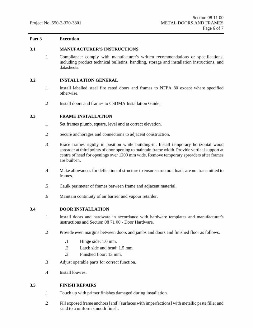
Section 08 11 00 Project No. 550-2-370-3801 METAL DOORS AND FRAMES Page 6 of 7 Part 3 Execution
3.1 MANUFACTURER'S INSTRUCTIONS
.1 Compliance: comply with manufacturer's written recommendations or specifications, including product technical bulletins, handling, storage and installation instructions, and datasheets.
3.2 INSTALLATION GENERAL
.1 Install labelled steel fire rated doors and frames to NFPA 80 except where specified otherwise.
.2 Install doors and frames to CSDMA Installation Guide.
3.3 FRAME INSTALLATION
.1 Set frames plumb, square, level and at correct elevation.
.2 Secure anchorages and connections to adjacent construction.
.3 Brace frames rigidly in position while building-in. Install temporary horizontal wood spreader at third points of door opening to maintain frame width. Provide vertical support at centre of head for openings over 1200 mm wide. Remove temporary spreaders after frames are built-in.
.4 Make allowances for deflection of structure to ensure structural loads are not transmitted to frames.
.5 Caulk perimeter of frames between frame and adjacent material.
.6 Maintain continuity of air barrier and vapour retarder.
3.4 DOOR INSTALLATION
.1 Install doors and hardware in accordance with hardware templates and manufacturer's instructions and Section 08 71 00 - Door Hardware.
.2 Provide even margins between doors and jambs and doors and finished floor as follows.
.1 Hinge side: 1.0 mm.
.2 Latch side and head: 1.5 mm.
.3 Finished floor: 13 mm.
.3 Adjust operable parts for correct function.
.4 Install louvres.
3.5 FINISH REPAIRS
.1 Touch up with primer finishes damaged during installation.
.2 Fill exposed frame anchors [and] [surfaces with imperfections] with metallic paste filler and sand to a uniform smooth finish.

Section 08 11 00 Project No. 550-2-370-3801 METAL DOORS AND FRAMES Page 7 of 7 3.6 GLAZING
.1 Install glazing for doors and frames as specified.
END OF SECTION 08 11 00

Section 08 14 16 Project No. 550-2-370-3801 Flush Wood Doors Page 1 of 3
Part 1 General
1.1 RELATED SECTIONS
.1 Section 07 92 00: Joint Sealing.
.2 Section 08 11 00 - Metal Doors and Frames.
.3 Section 08 71 00 - Door Hardware.
1.2 REFERENCES
.1 Architectural Woodwork Manufacturers Association of Canada (AWMAC).
.1 Architectural Woodwork Standards, 1st edition, 2009.
.2 Standards Council of Canada (CGSB).
.1 CAN/CGSB-71.19-M88 - Adhesive Contact Sprayable.
.2 CAN/CGSB-71.20-M88 - Adhesive Contact Brushable.
.3 Canadian Standards Association (CSA/CSA International)
.1 CSA O115-M1982(R2001) - Hardwood and Decorative Plywood.
.2 CAN/CSA O132.2-90(C1998) - Flush Wood Doors.
1.3 DOCUMENTS/SAMPLES SUBMITTALS
.1 Shop Drawings:
.1 Submit shop drawings in accordance with Section 01 33 00 - Submittal Procedures.
.2 Indicate door types and cut-outs for lights and louvers, sizes, core construction.
1.4 MANUFACTURER’S INSTRUCTIONS
.1 Submit manufacturer's instructions.
1.5 DELIVERY, STORAGE, AND HANDLING
.1 Storage and Protection of the doors:
.1 Protect doors from dampness. Arrange for delivery after work causing abnormal humidity has been completed.
.2 Store doors in well ventilated room, off floor, in accordance with manufacturer's recommendations.
.3 Protect doors from scratches, handling marks and other damage. Wrap and Crate doors.
.4 Store doors away from direct sunlight.
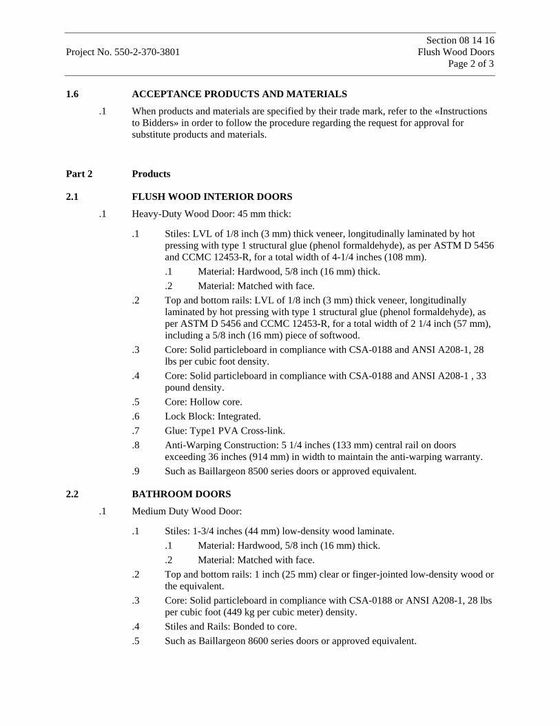
Section 08 14 16 Project No. 550-2-370-3801 Flush Wood Doors Page 2 of 3
1.6 ACCEPTANCE PRODUCTS AND MATERIALS
.1 When products and materials are specified by their trade mark, refer to the «Instructions to Bidders» in order to follow the procedure regarding the request for approval for substitute products and materials.
Part 2 Products
2.1 FLUSH WOOD INTERIOR DOORS
.1 Heavy-Duty Wood Door: 45 mm thick:
.1 Stiles: LVL of 1/8 inch (3 mm) thick veneer, longitudinally laminated by hot pressing with type 1 structural glue (phenol formaldehyde), as per ASTM D 5456 and CCMC 12453-R, for a total width of 4-1/4 inches (108 mm). .1 Material: Hardwood, 5/8 inch (16 mm) thick. .2 Material: Matched with face.
.2 Top and bottom rails: LVL of 1/8 inch (3 mm) thick veneer, longitudinally laminated by hot pressing with type 1 structural glue (phenol formaldehyde), as per ASTM D 5456 and CCMC 12453-R, for a total width of 2 1/4 inch (57 mm), including a 5/8 inch (16 mm) piece of softwood.
.3 Core: Solid particleboard in compliance with CSA-0188 and ANSI A208-1, 28 lbs per cubic foot density.
.4 Core: Solid particleboard in compliance with CSA-0188 and ANSI A208-1 , 33 pound density.
.5 Core: Hollow core.
.6 Lock Block: Integrated.
.7 Glue: Type1 PVA Cross-link.
.8 Anti-Warping Construction: 5 1/4 inches (133 mm) central rail on doors exceeding 36 inches (914 mm) in width to maintain the anti-warping warranty.
.9 Such as Baillargeon 8500 series doors or approved equivalent.
2.2 BATHROOM DOORS
.1 Medium Duty Wood Door:
.1 Stiles: 1-3/4 inches (44 mm) low-density wood laminate. .1 Material: Hardwood, 5/8 inch (16 mm) thick. .2 Material: Matched with face.
.2 Top and bottom rails: 1 inch (25 mm) clear or finger-jointed low-density wood or the equivalent.
.3 Core: Solid particleboard in compliance with CSA-0188 or ANSI A208-1, 28 lbs per cubic foot (449 kg per cubic meter) density.
.4 Stiles and Rails: Bonded to core.
.5 Such as Baillargeon 8600 series doors or approved equivalent.
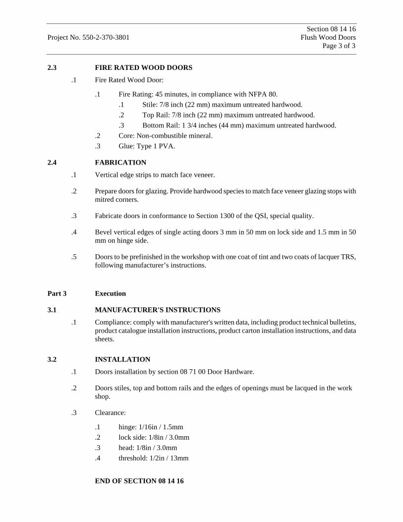
Section 08 14 16 Project No. 550-2-370-3801 Flush Wood Doors Page 3 of 3
2.3 FIRE RATED WOOD DOORS
.1 Fire Rated Wood Door:
.1 Fire Rating: 45 minutes, in compliance with NFPA 80. .1 Stile: 7/8 inch (22 mm) maximum untreated hardwood. .2 Top Rail: 7/8 inch (22 mm) maximum untreated hardwood. .3 Bottom Rail: 1 3/4 inches (44 mm) maximum untreated hardwood.
.2 Core: Non-combustible mineral.
.3 Glue: Type 1 PVA.
2.4 FABRICATION
.1 Vertical edge strips to match face veneer.
.2 Prepare doors for glazing. Provide hardwood species to match face veneer glazing stops with mitred corners.
.3 Fabricate doors in conformance to Section 1300 of the QSI, special quality.
.4 Bevel vertical edges of single acting doors 3 mm in 50 mm on lock side and 1.5 mm in 50 mm on hinge side.
.5 Doors to be prefinished in the workshop with one coat of tint and two coats of lacquer TRS, following manufacturer’s instructions.
Part 3 Execution
3.1 MANUFACTURER'S INSTRUCTIONS
.1 Compliance: comply with manufacturer's written data, including product technical bulletins, product catalogue installation instructions, product carton installation instructions, and data sheets.
3.2 INSTALLATION
.1 Doors installation by section 08 71 00 Door Hardware.
.2 Doors stiles, top and bottom rails and the edges of openings must be lacqued in the work shop.
.3 Clearance:
.1 hinge: 1/16in / 1.5mm
.2 lock side: 1/8in / 3.0mm
.3 head: 1/8in / 3.0mm
.4 threshold: 1/2in / 13mm
END OF SECTION 08 14 16
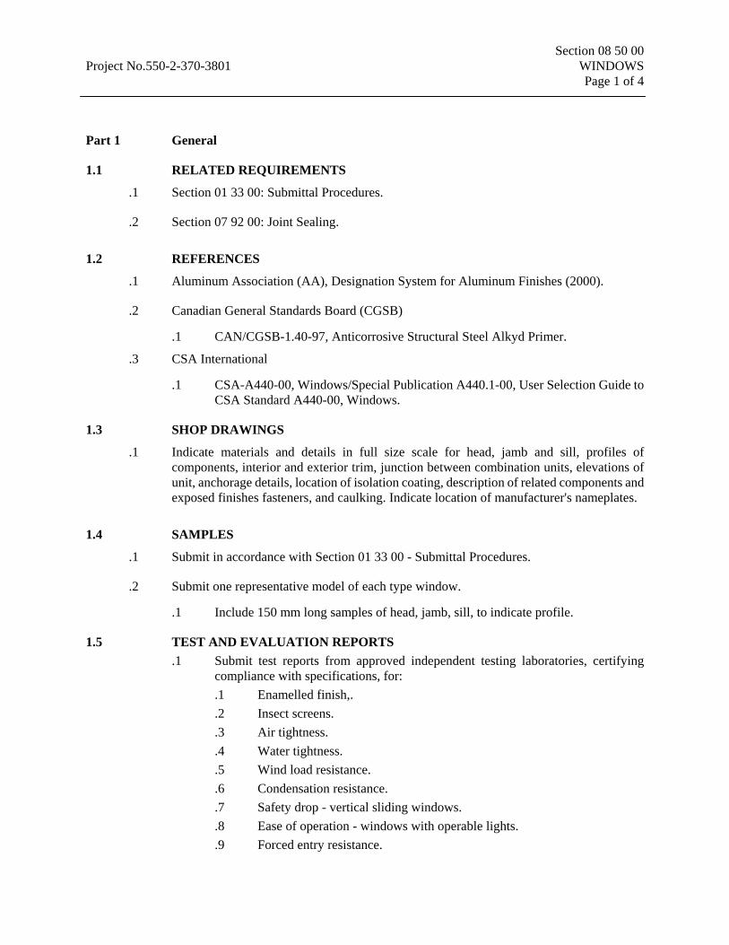
Section 08 50 00 Project No.550-2-370-3801 WINDOWS Page 1 of 4
Part 1 General
1.1 RELATED REQUIREMENTS
.1 Section 01 33 00: Submittal Procedures.
.2 Section 07 92 00: Joint Sealing.
1.2 REFERENCES
.1 Aluminum Association (AA), Designation System for Aluminum Finishes (2000).
.2 Canadian General Standards Board (CGSB)
.1 CAN/CGSB-1.40-97, Anticorrosive Structural Steel Alkyd Primer.
.3 CSA International
.1 CSA-A440-00, Windows/Special Publication A440.1-00, User Selection Guide to CSA Standard A440-00, Windows.
1.3 SHOP DRAWINGS
.1 Indicate materials and details in full size scale for head, jamb and sill, profiles of components, interior and exterior trim, junction between combination units, elevations of unit, anchorage details, location of isolation coating, description of related components and exposed finishes fasteners, and caulking. Indicate location of manufacturer's nameplates.
1.4 SAMPLES
.1 Submit in accordance with Section 01 33 00 - Submittal Procedures.
.2 Submit one representative model of each type window.
.1 Include 150 mm long samples of head, jamb, sill, to indicate profile.
1.5 TEST AND EVALUATION REPORTS .1 Submit test reports from approved independent testing laboratories, certifying
compliance with specifications, for: .1 Enamelled finish,. .2 Insect screens. .3 Air tightness. .4 Water tightness. .5 Wind load resistance. .6 Condensation resistance. .7 Safety drop - vertical sliding windows. .8 Ease of operation - windows with operable lights. .9 Forced entry resistance.
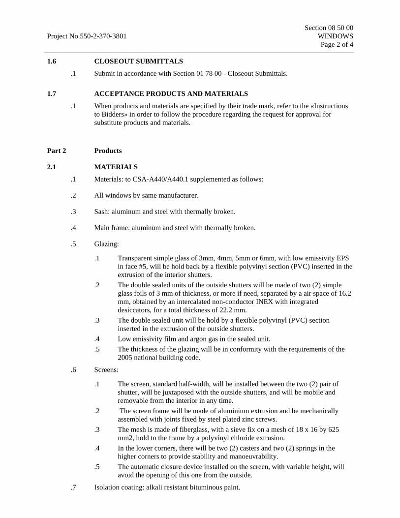
Section 08 50 00 Project No.550-2-370-3801 WINDOWS Page 2 of 4 1.6 CLOSEOUT SUBMITTALS
.1 Submit in accordance with Section 01 78 00 - Closeout Submittals.
1.7 ACCEPTANCE PRODUCTS AND MATERIALS
.1 When products and materials are specified by their trade mark, refer to the «Instructions to Bidders» in order to follow the procedure regarding the request for approval for substitute products and materials.
Part 2 Products
2.1 MATERIALS
.1 Materials: to CSA-A440/A440.1 supplemented as follows:
.2 All windows by same manufacturer.
.3 Sash: aluminum and steel with thermally broken.
.4 Main frame: aluminum and steel with thermally broken.
.5 Glazing:
.1 Transparent simple glass of 3mm, 4mm, 5mm or 6mm, with low emissivity EPS in face #5, will be hold back by a flexible polyvinyl section (PVC) inserted in the extrusion of the interior shutters.
.2 The double sealed units of the outside shutters will be made of two (2) simple glass foils of 3 mm of thickness, or more if need, separated by a air space of 16.2 mm, obtained by an intercalated non-conductor INEX with integrated desiccators, for a total thickness of 22.2 mm.
.3 The double sealed unit will be hold by a flexible polyvinyl (PVC) section inserted in the extrusion of the outside shutters.
.4 Low emissivity film and argon gas in the sealed unit.
.5 The thickness of the glazing will be in conformity with the requirements of the 2005 national building code.
.6 Screens:
.1 The screen, standard half-width, will be installed between the two (2) pair of shutter, will be juxtaposed with the outside shutters, and will be mobile and removable from the interior in any time.
.2 The screen frame will be made of aluminium extrusion and be mechanically assembled with joints fixed by steel plated zinc screws.
.3 The mesh is made of fiberglass, with a sieve fix on a mesh of 18 x 16 by 625 mm2, hold to the frame by a polyvinyl chloride extrusion.
.4 In the lower corners, there will be two (2) casters and two (2) springs in the higher corners to provide stability and manoeuvrability.
.5 The automatic closure device installed on the screen, with variable height, will avoid the opening of this one from the outside.
.7 Isolation coating: alkali resistant bituminous paint.
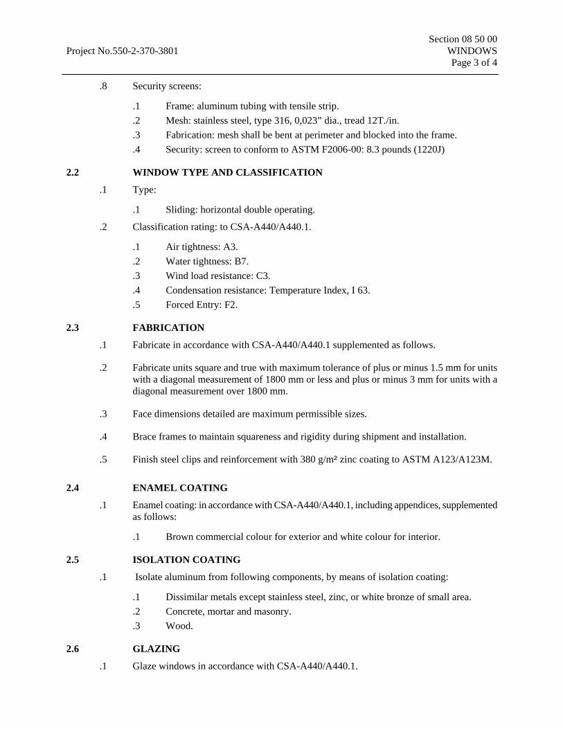
Section 08 50 00 Project No.550-2-370-3801 WINDOWS Page 3 of 4
.8 Security screens:
.1 Frame: aluminum tubing with tensile strip.
.2 Mesh: stainless steel, type 316, 0,023” dia., tread 12T./in.
.3 Fabrication: mesh shall be bent at perimeter and blocked into the frame.
.4 Security: screen to conform to ASTM F2006-00: 8.3 pounds (1220J)
2.2 WINDOW TYPE AND CLASSIFICATION
.1 Type:
.1 Sliding: horizontal double operating.
.2 Classification rating: to CSA-A440/A440.1.
.1 Air tightness: A3.
.2 Water tightness: B7.
.3 Wind load resistance: C3.
.4 Condensation resistance: Temperature Index, I 63.
.5 Forced Entry: F2.
2.3 FABRICATION
.1 Fabricate in accordance with CSA-A440/A440.1 supplemented as follows.
.2 Fabricate units square and true with maximum tolerance of plus or minus 1.5 mm for units with a diagonal measurement of 1800 mm or less and plus or minus 3 mm for units with a diagonal measurement over 1800 mm.
.3 Face dimensions detailed are maximum permissible sizes.
.4 Brace frames to maintain squareness and rigidity during shipment and installation.
.5 Finish steel clips and reinforcement with 380 g/m5 zinc coating to ASTM A123/A123M.
2.4 ENAMEL COATING
.1 Enamel coating: in accordance with CSA-A440/A440.1, including appendices, supplemented as follows:
.1 Brown commercial colour for exterior and white colour for interior.
2.5 ISOLATION COATING
.1 Isolate aluminum from following components, by means of isolation coating:
.1 Dissimilar metals except stainless steel, zinc, or white bronze of small area.
.2 Concrete, mortar and masonry.
.3 Wood.
2.6 GLAZING
.1 Glaze windows in accordance with CSA-A440/A440.1.
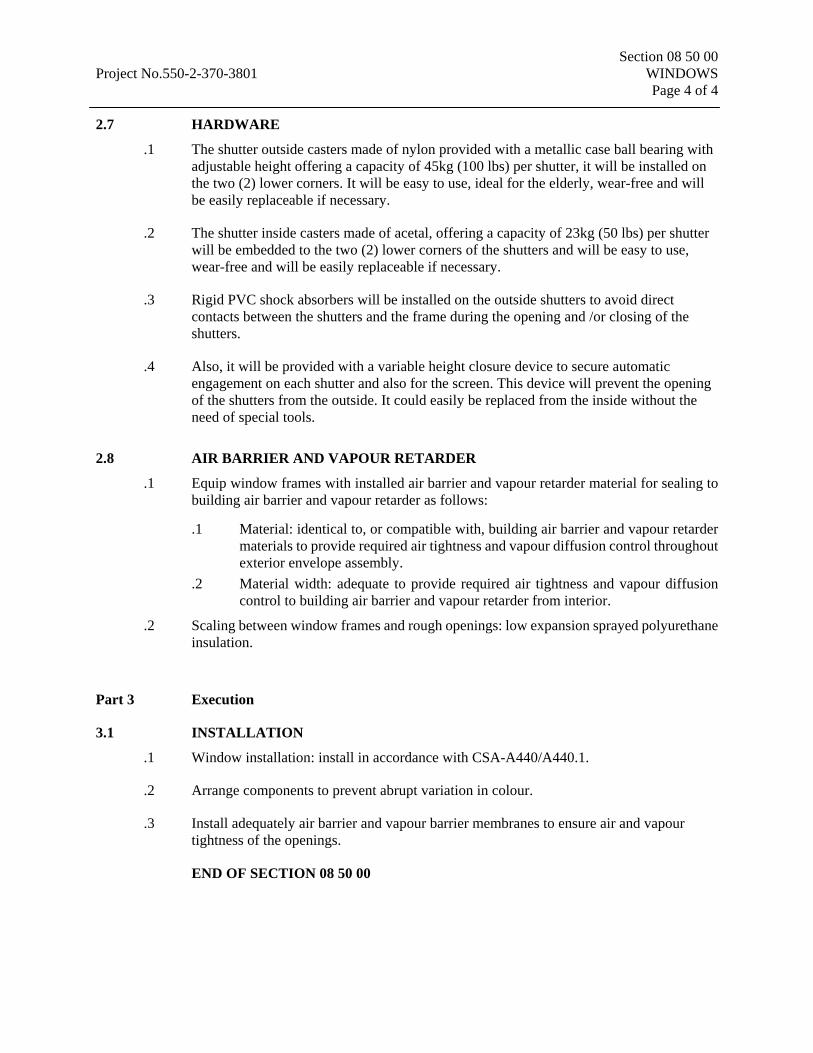
Section 08 50 00 Project No.550-2-370-3801 WINDOWS Page 4 of 4 2.7 HARDWARE
.1 The shutter outside casters made of nylon provided with a metallic case ball bearing with adjustable height offering a capacity of 45kg (100 lbs) per shutter, it will be installed on the two (2) lower corners. It will be easy to use, ideal for the elderly, wear-free and will be easily replaceable if necessary.
.2 The shutter inside casters made of acetal, offering a capacity of 23kg (50 lbs) per shutter will be embedded to the two (2) lower corners of the shutters and will be easy to use, wear-free and will be easily replaceable if necessary.
.3 Rigid PVC shock absorbers will be installed on the outside shutters to avoid direct contacts between the shutters and the frame during the opening and /or closing of the shutters.
.4 Also, it will be provided with a variable height closure device to secure automatic engagement on each shutter and also for the screen. This device will prevent the opening of the shutters from the outside. It could easily be replaced from the inside without the need of special tools.
2.8 AIR BARRIER AND VAPOUR RETARDER
.1 Equip window frames with installed air barrier and vapour retarder material for sealing to building air barrier and vapour retarder as follows:
.1 Material: identical to, or compatible with, building air barrier and vapour retarder materials to provide required air tightness and vapour diffusion control throughout exterior envelope assembly.
.2 Material width: adequate to provide required air tightness and vapour diffusion control to building air barrier and vapour retarder from interior.
.2 Scaling between window frames and rough openings: low expansion sprayed polyurethane insulation.
Part 3 Execution
3.1 INSTALLATION
.1 Window installation: install in accordance with CSA-A440/A440.1.
.2 Arrange components to prevent abrupt variation in colour.
.3 Install adequately air barrier and vapour barrier membranes to ensure air and vapour tightness of the openings.
END OF SECTION 08 50 00
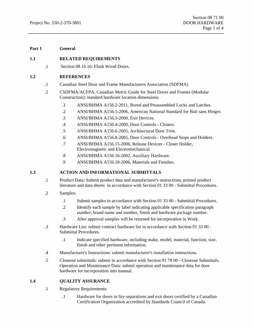
Section 08 71 00 Project No. 550-2-370-3801 DOOR HARDWARE Page 1 of 4
Part 1 General
1.1 RELATED REQUIREMENTS
.1 Section 08 14 16: Flush Wood Doors.
1.2 REFERENCES
.1 Canadian Steel Door and Frame Manufacturers Association (SDFMA)
.2 CSDFMA/ACFPA, Canadian Metric Guide for Steel Doors and Frames (Modular Construction): standard hardware location dimensions.
.1 ANSI/BHMA A156.2-2011, Bored and Preassembled Locks and Latches.
.2 ANSI/BHMA A156.1-2006, American National Standard for Butt sans Hinges
.3 ANSI/BHMA A156.3-2000, Exit Devices.
.4 ANSI/BHMA A156.4-2000, Door Controls - Closers.
.5 ANSI/BHMA A156.6-2005, Architectural Door Trim.
.6 ANSI/BHMA A156.8-2005, Door Controls - Overhead Stops and Holders.
.7 ANSI/BHMA A156.15-2006, Release Devices - Closer Holder, Electromagnetic and Electromechanical.
.8 ANSI/BHMA A156.16-2002, Auxiliary Hardware.
.9 ANSI/BHMA A156.18-2006, Materials and Finishes.
1.3 ACTION AND INFORMATIONAL SUBMITTALS
.1 Product Data: Submit product data and manufacturer's instructions, printed product literature and data sheets in accordance with Section 01 33 00 - Submittal Procedures.
.2 Samples:
.1 Submit samples in accordance with Section 01 33 00 - Submittal Procedures.
.2 Identify each sample by label indicating applicable specification paragraph number, brand name and number, finish and hardware package number.
.3 After approval samples will be returned for incorporation in Work.
.3 Hardware List: submit contract hardware list in accordance with Section 01 33 00 - Submittal Procedures.
.1 Indicate specified hardware, including make, model, material, function, size, finish and other pertinent information.
.4 Manufacturer's Instructions: submit manufacturer's installation instructions.
.5 Closeout submittals: submit in accordance with Section 01 78 00 - Closeout Submittals. Operation and Maintenance Data: submit operation and maintenance data for door hardware for incorporation into manual.
1.4 QUALITY ASSURANCE
.1 Regulatory Requirements:
.1 Hardware for doors in fire separations and exit doors certified by a Canadian Certification Organization accredited by Standards Council of Canada.

Section 08 71 00 Project No. 550-2-370-3801 DOOR HARDWARE Page 2 of 4
.2 Certificates: product certificates signed by manufacturer certifying materials comply with specified performance characteristics and criteria and physical requirements.
1.5 DELIVERY, STORAGE AND HANDLING
.1 Delivery and Acceptance Requirements: deliver materials to site in original factory packaging, labelled with manufacturer's name and address.
.2 Store materials in dry location in clean, dry, well-ventilated area.
Part 2 Products
2.1 HARDWARE ITEMS
.1 Use one manufacturer's products only for similar items.
2.2 DOOR HARDWARE
.1 Locks and latches:
.1 Bored and preassembled locks and latches: to ANSI/BHMA A156.2 -2011, series 4000 bored lock, grade 1.
.2 Knobs : plain design.
.3 Roses round model.
.4 Normal strikes: box type, lip projection not beyond jamb.
.5 Cylinders: key into keying system.
.6 Finished to 626.
.2 Butts and hinges:
.1 Butts and hinges: to ANSI A156.1-2006, designated by letter A and numeral identifiers, followed by size and finish, listed in Hardware Schedule.
.3 Exit devices: to ANSI A156.3, mortise type, grade 1, modern design, finished to 626.
.4 Door Closers and Accessories:
.1 Door controls (closers): to ANSI A156.4, class 1 designated by letter C and numeral identifiers listed in Hardware Schedule.
.2 Door controls - overhead holders: to ANSI/BHMA A156.8, designated by letter C and numeral identifiers listed in Hardware Schedule, finished to 626.
.3 Closer/holder release devices: to ANSI A156.15, designated by letter C and numeral identifiers listed in hardware schedule, finished to 626.
.5 Architectural door trim: to ANSI A156.6, designated by letter J and numeral identifiers listed in Hardware Schedule, finished to 626.
.1 Door protection plates: kick plate type, [1.27 mm thick stainless steel, finished to 626.
.6 Auxiliary hardware: to ANSI A156.16, listed in Hardware Schedule, finished to 626.
.7 Thresholds: 175 mm wide x full width of door opening, extruded aluminum mill finish, serrated surface, with thermal break of rigid PVC, with lip and vinyl door seal insert.
.8 Weather-stripping:
.1 Head and jamb seal:
Section 08 71 00 Project No. 550-2-370-3801 DOOR HARDWARE Page 3 of 4
.1 Extruded aluminum frame and solid closed cell neoprene, clear anodized finish.
.2 Door bottom seal: .1 Extruded aluminum frame and closed cell neoprene, clear anodized
finish.
2.3 FASTENINGS
.1 Use only fasteners provided by manufacturer. Failure to comply may void warranties and applicable licensed labels.
.2 Supply screws, bolts, expansion shields and other fastening devices required for satisfactory installation and operation of hardware.
.3 Exposed fastening devices to match finish of hardware.
.4 Where pull is scheduled on one side of door and push plate on other side, supply fastening devices, and install so pull can be secured through door from reverse side. Install push plate to cover fasteners.
.5 Use fasteners compatible with material through which they pass.
2.4 KEYING
.1 Supply keys in duplicate for every lock in this Contract.
.2 Supply 3 master keys for each master key or grand master key group.
.3 Stamp keying code numbers on keys and cylinders.
.4 Supply construction cores.
.5 Hand over permanent cores and keys to Departmental Representative.
Part 3 Execution
3.1 MANUFACTURER’S INSTRUCTIONS
.1 Manufacturer's Instructions: comply with manufacturer's written recommendations, including product technical bulletins, product catalogue installation instructions, product carton installation instructions, and data sheets.
.2 Supply metal door and frame manufacturers with complete instructions and templates for preparation of their work to receive hardware.
.3 Supply manufacturers' instructions for proper installation of each hardware component.
3.2 INSTALLATION
.1 Take out and store adequately hardware to be re-installed.
.2 Install hardware to standard hardware location dimensions in accordance with CSDFMA Canadian Metric Guide for Steel Doors and Frames (Modular Construction).
.3 Where door stop contacts door pulls, mount stop to strike bottom of pull.
.4 Install key control cabinet.
.5 Use only manufacturer's supplied fasteners. Use of "quick" type fasteners, unless specifically supplied by manufacturer, is unacceptable.
Section 08 71 00 Project No. 550-2-370-3801 DOOR HARDWARE Page 4 of 4
.6 Remove construction cores when directed by Departmental Representative. Install permanent cores and ensure locks operate correctly.
3.3 ADJUSTING
.1 Adjust door hardware, operators, closures and controls for optimum, smooth operating condition, safety and for weather tight closure.
.2 Lubricate hardware, operating equipment and other moving parts.
.3 Adjust door hardware to ensure tight fit at contact points with frames.
3.4 CLEANING
.1 Leave Work area clean at end of each day.
.2 Clean hardware with damp rag and approved non-abrasive cleaner, and polish hardware in accordance with manufacturer's instructions.
.3 Remove protective material from hardware items where present.
.4 Remove recycling containers and bins from site and dispose of materials at appropriate facility.
3.5 DEMONSTRATION
.1 Keying System Setup and Cabinet:
.1 Set up key control system with file key tags, duplicate key tags, numerical index, alphabetical index and key change index, label shields, control book and key receipt cards.
.2 Place file keys and duplicate keys in key cabinet on their respective hooks.
.3 Lock key cabinet and turn over key to Departmental Representative.
.2 Maintenance Staff Briefing:
.1 Brief maintenance staff regarding: .1 Proper care, cleaning, and general maintenance of projects complete
hardware. .2 Description, use, handling, and storage of keys. .3 Use, application and storage of wrenches for door closers, locksets and
fire exit hardware.
.3 Demonstrate operation, operating components, adjustment features, and lubrication requirements.
3.6 SCHEDULE
Next page
END OF SECTION 08 71 00
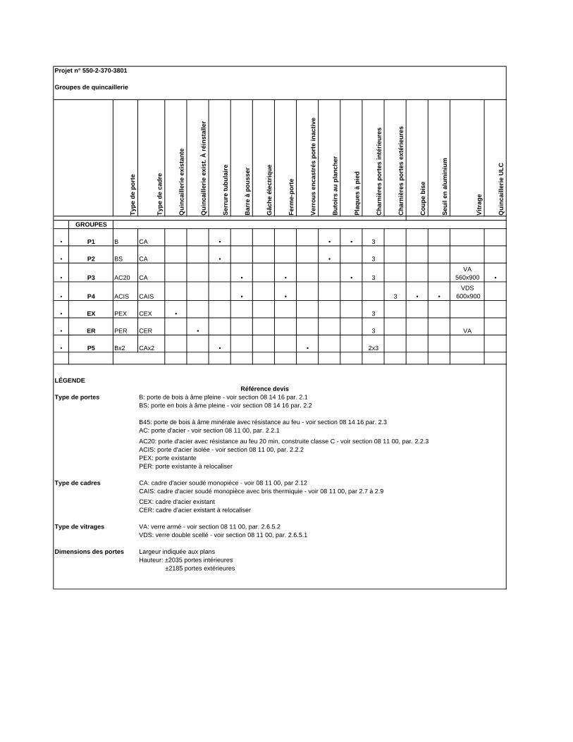
Projet n° 550-2-370-3801
Groupes de quincaillerie
Type
de
port
e
Type
de
cadr
e
Qui
ncai
llerie
exi
stan
te
Qui
ncai
llerie
exi
st. À
réin
stal
ler
Serr
ure
tubu
laire
Bar
re à
pou
sser
Gâc
he é
lect
rique
Ferm
e-po
rte
Verr
ous
enca
stré
s po
rte
inac
tive
But
oirs
au
plan
cher
Plaq
ues
à pi
ed
Cha
rniè
res
port
es in
térie
ures
Cha
rniè
res
port
es e
xtér
ieur
es
Cou
pe b
ise
Seui
l en
alum
iniu
m
Vitr
age
Qui
ncai
llerie
ULC
GROUPES
• P1 B CA • • • 3
• P2 BS CA • • 3
• P3 AC20 CA • • • 3VA
560x900 •
• P4 ACIS CAIS • • 3 • •VDS
600x900
• EX PEX CEX • 3
• ER PER CER • 3 VA
• P5 Bx2 CAx2 • • 2x3
PEX: porte existantePER: porte existante à relocaliser
CAIS: cadre d'acier soudé monopièce avec bris thermiquie - voir 08 11 00, par 2.7 à 2.9
CER: cadre d'acier existant à relocaliser
Dimensions des portes Largeur indiquée aux plansHauteur: ±2035 portes intérieures ±2185 portes extérieures
BS: porte en bois à âme pleine - voir section 08 14 16 par. 2.2
B45: porte de bois à âme minérale avec résistance au feu - voir section 08 14 16 par. 2.3AC: porte d'acier - voir section 08 11 00, par. 2.2.1
Référence devis
Type de cadres
Type de vitragesVDS: verre double scellé - voir section 08 11 00, par. 2.6.5.1VA: verre armé - voir section 08 11 00, par. 2.6.5.2
B: porte de bois à âme pleine - voir section 08 14 16 par. 2.1
ACIS: porte d'acier isolée - voir section 08 11 00, par. 2.2.2
CEX: cadre d'acier existant
CA: cadre d'acier soudé monopièce - voir 08 11 00, par 2.12
AC20: porte d'acier avec résistance au feu 20 min, construite classe C - voir section 08 11 00, par. 2.2.3
LÉGENDE
Type de portes
Section 09 21 16 Project No. 550-2-370-3801 GYPSUM BOARD ASSEMBLIES Page 1 of 5
Part 1 General
1.1 RELATED REQUIREMENTS
.1 Section 01 33 00: Submittal Procedures.
1.2 REFERENCES
.1 ASTM International
.1 ASTM C36/C36M-01, Specification for Gypsum Wallboard.
.2 ASTM C475-02(2007)], Standard Specification for Joint Compound and Joint Tape for Finishing Gypsum Board.
.3 ASTM C840-08, Standard Specification for Application and Finishing of Gypsum Board.
.4 ASTM C1002-07, Standard Specification for Steel Self-Piercing Tapping Screws for the Application of Gypsum Panel Products or Metal Plaster Bases to Wood Studs or Steel Studs.
.5 ASTM C1047-09, Standard Specification for Accessories for Gypsum Wallboard and Gypsum Veneer Base.
.6 ASTM C1177/C1177M-08, Standard Specification for Glass Mat Gypsum Substrate for Use as Sheathing.
.7 ASTM C1178/C1178M-08, Standard Specification for Glass Mat Water-Resistant Gypsum Backing Board.
.8 ASTM C1629-14, Standard Classification for Abuse-Resistant Non decorated Interior Gypsum Panel Products and Fiber-Reinforced Cement Panels.
.2 Association of the Wall and Ceilings Industries International (AWCI)
.3 Underwriters' Laboratories of Canada (ULC)
.1 CAN/ULC-S102-07, Standard Method of Test of Surface Burning Characteristics of Building Materials and Assemblies.
1.3 DELIVERY, STORAGE AND HANDLING
.1 Delivery and Acceptance Requirements: deliver materials to site in original factory packaging, labelled with manufacturer's name and address.
.2 Store gypsum board assemblies materials level off ground in dry location and in accordance with manufacturer's recommendations in clean, dry, well-ventilated area.
.3 Handle gypsum boards to prevent damage to edges, ends or surfaces. Protect prefinished aluminum surfaces with wrapping strippable coating.
1.4 AMBIENT CONDITIONS
.1 Maintain temperature 10 degrees C minimum, 21 degrees C maximum for 48 hours prior to and during application of gypsum boards and joint treatment, and for 48 hours minimum after completion of joint treatment.
Section 09 21 16 Project No. 550-2-370-3801 GYPSUM BOARD ASSEMBLIES Page 2 of 5
.2 Apply board and joint treatment to dry, frost free surfaces.
.3 Ventilation: ventilate building spaces as required to remove excess moisture that would prevent drying of joint treatment material immediately after its application.
1.5 SAMPLES
.1 Submit in accordance with Section 01-33 00 - Submittal procedures.
.2 Submit one (1) sample, 300mm x 300mm of glass mat gypsum board and of finishing trims.
1.6 ACCEPTANCE PRODUCTS AND MATERIALS
.1 When products and materials are specified by their trade mark, refer to the «Instructions to Bidders» in order to follow the procedure regarding the request for approval for substitute products and materials.
Part 2 Products
2.1 MATERIALS
.1 Standard board: to ASTM C1396/C1396M, Type X, 16 mm thick, 1200 mm wide x maximum practical length, ends square cut, edges bevelled on the sides. For ceilings application.
.2 Water resistant glass mat gypsum board, type X, 16 mm thick, impact resistant, 1200 mm wide x maximum practical length, ends square cut, edges bevelled on the sides. For ceilings application.
.3 Glass mat gypsum substrate sheathing: to ASTM C1178/C1178M, 16 mm thick, 1200 mm wide x maximum practical length. To be used as a substrate for ceramic tile. Such as DENSSHIELD from Georgia-Pacific.
.4 Resilient drywall furring: 0.5 mm base steel thickness galvanized steel for resilient attachment of gypsum board.
.5 Steel drill screws: to ASTM C1002.
.6 Casing beads, corner beads, control joints and edge trim: to ASTM C1047, [metal, zinc-coated by electrolytic process, 0.5 mm base thickness, perforated flanges, one piece length per location.
.7 Sealants: in accordance with Section 07 92 00 - Joint Sealants.
.8 Acoustic sealant: in accordance with ONGC9-GP-21M.
.9 Insulating strips: open cell neoprene strips, 3 mm thick x 12 mm width, with one face self-adhesive.
.10 Joint compound: to ASTM C475, asbestos-free.
Section 09 21 16 Project No. 550-2-370-3801 GYPSUM BOARD ASSEMBLIES Page 3 of 5
.11 Acoustical insulation:
.1 For partitions: to CAN4-S114, non combustible, glass or mineral fiber mats.
.2 For ceilings: mineral fiber mats, 150 mm thick, 40kg/cu.m. density. Such as Roxul AFB.
Part 3 Execution
3.1 ERECTION
.1 Do application and finishing of gypsum board to ASTM C840 except where specified otherwise.
.2 Do application of gypsum sheathing to ASTM C1280.
.3 Install work level to tolerance of 1:1200.
.4 Frame with furring channels, perimeter of openings for access panels, light fixtures, diffusers, grilles..
.5 Install furring above ceilings for gypsum board fire and sound stops and to form plenum areas.
3.2 APPLICATION
.1 Apply gypsum board after bucks, anchors, blocking, sound attenuation, electrical and mechanical work have been approved.
.2 Apply layers gypsum board to wood furring or framing using screw fasteners. Maximum spacing of screws 300 mm on centre.
.1 Single-Layer Application: .1 Apply gypsum board on ceilings prior to application of walls to ASTM
C840. .2 Apply gypsum board vertically or horizontally, providing sheet lengths that
will minimize end joints. .2 Double-Layer Application:
.1 Install gypsum board for base layer and exposed gypsum board for face layer.
.2 Apply base layer to ceilings prior to base layer application on walls; apply face layers in same sequence. Offset joints between layers at least [250] mm.
.3 Apply base layers at right angles to supports unless otherwise indicated.
.4 Apply base layer on walls and face layers vertically with joints of base layer over supports and face layer joints offset at least 250 mm with base layer joints.
.3 Apply water-resistant gypsum board where wall tiles coating to be applied. Apply water-resistant sealant to edges, ends, cut-outs which expose gypsum core and to fastener heads. Do not apply joint treatment on areas to receive tile finish.
Section 09 21 16 Project No. 550-2-370-3801 GYPSUM BOARD ASSEMBLIES Page 4 of 5
.4 Apply 12 mm diameter bead of acoustic sealant continuously around periphery of each face of partitioning to seal gypsum board/structure junction where partitions abut fixed building components. Seal full perimeter of cut-outs around electrical boxes, ducts, in partitions where perimeter sealed with acoustic sealant.
.5 Install ceiling boards in direction that will minimize number of end-butt joints. Stagger end joints at least 250 mm.
.6 Install gypsum board on walls vertically to avoid end-butt joints. At stairwells and similar high walls, install boards horizontally with end joints staggered over studs, except where local codes or fire-rated assemblies require vertical application.
.7 Install gypsum board with face side out.
.8 Do not install damaged or damp boards.
.9 Locate edge or end joints over supports. Stagger vertical joints over different studs on opposite sides of wall.
3.3 INSTALLATION
.1 Erect accessories straight, plumb or level, rigid and at proper plane. Use full length pieces where practical. Make joints tight, accurately aligned and rigidly secured. Mitre and fit corners accurately, free from rough edges. Secure using contact adhesive for full length.
.2 Install casing beads around perimeter of suspended ceilings.
.3 Install casing beads where gypsum board butts against surfaces having no trim concealing junction and where indicated. Seal joints with sealant.
.4 Install insulating strips continuously at edges of gypsum board and casing beads abutting metal window and exterior door frames, to provide thermal break.
.5 Install access doors to electrical and mechanical fixtures specified in respective sections.
.1 Rigidly secure frames to furring or framing systems.
.6 Finish face panel joints and internal angles with joint system consisting of joint compound, joint tape and taping compound installed according to manufacturer's directions and feathered out onto panel faces.
.7 Gypsum Board Finish: finish gypsum board walls and ceilings to following levels in accordance with AWCI Levels of Gypsum Board Finish. Finishing work must be in accordance with level 4.
.1 Levels of finish: .1 Level 0: no tapping, finishing or accessories required. .2 Level 1: embed tape for joints and interior angles in joint compound.
Surfaces to be free of excess joint compound; tool marks and ridges are acceptable.
.3 Level 2: embed tape for joints and interior angles in joint compound and apply one separate coat of joint compound over joints, angles, fastener
Section 09 21 16 Project No. 550-2-370-3801 GYPSUM BOARD ASSEMBLIES Page 5 of 5
heads and accessories; surfaces free of excess joint compound; tool marks and ridges are acceptable.
.4 Level 3: embed tape for joints and interior angles in joint compound and apply two separate coats of joint compound over joints, angles, fastener heads and accessories; surfaces smooth and free of tool marks and ridges.
.5 Level 4: embed tape for joints and interior angles in joint compound and apply three separate coats of joint compound over joints, angles, fastener heads and accessories; surfaces smooth and free of tool marks and ridges.
.6 Level 5: embed tape for joints and interior angles in joint compound and apply three separate coats of joint compound over joints, angles, fastener heads and accessories; apply a thin skim coat of joint compound to entire surface; surfaces smooth and free of tool marks and ridges.
.8 Finish corner beads, control joints and trim as required with two coats of joint compound and one coat of taping compound, feathered out onto panel faces.
.9 Fill screw head depressions with joint and taping compounds to bring flush with adjacent surface of gypsum board so as to be invisible after surface finish is completed.
.10 Sand lightly to remove burred edges and other imperfections. Avoid sanding adjacent surface of board.
.11 Completed installation to be smooth, level or plumb, free from waves and other defects and ready for surface finish.
.12 Protect gypsum finishes up to the time of substantial completion of the contract.
3.4 SCHEDULES
.1 Construct fire rated assemblies where indicated.
.1 3/4 hour fire rated partition assembly, Design No. W1a. Chart A-9.10.3.1.A Construction Code, 2005.
.2 [___] hour[s] fire rated floor/ceiling assembly, Design No. F5c, Chart A9.10.3.1.B, Construction Code, 2005.
END OF SECTION 09 21 06
Section 09 30 13 Project No. 550-2-370-3801 CERAMIC TILING Page 1 of 4
Part 1 General
1.1 RELATED REQUIREMENTS
.1 Section 06 10 00: Rough Carpentry.
.2 Section 09 21 16: Gypsum Board Assemblies.
1.2 REFERENCES
.1 American National Standards Institute (ANSI)/Ceramic Tile Institute (CTI)
.1 ANSI A108.1-99, Specification for the Installation of Ceramic Tile (Includes ANSI A108.1A-C, 108.4-.13, A118.1-.10, ANSI A136.1).
.2 American Society for Testing and Materials International (ASTM)
.1 ASTM C979-05, Specification for Pigments for Integrally Coloured Concrete.
.3 Canadian General Standards Board (CGSB)
.1 CAN/CGSB-75.1-M88, Tile, Ceramic.
.2 CAN/CGSB-25.20-[95], Surface Sealer for Floors.
.4 Terrazzo Tile and Marble Association of Canada (TTMAC)
.1 Tile Specification Guide 09 30 00 2006/2007, Tile Installation Manual.
1.3 ACTION AND INFORMATIONAL SUBMITTALS
.1 Provide submittals in accordance with Section 01 33 00 - Submittal Procedures.
.2 Provide product data in accordance with Section 01 33 00 - Submittal Procedures.
.1 Include manufacturer's information on: .1 Ceramic tile, marked to show each type, size, and shape required. .2 Levelling compound. .3 Latex cement mortar and grout. .4 Commercial cement grout. .5 Organic adhesive. .6 Waterproofing isolation membrane.
.3 Provide samples in accordance with Section 01 33 00 - Submittal Procedure].
.1 Floor tile: submit duplicate, 300 x 300 mm sample panels of each colour, texture, size, and pattern of tile.
.2 Adhere tile samples to 11 mm thick plywood and grout joints to represent project installation.
.3 Submit two (2) samples of marble doorstep and of aluminum trims.
1.4 QUALITY ASSURANCE
.1 Quality Assurance Submittals:
Section 09 30 13 Project No. 550-2-370-3801 CERAMIC TILING Page 2 of 4
.1 Manufacturer's Instructions: manufacturer's installation instructions.
1.5 AMBIENT CONDITIONS
.1 Maintain air temperature and structural base temperature at ceramic tile installation area above 12 degrees C for 48 hours before, during, and 48 hours after, installation.
.2 Do not install tiles at temperatures less than 12 degrees C or above 38 degrees C.
1.6 MAINTENANCE
.1 Extra Materials:
.1 Provide maintenance materials in accordance with Section 01 78 00 - Closeout Submittals,
.2 Provide minimum 2% of each type and colour of tile required for project for maintenance use. Store where directed.
1.7 ACCEPTANCE PRODUCTS AND MATERIALS
.1 When products and materials are specified by their trade mark, refer to the «Instructions to Bidders» in order to follow the procedure regarding the request for approval for substitute products and materials.
Part 2 Products
2.1 FLOOR TILE
.1 Porcelain tile: to CAN/CGSB-75.1, Class MR (02 -3.0%), 100 x 6 mm size, rounded edges, static coefficient of friction (wet surface) ≤0.60 to ASTM C1028, color to be selected by Departmental Representative among the complete selection of PORCEALTO from Daltile.
2.2 WALL TILE
.1 Ceramic mosaic tile: to CAN/CGSB-75.1, Type 1, Class MR 2, 108 x 218 x 6 mm size, rounded edges, color to be selected by Departmental Representative among the complete selection of MODERN DIMENSIONS of Daltile.
2.3 TRIM SHAPES
.1 Wall corners: RONDEC/AC, W, from Schluter.
.2 Tiling top edge: RONDEC/DB/AE, from Schluter.
2.4 WATERPROOF MEMBRANE
.1 Cimenteous flexible membrane, glass fiber reinforced, two components, such as MAPELASTIC 315 form Mapei. To be installed on the floor of the bathrooms and on the sides of the bathtub enclosure.

Section 09 30 13 Project No. 550-2-370-3801 CERAMIC TILING Page 3 of 4 2.5 BOND COAT
.1 Organic adhesive: to ANSI A136.1. Such as ULTRAMASTIC form Mapei. To be used to install wall tiles, except on the walls enclosing the bathtub.
.2 Latex Cement mortar: to ANSI A118.4, two-component universal dry-set mortar. Such as KERABOND/KERALASTIC from Mapei. To be used to install floor tiles and wall tiles on the walls enclosing the bathtub
2.6 GROUT
.1 Colouring Pigments:
.1 Pure mineral pigments, limeproof and nonfading, complying with ASTM C979.
.2 Colouring pigments to be added to grout by manufacturer.
.3 Job coloured grout are not acceptable.
.4 Use in Commercial Cement Grout, Dry-Set Grout, and Latex Cement Grout.
.2 Dry-Set Grout: to CTI A118.6.Latex Cement Grout: to ANSI A118.6, fast curing, high early strength, polymer-modified, stain resistant, sanded mix for floors, unsanded mix for walls and floors with polished tiles commercial tile grout. KERACOLOR for floors and KERACOLOR U for walls, from Mapei.
2.7 ACCESSORIES
.1 Thresholds: marble, 19 mm thick, rounded edges bevelled two sides, honed finish to exposed surfaces, size to suit door opening and frame width.
.2 Sealant: Silicone-based with integrated fungicide, such as PROGLAZE from Tremco or SANITARY 1700 from GE.
2.8 MIXES
.1 Mix bond and levelling coats, and grout to manufacturer's instructions.
Part 3 Execution
3.1 MANUFACTURER'S INSTRUCTIONS
.1 Compliance: comply with manufacturer's written recommendations or specifications, including product technical bulletins, handling, storage and installation instructions, and datasheets.
3.2 WORKMANSHIP
.1 Do tile work in accordance with TTMAC Tile Installation Manual 2006/2007, "Ceramic Tile", except where specified otherwise.
.2 Apply tile to clean and sound surfaces. Prior to installation, make sure marble door step is higher than floor drain by checking their respective levels.
.3 Fit tile around corners, fitments, fixtures, drains and other built-in objects. Maintain uniform joint appearance. Cut edges smooth and even. Do not split tiles.

Section 09 30 13 Project No. 550-2-370-3801 CERAMIC TILING Page 4 of 4
.4 Maximum surface tolerance 1:800.
.5 Make joints between tile uniform and approximately 2.0 mm wide, plumb, straight, true, even and flush with adjacent tile. Ensure sheet layout not visible after installation. Align patterns.
.6 Apply waterproof membrane on floor and continue up to 100 mm high on perimeter walls. Apply also on the walls enclosing the bathtubs. Membrane must make watertight joint at floor drain and at the bases of the shower cubicle. Continue membrane underneath marble door step.
.7 Lay out tiles so perimeter tiles are minimum 1/2 size. Install aluminum trims at angles and at top of wall tiles.
.8 Sound tiles after setting and replace hollow-sounding units to obtain full bond.
.9 Allow minimum 24 hours after installation of tiles, before grouting.
.10 Clean installed tile surfaces after installation and grouting cured.
3.3 WALL TILE
.1 Install in accordance with TTMAC details 305W and 306W, with membrane on the walls enclosing bathtub.
3.4 FLOOR TILE
.1 Install in accordance with TTMAC detail 313F with membrane.
END OF SECTION 09 30 13
Section 09 65 16 Project No. 550-2-370-3801 RESILIENT SHEET FLOORING Page 1 of 4
Part 1 General
1.1 RELATED SECTIONS
.1 Section 06 10 00: Rough Carpentry.
.2 Section 09 65 19: Resilient Tile Flooring.
1.2 REFERENCES
.1 South Coast Air Quality Management District (SCAQMD), California State
.1 SCAQMD Rule 1168-05, Adhesives and Sealants Applications.
1.3 SUBMITTALS
.1 Provide submittals in accordance with Section 01 33 00 - Submittal Procedures.
.2 Provide product data in accordance with Section 01 33 00 - Submittal Procedures.
.3 Provide samples in accordance with Section 01 33 00 - Submittal Procedures.
.1 Submit duplicate 300 x 300 mm sample pieces of sheet material, 300 mm long base.
.4 Provide maintenance data for resilient flooring for incorporation into manual specified in Section 01 78 00 - Closeout Submittals.
1.4 AMBIENT CONDITIONS
.1 Maintain air temperature and structural base temperature at flooring installation area above 20 degrees for 48 hours before, during and 48 hours after installation.
1.5 MAINTENANCE
.1 Extra Materials:
.1 Provide extra materials of resilient sheet flooring and adhesives.
.2 Provide 6 m2 of each colour, pattern and type flooring material required for project for maintenance use.
.3 Extra materials one piece and from same production run as installed materials.
.4 Identify each roll of sheet flooring and each container of adhesive.
.5 Deliver to Departmental Representative, upon completion of the work of this section.
.6 Store where directed by Departmental Representative.
1.6 ACCEPTANCE PRODUCTS AND MATERIALS
.1 When products and materials are specified by their trade mark, refer to the «Instructions to Bidders» in order to follow the procedure regarding the request for approval for substitute products and materials.
Section 09 65 16 Project No. 550-2-370-3801 RESILIENT SHEET FLOORING Page 2 of 4 Part 2 Products
2.1 MATERIALS
.1 Linoleum sheet flooring: composed of natural ingredients which are mixed and calendared onto a jute backing.
.1 Pattern: to match existing for local patches; to be selected by Departmental representative, among the selection of manufacturer, for the new linoleum on the ground floor.
.2 Thickness: 2.0 mm.
.2 Linoleum base: continuous, top set.
.1 Thickness: 2.0 mm.
.2 Height: 100 mm.
.3 Lengths: 2400 mm.
.4 Colour: to match flooring.
.3 Primers and adhesives: of types recommended by resilient flooring manufacturer for specific material on applicable substrate, above, on or below grade.
.1 Linoleum floor adhesives: .1 Adhesive: maximum VOC limit 60 g/L.
.4 Sub-floor filler and leveller: 2 part latex-type filler requiring no water as recommended by flooring manufacturer for use with their product.
.5 Transition edge strips:
.1 Vinyl strips with lip to extend under floor finish, shoulder flush with top of adjacent floor finish.
.6 Sealer and wax: type recommended by resilient flooring material manufacturer for material type and location.
Part 3 Execution
3.1 MANUFACTURER'S INSTRUCTIONS
.1 Compliance: comply with manufacturer's written recommendations or specifications, including product technical bulletins, handling, storage and installation instructions, and datasheets.
3.2 SITE VERIFICATION OF CONDITIONS
.1 Ensure concrete floors are clean and dry by using test methods recommended by flooring manufacturer.
3.3 PREPARATION
.1 Remove existing resilient flooring.
Section 09 65 16 Project No. 550-2-370-3801 RESILIENT SHEET FLOORING Page 3 of 4
.2 Remove or treat old adhesives to prevent residual, old flooring adhesives from bleeding through to new flooring and/or interfering with the bonding of new adhesives.
.3 Clean floor and apply filler; trowel and float to leave smooth, flat hard surface. Prohibit traffic until filler cured and dry.
.4 Remove sub-floor ridges and bumps. Fill low spots, cracks, joints, holes and other defects with sub-floor filler.
.5 Prime substract to resilient flooring manufacturer's printed instructions.
3.4 APPLICATION: FLOORING
.1 Provide high ventilation rate, with maximum outside air, during installation, and for 48 hours after installation. If possible, vent directly to outside. Do not let contaminated air recirculate through district or whole building air distribution system.
.2 Apply adhesive uniformly using recommended trowel. Do not spread more adhesive than can be covered by flooring before initial set takes place.
.3 Lay flooring to produce a minimum number of seams. Border widths minimum 1/3 width of full material.
.4 Run sheets in direction of traffic. Double cut sheet joints heat weld according to manufacturer's printed instructions.
.5 As installation progresses, and after installation roll flooring with 45 kg minimum roller to ensure full adhesion.
.6 Cut flooring around fixed objects.
.7 Continue flooring over areas which will be under built-in furniture.
.8 Continue flooring through areas to receive movable type partitions without interrupting floor pattern.
.9 Terminate flooring at centreline of door in openings where adjacent floor finish or colour is dissimilar.
.10 Install metal edge strips at unprotected or exposed edges where flooring terminates.
3.5 APPLICATION: BASE
.1 Lay out base to keep number of joints at minimum. Use straight bases on ground floor and toe bases identical to existing ones in the basement.
.2 Clean substrate and prime with one coat of adhesive.
.3 Apply adhesive to back of base.
.4 Set base against wall and floor surfaces tightly by using 3 kg hand roller.
.5 Install straight and level to variation of 1:1000.
Section 09 65 16 Project No. 550-2-370-3801 RESILIENT SHEET FLOORING Page 4 of 4
.6 Scribe and fit to door frames and other obstructions. Use premoulded end pieces at flush door frames.
.7 Heat weld base in accordance with manufacturer's printed instructions.
3.6 CLEANING
.1 Proceed in accordance with Section 01 74 11 - Cleaning.
.2 Remove excess adhesive from floor, base and wall surfaces without damage.
.3 Clean, seal and wax floor and base surface to flooring manufacturer's printed instructions.
3.7 PROTECTION
.1 Protect new floors from time of final set of adhesive until final inspection.
.2 Prohibit traffic on floor for 48 hours after installation.
.3 Use only water-based coating for linoleum.
END OF SECTION 09 65 16

Section 09 65 19 Project No. 550-2-370-3801. RESILIENT TILE FLOORING Page 1 of 4
Part 1 General
1.1 RELATED SECTIONS
.1 Section 06 10 00: Rough Carpentry.
1.2 REFERENCES
.1 American Society for Testing and Materials International (ASTM)
.1 ASTM F1066-04, Standard Specification for Vinyl Composition Floor Tile.
.2 ASTM F1344-04, Standard Specification for Rubber Floor Tile.
.2 Canadian General Standards Board (CGSB)
.1 CAN/CGSB-25.20-95, Surface Sealer for Floors.
.3 South Coast Air Quality Management District (SCAQMD), California State
.1 SCAQMD Rule 1168-05, Adhesives and Sealants Applications.
1.3 SUBMITTALS
.1 Provide submittals in accordance with Section 01 33 00 - Submittal Procedures.
.2 Provide product data in accordance with Section 01 33 00 - Submittal Procedures.
.3 Provide samples in accordance with Section 01 33 00 - Submittal Procedures.
.1 Submit duplicate tile in size specified, 300 mm long base, nosing, feature strips, treads, edge strips.
.4 Closeout Submittals:
.1 Provide maintenance data for resilient flooring for incorporation into manual specified in Section 01 78 00 - Closeout Submittals.
1.4 ENVIRONMENTAL REQUIREMENTS
.1 Maintain air temperature and structural base temperature at flooring installation area above 20 degrees C for 48 hours before, during and for 48 hours after installation.
1.5 MAINTENANCE
.1 Extra Materials:
.1 Provide maintenance materials of resilient tile flooring, base and adhesive.
.2 Provide 5m2 of each colour, pattern and type flooring material required for this project for maintenance use.
.3 Extra materials from same production run as installed materials.
.4 Identify each container of floor tile and each container of adhesive.
.5 Deliver to Departmental Representative, upon completion of the work of this section.
.6 Store where directed by Departmental Representative.
Section 09 65 19 Project No. 550-2-370-3801. RESILIENT TILE FLOORING Page 2 of 4 1.6 ACCEPTANCE PRODUCTS AND MATERIALS
.1 When products and materials are specified by their trade mark, refer to the «Instructions to Bidders» in order to follow the procedure regarding the request for approval for substitute products and materials.
Part 2 Products
2.1 MATERIALS
.1 High vinyl tile: to ASTM F1066, Composition 1 - non asbestos, Class 2 - through pattern tile plain, 3 mm, 300 x 300 mm size, colors to be selected by Departmental Representative, among manufacturer’s complete selection
.2 Rubber tile: to ASTM F1344, Class 1 - Homogeneous rubber tile, A-solid colour, smooth surface design, 3 mm base thickness 610 x 610 mm size, colour selected by Departmental Representative.
.3 Resilient base: rubber, straight, minimum 1200 mm length and 82 mm high selected by Departmental Representative, among the TIGHT LOCK series from Johnsonite
.4 Steps and risers: rubber combined steps and risers, from the series VIHTR form Johnsonite; color by Departmental Representative.
.5 Primers and adhesives: waterproof, recommended by flooring manufacturer for specific material on applicable substrate, above, at or below grade.
.1 Flooring adhesives: .1 Adhesive: maximum VOC limit 60 g/L.
.2 Cove base adhesives: .1 Adhesive: maximum VOC limit 50 g/L .
.6 Sub-floor filler and leveller: 2 part latex-type filler requiring no water as recommended by flooring manufacturer for use with their product.
.7 Transition vinyl edge strips: with lip to extend under floor finish, shoulder flush with top of adjacent floor finish.
.8 Sealer: type recommended by flooring manufacturer.
.9 Wax: type recommended by flooring manufacturer.
Part 3 Execution
3.1 MANUFACTURER'S INSTRUCTIONS
.1 Compliance: comply with manufacturer's written recommendations or specifications, including product technical bulletins, handling, storage and installation instructions, and datasheets.
Section 09 65 19 Project No. 550-2-370-3801. RESILIENT TILE FLOORING Page 3 of 4 3.2 INSPECTION
.1 Ensure concrete floors are dry, by using test methods recommended by tile manufacturer.
3.3 SUB-FLOOR TREATMENT
.1 Remove existing resilient flooring.
.2 Remove or treat old adhesives to prevent residual, old flooring adhesives from bleeding through to new flooring and/or interfering with the bonding of new adhesives.
.3 Clean subfloor and apply filler; trowel and float to leave smooth, flat hard surface. Prohibit traffic until filler cured and dry.
.4 Remove sub-floor ridges and bumps. Fill low spots, cracks, joints, holes and other defects with sub-floor filler.
.5 Prime subfloor to flooring manufacturer's printed instructions.
3.4 TILE APPLICATION
.1 Provide high ventilation rate, with maximum outside air, during installation, and for 48 hours after installation. If possible, vent directly to outside. Do not let contaminated air recirculate through district or whole building air distribution system.
.2 Apply adhesive uniformly using recommended trowel in accordance with flooring manufacturer's instructions. Do not spread more adhesive than can be covered by flooring before initial set takes place.
.3 Lay flooring with joints parallel to building lines to produce symmetrical tile pattern. Border tiles minimum half tile width.
.4 Install flooring to staggered pattern with continuous joints flowing with direction of length.
.5 As installation progresses, and after installation, roll flooring in 2 directions resilient tile with 45 kg minimum roller to ensure full adhesion.
.6 Cut tile and fit neatly around fixed objects.
.7 Terminate flooring at centerline of door in openings where adjacent floor finish or colour is dissimilar.
.8 Install transition edge strips at unprotected or exposed edges where flooring terminates.
3.5 STAIR APPLICATION
.1 Make sure existing surfaces are clean and free of former adhesives and other materials.
.2 Adhere over entire surface and fit accurately.
.3 Avoid circulation for 48 hours.
Section 09 65 19 Project No. 550-2-370-3801. RESILIENT TILE FLOORING Page 4 of 4 3.6 BASE APPLICATION
.1 Lay out base to keep number of joints at minimum. Base joints at maximum length available or at internal or premoulded corners.
.2 Clean substrate and prime with one coat of adhesive.
.3 Apply adhesive to back of base.
.4 Set base against wall and floor surfaces tightly by using 3 kg hand roller.
.5 Install straight and level to variation of 1:1000.
.6 Scribe and fit to door frames and other obstructions. Use premoulded end pieces at flush door frames.
3.7 CLEANING
.1 Remove excess adhesive from floor, base and wall surfaces without damage.
.2 Clean, seal and wax floor and base surface to flooring manufacturer's instructions.
3.8 PROTECTION
.1 Protect new floors from time of final set of adhesive until final inspection.
.2 Prohibit traffic on floor for 48 hours after installation.
.3 Use only water-based coating for linoleum.
END OF SECTION 09 65 19
Section 09 91 20 Project No. 550-2-370-3801 PAINTING Page 1 of 11
Part 1 General
1.1 REFERENCES
.1 Master Painters Institute (MPI)
.1 MPI Architectural Painting Specifications Manual, 2004 of Master Painters Institute.
.2 Environmental Protection Agency (EPA)
.1 Test Method for Measuring Total Volatile Organic Compound Content of Consumer Products, Method 24 (for Surface Coatings).
.3 Santé Canada/Système d'information sur les matières dangereuses utilisées au travail (SIMDUT)
.1 Products Data.
.4 South Coast Air Quality Management District (SCAQMD), California State
.1 SCAQMD Rule 1113-04, Architectural Coatings.
1.2 QUALITY ASSURANCE
.1 Qualifications:
.1 Contractor: minimum of five (5) years proven satisfactory experience. Provide list of last three (3) comparable jobs including, job name and location, specifying authority, and project manager.
.2 Journeymen: qualified journeymen who have "Tradesman Qualification Certificate of Proficiency" engaged in painting work.
.3 Apprentices: working under direct supervision of qualified trades person in accordance with trade regulations.
.2 Mock-Ups:
.1 Construct mock-up: .1 Provide mock-up in sufficient dimensions. Prepare and paint designated
surface, area, room or item (in each colour scheme) to specified requirements, with specified paint or coating showing selected colours, gloss/sheen, textures.
.2 Mock-up will be used: .1 To judge workmanship, substrate preparation, operation of
equipment and material application and workmanship to MPI Architectural Painting Specification Manual standards.
.3 Locate where indicated bu Departemental Representative.
.4 Allow 24hours for inspection of mock-up before proceeding with work.
.5 When accepted, mock-up will demonstrate minimum standard of quality required for this work. Approved mock-up may remain as part of finished work.
Section 09 91 20 Project No. 550-2-370-3801 PAINTING Page 2 of 11 1.3 SCHEDULING
.1 Submit work schedule for various stages of painting to Departmental Representative for review. Submit schedule minimum of 48 hours in advance of proposed operations.
.2 Obtain written authorization from Departmental Representative for changes in work schedule.
.3 Schedule painting operations to prevent disruption of occupants.
1.4 SUBMITTALS
.1 Submit product data and instructions for each paint and coating product to be used.in accordance with Section 01 33 00 - Submittal Procedures.
.2 Samples:
.1 Submit full range colour sample chips to indicate where colour availability is restricted.
.2 Retain reviewed samples on-site to demonstrate acceptable standard of quality for appropriate on-site surface.
.3 Test reports: submit certified test reports for paint from approved independent testing laboratories, indicating compliance with specifications for specified performance characteristics and physical properties.
.1 Lead, cadmium and chromium: presence of and amounts.
.2 Mercury: presence of and amounts.
.3 Organochlorines and PCBs: presence of and amounts. .4 Manufacturer's Instructions:
.1 Submit manufacturer's installation [and] [application] instructions. .5 Closeout Submittals: submit maintenance data for incorporation into manual
specified in Section 01 78 00 - Closeout Submittals include following: .1 Product name, type and use. .2 Manufacturer's product number. .3 Color numbers. .4 MPI Environmentally Friendly classification system rating.
1.5 DELIVERY, STORAGE AND HANDLING
.1 Pack, ship, handle and unload materials in accordance with manufacturer's written instructions.
.2 Acceptance at Site:
.1 Identify products and materials with labels indicating: .1 Manufacturer's name and address. .2 Type of paint or coating. .3 Compliance with applicable standard. .4 Colour number in accordance with established colour schedule.
.3 Remove damaged, opened and rejected materials from site.
Section 09 91 20 Project No. 550-2-370-3801 PAINTING Page 3 of 11
.4 Storage and Protection:
.1 Provide and maintain dry, temperature controlled, secure storage.
.2 Store materials and supplies away from heat generating devices.
.3 Store materials and equipment in well ventilated area with temperature range 7 degrees C to 30 degrees C. Store temperature sensitive products above minimum temperature as recommended by manufacturer.
.5 Keep areas used for storage, cleaning and preparation clean and orderly. After completion of operations, return areas to clean condition.
.6 Remove paint materials from storage only in quantities required for same day use.
.7 Fire Safety Requirements:
.1 Provide one (1) kg , Type ABC dry chemical fire extinguisher adjacent to storage area.
.2 Store oily rags, waste products, empty containers and materials subject to spontaneous combustion in ULC approved, sealed containers and remove from site on a daily basis.
.3 Handle, store, use and dispose of flammable and combustible materials in accordance with National Fire Code of Canada requirements.
.8 Waste Management and Disposal:
.1 Remove from site and dispose of packaging materials at appropriate recycling facilities.
.2 Place materials defined as hazardous or toxic in designated containers.
.3 Handle and dispose of hazardous materials in accordance with Regional and Municipal regulations.
.4 Ensure emptied containers are sealed and stored safely.
.5 Unused paint coating materials must be disposed of at official hazardous material collections site as approved by Departmental Representative.
.6 Paint, stain and wood preservative finishes and related materials (thinners, and solvents) are regarded as hazardous products and are subject to regulations for disposal. Information on these controls can be obtained from Provincial Ministries of Environment and Regional levels of Government.
.7 Material which cannot be reused must be treated as hazardous waste and disposed of in an appropriate manner.
.8 Place materials defined as hazardous or toxic waste, including used sealant and adhesive tubes and containers, in containers or areas designated for hazardous waste.
.9 To reduce the amount of contaminants entering waterways, sanitary/storm drain systems or into ground follow these procedures:
.1 Retain cleaning water for water-based materials to allow sediments to be filtered out.
.2 Retain cleaners, thinners, solvents and excess paint and place in designated containers and ensure proper disposal.
.3 Return solvent and oil soaked rags used during painting operations for contaminant recovery, proper disposal, or appropriate cleaning and laundering.
Section 09 91 20 Project No. 550-2-370-3801 PAINTING Page 4 of 11
.4 Dispose of contaminants in approved legal manner in accordance with hazardous waste regulations.
.5 Empty paint cans are to be dry prior to disposal or recycling (where available).
.10 Where paint recycling is available, collect waste paint by type and provide for delivery to recycling or collection facility.
.11 Set aside and protect surplus and uncontaminated finish materials: Deliver to or arrange collection by organizations for verifiable re-use or re-manufacturing.
1.6 SITE CONDITIONS
.1 Heating, Ventilation and Lighting:
.1 Ventilate enclosed spaces Provide heating facilities to maintain ambient air and substrate temperatures above 10 degrees C for 24 hours before, during and after paint application until paint has cured sufficiently.
.2 Provide continuous ventilation for seven days after completion of application of paint.
.3 Provide temporary ventilating and heating equipment where permanent facilities are not available or supplemental ventilating and heating equipment if ventilation and heating from existing system is inadequate to meet minimum requirements.
.4 Provide minimum lighting level of 323 Lux on surfaces to be painted.
.2 Temperature, Humidity and Substrate Moisture Content Levels:
.1 Unless pre-approved written approval by Specifying body and product manufacturer, perform no painting when:
.1 Ambient air and substrate temperatures are below 10 degrees C.
.2 Substrate temperature is above 32 degrees C unless paint is specifically formulated for application at high temperatures.
.3 Substrate and ambient air temperatures are not expected to fall within MPI or paint manufacturer's prescribed limits.
.4 The relative humidity is under 85% or when the dew point is more than three (3) degrees C variance between the air/surface temperature. Paint should not be applied if the dew point is less than three (3) degrees C below the ambient or surface temperature. Use sling psychrometer to establish the relative humidity before beginning paint work.
.5 Rain or snow are forecast to occur before paint has thoroughly cured or when it is foggy, misty, raining or snowing at site.
.6 Ensure that conditions are within specified limits during drying or curing process, until newly applied coating can itself withstand 'normal' adverse environmental factors.
.2 Perform painting work when maximum moisture content of the substrate is below: .1 12% for new concrete and masonry. .2 15% for wood. .3 12% for plaster and gypsum board.
.3 Test for moisture using calibrated electronic Moisture Meter. Test concrete floors for moisture using "cover patch test".
.4 Test concrete, masonry and plaster surfaces for alkalinity as required.
Section 09 91 20 Project No. 550-2-370-3801 PAINTING Page 5 of 11
.3 Surface and Environmental Conditions:
.1 Apply paint finish in areas where dust is no longer being generated by related construction operations or when wind or ventilation conditions are such that airborne particles will not affect quality of finished surface.
.2 Apply paint to adequately prepared surfaces and to surfaces within moisture limits.
.3 Apply paint when previous coat of paint is dry or adequately cured.
.4 Additional interior application requirements:
.1 Apply paint finishes when temperature at location of installation can be satisfactorily maintained within manufacturer's recommendations.
.2 Schedule operations to approval of Departmental Representative such that painted surfaces will have dried and cured sufficiently before occupants are affected.
Part 2 Products
2.1 MATERIALS
.1 Paint materials listed in the MPI Approved Products List (APL) are acceptable for use on this project.
.2 Provide paint materials for paint systems from single manufacturer.
.3 Only qualified products with E2 or E3 «Environmentally Friendly» rating are acceptable for use on this project.
.4 Conform to latest MPI requirements for interior painting work including preparation and priming.
.5 Linseed oil, shellac, and turpentine: highest quality product from approved manufacturer listed in MPI Architectural Painting Specification Manual, compatible with other coating materials as required.
.6 Provide paint products meeting MPI "Environmentally Friendly" E2 or E3 ratings based on VOC (EPA Method 24) content levels.
.7 Paints, coatings, adhesives, solvents, cleaners, lubricants, and other fluids:
.1 Manufactured without compounds which contribute to ozone depletion in the upper atmosphere.
.2 Manufactured without compounds which contribute to smog in the lower atmosphere.
.3 Do not contain methylene chloride, chlorinated hydrocarbons, toxic metal pigments.
.8 Formulate and manufacture water-borne surface coatings with no aromatic solvents, formaldehyde, halogenated solvents, mercury, lead, cadmium, hexavalent chromium or their compounds.
.9 Ensure manufacture and process of both water-borne surface coatings and recycled water-borne surface coatings does not release:
Section 09 91 20 Project No. 550-2-370-3801 PAINTING Page 6 of 11
.1 Matter in undiluted production plant effluent generating 'Biochemical Oxygen Demand' (BOD) in excess of 15 mg/L to natural watercourse or sewage treatment facility lacking secondary treatment.
.2 Total Suspended Solids (TSS) in undiluted production plant effluent in excess of 15 mg/L to natural watercourse or a sewage treatment facility lacking secondary treatment.
2.2 COLOURS
.1 Departmental Representative will provide Colour Schedule after Contract award.
.2 Colour schedule will be based upon selection of five (5) base colours and three (3) accent colours. No more than eight (8) colours will be selected for entire project and no more than three (3) colours will be selected in each area.
.3 Selection of colours from manufacturers full range of colours.
.4 Where specific products are available in restricted range of colours, selection based on limited range.
.5 First coat in three coat system to be tinted slightly lighter colour than top coat to show visible difference between coats.
2.3 MIXING AND TINTING
.1 Perform colour tinting operations prior to delivery of paint to site. Obtain written approval from Departmental Representative for tinting of painting materials.
.2 Mix paste, powder or catalyzed paint mixes inaccordance with manufacturer's written instructions.
.3 Use and add thinner in accordance with paint manufacturer's recommendations. Do not use kerosene or similar organic solvents to thin water-based paints.
.4 Thin paint for spraying in accordance with paint manufacturer's instructions.
.5 Re-mix paint in containers prior to and during application to ensure break-up of lumps, complete dispersion of settled pigment, and colour and gloss uniformity.
2.4 GLOSS/SHEEN RATINGS
.1 Paint gloss is defined as sheen rating of applied paint, in accordance with following values:
Gloss @ 60 degrees Sheen @ 85 degrees Gloss Level 1 - Matte Finish (flat) 0 to 5 Max. 10
Section 09 91 20 Project No. 550-2-370-3801 PAINTING Page 7 of 11
Gloss @ 60 degrees Sheen @ 85 degrees Gloss Level 2 - Velvet-Like Finish
0 to10 10 to 35
Gloss Level 3 - Eggshell Finish 10 to 25 10 to 35 Gloss Level 4 - Satin-Like Finish 20 to 35 min. 35 Gloss Level 5 - Traditional Semi-Gloss Finish
35 to 70
Gloss Level 6 - Traditional Gloss 70 to 85 Gloss Level 7 - High Gloss Finish More than 85
.2 Gloss level ratings of painted surfaces as indicated and as noted on Finish Schedule.
2.5 PAINTING SYSTEMS
.1 Clay masonry units: pressed and extruded brick:
.1 RIN 4.2A/INT 4.2A - Latex, finish: G3.
.2 Structural steel and metal fabrications:
.1 RIN 5.1H/INT 5.1H - Pigmented polyurethane finish (over epoxy and inorganic zinc).
.2 Institutional low/odour VOC 250g/l., rule 1113 of SCAQMD.
.3 Galvanized metal: doors, frames, railings, misc. steel, pipes, overhead decking, and ducts.
.1 Institutional low/odour VOC - 250g/l. rule 1113 of SCAQMD.
.2 RIN 5.3C/INT 5.3C - Alkyd finish: G4.
.4 Dimension lumber: columns, beams, exposed joists, underside of decking:
.1 RIN6.2B/INT 6.2B - High performance architectural latex, finish: eggshell.
.2 Institutional low/odour VOC - 50g/l., rule 1113 of SCAQMD.
.5 Dressed lumber: including doors, door and window frames, casings, mouldings:
.1 RIN6.3A/INT 6.3A - High performance architectural latex, semi-gloss.
.2 Institutional low/odour VOC - 50g/l., rule 1113 of SCAQMD.
.6 Wood paneling and casework: partitions, panels, shelving, millwork:
.1 RIN 6.4A/INT 6.4A - Latex, semi-gloss.
.2 Institutional low/odour VOC - 50g/l. rule 1113 of SCAQMD.
.7 Plaster and gypsum board: gypsum wallboard, drywall, "sheet rock type material", and textured finishes:
.1 RIN9.2A/INT 9.2A - Latex, finish: G3.
.2 Institutional low/odour VOC - 50g/l. rule 1113 of SCAQMD.
.8 Canvas and cotton coverings.
.1 RIN 10.1A/INT 10.1A - Latex, finish: G3.
.2 Institutional low odour/low VOC - 50g/l. rule 1113 of SCAQMD.
Section 09 91 20 Project No. 550-2-370-3801 PAINTING Page 8 of 11
.9 Exterior Metal Works:
.1 REX5.1B High performance acrylic high content of zinc, finish: G5.
.2 Prepare surfaces to SP3 (Structural Steel Painting Council).
Part 3 Execution
3.1 MANUFACTURER'S INSTRUCTIONS
.1 Compliance: comply with manufacturer's written recommendations or specifications, including product technical bulletins, handling, storage and installation instructions, and data sheet.
3.2 PREPARATION
.1 Protection:
.1 Protect existing building surfaces and adjacent structures from paint spatters, markings and other damage by suitable non-staining covers or masking. If damaged, clean and restore surfaces as directed by Departmental Representative.
.2 Protect items that are permanently attached such as Fire Labels on doors and frames.
.3 Protect factory finished products and equipment.
.4 Protect passing pedestrians and general public in and about the building.
.2 Surface Preparation:
.1 Remove electrical cover plates, light fixtures, surface hardware on doors, bath accessories and other surface mounted equipment, fittings and fastenings prior to undertaking painting operations. Identify and store items in secure location and re-installed after painting is completed.
.2 Move and cover furniture and portable equipment as necessary to carry out painting operations. Replace as painting operations progress.
.3 Place "WET PAINT" signs in occupied areas as painting operations progress. Signs to approval of Departmental Representative.
.3 Clean and prepare surfaces in accordance with MPI Architectural Painting Specification Manual requirements. Refer to MPI Manual in regard to specific requirements and as follows:
.1 Remove dust, dirt, and other surface debris by vacuuming, wiping with dry, clean cloths.
.2 Wash surfaces with a biodegradable detergent and clean warm water using a stiff bristle brush to remove dirt, oil and other surface contaminants.
.3 Rinse scrubbed surfaces with clean water until foreign matter is flushed from surface.
.4 Allow surfaces to drain completely and allow to dry thoroughly.
.5 Prepare surfaces for water-based painting, water-based cleaners should be used in place of organic solvents.
.6 Use trigger operated spray nozzles for water hoses.
Section 09 91 20 Project No. 550-2-370-3801 PAINTING Page 9 of 11
.7 Many water-based paints cannot be removed with water once dried. Minimize use of mineral spirits or organic solvents to clean up water-based paints.
.4 Prevent contamination of cleaned surfaces by salts, acids, alkalis, other corrosive chemicals, grease, oil and solvents before prime coat is applied and between applications of remaining coats. Apply primer, paint, or pretreatment as soon as possible after cleaning and before deterioration occurs.
.5 Where possible, prime non-exposed surfaces of new wood surfaces before installation. Use same primers as specified for exposed surfaces.
.1 Apply vinyl sealer to MPI #36 over knots, pitch, sap and resinous areas.
.2 Apply wood filler to nail holes and cracks.
.3 Tint filler to match stains for stained woodwork.
.6 Sand and dust between coats as required to provide adequate adhesion for next coat and to remove defects visible from a distance up to 1000 mm.
.7 Clean metal surfaces to be painted by removing rust, loose mill scale, welding slag, dirt, oil, grease and other foreign substances in accordance with MPI requirements. Remove traces of blast products from surfaces, pockets and corners to be painted by blowing with clean dry compressed air..
.8 Touch up of shop primers with primer as specified.
.9 Do not apply paint until prepared surfaces have been accepted by Departmental Representative.
3.3 APPLICATION
.1 Method of application to be as approved by Departmental Representative. Apply paint by brush, roller, air sprayer and airless sprayer. Conform to manufacturer's application instructions unless specified otherwise.
.2 Brush and Roller Application:
.1 Apply paint in uniform layer using brush and/or roller type suitable for application.
.2 Work paint into cracks, crevices and corners.
.3 Paint surfaces and corners not accessible to brush using spray, daubers and/or sheepskins. Paint surfaces and corners not accessible to roller using brush, daubers or sheepskins.
.4 Brush and/or roll out runs and sags, and over-lap marks. Rolled surfaces free of roller tracking and heavy stipple.
.5 Remove runs, sags and brush marks from finished work and repaint.
.3 Spray application:
.1 Provide and maintain equipment that is suitable for intended purpose, capable of atomizing paint to be applied, and equipped with suitable pressure regulators and gauges.
.2 Keep paint ingredients properly mixed in containers during paint application either by intermittent agitation as frequently as necessary.
Section 09 91 20 Project No. 550-2-370-3801 PAINTING Page 10 of 11
.3 Apply paint in uniform layer, with overlapping at edges of spray pattern. Back roll first coat application.
.4 Brush out immediately all runs and sags.
.5 Use brushes and rollers to work paint into cracks, crevices and places which are not adequately painted by spray.
.4 Use dipping, sheepskins or daubers only when no other method is practical in places of difficult access.
.5 Apply coats of paint continuous film of uniform thickness. Repaint thin spots or bare areas before next coat of paint is applied.
.6 Allow surfaces to dry and properly cure after cleaning and between subsequent coats for minimum time period as recommended by manufacturer.
.7 Sand and dust between coats to remove visible defects.
.8 Finish surfaces both above and below sight lines as specified for surrounding surfaces, including such surfaces as tops of interior cupboards and cabinets and projecting ledges.
.9 Finish inside of cupboards and cabinets as specified for outside surfaces.
.10 Finish closets and alcoves as specified for adjoining rooms.
3.4 MECHANICAL/ELECTRICAL EQUIPMENT
.1 Paint finished area exposed conduits, piping, hangers, ductwork and other mechanical and electrical equipment with colour and finish to match adjacent surfaces, except as indicated.
.2 Boiler room, mechanical and electrical rooms: paint exposed conduits, piping, hangers, ductwork and other mechanical and electrical equipment.
.3 Other unfinished areas: leave exposed conduits, piping, hangers, ductwork and other mechanical and electrical equipment in original finish and touch up scratches and marks.
.4 Touch up scratches and marks on factory painted finishes and equipment with paint as supplied by manufacturer of equipment.
.5 Do not paint over nameplates.
.6 Keep sprinkler heads free of paint.
.7 Paint inside of ductwork where visible behind grilles, registers and diffusers with primer and one coat of matt black paint.
.8 Do not paint interior transformers and substation equipment.
3.5 FIELD QUALITY CONTROL
.1 Interior surfaces requiring painting shall be inspected by Departmental Representative in writing of defects or problems, prior to commencing painting work, or after prime coat shows defects in substrate.
Section 09 91 20 Project No. 550-2-370-3801 PAINTING Page 11 of 11 3.6 CLEANING
.1 Cleaning in accordance with section01 74 11 - Cleaning.
3.7 RESTORATION
.1 Clean and re-install hardware items removed before undertaken painting operations.
.2 Remove protective coverings and warning signs as soon as practical after operations cease.
.3 Remove paint splashings on exposed surfaces that were not painted. Remove smears and spatter immediately as operations progress, using compatible solvent.
.4 Protect freshly completed surfaces from paint droppings and dust to approval of Departmental Representative. Avoid scuffing newly applied paint.
.5 Restore areas used for storage, cleaning, mixing and handling of paint to clean condition as approved by Departmental Representative.
END OF SECTION 09 91 20
Section 10 28 10 Project No. 550-2-370-3801 TOILET AND BATH ACCESSORIES Page 1 of 4
Part 1 General
1.1 RELATED REQUIREMENTS
.1 Section 06 10 11: Rough Carpentry.
1.2 REFERENCES
.1 ASTM International
.1 ASTM A167-99(2009), Standard Specification for Stainless and Heat-Resisting Chromium-Nickel Steel Plate, Sheet, and Strip.
.2 ASTM B456-03, Standard Specification for Electrodeposited Coatings of Copper Plus Nickel Plus Chromium and Nickel Plus Chromium.
.3 ASTM A653/A653M-09, Standard Specification for Steel Sheet, Zinc-Coated (Galvanized) or Zinc-Iron Alloy-Coated (Galvannealed) by the Hot-Dip Process.
.4 ASTM A924/A924M-09, Standard Specification for General Requirements for Steel Sheet, Metallic-Coated by the Hot-Dip Process.
.2 Canadian General Standards Board (CGSB)
.1 CAN/CGSB-1.81-M90, Air Drying and Baking Alkyd Primer for Vehicles and Equipment.
.2 CAN/CGSB-1.88-92, Gloss Alkyd Enamel, Air Drying and Baking.
.3 CGSB 31-GP-107MA-90, Non-inhibited Phosphoric Acid Base Metal Conditioner and Rust Remover.
.3 CSA International
.1 CAN/CSA-B651-F04, Accessible Design for the Built Environment.
.2 CAN/CSA-G164-M92(R2003), Hot Dip Galvanizing of Irregularly Shaped Articles.
1.3 ACTION AND INFORMATIONAL SUBMITTALS
.1 Provide submittals in accordance with Section 01 33 00 - Submittal Procedures.
.2 Product Data:
.1 Provide manufacturer's printed product literature and data sheets and include product characteristics, performance criteria, physical size, finish and limitations.
.3 Samples:
.1 Submit samples for 1 of each type of accessory.
.2 Samples will be returned for inclusion into work.
1.4 CLOSEOUT SUBMITTALS
.1 Provide maintenance data for toilet and bath accessories for incorporation into manual specified in Section 01 78 00 - Closeout Submittals.
Section 10 28 10 Project No. 550-2-370-3801 TOILET AND BATH ACCESSORIES Page 2 of 4 1.5 MAINTENANCE MATERIAL SUBMITTALS
.1 Tools:
.1 Provide special tools required for assembly, disassembly or removal for toilet and bath accessories in accordance with requirements specified in Section 01 78 00 - Closeout Submittals.
.2 Deliver special tools to Departmental Representative.
1.6 ACCEPTABLE PRODUCTS AND MATERIALS
.1 When products and materials are specified by their trade mark, refer to the «Instructions to Bidders» in order to follow the procedure regarding the request for approval for substitute products and materials.
Part 2 Products materials
2.1 MATERIALS
.1 Sheet steel: to ASTM A653/A653M with ZF001 designation zinc coating.
.2 Stainless steel sheet metal: to ASTM A167, Type 304, with no. 4 finish.
.3 Sustainability Characteristics:
.1 Laminate Adhesives. .1 Urea Formaldehyde Free.
.4 Stainless steel tubing: Type 304, commercial grade, seamless welded, 1.2 mm wall thickness.
.5 Fasteners: concealed screws and bolts hot dip galvanized, exposed fasteners to match face of unit. Expansion shields fibre, lead or rubber as recommended by accessory manufacturer for component and its intended use.
2.2 ACCESSORIES
.1 Accessories are specified in the drawings. Models specified are from Bobrick. Equivalent model from Watrous, Bradley or Can-Aqua are acceptable.
2.3 FABRICATION
.1 Weld and grind joints of fabricated components flush and smooth. Use mechanical fasteners only where approved.
.2 Wherever possible form exposed surfaces from one sheet of stock, free of joints.
.3 Brake form sheet metal work with 1.5 mm radius bends.
.4 Form surfaces flat without distortion. Maintain flat surfaces without scratches or dents.
.5 Back paint components where contact is made with building finishes to prevent electrolysis.
Section 10 28 10 Project No. 550-2-370-3801 TOILET AND BATH ACCESSORIES Page 3 of 4
.6 Hot dip galvanize concealed ferrous metal anchors and fastening devices to CAN/CSA-G164.
.7 Shop assemble components and package complete with anchors and fittings.
.8 Deliver inserts and rough-in frames to job site at appropriate time for building-in. Provide templates, details and instructions for building in anchors and inserts.
.9 Provide steel anchor plates and components for installation on studding and building framing.
2.4 FINISHES
.1 Chrome and nickel plating: to ASTM B456, satin finish.
.2 Baked enamel: condition metal by applying one coat of metal conditioner to CGSB 31-GP-107Ma, apply one coat Type 2 primer to CAN/CGSB-1.81 and bake, apply two coats Type 2 enamel to CAN/CGSB-1.88 and bake to hard, durable finish. Sand between final coats. Colour selected from standard range by Departmental Representative.
.3 Manufacturer's or brand names on face of units not acceptable.
Part 3 Execution
3.1 EXAMINATION
.1 Verification of Conditions: verify that conditions of substrates and surfaces to receive toilet and bathroom accessories previously installed under other Sections or Contracts are acceptable for product installation in accordance with manufacturer's instructions prior to toilet and bathroom accessories installation.
.2 Inform Departmental Representative of unacceptable conditions immediately upon discovery.
.3 Proceed with installation only after unacceptable conditions have been remedied [and after receipt of written approval from Departmental Representative.
3.2 INSTALLATION
.1 Install and secure accessories rigidly in place as follows:
.1 Stud walls: install steel back-plate to stud prior to plaster or drywall finish. Provide plate with threaded studs or plugs.
.2 Hollow masonry units, existing plaster or drywall: use toggle bolts drilled into cell or wall cavity.
.3 Solid masonry, marble, stone or concrete: use bolt with lead expansion sleeve set into drilled hole.
.4 Toilet and shower compartments: use male to female through bolts.
.2 Install grab bars on built-in anchors provided by bar manufacturer.
.3 Use tamper proof screws/bolts for fasteners.
Section 10 28 10 Project No. 550-2-370-3801 TOILET AND BATH ACCESSORIES Page 4 of 4
.4 Fill units with necessary supplies shortly before final acceptance of building.
3.3 ADJUSTING
.1 Adjust toilet and bathroom accessories components and systems for correct function and operation in accordance with manufacturer's written instructions.
.2 Lubricate moving parts to operate smoothly and fit accurately.
3.4 CLEANING
.1 Progress Cleaning: clean in accordance with Section 01 74 11 - Cleaning.
.1 Leave Work area clean at end of each day.
.2 Final Cleaning: upon completion remove surplus materials, rubbish, tools and equipment in accordance with Section 01 74 11 - Cleaning.
3.5 PROTECTION
.1 Protect installed products and components from damage during construction.
.2 Repair damage to adjacent materials caused by toilet and bathroom accessories installation.
END OF SECTION 10 28 10
Copyright © 2022 FDOKUMEN