Dynamic Analysis of a Maglev Conveyor Using an EM-PM Hybrid Magnet
8
J Electr Eng Technol Vol. 8, No. 6: 1571-1578, 2013 http://dx.doi.org/10.5370/JEET.2013.8.6.1571 1571 Dynamic Analysis of a Maglev Conveyor Using an EM-PM Hybrid Magnet Ki-Jung Kim*, Hyung-Suk Han**, Chang-Hyun Kim † and Seok-Jo Yang* Abstract – With the emergence of high-integration array and large area panel process, the need to minimize the generation of particles in the field of semiconductor, LCD and OLED has grown. As an alternative to the conventional roller system, a contactless magnetic conveyor has been proposed to reduce the generation of particles. An EM-PM hybrid which is one of magnetic levitation types is already proposed for the conveyor system. One of problems pointed out with this approach is the vibration caused by the dynamic interaction between conveyor and rail. To reduce the vibration, the introduction of a secondary suspension system which aims to decouple the levitation electromagnet from the main body is proposed. The objective of this study is to develop a dynamic model for the magnetically levitated conveyor, and to investigate the effect of the introduced suspension system. An integrated model of levitation system and rail based on 3D multibody dynamic model is proposed. With the proposed model, the dynamic characteristics of maglev conveyor system are analyzed, and the effect of the secondary suspension and the stiffness and damping are investigated. Keywords: Maglev conveyor, dynamic simulation, EM-PM hybrid magnet, Secondary suspension 1. Introduction During the last decade, the display industry has made great strides. Significantly, LCD and OLED displays are now widely used in digital devices such as TVs, computer monitors, and many handheld devices. In general, a high level of cleanness should be maintained in the display manufacturing process. But, it is difficult to accomplish this level cleanness with the contact-type conveyor system that is currently in use. It is important to decrease the particles generated during the conveyance process, because LCD or OLED panels are more likely to have defects than most semiconductor ICs due to their larger size. As friction between wheels and tracks is the main source of generated particles in conventional conveyor systems, a magnetically levitated suspension may be a good solution to this problem. An EM-PM hybrid which is one of the magnetically levitated types is already proposed for the conveyor system [1-5]. One of problems with this approach that has been pointed out is the vibration caused by the dynamic interaction between conveyor and rail. To reduce the vibration, the introduction of a secondary suspension system is proposed to decouple the levitation electromagnet from the reference body. The objective of this study is to develop a dynamic model for the magnetically levitated conveyor, and to investigate the effect of the introduced spring as a secondary suspension system. To achieve this, an integrated model of levitation system and rail based on a 3D multibody dynamic model is proposed. With the proposed model, the dynamic characteristics of the maglev conveyor system are analyzed, and the effect of the secondary suspension and their stiffness and damping are investigated. The remainder of this paper is organized as follows. Section II describes the design of the maglev conveyor system. Also, the design of levitation control and its feasibility are demonstrated. In Section III, dynamic modeling of the integrated system is explained. Section VI provides the dynamic analysis results of the conveyor with secondary suspension. Finally, Section V concludes this paper. 2. Design of the Maglev Conveyor System 2.1 Configuration Fig. 1 shows a concept of Maglev conveyor system. The configuration is similar to that of a maglev train, in which rail structure is surrounded by the levitation support [6-8]. Attraction forces between electromagnets and rails are used to support the conveyor. To reduce power consumption, we use permanent magnets (PM) as well as electromagnets (EM). The levitation forces are transmitted to the upper plate through a secondary suspension which is composed of linear guides and springs. In the middle of the vehicle, a † Corresponding Author : Dept. of Magnetic Levitation and Linear Drive, Korea Institute of Machinery and Materials (KIMM), Korea. ([email protected]) * Dept. of Mechatronics Engineering, Chungnam National University, Korea. ([email protected], [email protected]) ** Dept. of Magnetic Levitation and Linear Drive, Korea Institute of Machinery and Materials (KIMM), Korea. ([email protected]) Received: April 2, 2013; Accepted: July 9, 2013 ISSN(Print) 1975-0102 ISSN(Online) 2093-7423
Transcript of Dynamic Analysis of a Maglev Conveyor Using an EM-PM Hybrid Magnet
J Electr Eng Technol Vol. 8, No. 6: 1571-1578, 2013 http://dx.doi.org/10.5370/JEET.2013.8.6.1571
1571
Dynamic Analysis of a Maglev Conveyor Using an EM-PM Hybrid Magnet
Ki-Jung Kim*, Hyung-Suk Han**, Chang-Hyun Kim† and Seok-Jo Yang*
Abstract – With the emergence of high-integration array and large area panel process, the need to minimize the generation of particles in the field of semiconductor, LCD and OLED has grown. As an alternative to the conventional roller system, a contactless magnetic conveyor has been proposed to reduce the generation of particles. An EM-PM hybrid which is one of magnetic levitation types is already proposed for the conveyor system. One of problems pointed out with this approach is the vibration caused by the dynamic interaction between conveyor and rail. To reduce the vibration, the introduction of a secondary suspension system which aims to decouple the levitation electromagnet from the main body is proposed. The objective of this study is to develop a dynamic model for the magnetically levitated conveyor, and to investigate the effect of the introduced suspension system. An integrated model of levitation system and rail based on 3D multibody dynamic model is proposed. With the proposed model, the dynamic characteristics of maglev conveyor system are analyzed, and the effect of the secondary suspension and the stiffness and damping are investigated.
Keywords: Maglev conveyor, dynamic simulation, EM-PM hybrid magnet, Secondary suspension
1. Introduction
During the last decade, the display industry has made great strides. Significantly, LCD and OLED displays are now widely used in digital devices such as TVs, computer monitors, and many handheld devices. In general, a high level of cleanness should be maintained in the display manufacturing process. But, it is difficult to accomplish this level cleanness with the contact-type conveyor system that is currently in use. It is important to decrease the particles generated during the conveyance process, because LCD or OLED panels are more likely to have defects than most semiconductor ICs due to their larger size. As friction between wheels and tracks is the main source of generated particles in conventional conveyor systems, a magnetically levitated suspension may be a good solution to this problem.
An EM-PM hybrid which is one of the magnetically levitated types is already proposed for the conveyor system [1-5]. One of problems with this approach that has been pointed out is the vibration caused by the dynamic interaction between conveyor and rail. To reduce the vibration, the introduction of a secondary suspension system is proposed to decouple the levitation electromagnet from the reference body. The objective of this study is to
develop a dynamic model for the magnetically levitated conveyor, and to investigate the effect of the introduced spring as a secondary suspension system. To achieve this, an integrated model of levitation system and rail based on a 3D multibody dynamic model is proposed. With the proposed model, the dynamic characteristics of the maglev conveyor system are analyzed, and the effect of the secondary suspension and their stiffness and damping are investigated.
The remainder of this paper is organized as follows. Section II describes the design of the maglev conveyor system. Also, the design of levitation control and its feasibility are demonstrated. In Section III, dynamic modeling of the integrated system is explained. Section VI provides the dynamic analysis results of the conveyor with secondary suspension. Finally, Section V concludes this paper.
2. Design of the Maglev Conveyor System
2.1 Configuration Fig. 1 shows a concept of Maglev conveyor system. The
configuration is similar to that of a maglev train, in which rail structure is surrounded by the levitation support [6-8]. Attraction forces between electromagnets and rails are used to support the conveyor. To reduce power consumption, we use permanent magnets (PM) as well as electromagnets (EM). The levitation forces are transmitted to the upper plate through a secondary suspension which is composed of linear guides and springs. In the middle of the vehicle, a
† Corresponding Author : Dept. of Magnetic Levitation and Linear Drive, Korea Institute of Machinery and Materials (KIMM), Korea. ([email protected])
* Dept. of Mechatronics Engineering, Chungnam National University, Korea. ([email protected], [email protected])
** Dept. of Magnetic Levitation and Linear Drive, Korea Institute of Machinery and Materials (KIMM), Korea. ([email protected])
Received: April 2, 2013; Accepted: July 9, 2013
ISSN(Print) 1975-0102ISSN(Online) 2093-7423

Dynamic Analysis of a Maglev Conveyor Using an EM-PM Hybrid Magnet
1572
linear induction motor (LIM) is installed to thrust the vehicle with the electromagnetic induction force. In addition, guide rollers are employed to prevent collisions between the LIM and the rail. Fig. 2 shows the manufactured LCD glass conveyor system and its various components.
The required performances are listed in the Table 1.
Table 1. Specifications of the conveyor system
Items Value Weight (Payload) 250kg (100kg) Nominal air gap 3mm
Air gap deviation ±1mm Speed 4m/s
Acceleration 1m/s2
2.2 Levitation system
The levitation system consists of four EMs placed at
four corners of the vehicle, and is designed to lift a 250kg mass including a 100kg load. Table 2 shows the important specifications of the designed levitation electromagnet. The nominal gap is 3mm, and the computed levitation force without any current at the nominal gap is 285kg.
In order to calculate the basic characteristics of the EM-PM hybrid levitation system in the design step, 3-D FEM is used to analyze its magnetic field distributions and static forces. Due to the relatively large air gap, there exists a
large leakage flux which may leads to the error of 2-D FEM. We used a commercial 3-D FEM package named Ansoft’s Maxwell for the analysis.
Fig. 3 shows the estimated levitation force according to the current variation from -5A to +5A at different gaps. For example, assuming that the total weight of the vehicle is 285kg, an attraction force greater than 285kg can be generated by supplying +4A to the coil in order to levitate the vehicle at the landing position (5 mm gap). In addition, the attraction force is less than 285kg by supplying -4A to the coil in order to separate the vehicle from the rail at the stuck position (1 mm gap). Therefore, the levitation control of a 285kg vehicle can be achieved by supplying current within ±5A.
Fig. 4 shows the mathematical model of the electro-magnet. In this figure, ( )c t denotes the length of the air gap, ( )df t is the disturbance force, and ( )i t is the current of coils. The attraction force ( ( ), ( ))F i t c t , the so-called levitation force, of electromagnet suspension is expressed as (1), and force is the function of the current ( )i t and air gap ( )c t [9].
2
20 2
( ( ) )2
( ( ) )pm
pm
i t iF A N
c t cμ
+=
+ (1)
Here, A = the area of the pole ( 2m )
0μ = electrical coefficient N = number of turns ( )i t = current of electromagnet ( A )
Electromagnet
Guideroller
RailPermanent magnet
Linear induction motor
Secondarysuspension
Fig. 1. Cross-sectional view of the conveyor
CPS
CPSprimary coil
Barcode
Rail
Levitationcontroller
Magnet driver
Positioncontroller
LIM inverter
CPSconverter
Barcodereader
Secondarysuspension
Fig. 2. Maglev conveyor system
Table 2. Specifications of the Levitation Electromagnet
Items Value Dimension 150×20×60mm3 (L×W×H)
Total weight 30.4kg Nominal gap 3mm
Maximum current ±10A Levitation weight 285kg (@3mm,0A)
Fig. 3. Levitation force vs. coil current

Ki-Jung Kim, Hyung-Suk Han, Chang-Hyun Kim and Seok-Jo Yang
1573
( )c t = air gap ( mm ) pmi = bias current due to permanent magnet ( A ) pmc = bias air gap due to permanent magnet ( mm )
Above quantities are either physical constants or
determined by the shape of electromagnets. However, the accuracy of a physically derived model is not good enough to be used in simulations. Instead, we used an approximated model of which parameters are obtained from FEM results using least square estimation. The resultant model can be utilized in dynamic analysis and control design.
2.3 Control system
This paper expressed the gap ( )c t and the current ( )i t in
terms of the equilibrium state, 0c and 0i , and the displacement and the control current, ( )c tΔ and ( )i tΔ , around it as:
0( ) ( ),c t c c t= + Δ 0( ) ( )i t i i t= + Δ (2)
Then, the equation of motion around the equilibrium
position 0c is obtained as:
2
2( ) ( ) ( ( ), ( ))d
d z tm mg f t F i t c tdt
= + − (3)
The time delay between the commanded current and the
actual current is approximated by the simplest first-order time delay model as:
( ) ( )cr
c
wi t i t
s wΔ = Δ
+ (4)
where ( )ri tΔ is the reference current command and cw is the cut-off frequency of electromagnet current driver. The magnetic force is obtained by using linear approximation around the nominal equilibrium point ( 0i , 0c ) [7]. The resulting linear equations of the system are
0( ( ), ( )) ( ) ( )c iF c t i t k c t k i t FΔ Δ = Δ − Δ + (5)
Here,
02
0 20
4( )
pmi
pm
i ik A N
c cμ
+=
+
2
020 3
0
( )4
( )pm
cpm
i ik A N
c cμ
+=
+
Then, the control current signal ( )ri tΔ is designed by the
PD control theory as:
( ) ( ) ( )r P Di t k c t k c tΔ = Δ + Δ (6) The feedback gains, Pk and Dk , are designed for the
linearized equation (5) by using optimal regulator theory. Then, the resulting equation for the control current is
( ) ( ( ) ( ) ( ))c P Di t w k c t k c t i tΔ = Δ + Δ −Δ (7)
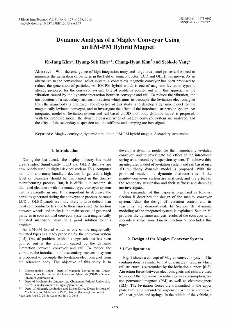
To verify the characteristics of the designed levitation electromagnets and control systems, a simple levitation experiment was carried out. Because the levitation system is of interest from a design perspective, we disabled the function of secondary suspension by inserting rigid metal blocks into it. The levitation experiment lasted for 10 seconds: levitation starts at 1 second and stops at 7 seconds. In order to take off and land smoothly, ramp input was used as a reference trajectory. The actual weight of the manufactured conveyor is 230kg and we load an additional 50kg weight so that the total weight becomes 280kg. In this study, 4 measurement points are used to measure air gaps, currents and accelerations as shown in Fig. 5.
Fig. 6 shows measured gap trajectories and coil currents. The measured gaps are tracking the reference gap and stay near 3mm after levitation completes. There are small differences in air gaps among the four corners, which mainly results from the unbalanced weight distribution of the conveyor.
),( ciF ( )c t
N
)(ti
)(tv
Windings
Permanentmagnet mg
pmh
)(tfd
Electromagnet
Rail
Fig. 4. Simplified model of the levitation system
V (m/s)
Sensor 1
Electromagnet
Sensor 2
Sensor 3 Sensor 4 Fig. 5. Air gap sensor placement, top view
Dynamic Analysis of a Maglev Conveyor Using an EM-PM Hybrid Magnet
1574
0 2 4 6 8 10
3
4
5
6 Sensor 1 Sensor 2 Sensor 3 Sensor 4
Air
gap(
mm
)
Time(s) (a) Air gaps
0 2 4 6 8 10-2
0
2
4
6
8 Sensor 1 Sensor 2 Sensor 3 Sensor 4
Cur
rent
(A)
Time(s) (b) Currents
Fig. 6. Experimented results of levitation control For the coil current, we expect that the required current
at the air gap of 3mm is about zero based on the levitation force characteristics in the previous section. From the figure, the coil current has a small positive value of about 0.5A as expected. In addition, it is observed that the required current for takeoff and landing is less than 6A, which is increased slightly because the initial air gap is larger than 5mm.
Based on these observations, the experiment results are consistent with the design results. We can utilize the design results to predict dynamic behaviors of the conveyor system in various simulations for further analysis.
3. Dynamic modeling To predict dynamic behaviors of the conveyor system in
various simulations, an integrated system model considering mechanical components, the designed levitation electro-magnets and control systems verified in the experiments is proposed.
3.1 Procedure
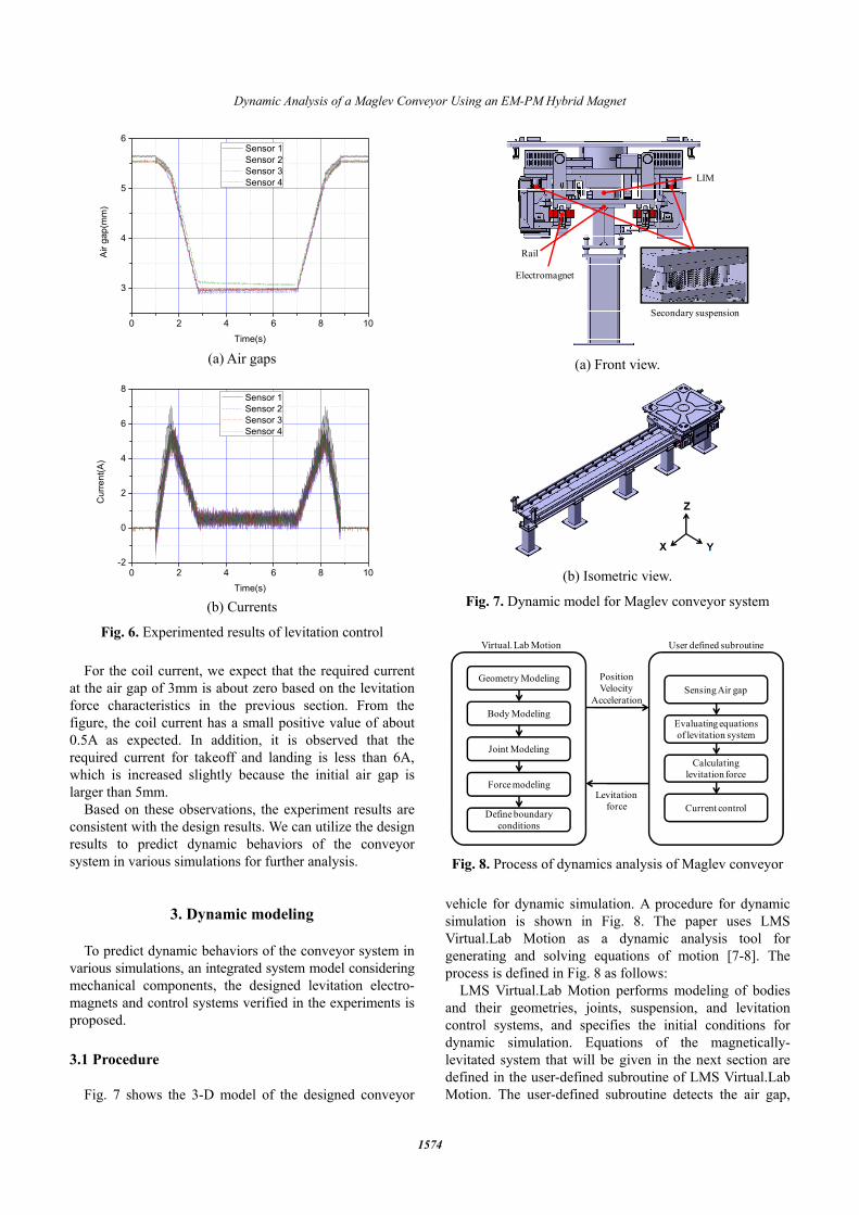
Fig. 7 shows the 3-D model of the designed conveyor
vehicle for dynamic simulation. A procedure for dynamic simulation is shown in Fig. 8. The paper uses LMS Virtual.Lab Motion as a dynamic analysis tool for generating and solving equations of motion [7-8]. The process is defined in Fig. 8 as follows:
LMS Virtual.Lab Motion performs modeling of bodies and their geometries, joints, suspension, and levitation control systems, and specifies the initial conditions for dynamic simulation. Equations of the magnetically-levitated system that will be given in the next section are defined in the user-defined subroutine of LMS Virtual.Lab Motion. The user-defined subroutine detects the air gap,
Secondary suspension
LIM
Rail
Electromagnet
(a) Front view.
(b) Isometric view.
Fig. 7. Dynamic model for Maglev conveyor system
Geometry Modeling
Body Modeling
Joint Modeling
Force modeling
Define boundary conditions
Sensing Air gap
Evaluating equations of levitation system
Calculatinglevitation force
PositionVelocity
Acceleration
Levitationforce Current control
Virtual. Lab Motion User defined subroutine
Fig. 8. Process of dynamics analysis of Maglev conveyor
Ki-Jung Kim, Hyung-Suk Han, Chang-Hyun Kim and Seok-Jo Yang
1575
which is the distance between an electromagnet and rail and its derivative. Then, the subroutine evaluates the system of differential equations of the levitation system, and calculates the levitation forces. The forces are applied to both the electromagnet and the rail in the subroutine.
3.2 Electromagnet
In the determining levitation force using (5) and (7),
the ( )c t , ( )c t must be calculated from the position and velocity of the pair of bodies. The definition of the vertical air gap is illustrated in Fig. 9 [7-8]. The vector between the electromagnet and the guiderail is first defined in the global reference frame as ' '
tm t m ot t ot om m om= − = + − −r r r r A s r A s (8)
where tA is the transformation matrix from guiderail to global reference frame and mA is the transformation matrix from electromagnet to global reference frame.
Transforming the vector in (8) into the guiderail reference frame, the vector in the guiderail reference frame is obtained by
'
'( )
0( )
tmT
tm t tm
x t
c t
⎡ ⎤⎢ ⎥
= =⎢ ⎥⎢ ⎥⎣ ⎦
r A r (9)
The z component of the vector in (9) is the ( )c t . Differentiating (8) with respect to time and transforming into the guiderail reference frame, the air gap velocity ( )c t can be derived as
' '
' ' ' 'tm t m ot t ot om m om
ot t t ot om m m om
= − = + − −
= + − −
r r r r A s r A s
r A ω s r A ω s (10)
'
'( )
0( )
tmT
tm t tm
x t
c t
⎡ ⎤⎢ ⎥
= =⎢ ⎥⎢ ⎥⎣ ⎦
r A r (11)
To more accurately calculate the levitation force
considering the relative position and orientation, the electromagnet’s levitation force is divided into 3 segments along the length of the pole face. After calculating the levitation force of each segment as shown in Fig. 10, they are summed into the total levitation force on one electromagnet, and the force is applied to both the electromagnet and the guiderail [7-8].
3.3 Guiderail
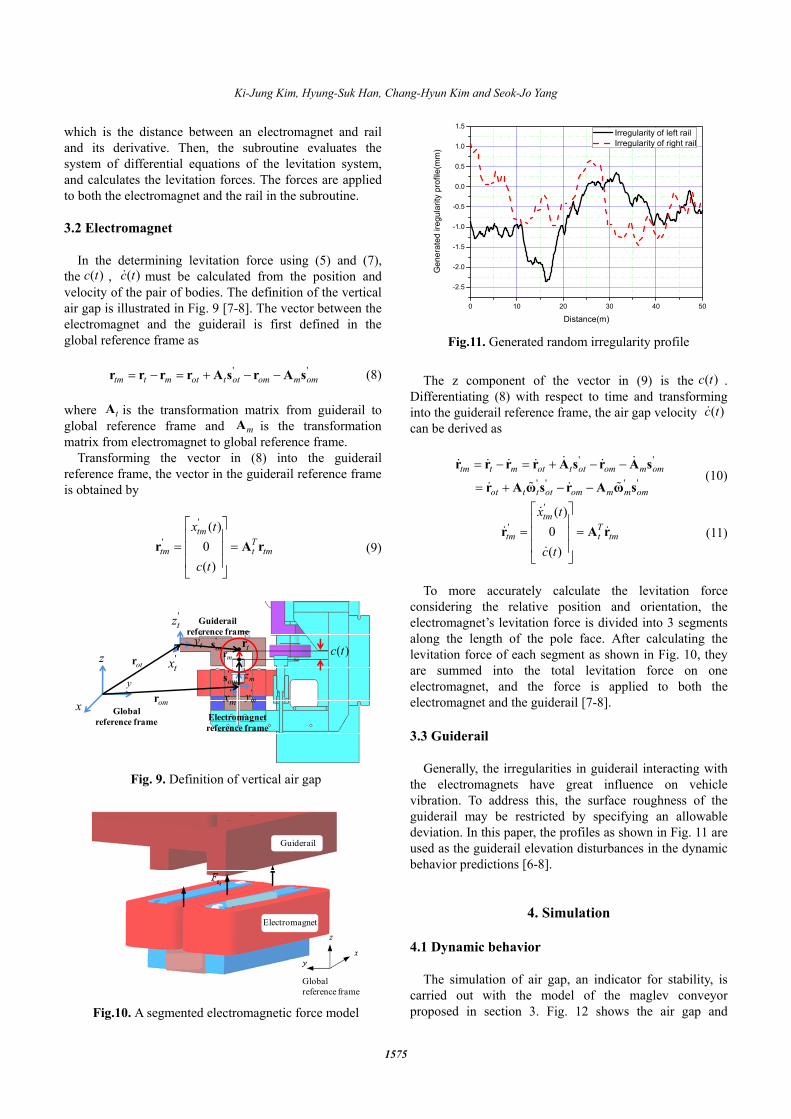
Generally, the irregularities in guiderail interacting with
the electromagnets have great influence on vehicle vibration. To address this, the surface roughness of the guiderail may be restricted by specifying an allowable deviation. In this paper, the profiles as shown in Fig. 11 are used as the guiderail elevation disturbances in the dynamic behavior predictions [6-8].
4. Simulation
4.1 Dynamic behavior The simulation of air gap, an indicator for stability, is
carried out with the model of the maglev conveyor proposed in section 3. Fig. 12 shows the air gap and
x
y
z
'tz
'tx
'ty
'mz
'mx '
myomr
otr'oms
'ots
Global reference frame
Guiderail reference frame
Electromagnetreference frame
( )c ttrmr
Fig. 9. Definition of vertical air gap
Guiderail
Electromagnet
Global reference frame
Fig.10. A segmented electromagnetic force model
0 10 20 30 40 50
-2.5
-2.0
-1.5
-1.0
-0.5
0.0
0.5
1.0
1.5
Gen
erat
ed ir
egul
arity
pro
file(
mm
)
Distance(m)
Irregularity of left rail Irregularity of right rail
Fig.11. Generated random irregularity profile
Dynamic Analysis of a Maglev Conveyor Using an EM-PM Hybrid Magnet
1576
levitation force time histories of each corner of electro-magnets measured at gap sensors 1-4 when the maglev conveyor travels over the guiderail with irregularities in Fig. 11 at a constant velocity of 3m/s. The suspension system is levitated stably, and all results indicate that the air gaps vary from the nominal air gap of 3mm. Thus, the maglev conveyor with an EM-PM hybrid suspension system yields stable performance with adequate gap response to the disturbance.
4.2 Analysis of the effect of secondary suspension
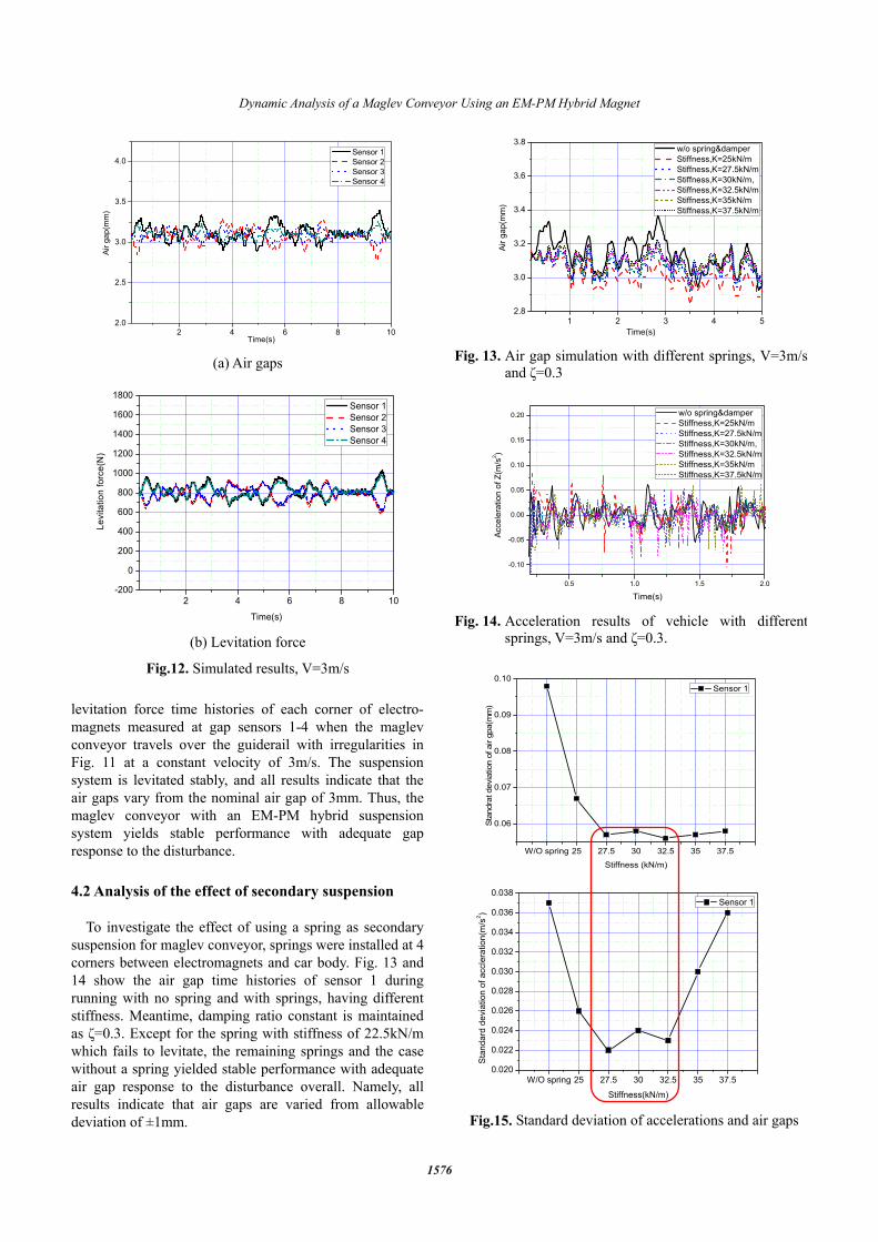
To investigate the effect of using a spring as secondary
suspension for maglev conveyor, springs were installed at 4 corners between electromagnets and car body. Fig. 13 and 14 show the air gap time histories of sensor 1 during running with no spring and with springs, having different stiffness. Meantime, damping ratio constant is maintained as ζ=0.3. Except for the spring with stiffness of 22.5kN/m which fails to levitate, the remaining springs and the case without a spring yielded stable performance with adequate air gap response to the disturbance overall. Namely, all results indicate that air gaps are varied from allowable deviation of ±1mm.
W/O spring 25 27.5 30 32.5 35 37.5
0.06
0.07
0.08
0.09
0.10 Sensor 1
Stan
drat
dev
iatio
n of
air
gpa(
mm
)
Stiffness (kN/m)
W/O spring 25 27.5 30 32.5 35 37.50.020
0.022
0.024
0.026
0.028
0.030
0.032
0.034
0.036
0.038
Stan
dard
dev
iatio
n of
acc
lera
tion(
m/s
2 )
Stiffness(kN/m)
Sensor 1
Fig.15. Standard deviation of accelerations and air gaps
2 4 6 8 102.0
2.5
3.0
3.5
4.0 Sensor 1 Sensor 2 Sensor 3 Sensor 4
Air g
ap(m
m)
Time(s) (a) Air gaps
2 4 6 8 10-200
0
200
400
600
800
1000
1200
1400
1600
1800 Sensor 1 Sensor 2 Sensor 3 Sensor 4
Levi
tatio
n fo
rce(
N)
Time(s) (b) Levitation force
Fig.12. Simulated results, V=3m/s
1 2 3 4 52.8
3.0
3.2
3.4
3.6
3.8
Air
gap(
mm
)
Time(s)
w/o spring&damper Stiffness,K=25kN/m Stiffness,K=27.5kN/m Stiffness,K=30kN/m, Stiffness,K=32.5kN/m Stiffness,K=35kN/m Stiffness,K=37.5kN/m
Fig. 13. Air gap simulation with different springs, V=3m/s
and ζ=0.3
0.5 1.0 1.5 2.0
-0.10
-0.05
0.00
0.05
0.10
0.15
0.20
Acce
lera
tion
of Z
(m/s
2 )
w/o spring&damper Stiffness,K=25kN/m Stiffness,K=27.5kN/m Stiffness,K=30kN/m, Stiffness,K=32.5kN/m Stiffness,K=35kN/m Stiffness,K=37.5kN/m
Time(s) Fig. 14. Acceleration results of vehicle with different
springs, V=3m/s and ζ=0.3.

Ki-Jung Kim, Hyung-Suk Han, Chang-Hyun Kim and Seok-Jo Yang
1577
In the acceleration responses of the car body, the results of each case show better performances than the designed specifications of the manufactured maglev conveyor, 1m/s2.
The standard deviation of air gaps and accelerations at sensor 1 are presented as shown in Fig. 15, to consider the variability in values. Consequently, all results indicate that the secondary suspension is feasible and effective for use in the maglev conveyor system. In addition, springs with stiffness between 27.5 and 32.5kN/m for air gap and acceleration have relatively strong effects.
5. Conclusion In this paper, the use of a multibody dynamic model for
an EM-PM hybrid-type maglev conveyor was proposed in order to accurately predict dynamic characteristics, and this was carried out using the Virtual Lab. Motion program. Based on the results of the dynamic simulation and experiments, the following conclusions can be drawn.
First, experiments were performed to verify the designed control method. We can see that the designed controller with PD feedback loop can be levitated steadily without contact.
Secondly, using the dynamic model with the defined levitation system, this paper presents a more realistic dynamic simulation of maglev vehicle. Therefore, dynamic simulation could be useful in designing an air gap control system.
Thirdly, we can see that the introduction of a secondary suspension system is considerably effective in the reducing vibration of this suspension system with EM-PM Hybrid.
Acknowledgements This research was supported by the Korea Research
Council for Industrial Science & Technology within the project entitled “Development of a magnetically levitated passive tray transfer system.”
References
[1] Tzeng, Y.-K. and Wang, T. C., 1995, “Dynamic analysis of the maglev system using controlled-pm electromagnets and robust zero-power-control strategy,” IEEE Trans. on Magnetics, vol. 31, No. 6, pp. 4211-4213.
[2] Morishita, M., Azukizawa, T., Kanda, S., Tamura, N. and Yokoyama, T., 1989, “A new maglev system for magnetically levitated carrier system,” IEEE Trans. on Vehicular Technology, vol. 38, No. 4, pp. 230-236.
[3] Kim, Y., Kim, K. and Lee, J., 2001, “Zero power control with load observer in controlled-pm
levitation,” IEEE Trans. on Magnetics, vol. 37, No. 4, pp. 116-132.
[4] Mizuno, T. and Takemori, Y., 2002, “A transfer- function approach to the analysis and design of zero-power controllers for magnetic suspension systems,” Electrical Engineering in Japan, vol. 141, No. 2, pp. 116-132.
[5] Sun, F. and Oka, K., 2009, “Zero power non-contact suspension system with permanent magnet motion feedback,” J. System Design and Dynamics, vol. 3, No. 4, pp. 627-638.
[6] Zhao, C.F. and Zhai, W. M., 2002, “Maglev vehicle/ guideway vertical random response and ride quality,” Vehicle System Dynamics, Vol. 38, No. 3, pp.185-210
[7] Han, H.S., Lee, J.M., Sung, H.K., Kim, B.H. and Kim, K.J., 2007, “Dynamic modeling of a magnetically levitated vehicle running over flexible guideway,” 2007 Multibody Dynamics, Proceedings, pp. 46-47.
[8] Han, H.S., Yim, B.H., Lee, N.J., Hur, Y.C. and Kim, S. S., 2008, “Effects of guideway’s vibrational characteristics on dynamics of a Maglev vehicle,” Vehicle System Dynamics, Vol. 47, No. 3, pp. 01-16.
[9] Sinha, P. K., 1987, Electromagnetic Suspension Dynamics & Control, Peter Peregrinus Ltd., London.
Ki-Jung Kim He received B.S., M.S. degree in mechatronics engineering from Chungnam National University, Korea, in 2009 and 2011. He is currently pursuing the Ph.D. degree in department of mechatronics engineer-ing at Chungnam National University. His research interests are the com-
putational mechanics in the human body and vehicles.
Hyung-Suk Han He received the Ph.D. degree in mechanical engineering from Ajou University, Suwon, Korea, in 1997. Since 1997, he has been a principal researcher in KIMM (Korea Institute of Machinery and Materials). His research interest is the dynamic simulation of maglev vehicles.
Chang-Hyun Kim He received the B.S., M.S. and Ph.D. degrees in elec-trical and electronic engineering from Korea Advanced Institute of Science and Technology in 2000, 2002 and 2009, respectively. Since 2009, he has been a senior researcher in KIMM (Korea Institute of Machinery and

Dynamic Analysis of a Maglev Conveyor Using an EM-PM Hybrid Magnet
1578
Materials). His research interest is the control of magnetic levitation and linear propulsion systems.
Seok-Jo Yang He received Ph.D. degree in Biomedical engineering from the University of Iowa. Since 2004, he has been a professor in Chungnam Na-tional University. His research interest is the computational mechanics in the human body and vehicles.